Embed Size (px)
Citation preview
This article appeared in a journal published by Elsevier. The attachedcopy is furnished to the author for internal non-commercial researchand education use, including for instruction at the authors institution
and sharing with colleagues.
Other uses, including reproduction and distribution, or selling orlicensing copies, or posting to personal, institutional or third party
websites are prohibited.
In most cases authors are permitted to post their version of thearticle (e.g. in Word or Tex form) to their personal website orinstitutional repository. Authors requiring further information
regarding Elsevier’s archiving and manuscript policies areencouraged to visit:
http://www.elsevier.com/copyright
Author's personal copy
Heterogeneous amphibolite facies deformation of a granulite facies layeredprotolith: Matches Island shear system, Parry Sound domain, Grenville Province,Ontario, Canada
Nicholas Culshawa,*, Christopher Gerbi b,1, Jeff Marsh b,2, Lawrence Plug a,3
aDepartment of Earth Sciences, Dalhousie University, Halifax B3H 3J5, CanadabDepartment of Earth Sciences, University of Maine, Orono, ME 04469, USA
a r t i c l e i n f o
Article history:Received 1 June 2010Received in revised form19 February 2011Accepted 8 March 2011Available online 15 March 2011
Keywords:Shear zonesRetrogressed granuliteDeep crust
a b s t r a c t
Amphibolite facies transposition of granulite facies gneiss resulted in the formation of a nappe-boundingkm-scale shear zone at the margin of the Parry Sound domain, Grenville Province. The Matches Islandshear system illustrates the earlier stages of transposition in which heterogenous retrogression of thewell layered (maficefelsic) granulite facies gneiss along pegmatites orthogonal to layering controlled thelocation of shear zones and ensured that unretrogressed granulite persisted as strong elements. Shearzones curve anticlockwise from their original orientation accompanied by rigid rotation of wall rocklayering which remains orthogonal to the shear zones. This relationship is modified so that wall rocklayering form sigmoidal mafic ‘fish’ where shear zone linkage occurs via: (i) merging of establishedparallel shear zones by wall rock ‘collapse’; (ii) merging of an established shear zone with a new shearzone formed within preexisting wall rock or; (iii) linking of two established zones by an oblique newshear zone. All of these wall rock e shear zone relations are displayed in the maximally transposednappe-bounding shear zone but contrast with those at the boundary of other nappes where uniformamphibolite facies protolith is transposed with a buckle-and-shear style.
� 2011 Elsevier Ltd. All rights reserved.
1. Introduction
The relevance of the study stems from the supposition thatshear zone systems may accommodate a significant fraction ofstrain in deep orogenic crust as exemplified by the Central GneissBelt (CGB) of the Grenville Province. Further, the Matches Islandshear system represents a small-scale sampling of the early stagesof formation of a nappe-bounding, regional shear zone and thusprovides insights into the evolution of major, large scale, deep-crustal structure.
The particular focus of the study is the geometry and kinematicsof processes in the early stages of ductile deformation, shearing andreorientation of one class of compositionally layered gneiss foundin the CGB: granulite facies gneiss inwhich shear zones nucleate onhydrated and often pegmatite-filled corridors (Marsh et al., 2011;Culshaw et al., 2010). Also we contrast the style present in this
outcrop with the distinct style shown by ductile deformation andreorientation of a second, regionally common, species of layeredgneiss: homogeneously amphibolized compositionally layeredgneiss which had never reached granulite facies before shearing.Such gneissic products of reworking during progressive deforma-tion may comprise structural styles generic to deep orogenic crust.
2. Geologic setting
2.1. Regional geology
The CGB is a major component of the Grenville Province, a ca.1160e1000 Ma collisional orogen (Fig. 1). The Matches Island shearsystem lies at the periphery of the Twelve Mile Bay shear zone(TMBSZ) along the southern margin of the Parry Sound domain(PSD), a lithotectonic domain within the CGB. The present erosionsurface of the CGB represents the deep levels of a thick orogen,comprising upper amphibolite to granulite facies gneisses and mig-matites recording peak metamorphic temperatures in excess of750 �C and pressures as high as 10e13 kb. The PSD, consisting ofmainly granulite facies gneiss, lies within a stack of upper amphib-olite facies domains in the CGB (Fig. 1) formed by either: (1) stacking
* Corresponding author. Tel.: þ1 902 494 3501; fax: þ1 902 494 6889.E-mail addresses: [email protected] (N. Culshaw), [email protected]
(C. Gerbi), [email protected] (J. Marsh), [email protected] (L. Plug).1 Tel.: þ1 207 581 2153.2 Tel.: þ1 207 581 2152.3 Tel.: þ1 902 494 1200.
Contents lists available at ScienceDirect
Journal of Structural Geology
journal homepage: www.elsevier .com/locate/ jsg
0191-8141/$ e see front matter � 2011 Elsevier Ltd. All rights reserved.doi:10.1016/j.jsg.2011.03.005
Journal of Structural Geology 33 (2011) 875e890
Author's personal copy
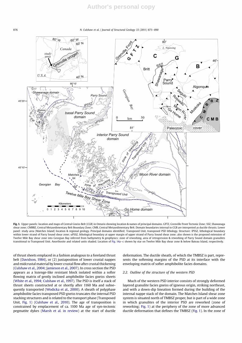
of thrust sheets emplaced in a fashion analogous to a foreland thrustbelt (Davidson, 1984), or (2) juxtaposition of lower crustal nappesandmidcrustalmaterial by lower crustalflowafter crustal thickening(Culshaw et al., 2004; Jamieson et al., 2007). In cross section the PSDappears as a lozenge-like resistant block isolated within a softerflowing matrix of gently inclined amphibolite facies gneiss sheets(White et al., 1994; Culshaw et al., 1997). The PSD is itself a stack ofthrust sheets constructed at or shortly after 1160 Ma and subse-quently transported (Wodicka et al., 2000). A sheath of polyphaseamphibolite facies transposed PSD gneiss truncates the internal PSDstacking structures and is related to the transport phase (TransposedUnit, Fig. 1) (Culshaw et al., 2010). The age of transposition isconstrained by emplacement of ca. 1100 Ma age of syn-tectonicpegmatite dykes (Marsh et al. in review) at the start of ductile
deformation. The ductile sheath, of which the TMBSZ is part, repre-sents the softening margins of the PSD at its interface with theenveloping matrix of softer amphibolite facies domains.
2.2. Outline of the structure of the western PSD
Much of the western PSD interior consists of strongly deformedlayered granulite facies gneiss of igneous origin, striking northeast,and with a down-dip lineation formed during the building of theinternal nappe stack of the domain. The Matches Island shear zonesystem is situated north of TMBSZ proper, but is part of a wide zonein which granulites of the interior PSD are reworked (zone ofreworking; Fig. 1) at the periphery of the zone of more advancedductile deformation that defines the TMBSZ (Fig. 1). In the zone of
Fig. 1. Upper panels: location and maps of Central Gneiss Belt (CGB) in Ontario showing location & names of principal domains. GFTZ, Grenville Front Tectonic Zone; SSZ, Shawanagashear zone; CMBBZ, Central Metasedimentary Belt Boundary Zone; CMB, Central Metasedimentary Belt. Domain boundaries internal to CGB are interpreted as ductile thrusts. Lowerpanel: study area (Matches Island) location & regional geology. Principal domains identified; Transposed Unit, transposed PSD lithology. Structure: lPSSZ, lithological boundarywithin lower strand of Parry Sound shear zone; uPSSZ, lithological boundary at upper margin of upper strand of Parry Sound shear zone; also shown is the proposed extension ofTwelve Mile Bay shear zone into Georgian Bay inferred from bathymetry & geophysics; zone of reworking, area of retrogression & reworking of Parry Sound domain granulitestransitional to Transposed Unit. Anorthosite and related units shaded. Location of Fig. 14aec shown by star on Twelve Mile Bay shear zone & below Bateau Island, respectively.
N. Culshaw et al. / Journal of Structural Geology 33 (2011) 875e890876
Author's personal copy
reworking, trends of unsheared granulite gneissosity and shearzones appear irregular at map scale but cylindrical viewed instereographic projection (Hanmer, 1984). To the south, in theTMBSZ segment of the Transposed Unit, PSD-derived and otherupper amphibolite facies gneisses in various states of shearing andreorientation and retrogression dip north-northeast beneath thePSD interior. The boundary between the zone of reworking and theTMBSZ is gradational; they are clearly genetically linked, as indi-cated by the geometric and lithologic similarity of sheared rocksand the presence of pegmatite dykes or their deformed equivalents(Culshaw et al., 2010).
The role of fractures, fluid and, in some cases, pegmatite dykes, inshear zone formation has been noted in several studies (e.g.,Pennacchioni, 2005; Pennacchioni and Mancktelow 2007;Mancktelow and Pennacchioni, 2005; Fusseis et al., 2006; Jamtveitet al., 2000; Jolivet et al., 2005). In the zone of reworking and theTransposed Unit (TMBSZ) their role is crucial (Marsh et al., 2011;Culshaw et al., 2010). Pegmatite- and granitoid-filled dykes withingranulite are associated with a hydration and retrogression halo inthe adjacent wall rock. Field relations show this hydration is
tantamount to anecessaryconditionof shear zone formationwith thepegmatite dykes as the source of the fluid that engendered softening,consistent with syn-tectonic pegmatite emplacement in fracturescaused by underlying over-pressured fluid-rich magma. Meta-morphic conditions for formation of the shear zones were in theamphibolite facies at ca. 6.5 kbar and ca. 700 �C (Marsh et al., 2011).
2.3. Geology of Matches Island
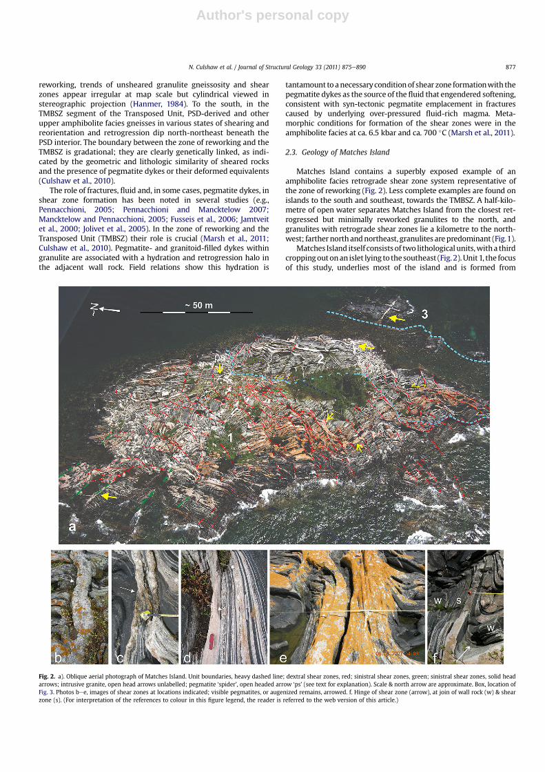
Matches Island contains a superbly exposed example of anamphibolite facies retrograde shear zone system representative ofthe zone of reworking (Fig. 2). Less complete examples are found onislands to the south and southeast, towards the TMBSZ. A half-kilo-metre of open water separates Matches Island from the closest ret-rogressed but minimally reworked granulites to the north, andgranulites with retrograde shear zones lie a kilometre to the north-west; farther northandnortheast, granulites arepredominant (Fig.1).
Matches Island itself consists of two lithological units,witha thirdcroppingoutonan islet lying to thesoutheast (Fig.2).Unit1, the focusof this study, underlies most of the island and is formed from
Fig. 2. a). Oblique aerial photograph of Matches Island. Unit boundaries, heavy dashed line; dextral shear zones, red; sinistral shear zones, green; sinistral shear zones, solid headarrows; intrusive granite, open head arrows unlabelled; pegmatite ‘spider’, open headed arrow ‘ps’ (see text for explanation). Scale & north arrow are approximate. Box, location ofFig. 3. Photos bee, images of shear zones at locations indicated; visible pegmatites, or augenized remains, arrowed. f. Hinge of shear zone (arrow), at join of wall rock (w) & shearzone (s). (For interpretation of the references to colour in this figure legend, the reader is referred to the web version of this article.)
N. Culshaw et al. / Journal of Structural Geology 33 (2011) 875e890 877
Author's personal copy
a protolith common in the granulites to the north and northeast. Thegneiss has decimetre to metre-scale layering of felsic (granitic) andmafic components. In and outside of the shear zones the felsic layerscontain anassemblage of plagioclase-K feldspar-quartz-hornblende-biotite.Whereas themafic layer assemblagewithin the shear zone ishornblende-plagioclase � biotite � quartz � titanite, wall rock mayretain coarser plagioclase-clinopyroxene-orthopyroxene-horn-blende mantled by symplectic garnet, hornblende and biotite. Wallrocks have a cm-scale mineralogical layering and a planar-linearmineral aggregate shape fabric (e.g., quartz blades in felsic gneiss),typical of the granulites regionally, but no strong mineralogicalfissility (e.g., mica schistosity).
Unit 2 is grey plagioclase-quartz-hornblende-biotite gneiss withscattered pink granite leucosomes, a uniform amphibolite faciesmineral assemblage and no mafic layers. Pink leucocratic graniteforms concordant layers within the grey gneiss but are morewidelyand irregularly spaced than similar layers in Unit 1. As in Unit 1there are pegmatite-cored shear zones, but in Unit 2, mineralogical
differences across these shear zones are absent and displacementrelatively low. Unit 3, underlying the adjacent islet, is a uniformamphibolite but with textural features (leucosome patches con-taining retrogressed pyroxene) suggesting granulite facies heritage.
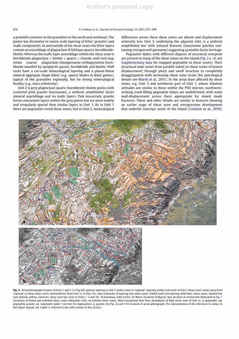
Pegmatite dykes with different degrees of structural overprintare present in many of the shear zones on the island (Fig. 2 aed; seeSupplementary data for mapped pegmatite in shear zones). Theirstructural state varies from parallel-sided (in shear zones of lowestdisplacement) through pinch and swell structure to completelydisaggregation with increasing shear zone strain (for petrologicaldetails see Marsh et al., 2011). In the areas least affected by shearzones, e.g. Unit 3 and northwest part of Unit 1, where foliationattitudes are similar to those within the PSD interior, northwest-striking crack-filling pegmatite dykes are undeformed, with somewall-displacement across them appropriate for mixed modefractures. These and other details are similar to features showingan earlier stage of shear zone and retrogression developmentthat underlie outcrops north of the island (Culshaw et al., 2010).
Fig. 3. Aerial photograph of parts of Units 1 and 2. (a) Top left, gneissic layering in Unit 2 strikes close to ‘regional’; layering within wall rocks of Unit 1 shear zones rotate away from‘regional’ as shear zones curve anticlockwise (from Unit 1c to Unit 1d); note continuity of layering into shear zones. Folded wall rock layering, bold lines; shear zones, dashed line(red, dextral; yellow, sinistral); shear zone tips close to Units 1e2 and 1de1b boundary, solid circles. (b) Boxes, locations of figures; line, location of section line illustrated in Fig. 7(locations of linked and unlinked shear zones indicated); eSZs, en echelon shear zones; thick transparent blue lines, boundaries of high strain zone of Unit 1c. p, pegmatite; pg,pegmatitic granite; ps, ‘pegmatite spider’ (see text for explanation); g, granite. See Fig. 2a and 5 for location of aerial photograph. (For interpretation of the references to colour inthis figure legend, the reader is referred to the web version of this article.)
N. Culshaw et al. / Journal of Structural Geology 33 (2011) 875e890878
Author's personal copy
The orthogonal orientation of wall rock layering relative to shearzones, common at all stages of development (Figs. 2 and 3), wasdetermined by this original orientation of the fluid and pegmatitebearing fractureswhich guided initial shear zone orientation (Marshet al., 2011; Culshaw et al., 2010). There is some evidence for a minorlater, syn-shear zonemagmatic component. This includes the spider-like group of pegmatites situated at the tip of the northern Unit 1e2boundary shear (ps, Fig. 3)whichmayhave absorbedextensionat thetip of a propagating shear zone. Some pegmatites may be syn-tectonic such as the large, pegmatitic granite lying within a shearzone (pg, Fig. 3)which contains inclusionswithgneissosityparallel tothe shear zone and small pegmatites at shear zone tips, arguablyemplaced during shear zone propagation (Fig. 4a, b).
3. Methods
Much of the analysis presented below derives from cm-scalemapping of structures across the island. We used three comple-mentary methods to generate the maps: low-altitude aerialphotographs, DGPS (Differential GPS), and photographs froma pole-mounted camera (6 m pole). Photographs taken during low-altitude flight (ca. 150 m altitude) are slightly oblique, givinga foreshortened down-plunge view of the DGPS map, but providea unique perspective of the structural character and nature of theunits. The map made with DGPS (Fig. 5) gives a more accurate planview of the island than the air photograph. The DGPS map showsmost of the shear zones on the island but the map is necessarilyincomplete with respect to comprehensively depicting the denselyspaced layering. The DGPS data also allow calculation of quantita-tive information such as density of shear zones (per unit area),frequency of shear zone intersections (per unit length) or strainestimates via displacement of marker layers across shear zones.Large-scale structural features gleaned from the air photographshave in many cases been ground-truthed with photographs takenwith the pole-mounted camera which gives excellent images ofstructures exposed on sub horizontal surfaces of low relief.
3.1. Map-scale structure of Matches Island
Summarising the structure at the scale of all dry land and visiblesubmerged rock, Unit 3 is a competent mafic layer with incipientboudinage shown by a fold of Unit 2 layering infilling a boudin neck(below ‘3’ in Fig. 2a). As indicated by the undeformed pegmatite(arrowed, Fig. 2a), Unit 3 has little internal syn/post-pegmatitedeformation. Based on density of shear zones, Unit 2 is divided intonorthern (Unit 2a, fewer shear zones) and southern (Unit 2b, more
shear zones) parts (Fig. 5). The northern and southern segments ofthe boundary of Unit 2 with Unit 1 are bounded by dextral shearzones but the segment between the sheared parts of Unit 2a and 2bboundaries is partially obscured by vegetation and its nature isunclear.
Unit 1 has northwestern and northeastern lobes that are poor inshear zones and showan orientation of the granulite layering similarto the regional one (Fig. 5, Units 1a, b). In contrast, the central part ofUnit 1 has densely developed shear zones curving anticlockwise ENEto NNE and forming a core zone to the island (Fig. 5, Units 1c, d).
Pole figures of gneissic layering in shear zone walls, shear zone-poor segments and shear zone cores show a dispersion around anaxis plunging 50e65� eastward. This axis corresponds both to thedrag fold axis of the granulite layering close to the shear zones(shear zone hinge) and, at a broader scale, to the curvature of theshear zones. It is also parallel to the fold axes within gneisses ofUnit 2 (see below; Fig. 5). The magnitude of the plunge implies thatthe map plane is inclined about 30� to the XZ plane of the shearzone system but is not a great distortion of that plane.
3.2. Shear zones and wall rock
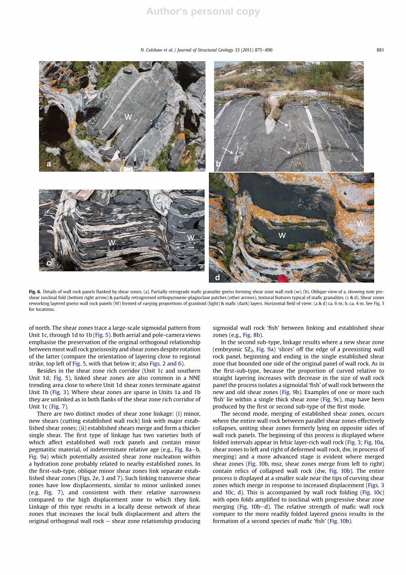
At outcrop scale, the shear zones consist of moderately grainsize refined, thinned wall rock gneiss layers and pegmatite dykeswithin the shear zones (arrows; Fig. 2bed) are progressivelydeformed in sympathy with shear zone strain (increasing: bed;Fig. 2). Most shear zones are dextral. Sinistral shear zones arerelatively rare and are concentrated in the northwest of the islandin Unit 1a and contiguous parts of 1d (Fig. 2a) and there are twominor sinistral shear zones in Unit 1c (long dashes, Fig. 3). In manyshear zone walls there is a lack of syn-shear zone deformation andshear zone walls preserve the regional pre-shear planar-linearfabrics, layering, and folds (Fig. 6b; bottom right arrow). In maficlayers melt-related textures (Fig. 6b; top right and left arrows)imposed during granulite facies metamorphism may be unalteredand accompany variably preserved granulite assemblages in thehost (Marsh et al., 2011). The lack of syn-shear deformation in thewall rocks and of evidence for transpression-related extrusion fromthe shear zones, implies simple shear for tabular shear zonesegments. Although there is no observed lineation in the shearzone, offset markers indicate that movement was perpendicular tothe steeply plunging ‘shear zone hinges’ formed where layeringcurves sharply into the shear zones.
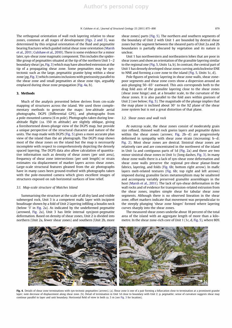
The measured shear zones underlie about 18 percent of the totalarea of the island with an aggregate length of more than a kilo-metre. In the shear zone-rich core of Unit 1 (1c, d, Fig. 5), where 80%
Fig. 4. Details of shear zone terminations with syn-tectonic pegmatites (arrows). (a). Shear zone is one of a pair forming a bifurcation close to termination at a prominent granitelayer; note decrease of displacement along shear zone. (b). Detail of termination in Unit 1d close to boundary with Unit 2; p, pegmatite; sense of curvature suggests shear maycontinue parallel to layer and unit boundary. Horizontal field of view in both ca. 5 m (see Fig. 3 for location).
N. Culshaw et al. / Journal of Structural Geology 33 (2011) 875e890 879
Author's personal copy
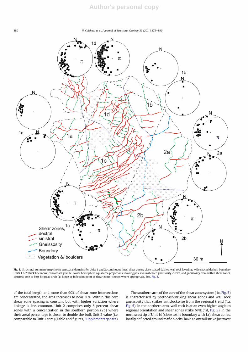
of the total length and more than 90% of shear zone intersectionsare concentrated, the area increases to near 30%. Within this coreshear zone spacing is constant but with higher variation wherelinkage is less common. Unit 2 comprises only 8 percent shearzones with a concentration in the southern portion (2b) wheretheir areal percentage is closer to double the bulk Unit 2 value (i.e.comparable to Unit 1 core) (Table and figures, Supplementary data).
The southern arm of the core of the shear zone system (1c, Fig. 5)is characterised by northeast-striking shear zones and wall rockgneissosity that strikes anticlockwise from the regional trend (1a,Fig. 5). In the northern arm, wall rock is at an even higher angle toregional orientation and shear zones strike NNE (1d, Fig. 5). In thenorthwest tipofUnit 1d (close to theboundarywith1a), shear zones,locallydeflectedaroundmaficblocks, haveanoverall strike justwest
Fig. 5. Structural summary map shows structural domains for Units 1 and 2; continuous lines, shear zones; close spaced dashes, wall rock layering; wide spaced dashes, boundaryUnits 1 & 2; thick line in SW, concordant granite. Lower hemisphere equal area projections showing poles to unsheared gneissosity, circles, and gneissosity fromwithin shear zones,squares; pole to best fit great circle (p, hinge or inflection point of shear zones) shown where appropriate. Box, Fig. 3.
N. Culshaw et al. / Journal of Structural Geology 33 (2011) 875e890880
Author's personal copy
of north. The shear zones trace a large-scale sigmoidal pattern fromUnit 1c, through 1d to 1b (Fig. 5). Both aerial and pole-camera viewsemphasise the preservation of the original orthogonal relationshipbetweenmostwall rockgneissosityand shear zonesdespite rotationof the latter (compare the orientation of layering close to regionalstrike, top left of Fig. 5, with that below it; also Figs. 2 and 6).
Besides in the shear zone rich corridor (Unit 1c and southernUnit 1d; Fig. 5), linked shear zones are also common in a NNEtrending area close to where Unit 1d shear zones terminate againstUnit 1b (Fig. 3). Where shear zones are sparse in Units 1a and 1bthey are unlinked as in both flanks of the shear zone rich corridor ofUnit 1c (Fig. 7).
There are two distinct modes of shear zone linkage: (i) minor,new shears (cutting established wall rock) link with major estab-lished shear zones; (ii) established shears merge and form a thickersingle shear. The first type of linkage has two varieties both ofwhich affect established wall rock panels and contain minorpegmatitic material, of indeterminate relative age (e.g., Fig. 8aeb,Fig. 9a) which potentially assisted shear zone nucleation withina hydration zone probably related to nearby established zones. Inthe first-sub-type, oblique minor shear zones link separate estab-lished shear zones (Figs. 2e, 3 and 7). Such linking transverse shearzones have low displacements, similar to minor unlinked zones(e.g. Fig. 7), and consistent with their relative narrownesscompared to the high displacement zone to which they link.Linkage of this type results in a locally dense network of shearzones that increases the local bulk displacement and alters theoriginal orthogonal wall rock e shear zone relationship producing
sigmoidal wall rock ‘fish’ between linking and established shearzones (e.g., Fig. 8b).
In the second sub-type, linkage results where a new shear zone(embryonic SZ2, Fig. 9a) ‘slices’ off the edge of a preexisting wallrock panel, beginning and ending in the single established shearzone that bounded one side of the original panel of wall rock. As inthe first-sub-type, because the proportion of curved relative tostraight layering increases with decrease in the size of wall rockpanel the process isolates a sigmoidal ‘fish’ of wall rock between thenew and old shear zones (Fig. 9b). Examples of one or more such‘fish’ lie within a single thick shear zone (Fig. 9c), may have beenproduced by the first or second sub-type of the first mode.
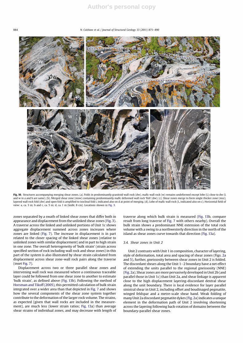
The second mode, merging of established shear zones, occurswhere the entire wall rock between parallel shear zones effectivelycollapses, uniting shear zones formerly lying on opposite sides ofwall rock panels. The beginning of this process is displayed wherefolded intervals appear in felsic layer-rich wall rock (Fig. 3; Fig. 10a,shear zones to left and right of deformedwall rock, dw, in process ofmerging) and a more advanced stage is evident where mergedshear zones (Fig. 10b, msz, shear zones merge from left to right)contain relics of collapsed wall rock (dw, Fig. 10b). The entireprocess is displayed at a smaller scale near the tips of curving shearzones which merge in response to increased displacement (Figs. 3and 10c, d). This is accompanied by wall rock folding (Fig. 10c)with open folds amplified to isoclinal with progressive shear zonemerging (Fig. 10bed). The relative strength of mafic wall rockcompare to the more readily folded layered gneiss results in theformation of a second species of mafic ‘fish’ (Fig. 10b).
Fig. 6. Details of wall rock panels flanked by shear zones. (a). Partially retrograde mafic granulite gneiss forming shear zone wall rock (w). (b). Oblique view of a, showing note pre-shear isoclinal fold (bottom right arrow) & partially retrogressed orthopyroxene-plagioclase patches (other arrows), textural features typical of mafic granulites. (c & d). Shear zonesreworking layered gneiss wall rock panels (W) formed of varying proportions of granitoid (light) & mafic (dark) layers. Horizontal field of view: (a & d) ca. 6 m; b, ca. 4 m. See Fig. 3for locations.
N. Culshaw et al. / Journal of Structural Geology 33 (2011) 875e890 881
Author's personal copy
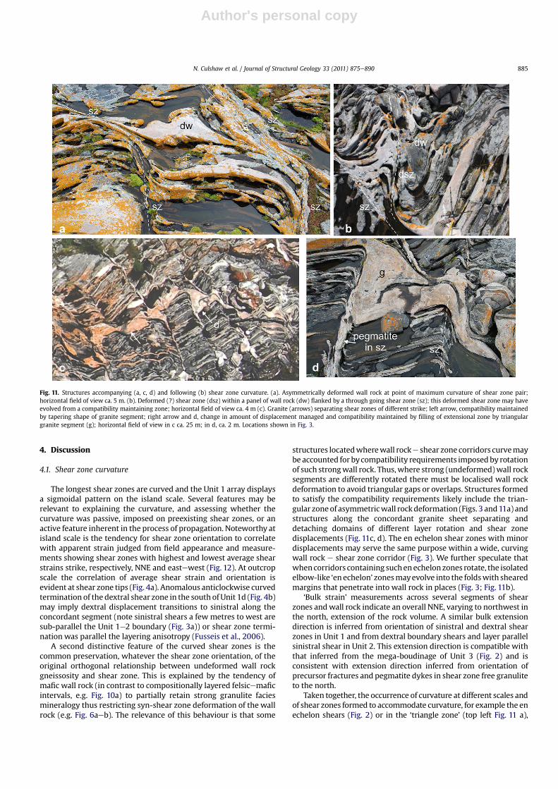
Unusual structures include those located at points of abruptcurvature of corridors of parallel shear zones, a triangular zone ofasymmetric wall rock deformation (Figs. 3 and 11a) and en echelonshears lie within broader zones of curvature (Fig. 3). In Unit 1c, anirregular concordant granite sheet separates domains of differentlayer rotationandshearzonedisplacements (Fig.11c).Onesegmentofthe granite fills an extensional zone mediating a change in displace-ment and strike along the shear zones (Fig.11d). Enigmatic foldswithsheared margins lie within wall rock but away from such bends inshear zoneewall rockcorridors. The shearedmarginsof the folds linkwith the main shear flanking the wall rock (Fig. 3; dsz, Fig. 11b).
Displacement along the shear zone terminations in Unit 1d,(close to the boundary with Unit 1b; filled circles at shear zone tips,Fig. 3), decreases with curvature (evident from variation of offset oflayering; Fig. 4a). Rotation (clockwise for dextral zones) from highto lower displacement segments is characteristic of the termina-tions. Although pegmatite is emplaced close to the shear zone tips,this geometry is consistent with shear zone propagation withoutnucleation along pegmatite (Fig. 4). In most cases the termination isabrupt close to a thick felsic layer that presumably formed a barrierto propagation (Figs. 3 and 4a), but one shear zone in the same areapenetrates the barrier and persists eastward across the island into
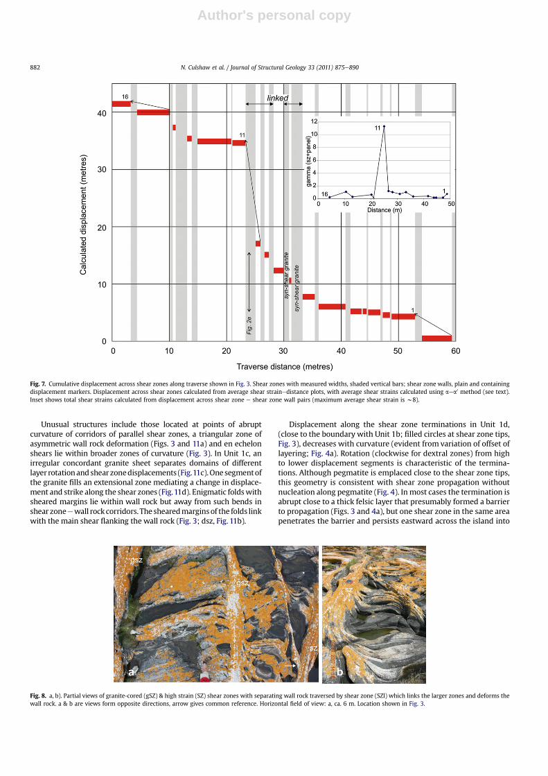
Fig. 7. Cumulative displacement across shear zones along traverse shown in Fig. 3. Shear zones with measured widths, shaded vertical bars; shear zone walls, plain and containingdisplacement markers. Displacement across shear zones calculated from average shear strainedistance plots, with average shear strains calculated using aea0 method (see text).Inset shows total shear strains calculated from displacement across shear zone e shear zone wall pairs (maximum average shear strain is w8).
Fig. 8. a, b). Partial views of granite-cored (gSZ) & high strain (SZ) shear zones with separating wall rock traversed by shear zone (SZl) which links the larger zones and deforms thewall rock. a & b are views form opposite directions, arrow gives common reference. Horizontal field of view: a, ca. 6 m. Location shown in Fig. 3.
N. Culshaw et al. / Journal of Structural Geology 33 (2011) 875e890882
Author's personal copy
the shear zone poor Unit 1b. In contrast, curving shear zones in thesoutheast of Unit 1d appear to terminate at the layer-concordantboundary with Unit 2a (open circle, Fig. 3). The curvature of thediscordant, dextral shear zone into the layer parallel segment isanticlockwise opposite to the previous examples (Fig. 4b).
3.3. Displacement and strains in the shear zone system
For individual shear zones we use several methods to estimatethe displacement and average shear strain (defined as straincalculated from total displacement across a zone of known thick-ness (Fusseis et al., 2006)). We also estimate the maximum shearstrain (gmax) within some shear zones, which together with theaverage shear strain (gmean) allows calculation of the strain local-isation intensity factor Iloc (Schrank et al., 2008):
Iloc ¼ 1� ðgmean=gmaxÞThe closer this factor is to unity the more abrupt and angular is
the shear zone profile, the closer to zero, the more smoothly curved(Schrank et al., 2008).
Because the gneiss is layered, the aea0 method (Ramsay andHuber, 1987) was the preferred method to measure shear strain.Plots of shear strain vs. distance across the shear zone permitted
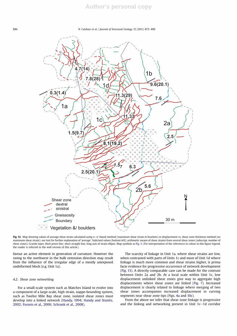
displacement calculations (e.g. Fusseis et al., 2006; Ramsay andGraham 1970). In many cases individual layers traceable acrossshear zones of known width allowed an independent estimate ofdisplacement and thus average shear strain (see Supplementarymaterial for examples of shear strain measurement, comparison ofresults by different methods and data). Maximum shear strains aredifficult to measure accurately because of uncertainties measuringlocal strike where there is extreme rotation of layering at higheststrains. Pegmatite forms a significant proportion of thewidth of lowdisplacement zones but any shear strain taken up within themwasunaccounted for due to the absence of strain markers. Thesecalculations show that average shear strain values (as definedabove) can be high (mean of values on Fig.12 is 6.15; for compilationfrom all shear zones measured by all methods see Supplementarydata). There is a tendency for the NNE-striking zones (e.g., Unit1d, Fig. 12) to have higher values than those striking northeast (e.g.,Unit 1c, Fig. 12). Maximum shear strains found within zones are inseveral cases in excess of 20. The average strain intensity localisationfactor is 0.72 (range 0.53e0.86) reflecting relatively abrupt, sub-angular profiles seen in shear zone images (Figs. 3 and 6).
Within the least rotated part of the core zone, Unit 1c, there aresignificant variations in displacement and strain of individual shearzones. As noted, Unit 1c has areas of predominantly unlinked shear
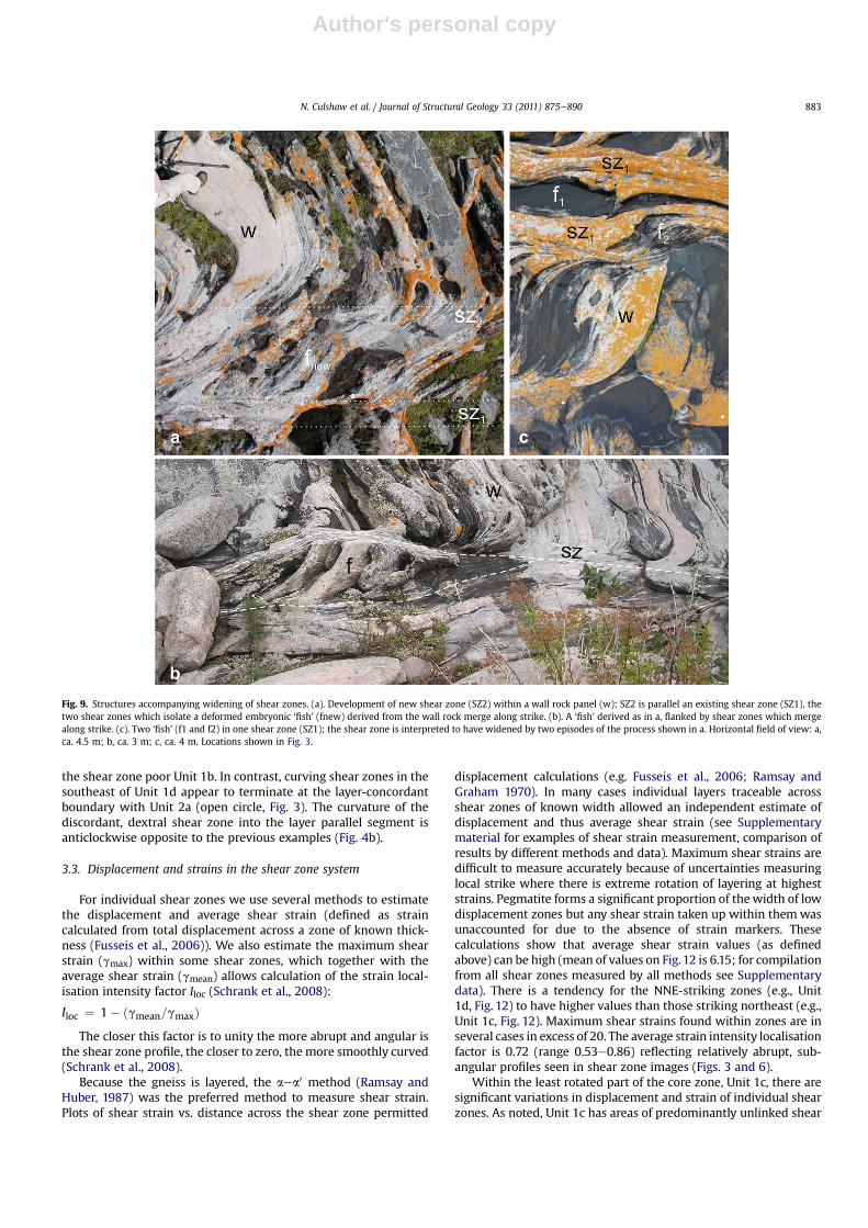
Fig. 9. Structures accompanying widening of shear zones. (a). Development of new shear zone (SZ2) within a wall rock panel (w); SZ2 is parallel an existing shear zone (SZ1), thetwo shear zones which isolate a deformed embryonic ‘fish’ (fnew) derived from the wall rock merge along strike. (b). A ‘fish’ derived as in a, flanked by shear zones which mergealong strike. (c). Two ‘fish’ (f1 and f2) in one shear zone (SZ1); the shear zone is interpreted to have widened by two episodes of the process shown in a. Horizontal field of view: a,ca. 4.5 m; b, ca. 3 m; c, ca. 4 m. Locations shown in Fig. 3.
N. Culshaw et al. / Journal of Structural Geology 33 (2011) 875e890 883
Author's personal copy
zones separated by a swath of linked shear zones that differ both inappearance anddisplacement from theunlinked shear zones (Fig. 3).A traverse across the linked and unlinked portions of Unit 1c showsaggregate displacement summed across zones increases wherezones are linked (Fig. 7). The increase in displacement is in partrelated to the closer spacing of the linked shear zones (relative tounlinked zones with similar displacement) and in part to high strainin one zone. The overall heterogeneity of ‘bulk strain’ (strain acrossspecified section of rock including wall rock and shear zones) in thispart of the system is also illustrated by shear strain calculated fromdisplacement across shear zone-wall rock pairs along the traverse(inset Fig. 7).
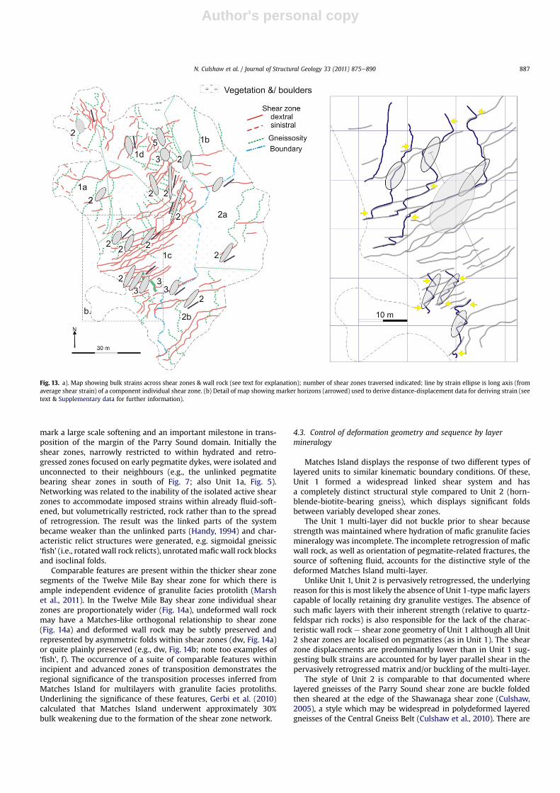
Displacement across two or three parallel shear zones andintervening wall rock was measured where a continuous traceablelayer could be followed from one shear zone to another to estimate‘bulk strain’, as defined above (Fig. 13b). Following the method ofHorsman and Tikoff (2005), this permitted calculation of bulk strainintegrated over a wider area than that depicted in Fig. 7 and showshow the several components of the shear zone system togethercontribute to the deformation of the larger rock volume. The strains,as expected (given that wall rocks are included in the measure-ment), are much less (lower strain ratios; Fig. 13a) than averageshear strains of individual zones, and may decrease with length of
traverse along which bulk strain is measured (Fig. 13b, compareresult from long traverse of Fig. 7 with others nearby). Overall thebulk strain shows a predominant NNE extension of the total rockvolumewith a swing to a northwesterly direction in the north of theisland as shear zones curve towards that direction (Fig. 13a).
3.4. Shear zones in Unit 2
Unit 2 contrastswithUnit 1 in composition, character of layering,style of deformation, total area and spacing of shear zones (Figs. 2aand 5), further, gneissosity between shear zones in Unit 2 is folded.The discordant shears along the Unit 1e2 boundary have a net effectof extending the units parallel to the regional gneissosity (NNE)(Fig. 2a). Shear zones aremorepervasivelydeveloped inUnit 2b (andparallel those in Unit 1c) than Unit 2a, and shear linkage is apparentclose to the high displacement layering-discordant dextral shearalong the unit boundary. There is local evidence for layer parallelsinistral shear in Unit 2, including offset and boudinaged pegmatite,winged feldspar and a metre-scale shear band. Weak folding ofmanyUnit 2adiscordantpegmatitedykes (Fig. 2a) indicates auniqueelement in the deformation path of Unit 2 involving shorteningacross the layering following back-rotation of domains between theboundary-parallel shear zones.
Fig. 10. Structures accompanying merging shear zones. (a). Folds in predominantly granitoid wall rock (dw), mafic wall rock (w) remains undeformed except lobe (L) close to dw (Land w in a and b are same). (b). Merged shear zone (msw) containing predominantly mafic deformed wall rock ‘fish’ (dw). (c). Shear zones merge to form single thicker zone (msz),layered wall rock fold (dw) and open fold is amplified to isoclinal fold i, indicated also on d at point of merging. (d). Lobe of mafic wall rock (L, indicated also on c). Horizontal field ofview: a, ca. 3 m; b and c, ca. 5 m; d, ca. 1 m (knife, 8 cm). Locations shown in Fig. 3.
N. Culshaw et al. / Journal of Structural Geology 33 (2011) 875e890884
Author's personal copy
4. Discussion
4.1. Shear zone curvature
The longest shear zones are curved and the Unit 1 array displaysa sigmoidal pattern on the island scale. Several features may berelevant to explaining the curvature, and assessing whether thecurvature was passive, imposed on preexisting shear zones, or anactive feature inherent in the process of propagation. Noteworthy atisland scale is the tendency for shear zone orientation to correlatewith apparent strain judged from field appearance and measure-ments showing shear zones with highest and lowest average shearstrains strike, respectively, NNE and eastewest (Fig. 12). At outcropscale the correlation of average shear strain and orientation isevident at shear zone tips (Fig. 4a). Anomalous anticlockwise curvedtermination of the dextral shear zone in the south ofUnit 1d (Fig. 4b)may imply dextral displacement transitions to sinistral along theconcordant segment (note sinistral shears a few metres to west aresub-parallel the Unit 1e2 boundary (Fig. 3a)) or shear zone termi-nation was parallel the layering anisotropy (Fusseis et al., 2006).
A second distinctive feature of the curved shear zones is thecommon preservation, whatever the shear zone orientation, of theoriginal orthogonal relationship between undeformed wall rockgneissosity and shear zone. This is explained by the tendency ofmafic wall rock (in contrast to compositionally layered felsicemaficintervals, e.g. Fig. 10a) to partially retain strong granulite faciesmineralogy thus restricting syn-shear zone deformation of the wallrock (e.g. Fig. 6aeb). The relevance of this behaviour is that some
structures locatedwherewall rocke shear zone corridors curvemaybe accounted for bycompatibility requirements imposedby rotationof such strongwall rock. Thus, where strong (undeformed)wall rocksegments are differently rotated there must be localised wall rockdeformation to avoid triangular gaps or overlaps. Structures formedto satisfy the compatibility requirements likely include the trian-gular zoneof asymmetricwall rockdeformation (Figs. 3 and11a) andstructures along the concordant granite sheet separating anddetaching domains of different layer rotation and shear zonedisplacements (Fig. 11c, d). The en echelon shear zones with minordisplacements may serve the same purpose within a wide, curvingwall rock e shear zone corridor (Fig. 3). We further speculate thatwhencorridors containing suchenechelonzones rotate, the isolatedelbow-like ‘enechelon’ zonesmayevolve into the foldswith shearedmargins that penetrate into wall rock in places (Fig. 3; Fig. 11b).
‘Bulk strain’ measurements across several segments of shearzones andwall rock indicate an overall NNE, varying to northwest inthe north, extension of the rock volume. A similar bulk extensiondirection is inferred from orientation of sinistral and dextral shearzones in Unit 1 and from dextral boundary shears and layer parallelsinistral shear in Unit 2. This extension direction is compatible withthat inferred from the mega-boudinage of Unit 3 (Fig. 2) and isconsistent with extension direction inferred from orientation ofprecursor fractures and pegmatite dykes in shear zone free granuliteto the north.
Taken together, the occurrence of curvature at different scales andof shear zones formed to accommodate curvature, for example the enechelon shears (Fig. 2) or in the ‘triangle zone’ (top left Fig. 11 a),
Fig. 11. Structures accompanying (a, c, d) and following (b) shear zone curvature. (a). Asymmetrically deformed wall rock at point of maximum curvature of shear zone pair;horizontal field of view ca. 5 m. (b). Deformed (?) shear zone (dsz) within a panel of wall rock (dw) flanked by a through going shear zone (sz); this deformed shear zone may haveevolved from a compatibility maintaining zone; horizontal field of view ca. 4 m (c). Granite (arrows) separating shear zones of different strike; left arrow, compatibility maintainedby tapering shape of granite segment; right arrow and d, change in amount of displacement managed and compatibility maintained by filling of extensional zone by triangulargranite segment (g); horizontal field of view in c ca. 25 m; in d, ca. 2 m. Locations shown in Fig. 3.
N. Culshaw et al. / Journal of Structural Geology 33 (2011) 875e890 885
Author's personal copy
favour an active element in generation of curvature. However theswing to the northwest in the bulk extension direction may resultfrom the influence of the irregular edge of a mostly unexposedundeformed block (e.g. Unit 1a).
4.2. Shear zone networking
For a small-scale system such as Matches Island to evolve intoa component of a large-scale, high strain, nappe-bounding system,such as Twelve Mile Bay shear zone, isolated shear zones mustdevelop into a linked network (Handy, 1994; Handy and Stunitz,2002; Fusseis et al., 2006; Schrank et al., 2008).
The scarcity of linkage in Unit 1a, where shear strains are low,when contrasted with parts of Units 1c and most of Unit 1d wherelinkage is much more common and shear strains higher, is primafacie evidence for progressive occurrence of network development(Fig. 13). A directly comparable case can be made for the contrastbetween Units 2a and 2b. At a local scale within Unit 1c, lowdisplacement unlinked shear zones give way to aggregate highdisplacements where shear zones are linked (Fig. 7). Increaseddisplacement is clearly related to linkage where merging of twoshear zones accompanies increased displacement in curvingsegments near shear zone tips (Figs. 4a and 10c).
From the above we infer that shear zone linkage is progressiveand the linking and networking present in Unit 1ce1d corridor
Fig. 12. Map showing values of average shear strain calculated using aea0-based method (maximum shear strain in brackets) or displacement vs. shear zone thickness method (nomaximum shear strain); see text for further explanation of ‘average’. Italicised values (bottom left), arithmetic means of shear strains from several shear zones (subscript, number ofshear zones). Granite layer, thick green line; short straight line, long axis of strain ellipse. Map symbols as Fig. 5. (For interpretation of the references to colour in this figure legend,the reader is referred to the web version of this article.)
N. Culshaw et al. / Journal of Structural Geology 33 (2011) 875e890886
Author's personal copy
mark a large scale softening and an important milestone in trans-position of the margin of the Parry Sound domain. Initially theshear zones, narrowly restricted to within hydrated and retro-gressed zones focused on early pegmatite dykes, were isolated andunconnected to their neighbours (e.g., the unlinked pegmatitebearing shear zones in south of Fig. 7; also Unit 1a, Fig. 5).Networking was related to the inability of the isolated active shearzones to accommodate imposed strains within already fluid-soft-ened, but volumetrically restricted, rock rather than to the spreadof retrogression. The result was the linked parts of the systembecame weaker than the unlinked parts (Handy, 1994) and char-acteristic relict structures were generated, e.g. sigmoidal gneissic‘fish’ (i.e., rotatedwall rock relicts), unrotatedmafic wall rock blocksand isoclinal folds.
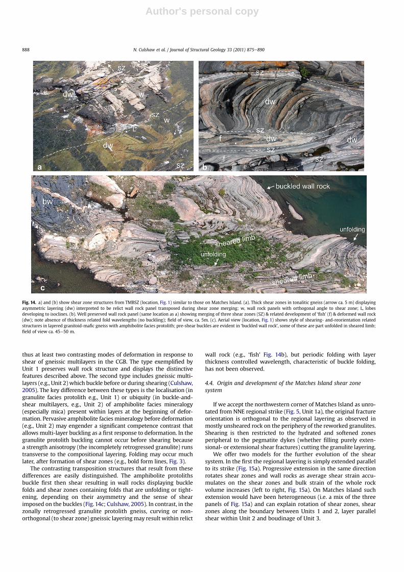
Comparable features are present within the thicker shear zonesegments of the Twelve Mile Bay shear zone for which there isample independent evidence of granulite facies protolith (Marshet al., 2011). In the Twelve Mile Bay shear zone individual shearzones are proportionately wider (Fig. 14a), undeformed wall rockmay have a Matches-like orthogonal relationship to shear zone(Fig. 14a) and deformed wall rock may be subtly preserved andrepresented by asymmetric folds within shear zones (dw, Fig. 14a)or quite plainly preserved (e.g., dw, Fig. 14b; note too examples of‘fish’, f). The occurrence of a suite of comparable features withinincipient and advanced zones of transposition demonstrates theregional significance of the transposition processes inferred fromMatches Island for multilayers with granulite facies protoliths.Underlining the significance of these features, Gerbi et al. (2010)calculated that Matches Island underwent approximately 30%bulk weakening due to the formation of the shear zone network.
4.3. Control of deformation geometry and sequence by layermineralogy
Matches Island displays the response of two different types oflayered units to similar kinematic boundary conditions. Of these,Unit 1 formed a widespread linked shear system and hasa completely distinct structural style compared to Unit 2 (horn-blende-biotite-bearing gneiss), which displays significant foldsbetween variably developed shear zones.
The Unit 1 multi-layer did not buckle prior to shear becausestrength was maintained where hydration of mafic granulite faciesmineralogy was incomplete. The incomplete retrogression of maficwall rock, as well as orientation of pegmatite-related fractures, thesource of softening fluid, accounts for the distinctive style of thedeformed Matches Island multi-layer.
Unlike Unit 1, Unit 2 is pervasively retrogressed, the underlyingreason for this is most likely the absence of Unit 1-type mafic layerscapable of locally retaining dry granulite vestiges. The absence ofsuch mafic layers with their inherent strength (relative to quartz-feldspar rich rocks) is also responsible for the lack of the charac-teristic wall rock e shear zone geometry of Unit 1 although all Unit2 shear zones are localised on pegmatites (as in Unit 1). The shearzone displacements are predominantly lower than in Unit 1 sug-gesting bulk strains are accounted for by layer parallel shear in thepervasively retrogressed matrix and/or buckling of the multi-layer.
The style of Unit 2 is comparable to that documented wherelayered gneisses of the Parry Sound shear zone are buckle foldedthen sheared at the edge of the Shawanaga shear zone (Culshaw,2005), a style which may be widespread in polydeformed layeredgneisses of the Central Gneiss Belt (Culshaw et al., 2010). There are
Fig. 13. a). Map showing bulk strains across shear zones & wall rock (see text for explanation); number of shear zones traversed indicated; line by strain ellipse is long axis (fromaverage shear strain) of a component individual shear zone. (b) Detail of map showing marker horizons (arrowed) used to derive distance-displacement data for deriving strain (seetext & Supplementary data for further information).
N. Culshaw et al. / Journal of Structural Geology 33 (2011) 875e890 887
Author's personal copy
thus at least two contrasting modes of deformation in response toshear of gneissic multilayers in the CGB. The type exemplified byUnit 1 preserves wall rock structure and displays the distinctivefeatures described above. The second type includes gneissic multi-layers (e.g., Unit 2) which buckle before or during shearing (Culshaw,2005). The key difference between these types is the localisation (ingranulite facies protolith e.g., Unit 1) or ubiquity (in buckle-and-shear multilayers, e.g., Unit 2) of amphibolite facies mineralogy(especially mica) present within layers at the beginning of defor-mation. Pervasive amphibolite facies mineralogy before deformation(e.g., Unit 2) may engender a significant competence contrast thatallows multi-layer buckling as a first response to deformation. In thegranulite protolith buckling cannot occur before shearing becausea strength anisotropy (the incompletely retrogressed granulite) runstransverse to the compositional layering. Folding may occur muchlater, after formation of shear zones (e.g., bold form lines, Fig. 3).
The contrasting transposition structures that result from thesedifferences are easily distinguished. The amphibolite protolithsbuckle first then shear resulting in wall rocks displaying bucklefolds and shear zones containing folds that are unfolding or tight-ening, depending on their asymmetry and the sense of shearimposed on the buckles (Fig. 14c; Culshaw, 2005). In contrast, in thezonally retrogressed granulite protolith gneiss, curving or non-orthogonal (to shear zone) gneissic layeringmay result within relict
wall rock (e.g., ‘fish’ Fig. 14b), but periodic folding with layerthickness controlled wavelength, characteristic of buckle folding,has not been observed.
4.4. Origin and development of the Matches Island shear zonesystem
If we accept the northwestern corner of Matches Island as unro-tated from NNE regional strike (Fig. 5, Unit 1a), the original fractureorientation is orthogonal to the regional layering as observed inmostly unsheared rock on the periphery of the reworked granulites.Shearing is then restricted to the hydrated and softened zonesperipheral to the pegmatite dykes (whether filling purely exten-sional- or extensional shear fractures) cutting the granulite layering.
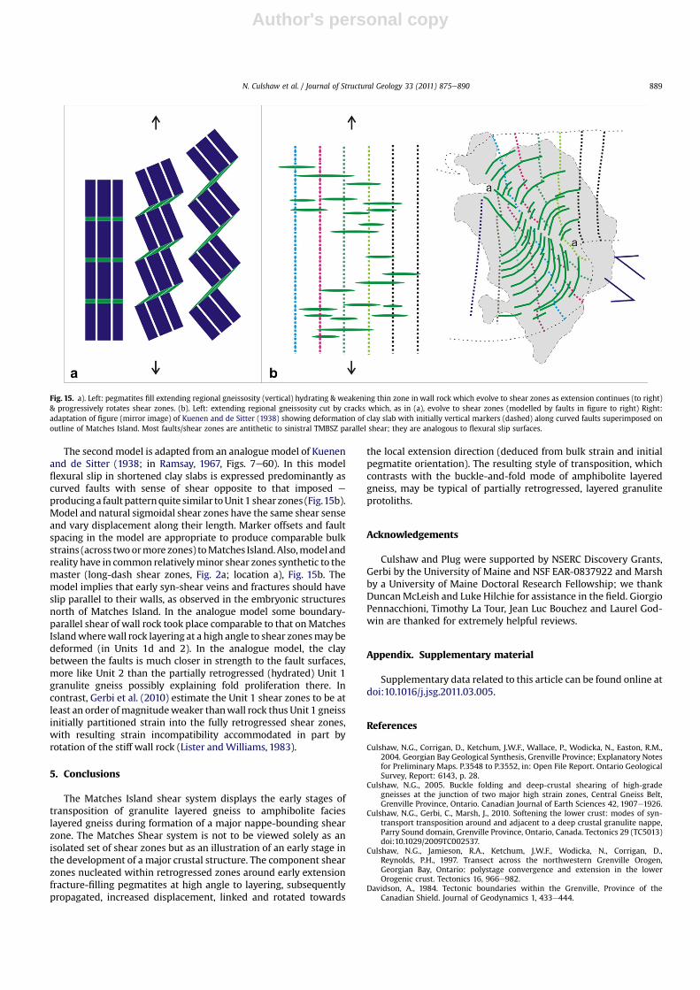
We offer two models for the further evolution of the shearsystem. In the first the regional layering is simply extended parallelto its strike (Fig. 15a). Progressive extension in the same directionrotates shear zones and wall rocks as average shear strain accu-mulates on the shear zones and bulk strain of the whole rockvolume increases (left to right, Fig. 15a). On Matches Island suchextension would have been heterogeneous (i.e. a mix of the threepanels of Fig. 15a) and can explain rotation of shear zones, shearzones along the boundary between Units 1 and 2, layer parallelshear within Unit 2 and boudinage of Unit 3.
Fig. 14. a) and (b) show shear zone structures from TMBSZ (location, Fig. 1) similar to those on Matches Island. (a). Thick shear zones in tonalitic gneiss (arrow ca. 5 m) displayingasymmetric layering (dw) interpreted to be relict wall rock panel transposed during shear zone merging; w, wall rock panels with orthogonal angle to shear zone; L, lobesdeveloping to isoclines. (b). Well preserved wall rock panel (same location as a) showing merging of three shear zones (SZ) & related development of ‘fish’ (f) & deformed wall rock(dw); note absence of thickness related fold wavelengths (no buckling); field of view, ca. 5m. (c). Aerial view (location, Fig. 1) shows style of shearing- and-reorientation relatedstructures in layered granitoid-mafic gneiss with amphibolite facies protolith; pre-shear buckles are evident in ‘buckled wall rock’, some of these are part unfolded in sheared limb;field of view ca. 45e50 m.
N. Culshaw et al. / Journal of Structural Geology 33 (2011) 875e890888
Author's personal copy
The secondmodel is adapted from an analogue model of Kuenenand de Sitter (1938; in Ramsay, 1967, Figs. 7e60). In this modelflexural slip in shortened clay slabs is expressed predominantly ascurved faults with sense of shear opposite to that imposed e
producinga fault patternquite similar toUnit1 shear zones (Fig.15b).Model and natural sigmoidal shear zones have the same shear senseand vary displacement along their length. Marker offsets and faultspacing in the model are appropriate to produce comparable bulkstrains (across twoormore zones) toMatches Island.Also,model andreality have in common relativelyminor shear zones synthetic to themaster (long-dash shear zones, Fig. 2a; location a), Fig. 15b. Themodel implies that early syn-shear veins and fractures should haveslip parallel to their walls, as observed in the embryonic structuresnorth of Matches Island. In the analogue model some boundary-parallel shear of wall rock took place comparable to that onMatchesIslandwherewall rock layering at a high angle to shear zonesmay bedeformed (in Units 1d and 2). In the analogue model, the claybetween the faults is much closer in strength to the fault surfaces,more like Unit 2 than the partially retrogressed (hydrated) Unit 1granulite gneiss possibly explaining fold proliferation there. Incontrast, Gerbi et al. (2010) estimate the Unit 1 shear zones to be atleast an order ofmagnitudeweaker thanwall rock thus Unit 1 gneissinitially partitioned strain into the fully retrogressed shear zones,with resulting strain incompatibility accommodated in part byrotation of the stiff wall rock (Lister andWilliams, 1983).
5. Conclusions
The Matches Island shear system displays the early stages oftransposition of granulite layered gneiss to amphibolite facieslayered gneiss during formation of a major nappe-bounding shearzone. The Matches Shear system is not to be viewed solely as anisolated set of shear zones but as an illustration of an early stage inthe development of a major crustal structure. The component shearzones nucleated within retrogressed zones around early extensionfracture-filling pegmatites at high angle to layering, subsequentlypropagated, increased displacement, linked and rotated towards
the local extension direction (deduced from bulk strain and initialpegmatite orientation). The resulting style of transposition, whichcontrasts with the buckle-and-fold mode of amphibolite layeredgneiss, may be typical of partially retrogressed, layered granuliteprotoliths.
Acknowledgements
Culshaw and Plug were supported by NSERC Discovery Grants,Gerbi by the University of Maine and NSF EAR-0837922 and Marshby a University of Maine Doctoral Research Fellowship; we thankDuncanMcLeish and Luke Hilchie for assistance in the field. GiorgioPennacchioni, Timothy La Tour, Jean Luc Bouchez and Laurel God-win are thanked for extremely helpful reviews.
Appendix. Supplementary material
Supplementary data related to this article can be found online atdoi:10.1016/j.jsg.2011.03.005.
References
Culshaw, N.G., Corrigan, D., Ketchum, J.W.F., Wallace, P., Wodicka, N., Easton, R.M.,2004. Georgian Bay Geological Synthesis, Grenville Province; Explanatory Notesfor Preliminary Maps. P.3548 to P.3552, in: Open File Report. Ontario GeologicalSurvey, Report: 6143, p. 28.
Culshaw, N.G., 2005. Buckle folding and deep-crustal shearing of high-gradegneisses at the junction of two major high strain zones, Central Gneiss Belt,Grenville Province, Ontario. Canadian Journal of Earth Sciences 42, 1907e1926.
Culshaw, N.G., Gerbi, C., Marsh, J., 2010. Softening the lower crust: modes of syn-transport transposition around and adjacent to a deep crustal granulite nappe,Parry Sound domain, Grenville Province, Ontario, Canada. Tectonics 29 (TC5013)doi:10.1029/2009TC002537.
Culshaw, N.G., Jamieson, R.A., Ketchum, J.W.F., Wodicka, N., Corrigan, D.,Reynolds, P.H., 1997. Transect across the northwestern Grenville Orogen,Georgian Bay, Ontario: polystage convergence and extension in the lowerOrogenic crust. Tectonics 16, 966e982.
Davidson, A., 1984. Tectonic boundaries within the Grenville, Province of theCanadian Shield. Journal of Geodynamics 1, 433e444.
Fig. 15. a). Left: pegmatites fill extending regional gneissosity (vertical) hydrating & weakening thin zone in wall rock which evolve to shear zones as extension continues (to right)& progressively rotates shear zones. (b). Left: extending regional gneissosity cut by cracks which, as in (a), evolve to shear zones (modelled by faults in figure to right) Right:adaptation of figure (mirror image) of Kuenen and de Sitter (1938) showing deformation of clay slab with initially vertical markers (dashed) along curved faults superimposed onoutline of Matches Island. Most faults/shear zones are antithetic to sinistral TMBSZ parallel shear; they are analogous to flexural slip surfaces.
N. Culshaw et al. / Journal of Structural Geology 33 (2011) 875e890 889
Author's personal copy
Fusseis, F., Handy, M.R., Schrank, C., 2006. Networking of shear zones at the brittle-to-viscous transition (Cap de Creus, NE Spain). Journal of Structural Geology 28,1228e1243.
Gerbi, C., Culshaw, N.G., Marsh, J.H., 2010. Magnitude of weakening during crustal-scale shear zone development. Journal of Structural Geology 32, 107e117.
Handy, M.R., 1994. Flow laws for rocks containing 2 nonlinear viscous phases e
a phenomenological approach. Journal of Structural Geology 16, 287e301.Handy, M.R., Stunitz, H., 2002. Strain localization by fracturing and reaction
weakening - a mechanism for initiating exhumation of subcontinental mantlebeneath rifted margins. In: de Meer, S., Drury, M.R., de Bresser, J.H.P.,Pennock, G.M. (Eds.), Deformation Mechanisms, Rheology and Tectonics.Current Status and Future Perspectives. Geological Society, London, SpecialPublications, vol. 200, pp. 387e407.
Hanmer, S.K., 1984. Structure of the Junction of Three Tectonic Slices; Ontario GneissSegment, Grenville Province. Paper. Geological Survey of Canada, 84e1B, pp.109e120.
Horsman, E., Tikoff, B., 2005. Quantifying simultaneous discrete and distributeddeformation. Journal of Structural Geology 27, 1168e1189.
Jamieson, R.A., Beaumont, C., Nguyen, M.H., Culshaw, N.G., 2007. Synconvergentductile flow in variable-strength continental crust; numerical models withapplication to the western Grenville Orogen. Tectonics 26 (TC5005).
Jamtveit, B., Austrheim, H., Malthe-Sorenssen, A., 2000. Accelerated hydration ofthe Earth’s deep crust induced by stress perturbations. Nature 408, 75e78.
Jolivet, L., Raimbourg, H., Labrousse, L., Avigad, D., Leroy, Y., Austrheim, H.,Andersen, T.B., 2005. Softening trigerred by eclogitization, the first step towardexhumation during continental subduction. Earth and Planetary Science Letters237, 532e547.
Kuenen, P.H., de Sitter, L.U., 1938. Experimental investigations into the mechanismsof folding. Leidsche Geological Magazine 10, 217e240.
Lister, G.S., Williams, P.F., 1983. The partitioning of deformation in flowing rockmasses. Tectonophysics 92, 1e33.
Mancktelow, N.S., Pennacchioni, G., 2005. The control of precursor brittle fractureand fluiderock interaction on the development of single and paired ductileshear zones. Journal of Structural Geology 27, 645e661.
Marsh, J.H., Gerbi, C., Culshaw, N.G., Johnson, S.E., Wooden, J.L., Clark, C. In Review.Using zircon U-Pb ages and trace element chemistry to constrain the timing ofmetamorphic events, dike emplacement, and shearing in the southern ParrySound domain, Grenville Province, Canada.
Marsh, J.H., Gerbi, C., Culshaw, N.G., Potter, J., Longstaffe, F., Johnson, S.E., 2011.Initiation and development of the Twelve Mile Bay shear zone: the lowviscosity sole of a granulite nappe. Journal of Metamorphic Geology 29,167e191.
Pennacchioni, G., 2005. Control of the geometry of precursor brittle structures onthe type of ductile shear zone in the Adamello tonalites, Southern Alps (Italy).Journal of Structural Geology 27, 627e644.
Pennacchioni, G.,Mancktelow, N.S., 2007. Nucleation and initial growth of a shear zonenetwork within compositionally and structurally heterogeneous granitoids underamphibolite facies conditions. Journal of Structural Geology 29, 1757e1780.
Ramsay, J.G., 1967. Folding and Fracturing of Rocks. McGraw-Hill, New York.Ramsay, J.G., Graham, R.H., 1970. Strain variation in shear belts. Canadian Journal of
Earth Sciences 7, 786e813.Ramsay, J.G., Huber, M.I., 1987. The Techniques of Modern Structural Geology.
In: Strain Analysis, vol. 1. Academic Press, London.Schrank, C.E., Handy, M.R., Fusseis, F., 2008. Multiscaling of shear zones and the
evolution of the brittle-to-viscous’transition in continental crust. Journal ofGeophysical Research 113, B01407. doi:10.1029/2006JB004833.
White, D.J., Easton, R.M., Culshaw, N.G., Milkereit, B., Forsyth, D.A., Carr, S.,Green, A.G., Davidson, A., 1994. Seismic images of the Grenville orogen inOntario. Canadian Journal of Earth Sciences 31, 293e307.
Wodicka, N., Ketchum, J.W.F., Jamieson, R.A., 2000. Grenvillian metamorphism ofmonocyclic rocks, Georgian Bay, Ontario, Canada, Implications for convergencehistory. Canadian Mineralogist 38, 471e510.
N. Culshaw et al. / Journal of Structural Geology 33 (2011) 875e890890


