Embed Size (px)
Citation preview
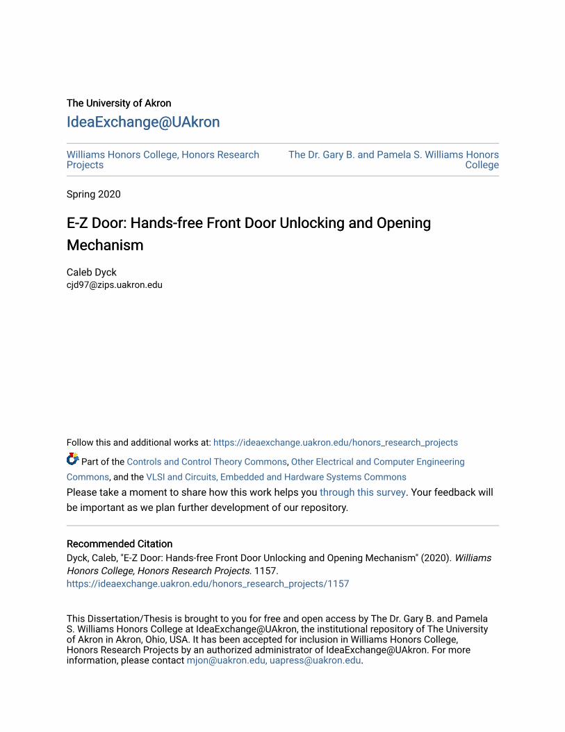
The University of Akron The University of Akron
IdeaExchange@UAkron IdeaExchange@UAkron
Williams Honors College, Honors Research Projects
The Dr. Gary B. and Pamela S. Williams Honors College
Spring 2020
E-Z Door: Hands-free Front Door Unlocking and Opening E-Z Door: Hands-free Front Door Unlocking and Opening
Mechanism Mechanism
Caleb Dyck [email protected]
Follow this and additional works at: https://ideaexchange.uakron.edu/honors_research_projects
Part of the Controls and Control Theory Commons, Other Electrical and Computer Engineering
Commons, and the VLSI and Circuits, Embedded and Hardware Systems Commons
Please take a moment to share how this work helps you through this survey. Your feedback will
be important as we plan further development of our repository.
Recommended Citation Recommended Citation Dyck, Caleb, "E-Z Door: Hands-free Front Door Unlocking and Opening Mechanism" (2020). Williams Honors College, Honors Research Projects. 1157. https://ideaexchange.uakron.edu/honors_research_projects/1157
This Dissertation/Thesis is brought to you for free and open access by The Dr. Gary B. and Pamela S. Williams Honors College at IdeaExchange@UAkron, the institutional repository of The University of Akron in Akron, Ohio, USA. It has been accepted for inclusion in Williams Honors College, Honors Research Projects by an authorized administrator of IdeaExchange@UAkron. For more information, please contact [email protected], [email protected].
1
2
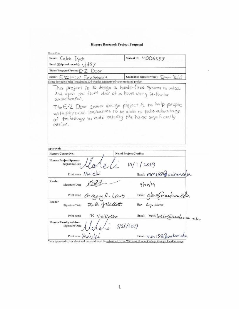
Honors Research Project
Submitted to
The Williams Honors College
The University of Akron
Approved:
Date:
Honors Project Sponsor (signed)
Honors Project Sponsor (printed)
Date:
Reader (signed)
Reader (printed)
Date:
Reader (signed)
Accepted:
Date:
Honors Department Advisor (signed)
Honors Department Advisor (printed)
Date:
Department Chair (signed)
Department Chair (printed)
9/30/2019
Robert Veillette
9/26/2019
Gregory A. Lewis
10/1/2019
Mehdi Maleki
E-Z Door
Caleb Dyck (Honors), Brice Brenneman, Justin Gnatiuk, Mitch Wilson
Department of Electrical Engineering
3
Reader (printed)
Senior Design Project Individual Responsibilities
Caleb Dyck
• Embedded Coding - I have written all of the embedded code for the senior design
project, including:
o Pulse Width Modulation code
o Bluetooth Communication Protocol code on the microcontroller
o LCD display code
o Analog to Digital Conversion code (to read in raw data from a microphone)
• Circuit design - worked with my team in developing circuit designs for the DC-DC
Buck converter circuit and the Solenoid lock circuit.
• Circuit Implementation – helped solder the DC-DC Buck converter circuit and the DC
H-Bridge motor circuit.
• Phone Application – began work creating an application that would connect to the board
via Bluetooth – when the other team member took over the application design, I had just
figured out how to connect the application to the board successfully.
• Project Lead – delegation of subsystems, integration, time, and sub-teams for the entire
project.
4
E-Z Door Project
Project Design Report
Design Team 11
Brice Brenneman, EE
Caleb Dyck, EE
Justin Gnatiuk, CPE
Mitch Wilson, CPE
Faculty Advisor: Mehdi Maleki Pirbazari
April 2, 2020
5
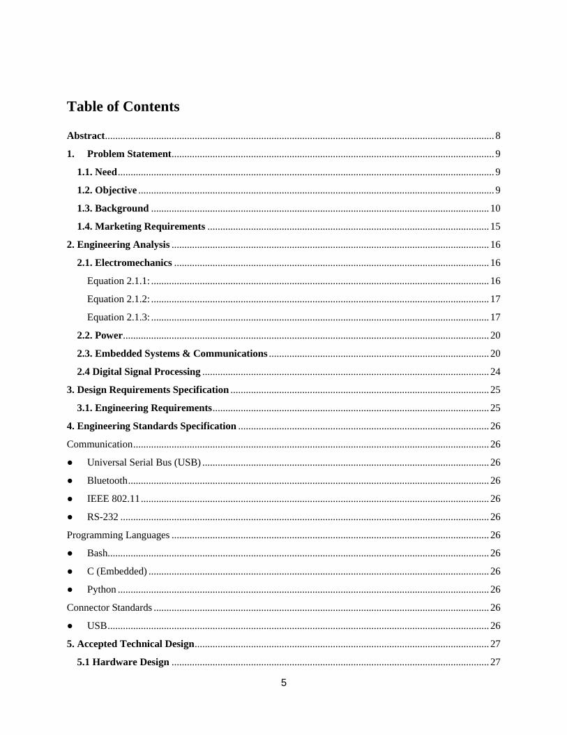
Table of Contents
Abstract ........................................................................................................................................................ 8
1. Problem Statement .............................................................................................................................. 9
1.1. Need ................................................................................................................................................... 9
1.2. Objective ........................................................................................................................................... 9
1.3. Background .................................................................................................................................... 10
1.4. Marketing Requirements .............................................................................................................. 15
2. Engineering Analysis ............................................................................................................................ 16
2.1. Electromechanics ........................................................................................................................... 16
Equation 2.1.1: .................................................................................................................................... 16
Equation 2.1.2: .................................................................................................................................... 17
Equation 2.1.3: .................................................................................................................................... 17
2.2. Power ............................................................................................................................................... 20
2.3. Embedded Systems & Communications ...................................................................................... 20
2.4 Digital Signal Processing ................................................................................................................ 24
3. Design Requirements Specification ..................................................................................................... 25
3.1. Engineering Requirements ............................................................................................................ 25
4. Engineering Standards Specification .................................................................................................. 26
Communication ........................................................................................................................................... 26
Universal Serial Bus (USB) ................................................................................................................ 26
Bluetooth ............................................................................................................................................. 26
IEEE 802.11 ........................................................................................................................................ 26
RS-232 ................................................................................................................................................ 26
Programming Languages ............................................................................................................................ 26
Bash..................................................................................................................................................... 26
C (Embedded) ..................................................................................................................................... 26
Python ................................................................................................................................................. 26
Connector Standards ................................................................................................................................... 26
USB ..................................................................................................................................................... 26
5. Accepted Technical Design ................................................................................................................... 27
5.1 Hardware Design ............................................................................................................................ 27
6
5.2. Software Design .............................................................................................................................. 34
6. Mechanical Sketch ................................................................................................................................ 45
7. Team Information ................................................................................................................................. 46
8. Parts List ................................................................................................................................................ 47
8.1 Accepted Technical Design Parts List ............................................................................................... 47
8.2 Bill of Materials ................................................................................................................................... 48
9. Project Schedule .................................................................................................................................... 49
10. Conclusions .......................................................................................................................................... 50
11. References ............................................................................................................................................ 51
12. Appendix .............................................................................................................................................. 53
A. Explorer 16/32 Product Information .............................................................................................. 53
B. Servo Motor Datasheet .................................................................................................................... 53
C. Buck Converter Datasheet .............................................................................................................. 53
7
List of Figures
Figure 1: Objective Tree ............................................................................................................................. 10
Figure 2: Door Opening Diagram ............................................................................................................... 18
Figure 3: Hardware Block Diagram - Level 0 ............................................................................................ 27
Figure 4: Hardware Block Diagram - Level 1 ............................................................................................ 27
Figure 5: Power Supply Schematic ............................................................................................................. 32
Figure 6: Voice Recognition Module Schematic ........................................................................................ 33
Figure 7: Software Block Diagram - Level 0 .............................................................................................. 34
Figure 8: Software Block Diagram - Level 1 .............................................................................................. 35
Figure 9: Software Block Diagram - Level 2 .............................................................................................. 36
Figure 10: Mechanical Sketch .................................................................................................................... 45
Figure 11: Gantt Chart DT11, Fall Semester 2019 ..................................................................................... 49
List of Tables
Table 1: Wireless Communications ............................................................................................................ 22
Table 2: Engineering Requirements ............................................................................................................ 25
Table 3: Bluetooth Receiver Functional Requirement ................................................................................ 28
Table 4: Microphone Functional Requirement ........................................................................................... 28
Table 5: Power Supply Functional Requirement ........................................................................................ 28
Table 6: Battery Backup Functional Requirement ...................................................................................... 29
Table 7: Lock/Unlock Functional Requirement .......................................................................................... 29
Table 8: Open/Close Servo Functional Requirement.................................................................................. 29
Table 9: Microcontroller Functional Requirement ..................................................................................... 30
Table 10: Parts List ..................................................................................................................................... 47
Table 11: Bill of Materials .......................................................................................................................... 48
8
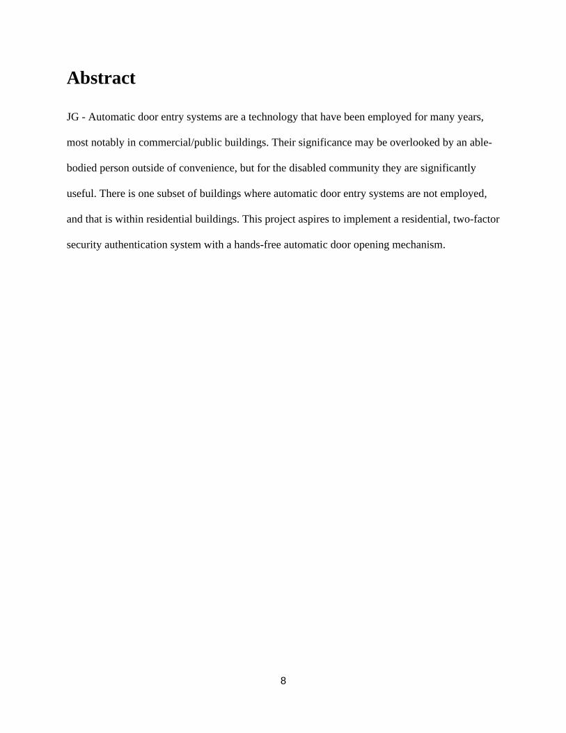
Abstract
JG - Automatic door entry systems are a technology that have been employed for many years,
most notably in commercial/public buildings. Their significance may be overlooked by an able-
bodied person outside of convenience, but for the disabled community they are significantly
useful. There is one subset of buildings where automatic door entry systems are not employed,
and that is within residential buildings. This project aspires to implement a residential, two-factor
security authentication system with a hands-free automatic door opening mechanism.
9
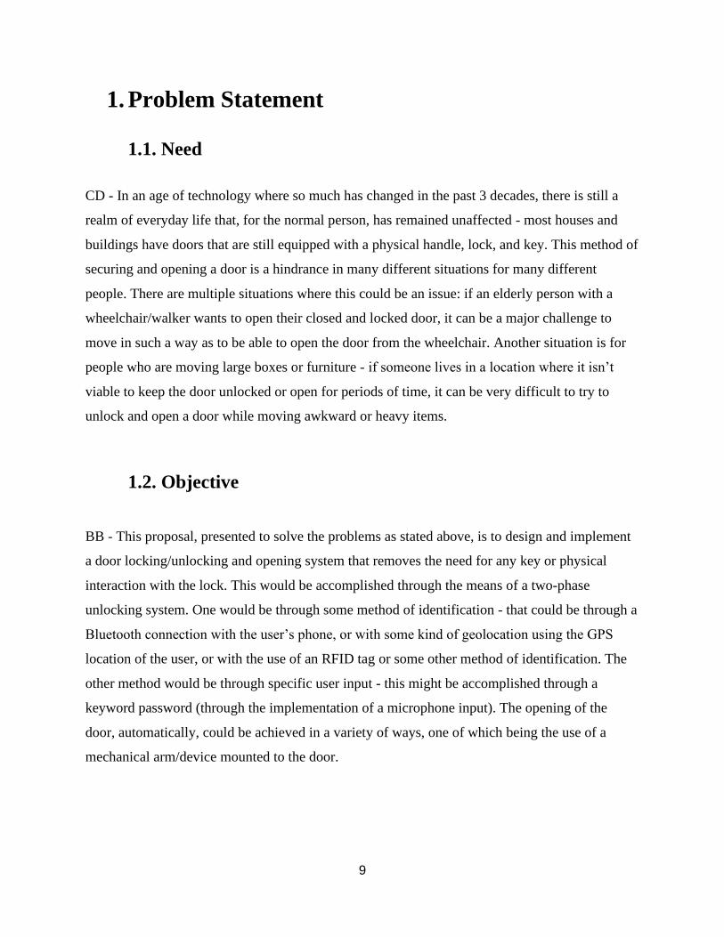
1. Problem Statement
1.1. Need
CD - In an age of technology where so much has changed in the past 3 decades, there is still a
realm of everyday life that, for the normal person, has remained unaffected - most houses and
buildings have doors that are still equipped with a physical handle, lock, and key. This method of
securing and opening a door is a hindrance in many different situations for many different
people. There are multiple situations where this could be an issue: if an elderly person with a
wheelchair/walker wants to open their closed and locked door, it can be a major challenge to
move in such a way as to be able to open the door from the wheelchair. Another situation is for
people who are moving large boxes or furniture - if someone lives in a location where it isn’t
viable to keep the door unlocked or open for periods of time, it can be very difficult to try to
unlock and open a door while moving awkward or heavy items.
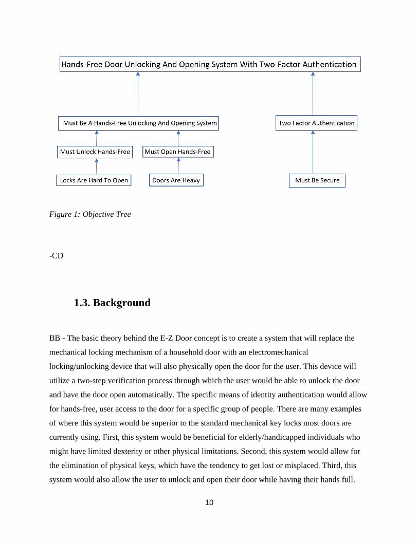
1.2. Objective
BB - This proposal, presented to solve the problems as stated above, is to design and implement
a door locking/unlocking and opening system that removes the need for any key or physical
interaction with the lock. This would be accomplished through the means of a two-phase
unlocking system. One would be through some method of identification - that could be through a
Bluetooth connection with the user’s phone, or with some kind of geolocation using the GPS
location of the user, or with the use of an RFID tag or some other method of identification. The
other method would be through specific user input - this might be accomplished through a
keyword password (through the implementation of a microphone input). The opening of the
door, automatically, could be achieved in a variety of ways, one of which being the use of a
mechanical arm/device mounted to the door.
10
Figure 1: Objective Tree
-CD
1.3. Background
BB - The basic theory behind the E-Z Door concept is to create a system that will replace the
mechanical locking mechanism of a household door with an electromechanical
locking/unlocking device that will also physically open the door for the user. This device will
utilize a two-step verification process through which the user would be able to unlock the door
and have the door open automatically. The specific means of identity authentication would allow
for hands-free, user access to the door for a specific group of people. There are many examples
of where this system would be superior to the standard mechanical key locks most doors are
currently using. First, this system would be beneficial for elderly/handicapped individuals who
might have limited dexterity or other physical limitations. Second, this system would allow for
the elimination of physical keys, which have the tendency to get lost or misplaced. Third, this
system would also allow the user to unlock and open their door while having their hands full.
11
These are just a few of the many scenarios where the E-Z Door system would be superior to
current mainstream mechanical locking mechanisms. In addition, this system could offer
customizable security options, multiple person access, and many other features depending on the
needs and desires of the user.
CD - There are a few similar device concepts existing that pertain to the use of phones and
speech recognition to unlock a door, but research shows that the systems that have been designed
before have all ended up falling short in the realm of pure hands-free technology. A proposal
from a group of researchers from the ARPN Journal of Engineering and Applied Sciences has
this to say on the subject: “Rather than using a key, it uses a command that is delivered digitally
via Bluetooth on Smartphone and other mobile devices.”[1] This approach implements the idea of
remotely unlocking a door through the use of Bluetooth technology, but it still requires a PIN
code to be entered by the user. Another approach, this one from a 2014 IEEE conference, is to
use “Short Message Service Text Messaging (SMS) as a mechanism to control the system via
mobile phone to lock and unlock the door.”[2] This approach has the same drawbacks as the
previous approach, in that it still lacks the true hands-free approach sought after in this proposal.
The technique of using speech recognition is used in conjunction with a user-entered PIN to
unlock the door, but as in the previous case, there is still a lack of hands-free use.
CD - There are some limitations with the current existing system concepts. The first type of
drawbacks in existing systems can be seen in the aspect of security. From a report in the 2018
International Conference on Information and Communications Technology, “The authentication
is using speech command or pin code. Users can choose one of it [them] from the android
application.” [3] This is a security weakness, as there are more ways for people to get into the
system. Another drawback in current systems can be found in a paper from IEEE, published in
2009. “Once the person is authenticated through password or RFID tag, the door lock is opened.”
[4] Again, this is a security risk - if someone found the RFID tag, they would be able to get into
the house with no other measures of authentication.
CD - Another type of drawback comes from the ways the user must interact with the system. As
a report published in the ARPN Journal of Engineering and Applied Sciences states, “Controlling
12
[is] conducted by sending a command via Bluetooth to the Arduino circuit that acts as a
connection between Android smart phone and solenoid.” [1] The user must physically send a PIN
from the Bluetooth app on the user’s phone, which can then be used as a means of accepting the
PIN and opening the solenoid lock. This method of entering a PIN on the user’s phone has two
negative impacts; it requires the user to pull out their phone every time to unlock the door, and it
lacks a second form of authentication.
JG - The system proposed differs from the current systems by implementing voice recognition
technology in order to make the system hands free. In almost all of the other solutions proposed,
there is still a physical user input, normally through a PIN entered on the user’s smartphone.
In order to accommodate those who might have difficulties with this, the proposed system is
being designed to ensure that it is completely hands free and will not need physical input.
This system may be designed around the concept of a home automation system, as explained in
the source, "Android-based home door locks application via Bluetooth for disabled people". The
article discusses how “it [Bluetooth] was seen as a simple, low cost and secure solution for
wirelessly connecting a mobile device to a home automation system”[2]. The system being
proposed can utilize some of the ideas from this source and others to ensure that the right balance
of utility, usability, and security will be found.
MW - As many technologies are becoming more readily available to the public, various designs
and implementations have arisen to make life easier. More specifically, an individual’s
smartphone could run a multitude of applications, and these applications can easily control older
and newer technologies remotely. Therefore, a smartphone can be utilized to control any or all
aspects of a system, whether mechanical or electrical. In recent years, many designs and products
have been developed for household automation. In the attempt to design such a remotely
controlled system comprised of hands-free accessibility of a household door via an advanced
smartphone-integrated door locking mechanism, it is necessary to understand the current
technologies being used in such an area.
MW - In regard to a system capable of opening and closing a door via some external signal, very
few such systems exist in residential/household environments. However, a garage door with
13
automatic open/close capabilities is a similar such system that is commonly used in residential
applications. Many factors must be accounted for to understand the lack of such a system in
other areas of a household, wherein it would appear useful. In a patent by Eccleston [9],
some limitations pertaining to an automatic operator are as follows: “Many door operators are
pneumatically, hydraulically, or electro-mechanically driven, and typically require substantial
modification to the door, the doorframe, and indeed the structure wherein the door and
doorframe are mounted. Installation of such an operator frequently requires a building permit and
the services of a skilled professional technician installer. As a result, “do-it-yourself” installation
is generally precluded. The resultant cost of permits, equipment, and labor often prevents
handicapped individuals from purchasing door operators for use at home and at work. In
addition, conventional door operators often are expensive to maintain” [9].
MW - Furthermore, Eccleston describes a remotely controllable operator system to be mounted
to a door frame and a movable door to control positioning of the door. The system encompasses
a motor assembly, linkage device, slip clutch assembly, and a remote-control interface [9]. While
the system described would provide basic operation that E-Z Door seeks to provide, complete
hands-free operation of the door would not be achieved. While maintaining remote operation of
the door positioning, as well as, manual operation functionality; with various changes and
critiques to a system such as Eccleston’s, it may prove to be a viable path for wirelessly
controlling the position of a door.
MW - One system that was found that opens and closes residential doors - the Residential
Automatic Door Opener, or RADO. [10] This is a prototype of a system that was designed to open
a residential door in a way that is both simple and cheap. This is done using a pulley and
mechanical arm system mounted to the side of the door. This system, when activated, opens the
door automatically. In addition, the system has a built-in slip clutch system in order to let the
system still function if the user was to manually move the door while the system is opening the
door. This system is very much still in the design stages, but it seems to be a very cost-effective
solution to the problem of an automatic door-opening system.
14
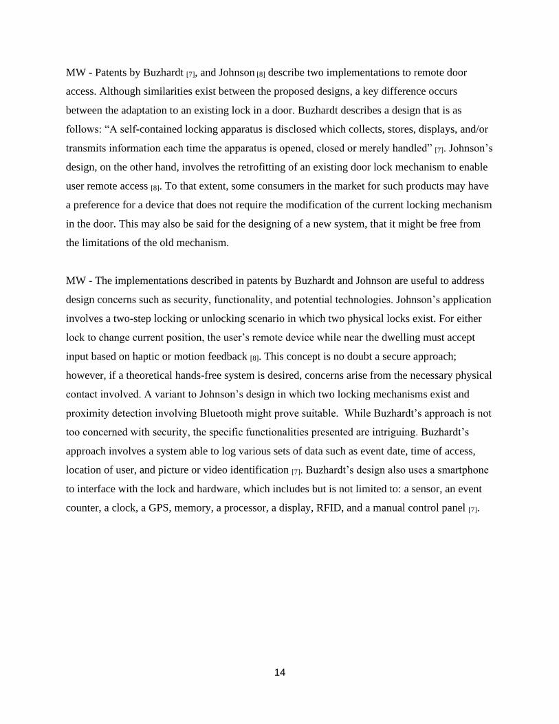
MW - Patents by Buzhardt [7], and Johnson [8] describe two implementations to remote door
access. Although similarities exist between the proposed designs, a key difference occurs
between the adaptation to an existing lock in a door. Buzhardt describes a design that is as
follows: “A self-contained locking apparatus is disclosed which collects, stores, displays, and/or
transmits information each time the apparatus is opened, closed or merely handled” [7]. Johnson’s
design, on the other hand, involves the retrofitting of an existing door lock mechanism to enable
user remote access [8]. To that extent, some consumers in the market for such products may have
a preference for a device that does not require the modification of the current locking mechanism
in the door. This may also be said for the designing of a new system, that it might be free from
the limitations of the old mechanism.
MW - The implementations described in patents by Buzhardt and Johnson are useful to address
design concerns such as security, functionality, and potential technologies. Johnson’s application
involves a two-step locking or unlocking scenario in which two physical locks exist. For either
lock to change current position, the user’s remote device while near the dwelling must accept
input based on haptic or motion feedback [8]. This concept is no doubt a secure approach;
however, if a theoretical hands-free system is desired, concerns arise from the necessary physical
contact involved. A variant to Johnson’s design in which two locking mechanisms exist and
proximity detection involving Bluetooth might prove suitable. While Buzhardt’s approach is not
too concerned with security, the specific functionalities presented are intriguing. Buzhardt’s
approach involves a system able to log various sets of data such as event date, time of access,
location of user, and picture or video identification [7]. Buzhardt’s design also uses a smartphone
to interface with the lock and hardware, which includes but is not limited to: a sensor, an event
counter, a clock, a GPS, memory, a processor, a display, RFID, and a manual control panel [7].
15
1.4. Marketing Requirements
1. The system will provide hands free opening of the door.
2. The system will have multiple levels of security.
3. The system will open/close remotely while user is inside their residence.
4. The system will prevent unauthorized access.
5. The system will only allow specific users to open the door.
-BB
16
2. Engineering Analysis
CD- The following section is organized to look closer at each engineering requirement, and to
provide analysis as to why it is needed for this project and how it was decided upon. In addition,
there are sections placed in relevant places to discuss in further detail the different broad
subsystems of the project, such as power supply research, communication, or motor choice and
specifications.
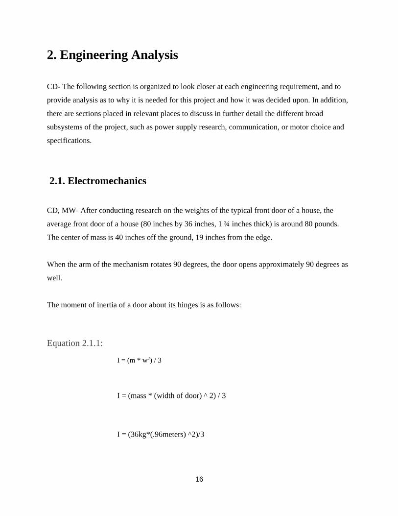
2.1. Electromechanics
CD, MW- After conducting research on the weights of the typical front door of a house, the
average front door of a house (80 inches by 36 inches, 1 ¾ inches thick) is around 80 pounds.
The center of mass is 40 inches off the ground, 19 inches from the edge.
When the arm of the mechanism rotates 90 degrees, the door opens approximately 90 degrees as
well.
The moment of inertia of a door about its hinges is as follows:
Equation 2.1.1:
I = (m * w2) / 3
I = (mass * (width of door) ^ 2) / 3
I = (36kg*(.96meters) ^2)/3
17
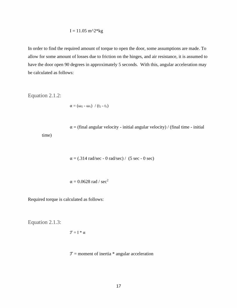
I = 11.05 m^2*kg
In order to find the required amount of torque to open the door, some assumptions are made. To
allow for some amount of losses due to friction on the hinges, and air resistance, it is assumed to
have the door open 90 degrees in approximately 5 seconds. With this, angular acceleration may
be calculated as follows:
Equation 2.1.2:
= (2 - 1) / (t2 - t1)
= (final angular velocity - initial angular velocity) / (final time - initial
time)
= (.314 rad/sec - 0 rad/sec) / (5 sec - 0 sec)
= 0.0628 rad / sec2
Required torque is calculated as follows:
Equation 2.1.3:
𝒯 = I *
𝒯 = moment of inertia * angular acceleration
18
𝒯 = 11.05 kg*m2 * 0.0628 rad / sec2
𝒯 = 0.6939 N * m
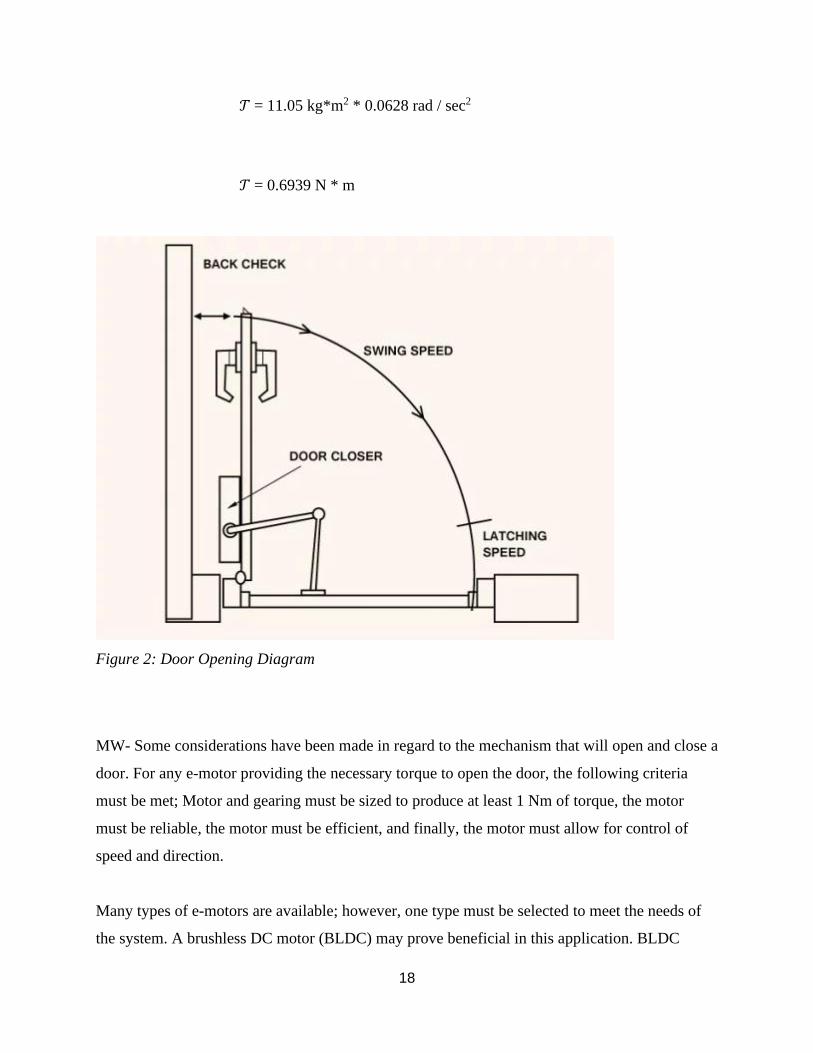
Figure 2: Door Opening Diagram
MW- Some considerations have been made in regard to the mechanism that will open and close a
door. For any e-motor providing the necessary torque to open the door, the following criteria
must be met; Motor and gearing must be sized to produce at least 1 Nm of torque, the motor
must be reliable, the motor must be efficient, and finally, the motor must allow for control of
speed and direction.
Many types of e-motors are available; however, one type must be selected to meet the needs of
the system. A brushless DC motor (BLDC) may prove beneficial in this application. BLDC
19
motors are generally reliable, highly efficient / high output power to size ratio, and smaller form
factor with higher speed ranges and lower electronic noise generation. As far specific selection
of the motor is concerned, pricing is often the determining factor. It is typically expensive and
outside the budget of the project to obtain a motor capable of more than 1 Nm of torque.
Control of a BLDC generally requires a driver circuit, and rotor position feedback. The driving
circuit typically consists of some serial interface, pulse width modulation and MOSFETs to
control the speed, position and direction of the rotor. Several options are available for rotor
position feedback, most often encoder or hall effect sensors are used, however, sensorless
systems are growing as well. Sensorless control is computationally heavy, therefore, if used in
this system, a larger processor may be necessary.
For reasons due generally to the scope of this project, the decision is made to seek other motor
options for the opening and closing of the door. For the complexity of control for a BLDC motor
outweighs the need in this application. Therefore, other options are considered.
BB- After further research and analysis a servo motor has been chosen rather than a BLDC
motor. Furthermore, the output shaft of the servo can be moved to an angle, position and velocity
that a BLDC motor, without an added driver circuit and position feedback, cannot achieve. Also,
the servo motor utilizes gearing coupled to a relatively small DC motor that allows for greater
output torque compared to the DC motor operating alone.
MW- The servo motor is selected by first realizing the characteristics that need to be satisfied.
While supplying ample torque, the servo should have more simplistic control than a BLDC
motor, and provide feedback such as rotor speed and position. All of which are crucial to the
system. The feedback is necessary in order to roughly sense the current that the motor is pulling
from the power supply. If the door were to be obstructed upon opening, and the motor achieves
maximum load, then the maximum current available will be pulled by the motor for the duration
of obstruction. Without any feedback from the servo, the motor could potentially continue to pull
current until the system is overwhelmed and fails.
20
2.2. Power
BB - The systems power supply will need to provide power to four main components, the
microcontroller, opening/closing mechanism, locking mechanism and the backup power supply.
The microcontroller that will be used in this design will be the Explorer 16/32 Developer Board
which can be powered one of two ways, by external 9Vdc supply or USB power. The motor for
the open/closing mechanism, as stated earlier will be a 12Vdc BLDC motor that will draw no
more than 15A. As for the locking mechanism the exact design has not yet been determined but
will need power for a small actuator to lock and unlock the modified deadbolt. From the power
needs discussed above a 12Vdc power supply with an input of 120Vac 60Hz will be needed to
supply the desired components. Also, as for the backup power supply, it will need to be properly
sized to provide power to the locking mechanism and microcontroller for at least 24 hours. Once
specific hardware is determined further power analysis for the system can be conducted.
2.3. Embedded Systems & Communications
According to a research paper by the International Journal of Science in 2016, the effective range
of a HC-05 Bluetooth module is around 10 meters.
Another variable to consider is that the Bluetooth modules take a significant amount of time to
connect - for example, according to reporting by users, the HC-05 module normally takes
between 1 and 2 seconds to connect reliable once the devices enter the range.
Combining these two facts, a reasonable range to expect from the system would be that the
Bluetooth module would connect successfully before coming within 5 meters of the door. This
would give the module time to connect, even if someone were to drive up or walk up reasonably
fast to the door.
21
User Interface
Once the successful connection has been made between the user’s phone and the door system,
serial communication between a phone application and the system should be straightforward to
create and configure. This is all contingent on the connection between the phone and the
Bluetooth module of the system.
Communications
CD- The decision to include two factors of authentication has been the main distinction between
the E-Z Door system design and the existing systems on the market. As shown in the background
research section, all the systems found while researching have only had one factor of
authentication. To set the E-Z Door system apart, and to ensure that the system was very hard to
hack or set apart, the decision for two factors was made. When deciding which two factors of
authentication, they had to be hands free. This limited the choices to sound or wireless
communication protocols. By examining the different wireless protocols out there, it was seen
that RFID would be convenient, but the range was too limited, with a maximum range of 18
inches. The design tradeoffs between Wi-Fi, Bluetooth, and Zigbee are shown in the figure
below, as seen from a paper published in 2012 on the benefits of Zigbee compared to the other
two. [11]
22
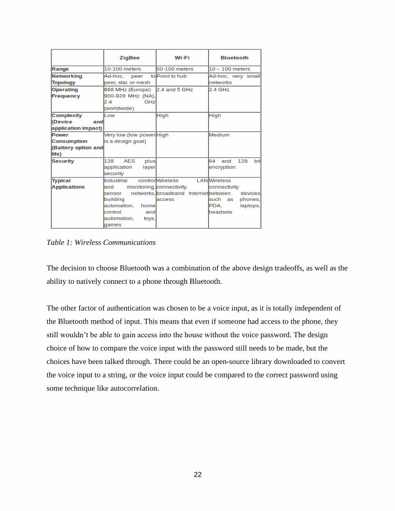
Table 1: Wireless Communications
The decision to choose Bluetooth was a combination of the above design tradeoffs, as well as the
ability to natively connect to a phone through Bluetooth.
The other factor of authentication was chosen to be a voice input, as it is totally independent of
the Bluetooth method of input. This means that even if someone had access to the phone, they
still wouldn’t be able to gain access into the house without the voice password. The design
choice of how to compare the voice input with the password still needs to be made, but the
choices have been talked through. There could be an open-source library downloaded to convert
the voice input to a string, or the voice input could be compared to the correct password using
some technique like autocorrelation.
23
Battery Backup
BB- System security and stability are two of the most important design parameters for the EZ
Door. Furthermore, the system will be controlling the locking/unlocking and opening/closing of
the user’s home entrance, thus if loss of power occurs the system should still be secure and
operate as designed. Specific design choices were analyzed in order to determine what portions
of the systems will be provided power by the uninterruptible power supply (UPS) and for how
long. Due to budget constraints the open/close electromechanical portion of the system will not
be supplied by the UPS when loss of power occurs. The locking mechanism and microcontroller
will be powered by the UPS for approximately 24 hours. These portions of the system were
chosen because of their low power consumption. Therefore, allowing the milli-amp-hours
provided by the UPS to be lower and consequently the price of the UPS to be cheaper.
Operates During Power Outage
CD- This requirement is an important factor to consider when implementing an electrical
replacement for a system which is normally mechanical. There should be a backup whereby the
owner of the house can gain access to the house, even if all power is out and the backup power
supply is depleted. This can be accomplished by maintaining the use of a manual key within the
new electronic locking mechanism.
Security
CD- When using communications and electronics, there is an inherent risk of a breach of
security. If there was just one level of authentication (Bluetooth on the user’s phone, for
example), if someone had access to the homeowner’s phone, the door would open for whoever
had the phone. This is a problem for security in the system. In order to resolve this, the system
must have at least two factors of authentication. For the design of the E-Z Door system, the two
24
factors of authentication are a Bluetooth input as the first level of authentication, and a voice
password input as the second level of authentication.
BB- With security and system integrity being an integral part of this design, access to
components from outside the residence is a topic of great concern. In order for the system to
perform as desired for an extended period of time, it is important that the location of the
mechanical portion of the opening mechanism must be located on the inner side of the door. If it
was located on the outside of the door, the system could be easily tampered with and even
compromised, allowing unauthorized access to the user's home.
2.4 Digital Signal Processing
[JG] The voice recognition module of the project uses digital signal processing in order to
recognize passwords from human speech. Different algorithms were considered that can be
broken down into two categories, speech-to-text and auto-correlation.
Speech-to-text can utilize a range of DSP algorithms such as “Fast Fourier Transform” or
“Hidden Markov Model” to convert human speech into a corresponding string of text.
Auto-correlation is another technique that utilizes DSP algorithms to essentially compare the
waveform of the set password to another user’s password waveform and accepts the user’s
password if it is within a certain margin of error of the original password waveform.
Speech-to-text is preferred given that auto-correlation would need a relatively low margin of
error set in the waveform if you want multiple people to be able to use the password. Two
different people can say the same password and still produce different waveforms and a low
margin of error for the speech recognition takes away from the system’s secure nature. A mix of
a DSP algorithm as well as a machine learning algorithm is the most secure option for the speech
recognition module.
25
3. Design Requirements Specification
3.1. Engineering Requirements
Marketing
Requirements Engineering Requirements Justification
1 1. Opening mechanism will provide a
minimum of 1 Nm of torque.
A certain threshold of force will
need to be applied to the door to
open it.
1 2. The system will require approximately 5
seconds to open, 5 seconds to close, and
allow user to configure the length of
time the door is open.
This would give the motor time to
open the door with room for error,
while still being reasonably fast.
3 3. The system will be powered by typical
120Vac 60Hz outlet.
Allows for easy household
installation and testing.
2, 3, 4, 5 4. Wireless communication should connect
within 5 meters.
Allows for latency time during
connection, with regards to the
ranges of the two modules.
4, 5 5. Phone Application which successfully
connects to the system, and acts as a UI.
Once a successful connection has
been made, the app must control
the system easily.
2, 4 6. Battery backup will provide power for
24 hours to the locking mechanism and
microcontroller.
If power loss occurs system should
still allow authorized user access
to the house.
4, 5 7. Deadbolt will be able to be
mechanically operated with loss of
power.
Will still allow for the system user
to actuate the lock in case of
complete power loss.
2, 5 8. The system will have at least two
factors of authentication.
The system must provide
additional security when compared
to a typical lock.
4 9. Mechanical portion of the system will
not be accessible from outside the door.
Prevents the system from being
tampered with and increases the
security of the system.
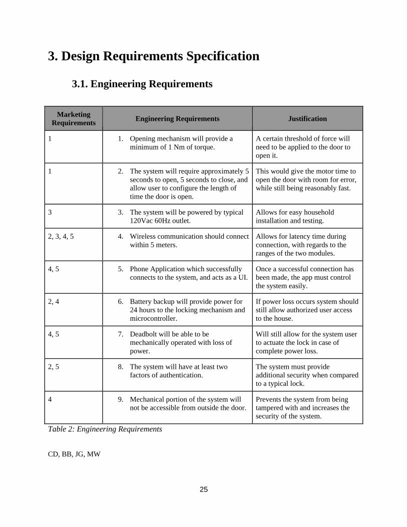
Table 2: Engineering Requirements
CD, BB, JG, MW
26
4. Engineering Standards Specification
Communication
Universal Serial Bus (USB)
Bluetooth
IEEE 802.11
RS-232
Programming Languages
Bash
C (Embedded)
Python
Connector Standards
USB
27
5. Accepted Technical Design
5.1 Hardware Design
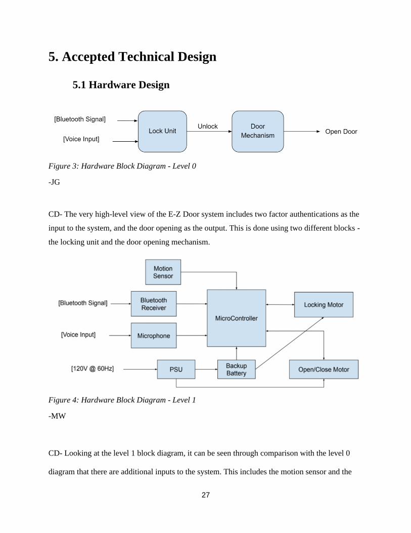
Figure 3: Hardware Block Diagram - Level 0
-JG
CD- The very high-level view of the E-Z Door system includes two factor authentications as the
input to the system, and the door opening as the output. This is done using two different blocks -
the locking unit and the door opening mechanism.
Figure 4: Hardware Block Diagram - Level 1
-MW
CD- Looking at the level 1 block diagram, it can be seen through comparison with the level 0
diagram that there are additional inputs to the system. This includes the motion sensor and the
28
power supply. The motion sensor adds the assurance that the door will not open if there are any
disturbances in the path of the door. The next addition to the inputs, the power supply, is also
necessary for us to keep in mind when it comes to design, especially as the system is to be able
to run on battery power for a minimum of 24 hours.
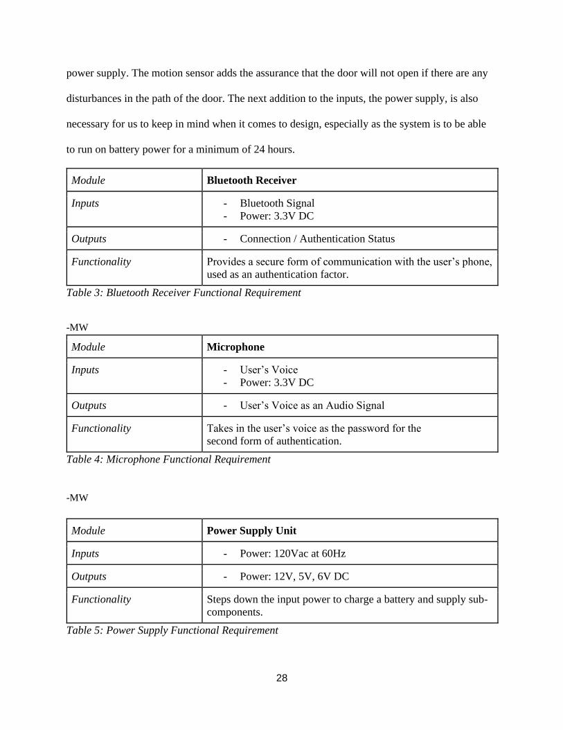
Module Bluetooth Receiver
Inputs - Bluetooth Signal
- Power: 3.3V DC
Outputs - Connection / Authentication Status
Functionality Provides a secure form of communication with the user’s phone,
used as an authentication factor.
Table 3: Bluetooth Receiver Functional Requirement
-MW
Module Microphone
Inputs - User’s Voice
- Power: 3.3V DC
Outputs - User’s Voice as an Audio Signal
Functionality Takes in the user’s voice as the password for the
second form of authentication.
Table 4: Microphone Functional Requirement
-MW
Module Power Supply Unit
Inputs - Power: 120Vac at 60Hz
Outputs - Power: 12V, 5V, 6V DC
Functionality Steps down the input power to charge a battery and supply sub-
components.
Table 5: Power Supply Functional Requirement
29
-MW
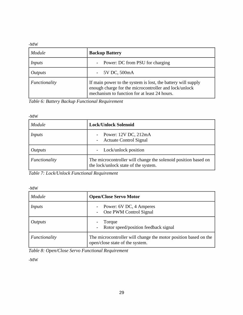
Module Backup Battery
Inputs - Power: DC from PSU for charging
Outputs - 5V DC, 500mA
Functionality If main power to the system is lost, the battery will supply
enough charge for the microcontroller and lock/unlock
mechanism to function for at least 24 hours.
Table 6: Battery Backup Functional Requirement
-MW
Module Lock/Unlock Solenoid
Inputs - Power: 12V DC, 212mA
- Actuate Control Signal
Outputs - Lock/unlock position
Functionality The microcontroller will change the solenoid position based on
the lock/unlock state of the system.
Table 7: Lock/Unlock Functional Requirement
-MW
Module Open/Close Servo Motor
Inputs - Power: 6V DC, 4 Amperes
- One PWM Control Signal
Outputs - Torque
- Rotor speed/position feedback signal
Functionality The microcontroller will change the motor position based on the
open/close state of the system.
Table 8: Open/Close Servo Functional Requirement
-MW
30
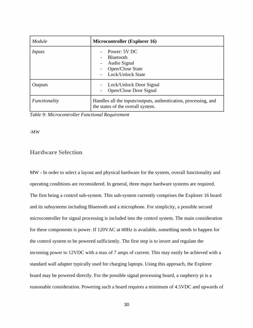
Module Microcontroller (Explorer 16)
Inputs - Power: 5V DC
- Bluetooth
- Audio Signal
- Open/Close State
- Lock/Unlock State
Outputs - Lock/Unlock Door Signal
- Open/Close Door Signal
Functionality Handles all the inputs/outputs, authentication, processing, and
the states of the overall system.
Table 9: Microcontroller Functional Requirement
-MW
Hardware Selection
MW - In order to select a layout and physical hardware for the system, overall functionality and
operating conditions are reconsidered. In general, three major hardware systems are required.
The first being a control sub-system. This sub-system currently comprises the Explorer 16 board
and its subsystems including Bluetooth and a microphone. For simplicity, a possible second
microcontroller for signal processing is included into the control system. The main consideration
for these components is power. If 120VAC at 60Hz is available, something needs to happen for
the control system to be powered sufficiently. The first step is to invert and regulate the
incoming power to 12VDC with a max of 7 amps of current. This may easily be achieved with a
standard wall adapter typically used for charging laptops. Using this approach, the Explorer
board may be powered directly. For the possible signal processing board, a raspberry pi is a
reasonable consideration. Powering such a board requires a minimum of 4.5VDC and upwards of
31
3 Amps of current. To account for this, a DC/DC buck converter is used to regulate to 5VDC
with enough current.
The second subsystem to consider is the locking/unlocking mechanism. For this, a solenoid that
mounts to the inner door frame is selected. Such a mechanism allows for existing door
handles/locks to be used. This reduces installation time and cost. The selected solenoid also
conveniently requires 12VDC and only a 212mA of current, therefore power may be supplied
indirectly through the wall adapter. However, a switching component is required to change the
position of the solenoid via software. Using an n-channel MOSFET, along with some passive
components the switching of the solenoid is achieved.
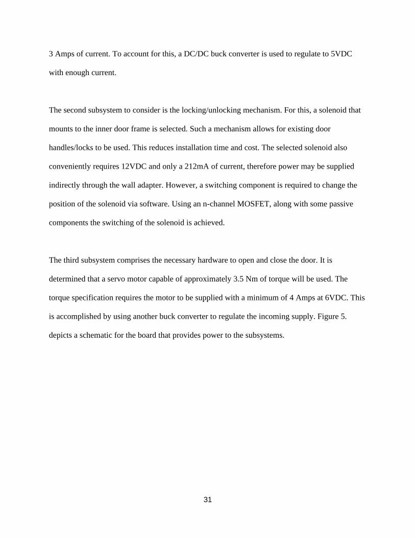
The third subsystem comprises the necessary hardware to open and close the door. It is
determined that a servo motor capable of approximately 3.5 Nm of torque will be used. The
torque specification requires the motor to be supplied with a minimum of 4 Amps at 6VDC. This
is accomplished by using another buck converter to regulate the incoming supply. Figure 5.
depicts a schematic for the board that provides power to the subsystems.
32
Figure 5: Power Supply Schematic
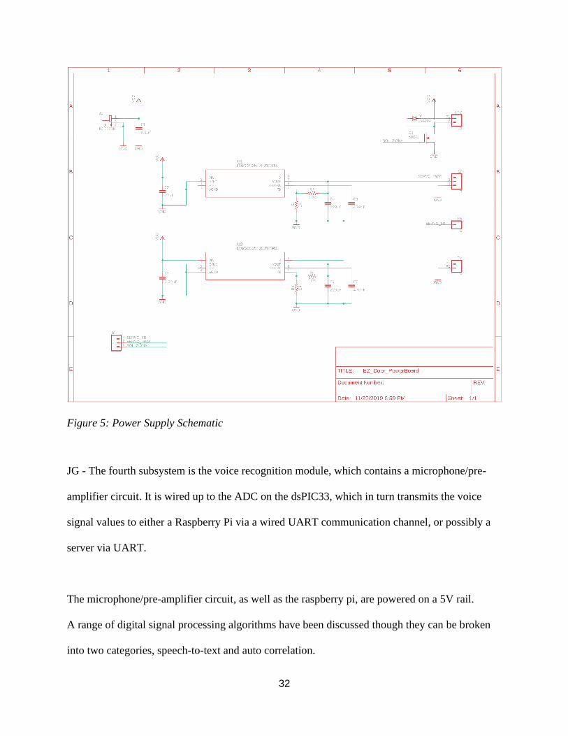
JG - The fourth subsystem is the voice recognition module, which contains a microphone/pre-
amplifier circuit. It is wired up to the ADC on the dsPIC33, which in turn transmits the voice
signal values to either a Raspberry Pi via a wired UART communication channel, or possibly a
server via UART.
The microphone/pre-amplifier circuit, as well as the raspberry pi, are powered on a 5V rail.
A range of digital signal processing algorithms have been discussed though they can be broken
into two categories, speech-to-text and auto correlation.
33
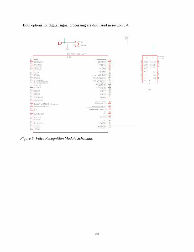
Both options for digital signal processing are discussed in section 3.4.
Figure 6: Voice Recognition Module Schematic
34
5.2. Software Design
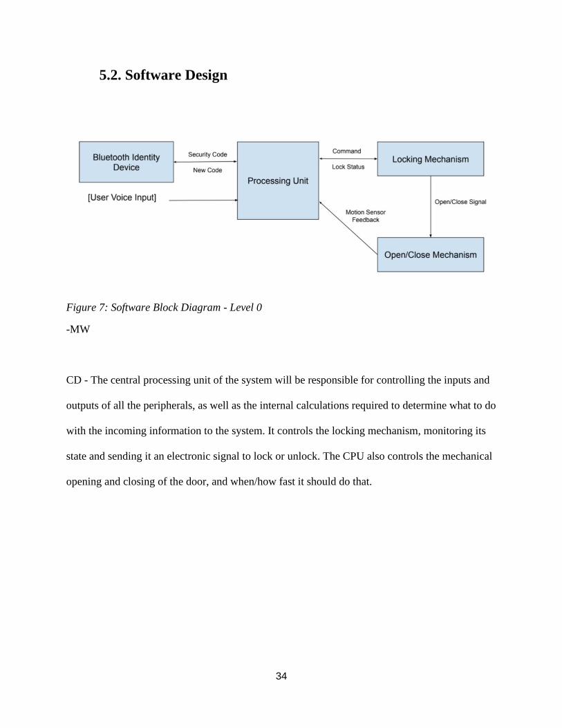
Figure 7: Software Block Diagram - Level 0
-MW
CD - The central processing unit of the system will be responsible for controlling the inputs and
outputs of all the peripherals, as well as the internal calculations required to determine what to do
with the incoming information to the system. It controls the locking mechanism, monitoring its
state and sending it an electronic signal to lock or unlock. The CPU also controls the mechanical
opening and closing of the door, and when/how fast it should do that.
35
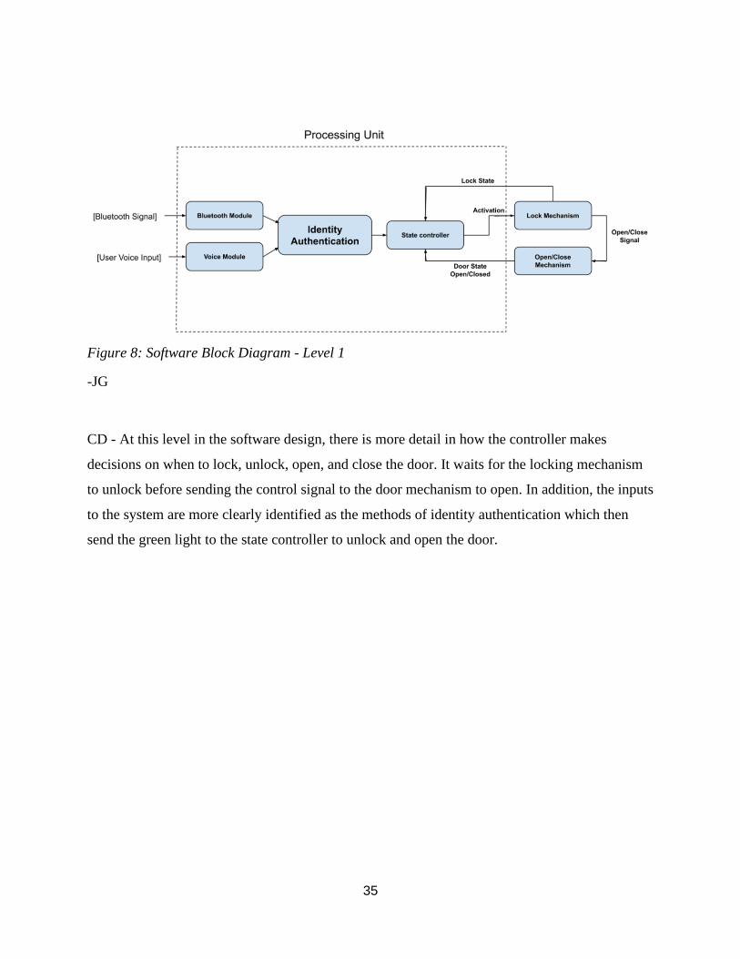
Figure 8: Software Block Diagram - Level 1
-JG
CD - At this level in the software design, there is more detail in how the controller makes
decisions on when to lock, unlock, open, and close the door. It waits for the locking mechanism
to unlock before sending the control signal to the door mechanism to open. In addition, the inputs
to the system are more clearly identified as the methods of identity authentication which then
send the green light to the state controller to unlock and open the door.
36
Figure 9: Software Block Diagram - Level 2
-JG
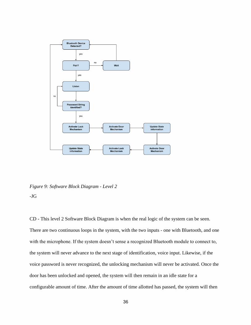
CD - This level 2 Software Block Diagram is when the real logic of the system can be seen.
There are two continuous loops in the system, with the two inputs - one with Bluetooth, and one
with the microphone. If the system doesn’t sense a recognized Bluetooth module to connect to,
the system will never advance to the next stage of identification, voice input. Likewise, if the
voice password is never recognized, the unlocking mechanism will never be activated. Once the
door has been unlocked and opened, the system will then remain in an idle state for a
configurable amount of time. After the amount of time allotted has passed, the system will then
37
close the door, activate the lock, disconnect the Bluetooth module, and resume normal operation
for a different Bluetooth device.
Software Selection
The dsPIC33 chip is running Embedded C code, which is the backbone of this project. The C
code for the dsPIC controls the following main parts of the E-Z Door system.
Bluetooth Communication with the user’s phone over UART
12-bit Analog-to-Digital Conversion (ADC) of microphone input data
UART Serial communication with the Raspberry Pi
Pulse Width Modulation (PWM) to control the servo motor
The dsPIC33 is configured to have an instruction clock cycle speed of 40MHz. The system is
using two internal timers of the dsPIC33 to control 2 different functions - TMR1 is used as a
millisecond delay function, and TMR3 is used to trigger sampling of the microphone data at a
rate of 16KHz.
When the microphone data is sent over serial communication to be processed, there are multiple
steps required to be able to analyze it. The data is first read into a file as a list of integers in C,
then using a library in python the integers are scaled and converted into a .wav sound file. Once
it is in a sound file, the deepspeech program is used to analyze the .wav file, and determine what
words were spoken. Lastly, the data is then placed into a string of standardized length to send
back to the dsPIC33 over UART to be displayed on the LCD and used for password verification.
38
All this code is used for the three steps of the system software. The first step is to verify the
user’s identity through the Bluetooth connection and voice password authentication. Second, the
signal will be sent to activate the solenoid to unlock the door. Lastly, once the door has been
unlocked, the PWM signal to control the servo motor will be sent to open the door.
The code used to implement this system is shown below, in the appropriate subsystem.
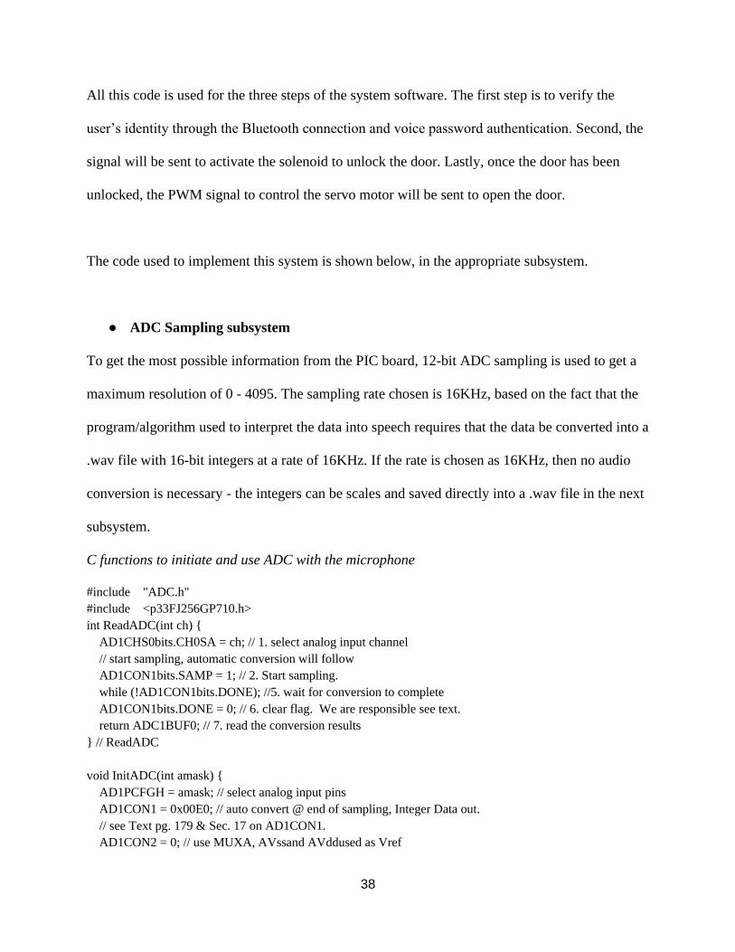
ADC Sampling subsystem
To get the most possible information from the PIC board, 12-bit ADC sampling is used to get a
maximum resolution of 0 - 4095. The sampling rate chosen is 16KHz, based on the fact that the
program/algorithm used to interpret the data into speech requires that the data be converted into a
.wav file with 16-bit integers at a rate of 16KHz. If the rate is chosen as 16KHz, then no audio
conversion is necessary - the integers can be scales and saved directly into a .wav file in the next
subsystem.
C functions to initiate and use ADC with the microphone
#include "ADC.h"
#include <p33FJ256GP710.h>
int ReadADC(int ch)
AD1CHS0bits.CH0SA = ch; // 1. select analog input channel
// start sampling, automatic conversion will follow
AD1CON1bits.SAMP = 1; // 2. Start sampling.
while (!AD1CON1bits.DONE); //5. wait for conversion to complete
AD1CON1bits.DONE = 0; // 6. clear flag. We are responsible see text.
return ADC1BUF0; // 7. read the conversion results
// ReadADC
void InitADC(int amask)
AD1PCFGH = amask; // select analog input pins
AD1CON1 = 0x00E0; // auto convert @ end of sampling, Integer Data out.
// see Text pg. 179 & Sec. 17 on AD1CON1.
AD1CON2 = 0; // use MUXA, AVssand AVddused as Vref
39
AD1CON3 = 0x1F01; // Tad = 2xTcy = 125ns. 31*Tad for conversion time.
AD1CSSL = 0; // no scanning required
AD1CON1bits.AD12B = 1;
AD1CON1bits.SSRC = 2;
T3CON = 0x8010;
PR3 = 312;
AD1CON1bits.ADON = 1; // Turn on the ADC
// InitADC
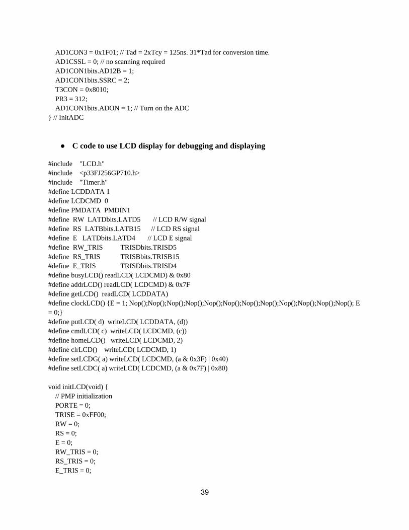
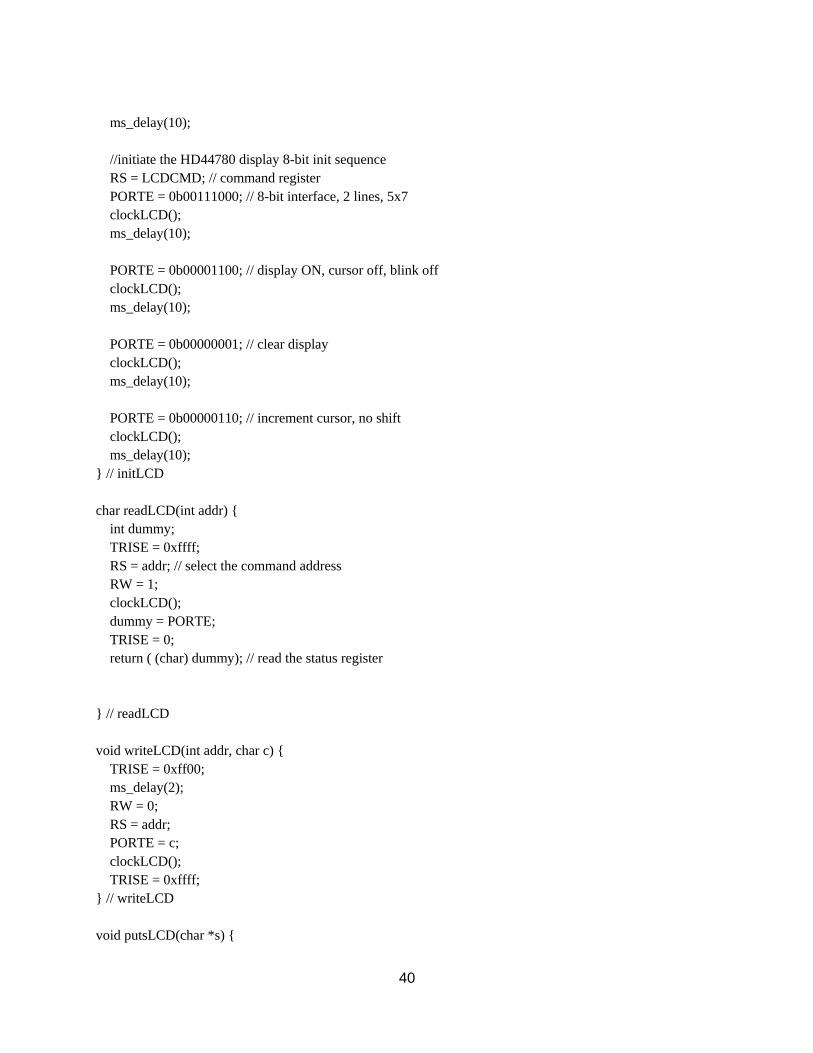
C code to use LCD display for debugging and displaying
#include "LCD.h"
#include <p33FJ256GP710.h>
#include "Timer.h"
#define LCDDATA 1
#define LCDCMD 0
#define PMDATA PMDIN1
#define RW LATDbits.LATD5 // LCD R/W signal
#define RS LATBbits.LATB15 // LCD RS signal
#define E LATDbits.LATD4 // LCD E signal
#define RW_TRIS TRISDbits.TRISD5
#define RS_TRIS TRISBbits.TRISB15
#define E_TRIS TRISDbits.TRISD4
#define busyLCD() readLCD( LCDCMD) & 0x80
#define addrLCD() readLCD( LCDCMD) & 0x7F
#define getLCD() readLCD( LCDDATA)
#define clockLCD() E = 1; Nop();Nop();Nop();Nop();Nop();Nop();Nop();Nop();Nop();Nop();Nop();Nop(); E
= 0;
#define putLCD( d) writeLCD( LCDDATA, (d))
#define cmdLCD( c) writeLCD( LCDCMD, (c))
#define homeLCD() writeLCD( LCDCMD, 2)
#define clrLCD() writeLCD( LCDCMD, 1)
#define setLCDG( a) writeLCD( LCDCMD, (a & 0x3F) | 0x40)
#define setLCDC( a) writeLCD( LCDCMD, (a & 0x7F) | 0x80)
void initLCD(void)
// PMP initialization
PORTE = 0;
TRISE = 0xFF00;
RW = 0;
RS = 0;
E = 0;
RW_TRIS = 0;
RS_TRIS = 0;
E_TRIS = 0;
40
ms_delay(10);
//initiate the HD44780 display 8-bit init sequence
RS = LCDCMD; // command register
PORTE = 0b00111000; // 8-bit interface, 2 lines, 5x7
clockLCD();
ms_delay(10);
PORTE = 0b00001100; // display ON, cursor off, blink off
clockLCD();
ms_delay(10);
PORTE = 0b00000001; // clear display
clockLCD();
ms_delay(10);
PORTE = 0b00000110; // increment cursor, no shift
clockLCD();
ms_delay(10);
// initLCD
char readLCD(int addr)
int dummy;
TRISE = 0xffff;
RS = addr; // select the command address
RW = 1;
clockLCD();
dummy = PORTE;
TRISE = 0;
return ( (char) dummy); // read the status register
// readLCD
void writeLCD(int addr, char c)
TRISE = 0xff00;
ms_delay(2);
RW = 0;
RS = addr;
PORTE = c;
clockLCD();
TRISE = 0xffff;
// writeLCD
void putsLCD(char *s)
41
while (*s) putLCD(*s++);
//putsLCD
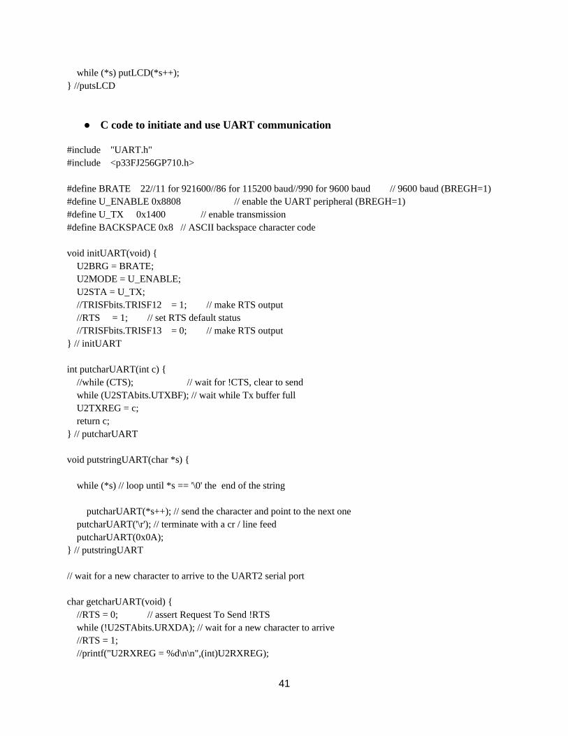
C code to initiate and use UART communication
#include "UART.h"
#include <p33FJ256GP710.h>
#define BRATE 22//11 for 921600//86 for 115200 baud//990 for 9600 baud // 9600 baud (BREGH=1)
#define U_ENABLE 0x8808 // enable the UART peripheral (BREGH=1)
#define U_TX 0x1400 // enable transmission
#define BACKSPACE 0x8 // ASCII backspace character code
void initUART(void)
U2BRG = BRATE;
U2MODE = U_ENABLE;
U2STA = U_TX;
//TRISFbits.TRISF12 = 1; // make RTS output
//RTS = 1; // set RTS default status
//TRISFbits.TRISF13 = 0; // make RTS output
// initUART
int putcharUART(int c)
//while (CTS); // wait for !CTS, clear to send
while (U2STAbits.UTXBF); // wait while Tx buffer full
U2TXREG = c;
return c;
// putcharUART
void putstringUART(char *s)
while (*s) // loop until *s == '\0' the end of the string
putcharUART(*s++); // send the character and point to the next one
putcharUART('\r'); // terminate with a cr / line feed
putcharUART(0x0A);
// putstringUART
// wait for a new character to arrive to the UART2 serial port
char getcharUART(void)
//RTS = 0; // assert Request To Send !RTS
while (!U2STAbits.URXDA); // wait for a new character to arrive
//RTS = 1;
//printf("U2RXREG = %d\n\n",(int)U2RXREG);
42
//PORTA = U2RXREG;
//char temp = U2RXREG;
//putstringUART("Received: ");
//putcharUART(temp);
//putcharUART('\r');
return U2RXREG; // read the character from the receive buffer
// getcharUART
char *getstringUART(char *s, int len)
char *p = s; // copy the buffer pointer
do
*s = getcharUART(); // wait for a new character
putcharUART(*s); // echo character
if ((*s == BACKSPACE)&&(s > p))
putcharUART(' '); // overwrite the last character
putcharUART(BACKSPACE);
len++;
s--; // back the pointer
continue;
if (*s == '\n') // line feed, ignore it
continue;
if (*s == '\r') // end of line, end loop
break;
s++; // increment buffer pointer
len--;
while (len > 1); // until buffer full
*s = '\0'; // null terminate the string
return p; // return buffer pointer
// getstringUART
Code to read in integers over serial UART communication
The dsPIC33 handles the ADC sampling, but the processor on the PIC is not powerful
enough to interpret that as sound. This must be done externally, and to do that, the data must
be sent over serial communication. The following code reads in the incoming information,
and outputs in into a text file with the name provided by the user upon running.
43
C code to read integers from serial communication
#include <stdio.h>
#include <string.h>
#define max 16000
int i;
int nums[max];
int main(int argc, char *argv[])
FILE *fp;
fp = fopen(argv[1],"w");
int i = 0;
while (i < max)
scanf("%d",&nums[i]);
i++;
i = 0;
while (i < max)
fprintf(fp,"%d\n",nums[i]);
i++;
int fclose( FILE *fp );
Python to create .wav file
The integers are read into a text file using C, but now these integers must be converted into a file
that can be interpreted as audio. This is done using python, and two libraries in python – numpy
and scipy. These two libraries combined have the functions to convert the integers into a format
that can be read as a .wav file.
Python code to convert string of integers into a .wav file
import numpy as np
import scipy.io.wavfile
import math
import sys
data2 = []
def read_integers(filename):
with open(filename) as f:
return [int(int(x) - 2024)*16 for x in f]
data2 = read_integers(sys.argv[1])
44
rate = 10000
k = 0;
data = np.array(data2).astype('int16')
scipy.io.wavfile.write(sys.argv[2],rate,data)
• Combining all of the functions into a complete system, running continuously
To get all of these functions and programs to run without prompting, a powerful program must
be used to run all of the programs in succession. This is accomplished using a bash script – it can
have an infinite loop that reads in the samples, converts it into a .wav file, and analyzes that file.
Bash script to compile and run C code, Python code, and deepspeech program in an infinite
while loop, and send the speech recognition output back to the dsPIC33
#!/bin/bash
while true; do
gcc -o go ReadInIntsFromPIC.c
sudo ./go < /dev/ttyACM0 in.log
python CreateWavIntsFromInts.py in.log Downloads/speech/audio/1.wav
deepspeech --model Downloads/speech/deepspeech-0.5.1-models/output_graph.pbmm --alphabet
Downloads/speech/deepspeech-0.5.1-models/alphabet.txt --lm Downloads/speech/deepspeech-0.5.1-
models/lm.binary --trie Downloads/speech/deepspeech-0.5.1-models/trie --audio
Downloads/speech/audio/1.wav > output.log
gcc -o o Output.c
./o > /dev/ttyACM0 output.log
Done
Servo Motor Subsystem
The Servo motor system is controlled via Pulse Width Modulation. A demonstration of PWM
was created in order to show that the Explorer board is capable of controlling a motor – this code
will need to be modified in order to control the specific servo motor chosen.
45
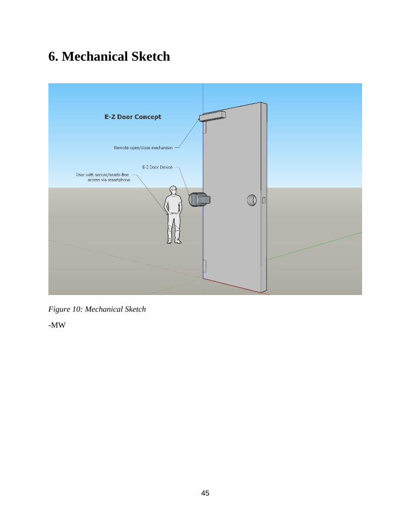
6. Mechanical Sketch
Figure 10: Mechanical Sketch
-MW

46
7. Team Information
There are 4 main sections of work that need to be accomplished to successfully complete this
project. The 4 sections are: Electronics, Communications, Electromechanics, and Embedded
Systems.
The 4 sections will each have two people assigned to it, a primary and a secondary, although all
members will also aid the others in the project, and the roles may change in the future.
Electronics
Primary: Mitch Wilson
Secondary: Brice Brenneman
Communications
Primary: Justin Gnatiuk
Secondary: Caleb Dyck
Electromechanics
Primary: Brice Brenneman
Secondary: Mitch Wilson
Embedded Systems
Primary: Caleb Dyck
Secondary: Justin Gnatiuk

47
8. Parts List
8.1 Accepted Technical Design Parts List
Qty Ref Des Part Number Description
1 C1 0.1uF Capacitor
1 C2 22uF Capacitor
2 C3, C7 470nF Capacitor
1 C4, C6 220uF Capacitor
1 C5 0.22uF Capacitor
2 R1, R3 1kΩ Resistor
1 R2 6.8kΩ Resistor
1 R4 5.6kΩ Resistor
1 D1 1N4004 Diode
1 Q1 BUZ71 N-Channel Power MOSFET
1 J1 PJ-059BH CONN PWR JACK 2.5X5.5MM SOLDER
2 U1, U2 LMZ22005TZE/NOPB DC/DC Converter
Table 10: Parts List
48
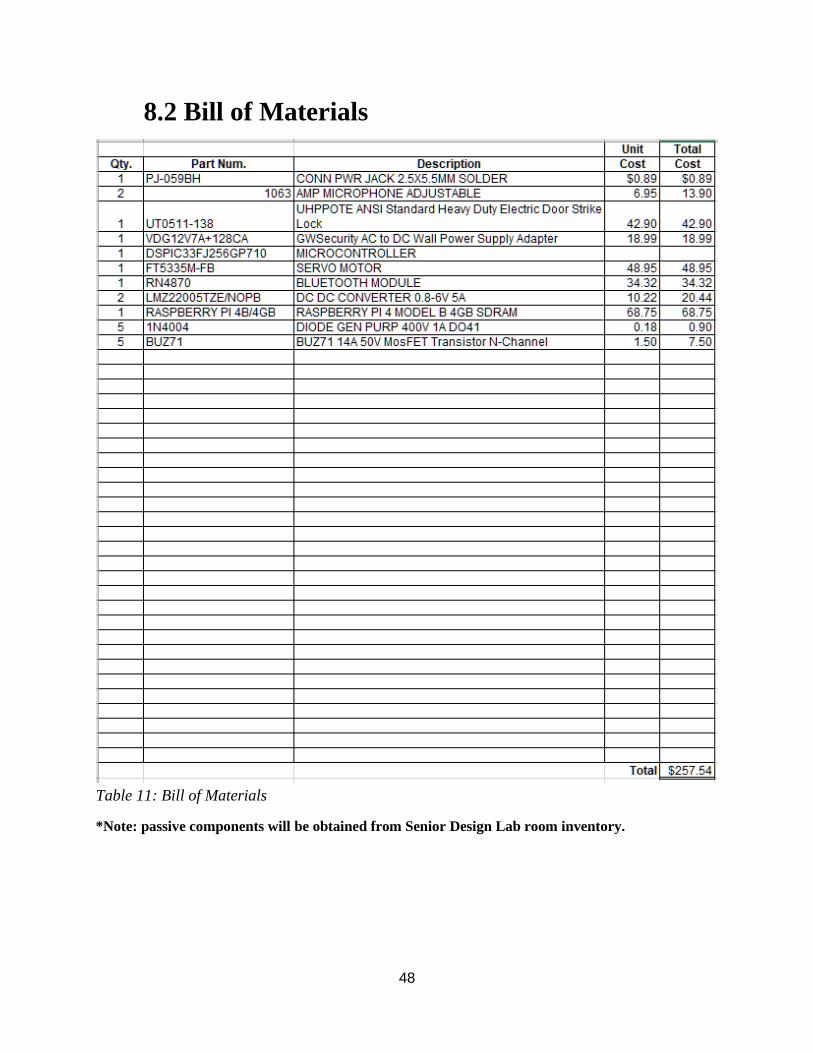
8.2 Bill of Materials
Table 11: Bill of Materials
*Note: passive components will be obtained from Senior Design Lab room inventory.
49
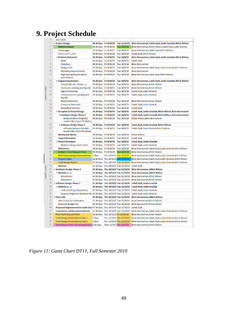
9. Project Schedule
Figure 11: Gantt Chart DT11, Fall Semester 2019
50
10. Conclusions
MW - The intended goal for this paper is to research, design and prove the theory of operation
for a completely hands-free door entry system. The objectives for the project are to develop the
required hardware and software components necessary to accomplish voice actuated
locking/unlocking, opening/closing, and security to standard household doors. The supporting
hardware and control of the system have been realized, while also cohering to the underlying
objectives. With this in mind, further development and testing of the system is necessary to fully
implement the design. Furthermore, active prototyping of the E-Z Door will advance operation
and functionality.
51
11. References
[1] Lia Kamelia, Alfin Noorhassan S.R, Mada Sanjaya and W.S., Edi Mulyana, “Door-
automation system using bluetooth-based android for mobile phone”, ARPN Journal of
Engineering and Applied Sciences, Vol. 9, No. 10, Oct. 2014.
[2] N. H. Ismail, Z. Tukiran, N. N. Shamsuddin and E. I. S. Saadon, "Android-based home
door locks application via Bluetooth for disabled people," 2014 IEEE International Conference
on Control System, Computing and Engineering (ICCSCE 2014), Batu Ferringhi, 2014, pp. 227-
231.
[3] R. Dinar Hayu Arifin and R. Sarno, "Door automation system based on speech command
and PIN using Android smartphone," 2018 International Conference on Information and
Communications Technology (ICOIACT), Yogyakarta, 2018, pp. 667-672.
[4] Y. T. Park, P. Sthapit and J. Pyun, "Smart digital door lock for the home automation,"
TENCON 2009 - 2009 IEEE Region 10 Conference, Singapore, 2009, pp. 1-6.
[5] Pradnya R. Nehete, J. P. Chaudhari, S. R. Pachpande, K. P. Rane, “Literature Survey on
Door Lock Security Systems.” International Journal of Computer Applications (0975-8887),
Vol. 153, No. 2, Nov. 2016.
[6] Anjali Bala, Abhijeet Kumar, Nidhika Birla, “Voice Command Recognition System
Based on MFCC and DTW”, International Journal of Engineering Science and Technology, Vol.
2, 2010.
[7] J. F. Buzhardt, “Smart door lock,” U.S Patent 0170447, Jun. 18, 2015.
[8] J. Johnson, “Intelligent door lock system retrofitted to existing door lock mechanism,”
U.S Patent 9767632, Sep. 19, 2017.
52
[9] J. E. Eccleston, “Remotely controllable automatic door operator and closer,”
U.S Patent 6891479. May. 10, 2005.
[10] S. Downs, A. Pollo, E. Bredemeier, “Residential Automatic Door Opener”, Washington
University Open Scholarship, Fall 2018
[11] Gutierrez Pascual, M. Deseada. (2012). Indoor Location Systems based on ZigBee
networks. 10.13140/2.1.4300.1126.
53
12. Appendix
A. Explorer 16/32 Product Information
https://www.microchip.com/developmenttools/ProductDetails/PartNo/DM240001-
2?utm_source=MicroSolutions&utm_medium=Article&utm_content=DevTools&utm_campaign=StandA
lone
B. Servo Motor Datasheet
https://www.pololu.com/file/0J1434/FT5335M-specs.pdf
C. Buck Converter Datasheet
http://www.ti.com/lit/ds/symlink/lmz22005.pdf
D. Microphone Datasheet https://cdn-shop.adafruit.com/datasheets/MAX4465-MAX4469.pdf