Embed Size (px)
Citation preview

Geological Survey of Western AustraliaGeological Survey of Western Australia
Industry and ResourcesIndustry and ResourcesDepartment ofDepartment of
RECORD2004/10
GSWA LANCER 1 WELLCOMPLETION REPORT (BASIC DATA)
OFFICER AND GUNBARREL BASINSWESTERN AUSTRALIA
by P. W. Haines, A. J. Mory,M. K. Stevens, and K. A. R. Ghori

GEOLOGICAL SURVEY OF WESTERN AUSTRALIA
Record 2004/10
GSWA LANCER 1 WELL COMPLETIONREPORT (BASIC DATA)OFFICER AND GUNBARREL BASINS,WESTERN AUSTRALIA
byP. W. Haines, A. J. Mory, M. K. Stevens, and K. A. R. Ghori
with a contribution by A. C. CookKeiraville Konsultants, 7 Dallas Street, Keiraville, N.S.W. 2500
Perth 2004

MINISTER FOR STATE DEVELOPMENTHon. Clive Brown MLA
DIRECTOR GENERAL, DEPARTMENT OF INDUSTRY AND RESOURCESJim Limerick
DIRECTOR, GEOLOGICAL SURVEY OF WESTERN AUSTRALIATim Griffin
REFERENCEThe recommended reference for this publication is:HAINES, P. W., MORY, A. J., STEVENS, M. K., and GHORI, K. A. R., 2004, GSWA Lancer 1 well completion report (basic data),
Officer and Gunbarrel Basins, Western Australia: Western Australia Geological Survey, Record 2004/10, 39p.
National Library of Australia Card Number and ISBN 0 7307 8964 0
Grid references in this publication refer to the Geocentric Datum of Australia 1994 (GDA94). Locations mentioned in the textare referenced using Map Grid Australia (MGA) coordinates, Zone 51. All locations are quoted to at least the nearest 100 m.
Cover image modified from Landsat data, courtesy of ACRES
Published 2004 by Geological Survey of Western AustraliaThis Record is published in digital format (PDF), as part of a digital dataset on CD, and is available online atwww.doir.wa.gov.au/gswa. Laser-printed copies can be ordered from the Information Centre for the cost of printing andbinding.
Further details of geological publications and maps produced by the Geological Survey of Western Australia can be obtainedby contacting:Information CentreDepartment of Industry and Resources100 Plain StreetEAST PERTH, WESTERN AUSTRALIA 6004Telephone: +61 8 9222 3459 Facsimile: +61 8 9222 3444

iii
Contents
Abstract ...................................................................................................................................................................... 1Introduction ............................................................................................................................................................... 1Well history ............................................................................................................................................................... 2
General data ....................................................................................................................................................... 2Drilling data ....................................................................................................................................................... 3Logging data ...................................................................................................................................................... 3
Regional structural setting ........................................................................................................................................ 4Stratigraphy ............................................................................................................................................................... 4
Cainozoic section ............................................................................................................................................... 5Unnamed regolith ....................................................................................................................................... 5
Palaeozoic section .............................................................................................................................................. 5Paterson Formation ..................................................................................................................................... 5
Neoproterozoic–Cambrian section .................................................................................................................... 7Lungkarta Formation .................................................................................................................................. 7
Neoproterozoic section ...................................................................................................................................... 7Wahlgu Formation ...................................................................................................................................... 7Keene Basalt (new name) ........................................................................................................................... 8Buldya Group .............................................................................................................................................. 8
Kanpa Formation ................................................................................................................................. 8Hussar Formation ................................................................................................................................ 9Browne Formation ............................................................................................................................. 10
Lancer Member (new name) ...................................................................................................... 10Undifferentiated upper Browne Formation ............................................................................... 10Woolnough Member .................................................................................................................. 10Lower Browne Formation .......................................................................................................... 11
?Mesoproterozoic section ................................................................................................................................ 11?Cornelia Sandstone ................................................................................................................................. 11
Petroleum geology (preliminary) ............................................................................................................................ 15Source potential ............................................................................................................................................... 15Reservoir characteristics .................................................................................................................................. 15Seals .................................................................................................................................................................. 16Shows ............................................................................................................................................................... 16
Contributions to geological knowledge .................................................................................................................. 18Acknowledgements ................................................................................................................................................. 19References ............................................................................................................................................................... 20
Appendices
1. Operations report ........................................................................................................................................... 212. Core photographs .......................................................................................................................................... 363. Definition of new stratigraphic units ............................................................................................................ 374. Preliminary well index sheet ........................................................................................................................ 39
Plate
1. GSWA Lancer 1 composite well log
Figures
1. Well location and access map ......................................................................................................................... 22. Tectonic elements of the Officer and Gunbarrel Basins ................................................................................ 33. Western end of seismic line N83-08 across Lancer 1 ................................................................................... 44. Regional stratigraphy of the Officer Basin .................................................................................................... 55. Lancer 1 stratigraphic summary ..................................................................................................................... 66. Correlation of Lancer 1 with petroleum and stratigraphic wells ................................................................. 127. Correlation of Lancer 1 with Empress 1/1A ................................................................................................ 148. Petroleum-source generating potential, kerogen type, and thermal maturity, Lancer 1 ............................ 16

iv
Tables
1. TOC and Rock-Eval data from Lancer 1 core samples ............................................................................... 152. Organic petrography of seven core samples, Lancer 1 (by A. C. Cook) .................................................... 173. Core porosity, grain density and permeability, Lancer 1 ............................................................................ 18

1
GSWA Record 2004/10 GSWA Lancer 1 well completion report (basic data)
GSWA Lancer 1 well completion report (basic data),Officer and Gunbarrel Basins, Western Australia
by
P. W. Haines, A. J. Mory, M. K. Stevens, and K. A. R. Ghoriwith a contribution from A. C. Cook*
AbstractGSWA Lancer 1 is a stratigraphic well drilled in 2003 at latitude 25°02'44.5"S, longitude 123°45'20.7"E in the Officer and GunbarrelBasins in Western Australia to a depth of 1501.3 m (driller’s depth). The interval from 104 to 1501.3 m was continuously cored bydiamond drilling with almost 100% recovery. Lancer 1 penetrated Carboniferous to ?Permian Paterson Formation of the GunbarrelBasin below Quaternary alluvium and the Neoproterozoic Lungkarta, Wahlgu, Kanpa, Hussar, and Browne Formations of the OfficerBasin before being terminated within ?Mesoproterozoic pebbly, well-cemented sandstone. A mafic extrusive unit (Keene Basalt, newname) was penetrated in the Kanpa Formation. Dips throughout the section are low. There are no hydrocarbon shows or indications ofmineralization.
The entire Neoproterozoic section shows evidence of shallow, marginal, and nonmarine conditions ranging from high-energyshoreface and eolian–beach–barrier environments to lagoons and evaporitic supratidal mudflats and coastal sabkhas. The basal part ofthe Browne Formation in Lancer 1 is remarkably similar, particularly in thickness, to that in drillhole GSWA Empress 1/1A, 260 km tothe southeast. This implies a low gradient across the ‘western platform’ of the basin during deposition of this formation, as well as alow-relief hinterland, and regional-scale controls on deposition and subsidence across this part of the Officer Basin. Eolian sandstonefacies at the top of the formation (Lancer Member, new name) are laterally equivalent to halite-dominated facies in Empress 1/1A. Aseries of basalt flows within the Kanpa Formation is the second record of extrusive igneous rocks within the Neoproterozoic successionof Western Australia. Most of the section can be correlated with scattered outcrops in the basin west and northwest of Lancer 1.
Preliminary analyses reveal that sandstone facies in the well typically have excellent reservoir characteristics (with porosities up to29% and permeabilities up to 10 darcies), and that there are potential regional seals at the base of the Hussar and Kanpa Formations.Organic richness, however, is low with just two samples yielding total organic carbon of more than 0.5%.
KEYWORDS: Carboniferous, Neoproterozoic, stratigraphy, diamond drilling, basalt, Mesoproterozoic, petroleum geology, reservoirdata, well logs, stromatolites, Officer Basin, Gunbarrel Basin.
IntroductionThe Geological Survey of Western Australia’s (GSWA’s)Lancer 1 is a stratigraphic hole drilled in the Officer Basin,on the HERBERT† 1:250 000 map sheet (SG 51-7), 390 kmeast-northeast of Wiluna and 115 km northeast of CarnegieHomestead (Fig. 1), at SP 690 on line N83-08 of theGibson Seismic Survey (Fig. 2). The drillhole is 69 kmwest-northwest of Mungilli Outstation, which, in turn, lies16 km north of the junction of the Gunbarrel and EagleHighways. Access to Lancer 1 is via the Gunbarrel andEagle Highways to the Mungilli Outstation, and then alongseismic line N83-08. The nearest wells are Hussar 1(67 km to the northeast), GSWA Trainor 1 (120 km to the
northwest), BMR Browne 1 (160 km to the east-southeast), and Lungkarta 1 (184 km southeast). GSWAEmpress 1/1A lies 264 km to the south (Fig. 2). Thenearest outcrops of the Officer Basin succession are 80 kmto the northwest (Skates Hills), 125 km to the north-northwest (Constance Headland), and 110 km to the north-northeast (around the Madley Diapir).
The primary objective of Lancer 1 was to continuouslycore the Neoproterozoic section of the Officer Basin inorder to gain geological information on the basin andevaluate its hydrocarbon generation potential, as well asreservoir and sealing characteristics in a section no morethan 1500 m thick. A secondary objective was to coreunderlying strata to provide data on the older Proterozoicrocks between those exposed in the Oldham Inlier of thenorthwest Paterson Orogen, and the Musgrave Complex.Lancer 1 was terminated within immature, well-cementedcross-bedded sandstone of probable Mesoproterozoic age.
* Keiraville Konsultants, 7 Dallas Street, Keiraville, N.S.W. 2500.† Capitalized names refer to standard 1:250 000 map sheets.

2
Haines et al.
Hydrocarbons were not expected in this drillhole becausea trap is not evident in the seismic data. During drilling,traces of hydrocarbons were interpreted from fluorescencewithin thin zones in the Hussar and Wahlgu Formations,but subsequent studies showed that these are almost entirelydue to carbonate cements. The hole was geophysicallylogged by Geoscience Associates. At abandonment, the wellwas plugged at the base of the HWT casing and at surface.An artesian flow from the Wahlgu Formation is containedbehind the HWT casing.
This Record provides the basic data for Lancer 1including the operations report (Appendix 1), corephotographs (Appendix 2), definition of two newlyrecognized units (Appendix 3), a provisional well indexsheet (Appendix 4), and a provisional composite well log(Plate 1). Additional analyses, including petroleum andmineral geochemistry, igneous petrography, radiometricdating, and palynology will be released at a future date asa series of complementary reports.
The core depths cited within this Record are, unlessotherwise specified, those reported by the drillers asmodified by the drillsite geologists. In the composite welllog (Plate 1), core descriptions are consistent with thesecore depths, as are the lithology, grain size, and sedimentarystructures columns. * Drillhole location preliminary, to within 100 m.
Homestead
Town or Settlement
Stratigraphic drillhole
Newman
Wiluna
LeinsterSandstone
Leonora
Laverton
Warburton
Carnegie
MungilliOutstation
Eag
le
GunbarrelHwy
Hhy
Can
ning
Stoc
kR
oute
GSWA Lancer 1
Unsealed track
Main road
Gas pipeline
AJM519 05.05.04
Great
Central
Road
126°00'120°00' 123°00'
29°00'
26°00'
200 km
Figure 1. Well location and access map
Well history
General dataPermit: VacantLocation: Latitude 25°02'44.5"S*, Longitude
123°45'20.7"E* (GDA94)Northing 7229780, Easting 576235*(MGA Zone 51J), estimated fromGlobal Positioning System (GPS)and SP 690 on line N83-08 of theGibson Seismic Survey
Derivation of name: Following the cavalry theme ofEagle Corporation wells,(Dragoon 1 and Hussar 1)
Total depth (TD): 1501.3 m (driller), 1502.25 m(logger)
Date spudded: 14:00 Friday 10 October 2003Reached TD: 19:15 Monday 17 November 2003Logging: 03:15 Tuesday 18 November –
14:30 Wednesday 19 November2003

3
GSWA Record 2004/10 GSWA Lancer 1 well completion report (basic data)
Date completed: 14:45 Thursday 20 November 2003Elevation: 450 m Australian Height Datum
(AHD), estimated from shot pointheights in Gibson Seismic Survey
Drill floor: 70 cm above ground levelStatus: Plugged and abandoned
Drilling dataDrilling Drillcorp Western Deephole,contractor: 42 Paramount Drive, Wangara,
W.A. 6065Rig: UDR 1500Rig datum: Rig floor 70 cm above ground
levelHole size: 0–6 m 216 mm with 178 mm
casing6–104 m 159 mm with PW
casing cemented tosurface
Dragoon 1
Hussar 1
BMR Browne 1
Kanpa 1/1A
GSWA Empress 1/1A
YilgarnCraton
MusgraveComplex
EaraheedyBasin
OldhamInlier
CanningBasin Amadeus
BasinCapricornOrogen
Figure 6
Drillhole
Seismic line
AJM520 24.06.04
PilbaraCraton
120°00' 123°00'
29°00'
26°00'
200 km
WardInlier Madley Diapirs
ConstanceHeadland
Skates Hill
Localities
Salt Ruptured
Zone
Salt Ruptured
Zone
126°00'
Weedy 1
Gunbarrel Basinover Officer Basin
EuclaBasin
OfficerBasin
Eucla Basinover Officer
Basin
OfficerBasin
GSWA Vines 1
Yowalga 3
GSWATrainor 1
Lungkarta 1
GunbarrelBasinoverbasement
Figure 3
GSWALancer 1
NJD1
Minibasins Zone
Minibasins Zone
Thrusted Zone
western platform
western platform
N83-08
Figure 2. Tectonic elements of the Officer and Gunbarrel Basins (after Carlsen et al., 2003)
104–429.5 m 115 mm PQ with HWTcasing cemented from428 m to about 90 m
429.5 – 96.1 mm HQ open hole1501.3 m
Mud: Mixture of KCl, NaCl, and polymer-based muds
Core recovery: 104.0 – 429.5 m PQ (85.0 mmdiameter) recovered 325.3 m (~100%)429.5 – 1501.3 m HQ (63.5 mmdiameter) recovered 1071.4 m (~100%)
Hole deviation: Within 0.9° of vertical
Plug: Two van Ruth plugs: at 448 m (HQ)and 35 m (PQ), capped by about 40and 34 m of cement respectively
Logging dataLogging Geoscience Associates, 20 Oborn Road,contractor: Enterprise Park, Mount Barker, S.A. 5251

4
Haines et al.
Logs run: Run 1: 16" normalresistivity 420–1501 m
Run 2: 64" normalresistivity 420–1501 m
Run 3: single point(Gam/G-N) resistance 420–1501 m
spontaneouspotential 420–1501 mneutron 0–1501 m
Run 4: gamma ray 0–1501 m(GAA/DDC) long-spaced
density 0–1501 mshort-spaceddensity 0–1501 mcaliper 0–1501 m
Run 5: sonic 420–1501 mRun 6: BHTV 1450–1500 m
(sonic 1200–1365 mscanner) 420–900 m
Note: the 16" normal resistivity, 64" normal resistivity, andsingle-point resistance logs are considered unreliable dueto the highly saline mud in the hole (required to core halitein the Browne Formation). In addition, the long-spaceddensity log values may be unreliable because they aregreater than the short-spaced density values where thecaliper indicates no reason for such a difference.
Regional structural settingLancer 1 was drilled in the northern part of theNeoproterozoic–Cambrian Officer Basin (Fig. 2) in an areawhere thin Carboniferous–Cretaceous strata of theGunbarrel Basin (Sherriff Shelf) obscure the Neoproterozoicsuccession of the Officer Basin. The drillhole is alongstructural strike from the Mesoproterozoic Ward andOldham Inliers, the nearest outcrops of which lie 67 km tothe west in the Oldham Inlier. The Palaeoproterozoic
Earaheedy Basin outcrops 140 km to the south-southwest.Structural subdivisions of the Officer Basin are presentlyin flux. Lancer 1 is in an area previously assigned to theWestwood Shelf (Hocking, 1994), but now referred to lessformally as the ‘western platform’ (Carlsen et al., 2003).
Lindsay (2002) recognized six periods of regionaldeformation in the Officer Basin, but the western portionof seismic line N83-08 (Fig. 3) shows that Lancer 1 wasdrilled in a region of the Officer Basin with low dips andthere is little evidence of these events apart from some minorfaults with associated low-amplitude rollovers. The regionaround the well is part of the ‘western platform’ of JNOC(1998) and Carlsen et al. (2003), which is the part of thebasin farthest from the Musgrave Complex and leastdeformed. Salt development near Lancer 1 was minor sothat structures such as saltwalls and diapirs, found in theregion to the northeast, are absent. In comparison, theunderlying ?Mesoproterozoic section shows much moredeformation in the seismic data, indicating that there waslittle deformation in the region after the start of theNeoproterozoic. Structural dips in the Officer Basin portionof Lancer 1 are all less than 2°, and even the single siltstonebed in the ?Mesoproterozoic section dips at about 4°.
StratigraphyThe regional Officer Basin stratigraphy in Lancer 1follows that detailed in Grey et al. (in prep.; Fig. 4).Younger strata are mostly Carboniferous – Lower Permianglacial deposits assigned to the overlying Gunbarrel Basin.Lancer 1 was spudded in Cainozoic sand and ferricrete.The boundary between Cainozoic sediments andsedimentary rocks of the Upper Carboniferous to LowerPermian Paterson Formation is placed tentatively at 17 m.Flat-lying Cretaceous strata outcrop in the region, but onlyat higher elevations than the Lancer 1 location. The topof the Officer Basin succession is placed tentatively at169.1 m, and includes the Lungkarta, Wahlgu, Kanpa,Hussar, and Browne Formations, in descending order.
W E110010501000950900850800750700650600550500450
0.5
1.0
1.5
Two-
way
tim
e (s
)
0.5
1.0
1.5
AJM514 05.04.04
Base WahlguTop HussarTop BrowneTop saltBase NeoProt
2 km
TD 1501 m
Lancer 1
Figure 3. Western end of seismic line N83-08 across Lancer 1 (see Fig. 2 for location)

5
GSWA Record 2004/10 GSWA Lancer 1 well completion report (basic data)
Well-cemented sandstone, tentatively correlated with thepre-Officer Basin Cornelia Sandstone, was intersectedbetween 1478.9 m and total depth (TD) at 1501.2 m(Fig. 5). Formation assignments and boundary positionsare tentative and subject to change following more-detailedstudies, including palaeontological, palaeomagnetic, andradiometric dating. A 1:100 graphic sedimentological logwas recorded at the drillsite, and has been placed in theDepartment of Industry and Resources’ statutorypetroleum exploration report S20880, which is part of theDepartment’s WAPIMS (Western Australian petroleuminformation management system) database.
Cainozoic section
Unnamed regolith
The uppermost regolith at the Lancer 1 site is about 20 cmof unconsolidated red sand and soil with scatteredferricrete pebbles. This overlies well-indurated nodularand pisolitic ferricrete, which is exposed in some areasnear the drillsite, the remainder being interpreted fromrotary cuttings. The upper 5 m consists of ferricrete andbrown to yellow ferruginous mudstone with minor fine-grained sandstone. The interval from 5 to 8 m comprisesconsolidated brown to yellow mudstone and light-grey
sandstone in approximately equal proportions, withsandstone grain size increasing downward from fine tomedium. Sandstone, commonly medium grained,predominates over minor mudstone between 8 and 17 m,with coarse-grained sandstone in the basal 3 m. The upper3 m of the interval is poorly consolidated. Porosity variesfrom fair to excellent, and this sandstone unit ispresumably the shallow aquifer intersected in nearby waterbores.
In the absence of palaeontological age constraints inthis preliminary report, any attempt at subdivision isspeculative. However, the Cretaceous section does notoutcrop below 450 m AHD (the level at which Lancer 1was spudded) within 50 km of Lancer 1, and the pre-Cainozoic topographically lower outcrops are all assignedto the Palaeozoic Paterson Formation. This implies thatthe top of the Paterson Formation is best placed at thesudden change from possible Cainozoic sandstone offluvial–lacustrine origin to predominantly claystone at17 m.
Palaeozoic section
Paterson Formation
The upper part of the Paterson Formation (?17 – ?169.1 m)is interpreted from rotary cuttings above 104 m. Theinterval from 17 to 70 m is dominated by claystone, withminor sandy interbeds in the upper 4 m. Traces of sandand granules are probably contamination from higher inthe hole. Below 40 m the claystone is light to moderategrey, but higher in the hole yellow to pale-green and pinkcolouration suggest various degrees of oxidation.Consolidation is variable, but particularly poor below33 m. The claystone unit is underlain by a 4.5 m-thickconglomeratic unit between 70 and 74.5 m, which containssubangular to subrounded pebble clasts mostly ofsedimentary origin.
The interval from 74.5 to 93 m is dominated by light-to moderate-grey mudstone, locally containing minor darkcarbonaceous material in samples from intervals 81–82 m,86–88 m, and 91–93 m. Minor conglomeratic materialnear the top of the interval is interpreted as contaminationfrom the conglomeratic unit above. Cuttings from 93 to104 m contain similar mudstone with increasingproportions of fine-grained sandstone up to about 40%.However, when PQ coring commenced at 104 m thelithology was found to be predominantly sandstone,with mudstone only as sparse intraclast horizons. Hence,a significant proportion of the mudstone in the intervalfrom 93 to 104 m may represent contamination fromhigher in the hole.
The interval below 104 m is dominated by sandstone,but with significant mudstone intervals below 155 m, andconglomerates in the basal 2 m below 167 m. Thesandstone is mostly grey above 133 m, but undergoes agradational change to predominantly reddish-brown andbrown below this depth. At about this depth the averagegrain size increases from uniform medium-grainedsandstone above to alternating medium- to coarse-grainedsandstone below. Most of the sandstone is cross-bedded,
Age
400
450
500
550
600
650
700
750
800
850
900
NW(Savory)
Western(Gibson–Yowalga)
Central(Lennis–Waigen)
Wanna Fm
Durba Ss ?? Lennis Fm
Table Hill Volcanics
Vines Fm
McFadden Fm Lungkarta Fm
LuptonFm
BoondawariFm Wahlgu Fm
Steptoe Fm
Kanpa FmKeeneBasalt
Hussar Fm
Browne Fm
Townsend Qtz andLefroy FmWatch Point and
Coondra Fms
Spearhole FmSkates Hill Fm
MundadjiniFm
BuldyaGroup
Rodingan Movement
Delamerian Orogeny
Petermann Orogeny
Areyonga Movement
Devonian
Silurian
Ord
ovic
ian
Cam
bria
nN
EO
PR
OT
ER
OZ
OIC
AJM511 05.05.04
Figure 4. Regional stratigraphy of the Officer Basin (afterGrey et al, in prep.) with tectonic events

6
Haines et al.
Depth(m)
100
0
Stratigraphy
200
300
400
500
600
700
800
900
1000
1100
1200
1300
1400
Gamma ray0 (API) 200
Density-0.25 (g/cm ) 0.5
3
Age Description
Cainozoic
LateCarboniferous
– ?Permian
Reddish-brown fine-grained sand, brown mudstoneand ferricrete oveylying multicoloured sandstone
Lithology
Unnamed 17
169
344
466.5
KeeneBasalt
527
576
Bul
dya
Gro
up (
Sup
erse
quen
ce 1
)PatersonFormation
LungkartaFormation
(Supersequence 4)
WahlguFormation
(Supersequence 3)
Clay, grey mudstone, grey to brown sandstone,minor conglomerate
707.5
1202
KanpaFormation
1298
HussarFormation
LancerMember
WoolnoughMember
1323
1358Browne
Formation
14411463
Unnamedhalite interval
1479?Cornelia Ss
Reddish-brown sandstone and polymictconglomeratec. 550–510
Ma
Red diamictites and mudstone, multicolouredsandstonec. 610–590
Ma
Neo
prot
eroz
oic
~760Ma
Dark, fine- to coarse-grained basalt, locallyamygdaloidal, erosional upper surface
Brown to grey claystone and mudstone, greystromatolitic dolostone, grey to brown sandstone
c. 780–720Ma
c. 810–780Ma
Brown stone, and stromatoliticdolostone
sandstone, mud
Reddish-brown cross-bedded sandstone inforesets up to 11 m thick
?Mesoproterozoic Bluish-grey, pebbly, clayey, medium-grained,cross-bedded sandstone
Reddish-brown sandstone and mudstone, red-greydolostone, halite
Red-grey stromatolitic dolostone, mudstone
Reddish-brown mudstone with halite crystalsbecoming abundant towards halite interval; grey,argillaceous dolostone, halite, fine-grainedsandstone, minor conglomerate, and mudstonebelow halite interval
c. 820–810Ma
TD 1501 BHT 63.5°C
Unconformity
Disconformity
AJM525 17.05.04
Conglomerate
Mudstone
Claystone
Diamictite
Dolostone
Anhydrite/gypsum
Halite
Basalt
Sandstone
Figure 5. Lancer 1 stratigraphic summary (Officer Basin ages from Grey et al., in prep.)

7
GSWA Record 2004/10 GSWA Lancer 1 well completion report (basic data)
some on a large scale. There is patchy calcareouscementation between 155 and 164 m. The base istentatively assigned to a sharp erosional contact overlainby a thin polymict pebble conglomerate at 169.1 m, whichis also marked by a distinct change in the gamma-raysignature.
In Lancer 1 the Paterson Formation is interpreted tobe mainly of fluvial origin. Glacial diamictites, as seenelsewhere, are absent. The age of the formation isconsidered to be ?Permian, based on one possibly Permianspore from the 50–52 m interval, to Late Carboniferous,based on likely Stage 1 (late Westphalian to Stephanian )palynomorphs from the 86–88 m interval (Backhouse, J.,written comm., 2004). Four siltstone beds near the baseof the unit were completely devoid of organic material.Other wells in the region, such as Empress 1/1A (Stevensand Apak, 1999), have yielded Early Permian and LateCarboniferous palynomorphs from this unit.
Neoproterozoic–Cambrian section
Lungkarta Formation
The Lungkarta Formation (?169.1 – 344.3 m) ofSupersequence 4 is defined in Grey et al. (in prep.) withits type section in Lancer 1, although it is widelyrecognized on seismic sections and in other drillholes. Theunit was previously identified as the ‘Babbagoola beds’(Townson, 1985) or ‘McFadden Formation equivalent’(Apak and Moors, 2000). In Lancer 1 the top of theformation is tentatively picked at an erosional surface at169.1 m, as previously described for the overlyingPaterson Formation.
The upper part of the formation from 169.1 to 205 mconsists of light-brown, medium-grained, moderately sortedand rounded, quartz-rich sandstone. It displays minor claymatrix, rare red mudstone interbeds and intraclasts,common siliceous concretions in the lower half, and issparsely pyritic mainly near the base. Sedimentarystructures are restricted to abundant cross-bedding.
The interval from 205 to 214 m is an overall fining-upward, mostly flat-bedded, succession of reddish-brown,fine- to coarse-grained, poorly sorted sandstone withlithic-granule conglomerate horizons in the lower half.
The remainder of the formation, from 214 to 344.3 m,is dominated by orange-brown to reddish-brown, medium-grained, well-sorted, well-rounded, porous, quartzsandstone. It is characterized by very large foresets,possibly exceeding 30 m in thickness, with dips up to 30°,but also contains flat-bedded intervals. The upper 22 mcontains sparse pyrite. There are minor mudstone andpolymict conglomeratic intervals, the latter increasing inabundance towards the base. The base of the formation isplaced at the sharp erosive base of a polymict granuleconglomerate at 344.3 m. This contact may represent anerosional hiatus of uncertain duration.
The upper part of the Lungkarta Formation (169.1 –214 m) was deposited subaqueously, probably in a fluvialor possibly high-energy shallow-marine environment. The
lower part (214 – 344.3 m) was deposited under mainlyeolian conditions as indicated by textural evidence and thescale and angle of foresets. Particularly diagnostic is thereversely graded translatent strata (Hunter, 1977) producedby laterally migrating wind ripples. Conglomeratic andmudstone intervals probably result from fluvial and playadeposition between migrating dunes. The age of theLungkarta Formation is constrained only by itsstratigraphic position. Because it disconformably overliesthe upper Neoproterozoic Wahlgu Formation and isoverlain by the Cambrian or Lower Ordovician Table HillVolcanics in other drillholes, it can be constrained to theupper Neoproterozoic or possibly Cambrian (Grey et al.,in prep.).
Neoproterozoic section
Wahlgu Formation
The Wahlgu Formation (344.3 – 466.5 m) of Super-sequence 3 is defined in Grey et al. (in prep.) with its typesection in Empress 1/1A (317.1 – 483 m) and Lancer 1 asa reference section. In Lancer 1 the formation ischaracterized by massive diamictite. The diamictite istypically reddish-brown, less commonly grey, and has amudstone or sandy mudstone matrix containing scatteredgranule, pebble, cobble, and boulder clasts. The largestobserved clast is about 0.5 m across. Large clasts rangefrom angular to well rounded and some have well-developed facets and striations typical of ice transport.Clast compositions include a variety of sedimentary,igneous, and metamorphic rock types. The largest clastsare most commonly mafic igneous rocks.
The diamictite intervals are interpreted to be of glacialorigin because of their massive and extremely poorlysorted nature, and the faceted and striated clasts typicalof ice transport. The relatively fresh nature of labileigneous clasts is also indicative of very cold conditions.Most of the diamictite shows little or no evidence ofreworking by currents, suggesting a subaerial orsubaqueous moraine resulting from sediment dumped byretreating ice sheets.
Also present are minor intervals of moderately to well-sorted sandstone, mudstone, and conglomerate. In contrastto the diamictite, these intervals are commonly wellstratified. Some sandstone horizons contain green claypellets, which may be glauconite. The interval from 391to 397 m consists of porous coarse-grained to pebblyreddish-brown sandstone with large foresets and is anartesian aquifer. Soft-sediment deformation, includingcontorted bedding, small slumps, and syndepositionalfaulting, is common in stratified intervals, particularly inthe lower 12 m of the formation. The sandstone, mudstone,and conglomerate intervals indicate periodic reworking bycurrents in an aquatic (marine, lacustrine or fluvial)environment. The presence of possible glauconite in somesandstone horizons, if confirmed, suggests at least periodicmarine influence.
The base of the formation — an erosional discon-formity overlying Kanpa Formation dolostones — is put at466.5 m, but could be slightly higher. The 466.5 m position

8
Haines et al.
marks the top of the highest definitely in situ, althoughsomewhat brecciated, dolostone bed. This bed is overlainby 4 m of sandstone, dolostone, and dolostone-clastconglomerate. It is inferred that apparent dolostone bedsin this interval are actually large tabular dolostone clasts.An alternate explanation is that the disconformity surfaceis very complex due to karstification and that the 466.5 mcontact represents the bottom of a small cavern fill.
The cap dolostone, present in Empress 1/1A (Stevensand Apak, 1999) and in the Boondawarri Formation to thenorth (Grey et al., in prep.), was not recognized inLancer 1. The Wahlgu Formation has been correlated withthe Marinoan glacial succession throughout the CentralianSuperbasin and the Adelaide Rift Complex, and withoutcropping Boondawari Formation in the adjacentnorthwestern Officer Basin (Grey et al., in prep.).
Keene Basalt (new name)
The upper Kanpa Formation sedimentary succession isdisrupted by 48.8 m of basalt flows, (527.4 – 576.2 m) herenamed the Keene Basalt (Appendix 3). The base overlies avuggy dolostone, which has been coarsely recrystallizedand silicified to grey and black laminated chert within 15 cmof the contact. The basal 3 m of basalt is very fine grainedwith irregular and inclined amygdaloidal zones and somebrecciation, possibly the result of subaerial extrusion overwet sediments. There are at least four and possibly fivedistinct flows with tops and bases marked by fine-grainedamygdaloidal basalt, whereas flow centres comprise coarse-grained massive basalt. The basalt is typically dark grey togreenish, but is reddened at the base and at two of the flowtops. Veins filled with calcite, red chert or chlorite arecommon, and amygdales are filled with similar material.The top of the basalt member is not fine grained,amygdaloidal or reddened, indicating that the top of thelast flow was eroded before resumption of clastic deposition.It is sharply overlain by 35 cm of grey muddy sandstonefollowed by stromatolitic dolostone. The depositionalenvironment before and after basalt extrusion was verysimilar, suggesting that subsidence kept pace with extrusion.Based on broad regional correlations, the Keene Basalt couldcorrelate with (but would not be comagmatic with) theCadlareena Volcanics of the northeastern Officer Basin inSouth Australia, which has an age between 780 and 760 Ma(Morton, 1997), and also the Boucaut Volcanics dated at777 ± 7 Ma in the Adelaide Rift Complex (Barovich et al.,2001).
Buldya Group
The Buldya Group erected by Grey et al. (in prep.), whichencompasses previously ungrouped formations assignedto Supersequence 1, was intersected between 466.5 and1478.9 m (466.6 –1480.3 m log depth). The basalt withinthe Kanpa Formation (Appendix 3), however, is notconsidered to be part of the group.
Kanpa Formation
The Kanpa Formation (466.5 – 707.5 m core depth, 466.6–708.0 m log depth) is a mixed succession of dolostone,
mudstone, claystone, and sandstone. In Lancer 1, aninformal two-part division is made with an upper intervalfrom 466.5 to 583 m containing seven stromatoliticdolostone cycles, and a lower interval from 583 to 707.5 mof mainly mudstone, claystone, and sandstone. Unique toLancer 1 is the 49 m-thick basalt unit within the upperdolomitic section.
The upper interval comprises seven major dolostoneunits from 3 to 10 m thick, separated by units of dolomiticmudstone or sandstone, or both, from 2 to 11.5 m thick.The dolostone is grey, stylolitic, and ranges from relativelypure to argillaceous and sandy. Dolomitic mudstone andsandstone form thin interbeds locally. Grainstone andpackstone, incorporating ooids, small intraclasts or otherunidentified allochems, are common. All except the topdolostone unit are partly stromatolitic, but it is possiblethat its stromatolitic component has been truncated byerosion. Pending more-detailed analysis, the stromatolitesare considered to include elements of the Baicalia burraStromatolite Assemblage (Grey, 1996). The lowest twodolostone-bearing units are separated by basalt, asdescribed below. Sandstones are light grey to brown, fineto coarse grained and mostly well sorted, rounded, andporous. Mudstones are mostly grey and locally black, flatlaminated, and dolomitic, with common thin dolostoneinterbeds.
The lower Kanpa Formation contains a number ofsandstone-dominated intervals, up to 22 m thick, gradingupward into intervals of mudstone or claystone, with orwithout interbedded sandstone. Sandstone is typicallywhite to light brown or grey, medium grained, well sorted,well rounded, and commonly porous. Sedimentarystructures include flat bedding and high- to low-anglecross-bedding. Mudstone intervals are mostly grey and flatlaminated. Where thin fine-grained sandstone interbeds arepresent, sedimentary structures include flat laminations,ripple cross-laminations, synaeresis cracks, soft-sedimentdeformation, and pot and gutter casts produced by theinfilling of erosional scours.
The megascopic alga Chuaria sp. is tentativelyidentified in grey shale beds between 651.7 and 651.9 m,and possibly also at 659.35 m. It consists of darkcarbonaceous discs, about 1 mm across, with concentricwrinkles and radial fractures on several bedding planes.The genus is generally known from Neoproterozoicdeposits ranging in age from 1000 to 700 Ma.
The lowest 44 m of the Kanpa Formation ispredominantly very fine grained, but has fine- to medium-grained sandstone interbeds below 689 m, including asandstone-rich interval between 695.6 and 699.7 m. Theinterval between 663.8 m and about 686 m compriseslaminated grey claystone, with sparse graded siltstoneinterbeds. Several claystone beds between 676 and 677 mand at approximately 683.5 m are notably hygroscopic andmay be bentonites (ash beds). The base of the KanpaFormation at 707.5 m is placed at a sharp conformableboundary between a 55 m-thick medium- to coarse-grained sandstone at the top of the Hussar Formation andbrown mudstone with minor thin sandstone interbedsabove.

9
GSWA Record 2004/10 GSWA Lancer 1 well completion report (basic data)
The Kanpa Formation is considered to be of shallow-marine to coastal origin. The upper part shows analternation of environments typical of shallowing-upwardperitidal carbonate cycles (Pratt et al., 1992). In contrast,the lower part displays mainly deepening-upward cyclesfrom high-energy beach–barrier–shoreface sands to quieterbasinal mudstones. Where fine sandstone interbeds arepresent there is evidence of storm-wave reworking, butlaminated claystone near the base of the formation wasdeposited below storm wave-base. The tentativeidentification of the B. burra Stromatolite Assemblageimplies correlation with the Tarcunyah Group of thenorthwestern Officer Basin and the Burra Group of theAdelaide Rift Complex (Grey et al., in prep.).
Hussar Formation
The Hussar Formation (707.5 – 1201.9 m core depth,708.0 –1202.8 m log depth) is a thick and lithologicallydiverse formation of sandstone, mudstone, dolostone, andevaporite. The unit is widespread in the western OfficerBasin with its type section in drillhole Yowalga 3 (Greyet al., in prep.). In Lancer 1 it is subdivided into fourinformal units for ease of description:• an upper sandstone-dominated unit (707.5 – 898.5 m);• an upper middle evaporitic mudstone and dolostone
unit (898.5 – 988.5 m);• a lower middle sandstone and dolostone unit (988.5 –
1069.7 m);• a lower evaporitic mudstone-dominated unit (1069.7
– 1201.9 m).
Upper and lower contacts of the formation are sharp.The upper contact is apparently conformable, but the lowermay represent a minor erosional hiatus.
The uppermost Hussar Formation is marked by 55 mof predominantly medium- to coarse-grained sandstonewith minor mudstone interbeds in two broadly coarsening-upward cycles (707.5 – 750.5 m and 750.5 – 762.7 m).The sandstone is white to light brown and light reddish-brown, well sorted, rounded, and porous. Consolidationvaries with most being subfriable, but an interval of verycoarse to coarse-grained sand from 713.3 to 713.6 m iscompletely unconsolidated. Bedding ranges from flatbedding to high- to low-angle cross-bedding. Someintervals are massive or structureless.
The top of the lower cycle is coarsely dolomitic andvuggy, and is capped by white nodular magnesite oranhydrite. Dolostone-rich intervals with interbeddedmudstone and sandstone are present between 762.7 and768.2 m, 794.5 and 797.5 m, and 800.3 and 809.5 m. Thedolostone is mostly brown to grey, locally silicified, andcommonly stromatolitic and stylolitic. Thin ooidgrainstones are present locally, and intraclast horizons andanhydrite nodules are common. Sandstone between thedolostone-rich intervals is similar to that described above.The section from 809.5 to 899 m is dominated by medium-to coarse-grained sandstone, but with intervals ofinterbedded finer sandstone and mudstone between 833.1and 838 m, 859.6 and 870.5 m, and 888.8 and 891.8 m.The main sandstone intervals comprise white to light-brown and light reddish-brown, well-sorted, rounded,
subfriable, and porous sandstone. Sedimentary structuresinclude flat bedding and high- to low-angle cross-bedding, with some massive intervals and soft-sedimentdeformation. Pyrite is sparse and anhydrite rare.Mudstone-bearing intervals vary from brown to yellowand green. Some green clay pellets may be glauconite.Current ripples are common in the fine-grained sandstonebeds. Anhydrite nodules are common between 859.5 and870.5 m.
The upper middle unit of the Hussar Formation (899 –988.5 m) comprises evaporitic mudstone and dolostone.The upper part (899 – 929 m) is marked by red dolomiticmudstone with abundant desiccation cracks, rip-up clasts,current ripples and anhydrite nodules and veins. Red andbrown dolostone interbeds between 912.5 and 921 m arecommonly stromatolitic and stylolitic. Between 929 and970 m the mudstone changes colour to predominantly grey,contains common grey dolostone interbeds and sparsepyrite, but lacks obvious evidence of desiccation. Thickerdolostone beds are commonly stromatolitic and stylolitic.Anhydrite is typically as ‘cauliflower’ nodules, and somebeds display ‘chicken-wire’ texture. Thicker beds ofmassive white anhydrite are present from 929.3 to 929.5 mand in three beds between 933.6 and 936.1 m interbeddedwith dolostone. The interval from 969 to 988.5 m isdominated by brown and reddish-brown, flat-laminatedmudstone with flat- to ripple cross-laminated siltstone andfine-grained sandstone interbeds. Green reductions spotsare common, but evaporite minerals are absent.
The lower middle unit (988.5 – 1069.7 m) is dominatedby sandstone, but contains numerous stromatolitic dolostoneintervals up to 5 m thick. The sandstone is medium to coarsegrained, moderately to well sorted, rounded, locallysubfriable, and variably porous. Sedimentary structuresinclude flat bedding and high- to low-angle cross-beddingand current ripple laminations. Colour varies from lightbrown to reddish-brown, green, and light grey. Mudstoneforms interbeds in places, some with desiccation cracks.Dolostone intervals are mainly reddish-brown, and locallyargillaceous. Ooid and other grainstone and packstone bedsand intraclast horizons are common, but recrystallizationof some beds makes identification of primary allochemsdifficult. Vugs and stylolites are locally common. Mostdolostone horizons also contain anhydrite nodules, somepartly replaced by chert.
The lower evaporitic mudstone unit from 1069.7 to1201.9 m is dominated by reddish-brown mudstone, withlocal thin, graded, very fine grained sandstone to siltstoneinterbeds. The basal 5 m of the unit contain numerousmedium-grained sandstone interbeds. Sulfate evaporites(predominantly anhydrite) form small nodules and are inveins, the latter including subvertical veins intersecting thecore for up to 3 m. Greenish zones, mottles, and reductionspots are present throughout. The mudstone is commonlyweakly dolomitic or calcareous and contains sevendolostone intervals ranging from less than 0.5 to 3 m thick.The dolostone intervals are typically grey and containchert nodules or horizons, with sulfate evaporites commonas layers, nodules or crosscutting veins. A 0.5 m-thickdolostone bed at the top of the unit contains possible halitepseudomorphs. One dolostone bed (1140.8 – 1143.1 m)contains partly silicified stromatolites.

10
Haines et al.
The Hussar Formation was deposited in shallow- andmarginal-marine conditions ranging from high-energyshoreface and beach–barrier environments to lagoons andevaporitic supratidal mudflats and coastal sabkhas.
Browne Formation
The Browne Formation (1201.9 – 1478.9 m, core depth,1202.8 – 1480.3 m log depth) is widespread in the westernOfficer Basin, and shows limited variation (Grey et al., inprep.). In Lancer 1 the top of the Browne Formation isplaced at a sharp contact at 1201.9 m between evaporiticmudstone of the lower Hussar Formation above and anorange-brown sandstone unit below. Correlation of thisboundary to other wells is difficult because the LancerMember (Grey et al., in prep.) has not been intersected inother wells. Elsewhere the upper boundary is defined atthe top of a halite-bearing unit. The lower contact betweenthe Browne Formation and an underlying well-cementedsandstone unit, tentatively identified as the CorneliaSandstone, is placed at 1478.9 m and is considered torepresent an erosional unconformity or disconformity.
The Browne Formation can be subdivided into anupper sandstone-dominated succession including theLancer Member, a central stromatolitic dolostone andmudstone unit named the Woolnough Member, and alower mudstone and evaporite succession. An upperevaporite succession, as seen in Hussar 1, Empress 1A,and other wells (Stevens and Apak, 1999), is not inLancer 1.
Lancer Member (new name)
The Lancer Member (1201.9 – 1297.7 m core depth,1202.8 –1298.7 m log depth) comprises the uppermostpart of the Browne Formation in Lancer 1. Grey et al. (inprep.) discussed regional correlations for the unit. Theupper contact with mudstone of the basal HussarFormation is sharp and erosional, but it is unclear if asignificant hiatus is involved. The Lancer Membercomprises fine- to coarse-grained orange-brown toreddish-brown quartz sandstone, most of which is mediumgrained, well sorted, well rounded, and porous. It displayslarge cross-beds with foresets up to 11 m in thickness andforeset dip angles up to 27° (assuming negligible structuraldip). Foreset beds grade downward with decreasing foresetangle into irregularly horizontally laminated sandstonezones, which are more poorly sorted and commonlydisplay an alternation of grain size from fine to mediumand locally to coarse. In places the foreset strata containsreversely graded translatent strata (Hunter, 1977). Inclinedsandstone dykes a few millimetres to about a centimetrein thickness along small-scale normal faults within theforeset facies are interpreted as mainly of syndepositionalorigin. The Lancer Member sharply overlies reddish-brown mudstone and very fine grained sandstone at1297.7 m.
The combination of primary sedimentary featuresindicates an eolian depositional environment for theLancer Member. The large foresets are interpreted asdeposition from migrating eolian dunes, whereas theirregularly laminated zones are considered to represent
deposition within an inter-dune facies. The latter are mostabundant and thickest in the lower part of the unit, whereasthe foreset dune facies increases in abundance andthickness in the upper part. The Lancer Member has notbeen recognized elsewhere, but may correlate with sandyfacies of the Mundadjini Formation in the northwestOfficer Basin, which shows similar large cross-bedding(Williams, 1992; Grey et al., in prep.). Comparison withthe section intersected by Empress 1A (Stevens and Apak,1999) indicates that the member could be laterallyequivalent to the halite and mudstone interval in the upperBrowne Formation elsewhere. Thus in Lancer 1 thesubaqueous evaporitic succession of the main basindepocentre is replaced by a mostly subaerial clastic facies,which apparently formed near the basin margin. Althoughthe top of the Browne Formation in Lancer 1 is picked forconvenience at the sharp top of the Lancer Member, itremains unclear how this stratigraphic position correlatesto other drillholes.
Undifferentiated upper Browne Formation
The 25.7 m interval (1297.7 to 1323.4 m core depth,1298.7 – 1324.4 log depth) between the Lancer andWoolnough Members is characterized by reddish-brown,poorly sorted, very fine grained sandstone and mudstonewith irregular laminations. The upper contact is very sharp.Medium-grained and, rarely, coarse-grained sandstone arepresent near the base and top. Minor greenish sandstonebeds are cleaner and better sorted. The contact with thecarbonate-rich Woolnough Member at 1323.4 m is sharp,but conformable. The interval was deposited underfrequently or predominantly emergent conditions such ason a supratidal flat or playa lake.
Woolnough Member
The Woolnough Member (first named the ‘Woolnoughbeds’ by Jackson and van de Graaff, 1981; Grey et al., inprep.) consists of dolostone, argillaceous dolostone,dolomitic mudstone, and minor dolomitic sandstone overthe interval 1323.4 – 1357.7 m (1324.4 – 1358.7 m logdepth). Dolostone beds vary from pink-grey to brownish-grey, whereas muddy horizons alternate between reddish-brown, green, and grey. There are at least nine distinctstromatolite horizons, although some appear to be anamalgamation of several stacked bioherms. The mostdistinctive type shows an upward transition from domalto narrow columnar form similar to Acaciella australica.Some of the nonstromatolitic dolostone beds appear to begrainstones, although recrystallization makes theidentification of primary allochems difficult. Laminatedmuddy horizons show evidence of desiccation, and rip-up mud clast and dolostone clast horizons are common.Anhydrite–gypsum is mainly a vein-filling material. Thelargest veins are subvertical and intersect the core for upto 3 m.
The Woolnough Member conformably overlies reddolomitic mudstones at 1357.7 m and is overlain abruptlyby sandstone at 1323.4 m. It was deposited in shallow-water to periodically emergent conditions, probably in anintertidal to lagoonal environment. Individual stromatoliticbands are interpreted as small-scale shallowing-upward

11
GSWA Record 2004/10 GSWA Lancer 1 well completion report (basic data)
cycles. The presence of the A. australica StromatoliteAssemblage allows correlation with the Skates HillFormation in the northwestern Officer Basin, the LovesCreek Member of the Bitter Springs Formation in theAmadeus Basin, the Yackah beds in the Georgina Basin,and the Coominaree Dolomite in the Adelaide RiftComplex (Grey, 1995; Hill et al., 2000; Grey et al., inprep.).
Lower Browne Formation
The lower Browne Formation (1357.7 to 1478.9 m coredepth, 1358.7 – 1480.3 log depth) is dominated bymudstone and evaporites. The interval from 1357.7 to1382.2 m comprises reddish-brown weakly dolomiticmudstone with common mottled-green reduction spots.The mudstone is massive to irregularly laminated, andcontains horizons of scattered sand grains near the baseof the interval. Unlike deeper parts of the formationit is devoid of evaporite minerals or their pseudomorphs.White anhydrite–gypsum forms nodules, veins, andpseudomorphs after halite below 1382.2 m, embedded inan otherwise similar mudstone succession. Thininterbedded dolostone beds are also present below thisdepth, together with current ripples and probabledesiccation cracks. Thin medium- to coarse-grainedimmature sandy and granule interbeds are typically sparse,but are abundant between 1386.5 and 1390 m.
The first preserved halite appears at 1408.5 m, andbetween this position and 1415 m the halite forms coreswithin partial anhydrite–gypsum pseudomorphs. Becausemost of the halite along the core surface was dissolvedout during drilling, the appearance is of voids lined withwhite anhydrite–gypsum. From 1415 to 1442 m, reddish-brown massive to weakly laminated dolomitic mudstonewith green reduction spots contains common clear haliteas isolated crystals, crystal clusters, and veins. The haliteforms distinct layers of greater abundance below 1428 m,but there are no massive halite beds in this interval.‘Pagoda’-shaped skeletal halite is common. The mudstonecontains sparse thin coarse-grained immature sandy beds.
The interval from 1440.8 to 1472.4 m consists ofcoarse-grained massive halite interbedded with reddish-brown dolomitic mudstone and grey dolostone. Individualhalite beds are more than 0.5 m thick, whereas fine-grained clastic interbeds range from centimetre scale to3 m in thickness. Interbedded lithologies contain scatteredhalite as isolated crystals and veins, variably dissolved outduring drilling. The halite crystals are mostly euhedral orsubhedral, although commonly distorted by compaction.‘Pagoda’-shaped skeletal halite is locally common, forexample around 1465 m. The halite varies from nearlycolourless to (more commonly) orange.
The basal 6.5 m of the formation (1472.4 – 1478.9 m)consists of interbedded grey laminated argillaceous andsilty dolostone and dolomitic sandstone, with thin dark-grey to black mudstone interbeds and minor conglomeratichorizons. Minor halite and anhydrite are present. Thehalite is more abundant at the top of the interval, but hascommonly been dissolved out by drilling fluids leavingvoids. A 10 cm-thick sandy conglomeratic bed overlies theerosional basal contact of the Browne Formation.
The lower Browne Formation is interpreted as ashallowing-upward, shallow- to marginal-marine evaporitesuccession. After a thin transgressive interval, massivehalite beds were deposited under brine pool conditions.The thickness of massive halite is indicative of a marinebrine source, but with tenuous connection to the oceanallowing hypersaline conditions to develop under theinfluence of an arid climate. The depositional environmentshallowed over time, leading to a supratidal evaporiticmudflat environment. Strong similarities in both facies andthickness to the lower Browne Formation in Empress 1A,260 km to the south (Stevens and Apak, 1999; Figs 6 and7), suggest subdued topography and uniform subsidenceduring this part of the basin’s history, at least across thewestern part of the basin.
?Mesoproterozoic section
?Cornelia Sandstone
The oldest stratigraphic unit penetrated in Lancer 1contains bluish-grey, well-cemented feldspathic andmicaceous sandstone from 1478.9 to 1501.2 m (1480.3 –1502.25 m log depth). The sandstone is moderately sortedand mostly medium grained, but contains coarse andgranular horizons and sparse small pebbles. The unitcontains minor clay matrix, probably derived from thebreakdown of labile minerals. There is no visible porosity,although the sonic log indicates some porosity, but thedensity log implies that this interval is denser than quartz.Medium-scale (10–30 cm) cross-bedding is ubiquitous.There is a single thin (~1 cm) mudstone interbed at1498.2 m. Deposition occurred in a fluvial or, less likely,a high-energy shallow-marine environment.
The total thickness of the unit is unknown, as only thetop 22.3 m was penetrated in Lancer 1. The contact withthe overlying Browne Formation at 1478.9 m is erosional.A hiatus of uncertain duration is thus indicated, althoughthere is no evidence of significant metamorphism ortectonism in the older unit. Fractures become more commontoward the upper contact and some are filled with halite orcalcite. The top surface of the thin mudstone interbed at1498.2 m dips at 4° to the horizontal (assuming verticalcore axis), in contrast to average dips derived from the lowerBrowne Formation of about 2°.
Although a slight angular relationship is possible, it isuncertain if the mudstone surface represents a reliableprimary horizontal surface. The age of the unit is poorlyconstrained, being early Neoproterozoic or older. It istentatively assigned to the Cornelia Sandstone, a unit ofprobable Mesoproterozoic age that forms much of theOldham Inlier and underlies the Officer Basin successionin northwestern areas (Hocking et al., 2000; Jones et al.,2000).
An alternative possibility is that the unit correlates withthe Townsend Quartzite of the north-central Officer Basin,although the absence of this formation in Empress 1Amakes this unlikely, as does the apparent structuraldiscontinuity with the overlying Officer Basin successionvisible on seismic data.

12
Haines et al.
Unconformity
Disconformity
KeeneBasalt
NNWGAMMA RAY
0 (API) 200
COMP. SONIC
140 (US/F) 40
500 m
1000 m
1500 m
Lungkarta 1
TD 1770 m
TD 1501 mTD 2040 m
500 m
1000 m
Lancer 1500 m
1000 m
1500 m
2000 m
Hussar 1
GAMMA RAY
0 (API) 200
COMP. SONIC
140 (US/F) 40
GAMMA RAY
0 (API) 200
COMP. SONIC
140 (US/F) 40
AJM523 17.05.04
WahlguFormation
KanpaFormation
HussarFormation
Paterson Formation
H5
H4
H3H2
H1
Lennis / Durba
Sandstone
Browne
Formation
Lungkarta Formation
Wahlgu Formation
Kanpa Formation
Paterson Formation
Lennis / Durba Sandstone
Table Hill Volcanics
Hussar Formation
Browne Formation
Steptoe Formation
Sandstone
Mudstone–siltstone
Conglomerate
Basalt
Diamictite
Dolomite
Calcareous shale
Evaporite
Keene Basalt
Table HillVolcanics
? LungkartaFormation
Figure 6. (This and facing page) Correlation of Lancer 1 with petroleum and stratigraphic wells (after Moorsand Apak, 2002, and Apak and Moors, 2000). Line of section shown on Figure 2

13
GSWA Record 2004/10 GSWA Lancer 1 well completion report (basic data)
SSE
Lennis / Durba Sandstone
Table Hill Volcanics
Wahlgu Form
ationSteptoeFormation
KanpaFormation
H5
H4
H3H2
H1
HussarFormation
GAMMA RAY
0 (API) 200
COMP. SONIC
140 (US/F) 40
GAMMA RAY
0 (API) 200
COMP. SONIC
140 (US/F) 40
500 m
1000 m
1500 m
Empress 1/1A
500 m
1000 m
1500 m
2000 m
2500 m
3000 m
3500 m
Kanpa 1A
TD 3803 m
TD 1625 m
500 m
1000 m
1500 m
2000 m
2500 m
3000 m
3500 m
4000 m
Yowalga 3
TD 4196.5 m
GAMMA RAY
0 (API) 200
COMP. SONIC
140 (US/F) 40
BrowneFormation
B6
B5
B4
B3
B2
AJM523a 17.05.04
B1
unnamed

14
Haines et al.
260 km
AJM524 17.05.04
GAMMA RAY
0 (API) 200
COMP. SONIC
140 (US/F) 40
Empress 1/1A
TD 1625 m
500 m
1000 m
1500 m
TD 1501 m
500 m
1000 m
Lancer 1GAMMA RAY
0 (API) 200
COMP. SONIC
140 (US/F) 40 Cainozoic
Paterson Formation
Table Hill VolcanicsLungkartaFormation
Wahlgu Formation
Kanpa Formation
HussarFormation
LancerMember
BrowneFormation
Woolnough Member
Mesoproterozoicand older
KeeneBasalt
Lennis / DurbaSandstone
SteptoeFormation
'cap dolomite'
Kanpa Formation
Keene Basalt
Hussar Formation
Lancer Member
Browne Formation
Woolnough Member
Paterson Formation
Table Hill Volcanics
Lennis / Durba Sandstone
Lungkarta Formation
Wahlgu Formation
Steptoe Formation
Sandstone
Mudstone–siltstone
Evaporite
Basalt
Conglomerate
Diamictite
Dolomite
Stromatolite
NNW SSE
unnamed
Unconformity
Disconformity
Figure 7. Correlation of Lancer 1 with Empress 1/1A

15
GSWA Record 2004/10 GSWA Lancer 1 well completion report (basic data)
Petroleum geology(preliminary)
Source potentialOf the 22 samples of fine-grained siliciclastic rockanalysed by Geotechnical Services (Table 1), only twofrom the Kanpa Formation yielded total organic carbon(TOC) greater than 0.5% (Fig. 8). Rock-Eval pyrolysisindicates that it is a poor source rock (S2 = 1.14 mg/g)likely to generate predominately gas (hydrogen index of163).
Palynomorphs with a thermal alteration index of 2(immature to mid-mature) were recovered from thePaterson Formation (Backhouse, J., written comm., 2004).Two samples (from 504.8 and 937.4 m) yielded reflectancevalues from nonfluorescing lamalginite (Table 2). In thehigher sample the colours and intensity of fluorescinglamalginite are consistent with a vitrinite reflectanceequivalent of about 0.85%, which is close to the maximumreflectance value measured from nonfluorescinglamalginite (0.86%), and indicates that the Neoproterozoicsection is within the oil-generative window, as does thepresence of rare oil droplets (Table 2). Lower reflectancevalues were obtained from the lower sample, but thelamalginite fluorescence is much weaker and overallindicates a more mature part of the section compared tothe higher sample (Table 2). In comparison, the lowtemperature of maximum pyrolytic yield (Tmax; Table 1)and the high permeabilities throughout the Neoproterozoic
and overlying section (Table 3) imply that it is immaturefor oil generation, but are not considered reliable guidesto maturity.
Reservoir characteristicsOn the basis of 40 core measurements (Table 3), overallsandstone reservoir quality is excellent, with severalintervals having porosities of more than 20% andpermeabilities above 1 darcy. Intervals with reservoirquality of this calibre include the Lancer Member ofthe Browne Formation, sandstone in the upper HussarFormation, the upper Wahlgu Formation, and sandstoneof the Lungkarta and Paterson Formations. Intermediate-quality reservoirs (porosity 12–23%, permeability 50–700 mD) include thin sandstone beds in the lower partsof the Hussar and Kanpa Formations. The dolostones havevery poor reservoir characteristics.
Twenty-eight samples were from sandstone, and thebest porosity (26.5%) is recorded at 753.5 m in the HussarFormation, with 3447 mD permeability. The two bestpermeabilities are from 393.1 m (Wahlgu Formation,10 080 mD, 25.7% porosity), and 1202.6 m (BrowneFormation, 9980 mD, 26.2% porosity).
Ten samples were from dolostone, of which the bestporosity (5.3%) is recorded at 477.0 m in the KanpaFormation, with less than 0.01 mD permeability. The bestpermeability is from 498.1 m (Kanpa Formation, 0.16 mD,2.3% porosity).
Table 1. TOC and Rock-Eval data from Lancer 1 core samples
Depth Formation Lithology Tmax S1 S2 S3 S1+S2 S2/S3 PI TOC HI OI(m) (°C) ______________ mg/g ______________ (%)
472.70 Wahlgu Fm medium-grey mudstone nd nd nd nd nd nd nd 0.20 nd nd504.50 Kanpa Fm medium-grey mudstone 419 0.02 0.34 0.17 0.36 2.00 0.06 0.52 65 33504.80 Kanpa Fm medium-grey mudstone 420 0.00 1.14 0.12 1.14 9.50 0.00 0.70 163 17505.08 Kanpa Fm medium-grey mudstone nd nd nd nd nd nd nd 0.26 nd nd508.90 Kanpa Fm pale-grey siltstone nd nd nd nd nd nd nd 0.02 nd nd605.14 Kanpa Fm dark-grey siltstone nd nd nd nd nd nd nd 0.12 nd nd614.10 Kanpa Fm medium-grey mudstone nd nd nd nd nd nd nd 0.17 nd nd621.85 Kanpa Fm medium-grey mudstone nd nd nd nd nd nd nd 0.02 nd nd648.35 Kanpa Fm medium-grey mudstone nd nd nd nd nd nd nd 0.05 nd nd666.00 Kanpa Fm dark-grey mudstone nd nd nd nd nd nd nd 0.16 nd nd672.70 Kanpa Fm medium-grey mudstone nd nd nd nd nd nd nd 0.14 nd nd681.00 Kanpa Fm dark-grey mudstone nd nd nd nd nd nd nd 0.17 nd nd690.35 Kanpa Fm medium-grey siltstone nd nd nd nd nd nd nd 0.09 nd nd937.44 Hussar Fm dark-grey mudstone nd nd nd nd nd nd nd 0.25 nd nd942.50 Hussar Fm dark-grey mudstone nd nd nd nd nd nd nd 0.05 nd nd965.00 Hussar Fm dark-grey mudstone nd nd nd nd nd nd nd 0.06 nd nd
1088.00 Hussar Fm very pale grey mudstone nd nd nd nd nd nd nd 0.03 nd nd1142.83 Hussar Fm pale-grey mudstone nd nd nd nd nd nd nd 0.06 nd nd1348.35 Browne Fm very pale grey mudstone nd nd nd nd nd nd nd 0.02 nd nd1470.58 Browne Fm dark-grey mudstone nd nd nd nd nd nd nd 0.08 nd nd1475.00 Browne Fm dark-grey mudstone nd nd nd nd nd nd nd 0.25 nd nd1498.22 ?Cornelia Ss pale green-grey siltstone nd nd nd nd nd nd nd 0.05 nd nd
NOTES: Fm: Formation HI: hydrogen index nd: not determinedOI: oxygen index PI: production index Ss: SandstoneS1: existing hydrocarbons S2: pyrolytic yield of hydrocarbons S3: organic carbon dioxideS1+S2: potential yield Tmax: temperature of maximum pyrolytic yield (S2) TOC: total organic carbon

16
Haines et al.
Fm Gamma ray Organic richness Generating potential Kerogen type Rock-Evalmaturity
Equivalent vitrinitereflectance maturity
0
500
1000
1500
1
2
3
4
5
6
7
Dep
th (
m)
1. Paterson Fm2. Lungkarta Fm3. Wahlgu Fm4. Kanpa Fm5. Hussar Fm6. Browne Fm7. Cornelia Ss
0 100 200 300GAPI
Fair
Goo
d
V.G
ood
Exc
elle
nt
0 1 2 3 4 5TOC (wt%)
Fair
V.G
ood
Exc
elle
nt
0 10 20 30 40 50S +S mg/g1 2
Type
III
Type
II
Type
I
0 300 600 900HI
Oil-
win
dow
Gas
-win
dow
440 480 520T (°C)max
Oil-
win
dow
Gas
-win
dow
%Ro0.2 0.5 1 2
AJM517 24.06.04
Figure 8. Petroleum-source generating potential, kerogen type, and thermal maturity, Lancer 1
A dolostone–sandstone sample from the KanpaFormation has a porosity of 5.6% and permeability of lessthan 0.01 mD.
A conglomerate sample from the Browne Formationhas a porosity of 0.8% and permeability of less than0.01 mD.
Seals
Potential regional seals include mudstone at the base ofthe Hussar and Kanpa Formations. The artesian flow fromthe Wahlgu Formation, which could not be controlled with1.2 SG mud weight, demonstrated that the formationcontains a regionally significant reservoir–seal couplet.
A leak-off test in the Wahlgu Formation confirmedexcellent sealing qualities, with the diamictite able to take2.67 SG mud weight.
ShowsNo anomalous mud-gas was recorded during drilling, andall fluorescence observed appears to be of mineral origin.Intra-Hussar and Wahlgu Formation hydrocarbonoccurrences implied by slow solvent cut and a faint smellof oil in the field do not appear to be significant becauseorganic petrography of these levels indicates that mostfluorescence is from carbonate cement, with traces ofbitumen and oil (Table 2).
The night-shift drilling crew noticed ‘frothing’ fromthe surface of the core at 534.4 m in the Keene Basalt,but the presumed release of gas stopped before thegeologist inspected the core a short time later. The‘frothing’ may have been a chemical reaction rather thanrelease of gas, but in either case it could not be evaluatedas it did not reoccur when the next tube was recovered,nor was anomalous gas recorded by the mud-gas detectorat the time.

17
GSWA Record 2004/10 GSWA Lancer 1 well completion report (basic data)
R
R
R
Table 2. Organic petrography of seven core samples, Lancer 1 (by A. C. Cook, Keiraville Konsultants)
KK Depth max Rmax N Sample description including liptinite fluorescence, maceral
ref no. (m) range abundances, and mineral fluorescence
T9570 504.8 Abundant lamalginite dull orange. (Siltstone. DOM abundant, L only, INFL 0.63 0.39 – 0.86(a) 8 and V absent. Lamalginite abundant. The lamalginite occurs as thin
wisps and as thicker felted lamellar masses. Locally, the lamalginite isreflecting and the reflectance of this component has been reported. Thereflectances obtained and the fluorescence colours and intensity for thelamalginite are consistent with a vitrinite reflectance equivalent of about0.85%. Rare very small bright-yellow oil drops, mostly associated withthe lamalginite, but some within or coating quartz grains. Mineralfluorescence weak dull orange within clay-sized particles, and absentfrom quartz grains. Pyrite abundant)
T8444 861.44 – 861.57 – – – Fluorescing liptinite absent. (Sandstone with calcite cement. DOMabsent. Sandstone contains irregular pale patches up to 1 cm across thatare associated with strong yellow to yellowish-orange fluorescence fromthe matrix, probably from calcite. Surrounding the paler sandstone,fluorescence is weak to absent. No evidence of free oil was found inassociation with the bright fluorescing matrix. Pyrite absent)
T8438 869.38 – 869.50 – – – Fluorescing liptinite absent. (Sandstone with calcite cement. DOMabsent. One grain of quartz contains rare small yellow oil inclusions.Mineral fluorescence mostly weak to absent, but patches up to 0.2 mmacross with strong yellow fluorescence that appears to come fromcarbonate. Pyrite absent)
T8439 890.17 – 890.32 – – – Fluorescing liptinite absent. (Sandstone with calcite cement. DOMabsent. Mineral fluorescence mostly weak to absent, but patches up to0.2 mm across with strong yellow fluorescence that appears to comefrom carbonate. Pyrite absent)
T8445 891.83 – 891.98 – – – Fluorescing liptinite absent. (Sandstone with calcite cement and thinlayer of micaceous claystone. DOM absent. Mineral fluorescence mostlyweak to absent, but patches up to 0.2 mm across with strong yellowfluorescence that appears to come from carbonate. Pyrite absent)
T9571 937.44 Sparse lamalginite dull orange. (Calcareous claystone. DOM L only, INFL 0.43 0.34 – 0.59(b) 3 and V absent. The lamalginite occurs as thin weakly fluorescing wisps.
Similar shaped wisps of diffuse humic matter probably representlamalginite coalified to the point where it has lost its fluorescence, butmost has not taken a polish. The reflectances obtained are lower thanthose from 504 m, but the lamalginite fluorescence is much weaker andoverall the indications are of a more mature part of the section comparedwith 504 m. Mineral fluorescence very weak dull orange. Iron oxidessparse. Pyrite abundant)
T9572 1475 – – – Sparse lamalginite yellowish-orange to dull orange. (Calcareousclaystone. Dom L>>? I and V absent. The lamalginite occurs as thinwisps that show marginally brighter fluorescence compared with T9571.Similar shaped wisps of diffuse humic matter probably representlamalginite coalified to the point where it has lost its fluorescence, butnone took a polish. A single small grain with reflectance of 1.54% isreferred to as inertinite, but is of unknown origin. The lamalginitefluorescence is marginally stronger compared with T9571, possiblyrepresenting different algal entities, but also probably indicating a lowmaturation gradient. Mineral fluorescence very weak dull orange. Ironoxides sparse. Pyrite abundant)
NOTES: DOM: dispersed organic matter NFL: nonfluorescing lamalginite I: inertiniteL: liptonite V: vitrinite –: not determined
max: mean maximum reflectance value Rmax: maximum reflectance value N: number of samples
The samples were examined as polished sections that had been impregnated with polyester resin and the rough sawn surfaces were also examined using both reflected white-light modeand fluorescence mode. The four sandstone samples from 861 to 892 m are to evaluate possible oil occurrences, whereas the other three are to evaluate thermal maturity.
No free oil was found in the samples from 861 to 892 m (eight blocks in all), and only one grain of quartz contains oil inclusions (sample T8438 from 869.38 – 869.50 m). In thesesamples the patches with strong yellow fluorescence probably represent calcite with some bitumen dispersed in the calcite. Normal quartz grains and calcite cement surround the brightlyfluorescing areas, with both these components showing weak to no fluorescence. The reason for the very localized nature of the brightly fluorescing patches is not clear. In T8444, largepale areas show strong interstitial fluorescence, but a similar colour pattern in T8445 does not show the same pattern of distribution of fluorescence. If attempts were made to recoverhydrocarbons from these samples, extraction of untreated samples is likely to yield only contaminants. It is probable that dissolving the calcite cement with hydrochloric acid wouldliberate some hydrocarbons. Complete dissolution with hydrofluoric acid is not likely to yield additional hydrocarbons.
The fine-grained clastic samples contain lamalginite showing variable fluorescence. The lowest maturity is clearly at 504.8 m. Some reflectance measurements were made onnonfluorescing lamalginite that had taken a polish. As well as the fields that had taken a polish, coalified lamalginite remains are present in all the cores of fine clastics as diffused humicorganic matter.
The fluorescing lamalginite provides better indications of the level of maturation compared with the sandstone cores. The characteristics of the shales indicate that the brightlyfluorescing patches within the sands could be related to the presence of oil, but the fluorescence within the rocks that contains the lamalginite is relatively weak. This could be taken toindicate that oil generation has not occurred or that it has occurred and that migration has been relatively efficient. The second option seems more likely.
(a)
0.2 0.4 0.6 0.8 1.00
1
2
Freq
uenc
y(a
t 1:1
)
Reflectance (%)AJM521 24.06.04
(b)
0
1
2 Nonfluorescing lamalginite
0.2 0.4 0.6 0.8 1.0Reflectance (%)
AJM522 24.06.04
Freq
uenc
y(a
t 1:1
)

18
Haines et al.
Contributions to geologicalknowledge
Lancer 1 provides a second fully cored section of theOfficer Basin succession, in a position close to thenorthwest Paterson Orogen and the exposed succession inthe northwestern Officer Basin. The ability to compare thissection with others to the east, southeast, and south,particularly Empress 1/1A, is a major contribution to theknowledge of the basin. Lancer 1 allows the stratigraphicframework used in outcrop, and as penetrated byBoondawari 1 and Mundadjini 1, of the northwesternOfficer Basin (the Sunbeam Group, BoondawariFormation, and Disappointment Group), to be correlatedwith the succession known from drillholes, seismicmapping, and a few diapirs and scattered outcrops in themain part of the Officer Basin in Western Australia. Thesecorrelations are discussed in detail by Grey et al. (in prep.).
Table 3. Core porosity, grain density and permeability, Lancer 1
Depth Formation Lithology Porosity Grain Permeability(m) helium density to air
(%) (g/cm3) (mD)
131.9 Paterson Formation Mottled medium-grained muddy sandstone 28.6 2.66 1 655149.5 Paterson Formation Light-brown coarse-grained sandstone 26.3 2.65 3 940174.5 Lungkarta Formation Light-brown medium-grained sandstone 21.8 2.65 1 109225.2 Lungkarta Formation Brown medium-grained muddy sandstone 24.8 2.64 1 713305.5 Lungkarta Formation Red-brown medium-grained muddy sandstone 18.8 2.67 197337.0 Lungkarta Formation Red-brown medium-grained muddy sandstone 22.4 2.66 37.2358.0 Wahlgu Formation Red-brown medium- to coarse-grained sandstone 24 2.67 1 624393.1 Wahlgu Formation Brown pebbly coarse-grained muddy sandstone 25.7 2.65 10 080450.8 Wahlgu Formation Light-brown fine- to medium-grained sandstone 13.4 2.68 2.94458.0 Wahlgu Formation Brown medium-grained muddy sandstone 13.3 2.71 0.08477.0 Kanpa Formation Grey fine-grained stromatolitic dolostone 5.3 2.82 <0.01498.1 Kanpa Formation Light-grey stromatolitic dolostone 2.3 2.85 0.16506.0 Kanpa Formation Light-grey dolostone and fine-grained sandstone 5.6 2.83 <0.01597.1 Kanpa Formation Brown fine- to medium-grained sandstone 23.7 2.64 68.5624.0 Kanpa Formation Light-brown medium-grained sandstone 16 2.64 400662.0 Kanpa Formation Dark-brown medium-grained sandstone 20.9 2.66 667696.2 Kanpa Formation Light-grey medium-grained sandstone 19.3 2.65 691708.5 Hussar Formation Grey medium- to coarse-grained sandstone 13.8 2.64 1 380737.9 Hussar Formation Light-grey medium- to coarse grained sandstone 22.1 2.64 3 273753.5 Hussar Formation Brown medium-grained sandstone 26.5 2.65 3 447767.1 Hussar Formation Light fine-grained laminated dolostone 2.1 2.8 <0.01780.1 Hussar Formation Light-brown medium-grained sandstone 29 2.64 5 660804.1 Hussar Formation Light-grey fine-grained stylolitic dolostone 0.5 2.84 <0.01839.7 Hussar Formation Brown medium- to coarse-grained sandstone 18.1 2.64 818863.4 Hussar Formation Light-grey medium-grained sandstone 21.2 2.64 252872.9 Hussar Formation Light-grey medium-grained sandstone 11.8 2.64 287896.2 Hussar Formation Light-green medium- to coarse-grained sandstone 20.9 2.64 1 880914.4 Hussar Formation Light-grey fine-grained dolostone 0 2.82 <0.01967.0 Hussar Formation Grey argillaceous dolostone 0.1 2.7 <0.01990.1 Hussar Formation Light-brown medium-grained sandstone 12 2.64 239
1 030.1 Hussar Formation Light-grey dolostone 0.3 2.84 <0.011 055.0 Hussar Formation Light-grey medium-grained sandstone 18.5 2.65 2721 122.9 Hussar Formation Light-grey cherty dolostone 0.1 2.77 0.011 142.6 Hussar Formation Light-grey dolostone 1.1 2.98 <0.011 156.1 Hussar Formation Light-grey-brown dolostone 0.2 2.77 <0.011 202.6 Browne Formation Light-brown medium-grained sandstone 26.2 2.63 9 9801 292.1 Browne Formation Brown medium-grained sandstone 20.2 2.65 1 9431 475.3 Browne Formation Light-brown conglomerate, sedimentary clasts 0.8 2.75 <0.011 477.6 Browne Formation Light-brown fine-grained sandstone 2.1 2.52 2.681 488.1 ?Cornelia Sandstone Light-grey fine- to medium-grained sandstone 0.5 2.61 <0.01
Sections of the Browne Formation in Lancer 1 andEmpress 1A, 260 km to the southeast, are remarkablysimilar, especially in thickness. The principal differenceis a sandstone unit of eolian origin at the top of theformation in Lancer 1 (Fig. 7), here named the LancerMember. This member correlates with evaporites (halitedominated) in Yowalga 3, Kanpa 1A, and Empress 1A(Fig. 6). The remarkable similarity with Empress 1A, andpronounced similarities to other well intersections, impliesa low topographic gradient across the ‘western platform’of the basin during deposition of the Browne Formation,a low-relief hinterland, and regional-scale controls ondeposition and subsidence across this part of the OfficerBasin. Regional correlations with wells farther southeast(Fig. 6) show a dramatic increase in the thickness of theBrowne Formation (by 800% from Empress 1A toYowalga 3) to the northeast, in part due to westward onlaponto basement rocks. The overlying Hussar Formationshows little variation in facies other than minor thinning

19
GSWA Record 2004/10 GSWA Lancer 1 well completion report (basic data)
from 494 m in Lancer 1 to 390 m in Empress 1A (Fig. 7).This is attributed to a continued decrease in thermalsubsidence within the western Officer Basin, perhaps asa product of far-field tectonics associated with a waningmantle plume beneath central Australia.
Based on the presence of A. australica StromatoliteAssemblage in both, the Browne Formation correlates withthe Skates Hills Formation, and probably the lowerMundadjini Formation. The upper Mundadjini Formationmay, based on lithological similarity and comparison ofthe sequences in Lancer 1 and Mundadjini 1, correlate inpart with the upper Browne Formation and in part withthe Hussar Formation. The Kanpa Formation appears tobe stratigraphically higher than the exposed SunbeamGroup, but may correlate with part of the TarcunyahGroup, which is of established Supersequence 1 age(Bagas et al., 1999) but more deformed than most otherSupersequence 1 rocks. The stratigraphic relationshipsboth within the Tarcunyah Group and with the remainderof the Officer Basin succession remain imprecise.
The top of the Kanpa Formation is possibly karstifiedin Lancer 1, and almost certainly has been eroded beneaththe Wahlgu Formation, implying a pronounced hiatus. TheWahlgu Formation in Lancer 1 is very similarlithologically to outcrops of parts of the BoondawariFormation, although the outcrops appear to extendstratigraphically higher than in Lancer 1, with a significantthickness of related rock above the ‘cap dolomite’. Theeolian sandstone of the Lungkarta Formation isremarkably similar to, and in the same relativestratigraphic position as, the McFadden Formation asexposed in the Durba and Diemels hills. It is also possiblethat the Durba Sandstone in the northwestern OfficerBasin, which is probably younger than the Cambrian,correlates with the interval between 101 and 169 m inLancer 1, which may in turn correlate with the LennisSandstone of the southern Officer Basin.
A series of basalt flows (Keene Basalt) within theKanpa Formation is the second record of extrusive igneousrocks within the Neoproterozoic succession of WesternAustralia, and may provide a regionally significant tie tothe radiometric timescale. Weedy 1 (600 km to the south-southeast on JUBILEE) intersected basaltic rocks withK–Ar ages of 657 ± 8 and 640 ± 10 Ma (Nelson, 2002),at shallow depths in channels evident on magnetic data.The stratigraphic affinities of the enclosing section areuncertain (Grey et al., in prep.), and it is unlikely that thesebasalts are similar in age to the Keene Basalt.
AcknowledgementsWe thank the Ngaanyatjarra Council and the Birriliburupeople for their cooperation, Tony Bullen (GoldfieldsLiaison Officer) for assisting with gaining access, and Ianand Faye Smith of Carnegie Station for improving thetrack to the site as well as clearing and rehabilitating thesite.

20
Haines et al.
References
APAK, S. N., and MOORS, H. T., 2000, Basin development andpetroleum exploration of the Yowalga area, Officer Basin, WesternAustralia: Western Australia Geological Survey, Report 76, 61p.
BAGAS, L., 1999, Geology of the Blanche–Cronin 1:100 000 sheet(part sheets 3551 and 3552): Western Australia Geological Survey,1:100 000 Geological Series Explanatory Notes, 16p.
BAROVICH, K., FODEN, J., JANE, M., and O’HALLORAN, G.,2001, Sr-isotopic evidence for Late Neoproterozoic rifting in theAdelaide Geosyncline at 586 Ma: implications for a Cu ore formingfluid flux: Precambrian Research, v. 106(3–4), p. 291–308.
CARLSEN, G. M., SIMEONOVA, A. P., and APAK, S. N., 2003,Petroleum systems and exploration opportunities in the Officer Basin,Western Australia: APPEA Journal, v. 43, p. 473–493.
HOCKING, R. M., 1994, Subdivisions of Western AustralianNeoproterozoic and Phanerozoic sedimentary basins: WesternAustralia Geological Survey, Record 1994/4, 84p.
GREY, K., 1995, Neoproterozoic stromatolites from the Skates HillsFormation, Savory Basin, Western Australia, and a review of thedistribution of Acaciella australica: Australian Journal of EarthSciences, v. 42, p. 123–132.
GREY, K., 1996, Preliminary stromatolite correlations for theNeoproterozoic of the Officer Basin and a review of Australia-widecorrelations: Western Australia Geological Survey, PalaeontologyReport no. 1996/16 (unpublished).
GREY, K., HOCKING, R. M., STEVENS, M. K., CARLSEN, G. M.,BAGAS, L., IRIMIES, F., HAINES, P. W., and APAK, S. N., inprep., Lithostratigraphic nomenclature of the Officer Basin andcorrelative parts of the Paterson Orogen, Western Australia: WesternAustralia Geological Survey, Record.
HILL, A. C., COTTER, K. L., and GREY, K., 2000, Mid-Neoproterozoicbiostratigraphy and isotope stratigraphy in Australia: PrecambrianResearch, v. 100, p. 283–300.
HOCKING, R. M., 1994, Subdivisions of Western AustralianNeoproterozoic and Phanerozoic sedimentary basins: WesternAustralia Geological Survey, Record 1994/4, 84p.
HOCKING, R. M, GREY, K., BAGAS, L., and STEVENS, M. K.,2000, Mesoproterozoic stratigraphy in the Oldham Inlier, Little SandyDesert, central Western Australia: Western Australia GeologicalSurvey, Annual Review 1999–2000, p. 49–56.
HUNTER, R. E., 1977, Terminology of cross-stratified sedimentarylayers and climbing ripple structures: Journal of SedimentaryPetrology, v. 47, p. 697–706.
JACKSON, M. J., and van de GRAAFF, W. J. E., 1981, Geology ofthe Officer Basin: Australia BMR, Bulletin 206, 102p.
JAPAN NATIONAL OIL COMPANY (JNOC), 1997, Geological andgeophysical survey in the western Officer Basin, Western Australia— integrated geological interpretation study: Western AustraliaGeological Survey, Statutory petroleum exploration report S10276(unpublished).
JONES, J. A., PIRAJNO, F., HOCKING, R. M., and GREY, K., 2000,Revised stratigraphy for the Earaheedy Group: implications for thetectonic evolution and mineral potential of the Earaheedy Basin:Western Australia Geological Survey, Annual Review 1999–2000,p. 57–64.
LINDSAY, J. F., 2002, Supersequences, superbasins, supercontinents –evidence from the Neoproterozoic–Early Palaeozoic basins of centralAustralia: Basin Research, v. 14, p. 207–223.
MOORS, H. T., and APAK, S. N., 2002, Basin development andpetroleum exploration of the Gibson area, Officer Basin, WesternAustralia: Western Australia Geological Survey, Report 80, 42p.
MORTON, J. G. G., 1997, Chapter 6: Lithostratigraphy andenvironments of deposition, in The petroleum geology of SouthAustralia. Volume 3: Officer Basin edited by J. G. G. MORTONand J. F. DREXEL: South Australian Department of Mines andEnergy Resources, Report Book 97/19, p. 47–86.
NELSON, D. R., 2002, Compilation of geochronology data 2001:Western Australia Geological Survey, Record 2002/2, 291p.
PRATT, B. R., JAMES, N. P., and COWAN, C. A., 1992, Peritidalcarbonates, in Facies models (3rd edition) edited by R. G. WALKERand N. P. JAMES: Geological Association of Canada, p. 303–322.
STEVENS, M. K., and APAK, S. N. (compilers), 1999, Empress 1 and1A well completion report, Yowalga Sub-basin, Officer Basin,Western Australia: Western Australia Geological Survey, Record1999/4, 110p.
TOWNSON, W. G., 1985, The subsurface geology of the western OfficerBasin — results of Shell’s 1980–1984 petroleum explorationcampaign: APEA Journal, v. 25, p. 34–51.
WILLIAMS, I. R., 1992, Geology of the Savory Basin, WesternAustralia: Western Australia Geological Survey, Bulletin 141, 115p.

21
GSWA Record 2004/10 GSWA Lancer 1 well completion report (basic data)
Appendix 1
Operations report
Introduction
Lancer 1 is a stratigraphic drillhole that was drilled in theOfficer Basin by Drillcorp Western Deephole using aUDR 1500 rig. The drillhole was spudded at 14:00 h onFriday 10 October 2003 and reached a total depth (TD)of 1501.3 m (drillers depth) at 19:15 h on Monday17 November 2003, after being continuously cored from104 to 1501.3 m. Time taken to reach TD was 38 days and5 hours, and the total time the rig was deployed at the sitewas 41 days and 1 hour. Lancer 1 was plugged andabandoned at 14:45 h on Thursday 20 November 2003(Fig. 1.1). The relative duration of the operationalactivities for Lancer 1 is summarized in Figure 1.2.
During geophysical logging from 18 to 19 November2003, Geoscience Associates recorded a TD of 1502.25 m,and a bottomhole temperature of 63.5°C. The logging toolswent into HWT casing at 428 m.
Note that the rig datum of Lancer 1 was raised 10 cmbetween the drilling of the PQ corehole at 429.5 m andthe HQ corehole below this depth, in order to install theblow-out prevention (BOP) on the HWT casing string on22 October.
Drilling operations
Drilling Two 12-hour shifts operated each dayshifts: (Table 1.1). Shift change was at 06:00 h
and 18:00 h.
Drilling Each crew consisted of one driller andcrews: two or three driller’s offsiders. The drillers
were R. Armstrong, C. Behan, R. Russel,M. Hillier, and B. Roberts.
GSWA Geologists: P. W. Haines, A. J. Mory,personnel: A. P. Simeonova, and M. K. Stevens;
Field assistants: D. J. Clark, R. A. Green,M. Holmes, and J. C. Stedman.
Orientation Hole orientation was monitored duringsurveys: drilling operations at various intervals
between 111.5 m and 1223.3 m with anEastman single shot camera (Table 1.2).Because deviations were minimal (<1° fromvertical), surveys were not carried out belowthis depth.
Mud Additives used during drilling aresystem: summarized in Table 1.3
Casing: The casing strings used in Lancer 1 areshown in Table 1.4 and in Figure 1.3.
Time–depth The time–depth curve (Fig. 1.1) shows thecurve: progress of the drillhole during drilling
based on times recorded in Table 1.1.
Core PQ core recovery was approximatelyrecovery: 325.3 m or 99.94% of 325.5 m drilled. HQ
core recovery was approximately 1071.3 mor 99.96% of 1071.8 m drilled. The onlyzone of core loss greater than 15 cm was27 cm at 795.30 – 795.57 m (Table 1.5).
Sampling Cuttings samples were collected at 1 mintervals to 104 m from the returning mudat the wellhead using a bucket, and werelater amalgamated to make a 3 m compositesample. Washed cuttings (up to 0.6 kg) werecollected in plastic bags and dried. PQ andHQ core were placed in metal core trays inwhich core length was measured using asteel tape and the percentage recovery wascalculated for each run (Table 1.5).
Mud-gas Two mud-gas detectors (CL 2100 anddetection: CL 900) were installed on 16 October at
294.5 m, but proved unreliable as shown bya large drift, especially during the day,possibly due to the slow rate of penetrationand the fine grain size of the cuttings duringwireline coring. The lack of air conditioningin the driller’s office where the detectorswere located may have contributed to theirunreliability.
Blow-out A 2000 psi annular BOP with a kill linepreventor: incorporating a 2000 psi check valve was
fitted on the HWT casing on 21 October at428 m to safely release unexpected wellfluids away from the rig via a flare line, butno such fluids were encountered.
Water Water for drilling and camp use wassupply: pumped from HRBB 2, a water bore drilled
1 km to the west of Lancer 1, which wascompleted from 18 to 24 m and producedwater from a sandstone probably in thePaterson Formation. The water boreHRBB 1 was drilled 30 m north ofLancer 1, but only produced fresh waterintermittently before watering out.
Drilling problems
Significant difficulties experienced in the drillholeincluded, in approximate chronological order:• 100% lost circulation in sandstone at 9 m was solved
by adding large amounts of lost circulation material,including diesel, Aus Gel, and sealant.
• Pulling out of the hole and reaming back to the bottomwas required to deal with clays binding around collarsand stabilizers at 75 m.
• One hour was spent reaming down through tightsections of PW casing while running in with PQ3barrel for first time.

22
Haines et al.
• Rods had to be pulled to retrieve core that droppedfrom the barrel at about 400 m. No core was lost ordamaged.
• On 19 October, after reaching a depth of 426.5 m, therods were pulled to put on a softer bit. The rodsbecame stuck at 397 m and an artesian water flow,presumed to be from 390.5 to 397 m, was swabbed inwhile freeing the drill string. Kill mud with specificgravity of 1.2 (the maximum available on site) failedto completely stop this flow, but reduced it to about 1litre per second. After coring ahead for 3 m (depth429.5 m) the tube was unable to be recovered, and mudproperties could not be controlled because of dilutionby the artesian aquifer. Considerable sand was notedin the possum belly, and also in the sand trap in theflow line. HWT casing was run in earlier than planned,but the HWT shoe could only be washed down to428 m (1.5 m off bottom). The HWT casing wascemented from 428 to 99 m within the PW casing,which successfully contained the artesian flow. HQcoring below the HWT casing shoe confirmed that theanulus from 428 to 429.5 m was not cemented.
Rotary drill to 6 m. Cement 7 inch casing
Rotary drill to 104 m. Cement PW casing
Important operational events
1200
1300
1400
1500
1600
0
100
200
300
400
500
600
700
800
900
1000
1100
Dep
th (
m b
elow
gro
und
leve
l)
10/1
0/04
12/1
0/04
14/1
0/04
16/1
0/04
18/1
0/04
20/1
0/04
22/1
0/04
24/1
0/04
26/1
0/04
28/1
0/04
30/1
0/04
01/1
1/04
03/1
1/04
05/1
1/04
07/1
1/04
09/1
1/04
11/1
1/04
13/1
1/04
15/1
1/04
17/1
1/04
19/1
1/04
PQ
cor
e to
426
.5 m
, Pul
l rod
s, r
ods
stuc
k at
397
mFr
ee r
ods,
pum
p ki
ll m
ud to
com
bat a
rtes
ian
flow
PQ
cor
e to
429
.5 m
, tub
e st
uck,
hol
e co
nditi
on d
eter
iora
ting
Cem
ent H
WT
cas
ing
from
428
to 9
9 m
.Art
esia
n aq
uife
r co
ntai
ned
Inst
all B
.O.P
.
HM
Q r
olle
r ou
t flo
at s
hoe
and
shoe
bit
HQ core 429.5–435.4 m
Cem
ent h
ole
435.
4–41
8.3
mC
ore
cem
ent 4
08–4
20 m
Cor
e ce
men
t 420
–435
.4 m
Total depth 1501.3 m
Cem
ent p
lug
1R
emov
e B
.O.P
.cut
and
rec
over
81
m o
f HW
TC
emen
t plu
g 2
Sta
rt w
irelin
e lo
ggin
g
20/1
1/04
AJM515 05.04.04
7 in
PW
HWT
PQ
cor
e to
429
.5 m
HQ
cor
e to
150
1.3
m
Date
PQ coring commences
HQ coring recommences
Figure 1.1. Time versus depth curve for Lancer 1
HQ Core44.1%
Other2.3%
Mobilization9.7% Rig up/down,
plug and abandon 5.1%
Change bits 4.4%
Condition hole 1.6%
PQ Core12.3%
Rotary drill2.4%
Breakdown/repairs2.4%
Surveying 1.4%Wireline logging 3.3%
Run casing/cementing
6.8%
Pull/run rods 4.3%
AJM512 05.03.04
Figure 1.2. Breakdown of operation time for Lancer 1

23
GSWA Record 2004/10 GSWA Lancer 1 well completion report (basic data)
Table 1.1. Chronological summary of drilling operations
Date Shift Time (indicative) Activity
10 October Day 06:00–14:00 rig up Rig up, spud at 14:00 h, rotary drill with 215.9 mm, 8.5" rock roller bit14:00–16:30 rotary drill 0–6 m, run 6 m of 177.8 mm (7") casing (6 m)16:30–18:00 case and cement
11 October Day 06:00–07:00 rotary drilling Rotary drill with 155.8 mm (6.25") rock roller bit 6–56 m,07:00–07:30 condition hole 100% loss of mud returns at 9 m (50 m)07:30–09:00 pulling rods09:00–18:00 rotary drilling
Night 18:00–24:00 rotary drilling Rotary drill with 155.8 mm (6.25") rock roller bit 56–92 m, pull rods24:00–01:30 pulling rods at 75 m,01:30–03:00 reaming ream back to bottom (36 m)03:00–06:00 rotary drilling
12 October Day 06:00–09:00 rotary drilling Rotary drill with 155.8 mm (6.25") rock roller bit 92–104 m, run PW09:00–09:30 condition hole shoe bit and float shoe (12 m)09:30–17:30 pulling andrunning rods/casing17:30–18:00 prepare to cement
Night 18:00–20:00 cement Cement through PW float shoe at 104 m to surface20:00–06:00 wait on cement
13 October Day 06:00–08:00 wait on cement Ream out with 121 mm (4.75") rock roller, PQ3 core 104–108 m (4 m)08:00–09:30 running rods09:30–10:30 drill out shoe10:30–11:30 pulling rods11:30–15:30 repair foot clamps15:30–16:30 ream16:30–18:00 PQ3 core
Night 18:00–19:30 PQ3 core PQ3 core 108 – 132.5 m (24.5 m)19:30–19:45 survey at 111.5 m19:45–21:00 repair bean pump21:00–06:00 PQ3 core
14 October Day 06:00–12:00 PQ3 core PQ3 core 132.5 – 165.5 m (33 m)12:00–12:15 survey at 141.5 m12:15–12:30 reconfigure mud system12:30–18:00 PQ3 core
Night 18:00–20:00 PQ3 core PQ3 core 165.5 – 195.5 m (30 m)20:00–20:15 survey at 171.5 m20:15 21:45 repair rig motor21:45–06:00 PQ3 core
15 October Day 06:00–15:00 PQ3 core PQ3 core 195.5 – 216.5 m (21 m)15:00–15:15 survey at 201.5 m15:15–15:45 repair hydraulic hose15:45–17:30 bit change Bit change at 205.2 m (Bit 4 101.2 m)17:30–1800 PQ3 core
Night 18:00–05:30 PQ3 core PQ3 core 216.5 – 261.5 m (45 m)05:30–06:00 surveys at231.5 and 261.5 m
16 October Day 06:00–17:15 PQ3 core PQ3 core 261.5 – 294.5 m (33 m)17:15–17:30 standby Install CL 2100 and CL 900 mud-gas detectors17:30–18:00 survey at 291 m
Night 18:00–05:30 PQ3 core PQ3 core 294.5 – 329.6 m (35.1 m)05:30–06:00 survey at 321.5 m
17 October Day 06:00–14:00 PQ3 core PQ3 core 329.6 – 348.5 m (18.9 m)14:00–17:30 bit change Bit change at 329.6 m (Bit 5 124.4 m) and 348.5 m (Bit 6, 100%) to17:30–18:00 condition hole suit ground conditions
Night 18:00–03:00 PQ3 core PQ3 core 348.5 – 363.1 m (14.6 m)03:00–05:30 bit change Bit change at 348.5 m (Bit 7) to suit ground conditions.05:30–06:00 condition hole Survey at 348.5 m
18 October Day 06:00–08:00 PQ3 core PQ3 core 361.3 – 384.5 m (21.4 m)Night 18:00–05:300 PQ3 core PQ3 core 384.5 – 399.5 m (15 m)
05:30–06:00 survey at 384.5 m
19 October Day 06:00–15:00 PQ3 core PQ3 core 399.5 – 417.5 m (18 m)15:00–15:30 condition hole Dropped core but 100 % recovery15:30–18:00 pull and run rods
Night 18:00–22:300 PQ3 core PQ3 core 417.5 – 426.5 m (9 m)22:30–23:00 survey at 417.5 m Commence pulling rods to put softer bit on. Rods stuck at 397 m.23:00–02:00 free rods and ream Free stuck rods. Pump kill mud to combat artesian water flow02:00–02:30 pull rods02:30–03:30 consult client03:30–06:00 pump kill mud

24
Haines et al.
Table 1.1. (continued)
Date Shift Time (indicative) Activity
20 October Day 06:00–08:00 pump kill mud PQ3 core 426.5 – 429.5 m (3 m)08:00–09:30 PQ3 core (Bit 7, 95%, 81 m). Pump kill mud (nearly contain aquifer),09:30–10:30 ream to bottom ream, core, tube stuck and hole making sand10:30–12:30 attempt to retrieve tube Pull barrel, construct packer element and run float shoe12:30–13:30 consult client and packer element to 428 m13:30–14:30 construct packer14:30–18:00 pull and run rods
Night 18:00–20:00 cement casing Cement HWT casing from 428 to 99 m. Artesian aquifer contained20:00–06:00 wait on cement
21 October Day 06:00–12:00 wait on cement Wait for cement to set before cracking head. Dig cellar for BOP12:00–18:00 dig cellar
Night 18:00–02:00 dig cellar Install BOP on HWT casing02:00–06:00 install BOP
22 October Day 06:00–14:00 install BOP Nipple up BOP, assemble kill line, flow line. Raise drill floor 10 cm,14:00–17:00 rig up install Jeronimo line. Run HMQ roller bit17:00–18:00 run rods
Night 18:00–00:30 ream Run HMQ roller bit, hanging up at intervals below 318 m. Roll out00:30–02:00 roll out shoe bit float shoe at 428 m with HMQ roller bit. Run HQ 3 m STD barrel to02:00–05:00 pull and run rods 429.5 m05:00–06:00 repair triplex pump
23 October Day 06:00–11:00 HQ core HQ core 429.5 – 435.4 m (5.9 m)11:00–12:00 condition hole Condition hole, wait for cement to arrive on site12:00–18:00 standby
Night 08:00–21:00 pull rods Pull 3 m barrel, run HMQ blank. Wait for cement to arrive on site21:00–22:30 run rods22:30–01:30 cementing Cement hole 435.4 – 418.3 m01:30–06:00 wait on cement
24 October Day 06:00–18:00 wait on cementNight 18:00–02:30 wait on cement HQ3 core cement 408 – 420 m (Bit 9)
02:30–04:00 run rods04:00–06:00 HQ3 core
25 October Day 06:00–12:00 wait on cement Wait on cement to ensure good integrity12:00–17:30 HQ3 core HQ3 core cement from 420 to 435.4 m17:30–18:00 condition hole
Night 18:00–18:45 leak off test LOT 2.67 SG, 22.48 ppg max kill mud weight18:45–05:30 HQ3 core HQ3 core 435.4 – 459.4 m (24 m)05:30–06:00 survey at 441.4 m
26 October Day 06:00–17:30 HQ3 core HQ3 core 459.4 – 486.4 m (27 m), Unconsolidated sand at 462 m17:30–18:00 survey at 477.4 m
Night 18:00–05:30 HQ3 core HQ3 core 486.4 – 513.4 m (27 m)05:30–06:00 survey at 510.4 m
27 October Day 06:00–13:45 HQ3 core HQ3 core 513.4 – 531.4 m (18 m),13:45–16:45 breakdown Repair Bean pump16:45–18:00 change bit Bit change at 531.4 m (Bit 9 0%, 101.9 m formation and 27.4 m
cement)Night 18:00–20:00 change bit HQ3 core 531.4 – 544.4 m (13 m). Bean pump stalling under pressure
20:00–03:00 HQ3 core Frothing mud noted at 534.4 m while retrieving tube03:00–03:30 condition hole03:30–06:00 breakdown
28 October Day 06:00–11:00 HQ3 core HQ3 core 544.4 – 555.4 m (11 m)11:00–13:30 bit change Bit change at 553.4 m (Bit 10 100%, 22 m) to suit ground conditions13:30–15:00 HQ3 core Repair Bean pump and kill pumps15:00–15:30 condition hole15:30–18:00 breakdown
Night 18:00–05:30 HQ3 core HQ3 core 555.4 – 576.4 m (21 m)05:30–06:00 survey at 558.4 m
29 October Day 06:00–17:15 HQ3 core HQ3 core 576.4 – 603.4 m (27 m)17:15–18:00 survey at 594.4 m
Night 18:00–05:00 HQ3 core HQ3 core 603.4 – 627.4 m (24 m)05:00–06:00 breakdown Repair hydraulic hose
30 October Day 06:00–13:00 HQ3 core HQ3 core 627.4 – 645.7 m (18.3 m)13:00–16:00 bit change Bit change at 642.4 m (Bit 11 60%, 74 m)16:00–17:30:00 HQ3 core Change from 3 m to 6 m barrel17:30–18:00 condition hole
Night 18:00–05:15 HQ3 core HQ3 core 645.7 – 669.7 m (24 m)05:15–06:00 survey at 648.7 m

25
GSWA Record 2004/10 GSWA Lancer 1 well completion report (basic data)
Table 1.1. (continued)
Date Shift Time (indicative) Activity
31 October Day 06:00–12:00 HQ3 core HQ3 core 669.7 – 687.7 m (18 m)12:00–15:00 bit change Bit change at 681.7 m to suit ground conditions (Bit 12 100%,
39.3 m)15:00–17:30 HQ3 core Mudstone blocking bit and balling up around bit and reamer17:30–18:00 condition hole
Night 18:00–05:00 HQ3 core HQ3 core 687.7 – 711.7 m (24 m)05:00–06:00 survey at 711.7 m
1 November Day 06:00–14:30 HQ3 core HQ3 core 711.7 – 741.7 m (30 m), unconsolidated sand at 713.4 m14:30–18:00 bit change
Night 18:00–03:30 HQ3 core HQ3 core 741.7 – 766.2 m (24.5 m)03:30–06:00 bit change Bit change at 766.2 m (Bit 13 0%, 84.5 m)
2 November Day 06:00–06:45 bit change HQ3 core 766.2 – 795.7 m (29.5 m)06:45–07:15 condition hole07:15–08:15 HQ3 core08:15–09:15 survey at 771.7 m09:15–18:00 HQ3 core
Night 18:00–03:00 HQ3 core HQ3 core 795.7 – 825.7 m (30 m)03:00–04:00 survey at 819.7 m04:00–06:00 HQ3 core
3 November Day 06:00–15:15 HQ3 core HQ3 core 825.7 – 855.7 m (30 m). Bit change at 855.7 m15:15–06:00 bit change (Bit 14, 60%, 89.5 m), pull out as unable to retrieve inner tube
Night 18:00–19:45 bit change HQ3 core 855.7 – 885.7 m (30 m)19:45–01:30 HQ3 core01:30–02:30 survey at 873.7 m02:30–06:00 HQ3 core
4 November Day 06:00–18:00 HQ3 core HQ3 core 885.7 – 912.7 m (27 m)Night 18:00–04:00 HQ3 core HQ3 core 912.7 – 930.7 m (18 m), mudstone gumming up bit and
reamer04:00–05:00 repairs to pump Repair bean pump05:00–06:00 orientation surveyat 930.7 m
5 November Day 06:00–11:30 bit change HQWh core 930.7 – 946.3 m (15.6 m). Bit change at 930.7 m(Bit 14A, 75.0 m)
11:30–12:00 condition hole Change barrel configuration from 6 m STD to 9 m STD12:00–18:00 HQ core Lost 10–15 % mud returns
Night 18:00–06:00 HQ core HQWh core 946.3 – 973.5 m (27.2 m). Lost 10–15 % mud returns
6 November Day 06:00–17:00 HQ core HQWh core 973.5 – 997.3 m (23.8 m)17:00–18:00 survey at 997.3 m Start adding flossy salt as expect to intersect halite beds of Browne
FormationNight 18:00–05:00 HQ core HQWh core 997.3 – 1020.8 m (23.5 m)
05:00–06:00 bit change Bit change at 1020.8 m (Bit 15 0%, 90.8 m)
7 November Day 06:00–10:00 bit change HQWh core 1020.8 – 1024.3 (3.5 m)10:00–12:00 HQ core12:00–17:30 repairs to pump Repair Bean pump and fluid system17:30–18:00 condition hole
Night 18:00–06:00 HQ core HQWh core 1024.3 – 1048.3 m (24 m)
8 November Day 06:00–18:00 HQ core HQWh core 1048.3 – 1078.3 m (30 m)Night 18:00–24:00 HQ core HQWh core 1078.3 – 1105.3 m (27 m)
00:00–01:00 survey at1093.3 m01:00–06:00 HQ core
9 November Day 06:00–18:00 HQ core HQWh core 1105.3 – 1135.3 m (30 m), sludge building up on bit,barrel and tube
Night 18:00–21:30 HQ core HQWh core 1135.3 – 1150.3 m (15 m)21:30–02:30 change bit Bit change at 1143.3 m (Bit 16 10%, 122.5 m)02:30–03:00 condition hole03:00–06:00 HQ core
10 November Day 06:00–18:00 HQ core 1150.3 – 1171.3 m (21 m). Slow penetration in mudstoneNight 18:00–06:00 HQ core HQWh core 1171.3 – 1193.3 m (22 m)
11 November Day 06:00–18:00 HQ core HQWh core 1193.3 – 1222.3 m (29 m)Night 18:00–06:00 HQ core HQWh core 1222.3 – 1253.3 m (31 m)
18:30–17:45 orientation surveyat 1223.3 m
12 November Day 06:00–15:00 HQ core HQWh core 1253.3 – 1273.3 m (20 m)15:00–18:00 pull rods Unable to seat tube due to pressure at bit face. Wireline loggers
mobilizeNight 18:00–23:00 flush hole, run rods HQWh core 1273.3 – 1292.3 m (19 m), flush hole at intervals while
23:00–06:00 HQ core running rods to relieve pressure at bit face

26
Haines et al.
Table 1.1. (continued)
Date Shift Time (indicative) Activity
13 November Day 06:00–17:30 HQ core HQWh core 1292.3 – 1321.3 m (29 m)17:30–18:00 standby Standby for lightning storm
Night 18:00–06:00 HQ core HQWh core 1321.3 – 1351.3 m (30 m)
14 November Day 06:00–18:00 HQ core HQWh core 1351.3 – 1372.3 m (21 m)Night 18:00–06:00 HQ core HQWh core 1372.3 – 1396.3 m (24 m)
15 November Day 06:00–11:15 HQ core HQWh core 1396.3 – 1407.3 m (11 m)11:15–16:15 change bit Bit change at 1407.3 m (Bit 17, 264 m)16:15–17:00 standby Standby for lightning storm17:00–18:00 change bit
Night 18:00–19:00 condition hole HQWh core 1407.3 – 1427.3 m (20 m)19:00–06:00 HQ core Intersect salt beds at 1410 m
16 November Day 06:00–15:30 HQ core HQWh core 1427.3 – 1447.3 m (20 m)15:30–18:00 change wireline Replace wireline with 2,500 m spool
Night 18:00–06:00 HQ core HQWh core 1447.3 – 1474.3 m (27 m). Wireline loggers on site at19:00 h
17 November Day 06:00–18:00 HQ core HQWh core 1474.3 – 1498.3 m (24 m)Night 18:00–19:15 HQ core HQWh core 1498.3 – 1501.3 m (24 m)
19:15–22:45 condition hole for logging Reached total depth of 1501.3 m at 19:15 h.22:45–03:15 pull rods Increase mud viscosity to 36 for wireline logging. Pull HMQ rods03:15–06:00 standby for logging 03:15–06:00 logging run 1 16N
18 November Day 06:00–18:00 standby for logging 06:00–08:00 logging run 1 16N08:00–15:00 logging run 2 64N15:00–18:00 logging run 3 SPR-SP-N
Night 18:00–06:00 standby for logging 18:00–19:00 logging run 3 SPR-SP-N19:00–24:00 logging run 4 GR-LD-Caliper24:00–06:00 logging run 5 sonic
19 November Day 06:00–14:30 standby for logging 06:00–07:00 logging run 5 sonic07:00–14:30 logging run 6 acoustic scanner
14:30–18:00 plugging Run HMQ blank, pump van Ruth plug to 448 m,cement plug from 448–408 m (base PW casing at 428 m), pull HMQblank
20 November Day 06:00–14:45 plug and abandon Remove BOP, cut HWT at 93 m unsuccessful, cut HWT at 81 m and14:45–18:00 pack up recover 81 m of HWT casing, surface plug in PW casing from
35 to 1.5 m, fit standpipe to well head. Lancer 1 plugged andabandoned at 14:45 h.
Therefore the annulus below the HWT casing shoe wasalso cemented before recommencing HQ coring. Thispart of the Wahlgu Formation also caused drillingproblems in Empress 1/1A.
• After HQ coring ahead to 435.4 m an additionalcement plug was set from 435.4 to 408 m, andalthough this was successful in sealing off the annulusbelow the HWT casing, this caused further delayswaiting for cement to set before drilling couldrecommence. Additional unconsolidated sands werenoted at 462, 500.5, 500.6 and 713.4 m in the core, butdid not cause any difficulties.
• Mud viscosity was reduced to counter mud blockingthe bit face and barrel at about 560 m.
• A bit change was required at 681.7 m in a mudstoneinterval to alleviate mud blocking the bit, and ballingup around the bit and reamer. The core recovered fromthis interval was extremely broken up in places.
• The rods had to be pulled at 855.7 m to retrieve theinner tube as the knuckle head had failed, and theovershot was unable to attach.
• Drilling slowed at about 920 m in mudstone, whichgummed up the bit and reamer.
• About 10% loss of mud returns between 930 and 970 m.• At about 1110 m the third mud pit was used to minimize
build up of solids and sludging of bit, barrel, and tubes.• Drilling slowed at about 1150 m due to mudstone
balling up at the bit.• Unable to seat tube at 1273.3 m due to pressure at bit
face.• On abandonment only the uppermost 81 m of the HWT
casing was recovered after the casing could not be liftedfrom a deeper cut at 93 m. This indicates that the cementused to hold this casing in place had risen above 93 m.
Depth matching of core to logs
Ninety-four tie points were established between the coreand wireline logs (Fig. 1.4, Table 1.6) and a line of bestfit was calculated using the equation: Wireline logger’sdepth (m) = 1.0012 × driller’s depth (m) – 0.5361.However, no depth corrections were applied to thelithological column in Plate 1.

27
GSWA Record 2004/10 GSWA Lancer 1 well completion report (basic data)
Table 1.2. Eastman camera deviationsurvey results for Lancer 1
Depth Deviation Azimuth (m) (°) (°)
111.5 89.5 109141.5 89.5 145171.5 89.0 130201.5 89.3 109231.5 89.1 128261.5 89.6 100291.0 89.6 130321.5 89.3 120351.5 89.2 115384.5 89.6 160417.5 89.4 064441.4 89.1 122477.4 89.1 118510.4 89.1 163558.4 89.5 174594.4 89.5 150648.7 89.7 154711.7 89.7 161771.7 89.9 280819.7 89.7 090873.7 89.6 117930.7 89.7 310997.3 89.9 155
1 093.3 89.9 2801 223.3 89.9 285
Table 1.3. Chemicals and other additives used inLancer 1
Chemical/additive Amount
Rotary 215.9 mm (8.5") hole from surface to 6 m:Cement 20 kg × 10CR 650 15 kg × 4Pac-R 15 kg × 2
Rotary 158.8 mm (6.25") hole from 6 to 104 m:Aus Gel Extra 25 kg × 8Aus-Plug 8 kgAus-Trol 1 kg × 110Cement 20 kg × 32CR 650 15 kg × 7Diesel 100 LPac-R 15 kg × 6
PQ corehole from 104 to 429.5 m:Aus-Plug 8 kgAus-Trol 15 kg × 7Cement 20 kg × 53CR 650 15 kg × 14KCl 25 kg × 356Pac-R 15 kg × 5Soda ash 25 kg × 3Sure Seal 10 kg
HQ corehole from 429.5 to 1501.3 m:Aus Det 25 kg × 47Aus-Trol 15 kg × 2Cement 20 kg × 58CR 650 15 kg × 8Flossy salt 25 kg × 758KCl 25 kg × 264Pac-R 15 kg × 22Soda ash 25 kg × 5
Total chemicals consumed for drillhole:Aus Det 25 L × 47Aus Gel Extra 25 kg × 8Aus-Plug 8 kg × 2Aus-Trol 119 kgCement 20 kg × 153CR 650 15 kg × 33Diesel 100 LFlossy salt 25 kg × 758KCl 25 kg × 620Pac-R 15 kg × 35Soda ash 25 kg × 8Sure Seal 10 kg
PW casing
05.05.04AJM516
Rotary drill215.9 mm (8.5 inch)
to 6 m
0 m
6 m
104 m99 m top cement
177.8 mm (7 inch)casing
Rotary drill155.8 mm (6.25 inch)
to 104 m
PQ core122.6 mm
to429.5 m
428.0 m HWT casing
429.5 m Base PQ core
HQ core96.1 mm
to 1501.3 m
81 m
81 m H
WT
recovered
B.O.Pon HWTcasing
1.5 m
Plug 2
35.0 m
408 m
Plug 1
448 m
1501.3 m Total depth
418.3 m top cement
Casing cement
Plugging cement
Casing shoe
Casing recovered
Figure 1.3. Engineering diagram for Lancer 1

28
Haines et al.
Table 1.4. Casing strings used in Lancer 1
Casing Outer diameter Inner diameter Depth interval(mm) (mm) (m)
7" 177.8 172.0 0–6 mPW 139.7 127.0 0–104 m (cemented into place)HWT 114.3 101.6 0–428 m (cemented into place below 99 m; 0–81 m retrieved)
Completion
Lancer 1 was completed on 20 November 2003 with allfree casing and drill strings pulled out. The well wasplugged using a HQ van Ruth plug in the WahlguFormation 20 m below the HWT casing shoe at 448 m andwas capped with 40 m of cement. An attempt to retrievethe HWT casing down to 96 m failed, indicating that itwas cemented to the PW casing. The second attempt at81 m was successful and a PW van Ruth plug was insertedat 35 m and capped by cement to 1.5 m. A capped steelpipe, on which the well name and the total depth arerecorded, was left on the PW surface casing.
00
Core depth (m)
Wir
elin
e-lo
g d
epth
(m
)
500
1000
1500
AJM 513 05.05.04
500 1000 1500
xwireline depth = 1.0012 core depth – 0.5631
Figure 1.4. Relationship between wireline and core depthsfor Lancer 1

29
GSWA Record 2004/10 GSWA Lancer 1 well completion report (basic data)
Table 1.5. Core recovery from Lancer 1
From To Metres Metres Recovery Discrepancy Comments(m) (m) drilled recovered rate % with
driller (m)
104.0 105.5 1.5 1.53 102 0.03105.5 108.0 2.5 2.52 101 0.05108.0 109.7 1.7 1.66 98 0.01109.7 111.5 1.8 1.82 101 0.03111.5 114.5 3.0 2.82 94 –0.15114.5 116.0 1.5 1.65 110 0.00116.0 117.5 1.5 1.50 100 0.00117.5 120.5 3.0 3.02 101 0.02120.5 123.5 3.0 2.98 99 0.00123.5 126.5 3.0 2.95 98 –0.05 5 cm core loss126.5 129.5 3.0 3.05 102 0.00129.5 132.5 3.0 3.01 100 0.01132.5 135.5 3.0 3.01 100 0.02135.5 137.2 1.7 1.70 100 0.02137.2 140.3 3.1 3.08 99 0.00140.3 143.4 3.1 3.08 99 –0.02143.4 146.5 3.1 3.12 101 0.00146.5 149.6 3.1 3.10 100 0.00149.6 152.7 3.1 3.12 101 0.02152.7 155.8 3.1 3.08 99 0.00155.8 158.9 3.1 3.12 101 0.02158.9 162.0 3.1 3.11 100 0.03162.0 165.0 3.0 3.00 100 0.03 6 cm extra (cf. 126.5 m)165.0 168.1 3.1 3.07 99 0.00168.1 171.2 3.1 3.10 100 0.00 mismarked: 4 cm extra171.2 174.3 3.1 3.12 101 0.02174.3 177.4 3.1 3.08 99 0.00177.4 180.1 2.7 2.71 100 0.01180.1 182.7 2.6 2.59 100 0.00182.7 185.8 3.1 3.10 100 0.00185.8 188.9 3.1 3.10 100 0.00188.9 192.0 3.1 3.10 100 0.00192.0 195.1 3.1 3.10 100 0.00195.1 198.2 3.1 3.12 101 0.02198.2 201.2 3.0 2.98 99 0.00201.2 204.3 3.1 3.10 100 0.00204.3 205.2 0.9 0.90 100 0.00205.2 207.5 2.3 2.26 98 –0.04207.5 210.5 3.0 2.98 99 –0.06210.5 213.5 3.0 3.10 103 –0.05213.5 216.5 3.0 3.05 102 0.00216.5 219.5 3.0 2.95 98 –0.05 Note dropped core219.5 222.5 3.0 3.05 102 0.00222.5 225.5 3.0 2.99 100 –0.01225.5 228.5 3.0 3.03 101 0.02228.5 231.5 3.0 3.0 99 0.0231.5 234.5 3.0 2.98 99 0.00234.5 237.5 3.0 3.00 100 0.00237.5 240.5 3.0 3.00 100 0.00240.5 243.5 3.0 3.00 100 0.00243.5 246.5 3.0 3.00 100 0.00246.5 249.5 3.0 2.97 99 –0.03249.5 252.5 3.0 3.03 101 0.00252.5 255.5 3.0 3.02 101 0.02255.5 258.5 3.0 2.98 99 0.00258.5 261.5 3.0 2.99 100 –0.01261.5 264.5 3.0 2.97 99 –0.04264.5 267.5 3.0 3.04 101 0.00267.5 270.5 3.0 3.00 100 0.00270.5 273.5 3.0 3.00 100 0.00273.5 276.5 3.0 3.00 100 0.00276.5 279.5 3.0 3.03 101 0.03279.5 282.5 3.0 2.97 99 0.00282.5 285.5 3.0 2.97 99 –0.03285.5 288.5 3.0 3.04 101 0.01288.5 291.5 3.0 2.97 99 –0.05

30
Haines et al.
Table 1.5. (continued)
From To Metres Metres Recovery Discrepancy Comments(m) (m) drilled recovered rate % with
driller (m)
291.5 295.5 4.0 3.99 100 –0.06295.5 297.5 2.0 2.01 101 –0.05297.5 300.5 3.0 2.98 99 –0.07300.5 303.5 3.0 3.07 102 0.00303.5 306.5 3.0 2.99 100 –0.01306.5 309.5 3.0 2.99 100 –0.02309.5 312.5 3.0 3.01 100 –0.01312.5 315.5 3.0 3.06 102 0.05315.5 318.5 3.0 2.90 97 –0.05318.5 321.5 3.0 3.05 102 0.00321.5 324.5 3.0 2.94 98 –0.06324.5 327.5 3.0 3.01 100 –0.05327.5 329.6 2.1 2.14 102 –0.01329.6 332.7 3.1 3.11 100 0.00 in friable sandstone332.7 335.8 3.1 3.01 97 –0.09 9 cm core loss335.8 338.9 3.1 3.19 103 0.00338.9 342.0 3.1 3.05 98 –0.05 5 cm core loss342.0 345.1 3.1 3.04 98 –0.11345.1 347.2 2.1 2.11 100 –0.10 rubbly347.2 347.5 0.3 0.40 133 0.00 rubbly347.5 348.5 1.0 1.02 102 0.02348.5 351.5 3.0 2.93 98 –0.05351.5 354.5 3.0 3.02 101 –0.03354.5 357.5 3.0 3.09 103 0.06357.5 360.0 2.5 2.40 96 –0.04360.0 363.1 3.1 3.13 101 –0.01363.1 366.2 3.1 3.11 100 0.00366.2 369.3 3.1 3.05 98 –0.05369.3 372.4 3.1 3.10 100 –0.05 very rubbly core around 372.4 m372.4 375.5 3.1 3.09 100 –0.06375.5 378.5 3.0 3.10 103 0.04 mismarked: extra 4 cm below 378.0 m378.5 381.5 3.0 2.96 99 0.00381.5 384.5 3.0 2.98 99 –0.02384.5 387.5 3.0 3.02 101 0.00387.5 390.5 3.0 2.99 100 –0.01390.5 393.5 3.0 3.01 100 0.00393.5 396.5 3.0 3.01 100 0.01396.5 399.5 3.0 2.98 99 –0.01399.5 402.5 3.0 3.06 102 0.05 401.5 m block missing402.5 405.1 2.6 2.65 102 0.10405.1 408.2 3.1 3.00 97 0.00408.2 411.3 3.1 3.10 100 0.00411.3 414.4 3.1 3.10 100 0.00414.4 417.5 3.1 3.04 98 –0.06417.5 420.5 3.0 3.06 102 0.00420.5 423.3 2.8 2.78 99 –0.02423.3 426.5 3.2 3.32 104 0.00426.5 429.5 3.0 3.00 100 0.00429.5 429.9 0.4 0.40 100 ?0.00 start of HQ core, broken up at base429.9 432.4 2.5 2.50 100 ?0.00 rubbly near base432.4 433.0 0.6 0.60 100 ?0.00433.0 435.4 2.4 2.40 100 ?0.00435.4 438.4 3.0 2.90 97 –0.10438.4 441.4 3.0 3.10 103 0.00441.4 444.4 3.0 3.00 100 ?0.00 core broken up444.4 447.4 3.0 3.00 100 ?0.00 core very rubbly447.4 450.4 3.0 3.06 102 0.06 mismarked: extra 6 cm to 450.5 m450.4 453.4 3.0 2.95 98 0.01453.4 456.4 3.0 2.99 100 0.00456.4 459.4 3.0 3.00 100 0.00459.4 462.4 3.0 3.05 102 0.05 mismarked: extra 5 cm to 450.5 m462.4 465.4 3.0 3.01 100 0.06465.4 468.4 3.0 2.95 98 0.01468.4 471.4 3.0 2.98 99 –0.01471.4 474.4 3.0 3.00 100 –0.01474.4 477.4 3.0 3.00 100 –0.01

31
GSWA Record 2004/10 GSWA Lancer 1 well completion report (basic data)
Table 1.5. (continued)
From To Metres Metres Recovery Discrepancy Comments(m) (m) drilled recovered rate % with
driller (m)
477.4 480.4 3.0 2.95 98 –0.06480.4 483.4 3.0 2.95 98 –0.11483.4 486.4 3.0 3.14 105 0.03486.4 489.4 3.0 3.01 100 0.04489.4 492.4 3.0 2.99 100 0.03492.4 495.4 3.0 2.96 99 0.01495.4 498.4 3.0 3.00 100 –0.01498.4 501.4 3.0 2.99 100 0.00501.4 504.4 3.0 2.95 98 –0.05504.4 507.4 3.0 3.08 103 0.03507.4 510.4 3.0 3.05 102 0.08 mismarked: 7 cm extra to 511.0 m510.4 513.4 3.0 2.92 97 0.00513.4 516.4 3.0 3.00 100 0.00516.4 519.4 3.0 3.00 100 0.00519.4 522.4 3.0 3.00 100 0.00522.4 525.4 3.0 3.02 101 0.02525.4 528.4 3.0 2.98 99 0.00528.4 531.2 2.8 2.77 99 –0.03531.2 534.3 3.1 3.13 101 0.00534.3 537.4 3.1 3.06 99 –0.04 mismarked: 4 cm short to 538.0 m537.4 540.4 3.0 3.05 102 0.01540.4 543.4 3.0 2.99 100 0.00543.4 544.4 1.0 0.90 90 –0.10 mismarked: 5 cm short to 545.0 m544.4 546.4 2.0 2.05 103 –0.05546.4 549.4 3.0 3.08 103 0.03549.4 552.4 3.0 2.97 99 0.00552.4 553.5 1.1 1.08 98 –0.02553.5 555.4 1.9 1.97 104 0.05555.4 558.4 3.0 2.92 97 –0.03558.4 560.0 1.6 1.64 102 0.01560.0 561.4 1.4 1.39 99 0.00561.4 564.4 3.0 3.00 100 0.00564.4 567.4 3.0 3.00 100 0.00567.4 570.4 3.0 3.00 100 0.00570.4 573.2 2.8 2.80 100 0.00 core worn at 574.9 m implies a small core loss573.2 576.3 3.1 3.14 101 0.04576.3 579.4 3.1 3.06 99 0.00 rubble makes measurement difficult579.4 582.4 3.0 2.99 100 –0.01582.4 585.4 3.0 2.99 100 –0.08585.4 588.4 3.0 2.99 100 –0.03588.4 591.4 3.0 3.03 101 0.00591.4 594.4 3.0 3.00 100 0.00594.4 597.4 3.0 3.03 101 0.03597.4 600.4 3.0 2.97 99 0.00600.4 603.4 3.0 3.02 101 0.02603.4 606.4 3.0 3.00 100 0.02606.4 609.4 3.0 2.98 99 0.00609.4 612.4 3.0 3.03 101 0.03612.4 615.4 3.0 2.97 99 0.00615.4 618.4 3.0 3.00 100 0.00618.4 621.4 3.0 3.00 100 0.00621.4 624.4 3.0 3.00 100 0.00624.4 627.4 3.0 3.02 101 0.02627.4 630.4 3.0 3.00 100 0.02630.4 633.4 3.0 2.98 99 0.00633.4 636.4 3.0 3.00 100 0.00636.4 639.4 3.0 3.00 100 0.00639.4 642.4 3.0 2.98 99 –0.02642.4 648.7 6.3 6.35 101 0.03648.7 654.7 6.0 5.96 99 –0.01654.7 660.7 6.0 6.01 100 0.00660.7 666.7 6.0 6.00 100 0.00666.7 672.7 6.0 6.00 100 0.00 in rubbly shale672.7 676.9 4.2 4.20 100 0.00676.9 681.1 4.2 4.20 100 0.00 shale disintegrating681.1 687.7 6.6 6.60 100 0.00
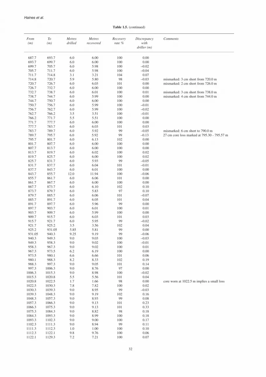
32
Haines et al.
Table 1.5. (continued)
From To Metres Metres Recovery Discrepancy Comments(m) (m) drilled recovered rate % with
driller (m)
687.7 693.7 6.0 6.00 100 0.00693.7 699.7 6.0 6.00 100 0.00699.7 705.7 6.0 5.98 100 –0.02705.7 711.7 6.0 5.98 100 –0.04711.7 714.8 3.1 3.21 104 0.07714.8 720.7 5.9 5.80 98 –0.03 mismarked: 3 cm short from 720.0 m720.7 726.7 6.0 6.03 101 0.00 mismarked: 2 cm short from 726.0 m726.7 732.7 6.0 6.00 100 0.00732.7 738.7 6.0 6.01 100 0.01 mismarked: 3 cm short from 738.0 m738.7 744.7 6.0 5.99 100 0.00 mismarked: 4 cm short from 744.0 m744.7 750.7 6.0 6.00 100 0.00750.7 756.7 6.0 5.99 100 –0.01756.7 762.7 6.0 5.99 100 –0.02762.7 766.2 3.5 3.51 100 –0.01766.2 771.7 5.5 5.51 100 0.00771.7 777.7 6.0 6.00 100 0.00777.7 783.7 6.0 6.03 101 0.03783.7 789.7 6.0 5.92 99 –0.05 mismarked: 6 cm short to 790.0 m789.7 795.7 6.0 5.92 99 –0.13 27 cm core loss marked at 795.30 - 795.57 m795.7 801.7 6.0 6.13 102 0.00801.7 807.7 6.0 6.00 100 0.00807.7 813.7 6.0 6.00 100 0.00813.7 819.7 6.0 6.02 100 0.02819.7 825.7 6.0 6.00 100 0.02825.7 831.7 6.0 5.93 99 –0.05831.7 837.7 6.0 6.04 101 –0.01837.7 843.7 6.0 6.01 100 0.00843.7 855.7 12.0 11.94 100 –0.06855.7 861.7 6.0 6.06 101 0.00861.7 867.7 6.0 6.00 100 0.00867.7 873.7 6.0 6.10 102 0.10873.7 879.7 6.0 5.83 97 0.10879.7 885.7 6.0 6.06 101 –0.07885.7 891.7 6.0 6.05 101 0.04891.7 897.7 6.0 5.96 99 0.00897.7 903.7 6.0 6.01 100 0.01903.7 909.7 6.0 5.99 100 0.00909.7 915.7 6.0 6.03 101 0.03915.7 921.7 6.0 5.95 99 –0.02921.7 925.2 3.5 3.56 102 0.04925.2 931.05 5.85 5.81 99 0.00931.05 940.3 9.25 9.19 99 –0.06940.3 949.3 9.0 9.03 100 –0.03949.3 958.3 9.0 9.02 100 –0.01958.3 967.3 9.0 9.02 100 0.01967.3 973.5 6.2 6.19 100 0.00973.5 980.1 6.6 6.66 101 0.06980.1 988.3 8.2 8.33 102 0.19988.3 997.3 9.0 9.05 101 0.14997.3 1006.3 9.0 8.76 97 0.00
1006.3 1015.3 9.0 8.98 100 –0.021015.3 1020.8 5.5 5.56 101 0.041020.8 1022.5 1.7 1.66 98 0.00 core worn at 1022.5 m implies a small loss1022.5 1030.3 7.8 7.82 100 0.021030.3 1039.3 9.0 8.95 99 –0.031039.3 1048.3 9.0 9.19 102 0.161048.3 1057.3 9.0 8.93 99 0.081057.3 1066.3 9.0 9.13 101 0.231066.3 1075.3 9.0 9.13 101 0.331075.3 1084.3 9.0 8.82 98 0.181084.3 1093.3 9.0 8.99 100 0.181093.3 1102.3 9.0 9.00 100 0.171102.3 1111.3 9.0 8.94 99 0.111111.3 1112.3 1.0 1.00 100 0.101112.3 1122.1 9.8 9.76 100 0.061122.1 1129.3 7.2 7.21 100 0.07

33
GSWA Record 2004/10 GSWA Lancer 1 well completion report (basic data)
Table 1.5. (continued)
From To Metres Metres Recovery Discrepancy Comments(m) (m) drilled recovered rate % with
driller (m)
1129.3 1138.3 9.0 8.88 99 –0.061138.3 1143.3 5.0 4.95 99 –0.111143.3 1153.2 9.9 10.03 101 0.021153.2 1163.3 10.1 10.09 100 0.071163.3 1173.3 10.0 9.99 100 0.061173.3 1183.3 10.0 10.01 100 0.071183.3 1193.3 10.0 10.02 100 0.091193.3 1203.3 10.0 10.06 101 0.151203.3 1213.3 10.0 10.00 100 0.151213.3 1223.3 10.0 9.97 100 0.121223.3 1233.3 10.0 10.09 101 0.211233.3 1243.3 10.0 10.01 100 0.221243.3 1253.3 10.0 10.03 100 0.221253.3 1263.3 10.0 9.96 100 0.251263.3 1273.1 9.8 9.81 100 0.221273.1 1282.3 9.2 9.09 99 0.111282.3 1292.3 10.0 9.99 100 0.11292.3 1302.3 10.0 10.03 100 0.131302.3 1312.3 10.0 10.02 100 0.131312.3 1322.3 10.0 10.03 100 0.161322.3 1332.3 10.0 10.13 101 0.291332.3 1342.3 10.0 9.87 99 0.161342.3 1352.3 10.0 10.02 100 0.181352.3 1362.3 10.0 10.01 100 0.181362.3 1372.3 10.0 9.99 100 0.181372.3 1382.3 10.0 10.01 100 0.191382.3 1392.3 10.0 9.99 100 0.181392.3 1402.1 9.8 9.77 100 0.151402.1 1407.1 5.0 5.13 103 0.281407.1 1407.3 0.2 0.14 70 0.221407.3 1417.3 10.0 10.01 100 0.231417.3 1427.3 10.0 9.98 100 0.211427.3 1437.3 10.0 9.92 99 0.131437.3 1447.2 9.9 9.76 99 –0.011447.2 1457.2 10.0 10.05 101 0.041457.2 1467.2 10.0 9.80 98 0.041467.2 1477.2 10.0 9.93 99 –0.08 15 cm core loss in salt from 1467.10 to 1467.25 m1477.2 1487.2 10.0 10.01 100 –0.071487.2 1497.2 10.0 10.03 100 –0.051497.2 1501.3 4.1 4.08 100 –0.07
Totals: 1397.3 1397.2 100% 56 cm core loss in total; the higher apparentrecovery is due to measurement errors

34
Haines et al.
Table 1.6. Comparison of core and wireline log depths in Lancer 1
Core depth Wireline depth Wireline – core Wireline – core depths(m) (m) depths (m) Wireline depth
121.8 121.3 -0.5 -0.004122128.7 129 0.3 0.002326150.5 150 -0.5 -0.003333175.5 175 -0.5 -0.002857205 205 0 0270.8 270.5 -0.3 -0.001109359 358.5 -0.5 -0.001395397 397 0 0449.5 449.5 0 0459 459 0 0480 480 0 0487 487 0 0505 505 0 0526 526 0 0618.4 618.5 0.1 0.000162639.6 639.6 0 0663.8 664 0.2 0.000301695.6 696 0.4 0.000575696.9 697.1 0.2 0.000287707.5 708 0.5 0.000706746.5 746.9 0.4 0.000536737.1 737.2 0.1 0.000136746.5 746.9 0.4 0.000536746.8 747 0.2 0.000268750.5 751 0.5 0.000666774.6 775 0.4 0.000516790.6 791 0.4 0.000506794.5 795.1 0.6 0.000755802 802.6 0.6 0.000748805.5 806 0.5 0.000620833.2 833.8 0.6 0.000720834.7 835.1 0.4 0.000479859.6 860.1 0.5 0.000581868.5 869 0.5 0.000575888.8 889.2 0.4 0.000450891.8 892.5 0.7 0.000784859.7 860.2 0.5 0.000581898.8 899.1 0.3 0.000334913 913.5 0.5 0.000547929.4 930 0.6 0.000645940.2 940.6 0.4 0.000425952.2 953 0.8 0.000839956.5 956.9 0.4 0.000418960.5 961.1 0.6 0.000624988.5 989 0.5 0.000506
1 007 1 007.6 0.6 0.0005951 017.3 1 017.9 0.6 0.0005891 031 1 031.5 0.5 0.0004851 031.9 1 032.6 0.7 0.0006781 037.2 1 038 0.8 0.0007711 047 1 047.5 0.5 0.0004771 059.5 1 060 0.5 0.0004721 062.2 1 062.9 0.7 0.0006591 068 1 068.5 0.5 0.0004681 121.6 1 122.5 0.9 0.0008021 124.5 1 125.1 0.6 0.0005331 134.1 1 135 0.9 0.0007931 135.5 1 136.1 0.6 0.0005281 140.8 1 141.9 1.1 0.0009631 143.2 1 144 0.8 0.0006991 154.5 1 155.3 0.8 0.0006921 157 1 157.9 0.9 0.0007771 165.6 1 166.8 1.2 0.0010281 167.1 1 167.9 0.8 0.0006851 195.1 1 196 0.9 0.0007531 215 1 215.8 0.8 0.000661 201.9 1 202.8 0.9 0.00075

35
GSWA Record 2004/10 GSWA Lancer 1 well completion report (basic data)
Table 1.6. (continued)
Core depth Wireline depth Wireline – core Wireline – core depths(m) (m) depths (m) Wireline depth
1 255.3 1256.2 0.9 0.000721 297.6 1298.6 1.0 0.000771 215 1215.8 0.8 0.000661 217.4 1217.8 0.4 0.000331 297.7 1298.7 1.0 0.000771 300.9 1301.9 1.0 0.000771 301.9 1302.9 1.0 0.000771 325.6 1326.5 0.9 0.000681 333.8 1334.8 1.0 0.000751 357.7 1358.8 1.1 0.000811 322.5 1323.6 1.1 0.000831 331.9 1332.5 0.6 0.000451 353.15 1354.5 1.35 0.001001 353.65 1354.6 0.95 0.000701 351.4 1352.4 1.0 0.000741 352.85 1353.85 1.0 0.000741 347.3 1348.3 1.0 0.000741 364.17 1365.6 1.43 0.001051 357.7 1358.9 1.2 0.000891 440.9 1442.8 1.9 0.001321 447 1447.1 0.1 0.000071 478.9 1480.3 1.4 0.000951 473.95 1474.6 0.65 0.000441 451.5 1453 1.5 0.001031 460.2 1461.4 1.2 0.000821 463.5 1465 1.5 0.001021 469.5 1471 1.5 0.001021 478.9 1481 2.1 0.00142

36
Haines et al.
Appendix 2
Core photographs
(see core photo library on this disk)

37
GSWA Record 2004/10 GSWA Lancer 1 well completion report (basic data)
Appendix 3
Definition of new stratigraphic units
Keene BasaltDefinition: Mafic extrusive igneous rocks within the KanpaFormation in Lancer 1 are here named the Keene Basalt,after Lake Keene, 10 km west of the drillhole. It isregarded as a separate unit rather than a part of the KanpaFormation or Buldya Group. There is no knownsynonomy.
Distribution and type section: The type section is theinterval between 527.4 and 576.2 m in Lancer 1. The inter-section is the first record of volcanic rocks within theKanpa Formation, and the only known occurrence of theKeene Basalt.
Lithology: The basal 3 m of basalt is very fine grained withirregular and inclined amygdaloidal zones and somebrecciation. There are at least four and possibly fivedistinct flows with tops and bases marked by fine-grainedamygdaloidal basalt, whereas flow centres comprisecoarse-grained massive basalt. The basalt is typically darkgrey to greenish, but is reddened at the base and at two ofthe flow tops. Veins filled with calcite, red chert or chloriteare common, and amygdales are filled with similarmaterial. There are no sediments interbedded within thebasalt.
Relationships and boundary criteria: The strata beneaththe flows have been baked and show some indications ofdewatering; those above the flows are not contactmetamorphosed, but show dewatering structures, perhapsindicative of earthquakes associated with volcanism(Pirajno, F., written comm., 2003). The top of the basaltis not fine grained, amygdaloidal or reddened, indicatingthat the top of the uppermost flow has been eroded downto its doleritic core before deposition of overlying fine-grained sediments.
Age and evidence: Based on broad regional correlations,the Keene Basalt could correlate with (but would not becomagmatic with) the Cadlareena Volcanics of thenortheastern Officer Basin in South Australia, which havean age between 780 and 760 Ma (Morton, 1997), as wellas the Boucaut Volcanics dated at 777 ± 7 Ma in theAdelaide Rift Complex (Barovich et al., 2001). Furtherdetails of petrography and age are not yet available,although work is in progress.
Depositional setting: From preliminary examination of thecore, there appear to be up to five flows, with texturesranging from basaltic to doleritic in the central, slowercooling parts of each flow.
Lancer MemberDefinition: The Lancer Member comprises very well-sorted medium-grained sandstone, showing large-scale
cross-bedding, in the upper Browne Formation. Themember has only been recognized in GSWA Lancer 1,after which it is named, but is sufficiently important towarrant recognition as a named member. There is noknown synonomy.
Distribution and type section: The type section is theinterval between 1201.9 and 1297.7 m (drilled depth,95.8 m thickness) in Lancer 1. The member may correlatewith sandy facies of the Mundadjini Formation in thenorthwest Officer Basin, or with the silty and sandy upperpart of the Skates Hills Formation as described byWilliams (1992). The section identified as HussarFormation in WMC NJD 1 (330 – 376.85 m) by Hocking(2003) could instead be the Lancer Member, beneath siltylower Hussar Formation, based on the presence of theLancer Member rather than evaporites in Lancer 1, and thesimilar position of Lancer 1 and NJD 1 relative to theinferred western basin margin.
Lithology: The Lancer Member consists of fine- tomedium-grained, very porous, well-sorted orange-brownquartz sandstone, and minor silty beds up to 0.6 m thick.It shows very large scale cross-bedding with foresets upto 11 m thick dipping at up to 30°, and reverse-gradedcentimetre-scale beds (translatent strata of Hunter, 1977).
Relationships and boundary criteria: The Lancer Memberrests on orange-brown siltstone and fine-grainedsandstone, here considered to be undifferentiated BrowneFormation. The contact is sharp, but this may simplyreflect dunes migrating over playas or supratidal mudflats.The upper contact is steep (implying that the sandstonewas at least partly lithified) and clearly erosional beneathbasal Hussar Formation. Above it, there is 10 cm ofreworked sandstone with mud clasts, then evaporiticmudstone of probable supratidal mudflat origin, with somereworked sand in the lower 5 m. Steep dune foresets aretruncated at the boundary. This juxtaposition of faciesrequires some sort of hiatus, so the boundary is probablydisconformable. Sandstone laminae are present in themudstone but decrease upward over about 5 m.
Age and evidence: Palaeontological work has yet to bedone on material from Lancer 1. The Acaciella australicaStromatolite Assemblage is present below the LancerMember, in the Woolnough Member, and the Baicaliaburra Stromatolite Assemblage is present above the LancerMember. Correlation with other wells indicates that themember equates with the halite interval in the upperBrowne Formation in Empress 1A, Kanpa 1A, andYowalga 3. A likely correlative, based on lithology, facies,and comparison with Boondawari 1 and Mudadjini 1, issandstone in the upper part of the Mundadjini Formationin the northwestern part of the Officer Basin.
Depositional setting: The sorting, lithology, very largecross-bedding and translatent strata indicate that the

38
Haines et al.
member is an eolian dune deposit. The siltstone bedsintercalated within the sandstone are presumably interdunedeposits, possibly reflecting shallow ephemeral lakes.
ReferencesBAROVICH, K., FODEN, J., JANE, M., and O’HALLORAN, G.,
2001, Sr-isotopic evidence for Late Neoproterozoic rifting in theAdelaide Geosyncline at 586 Ma: implications for a Cu ore formingfluid flux: Precambrian Research, v. 106(3–4), p. 291–308.
HOCKING, R. M. (compiler), 2003, Drillhole WMC NJD 1, westernOfficer Basin, Western Australia: Stratigraphy and petroleumgeology: Western Australia Geological Survey, Record 2002/18,26p.
HUNTER, R. E., 1977, Terminology of cross-stratified sedimentarylayers and climbing ripple structures: Journal of SedimentaryPetrology, v. 47, p. 697–706.
MORTON, J. G. G., 1997, Chapter 6: Lithostratigraphy andenvironments of deposition, in The petroleum geology of SouthAustralia. Volume 3: Officer Basin edited by J. G. G. MORTONand J. F. DREXEL: South Australian Department of Mines andEnergy Resources, Report Book 97/19, p. 47–86.
WILLIAMS, I. R., 1992, Geology of the Savory Basin, WesternAustralia: Western Australia Geological Survey, Bulletin 141, 115p.

39
GSWA Record 2004/10 GSWA Lancer 1 well completion report (basic data)
Appendix 4
Preliminary well index sheet
ORGANIZATION: Geological Survey of Western Australia Statutory Petroleum Exploration Report No.: S20880WELL: GSWA Lancer 1 BASINS: Gunbarrel Basin over Officer Basin TYPE: StratigraphicSPUDDED: 10 Oct 2003 SUB-BASINS: Sherriff Shelf over Westwood ShelfCOMPLETED: 20 Nov 2003 ELEVATION GL: 450 m AHD; RT: 449.3 m AHDTD: 1501.3 m (a) BHT: 63.5°C LATITUDE: 25°02'44.5"S(b); LONGITUDE: 123°45'21"E (GDA 94)(b)
STATUS: Plugged and abandoned NORTHING: 7229800; EASTING: 576200 (MGA Zone 51J) (b)
FORMATION TOPS (m) LITHOLOGICAL SUMMARY
DRILL SUBSEA
GUNBARREL BASIN:Cainozoic 0 +450.0 Reddish-brown fine-grained sand, brown mudstone and
ferricrete overlying multicoloured sandstonePaterson Formation ?17 +433 Clay, grey mudstone, grey to brown sandstone, minor
conglomerate
OFFICER BASIN:Lungkarta Formation ?169.1 +280.9 Reddish-brown sandstone and polymict conglomerateWahlgu Formation 344.3 +105.7 Red diamictites and mudstone, multicoloured sandstoneKanpa Formation 466.5 16.5 Brown to grey claystone and mudstone, grey stromatolitic
dolostone, grey to brown sandstoneKeene Basalt 527.4 – 576.2 77.4 – 126.2 Dark, fine- to coarse-grained basalt, locally amygdaloidal,
erosional upper surfaceHussar Formation 707.5 257.5 Brown sandstone, mudstone and stromatolitic dolostoneBrowne Formation 1201.9 751.9 Reddish-brown sandstone and mudstone, red–grey
dolostone, haliteLancer Member 1201.9 – 1297.7 751.9 – 847.7 Reddish-brown cross-bedded sandstone in foresets up to
11 m thickWoolnough Member 1323.4 – 1357.7 873.4 – 907.7 Red–grey stromatolitic dolostone, mudstonelower Browne Formation 1357.7 – 1478.9 907.7 – 1028.9 Reddish-brown mudstone with halite crystals becoming
abundant towards halite interval; grey, argillaceousdolostone, halite, fine-grained sandstone,minorconglomerate and mudstone below halite interval
unnamed halite interval 1440.8 – 1472.4 990.8 – 1022.4 Halite, reddish-brown mudstone, grey argillaceous dolostone
?MESOPROTEROZOIC BASIN?Cornelia Sandstone 1478.9 – 1501.3 1028.9 – 1051.3 Bluish-grey, pebbly, clayey, medium-grained, cross-bedded
sandstone, well cemented
CORES Continuously cored: PQ: 104–429.5 m; HQ: 429.5–1501.3 m (driller; 100% recovery)
LOGS Run 1: 16" normal resistivity 420–1501 mRun 2: 64" normal resistivity 420–1501 mRun 3 (Gam/G-N): SPR 420–1501 m
SP 420–1501 mN 0–1501 m
Run 4 (GAA/DDC): GR 0–1501 mLD 0–1501 mSD 0–1501 mCaliper 0–1501 m
Run 5: Sonic 420–1501 mRun 6: BHTV (acoustic scanner) 1450–1500 m; 1200–1365 m; and 420–900 m
CASING 7" (OD 178 mm, ID 172 mm) 0–6 mPW (OD 140 mm, ID 127 mm): 0–104 mHWT (OD 114 mm, ID 102 mm): 0–428 m
NOTES: (a) Depth from driller(b) Drillhole location preliminary, to within 100 mThe resistivity and SPR logs are adversely affected by the highly saline mud in the hole

Information CentreDepartment of Industry and Resources100 Plain StreetEast Perth WA 6004Phone: (08) 9222 3459 Fax: (08) 9222 3444www.doir.wa.gov.au/gswa
This Record is published in digital format(PDF), not hardcopy, as part of a digitaldataset on CD. It is also available onlineat: www.doir.wa.gov.au/gswa.This copy is provided for reference only.Laser-printed copies can be ordered fromthe Information Centre for the cost ofprinting and binding.
GSWA Lancer 1 w
ell completion report (basic data),
Officer and Gunbarrel Basins, Western Australia
RECORD 2004/10HAINES et al.


