Embed Size (px)
Citation preview
Masaru Ho
ELEX 7860
GSM General Information: GSM (Global System for Mobile Communications, formerly known as Groupe Spécial Mobile)
Purpose GSM was developed to replace the first generation analog cellular networks
In the 1980s the cellular service industry was becoming more international and there was great need develop a standardized cellular communication specification.
Typical Devices Most cell phones, (ie. Iphone)
GSM System Architecture: Main Architecture layers
The Mobile Station(MS)
Consists of the physical equipment, ie phone, SIM cards
The Base Station Subsystem (BSS)
Consists of the Base Transceiver Station (BTS) and Base Station Controller (BSC)
The Network Switching Subsystem (NSS)
Handles various functions from authentication to managing switching calls between mobiles
The Operation Support Subsystem(OSS)
Entity where network operator monitors and controls the system
Architecture Components
ME = Mobile Equipment
BTS = Base Receiving Station
BSC = Base Station Controller
MSC = Mobile Switching Center
VLR = Visitor Location Register
OMC = Operation and Maintenance Center
AuC = Authentication Center
HLR = Home Location Register
EIR = Equipment Identity Register
SMSC = Short Message Service Centre
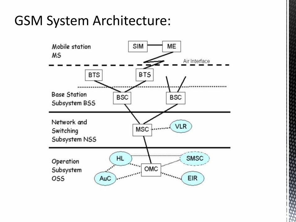
GSM System Architecture:
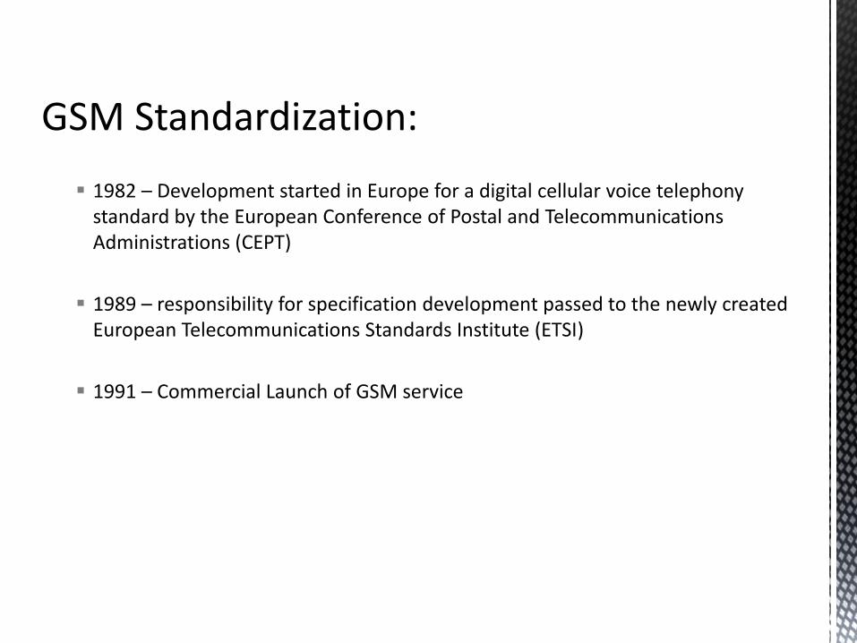
GSM Standardization:
1982 – Development started in Europe for a digital cellular voice telephony standard by the European Conference of Postal and Telecommunications Administrations (CEPT)
1989 – responsibility for specification development passed to the newly created European Telecommunications Standards Institute (ETSI)
1991 – Commercial Launch of GSM service
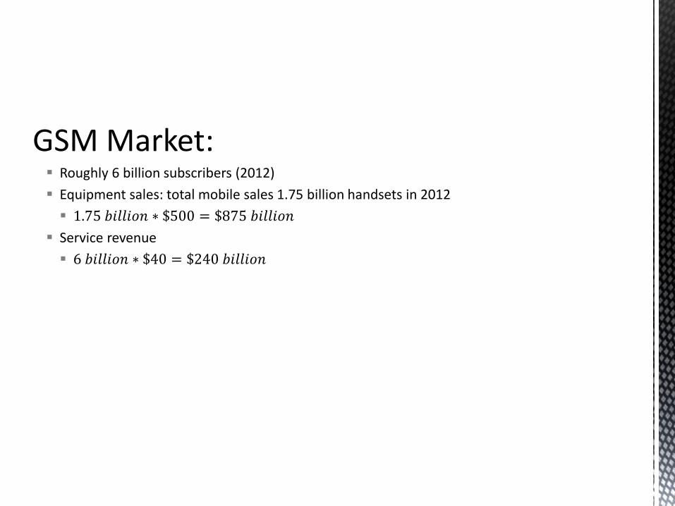
GSM Market: Roughly 6 billion subscribers (2012)
Equipment sales: total mobile sales 1.75 billion handsets in 2012
1.75 𝑏𝑖𝑙𝑙𝑖𝑜𝑛 ∗ $500 = $875 𝑏𝑖𝑙𝑙𝑖𝑜𝑛
Service revenue
6 𝑏𝑖𝑙𝑙𝑖𝑜𝑛 ∗ $40 = $240 𝑏𝑖𝑙𝑙𝑖𝑜𝑛
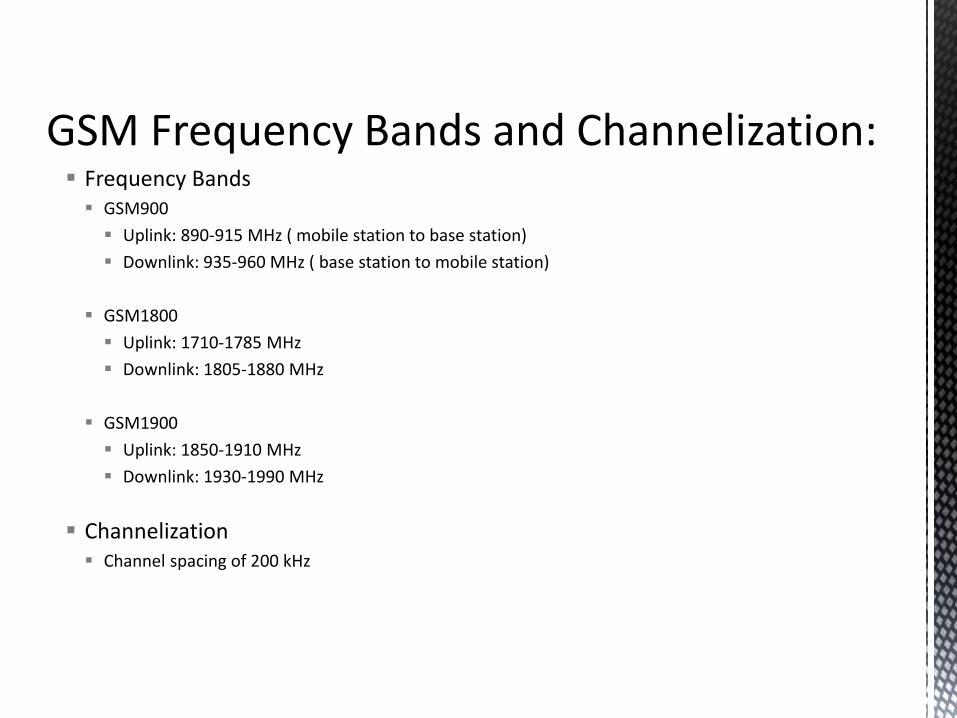
GSM Frequency Bands and Channelization: Frequency Bands
GSM900
Uplink: 890-915 MHz ( mobile station to base station)
Downlink: 935-960 MHz ( base station to mobile station)
GSM1800
Uplink: 1710-1785 MHz
Downlink: 1805-1880 MHz
GSM1900
Uplink: 1850-1910 MHz
Downlink: 1930-1990 MHz
Channelization Channel spacing of 200 kHz
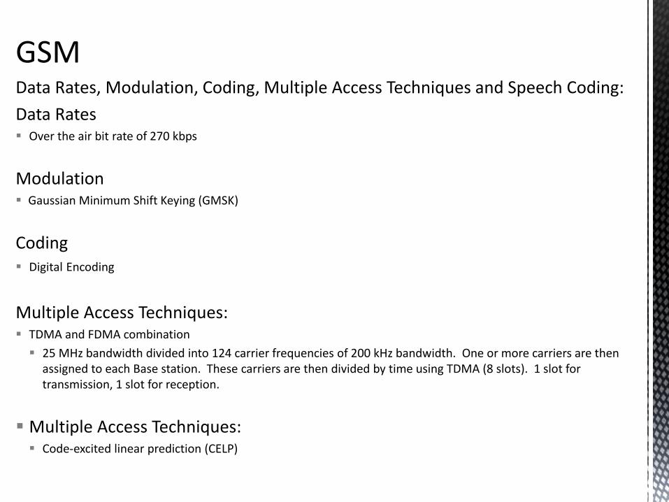
GSM Data Rates, Modulation, Coding, Multiple Access Techniques and Speech Coding:
Data Rates Over the air bit rate of 270 kbps
Modulation Gaussian Minimum Shift Keying (GMSK)
Coding Digital Encoding
Multiple Access Techniques: TDMA and FDMA combination
25 MHz bandwidth divided into 124 carrier frequencies of 200 kHz bandwidth. One or more carriers are then assigned to each Base station. These carriers are then divided by time using TDMA (8 slots). 1 slot for transmission, 1 slot for reception.
Multiple Access Techniques: Code-excited linear prediction (CELP)
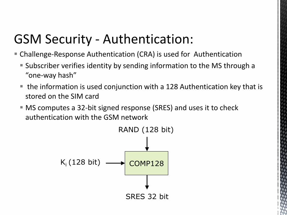
GSM Security - Authentication: Challenge-Response Authentication (CRA) is used for Authentication
Subscriber verifies identity by sending information to the MS through a “one-way hash”
the information is used conjunction with a 128 Authentication key that is stored on the SIM card
MS computes a 32-bit signed response (SRES) and uses it to check authentication with the GSM network
COMP128
RAND (128 bit)
Ki (128 bit)
SRES 32 bit
GSM Security - Encryption:
COMP128 encryption first broken April 1999
The Smartcard Developer Association (SDA) together with U.C. Berkeley researches cracked the COMP128 algorithm stored in SIM and succeeded to get Ki within several hours.
May 2002 The IBM Research group discovered a new way to quickly extract the
COMP128 keys using side channels
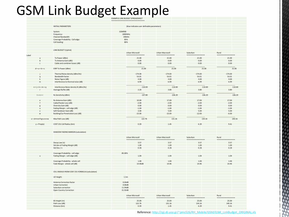
EXAMPLE LINK BUDGET SPREADSHEET
*********************************
INITIAL PARAMETERS (blue indicates user definable parameters)
System: GSM900
Frequency: 1800 MHz
Channel Bandwidth 200 kHz
Coverage Probability - Cell edge: 85 %
Cell loading: 80 %
LINK BUDGET (Uplink)
Urban Microcell Urban Macrocell Suburban Rural
Label ****************** ****************** ****************** ******************
a Tx Power (dBm) 21.00 21.00 21.00 21.00
b Tx Antenna Gain (dBi) 0.00 0.00 0.00 0.00
c Cable and combiner losses (dB) 0.00 0.00 0.00 0.00
__________________ __________________ __________________ __________________
d = a + b + c EIRP Tx Power (dBm) 21.00 21.00 21.00 21.00
j Thermal Noise density (dBm/Hz) -174.00 -174.00 -174.00 -174.00
q Bandwidth factor 53.01 53.01 53.01 53.01
k Noise Figure (dB) 4.00 4.00 4.00 4.00
m Interference to thermal noise (dB) 6.99 6.99 6.99 6.99
__________________ __________________ __________________ __________________
n = j + k + m + q Interference Noise density N (dBm/Hz) -110.00 -110.00 -110.00 -110.00
r Average Eb/No (dB) 2.20 3.80 3.80 3.80
__________________ __________________ __________________ __________________
t = n + r Rx Sensitivity (dBm) -107.80 -106.20 -106.20 -106.20
e Rx Antenna Gain (dBi) 10.00 17.00 17.00 17.00
f Cable/Feeder Loss (dB) -2.00 -2.00 -2.00 -2.00
g Diversity Gain (dB) 0.00 0.00 0.00 0.00
u Fading Margin - cell edge (dB) -1.04 -1.04 -1.04 -1.04
v Soft Handover Gain (dB) 2.00 5.00 5.00 5.00
w Building/Car Penetration Loss (dB) -15.00 -15.00 -12.00 -6.00
__________________ __________________ __________________ __________________
x = d+t+e+f+g+u+v+w Max Path Loss (dB) 122.76 131.16 134.16 140.16
y = Prop(x) COST 231 Cell Radius (km) 0.39 1.45 6.39 9.41
SHADOW FADING MARGIN (calculation)
Urban Microcell Urban Macrocell Suburban Rural
****************** ****************** ****************** ******************
Decay Law (n) 3.57 3.57 3.57 3.57
Std dev of Fading Margin (dB) 1.00 1.00 1.00 1.00
Std Dev / n 0.28 0.28 0.28 0.28
Coverage Probability - cell edge 85.00 %
u Fading Margin - cell edge (dB) 1.04 1.04 1.04 1.04
Coverage Probability - whole cell 1.00 1.00 1.00 1.00
Fade Margin - whole cell (dB) 14.46 dB 14.46 14.46 14.46
CELL RADIUS FROM COST 231 FORMULA (calculation)
UE Height: 1.5 m
Antenna Correction factor 0.04 dB
Urban Correction 0.00 dB
Suburban correction 11.94 dB
Open Country Correction 31.92 dB
Urban Microcell Urban Macrocell Suburban Rural
****************** ****************** ****************** ******************
BS Height (m) 25.00 25.00 25.00 25.00
Path Loss (dB) 122.76 131.16 134.16 140.16
Distance (km) 0.39 1.45 6.39 9.41
GSM Link Budget Example
Reference: http://cgi.di.uoa.gr/~pms526/RH_Mobile/GSM/GSM_LinkBudget_ORIGINAL.xls


