Embed Size (px)
Citation preview

Hindawi Publishing CorporationInternational Journal of Distributed Sensor NetworksVolume 2013, Article ID 701834, 21 pageshttp://dx.doi.org/10.1155/2013/701834
Review ArticleGreedy Routing in Underwater AcousticSensor Networks: A Survey
Mohammad Taghi Kheirabadi and Mohd Murtadha Mohamad
Department of Computer Science, Faculty of Computing, University Technology Malaysia (UTM), UTM Skudai,81310 Johor Bahru, Malaysia
Correspondence should be addressed to Mohammad Taghi Kheirabadi; [email protected]
Received 14 March 2013; Revised 10 June 2013; Accepted 13 June 2013
Academic Editor: Yanmin Zhu
Copyright © 2013 M. T. Kheirabadi and M. M. Mohamad. This is an open access article distributed under the Creative CommonsAttribution License, which permits unrestricted use, distribution, and reproduction in any medium, provided the original work isproperly cited.
Due to the significant advances of wireless sensor networks (WSNs), researchers are eager to use this technology in the subseaapplications. Because of rapid absorption of high radio frequency in the water, acoustic waves are used as communicationmedium,which pose new challenges, including high propagation delay, high path loss, low bandwidth, and high-energy consumption.Because of these challenges and high movement of nodes by water flow, end-to-end routing methods used in most of existingrouting protocols in WSNs are not applicable to underwater environments. Therefore, new routing protocols have been developedfor underwater acoustic sensor networks (UWASNs) in which most of the routing protocols take advantage of greedy routing.Due to inapplicability of global positioning system (GPS) in underwater environments, finding location information of nodesis too costly. Therefore, based on a need for location information, we divided the existing greedy routing protocols into twodistinctive categories, namely, location-based and location-free protocols. In addition, location-free category is divided into twosubcategories based on method of collecting essential information for greedy routing, including beacon-based and pressure-basedprotocols. Furthermore, a number of famous routing protocols belonging to each category are reviewed, and their advantages anddisadvantages are discussed. Finally, these protocols are compared with each other based on their features.
1. Introduction
Only less than one third of earth’s surface is covered byland, and the rest is covered by water. Due to severalreasons such as vast area, high pressure, and harshness ofunderwater environment, human presence in this area isvery limited. Hence, human knowledge about underwaterenvironment is so negligible in comparison with land. Inrecent decades, since the use of WSNs in different applica-tions has brought tremendous revolution, researchers havebeen interested recently in using these networks for gatheringdata from underwater environments [1, 2]. To this end,they have proposed underwater acoustic sensor networks(UWASNs) that are composed of a number of autonomousand self-organizing sensor nodes. These nodes are manuallyor randomly scattered in different depths in underwaterenvironments to collect specific data from deep or shallowwater.Then, they transfer collected data via acoustic waves to
the sink(s) located on water surface. In these networks, theordinary sensor nodes are equipped with acoustic modemto communicate with each other, while sinks are equippedwith both acoustic and radio modems in order to receivethe data from underwater nodes via acoustic waves andtransmit them to the onshore base station by radio waves [3].UWASNs can be used for a wide range ofmarine applications,including oceanography, environment monitoring, underseaexploration, disaster prevention, equipmentmonitoring,mil-itary oversight, and navigation [1–4].
The main challenge of employing WSNs in underwaterenvironment is that high radio frequency is rapidly absorbedin water and low radio frequency requires a very largeantenna [3]. In addition, the optical waves are not efficient inunderwater environments because they may be scattered [3].Since acoustic waves have a good performance in underwaterenvironments, they are used as a wireless communicationmedium [3]. Acoustic waves have high propagation delay,

2 International Journal of Distributed Sensor Networks
high path loss, low bandwidth, and high-energy consumptionin comparisonwith radiowaves [1, 3, 5, 6]. Additionally, otherchallenges such as high and continual movement of sensornodes with water flow, inapplicability of global positioningsystem (GPS) to this environment, and 3D nature of under-water environment increase the complexity [7].Therefore, themajor issue in this networks is that how the sensing data arerouted and successfully delivered to the sinks.
A large number of routing protocols have been proposedfor finding a path from source node to sink in the terrestrialwireless sensor networks (TWSNs) [8, 9]. However, theseprotocols are designed based on end-to-end method that arenot applicable to high dynamic topology networks with highpropagation delay (e.g., UWASNs) [1, 3]. Since UWASN is avery recent issue in this area of study, most researchers focuson physical layer [10, 11], link layer [12–14], and localization[15–19], whereas research on network layer is still in itsinfancy stage. Consequently, few routing protocols have beendeveloped for UWASNs [1, 3, 20]. Due to the aforementionedchallenges, among the different routingmethods, greedy hop-by-hop routing is the most promising method in underwaterenvironment [21]. Unlike the end-to-end routing in whicha path is found from the source node to the sink in thediscoverymode, the greedy routing approaches only findnexthop nodes at each hop; these nodes should have positiveprogress towards the sink.
Although a number of review articles have been pre-sented on the subject of routing in UWASNs, they havenot focused on greedy routing techniques and classificationof these routing protocols. In [22], a number of routingprotocols in UWASNs are reviewed and categorized intofour distinctive groups, including flooding based, multipath-based, cluster based, and miscellaneous. Then, this paperdescribes a number of example protocols for each category.However, it does not address the greedy routing protocols inunderwater environment and the features of these protocols.In [20], majority of famous routing protocols in UWASNsare discussed and compared with each other. In addition,various taxonomies are proposed based on different param-eters such as network architecture, data forwarding, andprotocol operation. However greedy routing in underwaterenvironment is the most promising technique for routing; itdoes not address the greedy routings, and it does not offer aclassification for them in underwater environments. In [23],a number of routing protocols are examined and comparedwith each other in terms of different quality metrics, includ-ing successful packet delivery ratio, the average end-to-enddelay, and energy consumption. However, this paper does nothave any classification for routing techniques in UWASNs,and it does not focus on greedy routing techniques. In [24],a number of routing protocols proposed for UWASNs arebriefly reviewed, and their advantages and disadvantages arehighlighted. However, it does not address the greedy routingprotocols and their features in underwater environments.
In this paper, we focus on greedy routing protocols inunderwater environments and their features. Since findinglocation information in UWASNs is so costly due to inappli-cability of GPS, we divide the greedy routing protocols intotwo distinctive categories based on requirement of protocols
to complete location information of nodes, including locationbased and location-free. Furthermore, to identify the positiveprogress toward the sink, based on method of collectingessential information, the location-free category is dividedinto two subcategories: beacon based and pressure based.Then, we describe and compare a number of famous routingprotocols belonging to each category based on their featuresand their simulation conditions.
The rest of this paper is organized as follows. In Section 2,a number of general information about UWASNs is given,including features of acoustic channel, main differencesbetween TWSNs and UWASNs, and the reasons of inapplica-bility of TWSN’s routing protocols to UWASNs. In Section 3,the features of greedy routing protocols in UWASNs aredescribed, and a number of famous greedy routing protocolsbelonging to different categories are explained and comparedwith each other. Finally, the recommendations for futurework and conclusion are provided in Section 4.
2. Underwater Acoustic Sensor Networks
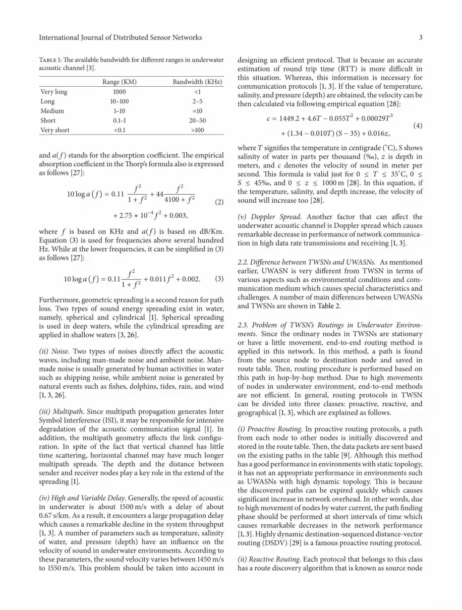
2.1. Acoustic Communications. Communication via acous-tic waves in underwater environment poses a number ofmain challenges, includingDoppler spread, high propagationdelay, multipath, noise, and high path loss. Due to thesefeatures of acoustic waves, not only the acoustic bandwidthis severely decreased in comparison with radio, but also itvaries based on communication range and acoustic frequency[25]. Since the low-frequency acoustic waves should beused in long ranges to avoid the absorption in water, thebandwidth is reduced significantly which causes a remarkableincrease in likelihood of error. In contrast, high-frequencywaves are used in short ranges to increase the bandwidthand decrease the likelihood of error. The relation betweendifferent bandwidth and communication ranges is shown inthe Table 1.
According to the direction of sound waves, the acousticlinks are categorized into two categories, namely, vertical andhorizontal, in which their propagation characteristics differfrom each other, especially in terms of scattering, multipathspreads, and delay variance [3].Themain factors affecting theacoustic channel are described as follows.
(i) Path Loss. Attenuation and geometric spreading are themain reasons for path loss in underwater environments. Themain reason for attenuation in underwater is the absorptionof acoustic waves in water due to changing sound energy tothermal energy [26]. It is severely dependent on distance andfrequency [27]. For instance, the amount of absorption at12.5 KHz is less than 1 dB/Km, while it is more than 20 dB/Kmat 70KHz [2].The amount of path loss based on distance 𝑙 andfrequency 𝑓 is given [27]:
𝐴 (𝑙, 𝑓) = 𝐴0𝑙𝑘𝑎 (𝑓) , (1)
where 𝑙 indicates distance, 𝑓 shows signal frequency, 𝐴0
signifies a constant for a normalization, 𝑘 denotes thespreading factor (𝑘 = 2 for spherical spreading, 𝑘 = 1 forcylindrical spreading, and 𝑘 = 1.5 for practical spreading),
International Journal of Distributed Sensor Networks 3
Table 1:The available bandwidth for different ranges in underwateracoustic channel [3].
Range (KM) Bandwidth (KHz)Very long 1000 <1Long 10–100 2–5Medium 1–10 ≈10Short 0.1–1 20–50Very short <0.1 >100
and 𝑎(𝑓) stands for the absorption coefficient. The empiricalabsorption coefficient in theThorp’s formula also is expressedas follows [27]:
10 log 𝑎 (𝑓) = 0.11𝑓2
1 + 𝑓2+ 44
𝑓2
4100 + 𝑓2
+ 2.75 ∗ 10−4𝑓2+ 0.003,
(2)
where 𝑓 is based on KHz and 𝑎(𝑓) is based on dB/Km.Equation (3) is used for frequencies above several hundredHz. While at the lower frequencies, it can be simplified in (3)as follows [27]:
10 log 𝑎 (𝑓) = 0.11𝑓2
1 + 𝑓2+ 0.011𝑓
2+ 0.002. (3)
Furthermore, geometric spreading is a second reason for pathloss. Two types of sound energy spreading exist in water,namely, spherical and cylindrical [1]. Spherical spreadingis used in deep waters, while the cylindrical spreading areapplied in shallow waters [3, 26].
(ii) Noise. Two types of noises directly affect the acousticwaves, including man-made noise and ambient noise. Man-made noise is usually generated by human activities in watersuch as shipping noise, while ambient noise is generated bynatural events such as fishes, dolphins, tides, rain, and wind[1, 3, 26].
(iii) Multipath. Since multipath propagation generates InterSymbol Interference (ISI), it may be responsible for intensivedegradation of the acoustic communication signal [1]. Inaddition, the multipath geometry affects the link configu-ration. In spite of the fact that vertical channel has littletime scattering, horizontal channel may have much longermultipath spreads. The depth and the distance betweensender and receiver nodes play a key role in the extend of thespreading [1].
(iv) High and Variable Delay. Generally, the speed of acousticin underwater is about 1500m/s with a delay of about0.67 s/km. As a result, it encounters a large propagation delaywhich causes a remarkable decline in the system throughput[1, 3]. A number of parameters such as temperature, salinityof water, and pressure (depth) have an influence on thevelocity of sound in underwater environments. According tothese parameters, the sound velocity varies between 1450m/sto 1550m/s. This problem should be taken into account in
designing an efficient protocol. That is because an accurateestimation of round trip time (RTT) is more difficult inthis situation. Whereas, this information is necessary forcommunication protocols [1, 3]. If the value of temperature,salinity, and pressure (depth) are obtained, the velocity can bethen calculated via following empirical equation [28]:
𝑐 = 1449.2 + 4.6𝑇 − 0.055𝑇2+ 0.00029𝑇
3
+ (1.34 − 0.010𝑇) (𝑆 − 35) + 0.016𝑧,
(4)
where 𝑇 signifies the temperature in centigrade (∘C), 𝑆 showssalinity of water in parts per thousand (‰), 𝑧 is depth inmeters, and 𝑐 denotes the velocity of sound in meter persecond. This formula is valid just for 0 ≤ 𝑇 ≤ 35∘C, 0 ≤𝑆 ≤ 45‰, and 0 ≤ 𝑧 ≤ 1000m [28]. In this equation, ifthe temperature, salinity, and depth increase, the velocity ofsound will increase too [28].
(v) Doppler Spread. Another factor that can affect theunderwater acoustic channel is Doppler spread which causesremarkable decrease in performance of network communica-tion in high data rate transmissions and receiving [1, 3].
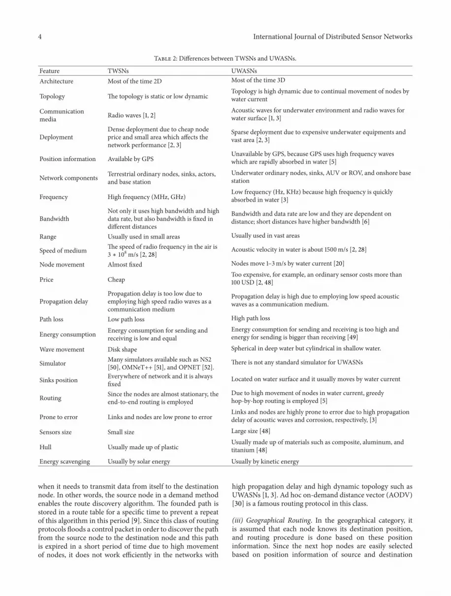
2.2. Difference between TWSNs and UWASNs. As mentionedearlier, UWASN is very different from TWSN in terms ofvarious aspects such as environmental conditions and com-munication mediumwhich causes special characteristics andchallenges. A number of main differences between UWASNsand TWSNs are shown in Table 2.
2.3. Problem of TWSN’s Routings in Underwater Environ-ments. Since the ordinary nodes in TWSNs are stationaryor have a little movement, end-to-end routing method isapplied in this network. In this method, a path is foundfrom the source node to destination node and saved inroute table. Then, routing procedure is performed based onthis path in hop-by-hop method. Due to high movementsof nodes in underwater environment, end-to-end methodsare not efficient. In general, routing protocols in TWSNcan be divided into three classes: proactive, reactive, andgeographical [1, 3], which are explained as follows.
(i) Proactive Routing. In proactive routing protocols, a pathfrom each node to other nodes is initially discovered andstored in the route table.Then, the data packets are sent basedon the existing paths in the table [9]. Although this methodhas a goodperformance in environmentswith static topology,it has not an appropriate performance in environments suchas UWASNs with high dynamic topology. This is becausethe discovered paths can be expired quickly which causessignificant increase in network overhead. In other words, dueto highmovement of nodes by water current, the path findingphase should be performed at short intervals of time whichcauses remarkable decreases in the network performance[1, 3]. Highly dynamic destination-sequenced distance-vectorrouting (DSDV) [29] is a famous proactive routing protocol.
(ii) Reactive Routing. Each protocol that belongs to this classhas a route discovery algorithm that is known as source node
4 International Journal of Distributed Sensor Networks
Table 2: Differences between TWSNs and UWASNs.
Feature TWSNs UWASNsArchitecture Most of the time 2D Most of the time 3D
Topology The topology is static or low dynamicTopology is high dynamic due to continual movement of nodes bywater current
Communicationmedia Radio waves [1, 2]
Acoustic waves for underwater environment and radio waves forwater surface [1, 3]
DeploymentDense deployment due to cheap nodeprice and small area which affects thenetwork performance [2, 3]
Sparse deployment due to expensive underwater equipments andvast area [2, 3]
Position information Available by GPSUnavailable by GPS, because GPS uses high frequency waveswhich are rapidly absorbed in water [5]
Network components Terrestrial ordinary nodes, sinks, actors,and base station
Underwater ordinary nodes, sinks, AUV or ROV, and onshore basestation
Frequency High frequency (MHz, GHz)Low frequency (Hz, KHz) because high frequency is quicklyabsorbed in water [3]
BandwidthNot only it uses high bandwidth and highdata rate, but also bandwidth is fixed indifferent distances
Bandwidth and data rate are low and they are dependent ondistance; short distances have higher bandwidth [6]
Range Usually used in small areas Usually used in vast areas
Speed of medium The speed of radio frequency in the air is3 ∗ 10
8m/s [2, 28]Acoustic velocity in water is about 1500m/s [2, 28]
Node movement Almost fixed Nodes move 1–3m/s by water current [20]
Price CheapToo expensive, for example, an ordinary sensor costs more than100USD [2, 48]
Propagation delayPropagation delay is too low due toemploying high speed radio waves as acommunication medium
Propagation delay is high due to employing low speed acousticwaves as a communication medium.
Path loss Low path loss High path loss
Energy consumption Energy consumption for sending andreceiving is low and equal
Energy consumption for sending and receiving is too high andenergy for sending is bigger than receiving [49]
Wave movement Disk shape Spherical in deep water but cylindrical in shallow water.
Simulator Many simulators available such as NS2[50], OMNeT++ [51], and OPNET [52].
There is not any standard simulator for UWASNs
Sinks position Everywhere of network and it is alwaysfixed
Located on water surface and it usually moves by water current
Routing Since the nodes are almost stationary, theend-to-end routing is employed
Due to high movement of nodes in water current, greedyhop-by-hop routing is employed [5]
Prone to error Links and nodes are low prone to errorLinks and nodes are highly prone to error due to high propagationdelay of acoustic waves and corrosion, respectively, [3]
Sensors size Small size Large size [48]
Hull Usually made up of plasticUsually made up of materials such as composite, aluminum, andtitanium [48]
Energy scavenging Usually by solar energy Usually by kinetic energy
when it needs to transmit data from itself to the destinationnode. In other words, the source node in a demand methodenables the route discovery algorithm. The founded path isstored in a route table for a specific time to prevent a repeatof this algorithm in this period [9]. Since this class of routingprotocols floods a control packet in order to discover the pathfrom the source node to the destination node and this pathis expired in a short period of time due to high movementof nodes, it does not work efficiently in the networks with
high propagation delay and high dynamic topology such asUWASNs [1, 3]. Ad hoc on-demand distance vector (AODV)[30] is a famous routing protocol in this class.
(iii) Geographical Routing. In the geographical category, itis assumed that each node knows its destination position,and routing procedure is done based on these positioninformation. Since the next hop nodes are easily selectedbased on position information of source and destination

International Journal of Distributed Sensor Networks 5
nodes, geographic routing class is a promising method forunderwater environments. The main challenge for applyingthis class of routing in the UWASNs is that GPS cannot beused in UWASNs due to rapid absorption of high frequencyin water. As a result, finding the information about nodesposition in underwater environments becomes very expen-sive [1, 3]. Geographical and energy aware routing (GEAR)[31] is a famous routing protocol in this class.
3. Routing in UWASNs
Routing is one of the fundamental issues in any network.The majority of studies conducted on UWASNs are focusedon the physical and MAC layers. However, researchers haveless attention to upper layers such as the network layer, andresearch in this layer is still in its infancy [20]. Since the maintask of the network layer is routing, designing efficient andpractical routing protocols for underwater environment thatconsider the underwater challenges are essential. In Figure 1,the architecture of the network layer of the OSI referencemodel is demonstrated.
According to the requirements of different applicationsin underwater environment, researchers have proposed var-ious routing protocols to improve the various performancemetrics in the network layer [20]. As previously mentioned,due to characteristics of acoustic channel and underwa-ter environments, end-to-end routing approaches used inTWSNs are not applicable in the UWASNs. According tothe literature, due to high movement of nodes with watercurrents, greedy hop-by-hop routing is the most promisingroutingmethod.This technique relies on an extremely simpleforwarding strategy at every hop to transmit a data packetto a local optimal forwarder node with a positive progresstowards the sink node.The greedy forwarding approaches donot always work properly. For instance, when data packetsreach a node which has no neighbor with positive progresstoward the sink, the greedy routing is faced with problemwhich is known as communication void or local maximum[32].
In the greedy hop-by-hop routing approaches, commu-nication void is one of crucial problems which routingapproaches should be able to handle.Themethod of handlingthe communication void is a technical challenge for anygreedy routing protocol [32]. In general, greedy routingprotocols are composed of two modes, namely, greedy modeand void handlingmode [32–34]. If each node has at least oneneighboring nodes with positive progress towards the sink, itworks in the greedymode; otherwise, it faces communicationvoid and changes the mode to void handling mode.
In order to forward the data packets in the greedy mode,each forwarder node sends the data packet to a set of neighbornodes with positive progress toward the sink. As a result,finding a set of neighbor nodes with positive progress towardthe sink is a crucial problem with the greedy mode. In caseof UWASNs, there are various methods introduced in theliterature. Since the sinks in UWASNs are deployed in thewater surface and ordinary nodes are scattered in the differentdepths of the underwater environment, neighbor node with
Application layer
Network layer
Data link layer
Physical layer
Transport layer
Session layer
Presentation layer
Data link layer
Physical layer
Upper layers
Other sublayer
Routing sublayer
Figure 1: Network layer architecture in the OSI reference model.
positive progress toward the sink are located in the top ofthe forwarder node. In other words, the neighbor nodes withpositive progress have less depth than the current forwardernode. According to this information, greedy routing can beemployed easily in UWASNs.
Since finding location information in UWASNs is soexpensive due to inapplicability of GPS to this area, wedivided routing protocols into two categories: location basedand location free. Moreover, the location-free category thatis based on techniques used for collecting information toidentify the positive progress area is divided into two sub-categories, namely, beacon based and pressure based. Thetaxonomy of greedy routing protocols in UWASNs and anumber of existing famous underwater routing protocolsbelonging to each category are presented in Figure 2. Here, adeep description for each category and subcategory of greedyrouting protocols is provided, and a number of existingfamous routing protocols proposed for them are explained.
3.1. Location-Based (Geographical) Routing. In the location-based category, it is assumed that each node knows geo-graphical information about itself and sinks to geographicallyidentify the positive progress area toward the sinks. Althoughall of the location-based routing protocols employ locationinformation for greedy routing, they have main differencesin the method of finding neighboring nodes with positiveprogress toward the sinks. To tackle with finding a positiveprogress area toward the sink, most of these protocols takeinto account a specific shape between forwarder node andsink node such as a virtual pipeline [7, 34, 35], cone [36],zone [37], and layer [38]. Only neighboring nodes located inthese shapes can participate in the packet forwarding process.As a result, the size of this shape has a direct impact onthe routing performance. If its size is too big, the numberof nodes that can participate in the routing process will beincreased which causes a remarkable increase in the networkoverhead and energy consumption; otherwise, the probability

6 International Journal of Distributed Sensor Networks
Greedy routing protocols inUWASNs
Location based(geographical)
Pressure based(depth based)
Beacon basedVBF
HH-VBF
DBR
DBMR
Hydro cast
EEDBR
VAPR
H2-DAB
2H-ACK
SEANAR
FBR
PER
DFR
Resilent
ERP2R
Location-free(nongeographical)
Figure 2: Taxonomy of greedy routing protocols in UWASNs.
of finding neighbor node in this area will decrease, whichcauses a significant increase in the probability of facing thecommunication void.
Regardless of the mentioned challenges in the location-based category, finding the location information of nodes isthe main challenge. That is because nodes move freely inunderwater environment by water current, and GPS is inap-plicable to underwater environment due to rapid absorptionof high frequency in water [1, 20]. Consequently, finding alocation information of nodes is too expensive due to usingunderwater localization protocols which are generally com-posed of three steps: rangemeasurement, location estimation,and calibration [39]. A number of existing location-basedrouting protocols in UWASNs are described as follows.
3.1.1. Vector Based Forwarding Protocol (VBF). VBF [7]is proposed as a solution to two important problems inunderwater environment, namely, the continual movementof ordinary nodes by water current and energy efficiency.VBF is a greedy and location-based routing protocol in whicheach node knows its own location and sink location. Inorder to identify the positive progress area toward the sink,it takes into account an assumptive routing vector betweensource and destination node and considers a predefinedradius as a threshold. Only those nodes can participate inforwarding process that their distance to the imaginativevector is less than predefined radius. In other words, only
the nodes in a virtual pipeline with a predefined radiusfrom source node to the sink node can take part in thegreedy routing. This virtual pipeline is clearly shown inFigure 3 for nodes A, B, and C. In VBF, each source nodecreates its own pipeline toward the sink and embeds its ownlocation, sink location, and its location as a forwarder nodein the packet and broadcasts this packet. Each ordinary nodethat receives the data packet calculates its distance to thisvector. If the computed distance is less than the predefinedradius, that means it is inside pipeline and it is eligible toforward the data packet. Therefore, it accepts and updatesthe data packet’s forwarder node information and broadcaststhe packet; otherwise, it simply discards this data packet. Inorder to improve the network traffic and energy consumptionin dense deployments, a desirable factor and a time intervaldelay are calculated by each eligible node to locally identifythe density and decrease the number of forwarder nodes.
VBF has some advantages; since few numbers of nodesare eligible to participate in the routing process, the net-work traffic and energy consumption decrease significantly.Furthermore, it handles high dynamic topology problemin UWASNs. However, VBF has a number of drawbacks;for instance, it supposes that localization information isavailable while finding a location of nodes is too costlydue to inapplicability of GPS in underwater environment.In addition, the performance of this protocol is directlydependent on the radius of virtual pipeline, and the radius ofpipeline plays the main role in the VBF. Moreover, although

International Journal of Distributed Sensor Networks 7
A B
C
Figure 3: VBF routing protocol which uses single pipeline for eachnode [35].
the probability of happening communication void especiallyin sparse deployment is too high, VBF does not take intoaccount this problem.
3.1.2. Hop-by-Hop Vector-Based Forwarding (HH-VBF). HH-VBF [35] is a greedy and location-based routing protocol.Indeed, it is an enhanced version of VBF proposed to improvethe probability of happening communication void in sparseenvironments in order to increase the successful data deliv-ery. In addition, it needs smaller radius than VBF for findingeligible forwarder nodes while causing an improvement inthe packet delivery ratio. However in VBF, only one virtualpipeline is considered from source to sink node for findingeligible forwarder nodes, in HH-VBF each forwarder nodetakes into account its own pipeline toward the sink, whichincreases the likelihood of finding eligible forwarder nodes.As a result, the performance of HH-VBF is better than VBFespecially in sparse deployments. Figure 4 obviously showshow virtual pipelines are created in each forwarder node ofHH-VBF. In this figure, source nodes including A, B, and Csend different data packets, and each forwarder node createsits own individual pipeline to send data packet toward thesink node.
The main advantages and disadvantages of HH-VBF aresimilar to VBF. It can handle high mobility of nodes inunderwater environment with reasonable energy consump-tion, and its data delivery is improved more in comparisonwith VBF. Although, a remarkable decrease in the likelihoodof communication void is shown in HH-VBF, it still cannothandle the communication void. The performance of HH-VBF depends on the radius of virtual pipelines; however, itsdependence is significantly reduced compared toVBF.Due todynamic topology and inapplicability of GPS, using locationinformation of nodes is the main drawback of HH-VBF.
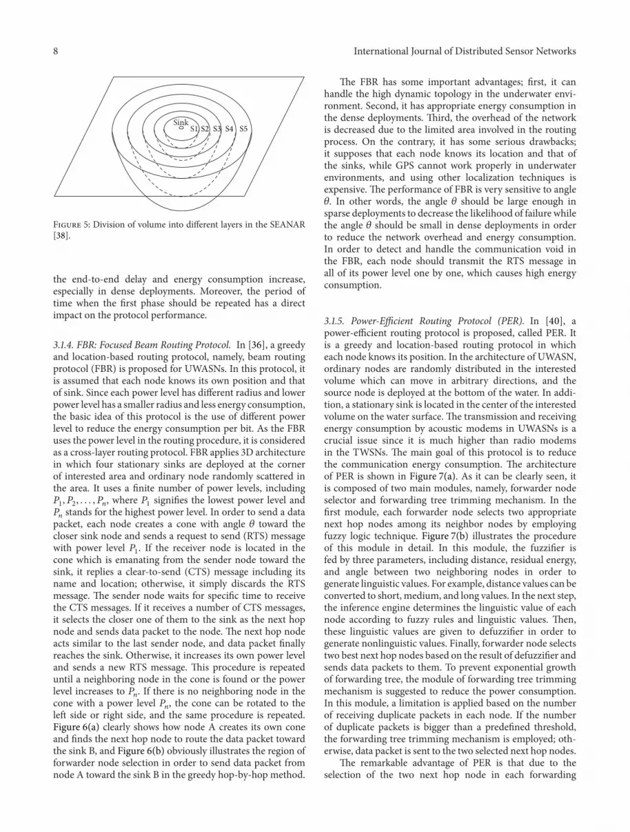
3.1.3. An Energy-Efficient and Topology-Aware Routing (SEA-NAR). In [38], an energy-efficient and topology-aware rout-ing protocol, named SEANAR, is proposed for the UWASNs.This is a greedy and location-based routing protocol in whicheach node has its complete location information. The mainpurpose of SEANAR is to obtain a high delivery ratiowith lowenergy consumption while handling the mobility of nodes.Therefore, each forwarder node should select the best next
A B
C
Figure 4: How virtual pipelines are created by HH-VBF [35].
hop node. To this end, a special topology is proposed bySEANAR in which ordinary nodes are randomly scattered inthe interested volumewhich canmove freely in the horizontaldirection by water current, and only one stationary sinkis deployed in the center of water surface. The volume isdivided into several spherical layers with the same thicknessand density which is clearly shown in Figure 5. According tothese layers, each node has three types of neighbors includingneighbors in the inner, neighbors in the aside layer, andneighbors in the outer layer. The inner neighbors are closerto sink, while outer neighbors are farther to sink, and asideneighbors have almost the same distance to sink.
SEANAR is composed of two phases: neighbors informa-tion maintenance phase and data sending phase. In the firstphase, each node periodically broadcasts a location messageincluding its node ID, location, and residual energy. If thereceiver node is located in the inner or aside layer, it updatesits inner neighbor table or its aside neighbor table; otherwise,it simply discards the message. Consequently, the degree ofeach node is computed by counting the number of nodes inthe inner and aside tables. In the second phase, each sendernode sends a hello message including the node ID, packetsequence number, and layer information. Upon receiving themessage, each node looks at the layer information. If thesender node is located in the inner layer, it simply discards it;otherwise, it replies an acknowledgment message includingits node ID, distance to sink, inner degree, aside degree,and residual energy. When all acknowledgment messagesare received by the sender node, it calculates their weightand selects the largest weight node as the forwarder nodethen sends data packet to this node. One of the significantadvantages of this protocol is the fact that since the degreeof nodes is used to select the next hop node, not only ithas appropriate performance in sparse networks, but also itreduces the likelihood of communication void. Furthermore,it can handle dynamic topology in UWASNs. However, oneof its important weaknesses is that it uses fully locationinformation of nodes in routing, which can be so costly. Inaddition, it does not benefit from the advantages of multisinkarchitecture which causes rapid drain in battery of thosenodes located closer to the single sink. Sinceweights of neigh-bor nodes are calculated in each hop of data sending phaseby sending and receiving messages to neighboring nodes,
8 International Journal of Distributed Sensor Networks
S1Sink
S2 S3 S4 S5
Figure 5: Division of volume into different layers in the SEANAR[38].
the end-to-end delay and energy consumption increase,especially in dense deployments. Moreover, the period oftime when the first phase should be repeated has a directimpact on the protocol performance.
3.1.4. FBR: Focused Beam Routing Protocol. In [36], a greedyand location-based routing protocol, namely, beam routingprotocol (FBR) is proposed for UWASNs. In this protocol, itis assumed that each node knows its own position and thatof sink. Since each power level has different radius and lowerpower level has a smaller radius and less energy consumption,the basic idea of this protocol is the use of different powerlevel to reduce the energy consumption per bit. As the FBRuses the power level in the routing procedure, it is consideredas a cross-layer routing protocol. FBR applies 3D architecturein which four stationary sinks are deployed at the cornerof interested area and ordinary node randomly scattered inthe area. It uses a finite number of power levels, including𝑃1, 𝑃2, . . . , 𝑃
𝑛, where 𝑃
1signifies the lowest power level and
𝑃𝑛stands for the highest power level. In order to send a data
packet, each node creates a cone with angle 𝜃 toward thecloser sink node and sends a request to send (RTS) messagewith power level 𝑃
1. If the receiver node is located in the
cone which is emanating from the sender node toward thesink, it replies a clear-to-send (CTS) message including itsname and location; otherwise, it simply discards the RTSmessage. The sender node waits for specific time to receivethe CTS messages. If it receives a number of CTS messages,it selects the closer one of them to the sink as the next hopnode and sends data packet to the node. The next hop nodeacts similar to the last sender node, and data packet finallyreaches the sink. Otherwise, it increases its own power leveland sends a new RTS message. This procedure is repeateduntil a neighboring node in the cone is found or the powerlevel increases to 𝑃
𝑛. If there is no neighboring node in the
cone with a power level 𝑃𝑛, the cone can be rotated to the
left side or right side, and the same procedure is repeated.Figure 6(a) clearly shows how node A creates its own coneand finds the next hop node to route the data packet towardthe sink B, and Figure 6(b) obviously illustrates the region offorwarder node selection in order to send data packet fromnode A toward the sink B in the greedy hop-by-hop method.
The FBR has some important advantages; first, it canhandle the high dynamic topology in the underwater envi-ronment. Second, it has appropriate energy consumption inthe dense deployments. Third, the overhead of the networkis decreased due to the limited area involved in the routingprocess. On the contrary, it has some serious drawbacks;it supposes that each node knows its location and that ofthe sinks, while GPS cannot work properly in underwaterenvironments, and using other localization techniques isexpensive. The performance of FBR is very sensitive to angle𝜃. In other words, the angle 𝜃 should be large enough insparse deployments to decrease the likelihood of failure whilethe angle 𝜃 should be small in dense deployments in orderto reduce the network overhead and energy consumption.In order to detect and handle the communication void inthe FBR, each node should transmit the RTS message inall of its power level one by one, which causes high energyconsumption.
3.1.5. Power-Efficient Routing Protocol (PER). In [40], apower-efficient routing protocol is proposed, called PER. Itis a greedy and location-based routing protocol in whicheach node knows its position. In the architecture of UWASN,ordinary nodes are randomly distributed in the interestedvolume which can move in arbitrary directions, and thesource node is deployed at the bottom of the water. In addi-tion, a stationary sink is located in the center of the interestedvolume on the water surface. The transmission and receivingenergy consumption by acoustic modems in UWASNs is acrucial issue since it is much higher than radio modemsin the TWSNs. The main goal of this protocol is to reducethe communication energy consumption. The architectureof PER is shown in Figure 7(a). As it can be clearly seen, itis composed of two main modules, namely, forwarder nodeselector and forwarding tree trimming mechanism. In thefirst module, each forwarder node selects two appropriatenext hop nodes among its neighbor nodes by employingfuzzy logic technique. Figure 7(b) illustrates the procedureof this module in detail. In this module, the fuzzifier isfed by three parameters, including distance, residual energy,and angle between two neighboring nodes in order togenerate linguistic values. For example, distance values can beconverted to short, medium, and long values. In the next step,the inference engine determines the linguistic value of eachnode according to fuzzy rules and linguistic values. Then,these linguistic values are given to defuzzifier in order togenerate nonlinguistic values. Finally, forwarder node selectstwo best next hop nodes based on the result of defuzzifier andsends data packets to them. To prevent exponential growthof forwarding tree, the module of forwarding tree trimmingmechanism is suggested to reduce the power consumption.In this module, a limitation is applied based on the numberof receiving duplicate packets in each node. If the numberof duplicate packets is bigger than a predefined threshold,the forwarding tree trimming mechanism is employed; oth-erwise, data packet is sent to the two selected next hop nodes.
The remarkable advantage of PER is that due to theselection of the two next hop node in each forwarding

International Journal of Distributed Sensor Networks 9
A
C
D
B
DB
CBAB
CD
DACA𝜃
(a)
A B
(b)
Figure 6: (a) Procedure of finding next hop node in the FBR [36], (b) The region of forwarder node selection in the FBR [36].
Forwarding node selector
Forwarding tree trimming
mechanism
Packets transmitted toselected sensor(s)
Transmissiondistance
Includedangle
Remainingenergy
Duplicate packet > 𝛿 Duplicate packet ≤ 𝛿
(a)
Fuzzifier
Inference engine
Defuzzifier
Fuzzy rule base
Suitability
Transmissiondistance
Includedangle
Remainingenergy
(b)
Figure 7: (a) The PER architecture [40] and (b) The fuzzy logic system in forwarding node selector module [40].
process, it has better performance in dense deployment incomparisonwith protocols such asVBF that floods the packetin a specific area. The forwarding tree trimming mechanismdecreases the number of duplicate packets, which results inless overhead and less energy consumption. However, PERhas somedrawbacks; for instance, it needs geographical infor-mation, which is very expensive in underwater environments.Additionally, it employs a single sink architecture, whichcauses rapid drain in the battery of the nodes that are closerto sink. Although communication void is a critical problemin the greedy routing, this problem is not taken into accountin PER.
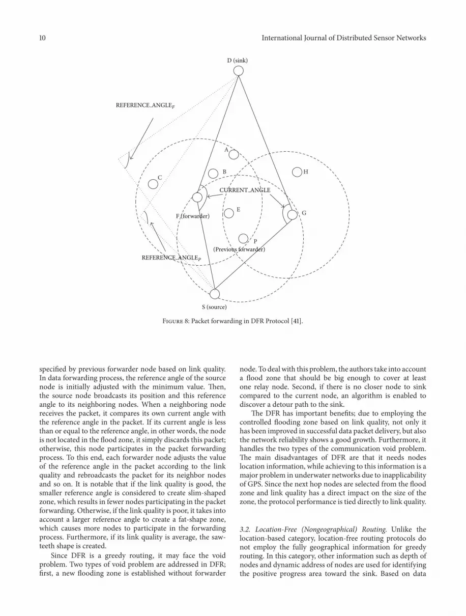
3.1.6. DFR: An Efficient Directional Flooding-Based RoutingProtocol. In [41], an efficient directional flooding-based rout-ing protocol in UWASNs is proposed which is called DFR.The main goal of this protocol is to achieve higher reliabilityand improve data packet delivery. The DFR is a greedy and
geographical routing protocol in which each node knowsthe location of itself and its neighboring nodes. In the DFRarchitecture, a number of ordinary nodes are installed inthe bottom of water. In addition, a source node and anunderwater sink are installed in the left end and right end ofthe interested area, respectively. The source node transmitsthe sensing data to underwater sink in hop-by-hop method,and the sink delivers this data to surface buoy.
The DFR is a flooding-based protocol in which data istransmitted to the neighboring nodes with positive progresstoward the underwater sink. In order to control the flood,it employs location information and link quality of theneighboring nodes to determine the flooding zone at eachhop. To this end, DFR takes into account two angles includingcurrent angle and reference angle. As Figure 8 clearly shows,the angle between FS and FD lines are called current anglein which F, S, and D are forwarder node, source node, anddestination node, respectively. The reference angle is also
10 International Journal of Distributed Sensor Networks
A
BC
H
G
P
E
S (source)
D (sink)
F (forwarder)
REFERENCE ANGLEP
CURRENT ANGLE
(Previous forwarder)
REFERENCE ANGLEF
Figure 8: Packet forwarding in DFR Protocol [41].
specified by previous forwarder node based on link quality.In data forwarding process, the reference angle of the sourcenode is initially adjusted with the minimum value. Then,the source node broadcasts its position and this referenceangle to its neighboring nodes. When a neighboring nodereceives the packet, it compares its own current angle withthe reference angle in the packet. If its current angle is lessthan or equal to the reference angle, in other words, the nodeis not located in the flood zone, it simply discards this packet;otherwise, this node participates in the packet forwardingprocess. To this end, each forwarder node adjusts the valueof the reference angle in the packet according to the linkquality and rebroadcasts the packet for its neighbor nodesand so on. It is notable that if the link quality is good, thesmaller reference angle is considered to create slim-shapedzone, which results in fewer nodes participating in the packetforwarding. Otherwise, if the link quality is poor, it takes intoaccount a larger reference angle to create a fat-shape zone,which causes more nodes to participate in the forwardingprocess. Furthermore, if its link quality is average, the saw-teeth shape is created.
Since DFR is a greedy routing, it may face the voidproblem. Two types of void problem are addressed in DFR;first, a new flooding zone is established without forwarder
node. To deal with this problem, the authors take into accounta flood zone that should be big enough to cover at leastone relay node. Second, if there is no closer node to sinkcompared to the current node, an algorithm is enabled todiscover a detour path to the sink.
The DFR has important benefits; due to employing thecontrolled flooding zone based on link quality, not only ithas been improved in successful data packet delivery, but alsothe network reliability shows a good growth. Furthermore, ithandles the two types of the communication void problem.The main disadvantages of DFR are that it needs nodeslocation information, while achieving to this information is amajor problem in underwater networks due to inapplicabilityof GPS. Since the next hop nodes are selected from the floodzone and link quality has a direct impact on the size of thezone, the protocol performance is tied directly to link quality.
3.2. Location-Free (Nongeographical) Routing. Unlike thelocation-based category, location-free routing protocols donot employ the fully geographical information for greedyrouting. In this category, other information such as depth ofnodes and dynamic address of nodes are used for identifyingthe positive progress area toward the sink. Based on data

International Journal of Distributed Sensor Networks 11
collection methods, this category can be divided into twosubcategories: beacon based and pressure based. Beacon-based subcategory employs beaconmessages to assign specialinformation such as dynamic address to each node in orderto identify the positive progress toward the sink, whilein pressure-based subcategory only the depth informationmeasured locally by pressure sensor can be used for identi-fying the positive progress area. A deep description of thesesubcategories is provided in the following subsections.
3.2.1. Beacon-Based Routing. In the beacon-based subcate-gory, the positive progress area toward the sink is identifiedbased on special information about the network such asaddress which is obtained by sending periodical beaconmessages from the surface of water to the bottom.The variousinformation is employed in different protocols to identify thepositive progress toward the sink. For example, in [21, 42],dynamic address is used to identify the neighboring nodeswith positive progress toward the sink, while the distance tosink is employed in [43]. These protocols usually composedof two phases, namely, information acquisition phase anddata forwarding phase. In the first one, the surface buoysperiodically send beacon message to the bottom of water.The beacon message is received by each neighbor node ofsurface buoy, and it updates its information and beaconmessage. Then, the node broadcasts the updated message toits neighbor nodes and so on. Finally, all nodes earn thedesired information. In the second phase, the informationobtained in the previous phase can be used for identifying theneighbor nodes with positive progress toward the sink andemploying greedy routing method in UWASNs. It should benoted that due to high mobility of nodes by water current inunderwater environments, the information acquisition phaseshould be done in short intervals, which causes a significantincrease in the network overhead. As a result, obtainingdesired information for greedy routing can be too expensivein high dynamic topology networks such as UWASNs. Anumber of protocols belonging to this category are describedas follows.
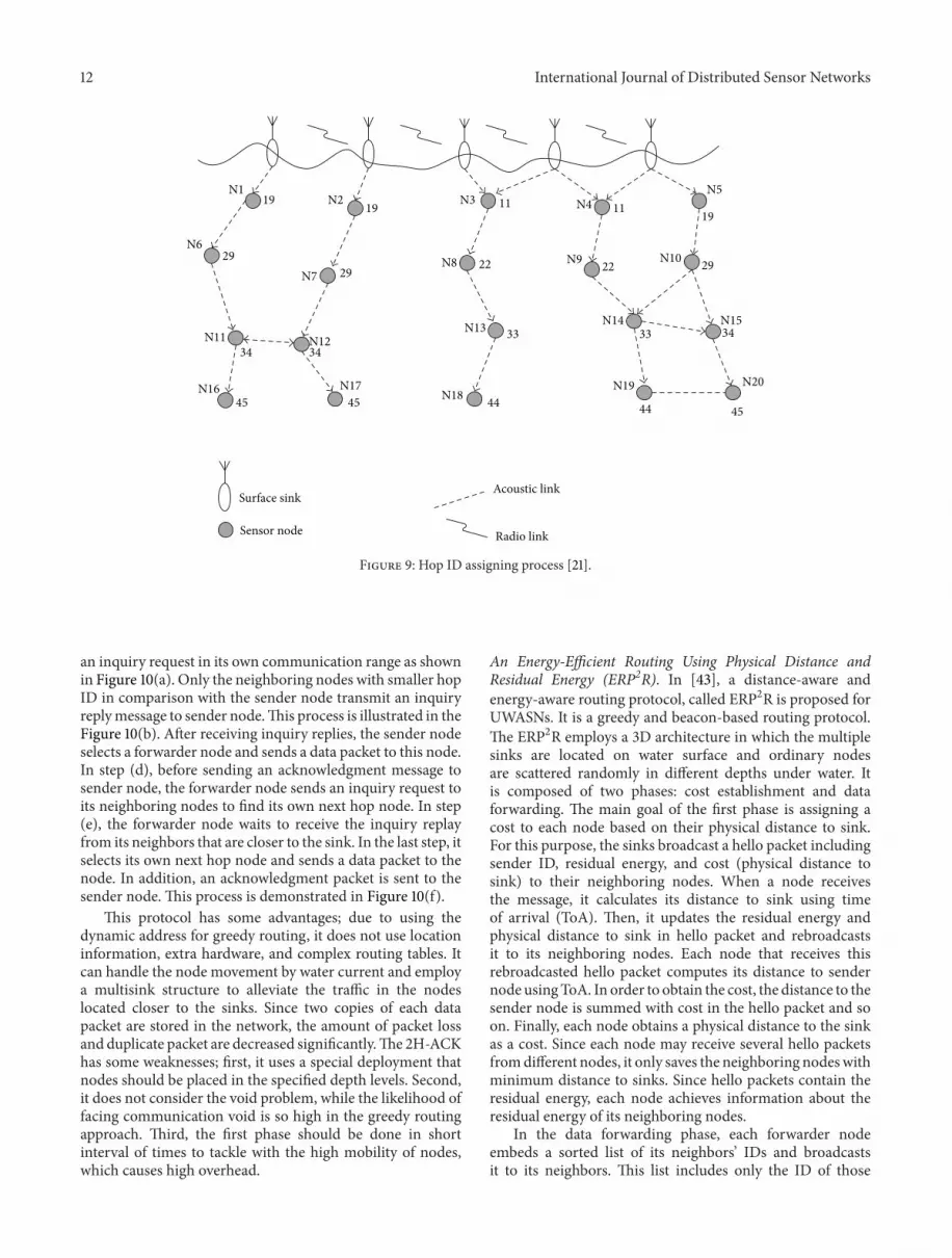
Hop-by-Hop Dynamic Addressing-Based Routing (H2-DAB).In [21], hop-by-hop dynamic address-based routing proto-col is proposed for UWASNs, which is called H2-DAB. Itis the first greedy and address-based routing protocol inunderwater environments. Since the most of greedy routingprotocols in UWASNs employ the location information oradditional hardware, the main goal of H2-DAB is to design agreedy routing protocol, which does not need any additionalhardware and location information. In the architecture of theprotocol, several stationary sinks are located onwater surface,while source nodes anchored at the bottom of the ocean.The ocean depth is divided into different levels, and ordinarynodes are equipped with buoyancy control and deployedin different depth levels between bottom and surface water.These nodes canmove freely in the horizontal direction whiletheir movement in the vertical direction is very little.
H2-DAB is composed of two phases, namely, assigningdynamic address to mobile nodes and data delivery. In the
first phase, a dynamic hop ID is allocated to all floating nodeswhose initial hop ID is equal to 99. To this end, sinks start tosend hello packet toward the bottom of water. Each node thatreceives the hello packet should update its hop ID accordingto the number of hops to the sink. The result of this processis that the closer sensors to sinks have smaller hop ID. Thisprocess is clearly demonstrated in Figure 9, in which eachnode can save the hop distance to two sinks. For instance,the hop ID of node N13 is equal to 34 that indicates its hopdistance from one sink is equal to 3 while its distance toanother sink is equal to 4. In the second phase, the data isdelivered to the sinks. To this end, each forwarder node sendsan inquiry request message to its neighboring nodes. Nodeslocated within the communication range receive the messageand send an inquiry reply message including their node IDand their hop ID. Since the nodes with smaller hop ID arecloser to the sinks, the forwarder node selects a node withsmallest hop ID as a next hop node. It is notable that hop IDshould be updated after an interval of time due to movementof nodes.
This protocol has a number of advantages; not onlyit handles the node movement by water flow, but also itemploys the multisink structure, which reduces the conges-tion at closer nodes to sink. Furthermore, it works withoutgeographical information of nodes, extra hardware, andcomplex routing tables. The H2-DAB has some drawbacksas follows. Since the mobile nodes should be deployed inspecial depth levels, deployment process is more difficultthan random deployment. Although communication void isa critical problem in greedy routing, this protocol does notconsider this problem. Due to the high mobility of nodesin underwater environments, the first phase should be donein a short interval of time, which decreases the networkperformance. This protocol employs a single forwarder nodestrategy at each hop without any consideration to the linkquality of the nodes, which results in an increase in thenumber of packet loss and low reliability.
AReliable Address-Based Routing Protocol (2H-ACK). In [42],a greedy and reliable address-based routing protocol is pro-posed to guarantee the successful data delivery in UWASNs.This protocol is called two-hop acknowledgment reliabilitymodel (2H-ACK). Indeed, this protocol is an enhancedversion of H2-DAB, which improves the network reliability.Similar to H2-DAB, its architecture is composed of severalsinks on water surface and a number of ordinary nodes;source nodes are stationary and anchored at the bottom ofwater, while mobile nodes are deployed in different depthlevels of water and can move in the horizontal direction. 2H-ACK is composed of two phases, namely, assigning dynamicaddress to mobile nodes and data packet forwarding. SimilartoH2-DAB, in the first phase, an address is assigned tomobilenodes based on their hop distance to the sink; nodes thatare closer to the sink obtain a smaller address. In the secondphase, a 6-step data forwarding strategy is employed in thispaper, in which two copies of data packets are stored in thenetwork in order to achieve high reliability. These steps areshown in Figure 10. In the first step, the sender node sends
12 International Journal of Distributed Sensor Networks
N1N2 N3
N5N4
N6
N7N8 N9 N10
N11 N12N13 N14 N15
N16 N17N18
N19 N20
19 19
29
34
45
29
34
45
11
22
33
44
11
22
33
44 45
19
29
34
Surface sink
Sensor node
Acoustic link
Radio link
Figure 9: Hop ID assigning process [21].
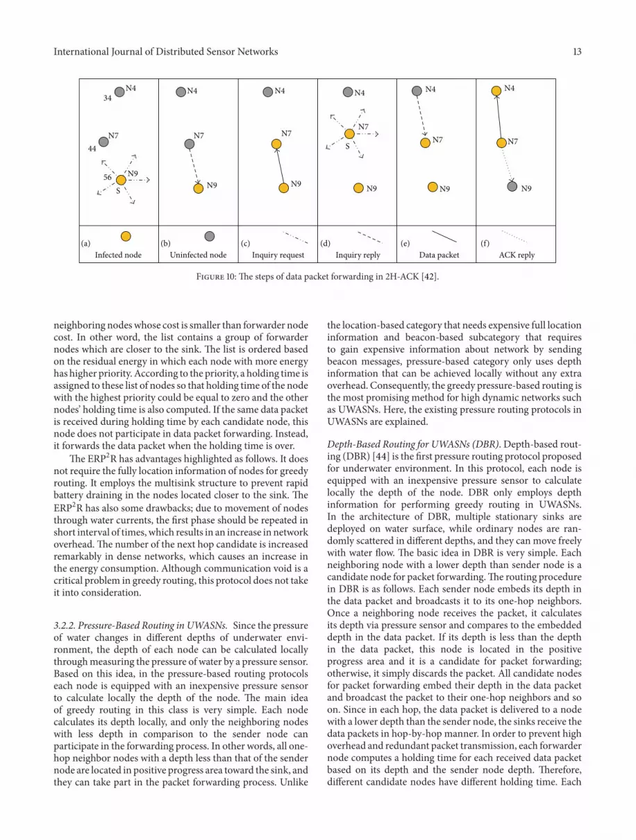
an inquiry request in its own communication range as shownin Figure 10(a). Only the neighboring nodes with smaller hopID in comparison with the sender node transmit an inquiryreplymessage to sender node.This process is illustrated in theFigure 10(b). After receiving inquiry replies, the sender nodeselects a forwarder node and sends a data packet to this node.In step (d), before sending an acknowledgment message tosender node, the forwarder node sends an inquiry request toits neighboring nodes to find its own next hop node. In step(e), the forwarder node waits to receive the inquiry replayfrom its neighbors that are closer to the sink. In the last step, itselects its own next hop node and sends a data packet to thenode. In addition, an acknowledgment packet is sent to thesender node. This process is demonstrated in Figure 10(f).
This protocol has some advantages; due to using thedynamic address for greedy routing, it does not use locationinformation, extra hardware, and complex routing tables. Itcan handle the node movement by water current and employa multisink structure to alleviate the traffic in the nodeslocated closer to the sinks. Since two copies of each datapacket are stored in the network, the amount of packet lossand duplicate packet are decreased significantly.The 2H-ACKhas some weaknesses; first, it uses a special deployment thatnodes should be placed in the specified depth levels. Second,it does not consider the void problem, while the likelihood offacing communication void is so high in the greedy routingapproach. Third, the first phase should be done in shortinterval of times to tackle with the high mobility of nodes,which causes high overhead.
An Energy-Efficient Routing Using Physical Distance andResidual Energy (ERP2R). In [43], a distance-aware andenergy-aware routing protocol, called ERP2R is proposed forUWASNs. It is a greedy and beacon-based routing protocol.The ERP2R employs a 3D architecture in which the multiplesinks are located on water surface and ordinary nodesare scattered randomly in different depths under water. Itis composed of two phases: cost establishment and dataforwarding. The main goal of the first phase is assigning acost to each node based on their physical distance to sink.For this purpose, the sinks broadcast a hello packet includingsender ID, residual energy, and cost (physical distance tosink) to their neighboring nodes. When a node receivesthe message, it calculates its distance to sink using timeof arrival (ToA). Then, it updates the residual energy andphysical distance to sink in hello packet and rebroadcastsit to its neighboring nodes. Each node that receives thisrebroadcasted hello packet computes its distance to sendernode usingToA. In order to obtain the cost, the distance to thesender node is summed with cost in the hello packet and soon. Finally, each node obtains a physical distance to the sinkas a cost. Since each node may receive several hello packetsfromdifferent nodes, it only saves the neighboring nodeswithminimum distance to sinks. Since hello packets contain theresidual energy, each node achieves information about theresidual energy of its neighboring nodes.
In the data forwarding phase, each forwarder nodeembeds a sorted list of its neighbors’ IDs and broadcastsit to its neighbors. This list includes only the ID of those
International Journal of Distributed Sensor Networks 13
Infected node
N434
N744
56 N9
S
(a)Uninfected node
N7
N9
(b)
N4
Inquiry request
N7
N9
(c)
N4
N7
N9
(d)
N4
N7
N9
(e)
N4
N7
N9
(f)
N4
Inquiry reply Data packet ACK reply
S
Figure 10: The steps of data packet forwarding in 2H-ACK [42].
neighboring nodeswhose cost is smaller than forwarder nodecost. In other word, the list contains a group of forwardernodes which are closer to the sink. The list is ordered basedon the residual energy in which each node with more energyhas higher priority. According to the priority, a holding time isassigned to these list of nodes so that holding time of the nodewith the highest priority could be equal to zero and the othernodes’ holding time is also computed. If the same data packetis received during holding time by each candidate node, thisnode does not participate in data packet forwarding. Instead,it forwards the data packet when the holding time is over.
The ERP2R has advantages highlighted as follows. It doesnot require the fully location information of nodes for greedyrouting. It employs the multisink structure to prevent rapidbattery draining in the nodes located closer to the sink. TheERP2R has also some drawbacks; due to movement of nodesthrough water currents, the first phase should be repeated inshort interval of times,which results in an increase in networkoverhead.The number of the next hop candidate is increasedremarkably in dense networks, which causes an increase inthe energy consumption. Although communication void is acritical problem in greedy routing, this protocol does not takeit into consideration.
3.2.2. Pressure-Based Routing in UWASNs. Since the pressureof water changes in different depths of underwater envi-ronment, the depth of each node can be calculated locallythroughmeasuring the pressure of water by a pressure sensor.Based on this idea, in the pressure-based routing protocolseach node is equipped with an inexpensive pressure sensorto calculate locally the depth of the node. The main ideaof greedy routing in this class is very simple. Each nodecalculates its depth locally, and only the neighboring nodeswith less depth in comparison to the sender node canparticipate in the forwarding process. In other words, all one-hop neighbor nodes with a depth less than that of the sendernode are located in positive progress area toward the sink, andthey can take part in the packet forwarding process. Unlike
the location-based category that needs expensive full locationinformation and beacon-based subcategory that requiresto gain expensive information about network by sendingbeacon messages, pressure-based category only uses depthinformation that can be achieved locally without any extraoverhead. Consequently, the greedy pressure-based routing isthe most promising method for high dynamic networks suchas UWASNs. Here, the existing pressure routing protocols inUWASNs are explained.
Depth-Based Routing for UWASNs (DBR). Depth-based rout-ing (DBR) [44] is the first pressure routing protocol proposedfor underwater environment. In this protocol, each node isequipped with an inexpensive pressure sensor to calculatelocally the depth of the node. DBR only employs depthinformation for performing greedy routing in UWASNs.In the architecture of DBR, multiple stationary sinks aredeployed on water surface, while ordinary nodes are ran-domly scattered in different depths, and they can move freelywith water flow. The basic idea in DBR is very simple. Eachneighboring node with a lower depth than sender node is acandidate node for packet forwarding.The routing procedurein DBR is as follows. Each sender node embeds its depth inthe data packet and broadcasts it to its one-hop neighbors.Once a neighboring node receives the packet, it calculatesits depth via pressure sensor and compares to the embeddeddepth in the data packet. If its depth is less than the depthin the data packet, this node is located in the positiveprogress area and it is a candidate for packet forwarding;otherwise, it simply discards the packet. All candidate nodesfor packet forwarding embed their depth in the data packetand broadcast the packet to their one-hop neighbors and soon. Since in each hop, the data packet is delivered to a nodewith a lower depth than the sender node, the sinks receive thedata packets in hop-by-hop manner. In order to prevent highoverhead and redundant packet transmission, each forwardernode computes a holding time for each received data packetbased on its depth and the sender node depth. Therefore,different candidate nodes have different holding time. Each

14 International Journal of Distributed Sensor Networks
candidate node waits until the holding time is over, then ittransmits the data packet. During this period, if the samepacket is received by the node from a lower depth node, itremoves the packet from its sending queue. DBR is careful toavoid the same packet retransmission by each node. To thisend, each successfully delivered data packet is added to thepacket history buffer.
The DBR has some advantages highlighted as follows.Not only it can handle easily the high movement of nodesthrough water current, but also it employs a multisinkstructure to avoid the high traffic and rapid battery drainin the nodes closer to the sinks. It has also a number ofremarkable disadvantages explained as follows. First, how-ever the communication void problem is a common problemin greedy routing, DBR does not suggest a solution to tacklethis problem. Second, although DBR tries to avoid sendingduplicate packet, yet a number of duplicate packets is sent,which affects the protocol performance.
Depth-Based Multihop Routing for UWASNs (DBMR). In[45], a greedy and depth-based multihop routing (DBMR) isproposed to improve the energy consumption.UnlikeDBR inwhich each node floods the data packets for its neighboringnodes, in the DBMR, only one node is selected as the nexthop node to reduce the communication overhead. In thearchitecture of DBMR, several stationary sinks are deployedon water surface, while ordinary nodes are equipped withan inexpensive pressure sensor and scattered randomly inunderwater environment. They move based on the randomwalk pattern. DBMR is composed of two phases: routediscovery and send packets. In the first phase, the next hopnode of each node is discovered. To this end, each nodemeasures its depth by pressure sensor and broadcasts its ownID and depth information as a control message. It waits toreceive the reply message for a specific period of time. Eachneighbor node which receives the control message comparesthe depth in themessage with its own depth. If its depth is lessthan the depth in the control message, it calculates its weightaccording to its depth and residual energy, then it embedsits ID and weight in the message and replies it; otherwise, itreadily discards the control message. When the waiting timeis over, each node selects the largest weight node as the nexthop node and saves it in the routing table. The second phaseis responsible for data packet forwarding. To this end, eachnode retrieves the next hop node from the routing table andtransmits the data packet to this node in order to avoid thehigh communication overhead.
The main benefits of DBMR are that it handles the highmobility of nodes through water current and it employs amultisink structure to decrease the likelihood of traffic in thenodes located closer to the sinks. It applies a single-next hopstrategy to reduce the communication overhead and increasethe network lifetime. However, it has some remarkabledrawbacks; for instance, it cannot handle the communicationvoid problem, which causes high packet loss. Due to thehigh mobility of nodes by water current, the discovery phaseshould be done at short intervals, which results in an increasein the network overhead. Since acoustic links are unreliableand DBMR does not consider link quality for selecting the
next hopnode, the amount of packet retransmission increasessignificantly, which causes a remarkable increase in energyconsumption.
Pressure Routing for UWASNs (HydroCast). In [33], a pres-sure routing for underwater sensor networks (HydroCast)is proposed to improve the reliability of the network andhandle the void problem. In HydroCast, ordinary nodes arerandomly scattered in underwater environment, and they canmove freely with water flow. These nodes are equipped withan inexpensive pressure sensor to measure their own depthlocally. Multiple mobile sinks are also deployed on watersurface, which move with water flow. In order to identifypositive progress area toward the sink, this protocol employsonly depth information which is calculated by measuringpressure of water in different depths. HydroCast has twomodes, including greedy routing and void handling. In thefirst mode, an opportunistic forwarding mechanism is used.To this end, this mechanism selects a subset of neighboringnodes with positive progress toward the sink as a next hopcandidate to maximize the greedy progress. In this process,it takes into account the expected packet advance (EPA)metric to select the higher link quality neighboring nodes andhidden terminal problem to suppress the redundant packetforwarding by the nodes in the subset. In this subset, thenodes that are closer to the sink have higher priority. Eachforwarder node embeds the ID of candidate nodes in a datapacket and broadcasts it. After a neighboring node receivesthe data packet, it retrieves the list of IDs in the data packet.If its ID is not on the list, it simply discards the packet.Otherwise, it calculates a holding time and sends a datapacket based on this holding time. It should be noted thatif it receives the same packet from higher priority node inthe holding time, it suppresses the data packet forwarding toprevent the redundant packet forwarding.
In the second mode, void handling mechanism isemployed in order to deal with the communication void.When a node does not have any neighbor with a depthlower than that of itself, it cannot employ the greedy routing;therefore, this node is considered as a local maximum node.In this condition, it enables a void handling mechanismto deal with this problem. In this mechanism, each localmaximum node finds and stores a detour path to a node witha depth lower than that of itself and transmits the data packetto this node. The procedure of this mechanism is illustratedin Figure 11. As can be seen, LM1 is a local maximum node.It finds a detour path to a node with a depth lower than thatof itself (i.e., LM 2) and sends the data packet for this node.Since LM2 is a local maximum, it finds other node with alower depth such as S and transmits the data packet for thisnode. Finally, the data packet reaches a node that is not alocal maximum node, and this node sends the data packetin greedy mode.
The HydroCast has some advantages highlighted as fol-lows. First, it can handle the void problem. Second, it onlyemploys the depth information instead of using high-costfull location information and beacon messages. Third, it canhandle the highmobility of nodes with the water flow. Finally,it uses the advantage of the multisink structure to tackle

International Journal of Distributed Sensor Networks 15
S
LM1
LM2
Figure 11: Recovery mode in HydroCast [33].
with a rapid battery drain in the nodes closer to the sink.However, it has a number of serious problems; for example,it calculates the information of distances from two-hopneighboring nodes in greedymode to select a set of forwardernode, while measuring two-hop neighboring nodes’ distanceby ToA causes high communication overhead. Due to thehigh mobility of nodes in underwater environments, detourpath discovered by a local maximum node is expired in ashort period. Consequently, the finding detour path in thelocal maximum nodes should be repeated, which increasesthe communication overhead and energy consumption.
An Energy Efficient Localization-Free Routing (EEDBR). In[46], the authors proposed an energy efficient localization-free routing protocol (EEDBR) for the greedy pressure-basedrouting group of UWASNs.The aim of this protocol is to bal-ance the energy of nodes and improve the network lifetime.In the architecture of EEDBR, multiple sinks are deployedon the water surface and equipped with radio and acousticmodems, while ordinary nodes are randomly scattered in thearea of interest. They can move freely through water flow,and they are equipped with acoustic modem. Unlike DBRthat is a receiver-based routing protocol, EEDBR is a sender-based routing protocol in which sender node selects a set ofnext hop nodes based on their depth and residual energy.EEDBR is composed of two phases: knowledge acquisitionand data forwarding. In the first one, each node broadcastsits own depth and residual energy as a Hello packet to itsneighboring nodes. Therefore, all nodes collect and savetheir neighboring nodes’ information. In the second phase,a subset of forwarder nodes is selected based on their depthinformation and residual energy. In other words, a group ofneighboring nodes with a depth smaller than that of sendernode that have suitable residual energy are selected as nexthop node candidates. The sender node embeds a list ofselected nodes ID in data packet and forwards it. The nodeson the list are sorted based on their residual energy, whichshows their priorities. In order to prevent redundant datapacket forwarding, each candidate node considers a holdingtime according to its residual energy and priority in which ashorter holding time is assigned to a node with more residualenergy. In addition, the nodes with the same residual energy
have different priority which result in different holding timefor these nodes.
The major advantages of EEDBR are as follows. First, itcan handle the mobility of nodes with water flow. Second,it uses the advantages of multisink structure to prevent therapid battery drain in the nodes closer to the sink.Third, onlydepth information is used in the greedy routing procedure,and it does not require to obtain expensive full locationinformation and to send the beacon messages. The maindrawback of this protocol is that knowledge acquisition phaseshould be repeated in a short interval of time due to highmovement of nodes with water current, which causes highoverhead. In addition, EEDBR does not take into account thelink quality of nodes, while it is an important parameter inunderwater environments due to unreliable acoustic links.Furthermore, it cannot handle the void problem, whereas itis considered as a critical problem in greedy routing.
Void-Aware Pressure Routing (VAPR). As mentioned earlier,the communication void problem is one of the most criticalproblems in greedy routing. If a forwarder node does nothave at least one neighboring node with positive progresstoward the sink, it encounters this problem [32]. In [47], avoid-aware pressure routing (VAPR) is proposed to handlethe void problem in this category of greedy routings. In thisprotocol, multiple sinks are deployed on water surface, whileordinary nodes are randomly scattered in the undersea area,and they move with water current based on MeanderingCurrent Mobility (MCM) model. However existing 3D voidhandling methods in UWASNs use the flooding technique toidentify the detour path, VAPR employs periodical beaconmessages to identify the direction of each node in a heuristicmanner. This direction is used for packet forwarding. SinceVAPR employs depth information and information acquiredfrom beacon messages, it belongs to both pressure based andbeacon based categories.
VAPR is composed of two components, namely,enhanced beaconing and opportunistic directional dataforwarding. In the first one, each sink broadcasts a beaconmessage including depth of sender node, the sequencenumber, number of hop count to sink, and direction ofthe current node toward the sink. After a node receives

16 International Journal of Distributed Sensor Networks
a
b
c
d
e
f
g
h
i
j
n
m
L
k
Localmaximum
Sonobuoy
Monitoringcenter
a’s depthDF dir: UPSN: 107Hop cnt: 1
Sonobuoy’s depthDF dir: UPSN: 108Hop cnt: 0
e’s depthDF dir: DNSN: 103Hop cnt: 5
j’s depthDF dir: UPSN: 103Hop cnt: 5
g’s depthDF dir: DNSN: 101Hop cnt: 7
k’s depthDF dir: UPSN: 104Hop cnt: 4
h’s depthDF dir: UPSN: 100Hop cnt: 8
MC’s depthDF dir: UPSN: 108Hop cnt: 0
n’s depthDF dir:UPSN: 107Hop cnt: 1
Figure 12: Enhanced beacon reception in two directions [47].
the message, it updates the message and broadcasts theupdated message to its neighboring nodes. It is notablethat if the beacon message is received from a node with adepth smaller than the receiver node, the direction of nodeis updated to up; otherwise, it updates to down. Figure 12demonstrates the procedure of the enhanced beaconingcomponent in two directions. For example, since node 𝑎receives the packet from a node with less depth, its directionis up, while the direction of node 𝑒 is down because itreceives the beacon message from a node with more depth.In the second component, a directional opportunistic dataforwarding algorithm is proposed to forward the data packettoward the sinks. In this algorithm, each node employs thedirection information to forward the packet and avoids thecommunication void.
The main advantages of VAPR are that it employs amultisink structure to prevent from a rapid battery drain inthe nodes closer to the sinks. Furthermore, it can handle themobility of nodes with water flow. It can handle the voidproblemwith a heuristic method.The important drawback ofVAPR is that due to the highmovement of nodes inUWASNs,the enhanced beaconing component should be repeated inthe short intervals of time, which causes a significant increasein the network overhead.
3.3. Comparison between Greedy Routing Categories and Pro-tocols. The location-based category uses geographic infor-mation to carry out the greedy routing. The main benefit oflocation-based category is that positive progress area towardthe sinks can be found and controlled easily, which helps todeliver the data packets to sink in an almost direct route.However, the major drawback of this category is that dueto inapplicability of GPS in underwater environment andhigh mobility of nodes by water current, finding the locationinformation of nodes by localization techniques is too costly.
Since location-free category does not employ geograph-ical information for routing, there is no need for costlylocalization techniques to find the geographical information.Location-free category is composed of two subcategories:beacon-based, and pressure-based. In the beacon-based sub-category, sinks periodically broadcast a beaconmessage fromthe surface of water to the bottom in order to assign a specificinformation to each node. The main advantages of thiscategory is that it does not require the expensive geographicalinformation of nodes. However, the main drawback of thiscategory is that due to high movement of nodes by water cur-rent in UWASNS, this special information must be updatedin a short period, which causes high overhead of the network.In the pressure-based subcategory, each ordinary node isequipped with an inexpensive pressure sensor to measurelocally the pressure of water and calculate the direct distanceof node from water surface. The main advantage of thiscategory is that it only uses the depth information in routingprocess and does not require expensive location informationand high overhead beacon messages. The main shortcomingof this category is that they are equipped with pressure sensorthat is costly. Table 3 compares the features of the protocolsdiscussed in this paper, and Table 4 demonstrates a numberof simulation conditions such as simulator name, the size ofsimulation area, communication range, node speed, soundspeed, energy consumption in different modes, and nodedeployment.
Regardless of the information used to identify positiveprogress area in the greedy routing, a number of otherrouting parameters including residual energy, link quality,node degree, and number of hop count are employed byrouting protocols to improve the efficiency of protocols.These parameters directly affect different network metricssuch as reliability, network lifetime, and end-to-end delay. Forexample, residual energy of node is used in [38, 43, 45] to

International Journal of Distributed Sensor Networks 17
Table3:Features
ofgreedy
routingprotocolsinUWASN
s.
Protocol
Sing
le/m
ultip
lecopies
Positive
progressarea
Num
bero
fnext
hops
Sing
le/m
ultip
lesin
k2D
/3D
Additio
nal
requ
est
Forw
ardern
ode
criteria
Opp
ortunistic
Handle
void
Send
erbased/receiver
based
Com
pared
with
Locationbased
VBF
[7]
Multip
leVirtual
pipelin
eMulti
Sing
le3D
Locatio
ninfo.
Distance
Yes
No
Receiver
based
—
HH-VBF
[35]
Multip
leVirtual
pipelin
eMulti
Sing
le3D
Locatio
ninfo.
Distance
Yes
No
Receiver
based
VBF
SEANAR
[38]
Sing
leInnera
ndasidelayers
One
Sing
le3D
Locatio
ninfo./p
ower
control
Distance/energy/no
dedegree
No
No
Send
erbased
VBF
,GF
FBR[36]
Sing
leCon
eOne
Multip
le2D
Locatio
ninfo.
Distance
No
Yes
Send
erbased
Min.Pow
er
PER[40]
Multip
leDistance
Two
Sing
le3D
Locatio
ninfo.
Distance/energy
No
No
Send
erbased
DBR
DFR
[41]
Multip
leAng
leMulti
Sing
le2D
Locatio
ninfo./link
quality
Distance/link
quality
Yes
Yes
Receiver
based
HH-VBF
,VBV
A
LocationfreeBeaconbased
H2 -DAB
[21]
Sing
leLo
wer
address
One
Multip
le3D
—Ad
dress
No
No
Send
erbased
—
2H-ACK
[42]
Sing
leLo
wer
address
One
Multip
le3D
—Ad
dress
No
No
Send
erbased
HbH
-ACK
ERP2R
[43]
Multip
lePh
ysical
distance
Multi
Multip
le3D
—Ph
ysical
distance/energy
Yes
No
Send
erbased
DBR
Pressurebased
DBR
[44]
Multip
leLo
wer
depth
Multi
Multip
le3D
Pressure
sensor
Depth
Yes
No
Receiver
based
VBF
DBM
R[45]
Sing
leLo
wer
depth
One
Multip
le3D
Pressure
sensor
Depth/energy
No
No
Send
erbased
DBR
HydroCa
st[33]
Multip
leLo
wer
depth
Multi
Multip
le3D
Pressure
sensor/tw
oho
pclu
ster
Depth/link
quality
Yes
Yes
Receiver
based
DBR
EEDBR
[46]
Multip
leLo
wer
depth
Multi
Multip
le3D
Pressure
sensor
Depth/energy
Yes
No
Send
erbased
DBR
VAPR
[47]
Multip
leLo
wer
depth
Multi
Multip
le3D
Pressure
sensor
Depth/dire
ction/ho
pcoun
t./seq.no
.Yes
Yes
Send
erbased
DBR
,HBR
,HydroCa
st
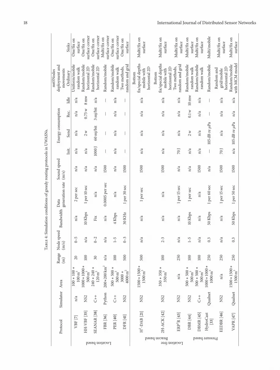
18 International Journal of Distributed Sensor Networks
Table4:Simulationcond
ition
sofgreedyroutingprotocolsinUWASN
s.
Protocol
Simulator
Area
Range
(m)
Nod
espeed
(m/s)
Band
width
Data
generatio
nrate
Soun
dspeed
(m/s)
Energy
consum
ption
m65Nod
esdeploymentand
movem
ents
Init.
Send
Rec.
Idle
Ordinary
Sink
s
Locationbased
VBF
[7]
n/a100∗100∗
100m
320
0–5
n/a
2persec
n/a
n/a
n/a
n/a
n/a
Uniform
/mob
ilerand
omwalk
One/fixon
surfa
ce
HH-VBF
[35]
NS21000∗1000∗
500m
3100
n/a
10Kb
ps1p
er10sec
n/a
n/a
2w0.75
w8m
wRa
ndom
/mob
ileho
rizon
tal2D
One/fixon
surfa
cecorner
SEANAR[38]
C++240∗240∗
120m
330
0–2
Fix
n/a
n/a
1000
J60
mj/b
it3m
j/bit
n/a
Rand
om/m
obile
horiz
ontal2D
One/fixon
surfa
cecorner
FBR[36]
Python200∗200km
2n/a
n/a
n/a
0.00
05persec
1500
——
——
Rand
om/m
obile
Multi/fix
onsurfa
cecorner
PER[40]
C++500∗500∗
500m
3100
1–5
4Kbp
sn/a
n/a
n/a
n/a
n/a
n/a
Rand
om/m
obile
rand
omwalk
One/fixon
surfa
cecorner
DFR
[41]
NS2
3000∗
4000m
2500
0–3
30KH
z1p
er30
sec
1500
——
——
Twometho
ds,
rand
omandgrid
One/fixon
surfa
ce
LocationfreeBeaconbased
H2 -DAB[21]
NS21500∗1500∗
1500m
3500
n/a
n/a
1per
sec
1500
n/a
n/a
n/a
n/a
Botto
mfix
/specialdepths
mob
ilewith
horiz
ontal2D
Multi/fix
onsurfa
ce
2H-ACK
[42]
NS2350∗350∗
350m
3100
2-3
n/a
n/a
1500
n/a
n/a
n/a
n/a
Botto
mfix
/specialdepths
mob
ilewith
horiz
ontal2D
Multi/fix
onsurfa
ce
ERP2R[43]
NS2
n/a
250
n/a
n/a
1per
15sec
n/a
70J
n/a
n/a
n/a
Twometho
ds,
rand
omandgrid
Multi/fix
onsurfa
ce
Pressurebased
DBR
[44]
NS2500∗500∗
500m
3100
1–5
10Kb
ps1p
ersec
n/a
n/a
2w0.1w
10mw
Rand
om/m
obile
rand
omwalk
Multi/fix
onsurfa
ce
DBM
R[45]
C++500∗500∗
500m
3100
n/a
n/a
n/a
1500
n/a
n/a
n/a
n/a
Rand
om/m
obile
rand
omwalk
Multi/fix
onsurfa
ceHydroCa
st[33]
Qualnet1000∗1000∗
1000m
3250
0.3
50Kb
ps1p
er60
sec
n/a
—105d
Bre𝜇Pa
——
Rand
om/m
obile
Multi/mob
ile
EEDBR
[46]
NS2
n/a
250
n/a
n/a
1per
15sec
1500
70J
n/a
n/a
n/a
Rand
omand
grid/m
obile
horiz
ontal2D
Multi/fix
onsurfa
ce
VAPR
[47]
Qualnet1500∗1500∗
1500m
3250
0.3
50Kb
ps1p
er50
sec
1500
n/a
105d
Bre𝜇Pa
n/a
n/a
Rand
om/m
obile
with
MCM
mod
elMulti/fix
onsurfa
ce

International Journal of Distributed Sensor Networks 19
balance the energy consumption and improve the networklifetime.
The number of next hop nodes involving in routingprocedures has a direct impact on the protocol performance.According to the number of nodes selected as the next hopnodes, the greedy routing protocols can be divided intotwo groups, namely, one-next-hop nodes and multinext-hopnodes. In the first group, the protocols select only one nexthop node at each hop [21, 36, 38, 45] in order to decreasethe communication overhead and energy consumption. Themain drawback of this group is that likelihood of data packetretransmission increases due to high path loss in UWASNs,which causes a significant decrease in routing performance.In the second group, protocols select a set of next hop nodeswith positive progress toward the sink [7, 35, 41, 44] in orderto take advantage of opportunistic routing. In opportunisticrouting, each node floods the data packets to its neighbor-ing nodes, and only the neighbors with positive progresstoward the sinks can participate in the routing process todecrease the communication overhead. The main drawbackof this group is that the communication overhead increasessignificantly due to involving multiple nodes in forwardingthe same data packet. Although in opportunistic routingtechnique, a holding time is assigned to each next hop nodeto forward the data packet in different times and prevent fromforwarding the same packet by different next hop nodes, thistechnique cannot prevent completely the redundant packetforwarding.
4. Future Work and Conclusion
4.1. Future Work. UWASN is a new area of research thathas recently emerged in field of wireless sensor network.However, many studies have been conducted on the lowerlayers of OSI model such as physical and data link layers;the research on upper layers such as network layer is stillin its infancy stages. In recent years, a number of routingprotocols have been proposed to solve the problems relatedto underwater environment. However, most of these routingprotocols cannot completely handle the problems and anumber of issues still have not been addressed. A number ofopen issues in the network layer of UWASNs are explained asfollows.
(i) Most of the existing routing protocols have beenproposed for small-scale UWASNs, while a numberof special applications require large-scale routingprotocols. As a result, it is necessary to developa new routing protocol for large-scale networks inunderwater environment.
(ii) The acoustic wave is used as a communicationmedium in UWASNs instead of radio waves, whilecommon network simulators such as OMNeT++,JSim, QualNet, and NS2 cannot support the acousticwave. Furthermore, the underwater environment has3D nature. However, famous networks simulator suchas NS2 only support 2D environments. Therefore,a number of existing routing protocols use existing
simulators and change some features on the simulatorto be adapted with features of UWASNs, while otherprotocols use a customize simulator with differentlanguages such as C++, Perl, Peyton, and Matlab[53]. It seems crucial to develop a standard simulatorfor UWASNs to cover all features of underwaterenvironment.
(iii) The underwater networks suffer from lack of a real-istic model for node mobility. Most of the routingprotocols apply random walk mobility, and a numberof them employ other mobility models such as MCM[47]. However, these mobility models are not suitablefor undersea environments. Therefore, designing anew mobility model for undersea environments isessential.
(iv) In many UWASN applications such as military appli-cations, a secure communication between nodes isone of the main challenges. However, the existingrouting protocols have not addressed this issue. Con-sequently, it is essential to design a secure routingprotocol for UWASNs with capability of tackling withunderwater challenges.
(v) Congestion is a common issue in applications that useevent-driven data reporting models. However, exist-ing routing protocols do not take into account thisissue. Since congestion in node and link creates highpacket loss, which results in a significant decreasein network performance, designing a new routingprotocol to address this issue seems an essentialresearch.
(vi) Communication void is a crucial problem in greedyrouting protocols. Due to 3D nature of underwaterenvironment, the existing void handling techniquesin TWSNs are not applicable to UWASNs. Sincemost of the existing void handling techniques inUWASNs employ flooding techniques to find thedetour path, designing new void handling techniqueswith low overhead is essential for using in underwaterenvironment.
(vii) Energy efficiency inUWASNs ismore important thanthat of TWSNs. This is because underwater networksemploy acoustic as a communication medium, andenergy consumption by acoustic is much more thanradio frequency [54]. Therefore, it is necessary todesign an energy efficient routing protocol that isable to balance the nodes energy and decrease thecommunication overhead. Furthermore, new energyscavenging methods should be designed to sup-ply the energy of nodes by converting the othertypes of energy such as kinetic energy to electricalenergy.
(viii) Most of existing routing protocols take into accountthe sound speed equal to 1500m/s in underwa-ter environment, while the sound speed is variedwith salinity, pressure, and temperature, which have

20 International Journal of Distributed Sensor Networks
a direct impact on network performance. Conse-quently, there is still room to consider this issue indesigning routing protocols for UWASNs.
4.2. Conclusion. As mentioned earlier, greedy routingmethod is themost promising routing approach in UWASNs.A routing protocol in underwater environment faces differentchallenges such as high movement of nodes by water flow,3D environment, high path loss, low bandwidth, and highpropagation delay. Since none of the routing protocols cantackle with all of the issues, each protocol takes into accounta few ones of these issues to handle. In this paper, the basicissues of an acoustic communication and its challengeswere presented. Then, the architecture of an underwaternode and its components was explained in detail. Next,features of some recent commercial and scientific acousticmodems were expressed. The main differences betweenTWSNs and UWASNs were explained, and the reasons oflow performance of TWSN’s routing protocols in underwaterenvironment were discussed. After that, a survey wasgiven on greedy routing protocols proposed for UWASNs.According to information required for identifying thepositive progress area toward the sink, we divided thegreedy routing protocols into two categories: locationbased and location-free. The location-free category, inturn, was composed of two subcategories, namely, beaconbased and pressure based. For each category, a number offamous routing protocols were briefly described, and theiradvantages and disadvantages are explained. Furthermore,these protocols were compared to each other based on theirfeatures and their simulation conditions. Finally, we providean outlook on open issues in underwater routing protocols.
Acknowledgments
This work is supported by Universiti Teknologi Malaysia(UTM). The authors would like to thank the ResearchManagement Center (RMC) for the partial funding and Per-vasive Computing Research Groups (PCRG) of the Facultyof Computing for the support and insightful comments inmaking this study a success.
References
[1] I. F. Akyildiz, D. Pompili, and T. Melodia, “State-of-the-art inprotocol research for underwater acoustic sensor networks,”in Proceedings of the 1st ACM International Workshop onUnderwater Networks, pp. 7–16, September 2006.
[2] J. Heidemann, W. Ye, J. Wills, A. Syed, and Y. Li, “Researchchallenges and applications for underwater sensor networking,”in Proceedings of the IEEE Wireless Communications and Net-working Conference (WCNC ’06), vol. 1–4, pp. 228–235, April2006.
[3] I. F. Akyildiz, D. Pompili, and T. Melodia, “Challenges for effi-cient communication in underwater acoustic sensor networks,”ACM Sigbed Review, vol. 1, pp. 3–8, 2004.
[4] Y. C. Mao, Y. Liang, X. F. Li, and Z. J. Wang, “Challengesand application of underwater sensor networks for large-scale aquatic applications,” in Proceedings of the Proceedings
of Information Technology and Environmental System Sciences(Itess ’08), vol. 1, pp. 1097–1102, 2008.
[5] D. Pompili, T. Melodia, and I. F. Akyildiz, “A resilient routingalgorithm for long-term applications in underwater sensornetworks,” in In Proceedings of the Mediterranean Ad HocNetworking Workshop, 2006.
[6] P. Casari, M. Stojanovic, and M. Zorzi, “Exploiting thebandwidth-distance relationship in underwater acoustic net-works,” in Proceedings of the Ocean MTS/IEEE Conference, vol.1–5, pp. 958–957, October 2007.
[7] P. Xie, J.-H. Cui, and L. Lao, “VBF: vector-based forwardingprotocol for underwater sensor networks,” Networking, vol.3976, pp. 1216–1221, 2006.
[8] I. F. Akyildiz, W. Su, Y. Sankarasubramaniam, and E. Cayirci,“Wireless sensor networks: a survey,” Computer Networks, vol.38, no. 4, pp. 393–422, 2002.
[9] J. N. Al-Karaki andA. E. Kamal, “Routing techniques inwirelesssensor networks: a survey,” IEEEWireless Communications, vol.11, no. 6, pp. 6–27, 2004.
[10] J. M. Hovem, “Underwater acoustics: propagation, devices andsystems,” Journal of Electroceramics, vol. 19, no. 4, pp. 339–347,2007.
[11] J.-H. Jeon, T.-H. Won, H. Cho, and S.-J. Park, “Implementationof amicro-modem for underwater wireless sensor networks,” inProceedings of the OCEANS IEEE-Spain, June 2011.
[12] H. T. Nguyen, S. Y. Shin, and S. H. Park, “State-of-the-art inMAC protocols for underwater acoustics sensor networks,” inProceedings of theconference on Emerging direction in embeddedand ubiquitous computing,, vol. 4809, pp. 482–493, 2007.
[13] V. Rodoplu andM. K. Park, “An energy-efficient MAC protocolfor underwater wireless acoustic networks,” inProceedings of theMTS/IEEE OCEANS, vol. 1–3, pp. 1198–1203, 2005.
[14] N. Chirdchoo, W.-S. Soh, and K. C. Chua, “Aloha-based MACprotocols with collision avoidance for underwater acoustic net-works,” in Proceedings of the 26th IEEE International Conferenceon Computer Communications, vol. 1–5, pp. 2271–2275, May2007.
[15] Z. Zhou, J. H. Cui, and S. L. Zhou, “Localization for large-scaleunderwater sensor networks,” in Proceedings of the 6th inter-national IFIP-TC6 conference on Ad Hoc and sensor networks,wireless networks, next generation internet, vol. 4479, pp. 108–119, 2007.
[16] J. H. Ko, J. Shin, S. Kwon, and C. Kim, “Localization ofsensor nodes in underwater acoustic sensor networks using tworeference points,” in Proceedings of the International Conferenceon Information Networking (ICOIN ’08), pp. 454–458, January2008.
[17] A. K. Othman, “GPS-less localization protocol for underwateracoustic networks,” inProceedings of the 5th IEEE and IFIP Inter-national Conference on Wireless and Optical CommunicationsNetworks (WOCN ’08), pp. 273–278, May 2008.
[18] M. Erol and S. Oktug, “Localization in underwater sensornetworks,” in Proceedings of the 17th Signal Processing andCommunications Applications Conference (SIU ’09), pp. 307–310,April 2009.
[19] A. Y. Teymorian, W. Cheng, L. Ma, X. Cheng, X. Lu, andZ. Lu, “3D underwater sensor network localization,” IEEETransactions on Mobile Computing, vol. 8, no. 12, pp. 1610–1621,2009.
[20] M. Ayaz, I. Baig, A. Abdullah, and I. Faye, “A survey on routingtechniques in underwater wireless sensor networks,” Journal of
International Journal of Distributed Sensor Networks 21
Network and Computer Applications, vol. 34, no. 6, pp. 1908–1927, 2011.
[21] M. Ayaz and A. Abdullah, “Hop-by-hop dynamic addressingbased (H2-DAB) routing protocol for underwater wirelesssensor networks,” in Proceedings of the International Conferenceon Information and Multimedia Technology (ICIMT ’09), pp.436–441, December 2009.
[22] A. Wahid and K. Dongkyun, “Analyzing routing protocols forunderwater Wireless sensor networks,” International Journal ofCommunication Networks and Information Security, vol. 2, no.3, pp. 253–261, 2010.
[23] C. Giantsis andA. A. Economides, “Comparison of routing pro-tocols for underwater sensor networks: a survey,” InternationalJournal of Communication Networks and Distributed Systems,vol. 7, no. 3-4, pp. 192–228, 2011.
[24] H.Wu,M.Chen, andX.Guan, “Anetwork coding based routingprotocol for underwater sensor networks,” Sensors, vol. 12, no.4, pp. 4559–4577, 2012.
[25] P. Casari, S. Marella, and M. Zorzi, “A comparison of multipleaccess techniques in clustered underwater acoustic networks,”in Proceedings of the OCEANS, vol. 1–3, pp. 933–938, June 2007.
[26] J. Preisig, “Acoustic propagation considerations for underwateracoustic communications network development,” in Proceed-ings of the ACM SIGMOBILE Mobile Computing and Commu-nications Review, vol. 11, pp. 2–10, 2007.
[27] M. Stojanovic, “On the relationship between capacity anddistance in an underwater acoustic communication channel,”ACM SIGMOBILE Mobile Computing and CommunicationsReview, vol. 11, pp. 34–43, 2007.
[28] L. M. Brekhovskikh and I. U. R. P. Lysanov, Fundamentals ofOcean Acoustics, Springer, 2003.
[29] C. E. Perkins and P. Bhagwat, “Highly dynamic destination-sequenced distance-vector routing (DSDV) formobile comput-ers,” ACM SIGCOMM Computer Communication Review, vol.24, pp. 234–244, 1994.
[30] C. E. Perkins, E. Royer, and S. Das, “Ad hoc on-demand distancevector (AODV),” Request For Comments (RFC), vol. 3561, p. 30,2003.
[31] Y. Yu, R. Govindan, and D. Estrin, “Geographical and energyaware routing: a recursive data dissemination protocol forwireless sensor networks,” Energy, vol. 463, 2001.
[32] D. Chen and P. K. Varshney, “A survey of void handlingtechniques for geographic routing in wireless networks,” IEEECommunications Surveys and Tutorials, vol. 9, pp. 50–67, 2007.
[33] U. Lee, P. Wang, Y. Noh, L. F. M. Vieira, M. Gerla, and J.-H. Cui, “Pressure routing for underwater sensor networks,” inProceedings of the IEEE INFOCOM, pp. 1–9, March 2010.
[34] P. Xie, Z. Zhou, Z. Peng, J.-H. Cui, and Z. Shi, “Void avoidancein three-dimensional mobile underwater sensor networks,”Wireless Algorithms, Systems, and Applications, vol. 5682, pp.305–314, 2009.
[35] N. Nicolaou, A. See, P. Xie, J.-H. Cui, and D. Maggiorini,“Improving the robustness of location-based routing for under-water sensor networks,” in Proceedings of the OCEANS, vol. 1–3,pp. 1485–1490, June 2007.
[36] J. M. Jornet, M. Stojanovic, and M. Zorzi, “Focused beam rout-ing protocol for underwater acoustic networks,” in Proceedingsof the 3rd International Workshop on Underwater Networks(WuWNeT ’08), pp. 75–81, September 2008.
[37] D. Hwang and D. Kim, “DFR: directional flooding-based rout-ing protocol for underwater sensor networks,” in Proceedings ofthe OCEANS 2008, vol. 1–4, pp. 922–928, September 2008.
[38] X. Wu, G. Chen, and J. Chen, “Energy-efficient and topology-aware routing for underwater sensor networks,” in Proceedingsof the 19th International Conference on Computer Communica-tions and Networks (ICCCN ’10), August 2010.
[39] M. Moradi, J. Rezazadeh, and A. S. Ismail, “A reverse localiza-tion scheme for underwater acoustic sensor networks,” Sensors,vol. 12, no. 4, pp. 4352–4380, 2012.
[40] C.-J. Huang, Y.-W. Wang, H.-H. Liao, C.-F. Lin, K.-W. Hu, andT.-Y. Chang, “A power-efficient routing protocol for underwaterwireless sensor networks,” Applied Soft Computing Journal, vol.11, no. 2, pp. 2348–2355, 2011.
[41] D. Shin, D. Hwang, and D. Kim, “DFR: an efficient direc-tional flooding-based routing protocol in underwater sensornetworks,” Wireless Communications and Mobile Computing,vol. 12, no. 17, pp. 1517–1527, 2012.
[42] M. Ayaz, A. Abdullah, and I. Faye, “Hop-by-hop reliabledata deliveries for underwater wireless sensor networks,” inProceedings of the 5th International Conference on BroadbandWireless Computing, Communication andApplications (BWCCA’10), pp. 363–368, November 2010.
[43] A. Wahid, S. Lee, and D. Kim, “An energy-efficient routingprotocol for UWSNs using physical distance and residualenergy,” in Proceedings of the OCEANS, June 2011.
[44] H. Yan, Z. J. J. Shi, and J. H. Cui, “DBR: depth-based routingfor underwater sensor networks,” in Proceedings of the 7thinternational IFIP-TC6 networking conference on AdHoc andsensor networks, wireless networks, next generation internet, vol.4982, pp. 72–86, 2008.
[45] G. Liu and Z. Li, “Depth-based multi-hop routing protocol forunderwater sensor network,” in Proceedings of the 2nd Interna-tional Conference on Industrial Mechatronics and Automation(ICIMA ’10), pp. 268–270, May 2010.
[46] A. Wahid and D. Kim, “An energy efficient localization-freerouting protocol for underwater wireless sensor networks,”International Journal of Distributed Sensor Networks, vol. 2012,Article ID 307246, 11 pages, 2012.
[47] Y. Noh, U. Lee, P. Wang, B. Choi, and M. Gerla, “VAPR: voidaware pressure routing for underwater sensor networks,” IEEETransactions on Mobile Computing, vol. 12, no. 5, pp. 895–908,2013.
[48] J. Yuh, “Design and control of autonomous underwater robots:a survey,” Autonomous Robots, vol. 8, no. 1, pp. 7–24, 2000.
[49] P. Casari and M. Zorzi, “Protocol design issues in underwateracoustic networks,” Computer Communications, vol. 34, no. 17,pp. 2013–2025, 2011.
[50] NS-2, http://www.isi.edu/nsnam/ns/ .[51] OMNeT++, http://www.omnetpp.org/ .[52] OPNET, http://www.opnet.com/ .[53] S. A. Samad, “A survey of modeling and simulation tools for
underwater acoustic sensor networks,” International Journal ofResearch and Reviews in Computer Science (IJRRCS), vol. 2, pp.40–47, 2011.
[54] A. F. Harris III andM. Zorzi, “On the design of energy-efficientrouting protocols in underwater networks,” in Proceedings of the4th Annual IEEE Communications Society Conference on Sensor,Mesh and Ad Hoc Communications and Networks (SECON ’07),pp. 80–90, June 2007.

Submit your manuscripts athttp://www.hindawi.com
Control Scienceand Engineering
Journal of
Hindawi Publishing Corporationhttp://www.hindawi.com Volume 2013
International Journal of
RotatingMachinery
Hindawi Publishing Corporationhttp://www.hindawi.com
Volume 2013Part I
VLSI Design
Hindawi Publishing Corporationhttp://www.hindawi.com Volume 2013
ISRN Signal Processing
Hindawi Publishing Corporationhttp://www.hindawi.com Volume 2013
Hindawi Publishing Corporationhttp://www.hindawi.com Volume 2013
Mechanical Engineering
Advances in
Modelling & Simulation in EngineeringHindawi Publishing Corporationhttp://www.hindawi.com Volume 2013
Advances inAcoustics &Vibration
Hindawi Publishing Corporationhttp://www.hindawi.com Volume 2013
ISRN Sensor Networks
Hindawi Publishing Corporationhttp://www.hindawi.com Volume 2013
Hindawi Publishing Corporationhttp://www.hindawi.com Volume 2013
Electrical and Computer Engineering
Journal of
Hindawi Publishing Corporationhttp://www.hindawi.com Volume 2013
DistributedSensor Networks
International Journal of
ISRN Robotics
Hindawi Publishing Corporationhttp://www.hindawi.com Volume 2013
International Journal of
Antennas andPropagation
Hindawi Publishing Corporationhttp://www.hindawi.com Volume 2013
ISRN Electronics
Hindawi Publishing Corporationhttp://www.hindawi.com Volume 2013
Advances inOptoElectronics
Hindawi Publishing Corporationhttp://www.hindawi.com
Volume 2013
Hindawi Publishing Corporation http://www.hindawi.com Volume 2013Hindawi Publishing Corporation http://www.hindawi.com Volume 2013
The Scientific World Journal
Hindawi Publishing Corporationhttp://www.hindawi.com Volume 2013
Active and Passive Electronic Components
Chemical EngineeringInternational Journal of
Hindawi Publishing Corporationhttp://www.hindawi.com Volume 2013
ISRN Civil Engineering
Hindawi Publishing Corporationhttp://www.hindawi.com Volume 2013
Hindawi Publishing Corporationhttp://www.hindawi.com Volume 2013
Journal of
Sensors


