Embed Size (px)
Citation preview
lable at ScienceDirect
Nuclear Engineering and Technology 53 (2021) 2600e2609
Contents lists avai
Nuclear Engineering and Technology
journal homepage: www.elsevier .com/locate/net
Original Article
Environmental fatigue correction factor model for domestic nuclear-grade low-alloy steel
Jun Gao a, b, Chang Liu c, Jibo Tan a, *, Ziyu Zhang a, Xinqiang Wu a, En-Hou Han a,Rui Shen c, Bingxi Wang c, Wei Ke a
a CAS Key Laboratory of Nuclear Materials and Safety Assessment, Liaoning Key Laboratory for Safety and Assessment Technique of Nuclear Materials,Institute of Metal Research, Chinese Academy of Sciences, Shenyang, 110016, PR Chinab School of Materials Science and Engineering, University of Science and Technology of China, Hefei, 230026, PR Chinac Shanghai Nuclear Engineering Research and Design Institute, Shanghai, 200233, PR China
a r t i c l e i n f o
Article history:Received 4 September 2020Received in revised form28 January 2021Accepted 13 February 2021Available online 22 February 2021
Keywords:Low cycle fatigueLow-alloy steelEnvironmental assisted fatigueDesign codes
* Corresponding author.E-mail address: [email protected] (J. Tan).
https://doi.org/10.1016/j.net.2021.02.0141738-5733/© 2021 Korean Nuclear Society, Publishedlicenses/by-nc-nd/4.0/).
a b s t r a c t
Low cycle fatigue behaviors of SA508-3 low-alloy steel were investigated in room-temperature air, high-temperature air and in light water reactor (LWR) water environments. The fatigue mean curve and designcurve for the low-alloy steel are developed based on the fatigue data in room-temperature and high-temperature air. The environmental fatigue model for low-alloy steel is developed by the environ-mental fatigue correction factor (Fen) methodology based on the fatigue data in LWR water environmentswith the consideration of effects of strain rate, temperature, and dissolved oxygen concentration on thefatigue life.© 2021 Korean Nuclear Society, Published by Elsevier Korea LLC. This is an open access article under the
CC BY-NC-ND license (http://creativecommons.org/licenses/by-nc-nd/4.0/).
1. Introduction
Cyclic loadings on the pressure boundary components of nu-clear power plants occur because of changes in thermal and me-chanical loadings as the high-temperature high-pressure watersystem goes from one load set (temperature, pressure and forceloading) to another, including shutdown and restart, flow-inducedvibration, thermal shock, thermal stratification and thermal strip-ing. Section III subsection NB “Rules for construction of nuclearfacility Class 1 components” of the American Society of MechanicalEngineers Boiler and Pressure Vessel Code (ASME Code Section III)contains rules used for the design of nuclear facility Class 1 com-ponents. ASME Code Section III fatigue analysis is conducted withconsideration of all the loading cycles based on the anticipatednumber of thermal and pressure transients. During the analysis, anindividual fatigue usage factor (Ui) is determined by the ratio of theanticipated number of fatigue cycles during the design lifetime ofthe pressure boundary components to the allowable number ofcycles for each load cycle or load set pair [1,2]. However, the effects
by Elsevier Korea LLC. This is an
of light water reactors (LWRs) environment on the fatigue lives ofthe components were not fully considered in the fatigue designcurves of ASME Code Section III [1e4]. Therefore, the fatigue designin accordance with ASME Code Section III may not adequatelyaddress the LWRs environment effects on the fatigue life of com-ponents [3e21]. Accordingly, U.S. Nuclear Regulatory Commission(U.S. NRC) issued the Regulatory Guide 1.207 in 2007, which pro-vides guidance to determine the acceptable fatigue life of pressureboundary components used in LWRs nuclear power plants withconsideration of the effects of LWRs environment, and requires thatthe impact of LWRs environment must be considered in the safetydesign and life assessment of new LWRs nuclear power plants [22].
In the recent years, U.S. Argonne National Laboratory (ANL),Japan Nuclear Energy Safety Organization (JNES) and other researchinstitutions have studied the effects of LWRs environment on thefatigue performance of nuclear-grade low-alloy steels, carbonsteels, stainless steels, nickel-base alloys, mainly with consider-ation of the factors of strain rate, temperature, dissolved oxygen(DO) concentration and sulfur content of the material. Based onthese studies, the ANL model (US) [3,4,23], JSME (Japan) [24] andEDF model (France) [25,26] were developed with consideration ofthe environmental assisted fatigue effects. U.S. NRC recommendsthat the environmental fatigue correction factor (Fen) methodology
open access article under the CC BY-NC-ND license (http://creativecommons.org/
J. Gao, C. Liu, J. Tan et al. Nuclear Engineering and Technology 53 (2021) 2600e2609
is used to incorporate the environment effects into ASME CodeSection III fatigue analysis based on the ANL model. Fen is the factorof reduction effect of fatigue life in high-temperature water and isdefined as the ratio of the fatigue life in air (Nair) to that in high-temperature water (Nwater) [4,24]. The fatigue usage factor for aspecific load cycle or load set pair is multiplied by the Fen to accountfor LWRs environment effects. In ASME Code Section III fatigueanalysis, the cumulative usage factor (CUF) is the sum of the indi-vidual fatigue usage factors (Ui) for all load set pair, and it isrequired that the CUF must not exceed unity for acceptable fatiguedesign at each location of the pressure boundary components. Withconsideration of LWRs environment effects, the CUF with envi-ronment effects is calculated by linear sum-up of individual fatigueusage factor (Ui) by the Fen,i for the load cycle in the ANL and JSMEmodels [4,24]. Althoughmany works have been done to investigatethe LWRs environment effects on the fatigue life of the componentmaterials, there are still the unknown or controversies, such as theeffect of loading waveforms, the effect of in-phase/out-of-phasesequence in temperature and strain cycling [4]. Meanwhile, theANLmodel is constantly updated and improved using amuch largerdatabase, considering much more loading transients and influencefactors.
The environmental fatigue data of domestic materials of pres-sure boundary components are limited and the environmental fa-tigue design models have not been systematically developed inChina [19,20,27e35]. Also, the environmental fatigue data for do-mestic materials of pressure boundary components are notincluded in the ANLmodel [3,4,23] and JSMEmodel [24]. Therefore,it is necessary to conduct the environmental fatigue research ondomestic nuclear materials and to further develop the domesticenvironmental fatigue model, which guarantees the structuralintegrity of pressure boundary components, and to further provideguidance for fatigue design, safety review and life assessment.SA508-3 low-alloy steel is used for the domestic reactor pressurevessel (RPV) of LWRs. In the present work, a series of fatigue tests ofSA508-3 were conducted in room-temperature (RT) air, high-temperature air and in LWR water environments. The air fatiguemodel is developed based on the fatigue data in RT and high-temperature air. The domestic environmental fatigue model forlow-alloy steel is developed by environmental fatigue correctionfactor (Fen) methodology based on the fatigue data in LWR waterenvironments with consideration of the effects of strain rate,temperature, DO concentration on the fatigue life.
2. Experimental
2.1. Materials and specimen
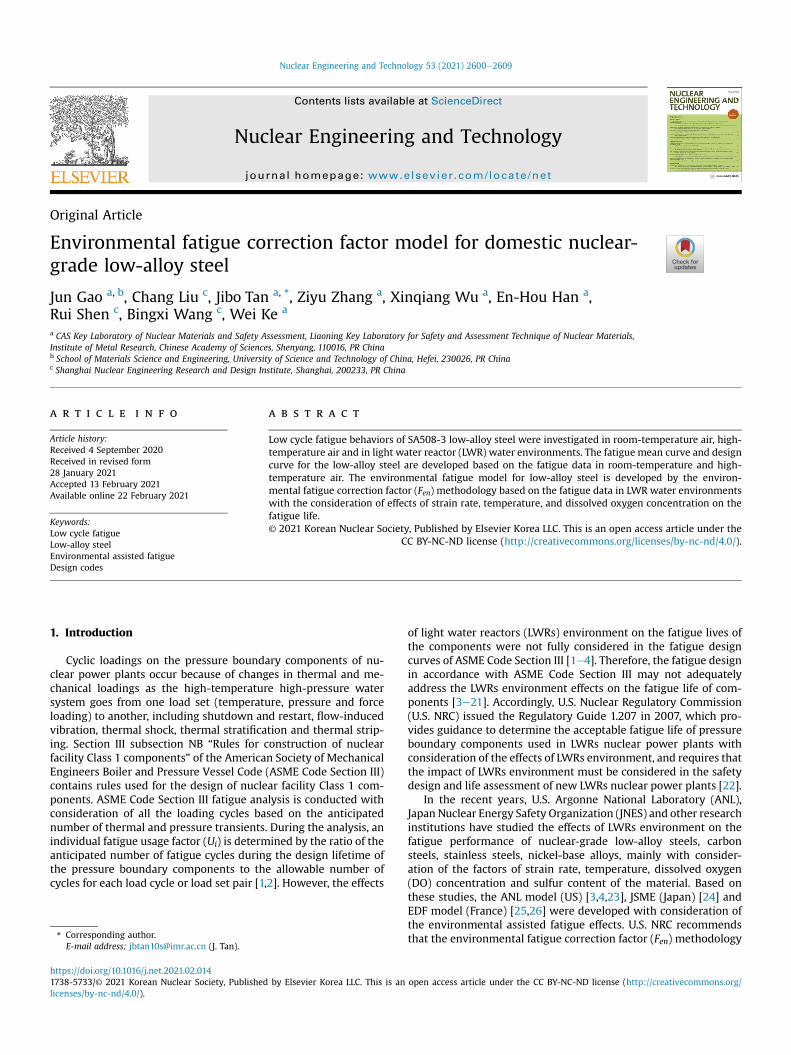
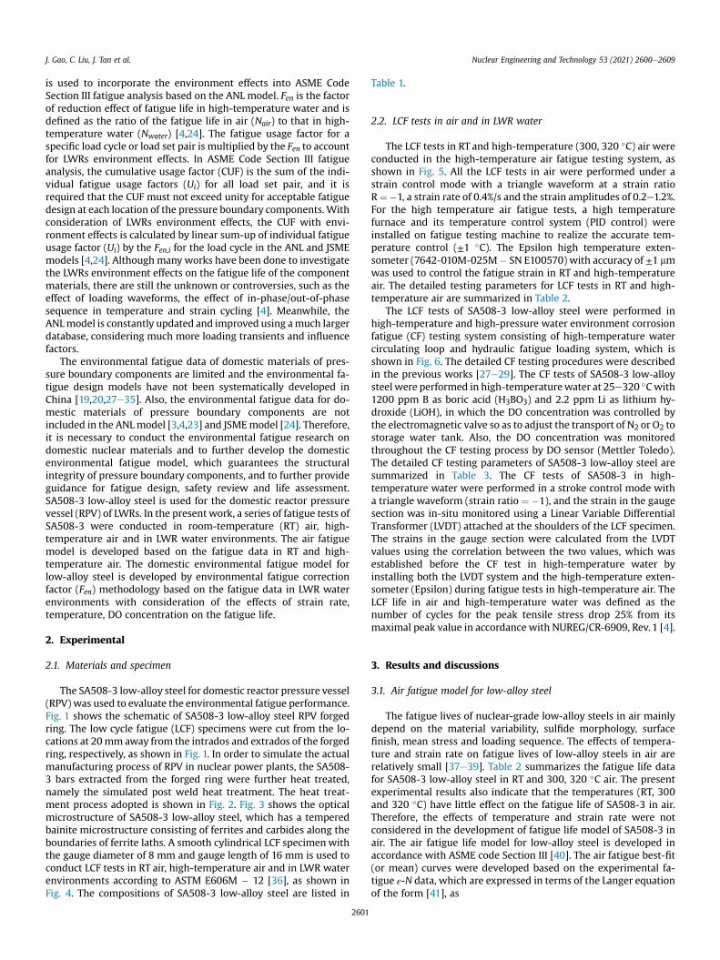
The SA508-3 low-alloy steel for domestic reactor pressure vessel(RPV) was used to evaluate the environmental fatigue performance.Fig. 1 shows the schematic of SA508-3 low-alloy steel RPV forgedring. The low cycle fatigue (LCF) specimens were cut from the lo-cations at 20mm away from the intrados and extrados of the forgedring, respectively, as shown in Fig. 1. In order to simulate the actualmanufacturing process of RPV in nuclear power plants, the SA508-3 bars extracted from the forged ring were further heat treated,namely the simulated post weld heat treatment. The heat treat-ment process adopted is shown in Fig. 2. Fig. 3 shows the opticalmicrostructure of SA508-3 low-alloy steel, which has a temperedbainite microstructure consisting of ferrites and carbides along theboundaries of ferrite laths. A smooth cylindrical LCF specimenwiththe gauge diameter of 8 mm and gauge length of 16 mm is used toconduct LCF tests in RT air, high-temperature air and in LWR waterenvironments according to ASTM E606M � 12 [36], as shown inFig. 4. The compositions of SA508-3 low-alloy steel are listed in
2601
Table 1.
2.2. LCF tests in air and in LWR water
The LCF tests in RT and high-temperature (300, 320 �C) air wereconducted in the high-temperature air fatigue testing system, asshown in Fig. 5. All the LCF tests in air were performed under astrain control mode with a triangle waveform at a strain ratioR¼�1, a strain rate of 0.4%/s and the strain amplitudes of 0.2e1.2%.For the high temperature air fatigue tests, a high temperaturefurnace and its temperature control system (PID control) wereinstalled on fatigue testing machine to realize the accurate tem-perature control (±1 �C). The Epsilon high temperature exten-someter (7642-010M-025M� SN E100570) with accuracy of ±1 mmwas used to control the fatigue strain in RT and high-temperatureair. The detailed testing parameters for LCF tests in RT and high-temperature air are summarized in Table 2.
The LCF tests of SA508-3 low-alloy steel were performed inhigh-temperature and high-pressure water environment corrosionfatigue (CF) testing system consisting of high-temperature watercirculating loop and hydraulic fatigue loading system, which isshown in Fig. 6. The detailed CF testing procedures were describedin the previous works [27e29]. The CF tests of SA508-3 low-alloysteel were performed in high-temperaturewater at 25e320 �Cwith1200 ppm B as boric acid (H3BO3) and 2.2 ppm Li as lithium hy-droxide (LiOH), in which the DO concentration was controlled bythe electromagnetic valve so as to adjust the transport of N2 or O2 tostorage water tank. Also, the DO concentration was monitoredthroughout the CF testing process by DO sensor (Mettler Toledo).The detailed CF testing parameters of SA508-3 low-alloy steel aresummarized in Table 3. The CF tests of SA508-3 in high-temperature water were performed in a stroke control mode witha triangle waveform (strain ratio ¼ �1), and the strain in the gaugesection was in-situ monitored using a Linear Variable DifferentialTransformer (LVDT) attached at the shoulders of the LCF specimen.The strains in the gauge section were calculated from the LVDTvalues using the correlation between the two values, which wasestablished before the CF test in high-temperature water byinstalling both the LVDT system and the high-temperature exten-someter (Epsilon) during fatigue tests in high-temperature air. TheLCF life in air and high-temperature water was defined as thenumber of cycles for the peak tensile stress drop 25% from itsmaximal peak value in accordance with NUREG/CR-6909, Rev. 1 [4].
3. Results and discussions
3.1. Air fatigue model for low-alloy steel
The fatigue lives of nuclear-grade low-alloy steels in air mainlydepend on the material variability, sulfide morphology, surfacefinish, mean stress and loading sequence. The effects of tempera-ture and strain rate on fatigue lives of low-alloy steels in air arerelatively small [37e39]. Table 2 summarizes the fatigue life datafor SA508-3 low-alloy steel in RT and 300, 320 �C air. The presentexperimental results also indicate that the temperatures (RT, 300and 320 �C) have little effect on the fatigue life of SA508-3 in air.Therefore, the effects of temperature and strain rate were notconsidered in the development of fatigue life model of SA508-3 inair. The air fatigue life model for low-alloy steel is developed inaccordance with ASME code Section III [40]. The air fatigue best-fit(or mean) curves were developed based on the experimental fa-tigue ε-N data, which are expressed in terms of the Langer equationof the form [41], as
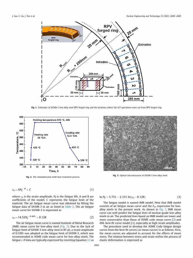
Fig. 1. Schematic of SA508-3 low-alloy steel RPV forged ring and the locations where the LCF specimens were cut from RPV forged ring.
Fig. 2. The simulated post weld heat treatment process.Fig. 3. Optical microstructure of SA508-3 low-alloy steel.
J. Gao, C. Liu, J. Tan et al. Nuclear Engineering and Technology 53 (2021) 2600e2609
εa ¼ANf�B þ C (1)
where ea is the strain amplitude, Nf is the fatigue life, A and B arecoefficients of the model, C represents the fatigue limit of thematerial. The air fatigue mean curve was obtained by fitting thefatigue data of SA508-3 in air as listed in Table 2. The air fatiguemean curve for SA508-3 is expressed as
εa ¼ 14:52Nf�0:465 þ 0:128 (2)
The air fatigue mean curve is named Institute of Metal Research(IMR) mean curve for low-alloy steel (Fig. 7). Due to the lack offatigue limit of SA508-3 low-alloy steel in RT air, a strain amplitudeof 0.128% was adopted as the fatigue limit of SA508-3, which wasrecommended in ASME code mean curve for low-alloy steels. Thefatigue ε-N data are typically expressed by rewriting Equation (2) as
2602
ln Nf ¼5:751� 2:151 lnðεa �0:128Þ (3)
The fatigue model is named IMR model. Note that IMR modelconsists of air fatigue mean curve and the Fen expression for low-alloy steels in the present work. As shown in Fig. 7, IMR meancurve can well predict the fatigue lives of nuclear-grade low-alloysteels in air. The predicted lives based on IMR model are lower andmore conservative than those of ASME code mean curve [2] andANL best-fit curve model [4], especially at high strain amplitudes.
The procedure used to develop the ASME Code fatigue designcurves from the best-fit curves (or mean curves) is as follows. First,the mean curves are adjusted to account for the effects of meanstress. The relation between stress and strain within the process ofelastic deformation is expressed as
Fig. 4. Dimensions of the LCF specimen of SA508-3 low-alloy steel used in the present work.
Table 1Compositions of SA 508-3 low-alloy steel (wt.%).
C Mn P S Si Ni Cr Mo V Fe
0.20 1.41 <0.005 0.002 0.16 0.78 0.13 0.49 <0.002 Bal.
J. Gao, C. Liu, J. Tan et al. Nuclear Engineering and Technology 53 (2021) 2600e2609
Sa ¼ Eεa (4)
where Sa is the stress amplitude; E is the elastic modulus of thematerial. The stress amplitudes at different strain amplitudes canbe obtained by Equation (4) in the regime of high-cycle fatigue,which involves little or no plastic strain. However, low cycle fatigueinvolves strains in excess of the yield strain. For low cycle fatigue,the stress amplitudes at different strain amplitudes can be obtained
Fig. 5. High-temperature air
2603
by fitting cyclic stress-strain data. Based on the combination of twoabove, the Sa-Nf equation is developed. Mean stress was accountedfor using the modified Goodman relationship given by
S0a ¼ Sa
�su � sysu � Sa
�Sasy
S0a ¼ Sa Sasy
(5)
where S0a is the adjusted stress amplitude value, su is monotonicultimate strength, sy is the yield strengths of the material.Accordingly, the nominal stress amplitude vs. fatigue life relation-ship is obtained. The original ASME Code Section III fatigue designcurves (2004) were obtained by reducing the fatigue life at eachpoint on the adjusted mean curve by a factor of 2 on strain (orstress) or 20 on fatigue lives [1]. The factor of 20 on fatigue life was
fatigue testing system.
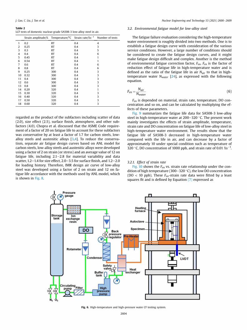
Table 2LCF tests of domestic nuclear-grade SA508-3 low-alloy steel in air.
Strain amplitude/% Temperature/oC Strain rate/%s�1 Number of tests
1 0.2 RT 0.4 42 0.25 RT 0.4 33 0.3 RT 0.4 54 0.4 RT 0.4 65 0.45 RT 0.4 16 0.54 RT 0.4 17 0.6 RT 0.4 68 0.8 RT 0.4 69 0.25 300 0.4 310 0.32 300 0.4 311 0.4 300 0.4 312 0.6 300 0.4 313 0.8 300 0.4 314 0.20 320 0.4 115 0.30 320 0.4 316 0.40 320 0.4 317 0.50 320 0.4 318 0.60 320 0.4 3
J. Gao, C. Liu, J. Tan et al. Nuclear Engineering and Technology 53 (2021) 2600e2609
regarded as the product of the subfactors including scatter of data(2.0), size effect (2.5), surface finish, atmosphere, and other sub-factors (4.0). Chopra et al. discussed that the ASME Code require-ment of a factor of 20 on fatigue life to account for these subfactorswas conservative by at least a factor of 1.7 for carbon steels, low-alloy steels and austenitic alloys [3,4]. To reduce the conserva-tism, separate air fatigue design curves based on ANL model forcarbon steels, low-alloy steels and austenitic alloys were developedusing a factor of 2 on strain (or stress) and an average value of 12 onfatigue life, including 2.1e2.8 for material variability and datascatter, 1.2e1.4 for size effect, 2.0e3.5 for surface finish, and 1.2e2.0for loading history. Therefore, IMR design air curve of low-alloysteel was developed using a factor of 2 on strain and 12 on fa-tigue life accordance with the methods used by ANL model, whichis shown in Fig. 8.
Fig. 6. High-temperature and high-p
2604
3.2. Environmental fatigue model for low-alloy steel
The fatigue failure evaluation considering the high-temperaturewater environment is roughly divided into two methods. One is toestablish a fatigue design curve with consideration of the variousservice conditions. However, a large number of conditions shouldbe considered to create the fatigue design curves, and it mightmake fatigue design difficult and complex. Another is the methodof environmental fatigue correction factor, Fen. Fen is the factor ofreduction effect of fatigue life in high-temperature water and isdefined as the ratio of the fatigue life in air Nair to that in high-temperature water Nwater [24], as expressed with the followingequation.
Fen ¼ Nair
Nwater(6)
Fen is depended on material, strain rate, temperature, DO con-centration and so on, and can be calculated by multiplying the ef-fects of these parameters.
Fig. 9 summarizes the fatigue life data for SA508-3 low-alloysteel in high-temperature water at 200e320 �C. The present workmainly investigates the effects of strain amplitude, temperature,strain rate and DO concentration on fatigue life of low-alloy steel inhigh-temperature water environment. The results show that thefatigue life of SA508-3 decreased in high-temperature watercompared with the life in air, and can decrease by a factor ofapproximately 10 under special condition such as temperature of320 �C, DO concentration of 1000 ppb, and strain rate of 0.01 %s�1.
3.2.1. Effect of strain rateFig. 10 shows the Fen vs. strain rate relationship under the con-
dition of high temperature (300e320 �C), the lowDO concentration(DO < 10 ppb). These Fen-strain rate data were fitted by a leastsquares fit and is defined by Equation (7) expressed as
ressure water CF testing system.
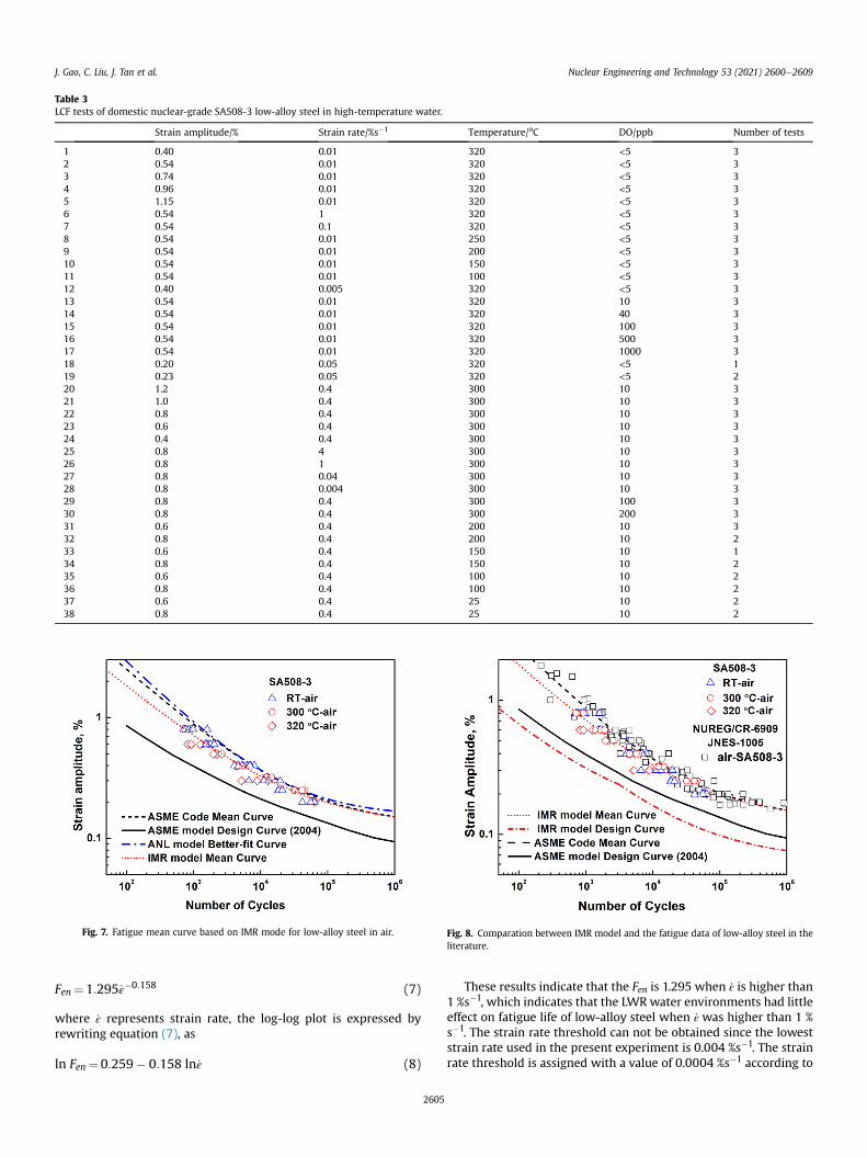
Table 3LCF tests of domestic nuclear-grade SA508-3 low-alloy steel in high-temperature water.
Strain amplitude/% Strain rate/%s�1 Temperature/oC DO/ppb Number of tests
1 0.40 0.01 320 <5 32 0.54 0.01 320 <5 33 0.74 0.01 320 <5 34 0.96 0.01 320 <5 35 1.15 0.01 320 <5 36 0.54 1 320 <5 37 0.54 0.1 320 <5 38 0.54 0.01 250 <5 39 0.54 0.01 200 <5 310 0.54 0.01 150 <5 311 0.54 0.01 100 <5 312 0.40 0.005 320 <5 313 0.54 0.01 320 10 314 0.54 0.01 320 40 315 0.54 0.01 320 100 316 0.54 0.01 320 500 317 0.54 0.01 320 1000 318 0.20 0.05 320 <5 119 0.23 0.05 320 <5 220 1.2 0.4 300 10 321 1.0 0.4 300 10 322 0.8 0.4 300 10 323 0.6 0.4 300 10 324 0.4 0.4 300 10 325 0.8 4 300 10 326 0.8 1 300 10 327 0.8 0.04 300 10 328 0.8 0.004 300 10 329 0.8 0.4 300 100 330 0.8 0.4 300 200 331 0.6 0.4 200 10 332 0.8 0.4 200 10 233 0.6 0.4 150 10 134 0.8 0.4 150 10 235 0.6 0.4 100 10 236 0.8 0.4 100 10 237 0.6 0.4 25 10 238 0.8 0.4 25 10 2
Fig. 7. Fatigue mean curve based on IMR mode for low-alloy steel in air. Fig. 8. Comparation between IMR model and the fatigue data of low-alloy steel in theliterature.
J. Gao, C. Liu, J. Tan et al. Nuclear Engineering and Technology 53 (2021) 2600e2609
Fen¼1:295 _ε�0:158 (7)
where _ε represents strain rate, the log-log plot is expressed byrewriting equation (7), as
ln Fen ¼0:259� 0:158 ln_ε (8)
2605
These results indicate that the Fen is 1.295 when _ε is higher than1 %s�1, which indicates that the LWR water environments had littleeffect on fatigue life of low-alloy steel when _ε was higher than 1 %s�1. The strain rate threshold can not be obtained since the loweststrain rate used in the present experiment is 0.004 %s�1. The strainrate threshold is assigned with a value of 0.0004 %s�1 according to

Fig. 9. Effect of high-temperature water on the fatigue life of nuclear-grade SA508-3low-alloy steel.
Fig. 10. The Fen vs. strain rate relationship for nuclear-grade low alloy steel in LWRwater environments.
Fig. 11. The Fen vs. temperature relationship for nuclear-grade low alloy steel in LWRwater environments.
Fig. 12. The Fen vs. DO concentration relationship for nuclear-grade low alloy steel inLWR water environments.
J. Gao, C. Liu, J. Tan et al. Nuclear Engineering and Technology 53 (2021) 2600e2609
NUREG/CR 6909 Rev.1 [4], and this means that the influence of LWRwater environments on fatigue life of low-alloy steel is saturatedwhen the strain rate is below the threshold value. The fatigue livesdecreased by a factor of 3 when the strain rate decreased from 1 %s�1 to 0.004 %s�1.
3.2.2. Effect of temperatureFig. 11 shows the Fen vs. temperature relationship under the
condition of the strain rate (0.01 %s�1), the low DO concentration(DO < 10 ppb). Note that the Fen data at different strain rates wereconverted to those equivalent to the strain rate of 0.01 %s�1 for low-alloy steel by using the Fen vs. strain rate relationship (Equation (7))so as to cover as much data as possible to evaluate the effect oftemperature on Fen. These Fen-temperature data for temperatureabove 150 �C were fitted by a least squares fit and is defined byEquation (9) expressed as
Fen¼ exp½0:0055ðT �150Þ� (9)
the log-log plot is expressed by rewriting equation (9), as
ln Fen ¼0:0055ðT �150Þ (10)
2606
These results show that the Fen is 1 when the temperature islower than 150 �C, which indicates that the high-temperaturewater environment (T < 150 �C) had no or little effect on fatiguelife of low-alloy steel. The environmental fatigue life decreasedwith increasing temperature in the range of 150e320 �C, and thelife decreased by a factor of 2.6 at 320 �C. The upper limit of tem-perature in the temperature dependence relationship in the Fenexpression is determined for 320 �C with consideration of theservice temperature of LWRs (292e327 �C) and the lack of fatiguedata with the temperature above 320 �C.
3.2.3. Effect of DO concentrationFig. 12 shows that the Fen vs. DO concentration relationship
under the condition of the temperature (320 �C), the strain rate(0.01 %s�1). These Fen-temperature data were fitted by a leastsquares fit and is defined by Equation (11) expressed as
Fen ¼0:503DO0:427 (11)
the log-log plot is expressed by rewriting equation (11), as
ln Fen¼0:427 lnðDOÞ � 0:687 (12)
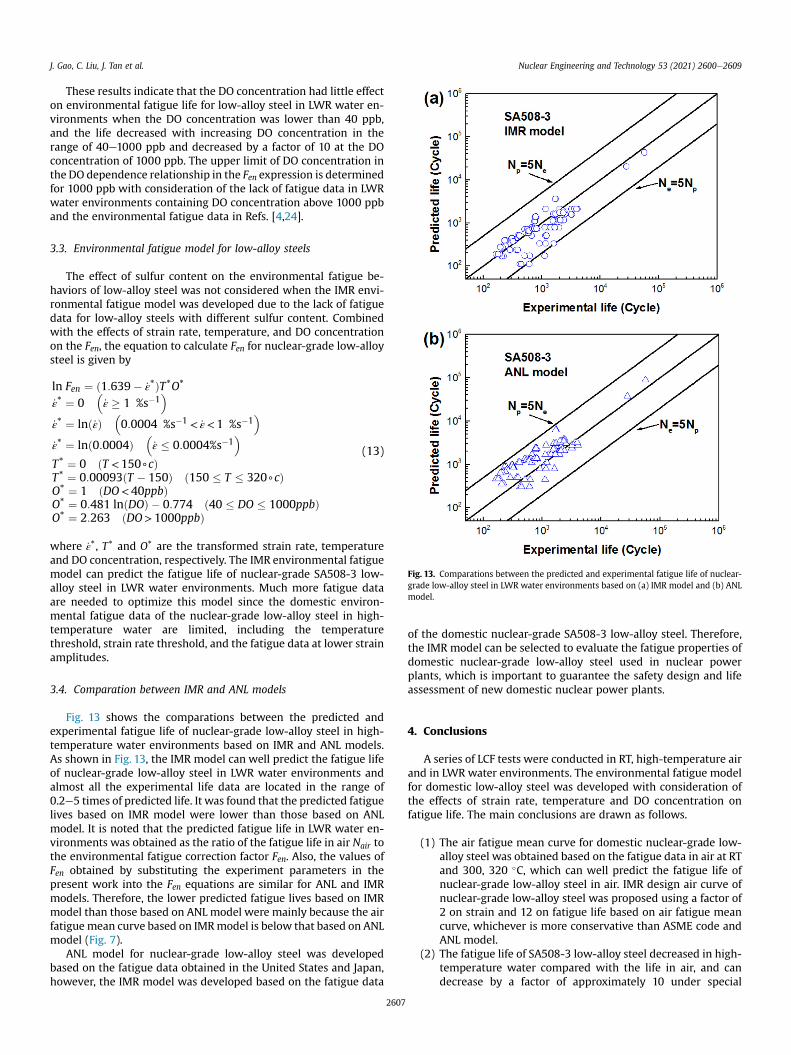
Fig. 13. Comparations between the predicted and experimental fatigue life of nuclear-grade low-alloy steel in LWR water environments based on (a) IMR model and (b) ANLmodel.
J. Gao, C. Liu, J. Tan et al. Nuclear Engineering and Technology 53 (2021) 2600e2609
These results indicate that the DO concentration had little effecton environmental fatigue life for low-alloy steel in LWR water en-vironments when the DO concentration was lower than 40 ppb,and the life decreased with increasing DO concentration in therange of 40e1000 ppb and decreased by a factor of 10 at the DOconcentration of 1000 ppb. The upper limit of DO concentration inthe DO dependence relationship in the Fen expression is determinedfor 1000 ppb with consideration of the lack of fatigue data in LWRwater environments containing DO concentration above 1000 ppband the environmental fatigue data in Refs. [4,24].
3.3. Environmental fatigue model for low-alloy steels
The effect of sulfur content on the environmental fatigue be-haviors of low-alloy steel was not considered when the IMR envi-ronmental fatigue model was developed due to the lack of fatiguedata for low-alloy steels with different sulfur content. Combinedwith the effects of strain rate, temperature, and DO concentrationon the Fen, the equation to calculate Fen for nuclear-grade low-alloysteel is given by
ln Fen ¼ ð1:639� _ε*ÞT*O*
_ε* ¼ 0�_ε � 1 %s�1
�_ε* ¼ lnð_εÞ
�0:0004 %s�1 < _ε<1 %s�1
�_ε* ¼ lnð0:0004Þ
�_ε � 0:0004%s�1
�T* ¼ 0 ðT <150+cÞT* ¼ 0:00093ðT � 150Þ ð150 � T � 320+cÞO* ¼ 1 ðDO<40ppbÞO* ¼ 0:481 lnðDOÞ � 0:774 ð40 � DO � 1000ppbÞO* ¼ 2:263 ðDO>1000ppbÞ
(13)
where _ε*, T* and O* are the transformed strain rate, temperatureand DO concentration, respectively. The IMR environmental fatiguemodel can predict the fatigue life of nuclear-grade SA508-3 low-alloy steel in LWR water environments. Much more fatigue dataare needed to optimize this model since the domestic environ-mental fatigue data of the nuclear-grade low-alloy steel in high-temperature water are limited, including the temperaturethreshold, strain rate threshold, and the fatigue data at lower strainamplitudes.
3.4. Comparation between IMR and ANL models
Fig. 13 shows the comparations between the predicted andexperimental fatigue life of nuclear-grade low-alloy steel in high-temperature water environments based on IMR and ANL models.As shown in Fig. 13, the IMR model can well predict the fatigue lifeof nuclear-grade low-alloy steel in LWR water environments andalmost all the experimental life data are located in the range of0.2e5 times of predicted life. It was found that the predicted fatiguelives based on IMR model were lower than those based on ANLmodel. It is noted that the predicted fatigue life in LWR water en-vironments was obtained as the ratio of the fatigue life in air Nair tothe environmental fatigue correction factor Fen. Also, the values ofFen obtained by substituting the experiment parameters in thepresent work into the Fen equations are similar for ANL and IMRmodels. Therefore, the lower predicted fatigue lives based on IMRmodel than those based on ANL model were mainly because the airfatigue mean curve based on IMRmodel is below that based on ANLmodel (Fig. 7).
ANL model for nuclear-grade low-alloy steel was developedbased on the fatigue data obtained in the United States and Japan,however, the IMR model was developed based on the fatigue data
2607
of the domestic nuclear-grade SA508-3 low-alloy steel. Therefore,the IMR model can be selected to evaluate the fatigue properties ofdomestic nuclear-grade low-alloy steel used in nuclear powerplants, which is important to guarantee the safety design and lifeassessment of new domestic nuclear power plants.
4. Conclusions
A series of LCF tests were conducted in RT, high-temperature airand in LWR water environments. The environmental fatigue modelfor domestic low-alloy steel was developed with consideration ofthe effects of strain rate, temperature and DO concentration onfatigue life. The main conclusions are drawn as follows.
(1) The air fatigue mean curve for domestic nuclear-grade low-alloy steel was obtained based on the fatigue data in air at RTand 300, 320 �C, which can well predict the fatigue life ofnuclear-grade low-alloy steel in air. IMR design air curve ofnuclear-grade low-alloy steel was proposed using a factor of2 on strain and 12 on fatigue life based on air fatigue meancurve, whichever is more conservative than ASME code andANL model.
(2) The fatigue life of SA508-3 low-alloy steel decreased in high-temperature water compared with the life in air, and candecrease by a factor of approximately 10 under special
J. Gao, C. Liu, J. Tan et al. Nuclear Engineering and Technology 53 (2021) 2600e2609
condition such as temperature of 320 �C, DO concentration of1000 ppb, and strain rate of 0.01 %s�1.
(3) The LWR water environments had little effect on fatigue lifeof low-alloy steel when the strain rate was higher than 1 %s�1. The fatigue lives decreased by a factor of 3 when thestrain rate decreased from 1 %s�1 to 0.004 %s�1.
(4) The high-temperature water environment (T < 150 �C) hadno or little effect on fatigue life of SA508-3 low-alloy steel.The environmental fatigue life decreased with increasingtemperature in the range of 150e320 �C, and the lifedecreased by a factor of 2.6 at 320 �C.
(5) The DO concentration had little effect on environmental fa-tigue life for low-alloy steel in LWR water environmentswhen the DO concentration was lower than 40 ppb, and thelife decreased with increasing DO concentration in the rangeof 40e1000 ppb.
(6) IMR environmental fatigue model was developed based onthe environmental fatigue data of domestic nuclear-gradeSA508-3, which considered the effects of strain rate, tem-perature and DO concentration on the environmental fatiguecorrection factor Fen. The IMR model can well predict thefatigue life of nuclear-grade low-alloy steel in LWR waterenvironments. The predicted fatigue lives based on IMRmodel were lower than those based on ANL model, whichwas mainly because the air fatigue mean curve based on IMRmodel is below that based on ANL model.
Data availability
The raw/processed data required to reproduce these findings areincluded in the article, and are available from the correspondingauthors upon reasonable request.
Declaration of competing interest
The authors declare that they have no known competingfinancial interests or personal relationships that could haveappeared to influence the work reported in this paper.
Acknowledgements
This study was jointly supported by the National Science andTechnology Major Project (2017ZX06002003-004-002), the KeyPrograms of the Chinese Academy of Sciences (Research on theDevelopment of Nuclear Power Materials and Service SecurityTechnology, ZDRWeCNe2017-1), the National Natural ScienceFoundation of China (51601201 & 51671201), and the InnovationFund of Institute of Metal Research, Chinese Academy of Sciences(SCJJ-2013-ZD-02).
References
[1] American Society Mechanical Engineers, ASME Boiler and Pressure VesselCode Section III, New York, 2004.
[2] American Society Mechanical Engineers, ASME Boiler and Pressure VesselCode Section III, New York, 2015.
[3] O.K. Chopra, W.J. Shack, Effect of LWR coolant environments on the fatigue lifeof reactor materials, NUREG/CR (United States. Nucl. Regul. Comm.) 6909(2007).
[4] O.K. Chopra, G.L. Stevens, Effect of LWR coolant environments on the fatiguelife of reactor materials, NUREG/CR-6909 Rev 1 (2018).
[5] H.P. Seifert, S. Ritter, H.J. Leber, Corrosion fatigue crack growth behaviour ofaustenitic stainless steels under light water reactor conditions, Corrosion Sci.55 (2012) 61e75.
[6] H.P. Seifert, S. Ritter, H.J. Leber, Corrosion fatigue initiation and short crackgrowth behaviour of austenitic stainless steels under light water reactorconditions, Corrosion Sci. 59 (2012) 20e34.
2608
[7] H.P. Seifert, S. Ritter, H. Leber, Effect of static load hold periods on thecorrosion fatigue behaviour of austenitic stainless steels in simulated BWRenvironments, in: 15th International Conference on Environmental Degra-dation of Materials in Nuclear Systems - Water Reactors, CD-ROM, NACE/TMS/ANS, Colorado Springs, Colorado, USA, 2011. August 7-11.
[8] F.P. Ford, P.W. Emigh, The prediction of the maximum corrosion fatigue crack-propagation rate in the low-alloy steel de-oxygenated water-system at 288 �C,Corrosion Sci. 25 (1985) 673e692.
[9] F.P. Ford, Quantitative prediction of environmentally assisted cracking,Corrosion Sci. 52 (1996) 375e395.
[10] A. Turnbull, D.H. Ferriss, Mathematical-modeling of the electrochemistry incorrosion fatigue cracks in structural-steel cathodically protected in sea-wa-ter, Corrosion Sci. 26 (1986) 601e628.
[11] A. Turnbull, Modelling of environment assisted cracking, Corrosion Sci. 34(1993) 921e960.
[12] P.M. Scott, A.E. Truswell, Corrosion fatigue crack growth in reactor pressurevessel steels in PWR primary water, J. Press. Vess. Technol. Trans. 105 (1983)245e254.
[13] H. H€anninen, W. Cullen, M. Kemppainen, Effects of MnS inclusion dissolutionon environmentally assisted cracking in low-alloy and carbon steels, Corro-sion 46 (1990) 563e573.
[14] H. H€anninen, K. T€orr€onen, M. Kemppainen, S. Salonen, On the mechanisms ofenvironment sensitive cyclic crack growth of nuclear reactor pressure vesselsteels, Corrosion Sci. 23 (1983) 663e679.
[15] C. Jang, P.Y. Cho, M. Kim, S.J. Oh, J.S. Yang, Effects of microstructure and re-sidual stress on fatigue crack growth of stainless steel narrow gap welds,Mater. Des. 31 (2010) 1862e1870.
[16] H. Cho, B.K. Kim, I.S. Kim, C. Jang, D.Y. Jung, Fatigue life and crack growthmechanisms of the Type 316LN austenitic stainless steel in 310�C deoxy-genated water, J. Nucl. Sci. Technol. 44 (2007) 1007e1014.
[17] H. Cho, B.K. Kim, I.S. Kim, C. Jang, Low cycle fatigue behaviors of type 316LNaustenitic stainless steel in 310�C deaerated water-fatigue life and dislocationstructure development, Mat. Sci. Eng. A-Struct 476 (2008) 248e256.
[18] J.-D. Hong, J. Lee, C. Jang, T.S. Kim, Low cycle fatigue behavior of alloy 690 insimulated PWR water-Effects of dynamic strain aging and hydrogen, Mat. Sci.Eng. A-Struct. 611 (2014) 37e44.
[19] S. Xu, X. Wu, E.-H. Han, W. Ke, Y. Katada, Crack initiation mechanisms for lowcycle fatigue of type 316Ti stainless steel in high temperature water, Mat. Sci.Eng. A-Struct. 490 (2008) 16e25.
[20] X. Wu, Y. Katada, Strain-rate dependence of low cycle fatigue behavior in asimulated BWR environment, Corrosion Sci. 47 (2005) 1415e1428.
[21] P.L. Andresen, Effects of temperature on crack growth rate in sensitized type304 stainless steel and Alloy 600, Corrosion 49 (1993) 714e725.
[22] R.G. 1, 207, Guidelines for Evaluating Fatigue Analyses Incorporating the LifeReduction of Metal Components Due to the Effects of the Light-Water Reactor,U.S. Nuclear Regulatory Commission, Washington, DC, March, 2007.
[23] O.K. Chopra, Y. Garud, G. Stevens, Update of NUREG/CR-6909 Methodology forEnvironmentally Assisted Fatigue (EAF)-revised Fen Expressions, ASME CodeMeetings, Section III Subgroup on Fatigue Strength, Nashville, TN, 2012.
[24] Environmental Fatigue Evaluation Method for Nuclear Power Plants, JNES-SS-1005, Japan Nuclear Energy Safety Organization, 2011.
[25] C. Faidy, Status of French road map to improve environmental fatigue rules,ASME Pressure Vessels and Piping Division Conference, 2012. PVP2012-78805.
[26] Design and Construction Rules for PWR Nuclear Island, RCC-M, AFCEN, 2007.[27] J. Gao, Z. Zhang, J. Tan, X. Wu, E.-H. Han, W. Ke, Environmentally assisted
fatigue behavior of 308L weld metal in borated and lithiated high-temperature water, J. Nucl. Mater. 539 (2020) 152365.
[28] J. Gao, J. Tan, M. Jiao, X. Wu, L. Tang, Y. Huang, Role of welding residual strainand ductility dip cracking on corrosion fatigue behavior of Alloy 52/52Mdissimilar metal weld in borated and lithiated high-temperature water,J. Mater. Sci. Technol. 42 (2020) 163e174.
[29] J. Gao, J. Tan, X. Wu, S. Xia, Effect of grain boundary engineering on corrosionfatigue behavior of 316LN stainless steel in borated and lithiated high-temperature water, Corrosion Sci. 152 (2019) 190e201.
[30] Z. Zhang, J. Tan, X. Wu, E.-H. Han, W. Ke, J. Rao, Corrosion fatigue behavior andcrack-tip characteristic of 316LN stainless steel in high-temperature pres-surized water, J. Nucl. Mater. 518 (2019) 21e29.
[31] Z. Zhang, J. Tan, X. Wu, E.-H. Han, W. Ke, J. Rao, Effects of temperature oncorrosion fatigue behavior of 316LN stainless steel in high-temperaturepressurized water, Corrosion Sci. 146 (2019) 80e89.
[32] Z. Zhang, J. Tan, X. Wu, E.-H. Han, W. Ke, Synergistic effect of mechanical andenvironmental damages of 316LN stainless steel under different fatigue strainamplitudes in high-temperature pressurized water, Mat. Sci. Eng. A-Struct.743 (2019) 243e250.
[33] J. Tan, X. Wu, E.-H. Han, W. Ke, X. Wang, H. Sun, Strain-rate dependent fatiguebehavior of 316LN stainless steel in high-temperature water, J. Nucl. Mater.489 (2017) 33e41.
[34] J. Tan, X. Wu, E.-H. Han, W. Ke, X. Liu, F. Meng, X. Xu, Corrosion fatiguebehavior of Alloy 690 steam generator tube in borated and lithiated hightemperature water, Corrosion Sci. 89 (2014) 203e213.
[35] J. Tan, X. Wu, E.-H. Han, W. Ke, X. Liu, F. Meng, X. Xu, Role of TiN inclusion oncorrosion fatigue behavior of Alloy 690 steam generator tubes in borated andlithiated high temperature water, Corrosion Sci. 88 (2014) 349e359.
[36] Standard Test Method for Strain-Controlled Fatigue Testing, ASTM
J. Gao, C. Liu, J. Tan et al. Nuclear Engineering and Technology 53 (2021) 2600e2609
International, 2012, pp. 1e16.[37] O.K. Chopra, W.J. Shack, Effects of LWR Coolant Environments on Fatigue
Design Curves of Carbon and Low-Alloy Steels, NUREG/CR-6583, ArgonneNational Laboratory (ANL)-97/18, Argonne National Laboratory, Argonne, IL,February 1998.
[38] H. Abdel-Raouf, A. Plumtree, T.H. Topper, Effects of temperature and defor-mation rate on cyclic strength and fracture of low-carbon steel, in: CyclicStress-Strain Behavior-Analysis, Experimentation, and Failure Prediction,ASTM STP-519, American Society for Testing and Materials, Philadelphia, PA,
2609
1973, pp. 28e52.[39] B.H. Lee, I.S. Kim, Dynamic strain aging in the high-temperature low-cycle
fatigue of SA508 Cl. 3 forging steel, J. Nucl. Mater. 226 (1995) 216e225.[40] Criteria of the ASME Boiler and Pressure Vessel Code for Design by Analysis in
Sections III and VIII, Division 2, American Society of Mechanical Engineers,New York, 1969.
[41] B.F. Langer, Design of pressure vessels for low cycle fatigue, ASME J. Basic. Eng.84 (1962) 389e402.


