Embed Size (px)
Citation preview
Bharat Heavy Electricals Limited
Heavy Electrical Equipment Plant, Haridwar-249403
Works Engineering & Services
Works Contract Section
NOTICE INVITING TENDER
(Global Open Tender)
Tender Document
Name of Work: “Engagement of consultant for design & Engg Services for ACC for 3X800 MW Patratu.”
Tender Enquiry No.: BHEL/HEEP/WEX-WCS/21-22/4022/20210096 DT.20.11.2021
Due date of Tender Opening: 03.12.2021
Type of Bid: Two Part
Place of Submission of Tender / Bid:
Through
email at [email protected]
Or Paper Bid to Tender Room, Purchase Deptt., 4th floor, Main
Administrative Building, BHEL , HEEP, Haridwar-249403
(Uttarakhand)
1. Himanshu Arora, Dy. Manager(WEX-WCS)
Contact Address: WCS, ADM-4, BHEL (HEEP), Haridwar-249403
Email: [email protected] ;
Phone: +91-1334-281932; Fax: +91-1334-226460
2. Shiv Charan Meena, Manager (WEX-WCS)
Contact Address: WCS, ADM-4, BHEL (HEEP), Haridwar-249403
Email: [email protected]
Phone: +91-1334-284137; Fax: +91-1334-226460
------------------------------------------------------------------------------------------------
Document can be downloaded from www.bhel.com/ www.hwr.bhel.com Note: All corrigenda / addenda / amendments / time extensions / clarifications, etc. to the tender will be hosted on our website i.e. www.bhel.com / www.hwr.bhel.com only and will not be published in any other media. Bidders should regularly visit above website to keep themselves updated.
NOTICE FOR TENDER (NIT)
BHARAT HEAVY ELECTRICAL LIMITED HEEP, Haridwar-249403(UTTARAKHAND)
Name of Dept Works Engineering & Services (Works Contract Section)
Phone 01334-281932 Fax 01334-226460
Email Address for tender submission [email protected]
Email Address for communication [email protected]; [email protected]
Contact Person Himanshu Arora
NIT Key. 20210096 Dated 20.11.2021 NIT No. BHEL/HEEP/WEX-WCS/21-22/4022/20210096 DT.20.11.2021
NIT No. on www.bhel.com
NIT No. on www.hwr.bhel.com
Type Of Tender GLOBEN OPEN TENDER
#Tender Cost (in INR) NIL
EMD ( in INR ) NIL
Period of completion of work 12 Months
Two Part Bid /single bid Two Part Bid
NIT Value (in Rs.) ------
Last Date of submission of Tender 03.12.2021 Time : 01:45PM
* Date and Time for opening of Technical
Bid 03.12.2021 Time : 02:00PM
Pre Bid Meeting date 26.11.2021 Time : 02:00PM
Place Of submission of Tender Through email: [email protected]
Or
For paper bid: Tender Room, Purchase Deptt., 4th floor, Main Administrative Building, BHEL , HEEP, Haridwar-249403 (Uttarakhand)
* In case of two-part bid, date of opening of Tender means the date of opening of Techno-commercial bid.
However, date of opening of price bid shall be intimated to technically qualified parties. If the due date of tender opening happens to be a holiday, the tenders will be opened on the next working Tuesday/Friday.
Name of Work: “Engagement of consultant for design & Engg Services for ACC for 3X800 MW
Patratu.”
Contracting Executive Name: Himanshu Arora
Date:
1. BHEL reserves the right to accept or reject any/ all application(s) without assigning any reason thereof. 2. If any document submitted by tenderer found false at any stage, the tender/ work order will be cancelled
immediately and the financial loss to BHEL if any in making alternative arrangement will be recovered from the contractor.
3. BHEL will not be responsible for the loss or delay of tenders in transit in any case. 4. All further corrigenda, addenda, amendments, time extensions, clarifications & etc. to the tender, if any
shall only be notified on BHEL websites (www.bhel.com / www.hwr.bhel.com) as applicable. 5. For detailed instructions/information refer the tender document on BHEL website.
General Instructions to Tenderer
The Contractors who wish to participate should go through the Tender documents thoroughly and
plan well before quoting, to ensure that the Tender process is not aborted / vitiated, due to their
reasons.
1.0 Quoting & Signing the Tender
a. Before Quoting, the tenderers are advised to inspect the site of work and its environment and
be well acquainted with the actual working and other relevant conditions, position of materials
and labor. Tenderers are also requested to go through General -Terms & conditions, Special -
Terms & conditions of tender, Scope of work, Technical Terms & Conditions, drawings and
specifications and all other documents which are part of tender will form part of the agreement
to be entered into.
b. While quoting the rate, the tenderer is advised to take into account the likely expenditure, taxes
etc. during the operation of the Contract period from the date of commencement of work as
directed by BHEL.
c. While quoting the rates the tenderer is advised to take into account all factors including any
fluctuations in market rates. No claim will be entertained on this account after acceptance of
the tender or during the execution of the contract.
d. All entries in Tender documents shall be clearly written in one ink or typed. All the corrections
/ cancellations / insertions, if any, shall be duly attested by the Bidders concerned.
e. Rates should be quoted as per the Price Bid. Rates quoted in any other form will not be accepted
and is liable to be rejected.
a) If, in the price structure quoted for the required goods / services / works, there is
discrepancy between the unit price and the total price (which is obtained by multiplying
the unit price by the quantity), the unit price shall prevail and the total price corrected
accordingly, unless in the opinion of the purchaser there is an obvious misplacement of
the decimal point in the unit price, in which case the total price as quoted shall govern and
the unit price corrected accordingly.
b) If there is an error in a total corresponding to the addition or subtraction of subtotals, the
subtotals shall prevail and the total shall be corrected; and
c) If there is a discrepancy between words and figures, the amount in words shall prevail,
unless the amount expressed in words is related to an arithmetic error, in which case the
amount in figures shall prevail subject of e(a) and e(b) above.
d) If there is such discrepancy in an offer, the same shall be conveyed to the bidder with
target date up to which the bidder has to send his acceptance on the above lines and if the
bidder does not agree to the decision of the purchaser, the bid is liable to be ignored.
f. The Bidder shall fill in all the required particulars of the Tender documents and also sign &
Stamp on each and every page of the Tender documents (Techno- Commercial Bid, Price Bids,
Terms & Conditions etc.) including corrigendum & the drawing attached therein while
submitting their tender.
g. Should a Bidder find discrepancies or omissions in the Tender documents or should there any
doubt as to their meaning, he should at once address the authority inviting the Tender, for
clarification well before the due date, so as to submit his Tender in time.
h. Every endeavour is made to avoid any error which can materially affect the basis of the tender
but the successful tenderer shall take upon himself to provide for the risk or any error which
may be subsequently discovered and shall make no subsequent claim on account thereof.
i. Tenders not in accordance with the Tender conditions herein contained and the Tenders not in
original ARE LIABLE TO BE REJECTED.
j. If a Bidder deliberately gives wrong information in his Tender or creates conditions favourable
for the acceptance of his Tender, BHEL WILL REJECT SUCH TENDER AT ANY STAGE.
k. Words imparting singular number shall be deemed to include plural number and vice-versa
where the context so requires.
l. Canvassing in any form, in connection with the Tender is strictly prohibited and such Tenders
are bound to be rejected. All information furnished is taken to be authentic by the bidder for
evaluation of the Tender. Should any information be found incorrect subsequently, at any later
stage, the Tender / Contract shall be rejected / terminated and action as per BHEL Policy, rules
& prevailing Guidelines shall be taken.
m. Should a Bidder's or a Contractor's or in the case of a firm or company of Contractors / any of
its shareholder's or shareholder's relative be employed in BHEL Haridwar, the authority
inviting the Tenders shall be informed in writing of this fact at the time of submission of the
Tender, failing which the Tender may be disqualified, or if such fact subsequently comes to
light, the Contract may be cancelled.
n. The Tender schedule and the Tender shall be deemed to form an integral part of the Contract
to be entered into for this work.
o. Tenders are to be submitted in Tender Room, Purchase Deptt., 4th floor, Main
Administrative Building, BHEL, HEEP, Haridwar-249403 (Uttarakhand) upto 01:45 PM
on the date of tender opening. BHEL will not be responsible for any consequences that may
arise leading to delay in submission of tender/bid.
p. Late and Delayed Tenders shall be rejected.
q. In case of Limited Tender Enquiry if you are not interested to submit the offer, please send a
letter specifying the same.
r. Price bid should not be enclosed along with the techno commercial bid and other documents
in the same cover/envelope. The price bids have to be given category wise in a sealed cover
and the entire lot of price bid sealed covers will have to be kept in a separate large cover, duly
sealed.
ALL THE REQUIRED DOCUMENTS SHALL BE FILLED IN THE SAME SERIAL ORDER
AS PER THE FORMAT / COLUMN OF THE “TECHNO-COMMERCIAL BID”. ALL THE PAGES SHALL BE SERIALLY NUMBERED ON THE RIGHT HAND SIDE TOP CORNER.
PAGE NUMBERS AND DETAILS OF THE CONCERNED DOCUMENTS ALSO SHALL BE
FILLED IN “TECHNO- COMMERCIAL BID” IN THE BOXES PROVIDED. ALL THE PAGES OF TENDER DOCUMENTS ARE TO BE DULY SIGNED AND STAMPED BY THE
BIDDER. s. All the envelopes shall be super-scribed with Name of work, NIT No. & Date of Tender
Opening with the Name & Complete address of the bidder.
t. The envelope Containing Price Bid shall additionally be super-scribed as “PRICE BID” and the envelope containing Techno-commercial bid shall be additionally super-scribed
with “TECHNO-COMMERCIAL BID”. u. Tender Fees & EMD or Proof related to exemption as required as per Terms & Conditions of
Tender shall be kept in Techno-commercial bid envelope.
v. The contractor must ink sign and stamp on each page of tender document including
supporting documents submitted with tender. w. The annual maintenance and service contract shall be governed as per the BHEL Works policy,
Rules & General conditions of the contract.
x. Bidders shall enclose the certificate of satisfactory performance, from previous customer in the
Techno-Commercial Bid envelope, along-with the tender documents in support of their claim
of having minimum experience of similar works and /or provide all documents as per PQR
criteria.
y. Vendor shall ensure meeting all statutory obligations as applicable during the contract period.
z. Deviation from any of the specified requirements should be clearly brought out on a separate
sheet titled as deviation. In case of no deviation a "NO DEVIATION STATEMENT" shall be
submitted with the tender (Techno-commercial offer).
2.0 Signing the Tender
a. The Tender shall be signed by the Authorized Signatory Only.
b. Authorized signatory shall be the Proprietor.
c. In case the Bidder is a Partnership Firm under Partnership Act, the Tender shall be signed by
all the Partners of the firm or by Partner having authority to sign on behalf of all other
partners. Copy of the authority should be enclosed.
d. In case the Bidder is a company, authorized signatory of the company. Copy of the authority
will have to be enclosed.
e. In case of Power of Attorney (POA). A copy of the Power of Attorney, duly attested by the
issuer shall accompany the tender.
f. If the POA is revoked during the existence of the contract, it shall be the responsibility of the
of the issuer to inform the same to BHEL. The issuer shall remain bound by the acts
committed under the POA till the date of such information to BHEL.
3.0 Date / Time for opening of Tender
a. Sealed covers so received will be opened at Tender Room, Purchase Deptt., 4th floor, Main
Administrative Building, BHEL, HEEP, Haridwar-249403 (Uttarakhand) at 02:00 PM on
the same day of due date of tender submission as per NIT (Notice inviting Tender) in the
presence of the Bidders or their Authorised Representatives who may choose to witness the
same.
b. The Techno Commercial bids only will be opened in case of two-part bid.
c. In case of two-part bid, the Price Bids of bidders, who are technically qualified will be opened
later. The date & time of price bid opening will be informed to the technically qualified
Bidders.
4.0 Witnessing the Tender opening a. The representative of the Bidder may choose to witness the Tender opening and have to
produce the Authorization Letter in the tender room, before opening of the Tender. The
representatives without Authorization Letter will not be allowed to participate in the Tender
opening.
b. Only one representative from one bidder will be allowed to participate in the Tender opening.
5.0 Quoting a. Quoting best rate and the sanctity of the L1 status.
b. Quoting the lowest best rate is a must against this Tender. However, bidders are required to
understand that the lowest rate offered by them or accepted by them, as the case may be should
be honoured throughout the period of the Contract.
6.0 Participation The Parties who have been suspended or black listed or banned by BHEL HEEP, Haridwar or any
other BHEL Unit will not be allowed to participate in the Tender and the bidder should declare the
same in the Tender. Even during the course of evaluation / finalization of Tender if it is found that
some of the parties are black listed / barred from business transactions / under business hold, BHEL
will reject their offer.
7.0 Validity of Offers: The rates quoted shall be valid for acceptance for a minimum period of 120 days from the date of
tender opening. Withdrawal of Tender or increasing the rates during this validity period is not
allowed. Date of tender opening shall be date of opening of first/Techno-commercial bid.
8.0 Address for sending the offer: The offer should be sent to address as below well in advance so that it reaches before or on due date
and time through registered post or in person.
In charge, Tender Room, Purchase Deptt., 4th floor, Main Administrative Building, BHEL, HEEP,
Haridwar-249403 (Uttarakhand).
Submission of E-mail bids:
1. Bidders may also submit tenders/bids through email from their official email id on
[email protected] . Tenders/bids submitted through email should be in pdf format with
separate password protection for both techno-commercial bid and price bid. The attached file
name shall carry NIT/ Enquiry number and super scribed with techno-commercial Bid and Price
Bid so that both bids can be separately identified before opening. The date and time of Price Bid
opening will be informed to the technically qualified bidders normally two days before date of
price bid opening.
2. Bidder is required to share the password for opening of techno-commercial bid/ price bid through
email on [email protected] after 01:45 PM (IST) on the opening date of Techno-
commercial bid/ price bid. Bidder to share the relevant bid opening password only. However, if
no password is received up to 04:00 PM (IST) bids will not be opened and shall be ignored.
3. BHEL will not be responsible for any consequences that may arise due to submission of wrong
password by the bidder.
Bidder submitting offer through email shall be super scribed as per subject below:
a. Tender Enquiry Reference no. (NIT no.) _____________________________
b. Bid opening date (Part 1, Techno commercial) _______________________
4. Bid submission through email will be considered as consent to open the bid without physically
witnessing the event.
Annexure-I-1
Pre-Qualification Requirement (PQR)
For Design consultancy of Air Cooled Condenser
1. The ‘Bidder’ shall have independently provided Design & Engineering services for
minimum two nos. of ACC packages which include thermo-hydraulic design as minimum
scope. These contracts shall not include the manufacturing and supply of ACC.
Above contracts shall be for customers who are not an associate i.e. Joint Venture /
Subsidiary / Associate of the bidder. These contracts shall be for an ACC package of
minimum 150 MW STG (Steam Turbine Generator).
2.1 Bidder shall have previously designed by itself /Consortium/ Joint Venture/ Associates
minimum, one (1) no. of ACC (Direct Air cooled Forced cooling, Single Row) of 500 MW
(STG) or higher rating. Such designed ACC must have been in operation.
2.2 Bidder who have designed ACC in clause 2.1 through Consortium/Joint Venture
Subsidiary / Associates shall have additionally designed by itself minimum one (1) no.
of ACC of 150 MW (STG) or higher rating. Such designed ACC must have been in
operation.
3. Purchase Order (PO) against clause no. 2.1 and / or 2.2 ( as applicable) shall be for
project (s) installed other than in the country where the Bidder is registered. This is
applicable only for the Bidders outside of India.
4. Bidder shall furnish following documents in support of above proven-ness.
For clause no. 1
a) Unpriced POs in favour of the Bidder for two nos. of orders.
b) Self- declaration for carrying out thermo-hydraulic design for the
reference contracts.
For Clause No. 2.1 / 2.2
a. Unpriced PO in favour of the Bidder
b. Documents in support to establish operation for reference POs.
HXE/SK/2282
Rev01; 14/11/21
1
SPECIAL TERMS AND CONDITIONS OF CONTRACT
1.1 Contract
The terms and conditions of the RFP document, any pre-bid minutes published and LOI / WO
placed shall constitute the entire agreement between the parties hereto. Contract
agreement as specified by BHEL needs to be executed upon acceptance of LOI / WO. Until a
formal contract is signed, the Work Order and acceptance of the same will constitute a
binding contract.
1.2 Authorized signatory
The selected bidder shall submit at the time of signing the contract, authorization from
Proprietor/ Country Head / Board (certified copy of Board resolution, authenticated by
Company Secretary), authorizing an official or officials of the company to discuss, sign
agreements/contracts with BHEL, raise invoice and accept payments and also to correspond.
1.3 Work timings
The selected bidder and the team deployed for this assignment shall consider normal working
hours of BHEL (0900-1730 hrs at Delhi NCR; 0800-1700 hrs, or as applicable at other
manufacturing locations) while planning their resources and performance commitments.
1.4 Rights of BHEL
BHEL reserves the following rights in respect of this contract during the original
contract period or its extensions if any.
To terminate the contract or withdraw a portion of work and get it done through
other agency, the consulting firm shall pay the complete/balance/excess cost to be
incurred for the completion of the contract at the risk and cost of the contractor after
14 days' notice by BHEL in any of the following cases:
Poor progress of the work vis-à-vis execution timeline as stipulated in the
contract
ii. Backlog attributable to the selected bidder including the unexecuted portion
of work does not appear to be executable within a balance available period
considering its performance of execution.
iii. Withdrawal from or abandonment of the work by the selected bidder before
completion of the work as per contract.
iv. Non-completion of work by the selected bidder within the scheduled
completion period as per contract or as extended from time to time, for the
reasons attributable to the selected bidder.
v. Termination of contract on account of any other reason/s attributable to the
selected bidder.
vi. Assignment, transfer, subletting of contract without prior permission.
HXE/SK/2282
Rev01; 14/11/21
2
vii. Non-compliance to any contractual condition or any other default attributable
to the selected bidder
Viii If the successful bidder becomes insolvent or bankrupt
ix. If the successful bidder, in the judgment of BHEL has engaged in corrupt or fraudulent
practices in competing for or in executing the contract
1.5 Integrity Pact (IP)
The bidders shall have to enter into Integrity Pact(lP) with BHEL (Annexure-A)
a. IP is a tool to ensure that activities and transactions between the company and its
bidders/contractors are handled in a fair, transparent and corruption-free manner.
Following Independent, External Monitors IEMs) on the present panel has been
appointed by BHEL with the approval of CVC to oversee implementation of IP in
BHEL.
No IEM Address Ph/email
1 Shri Arun
Chandra Verma,
IPS (Retd.)
Flat No. C -1204,
C Tower, Amrapali Platinum
Complex, Sector 119, Noida (UP.)
+91 8130386387
2 Shri Virendra
Bahadur Singh,
IPS (Retd.)
H. No. B-5/64, Vineet Khand,
Gomti Nagar, Lucknow - 226010
+91 8853760730,
9818377360
b. The IP as enclosed with the RFP is to be submitted (duly signed by authorized
signatory) along with technical bid (Part-A). Only those bidders who have entered
into such an IP with BHEL would be competent to participate in the bidding. In other
words, entering into this pact would be a preliminary qualification.
c. Please refer to section 8 of IP for the roles and responsibilities of IEMs. In case of any
complaint arising out of the bidding process, the matter may be referred to any one of
the above IEMs. All correspondence with the IEMs shall be done through email only.
d. No routine correspondence shall be addressed to the IEM (phone/post/email) regarding
the clarifications, time extensions, or any other administrative queries, etc. on the RFP
issued. All such clarifications/issues shall be addressed directly to the RFP issuing
department's officials.
1.6 Corrupt or fraudulent practices
The bidder along with its associates/ collaborators/ sub-contractors/sub-vendors/
consultants/ service providers shall strictly adhere to BHEL Fraud Prevention Policy hosted
on the BHEL website http://www.bhel.com and shall immediately bring to the BHEL about
any fraud or suspected fraud as soon as it comes to their notice.
HXE/SK/2282
Rev01; 14/11/21
3
1.7 Integrity commitment, performance of the contract and punitive action
Commitment by BHEL: BHEL commits to take all measures necessary to prevent corruption
in connection with the bidding process and execution of the contract. BHEL will during this
process treat all bidder(s) in a transparent and fair manner, and with equality.
Commitment by bidder: The bidder commits to take all measures to prevent corruption and
will not directly or indirectly influence any decision or benefit which he is not legally entitled
to nor will act or omit in any manner which tantamount to an offence punishable under any
provision of the Indian Penal Code, 1860 or any other law in force in India. The bidder will,
when presenting his bid, disclose any and all payments he has made, and is committed to
or intends to make to agents, brokers or any other intermediaries in connection with the
award of the contract and shall adhere to relevant guidelines issued from time to time by
Govt. of India/ BHEL. The bidder will perform/ execute the contract as per the contract
terms & conditions and will not default without any reasonable cause, which causes loss of
business/ money/ reputation, to BHEL.
If any bidder during pre-bid/ biding/ post-bidding/ award/ execution/ post-execution stage
indulges in malpractices, cheating, bribery, fraud or and other misconduct or formation of
cartel so as to influence the bidding process or influence the price or acts or omits in any
manner which tantamount to an offence punishable under any provision of the Indian Penal
Code, 1860 or any other law in force in India, then, action may be taken against such bidder/
supplier/ contractor as per extant guidelines of the company available on www. bhel.com
and/or under applicable legal provisions".
1.8 Not Banned / Holiday listed / Blacklisted
The bidder should not have been banned from participating in tenders or on holiday
list/ blacklist at the time of bidding by BHEL or its Administrative Ministry (Ministry of
Heavy Industries & Public Enterprises). Bidder to submit a declaration as part of General
Declaration Certificate-Declaration (Annexure-B).
1.9 Conflict of interest
a. In case the Proprietor, Partner or Director of the bidder, or any of the team
members proposed to be deployed have any relative or relation employed
in BHEL, the authority inviting the bid shall be informed of the fact as and
when the bidder/ consultant become aware of them. Failing to do so, BHEL
may, at its sole discretion, reject the bid or cancel the contract and forfeit
any money due.
b. The term 'relative' for this purpose would be as defined in Section 2(77) of
the Companies Act, 2013.
c. The consulting firm shall not engage, either directly or indirectly, during the
term of this contract, in any business or professional activities that would
conflict with the activities assigned to them under this contract.
HXE/SK/2282
Rev01; 14/11/21
4
d. The remuneration of the consulting firm pursuant to this contract shall
constitute the consulting firm's sole remuneration in connection with this
contract or the services and the consulting firm shall not accept for its own
benefit any trade commission, discount or similar payment in connection
with activities pursuant to this Agreement
e. The Consulting firm agrees that during the term of this Agreement and after
its termination, the Consulting firm, or any of its affiliates, shall be
disqualified from providing goods, works or services related to the initial
assignment (other than the services specifically mentioned in this RFP).
1.10 Force Majeure
"Force Majeure" shall mean any event beyond the reasonable control of the parties
including but not limited to fire, flood, earthquake or other acts of God, war, riots, civil
war and restraints of Governing States, as the case may be, and which is unavoidable
notwithstanding the reasonable care of the party affected.
If either party is prevented, hindered or delayed from or in performing any of its
obligations under the contract by an event of Force Majeure, then it shall notify the other
in writing of the occurrence of such event and the circumstances thereof within 15
(fifteen) days after the occurrence of such event. The party who has given such notice
shall be excused from the performance or punctual performance of its obligations under
the contract for so long as the relevant event of Force Majeure continues and to the
extent that such party's performance is prevented, hindered or delayed. The time for
completion shall be extended by a period of time equal to the period of delay caused due
to such Force Majeure event.
Delay or non-performance by either party hereto caused by the occurrence of any event
of Force Majeure shall not constitute a default or breach of the Contract or give rise to
any claim for damages or additional cost or expense occasioned thereby.
In case of delays lasting over one month notwithstanding force majeure, BHEL reserves
the right to terminate the contract and, the provisions governing termination as given in
this document shall apply.
1.11 Dispute resolution
Conciliation: If at any time any Disputes (which term shall mean and include any dispute,
difference, question or disagreement arising in connection with construction, meaning,
operation, effect, interpretation or breach of the Contract/Order, which the Parties are
unable to settle mutually), arise inter-se the Parties, the same may be referred by either
Party to Conciliation to be conducted through Independent Experts Committee (IEC) to
be appointed by competent authority of the Buyer from the BHEL Panel of Conciliators.
a. No serving or a retired employee of the BHEL/ Administrative Ministry of BHEL shall be
included in the BHEL Panel of Conciliators.
HXE/SK/2282
Rev01; 14/11/21
5
b. Any other person(s) can be appointed as Conciliator(s) who is/are mutually agreeable to
both the parties from outside the BHEL Panel of Conciliators.
c. The proceedings of Conciliation shall broadly be governed by Part-Ill of the Arbitration &
Conciliation Act, 1996 or any statutory modification thereof and as provided in the BHEL
Conciliation Scheme
d. If conciliation fails then matter shall be referred to arbitration as per GSTC.
e. Notwithstanding the existence of any dispute or differences and/or reference for the
arbitration, the Contractor shall proceed with and continue without hindrance the
performance of its obligations under this Contract with due diligence and expedition in
a professional manner except where the Contract has been terminated by either Party
in terms of this Contract.
1.12 Compliance to regulations and bye-laws
The successful bidder shall conform to the provisions of any statute relating to the work
and regulations and bye-laws of the statutory authority. The successful bidder shall be
bound to give all notices required by statutory regulations or by-laws as aforesaid and to
pay all fees and taxes payable to any authority in respect thereof. The successful bidder
shall be responsible for all statutory obligations and any other laws in above regard in
force from time to time regarding employment or condition of service of bidder's
workmen or employees.
1.13 Accidents/ damages/ claims liabilities
a. In event of any accident or damages while on BHEL's duty, BHEL shall be completely free
from any liability of any nature connected with the accident/ damage(s). Selected bidder
himself will be fully and exclusively responsible for any personal injury to the deployed
personnel or any other person in employment or damage to any property or person,
including any third party claims.
b. Selected bidder may safeguard his interest through insurance at his own cost. Under no
circumstances, BHEL will take any liability arising out of or due to the action of the
deployed manpower, including third-party claims. Selected bidder will have the sole
liability of the damages/injuries caused to the deployed manpower or due to the action
of the deployed manpower (including accidents and third-party claims)
c. Arrangement of alternative/substitute is the responsibility of selected bidder unless
otherwise exempted for reasons beyond Service Provider's control.
1.14 Safety and statutory requirements
The team deployed by the selected consulting firm shall abide by all Safety Rules and
Guidelines of BHEL and ensure the usage of proper Personal Protection Equipment
(PPEs) while visiting the manufacturing units/ sites. The consulting firm shall also be
responsible for compliance to statutory and government regulations as applicable as
HXE/SK/2282
Rev01; 14/11/21
6
welt as the safety & welfare of all employees deployed at BHEL and payment of salaries
to their employees and statutory deductions if any.
1.15 Liabilities
The selected bidder shall be responsible for any financial losses, damages, liabilities
arising out of any breach of contract or any other event attributable to the bidder's
management of the contract. BHEL can recover all such losses from the unpaid invoices
of the selected bidder or by invoking the available bank guarantees.
1.16 Guarantees
The bidder will indemnify, protect BHEL against all claims, losses, costs, damages,
expenses, action suits and other proceedings resulting from infringement of any patent,
trademarks, copyrights, etc. in respect of the items or services supplied by them. The
bidder will be required to bear all the costs in such cases.
1.17 Professional liability
a. The consulting firm is expected to carry out its assignment with due diligence and in
accordance with the prevailing standards of the profession. The consulting firm shall
provide detailed reports/ presentations in line with deliverables. The reports/
presentations shall be reviewed by BHEL for validation of the suggestions/ progress
made. BHEL may also at times engage any other party for validation of the
recommendations made by the consulting firm.
b. In case, any deficiency is observed or the recommendations suggested by the
consulting firm is not appropriate, the report/presentations shall not be accepted and
the consulting firm would be required to make a fresh report/ presentations. Such
delays in the final acceptance of the consulting firm's report/presentation after every
stage shall be considered as deficiency in service. To avoid deficiency in service and
delays arising out of such events, it shall be the endeavor of the consulting firm to
hold mutual discussions with BHEL at every stage in order to complete the activities
as scheduled.
1.18 Change in character of the bidder
In the event, wherein there is any change in the character of the consulting firm by
means of changes in structure or the transfer of ownership of the firm, the consulting
firm will have to inform BHEL at least three months in advance in writing with proper
documentation that the new entity shall be contractually accountable to BHEL for the
contract signed by the original firm.
1.19 Non-Disclosure Agreement
The selected bidder after placement of work order and prior to commencement of
work must sign the Non-Disclosure Agreement (NDA) as per the format specified by
BHEL (Annexure-C) or any other as mutually agreed.
1.20 Use of contract documents, specifications, design
The consulting firm shall not, without BHEL's prior written consent, disclose the
contract or any provision thereof or any data, findings etc. or information furnished by
HXE/SK/2282
Rev01; 14/11/21
7
or on behalf of BHEL in connection or to any person other than a person employed by
the consulting firm in the performance of the work order/ contract. Disclosure to any
such employed person shall be made in confidence and shall extend only so as may be
necessary for the purpose of such performance. The bidder will bind such employees
to the secrecy of information.
1.21 Documents/ reports/ deliverables
Reports & documents submitted by the successful bidder shall become and remain the
property of BHEL. BHEL will be authorized to use the intellectual property contained in
the report for its own purposes in accordance with the contract. BHEL can download,
make copies, distribute, modify and create derivate works of the reports.
1.22 Modification
Modification of the terms and conditions of this contract, including any modification in
the scope or price of the contract, may only be made by written agreement between
BHEL and the selected bidder.
1.23 Sub-contracting and assignment
This contract shall not be assigned or subcontracted by the consulting firm to any third
party without the prior written consent of BHEL.
1.24 Pre-bid meeting shall take place after one week from date of enquiry.
1.25 No Reverse Auction (RA) has been envisaged in the enquiry.
HXE/SK/2282
Rev01; 14/11/21
53
2. Payment Conditions
2.1 Security Deposit (SD)--Not Applicable
2.2 Earnest Money Deposit (EMD)---- Not Applicable
2.3 Contract period
The total duration will be for a period of 12 months to complete the deliverables for in
the Bidder’s scope. This shall be precluding the time required for under the head
‘Additional Services and ‘Optional Services ‘ in the chapter Scope of Supply of the
Specification. The total programme may need to be extended as required in order to
accommodate the various initiatives.
The scope of the work order should be completed during this period as per the timelines
specified. However, if the delay in delivery is due to Force Majeure conditions or reasons
attributed to BHEL, BHEL may extend this contract for a further period beyond the
scheduled contract completion date without any cost implication to BHEL. For any such
extensions, terms and conditions shall remain the same.
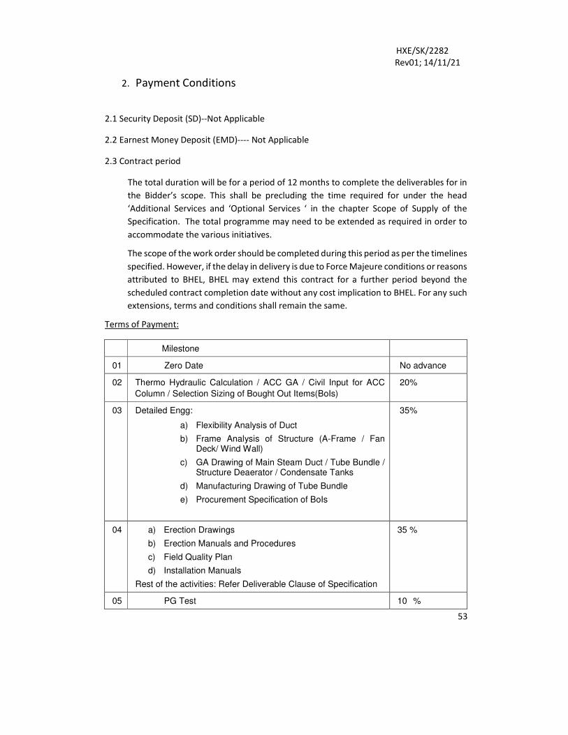
Terms of Payment:
Milestone
01 Zero Date No advance
02 Thermo Hydraulic Calculation / ACC GA / Civil Input for ACC
Column / Selection Sizing of Bought Out Items(BoIs)
20%
03 Detailed Engg:
a) Flexibility Analysis of Duct
b) Frame Analysis of Structure (A-Frame / Fan Deck/ Wind Wall)
c) GA Drawing of Main Steam Duct / Tube Bundle / Structure Deaerator / Condensate Tanks
d) Manufacturing Drawing of Tube Bundle
e) Procurement Specification of BoIs
35%
04 a) Erection Drawings
b) Erection Manuals and Procedures
c) Field Quality Plan
d) Installation Manuals
Rest of the activities: Refer Deliverable Clause of Specification
35 %
05 PG Test 10 %
HXE/SK/2282
Rev01; 14/11/21
54
Payment against above milestones shall be divided in two parts. 70% of the respective
payments shall be due after confirmation / certification by BHEL. Rest of the 30% payment
shall be due only after the approval of the document by BHEL-customer for the present
project. The above payment shall be against Sl. No. 1 of the price bid format. For Sl. No. 2 to
6 payment shall be made on actual basis.
2.4 Payment shall be made within 30 days of receipt of signed invoice at the office of Heat
Exchanger Engineering, HEEP, Haridwar. Invoice shall be raised after completion of
milestone as listed above.
2.5 Prices shall be quoted in figures and words both. In case of any discrepancy in value, the
prices quoted in words shall be considered. No advance payment shall be admissible. No
other payment against Travel/Daily Allowances/ Incidental Allowances/Boarding/Lodging
etc shall be considered by BHEL. However, Boarding/Lodging at BHEL field site shall be
made available by BHEL to the Bidder.
2.6 Travel & Other expenses
The bidders shall quote the prices inclusive of all charges, overtime charges, out of
pocket allowance, travel (air / train / road), accommodation, TA/DA, etc
No other claim on account of any other expenses shall be entertained by BHEL.
2.7 Global resource sharing
All the global resources including domain area experts of the bidder should be available
to BHEL for this engagement without any additional costs. For this, the bidder must
provide (i) Letter of Comfort for sharing the global resources (Annexure-D), (ii) Proof of
Arrangement (e.g. shareholding pattern) along with the bid.
2.8 Price escalation
The rates will be valid until the entire scope of the RFP is executed in all respects. No
escalation in the rates shall be accepted during the entire period of the contract.
2.9 Liquidated Damages:
Bidder shall be liable as below for the short-fall in ACC performance
1. For Short-fall in Condenser Pressure:
a) $ 3,75,632 per 1 mm Hg in Condenser Pressure (Max. shortfall <
4 mm Hg).
b) Beyond maximum shortfall in Condenser Back Pressure, Bidder
shall suggest the improvement / replacement of procedures /
components
HXE/SK/2282
Rev01; 14/11/21
55
2. For Deficiency in Auxiliary power of ACC Fan Motor:
a) US $ 3,025 /- (US Dollar Three Thousand Twenty-Five only) per 1 KW increase in
Auxiliary power consumption (maximum shortfall = (+)1% of the guaranteed value.)
b) The power consumed by each auxiliary shall be measured at the motor terminal
end.
c) Beyond maximum shortfall in Auxiliary power, Bidder shall suggest the improvement
/ replacement of procedures / components
Above LD is for one Unit only. In case guaranteed back pressure /auxiliary power is not
achieved in first PG test, LD on the bidder shall be for 3 units. Maximum amount of LD shall
be limited to 10% of contract value.
PBG (Performance Bank Guarantee) shall be 10% of Contract value. Duration of PBG
shall be for the entire duration of the contract execution. This is to be extended suitably if
required. Any payment by BHEL shall be made only after receipt of PBG .
2.10 Taxes & duties
2.10.1 (Provisions relating to GST in tender applicable for Indian vendors only or for services
rendered in India against Indian GST registration)
Bidders to quote the rates inclusive of all taxes & duties whether Indian or foreign
except applicable Indian GST which shall be paid against proper invoices and subject
to fulfilling the requirements as outlines in applicable Indian GST laws, rules and
regulations amended or made applicable from time to time.
2.10.2 Consulting firm shall submit GST compliant invoice containing all the particulars as
stipulated under Invoice Rules of Indian GST Law. Payment shall be made to the firm
only after submission of GST complaint invoice. The successful firm shall raise GST
compliant invoice affixing GSTIN of BHEL's unit availing the services.
2.10.3 BHEL reserves the right to protect its interest against any loss on account of
availability of GST credit, wherever such GST ITC is available as per GST Law provisions.
2.10.4 GSTIN of BHEL will be provided to the service provider(s) along with the work order.
2.10.5 Any new/change in statutory levy as and when made applicable by the Government
shall become applicable against documentary evidence.
HXE/SK/2282
Rev01; 14/11/21
56
2.10.6 Income tax will be deducted at the rate applicable on the date of payment, as per
provisions of Indian income tax act/rules.
2.10.7 Applicable GST shall also be recoverable from the service provider(s) in case of PRS
recovery/penalty on account of breach of terms of contract.
2.11 Variation in taxes & duties
Any upward variation in GST shall be considered for reimbursement provided supply of
goods and services are made within schedule date stipulated in the contract or any
extension thereof for reasons solely attributable to BHEL. However downward variation
shall be subject to adjustment as per actual GST applicability.
In case the Government imposes any new levy/tax on the output service/goods after
price bid opening, the same shall be reimbursed by BHEL at actual. The reimbursement
under this clause is restricted to the direct transaction between BHEL and consulting
firm only and within the contractual delivery period only
2.12 Bidder is required to submit duly signed & stamped copies of following documents
(whichever is applicable) along with the techno commercial bid i.e. Part-I of tender.
i. Form 10 F
ii. PAN Card
iii. Tax Residency Certificate
2.13 In the case of a non-resident, not being a company, or a foreign company and not
having permanent account number, the bidder shall furnish the following details &
documents to BHEL: -
(i) Name, e-mail id, contact number;
(ii) Address in the country or specified territory outside India of which the bidder is
a resident;
(iii) A certificate of his being resident in any country or specified territory outside
India from the Government of that country or specified territory if the law of
that country or specified territory provides for issuance of such certificate;
(iv) Tax Identification Number of the bidder in the country or specified territory of
his residence and in case no such number is available, then a unique number on
the basis of which the deductee is identified by the Government of that country
or the specified territory of which he claims to be a resident.
HXE/SK/2282
Rev01; 14/11/21
57
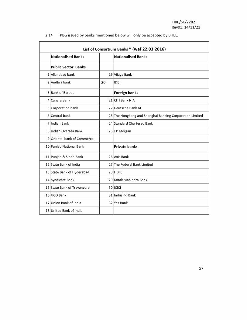
2.14 PBG issued by banks mentioned below will only be accepted by BHEL.
List of Consortium Banks * (wef 22.03.2016)
Nationalised Banks Nationalised Banks
Public Sector Banks
1 Allahabad bank 19 Vijaya Bank
2 Andhra bank 20 IDBI
3 Bank of Baroda Foreign banks
4 Canara Bank 21 CITI Bank N.A
5 Corporation bank 22 Deutsche Bank AG
6 Central bank 23 The Hongkong and Shanghai Banking Corporation Limited
7 Indian Bank 24 Standard Chartered Bank
8 Indian Oversea Bank 25 J P Morgan
9 Oriental bank of Commerce
10 Punjab National Bank Private banks
11 Punjab & Sindh Bank 26 Axis Bank
12 State Bank of India 27 The Federal Bank Limited
13 State Bank of Hyderabad 28 HDFC
14 Syndicate Bank 29 Kotak Mahindra Bank
15 State Bank of Travancore 30 ICICI
16 UCO Bank 31 Indusind Bank
17 Union Bank of India 32 Yes Bank
18 United Bank of India
HXE/SK/2282
Rev01; 14/11/21
58
ANNEXURE-A
INTEGRITY PACT
Between
Bharat Heavy Electricals Ltd. (BHEL), a company registered under the Companies Act 1956
and having its registered office at "BHEL House", Siri Fort, New Delhi - 110049 (India)
hereinafter referred to as "The Principal", which expression unless repugnant to the context
or meaning hereof shall iriclude its successors or assigns of the ONE PART
And
[ e ] (description of the party along with address), hereinafter referred to as "The bidder/
Contractor" which expression unless repugnant to the context or meaning hereof shall
include its successors or assigns of the OTHER PART
Preamble
The Principal intends to award, under laid-down organizational procedures, contract/s for [ 0
] The Principal values full compliance with atl relevant laws of the land, rules and regulations,
and the principles of economic use of resources, and of fairness and transparency in its
relations with its bidder(s)/ Contractor(s).
In order to achieve these goals, the Principal will appoint Independent External Monitor(s),
who will monitor the tender process and the execution of the contract for compliance with
the principles mentioned above.
Section 1- Commitments of the Principal
1. The Principal commits itself to take all measures necessary to prevent corruption and
to observe the following principles:
1.1. No employee of the Principal, personally or through family members, will in
connection with the tender for, or the execution of a contract, demand, take a
promise for or accept, for self or third person, any material or immaterial benefit
which the person is not legally entitled to.
1.2. The Principal will, during the tender process treat all bidder(s) with equity and
reason. The Principal will in particular, before and during the tender process, provide
to all bidder(s) the same information and will not provide to any bidder(s)
confidential/ additional information through which the bidder(s) could obtain an
advantage in relation to the tender process or the contract execution.
1.3. The Principal will exclude from the process all known prejudiced persons.
2. If the Principal obtains information on the conduct of any of its employees which is a
penal offence under the Indian Penal Code 1860 and Prevention of Corruption Act 1988
HXE/SK/2282
Rev01; 14/11/21
59
or any other statutory penal enactment, or if there be a substantive suspicion in this
regard, the Principal will inform its Vigilance Office and in addition can initiate disciplinary
actions.
Section 2- Commitments of the bidder(s)/ Contractor(s)
2. The bidder(s)/ Contractor(s) commit himself to take all measures necessary to prevent
corruption. He commits himself to observe the following principles during his
participation in the tender process and during the contract execution.
2.1. The bidder(s)/ Contractor(s) will not, directly or through any other person or
firm, offer, promise or give to the Principal or to any of the Principal's employees
involved in the tender process or the execution of the contract or to any third person
any material, immaterial or any other benefit which he/ she is not legally entitled to,
in order to obtain in exchange any advantage of any kind whatsoever during the
tender process or during the execution of the contract.
2.2. The bidder(s)/ Contractor(s) will not enter with other bidder(s) into any illegal
or undisclosed agreement or understanding, whether formal or informal. This applies
in particular to prices, specifications, certifications, subsidiary contracts, submission
or non-submission of bids or any other actions to restrict competitiveness or to
introduce cartelization in the bidding process.
2.3. The bidder(s)/ Contractor(s) will not commit any penal offence under the
relevant
Indian Penal Code (IPC) and Prevention of Corruption Act; further the bidder(s)/
Contractor(s) will not use improperly, for purposes of competition or personal gain,
or pass on to others, any information or document provided by the Principal as part
of the business relationship, regarding plans, technical proposals and business
details, including information contained or transmitted electronically.
2.4. Foreign bidder(s)/ Contractor(s) shall disclose the name and address of agents
and representatives in India and Indian bidder(s)/ Contractor(s) to disclose their
foreign principals or associates. The bidder(s)/ Contractor(s) will, when presenting his
bid, disclose any and all payments he has made, and is committed to or intends to
make to agents, brokers or any other intermediaries in connection with the award of
the contract.
3. The bidder(s)/ Contractor(s) will not instigate third persons to commit offences
outlined above or be an accessory to such offences.
4. The bidder(s)/ Contractor(s) shall not approach the Courts while representing the
matters to IEMs and will await their decision in the matter.
HXE/SK/2282
Rev01; 14/11/21
60
Section 3- Disqualification from tender process and exclusion from future contracts
If the bidder(s)/ Contractor(s), before award or during execution has committed a
transgression through a violation of Section 2 above, or acts in any other manner such as to
put his reliability or credibility in question, the Principal is entitled to disqualify the bidder(s)/
Contractor(s) from the tender process or take action as per the separate "Guidelines on
Banning of Business dealings with Suppliers/ Contractors", framed by the Principal.
Section 4- Compensation for Damages
1. If the Principal has disqualified the bidder from the tender process prior to the award
according to Section 3, the Principal is entitled to demand and recover the damages
equivalent Earnest Money Deposit/ bid Security / Bank Guarantees, if any..
2. If the Principal has terminated the contract according to Section 3, or if the Principal
is entitled to terminate the contract according to section 3, the Principal shall be entitled
to demand and recover from the Contractor liquidated damages equivalent to 5% of the
contract value or the amount equivalent to Security Deposit/ Performance Bank
Guarantee or any other Bank guarantees, whichever is higher.
Section 5- Previous Transgression
1. The bidder declares that no previous transgressions occurred in the last 3 years with
any other company in any country conforming to the anti-corruption approach or with
any other Public Sector Enterprise in India that could justify his exclusion from the tender
process.
2. If the bidder makes an incorrect statement on this subject, he can be disqualified from
the tender process or the contract, if already awarded, can be terminated for such reason.
Section 6- Equal treatment of all bidders/ Contractors / Sub-contractors
1. The Principal will enter into agreements with identical conditions as this one with all
bidders and Contractors. In the case of sub-contracting, the Principal contractor shall be
responsible for the adoption of IP by his sub-contractors and shall continue to remain
responsible for any default by his sub-contractors.
2. The Principal will disqualify from the tender process all bidders who do not sign this
pact or violate its provisions.
Section 7- Criminal Charges against violating bidders/ Contractors /Subcontractors
If the Principal obtains knowledge of the conduct of a bidder, Contractor or Subcontractor,
or of an employee or a representative or an associate of a bidder, Contractor or Subcontractor
which constitutes corruption, or if the Principal has substantive suspicion in this regard, the
Principal will inform the Vigilance Office.
Section 8 -Independent External Monitor(s)
HXE/SK/2282
Rev01; 14/11/21
61
1. The Principal appoints competent and credible Independent External Monitor for this
Pact. The task of the Monitor is to review independently and objectively, whether and to
what extent the parties comply with the obligations under this agreement.
2. The Monitor is not subject to instructions by the representatives of the parties and
performs his functions neutrally and independently, He reports to the CMD, BHEL.
3. The bidder(s)/ Contractor(s) accepts that the Monitor has the right to access without
restriction to all contract documentation of the Principal including that provided by the
bidder(s)/ Contractor(s). The bidder(s)/ Contractor(s) will grant the monitor, upon his
request and demonstration of a valid interest, unrestricted and unconditional access to
his contract documentation. The same is applicable to Sub-contractor(s). The Monitor is
under contractual obligation to treat the information and documents of the bidder(s)/
Contractor(s) / Sub-contractor(s) with confidentiality in line with Non- disclosure
agreement.
4. The Principal will provide to the Monitor sufficient information about all meetings
among the parties related to the contract provided such meetings could have an impact
on the contractual relations between the Principal and the Contractor. The parties offer
to the Monitor the option to participate in such meetings.
5. The role of 'EMS is advisory, would not be legally binding and it is restricted to
resolving issues raised by an intending bidder regarding any aspect of the tender which
allegedly restricts competition or bias towards some bidders. At the same time, it must
be understood that IEMs are not consultants to the Management. Their role is
independent in nature and the advice once tendered would not be subject to review at
the request of the organization.
6. For ensuring the desired transparency and objectivity in dealing with the complaints
arising out of any tendering process, the matter should be examined by the full panel of
IEMs jointly as far as possible, who would look into the records, conduct an investigation,
and submit their joint recommendations to the Management.
7. The IEMs would examine all complaints received by them and give their
recommendations/ views to CMD, BHEL, at the earliest. They may also send their report
directly to the CVO and the Commission, in case of suspicion of serious irregularities
requiring legal/ administrative action. IEMs will tender their advice on the complaints
within 10 days as far as possible.
8. The CMD, BHEL shall decide the compensation to be paid to the Monitor and its terms
and conditions.
9. IEM should examine the process of integrity; they are not expected to concern
themselves with fixing of responsibility of officers. Complaints alleging mala fide on the
HXE/SK/2282
Rev01; 14/11/21
62
part of any officer of the organization should be looked into by the CVO of the concerned
organization.
10. If the Monitor has reported to the CMD, BHEL, a substantiated suspicion of an offense
under relevant Indian Penal Code/ Prevention of Corruption Act, and the CMD, BHEL has
not, within reasonable time, taken visible action to proceed against such offense or
reported it to the Vigilance Office, the Monitor may also transmit this information directly
to the Central Vigilance Commissioner, Government of India.
11. The number of Independent External Monitor(s) shall be decided by the CMD, BHEL.
12. The word 'Monitor' would include both singular and plural.
Section 9- Pact Duration
1. This Pact shall be operative from the date IP is signed by both the parties till the final
completion of the contract for successful bidder and for all other bidders 6 months after
the contract has been awarded. Issues like warranty/guarantee etc. should be outside the
purview of IEMs.
2. If any claim is made/ lodged during the currency of IP, the same shall be binding and
continue to be valid despite the lapse of this pact as specified above, unless it is
discharged/ determined by the CMD, BHEL.
Section 10- Other Provisions
1. This agreement is subject to Indian laws and jurisdiction shall be the registered office
of the Principal, i.e. New Delhi.
2. Changes and supplements, as well as termination notices, need to be made in writing.
Side agreements have not been made.
3. If the Contractor is a partnership or a consortium, this agreement must be signed by
all partners or consortium members.
4. Should one or several provisions of this agreement turn out to be invalid, the
remainder of this agreement remains valid. In this case, the parties will strive to come to
an agreement with their original intentions.
5. Only those bidders/contractors who have entered into this agreement with the
Principal would be competent to participate in the bidding. In other words, entering into
this agreement would be a preliminary qualification.
For & on behalf of the
bidder (Office Seal)
Witness: Name &
Address:
Place: Date:
HXE/SK/2282
Rev01; 14/11/21
63
ANNEXURE-B
GENERAL DECLARATION CERTIFICATE
To,
(Write Name & Address of Officer of BHEL inviting the bid)
Dear Sir/Madam,
Sub: Declaration by the authorised signatory
Ref: RFP Ref No: [.1
l, ['l hereby certify that all the information and data furnished with regard to this RFP No. [ e ]
are true and complete to the best of my knowledge. I have gone through the specification,
conditions and stipulations in detail and agree to comply with the requirements and intent of
specification.
I hereby certify that all the documents submitted by us in support of the possession of
"Qualifying Requirements" are true copies of the original and are fully compliant required for
qualifying / applying in the bid and shall produce the original of same as and when required
by Bharat Heavy Electricals Limited.
I hereby further confirm that no tampering has been done with the documents submitted in
support of our qualification as a bidder. I understand that at any stage (during the bidding
process or while executing the awarded works) if it is found that fake/false/ forged bid
qualifying / supporting documents/certificates were submitted, it would lead to summarily
rejection of our bid/termination of contract. BHEL shall be at liberty to initiate other
appropriate actions as per the terms of the bid / Contract or other extant policies of Bharat
Heavy Electricals Limited.
We hereby declare that we have not been placed on any holiday list or blacklist declared by
BHEL or its Administrative Ministry (Ministry of Heavy Industries and Public Enterprises).
l, further certify that I have been duly authorized by my company i.e. under mentioned bidder
for signing and submission of bids and all other documents.
Place & date Signature & seal of the Authorized Signatory
HXE/SK/2282
Rev 01;14/11/21
ANNEXURE-C
NON-DISCLOSURE AGREEMENT
(To be signed with the selected bidder)
M/S...
(Name and details of the consulting firm)
Non-Disclosure Agreement
BHEL has appointed M/S [ o ] (hereinafter referred to as 'Consulting Firm') for providing
services with regard to "Engagement of a Consulting Firm for Design and Engineering Services
for Air Cooled Condenser "
For purpose of this Agreement, "confidential information" means all information whether
oral, hard copy or electronic which may be disclosed or to which the recipient may be
provided access in accordance with this Agreement or which is generated as a result of or in
connection with the business purposes which is generally not made available to the public.
As a condition of the consulting firm's involvement in this work with BHEL, the consulting firm
will be bound by the following terms and conditions (hereinafter also the "Agreement"):
• In performing the duties for which the consulting firm has been associated with BHEL,
the consulting firm may see and have access to confidential, sensitive and/or private
information (hereafter "confidential information"), disclosed to him/her or known by
him/her as a consequence of his/her association with BHEL and not generally known
outside BHEL, consulting firm will not disclose such confidential information.
• During the consulting firm's involvement in this work & association with BHEL and
after his association is completed/terminated, the consulting firm will not disclose to,
discuss or share with any unauthorized person, group or department, inside or
outside of BHEL, any confidential information, in any form, except to the extent such
disclosure, discussion or sharing is authorized by BHEL.
• The consulting firm will not use confidential information for his/her own personal
purposes.
• The consulting firm will not copy or remove any information from BHEL materials
containing confidential information, except to the extent that the consulting firm is
given permission to do so by BHEL.
• The consulting firm will not look at, examine, or retrieve any document, file, or
database, except those to which the consulting firm is authorized to access and which
are necessary for him/her to access in order to perform his/her assigned duties.The
consulting firm will not discuss or share with any unauthorized person, group or
department, inside or outside BHEL, any conclusions that the consulting firm or others
draw from confidential information if discussing or sharing those conclusions would
reveal any confidential information.
• If the consulting firm is ever uncertain whether any information is confidential or not,
the consulting firm will resolve all uncertainties in favor of preserving the
confidentiality of that information, and the consulting firm will seek clarification from
BHEL before engaging in any conduct that could jeopardize the confidentiality of the
information.
HXE/SK/2282
Rev 01;14/11/21
• If the consulting firm has to disclose the confidential information to a person inside
BHEL, it is his/her responsibility to inform that person about the confidentiality code
laid here and to make him/her accept this code before giving the confidential
information to him/her.
• If the consulting firm becomes aware that a breach of confidentiality has occurred due
to his/her own or others' acts or omissions, the consulting firm will immediately notify
BHEL.
• Upon termination of his/her assignment or as requested by BHEL, the consulting firm
will return all material containing confidential information to BHEL.
• The consulting firm has to take prior permission from BHEL w.r.t. sharing the outcome
and tailored made recommendations of this study with any outside agency.
Exceptions
The confidentiality obligations shall not apply to:
• information which is, or later becomes obtainable from other non-confidential sources,
information that was known to the recipient prior to the disclosure thereof; as
evidenced by written records, information that the BHEL waives the recipient's duty
as to the confidentiality in writing.
• disclosure of information required by law, any decree or order of Government
authority, by court or statutory law, by judicial/quasi-judicial bodies, statutory bodies.
The consulting firm agrees to abide by the clauses of the Confidentiality Agreement that BHEL
has executed with the consulting firm.
The obligations contained in this Agreement shall subsist for a period of five (5) years from
the date of signing this Agreement and shall not terminate upon completion or termination
of the Exercise or Discussions.
The provisions of this Agreement shall be governed by and construed in accordance with the
laws of India and any dispute arising out of this Agreement shall be subject to the exclusive
jurisdiction of the Indian courts located at New Delhi. Please indicate your acceptance of the
terms hereof by returning the enclosed copy of the present letter countersigned by your
company's legal representatives, whereupon it shall
become a binding agreement.
Bharat Heavy Electricals Ltd. Agreed and accepted by:
Name:
Title :
Date:
Name:
Title :
Date:
HXE/SK/2282
Rev 01;14/11/21
ANNEXURE-D
LETTER OF COMFORT
(on the letterhead of parent company of the bidder)
(Write Name & Address of Officer of BHEL inviting the Tender)
Dear Sir/ Madam,
Sub: Comfort Letter
We hereby confirm that, for the work under RFP no. [ e ] for Engagement of a consulting firm
for Design and Engineering Services for ACC, [the name of the parent company] is willing to
provide access to all its global partners/ domain area experts to BHEL, as and when required
by BHEL for this assignment, without any additional costs.
On behalf of [name of the Signature & seal of CEO/country
parent company]
[Signature & seal]
head/ Director/ equivalent
Place & date Place & date
स
ामग्री
सूची
संख्य
ा को
S
UP
ER
SE
DE
S
अ
धिकध
मत क
रता ह
ै
INV
EN
TO
RY
NO
.
स्वत्व
ाधिका
र एव
ंगोप
नीय
इस प्र
लखे म
ें दी
गई सू
चना
भारत
हवेी
एलेध
रिकल
स क
ी सम्
पधि
ह ै इ
सका
प्रत्यक्ष
एवं
अप्रत्य
क्ष रू
प से
ककस
ी भी
तरह
प्रयो
ग , ज
ो कक
कंम्प
नी के
धहत
में ह
ाधनका
रक ह
ो न
ककया
जा
य |
कद
नाक
एवं ह
स्ताक्ष
र S
IGN
& D
AT
E
SPECIFICATION
HXE/SK/2281
Page 1 of 50
Rev. no.00 धनमााणकताा WORKED BY
MUKESH
13.11.2021
जांचकताा CHECKED BY
ASHISH
GUPTA
12.11.2021
CO
PY
RIG
HT
AN
D C
ON
FID
EN
TIA
L
The
info
rmat
ion o
n t
his
docu
men
ts i
s th
e pro
per
ty o
f B
har
at H
eavy E
lect
rica
l L
imit
ed.
It m
ust
not
be
use
d d
irec
tly o
r in
dir
ectl
y i
n a
ny
way
det
rim
enta
l to
the
inte
rest
of
the
com
pan
y
कदना
क एव
ंहस्त
ाक्षर
SIG
N &
DA
TE
सामग्र
ी सूच
ी संख्य
ा IN
VE
NT
OR
Y N
O.
DESIGN AND ENGINEERING SERVICES FOR AIR
COOLED CONDENSER PACKAGE
स
ामग्री
सूची
संख्य
ा को
S
UP
ER
SE
DE
S
अ
धिकध
मत क
रता ह
ै
INV
EN
TO
RY
NO
.
स्वत्व
ाधिका
र एव
ंगोप
नीय
इस प्र
लखे म
ें दी
गई सू
चना
भारत
हवेी
एलेध
रिकल
स क
ी सम्
पधि
ह ै इ
सका
प्रत्यक्ष
एवं
अप्रत्य
क्ष रू
प से
ककस
ी भी
तरह
प्रयो
ग , ज
ो कक
कंम्प
नी के
धहत
में ह
ाधनका
रक ह
ो न
ककया
जा
य |
कद
नाक
एवं ह
स्ताक्ष
र S
IGN
& D
AT
E
SPECIFICATION
HXE/SK/2281
Page 2 of 50
Rev. no.00 धनमााणकताा WORKED BY
MUKESH
13.11.2021
जांचकताा CHECKED BY
ASHISH
GUPTA
12.11.2021
CO
PY
RIG
HT
AN
D C
ON
FID
EN
TIA
L
The
info
rmat
ion o
n t
his
docu
men
ts i
s th
e pro
per
ty o
f B
har
at H
eavy E
lect
rica
l L
imit
ed.
It m
ust
not
be
use
d d
irec
tly o
r in
dir
ectl
y i
n a
ny
way
det
rim
enta
l to
the
inte
rest
of
the
com
pan
y
कदना
क एव
ंहस्त
ाक्षर
SIG
N &
DA
TE
सामग्र
ी सूच
ी संख्य
ा IN
VE
NT
OR
Y N
O.
CONTENT
I. INTENT OF SPECIFICATION 3
II. PROJECT INFORMATION 4
III. SCOPE OF ENQUIRY 5
IV. DELIVERABLES 6-10
V. GUARANTEES 11-13
VI. DURATION OF CONSULTANCY 14
VII. TECHNICAL REQUIREMENT FOR MECHANICAL COMPONENT 15-31
VIII. QUALITY ASSURANCE, TESTING AND INSPECTION 32-37
IX. DOCUMENT/INFORMATION TO BE FURNISHED ALONG WITH OFFER 38
X. CIVIL 39-40
XI. C&I 41-43
XII. LAYOUT & SAFETY CONSIDERATION 44-45
XIII. ERECTION AND COMMISSIOING 46
XIV. SYSTEM CLEANING & FLUSHING 47
XV. FIELD QUALITY REQUIREMENT 48
XVI. OTHER SERVICES 49
XVII. LIST OF ANNEXURES TO THIS SPECIFICATION 50
स
ामग्री
सूची
संख्य
ा को
S
UP
ER
SE
DE
S
अ
धिकध
मत क
रता ह
ै
INV
EN
TO
RY
NO
.
स्वत्व
ाधिका
र एव
ंगोप
नीय
इस प्र
लखे म
ें दी
गई सू
चना
भारत
हवेी
एलेध
रिकल
स क
ी सम्
पधि
ह ै इ
सका
प्रत्यक्ष
एवं
अप्रत्य
क्ष रू
प से
ककस
ी भी
तरह
प्रयो
ग , ज
ो कक
कंम्प
नी के
धहत
में ह
ाधनका
रक ह
ो न
ककया
जा
य |
कद
नाक
एवं ह
स्ताक्ष
र S
IGN
& D
AT
E
SPECIFICATION
HXE/SK/2281
Page 3 of 50
Rev. no.00 धनमााणकताा WORKED BY
MUKESH
13.11.2021
जांचकताा CHECKED BY
ASHISH
GUPTA
12.11.2021
CO
PY
RIG
HT
AN
D C
ON
FID
EN
TIA
L
The
info
rmat
ion o
n t
his
docu
men
ts i
s th
e pro
per
ty o
f B
har
at H
eavy E
lect
rica
l L
imit
ed.
It m
ust
not
be
use
d d
irec
tly o
r in
dir
ectl
y i
n a
ny
way
det
rim
enta
l to
the
inte
rest
of
the
com
pan
y
कदना
क एव
ंहस्त
ाक्षर
SIG
N &
DA
TE
सामग्र
ी सूच
ी संख्य
ा IN
VE
NT
OR
Y N
O.
Technical Specification Air Cooled Condenser (ACC) Package
I. Intent of Specification
Bidder shall be responsible for providing the complete design and engineering services for ACC package for 3X800MW Project. Bidder’s scope (detailed subsequently) shall include, design, drawings (General Arrangement, manufacturing/fabrication, erection etc. as per scope), procurement specification, support for manufacturing with respect to deviation/non conformities, limited supervision of erection & commissioning and assistance for PG testing as specified / or otherwise which are required to complete the job. Pre-bid meeting for the clarification shall take place after one week of publishing of the enquiry.
स
ामग्री
सूची
संख्य
ा को
S
UP
ER
SE
DE
S
अ
धिकध
मत क
रता ह
ै
INV
EN
TO
RY
NO
.
स्वत्व
ाधिका
र एव
ंगोप
नीय
इस प्र
लखे म
ें दी
गई सू
चना
भारत
हवेी
एलेध
रिकल
स क
ी सम्
पधि
ह ै इ
सका
प्रत्यक्ष
एवं
अप्रत्य
क्ष रू
प से
ककस
ी भी
तरह
प्रयो
ग , ज
ो कक
कंम्प
नी के
धहत
में ह
ाधनका
रक ह
ो न
ककया
जा
य |
कद
नाक
एवं ह
स्ताक्ष
र S
IGN
& D
AT
E
SPECIFICATION
HXE/SK/2281
Page 4 of 50
Rev. no.00 धनमााणकताा WORKED BY
MUKESH
13.11.2021
जांचकताा CHECKED BY
ASHISH
GUPTA
12.11.2021
CO
PY
RIG
HT
AN
D C
ON
FID
EN
TIA
L
The
info
rmat
ion o
n t
his
docu
men
ts i
s th
e pro
per
ty o
f B
har
at H
eavy E
lect
rica
l L
imit
ed.
It m
ust
not
be
use
d d
irec
tly o
r in
dir
ectl
y i
n a
ny
way
det
rim
enta
l to
the
inte
rest
of
the
com
pan
y
कदना
क एव
ंहस्त
ाक्षर
SIG
N &
DA
TE
सामग्र
ी सूच
ी संख्य
ा IN
VE
NT
OR
Y N
O.
II. Project Information
i. Location and Approach, Meteorological Data etc. as per Annexure-II-1 ii. Plant Configuration (3X800MW)
(a) LP Turbine shall be one exhaust casing with single flow to ACC. (b) For normal make up to the power cycle, DM water shall be added in the
condensate storage tank through the cycle makeup control station. (c) The condensate to regenerative cycle shall be through Condensate Extraction
Pump (CEP) discharge at specified flow and pressure value. Recirculation line for CEP and its control shall be done through DCS and provision of connection in condensate tank shall be provided
(d) There shall be 2 nos of LP exhaust opening and 2 no.s of auxiliary turbine exhaust opening for sizing of the air evacuation system .
(e) For Air evacuation pump selection, volume other than ACC shall be considered as 2200m3
(f) Maximum Fan motor rating for one unit shall be 10560KW .
स
ामग्री
सूची
संख्य
ा को
S
UP
ER
SE
DE
S
अ
धिकध
मत क
रता ह
ै
INV
EN
TO
RY
NO
.
स्वत्व
ाधिका
र एव
ंगोप
नीय
इस प्र
लखे म
ें दी
गई सू
चना
भारत
हवेी
एलेध
रिकल
स क
ी सम्
पधि
ह ै इ
सका
प्रत्यक्ष
एवं
अप्रत्य
क्ष रू
प से
ककस
ी भी
तरह
प्रयो
ग , ज
ो कक
कंम्प
नी के
धहत
में ह
ाधनका
रक ह
ो न
ककया
जा
य |
कद
नाक
एवं ह
स्ताक्ष
र S
IGN
& D
AT
E
SPECIFICATION
HXE/SK/2281
Page 5 of 50
Rev. no.00 धनमााणकताा WORKED BY
MUKESH
13.11.2021
जांचकताा CHECKED BY
ASHISH
GUPTA
12.11.2021
CO
PY
RIG
HT
AN
D C
ON
FID
EN
TIA
L
The
info
rmat
ion o
n t
his
docu
men
ts i
s th
e pro
per
ty o
f B
har
at H
eavy E
lect
rica
l L
imit
ed.
It m
ust
not
be
use
d d
irec
tly o
r in
dir
ectl
y i
n a
ny
way
det
rim
enta
l to
the
inte
rest
of
the
com
pan
y
कदना
क एव
ंहस्त
ाक्षर
SIG
N &
DA
TE
सामग्र
ी सूच
ी संख्य
ा IN
VE
NT
OR
Y N
O.
III. Scope of the Enquiry
Following shall be the scope of enquiry
I. Basic engineering of all the equipment/component and systems of ACC and Detailed engineering of items as per Annexure-IV.1-1
II. Thermo-hydraulic Design of ACC. III. Mechanical design of ACC components like Tube bundle/Structure/Steam duct etc. IV. Flexibility Analysis of Exhaust Duct System. V. C&I System (Selection & Sizing). VI. Civil Input for Column & Foundation design.
VII. Structural Engineering of structures supported on RC Columns (A-frame, fan deck and windwall etc.).
VIII. Selection and Sizing of Bought out items (BOIs). IX. Performance Guarantee procedure. X. Operation and Maintenance Procedures. XI. Probable vendors list of BOIs
XII. Procurement specification of bought out items viz. fan, gearbox, motor etc. XIII. Erection & commissioning manuals and procedures. XIV. Interface of electrical cabling drawing of ACC furnished by BHEL. XV. Other services:
3-D model of complete package together with all necessary piping, valves, fittings, supports, pumps and drives etc.
ADDITIONAL SERVICES
a. Support for engg. services during manufacturing b. Supervision for Erection and Commissioning c. Support for Performance Guarantee Test ( PG Test)
Optional Services
a. Training of BHEL personals and Owner's personnel / Customer as per requirement specified. (Optional)
b. e-learning module as per the requirement specified. (Optional) Bidder shall be required to furnish price of optional scope of supply in the price schedule. It shall be BHEL discretion to exercise the options during placement of order/project execution.
स
ामग्री
सूची
संख्य
ा को
S
UP
ER
SE
DE
S
अ
धिकध
मत क
रता ह
ै
INV
EN
TO
RY
NO
.
स्वत्व
ाधिका
र एव
ंगोप
नीय
इस प्र
लखे म
ें दी
गई सू
चना
भारत
हवेी
एलेध
रिकल
स क
ी सम्
पधि
ह ै इ
सका
प्रत्यक्ष
एवं
अप्रत्य
क्ष रू
प से
ककस
ी भी
तरह
प्रयो
ग , ज
ो कक
कंम्प
नी के
धहत
में ह
ाधनका
रक ह
ो न
ककया
जा
य |
कद
नाक
एवं ह
स्ताक्ष
र S
IGN
& D
AT
E
SPECIFICATION
HXE/SK/2281
Page 6 of 50
Rev. no.00 धनमााणकताा WORKED BY
MUKESH
13.11.2021
जांचकताा CHECKED BY
ASHISH
GUPTA
12.11.2021
CO
PY
RIG
HT
AN
D C
ON
FID
EN
TIA
L
The
info
rmat
ion o
n t
his
docu
men
ts i
s th
e pro
per
ty o
f B
har
at H
eavy E
lect
rica
l L
imit
ed.
It m
ust
not
be
use
d d
irec
tly o
r in
dir
ectl
y i
n a
ny
way
det
rim
enta
l to
the
inte
rest
of
the
com
pan
y
कदना
क एव
ंहस्त
ाक्षर
SIG
N &
DA
TE
सामग्र
ी सूच
ी संख्य
ा IN
VE
NT
OR
Y N
O.
IV. DELIVERABLES
The following documents/activities are the deliverable against this enquiry for the following systems
a) Design Optimisation:
Bidder to provide three optimised designs within one week after PO placement. Optimisation shall be done with respect to ACC total cost and Auxiliary power consumption. Bidder to provide the following minimum information viz. no of modules, no of columns, overall surface area, no of tubes/bundles, Fan motor rating, Fan Diameter Fan shaft power, ACC height etc. in all three designs BHEL will be free to finalise any one of the optimised design and inform the same to bidder. Bidder has to do detailed design work on the BHEL selected design.
b) ACC System
1. ACC General Arrangement Drawing 2. ACC Layout drawing indicating ACC equipment, vacuum pump, drain pump, drain tank,
condensate tank, pipe routing, MCC room, cleaning system etc. 3. Thermo-hydraulic Design / Calculations of ACC 4. Functional Description of ACC 5. ACC P&ID 6. ACC Performance curves 7. ACC Data sheet 8. Electrical Load list (tentative) 9. ACC performance at 60% BMCR and HP-LP Bypass condition
c) Exhaust Duct System
1. Mechanical Calculation of Steam Duct 2. Pressure Drop Calculation in Steam Duct system 3. Detailed General Arrangement and BoQ of Duct System including saddle, guide vain
details, Teflon plates, sliding support details etc ( for preparation of fabrication drawings) 4. Forces and moments on Hot Box duct connection 5. Details of Expansion joints, isolation valves, rupture disc, snubbers (if applicable),
hangers and support location. 6. Design Basis of Flexibility analysis of Duct / Piping having following details
a) Load Calculation of Duct / Piping loads supporting structure(s) in weight (cold) case, Operating case and Occasional cases (Seismic / Wind etc) and all possible load cases.
b) Stress Calculation and stress check as per the applicable code(s) for all possible load cases, as mentioned above
स
ामग्री
सूची
संख्य
ा को
S
UP
ER
SE
DE
S
अ
धिकध
मत क
रता ह
ै
INV
EN
TO
RY
NO
.
स्वत्व
ाधिका
र एव
ंगोप
नीय
इस प्र
लखे म
ें दी
गई सू
चना
भारत
हवेी
एलेध
रिकल
स क
ी सम्
पधि
ह ै इ
सका
प्रत्यक्ष
एवं
अप्रत्य
क्ष रू
प से
ककस
ी भी
तरह
प्रयो
ग , ज
ो कक
कंम्प
नी के
धहत
में ह
ाधनका
रक ह
ो न
ककया
जा
य |
कद
नाक
एवं ह
स्ताक्ष
र S
IGN
& D
AT
E
SPECIFICATION
HXE/SK/2281
Page 7 of 50
Rev. no.00 धनमााणकताा WORKED BY
MUKESH
13.11.2021
जांचकताा CHECKED BY
ASHISH
GUPTA
12.11.2021
CO
PY
RIG
HT
AN
D C
ON
FID
EN
TIA
L
The
info
rmat
ion o
n t
his
docu
men
ts i
s th
e pro
per
ty o
f B
har
at H
eavy E
lect
rica
l L
imit
ed.
It m
ust
not
be
use
d d
irec
tly o
r in
dir
ectl
y i
n a
ny
way
det
rim
enta
l to
the
inte
rest
of
the
com
pan
y
कदना
क एव
ंहस्त
ाक्षर
SIG
N &
DA
TE
सामग्र
ी सूच
ी संख्य
ा IN
VE
NT
OR
Y N
O.
c) Sketches indicating the method / arrangement of supporting with the ACC steel structure
d) Flexibility analysis input file(s)
d) Steam Header and Tube Bundle Headers
1. Mechanical Calculation 2. Detailed General Arrangement including saddle details, manhole etc (for preparation of
fabrication drawings) 3. Connection details of header with tube bundle and structure
e) Rupture Disc, Expansion Joints, Isolation Valve and Load Hangers/Snubbers
1. Selection and sizing (calculation) of equipment ( as applicable) 2. Bought out item specification including technical, quality, testing, packing, erection
requirements etc. 3. Data sheet
f) Tube Bundle
1. Finned tube drawing 2. Detailed Tube Bundle drawing 3. Mechanical Calculation of Tube and Tube Bundle 4. Manufacturing Drawing of Tube and Tube bundle 5. Procurement Specification including technical, quality, testing, packing, erection
requirements etc. 6. Tube Replacement and Tube Repair Procedures during manufacturing 7. Bidder to furnish the list of vendors for tube bundle. These vendors must have
manufacturing and testing facilities in the countries not sharing land borders with India. Bidder to confirm that it does not have any proprietary issue with shape/ geometry of tube/ tube bundle used in design and BHEL is free to get the tube bundle manufacture by itself/third party.
g) Fan, Motor & Gear Box
1. Selection and sizing method of equipment 2. Procurement specification having technical, quality, testing, packing, erection etc
requirements. 3. Data sheet. 4. Installation Drawing of fan, motor and gearbox in fan bridge
h) Fan Bell and Fan Guard
1. Selection and sizing method 2. Detailed drawing of Fan bell and Fan guard 3. Interconnection drawing of Fan Bell and Fan Guard with structure
स
ामग्री
सूची
संख्य
ा को
S
UP
ER
SE
DE
S
अ
धिकध
मत क
रता ह
ै
INV
EN
TO
RY
NO
.
स्वत्व
ाधिका
र एव
ंगोप
नीय
इस प्र
लखे म
ें दी
गई सू
चना
भारत
हवेी
एलेध
रिकल
स क
ी सम्
पधि
ह ै इ
सका
प्रत्यक्ष
एवं
अप्रत्य
क्ष रू
प से
ककस
ी भी
तरह
प्रयो
ग , ज
ो कक
कंम्प
नी के
धहत
में ह
ाधनका
रक ह
ो न
ककया
जा
य |
कद
नाक
एवं ह
स्ताक्ष
र S
IGN
& D
AT
E
SPECIFICATION
HXE/SK/2281
Page 8 of 50
Rev. no.00 धनमााणकताा WORKED BY
MUKESH
13.11.2021
जांचकताा CHECKED BY
ASHISH
GUPTA
12.11.2021
CO
PY
RIG
HT
AN
D C
ON
FID
EN
TIA
L
The
info
rmat
ion o
n t
his
docu
men
ts i
s th
e pro
per
ty o
f B
har
at H
eavy E
lect
rica
l L
imit
ed.
It m
ust
not
be
use
d d
irec
tly o
r in
dir
ectl
y i
n a
ny
way
det
rim
enta
l to
the
inte
rest
of
the
com
pan
y
कदना
क एव
ंहस्त
ाक्षर
SIG
N &
DA
TE
सामग्र
ी सूच
ी संख्य
ा IN
VE
NT
OR
Y N
O.
i) Drain Tank, Condensate Tank & Deaerator
1. Sizing of equipment 2. Mechanical Calculation of Tanks 3. Detailed General Arrangement drawing including saddles etc (for preparation of
fabrication drawings) 4. Installation of level instruments drawings. 5. Load on foundation/structure 6. Allowable Forces and moments on nozzles. 7. Functional description of Deaerator
j) Semi-Automatic Fin Tube Cleaning System
1. Selection and sizing method 2. Procurement specification including technical, quality, testing, packing, erection
requirements etc. 3. Data sheet. 4. P&ID of cleaning system
k) Drain Pump
1. Sizing calculations 2. Purchase specification including technical, quality, testing, packing, erection,
requirements etc. 3. Data sheet. 4. Drain Pump control philosophy (recirculation line operation).
l) Vacuum Pumps:
1. Selection and sizing of vacuum pump 2. Data Sheet.
m) Crane and Hoist ( for ACC equipment and Drain Pump , Vacuum pump):
1. Selection and sizing 2. Procurement specification including technical, quality, testing, packing, erection,
requirements etc. 3. Input Data sheet 4. Layout drawing of handling arrangement.
n) Piping and Auxiliaries (Air Evacuation, Condensate, Drain Piping, Fin cleaning piping,
pressure balancing piping, CW/ACW, IA/SA piping)
1. Selection and sizing of piping 2. Detailed design of piping including stress analysis.
स
ामग्री
सूची
संख्य
ा को
S
UP
ER
SE
DE
S
अ
धिकध
मत क
रता ह
ै
INV
EN
TO
RY
NO
.
स्वत्व
ाधिका
र एव
ंगोप
नीय
इस प्र
लखे म
ें दी
गई सू
चना
भारत
हवेी
एलेध
रिकल
स क
ी सम्
पधि
ह ै इ
सका
प्रत्यक्ष
एवं
अप्रत्य
क्ष रू
प से
ककस
ी भी
तरह
प्रयो
ग , ज
ो कक
कंम्प
नी के
धहत
में ह
ाधनका
रक ह
ो न
ककया
जा
य |
कद
नाक
एवं ह
स्ताक्ष
र S
IGN
& D
AT
E
SPECIFICATION
HXE/SK/2281
Page 9 of 50
Rev. no.00 धनमााणकताा WORKED BY
MUKESH
13.11.2021
जांचकताा CHECKED BY
ASHISH
GUPTA
12.11.2021
CO
PY
RIG
HT
AN
D C
ON
FID
EN
TIA
L
The
info
rmat
ion o
n t
his
docu
men
ts i
s th
e pro
per
ty o
f B
har
at H
eavy E
lect
rica
l L
imit
ed.
It m
ust
not
be
use
d d
irec
tly o
r in
dir
ectl
y i
n a
ny
way
det
rim
enta
l to
the
inte
rest
of
the
com
pan
y
कदना
क एव
ंहस्त
ाक्षर
SIG
N &
DA
TE
सामग्र
ी सूच
ी संख्य
ा IN
VE
NT
OR
Y N
O.
3. Composite piping layout (for checking fouling of piping with each other) 4. Isometric Drawing of piping for erection 5. Piping support design and drawings 6. BOQ of piping and support 7. Procurement specification of hanger and support
o) Structure on RC columns including A frame, fan deck, wind wall, partition etc
1. Design Basis Report 2. Structural analysis including loading data. 3. Design documents. 4. Engineering drawings. 5. Input for design of RC column and foundation.
p) Condensate Tank Supporting structure
1. Layout and General Arrangement drawing of tank 2. Equipment loads and support details
q) Pipe rack and Access Platforms
1. Layout and General Arrangement drawing 2. Equipment (Pipe, cables etc.) loads
r) Equipment foundations (drain tank, cleaning system, vacuum pump, drain pump etc)
1. Layout and General Arrangement drawing of Equipment 2. Equipment loading and support details
s) List of probable vendors for major BOI’s (tube, tube bundle, gearbox, fan, cleaning
system, expansion joints, isolation valves, pumps etc)
t) Evaluation of vendor drawings/data sheet/procedures of major BOI items like Fan, gearbox, cleaning system etc. however bidder may suggest for any other major items which need to be evaluated from performance point of view by bidder during detailed engineering without any cost implication.
u) Erection Documents:
1. Erection manual 2. Commissioning manual 3. Leakage testing and attending procedure of ACC. 4. Air tightness test procedure. 5. Tube bundle installation drawing. 6. Tube leakage detection and repair procedure. 7. Duct installation manual.
स
ामग्री
सूची
संख्य
ा को
S
UP
ER
SE
DE
S
अ
धिकध
मत क
रता ह
ै
INV
EN
TO
RY
NO
.
स्वत्व
ाधिका
र एव
ंगोप
नीय
इस प्र
लखे म
ें दी
गई सू
चना
भारत
हवेी
एलेध
रिकल
स क
ी सम्
पधि
ह ै इ
सका
प्रत्यक्ष
एवं
अप्रत्य
क्ष रू
प से
ककस
ी भी
तरह
प्रयो
ग , ज
ो कक
कंम्प
नी के
धहत
में ह
ाधनका
रक ह
ो न
ककया
जा
य |
कद
नाक
एवं ह
स्ताक्ष
र S
IGN
& D
AT
E
SPECIFICATION
HXE/SK/2281
Page 10 of 50
Rev. no.00 धनमााणकताा WORKED BY
MUKESH
13.11.2021
जांचकताा CHECKED BY
ASHISH
GUPTA
12.11.2021
CO
PY
RIG
HT
AN
D C
ON
FID
EN
TIA
L
The
info
rmat
ion o
n t
his
docu
men
ts i
s th
e pro
per
ty o
f B
har
at H
eavy E
lect
rica
l L
imit
ed.
It m
ust
not
be
use
d d
irec
tly o
r in
dir
ectl
y i
n a
ny
way
det
rim
enta
l to
the
inte
rest
of
the
com
pan
y
कदना
क एव
ंहस्त
ाक्षर
SIG
N &
DA
TE
सामग्र
ी सूच
ी संख्य
ा IN
VE
NT
OR
Y N
O.
8. Fan, Motor, gearbox installation document 9. Field Quality Plan 10. Steam cleaning procedure 11. Erection drawing of equipment’s where detailed design is in bidder scope. 12. Storage instruction at site 13. Troubleshooting guidelines of ACC equipment during erection, commissioning and
operation. 14. Operation and Maintenance Manual of ACC. 15. Cable Schedule of C & I
In addition to above deliverables, Bidder to furnish the documents as per MDL list (refer Annexure IV.10-1) during detail engineering. It is bidder‘s responsibility to provide all necessary support for approval of documents. Any further clarifications, presentation and documents during the execution of project for approval of document to be provided by Bidder without any cost implication.
Additional Engineering Services
A. Engineering support during execution:
Bidder to provide the engineering support at manufacturing/ execution stage as and when required. Bidder to quote per man day cost in the offer. Total 20 man-days charges shall be considered for bid evaluation. However, payment shall be done on actual basis. Support through correspondence, Tele/Video conferencing may be required for this.
B. Supervision of Erection and Commissioning:
Bidder to provide the supervision of erection and commissioning at site as and when required. Bidder to quote per man day charges in the offer excluding lodging and boarding charges. Total 50 mandays charges shall be considered for bid evaluation. However, payment shall be done on actual basis.
C. Assistance for Performance Guarantee Test: Bidder to provide the assistance for Performance Guarantee Test for one unit. Bidder to quote per man day charges in the offer. Total 20 man-days charges shall be considered for bid evaluation. However, payment shall be done on actual basis. Note: 1. Facilities provided at site are mentioned in clause no XIV. Bidder to quote accordingly.
2. Man-days mentioned above will be calculated based on Bidder’s personal available at site.
If it is found during the discussions that the package offered is not complete and not in line
with the requirement of specification, the bidder shall agree to comply with the requirement of BHEL without any extra commercial implication and completion schedule
Nothing in this specification shall be construed to relieve the Bidder of his responsibility.
स
ामग्री
सूची
संख्य
ा को
S
UP
ER
SE
DE
S
अ
धिकध
मत क
रता ह
ै
INV
EN
TO
RY
NO
.
स्वत्व
ाधिका
र एव
ंगोप
नीय
इस प्र
लखे म
ें दी
गई सू
चना
भारत
हवेी
एलेध
रिकल
स क
ी सम्
पधि
ह ै इ
सका
प्रत्यक्ष
एवं
अप्रत्य
क्ष रू
प से
ककस
ी भी
तरह
प्रयो
ग , ज
ो कक
कंम्प
नी के
धहत
में ह
ाधनका
रक ह
ो न
ककया
जा
य |
कद
नाक
एवं ह
स्ताक्ष
र S
IGN
& D
AT
E
SPECIFICATION
HXE/SK/2281
Page 11 of 50
Rev. no.00 धनमााणकताा WORKED BY
MUKESH
13.11.2021
जांचकताा CHECKED BY
ASHISH
GUPTA
12.11.2021
CO
PY
RIG
HT
AN
D C
ON
FID
EN
TIA
L
The
info
rmat
ion o
n t
his
docu
men
ts i
s th
e pro
per
ty o
f B
har
at H
eavy E
lect
rica
l L
imit
ed.
It m
ust
not
be
use
d d
irec
tly o
r in
dir
ectl
y i
n a
ny
way
det
rim
enta
l to
the
inte
rest
of
the
com
pan
y
कदना
क एव
ंहस्त
ाक्षर
SIG
N &
DA
TE
सामग्र
ी सूच
ी संख्य
ा IN
VE
NT
OR
Y N
O.
V. GUARANTEES
1. Functional guarantees
CATEGORY-1 (subjected to Liquidated Damages)
i) ACC should be designed for guaranteed back pressure of 160 mmHg (abs)
(parameters as per annexure IV.3-1) with 5% margin on design steam flow
measured at 300 mm downstream of welding joint of turbine exhaust at Hotbox
at valve wide open (VWO) 3 % make-up (MU) Condition considering pressure
drop in Hot Box / ETD as per clause IV.3.5.
ii) Guaranteed Power consumption of all unit Auxiliaries required for continuous
unit operation measured at motor terminal at the condition i) above.
CATEGORY-3 ( Only demonstration)
i) Noise level shall not exceed 85 dBA at distance of 1.0 m horizontally from the
nearest surface of any equipment / machine and at a height of 1.5 M above the
floor level elevation. Floor level elevation in case of Fan deck and associated
component / equipment shall be considered as Fan Deck level. Noise
measurement shall be carried out using applicable and internationally
acceptable standards. The measurement shall be carried out with a
calibrated integrating sound level meter meeting the requirement of IEC
61672-1 and IEC 61672-2 (latest edition).Minimum 6 points around each
component / equipment shall be covered for measurement. Additional
measurement points shall be considered based on the applicable standards
and the size of the equipment. The measurement shall be done with slow
response on the A - weighting scale. The average of A-weighted sound
pressure level measurements expressed in decibels to a reference of 0.0002
micro bar shall not exceed the guaranteed value. Corrections for background
noise shall be considered in line with the applicable standards. All the
necessary data for determining these corrections, in line with the applicable
standards, shall be collected during the tests.
ii) Air Leakage to ACC shall not exceed 50% of design value taken for sizing of
Vacuum Pumps.
iii) Max. Oxygen content of Condensate is to be less than 0.015 cc/ltr as per HEI.
स
ामग्री
सूची
संख्य
ा को
S
UP
ER
SE
DE
S
अ
धिकध
मत क
रता ह
ै
INV
EN
TO
RY
NO
.
स्वत्व
ाधिका
र एव
ंगोप
नीय
इस प्र
लखे म
ें दी
गई सू
चना
भारत
हवेी
एलेध
रिकल
स क
ी सम्
पधि
ह ै इ
सका
प्रत्यक्ष
एवं
अप्रत्य
क्ष रू
प से
ककस
ी भी
तरह
प्रयो
ग , ज
ो कक
कंम्प
नी के
धहत
में ह
ाधनका
रक ह
ो न
ककया
जा
य |
कद
नाक
एवं ह
स्ताक्ष
र S
IGN
& D
AT
E
SPECIFICATION
HXE/SK/2281
Page 12 of 50
Rev. no.00 धनमााणकताा WORKED BY
MUKESH
13.11.2021
जांचकताा CHECKED BY
ASHISH
GUPTA
12.11.2021
CO
PY
RIG
HT
AN
D C
ON
FID
EN
TIA
L
The
info
rmat
ion o
n t
his
docu
men
ts i
s th
e pro
per
ty o
f B
har
at H
eavy E
lect
rica
l L
imit
ed.
It m
ust
not
be
use
d d
irec
tly o
r in
dir
ectl
y i
n a
ny
way
det
rim
enta
l to
the
inte
rest
of
the
com
pan
y
कदना
क एव
ंहस्त
ाक्षर
SIG
N &
DA
TE
सामग्र
ी सूच
ी संख्य
ा IN
VE
NT
OR
Y N
O.
iv) The vibration, noise level and parallel operation, wherever applicable, of the
pumps, fans and rotating equipment shall be demonstrated.
In case during performance guarantee tests it is found that the equipment/system has
failed to meet the guarantees, Bidder shall suggest / design for carrying out all
necessary modifications and/or replacements to make the equipment/system comply
with the guaranteed requirements at no extra cost.
2. Performance Guarantee Acceptance Test:
Condenser back pressure Acceptance Test shall be carried out as per ASME PTC 30.1.
Following Corrections Curves shall be required for PG Testing (even if not cover under PTC 30.1):
a. Correction for variation of Ambient Air Temperature.
b. Correction for variation in Wind speed.
c. Correction for Heat Load.
During PG test the base value for correction in steam flow / Heat Load shall be based
on value calculated by adding 5% margin on design steam flow.
Bidder to provide the correction curve for the above during detail engineering.
Above tests shall be done under the supervision of Bidder. Bidder will provide relevant
procedures and guidelines for conducting the tests.
3. Liquidated Damages:
Bidder shall be liable as below for the deficiency in ACC
performance
1. For shortfall in Condenser Back Pressure:
$ 3,75,632 per 1 mm Hg in Condenser Pressure
(Max. shortfall < 4 mm Hg)
Beyond maximum shortfall in Condenser Back Pressure, Bidder shall suggest the
improvement / replacement of procedures / components to meet the guaranteed value.
2. For increase in Auxiliary power of ACC Fan Motor:
a) Guaranteed value of Aux Power shall be the design value suggested / selected by
the bidder.
स
ामग्री
सूची
संख्य
ा को
S
UP
ER
SE
DE
S
अ
धिकध
मत क
रता ह
ै
INV
EN
TO
RY
NO
.
स्वत्व
ाधिका
र एव
ंगोप
नीय
इस प्र
लखे म
ें दी
गई सू
चना
भारत
हवेी
एलेध
रिकल
स क
ी सम्
पधि
ह ै इ
सका
प्रत्यक्ष
एवं
अप्रत्य
क्ष रू
प से
ककस
ी भी
तरह
प्रयो
ग , ज
ो कक
कंम्प
नी के
धहत
में ह
ाधनका
रक ह
ो न
ककया
जा
य |
कद
नाक
एवं ह
स्ताक्ष
र S
IGN
& D
AT
E
SPECIFICATION
HXE/SK/2281
Page 13 of 50
Rev. no.00 धनमााणकताा WORKED BY
MUKESH
13.11.2021
जांचकताा CHECKED BY
ASHISH
GUPTA
12.11.2021
CO
PY
RIG
HT
AN
D C
ON
FID
EN
TIA
L
The
info
rmat
ion o
n t
his
docu
men
ts i
s th
e pro
per
ty o
f B
har
at H
eavy E
lect
rica
l L
imit
ed.
It m
ust
not
be
use
d d
irec
tly o
r in
dir
ectl
y i
n a
ny
way
det
rim
enta
l to
the
inte
rest
of
the
com
pan
y
कदना
क एव
ंहस्त
ाक्षर
SIG
N &
DA
TE
सामग्र
ी सूच
ी संख्य
ा IN
VE
NT
OR
Y N
O.
b) Auxiliary Power consumption of ACC shall be considered for fan motor only.
c) LD shall be US $ 3,025 /- (US Dollar Three Thousand Twenty-Five only) per 1 KW
increase in Auxiliary power consumption (maximum shortfall = (+)1% of the
guaranteed value.)
d) The power consumed by each fan motor shall be measured at the motor terminal
end.
e) Beyond maximum increase in Auxiliary power, Bidder shall suggest the improvement /
replacement of procedures / components.
Above LD is for one Unit only. In case, guaranteed condenser back pressure and
auxilary power are not achieved in first PG test, LD on the bidder shall be for 3
units. Maximum Liquidated Damage shall be limited to the value as indicated in
Terms and Conditions of the enquiry.
स
ामग्री
सूची
संख्य
ा को
S
UP
ER
SE
DE
S
अ
धिकध
मत क
रता ह
ै
INV
EN
TO
RY
NO
.
स्वत्व
ाधिका
र एव
ंगोप
नीय
इस प्र
लखे म
ें दी
गई सू
चना
भारत
हवेी
एलेध
रिकल
स क
ी सम्
पधि
ह ै इ
सका
प्रत्यक्ष
एवं
अप्रत्य
क्ष रू
प से
ककस
ी भी
तरह
प्रयो
ग , ज
ो कक
कंम्प
नी के
धहत
में ह
ाधनका
रक ह
ो न
ककया
जा
य |
कद
नाक
एवं ह
स्ताक्ष
र S
IGN
& D
AT
E
SPECIFICATION
HXE/SK/2281
Page 14 of 50
Rev. no.00 धनमााणकताा WORKED BY
MUKESH
13.11.2021
जांचकताा CHECKED BY
ASHISH
GUPTA
12.11.2021
CO
PY
RIG
HT
AN
D C
ON
FID
EN
TIA
L
The
info
rmat
ion o
n t
his
docu
men
ts i
s th
e pro
per
ty o
f B
har
at H
eavy E
lect
rica
l L
imit
ed.
It m
ust
not
be
use
d d
irec
tly o
r in
dir
ectl
y i
n a
ny
way
det
rim
enta
l to
the
inte
rest
of
the
com
pan
y
कदना
क एव
ंहस्त
ाक्षर
SIG
N &
DA
TE
सामग्र
ी सूच
ी संख्य
ा IN
VE
NT
OR
Y N
O.
VI. Duration of Consultancy:
Consultancy is targeted for completion in 12 months, excluding additional / optional services & support during Project execution by BHEL ( refer chapter on Scope of Supply). First submission of all design documents shall be completed in 6 months.
During this period, in addition to the submission of design documents, Bidder shall also be required to give Engineering support for the following:
a. Manufacturing support for non-conformity/ deviations.
b. Resolution of Customer Comments through discussion/ VC etc. Clarifications regarding drawings / datasheets/ purchase specifications
Additionally, as detailed elsewhere, Bidder shall provide support, as and when required for manufacturing, supervision of erection and commissioning assistance / supervision for PG Test for one Unit only. During PG test, Bidder may be required to make site visits at Patratu, Jharkhand (India) for pre-assessment and actual PG Test as and when required. PG Test is likely to take place by Aug’24.
स
ामग्री
सूची
संख्य
ा को
S
UP
ER
SE
DE
S
अ
धिकध
मत क
रता ह
ै
INV
EN
TO
RY
NO
.
स्वत्व
ाधिका
र एव
ंगोप
नीय
इस प्र
लखे म
ें दी
गई सू
चना
भारत
हवेी
एलेध
रिकल
स क
ी सम्
पधि
ह ै इ
सका
प्रत्यक्ष
एवं
अप्रत्य
क्ष रू
प से
ककस
ी भी
तरह
प्रयो
ग , ज
ो कक
कंम्प
नी के
धहत
में ह
ाधनका
रक ह
ो न
ककया
जा
य |
कद
नाक
एवं ह
स्ताक्ष
र S
IGN
& D
AT
E
SPECIFICATION
HXE/SK/2281
Page 15 of 50
Rev. no.00 धनमााणकताा WORKED BY
MUKESH
13.11.2021
जांचकताा CHECKED BY
ASHISH
GUPTA
12.11.2021
CO
PY
RIG
HT
AN
D C
ON
FID
EN
TIA
L
The
info
rmat
ion o
n t
his
docu
men
ts i
s th
e pro
per
ty o
f B
har
at H
eavy E
lect
rica
l L
imit
ed.
It m
ust
not
be
use
d d
irec
tly o
r in
dir
ectl
y i
n a
ny
way
det
rim
enta
l to
the
inte
rest
of
the
com
pan
y
कदना
क एव
ंहस्त
ाक्षर
SIG
N &
DA
TE
सामग्र
ी सूच
ी संख्य
ा IN
VE
NT
OR
Y N
O.
VII. TECHNICAL REQUIREMENT FOR MECHANICAL COMPONENT
a. Design Criteria for Air Cooled Condenser
i. The Air Cooled Condenser shall be designed to achieve Condenser Pressure of 160 mm Hg (abs) measured at 300mm downstream from welding joint of turbine exhaust in Hotbox under Valve wide open (VWO) 3% make up (MU) condition (design parameters as per Annexure IV.3-1) with 5% margin on design steam flow at ambient air temperature of 38°C considering pressure drop in Hot Box / ETD as 5.33 mbar.
The Air cooled condenser (ACC) shall be designed, manufactured and tested to requirements of the HEI for Air Cooled Condenser, ASME VIII Div-1, TEMA and to standards wherever specified in the specification. Requirements as per HEI shall prevail in case of similar requirement specified. Manufactures standard and proven practice shall be followed where HEI for Air Cooled Condenser or standards as specified does not specify design, manufacturing and testing criteria.
ii. The equipment and auxiliaries shall be suitable for continuous operation in the frequency range of 47.5 Hz to 51.5 Hz.
Pressure drop value from Turbine Exhaust to inlet of ACC duct shall be 5.33 mbar at VWO 3% mu condition. Inlet of ACC Duct is the interface between Hot Box Outlet and Main Steam Duct . Main steam Duct is directly welded to Hotbox Outlet on a landing bar.
The worst condenser pressure shall not be poorer than 218.8 mm Hg at 45 deg C ambient temperature.
iii. ACC shall be designed for wind velocity: 5m/s (any direction).
iv. Under all the operating conditions, while passing the required steam flows as per the relevant heat balances, the condenser should be able to accept the entire steam without increasing the exhaust hood temperature and condenser pressure beyond the maximum permissible value. The ACC shall be capable of condensing the steam flows under the following, but not limited to following conditions ( at Design Air temperature) :
. a) LP by-pass condition ( as per annexure IV.3-7 ). b) In addition, this system shall be able to meet the operation under various operating
conditions (including operations in winter, summer, at different loads, upon unit start/stop, bypass operation of steam turbine, etc) as specified in specification. Bidder to ensure provision of suitable feature to control the fluctuation in steam turbine back pressure due to low load operation. Bidder to provide control philosophy adopted for safe and reliable operation of ACC under all operating conditions.
स
ामग्री
सूची
संख्य
ा को
S
UP
ER
SE
DE
S
अ
धिकध
मत क
रता ह
ै
INV
EN
TO
RY
NO
.
स्वत्व
ाधिका
र एव
ंगोप
नीय
इस प्र
लखे म
ें दी
गई सू
चना
भारत
हवेी
एलेध
रिकल
स क
ी सम्
पधि
ह ै इ
सका
प्रत्यक्ष
एवं
अप्रत्य
क्ष रू
प से
ककस
ी भी
तरह
प्रयो
ग , ज
ो कक
कंम्प
नी के
धहत
में ह
ाधनका
रक ह
ो न
ककया
जा
य |
कद
नाक
एवं ह
स्ताक्ष
र S
IGN
& D
AT
E
SPECIFICATION
HXE/SK/2281
Page 16 of 50
Rev. no.00 धनमााणकताा WORKED BY
MUKESH
13.11.2021
जांचकताा CHECKED BY
ASHISH
GUPTA
12.11.2021
CO
PY
RIG
HT
AN
D C
ON
FID
EN
TIA
L
The
info
rmat
ion o
n t
his
docu
men
ts i
s th
e pro
per
ty o
f B
har
at H
eavy E
lect
rica
l L
imit
ed.
It m
ust
not
be
use
d d
irec
tly o
r in
dir
ectl
y i
n a
ny
way
det
rim
enta
l to
the
inte
rest
of
the
com
pan
y
कदना
क एव
ंहस्त
ाक्षर
SIG
N &
DA
TE
सामग्र
ी सूच
ी संख्य
ा IN
VE
NT
OR
Y N
O.
v. Water, steam properties functions shall be as per IAPWS-IF97.
vi. All components of the condenser system and the auxiliaries shall be designed for 0.5 bar(g) and full vacuum. The design temperature shall be 121 deg C.
vii. Maximum oxygen content of condensate at the outlet of condensate storage tank shall be 21PPB as per HEI. To achieve the same proper deareation system for make-up water and condensate shall be provided. Bidder to provide the sizing calculation of the deaerator. DM Make-up water parameters to be considered is as below:
a. DM make up flow – 3% of Main Steam flow (Maximum steam flow is 2567T/hr) b. Oxygen content in DM Make up 7 TO 8 PPM.
viii. Components shall be designed for outdoor location or placed in open shed except drain tank/pot. All Drain pumps shall be located outside the TG building.
ix. The natural frequency of the fan or fan components shall not be within 20% of the blade –pass frequency.
x. Suitable supports, anchors, hangers, saddles, clamps etc. shall be considered for the piping system covered in the scope of the specification. The supports shall be so interspaced as to minimize sagging of the pipes.
xi. ACC shall be connected to each other (for different units) at fan deck level for movement from one unit to another unit. The walking platform all around the ACC shall be minimum 2m wide.
xii. Fan motor shall be single speed motor with a provision of ON/OFF. Fans for Air cooled condenser shall be provided with automatic algorithm for switching ON/OFF based on load, ambient temperature and condenser pressure in order to optimize Aux power consumption.
xiii. Provision of rupture devices shall be as per latest HEI.
xiv. Support shall be provided for sliding movement of pipe over the support. All steel sliding support faces shall be covered with Teflon plates fitted with counter sunk screws on both top and bottom sliding faces of support.
xv. Following characteristic curves of ACC shall be provided:
i. Heat Load Vs ACC Back Pressure for entire range of ambient temperature as per climatogical table
ii. Heat Load Vs ACC Back pressure under different operating conditions (VWO, TMCR, HP-LP Bypass operation, House load operation etc.)
iii. ACC Back pressure Vs Fan power under design Heat Load at different ambient air temperature.
स
ामग्री
सूची
संख्य
ा को
S
UP
ER
SE
DE
S
अ
धिकध
मत क
रता ह
ै
INV
EN
TO
RY
NO
.
स्वत्व
ाधिका
र एव
ंगोप
नीय
इस प्र
लखे म
ें दी
गई सू
चना
भारत
हवेी
एलेध
रिकल
स क
ी सम्
पधि
ह ै इ
सका
प्रत्यक्ष
एवं
अप्रत्य
क्ष रू
प से
ककस
ी भी
तरह
प्रयो
ग , ज
ो कक
कंम्प
नी के
धहत
में ह
ाधनका
रक ह
ो न
ककया
जा
य |
कद
नाक
एवं ह
स्ताक्ष
र S
IGN
& D
AT
E
SPECIFICATION
HXE/SK/2281
Page 17 of 50
Rev. no.00 धनमााणकताा WORKED BY
MUKESH
13.11.2021
जांचकताा CHECKED BY
ASHISH
GUPTA
12.11.2021
CO
PY
RIG
HT
AN
D C
ON
FID
EN
TIA
L
The
info
rmat
ion o
n t
his
docu
men
ts i
s th
e pro
per
ty o
f B
har
at H
eavy E
lect
rica
l L
imit
ed.
It m
ust
not
be
use
d d
irec
tly o
r in
dir
ectl
y i
n a
ny
way
det
rim
enta
l to
the
inte
rest
of
the
com
pan
y
कदना
क एव
ंहस्त
ाक्षर
SIG
N &
DA
TE
सामग्र
ी सूच
ी संख्य
ा IN
VE
NT
OR
Y N
O.
xvi. For the purpose of sizing and establishing the rated capacity of the condensate storage tank, it shall be sized for five (5) minutes’ storage capacity (between normal and low level) of total design flow with the turbine operating at VWO + 3% make-up, design condenser pressure (Refer Annexure-IV.3-1) as per HEI for ACC. The low-low level shall be at least 200 mm above bottom of the tank.
xvii. Space available at site for arranging three units of ACCs (including big exhaust steam
pipe outside A-row and walkway of ACC platform) shall be as per sketch “layout constraints” attached ANNEXURE-IV.3-2. Suggestive P&ID for system is as per Annexure-IV.3-3.
xviii. Corrosion allowance for all ACC equipment / component shall be as per HEI / relevant
standards
Typical corrosion Allowance Values as per HEI are as follows: Sl.No ACC Equipment Corrosion Allowance value 1 Ducting 1mm 2 Tubes 0mm 3 Piping 3mm 4 Tanks 3mm
स
ामग्री
सूची
संख्य
ा को
S
UP
ER
SE
DE
S
अ
धिकध
मत क
रता ह
ै
INV
EN
TO
RY
NO
.
स्वत्व
ाधिका
र एव
ंगोप
नीय
इस प्र
लखे म
ें दी
गई सू
चना
भारत
हवेी
एलेध
रिकल
स क
ी सम्
पधि
ह ै इ
सका
प्रत्यक्ष
एवं
अप्रत्य
क्ष रू
प से
ककस
ी भी
तरह
प्रयो
ग , ज
ो कक
कंम्प
नी के
धहत
में ह
ाधनका
रक ह
ो न
ककया
जा
य |
कद
नाक
एवं ह
स्ताक्ष
र S
IGN
& D
AT
E
SPECIFICATION
HXE/SK/2281
Page 18 of 50
Rev. no.00 धनमााणकताा WORKED BY
MUKESH
13.11.2021
जांचकताा CHECKED BY
ASHISH
GUPTA
12.11.2021
CO
PY
RIG
HT
AN
D C
ON
FID
EN
TIA
L
The
info
rmat
ion o
n t
his
docu
men
ts i
s th
e pro
per
ty o
f B
har
at H
eavy E
lect
rica
l L
imit
ed.
It m
ust
not
be
use
d d
irec
tly o
r in
dir
ectl
y i
n a
ny
way
det
rim
enta
l to
the
inte
rest
of
the
com
pan
y
कदना
क एव
ंहस्त
ाक्षर
SIG
N &
DA
TE
सामग्र
ी सूच
ी संख्य
ा IN
VE
NT
OR
Y N
O.
b. Detailed Technical Specification Mechanical Components
The type of Air Cooled Condenser (ACC) shall be Direct air cooled, forced cooling type, single row. The exhaust steam from the turbine shall be cooled using an ACC with forced convection air as a cooling medium. Expanded steam from the Steam Turbine is condensed through the condenser tubes. Cooling air is drawn over the condenser tubes by motor fans to produce condensate. The condensate is collected in a common condensate tank and returned to the feed water tank / deaerator via the condensate pumps. Bidder's design scope for Air Cooled Condenser package comprises of the following components and services. However, manufacturing /procurement and supply are in BHEL scope.
i. Steam Duct System
1. Steam duct system shall be from steam turbine outlet to the ACC unit including Turbine
Exhaust Device / Hot Box / Exhaust Transition Device. However, design of Hotbox is not in the scope of the bidder. Design of main stream duct, steam distribution manifold, steam header, condensate collection header as defined elsewhere in the specification shall be included.
Steam Duct System shall also include expansion joints, rupture discs, inspection ports, drain pots and necessary vent and drain connections, manholes etc. Bidder to refer annexure IV.1-1 for broad scope of design.
2. Connection between pipelines is required to be made by welding, there shall be (if applicable) provisions of baffle plate inside the bend at the curved section. External surface of the piping shall be treated for corrosion protection, and a description of internal surface purging, flushing and corrosion protection of the pipeline shall be given before the pipeline system is put into operation and after it is shut down. The maximum steam side velocities in the duct at the inlet of tubes shall be per latest HEI.
3. The layout, elevation and requirement of the exhaust duct system shall be made suitable as per the drawing no ANNEXURE-IV.4-1. The clear space between the TG columns is 9800mm, bidder to select the size of duct suitably.
4. The Bidder shall indicate the number of rupture discs equipped for ACC system. Exhaust steam volume, diameter, set pressure and installation position of each pressure relief valve or rupture disc to be furnished. The rupture disc to be designed as per maximum steam flow of 2891T/hr.
5. The duct design shall be as per ASME section VIII Div.1 and shall have stiffeners on outside
surface.
स
ामग्री
सूची
संख्य
ा को
S
UP
ER
SE
DE
S
अ
धिकध
मत क
रता ह
ै
INV
EN
TO
RY
NO
.
स्वत्व
ाधिका
र एव
ंगोप
नीय
इस प्र
लखे म
ें दी
गई सू
चना
भारत
हवेी
एलेध
रिकल
स क
ी सम्
पधि
ह ै इ
सका
प्रत्यक्ष
एवं
अप्रत्य
क्ष रू
प से
ककस
ी भी
तरह
प्रयो
ग , ज
ो कक
कंम्प
नी के
धहत
में ह
ाधनका
रक ह
ो न
ककया
जा
य |
कद
नाक
एवं ह
स्ताक्ष
र S
IGN
& D
AT
E
SPECIFICATION
HXE/SK/2281
Page 19 of 50
Rev. no.00 धनमााणकताा WORKED BY
MUKESH
13.11.2021
जांचकताा CHECKED BY
ASHISH
GUPTA
12.11.2021
CO
PY
RIG
HT
AN
D C
ON
FID
EN
TIA
L
The
info
rmat
ion o
n t
his
docu
men
ts i
s th
e pro
per
ty o
f B
har
at H
eavy E
lect
rica
l L
imit
ed.
It m
ust
not
be
use
d d
irec
tly o
r in
dir
ectl
y i
n a
ny
way
det
rim
enta
l to
the
inte
rest
of
the
com
pan
y
कदना
क एव
ंहस्त
ाक्षर
SIG
N &
DA
TE
सामग्र
ी सूच
ी संख्य
ा IN
VE
NT
OR
Y N
O.
a. Main Steam Ducting
1. The ducting carrying steam between the connection at ETD / Hot Box and the ACC shall be of welded steel construction as per HEI, arranged in conjunction with the ACC tube arrangement to ensure proper distribution of steam over the whole of the parallel flow tube banks , so as to prevent the stagnation of steam at any point. The ducting from the steam turbine shall be designed with suitable turning vanes to prevent internal erosion, if required.
2. The ducting shall be of adequate size to reduce the pressure drop along the length of the steam path to a practical minimum. Guide vanes shall be used within large diameter bends in the ducting. .
3. The main duct is also designed to provide connection points. Location of the connections shall be finalised at the stage of Detailed Engineering.
4. Any exhaust duct drainage shall be by means of gravity rather than a pumped system to the drains collecting vessel.
5. The exhaust steam duct shall satisfy max. thrust and moment value which the outlet of ETD / HotBox of steam turbine is able to withstand. The permitted value of allowable forces and moments shall be as per Annexure IV.4-10.
6. Motorized Butterfly valves (sectionalizing valves) to isolate each street on steam side,
condensate side & vacuum side of ACC for maintenance of individual . The valves shall meet the requirement as specified in Annexure-IV.4-7.
b. Steam Distribution Manifold
This manifold shall include vertical ducts also known as risers. The risers shall have arrangement to accommodate the thermal expansion. This manifold should not be routed at ground level and should be bracket supported from fan deck structure. No support from ground is allowed since transformers are placed below manifold.
Design Data to be considered for Exhaust steam pipeline system:
i. Material of construction
MS as per IS:2062 EN250 or equivalent. Flanges : ASTM A 105 Fittings : ASTM A 105 / A234 WPB Stud / Nuts : A 193 B7 / A 194 2H
ii. Design standard HEI (latest edition), ASME Section VIII Div1
and ASME B31.1
iii. Corrosion allowance As per HEI (latest edition) for ACC iv. Design Temperature 121 Deg C v. Insulation Refer section IV.4.21
स
ामग्री
सूची
संख्य
ा को
S
UP
ER
SE
DE
S
अ
धिकध
मत क
रता ह
ै
INV
EN
TO
RY
NO
.
स्वत्व
ाधिका
र एव
ंगोप
नीय
इस प्र
लखे म
ें दी
गई सू
चना
भारत
हवेी
एलेध
रिकल
स क
ी सम्
पधि
ह ै इ
सका
प्रत्यक्ष
एवं
अप्रत्य
क्ष रू
प से
ककस
ी भी
तरह
प्रयो
ग , ज
ो कक
कंम्प
नी के
धहत
में ह
ाधनका
रक ह
ो न
ककया
जा
य |
कद
नाक
एवं ह
स्ताक्ष
र S
IGN
& D
AT
E
SPECIFICATION
HXE/SK/2281
Page 20 of 50
Rev. no.00 धनमााणकताा WORKED BY
MUKESH
13.11.2021
जांचकताा CHECKED BY
ASHISH
GUPTA
12.11.2021
CO
PY
RIG
HT
AN
D C
ON
FID
EN
TIA
L
The
info
rmat
ion o
n t
his
docu
men
ts i
s th
e pro
per
ty o
f B
har
at H
eavy E
lect
rica
l L
imit
ed.
It m
ust
not
be
use
d d
irec
tly o
r in
dir
ectl
y i
n a
ny
way
det
rim
enta
l to
the
inte
rest
of
the
com
pan
y
कदना
क एव
ंहस्त
ाक्षर
SIG
N &
DA
TE
सामग्र
ी सूच
ी संख्य
ा IN
VE
NT
OR
Y N
O.
ii. Drain tank (drain pot) and drain pumps package and associated condensate
pipeline
1. There shall be one number Drain Pot / Drain Tank, Drain Pumps along with suction isolation, stand pipes, discharge control & isolation valves, instrumentation, interconnecting pipelines. Drain Pump may be either of 2 x 100% or 3 x 50% configuration.
2. The water condensed through Duct of ACC, ETD / HotBox and drains from Flash tanks etc. is collected through condensate pipeline (design of interconnecting piping is also in Bidder’s scope however supply is in BHEL scope) and flows by gravity into external drain tank/pot placed below ETD/ HotBox and Main steam duct. A condensate blowdown port shall be provided at appropriate position on the condensate pipeline so as to discharge the blowdown water during hot cleaning prior to system startup. The Bidder to provide thermal insulation as per specification (if required) of condensate pipeline according to its own technical characteristics and measures to prevent pipeline shock due to steam (gas) hammer inside the condensate pipe.
3. Drain tank/pot material shall be as per ASTM A285 Gr. C or equivalent. Drain tank/pot shall be designed as per ASME Section VIII Div 1.
4. Drain tank/pot shall be placed in TG Building under the hot box as shown in Annnexure-IV.4-1.
5. Flow through control valve shall be controlled through feedback mechanism received from flow meter (refer indicative P &ID Annexure IV.3-3)
6. Drain from drain tank/pot shall be pumped automatically to condensate tank at a predetermined level.
7. Level control mechanism in the drain tank/pot shall be provided. Stand pipe shall be provided with instruments & isolation valves such as Level transmitters (radar type only), level switch (Magnetic Float type), level gauge and control valves. There shall be strainer in the suction line.
iii. Tube Bundles
1. Heat Exchanger of Air Cooled Condenser shall be comprised of finned tube bundles arranged on A-frame structure. A bundle shall consist of finned tubes, only Single Row Tube design shall be acceptable, the details of tube to tube sheet joint shall be furnished by Bidder at the time of detailed engineering. Tube to Tube sheet shall be welded type.
2. Cooling fins shall be designed to withstand the cleaning water jet pressure.
स
ामग्री
सूची
संख्य
ा को
S
UP
ER
SE
DE
S
अ
धिकध
मत क
रता ह
ै
INV
EN
TO
RY
NO
.
स्वत्व
ाधिका
र एव
ंगोप
नीय
इस प्र
लखे म
ें दी
गई सू
चना
भारत
हवेी
एलेध
रिकल
स क
ी सम्
पधि
ह ै इ
सका
प्रत्यक्ष
एवं
अप्रत्य
क्ष रू
प से
ककस
ी भी
तरह
प्रयो
ग , ज
ो कक
कंम्प
नी के
धहत
में ह
ाधनका
रक ह
ो न
ककया
जा
य |
कद
नाक
एवं ह
स्ताक्ष
र S
IGN
& D
AT
E
SPECIFICATION
HXE/SK/2281
Page 21 of 50
Rev. no.00 धनमााणकताा WORKED BY
MUKESH
13.11.2021
जांचकताा CHECKED BY
ASHISH
GUPTA
12.11.2021
CO
PY
RIG
HT
AN
D C
ON
FID
EN
TIA
L
The
info
rmat
ion o
n t
his
docu
men
ts i
s th
e pro
per
ty o
f B
har
at H
eavy E
lect
rica
l L
imit
ed.
It m
ust
not
be
use
d d
irec
tly o
r in
dir
ectl
y i
n a
ny
way
det
rim
enta
l to
the
inte
rest
of
the
com
pan
y
कदना
क एव
ंहस्त
ाक्षर
SIG
N &
DA
TE
सामग्र
ी सूच
ी संख्य
ा IN
VE
NT
OR
Y N
O.
3. Materials of construction for tubes shall be Aluminum clad (from outside) with carbon steel base sheet. Tube shall be finned with aluminum or Aluminum alloy fins brazed to the tubes.
4. The weld location on the base tube of the single-row flat tube shall be provided with anticorrosion treatment (if required). The base tube weld shall ensure 30 years of service life.
5. The finned tubes shall be designed for the full vacuum and internal pressure of 0.5 bar(g).
6. Air Tightness test of each tube bundle shall be carried out at a pressure as per ASME Sec VIII Div. 1 i.e. minimum 1.1 times of design pressure. Alternatively, vacuum drop test on the tube bundle shall be conducted as per approved procedure.
7. The Bidder shall provide details of the method of attaching tube bundle to the steam supply headers and condensate collectors
iv. Cooling air system
The complete cooling air system consists of the following main elements: Multi-bladed fan mounted on fan hubs Speed reduction gear box Electric motor Fan bell / Fan ring Fan protection screen
Instrumentation and All necessary accessories.
Axial flow fans, installed at ACC deck level shall be driven by single speed electric motors. Each fan or gearbox shall be fitted with vibration transmitter arranged to trip the fan due to high vibration. Selection of fans and speed reducer shall be as per HEI.
The complete cooling air system (fan assembly, motor and gearbox) will operate outdoors and shall be able to adapt to the natural environment of the region where the plant site is located. The fan shall adopt axial-flow fan and shall be equipped with supporting bridge, air-guide duct, grid guard, etc Cooling air system shall be equipped with inlet bell rings to improve the entering airflow characteristics upstream of the fan. Wind wall to avoid air –recirculation shall be provided all round at fan deck. Fan bell shall be designed to cater higher cross wind speeds.
Each cooling air condenser cell shall be separated by a wall and arrangement shall be made such that all main components of separate cell shall be lifted via hoist and beam for maintenance.
स
ामग्री
सूची
संख्य
ा को
S
UP
ER
SE
DE
S
अ
धिकध
मत क
रता ह
ै
INV
EN
TO
RY
NO
.
स्वत्व
ाधिका
र एव
ंगोप
नीय
इस प्र
लखे म
ें दी
गई सू
चना
भारत
हवेी
एलेध
रिकल
स क
ी सम्
पधि
ह ै इ
सका
प्रत्यक्ष
एवं
अप्रत्य
क्ष रू
प से
ककस
ी भी
तरह
प्रयो
ग , ज
ो कक
कंम्प
नी के
धहत
में ह
ाधनका
रक ह
ो न
ककया
जा
य |
कद
नाक
एवं ह
स्ताक्ष
र S
IGN
& D
AT
E
SPECIFICATION
HXE/SK/2281
Page 22 of 50
Rev. no.00 धनमााणकताा WORKED BY
MUKESH
13.11.2021
जांचकताा CHECKED BY
ASHISH
GUPTA
12.11.2021
CO
PY
RIG
HT
AN
D C
ON
FID
EN
TIA
L
The
info
rmat
ion o
n t
his
docu
men
ts i
s th
e pro
per
ty o
f B
har
at H
eavy E
lect
rica
l L
imit
ed.
It m
ust
not
be
use
d d
irec
tly o
r in
dir
ectl
y i
n a
ny
way
det
rim
enta
l to
the
inte
rest
of
the
com
pan
y
कदना
क एव
ंहस्त
ाक्षर
SIG
N &
DA
TE
सामग्र
ी सूच
ी संख्य
ा IN
VE
NT
OR
Y N
O.
a. FAN:
a. Fan shall be axial. Minimum no. of fan blades for an individual fan shall be five (05). b. Complete fan assemblies comprised of blades, hub and seal disks to provide optimum
efficiencies over the expected range of ambient temperature. Suitable arrangement shall be provided to improve the entering airflow characteristics upstream of the fan.
c. The Bidder shall verify that the fans and the ACC will perform in minimum and
maximum density inlet air environments, including those associated with warm weather conditions, plus a recirculation allowance.
d. Fan blades shall be FRP / Glass fiber-reinforced plastic or equivalent, fan blade shaft
material shall be of suitable material having reinforcement at the location of high stress/load. The bolts, nuts and washers for fixing of the fan blades on the hub shall be 1401 SAE grade or SS A2 or equivalent or with higher grade and coupling piece shall be Aluminum. The fan hub plate material shall be Hot dip galvanized or painted steel, the hub flange shall be steel with polyurethane coating or galvanized, bushing and seal ring (if applicable) shall be as per standard practice of Bidder and the bolts, nuts and washer for hub flange shall be steel grade 8.8 with galvanizing. This shall be confirmed in material test certificate. The angle of fan blade shall be adjustable at standstill. Fan blade and hub assemblies shall be designed to facilitate adjustment of blade pitch following installation and operation in the ACC. Special tool for Fan blade fastening to be provided.
e. Record of fan blade and hub assemblies must be maintained and communicated with the shipment of separate fan blades and hubs. Replacement fan blades shall be manufactured in such a fashion as to be interchangeable, without adverse impacts to static balancing. The blades of the fans installed per ACC shall be made in such a way that either all blades or blades in pair shall be interchangeable with each other.
f. Fans shall be capable of operating at 110% of their design operating speeds.
g. The inlet fan rings/ fan bells shall be fabricated from multi-segmented FRP. The
inlets to each fan shall be protected with a screen capable of preventing objects such as local birds, entrained paper, plastic bags, and the like from being carried into the rotating fan assemblies and also protect the space & all installations below the ACC platform in case of fan or equipment failure.
The fan system installation, including inlet bell, shall result in fan tip clearances not to exceed the performance and installation guidelines set forth by the fan manufacturer. The fan bell discharge mouth shall be flushed with fan deck top metal sheeting.
h. The Fan characteristic performance curve shall relate static pressure, rate of flow, blade pitch and fan input brake horsepower. Bidder to furnish the brake horsepower at guaranteed condenser pressure point. The fan total static pressure shall include pressure losses as per HEI.
स
ामग्री
सूची
संख्य
ा को
S
UP
ER
SE
DE
S
अ
धिकध
मत क
रता ह
ै
INV
EN
TO
RY
NO
.
स्वत्व
ाधिका
र एव
ंगोप
नीय
इस प्र
लखे म
ें दी
गई सू
चना
भारत
हवेी
एलेध
रिकल
स क
ी सम्
पधि
ह ै इ
सका
प्रत्यक्ष
एवं
अप्रत्य
क्ष रू
प से
ककस
ी भी
तरह
प्रयो
ग , ज
ो कक
कंम्प
नी के
धहत
में ह
ाधनका
रक ह
ो न
ककया
जा
य |
कद
नाक
एवं ह
स्ताक्ष
र S
IGN
& D
AT
E
SPECIFICATION
HXE/SK/2281
Page 23 of 50
Rev. no.00 धनमााणकताा WORKED BY
MUKESH
13.11.2021
जांचकताा CHECKED BY
ASHISH
GUPTA
12.11.2021
CO
PY
RIG
HT
AN
D C
ON
FID
EN
TIA
L
The
info
rmat
ion o
n t
his
docu
men
ts i
s th
e pro
per
ty o
f B
har
at H
eavy E
lect
rica
l L
imit
ed.
It m
ust
not
be
use
d d
irec
tly o
r in
dir
ectl
y i
n a
ny
way
det
rim
enta
l to
the
inte
rest
of
the
com
pan
y
कदना
क एव
ंहस्त
ाक्षर
SIG
N &
DA
TE
सामग्र
ी सूच
ी संख्य
ा IN
VE
NT
OR
Y N
O.
i. Blade pitch angle shall be indicated by the fan vendor. j. Fan tip speed shall not exceed 60 m/s (12000 fpm).
k. The fan blade shall be statically balanced in accordance with DIN ISO 1940 to meet the balancing grade G6.3.
l. The fan hub shall be dynamically balanced at speeds at least equal to operating speed or statically balanced in accordance with DIN ISO 1940 to meet balancing grade G 6.3.
b. GEAR BOX:
a. The gearbox matched with the fan shall be of parallel vertical shaft helical gear type, the design service factor or application factor shall not be less than 2.0 according to the rotating speed on the motor nameplate rating.
b. Gearbox shall be designed as per AGMA. c. The design life of gearbox under the condition of full load and total speed shall not be
less than 100,000 hours . Reverse fan rotation is not foreseen. All the bearings in the gearbox shall be designed for a life of 100,000 hours.
d. Gearboxes shall be equipped with a means of simple access for filling and servicing of
lubricating oil. e. There shall be provision of lube oil pump . The lubrication of the gear shall be ensured
over the entire speed range including wind milling of the fan.
f. Expected gear lubrication Oil temperature, initial grade of oil viscosity, any other lubrication recommendation including filled in lubrication schedule shall be included in the specification..
g. The gear box housing shall have provision for mounting of flanged mounted motor.
The motor end shaft of gear box shall be sized suitable for taking loads at starting and operative conditions.
h. The fan end shaft shall be sized suitable for taking fan loads during starting and
operative conditions.
i. Calculation for Input/ Output shaft diameter and selection of bearing shall be provided by supplier.
j. Input /Output shaft shall be parallel type.
k. The bearing-design shall incorporate seals to prevent the loss of lubricant and entry of foreign materials.
स
ामग्री
सूची
संख्य
ा को
S
UP
ER
SE
DE
S
अ
धिकध
मत क
रता ह
ै
INV
EN
TO
RY
NO
.
स्वत्व
ाधिका
र एव
ंगोप
नीय
इस प्र
लखे म
ें दी
गई सू
चना
भारत
हवेी
एलेध
रिकल
स क
ी सम्
पधि
ह ै इ
सका
प्रत्यक्ष
एवं
अप्रत्य
क्ष रू
प से
ककस
ी भी
तरह
प्रयो
ग , ज
ो कक
कंम्प
नी के
धहत
में ह
ाधनका
रक ह
ो न
ककया
जा
य |
कद
नाक
एवं ह
स्ताक्ष
र S
IGN
& D
AT
E
SPECIFICATION
HXE/SK/2281
Page 24 of 50
Rev. no.00 धनमााणकताा WORKED BY
MUKESH
13.11.2021
जांचकताा CHECKED BY
ASHISH
GUPTA
12.11.2021
CO
PY
RIG
HT
AN
D C
ON
FID
EN
TIA
L
The
info
rmat
ion o
n t
his
docu
men
ts i
s th
e pro
per
ty o
f B
har
at H
eavy E
lect
rica
l L
imit
ed.
It m
ust
not
be
use
d d
irec
tly o
r in
dir
ectl
y i
n a
ny
way
det
rim
enta
l to
the
inte
rest
of
the
com
pan
y
कदना
क एव
ंहस्त
ाक्षर
SIG
N &
DA
TE
सामग्र
ी सूच
ी संख्य
ा IN
VE
NT
OR
Y N
O.
l. The shaft stresses shall not exceed the value given in AGMA standard 6001-C. The shaft shall have key seats per ANSI -B17.1.
m. Fan vibration sensor along with transmitters are required for vibration measurement and
control. n. The gear box shall have Dust proof breather plug, low oil level switch, Lube oil sight
glass, Lube oil drain cock with drain hose connection, Fan reverse rotation backstop, Double oil shaft seals and dipstick assembly for oil level monitoring, lube oil sump temperature measurement device, lube oil pressure switch, Fan & motor to gear box coupling.
o. The transmission efficiency of the gearbox shall not be lower than 97% .
v. Condensate Storage tank (CST) and associated pipeline 1. There shall be one number Condensate storage tank including connections for
makeup water with condensate strainer, standpipe, manholes, nozzles connection, hand railing etc.
2. The condensate tank shall be a horizontal cylindrical tank sized using the design steam turbine flow rate, drains coming from drain pot, normal and emergency make-up and other connections. The condensate is to be drained out of the condensate collector and flows by gravity towards the condensate tank. List of connections shall be finalized at the time of detailed engineering. The drain lines shall be designed and routed to prevent drain condensate from flashing.
3. The condensate tank shall be mounted on a steel structure on higher elevation
(minimum 15m).
4. Condensate collection tank material shall be as per ASTM A285 Gr. C or equivalent. 5. Condensate tank shall be designed as per ASME Sec VIII, Div1.
6. Corrosion allowance shall be as per HEI .
7. Stand pipes with necessary instruments with water level gauges and isolation valves
shall be there for condensate storage tank.
vi. Piping, valves, Fittings and accessories
1. Piping shall have inter connecting piping, drain piping, vent piping, condensate piping, cooling water piping for fin cleaning. Bidder to provide detailed isometric drawings, pipe, nozzle and valve schedule of all piping.
स
ामग्री
सूची
संख्य
ा को
S
UP
ER
SE
DE
S
अ
धिकध
मत क
रता ह
ै
INV
EN
TO
RY
NO
.
स्वत्व
ाधिका
र एव
ंगोप
नीय
इस प्र
लखे म
ें दी
गई सू
चना
भारत
हवेी
एलेध
रिकल
स क
ी सम्
पधि
ह ै इ
सका
प्रत्यक्ष
एवं
अप्रत्य
क्ष रू
प से
ककस
ी भी
तरह
प्रयो
ग , ज
ो कक
कंम्प
नी के
धहत
में ह
ाधनका
रक ह
ो न
ककया
जा
य |
कद
नाक
एवं ह
स्ताक्ष
र S
IGN
& D
AT
E
SPECIFICATION
HXE/SK/2281
Page 25 of 50
Rev. no.00 धनमााणकताा WORKED BY
MUKESH
13.11.2021
जांचकताा CHECKED BY
ASHISH
GUPTA
12.11.2021
CO
PY
RIG
HT
AN
D C
ON
FID
EN
TIA
L
The
info
rmat
ion o
n t
his
docu
men
ts i
s th
e pro
per
ty o
f B
har
at H
eavy E
lect
rica
l L
imit
ed.
It m
ust
not
be
use
d d
irec
tly o
r in
dir
ectl
y i
n a
ny
way
det
rim
enta
l to
the
inte
rest
of
the
com
pan
y
कदना
क एव
ंहस्त
ाक्षर
SIG
N &
DA
TE
सामग्र
ी सूच
ी संख्य
ा IN
VE
NT
OR
Y N
O.
2. The design, fabrication, assembly and testing of pipes, fittings, flanges, piping components etc. shall generally conform to the requirements of ASME/ ANSI B 31.1.
3. Bidder shall consider Annexure-IV.4-7 while preparing the specification of piping, valves
and fittings 4. Valves shall be installed in accessible position otherwise suitable operating platform/valve
operating mechanisms shall be provided for access to the valves. 5. Wherever required for safety purpose, locking devices shall be furnished with the valves. 6. All piping shall be provided with vents at the highest point and drains at the lowest points.
The drain valves shall be provided with threaded plugs. 7. Suitable support, hanger, anchor, saddles, clamps etc. shall be provided for the piping
system. The entire piping system shall be effectively earthed. 8. Adequate provision for allowing smooth movement due to thermal expansion shall be
provided. Suitable slope shall be given in all pipelines towards drain point. 9. All drains and vents shall be provided with isolating valves. 10. Standard pipes, fittings and connecting pieces shall be acid pickled, neutralized,
passivated or blasted on the inside, cleaned (the abrasive material removed), primed on the outside and fitted with end caps . The inside surface of the pipe material must be
minimum comply with the requirements of Rust Level C as per ISO 8501. This means a steel surface from which scale has rusted away or can be scraped off but which has only the initial signs of pitting visible to the naked eye.If the pipes, fittings and connecting pieces are blasted, the quality of the inside surfaces must be at least Sa 2½ or "very thorough blasting" i.e scales, rust and coatings must be removed to the extent that residual material on the surface of the steel remains visible only as a slight shadow as a result of the discoloration produced by the pores.
vii. Valves
The specification of valves shall be as per Annexure-IV.4-7.
viii. Air Evacuation package
1. Pumps shall be sized as per latest HEI .Each unit shall consist of 2x100% vacuum pumps minimum 40SCFM (68m3/hr under standard condition i.e 760mm of Hg (abs) and 21.1 deg.C ) capacity at 1 inch (25.4mm) of Hg(a) for holding operation with all accessories and instrumentation for condenser air evacuation.
स
ामग्री
सूची
संख्य
ा को
S
UP
ER
SE
DE
S
अ
धिकध
मत क
रता ह
ै
INV
EN
TO
RY
NO
.
स्वत्व
ाधिका
र एव
ंगोप
नीय
इस प्र
लखे म
ें दी
गई सू
चना
भारत
हवेी
एलेध
रिकल
स क
ी सम्
पधि
ह ै इ
सका
प्रत्यक्ष
एवं
अप्रत्य
क्ष रू
प से
ककस
ी भी
तरह
प्रयो
ग , ज
ो कक
कंम्प
नी के
धहत
में ह
ाधनका
रक ह
ो न
ककया
जा
य |
कद
नाक
एवं ह
स्ताक्ष
र S
IGN
& D
AT
E
SPECIFICATION
HXE/SK/2281
Page 26 of 50
Rev. no.00 धनमााणकताा WORKED BY
MUKESH
13.11.2021
जांचकताा CHECKED BY
ASHISH
GUPTA
12.11.2021
CO
PY
RIG
HT
AN
D C
ON
FID
EN
TIA
L
The
info
rmat
ion o
n t
his
docu
men
ts i
s th
e pro
per
ty o
f B
har
at H
eavy E
lect
rica
l L
imit
ed.
It m
ust
not
be
use
d d
irec
tly o
r in
dir
ectl
y i
n a
ny
way
det
rim
enta
l to
the
inte
rest
of
the
com
pan
y
कदना
क एव
ंहस्त
ाक्षर
SIG
N &
DA
TE
सामग्र
ी सूच
ी संख्य
ा IN
VE
NT
OR
Y N
O.
2. The capacity of each pump during Hogging shall not be less than 1050 SCFM (1784m3/h) under standard condition (i.e 760mm of Hg (abs) and 21.1 deg.C) at 10 inch (254mm) of Hg (abs).
3. One start up hogging vacuum pump per unit with capacity not be less than 1050 scfm (1784 cu.m per hour) under standard condition (i.e 760mm of Hg (abs) and 21.1 deg.C) at 10 inch of Hg (abs) shall be considered in design.
4. All three pumps running together should be able to bring condenser pressure from atmospheric pressure to 10 inch of Hg (abs) within 30 minutes.
ix. Condensate extraction pumps (Not in Bidder’s scope of Design)
3 x 50% capacity motor driven condensate extraction pumps for each unit along with all accessories, drives, suction strainers, associated piping, and valves, flow elements with flow transmitter and indicators, instrumentation and control etc. Including one number canister drainage pump per station shall be provided. It will be located away from the condensate storage tank (CST) of ACC.
x. Pipe racks, pipe trestles
The pipes in ACC area shall be routed on trestle at a height of about 8.0 m bottom of steel(B.O.S.). The pipes routed above ground on trestles shall have minimum clearance of 8.0m bottom of steel(B.O.S.). At road crossings the minimum elevation shall be 11.5m for transformer movement during movement. Final value will be provided during detailed xi. Access
1. General – Access refers to all stairways, platforms, ladders, manways, etc. to safely
access, inspect, maintain, and operate the ACC. Same shall be indicated by bidder in respective GA drawings. Refere annexure IV.1-1 for design scope.
2. Recommended Access Type and Locations:
a. Design of Staircase and Elevator(04 Nos for 3Units) shall be in BHEL scope.
b. Grating platforms connecting the ACC cells and accessing the mechanical equipment.
c. Minimum 2m wide Walkway around the ACC perimeter at the tube-bundle condensate collection level
d. Design of Access to steam duct rupture disc and any valve that may require manual
operation
e. Access to instrumentation and sensor locations, including all permanent and temporary test wells or ports
स
ामग्री
सूची
संख्य
ा को
S
UP
ER
SE
DE
S
अ
धिकध
मत क
रता ह
ै
INV
EN
TO
RY
NO
.
स्वत्व
ाधिका
र एव
ंगोप
नीय
इस प्र
लखे म
ें दी
गई सू
चना
भारत
हवेी
एलेध
रिकल
स क
ी सम्
पधि
ह ै इ
सका
प्रत्यक्ष
एवं
अप्रत्य
क्ष रू
प से
ककस
ी भी
तरह
प्रयो
ग , ज
ो कक
कंम्प
नी के
धहत
में ह
ाधनका
रक ह
ो न
ककया
जा
य |
कद
नाक
एवं ह
स्ताक्ष
र S
IGN
& D
AT
E
SPECIFICATION
HXE/SK/2281
Page 27 of 50
Rev. no.00 धनमााणकताा WORKED BY
MUKESH
13.11.2021
जांचकताा CHECKED BY
ASHISH
GUPTA
12.11.2021
CO
PY
RIG
HT
AN
D C
ON
FID
EN
TIA
L
The
info
rmat
ion o
n t
his
docu
men
ts i
s th
e pro
per
ty o
f B
har
at H
eavy E
lect
rica
l L
imit
ed.
It m
ust
not
be
use
d d
irec
tly o
r in
dir
ectl
y i
n a
ny
way
det
rim
enta
l to
the
inte
rest
of
the
com
pan
y
कदना
क एव
ंहस्त
ाक्षर
SIG
N &
DA
TE
सामग्र
ी सूच
ी संख्य
ा IN
VE
NT
OR
Y N
O.
f. Hinged doorways with full seals for access to each end of a street.
g. Provision to be provided by Bidder for exit / access at fan deck for safety of personals to
work at peak temperatures (above 65 deg C) at the perimeter of ACC tube bundles walkway.
h. Rolling staircase for access to upper surfaces of tube bundles and cleaning spray nozzles. Minimum access location are indicated above. Bidder to provide the list of access to be required for smooth operation and maintenance during detail engineering.
xii. Semi-Automatic Tube Cleaning system
Fin tube cleaning system shall be of semi-automatic type as per HEI. The fin tube bundles shall be cleaned using high pressure water . Cleaning water shall be clarified water (refer Annexure-II-1 for expected clarified water analysis). Nozzles for cleaning shall be designed for clarified water.
The complete system shall consist of high pressure pumps including electric motor, motor control centre, local panel, safety valves, filters, pipes, valves and instrumentation etc. necessary for reliable and safe operation of the system.
Design Requirements and Data
For each condenser street cleaning rig shall be provided on both side of the A-frame with the provision of cleaning the both sides. The cleaning rig shall consist of vertical tube running along the length of the tube bundle. Horizontal pipes with spray nozzles shall be connected to the vertical tube to achieve full area of tube bundles and if movement of spray nozzles is required
then it shall be controlled using motor to achieve full area of tube bundles to be cleaned.
The rig shall be fitted with monorail and caster wheel in order to move the rig along the complete length of Condenser Street. Cleaning can either be done during shutdown or during operation of the ACC.
xiii. EXPANSION JOINTS
1. Metallic expansion joints are to be used for Main duct, risers, steam distribution manifold or piping etc.
a. METALLIC EXPANSION JOINTS
The design, material, construction, manufacture, inspection, testing and performance of the expansion joints shall comply with the currently applicable requirement of EJMA and all statutes, regulations and safety codes. The bellow shall be hydraulically or roll formed from perfect cylinders of single ply, 304 grade stainless steel. It shall have internal sleeves of the same material as the bellows and installed with sufficient clearance to allow full rated deflection
b. Type test of Metallic Expansion joints
i. Following tests (Type tests) shall be carried out for metallic expansion joints as per the procedures given in EJMA. Each type shall be witnessed by BHEL. For large
स
ामग्री
सूची
संख्य
ा को
S
UP
ER
SE
DE
S
अ
धिकध
मत क
रता ह
ै
INV
EN
TO
RY
NO
.
स्वत्व
ाधिका
र एव
ंगोप
नीय
इस प्र
लखे म
ें दी
गई सू
चना
भारत
हवेी
एलेध
रिकल
स क
ी सम्
पधि
ह ै इ
सका
प्रत्यक्ष
एवं
अप्रत्य
क्ष रू
प से
ककस
ी भी
तरह
प्रयो
ग , ज
ो कक
कंम्प
नी के
धहत
में ह
ाधनका
रक ह
ो न
ककया
जा
य |
कद
नाक
एवं ह
स्ताक्ष
र S
IGN
& D
AT
E
SPECIFICATION
HXE/SK/2281
Page 28 of 50
Rev. no.00 धनमााणकताा WORKED BY
MUKESH
13.11.2021
जांचकताा CHECKED BY
ASHISH
GUPTA
12.11.2021
CO
PY
RIG
HT
AN
D C
ON
FID
EN
TIA
L
The
info
rmat
ion o
n t
his
docu
men
ts i
s th
e pro
per
ty o
f B
har
at H
eavy E
lect
rica
l L
imit
ed.
It m
ust
not
be
use
d d
irec
tly o
r in
dir
ectl
y i
n a
ny
way
det
rim
enta
l to
the
inte
rest
of
the
com
pan
y
कदना
क एव
ंहस्त
ाक्षर
SIG
N &
DA
TE
सामग्र
ी सूच
ी संख्य
ा IN
VE
NT
OR
Y N
O.
size bellow (> 3500NB) the type test may be conducted on scaled down model. a. Life Cycle Test: the number of test cycles shall be minimum 10,000
cycles b. Meridional yield-rupture testing c. Squirm testing
ii. For the purpose of carrying out type tests; metallic bellows shall be grouped based
on the parameters as given below. The bellows conforming to same combination of these parameters shall constitute one group. Type test shall be carried out on one or more bellows (as required) for the successful completion of all the type tests specified above.
(a) Material of bellow: Based on material of bellow, bellows shall be categorized into three category namely Carbon steel, stainless steel (Eg. SS304, 316, 321etc.) & High alloy steel (Eg. Inconel ).
(b) Profile of convolutions: Each profile shall be considered as separate category (e.g. U profile, V profile & Lyra profile etc.).
(c) Dimension of bellows: Based on the size, the categories shall be as under: 1. Nominal diameter of metallic expansion joint up to and including
800mm NB. 2. Nominal diameter of metallic expansion joint greater than 800mm
NB up to & including 1600 NB. 3. Each size above 1600mm NB shall be a separate category.
(d) Design pressure: Based on the design pressure, bellows shall be categorized as under:
1. Design pressure from full vacuum up to 5 kg / sq.cm (g). 2. Design pressure above 5 kg / sq.cm (g) and up to 10 kg / sq.cm
(g) with or without vacuum. (e) Number of cycles (f) For the life cycle test, the number of test cycles shall be minimum 10,000
cycles.
xiv. Hangers and Supports
1. General
a. Design and manufacture of hangers / supports shall conform to requirements as detailed in the Annexure IV.4-7.
b. The bidder shall design and detail all piping hangers and supports, restraints, guides, stops, snubbers, anchors, dampers etc. including pipe attachment, tie rods, clamps, devices, structural attachments, pipe attachments etc. the bidder's design documents ( drawings and calculations) shall be submitted for BHEL/ Owner's review.
c. Hangers & supports/ restraint shall be designed such that they do not become disengaged due to normal piping movements/ vibrations during operation.
स
ामग्री
सूची
संख्य
ा को
S
UP
ER
SE
DE
S
अ
धिकध
मत क
रता ह
ै
INV
EN
TO
RY
NO
.
स्वत्व
ाधिका
र एव
ंगोप
नीय
इस प्र
लखे म
ें दी
गई सू
चना
भारत
हवेी
एलेध
रिकल
स क
ी सम्
पधि
ह ै इ
सका
प्रत्यक्ष
एवं
अप्रत्य
क्ष रू
प से
ककस
ी भी
तरह
प्रयो
ग , ज
ो कक
कंम्प
नी के
धहत
में ह
ाधनका
रक ह
ो न
ककया
जा
य |
कद
नाक
एवं ह
स्ताक्ष
र S
IGN
& D
AT
E
SPECIFICATION
HXE/SK/2281
Page 29 of 50
Rev. no.00 धनमााणकताा WORKED BY
MUKESH
13.11.2021
जांचकताा CHECKED BY
ASHISH
GUPTA
12.11.2021
CO
PY
RIG
HT
AN
D C
ON
FID
EN
TIA
L
The
info
rmat
ion o
n t
his
docu
men
ts i
s th
e pro
per
ty o
f B
har
at H
eavy E
lect
rica
l L
imit
ed.
It m
ust
not
be
use
d d
irec
tly o
r in
dir
ectl
y i
n a
ny
way
det
rim
enta
l to
the
inte
rest
of
the
com
pan
y
कदना
क एव
ंहस्त
ाक्षर
SIG
N &
DA
TE
सामग्र
ी सूच
ी संख्य
ा IN
VE
NT
OR
Y N
O.
d. The axis of all supports shall be concentric with the neutral axis of the structural steel members as far as possible. Eccentric attachment shall be made only with Owner's / BHEL approval. Supports from brackets to steel framing, supports from bracing will normally not to be permitted.
e. Generally where horizontal piping movements exceeds 25mm, the hanger and structural attachments shall be offset in the cold position in such a manner that the hanger rod is vertical in operating conditions.
f. Hanger/ supports/ anchor locations shall be indicated on the pipe layout/ isometric drawings furnished by the bidder.
xv. Supports and Attachments
a. All hangers and supports shall be provided with suitable linkage to permit swing, adjustment during installation and subsequent readjustment. Adjustment facilities shall be such as to minimise the use of temporary supports during installation and during cold pull procedure, if any.
b. All sliding surfaces of supports and restraint shall have teflon lining on one surface coming in contact with stainless steel lining on the other surface..
c. All pipe hangers and supports shall be designed to carry the weight of the piping, fittings, thermal insulation, self-weight of the hanger assembly and medium transported or test medium whichever is heavier.
d. NTPC specification as per Annexure- IV.4-7 shall be read in conjunction with above requirement.
xvi. Spring hangers
a. Constant load hangers shall generally be used when vertical displacement exceeds 40mm or where the supporting effort variation available exceeds 25%.
b. Constant load hangers shall be of moment-coil spring counter balanced design. Variable spring hanger shall be of helical spring design. Spring hangers shall be constructed such that complete release of piping load is impossible in case of spring misalignment or failure.
c. Constant load hangers shall have a minimum field adjustment range of +15% of the load. The total travel for constant load hangers shall be design travel plus 20% but in no case shall the difference between total travel and design travel be less than 50mm. The supporting effort variation shall not exceed 3.5% throughout the travel range of constant load hangers.
d. Variable spring hangers shall have supporting efforts variation of not more than 25% throughout the total travel range.
स
ामग्री
सूची
संख्य
ा को
S
UP
ER
SE
DE
S
अ
धिकध
मत क
रता ह
ै
INV
EN
TO
RY
NO
.
स्वत्व
ाधिका
र एव
ंगोप
नीय
इस प्र
लखे म
ें दी
गई सू
चना
भारत
हवेी
एलेध
रिकल
स क
ी सम्
पधि
ह ै इ
सका
प्रत्यक्ष
एवं
अप्रत्य
क्ष रू
प से
ककस
ी भी
तरह
प्रयो
ग , ज
ो कक
कंम्प
नी के
धहत
में ह
ाधनका
रक ह
ो न
ककया
जा
य |
कद
नाक
एवं ह
स्ताक्ष
र S
IGN
& D
AT
E
SPECIFICATION
HXE/SK/2281
Page 30 of 50
Rev. no.00 धनमााणकताा WORKED BY
MUKESH
13.11.2021
जांचकताा CHECKED BY
ASHISH
GUPTA
12.11.2021
CO
PY
RIG
HT
AN
D C
ON
FID
EN
TIA
L
The
info
rmat
ion o
n t
his
docu
men
ts i
s th
e pro
per
ty o
f B
har
at H
eavy E
lect
rica
l L
imit
ed.
It m
ust
not
be
use
d d
irec
tly o
r in
dir
ectl
y i
n a
ny
way
det
rim
enta
l to
the
inte
rest
of
the
com
pan
y
कदना
क एव
ंहस्त
ाक्षर
SIG
N &
DA
TE
सामग्र
ी सूच
ी संख्य
ा IN
VE
NT
OR
Y N
O.
e. All springs shall remain under compression throughout their operating regime and never under tension.
f. Spring hangers shall have provision for locking the hangers in any position of the travel.
g. Spring hangers shall be adjusted to the cold position before shipment and blocked in that position. The cold and hot position shall be clearly marked on the travel indicator scales.
h. All spring hangers shall be locked before performing the pneumatic test. The locking shall be removed before the line is placed under operation.
i. NTPC specification as per Annexure- IV.4-7 shall be read in conjunction with above requirement.
xvii. Restraints and Anchors
a. All anchors shall be designed for direct rigid fastening to the structural steel member.
b. Anchors, guides and restraints shall be capable of withstanding the forces & moments due to thermal expansion and dynamic effect.
xviii. Thermal Insulation
Specification for thermal insulation for Heat conservation and/or personal protection shall conform to the requirements as per Annexure IV.4-9.
xix. DM Make-up lines with control valve and piping. (Design Not in the
scope of Bidder )
DM water Make-up lines along with control valve and piping shall be in BHEL scope.
xx. Special tools and tackles Bidder shall suggest / design tools and tackle for erection of tube bundle at site.
xxi. Structural steel work, walkways, intermediate landings, gratings and handrails and Ducts
i. Bidder shall design bolted structures which includes fan deck structure, A-frame structure, wind wall structure, partition between each cell etc. (Refer Annexure IV.1-1 for detailed scope). Bidder shall inform the list of applicable standards for design, engineering and fabrication of structural steel.
ii. All bolts, nuts and washers shall conform to the relevant national or international standards.
स
ामग्री
सूची
संख्य
ा को
S
UP
ER
SE
DE
S
अ
धिकध
मत क
रता ह
ै
INV
EN
TO
RY
NO
.
स्वत्व
ाधिका
र एव
ंगोप
नीय
इस प्र
लखे म
ें दी
गई सू
चना
भारत
हवेी
एलेध
रिकल
स क
ी सम्
पधि
ह ै इ
सका
प्रत्यक्ष
एवं
अप्रत्य
क्ष रू
प से
ककस
ी भी
तरह
प्रयो
ग , ज
ो कक
कंम्प
नी के
धहत
में ह
ाधनका
रक ह
ो न
ककया
जा
य |
कद
नाक
एवं ह
स्ताक्ष
र S
IGN
& D
AT
E
SPECIFICATION
HXE/SK/2281
Page 31 of 50
Rev. no.00 धनमााणकताा WORKED BY
MUKESH
13.11.2021
जांचकताा CHECKED BY
ASHISH
GUPTA
12.11.2021
CO
PY
RIG
HT
AN
D C
ON
FID
EN
TIA
L
The
info
rmat
ion o
n t
his
docu
men
ts i
s th
e pro
per
ty o
f B
har
at H
eavy E
lect
rica
l L
imit
ed.
It m
ust
not
be
use
d d
irec
tly o
r in
dir
ectl
y i
n a
ny
way
det
rim
enta
l to
the
inte
rest
of
the
com
pan
y
कदना
क एव
ंहस्त
ाक्षर
SIG
N &
DA
TE
सामग्र
ी सूच
ी संख्य
ा IN
VE
NT
OR
Y N
O.
iii. All stairways and intermediate landings shall be fabricated as a complete unit and shall include grating treads, landings, hangers, brackets, struts, clips, bracings etc. as necessary along with structural steel framings. The usual span of gratings will not generally exceed 1.5 meters. Handrails shall be provided on open sides of platforms, stairways and walkways. Handrails shall be of standard weight steel pipe of flush welded constructions, ground smooth using 32 mm nominal bore medium class pipe provided with double rail, top rail about 1 meter above platform level and pipe posts spaced not more than 1.5 meters apart.
iv. All factory fabricated structures shall have bolted field connections. Design shall be done accordingly.
v. Material of construction Structural Steel (including embedded Steel) shall be straight, sound, free from twists, cracks, flaw, laminations and all other defects. Structural steel shall comprise of mild steel, medium strength steel and high tensile steel as specified below. ASTM or International make for Structural steel are acceptable subject to the following:
1. Specific steel making / refining processes and Testing requirements shall be as per below:
a. Mild steel:
i. Rolled sections shall be of grade designation E250, Quality A/BR, Semi-killed/ killed conforming to IS 2062. All steel plates shall be of grade designation E250, Quality BR
(fully killed), conforming to IS 2062 and shall pass the impact test value at room temperature of 20deg C. Plates beyond 12mm thickness and up to 40mm thickness shall be normalized rolled. Plates beyond 40mm thickness shall be vacuum degassed & furnace normalised and shall also be 100% ultrasonically tested as per ASTM –A578 level B-S2.
ii. Pipes shall conform to IS: 1161 (Hand rails only). iii. Hollow (square and rectangular) steel sections shall be hot formed conforming to
IS:4923 and shall be of minimum Grade Yst 240. Minimum thickness of hollow section shall be 4mm.
iv. Chequered plate shall conform to IS 3502 and shall be minimum 6 mm thick excluding projection. Steel for chequered plate shall conform to grade E250A semi-killed of IS: 2062 or equivalent grade conforming to ASTM & BS standards only
b. Medium and High Tensile steel:
i. Rolled Sections and plates shall be of grade designation E350 or higher, Quality
B0 (Fully killed), conforming to IS 2062. Plates beyond 12mm thickness and up to 40mm thickness shall be normalized rolled. Plates beyond 40mm thickness shall be vacuum degassed & furnace normalised and shall also be 100% ultrasonically tested as per ASTM –A578 level BS2.
स
ामग्री
सूची
संख्य
ा को
S
UP
ER
SE
DE
S
अ
धिकध
मत क
रता ह
ै
INV
EN
TO
RY
NO
.
स्वत्व
ाधिका
र एव
ंगोप
नीय
इस प्र
लखे म
ें दी
गई सू
चना
भारत
हवेी
एलेध
रिकल
स क
ी सम्
पधि
ह ै इ
सका
प्रत्यक्ष
एवं
अप्रत्य
क्ष रू
प से
ककस
ी भी
तरह
प्रयो
ग , ज
ो कक
कंम्प
नी के
धहत
में ह
ाधनका
रक ह
ो न
ककया
जा
य |
कद
नाक
एवं ह
स्ताक्ष
र S
IGN
& D
AT
E
SPECIFICATION
HXE/SK/2281
Page 32 of 50
Rev. no.00 धनमााणकताा WORKED BY
MUKESH
13.11.2021
जांचकताा CHECKED BY
ASHISH
GUPTA
12.11.2021
CO
PY
RIG
HT
AN
D C
ON
FID
EN
TIA
L
The
info
rmat
ion o
n t
his
docu
men
ts i
s th
e pro
per
ty o
f B
har
at H
eavy E
lect
rica
l L
imit
ed.
It m
ust
not
be
use
d d
irec
tly o
r in
dir
ectl
y i
n a
ny
way
det
rim
enta
l to
the
inte
rest
of
the
com
pan
y
कदना
क एव
ंहस्त
ाक्षर
SIG
N &
DA
TE
सामग्र
ी सूच
ी संख्य
ा IN
VE
NT
OR
Y N
O.
VIII. Quality Assurance, Testing and Inspection
GENERAL REQUIREMENTS OF QUALITY ASSURANCE
All materials, components and equipment covered under this specification shall be procured, manufactured, erected, commissioned and tested at all the stages, as per a comprehensive Quality Plan for manufacturing and field activities. Quality Plan shall be drawn up by the manufacturer of equipment. Bidder to include all the checks/tests right from the material procurement stage to final completion stage for all major items in respective equipment procurement specification. (Blank format of Quality Plan is at Annexure IV.7-1 for reference).
1. Latest statutory/regulatory requirements wherever applicable shall be followed. 2. All gas cut weld edge preparations on alloy steels/stainless steels shall be examined by
MPI/DPT. 3. All non-destructive examination shall be performed in accordance with written procedures
(as per International standard). The NDT operator shall be qualified as per SNT-TC-IA (of the American Society of non-destructive examination). NDT shall be recorded in a report which includes details of procedure, equipment used, result evaluation, job data, identification of personnel employed and details of co-relations the test report with the job.
4. UT shall be carried out for raw material thickness ≥40mm at plates, bars, forgings etc.
Major items to be covered in detail in Quality Plan are listed below along with minimum checks to be covered.
1. DRAIN PUMPS
a. Material tests as per specification requirements.
b. Dimensional check of all the component parts including surface finish, axial and radial runout of shaft etc. during manufacture and assembly.
c. Non-destructive examination as follows:
i. Impeller/wear ring/ shaft sleeve/Casing/ diffuser: MPI/DPT. ii. Shaft, Couplings and other active components: UT and DPT. iii. Fabricated Pump components: Dye penetration test on weld.
d. Hydro-test of pump casing shall be done as per approved drawing/standard.
स
ामग्री
सूची
संख्य
ा को
S
UP
ER
SE
DE
S
अ
धिकध
मत क
रता ह
ै
INV
EN
TO
RY
NO
.
स्वत्व
ाधिका
र एव
ंगोप
नीय
इस प्र
लखे म
ें दी
गई सू
चना
भारत
हवेी
एलेध
रिकल
स क
ी सम्
पधि
ह ै इ
सका
प्रत्यक्ष
एवं
अप्रत्य
क्ष रू
प से
ककस
ी भी
तरह
प्रयो
ग , ज
ो कक
कंम्प
नी के
धहत
में ह
ाधनका
रक ह
ो न
ककया
जा
य |
कद
नाक
एवं ह
स्ताक्ष
र S
IGN
& D
AT
E
SPECIFICATION
HXE/SK/2281
Page 33 of 50
Rev. no.00 धनमााणकताा WORKED BY
MUKESH
13.11.2021
जांचकताा CHECKED BY
ASHISH
GUPTA
12.11.2021
CO
PY
RIG
HT
AN
D C
ON
FID
EN
TIA
L
The
info
rmat
ion o
n t
his
docu
men
ts i
s th
e pro
per
ty o
f B
har
at H
eavy E
lect
rica
l L
imit
ed.
It m
ust
not
be
use
d d
irec
tly o
r in
dir
ectl
y i
n a
ny
way
det
rim
enta
l to
the
inte
rest
of
the
com
pan
y
कदना
क एव
ंहस्त
ाक्षर
SIG
N &
DA
TE
सामग्र
ी सूच
ी संख्य
ा IN
VE
NT
OR
Y N
O.
e. Dynamic balancing as per ISO-1940, Gr 6.3 of assembled rotor.
f. Performance test as per Hydraulic Institute Standards and approved data sheet over entire operating range at rated speed, including vibration and noise measurement.
g. Type test of NPSH (R) of drain pump to be carried out and same shall be witnessed by BHEL.
h. SITE TEST: Tests shall be carried out to ensure satisfactory parallel operation, vibration and noise level tests shall also be performed.
2. FABRICATION OF PRESSURE PARTS (DUCT, ELBOW, CONDENSATE TANK & DRAIN POT)
a. DPT/MPI on all welds shall be carried out as per ASME/equivalent agreed standard.
b. Edge preparation for welds to be carried out at site shall be checked by DPT/ magnetic particle inspection method before dispatch.
c. All welds shall be visually examined. Radiographic examination of 10% of butt welds shall be carried out as per ASME/equivalent agreed standard. Same shall be applied for site welds.
d. In case of fabricated flanges, welds shall be checked by 100% radiographic/ ultrasonic and 100% magnetic particle inspection methods to ensure freedom from internal and surface defects.
e. Plates greater than 40 mm thick shall be ultrasonically tested as per ASTM A 435 or equivalent.
f. Drain pot and condensate tank shall be hydraulically tested at 1.3 times the design pressure.
g. Hydraulic test of tanks to be carried out as per ASME Sec VIII Div1.
3. STRAINERS/FILTERS
a. Check for mesh size shall be carried out.
b. Suitable NDT shall be carried on body and cover to ensure freedom from defects as per agreed norms.
c. Strainer body shall be subjected to hydraulic test at 1.3 times the design pressure.
d. Pressure drop tests shall be carried out at rated flow to demonstrate, pressure drop in
clean conditions, clogged conditions and filter characteristics.
स
ामग्री
सूची
संख्य
ा को
S
UP
ER
SE
DE
S
अ
धिकध
मत क
रता ह
ै
INV
EN
TO
RY
NO
.
स्वत्व
ाधिका
र एव
ंगोप
नीय
इस प्र
लखे म
ें दी
गई सू
चना
भारत
हवेी
एलेध
रिकल
स क
ी सम्
पधि
ह ै इ
सका
प्रत्यक्ष
एवं
अप्रत्य
क्ष रू
प से
ककस
ी भी
तरह
प्रयो
ग , ज
ो कक
कंम्प
नी के
धहत
में ह
ाधनका
रक ह
ो न
ककया
जा
य |
कद
नाक
एवं ह
स्ताक्ष
र S
IGN
& D
AT
E
SPECIFICATION
HXE/SK/2281
Page 34 of 50
Rev. no.00 धनमााणकताा WORKED BY
MUKESH
13.11.2021
जांचकताा CHECKED BY
ASHISH
GUPTA
12.11.2021
CO
PY
RIG
HT
AN
D C
ON
FID
EN
TIA
L
The
info
rmat
ion o
n t
his
docu
men
ts i
s th
e pro
per
ty o
f B
har
at H
eavy E
lect
rica
l L
imit
ed.
It m
ust
not
be
use
d d
irec
tly o
r in
dir
ectl
y i
n a
ny
way
det
rim
enta
l to
the
inte
rest
of
the
com
pan
y
कदना
क एव
ंहस्त
ाक्षर
SIG
N &
DA
TE
सामग्र
ी सूच
ी संख्य
ा IN
VE
NT
OR
Y N
O.
4. RUPTURE DISC
a. Test certificates of raw material for disc and safety head shall be tested as per applicable material standards and shall be tested for internal defects as per relevant code.
b. Burst testing of Disc shall be done as per approved drawing/ standard. (1 no. per lot)
5. EXPANSION BELLOW
a. Test certificates of raw material for end pipe and bellow shall be tested as per applicable material standards and shall be tested for internal defects as per relevant code.
b. 100% DPT of longitudinal butt weld joints of bellow before forming and 100% DPT after forming shall be done as per ASME Sec V.
c. All welds shall be subjected to 100% magnetic particle/dye penetrant check and butt welds
shall be subjected to 100% radiographic testing.
d. Hydraulic /Pneumatic pressure test as applicable shall be carried out on each pipe and expansion bellow.
e. All the bellows subject to vacuum service shall be subject to vacuum test.
f. Rubber expansion joints (if applicable) shall be tested as detailed in Annexure-IV.7-3.
g. The bellows shall be subjected to movement test to establish suitability to perform satisfactorily in site conditions. During this test spring rate shall also be measured.
h. Type test (life cycle test, meridional yield rupture and squirm test) to be carried out on
prototype bellow as per EJMA.
6. PIPING
Piping system shall be tested as per the requirement specified in Annexure-IV.7-3.
7. TUBE BUNDLES
a. Test certificates of raw material for tube sheet, tubes, header, fins etc shall be tested as per applicable material standards and shall be tested for internal defects as per relevant code.
b. Finned tubes shall be dimensionally checked and tested as per approved drawing and
manufacture’s standard.
स
ामग्री
सूची
संख्य
ा को
S
UP
ER
SE
DE
S
अ
धिकध
मत क
रता ह
ै
INV
EN
TO
RY
NO
.
स्वत्व
ाधिका
र एव
ंगोप
नीय
इस प्र
लखे म
ें दी
गई सू
चना
भारत
हवेी
एलेध
रिकल
स क
ी सम्
पधि
ह ै इ
सका
प्रत्यक्ष
एवं
अप्रत्य
क्ष रू
प से
ककस
ी भी
तरह
प्रयो
ग , ज
ो कक
कंम्प
नी के
धहत
में ह
ाधनका
रक ह
ो न
ककया
जा
य |
कद
नाक
एवं ह
स्ताक्ष
र S
IGN
& D
AT
E
SPECIFICATION
HXE/SK/2281
Page 35 of 50
Rev. no.00 धनमााणकताा WORKED BY
MUKESH
13.11.2021
जांचकताा CHECKED BY
ASHISH
GUPTA
12.11.2021
CO
PY
RIG
HT
AN
D C
ON
FID
EN
TIA
L
The
info
rmat
ion o
n t
his
docu
men
ts i
s th
e pro
per
ty o
f B
har
at H
eavy E
lect
rica
l L
imit
ed.
It m
ust
not
be
use
d d
irec
tly o
r in
dir
ectl
y i
n a
ny
way
det
rim
enta
l to
the
inte
rest
of
the
com
pan
y
कदना
क एव
ंहस्त
ाक्षर
SIG
N &
DA
TE
सामग्र
ी सूच
ी संख्य
ा IN
VE
NT
OR
Y N
O.
c. Tube to tube sheet joint mock-up shall be done as per ASME Sec VIII Div1/approved drg.
d. 100% DPT Tube to tube sheet welding as per agreed norms.
e. 100% Air tightness test of tube bundles at a pressure of 1.1 times the design internal pressure or vacuum drop test shall be conducted.
f. 100% DPT of Header pipe with tube sheet fit-up shall be done as per approved drawing.
8. FAN
a. Test certificates of raw material for hub, disc and blades shall be tested as per applicable material standards and shall be tested for internal defects as per relevant code.
b. Blade track variation, tip clearance shall be checked as per approved drawing.
c. In case of fabrication of hub and blades by welding, the weld joint shall be 100% RT tested as per agreed norms.
d. Type test of fan performance shall be carried out as per section IV.4.5.1.
e. Ultrasonic test shall be carried out on shaft material dia ≥40mm.
f. Moment weight (proof load) test on blades shall be checked.
g. Assembly fit-up and balancing shall be checked either at manufacturing shop or at site.
9. GEAR BOX
a. Test certificates of raw material for casing, pinion, input shaft, output shaft and gear wheel shall be furnished as per applicable material standards.
b. Kerosene Leak test of Gear Box casing shall be done as per approved drg.
c. Heat Treatment of Gears, pinions and shaft shall be done as per manufacturer’s standard for checking the HT cycle verification, hardness, case hardening depth etc. to be furnished.
d. Performance test at no load for smooth running, gear ratio, noise level etc. as per procedure. Test of first Gear box shall be witnessed by BHEL. Procedure of performance testing is to be submitted to BHEL.
e. Gear box shall be tested for no load run test for 4 hours.
स
ामग्री
सूची
संख्य
ा को
S
UP
ER
SE
DE
S
अ
धिकध
मत क
रता ह
ै
INV
EN
TO
RY
NO
.
स्वत्व
ाधिका
र एव
ंगोप
नीय
इस प्र
लखे म
ें दी
गई सू
चना
भारत
हवेी
एलेध
रिकल
स क
ी सम्
पधि
ह ै इ
सका
प्रत्यक्ष
एवं
अप्रत्य
क्ष रू
प से
ककस
ी भी
तरह
प्रयो
ग , ज
ो कक
कंम्प
नी के
धहत
में ह
ाधनका
रक ह
ो न
ककया
जा
य |
कद
नाक
एवं ह
स्ताक्ष
र S
IGN
& D
AT
E
SPECIFICATION
HXE/SK/2281
Page 36 of 50
Rev. no.00 धनमााणकताा WORKED BY
MUKESH
13.11.2021
जांचकताा CHECKED BY
ASHISH
GUPTA
12.11.2021
CO
PY
RIG
HT
AN
D C
ON
FID
EN
TIA
L
The
info
rmat
ion o
n t
his
docu
men
ts i
s th
e pro
per
ty o
f B
har
at H
eavy E
lect
rica
l L
imit
ed.
It m
ust
not
be
use
d d
irec
tly o
r in
dir
ectl
y i
n a
ny
way
det
rim
enta
l to
the
inte
rest
of
the
com
pan
y
कदना
क एव
ंहस्त
ाक्षर
SIG
N &
DA
TE
सामग्र
ी सूच
ी संख्य
ा IN
VE
NT
OR
Y N
O.
10. SPRING ASSEMBLY (IF REQUIRED)
a. Static load testing of the springs shall be carried out and spring characteristics shall be drawn and verified.
b. Surface defect test shall be carried out on all the springs after coiling and heat treatment.
c. Surface cleaning shall be checked prior to painting and check for thickness of painting shall be carried out.
11. Hangers and Supports
Hanger and support shall be tested as per the requirement specified in Annexure-IV.7-3.
12. VALVES AND FLANGES
a. The testing of conventional valves shall be as per Annexure-IV.7-3.
b. Testing requirement for control valves shall be as per ANSI B 16.31.
c. Functional test on control valves shall include check for hysteresis, opening & closing time and correct action on loss of supply. Functional test on stop valve shall include check for stroking time, limit switch setting etc. These tests shall be carried out alongwith respective actuators and accessories.
d. Type test for discharge coefficient, relieving capacity and pressure drop co-efficient as applicable shall be carried out. Report of same shall be furnished.
e. Flanges shall be forged or made from single plates as far as possible. For flanges 50
mm and above in thickness ultrasonic testing shall be carried out on plates as per ASTM A-435/ A 435 M-90. In case of forged flanges, ultrasonic testing shall be carried out as per ASTM E-388.
f. Flanges shall be completely stress relieved after welding in accordance with specified codes.
g. In case of fabricated flanges, all welds shall be subjected to 100% radiographic examination after rough machining. Sealing welds after back gouging and final run of welded joints shall be subjected to magnetic particle dye penetrant examination.
13. Nuts, Bolts etc.
a. Bolts, nuts and other hardware shall comply with the requirements of relevant code and shall bear manufacturer's trade mark and give identification as per IS standard or equivalent.
स
ामग्री
सूची
संख्य
ा को
S
UP
ER
SE
DE
S
अ
धिकध
मत क
रता ह
ै
INV
EN
TO
RY
NO
.
स्वत्व
ाधिका
र एव
ंगोप
नीय
इस प्र
लखे म
ें दी
गई सू
चना
भारत
हवेी
एलेध
रिकल
स क
ी सम्
पधि
ह ै इ
सका
प्रत्यक्ष
एवं
अप्रत्य
क्ष रू
प से
ककस
ी भी
तरह
प्रयो
ग , ज
ो कक
कंम्प
नी के
धहत
में ह
ाधनका
रक ह
ो न
ककया
जा
य |
कद
नाक
एवं ह
स्ताक्ष
र S
IGN
& D
AT
E
SPECIFICATION
HXE/SK/2281
Page 37 of 50
Rev. no.00 धनमााणकताा WORKED BY
MUKESH
13.11.2021
जांचकताा CHECKED BY
ASHISH
GUPTA
12.11.2021
CO
PY
RIG
HT
AN
D C
ON
FID
EN
TIA
L
The
info
rmat
ion o
n t
his
docu
men
ts i
s th
e pro
per
ty o
f B
har
at H
eavy E
lect
rica
l L
imit
ed.
It m
ust
not
be
use
d d
irec
tly o
r in
dir
ectl
y i
n a
ny
way
det
rim
enta
l to
the
inte
rest
of
the
com
pan
y
कदना
क एव
ंहस्त
ाक्षर
SIG
N &
DA
TE
सामग्र
ी सूच
ी संख्य
ा IN
VE
NT
OR
Y N
O.
b. Bolts and nuts of well-known manufacturer are only acceptable with manufacturer's test
certificates. However, in case supplier is not able to produce the manufacturer's test certificate, the same can be inspected only after satisfactory testing as per IS 1367 or equivalent international standard. For the purpose of these tests the inspecting officer shall select at random samples for each test out of each consignment of 1000 nos. or less and instruct the supplier to carry out the tests in his presence. Cost of testing shall be borne by the bidder.
14. Fin Tube Cleaning System
The testing shall be carried out as per standard and proven practice of Bidder and same shall be included in quality plan as per Annexure IV.7-1.
15. Thermal Insulation
The testing requirement shall as per Annexure IV.7-3.
16. Inspection during fabrication and erection
a. All components / members/ items shall be checked for dimensional tolerances, alignment, and orientation during fabrication and erection as per drg.
b. The tolerance on dimensions for fabrication and erection shall be as per standards IS 7215
/ IS 12843 or equivalent.
c. All weld seams shall be subjected to magnetic particle examination. At least 10% of butt welds shall be subjected to radiographic examination. Acceptance criteria of welds shall be as per AWS D1.1
d. Care shall be taken in assembly of sections and correctness of alignment and fit up shall be checked. Site welding shall be carried out as per the procedure approved by the Project Manager.
e. Pneumatic test of ACC system including Duct system and Tube Bundle assembly for leak tightness as per HEI to be carried out.
f. Testing and inspection shall be as per approved QP.
स
ामग्री
सूची
संख्य
ा को
S
UP
ER
SE
DE
S
अ
धिकध
मत क
रता ह
ै
INV
EN
TO
RY
NO
.
स्वत्व
ाधिका
र एव
ंगोप
नीय
इस प्र
लखे म
ें दी
गई सू
चना
भारत
हवेी
एलेध
रिकल
स क
ी सम्
पधि
ह ै इ
सका
प्रत्यक्ष
एवं
अप्रत्य
क्ष रू
प से
ककस
ी भी
तरह
प्रयो
ग , ज
ो कक
कंम्प
नी के
धहत
में ह
ाधनका
रक ह
ो न
ककया
जा
य |
कद
नाक
एवं ह
स्ताक्ष
र S
IGN
& D
AT
E
SPECIFICATION
HXE/SK/2281
Page 38 of 50
Rev. no.00 धनमााणकताा WORKED BY
MUKESH
13.11.2021
जांचकताा CHECKED BY
ASHISH
GUPTA
12.11.2021
CO
PY
RIG
HT
AN
D C
ON
FID
EN
TIA
L
The
info
rmat
ion o
n t
his
docu
men
ts i
s th
e pro
per
ty o
f B
har
at H
eavy E
lect
rica
l L
imit
ed.
It m
ust
not
be
use
d d
irec
tly o
r in
dir
ectl
y i
n a
ny
way
det
rim
enta
l to
the
inte
rest
of
the
com
pan
y
कदना
क एव
ंहस्त
ाक्षर
SIG
N &
DA
TE
सामग्र
ी सूच
ी संख्य
ा IN
VE
NT
OR
Y N
O.
IX. Documents / Information to be furnished with Technical Offer
1. Documents pertaining to PQR Qualifications 2. Signed and stamped copy of ‘Broad Scope for Design of ACC Component’ (Annexure IV.1-1) 3. Confirmation for Broad Scope of Supply (Annexure-IV.1-1) 4. Confirmation Schedule of Documents submission.(Annexure-XV-2) 5. Price bid format 6. Confirmation of Payment Terms 7. Confirmation for Terms and Conditions (Document HXE/SK/2282) 8. Deviation if any with cost of Deviation withdrawal.
स
ामग्री
सूची
संख्य
ा को
S
UP
ER
SE
DE
S
अ
धिकध
मत क
रता ह
ै
INV
EN
TO
RY
NO
.
स्वत्व
ाधिका
र एव
ंगोप
नीय
इस प्र
लखे म
ें दी
गई सू
चना
भारत
हवेी
एलेध
रिकल
स क
ी सम्
पधि
ह ै इ
सका
प्रत्यक्ष
एवं
अप्रत्य
क्ष रू
प से
ककस
ी भी
तरह
प्रयो
ग , ज
ो कक
कंम्प
नी के
धहत
में ह
ाधनका
रक ह
ो न
ककया
जा
य |
कद
नाक
एवं ह
स्ताक्ष
र S
IGN
& D
AT
E
SPECIFICATION
HXE/SK/2281
Page 39 of 50
Rev. no.00 धनमााणकताा WORKED BY
MUKESH
13.11.2021
जांचकताा CHECKED BY
ASHISH
GUPTA
12.11.2021
CO
PY
RIG
HT
AN
D C
ON
FID
EN
TIA
L
The
info
rmat
ion o
n t
his
docu
men
ts i
s th
e pro
per
ty o
f B
har
at H
eavy E
lect
rica
l L
imit
ed.
It m
ust
not
be
use
d d
irec
tly o
r in
dir
ectl
y i
n a
ny
way
det
rim
enta
l to
the
inte
rest
of
the
com
pan
y
कदना
क एव
ंहस्त
ाक्षर
SIG
N &
DA
TE
सामग्र
ी सूच
ी संख्य
ा IN
VE
NT
OR
Y N
O.
X. CIVIL
a. The Scope of Work: Structural
ACC is envisaged to be supported on circular hollow reinforced concrete (RC) columns
spaced at twice the spacing between Centreline of Fans in both directions. The fans are
supported on Structural Steel Truss above RC Columns i.e. from top of RC Column to fan
deck. The end one row of fan is supported on Structural steel framework as cantilever
structural steel truss supported arrangement and this may extend on both sides of ACC in
either direction depending upon number of fan modules in ACC of each Unit.
The detailed scope of work under structural engineering of ACC structure excluding the design
of RC columns and foundations shall be as follows:
(a) Structural analysis of ACC structure (A frame, fan deck, wind wall, partition etc) alongwith RC
columns complying to the technical requirements mentioned in Annexure-1. Bidder should provide
required inputs for design of RC Column and foundations.
(b) Design of ACC structure supported on RC columns (A frame, fan deck, wind wall, partition etc).
Rolled sections used in design shall conform to IS 808/492/1161. Optimised design meeting the
requirement of relevant codes and technical specification as per Annexure-1 shall be the
responsibility of bidder.
(c) Engineering drawings of ACC structure supported on RC columns (A frame, fan deck,
wind wall, partition etc). The drawings shall also include support detail of space frame on RC column.
(d) Layout, GA and equipment loading detail for condensate tank supporting structure for design of foundation by BHEL.
(e) Layout, GA and equipment (pipe etc.) loading detail for access platform for design of structure and foundation by BHEL.
(f) Layout, GA, loading and support detail of duct supporting foundation and any other misc equipment/ structure for design of foundation by BHEL.
(g) Design of all steel inserts/embedment plates for ACC supporting structure on top of RC Columns, Duct supporting sliding/fixed arrangement on foundations, Duct supporting structure, all equipment foundations, input for rain water down comers and pipe supports along column, etc.
स
ामग्री
सूची
संख्य
ा को
S
UP
ER
SE
DE
S
अ
धिकध
मत क
रता ह
ै
INV
EN
TO
RY
NO
.
स्वत्व
ाधिका
र एव
ंगोप
नीय
इस प्र
लखे म
ें दी
गई सू
चना
भारत
हवेी
एलेध
रिकल
स क
ी सम्
पधि
ह ै इ
सका
प्रत्यक्ष
एवं
अप्रत्य
क्ष रू
प से
ककस
ी भी
तरह
प्रयो
ग , ज
ो कक
कंम्प
नी के
धहत
में ह
ाधनका
रक ह
ो न
ककया
जा
य |
कद
नाक
एवं ह
स्ताक्ष
र S
IGN
& D
AT
E
SPECIFICATION
HXE/SK/2281
Page 40 of 50
Rev. no.00 धनमााणकताा WORKED BY
MUKESH
13.11.2021
जांचकताा CHECKED BY
ASHISH
GUPTA
12.11.2021
CO
PY
RIG
HT
AN
D C
ON
FID
EN
TIA
L
The
info
rmat
ion o
n t
his
docu
men
ts i
s th
e pro
per
ty o
f B
har
at H
eavy E
lect
rica
l L
imit
ed.
It m
ust
not
be
use
d d
irec
tly o
r in
dir
ectl
y i
n a
ny
way
det
rim
enta
l to
the
inte
rest
of
the
com
pan
y
कदना
क एव
ंहस्त
ाक्षर
SIG
N &
DA
TE
सामग्र
ी सूच
ी संख्य
ा IN
VE
NT
OR
Y N
O.
(h) Drawing of all steel handrails, platforms, gratings/chequered plate as per specification &
functional requirements as approved in Mechanical/Electrical layout drawings for all approaches at ACC fan deck, equipment, intermediate levels etc.
b. SUBMISSION:
Bidder has to submit the following documents/drawings for review and approval of BHEL:
(a) Design criteria which shall also include detailed load calculation of Dead load, Live load,
Equipment load, Wind Load, Earthquake load, thermal load, dynamic load, any other applicable load and load combinations used for analysis and design.
(b) Structural analysis document and analysis file in native format.
(c) Engineering drawings & design documents. Drawing shall be submitted in Autocad format and also in pdf format. Design document shall be submitted in pdf.
(d) Drawing/ document indicating the member forces in RC columns for design of RC column and foundation by BHEL
(e) Detailed drawings & design of Duct supporting arrangement from Turbine end to ACC top.
Sizing calculations for pits to drain out ACC ducts and thrust load calculations etc.
(f) Dynamic analysis checks of superstructure for fan operations to be provided for typical ACC.
(g) Layout drawings of Beam Plan for the Structure, Stage Plan of Structure, Sectional
elevation of Supporting Steel Structure / RCC Structure, Plan & Elevation of ACC Duct Supporting Structure, Plan & Elevation of Duct Evacuation Pit, Support on TG raft for Duct/ Hot Box.
(h) Design and drawing of ACC structural anchors/embedment & connections of fan deck
structure to top of RCC Column. Any document/drawing not mentioned above but required for completion of work shall also be furnished by the bidder. Part of design Specification (for EPC work) is attached and relevant part may be referred.
स
ामग्री
सूची
संख्य
ा को
S
UP
ER
SE
DE
S
अ
धिकध
मत क
रता ह
ै
INV
EN
TO
RY
NO
.
स्वत्व
ाधिका
र एव
ंगोप
नीय
इस प्र
लखे म
ें दी
गई सू
चना
भारत
हवेी
एलेध
रिकल
स क
ी सम्
पधि
ह ै इ
सका
प्रत्यक्ष
एवं
अप्रत्य
क्ष रू
प से
ककस
ी भी
तरह
प्रयो
ग , ज
ो कक
कंम्प
नी के
धहत
में ह
ाधनका
रक ह
ो न
ककया
जा
य |
कद
नाक
एवं ह
स्ताक्ष
र S
IGN
& D
AT
E
SPECIFICATION
HXE/SK/2281
Page 41 of 50
Rev. no.00 धनमााणकताा WORKED BY
MUKESH
13.11.2021
जांचकताा CHECKED BY
ASHISH
GUPTA
12.11.2021
CO
PY
RIG
HT
AN
D C
ON
FID
EN
TIA
L
The
info
rmat
ion o
n t
his
docu
men
ts i
s th
e pro
per
ty o
f B
har
at H
eavy E
lect
rica
l L
imit
ed.
It m
ust
not
be
use
d d
irec
tly o
r in
dir
ectl
y i
n a
ny
way
det
rim
enta
l to
the
inte
rest
of
the
com
pan
y
कदना
क एव
ंहस्त
ाक्षर
SIG
N &
DA
TE
सामग्र
ी सूच
ी संख्य
ा IN
VE
NT
OR
Y N
O.
XI. CONTROL & INSTRUMENTATION
1. GENERAL SPECIFICATIONS
AIR COOLED CONDENSOR (ACC) and its associated equipments shall be designed for safe and efficient operation under all operating regimes in the Power Plant. The system shall be designed as per HEI for Air cooled condensers. All necessary instrumentation, field devices, Junction Box, cables etc. shall be provided by BHEL to make the system complete. Operation, Protection, Monitoring, control, alarm, etc. shall be implemented in BHEL supplied Distributed Control system (DCS) based on logics and control philosophy provided by the Consultant. All sequential, interlocks & protection shall be clearly brought out in the logic diagram and write-up.
1.1 CONSULTANT SCOPE OF SUPPLY
1. Instruments list for ACC system 2. Hook up drawing of instruments/Sensors 3. Function write up of ACC 4. Detailed functional Logic for ACC 5. Drive list for ACC system 6. Design of LIRs/LIE for mounting of pressure transmitters and other
instruments 7. Cable schedule along with terminations.
2. SYSTEM DESIGN
2.1 GENERAL The work shall be consistent with modern power plant practices and shall be in compliance with all applicable codes, standards, guides, statutory regulations and safety requirements in force.
2.2. REDUNDANCY CRITERIA OF SENSORS / INSTRUMENTS Triple redundancy of sensors and transmitters shall be provided for critical control /Protection applications. Double redundancy shall be provided for modulating control & interlock purpose of equipment. Single sensor/transmitters for alarm & monitoring purpose. Triple sensors shall be provided for Instruments required for auto starting of pumps or pump tripping due to very low level of water.
स
ामग्री
सूची
संख्य
ा को
S
UP
ER
SE
DE
S
अ
धिकध
मत क
रता ह
ै
INV
EN
TO
RY
NO
.
स्वत्व
ाधिका
र एव
ंगोप
नीय
इस प्र
लखे म
ें दी
गई सू
चना
भारत
हवेी
एलेध
रिकल
स क
ी सम्
पधि
ह ै इ
सका
प्रत्यक्ष
एवं
अप्रत्य
क्ष रू
प से
ककस
ी भी
तरह
प्रयो
ग , ज
ो कक
कंम्प
नी के
धहत
में ह
ाधनका
रक ह
ो न
ककया
जा
य |
कद
नाक
एवं ह
स्ताक्ष
र S
IGN
& D
AT
E
SPECIFICATION
HXE/SK/2281
Page 42 of 50
Rev. no.00 धनमााणकताा WORKED BY
MUKESH
13.11.2021
जांचकताा CHECKED BY
ASHISH
GUPTA
12.11.2021
CO
PY
RIG
HT
AN
D C
ON
FID
EN
TIA
L
The
info
rmat
ion o
n t
his
docu
men
ts i
s th
e pro
per
ty o
f B
har
at H
eavy E
lect
rica
l L
imit
ed.
It m
ust
not
be
use
d d
irec
tly o
r in
dir
ectl
y i
n a
ny
way
det
rim
enta
l to
the
inte
rest
of
the
com
pan
y
कदना
क एव
ंहस्त
ाक्षर
SIG
N &
DA
TE
सामग्र
ी सूच
ी संख्य
ा IN
VE
NT
OR
Y N
O.
3. SPECIFICATION OF FIELD INSTRUMENTS
3.1 GENERAL
Control valves and analyzers with HART protocol for maintenance, diagnostics and record keeping are required.
All Electronic Transmitters for measurement of flow, pressure, temperature, level etc. shall be SMART type with HART protocol meeting functional redundancy, available and reliability.
Following minimum requirement of field instruments shall be fulfilled (whichever applicable):
1. Level Transmitters / Pressure transmitters/flow transmitters etc. for Alarms / Interlocks /Protection.
2. Pressure Transmitters at inlet, outlet of individual pumps and discharge header of pumps for
protection and auto start / stop & alarms and pressure gauge at outlet of individual pumps. 3. Level Transmitters for sump/tank level high/normal/ low/very low interlocks. 4. Pressure gauges and temperature gauges in Tanks as per requirement. 5. Differential pressure transmitters with integrated indicator display across the filters/strainers. 6. Tapping points/test points shall be provided. 7. All RTDs shall be Duplex and 4 wire. 8. Temperature Transmitters (including Junction Box) for all temperature measuring
instruments except temperature Gauges. 9. Vibration sensor along with transmitter for protection from vibration of fan/motor/ gearbox.
Pressure Transmitter/switch (as applicable) and Temperature transmitter/switch (as applicable) for FAN gear box oil parameters measurement.
10. For measurement of Condenser / Hotwell level, LP Heaters level and Deaerator level Guided Radar type level transmitters shall be provided.
11. For protection of Motor Winding of Fans, temperature switches shall be provided in Motor winding and shall be integrated to MCC. From MCC, Motor trip feedback signal shall be taken to BHEL DCS. If RTDs are used for monitoring Motor winding temperature, then temperature transmitters are to be provided along with RTDs by bidder for indication in DCS.
12. For Back Pressure & Steam Temperature Measurement, Atleast 3 Pressure Transmitters & 3 Temperature Transmitters shall be provided.
13. Condensate temperature in the condensate tank: At least two temperature element should be installed below the lowest operating condensate level.
14. Condensate temperature in the condensate headers: At least one temperature element should be installed in each condensate header.
15. Temperature of the non- condensables: At least one temperature element should be installed in each air removal line per row.
16. Inlet air temperature: At least one temperature element should be installed in the air inlet stream of the ACC and shielded from solar radiation.
17. Fan speed for VFD: Fan motor speed status shall be monitored for each individual fan via feedback from the Motor Control Centre in case of VFD supplied Fan system.
स
ामग्री
सूची
संख्य
ा को
S
UP
ER
SE
DE
S
अ
धिकध
मत क
रता ह
ै
INV
EN
TO
RY
NO
.
स्वत्व
ाधिका
र एव
ंगोप
नीय
इस प्र
लखे म
ें दी
गई सू
चना
भारत
हवेी
एलेध
रिकल
स क
ी सम्
पधि
ह ै इ
सका
प्रत्यक्ष
एवं
अप्रत्य
क्ष रू
प से
ककस
ी भी
तरह
प्रयो
ग , ज
ो कक
कंम्प
नी के
धहत
में ह
ाधनका
रक ह
ो न
ककया
जा
य |
कद
नाक
एवं ह
स्ताक्ष
र S
IGN
& D
AT
E
SPECIFICATION
HXE/SK/2281
Page 43 of 50
Rev. no.00 धनमााणकताा WORKED BY
MUKESH
13.11.2021
जांचकताा CHECKED BY
ASHISH
GUPTA
12.11.2021
CO
PY
RIG
HT
AN
D C
ON
FID
EN
TIA
L
The
info
rmat
ion o
n t
his
docu
men
ts i
s th
e pro
per
ty o
f B
har
at H
eavy E
lect
rica
l L
imit
ed.
It m
ust
not
be
use
d d
irec
tly o
r in
dir
ectl
y i
n a
ny
way
det
rim
enta
l to
the
inte
rest
of
the
com
pan
y
कदना
क एव
ंहस्त
ाक्षर
SIG
N &
DA
TE
सामग्र
ी सूच
ी संख्य
ा IN
VE
NT
OR
Y N
O.
18. Valve positions of automated valves: The valve position of each automated valve within the ACC should be monitored via the limit switches or valve positioners. Regulating valve shall be provided with position transmitter.
19. 2 nos. specific conductivity analyzer/transmitter in condensate storage tank are required.
4. INSTRUMENTATION – TAPPING POINTS AND PROCESS CONNECTION:
All transmitters, switches etc. shall be suitable grouped together and mounted inside Local Instrument Racks (LIRs) or Local Instrument Enclosures (LIEs). LIRs/LIEs complete with all fittings, mountings and accessories etc. are to be designed for procurement by BHEL. For skid mounted instruments and instruments integral to equipments, process connection and piping can be in line with standard and proven practice. All transmitters, switches/guages etc. shall be suitably grouped together and mounted inside:- (i)Local Instrument Racks for pressure transmitters/gauges. (ii) Enclosures (with suitable protection class) for Temperature transmitters. The necessary root valves, impulse piping, drain cocks, gauge zeroing cocks, valve manifolds and all other accessories required for mounting/erection of all local field instruments shall be provided in hook up drawings. For pressure > 40 bar impulse pipe ½ “ NB with weld connection shall be used and two isolating valves shall be provided for pressure /Level measurements above 40 Kg/sq.cm. For pressure < 40 bar impulse tube ½” OD SS-316 with double compression SS-316 fittings shall be used.
5. DOCUMENTATION
The following drawings/ documents/information for the ACC system and its associated accessories are required as a minimum; a) Preparation of basic logic / loop diagrams, Drive list, instrument list, write ups by the OEM’s for ACC system. Sample Instrument list is attached at the end of the chapter. Consultant to furnish the instrument details as per sample instrument list. b) Detailed drawings of Process connection and piping, Control valves, FAN control etc. c) Design philosophy, Control write-up of C&I systems. d) Suggested Closed Loop and Open Loop Control Diagrams along with write-up. e) List of Recommended, Start-up and Commissioning spares. f) P&ID of ACC and its auxiliary system. g) VFD interface with DCS (if applicable) h) Instruments and stub details for PG test i) hook up diagram/mounting details of vibration transmitters, level transmitters, pressure transmitters, etc. j) Junction Box list, wiring diagram of instruments up to junction box with terminations. k) Cable schedule.
स
ामग्री
सूची
संख्य
ा को
S
UP
ER
SE
DE
S
अ
धिकध
मत क
रता ह
ै
INV
EN
TO
RY
NO
.
स्वत्व
ाधिका
र एव
ंगोप
नीय
इस प्र
लखे म
ें दी
गई सू
चना
भारत
हवेी
एलेध
रिकल
स क
ी सम्
पधि
ह ै इ
सका
प्रत्यक्ष
एवं
अप्रत्य
क्ष रू
प से
ककस
ी भी
तरह
प्रयो
ग , ज
ो कक
कंम्प
नी के
धहत
में ह
ाधनका
रक ह
ो न
ककया
जा
य |
कद
नाक
एवं ह
स्ताक्ष
र S
IGN
& D
AT
E
SPECIFICATION
HXE/SK/2281
Page 44 of 50
Rev. no.00 धनमााणकताा WORKED BY
MUKESH
13.11.2021
जांचकताा CHECKED BY
ASHISH
GUPTA
12.11.2021
CO
PY
RIG
HT
AN
D C
ON
FID
EN
TIA
L
The
info
rmat
ion o
n t
his
docu
men
ts i
s th
e pro
per
ty o
f B
har
at H
eavy E
lect
rica
l L
imit
ed.
It m
ust
not
be
use
d d
irec
tly o
r in
dir
ectl
y i
n a
ny
way
det
rim
enta
l to
the
inte
rest
of
the
com
pan
y
कदना
क एव
ंहस्त
ाक्षर
SIG
N &
DA
TE
सामग्र
ी सूच
ी संख्य
ा IN
VE
NT
OR
Y N
O.
XII. Layout and safety considerations
a. Layout Considerations
i. General
a. The constraint and details of area for layout for ACC is as per Annexure-IV.3-2. The location of various facilities/ buildings as marked on this drawing is only tentative and the exact location shall be finalised during the detailed engineering stage.
b. The finished floor level at ground level of the TG building shall be designated at EL.0.0M and shall be 500mm above the finished ground level (FGL) off-site area. The finished floor level for various areas / facilities shall be as follows :-
i. FFL of Main Plant Building El.. 0.00M ii. Top of paving for Transformer Yard and ACC area El. (-)0.10M iii. FFL of offsite buildings 500 mm above FGL of respective area.
c. The pipes in ACC area shall be routed on trestle at a height of about 8.0m bottom of steel (B.O.S.). The pipes/ cables routed over ground on trestles shall have minimum clearance of 8.0 m bottom of steel (B.O.S.) at road crossing. For cables/pipes routing of the system engineered by Purchaser/ Owner, space provision in bridges, trestle/cable conduit may be required and these shall be finalised during detailed engineering stage. Structural steel above concrete pedestals and pipe racks to maintain the requisite pipe elevation and slope are to be provided by bidder as per requirement.
ii. Equipment Layout
While developing the layouts, bidder must give due considerations to the following requirements:
a. All equipment except, drain tank/pot shall be placed in an open shed.
b. Adequate numbers of stairs (minimum width 1200mm) and platforms shall be provided at suitable locations to provide easy & effective approach to various equipment, valves and any other equipment requiring manual operation or maintenance during plant running.
c. Clear headroom of 2.5 m are to be maintained during pipe, cable routings. Clear walkways in congested areas are to be maintained.
d. Insulation of equipments/ piping for personnel protection are to be provided if the temperature exceeds 60 deg C.
e. A clear passage (walkway) of about 2000 mm width shall be provided from one end to the other end.
f. Bidder's shall prepare the detailed layout indicating the location of all major equipments. The layout shall be furnished along with the bids submitted by the bidder.
b. Safety Requirements
i. The layout of various equipment shall permit sufficient lay down area for all the parts/ components to enable carrying out maintenance and overhauling operations without any restrictions and without any hindrance to the operating personnel of other units.
स
ामग्री
सूची
संख्य
ा को
S
UP
ER
SE
DE
S
अ
धिकध
मत क
रता ह
ै
INV
EN
TO
RY
NO
.
स्वत्व
ाधिका
र एव
ंगोप
नीय
इस प्र
लखे म
ें दी
गई सू
चना
भारत
हवेी
एलेध
रिकल
स क
ी सम्
पधि
ह ै इ
सका
प्रत्यक्ष
एवं
अप्रत्य
क्ष रू
प से
ककस
ी भी
तरह
प्रयो
ग , ज
ो कक
कंम्प
नी के
धहत
में ह
ाधनका
रक ह
ो न
ककया
जा
य |
कद
नाक
एवं ह
स्ताक्ष
र S
IGN
& D
AT
E
SPECIFICATION
HXE/SK/2281
Page 45 of 50
Rev. no.00 धनमााणकताा WORKED BY
MUKESH
13.11.2021
जांचकताा CHECKED BY
ASHISH
GUPTA
12.11.2021
CO
PY
RIG
HT
AN
D C
ON
FID
EN
TIA
L
The
info
rmat
ion o
n t
his
docu
men
ts i
s th
e pro
per
ty o
f B
har
at H
eavy E
lect
rica
l L
imit
ed.
It m
ust
not
be
use
d d
irec
tly o
r in
dir
ectl
y i
n a
ny
way
det
rim
enta
l to
the
inte
rest
of
the
com
pan
y
कदना
क एव
ंहस्त
ाक्षर
SIG
N &
DA
TE
सामग्र
ी सूच
ी संख्य
ा IN
VE
NT
OR
Y N
O.
ii. Provision of handling arrangement of equipment by suitable capacity mono-rail crane for carrying out maintenance and overhauling shall be considered while developing the layout.
iii. Corrosion protection measures for structural steel members against aggressive ground condition and environment shall be provided, if required.
iv. Suitable guards shall be provided for protection of personnel on all exposed rotating and/or moving machine parts. All such guards shall be designed for easy installation and removal for maintenance purpose.
स
ामग्री
सूची
संख्य
ा को
S
UP
ER
SE
DE
S
अ
धिकध
मत क
रता ह
ै
INV
EN
TO
RY
NO
.
स्वत्व
ाधिका
र एव
ंगोप
नीय
इस प्र
लखे म
ें दी
गई सू
चना
भारत
हवेी
एलेध
रिकल
स क
ी सम्
पधि
ह ै इ
सका
प्रत्यक्ष
एवं
अप्रत्य
क्ष रू
प से
ककस
ी भी
तरह
प्रयो
ग , ज
ो कक
कंम्प
नी के
धहत
में ह
ाधनका
रक ह
ो न
ककया
जा
य |
कद
नाक
एवं ह
स्ताक्ष
र S
IGN
& D
AT
E
SPECIFICATION
HXE/SK/2281
Page 46 of 50
Rev. no.00 धनमााणकताा WORKED BY
MUKESH
13.11.2021
जांचकताा CHECKED BY
ASHISH
GUPTA
12.11.2021
CO
PY
RIG
HT
AN
D C
ON
FID
EN
TIA
L
The
info
rmat
ion o
n t
his
docu
men
ts i
s th
e pro
per
ty o
f B
har
at H
eavy E
lect
rica
l L
imit
ed.
It m
ust
not
be
use
d d
irec
tly o
r in
dir
ectl
y i
n a
ny
way
det
rim
enta
l to
the
inte
rest
of
the
com
pan
y
कदना
क एव
ंहस्त
ाक्षर
SIG
N &
DA
TE
सामग्र
ी सूच
ी संख्य
ा IN
VE
NT
OR
Y N
O.
XIII. Erection and Commissioning
Limited supervision of Erection and commissioning shall be provided as mentioned in additional engineering services.
a. Facilities to be provided
i. Facilities to be provided by BHEL for the Supervising Engineers during erection &
commissioning and PG testing- Free furnished Bachelor accommodation will be provided by BHEL for four Supervising engineers at their Colony / Guest House being built at site. BHEL shall also provide Vehicle for movement of Supervising engineers free of any charges. Any facility required over and above shall have to be arranged by the supplier within their quoted price.
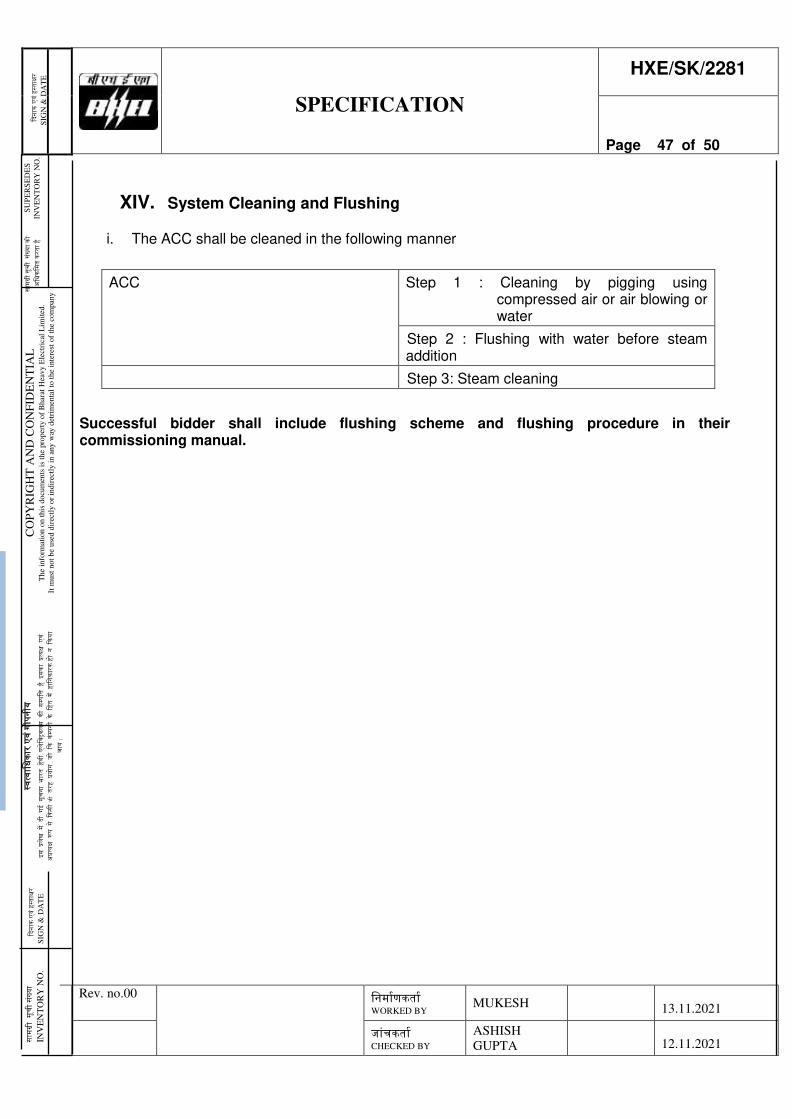
स
ामग्री
सूची
संख्य
ा को
S
UP
ER
SE
DE
S
अ
धिकध
मत क
रता ह
ै
INV
EN
TO
RY
NO
.
स्वत्व
ाधिका
र एव
ंगोप
नीय
इस प्र
लखे म
ें दी
गई सू
चना
भारत
हवेी
एलेध
रिकल
स क
ी सम्
पधि
ह ै इ
सका
प्रत्यक्ष
एवं
अप्रत्य
क्ष रू
प से
ककस
ी भी
तरह
प्रयो
ग , ज
ो कक
कंम्प
नी के
धहत
में ह
ाधनका
रक ह
ो न
ककया
जा
य |
कद
नाक
एवं ह
स्ताक्ष
र S
IGN
& D
AT
E
SPECIFICATION
HXE/SK/2281
Page 47 of 50
Rev. no.00 धनमााणकताा WORKED BY
MUKESH
13.11.2021
जांचकताा CHECKED BY
ASHISH
GUPTA
12.11.2021
CO
PY
RIG
HT
AN
D C
ON
FID
EN
TIA
L
The
info
rmat
ion o
n t
his
docu
men
ts i
s th
e pro
per
ty o
f B
har
at H
eavy E
lect
rica
l L
imit
ed.
It m
ust
not
be
use
d d
irec
tly o
r in
dir
ectl
y i
n a
ny
way
det
rim
enta
l to
the
inte
rest
of
the
com
pan
y
कदना
क एव
ंहस्त
ाक्षर
SIG
N &
DA
TE
सामग्र
ी सूच
ी संख्य
ा IN
VE
NT
OR
Y N
O.
XIV. System Cleaning and Flushing
i. The ACC shall be cleaned in the following manner
ACC Step 1 : Cleaning by pigging using compressed air or air blowing or water
Step 2 : Flushing with water before steam addition
Step 3: Steam cleaning
Successful bidder shall include flushing scheme and flushing procedure in their commissioning manual.
स
ामग्री
सूची
संख्य
ा को
S
UP
ER
SE
DE
S
अ
धिकध
मत क
रता ह
ै
INV
EN
TO
RY
NO
.
स्वत्व
ाधिका
र एव
ंगोप
नीय
इस प्र
लखे म
ें दी
गई सू
चना
भारत
हवेी
एलेध
रिकल
स क
ी सम्
पधि
ह ै इ
सका
प्रत्यक्ष
एवं
अप्रत्य
क्ष रू
प से
ककस
ी भी
तरह
प्रयो
ग , ज
ो कक
कंम्प
नी के
धहत
में ह
ाधनका
रक ह
ो न
ककया
जा
य |
कद
नाक
एवं ह
स्ताक्ष
र S
IGN
& D
AT
E
SPECIFICATION
HXE/SK/2281
Page 48 of 50
Rev. no.00 धनमााणकताा WORKED BY
MUKESH
13.11.2021
जांचकताा CHECKED BY
ASHISH
GUPTA
12.11.2021
CO
PY
RIG
HT
AN
D C
ON
FID
EN
TIA
L
The
info
rmat
ion o
n t
his
docu
men
ts i
s th
e pro
per
ty o
f B
har
at H
eavy E
lect
rica
l L
imit
ed.
It m
ust
not
be
use
d d
irec
tly o
r in
dir
ectl
y i
n a
ny
way
det
rim
enta
l to
the
inte
rest
of
the
com
pan
y
कदना
क एव
ंहस्त
ाक्षर
SIG
N &
DA
TE
सामग्र
ी सूच
ी संख्य
ा IN
VE
NT
OR
Y N
O.
XV. Field Quality Requirement during Erection, commissioning, Start-up, Trial operation and Performance Tests
a. Erection
The bidder shall submit to the BHEL/ Owner field welding schedule for field welding activities. The field welding schedule shall be submitted to the Purchaser/Owner along with all supporting procedures, like welding procedures, heat treatment procedures, NDT procedures etc.,
b. Commissioning
Commissioning of the power plant will be carried out stepwise. Before starting test runs, with the entire plant the individual systems with their components must be tested and commissioned carefully.
All necessary commissioning steps are to be performed according to the corresponding commissioning procedure which is to be prepared in advance. The results of these commissioning activities are to be documented properly too.
Bidder shall prepare a comprehensive commissioning program for the system including commissioning instructions, commissioning checklists, logic diagrams etc. All pre-commissioning tests &activities as required for successful running of the equipment or as mentioned in the technical specification elsewhere shall be documents properly.
The system specific commissioning programmes shall include
1.0 System inspection
2.0 Cleaning
3.0 Pressure test/ leak test
4.0 Electrical commissioning activities
5.0 Interlock checks
6.0 Components test
7.0 System specific process test as per approved commissioning procedure
8.0 Records of commissioning results and handed over to the purchaser/ Owner.
स
ामग्री
सूची
संख्य
ा को
S
UP
ER
SE
DE
S
अ
धिकध
मत क
रता ह
ै
INV
EN
TO
RY
NO
.
स्वत्व
ाधिका
र एव
ंगोप
नीय
इस प्र
लखे म
ें दी
गई सू
चना
भारत
हवेी
एलेध
रिकल
स क
ी सम्
पधि
ह ै इ
सका
प्रत्यक्ष
एवं
अप्रत्य
क्ष रू
प से
ककस
ी भी
तरह
प्रयो
ग , ज
ो कक
कंम्प
नी के
धहत
में ह
ाधनका
रक ह
ो न
ककया
जा
य |
कद
नाक
एवं ह
स्ताक्ष
र S
IGN
& D
AT
E
SPECIFICATION
HXE/SK/2281
Page 49 of 50
Rev. no.00 धनमााणकताा WORKED BY
MUKESH
13.11.2021
जांचकताा CHECKED BY
ASHISH
GUPTA
12.11.2021
CO
PY
RIG
HT
AN
D C
ON
FID
EN
TIA
L
The
info
rmat
ion o
n t
his
docu
men
ts i
s th
e pro
per
ty o
f B
har
at H
eavy E
lect
rica
l L
imit
ed.
It m
ust
not
be
use
d d
irec
tly o
r in
dir
ectl
y i
n a
ny
way
det
rim
enta
l to
the
inte
rest
of
the
com
pan
y
कदना
क एव
ंहस्त
ाक्षर
SIG
N &
DA
TE
सामग्र
ी सूच
ी संख्य
ा IN
VE
NT
OR
Y N
O.
XVI. Services
a. Other Services : 3-D modeling
All the plant layouts shall be made in computerised 3D modelling system. Contractor shall progressively provide an integrated, intelligent and editable 3-D model of entire ACC package scope made using rule-based, data centric 3D Design software that should accept 3D data from heterogeneous systems with equipment drawings attached to the respective equipment / systems in the 3D model. BHEL shall inform the details of software to be used for 3-D modelling at detailed engineering.
BHEL shall be using IPDS which is based on Intergraph’s Smart Plant using SPPID, SPEL, SPI, SP Foundation, SP 3D etc with the capability of importing models from source like PDS, PDMS, Plant Space, Micro Station, AutoCAD, CADWorx, CAESAR II, SAT, IFC, XMpLant, i-model. The model of ACC and ACC engineering data will be required to be integrated with BHEL data. A brief write-up on file format compatibility with IPDS is attached at Annexure-XIV.2-1.
b. Optional Sevices
i. Training (optional)
The scope of service shall include a training module covering the areas of Product design, Engineering, manufacturing and O&M/ trouble shooting. Such training should cover the following areas as a minimum in order to enable these personnel to individually take the responsibility in a manner acceptable to the purchaser and Owner.
The scope of services under training shall be for min. 50 mandays. For example training given to 10 persons for 5 days shall be be cnsidered as 50 mandays of training. Training schedule shall be finalized based on the Bidder’s proposal within two (2) months from placement of award.
ii. E-learning package (optional)
Bidder to furnish E-learning package for complete ACC along with vacuum pump, drain pump as per annexure XIV.3-1
स
ामग्री
सूची
संख्य
ा को
S
UP
ER
SE
DE
S
अ
धिकध
मत क
रता ह
ै
INV
EN
TO
RY
NO
.
स्वत्व
ाधिका
र एव
ंगोप
नीय
इस प्र
लखे म
ें दी
गई सू
चना
भारत
हवेी
एलेध
रिकल
स क
ी सम्
पधि
ह ै इ
सका
प्रत्यक्ष
एवं
अप्रत्य
क्ष रू
प से
ककस
ी भी
तरह
प्रयो
ग , ज
ो कक
कंम्प
नी के
धहत
में ह
ाधनका
रक ह
ो न
ककया
जा
य |
कद
नाक
एवं ह
स्ताक्ष
र S
IGN
& D
AT
E
SPECIFICATION
HXE/SK/2281
Page 50 of 50
Rev. no.00 धनमााणकताा WORKED BY
MUKESH
13.11.2021
जांचकताा CHECKED BY
ASHISH
GUPTA
12.11.2021
CO
PY
RIG
HT
AN
D C
ON
FID
EN
TIA
L
The
info
rmat
ion o
n t
his
docu
men
ts i
s th
e pro
per
ty o
f B
har
at H
eavy E
lect
rica
l L
imit
ed.
It m
ust
not
be
use
d d
irec
tly o
r in
dir
ectl
y i
n a
ny
way
det
rim
enta
l to
the
inte
rest
of
the
com
pan
y
कदना
क एव
ंहस्त
ाक्षर
SIG
N &
DA
TE
सामग्र
ी सूच
ी संख्य
ा IN
VE
NT
OR
Y N
O.
XVII. List of Annexure to this specification
1. General a. Annexure-II-1 Project Information
2. Mechanical
a. Annexure-IV.1-1 Broad Scope fo design b. Annexure-IV.3-1 HBD at design back pressure c. Annexure-IV.3-2 Layout and Constraints d. Annexure-IV.3-3 Suggestive P&ID e. Annexure-IV.3-4 Input Data at 60% BMCR condition f. Annexure-IV.3-6 Design Data sheet g. Annexure-IV.3-7 Input Data at HP-LP bypass condition h. Annexure-IV.4-1 Terminal point: Hot Box i. Annexure-IV.4-7 Specification for Pipe, Fittings and Valves j. Annexure-IV.4-9 Specification for Thermal Insulation k. Annexure-IV.4-10 Allowable forces and moments l. Annexure-IV.7-2 Field Quality plan for structural steel m. Annexure-IV.7-3 Quality Assurance of Valves, Hanger, Thermal Insulation and
Piping system n. Annexure-IV.7-5 Quality Assurance of Drain pumps o. Annexure-IV.8-2 Instrument Air Format p. Annexure-IV.8-3 Cooling Water Requirement q. Annexure-IV.8-4 Condenser data sheet
r. Annexure-IV.10-1 List of MDL documents
3. Electrical
a. Annexure-V.1-2 Electrical Load List formats b. Annexure-V.1-4 Specification for Motors
4. Civil
i. Annexure-VII-1 NTPC specification for Civil Works
5. Other Services i. Annexure-XIV.2-1 File Format Compatibility with IPDS ii. Annexure-XIV.3-1 E-Learning Module
6. Erection Guidelines
i. Annexure- XV-2 Document schedule

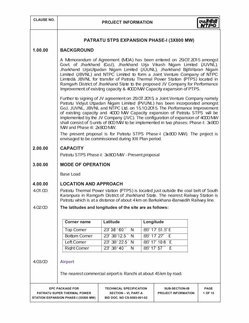
A Memorandum of Agreement (MOA) has been entered on 29.07.2015 amongst Govt. of Jharkhand (GoJ), Jharkhand Urja Vikash Nigam Limited (JUVNL), Jharkhand UrjaUtpadan Nigam Limited (JUUNL), Jharkhand BijliVitaran Nigam Limited (JBVNL) and NTPC Limited to form a Joint Venture Company of NTPC Limted& JBVNL for transfer of Patratu Thermal Power Station (PTPS) located in Ramgarh District of Jharkhand State to the proposed JV Company for Performance Improvement of existing capacity & 4000 MW Capacity expansion of PTPS. Further to signing of JV agreement on 29.07.2015, a Joint Venture Company namely Patratu Vidyut Utpadan Nigam Limited (PVUNL) has been incorporated amongst GoJ, JUVNL, JBVNL and NTPC Ltd. on 15.10.2015. The Performance Improvement of existing capacity and 4000 MW Capacity expansion of Patratu STPS will be implemented by the JV Company (JVC). The configuration of expansion of 4000 MW shall consist of 5 units of 800 MW to be implemented in two phases; Phase-I: 3x800 MW and Phase-II: 2x800 MW.The present proposal is for Patratu STPS Phase-I (3x800 MW). The project is envisaged to be commissioned during XIII Plan period.Patratu STPS Phase-I: 3x800 MW - Present proposal Base Load
4.01.00 Patratu Thermal Power station (PTPS) is located just outside the coal belt of South Karanpura in Ramgarh District of Jharkhand State. The nearest Railway Station is Patratu which is at a distance of about 4 km on Barkakhana-Barwadih Railway line.4.02.00
Top Corner 23° N 85° 17’ 51.5” EBottom Corner 23° 38 N 85° 17’ 27” ELeft Corner 23° 38 N 85° ERight Corner 23° 38 N 85° E4.03.00
The nearest commercial airport is Ranchi at about 45 km by road.
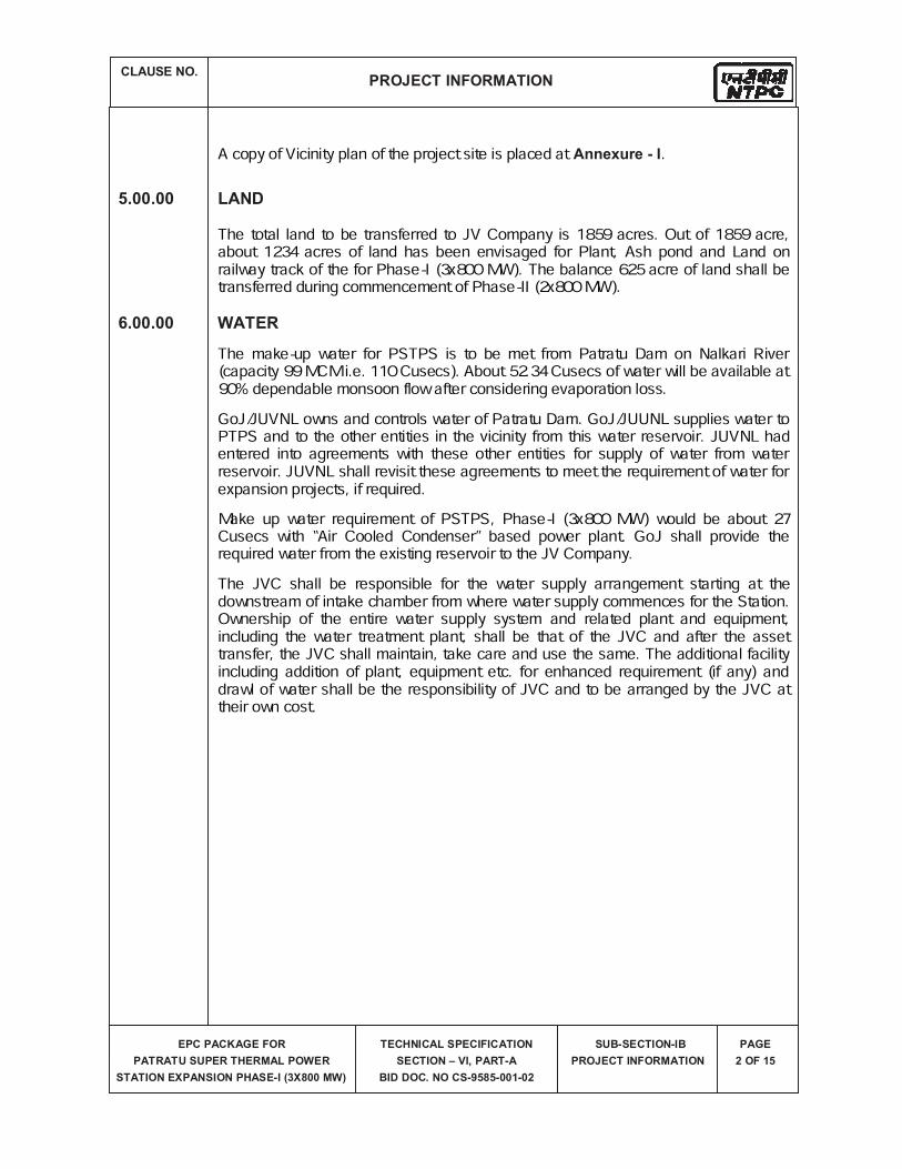
A copy of Vicinity plan of the project site is placed at .
The total land to be transferred to JV Company is 1859 acres. Out of 1859 acre, about 1234 acres of land has been envisaged for Plant, Ash pond and Land on railway track of the for Phase-I (3x800 MW). The balance 625 acre of land shall be transferred during commencement of Phase-II (2x800 MW).The make-up water for PSTPS is to be met from Patratu Dam on Nalkari River (capacity 99 MCM i.e. 110 Cusecs). About 52.34 Cusecs of water will be available at 90% dependable monsoon flow after considering evaporation loss. GoJ/JUVNL owns and controls water of Patratu Dam. GoJ/JUUNL supplies water to PTPS and to the other entities in the vicinity from this water reservoir. JUVNL had entered into agreements with these other entities for supply of water from water reservoir. JUVNL shall revisit these agreements to meet the requirement of water for expansion projects, if required.Make up water requirement of PSTPS, Phase-I (3x800 MW) would be about 27 Cusecs with “Air Cooled Condenser” based power plant. GoJ shall provide the required water from the existing reservoir to the JV Company. The JVC shall be responsible for the water supply arrangement starting at the downstream of intake chamber from where water supply commences for the Station. Ownership of the entire water supply system and related plant and equipment, including the water treatment plant, shall be that of the JVC and after the asset transfer, the JVC shall maintain, take care and use the same. The additional facility including addition of plant, equipment etc. for enhanced requirement (if any) and drawl of water shall be the responsibility of JVC and to be arranged by the JVC attheir own cost.
System for the project would be taken up with them for planning and execution of transmission system modalities as Inter-State System or ISTS System. Considering overall capacity of the project as 4000 MW, 765 kV step-up system has been envisaged. Two D/C 765 KV line, one each to New Ranchi (Bero) and Gaya has been envisaged. This would also form part of 765 kV transmission corridor connecting Ranchi to Gaya. These lines can be used to evacuate power to the Eastern Region ISTS as well as to Jharkhand State. In view of above, provision of four nos. of 765 kV outgoing Line bays has been kept in the new 765 kV generation switchyard.The issue of power evacuation of the proposed project shall be taken up with appropriate Transmission Utility (STU or CTU) as per regulatory provision, based on allocation of power. The meteorological data from nearest observatory is placed at The Plant water scheme is described below.13.01.00 The plant auxiliaries of Steam Generator and Turbine Generator shall be cooled by Demineralized (DM) water in a closed circuit. The primary circuit DM water shall be cooled through plate type heat exchangers by Circulating Water tapped from ACW system in a secondary circuit. The station auxiliaries such as Air compressors, Compressors of ash handling plant, compressor of mill reject system etc. shall also be cooled by Demineralized (DM) water in a closed circuit .The hot secondary circuit cooling water shall be cooled in the cooling towers and shall be returned back to the system. It is proposed to provide independent primary cooling water circuit for Steam Generator & auxiliaries and TG & its auxiliaries.13.02.0013.03.00 (a)The drinking water requirement of the plant shall be provided from water treatment plant.(b) Steam Cycle make-up water, makeup to the primary circuit of ECW (unit auxiliaries) system, boiler fill water shall be provided from demineralizingplant.(c) The quality of Raw Water & DM Water is enclosed with this sub-section as .(d) Effluent from various areas in TG & SG system shall be collected in respective pits in their areas and pumped to a common terminal point as shown in plant water scheme.
All power plant structures and equipment, including plant auxiliary structures and equipment shall be designed for seismic forces as given in Part-B of this section
All structures and equipment of the power plant, including plant auxiliary structures and equipment, shall be designed for wind forces as given as given in Part-B of this section.
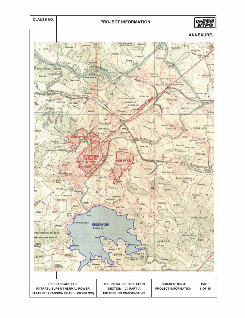
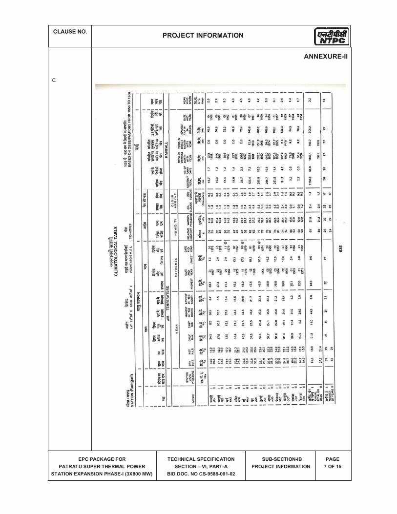
c
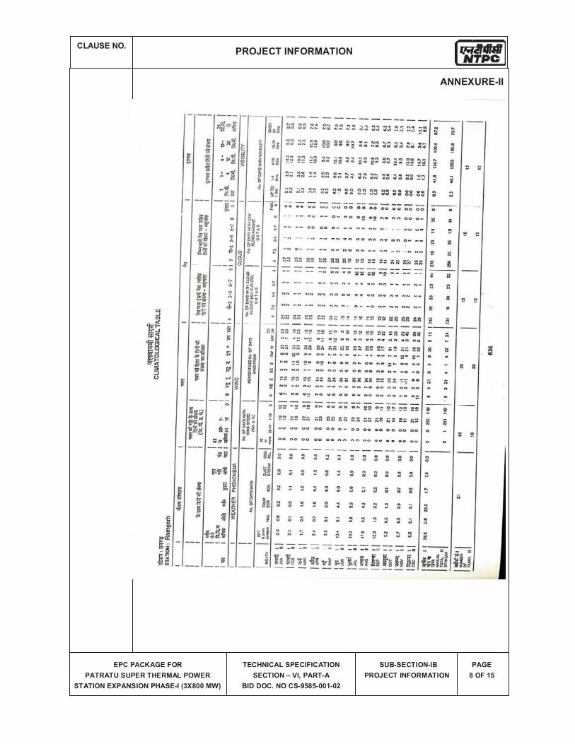
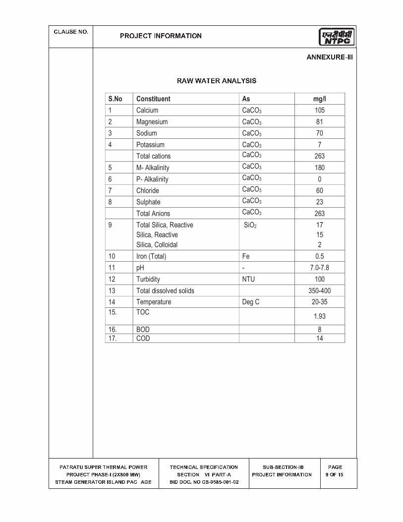
� ✁ ✂ ✄ ☎ ✆ ✝ ✞ ✟ ✠ ✡ ☛ ☞ ✌ ✍ ✎ ✏ ✑ ✒ ☛ ✡ ✓ ✔ ✎ ✏ ☛ ✑
✕ ✖ ✗ ✘ ✖ ✗ ✙ ✚ ✙ ✕ ✛ ✘ ✗ ✜ ✛ ✘ ✢ ✖ ✣ ✕ ✤ ✥ ✛ ✘✕ ✘ ✤ ✦ ✛ ✧ ✗ ✕ ✜ ✖ ✚ ✛ ★ ✩ ✪ ✫ ✬ ✭ ✮ ✮ ✢ ✥ ✯✚ ✗ ✛ ✖ ✢ ✰ ✛ ✱ ✛ ✘ ✖ ✗ ✤ ✘ ✩ ✚ ✣ ✖ ✱ ✲ ✕ ✖ ✧ ✳ ✖ ✰ ✛ ✗ ✛ ✧ ✜ ✱ ✩ ✧ ✖ ✣ ✚ ✕ ✛ ✧ ✩ ✴ ✩ ✧ ✖ ✗ ✩ ✤ ✱✚ ✛ ✧ ✗ ✩ ✤ ✱ ✳ ✵ ✩ ✳ ✕ ✖ ✘ ✗ ★ ✖✶ ✩ ✲ ✲ ✤ ✧ ✷ ✱ ✤ ✧ ✚ ★ ✸ ✹ ✭ ✹ ★ ✮ ✮ ✺ ★ ✮ ✫ ✚ ✙ ✶ ★ ✚ ✛ ✧ ✗ ✩ ✤ ✱ ★ ✩ ✶✕ ✘ ✤ ✦ ✛ ✧ ✗ ✩ ✱ ✴ ✤ ✘ ✢ ✖ ✗ ✩ ✤ ✱ ✕ ✖ ✰ ✛✸ ✤ ✴ ✺ ✹
✔ ✑ ✑ ✌ ✻ ✼ ✡ ✌ ✽ ✏ ✏ ✏✡ ✔ ✾ ✾ ✔ ✎ ✌ ✡ ✔ ✑ ✔ ✿ ❀ ❁ ✏ ❁S.No Constituent As mg/I
1 Calcium CaCO3 105
2 Magnesium CaCO3 81
3 Sodium CaCO3 70
4 Potassium CaCO3 7
Total cations CaCO3 263
5 M- Alkalinity CaCO3 180
6 P- Alkalinity CaCO3 0
7 Chloride CaCO3 60
8 Sulphate CaCO3 23
Total Anions CaCO3 263
9 Total Silica, Reactive
Silica, Reactive
Silica, Colloidal
SiO2 17
15
2
10 Iron (Total) Fe 0.5
11 pH - 7.0-7.8
12 Turbidity NTU 100
13 Total dissolved solids 350-400
14 Temperature Deg C 20-35
15. TOC1.93
16. BOD 8
17. COD 14
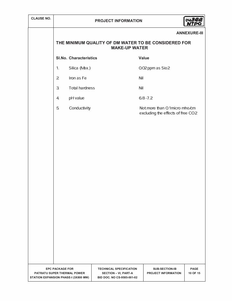
1. Silica (Max.) 0.02 ppm as Sio22. Iron as Fe Nil3. Total hardness Nil4. pH value 6.8 -7.25. Conductivity Not more than 0.1micro mho/cm excluding the effects of free CO2
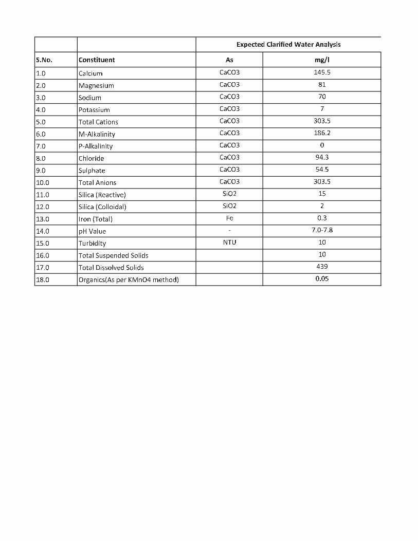
❂ ❃ ❄ ❅ ❃ ❆ ❅ ❇ ❈ ❉ ❊ ❉ ❋ ● ❇ ❉ ❍ ❈ ■ ❏ ❑ ▲▼ ◆ ❖ P ◗ ❘ ❙ ❚ ❯ ❱ P ◗ P ❲ ❳ ▼ ❨ ❩ ◆ ❩❬ ◆ ❖ ❭ ◗ ❪ ❫ ❴ ❵ ❚ ❯ ❱ P ◗ P ❲ ❳ ❛ ▼❳ ◆ ❖ ❜ ❝ ❞ ❚ ❯ ❱ P ◗ P ❲ ❳ ❡ ❖❨ ◆ ❖ ❢ ❝ ❣ ◗ ❵ ❵ ❚ ❯ ❱ P ◗ P ❲ ❳ ❡❩ ◆ ❖ ❤ ❝ ❣ ◗ ❘ P ◗ ❣ ❚ ❝ ❫ ❵ P ◗ P ❲ ❳ ❳ ❖ ❳ ◆ ❩✐ ◆ ❖ ❭ ❥ ❘ ❦ ◗ ❘ ❚ ❫ ❚ ❣ ❧ P ◗ P ❲ ❳ ▼ ❛ ✐ ◆ ❬❡ ◆ ❖ ❢ ❥ ❘ ❦ ◗ ❘ ❚ ❫ ❚ ❣ ❧ P ◗ P ❲ ❳ ❖❛ ◆ ❖ P ♠ ❘ ❝ ♥ ❚ ❞ ❴ P ◗ P ❲ ❳ ♦ ❨ ◆ ❳♦ ◆ ❖ ❜ ❯ ❘ ♣ ♠ ◗ ❣ ❴ P ◗ P ❲ ❳ ❩ ❨ ◆ ❩▼ ❖ ◆ ❖ ❤ ❝ ❣ ◗ ❘ ❥ ❫ ❚ ❝ ❫ ❵ P ◗ P ❲ ❳ ❳ ❖ ❳ ◆ ❩▼ ▼ ◆ ❖ ❜ ❚ ❘ ❚ ❙ ◗ q r ❴ ◗ ❙ ❣ ❚ s ❴ t ❜ ❚ ❲ ❬ ▼ ❩▼ ❬ ◆ ❖ ❜ ❚ ❘ ❚ ❙ ◗ q P ❝ ❘ ❘ ❝ ❚ ❞ ◗ ❘ t ❜ ❚ ❲ ❬ ❬▼ ❳ ◆ ❖ ✉ ♥ ❝ ❫ q ❤ ❝ ❣ ◗ ❘ t ✈ ❴ ❖ ◆ ❳▼ ❨ ◆ ❖ ♣ ✇ ① ◗ ❘ ❯ ❴ ❡ ◆ ❖ ❡ ◆ ❛▼ ❩ ◆ ❖ ❤ ❯ ♥ ② ❚ ❞ ❚ ❣ ❧ ③ ❤ ④ ▼ ❖▼ ✐ ◆ ❖ ❤ ❝ ❣ ◗ ❘ ❜ ❯ ❵ ♣ ❴ ❫ ❞ ❴ ❞ ❜ ❝ ❘ ❚ ❞ ❵ ▼ ❖▼ ❡ ◆ ❖ ❤ ❝ ❣ ◗ ❘ ⑤ ❚ ❵ ❵ ❝ ❘ s ❴ ❞ ❜ ❝ ❘ ❚ ❞ ❵ ❨ ❳ ♦▼ ❛ ◆ ❖ ❲ ♥ ❪ ◗ ❫ ❚ ❙ ❵ q ❥ ❵ ♣ ❴ ♥ ⑥ ❭ ❫ ❲ ❨ ❱ ❴ ❣ ♠ ❝ ❞ t ❖ ◆ ❖ ❩
⑦ ⑧ ⑨ ● ⑩ ❉ ● ❶ ❆ ▲ ❷ ❸ ❊ ❹ ❊ ● ❶ ❺ ❷ ❉ ● ❸ ❍ ❇ ❷ ▲ ❻ ❈ ❊ ❈
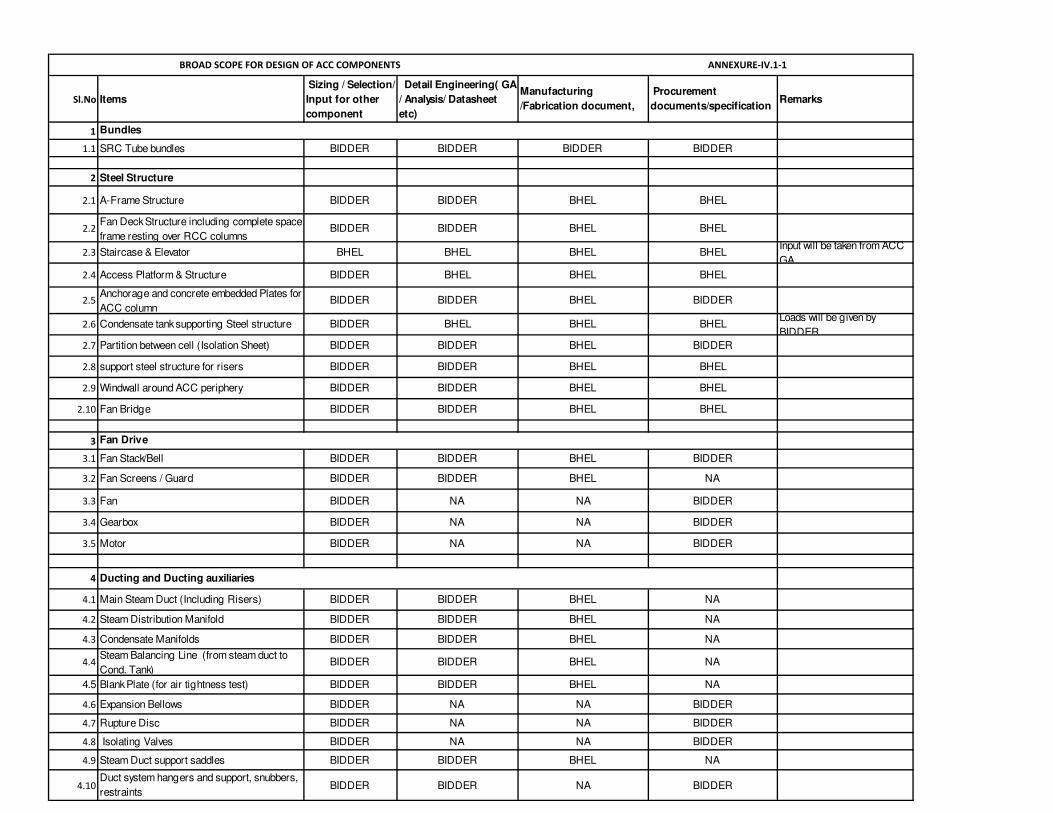
Sl.No Items
Sizing / Selection/
Input for other
component
Detail Engineering( GA
/ Analysis/ Datasheet
etc)
Manufacturing
/Fabrication document,
Procurement
documents/specification Remarks
1
1.1 SRC Tube bundles BIDDER BIDDER BIDDER BIDDER
2 Steel Structure
2.1 A-Frame Structure BIDDER BIDDER BHEL BHEL
2.2Fan Deck Structure including complete space
frame resting over RCC columnsBIDDER BIDDER BHEL BHEL
2.3 Staircase & Elevator BHEL BHEL BHEL BHELInput will be taken from ACC
GA
2.4 Access Platform & Structure BIDDER BHEL BHEL BHEL
2.5Anchorage and concrete embedded Plates for
ACC columnBIDDER BIDDER BHEL BIDDER
2.6 Condensate tank supporting Steel structure BIDDER BHEL BHEL BHELLoads will be given by
BIDDER
2.7 Partition between cell (Isolation Sheet) BIDDER BIDDER BHEL BIDDER
2.8 support steel structure for risers BIDDER BIDDER BHEL BHEL
2.9 Windwall around ACC periphery BIDDER BIDDER BHEL BHEL
2.10 Fan Bridge BIDDER BIDDER BHEL BHEL
3
3.1 Fan Stack/Bell BIDDER BIDDER BHEL BIDDER
3.2 Fan Screens / Guard BIDDER BIDDER BHEL NA
3.3 Fan BIDDER NA NA BIDDER
3.4 Gearbox BIDDER NA NA BIDDER
3.5 Motor BIDDER NA NA BIDDER
4
4.1 Main Steam Duct (Including Risers) BIDDER BIDDER BHEL NA
4.2 Steam Distribution Manifold BIDDER BIDDER BHEL NA
4.3 Condensate Manifolds BIDDER BIDDER BHEL NA
4.4Steam Balancing Line (from steam duct to
Cond. Tank)BIDDER BIDDER BHEL NA
4.5 Blank Plate (for air tightness test) BIDDER BIDDER BHEL NA
4.6 Expansion Bellows BIDDER NA NA BIDDER
4.7 Rupture Disc BIDDER NA NA BIDDER
4.8 Isolating Valves BIDDER NA NA BIDDER
4.9 Steam Duct support saddles BIDDER BIDDER BHEL NA
4.10Duct system hangers and support, snubbers,
restraintsBIDDER BIDDER NA BIDDER
BROAD SCOPE FOR DESIGN OF ACC COMPONENTS ANNEXURE-IV.1-1
Bundles
Fan Drive
Ducting and Ducting auxiliaries
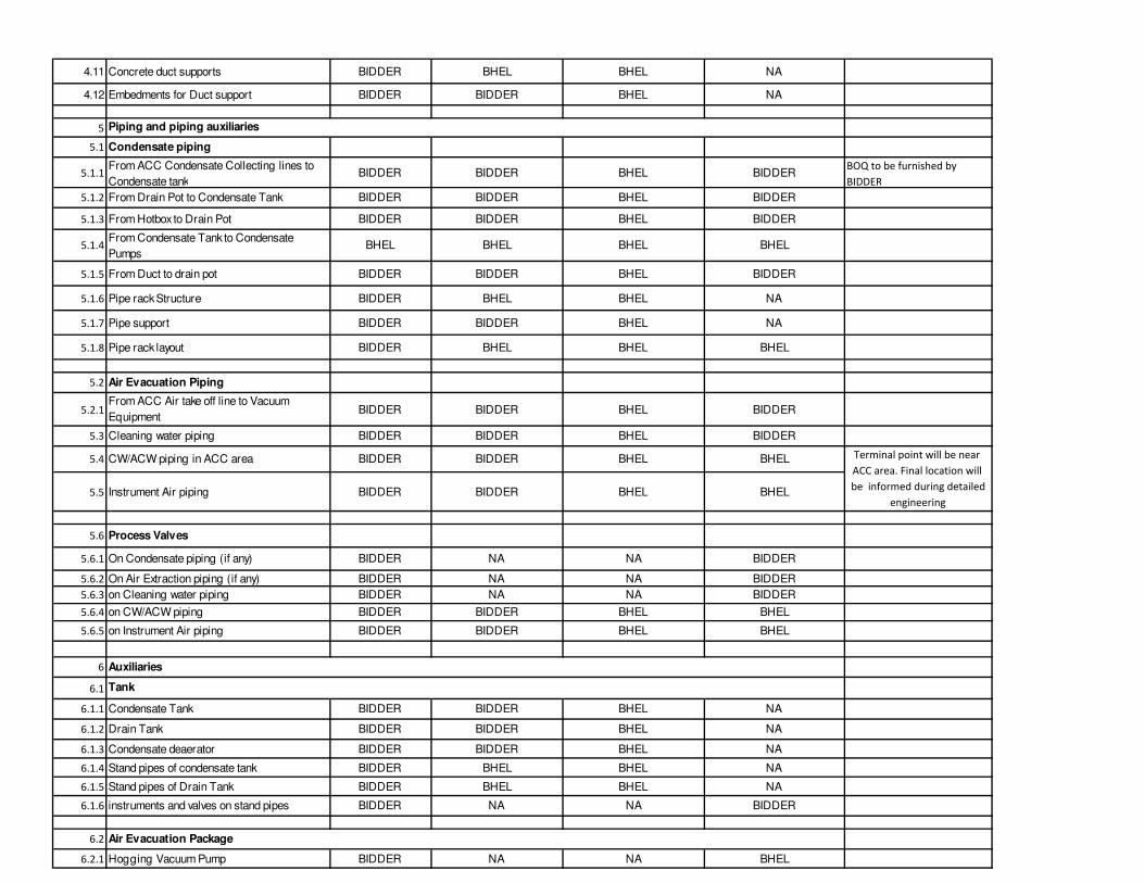
4.11 Concrete duct supports BIDDER BHEL BHEL NA
4.12 Embedments for Duct support BIDDER BIDDER BHEL NA
5
5.1 Condensate piping
5.1.1From ACC Condensate Collecting lines to
Condensate tankBIDDER BIDDER BHEL BIDDER
BOQ to be furnished by
BIDDER
5.1.2 From Drain Pot to Condensate Tank BIDDER BIDDER BHEL BIDDER
5.1.3 From Hotbox to Drain Pot BIDDER BIDDER BHEL BIDDER
5.1.4From Condensate Tank to Condensate
PumpsBHEL BHEL BHEL BHEL
5.1.5 From Duct to drain pot BIDDER BIDDER BHEL BIDDER
5.1.6 Pipe rack Structure BIDDER BHEL BHEL NA
5.1.7 Pipe support BIDDER BIDDER BHEL NA
5.1.8 Pipe rack layout BIDDER BHEL BHEL BHEL
5.2 Air Evacuation Piping
5.2.1From ACC Air take off line to Vacuum
EquipmentBIDDER BIDDER BHEL BIDDER
5.3 Cleaning water piping BIDDER BIDDER BHEL BIDDER
5.4 CW/ACW piping in ACC area BIDDER BIDDER BHEL BHEL
5.5 Instrument Air piping BIDDER BIDDER BHEL BHEL
5.6 Process Valves
5.6.1 On Condensate piping (if any) BIDDER NA NA BIDDER
5.6.2 On Air Extraction piping (if any) BIDDER NA NA BIDDER
5.6.3 on Cleaning water piping BIDDER NA NA BIDDER
5.6.4 on CW/ACW piping BIDDER BIDDER BHEL BHEL
5.6.5 on Instrument Air piping BIDDER BIDDER BHEL BHEL
6
6.1
6.1.1 Condensate Tank BIDDER BIDDER BHEL NA
6.1.2 Drain Tank BIDDER BIDDER BHEL NA
6.1.3 Condensate deaerator BIDDER BIDDER BHEL NA
6.1.4 Stand pipes of condensate tank BIDDER BHEL BHEL NA
6.1.5 Stand pipes of Drain Tank BIDDER BHEL BHEL NA
6.1.6 instruments and valves on stand pipes BIDDER NA NA BIDDER
6.2
6.2.1 Hogging Vacuum Pump BIDDER NA NA BHEL
Piping and piping auxiliaries
Auxiliaries
Tank
Air Evacuation Package
Terminal point will be near
ACC area. Final location will
be informed during detailed
engineering
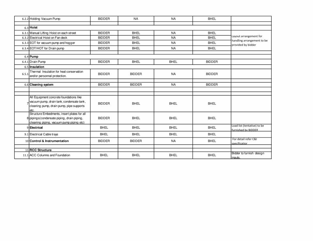
6.2.2 Holding Vacuum Pump BIDDER NA NA BHEL
6.3
6.3.1 Manual Lifting Hoist on each street BIDDER BHEL NA BHEL
6.3.2 Electrical Hoist on Fan deck BIDDER BHEL NA BHEL
6.3.3 EOT for vacuum pump and hogger BIDDER BHEL NA BHEL
6.3.4 EOT/HOT for Drain pump BIDDER BHEL NA BHEL
6.4
6.4.1 Drain Pump BIDDER BHEL BHEL BIDDER
6.5
6.5.1Thermal Insulation for heat conservation
and/or personnal protection.BIDDER BIDDER NA BIDDER
6.6 Cleaning system BIDDER BIDDER NA BIDDER
7
All Equipment concrete foundations like
vacuum pump, drain tank, condensate tank ,
cleaning pump, drain pump, pipe supports
etc.
BIDDER BHEL BHEL BHEL
8
Structure Embedments, insert plates for all
pipings(condensate piping, drain piping,
cleaning piping, vacuum pump piping etc)
BIDDER BHEL BHEL BHEL
9 Electrical BHEL BHEL BHEL BHELLoad list (tentative) to be
furnished by BIDDER
9.1 Electrical Cable trays BHEL BHEL BHEL BHEL
10 Control & Instrumentation BIDDER BIDDER NA BHEL For detail refer C&I
specification
11 RCC Structure
11.1 ACC Columns and Foundation BHEL BHEL BHEL BHELBidder to furnish design
inputs.
Hoist
Pump
Insulation
Layout arrangement for
handling arrangement to be
provided by bidder
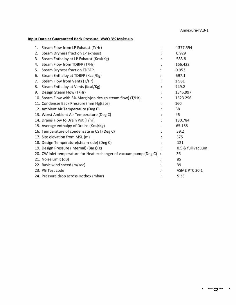
Annexure-IV.3-1
Input Data at Guaranteed Back Pressure, VWO 3% Make-up
1. Steam Flow from LP Exhaust (T/Hr) : 1377.594
2. Steam Dryness fraction LP exhaust : 0.929
3. Steam Enthalpy at LP Exhaust (Kcal/Kg) : 583.8
4. Steam Flow from TDBFP (T/Hr) : 166.422
5. Steam Dryness fraction TDBFP : 0.952
6. Steam Enthalpy at TDBFP (Kcal/Kg) : 597.1
7. Steam Flow from Vents (T/Hr) : 1.981
8. Steam Enthalpy at Vents (Kcal/Kg) : 749.2
9. Design Steam Flow (T/Hr) : 1545.997
10. Steam Flow with 5% Margin(on design steam flow) (T/Hr) : 1623.296
11. Condenser Back Pressure (mm Hg)(abs) : 160
12. Ambient Air Temperature (Deg C) : 38
13. Worst Ambient Air Temperature (Deg C) : 45
14. Drains Flow to Drain Pot (T/hr) : 130.784
15. Average enthalpy of Drains (Kcal/Kg) : 65.155
16. Temperature of condensate in CST (Deg C) : 59.2
17. Site elevation from MSL (m) : 375
18. Design Temperature(steam side) (Deg C) : 121
19. Design Pressure (Internal) (Bars)(g) : 0.5 & full vacuum
20. CW inlet temperature for Heat exchanger of vacuum pump (Deg C) : 36
21. Noise Limit (dB) : 85
22. Basic wind speed (m/sec) : 39
23. PG Test code : ASME PTC 30.1
24. Pressure drop across Hotbox (mbar) : 5.33
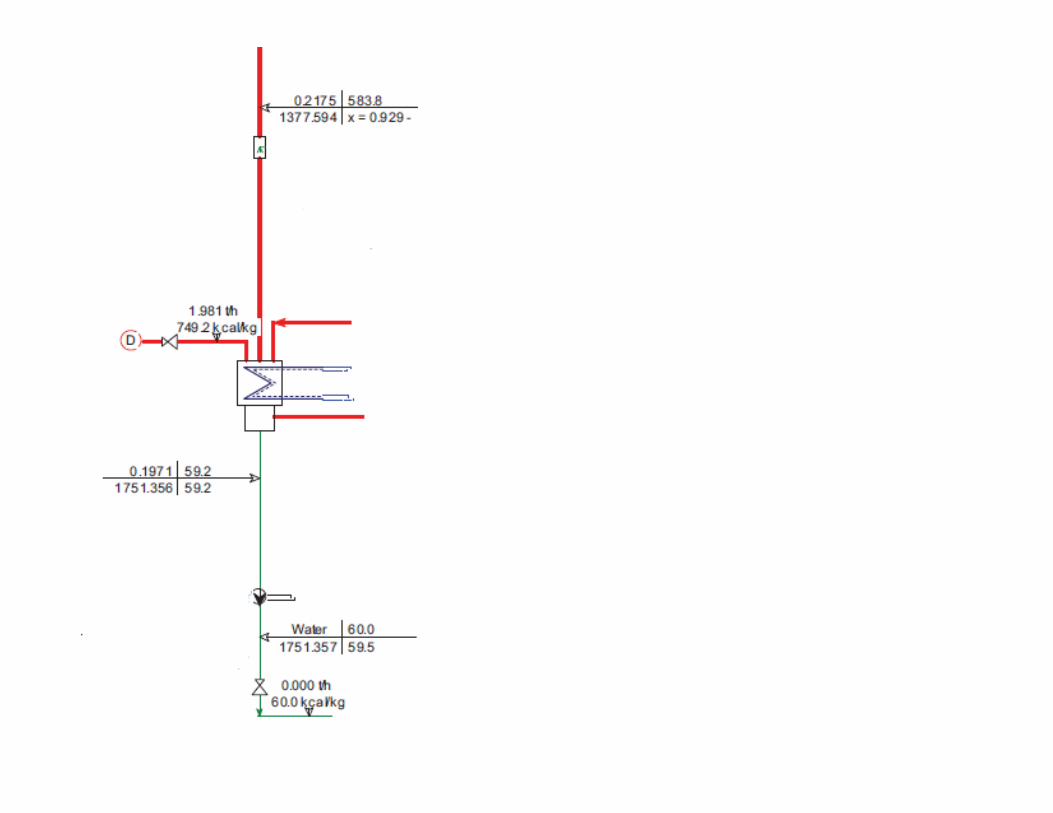

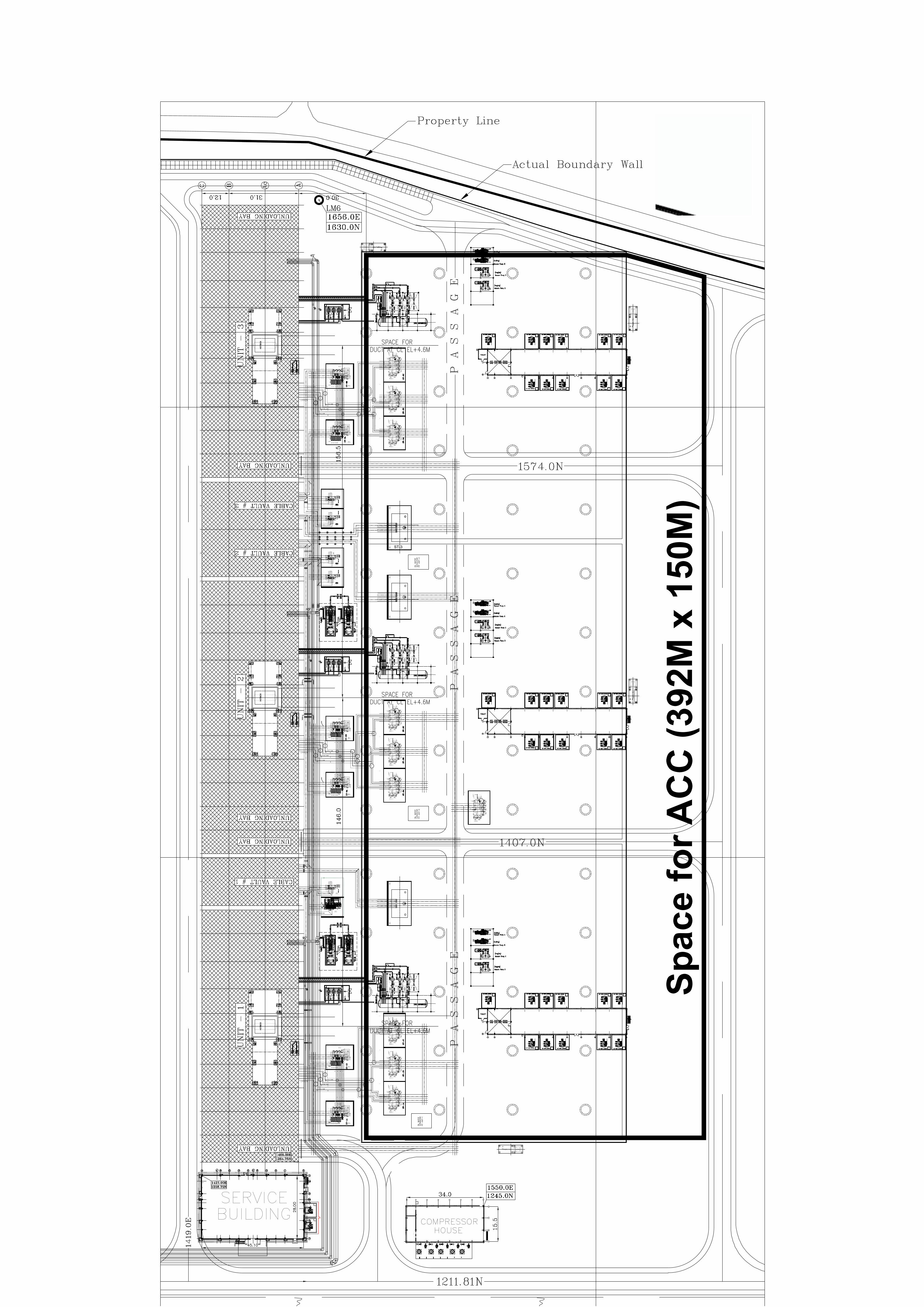
FILTER
NO. 1
NO. 2 NO. 3 NO. 4 NO. 5
INSTRU.AIR RECEIVER
NO. 1
INSTRU.AIR RECEIVER
NO. 2
INSTRU.AIR RECEIVER
NO. 3
SERVICEAIR RECEIVER
NO. 1
SERVICEAIR RECEIVER
NO. 2
AIR SUCT.
CAP-10 m3 CAP-10 m3 CAP-10 m3 CAP-10 m3 CAP-10 m3
DRAIN PIT
F/T
875
826
F/T
875
826
F/T
875
826
F/T
875
826
N5.0 N6.0
N5.0 N6.0
N5.0 N6.0
N5.0 N6.0
UT
-1A
SP
B B
OD
8.9
5M
EL.
UT
-1A
SP
B B
OD
10.6
0M
EL.
UT
-1A
SP
B B
OD
8.9
5M
EL.
UT
-1A
SP
B B
OD
8.9
5M
EL.
0B
A-0
BC
TIE
BO
D 8
.95M
EL.
0B
A-0
BC
TIE
BO
D 1
2.6
0M
EL.
0B
A-0
BC
TIE
BO
D 8
.95M
EL.
0B
A-0
BC
TIE
BO
D 8
.95M
EL.
UT
-1B
SP
B B
OD
10.6
0M
EL.
UT
-1B
SP
B B
OD
8.9
5M
EL.
UT
-1B
SP
B B
OD
8.9
5M
EL.
UT
-1B
SP
B B
OD
8.9
5M
EL.
R Y
B
Sp
ac
e f
or
AC
C (
392M
x 1
50M
)

ANNEXURE IV.3-3 SUGGESTIVE P&ID
Work by Check by
Approve by
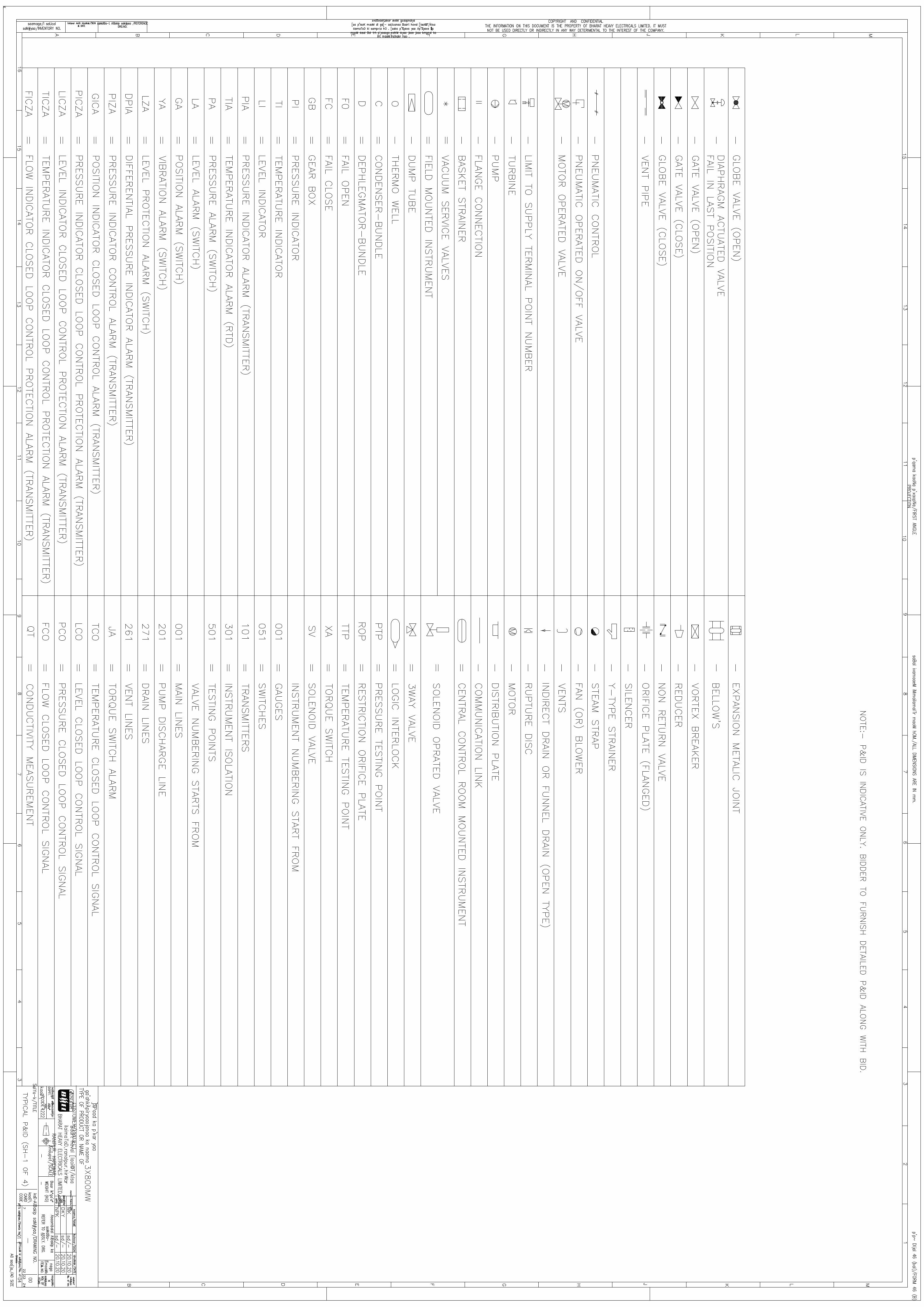
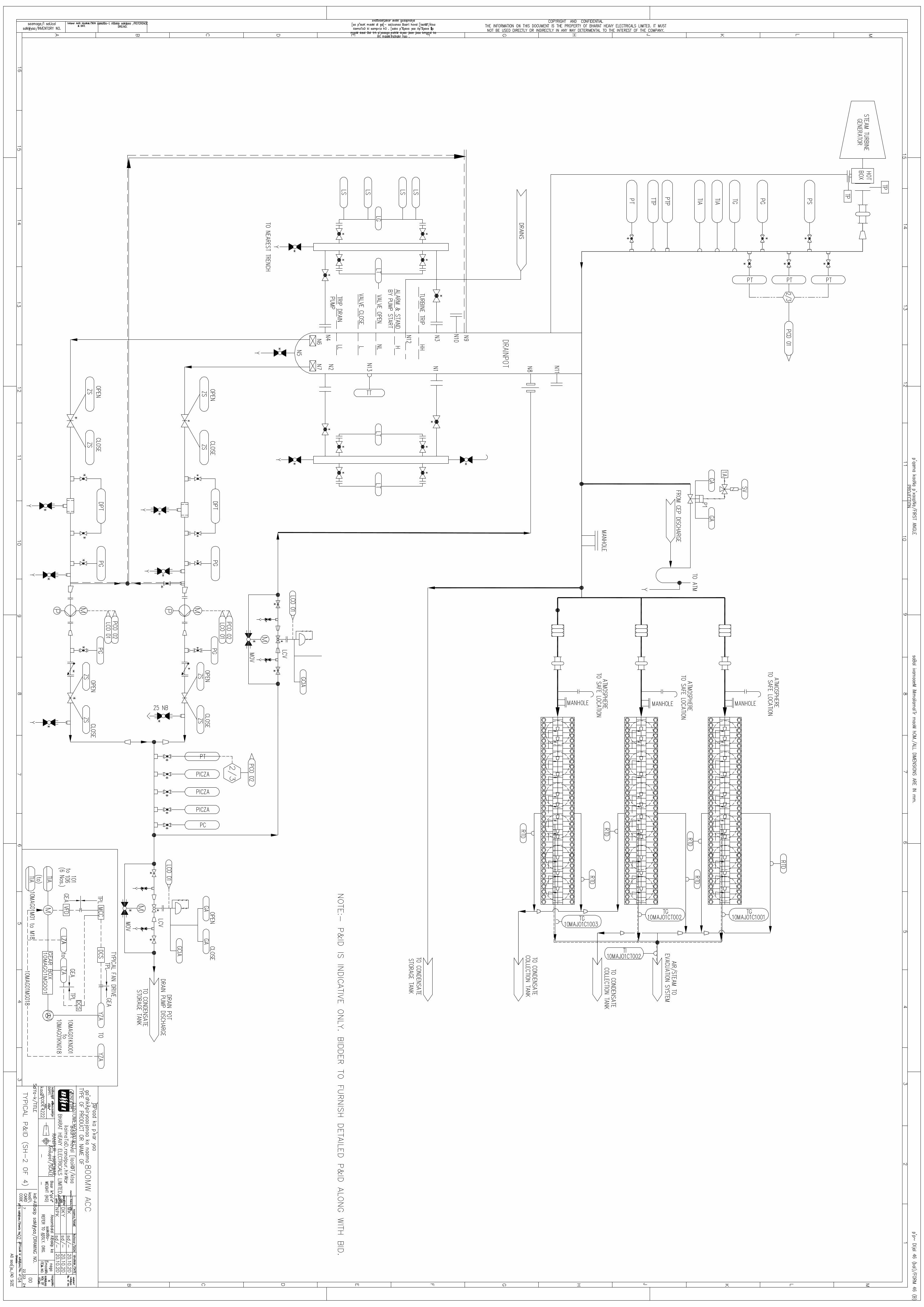
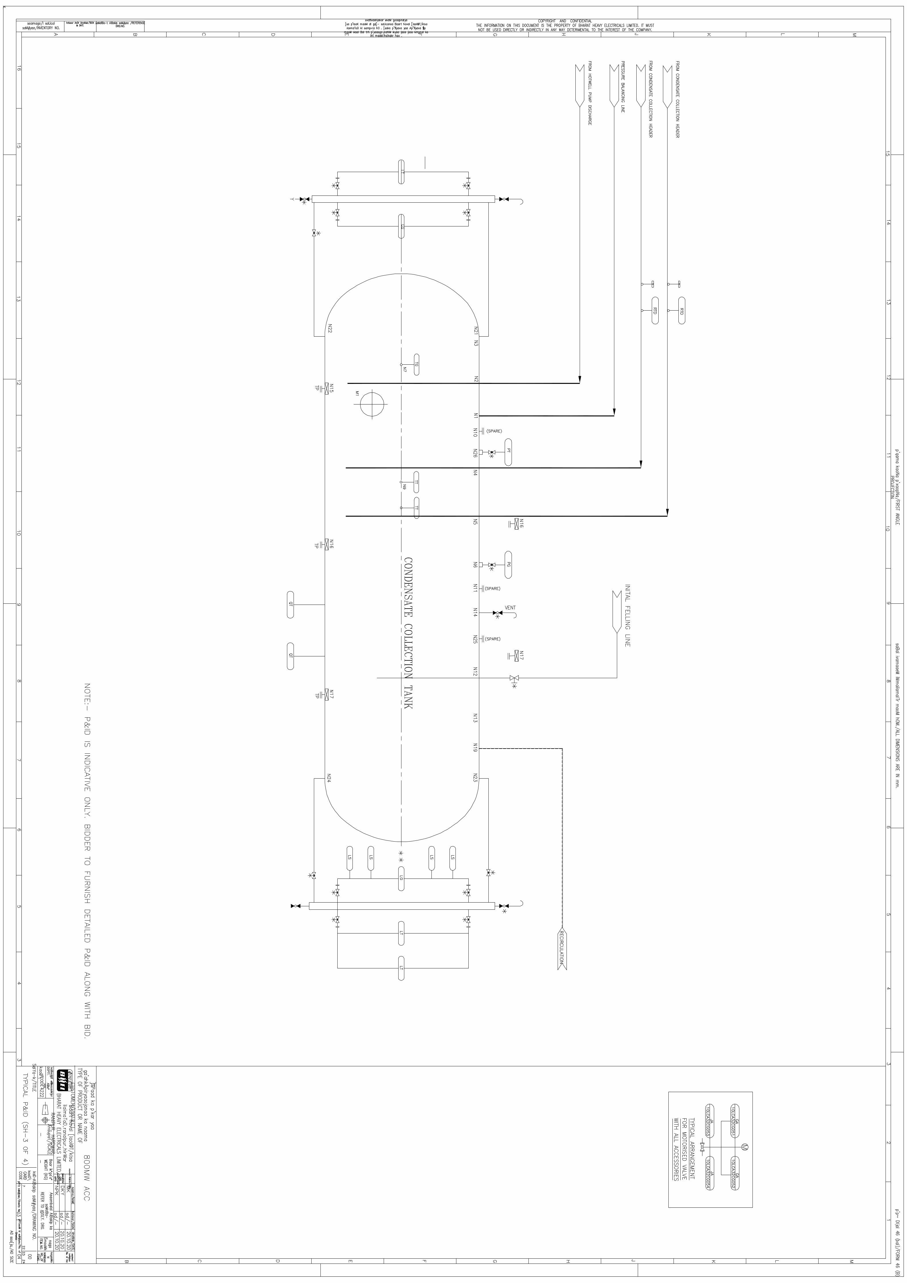
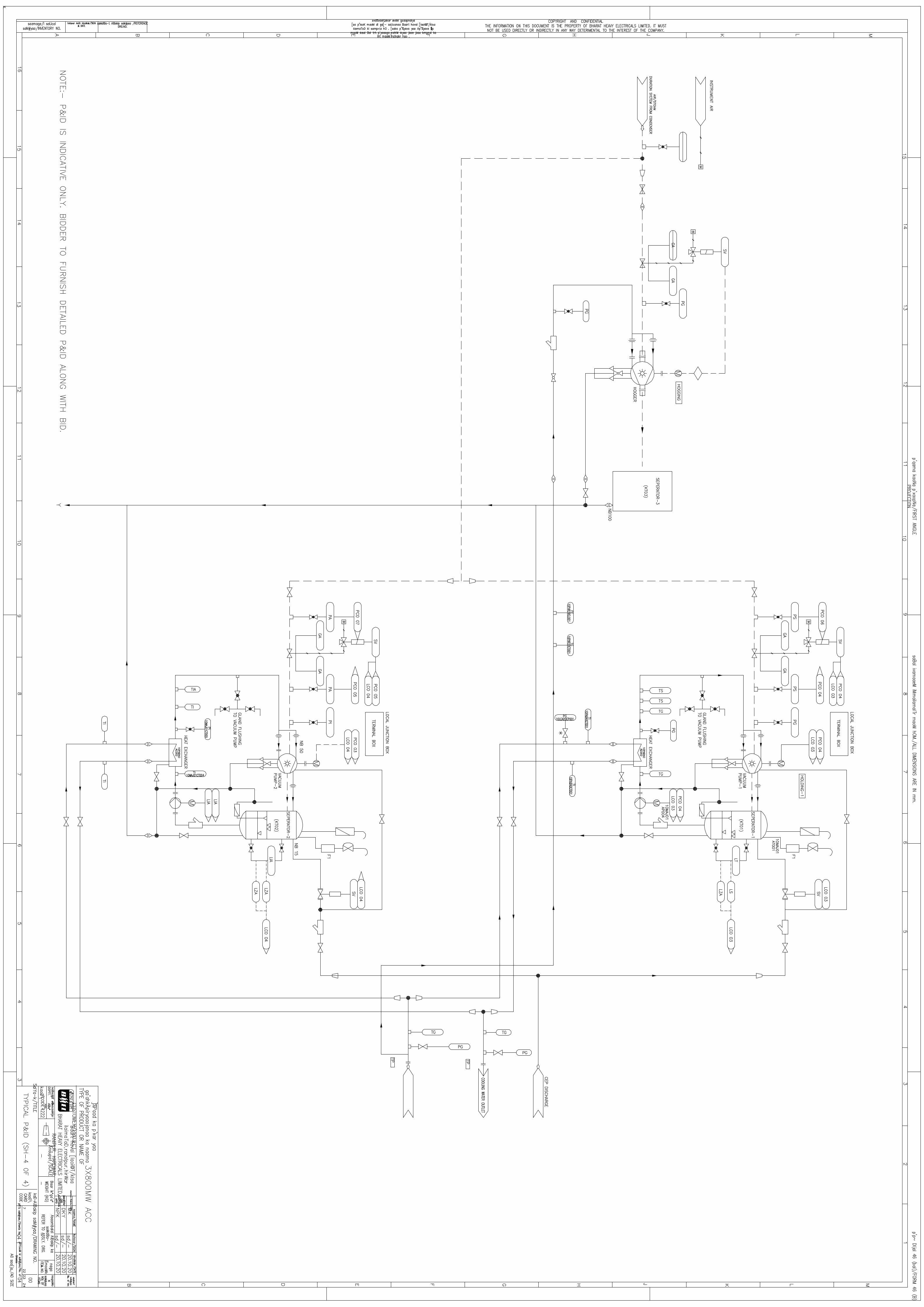
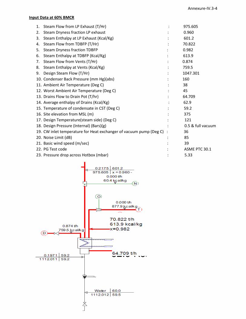
Annexure-IV.3-4
Input Data at 60% BMCR
1. Steam Flow from LP Exhaust (T/Hr) : 975.605
2. Steam Dryness fraction LP exhaust : 0.960
3. Steam Enthalpy at LP Exhaust (Kcal/Kg) : 601.2
4. Steam Flow from TDBFP (T/Hr) : 70.822
5. Steam Dryness fraction TDBFP : 0.982
6. Steam Enthalpy at TDBFP (Kcal/Kg) : 613.9
7. Steam Flow from Vents (T/Hr) : 0.874
8. Steam Enthalpy at Vents (Kcal/Kg) : 759.5
9. Design Steam Flow (T/Hr) : 1047.301
10. Condenser Back Pressure (mm Hg)(abs) : 160
11. Ambient Air Temperature (Deg C) : 38
12. Worst Ambient Air Temperature (Deg C) : 45
13. Drains Flow to Drain Pot (T/hr) : 64.709
14. Average enthalpy of Drains (Kcal/Kg) : 62.9
15. Temperature of condensate in CST (Deg C) : 59.2
16. Site elevation from MSL (m) : 375
17. Design Temperature(steam side) (Deg C) : 121
18. Design Pressure (Internal) (Bars)(g) : 0.5 & full vacuum
19. CW inlet temperature for Heat exchanger of vacuum pump (Deg C) : 36
20. Noise Limit (dB) : 85
21. Basic wind speed (m/sec) : 39
22. PG Test code : ASME PTC 30.1
23. Pressure drop across Hotbox (mbar) : 5.33
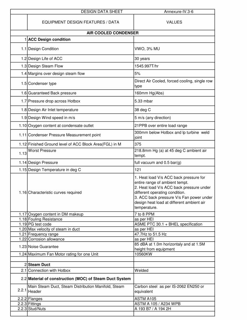
EQUIPMENT DESIGN FEATURES / DATA VALUES
1 ACC Design condition
1.1 Design Condition VWO, 3% MU
1.2 Design Life of ACC 30 years
1.3 Design Steam Flow 1545.997T/hr
1.4 Margins over design steam flow 5%
1.5 Condenser typeDirect Air Cooled, forced cooling, single row
type
1.6 Guaranteed Back pressure 160mm Hg(Abs)
1.7 Pressure drop across Hotbox 5.33 mbar
1.8 Design Air Inlet temperature 38 deg C
1.9 Design Wind speed in m/s 5 m/s (any direction)
1.10 Oxygen content at condensate outlet 21PPB over entire load range
1.11 Condenser Pressure Measurement point300mm below Hotbox and lp turbine weld
joint
1.12 Finished Ground level of ACC Block Area(FGL) in M 375
1.13Worst Pressure 218.8mm Hg (a) at 45 deg C ambient air
tempt.
1.14 Design Pressure full vacuum and 0.5 bar(g)
1.15 Design Temperature in deg C 121
1.16 Characteristic curves required
1. Heat load V/s ACC back pressure for
entire range of ambient tempt.
2. Heat load V/s ACC back pressure under
different operating condition.
3. ACC back pressure V/s Fan power under
design heat load at different ambient air
temperature.
1.17 Oxygen content in DM makeup 7 to 8 PPM
1.18 Fouling Resistance as per HEI
1.19 PG test code ASME PTC 30.1 + BHEL specification
1.20 Max velocity of steam in duct as per HEI
1.21 Frequency range 47.7Hz to 51.5 Hz
1.22 Corrosion allowance as per HEI
1.23 Noise Guarantee85 dBA at 1.0m horizontaly and at 1.5M
height from equipment
1.24 Maximum Fan Motor rating for one Unit 10560KW
2 Steam Duct
2.1 Connection with Hotbox Welded
2.2 Material of construction (MOC) of Steam Duct System
2.2.1Main Steam Duct, Steam Distribution Manifold, Steam
Header
Carbon steel as per IS-2062 EN250 or
equivalent
2.2.2 Flanges ASTM A105
2.2.3 Fittings ASTM A 105 / A234 WPB
2.2.3 Stud/Nuts A 193 B7 / A 194 2H
DESIGN DATA SHEET Annexure-IV.3-6
AIR COOLED CONDENSER
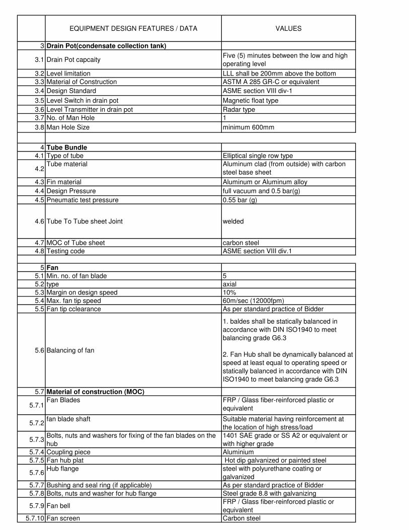
EQUIPMENT DESIGN FEATURES / DATA VALUES
3 Drain Pot(condensate collection tank)
3.1 Drain Pot capcaityFive (5) minutes between the low and high
operating level
3.2 Level limitation LLL shall be 200mm above the bottom
3.3 Material of Construction ASTM A 285 GR-C or equivalent
3.4 Design Standard ASME section VIII div-1
3.5 Level Switch in drain pot Magnetic float type
3.6 Level Transmitter in drain pot Radar type
3.7 No. of Man Hole 1
3.8 Man Hole Size minimum 600mm
4 Tube Bundle
4.1 Type of tube Elliptical single row type
4.2Tube material Aluminum clad (from outside) with carbon
steel base sheet
4.3 Fin material Aluminum or Aluminum alloy
4.4 Design Pressure full vacuum and 0.5 bar(g)
4.5 Pneumatic test pressure 0.55 bar (g)
4.6 Tube To Tube sheet Joint welded
4.7 MOC of Tube sheet carbon steel
4.8 Testing code ASME section VIII div.1
5 Fan
5.1 Min. no. of fan blade 5
5.2 type axial
5.3 Margin on design speed 10%
5.4 Max. fan tip speed 60m/sec (12000fpm)
5.5 Fan tip cclearance As per standard practice of Bidder
5.6 Balancing of fan
1. baldes shall be statically balanced in
accordance with DIN ISO1940 to meet
balancing grade G6.3
2. Fan Hub shall be dynamically balanced at
speed at least equal to operating speed or
statically balanced in accordance with DIN
ISO1940 to meet balancing grade G6.3
5.7 Material of construction (MOC)
5.7.1Fan Blades FRP / Glass fiber-reinforced plastic or
equivalent
5.7.2fan blade shaft Suitable material having reinforcement at
the location of high stress/load
5.7.3Bolts, nuts and washers for fixing of the fan blades on the
hub
1401 SAE grade or SS A2 or equivalent or
with higher grade
5.7.4 Coupling piece Aluminium
5.7.5 Fan hub plat Hot dip galvanized or painted steel
5.7.6Hub flange steel with polyurethane coating or
galvanized
5.7.7 Bushing and seal ring (if applicable) As per standard practice of Bidder
5.7.8 Bolts, nuts and washer for hub flange Steel grade 8.8 with galvanizing
5.7.9 Fan bellFRP / Glass fiber-reinforced plastic or
equivalent
5.7.10 Fan screen Carbon steel
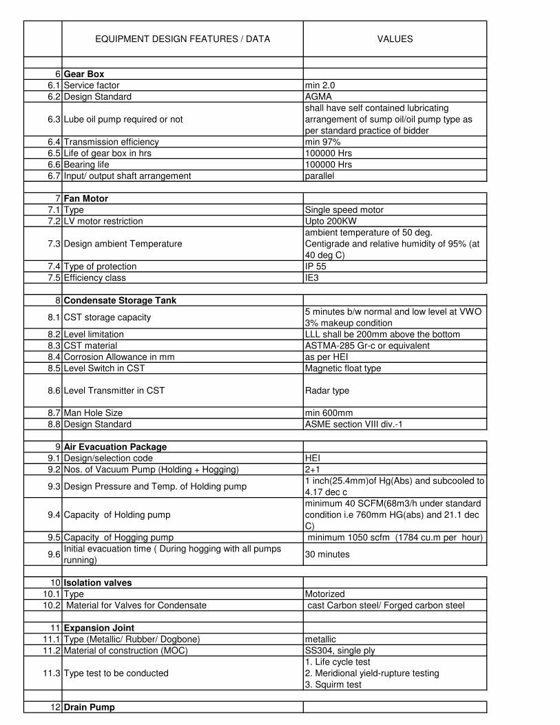
EQUIPMENT DESIGN FEATURES / DATA VALUES
6 Gear Box
6.1 Service factor min 2.0
6.2 Design Standard AGMA
6.3 Lube oil pump required or not
shall have self contained lubricating
arrangement of sump oil/oil pump type as
per standard practice of bidder
6.4 Transmission efficiency min 97%
6.5 Life of gear box in hrs 100000 Hrs
6.6 Bearing life 100000 Hrs
6.7 Input/ output shaft arrangement parallel
7 Fan Motor
7.1 Type Single speed motor
7.2 LV motor restriction Upto 200KW
7.3 Design ambient Temperature
ambient temperature of 50 deg.
Centigrade and relative humidity of 95% (at
40 deg C)
7.4 Type of protection IP 55
7.5 Efficiency class IE3
8 Condensate Storage Tank
8.1 CST storage capacity5 minutes b/w normal and low level at VWO
3% makeup condition
8.2 Level limitation LLL shall be 200mm above the bottom
8.3 CST material ASTMA-285 Gr-c or equivalent
8.4 Corrosion Allowance in mm as per HEI
8.5 Level Switch in CST Magnetic float type
8.6 Level Transmitter in CST Radar type
8.7 Man Hole Size min 600mm
8.8 Design Standard ASME section VIII div.-1
9 Air Evacuation Package
9.1 Design/selection code HEI
9.2 Nos. of Vacuum Pump (Holding + Hogging) 2+1
9.3 Design Pressure and Temp. of Holding pump1 inch(25.4mm)of Hg(Abs) and subcooled to
4.17 dec c
9.4 Capacity of Holding pump
minimum 40 SCFM(68m3/h under standard
condition i.e 760mm HG(abs) and 21.1 dec
C)
9.5 Capacity of Hogging pump minimum 1050 scfm (1784 cu.m per hour)
9.6Initial evacuation time ( During hogging with all pumps
running)30 minutes
10 Isolation valves
10.1 Type Motorized
10.2 Material for Valves for Condensate cast Carbon steel/ Forged carbon steel
11 Expansion Joint
11.1 Type (Metallic/ Rubber/ Dogbone) metallic
11.2 Material of construction (MOC) SS304, single ply
11.3 Type test to be conducted
1. Life cycle test
2. Meridional yield-rupture testing
3. Squirm test
12 Drain Pump
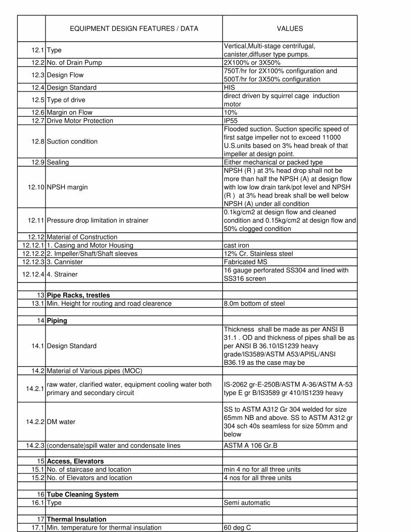
EQUIPMENT DESIGN FEATURES / DATA VALUES
12.1 Type Vertical,Multi-stage centrifugal,
canister,diffuser type pumps.
12.2 No. of Drain Pump 2X100% or 3X50%
12.3 Design Flow750T/hr for 2X100% configuration and
500T/hr for 3X50% configuration
12.4 Design Standard HIS
12.5 Type of drivedirect driven by squirrel cage induction
motor
12.6 Margin on Flow 10%
12.7 Drive Motor Protection IP55
12.8 Suction condition
Flooded suction. Suction specific speed of
first satge impeller not to exceed 11000
U.S.units based on 3% head break of that
impeller at design point.
12.9 Sealing Either mechanical or packed type
12.10 NPSH margin
NPSH (R ) at 3% head drop shall not be
more than half the NPSH (A) at design flow
with low low drain tank/pot level and NPSH
(R ) at 3% head break shall be well below
NPSH (A) under all condition
12.11 Pressure drop limitation in strainer
0.1kg/cm2 at design flow and cleaned
condition and 0.15kg/cm2 at design flow and
50% clogged condition
12.12 Material of Construction
12.12.1 1. Casing and Motor Housing cast iron
12.12.2 2. Impeller/Shaft/Shaft sleeves 12% Cr. Stainless steel
12.12.3 3. Cannister Fabricated MS
12.12.4 4. Strainer16 gauge perforated SS304 and lined with
SS316 screen
13 Pipe Racks, trestles
13.1 Min. Height for routing and road clearence 8.0m bottom of steel
14 Piping
14.1 Design Standard
Thickness shall be made as per ANSI B
31.1 . OD and thickness of pipes shall be as
per ANSI B 36.10/IS1239 heavy
grade/IS3589/ASTM A53/API5L/ANSI
B36.19 as the case may be
14.2 Material of Various pipes (MOC)
14.2.1raw water, clarified water, equipment cooling water both
primary and secondary circuit
IS-2062 gr-E-250B/ASTM A-36/ASTM A-53
type E gr B/IS3589 gr 410/IS1239 heavy
14.2.2 DM water
SS to ASTM A312 Gr 304 welded for size
65mm NB and above. SS to ASTM A312 gr
304 sch 40s seamless for size 50mm and
below
14.2.3 (condensate)spill water and condensate lines ASTM A 106 Gr.B
15 Access, Elevators
15.1 No. of staircase and location min 4 no for all three units
15.2 No. of Elevators and location 4 nos for all three units
16 Tube Cleaning System
16.1 Type Semi automatic
17 Thermal Insulation
17.1 Min. temperature for thermal insulation 60 deg C
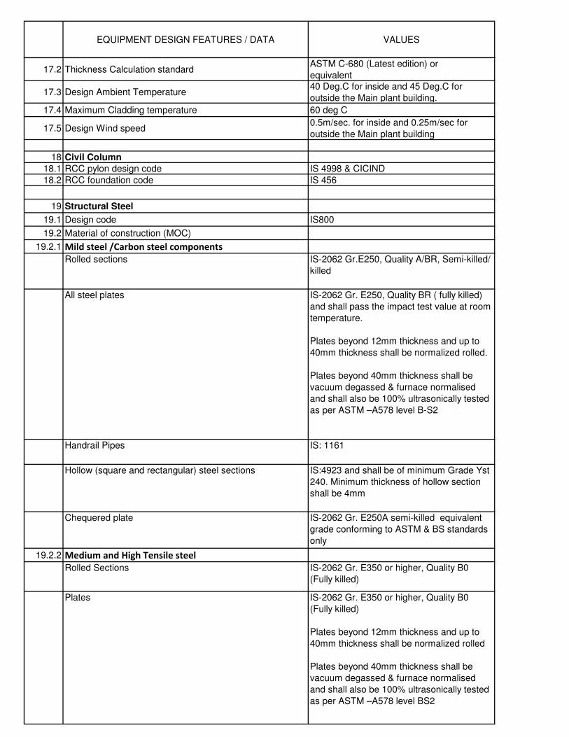
EQUIPMENT DESIGN FEATURES / DATA VALUES
17.2 Thickness Calculation standardASTM C-680 (Latest edition) or
equivalent
17.3 Design Ambient Temperature40 Deg.C for inside and 45 Deg.C for
outside the Main plant building.
17.4 Maximum Cladding temperature 60 deg C
17.5 Design Wind speed0.5m/sec. for inside and 0.25m/sec for
outside the Main plant building
18 Civil Column
18.1 RCC pylon design code IS 4998 & CICIND
18.2 RCC foundation code IS 456
19 Structural Steel
19.1 Design code IS800
19.2 Material of construction (MOC)
19.2.1 Mild steel /Carbon steel components
Rolled sections IS-2062 Gr.E250, Quality A/BR, Semi-killed/
killed
All steel plates IS-2062 Gr. E250, Quality BR ( fully killed)
and shall pass the impact test value at room
temperature.
Plates beyond 12mm thickness and up to
40mm thickness shall be normalized rolled.
Plates beyond 40mm thickness shall be
vacuum degassed & furnace normalised
and shall also be 100% ultrasonically tested
as per ASTM –A578 level B-S2
Handrail Pipes IS: 1161
Hollow (square and rectangular) steel sections IS:4923 and shall be of minimum Grade Yst
240. Minimum thickness of hollow section
shall be 4mm
Chequered plate IS-2062 Gr. E250A semi-killed equivalent
grade conforming to ASTM & BS standards
only
19.2.2 Medium and High Tensile steel
Rolled Sections IS-2062 Gr. E350 or higher, Quality B0
(Fully killed)
Plates IS-2062 Gr. E350 or higher, Quality B0
(Fully killed)
Plates beyond 12mm thickness and up to
40mm thickness shall be normalized rolled
Plates beyond 40mm thickness shall be
vacuum degassed & furnace normalised
and shall also be 100% ultrasonically tested
as per ASTM –A578 level BS2
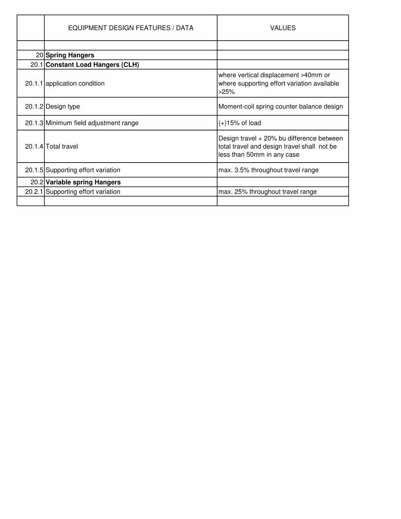
EQUIPMENT DESIGN FEATURES / DATA VALUES
20 Spring Hangers
20.1 Constant Load Hangers (CLH)
20.1.1 application condition
where vertical displacement >40mm or
where supporting effort variation available
>25%
20.1.2 Design type Moment-coil spring counter balance design
20.1.3 Minimum field adjustment range (+)15% of load
20.1.4 Total travel
Design travel + 20% bu difference between
total travel and design travel shall not be
less than 50mm in any case
20.1.5 Supporting effort variation max. 3.5% throughout travel range
20.2 Variable spring Hangers
20.2.1 Supporting effort variation max. 25% throughout travel range
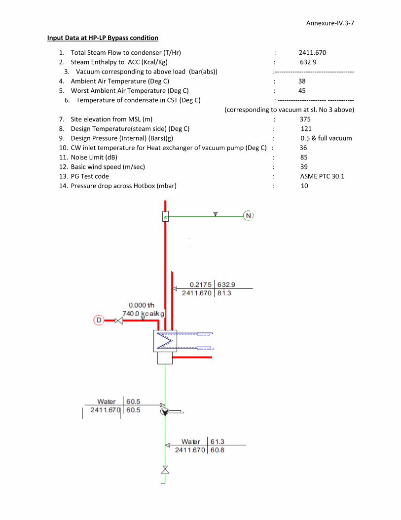
Annexure-IV.3-7
Input Data at HP-LP Bypass condition
1. Total Steam Flow to condenser (T/Hr) : 2411.670
2. Steam Enthalpy to ACC (Kcal/Kg) : 632.9
3. Vacuum corresponding to above load (bar(abs)) :------------------------------------
4. Ambient Air Temperature (Deg C) : 38
5. Worst Ambient Air Temperature (Deg C) : 45
6. Temperature of condensate in CST (Deg C) : ---------------------- ------------
(corresponding to vacuum at sl. No 3 above)
7. Site elevation from MSL (m) : 375
8. Design Temperature(steam side) (Deg C) : 121
9. Design Pressure (Internal) (Bars)(g) : 0.5 & full vacuum
10. CW inlet temperature for Heat exchanger of vacuum pump (Deg C) : 36
11. Noise Limit (dB) : 85
12. Basic wind speed (m/sec) : 39
13. PG Test code : ASME PTC 30.1
14. Pressure drop across Hotbox (mbar) : 10
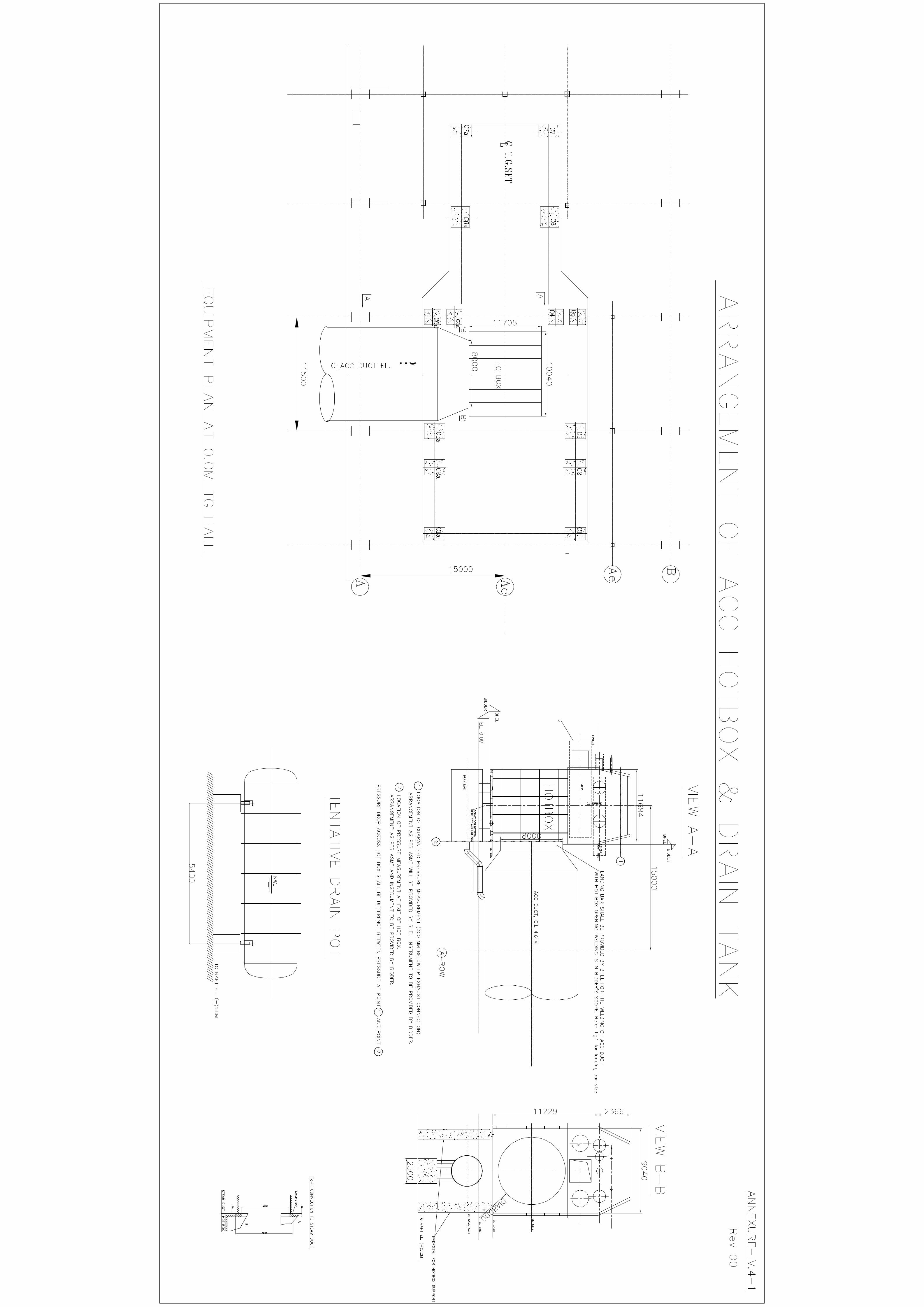
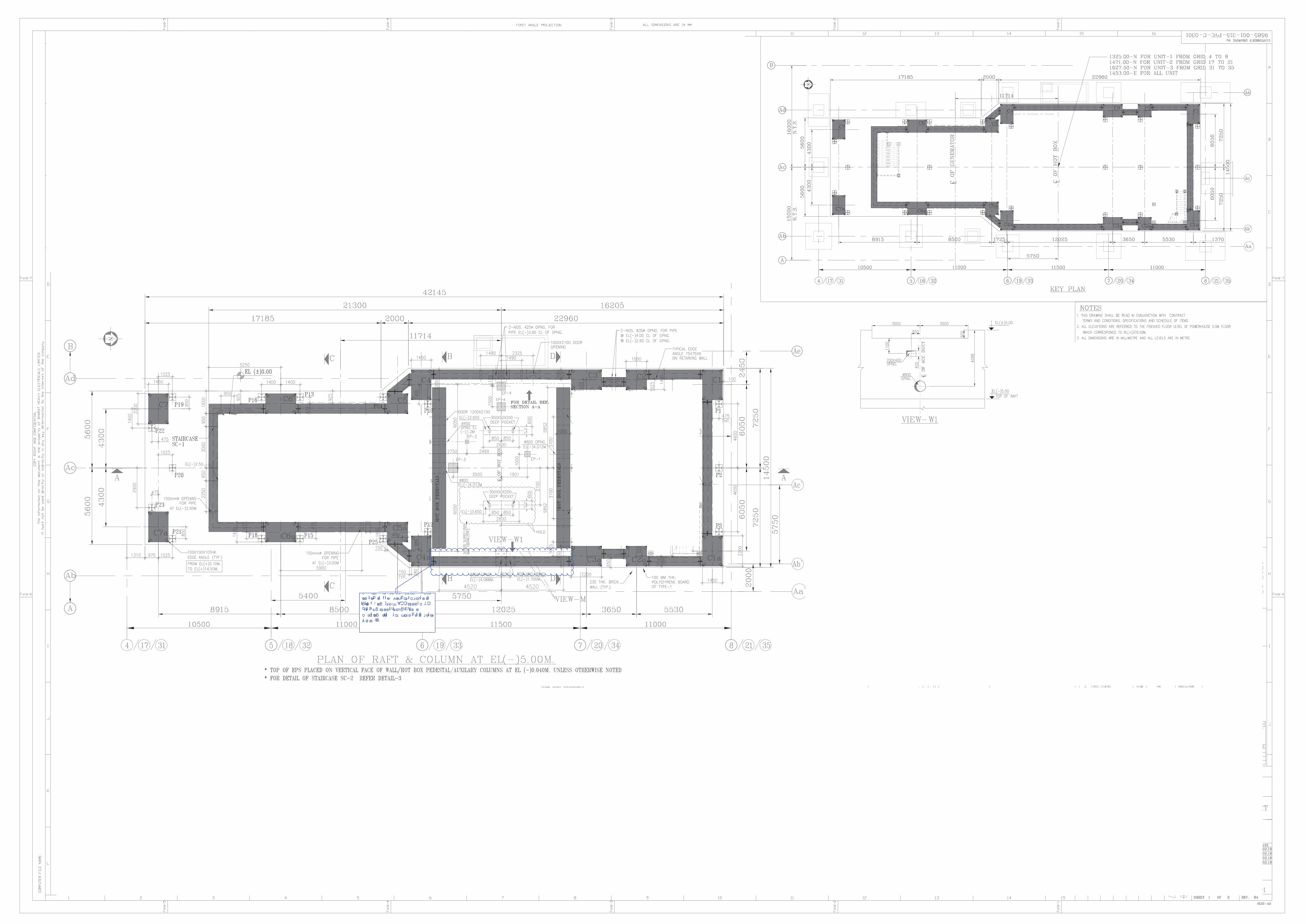
Maharatna Company
� ✁ ✂✄ ☎ ✆ ✝ ✝✞ ✟ ✠ � ✂ ✟ ✡ ✁ ✆✄ ✆ ✝ ✠ ☛ ✆ ☞✌ ✍ ☛ ☛ ✡✎ ✆✄ � ☛ ☞ ✆ � ✄ ✂ � ☛✏ ✑ ☛ ✡ ☞ ✟ ✠ � ✟ ✠ ✟ ✒ � ☛ ✆ ✝ ✝� ✁ ☛✞ ✂✞ ✂ ✡ ✓✄ ✔ ✠ ✟ ✕ ✖ ✗ ✗ ✆ ✠ ☛ ✆ � ✟ ✘ ✙✍ ✒ ✂ ✝ ☞ ✂ ✡ ✓ ✆ ✠ ☛ ✆ � ✁ ✠ ✟ ✒ ✓ ✁ � ✁ ☛✄ ☛✟✞ ☛ ✡ ✂ ✡ ✓✄ ✟ ✡ ✝✌ ✏ ✔ ✟ ✠ ✕ ✟ ✠ ☛ ☞ ☛ � ✆ ✂ ✝ ✠ ☛ ✔ ☛ ✠✑ ✂ ☛ ☎ ✚ ✛

EPC PACKAGE FOR
PATRATU SUPER THERMAL POWER STATION EXPANSION PHASE –I ( 3X 800MW)
TECHNICAL SPECIFICATION SECTION-VI
BID DOC. NO.: CS:9585-001-2
LOW PRESSURE PIPING
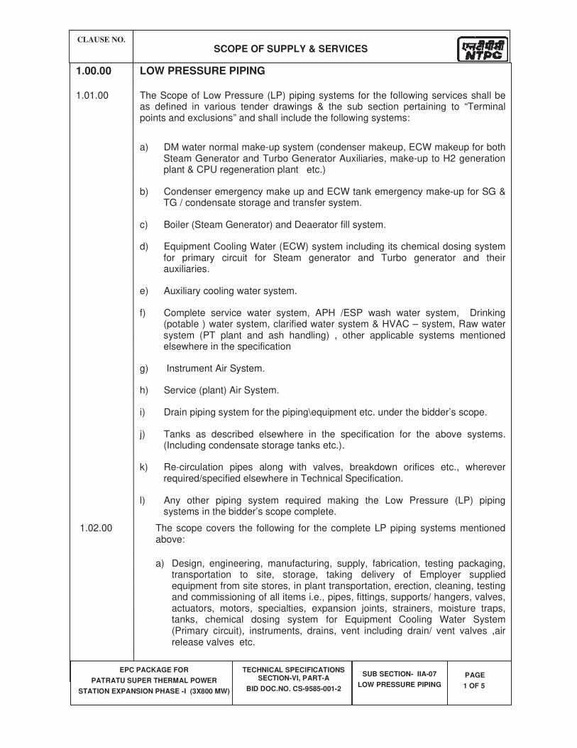
CLAUSE NO.
SCOPE OF SUPPLY & SERVICES
EPC PACKAGE FOR
PATRATU SUPER THERMAL POWER
STATION EXPANSION PHASE -I (3X800 MW)
TECHNICAL SPECIFICATIONS SECTION-VI, PART-A
BID DOC.NO. CS-9585-001-2
SUB SECTION- IIA-07
LOW PRESSURE PIPING
PAGE
1 OF 5
1.00.00 LOW PRESSURE PIPING
1.01.00 The Scope of Low Pressure (LP) piping systems for the following services shall be as defined in various tender drawings & the sub section pertaining to “Terminal points and exclusions” and shall include the following systems:
a) DM water normal make-up system (condenser makeup, ECW makeup for both Steam Generator and Turbo Generator Auxiliaries, make-up to H2 generation plant & CPU regeneration plant etc.)
b) Condenser emergency make up and ECW tank emergency make-up for SG & TG / condensate storage and transfer system.
c) Boiler (Steam Generator) and Deaerator fill system.
d) Equipment Cooling Water (ECW) system including its chemical dosing system for primary circuit for Steam generator and Turbo generator and their auxiliaries.
e) Auxiliary cooling water system.
f) Complete service water system, APH /ESP wash water system, Drinking (potable ) water system, clarified water system & HVAC – system, Raw water system (PT plant and ash handling) , other applicable systems mentioned elsewhere in the specification
g) Instrument Air System.
h) Service (plant) Air System.
i) Drain piping system for the piping\equipment etc. under the bidder’s scope.
j) Tanks as described elsewhere in the specification for the above systems. (Including condensate storage tanks etc.).
k) Re-circulation pipes along with valves, breakdown orifices etc., wherever required/specified elsewhere in Technical Specification.
l) Any other piping system required making the Low Pressure (LP) piping systems in the bidder’s scope complete.
1.02.00 The scope covers the following for the complete LP piping systems mentioned above:
a) Design, engineering, manufacturing, supply, fabrication, testing packaging, transportation to site, storage, taking delivery of Employer supplied equipment from site stores, in plant transportation, erection, cleaning, testing and commissioning of all items i.e., pipes, fittings, supports/ hangers, valves, actuators, motors, specialties, expansion joints, strainers, moisture traps, tanks, chemical dosing system for Equipment Cooling Water System (Primary circuit), instruments, drains, vent including drain/ vent valves ,air release valves etc.
CLAUSE NO.
SCOPE OF SUPPLY & SERVICES
EPC PACKAGE FOR
PATRATU SUPER THERMAL POWER
STATION EXPANSION PHASE -I (3X800 MW)
TECHNICAL SPECIFICATIONS SECTION-VI, PART-A
BID DOC.NO. CS-9585-001-2
SUB SECTION- IIA-07
LOW PRESSURE PIPING
PAGE
2 OF 5
The items though not specifically mentioned or indicated here in but are needed to make the system / equipment complete shall also be furnished and treated as if included in the specification unless otherwise specifically excluded.
1.03.00 Bidder’s scope of supply & works shall include but not be limited to the following:
a) Pipes, headers and manifolds, bends, elbows, returns, tees, laterals, crosses, reducers/ expanders, caps and closures, couplings, plugs, sleeves, and saddles, stubs and bosses, unions and other similar fittings, flanges, gaskets, fasteners and sealants, ring joints, backing rings, all types of valves including drain/ vent/ air release valves, 3-way valves(where applicable) with test connection for instruments/ manifolds etc.actuators, specialties, orifices, flow nozzles, etc. as per finalized single line flow diagrams and layout drawings/ isometric drawings.
b) Complete assemblies of hangers, supports anchor, guides, restraints, etc. including welded attachments, clamps, devices tie-rods, turn-buckles, springs and spring cages, shoes, rollers, trapezes etc.
c) Weather hoods for pipes crossing ceilings and walls.
d) Instrument tapping and stub connections, root valves, 3-way valves (where applicable) with test connections, drains and vent valves & expanders / reducers as required and instruments as indicated else where for instruments supplied by the Contractor..
e) Drain funnels, drip pans, moisture traps etc. where ever required shall be provided.
f) Instrument tapping, stub connections, root valves and instrument tubing up to root valves for instruments supplied by the Employer for onward connections by the Employer.
g) All supporting attachments like plates, saddles, stools, shoes, base plate, saddle plates, angles, channels, I-beams, trapeze, cantilevers, brackets, sways, braces, nuts, bolts, cleats, clamps, needed to complete the erection of piping system covered under this specification.
Anchor bolts, bed & foundation plates, pipe sleeves and Nuts to be embedded in concrete for piping where ever indicated in the drawing. All grouting and chipping work (including supply of cement, sand and stone chips) for equipment foundations, pipe supporting etc.
Reinforced concrete valve chambers wherever required for underground piping.
h) Surface preparation, priming and painting of all non-insulated above ground piping and equipment except galvanized steel piping & surfaces , stainless steel piping & surfaces, and gun metal surfaces.
CLAUSE NO.
SCOPE OF SUPPLY & SERVICES
EPC PACKAGE FOR
PATRATU SUPER THERMAL POWER
STATION EXPANSION PHASE -I (3X800 MW)
TECHNICAL SPECIFICATIONS SECTION-VI, PART-A
BID DOC.NO. CS-9585-001-2
SUB SECTION- IIA-07
LOW PRESSURE PIPING
PAGE
3 OF 5
Paints and varnishes, primers, thinners etc. as required for anti-corrosive protection of piping & equipment above ground.
i) Bidder shall provide anti-corrosive protection anticorrosive tape or coating-wrapping on the external surfaces of pipes to all directly buried piping including galvanized carbon steel piping.
j) On the internal surface of all pipes 1000 mm and above, a coat of primer followed by a hot coat of coal tar enamel paint or coal tar epoxy paint shall be applied.
k) Excavation, preparation of bed, backfilling with compaction of soil and removal of extra-earth to designated places in case of pipes to be buried.
l) Bidder shall also design, supply, fabricate, erect, set and commission all hangers, tie-rods, turn-buckles, supports, guides, restraints, anchors, etc. as required for the, piping system. This includes the provision of all associated steel work including brackets, cradle supports, duck foots, channels, angles, etc. It is Bidder's responsibility to estimate these requirements and include them in their offer price. Whenever, straight run of the yard pipes are more than 300 meters, flexibility analysis shall be conducted by the contractor to identify the requirement of loops, type of supports etc.
m) In covered concrete trenches bidder shall supply necessary supporting materials such as stools, saddles, base plates, clamps, U-bolts, angles, clips etc.
n) Bidder shall supply all necessary drains and vents with drain & vent valves including anti-flash funnels and moisture traps for compressed air system as required for the safe and effective draining-venting of the piping systems based on the approved flow scheme / single line diagram. It is bidder's responsibility to identify the requirements of drains, vents, and supply the necessary pipe work, fittings, hangers and supports etc. for the same.
o) Bidder shall supply and install necessary matching pieces as may be needed for connection of piping systems with equipment terminals, valves and specialties.
p) Bidder shall erect all instrument impulse piping and fittings from the tap-off point of the last root valve including the root valve and instruments.
q) Bidder shall perform necessary internal machining of pipe for installing orifices, flow nozzles, straightening vanes etc.
r) The Bidder shall prepare the flow diagrams, detailed dimensional piping layout/ Isometric/ fabrication/ As built drawings of all the systems along with Cross sectional drawings, showing all supports and equipment as required.
CLAUSE NO.
SCOPE OF SUPPLY & SERVICES
EPC PACKAGE FOR
PATRATU SUPER THERMAL POWER
STATION EXPANSION PHASE -I (3X800 MW)
TECHNICAL SPECIFICATIONS SECTION-VI, PART-A
BID DOC.NO. CS-9585-001-2
SUB SECTION- IIA-07
LOW PRESSURE PIPING
PAGE
4 OF 5
s) In addition to submission of drawings as stipulated above bidder shall also furnish the data/ documents with respect to following:
1) Thickness calculation of large diameter buried pipes as per AWWA-M-11.
2) System design calculation of Primary closed circuit ECW and secondary circuit ACW system for flow & pressure balancing.
3) Design calculations for condensate storage tank and Drinking water tank.
4) Static Analysis for Long (more than 300 metre straight run) above-ground piping wherever required.
t) Bidder's scope of supply for fabrication, erection, cleaning, testing and commissioning of the piping systems installed by him shall include the following:-
All welding consumables like welding electrodes, filler rods and wires; gases like oxygen, acetylenes, argon, carbon-dioxide, propane, backing rings etc.
Films for radiographic examination of welds.
X-ray and Gamma -ray equipment including isotopes, dye penetrants, and other required non-destructive testing materials and equipment (all to be taken back by the Bidder after completion of work).
All heating and stress relieving equipment, thermocouples asbestos blankets, cables, temperature recorders, charts heat sensitive chalks and crayons etc. (All to be taken back by bidder after completion of work).
All machinery, equipment tools and tackles as required for transportation handling, fabrication and erection (All to be taken back by Bidder after completion of work).
All equipment/ materials as required for cleaning, flushing, blowing out and hydro testing of the piping systems; these shall include but not be limited to pumps and compressors with prime movers, instruments, pipe work with supports, valves, strainers and other specialties, blanks, plugs, spool pieces, dummy plates, electrical accessories, etc. (All to be taken back by Bidder after completion of work).
All scaffolding materials and false work (To be taken back by Bidder after completion of work).
1.04.00 The Bidder shall provide Services of erection superintendent and foremen, fitters and riggers, welders, transport and crane operators and other skilled and unskilled labour.
The design engineering and providing all temporary pipe work as required for erection, cleaning, flushing, blowing out, testing and commissioning of the piping system is the responsibility of the Bidder.
CLAUSE NO.
SCOPE OF SUPPLY & SERVICES
EPC PACKAGE FOR
PATRATU SUPER THERMAL POWER
STATION EXPANSION PHASE -I (3X800 MW)
TECHNICAL SPECIFICATIONS SECTION-VI, PART-A
BID DOC.NO. CS-9585-001-2
SUB SECTION- IIA-07
LOW PRESSURE PIPING
PAGE
5 OF 5
The Bidder's scope shall include design, supply of required structural steel (except those which are specifically excluded), their fabrication and erection where ever required.
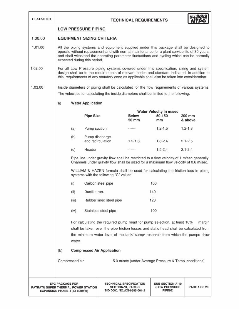
CLAUSE NO. TECHNICAL REQUIREMENTS
EPC PACKAGE FOR
PATRATU SUPER THERMAL POWER STATION EXPANSION PHASE–I (3X 800MW)
TECHNICAL SPECIFICATION SECTION-VI, PART-B
BID DOC. NO.:CS-9585-001-2
SUB-SECTION-A-10 (LOW PRESSURE
PIPING) PAGE 1 OF 20
LOW PRESSURE PIPING
1.00.00 EQUIPMENT SIZING CRITERIA
1.01.00 All the piping systems and equipment supplied under this package shall be designed to operate without replacement and with normal maintenance for a plant service life of 30 years, and shall withstand the operating parameter fluctuations and cycling which can be normally expected during this period.
1.02.00 For all Low Pressure piping systems covered under this specification, sizing and system design shall be to the requirements of relevant codes and standard indicated. In addition to this, requirements of any statutory code as applicable shall also be taken into consideration.
1.03.00 Inside diameters of piping shall be calculated for the flow requirements of various systems.
The velocities for calculating the inside diameters shall be limited to the following:
a) Water Application Water Velocity in m/sec Pipe Size Below 50-150 200 mm 50 mm mm & above
(a) Pump suction ------ 1.2-1.5 1.2-1.8
(b) Pump discharge and recirculation 1.2-1.8 1.8-2.4 2.1-2.5
(c) Header ------ 1.5-2.4 2.1-2.4
Pipe line under gravity flow shall be restricted to a flow velocity of 1 m/sec generally. Channels under gravity flow shall be sized for a maximum flow velocity of 0.6 m/sec.
WILLIAM & HAZEN formula shall be used for calculating the friction loss in piping systems with the following "C" value:
(i) Carbon steel pipe 100
(ii) Ductile Iron. 140
(iii) Rubber lined steel pipe 120
(iv) Stainless steel pipe 100
For calculating the required pump head for pump selection, at least 10% margin
shall be taken over the pipe friction losses and static head shall be calculated from
the minimum water level of the tank/ sump/ reservoir from which the pumps draw
water.
(b) Compressed Air Application
Compressed air 15.0 m/sec.(under Average Pressure & Temp. conditions)
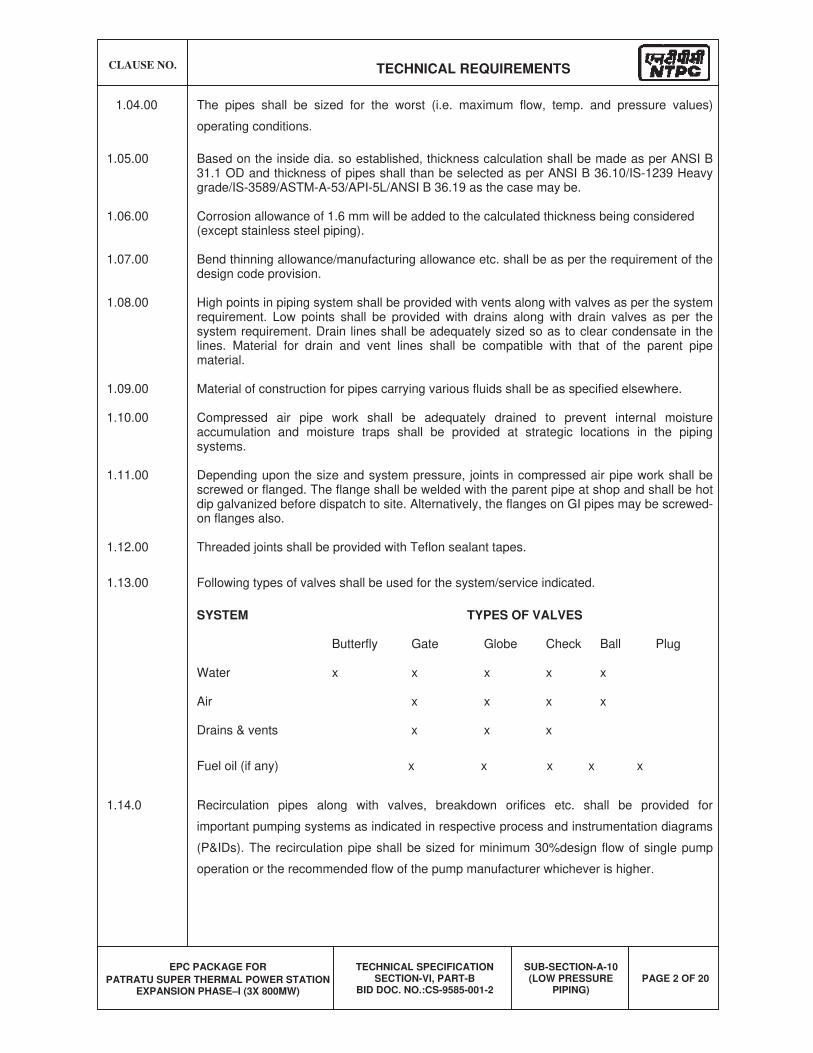
CLAUSE NO. TECHNICAL REQUIREMENTS
EPC PACKAGE FOR
PATRATU SUPER THERMAL POWER STATION EXPANSION PHASE–I (3X 800MW)
TECHNICAL SPECIFICATION SECTION-VI, PART-B
BID DOC. NO.:CS-9585-001-2
SUB-SECTION-A-10 (LOW PRESSURE
PIPING) PAGE 2 OF 20
1.04.00 The pipes shall be sized for the worst (i.e. maximum flow, temp. and pressure values)
operating conditions.
1.05.00 Based on the inside dia. so established, thickness calculation shall be made as per ANSI B 31.1 OD and thickness of pipes shall than be selected as per ANSI B 36.10/IS-1239 Heavy grade/IS-3589/ASTM-A-53/API-5L/ANSI B 36.19 as the case may be.
1.06.00 Corrosion allowance of 1.6 mm will be added to the calculated thickness being considered (except stainless steel piping).
1.07.00 Bend thinning allowance/manufacturing allowance etc. shall be as per the requirement of the design code provision.
1.08.00 High points in piping system shall be provided with vents along with valves as per the system requirement. Low points shall be provided with drains along with drain valves as per the system requirement. Drain lines shall be adequately sized so as to clear condensate in the lines. Material for drain and vent lines shall be compatible with that of the parent pipe material.
1.09.00 Material of construction for pipes carrying various fluids shall be as specified elsewhere.
1.10.00 Compressed air pipe work shall be adequately drained to prevent internal moisture accumulation and moisture traps shall be provided at strategic locations in the piping systems.
1.11.00 Depending upon the size and system pressure, joints in compressed air pipe work shall be screwed or flanged. The flange shall be welded with the parent pipe at shop and shall be hot dip galvanized before dispatch to site. Alternatively, the flanges on GI pipes may be screwed-on flanges also.
1.12.00 Threaded joints shall be provided with Teflon sealant tapes.
1.13.00 Following types of valves shall be used for the system/service indicated.
SYSTEM TYPES OF VALVES
Butterfly Gate Globe Check Ball Plug
Water x x x x x
Air x x x x
Drains & vents x x x
Fuel oil (if any) x x x x x
1.14.0 Recirculation pipes along with valves, breakdown orifices etc. shall be provided for
important pumping systems as indicated in respective process and instrumentation diagrams
(P&IDs). The recirculation pipe shall be sized for minimum 30%design flow of single pump
operation or the recommended flow of the pump manufacturer whichever is higher.
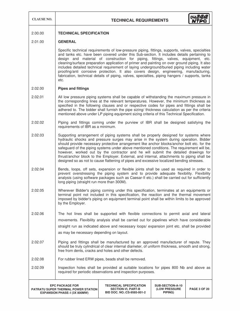
CLAUSE NO. TECHNICAL REQUIREMENTS
EPC PACKAGE FOR
PATRATU SUPER THERMAL POWER STATION EXPANSION PHASE–I (3X 800MW)
TECHNICAL SPECIFICATION SECTION-VI, PART-B
BID DOC. NO.:CS-9585-001-2
SUB-SECTION-A-10 (LOW PRESSURE
PIPING) PAGE 3 OF 20
2.00.00 TECHNICAL SPECIFICATION
2.01.00 GENERAL
Specific technical requirements of low-pressure piping, fittings, supports, valves, specialties and tanks etc. have been covered under this Sub-section. It includes details pertaining to design and material of construction for piping, fittings, valves, equipment, etc. cleaning/surface preparation application of primer and painting on over ground piping. It also includes detailed technical requirement of laying underground/buried piping including water proofing/anti corrosive protection. It also covers design, engineering, manufacturing, fabrication, technical details of piping, valves, specialties, piping hangers / supports, tanks etc.
2.02.00 Pipes and fittings
2.02.01 All low pressure piping systems shall be capable of withstanding the maximum pressure in the corresponding lines at the relevant temperatures. However, the minimum thickness as specified in the following clauses and or respective codes for pipes and fittings shall be adhered to. The bidder shall furnish the pipe sizing/ thickness calculation as per the criteria mentioned above under LP piping equipment sizing criteria of this Technical Specification.
2.02.02 Piping and fittings coming under the purview of IBR shall be designed satisfying the requirements of IBR as a minimum.
2.02.03 Supporting arrangement of piping systems shall be properly designed for systems where hydraulic shocks and pressure surges may arise in the system during operation. Bidder should provide necessary protective arrangement like anchor blocks/anchor bolt etc. for the safeguard of the piping systems under above mentioned conditions. The requirement will be, however, worked out by the contractor and he will submit the detailed drawings for thrust/anchor block to the Employer. External, and internal, attachments to piping shall be designed so as not to cause flattening of pipes and excessive localized bending stresses.
2.02.04 Bends, loops, off sets, expansion or flexible joints shall be used as required in order to prevent overstressing the piping system and to provide adequate flexibility. Flexibility analysis (using software packages such as Caesar-II etc.) shall be carried out for sufficiently long piping (straight run more than 300M).
2.02.05 Wherever Bidder's piping coming under this specification, terminates at an equipments or terminal point not included in this specification, the reaction and the thermal movement imposed by bidder's piping on equipment terminal point shall be within limits to be approved by the Employer.
2.02.06 The hot lines shall be supported with flexible connections to permit axial and lateral
movements. Flexibility analysis shall be carried out for pipelines which have considerable
straight run as indicated above and necessary loops/ expansion joint etc. shall be provided
as may be necessary depending on layout.
2.02.07 Piping and fittings shall be manufactured by an approved manufacturer of repute. They should be truly cylindrical of clear internal diameter, of uniform thickness, smooth and strong, free from dents, cracks and holes and other defects.
2.02.08 For rubber lined ERW pipes, beads shall be removed.
2.02.09 Inspection holes shall be provided at suitable locations for pipes 800 Nb and above as required for periodic observations and inspection purposes.
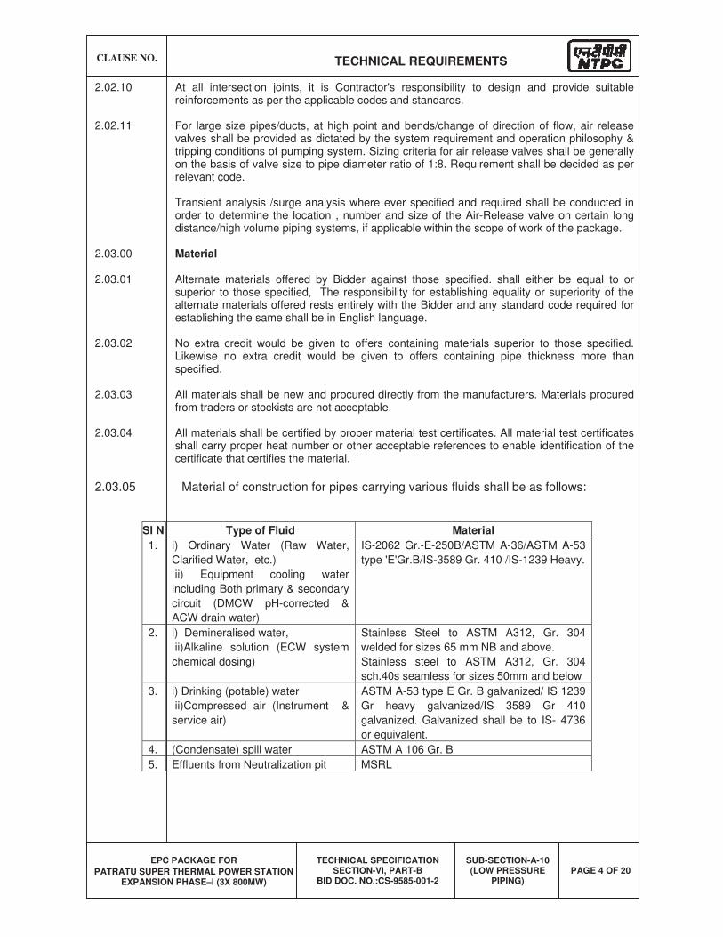
CLAUSE NO. TECHNICAL REQUIREMENTS
EPC PACKAGE FOR
PATRATU SUPER THERMAL POWER STATION EXPANSION PHASE–I (3X 800MW)
TECHNICAL SPECIFICATION SECTION-VI, PART-B
BID DOC. NO.:CS-9585-001-2
SUB-SECTION-A-10 (LOW PRESSURE
PIPING) PAGE 4 OF 20
2.02.10 At all intersection joints, it is Contractor's responsibility to design and provide suitable reinforcements as per the applicable codes and standards.
2.02.11 For large size pipes/ducts, at high point and bends/change of direction of flow, air release valves shall be provided as dictated by the system requirement and operation philosophy & tripping conditions of pumping system. Sizing criteria for air release valves shall be generally on the basis of valve size to pipe diameter ratio of 1:8. Requirement shall be decided as per relevant code.
Transient analysis /surge analysis where ever specified and required shall be conducted in order to determine the location , number and size of the Air-Release valve on certain long distance/high volume piping systems, if applicable within the scope of work of the package.
2.03.00 Material
2.03.01 Alternate materials offered by Bidder against those specified. shall either be equal to or superior to those specified, The responsibility for establishing equality or superiority of the alternate materials offered rests entirely with the Bidder and any standard code required for establishing the same shall be in English language.
2.03.02 No extra credit would be given to offers containing materials superior to those specified. Likewise no extra credit would be given to offers containing pipe thickness more than specified.
2.03.03 All materials shall be new and procured directly from the manufacturers. Materials procured from traders or stockists are not acceptable.
2.03.04 All materials shall be certified by proper material test certificates. All material test certificates shall carry proper heat number or other acceptable references to enable identification of the certificate that certifies the material.
2.03.05 Material of construction for pipes carrying various fluids shall be as follows:
Sl No Type of Fluid Material
1. i) Ordinary Water (Raw Water,
Clarified Water, etc.)
ii) Equipment cooling water
including Both primary & secondary
circuit (DMCW pH-corrected &
ACW drain water)
IS-2062 Gr.-E-250B/ASTM A-36/ASTM A-53
type 'E'Gr.B/IS-3589 Gr. 410 /IS-1239 Heavy.
2. i) Demineralised water,
ii)Alkaline solution (ECW system
chemical dosing)
Stainless Steel to ASTM A312, Gr. 304
welded for sizes 65 mm NB and above.
Stainless steel to ASTM A312, Gr. 304
sch.40s seamless for sizes 50mm and below
3. i) Drinking (potable) water
ii)Compressed air (Instrument &
service air)
ASTM A-53 type E Gr. B galvanized/ IS 1239
Gr heavy galvanized/IS 3589 Gr 410
galvanized. Galvanized shall be to IS- 4736
or equivalent.
4. (Condensate) spill water ASTM A 106 Gr. B
5. Effluents from Neutralization pit MSRL
CLAUSE NO. TECHNICAL REQUIREMENTS
EPC PACKAGE FOR
PATRATU SUPER THERMAL POWER STATION EXPANSION PHASE–I (3X 800MW)
TECHNICAL SPECIFICATION SECTION-VI, PART-B
BID DOC. NO.:CS-9585-001-2
SUB-SECTION-A-10 (LOW PRESSURE
PIPING) PAGE 5 OF 20
2.03.06 In water lines, pipes upto 150mm Nb shall conform to ANSI B36.10/ASTM-A-53, Type-E Gr.B /IS:1239 Gr. Heavy and minimum selected thickness shall not be less than IS:1239 Grade Heavy except for demineralised water, drinking water and condensate spill lines.
2.03.07 Pipes of above 150mm Nb shall be to AWWA-C200/ANSI B 36.10/ASTM A-53/IS 3589 Gr.410. Pipe to be fabricated by the bidder shall be rolled and butt welded from plates conforming to ASTM A-53 type 'E' Gr. B/IS 2062 Gr.E-250B/ASTM-A-36. However, larger pipes, i.e. 1000mm Nb and above shall be made from plates conforming to ASTM A 36/IS 2062 Gr.E-250B and shall meet the requirements of AWWA-M-11 (for deflection & buckling criteria considering water filled pipe as well as vacuum condition that may prevail during transient/surge conditions, truck-load, rail-load and weight density for compacted soil or any other load as the case may be).
2.03.08 In demineralised water service, the pipes upto 50 Nb shall be of stainless steel ASTM A 312, Gr. 304 sch. 40 Seamless. The size for these pipes shall be to ANSI B 36.19. These shall be socket welded. The material for pipe from 65mm NB upto and including 400 NB shall be to ASTM A 312, Gr. 304 (welded). In no case the thickness of fittings shall be less than parent pipe thickness.
Bidder/Contractor shall note that pipes offered as per a particular code shall conform to that code in all respects i.e. Dimension, tolerances, manufacturing methods, material, heat treatment, testing requirements, etc. unless otherwise mentioned elsewhere in the specification.
2.03.09 Instrument air, Plant (service) air lines and Drinking water lines shall be to ASTM A 53 type E grade B/ANSI B 36. 10/IS 3589, Gr. 410 / IS: 1239 Heavy (in case thickness calculated is more than gr. Heavy, ANSI B 36.10 Schedule numbers shall be followed) and galvanized to IS 4736 or any equivalent internationally reputed standard. The material of the pipes shall be to ASTM A 53 type 'E' Gr. B / IS: 3589, Gr. 410 / IS: 1239 Gr. Heavy. The fittings shall be of either same as parent material or malleable iron to IS-1879 (galvanized).
2.03.10 Spiral welded pipes as per API-5L/IS-3589 are also acceptable for pipe of size above 150 NB. However minimum thickness of the pipes shall be as elaborated in above clauses.
2.03.11 Condensate lines shall be to ASTM A 106 Gr. B and dimension to ANSI B 36.10 schedule "standard" as minimum to be maintained.
2.03.12 If carbon steel plates of thickness more than 12 mm are used for manufacture of pipes, fittings and other appurtenances, then the same shall be control-cooled or normalized as the case may be following the guidelines of the governing code.
2.04.00 Field routed pipes:
2.04.01 Pipe lines of NB 50 size and below are regarded as field run piping. It is Bidder's responsibility to plan suitable layouts for these system insitu. Bidder shall prepare drawings indicating the layout of field run pipe work. These drawings shall be approved by Project Manager to the installation of the field run pipe work. Based on these approved layouts the Bidder shall prepare the BOQ of field run-pipes and submit to Employer for approval.
2.05.00 Slope/Drains and Vents
2.05.01 Suitable slope shall be provided for all pipelines towards drain points. It is Bidder responsibility to identify the requirements of drains and vents, and supply the necessary pipe work, valves, fittings, hangers and supports etc. As per the system requirement low points in the pipelines shall be provided with suitable draining arrangement and high points shall be provided with vent connections where air or gas pockets may occur. Vent for use during hydrostatic test shall be plugged after the completion of the test. Vent shall not be less than 15mm size. Drains shall be provided at low points and at pockets in piping such that complete drainage of all systems is possible. Drain shall not be less than 15mm for line size
CLAUSE NO. TECHNICAL REQUIREMENTS
EPC PACKAGE FOR
PATRATU SUPER THERMAL POWER STATION EXPANSION PHASE–I (3X 800MW)
TECHNICAL SPECIFICATION SECTION-VI, PART-B
BID DOC. NO.:CS-9585-001-2
SUB-SECTION-A-10 (LOW PRESSURE
PIPING) PAGE 6 OF 20
up to 150mm, not less than 20mm up to 300mm and not less than 25mm for 350mm to 600mm pipes and not less than 50mm for 600mm and above pipes.
2.05.02 Air piping shall be sloped so that any part of the system can be drained through the shut-off drain valve or drain plugs.
2.06.00 Pipe Joints
In general all water lines 65mm NB and above, are to be joined generally by butt welding except the locations where valves/fittings are to be installed with flanged connections and 50mm and below by socket welding unless mentioned otherwise specifically. All air lines shall be of screwed connection and rubber lined pipes of flanged connections.
2.06.01 Screwed Joints
(a) Threading of pipes shall be carried out after bending, heat treatment etc. If not possible, threading may be done prior to these operations but proper care should be taken to protect them from damage. Threads shall be to ANSI B 2.1 (taper) NPT/IS: 554 unless specified otherwise.
(b) Galvanized pipe shall generally be joined by screwing into sockets. The exposed threaded portion on the outside of the pipes shall be given a zinc silicate coating. Galvanized pipes shall not be field joined by welding for protection of Galvanising Zinc layer. Screwed ends of GI pipes shall be thoroughly cleaned and painted with a mixture of red and white lead before jointing. For galvanized pipe sizes above 150 mm NB, screw & socket jointing as per ASTM-A-865 shall be employed for both pipe-to-pipe and pipe-to-fitting jointing. For pipe to fitting connection since no direct threading can be done on the fittings (supplied as per ASTM-A-234 Gr. WPB and ANSI B-16.9) necessary straight pipe lengths acting as match pieces shall be welded to the fitting at both ends and subsequently the free ends of the straight lengths shall be threaded as per ASTM A-865 for jointing with main pipe. Once welding of fittings with match pieces and threading of free ends of match pieces are over, the entire fabricated piece shall be galvanized, or in case match pipes and fittings are already galvanized before the above mentioned fabrication then suitable application of Zinc-Silicate paste adequately at the welded surface (both in side & out side) after welding with zinc rich electrode, along with the nascent threaded metal portions at both free ends given the same application of Zinc Silicate paste. Alternatively flanged jointing may be employed for pipe sizes 100 NB and above. However, the bidder shall ensure the galvanized pipe joints do not fail during hydro test.
(c) Teflon tapes shall be used to seal out screwed joints and shall be applied to the male threads only. Threaded parts shall be wiped clean of oil or grease with appropriate solvent if necessary and allowing proper time for drying before applying the sealant. Pipe ends shall be reamed and all chips shall be removed. Screwed flanges shall be attached by screwing the pipe through the flange and the pipe and flange shall be refaced accurately.
(d) For pipe sizes from 350 mm NB to 550 mm NB (including 350 NB & 550 NB) the GI pipes shall be of flanged connection. However, the pipes after welding of flanges shall be completely galvanized. Any site welding done on galvanized pipes shall be done with zinc-rich special electrodes and the welded surfaces whether inside or outside shall be coated with zinc-silicate paste. Seal welding of flanges with zinc-rich electrode will be permitted only when any flange is leak-prone during hydro testing.
(e) For pipe sizes 600 mm NB and above, the GI pipes shall be of welded connection (with zinc-rich special electrodes) followed by application of zinc silicate coating at welded surfaces both inside and outside the pipe, except for the last blank/blind flange, or, equipment connection where application of zinc-silicate paste after welding cannot be done due to inaccessibility of the inside welded surface and where
CLAUSE NO. TECHNICAL REQUIREMENTS
EPC PACKAGE FOR
PATRATU SUPER THERMAL POWER STATION EXPANSION PHASE–I (3X 800MW)
TECHNICAL SPECIFICATION SECTION-VI, PART-B
BID DOC. NO.:CS-9585-001-2
SUB-SECTION-A-10 (LOW PRESSURE
PIPING) PAGE 7 OF 20
galvanic protection has been impaired due to welding of pipe-to-pipe joint. Thus the last erection joint shall be flanged joint.
2.06.02 Welded Joints
(a) For making up welded joints (butt weld or socket weld) the welding shall be performed by manual shielded metal arc process in accordance with the requirements specified elsewhere in the spec. Any welder employed for carrying butt welding shall be qualified as per ASME section IX for the type of joints he is going to weld. Jointing by butt weld, or socket weld shall depend upon the respective piping material specifications.
2.06.03 Flanged Joints
(a) Flanged connections for pipes are to be kept to the minimum and used only for connections to vessel, equipments, flanged valves and other fittings like strainer/traps/orifices etc. for ease of connection and maintenance etc. Rubber lined pipes shall be flange joined only.
(b) All flanged valves intended for installation on steel piping system, shall have their flanges drilled to ANSI B 16.5 (or equivalent) and according to the pressure class stated in their respective piping material specification.
(c) Drilling on flanges of flanged valves must correspond to the drilling of flanges on the piping system on which the valves are installed.
2.07.00 Bends/elbows/mitre bends/ Tees/ Reducers & other fittings
2.07.01 For pipe fittings such as elbows (long radius), reducers, tees, etc. the material shall be to ASTM-A-234 Gr. WPB/ASTM-105 up to 300 NB. For pipe fittings above 300 NB, the fittings may be fabricated conforming to parent pipe material. Provision of compensation pads shall be kept as per ANSI B 31.1. The fitting shall conform to the dimensional standard of ANSI B-16.9/ 16.11.Further branching in pipes for sizes 65nb and above is also acceptable (ANSI B 31.1).
However, for pipes up to 150 NB, pipe fittings may be supplied with material and dimension conforming to IS 1239 in case parent pipes also conform to IS 1239.
2.07.02 For pipe size 350Nb and above mitre bends may be used for all pipes except rubber lined pipes. The bend radius shall be 1½ times the nominal pipe diameter. 90 deg. bends (mitre) shall be in 4 pieces (3 cuts) and 45 deg. mitre bends shall be in 3 pieces 22½ deg. Fabrication of mitre bends shall be as detailed in BS 2633/BS534.
2.07.03 For pipes, above 1200 NB, reducer and tees shall be to dimensional standard of AWWA-C-208.
2.07.04 Stainless steel fittings shall conform to either ASTM-A-182 Gr. 304 or ASTM-A-403 Grade WP. 304 Class-S, for sizes upto and including 50 mm NB, i.e. the fittings shall be of seamless construction. However, for stainless fittings above 50 mm NB, the same shall conform to ASTM-A-403 Gr. WP 304 Class W i.e. the fittings shall be of welded construction strictly in accordance with ASTM-A-403.
2.07.07 In no case, the thickness of fittings shall be less than the thickness of parent pipe, irrespective of material of construction.
2.08.00 Flanges
2.08.01 Flanges shall be slip on type. Welding of flanges in tension is not permitted.
CLAUSE NO. TECHNICAL REQUIREMENTS
EPC PACKAGE FOR
PATRATU SUPER THERMAL POWER STATION EXPANSION PHASE–I (3X 800MW)
TECHNICAL SPECIFICATION SECTION-VI, PART-B
BID DOC. NO.:CS-9585-001-2
SUB-SECTION-A-10 (LOW PRESSURE
PIPING) PAGE 8 OF 20
2.08.02 All flanges and-flanged drilling shall be to ANSI B 16.5/BS EN-1092 of relevant pressure/temperature class. Flanges shall be fabricated from steel plates conforming to ASTM A 105/IS 2062 Gr. E-250B. However stainless steel flanges shall be fabricated from SS plates to ASTM-A-240, Gr. 304 or equivalent.
2.09.00 Specific technical requirement of laying buried pipe with anti corrosive treatment
The pipe in general shall be laid with the top of the pipe minimum 1.0 (one) meter below finished general ground level.
2.09.01 Trenching
(a) The trench shall be cut true to the line and level and shall follow the gradient of the pipeline. The width of the trench shall be sufficient to give free working space on each side of the pipe. Trenches shall conform to IS 5822 or any international standard.
2.09.02 Preparation and cleaning of piping
(a) The pipeline shall be thoroughly cleaned of all rust, grease, dirt, weld scales and weld burrs etc. moisture or other foreign matter by power cleaning method such as sand or grit blasting, power tool cleaning, etc. Grease or heavy oil shall be removed by washing with a volatile solvent such as gasoline. Certain inaccessible portions of the pipeline (which otherwise not possible to be cleaned by power cleaning methods) may be scrubbed manually with a stiff wire brush and scrapped where necessary with specific permission of the Project Manager.
(b) On the internal surface for pipes 1000 Nb and above, a coat of primer followed by a hot coal-tar enamel or coal tar epoxy painting (cold) shall be applied.
2.09.03 Coating and wrapping/ Anti corrosive Protection Coal tar tape
a. Buried piping shall be coated and wrapped, as per specification, after completion of welded and/or flanged connections, and after completion and approval of Hydro testing. Materials to be used for coating and wrapping of underground pipelines are:
(1) Coating primer (coal tar primer)
(2) Coating enamel (coal tar enamel)
(3) Wrapping materials.
All primer/coating/wrapping materials and methods of application shall conform to IS: 10221 except asphalt/bitumen material. Materials (primer/coating/wrapping) as per AWWA-C-203 are also acceptable.
Protective coating shall consist of coal tar primer, coal tar enamel coating, glass fiber, tissue inner wrap followed by glass fiber or coal tar impregnated Kraft outer wrap or finish coat.
Number of coats and wraps, minimum thickness for each layer of application shall be as per IS-10221. Number of. Coats and wraps shall be decided based on soil corrosivity/resistivity as indicated in IS-10221. Soil data-for this purpose shall be made available.
Total thickness of completed coating and wrapping shall not be less than 4.0 mm.
b. Alternatively, the anti-corrosive protection for buried pipes can consist of anti-corrosive protection Coal-tar tapes. Material and application of tapes shall conform to IS 15337 or equivalent. These-tapes shall be applied hot over the cold coal tar
CLAUSE NO. TECHNICAL REQUIREMENTS
EPC PACKAGE FOR
PATRATU SUPER THERMAL POWER STATION EXPANSION PHASE–I (3X 800MW)
TECHNICAL SPECIFICATION SECTION-VI, PART-B
BID DOC. NO.:CS-9585-001-2
SUB-SECTION-A-10 (LOW PRESSURE
PIPING) PAGE 9 OF 20
primer in steps of 2mm thickness so as to cover the spiral edges of the first tape by the application of second tape. The total thickness of the finished protective coating shall be 4.0 mm minimum.
2.09.04 Trench bed preparation and back filling
Prior to lowering and laying pipe in any excavated trench, the bottom of the trench may require to be back filled and compacted (or as the case may be) to provide an acceptable bed for placing the pipe. Bed preparation in general shall be as per IS: 5822.
2.09.05 laying of galvanized steel (GI) pipes
All the joints shall be screwed with socket or flanged. Screwed ends of GI pipes shall be thoroughly cleaned and painted with a mixture of red and white lead before jointing Threaded portion on either side of the socket joint shall be applied with Zinc silicate paste.
All the provisions for trenching' bed preparation' laying the pipe application of primer' coating' wrapping with tapes and back filling etc. as indicated for "laying of buried piping" and " anti corrosive protection for buried piping" are applicable for buried galvanized steel (GI) pipes also.
2.10.00 Cleaning and flushing
2.10.01 All piping shall be cleaned by the Bidder before and after erection to remove grease, dirt, dust, scale and welding slag.
2.10.02 Before erection all pipe work, assemblies, sub-assemblies, fittings, and components, etc. shall be thoroughly cleaned internally and externally by blast cleaning or by power driven wire brushes and followed by air-blowing . However for pipe sizes below 100nb the pipes may be cleaned internally by compressed air blowing as an alternative to internal blast cleaning. The brushes shall be of the same or similar material as the metal being cleaned. Cleaning of Galvanized pipes shall be done by air blowing only.
2.10.03 After erection, all water lines shall be mass flushed with water. The cleaning velocities in water lines shall be 1.2-1.5 times the operating velocities in the pipelines.
2.10.04 All compressed air pipe work shall be cleaned by blowing compressed air.
2.11.00 Specification for hangers and supports
2.11.01 All supports and parts shall conform to the requirement of power piping code ANSI B 31.1 or approved equivalent.
2.11.02 The maximum spans of the supports of straight length shall not exceed the recommended values indicated in ANSI B 31.1.
2.11.03 At all sliding surfaces of supports suitable arrangement is to be provided to minimize sliding
friction.
2.12.00 Design/Construction/Material Particulars of Gate/ Globe /Check /Butterfly / Ball / Air
release /Float valves / Moisture Traps.
2.12.01 GENERAL
(a) All valves shall have indicators or direction clearly marked on the hand-wheel so that the valves opening/closing can be readily determined.
CLAUSE NO. TECHNICAL REQUIREMENTS
EPC PACKAGE FOR
PATRATU SUPER THERMAL POWER STATION EXPANSION PHASE–I (3X 800MW)
TECHNICAL SPECIFICATION SECTION-VI, PART-B
BID DOC. NO.:CS-9585-001-2
SUB-SECTION-A-10 (LOW PRESSURE
PIPING) PAGE 10 OF 20
(b) Special attention shall be given to operating mechanism for large size valves with a view to obtaining quick and easy operation ensuring that a minimum of maintenance is required.
(c) The valves coming in vacuum lines shall be of extended gland type and/or water sealed.
(d) The actuator-operated valves shall be designed on the basis of the following:
(1) The internal parts shall be suitable to support the pressure caused by the actuators;
(2) The valve-actuator unit shall be suitably stiff so as not to cause vibrations, misalignments, etc.
(3) All actuator-operated valves shall be provided with hand operated gearing mechanism also.
(4) All actuators operated valves shall open/ close fully within time required by the process.
(e) Valves coming under the purview of IBR shall meet IBR requirements.
(f) All valves shall be provided with embossed name plate giving details such as tag number, type, size etc.
(g) Wherever required valves shall be provided with chain operator, extension spindles and floor stands or any other arrangement approved by employer so that they can be operated with ease from the nearest operating floor. Wherever necessary for safety purpose locking device shall be provided. Further, necessary small platforms for facilitating easy valve operation shall be provided by the contractor wherever necessary in consultation with project manager within the bid price at no extra cost to employer
2.12.02 VALVE BODY MATERIAL
Valve body material for various services shall be as follows:
Valve body material for water application like Secondary circuit auxiliary cooling water of ECW system, Raw water, Ash water make-up, service water, clarified water, DM cooling water (pH corrected) , drinking water etc. shall be cast iron for sizes 65NB and above; gun-metal for sizes 50 Nb and below.
For compressed air application, valve body material shall be cast carbon steel or forged carbon steel for sizes 65 mm NB & above and Gun metal for sizes 50 NB and below.
DM water: SS body and disc along with SS internals. However for butterfly valves, Cast Iron /Ductile Iron/SG iron/carbon steel body and disc with elastomer lining are also acceptable.
Condensate: Cast Carbon Steel / Forged Carbon Steel.
2.12.03 The design, material, construction, manufacture, inspection, testing and performance of valves shall comply with all currently applicable statutes, regulations and safety codes in the locality where the valves will be installed. The valves shall conform to the latest editions of applicable codes and standards as mentioned elsewhere. Nothing in this specification shall be construed to relieve the Bidder of his responsibility. Valves in general shall conform to the requirements of the following standards.
CLAUSE NO. TECHNICAL REQUIREMENTS
EPC PACKAGE FOR
PATRATU SUPER THERMAL POWER STATION EXPANSION PHASE–I (3X 800MW)
TECHNICAL SPECIFICATION SECTION-VI, PART-B
BID DOC. NO.:CS-9585-001-2
SUB-SECTION-A-10 (LOW PRESSURE
PIPING) PAGE 11 OF 20
Standards and Codes
AWWA-C-504 Rubber seated butterfly valves.
BS-5155/EN-593 Cast iron and steel body butterfly valves for general
purpose.
IS-778 Gun-metal gate, globe and check valves for general purpose.
BS-5154 Copper alloy globe/globe stop and check and gate valves for general purpose.
IS-780 Sluice valves for water works purpose (50-300 mm size)
IS-2906 Sluice valves for water works purpose (350-1200 mm size)
IS-5150 Cast iron wedge and double disc gate for general purpose.
BS-5152 Specification for cast iron globe valves.
BS-5153 Cast iron check valves for general purpose.
IS-5312 Swing check type reflux (non-return) valves.
ANSI B 16.34 Standard for valves.
API-594 Standard for Dual-check valves.
API-600 Steel gate valves.
ANSI-B-16.10 Valves face to face and other relevant dimension.
API-598 Valves inspection test.
2.12.04 End Connections
The end connections, shall comply with the following:
Socket welding (SW) - ANSI B 16.11
Butt Welding (BW) - ANSI B 16.25.
Threaded (SC) - ANSI B 2.1
Flanged (FL) - ANSI B 16.5& AWWA-C-207 (steel flanges), ANSI B 16.1 (Cast Iron flanges).
2.13.00 Gate/Globe/Check Valves
(a) All cast iron body valves (gate, globe and non-return) shall have flanged end connections; (screwed ends for Ductile D.2NI body valves are not acceptable).
(b) All steel and stainless steel body valves of sizes 65 mm and above shall have flanged or butt welding ends. Valves of sizes below 65mm shall have flanged or socket welded ends. Compatibility of welding between valve body material and connecting pipe material is a pre-requisite in case of butt-welded joints.
CLAUSE NO. TECHNICAL REQUIREMENTS
EPC PACKAGE FOR
PATRATU SUPER THERMAL POWER STATION EXPANSION PHASE–I (3X 800MW)
TECHNICAL SPECIFICATION SECTION-VI, PART-B
BID DOC. NO.:CS-9585-001-2
SUB-SECTION-A-10 (LOW PRESSURE
PIPING) PAGE 12 OF 20
(c) All gun metal body valves shall have screwed ends.
(d) All flanged end valves/specialties. shall be furnished along with matching counter flanges, fasteners, gaskets etc. as required to complete the joints.
(e) Gate/sluice valves shall be used for isolation of flow. All gate valves shall be of the full-way type, and when in the full open position the bore of the valve shall not be constricted by any part of the gate.
Gate valves shall be of the solid/elastic or articulated wedge disc. Gate valves shall be provided with the following accessories in addition to other standard items:
(1) Hand wheel
(2) Position indicator (for above 50 mm NB valve size)
(3) Draining arrangement wherever required.
(f) Globe valves shall be used for regulation purposes. They shall be provided with hand wheel, position indicator, draining arrangement (wherever required) and arrow indicating flow direction. Preferably, the valves shall be of the vertical stem type. Globe valves shall preferably have radiused or spherical seating and discs shall be free to revolve on the spindle.
The pressure shall preferably be under the disc of the valve. However, globe valves, with pressure over the disc shall also be accepted provided (i) no possibility exists that flow from above the disc can remove either the disc from stem or component from disc (ii) manual globe valves can easily be operated by hand. If the fluid load on the top of the disc is higher than 40-60 KN, bypass valve shall be provided which permits the downstream system to be pressurized before the globe valve is opened.
(g) Check valves shall be used for non-return service. They shall be swing. check type or double door (Dual plate)check type with a permanent arrow inscription on the valve body indicating the fluid flow direction. In long distance pipes lines with possibility of surge-occurrence, dual plate check valves are preferable for its spring controlled opening /closing of flaps/doors against flow reversals. However, dual plate check valves shall not be used for sizes more than 600mm NB.
(h) For bore greater than 2" the valves must be swing check type or dual plate check type suitable for installation in all positions (vertical and horizontal);
(i) For bore smaller than or equal to 2" the valves must be of the piston type to be installed, in horizontal position.
(j) All gate and globe valves shall be provided with back seating arrangement to enable on line changing of gland packing. The valves shall be preferably outside screw & yoke type.
(k) All gate and globe valves shall be rising stem type and shall have limit switches for full OPEN and full CLOSED indication wherever required. This will include motor-operated valves also wherever required. In such cases the limit switches shall form an integral part of the valve. Stop-gap arrangement in this respect is not acceptable.
(l) All valves except those with rising stems shall be provided with continuous mechanical position indicators; rising stem valves shall have only visual indication through plastic/metallic stem cover for sizes above 50 mm nominal bore.
CLAUSE NO. TECHNICAL REQUIREMENTS
EPC PACKAGE FOR
PATRATU SUPER THERMAL POWER STATION EXPANSION PHASE–I (3X 800MW)
TECHNICAL SPECIFICATION SECTION-VI, PART-B
BID DOC. NO.:CS-9585-001-2
SUB-SECTION-A-10 (LOW PRESSURE
PIPING) PAGE 13 OF 20
(m) For Cl gate, globe and check valves wherever thickness of body/bonnet is not mentioned in the valves standards, thickness mentioned in IS- 1538 for fitting shall be applicable.
2.13.01 MATERIAL OF CONSTRUCTION (GATE/GLOBE/CHECK VALVE)
(a) The materials shall generally comply with the following:
(1) Cast Steel Valves
Body & bonnet ASTM A 216 Gr. WCB/ ASTM A 105
Disc for non-return ASTM A 216 Gr. WCB/ Valves ASTM A 105
Trim. ASTM A 182 Gr. F6 or Equivalent
(2) Stainless steel valves Body & Bonnet SS 304 Disc -do-
Trim. SS 316
(3) Cast iron valves
Body & bonnet BS 1452 Gr. 14/ IS-210 Gr. FG 260
Seating surfaces and rings 13% chromium steel/ 13% Chrome overlay
Disc for non-return valves BS 1452 Gr. 14/IS-210 Gr FG 260
Hinge pin for non-return valves AISI 316
Stem for gate globe valves 13% chromium steel or Equivalent
Back seat 13 % chromium steel / 13% Chrome overlay
(4) Gun Metal valves
Body and bonnet IS 318 Gr. 2/ Equivalent Standard
Trim. -do- (b) Cast iron body valves shall have high alloy steel stem and seat.
(c) Material for counter flanges shall be the same as for the piping.
(d) Forged carbon steel valves are also acceptable in place of Gun metal valves.
CLAUSE NO. TECHNICAL REQUIREMENTS
EPC PACKAGE FOR
PATRATU SUPER THERMAL POWER STATION EXPANSION PHASE–I (3X 800MW)
TECHNICAL SPECIFICATION SECTION-VI, PART-B
BID DOC. NO.:CS-9585-001-2
SUB-SECTION-A-10 (LOW PRESSURE
PIPING) PAGE 14 OF 20
2.14.00 Air Release Valve
(a) The air release valves shall be of automatic double air valve with two orifices and two floats. The float shall not close the valve at higher air velocities. The orifice contact joint with the float shall be leak tight joint.
(b) The valve shall efficiently discharge the displaced air automatically from ducts/pipes while filling them and admit air automatically into the ducts/pipes while they are being emptied. The valve shall also automatically release trapped air from ducts/pipes during operation at the normal working pressure.
(c) Body material of automatic air release valves shall comply generally with BS 1452 Gr. 14/IS: 210 Gr. FG 260. and spindle shall conform to high tensile brass.
(d) Air release valves shall not have any integral isolation device within them. Each Air release valve shall be mounted, preceded by a separate isolation gate/ butterfly valve.
2.15.00 Butterfly valves
2.15.01 Design/Construction
(a) The valves shall be designed for the design pressure/temperature of the system on which it is installed and in accordance with AWWA-C-504, EN-593 or any other approved equivalent standard latest edition. Fabricated steel (IS: 2062 GR. E-250B) butterfly valves instead of cast iron body valves are also acceptable for size above 300 mm nb diameter.
(b) The valves shall be suitable for installation in any position (horizontal/vertical etc.) and shall be generally of double-flanged construction. However for sizes 600 NB and below the valves of Wafer construction are also acceptable (c) Valves-350Nb and above shall have pressure equalizing bypass valves, wherever
system parameters warrant the same.
(d) Valves-200Nb and above shall also be provided with gear operator arrangement as a standard practice suitable for manual operation. Manual operation of valve shall be through gear arrangement having totally enclosed gearing with hand wheel diameter and gear ratio designed to meet the required operating torque It shall be designed to hold the valve disc in intermediate position between full open and full closed position without creeping or fluttering. Adjustable stops shall be provided to prevent over travel in either direction.
Limit and torque switches (if applicable) shall be enclosed in water tight enclosures along with suitable space heaters for motor actuated valves, which may be either for On-Off operation or inching operation with position transmitter.
2.15.02 Material of Construction (Butterfly Valves)
Materials and other design details shall be as indicated below :
(a) Cast Iron Butterfly Valves
Body & Disc ASTM A48, Gr. 40 with 2% Ni / IS: 210. Gr. FG-260, with 2% Ni / SG iron BSEN 1563, Gr EN GJS-400-15 with 2%Ni and epoxy coated
CLAUSE NO. TECHNICAL REQUIREMENTS
EPC PACKAGE FOR
PATRATU SUPER THERMAL POWER STATION EXPANSION PHASE–I (3X 800MW)
TECHNICAL SPECIFICATION SECTION-VI, PART-B
BID DOC. NO.:CS-9585-001-2
SUB-SECTION-A-10 (LOW PRESSURE
PIPING) PAGE 15 OF 20
Shaft BS 970 431 S: 291 / EN 57, or AISI-410 or AWWA-permitted shaft material equivalent to EN-57/AISI-410 or better.
Seat ring 18-8 Stainless steel
SEAL NITRILE RUBBER
(b) Stainless Steel Butterfly Valves
Body & Disc SS 304 . Shaft SS 316
Seat Rings EPT/BUNA-N/Neoprene
(c) Carbon steel Butterfly Valves
Body & Disc ASTM A 216, Gr. WCB
Shaft SS 304
Disc & Seat Rings EPT/BUNA-N/Neoprene
(d) Elstomer lined Butterfly Valves
Body & Disc ASTM A48, Gr. 40 / IS: 210. Gr. FG-260 / SG Iron (ductile iron) IS 1865 Gr 400-15 or BSEN 1563, Gr EN GJS-400-15 / ASTM A 216, Gr. WCB with elastomer lining.
Shaft SS 316
2.15.03 Proof of Design Test (Type Test) for Butterfly Valves
Proof of Design (P.O.D.) test certificates shall be furnished by the bidder for all applicable size-ranges and classes of Butterfly valves supplied by him, in the absence of which actual P.O.D. test shall be conducted by the bidder.
All valves that are designed and manufactured as per AWWA-C-504 / AWWA-C-516 shall be governed by the relevant clauses of P.O.D test in AWWA-C-504/AWWA-C-516. For Butterfly valves, designed and manufactured to EN-593 or equivalent, the P.O.D. test methods and procedures shall generally follow the guidelines of AWWA-C-504 in all respect except that Body & seat hydro test and disc-strength test shall be conducted at the pressures specified in EN-593 or the applicable code. Actuators shall also meet requirements of P.O.D. test of AWWA-C-504/AWWA-C-516.
2.16.00 Float operated valves
(a) Valve shall automatically control the rate of filling and will shut off when a predetermined level is reached and close to prevent over flow on pre-set maximum water level. Valve shall also open and close in direct proportion to rise or fall of water level.
CLAUSE NO. TECHNICAL REQUIREMENTS
EPC PACKAGE FOR
PATRATU SUPER THERMAL POWER STATION EXPANSION PHASE–I (3X 800MW)
TECHNICAL SPECIFICATION SECTION-VI, PART-B
BID DOC. NO.:CS-9585-001-2
SUB-SECTION-A-10 (LOW PRESSURE
PIPING) PAGE 16 OF 20
(b) DESIGN AND CONSTRUCTION FEATURES
The following design and construction feature of the valve shall be the minimum acceptable.
(c) Valves shall be right-angled or globe pattern.
(d) Valves shall be balance piston type with float ball.
(e) Leather liner shall not be provided.
(f) The body and cover material shall be cast iron conforming to ASTM-A 126 Grade 'B' or IS: 210 Grade 200 or equivalent, and Float shall be of copper with epoxy painting of two (2) coats.
(g) Valves shall be suitable for flow velocities of 2 to 2.5m/sec.
(h) The valves shall have flanged connections.
2.17.00 Tanks and Accessories
2.17.01 The designer and manufacturer of storage tanks shall comply with and obtain approval of all currently applicable statutory regulations and safety codes in the locality where the equipment will be installed. The tanks shall conform to IS 803/IS804/IS 805/ IS 2825/ API 650/ IS 4049/ IS 4682 (part-I) and IS 4864 to 4870/ ASME B & PV code Sec.-VIII as the case may be.
2.17.02 DESIGN AND CONSTRUCTION
(a) Design of all vertical atmospheric storage tanks containing water, acid, alkali and other chemical shall conform to IS:803 & API 650.
(b) Design of all horizontal atmospheric storage tanks containing water, acid, alkali and other chemicals shall generally conform to IS:2825 as regards to fabrication and general construction taking care of combined bending, shear & hoop stresses developed due to supporting arrangement.
(c) Tank shall be made from mild steel plates to BS 4360/IS-2062 Gr.E-250B (or equivalent) for ordinary wafer application when it is not corrosive in nature.
(f) Tank shall be provided with suitable supporting joints. All vessels shall be provided with lifting lugs, eye bolts etc. for effective handling during erection.
(j) Tanks shall be provided with float operated level indicators/level gauges/level transmitters and level switches, as required, with complete assembly. Suitable flanged pads for level switches mounting shall also be provided. The level indicator can be top or side mounted as the case may be.
(k) In addition to inlet and outlet nozzles, the tanks shall be provided with vents, overflow, drain nozzles complete for various connections on tanks. Overflow lines from storage tanks is to be routed to the nearest surface drains. For tanks containing dm water, alkaline water or power cycle water the vent to atmosphere shall be through carbon-di-oxide absorber vessel suitably mounted on the tank. CO2 absorber vessel shall be provided with the initial fill of chemicals.
(l) Tanks shall have suitable stairs/ladders on inside and outside of the tanks, manholes/inspection covers as required and also platform suitably located.
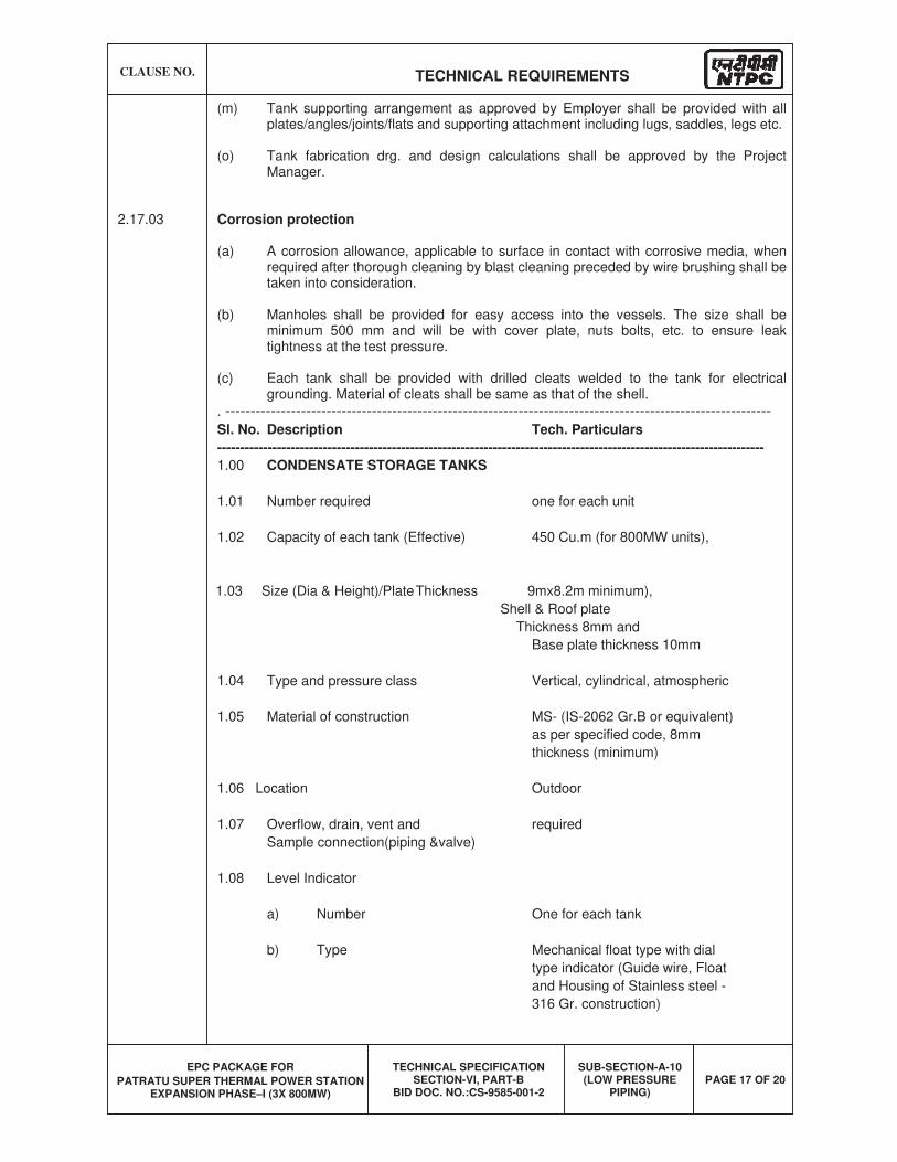
CLAUSE NO. TECHNICAL REQUIREMENTS
EPC PACKAGE FOR
PATRATU SUPER THERMAL POWER STATION EXPANSION PHASE–I (3X 800MW)
TECHNICAL SPECIFICATION SECTION-VI, PART-B
BID DOC. NO.:CS-9585-001-2
SUB-SECTION-A-10 (LOW PRESSURE
PIPING) PAGE 17 OF 20
(m) Tank supporting arrangement as approved by Employer shall be provided with all plates/angles/joints/flats and supporting attachment including lugs, saddles, legs etc.
(o) Tank fabrication drg. and design calculations shall be approved by the Project Manager.
2.17.03 Corrosion protection
(a) A corrosion allowance, applicable to surface in contact with corrosive media, when required after thorough cleaning by blast cleaning preceded by wire brushing shall be taken into consideration.
(b) Manholes shall be provided for easy access into the vessels. The size shall be minimum 500 mm and will be with cover plate, nuts bolts, etc. to ensure leak tightness at the test pressure.
(c) Each tank shall be provided with drilled cleats welded to the tank for electrical grounding. Material of cleats shall be same as that of the shell.
. ------------------------------------------------------------------------------------------------------------
Sl. No. Description Tech. Particulars
-----------------------------------------------------------------------------------------------------------------------
1.00 CONDENSATE STORAGE TANKS
1.01 Number required one for each unit
1.02 Capacity of each tank (Effective) 450 Cu.m (for 800MW units),
1.03 Size (Dia & Height)/Plate Thickness 9mx8.2m minimum),
Shell & Roof plate
Thickness 8mm and
Base plate thickness 10mm
1.04 Type and pressure class Vertical, cylindrical, atmospheric
1.05 Material of construction MS- (IS-2062 Gr.B or equivalent)
as per specified code, 8mm
thickness (minimum)
1.06 Location Outdoor
1.07 Overflow, drain, vent and required
Sample connection(piping &valve)
1.08 Level Indicator
a) Number One for each tank
b) Type Mechanical float type with dial
type indicator (Guide wire, Float
and Housing of Stainless steel -
316 Gr. construction)
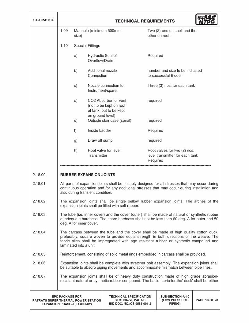
CLAUSE NO. TECHNICAL REQUIREMENTS
EPC PACKAGE FOR
PATRATU SUPER THERMAL POWER STATION EXPANSION PHASE–I (3X 800MW)
TECHNICAL SPECIFICATION SECTION-VI, PART-B
BID DOC. NO.:CS-9585-001-2
SUB-SECTION-A-10 (LOW PRESSURE
PIPING) PAGE 18 OF 20
1.09 Manhole (minimum 500mm Two (2)-one on shell and the
size) other on roof
1.10 Special Fittings
a) Hydraulic Seal of Required
Overflow/Drain
b) Additional nozzle number and size to be indicated
Connection to successful Bidder
c) Nozzle connection for Three (3) nos. for each tank
Instrument/spare
d) CO2 Absorber for vent required
(not to be kept on roof
of tank, but to be kept
on ground level)
e) Outside stair case (spiral) required
f) Inside Ladder Required
g) Draw off sump required
h) Root valve for level Root valves for two (2) nos.
Transmitter level transmitter for each tank
Required
----------------------------------------------------------------------------------------------------------------------
2.18.00 RUBBER EXPANSION JOINTS
2.18.01 All parts of expansion joints shall be suitably designed for all stresses that may occur during continuous operation and for any additional stresses that may occur during installation and also during transient condition.
2.18.02 The expansion joints shall be single bellow rubber expansion joints. The arches of the expansion joints shall be filled with soft rubber.
2.18.03 The tube (i.e. inner cover) and the cover (outer) shall be made of natural or synthetic rubber of adequate hardness. The shore hardness shall not be less than 60 deg. A for outer and 50 deg. A for inner cover.
2.18.04 The carcass between the tube and the cover shall be made of high quality cotton duck, preferably, square woven to provide equal strength in both directions of the weave. The fabric plies shall be impregnated with age resistant rubber or synthetic compound and laminated into a unit.
2.18.05 Reinforcement, consisting of solid metal rings embedded in carcass shall be provided.
2.18.06 Expansion joints shall be complete with stretcher bolt assembly. The expansion joints shall be suitable to absorb piping movements and accommodate mismatch between pipe lines.
2.18.07 The expansion joints shall be of heavy duty construction made of high grade abrasion-resistant natural or synthetic rubber compound. The basic fabric for the' duck' shall be either
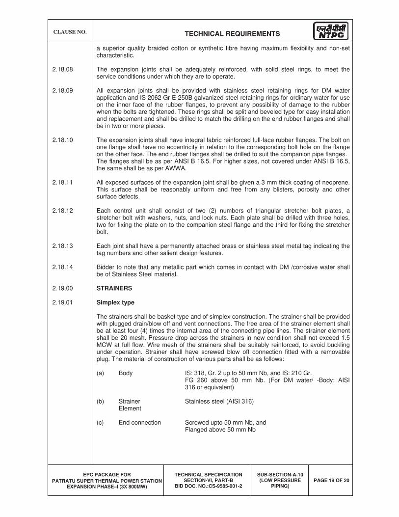
CLAUSE NO. TECHNICAL REQUIREMENTS
EPC PACKAGE FOR
PATRATU SUPER THERMAL POWER STATION EXPANSION PHASE–I (3X 800MW)
TECHNICAL SPECIFICATION SECTION-VI, PART-B
BID DOC. NO.:CS-9585-001-2
SUB-SECTION-A-10 (LOW PRESSURE
PIPING) PAGE 19 OF 20
a superior quality braided cotton or synthetic fibre having maximum flexibility and non-set characteristic.
2.18.08 The expansion joints shall be adequately reinforced, with solid steel rings, to meet the service conditions under which they are to operate.
2.18.09 All expansion joints shall be provided with stainless steel retaining rings for DM water application and IS 2062 Gr E-250B galvanized steel retaining rings for ordinary water for use on the inner face of the rubber flanges, to prevent any possibility of damage to the rubber when the bolts are tightened. These rings shall be split and beveled type for easy installation and replacement and shall be drilled to match the drilling on the end rubber flanges and shall be in two or more pieces.
2.18.10 The expansion joints shall have integral fabric reinforced full-face rubber flanges. The bolt on one flange shall have no eccentricity in relation to the corresponding bolt hole on the flange on the other face. The end rubber flanges shall be drilled to suit the companion pipe flanges.
The flanges shall be as per ANSI B 16.5. For higher sizes, not covered under ANSI B 16.5, the same shall be as per AWWA.
2.18.11 All exposed surfaces of the expansion joint shall be given a 3 mm thick coating of neoprene. This surface shall be reasonably uniform and free from any blisters, porosity and other surface defects.
2.18.12 Each control unit shall consist of two (2) numbers of triangular stretcher bolt plates, a stretcher bolt with washers, nuts, and lock nuts. Each plate shall be drilled with three holes, two for fixing the plate on to the companion steel flange and the third for fixing the stretcher bolt.
2.18.13 Each joint shall have a permanently attached brass or stainless steel metal tag indicating the tag numbers and other salient design features.
2.18.14 Bidder to note that any metallic part which comes in contact with DM /corrosive water shall be of Stainless Steel material.
2.19.00 STRAINERS
2.19.01 Simplex type
The strainers shall be basket type and of simplex construction. The strainer shall be provided with plugged drain/blow off and vent connections. The free area of the strainer element shall be at least four (4) times the internal area of the connecting pipe lines. The strainer element shall be 20 mesh. Pressure drop across the strainers in new condition shall not exceed 1.5 MCW at full flow. Wire mesh of the strainers shall be suitably reinforced, to avoid buckling under operation. Strainer shall have screwed blow off connection fitted with a removable plug. The material of construction of various parts shall be as follows:
(a) Body IS: 318, Gr. 2 up to 50 mm Nb, and IS: 210 Gr. FG 260 above 50 mm Nb. (For DM water/ -Body: AISI 316 or equivalent)
(b) Strainer Stainless steel (AISI 316) Element
(c) End connection Screwed upto 50 mm Nb, and Flanged above 50 mm Nb
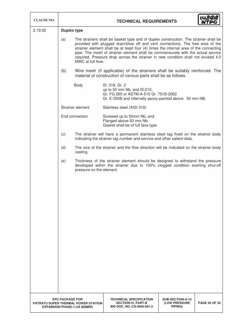
CLAUSE NO. TECHNICAL REQUIREMENTS
EPC PACKAGE FOR
PATRATU SUPER THERMAL POWER STATION EXPANSION PHASE–I (3X 800MW)
TECHNICAL SPECIFICATION SECTION-VI, PART-B
BID DOC. NO.:CS-9585-001-2
SUB-SECTION-A-10 (LOW PRESSURE
PIPING) PAGE 20 OF 20
2.19.02 Duplex type
(a) The strainers shall be basket type and of duplex construction. The strainer shall be provided with plugged drain/blow off and vent connections. The free area of the strainer element shall be at least four (4) times the internal area of the connecting pipe. The mesh of strainer element shall be commensurate with the actual service required. Pressure drop across the strainer in new condition shall not exceed 4.0 MWC at full flow.
(b) Wire mesh (if applicable) of the strainers shall be suitably reinforced. The material of construction of various parts shall be as follows.
Body IS: 318, Gr. 2 up to 50 mm Nb, and IS:210, Gr. FG 260 or ASTM-A-515 Gr. 75/IS-2062
Gr. E-250B and internally epoxy-painted above 50 mm NB.
Strainer element Stainless steel (AISI 316)
End connection Screwed up to 50mm Nb, and Flanged above 50 mm Nb.
Gasket shall be of full face type
(c) The strainer will have a permanent stainless steel tag fixed on the strainer body indicating the strainer tag number and service and other salient data.
(d) The size of the strainer and the flow direction will be indicated on the strainer body casting.
(e) Thickness of the strainer element should be designed to withstand the pressure developed within the strainer due to 100% clogged condition exerting shut-off pressure on the element.
EPC PACKAGE FOR
PATRATU SUPER THERMAL POWER STATION EXPANSION PHASE –I ( 3X 800MW)
TECHNICAL SPECIFICATION SECTION-VI
BID DOC. NO.: CS:9585-001-2
POWER CYCLE PIPING
CLAUSE NO.
SCOPE OF SUPPLY & SERVICES
EPC PACKAGE FOR
PATRATU SUPER THERMAL POWER
STATION EXPANSION PHASE-I (3X800 MW)
TECHNICAL SPECIFICATION
SECTION-VI, PART-A
BID DOC. NO.: CS-9585-001-2
SUB SECTION-IIA-06
POWER CYCLE PIPING
PAGE
1 OF 4
1.00.00 POWER CYCLE PIPING
1.01.00 General:
1.01.01 The scope for Power Cycle piping system shall include complete design, engineering, manufacture/fabrication, statutory/IBR approvals, supply, transportation, storage, erection, cleaning, testing and successful commissioning of below mentioned piping systems complete in all respect.
a) Complete Main steam, Hot Reheat & Cold Reheat piping system between boiler and turbine nozzles
b) HP bypass and LP bypass piping system
c) Feed water piping system including booster pumps suction, discharge, BFPdischarge piping, re-circulation, BFP warm up (if applicable) & leak off.
d) Auxiliary Steam piping system including Aux. steam unit & station headers, Aux. steam interconnection between units, aux. steam to Deaerator & BFP drive turbine etc.
e) BFP Drive turbine exhaust to condenser
f) All extraction steam piping including extraction to HP & LP Heaters, Deareator, BFP Drive turbine etc.
g) Condensate piping including CEP suction, discharge, recirculation etc.
h) Spray piping system for Superheater, Reheater, Auxiliary PRDS, Flash Tanks/Boxes & HP/ LP Bypass system,
i) Heater drains and vents piping
j) Flash tanks/flash boxes including their manifolds, drain & vent piping,
k) HP Bypass & LP bypass warm-up line,
l) Exhaust piping of Safety valves/ relief valves/ERVs on MS, CRH & HRH piping,HP & LP heaters, Deareator, aux. steam piping & on other piping systems (as applicable) mentioned above,
m)Valve gland sealing piping,
n) temporary piping for steam blowing, chemical cleaning & hydro static testing
o) Steam drains from above-mentioned piping /equipment to flash Tank(s)/flash tank manifolds,
p) Miscellaneous line drains and vents
q) Any other piping system required to make the power cycle piping system complete.
CLAUSE NO.
SCOPE OF SUPPLY & SERVICES
EPC PACKAGE FOR
PATRATU SUPER THERMAL POWER
STATION EXPANSION PHASE-I (3X800 MW)
TECHNICAL SPECIFICATION
SECTION-VI, PART-A
BID DOC. NO.: CS-9585-001-2
SUB SECTION-IIA-06
POWER CYCLE PIPING
PAGE
2 OF 4
1.02.00 Scope of Supply:
1.02.01 The scope of supply for the piping systems identified above and/or as per schemes approved during detailed engineering shall comprises of but not be limited to the following:
1.02.02 Pipes, pipe fittings, bends, Y-pieces, valves including safety valves, relief valves, instrument root valves & valve actuators, specialties like expansion joints, strainers, steam traps & orifice plates, stubs including thermo well & other instrumentation stubs, boss/half coupling, weldolet, plugs, flanges, caps, orifice assembly, hangers & supports including variable & constant spring hangers, restraints, anchors, snubbers, etc. along with necessary auxiliary steel structures/beams/sections, steel insert plates, graphite/Teflon/Stainless steel plates, pipe/beam attachments like clamps, welding lugs etc., flash tanks, drip pan, weather hood for pipes crossing ceilings and walls and other accessories etc..
1.02.03 The Contractor shall supply all standard and non-standard matching pieces/tube transition pieces as may be needed for the piping systems and for connection of these piping systems at terminal points, including those which are to be welded with dissimilar material of equipment nozzles, valves, specialties & piping.
1.02.04 Supply and installation of creep measuring instrument on the piping operating in creep region viz. Main steam and Hot Reheat
1.02.05 Supply & installation of thermal insulation and cladding along with all necessary accessories for the piping systems and equipment, tanks etc. in bidder’s scope.
1.02.06 Special accessories like floor stands, chain operator, extended spindle etc. as required for valve operation. Valve, especially for which approach from existing floors are not possible for O&M, appropriate platforms with the access ladders for the same shall be provided.
1.02.07 In case the steam to the turbine enters from the top casing, flange(s) shall be supplied for the piping connected to the steam inlet nozzle on turbine top casing. This is to facilitate dismantling of turbine top casing during maintenance without cutting the pipe. The material of flange shall be same or compatible with the material of connecting piping so that direct welding between pipe & flange can be done at site.
1.02.08 Paints and primers for pipes, fittings, hangers & supports, valves, specialties, aux. steel structures etc. as specified elsewhere in this technical specification.
1.02.09 All erection material such as bolts, nuts, washers, gaskets, electrodes, filler materials, welding gas, consumable inserts and backing rings, accessories and miscellaneous specialties etc. required for the proper installation of piping systems.
1.02.10 Complete temporary piping system including hangers & supports, valves, pipe spools for valves, control valves, flow nozzles & specialties, plugs, caps, blanking plates, pipe spools at terminal points for blanking of piping to carry out hydro test/
CLAUSE NO.
SCOPE OF SUPPLY & SERVICES
EPC PACKAGE FOR
PATRATU SUPER THERMAL POWER
STATION EXPANSION PHASE-I (3X800 MW)
TECHNICAL SPECIFICATION
SECTION-VI, PART-A
BID DOC. NO.: CS-9585-001-2
SUB SECTION-IIA-06
POWER CYCLE PIPING
PAGE
3 OF 4
steam blowing, temporary valve heads/valve blow down cover plate/ flanges, blanking inserts, blow tools, target plates, pumps, tanks, strainers, hydraulic kits, instrumentation & control, gaskets, bolts & nuts, tools & tackles, special devices and any other accessories as required to complete the hydro testing, chemical cleaning(including chemicals) and steam blowing operation of piping systems as specified elsewhere in the technical specification.
1.02.11 All auxiliary steel structures (including structures in TG Building, CD bay, Boiler envelop etc.) required for providing proper supporting arrangement for the pipingsystems in bidder’s scope.
1.03.00 Scope of Services
1.03.01 It is the responsibility of the contractor to identify and obtain all necessary approvals from various Government agencies/board/statutory authorities/ IBR ( CBB, Delhi / CIB of the state in which the power plant is being installed) etc., as applicable for the material, design, manufacture, erection and testing of pipes, valves, fittings, specialties etc. and furnishing the same to employer. This includes furnishing all required documentation, certificates of manufacturing & testing in IBR formats, IBR fees, etc.
1.03.02 Following drawing / documents shall be furnished by contractor for employer’s review/ record:
(a.) For Employer’s review & approval: (i) P&IDs, Composite piping layout drawings, design philosophy & design parameter selection for each piping system, Pressure drop calculation & flash tank sizing calculation (ii) System-wise or P&ID wise prepared pipe schedule, valve schedule, insulation schedule, hanger schedule and Piping isometric/ fabrication isometric drawings for pipe size 65mm NB and above with BOM, (iii) painting schedule
(b.) For approval under information category: (i) Hanger/support arrangement drawing with BOM, (ii) Valve GA drawings (iii) Layout drawings for site routed piping along with BOM (and submission of the same to the employer/project manager before start of work) and (iv) System wise stress analysis/dynamic analysis report (including input) along with stress isometric drg./sketch marked with node points.
(c.) As-Built drawing for information & Records: (i) Piping fabrication isometric drawing (ii) composite piping layout drawing (iii) Hanger /Support arrangement drawing
1.03.03 Basic engineering as well as detailed engineering including static & dynamic analysis, hanger engineering and engineering of thermal insulation etc. for the power cycle piping systems. This also includes design and engineering of all temporary piping that are required for the pre-commissioning/commissioning activities of thepower cycle piping system.
1.03.04 Hydro static testing, steam blowing & chemical cleaning of piping systems, as specified elsewhere in the specification, after complete erection is to be carried out, which also includes supply, erection, making temporary closures, dismantling and
CLAUSE NO.
SCOPE OF SUPPLY & SERVICES
EPC PACKAGE FOR
PATRATU SUPER THERMAL POWER
STATION EXPANSION PHASE-I (3X800 MW)
TECHNICAL SPECIFICATION
SECTION-VI, PART-A
BID DOC. NO.: CS-9585-001-2
SUB SECTION-IIA-06
POWER CYCLE PIPING
PAGE
4 OF 4
removal of all temporary material/piping, equipment and materials from site, disposal of water/waste water/effluent including providing of all facilities/equipment required for the same, clean up and reinstatement of the cleaned piping system.
1.03.05 In case any localized modifications/re-routing/re-erection etc. is required for the piping systems/supporting arrangement after approval of the drawings or during erection, the same shall be carried out by the bidder/piping contractor under his scope with material in consultation with employer.
1.03.06 Providing all other necessary services for making the piping systems in bidder’s scope complete.
1.03.07 In order to ensure that all supporting elements, anchor and restraints etc. have been installed and adjusted in accordance with design documentation, the Contractor shall inspect and log the hanger readings for the hangers associated with the power cycle piping system as follows:
(a.) After hydrostatic test with the piping in the cold position, with all travel stops removed, with the pipe completely insulated and in all respect ready for startup.
(b.) Piping in hot position, with the unit operating at rated parameters
(c.) Piping in hot position (rated parameter condition) after six (6) months of operation
(d.) Piping in cold position during the first complete shutdown after at least six (6) months of operation.
(e.) After steam blowing, in case steam blowing is applicable for the line.
1.03.08 At the time of each inspection, the Contractor will determine the necessity for revision, adjustment or replacement of pipe supporting elements, restraints and anchors. Any changes proposed shall be subject to the concurrence of the Employer. The changes shall be incorporated by the Bidder after Employer's concurrence. A written record shall be furnished to the Employer
1.03.09 Performing all tests including all shop tests as required by the applicable codes, ANSI Standards, IBR and other standards enumerated or specified and implementing all quality control procedures as specified herein including provision of testing equipment, stress relieving equipment, radiography equipment and any other equipment necessary to meet the requirements of the specification.
1.03.10 Certified copies of test reports for all tests and examinations specified elsewhere in the technical specification shall be furnished to Employer.
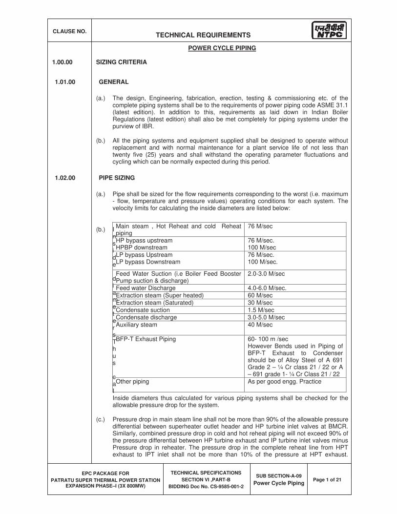
CLAUSE NO. TECHNICAL REQUIREMENTS
EPC PACKAGE FOR
PATRATU SUPER THERMAL POWER STATION EXPANSION PHASE–I (3X 800MW)
TECHNICAL SPECIFICATIONS
SECTION VI ,PART-B
BIDDING Doc No. CS-9585-001-2
SUB SECTION-A-09
Power Cycle PipingPage 1 of 21
POWER CYCLE PIPING
1.00.00 SIZING CRITERIA
1.01.00 GENERAL
(a.) The design, Engineering, fabrication, erection, testing & commissioning etc. of the complete piping systems shall be to the requirements of power piping code ASME 31.1 (latest edition). In addition to this, requirements as laid down in Indian Boiler Regulations (latest edition) shall also be met completely for piping systems under the purview of IBR.
(b.) All the piping systems and equipment supplied shall be designed to operate without replacement and with normal maintenance for a plant service life of not less than twenty five (25) years and shall withstand the operating parameter fluctuations and cycling which can be normally expected during this period.
1.02.00 PIPE SIZING
(a.) Pipe shall be sized for the flow requirements corresponding to the worst (i.e. maximum - flow, temperature and pressure values) operating conditions for each system. The velocity limits for calculating the inside diameters are listed below:
(b.) Inside
diametersThus
caIInside diameters thus calculated for various piping systems shall be checked for the allowable pressure drop for the system.
(c.) Pressure drop in main steam line shall not be more than 90% of the allowable pressure differential between superheater outlet header and HP turbine inlet valves at BMCR. Similarly, combined pressure drop in cold and hot reheat piping will not exceed 90% of the pressure differential between HP turbine exhaust and IP turbine inlet valves minus Pressure drop in reheater. The pressure drop in the complete reheat line from HPT exhaust to IPT inlet shall not be more than 10% of the pressure at HPT exhaust.
Main steam , Hot Reheat and cold Reheat piping
76 M/sec
HP bypass upstream HPBP downstream
76 M/sec. 100 M/sec
LP bypass Upstream LP bypass Downstream
76 M/sec. 100 M/sec.
Feed Water Suction (i.e Boiler Feed Booster Pump suction & discharge)
2.0-3.0 M/sec
Feed water Discharge 4.0-6.0 M/sec. Extraction steam (Super heated) 60 M/sec Extraction steam (Saturated) 30 M/sec Condensate suction 1.5 M/sec Condensate discharge 3.0-5.0 M/sec Auxiliary steam 40 M/sec
BFP-T Exhaust Piping 60- 100 m /sec However Bends used in Piping of BFP-T Exhaust to Condenser should be of Alloy Steel of A 691 Grade 2 – ¼ Cr class 21 / 22 or A – 691 grade 1- ¼ Cr Class 21 / 22
Other piping As per good engg. Practice
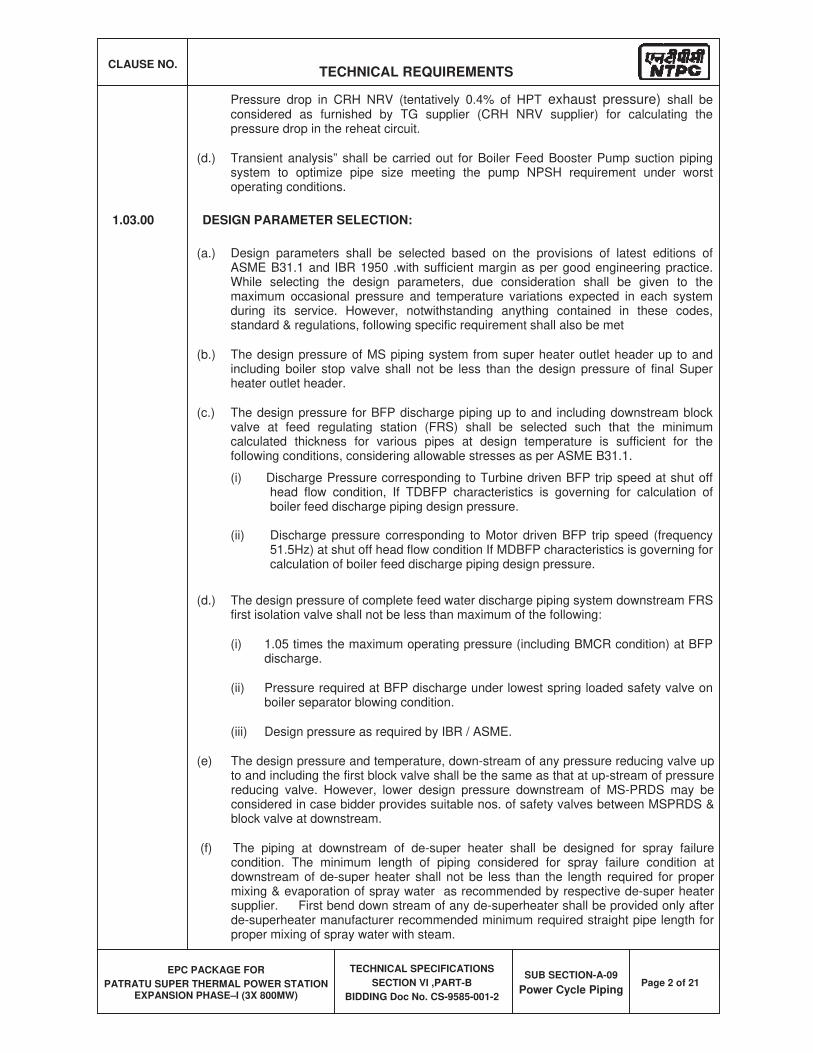
CLAUSE NO. TECHNICAL REQUIREMENTS
EPC PACKAGE FOR
PATRATU SUPER THERMAL POWER STATION EXPANSION PHASE–I (3X 800MW)
TECHNICAL SPECIFICATIONS
SECTION VI ,PART-B
BIDDING Doc No. CS-9585-001-2
SUB SECTION-A-09
Power Cycle PipingPage 2 of 21
Pressure drop in CRH NRV (tentatively 0.4% of HPT exhaust pressure) shall be considered as furnished by TG supplier (CRH NRV supplier) for calculating the pressure drop in the reheat circuit.
(d.) Transient analysis” shall be carried out for Boiler Feed Booster Pump suction piping system to optimize pipe size meeting the pump NPSH requirement under worst operating conditions.
1.03.00 DESIGN PARAMETER SELECTION:
(a.) Design parameters shall be selected based on the provisions of latest editions of ASME B31.1 and IBR 1950 .with sufficient margin as per good engineering practice. While selecting the design parameters, due consideration shall be given to the maximum occasional pressure and temperature variations expected in each system during its service. However, notwithstanding anything contained in these codes, standard & regulations, following specific requirement shall also be met
(b.) The design pressure of MS piping system from super heater outlet header up to and including boiler stop valve shall not be less than the design pressure of final Super heater outlet header.
(c.) The design pressure for BFP discharge piping up to and including downstream block valve at feed regulating station (FRS) shall be selected such that the minimum calculated thickness for various pipes at design temperature is sufficient for the following conditions, considering allowable stresses as per ASME B31.1.
(i) Discharge Pressure corresponding to Turbine driven BFP trip speed at shut off head flow condition, If TDBFP characteristics is governing for calculation of boiler feed discharge piping design pressure.
(ii) Discharge pressure corresponding to Motor driven BFP trip speed (frequency 51.5Hz) at shut off head flow condition If MDBFP characteristics is governing for calculation of boiler feed discharge piping design pressure.
(d.) The design pressure of complete feed water discharge piping system downstream FRS first isolation valve shall not be less than maximum of the following:
(i) 1.05 times the maximum operating pressure (including BMCR condition) at BFP discharge.
(ii) Pressure required at BFP discharge under lowest spring loaded safety valve on boiler separator blowing condition.
(iii) Design pressure as required by IBR / ASME.
(e) The design pressure and temperature, down-stream of any pressure reducing valve up to and including the first block valve shall be the same as that at up-stream of pressure reducing valve. However, lower design pressure downstream of MS-PRDS may be considered in case bidder provides suitable nos. of safety valves between MSPRDS & block valve at downstream.
(f) The piping at downstream of de-super heater shall be designed for spray failure condition. The minimum length of piping considered for spray failure condition at downstream of de-super heater shall not be less than the length required for proper mixing & evaporation of spray water as recommended by respective de-super heater supplier. First bend down stream of any de-superheater shall be provided only after de-superheater manufacturer recommended minimum required straight pipe length for proper mixing of spray water with steam.
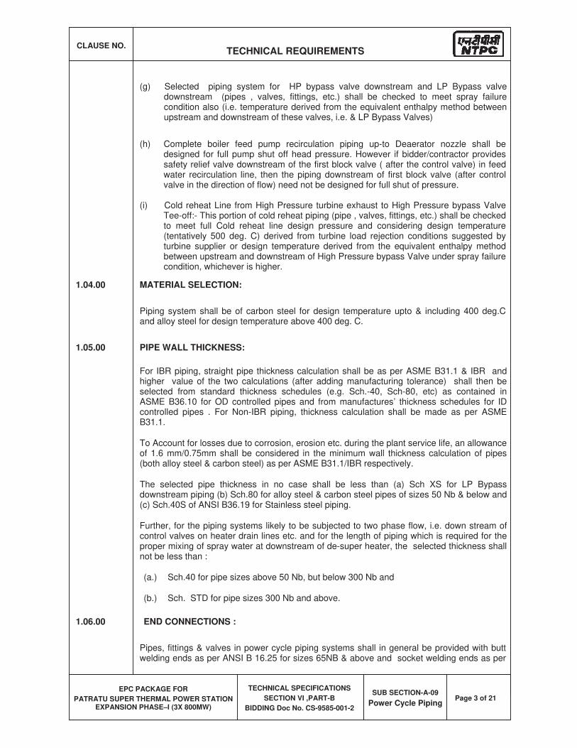
CLAUSE NO. TECHNICAL REQUIREMENTS
EPC PACKAGE FOR
PATRATU SUPER THERMAL POWER STATION EXPANSION PHASE–I (3X 800MW)
TECHNICAL SPECIFICATIONS
SECTION VI ,PART-B
BIDDING Doc No. CS-9585-001-2
SUB SECTION-A-09
Power Cycle PipingPage 3 of 21
(g) Selected piping system for HP bypass valve downstream and LP Bypass valve downstream (pipes , valves, fittings, etc.) shall be checked to meet spray failure condition also (i.e. temperature derived from the equivalent enthalpy method between upstream and downstream of these valves, i.e. & LP Bypass Valves)
(h) Complete boiler feed pump recirculation piping up-to Deaerator nozzle shall be designed for full pump shut off head pressure. However if bidder/contractor provides safety relief valve downstream of the first block valve ( after the control valve) in feed water recirculation line, then the piping downstream of first block valve (after control valve in the direction of flow) need not be designed for full shut of pressure.
(i) Cold reheat Line from High Pressure turbine exhaust to High Pressure bypass Valve Tee-off:- This portion of cold reheat piping (pipe , valves, fittings, etc.) shall be checked to meet full Cold reheat line design pressure and considering design temperature (tentatively 500 deg. C) derived from turbine load rejection conditions suggested by turbine supplier or design temperature derived from the equivalent enthalpy method between upstream and downstream of High Pressure bypass Valve under spray failure condition, whichever is higher.
1.04.00 MATERIAL SELECTION:
Piping system shall be of carbon steel for design temperature upto & including 400 deg.C and alloy steel for design temperature above 400 deg. C.
1.05.00 PIPE WALL THICKNESS:
For IBR piping, straight pipe thickness calculation shall be as per ASME B31.1 & IBR and higher value of the two calculations (after adding manufacturing tolerance) shall then be selected from standard thickness schedules (e.g. Sch.-40, Sch-80, etc) as contained in ASME B36.10 for OD controlled pipes and from manufactures’ thickness schedules for ID controlled pipes . For Non-IBR piping, thickness calculation shall be made as per ASME B31.1.
To Account for losses due to corrosion, erosion etc. during the plant service life, an allowance of 1.6 mm/0.75mm shall be considered in the minimum wall thickness calculation of pipes (both alloy steel & carbon steel) as per ASME B31.1/IBR respectively.
The selected pipe thickness in no case shall be less than (a) Sch XS for LP Bypass downstream piping (b) Sch.80 for alloy steel & carbon steel pipes of sizes 50 Nb & below and (c) Sch.40S of ANSI B36.19 for Stainless steel piping.
Further, for the piping systems likely to be subjected to two phase flow, i.e. down stream of control valves on heater drain lines etc. and for the length of piping which is required for the proper mixing of spray water at downstream of de-super heater, the selected thickness shall not be less than :
(a.) Sch.40 for pipe sizes above 50 Nb, but below 300 Nb and
(b.) Sch. STD for pipe sizes 300 Nb and above.
1.06.00 END CONNECTIONS :
Pipes, fittings & valves in power cycle piping systems shall in general be provided with butt welding ends as per ANSI B 16.25 for sizes 65NB & above and socket welding ends as per
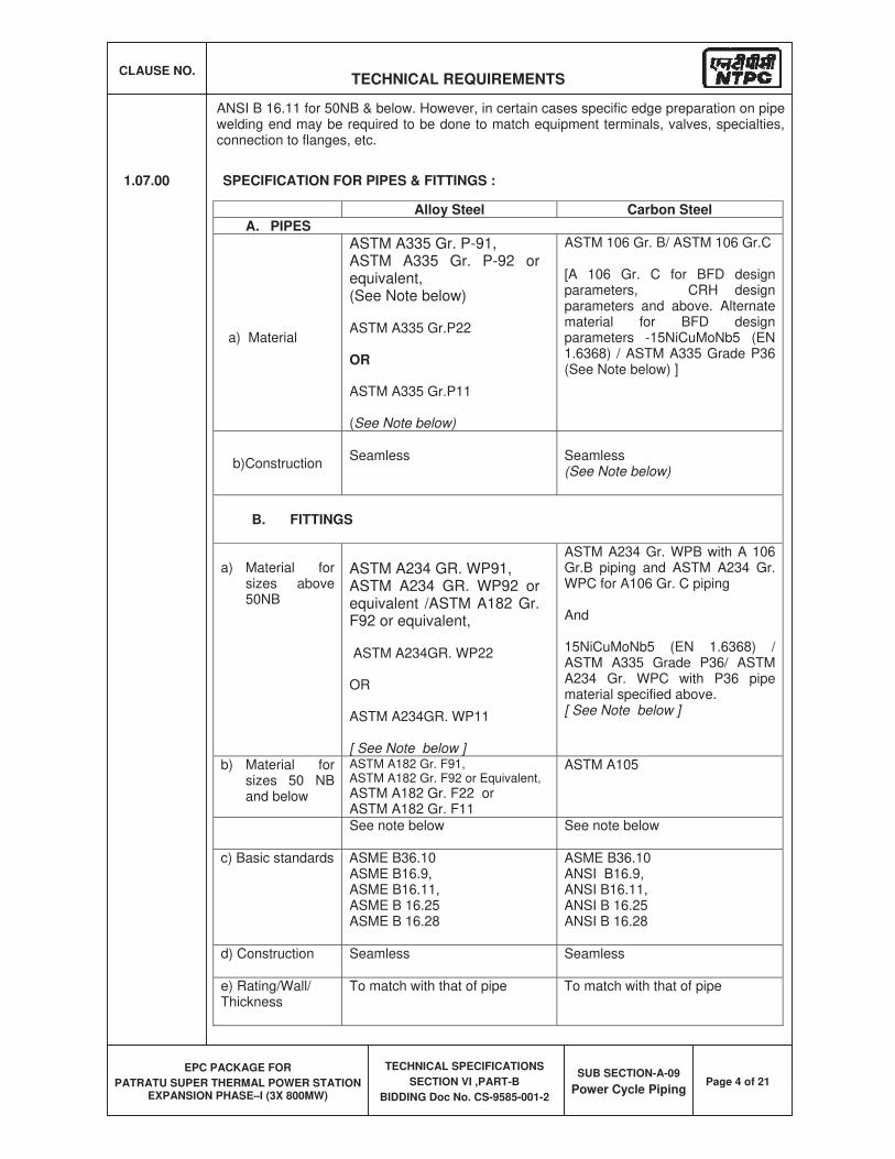
CLAUSE NO. TECHNICAL REQUIREMENTS
EPC PACKAGE FOR
PATRATU SUPER THERMAL POWER STATION EXPANSION PHASE–I (3X 800MW)
TECHNICAL SPECIFICATIONS
SECTION VI ,PART-B
BIDDING Doc No. CS-9585-001-2
SUB SECTION-A-09
Power Cycle PipingPage 4 of 21
ANSI B 16.11 for 50NB & below. However, in certain cases specific edge preparation on pipe welding end may be required to be done to match equipment terminals, valves, specialties, connection to flanges, etc.
1.07.00 SPECIFICATION FOR PIPES & FITTINGS :
Alloy Steel Carbon Steel A. PIPES
a) Material
ASTM A335 Gr. P-91, ASTM A335 Gr. P-92 orequivalent,(See Note below)
ASTM A335 Gr.P22
OR
ASTM A335 Gr.P11
(See Note below)
ASTM 106 Gr. B/ ASTM 106 Gr.C
[A 106 Gr. C for BFD design parameters, CRH design parameters and above. Alternate material for BFD design parameters -15NiCuMoNb5 (EN 1.6368) / ASTM A335 Grade P36 (See Note below) ]
b)ConstructionSeamless Seamless
(See Note below)
B. FITTINGS
a) Material for sizes above 50NB
ASTM A234 GR. WP91, ASTM A234 GR. WP92 or equivalent /ASTM A182 Gr. F92 or equivalent,
ASTM A234GR. WP22
OR
ASTM A234GR. WP11
[ See Note below ]
ASTM A234 Gr. WPB with A 106 Gr.B piping and ASTM A234 Gr. WPC for A106 Gr. C piping
And
15NiCuMoNb5 (EN 1.6368) / ASTM A335 Grade P36/ ASTM A234 Gr. WPC with P36 pipe material specified above. [ See Note below ]
b) Material for sizes 50 NB and below
ASTM A182 Gr. F91, ASTM A182 Gr. F92 or Equivalent,
ASTM A182 Gr. F22 or ASTM A182 Gr. F11
ASTM A105
See note below See note below
c) Basic standards ASME B36.10 ASME B16.9,ASME B16.11, ASME B 16.25 ASME B 16.28
ASME B36.10 ANSI B16.9, ANSI B16.11, ANSI B 16.25 ANSI B 16.28
d) Construction Seamless Seamless
e) Rating/Wall/ Thickness
To match with that of pipe To match with that of pipe
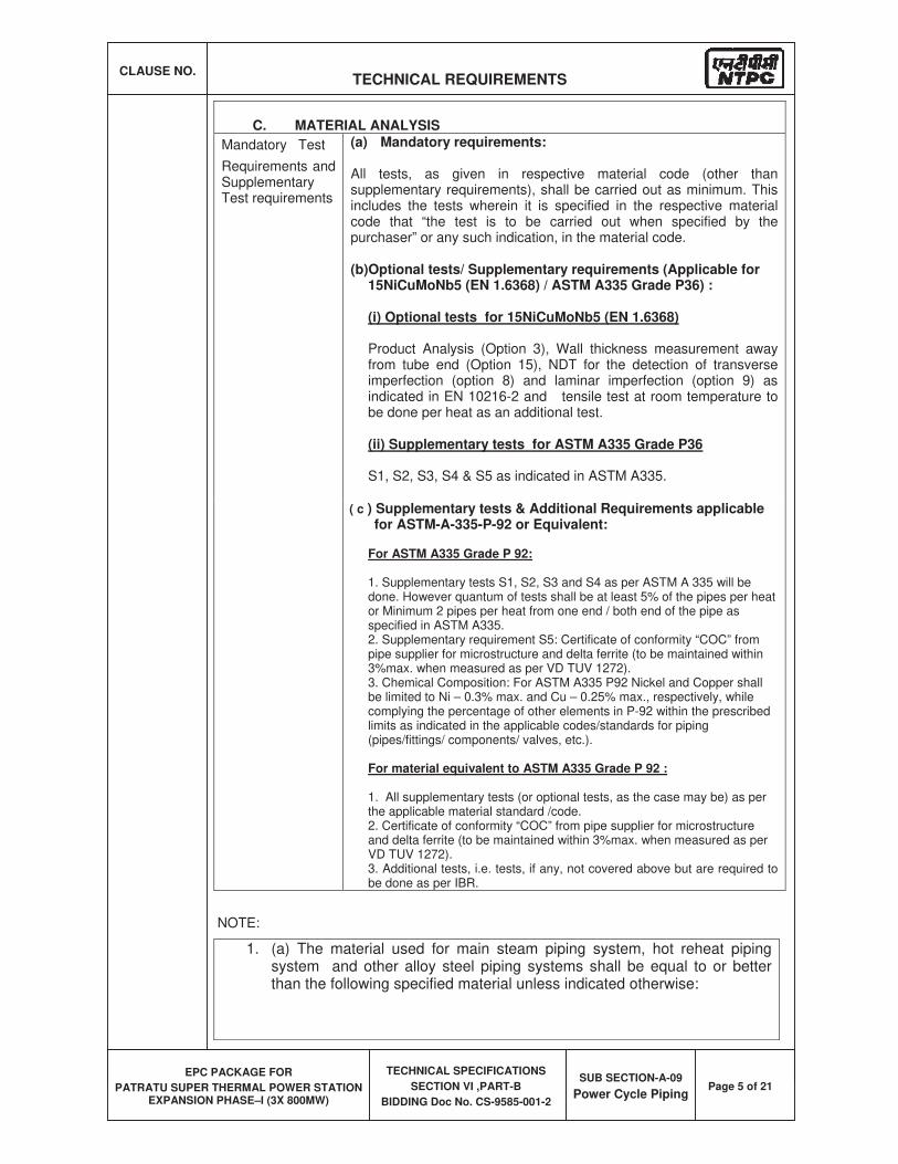
CLAUSE NO. TECHNICAL REQUIREMENTS
EPC PACKAGE FOR
PATRATU SUPER THERMAL POWER STATION EXPANSION PHASE–I (3X 800MW)
TECHNICAL SPECIFICATIONS
SECTION VI ,PART-B
BIDDING Doc No. CS-9585-001-2
SUB SECTION-A-09
Power Cycle PipingPage 5 of 21
C. MATERIAL ANALYSIS
Mandatory Test
Requirements and Supplementary Test requirements
(a) Mandatory requirements:
All tests, as given in respective material code (other than supplementary requirements), shall be carried out as minimum. This includes the tests wherein it is specified in the respective material code that “the test is to be carried out when specified by the purchaser” or any such indication, in the material code.
(b)Optional tests/ Supplementary requirements (Applicable for 15NiCuMoNb5 (EN 1.6368) / ASTM A335 Grade P36) :
(i) Optional tests for 15NiCuMoNb5 (EN 1.6368)
Product Analysis (Option 3), Wall thickness measurement away from tube end (Option 15), NDT for the detection of transverse imperfection (option 8) and laminar imperfection (option 9) as indicated in EN 10216-2 and tensile test at room temperature to be done per heat as an additional test.
(ii) Supplementary tests for ASTM A335 Grade P36
S1, S2, S3, S4 & S5 as indicated in ASTM A335.
( c ) Supplementary tests & Additional Requirements applicable for ASTM-A-335-P-92 or Equivalent:
For ASTM A335 Grade P 92:
1. Supplementary tests S1, S2, S3 and S4 as per ASTM A 335 will be done. However quantum of tests shall be at least 5% of the pipes per heat or Minimum 2 pipes per heat from one end / both end of the pipe as specified in ASTM A335. 2. Supplementary requirement S5: Certificate of conformity “COC” from pipe supplier for microstructure and delta ferrite (to be maintained within 3%max. when measured as per VD TUV 1272). 3. Chemical Composition: For ASTM A335 P92 Nickel and Copper shall be limited to Ni – 0.3% max. and Cu – 0.25% max., respectively, while complying the percentage of other elements in P-92 within the prescribed limits as indicated in the applicable codes/standards for piping (pipes/fittings/ components/ valves, etc.).
For material equivalent to ASTM A335 Grade P 92 :
1. All supplementary tests (or optional tests, as the case may be) as per the applicable material standard /code. 2. Certificate of conformity “COC” from pipe supplier for microstructure and delta ferrite (to be maintained within 3%max. when measured as per VD TUV 1272). 3. Additional tests, i.e. tests, if any, not covered above but are required to be done as per IBR.
NOTE:
1. (a) The material used for main steam piping system, hot reheat piping system and other alloy steel piping systems shall be equal to or better than the following specified material unless indicated otherwise:
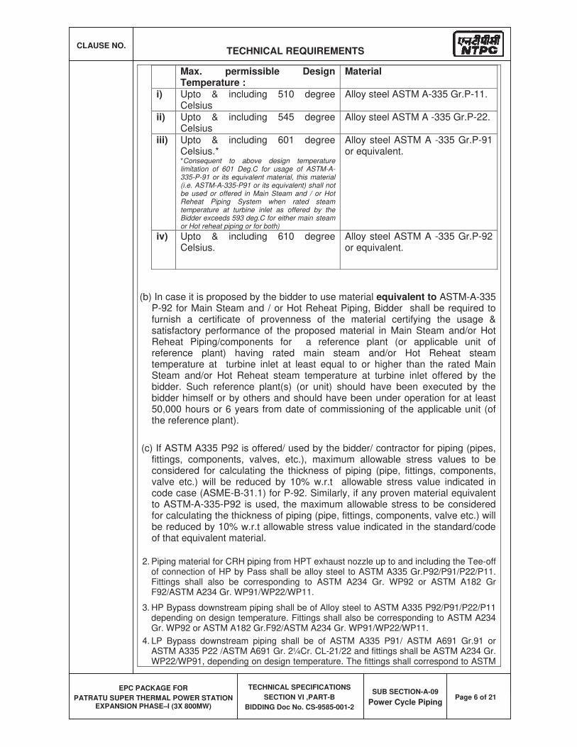
CLAUSE NO. TECHNICAL REQUIREMENTS
EPC PACKAGE FOR
PATRATU SUPER THERMAL POWER STATION EXPANSION PHASE–I (3X 800MW)
TECHNICAL SPECIFICATIONS
SECTION VI ,PART-B
BIDDING Doc No. CS-9585-001-2
SUB SECTION-A-09
Power Cycle PipingPage 6 of 21
Max. permissible Design Temperature :
Material
i) Upto & including 510 degree Celsius
Alloy steel ASTM A-335 Gr.P-11.
ii) Upto & including 545 degree Celsius
Alloy steel ASTM A -335 Gr.P-22.
iii) Upto & including 601 degree Celsius.* *Consequent to above design temperature limitation of 601 Deg.C for usage of ASTM-A-335-P-91 or its equivalent material, this material (i.e. ASTM-A-335-P91 or its equivalent) shall not be used or offered in Main Steam and / or Hot Reheat Piping System when rated steam temperature at turbine inlet as offered by the Bidder exceeds 593 deg.C for either main steam or Hot reheat piping or for both)
Alloy steel ASTM A -335 Gr.P-91 or equivalent.
iv) Upto & including 610 degree Celsius.
Alloy steel ASTM A -335 Gr.P-92 or equivalent.
(b) In case it is proposed by the bidder to use material equivalent to ASTM-A-335 P-92 for Main Steam and / or Hot Reheat Piping, Bidder shall be required to furnish a certificate of provenness of the material certifying the usage & satisfactory performance of the proposed material in Main Steam and/or Hot Reheat Piping/components for a reference plant (or applicable unit of reference plant) having rated main steam and/or Hot Reheat steam temperature at turbine inlet at least equal to or higher than the rated Main Steam and/or Hot Reheat steam temperature at turbine inlet offered by the bidder. Such reference plant(s) (or unit) should have been executed by the bidder himself or by others and should have been under operation for at least 50,000 hours or 6 years from date of commissioning of the applicable unit (of the reference plant).
( (c) If ASTM A335 P92 is offered/ used by the bidder/ contractor for piping (pipes, fittings, components, valves, etc.), maximum allowable stress values to be considered for calculating the thickness of piping (pipe, fittings, components, valve etc.) will be reduced by 10% w.r.t allowable stress value indicated in code case (ASME-B-31.1) for P-92. Similarly, if any proven material equivalent to ASTM-A-335-P92 is used, the maximum allowable stress to be considered for calculating the thickness of piping (pipe, fittings, components, valve etc.) will be reduced by 10% w.r.t allowable stress value indicated in the standard/code of that equivalent material.
2. Piping material for CRH piping from HPT exhaust nozzle up to and including the Tee-off of connection of HP by Pass shall be alloy steel to ASTM A335 Gr.P92/P91/P22/P11. Fittings shall also be corresponding to ASTM A234 Gr. WP92 or ASTM A182 Gr F92/ASTM A234 Gr. WP91/WP22/WP11.
3. HP Bypass downstream piping shall be of Alloy steel to ASTM A335 P92/P91/P22/P11 depending on design temperature. Fittings shall also be corresponding to ASTM A234 Gr. WP92 or ASTM A182 Gr.F92/ASTM A234 Gr. WP91/WP22/WP11.
4. LP Bypass downstream piping shall be of ASTM A335 P91/ ASTM A691 Gr.91 or ASTM A335 P22 /ASTM A691 Gr. 2¼Cr. CL-21/22 and fittings shall be ASTM A234 Gr. WP22/WP91, depending on design temperature. The fittings shall correspond to ASTM
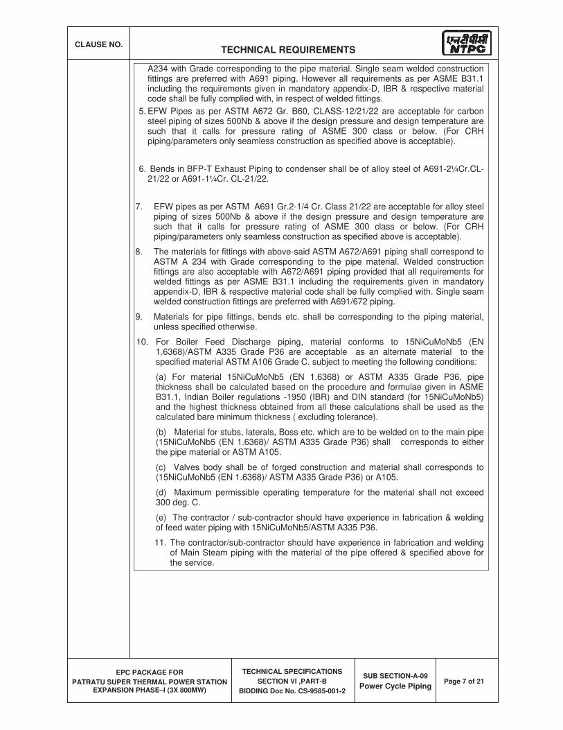
CLAUSE NO. TECHNICAL REQUIREMENTS
EPC PACKAGE FOR
PATRATU SUPER THERMAL POWER STATION EXPANSION PHASE–I (3X 800MW)
TECHNICAL SPECIFICATIONS
SECTION VI ,PART-B
BIDDING Doc No. CS-9585-001-2
SUB SECTION-A-09
Power Cycle PipingPage 7 of 21
A234 with Grade corresponding to the pipe material. Single seam welded construction fittings are preferred with A691 piping. However all requirements as per ASME B31.1 including the requirements given in mandatory appendix-D, IBR & respective material code shall be fully complied with, in respect of welded fittings.
5. EFW Pipes as per ASTM A672 Gr. B60, CLASS-12/21/22 are acceptable for carbon steel piping of sizes 500Nb & above if the design pressure and design temperature are such that it calls for pressure rating of ASME 300 class or below. (For CRH piping/parameters only seamless construction as specified above is acceptable).
6. Bends in BFP-T Exhaust Piping to condenser shall be of alloy steel of A691-2¼Cr.CL-21/22 or A691-1¼Cr. CL-21/22.
7. EFW pipes as per ASTM A691 Gr.2-1/4 Cr. Class 21/22 are acceptable for alloy steel piping of sizes 500Nb & above if the design pressure and design temperature are such that it calls for pressure rating of ASME 300 class or below. (For CRH piping/parameters only seamless construction as specified above is acceptable).
8. The materials for fittings with above-said ASTM A672/A691 piping shall correspond to ASTM A 234 with Grade corresponding to the pipe material. Welded construction fittings are also acceptable with A672/A691 piping provided that all requirements for welded fittings as per ASME B31.1 including the requirements given in mandatory appendix-D, IBR & respective material code shall be fully complied with. Single seam welded construction fittings are preferred with A691/672 piping.
9. Materials for pipe fittings, bends etc. shall be corresponding to the piping material, unless specified otherwise.
10. For Boiler Feed Discharge piping, material conforms to 15NiCuMoNb5 (EN 1.6368)/ASTM A335 Grade P36 are acceptable as an alternate material to the specified material ASTM A106 Grade C. subject to meeting the following conditions:
(a) For material 15NiCuMoNb5 (EN 1.6368) or ASTM A335 Grade P36, pipe thickness shall be calculated based on the procedure and formulae given in ASME B31.1, Indian Boiler regulations -1950 (IBR) and DIN standard (for 15NiCuMoNb5) and the highest thickness obtained from all these calculations shall be used as the calculated bare minimum thickness ( excluding tolerance).
(b) Material for stubs, laterals, Boss etc. which are to be welded on to the main pipe (15NiCuMoNb5 (EN 1.6368)/ ASTM A335 Grade P36) shall corresponds to either the pipe material or ASTM A105.
(c) Valves body shall be of forged construction and material shall corresponds to (15NiCuMoNb5 (EN 1.6368)/ ASTM A335 Grade P36) or A105.
(d) Maximum permissible operating temperature for the material shall not exceed 300 deg. C.
(e) The contractor / sub-contractor should have experience in fabrication & welding of feed water piping with 15NiCuMoNb5/ASTM A335 P36.
11. The contractor/sub-contractor should have experience in fabrication and welding of Main Steam piping with the material of the pipe offered & specified above for the service.
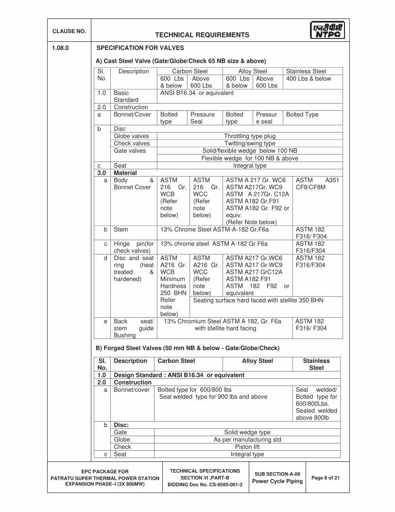
CLAUSE NO. TECHNICAL REQUIREMENTS
EPC PACKAGE FOR
PATRATU SUPER THERMAL POWER STATION EXPANSION PHASE–I (3X 800MW)
TECHNICAL SPECIFICATIONS
SECTION VI ,PART-B
BIDDING Doc No. CS-9585-001-2
SUB SECTION-A-09
Power Cycle PipingPage 8 of 21
1.08.0 SPECIFICATION FOR VALVES
A) Cast Steel Valve (Gate/Globe/Check 65 NB size & above)
Sl.No.
Description Carbon Steel Alloy Steel Stainless Steel 600 Lbs & below
Above 600 Lbs
600 Lbs & below
Above600 Lbs
400 Lbs & below
1.0 Basic Standard
ANSI B16.34 or equivalent
2.0 Construction a Bonnet/Cover Bolted
typePressure Seal
Boltedtype
Pressure seal
Bolted Type
b Disc Globe valves Throttling type plug Check valves Twilting/swing type Gate valves Solid/flexible wedge below 100 NB
Flexible wedge for 100 NB & above c Seat Integral type
3.0 Material a Body &
Bonnet Cover ASTM216 Gr. WCB(Refer notebelow)
ASTM216 Gr. WCC (Refer notebelow)
ASTM A 217 Gr. WC6 ASTM A217Gr. WC9 ASTM A 217Gr. C12A ASTM A182 Gr.F91 ASTM A182 Gr. F92 or equiv.(Refer Note below)
ASTM A351 CF8/CF8M
b Stem 13% Chrome Steel ASTM-A-182 Gr.F6a ASTM 182 F316/ F304
c Hinge pin(for check valves)
13% chrome steel ASTM A-182 Gr F6a ASTM 182 F316/F304
d Disc and seat ring (heat treated & hardened)
ASTMA216 Gr. WCB MinimumHardness250 BHN Refernotebelow)
ASTMA216 Gr. WCC (Refer notebelow)
ASTM A217 Gr.WC6 ASTM A217 Gr.WC9 ASTM A217 GrC12A ASTM A182 F91 ASTM 182 F92 or equivalent
ASTM 182 F316/F304
Seating surface hard faced with stellite 350 BHN
e Back seat/ stem guide Bushing
13% Chromium Steel ASTM A 182, Gr. F6a with stellite hard facing
ASTM 182 F316/ F304
B) Forged Steel Valves (50 mm NB & below - Gate/Globe/Check)
Sl.No.
Description Carbon Steel Alloy Steel Stainless Steel
1.0 Design Standard : ANSI B16.34 or equivalent 2.0 Construction
a Bonnet/cover Bolted type for 600/800 lbs Seal welded type for 900 lbs and above
Seal welded/ Bolted type for 600/800Lbs. Sealed welded above 800lb
b Disc:Gate Solid wedge type Globe As per manufacturing std Check Piston lift
c Seat Integral type
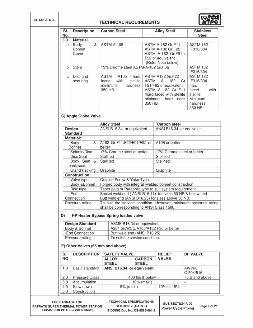
CLAUSE NO. TECHNICAL REQUIREMENTS
EPC PACKAGE FOR
PATRATU SUPER THERMAL POWER STATION EXPANSION PHASE–I (3X 800MW)
TECHNICAL SPECIFICATIONS
SECTION VI ,PART-B
BIDDING Doc No. CS-9585-001-2
SUB SECTION-A-09
Power Cycle PipingPage 9 of 21
Sl.No.
Description Carbon Steel Alloy Steel Stainless Steel
3.0 Material a Body &
Bonnet Cover
ASTM A-105 ASTM A-182 Gr.F11 ASTM A-182 Gr.F22 ASTM A-182 Gr.F91 / F92 or equivalent (Refer Note below)
ASTM 182 F316/304
b Stem 13% chrome steel ASTM-A-182 Gr.F6a ASTM 182 F316/304
c Disc and seat ring
ASTM A105 hard faced with stellite minimum hardness 350 HB
ASTM A182 Gr.F22 ASTM A 182 Gr F91/F92 or equivalent ASTM A 182 Gr F11 /hard faced with stellite minimum hard ness 350 HB
ASTM 182 F316/304hardfaced with stelliteMinimumhardness 350 HB
C) Angle Globe Valve
Alloy Steel `Carbon steel DesignStandard
ANSI B16.34 or equivalent ANSI B16.34 or equivalent
Material: Body &
Bonnet A182 Gr.F11/F22/F91/F92 or better
A105 or better
Spindle/Disc 17% Chrome steel or better 17% Chrome steel or better Disc Seat Stellited Stellited Body Seat &
back seat Stellited Stellited
Gland Packing Graphite Graphite
Construction: Valve type Outside Screw & Yoke Type Body &Bonnet Forged body with integral /welded bonnet construction Disc type Taper plug or Parabolic type to suit system requirement
End Connection
Socket weld end ( ANSI B16.11) for sizes 50 NB & below and Butt weld end (ANSI B16.25) for sizes above 50 NB.
Pressure rating To suit the service condition. However, minimum pressure rating shall be corresponding to ANSI Class 1500
D) HP Heater Bypass Spring loaded valve :
Design Standard ASME B16.34 or equivalent Body & Bonnet A234 Gr.WCC/A105/A182 F36 or better End Connection Butt weld end (ANSI B16.25) Pressure rating To suit the service condition.
E) Other Valves (65 mm and above)
S.NO.
DESCRIPTION SAFETY VALVE RELIEF VALVE
BF VALVE
ALLOYSTEEL
CARBON STEEL
1.0 Basic standard ANSI B16.34 or equivalent AWWA C-504/516
2.0 Pressure Class 400 lbs & below 75 B and above 3.0 Accumulation 10% (max.) -4.0 Blow down 5% (max.) 10% to 15% -5.0 Construction
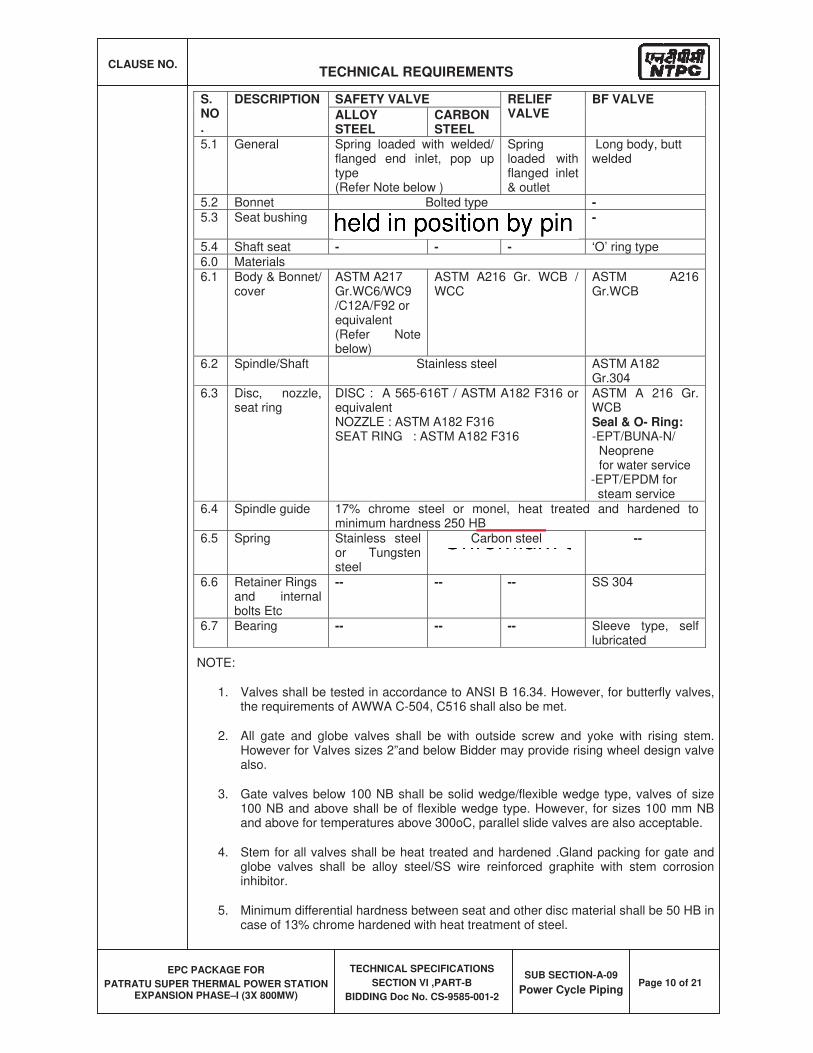
CLAUSE NO. TECHNICAL REQUIREMENTS
EPC PACKAGE FOR
PATRATU SUPER THERMAL POWER STATION EXPANSION PHASE–I (3X 800MW)
TECHNICAL SPECIFICATIONS
SECTION VI ,PART-B
BIDDING Doc No. CS-9585-001-2
SUB SECTION-A-09
Power Cycle PipingPage 10 of 21
S.NO.
DESCRIPTION SAFETY VALVE RELIEF VALVE
BF VALVE
ALLOYSTEEL
CARBON STEEL
5.1 General Spring loaded with welded/ flanged end inlet, pop up type(Refer Note below )
Springloaded with flanged inlet & outlet
Long body, butt welded
5.2 Bonnet Bolted type -5.3 Seat bushing Renewable type screwed on and held in
position by pin -
5.4 Shaft seat - - - ‘O’ ring type 6.0 Materials 6.1 Body & Bonnet/
cover ASTM A217 Gr.WC6/WC9/C12A/F92 or equivalent (Refer Note below)
ASTM A216 Gr. WCB / WCC
ASTM A216 Gr.WCB
6.2 Spindle/Shaft Stainless steel ASTM A182 Gr.304
6.3 Disc, nozzle, seat ring
DISC : A 565-616T / ASTM A182 F316 or equivalent NOZZLE : ASTM A182 F316 SEAT RING : ASTM A182 F316
ASTM A 216 Gr. WCB Seal & O- Ring: -EPT/BUNA-N/ Neoprene for water service -EPT/EPDM for steam service
6.4 Spindle guide 17% chrome steel or monel, heat treated and hardened to minimum hardness 250 HB
6.5 Spring Stainless steel or Tungsten steel
Carbon steel --
6.6 Retainer Rings and internal bolts Etc
-- -- -- SS 304
6.7 Bearing -- -- -- Sleeve type, self lubricated
NOTE:
1. Valves shall be tested in accordance to ANSI B 16.34. However, for butterfly valves, the requirements of AWWA C-504, C516 shall also be met.
2. All gate and globe valves shall be with outside screw and yoke with rising stem. However for Valves sizes 2”and below Bidder may provide rising wheel design valve also.
3. Gate valves below 100 NB shall be solid wedge/flexible wedge type, valves of size 100 NB and above shall be of flexible wedge type. However, for sizes 100 mm NB and above for temperatures above 300oC, parallel slide valves are also acceptable.
4. Stem for all valves shall be heat treated and hardened .Gland packing for gate and globe valves shall be alloy steel/SS wire reinforced graphite with stem corrosion inhibitor.
5. Minimum differential hardness between seat and other disc material shall be 50 HB in case of 13% chrome hardened with heat treatment of steel.
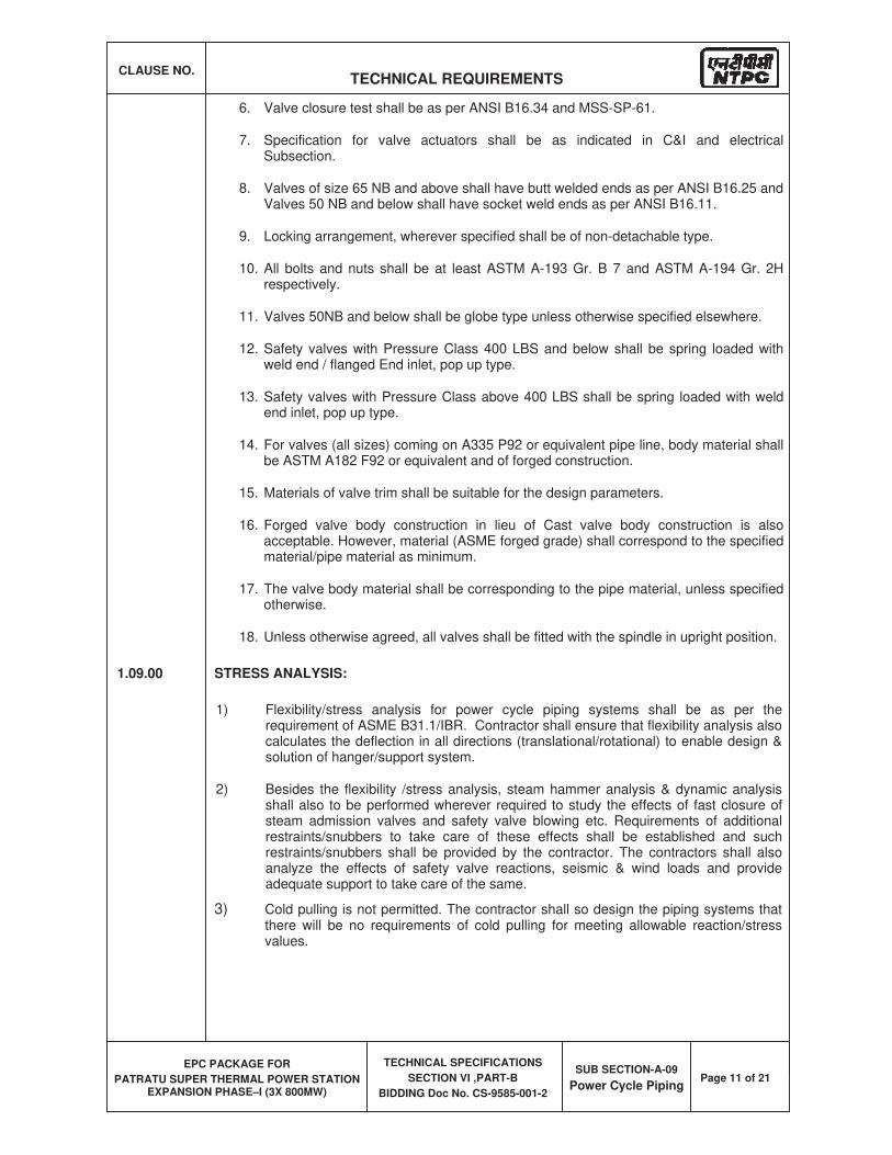
CLAUSE NO. TECHNICAL REQUIREMENTS
EPC PACKAGE FOR
PATRATU SUPER THERMAL POWER STATION EXPANSION PHASE–I (3X 800MW)
TECHNICAL SPECIFICATIONS
SECTION VI ,PART-B
BIDDING Doc No. CS-9585-001-2
SUB SECTION-A-09
Power Cycle PipingPage 11 of 21
6. Valve closure test shall be as per ANSI B16.34 and MSS-SP-61.
7. Specification for valve actuators shall be as indicated in C&I and electrical Subsection.
8. Valves of size 65 NB and above shall have butt welded ends as per ANSI B16.25 and Valves 50 NB and below shall have socket weld ends as per ANSI B16.11.
9. Locking arrangement, wherever specified shall be of non-detachable type.
10. All bolts and nuts shall be at least ASTM A-193 Gr. B 7 and ASTM A-194 Gr. 2H respectively.
11. Valves 50NB and below shall be globe type unless otherwise specified elsewhere.
12. Safety valves with Pressure Class 400 LBS and below shall be spring loaded with weld end / flanged End inlet, pop up type.
13. Safety valves with Pressure Class above 400 LBS shall be spring loaded with weld end inlet, pop up type.
14. For valves (all sizes) coming on A335 P92 or equivalent pipe line, body material shall be ASTM A182 F92 or equivalent and of forged construction.
15. Materials of valve trim shall be suitable for the design parameters.
16. Forged valve body construction in lieu of Cast valve body construction is also acceptable. However, material (ASME forged grade) shall correspond to the specified material/pipe material as minimum.
17. The valve body material shall be corresponding to the pipe material, unless specified otherwise.
18. Unless otherwise agreed, all valves shall be fitted with the spindle in upright position.
1.09.00 STRESS ANALYSIS:
1) Flexibility/stress analysis for power cycle piping systems shall be as per the requirement of ASME B31.1/IBR. Contractor shall ensure that flexibility analysis also calculates the deflection in all directions (translational/rotational) to enable design & solution of hanger/support system.
2) Besides the flexibility /stress analysis, steam hammer analysis & dynamic analysis shall also to be performed wherever required to study the effects of fast closure of steam admission valves and safety valve blowing etc. Requirements of additional restraints/snubbers to take care of these effects shall be established and such restraints/snubbers shall be provided by the contractor. The contractors shall also analyze the effects of safety valve reactions, seismic & wind loads and provide adequate support to take care of the same.
3) Cold pulling is not permitted. The contractor shall so design the piping systems that there will be no requirements of cold pulling for meeting allowable reaction/stress values.
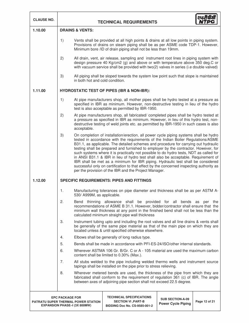
CLAUSE NO. TECHNICAL REQUIREMENTS
EPC PACKAGE FOR
PATRATU SUPER THERMAL POWER STATION EXPANSION PHASE–I (3X 800MW)
TECHNICAL SPECIFICATIONS
SECTION VI ,PART-B
BIDDING Doc No. CS-9585-001-2
SUB SECTION-A-09
Power Cycle PipingPage 12 of 21
1.10.00 DRAINS & VENTS:
1) Vents shall be provided at all high points & drains at all low points in piping system. Provisions of drains on steam piping shall be as per ASME code TDP-1. However, Minimum bore /ID of drain piping shall not be less than 19mm.
2) All drain, vent, air release, sampling and instrument root lines in piping system with design pressure 40 Kg/cm2 (g) and above or with temperature above 350 deg.C or with vacuum service shall be provided with two(2) valves in series (i.e double valved)
3) All piping shall be sloped towards the system low point such that slope is maintained in both hot and cold condition.
1.11.00 HYDROSTATIC TEST OF PIPES (IBR & NON-IBR):
1) At pipe manufacturers shop, all mother pipes shall be hydro tested at a pressure as specified in IBR as minimum. However, non-destructive testing in lieu of the hydro test is also acceptable as permitted by IBR-1950.
2) At pipe manufacturers shop, all fabricated/ completed pipes shall be hydro tested at a pressure as specified in IBR as minimum. However, in lieu of this hydro test, non-destructive testing of weld joints etc. as permitted by IBR-1950 in such cases is also acceptable.
3) On completion of installation/erection, all power cycle piping systems shall be hydro tested in accordance with the requirements of the Indian Boiler Regulations/ASME B31.1, as applicable. The detailed schemes and procedure for carrying out hydraulic testing shall be prepared and furnished to employer by the contractor. However, for such systems where it is practically not possible to do hydro tests, NDT as called for in ANSI B31.1 & IBR in lieu of hydro test shall also be acceptable. Requirement of IBR shall be met as a minimum for IBR piping. Hydraulic test shall be considered successful only on certification to that effect by the concerned inspecting authority as per the provision of the IBR and the Project Manager.
1.12.00 SPECIFIC REQUIREMENTS: PIPES AND FITTINGS
1. Manufacturing tolerances on pipe diameter and thickness shall be as per ASTM A-530/ A999M, as applicable.
2. Bend thinning allowance shall be provided for all bends as per the recommendations of ASME B 31.1. However, bidder/contractor shall ensure that the minimum wall thickness at any point in the finished bend shall not be less than the calculated minimum straight pipe wall thickness
3. Instrument tubing upto and including the root valves and all line drains & vents shall be generally of the same pipe material as that of the main pipe on which they are located unless & until specified otherwise elsewhere.
4. Elbows shall be generally of long radius type.
5. Bends shall be made in accordance with PFI-ES-24/ISO/other internal standards.
6. Wherever ASTMA 106 Gr. B/Gr. C or A - 105 material are used the maximum carbon content shall be limited to 0.30% (Max.).
7. All stubs welded to the pipe including welded thermo wells and instrument source tapings shall be installed on the pipe prior to stress relieving.
8. Wherever metered bends are used, the thickness of the pipe from which they are fabricated shall conform to the requirement of regulation 361 (c) of IBR. The angle between axes of adjoining pipe section shall not exceed 22.5 degree.
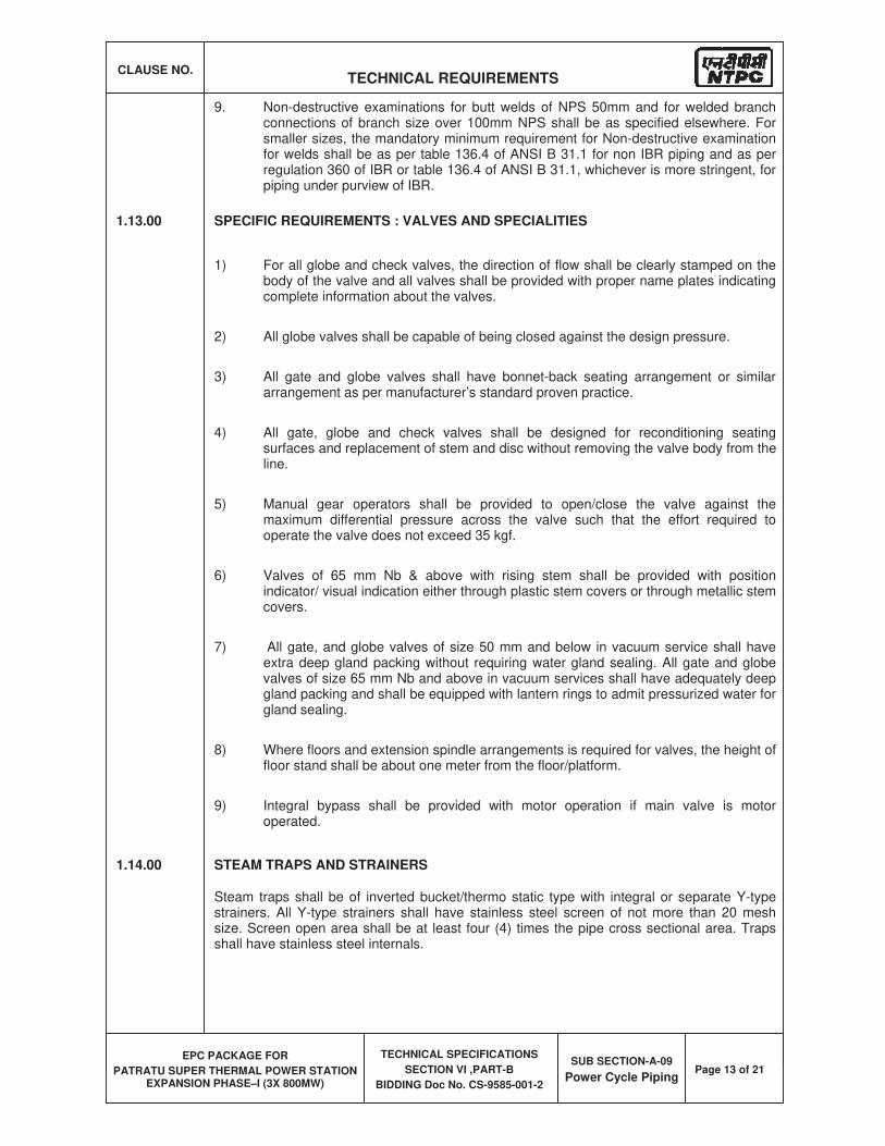
CLAUSE NO. TECHNICAL REQUIREMENTS
EPC PACKAGE FOR
PATRATU SUPER THERMAL POWER STATION EXPANSION PHASE–I (3X 800MW)
TECHNICAL SPECIFICATIONS
SECTION VI ,PART-B
BIDDING Doc No. CS-9585-001-2
SUB SECTION-A-09
Power Cycle PipingPage 13 of 21
9. Non-destructive examinations for butt welds of NPS 50mm and for welded branch connections of branch size over 100mm NPS shall be as specified elsewhere. For smaller sizes, the mandatory minimum requirement for Non-destructive examination for welds shall be as per table 136.4 of ANSI B 31.1 for non IBR piping and as per regulation 360 of IBR or table 136.4 of ANSI B 31.1, whichever is more stringent, for piping under purview of IBR.
1.13.00 SPECIFIC REQUIREMENTS : VALVES AND SPECIALITIES
1) For all globe and check valves, the direction of flow shall be clearly stamped on the body of the valve and all valves shall be provided with proper name plates indicating complete information about the valves.
2) All globe valves shall be capable of being closed against the design pressure.
3) All gate and globe valves shall have bonnet-back seating arrangement or similar arrangement as per manufacturer’s standard proven practice.
4) All gate, globe and check valves shall be designed for reconditioning seating surfaces and replacement of stem and disc without removing the valve body from the line.
5) Manual gear operators shall be provided to open/close the valve against the maximum differential pressure across the valve such that the effort required to operate the valve does not exceed 35 kgf.
6) Valves of 65 mm Nb & above with rising stem shall be provided with position indicator/ visual indication either through plastic stem covers or through metallic stem covers.
7) All gate, and globe valves of size 50 mm and below in vacuum service shall have extra deep gland packing without requiring water gland sealing. All gate and globe valves of size 65 mm Nb and above in vacuum services shall have adequately deep gland packing and shall be equipped with lantern rings to admit pressurized water for gland sealing.
8) Where floors and extension spindle arrangements is required for valves, the height of floor stand shall be about one meter from the floor/platform.
9) Integral bypass shall be provided with motor operation if main valve is motor operated.
1.14.00 STEAM TRAPS AND STRAINERS
Steam traps shall be of inverted bucket/thermo static type with integral or separate Y-type strainers. All Y-type strainers shall have stainless steel screen of not more than 20 mesh size. Screen open area shall be at least four (4) times the pipe cross sectional area. Traps shall have stainless steel internals.
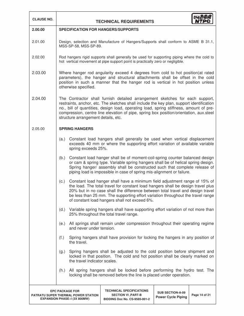
CLAUSE NO. TECHNICAL REQUIREMENTS
EPC PACKAGE FOR
PATRATU SUPER THERMAL POWER STATION EXPANSION PHASE–I (3X 800MW)
TECHNICAL SPECIFICATIONS
SECTION VI ,PART-B
BIDDING Doc No. CS-9585-001-2
SUB SECTION-A-09
Power Cycle PipingPage 14 of 21
2.00.00 SPECIFICATION FOR HANGERS/SUPPORTS
2.01.00 Design, selection and Manufacture of Hangers/Supports shall conform to ASME B 31.1, MSS-SP-58, MSS-SP-89.
2.02.00 Rod hangers rigid supports shall generally be used for supporting piping where the cold to hot vertical movement at pipe support point is practically zero or negligible.
2.03.00 Where hanger rod angularity exceed 4 degrees from cold to hot position(at rated parameters), the hanger and structural attachments shall be offset in the cold position in such a manner that the hanger rod is vertical in hot position unless otherwise specified.
2.04.00 The Contractor shall furnish detailed arrangement sketches for each support, restraints, anchor, etc. The sketches shall include the key plan, support identification no., bill of quantities, design load, operating load, spring stiffness, amount of pre-compression, centre line elevation of pipe, spring box position/orientation, aux.steel structure arrangement details, etc.
2.05.00 SPRING HANGERS
(a.) Constant load hangers shall generally be used when vertical displacement exceeds 40 mm or where the supporting effort variation of available variable spring exceeds 25%.
(b.) Constant load hanger shall be of moment-coil-spring counter balanced design or cam & spring type. Variable spring hangers shall be of helical spring design. Spring hanger/ assembly shall be constructed such that complete release of piping load is impossible in case of spring mis-alignment or failure.
(c.) Constant load hanger shall have a minimum field adjustment range of 15% of the load. The total travel for constant load hangers shall be design travel plus 20% but in no case shall the difference between total travel and design travel be less than 25 mm. The supporting effort variation throughout the travel range of constant load hangers shall not exceed 6%.
(d.) Variable spring hangers shall have supporting effort variation of not more than 25% throughout the total travel range.
(e.) All springs shall remain under compression throughout their operating regime and never under tension.
(f.) Spring hangers shall have provision for locking the hangers in any position of the travel.
(g.) Spring hangers shall be adjusted to the cold position before shipment and locked in that position. The cold and hot position shall be clearly marked on the travel indicator scales.
(h.) All spring hangers shall be locked before performing the hydro test. The locking shall be removed before the line is placed under operation.
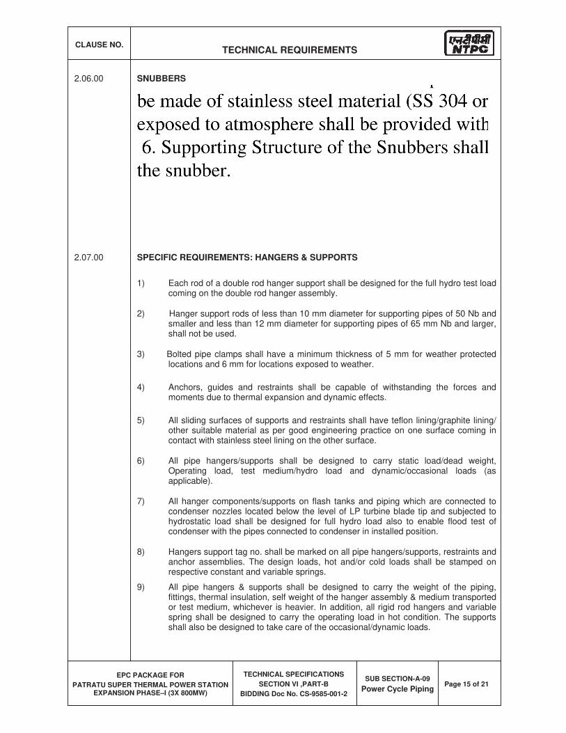
CLAUSE NO. TECHNICAL REQUIREMENTS
EPC PACKAGE FOR
PATRATU SUPER THERMAL POWER STATION EXPANSION PHASE–I (3X 800MW)
TECHNICAL SPECIFICATIONS
SECTION VI ,PART-B
BIDDING Doc No. CS-9585-001-2
SUB SECTION-A-09
Power Cycle PipingPage 15 of 21
2.06.00 SNUBBERS
1. Snubbers shall be designed to allow normal movement of pipe due to thermal expansion and shall require minimal maintenance.
2. Selected snubbers shall be capable to withstand twice the rated load without loss of structural integrity and shall have convenient means for determining rod extension.
3. Snubbers shall be of hydraulic type of Lisega/ITT Grinell, Germany or Employer approved equivalent.
4. Axes of snubbers/restraints shall be parallel to the direction of the expected reaction force in operating condition.
5. Construction of snubbers shall be of Stainless Steel.
2.07.00 SPECIFIC REQUIREMENTS: HANGERS & SUPPORTS
1) Each rod of a double rod hanger support shall be designed for the full hydro test load coming on the double rod hanger assembly.
2) Hanger support rods of less than 10 mm diameter for supporting pipes of 50 Nb and smaller and less than 12 mm diameter for supporting pipes of 65 mm Nb and larger, shall not be used.
3) Bolted pipe clamps shall have a minimum thickness of 5 mm for weather protected locations and 6 mm for locations exposed to weather.
4) Anchors, guides and restraints shall be capable of withstanding the forces and moments due to thermal expansion and dynamic effects.
5) All sliding surfaces of supports and restraints shall have teflon lining/graphite lining/ other suitable material as per good engineering practice on one surface coming in contact with stainless steel lining on the other surface.
6) All pipe hangers/supports shall be designed to carry static load/dead weight, Operating load, test medium/hydro load and dynamic/occasional loads (as applicable).
7) All hanger components/supports on flash tanks and piping which are connected to condenser nozzles located below the level of LP turbine blade tip and subjected to hydrostatic load shall be designed for full hydro load also to enable flood test of condenser with the pipes connected to condenser in installed position.
8) Hangers support tag no. shall be marked on all pipe hangers/supports, restraints and anchor assemblies. The design loads, hot and/or cold loads shall be stamped on respective constant and variable springs.
9) All pipe hangers & supports shall be designed to carry the weight of the piping, fittings, thermal insulation, self weight of the hanger assembly & medium transported or test medium, whichever is heavier. In addition, all rigid rod hangers and variable spring shall be designed to carry the operating load in hot condition. The supports shall also be designed to take care of the occasional/dynamic loads.
CLAUSE NO. TECHNICAL REQUIREMENTS
EPC PACKAGE FOR
PATRATU SUPER THERMAL POWER STATION EXPANSION PHASE–I (3X 800MW)
TECHNICAL SPECIFICATIONS
SECTION VI ,PART-B
BIDDING Doc No. CS-9585-001-2
SUB SECTION-A-09
Power Cycle PipingPage 16 of 21
10) Testing and Inspection:
a) All shop tests shall be conducted in accordance with ANSI standards and other applicable codes/standards.
b) Each Constant load hanger shall be tested before delivery to ensure that the variation in supporting capacity provided through specified range does not exceed 6%.
c) Each variable load spring hangers shall be tested before delivery for its spring stiffness.
3.00.0 MATERIAL TEST AND ANALYSIS
All materials shall be furnished in strict accordance with the applicable codes. All sources of materials shall be disclosed and relevant test certificates giving precise details of identification of material for the physical and chemical properties shall be submitted to the Employer/Project Manager.
4.00.00 SPECIFIC REQUIREMENTS: FABRICATION
1) All dissimilar material piping connections shall be subjected to the prior acceptance and approval of the Employer/Project Manager. Direct welding of P91 & other higher grade material to lower grade alloy steel or carbon steel shall be avoided by introducing suitable transition piece.
2) Access holes for radiography at shop for piping requiring 100% radiography shall be provided only if the area to be radio graphed is not accessible from pipe ends. Access holes for field radiography shall be provided.
3) Where examination of bends indicates that wall thinning has resulted in thickness less than the minimum specified, repair by weld deposition shall be allowed only where the length of the affected area is 150 mm or less as measured along the outside arc of the bend. Repairs in excess of this amount shall not be allowed. All repairs shall be carried out only after approval of the Employer.
4) Branch connections shall conform to the requirements of ASME B 31.1. All branch connection welds shall be full penetration welds, except as permitted by ASME B31.1/IBR.
5) When ‘C’ clamps are tack welded to the pipe for the purpose of alignments of a joint, preheating for the tack welding shall be performed if the main joint adjacent to it to be preheated as per the requirements of this specification, otherwise preheating for the tack weld may be omitted. After the joint is completed, all tack welds shall be removed, flushed with the adjacent surface of pipe by chipping and/or grinding. The areas where ‘c’ clamps were attached shall be subjected to stress relieving as required.
6) Cutting/welding/edge preparation and re-welding required for blanking, temporary piping connection and/or for replacements by spool pieces including reinstallation of components/piping systems after chemical cleaning/steam blowing/hydraulic testing shall be the responsibility of contractor
7) Where welded pipe and fittings are used, the longitudinal weld seams of adjoining sections shall be staggered by 90 deg.
CLAUSE NO. TECHNICAL REQUIREMENTS
EPC PACKAGE FOR
PATRATU SUPER THERMAL POWER STATION EXPANSION PHASE–I (3X 800MW)
TECHNICAL SPECIFICATIONS
SECTION VI ,PART-B
BIDDING Doc No. CS-9585-001-2
SUB SECTION-A-09
Power Cycle PipingPage 17 of 21
8) Elbows shall be generally of long radius type
9) Bends for piping of sizes 65mm Nb and above shall be made hot and for piping of sizes 50mm Nb and below may be made cold.
10) Bends shall be made in accordance with PFI-ES-24/ISO/other international standards. Bends shall be supplied with the minimum tangents except where the piping layout necessitates shorter lengths in which case the tangents shall be suitably reduced after the bending operation to suit the requirement of the piping layout.
11) Heat treatment of bends shall be done as per material specification.
12) All bends 65mm Nb and larger shall be ultrasonically examined as per PFI-ES-20.
13) All material that are bent, forged or formed shall be subject to heat treatment after the forming operation as required by the original material specification. For alloy steel materials the preferred heat treatment process is full annealing.
5.00.00 SPECIFIC REQUIREMENTS – ERECTION
1) Where control valves, flow nozzles, orifices, thermo wells and other piping appurtenances are to be installed, they shall be installed only after steam blowing and chemical cleaning operation. After the completion of the steam blowing/chemical cleaning the contractor shall cut spool pieces of required length and install the components.
2) Field run piping shall be erected only after completion of erection of all other piping system, structures and equipment unless otherwise approved/directed by the Employer/Project Manager.
3) The hydrostatic testing of the piping system shall be done after proper installation of all permanent hangers/supports. Spring hangers shall be locked during hydrostatic test. Prior to steam blowing all hangers which had been locked for the hydrostatic testing shall be unlocked.
4) Use of backing rings not permitted for welding /jointing pipes
5) All gaskets shall be asbestos free material and suitable for the service application
6) The setting and logging of all supports, restraints/limit stop, spring hangers, etc. is the responsibility of the contractor. The initial setting on all hangers and supports and clearance on restraints and limit stops shall correspond to the design cold values. The Contractor shall check all readings after completion of erection of piping system and application of insulation and carry out readjustment as necessary to be in line with the design cold values. After satisfactory setting of all hangers/restraints, hanger readings/clearances shall be logged by the contractor in proper format and a joint protocol be made.
7) The contractor shall monitor the behavior of all hangers, supports, restraints etc. during the initial stages of plant operation. When the piping system(s) have attained their rated temperature the contractor shall log, hanger readings, snubber deflections, restraints / limits stop clearances, as specified elsewhere.
CLAUSE NO. TECHNICAL REQUIREMENTS
EPC PACKAGE FOR
PATRATU SUPER THERMAL POWER STATION EXPANSION PHASE–I (3X 800MW)
TECHNICAL SPECIFICATIONS
SECTION VI ,PART-B
BIDDING Doc No. CS-9585-001-2
SUB SECTION-A-09
Power Cycle PipingPage 18 of 21
8) Wherever there is possibility of ingress of rain water through floor/ceiling opening at points where any pipe passes through floor/ceiling suitable weather protection hood shall be provided
6.00.00 SPECIFICATION FOR CHEMICAL CLEANING OF PIPING SYSTEMS AND EQUIPMENTS
1) It is intended to chemically clean the following piping system.
(a) Boiler feed piping (b) Heater drains piping (c) Main condensate piping (d) Extraction steam piping (e) Reheater spray piping (f) H.P. Heaters (g) L.P. Heaters (h) Deaerator (i) Gland steam cooler (j) Drain cooler (k) Any other piping/equipment in contractor’s scope to be cleaned
through chemical cleaning as finalized during detailed engineering.
2) Bidder shall submit along with the offer his usual procedures and practices for chemical cleaning of the piping and equipment specified. The Bidder shall submit all schematics; write up, details of chemicals to be used etc. and detailed procedures he intends to follow. These schematics and procedures shall be subject to the approval of the Employer.
3) All the piping systems and equipment listed above shall be water flushed before introducing chemicals. Water flushing will be followed by alkaline cleaning, acid cleaning and passivation. Hand cleaning of the interiors of all vessels which are included in the cleaning operation.
Upon completion of each stage of cleaning, the waste products shall be drained and transferred to the waste treatment basins (in bidder scope). The Contractor shall then supply and add the necessary chemicals to the basin to neutralize all waste solutions and rinses generated by the cleaning process, and arrange for its disposal to an area to be indicated by the Employer/Project Manager.
7.00.00 SPECIFICATION FOR STEAM BLOWING OF PIPING SYSTEMS
1. The following piping systems shall be cleaned through steam blowing operation. Contractor shall submit their recommended procedure for steam blowing operation of these piping systems along with scheme/ layout/ drawings giving step by step procedure for performing steam blowing of each these piping systems to the Employer.
1) Main steam 2) Hot reheat 3) Cold reheat 4) HP bypass & LP bypass 5) complete auxiliary steam piping system including unit header & station
header 6) Main Turbine gland sealing system
CLAUSE NO. TECHNICAL REQUIREMENTS
EPC PACKAGE FOR
PATRATU SUPER THERMAL POWER STATION EXPANSION PHASE–I (3X 800MW)
TECHNICAL SPECIFICATIONS
SECTION VI ,PART-B
BIDDING Doc No. CS-9585-001-2
SUB SECTION-A-09
Power Cycle PipingPage 19 of 21
7) Boiler Feed Pump Drive Turbine gland sealing system 8) Steam line feeding turbines of boiler feed pumps. 9) Steam lines to Deaerator 10) Any other piping systems in contractor’s scope to be cleaned through steam
blowing (as finalized during detailed engineering).
Note: Boiler Feed Pump Drive Turbine exhaust to condenser shall be cleaned at site after erection as per standard practice of contractor subject to approval of employer.
2. Steam blowing shall include design, engineering, fabrication, supply and installation of all temporary piping, valves, fittings including quick actuating valves (for puffing purposes), supports, blanking plates, blanking inserts, blow out & blow through tools, spools, target plates, instruments, controls , Thermal insulation and all other accessories and services required to complete the cleaning process .
3. Steam blowing shall also include reinstatement of cleaned piping systems and dismantling/removal of all temporary piping, equipment and materials from site. All temporary piping, valves, equipment and materials shall be taken back by the contractor upon satisfactory completion of cleaning, and shall be removed from the Employer's premises.
4. Cleanliness of system shall be checked by means of test plates (target plates) made of suitable materials as specified elsewhere in this technical specification for pre-commissioning/commissioning (sub-section A-29) .The steam blowing termination criteria /acceptance target plate condition will also be as specified in pre-commissioning/commissioning chapter(sub-section A-29) .
8.00.00 FLASH TANKS
1) The flash tanks and accessories shall be designed, manufactured and tested in accordance with ASME Boiler and pressure vessels (B&PV) codes (latest) and other applicable ANSI standards referenced in the above codes.
2) The flash tanks shall be adequately sized to take care of the total drains in the complete power cycle piping system. There shall be sufficient margin to accommodate the possible variation in drain quantities as well as flash steam. It shall be vertical, cylindrical design and of welded construction with torispherical or hemispherical heads complete with access ladders for access to the instruments(if required), valves, main holes, a full length level indicating gauge glass complete with protective rods, isolation valves and drains, Temperature indicators and temperature switches, supports , etc..
3) Minimum design pressure and temperature for the flash tanks shall be full vacuum & 3.5 Kg/cm2 (g) and 210 degC respectively.
4) The minimum thickness of the vessels including corrosion allowance shall not be less than 8 mm. Corrosion allowance shall be 3.0 mm.
5) In case the spray is in manifold, the material for the flash tank manifolds shall conform to ASTM A335 Gr. P22 or better and its thickness shall not be less than SCH 100 of ANSI B36.10 irrespective of temperature of the fluid handled.
6) Schedule of Materials
Shell and Head ASTM A 285 Gr.C
Wear Plate/Baffle ASTM A 285 Gr.C
CLAUSE NO. TECHNICAL REQUIREMENTS
EPC PACKAGE FOR
PATRATU SUPER THERMAL POWER STATION EXPANSION PHASE–I (3X 800MW)
TECHNICAL SPECIFICATIONS
SECTION VI ,PART-B
BIDDING Doc No. CS-9585-001-2
SUB SECTION-A-09
Power Cycle PipingPage 20 of 21
Nozzle Neck ASTM A 106 Gr.B
Manhole nozzle flange and cover ASTM A 285 Gr.C Couplings ASTM A 105
Bolts and studs ASTM A 193 Gr. B7
Nuts ASTM A 194 Gr. 2 H
Gaskets Spiral wound SS 316 with graphite
However the material as per ASTM A 516 Gr. 60 or IS 2062 Gr. B shall also be acceptable subject to the relevant codes / standards permitting so for the design parameters of various flash tanks.
9.00.00 SPECIFICATION FOR METALLIC EXPANSION JOINTS
(1) The design, material, construction, manufacture, inspection, testing and performance of the expansion joints shall comply with the currently applicable requirement of EJMA, Boiler and Pressure Vessel Code Section III, ANSI B-31.1 and all statutes, regulations and safety codes.
(2) The bellow shall be hydraulically or roll formed from perfect cylinders of single ply, 304 grade stainless steel. It shall have internal sleeves of the same material as the bellows and installed with sufficient clearance to allow full rated deflection
(3) Type test of Metallic Expansion joints
Following tests (Type tests) shall be carried out for metallic expansion joints as per the procedures given in EJMA.
a) Life Cycle Test b) Meridional yield-rupture testing c) Squirm testing
(4) For the purpose of carrying out type tests; metallic bellows shall be grouped based on the parameters as given below. The bellows conforming to same combination of these parameters shall constitute one group. Type test shall be carried out on one or more bellows (as required) for the successful completion of all the type tests specified above.
I. Material of bellow: Based on material of bellow, bellows shall be categorized into three category namely Carbon steel, stainless steel (Eg. SS304, 316, 321etc.) & High alloy steel (Eg. Inconel).
II. Profile of convolutions: Each profile shall be considered as separate category (e.g. U profile, V profile & Lyra profile etc.).
III. Dimension of bellows: Based on the size, the categories shall be as under: IV. Nominal diameter of metallic expansion joint up to and including 800mm NB. V. Nominal diameter of metallic expansion joint greater than 800mm NB up to &
including 1600 NB. VI. Each size above 1600mm NB shall be a separate category.
VII. Design pressure: Based on the design pressure, bellows
VIII. shall be categorized as under:
CLAUSE NO. TECHNICAL REQUIREMENTS
EPC PACKAGE FOR
PATRATU SUPER THERMAL POWER STATION EXPANSION PHASE–I (3X 800MW)
TECHNICAL SPECIFICATIONS
SECTION VI ,PART-B
BIDDING Doc No. CS-9585-001-2
SUB SECTION-A-09
Power Cycle PipingPage 21 of 21
IX. Design pressure from full vacuum up to 5 kg / sq.cm (g). X. Design pressure above 5 kg / sq.cm (g) and up to 10 kg / sq.cm (g) with or without
vacuum.
XI. Number of cycles XII. For the life cycle test, the number of test cycles shall be minimum 10,000 cycles.
(5) Other tests for metallic expansion joints shall be carried out as per the approved QP / QA Section. Further, other terms and conditions for type test shall be as specified elsewhere in the specification.
10.00.00 Testing Requirements:
The detailed testing requirements for power cycle piping and its components are given in the subsection for Quality Assurance(QA) .The requirements pertaining to testing given in this subsection if in variance with that given in QA subsection, then the more stringent of the two shall be followed.
11.00.00 Cleaning and Protection & Marking
a) All fabricated piping shall be cleaned as per relevant SSPC cleaning technique/practice such that both inside and outside surfaces of the piping. .After cleaning outside surface shall be coated with enamel or other protective paint and internally with a water soluble preservative. The weld end preparation shall be coated with deoxyalumina be paint and protected adequately. Use of grease or oil, other than light grade mineral oil is not allowed. Following cleaning and preservation, the fabricated sections shall be covered, boxed, capped, or others shielded from further contamination or corrosion.
b) All piping shall be marked clearly and legibly at the shop with its identifying pipeline description and piece no. as per the appropriate component or spool piece fabrication drawing
12.00.00 Painting & Thermal insulation
Specification for surface preparation/primer/ painting and thermal insulation shall be as per Subsection A-12 (surface preparation & painting) and subsection A-13 (Thermal insulation) respectively.


EPC PACKAGE FOR
PATRATU SUPER THERMAL POWER STATION EXPANSION PHASE –I ( 3X 800MW)
TECHNICAL SPECIFICATION SECTION-VI
BID DOC. NO.: CS:9585-001-2
THERMAL INSULATION
CLAUSE NO. TECHNICAL REQUIREMENTS
EPC PACKAGE FOR
PATRATU SUPER THERMAL POWER STATION EXPANSION PHASE–I (3X 800MW)
TECHNICAL SPECIFICATIONS
SECTION VI, PART-B
BID DOC. NO. CS-9585-001-2
SUB-SECTION -A-13 THERMAL INSULATION
Page 1 of 8
1.00.0 THERMAL INSULATION
a) For all Piping/ SG/TG systems and the equipment with surface operating temperature of 60 deg.C and above, thermal insulation shall be applied for heat conservation and/or personnel protection such that the temperature of protective cladding shall not exceed 60 deg.C. Insulation thickness shall be calculated based on the following design data & methodology:
Design ambient temperature 40 Deg.C for inside and 45 Deg.C for outside the Main plant building.
Maximum cladding temperature 60 Deg.C Wind speed 0.5m/sec. for inside and
0.25m/sec for outside the Main plant building
Emissivity of cladding 0.2
Pipe/Equipment wall temp. Maximum operating temperature.
Thickness calculation As per ASTM C-680 (Latest edition) or equivalent
Thermal insulation shall also be provided for piping systems where it is expected that occasional rise in fluid temperature during operation exceeds 60 deg.C,
Upstream of all drain lines and the lines connected to steam traps, shall be insulated up to and including isolating valve for heat conservation. Rest of such lines drain lines and other lines such as safety valve discharges, vents, etc. shall be insulated for personnel protection.
b) Insulating materials should conform to the following requirements:
i) The minimum insulation thickness, however, shall not be less than 75 mm for Steam Generator surfaces and 25 mm for other surfaces. Also refer as specified at clause no 1.00.00 b (ii) of this chapter. Material and application of insulation material, protective cladding, wire mesh etc. shall also be conforming to latest edition of following Codes: IS: 8183, IS: 3677, IS: 3144, IS: 14164, IS: 280, ASTM-B 209.
Physical requirements — Following shall be met by testing as per relevant clauses of IS:3144.
a) Shot content 5% by weight (maxm.), size of any shot not to exceed 5 mm in diameter
b) Bulk density To comply with Table 2.01.00 below.
c) Weight gain by moisture absorption
2% (maxm.)
d) Sulphur Content Not exceeding 0.6%
e) Alkalinity pH Between 7 to 10
f) Settlement Not exceeding 1% due to vibrations, when tested as per Clause 22.2 of IS:3144
Not exceeding 3% for resistance due to jolting, when tested as per Clause 22.3 of IS:3144
g) Handability Fully handable, without any lump formation and disintegration of material
h) Loss of weight after combustibility test
Not exceeding 5% by weight
CLAUSE NO. TECHNICAL REQUIREMENTS
EPC PACKAGE FOR
PATRATU SUPER THERMAL POWER STATION EXPANSION PHASE–I (3X 800MW)
TECHNICAL SPECIFICATIONS
SECTION VI, PART-B
BID DOC. NO. CS-9585-001-2
SUB-SECTION -A-13 THERMAL INSULATION
Page 2 of 8
In addition to requirements of as specified above, the Mineral wool shall:
(a) Pass standard combustibility test both immediately after application and after subjected to maximum operating temperature for not less than 100 hrs.
(b) Not suffer permanent deterioration as a result of contact with moisture due to condensation and shall be free from objectionable odor.
(c) Not cause corrosion of the surface being insulated or of cladding on it under normal site conditions.
(d) Not suffer any quality deterioration under specified service conditions (both cold/hot face temp.) of use.
(e) Not contain asbestos in finishing materials of insulation in any form
(ii) Insulation mattress/section shall be supplied in thickness of 25, 40, 50 and 75 mm. Insulation of higher thickness shall be made up in multiple layers using mattress/slabs of thickness specified above. However, if the required thickness is such that by using above mattress/slabs the calculated thickness is not achieved, the mattress/slabs in increment of 5 mm shall be acceptable for outer layers. The min. thickness however, shall not be less than 25 mm and number of layers shall be minimum and innermost layer shall be thickest.
c) INSULATION (STEAM TURBINE AND BFP)
(a) Bidder shall provide insulation & cladding for all equipment & piping with
surface temp. more than 60oC.
(b) Bidder to ensure temp. of Cold face of finished insulation not greater than
60oC with ambient temp. of 40oC.
(c) The HP cylinder, IP cylinder, steam chest and interconnection piping,
crossover / cross-around piping, such parts of LP cylinder as considered
necessary, and all associated piping and valves shall be efficiently insulated
with inner thermal insulating materials. The insulated portion of the steam
turbines shall be covered with fabricated steel cover, provided with suitable
anti-drumming and sound pressure attenuating material inside. The
insulation and steel covering should be so designed and erected as to
provide easy accessibility to parts requiring frequent inspection.
(d) The thermal insulation for the turbine casing shall preferably be insulated by preformed ceramic mattress blankets conforming to IS15402 or equivalent. These mattresses are fixed over the casing and held in position by metallic washers fastened to the MS rod welded to the casing. To meet the thickness requirements, multiple layers of mattresses may be applied.
Alternatively, bidder may apply turbine insulation as per their standard practice i.e. sprayed insulation produced by projecting specially prepared mineral wool along with a fine liquid spray. This should be covered with prefabricated 'blanket' type insulation. The bidder may apply complete spray type or complete blanket type or combination of both of above as per their standard practice. These blankets shall consist of high temperature felted
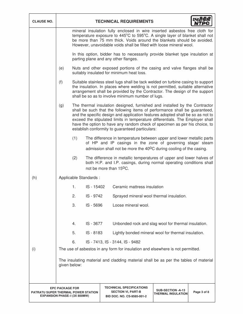
CLAUSE NO. TECHNICAL REQUIREMENTS
EPC PACKAGE FOR
PATRATU SUPER THERMAL POWER STATION EXPANSION PHASE–I (3X 800MW)
TECHNICAL SPECIFICATIONS
SECTION VI, PART-B
BID DOC. NO. CS-9585-001-2
SUB-SECTION -A-13 THERMAL INSULATION
Page 3 of 8
mineral insulation fully enclosed in wire inserted asbestos free cloth for temperature exposure to 445oC to 595oC. A single layer of blanket shall not be more than 75 mm thick. Voids around the blankets should be avoided. However, unavoidable voids shall be filled with loose mineral wool.
In this option, bidder has to necessarily provide blanket type insulation at parting plane and any other flanges.
(e) Nuts and other exposed portions of the casing and valve flanges shall be suitably insulated for minimum heat loss.
(f) Suitable stainless steel lugs shall be tack welded on turbine casing to support the insulation. In places where welding is not permitted, suitable alternative arrangement shall be provided by the Contractor. The design of the support shall be so as to involve minimum number of lugs.
(g) The thermal insulation designed, furnished and installed by the Contractor shall be such that the following items of performance shall be guaranteed, and the specific design and application features adopted shall be so as not to exceed the stipulated limits in temperature differentials. The Employer shall have the option to have any random check of specimen as per his choice, to establish conformity to guaranteed particulars:
(1) The difference in temperature between upper and lower metallic parts of HP and IP casings in the zone of governing stage/ steam
admission shall not be more the 40oC during cooling of the casing.
(2) The difference in metallic temperatures of upper and lower halves of both H.P. and I.P. casings, during normal operating conditions shall
not be more than 15oC.
(h) Applicable Standards :
1. IS - 15402 Ceramic mattress insulation
2. IS - 9742 Sprayed mineral wool thermal insulation.
3. IS - 5696 Loose mineral wool.
4. IS - 3677 Unbonded rock and slag wool for thermal insulation.
5. IS - 8183 Lightly bonded mineral wool for thermal insulation.
6. IS - 7413, IS - 3144, IS - 9482
(i) The use of asbestos in any form for insulation and elsewhere is not permitted.
The insulating material and cladding material shall be as per the tables of material given below:
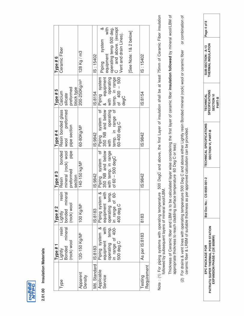
EP
C P
AC
KA
GE
FO
R
PA
TR
AT
U S
UP
ER
TH
ER
MA
L P
OW
ER
ST
AT
ION
E
XP
AN
SIO
N P
HA
SE
–I
(3X
80
0M
W)
Bid
Do
c N
o.:
C
S-9
585-0
01-2
T
EC
HN
ICA
L S
PE
CIF
ICA
TIO
NS
SE
CT
ION
VI,
PA
RT
-B
TE
CH
NIC
AL
S
PE
CIF
ICA
TIO
NS
SE
CT
ION
VI
PA
RT
-B
SU
B-S
EC
TIO
N -
A-1
3
T
HE
RM
AL
IN
SU
LA
TIO
N
Pa
ge
4 o
f 8
2.0
1.0
0 In
su
lati
on
Mate
rials
No
te :
(1
) F
or
pip
ing
syste
ms w
ith
ope
ratin
g t
em
pe
ratu
re
50
0 D
egC
and
abo
ve
, th
e f
irst
La
ye
r o
f in
su
latio
n s
ha
ll b
e a
t le
ast
75
mm
of
Cera
mic
Fib
er
insu
latio
n
follo
wed b
y s
ubsequent la
yers
of m
inera
l w
ool/LB
M.
Th
ickn
ess o
f C
era
mic
fib
er
an
d L
BM
is t
o b
e c
alc
ula
ted
la
ye
r w
ise c
onsid
erin
g t
he
first
laye
r o
f ce
ram
ic f
ibe
r in
su
lati
on
fo
llo
wed
by m
inera
l w
ool/LB
M o
f a
pp
ropria
te th
ickn
ess to
re
ach
cla
dd
ing
su
rface
te
mp
era
ture
6
0 D
eg
C o
r le
ss)
(2)
For
dra
ins &
vent lin
es w
ith o
pera
ting tem
pera
ture
500 D
eg C
and a
bove e
ither
Lig
htly r
esin
Bonded m
inera
l (r
ock)
wool or
cera
mic
fib
er
o
r com
bin
ation
of
ce
ram
ic fib
er
& L
RB
M o
f su
ita
ble
th
ickne
ss a
s p
er
app
rove
d c
alc
ula
tio
n c
an
be
pro
vid
ed
.
T
yp
e #
1
Typ
e #
2
Typ
e #
3
Typ
e #
4
Typ
e #
5
Typ
e #
6
Typ
eL
igh
tly
resin
B
on
de
d
min
era
l (r
ock)
wo
ol
Lig
htly
resin
b
on
de
d
min
era
l (r
ock)
wo
ol
Re
sin
b
on
de
d
min
era
l (r
ock)
wo
ol
pre
form
ed
p
ipe
se
ctio
n
Re
sin
bo
nd
ed
gla
ss
wo
ol
pre
form
ed
p
ipe
se
ctio
n
Ca
lciu
msili
ca
tep
refo
rme
db
lock t
yp
e
Ce
ram
ic F
ibe
r
Ap
pa
ren
tD
en
sity
12
0-1
50
Kg
/M³
10
0 K
g/M
³1
40
-15
0 k
g/M
³6
0-8
0K
g/M
³2
00
-25
0K
g/m
³1
28
Kg
/ m
3
Mtl.
Sta
nd
ard
IS:8
18
3IS
:81
83
IS:9
84
2IS
:98
42
IS:8
15
4IS
: 1
54
02
A
pp
lica
ble
Se
rvic
eP
ipin
g
syste
m
&
eq
uip
me
nt
with
o
pe
ratin
g
tem
p.
in
ra
ng
e
of
40
0-
50
0 d
eg
.C
Pip
ing
syste
m &
e
qu
ipm
en
t w
ith
o
pe
ratin
g
tem
p.
in
ran
ge
o
f 6
0-
40
0 d
eg
.C
Pip
ing
syste
m
of
35
0 N
B a
nd
b
elo
w
with
te
mp
. in
ra
ng
e
of
60
– 5
00
de
gC
Pip
ing
syste
m
of
35
0 N
B a
nd
b
elo
w
with
o
pe
ratin
g
tem
p.
in
ran
ge
o
f 6
0-4
00
de
g.C
Pip
ing
syste
m
&
eq
uip
me
nt
with
o
pe
ratin
g
tem
p.
in ra
ng
e
of
4
00
–
5
00
d
eg
C
Pip
ing
syste
m
&
eq
uip
me
nt
with
o
pe
ratin
g t
em
p 5
00
de
g.
C a
nd
a
bo
ve
. (e
xce
pt
Ve
nt
an
d d
rain
Lin
es).
[Se
e N
ote
: 1
& 2
be
low
]
Te
stin
gR
eq
uire
me
nt
As p
er
IS:8
18
38
18
3IS
:98
42
IS:9
84
2IS
:81
54
IS :
15
40
2
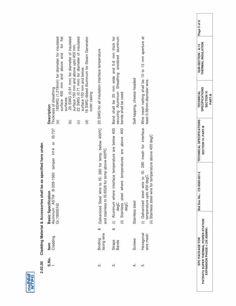
EP
C P
AC
KA
GE
FO
R
PA
TR
AT
U S
UP
ER
TH
ER
MA
L P
OW
ER
ST
AT
ION
E
XP
AN
SIO
N P
HA
SE
–I
(3X
80
0M
W)
Bid
Do
c N
o.:
C
S-9
585-0
01-2
T
EC
HN
ICA
L S
PE
CIF
ICA
TIO
NS
SE
CT
ION
VI,
PA
RT
-B
TE
CH
NIC
AL
S
PE
CIF
ICA
TIO
NS
SE
CT
ION
VI
PA
RT
-B
SU
B-S
EC
TIO
N -
A-1
3
T
HE
RM
AL
IN
SU
LA
TIO
N
Pa
ge
5 o
f 8
2.0
2.0
0 C
lad
din
g M
ate
rial &
Access
ori
es s
hall b
e a
s s
pec
ifie
d h
ere
un
der.
S.N
o.
Item
B
asic
Sp
ecif
icati
on
D
escri
pti
on
1
. C
ladd
ing
Alu
min
um
A
ST
M
B-2
09-1
06
0
tem
per
H14
o
r IS
:73
7
Gr.
19000/H
2
Th
ickn
ess o
f sh
ea
thin
g
(a)
18S
WG
(1.2
19m
m)
for
dia
mete
r fo
r in
sula
ted
su
rface
45
0
mm
a
nd
ab
ove
a
nd
for
fla
t su
rfaces
(b)
20 S
WG
(0.9
1 m
m)
for
dia
mete
r of
insula
ted
su
rface
15
0 m
m a
nd
abo
ve
up
to 4
50
mm
. (c
) 22 S
WG
(0.7
1 m
m)
for
dia
mete
r of
insula
ted
su
rface
15
0 m
m a
nd
be
low
. (d
)
1
6 S
WG
rib
bed A
lum
inum
for
Ste
am
Genera
tor
ou
ter
ca
sin
g
2.
Bin
din
g
&
lacin
g w
ire
Galv
aniz
ed S
teel
wire t
o I
S:
280 f
or
tem
p.
belo
w 4
00
oC
an
d s
tain
less to
IS
:65
28
fo
r te
mp
ab
ove
40
0oC
20
SW
G fo
r all
insu
latio
n inte
rfa
ce
te
mp
era
ture
3.
Str
ap
s
&
Bands
(i)
Alu
min
um
where
inte
rface t
em
pera
ture
are
belo
w 4
00
degC
(ii)
Sta
inle
ss
ste
el
where
te
mpera
ture
s
are
above
40
0
degC
Band
shall
be
20
mm
w
ide
and
0.6
m
m
thic
k
for
secu
rin
g
Alu
min
um
S
he
ath
ing
a
no
diz
ed
a
lum
inum
bends s
hall
be
used
.
4.
Scre
ws
Sta
inle
ss s
tee
l S
elf-t
appin
g, cheese h
eade
d
5.
He
xa
go
na
l w
ire m
esh
(i)
Ga
lvan
ized
ste
el
wire
to
IS:
28
0
me
sh
fo
r in
terf
ace
tem
pera
ture
upto
400 d
egC
.
(ii) S
tain
less s
tee
l w
ire
fo
r te
mp
era
ture
ab
ove
400
deg
C
Wire
me
sh
ne
ttin
g s
ha
ll be
10
to
13
mm
ap
ert
ure
at
least 0.5
6m
m d
iam
ete
r w
ire.
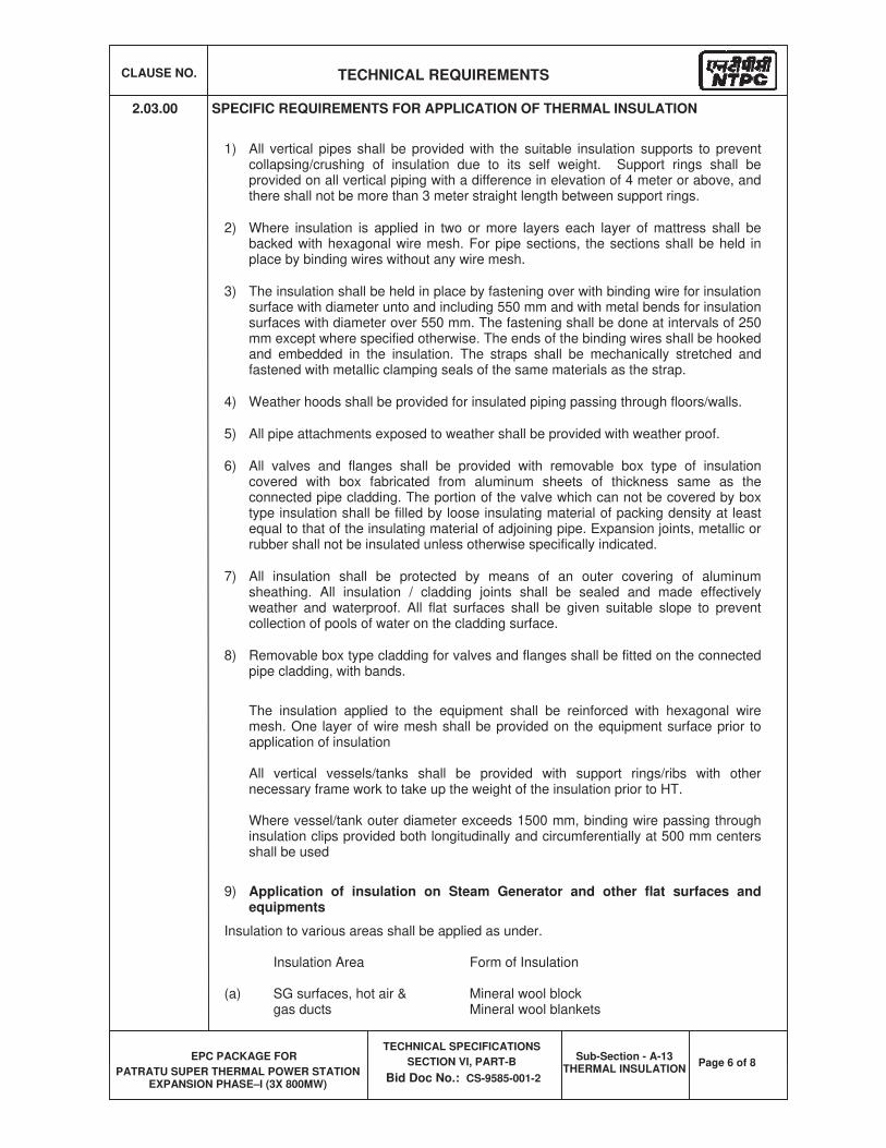
CLAUSE NO. TECHNICAL REQUIREMENTS
EPC PACKAGE FOR
PATRATU SUPER THERMAL POWER STATION EXPANSION PHASE–I (3X 800MW)
TECHNICAL SPECIFICATIONS
SECTION VI, PART-B
Bid Doc No.: CS-9585-001-2
Sub-Section - A-13 THERMAL INSULATION
Page 6 of 8
2.03.00 SPECIFIC REQUIREMENTS FOR APPLICATION OF THERMAL INSULATION
1) All vertical pipes shall be provided with the suitable insulation supports to prevent collapsing/crushing of insulation due to its self weight. Support rings shall be provided on all vertical piping with a difference in elevation of 4 meter or above, and there shall not be more than 3 meter straight length between support rings.
2) Where insulation is applied in two or more layers each layer of mattress shall be backed with hexagonal wire mesh. For pipe sections, the sections shall be held in place by binding wires without any wire mesh.
3) The insulation shall be held in place by fastening over with binding wire for insulation surface with diameter unto and including 550 mm and with metal bends for insulation surfaces with diameter over 550 mm. The fastening shall be done at intervals of 250 mm except where specified otherwise. The ends of the binding wires shall be hooked and embedded in the insulation. The straps shall be mechanically stretched and fastened with metallic clamping seals of the same materials as the strap.
4) Weather hoods shall be provided for insulated piping passing through floors/walls.
5) All pipe attachments exposed to weather shall be provided with weather proof.
6) All valves and flanges shall be provided with removable box type of insulation covered with box fabricated from aluminum sheets of thickness same as the connected pipe cladding. The portion of the valve which can not be covered by box type insulation shall be filled by loose insulating material of packing density at least equal to that of the insulating material of adjoining pipe. Expansion joints, metallic or rubber shall not be insulated unless otherwise specifically indicated.
7) All insulation shall be protected by means of an outer covering of aluminum sheathing. All insulation / cladding joints shall be sealed and made effectively weather and waterproof. All flat surfaces shall be given suitable slope to prevent collection of pools of water on the cladding surface.
8) Removable box type cladding for valves and flanges shall be fitted on the connected pipe cladding, with bands.
The insulation applied to the equipment shall be reinforced with hexagonal wire mesh. One layer of wire mesh shall be provided on the equipment surface prior to application of insulation
All vertical vessels/tanks shall be provided with support rings/ribs with other necessary frame work to take up the weight of the insulation prior to HT.
Where vessel/tank outer diameter exceeds 1500 mm, binding wire passing through insulation clips provided both longitudinally and circumferentially at 500 mm centers shall be used
9) Application of insulation on Steam Generator and other flat surfaces and equipments
Insulation to various areas shall be applied as under.
Insulation Area Form of Insulation
(a) SG surfaces, hot air & Mineral wool block gas ducts Mineral wool blankets
CLAUSE NO. TECHNICAL REQUIREMENTS
EPC PACKAGE FOR
PATRATU SUPER THERMAL POWER STATION EXPANSION PHASE–I (3X 800MW)
TECHNICAL SPECIFICATIONS
SECTION VI, PART-B
Bid Doc No.: CS-9585-001-2
Sub-Section - A-13 THERMAL INSULATION
Page 7 of 8
(b) All other surfaces/not enclosed Calcium silicate block or as per (a) above by SG casing
I. For the Steam Generator furnace, if provided with skin casing and the super heater, reheater and economizer casings where water cooled walls are involved, a first covering of refractory material shall be applied to the external tube surfaces before the application of any further heat resistant insulating material
II. The access doors and inspection doors in the Steam Generator shall be lined with refractory material. The access doors in other portions of the Steam Generator shall be insulated in a similar manner corresponding to any casing, flue-ducts or air, ducts where such openings and access doors occur.
III. While applying mineral wool blanket insulation:
(a) Provide expended metal or hexagonal wire mesh on both sides for single layer mattress and on first layer in case of multilayer insulation. Subsequent layers of multilayer insulation to have only one side wire netting.
(b.) The edges of adjacent blankets to be leased together, by appropriate lacing wire as per as specified at clause no 2.02.00 of this chapter.
(b) Any gap between joints between insulation layers shall be filled by loose mineral wool confirming to IS 3677.
(c) All insulation to be secured by 1.63 mm diameter wire netting over blankets with ends of wire tightly twisted, and pressed in to insulation surface.
(d) Impelling pins shall be placed on centers not exceeding 300 mm.
iv) Air & Flue Gas ducts with external stiffeners shall have first layer of insulation between the stiffeners and a second layer of insulation over stiffeners so that stiffeners are also insulated and a level surface is achieved. Other requirements are same as given in as specified at clause no 1.00.00 of this chapter.
v) Penthouse Insulation Arrangement:
Penthouse vertical wall shall be insulated from outside. Similarly, the upper deck sheet of pent house shall also be insulated from outside only. The flat surface of deck sheet shall be insulated by pourable/castable refractory only.
10) Testing and Guarantee for insulation:
1. All tests, as per the applicable material standards and as specified shall be carried out in accordance with the methods prescribed. Employer shall have the right to witness any or all of the tests conducted by the contractor at the shop or laboratory.
2. The Contractor shall guarantee that if on actual measurement the specified maximum insulation surface temperatures are exceeded, the contractor shall either replace the insulation with a superior material or provide additional insulation thickness at no extra cost.
2.04.00 Refractories
2.04.01 The refractory material shall comply with relevant Indian Standards. The refractory selected shall ensure perfect sealing, and shall have good thermal cycling properties allowing quick startup/shut down of Steam Generators.
CLAUSE NO. TECHNICAL REQUIREMENTS
EPC PACKAGE FOR
PATRATU SUPER THERMAL POWER STATION EXPANSION PHASE–I (3X 800MW)
TECHNICAL SPECIFICATIONS
SECTION VI, PART-B
Bid Doc No.: CS-9585-001-2
Sub-Section - A-13 THERMAL INSULATION
Page 8 of 8
2.04.02 The refractory material shall
(a) Have high bulk density and minimum moisture content,
(b) Be capable of withstanding service temperature of 1700 degree Celsius.
(c) Be resistant to slagging products due to coal, and to impurities of oil like V2O5,Fe2O3, K2O2, Na2O etc. and to erosion due to fly ash.
(d) Be chemically inactive towards alkalis, iron, silica etc. shall pose no health hazard to working personnel, and shall not have any explosive properties.
(e) Have sufficient strength to withstand forces generated in Steam Generator, without any rupture or damage.
2.04.03 Application of refractory shall be such that:
(a) To ensure perfect sealing, easy maintenance, minimum time for application.
(b) To ensure minimum number of joints, all the joints to be filled and tightly packed with loose powder of same material.
(c) Selection of Refractory shall consider the applied stress, stress distribution and expansion allowance.
(d) Refractories shall have good thermal cycling properties to ensure quick start up and shut down of Steam Generators.
Annexure-IV.4-10
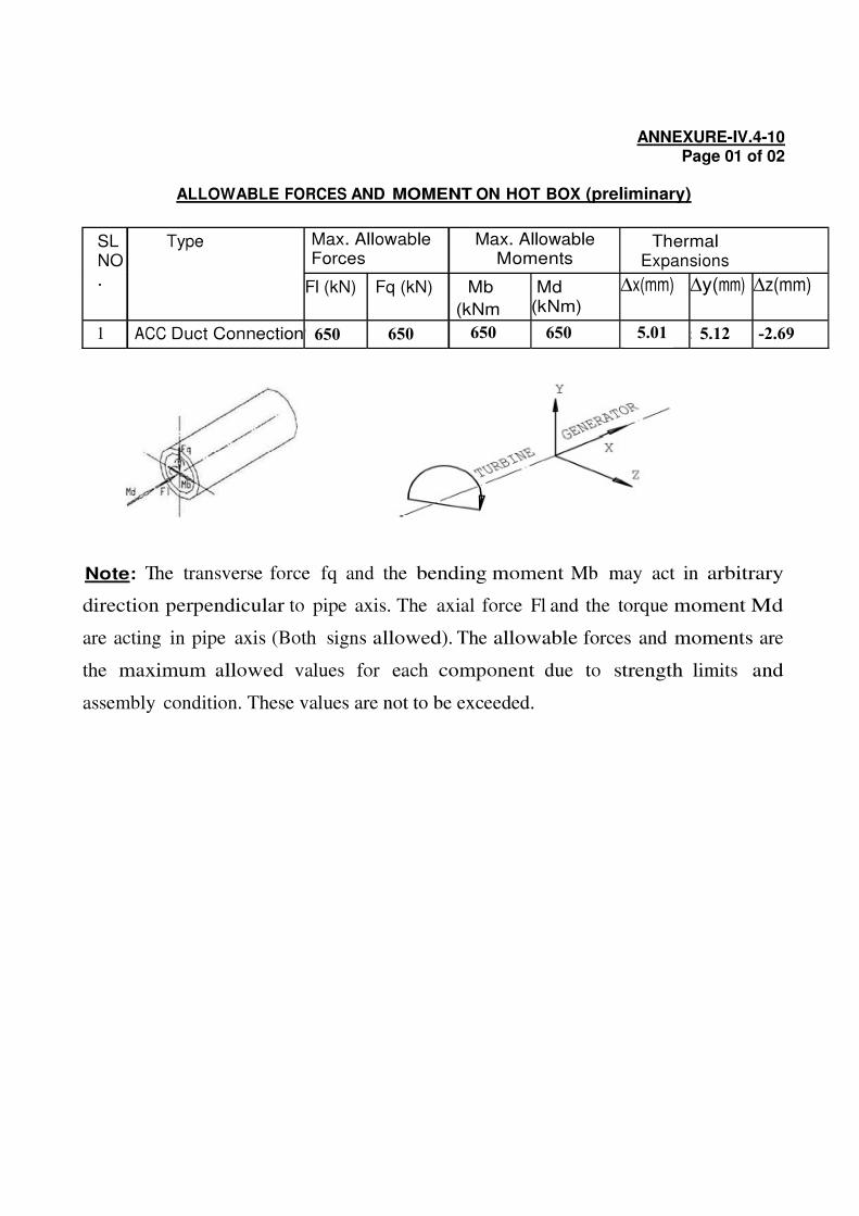
650 650 650 650 5.01 5.12 -2.69
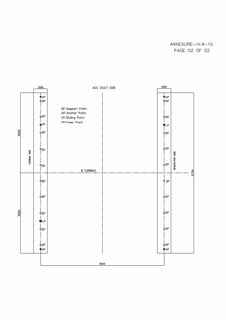
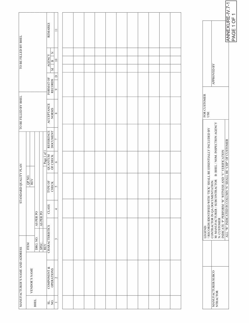
MA
NU
FA
CT
UR
ER
’S N
AM
E A
ND
AD
DR
ES
SS
TA
ND
AR
D Q
UA
LIT
Y P
LA
NT
O B
E F
ILL
ED
BY
BH
EL
TO
BE
FIL
LE
D B
Y B
HE
L
BH
EL
VE
ND
OR
’S N
AM
EIT
EM
QP
NO
.
RE
V
DR
G.
NO
.A
S P
ER
PO
SP
EC
.A
S P
ER
PO
RE
VP
age
1of
1
SL
.
NO
.
CO
MP
ON
EN
T &
OP
ER
AT
ION
S
CH
AR
AC
TE
RIS
TIC
SC
LA
SS
TY
PE
OF
CH
EC
K
QU
AN
TU
M
OF
CH
EC
K
RE
FE
RE
NC
E
DO
CU
ME
NT
AC
CE
PT
AN
CE
NO
RM
S
FO
RM
AT
OF
RE
CO
RD
S
AG
EN
CY
RE
MA
RK
S
MB
N
12
34
56
78
9D
10
11
LE
GE
ND
:
! R
EC
OR
DS
ID
EN
TIF
IED
WIT
H ‘
TIC
K’
SH
AL
L B
E E
SS
EN
TIA
LL
Y I
NC
LU
DE
D B
Y
CO
NT
RA
CT
OR
IN
QA
DO
CU
ME
NT
AT
ION
.
M:
MA
NU
FA
CT
UR
ER
/ S
UB
CO
NT
RA
CT
OR
B:
BH
EL
/ N
OM
. IN
SP
EC
TIO
N A
GE
NC
Y
N:
CU
ST
OM
ER
IND
ICA
TE
‘P
’ P
ER
FO
RM
‘W
’ W
ITN
ES
S A
ND
‘V
’ V
ER
IFIC
AT
ION
AL
L ‘
W’
IND
ICA
TE
D I
N C
OL
UM
N ‘
N’
SH
AL
L B
E ‘
CH
P’
OF
CU
ST
OM
ER
FO
R C
US
TO
ME
R
US
E
MA
NU
FA
CT
UR
ER
/SU
BC
O
NT
RA
CT
OR
AP
PR
OV
ED
BY
ANNEXURE-IV.7-1
PAGE1OF1
FIELD QUALITY PLAN
FOR
STRUCTURAL WORKS
BHARAT HEAVY ELECTRICALS LIMITED
TABLE OF CONTENTS
QP NO.:
REV No.: 00
DATE:
PAGE: 01 OF 01
S. No. Description No. of Pages
1.0 Documents referred in FQP 01
2.0 Authorization for checks and nonconformity disposition 01
3.0 Field Quality Checks for Erection 09
4.0 Log Sheets (L-00) 00
* * * * * *
DOCUMENTS REFERRED IN
FIEDL QUALITY PLAN
QP NO.:
REV No.: 00
DATE:
PAGE: 01 OF 01
S. NO. Reference Document
1. WELDING MANUAL
2. HEAT TREATMENT MANUAL
3. NDE MANUAL
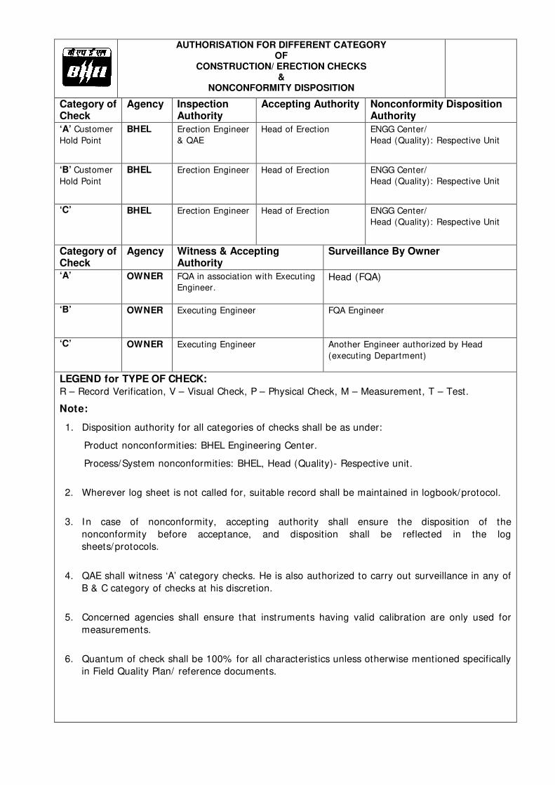
AUTHORISATION FOR DIFFERENT CATEGORY OF
CONSTRUCTION/ ERECTION CHECKS &
NONCONFORMITY DISPOSITION
Category of Check
Agency Inspection Authority
Accepting Authority Nonconformity Disposition Authority
‘A’ Customer
Hold Point
BHEL Erection Engineer
& QAE
Head of Erection ENGG Center/
Head (Quality): Respective Unit
‘B’ Customer
Hold Point
BHEL Erection Engineer Head of Erection ENGG Center/
Head (Quality): Respective Unit
‘C’ BHEL Erection Engineer Head of Erection ENGG Center/
Head (Quality): Respective Unit
Category of Check
Agency Witness & Accepting Authority
Surveillance By Owner
‘A’ OWNER FQA in association with Executing
Engineer. Head (FQA)
‘B’ OWNER Executing Engineer FQA Engineer
‘C’ OWNER Executing Engineer Another Engineer authorized by Head
(executing Department)
LEGEND for TYPE OF CHECK:
R – Record Verification, V – Visual Check, P – Physical Check, M – Measurement, T – Test.
Note:
1. Disposition authority for all categories of checks shall be as under:
Product nonconformities: BHEL Engineering Center.
Process/System nonconformities: BHEL, Head (Quality)- Respective unit.
2. Wherever log sheet is not called for, suitable record shall be maintained in logbook/protocol.
3. In case of nonconformity, accepting authority shall ensure the disposition of the
nonconformity before acceptance, and disposition shall be reflected in the log
sheets/protocols.
4. QAE shall witness ‘A’ category checks. He is also authorized to carry out surveillance in any of
B & C category of checks at his discretion.
5. Concerned agencies shall ensure that instruments having valid calibration are only used for
measurements.
6. Quantum of check shall be 100% for all characteristics unless otherwise mentioned specifically
in Field Quality Plan/ reference documents.

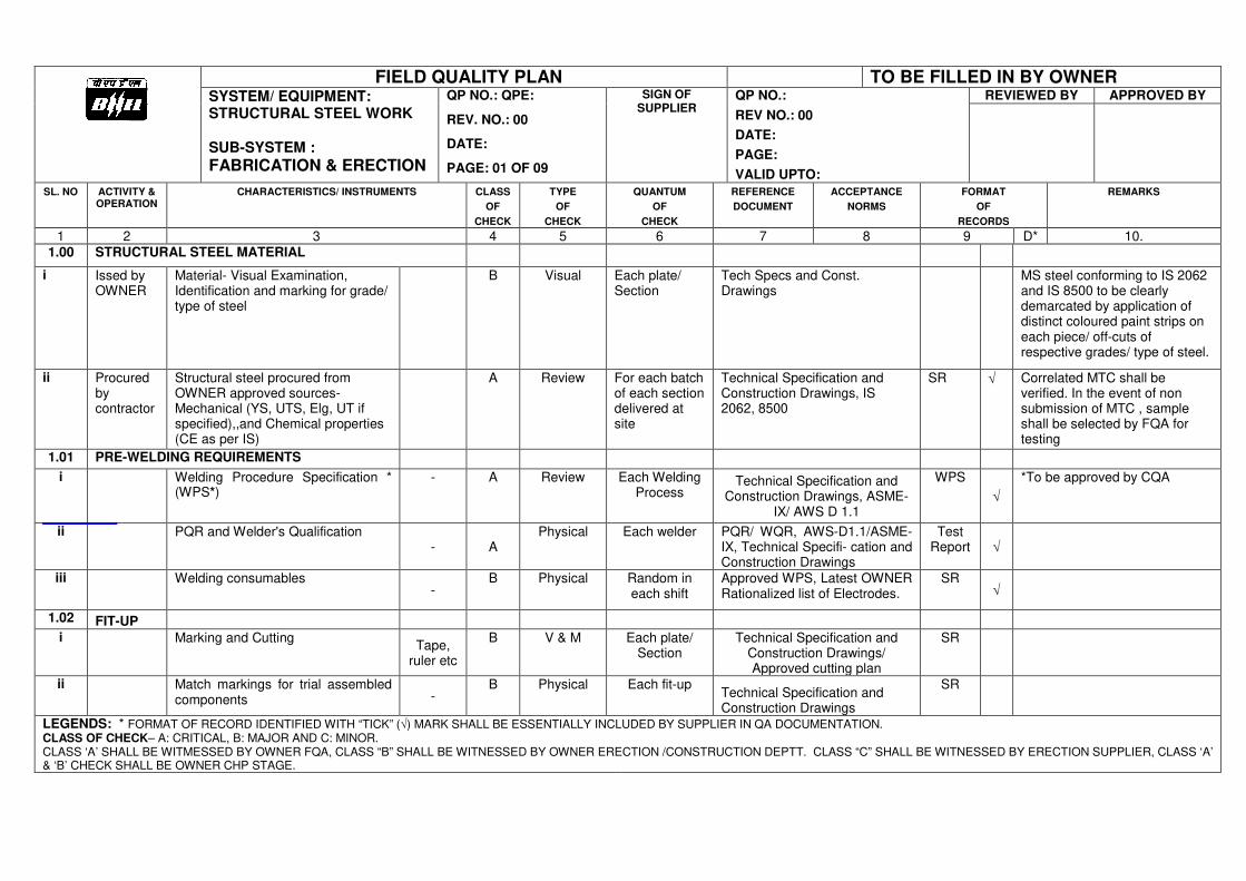
FIELD QUALITY PLAN TO BE FILLED IN BY OWNER SYSTEM/ EQUIPMENT: STRUCTURAL STEEL WORK SUB-SYSTEM :
FABRICATION & ERECTION
QP NO.: QPE:
REV. NO.: 00
DATE:
PAGE: 01 OF 09
SIGN OF SUPPLIER
QP NO.:
REV NO.: 00
DATE:
PAGE:
VALID UPTO:
REVIEWED BY APPROVED BY
SL. NO ACTIVITY & OPERATION
CHARACTERISTICS/ INSTRUMENTS CLASS
OF
CHECK
TYPE
OF
CHECK
QUANTUM
OF
CHECK
REFERENCE
DOCUMENT
ACCEPTANCE
NORMS
FORMAT
OF
RECORDS
REMARKS
1 2 3 4 5 6 7 8 9 D* 10. 1.00 STRUCTURAL STEEL MATERIAL
i Issed by OWNER
Material- Visual Examination, Identification and marking for grade/ type of steel
B Visual Each plate/ Section
Tech Specs and Const. Drawings
MS steel conforming to IS 2062 and IS 8500 to be clearly demarcated by application of distinct coloured paint strips on each piece/ off-cuts of respective grades/ type of steel.
ii Procured by contractor
Structural steel procured from OWNER approved sources- Mechanical (YS, UTS, Elg, UT if specified),,and Chemical properties (CE as per IS)
A Review For each batch of each section delivered at site
Technical Specification and Construction Drawings, IS 2062, 8500
SR √ Correlated MTC shall be verified. In the event of non submission of MTC , sample shall be selected by FQA for testing
1.01 PRE-WELDING REQUIREMENTS
i Welding Procedure Specification * (WPS*)
- A Review Each Welding Process
Technical Specification and Construction Drawings, ASME-
IX/ AWS D 1.1
WPS
√ *To be approved by CQA
ii PQR and Welder's Qualification - A
Physical Each welder PQR/ WQR, AWS-D1.1/ASME-IX, Technical Specifi- cation and Construction Drawings
Test Report √
iii Welding consumables -
B Physical Random in each shift
Approved WPS, Latest OWNER Rationalized list of Electrodes.
SR √
1.02 FIT-UP
i Marking and Cutting Tape,
ruler etc
B V & M Each plate/ Section
Technical Specification and Construction Drawings/ Approved cutting plan
SR
ii Match markings for trial assembled components -
B Physical Each fit-up Technical Specification and Construction Drawings
SR
LEGENDS: * FORMAT OF RECORD IDENTIFIED WITH “TICK” (√) MARK SHALL BE ESSENTIALLY INCLUDED BY SUPPLIER IN QA DOCUMENTATION. CLASS OF CHECK– A: CRITICAL, B: MAJOR AND C: MINOR. CLASS ‘A’ SHALL BE WITMESSED BY OWNER FQA, CLASS “B” SHALL BE WITNESSED BY OWNER ERECTION /CONSTRUCTION DEPTT. CLASS “C” SHALL BE WITNESSED BY ERECTION SUPPLIER, CLASS ‘A’ & ‘B’ CHECK SHALL BE OWNER CHP STAGE.
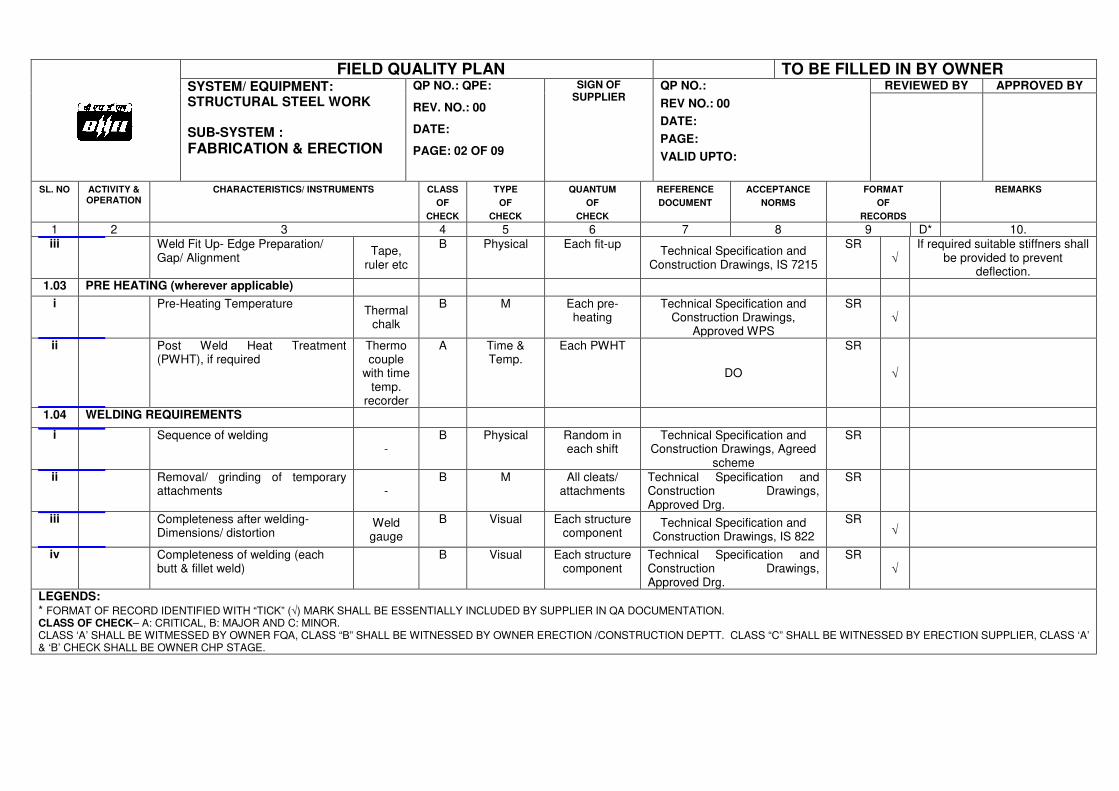
FIELD QUALITY PLAN TO BE FILLED IN BY OWNER SYSTEM/ EQUIPMENT: STRUCTURAL STEEL WORK SUB-SYSTEM :
FABRICATION & ERECTION
QP NO.: QPE:
REV. NO.: 00
DATE:
PAGE: 02 OF 09
SIGN OF SUPPLIER
QP NO.:
REV NO.: 00
DATE:
PAGE:
VALID UPTO:
REVIEWED BY APPROVED BY
SL. NO ACTIVITY & OPERATION
CHARACTERISTICS/ INSTRUMENTS CLASS
OF
CHECK
TYPE
OF
CHECK
QUANTUM
OF
CHECK
REFERENCE
DOCUMENT
ACCEPTANCE
NORMS
FORMAT
OF
RECORDS
REMARKS
1 2 3 4 5 6 7 8 9 D* 10. iii Weld Fit Up- Edge Preparation/
Gap/ Alignment Tape,
ruler etc
B Physical Each fit-up Technical Specification and
Construction Drawings, IS 7215
SR √
If required suitable stiffners shall be provided to prevent
deflection. 1.03 PRE HEATING (wherever applicable)
i Pre-Heating Temperature Thermal
chalk
B M Each pre-heating
Technical Specification and Construction Drawings,
Approved WPS
SR √
ii Post Weld Heat Treatment (PWHT), if required
Thermo couple
with time temp.
recorder
A Time & Temp.
Each PWHT
DO
SR
√
1.04 WELDING REQUIREMENTS
i Sequence of welding -
B Physical Random in each shift
Technical Specification and Construction Drawings, Agreed
scheme
SR
ii Removal/ grinding of temporary attachments -
B M All cleats/ attachments
Technical Specification and Construction Drawings, Approved Drg.
SR
iii Completeness after welding- Dimensions/ distortion
Weld gauge
B Visual Each structure component
Technical Specification and Construction Drawings, IS 822
SR √
iv Completeness of welding (each butt & fillet weld)
B Visual Each structure component
Technical Specification and Construction Drawings, Approved Drg.
SR √
LEGENDS: * FORMAT OF RECORD IDENTIFIED WITH “TICK” (√) MARK SHALL BE ESSENTIALLY INCLUDED BY SUPPLIER IN QA DOCUMENTATION. CLASS OF CHECK– A: CRITICAL, B: MAJOR AND C: MINOR. CLASS ‘A’ SHALL BE WITMESSED BY OWNER FQA, CLASS “B” SHALL BE WITNESSED BY OWNER ERECTION /CONSTRUCTION DEPTT. CLASS “C” SHALL BE WITNESSED BY ERECTION SUPPLIER, CLASS ‘A’ & ‘B’ CHECK SHALL BE OWNER CHP STAGE.
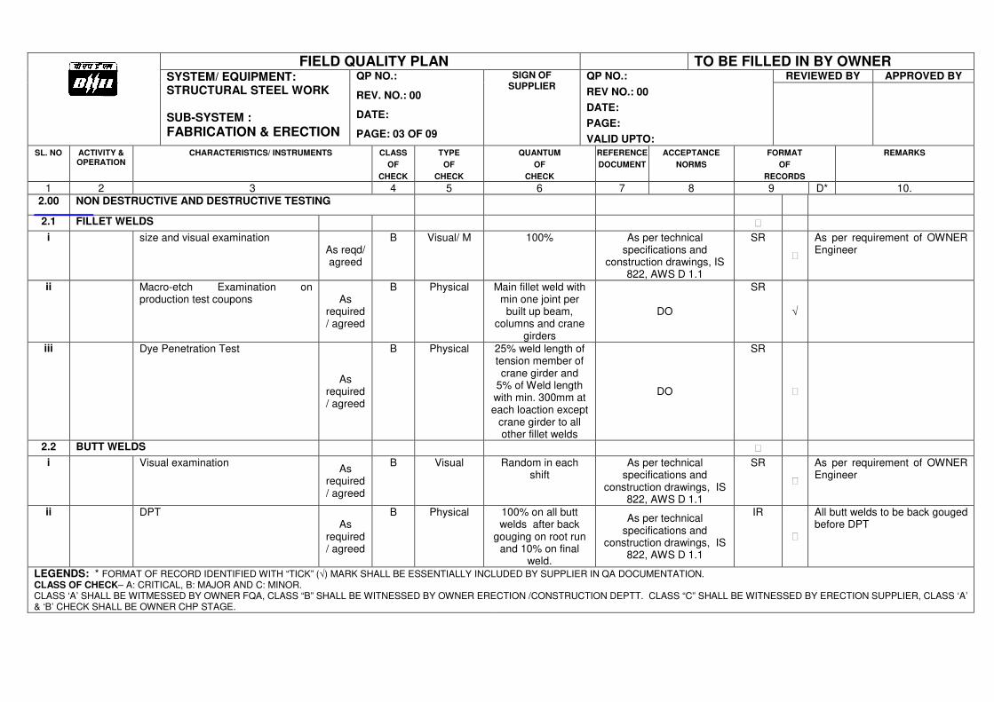
FIELD QUALITY PLAN TO BE FILLED IN BY OWNER SYSTEM/ EQUIPMENT: STRUCTURAL STEEL WORK SUB-SYSTEM :
FABRICATION & ERECTION
QP NO.:
REV. NO.: 00
DATE:
PAGE: 03 OF 09
SIGN OF SUPPLIER
QP NO.:
REV NO.: 00
DATE:
PAGE:
VALID UPTO:
REVIEWED BY APPROVED BY
SL. NO ACTIVITY & OPERATION
CHARACTERISTICS/ INSTRUMENTS CLASS
OF
CHECK
TYPE
OF
CHECK
QUANTUM
OF
CHECK
REFERENCE
DOCUMENT
ACCEPTANCE
NORMS
FORMAT
OF
RECORDS
REMARKS
1 2 3 4 5 6 7 8 9 D* 10. 2.00 NON DESTRUCTIVE AND DESTRUCTIVE TESTING
2.1 FILLET WELDS
i size and visual examination As reqd/ agreed
B Visual/ M 100% As per technical specifications and
construction drawings, IS 822, AWS D 1.1
SR
As per requirement of OWNER Engineer
ii Macro-etch Examination on production test coupons As
required/ agreed
B Physical Main fillet weld with min one joint per built up beam,
columns and crane girders
DO
SR
√
iii Dye Penetration Test
As required/ agreed
B Physical 25% weld length of tension member of crane girder and
5% of Weld length with min. 300mm at each loaction except
crane girder to all other fillet welds
DO
SR
2.2 BUTT WELDS
i Visual examination As
required/ agreed
B Visual Random in each shift
As per technical specifications and
construction drawings, IS 822, AWS D 1.1
SR
As per requirement of OWNER Engineer
ii DPT As
required/ agreed
B Physical 100% on all butt welds after back
gouging on root run and 10% on final
weld.
As per technical specifications and
construction drawings, IS 822, AWS D 1.1
IR
All butt welds to be back gouged before DPT
LEGENDS: * FORMAT OF RECORD IDENTIFIED WITH “TICK” (√) MARK SHALL BE ESSENTIALLY INCLUDED BY SUPPLIER IN QA DOCUMENTATION. CLASS OF CHECK– A: CRITICAL, B: MAJOR AND C: MINOR. CLASS ‘A’ SHALL BE WITMESSED BY OWNER FQA, CLASS “B” SHALL BE WITNESSED BY OWNER ERECTION /CONSTRUCTION DEPTT. CLASS “C” SHALL BE WITNESSED BY ERECTION SUPPLIER, CLASS ‘A’ & ‘B’ CHECK SHALL BE OWNER CHP STAGE.
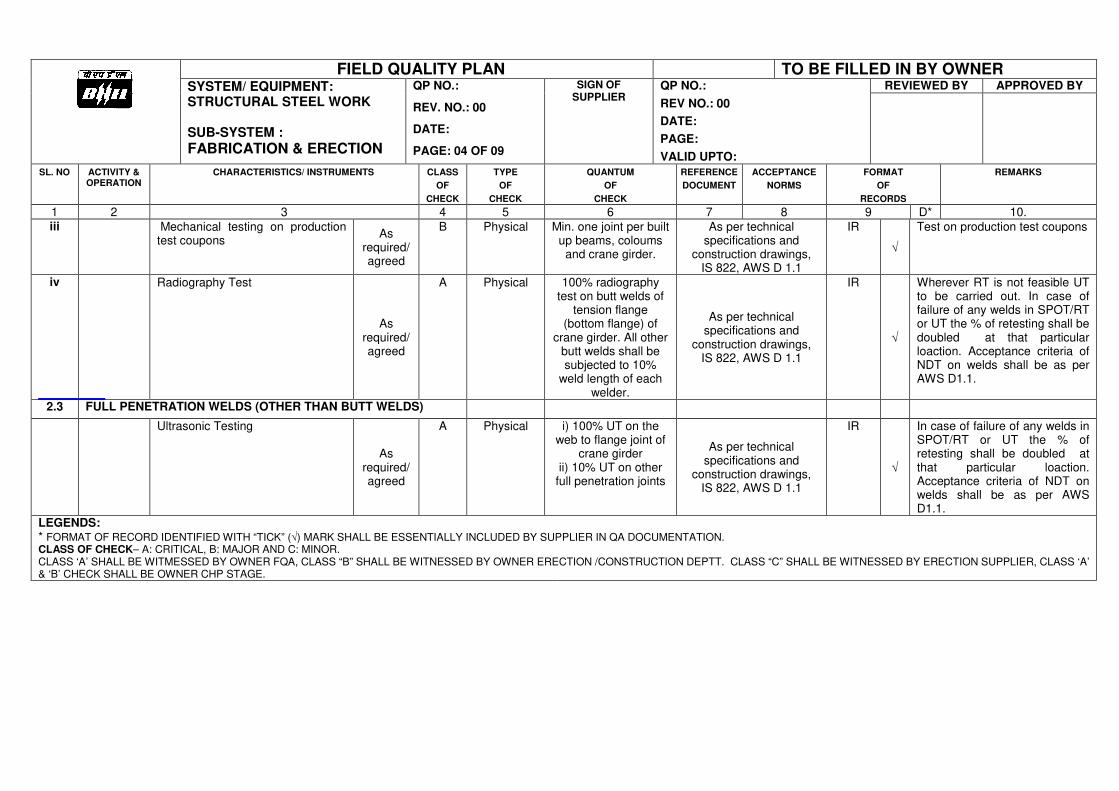
FIELD QUALITY PLAN TO BE FILLED IN BY OWNER SYSTEM/ EQUIPMENT: STRUCTURAL STEEL WORK SUB-SYSTEM :
FABRICATION & ERECTION
QP NO.:
REV. NO.: 00
DATE:
PAGE: 04 OF 09
SIGN OF SUPPLIER
QP NO.:
REV NO.: 00
DATE:
PAGE:
VALID UPTO:
REVIEWED BY APPROVED BY
SL. NO ACTIVITY & OPERATION
CHARACTERISTICS/ INSTRUMENTS CLASS
OF
CHECK
TYPE
OF
CHECK
QUANTUM
OF
CHECK
REFERENCE
DOCUMENT
ACCEPTANCE
NORMS
FORMAT
OF
RECORDS
REMARKS
1 2 3 4 5 6 7 8 9 D* 10. iii Mechanical testing on production
test coupons As
required/ agreed
B Physical Min. one joint per built up beams, coloums
and crane girder.
As per technical specifications and
construction drawings, IS 822, AWS D 1.1
IR
√
Test on production test coupons
iv Radiography Test
As required/ agreed
A Physical 100% radiography test on butt welds of
tension flange (bottom flange) of
crane girder. All other butt welds shall be subjected to 10%
weld length of each welder.
As per technical specifications and
construction drawings, IS 822, AWS D 1.1
IR
√
Wherever RT is not feasible UT to be carried out. In case of failure of any welds in SPOT/RT or UT the % of retesting shall be doubled at that particular loaction. Acceptance criteria of NDT on welds shall be as per AWS D1.1.
2.3 FULL PENETRATION WELDS (OTHER THAN BUTT WELDS)
Ultrasonic Testing
As required/ agreed
A Physical i) 100% UT on the web to flange joint of
crane girder ii) 10% UT on other
full penetration joints
As per technical specifications and
construction drawings, IS 822, AWS D 1.1
IR
√
In case of failure of any welds in SPOT/RT or UT the % of retesting shall be doubled at that particular loaction. Acceptance criteria of NDT on welds shall be as per AWS D1.1.
LEGENDS: * FORMAT OF RECORD IDENTIFIED WITH “TICK” (√) MARK SHALL BE ESSENTIALLY INCLUDED BY SUPPLIER IN QA DOCUMENTATION. CLASS OF CHECK– A: CRITICAL, B: MAJOR AND C: MINOR. CLASS ‘A’ SHALL BE WITMESSED BY OWNER FQA, CLASS “B” SHALL BE WITNESSED BY OWNER ERECTION /CONSTRUCTION DEPTT. CLASS “C” SHALL BE WITNESSED BY ERECTION SUPPLIER, CLASS ‘A’ & ‘B’ CHECK SHALL BE OWNER CHP STAGE.
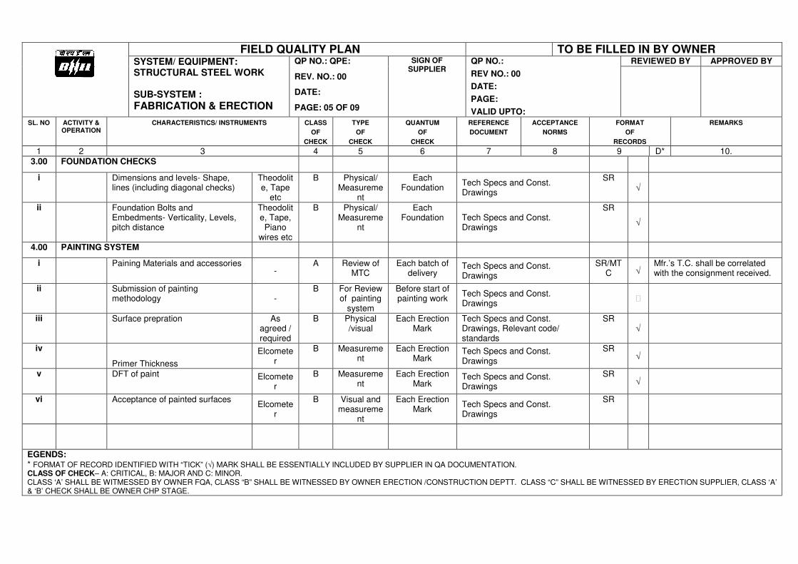
FIELD QUALITY PLAN TO BE FILLED IN BY OWNER SYSTEM/ EQUIPMENT: STRUCTURAL STEEL WORK SUB-SYSTEM :
FABRICATION & ERECTION
QP NO.: QPE:
REV. NO.: 00
DATE:
PAGE: 05 OF 09
SIGN OF SUPPLIER
QP NO.:
REV NO.: 00
DATE:
PAGE:
VALID UPTO:
REVIEWED BY APPROVED BY
SL. NO ACTIVITY & OPERATION
CHARACTERISTICS/ INSTRUMENTS CLASS
OF
CHECK
TYPE
OF
CHECK
QUANTUM
OF
CHECK
REFERENCE
DOCUMENT
ACCEPTANCE
NORMS
FORMAT
OF
RECORDS
REMARKS
1 2 3 4 5 6 7 8 9 D* 10. 3.00 FOUNDATION CHECKS
i Dimensions and levels- Shape, lines (including diagonal checks)
Theodolite, Tape
etc
B Physical/ Measureme
nt
Each Foundation
Tech Specs and Const. Drawings
SR √
ii Foundation Bolts and Embedments- Verticality, Levels, pitch distance
Theodolite, Tape, Piano
wires etc
B Physical/ Measureme
nt
Each Foundation Tech Specs and Const.
Drawings
SR
√
4.00 PAINTING SYSTEM
i Paining Materials and accessories -
A Review of MTC
Each batch of delivery
Tech Specs and Const. Drawings
SR/MTC √
Mfr.’s T.C. shall be correlated with the consignment received.
ii Submission of painting methodology -
B For Review of painting
system
Before start of painting work
Tech Specs and Const. Drawings
iii Surface prepration As agreed / required
B Physical /visual
Each Erection Mark
Tech Specs and Const. Drawings, Relevant code/ standards
SR √
iv
Primer Thickness
Elcometer
B Measurement
Each Erection Mark
Tech Specs and Const. Drawings
SR √
v DFT of paint Elcomete
r
B Measurement
Each Erection Mark
Tech Specs and Const. Drawings
SR √
vi Acceptance of painted surfaces Elcomete
r
B Visual and measureme
nt
Each Erection Mark
Tech Specs and Const. Drawings
SR
EGENDS: * FORMAT OF RECORD IDENTIFIED WITH “TICK” (√) MARK SHALL BE ESSENTIALLY INCLUDED BY SUPPLIER IN QA DOCUMENTATION. CLASS OF CHECK– A: CRITICAL, B: MAJOR AND C: MINOR. CLASS ‘A’ SHALL BE WITMESSED BY OWNER FQA, CLASS “B” SHALL BE WITNESSED BY OWNER ERECTION /CONSTRUCTION DEPTT. CLASS “C” SHALL BE WITNESSED BY ERECTION SUPPLIER, CLASS ‘A’ & ‘B’ CHECK SHALL BE OWNER CHP STAGE.
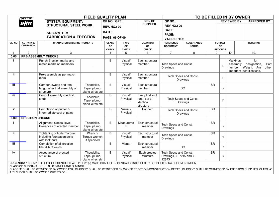
FIELD QUALITY PLAN TO BE FILLED IN BY OWNER SYSTEM/ EQUIPMENT: STRUCTURAL STEEL WORK SUB-SYSTEM :
FABRICATION & ERECTION
QP NO.: QPE:
REV. NO.: 00
DATE:
PAGE: 06 OF 09
SIGN OF SUPPLIER
QP NO.:
REV NO.: 00
DATE:
PAGE:
VALID UPTO:
REVIEWED BY APPROVED BY
SL. NO ACTIVITY & OPERATION
CHARACTERISTICS/ INSTRUMENTS CLASS
OF
CHECK
TYPE
OF
CHECK
QUANTUM
OF
CHECK
REFERENCE
DOCUMENT
ACCEPTANCE
NORMS
FORMAT
OF
RECORDS
REMARKS
1 2 3 4 5 6 7 8 9 D* 10. 5.00 PRE-ASSEMBLY CHECKS
i Punch Erection marks and match marks on members
-
B Visual/ Physical
Each structural member Tech Specs and Const.
Drawings
Markings for - Assembly designation, Part number, Weight, Any other important identifications.
ii Pre-assembly as per match mark -
B Visual/ Physical
Each structural member
Tech Specs and Const. Drawings
iii Camber, sweep and total length after trial assembly of structure.
Theodolite, Tape, plumb,
piano wires etc
B Visual/ Physical
Each structural member
DO
SR √
iv Control assembly check at shop
Theodolite, Tape, plumb,
piano wires etc
B Visual/ Physical
Every first and tenth set of identical structure
Tech Specs and Const. Drawings
V Completion of primer & intermediate coat of paint
B Visual / Physical
Random Tech Specs and Const. Drawings
SR
6.00 ERECTION CHECKS
i Alignment, slopes, level, tolerances of erected member
Theodolite, Tape, plumb,
piano wires etc
B Measurement
Each structural member
Tech Specs and Const. Drawings
SR √
ii Tightening of bolts/ Torque including foundation bolts with lock nuts
Wrench/ Torque wrench
if specified
B Visual/ Physical
Each structural member
Tech Specs and Const. Drawings
SR √
iii Completion of all erection fillet & butt welds
B Visual Each structural member
DO
SR √
iv Acceptance of erected structure
Theodolite, Tape, plumb,
piano wires etc
B Visual/ Physical
Each erected structure
Tech Specs and Const. Drawings, IS 7215 and IS 12843
SR √
LEGENDS: * FORMAT OF RECORD IDENTIFIED WITH “TICK” (√) MARK SHALL BE ESSENTIALLY INCLUDED BY SUPPLIER IN QA DOCUMENTATION. CLASS OF CHECK– A: CRITICAL, B: MAJOR AND C: MINOR. CLASS ‘A’ SHALL BE WITMESSED BY OWNER FQA, CLASS “B” SHALL BE WITNESSED BY OWNER ERECTION /CONSTRUCTION DEPTT. CLASS “C” SHALL BE WITNESSED BY ERECTION SUPPLIER, CLASS ‘A’ & ‘B’ CHECK SHALL BE OWNER CHP STAGE.
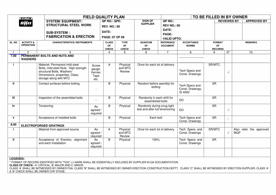
FIELD QUALITY PLAN TO BE FILLED IN BY OWNER SYSTEM/ EQUIPMENT: STRUCTURAL STEEL WORK SUB-SYSTEM :
FABRICATION & ERECTION
QP NO.: QPE:
REV. NO.: 00
DATE:
PAGE: 07 OF 09
SIGN OF SUPPLIER
QP NO.:
REV NO.: 00
DATE:
PAGE:
VALID UPTO:
REVIEWED BY APPROVED BY
SL. NO ACTIVITY & OPERATION
CHARACTERISTICS/ INSTRUMENTS CLASS
OF
CHECK
TYPE
OF
CHECK
QUANTUM
OF
CHECK
REFERENCE
DOCUMENT
ACCEPTANCE
NORMS
FORMAT
OF
RECORDS
REMARKS
1 2 3 4 5 6 7 8 9 D* 10. 7.00 PERMANENT BOLTS AND NUTS AND
WASHERS
i Material- Permanent mild steel Bolts, mild steel Nuts, High strength structural Bolts, Washers-Dimensions, properties, Class, storage along with MTC
Screw gauge, Vernier,
Tape etc.
A Physical and MTC Review
Once for each lot of delivery
Tech Specs and Const. Drawings
SR/MTC
√
ii Contact surfaces before bolting
-
B Physical Random before asembly for bolting
Tech Specs and Const. Drawings, IS 4000
SR
iii Inspection of the assembled bolts -
B Physical Randomly in each shift for assembeled bolts DO
SR
iv Tensioning As agreed / required
B Physical Randomly during snug tight test and after full tensinoning DO
SR
√
v Acceptance of installed bolts -
B Physical Each bolt Tech Specs and Const. Drawings
SR
8.00 ELECTROFORGED GRATINGS
i
Material from approved source As agreed / required
A Physical and MTC Review
Once for each lot of delivery Tech Specs and Const. Drawings
SR/MTC √
Also refer the approved MQP
ii Acceptance of Erection, alignment and each Installation
As agreed / required
B Physical 100% Tech Specs and Const. Drawings
SR
LEGENDS: * FORMAT OF RECORD IDENTIFIED WITH “TICK” (√) MARK SHALL BE ESSENTIALLY INCLUDED BY SUPPLIER IN QA DOCUMENTATION. CLASS OF CHECK– A: CRITICAL, B: MAJOR AND C: MINOR. CLASS ‘A’ SHALL BE WITMESSED BY OWNER FQA, CLASS “B” SHALL BE WITNESSED BY OWNER ERECTION /CONSTRUCTION DEPTT. CLASS “C” SHALL BE WITNESSED BY ERECTION SUPPLIER, CLASS ‘A’ & ‘B’ CHECK SHALL BE OWNER CHP STAGE.
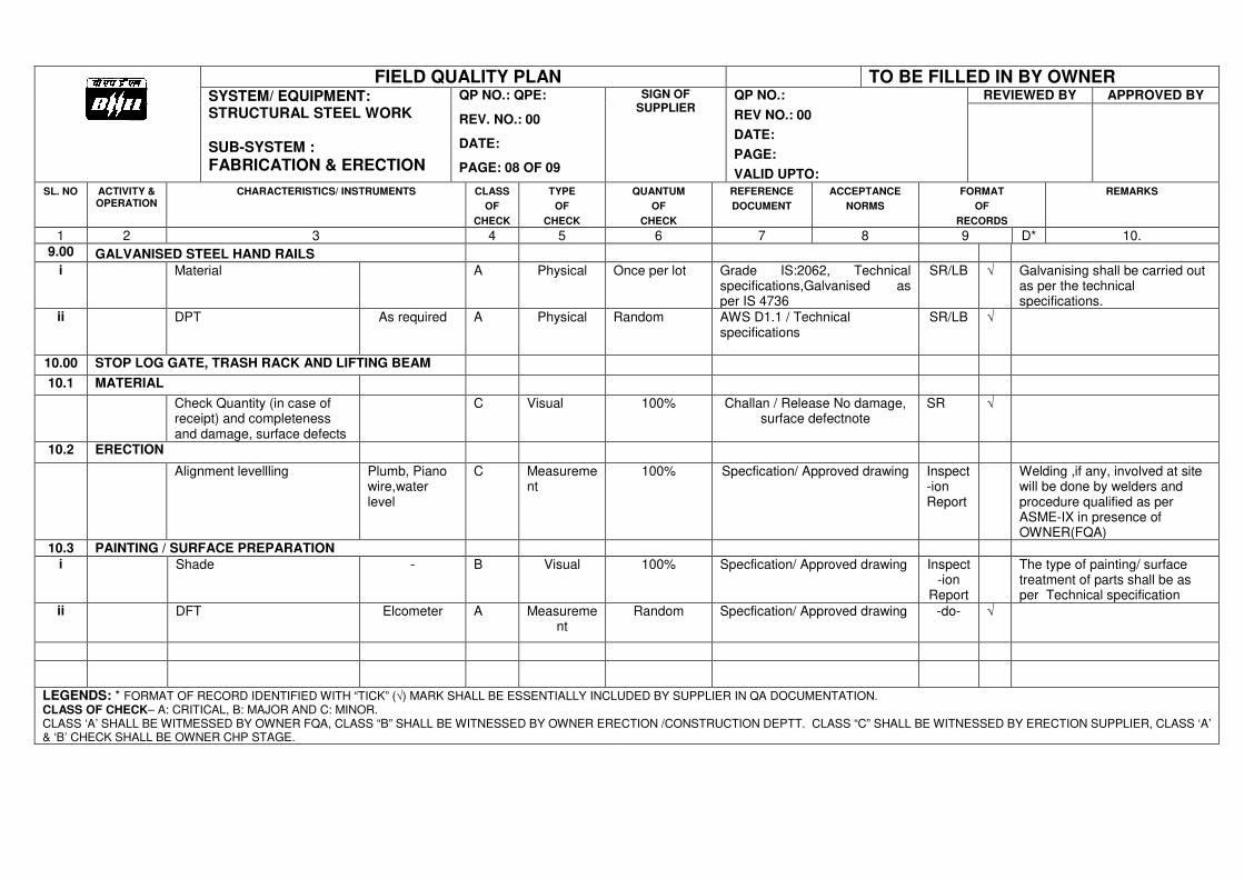
FIELD QUALITY PLAN TO BE FILLED IN BY OWNER SYSTEM/ EQUIPMENT: STRUCTURAL STEEL WORK SUB-SYSTEM :
FABRICATION & ERECTION
QP NO.: QPE:
REV. NO.: 00
DATE:
PAGE: 08 OF 09
SIGN OF SUPPLIER
QP NO.:
REV NO.: 00
DATE:
PAGE:
VALID UPTO:
REVIEWED BY APPROVED BY
SL. NO ACTIVITY & OPERATION
CHARACTERISTICS/ INSTRUMENTS CLASS
OF
CHECK
TYPE
OF
CHECK
QUANTUM
OF
CHECK
REFERENCE
DOCUMENT
ACCEPTANCE
NORMS
FORMAT
OF
RECORDS
REMARKS
1 2 3 4 5 6 7 8 9 D* 10. 9.00 GALVANISED STEEL HAND RAILS
i Material A Physical Once per lot Grade IS:2062, Technical specifications,Galvanised as per IS 4736
SR/LB √ Galvanising shall be carried out as per the technical specifications.
ii DPT As required A Physical Random AWS D1.1 / Technical specifications
SR/LB √
10.00 STOP LOG GATE, TRASH RACK AND LIFTING BEAM
10.1 MATERIAL
Check Quantity (in case of receipt) and completeness and damage, surface defects
C Visual 100% Challan / Release No damage, surface defectnote
SR √
10.2 ERECTION
Alignment levellling Plumb, Piano wire,water level
C Measurement
100% Specfication/ Approved drawing Inspect-ion Report
Welding ,if any, involved at site will be done by welders and procedure qualified as per ASME-IX in presence of OWNER(FQA)
10.3 PAINTING / SURFACE PREPARATION i
Shade - B Visual 100% Specfication/ Approved drawing Inspect-ion
Report
The type of painting/ surface treatment of parts shall be as per Technical specification
ii
DFT Elcometer A Measurement
Random Specfication/ Approved drawing -do- √
LEGENDS: * FORMAT OF RECORD IDENTIFIED WITH “TICK” (√) MARK SHALL BE ESSENTIALLY INCLUDED BY SUPPLIER IN QA DOCUMENTATION. CLASS OF CHECK– A: CRITICAL, B: MAJOR AND C: MINOR. CLASS ‘A’ SHALL BE WITMESSED BY OWNER FQA, CLASS “B” SHALL BE WITNESSED BY OWNER ERECTION /CONSTRUCTION DEPTT. CLASS “C” SHALL BE WITNESSED BY ERECTION SUPPLIER, CLASS ‘A’ & ‘B’ CHECK SHALL BE OWNER CHP STAGE.
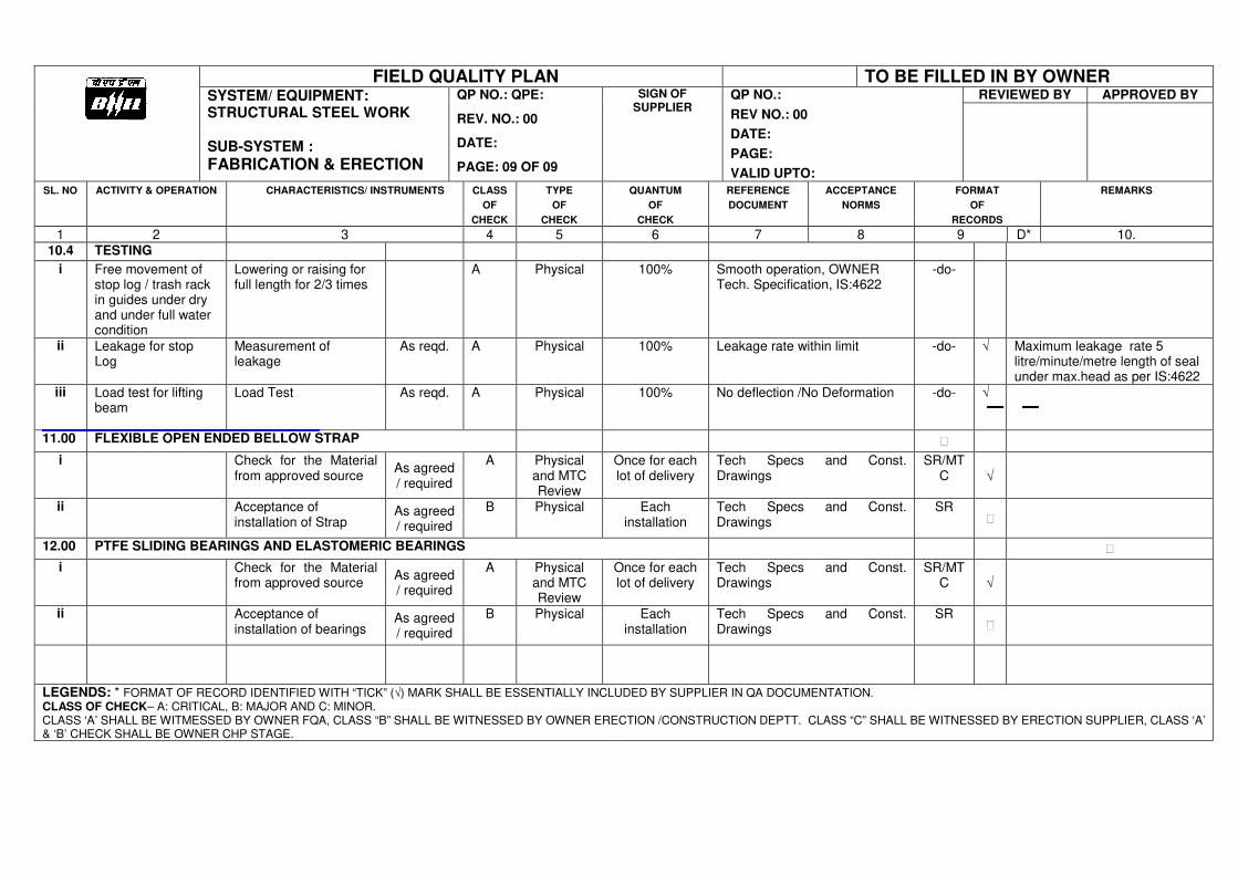
FIELD QUALITY PLAN TO BE FILLED IN BY OWNER SYSTEM/ EQUIPMENT: STRUCTURAL STEEL WORK SUB-SYSTEM :
FABRICATION & ERECTION
QP NO.: QPE:
REV. NO.: 00
DATE:
PAGE: 09 OF 09
SIGN OF SUPPLIER
QP NO.:
REV NO.: 00
DATE:
PAGE:
VALID UPTO:
REVIEWED BY APPROVED BY
SL. NO ACTIVITY & OPERATION CHARACTERISTICS/ INSTRUMENTS CLASS
OF
CHECK
TYPE
OF
CHECK
QUANTUM
OF
CHECK
REFERENCE
DOCUMENT
ACCEPTANCE
NORMS
FORMAT
OF
RECORDS
REMARKS
1 2 3 4 5 6 7 8 9 D* 10. 10.4 TESTING
i Free movement of stop log / trash rack in guides under dry and under full water condition
Lowering or raising for full length for 2/3 times
A Physical 100% Smooth operation, OWNER Tech. Specification, IS:4622
-do-
ii Leakage for stop Log
Measurement of leakage
As reqd. A Physical 100% Leakage rate within limit -do- √ Maximum leakage rate 5 litre/minute/metre length of seal under max.head as per IS:4622
iii Load test for lifting beam
Load Test As reqd. A Physical 100% No deflection /No Deformation -do- √
11.00 FLEXIBLE OPEN ENDED BELLOW STRAP
i Check for the Material from approved source
As agreed / required
A Physical and MTC Review
Once for each lot of delivery
Tech Specs and Const. Drawings
SR/MTC √
ii Acceptance of installation of Strap
As agreed / required
B Physical Each installation
Tech Specs and Const. Drawings
SR
12.00 PTFE SLIDING BEARINGS AND ELASTOMERIC BEARINGS
i Check for the Material from approved source
As agreed / required
A Physical and MTC Review
Once for each lot of delivery
Tech Specs and Const. Drawings
SR/MTC √
ii Acceptance of installation of bearings
As agreed / required
B Physical Each installation
Tech Specs and Const. Drawings
SR
LEGENDS: * FORMAT OF RECORD IDENTIFIED WITH “TICK” (√) MARK SHALL BE ESSENTIALLY INCLUDED BY SUPPLIER IN QA DOCUMENTATION. CLASS OF CHECK– A: CRITICAL, B: MAJOR AND C: MINOR. CLASS ‘A’ SHALL BE WITMESSED BY OWNER FQA, CLASS “B” SHALL BE WITNESSED BY OWNER ERECTION /CONSTRUCTION DEPTT. CLASS “C” SHALL BE WITNESSED BY ERECTION SUPPLIER, CLASS ‘A’ & ‘B’ CHECK SHALL BE OWNER CHP STAGE.
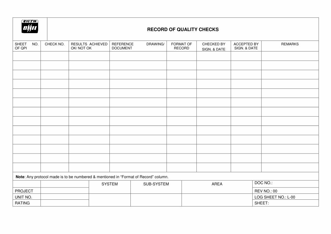
RECORD OF QUALITY CHECKS
SHEET NO. OF QPI
CHECK NO. RESULTS ACHIEVED OK/ NOT OK
REFERENCE DRAWING/ DOCUMENT
FORMAT OF RECORD
CHECKED BY
SIGN. & DATE
ACCEPTED BY SIGN. & DATE
REMARKS
Note: Any protocol made is to be numbered & mentioned in “Format of Record” column.
SYSTEM SUB-SYSTEM AREA DOC NO.:
PROJECT REV NO.: 00
UNIT NO. LOG SHEET NO.: L-00
RATING SHEET:
Annexure-IV.7-3
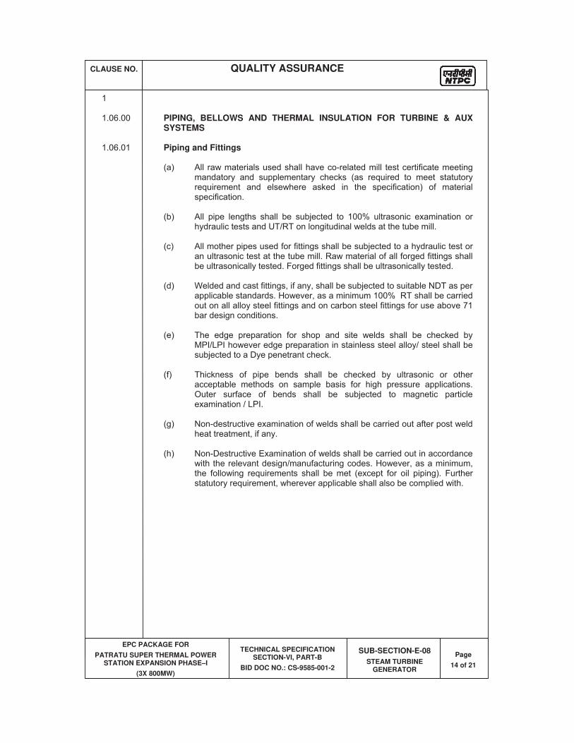
CLAUSE NO. QUALITY ASSURANCE
EPC PACKAGE FOR
PATRATU SUPER THERMAL POWER STATION EXPANSION PHASE–I
(3X 800MW)
TECHNICAL SPECIFICATION SECTION-VI, PART-B
BID DOC NO.: CS-9585-001-2
SUB-SECTION-E-08
STEAM TURBINE GENERATOR
Page
14 of 21
1 1.06.00 PIPING, BELLOWS AND THERMAL INSULATION FOR TURBINE & AUX
SYSTEMS 1.06.01 Piping and Fittings (a) All raw materials used shall have co-related mill test certificate meeting
mandatory and supplementary checks (as required to meet statutory requirement and elsewhere asked in the specification) of material specification.
(b) All pipe lengths shall be subjected to 100% ultrasonic examination or
hydraulic tests and UT/RT on longitudinal welds at the tube mill. (c) All mother pipes used for fittings shall be subjected to a hydraulic test or
an ultrasonic test at the tube mill. Raw material of all forged fittings shall be ultrasonically tested. Forged fittings shall be ultrasonically tested.
(d) Welded and cast fittings, if any, shall be subjected to suitable NDT as per
applicable standards. However, as a minimum 100% RT shall be carried out on all alloy steel fittings and on carbon steel fittings for use above 71 bar design conditions.
(e) The edge preparation for shop and site welds shall be checked by
MPI/LPI however edge preparation in stainless steel alloy/ steel shall be subjected to a Dye penetrant check.
(f) Thickness of pipe bends shall be checked by ultrasonic or other
acceptable methods on sample basis for high pressure applications. Outer surface of bends shall be subjected to magnetic particle examination / LPI.
(g) Non-destructive examination of welds shall be carried out after post weld
heat treatment, if any. (h) Non-Destructive Examination of welds shall be carried out in accordance
with the relevant design/manufacturing codes. However, as a minimum, the following requirements shall be met (except for oil piping). Further statutory requirement, wherever applicable shall also be complied with.
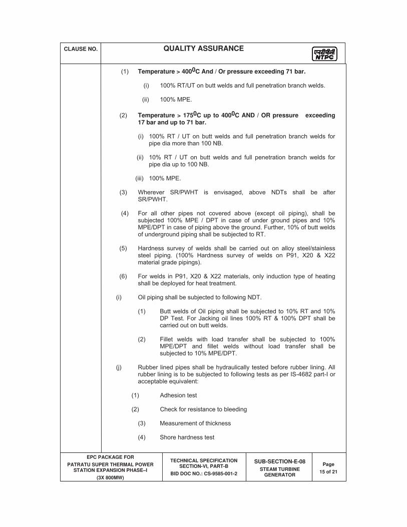
CLAUSE NO. QUALITY ASSURANCE
EPC PACKAGE FOR
PATRATU SUPER THERMAL POWER STATION EXPANSION PHASE–I
(3X 800MW)
TECHNICAL SPECIFICATION SECTION-VI, PART-B
BID DOC NO.: CS-9585-001-2
SUB-SECTION-E-08
STEAM TURBINE GENERATOR
Page
15 of 21
(1) Temperature > 4000C And / Or pressure exceeding 71 bar.
(i) 100% RT/UT on butt welds and full penetration branch welds.
(ii) 100% MPE.
(2) Temperature > 1750C up to 4000C AND / OR pressure exceeding 17 bar and up to 71 bar.
(i) 100% RT / UT on butt welds and full penetration branch welds for
pipe dia more than 100 NB.
(ii) 10% RT / UT on butt welds and full penetration branch welds for pipe dia up to 100 NB.
(iii) 100% MPE.
(3) Wherever SR/PWHT is envisaged, above NDTs shall be after
SR/PWHT.
(4) For all other pipes not covered above (except oil piping), shall be subjected 100% MPE / DPT in case of under ground pipes and 10% MPE/DPT in case of piping above the ground. Further, 10% of butt welds of underground piping shall be subjected to RT.
(5) Hardness survey of welds shall be carried out on alloy steel/stainless
steel piping. (100% Hardness survey of welds on P91, X20 & X22 material grade pipings).
(6) For welds in P91, X20 & X22 materials, only induction type of heating
shall be deployed for heat treatment. (i) Oil piping shall be subjected to following NDT. (1) Butt welds of Oil piping shall be subjected to 10% RT and 10%
DP Test. For Jacking oil lines 100% RT & 100% DPT shall be carried out on butt welds.
(2) Fillet welds with load transfer shall be subjected to 100%
MPE/DPT and fillet welds without load transfer shall be subjected to 10% MPE/DPT.
(j) Rubber lined pipes shall be hydraulically tested before rubber lining. All
rubber lining is to be subjected to following tests as per IS-4682 part-I or acceptable equivalent:
(1) Adhesion test (2) Check for resistance to bleeding (3) Measurement of thickness (4) Shore hardness test
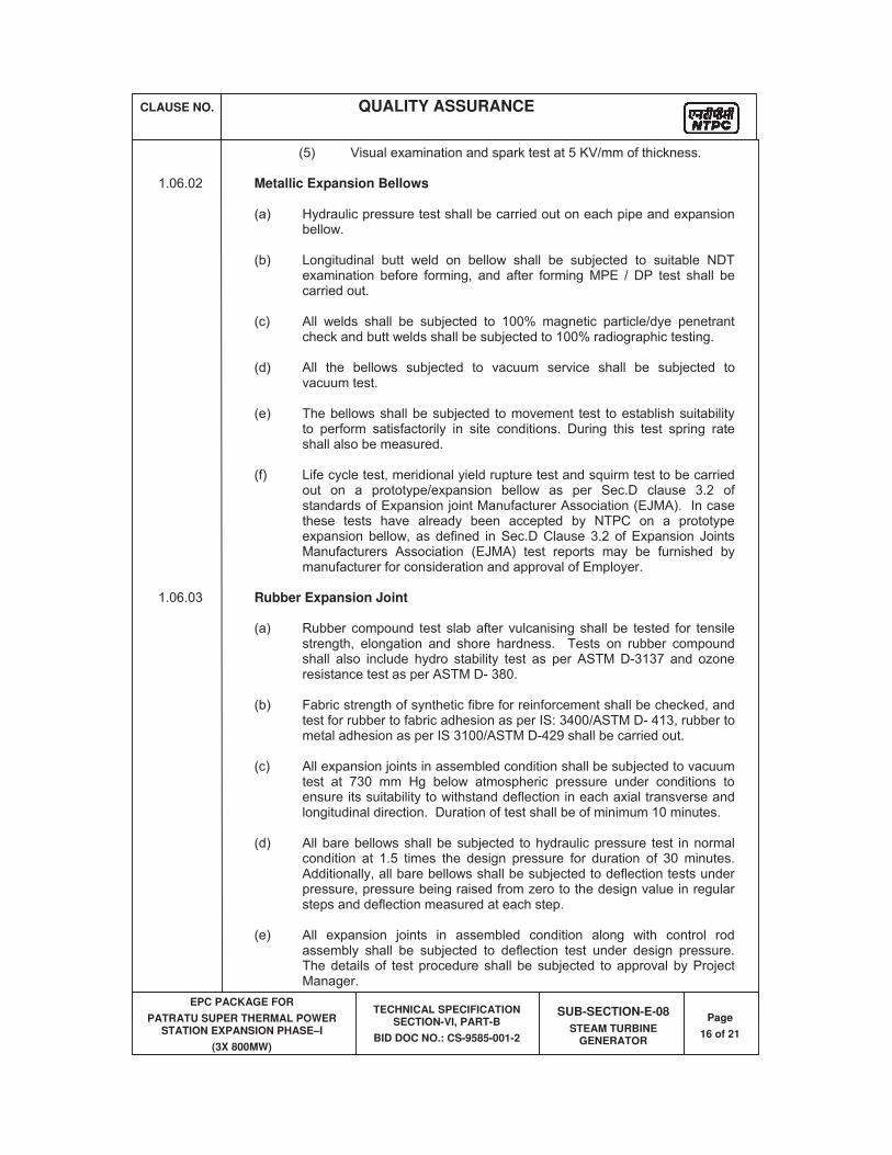
CLAUSE NO. QUALITY ASSURANCE
EPC PACKAGE FOR
PATRATU SUPER THERMAL POWER STATION EXPANSION PHASE–I
(3X 800MW)
TECHNICAL SPECIFICATION SECTION-VI, PART-B
BID DOC NO.: CS-9585-001-2
SUB-SECTION-E-08
STEAM TURBINE GENERATOR
Page
16 of 21
(5) Visual examination and spark test at 5 KV/mm of thickness. 1.06.02 Metallic Expansion Bellows (a) Hydraulic pressure test shall be carried out on each pipe and expansion
bellow. (b) Longitudinal butt weld on bellow shall be subjected to suitable NDT
examination before forming, and after forming MPE / DP test shall be carried out.
(c) All welds shall be subjected to 100% magnetic particle/dye penetrant
check and butt welds shall be subjected to 100% radiographic testing. (d) All the bellows subjected to vacuum service shall be subjected to
vacuum test. (e) The bellows shall be subjected to movement test to establish suitability
to perform satisfactorily in site conditions. During this test spring rate shall also be measured.
(f) Life cycle test, meridional yield rupture test and squirm test to be carried
out on a prototype/expansion bellow as per Sec.D clause 3.2 of standards of Expansion joint Manufacturer Association (EJMA). In case these tests have already been accepted by NTPC on a prototype expansion bellow, as defined in Sec.D Clause 3.2 of Expansion Joints Manufacturers Association (EJMA) test reports may be furnished by manufacturer for consideration and approval of Employer.
1.06.03 Rubber Expansion Joint (a) Rubber compound test slab after vulcanising shall be tested for tensile
strength, elongation and shore hardness. Tests on rubber compound shall also include hydro stability test as per ASTM D-3137 and ozone resistance test as per ASTM D- 380.
(b) Fabric strength of synthetic fibre for reinforcement shall be checked, and
test for rubber to fabric adhesion as per IS: 3400/ASTM D- 413, rubber to metal adhesion as per IS 3100/ASTM D-429 shall be carried out.
(c) All expansion joints in assembled condition shall be subjected to vacuum
test at 730 mm Hg below atmospheric pressure under conditions to ensure its suitability to withstand deflection in each axial transverse and longitudinal direction. Duration of test shall be of minimum 10 minutes.
(d) All bare bellows shall be subjected to hydraulic pressure test in normal
condition at 1.5 times the design pressure for duration of 30 minutes. Additionally, all bare bellows shall be subjected to deflection tests under pressure, pressure being raised from zero to the design value in regular steps and deflection measured at each step.
(e) All expansion joints in assembled condition along with control rod
assembly shall be subjected to deflection test under design pressure. The details of test procedure shall be subjected to approval by Project Manager.
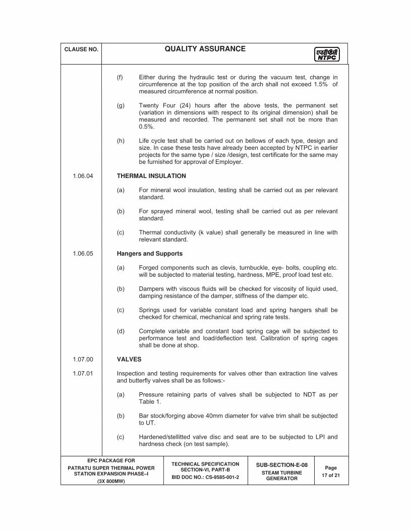
CLAUSE NO. QUALITY ASSURANCE
EPC PACKAGE FOR
PATRATU SUPER THERMAL POWER STATION EXPANSION PHASE–I
(3X 800MW)
TECHNICAL SPECIFICATION SECTION-VI, PART-B
BID DOC NO.: CS-9585-001-2
SUB-SECTION-E-08
STEAM TURBINE GENERATOR
Page
17 of 21
(f) Either during the hydraulic test or during the vacuum test, change in
circumference at the top position of the arch shall not exceed 1.5% of measured circumference at normal position.
(g) Twenty Four (24) hours after the above tests, the permanent set
(variation in dimensions with respect to its original dimension) shall be measured and recorded. The permanent set shall not be more than 0.5%.
(h) Life cycle test shall be carried out on bellows of each type, design and
size. In case these tests have already been accepted by NTPC in earlier projects for the same type / size /design, test certificate for the same may be furnished for approval of Employer.
1.06.04 THERMAL INSULATION
(a) For mineral wool insulation, testing shall be carried out as per relevant standard.
(b) For sprayed mineral wool, testing shall be carried out as per relevant
standard.
(c) Thermal conductivity (k value) shall generally be measured in line with relevant standard.
1.06.05 Hangers and Supports (a) Forged components such as clevis, turnbuckle, eye- bolts, coupling etc.
will be subjected to material testing, hardness, MPE, proof load test etc. (b) Dampers with viscous fluids will be checked for viscosity of liquid used,
damping resistance of the damper, stiffness of the damper etc. (c) Springs used for variable constant load and spring hangers shall be
checked for chemical, mechanical and spring rate tests. (d) Complete variable and constant load spring cage will be subjected to
performance test and load/deflection test. Calibration of spring cages shall be done at shop.
1.07.00 VALVES 1.07.01 Inspection and testing requirements for valves other than extraction line valves
and butterfly valves shall be as follows:- (a) Pressure retaining parts of valves shall be subjected to NDT as per
Table 1. (b) Bar stock/forging above 40mm diameter for valve trim shall be subjected
to UT. (c) Hardened/stellitted valve disc and seat are to be subjected to LPI and
hardness check (on test sample).
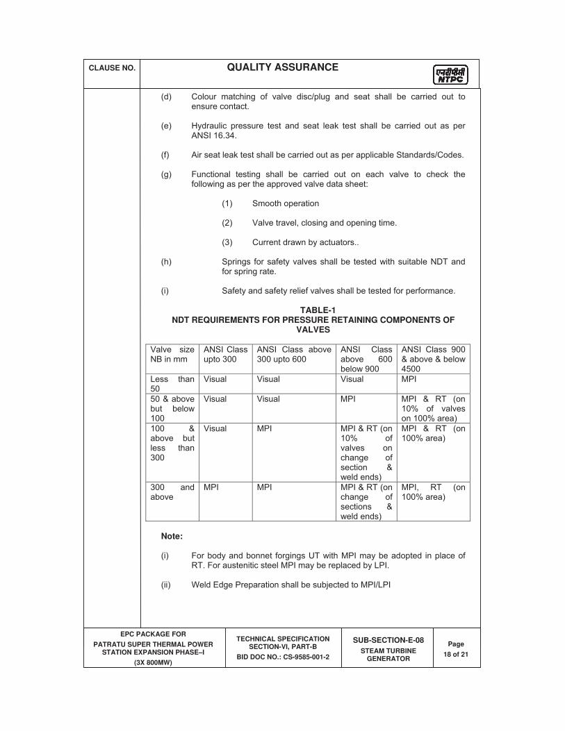
CLAUSE NO. QUALITY ASSURANCE
EPC PACKAGE FOR
PATRATU SUPER THERMAL POWER STATION EXPANSION PHASE–I
(3X 800MW)
TECHNICAL SPECIFICATION SECTION-VI, PART-B
BID DOC NO.: CS-9585-001-2
SUB-SECTION-E-08
STEAM TURBINE GENERATOR
Page
18 of 21
(d) Colour matching of valve disc/plug and seat shall be carried out to ensure contact.
(e) Hydraulic pressure test and seat leak test shall be carried out as per
ANSI 16.34. (f) Air seat leak test shall be carried out as per applicable Standards/Codes. (g) Functional testing shall be carried out on each valve to check the
following as per the approved valve data sheet: (1) Smooth operation (2) Valve travel, closing and opening time. (3) Current drawn by actuators.. (h) Springs for safety valves shall be tested with suitable NDT and
for spring rate. (i) Safety and safety relief valves shall be tested for performance.
TABLE-1 NDT REQUIREMENTS FOR PRESSURE RETAINING COMPONENTS OF
VALVES
Valve size NB in mm
ANSI Class upto 300
ANSI Class above 300 upto 600
ANSI Class above 600 below 900
ANSI Class 900 & above & below 4500
Less than 50
Visual Visual Visual MPI
50 & above but below 100
Visual Visual MPI MPI & RT (on 10% of valves on 100% area)
100 & above but less than 300
Visual MPI MPI & RT (on 10% of valves on change of section & weld ends)
MPI & RT (on 100% area)
300 and above
MPI MPI MPI & RT (on change of sections & weld ends)
MPI, RT (on 100% area)
Note: (i) For body and bonnet forgings UT with MPI may be adopted in place of
RT. For austenitic steel MPI may be replaced by LPI. (ii) Weld Edge Preparation shall be subjected to MPI/LPI
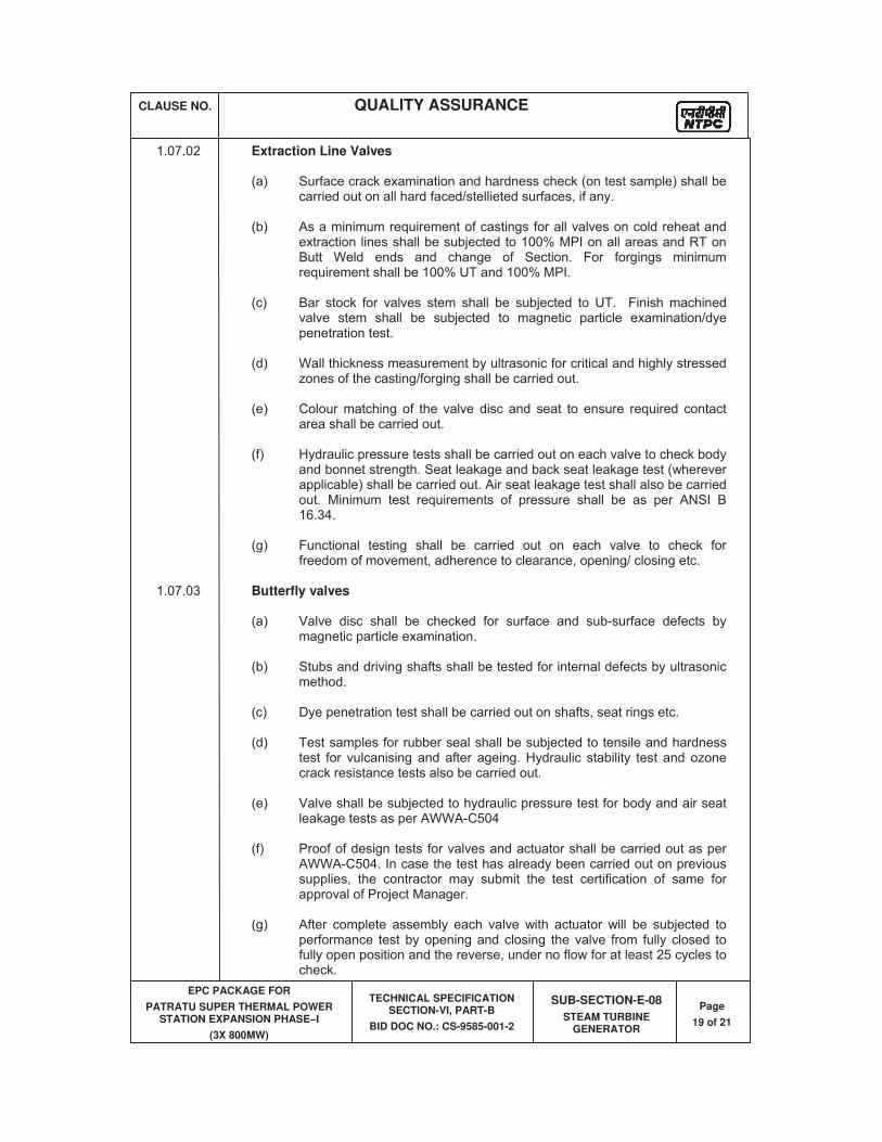
CLAUSE NO. QUALITY ASSURANCE
EPC PACKAGE FOR
PATRATU SUPER THERMAL POWER STATION EXPANSION PHASE–I
(3X 800MW)
TECHNICAL SPECIFICATION SECTION-VI, PART-B
BID DOC NO.: CS-9585-001-2
SUB-SECTION-E-08
STEAM TURBINE GENERATOR
Page
19 of 21
1.07.02 Extraction Line Valves (a) Surface crack examination and hardness check (on test sample) shall be
carried out on all hard faced/stellieted surfaces, if any. (b) As a minimum requirement of castings for all valves on cold reheat and
extraction lines shall be subjected to 100% MPI on all areas and RT on Butt Weld ends and change of Section. For forgings minimum requirement shall be 100% UT and 100% MPI.
(c) Bar stock for valves stem shall be subjected to UT. Finish machined
valve stem shall be subjected to magnetic particle examination/dye penetration test.
(d) Wall thickness measurement by ultrasonic for critical and highly stressed
zones of the casting/forging shall be carried out. (e) Colour matching of the valve disc and seat to ensure required contact
area shall be carried out. (f) Hydraulic pressure tests shall be carried out on each valve to check body
and bonnet strength. Seat leakage and back seat leakage test (wherever applicable) shall be carried out. Air seat leakage test shall also be carried out. Minimum test requirements of pressure shall be as per ANSI B 16.34.
(g) Functional testing shall be carried out on each valve to check for
freedom of movement, adherence to clearance, opening/ closing etc. 1.07.03 Butterfly valves (a) Valve disc shall be checked for surface and sub-surface defects by
magnetic particle examination. (b) Stubs and driving shafts shall be tested for internal defects by ultrasonic
method. (c) Dye penetration test shall be carried out on shafts, seat rings etc. (d) Test samples for rubber seal shall be subjected to tensile and hardness
test for vulcanising and after ageing. Hydraulic stability test and ozone crack resistance tests also be carried out.
(e) Valve shall be subjected to hydraulic pressure test for body and air seat
leakage tests as per AWWA-C504 (f) Proof of design tests for valves and actuator shall be carried out as per
AWWA-C504. In case the test has already been carried out on previous supplies, the contractor may submit the test certification of same for approval of Project Manager.
(g) After complete assembly each valve with actuator will be subjected to
performance test by opening and closing the valve from fully closed to fully open position and the reverse, under no flow for at least 25 cycles to check.
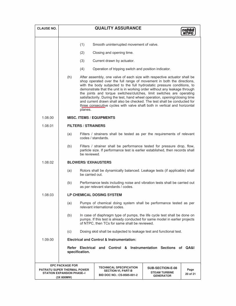
CLAUSE NO. QUALITY ASSURANCE
EPC PACKAGE FOR
PATRATU SUPER THERMAL POWER STATION EXPANSION PHASE–I
(3X 800MW)
TECHNICAL SPECIFICATION SECTION-VI, PART-B
BID DOC NO.: CS-9585-001-2
SUB-SECTION-E-08
STEAM TURBINE GENERATOR
Page
20 of 21
(1) Smooth uninterrupted movement of valve. (2) Closing and opening time. (3) Current drawn by actuator. (4) Operation of tripping switch and position indicator. (h) After assembly, one valve of each size with respective actuator shall be
shop operated over the full range of movement in both the directions, with the body subjected to the full hydrostatic pressure conditions, to demonstrate that the unit is in working order without any leakage through the joints and torque switches/clutches, limit switches are operating satisfactorily. During the test, hand wheel operation, opening/closing time and current drawn shall also be checked. The test shall be conducted for three consecutive cycles with valve shaft both in vertical and horizontal planes.
1.08.00 MISC. ITEMS / EQUIPMENTS 1.08.01 FILTERS / STRAINERS (a) Filters / strainers shall be tested as per the requirements of relevant
codes / standards. (b) Filters / strainer shall be performance tested for pressure drop, flow,
particle size. If performance test is earlier established, then records shall be reviewed.
1.08.02 BLOWERS/ EXHAUSTERS (a) Rotors shall be dynamically balanced. Leakage tests (if applicable) shall
be carried out. (b) Performance tests including noise and vibration tests shall be carried out
as per relevant standards / codes. 1.08.03 LP CHEMICAL DOSING SYSTEM (a) Pumps of chemical doing system shall be performance tested as per
relevant international codes. (b) In case of diaphragm type of pumps, the life cycle test shall be done on
pumps. If this test is already conducted for same model in earlier projects of NTPC, then TCs for same shall be reviewed.
(c) Dosing skid shall be subjected to leakage test and functional test. 1.09.00 Electrical and Control & Instrumentation: Refer Electrical and Control & Instrumentation Sections of QA&I
specification.
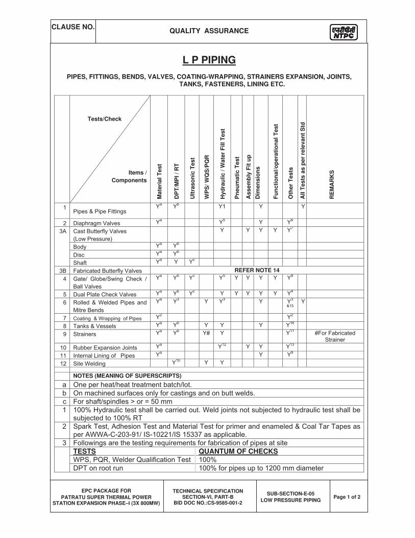
CLAUSE NO. QUALITY ASSURANCE
EPC PACKAGE FOR
PATRATU SUPER THERMAL POWER STATION EXPANSION PHASE–I (3X 800MW)
TECHNICAL SPECIFICATION SECTION-VI, PART-B
BID DOC NO.:CS-9585-001-2
SUB-SECTION-E-05
LOW PRESSURE PIPING Page 1 of 2
L P PIPING
PIPES, FITTINGS, BENDS, VALVES, COATING-WRAPPING, STRAINERS EXPANSION, JOINTS, TANKS, FASTENERS, LINING ETC.
Tests/Check
Items /
Components
Mate
rial
Test
DP
T/M
PI
/ R
T
Ult
ras
on
ic T
es
t
WP
S/
WQ
S/P
QR
Hy
dra
uli
c /
Wa
ter
Fil
l T
es
t
Pn
eu
mati
c T
est
As
se
mb
ly F
it u
p
Dim
en
sio
ns
Fu
nc
tio
na
l/o
pe
rati
on
al
Te
st
Oth
er
Te
sts
All T
ests
as p
er
rele
van
t S
td
RE
MA
RK
S
REFER NOTE 14
NOTES (MEANING OF SUPERSCRIPTS)
TESTS QUANTUM OF CHECKS
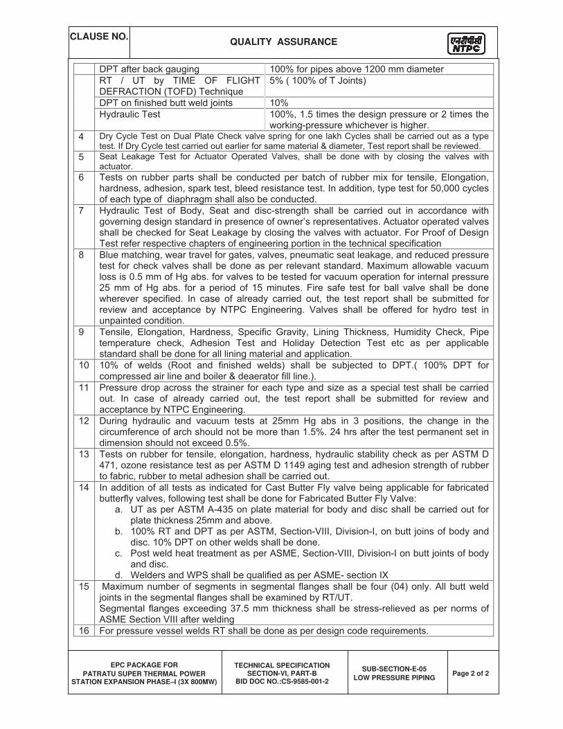
CLAUSE NO. QUALITY ASSURANCE
EPC PACKAGE FOR
PATRATU SUPER THERMAL POWER STATION EXPANSION PHASE–I (3X 800MW)
TECHNICAL SPECIFICATION SECTION-VI, PART-B
BID DOC NO.:CS-9585-001-2
SUB-SECTION-E-05
LOW PRESSURE PIPING Page 2 of 2
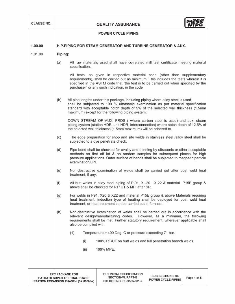
CLAUSE NO. QUALITY ASSURANCE
EPC PACKAGE FOR
PATRATU SUPER THERMAL POWER STATION EXPANSION PHASE–I (3X 800MW)
TECHNICAL SPECIFICATION SECTION-VI, PART-B
BID DOC NO.:CS-9585-001-2
SUB-SECTION-E-06
POWER CYCLE PIPING Page 1 of 5
POWER CYCLE PIPING
1.00.00 H.P.PIPING FOR STEAM GENERATOR AND TURBINE GENERATOR & AUX.
Piping:
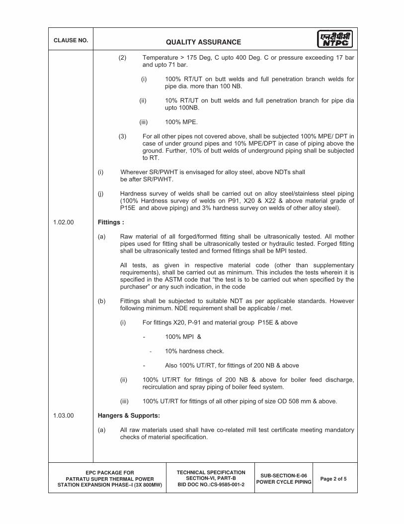
CLAUSE NO. QUALITY ASSURANCE
EPC PACKAGE FOR
PATRATU SUPER THERMAL POWER STATION EXPANSION PHASE–I (3X 800MW)
TECHNICAL SPECIFICATION SECTION-VI, PART-B
BID DOC NO.:CS-9585-001-2
SUB-SECTION-E-06
POWER CYCLE PIPING Page 2 of 5
Fittings :
Hangers & Supports:
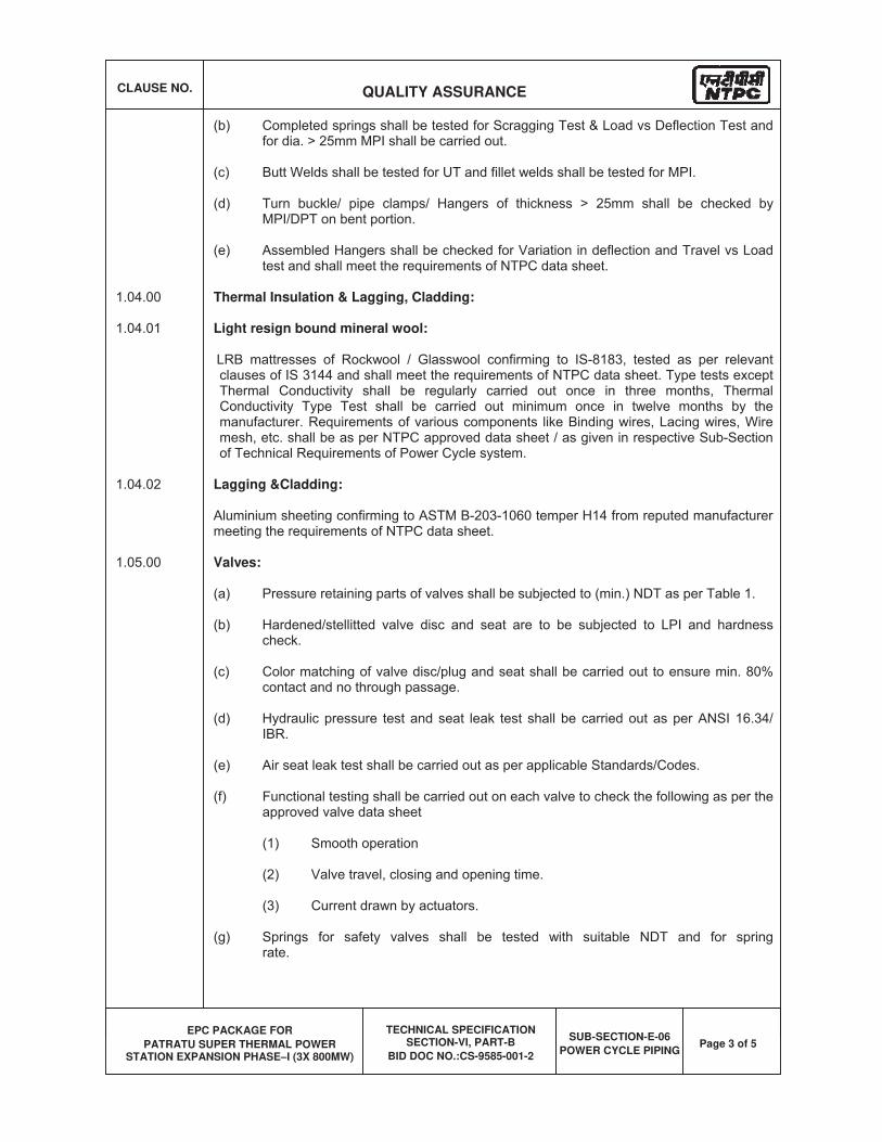
CLAUSE NO. QUALITY ASSURANCE
EPC PACKAGE FOR
PATRATU SUPER THERMAL POWER STATION EXPANSION PHASE–I (3X 800MW)
TECHNICAL SPECIFICATION SECTION-VI, PART-B
BID DOC NO.:CS-9585-001-2
SUB-SECTION-E-06
POWER CYCLE PIPING Page 3 of 5
Thermal Insulation & Lagging, Cladding:
Light resign bound mineral wool:
Lagging &Cladding:
Valves:
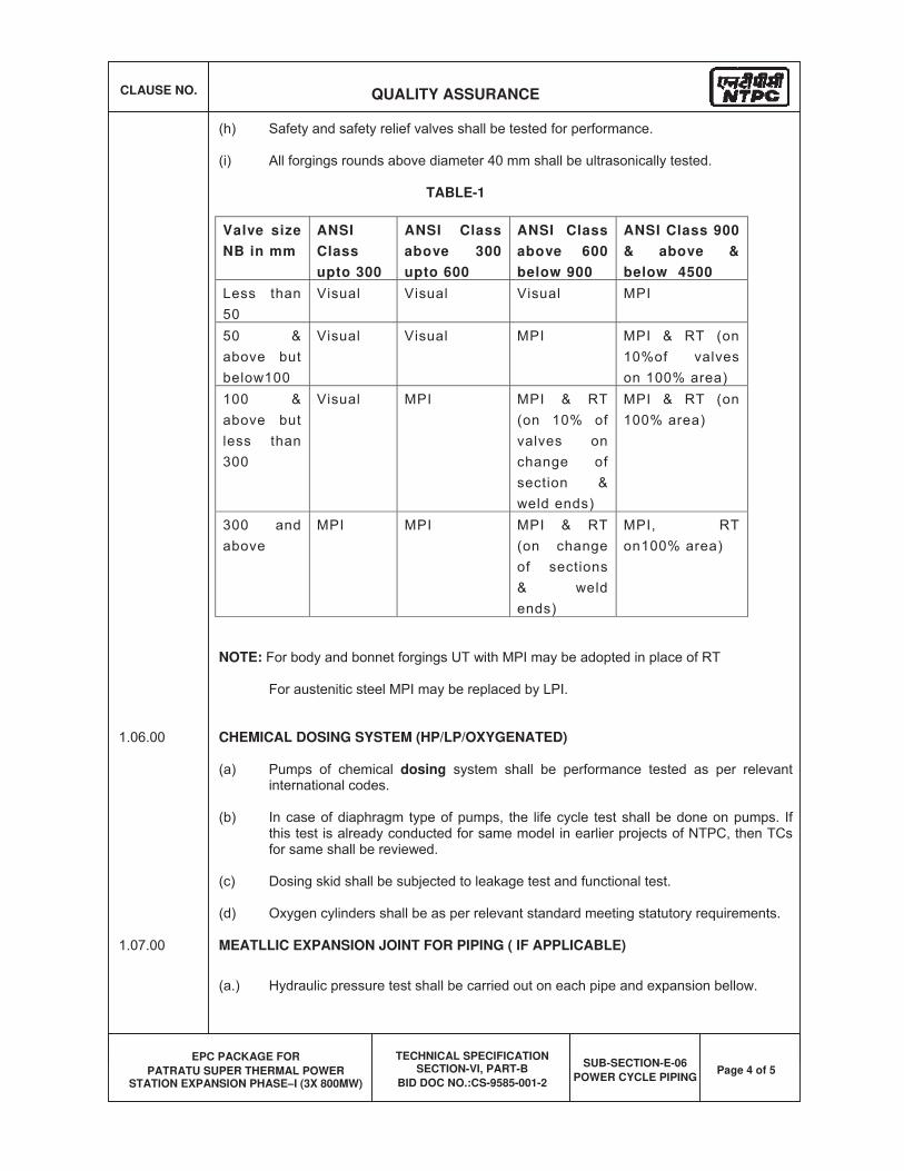
CLAUSE NO. QUALITY ASSURANCE
EPC PACKAGE FOR
PATRATU SUPER THERMAL POWER STATION EXPANSION PHASE–I (3X 800MW)
TECHNICAL SPECIFICATION SECTION-VI, PART-B
BID DOC NO.:CS-9585-001-2
SUB-SECTION-E-06
POWER CYCLE PIPING Page 4 of 5
TABLE-1
Valve size
NB in mm
ANSI
Class
upto 300
ANSI Class
above 300
upto 600
ANSI Class
above 600
below 900
ANSI Class 900
& above &
below 4500
NOTE:
CHEMICAL DOSING SYSTEM (HP/LP/OXYGENATED)
dosing
MEATLLIC EXPANSION JOINT FOR PIPING ( IF APPLICABLE)
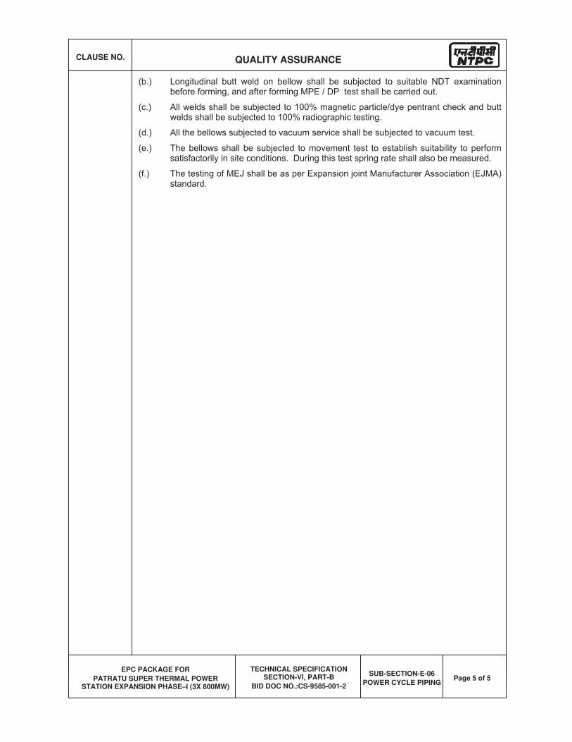
CLAUSE NO. QUALITY ASSURANCE
EPC PACKAGE FOR
PATRATU SUPER THERMAL POWER STATION EXPANSION PHASE–I (3X 800MW)
TECHNICAL SPECIFICATION SECTION-VI, PART-B
BID DOC NO.:CS-9585-001-2
SUB-SECTION-E-06
POWER CYCLE PIPING Page 5 of 5
� ✁ ✂ ✁ ✄ ✂ ☎ ✄ ✆ � ✝ ✞ ✟✁ ✄ ✠ ✟ ✄ ✠ ✡ ☛ ✡ ✁ � ✟ ✠ ☞ � ✟ ✌ ✄ ✍ ✁ ✞ ✎ � ✟ ☛ ✠ ✄ ✠ ✏ ✞ ✑� ✒ ✁ ✄ ✑ ☛ ✏ ✞ ✑ ✁ ☞ ✄ ☛ � ✓ ✏ ✔ ✕ ✒ ✖ ✗ ✗ ✌ ✎ ✘ ✙ ✚ ✛ ✜ ✢ ✣ ✛ ✤ ✥ ✦ ✧ ✚ ✛ ✣ ★ ✣ ✛ ✤ ✙ ✣ ✩ ✢✦ ✚ ✛ ✙ ✣ ✩ ✢ ✪ ✫ ✣ ✬ ✧ ✤ ✭ ✙ ✪ ✮✮ ✣ ✯ ✯ ✩ ✛ ✢ ✩ ✰ ✱ ✛ ✦ ✪ ✲ ✳ ✴ ✳ ✪ ✵ ✵ ✶ ✪ ✷
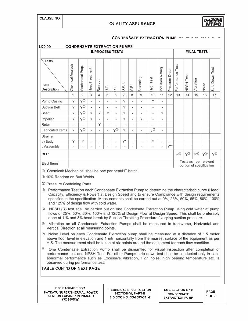
✂ ✍ ✄ ✡ ☛ � ✑ ✞ ✸ ✹ ✺ ✻ ✼ ✽ ✾ ✿ ✻ ❀ ❀ ✺ ❁ ✻ ❂ ❃ ❄
❅ ❆ ❇ ❆ ❈ ❇ ❉ ❈ ❊ ❅ ❋ ● ❍❆ ❈ ■ ❍ ❈ ■ ❏ ❑ ❏ ❆ ❅ ❍ ■ ▲ ❅ ❍ ▼ ❈ ◆ ❆ ● ❖ ❅ ❍❑ ■ ❈ ■ P ● ◗ ❅ ❘ ❆ ❈ ◗ ❑ P ● ◗ ❆ ▲ ❈ ❑ ❅ ❙ P❚ ❯ ❘ ❱ ❲ ❲ ▼ ❖ ❳ ■ ❅ ❇ ▲ ◗ P ❇ ❈ ◆ ❑ ❆ ❅ ❇ P ❋ P ❇ ❈ ■ P ● ◗❑ ❅ ❇ ■ P ● ◗ ❨ ❩ P ❬ ❆ ❈ ❍ ■ ❨ ❭❭ P ❪ ❪ ● ❇ ◗ ● ❫ ❴ ❇ ❑ ❨ ❵ ❛ ❱ ❛ ❨ ❲ ❲ ❜ ❨ ❝ ❑ ❏ ❭ ❨ ❑ ❅ ❇ ■ P ● ◗ ❨ ❅ ❨ ❜ ❲❇ ● ◗ ❪ ❅ ◗ ❑ ❈ ■ ❅❅ ❘ ■ ❍ ❈ ❇ ■ P ● ◗ ❆ ❏ ▼ ❆ ❆ ❈ ❊ ❅❜ ● ❋ ❝
✛ ✩ ✢ ✯ ✚ ✢ ✦ ✤ ✙ ✚ ✚ ❞ ✙ ✭ ✤ ✛ ✙ ✣ ✩ ✢ ✧ ❡ ❢ ✧✶ ✰ ✵ ✵ ✰ ✵ ✵ ✛ ✩ ✢ ✯ ✚ ✢ ✦ ✤ ✙ ✚ ✚ ❞ ✙ ✭ ✤ ✛ ✙ ✣ ✩ ✢ ✧ ❡ ❢ ✧ ✦✏ ✑ ✁ ✟ ✞ ✂ � ☛ ☛ ✠ � ☛ ✠ ☛ ✝ ✏ ✑ ✄ ✍ ✠ � ☛ ✠ ☛ Tests
Item/
Description Chem
ical A
naly
sis
Mecha
nic
al P
rop.
Heat
Tre
atm
en
t
Run o
ut
U.T
.
R.T
.
D.P
.T.
M.P
.I.
Bala
ncin
g
Hyd.
Test
Inclu
sio
n R
atin
g
Pre
ssure
Dro
p
Perf
orm
ance T
est
NP
SH
Test
Vib
ration
Nois
e
Str
ip D
ow
n T
est
1. 2. 3. 4. 5. 6. 7. 8. 9. 10. 11. 12 13. 14. 15. 16. 17.
Pump Casing Y Y - - - - Y - - Y -
Suction Bell Y Y - - - - Y - - - -
Shaft Y Y Y Y Y - Y Y - - Y
Impeller Y Y Y - - - Y - Y - -
Rotor - - - Y - - - - - -
Fabricated Items Y Y - - - Y Y - - Y -
Strainer
a) Body Y Y - - - - Y* - - Y - -
b)Assembly - - - - - - - - - - - Y** ✂ � ✁
Y Y Y Y Y
Elect Items Tests as per relevant portion of specification
Chemical/ Mechanical shall be one per heat/HT batch.
10% Random on Butt Welds
Pressure Containing Parts.
Performance Test on each Condensate Extraction Pump to determine the characteristic curve (Head, Capacity, Efficiency & Power) at Design Speed and to ensure Compliance with design requirements specified in the specification. Measurements shall be carried out at 0%, 25%, 50%, 65%, 80%, 100% and 125% of design flow with cold water.
NPSH (R) test shall be carried out on one Condensate Extraction Pump using cold water at pump flows of 25%, 50%, 80%, 100% and 125% of Design Flow at Design Speed. This shall be preferablydone at 1 % and 3% head break by Suction Throttling Procedure / varying suction pressure.
Vibration on all Condensate Extraction Pumps shall be measured in transverse, Horizontal and Vertical Direction at all measuring points.
Noise Level on each Condensate Extraction pump shall be measured at a distance of 1.5 meter above floor level in elevation and 1 mtr horizontally from the nearest surface of the equipment as per HIS. The measurement shall be taken at six points around the equipment for each flow condition.
One Condensate Extraction Pump shall be dismantled for visual inspection after completion of performance test and NPSH Test. For other Pumps strip down test shall be conducted only in case abnormal performance such as Excessive Vibration, High noise, high bearing temperature etc. is observed during performance test. ✙ ✤ ✮ ✥ ✚ ✛ ✩ ✢ ✙ ❣ ✯ ✩ ✢ ✢ ✚ ❞ ✙ ✧ ✤ ❤ ✚
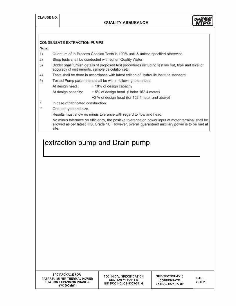
✂ ✍ ✄ ✡ ☛ � ✑ ✞ ✸ ✹ ✺ ✻ ✼ ✽ ✾ ✿ ✻ ❀ ❀ ✺ ❁ ✻ ❂ ❃ ❄
❅ ❆ ❇ ❆ ❈ ❇ ❉ ❈ ❊ ❅ ❋ ● ❍❆ ❈ ■ ❍ ❈ ■ ❏ ❑ ❏ ❆ ❅ ❍ ■ ▲ ❅ ❍ ▼ ❈ ◆ ❆ ● ❖ ❅ ❍❑ ■ ❈ ■ P ● ◗ ❅ ❘ ❆ ❈ ◗ ❑ P ● ◗ ❆ ▲ ❈ ❑ ❅ ❙ P❚ ❯ ❘ ❱ ❲ ❲ ▼ ❖ ❳ ■ ❅ ❇ ▲ ◗ P ❇ ❈ ◆ ❑ ❆ ❅ ❇ P ❋ P ❇ ❈ ■ P ● ◗❑ ❅ ❇ ■ P ● ◗ ❨ ❩ P ❬ ❆ ❈ ❍ ■ ❨ ❭❭ P ❪ ❪ ● ❇ ◗ ● ❫ ❴ ❇ ❑ ❨ ❵ ❛ ❱ ❛ ❨ ❲ ❲ ❜ ❨ ❝ ❑ ❏ ❭ ❨ ❑ ❅ ❇ ■ P ● ◗ ❨ ❅ ❨ ❜ ❲❇ ● ◗ ❪ ❅ ◗ ❑ ❈ ■ ❅❅ ❘ ■ ❍ ❈ ❇ ■ P ● ◗ ❆ ❏ ▼ ❆ ❆ ❈ ❊ ❅❝ ● ❋ ❝
✛ ✩ ✢ ✯ ✚ ✢ ✦ ✤ ✙ ✚ ✚ ❞ ✙ ✭ ✤ ✛ ✙ ✣ ✩ ✢ ✧ ❡ ❢ ✧ ✦✢ ✐ ❥ ❦ ✱1) Quantum of In-Process Checks/ Tests is 100% until & unless specified otherwise.
2) Shop tests shall be conducted with soften Quality Water.
3) Bidder shall furnish details of proposed test procedures including test lay out, type and level of accuracy of instruments, sample calculation etc.
4) Tests shall be done in accordance with latest edition of Hydraulic Institute standard.
5) Tested Pump parameters shall be within following tolerances.
At design head : + 10% of design capacity
At design capacity: + 5% of design head (Under 152.4 meter)
+3 % of design head (for 152.4meter and above)
* In case of fabricated construction.
** One per type and size.
Results must show no minus tolerance with regard to flow and head.
No minus tolerance on efficiency, the positive tolerance on power input at motor terminal shall be allowed as per latest HIS, Grade 1U. However, overall guaranteed auxiliary power is to be met at site.
ANNEXURE-. IV.8-2
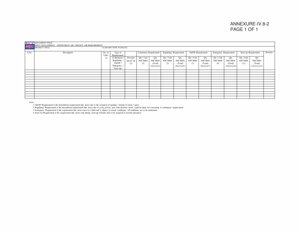
ANNEXURE-IV.8-2
PAGE 1 OF 1
DOCUMENT TITLE
INPUT DATA FORMAT - INSTRUMENT AIR / SERVICE AIR REQUIREMENT
PROJECT TITLE 3 X 800 MW NTPC PATRATU
S.No. Description
No. of
Units
Type of
Requirement
Continuous Requirement
Regulating Requirement On/Off Requirement Emergency Requirement Start-up Requirement
Remarks
(1) (Continuous /
Regulating /
On/Off /
Emergency /
Start-up)
Pressure
kg/cm2
(g)
(2)
Qty / Unit
NM3/MIN
(3)
Qty
NM3/MIN
(Total)
(4)=(1)x(3)
Qty / Unit
NM3/MIN
(5)
Qty
NM3/MIN
(Total)
(6)=(1)x(5)
Qty / Unit
NM3/MIN
(7)
Qty
NM3/MIN
(Total)
(8)=(1)x(7)
Qty / Unit
NM3/MIN
(9)
Qty
NM3/MIN
(Total)
(10)=(1)x(9)
Qty / Unit
NM3/MIN
(11)
Qty
NM3/MIN
(Total)
(12)=(1)x(11)
Note:
1 On/Off Requirement is the intermittent requirement that arises due to the actuation of opening / closing of valves / gates
2 Regulating Requirement is the intermittent requirement that arises due to cyclic activity and some diversity factor could be taken for converting to continuous requirement.
3 Emergency Requirement is the requirement that arises once in a while and is subject to certain conditions. All conditions are to be mentioned.
4 Start-Up Requirement is the requirement that arises only during start-up of boiler and is not required in normal operation.
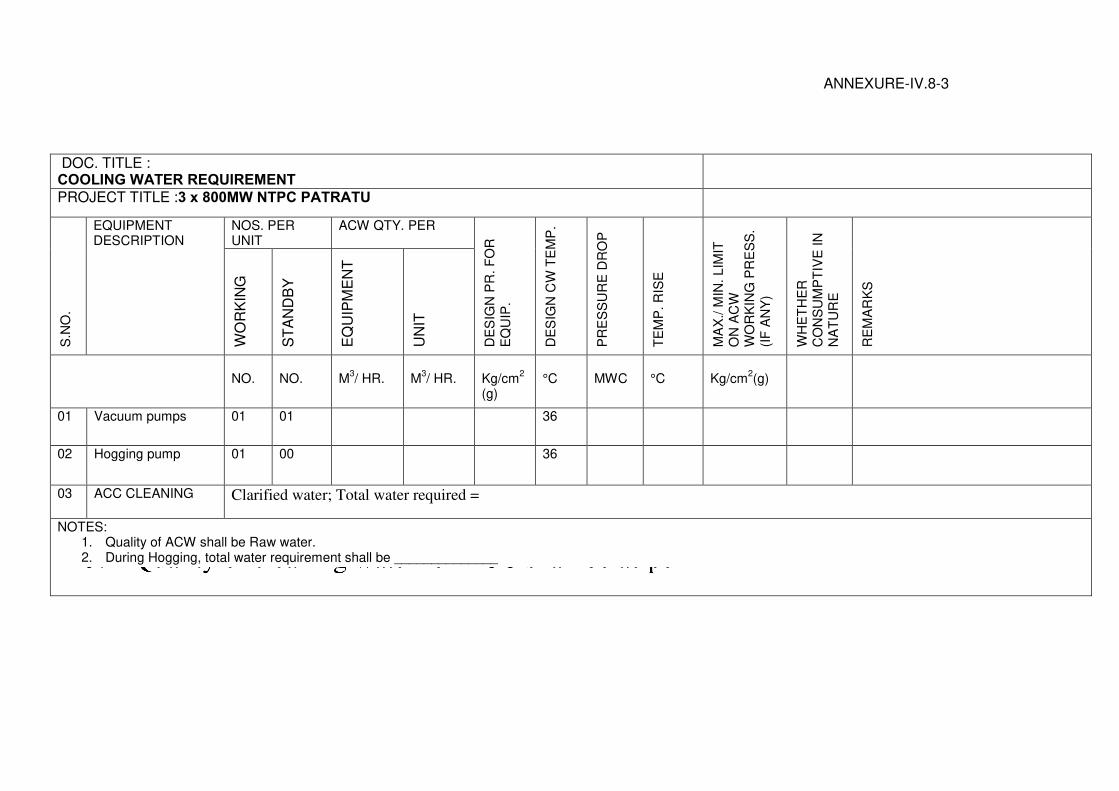
ANNEXURE-IV.8-3
DOC. TITLE : COOLING WATER REQUIREMENT
PROJECT TITLE :3 x 800MW NTPC PATRATU
S.N
O.
EQUIPMENT DESCRIPTION
NOS. PER UNIT
ACW QTY. PER
DE
SIG
N P
R. F
OR
E
QU
IP.
DE
SIG
N C
W T
EM
P.
PR
ES
SU
RE
DR
OP
TE
MP
. R
ISE
MA
X./ M
IN. L
IMIT
O
N A
CW
W
OR
KIN
G P
RE
SS
. (I
F A
NY
)
WH
ET
HE
R
CO
NS
UM
PT
IVE
IN
N
AT
UR
E
RE
MA
RK
S
WO
RK
ING
S
TA
ND
BY
E
QU
IPM
EN
T
UN
IT
NO.
NO.
M
3/ HR.
M
3/ HR.
Kg/cm
2
(g)
°C
MWC
°C
Kg/cm
2(g)
01 Vacuum pumps 01 01 36
02 Hogging pump 01 00 36
03 ACC CLEANING Clarified water; Total water required =
NOTES: 1. Quality of ACW shall be Raw water. 2. During Hogging, total water requirement shall be ______________
Annexure-IV.8-4
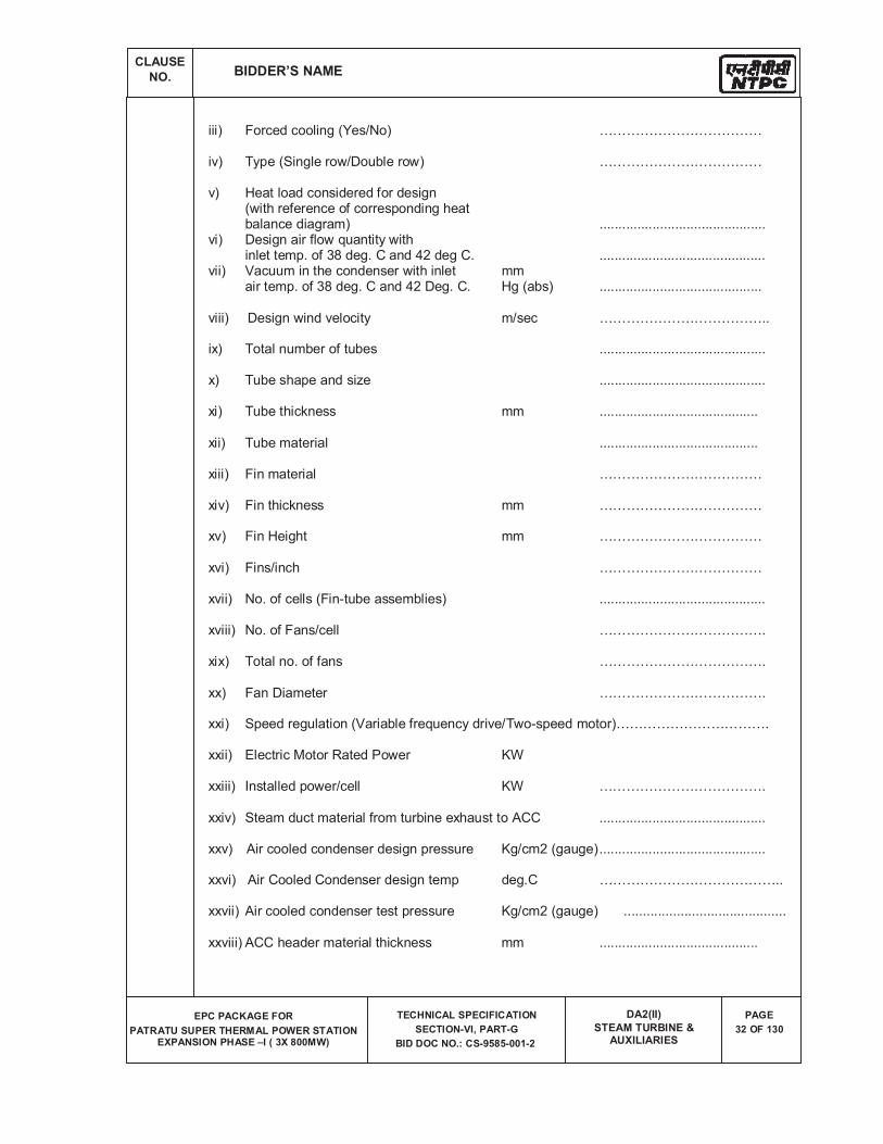
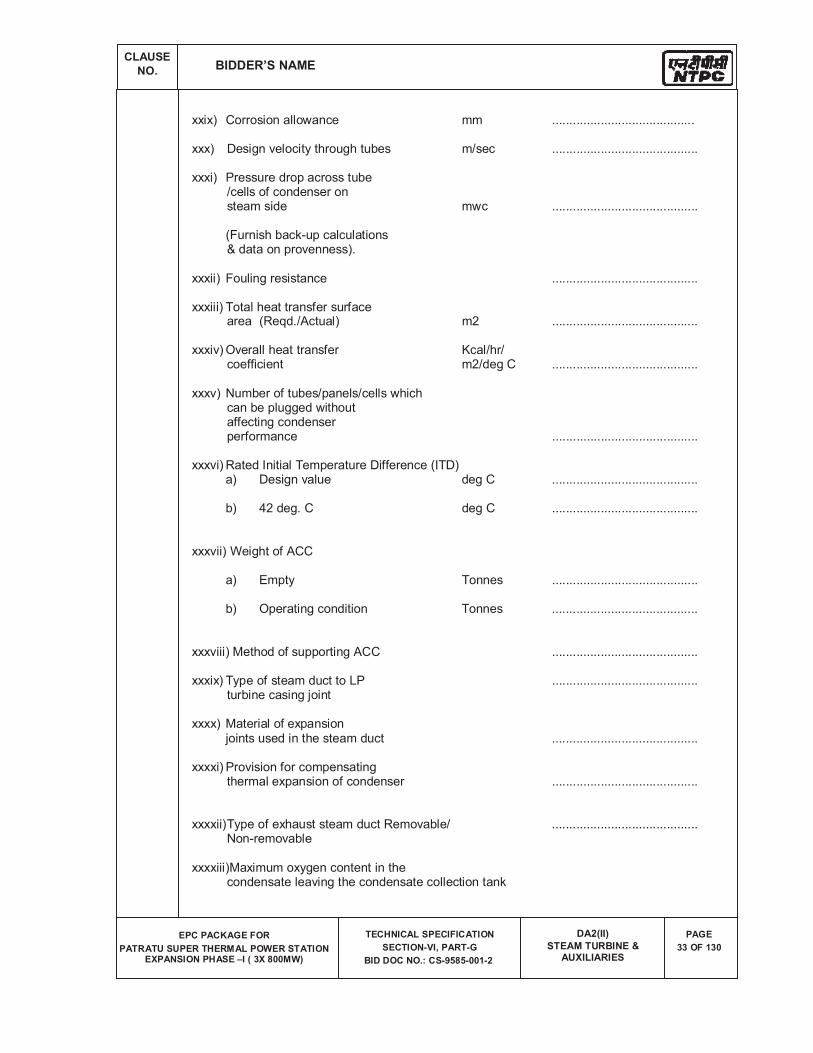
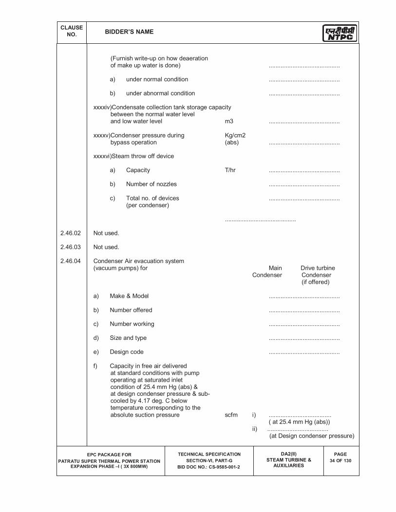
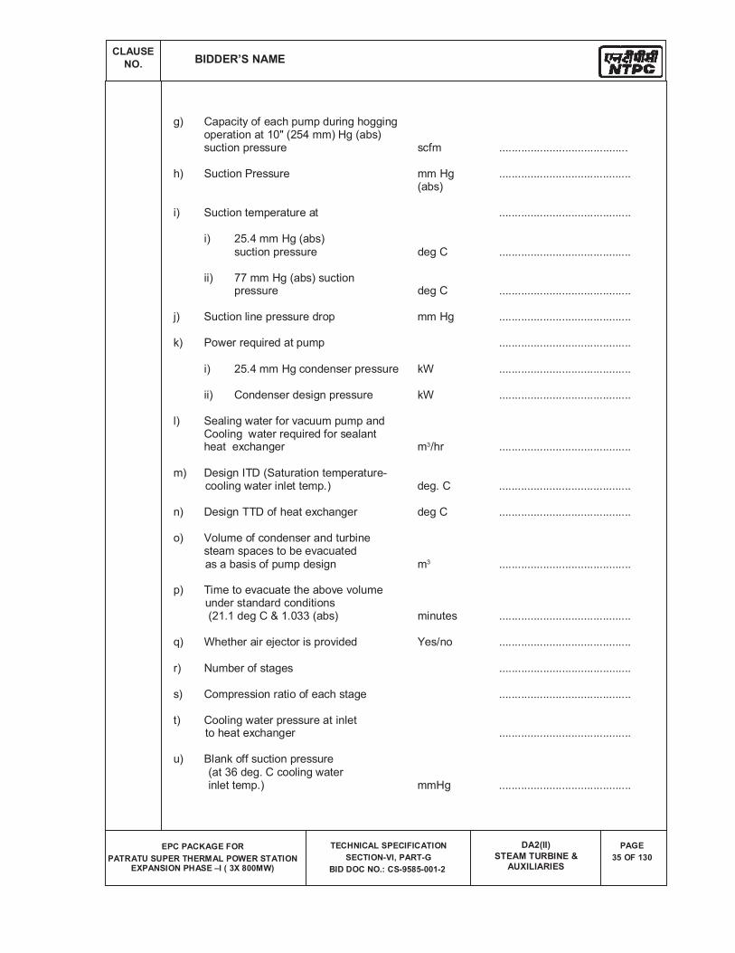
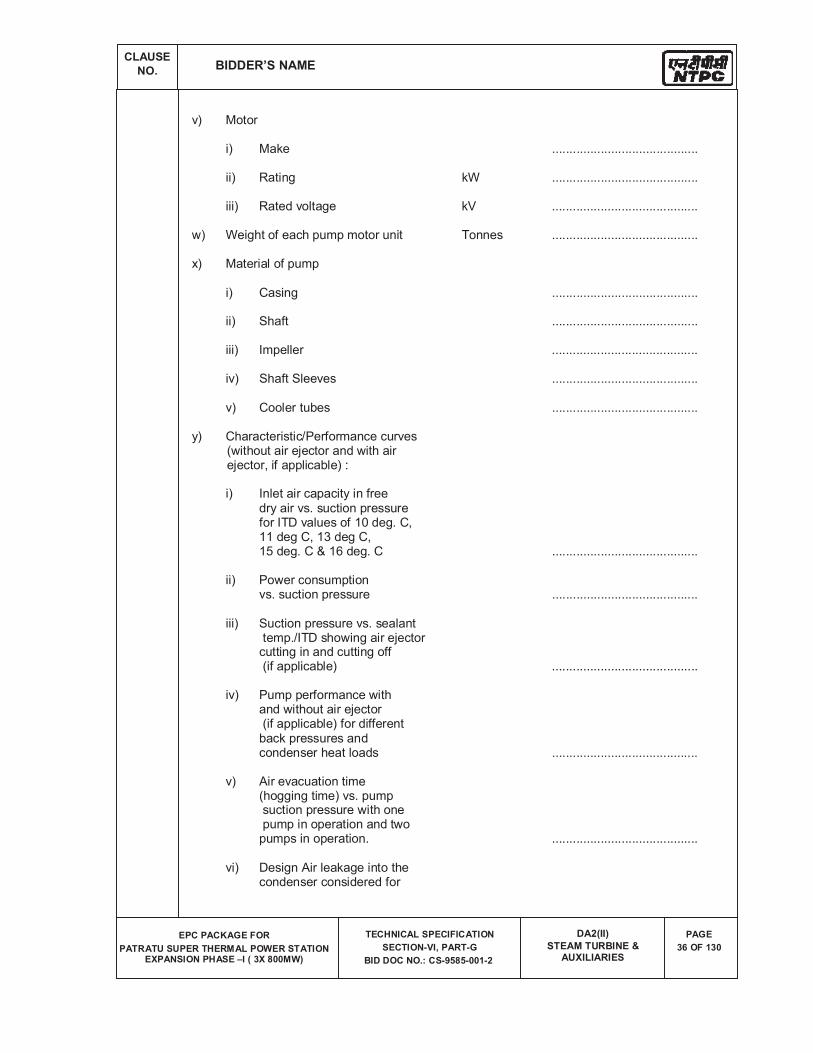
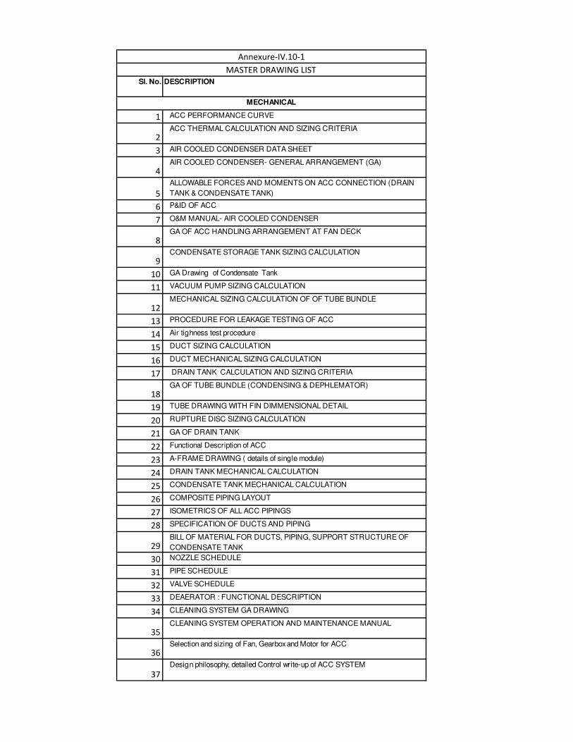
Sl. No. DESCRIPTION
1 ACC PERFORMANCE CURVE
2ACC THERMAL CALCULATION AND SIZING CRITERIA
3 AIR COOLED CONDENSER DATA SHEET
4AIR COOLED CONDENSER- GENERAL ARRANGEMENT (GA)
5
ALLOWABLE FORCES AND MOMENTS ON ACC CONNECTION (DRAIN
TANK & CONDENSATE TANK)
6 P&ID OF ACC
7 O&M MANUAL- AIR COOLED CONDENSER
8GA OF ACC HANDLING ARRANGEMENT AT FAN DECK
9CONDENSATE STORAGE TANK SIZING CALCULATION
10 GA Drawing of Condensate Tank
11 VACUUM PUMP SIZING CALCULATION
12MECHANICAL SIZING CALCULATION OF OF TUBE BUNDLE
13 PROCEDURE FOR LEAKAGE TESTING OF ACC
14 Air tighness test procedure
15 DUCT SIZING CALCULATION
16 DUCT MECHANICAL SIZING CALCULATION
17 DRAIN TANK CALCULATION AND SIZING CRITERIA
18GA OF TUBE BUNDLE (CONDENSING & DEPHLEMATOR)
19 TUBE DRAWING WITH FIN DIMMENSIONAL DETAIL
20 RUPTURE DISC SIZING CALCULATION
21 GA OF DRAIN TANK
22 Functional Description of ACC
23 A-FRAME DRAWING ( details of single module)
24 DRAIN TANK MECHANICAL CALCULATION
25 CONDENSATE TANK MECHANICAL CALCULATION
26 COMPOSITE PIPING LAYOUT
27 ISOMETRICS OF ALL ACC PIPINGS
28 SPECIFICATION OF DUCTS AND PIPING
29BILL OF MATERIAL FOR DUCTS, PIPING, SUPPORT STRUCTURE OF
CONDENSATE TANK
30 NOZZLE SCHEDULE
31 PIPE SCHEDULE
32 VALVE SCHEDULE
33 DEAERATOR : FUNCTIONAL DESCRIPTION
34 CLEANING SYSTEM GA DRAWING
35CLEANING SYSTEM OPERATION AND MAINTENANCE MANUAL
36Selection and sizing of Fan, Gearbox and Motor for ACC
37
Design philosophy, detailed Control write-up of ACC SYSTEM
Annexure-IV.10-1
MASTER DRAWING LIST
MECHANICAL
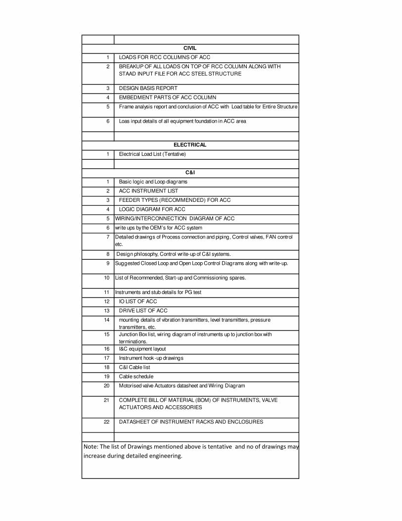
1 LOADS FOR RCC COLUMNS OF ACC
2 BREAKUP OF ALL LOADS ON TOP OF RCC COLUMN ALONG WITH
STAAD INPUT FILE FOR ACC STEEL STRUCTURE
3 DESIGN BASIS REPORT
4 EMBEDMENT PARTS OF ACC COLUMN
5 Frame analysis report and conclusion of ACC with Load table for Entire Structure
6 Loas input details of all equipment foundation in ACC area
1 Electrical Load List (Tentative)
1 Basic logic and Loop diagrams
2 ACC INSTRUMENT LIST
3 FEEDER TYPES (RECOMMENDED) FOR ACC
4 LOGIC DIAGRAM FOR ACC
5 WIRING/INTERCONNECTION DIAGRAM OF ACC
6 write ups by the OEM’s for ACC system
7 Detailed drawings of Process connection and piping, Control valves, FAN control
etc.
8 Design philosophy, Control write-up of C&I systems.
9 Suggested Closed Loop and Open Loop Control Diagrams along with write-up.
10 List of Recommended, Start-up and Commissioning spares.
11 Instruments and stub details for PG test
12 IO LIST OF ACC
13 DRIVE LIST OF ACC
14 mounting details of vibration transmitters, level transmitters, pressure
transmitters, etc.
15 Junction Box list, wiring diagram of instruments up to junction box with
terminations.
16 I&C equipment layout
17 Instrument hook -up drawings
18 C&I Cable list
19 Cable schedule
20 Motorised valve Actuators datasheet and Wiring Diagram
21 COMPLETE BILL OF MATERIAL (BOM) OF INSTRUMENTS, VALVE
ACTUATORS AND ACCESSORIES
22 DATASHEET OF INSTRUMENT RACKS AND ENCLOSURES
Note: The list of Drawings mentioned above is tentative and no of drawings may
increase during detailed engineering.
C&I
CIVIL
ELECTRICAL

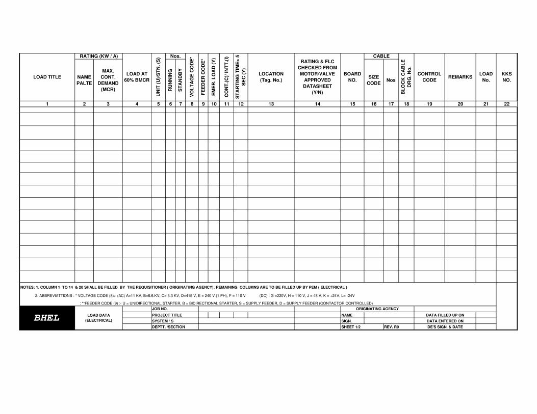
NAME
PALTE
MAX.
CONT.
DEMAND
(MCR) RU
NN
ING
ST
AN
DB
Y
SIZE
CODENos
1 2 3 4 5 6 7 8 9 10 11 12 13 14 15 16 17 18 19 20 21 22
NAME
SIGN.
VO
LT
AG
E C
OD
E*
KKS
NO.
LOAD
No.REMARKS
FE
ED
ER
CO
DE
*
EM
ER
. L
OA
D (
Y)
LOCATION
(Tag. No.)
CABLE
BL
OC
K C
AB
LE
DR
G. N
o.
CONTROL
CODE
DATA ENTERED ON
LOAD TITLE
RATING (KW / A)
UN
IT (
U)/
ST
N. (S
)
CO
NT
.(C
)/ IN
TT
.(I)
ST
AR
TIN
G T
IME
> 5
SE
C (
Y)
BOARD
NO.
Nos.
PROJECT TITLE
2. ABBREVIATTIONS : * VOLTAGE CODE (8):- (AC) A=11 KV, B=6.6.KV, C= 3.3 KV, D=415 V, E = 240 V (1 PH), F = 110 V (DC) : G =220V, H = 110 V, J = 48 V, K = +24V, L= -24V
: **FEEDER CODE (9) :- U = UNIDIRECTIONAL STARTER, B = BIDIRECTIONAL STARTER, S = SUPPLY FEEDER, D = SUPPLY FEEDER (CONTACTOR CONTROLLED)
DE'S SIGN. & DATE
DATA FILLED UP ONBHEL
LOAD DATA
(ELECTRICAL)
JOB NO.
RATING & FLC
CHECKED FROM
MOTOR/VALVE
APPROVED
DATASHEET
(Y/N)
LOAD AT
60% BMCR
DEPTT. /SECTION SHEET 1/2 REV. R0
SYSTEM / S
NOTES: 1. COLUMN 1 TO 14 & 20 SHALL BE FILLED BY THE REQUISITIONER ( ORIGINATING AGENCY); REMAINING COLUMNS ARE TO BE FILLED UP BY PEM ( ELECTRICAL )
ORIGINATING AGENCY

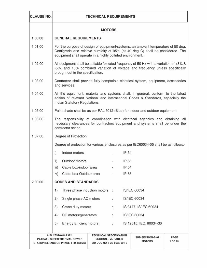
CLAUSE NO.
TECHNICAL REQUIREMENTS
EPC PACKAGE FOR
PATRATU SUPER THERMAL POWER
STATION EXPANSION PHASE–I (3X 800MW
TECHNICAL SPECIFICATION
SECTION – VI, PART-B
BID DOC NO. : CS-9585-001-2
SUB-SECTION-B-07
MOTORS
PAGE
1 OF 10
MOTORS
1.00.00 GENERAL REQUIREMENTS
1.01.00 For the purpose of design of equipment/systems, an ambient temperature of 50 deg.
Centigrade and relative humidity of 95% (at 40 deg C) shall be considered. The
equipment shall operate in a highly polluted environment.
1.02.00 All equipment shall be suitable for rated frequency of 50 Hz with a variation of +3% &
-5%, and 10% combined variation of voltage and frequency unless specifically
brought out in the specification.
1.03.00 Contractor shall provide fully compatible electrical system, equipment, accessories
and services.
1.04.00 All the equipment, material and systems shall, in general, conform to the latest
edition of relevant National and international Codes & Standards, especially the
Indian Statutory Regulations.
1.05.00 Paint shade shall be as per RAL 5012 (Blue) for indoor and outdoor equipment.
1.06.00 The responsibility of coordination with electrical agencies and obtaining all
necessary clearances for contractors equipment and systems shall be under the
contractor scope.
1.07.00 Degree of Protection
Degree of protection for various enclosures as per IEC60034-05 shall be as follows:-
i) Indoor motors - IP 54
ii) Outdoor motors - IP 55
iii) Cable box-indoor area - IP 54
iv) Cable box-Outdoor area - IP 55
2.00.00 CODES AND STANDARDS
1) Three phase induction motors : IS/IEC:60034
2) Single phase AC motors : IS/IEC:60034
3) Crane duty motors : IS:3177, IS/IEC:60034
4) DC motors/generators : IS/IEC:60034
5) Energy Efficient motors : IS 12615, IEC: 60034-30
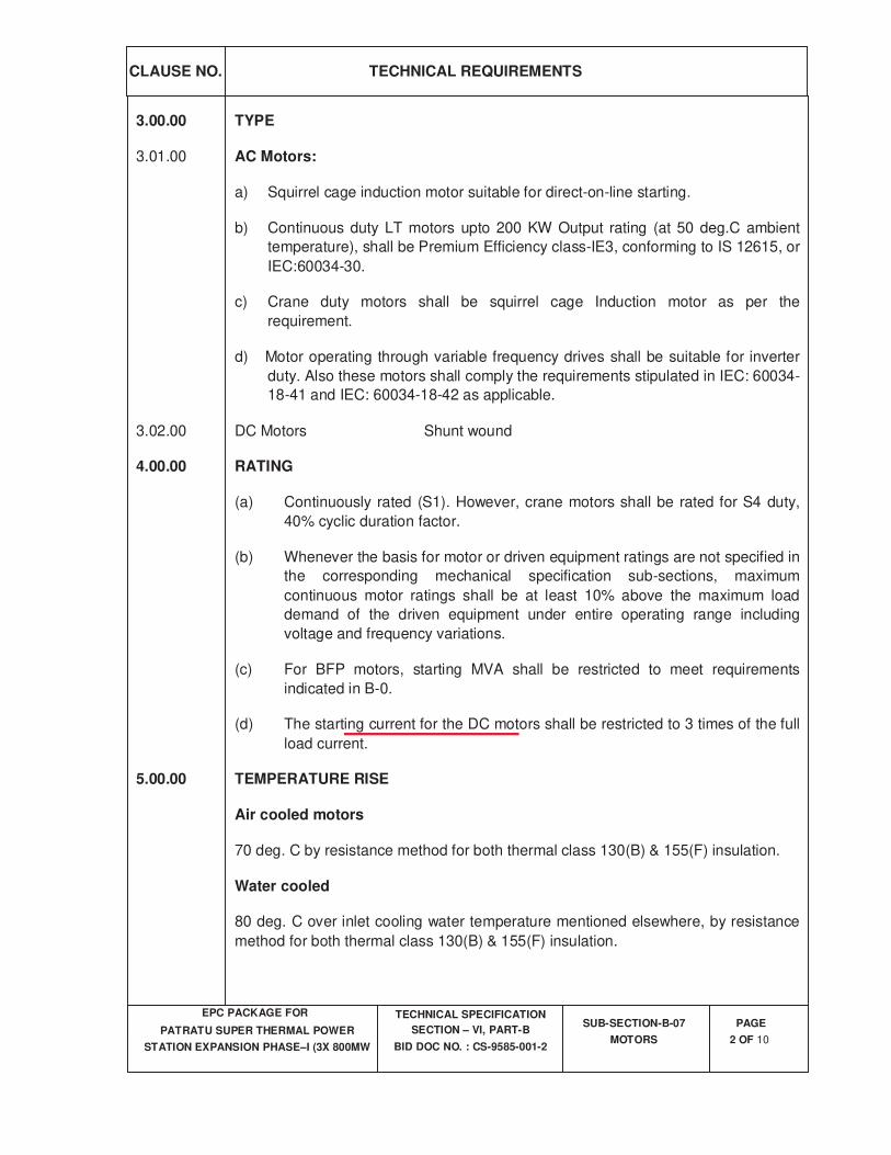
CLAUSE NO.
TECHNICAL REQUIREMENTS
EPC PACKAGE FOR
PATRATU SUPER THERMAL POWER
STATION EXPANSION PHASE–I (3X 800MW
TECHNICAL SPECIFICATION
SECTION – VI, PART-B
BID DOC NO. : CS-9585-001-2
SUB-SECTION-B-07
MOTORS
PAGE
2 OF 10
3.00.00 TYPE
3.01.00 AC Motors:
a) Squirrel cage induction motor suitable for direct-on-line starting.
b) Continuous duty LT motors upto 200 KW Output rating (at 50 deg.C ambient
temperature), shall be Premium Efficiency class-IE3, conforming to IS 12615, or
IEC:60034-30.
c) Crane duty motors shall be squirrel cage Induction motor as per the
requirement.
d) Motor operating through variable frequency drives shall be suitable for inverter
duty. Also these motors shall comply the requirements stipulated in IEC: 60034-
18-41 and IEC: 60034-18-42 as applicable.
3.02.00 DC Motors Shunt wound
4.00.00 RATING
(a) Continuously rated (S1). However, crane motors shall be rated for S4 duty,
40% cyclic duration factor.
(b) Whenever the basis for motor or driven equipment ratings are not specified in
the corresponding mechanical specification sub-sections, maximum
continuous motor ratings shall be at least 10% above the maximum load
demand of the driven equipment under entire operating range including
voltage and frequency variations.
(c) For BFP motors, starting MVA shall be restricted to meet requirements
indicated in B-0.
(d) The starting current for the DC motors shall be restricted to 3 times of the full
load current.
5.00.00 TEMPERATURE RISE
Air cooled motors
70 deg. C by resistance method for both thermal class 130(B) & 155(F) insulation.
Water cooled
80 deg. C over inlet cooling water temperature mentioned elsewhere, by resistance
method for both thermal class 130(B) & 155(F) insulation.
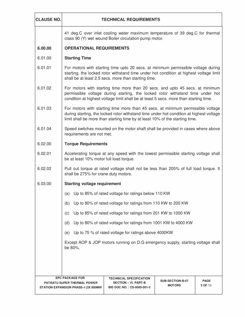
CLAUSE NO.
TECHNICAL REQUIREMENTS
EPC PACKAGE FOR
PATRATU SUPER THERMAL POWER
STATION EXPANSION PHASE–I (3X 800MW
TECHNICAL SPECIFICATION
SECTION – VI, PART-B
BID DOC NO. : CS-9585-001-2
SUB-SECTION-B-07
MOTORS
PAGE
3 OF 10
41 deg.C over inlet cooling water maximum temperature of 39 deg.C for thermal
class 90 (Y) wet wound Boiler circulation pump motor.
6.00.00 OPERATIONAL REQUIREMENTS
6.01.00 Starting Time
6.01.01 For motors with starting time upto 20 secs. at minimum permissible voltage during
starting, the locked rotor withstand time under hot condition at highest voltage limit
shall be at least 2.5 secs. more than starting time.
6.01.02 For motors with starting time more than 20 secs. and upto 45 secs. at minimum
permissible voltage during starting, the locked rotor withstand time under hot
condition at highest voltage limit shall be at least 5 secs. more than starting time.
6.01.03 For motors with starting time more than 45 secs. at minimum permissible voltage
during starting, the locked rotor withstand time under hot condition at highest voltage
limit shall be more than starting time by at least 10% of the starting time.
6.01.04 Speed switches mounted on the motor shaft shall be provided in cases where above
requirements are not met.
6.02.00 Torque Requirements
6.02.01 Accelerating torque at any speed with the lowest permissible starting voltage shall
be at least 10% motor full load torque.
6.02.02 Pull out torque at rated voltage shall not be less than 205% of full load torque. It
shall be 275% for crane duty motors.
6.03.00 Starting voltage requirement
(a) Up to 85% of rated voltage for ratings below 110 KW
(b) Up to 80% of rated voltage for ratings from 110 KW to 200 KW
(c) Up to 85% of rated voltage for ratings from 201 KW to 1000 KW
(d) Up to 80% of rated voltage for ratings from 1001 KW to 4000 KW
(e) Up to 75 % of rated voltage for ratings above 4000KW
Except AOP & JOP motors running on D.G emergency supply, starting voltage shall
be 80%.
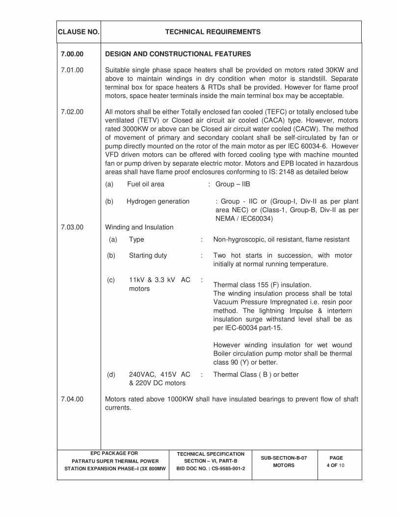
CLAUSE NO.
TECHNICAL REQUIREMENTS
EPC PACKAGE FOR
PATRATU SUPER THERMAL POWER
STATION EXPANSION PHASE–I (3X 800MW
TECHNICAL SPECIFICATION
SECTION – VI, PART-B
BID DOC NO. : CS-9585-001-2
SUB-SECTION-B-07
MOTORS
PAGE
4 OF 10
7.00.00 DESIGN AND CONSTRUCTIONAL FEATURES
7.01.00 Suitable single phase space heaters shall be provided on motors rated 30KW and
above to maintain windings in dry condition when motor is standstill. Separate
terminal box for space heaters & RTDs shall be provided. However for flame proof
motors, space heater terminals inside the main terminal box may be acceptable.
7.02.00 All motors shall be either Totally enclosed fan cooled (TEFC) or totally enclosed tube
ventilated (TETV) or Closed air circuit air cooled (CACA) type. However, motors
rated 3000KW or above can be Closed air circuit water cooled (CACW). The method
of movement of primary and secondary coolant shall be self-circulated by fan or
pump directly mounted on the rotor of the main motor as per IEC 60034-6. However
VFD driven motors can be offered with forced cooling type with machine mounted
fan or pump driven by separate electric motor. Motors and EPB located in hazardous
areas shall have flame proof enclosures conforming to IS: 2148 as detailed below
(a) Fuel oil area : Group – IIB
(b) Hydrogen generation : Group - IIC or (Group-I, Div-II as per plant
area NEC) or (Class-1, Group-B, Div-II as per
NEMA / IEC60034)
7.03.00 Winding and Insulation
(a) Type : Non-hygroscopic, oil resistant, flame resistant
(b) Starting duty : Two hot starts in succession, with motor
initially at normal running temperature.
(c) 11kV & 3.3 kV AC
motors
:
Thermal class 155 (F) insulation.
The winding insulation process shall be total
Vacuum Pressure Impregnated i.e. resin poor
method. The lightning Impulse & intertern
insulation surge withstand level shall be as
per IEC-60034 part-15.
However winding insulation for wet wound
Boiler circulation pump motor shall be thermal
class 90 (Y) or better.
(d) 240VAC, 415V AC
& 220V DC motors
: Thermal Class ( B ) or better
7.04.00 Motors rated above 1000KW shall have insulated bearings to prevent flow of shaft
currents.
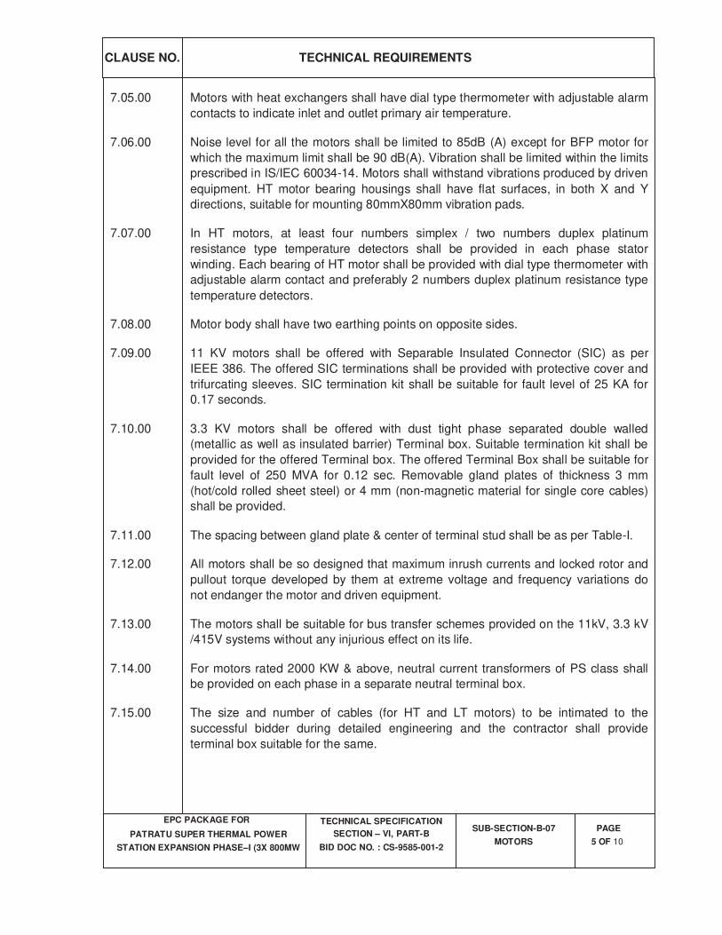
CLAUSE NO.
TECHNICAL REQUIREMENTS
EPC PACKAGE FOR
PATRATU SUPER THERMAL POWER
STATION EXPANSION PHASE–I (3X 800MW
TECHNICAL SPECIFICATION
SECTION – VI, PART-B
BID DOC NO. : CS-9585-001-2
SUB-SECTION-B-07
MOTORS
PAGE
5 OF 10
7.05.00 Motors with heat exchangers shall have dial type thermometer with adjustable alarm
contacts to indicate inlet and outlet primary air temperature.
7.06.00 Noise level for all the motors shall be limited to 85dB (A) except for BFP motor for
which the maximum limit shall be 90 dB(A). Vibration shall be limited within the limits
prescribed in IS/IEC 60034-14. Motors shall withstand vibrations produced by driven
equipment. HT motor bearing housings shall have flat surfaces, in both X and Y
directions, suitable for mounting 80mmX80mm vibration pads.
7.07.00 In HT motors, at least four numbers simplex / two numbers duplex platinum
resistance type temperature detectors shall be provided in each phase stator
winding. Each bearing of HT motor shall be provided with dial type thermometer with
adjustable alarm contact and preferably 2 numbers duplex platinum resistance type
temperature detectors.
7.08.00 Motor body shall have two earthing points on opposite sides.
7.09.00 11 KV motors shall be offered with Separable Insulated Connector (SIC) as per
IEEE 386. The offered SIC terminations shall be provided with protective cover and
trifurcating sleeves. SIC termination kit shall be suitable for fault level of 25 KA for
0.17 seconds.
7.10.00 3.3 KV motors shall be offered with dust tight phase separated double walled
(metallic as well as insulated barrier) Terminal box. Suitable termination kit shall be
provided for the offered Terminal box. The offered Terminal Box shall be suitable for
fault level of 250 MVA for 0.12 sec. Removable gland plates of thickness 3 mm
(hot/cold rolled sheet steel) or 4 mm (non-magnetic material for single core cables)
shall be provided.
7.11.00 The spacing between gland plate & center of terminal stud shall be as per Table-I.
7.12.00 All motors shall be so designed that maximum inrush currents and locked rotor and
pullout torque developed by them at extreme voltage and frequency variations do
not endanger the motor and driven equipment.
7.13.00 The motors shall be suitable for bus transfer schemes provided on the 11kV, 3.3 kV
/415V systems without any injurious effect on its life.
7.14.00 For motors rated 2000 KW & above, neutral current transformers of PS class shall
be provided on each phase in a separate neutral terminal box.
7.15.00 The size and number of cables (for HT and LT motors) to be intimated to the
successful bidder during detailed engineering and the contractor shall provide
terminal box suitable for the same.
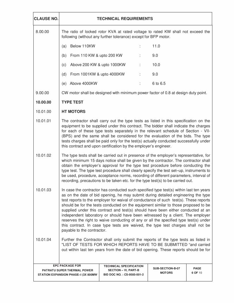
CLAUSE NO.
TECHNICAL REQUIREMENTS
EPC PACKAGE FOR
PATRATU SUPER THERMAL POWER
STATION EXPANSION PHASE–I (3X 800MW
TECHNICAL SPECIFICATION
SECTION – VI, PART-B
BID DOC NO. : CS-9585-001-2
SUB-SECTION-B-07
MOTORS
PAGE
6 OF 10
8.00.00 The ratio of locked rotor KVA at rated voltage to rated KW shall not exceed the
following (without any further tolerance) except for BFP motor.
(a) Below 110KW : 11.0
(b) From 110 KW & upto 200 KW : 9.0
(c) Above 200 KW & upto 1000KW : 10.0
(d) From 1001KW & upto 4000KW : 9.0
(e) Above 4000KW : 6 to 6.5
9.00.00 CW motor shall be designed with minimum power factor of 0.8 at design duty point.
10.00.00 TYPE TEST
10.01.00 HT MOTORS
10.01.01 The contractor shall carry out the type tests as listed in this specification on the
equipment to be supplied under this contract. The bidder shall indicate the charges
for each of these type tests separately in the relevant schedule of Section - VII-
(BPS) and the same shall be considered for the evaluation of the bids. The type
tests charges shall be paid only for the test(s) actually conducted successfully under
this contract and upon certification by the employer’s engineer.
10.01.02 The type tests shall be carried out in presence of the employer’s representative, for
which minimum 15 days notice shall be given by the contractor. The contractor shall
obtain the employer’s approval for the type test procedure before conducting the
type test. The type test procedure shall clearly specify the test set–up, instruments to
be used, procedure, acceptance norms, recording of different parameters, interval of
recording, precautions to be taken etc. for the type test(s) to be carried out.
10.01.03 In case the contractor has conducted such specified type test(s) within last ten years
as on the date of bid opening, he may submit during detailed engineering the type
test reports to the employer for waival of conductance of such test(s). These reports
should be for the tests conducted on the equipment similar to those proposed to be
supplied under this contract and test(s) should have been either conducted at an
independent laboratory or should have been witnessed by a client. The employer
reserves the right to waive conducting of any or all the specified type test(s) under
this contract. In case type tests are waived, the type test charges shall not be
payable to the contractor.
10.01.04 Further the Contractor shall only submit the reports of the type tests as listed in
"LIST OF TESTS FOR WHICH REPORTS HAVE TO BE SUBMITTED “and carried
out within last ten years from the date of bid opening. These reports should be for
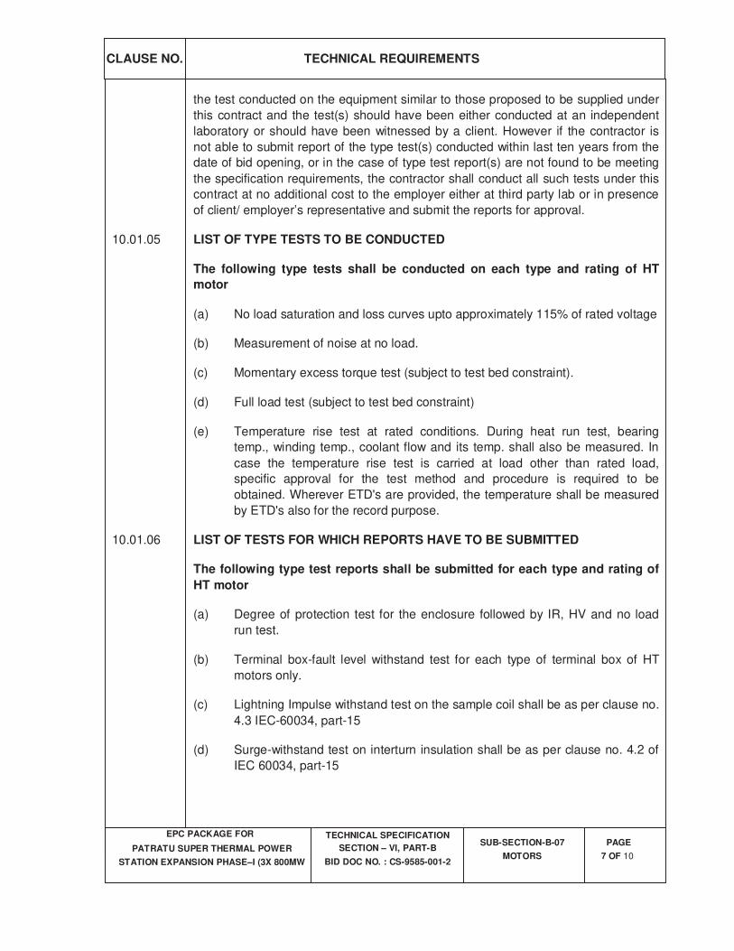
CLAUSE NO.
TECHNICAL REQUIREMENTS
EPC PACKAGE FOR
PATRATU SUPER THERMAL POWER
STATION EXPANSION PHASE–I (3X 800MW
TECHNICAL SPECIFICATION
SECTION – VI, PART-B
BID DOC NO. : CS-9585-001-2
SUB-SECTION-B-07
MOTORS
PAGE
7 OF 10
the test conducted on the equipment similar to those proposed to be supplied under
this contract and the test(s) should have been either conducted at an independent
laboratory or should have been witnessed by a client. However if the contractor is
not able to submit report of the type test(s) conducted within last ten years from the
date of bid opening, or in the case of type test report(s) are not found to be meeting
the specification requirements, the contractor shall conduct all such tests under this
contract at no additional cost to the employer either at third party lab or in presence
of client/ employer’s representative and submit the reports for approval.
10.01.05 LIST OF TYPE TESTS TO BE CONDUCTED
The following type tests shall be conducted on each type and rating of HT
motor
(a) No load saturation and loss curves upto approximately 115% of rated voltage
(b) Measurement of noise at no load.
(c) Momentary excess torque test (subject to test bed constraint).
(d) Full load test (subject to test bed constraint)
(e) Temperature rise test at rated conditions. During heat run test, bearing
temp., winding temp., coolant flow and its temp. shall also be measured. In
case the temperature rise test is carried at load other than rated load,
specific approval for the test method and procedure is required to be
obtained. Wherever ETD's are provided, the temperature shall be measured
by ETD's also for the record purpose.
10.01.06 LIST OF TESTS FOR WHICH REPORTS HAVE TO BE SUBMITTED
The following type test reports shall be submitted for each type and rating of
HT motor
(a) Degree of protection test for the enclosure followed by IR, HV and no load
run test.
(b) Terminal box-fault level withstand test for each type of terminal box of HT
motors only.
(c) Lightning Impulse withstand test on the sample coil shall be as per clause no.
4.3 IEC-60034, part-15
(d) Surge-withstand test on interturn insulation shall be as per clause no. 4.2 of
IEC 60034, part-15
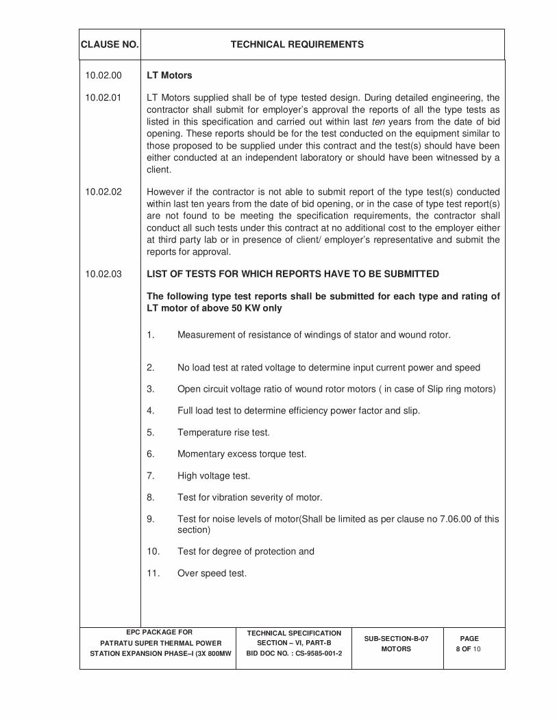
CLAUSE NO.
TECHNICAL REQUIREMENTS
EPC PACKAGE FOR
PATRATU SUPER THERMAL POWER
STATION EXPANSION PHASE–I (3X 800MW
TECHNICAL SPECIFICATION
SECTION – VI, PART-B
BID DOC NO. : CS-9585-001-2
SUB-SECTION-B-07
MOTORS
PAGE
8 OF 10
10.02.00 LT Motors
10.02.01 LT Motors supplied shall be of type tested design. During detailed engineering, the
contractor shall submit for employer’s approval the reports of all the type tests as
listed in this specification and carried out within last ten years from the date of bid
opening. These reports should be for the test conducted on the equipment similar to
those proposed to be supplied under this contract and the test(s) should have been
either conducted at an independent laboratory or should have been witnessed by a
client.
10.02.02 However if the contractor is not able to submit report of the type test(s) conducted
within last ten years from the date of bid opening, or in the case of type test report(s)
are not found to be meeting the specification requirements, the contractor shall
conduct all such tests under this contract at no additional cost to the employer either
at third party lab or in presence of client/ employer’s representative and submit the
reports for approval.
10.02.03 LIST OF TESTS FOR WHICH REPORTS HAVE TO BE SUBMITTED
The following type test reports shall be submitted for each type and rating of
LT motor of above 50 KW only
1. Measurement of resistance of windings of stator and wound rotor. 2. No load test at rated voltage to determine input current power and speed
3. Open circuit voltage ratio of wound rotor motors ( in case of Slip ring motors) 4. Full load test to determine efficiency power factor and slip. 5. Temperature rise test. 6. Momentary excess torque test. 7. High voltage test.
8. Test for vibration severity of motor. 9. Test for noise levels of motor(Shall be limited as per clause no 7.06.00 of this
section) 10. Test for degree of protection and 11. Over speed test.
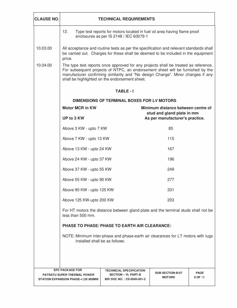
CLAUSE NO.
TECHNICAL REQUIREMENTS
EPC PACKAGE FOR
PATRATU SUPER THERMAL POWER
STATION EXPANSION PHASE–I (3X 800MW
TECHNICAL SPECIFICATION
SECTION – VI, PART-B
BID DOC NO. : CS-9585-001-2
SUB-SECTION-B-07
MOTORS
PAGE
9 OF 10
12. Type test reports for motors located in fuel oil area having flame proof enclosures as per IS 2148 / IEC 60079-1
10.03.00 All acceptance and routine tests as per the specification and relevant standards shall
be carried out. Charges for these shall be deemed to be included in the equipment
price.
10.04.00 The type test reports once approved for any projects shall be treated as reference. For subsequent projects of NTPC, an endorsement sheet will be furnished by the manufacturer confirming similarity and “No design Change”. Minor changes if any shall be highlighted on the endorsement sheet.
TABLE - I
DIMENSIONS OF TERMINAL BOXES FOR LV MOTORS
Motor MCR in KW Minimum distance between centre of
stud and gland plate in mm
UP to 3 KW As per manufacturer's practice.
Above 3 KW - upto 7 KW 85
Above 7 KW - upto 13 KW 115
Above 13 KW - upto 24 KW 167
Above 24 KW - upto 37 KW 196
Above 37 KW - upto 55 KW 249
Above 55 KW - upto 90 KW 277
Above 90 KW - upto 125 KW 331
Above 125 KW-upto 200 KW 203
For HT motors the distance between gland plate and the terminal studs shall not be
less than 500 mm.
PHASE TO PHASE/ PHASE TO EARTH AIR CLEARANCE:
NOTE: Minimum inter-phase and phase-earth air clearances for LT motors with lugs
installed shall be as follows:
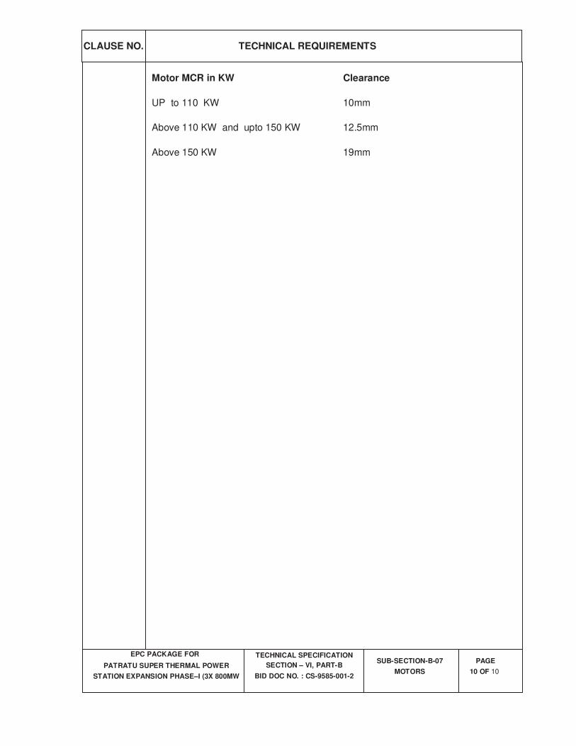
CLAUSE NO.
TECHNICAL REQUIREMENTS
EPC PACKAGE FOR
PATRATU SUPER THERMAL POWER
STATION EXPANSION PHASE–I (3X 800MW
TECHNICAL SPECIFICATION
SECTION – VI, PART-B
BID DOC NO. : CS-9585-001-2
SUB-SECTION-B-07
MOTORS
PAGE
10 OF 10
Motor MCR in KW Clearance
UP to 110 KW 10mm
Above 110 KW and upto 150 KW 12.5mm
Above 150 KW 19mm

ANNEXURE- amd2.3
File Formats supported for
IPDS
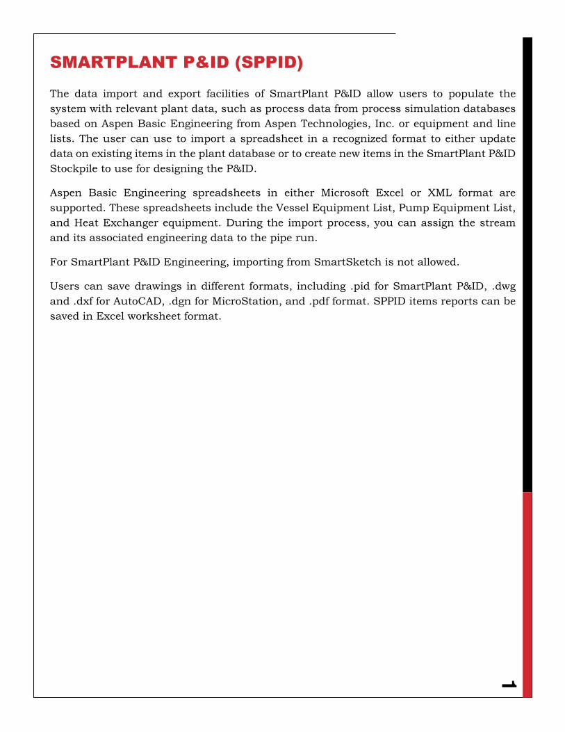
1
SMARTPLANT P&ID (SPPID)
The data import and export facilities of SmartPlant P&ID allow users to populate the
system with relevant plant data, such as process data from process simulation databases
based on Aspen Basic Engineering from Aspen Technologies, Inc. or equipment and line
lists. The user can use to import a spreadsheet in a recognized format to either update
data on existing items in the plant database or to create new items in the SmartPlant P&ID
Stockpile to use for designing the P&ID.
Aspen Basic Engineering spreadsheets in either Microsoft Excel or XML format are
supported. These spreadsheets include the Vessel Equipment List, Pump Equipment List,
and Heat Exchanger equipment. During the import process, you can assign the stream
and its associated engineering data to the pipe run.
For SmartPlant P&ID Engineering, importing from SmartSketch is not allowed.
Users can save drawings in different formats, including .pid for SmartPlant P&ID, .dwg
and .dxf for AutoCAD, .dgn for MicroStation, and .pdf format. SPPID items reports can be
saved in Excel worksheet format.
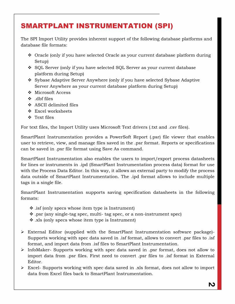
2
SMARTPLANT INSTRUMENTATION (SPI)
The SPI Import Utility provides inherent support of the following database platforms and
database file formats:
Oracle (only if you have selected Oracle as your current database platform during
Setup)
SQL Server (only if you have selected SQL Server as your current database
platform during Setup)
Sybase Adaptive Server Anywhere (only if you have selected Sybase Adaptive
Server Anywhere as your current database platform during Setup)
Microsoft Access
.dbf files
ASCII delimited files
Excel worksheets
Text files
For text files, the Import Utility uses Microsoft Text drivers (.txt and .csv files).
SmartPlant Instrumentation provides a PowerSoft Report (.psr) file viewer that enables
user to retrieve, view, and manage files saved in the .psr format. Reports or specifications
can be saved in .psr file format using Save As command.
SmartPlant Instrumentation also enables the users to import/export process datasheets
for lines or instruments in .ipd (SmartPlant Instrumentation process data) format for use
with the Process Data Editor. In this way, it allows an external party to modify the process
data outside of SmartPlant Instrumentation. The .ipd format allows to include multiple
tags in a single file.
SmartPlant Instrumentation supports saving specification datasheets in the following
formats:
.isf (only specs whose item type is Instrument)
.psr (any single-tag spec, multi- tag spec, or a non-instrument spec)
.xls (only specs whose item type is Instrument)
External Editor (supplied with the SmartPlant Instrumentation software package)-
Supports working with spec data saved in .isf format, allows to convert .psr files to .isf
format, and import data from .isf files to SmartPlant Instrumentation.
InfoMaker- Supports working with spec data saved in .psr format, does not allow to
import data from .psr files. First need to convert .psr files to .isf format in External
Editor.
Excel- Supports working with spec data saved in .xls format, does not allow to import
data from Excel files back to SmartPlant Instrumentation.
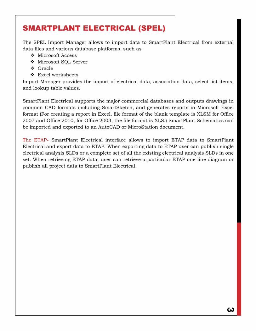
3
SMARTPLANT ELECTRICAL (SPEL)
The SPEL Import Manager allows to import data to SmartPlant Electrical from external
data files and various database platforms, such as
Microsoft Access
Microsoft SQL Server
Oracle
Excel worksheets
Import Manager provides the import of electrical data, association data, select list items,
and lookup table values.
SmartPlant Electrical supports the major commercial databases and outputs drawings in
common CAD formats including SmartSketch, and generates reports in Microsoft Excel
format (For creating a report in Excel, file format of the blank template is XLSM for Office
2007 and Office 2010, for Office 2003, the file format is XLS.) SmartPlant Schematics can
be imported and exported to an AutoCAD or MicroStation document.
The ETAP- SmartPlant Electrical interface allows to import ETAP data to SmartPlant
Electrical and export data to ETAP. When exporting data to ETAP user can publish single
electrical analysis SLDs or a complete set of all the existing electrical analysis SLDs in one
set. When retrieving ETAP data, user can retrieve a particular ETAP one-line diagram or
publish all project data to SmartPlant Electrical.
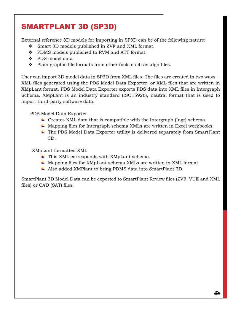
4
SMARTPLANT 3D (SP3D)
External reference 3D models for importing in SP3D can be of the following nature:
Smart 3D models published in ZVF and XML format.
PDMS models published to RVM and ATT format.
PDS model data
Plain graphic file formats from other tools such as .dgn files.
User can import 3D model data in SP3D from XML files. The files are created in two ways—XML files generated using the PDS Model Data Exporter, or XML files that are written in
XMpLant format. PDS Model Data Exporter exports PDS data into XML files in Intergraph
Schema. XMpLant is an industry standard (ISO15926), neutral format that is used to
import third-party software data.
PDS Model Data Exporter
Creates XML data that is compatible with the Intergraph (Ingr) schema.
Mapping files for Intergraph schema XMLs are written in Excel workbooks.
The PDS Model Data Exporter utility is delivered separately from SmartPlant
3D.
XMpLant-formatted XML
This XML corresponds with XMpLant schema.
Mapping files for XMpLant schema XMLs are written in XML format.
Also added XMPlant to bring PDMS data into SmartPlant 3D
SmartPlant 3D Model Data can be exported to SmartPlant Review files (ZVF, VUE and XML
files) or CAD (SAT) files.
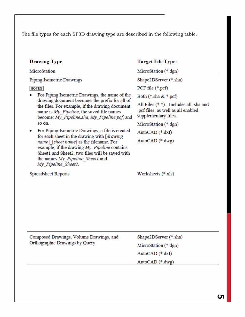
5
The file types for each SP3D drawing type are described in the following table.
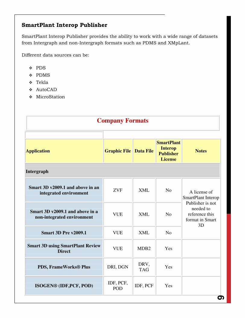
6
SmartPlant Interop Publisher
SmartPlant Interop Publisher provides the ability to work with a wide range of datasets
from Intergraph and non-Intergraph formats such as PDMS and XMpLant.
Different data sources can be:
PDS
PDMS
Tekla
AutoCAD
MicroStation
Company Formats
Application Graphic File Data File
SmartPlant
Interop
Publisher
License
Notes
Intergraph
Smart 3D v2009.1 and above in an
integrated environment ZVF XML No A license of
SmartPlant Interop
Publisher is not
needed to
reference this
format in Smart
3D
Smart 3D v2009.1 and above in a
non-integrated environment VUE XML No
Smart 3D Pre v2009.1 VUE XML No
Smart 3D using SmartPlant Review
Direct VUE MDB2 Yes
PDS, FrameWorks® Plus DRI, DGN DRV,
TAG Yes
ISOGEN® (IDF,PCF, POD) IDF, PCF,
POD IDF, PCF Yes
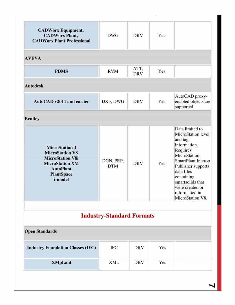
7
Industry-Standard Formats
Open Standards
Industry Foundation Classes (IFC) IFC DRV Yes
XMpLant XML DRV Yes
CADWorx Equipment,
CADWorx Plant,
CADWorx Plant Professional
DWG DRV Yes
AVEVA
PDMS RVM ATT,
DRV Yes
Autodesk
AutoCAD v2011 and earlier DXF, DWG DRV Yes
AutoCAD proxy-
enabled objects are
supported.
Bentley
MicroStation J
MicroStation V8
MicroStation V8i
MicroStation XM
AutoPlant
PlantSpace
i-model
DGN, PRP,
DTM DRV Yes
Data limited to
MicroStation level
and tag
information.
Requires
MicroStation.
SmartPlant Interop
Publisher supports
data files
containing
smartsolids that
were created or
reformatted in
MicroStation V8.
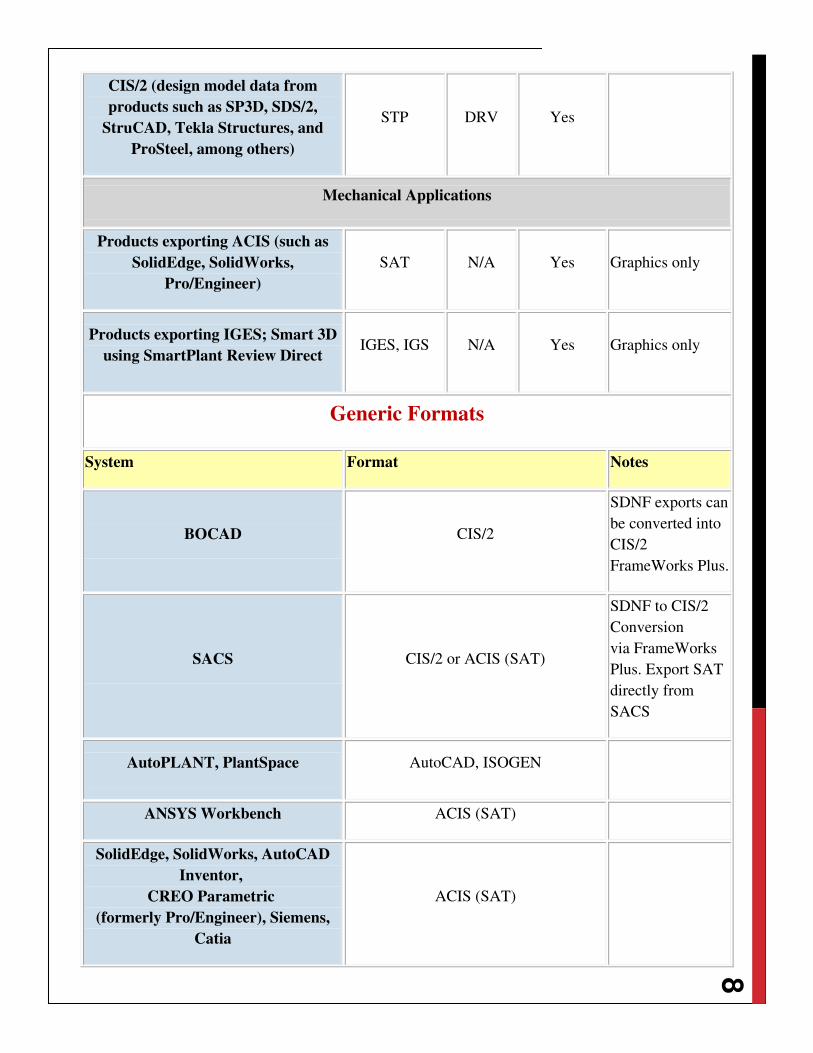
8
CIS/2 (design model data from
products such as SP3D, SDS/2,
StruCAD, Tekla Structures, and
ProSteel, among others)
STP DRV Yes
Mechanical Applications
Products exporting ACIS (such as
SolidEdge, SolidWorks,
Pro/Engineer)
SAT N/A Yes Graphics only
Products exporting IGES; Smart 3D
using SmartPlant Review Direct IGES, IGS N/A Yes Graphics only
Generic Formats
System Format Notes
BOCAD CIS/2
SDNF exports can
be converted into
CIS/2
FrameWorks Plus.
SACS CIS/2 or ACIS (SAT)
SDNF to CIS/2
Conversion
via FrameWorks
Plus. Export SAT
directly from
SACS
AutoPLANT, PlantSpace AutoCAD, ISOGEN
ANSYS Workbench ACIS (SAT)
SolidEdge, SolidWorks, AutoCAD
Inventor,
CREO Parametric
(formerly Pro/Engineer), Siemens,
Catia
ACIS (SAT)
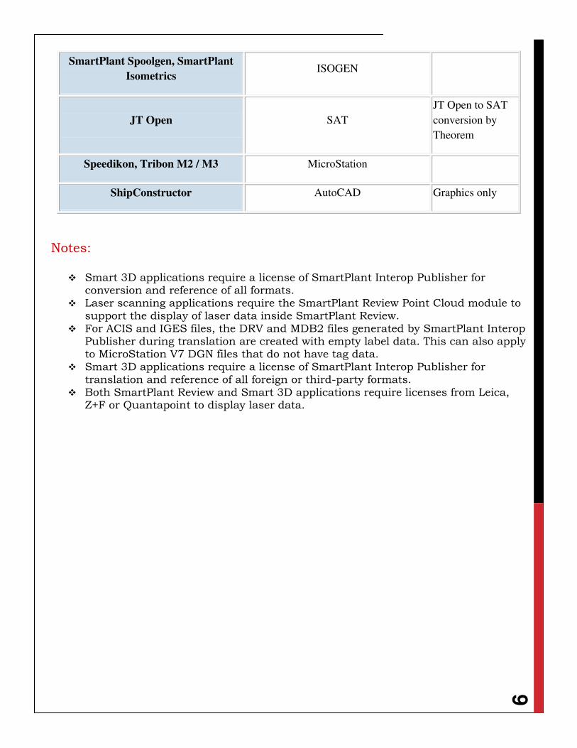
9
SmartPlant Spoolgen, SmartPlant
Isometrics ISOGEN
JT Open SAT
JT Open to SAT
conversion by
Theorem
Speedikon, Tribon M2 / M3 MicroStation
ShipConstructor AutoCAD Graphics only
Notes:
Smart 3D applications require a license of SmartPlant Interop Publisher for conversion and reference of all formats.
Laser scanning applications require the SmartPlant Review Point Cloud module to support the display of laser data inside SmartPlant Review.
For ACIS and IGES files, the DRV and MDB2 files generated by SmartPlant Interop Publisher during translation are created with empty label data. This can also apply to MicroStation V7 DGN files that do not have tag data.
Smart 3D applications require a license of SmartPlant Interop Publisher for translation and reference of all foreign or third-party formats.
Both SmartPlant Review and Smart 3D applications require licenses from Leica, Z+F or Quantapoint to display laser data.
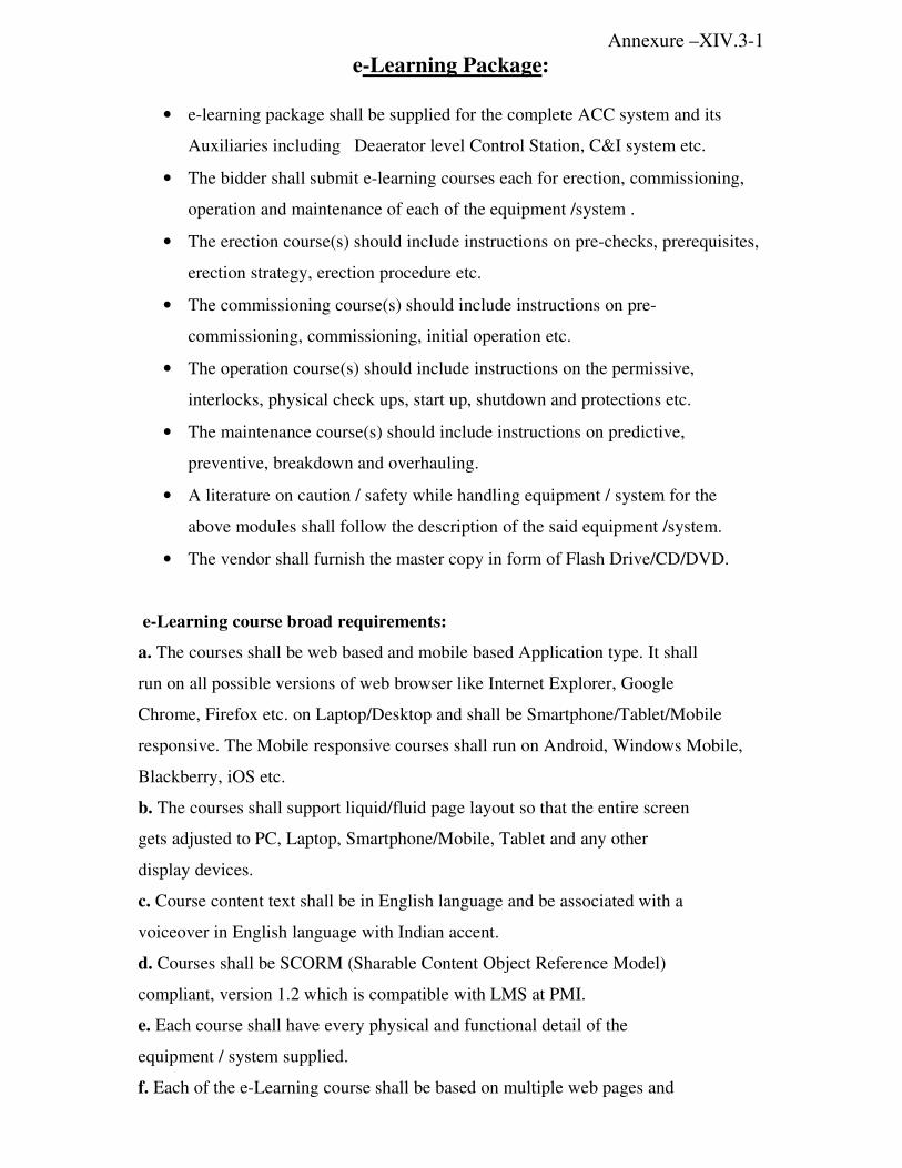
Annexure –XIV.3-1
e-Learning Package:
• e-learning package shall be supplied for the complete ACC system and its
Auxiliaries including Deaerator level Control Station, C&I system etc.
• The bidder shall submit e-learning courses each for erection, commissioning,
operation and maintenance of each of the equipment /system .
• The erection course(s) should include instructions on pre-checks, prerequisites,
erection strategy, erection procedure etc.
• The commissioning course(s) should include instructions on pre-
commissioning, commissioning, initial operation etc.
• The operation course(s) should include instructions on the permissive,
interlocks, physical check ups, start up, shutdown and protections etc.
• The maintenance course(s) should include instructions on predictive,
preventive, breakdown and overhauling.
• A literature on caution / safety while handling equipment / system for the
above modules shall follow the description of the said equipment /system.
• The vendor shall furnish the master copy in form of Flash Drive/CD/DVD.
e-Learning course broad requirements:
a. The courses shall be web based and mobile based Application type. It shall
run on all possible versions of web browser like Internet Explorer, Google
Chrome, Firefox etc. on Laptop/Desktop and shall be Smartphone/Tablet/Mobile
responsive. The Mobile responsive courses shall run on Android, Windows Mobile,
Blackberry, iOS etc.
b. The courses shall support liquid/fluid page layout so that the entire screen
gets adjusted to PC, Laptop, Smartphone/Mobile, Tablet and any other
display devices.
c. Course content text shall be in English language and be associated with a
voiceover in English language with Indian accent.
d. Courses shall be SCORM (Sharable Content Object Reference Model)
compliant, version 1.2 which is compatible with LMS at PMI.
e. Each course shall have every physical and functional detail of the
equipment / system supplied.
f. Each of the e-Learning course shall be based on multiple web pages and
mobile pages with multiple modules.
g. There shall be option for self-assessment test after every course. In case the
user doesn’t opt for self assessment test the user shall be able to go to the
next course. There shall be no restriction in no. of times for repeating the
assessments. All correct answers along with the answers marked by the
users shall be displayed at the end of test/quiz.
h. If Java and Flash, as applicable are not available in the system to run the
package, then there shall be a prompt message for updation of the same.
i. Each course shall have a self-running interactive content with navigation
buttons containing forward, backward, pause, bookmark and menu options
in the course window.
j. The course shall contain chapter titled 'Introduction/overview' that explains
the purpose of the course.
k. The course content shall contain descriptive text shall be factual, specific,
terse, clearly worded, and simply illustrative, so that the user can understand it.
l. The system shall provide the user with the ability to select the information
with a Cursor.
m. The course menu should contain table of content linked to concerned
pages. The user shall be given the capability to access all of the functions
available on the system through a menu system. This shall consist of active
buttons, which shall control a hierarchy of pull down/pop up menus. Menu
shall appear quickly and exist only while a selection is being made. The
user shall be given the capability to position the cursor or pointer on the
menu item and use pointer device such as mouse to activate the function.
n. Every course shall contain the 3D design/drawing/exploded view/3600
turn around view of the equipment/system, textual description of the
equipment/system and its functionality with video (as applicable),
animation and audio.
o. The users shall be able to control audio sound level associated with the
courses.
p. Drawings / text in the courses shall be scalable (Zoom In/ Out).
q. The user shall have the capability to record a bookmark to mark displayed
information for later recall, whenever he accesses the same course next
time.

Notes:
1. e-learning Package of an equipment / system shall include e-learning
courses for each of erection, commissioning, operation and maintenance
of that equipment / system.
2. e-learning courses on erection, commissioning, operation and
maintenance of an equipment / system shall include e-learning
lessons/chapters/modules (as required) for erection, commissioning,
operation and maintenance respectively of that equipment / system.
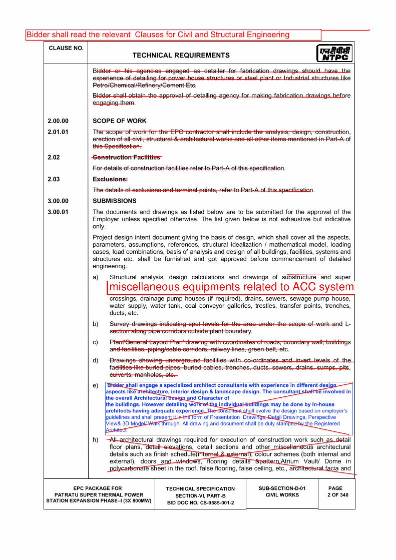
CLAUSE NO.
TECHNICAL REQUIREMENTS
EPC PACKAGE FOR
PATRATU SUPER THERMAL POWER STATION EXPANSION PHASE�I (3X 800MW)
TECHNICAL SPECIFICATION
SECTION-VI, PART-B
BID DOC NO. CS-9585-001-2
SUB-SECTION-D-01
CIVIL WORKS
PAGE
2 OF 340
Bidder or his agencies engaged as detailer for fabrication drawings should have the experience of detailing for power house structures or steel plant or Industrial structures like Petro/Chemical/Refinery/Cement Etc.
Bidder shall obtain the approval of detailing agency for making fabrication drawings before engaging them.
2.00.00 SCOPE OF WORK
2.01.01 The scope of work for the EPC contractor shall include the analysis, design, construction, erection of all civil, structural & architectural works and all other items mentioned in Part-A of this Specification.
2.02 Construction Facilities
For details of construction facilities refer to Part-A of this specification.
2.03 Exclusions:
The details of exclusions and terminal points, refer to Part-A of this specification.
3.00.00 SUBMISSIONS
3.00.01 The documents and drawings as listed below are to be submitted for the approval of the Employer unless specified otherwise. The list given below is not exhaustive but indicative only.
Project design intent document giving the basis of design, which shall cover all the aspects, parameters, assumptions, references, structural idealization / mathematical model, loading cases, load combinations, basis of analysis and design of all buildings, facilities, systems and structures etc. shall be furnished and got approved before commencement of detailed engineering.
a) Structural analysis, design calculations and drawings of substructure and super structures for all buildings, structures, facilities, and systems. Analysis, design calculations and drawings for all services like roads, culverts, bridges, road/rail crossings, drainage pump houses (if required), drains, sewers, sewage pump house, water supply, water tank, coal conveyor galleries, trestles, transfer points, trenches, ducts, etc.
b) Survey drawings indicating spot levels for the area under the scope of work and L-section along pipe corridors outside plant boundary.
c) Plant'General Layout Plan' drawing with coordinates of roads, boundary wall, buildings and facilities, piping/cable corridors, railway lines, green belt, etc.
d) Drawings showing underground facilities with co-ordinates and invert levels of the facilities like buried pipes, buried cables, trenches, ducts, sewers, drains, sumps, pits, culverts, manholes, etc.
e) Architectural Design and Detailing aspect of all the Building shall be rendered through professional services of a registered Architect. The Architect consultant shall be of National/ International repute, having experience in similar kind of works. The consultant shall evolve the design based on employer's guidelines and shall present it in the form of Presentation Drawings, Detail Drawings, Perspective View& 3D Model/ Walk through. All drawing and document shall be duly stamped by the Registered Architect.
h) All architectural drawings required for execution of construction work such as detail floor plans, detail elevations, detail sections and other miscellaneous architectural details such as finish schedule(internal & external), colour schemes (both internal and external), doors and windows, flooring details &pattern,Atrium Vault/ Dome in polycarbonate sheet in the roof, false flooring, false ceiling, etc., architectural facia and
Bidder shall engage a specialized architect consultants with experience in different design
aspects like architecture, interior design & landscape design. The consultant shall be involved in
the overall Architectural design and Character of
the buildings. However detailing work of the individual buildings may be done by In-house
architects having adequate experience. The consultant shall evolve the design based on employer's
guidelines and shall present it in the form of Presentation Drawings, Detail Drawings, Perspective
View& 3D Model/ Walk through. All drawing and document shall be duly stamped by the Registered
Architect
Annexure-1
Bidder shall read the relevant Clauses for Civil and Structural Engineering
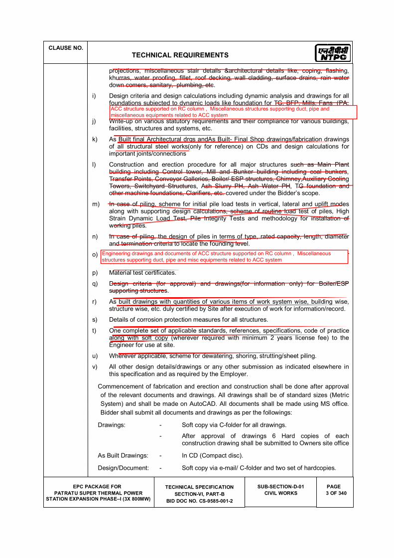
CLAUSE NO.
TECHNICAL REQUIREMENTS
EPC PACKAGE FOR
PATRATU SUPER THERMAL POWER STATION EXPANSION PHASE�I (3X 800MW)
TECHNICAL SPECIFICATION
SECTION-VI, PART-B
BID DOC NO. CS-9585-001-2
SUB-SECTION-D-01
CIVIL WORKS
PAGE
3 OF 340
projections, miscellaneous stair details &architectural details like, coping, flashing, khurras, water proofing, fillet, roof decking, wall cladding, surface drains, rain water down comers, sanitary, plumbing, etc.
i) Design criteria and design calculations including dynamic analysis and drawings for all foundations subjected to dynamic loads like foundation for TG, BFP, Mills, Fans (PA, FD, ID& Seal Air), Crusher etc.
j) Write-up on various statutory requirements and their compliance for various buildings, facilities, structures and systems, etc.
k) As Built final Architectural drgs andAs Built- Final Shop drawings/fabrication drawings of all structural steel works(only for reference) on CDs and design calculations for important joints/connections
l) Construction and erection procedure for all major structures such as Main Plant building including Control tower, Mill and Bunker building including coal bunkers, Transfer Points, Conveyor Galleries, Boiler/ ESP structures, Chimney,Auxiliary Cooling Towers, Switchyard Structures, Ash Slurry PH, Ash Water PH, TG foundation and other machine foundations, Clarifiers, etc. covered under the Bidder�s scope.
m) In case of piling, scheme for initial pile load tests in vertical, lateral and uplift modes along with supporting design calculations, scheme of routine load test of piles, High Strain Dynamic Load Test, Pile Integrity Tests and methodology for installation of working piles.
n) In case of piling, the design of piles in terms of type, rated capacity, length, diameter and termination criteria to locate the founding level.
o) Marking scheme identifying the equipment lay-down areas, with distinctive colour scheme.
p) Material test certificates.
q) Design criteria (for approval) and drawings(for information only) for Boiler/ESP supporting structures.
r) As built drawings with quantities of various items of work system wise, building wise, structure wise, etc. duly certified by Site after execution of work for information/record.
s) Details of corrosion protection measures for all structures.
t) One complete set of applicable standards, references, specifications, code of practice along with soft copy (wherever required with minimum 2 years license fee) to the Engineer for use at site.
u) Wherever applicable, scheme for dewatering, shoring, strutting/sheet piling.
v) All other design details/drawings or any other submission as indicated elsewhere in this specification and as required by the Employer.
Commencement of fabrication and erection and construction shall be done after approval
of the relevant documents and drawings. All drawings shall be of standard sizes (Metric
System) and shall be made on AutoCAD. All documents shall be made using MS office.
Bidder shall submit all documents and drawings as per the followings:
Drawings: - Soft copy via C-folder for all drawings.
- After approval of drawings 6 Hard copies of each construction drawing shall be submitted to Owners site office
As Built Drawings: - In CD (Compact disc).
Design/Document: - Soft copy via e-mail/ C-folder and two set of hardcopies.
ACC structure supported on RC column , Miscellaneous structures supporting duct, pipe and
miscellaneous equipments related to ACC system
Engineering drawings and documents of ACC structure supported on RC column , Miscellaneous
structures supporting duct, pipe and misc equipments related to ACC system
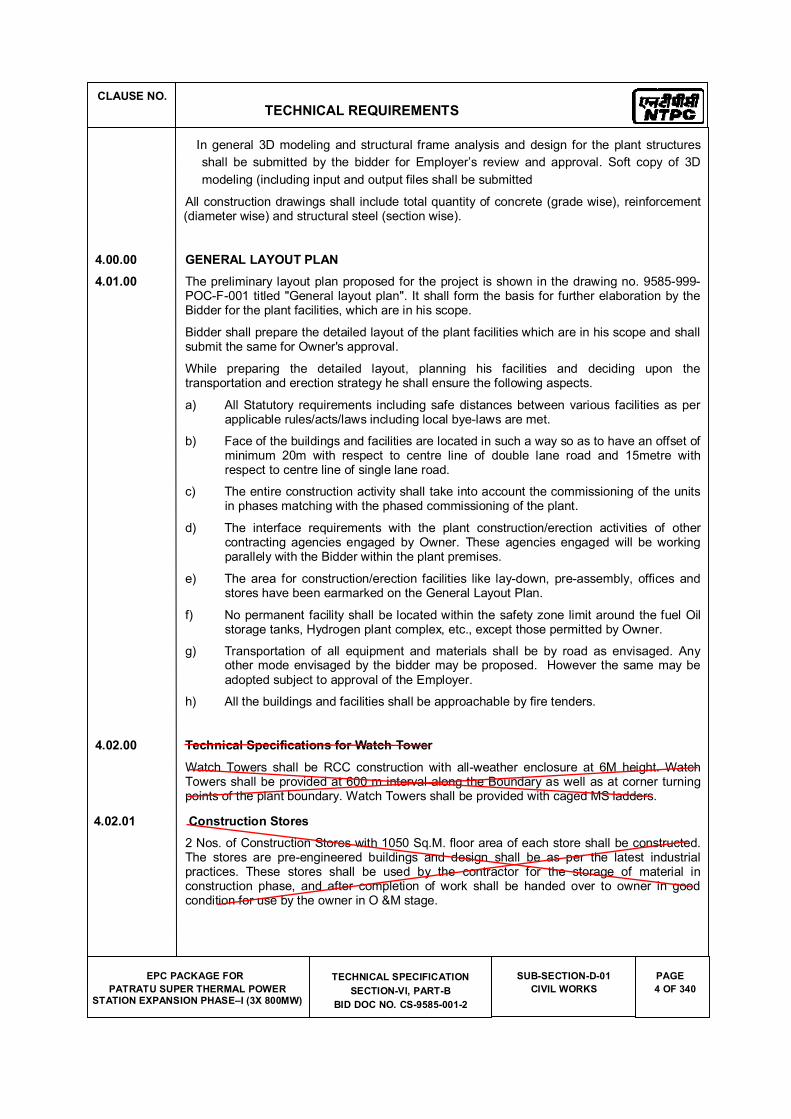
CLAUSE NO.
TECHNICAL REQUIREMENTS
EPC PACKAGE FOR
PATRATU SUPER THERMAL POWER STATION EXPANSION PHASE�I (3X 800MW)
TECHNICAL SPECIFICATION
SECTION-VI, PART-B
BID DOC NO. CS-9585-001-2
SUB-SECTION-D-01
CIVIL WORKS
PAGE
4 OF 340
In general 3D modeling and structural frame analysis and design for the plant structures
shall be submitted by the bidder for Employer�s review and approval. Soft copy of 3D
modeling (including input and output files shall be submitted
All construction drawings shall include total quantity of concrete (grade wise), reinforcement (diameter wise) and structural steel (section wise).
4.00.00 GENERAL LAYOUT PLAN
4.01.00 The preliminary layout plan proposed for the project is shown in the drawing no. 9585-999-POC-F-001 titled "General layout plan". It shall form the basis for further elaboration by the Bidder for the plant facilities, which are in his scope.
Bidder shall prepare the detailed layout of the plant facilities which are in his scope and shall submit the same for Owner's approval.
While preparing the detailed layout, planning his facilities and deciding upon the transportation and erection strategy he shall ensure the following aspects.
a) All Statutory requirements including safe distances between various facilities as per applicable rules/acts/laws including local bye-laws are met.
b) Face of the buildings and facilities are located in such a way so as to have an offset of minimum 20m with respect to centre line of double lane road and 15metre with respect to centre line of single lane road.
c) The entire construction activity shall take into account the commissioning of the units in phases matching with the phased commissioning of the plant.
d) The interface requirements with the plant construction/erection activities of other contracting agencies engaged by Owner. These agencies engaged will be working parallely with the Bidder within the plant premises.
e) The area for construction/erection facilities like lay-down, pre-assembly, offices and stores have been earmarked on the General Layout Plan.
f) No permanent facility shall be located within the safety zone limit around the fuel Oil storage tanks, Hydrogen plant complex, etc., except those permitted by Owner.
g) Transportation of all equipment and materials shall be by road as envisaged. Any other mode envisaged by the bidder may be proposed. However the same may be adopted subject to approval of the Employer.
h) All the buildings and facilities shall be approachable by fire tenders.
4.02.00 Technical Specifications for Watch Tower
Watch Towers shall be RCC construction with all-weather enclosure at 6M height. Watch Towers shall be provided at 600 m interval along the Boundary as well as at corner turning points of the plant boundary. Watch Towers shall be provided with caged MS ladders.
4.02.01 Construction Stores
2 Nos. of Construction Stores with 1050 Sq.M. floor area of each store shall be constructed. The stores are pre-engineered buildings and design shall be as per the latest industrial practices. These stores shall be used by the contractor for the storage of material in construction phase, and after completion of work shall be handed over to owner in good condition for use by the owner in O &M stage.
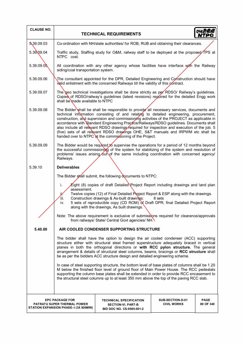
CLAUSE NO.
TECHNICAL REQUIREMENTS
EPC PACKAGE FOR
PATRATU SUPER THERMAL POWER STATION EXPANSION PHASE�I (3X 800MW)
TECHNICAL SPECIFICATION
SECTION-VI, PART-B
BID DOC NO. CS-9585-001-2
SUB-SECTION-D-01
CIVIL WORKS
PAGE
89 OF 340
5.39.09.03 Co-ordination with NH/state authorities/ for ROB, RUB and obtaining their clearances.
5.39.09.04 Traffic study, Staffing study for O&M, railway staff to be deployed at the proposed TPS at NTPC cost.
5.39.09.05 All coordination with any other agency whose facilities have interface with the Railway siding/coal transportation system.
5.39.09.06 The consultant appointed for the DPR, Detailed Engineering and Construction should have valid enlistment with the concerned Railways till the validity of this contract.
5.39.09.07 The geo technical investigations shall be done strictly as per RDSO/ Railway�s guidelines. Copies of RDSO/railway�s guidelines (latest revisions) required for the detailed Engg work shall be made available to NTPC
5.39.09.08 The Bidder shall be shall be responsible to provide all necessary services, documents and technical information consisting of and relating to detailed engineering, procurement, construction, and supervision and commissioning activities of the PROJECT as applicable in accordance with Standard Engineering Practice/Railways/RDSO guidelines. Documents shall also include all relevant RDSO drawings required for inspection and execution of the job. 5 (five) sets of all relevant RDSO drawings OHE, S&T manuals and IRPWM etc shall be handed over to NTPC at the commissioning of the Project.
5.39.09.09 The Bidder would be required to supervise the operations for a period of 12 months beyond the successful commissioning of the system for stabilizing of the system and resolution of problems/ issues arising out of the same including coordination with concerned agency/ Railways.
5.39.10 Deliverables
The Bidder shall submit, the following documents to NTPC:
i. Eight (8) copies of draft Detailed Project Report including drawings and land plan assessment.
ii. Twelve copies (12) of Final Detailed Project Report & ESP along with the drawings. iii. Construction drawings & As-built drawings: 8 sets iv. 5 sets of reproducible copy (CD ROM) of Draft DPR, final Detailed Project Report
along with the drawings, As built drawings.
Note: The above requirement is exclusive of submissions required for clearance/approvals from railways/ State/ Central Govt agencies/ NH.
5.40.00 AIR COOLED CONDENSER SUPPORTING STRUCTURE
The bidder shall have the option to design the air cooled condenser (ACC) supporting structure either with structural steel framed superstructure adequately braced in vertical planes in both the orthogonal directions or with RCC pylon structure. The general arrangement & details of structural steel columns, beams, bracings or RCC structure shall be as per the bidders ACC structure design and detailed engineering scheme.
In case of steel supporting structure, the bottom level of base plates of columns shall be 1.20 M below the finished floor level of ground floor of Main Power House. The RCC pedestals supporting the column base plates shall be extended in order to provide RCC encasement to the structural steel columns up to at least 350 mm above the top of the paving RCC slab.
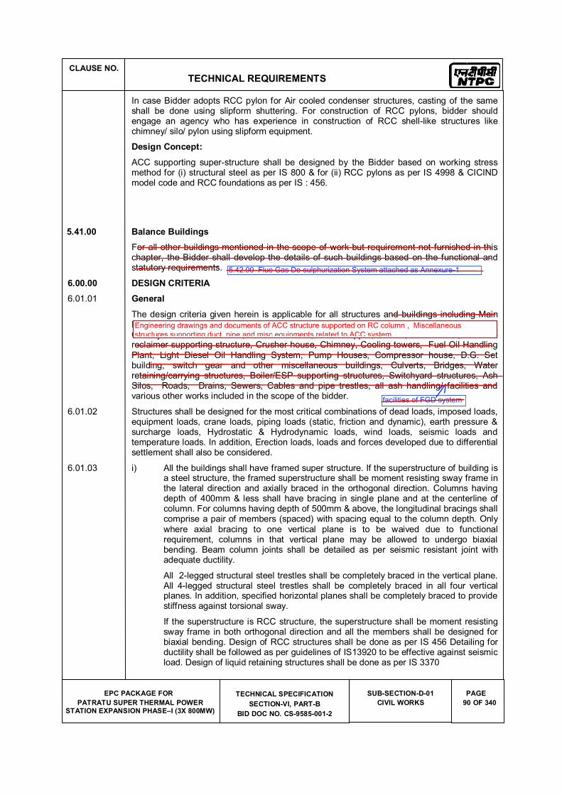
CLAUSE NO.
TECHNICAL REQUIREMENTS
EPC PACKAGE FOR
PATRATU SUPER THERMAL POWER STATION EXPANSION PHASE�I (3X 800MW)
TECHNICAL SPECIFICATION
SECTION-VI, PART-B
BID DOC NO. CS-9585-001-2
SUB-SECTION-D-01
CIVIL WORKS
PAGE
90 OF 340
In case Bidder adopts RCC pylon for Air cooled condenser structures, casting of the same shall be done using slipform shuttering. For construction of RCC pylons, bidder should engage an agency who has experience in construction of RCC shell-like structures like chimney/ silo/ pylon using slipform equipment.
Design Concept:
ACC supporting super-structure shall be designed by the Bidder based on working stress method for (i) structural steel as per IS 800 & for (ii) RCC pylons as per IS 4998 & CICIND model code and RCC foundations as per IS : 456.
5.41.00 Balance Buildings
For all other buildings mentioned in the scope of work but requirement not furnished in this chapter, the Bidder shall develop the details of such buildings based on the functional and statutory requirements.
6.00.00 DESIGN CRITERIA
6.01.01 General
The design criteria given herein is applicable for all structures and buildings including Main Plant buildings, Control building, office/service building, Mill and Bunker building, Coal Conveyor Galleries/Trestles, Transfer Points, Track hopper, Tunnel, Pent house, Stacker-reclaimer supporting structure, Crusher house, Chimney, Cooling towers, Fuel Oil Handling Plant, Light Diesel Oil Handling System, Pump Houses, Compressor house, D.G. Set building, switch gear and other miscellaneous buildings, Culverts, Bridges, Water retaining/carrying structures, Boiler/ESP supporting structures, Switchyard structures, Ash Silos, Roads, Drains, Sewers, Cables and pipe trestles, all ash handling/ facilities and various other works included in the scope of the bidder.
6.01.02 Structures shall be designed for the most critical combinations of dead loads, imposed loads, equipment loads, crane loads, piping loads (static, friction and dynamic), earth pressure & surcharge loads, Hydrostatic & Hydrodynamic loads, wind loads, seismic loads and temperature loads. In addition, Erection loads, loads and forces developed due to differential settlement shall also be considered.
6.01.03 i) All the buildings shall have framed super structure. If the superstructure of building is a steel structure, the framed superstructure shall be moment resisting sway frame in the lateral direction and axially braced in the orthogonal direction. Columns having depth of 400mm & less shall have bracing in single plane and at the centerline of column. For columns having depth of 500mm & above, the longitudinal bracings shall comprise a pair of members (spaced) with spacing equal to the column depth. Only where axial bracing to one vertical plane is to be waived due to functional requirement, columns in that vertical plane may be allowed to undergo biaxial bending. Beam column joints shall be detailed as per seismic resistant joint with adequate ductility.
All 2-legged structural steel trestles shall be completely braced in the vertical plane. All 4-legged structural steel trestles shall be completely braced in all four vertical planes. In addition, specified horizontal planes shall be completely braced to provide stiffness against torsional sway.
If the superstructure is RCC structure, the superstructure shall be moment resisting sway frame in both orthogonal direction and all the members shall be designed for biaxial bending. Design of RCC structures shall be done as per IS 456 Detailing for ductility shall be followed as per guidelines of IS13920 to be effective against seismic load. Design of liquid retaining structures shall be done as per IS 3370
5.42.00 Flue Gas De-sulphurization System attached as Annexure-1
facilities of FGD system
Engineering drawings and documents of ACC structure supported on RC column , Miscellaneous
structures supporting duct, pipe and misc equipments related to ACC system
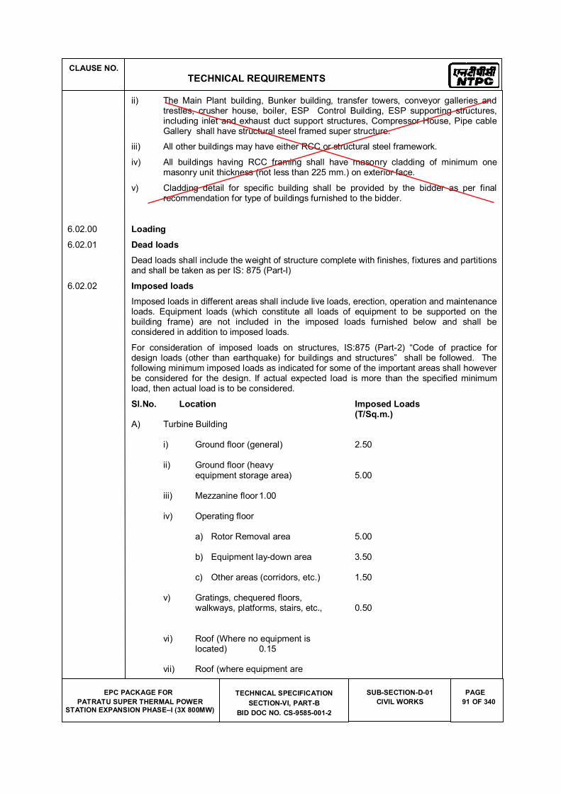
CLAUSE NO.
TECHNICAL REQUIREMENTS
EPC PACKAGE FOR
PATRATU SUPER THERMAL POWER STATION EXPANSION PHASE�I (3X 800MW)
TECHNICAL SPECIFICATION
SECTION-VI, PART-B
BID DOC NO. CS-9585-001-2
SUB-SECTION-D-01
CIVIL WORKS
PAGE
91 OF 340
ii) The Main Plant building, Bunker building, transfer towers, conveyor galleries and trestles, crusher house, boiler, ESP Control Building, ESP supporting structures, including inlet and exhaust duct support structures, Compressor House, Pipe cable Gallery shall have structural steel framed super structure.
iii) All other buildings may have either RCC or structural steel framework.
iv) All buildings having RCC framing shall have masonry cladding of minimum one masonry unit thickness (not less than 225 mm.) on exterior face.
v) Cladding detail for specific building shall be provided by the bidder as per final recommendation for type of buildings furnished to the bidder.
6.02.00 Loading
6.02.01 Dead loads
Dead loads shall include the weight of structure complete with finishes, fixtures and partitions and shall be taken as per IS: 875 (Part-I)
6.02.02 Imposed loads
Imposed loads in different areas shall include live loads, erection, operation and maintenance loads. Equipment loads (which constitute all loads of equipment to be supported on the building frame) are not included in the imposed loads furnished below and shall be considered in addition to imposed loads.
For consideration of imposed loads on structures, IS:875 (Part-2) �Code of practice for design loads (other than earthquake) for buildings and structures� shall be followed. The following minimum imposed loads as indicated for some of the important areas shall however be considered for the design. If actual expected load is more than the specified minimum load, then actual load is to be considered.
Sl.No. Location Imposed Loads (T/Sq.m.) A) Turbine Building
i) Ground floor (general) 2.50
ii) Ground floor (heavy equipment storage area) 5.00
iii) Mezzanine floor 1.00
iv) Operating floor
a) Rotor Removal area 5.00
b) Equipment lay-down area 3.50
c) Other areas (corridors, etc.) 1.50
v) Gratings, chequered floors, walkways, platforms, stairs, etc., 0.50
vi) Roof (Where no equipment is located) 0.15
vii) Roof (where equipment are
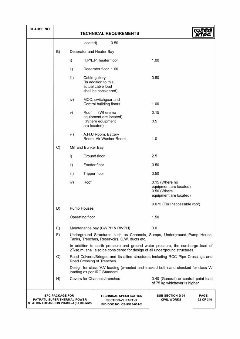
CLAUSE NO.
TECHNICAL REQUIREMENTS
EPC PACKAGE FOR
PATRATU SUPER THERMAL POWER STATION EXPANSION PHASE�I (3X 800MW)
TECHNICAL SPECIFICATION
SECTION-VI, PART-B
BID DOC NO. CS-9585-001-2
SUB-SECTION-D-01
CIVIL WORKS
PAGE
92 OF 340
located) 0.50
B) Deaerator and Heater Bay
i) H.P/L.P. heater floor 1.00
ii) Deaerator floor 1.00
iii) Cable gallery 0.50 (In addition to this, actual cable load shall be considered)
iv) MCC, switchgear and Control building floors 1.00
v) Roof (Where no 0.15 equipment are located) (Where equipment 0.5 are located)
vi) A.H.U Room, Battery Room, Air Washer Room 1.0
C) Mill and Bunker Bay
i) Ground floor 2.5
ii) Feeder floor 0.50
iii) Tripper floor 0.50
iv) Roof 0.15 (Where no equipment are located) 0.50 (Where equipment are located) 0.075 (For Inaccessible roof) D) Pump Houses
Operating floor 1.50
E) Maintenance bay (CWPH & RWPH) 3.0
F) Underground Structures such as Channels, Sumps, Underground Pump House, Tanks, Trenches, Reservoirs, C.W. ducts etc.
In addition to earth pressure and ground water pressure, the surcharge load of 2T/sq.m. shall also be considered for design of all underground structures.
G) Road Culverts/Bridges and its allied structures including RCC Pipe Crossings and Road Crossing of Trenches.
Design for class �AA� loading (wheeled and tracked both) and checked for class �A� loading as per IRC Standard.
H) Covers for Channels/trenches 0.40 (General) or central point load of 75 kg whichever is higher
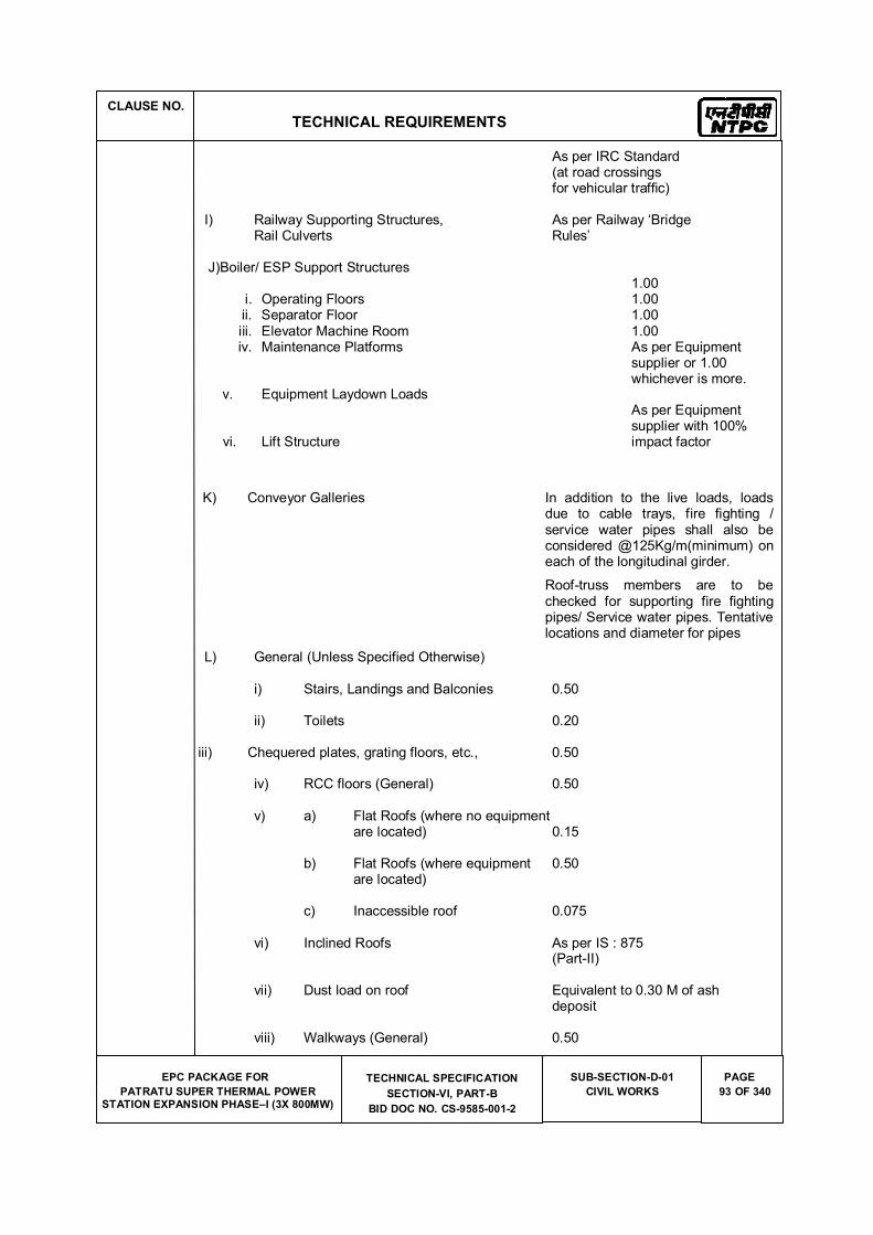
CLAUSE NO.
TECHNICAL REQUIREMENTS
EPC PACKAGE FOR
PATRATU SUPER THERMAL POWER STATION EXPANSION PHASE�I (3X 800MW)
TECHNICAL SPECIFICATION
SECTION-VI, PART-B
BID DOC NO. CS-9585-001-2
SUB-SECTION-D-01
CIVIL WORKS
PAGE
93 OF 340
As per IRC Standard (at road crossings for vehicular traffic)
I) Railway Supporting Structures, As per Railway �Bridge Rail Culverts Rules�
J)Boiler/ ESP Support Structures
i. Operating Floors ii. Separator Floor iii. Elevator Machine Room iv. Maintenance Platforms
v. Equipment Laydown Loads
vi. Lift Structure
1.00 1.00 1.00 1.00 As per Equipment supplier or 1.00 whichever is more.
As per Equipment supplier with 100% impact factor
K) Conveyor Galleries In addition to the live loads, loads due to cable trays, fire fighting / service water pipes shall also be considered @125Kg/m(minimum) on each of the longitudinal girder.
Roof-truss members are to be checked for supporting fire fighting pipes/ Service water pipes. Tentative locations and diameter for pipes
L) General (Unless Specified Otherwise)
i) Stairs, Landings and Balconies 0.50
ii) Toilets 0.20
iii) Chequered plates, grating floors, etc., 0.50 iv) RCC floors (General) 0.50 v) a) Flat Roofs (where no equipment are located) 0.15
b) Flat Roofs (where equipment 0.50 are located)
c) Inaccessible roof 0.075
vi) Inclined Roofs As per IS : 875 (Part-II)
vii) Dust load on roof Equivalent to 0.30 M of ash deposit
viii) Walkways (General) 0.50
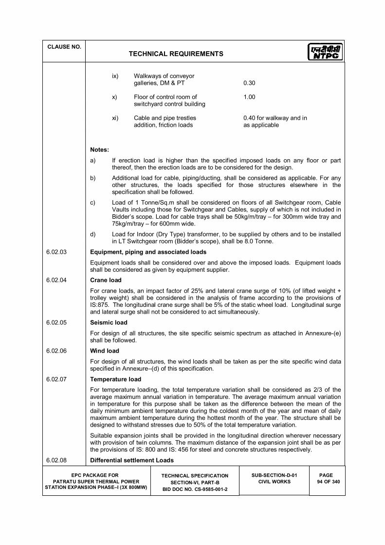
CLAUSE NO.
TECHNICAL REQUIREMENTS
EPC PACKAGE FOR
PATRATU SUPER THERMAL POWER STATION EXPANSION PHASE�I (3X 800MW)
TECHNICAL SPECIFICATION
SECTION-VI, PART-B
BID DOC NO. CS-9585-001-2
SUB-SECTION-D-01
CIVIL WORKS
PAGE
94 OF 340
ix) Walkways of conveyor galleries, DM & PT 0.30
x) Floor of control room of 1.00 switchyard control building
xi) Cable and pipe trestles 0.40 for walkway and in addition, friction loads as applicable
Notes:
a) If erection load is higher than the specified imposed loads on any floor or part thereof, then the erection loads are to be considered for the design.
b) Additional load for cable, piping/ducting, shall be considered as applicable. For any other structures, the loads specified for those structures elsewhere in the specification shall be followed.
c) Load of 1 Tonne/Sq.m shall be considered on floors of all Switchgear room, Cable Vaults including those for Switchgear and Cables, supply of which is not included in Bidder�s scope. Load for cable trays shall be 50kg/m/tray � for 300mm wide tray and 75kg/m/tray � for 600mm wide.
d) Load for Indoor (Dry Type) transformer, to be supplied by others and to be installed in LT Switchgear room (Bidder�s scope), shall be 8.0 Tonne.
6.02.03 Equipment, piping and associated loads
Equipment loads shall be considered over and above the imposed loads. Equipment loads shall be considered as given by equipment supplier.
6.02.04 Crane load
For crane loads, an impact factor of 25% and lateral crane surge of 10% (of lifted weight + trolley weight) shall be considered in the analysis of frame according to the provisions of IS:875. The longitudinal crane surge shall be 5% of the static wheel load. Longitudinal surge and lateral surge shall not be considered to act simultaneously.
6.02.05 Seismic load
For design of all structures, the site specific seismic spectrum as attached in Annexure-(e) shall be followed.
6.02.06 Wind load
For design of all structures, the wind loads shall be taken as per the site specific wind data specified in Annexure�(d) of this specification.
6.02.07 Temperature load
For temperature loading, the total temperature variation shall be considered as 2/3 of the average maximum annual variation in temperature. The average maximum annual variation in temperature for this purpose shall be taken as the difference between the mean of the daily minimum ambient temperature during the coldest month of the year and mean of daily maximum ambient temperature during the hottest month of the year. The structure shall be designed to withstand stresses due to 50% of the total temperature variation.
Suitable expansion joints shall be provided in the longitudinal direction wherever necessary with provision of twin columns. The maximum distance of the expansion joint shall be as per the provisions of IS: 800 and IS: 456 for steel and concrete structures respectively.
6.02.08 Differential settlement Loads
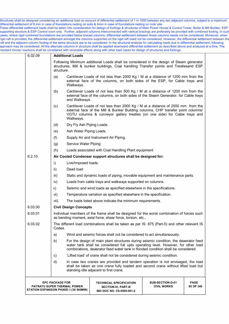
CLAUSE NO.
TECHNICAL REQUIREMENTS
EPC PACKAGE FOR
PATRATU SUPER THERMAL POWER STATION EXPANSION PHASE�I (3X 800MW)
TECHNICAL SPECIFICATION
SECTION-VI, PART-B
BID DOC NO. CS-9585-001-2
SUB-SECTION-D-01
CIVIL WORKS
PAGE
95 OF 340
Structures shall be designed considering an additional load on account of differential settlement of 1 in 1000 between any two adjacent columns, subject to a maximum differential settlement of 8 mm.
6.02.09 Additional Loads
Following Minimum additional Loads shall be considered in the design of Steam generator structures, Mill & bunker buildings, Coal handling Transfer points and Trestlesand ESP structure.
(a) Cantilever Loads of not less than 2000 Kg / M at a distance of 1200 mm from the external face of the columns, on both sides of the ESP, for Cable trays and Walkways.
(b) Cantilever Loads of not less than 500 Kg / M at a distance of 1200 mm from the external face of the columns, on both sides of the Steam Generator, for Cable trays and Walkways.
(c) Cantilever Loads of not less than 2000 Kg / M at a distance of 2500 mm from the external face of the Mill & Bunker Building columns, CHP transfer point columns/ VGTU columns & conveyor gallery trestles (on one side) for Cable trays and Walkways.
(d) Dry Fly Ash Piping Loads.
(e) Ash Water Piping Loads.
(f) Supply Air and Instrument Air Piping.
(g) Service Water Piping
(h) Loads associated with Coal Handling Plant equipment
6.2.10 Air Cooled Condenser support structures shall be designed for:
i) Live/Imposed loads.
ii) Dead load
iii) Static and dynamic loads of piping, movable equipment and maintenance parts.
iv) Loads from cable trays and walkways supported on columns.
v) Seismic and wind loads as specified elsewhere in the specifications.
vi) Temperature variation as specified elsewhere in the specification.
vii) The loads listed above indicate the minimum requirements.
6.03.00 Civil Design Concepts
6.03.01 Individual members of the frame shall be designed for the worst combination of forces such as bending moment, axial force, shear force, torsion, etc.,
6.03.02 The different load combinations shall be taken as per IS: 875 (Part-5) and other relevant IS Codes.
a) Wind and seismic forces shall not be considered to act simultaneously.
b) For the design of main plant structures during seismic condition, the deaerator feed water tank shall be considered full upto operating level. However, for other load combinations, deaerator feed water tank in flooded condition shall be considered.
c) �Lifted load� of crane shall not be considered during seismic condition.
d) In case two cranes are provided and tandem operation is not envisaged, the load shall be taken as one crane fully loaded and second crane without lifted load but standing idle adjacent to first crane.
Structures shall be designed considering an additional load on account of differential g gsettlement of 1 in 1000 between any two adjacent columns, subject to a maximum differentialsettlement of 8 mm.
Structures shall be designed considering an additional load on account of differential settlement of 1 in 1000 between any two adjacent columns, subject to a maximum
differential settlement of 8 mm in case of foundations resting on soils & 4mm in case of foundations resting on rock/ pile.
These differential settlement loads shall be taken into consideration for design of footings & structures of Main Power House & Control Tower, Boiler & Mill Bunker, ESP
supporting structure & ESP Control room only. Further, adjacent columns interconnected with vertical bracings are preferably be provided with combined footing. In such
cases, where rigid combined foundations are provided below braced columns, differential settlement between those columns needs not be considered. Moreover, when
rigid raft is provided, the differential settlement amongst the columns supported on the rigid raft need not be considered. However, the differential settlement between the
raft and the adjacent column footing of the same structure are to be considered. In the structural analysis for calculating loads due to differential settlement, following
approach may be considered: All the alternate columns in structure shall be applied downward differential settlement as described above and analyzed at a time. The
resultant forces/ reactions shall be considered with reversible effects along with other load cases for design of structures and footings.
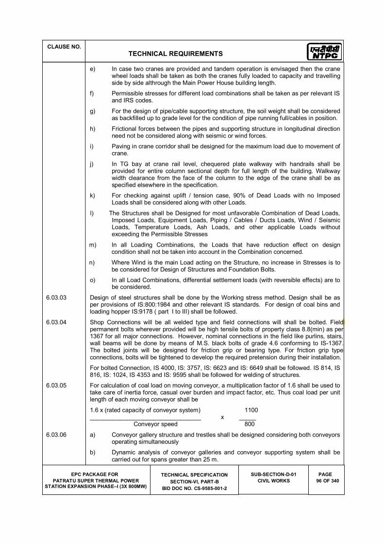
CLAUSE NO.
TECHNICAL REQUIREMENTS
EPC PACKAGE FOR
PATRATU SUPER THERMAL POWER STATION EXPANSION PHASE�I (3X 800MW)
TECHNICAL SPECIFICATION
SECTION-VI, PART-B
BID DOC NO. CS-9585-001-2
SUB-SECTION-D-01
CIVIL WORKS
PAGE
96 OF 340
e) In case two cranes are provided and tandem operation is envisaged then the crane wheel loads shall be taken as both the cranes fully loaded to capacity and travelling side by side althrough the Main Power House building length.
f) Permissible stresses for different load combinations shall be taken as per relevant IS and IRS codes.
g) For the design of pipe/cable supporting structure, the soil weight shall be considered as backfilled up to grade level for the condition of pipe running full/cables in position.
h) Frictional forces between the pipes and supporting structure in longitudinal direction need not be considered along with seismic or wind forces.
i) Paving in crane corridor shall be designed for the maximum load due to movement of crane.
j) In TG bay at crane rail level, chequered plate walkway with handrails shall be provided for entire column sectional depth for full length of the building. Walkway width clearance from the face of the column to the edge of the crane shall be as specified elsewhere in the specification.
k) For checking against uplift / tension case, 90% of Dead Loads with no Imposed Loads shall be considered along with other Loads.
l) The Structures shall be Designed for most unfavorable Combination of Dead Loads, Imposed Loads, Equipment Loads, Piping / Cables / Ducts Loads, Wind / Seismic Loads, Temperature Loads, Ash Loads, and other applicable Loads without exceeding the Permissible Stresses
m) In all Loading Combinations, the Loads that have reduction effect on design condition shall not be taken into account in the Combination concerned.
n) Where Wind is the main Load acting on the Structure, no increase in Stresses is to be considered for Design of Structures and Foundation Bolts.
o) In all Load Combinations, differential settlement loads (with reversible effects) are to be considered.
6.03.03 Design of steel structures shall be done by the Working stress method. Design shall be as per provisions of IS:800:1984 and other relevant IS standards. For design of coal bins and loading hopper IS:9178 ( part I to III) shall be followed.
6.03.04 Shop Connections will be all welded type and field connections will shall be bolted. Field permanent bolts wherever provided will be high tensile bolts of property class 8.8(min) as per 1367 for all major connections. However, nominal connections in the field like purlins, stairs, wall beams will be done by means of M.S. black bolts of grade 4.6 conforming to IS-1367. The bolted joints will be designed for friction grip or bearing type. For friction grip type connections, bolts will be tightened to develop the required pretension during their installation.
For bolted Connection, IS 4000, IS: 3757, IS: 6623 and IS: 6649 shall be followed. IS 814, IS 816, IS: 1024, IS 4353 and IS: 9595 shall be followed for welding of structures.
6.03.05 For calculation of coal load on moving conveyor, a multiplication factor of 1.6 shall be used to take care of inertia force, casual over burden and impact factor, etc. Thus coal load per unit length of each moving conveyor shall be
1.6 x (rated capacity of conveyor system) 1100 _________________________________ x _____ Conveyor speed 800
6.03.06 a) Conveyor gallery structure and trestles shall be designed considering both conveyors operating simultaneously
b) Dynamic analysis of conveyor galleries and conveyor supporting system shall be carried out for spans greater than 25 m.
d
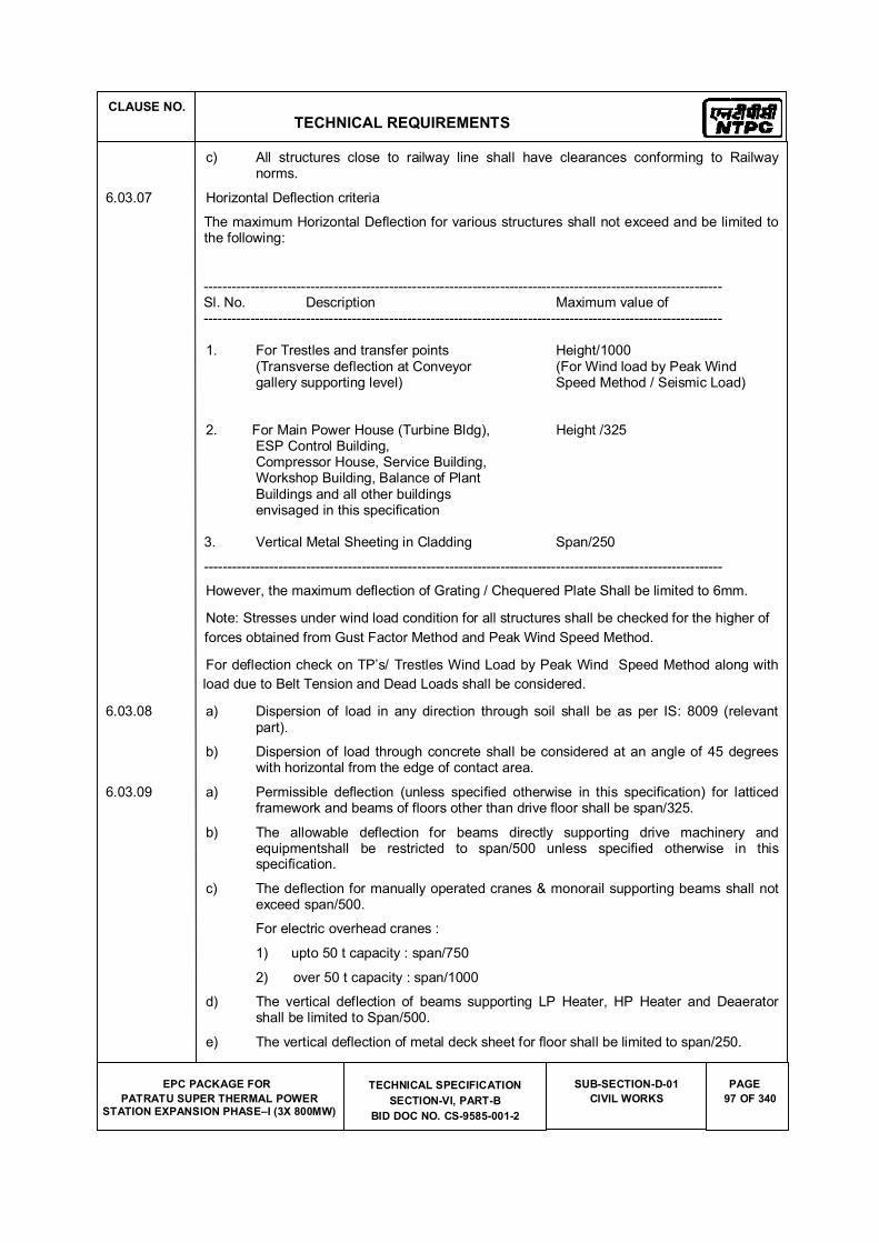
CLAUSE NO.
TECHNICAL REQUIREMENTS
EPC PACKAGE FOR
PATRATU SUPER THERMAL POWER STATION EXPANSION PHASE�I (3X 800MW)
TECHNICAL SPECIFICATION
SECTION-VI, PART-B
BID DOC NO. CS-9585-001-2
SUB-SECTION-D-01
CIVIL WORKS
PAGE
97 OF 340
c) All structures close to railway line shall have clearances conforming to Railway norms.
6.03.07 Horizontal Deflection criteria
The maximum Horizontal Deflection for various structures shall not exceed and be limited to the following:
---------------------------------------------------------------------------------------------------------------- Sl. No. Description Maximum value of ----------------------------------------------------------------------------------------------------------------
1. For Trestles and transfer points Height/1000 (Transverse deflection at Conveyor (For Wind load by Peak Wind gallery supporting level) Speed Method / Seismic Load)
2. For Main Power House (Turbine Bldg), Height /325 ESP Control Building, Compressor House, Service Building, Workshop Building, Balance of Plant Buildings and all other buildings envisaged in this specification
3. Vertical Metal Sheeting in Cladding Span/250
----------------------------------------------------------------------------------------------------------------
However, the maximum deflection of Grating / Chequered Plate Shall be limited to 6mm.
Note: Stresses under wind load condition for all structures shall be checked for the higher of
forces obtained from Gust Factor Method and Peak Wind Speed Method.
For deflection check on TP�s/ Trestles Wind Load by Peak Wind Speed Method along with
load due to Belt Tension and Dead Loads shall be considered.
6.03.08 a) Dispersion of load in any direction through soil shall be as per IS: 8009 (relevant part).
b) Dispersion of load through concrete shall be considered at an angle of 45 degrees with horizontal from the edge of contact area.
6.03.09 a) Permissible deflection (unless specified otherwise in this specification) for latticed framework and beams of floors other than drive floor shall be span/325.
b) The allowable deflection for beams directly supporting drive machinery and equipmentshall be restricted to span/500 unless specified otherwise in this specification.
c) The deflection for manually operated cranes & monorail supporting beams shall not exceed span/500.
For electric overhead cranes :
1) upto 50 t capacity : span/750
2) over 50 t capacity : span/1000
d) The vertical deflection of beams supporting LP Heater, HP Heater and Deaerator shall be limited to Span/500.
e) The vertical deflection of metal deck sheet for floor shall be limited to span/250.
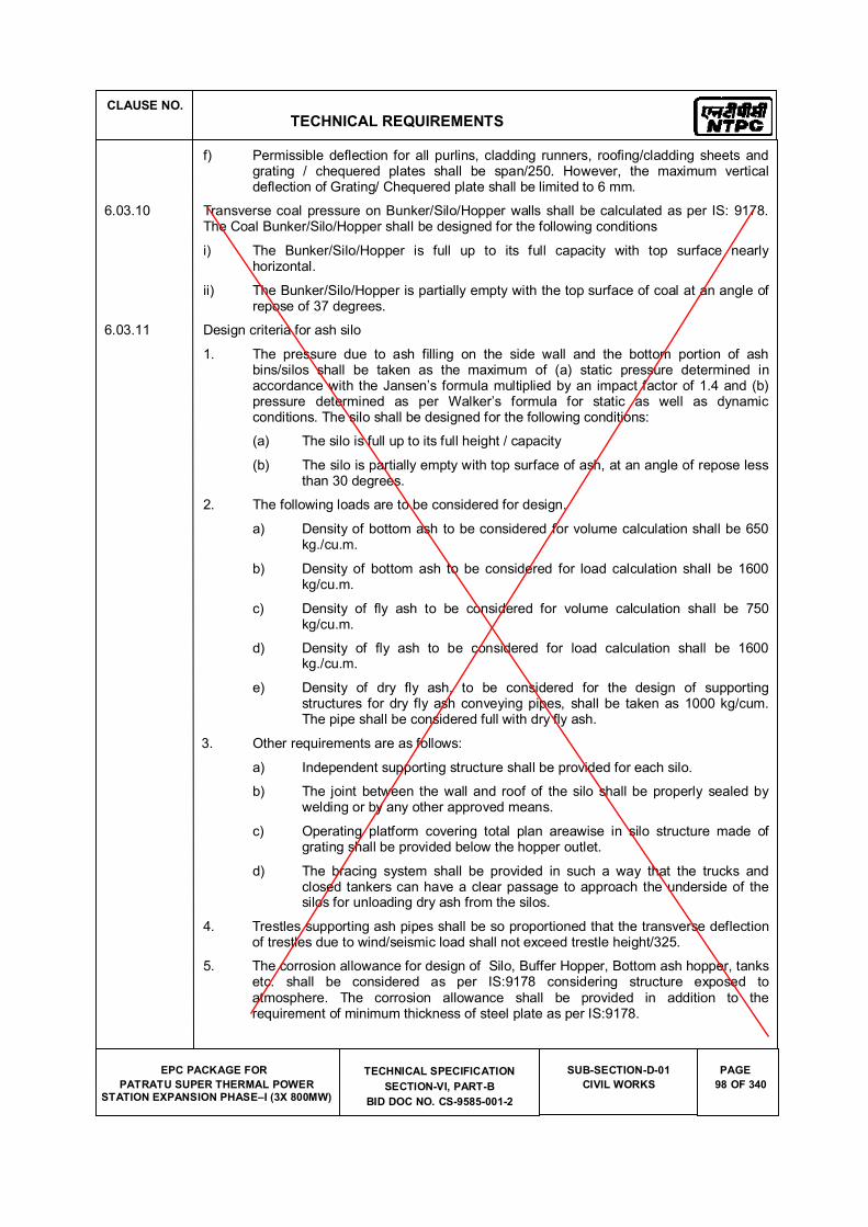
CLAUSE NO.
TECHNICAL REQUIREMENTS
EPC PACKAGE FOR
PATRATU SUPER THERMAL POWER STATION EXPANSION PHASE�I (3X 800MW)
TECHNICAL SPECIFICATION
SECTION-VI, PART-B
BID DOC NO. CS-9585-001-2
SUB-SECTION-D-01
CIVIL WORKS
PAGE
98 OF 340
f) Permissible deflection for all purlins, cladding runners, roofing/cladding sheets and grating / chequered plates shall be span/250. However, the maximum vertical deflection of Grating/ Chequered plate shall be limited to 6 mm.
6.03.10 Transverse coal pressure on Bunker/Silo/Hopper walls shall be calculated as per IS: 9178. The Coal Bunker/Silo/Hopper shall be designed for the following conditions
i) The Bunker/Silo/Hopper is full up to its full capacity with top surface nearly horizontal.
ii) The Bunker/Silo/Hopper is partially empty with the top surface of coal at an angle of repose of 37 degrees.
6.03.11 Design criteria for ash silo
1. The pressure due to ash filling on the side wall and the bottom portion of ash bins/silos shall be taken as the maximum of (a) static pressure determined in accordance with the Jansen�s formula multiplied by an impact factor of 1.4 and (b) pressure determined as per Walker�s formula for static as well as dynamic conditions. The silo shall be designed for the following conditions:
(a) The silo is full up to its full height / capacity
(b) The silo is partially empty with top surface of ash, at an angle of repose less than 30 degrees.
2. The following loads are to be considered for design.
a) Density of bottom ash to be considered for volume calculation shall be 650 kg./cu.m.
b) Density of bottom ash to be considered for load calculation shall be 1600 kg/cu.m.
c) Density of fly ash to be considered for volume calculation shall be 750 kg/cu.m.
d) Density of fly ash to be considered for load calculation shall be 1600 kg./cu.m.
e) Density of dry fly ash, to be considered for the design of supporting structures for dry fly ash conveying pipes, shall be taken as 1000 kg/cum. The pipe shall be considered full with dry fly ash.
3. Other requirements are as follows:
a) Independent supporting structure shall be provided for each silo.
b) The joint between the wall and roof of the silo shall be properly sealed by welding or by any other approved means.
c) Operating platform covering total plan areawise in silo structure made of grating shall be provided below the hopper outlet.
d) The bracing system shall be provided in such a way that the trucks and closed tankers can have a clear passage to approach the underside of the silos for unloading dry ash from the silos.
4. Trestles supporting ash pipes shall be so proportioned that the transverse deflection of trestles due to wind/seismic load shall not exceed trestle height/325.
5. The corrosion allowance for design of Silo, Buffer Hopper, Bottom ash hopper, tanks etc. shall be considered as per IS:9178 considering structure exposed to atmosphere. The corrosion allowance shall be provided in addition to the requirement of minimum thickness of steel plate as per IS:9178.
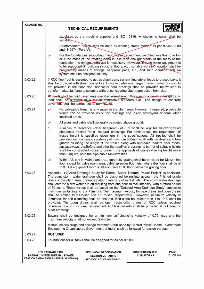
CLAUSE NO.
TECHNICAL REQUIREMENTS
EPC PACKAGE FOR
PATRATU SUPER THERMAL POWER STATION EXPANSION PHASE�I (3X 800MW)
TECHNICAL SPECIFICATION
SECTION-VI, PART-B
BID DOC NO. CS-9585-001-2
SUB-SECTION-D-01
CIVIL WORKS
PAGE
101 OF 340
stipulated by the machine supplier and ISO 10816, whichever is lower, shall be satisfied.
Reinforcement design shall be done by working stress method as per IS:456-2000 and IS:2974 (Part-IV).
b) For the foundations supporting minor rotating equipment weighing less than one ton or if the mass of the rotating parts is less than one hundredth of the mass of the foundation, no dynamic analysis is necessary. However, if such minor equipment is to be supported on building structure, floors, etc., suitable vibration isolation shall be provided by means of springs, neoprene pads, etc., and such vibration isolation system shall be designed suitably.
6.03.22 If RCC floor/roof is assumed to act as diaphragm, transmitting lateral loads to braced bays, it shall be provided with shear connectors. However, whenever large / more number of cut-outs are provided in the floor slab, horizontal floor bracings shall be provided below slab to transfer horizontal force to columns without considering diaphragm action from slab.
6.03.23 All roads shall be rigid pavements specified elsewhere in this specification. The design traffic load shall be a minimum 4 million cumulative standard axle. The design of concrete pavement shall be carried out as per IRC-58.
6.03.24 a) No cable/pipe trench is envisaged in the plant area. However, if required, pipe/cable trench can be provided inside the buildings and inside switchyard or some other localised areas.
b) All pipes and cable shall generally be routed above ground.
c) A minimum clearance (clear headroom) of 8 m shall be kept for all over-ground pipe/cable trestles for all road/rail crossings. For other areas, the requirement of trestle height is specified elsewhere in the specifications. All trestles shall be provided with continuous walkway of minimum 600mm width with hand-rails and toe-guards all along the length of the trestle along with approach ladders near roads, passageways, etc.Before and after the road/rail crossings, a barrier of suitable height shall be constructed so as to prevent the approach of cranes (having height more than 8 m) etc, upto the pipe/cable racks/trestles.
d) Within AB bay in Main plant area, generally grating shall be provided for Mezzanine floor except for valve room area, cable spreader floor, etc. where the floor shall be of RCC. Oil equipment room shall also have RCC floor below the grating floor.
6.03.25 Appendix �(1)�Area Drainage Study for Patratu Super Thermal Power Project� is enclosed. The plant storm water drainage shall be designed taking into account the finished grade levels of the plant area, drainage pattern, intensity of rainfall, etc., The storm water drainage shall cater to storm water run off resulting from one hour rainfall intensity, with a return period of 50 years. These values shall be based on the "Detailed Area Drainage Study" subject to minimum rainfall intensity of 75mm/hr. The maximum velocity for pipe drains and open drains shall be limited to 2.4m/sec and 1.8 m/sec. respectively. However, minimum velocity of 0.6m/sec. for self-cleansing shall be ensured. Bed slope not milder than 1 in 1000 shall be provided. The open drains shall be open rectangular drains of RCC unless required otherwise due to functional requirement. RC box culverts shall be provided at rail, road or other crossings.
6.03.26 Sewers shall be designed for a minimum self-cleansing velocity of 0.75m/sec and the maximum velocity shall not exceed 2.4m/sec.
Manual on sewerage and sewage treatment (published by Central Public Health Environment Engineering Organisation, Government of India) shall be followed for design purpose.
6.03.27 NOT USED
6.03.28 Foundations for all tanks shall be designed for as per IS: 803.

CLAUSE NO.
TECHNICAL REQUIREMENTS
EPC PACKAGE FOR
PATRATU SUPER THERMAL POWER STATION EXPANSION PHASE�I (3X 800MW)
TECHNICAL SPECIFICATION
SECTION-VI, PART-B
BID DOC NO. CS-9585-001-2
SUB-SECTION-D-01
CIVIL WORKS
PAGE
103 OF 340
normal/convenient access to all points in the boiler is blocked or obstructed.
6.03.33 In design of boiler/ ESP support structures, dynamic piping loads need not be considered acting simultaneously with wind or seismic loads. Increase in permissible stresses shall be allowed in load combinations where dynamic piping loads are considered and shall be as permitted under seismic load conditions.
6.03.34 Design Criteria for foundations and some other facilities/areas are covered separately in this specification.
6.03.35 Plinth level of all buildings shall be kept at least 500 mm above the finished grade/formation level.
Finished floor level of boiler area paving shall be kept about 200 mm lower than the finished floor level of Main Plant buildings.
6.03.36 Joints/Connections in steel structures:
Steel structures shall be detailed and connection and joints provided as per the provisions of IS:800, IS:816, IS:9595, IS:1367, and IS:9178 and as per following requirements.
a) Connection of vertical bracings with connection members and diagonals of truss members shall be designed for full tensile capacity of the bracings unless actual loads are indicated on the drawings.
b) Size of fillet weld for flange to web connection for built up section shall be as follows:
i) For box section weld size shall be designed for full shear capacity or actual shear whichever is more. Where fillet weld is not possible, full penetration butt weld shall be provided.
ii) For built up I section, weld size shall be designed for 80% of full shear capacity or actual shear, (if indicated, in drawings) whichever is more. However, weld size shall not be less than 0.5 times the web thickness. Weld shall be double fillet.
iii) All welds shall be continuous unless otherwise specifically approved. The minimum size of the fillet weld shall be 6mm.
c) Shear connections shall be designed for 60% of section strength for rolled sections and 80% of section strength for built up section or rolled section with cover plates. However, if load is more than above, the connection shall be designed for actual load.
d) Moment connections between beam and column shall be designed for 100% of moment capacity of the beam section.
e) All butt welds shall be full penetration butt welds.
f) The connection between top flange and web of crane girder shall be full penetration butt weld. Bottom flange, connection with web can be fillet weld or butt weld as directed by Engineer.
g) Connection of base plate and associated stiffeners with the columns shall be designed considering the total load transferred through welds. However, minimum weld size (double fillet) shall not be less than 0.6 times the thickness of stiffeners.
h) Splicing: All work shall be full strength. Field splicing shall be done with web and flange cover plates for full strength. Shop splicing for all sections other than rolled shall be carried out by full penetration butt welds with no cover plates. Splicing for all rolled sections shall be carried out using web and flange cover plate.
6.03.37 Pipe Pedestals, pipe supports and other structures for Ash handling system:
a) The design of Pipe Pedestal and pipe supports shall be carried out considering Dead
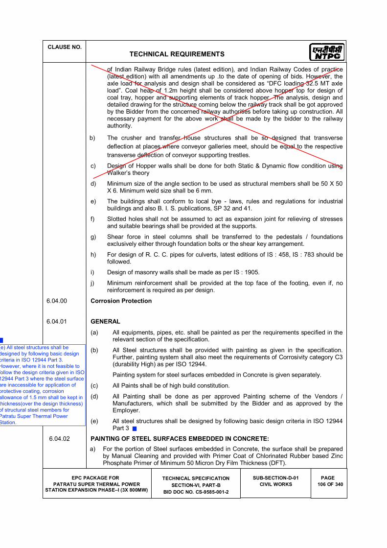
CLAUSE NO.
TECHNICAL REQUIREMENTS
EPC PACKAGE FOR
PATRATU SUPER THERMAL POWER STATION EXPANSION PHASE�I (3X 800MW)
TECHNICAL SPECIFICATION
SECTION-VI, PART-B
BID DOC NO. CS-9585-001-2
SUB-SECTION-D-01
CIVIL WORKS
PAGE
106 OF 340
of Indian Railway Bridge rules (latest edition), and Indian Railway Codes of practice (latest edition) with all amendments up .to the date of opening of bids. However, the axle load for analysis and design shall be considered as �DFC loading 32.5 MT axle load�. Coal heap of 1.2m height shall be considered above hopper top for design of coal tray, hopper and supporting elements of track hopper. The analysis, design and detailed drawing for the structure coming below the railway track shall be got approved by the Bidder from the concerned railway authorities before taking up construction. All necessary payment for the above work shall be made by the bidder to the railway authority.
b) The crusher and transfer house structures shall be so designed that transverse
deflection at places where conveyor galleries meet, should be equal to the respective
transverse deflection of conveyor supporting trestles.
c) Design of Hopper walls shall be done for both Static & Dynamic flow condition using Walker�s theory
d) Minimum size of the angle section to be used as structural members shall be 50 X 50 X 6. Minimum weld size shall be 6 mm.
e) The buildings shall conform to local bye - laws, rules and regulations for industrial buildings and also B. I. S. publications, SP 32 and 41.
f) Slotted holes shall not be assumed to act as expansion joint for relieving of stresses and suitable bearings shall be provided at the supports.
g) Shear force in steel columns shall be transferred to the pedestals / foundations exclusively either through foundation bolts or the shear key arrangement.
h) For design of R. C. C. pipes for culverts, latest editions of IS : 458, IS : 783 should be followed.
i) Design of masonry walls shall be made as per IS : 1905.
j) Minimum reinforcement shall be provided at the top face of the footing, even if, no reinforcement is required as per design.
6.04.00 Corrosion Protection
6.04.01 GENERAL
(a) All equipments, pipes, etc. shall be painted as per the requirements specified in the relevant section of the specification.
(b) All Steel structures shall be provided with painting as given in the specification. Further, painting system shall also meet the requirements of Corrosivity category C3 (durability High) as per ISO 12944.
Painting system for steel surfaces embedded in Concrete is given separately.
(c) All Paints shall be of high build constitution.
(d) All Painting shall be done as per approved Painting scheme of the Vendors / Manufacturers, which shall be submitted by the Bidder and as approved by the Employer.
(e) All steel structures shall be designed by following basic design criteria in ISO 12944 Part 3
6.04.02 PAINTING OF STEEL SURFACES EMBEDDED IN CONCRETE:
a) For the portion of Steel surfaces embedded in Concrete, the surface shall be prepared by Manual Cleaning and provided with Primer Coat of Chlorinated Rubber based Zinc Phosphate Primer of Minimum 50 Micron Dry Film Thickness (DFT).
(e) All steel structures shall be
designed by following basic design
criteria in ISO 12944 Part 3.
However, where it is not feasible to
follow the design criteria given in ISO
12944 Part 3 where the steel surface
are inaccessible for application of
protective coating, corrosion
allowance of 1.5 mm shall be kept in
thickness(over the design thickness)
of structural steel members for
Patratu Super Thermal Power
Station.
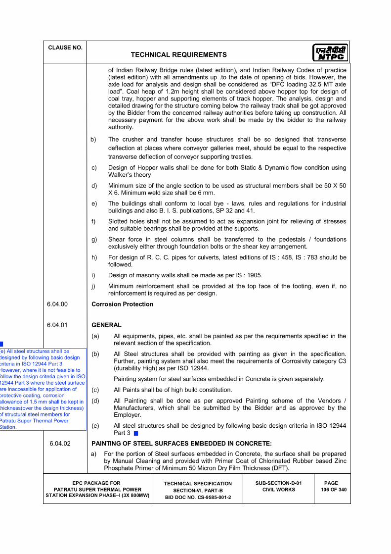
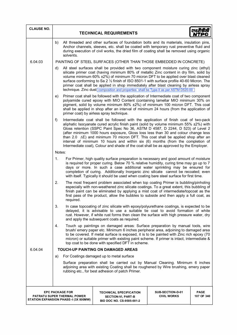
CLAUSE NO.
TECHNICAL REQUIREMENTS
EPC PACKAGE FOR
PATRATU SUPER THERMAL POWER STATION EXPANSION PHASE�I (3X 800MW)
TECHNICAL SPECIFICATION
SECTION-VI, PART-B
BID DOC NO. CS-9585-001-2
SUB-SECTION-D-01
CIVIL WORKS
PAGE
107 OF 340
b) All threaded and other surfaces of foundation bolts and its materials, insulation pins, Anchor channels, sleeves, etc. shall be coated with temporary rust preventive fluid and during execution of civil works, the dried film of coating shall be removed using organic solvents.
6.04.03 PAINTING OF STEEL SURFACES (OTHER THAN THOSE EMBEDDED IN CONCRETE)
d) All steel surfaces shall be provided with two component moisture curing zinc (ethyl) silicate primer coat (having minimum 80% of metallic Zinc content in dry film, solid by volume minimum 60% ±2%) of minimum 70 micron DFT to be applied over blast cleaned surface conforming to Sa 2 ½ finish of ISO 8501-1 with surface profile 40-60 Micron. The primer coat shall be applied in shop immediately after blast cleaning by airless spray technique. Zinc dust quality should be as per ASTM D 520 Type 2
e) Primer coat shall be followed with the application of Intermediate coat of two component polyamide cured epoxy with MIO Content (containing lamellar MIO minimum 30% on pigment, solid by volume minimum 80% ±2%) of minimum 100 micron DFT. This coat shall be applied in shop after an interval of minimum 24 hours (from the application of primer coat) by airless spray technique.
f) Intermediate coat shall be followed with the application of finish coat of two-pack aliphatic Isocyanate cured acrylic finish paint (solid by volume minimum 55% ±2%) with Gloss retention (SSPC Paint Spec No 36, ASTM D 4587, D 2244, D 523) of Level 2 (after minimum 1000 hours exposure, Gloss loss less than 30 and colour change less than 2.0 and minimum 70 micron DFT. This coat shall be applied shop after an interval of minimum 10 hours and within six (6) months (from the completion of Intermediate coat), Colour and shade of the coat shall be as approved by the Employer.
Notes:
1. For Primer, high quality surface preparation is necessary and good amount of moisture is required for proper curing. Below 70 % relative humidity, curing time may go up to 7 days or more. In such a case additional water sprinkling may be ensured for completion of curing. Additionally Inorganic zinc silicate cannot be recoated; even with itself. Typically it should be used when coating bare steel surface for first time.
2. The most frequent problem associated when top coating Primer is bubbling/pinholing especially with non-weathered zinc silicate coatings. To a great extent, this bubbling of finish paint can be eliminated by applying a mist coat of intermediate/topcoat as the first pass of the product, allow the bubbles to subside and then apply a full coat, as required.
3. In case topcoating of zinc silicate with epoxy/polyurethane coatings, is expected to be delayed, it is advisable to use a suitable tie coat to avoid formation of white rust. However, if white rust forms then clean the surface with high pressure water, dry and apply the subsequent coats as required.
4. Touch up paintings on damaged areas: Surface preparation by manual tools, wire brush/ emery paper etc. Minimum 6 inches peripheral area, adjoining to damaged area to be covered. If metal surface is exposed, it is to be painted with Zinc rich epoxy (70 micron) or suitable primer with existing paint scheme. If primer is intact, intermediate & top coat to be done with specified DFT in scheme.
6.04.04 TOUCH-UP PAINTING ON DAMAGED AREAS
a) For Coatings damaged up to metal surface
Surface preparation shall be carried out by Manual Cleaning. Minimum 6 inches adjoining area with existing Coating shall be roughened by Wire brushing, emery paper rubbing etc., for best adhesion of patch Primer.
composition and properties shall be Type-II as per ASTM D520-00
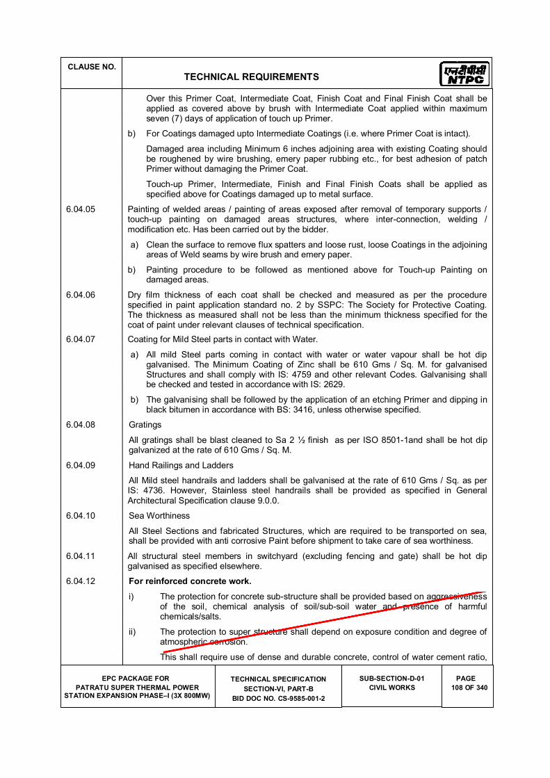
CLAUSE NO.
TECHNICAL REQUIREMENTS
EPC PACKAGE FOR
PATRATU SUPER THERMAL POWER STATION EXPANSION PHASE�I (3X 800MW)
TECHNICAL SPECIFICATION
SECTION-VI, PART-B
BID DOC NO. CS-9585-001-2
SUB-SECTION-D-01
CIVIL WORKS
PAGE
108 OF 340
Over this Primer Coat, Intermediate Coat, Finish Coat and Final Finish Coat shall be applied as covered above by brush with Intermediate Coat applied within maximum seven (7) days of application of touch up Primer.
b) For Coatings damaged upto Intermediate Coatings (i.e. where Primer Coat is intact).
Damaged area including Minimum 6 inches adjoining area with existing Coating should be roughened by wire brushing, emery paper rubbing etc., for best adhesion of patch Primer without damaging the Primer Coat.
Touch-up Primer, Intermediate, Finish and Final Finish Coats shall be applied as specified above for Coatings damaged up to metal surface.
6.04.05 Painting of welded areas / painting of areas exposed after removal of temporary supports / touch-up painting on damaged areas structures, where inter-connection, welding / modification etc. Has been carried out by the bidder.
a) Clean the surface to remove flux spatters and loose rust, loose Coatings in the adjoining areas of Weld seams by wire brush and emery paper.
b) Painting procedure to be followed as mentioned above for Touch-up Painting on damaged areas.
6.04.06 Dry film thickness of each coat shall be checked and measured as per the procedure specified in paint application standard no. 2 by SSPC: The Society for Protective Coating. The thickness as measured shall not be less than the minimum thickness specified for the coat of paint under relevant clauses of technical specification.
6.04.07 Coating for Mild Steel parts in contact with Water.
a) All mild Steel parts coming in contact with water or water vapour shall be hot dip galvanised. The Minimum Coating of Zinc shall be 610 Gms / Sq. M. for galvanised Structures and shall comply with IS: 4759 and other relevant Codes. Galvanising shall be checked and tested in accordance with IS: 2629.
b) The galvanising shall be followed by the application of an etching Primer and dipping in black bitumen in accordance with BS: 3416, unless otherwise specified.
6.04.08 Gratings
All gratings shall be blast cleaned to Sa 2 ½ finish as per ISO 8501-1and shall be hot dip galvanized at the rate of 610 Gms / Sq. M.
6.04.09 Hand Railings and Ladders
All Mild steel handrails and ladders shall be galvanised at the rate of 610 Gms / Sq. as per IS: 4736. However, Stainless steel handrails shall be provided as specified in General Architectural Specification clause 9.0.0.
6.04.10 Sea Worthiness
All Steel Sections and fabricated Structures, which are required to be transported on sea, shall be provided with anti corrosive Paint before shipment to take care of sea worthiness.
6.04.11 All structural steel members in switchyard (excluding fencing and gate) shall be hot dip galvanised as specified elsewhere.
6.04.12 For reinforced concrete work.
i) The protection for concrete sub-structure shall be provided based on aggressiveness of the soil, chemical analysis of soil/sub-soil water and presence of harmful chemicals/salts.
ii) The protection to super structure shall depend on exposure condition and degree of atmospheric corrosion.
This shall require use of dense and durable concrete, control of water cement ratio,
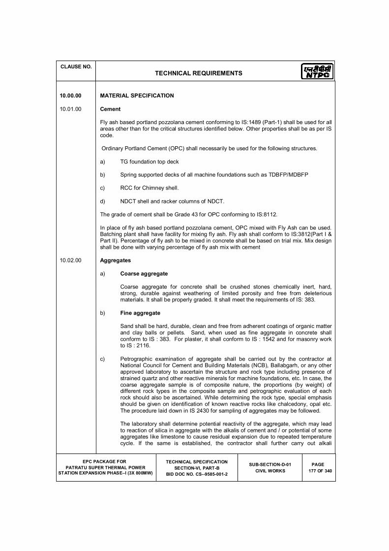
CLAUSE NO.
TECHNICAL REQUIREMENTS
EPC PACKAGE FOR
PATRATU SUPER THERMAL POWER
STATION EXPANSION PHASE�I (3X 800MW)
TECHNICAL SPECIFICATION
SECTION-VI, PART-B
BID DOC NO. CS--9585-001-2
SUB-SECTION-D-01
CIVIL WORKS
PAGE
177 OF 340
10.00.00 MATERIAL SPECIFICATION
10.01.00 Cement
Fly ash based portland pozzolana cement conforming to IS:1489 (Part-1) shall be used for all areas other than for the critical structures identified below. Other properties shall be as per IS code.
Ordinary Portland Cement (OPC) shall necessarily be used for the following structures.
a) TG foundation top deck
b) Spring supported decks of all machine foundations such as TDBFP/MDBFP
c) RCC for Chimney shell.
d) NDCT shell and racker columns of NDCT.
The grade of cement shall be Grade 43 for OPC conforming to IS:8112.
In place of fly ash based portland pozzolana cement, OPC mixed with Fly Ash can be used. Batching plant shall have facility for mixing fly ash. Fly ash shall conform to IS:3812(Part I & Part II). Percentage of fly ash to be mixed in concrete shall be based on trial mix. Mix design shall be done with varying percentage of fly ash mix with cement
10.02.00 Aggregates
a) Coarse aggregate
Coarse aggregate for concrete shall be crushed stones chemically inert, hard, strong, durable against weathering of limited porosity and free from deleterious materials. It shall be properly graded. It shall meet the requirements of IS: 383.
b) Fine aggregate
Sand shall be hard, durable, clean and free from adherent coatings of organic matter and clay balls or pellets. Sand, when used as fine aggregate in concrete shall conform to IS : 383. For plaster, it shall conform to IS : 1542 and for masonry work to IS : 2116.
c) Petrographic examination of aggregate shall be carried out by the contractor at National Council for Cement and Building Materials (NCB), Ballabgarh, or any other approved laboratory to ascertain the structure and rock type including presence of strained quartz and other reactive minerals for machine foundations, etc. In case, the coarse aggregate sample is of composite nature, the proportions (by weight) of different rock types in the composite sample and petrographic evaluation of each rock should also be ascertained. While determining the rock type, special emphasis should be given on identification of known reactive rocks like chalcedony, opal etc.
The procedure laid down in IS 2430 for sampling of aggregates may be followed.
The laboratory shall determine potential reactivity of the aggregate, which may lead to reaction of silica in aggregate with the alkalis of cement and / or potential of some aggregates like limestone to cause residual expansion due to repeated temperature cycle. If the same is established, the contractor shall further carry out alkali
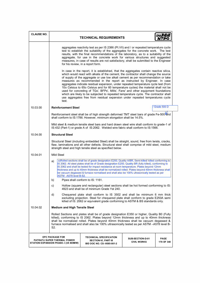
CLAUSE NO.
TECHNICAL REQUIREMENTS
EPC PACKAGE FOR
PATRATU SUPER THERMAL POWER
STATION EXPANSION PHASE�I (3X 800MW)
TECHNICAL SPECIFICATION
SECTION-VI, PART-B
BID DOC NO. CS--9585-001-2
SUB-SECTION-D-01
CIVIL WORKS
PAGE
178 OF 340
aggregates reactivity test as per IS 2386 (Pt.VII) and / or repeated temperature cycle test to establish the suitability of the aggregates for the concrete work. The test results, with the final recommendations of the laboratory, as to a suitability of the aggregate, for use in the concrete work for various structures and suggested measures, in case of results are not satisfactory, shall be submitted to the Engineer for his review, in a report form.
In case in the report, it is established, that the aggregates contain reactive silica, which would react with alkalis of the cement, the contractor shall change the source of supply of the aggregate or use low alkali cement as per recommendation or take measures as recommended in the report as instructed by Engineer. In case aggregates indicate residual expansion, under repeated temperature cycle test (from 10o Celsius to 65o Celsius and for 60 temperature cycles) the material shall not be used for concreting of TGs', BFPs', Mills', Fans' and other equipment foundations which are likely to be subjected to repeated temperature cycle. The contractor shall use aggregates free from residual expansion under repeated temperatures cycle test.
10.03.00 Reinforcement Steel
Reinforcement steel shall be of high strength deformed TMT steel bars of grade Fe-500 and shall conform to IS:1786. However, minimum elongation shall be 14.5%.
Mild steel & medium tensile steel bars and hard drawn steel wire shall conform to grade-1 of IS:432 (Part-1) or grade A of IS:2062. Welded wire fabric shall conform to IS:1566.
10.04.00 Structural Steel
Structural Steel (including embedded Steel) shall be straight, sound, free from twists, cracks, flaw, laminations and all other defects. Structural steel shall comprise of mild steel, medium strength steel and high tensile steel as specified below.
10.04.01 Mild Steel
a) Rolled Sections and plates shall be of grade designation E350, Quality B0 (killed),conforming to IS 2062. Plates beyond 12mm thickness and up to 40mm thickness shall be normalized rolled. Plates beyond 40mm thickness shall be vacuum degassed & furnace normalised and shall also be 100% ultrasonically tested as per ASTM �A578 level B-S2.
b) Pipes shall conform to IS: 1161.
c) Hollow (square and rectangular) steel sections shall be hot formed conforming to IS: 4923 and shall be of minimum Grade Yst 240.
d) Chequered plate shall conform to IS 3502 and shall be minimum 6 mm thick excluding projection. Steel for chequered plate shall conform to grade E250A semi killed of IS: 2062 or equivalent grade conforming to ASTM & BS standards only.
10.04.02 Medium and High Tensile Steel
Rolled Sections and plates shall be of grade designation E350 or higher, Quality B0 (Fully killed), conforming to IS 2062. Plates beyond 12mm thickness and up to 40mm thickness shall be normalized rolled. Plates beyond 40mm thickness shall be vacuum degassed & furnace normalised and shall also be 100% ultrasonically tested as per ASTM �A578 level B-S2.
/ Grade 500 D
a)Rolled sections shall be of grade designation E250, Quality A/BR, Semi-killed/ killed conforming to
IS 2062. All steel plates shall be of Grade designation E250, Quality BR (fully killed), conforming to
IS 2062 and shall be tested for impact resistance at room temperature. Plates beyond 12mm
thickness and up to 40mm thickness shall be normalized rolled. Plates beyond 40mm thickness shall
be vacuum degassed & furnace normalised and shall also be 100% ultrasonically tested as per
ASTM -A578 level B-S2.
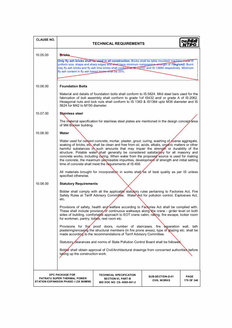
CLAUSE NO.
TECHNICAL REQUIREMENTS
EPC PACKAGE FOR
PATRATU SUPER THERMAL POWER
STATION EXPANSION PHASE�I (3X 800MW)
TECHNICAL SPECIFICATION
SECTION-VI, PART-B
BID DOC NO. CS--9585-001-2
SUB-SECTION-D-01
CIVIL WORKS
PAGE
179 OF 340
10.05.00 Bricks
Bricks shall be table mounted/ machine made of uniform size, shape and sharp edges and shall have minimum compressive strength of 50kg/cm2. Burnt clay fly ash bricks and fly ash lime bricks shall conform to IS:13757 and IS:12894 respectively. Minimum fly ash content in fly ash based bricks shall be minimum 25%. Common burnt clay bricks shall conform to IS:1077.
10.06.00 Foundation Bolts
Material and details of foundation bolts shall conform to IS:5624. Mild steel bars used for the fabrication of bolt assembly shall conform to grade 1of IS432 and/ or grade A of IS:2062. Hexagonal nuts and lock nuts shall conform to IS 1363 & IS1364 upto M36 diameter and IS 5624 for M42 to M150 diameter.
10.07.00 Stainless steel
The material specification for stainless steel plates are mentioned in the design concept area
of Mill Bunker building.
10.08.00 Water
Water used for cement concrete, mortar, plaster, grout, curing, washing of coarse aggregate, soaking of bricks, etc. shall be clean and free from oil, acids, alkalis, organic matters or other harmful substances in such amounts that may impair the strength or durability of the structure. Potable water shall generally be considered satisfactory for all masonry and concrete works, including curing. When water from the proposed source is used for making the concrete, the maximum permissible impurities, development of strength and initial setting
time of concrete shall meet the requirements of IS:456.
All materials brought for incorporation in works shall be of best quality as per IS unless specified otherwise.
10.08.00 Statutory Requirements
Bidder shall comply with all the applicable statutory rules pertaining to Factories Act, Fire Safety Rules at Tariff Advisory Committee. Water Act for pollution control, Explosives Act, etc.
Provisions of safety, health and welfare according to Factories Act shall be complied with. These shall include provision of continuous walkways along the crane - girder level on both sides of building, comfortable approach to EOT crane cabin, railing, fire escape, locker room for workmen, pantry, toilets, rest room etc.
Provisions for fire proof doors, number of staircases, fire separation wall, lath plastering/encasing the structural members (in fire prone areas), type of glazing etc. shall be made according to the recommendations of Tarrif Advisory Committee.
Statutory clearances and norms of State Pollution Control Board shall be followed.
Bidder shall obtain approval of Civil/Architectural drawings from concerned authorities before taking up the construction work.
Only fly ash bricks shall be used in all construction. Bricks shall be table moulded/ machine made of
uniform size, shape and sharp edges and shall have minimum compressive strength of 75kg/cm2. Burnt
clay fly ash bricks and fly ash lime bricks shall conform to IS :13757 and IS:12894 respectively. Minimum
fly ash content in fly ash based bricks shall be 25%.
CLAUSE NO.
TECHNICAL REQUIREMENTS
EPC PACKAGE FOR
PATRATU SUPER THERMAL POWER
STATION EXPANSION PHASE�I (3X 800MW)
TECHNICAL SPECIFICATION
SECTION-VI, PART-B
BID DOC NO. CS--9585-001-2
SUB-SECTION-D-01
CIVIL WORKS
PAGE
180 OF 340
11.00.00 Inspection, Testing And Quality Control
11.01.00 Sampling and testing of major items of civil works viz. earthwork, concreting, structural steel work (including welding), piling, sheeting, etc. shall be carried out in accordance with the requirements of this specification. Wherever nothing is specified relevant Indian Standards shall be followed. In absence of Indian Standard equivalent International Standards may be used.
The Bidder shall submit and finalise a detailed field Quality Assurance Programme before starting of the construction work according to the requirement of this specification. This shall include frequency of sampling and testing, nature/type of test, method of test, setting of a testing laboratory, arrangement of testing apparatus/equipment, deployment of qualified/experienced manpower, preparation of format for record, Field Quality Plan, etc. Tests shall be done in the field and/or at a laboratory approved by the Engineer. The Bidder shall furnish the test certificate from the manufacturer�s of various materials to be used in the
construction.
11.02.00 Workmanship and dimensional shall be checked as stipulated below.
12.00.00 ANNEXURES
(a) List Of Codes And Standards
All applicable standards, references, specifications, codes of practice, etc., shall be the latest edition including all applicable official amendments and revisions. A complete set of all these documents shall be available at site with Bidder. List of some of the applicable Standards, in original Codes and references is as given in Annexure-a of this specification.
CLAUSE NO.
TECHNICAL REQUIREMENTS
EPC PACKAGE FOR
PATRATU SUPER THERMAL POWER
STATION EXPANSION PHASE�I (3X 800MW)
TECHNICAL SPECIFICATION
SECTION-VI, PART-B
BID DOC NO. CS--9585-001-2
SUB-SECTION-D-01
CIVIL WORKS
PAGE
181 OF 340
Annexure-(a)
LIST OF CODES AND STANDARDS
Excavation and Filling
IS :2720 Methods of test for soils(relevant parts)
IS:4701 Code of practice for earth work on canals.
IS:9759 Guide lines for dewatering during construction.
IS:10379 Code of practice for field control of moisture and compaction of soils for embankment and sub-grade.
Properties, Storage and Handling of Common Building Materials
IS:269 33 grade for ordinary Portland cement.
IS:383 Coarse and fine aggregates from natural sources for concrete.
IS:432 Specification for mild steel and medium tensile steel bars and
(Part 1&2) hard drawn steel wires for concrete reinforcement.
IS:455 Portland slag cement.
IS:702 Industrial bitumen.
IS:712 Specification for building limes.
IS:1077 Common burnt clay buidling bricks.
IS:1161 Steel tubes for structural purposes.
IS:1239 Mild steel tubes, tubulars and other wronght steel fillting - MS tubes.
IS:1363 Hexagon head bolts, screws and nuts of productions
(Part 1-3) grade - C.
IS:1364 Hexagon head bolts, screws and nuts of productions
(Part 1-5) grade-A & B.
IS:1367 Technical supply condition for threaded fasteners. (Part 1-18)
IS:1489 Portland-pozzolana cement. (Part-I) Fly ash based
IS:1542 Sand for Plaster.
CLAUSE NO.
TECHNICAL REQUIREMENTS
EPC PACKAGE FOR
PATRATU SUPER THERMAL POWER
STATION EXPANSION PHASE�I (3X 800MW)
TECHNICAL SPECIFICATION
SECTION-VI, PART-B
BID DOC NO. CS--9585-001-2
SUB-SECTION-D-01
CIVIL WORKS
PAGE
182 OF 340
IS:1566 Hard drawn steel wire fabric for concrete reinforcement.
IS:1786 High strength deformed steel bars & wires for concrete reinforcement.
IS:2062 Hot Rolled Low, Medium and High Tensile Structural Steel
IS:2116 Sand for masonry mortars.
IS : 2185 Hollow & solid concrete blocks. (Part 1) (Part 2) Hollow & solid light weight concrete blocks.
IS:2386 Testing of aggregates for concrete.
(Part I-VIII)
IS:3812 Specification for fly ash for use as pozzolona and admixture.
IS:4082 Recommendation on stacking and storage of construction materiel and components at site
IS:8112 43 grade ordinary portland cement.
IS:8500 Structural steel-Microalloyed (Medium and high strength qualities).
IS:12269 53 grade ordinary portland cement.
IS:12894 Specification for fly ash lime bricks.
IS:13757 Burnt clay fly ash building bricks.
Cast in-situ Concrete and Allied Works
IS:280 Mild steel wire for general engineering purpose.
IS:456 Code of practice for plain and reinforcement concrete.
IS:457 Code of practice for general construction of plain and reinforced concrete for
dams and other massive structures.
IS:516 Method of test for strength of concrete. IS:1199 Methods of sampling and analysis of concrete.
IS:1791 General requirement for batch type concrete mixers.
IS:1834 Hot applied sealing compound for joints in concrete.
IS:1838 Preformed fillers for expansion joints in concrete pavement and structures.
IS:2438 Specification for roller pan mixers.
IS:2502 Code of practice for bending and fixing of bars for concrete reinforcement.
IS:2505 Concrete vibrators - immersion type.
CLAUSE NO.
TECHNICAL REQUIREMENTS
EPC PACKAGE FOR
PATRATU SUPER THERMAL POWER
STATION EXPANSION PHASE�I (3X 800MW)
TECHNICAL SPECIFICATION
SECTION-VI, PART-B
BID DOC NO. CS--9585-001-2
SUB-SECTION-D-01
CIVIL WORKS
PAGE
183 OF 340
IS:2506 General requirements for screed board concrete vibrators.
IS:2722 Specification for Portable Swing weigh batchers for concrete (single and double bucket type).
IS:2750 Steel scaffoldings
IS:2751 Recommended practice for welding of mild steel plain and deformed bars for reinforced construction.
IS:3150 Hexagonal wire netting for general purposes.
IS:3366 Specification for pan vibrators.
IS:3370 Code of practice for concrete structures for the (Part 1-4) storage of liquids.
IS:3558 Code of practice for use of immersion vibrators for consolidating concrete.
IS:4014 Code of practice for steel tubular scaffolding. (Part-1&2)
IS:4326 Code of practice for earth quake resistant design and construction of buildings.
IS:4656 Form vibrators for concrete.
IS:4925 Concrete batching and mixing plant. IS:4990 Plywood for concrete shuttering work.
IS:5256 Code of practice for sealing expansion joints in concrete lining on canals.
IS:5525 Recommendations for detailing of reinforcement in reinforced concrete works.
IS:6461 Glossary of terms relating to cement concrete.
IS:6494 Code of practice for water proofing of underground reservoir and swimming pools.
IS:6509 Code of practice for installation of joints in concrete pavements.
IS:7861 Code of practice for extreme weather concreting. (Part -1&2)
IS:9012 Recommended practice for shotcreting.
IS:9103 Admixtures for concrete.
IS:9417 Recommendations for welding cold worked bars for reinforced concrete construction.
IS:10262 Recommended guidelines for concrete mix design.
CLAUSE NO.
TECHNICAL REQUIREMENTS
EPC PACKAGE FOR
PATRATU SUPER THERMAL POWER
STATION EXPANSION PHASE�I (3X 800MW)
TECHNICAL SPECIFICATION
SECTION-VI, PART-B
BID DOC NO. CS--9585-001-2
SUB-SECTION-D-01
CIVIL WORKS
PAGE
184 OF 340
IS:11384 Code of practice for composite construction in structural steel and concrete.
IS:12118 Two parts polysulphide based sealants.
IS:12200 Code of practice for provision of water stops at transverse construction joints in masonry and concrete dams.
IS:13311 Non destructive testing of concrete - methods of test.
(Part 1) Ultrasonic pulse velocity.
(Part 2) Rebound hammer.
SP-16 Design codes for reinforced concrete to IS:456-1978.
SP-23 Hand book of concrete mixes.
SP-24 Explanatory handbook on Indian standards code for plain and reinforced concrete. (IS : 456)
SP-34 Hand book on concrete reinforcement and detailing.
ACI-318 American Concrete Institute code for structural concrete.
Precast Concrete Works
SP:7 National Building Code - Structural Design (Part 6/Sec.7) Prefabrication and system building and mixed / composite construction.
IS:10297 Code of practice for design and construction of floors and roofs using precast reinforced/prestressed concrete ribbed or cored slab units.
IS:10505 Code of practice for construction of floors and roofs using pre-cast reinforced concrete waffle units.
IS:15658 Pre-cast concrete block for paving.
Masonry & Allied Works
IS:1905 Code of practice for structural use of unreinforced masonry.
IS: 2185 Part-1 Concrete Masonry Units - Specification Part 1 Hollow and Solid Concrete Blocks
Part-3 Specification for concrete masonry units: Part 2 Hollow and solid light
weight concrete blocks IS:2212 Code of practice for brick work.
IS:2250 Code of practice for preparation and use of masonry mortars.
IS:2572 Code of practice for construction of hollow concrete block masonry.
SP:20 Hand book on masonry design and construction.
CLAUSE NO.
TECHNICAL REQUIREMENTS
EPC PACKAGE FOR
PATRATU SUPER THERMAL POWER
STATION EXPANSION PHASE�I (3X 800MW)
TECHNICAL SPECIFICATION
SECTION-VI, PART-B
BID DOC NO. CS--9585-001-2
SUB-SECTION-D-01
CIVIL WORKS
PAGE
185 OF 340
Sheeting Works
IS:277 Galvanised steel sheets (Plan & corrugated).
IS:513 Cold-rolled low carbon steel sheets & strips.
IS:730 Hook bolts for corrugated sheet roofing.
IS:801 Code of practice for use of cold formed light gauge steel structural members in general building construction.
IS:2527 Code of practice for fixing rain water gutters and down pipe for roof drainage.
IS:7178 Technical supply condition for tapping screw.
IS:8183 Bonded mineral wool.
IS:8869 Washers for corrugated sheet roofing.
IS:12093 Code of practice for laying and fixing of sloped roof covering using plain and corrugated galvanised steel sheets.
IS:12436 Preformed rigid Polyurethane (PUR) and isocyanurate (PIR) foams for thermal insulation.
IS:12866 Plastic translucent sheets made from thermosetting polyester resin (glass fibre reinforced).
IS:14246 Continuously pre-painted galvanised steel sheets and coils.
BS:5950 Code of practice for design of light gauge profiled
(Part-6) steel sheeting
Fabrication and Erection of Structural Steel Works
IS:800 Code of practice for General Construction of steel.
IS:813 Scheme for symbols for welding.
IS:814 Covered electrodes for manual metal arc welding of carbon & carbon manganese steel.
IS:816 Code of practice for use of metal arc welding for general construction in mild
steel.
IS:817 Code of practice for training and testing of metal arc welders.
IS:1024 Welding in bridges and substructured subject to dynamic.
IS:1181 Qualifying tests for Metal Arc welders (engaged in welding structures other than pipes).
CLAUSE NO.
TECHNICAL REQUIREMENTS
EPC PACKAGE FOR
PATRATU SUPER THERMAL POWER
STATION EXPANSION PHASE�I (3X 800MW)
TECHNICAL SPECIFICATION
SECTION-VI, PART-B
BID DOC NO. CS--9585-001-2
SUB-SECTION-D-01
CIVIL WORKS
PAGE
186 OF 340
IS:1182 Recommended practice for Radiographic examination of fusion welded butt joints in steel plates
IS:1608 Mechanical testing of metals - tensile testing
IS:1852 Rolling and Cutting Tolerances for Hot rolled steel products.
IS:2016 Specification for Plain washers.
IS:2595 Code of practice for Radiographic testing
IS:2629 Hot dip galvanising of iron and steel
IS:3502 Steel chequred plate.
IS:3613 Acceptance tests for wire flux combination for submerged arc welding.
IS:3658 Code of practice for liquid penetrant flaw detection.
IS:3664 Code of practice for ultra sonic pulse echo testing contact and immersion method
IS:3757 High strength structural bolts.
IS:4000 High strength bolts in steel structure - code of practice.
IS:4353 Sub merged arc welding of mild steel and low alloy steel Recommendation
IS:4759 Hot dip zinc coating on structural steel and other allied products.
IS:5334 Code of practice for magnetic particle flaw detection of welds.
IS:5369 General requirements for plain washers and lock washer
IS : 6623 High strength structural nuts.
IS:6649 Hardened and tampered washers for high strength structural bolts & nuts.
IS:6911 Stainless steel plate, sheet and strip.
IS:7205 Safety code for erection of structural steel.
IS:7215 Tolerances for fabrication of structural steel.
IS:7307 Approved test for welding procedures
(Part - I) Fusion welding of steel.
IS:7310 Approval test for welders working to approval welding procedure. (Part-I) Fusion welding of steel
IS:9178 Criteria for design of steel bins for storage of bulk material. (Part-1to 3)
CLAUSE NO.
TECHNICAL REQUIREMENTS
EPC PACKAGE FOR
PATRATU SUPER THERMAL POWER
STATION EXPANSION PHASE�I (3X 800MW)
TECHNICAL SPECIFICATION
SECTION-VI, PART-B
BID DOC NO. CS--9585-001-2
SUB-SECTION-D-01
CIVIL WORKS
PAGE
187 OF 340
IS:9595 Recommendations for metal arc welding of carbon & carbon manganese steel.
IS:12843 Tolerances for erection of steel structures.
SP:6 ISI Hand book for structural Engineers. (Part 1 to 7)
Plastering and Allied Works
IS:1661 Code of practice for application of cement and cement lime plaster finishes.
IS:2402 Code of practice for external rendered finishes.
IS:2547 Gypsum building plaster. (Parts 1&2)
Acid and Alkali Resistant Lining
IS:158 Ready mixed paint, brushing, bituminous, black, lead free, acid, alkali & heat resisting.
IS:412 Expanded metal steel sheets for general purpose.
IS:4441 Code of practice for use of silica type chemical resistant mortars.
IS:4443 Code of practice for use of resin type chemical resistant mortars.
IS:4456 Method of Test for chemical resistant tiles. (Part I & II)
IS:4457 Ceramic unglazed vitreous acid resisting tiles.
IS:4832 Specification for chemical resistant mortars.
(Part - 1) Silicate type
(Part - 2) Resin type
(Part - 3) Sulfur type
IS:4860 Acid resistant bricks.
IS:9510 Bitumastic acid resisting grade.
Water Supply, Drainage and Sanitation
IS:458 Precast concrete pipes (with & without reinforcement).
IS:554 Pipe threads where pressure tight joints are made on the threads � dimensions, tolerances and designation.
IS:651 Salt glazed stoneware pipes and fittings.
IS:774 Flushing cisterns for water closets and urinals.
CLAUSE NO.
TECHNICAL REQUIREMENTS
EPC PACKAGE FOR
PATRATU SUPER THERMAL POWER
STATION EXPANSION PHASE�I (3X 800MW)
TECHNICAL SPECIFICATION
SECTION-VI, PART-B
BID DOC NO. CS--9585-001-2
SUB-SECTION-D-01
CIVIL WORKS
PAGE
188 OF 340
IS:775 Cast iron brackets and supports for wash basins and sinks.
IS:778 Copper alloy gate, globe and check valves for water works purposes.
IS:781 Cast copper alloy screw down bib taps & stop valves for water services.
IS:782 Caulking lead.
IS:783 Code of practice for laying of concrete pipes.
IS:1172 Code of basic requirements of water supply, drainage and sanitation.
IS:1230 Cast iron rain water pipes and fittings.
IS:1239 Mild Steel tubes, tubulars and other wrought steel fittings (Part 1&2)
IS:1536 Centrifugally cast (Spun) iron pressure pipes for water.
IS:1537 Vertically cast iron pressure pipes for water, gas and sewage.
IS:1538 Cast iron fittings for pressure pipe for water, gas and sewage.
IS:1703 Copper alloy float valve for water supply fitting.
IS:1726 Cast iron manhole covers and frames.
IS:1729 Cast iron / Ductile iron drainage pipes and pipe/fittings for over ground non pressure pipeline socket and spigot series.
IS:1742 Code of practice for building drainage.
IS:2064 Selection, installation and maintenance of sanitary appliances.
IS:2065 Code of practice for water supply in buildings.
IS:2326 Automatic flushing cisterns for urinals.
IS:2548 Plastic seats and covers for water closets.
IS:2556 Vitreous sanitary appliances (vitreous china).
IS:3114 Code of practice for laying of cast iron pipes.
IS:3311 Waste plug and its accessories for sinks and wash basins.
IS:3438 Silvered glass mirrors for general purposes.
IS:3486 Cast iron spigot and socket drain pipes.
IS:3589 steel pipe for water and sewage (168.3 to 2540mm outside diameter)
IS:3989 Centrifugally cast (Spun) iron spigot and socket soil, waste and ventilating pipes, fittings and accessories.
CLAUSE NO.
TECHNICAL REQUIREMENTS
EPC PACKAGE FOR
PATRATU SUPER THERMAL POWER
STATION EXPANSION PHASE�I (3X 800MW)
TECHNICAL SPECIFICATION
SECTION-VI, PART-B
BID DOC NO. CS--9585-001-2
SUB-SECTION-D-01
CIVIL WORKS
PAGE
189 OF 340
IS:4111 Code of practice for ancillary structure in sewerage system. (Part 1 to 5)
IS:4127 Code of practice for laying of glazed stone ware pipes.
IS : 4733 Methods of sampling and testing sewage effluents.
IS:4764 Tolerance limits for sewage effluents discharged into inland surface waters.
IS:1068 Electroplated coating of nickel plus chromium and copper plus nickel plus chromium.
IS:5329 Code of practice for sanitary pipe work above ground for buildings.
IS:5382 Rubber sealing rings for gas mains, water mains and sewers.
IS:5822 Code of practice for laying of electrically welded steel pipes for water supply.
IS:5961 Specification for cast iron grating for drainage purpose.
IS:7740 Code of practice for construction and maintenance of road gullies.
IS:8931 Copper alloy fancy single taps combination tap assembly and stop valves for water services.
IS:9762 Polyethylene floats for float valves.
IS:10592 Industrial emergency showers, eye and face fountains and combination units.
IS:12592 Specification for precast concrete manhole covers and frames.
IS:12701 Rotational moulded polyethylene water storage tanks.
IS:13983 Stainless steel sinks for domestic purposes.
SP:35 Hand book on water supply and drainage with special emphasis on plumbing.
CPH&EEO Manual on sewage and sewage treatment
Publication - as updated.
Doors Windows and Allied Works
IS:204 Tower Bolts.
(Part 1) Ferrous metals
(Part 2) Non - ferrous metals
IS:208 Door Handles.
IS:281 Mild steel sliding door bolts for use with padlocks.
CLAUSE NO.
TECHNICAL REQUIREMENTS
EPC PACKAGE FOR
PATRATU SUPER THERMAL POWER
STATION EXPANSION PHASE�I (3X 800MW)
TECHNICAL SPECIFICATION
SECTION-VI, PART-B
BID DOC NO. CS--9585-001-2
SUB-SECTION-D-01
CIVIL WORKS
PAGE
190 OF 340
IS:362 Parliament Hinges.
IS:419 Putty, for use on window frames.
IS:451 Technical supply conditions for wood screws
IS:733 Wrought aluminium and aluminium alloy bars, rods and sections for general engineering purposes.
IS:1003 Timber panelled and glazed shutters (doors shutters). (Part I)
IS:1003 Timber panelled and glazed shutters
(Part-1) door shutters.
IS:1038 Steel doors, windows and ventilators.
IS:1081 Code of practice for fixing and glazing of metal (steel and aluminium) doors, windows and ventilators.
IS:1285 Wrought aluminium and aluminium alloy extruded round tube & hollow section (for general engineering purposes).
IS:1341 Steel butt hinges.
IS:1361 Steel windows for Industrial buildings.
IS:1823 Floor door stoppers.
IS:1868 Anodic coatings on Aluminium and its alloys.
IS:2202 Wooden flush door shutters (solid core type) particle
(Part-2) board face panels and hard board face panels.
IS:2209 Mortice locks (vertical type)
IS:2553 Safety glass.
(Part-1) General purposes
IS:2835 Flat transparent sheet glass.
IS:3548 Code of practice for glazing in buildings.
IS:3564 Door closers (Hydraulically regulated)
IS:3614 Specification for fire check doors :
(Part-1) plate, metal covered and rolling type.
(Part-2) Resistance test and performance criteria.
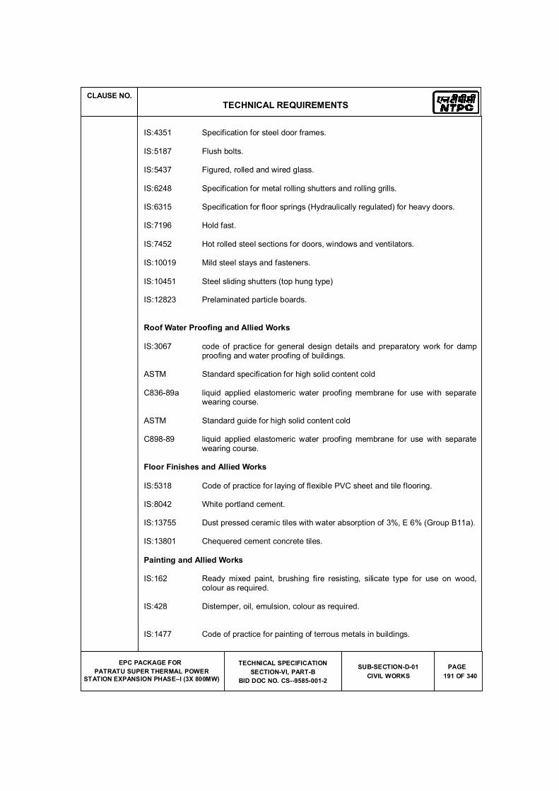
CLAUSE NO.
TECHNICAL REQUIREMENTS
EPC PACKAGE FOR
PATRATU SUPER THERMAL POWER
STATION EXPANSION PHASE�I (3X 800MW)
TECHNICAL SPECIFICATION
SECTION-VI, PART-B
BID DOC NO. CS--9585-001-2
SUB-SECTION-D-01
CIVIL WORKS
PAGE
191 OF 340
IS:4351 Specification for steel door frames.
IS:5187 Flush bolts.
IS:5437 Figured, rolled and wired glass.
IS:6248 Specification for metal rolling shutters and rolling grills.
IS:6315 Specification for floor springs (Hydraulically regulated) for heavy doors.
IS:7196 Hold fast.
IS:7452 Hot rolled steel sections for doors, windows and ventilators.
IS:10019 Mild steel stays and fasteners.
IS:10451 Steel sliding shutters (top hung type)
IS:12823 Prelaminated particle boards.
Roof Water Proofing and Allied Works
IS:3067 code of practice for general design details and preparatory work for damp proofing and water proofing of buildings.
ASTM Standard specification for high solid content cold
C836-89a liquid applied elastomeric water proofing membrane for use with separate wearing course.
ASTM Standard guide for high solid content cold
C898-89 liquid applied elastomeric water proofing membrane for use with separate wearing course.
Floor Finishes and Allied Works
IS:5318 Code of practice for laying of flexible PVC sheet and tile flooring.
IS:8042 White portland cement.
IS:13755 Dust pressed ceramic tiles with water absorption of 3%, E 6% (Group B11a).
IS:13801 Chequered cement concrete tiles.
Painting and Allied Works
IS:162 Ready mixed paint, brushing fire resisting, silicate type for use on wood, colour as required.
IS:428 Distemper, oil, emulsion, colour as required.
IS:1477 Code of practice for painting of terrous metals in buildings.
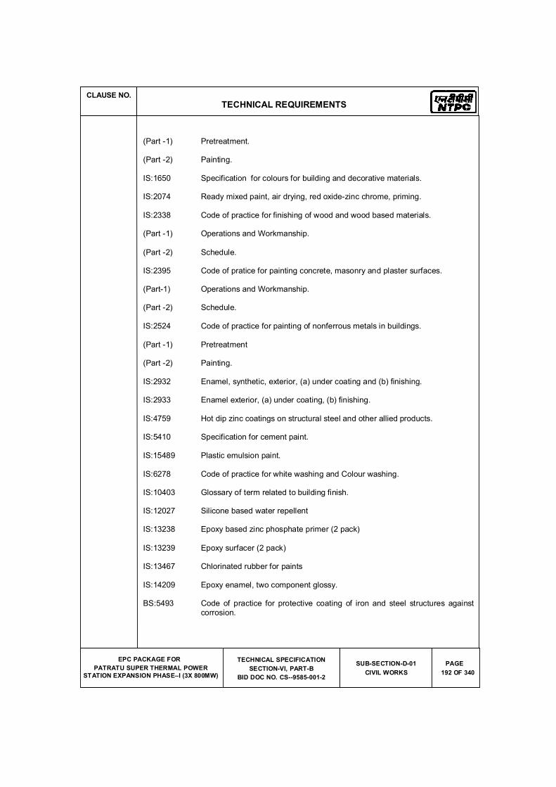
CLAUSE NO.
TECHNICAL REQUIREMENTS
EPC PACKAGE FOR
PATRATU SUPER THERMAL POWER
STATION EXPANSION PHASE�I (3X 800MW)
TECHNICAL SPECIFICATION
SECTION-VI, PART-B
BID DOC NO. CS--9585-001-2
SUB-SECTION-D-01
CIVIL WORKS
PAGE
192 OF 340
(Part -1) Pretreatment.
(Part -2) Painting.
IS:1650 Specification for colours for building and decorative materials.
IS:2074 Ready mixed paint, air drying, red oxide-zinc chrome, priming.
IS:2338 Code of practice for finishing of wood and wood based materials.
(Part -1) Operations and Workmanship.
(Part -2) Schedule.
IS:2395 Code of pratice for painting concrete, masonry and plaster surfaces.
(Part-1) Operations and Workmanship.
(Part -2) Schedule.
IS:2524 Code of practice for painting of nonferrous metals in buildings.
(Part -1) Pretreatment
(Part -2) Painting.
IS:2932 Enamel, synthetic, exterior, (a) under coating and (b) finishing.
IS:2933 Enamel exterior, (a) under coating, (b) finishing.
IS:4759 Hot dip zinc coatings on structural steel and other allied products.
IS:5410 Specification for cement paint.
IS:15489 Plastic emulsion paint.
IS:6278 Code of practice for white washing and Colour washing.
IS:10403 Glossary of term related to building finish.
IS:12027 Silicone based water repellent
IS:13238 Epoxy based zinc phosphate primer (2 pack)
IS:13239 Epoxy surfacer (2 pack)
IS:13467 Chlorinated rubber for paints
IS:14209 Epoxy enamel, two component glossy.
BS:5493 Code of practice for protective coating of iron and steel structures against corrosion.
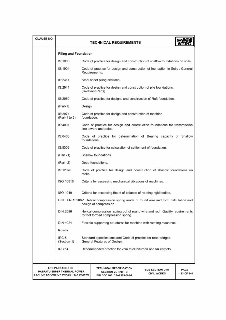
CLAUSE NO.
TECHNICAL REQUIREMENTS
EPC PACKAGE FOR
PATRATU SUPER THERMAL POWER
STATION EXPANSION PHASE�I (3X 800MW)
TECHNICAL SPECIFICATION
SECTION-VI, PART-B
BID DOC NO. CS--9585-001-2
SUB-SECTION-D-01
CIVIL WORKS
PAGE
193 OF 340
Piling and Foundation
IS:1080 Code of practice for design and construction of shallow foundations on soils.
IS:1904 Code of practice for design and construction of foundation in Soils : General Requirements.
IS:2314 Steel sheet piling sections.
IS:2911 Code of practice for design and construction of pile foundations. (Relevant Parts)
IS:2950 Code of practice for designs and construction of Raft foundation.
(Part-1) Design
IS:2974 Code of practice for design and construction of machine (Part-1 to 5) foundation.
IS:4091 Code of practice for design and construction foundations for transmission line towers and poles.
IS:6403 Code of practice for determination of Bearing capacity of Shallow foundations.
IS:8009 Code of practice for calculation of settlement of foundation.
(Part -1) Shallow foundations.
(Part -2) Deep foundations.
IS:12070 Code of practice for design and construction of shallow foundations on rocks.
ISO 10816 Criteria for assessing mechanical vibrations of machines.
ISO 1940 Criteria for assessing the st of balance of rotating rigid bodies.
DIN : EN 13906-1 Helical compression spring made of round wire and rod : calculation and design of compression .
DIN:2096 Helical compression spring out of round wire and rod : Quality requirements for hot formed compression spring.
DIN:4024 Flexible supporting structures for machine with rotating machines.
Roads
IRC:5 Standard specifications and Code of practice for road bridges, (Section-1) General Features of Design.
IRC:14 Recommended practice for 2cm thick bitumen and tar carpets.
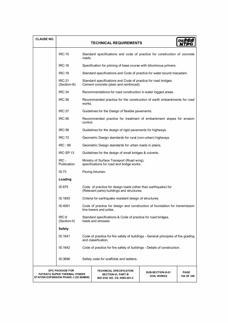
CLAUSE NO.
TECHNICAL REQUIREMENTS
EPC PACKAGE FOR
PATRATU SUPER THERMAL POWER
STATION EXPANSION PHASE�I (3X 800MW)
TECHNICAL SPECIFICATION
SECTION-VI, PART-B
BID DOC NO. CS--9585-001-2
SUB-SECTION-D-01
CIVIL WORKS
PAGE
194 OF 340
IRC:15 Standard specifications and code of practice for construction of concrete roads.
IRC:16 Specification for priming of base course with bituminous primers.
IRC:19 Standard specifications and Code of practice for water bound macadam.
IRC:21 Standard specifications and Code of practice for road bridges. (Section-III) Cement concrete (plain and reinforced).
IRC:34 Recommendations for road construction in water logged areas.
IRC:36 Recommended practice for the construction of earth embankments for road
works.
IRC:37 Guidelines for the Design of flexible pavements.
IRC:56 Recommended practice for treatment of embankment slopes for erosion control.
IRC:58 Guidelines for the design of rigid pavements for highways.
IRC:73 Geometric Design standards for rural (non-urban) highways.
IRC : 86 Geometric Design standards for urban roads in plains.
IRC:SP:13 Guidelines for the design of small bridges & culverts.
IRC - Ministry of Surface Transport (Road wing), Publication specifications for road and bridge works.
IS:73 Paving bitumen.
Loading
IS:875 Code of practice for design loads (other than earthquake) for (Relevant parts) buildings and structures.
IS:1893 Criteria for earthquake resistant design of structures.
IS:4091 Code of practice for design and construction of foundation for transmission line towers and poles.
IRC:6 Standard specifications & Code of practice for road bridges. (Section-II) loads and stresses
Safety
IS:1641 Code of practice for fire safety of buildings - General principles of fire grading and classification.
IS:1642 Code of practice for fire safety of buildings - Details of construction.
IS:3696 Safety code for scaffolds and ladders.
CLAUSE NO.
TECHNICAL REQUIREMENTS
EPC PACKAGE FOR
PATRATU SUPER THERMAL POWER
STATION EXPANSION PHASE�I (3X 800MW)
TECHNICAL SPECIFICATION
SECTION-VI, PART-B
BID DOC NO. CS--9585-001-2
SUB-SECTION-D-01
CIVIL WORKS
PAGE
195 OF 340
(Part-1&2)
IS:3764 Excavation work - code of safety.
IS:4081 Safety code for blasting and related drilling operations.
IS:4130 Demolition of buildings - code of safety.
IS:5121 Safety code for piling and other deep foundations.
IS:5916 Safety code for construction involving use of hot bituminous materials.
IS:7205 Safety code for erection of structural steel work.
IS:7293 Safety code for working with construction machinery.
IS:7969 Safety code for handling and storage of building materials. Indian Explosives (As updated) Act 1940)
Architectural Design of Buildings
SP:7 National Building Code of India
SP:41 Hand book on functional requirements of buildings (other than industrial buildings)
ECBC Energy Conservation Building Code
GRIHA Green Rating For Integrated Habitat Assessment.
Chimney
IS:4998 Criteria for design of reinforced chimneys IS:6533 Code of practice for design and construction of steel chimneys
ICAO International Civil Aviation Organisation (ICAO)
DGCA Instruction of Director General of Civil Aviation , India
ACI:307 Specification for the design and construction of reinforced concrete chimneys
BS:4076 Specification for steel chimneys
CICIND Model Code for concrete chimneys Model code for steel chimneys
ASCE Code Design and construction of steel chimney liners prepared by Task committee on steel chimney liners. Fossil power committee, Power division published by ASCE - 1975.
IS:1554 PVC insulated (heavy duty) electric cables
IS:2606 Alloy lead anodes for chromium plating
CLAUSE NO.
TECHNICAL REQUIREMENTS
EPC PACKAGE FOR
PATRATU SUPER THERMAL POWER
STATION EXPANSION PHASE�I (3X 800MW)
TECHNICAL SPECIFICATION
SECTION-VI, PART-B
BID DOC NO. CS--9585-001-2
SUB-SECTION-D-01
CIVIL WORKS
PAGE
196 OF 340
IS:3043 Code of Practice for Earthing
IS:9537 Conduits for electrical installations. The Indian Electricity Rules The Indian Electricity Act The Indian Electricity (Supply) Act The Indian Factories Act
IS:2309 Practice for protection of buildings and allied structures against lightning
Miscellaneous
IS:802 Code of practice for use of structural steel in overhead trans- (Relevant parts) mission line towers.
IS:803 Code of practice for design, fabrication and erection of vertical mild steel cylindrically welded in storage tanks.
IS:10430 Criteria for design of lined canals and guidance for selection of type of lining.
IS:11592 Code of practice for selection and design of belt conveyors.
IS:12867 PVC handrails covers.
IS 11504 Criteria for structural design of reinforced concrete natural draught cooling towers
BS:4485 (IV) British Standard : Code of design for water cooling towers
CIRIA Design and construction of buried thin-wall pipes. Publication IS 4671 Expanded polystyrene for thermal insulation purposes.
CLAUSE NO.
TECHNICAL REQUIREMENTS
EPC PACKAGE FOR
PATRATU SUPER THERMAL POWER STATION EXPANSION PHASE�I (3X 800MW)
TECHNICAL SPECIFICATIONS
SECTION-VI, PART-B
BID DOC NO. CS-9585-001-2
SUB-SECTION-D-01
CIVIL WORKS
PAGE
122 OF 340
8.00.00 GENERAL SPECIFICATION
8.1.0 General Requirements
8.1.1 Joints in Concrete Structures
Construction Joints
All horizontal construction joints shall be provided with a groove (shear key) for transfer of shear force.
For construction joint in concrete wall, the maximum height of any lift should not exceed 2 meters. However, the time interval between the successive lifts should be as small possible
and the wall should be built to its full height in the least possible time.
Construction/ Expansion joints for all underground structures shall be made water tight by using ribbed PVC water stops with central bulb or of kicker type. The thickness and width of PVC water stops shall be as per the requirement of design. However, the minimum thickness and width shall be 6mm and 225mm respectively. Two - part polysulphide sealant conforming to IS 12118 shall be used for sealing of joints. Preformed bitumen impregnated fibre board conforming to IS 1838 shall be used as joint filler.
Expansions Joints
In case of expansion joints, preformed bitumen impregnated fibre board conforming to IS 1838 shall be used as joint filler. The joints shall be sealed with bitumen sealing compound conforming to IS 1834, however in case of liquid retaining/carrying structures, two parts polysulphide sealant conforming to IS 12118 or silicon sealing compound shall be used.
IS 3414 shall be followed for details of joints in buildings. 3 mm thick stainless steel strip in matt or buff finish shall be provided over building expansion joints.
8.1.2 Miscellaneous General requirements
8.1.2.1 All steel sections and fabricated structures, which are required to be transported on sea, shall
be provided with anti-corrosive paint before shipment to take care of sea worthiness.
8.1.2.2 Monorails, monorail girders and fixtures shall be provided, wherever required to facilitate erection / maintenance of equipment.
8.1.2.3 Wherever possible all floor openings shall be provided with 100 mm thick 150 mm high RCC kerb all around.
8.1.2.4 Angles 75 x 75 x 6 mm (minimum) with 8mm dia and 150mm long MS lugs @ 150 c/c shall be provided for edge protection all around cut outs/openings in floor slabs. Angles 50 x 50 x 6mm with effective anchor lugs shall be provided for edges of concrete drains supporting
grating/covers, edges of RCC cable / pipe trenches supporting covers/chequered plates/ grating, edges of manholes supporting covers, supporting edges of precast RCC covers and any other place where breakage of corners of concrete is expected.
8.1.2.5 Floor of switchgear room shall be provided with embedded M.S. channel suitable for easy movement of breaker panels.
8.1.2.6 Anti termite constructional measures and chemical treatment measures shall be given to all vulnerable areas susceptible to termite including column pits, wall trenches, foundations of buildings, filling below the floors, etc., as per IS 6313 and other relevant Indian Standards.
CLAUSE NO.
TECHNICAL REQUIREMENTS
EPC PACKAGE FOR
PATRATU SUPER THERMAL POWER STATION EXPANSION PHASE�I (3X 800MW)
TECHNICAL SPECIFICATIONS
SECTION-VI, PART-B
BID DOC NO. CS-9585-001-2
SUB-SECTION-D-01
CIVIL WORKS
PAGE
123 OF 340
8.1.2.7 Trenches located outside the buildings shall project at least 200mm above the finished formation level unless noted otherwise elsewhere in this specification so that no storm water shall enter the trench. The bottom of the trench shall be provided with a longitudinal slope of 1:500.The downstream end of cable trenches shall be connected through pipe drains to the nearby RCC manholes (to convey water from trenches) of storm water drainage system, but avoiding back flow of storm water. The precast covers shall not be more than 300 mm in width and shall not weigh more than 65 kg. Lifting hooks shall be provided in the precast covers. The trenches shall be given a slope of 1 in 250 in the direction perpendicular to the run of the trenches. PVC water stops shall be provided at all expansion joints of all trenches. Trench covers near entry or at road crossings shall be designed for 10 T wheel load at centre. Pre - cast covers shall be designed for central point load of 75 Kgs. R. C. C. cable slits shall be filled with sand after erection of cables, up to top level and covered with pre - cast R. C. C. covers.
8.1.2.8 All steel platforms above grade shall be provided with 100 x 6 thick kick plates at edge of platform.
8.1.2.9 Duct banks consisting of PVC conduits conforming to IS 4985 for cables shall be provided with proper sealing arrangement consisting of fire retardant sealing compound.
8.1.2.10 Independent network of lines for sewerage and drainage shall be provided. Plant effluent shall not be mixed with either storm water or sewage.
8.1.2.11 The sub-grade for the roads and embankment filling shall be compacted to minimum 95% of
the Standard Proctor density at Optimum moisture content (OMC.)
8.1.2.12 Detailed scheme for dewatering shall be prepared, wherever required, before starting of deep excavation work. IS 9758 shall be followed as general guidance for dewatering.
8.1.2.13 Structural steel column base plates and bolts, gussets, etc., shall not project above the floor level. These shall be encased by concrete cover up to floor level with concrete grade M 25.
8.1.2.14 Non-shrink flowable grout shall be used for under-pinning work below base plate of columns. Nominal thickness of grout shall be 50 mm. Non-shrink cum plasticizer admixture shall be added in the grout. Crushing strength of the grout shall generally be one grade higher than
that of the base concrete. Minimum grade of grout shall be M-30.
Grouting of all pockets, blockouts, sleeves and the openings around the embedment, inserts, bolts etc. and under pinning below the base / sole plate shall be with non - shrink flowable grout. Grade of grout shall be one grade higher than concrete. However minimum grade of grout shall be M - 30.
However, for equipment foundations, high strength (minimum characteristic compressive strength of 60 N/sq.mm at 28 days) ready mixed non-shrink, chloride free, cement based, free flowing, non-metallic grout as recommended by equipment manufacturer shall be used.
8.1.2.15 Rail-track from transformer yard to unloading bay of Main Power House shall be provided with rigid type RCC foundation. Rail weighing 52 kg/m shall be used.
8.1.2.16 All building shall be design to take care of Rain Water harvesting & ground water recharging.
8.1.2.17 As required suitable steel frames shall be provided around openings in the roof and external walls for mounting exhaust fans.
8.1.2.18 All cable trenches shall be provided with suitable insert plates for fixing support angles of cable trays.
unless and noted otherwise
CLAUSE NO.
TECHNICAL REQUIREMENTS
EPC PACKAGE FOR
PATRATU SUPER THERMAL POWER STATION EXPANSION PHASE�I (3X 800MW)
TECHNICAL SPECIFICATIONS
SECTION-VI, PART-B
BID DOC NO. CS-9585-001-2
SUB-SECTION-D-01
CIVIL WORKS
PAGE
124 OF 340
8.1.2.19 All internal cable trenches shall have minimum 6mm thick (o / p) chequered plate covers while external cable trenches shall have pre - cast RCC covers. However, the portion of the cable trench behind and sides of control panel / MCC shall be provided with suitable chequered plate covers as directed by the Engineer.
8.1.2.20 750mm wide x 100 mm thick plinth protection in PCC (M-15) shall be provided around all buildings, pits / sumps, clarifiers, tanks, etc.
8.1.2.21 All masonry walls shall be provided with Damp Proof Course at plinth level.
8.1.2.22 All monorail openings in the walls shall be provided with double plate flush steel door shutters with suitable access platform and ladder as required.
8.1.2.23 Hand rail (of minimum 1m height), size and material to be adopted shall be as per general architectural specification.
8.1.2.24 In all buildings, suitable arrangement for draining out water collected from equipment blow
downs, leakages, floor washings, firefighting etc. shall be provided for each floor with suitable floor drains.
8.1.2.25 All cable & pipe routing in outlying area shall be clubbed and shall run over ground on steel trestles or other supporting structures at a height specified elsewhere in this specification except in some localized area (as approved by Employer) where the same can run in trenches. In case cable route is not envisaged in the area, pipe shall be routed on ground over RCC pedestals at a height of not less than 500 mm. All trenches shall be of RCC with removable RCC covers.
8.1.2.26 Water supply line, drainage & Sewerage line of buildings/ facilities shall be connected with the nearest Employer's water supply & drainage line.
8.1.2.27 Unless specified all sand filling shall be compacted to minimum 80% of the relative density and backfilled earth shall be compacted to minimum 90% of the Standard proctor density at OMC.
8.1.2.28 All buildings shall be provided with peripheral drains by the side of plinth protection for catering to the rain water from roofs and storm water from adjacent area.
8.1.2.29 Minimum 2.0m wide walkway with concrete paving shall be provided connecting all buildings
and facilities. The top of walkway shall be minimum 200mm above FGL.
8.1.2.30 For all buildings, finished floor level (FFL) shall be minimum 500mm above finished ground level (FGL).
8.1.2.31 All underground concrete structures like trenches, substructures of pump houses, all water retaining / carrying structures, etc., shall have super-plasticizer cum water proofing cement additive conforming to IS 9103. In addition, limit on permeability as given in IS 2645 shall also be met with.
8.1.2.32 40mm Diameter MS rods as earthing mat, placed at a distance of 1.0m away and at depths between 0.60m and 1.00m shall be supplied and laid all around the periphery of buildings, structures, and out door equipment, as per approved drawings. Riser of 40mm Dia. MS rods and connecting to the above Earthing mat shall also be supplied and laid in position by the Contractor, as per the approved drawings. Raiser shall be laid up to a height of 300 mm above the local Ground level, at each of the columns of the buildings on the outside of the buildings, and minimum 2 (two) numbers of structures and equipment. The contractor shall also supply and lay necessary number of 3.0 m deep 40 mm diameter MS rods Earthing
Cl no 8.1.2.31 deleted
Cl no 8.1.2.26 deleted
CLAUSE NO.
TECHNICAL REQUIREMENTS
EPC PACKAGE FOR
PATRATU SUPER THERMAL POWER STATION EXPANSION PHASE�I (3X 800MW)
TECHNICAL SPECIFICATIONS
SECTION-VI, PART-B
BID DOC NO. CS-9585-001-2
SUB-SECTION-D-01
CIVIL WORKS
PAGE
128 OF 340
R.C.C. foundations for the post and stays shall be provided based on the prevailing soil conditions. All posts of fencing shall be painted with chlorinated rubber paint over a suitable primer.
Toe walls either of brick masonry with bricks of minimum 50 kg./sq.cm. crushing strength or
of hollow concrete block masonry shall be provided between the fence posts all along the run of the fence with suitable foundation. Toe wall shall be minimum 200mm above the formation level with 50mm thick P.C.C. coping (1:2:4) and shall extend minimum 300mm below the formation level. Toe wall shall be plastered with cement sand mortar (1:6) on both sides and shall be painted with two coats of textured cement point (Sandtax Matt or equivalent) of approved colour and shade. Toe wall shall be provided with weep holes at appropriate spacings.
Gate along fencing
All gates shall be of structural steel of minimum 3.75 metres width for single lane access road and 8.00 m width for double lane access roads. The height of gate shall be same as that of the fence unless noted otherwise. Each gate shall have provision for wicket gate of size 1.0 m x 2.1 m.
The gate frame and post shall be fabricated from medium class MS pipe of nominal diameter not less than 75 mm. The panel plate shall be of minimum thickness 2.5 mm conforming to IS:513.
The gate shall be complete with fabricated hinges, MS aldrops with locking arrangement, tempered steel pivot, guide track of MS tee, bronze aluminium ball bearing arrangement, castor wheel, etc.
8.6.0 Grating
All gratings shall be electroforged types. Minimum thickness of the grating shall be 40 mm for indoor installation and 32 mm for outdoor installation. The opening size shall not be more than 30mmx100mm. The minimum thickness of the main bearing bar shall be 5 mm or as per design requirement whichever is higher. All gratings shall be hot dip galvanised at the rate of 610 g. per sq.m. after surface preparation by means of shot blasting.
8.7.0 Fabrication
The fabrication shall be done as per fabrication drawing which would clearly indicate various details of joints to be welded, type of weld, length and size of weld.
All steel structures shall be fabricated in factory, transported and erected at site. All factory fabricated structures shall have bolted field connections. Bunker/Hopper segments shall be fabricated in factory, transported and assembled at site.
The factory referred above shall be in operation for the last two (2) years from the date of techno-commercial bid opening. The factory shall have the following facilities:
a) Multi-Axis Drilling Machine( Computer Numeric Controlled) b) Quality Set-up for carrying out necessary Non-Destructive Tests like Dye-Penetration
Tests, Ultrasonic Tests, Radiographic Tests etc. c) Heat Treatment facilities
d) Area for Pre-Assembly bed
Coal bunkers with hoppers and
chimney flue liners can either be
fabricated at factory in segments,
transported and welded at site
before erection or fabricated at site.
For coal bunkers, hoppers and
chimney flue liners, to prevent coal
dust/fle gas leakages, the applicable
field joints shall necessary be
welded.
Note: steel structures shall mean
Plant and Non plant building
structures, Boiler & ESP support
structures, CHP structures, AHP
structures, Chimney flue liners
support platforms & stairs, pipe and
cable support structures.
CLAUSE NO.
TECHNICAL REQUIREMENTS
EPC PACKAGE FOR
PATRATU SUPER THERMAL POWER STATION EXPANSION PHASE�I (3X 800MW)
TECHNICAL SPECIFICATIONS
SECTION-VI, PART-B
BID DOC NO. CS-9585-001-2
SUB-SECTION-D-01
CIVIL WORKS
PAGE
129 OF 340
Welding
a) Welding of Structural steel shall be done by an electric arc process and shall
conform generally to relevant acceptable standards viz. IS:816, IS:9595, IS:814, IS:2014, IS:4354 and Indian Standard Hand Book for metal arc welding, and other standards, codes of practice internationally accepted. For welding of any particular type of joint, Bidder shall give appropriate tests as described in any of the Indian Standards - IS: 817, IS: 7307 and international standards as relevant.
b) Submerged arc-welding shall be used for welding longitudinal fillet welds (connecting flange with web) and longitudinal / transverse butt joints for fabrication of columns, framing beams and crane girders and all other built-up members, unless manual arc welding is specifically approved by the Engineer. Necessary jigs and fixtures and rotation of structures shall be so arranged that vertically down-hand position of welding becomes possible. �Open-Arc-Welding� process employing coated electrodes shall be employed for fabrication of other welded connections and field welding.
c) Wherever welding is done for assembling the components of structures, the job shall so positioned that downhand welding is possible.
d) Any structural joint shall be welded only by those welders who are qualified for all welding procedures and positions in such type of joint that is welded.
e) All records for entire welding operations such as welders identification marks, the joints welded by the each welder, the welding procedures adopted, welding machine employed, pre and post heating done and any non destructive test done and stress relieving /heat treatment performed on such joints shall be accessible to the Engineer for scrutiny.
f) In a fabrication of plated columns/beams and built up members all shop splices in each component part shall be done before such component part is welded to other parts of the member. Wherever weld reinforcement interferes with proper fitting between components to be assembled by welding, these welds shall be ground flush prior to assembly.
g) The members to be jointed by fillet welding shall be brought and held as close together as possible and in no event shall be separated locally by more than 3mm. If the local separation is 1.5mm or greater, the fillet weld size shall be increased by the
amount of separation.
Edge preparation for welding as per weld joint detail shall be prepared either by machines or by automatic gas cutting. All edges cut by flame shall be ground before they are welded.
Electrodes
a) The electrodes used for welding shall be of suitable type and size depending upon specification of the parent materials, the method of welding, the position of welding and quality of welds desired e.g. normal penetration welds or deep penetration welds. However, only low Hydrogen electrodes shall be used for plate thickness
above 20 mm.
b) All low hydrogen electrodes shall be baked and stored before use as per manufacturer recommendation. The electrodes shall be rebaked at 2500C - 3000 C for one hour and later on cooled in the same oven to 1000C. It shall be transferred to an holding oven maintained at 600C - 700C. The electrodes shall be drawn from this oven for use.
CLAUSE NO.
TECHNICAL REQUIREMENTS
EPC PACKAGE FOR
PATRATU SUPER THERMAL POWER STATION EXPANSION PHASE�I (3X 800MW)
TECHNICAL SPECIFICATIONS
SECTION-VI, PART-B
BID DOC NO. CS-9585-001-2
SUB-SECTION-D-01
CIVIL WORKS
PAGE
130 OF 340
c) Where coated electrodes are used they shall meet the requirements of IS:814 and relevant ASME-Sec. Covering shall be heavy to withstand normal conditions of handling and storage.
d) Only those electrodes which give radiographic quality welds shall be used for welds
which are subjected to radiographic testing
e) Where bare electrodes are used, these shall correspond to specification of the parent material. The type of flux-wire combination for submerged arc welding shall conform to the requirements of F-60 Class of AWSA-5-17-69 and IS:3613. The electrodes shall be stored properly and the flux shall be baked before use in an oven in accordance with the manufacturer�s requirements as stipulated.
f) 308L and 309L electrodes / fillers shall be used for welding of stainless steel to stainless steel and stainless steel to mild steel respectively.
g) Specific approval of the Engineer shall be taken by Bidder for the various electrodes proposed to be used on the work before any welding is started.
Preheating inter-pass temperature and post weld heat treatment.
a) Mild steel plates conforming to IS:2062 and thicker than 20mm, may require preheating of the parent plate prior to welding as mentioned in Table-I.
However, higher preheat and interpass temperatures required due to joint restraint etc. and will be followed as per approved welding procedure. In welding materials of unequal thickness, the thicker part shall be taken for this purpose.
c) Base metal shall be preheated, not withstanding provisions of IS:9595, to the temperature given in Table-1 prior to welding or tack welding. Preheating shall bring the surface of the base metal to the specified preheat temperature and this temperature shall be maintained as minimum temperature while welding is in progress.
TABLE � 1 MINIMUM PREHEAT and INTER PASS TEMPERATURE FOR WELDING
Thickness of thicker part Welding using Low hydrogen at point of Welding electrodes or Submerged arc welding
Upto and including 20mm None
Over 20mm and upto and 20 0C including 40m
Over 40mm and upto and 66 0C including 63mm
Over 63mm 110 0C
c) Preheating may be applied by external flame which is non-carbonising like LPG, by electric resistance or electric induction process such that uniform heating of the surface extending upto a distance of four times the thickness of the plate on either side of the welding joint is obtained.
CLAUSE NO.
TECHNICAL REQUIREMENTS
EPC PACKAGE FOR
PATRATU SUPER THERMAL POWER STATION EXPANSION PHASE�I (3X 800MW)
TECHNICAL SPECIFICATIONS
SECTION-VI, PART-B
BID DOC NO. CS-9585-001-2
SUB-SECTION-D-01
CIVIL WORKS
PAGE
131 OF 340
d) Thermo-chalk, thermo-couple or other approved methods, shall be used for measuring the plate temperature.
e) All butt welds with plates thicker than 50mm and all site butts weld of main framing beam shall require post weld heat treatment as per procedure given in AWS D-1.1.
Post heating shall be done upto 600 deg.C and rate of application shall be 200 deg.C per hour. The post heat temperature shall be maintained for 60 minutes per 2.5cm. thickness. For maintaining slow and uniform cooling, asbestos pads shall be used for covering the heated areas.
Sequence of Welding
a) The sequence of welding shall be carefully chosen to ensure that the components assembled by welding are free from distortion and large residual stresses are not developed. The distortion should be effectively controlled either by a counter effect or by a counter distortion. The direction of welding should be away from the point of restraint and towards the point of maximum freedom.
b) Each case shall be carefully studied before finally following a particular sequence of welding.
c) Butt weld in flange plates and/or web plates shall be completed before the flanges and webs are welded together.
d) The beam and column stiffeners shall preferably be welded to the webs before the web and flanges are assembled unless the web and flanges to the beam or column
are assembled by automatic welding process.
e) All welds shall be finished full and made with correct number of runs, the weld being kept free from slag and other inclusions, all adhering slag being removed.
f) Current shall be appropriate for the type of electrode used. To ensure complete fusion, the weaving procedure should go proper and rate of arc advancement should not be so rapid as to leave the edges unmelted.
g) Pudding shall be sufficient to enable the gases to escape from the molten metal before it solidifies.
h) Non-uniform heating and cooling should be avoided to ensure that excessive stresses are not locked up resulting ultimately in cracks.
i) The ends of butt welds shall have full throat thickness. This shall be obtained on all main butt welds by the use of run off and run on pieces adequately secured on either side of main plates. The width of these pieces shall not be less than the thickness of the thicker part joined. Additional metal remaining after the removal of extension pieces shall be removed by grinding or by other approval means and the ends and surface of the welds shall be smoothly finished. Where the abutting parts are thinner
than 20mm the extension pieces may be omitted but the end be welded to provide the ends with the required reinforcement.
j) The fusion faces shall be carefully aligned. Angle shrinkage shall be controlled by presetting. Correct gap and alignment shall be maintained during the welding operation.
k) All main butt welds shall have complete penetration and back surface of the weld being gouged out clean before first run of the weld is given from the back. However,
CLAUSE NO.
TECHNICAL REQUIREMENTS
EPC PACKAGE FOR
PATRATU SUPER THERMAL POWER STATION EXPANSION PHASE�I (3X 800MW)
TECHNICAL SPECIFICATIONS
SECTION-VI, PART-B
BID DOC NO. CS-9585-001-2
SUB-SECTION-D-01
CIVIL WORKS
PAGE
132 OF 340
partial penetration butt weld shall be permitted, when specifically shown in the design drawings.
l) Intermittent welds shall be permitted only when shown in the design drawings.
m) The welding shrinkage shall be minimised by adopting the correct welding procedure
and method. In long and slender member extra length should be provided at the time of fabrication for shrinkage.
Testing of Welders
All the welders to be employed for the job shall have to qualify the appropriate tests laid down in IS: 817 and IS: 1181 and ASME IX/AWS D1.1. All the necessary arrangements required for the testing of welders are to be provided by the Bidder.
Inspection of Welds
a) Visual Inspection
100 percent of the welds shall be inspected visually for external defects. Dimensions of welds shall be checked. The lengths and size of weld shall be as per fabrication drawings. It may be slightly oversized but should not be undersized. The profile of weld is affected by the position of the joint but it should be uniform. The welds should have regular height and width of beads. The height and spacing of ripples shall be uniform. The joints in the welds run shall as far as possible be smooth and should not show any humps or craters in the weld surface. Welds shall be free from unfilled craters on the surface, under-cuts, stages on the surface and
visible cracks.
Such inspection shall be done after cleaning the weld surface with steel wire brushes and chisel to remove the spatter metal, scales, slag, etc., If external defects mentioned above are noticed, there is every possibility of internal defects and further radiographic/ultrasonic examination shall be undertaken.
b) Production Test Plate
Test plates shall be incorporated on either side of at least one main butt welds of each flange plate and web plate of every main frame columns and crane girder. The
weld shall be continuous over the test plate. The test plate extensions of the main plates and shall be fixed so that metal lies in the same direction as that of the main plate. Test plates shall be prepared and tested in accordance with the accepted Standards, in the presence of the Engineer or his authorised representative. Should any of these tests fail, further radiographic examination of the welds shall be done. These tests for test plates and radiographic examination are additional to those contemplated under inspection and testing.
c) Non-destructive and special testing
Radiographic / ultrasonic or other non-destructive examination shall be carried out. All tests of welds shall be carried out by the Bidder at his own cost. The cordoning of radiation zone, while Radiography testing is going on, shall be done.
In case of failure of any of the tests, re-testing of the joints shall also be carried out after rectification is done.
CLAUSE NO.
TECHNICAL REQUIREMENTS
EPC PACKAGE FOR
PATRATU SUPER THERMAL POWER STATION EXPANSION PHASE�I (3X 800MW)
TECHNICAL SPECIFICATIONS
SECTION-VI, PART-B
BID DOC NO. CS-9585-001-2
SUB-SECTION-D-01
CIVIL WORKS
PAGE
133 OF 340
d) Rectification of defective welding work
Wherever defects like improper penetration, extensive presence of blow holes, undercuts, cracking, slag inclusion, etc., are noticed by visual inspection/other tests, the welds, in such location shall be removed by gouging process. The joints shall be
prepared again by cleaning the burrs and residual matters with wire brushes and grinding, if necessary, and rewelded. The gouging shall as far as possible be done using gouging electrodes.
Inspection and Testing
a) Fillet Welds
i) All fillet welds shall be checked for size and visual defects.
ii) Macroetch examination on production test coupons for main fillet weld with minimum one joint per built up beam, column and crane girder, etc.
iii) 25% weld length of tension members of crane girder shall be subjected to dye-penetration test.
iv) On all other welds, dye-penetration test on 5% of weld length with minimum 300mm at each location shall be carried out.
b) Butt Welds
i) 100% visual examination.
ii) Dye penetration test on all butt welds after back gouging shall be carried out.
iii) Mechanical testing of production test coupons - minimum one joint/built up beam, column and crane girder. The engineer may reduce the frequency of the test, after getting consistently satisfactory results of initial 10 tests.
iv) 100% radiography test on butt welds of tension flange (bottom flange) of crane girder and bunker supporting girders. All other butt welds shall be subjected to radiography test on 10% of weld length of each welder.
c) Dimensional Tolerance and Acceptance Criteria of Welds
i) Every first and further every 10th set of identical structure shall be checked for control assembly at shop before erection.
ii) All structures, components/members shall be checked for dimensional tolerance during fabrication and erection as per IS:7215 and IS:12843 respectively.
iii) Dry film thickness after painting shall be checked by using elchometer.
iv) Acceptance criteria of NDTs on welds shall be as per AWS D-1.1 (Dynamically loaded structures - Tension welds).
Correction of Defective Welds
Correction of defective welds shall be carried out without damaging the parent metal. When a crack in the weld is removed magnetic particles inspection or any other equally positive
CLAUSE NO.
TECHNICAL REQUIREMENTS
EPC PACKAGE FOR
PATRATU SUPER THERMAL POWER STATION EXPANSION PHASE�I (3X 800MW)
TECHNICAL SPECIFICATIONS
SECTION-VI, PART-B
BID DOC NO. CS-9585-001-2
SUB-SECTION-D-01
CIVIL WORKS
PAGE
134 OF 340
means shall be used to ensure that the whole of the crack and material up to 25mm beyond each end of the crack has been removed.
Painting
a) Surface treatment and painting before and after delivery to site shall be in
accordance with Clause no. 6.4.0 above. All steel structures shall be designed by following basic design criteria in ISO 12944 Part 3.
b) For parts to be bolted, the surfaces in contact shall be provided with ethyl Zinc silicate primer as specified in clause 6.4.3 (a) and shall be free of oil, dirt, loose rust, burrs and other defects, which would prevent proper seating of the parts. For design of friction type bolted joints slip factor for surfaces with ethyl zinc silicate primer as given in IS 4000 shall be considered.
c) Surfaces inaccessible after shop assembly shall receive the full-specified protective
treatment before assembly. However, interior surfaces of Box-sections, which are effectively sealed from all ends, need not be painted.
Bolting
The threaded portion of each bolt shall project through the nut by at least one thread. Approved high strength friction grip bolts, preferably the type with indicated load, shall be used where specified and shall be tightened strictly in accordance with the manufacturer's instructions and the relevant regulations.
When connections are made using high strength friction grip bolts the relevant standards
shall be observed.
Erection of Structures
All erection work shall be done with the help of cranes, use of derrick is not envisaged.
Erection Marks
a) Erection marks in accordance with fabrication drawing shall be clearly painted on the fabricated steelwork. Each piece shall be marked in at least on two places. Each piece shall also have its weight marked thereon.
d) The centre lines of all columns, elevations and girder bearings shall be marked on
the sections to ensure proper alignment and assembly of the pieces at site.
Erection Scheme
a) The Erection Scheme for the erection of all major structures shall be furnished. The erectability of the structure shall be checked by the Bidder before commencement of fabrication work to avoid future modification. The erection scheme shall indicate the approximate weight of the structural members, position of lifting hook, crane boom length, crane capacity at different boom length and at different boom inclination, etc., Bidder shall take up the erection work only after he has obtained the approval of the
erection scheme from the Engineer.
b) The erection scheme shall also give details of the method of handling, transport, hoisting, including false work/staging, temporary, bracing, guying, temporary strengthening, etc., It will also give the complete details of the number and capacity of the various erection equipment that will be used such as cranes, winches, etc.,
However, where it is not feasible
to follow the design criteria
given in ISO 12944 Part 3 where
the steel surface are
inaccessible for application of
protective coating, corrosion
allowance in thickness(over the
design thickness) of structural
steel members shall be kept
except for tubular and hollow
sections where ends are
completely sealed with end
plates.
CLAUSE NO.
TECHNICAL REQUIREMENTS
EPC PACKAGE FOR
PATRATU SUPER THERMAL POWER STATION EXPANSION PHASE�I (3X 800MW)
TECHNICAL SPECIFICATIONS
SECTION-VI, PART-B
BID DOC NO. CS-9585-001-2
SUB-SECTION-D-01
CIVIL WORKS
PAGE
135 OF 340
along with disposition at the time of erection of columns, trusses, etc.
c) The erection of columns, trusses, trestles, portals, etc., shall be carried out in one single piece as far as practicable. No column shall be fabricated and erected in more than 3 pieces. Galleries shall generally be erected as box i.e. the bottom chord
and bracings, top chord and bracings, side vertical posts and bracings, end portals and roof-trusses shall be completely welded prior to erection and if required temporary strengthening during erection shall be made. The inside sheeting runners and roof sheeting purlins may be erected individually. When erection joints are provided in columns, their location shall generally be just above a floor level.
8.8.0 Steel Helical Springs and Viscous Dampers Units
8.8.1 General Requirement
This part of the specification covers the requirement for the manufacturing, testing, supply, transport to site, pre-stressing erection, supervision of erection by the vendor, release of pre-stress, alignment, commissioning, etc. of Steel helical springs and viscous dampers units.
The Steel helical springs and viscous dampers units supplied should be of proven make.
8.8.2 Codes and Standards
Some of the relevant applicable Indian standards and codes, etc, applicable to this section of the specification are listed below:
DIN : 4024 Machine foundations; Flexible supporting structures for machine with rotating masses.
DIN : EN 13906-1 Cylindrical helical springs made from round wire and bar: calculation & design.
DIN : 2096 Helical compression springs out of round wire and rod; quality requirements for hot formed compression springs.
ISO : 10816 Criteria for assessing mechanical vibrations of machine.
ISO : 1940 Criteria for assessing the state of balance of rotating rigid bodies.
8.8.3 Design & Supply of Material
i) Supply
Steel helical springs and viscous dampers and associated auxiliaries shall consist of:
(a) Steel helical springs units (fully pre-stressable) and viscous dampers units along with viscous liquid including associated auxiliaries for installation of the spring units and dampers like steel shims, adhesive pads, etc.
(b) Frames for pre-stressing of spring elements.
(c) Suitable hydraulic jack system including electric pumps, high pressure tubes etc. required for the erection, alignment etc., of the spring units. One set of
CLAUSE NO.
TECHNICAL REQUIREMENTS
EPC PACKAGE FOR
PATRATU SUPER THERMAL POWER STATION EXPANSION PHASE�I (3X 800MW)
TECHNICAL SPECIFICATIONS
SECTION-VI, PART-B
BID DOC NO. CS-9585-001-2
SUB-SECTION-D-01
CIVIL WORKS
PAGE
136 OF 340
extra hydraulic jacks, and hand operated pumps shall also be provided.
(d) Any other items which may be required for the pre-stressing, erection, release of pre-stress, alignment, and commissioning of the Steel helical springs and viscous dampers.
ii) Design
The spring units should have stiffness in both vertical and horizontal directions with the horizontal stiffness not less than 50% of vertical stiffness. However, for projects in high seismic zones, the minimum stiffness in horizontal direction shall be reviewed based on the design requirement and in no case it shall be less than 15% of vertical stiffness.
The stiffness should be such that the vertical natural frequency of any spring unit at its rated load carrying capacity is between 2 Hz to 4 Hz. The damper units or spring-
cum-damper units should be of viscous type offering velocity proportional damping. The damper units should be suitable for temperatures ranging from 0 to 50°C. The damping resistance of individual damper units should be such that the designed damping can be provided using reasonable number of Units.
The Steel helical spring units and viscous damper units and their housings shall be designed for a minimum operating life of 30 years. Steel helical spring units shall conform to infinite life fatigue load calculations as per DIN EN 13906-1.
8.8.4 Manufacturing & Testing
Complete manufacturing and testing of the Steel helical springs and viscous dampers shall be done at the manufacturing shop of the approved sub vendor / supplier. For this purpose the contractor / sub vendor shall submit the detailed quality plan for approval of engineer and take up the manufacturing / testing after approval of such quality plan. The quality plan shall include
(a) Manufacturing schedule and quality check exercised during manufacturing.
(b) Detail of test to be carried out at the manufacturing shop with their schedule.
(c) Special requirements, if any, regarding concreting of top deck.
(d) Complete step-by-step procedure covering the installation and commissioning of the spring system.
(e) Manuals for erection, commissioning, testing and maintenance of the Steel helical springs and viscous dampers.
(f) A checklist for confirming the readiness of the civil fronts for erection of Steel helical springs and viscous dampers.
(g) Checklist for equipment required at each stage of erection.
(h) Bill of materials and data sheet of various elements such as spring units, viscous
dampers, with their rating, stiffness etc. included in the supply.
(i) Bill of material and data sheet for frames for pre stressing, hydraulic jack including electric pump, high pressure tubes, hand operated pump etc., with their rating and umbers.
CLAUSE NO.
TECHNICAL REQUIREMENTS
EPC PACKAGE FOR
PATRATU SUPER THERMAL POWER STATION EXPANSION PHASE�I (3X 800MW)
TECHNICAL SPECIFICATIONS
SECTION-VI, PART-B
BID DOC NO. CS-9585-001-2
SUB-SECTION-D-01
CIVIL WORKS
PAGE
137 OF 340
(j) Any other details which may be necessary to facilitate design and construction of the foundations / structures.
8.8.5 The Springs shall conform to codes DIN EN 13906-1 and DIN 2096. The quality assurance and inspection procedure shall be finalized on the basis of the above codes and the quality
plans be drawn accordingly.
8.8.6 Transportation
Steel helical springs and viscous dampers shall be suitably protected, coated, covered, boxed and crated to prevent damage or deterioration during transit, handling and storage at site till the time of erection.
8.8.7 Erection and Commissioning
Complete erection and commissioning of the Steel helical springs and viscous dampers including pre-stressing of elements, placing of elements in position, checking clearances on
the shuttering of the RCC top deck, releasing of pre-stress in spring elements, making final adjustments and alignments etc. shall be carried out by a specialist supervisor of vendor.
The contractor shall guarantee the performance of the Steel helical springs and viscous dampers for 24 months from the date of commissioning of each machine which shall be termed as Guarantee Period�.
8.8.8 Supervision
The supervision of installation of Steel helical springs and viscous dampers including pre-stressing, placing, releasing and alignment of spring units shall be done by a specialist supervisor of sub vendor / supplier, trained for this purpose.
8.8.9 Realignment of Spring System
If any realignment of the Steel helical springs and viscous dampers is required to be done for aligning the shaft or for any other reasons during the first one year of operation from the date of commissioning of the machine, the same shall be done by the contractor.
8.8.10 Acceptance Criteria
Stiffness values shall be checked. The permissible deviations shall be as per DIN 2096.
Following acceptance criteria shall be followed:
General workmanship is being good as recommended by the manufacturer and approved by the Engineer.
Tolerances are within the specified limit.
Manufacturer�s test certificate (MTC) shall be in compliance with the applicable codes / standards.
Bought out material is from the approved manufacturer / vendor.
Bought out material is matching with the approved sample.
CLAUSE NO.
TECHNICAL REQUIREMENTS
EPC PACKAGE FOR
PATRATU SUPER THERMAL POWER STATION EXPANSION PHASE�I (3X 800MW)
TECHNICAL SPECIFICATIONS
SECTION-VI, PART-B
BID DOC NO. CS-9585-001-2
SUB-SECTION-D-01
CIVIL WORKS
PAGE
138 OF 340
9.00.00 Architectural Concepts and Design
9.01.00 For Architectural Concepts and Design refer to 5.00.01 in this specification.
9.02.00 General Architectural Specifications
9.02.01 General
a) Minimum 1000 mm high (from floor/ roof level) hand railing shall be provided around all floor/roof openings, projections/balconies, walkways, platforms, steel stairs, etc., wherever the height of the building is more than 12m, railing ht to be 1.2m. All handrails and ladder pipes (except at operating floors) shall be 32 mm nominal bore MS pipes (medium class) conforming to IS:1161 and shall be galvanised as per IS : 4736 and finished with suitable paint. All rungs and ladders shall also be galvanised. Minimum weight of galvanising shall be 610 g/sqm. The spacing of vertical posts shall be maximum 1500mm. Two number of horizontal rails shall be provided including the top
member. In addition, toe guard/ kick plate of min size 100x6th shall be provided above the floor level.
In Service Building, Administrative Building, Plant Auditorium and Canteen Building RCC stairs and passages/ corridors hand railing with posts shall be made of stainless steel and be 1200mm high. For Atrium areas, same shall be provided with 10mm thick laminated Glass infill panels.
For RCC stairs, passages & Atriums in buildings, around all floor openings at operating floors, 1000 mm /1200mm high hand railing with 32 NB (polished) stainless steel pipe
shall be provided. The spacing of vertical posts shall be 1500mm. Two number of horizontal rails shall be provided including the top member.Toe guard and kick plate shall be provided above the floor level.
b) All stairs shall have a maximum riser height of 180mm and a minimum tread width of 275 mm. Minimum clear width of stair shall be 1200 mm unless specified otherwise. For Administration Building& Service Building, stairs width shall be minimum 1500 mm, with Riser 150mm and Tread 300 mm.
c) All buildings having metal cladding shall be provided with a 150 mm high RCC toe kerb at the edge of the floor along the metal cladding. 1000 mm high hand railing shall be provided on this RCC kerb, wherever required from the safety point of view.
d) In all buildings, structures, suitable arrangement for draining out water collected from equipment blowdowns, leakages, floor washings, fire fighting, etc., shall be provided for each floor. All the drains shall be suitably covered with grating or precast RCC panels.
e) RCC staircase shall be provided for main entrance of Turbine building; control tower area and all other RCC construction buildings.
f) Parapet, Chajjas 450mm over window and 600mm door heads, 900mm over rolling shutters, architectural facias, projections, etc., shall be provided with drip course in cement sand mortar 1:3.
g) All fire exits shall be painted with fire resistant paint P.O red/signal red colour shade which shall not be used anywhere except to indicate emergency or safety measure. Fire safety norms shall be followed as per National Building Codes and fire safety requirements for providing fire exits, escape stairs and fire fighting equipment. In
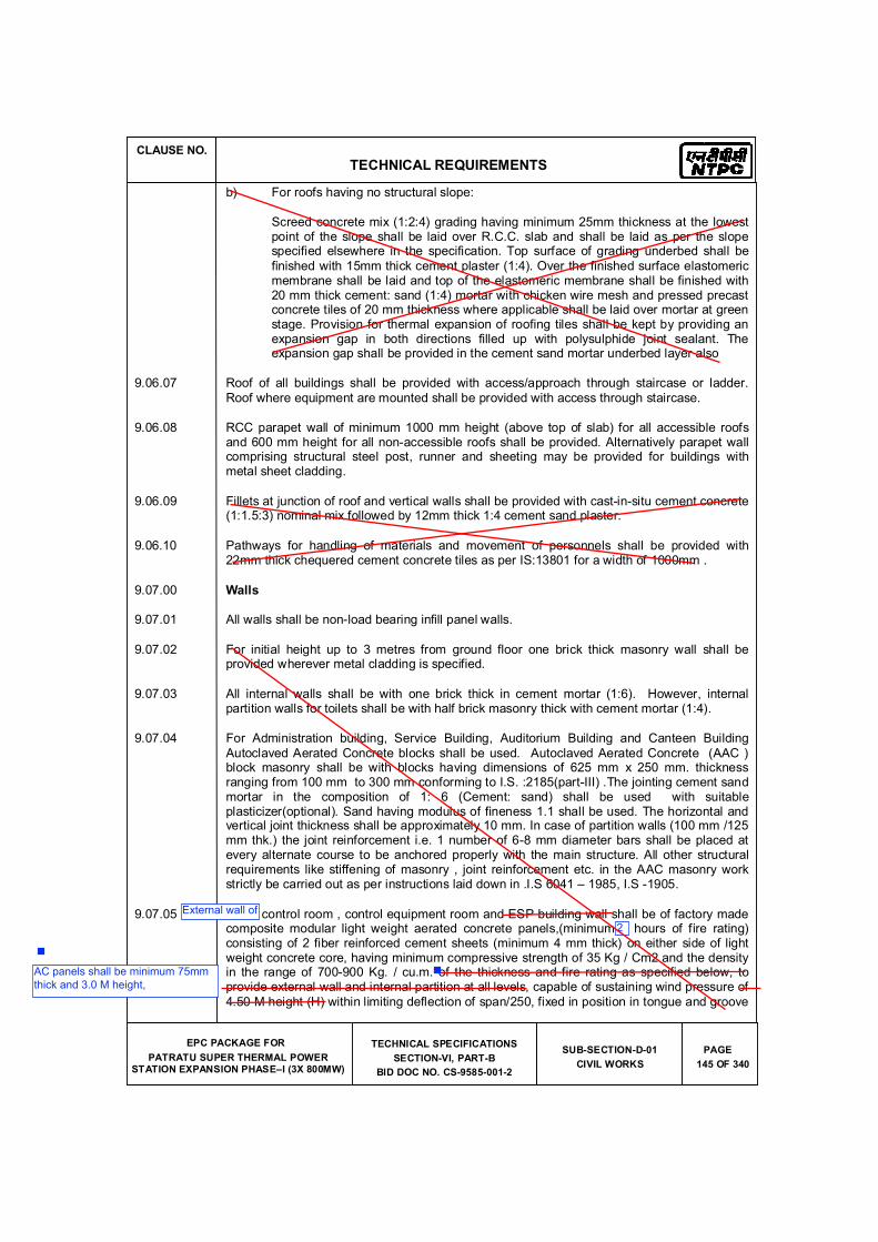
CLAUSE NO.
TECHNICAL REQUIREMENTS
EPC PACKAGE FOR
PATRATU SUPER THERMAL POWER STATION EXPANSION PHASE�I (3X 800MW)
TECHNICAL SPECIFICATIONS
SECTION-VI, PART-B
BID DOC NO. CS-9585-001-2
SUB-SECTION-D-01
CIVIL WORKS
PAGE
145 OF 340
b) For roofs having no structural slope:
Screed concrete mix (1:2:4) grading having minimum 25mm thickness at the lowest point of the slope shall be laid over R.C.C. slab and shall be laid as per the slope specified elsewhere in the specification. Top surface of grading underbed shall be
finished with 15mm thick cement plaster (1:4). Over the finished surface elastomeric membrane shall be laid and top of the elastomeric membrane shall be finished with 20 mm thick cement: sand (1:4) mortar with chicken wire mesh and pressed precast concrete tiles of 20 mm thickness where applicable shall be laid over mortar at green stage. Provision for thermal expansion of roofing tiles shall be kept by providing an expansion gap in both directions filled up with polysulphide joint sealant. The expansion gap shall be provided in the cement sand mortar underbed layer also
9.06.07 Roof of all buildings shall be provided with access/approach through staircase or ladder.
Roof where equipment are mounted shall be provided with access through staircase.
9.06.08 RCC parapet wall of minimum 1000 mm height (above top of slab) for all accessible roofs and 600 mm height for all non-accessible roofs shall be provided. Alternatively parapet wall comprising structural steel post, runner and sheeting may be provided for buildings with metal sheet cladding.
9.06.09 Fillets at junction of roof and vertical walls shall be provided with cast-in-situ cement concrete (1:1.5:3) nominal mix followed by 12mm thick 1:4 cement sand plaster.
9.06.10 Pathways for handling of materials and movement of personnels shall be provided with 22mm thick chequered cement concrete tiles as per IS:13801 for a width of 1000mm .
9.07.00 Walls
9.07.01 All walls shall be non-load bearing infill panel walls.
9.07.02 For initial height up to 3 metres from ground floor one brick thick masonry wall shall be provided wherever metal cladding is specified.
9.07.03 All internal walls shall be with one brick thick in cement mortar (1:6). However, internal partition walls for toilets shall be with half brick masonry thick with cement mortar (1:4).
9.07.04 For Administration building, Service Building, Auditorium Building and Canteen Building
Autoclaved Aerated Concrete blocks shall be used. Autoclaved Aerated Concrete (AAC ) block masonry shall be with blocks having dimensions of 625 mm x 250 mm. thickness ranging from 100 mm to 300 mm conforming to I.S. :2185(part-III) .The jointing cement sand mortar in the composition of 1: 6 (Cement: sand) shall be used with suitable plasticizer(optional). Sand having modulus of fineness 1.1 shall be used. The horizontal and vertical joint thickness shall be approximately 10 mm. In case of partition walls (100 mm /125 mm thk.) the joint reinforcement i.e. 1 number of 6-8 mm diameter bars shall be placed at every alternate course to be anchored properly with the main structure. All other structural requirements like stiffening of masonry , joint reinforcement etc. in the AAC masonry work strictly be carried out as per instructions laid down in .I.S 6041 � 1985, I.S -1905.
9.07.05 For control room , control equipment room and ESP building wall shall be of factory made composite modular light weight aerated concrete panels,(minimum 4 hours of fire rating) consisting of 2 fiber reinforced cement sheets (minimum 4 mm thick) on either side of light weight concrete core, having minimum compressive strength of 35 Kg / Cm2 and the density in the range of 700-900 Kg. / cu.m. of the thickness and fire rating as specified below, to provide external wall and internal partition at all levels, capable of sustaining wind pressure of
4.50 M height (H) within limiting deflection of span/250, fixed in position in tongue and groove
External wall of
2
AC panels shall be minimum 75mm
thick and 3.0 M height,
CLAUSE NO.
TECHNICAL REQUIREMENTS
EPC PACKAGE FOR
PATRATU SUPER THERMAL POWER STATION EXPANSION PHASE�I (3X 800MW)
TECHNICAL SPECIFICATIONS
SECTION-VI, PART-B
BID DOC NO. CS-9585-001-2
SUB-SECTION-D-01
CIVIL WORKS
PAGE
146 OF 340
jointing system by screwing the panels to top and bottom U channels, (channels minimum 1.25 mm thick and galvanised to grade 180 (minimum) as per IS : 277), fixing U profiled top and bottom channels to concrete / primary steel members which are placed at the maximum vertical spacing of 4.5m with the help of galvanised steel expansion fasteners, filling the joints from both faces with silicon acrylic paste and making the same water tight by covering with fibre glass tape (minimum 50 mm wide and minimum 0.5 mm thick) or by any other suitable material, so as to ensure that the entire construction done with the light weight aerated concrete panels are weather proof and panel surfaces are flush for painting, creating opening for doors / windows /ventilators / ducts / pipes/fans/AC etc. and finishing the opening face with the same U profiled galvanized steel channel which is used at the top and bottom.
9.07.06 For Main plant building, Control tower and other buildings, the type, thickness and initial height of external cladding facing the transformer yard shall be according to the
requirements.
External face of Toilets, Air-conditioned and pressurised areas shall be provided with masonry wall as per functional / aesthetic requirements. (Inside the metal cladding wherever provided).
9.07.07 50 mm thick DPC in Cement concrete (1:1.5:3) with water proofing compound followed by two layers of bitumen coating 85/25 grade as per IS:702 @ 1.7 kg./sq.m. shall be provided at plinth level before starting the masonry work.
9.08.00 COLOUR COATED AND OTHER SHEETING WORK
9.08.01 Material
a) Wall Cladding & Roofing Material
Troughed permanently colour coated sheet of approved shade and colour shall be
i) either of steel with minimum 0.6mm bare metal thickness (i.e. excluding the thickness of galvanizing/aluminium-zinc coating and painting) of grade G250 as per AS1397 / grade SS255 as per ASTM A653M / grade S250GD as per EN 10326 with zinc coating to class Z275 / aluminium-zinc alloy coating to class AZ150
ii) or of minimum 0.5mm BMT (i.e. excluding the thickness of galvanizing/aluminium-zinc coating and painting) of grade G350 as per AS1397 / grade SS340 class 4 as per ASTM A792M / grade S350GD as per EN 10326 with zinc coating to class Z275 / aluminium-zinc alloy coating to class AZ150
iii) or of steel of minimum 0.4mm BMT (i.e. excluding the thickness of galvanizing/aluminium-zinc coating and painting) of grade G550 as per AS1397 / grade SS550 as per ASTM A792M / grade S550GD as per EN 10326 with zinc
coating to class Z275 / aluminium-zinc alloy coating to class AZ150
Alternatively aluminium feed material of minimum bare metal thickness of 0.7 mm of aluminium alloy of Series 31000 and above as per IS 737 and IS 1254.
b) Metal Deck Roof Material
Troughed permanently colour coated metal decking sheets shall be
i) either of steel with minimum 0.8mm bare metal thickness (i.e. excluding the thickness of galvanizing/aluminium-zinc coating and painting) of grade G250 as
3
CLAUSE NO.
TECHNICAL REQUIREMENTS
EPC PACKAGE FOR
PATRATU SUPER THERMAL POWER STATION EXPANSION PHASE�I (3X 800MW)
TECHNICAL SPECIFICATIONS
SECTION-VI, PART-B
BID DOC NO. CS-9585-001-2
SUB-SECTION-D-01
CIVIL WORKS
PAGE
147 OF 340
per AS1397 / grade SS255 as per ASTM A653M / grade S250GD as per EN 10326 with zinc coating to class Z275
ii) or of minimum 0.6mm BMT (i.e. excluding the thickness of galvanizing/aluminium-zinc coating and painting) of grade G350 as per AS1397 / grade SS340 class 4 as per ASTM A792M / grade S350GD as per EN 10326 with zinc coating to class Z275
iii) or of steel of minimum 0.6mm BMT (i.e. excluding the thickness of galvanizing/aluminium-zinc coating and painting) of grade G550 as per AS1397 / grade SS550 as per ASTM A792M / grade S550GD as per EN 10326 with zinc coating to class Z275.
Alternatively aluminium feed material of minimum bare metal thickness of 0.9 mm of aluminium alloy of Series 31000 and above as per IS 737 and IS 1254 can also be used for metal decking.
Thickness tolerance of (+/-) 0.04mm is permissible. However, all design calculations shall be carried out on the basis of lowest value of sheet thickness provided.
9.08.02 Colour Coating
Steel shall be colour coated with total coating thickness of at least 40 microns (nominal) comprising of silicon modified polyester (SMP with silicon content of 30% to 50%) paint or
Super Polyester paint, of minimum 20 microns (nominal) dry film thickness (DFT) on external face over primer coat of minimum 5 microns (nominal) and minimum 10 microns (nominal) SMP or super polyester paint over primer coat of minimum 5 microns (nominal) on internal face. SMP and Super polyester paint systems shall be of industrial finish of product type 4 of AS/NZ2728.
9.08.03 Design Criteria
For wall cladding insulated / uninsulated and conveyor gallery sides and roof, permanently colour coated sheet of troughed profile shall be used. The nominal depth of trough shall be
30 mm. However alternative profile meeting the strength, deflection and other functional requirements such as section modulus and moment of inertia shall be provided.
Sheet shall be of approved profile, sectional properties, colour and shade.
For profiled metal decking sheets (to be used for RCC floor slab or roof slab) the sectional modulus and moment of inertia of troughed profile per meter width shall be so as to limit the deflection of sheets to span/250 under total super imposed loading (DL +LL) comprising the self-weight of metal deck sheet, dead weight of green concrete and an additional construction load 100kg per sq.m for two span condition. The section modulus and moment
of inertia of troughed profile shall be computed as per the provisions of IS 801 for satisfying the deflection and strength requirements.
For metal deck sheets used for roofing (with or without RCC) and side cladding, the sectional modulus and moment of inertia of troughed profile per metre width shall be such that the deflection of sheets is limited to span/250 under design wind pressure for two span condition. The sectional modulus and moment of inertia of troughed profile shall be computed as per the provisions of IS 801 for satisfying the deflection and strength requirements. No increase in allowable stress is permissible under wind load condition.
CLAUSE NO.
TECHNICAL REQUIREMENTS
EPC PACKAGE FOR
PATRATU SUPER THERMAL POWER STATION EXPANSION PHASE�I (3X 800MW)
TECHNICAL SPECIFICATIONS
SECTION-VI, PART-B
BID DOC NO. CS-9585-001-2
SUB-SECTION-D-01
CIVIL WORKS
PAGE
148 OF 340
9.08.04 Fasteners
Side cladding/roofing/decking sheets shall be fixed to the runner/purlins using self-drilling special coated fasteners confirming to corrosion resistant class 3 of AS3566 and tested for 1000 hours salt spray test. Spacing of Self-drilling fasteners in transverse direction (along
runners/purlin) shall be equal to the pitch of trough or 250(+/-100) mm, whichever is lesser and in longitudinal direction at every runner/purlin location.
Shear anchor studs shall also be provided through metal deck, which are to be used as permanent shuttering, at regular interval on all top flange / flange plate of structural beams as specified in Clause no. 8.03.00.
Alternatively, J/U type hooks shall be used in roofing which shall be provided in transverse direction (along runners/purlin) at a spacing equal to the pitch of trough or 250(+/-100) mm, whichever is lesser and in longitudinal direction at every runner/purlin location.
9.08.05 Miscellaneous Details
To minimize the number of joints, the length of the sheet shall preferably be not less than 4.5m, cut pieces shall not be used, unless specifically approved by the Engineer. However, the actual length shall be such so as to suit the purlin / runner spacing.
Lap between the sheets shall be at least 150mm in the longitudinal direction and at least one crest wide in the transverse direction which shall be properly anchored / fixed with fasteners.
Z spacers if required shall be made of at least 2 mm thick galvanised steel sheet of grade 350 as per IS 277
Sealant used for cladding shall be butyl based, two parts poly sulphide or equivalent approved, non stainless material and be flexible enough not to interface with fit of the sheets
. Filler blocks as a trough filler shall be used to seal cavities formed between the profiled sheet and the support or flashing. The filler blocks shall be manufactured from black synthetic rubber or any other material approved by the Engineer.
For insulation of cladding and other areas, mineral wool conforming to IS 8183 shall be used. The density shall be 32 or 48 kg. /cu.m for glass or rock wool respectively. The nominal thickness of insulation shall be 50mm.
All flashings, trim closures, caps etc. required for the metal cladding system shall be made out of plain sheets having same material and any weather/moisture sealants with appropriate material and coating specification as mentioned above for the outer face of the metal cladding. Overlap shall be min. 150 mm or as specified by manufacturer.
The contractor shall prepare working drawings of sheeting system including end and side laps, flashing, fixing details etc. before starting sheeting work at site.
9.08.06 Pre-Fabricated Insulated Metal Sandwich Panels
For buildings where Pre-Fabricated Insulated Metal Sandwich Panels shall be used for
Roofing, the sandwich panels shall comprise top sheet as troughed permanently colour coated sheet & bottom sheet as plain permanently colour coated with 50mm thick insulation sandwiched between the two sheets. Each sheet shall be
i) either of steel with minimum 0.6mm bare metal thickness (i.e. excluding the thickness of galvanizing/aluminium-zinc coating and painting) of grade G250 as per
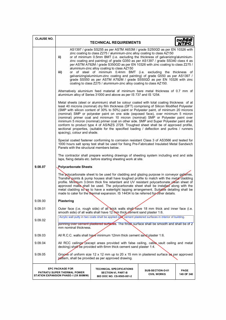
CLAUSE NO.
TECHNICAL REQUIREMENTS
EPC PACKAGE FOR
PATRATU SUPER THERMAL POWER STATION EXPANSION PHASE�I (3X 800MW)
TECHNICAL SPECIFICATIONS
SECTION-VI, PART-B
BID DOC NO. CS-9585-001-2
SUB-SECTION-D-01
CIVIL WORKS
PAGE
149 OF 340
AS1397 / grade SS255 as per ASTM A653M / grade S250GD as per EN 10326 with zinc coating to class Z275 / aluminium-zinc alloy coating to class AZ150
ii) or of minimum 0.5mm BMT (i.e. excluding the thickness of galvanizing/aluminium-zinc coating and painting) of grade G350 as per AS1397 / grade SS340 class 4 as per ASTM A792M / grade S350GD as per EN 10326 with zinc coating to class Z275 / aluminium-zinc alloy coating to class AZ150
iii) or of steel of minimum 0.4mm BMT (i.e. excluding the thickness of galvanizing/aluminium-zinc coating and painting) of grade G550 as per AS1397 / grade SS550 as per ASTM A792M / grade S550GD as per EN 10326 with zinc coating to class Z275 / aluminium-zinc alloy coating to class AZ150.
Alternatively aluminium feed material of minimum bare metal thickness of 0.7 mm of aluminium alloy of Series 31000 and above as per IS 737 and IS 1254.
Metal sheets (steel or aluminium) shall be colour coated with total coating thickness of at least 40 microns (nominal) dry film thickness (DFT) comprising of Silicon Modified Polyester (SMP with silicon content of 30% to 50%) paint or Polyester paint, of minimum 20 microns (nominal) SMP or polyester paint on one side (exposed face), over minimum 5 micron (nominal) primer coat and minimum 10 micron (nominal) SMP or Polyester paint over minimum 5 micron (nominal) primer coat on other side. SMP and Super Polyester paint shall conform to product type 4 of AS/NZS 2728. Troughed sheet shall be of approved profile, sectional properties, (suitable for the specified loading / deflection and purlins / runners spacing), colour and shade.
Special coated fastener conforming to corrosion resistant Class 3 of AS3566 and tested for 1000 hours salt spray test shall be used for fixing Pre-Fabricated Insulated Metal Sandwich Panels with the structural members below.
The contractor shall prepare working drawings of sheeting system including end and side laps, fixing details etc. before starting sheeting work at site.
9.08.07 Polycarbonate Sheets
The polycarbonate sheet to be used for cladding and glazing purpose in conveyor galleries,
Transfer points & pump houses shall have toughed profile to match with the metal cladding profile. Minimum 3.0mm thick fire retardant and UV resistant polycarbonate clean sheet of approved make shall be used. The polycarbonate sheet shall be installed along with the metal cladding so as to have a watertight lapping arrangement. Suitable detailing shall be made to cater for the thermal expansion. IS 14434 to be referred for other details.
9.09.00 Plastering
9.09.01 Outer face (i.e. rough side) of all brick walls shall have 18 mm thick and inner face (i.e. smooth side) of all walls shall have 12 mm thick cement sand plaster 1:6.
9.09.02 Plaster of paris (Gypsum Anhydrous) conforming to IS:2547 shall be used for plaster of paris punning over cement plastered surfaces. The finish surface shall be smooth and shall be of 2 mm nominal thickness.
9.09.03 All R.C.C. walls shall have minimum 12mm thick cement sand plaster 1:6.
9.09.04 All RCC ceilings (except areas provided with false ceiling, cable vault ceiling and metal decking) shall be provided with 6mm thick cement sand plaster 1:4.
9.09.05 Groove of uniform size 12 x 12 mm up to 20 x 15 mm in plastered surface as per approved pattern, shall be provided as per approved drawing.
Acrylic wall putty in two coats shall be applied over cement plastered surfaces in interior of building.
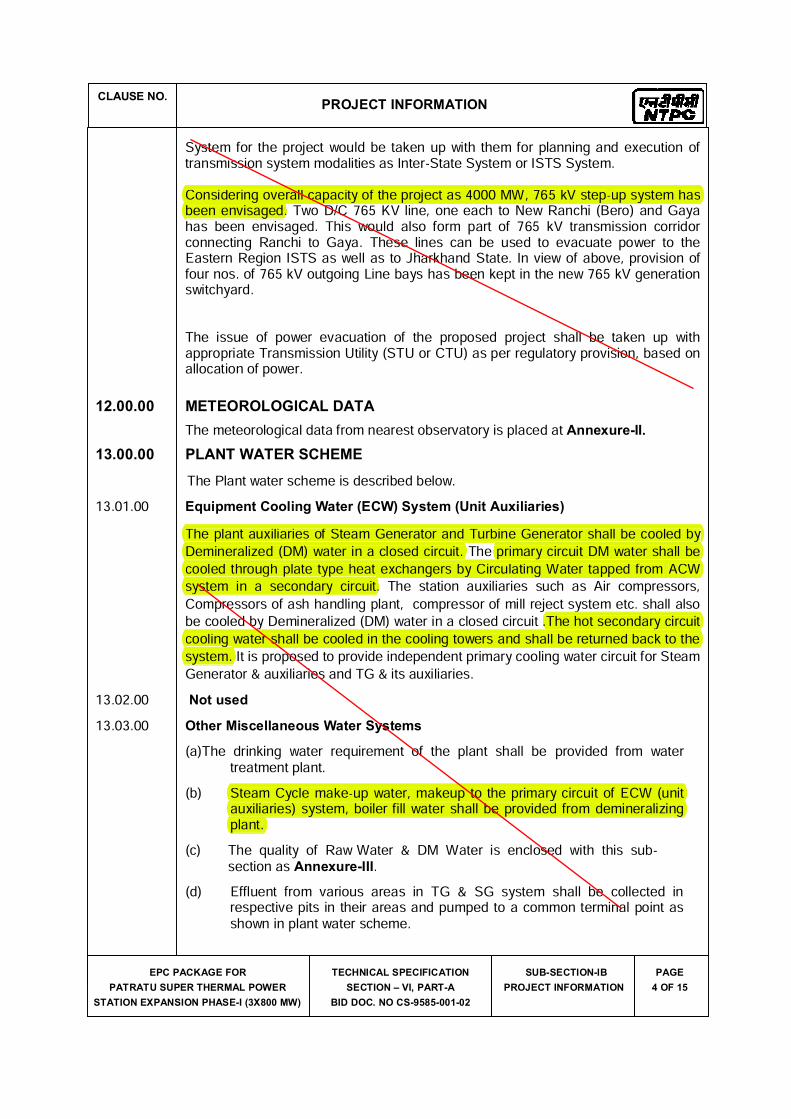
CLAUSE NO.PROJECT INFORMATION
EPC PACKAGE FOR
PATRATU SUPER THERMAL POWER
STATION EXPANSION PHASE-I (3X800 MW)
TECHNICAL SPECIFICATION
SECTION � VI, PART-A
BID DOC. NO CS-9585-001-02
SUB-SECTION-IB
PROJECT INFORMATION
PAGE
4 OF 15
System for the project would be taken up with them for planning and execution of transmission system modalities as Inter-State System or ISTS System. Considering overall capacity of the project as 4000 MW, 765 kV step-up system has been envisaged. Two D/C 765 KV line, one each to New Ranchi (Bero) and Gaya has been envisaged. This would also form part of 765 kV transmission corridor connecting Ranchi to Gaya. These lines can be used to evacuate power to the Eastern Region ISTS as well as to Jharkhand State. In view of above, provision of four nos. of 765 kV outgoing Line bays has been kept in the new 765 kV generation switchyard.The issue of power evacuation of the proposed project shall be taken up with appropriate Transmission Utility (STU or CTU) as per regulatory provision, based on allocation of power.
12.00.00 METEOROLOGICAL DATAThe meteorological data from nearest observatory is placed at Annexure-II.
13.00.00 PLANT WATER SCHEMEThe Plant water scheme is described below.13.01.00 Equipment Cooling Water (ECW) System (Unit Auxiliaries)
The plant auxiliaries of Steam Generator and Turbine Generator shall be cooled by Demineralized (DM) water in a closed circuit. The primary circuit DM water shall be cooled through plate type heat exchangers by Circulating Water tapped from ACW system in a secondary circuit. The station auxiliaries such as Air compressors, Compressors of ash handling plant, compressor of mill reject system etc. shall also be cooled by Demineralized (DM) water in a closed circuit .The hot secondary circuit cooling water shall be cooled in the cooling towers and shall be returned back to the system. It is proposed to provide independent primary cooling water circuit for Steam Generator & auxiliaries and TG & its auxiliaries.13.02.00 Not used13.03.00 Other Miscellaneous Water Systems(a)The drinking water requirement of the plant shall be provided from water treatment plant.(b) Steam Cycle make-up water, makeup to the primary circuit of ECW (unit auxiliaries) system, boiler fill water shall be provided from demineralizingplant.(c) The quality of Raw Water & DM Water is enclosed with this sub-section as Annexure-III.(d) Effluent from various areas in TG & SG system shall be collected in respective pits in their areas and pumped to a common terminal point as shown in plant water scheme.
Considering overall capacity of the project as 4000 MW, 765 kV step-up system has Considering overbeen envisaged.
The plant auxiliaries of Steam Generator and Turbine Generator shall be cooled by The plant auxiliaries of Steam Generator and Demineralized (DM) water in a closed circuit. The primary circuit DM water shall be rbine Generator shall be cooled by it. The primary circuit DM water shall be cooled through plate type heat exchangers by Circulating Water tapped from ACW Demineralized (DM) water in a closed circuit. cooled through plate type heat system in a secondary circuit. reject system etc. shall also it .The hot secondary circuit be cooled by Demineralized (DM) water in a closed circuit .The hot secondary circuit cooling water shall be cooled in the cooling towers and shall be returned back to the cooling wsystem. I
Steam Cycle make-up water, makeup to the primary circuit of ECW (unit Steam Cycle make up water, makeup to the primary circuit of ECW (unit auxiliaries) system, boiler fill water shall be provided from demineralizingauxiliaplant.
CLAUSE NO.PROJECT INFORMATION
EPC PACKAGE FOR
PATRATU SUPER THERMAL POWER
STATION EXPANSION PHASE-I (3X800 MW)
TECHNICAL SPECIFICATION
SECTION � VI, PART-A
BID DOC. NO CS-9585-001-02
SUB-SECTION-IB
PROJECT INFORMATION
PAGE
5 OF 15
14.00.00 CRITERIA FOR EARTHQUAKE RESISTANT DESIGN OF STRUCTURES AND EQUIPMENT
All power plant structures and equipment, including plant auxiliary structures and equipment shall be designed for seismic forces as given in Part-B of this section.
15.00.00 CRITERIA FOR WIND RESISTANT DESIGN OF STRUCTURES AND EQUIPMENT
All structures and equipment of the power plant, including plant auxiliary structures and equipment, shall be designed for wind forces as given as given in Part-B of this section.
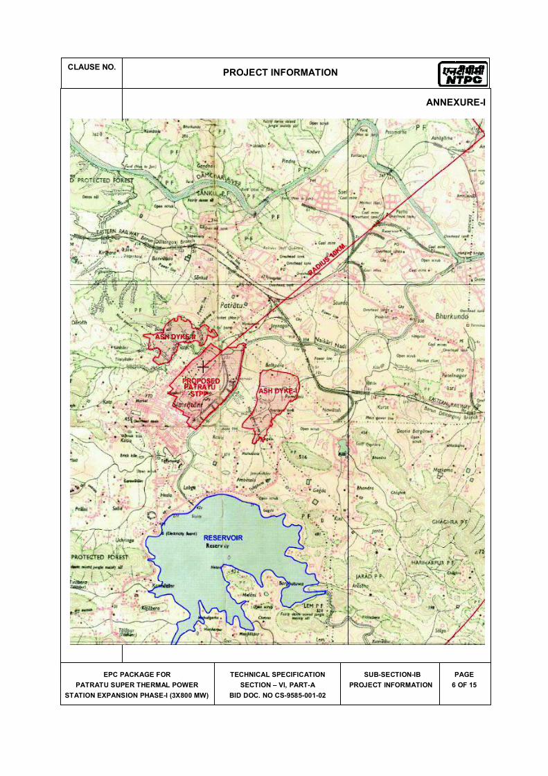
CLAUSE NO.PROJECT INFORMATION
EPC PACKAGE FOR
PATRATU SUPER THERMAL POWER
STATION EXPANSION PHASE-I (3X800 MW)
TECHNICAL SPECIFICATION
SECTION � VI, PART-A
BID DOC. NO CS-9585-001-02
SUB-SECTION-IB
PROJECT INFORMATION
PAGE
6 OF 15
ANNEXURE-I
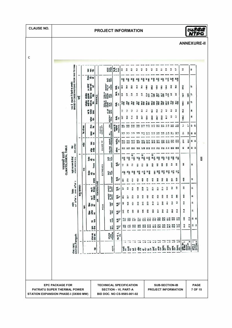
CLAUSE NO.PROJECT INFORMATION
EPC PACKAGE FOR
PATRATU SUPER THERMAL POWER
STATION EXPANSION PHASE-I (3X800 MW)
TECHNICAL SPECIFICATION
SECTION � VI, PART-A
BID DOC. NO CS-9585-001-02
SUB-SECTION-IB
PROJECT INFORMATION
PAGE
7 OF 15
ANNEXURE-II
c
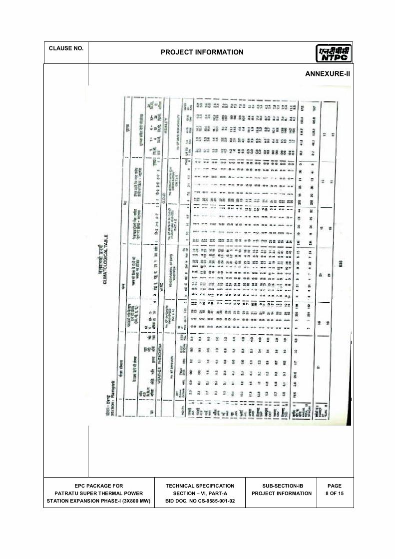
CLAUSE NO.PROJECT INFORMATION
EPC PACKAGE FOR
PATRATU SUPER THERMAL POWER
STATION EXPANSION PHASE-I (3X800 MW)
TECHNICAL SPECIFICATION
SECTION � VI, PART-A
BID DOC. NO CS-9585-001-02
SUB-SECTION-IB
PROJECT INFORMATION
PAGE
8 OF 15
ANNEXURE-II

CLAUSE NO.
TECHNICAL REQUIREMENTS
EPC PACKAGE FOR
PATRATU SUPER THERMAL POWER
STATION EXPANSION PHASE�I (3X 800MW)
TECHNICAL SPECIFICATION
SECTION-VI, PART-B
BID DOC NO. CS--9585-001-2
SUB-SECTION-D-01
CIVIL WORKS
PAGE
333 OF 340
ANNEXURE- (d) CRITERIA FOR WIND RESISTANT DESIGN OF STRUCTURES AND EQUIPMENT
All structures shall be designed for wind forces in accordance with IS 875 (Part-3) and as specified in this document. See Annexure � B for site specific information.
Along wind forces shall generally be computed by the Peak (i.e. 3 second gust) Wind Speed method as defined in the standard.
Along wind forces on slender and wind sensitive structures and structural elements shall also be computed, for dynamic effects, using the Gust Factor or Gust Effectiveness Factor
Method as defined in the standard. The structures shall be designed for the higher of the forces obtained from Gust Factor method and the Peak Wind Speed method.
Analysis for dynamic effects of wind must be undertaken for any structure which has a height to minimum lateral dimension ratio greater than �5� and/or if the fundamental frequency of the structure is less than 1 Hz.
Susceptibility of structures to across-wind forces, galloping, flutter, ovalling etc. should be examined and designed/detailed accordingly following the recommendations of IS 875(Part-3) and other relevant Indian standards.
It should be estimated if size and relative position of other structures are likely to enhance the wind loading on the structure under consideration. Enhancement factor, if necessary, shall suitably be estimated and applied to the wind loading to account for the interference effects.
Damping in Structures
The damping factor (as a percentage of critical damping) to be adopted shall not be more than as indicated below for:
a) Welded steel structures : 1.0%
b) Bolted steel structures : 2.0%
c) Reinforced concrete structures : 1.6%
d) Steel stacks : As per IS 6533 & CICIND Model Code whichever is more critical.
SITE SPECIFIC DESIGN PARAMETERS
The various design parameters, as defined in IS 875 (Part-3), to be adopted for the project site shall be as follows:
a) The basic wind speed �Vb� at ten metre above the mean ground level: 39 metre/second
b) The risk coefficient �K1� : 1.06
c) Category of terrain : Category-2
Annexure-2
CRITERIA FOR EARTHQUAKE RESISTANT DESIGN OF STRUCTURES
AND EQUIPMENT
All structures and equipment shall be designed for seismic forces adopting the site
specific seismic information provided in this document and using the other provisions
in accordance with IS:1893 (Part 1 to Part 4). Pending finalization of Part 5 of
IS:1893, provisions of part 1 shall be read along with the relevant clauses of
IS:1893:1984, for embankments.
A site specific seismic study has been conducted for the project site. The peak ground horizontal acceleration for the project site, the site specific acceleration spectral
coefficients (in units of gravity acceleration ‘g’) in the horizontal direction for the various damping values and the multiplying factor (to be used over the spectral
coefficients) for evaluating the design acceleration spectra are as given at Appendix-I.
Vertical acceleration spectral values shall be taken as 2/3rd of the corresponding horizontal values.
The site specific design acceleration spectra shall be used in place of the response
acceleration spectra, given at figure-2 in IS:1893 (Part 1) and Annex B of IS:1893
(Part 4). The site specific acceleration spectra along with multiplying factors specified
in Appendix-I includes the effect of the seismic environment of the site, the
importance factor related to the structures and the response reduction factor. Hence,
the design spectra do not require any further consideration of the zone factor (Z), the
importance factor (I) and response reduction factor (R) as used in the IS:1893 (Part 1
to Part 4).
Damping in Structures
The damping factor (as a percentage of critical damping) to be adopted shall not be
more than as indicated below for:
a) Steel structures : 2%
b) Reinforced Concrete structures : 5%
c) Reinforced Concrete Stacks : 3%
d)
Steel stacks : 2%
Sheet 2/6
Method of Analysis
Since most structures in a power plant are irregular in shape and have irregular
distribution of mass and stiffness, dynamic analysis for obtaining the design seismic
forces shall be carried out using the response spectrum method. The number of
vibration modes used in the analysis should be such that the sum total of modal
masses of all modes considered is at least 90 percent of the total seismic mass and
shall also meet requirements of IS:1893 (Part 1). Modal combination of the peak
response quantities shall be performed as per Complete Quadratic Combination
(CQC) method or by an acceptable alternative as per IS:1893 (Part 1).
In general, seismic analysis shall be performed for the three orthogonal (two principal
horizontal and one vertical) components of earthquake motion. The seismic response from the three components shall be combined as specified in IS:1893 (Part 1).
The spectral acceleration coefficient shall get restricted to the peak spectral value if
the fundamental natural period of the structure falls to the left of the peak in the spectral acceleration curve.
For buildings, if the design base shear (VB) obtained from modal combination is less
than the base shear (VB) computed using the approximate fundamental period (Ta) given in IS:1893:Part 1 and using site specific acceleration spectra with appropriate
multiplying factor, the response quantities (e.g. member forces, displacements, storey
forces, storey shears and base reactions) shall be enhanced in the ratio of VB/ VB.
However, no reduction is permitted if VB is less than VB.
For regular buildings less than 12m in height, design seismic base shear and its
distribution to different floor levels along the height of the building may be carried out as specified under clause 7.5, 7.6 & 7.7 of IS:1893 (Part 1) and using site specific
design acceleration spectra. The design horizontal acceleration spectrum value (Ah) shall be computed for the fundamental natural period as per clause 7.6 of IS:1893
(Part 1) using site specific spectral acceleration coefficients with appropriate multiplying factor given in Appendix-I.
Design/Detailing for Ductility for Structures
The site specific design acceleration spectra is a reduced spectra and has an in-built
allowance for ductility. Structures shall be engineered and detailed in accordance with
relevant Indian/International standards to achieve ductility.
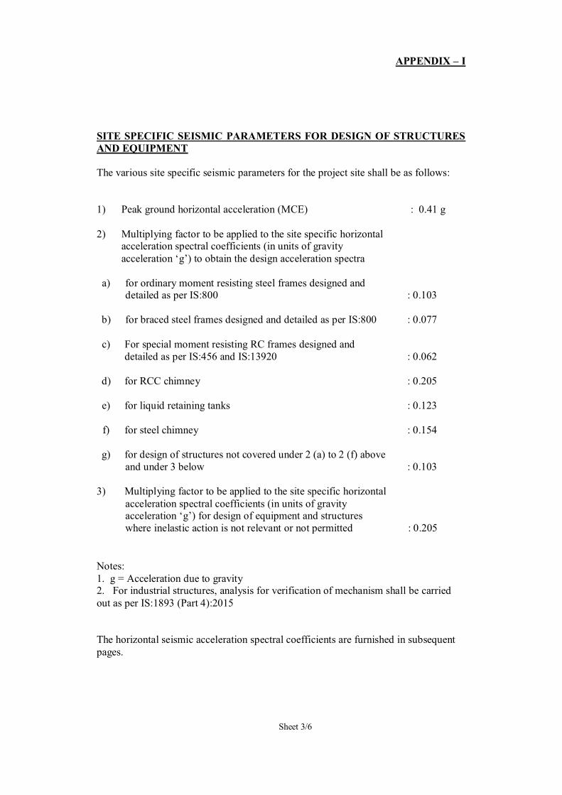
APPENDIX – I
Sheet 3/6
SITE SPECIFIC SEISMIC PARAMETERS FOR DESIGN OF STRUCTURES
AND EQUIPMENT
The various site specific seismic parameters for the project site shall be as follows:
1) Peak ground horizontal acceleration (MCE)
: 0.41 g
2) Multiplying factor to be applied to the site specific horizontal acceleration spectral coefficients (in units of gravity
acceleration ‘g’) to obtain the design acceleration spectra
a) for ordinary moment resisting steel frames designed and detailed as per IS:800
: 0.103
b) for braced steel frames designed and detailed as per IS:800
: 0.077
c) For special moment resisting RC frames designed and
detailed as per IS:456 and IS:13920
: 0.062
d) for RCC chimney
: 0.205
e) for liquid retaining tanks
: 0.123
f) for steel chimney
: 0.154
g) for design of structures not covered under 2 (a) to 2 (f) above
and under 3 below
: 0.103
3) Multiplying factor to be applied to the site specific horizontal
acceleration spectral coefficients (in units of gravity acceleration ‘g’) for design of equipment and structures
where inelastic action is not relevant or not permitted
: 0.205
Notes:
1. g = Acceleration due to gravity 2. For industrial structures, analysis for verification of mechanism shall be carried
out as per IS:1893 (Part 4):2015
The horizontal seismic acceleration spectral coefficients are furnished in subsequent
pages.
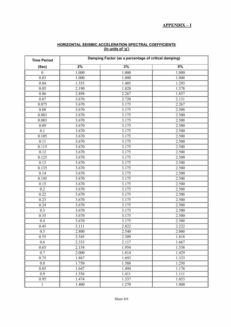
APPENDIX – I
Sheet 4/6
HORIZONTAL SEISMIC ACCELERATION SPECTRAL COEFFICIENTS (In units of ‘g’)
Time Period Damping Factor (as a percentage of critical damping)
(Sec) 2% 3% 5%
0 1.000 1.000 1.000
0.03 1.000 1.000 1.000
0.04 1.555 1.405 1.293
0.05 2.190 1.828 1.578
0.06 2.898 2.267 1.857
0.07 3.670 2.720 2.131
0.075 3.670 3.175 2.267
0.08 3.670 3.175 2.500
0.083 3.670 3.175 2.500
0.085 3.670 3.175 2.500
0.09 3.670 3.175 2.500
0.1 3.670 3.175 2.500
0.105 3.670 3.175 2.500
0.11 3.670 3.175 2.500
0.115 3.670 3.175 2.500
0.12 3.670 3.175 2.500
0.125 3.670 3.175 2.500
0.13 3.670 3.175 2.500
0.135 3.670 3.175 2.500
0.14 3.670 3.175 2.500
0.145 3.670 3.175 2.500
0.15 3.670 3.175 2.500
0.2 3.670 3.175 2.500
0.22 3.670 3.175 2.500
0.23 3.670 3.175 2.500
0.24 3.670 3.175 2.500
0.3 3.670 3.175 2.500
0.35 3.670 3.175 2.500
0.4 3.670 3.175 2.500
0.45 3.111 2.822 2.222
0.5 2.800 2.540 2.000
0.55 2.545 2.309 1.818
0.6 2.333 2.117 1.667
0.65 2.154 1.954 1.538
0.7 2.000 1.814 1.429
0.75 1.867 1.693 1.333
0.8 1.750 1.588 1.250
0.85 1.647 1.494 1.176
0.9 1.556 1.411 1.111
0.95 1.474 1.337 1.053
1 1.400 1.270 1.000
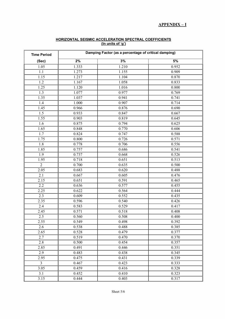
APPENDIX – I
Sheet 5/6
HORIZONTAL SEISMIC ACCELERATION SPECTRAL COEFFICIENTS (In units of ‘g’)
Time Period Damping Factor (as a percentage of critical damping)
(Sec) 2% 3% 5%
1.05 1.333 1.210 0.952
1.1 1.273 1.155 0.909
1.15 1.217 1.104 0.870
1.2 1.167 1.058 0.833
1.25 1.120 1.016 0.800
1.3 1.077 0.977 0.769
1.35 1.037 0.941 0.741
1.4 1.000 0.907 0.714
1.45 0.966 0.876 0.690
1.5 0.933 0.847 0.667
1.55 0.903 0.819 0.645
1.6 0.875 0.794 0.625
1.65 0.848 0.770 0.606
1.7 0.824 0.747 0.588
1.75 0.800 0.726 0.571
1.8 0.778 0.706 0.556
1.85 0.757 0.686 0.541
1.9 0.737 0.668 0.526
1.95 0.718 0.651 0.513
2 0.700 0.635 0.500
2.05 0.683 0.620 0.488
2.1 0.667 0.605 0.476
2.15 0.651 0.591 0.465
2.2 0.636 0.577 0.455
2.25 0.622 0.564 0.444
2.3 0.609 0.552 0.435
2.35 0.596 0.540 0.426
2.4 0.583 0.529 0.417
2.45 0.571 0.518 0.408
2.5 0.560 0.508 0.400
2.55 0.549 0.498 0.392
2.6 0.538 0.488 0.385
2.65 0.528 0.479 0.377
2.7 0.519 0.470 0.370
2.8 0.500 0.454 0.357
2.85 0.491 0.446 0.351
2.9 0.483 0.438 0.345
2.95 0.475 0.431 0.339
3 0.467 0.423 0.333
3.05 0.459 0.416 0.328
3.1 0.452 0.410 0.323
3.15 0.444 0.403 0.317
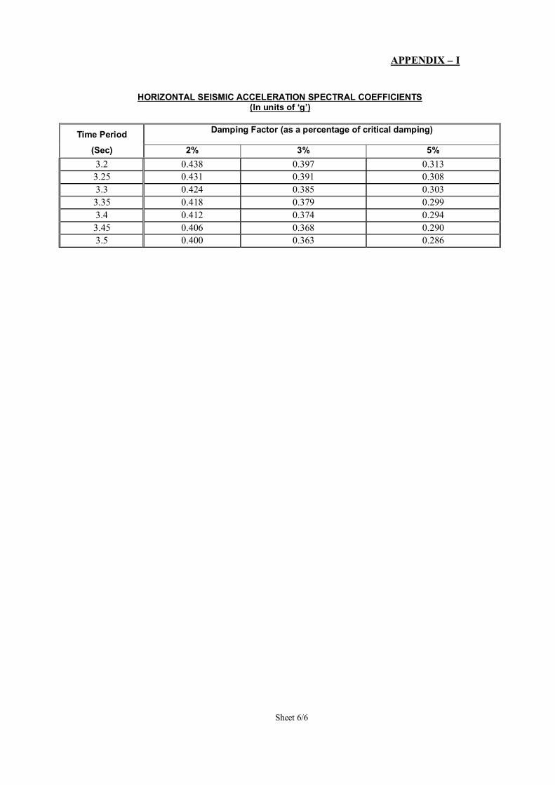
APPENDIX – I
Sheet 6/6
HORIZONTAL SEISMIC ACCELERATION SPECTRAL COEFFICIENTS (In units of ‘g’)
Time Period Damping Factor (as a percentage of critical damping)
(Sec) 2% 3% 5%
3.2 0.438 0.397 0.313
3.25 0.431 0.391 0.308
3.3 0.424 0.385 0.303
3.35 0.418 0.379 0.299
3.4 0.412 0.374 0.294
3.45 0.406 0.368 0.290
3.5 0.400 0.363 0.286
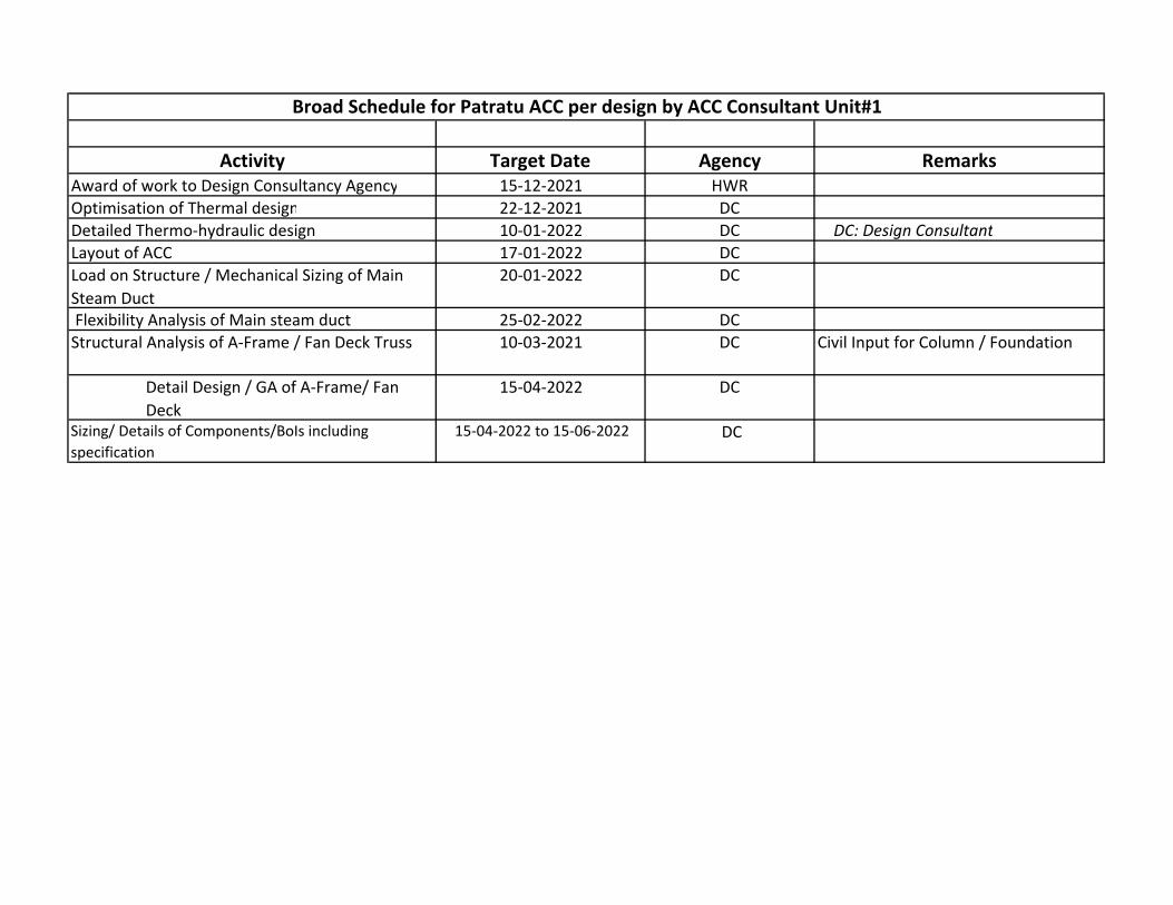
Activity Target Date Agency Remarks
Award of work to Design Consultancy Agency 15-12-2021 HWR
Optimisation of Thermal design 22-12-2021 DC
Detailed Thermo-hydraulic design 10-01-2022 DC DC: Design Consultant
Layout of ACC 17-01-2022 DC
Load on Structure / Mechanical Sizing of Main
Steam Duct
20-01-2022 DC
Flexibility Analysis of Main steam duct 25-02-2022 DC
Structural Analysis of A-Frame / Fan Deck Truss 10-03-2021 DC Civil Input for Column / Foundation
Detail Design / GA of A-Frame/ Fan
Deck
15-04-2022 DC
Sizing/ Details of Components/BoIs including
specification
15-04-2022 to 15-06-2022 DC
Broad Schedule for Patratu ACC per design by ACC Consultant Unit#1
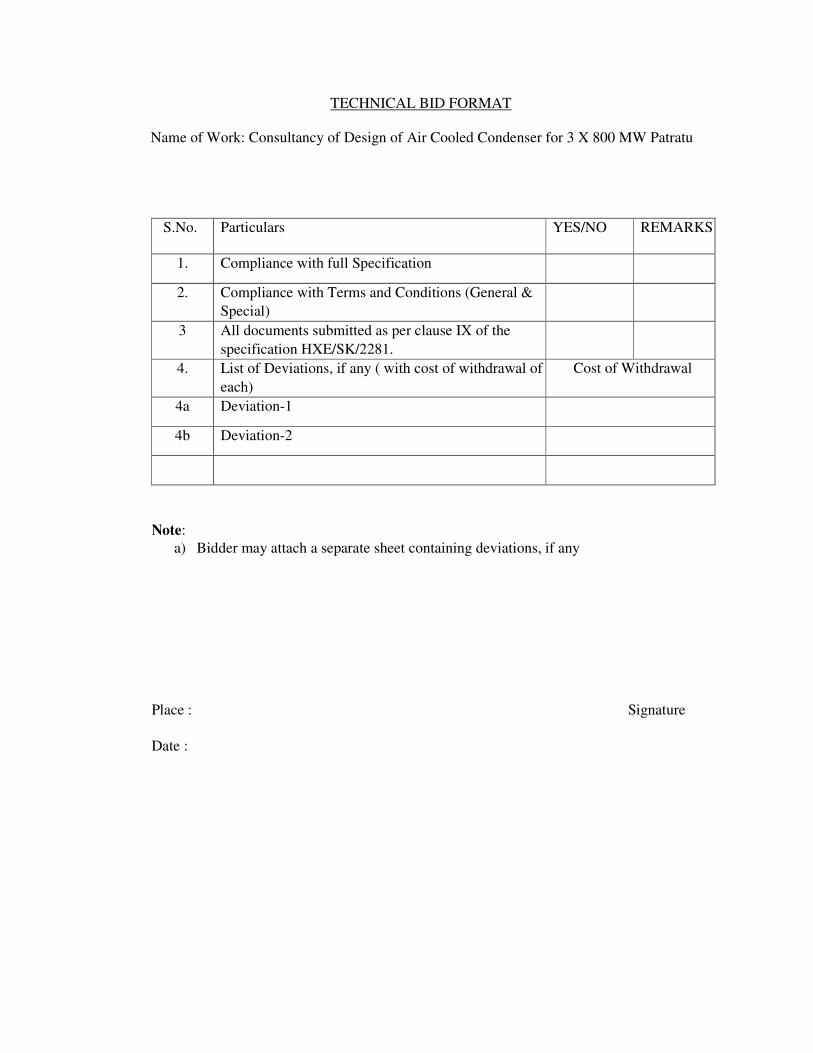
TECHNICAL BID FORMAT
Name of Work: Consultancy of Design of Air Cooled Condenser for 3 X 800 MW Patratu
S.No. Particulars YES/NO REMARKS
1. Compliance with full Specification
2. Compliance with Terms and Conditions (General &
Special)
3 All documents submitted as per clause IX of the
specification HXE/SK/2281.
4. List of Deviations, if any ( with cost of withdrawal of
each)
Cost of Withdrawal
4a Deviation-1
4b Deviation-2
Note:
a) Bidder may attach a separate sheet containing deviations, if any
Place : Signature
Date :
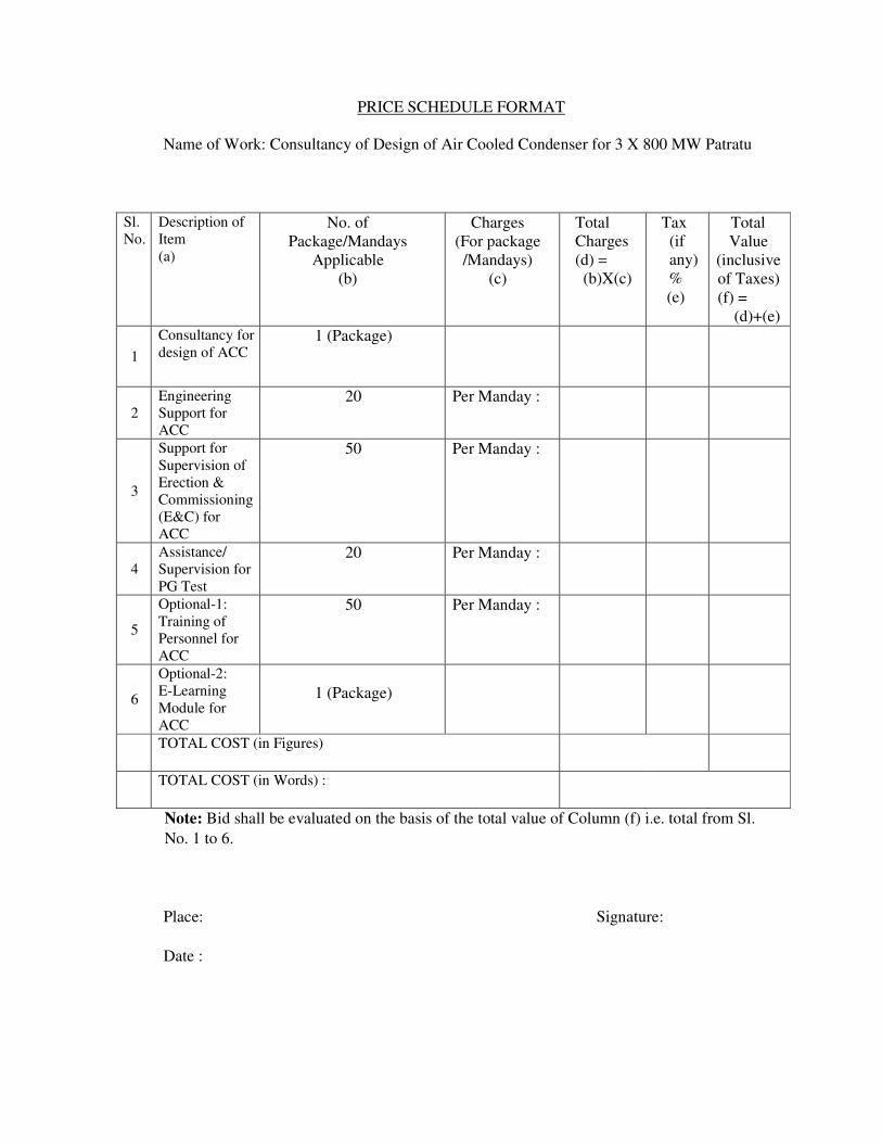
PRICE SCHEDULE FORMAT
Name of Work: Consultancy of Design of Air Cooled Condenser for 3 X 800 MW Patratu
Sl.
No.
Description of
Item
(a)
No. of
Package/Mandays
Applicable
(b)
Charges
(For package
/Mandays)
(c)
Total
Charges
(d) =
(b)X(c)
Tax
(if
any)
%
(e)
Total
Value
(inclusive
of Taxes)
(f) =
(d)+(e)
1
Consultancy for
design of ACC 1 (Package)
2
Engineering
Support for
ACC
20 Per Manday :
3
Support for
Supervision of
Erection &
Commissioning
(E&C) for
ACC
50 Per Manday :
4
Assistance/
Supervision for
PG Test
20 Per Manday :
5
Optional-1:
Training of
Personnel for
ACC
50 Per Manday :
6
Optional-2:
E-Learning
Module for
ACC
1 (Package)
TOTAL COST (in Figures)
TOTAL COST (in Words) :
Note: Bid shall be evaluated on the basis of the total value of Column (f) i.e. total from Sl.
No. 1 to 6.
Place: Signature:
Date :