Embed Size (px)
Citation preview
DOCUMENT-RESUME
ED 072 665 EM 010 824
AUTHOR Pilnick, Carl; Glixon, Harry R.TITLE A Primer on Telecommunications in Education. Part of:
A Planning Document for the Establishment of aNationwide Educational Telecommunications System.
INSTITUTION' Synergetics, Inc., Washington, D. C.SPONS AGENCY National Center for Educational Technology (DHEW/OE),
Washington, D. C.PUB DATE Mai 72CONTRACT OEC -0 -71 -3955 (099)NOTE 406p.; See also ED 060 395.and ED 060 396
EDRS PRICE MF-$0.65 HC-$16.45DESCRIPTORS Audio Equipment; Audiovisual Instruction; Cable
Television; Computer Assisted Instruction; CostEffectiveness; Educational Change; *EducationalImprovement; Educational Objectives; EducationalTechnology; *Instructional Systems; *InstructionalTechnology; Instructional Television; Surveys;*Technological Advancement; *Telecommunication; VideoTape Recordings
ABSTRACTIntended as a general reference handbook for those
concerned with applying telecommunications technology to the processof education, this survey focuses on the use of the technology ratherthan the technology itself. It reviews engineering or technicalaspects to prom,ida sufficient background to permit the reader toevaluate each component or system with respect to educationalobjectives. It also provides relevant cost and coverage data whichwill assist in developing the foundation for more effective -
application-of telecommunications. In addition, the volume providesdescriptions of the components and techniques used in educationaltelecommunications; it reviews the carrier and distributionsubsystems available for transmission; it offers examples ofintegrated educational systems; and it forecasts trends, futureapplications, and projected evolutionary telecommunications networks.(Auttxm/SH)
A PLANNING DOCUMENT FORTHE ESTABLISHMENT OF
A NATIONWIDEEDUCATIONAL TELECOMMUNICATIONS SYSTEM
TELECOMMUNICATIONSIN EDUCATION
Published for:National Center for Educational TechnologiesU.S. Office of EducationDepartment of Health, Education and Welfare
Under Contract*OEC-71-3955(099)
sulossines.525 School Street, S.W. Washington,-D.C. 20024
CARL PILNICK
and
HARRY R. GLIXON
A PRIMER ON
TELECOMMUNICATIONS I N EDUCATION
Carl Pilnick
Harry R. GlixonU.S . DEPARTMENT OF HEALTH.
EDUCATION & WELFAREOFFICE OF EDUCATION
THIS DOCUMENT HAS BEEN REPRO-DUCE° EXACTLY AS RECEIVED FROMTHE PERSON OR ORGANIZATION ORIG.INATING IT. POINTS OF VIEW OR OPINIONS STATED DO NOT NECESSARILYREPRESENT OFFICIAL OFFICE OF EDU-CATION POSITION OR POLICY. March, 1972
Part of:
A PLANNING-DOCUMENT FOR THE ESTABLISHMENT OF A
NATIONWIDE EDUCATIONAL TELECOMMUNICATIONS SYSTEM
Under Contract:OEC-0-71-3955(099)
Published for:National Center for Educational TechnologyU.S. Office of EducationDepartment of Health, Education and Welfare
SYNERGETICS, INC.525 School Street, S. W.Suite 303Washington, D. C. 20024(202) 638-0400
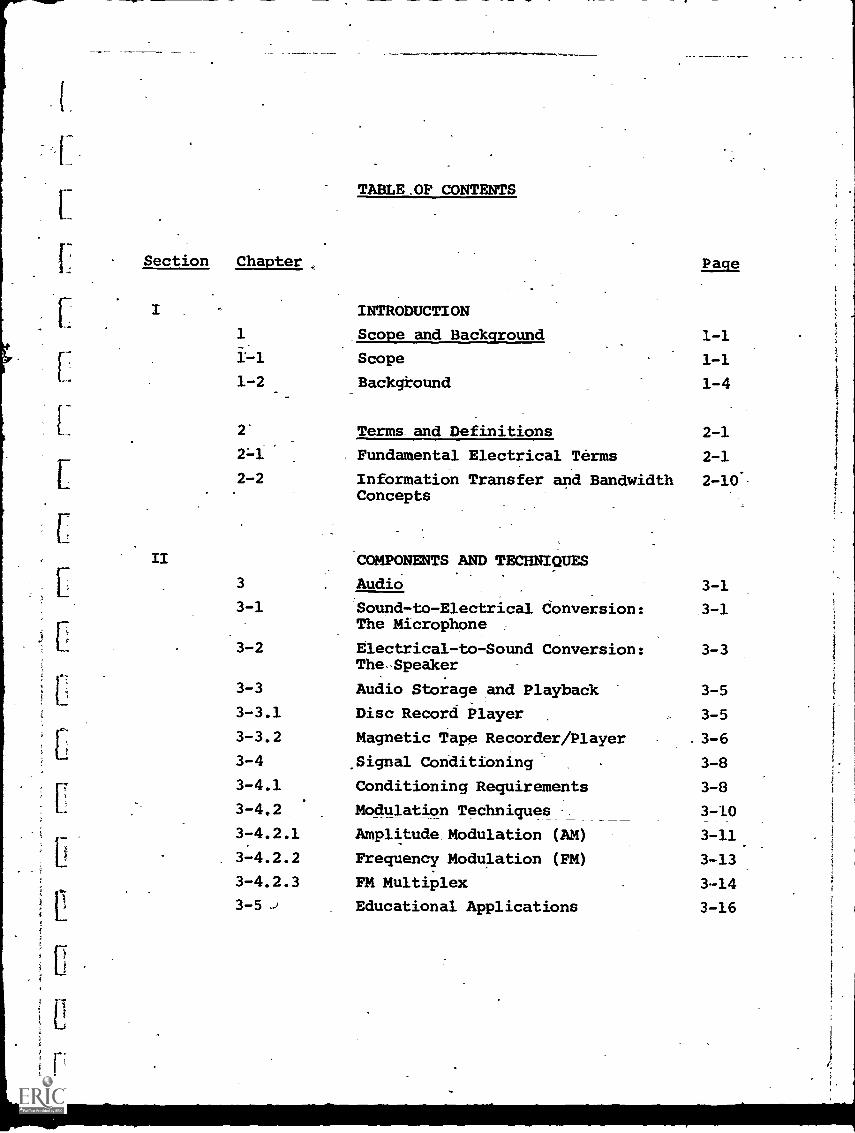
-TABLE OF CONTENTS.
Section Chapter
INTRODUCTION
Page
I
1 Scope and Background 1-1
1-1 Scope 1-1
1-2 Background 1-4
2 Terms. and Definitions 2-1
2-1 Fundamental Electrical Terms 2-1
2-2 Information Transfer and Bandwidth 2-10'Concepts
II COMPONENTS AND TECHNIQUES
3 Audio 3-1
3-1 Sound-to-Electrical Conversion: 3-1The Microphone
3-2 Electrical-to-Sound Conversion: 3-3The .Speaker
3-3 Audio Storage and Playback 3-5
3-3.1 Disc Record Player 3-5
3-3.2 Magnetic Tape Recorder/Player 3-6
3-4 _Signal Conditioning 3-8
3-4.1 Conditioning Requirements 3-8
3-4,2 Modulation Techniques 3-10
3-4.2.1 Amplitude. Modulation (AM) 3-11
3-4.2.2 Frequency Modulation (FM) 3-13
3-4.2.3 FM Multiplex 3-14
3-5 Educational Applications 3-16
Section Chapter
4 Video 4-1
4-1 Component Categories 4-1
4-2 Visual-to-Electrical Conversion 4-3
4-2.a . Video Cameras and Scahners 4-8
4-2:a.1 Special-Purpose Scanners. 4-12
4-2.b Secondary Storage Media Equipment 4-14
4-2.c Auxiliary and Support Equipment 4-15
4-3 Electrical-to-Visual Conversion 4-18
4-3.a TV Receivers 4-22
4-3.b CRT Display Terminals 4 -25
4-3.c Image Projection. 4-28.
4-4.a Video Recorder/Players 4-30
4-4:b "Home" Video Recorder/Players 4-32
4-4.b.1 Video Tape Recording (VTR) 4-34
4-4.b.2 Electronic Video Recording (EVR) 4-39
4-4.b.3 Selectavision 4-43
4-4.b.4 Video Disc 4-47
4-4.b.5 Super 8 MM Film-to-Video- 4-49
4-4.b.6 Impact of Home Video Recorderson Education
4-50
4-5 Signal Conditioning 4-50
4-6 Educational Applications 4-51
5 Hard Copy 5-1
5-1 Alphanumeric Terminals 5-2
5-1.1 Teletype Conversion of Alphanumeric 5-3Information
5-1.2 Teleprinters 5-6
5-1.3 High Speed Printers 5-10
r.
Section Chapter Page
5-2 Full-Range Terminals 5-115-2.1 Plotters" 5-115-2.2 Facsimile .5-14
5-2.3 Photographic Conversion 5-215-3 Educational Applications 5-22
6 Computers 6-16-1 Computer Fundamentals 6-16-1.1 Basic Elements of a Computer 6-26-1.2 Operational Concepts 6-126-1.3 Range of Computer Capabilities 6-176-1.3.1 Potential of Mini-Computers 6-206-1.4 Software Considerations 6-226-2 Educational Applications 6-296-2.1 Computer Assisted Instruction- 6-306-2.1.1 Drill-and-Practice 6 -33
6-2.1.2 Tutorial 6-346-2.1.3 Inquiry/Response (Dialog) '6-35
6-2.1.4 Problem-Solving and Computation 6-356-2.1.5 Modeling and Simulation 6-366-2.2 Computer-Managed Instruction (CMI) 6-376-2.3 Information Storage and Retrieval 6-386-2.4 Selection of Computer Systems 6-416-2.4.1 Centralized vs. Decentralized 6-42
Computers
6-2.5 Costs of Computer - Based 6-43Instruction
III CARRIER AND DISTRIBUTION SUB-SYSTEMS
-----"--
Section Chapter Paqe,
7 Distribution Techniques 7-17-1 Communication Modes 7 -1
7-1.1 Transmission Medium r 7-17-1.2 Information Flow 7-47-1.3 Modulation 7-67-1.4 Multiplexing 7-77-2 Distribution Networks 7-107-3 Analog vs. Digital Transmission 7-157-3.1 Characteristics of Analog and 7-15
Digital Information
7-3.2 Digital (Data) Transmission 7-187-3.2.1 Parallel and Serial Transmission 7-187-3.2.2 Communications Codes 7-217-3.2.3 Modems 7-24
8 Wire Carriers 8-18-1 Types of Wire Communications 8-1
Circuits
8-1.1 Private vs. Leased Lines 8-48-1.2 Advantages and Disadvantages of 8-11
Common-Carrier Communications Links8-2 Broadband Commuhications Networks 8-148 -2.1 Cable Television (CATV)' 8-14
9 Wireless Carriers 9-19-1 Wireless Transmission 9-19-1.1 Use of Electromagnetic Spectrum 9-39-2 Instructional Television Fixed 9-7
Service (ITFS)
9-2.1 Description 9-7
Section Chapter Page
9-2.2 Elements of an ITFS System 9-99-2.3 ITFS Applications 9-129-3. Communications Satellites 9-149-3.1 Description and Background 9-149-3.2 Application to Education 9-179-4 Electro-Optical Transmission 9-22
IV INTEGRATED EDUCATIONAL SYSTEMS10 Audio Systems 10-110.-L1 "Individualized Instruction" 10-1
Systems
10-1.1 The Learning Laboratory 10-210-1.2 Dial-Access Audio Information 10-4
Retrieval
10-1.2.1 Oak Park and River Forest 10-8High School System
10-2 Telephone-Based Systems 10-1310-2.1 Educational Telephone Network (ETN) 10-1510-2.2 Telephone-Based Dial-Access 10-1610-3 Educational Radio 10-1710-3a Radio Networking 10-20
11 Audio/Visual Systems 11-111-1 Visual/Static Systems 11-211-1.1 Facsimile - Based Systems 11-311-1.2 TICCIT, an Interactive Page - 11-6
Retrieval TV System
11-2 Quasi-Static Visual Information 11-1211-2.1 Blackboard -by -Wire 11-1311-2.2 Slow-scan TV 11-14
Section Chapter
Visual/Motion Systems
Educational /InstructionalTelevision (ETV/ITV)
Broadcast and CCTV Systems
Audio/Visual Dial-Access
The Stanford University ITFSNetwork
Page
11-3
11-3.1
11-3.1.1
11-3.1.2
11-3.1.3
11-16
11-17
11-18
11-24
11-28
11-3.1.4 Comparative Costs of Television 11-36Based Systems
.12 Computer-Based Systems 12-1
12-1 Stanford University. CAI Project 12-2
12-2 University of Illinois Plato Program 12-8
12-3 Dartmouth Time-Sharing-System 12-17(DTSS)
12-4 IMS Computer-Managed Instruction 12-24System
12 -5 USC-Operated Information Retrieval 12-25System (ffESRAC)
12-6 Information Networking System . 12-3012-7 Commercial Systems 12-32
12-8 Evaluation of Current StatuS 12-34
V TRENDS AND PROJECTIONS
13 Future Applications 13-1
13.1 Predictions for the 1970's Decade 13-1
13-2 Changing Role of the Teacher 13-5
13-3 Technology Trends 13-6
1.1
1
7
Section ChapterPage
14 Projected Sy tems 14-114-1 Concept of the Educational 14-1
"Telecenter"
14-2 Evolving Telecommunications 14-5Networks
14-3 Interactive Systems 14-1314-4 ,Summary 14-17
TABLE OF ABBREVIATIONS
GLOSSARY.
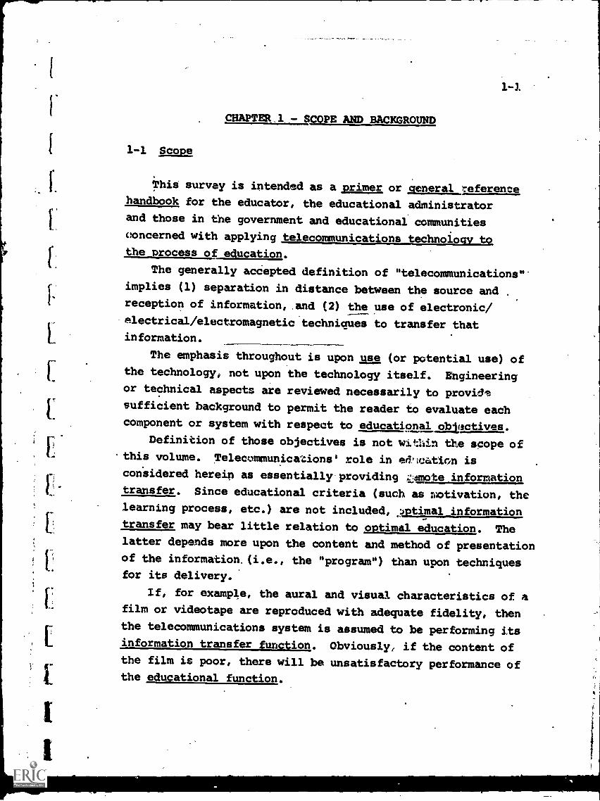
CHAPTER.1 - SCOPE AND BACKGROUND
1-1 Scope
This survey is intended as a primer or general referencehandbook for the educator, the educational administratorand those in the government and educational communities
concerned with applying telecommunications technology to,
the process of education.
The generally accepted definition of "telecommunications"
implies (1) separation in distance between the source and
reception of information, and (2) the use of electronic/
electrical /electromagnetic techniques to transfer thatinformation.
The emphasis throughout is upon use (or potential use) ofthe technology, not upon the technology itself. Engineeringor technical aspects are reviewed necessarily to provide
sufficient background to permit the reader to evaluate eachcomponent or system with respect to educational objectives,
Definition of those objectives is not wIthin the scope of.this volume. Telecommunications' role in ed,ication is
considered herein as essentially providing :::mote informationtransfer. Since educational criteria (such as rootivation, the
learning process, etc.) are not included, .? timal information
transfer may bear little relation to optimal education. Thelatter depends more upon the content and method of presentation
of the information.(i.e., the "program") than upon techniquesfor its delivery.
If, for example, the aural and visual characteristics of afilm or videotape are reproduced with adequate fidelity, then
the telecommunications system is assumed to be performing its
information transfer function. Obviously, if the content ofthe film is poor, there will be unsatisfactory performance ofthe educational function.
. IL2
Ideally, the establishment of educational objectives (and,
concurrently, of criteria and a methodology by which achieving
those objectives can be measured and evaluated) should precedea review of the available technology. In that way, telecom-
munications components and systems can be selected which bestmatch the objectives..
Considering the difficulty in obtaining consensus amongedudators in defining objectives, a less ideal, but perhaps
more practicable approach to applying telecommunications is tostart with a familiarity with the current technology, what
equipment is available, and what applications have already takenplace. From there, a knowledge of future technological trendscan extend the spectrum of alternatives.
This base of technological information, when combined with
educational creativity (constrained of course by ubiquitousbudgetary limitations), can provide the foundation for more
effective application of telecommunications. Educationalobjectives should still be defined before system implementation(nothing is sadder or more expensive than a technological
system which outraces its social objectives), but the processcan be iterative. The iterations can converge between cost-effective technology and improvements, at least, over previous
educational performance.
The intent of this volume_is to supply much of the basic
technblogy information, together with relevant cost and coveragedata, which will assist such iteration. Only an introduction
to components and systems can be provided in many cases, so that
the referenced bibliographic material should be reviewed in anyspecific area of interest.
Section II of this volume provides descriptions of the
components and techniques used in educational telecommunications.Section III reviews the carrier and distribution sub-systems
available to transmit electrical information from one point to
another, with discussion of their relative costs and advantages.
t
3
EC
1-3
Examples of integrated educational systems (where "integrated"
refers to the incluion of all elements of the system from the
-information source to its point of reception and use) are providedin Section IV.
Finally- some brief forecasts of trends, future applications
and projected, evolutionary, telecommunications networks are
provided in Section V.
1-2 Background
1-4
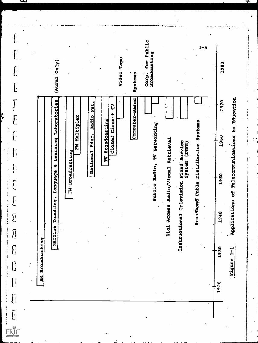
Figure 1-1 illustrates, in truncated form, the chronology
of telecommunications applications to education, starting about
the time of construction of the first educational radio broad-
cast station over 50 years ago.
It may be noted that, until the last decade, most appli-
cations have been of the "single- medium" type. By this is
meant that only one form of educational or instructional material
was made available to the student audience. This might be a
radio broadcastio a large number of listeners or a foreign-
language recording made available to a single student at a
listening station in a school's "learning laboratory ". The
advent of television permitted both aural and visual material to
be transmitted, but the single-medium character of the communic-
ations did not change.
The essential point is that the available technology was
used to simulate, as closely as possible, the conventional
teacher-student relationship and cl=qroom environment. A
television broadcast, in most cases, would parallel the classical
"impartation-of-knowledge" techniques a teacher might use if the
audience were physically in his classroom.
This approach is certainly valid and will continue to be
used. Only in the last decade, hwever, has telecommunications
technology begun to be utilized on a "multi-media" basis, An
automated audio/visual retrieval system, for example, can
provide upon request a playback of an audio tape, or a film or
television program, from a large program library. Computer-
based systems can provide formalizsd instruction and drill in
speafic subjects, or can be used as problem-solving tools on
an unstructured basis.
Not only do these systems provide greater choice, but they
also imply fundamental changes both in methods of learning and
AM Broadcasting
rr",
r7,71
Machine Teaching,
Language & Learning Laboratories
(Aural Only)
IFM Broadcasting
I FM Multiplex
National Educ. Radio Net.
1 TVBroadcasting
[Closed Circuit TV
Video Tape
IComputer-Based
Systems
Public Radio, TVNetwokking,
Dial Access Audio/Visual Retrieval
Instructional Television FixedService
System (ITPS)
Broadband Cable-Distribution Systems
r1
Corp. for Public
Broadcasting
1920
1930
1940
1950.
1960
`1970
-Figure 1-1
Applications of Telecommunications toEducation
1980
1-6
in the teacher-student relationship. The more sophisticated
systems may be viewed as "learning resources" (as contrasted
to the older concept of "teaching machines"), and to a larger
extent their use will be student-directed and student - paced.
This does not mean a lessening of the teacher's role. In
fact, quite the reverse true. The teacher who is involvedwith such interactive :;y5:.= 1:: must not only retain the basic
educational skills, blAt also 'oecome aware of both the technology
(to a limited exten'.;) and the psychology (to a much broader
extent) involved in using such systems effectively. Specialized
subject knowledge will tae supplemented not only by traditional
teaching proficiency, but also by a newer pmfessionalism'in suchareas as:
. Diagnosing the results of student-paced instruction, and
prescribing appropriate support.
. Evaluating, on a. comparative basis, the cost-effectiveness
of telecommunications techniques.
. Providing the interface between user and system ("man and
machine"), very possibly with a different degree of
interfacing required by each student.
. Preparing or recommending new program material, in a form
which both provides effective education and uses the
technology appropriately.
. Planning to meet, through telecommunications, the require-
ments of a more remote, more diversified student audience
than normally encountered in an on-campus environment.
Obviously, not every teacher or educational administrator
will become heavily involved in advanced-technology systems, nor
be required to become expert in the related gamut of'knowledge.
The corollary is probably true, howeVer, in that (within perhaps
3-5 years) no teacher will remain completely untouched by some
aspect of telecommunications-augmented education.
H
1-7
CHAPTER 1 - BIBLIOGRAPHY
1. "Computers: Super-media for education?", Computer Decisions,April 1970, p. 23-26
Klein, M.L. and Klein, R.L., "Progress in the Application ofTechnology to Education", Presented at the 1968 WesternElectronic Show and Convention.
3. Martin, James, "Future Developments in Telecommunications,"1971, Prentice-Hall (Library of Congress Card No. 74-150757)
4. Martin, James,"Telecommunications and the Computer", 1969,Prentice-Hall.
5. Oettinger, A.G., "Run, Computer, Run", Harvard UniversityPress, Cambridge, 1969.
6. Silberman, C.E., "Technology is Knocking at the SchoolhouseDoor",Fortune, Aug. 1966, p. 120.
7. Skinner, B.F. "The Technology of Teaching", Appletoh-Century-Crafts, N.Y. , 1968.
3. Wilson, Ira G. and Marthann E., "Information, Computers, andSystem Design", 1965, John Wiley & Sons(Library of CongressCard No. 65-21430)
i
2-1
CHAPTER 2 - TERMS AND DEFINITIONS
For those with little or no experience with electrical and
telecommunications fundamentals, this chapter provides a brief
introduction to the terminology and elementary concepts. The
treatment is necessarily superficial but should serve at least
as a preliminary frame of reference from which to continae
through the remaining chapters. More detailed material is ,
.available in the references cited in the Biblidgraphy.and in
numerous other introductory. texts.
2-1 Fundamental Electrical Terms
An underitanding of some dozen or so fundamental electrical
terms will provide sufficient background to proceed with the
review of telecommunications systems and applications.
Probably the most difficult term of all to define is
"electricity" itself, since we possess an excellent knowledge
of what it can do and how to predict its behavior without really
having a satisfactory description of its basic property. With
respect to this volume, it will simply be considered as a form
of energy which can be transmitted over distance.
"Electronics" originally referred to the use of vacuum-
tube devices to control and manipulate electrical Jnergy. Since
vacuum-tubes have, in the main, given way to solid-state devices
such as the transistor, electronics is now a more generalized
term and usually connotes any equipment or technique, used in
controlling the flow-of electricity.
Thetransfer of electrical energy from one point to.another
most often occurs as one of two phenomena:
(a) the physical movement of charged molecular particles
(usually electrons) through a material.
(b) the radiation of electromagnetic waves through space.
2-2
Since the second mode can occur even in a vacuum (e.g.', ourradio communications with the Apollo astronauts on the moon),radiated transmission is considered as a movement or variation ofenergy fields or waves rather than particulate motion, but thisexplanation, while empirically satisfactory, reveals again alimited understanding of the basic phenomena.
This limitation does not prevent our use of electricity,
or the ability to design equipment which can control its effectsin accordance with our desires.
In terms of using electricity, a few parameters can definemuch of its behavior.
Three of the most elementary are "voltage ", "current" and"resistance". Voltage (also called electric potential) is thepressure or force available to more electricity, current is ameasure of the quantity, of electricity moved, and resistanceis the property of the medium through which the electricity movesthat *ermines how much force will be necessary to 'achieve adesired current flow.
An often used analogy is shown in Figure 2-1. Water tankA is located at a height above tank B. This height differenceresults in a gravitational force which makes the water flowfrom A to B.
In an electrical circuit, the voltage is the equivalent ofthe gravitational force, and the current is the equivalent ofthe amount of water flowing per unit time. The resistance isthe equivalent of the pipe diameter. If the pipe were large,the rate of flow would be greater than it it were small.
Note that if water tanks A and B were at the same height,and initially contained the same amount of water, there would
'be no flow. This means that the relative difference in waterpressure, or gravitational force,etween A and B is thedetermining factor and not the absolute value of eitherA or Balone. This is also true in electrical circuits where the
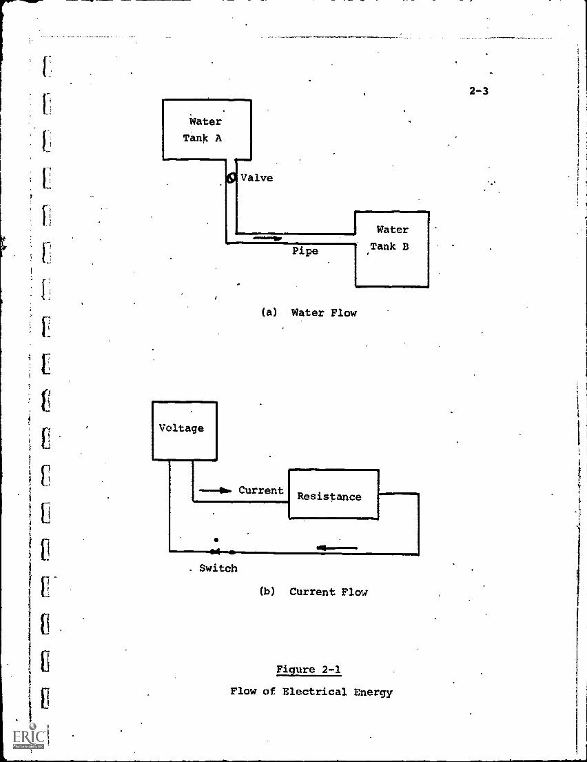
Voltage
(a) Water Flow
---00. CurrentResistance
. Switch
(b) Current Flow
Figure 2-1
Flow of Electrical Energy
2-3
2-4
difference in electric potential, or voltage, determines currentflow. Two similar batteries connected in a circuit so that
their voltages oppose and cancel each other will result in no
current flow.
The magnitude of the resistance to electrical flow is a
physical property of the material through which the flow occurs.
Metals, which make up all the wire transmission networks, have
a low resistance (high conductivity) to the flow of electricity.
In practical terms this means that relatively low voltages can
force higher currents through metal than through most other
materials.
Electrical power is a measure of both voltage and current,
and indeed is defined as their product. Electrical energy is
the power expended-over A_Reriod of time.
In mathematical terms, the following relations hold:
(a) Voltage (volts) = Current (amperes) x Resistance (ohms)
or, symbolically: E = I x R
(b) Power (watts) = Voltage (volts) x Current (amperes)
P = E x I
(c) Energy (watt - hours) = Power (watts) x Time (hours)
Energy = P x T
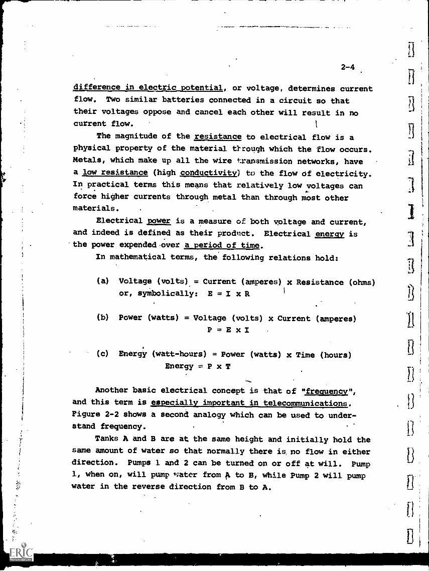
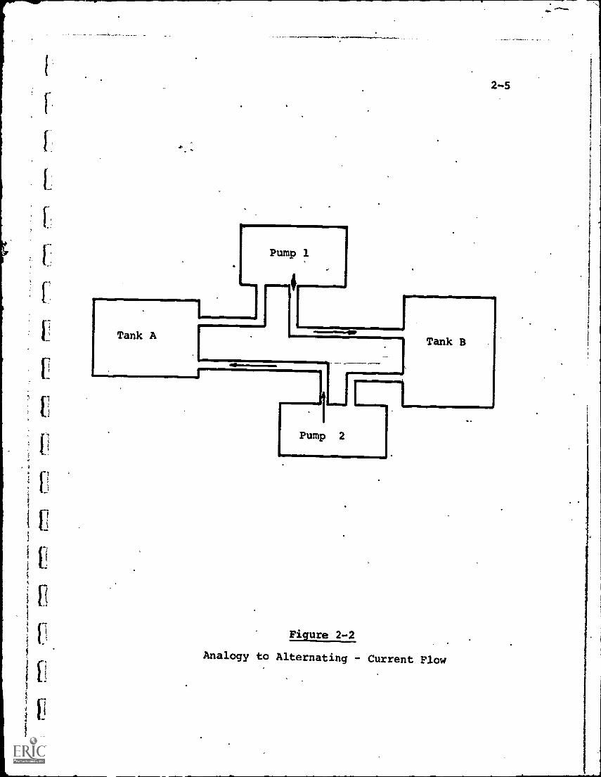
Another basic electrical concept is that of "frequency",
and this term is especially important in telecommunications.
Figure 2-2 shows a second analogy which can be used to under-
stand frequency.
Tanks A and B are at the same height and initially hold the
same amount of water so that normally there is, no flow in either
direction. Pumps 1 and 2 can be turned on or off at will. Pump
1, when on, will pump 'later from A to B, while Pump 2 will pump
water in the reverse direction from B to A.
Tank A
Pump 1
Pump 2
Tank B
Figure 2-2
Analogy to Alternating - Current Flow
2-6
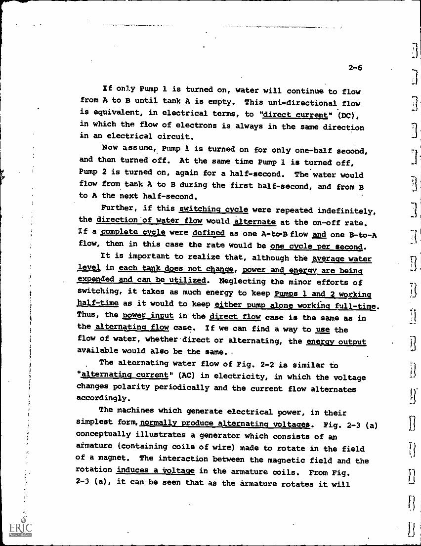
If only Pump 1 is turned on, water will continue to flowfrom A to B until tank A is empty. This uni- directional flowis equivalent, in electrical terms, to "direct current" (DC),in which the flow of electrons is always in the same directionin an electrical circuit.
Now assume, Pump 1 is turned on for only one-half second,and then turned off. At the same time Pump 1 is turned off,Pump 2 is turned on, again for a half-second. The water wouldflow from tank A to B during the first half-second, and from Bto A the next half-second.
Further, if this switching cycle were repeated indefinitely,
the direction'of water flow would alternate at the on-off rate.If a complete cycle were defined as one A -to-B flow and one B-to-A
flow, then in this case the rate would be one dycle per second.
It is important to realize that, although the average waterlevel in each tank does not change, power and energy are beingexpended and can be utilized. Neglecting the minor efforts ofswitching, it takes as much energy to keep Pumps 1 and 2 workinghalf-time as it would to keep either pump alone working full-time.Thus, the power input in the direct flow case is the same as inthe alternating flow case. If we can find a way to use theflow of water, whether*direct or alternating, the energy output
available would also be the same..
The alternating water flow of Fig. 2-2 is similar to"alternating current" (AC) in electricity, in which the voltagechanges polarity periodically and the current flow alternatesaccordingly.
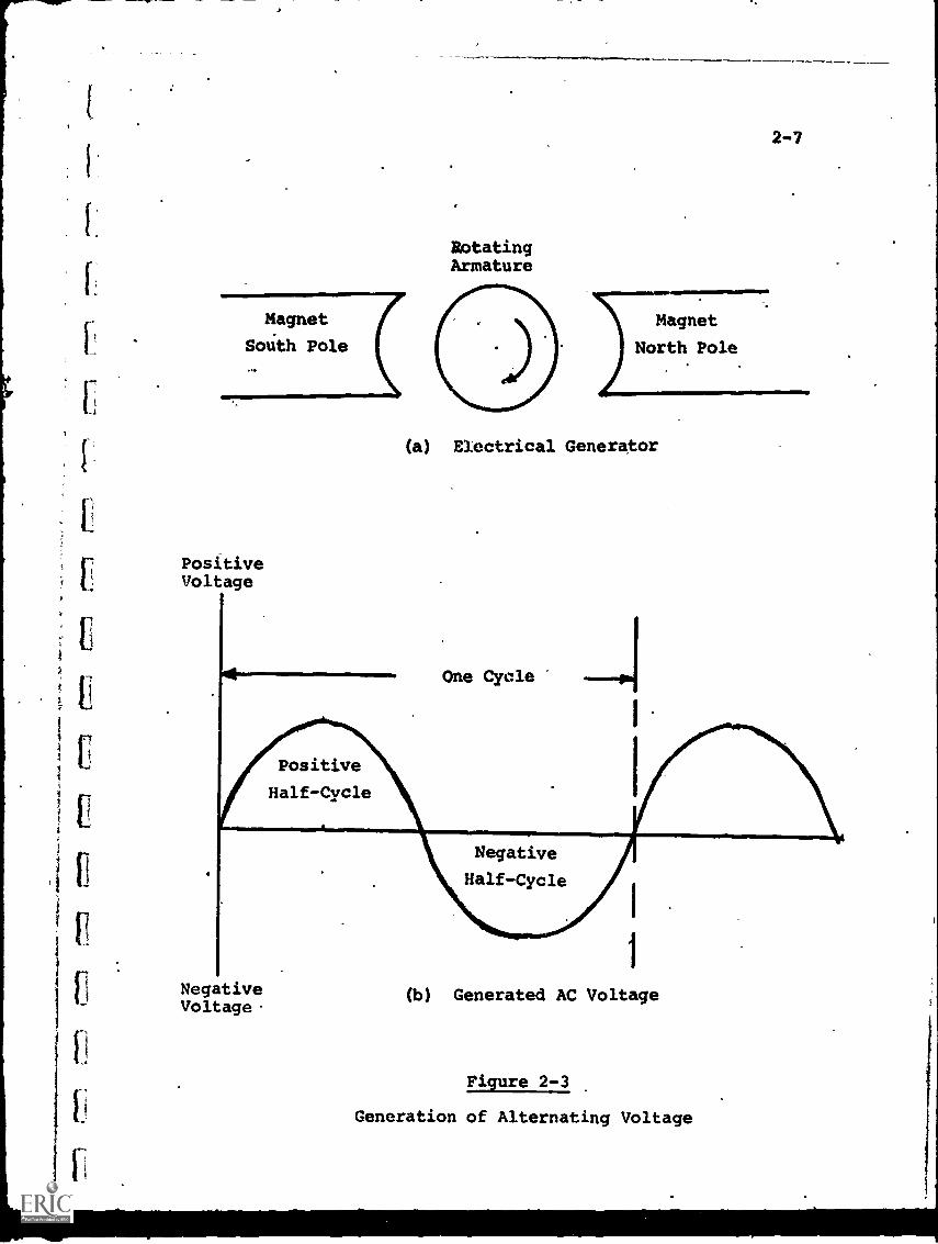
The machines which generate electrical power, in theirsimplest produce Fig. 2-3 (a)conceptually illustrates a generator which consists of an
armature (containing coils of wire) made to rotate in the fieldof a magnet. The interaction between the magnetic field and therotation induces a voltage in the armature coils. From Fig.2-3 (a), it can be seen that as the armature rotates it will
RotatingArmature
Magnet
South Pole
PositiveVoltage
Positive
Half-Cycle
Magnet
North Pole
2-7
(a) Electrical Generator
One Cycle
Negative
Half-Cycle
NegativeVoltage.
(b) Generated AC Voltage
Figure 2-3
Generation of Alternating Voltage
2-8
sequentially pass through areas of greatest magnetic strength
and areas of little or no magnetic strength. Further, the
north and south poles of the magnet will induce voltages of
opposite polarity.
The resulting generated voltage is shown in Fig.2-3 (b).
It is an alternating voltage known as a "sine wave" because
it can be shown that the magnitude of the voltage varies in
accordance with the mathematical value of the sine of an angle.
One cycle of this AC voltage is shown, consisting of two
opposite half- cycles. Each successive cycle is a repetition of
the first.
The rate at which these AC cycles repeat is the frequency
of the electrical voltage or current. If the generator of
Fig. 2-3 (a) rotated at 60 revolutions per second (3600 rpm),
the voltage it produced would have a frequency of 60 cycles per
second.
If AC were produced by some other source and it was an
irregular wave-shape rather than a sine wave, but still contained
current reversals, it can be shown mathematically thit it can
be broken down into the sum of a number of pure sine waves and
treated therefore as a composite of those frequencies. Thus,
any alternating electrical flow, regardless of its pattern, can
be Considered through its separate components.
The differeme, in cycles per second, between the lowest
and the highest frequency components of the composite AC voltage
is defined as^the "bandwidth". For example, if an AC composite
voltage was made up of a 40 cycle per second sine wave, a 100
cycle per second sine wave, and a 500 cycle per second sine wave,
the bandwidth would be 500-40, or 460 cycles per second.
(In recent years, the term "Hertz" (abbreviated Hz) has
been adopted internationally as a replacement for "cycles per
second", and therefore it will be used from this point on.
Table 8-1 lists the various prefixes associated with Hertz
and their respective values.)
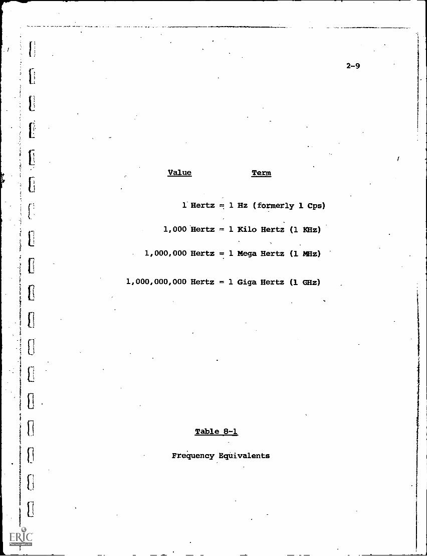
Value Term
l Hertz = 1 Hz (formerly 1 Cps)
1,000 Hertz ,.= 1 Kilo Hertz (1 XHz)
. 1,000,000 Hertz = 1 Mega Hertz (1 MHz)
1,000,000,000 Hertz = 1 Giga Hertz (1 GHz)
Table 8-1
Frequency EqUivalents
2-9
I
2-10
Bandwidth is an important concept with respect to
telecommunications, since it is a measure of how much information
can be accommodated. Later discussion will expand its specific
meaning and application.
DC plays a relatively unimportant role in telecommunications.
AC can be transformed (changed in magnitude of voltage and current)
and amplified much more easily than DC, and this permits easier
matching to a variety of electronic devices which make up the
telecommunications system. Even when a source of electrical
energy (e.g., a battery) produces DC directly, it must beconverted to AC to radiate it from a transmitter, for example.
With the foregoing review of basic electrical terms, the
process of transferring information via electricity can be
discussed.
2 -2 Information Transfer and Bandwidth Concepts
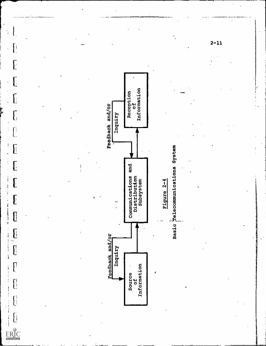
Figure 2-4 illustrates, in simplified form, the elements
of a telecommunications system.
In most educational applications, the source information
is aural and/or visual in character. Information transfer via
senses other than the eye and ear (i.e., smell, touch, taste)
is sufficiently rare (and incompatible with telecommunications)
to be neglected here.
The function of the telecommunications system is to convert
this aural/visual information into electrical form at the source,
transmit it to the receiving location and there reconvert it,
as fiithfully as possible, to the original.
Aural information, in electrical form, is called "audio",
and correspondingly "video" is the term correspondinTto the
electrical form of visual information (which leaves the commonly
used phrase "audio/visual" in no-man's land).
II
Ii
.1,:
F
'-
r".7.771
rrn
rrn
Feedback and/or
Inquiry
Source
of
Information
Communications and
Distribution
Subsystem
Feedback and/or
Inquiry
4111
1111
1111
1=1M
r777-1
iffrn
Figure 2-4
Basic Telecommunications System
Reception
of
Information
2-12
Sound waves, or aural information, are absorbed through the
human ear as energy transmitted through air in the form of a
traveling fluctuation in air pressure. Sound is usually measured
in terms of two parameters, "intensity" (loudness) -and "frequency"
(pitch),,which also have their electrical equivalents in
"amplitude" and "frequency" respectively.
The frequency range for human hearing is about 20-20,000
cycles per second of sound energy. In terms of sound energy,
the sound produced by a tuning-fork would be .a single frequency,
say at.1,000 cycles per second. The sound of human speech or
music would be a composite of many single frequencies, much the
same as the AC composite electrical signal mentioned previously.
Because of the similarities, sound energy can be trans-
formed into electrical form almost on a "one-for-one" basis,
i.e., the 20-20,000 cycle per second bandwidth of sound energy
converted into an equivalent 20-20 000 Hz electrical bandwidth.
An ideal communications system transmitting only aural
inforMation would convert and transmit the original sounds
without loss or distortion. This is equivalent to the per-
formance of a high-quality stereo set (e.g., "flat response"
from 20-20,000 Hz).
In practice, however, most audio communications links operate
on a much narrower frequency spectrukt. The telephone line,
designed primarily for voice transmission, operates, for example,
on a channel only about 3,000 Hz wide. FM radio stations broad-
casting so-called "high fidelity" music transmit a wider band
of frequencies, but some cutoff'of frequency extremes still
takes place, either at the source or the receiver.
Visual information is much more complex than aural, involving
motion of the visual imagein time and space, as well as the
process by which the human eye assembles'bits of the image to-
gether into a totality. A detailed discussion of conversion
of visual information is provided in Chapter 4, but at this
point it can be noted that to convert a moving electrical image
1-J
2-13
into electrical form, so that it can be communicated and viewedWithout any time delay, requires an electrical bandwidth ofseveral MHz, as contrasted to the 20 KHz of high-fidelity musicor the 3 KHz of a telephone line. Standard TV channels, forexample, are 6 MHz wide, which is 2.000 times the bandwidth ofa telephone line.
In any telecommunications system, the parameter of band-width, as related to cost, becomes the single most importantevaluation criterion. For equal cost, a wider band system willpermit greater information transfek per unit of time, whichcan either be a quantitative or qualitative (e.g., improved TVpicture quality) advantage. This is why a cost/bandwidthfigure of merit is used to compare telecommunications systems.
Obviously, the corollary of the previous statement is alsotrue, i.e., thatrwidiarbalE0th21Etsjmeejmney. The trade-off between cost and how fast information is to be transferredis a major decision for each system.
Wider bandwidth also permits greater flexibility. Acommunications link, for example, with a bandwidth of 12 MHzcan carry two TV channels, or one TV channel and 1000-2000
voice-grade telephone channels, or any other combination ofinformation messages which does not exceed the 12 MHz totalcapacity. A narrow-band system, on the other hand, can carryhigh quantities of information only by transmitting over long,"stretched-out" intervals of time, (similar to forcing a riverof water through a narrow pipe). This may be tolerable forsome applications (e.g., facsimile), but completely unacceptablewhere real-time reception is necessary, as in TV.
II. COMPONENTS AND TECHNIQUES
Chapter 3 AudioChapter 4 VideoChapter 5 Hard CopyChapter 6 Computers
1
CHAPTER 3 - AUDIO
[.:
3-1
The conversion of sound into electrical form is one of
the oldest applications of telecommunications, beginning
with the invention of the telephone.
There are generally three reasons to transform sound
energy:
(1) to reproduce the sound at the same location, but
with controllable volume (e.g., public address
systems)
(2) to store the sound for later reproduction
(3) to reproduce the sound at a different location
Of these, only the third falls directly within the
definition of telecommunications, although the second is use-
ful in many educational applications.
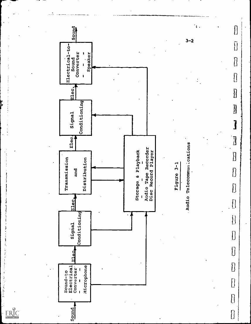
Fig 3-1 illustrates the functional components of a
telecommunications system which transmits only audio
information.
Since Section III deals with the methods of transmitting
and distributing electrical information, including sound and
pictures, this chapter focuses upon the components and
techniques used at the information source and receiving points,
eithek to convert or store sound energy, and to condition the
electrical signals properly.
3-1 Sound-to-Electrical Conversion: The Microphone
Aural-to-electrical conversion is usually performed by
a microphone which changes ambient sound waves into a
proportionally varying electrical parameter. Either the
sound pressure or the pressure-gradient (velocity) may be
used.
A typical pressure-operated microphone, for example,
utilizes the sound pressure to deflect a sensitive diaphragm,
producing mechanical motion. This motion may change the
Sound
Sound-to
Electrical
Converter
OE
MA
M,
MO
Microphone
Signal
Elect.
ConditionincA
Transmission
and
Distribution
Elect
Signal
Conditioning
Electrical-to-
Elec.
Sound
Sound
Converter
Storage& Playback
Audio Tape Recorder
Disc Record
Player
AM
PA
MP
Speaker
A
Figure 3-1
Audio TelecommunLcations
I
re=
tpir
mi
r"--1
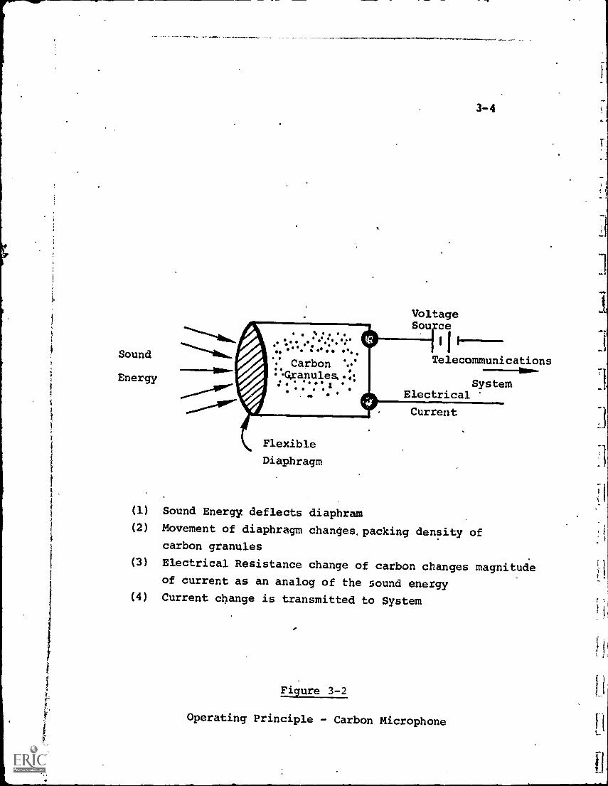
packing density of carbon granules within a small chamber,
and thus change the electrical resistance of the carbon,
(Fig. 3-2) or it may slightly deform a crystal which, through
the piezo-electric effect, changes its capacitive reactance.
In either case, the change in electrical value follows.
(becomes an analog of) the varying sound pressure.
The electrical output signal from the microphone, though
a close representation of the sound, is low in power and in
almost all cases must be amplified to be of use in transmission
or reproduction. Further, the frequency range, from 20 to
perhaps 20,000'H z, is in many cases not the most efficient for
long-range transmission, so that modulation (use of the
information signal to control another electrical signal which
serves as a carrier) is also required.
3-2 Electrical-to-Sound Conversion: The Speaker
At the receiving location, the electrical signal is
converted back into a sound pattern duplicating that at the
source. This accomplished by means of an electro-acoustic
converter called a loudspeaker, or more simply, a speaker.
In the most common version, the electrical current energizes
a "voice coil" which is mounted in a magnetic field. The
interaction of the quiescent field and the dynamic one
produced by the currents. in the voice coil will force the
voice coil to move. Since the voice coil is fastened to a
specially shaped flexible mechanical cone, the cone will
move also, and its motion energizes the surrounding air,
producing sound waves.
Speakers vary in size from the very small hearing-aid
and transistor radio types or the headphones used in telephone
receivers, to the large, high -power public address units
designed for area coverage. They also vary in fidelity of
sound reproduction from poor to excellent. The high-fidelity
systems generally utilize combinations of speakers, each
Sound
Energy
VoltageSou ce
Flexible
Diaphragm
3-4
Telecommunications
SystemElectrical
Current
(1) Sound Energy deflects diaphram
(2) Movement of diaphragm changes, packing density ofcarbon granules
(3) Electrical Resistance change of carbon changes magnitudeof current as an analog of the sound energy
(4) Current change is transmitted to System
Figure 3-2
Operating Principle - Carbon Microphone ri
11
U
3-5
reproducing a portion of the sound spectrum. Thus, "woofers"
are speakers designed for the low (bass) sound frequencies,
while "tweeters" reproduce the higher (treble) portion of
the range.
3-3 Audio AtorAggtryldpia bank
At present, audio information is most commonly stored on,
and played back from, one of two media:
(1) phonograph discs
(2) magnetic tape
The wide use of both media or entertainment and
education requires no elaboration. Music, drama, speeches,
educational and training courses are available, both 'on disc
and tape, in such profusion as to offer a bewildering variety
of. choice.
3-3.1 Disc Record Player
The phonograph, oldest of the audio storage and playback
devices, has the advantage of low cost for the player and
discs. A player adequate for a single classroom, where high
fidelity reproduction is not required, would cost $25-75.
Long-playing (33-1/3 rpm) discs average $2-10 each, depending
upon the program material.
Apart from disc wear, which degrades playback quality
with continued usage, the major disadvantage of the phono-
graph is that it is a playback device only, with no facility
for local recording of programs. This limits educational
applications to that previously recorded material which
happens to be available and also fits local educational needs.
Innovative program material, or material which is of interest
to relatively small groups, is likely to be rare.
3-6
3-3.2 Magnetic Tape Recorder/Player
The magnetic tape recorder/player offers the advantageof convenient local recording capability, which the phono-graph lacks. With a microphone accessory, any sounds capableof being heard can be recorded and stored on tape for laterplayback. Thus, classroom lectures, field interviews orradio or television programs can be taped 'for subsequent
use.
Information is stored on magnetic tape by orientingthe magnetic particles which coat the tape into a patternwhich follows the sound variations. The electrical currentoutput from the microphone (or any similar source) is
amplified and connected to a magnetic recording "head",
which generates a strong magnetic field in the vicinity ofthe tape moving under it. This fluctuating magnetic field
moves the metal oxide particles on the tape in a mannersimilar to the a way a permanent magnet moves iron filingson a sheet of paper. The resulting pattern on the tape is
an electromagnetically-stored equivalent of the originalsounds.
For playback, the process is reversed. The prerecordedtape is moved under a "pickup" head which, in this case,
senses the pattern variations of the tape's magnetic field andproduces a current following the pattern. This current isamplified and used to energize a speaker, reproducing theoriginal sound.
Until the last few years, magnetic tape was wound on
open reels which required some care in handling, threading
and storage. Recently, however, the introduction of the tape
cassette and cartridge have greatly simplified recorder
operation and provided a more convenient program module.
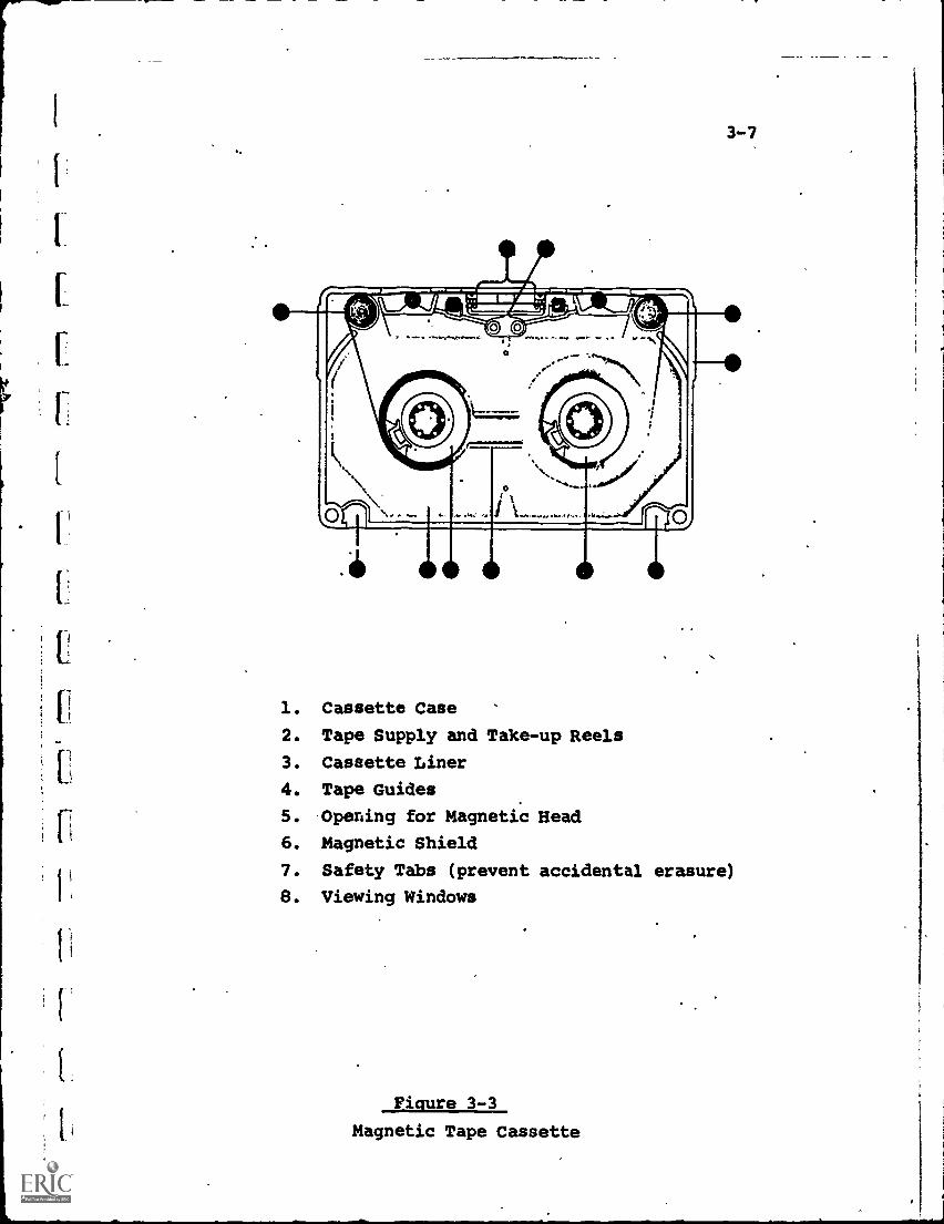
A cassette is basically an enclosed version of the
original reel-to-reel concept (see Fig. 3-3). The two reels
are enclosed in a plastic case with an opening for the
3-7
1. Cassette Case
2. Tape Supply and Take-up Reels
3. Cassette Liner
4. Tape Guides
5. Opening for Magnetic Head
6. Magnetic Shield
7. Safety Tabs (prevent accidental erasure)
8. Viewing Windows
Figure 3-3
Magnetic Tape Cassette
3-8
recorder's magnetic head. In use, the tape reels, are drivenso.that the tape unwinds from one reel and winds onto theother. The user does not have to touch the tape itself or,open the cassette.
An accepted standard at present is the "Philips" cassette,developed by North American Philips; which utilizes 1/4-inchwide magnetic tape moving at 1-7/8-inch per second rate.
A magnetic tape cartridge is a single-reel module. Thetape unwinds from the reel and is designed to rewind overthe same reel so that an "endless loop" is formed. Thus, ifthe cartridge contains music, it is possible to plug it intothe player and hear the sound start in the middle of themusical piece, continue to the end, and then begin over again.This feature is useful for unattended applications, such asthe music track in an airplane's entertainment system, or
background music systems like Muzak.
At present, 4-track and 8-track cartridges are available,providing a range of program lengths up to several h'urs. Asin the cassette, the user never handles the tape directly,
and the cartridge isa plug-in, snap-out module.Casiette and cartridge recorder/players are rapidly
becoming competitive in price with phonograph players,ranging from $50-400 for home or classroom units, up to$500-1,000 for professional and institutional equipment. Add-on units, which physically accept the cassette cr cartridge,but which use the amplifier-speaker combination of a separatestereo or radio set, are also available at a $25-100 costrange.
3-4 Signal Conditioning
3-4.1 Conditioning Requirements
Depending upon the nature of the telecommunicationsystem, it usually is necessary to "condition" the zAidio
electrical signals prior to transmission and distribution.
3-9
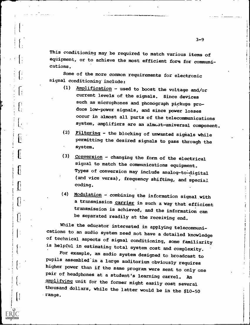
This conditioning may be required to match various items ofequipment, or to achieve the most efficient form for communi-cations.
Some of the more common requirements for electronicsignal conditioning' include:
(1) Amplification - used to boost the voltage and/or
current levels of the signals. Since devices
such as microphones and phonograph pickups pro-duce low-power signals, and since power losses
occur in almost all parts of the telecommunicationssystem, amplifiers are an almat-universal component.
(2) Filtering - the blocking of unwanted signals whilepermitting the desired signals to pass through thesystem.
(3) Conversion - changing the form of the electricalsignal to match the communications equipment.Types of conversion may include analog-to:-digital(and vice versa), frequency shifting, and specialcoding.
(4) Modulation - combining the information signal witha transmission carrier in such a way that efficienttransmission is achieved, and the information canbe separated readily at the receiving end.
While the educator interested in applying telecommuni-cations to an audio system need not have a detailed knowledgeof technical aspects of signal conditioning, some familiarityis helpful in estimating total system cost and complexity.
For example, an audio system designed to broadcast topupils assembled'in a large auditorium obviously requireshigher power than if the same program were sent to only onepair of headphones at a student's learning carrel. Anamplifying unit for the former might easily cost severalthousand dollars, while the latter would be in the $10-50range.
3-10
Similarly, if many signals ate distributed simultaneouslythrough the same system, the filtering and conversion equip-ment necessary to insure that they do not interfere withdistort each other can be quite expensive. If, further, thesignals are broadcast over the air waves, the FCC imposes,
stringent regulations on the characteristics of the signalsto prevent interference with other broadcast stations. Suchregulation increases the magnitude and cost of the conditioningequipment to the point where, in many systems, these costs maybe the dominant factor.
3-4.2 Modulation Techniques
If aural information is converted into electrical formand transmitted to the receiving point with no significantchanges other than amplification, the signals are :-.ermed
"unmodulated" or " direct audio". An example would be apublic address system.
While permitting the simplest equipment configuration,direct transmission of audio signals in the 20-20 KHzfrequency range is inefficient either for wireless broad-casting or for wired systems exceeding a few miles. Toomuch power is lost during transmission, and the equipmentrequired is excessively large and bulky. (This is relatedto themWavelength" of the electrical signals, which is theinverse of frequency. Thus, low-frequency audio signalshave long wavelengths).
For any long-distance applications, therefore, modulationis required. In this process, a carrier is selected whichdoes permit efficient transmission, and the audio signals areuse to modulate (vary or control) a characteristic of thecarrier in such away that the desired information contentis transmitted as part of the carrier.
The two most commonly used modulation techniques for audio
r
3-11
transmission are Amplitude Modulation (AM) and FrequencyModulation (FM). The terms, at least, are familiar to all
due to their use in radio broadcasting.
3-4.2.1 Amplitude Modulation (AM)
Just as sound energy is characterized and measured
through the parameters of intensity and pitch which define,
respectively, the loudness and frequency, so is the audio
electrical signal defined by two similar parameters, amplitudeand frequency. The amplitude is a measure of the magnitude
or intensity of the audio voltage or current while the
frequency describes the rate of change of directional flowof current.
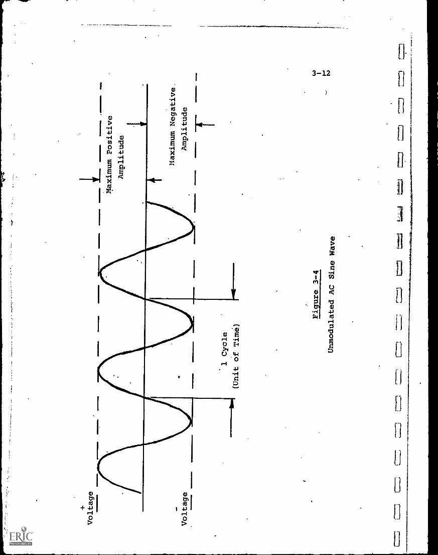
Figure 3-4 is a pictorial illustration of a constant-
amplitude, constant-frequency"alternating current" (AC)
signal, termed a sine wave. It is the form of signal produced
by a rotating electrical generator, due to the physical design
and location of magnet and armature. Since this kind of
generator produces most. of the worlds' electrical power, theAC sine wave has been adopted as the universal standard of
a "raw", unmodulated (informationless) electrical signal.
("Direct current" or DC signals are used for specialized
applications, but relatively rarely in telecommunications.
Transmission efficiency is poor, and they present difficulty
in transformation).
In Fig. 3-4, although the electrical voltage and current.
vary, they do so in a predetermined pattern, with each cycle
being a repetitive duplicate of the others. Thus, the
maximum amplitude (or any selected average or root-mean-square
amplitude) can be said to be constant over any number'of cycles.
If another electrical signal is added to that of Fig. 3-4,
so that the amplitude of the sine wave varies in proportion
to the new signal, the process is termed Amplitude Modulation
The original sine wave is the carrier, and the second signal
Voltage
1 Cycle
bin
(Unit of Time)
Figure 3-4
Unmodulated AC Sine Wave
Maximum Positive
Amplitude
OE
M
IMIM
EM
N
Maximum Negative.
Amplitude
3-13
is the modulating information. -Thus, the modulated carrier
is actually the total signal communicated. At the receivingend, the carrier and modulating information are separated by
a reverse demodulation process and the audio informationretained for reproduction.
Thus, in an AM radio broadcast the carrier frequency, may
be 1000 KHz, while the audio information only ranges up to15 KHz. This audio modulates the '1000 KHz carrier, "ridesalong" as part of the broadcast signal, and is separated outagain at the radio receiver to produce the desired sound fromthe speaker.
AM is used for most commercial radio broadcasting, sinceit was developed before FM historically, and the rapid growthof radio in the 1920's and 1930's forced standardization. As
an information transmission technique, however, AM has the
drawback of being highly susceptible to electrical interference,noise and distortion. Most electrical disturbances, whetherdue to power fluctuations, lightning, atmospheric disturbances,etc., will affect the instantaneous amplitude of a signal more
drastically than its frequency. Consequently, AM broadcastsinherently are more "static-prone" than FM.
EquLpment costs for both transmission and reception ofAM are, however, lower than for FM and thus present an
advantage where noise-free reproduction is not a criticalrequirement. AM transistor radios, as an example, are avail-able for as low as $5 each, as compared to 3-4 times that
price for an equivalent FM model.
3-4.2.2 Frequency Modulation (FM)
If, in Fig. 3-4, the audio signal is made to modulate
the frequency of the carrier rather'than its amplitude, theprocess is called Frequency Modulation. Usually the carrieris made to "swing" (deviate) above and below its unmodulated
nominal frequency at a rate proportional to the amplitude
of the modulating signal, and by an amount proportional to
ll
3-14
the frequency of the modulating signal (although many othertechniques are possible). Thus, to transmit a 15 KHz audiorange would require +15 KHz deviation around the FM carrier.
As noted, FM's chief advantage issa higher immunity tonoise and static, as many FM radio devotees will testify.FM is also used for the sound portion of commercial television,although, paradoxically, the picture portion utilizes AM toconserve assigned frequency spectrum.
3-4.2.3 FM Multiplex
One relatively new concept in FM broadcasting, which hassignificant educational potential is the technique of"FM
11multiplexing" permitted by the FCC under the Subsidiary
Communications Authorization (SCA) in 1955, but coming intowidespread utilization only lately.
FM multiplexing is an electronic method of placingtwo or more separate signals onto a single assigned FMchannel, in effect permitting an FM station to broadcasttwo or more different signals simultaneously. The "subsidia::y"signal is "Piggy-backed",on the primary FM signal.
Most FM listeners are familiar with "stereo multiplex"11
in which separate portions of the transmission band areallocated to "left" and "right" sections, representing thedifferent sounds heard from different locations in an orchestra.Also possible, however, is the carriage of signals which haveno relation to each other.
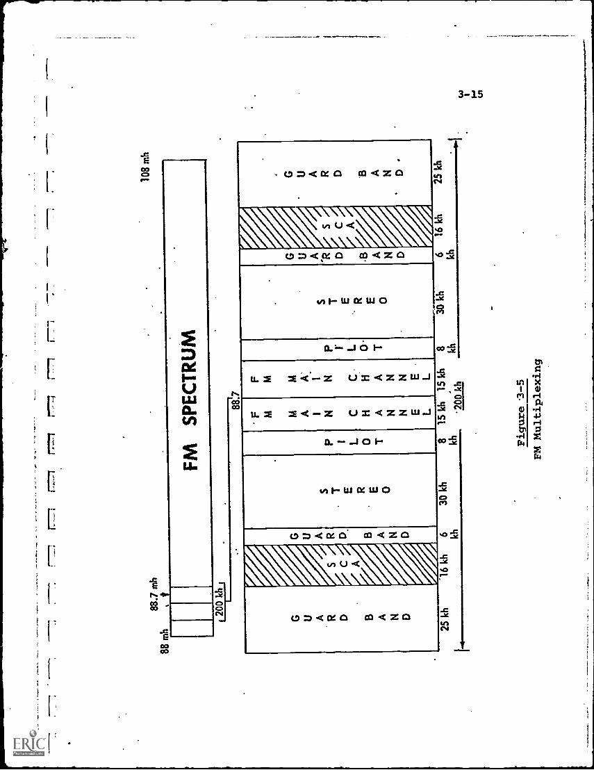
Fig. 3-5 illustrates the FM multiplexing technique. Astandard FM station operates within a 200 KHz band,100 KHzon each side of the assigned carrier frequency. Of the 200 KHz,only 30 KHz (+15 KHz around the carrier) are used for theprimary FM signal.
88.7
mh
88 m
h,
108
mh
FM
SP
EC
TR
UM
200k
h1,..
.
G U A R D B A N D
S C A
A
G U A R A N D
S T E
.R E 0 .
P 1 L 0 T
F M M A I N C H A N N E L
F M M A'
I N C.
H A N N E.
L
P l L 0 -
T
S T E R E 0
G U A R .
A N D
S C A
.
G U A R D B A N D
1A L
t.ic
Lk
it25
kh
16 k
h6 kh
1315
kh i5
kh0
kh20
0 kh
kh
Figure 3-5
FM Multiplexing
kh
3-16
When stereo is broadcast, fout additional subchannelsare used as shown, a pilot channel (which provides asynchronoussignal to coordinate the stereo and main channel signals) anda stereo subchannel on each side of the carrier. When guardbands are added to separate the various signals, there stillis left two 16 KHz subchannels, cross-hatched "SCA", one oneach side of the carrier.
This SCA frequency spectrum can be used for broad-casting a signal or message completely different from the mainand stereo signals. To receive the SCA message, however, aspecial receiver is necessary to eliminate the surroundingFM main and stereo subchannels. This receiver is a non-tunabledevice costing about $100, and can receive only the SCAsignal from a specific transmitter.
Originally SCA was authorized to help FM stationsfinancially. The SCA subchannel actually transmitted musicto special receivers in restaurants; stores, etc., for afee and thus was a wimless competitor to Muzak.
In 1961, the FCC authorized SCA operations for educational
purposes, and since than: time a number of educational and/orinstructional programs have been multiplexed and transmittedfrom both commercial and educational FM stations.
3-5 Educational Applications
Because of the almost- universal availability, over manyyears, of audio equipment and distribution systems (telephone,radio, disc and tape recorders, stereo, etc.), the greatest
progress to date in applying educational technology has,
naturally, occurred in the audio area.
Obviously, any subject which can be taught in the class-
room adequately without the need for visual demonstration isalso a candidate for remote audio instruction through tele-communications.
f.
3-17
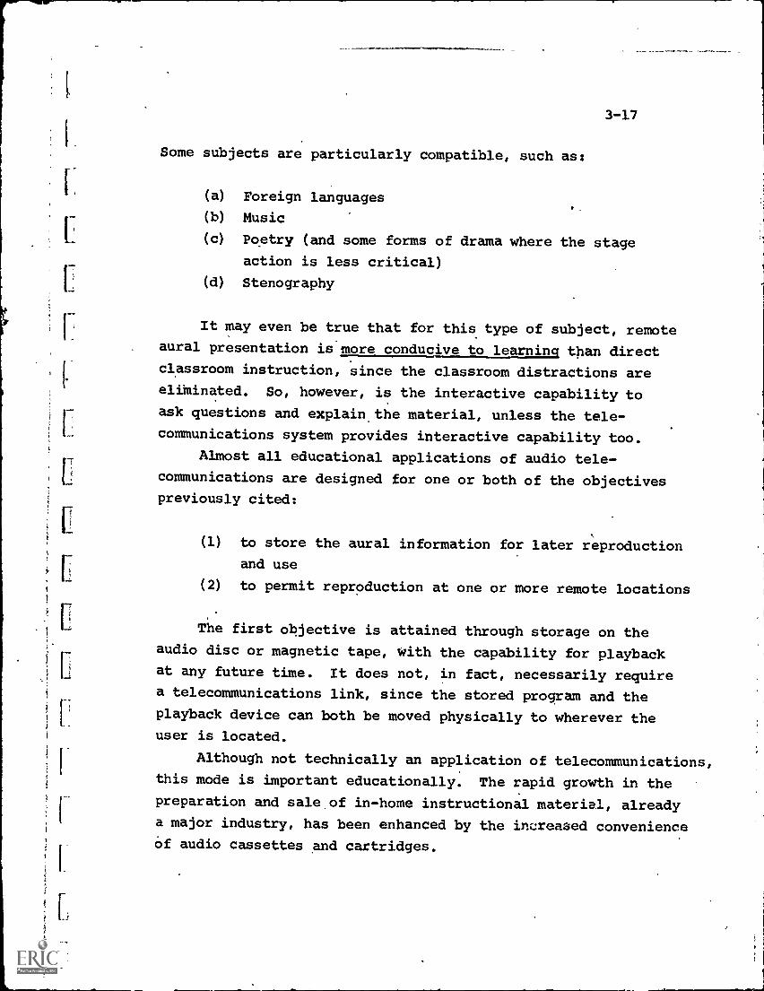
Some subjects are particularly compatible, such as:
(a) Foreign languages
(b) Music
(c) Poetry (and some forms of drama where the stage
action is less critical)
(d) Stenography
It may even be true that for this type of subject, remote
aural presentation is.more conducive to learning than direct
classroom instruction, since the classroom distractions areeliktinated. So, however, is the interactive capability to
ask questions and explain the material, unless the tele-
communications system provides interactive capability too.
Almost all educational applications of audio tele-
communications are designed for one or both of the objectives
previously cited:
(1) to store the aural information for later reproduction
and use
(2) to permit reproduction at one or more remote locations
The first objective is attained through storage on the
audio disc or magnetic tape, with the capability for playbackat any future time. It does not, in fact, necessarily require
a telecommunications link, since the stored program and the
playback device can both be moved physically to wherever theuser is located.
Although not technically an application of telecommunications,this mode is important educationally. The rapid growth in the
preparation and sale of in-home instructional material, already
a major industry, has been enhanced by the increased convenienceof audio cassettes and cartridges.
3-18
For some considerable portion of the population, such asthe handicapped or aged student located in a remote, isolated
geographical area where the cost of telecommunications wouldbe excessive, the physical delivery of program material
(particularly when, in the future, video as well as audiocassettes become available) may represent the most practicalsolution to education.
Where the primary objective is to disseminate audio
material simultaneously to a number of remotely located users,
a cost-effective choice must be made from the availableequipment and communications links. The latter are reviewed inSection III.
Examples of integrated audio educational systems
Utilizing telecommunications are provided in Chapter 10 ofSection IV.
4-1
CHAPTER 4. VIDEO
4-1 Component Categories
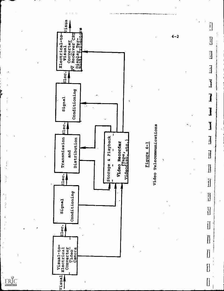
As for audio, the major video components utilized ineducational telecommunications systems function either(1) at the information source, or (2) at the information
receiving point, and are involved, respectively, in thevisual -to- electronic and electronic-to-visual conversionprocesses. Fig. 4-1 illustrates the functional elementsof a video communication system, and it can be noted thatit is identical to Fig. 3-1 except for the substitution ofvideo conversion and storage components.
At the information source, the most commonly used videocomponents include:
(a) Video Cameras and/or Scanners - which change
visual images into electronic signals in a
format compatible with the distributionmethod and the receiving and display equipment.
(b) Secondary Storage Media Equipment - this includes
equipment to record and store visual informationin a form not directly compatible with the tele-
communications system. Examples are motion picturefilm, slides, or microfilm cameras and projectors,
since the photographic data stored on the filmmust be converted by a video camera into an
electronic signal before it can be transmitted
to a remote receiving location.
(c) Auxiliary and Support Equipment - this categoryincludes the items necessary to integrate components
into a functioning system, such as signal switchersand mixers, amplifiers, control consoles, lighting,
video monitors, etc. Though performing supportrather than primary functions, they constitute a
Visual-to-
Electrical
Converter
Video
Camera
Elec.
Signal
Conditioning
Elec.
Conditioning
rolo
rior
mq
Transmission
and
Distribution
Elec.
1Storage & Playback
110
Video Recorder
(Tape,
Videodisc. etc.)
Signal
Conditioning
Electrical-to
Elec.
Visual
Converter
PV RecgiverCR
Disola
Ter-
*minai
roi ectcJreisua
Figure 4-1
Video Telecommunications
=1
Wer
oti
howl
IIPP
*1
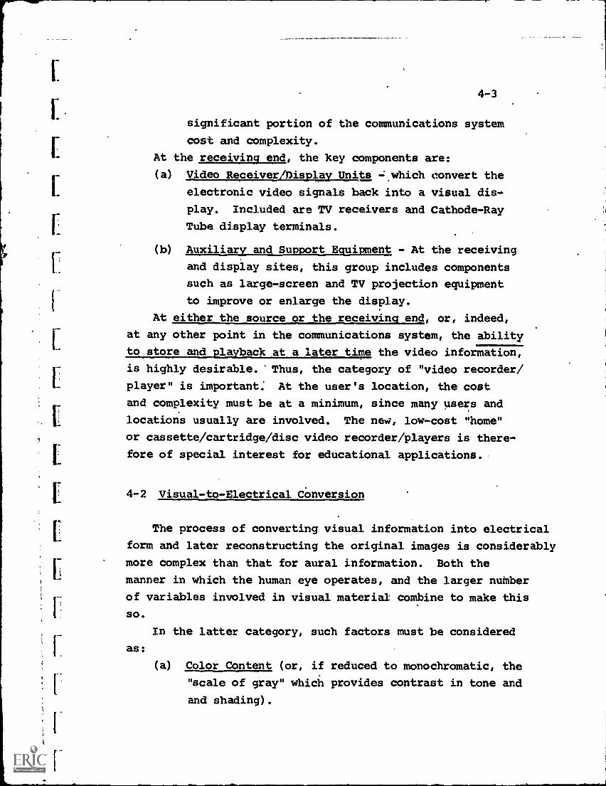
4-3
significant portion of the communications system
cost and complexity.
At the receiving end, the key components are:
(a) Video Receiver/Display Units *which convert the
electronic video signals back into a visual dis-
play. Included are TV receivers and Cathode-Ray
Tube display terminals.
(b) Auxiliary and Support Equipment - At the receiving
and display sites, this group includes components
such as large-screen and TV projection equipment
to improve or enlarge the display.
At either the source or the receiving end, or, indeed,
at any other point in the communications system, the ability
to store and playback at a later time the video information,
is highly desirable. 'Thus, the category of "video recorder/
player" is important: At the user's location, the cost
and complexity must be at a minimum, since many users and
locations usually are involved. The new, low-cost "home"
or cassette/cartridge/disc video recorder/players is there-
fore of special interest for educational applications.
4-2 Visual-to-Electrical Conversion
The process of converting visual information into electrical
form and later reconstructing the original images is considerably
more complex than that for aural information. Both the
manner in which the human eye operates, and the larger number
of variables involved in visual material combine to make this
SO.
as:
In the latter category, such factors must be considered
(a) Color Content (or, if reduced to monochromatic, the
"scale of gray" which provides contrast in tone and
and shading).
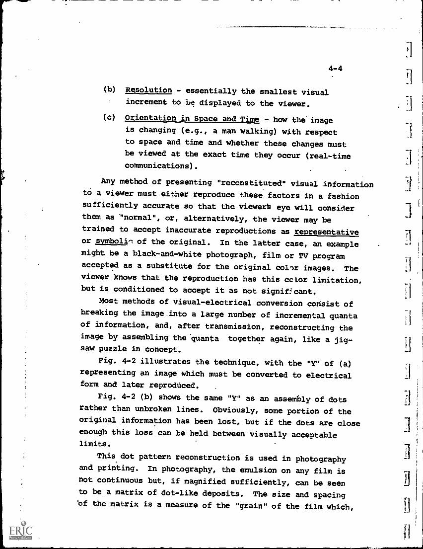
4-4
(b) Resolution - essentially the smallest visual
increment to ie displayed to the viewer.
(c) Orientation in Space and Time - how the image
is changing (e.g., a man walking) with respect
to space and time and whether these changes mustbe viewed at the exact time they occur (real-time
communications).
Any method of presenting "reconstituted" visual informationto a viewer must either reproduce these factors in a fashionsufficiently accurate so that the viewers eye will considerthem as "normal", or, alternatively, the viewer may betrained to accept inaccurate reproductions as representativeor symbolin of the original. In the latter case, an examplemight be a black-and-white photograph, film or TV programaccepted as a substitute for the original collr images. Theviewer knows that the reproduction has this cclor limitation,but is conditioned to accept it as not significant.
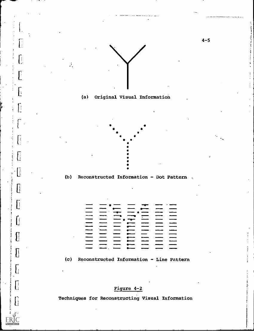
Most methods of visual-electrical conversion consist ofbreaking the image.into a large number of incremental quanta
of information, and, after transmission, reconstructing theimage by assembling the 'quanta together again, like a jig-saw puzzle in concept.
Fig. 4-2 illustrates the technique, with the "Y" of (a)representing an image which must be converted to electricalform and later reproduced.
Fig. 4-2 (b) shows the same "Y" as an assembly of dots
rather than unbroken lines. Obviously, some portion of theoriginal information has been lost, but if the dots are closeenough this loss can be held between visually acceptablelimits.
This dot pattern reconstruction is used in photographyand printing. In photography, the emulsion on any film isnot continuous but, if magnified sufficiently, can be seento be a matrix of dot-like deposits. The size and spacing'of the matrix is a measure of the "grain" of the film which,
it
(a) Original Visual Information
(b) Reconstructed Information - Dot Pattern
-MNIMMIIM -. .-- 41.-101111- ,I=MINNIMM MMI1MP
11111 01 OIM41
.111411111
Ww. MEM0. Mw MINOW 4=11141.10 MMW.MM
.1.111 1110.41. .1 11 11111
(c) Reconstructed Information - Line Pattern
Figure 4-2
Techniques for Reconstructing Visual Information
4-6
in turn, determines the resolution of the picture, and howmuch it can be enlarged before the spacing between dots
becomes objectionable.
Similarly, in printing of halftone photographic material,the picture is "screened", which results in the printing ofa pattern of dots rather than a continuous variation in black-,white intensity. Again, under magnification the dots becomeclearly visible.
When a visual image is converted for the purpose of sendingit electronically to a remote location, there must be someagreed-upon "code" or method of breaking up the image sothat it can be reconstructed properly at the receiving end.
This coding process is called "scanning".
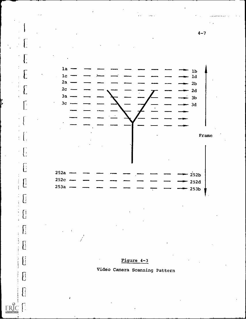
The method of scanning used in broadcast TV is illustratedin 4-2 (c), and consists of viewing each incremental portionof the image in an orderly sequence of individual, closely-spaced horizontal lines. This is by no means the only acceptablescanning pattern (facsimile, for example, uses a helical scan-ning pattern), but simply the accepted standard for commercialTV.
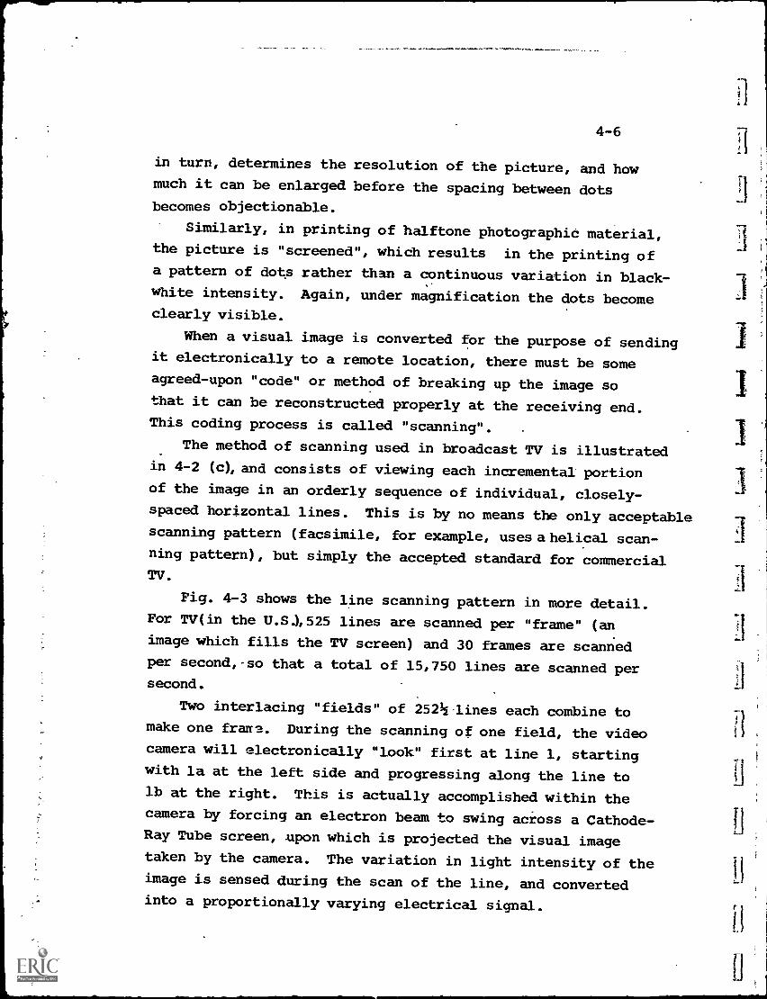
Fig. 4-3 shows the line scanning pattern in more detail.For TV(in the U.S),525 lines are scanned per "frame" (an
image which fills the TV screen) and 30 frames are scanned
per second,-so that a total of 15,750 lines are scanned per11second.
Two interlacing "fields" of 252h lines each combine tomake one frame. During the scanning of one field, the videocamera will electronically "look" first at line 1, startingwith la at the left side and progressing along the line tolb at the right. This is actually accomplished within thecamera by forcing an electron beam to swing across a Cathode-
/-1Ray Tube screen, .upon which is projected the visual imagetaken by the camera. The variation in light intensity of the
11image is sensed during the scan of the line, and converted
into a proportionally varying electrical signal.
la
lc
2a
2c
11. 01111111 111.11111.
3a
3c
252a ---
252c
253a
11=6
Imml
II=11=8.
111
11
0141011.
1=1111111
I
Figure 4-3
Video Camera Scanning Pattern
--"m- lb
ld
2b
2d
3b
3d
4-7
Frame
252b
252d
253b
4-8
After line la-b has been scanned, the electron beam islowered slightly and swung back to point 2a. During this"retrace" time, the beam is turned off to prevent scanningextraneous information. Line 2a-b is scanned identically toline la-b, and in sequence, all of the first field is scannedsimilarly. This occurs in 1/60 second. The second field(lines lc -d, etc.) is then scanned in an identical manner toproduce the 525-line frame.
At the end of the frame, the beam is turned off andreturned to point la. This takes a longer time than a "retrace"of one line position, and is called a "blanking interval".After the blanking, a second frame is scanned and the processcontinues indefinitely.
Again, it is emphasized that this particular pattern hasno inherent advantage over others that can be devised. Since,however, it is the standard of U.S. television (other countries,particularly in Europe have other standards), it forms thebasis for most video equipment presently on the market.
In some non-TV applications, the TV standards are a handi-cap. For example, the ratio of horizontal to vertical picturesize selected as desirable for TV is not suitable to caseswhere it is desired that vertical and horizontal resolutionbe equal.
Educators, therefore, should consider their specificapplication carefully. If the visual information is not goingto be displayed on standard TV receivers, there may be betteralternatives to the use of TV-compatible equipment.
4-2.a Video Cameras and Scanners
As indicated by the foregoing discussion of visual-to-electrical conversion, a video' camera is basically a combinationof a portion of a motion-picture film camera with an electronicscanning device.
I1
I
1
1
1
I
4-9
The "input" section of the video camera includes a lens
to focus the picture and project it to a point inside the
camera housing. The lens may be supplemented with view-
finder and "zoom" attachments as in a film camera.
Instead of the image being focused on a moving film,
however, it is projected onto the screen of the camera "pickup"
tube, from which it is scanned and converted into a varying
electrical signal, as outlined above.
Two major types of camera pickup tubes have.been used to
date, the "Image Orthicon" and the "Vidicon" (although the
latter is undergoing some recent competition from the "Plumbicon",
developed by N.A. Philips).
The Image Orthicon is much more sensitive and will operate
at relatively low light levels, and therefore has become the.
standard for professional TV camera use. The tube alone may
cost $1,000 - $2,000, and the entire camera usually ranges
in cost from $15,000 - $25,000 for black-and-white, and as
high as $75,000 for a broadcast quality color unit.
The VidicOn tube offers low cost and long operating life,
and is therefore popular-for school and semi-professional use.
A Vidicon replacement tube costs $200 - $500, while complete
cameras are available as low as $500,. up to $5,000 - $10,000
for the deluxe black-and-white models, or $10,000 - $20,000
for color.
The basic disadvantage of the Vidicon tube is that it
requires high ambient light levels. Thus, its use outside
of the well-lighted studio is severely restricted.
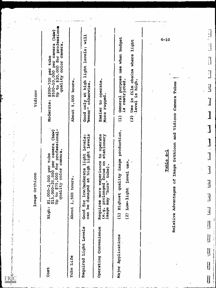
Table 4-1 lists the key characteristics of both camera
types. In most cases, 'educational usage has featured the
Vidicon camera because of its cost advantage, with a few of
the more well-financed institutions, with near-professional
facilities, using the Image Orthicon units.
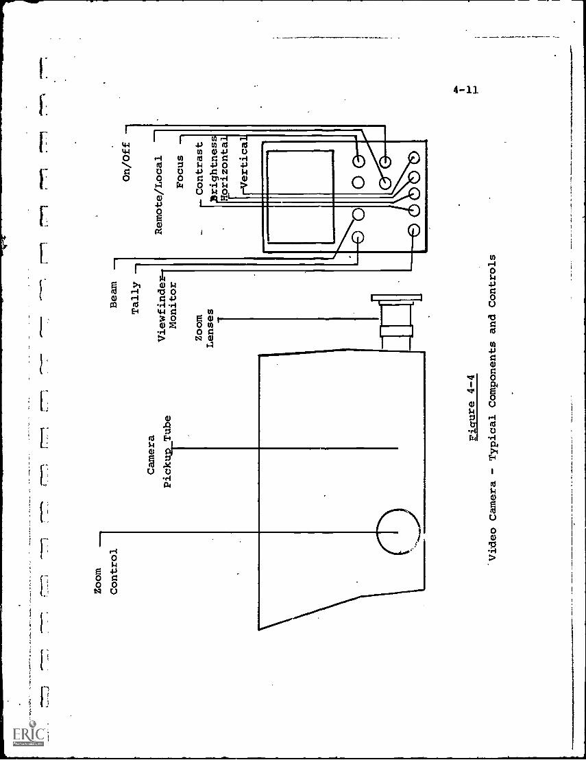
Fig. 4-4 illustrates the external components and controls
of a typical video camera, with vica-finder/monitor display
and zoom control. The view-finder is a Cathode-Ray Tube
monitor which allows the operat:: to see exactly what is being
Cos
t
Image Orthicon
High: $1,000-2,000 per tube
$15,000-25,000 per camera (b&w)
Up to $75,000 for professional-
quality color camera.
Vidicon
Moderate: $200-700 per tube
$500-10,000 per camera (b&w)
Up to $20,000 for professions
quality color camera.
Tube Life
About 1,500 hours.
About 5,000 hours.
Required Light Levels
Good for low/moderate light levels;
can be damaged at high light levels
Good only at high light levels; will
"smear" otherwise.
Operating Convenience
Requires more experience to operate
(e.g. prolonged focus on stationery
image may "burn" tube).
Major Applications
kow
nmew
*
Easier to operate.
More rugged.
(1) Highest quality image production.
(2) Low-light level use.
(1) General purpose use when budget
is restricted.
(2) Use in film chains where light
.level is high.
Table 4-1
Relative Advantages of Image Orthicon and Vidicon
Camera Tubes
Zoom
Control
,..
r77.
7.1
I -
-
Camera
Pickun_Tube
Beam
Tally --
Viewfinder-.
Monitor
Zoom
Lenses
1 On/Off --
Remote/Local
Focus
NO
INN
wr
- Contrast
Ifrightness
Horizontal
ertical
OD
0
Figure 4-4
Video Camera - Typical Components and Controls

4-12
photographed, while the zoom crank permits rapid transitionfrom long shot to closeup, and vice versa.
The electronic controls, it may be noted, resemble thoseof TV, which is natural since the electronic signal intowhich the image is converted-is designed to be compatiblewith a standard TV receiver. Thus, "focus", "contrast","brightness", "horizontal hold" and "vertical hold!' haveexactly the same functions as they do on a home TV 'set.
The configuration shown is that of a bladk-ind-whitevideo camera. For color, many of the components are triplicated,resulting in a much more complex and expensive unit. Typically,a color comera will incorporate a precision optical systemwhich takes the image from the camera lens'and splits it intothree parallel primary color-beams (red, blue and green).Three separate pickup tubes are used, each designed for peakefficiency over its own primary color spectrum, and each withits own scanning and signal generation electronic circuitry.The three signals are maintained independently throughoutwhatever transmission or recording facilities are involved,and recombined on the viewer's color TV receiver to form theoriginal image.
This redundancy of components, together with.the greatcare necessary to establish and keep the correct balance andproportion of the three color signals throughout the completesystem, is the reason for the substantial difference in thecost between monochromatic and color television.
4-2.a.1 Special-Purpose Scanners,
The "normal" video camera is designed to produce anoutput compatible with a broadcast TV signal (except for theRF carrier), and thus is most suitable for visual informationwith a relatively high degree of motion, i.e., equivalent toa motion picture film.
There are many applications, particularly in education,where visual information is static or has relatively little
r.
lt
4-13
motion. Examples are displays.of graphical or alphanumericdata, photographs, microfilm images, etc.
In these cases, both the scanning technique and theimage conversion tubes used for TV-compatible video arewasteful of bandwidth, and other special-purpose scanningsystems are used.
Facsimile, one of these special systems, is described inChapter 5. It is limited, however, to informatioh where theoriginal is in document form, and has no selective editingcapability.
More versatile is the storage or "scan converter" tube,and scanning systems which can be used in conjunction withit. The scan converter is essentially a Cathode-Ray Tubewhich displays an electrical signal on its face in a standardmanner, but with a long-persistence screen and with associatedelectronics that permits erasure and rewriting of either theentire image or selected portions, on command.
Thus, the scan converter can be used as a "frame grabber"or picture-freezing display, holding its image for any desiredlength of time. A video camera might be used to scan theimage in a single frame, transmitting this frame to a remotelocation. The viewer, for example, in a retrieval system,could read one page which remains motionless until replacedby a second page.
Although the standard TV system can also peform thisfunction, it would be inefficient, having to "reshow" thesame page 15,750 times per second to maintain the image. Witha stored-memory system, however, the picture need only beconverted once. During the time one viewer is looking at hisdisplay, the system can supply other fixed-frame displays to
many other viewers. An example of this type of frame-retrievalsystem is described in Chapter 11.
Complete memory systems, incorporating the scan convertertube, are available from Hughes Aircraft, and others, rangingin cost from $3,000 - $10,000. With suitable input/output
4-14
and control circuitry, they can form the basic storage and
editing component of many educational systems, such as
computer-aided-instruction, information retrieval, computergraphics and data communications.
4-2.b Secondary Storage Media Equipment
Much of the visual information which must be transmittedto remote locations is stored on media not directly compatiblewith the telecommunications system. If a school desires, forexample, to use a motion picture film on an instructional TVnetwork, the images stored in photographic form on the filmmust be converted to electrical signals for transmission.
The technique is similar to conversion of a live visualimage, except that special mounting and lighting provisions
are included to minimize the degradation involved in trans-ferring the information from one medium to another. If theoriginal medium is motion-pictUre film, a further require-
ment is that the speed at which the film moves through thereel while being viewed by a video camera be sychronizedwith the camera's scanning rate. This means that the 16frames per second film playback rate must be synchronizedwith the 15,750 frames per second TV scanning rate in such a
manner that the motion on the TV screen appears normal andlife-like.
Equipment to perform this film-to-video converstion istermed a "film chain", and consists of film (and/or slideor filmstrip) projectors optically linked to a video camera.When several projectors are linked with one camera, combina-
tions of.mirrors and prisms known as "optical multiplexers"
are used to admit only the desired projector beam into thecamera lens.
The costs of a film chain are from $3,000 -.$10,000 for
monochrome, and $10,000 - $50,000 for color.
Also available is equipment to perform the reverse
function, such as converting images stored on video tape to
fl
fl
it
it
4-15
film. These units play back the taped information into a
monitor screen, usually designed for high brightness. Afilm camera photographs the image from the face of the screen,again maintaining speed synchronism.
This technique was used in the early days of TV, beforevideo tape was developed,to produce "kinescope" filmrecordings of live TV broadcasts. Recent equipment, however,produces substantially better quality film than representedby those examples.
Black-and-white video-to-film recorders cost from $10,000 -
$20,000 while color units are in the $50,000 - $75,000 range.
4-2.c Auxiliary and Support Equipment
For any video studio facility which must operate under
flexible conditions, the basic camera and film chain equip-ment must be supported by a variety of auxiliary and controlcomponents.
Typical support equipment includes:.
(1) Video Switches - As shown in Fig. 4-5, video
signals may originate from a number of sources
such as video cameras, video tape recorders orfilm chains. All of these are connected into
the video switches where, by pressing the appro-
priate pushbutton, only the selected signal is
permitted to proceed through the system. In a
commercial TV broadcast, the director will
select'those images, in sequence, which he
believes will result in the most interesting
program.
(2) Audio Mixer - The audio mixer, illustrated
functionally in Fig. 4-6, accepts a variety of
audio inputs in a manner similar to the videoswitches. Most applications, however, require
the mixing (simultaneous transmission) of a
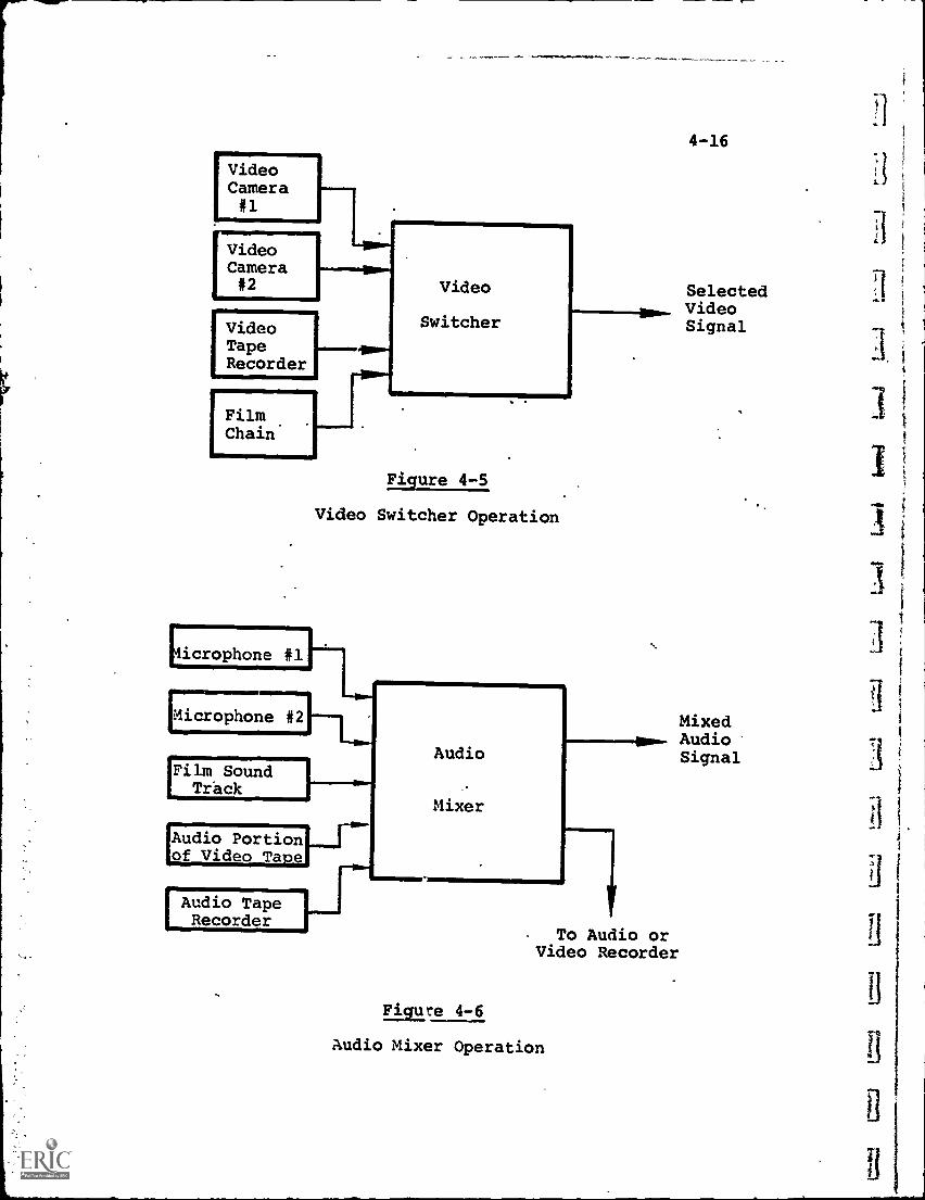
VideoCamera#1
MillMs
VideoCamera#2
VideoTapeRecorder
I FilmChain
Video
Switcher
Figure 4-5
Video Switcher Operation
4-16
SelectedVideoSignal
icrophone #1
MixedAudio
'Microphone #2
ow.Audio Signal
'Film SoundTr'ack
Mixer
'Audio Portionof Video Tape
IAudio TapeRecorder
To Audio orVideo Recorder
Figure 4-6
Audio Mixer Operation
4-17
number of audio signals rather than theselection of only one. For example, a paneldiscussion may feature several speakers, eachwith his own microphone and all voices mustbe heard, even when speakers are talking atthe same time. Thus, although the capability
to choose only one audio signal and exclude
others is present, this is not the normalmode of operation.
Both the video switches and audio mixer, in
addition to selecting signals, provide theability to balance the signals against eachother so that switching does not result inany disproportion.
(3) Video MonitorS - Theie are display units which
permit the studio operators to look at what is
being scanned by any camera (or other video
sourcerat any time, so that the desired selectioncan be made. They'also serve to indicate mal-function, if it occurs. The monitor unit is theequivalent of a TV receiver with the RF and
channel tuning sections omitted.
(4) Special Effects - Equipment is available to
produce a variety of special effects, such as:(a) Dissolve - which allows variation of the
camera output signal from full intensity
to zero, producing an image which fades
away (dissolves) or, conversely, fades
in from a blank screen.
(b' Insert or Superposition - which permits
inserting one image over another at any
designated location. The split-screen
effect is a variation of this.
4-18
(c) Wipe - permitting an image to be wipedaway sequentially, as, for example, dis-
appearing from left to right across thescreen.
(5) Lighting - Lighting equipment may range from abasic minimum package of two or three floodlights,with adjustable stands, to a very expensive com-plex of lights, filters and controls designedfor televising, for example, a costume play incolor where the various actors, costumes andportions of the set require individualillumination.
To illustrate the wide range of costs possible for atotal video studio package, Table 4-2 lists the componentsof four systems offered by Audiotronics Corp., designed forthe lower-cost educational applications, and three systemsoffered by RCA, which are closer to professional broadcastquality. The cost variations, from a low of about $2,000to a high of over $100,000, indicate that equipment isavailable for almost every budget.
4-3 Electrical-to-Visual Conversion
ViCeo electrical signals are most generally convertedback into visual form by ut;lizing a Cathode-Ray Tube (CRT)as the basic conversion device. A CRT is a vacuum tube withone end shaped in the form of a relatively flat surface (seeFig. 4-7), which may be either rectangular or round. Theinsien of this flat surface is coated with phosphorescentmaterial which 'emits light when struck by a high-energy beamof electrons.
.
At the narrow end of the CRT, an "electron gun" isprovided. This is a grOUp of components which include:
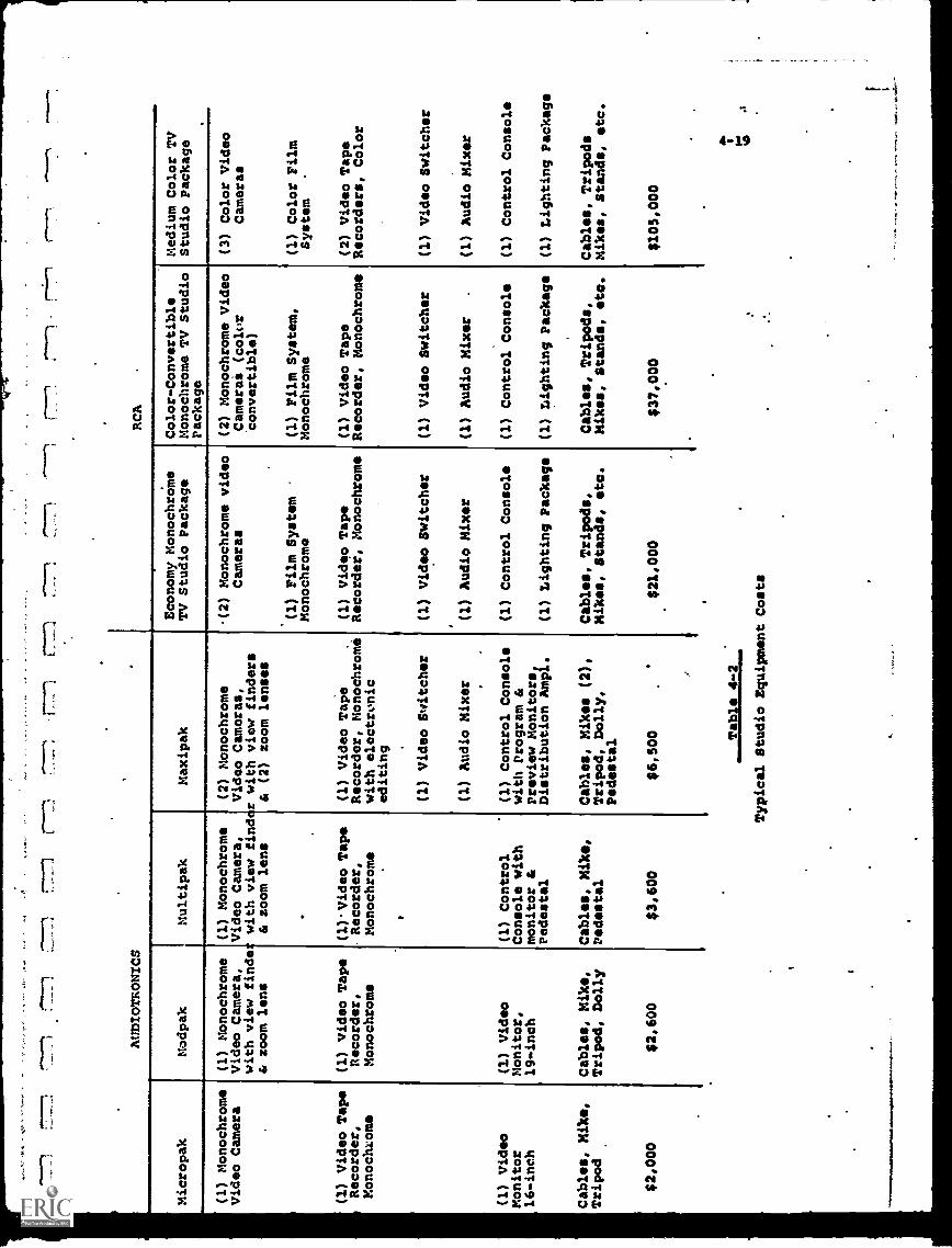
/=
AUDIOTRONICS
RCA
Micropak
Modpak
(1) Monochrome
(1) Monochrome
Video Camera
Video Camera,
with view finde
& zoom lens
(1) Video Tape
(1) Video Tape
Recorder,
Recorder,
Monochrome
Monochrome
(1) Video
Monitor
16-inch
(1) Video
Monitor,
19-inch
Multipak
Maxipak
(1) Monochrome
(2) Monochrome
Video Camera,
Video Cameras,
with view findcr with view finders
& zoom lens
& (2) zoom lenses
Economy MonochrOme
TV Studio Package
Color-Convertible
Monochrome TV Studio
Package
(2) Monochrome video
(2) Monochrome Video
Cameras
Camerai (color
Convertible)
(1) Film System
Monochromo
(1) Film System,
Monochrome
(1)Video Tape
(1) Video Tape
.(1) Video Tape
(1) Video Tape
Recorder,
Recorder, Monochrome Recorder, Monochrome Recorder, Monochrome
Monochrome
with electronic
editing
(1) Control
Console with
monitor &
Pedestal
Cables, Mike,
Cables, mike,
Cables, Mike,
Tripod
Tripod, Dolly
Pedestal
$2,000
$2,600
$3,600
(1) Video Switcher
(1) Audio Mixer
(1) Control Console
with Program &
Preview Monitors,
Distribution Ampl.
Cables, Mikes (2),
Tripod, Dolly,
Pedestal
$6,500 Table 4-2
Typical Studio Equipment Costs
(1) Video Switcher
(1) Audio Mixer
(1) Control Console
(1) Lighting Package
Cables, Tripod*.
Mikes, Stands, eta.
$21,000
(1) Video Switcher
(1) Audio Mixer
(1) Control Console
(1) Lighting Package
Cables, Tripods,
Mikes, Stands, eta.
$37,000
Medium Color TV
Studio Package
(3) Color Video
Cameras
(1) Color Film
System
(2) Video Tape
Recorders, Color
(1) Video Switcher
(1) Audio Mixer
(1) Control Console
(1) Lighting Package
Cables, Tripods
Mikes, Stands, etc.
$105,000
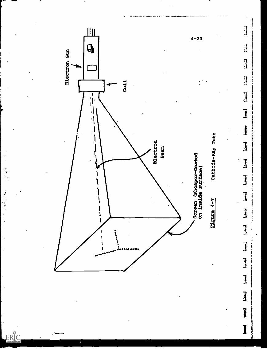
ME
NN
EN
..
Election Gun
wiP
m.1
11.
mom
*V
ow..
%.
Electron
Beam
Screen (Phospor-Coated
on inside surface)
Figure 4-7
Cathode-Ray Tube
Coil
bosii
Wk.)
t,..:m
.41,
7141
.mt
ip.f
orre
l4;
0014
(441
1104
6104
1104
,64
tin,g
alti
rlaN
gria
raiti
gliA
liffil
lodW
omid
iailo
.411
410.
1hah
-.14
t
0
A.
*11I
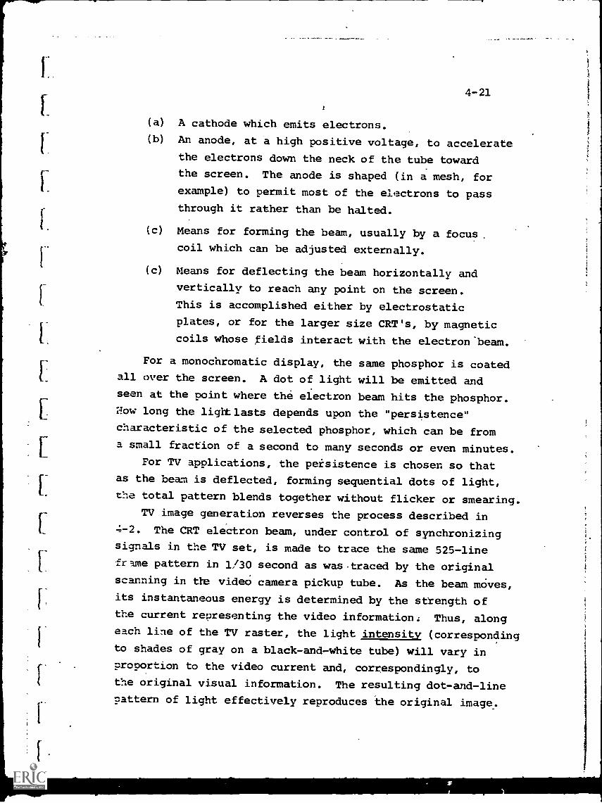
4-21
(a) A cathode which emits electrons.
(b) An anode, at a high positive voltage, to accelerate
the electrons down the neck of the tube towardthe screen. The anode is shaped (in a mesh, for
example) to permit most of the electrons to pass
through it rather than be halted.
(c) Means for forming the beam, usually by a focus,
coil which can be adjusted externally.
(c) Means for deflecting the beam horizontally and
vertically to reach any point on the screen.
This is accomplished either by electrostatic
plates, or for the larger size CRT's, by magnetic
coils whose fields interact with the electron beam.
For a monochromatic display, the same phosphor is coatedall over the screen. A dot of light will be emitted and
seen at the point where the electron beam hits the phosphor.l;ow long the light lasts depends upon the "persistence"
characteristic of the selected phosphor, which can be froma small fraction of a second to many seconds or even minutes.
For TV applications, the peisistence is chosen so that
as the beam is deflected, forming sequential dots of light,
the total pattern blends together without flicker or smearing.TV image generation reverses the process described in
4-2. The CRT electron beam, under control of synchronizingsignals in the TV set, is made to trace the same 525-line
irame pattern in 1/30 second as was .traced by the original
scanning in tha video camera pickup tube. As the beam moves,its instantaneous energy is determined by the strength of
the current representing the video information. Thus, alongeach line of the TV raster, the light intensity (correspondingto shades of gray on a black-and-white tube) will vary inproportion to the video current and, correspondingly, tothe original visual information. The resulting dot-and-line
pattern of light effectively reproduces the original image.
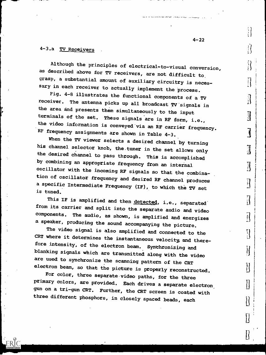
4-22
4-3.a TV Receivers
Although the principles of electrical-to-visual conversion,as described above for TV receivers, are not difficult to.grasp, a substantial amount of auxiliary circuitry is neces-sary in each receiver to actually implement the 'process.
Fig. 4-8 illustrates the functional components of a TVreceiver. The antenna picks up all broadcast TV'signals inthe area and presents them simultaneously to the inputterminals of the set. These signals are in RF form, i.e.,the video information is conveyed via an RF carrier frequency.RF frequency assignments are shown in Table 4-3.
When the TV viewer selects a desired channel by turninghis channel selector knob, the.tuner in the set allows onlythe desired channel to pass through. This is accomplishedby combining an appropriate frequency from an internaloscillator with the incoming RF signals so that the combina-tion of oscillator frequency and desired RF channel producesa specific Intermediate Frequency (IF), to which the TV setis tuned.
This IF is amplified and then detected, i.e., separated'from its carrier and split into the separate audio and videocomponents. The audio, as shown, is amplified and energizesa speaker, producing the sound accompanying the picture.
The video signal is also amplified and connected to theCRT where it determines the instantaneous velocity, and there-fore intensity, of the electron beam. Synchronizing andblanking signals which are transmitted along with the videoare used to synchronize the scanning pattern of the CRTelectron beam, so that the picture is properly reconstructed.
For color, three separate video paths, for the threeprimary colors, are provided. Each drives a separate electron.gun on a tri-gun CRT. Further, the CRT screen is coated withthree different phosphors, in closely spaced beads, each
Ant. RF.
Radio-
Frequency
Amplifier
RF
Channel +Selection
Tuner
IF
--7
777
--
Intermediate
Frequency
Amplifier
IF
Audio
Detector
Audio
Amplifier
Speaker
Video
Video
AMplifier
Video
Information
Synchr.
Signal
1111
1111
1111
1p
Deflection
& Synchronizing
Circuits
Cathode-Ray-Tube
Acceleration
(High Voltage)
Circuits
Figure 4-8
Functional Elements of a TV Receiver
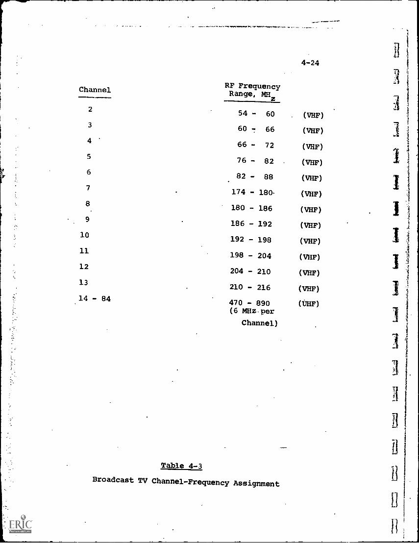
Channel
-
RF FrequencyRange, MHz
4-24
2 54 - 60 (VHF)
360 - 66 (VHF)
466 - 72 (VHF)
5 76 - 82 (VHF)
682 - 88 (VHF)
7174 - 180 (VHF)
8180 - 186 (VHF)
9186 - 192 (VHF)
10192 - 198 (VHF)
11198 - 204 (VHF)
12204 - 210 (VHF)
13210 - 216 (VHF)
14 - 84470 - 890 (tHF)(6 MHz.per
Channel)
Table 4-3
Broadcast TV Channel-Frequency AssignmentU
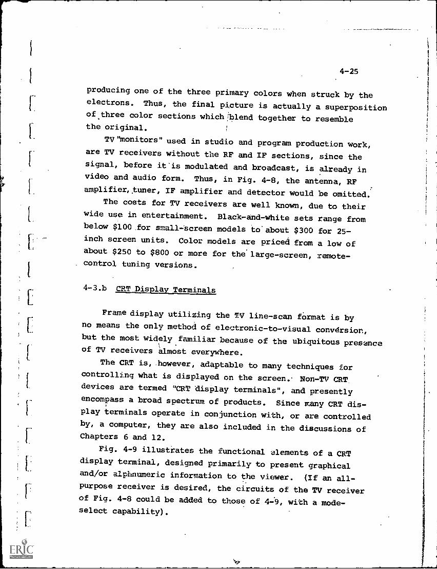
4-25
producing one of the three primary colors when struck by theelectrons. Thus, the final picture is actually a superpositionof.three color sections which!blend together to resemblethe original.
TV "monitors" used in studio and program production work,are TV receivers without the RF and IF sections, since thesignal, before it'is modulated and broadcast, is already invideo and audio form. Thus, in Fig. 4-8, the antenna, RFamplifier, tuner, IF amplifier and detector would be omitted.
The costs for TV receivers are well known, due to theirwide use in entertainment. Black-and-white sets range frombelow $100 for small-'screen models to'about $300 for 25-inch screen units. Color models are priced from a low ofabout $250 to $800 or more for the large-screen, remote-control tuning versions.
4-3.h CRT Display Terminals
Frame display utilizing the TV line-scan fOrmat is byno means the only method of electronic-to-visual convdrsion,but the most widely familiar because of the ubiquitous presenceof TV receivers almost everywhere.
The CRT is, .however, adaptable to many techniques forcontrolling what is displayed on the screen. Non-TV CRTdevices are termed "CRT display terminals", and presentlyencompass a broad spectrum of products. Since many CRT dis-play terminals operate in conjunction with, or are controlledby, a computer, they are also included in the discussions ofChapters 6 and 12.
Fig. 4-9 illustrates the functional elements of a CRTdisplay terminal, designed primarily to present graphicaland/or alphnumeric information to the viewer. (If an all-purpose receiver is desired, the circuits of the TV receiverof Fig. 4-8 could be added to those of 4-9, with a mode-select capability).
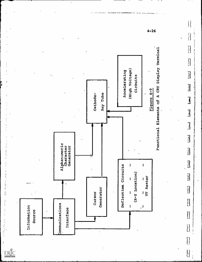
L...
Information
Source
Alphanumeric
Character
Generator
Cathode-
Ray.Tube
to.
Deflection Circuits
(X-Y Location)
Orr
TV Raster
Accelerating
(High Voltage)
Cirbuits
Figure 4-9
Functional Elements of A CRT Display Terminal
4-27
Information representing a graph or series of alphanumeric
characters arrives from the source through a communications
interface unit which provides the necessary decoding or
format transformation. The information is usually of two
kinds, (1) what to display (e.g., dot, ietter, number, symbol,
etc.), and (2) where on the CRT screen to locate it. Thelatter is either provided as, or converted into,"X" and "Y"
deflection voltages which swing the electron beam the
appropriate distance along both coordinates.
If a graph is drawn, the electron beam is swung to thepoint on the CRT screen where one end of the graph is located.A point of light appears. The beam is then deflected suc-
cessively through the path necessary to "draw" the graph onthe CRT screen.
For alphanumeric characters, each character could be
drawn as required by commanding the beam to, trace through the
required outline. This would be wasteful, however, of infor-
mation storage space at the source. It is more convenientto store, in the CRT terminal itself, a "character generator"
which is programmed, upon command, to force the CRT beam to
trace the shape of that character. Letters, numbers and
symbols are usually formed by a series of short "strokes"
which, together, appear to form the desired character.
Thus, to display the letter "6", a code for 6 is sent
to the character generator, while the desired location is sentto the deflection circuits. The output of the character
generator will be a series of varying voltages which will
produce short strokes of light on the CRT screen, combining
to form the shape of a 6.
By means such as this, any kind of visual display can
be presented, no matter how complicated. Although Fig. 4-9
shows a one-way "receiver only" terminal, by including
inquiry capability, the CRT terminal becomes a two-way device,
capable both of requesting and receiving information.
4-28
CRT display terminals presently on the market vary incost from about $2,000 for a minimal 2-way unit, up to$20,000 or more for models designed. for complex computergraphics applications.
4-3.c Image Projection
The.size and brightness of CRT displays are limited bythe tube itself. Since air is evacuated from the CRT, alarge tube means a very high total air pressure.on the out-side surface, which tends to crush the tube unless strong,thick glass is used. At present,. CRT screens with a maxi-mum viewable area of about 400-500 square inches are apractical limit, since larger CRT's would be excessivelycostly.
This results in no more than perhaps 25-40 viewers, orabout one classroom, being able comfortably to view a singledisplay. To alleviate this, image projection systems havebeen designed which enlarge and project the TV image to per-mit more viewers. Extreme examples are the closed-circuitdiSplays of sports events, such as championship prize fights,held in movie houses, where the TV image is projected ontothe large movie screen.
TV image projection systems are identical in the signalprocessing sections to standard TV receivers. The CRT, how-ever, is a small, high-voltage unit designed to produce a .
very bright image which can be projected onto a large motionpicture type screen by an optical projection system.
One system, known is the Schmidt system, is illustratedin Fig. 4-10. A high-intensity picture appears on thespecial CRT face. Light from the CRT is transmitted to a.spherical mirror and reflected in the reverse direction throughcorrecting lenses onto a screen.
Typical screen sizes can be from 6' X.8' to 15' X 20',with the screen located some 15-35 feet from the projector.About 50-150 viewers can view the screen in reasonable com-fort. Picture quality inevitably suffers some degradation.
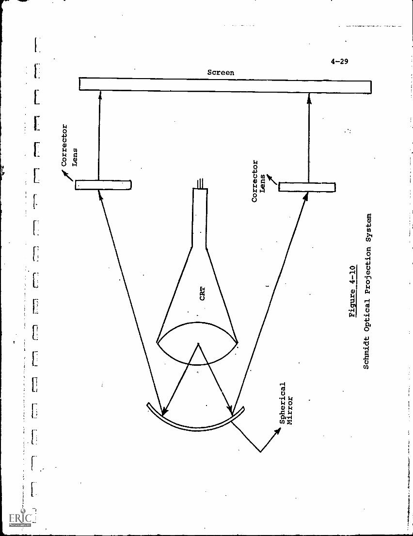
r-7.77.1
p."-n
r-1
rr,
r-1
r771
'Corrector
__(
Lens
Spherical
Mirror
Figure 4-10
Schmidt Optical Projection
System
co
fD
CD
4-30
The cost for such a projection system is about $3,000 -$4,000. The system isconsidered useful where picturebrilliancy, distortion and resolution can be sacrificed tosome extent to the ability to serve more viewers.
4-4.a Video Recorder/Players
To date, the only method of storing and playing backvideo information directly without requiring intermediatemedia transformation, has been the use of video magnetictape.
The video tape recorder/player was introduced to the TVbroadcasting industry in 1965, and equipment in a wide rangeof sizes, capabilities and prices has become available sincethen.
The basic concept of the video tape recorder is identicalto that of the audio recorder, namely, the conversion of thevisual information into electrical currents and the use ofthese currents to structure the magnetic coating on a stripof tape. The key difference, however, (and a major one) isin the volume of information to be stored per unit of time.The audio recorder must store signals with a bandwidth ofperhaps 20 KHz, while the video unit must store some 200 -300 times that quantity.
Theoretically, this might be accomplished by "writing"on the same tape at a proportionally higher tape speed. Theenormous tape speeds required, in the order of thousands ofinches per second, makes this approach mechanically unfeasible.
The solution was a design in which both the magnetichead(s) and tape move at a high speed relative to each other.Four heads are eqUally spaced around a rotating wheelpowered by an electric motor. The wheel brings each headtransversely down the tape, while the tape itself is movingrelatively slowly in a direction parallel to the axis of the
it
H
4-31
head wheel. The tape motion 's designed to be just fast
enough so that each head can write one magnetic track
traversely across the tape. (Actually the track is slightly
skewed from the transverse due to the tape motion; by the
time the head has reached the bottom of the tape, it hasmoved a little.) The next head on the wheel records another
track adjacent to the first, and each quarter-revolution of
the wheel therefore continues to record another track.
Because of the four heads, this type of recording is
Called "quadruplex". Quadruplex video recorders, using 2-inch wide tape, have become standardized for professional
TV broadcast use. Although providing high-quality video
storage, with no 'noticeable loss of visual information, they
are expensive, running from $20,000 up to about $100,000 fora color unit.
More recently, a second recording technique termed
"helical scan" or "Slant-track" recording Was been developed,
permitting the manufacture of.smaller, lower-cost video tape
recorders, more suitable to educational budgets. The methodof recording is somewhat similar to the principle long used
in facsimile of combining rotary with linear motion to
produce a helical scanning or recording pattern.
The magnetic tape is wrapped around a large scanning
drum containing one or two magnetic heads which rotate on a
high-speed disc inside the drum. The tape is moved just fast
enough so that, in conjunction with the head movement, a
series of tracks are recorded slant-wise across the tape.
These are relatively long compared to the short, nearly-
tra averse tracks of the quadruplex recorder.
Usually the combination of tape width, number of heads,
head speed and tape speed are chosen so that the time duration
of one slant track is exactly equal to one(or some submultipleof a)TV frame. This makes the recorder more compatible with
4-32
with playback into a TV receiver. It also provides "stop-frame" amd "frame-grabbing" capability by, in essence,farming a reiterative playback of a single track.
Helical-scan recorders are available at modest prices,from below $1,000 to about $15,000. They come in a varietyof tape widths (1/2-inch to 2 inches), tape speeds, reelsizes and performance characteristics.
The major problem with helical-scan recorders, unlikethe more professional quadruplex units, is their lack ofstandardization. Not only can tapes from one manufacturer'srecorder usually notl)e capable of playback by anothermanufacturer's unit, but it is not unusual to encounter thisincompatibilicy between different recorders of the samemanufacture and model.
This highly undesirable featute, not yet remedied,drastically limits the interchange of program tapes, andincreases the cost of educational programming.
Not all helical-scan recorders are acceptable for broad-cast applications, since the FCC sets technical standardswhich these units may not meet. No such standards are in
.force for closed-circuit, cable or other non-broadcast use.Costs for the blank, unrecorded magnetic tape range from
$20-$30 for a 1/2-hour, 1/2-inch size to several hundreddollars for the 2-inch wide professional quality reel.5
4-4.b "Home" Video Recorder /Players
The video recorder/players described in 4-4.a can also,of course, be utilized at the receiving and viewing site.Because of their high cost, however, the primary componentof interest to the user is the "home" unit.
Within the last two or three years, an exceptionaldegree of interest (and publicity) has been generated withrespect to "home" video recorders, by which is meant.:
LI
4-33
(1) A relatively low-cost unit capable of playing
back-stored aural/visual material through a
standard TV receiver, using the receiver screen
as the display.
(2) A modular, easily handled package for the program
material, permitting convenient use by the
general public (e.g., the reel threading and
handling requirements of a professional video
tape recorder would not qualify). Currently,
the modules either in use or under development
include cartridges, cassettes and discs.
In some cases, the home unit also can record material,
such as an off-the-air TV program recorded electrically
through signals taken from within the TV receiver, or optically
with the addition of a video zamera. The recording function,
however, generally is subsidiary to that of playback, which
permits access to prerecorded programs from a wide variety
of sources, and allows the viewer to select the desired
subject material from available "libraries".
If the home video recorder/player and, even more
importantly, the program modules, can be priced attractively,
presumably the entire U.S. population is opened as a potential
market for buying or renting A/V program modules, in much
the same way as it currently buys audio discs and tapes.
Educational applications are a particularly interesting portion
of this market, since the requirement for wired or broadcast
networks could be eliminated in many cases, and the programs
delivered directly to the end-user. As an example, cor-
respondence school courses might naturally use A/V cartridges
rather than the printed texts currently utilized to teach
students.
Because of this vast potential, a number of companies
are developing home video devices. Announcement of equip-,,opp
ment characteristics and prices have been plentiful, but no
mass consumer sales have yet occurred.
4-34
Not only are many companies developing products, butunfortunately, the technical approaches of the major competitorsare different, and incompatible with each other. This isreminiscent of past compatibility problems in color TV, andthe 33-1/3 vs. 45 rpm battle in phonograph records. Evenwhere the technical approach is thesame, such as in videotape recording, there is no accepted standard amongmanufacturers with respect to critical features such as tapewidth, cassette/cartridge size and type, performancecharacteristics, etc.
This lack of standardization acts as a barrier to useracceptance. Together with the fact that development is stillin process for most announced systems, the result is thathome video'recorders remain a future, rather than a present,educational tool, although undoubtedly one of great significance.
Currently five technical approaches are vying for aportion of the mass A/V market. These include:
(1) Video Tape Recording (VTR)(2) Electronic Video Recording (EVR)(3) Sele'tavision
(4) Video Disc Recording
(5) Film-to-TV Conversion
A brief description of each of these approaches isprovided below. Tables 4-4 and 4-5 list, comparatively,the key features and relative advantages and disadvantagesof each system. It should be noted that in many cases thedata are based on manufacturers' future estimates ratherthan on equipment now in production.
4-4.b.1 Video Tape Recording (VTR)
This approach retains video magnetic tape as the basicstorage /playback medium, and is therefore similar in conceptto professional and institutional applications now in use.
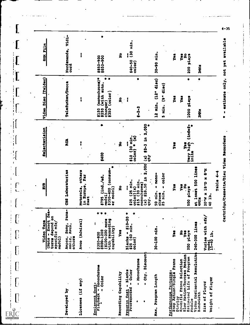
% Developed by
Video Tape
EVR
Selectavision
Video Disc (Teldec)
SMM Film
(Note - Exact fea-
tures depend 'on
specific mfr/
model)
Ampex, Sony, Pana-
sonic, Avco,
others
CBS Laboratories
RCA
Telefunken/Decca
Nordemende, Vidi-
cord
Licenses (if any)
Avco (Admiral)
Motorola, others
in Europe, Far
,O
D O
MM
OD
East
Eouipment Cost:
Playback - Monochrome
$350-800
$150 (monochrome)
$850-900
Color
$800-1200
*($100-200 more
with recording
capability)
$795 (ind./sd.
model)
$350-400 (consum-
er modal)
$400
$250 (with auto.
changer)
$350 (color)
$850-900
Recording Capability
Yes
No
No
No
No
Program Cost - Blanks
Blanks - $10-20 *
NO
ND
VI
MO
D
Prerecorded - Color
$25 (60 min.
$25 (25 min.
$10 (30 min.
$40 -SO (30 min.
color)
color)(x)
color)
(x)
color)
- Monochrome
$15 (30 min.
monochrome)
$-2-3
- Qty. Discoun
(x) $18.50 in 2,000
qty.
(x) $2-3 in 2,000
qty
Max. Program Length
30.100 min.
50 min. - mono-
chrome
12 min, (12" disc)
30-90 min.
25 min.
color
S min. (9" disc)
Performance Featuross
Stop Action/Single Frame
Yes
Yes
Yes
Yes
Yes
Display
Specific Frame Selection
No
Yes
Yes
Yes
Slow Motion/Reverse Motion
Yes
No
Yes
No
Estimated Life of Program
Module
Video Horizontal Resolutib
200 plays
240-300 lines
500 plays
at least 500 lines
Very high (indef-
inite
)
1000 plays
200 plays
DUndwidth
4MHs
31Bis
3Mlis
Size of Player
Weight of Player
Varies with mfr/
model
15-40 lb.
20"W x 18"D x 8"11
40 lb.
Table 4-4
Cartridge/Cassette/Disc Video Recorders
- estimate only, not yet available
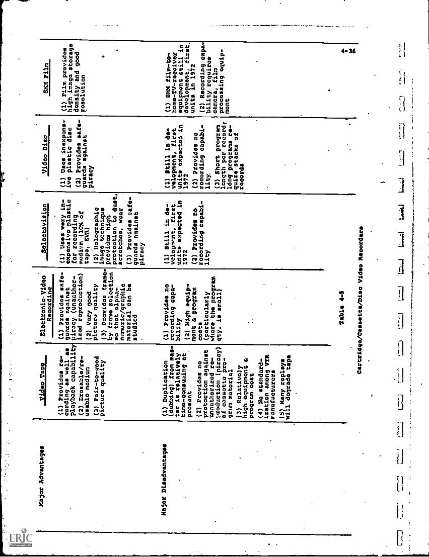
Major Advantages
Major Disadvantages
Video Tape
(1) Providos re-
cording as well as
playback capability
(2) Erasable/re-
usable medium
(3) Fair-to-good
picture quality
(1) Duplication
(dubbing) from mas-
ter is relatively
time-consuming at
present
(2) Provides no
protection against
unauthorized re-
production (piracy)
of cassette pro-
gram material
(3) Rolativo'y
high equipment &
program cost
(4) No standard-
ization among VTR
manufacturors
(S) Many replays
will degrade tape
'
Electronic. Video
Recording
(1) Provides safe-
guards against
piracy (unauthor-
izod reproduction)
(2) Very good
picture quality
(3) Provides ftame-
by frame selection
so that alpha-
numeric/graphic
material can be
studied
(1) Provides no
recording capa-
bility
(2) High equip-
ment & program
costs
(particularly
whore the program
qty. is small)
Table 4-S
Soloctavision
(1) Um vary in-
expensive plastic
for recording
medium (10% of
tape, EVR)
(2) Holographic
image tochnique
providos high
protection to dust,
scratches, wear
(3) Provides safe-
guards against
piracy
(1) Still in de-
volopmant, first
units expectedin
1972
(2) Provides no
recording capabi-
lity
Cartridgo/Cassatta/Dise Vida* Recorders
-L=
J1.
z..;1
Lok
i
Video Disc
(1) Uses inexpens-
ive plastic disc
(2) Provides safe-
guards against
piracy
Cl) Still in de-
velopment, first
units expected in
1972
(2) Provides no
recording capabi-
lity.
(3) Short program
length per records
long programs re-
quire stacks of
records
...
SMX Film
(I) Film provides
high imago storage
density and good
resolution
(1)
81.01. film-to-
home-TV-receiver
equipment still in
development, first.
units in 1972
(2) Recording capa-
bility requires
camera, film
processing equip-
mont
,
44.1
4-37
The recording playback equipment, however, and to some extentthe tape itself, are miniaturized and designed for a costlow enough to be attractive to the mass consumer market.
Ampex, -Sony, Panasonic and Avco (Cartrivision subsidiary)have, among others, announced both recorder/players andcartridge or cassette modules for this market. As noted above,the products of these companies are not designed to commonstandards, so that a cassette for one system cannot be playedback through another. Consequently, the first column ofTable 4-4 represents a range of values covering the spectrumof all manufacturers' products.
Video tape recording is uniqUe among the five approacheslisted in permitting convenient home recording as well asplayback. Naturally, the manufacturers of video tape equip-ment stress this advantage, as well as the erasibility and
reusability of the tape. Proponents of.other approaches notonly downgrade the need for recording by the user, but pointout that this very quality permits unauthorized reproductionand piracy of copyrighted program material, of the type nowplaguing the audio disc and tape industry.
Figure 4-11 illustrates all of the steps required to
produce mass quantities of preredorded tape and replay themthrough the home TV receiver. The original A/V material,whether live, on film or video tape (probably non-compatible) ,
is scanned and recorded on a video tape "master ", designed
to resist wear during the process oftlubbing", i.e., producingduplicates from the master.
At present, dubbing is relatively slow, increasing thecost of the prerecorded tape modules. Irprovement in rapidduplication of multiple tapes is under development by anumber of manufacturers.
Once'duplicated and packaged into the appropriatecartridge or cassette, the program is made available through
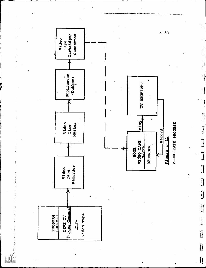
PROGRAM
SOURCES
LIVE TV
(Video Camera)*
Film
Video Tape
1111
.11
Video
Tape
Recorder
Video
Tape
Master
rEm
me.
4.10
.
HOME
VIDEO TAPE
PLAYER
RECORDER
DupliCator.
(Dubber)
Arm
smIM
OIM
EM
Mam
MO
WIN
ININ
I
1Record
Figure 4- 11
TV RECEIVER
VIDEO TAPE PROCESS
L=.!
t
Video
Tape
Cartridge/
Cassettes
4-39
the normal distrubution outlets (plus, for educational.appli-
cations, perhaps, new outlets such as schools and libraries)
and can be played back at any location where there is a TV
receiver.
Since Table 4-4 lists a composite of many VTR systems,
it may be of interest to examine, more specifically, the
characteristics of a single manufacturer's VTR equipment.
For this purpose, Ampex's "Instavideo" unit was selected,
since Ampex claims this to be the smallest cartridge-loading
video system in existence.
Table 4-6 provides the major Instavideo featuies,
extracted. from Ampex specification data.
4-4.b.2 Electronic Video Recording (EVR)
Of the five systems described, the'Electronic Video
Recording (EVR) process, developed by CBS Laboratories, is
the first to market, having delivered playback equipment to
institutional users within the last year.
EVR uses a combination of photographic and electronic
techniques. The source information is co-.verted into electrical
s:;_gnals by a scanning process ( see Fig. 4-12), similar to
that of broadcast TV or video tape recording, but in this
case the signals vary the intensity of a beam of electrons
within a vacuum chamber. The beam is formed by an "electron
gun" not unlike that in the neck of a Cathode-Ray Tube.
Instead of being focused on a CRT screen, however, the beam
is moved over a special, high-resolution photographic film..
The varying energy and tne scanning motion of the beam combine
to expose the film in a pattern analagous to the picture at
the source.
The beam recording produces the "master" EVR negative.
This negative'is then used in conjunction with a high speed
photographic contact printer to produce multiple positive
copies, or "prints", on silver halide film, which are then
packaged in cartridges.
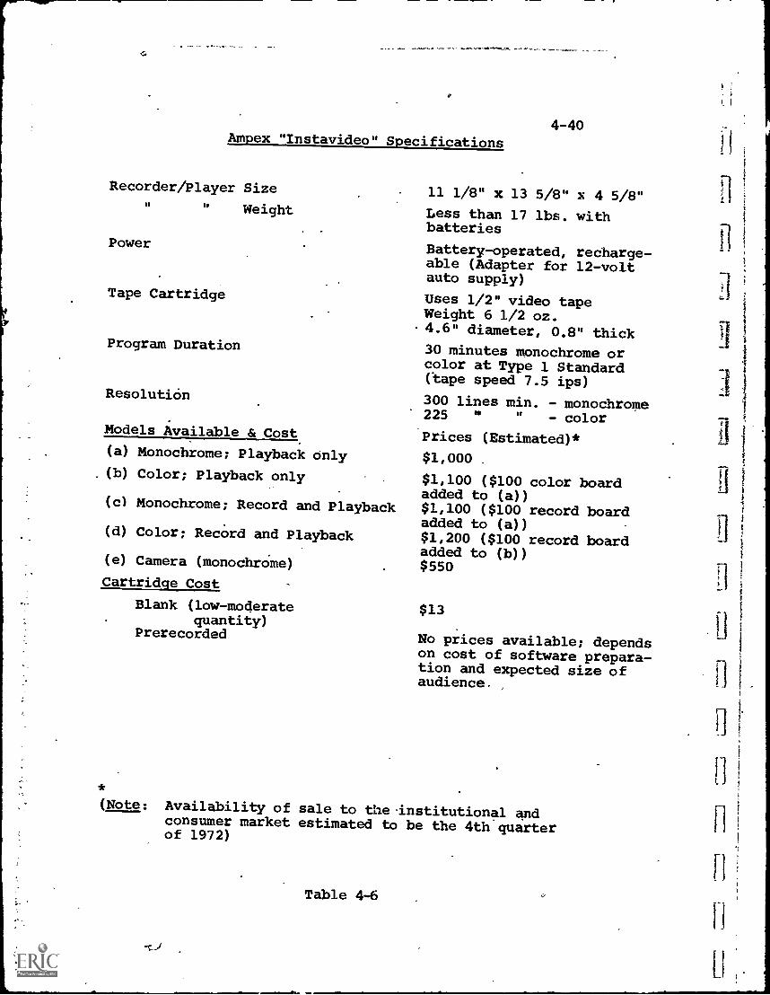
Ampex "Instavideo" Specifications
Recorder/Player Size
Weight
Power
Tape Cartridge
Program Duration
Resolution
Models Available & Cost.
(a) Monochrome; Playback Only(b) Color; Playback only
(c) Monochrome; Record and Playback
(d) Color; Record and Playback
(e) Camera (monochrOme)
Cartridge Cost
Blank (low-moderatequantity)
Prerecorded
4-40
11 1/8" x 13 5/8" x 4 5/8"
Less than 17 lbs. withbatteries
Battery-operated, recharge-able (Adapter for 12-voltauto supply)
Uses 1/2" video tapeWeight 6 1/2 oz.
-4.6" diameter, 0.8" thick
30 minutes monochrome orcolor at Type 1 Standard(tape speed 7.5 ips)
300 lines min. - monochrome225 " " - color
Prices (Estimated)*
$1,000 .
$1,100 ($100 color boardadded to (a))$1,100 ($100 record boardadded to (a))$1,200 ($100 record boardadded to (b))$550
$13
No prices available; dependson cost of software prepara-tion and expected size ofaudience.
(Note: Availability of sale to the-institutional andconsumer market estimated to be the 4th quarterof 1972)
Table 4-6
II
1
t_
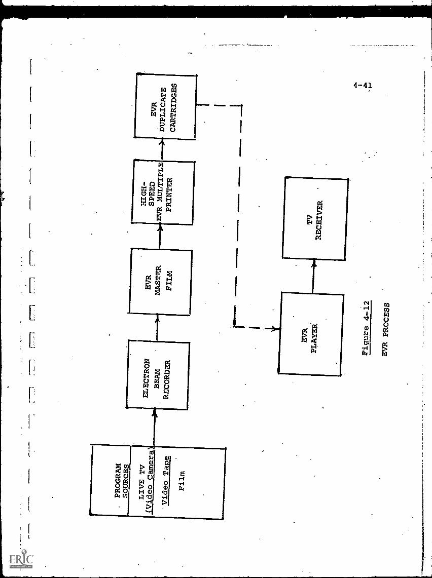
.PROGRAM
SOURCES
LIVE TV
(Video Camera
Video Tape
Film
ELECTRON
BEAM
'
RECORDER
EVR
MASTER
FILM
$HIGH-
SPEED
EVR MULTIPLE
PRINTER
Figmre 4-12
EVR PROCESS
EVR
DUPLICATE
CARTRIDGES
...m
ilIM
MIM
O
4-42
The EVR cartridge film is dual-tracked, storing twoadjacent rows of visual frames together with two parallelmagnetic-stripe sound tracks. For monochrome programs, '
each Visual track may carry independent information, result-ing in a maximum playing time of 50 minutes for the standard7-inch diameter EVR cartridge. For color, one visual framecarries "luminance" information while the adjacent framecarries coded color, or "chroma" information, so that only25 minutes playing time is available from the same sizecartridge.
Since information is stored on a frame-by-frame basis,as on motion picture film, and since also there are synchronizingsignals stored, the EVR system lends itself to "selected frame"applications such as calling for pages from a book. This isparticularly attractive for educational programs involvinginformation storage and retrieval. The 180,000 individualframes (monochrome) stored on one EVR cartridge are, forexample, equal to 600 volumes of 300 pages each, if one pagecan be legibly reproduced in a single frame.
CBS claims exceptionally good quality reprOduction, dueto the electron beam recording process. With a beam diameterin the order of 0.0001 inch, and very fine grain emulsion forthe master, the resolution of, the recording process, includ-ing the losses in duplicate printing, is claimed to be betterthan standard TV broadcast.
Because of the complex vacuum and electronic equipmentnecessary to produce an EVR master negative, no recordingcapability is possible at the playback site. "Software" orprogram production (i.e., prerecording on an EVR cartridge)is, therefore, strictly a factory operation. Indeed, formost educational applications, where it is impractical toset up a live production at the EVR factory, it may be neces-sary to record the program first on another medium, such asfilm or video tape, which is then sent to the EVR processing
4-43
plant for transformation and duplication. This is somewhatawkward and costly, and, in addition, partially negatesEVR's good reproduction qualities, since some degradationwill take place. during translation.
The EVR player unit containe a small CRT scanner whichelectronically scans the images on the film in the cartridgeas it is moved past the scanning area. The scanning signaloutput is designed to resemble a TV video signal. Thisvideo output modulates an internal RF carrier set at anydesired TV receiver channel frequency (probably a channelnot assigned in that geographic area). Thus, the outputfrom the EVR player resembles a broadcast TV program inevery respect and can therefore be connected to the antennaterminals of any TV receiver.
Costs for the EVR player and prerecorded cartridges are,at this writing, relatively high for acceptance by a massmarket. (The player costs about $800, with :10;or programsaveraging about $1 per minute). For this reason, initialsales are aimed at the institutional and educational markets.By 1972-73, the player cost is targeted to drop to perhaps$350-$400, at which time the consumer market may becomepredominant.
(Note- At the end of 1971, CBS announced that it waswithdrawing from all manufacturing phases of the EVR market,concentrating only in software (program) production.Presumably the manufacturing of players and prerecorded.cartridges would be licensed and taken over by others, butthe accompanying indications that the video cassette marketwas developing more slowly than expected may make the abovetarget dates optimistic.)
14-4.b.3 Selectavision
Selectavision is the trade name given to the systemunder development by RCA, which, technologically, is themost radical, utilizing laser holography. The player unit
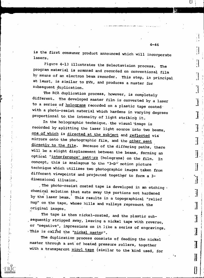
4-44
is the first consumer product announced which will incorporatelasers.
Figure 4-13 illustrates the Selectavision process. Theprogram material is scanned and recorded on conventional filmby means of an electron beam recorder. This step, in principalat least, is similar to EVR, and produces a master forsubsequent duplication.
The RCA duplication process, however, is completelydifferent. The developed master film. is converted by a laserto a series of holograms recorded on a plastic tape coatedwith a photo-resist material which hardens in varying degreesproportional to.the intensity of light striking it.
In the holographic technique, the visual-image isrecorded by splitting the laser light source into two beams,one of which is directed at the subject and reflected viamirrors onto the photographic film, and the other sentdirectly to the film. Because of the differing paths, therewill be a slight displacement between the beams, forming anoptical "interference" (holograms) on the film. Inconcept, this is analagous to the "3-1)". motion picture
technique which utilizes two photographic images taken fromdifferent viewpointd and projected together to form a 3-dimensional illusion.
The photo-resist coated tape is developed in an etchingchemical solution that eats away the portions not hardenedby the laser beam. This results in a topographical "reliefmap" on the tape, whose hills and valleys represent theoriginal images.
The tape is then nickel-coated, and the plastic sub-,sequently stripped away, leaving a nickel tape with reverse,or "negative", impressions on it like a series of engravings.This is calAd the "nickel master".
The duplication process consists of feeding the nickelmaster through a set of heated pressure rollers, togetherwith a transparent vinyl tape (similar to the kind used, for
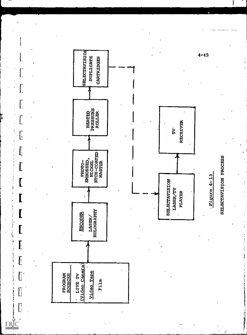
1-7-1!"-
r""li
Pool
P141
r""1-1
PROGRAM
SOURCES
LIVE TV
(Video Camera)
ENCODER
PHOTO-
SELECTAVISIO
Video Tape
LASER/
HOLOGRAPHY
EMBOSSED,
NICKEL
ETCH-COATED
__low,_HEATED
PRESSUgE
ROLLER
h"---**
DUPLICATE
CARTRIDGES
Film.
MASTER
SELECTAVISION
LASER/TV
PLAYER
Figure 4-13
SELECTAVISION PROCESS
"-"*
".42
,440
5414
04.,4
,',4<
-44.
-.A
4,44
.414
4.40
44.0
.:$44
44..4
,4,
TV'
RECEIVER
41.1
0411
4014
.1.
sis
U1
4-46
example, to wrap meats in a supermarket) of similar dimensions.
The holographic engraving on the nickel master, due to theaction of the pressure rollers, are embossed on the smooth
surface of the vinyl, prolucing a duplicate "positive".
This is then packaged in the Selectavision Cartridge.
This use of very low cost vinyl stock for the dupli-
cates is a key feature of Selectavision. Estimates are that
the cost of the raw vinyl would be about $0.06 for a half-hour cartridge. Furthermore, the nickel master can be used :
for thousands of "prints" without loss of quality, and the
duplication time can be very short, since the embossing
technique does not involve the time delay inherent in photo-
graphic, optical or'magnetic response characteristics of
various materials (as do EVR and video tape).
Thus, as shown in Table 4-4, RCA's present estimates
are that prerecorded cartridges, in quantity, can be sold inthe $2-3 range. If confirmed in practice, this is a great
advantage of Selectavision.
Since the optical interference patterns of holograms
require "coherent" light (extremely "pure" or, technically,
single-frequency) to produce good resolution, and the most
practical source of coherent light is the laser, this is whyRCA uses the laser-holographic technique for recording. In
general, the reverse is also true, that holograms require lasersto be read out. Thus, the Selectavision player also incorporates
a laser for playback.
This is accomplished by passing the coherent beams from
a low-powered laser in the player unit through the vinyl tape
hologram. The image is reconstructed (with the two interference
images superimposed back together) and projected to a Vidicon
TV camera which scans and converts this image into an electrical
form compatible with the TV receiver.
is
f.
C
4-47
The properties of holograms are such that Selectavision
claims further advantages. First, holograms contain all theinformation needed to reconstruct images throughout theirstructure. Thus, if the vinyl tape is slit to half its
thickness, no picture content will be lost. This property,
at least in theory, makes the tape relatively immune to
scratches, wear and tear, etc.
Secondly, as the holographic pattern or the tape is
scanned, the image projected from one hologram fades out as
that of'the next hologram fades in. This overlap and super-
imposition takes pface regardless of the position of the
tape, so that there is no need for synchronism between the
tape motion and'the camera scanning rate. This permits
motion at any speed, slow motion, and single-frame stop-action.
In summary, RCA claims for Selectavision very low
program cost, excellent wear characteristics and flexibilityof viewing mode. These are significant features, but the
proof awaits volume production of Selectavision players and
cartridges, currently estimated for 1972-73.
4-4.b.4 Video Disc
The development of a video disc, similar in many
respects to the present audio version, is currently under
way in Europe through a joint effort of Telefunken andBritish Decca (TelDec). Production versions of players and
discs are targeted for the European market by 1972.
The TelDec video disc is made of thin plastic foil,
and is designed to deliver a picture to a TV receiver screen
with a horizontal resolution of 250 lines. This is slightly
inferior to standard TV broadcast quality.
A new method of recording grooves and ridges on the
disc has been developed, in order to achieve the 200-fold
increase in storage of information necessary for video images.
Correspondingly, a new type of "pick-up" is required in the
playback unit, which translates the mechanical variations on
4-48
the disk into electrical signals, The TelDec player utilizesa sensitive pressure transducer which does not ride in thegroove walls, as in a phonograph, but senses the vaxiationsin the surface of the disc.
Rather than a turntable, the disc is driven by a centralcarrier in the player and rotates above a-stationary plate atspeeds of 1000r2000 rpm. A thin cushion of air is formed betweenthe disc and the plate, which has the effect of stabilizingdisc motion.
For each single.revolution of the disc, the pick-up armis mechanically coupled so that it moves over the surface ofone groove. This corresponds to one picture frame, so that
.
one 360° disc revolution permits presentation of one -frame onthe TV screen. Thus, for the U.S. broadcast standard of 30TV frames per second, the disc would revolve at 30 revolutionsper second, or 1800 rpm. Since each groove is a completeframe, stop-frame and random access frame selection arepossible.
The anticipated advantages of the TelDec disc are lowcost for the_plaver and discs. Production prices, as shownin Table 4-4 are estimated at'$150 for a one-disc monochromeplayer and in-the order of $2-3 per disc.
A disadvantage is that the discs, as presently designed,do not offer much playing time. An 8-inch diameter discprovides about 5 minutes, and a 12-inch disc about 12 minutes,of program time. Longer programs can be provided by stackingdiscs in an automatic changer mechanism, similar to phonographrecord players, but this feature is bound to draw adversecomment.
The initial TelDec demonstration models have been mono-chrome versions. Color models are expected by the time initialmarketing takes place.
For short A/V programs, up to the 12-minute maximum, theanticipated low cost of player and discs may hold some attrac-;tion. As in EVR and Selectavision, "masters" must be preparedin a factory processing facility, which would tend to inhibit.
4-49
educational applications where local program preparation andshort "turnaround" times are desirable.
4-4.b.5 Super 8 MM Film-to-Video
Super 8 MM film-cartridges are not in themselves acompetitor to home video recorders since they require a sep-arate projector and screen, and normally do not operatethrough a TV receiver.
However, two European firms,_Nordmende (Germany) andVidicord (England), have developed film-to-TV convertersthat can play Super 8 MM movies through a standard TV set.These systems have been demonstrated in trade expositions inEurope but are not yet available for sale.
The Nordmende converter carries an estimated sellingprice of $850 (color), while the Vidicord unit is priced at$888 (monochrome). Cartridge costs are estimated at about$1.20 a minute.
The_ advantages of the film -to-TV conversion are some-what problematical. The need for a darkened room is eliminated,which is helpful for note-taking and classroom discipline inan educational environment. Further, the conversion permitsdistribution-of the TV signal to a 'number of remote receiversso that several classrooms, for example, can view the picturesimultaneously. Whether these justify the purchase of aconverter in the near-$1000,price range, particularly whenplayback can be accomplished more directly and with better
resolution through an 8 MM projector, is difficult to determine.Super 8 MM cartridges are not standardized and generally
can be played back through only one MianUfactUrer's projector.This added burden makes the acceptance of film-to-TV conversionequipment even more dubious.
4-50,
4-4.b.6 Impact of Home Video Recorders on Education
The impact of the "home video recorder" upon educationis difficult to assess. Certainly,= instructional, training andeducational programs in cassette/cartridge/disc
form will beavailable, and probably in quantity starting in 1972-74. Theaudience which is interested can select material as desired,view (and review) it at home, and with convenience. How manywill take advantage of the opportunity will depend on manyfactors (e.g. motivation, progkam quality, cost, etc.), but asubstantial positive stimulus is a reasonable expectation.
For the mass consumer audience, the primary reason topurchase and use home video equipment will be, if past historyis any indication, the desire to extend the available spectrumof entertainment.
Educational applications, however, may bea large enough secondary motivation to be of significance,even on an informal,
individualistic basis.In terms of formal, institution- directed- education, the
home video recorder represents a more convenient and, possibly,less expensive method of distribution of A/V information. Thisis true because of the resent availabilit of large numbers ofTV receivers, and not because of any new educational techniquesprovided by the equipment. Thus, more flexible and cost-effectiveprogram distribution to a larger audience is probable, but itis difficult to perceive any "cassette revolution" in terms ofeducational methodology.
4-5 Signal Conditioning_
Almost all of the comments on audio signal conditioningand modulation techniques (3-4.1 and 3-4.2) are also validfor video signals, and therefore, will not be repeated here.Since much wider bandwidths are encountered with video,however, equipment to perform the same functions is usuallymore complex and costly.
r.4-51
TV broadcasting utilizes AM for the video inforMation.and FM for the audio. The arguments in favor of FM are aspertinent to video as to audio, but the required bandwidth
for each TV,channel would be so great as to make the conceptimpractical.
4-6 Educational Applications
The audio and video components reviewed in Chapter 3and this chapter can be combined in a myriad of ways for
educational applications, limited only by the normal constraints
of cost-effectiveness and the imagination of educationalplanners.
Six typical applications are illustrated in Figures 4-14through 4-19. These are suggestive only, and in no wayexhaust the list of possibilities..
(1) Educational/Instructional TV - Fig. 4-14 illustrateswhat is currently the most-utilized educational applicationof ASV telecommunications, namely, providing educational orinstructional TV programs to distant locations.- These maybe broadcast over-the-air, or transmitted over cable networks.
(2) Reproduction of Program Material - Rather thantransmit the educational program in electrical form, an
alternate is to deliver a stored version of the program for
playback is desired by the user. Figure 4-15 illustratesone such system, in which reproductions of prerecorded videotape are dubbed from one recorder to another. The dubbed tapes
are then physically transported to the using site.(3) Recording of Broadcast Material - Many broadcast or
cable -cast programs are transmitted at a time not convenient
for viewing by all users. With video tape recorder, the
program can be recorded for later playback (Fig 4-16). Ifthe TV receiver does not have an output jack providing a videosignal, a minor modification maybe necessary to extract thissignal.
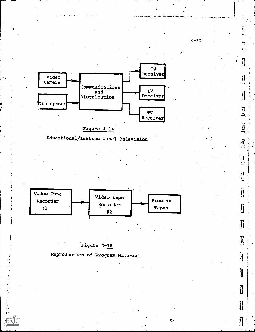
VideoCamera
icropho
Communicationsand
61-111.1
Distribution
n
--11
. TVReceive
1 TV,Receive
--1-44ReTc:iveri
Figure 4-14
Educational/Instructional Television
Video Tape
Recorder
#1
Video Tape
Recorder
#2
.---ow] Program
Tapes
Figure 4-15
Reproduction of Program Material
/.
4-52
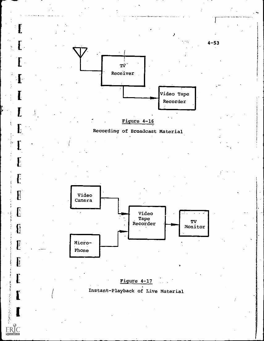
TVReceiver
Figure 4-16
Video Tape
Recorder
Recording of Broadcast Material
VideoCamera
Micro-
Phone
VideoTape
Recorder
Figure 4-17
4-53
TVMonitor
Instant-Playback of Live Material
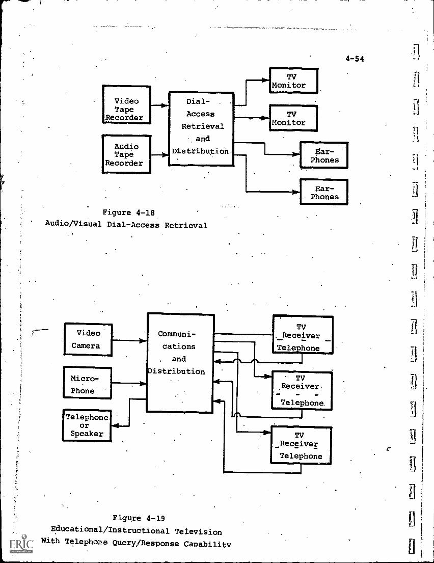
VideoTape
Recorder411111
AudioTape
Recorder
Dial-
Access
Retrieval
and
Distribution-
4-54
Monitor
TVMonitor
Figure 4-18
Audio/Visual Dial-Access Retrieval
Video
Camera
[Micro-
Phone
Telephoneor
Speaker
11.1
Communi-
cations
and
Distribution
Ear -
Phones
Ear-Phones
TVReceiver
Telephone
TVReceiver
Telephone
I
Figure 4-19
Educational/Instructional TelevisionWith Telephone Query/Response Capability
TVReceiver
Telephone
fI
4-55
(4) Instant Playback of Live Material -.Many educational
subjects such as dra:ra, public speaking, gymnastics, etc., can
benefit greatly if .the pupil can see his or her own performance,
rather than having it described by others. Video taping and
immediate playback offer this capability, as illustrated in
Fig. 4-17.
(5) Audio/Visual Dial Access Retrieval - Either video,
audio, or combined A/V material can be recorded and stored in
a manner permitting-dial-access control and retrieval, and
delivery of the retrieved information to any number of remote
users (Fig. 4-18).
(6) Educational/Instructional Television with Telephone
Query/Response Capability - Fig. 4-19 is an expanded version
of the one-way system of 4-14, adding the capability of each
viewer being able to ask questions pf*tho instructor or comment
on the program. This converts a passive educational technique
into an interactive one, more nearly simulating the clasdroom
environment.
Chapter 11 describes a number of integrated, educational
telecommunications systems, actually in operation, which
perform the above functions, and others. It is important to
emphasize again, however, that'many other combinations of
the available components and carriers are possible and warrant
investigation. The technology in certain areas is, in addition,
advancing rapidly so that concepts previously considered and
abandoned may soon be both technically and economically feasible.
CHAPTER 4- BIBLIOGRAPHY
4-56
1. "Cartridge Television", industry report, Billboard, Sept.26, 1970.
2. "Portable Video Tape Recorder: A Guide for Teachers", StockNo. 071-02514, Division of Educational.Technology, NationalEducation Association, Wash., D.C.
3. "Television Cartridge and Disc Systems: What Are They GoodFor?", February 1971, National Association of EducationalBroadcasters, Wash., D.C.
4. "The Cartridge.Revolutioh", special supplement, Cinema, Vol.6, No.l.
5. "Video Tape Recorders for Institutional Use", Booklet #5,Maryland Center for Public Broadcasting, Owings Mills, Md.McAdam, J. Robert, and'Vento, Charles J.
6. Witherspoon, J.P., and Kessler, W.J., "Instructional.Television Facilities: A Planning Guide", Report 0E-34043,Office of Education, under Contract No. OEC-1-7-071021-4429,U.S. Dept. of Health, Education and Welfare, 1969
5-1
Chapter 5 - Hard Copy
Many telecommunications systems, educational or otherwiserequire a permanent record, in printed or graphical form, ofthe information being received. This type of record, usually
on paper, is termed "hard copy" to distinguish it from the
"soft" (non-permanent) records such as the display on a TVreceiver screen.
Examples of hard copy are alphanumeric messages, maps,
illustrations, graphs, photographs or hybrid combinations ofany of these. Physically, hard copy may be produced on
standard sheets, continuous tear-off rolls, fan-fold print-
out forms or in a format designed especially for a specifichard copy terminal. The only common element is that a
permanent record suitable for visual interpretation be theend-item.
Two categories of hard copy devices, which include
almost all possible applications, are considered. The
first is limited to reproduction of alphanumeric (and some
symbolic) characters only, essentially the equivalent oftext material. The second is more comprehensive, being
capable of hard copy reproduction of smehical. and photo-
graphic material in addition to alphanumeric. For this
reason, the latter can be termed "full-range" hard copy termi-
nals since almost any v5 ual image at the sending end can bereproduced at the receiving site.
The devices described below are "terminals" of a larger
system rather than stand-alone units in that they are
activated by electrical signals emanating from the system.
Thus, a typewriter whose keys are actuated by incoming elect-
rical signals falls into this category, whereas the same type-
writer actuated by a humar operator is not considered a
telecommunications device.
5-2
5-1 Alphanumeric Terminals
The telegraph, as the pioneer application of telecom-munications to the transmission of alphanumeric information,is still the conceptual model from which modern data communicationsand hard copy alphanumeric printout have evolved. As tuch, a.brief review of telegraphic technicres is warranted as back-)ground.
A telegraph system, Uke the more general telecommunicationssystem, includes the information source, the transmission and
distribution network, and the receiving terminal(s). SpeCifically,the following actions take place:
(1) At the information source, the alphanumerics are
converted into electrical signals with An agreed-
uvon,code for each letter, number and symbol. Sincethere is a discrete number of alphanumerics, therewill be a discrete number of codes which represent allof the information that can be transmitted.
(2) The coded signals are sent through the 'systeri, to-
getherwith synchronization information (start/stop
or Mark/Space) that allows the receiver to keeptrack of the incoming message.
(3) At the receiving terminal, the code signals are con-verted back into printed alphanumerics.
Before the advent of keyboard devices such as the tele-typewriter, the telegraph operator used a simple "sending key"to perform manually the alphanumeric-into - electrical translation.
The key consisted of a pair of electrical contacts normallyheld open by a spring. When the knob on a contact lever onthe key is depressed, the contacts close, permitting currentto flow in an electrical circuit. Thus, the operator caninterrupt the current flow in accordance with the pattern ofkey depressions.
5-3The code long used in telegraphy for transmittinginfor-
mation is the famous Morse Code (still utilized). This representseach letter or number by a combination of "dots" and "dashes".
The dots correspond to short pulses of current resulting from
the telegraph operator depressing the key for a short time foreach dot, and the dashes to longer key depression and currentpulses.
With this technique, the skill of the manual operator was
a major factor in the system, and also a limitation in terms of
achievable transmission speed. The development of the tele-
typewriter increased transmission speeds and decreased errors,but was still subject to operator limitations. Still later,the introduction of punched-paper tape and magnetic tape controlof data transmission effectively removed this bottleneck.
5-1.1 Teletype Conversion of Alphanumeric Information
When the keyboard-operated teletypewriter supplanted thesending key in telegraphy, it laid the foundation for most data
communications techniques and components. Its operation,described below, can therefore be considered a prototype of
many current printout devices.
Each key of the teletypewriter, when depressed, closes agroup of switches, which corresponds to a specific electrical
code assigned to that character.
A variety of codes can be used. Early equipment used onlyfive switches, allowing a total of only 32 combinations. Sincethis is insufficient to transmit even the minimum of 26 letters(A-E) and 10 numbers (0-9), a coding "trick" was used in which,if a special upper /lower case key were depressed, each code
could represent one of two characters. Thus, up to 64 characterscould be transmitted.
More modern codes range up to 9 elements per character,
allowing special symbols to be sent and providing error checkingcapability.
5-4
One possible method of transmission is to send each codeelement of a'character simultaneously over a separate line
(parallel transmission). This simplifies the electronic.
circuitry but requires, for example,7 wires for a 7-elementcode. This may be acceptable, and even desirable, for short
transmission distances but is too expensive for long-haultransmission.
The alternative is serial transmission on a single line,
and this.is the technique used almost universally today.
In the serial mode, the keyboard switches connect to adevice that resembles an automobile distributor. When a keyis depressed, the rotor mechanism starts up to encode the
character, makino.one complete revolution at a fixed speed tosense all switch settings. As the rotor passes the segment for
a given switch, a pulse is transmitted over the communicationsline. '(See Figure 5-1)
At the receiving end, a similar rotor mechanism converts theserial pulses back to parallel ones as the rotor passes each
receiving switch position.
The receiving rotor must be kept in step with the sendingrotor to set the switches properly. Since the rotor mechanism
of the receiving unit makes a revolution only when a Char-
acter is to come in, the problem is solved by sending a "start"
pulse before the transmission of the serialized character. Thispulse also starts the rotor in the receiver. Mechanical_
governors keep the receiving rotor in step with the sending rotor.
Occasionally spurious signals enter the line from such things
as lightning storms or line shorts, and throw the two tele-printers out of synchronism. To resolve this problem, one or
more"stoppulses are transmitted to reset the mechanism at theend of each character.
Thus, each transmitted character is a complete packet of
information containing start; information, and stop pulses - ascheme known as asynchronous transmission. The characters maybe sent continuously or with large gaps of time between them.
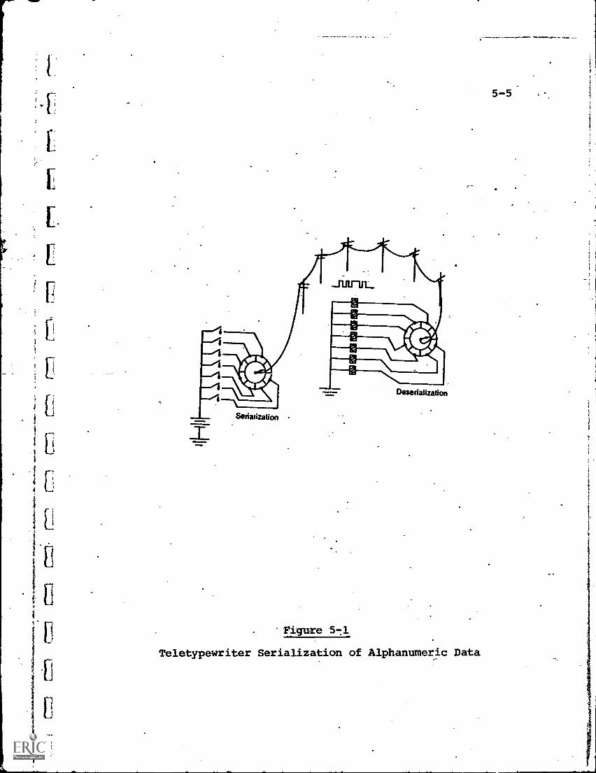
5-5'
Serialization
Deserialization
Figure 5 -1
Teletypewriter Serialization of Alphanumeric Data
5-6
At the receiving teletypewriter terminal, the switch settinas
established by the rotor are used to select a particular solenoid
(electro-mechanical actuator) which is associated with, the key
corresponding to the code just transmitted. The solenoid is
energized, pulls down the key, and the key striking the paperproduces the character.
5-1.2 Teleprinters
"Teleprinter" is the generic term for interactive electrically-
actuated printing devices which also incorporate a keyboard,
including as one major category the teletypewriter describedabove. In addition to hard copy, some units can also provide a
coded perforated paper tape or magnetic tape which records the
same information printed.
The interactive send-receive capability, the simple keyboardinput and the low/medium printing rates make the teleprinter
most compatible with educational appliCations of the query-
response type, and accordingly this class of printers is
encountered most often. When more retrieval systems come into
operation, placing a premium on higher printing speeds, the
faster types of printers, such as the line printers discussed
below, will be utilized to a greater extent.
Teleprinters can be characterized in several different ways:(a) their maximum printing speed
(b) the printing technique used
(c) the capability to interface with communications,
computer or other terminal equipment
(d) their cost, size and/or degree of portability
(e) the code(s) used for data communications
Since a keyboard is used to send information, the data
input rate usually will be comparable to that of a good typist,
in the order of 10 characters per second. This, in the past,
determined the data output (printing) rate too. More recently,
t
5-7
however, it has been an increasingly common practice to store
the data on tape, as it _is being typed, and play it back into
the'communications system at a higher speed, to take advantage
of the maximum transmission capability of the communicationslink.
With this technique, it is desirable to have the receiving
printer able to match the higher rate. Consequently, many
modern teleprinters can print at speeds up to 30 or more
characters per second.
Almost all teleprinters, either in their standard model
or with modifications, can interface with a computer or another
teleprinter, either directly or through a. communications link.
In fact, virtually every computer time-sharing system features
teleprinters as the major remote terminals.
One significant recent advance has been the standardization
of code and electrical charactistics. Although.a variety of
character coding schemes are still used, many equipment manu-
facturers have accepted the USACII (U.S.A. Standard Code for
Information Interchange) code for general use. USACII is an
8-level, 128-character code standardized by the federal
government for its internal data communications.
The electrical interface characteristics between a terminal
and a communications channel have also been standardized by
Electronic Industries Association (EIA) Standard RS-232. This
defines features such as pulse widths, rise times, etc. for
equipment designers.
Printing techniques are either of the impact or non-impact
type. The impact type,is similar to a typewriter mechanism in
which, as each character is selected, a typing bar or other
moving element strikes the paper through a ribbon or inking
device. Speeds of impact teleprinters are limited to 10-15
characters per second, and costs are in the $600-3,000 .range.
Carbon copies can be produced as desired.
5-8
Non-impact techniques include "ink-jet squirting" and
electrostatic or electrographic transfer. Examples of the
ink-jet type are the Teletype Corp. "Inktronic" and A.B. Dick
Company's "Videojet" printers. The Inktronic uses 40 stationary*
nozzles through which ink is electrostatically drawn and
simultaneously charg,e.d. .The charged ink stream is squirted onto
the paper, writing one character at a time. Each character is
actually written as a series of dots of ink which, blending
together,give the appearance of a continuous line. Up to 120
characters per second can be printed. The,Videojetis evenfaster, capable of 250 characters per second, which is equivalent
to the data capacity of.a voice-grade telephone circuit.
The cost of an ink-jet type teleprinter is in the $5,000-
$7,000 range, restricting their use to medium/high speed
applications.
The electrostatic/electrographic printers are also capable
of higher speed than the impact type. They use a stationary
matrix of wire stylii (essentially metal needles) under whichthe paper moves. Electrical current is sent to only those
stylii needed to form a character. If the process is electro-
static, each stylus which is energized will charge a small
area of paper, while in the thermal electrographic process, the
stylus slightly burns the paper area. In either case, the
paper moves on through a chemical "toner" both, after which the
imprinted characters appear more clearly.
Costs for the electrostatic/electrographic printers approxi-
mate the ink-jet type, and even higher printing rates are
possible.
.A disadvantage of both the ink-jet and stylus printers is
that only one copy is produced and carbons, are not possible.
Of the hundreds of thousands of teleprinters in current
use, the vast majority are Teletype Corp. units, partly becauseof their utilization for many years in telegraphy and partly
because of their relatively low cost and adequate reliability.
11
U
5-9
The older Teletype units most often encountered are the
Models 33 and 35. The Model 33 is designed to send and print
only numbers (at a maximum 10 per second rate), with a few
letter keys as control symbols. It is, therefore, primarily
for data processing and-computation applications. The Model
33 is the lowest cost teleprinter, priced at $600-700 depending
upon options.
The Model 35 has complete alphanumeric capability, with a
keyboard almost identical to that of a typewriter. Its trans-
mission and printing rate is the same as the Model 33, and its
cost is in the $1,700 range.
A more recent unit, the Model 37, has a higher speed
capability, up to 15 characters per second, and sells for about
$2,450.
Dozens of other manufacturers and models are available,
with typical product surveys referenced in the bibliography
for this c'..,Ppter.
ModeLn teleprinters feature solid-state electronic circuits
replacing most of the mechanical operations for coding, etc.,
reducing the operating noise of the unit andimproving relia-
bility.
Before a selection can'be made for any educational
application, the system requirements must be defined in terms of:
(a)* Interface to the communications system
(b) Printing speed (maximum)
(c) Need for duplicate copies
(d) Desired printout format (e.g., on pre - printed forms)
(e) Need for recording on magnetic or perforated tape
(f) Specific coding, if any
Once these have been determined, the choice can be narrowed
down to a manageable number of printer models, and the normal
selection factors of price, reliability, maintenance, etc. can
Come into play.
5-10
5.1.3 High Speed Printers
While teleprinters are used primarily in the interactivemodes, such as human-to-human or human-to-computer, thereis a category of printers, operating in the computer -to -hard
copy mode, which calls for very high printing speed to matchthe output capability of the computer. The hard copy, although
eventually viewed by humans, is viewed later after printingis complete. Thus, the printer does not have to be sloweddown to human reading'rates.
Most high speed, computer-output printers are "line
printers" in that complete lines, rather than individual
characters, are printed simultaneously, at speeds of hundreds
(in some cases, thousands) of lines per minute.
printing a line at a time is accomplished by including abuffer storage in the printer which holds each character as itarrives until a line has been assembled. Then all characters
are printed at once and the buffer emptied for the next line.
In pace with the high speeds are high costs, ranging from
$5,000-100,000 each.
Line printers are usually "receive-only"devices having nokeyboard or other sending capability. They too are of the
impact or non-impact types described above, with the non-impact
units preferred for silent operation and graphic flexibility,
while the impact models are used where multiple copies arenecessary.
Because of their restriction to high-volume computer-
generated data applications, line printers have not been used
significantly in educational systems to date. With the growth
of retrieval systems.in the future, such as library inter-change of printed material, high -speed hard copy may become a
more important requirement. Large systems, in which the output
is centralized at one or two locations could justify the costof line printers. Until that time, however, business rather
than educational systems will to continue to be the major user.
5-2 Full-Range Terminals
5-2.1 Plotters
5-11
Plotters can be defined as equipment that accepts electrical
input signals and produces a permanent hard copy"picturew. The
picture may be any two-dimensional visual pattern.
Since facsimile recorders do the same thing, It may be
helpful to describe the differences. Facsimile, described next,
is a system in which the operation of the sending and receiving
devices cannot be divorced from each other. The facsimile
receiver/recorder, in fact, is synchronized always to be "in
step" with the scanning process at the transmitter, and the
picture is reproduced in the samepattern as scanned. .A
facsimile recorder, therefore, cannot function except as partof a paired set.
Plotters, on the other hand, can accept input signals from
a variety of sources such as computers, measuring instruments,
magnetic or paper tape readers, etc. They are "receive-only"
devices, placing essentially no constraints on the informationsource.
Since many plotters can draw alphanumeric and symbolic
characters as well as graphical material, certain models are
sometimes termed "printer/plotters" to signify this full rangecapability. They are similar in principle to any other plotters,
but their resolution is sufficiently small to permit charactersto be shown clearly. For such applications as annotating or
labeling maps and illustrations, this feature is important.
Plotters operate through the relative motion between a writingpen or stylus, and the paper. One basic type of plotter, which
keeps the paper stationary and moves the pen, is shown in
principle in Fig. 5-2.
The writing pen is driven simultaneously along the X-axis
and Y-axis of the paper by two motors and drive mechanisms.
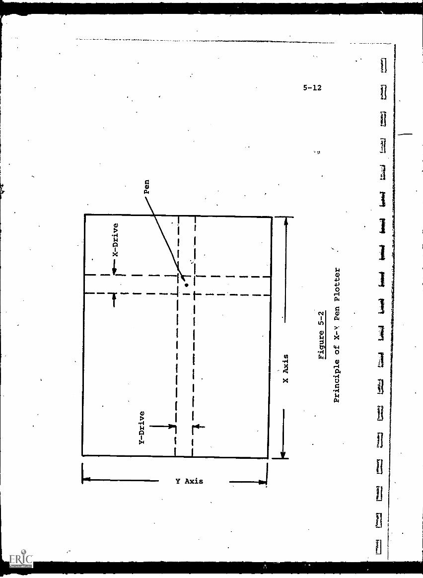
X r.
to
Y -Drive
NN
W. M
OM
4111
a 011
1.1Ma
- MINIM
OM
EN
. - 4
1111
1111
11.1
,
.101
.111
11.1
1111
11a
4111
1=11
,--- -- -
OM
EN
.O
MN
I
elm1
` IIM
ME
D.1
1M -
X Axis Figure 5-2
Principle of X -V Pen Plotter
Pen
=i
frow
ilba
sil
impo
ilfo
wl
;.=/
5-13
The X-drive, for example, is a vertically aligned track whichmoves left or right, and carries the pen along with it. Similarly,the Y-drive track moves up or down, again carrying the pen.
The distance either track moves depends on the magnitudeof the electrical signal sent to the respective motors. If, forexample, the plotter is designed so that an input of 10 voltsto the X-motor will drive the track across the full width of thepaper, an input of 5 volts will drive it to the middle.
The pen position, therefore, can be controlled in apredictable fashion by the electrical X and Y signals: Onefurther item of information is required, i.e., when to print.Normally, the point of the pen is kept raised from the paper sothat the pen will not smear while it is moving from one plotposition to the other. A "plot "command" lowers the pen so thata point is drawn at that instant.
Since the total picture is composed of dots, the plotresolution (like the photograph, TV picture or facsimile image)is determined by how small a dot can be drawn and how close thedots can be to each other. These key features, plus how fastthe dots can be drawn, are the major factors that determineplotter'cost.
A second plotting technique is to let the paper move so thatin effort it replaces one axis drive. If the paper were woundon a cylindrical drum and unwound so that its motion were inthe X-direction, then only a Y-axis drive would be necessary.This results in a simpler plotter mechanism, but the disadvantageis that the plot must be completed in one "pass" since the papermoves only once under the Y-axis drive. Some plots do not lendthemselves to this technique.
A further refinement is the electrostatic/electrographicplotter/printer in which only the paper moves. The paper isrevolved by.a drum as before, moving past a row of styliiwhich extend from the bottom to the top of the Y-axis. Insteadof physically moving a pen up and down, the appropriately
located stylus is pulsed at the right time and a point drawn.
5-14
Another limitation of the drum plotter is that the drumspeed is usually maintained constant. This is fine for graphsin which time is the X-coordinate, but restrictive for moregeneral graphical material.
"Digital" plotters are'those in which the input signalsare in' the form of numbers, rather than analog voltages. Theplotter internal mechanism converts the numbers into positioningand plot commands. The ability to accept digital inputs makesthe plotter a natural output device for computer-generatedinformation, and in recent years many high-speed digital plottershave been designed to match a wide varity of computer appli-cations.
The cost ranges for slow speed, X-Y pen plotters arefrom $500-2,500, while a fairly fast, high-resolution unit is inthe $5,000 range. Computer-compatible digital plotters vary incost from a low of $3,000-5,000 to upwards of $100,000.
Educational applications for plotters have been relativelyrare to date,41artly because of the equipment cost and partlydue to a lack of definition of educational systems which mightrequire a hard copy plot output.
5-2.2 Facsimile
Facsimile is the term given to the method of producinghard copy reproductions (facsimiles) of printed or graphicmaterial at distances remote from the original by means ofelectro-optical scanning, telecommunications, and plotter/printer techniques. It differs from television in 'the followingways:
(a) The original material is motionless, fixed inposition for scanning, and is usually limited todocuments (letters, drawings, maps, photographs,etc.) where the key information is two-dimensional.For this reason, facsimile is also termed "graphiccommunications."
!-1
11
11
11
11
11
B
F
5 -i5
(b) While rapid reproduction is always desirable, it isusually not a critical parameter compared to
reproduction quality or cost. Cost is dependent on
transmission time, since common-carrier transmissionfacilities are generally utilized and paid for on a
"time-utilized" basis (like a long-distance telephonecall).
(c), The end, product is a permanent (paper) copy serving, atthe receiving end, the same function as the original
would if it had been physietlly transported. Thus,not only the inllrmation content, but tte format and
record storage capability are important.
The scanning process in facsimile is similar in conceptto that of television, using a line-dot pattern. In facsimile,however, the original material is scanned only once. Sinceit is motionless, a single scan will gather all the visual infor-mation.
A resolution of about 100 dots to the lineal inch is usedin commericial facsimile equipment (10,000 per square inch).This is sufficient to reproduce text, drawings and continuous-tone images such as photographs with acceptable quality. Forexample, "wirephoto", a facsimile process, has been used foryears to transmit newspaper photographs for subsequent printing.
The main problem with facsimile is the historical decision,made many years ago, that the common-carrier telephone/telegraphnetwork would be the primary communications link for facsimiletransmission. This was logical since the network was available,and the users of facsimile, mostly business and industrial firms,were not interested in financing special-purpose transmissionsystems.
Therefore, facsimile transmission was constrained to thedata rates of voice-grade telephone lines with bandwidths ofabout 3 KHz. To see the effect of this, consider sending onepage of material over a phone line via facsimile.
5-16
An 8-1/2" by 11",page covers an area of 80 square inches,
assuming the contents lie within 8" by 10" borders. At 10,000dots per square inch, the total facsimile message is 80 times10,000, or 800,000 dots of black/white information which havebeen scanned in a predetermined sequence. If we' make a crudeapproximation of equating each dot to the information contentof one frequency cycle of alternating current (which a repetitiveblack/white pattern, alternating every dot, would approach),
then the 800,000 dots would be the equivalent of 800,000successive cycles.
When we take this number of cycles and transmit them overa 3 KHz telephone line, which can carry only a total of 3000cycles each second, it obviously will take or 267,seconds to completely transmit the message. This is aroundfour and one half minutes and is the approximate time requiredby facsimile systems. Most commercial equipment presently on themarket requires from three to six minutes to reproduce one8-1/2' by 11" page, while more recent and more expensive higherspeed units require about one to two minutes.
It is evident that the only way to increase reproductionspeed (assuming no. degradation in quality, which means at leastthe same incremental resolution) is,to increase the rate ofscanning, which generates the dot sequence, and also the speed,
of transmission, which in turn means more dots transmitted persecond. This leads away from the standard, voice-grade line tohigher band-width communications links, and these indeed havebeen utilized. The cost, however, increases proportion:J.1y.
Furthermore, if the scanning rate is increased substantially,the present electromechanical scanning methods of facsimileequipment must be replaced by all-electronic techniques. In effect,a facsimile scanner becomes more like a video camera and facsimiletransmission becomes more like slow-scan TV. The only differenceremaining is the hard copy output of facsimile, and since thisis also produced by electromechanical means, there is a definite
rI
U
1
5 -17
limit to transmission speed which is imposed at the receivingsite. This can be overcome by recording the incoming signal on
tape, for example, and playing it back later at a slower rate
into the facsimile recorder, but the system becomes cumbersomeand expensive.
From *the point of view of educational applications, there
are certain advantages to facsimile:
(a) Both the original and final products are paper
documents resembling items that normally are used to
a major extent in education (e.g., textbooks, reports,
diagrams, quizzes and test papers, etc.). Thus, if
facsimile reproductions are used instead of originals,
no psychological adjustments are necessary by
teachers or students.
(b) Facsimile has a wide tolerance to communications
transmission errors. Since any single image is made
up of many dots, the loss or misplacement of a sur-
prisingly large number will"not generally prevent the
human eye and brain from reconstituting the original.
(See Fig. 5-3)
(c) Facsimile'is inherently compatible with computer-
controlled output information whether microfilm,
graphical or alphanumeric, or more likely, combina-
tions of these.
Until the present, these advantages have been overbalanced
by the relatively poor speed and cost characteristics. Major
improvements in the future can, however, expand facsimile's
usage cLt of the business applications category into educational
areas. 1
The technology of facsimile is relatively simple to under-
stand, and comparison charts of available products are periodically
published (see Bibliography) and updated.
A minimum facsimile system consists of one scanner/
transmitter, one receiver/recorder and the communications link.
If two-way send-receive capability is required, a "transceiver"
combining the capability either to transmit or receive is used
at each end.
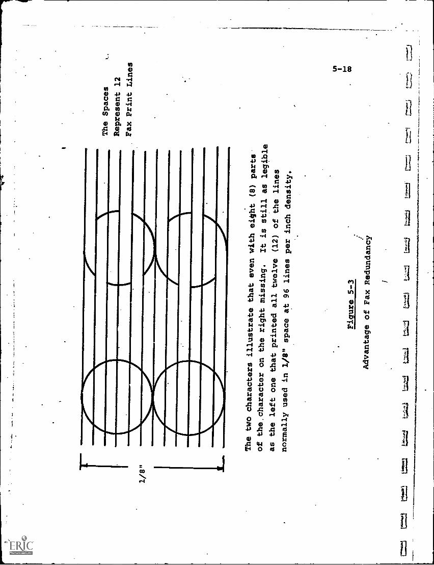
1/8"
The two characters illustrate
that even with eight (8)
parts
of the.character on the
right missing.
It is still as legible
as the left one that printed all
twelve (12) of the lines
normally used in 1/8"
space at 96 lines per inch density.
Figure 5-3
Advantage of Fax Redundancy
1tz-1,4.1
t>4.4:44.
uxzt
The Spaces
Represent 12
Fax Print Lines
1.,
t--;
5-19
Almost all current facsimile scanners use electro-
mechanical scanning techniques in which relative motion in
a predetermined sequence between the document to be reproducedand a photo-optical sensor produces a sequential output of
pulse signals from the sensor. This is the so-called "flying,
spot" technique used in the past for CBS' proposed color tele-vision system (before standardization on the current electronic
raster), and presently being utilized in at least one of thenew "home video recorder" units.
The relative motion many be produced with the document
remaining motionless and the photo-optical lamp/sensor headproviding all of the scanning motion (flat bed technique), orthe document wrapped around a rotating 'cylinder or drum, with
the flying-spot sensor tracing a helical path which eventuallyscans all of the document area. Faster drum rotation speedsproduce a more rapid scan. The key performance parameters are:
(a) Transmission Time. This ranges from about one to six
minutes per 8-1/2" by 11" page, as previously noted,
with standard phone lines.
(b) Scanning Density. The scanning density is a measure
of the resolving power of the reproduction process.
As noted, "100" means 100 resolvable increments to
the lineal inch in any direction. Obviously, thegreater the scanning density number, the more closelywill the facsimile resemble the original. A densityof around 80-100 has been found adequate to reproduce
most text sizes, but it is important to realize thatthis assumes character sizes about 1/8" high or greater.
For small type, 1/16" high for example, a density of
about 160-200 is necessary. This doubling of the
density per lineal inch would quadruple the information
content per square inch and thus quadruple the total
message length and, with the same line facilities,
also the transmission time. This tradeoff alwaysoccurs, resolution (quality) versus time (and corres-pondingly, cost).
5-20
(c) Document Width. This is a constraint upon the
original material to be reproduced. Although morea matter of standardization than of technology, the
commercial manufacturers naturally have selectedsize standards meeting volume-market applications
(e.g., 8-1/2" by 11" standard text page). Documentsat the 'small and large size extremes may also be
transmitted, the latter by sections at a time.
Recent'facsimile recorders use paper rolls ratherthan single sheets. This reduces labor at thereceiving end, permitting longer periods ofunattended operation.
Another point to note is that the density content of theoriginal document has no bearing on the facsimile speed. Sincea fixed scanning sequence is used, it takes as long to scan apage with only One word in the center as a page crammed fullwith text, diagrams, etc. Naturally, the first case is morewasteful of both scanning time and communications facilities.
Along these lines, newer systems are using "data compression"techniques similar to those employed in aerospace and computerdata transmission systems. These generally involve "looking" atthe electrical signals and detecting. repetitive patterns whichrepresent sizable patches of black or white on the documentoriginal. For transmission, only a transition from white toblack or vice versa is communicated. The time interval betweeneach transition also must be communicated by some scheme tothe receiver to permit ree6nstitution. Thus, breaking thesignal into two determining components, (1) period of timeduring which a black or white state continues and (2) locationof transition points, permits sending all essential data,without transmitting repetitive signals which provide no newinformation.
ti
tl
rt
1.1
5-21
Equipment is available which achieves one-minute trans-
mission time over voice-grade lines for a 8-1/2" by 11"
document, using such a data compression technique. A small
special computer monitors the original scan, makes the compres-
sion decisions and translates the signals into an appropriate
format.
A reduction of transmission time, using average toll
charges of 20 per minute, will save 60 per transmission if
three minutes are saved. Of more significance is the per-
centage decrease, 75% in going from four minutes to one minuteper transmission.
These improvements have led to more widespread use of
facsimile in recent years (see Chapter 11). In each case, the
key factors which must justify its use are quality of picture,
transmission time and cost, with any improvement in one factor
usually at the expense of the others.
For a single two-way installation, i.e., one transceiver at
each of two locations, the cost of medium speed equipment
(3-6 minutes per page) will be about $5,000-$15,000, or an
equivalent monthly rental charge of $100-300. It is important
to note, however, that the phone line costs, depending on
usage, can annually exceed the equipment costs.
5-2.3 Photographic Conversion
A seldom- considered -alternative to producing a hard copy
print or plot is simply to photograph a "soft"'copy display,
such as presented on a TV screen or CRT terminal. If the
soft display is already available, the incremental cost of astill or motion picture camera is much less than that of a
plotter.
Whether this method is acceptable depends on what kindof hard copy is desired, and also upon the quality of theimage. If, for example, the hard copy is a page of text or
a drawing which eventually will be microfilmed for permanent
storage, then photographing directly would save time and money.
5-22
If, however, the hard copy pages will be bound in a book,the photographs must be enlarged and printed, and this procedurewould appear wasteful.
Each time a media transformation takes place, some imagedegradation is inevitable. Thus, a film taken of a TV screendisplay will be inferior in picture quality to that viewed onthe screen. These transformation losses must betaken intoaccount to determine if the final result is acceptable.
5-3 Educational Applications
In theory, hard copy devices should find many applicationsin education, since what they produce is so similar to thekind of material that students conventionally use. The. abilityto transmit a map or engineering drawing to a remote classroom,in.a form that the student can retain and mark up if he chooses,obviously is desirable.
The factors which, to date, have mitigated against suchapplications are cost, and also the relative infancy ofplannednns which can efficiently utilize such terminals.
The cost factor includes not only equipment but communicationscharges which exist for all but in-house systems. Even themost elementary use of computer time- sharing systems, for example,requires a teleprinter terminal which carries a rental of$100-300 per month. If the terminal is used in a school class-room 8 hours a day, and the computer is far enough away torequire phone line connection, the phone charges for thatterminal alone can run $500-1,000 a month. If 100 studentsshare the terminal, the cost per student per month is perhaps$10-15, which is a significant percentage of the school'stotal budget per student.
Nevertheless, interactive computer communications withhard copy printout is a part of a number of educational
telecommunications systems now operating (see Chapter 12,for example), and can be expected to increase in the future.
5-23
This increase would be speeded up immeasurably if a low cost,
educationally-oriented print /plot terminal were developed.Almost all terminals used today for education were designed asprintouts for business or scientific use, and are not idealfor many instructional requirements. Students are using aTeletype (with all its noise and slow speed) to communicatewith a computer simply because it is the cheapest marginally-adequate unit available, and certainly not because it isideally suited to their needs.
The dearth of planned, organized and interactive educa-tional telecommunications systems is also a problem. Hard copyterminals are what the name implies, terminal points of asystem. The task of determining what to send a plotter, forexample, and how to put it into the proper form are part of thesystem design.
Despite this, the trend is to an increase in the versatilityof terminals, including plot/print flexibil.,zy, and it is tobe expected that their use,in educational telecommunicationswill rise sharply.
5-24
CHAPTER 5 - BIBLIOGRAPHY
1. "Facsimile Survey; Telecommunications, May 1971,.
2. "Hard Copy Printers: The State of the Art", Telecommunications,December 1970.
3. Stiefel, M.L., "Digital Plotter Terminals & Systems", productprofile, Modern Data, Sept. 1971.
4. Stiefel, M.L., and Murphy, J.A., "Teleprinters", product profile,Modern Data, May 1971.
5. Stiefel, M.L., "Printers", technology profile, Modern Data,February 1971 (Part I); March 1971 (Part II).
Chapter '6 - Commiters
6-1
The pervasive role which computers have played in modern
life needs no belaboring, and it is obvious that this role
will continue to expand in the future. Applications which
were theorefzical concepts only a'few years ago are now
operational and thriving. Fox example, computer time-sharing
has been available commercially only since 1965, and currently.represents a market with annual revenues in excess of $100,000,000.
In education, the use of computers has been evolving some-what more slowly than in other areas, partly due to the necessity
to translate educational objectives into terms compatible withcomputer technology. Many projects have been initiated on atrial basis, with greater or lesser degrees of success, and some
educational institutions have advanced to the point where computer-
based instruction is an accepted portion of the curriculum. In
general, however, the impact of computers on education in theU.S. is still preliminary and tentative.
Regardless of many valid arguments as to the appropriate
relationship between instructor and computer, or the cost-
effectiveness of computer education, it is clear that the computer's
potential for augmenting the educational process is enormous, and
that educational application will increase in the future. Theeventual impact of computers on education may not reach the
point of domination, as some computer proponents would forecast,
but it will certainly affect in a major way everyone involved,
educational administrators, teachers, students and the public.
6-1 Computer Fundamentals
Whenever the generic term "computer" is used today, it
almost always refers to the electronic digital computer. There
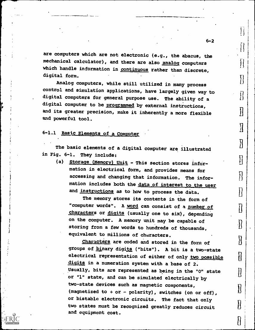
6-2
are computers which are not electronic (e.g., the abacus, the
mechanical calculator), and there are also analog computerswhich handle information in continuous rather than discrete,digital form.
Analog computers, while still utilized in many processcontrol and simulation applications, have largely given way todigital computers for general purpose use. The ability of adigital computer to be programmed by external instructions,and its greater precision, make it inherently a more flexibleand powerful tool.
6-1.1 Basic Elements of a Computer
The basic elements of a digital computer are illustratedin Fig. 6-1. They include:
(a) Storage (Memory) Unit - This section stores infor-
mation in electrical form, and provides means for
accessing and changing that information. The infor-
mation includes both the data of interest to the user
and instructions as to how to process the data.
The memory stores its contents in the form of
"computer words". A word can consist of a number of
characters or digits (usually one to six), dependingon the computer. A memory unit may be capable of
storing from a few words to hundreds of thousands,
equivalent to millions of characters.
Characters are coded and stored in the form of
groups of binary digits ("bits"). A bit is a two-state
electrical representation of either of only two possible
digits in a numeration system with a base of 2.
Usually, bits are represented as being in the "0" state
or "1" state, and can be simulated electrically bytwo-state devices such as magnetic components,
(magnetized to + or - polarity), switches (on or off),
or bistable electronic circuits. The fact that only
two states must be recognized greatly reduces circuitand equipment cost.
II
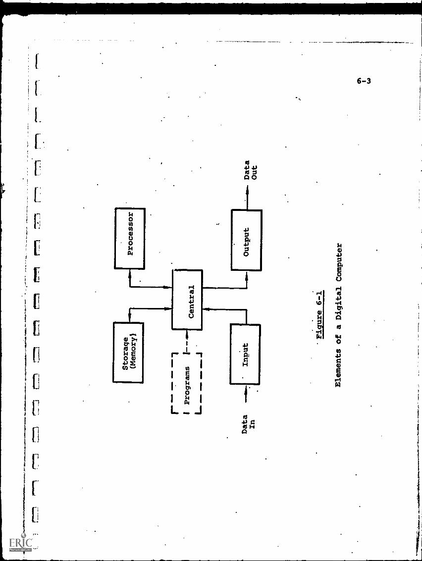
Storage
(Memory)
awill
aim
rProcessor
r._
_I
Programs
L
Data
In
__1
1 --
.. J
Central
Data
A
LI
Input
I-Output
Out
Figure 6-1
Elements of a Digital
6-4
Combinations of "0" and "1" bits can be used invarious coding schemes to represent any alphanumericdata. For example, two bits can provide four differentcombinations, "00", "01", "10" and "11", and thereforecan be used to represent any four numbers or characters.
A binary code is one in which "1" bits are
assigned values in a sequence of powers of 2, fromright to left. Thus, in the binary number "101",
,the right-hand "1" is equivalent to 2° power or 1.The middle number is the 2
1power number, and if it
were a "1" bit would be equal to 2, but since it is a"0" it is equal to zero. The left hand "1" corres-ponds to the 22 digit, and would be equal to 4. Thetotal number is the sum of the individual digit values,and for "101" would equal "4 + 0 + 1" or 5. Thus, thebinary number "101" can represent the arithmeticcharacter 511.
Table 6-1 shows how combinations of only six bits,in binary code form, can represent any digit, alpha-betical letter, or symbol.
Thus, the memory section of the computer storesgroups of bits in electrical or electromagnetic form.The bits in turn are coded to represent characters
which may, if desired, be further grouped to formwords. Subject only to the limitations of memorysize and cost, any type of information can be storedand retrieved.
(b) Processor - This unit is the computational and data
processing section of the computer. It must perform
the minimal arithmetic functions of addition, sub-
traction, multiplication and division, and, dependingon the size and complexity of the computer, usuallycan perform many more mathematical and manipulativeoperations.
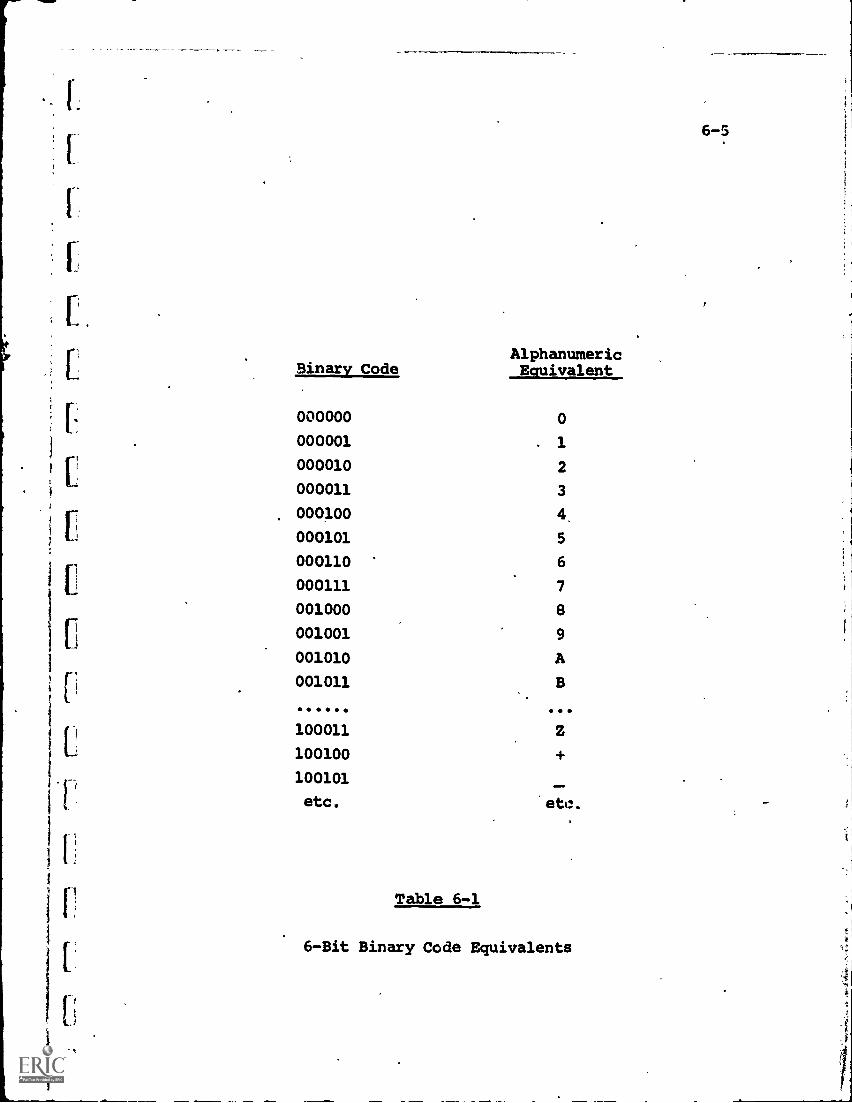
AlphanumericBinary Code Equivalent
000000 0
000001 1
000010 2
000011 3
000100 4,
000101 5
000110 6
000111 7
001000 8
001001 9
001010 A
001011
100011
100100
100101
etc. etc.
Table 6-1
6-Bit Binary Code Equivalents
6-5
6-6
Computers designed primarily for computationwill have extensive processor sections which
complete thousands of arithmetic operations persecond. Large, scientifically- oriented machines,(sometimes called "number crunchers") for example,may have an "add cycle time" (the time two numbers ofword length can be added together) of one or twomillionths of a second.
Computers used in information retrieval systems,on the other hand, are not required to perform muchcomputation and will have limited capability in therespect, They will, however, feature highly efficientmethods for accessing and moving large quantities ofdata, both internally and to external users of thesystem.
(c) Control - the control section is the "traffic director"of the computer, providing instructions to all componentsof the system as to what to do, and when to do it. Theinstructions originate from programs prepared previously.
Some functions exercised by the control sectionare:
(1) providing timing and synchronization signals(2) directing the flow of data into and out of
each section of the computer
(3) monitoring each operation to confirm that ithas taken place
(4) checking for errors or omissions(5) providing an interface to the human operators
and/or users of the system
The control and processor sections in some computersystems are designed and constructed integrally, withthe combined unit termed the "central processing unit"(CPU) or "main frame", including all computer equip-ment except memory, input and output
[
F
[1
6-7
(d) Programs - Computer programs are the instructions which
cause the computer JD perform a desired sequence ofoperations. Programs are designed first as logical
operational events which must take place, and then
converted into appropriate electrical signals used
to force the computer through these events. These
signals, called "routines" and "instructions" are
stored until needed for use, some within the computer
memory itself and some on auxiliary eauipment such as
magnetic tape or discs which feed them into the computer.
when required.
The general classes of programs include:
(1) Operating Systems and Executive Programs -
this category provides the basic instructions
which are necessary regardless of the parti-
cular computer application. In effect, the
operating system is the framework or structure
which determines the path taken by each
computer operation, the internal timing
sequence and the integration of components.
It can be likened to the engine of a car,
which must provide certain capabilities
regardless of which direction or how fast
the driver wishes to go.
Operating systems are usually provided
by the manufacturer of the computer. They
may be modified or even replaced by user-
created programs, but this requires expert
knowledge on the part of the user.
(2) Applications Programs - these are the special-
purpose instructions designed for particular
applications of the computer. If the computer
is to be used for education, for example, the
programs which are prepared to allow the -
computer to accept and store educational'
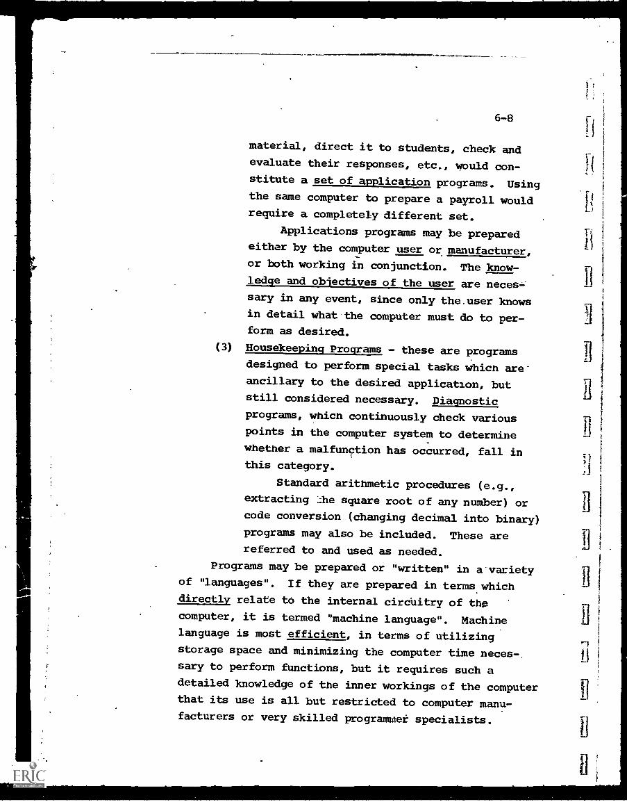
6-8
material, direct it to students, check andevaluate their responses, etc., would con-
stitute a set of application programs. Usingthe same computer to prepare a payroll would
require a completely different set.
Applications programs may be preparedeither by the computer user or manufacturer,
or both working in conjunction. The know-
ledge and objectives of the user are neces-:
sary in any event, since only the.user knowsin detail what the computer must do to per-form as desired.
(3) Housekeeping Programs - these are programs
designed to perform special tasks which are-ancillary to the desired application, butstill considered necessary. Diagnostic
programs, which continuously check various
points in the computer system to determine
whether a malfunction has occurred, fall inthis category.
Standard arithmetic procedures (e.g.,
extracting ;:he square root of any number) or
code conversion (changing decimal into binary)
programs may also be included. These are
referred to and used as needed.
Programs may be prepared or "written" in a-varietyof "languages". If they are prepared in terms whichdirectly relate to the internal circuitry of the
computer, it is termed "machine language". Machinelanguage is most efficient, in terms of utilizing
storage space and minimizing the computer time neces-,
sary to perform functions, but it requires such a
detailed knowledge of the inner workings of the computerthat its use is all but restricted to computer manu-facturers or very skilled programmer specialists.
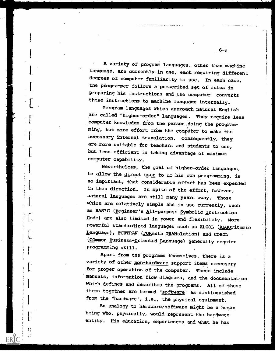
6-9
A variety of program languages, other than machinelanguage, are currently in use, each requiring differentdegrees of computer familiarity to use. In each case,the programmer follows a prescribed set of rules inpreparing his instructions and the computer convertsthese instructions to machine language internally.
Program languages which approach natural Englishare called "higher-order" languages. They require lesscomputer knowledge from the person doing the program-ming, but more effort frOm the compUter to make the
necessary internal translation. Consequently, theyare more suitable for teachers and students to use,but less efficient in taking advantage of maximumcomputer capability.
Nevertheless, the goal of higher-order languages,to allow the direct user to do his own programming, is
so important, that considerable. effort has been expendedin this direction. In spite of the effort, however,
natural languages are still many years away. Thosewhich are relatively simple and.in use currently, suchas BASIC (Beginner's All-purpose Symbolic InstructionCode) are also limited in power and flexibility. Morepowerful standardized languages such as ALGOL (ALGOrithmic
Language), FORTRAN (FORmula TRANslation) and COBOL(COmmon Business-Oriented Language) generally requireprogramming skill.
Apart from the programs themselves, there is avariety of other non-hardware support items necessaryfor proper operation of the computer. These includemanuals, information flow diagrams, and the documentationwhich defineb and describes the programs. All of theseitems together are termed "software" as distinguishedfrom the "hardware", i.e., the physical equipment.
An analogy to hardware/software might be a humanbeing who, physically, would represent the hardwareentity. His education, experiences and what he has
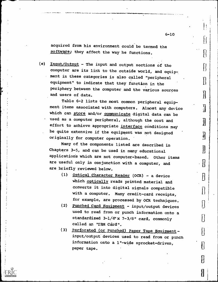
6-10
acquired from his environment could be termed the
software; they affect the way he functions.
(e) Input/Output - The input and output sections of the
computer are its link to the outside world, and equip7ment in these categories is also called "peripheral
equipment" to indicate that they function in the
periphery between the computer and the various sourcesand users of data.
Table 6-2 lists the most common peripheral equip-
ment items associated with computers. Almost any devicewhich can store and/or communicate digital data can beused as a computer peripheral, although the cost andeffort to achieve appropriate interface conditions maybe quite extensive if the equipment was not designed
originally for computer operation.
Many of the components listed are described inChapters 3-5, and can be used in many educational
applications which are not computer-based. Other itemsare useful only in conjunction with a computer, andare briefly reviewed below.
(1) Optical Character Reader (OCR) - a device
Which optically reads printed material and
converts it into digital signals compatible
with a computer. Many credit-card receipts,
for example, are processed by OCR techniques.(2) Punched Card Equipment - input/output devices
used to read from or punch information onto a
standardized 3-1/4"x 7-3/8" card, commonly
called an "IBM Card".
(3) Perforated (or Punched) Payer Tape Equipment-
input/output devices used to read from or punch
information onto a 1"-wide sprocket-driven,
paper tape.
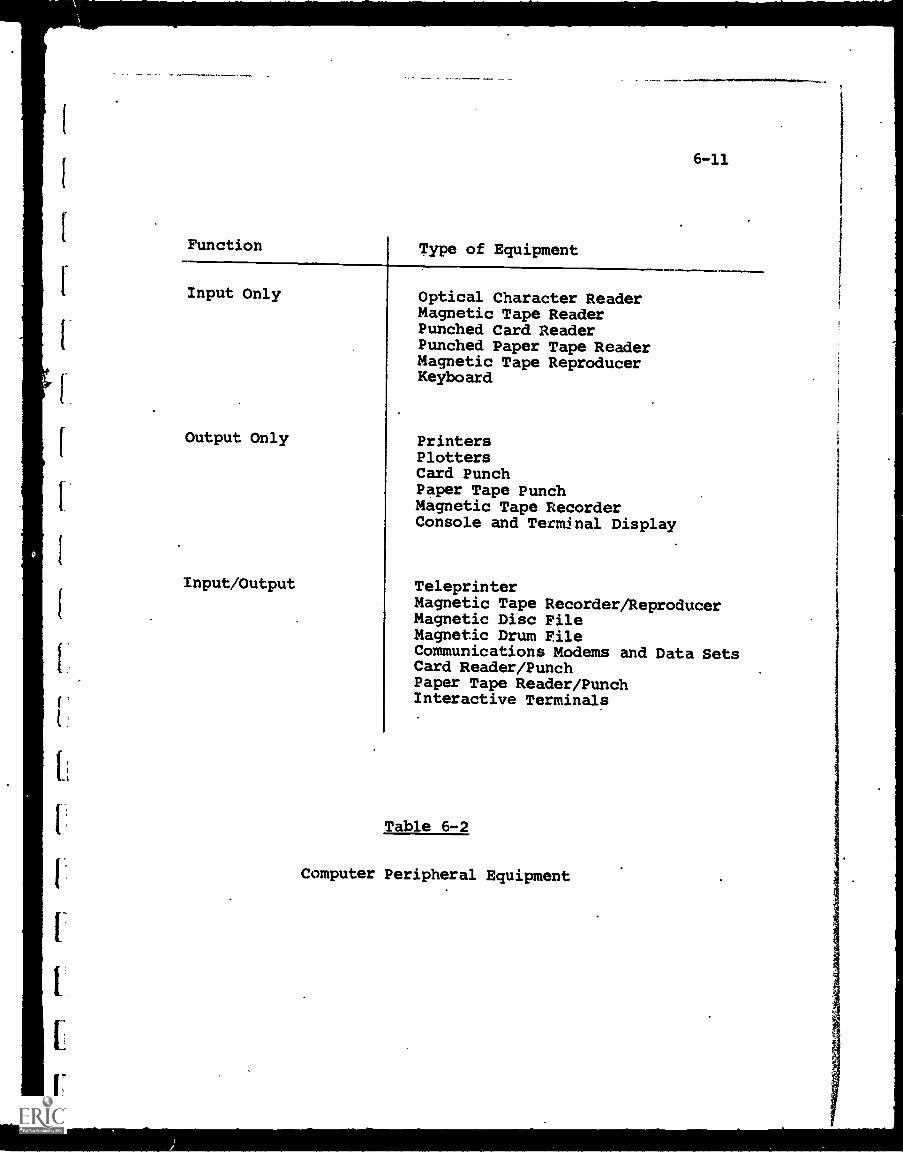
Function Type of Equipment
6-11
Input Only
Output Only
Input/Output
Optical Character ReaderMagnetic Tape ReaderPunched Card ReaderPunched Paper Tape ReaderMagnetic Tape ReproducerKeyboard
PrintersPlottersCard PunchPaper Tape PunchMagnetic Tape RecorderConsole and Terminal Display
TeleprinterMagnetic Tape Recorder/ReproducerMagnetic Disc FileMagnetic Drum FileCommunications Modems and Data SetsCard Reader/PunchPaper Tape Reader/PunchInteractive Terminals
Table 6-2
Computer Peripheral Equipment
6-12
(4) Magnetic Disc File - a storage device, or
auxiliary memory, which stores information on
one, or a number of, magnetically-coated discs
rotating at high speeds. Discs can be perman-
ently fixed or removable (which permits inter-
change of storage files or programs on a
modular basis).
(5) Magnetic Drum - a storage device, or auxiliary
memory, which stores information on "tracks"
of a magnetically-coated rotating dram. It
serves the same purpose as a disc file,
usually with somewhat longer data access times.
6-1.2 Operational Concepts
During the early and mid-1950's, the application of computertechnology followed a growth curve so phenomenal that appel-lations such as "the second industrial revolution" becarite common-place.
In most instances, the computer system was used in an "off-line" supportive function, (such as payroll preparation, forexample). "Off-line" is characterized;by:
(1) The computer and peripheral equipment generally areregarded as a semi-autonomous facility.
(2) Input data to the computer may originate from a single
Source or multiple sources, but in either case the
original data usually is not compatible with computerinput requirements. Transformation to punched cards,
or perforated or magnetic tape, for example, isrequired before the computer can process the data.
This transformation, in almost all cases, is performedwithin the computer facility.
6-13
(3) Input data are processed on a "batch" basis; i.e.,
a quantity of data, such as payroll information, is
processed by repetitive application of the same or
similar computer programs. (This is equivalent
roughly to a batch of cookies baked on a single
conveyor belt moving slowly through the same oven,
subject to identical temperature and time environment.)
Interruption of the data processing, once begun, is
rare, and the processing workload can be defined
accurately.
(4) The output from the computer may be printed reports,
tables, graphs, payroll checks, etc. The time frame
for deciiions arising from the output data usually is
not so short as to impin'ge immediately on the using
organization's operations.
In recent years, the emphasis has shifted to "on-line"
systems, in which the computer is used directly as'an inter-
acting element within the operations of the using organization.
An "on-line" computer system (see Fig. 6-2), as contrasted
to an off-line system, is normally defined by these character-
istics:
(1) The computer and peripheral equipment are essentially
a subsystem of a total information system which
extends beyond the physical computer boundaries.
Thus, input data are transmitted to the computer
directly from the point of origin, and output data
from the computer are transmitted directly to the
users.
(2) With multiple data sources and users, the terminal
equipment at each location, which acts as the man-
machine link to the computer, becomes of primary
significance. In many systems, the design and
operation of the terminal and communications equipment
are critical factors, and the computer itself is of
secondary importance (assuming a capability above a
minimum acceptable level).
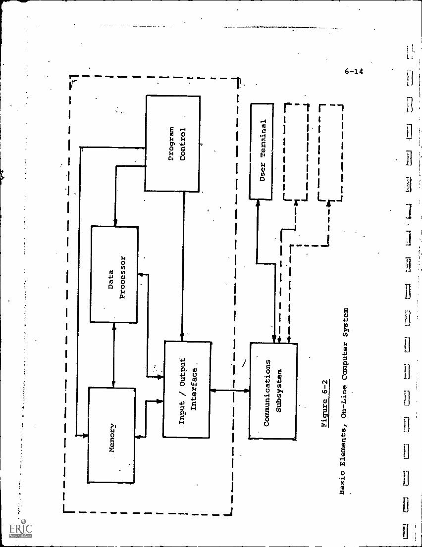
01M
b I I
Ma
ON
EM
SM
MIM
4MO
MO
WN
S W
Mb
0 aM
M01
04M
ON
IDM
ME
MIN
eWD
0111
10W
M II
MN
Dt.I
M 1
0
Memory
OE
M..
4111
11=
6 IM
MO
Data
Processor
Input / Output
Interface.
111.
M 4
1111
1MIII
41
Program
Control
exr.
w.
esow
som
omam
mo.
mum
..an
wim
b .1
1.1
1111
041
111,
mor
on a
mm
oam
mo
sow
, mum
e
Communications
Subsystem
Figure 6-2
=M
OW
WM
/41
1111
110,
.II1D
1101
0
OR
EM
11
Basic Elements, On-Line
Computer System
Vi
User Terminal
4111
0 flI
M
L.-
GO
MM
411
M.
41 IM
MO
MO
OW.,11
IIMIe
m O
M.
GO
MM
41.1
0
r- LO
NM
Et
OM
II O
MM
P A
MM
OIN
MIP
=11
a a
sm. .
111.-
S em
s
I I I I I (71
I-0
ds
=3
=7-1
4:4;
41.
aaw
n...s
s1
=
1
6-15
(3) When input data arrive from many sources, possibly
in a random time sequence, the computer programming
must include provision for establishing data-processing
priorities. This can include holding new inputs until
previous processing is complete and/or interrupting
lower-priority processing upon receipt of higher-
priority data. Thus, batch processing, with its
orderly progression and rigid control, gives way to
processing which must be analyzed through statistical
and probability techniques to determine "notmal" and
worst -case conditions.
Table 6-3 presents a few examples of both off-line and
on-line computer applications. The main differences do not
involve the computer itself, but how it is .used in relation
to its input and output. The on-line systems, in effect, bring
the computer to a variety of data sources and users, by means
of the remote input/output terminals and communications links.
At each terminal location, the computer functions directly on
a command/response basis with human beings, most of whom have
no more familiarity with the technical details of the computer
than the average driver has with the engine of his automobile.'
So far as educational application of computers are concerned,
some of which are described later in this chapter, most operate
on-line in the sense that many user terminals, scattered over
some geographical area, time-share the same computer. Although
the computer is processing many requests in a very short period
of time, each user sitting at his terminal is served as if the
complete computer facility were solely at his command. Further,
the user, whether a student or faculty member, needs to learn
only some elementary operational and programming procedures
and in a few hours usually can become sufficiently proficient
for his purposes.
Apart from an increase in the on-line, multi-terminal
mode of computer operation, another major trend has been the'use
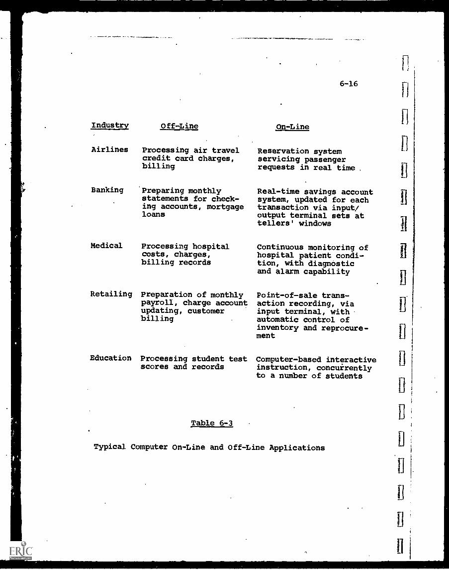
Industry Off-Line
Airlines Processing air travelcredit card charges,billing
Banking Preparing monthlystatements for check-ing accounts, mortgageloans
Medical Processing hospitalcosts, charges,billing records
Retailing Preparation of monthlypayroll, charge accountupdating, customerbilling
6-16
On-Line
Reservation systemservicing passengerrequests in real time
Real-time savings accountsystem, updated for eachtransaction via input/output terminal sets attellers' windows
Continuous monitoring ofhospital patient condi-tion, with diagnosticand alarm capability
Point-of-sale trans-action recording, viainput terminal, withautomatic control ofinventory and reprocure-ment
Education Processing student test Computer-based interactivescores and records instruction, concurrently
to a number of students
Table 6-3
Typical Computer On-Line and Off-Line Applications
6-17
of computer systems for noncomputational purposes. A growing
number of applications do not rely on the computer's ability to
add, subtract, multiply, or divide. Rather, they rely on its
ability to receive and store information, to queue messages, to
organize data and to control communications.
This trend is as valid for educational applications as for
any other. The newer computer-based educational systems, some
of which are described in,Chapter 12, utilize the computer's
comput'ational function only a small percentage of the time, and
rely much more heavily on the information storage and management
functions noted above. There are many educational systems
(e.g., computer-based instruction in a foreign language, or
history) whiCh, indeed, do not rise any computation capability
at all.
Thus, the educator must view the computer less as a very
fast calculator and more as an information management tool to
be able to estimate accurately its potential for augmenting
education.
6-1.3 Range of Computer Capabilities
There are so many types, models and sizes of computers
available that even computer specialists cannot hope to know
the salient characteristics of each. Further, many of the
characteristics quoted by the manufacturer are highly technical,
and, in many cases, unstandardized so that comparison is
difficult.
Obviously, then, the educator must seek qualified assistance
when ready to specify and purchase computer equipment. During
the planning and estimating stages, however, a familiarity with
a relatively few charactal3stics can be he_pful in "sizing" the
proposed system.
Table 6-4 provides an approximation of the range of costs
and key characteristics for four arbitrarily defined size class-
ifications of computers, "very large","medium/large", "small/
medium" and "mini".
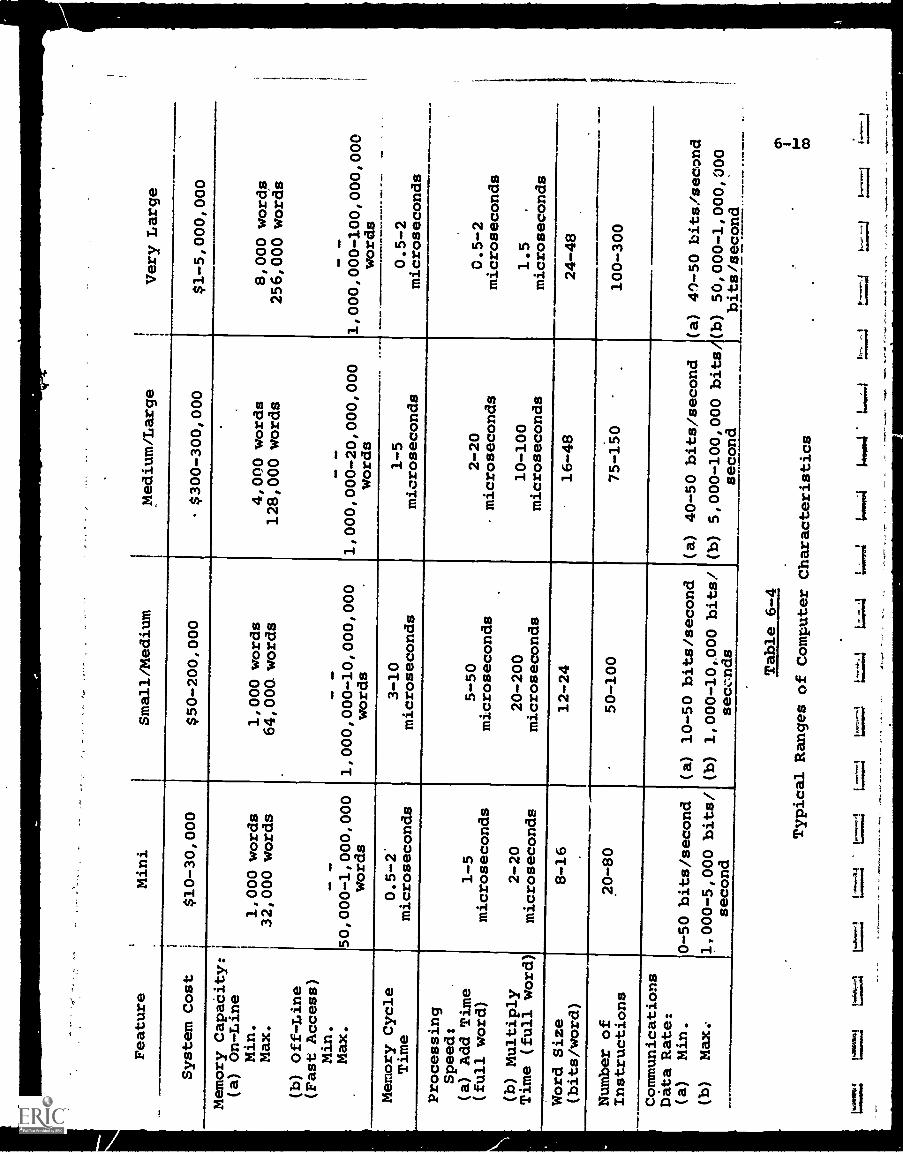
Feature
Mini
Small/Medium
Medium/Large
Very Large
System Cost
$10-30,000
$50-200,000
$300-300,000
$1-5,000,000
Memory CapaCity:
(a) On-Line
Min.
Max.
1,000 words
32,000 words
1,000 words
64,000. words
4,000 words
128,000 words
8,000 words
256,000 words
(b) Off-Line
(Fast Access)
Min.
Max.
50,000-1,000,000
words
1,000,000-10,000,000
words
1,000,000-20,000,000
words
1,000,000-100,000,000
words
4Memory Cycle
Time
Processing
Speed:
(a) Add Time
(full word)
0.5-2
microseconds
1-5
microseconds
3-10
microseconds
1-5
microseconds
0.5-2
microseconds
5-50
microseconds
2-20
microseconds
0.5-2
microseconds
2-20
microseconds
20-200
microseconds
10-100
microseconds
1.5
microseconds
Word Size
(bits/word)
Number of
Instructions
12-24
50-100
16-48
75 -150
100-300
Communications
Data Rate:
(a)
Min.
(b)
Max:
0 -50 bits/second
1,000-5,000 bits/
second
(a) 10-50 bits/second
(b) 1,000-10,000 bits!
sec-ds
(a) 40-50 bits/second
(a) 41-50 bits /second
(b) 5,000-100,000 bits/(b)
50,000-1,000,000
second
bits/second
Table 6-4
Typical Ranges of Computer
Characteristics
low
eet4
1.46
,0
cri
co
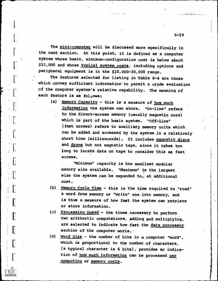
6-19
The mini - computer will be discussed more specifically inthe next section. At this point, it is defined as a computer
system whose basic, mimimum-configuration cost is below about
$15,000 and whose typical system costs, including options and
peripheral equipment is in the $10,000-30,000 range.
The features selected for listing in Table 6-4 are those
which convey sufficient information to permit a crude evaluation
of the computer system's relative capability. The meaning ofeach feature is as follows:
(a) Memory Capacity - this is a measure of how much
information the system can store. "On-line" refers
to the direct-access memory (usually magnetic core)
which is part of the basic system. "Off-line"
(fast access) refers to auxiliary memory units which
can be added and accessed by the system in a relativelyshort time (milliseconds). It includes magnetic discs
and drums but not magnetic tape, since it takes too
long to locate data on tape to consider this as fastaccess.
"Minimum" capacity is the smallest modular
memory size available. "Maximum" is the largest
size the system can be expanded to, at additional
cost.
(b) Memory Cycle Time - this is the time required to "read"
a word from memory or "write" one into memory, and
is thus a measure of how fast the system can retrieveor store information.
(c) Processing Speed - the times necessary to perform
two arithmetic computations, adding and multiplying,
are selected to indicate how fast the data processor
section of the computer works.
(d) Word Size - the number of bits in a computer "word",
which is proportional to the number of characters,
(a typical character is 6 bits), provides an indica-
tion of how much information can be processed per
computing or memory cycle.
6-20
(e) Number of Basic Instructions - this gives an indica-tion of how powerful the computer's instruction setis. As a general rule, the more basic types of
instructions available, the fewer the numbers ofindividual instructions necessary to form a program.
Thus, programming is easier and less costly.(f) Communications Data Rate - this indicates how fast
information can be received from or accepted by thecomputer. For an on-line system with many terminals,the "maximum" rate shown is the total for all terminalsand can become a bottleneck to the utility of thesystem.
It is emphasized again that these characteristics, whileinformative, are by no means sufficient to arrive at adefinite decision as to an optimum computer for any particularapplication. A broad spectrum of other factors, many inter-dependent with the way the system will be used, must be care-fully analyzed. Even with expert guidance, the number ofcomputer-based systems which have not met initial expectationsis significant.
From Table 6-4, it can be seen that the cost of a "medium/large" or "very large" computer facility makes its acquisitiona major financial project, certainly for educational appli-cations. While large systems are of definite interest, andsome are described in Chapter 12, a more recent developmenthas been the growth of mini-computer applications.
Since these hold great attraction for some educationalsystems, and since their newness makes them more unfamiliar,a brief summary of the features of mini-computers is warranted.
6-1.3.1 Potential of Mini-Computers
Within the last few years, the cost of microelectroniccircuitry has dropped sharply. Standardization of circuitsand high-volume production, plus the achievement of better
r.
E
6-21
yields in high-density packaging (such as building hundreds
of circuits on a tiny wafer as in Large-Scale Integration) have
combined to make possible for.the first time low cost yet
surprisingly powerful computeri.
This category of mini-computers is separated from other
computers in cost and size alone. Otherwise a mini-computer
has all the features of a larger unit.
The dividing point is somewhat debatable, bLt it is
usually accepted that any computer system, including peripherals,
that costs less than $25-50,000 (the exact price depends upon
whoever is doing the defining) is a mini-computer.
The basic components of the mini-computer, the Rrocessor/
control unit and the smallest module of memory, currently cost
from about $2,500 at the low end to about $15,000 at the high.
To this minimum configuration must be added peripheral equip-
ment and, depending upon requirements, more memory modules as
the system expands, resulting in the $25,000-50,000 total
system cost noted above.
Obviously, the most attractive feature is the reduced cost.
There are now educational time-sharing systems, using mini-
computers, which can handle 8 terminals for a total system
cost below $40,000 and up to 32 terminals for about $80,000.
This makes the use of small, on-campus systems much moreattractive.
It is interesting to note, from Table 6-4, that many of
the features of mini-computers, such as processing speed,
are as good as the large and very large systems. This is
due to the use of the same types of electronic circuitry,
although in smaller. quantity.
There are some disadvantages to mini-computers, at least
in their current state of development. First, the use of
smaller word lengths presents some difficulty in data mani-
pulation. Secondly, the restricted amount of memory space
available places a premium on programming so that efficient.
'6-22
use is made of the room that is available. Since the mostefficient type of programming is in machine language, as.previously noted, many users are forced in this directionif their application requires all the memory available. Thus;the advantages of more convenient programming languages suchas BASIC may be lost, or conversely, if used will require theaddition of more memory to the system.
A third problem is that, unlike the main-frame and memory,the cost and size of peripheral and input/output equipment have-not gone.down proportionately. A teleprinter, for example, isthe same in either a large system or a mini-computer system,and costs the same in each case. Some progress has beenmade in a rvw areas. Magnetic tape cassette units are becomingavailable w_th a reduction in cost, and smaller disc storageunits are being designed especially for mini-computer appli-cations. As a general rule, however, many items of petipheralequipment are over-designed, over-sized and over-priced for.
mini-computer systems, and consequently they dominate thesystems' overall cost-effectiveness.
This condition will be remedied, however, and the growthin mini-computer systems seems assured. The key factor isthat when the cost gets low enough, many-applications whichformerly could be handled only through a large centralized
facility can now be localized and decentralized (see 6-2.4.1).
6-1.4 Software Considerations
As anyone with computer experience is well aware, theimportance of the software cannot be over-emphasized. Properlyconceived and implemented, computer programs-can direct thesystem to operate with amazing efficiency, while conversely,poorly developed programs can render an expensive installation
almost worthless.
6-23
Despite its criticality, software (which as used herein
means everything necessary to make the computer system work
except the physical equipment) has been and remains more of
a craft than a science to even its professional practitioners.
To the educator who wishes to use a computer system, it can
be the area of least familiarity and highest difficulty.
The manufacturer of each computer generally supplies a
software "package" which includes the general-purpose operating
system and executive programs, and perhaps some self-test or
diagnostic programs. Documentation is also available in the
form of manuals which explain what these programs are designed
to do.
At this point the computer system can be used for a
variety of general-purpose tasks. Indeed, libraries of programs
are available, either from the manufacturer or from user
organizations, which can increase the number and scope of these
tasks.
For almost any new application, however, a group of
special-purpose programs must be developed. For an instructional
system, as an illustrative case, the content of the curriculum
has to be translated into computer operations, and the capability
for query and response, with a variety of possible combinations,
also has to be programmed.
These application programs (which for many systems can
represent more man-years of programming effort than the general-
purpose software) can be produced in many ways. The educator,
for example, can provide the computer manufacturer with his
objectives and course material and the manufacturer can
develop the applications program package.
This removes the programming burden, and in many cases
is reasonably satisfactory, but suffers from some disadvantages.
Costs are high, since the manufacturer is diluting his primary
effort into a specialized area, and indeed some manufacturers
are not interested at all in doing this.
The major problem, however, is that the achievement of
the uses' objectives, in this case educational, is delegated
6-24
to someone who has admitted computer expertise but possibly notenough knowledge of the educational process. Distortions ofintent will occur inevitably, and may be major. The educator-user cannot be sure that the distortions are due to theinherent limitations of the computer, or to the delegation process.
Obviously,. close coordination between the user and thesoftware developer, whether it be the computer manufacturer orindependent software specialists, will help to minimize thisproblem. It still remains as a serious one, however.
One way of improving the situation is for the user togain some familiarity with programming techniques. Thisdoes not imply becoming expert, but learning enough to providea better degree of coordination between the objectives andthe resulting programs.
As a case in point, when NASA experienced its greatperiod of initial growth, in the early and middle 1960's, theproblem arose of testing the new rocket boosters and spacevehicles by means of computer-based testing systems. Thequestion arose as to how to transfer the very specializedskills of the aerospace test engineers into the required pro-grams. The alternatives were:
(1) train the cognizant aerospace test engineers inprogramming and have them develop the programs
(2) train 'experienced programmers in aerospace testing(3) use teams'of engineers and programmers working
'together
In practice, all three alternatives and hybrids of themwere utilized, with the third being perhaps the most prevalentbecause of the urgent time constraints. Where time and man-power permitted, however, the first alternative proved to bemuch more efficient. It was easier for an aerospace engineerto learn programming than for a programmer, who usually hadless scientific and engineering training, to learn enough aboutthe test recinirements to be efficient in translating them for,the computer.
6-25
The same probably holds true for educational computersystems, (or medical, legal or any other highly professional
application), and where a teacher or faculty administrator can
and does become familiar with programming, the best resultscan be achieved.
Quite apart from the technical aspects of programming, itmust be realized that the software represents the "master plan"
for the system, and must be conceived and structured to dowhat the user wants done. This is not necessarily the same
as making the programming task easy for the progtammers.
Figure 6-3 illustrates, in simplified form, the planningand development cycle for a computer system and is as validfor education as any other application. The cycle begins withthe initial user motivation which may or may not result in a
decision to develop the system. In most cases, a justification
analysis is necessary to determine whether the contemplated
system appears feasible and can meet preliminary objectives.
Once the decision for implementation has been reached(the "Yes" of Figure 6-3), the user must define:
(a) What the System Should Do - Since an on-line computing
system is basically an informatiOn distributor withthe information used for a variety of purposes (control,
decision-making, reporting, etc.), defining what the
system should do may be considered the equivalent of
establishing the information flow and format
requirements.
Ideally, the user should define these objectives
before the constraints of available hardware or
standardized software are applied, rather than permit
the latter to inhibit the desired information flow.
The idealized objectives necessarily will be, modified
if they cannot be achieved realistically, but their
initial establishment at a user level sufficiently
high to be able to weigh all relevant factors is
the crucial point.
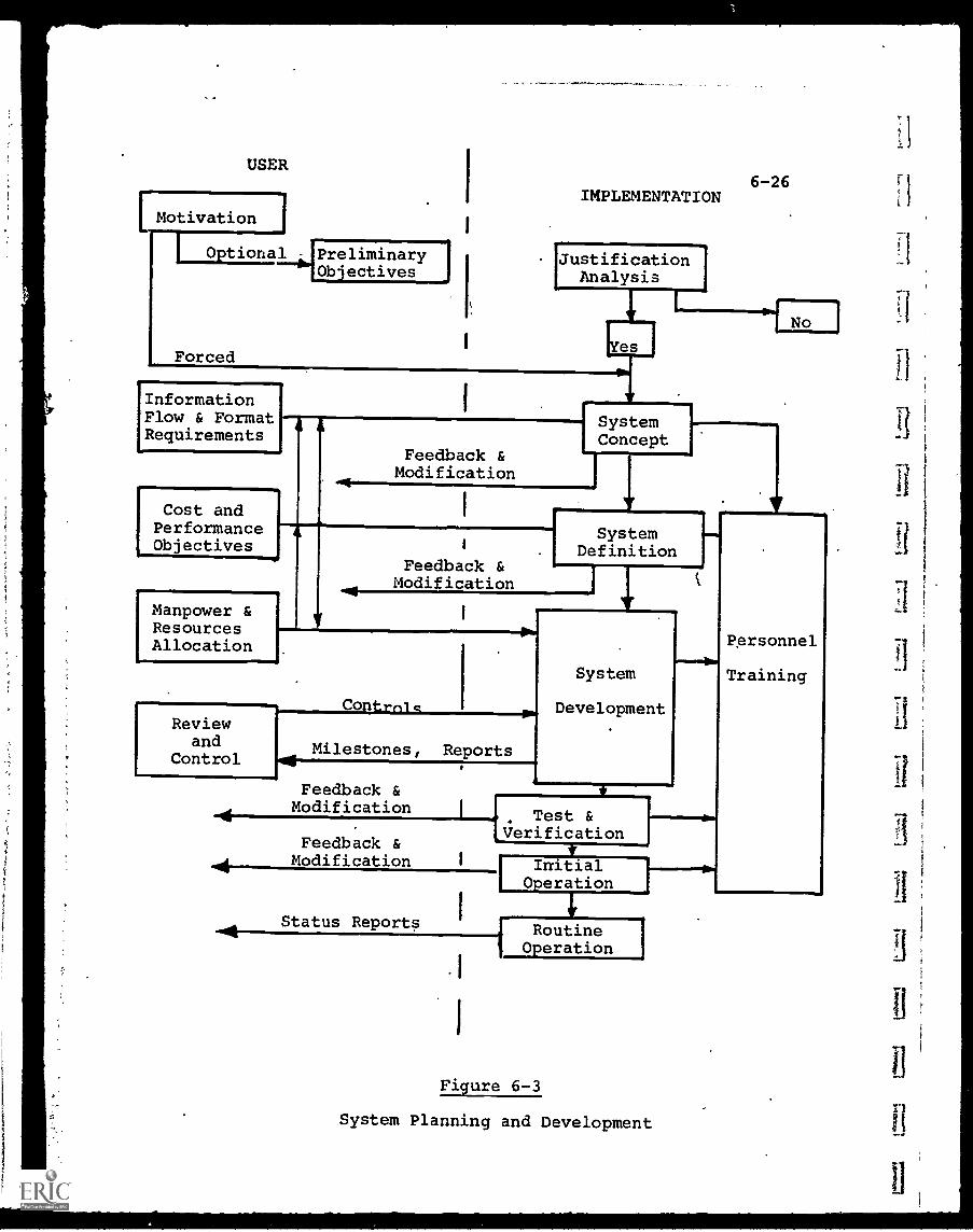
USER
Motivation
Forced
IMPLEMENTATION
JustificationAnalysis
InformationFlow & FormatRequirements
6-26
Cost andPerformanceObjectives
&
Feedback &Modification
SystemConcept
Manpower &ResourcesAllocation
Feedback &Modification
SystemDefinition
ContrnicReview
and Milestones, ReportsControl
Feedback &Modification
14
System
Development
111.11=141=1114
t Test &Verification
Feedback &Modification
Status Reports
I InitialOperation
RoutineOperation
.1
Figure 6-3
System Planning and Development
Personnel
Training
LI
6-27
Thedefining of this flow dictates the final
software structure. The more detailed the definition,
the fewer the difficulties which usually arise when
the software is considered in depth only after the
computer hardware has been sized and selected.
Decisions on the desired information flow and
format are no different from the normal management
responsibility to establish the ground rules and
over-all requirements for any complex project. The
dominant feature of on-line computing systems, as
compared to other equipment systems, is the dependence
upon software which in most cases requires a maior
special-purpose one -time development effort. This
area simply is too vital to be permitted to proceed
without adequate management definition and control.
(b) How Much the Desired Performance is Worth - The
information flow and format requirements, in most
cases, will not be fixed within rigid limits, but
rather will permit a range of performance ranging
from "ideal" down to "barely adequate". This
spectrum must be correlated with a corresponding
range of estimated costs for the contemplated system.
Again, this concept is not Unique to computer systems,
but the emphasis on "total cost" is especially
critical. The environment for on-line systems is
.exceptionally fluid and subject to change, and
historically, this has led to gross underestimates
of both the initial and sustaining costs of software.
An expression often used to describe real-time
systems is, "Pay for the hardware once; pay for the
software forever". The point made is that users
should expect and be prepared for a substantial
continuing effort in upgrading and modifying soft-
ware, unless the operating environment is unusually
static. Allowance for this.continuing effort will
6-28
increase the estimated total cost, which in turnwill provide a more realistic appraisal of the
system's cost-effectiveness.
(c) How the System will be Implemented - Together withcost and performance objectives, the method of imple-menting the proposed computer system is also theconcern of management. How the system will relateto the total organization, the assignment of man-power and resources, departmental responsibilitiesand controls, and interdisciplinary training mustbe considered as dynamic elements of the computer
system and, to the extent possible, defined andstructured.
Implementing the system may dictate a realign-ment of traditional departmental and individual
responsibilities. The related procedures and
personnel relationships may well require considerabletime before realization.
After the preliminary objectives and contraints havebeen defined, a system concept can be formulated. At this pointthe help of computer experts can be enlisted, and a range ofavailable computer hardware and software configurations
evaluated to arrive at relative figures of merit.
From the conceptual phase through the initial systemoperation, there is a continuous feedback and modification
process, in which the status of the system is compared againstinitial and updated objectives and.appropriate changes made.
With the acceptance of a conceptual design, the implementa-tion proceeds into the system definition phase. Here, firmhardware and software specifications are prepared and interfacerequirements defined and controlled. These, when approved, formthe basis for selection of the most suitable computer,
peripheral and terminal equipment, and for structuring thesoftware.
6-29
The entire effort to this point is part of the initialanalysis of objectives, and the translation c2 these objectivesinto documentation sufficiently precise to permit implementingthe system with a high expectation of adequacy and efficiency.Up to this point, theoretically, no comitment is made to specifichardware procurement or computer programming.
Understandably, this process i2 expensive and time- consuming.The bulk of experience to date indicates, however, that extendedeffort in this initial stage almost invariably reduces the totalsystem cost and development tile, and increases its efficiencyby orders of magnitude.- If any generalization can be made withcertainty, it is to recommend erring in the direction of moreeffort, rather than less, in the planning and definition stages.Revisions, can be made without the multiplied cost and timepenalties implicit at later stages, when hardware is in beingand thousands of manh-Jurs of programming have been completed.
6-2 Educational Awlications
The use of computer-based educational systems is still inits infancy, although many pioneering efforts have been inoperation long enough to arrive at some preliminary evaluations,at least. Because of the computer's power and flexibility,it is certain to be used more in the future, and in ways whichhave not yet been conceived.
"Machine teaching", in which automated devices were usedto assist instruction, was initiated in the 1920's, even before
the development of the computer. Many devices were developedduring the course ofthe years, and continue to be developedat present. Most were conceived by non-educators, priCed
relatively high, and did not demonstrate any significant
instructional advantages. The focus invariably was on thehardwaie, with most products being incompatible with any others.The software, in many cases, provided no greater instructional
6-30
value than did programmed textbooks. As a result, the use of
teaching machines never attained widespread acceptance.
In the late 1950's and 1960's, a growing number of digital
computers on college campuses, which were acquired for scientific
research or for accounting and record-keeping, became available
for other applications. Faculty members, some of whom had
computer experience, became interested in developing educational
systems and, in some cases, obtained sufficient financial
sponsorship to develop sizeable projects. In parallel withthis a few computer manufacturers began to take interest in
the market for educational systems and offered specialized
products and software for sale.
Some typical systems are described in Chapter 12. Before
these can be evaluated, however, a brief discussion of the
ways in which computers have been applied to education may be
helpful.
6-2.1 Computer Assisted Instruction
Computer Assisted Instruction (CA/) is the utilization of
a computer to guide a student through a programmed course of
instruction, with the computer as an active element of the
instructional process. Other names for essentially the same
technique are Computer-Aided Instruction, Computer-Augmented
Instruction, Computer-Administered Instruction, all designated
CAI. Occasionally the word "Learning" is substituted for
"Instruction", resulting in "CAL".
In the narrow sense,, CAI implies a computer program
developed for a specific course which presents to the student
a planned sequence of instructional material, through a remote
terminal. Used more broadly, it can include all uses of the
computer for education, including data processing and problem-
solving computation.
1
I
1
1
6-31
In simplified form, the following guidelines are character-istic of CAI:
(a) Both the instructional content and testing material
are stored in the computer memory
(b) The instructional content is structured in terms of
measurable student performance objectives
(c) The rate of instruction is controlled by. each indiv-
dual student. Each student may be at a different
point in the "course" at any given time.
(d) Information feedback (e.g., test results) is used to
attain individually responsive instruction.
(e) Knowledge of results and progress is provided to
students on an immediate basis. Progress to a new
increment of instruction usually requires correct
response to prior increments.
(f) Recycling through any portion of the program is
permitted.
(g) Instructor assistance is available for students
encountering difficulty
(h) Instruction is modularized, with each module containing:
(1) a "pre-test element" - which enables a student to
pre-test himself and skip material he already
knows
(2) a "lesson element" - the instructional material
(3) a "review element" - a review and/or test for
mastery of the objectives established for the
lesson module.
Figure 6-4 illustrates the infOrmation flow of a typical
CAI system. The student begins at the pre-test element and
answers questions directed at him by the computer. If he passes
the pre-test, he can skip the lesson and review elements and
proceed directly to the next lesson module.
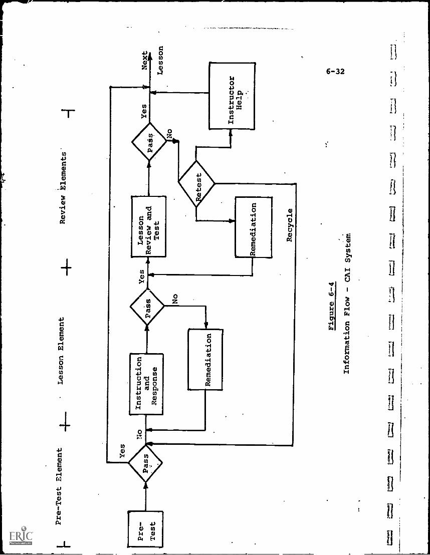
Pre-Test Element
Lesson Element
4-Review ilements'
Pre-
Test
Instruction
and
Response
Remediation
Pass
Yes
Lesson
Review and
Test
Remediation
Recycle
Figure 6-4
Information Flow
- CAI System
L=2
Yes
Next
Lesson
Instructor
Help
6-33
If he does.not pass, he is required to continue into thelesson element. Her..:, depending on how the course is programmed,
he receives a combination of problems and instruction which
are designed to teach him the subject. These are presented in
a sequence so that the student must understand a particular
step before proceeding to the next.
At the end of the lesson element, the student is testedagain. A "pass" permits him to proceed to the review element,
while a "fail" requires that he take a remedial instructional
sequence and go through the lesson element once again.
The same procedure holds for the review element, except
that the computer judges the final test results and, if the
student fails, classifies the degree of failure to determine
appropriate action. The student may be directed to undergo
another remedial sequence, or recycle back to the beginning of
the element, or seek assistance from the instructor.
Obviously, CAI is more easily adapted to courses which
are fact and logic-oriented (e.g., mathematics) and least
adaptable to subjects in which "right" and "wrong" answers aredifficult to define (e.g., philosophy, creative writing).
Further, even in a course such as mathematics, only a portion of
the course material may lend itself easily to CAI technique.
It is also clear that the value of any CAI course depends
greatly on the software, i.e., that is, how good a job has been
done in translating instructional procedures to computer form.
This task requires close interdisciplinary cooperation between
educational and computer specialists.
To date, a number of CAI operational modes have been
developed, on an ascending scale of sophistication. The mostcommon are described below.
6-2.1.1 Drill-and-Practice
The "drill-and-practice" mode is the simplest CAI application
The computer stores practice exercises in increasing degrees of
6-34
difficulty, and presents them to the student in that sequence.
By using the memory capacity of the computer and its ability tomonitor a number of students concurrently, the teacher is relievedof the burden of repetitive drill and supervision. Thus, drill-and-practice is designed to supplement the teacher's duties, or,at best, to assume the more routine functions, rather than to
present new instructional concepts.
In this task, the computer undoubtedly is very efficient(and patient), and readily permits each student to proceed onan individualized basis, both as to level of difficulty and rate
of presentation.
6-2.1.2 Tutorial
The "tutorial" mode of CAI is more advanced than drill-
and-practice, endeavoring to ptesent to the student essentially
the same information as might be contained in a programmed text-book. The computer program assumes responsibility for specific
.instruction, and approximates the tutor-student relationship.
The justification for using a computer lies in its ability
to store many contingent instruction modules, selecting the
appropriate path to match the student's progress. With this
"branching" capability, the student can more easily evolve or
construct the answer rather than simply select one from two orthree choices.
Because it attempts a more complex instructional mode,
tutorial CAI naturally is more difficult to program than drill-
and-practice. A broader range of student responses must be
anticipated, and provided for (including even such minor tech-
nicalities of recognizing mispelled words). If the advantages
of the computer are not utilized efficiently,' the cost of this
CAX mode can be intolerably high.
6-2.1.3 Inquiry/Response
6-35
In the "inquiry/response" mode, an interactive or
conversational dialog takes place between the student and the
computer which goes beyond simply matching student answers witha list of acceptable responses stored in the computer's memory.
In a simple dialog system, the student is free to makea wide variety of responses which are judged by the computer.
In a language program, for example, the student could begin to
write complete sentences after having received very littleprior instruction. The computer would tell him what he is doing
correctly in each case, allowing the student to "zero in" or
converge upon an acceptable form after a number Of attempts.
Thus, learning is achieved by discovery, or trial and error,than by a structureditight/Wrong" instructional program.
More complex dialog systems would allow even wider lati-tude in student inquiry, with the objective of achieving aSocratic model of instruction. As this objective is approached,
however, great difficulties arise in programming the computer.
Ideally, the student should be able to enter his questions in
"natural" language, which would be properly intepreted by thecomputer. As yet, the programing "languages" which have beendeveloped are highly restrictive, forcing student inquiries to
conform to the limited rules of the program language utilized.
Some progress has been made in selected systems, but todate the dialog systems which have been implemented are relativelynarrow in scope. The full potential of this technique awaits
the refinement of "higher-level" programming, i.e., approachingnatural language so far as the user'is concerned.
6-2.1.4 Problem-Solvinq and Computation
The "problem-solving" CAI mode consists of using the computer
as a computational tool rather than a textbook, with less reliance
on a body of data stored in the computer memory.
6-36
In a simple application, the computer acts as a high-speed
calculator to do the computation required to solve a problem
that might otherwise be too difficult or lengthy. A problem such
as computing the value of "ft to a high degree of precision
(at last record a computerbos actually done this to over 2000
places) would simply be unmanageable without the computer.
A more complex application permits the computer not only
to compute, but assist in the problem-solving process by
evaluating each step and indicating errors as they occur. Thiscan be done by giving the student.access to a number of pre
programmed routines which can not only perform calculations,
but can be combined for error checking.
Computation need not be a separate mode in itself, but
can be combined with other CAI moded such as inquiry/response.
The programming becomes more difficult in this case, and to
some extent, computer efficiency is reduced since a compromise
must be effected between the predominately memory-oriented
instructional process on the one hand and the computation-
oriented problem-solving routines on the other.
6-2.1.5 Modeling and Simulation
A promising application of.computers to instruction is
that of "modeling" and simulation. These techniques have been
used extensively in "war games", system design, business fore-
casting, etc., but are relatively new in education.
A typical example in a business administration course, for
example, would be to set up the characteristics of a company in
the computer, including past history of sales, earnings, operating
ratios, competitive factors, product development, etc. Then aset of assumed conditions for the future could be given to the
students such as national economic conditions, potential new
markets, technology trends and any others deemed relevant.
6-37
The student is then requested to decide upon specificaction to be taken, constituting in effect a business plan.These actions are entered into the computer, which is programmedto evaluate their effect upon the company. This effect, in theform of projections of future sales and profits, is then presentedto the student.
The advantages of a computer in such a simulation exerciseare that it can quickly analyze the combined effect of manyparameters (but only in accordance with the rules of the game,its programmed instructions). Thus, a 20-year projection canbe calculated in minutes or hours.
Further, the rules can be changed if desired, permittingevaluation of many combinations and ranges of inflUencingfactors, again in a short time. This task, like the difficultcomputational job discussed above, simply could not be doneany other way without excessive cost or time being expended.
As might be expected, the value of such simulation dependscompletely on how accurate the model is, and whether the programrules are flexible enough to embrace the numerous possibilitiesworthy of exploration. If a process is not understood wellenough to construct an acceptable model, the power of thecomputer to mislead can be as strong as its power to illuMinate.
6-2.2 Computer-Managed Instruction (CMI)
Computer-Managed Instruction (CMI) involves the use ofcomputers primarily as tools for evalaatinq student progressand matching students with instruction appropriate to theirindividual needs rather than actually performing the instruction.
Thus CMI depends upon the resources of conventional textbooksand audio/visual devices, in addition to the human instructor,and acts more in diagnostic and administrative support of theinstructor.
6-38
Some of the functions implicit in CMI include:
(a) testing'students and evaluating' test results, usually
at a number of stages in the course.
(b) Matching test results with appropriate learning
prescriptions.
(c) limited use of drill-and-practice CAI, again primarily
as an evaluation device and for remedial purposes.
(d) development, maintenance and supervision of student
instructional histories.
The data base developed by CMI systems which have been
operating for some period of time can be used as a guide to
improve CAI techniques and programs. With iterative refinement,
not only can CAI be-optimized for the majority of students, but
special versions can be produced for the minority of "exceptional"
students, either in the advanced or retarded category;
Many variations of CMI are possible, from a simple record-
keeping system to one with interactive diagnostic and counseling
capability, in which students are guided to the appropriate
instructional materials by the computer, which in turn has been
supplied with student progress records by the instructors.
6-2.3 Information Storage and Retrieval
In information storage and retrieval systems, the computer's
prime function is to store, provide access to, and distribute
information from a "data-bank". The flow of information,
particularly from the computer to the user, may be relatively
large compared to an interactive system.
The information stored and retrieved may be in direct
computer-compatible form, such as coded alphanumeric data in
the computer's memory. It may also be in non-compatible form,
such as microfilm or video tape, in which case the computer
controls the means for selecting the appropriate information,
but the transmission back to the user is non-digital and
essentially outside the computer's purview.
6-39
In this category are included information networking, dial-
access audio/visual, and computer-based mixed-media systems.
There is considerable overlap between the retrieval andinteractive systems. For example, a computer system may include
the dual capability for interactive problem-solving and also
accessing a large data-bank. Nevertheless, the separation is
useful from a technological point of view, as the information
storage, communications and display characteril,ics differ
markedly.
In a problem-solving system, there generally is a low
volume of data tramsmitted between the computer and any userterminal. This is partly because of the nature of the terminal
itself, usually a slow-speed teleprinter, and partly because of
the inherent delays in CAI, primarily at the user end while the
student is deciding how to respond.
Thus, in many cases, a very low bandwidth communications
link is adequate. Voice-grade telephone lines are entirely
satisfactory for single-user connection and, in fact, are used
as "party lines" in most systems, to accommodate a number of.
user terminals.
For a retrieval system; the low bandwidth link may be
adequate for user-to-computer communications, in which a request
is transmitted. For the response, this.is not true. If, for
example, the request is for receipt of a TV program, a"wideband
communications link is necessary.
Even for retrieval of static visual data, such as still
pictures, pages of a book, etc., telephone links impose an
opeiational handicap. As noted, the transmission of one
8-1/21, x 11" page by facsimile normally requires some 3-6
minutes over telephone lines. While this may be adequate for
Isolated cases, it would hardly be compatible with a general
purpose, multi-user retrieval system.
The features of the user terminal also vary greatly between
the interactive and retrieval computer system. The interactive
system can use a teleprinter terminal because the time interval
6-40
of the user inquiries and the computer's response are reason-
ably compatible with the speed and printout capability of theterminal.
For a retrieval system, the user's terminal may not differin the "request" capability. The "response" portion of the user'sterminal, however, must match the characteristics of the databeing retrieved and may correspondingly be much more elaborateand expensive. If a TV video/tape isbeing accessed and retrieved,the user's terminal must in effect be a TV receiver. If visual/static graphical or microform data is retrieved, then perhaps afacsimile hard copy receiver is required. If library inter-change of large quantities of alphanumeric data is the objective,
a high-speed line printer may be the receiving terminal device.For interactive problem-solving, the computer memory
storage is not required to store' and provide accessto verylarge quantities of essentially similar data. On the otherhand, the software library, i.e., the programs necessary tosolve the wide variety of problems anticipated will be extensive.Thus, the interactive systeM is useful in proportion to thecomprehensiveness and variety of its li racy of "applications"programs. Any specific program may be used relatively rarely;however, and in almost all cases the quantity of data manipulatedand transmitted in either direction is relatively small.
Conversely, the networking/retrieval computer systemstores a vast amount of data, ordered and filed so as to be
accessible within acceptable time limits. Essentially nocomputation or data processing is done, but the software in thiscase acts as a traffic director. The critical functions of thesoftware are large-file management, data access'and control ofcommunications. The computer, in this'instance, "computes"very little but serves as a data repository, i.e., a library,with its attendant functions.
From the above summary of characteristics, certain operationalconclusions may be inferred. The interactive system permits the
I
computer and user to interface at an input/output rate more con-
6-41
1
to the user. In other words, the man-machine interfaceis designed more for the slower human rates than for the computer.For this reason, use of the computer in the interactive modeusually is not cost-effective unless a large number of users canbe served.
The information networking or retrieval system, on theother hand, is usually not cost-effective unless agreat deal ofdata can be communicated to the user in a short time, in mostcases shorter than the time required for utilization of thedata. Thus, a retrieval system (except for the extreme caseswhere only small quantities of data are retrieved) is moreefficient as a machine-to machine system and is constrained,sometimes drastically, by the man-machine output interface, i.e.the user terminal.
6-2.4 Selection of Computer Systems
It is clear from the foregoing dlscussions that selectionof a particular computer as the optimum for an educationalapplication is not an easy task. In most cases, this decisionhas been either abdicated or rendered moot because a specificcomputer was already available and had to be used, or becausea standard system was purchased from a manufacturer. Examplesof the latter are the IBM 1500 Instructional System or RCA'sEducational 70 System.
There are no rules which can guide the educator auto-matically to selecting the best hardware/software configurationfrom a maze of possibilities and in most cases expert adviceand consultation is necessary. The critical factor, however,is that the educational user must first define the requirementsof the system and then modify these, if necessary, to fitequipment constraints, rather than than accepting a recommendationfor a specific system and then trying to fit his educational needs
6-42
to that. The first case permits him to know exactly how muchhe is deviating from his obiectives, the second does not.
This is even more true in the software area than in hardware,
since the questions of what is presented to the student, andhow it is presented, determine whether the system gains acceptanceand represents any improvement over present methods.
6-2.4.1 Centralized vs. Decentralized Com uters
One basic decision which must be reached in any widespreadeducational use of computers is the choice of whether a
centralized or decentralized system approach should be used.
A centralized system is one which uses a single, large-
scale computer to serve many user terminals and locations.
The computer might be a facility costing millions of dollars,
and could serve a region of schools and universities, possiblywith thousands of terminals. Since a large geographical areais served, the terminals are linked to the computer by communi-
cations networks, usually telephone lines.
A decentralized system would use small computers locatedat each using facility, e.g., one per school. The small,computer could serve a much smaller number of users, but enoughfor that location. The connection from computer to user terminalsis usually direct-cable, paid for and owned by the usinginstitution.
There are advantages and disadvantages to each approach.(1) Centralized:
(a) The large computer offers "economy of scale"performance, i,e., it gives more computing powerper dollar.
(b) Program preparation can also be centralized andand made more efficient. Further, programmingeffort does not have to be duplicated at eachlocation, and a large library can be built up. foreveryone's use.
6-43
(c) The computer can be operated-and maintained by a
group of skilled professionals who would not be
obtainable by smaller facilities
(2) Decentralized:
(a) The system is not dependent on costly, and some-
times unreliable communications links.(b) The system can be "dedicated" to a single
application and optimized for that, instead of
having to be able to serve in a variety of
applicationi,
(c) Changes, in both hardware and software, can be
made much more quickly and easily.
At this point in time, no clear-cut choice can be madefor all cases, but it is likely that decentralized systems willproliferate faster than centralized ones. This is partly dueto the jurisdictional and budgetary quirks of U.S. schooldistricts, where smaller sums are more easily come by, and partly
to the expectation that mini-computer systems will become evenmore attractive in cost and performance.
The software requirements of the decentralized systems,however, will represent a substantial challenge to local educators
and, if this challenge is not met, the utility of such systemscould prove disappointing.
6-2.5 Costs of Computer - Based Instruction
It is extremely difficult to determine the precise costs ofa computer-based educational system. Historical records ofprototype systems are available, and provide the best sourcesof data, but even there a number of interrelated factors tendto blur the evaluation. Some of these are:
(1) The computer in many cases is being used not only for
instruction but for other tasks such as record-keepingand accounting.
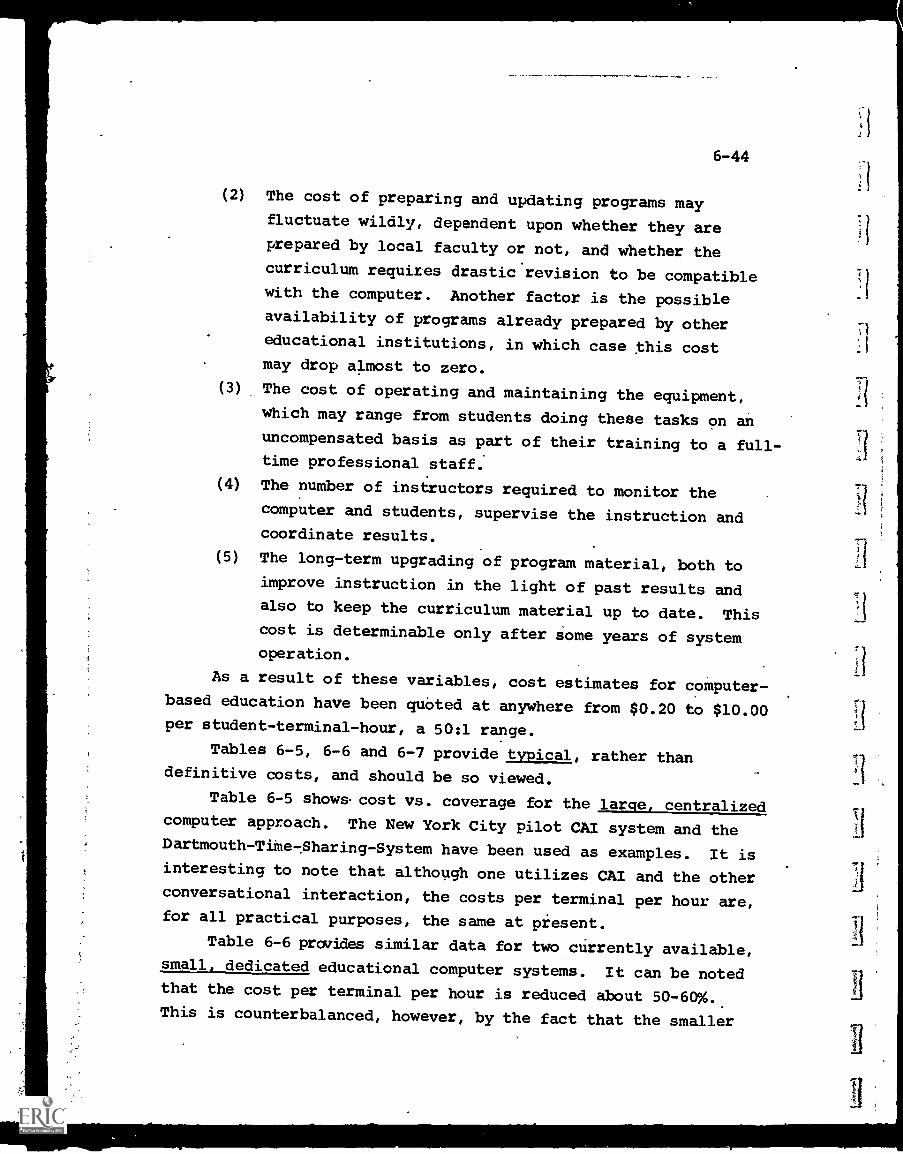
6-44
(2) The cost of preparing and updating programs mayfluctuate wildly, dependent upon whether they areprepared by local faculty or not, and whether the
curriculum requires drastic revision to be compatiblewith the computer. Another factor is the possibleavailability of programs already prepared by other
educational institutions, in which case this costmay drop almost to zero.
(3) The cost of operating and maintaining the equipment,which may range from students doing these tasks on anuncompensated basis as part of their training to a full-time professional staff.
(4) The number of instructors required to monitor thecomputer and students, supervise the instruction andcoordinate results.
(5) The long-term upgrading of program material, both toimprove instruction in the light of past results andalso to keep the curriculum material up to date. Thiscost is determinable only after some years of systemoperation.
As a result of these variables, cost estimates for computer-based education have been quOted at anywhere from $0.20 to $10.00per student-terminal-hour, a 50:1 range.
Tables 6-5, 6-6 and 6-7 provide typical, rather thandefinitive costs, and should be so viewed.
Table 6-5 shows cost vs. coverage for the large, centralizedcomputer approach. The New York City pilot CAI system and theDartmouth-TiMe-$haring-System have been used as examples. It isinteresting to note that although one utilizes CAI and the otherconversational interaction, the costs per terminal per hour are,for all practical purposes, the same at present.
Table 6-6 provides similar data for two currently available,small, dedicated educational computer systems. It can be notedthat the cost per terminal per hour is reduced about 50 -60%.This is counterbalanced, however, by the fact that the smaller

computers are more limited in both capability and flexibility,
and require more sophisticated programming in many cases.
Table 6-7 compares the cost of a CAI course in college
physics at Florida State University against a CMI project
also developed by the same staff. As expected,'the CMI costsare much lower.
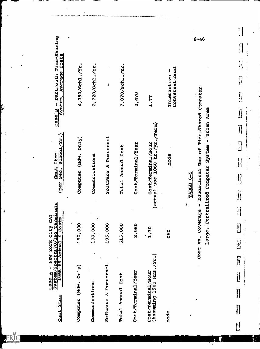
Case A - New YorkCity CAI
Terminals
Cost Item
Case B - Dartmouth Time-Sharing
Svstem/Spectra70/192
Cost Item
1968-69 Actual $ Costs
(per Sec. School/Yr.)
System Average Costs
Computer (Hdw. Only)
190,000
Computer (Hdw. Only)
4,350/Schl./Yr.
Communications
130,000
Communications
2,720/Schl./Yr.
Software & Personnel
195,000
Software & Personnel
-
Total Annual Cost
515,000
Total Annual Cost
7,070/Schl./Yr.
Cost/Terminal/Year
2,680
Cost/Terminal/Year
2,470
Cost/Terminal/Hour
1.70
Cost/Terminal/Hour
1.77
(Assuming 1500 Hrs./Yr.)
(actual use 1860 hr./yr./Term)
Mode
CAI
Mode
.Interactive -
Conversational
TABLE 6-5
cnCost vs. Coverage - Educational Use of Time-Shared Computer
Large, Centralized Computer System - Urban Area
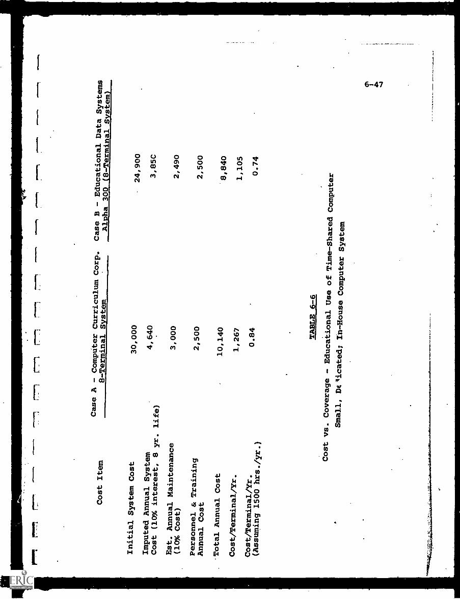
1
Cost Item
pil1
1.4
Case A - Computer Curriculum
Corp,.
Case B - EducationalData Systems
8-Terminal System
Alpha 300 (8-Terminal System)
Initial System Cost
30,000
Imputed Annual System
4,640
Cost (10% interest, 8
yr. life)
Est. Annual Maintenance
3,000
(10% Cost)
Personnel & Training
2,500
Annual Cost
Total Annual Cost
10,140
Cost/Terminal/Yr.
1,267
Cost/Terminal/Yr.
0.84
(Assuming 1500 hrs./yr.)
TABLE 6-6
24,900
3,85C
2,490
2,500
'8,840
1,105
0.74
Cost vs. Coverage
- Educational Use of Time-SharedComputer
Small, Delicated; Ih-HouseComputer System
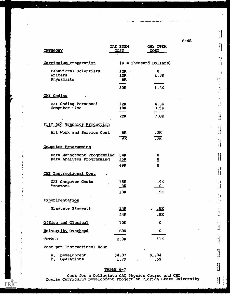
CATEGORY
6-48
CAI ITEM CMI ITEMCOST COST
Curriculum Preparation (K = Thousand Dollars)
Behavioral 'Scientists 12K . 0Writers 12K. 1.3KPhysicists 6K
30K 1.3K
CAI Coding
CAI Coding Personnel 12K 4.3KComputer Time 10K 3.5K
Film and Graphics Production
22K 7.8K
Art Work and Service Cost 6K .2K
6K .2K
Computer Programming
Data Management Programming 54KData Analyses Programming 15K
CAI Instructional Cost
00
69K 0
CAI Computer Costs 15K .9KProctors 3K 0
18K .9K
Experimentation
Graduate Students 24K .8K
24K .8K
Office and Clerical 10K 0
University Overhead 60K 0
TOTALS 239K 11K
Cost per Instructional Hour
a. Development $4.07 $1.04b. Operations 1.79 .59
TABLE 6-7
Cost for a Collegiate CAI Physics Course and CMICourse Curriculum Development Project at Florida State University
0
6 -413
CHAPTER 6 - BIBLIOGRAPHY
1. "Computers in Higher Education", Report of the President'sScience Advisory Committee, 1967, Government Printing Office,Wash. D.C.
2. "Educational Technology in Higher Education: The Promisesand Limitations of ITV and CAI", Report, InstructionalTechnology Committee, Commission on Education, NationalAcademy of Engineering, Sept. 1969.
3. Hansen, D.N., "The Role of Computers in Educatioh During the1970's", Tech. Memo No. 15, May 15, 1970, Florida StateUniversity, prepared under Contract No. N00014-68-A-0494, Officeof Naval Research.
4. Levien, R.E. (Editor), "Computers in Instruction: TheirFuture for Higher Education", Proceedings of Conference Oct.
.7 1970, sponsored by NSF, the Carnegie Commission on HigherEducation, and the Rand Corp., Rand R -718- NSF /CCOM/RC, July1971.
ORINIi WWI imail immuml limn; 1
7 -1
CHAPTER 7 - DISTRIBUTION TECHNIQUES
Information in electrical form may be distributed in avariety of ways. Some of the questions which must be answeredbefo. e a choice of distribution systems can be made include:
(a) What is the form of the electrical signal as itenters the distribution system?
(b) What is the desired information flow (i.e., how manysources, how many receptors, one-way or two-waycommunications)?
(c) Can the original electrical form be transmittedefficiently?
(d) Are there many signals to be distributed over thesame paths?
.(e) What form is desired at each reception point (tomatch the receiving terminal)?
(f) What are the relative costs of alternate distri-bution methods?
(g) What constraints are there (e.g., FCC allocationsof frequencies)?
Even after the answers have been determined, the selectionof an optimum system is not always cLar, and in many cases mayrequire the services of communications specialists.
This chapter reviews the basic concepts involved in trans-mitting and distributing electrical information. Chapters 8and 9 focus, respectively, upon wire and wireless carriers.
7-1. Communication Modes
7-1.1. Transmission Medium
Electrical signals can be transmitted as a current throughelectrically conductive material, such as wire and cable, or
they can be sent through space as an electromagnetic radiation.
Both media are in wide use, and almost all systems combinethe two for different portions of the transmission path. Aradio broadcast station, for example, will use wire to feedthe signal to the transmitting antenna, and wireless from that 11
point to the receivers.
Fig. 7-1(a) is the generalized diagram. of any electricaldistribution system. There must be a source of electrical
power which forces the flow of electrons in a wire, or radiatedenergy through the air. This power must be used by a load ofsome sort, and, finally, there must be a complete path for theelectrical flow.
Fig. 7 -1(b) is an elementary sample of wire transmission.
The battery forces electrical current through the resistor,which uses (dissipates) power, and around the complete circuit.
Although metals are more highly conductive to electricity(offer less resistance) and are therefore commonly used forwires and cables, they are not the only materials which cantransmit electricity. All materials, in fact, will conductsome amount. Those-which, for practical purposes, conductan insignificant amount are called insulators, while there isa category which permits some conduction but not so much asthe metallic elements.
The earth itself will conduct electricity with varyingdegrees of resistance, depending upon ground conditions betweenthe points of entry and exit. Thus, in Fig. 7-1(c), the earthbetween the two "ground"connections will complete the electricalpath, allowing some current to flow.
Since the metallic wire or cable is a much better conductorthza the earth, and also subject to less interference fromoutside signals, most wired systems provide complete pathswithout depending upon a ground return path for the normalflow of current. Many systems, however, use a metal case orchassis as a common connection point, which is also called
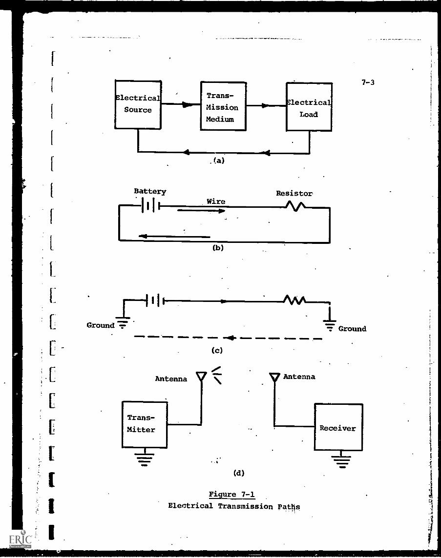
.10
a,
7-3
Electrical
Source
Trans-
Mission
Medium
lectrica
Load 1
Battery
I,I.
PGround -:-
.la)
Wireamma=1".
I
Resistor
I I t
IMOIllo
(b)
.0110 IMIIIIII ammiml. ANI =11, .11=111.
Trans-
Mitter
amminOnl1ONO
(d)
Figure 7-1
Electrical Transmission Paths
=Nom,
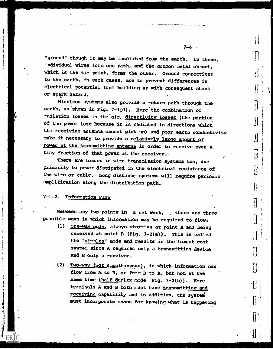
7-4
"ground" though it may be insolated from the earth. In these,individual wires form one path, and the common metal object,
which is the tie point, forms the other. Ground connectionsto the earth, in such cases, are to prevent differences in
electrical potential from building up with consequent shockor spark hazard.
Wireless systems also provide a return path through the
earth, asshowm in Fig. 7-1(d). Here.the combination of
radiation losses in the air, directivity losses (the portion
of the paWer lost because it is radiated in directions which
the receiving antenna cannot pick up) and poor earth conductivitymake it necessary to provide a relatively large amount of
power at the transmitting antenna in order to receive even atiny fraction of that power at the receiver.
There are losses in wire transmission systems too, due
primarily to power dissipated in the electrical resistance ofthe wire or cable. Long distance systems will require periodic
amplification along the distribution path.
7-1.2. Information Flow
Between any two points in a net work, there are three
possible ways in which information may be required to flow:(1) One -way only, always starting at point A and being
received at point B (Fig. 7-2(a)). This is called
the "simplex" mode and results in the'lowest cost
system sinceA requires only a transmitting deviceand B only a receiver.
(2) Two-way jnot simultaneous), in which information can
flow from A to B, or from B to A, but not at the
same time (half duplex mode Fig. 7- 2(b)). Here
terminals A and B both must have transmitting and
receiving capability and in addition, the system
must incorporate means for knowing what is happening
tj
I
nEi
ti
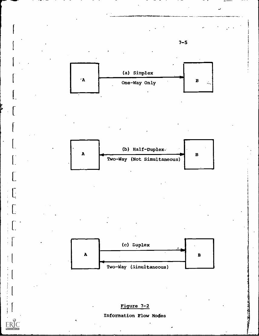
(a) Simplex
7-5
One-Way Only
ATwo-Way (Not Simultaneous)
(b) Half- Duplex
(c) Duplex
Two -Way (Simultaneous)
Figure 7-2
Information Flow Modes
7-6
so that no attempt to transmit both ways simultaneously
can occur.
(3) Two-way (simultaneous), in which information can
flow either way .at any time (duplex mode, Fig. 7-2(c)).
To permit this, either two separate simplex cir-
cuits are _used, or the two signals must be separated
electrically (either in frequency or time) so that
they will not interfere with each other.
Full duplex or half-duplex does not necessarily require
that the channels be symmetrical or of equal bandwidth in bothdirections. A student communicating through a keyboard with
a computer,-for example, can only send data very slowly, but
the return from the computer may contain a high volume of data
in a short response time.' Thus one channel might be a telegraph
or phone line, and the other a wideband video circuit.
7-1.3. Modulation
In Chapter 3, the necessity for modulation was briefly
outlined, and the two most common forms, AM and FM, described.
Unmodulated signals, such as the audio outpilt from a
microphone or the video output from a video camera, can be
transmitted only over short distances without excessive penalty
paid in power losses and degradation. A closed-circuit
television system confined to a single building or campus might
well use direct distribution of audio and video signals, but
if the cable distances extend to a few miles or more, the need
for amplifiers and similar components will begin to outweigh
the efficiencies achieved by modulation.
The choice of what carrier frequency to use, if through-
the-air broadcasting is used, may well be dictated by FCC
assignment rather than any other criteria. For wire trans-
mission, particularly coaxial cable where the outer conductor
shield keeps radiation from occurring, more selectivity can
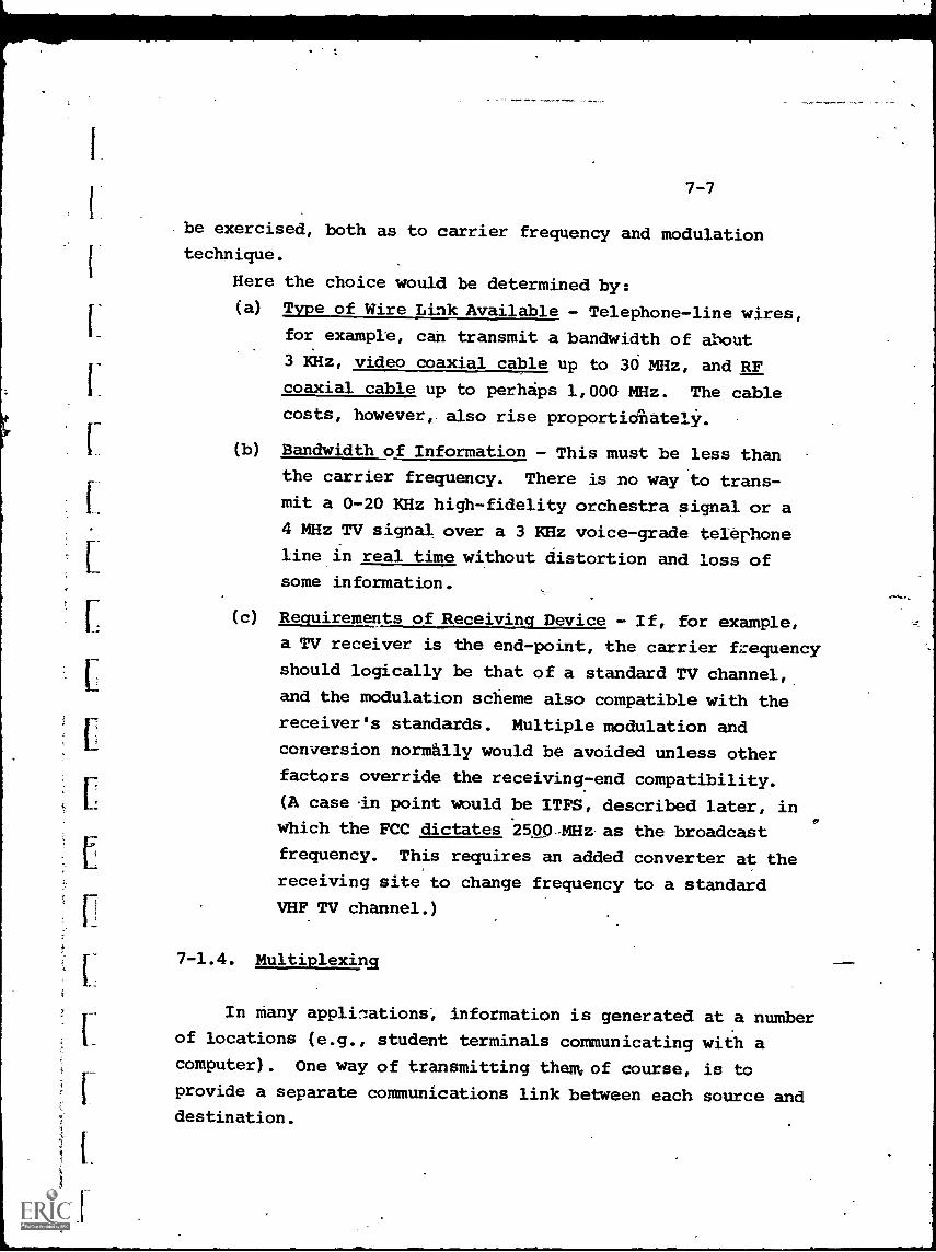
7-7
be exercised, both as to carrier frequency and modulationtechnique.
Here the choice would be determined by:
(a) Type of Wire Link Available - Telephone-line wires,
for example, can transmit a bandwidth of about
3 KHz, video coaxial cable up to 30 MHz, and RF
coaxial cable up to perhaps 1,000 MHz. The cable
costs, however, also rise proportiOnatelir.
(b) Bandwidth of Information - This must be less than
the carrier frequency. There is no way to trans-
mit a 0-20 KHz high-fidelity orchestra signal or a
4 MHz TV signal over a 3 KHz voice-grade telephone
line in real time without distortion and loss ofsome information.
(c) Requirements of Receiving Device - If, for example,
a TV receiver is the end-point, the carrier frequency
should logically be that of a standard TV channel,
and the modulation scheme also compatible with the
receiver's standards. Multiple modulation and
conversion normally would be avoided unless other
factors override the receiving-end compatibility.
(A case in point would be ITFS, described later, inwhich the FCC dictates 2500-- MHz as the broadcast
frequency. This requires an added converter at the
receiving site to change frequency to a standard
VHF TV channel.)
7-1.4. Multiplexing
In many applilations, information is generated at a number
of locations (e.g., student terminals communicating with acomputer). One way of transmitting them of course, is to
provide a separate communications link between each source anddestination.
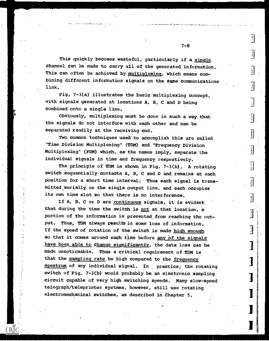
7-8
This quickly becomes wasteful, particularly if a single
channel can be made to carry all of the-generated information.
This can often be achieved by multiplexing, which means com-
bining different information signals on the same communications
link.
Fig. 7-3(a) illustrates the basic multiplexing concept,
with signals generated at locations A, B, C and D being
combined onto a single line.
Obviously, multiplexing must be done in such a way. that
the signals do not interfere with each other and' can be
separated readily at the receiving end.
Two common 'techniques used'to accomplish this are called
"Time Division Multiplexing" (TDM) and "Frequency Division
Multiplexing" (FDM) which, as the names imply, separate the
individual signals in time and frequency respectively.
The principle of TDM is shown in Fig. 7-3(b). A rotating
switch sequentially contacts A, B, C and D and remains at each
position for a short time interval: Thus each signal-is trans -
mitted.serially, on the single output line, and each occupiei
its own time slot so that there is no interference.
If A, B, C or D are continuous signals, it is evident.
that during the time the switch is not at that location, a
portion of the information is prevented.from reaching the out-
put. Thus, TDM always results in some loss of information.
If the speed of rotation of the switch .is made high enough
so that it comes around each time before any of the signals
have been able to change significantly, the data loss can be
made unnoticeable. Thus a critical requirement of TDM is
that the sampling rate be high compared to the frequency,
spectrum of any individual signal. In practice, the rotating
switch of Fig. 7 -3(b) would probably be an electronic sampling
circuit capable of very high switching speeds. Many slow -speed
telegraph/teleprinter systems, however, still use rotating
electromechanical switches, as described in Chapter 5.
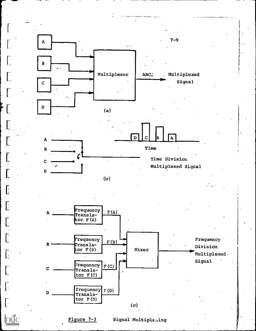
D
A
B
C
Multiplexer
(a)
7-9
ABC Multiplexed
Signal
FrequencyTransla-tor, F (A)
(b)
F (A)
D
FrequencyTransla-tor F(B)
F (B)
Time
Time Division
Multiplexed Signal
?requencyTransla-tor F(C)
FrequencyTransla-tor F(D)
F (C)
(D)
Mixer
(c)
Figure 7-3 Signal Multiplelang
Frequency
Division'
Multiplexed
Signal
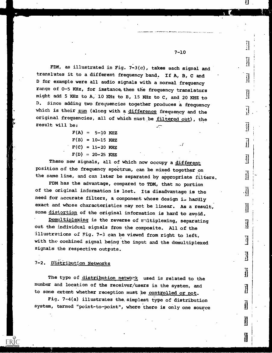
7-10
FDM, as illustrated in Fig. 7-3(c), takes each signal andtranslates it to a different frequency band. If A, B, C andD for example were all audio signals with a normal frequency
range of 0 -5 KHz, for instance, then the frequency translatorsmight add 5 KHz to A, 10 KHz to B, 15 KHz to C, and 20 KHZ toD. Since adding two frequencies together produces a frequencywhich is their sum (along with a difference frequency and the
original frequencies, all of which must.be filtered out), theresult will be:
F(A) = 5-10 '<HZ
F(B) = 10-15 KHZ
F(C) = 15-20 KHZ
F(D) = 20-25 KHZ
These new signals, all of which now occupy a different
position of the frequency speCtrum, can be mixed together on
the same line, and can later be separated by appropriate filters.
FDM has the advantage, compared to TDM, that no portion
of the original information is lost. Its disadvantage is theneed for accurate filters, a component whose design i. hardly
exact and whose characteristics may not be linear. As a result,
some distortion of the original information is hard to avoid.
Demultiplexinq is the reverse of multiplexing, separating
out the individual signals from the composite. All of theillustrations of Pig. 7-3 can be viewed from right to left,
with the. combined signal being the input and the demultiplexedsignals the respective outputs.
7-2. Distribution Networks
The type of distribution netwO77k used is related to the
number and location of the receiver/users in the system, and
to some extent whether reception must be controlled or not.
Fig. 7 -4(a) illustrates the. simplest type of distribution
system, termed "point-to-point", where there is only one source
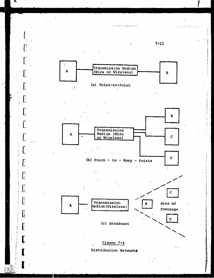
(a) Point-to-Point
TransmissionMedium (Wireor Wireless)
(b) Point'- to - Many - Points
Area of
.,. Coverage
.%..
(c) Broadcast
Figure 7-4
Distribution Networkd
7-12
of information and one using location., A wired system wouldbe a direct connection between the two points (neglecting anyrequirement for amplifiers, modulators, etc.). The wirelessequivalent would be a highly directive beam aimed from a trans-mitter.so that only one receiver in a specific location couldreceive its signal. (This is a typical microwave repeaterlink, used in cases where cable connection might be too expensiveor difficult, such as across a river.)
Fig. 7 -4(b) illustrates a "point-to-many-points" networkin which information is directed from a single source to aselected number of receiving locations. Again the actual pathscould be either wire or wireless. An example of the formerwould be a CCTV system in which a TV program can be sent to aspecific group of receiving monitors possibly under control.
at the source.
The "broadcast "mode of Fig. 7-4(c) implies a signal whichcovers a relatively broad geographical area. A radio' or TVstation which might have a strong signal up to a 50-mile radiusfrom the transmitter would be an example. Anyone who possessesa compatible receiver can receive the signal, with no pos-sibility of being able to. select or control the number ofreceivers at any time. If, of course, a non-standard frequencyor mode of modulation is transmitted, the potential user isforced to obrain a receiver which is compatible, but the generalphilosophy of broadcast systems is to maximize, not limit, theaudience.
The concept of "cable-casting" has arisen recently,-
particularly with respect to CATV systems, and it is a wiredequivalent to wireless broadcasting, in which a locally-generated program is sent over a particular cable channel,'andany subscriber connected to the cable system can receive it onhis TV set.' This is not a retransmission of an over the-airTV signal, but one originated by the CATV operator (or perhapsa local school) within the cable system itself.
7-13
Apart from the destinations to be reached, another
significant feature of the distribution network is the nature
of the path taken. Fig. 7-5 illustrates various routing
techniques in common use.
. The "switched network", shown in Fig. 7-5(a), is one in
which many paths are available between the source A and the
destination B. Which particular path is selected at any
particular time depends on whether some are being used for
other messages. The system will automatically search for an.
"open" path and route the A-B message on it.- At a later time,
another path likely will be selected.
The most obvious example of the switched network is the
dial telephone system. If someone in New York dials a number
in Chicago, his call-may go directly to a wire link between
New York and Chicago. If, however, these direct circuits are
all busy, his call may be routed from New York to Los Angeles,
and then from Los Angeles to Chicago. The caller does not
know, or care particularly, which route is taken and he is
charged the same toll in either case.
The advantage of the switched network is the ability to
"load-share", i.e., seek out and use idle circuits when others
are temporarily overloaded, thus smoothing out the peaks and
valleys of traffic flow. The cost and complexity of the seek-
ing and switching apparatus, however, reserves this technique
for large-scale systems. Further, the diversity of paths
carry with them an equal diversity of possible noise and inter-
ference.
Fig. 7-5(b) illustrates the fixed-path, "dedicated"
connection. This is equivalent to a point-to-point direct
link in that, even though a variety of equipment is in the
traffic path, the path is always the same. Thus it can be
optimized in terms of matching the signal characteristics.
Since it is dedicated to only one source and user, however, the
24-hour-a-day cost must be borne by that application and in
many cases the cost is high.
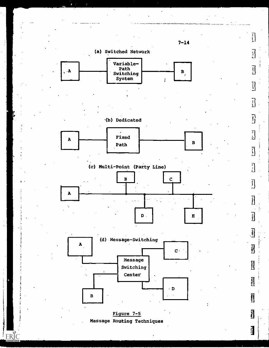
(a) Switched Network
Variable-Path
SwitchingSystem
7-14
-(b) Dedicated
A
Fixed
Path
B
(c) Multi-Point (Party Line)
B
D
(d)- Message- Switching
B
Message
Switching
Center
C .
D
Figure 7-5
Message Routing Techniques
r.
f
El
7-15
The .party-line type of routing is shown in Fig. 7-5(c) in
which one channel carries the-same information "down the pipe",
and many users can tap in at any location. The number is
limited only by whether the taps degrade the main stream of
infoimation or cause inteference among users.
A more sophisticated routing technique is the "message
switching' approach of Fig. 7-5(d). The message switching center
contains storage, address location and comptational capability
in addition to switching.
As an illustration, both A and B may wish to send a message
to C. In each case, the message is coded with an addresi which
identifies C as the recipient. The message center receives
both messages and, depending upon the way it is programmed, may:
(a) Immediately'send message A-C, followed by B-C
(b) Store both, hold them until more messages for C are
accumulated, and then send them all (Store-and
forward mode)
(c) Check message priority and send the high-priority
at once, accumulating the lower - priority messages
for later transmission.
At present, message switching systems are used primarily
on common-carrier and government networks, but they are equally
applicable, for example, to a large educational time-sharing
computer system where terminals must communicate not only with
the computer but also with each other.
7-3. Analog vs. Digital Transmission
7-3.1. Characteristics of Analog and Digital Information
Some preliminary discussion of digital information and
coding was provided in Chapter 6, in connection with computer
storage and processing techniques.
7-16
In a- more general way, digital information in electricalform can be described as that information which can be completedefined by a combination of two procedures:
(a) Representation by a number of discrete elements.Although not the only approach, almost all electricalsystems limit these elements to either of twoPossible values. This permits low-cost data processingand communications circuitry, since each circuit needonly maintain (or recognize) these two states.
(b) Establishment of a code which translates groups ofthese two-state elements into equivalent numbers,letters or symbols.
In computer terminology, the two-states are designated "0"and "1" and the elements are called "bits". The rate of trans-mission of digital information is measured by bits-per-secondt
CbpsY and all bits are electrical pulses of equal time duration.Thus, a transmission rate cf 1,000 bps means that 1000 bits,each of which can be either a "0" or "1", are sent through thedistribution system in one second. Each bit lasts the sameperiod of time (perhaps 1/2 millisecond) and is separated bya period of time (the other 1/2 millisecond) from the next bit.
In data communication1 another term is used which issometimes confused with "bits" and "bps". This is the "baud"an old telegraphy term. A baud is defined as the reciprocalin time of the shortest code element. Bands and bit ratesare equal to each other if two -level signaling is used and all,code elements are equal in time.. This is true of computer-generated data. In telegraphy, however, some code elements(such as "dashes" in the Morse Code) are transmitted for longertime intervals than others ("dots") and the baud would be rdifferent from bit rate. Since it'is the reciprocal of theshortest code element, the baud is a measure of the maximumtransmission rate. If the shortest element, together with
7-17
its spacing interval requires one-hundredth of a second, the
baud rate would be 100, meaning that up to 100 of these
elements could-be transmitted. per second through the system.
Many common-carrier links are specified in baud, particularly
the low and medium speed channels. The decreasing use of
telegraph-type codes, however, is resulting in bit rate gradually
superseding baud as the measure of- :digital transmission rate.
So far as educational telecommunications systems are
concerned, the main categories of information transmitted are
audio, video and data.- Audio and video are generally analog,
or continuous, in form (although it is-possible to convert
them to a series of digital values if this offers any advantage).
Datat on the other hand, is inherently digital in nature,
consisting'of text (discrete alphabetical letters), numbers
and symbolic characters. In the word "AN", for example, the
A and N are separate characters and, once-coded digitally,
make up all of the information to be stored or transmitted.
If these two letters in digital electrical form' are transmitted
and recognized properly, there-can be no loss of information.
This feature gives digital transmission one significant.
advantage. Analog signals, whether transmitted by wire or
wireless carriers, are subject to degradation and distortion
from many sources. Some of these are the nonlinearities
introduced by such devices as amplifiers (needed to compensate
for signal losses) and filters (to block unwanted signals).
Others, such as thermal noise generated by random eleCtronic
motion, are inherent in the electronic process. In either
case, the pertubations make more difficult the task of receiv-
ing the analog signal as an exact representation' of the original
information. The prOblem can be likened to measuring an
exact point on the ruler - with the ruler moving 'somewhat
erratically all the while.
In digital transmission, however, the receiving equipment
need only determine which of two states each bit signifies.
7-18
This task .is much easier than measuring and reproducing a
specific analog value on a continuous scale. Further, only
very gross perturbations in the transmission system can cause
an error in this determination. As an example, attenuation
can reduce the amplitude of digital pulses, but an amplifier
inserted into the system need only recognize whether each bit
is a "0" or "1", and it then can regenerate a clean, high
power output signal. This is true even if individual pulses
are degraded seriously (but not enotjh to prevent the "0" or
"1" recognition).
The advantages of digital transmission in terms of greater
error immunity and simpler switching and multiplexing circuitry
are somewhat balanced by the fact that greater bandwidth is
required to transmit the same information. Each digital
character, since it is coded into a group of pulses represent-
ing bits, takes more time to transmit. Consequently, if
transmission time is'to be conserved,'the transmission rate
must increase, necessitating increased channel bandwidth.
In spite of this, the greater immunity to error and
the direct compatibilLtywith computers make digital trans-
mission more and more popular in communications systems.
7-3.2. Digital (Data) Transmission
7-3.2.1. Parallel and Serial Transmission
Transmission of data coded in digital form involves
sending a number of electrical pulses over the communications
system. A group of pulses (anywhere from 5-8 depending on
the code used) represents a specific character, which may
be a number, letter or symbol.
In order to transmit coded characters, it is necessary
to arrange them in a way that will allow their reception without
uncertainty. Two techniques permit this to _Je done, and are
known as "parallel" and "serial" data transmission.
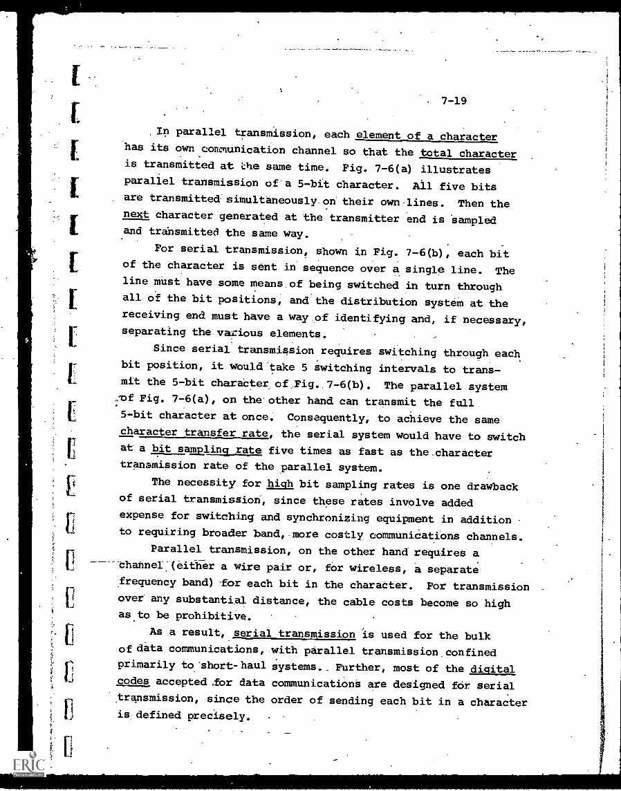
7-19
In parallel transmission, each element of a characterhas its own communication channel so that the total characteris transmitted at the same time. Fig. 7-6(a) illustratesparallel transmission of'a 5-bit character. All five bitsare transmitted - simultaneously-on their own lines. Then thenext character generated at the transmitter end is Sampledand transmitted the same way.
For serial transmission, shown in Fig. 7-6(b), each bitof the character is sent in sequence over a single line. Theline must have some means of being switched in turn throughall of the bit positions, and the distribution systeM at thereceiving end must have a way_of identifying and, if necessary,separating the various elements.
Since serial transmission requires switching through eachbit position, it would 'take 5 switching intervals to trans-mit the 5-bit charaCter of Fig. 7-6(b). The parallel systemof Fig. 7-6(a), on the other hand can transmit the full5-bit character at once. Consequently, to achieve the samecharacter transfer rate, the serial system would have to switchat a bit samplinct rate, five times as fast as the _character
transmission rate of the parallel system.
The necessity for high bit sampling rates is one drawbackof serial transmission, since these rates involve added
expense for switching and synchronizing equipment in additionto requiring broader band, more costly communications channels.
Parallel transmission, on the other hand requires achannel(eitfier a wire pair or, for wireless, a separate
frequency band) for each bit in the character. For transmissionover any substantial distance, the cable costs become so highas to be prohibitive.
As a result, serial transmission is used for the bulkof data communications, with parallel transmission confinedprimarily to 'short-haul Systems. Further, most of the digitalcodes accepted ,for data communications are designed for serial
transmission, since the order of sending each bit in a characteris defined precisely.
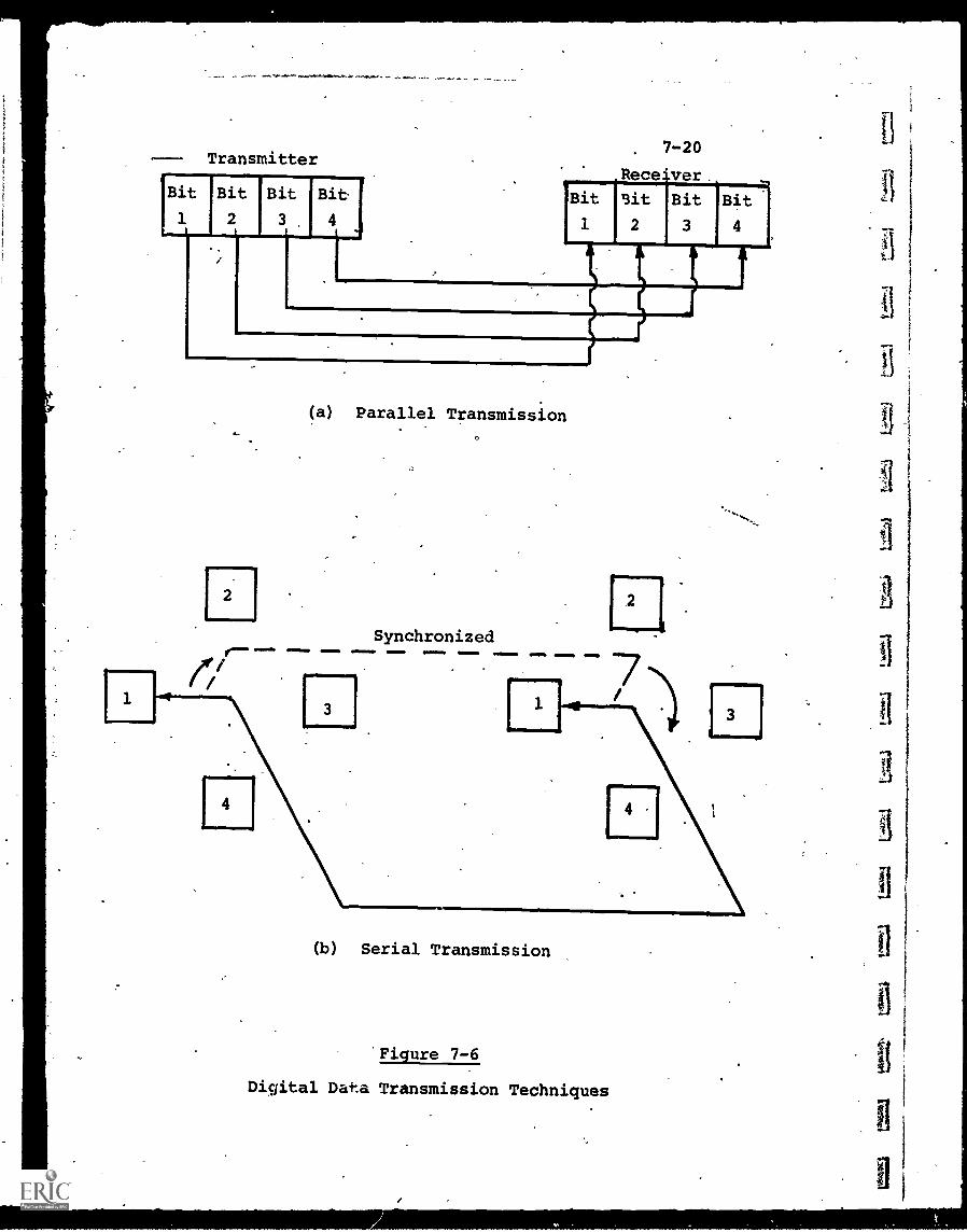
are ame-a.
--- Transmitter
Bit
1t I
Bit
21
Bit
3t
Bit
41
7-20
Receiver
Bit
1
it
2
Bit ,Bit
3 4
11laap
2
1111111111
(a) Parallel Transmission
Synchronized
(b) Serial Transmission
Figure 7-6
Digital Data Transmission Techniques
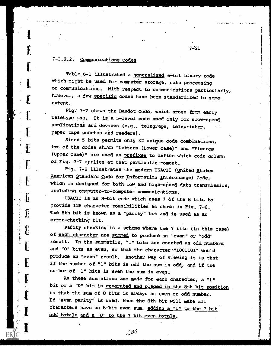
7-:21
7-3.2.2. Communications Codes
Table 6 -1 illustrated a generalized 6-bit binary codewhich might be used for computer storage, data processingor communications. With respect to communications particularly,howeve::, a few specific codes have been standardized to someextent.
Fig; 7-7 shows the Baudot Code, which arose from earlyTeletype use. It is 'a 5-level code used only for slow-speedapplicationi and devices (e.g., telegraph, teleprinter,
paper tape punches and readers).
Since 5 .bits permits only 32 unique code combinations,
two of the codes shown "Letters (Lower Case)" and "Figures(Upper Case)" are used as prefixes to define which code columnof Fig. applies at that particular moment.
Fig. 7-8 illustrates the modern USACII (United StatesAmerican Standard Code for Information Interchange) Code,
which is designed for both low and high -speed data transmission,
including computer-to-computer communications.
USACII is an 8-bit code which uses 7 of the 8 bits to
provide 128 character possibilities as shown in Fig. 7-8.The 8th bit is known as a "parity" bit and is used as an
error-checking bit.
Parity checking is a scheme where the 7 bits (in this case)
of each character are summed to produce an "even" or "odd"result. In the summation, "1" bits are counted as odd, numbers
and "0" bits as even, so that the character-"1001101" wouldproduce an "even" result. Another way of viewing it is that
if the number of "1" bits is odd the sum is odd, and if the
number of "1" bits is even the sum is even.
As these summations are made for each character, a "1"bit or a "0" bit is generated and placed in the 8th bit position
so that the sum of 8 bits is always an even or odd number.
If "even parity" is used, then the 8th bit will make all
characters have an 8-bit even sum, adding a "1" to the 7 bit
odd totals and a "0" to the 7 bit even totals.
j00
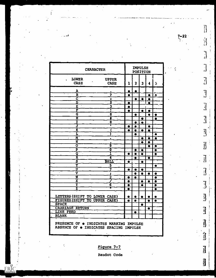
CHARACTER IMPULSEPOSITION
. LOWER UPPERCASE CASE
1
A .
BC s 41?
E 3 t
FG 8 0H iI 8
J e -K (
LMN
11.
0P 0
Q 1R 4S BELL
..
T 5U 7V ;
W 2X /Y 6Z 11
LETTERS(SHIFT TO LOWER CASE)FIGURES(SHIFT TO UPPER CASE)SPACECARRIAGE RETURNLINE FEED
. BLANK.
PRESENCE OF INDICATES MARKING IMPULSEABSENCE OF INDICATES SPACING IMPULSE
Figure 7-7
Baudot Code
7 -22
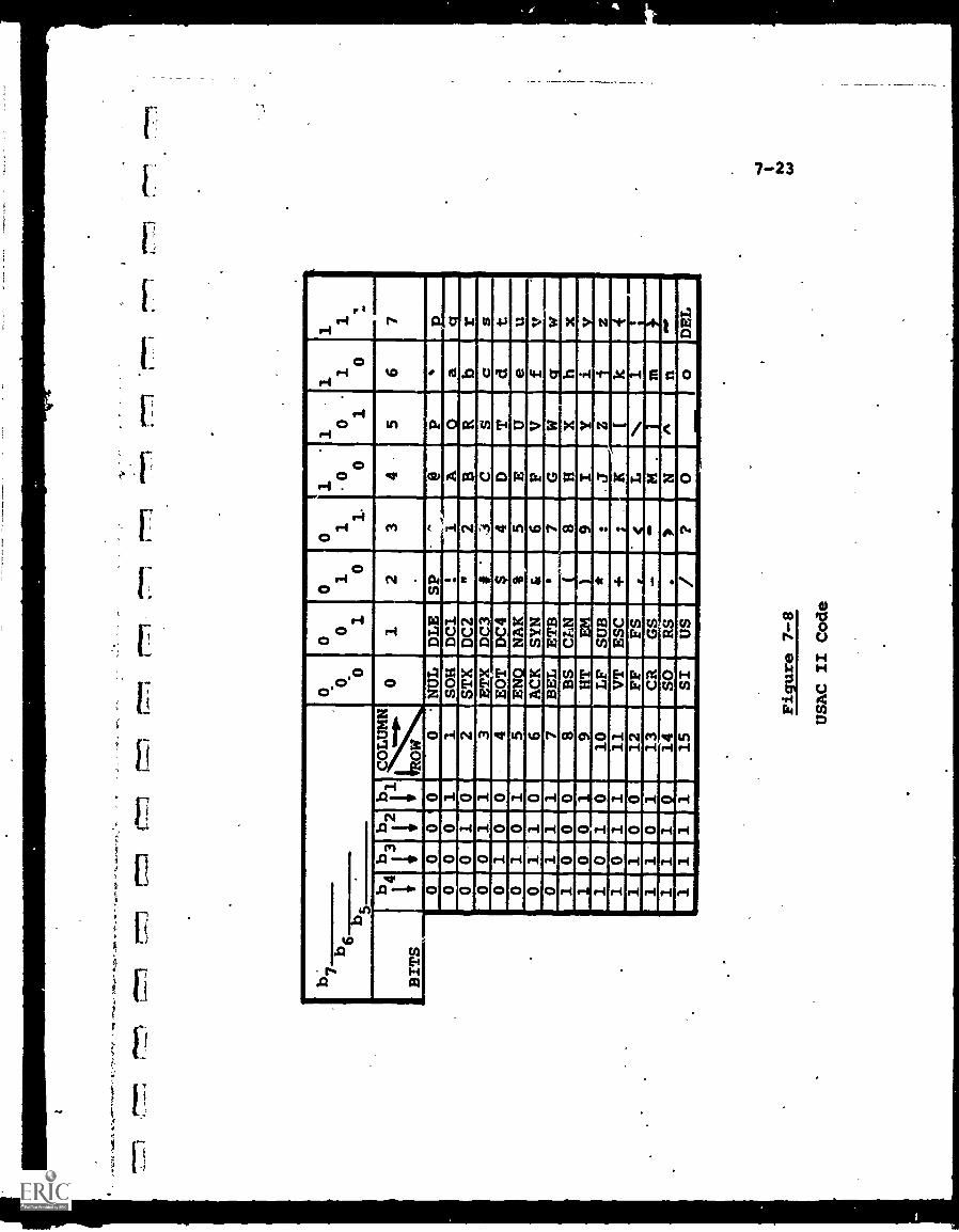
-' w
os,
Po.
,'"*
-'
11P
"sow
0111
.0ft.,
,
bq00
o01
o10
o11.
1 00
101
1 1
10
111
6-6T-7--
BITS "
.
b4b3b2b1ON
y-io.
0
01
23
45
67
0000
0 *NUL
DLE
SP
''
@P
.
00
01
1SOH
DC1
21
A.
a0
01
02
STX
DC2
"2
BR
b0
11
3ETX
DC3
#.
CS
cs
01
00
4EOT
DC4
4D
Td
t0
10
15
EN.
NAK
5E
Ue
u0
11
06
ACK
SYN
&6
FV
f1
17
BEL
ETB
7G
Wq
w1
00
08
BS
CLN
......
(8
Hlx
h1
00
19
HT
EM
)9
IY
iV
10
10
10
LF
SUB
*:JZiz
10
11
11
VT
ESC
+;
KI
k4
11
00
12
FF
FS
LN
1i
11
01
13
CR
GS
-M.
in
11
1Q
14
SO
RS
.N
n1
11
115
SI
I
US
DEL
Figure 7-8
USAC II Code
7-24
When the data has been transmitted and received, acircuit in the receiving equipment will check to see if,
indeed, the sum of each 8 bits is even. If so, the character
is assumed correct and if not, a transmission error will benoted.
This scheme will detect many errors but not all. If the
parity sum is odd, then an error must have occurred since the
received 8-bit character differs froni that sent. If, however,two "1" bits of a character are changed to "0",bits, the sum
remains the same, even or oddy-as before. Thus, moomattingerrors are not detected by parity checking.
A large percentage of transmission errors, however, are
caused by short electrical transients which may affect asmall group cf characters. Even the detection of only one
parity error in the group can serve to call attention to the
possibility that the data may be suipect. Some systems
automatically request a second transmission in that event.
The parity feature, therefore, has some value and canbe incorporated at relatively little extra expense.
Most computer and terminal manufacturers today are
designing for cympatibility with USACII so far as the device-
to-device communications are concerned, even'though a computer
may use a different code in its internal processing.
3
7-3.2.3. Modems
The term "modem" is a contraction of "modulator/demodulator", I
and refers to equipment that changes the form of electrical
information to 'best match the communications and distribution
11system that will be used. (The Bell System uses the term
"data set" instead of modem, and this has also gained acceptance,
so that the two terms are used interchangeably.)
When digital information, in the form of a sequence of
pulses, is to be transmitted over a voice-grade telephone line,
7-25
certain inherent incompatibilities exist, since the telephonenetwork is designed primarily for analog voice signals.
As one example, "noise" or transients on a phone line
are not uncommon, but they will not generally. distort a voice
conversation so badly that it cannot be understood. Thesesame transients, however, can introduce many errors into aserial train of pulses and possibly render the data completelyuseless.
Consequently, it has been found necessary to modulate the
pulse train by converting it to an'analog signal which carries
the same information as the pulse train but can be transmittedover the phone line more conveniently. At the receiving end,
a matching modem demodulates the analog signal back to theoriginal form.
Many techniques are employed by modems, depending uponthe required rate of data transmission, and whether optionalfeatures such as error checking are desired. One of the
simplest schemes is "frequency shift keying" (FSK) in which
a digital "1" shifts a carrier frequency to one value, anda "0" to a second malue. As an example, a carrier frequency
might be 2000 Hz, which is a good frequency for voice-grade
lines.. A "1" bit would cause the frequency to shift to 2100 Hz,
while a "0" would shift it the other way to 1900 Hz. At thereceiving end, the 2100 Hz and 1900 Hz "bursts" would be
reconverted back to l's and O's. .
Modems are available from both telephone-companies and
independent manufacturers, in a wide variety of data trans-
mission rates. (See Chapter 8 for more detailed data.)
Prices average about $1 for each bit-per-second, as a rule ofthumb.
Standard, dial-up phone lines can be used to transmit upto 2400 bps with relatively error-free results, and up to
4800.bps with specialized techniques for minimizing and
detecting erros. Above this, a "dedicated, conditioned"
7-26
line may permit data rates to perhaps 9600 bps, and requirements
in excess of that necessitate a broadband, rather than
voice - grade, communications link.
There are now under development all-digital wire
communications networks in which the characteristics of the
cable, switching centers, etc. are specifically designed for
digital data communications. These, when available would
require no modem equipment.
CHAPTER 7 - BIBLIOGRAPHY
7-27
1. Cronin, F.R., "Modems and Multiplexers - What They Do forData Communications", Data Processing Magazine, Nov. 1970
2. Murphy, D.E., and Kallis, S.A., Jr., "Introduction to DataCommunications", Digital Equipment Corp. handbook, 1968.
3. O'Hare, R.A., "Technology Profile: Modems & Multiplexers",Modekn Data, Dec. 1970.
4. Riezenman, M.J., "Data Communications; The Medium and theMessage", Special Report, Electronic Design, April 26, 1969.
E.
1
r.
8-1
CHAPTER 8 - WIRE CARRIERS
Early analysis of the possible uses of electricity focused
on how electrical energy could be transferred from one location
to another. It was found that the metallic elements, in
general, offered low resistance to the flow of electrical
current. This meant that less power is required at the source
to force a significant current flow, and also'less'power is
dissipated along the metallic path itself than for most other
materials.
These characteristics, plus the mechanical strength of
metals, and their relatively low cost (particularly copper and
aluminium) presented an ideal combination for the conduction
of electrical energy. As a result, the electric utility
industry was born, and a vast network of wire and cable was
developed to transfer power from generating sources to users.
With the invention of the telegraph, and later the
telephone, wire began to be used for the transmission of
information rather than raw power, and a second network,
designed primarily for telecommunications, came into being.
In the field of electrical power transmission, metallic
conductors remain the only carrier used to any significant
.extent, since in wireless transmission most of the power
radiated is dissipated in space. So far as information
transmission is concerned, hOwever, wireless techniques have,
-since the advent of radio, grown to be a major competitor
to wire carriers, since the criterion is receipt of an
accurate representation of the original information, rather
than receipt of large amounts of power.
8-1. Types of Wire Communications Circuits
Wire communications circuits can be classified by the
physical characteristics of the wire itself, or by the kind
8-2
of information they are designed to transmit. In the latter
case, three major categories are commonly used:
(a) Low-speed lines - these include all lines whose
bandwidth capability is below that sufficient to
carry a human voice intelligently: Telegraph
and teletypewriter communications constitute
the main applications for this category with
data rates of'up to perhaps 150 bits per second.
(b) Medium-speed lines - this category, also termed
"voice-grade" includes lines which,do have the band-
width for human voice transmission, 'whether or not
they are actually used for voice communications.
All Of the nation's telephone-line circuits fall
into this group, constituting by far the major net-
work in the U.S. and, indeed, the world. Typical
bandwidth of a voice-grade line is 300-3500 Hz,
which means that both low frequency information and
also information above 3500 Hz (but still in the
audio range) cannot be communicated without severe
distortion. With an appropriate modem and special
conditioning,digital data up to.about 10,000 bps
can be transmitted over a voice-grade line..
(c) High-speed lines -.these include every channel whose
bandwidth is greater than that of a voice-grade
phone line. Terms such as "wide-band" and "broad-
band" are also used interchangeably to signify
high-speed communication circuits.
Physically, simple wire pairs are used for most low and
medium-speed circuits. For very'short distances, individual
wires may be connected on a point-to-point basis, but for
longer distances, multi-conductor cables are generally used.
These contain a number of pairs of wires within the same
jacket and braided metallic shield. Cables are available
with anywhere from a few pairs up to hundreds of pairs,
depending on how many individual circuits are needed.
3
f.
ii
8-3
Many circuits use a "twisted-pair" configuration in which
the two insulated wires are twisted around each other through-
out their length. This is to minimize unwanted interference,
since the electromagnetic fields set up around the wires tend
to cancel each other out.
For any substantial communications distance, wire pairs
are limited to frequencies below one or two MHz. One reason
for this is the increased power losses for higher frequencies.
A second.is the so-called "skin-effect". As the frequency of
the electrical current increases; more and.more current flows
around the surface of the wire,' rather than being distributed
uniformly throughout its cross-section. This not only results
in effectively wasting most of the conductive material, but
also increases the possibility of radiating signals outside
the wire, much as an antenna does.
Thus, for any high-frequency transmission, starting with
the video range, coaxial cable is used. In the coaxial con-
figuration, a solid copper inner conductor is surrounded byinsulating material which maintains constant spacing to a
cylindrical braided copper outer conductor. A protective
insulating jacket covers the entire assembly.
With this geometry, the electromagnetic fields are main-
tained entirely within the cable itself. The outer conductor
is almost always "grounded" and thus serves as a shield, both
to prevent pickup from outside the cable, and.to restrict
radiation froM within.
Many types of coaxial cable are available, designed for
different frequency ranges, underground or aerial wiring,
necessity to bend around sharp corners, etc. In general, the
larer the cable diameter the reater its bandwidth capacity.
Video coaxial cable is capable of transmitting a bandwidth
frOm 0-30 MHz. Radio-frequency (RF) coaxial cable is available
to carry signals up to perhaps 1,000 MHz with tolerable
attenuation and power loss.
8-1.1. Private vs. Leased Lines
8-4
For those telecommunications systems entirely within a
user's facility (e.g., a school building or the campus of a
college), the communications lines generally will be installed
_privately, as part of a user-owned facility.
When longer distances are involved, however, the
practicability of privately owned lines decreases sharply. If,
for example, a school district wishes to interconnect ten
schools as part of a closed-circuit TV system, the lines may
have to cross many municipal jurisdictions and rights-of-way.
Simply to get permission may be too time-consuming and
expensive, let alone actually stringing poles or digging
conduit through a sizeable geographical area.
In these cases, the "common carrier" companies offer an
alternative in terms of leased communications channels. The
common carriers (the term "carrier" in this case refers to
the companies, rather than the technique forsending electrical
signals) are companies whose business it is to provide com-
munications facilities to the public. They are generally
regulated monopolies, since their operations impact the'public
scrdirectly.'
The best known common carriers are the telephone companies,
with AT&T (the Bell System) owning about 80% of U.S. tele-
phones, and General Telephone and Electronics (GT&E) and a
host of smaller companies the remainder._ Western Union is
the other major common carrier, specializing in telegraphic
and data communications services.
Table 8-1 outlines the types of leased lines available
from the Bell System. In many cases, Western UniOn offers
comparable channels.
For almost all facilities, the.choice is available between
switched-network or private, dedicated channels. As noted in
Chapter,l, with the switched-network, the path the signal takes
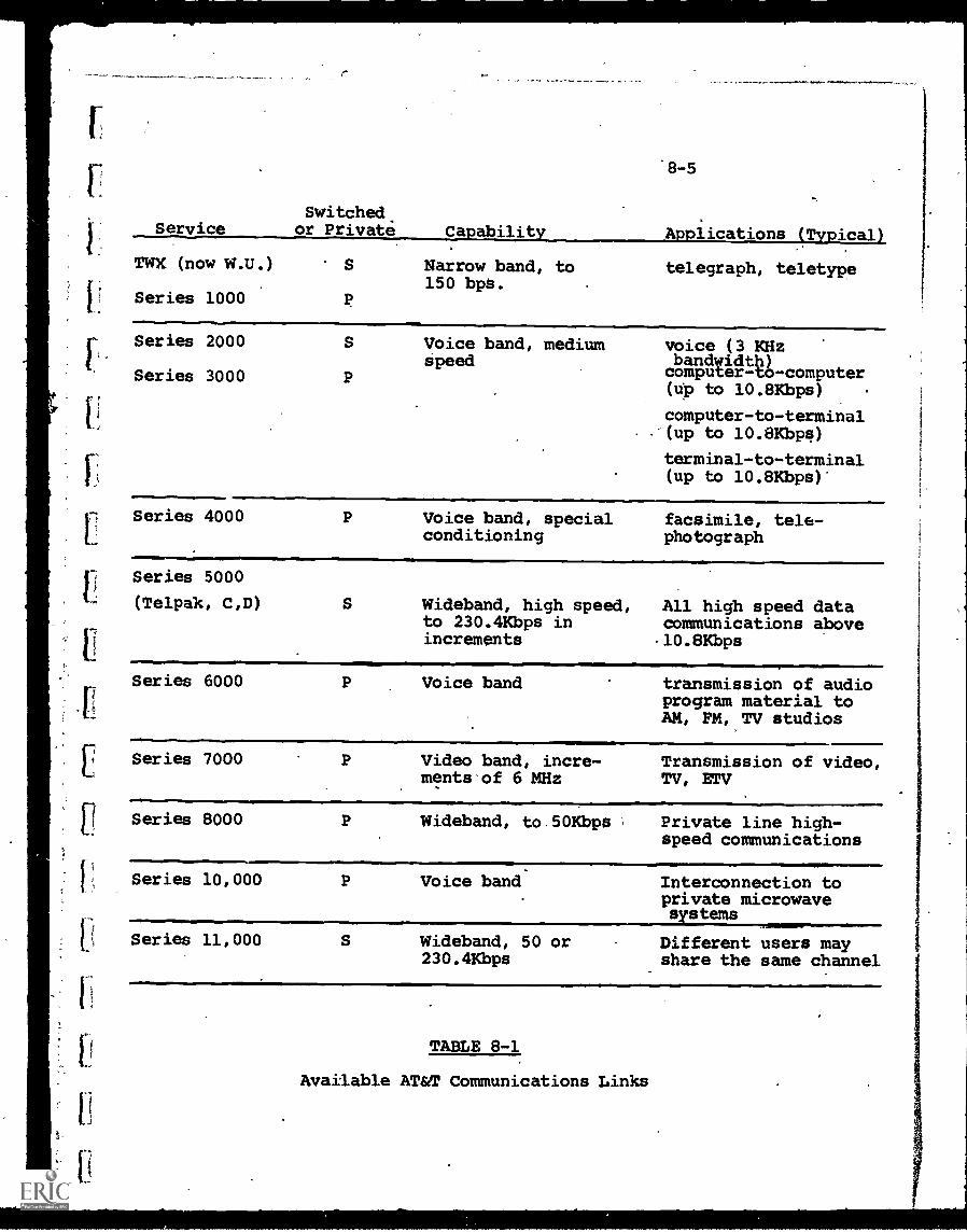
Switched.
1
Service or Private
TWX (now W.U.)
Series 1000
IT
8 -5
Ca abilit A lications T ical
S Narrow band, to150 bpS.
P
telegraph, teletype
Series 2000
Series 3000
S Voice band, mediumSpeed
P
voice (3 KHzbandwidth)computer-to-computer(up to 10.8Kbps)
computer-to-terminal-(up to 10.8Kbps)
terminal-to-terminal(up to 10.8Kbps)*
Series 4000
Series 5000L (Telpak, C,D)
I
P Voice band, specialconditioning
facsimile, tele-photograph
S Wideband, high speed,to 230.4Kbps inincrements
All high speed datacommunications above-10.8Kbps
Series 6000
Series 7000
Series 8000
Series 10,000
[( Series 11,000
1-1
P Voice band transmission of audioprogram material toAM, FM, TV studios
P Video band, incre-ments of 6 MHz
Transmission of video,TV, ETV
P
P
Wideband, to.50Kbps Private line high-speed communications
Voice band Interconnection toprivate microwavesystems
S Wideband, 50 or230.4Kbps
Different users mayshare the same channel
TABLE 8-1
Available AT&T Communications Links
8-6
is impossible to predict. This leads to a much greater
possibility of changing electrical characteristics, noise,
interference and distortion. If these can be tolerated, costs
are generally lower.
Private lines, since they are dedicated to a single user,
must be leased on a 24-hour-a-day basis. If the anticipated
usac.,:* is low, the cost is generally prohibitive.
conditioning is available on voice-grade rivate
lines, which in effect means the electrical characteristics
are optimized for the expected type of signals.
-Table 8-2 lists typical costs to lease a private, low-speed0
line. Costs may vary from state to state, since the applicable
tariffs must be approved by each state's public utility com-
mission. From Table 8 -2, the cost of a 100-mile, Type 1002
line would be $140/month. If a teleprinter terminal were at
each end, and the terminals are assumed to rent for $100/month
each, the operating cost of this communications link would be
$340/month. It can be seen that for an education computer-
_based system, if the distances were long and the number of
terminals sizeable, the communications'cost would be a major
financial undertaking.
If a .voice-grade, medium-speed line is required, Fig. 8 -i
illustrates typical toll charges for the dial-up, switched
network. These charges, depending on distance'and time of day,
vary from a low of $3/hour to as high as $27/hour. The
advantage, however, is that only the time used is.paid for.
In contrast, Table 8-3 lists typical costs for a private
voice-grade line. The cost per hour is less when amortized
over a 24-hour-per-day, 30-day-per-month interval, but the
line must be leased for the full month and if only in actual
use a few hours, the cost per hour of use could be high.
Private lines, obviously, require a minimum usage threshhold
to be practical.
Table 8-4 shows the typical lease rates for a high-speed
line, in this case capable of carrying up to 50,000 bits per
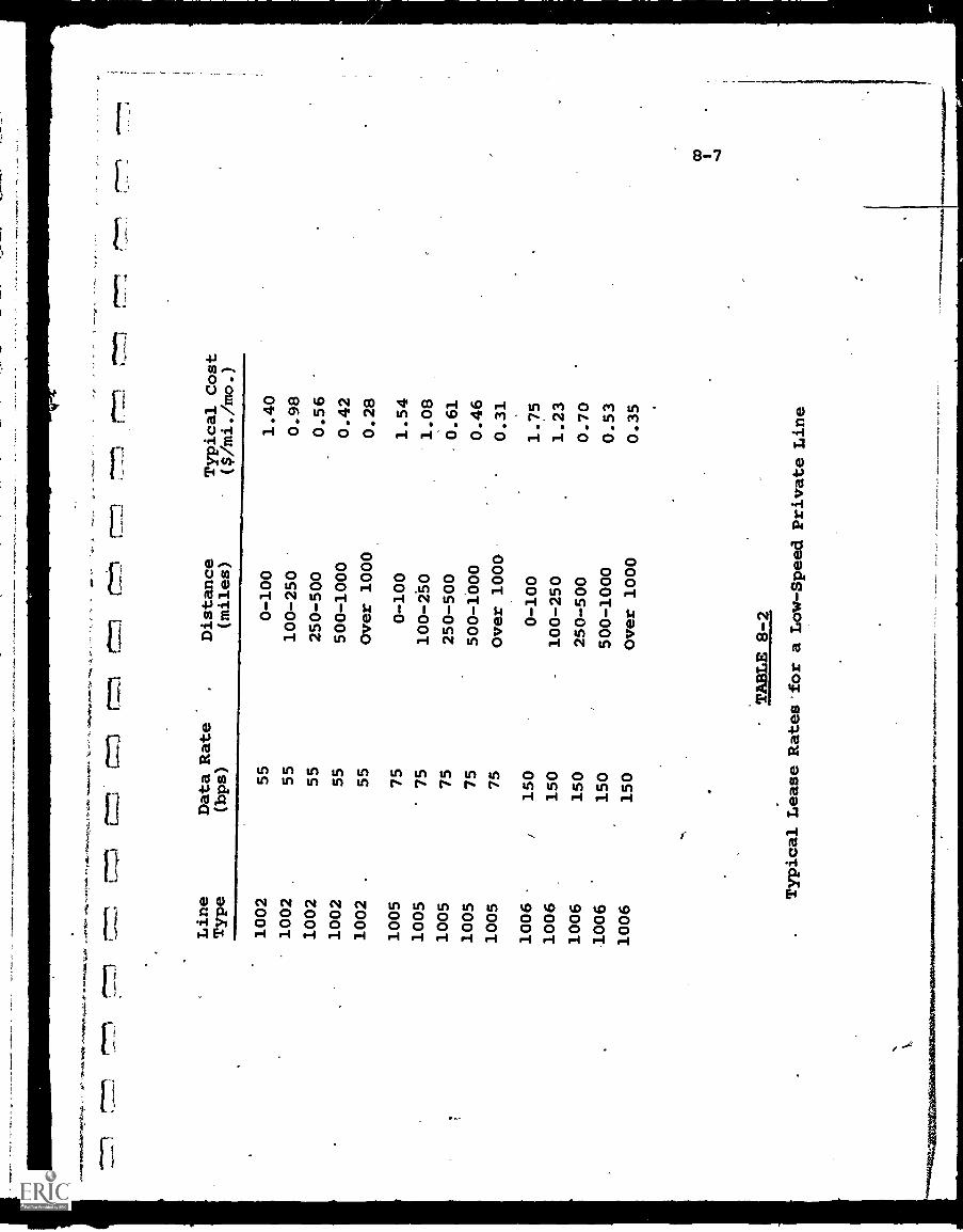
710
S.
Line
Type
Data Rate
(bps)
Distance
(miles)
Typical Cost
($/mi./mo.)
1002
55
0-100
1.40
1002
55
100-250
0.98
1002
55
250-500
0.56
1002
55
500-1000
0.42
1002
55
Over 1000
0.28
1005
75
0-100
1.54
1005
75
100-250
1.08
1005
75
250-500
0.61
1005
75
500-1000
0.46
1005
75
Over 1000
0.31
1006
/150
0-100
1.75
1006
150
100-250
1.23
1006
150
250-500
0.70
1006
150
500-1000
0.53
1006
150
Over 1000
0.35
TABLE 8-2
Typical Lease Rates for aLow-Speed Private Line
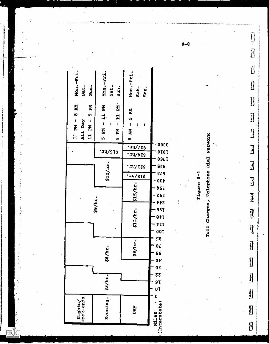
0161
1....
...11
7161
46.6
41.0
.110
40.4
6,
Nights/
week-ends
Evening_
Day
Miles
. o
(Interstate)
Lun
t=
$3/hr.
$6/hr.
$9 /hr..=i
11 pm - 8AM
Mon.-Fri.
All Day
Sat.
11 PM - 5 PM
Sun.
$12 /hr..
$4 in !A-
5 PM - 11 PM
Mon.-Fri:
Sat.
5 PM - 11 PM'
Sun.
$9/hr.
$12/hr..
$15/hr.
$4 4 CO I-I
44-
$4 4 1-4
03
4 CV
in-
$.4 4 C
V44
.
8 AM - 5 PM
Mon.-Fri.
Sat..
4WD
Sun.
ou) r-
1
I)
N o ou.)
csa
cnes
!
11 o
inrs
-
4n ao a .-
4
II 03
t'S3
e.-
4
I
4;11
er
I N ON
ts.1
1 etO
In re/
Lel
Is.
Wo
111
0C
VIn
0 0 1.4
0 0 In
Figure 8-1
Toll Charges, Telephone Dial Network
"P...tt!
t=
3'"
LAO
te4c
.01
-4-
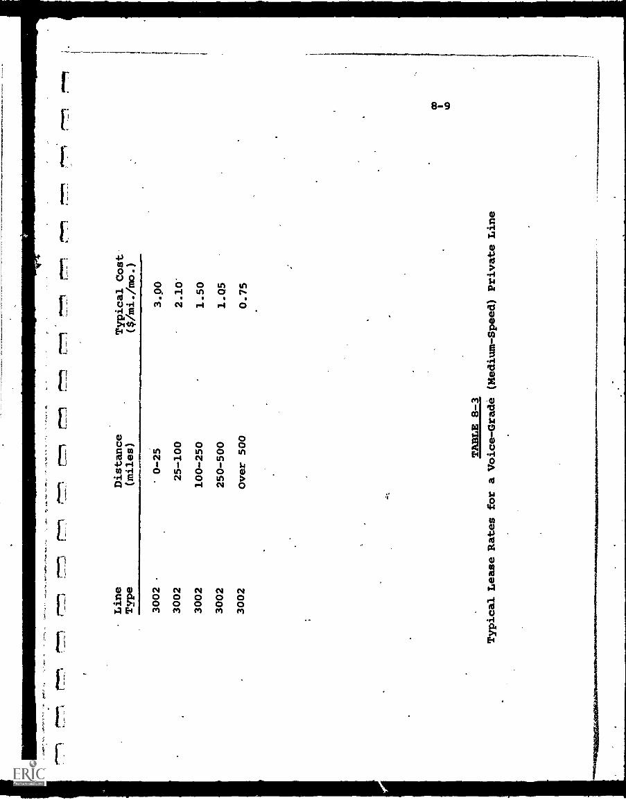
Lin
eT
vpe
Dis
tanc
e(m
iles)
Typ
ical
Cos
t($
/mi.
/mo.
)
3002
' 0-2
53.
0030
0225
-100
2.10
'30
0210
0-25
01.
5030
0225
0-50
01.
0530
02O
ver
500
0.75
011.
9*. -A
TA
BL
E 8
-3T
ypic
al L
ease
Rat
es f
or a
Voi
ce-G
rade
(M
ediu
m-S
peed
) Pr
ivat
e L
ine
03
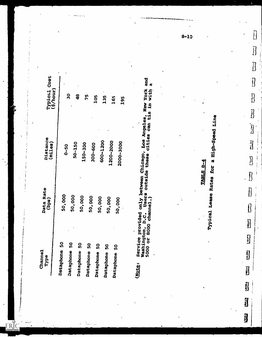
Channel
Type
Data Rate
(bps)
Distance
(miles)
Typical Cost
($/h
our)
Dataphone 50
50,000
0-50
30
Dataphone 50
50,000
50-150
48
Dataphone 50
50,000
150-300
75
Dataphone 50
50,000
300-600
105
Dataphone 50
50,000
600-1200
135
Dataphone 50
50,000
1200-2000
165
Dataphone 50
50,000
2000-3000
195
(Note:
Serviceprovided onlybetween Chicago,
Los Angeles,
New York and
Washington,
D.C.
Users outsidethese cities
can tie in witha
5000 or 8000
channel.)
TABLE 8-4
Typical Lease
Rat
es f
ora
Hig
h-Sp
eed
Lin
e
ttiou
:t=
ttt1
10"
0*-',
8-11
second. This is the equivalent of about 12 voice-grade lines,and. the rates, compared to Fig. 8-1, are in the order of 7-10times as high as a single voice line.
It is interesting to note that even this high-speed linefalls far short of the bandwidth necessary to carry one TVchannel. The 6 MHz required in that case is the informational
equivalent of some 2000 voice channels of 3 KHz each. Thus,
video information can be sent over the. voice network. only by
slowing down the transmission rate, which requires storage on
tape and playback at a very low speed.
Table 8-5 shows the Data Sets (modems) available from the
Bell System. when digital data must be sent over the voice net-work. Many other manufacturers offer comparable equipment,
functionally interchangeable with the Bell units, on either apurchase or lease basis.
At present, seitral non-common carrier companies are
requesting FCC authorization to construct all-digital, communi-
cations networks which would be designed only for datatransmission. The future availability of such service will
eliminate the need for modems.
8-1.2. Advantages and DisadvantAaes of Common-Carrier
Communications Links
There are many advantages, that leased common-carrier
communications can offer to designers and users of educational
telecommunications systems:
(a) No capital investment is required for the communications
portion of the system.
(b) Almost any point in the U.S. either is served by,
or accessible to, a common carrier.
(c) There is unlimited flexibility to expand (or con-
tract) the system as necessary, again without a
capital expenditure.
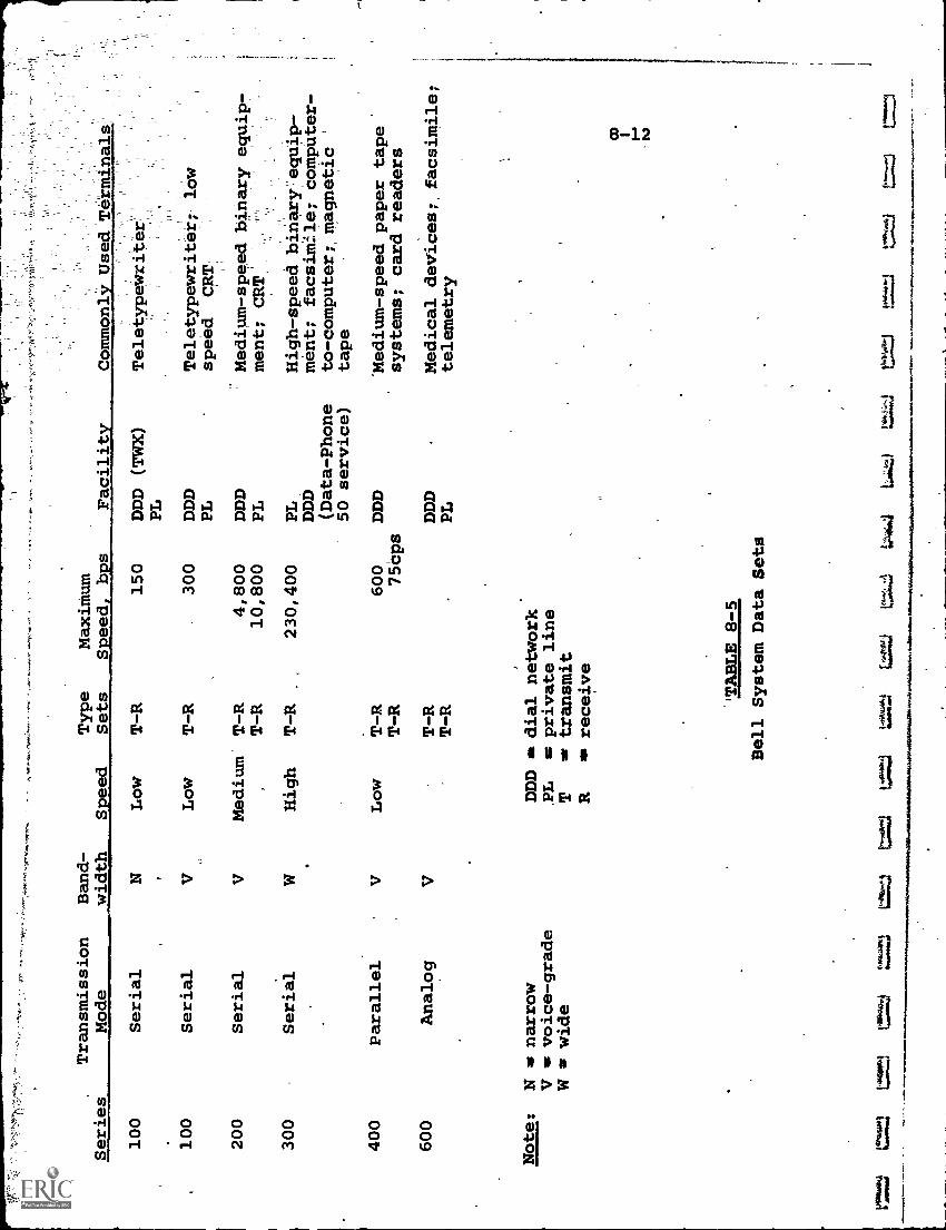
Series
Transmission
Mode
Band-
width
eed
Type
Sets
Maximum
Seed b s
Facility
100
Serial
NLow
T-R
150
DDD (TWX)
PL
100
Serial
Low
T-R
300
DDD
PL
200
Serial
VMedium
T-R
4,800
DDD
T-R
10,800
PL
300
Serial
High
T-R
230,400
PL
DDD
(Data-Phone
50 service)
400
Parallel
VLow
T-R
600
DDD
T-R
75Cps
600
Analog
VT-R
DDD
T-R
PL
Note:
N m narrow
V m voice-grade
W a wide
gkes
ftsw
k
DDD m dial network
PL m private line
Tar transmit
Ran receive
`TABLE 8-5
Bell System Data Sets
VITL1
1.."74:1
=3
1:17;4
4..tj
.Commonly Used'Terminals
Teletype*
Teletypewriter
low
speed CRT
Medium-speed binary equip-
ment; CRT
'
High-speed biriary equip-
ment; facsimile; computer-
to-computer; magnetic
tape
'Medium-speed paper tape
systems; card readers
Medical devices;, facsimile;
telemetry
8-13
(d) The time required to integrate the communications
links into the system is usualiy much shorter than
if a new privately-owned network were constructed.
(e), Funds for operating a system may be more easily
obtained by educational organizations than for
constructing one, as there are generally limitations
on new plant expenditures.
When these are added to the fact that in many instances,
the, difficulties'involved in constructing a private communi-
cations network over a sizeable area simply cannot be met by
an educational institution, the common-carrier networks
generally win by default if for no better reason.
Although there may be no other choice, the disadvantages
of common-carrier communications must be acknowledged and
evaluated before any applications can be implemented:
(a) Switched-network communications are susceptible
to unpredictable variation in performance
characteristics. Private linei are better, but
require a high usage factor.
(b) Digital (data) communications facilities are marginal-
to-inadequate, since most common-carrier circuits
were designed for analog transmission.
(c) Line rental charges are relatively high, making
the communications portion of the system a major
operating burden.
(d) There is a shortage of broadband channels, which
can accept mixed-media signals, such as video, audio
and data combined together.
The last item is particularly critical, since the majority
of educational systems will-have mixed-media requirements, and
most particularly will transmit video information which in
itself requires broadband communications links;
8-14
This expanding need for video transmission has led to
particular consideration of new broadband communications net-
works (BCN's). Closed-circuit television (CCTV) is a form
of BCN which has been utilized by schools for many years,
but it offers no solution to the problem of distribution. With
CCTV, either a privately-owned coaxial cable distribution is
installed, or common-carrier cable services are leased. In
either case, the limitations noted above are present.
Two more recent hybrid distribution techniques offer
great potential for educational systems. The first is
Instructional Television Fixed Service (ITFS), a broadcast
system in which a special frequency is assigned by the FCC
for instructional purposes only. The second is CATV, which
is a wired broadband distribution system reaching an increasing
number of U.S. homes.
ITFS is described in detail in Chapter 9. The background
and potential of CATV are discussed below.
8-2. Broadband Communications Networks
8-2.1. Cable Television (CATV)
The original justification for Community Antenna Television
(CATV) is well-known: to bring commercially broadcast teleL-
vision programs to remote or inaccessible areas which could not
receive a satisfactory "off the air" signal. In 1948-1949 the
first CATV systems were constructed, using strategically
located high-gain receiving antennas to Fick up broadcast signals,
and a coaxial cable network which distributed the signals to
each subscriber's TV receiver.
Although first aimed at geographical areas of weak broad-
cast signal strength, CATV later became popular in metropolitan
and suburban locations where broadcast television signals
were strong. Among the reasons for this popularity were the
r.
8-15
desire to have a choice of.more programs than were broadcast
in the local community and an improvement in picture quality
due to elimination of interference from buildings, radiated
electrical noise, etc. Table 8-6 illustrates the exceptional
growth of CATV between 1952 and 1970. Projections are that
by 1986, perhaps 20-30,000,000 homes will be "cabled".
While CATV was growing in number of operating systems,
there was a concurrent growth in channel capacity (a CATV
"channel". is 6 MHz, consistent with commercial TV standards).
From the original 3-5 channel systems, rapie introduction of
seven-channel (the maximum number of VHF stacions assigned
to any single metropolitan area), and twelve-channel (the total
number of assigned VHF channesl) systems took place. Currently,
many municipal CATV franchise ordinances call for a minimum
of 20 channels capacity, and 30-50 channel capacity is
foreseen for new systems.
Until recently, CATV systems distributed commercial
television programs almost. exclusively. In recent years, "local
origination" programming has commenced on some systems, prodded
partly by the FCC and partly by the syitem operators' interest
in developing local advertising and viewer good will. Even
more recently, the concept of "public access" to selected
channels is being explored and initiated on a trial basis in
a few areas (e.g., New York City). Under this concept, one or
more CATV channels are considered as common carriers and are
available to all members of the public under appropriate ground
rules (limitation of time, usage fees, etc.).
Much has been written about the future use of CATV (now
more appropriately termed "cable television" or "broadband
cable communications", since the community antenna connotation
has largely vanished). The glowing forecasts, in some cases
based on dubious economic and technological premises, arise
from the following key characteristics of cable television
distribution systems:
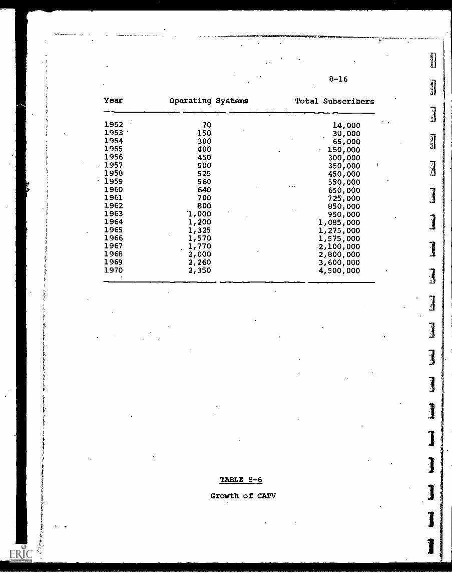
8-16
Year Operating Systems Total Subscribers
19521953195419551956
70150300400450
14,00030,00065,000
150,000300,000
1957 500 350,000 r
1958 525 450,0001959 560 550,0001960 640 650,0001961 700 725,0001962 800 850,0001963 1,000 950,0001964 1,200 1,085,0001965 1,325 1,275,0001966 1,570 1,575,0001967 1,770 2,100,0001968 2,000 2,800,0001969 2,260 3,600,0001970 2,350 4,500,000
TABLE 8-6
Growth of CATV
I
Although its primary mission is to transmit standardTV programs, each occupying a 6 MHz bandwidth; any
channel on the cable is capable of distributing manyother kinds of information. A single 6 MHz_channelis the informational equivalent, for example, of 1500
telephone voice-grade channels of 4 KHz bandwidth each.
Thus many contemplated applications involying a mix ofvideo, audio, and digital signals can utilize the cable"highway ".
The use of shielded coaxial cables for signal trans-
mission requires no utilization of the'already crowded
broadcast frequency spectrum and therefore no
competition against other services for assignment offrequencies.
System expansion incurs a relatively modest initialcost. A large share of the cost of installing a cablesystem comes from the physical preparation of cable.
rights-of-way (either digging underground paths or
attaching the cables to existing telephone poles).
Once a trench has been dug, the cost of installing a.
20-channel cable system is not so much higher than a
12-channel system as to preclude the larger installationif it appears at all reasonable that the spare channels
will be used in the future. Once installed, however,
the cost of a retrofit expansion is inordinately high.
Consequently, many current cable systems are installedwith spare channel capacity. These are later available
for use at relatively insignificant cost.
Transmission of signals through the cable, althoughalmost exclusively unidirectional in the past, can
be made bidirectional, though admittedly with some costand effort. The cable itself is bidirectional, but
the associated amplifiers are not, so that either reverse
8-18
amplifiers, with some means of switching, or a full
.duplicate system, may be involved. In any event the
bidirectional capability, which opens the system toa host of new applications,is much more easily achievedvia cable than through a wireless broadcast medium.
Cable television, because of its past and anticipated
future growth, reaches a sizeable percentage of the
total population of the United States. If it begins
to approach the universality of the telephone, it willindeed ermit man "mass audience* a lications whichcould not be implemented by broadcast techniques, withits scarcit of fre enc s ectrum s ace.
Cable systems permit communications to a precisely
defined secialized local audience (sometimes termed
"narrow-casting", as contrasted with broadcasting whichreaches a large audience but.with generalized, "majority-oriented" material). Thus local or specialized interests
can be satisfied more easily. If there is two -way com-munications capability, applications termed "narrow-
gathering"(collecting data from a large number of
subscribers and sending it over to a centralized
processing unit, such as in audience polling) becomepossible.
CATV System Structure
In a typical CATV system, the broadcast signals are receivedby specially designed antennas at carefully located reception
sites and are processed for introduction into the cable distri-bution network. The combination of antennas and processing
equipment is commonly referred to as the "head-end". The
distribution and processing center, which may or may not be
at the antenna location, is often referred to as the "hub",
where off-air signals and locally originated signals are mergedfor distribution. A typical head7end is illustrated in Fig. 8-2.
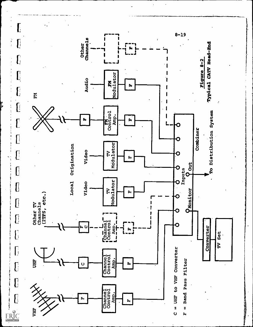
_L°77"J
L77
r-77.1
r:7-
1=
.1r_
777.
1
VHF
UHF
Channel
Control
Amp.
F
Other TV
Channels
i(7PS, etc.)
hannel
Control
i
Local
Video
I
F C L
Arm
TV
!adulator
C = UHF to VHF Converter
F = Band Pass Filter
Origination
Video
I TV
Modulator
6O
0Inputs
Monitor
0Out
CoFntMrol
Amp.
FM
Audio
,F24
odulator
Converter
rI
TV Set
Combiner
.1"ToDistribution System
Other
Channels
I
I
Figure 8-2.
Typical CATV Head-End
8-20
Usually, individual antennas are used for each TV channelto provide maximum gain and directivity. Weak signals may bestrengthened by preamplifiers located at the antenna terminals.
The output from the head-end, which is the total combinationof off-air and locally originated television and FM signals,is carried to the subscriber through special shielded coaxialcable. The cable may be attached to existing telephone and/orpower poles or placed underground, either through existing
conduits'owned by the telephone and power companies or throughprivately owned rights-of-way. Fig. 8-3 illustrates a typicalCATV distribution system.
The main distribution cables are known as "trunk" cablesor "trunklines". These branch into secondary "feeder" cables
and finally into the subscribers' homes through "drop" cables.All signals experience some attenuation loss in the network,
which is a function of the signal frequencies and type ofcable used. To offset this loss, various types of "amplifiers"
are required to maintain signal level throughout the system.The loss at' the higher frequencies is greater than that at thelower frequencies. This requires that the system be "equalized"
to compensate for this differential loss. Modern amplifiershave built-in equalizing characteristics.
The coaxial cable used today is capable of carrying
bandwidths up to perhaps 1000 MHz (over 160,TV channels) withtolerable performance.
Current state-of-the-art amplifiers, however, can provide
flat bandwidths only to about 300 MHz, which theoretically isequivalent to 50 TV channels. Because of practical limitations
(such as second-harmonic interference, filtering problems atthe lower frequencies, requirement for guard bands,.etc.), CATV
equipment manufacturers claim in their current designs 20-30
channel capacity for a single trunk cable system. Dual or
multiple cables can, of course, increase total channel capacity
with essentially no technological limit.
Ia
F
CJ
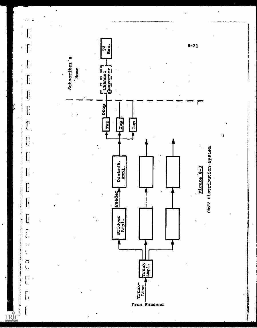
raou
rwan
,as,
-ss
,s
ts: o Trunk -
Line
Trunk
pl.
p. cD
Dro
-Hp] Bridger.]
Ampl.
Ampl.
Feeder ow
Dis
trib
.
Figure 8-3
CATV Distribution-System
I I I I I I I I I I
Subscriber's
Home
r.II
111
et
IChannel
Converter j
TV
Rec.
8-22
This large number of channels is of key interest to
educators, among others. Since commercial TV is limited to
7 broadcast stations in any arca, even bringing in non-local
stations and "public" stations would probably saturate a
CATV system at about 10-15 channels. Any channel availability
above that number could be used for educational applications
at very low cost. The major constraint is the need, for the
"students" to have access to the cable network. This access
is aided by the practice of providing free CATV connections
to local schools, and by the growing number of homes which
subscribe to CATV service.
Two-Way Communications Capability
The value of cable distribution systems to education may
depend to a sizeable extent upon the feasibility of providing
two-way communications capability. This would permit querying
and interactive response by the student. Many other non-
educational applicitions also would, be enhanced by two-way
transmission. Because of this, the FCC has decreed that two-
way capability be included in the newer and larger CATV systems.
At least three basic techniques are currently being evaluated
for two-way transmission. (It should be noted that here again
the amplifiers; which are unidirectional devices, are the
major technological problem; the cable itself, inherently
bidirectional, offers no barrier to two -way' communications.)
The simplest approach is merely to provide a second cable
with reversed amplifiers for "upstream" (subscriber to central,
head-end) transmission. While presenting no technical problem,
the cost of this approach is high. Further, for most
anticipated applications there may be no need for wide. band-
width capability for upstream operation, since audio or digital
messages, rather than video, would probably be utilized. An
example would be a school delivering an instructional TV
program to students, but permitting only audio querying from
students to the originating classroom or studio.
f
8-23
. The multiple cable approach, since its technical
feasibility is unquestioned, is being used currently where
bidirectional capability is a .firm requirement.
A second approach, called."discade", is illustrated
in Fig. 8-4. Each channel is carried on a separate cable at the
same reduced frequency and sent to an area distribution center
serving 24 TV home receivers. From the distribution center,
only one cable goes to each home through a channel selector
converter. By selecting the channel, the subscriber commands
the distribution center to switch the appropriate channel to
his home. For reverse transmission, other than channel
selection, a separate cable runs back to the head-end. One
converter position is assigned to reverse transmission. The
advantage to this approach is that the main cable transmission
is at a low frequency, 5-20 MHz, with lower cable loss and less
stringent amplifier requirements. The obvious disadvantages
are the multiplicity of cables, the complex switching required
at the distribution centers, and the waste of unused cable
bandwidth capacity.
The third approach uses a form of frequency division'
multiplexing, as illustrated in Fig. 8-5. With this technique
the upstreain and downstream transmissions are run through the
same cable at different frequencies. The unidirectional
amplifiers are bypassed for reverse transmission by "cross-
over" filters. A complementary filter pair is placed both in
front and behind each amplifier. Each filter accepts all
input frequencies and has two outputs, high-band and low-band.
The high-band output (above 54 MHz) is connected to the down-
stream amplifier input, while the low-band (below channel 2,
54 MHz) is connected into the reverse amplifier.
Thus, frequencies below 54 MHz can be used for reverse
transmission, while *downstream operation is unaffected, at
least in theory. In an actual system, of course, the upstream
transmission components may perturb normal operation, and at
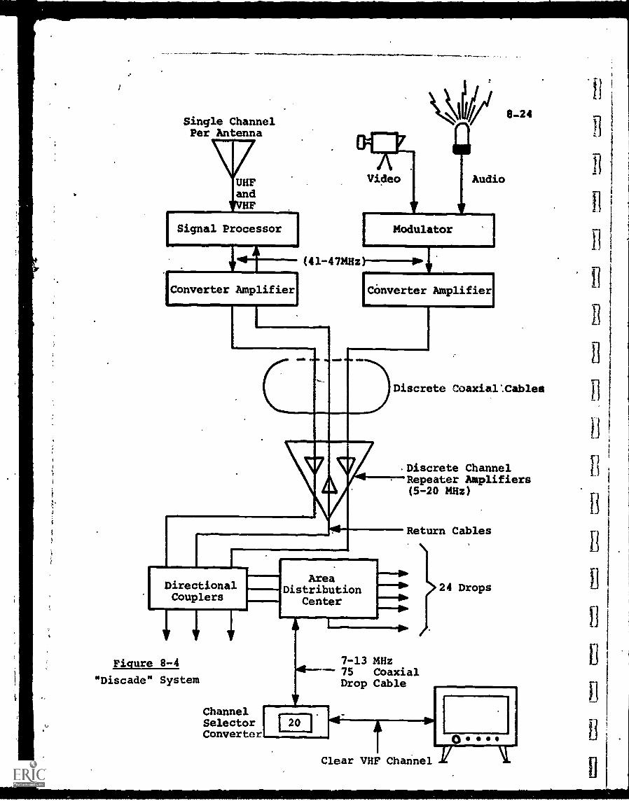
Single ChannelPer Antenna
UHFandVHF
[ Signal Processor
Video
Modulator
(41-4714Hz)----IPP ig7
Audio
Converter Amplifier Converter Amplifier
Gila AMMO gm
v
8-24
Discrete Coaxial:Cables
Discrete ChannelRepeater Amplifiers(5-20 MHz)
DirectionalCouplers
Figure 8-4
"Discade" System
AreaDistribution
Center
A
Return Cables
7-13 MHz-- 75 Coaxial
Drop Cable
141
ChannelSelector 1 20 1Converter
24 Drops
Clear VHF Channel I(
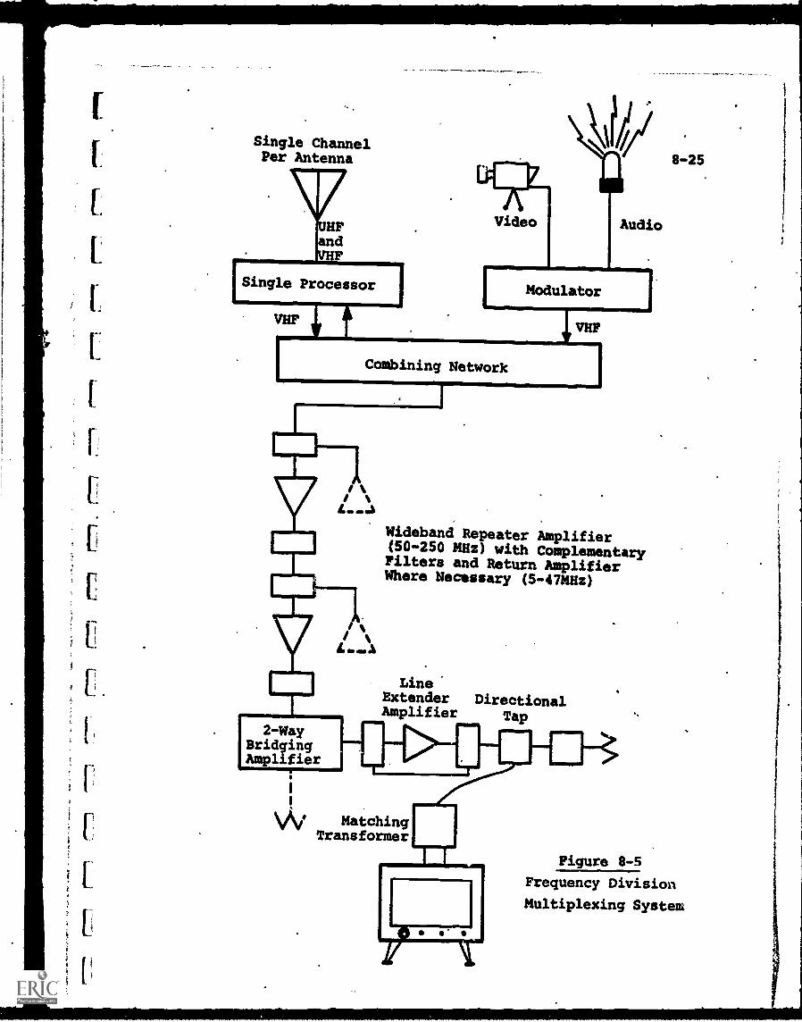
f.
Single ChannelPer Antenna
Single Processor
Video
errAudio
ModulatorI I
Combining Network
NIB
Tv
vv
2-WayBridgingAmplifier
Wideband Repeater Amplifier(50-250 MHz) with ComplementaryFilters and Return AmplifierWhere Necessary (5-47MHz)
Line.Extender DirectionalAmplifier Tap
1
\AI MatchingTransformer
8-25
Figure 8-5
Frequency Division
Multiplexing System
8-26
this point in time there still remain some technological
problems with this approach.
In summation, two-way transmission at this time is well
past the conceptual stage, but not yet incorporated into morethan a few commercial cable systems. When this capability is
more universal, the potential for many new interactive
educational applications may be realized.
Program Origination
Another capability being implemented-on many CATV systems
is the ability to "cable-cast", i.e., originate programs locally
and distribute them on spare channels. The CATV system then
becomes a more flexible communications network, not relying
solely on redistribution of "off-the-air" TV programs.
Local program origination has been conducted on a small
scale for a number of years. Initial efforts, designed to
leep equipment and program preparation costs at a minimum, were
limited to such "automatic" program generating techniques
as photographing a time/weather instrument dial, or taking the
output from a news or stock market ticker and converting it
into an alphanumeric display at the viewer's TV screen. This
involved practically no operating costs after the initial modestcapital investment.
Some CATV operators extended this by adding inexpensive
16 mm. film camera chains and renting or purchasing Mins forviewing. "Local event" origination followed, in which events
of special local interest (city council meetings, high school
basketball, etc.) were televised, with the use of more modern
but still low-cost, mobile television camera chains. These
were the first instances of fulfilling the oft-expressed claim
that CATV could cater to the unique interests of the local com-
munity. The FCC has expressed the opinion that this is a function
which should be emphasized, and reinforced this stand by requiring
local program origination for all cable systems with more than
3500 subscribers.
8-27
In addition to the FCC ruling, many municipalities in
recent CATV enabling ordinances have specified that a centrally
located studio equipped for color television program origination,
plus mobile television facilities, be a requirement of the
franchise. This has been motivated both by the interest in
local event programs and also by growing pressure from educators
and school districts who wish to share'the facilities for
educational programming.
In response, studio equipment has been tailored for the
special "cable-casting" market. Comparatively low-cost items
(e.g., a $10,000 color camera as compared to a $60,000 network
camera) offer near-broadcast quality results. Equipment also
has been miniaturized and simplified, with consoles designed
to fit into the back of a station wagon, or even in the back
seat of a passenger automobile. A.compact color television
studio package for CATV is available for a total system price
of about $65,000.
Use of Cable Systems in Education
To date, the use of cable television facilities for
educational purposes has been limited, although the portents
for future expansion are encouraging. The primary educatioral
applications have been:
Increased Availability of Educational/Public TV Channels.
By bringing in distant educational and public broadcast
channels, and also in some cases converting UHF channels
to more popular VHF, CATV systems have provided their
viewers with an increased choice of educational programs.
Reservation of Educational Channels. Most reckunt city
CATV ordinances, in compliance with the expressed
objectives of the NEA and local school districts, require
reservation (or preemption at a later date if the local
educators are not yet ready) of 20% of the total number
of, channels exclusively for educational use, without
charge. Thus four channels of a 20-channel system would
8-28
be available for use as the local educators determine.
They could generate their own programs or use material
available from outside.sources.
Cab Drop to Schools. The CATV operator is generally
required to provide free cable drops to each school
within the area served by the cable system. Thus, the
programs carried are available for viewing'at the
schools without cost.
ITFS Interface. Instructional Television Fixed Station(ITFS) service is described in more detail in Chapters8 and 11. For schools or universities who are operating
ITFS, there are cases where CATV systems in the area
of reception have agreed to install receiving antennas
and converters to translate the 2500 MHz 'ITFS signals
into a standard television channel frequency which is
then sent over the cable system to subscribers and local
schools. This expands the relatively narrow ITFS
coverage.
Use of Studio and Program Origination Facilities. In
some CATV systems educators are permitted to use the
studio and program origination facilities without charge
at agreed times and with student operator personnel.
In others, some charge is levied. A third category is
where the CATV operators and the schools have designed
a facility satisfactory to both and where both the
capital and operating costs are shared.
In all the above cases, the effects, while certainly
beneficial, have merely extended the availability or reduced the
cost of TV-type or film-type instruction, without adding any
new dimension to the instructional and/or educational process.
Such new dimensions must await widespread extensions in cable
system technology, such as two-way transmission or a mix of
audio-visual and digital-graphical data-bank sources of
instructional material.
}
r.
C
8-29
The key feature of the cable system is the abundance ofbroadband communication channels, available at low cost (once
-the system has been installed) and free of constraint such as
FCC frequency allocations. This, in effect, provides many
"highways" which pose a challenge to educators, among others,to use constructively.
8-30
CHAPTER 8 - BIBLIOGRAPHY
1. Greenhill, L.P., "Closed Circuit Television for Teachingin Colleges and Universities", Penn. State University, Jan.1966.
2. Hinkleman, R.M., "Planning a Data Communications System -Part I: A broad Overview and Basic Concepts Modern Data,
April, 1970Part II: Common Carrier Facilities", Modern Data, May and
June 1970.
3. "Planning Effective Data Communications Systems", DataProcessing Magazine, Nov. 1970.
4. Reagan, F.H., "A Manager's Guide to Phone and Data Services",Computer Decisions, Part I, October 1971; Part II, Nov. 1971
9-3.
Chapter 9 - Wireless Carriers
9-1 Wireless Transmission
In transmitting electrical signals over wire, it is only
necessary to provide different wires or cables (adequately
shielded) for different messages to avoid any posdibility ofinterference. When the wireless medium is used the problem is
more complex, unfortunately. Broadcast signals can and will
interfere with each other, particularly if they are at the same
or adjacent frequencies, or if one frequency is a multiple of
another.
For this reason, the allocation of broadcast frequencies is
very critical and, in the U.S., is one of the FCC's most important
responsibilities. No signal can be broadcast at any time, on
any frequency, without FCC authorization.
When it is realized further that the frequency spectrum
currently in use is extremely crowded, with more potential users
arising every year, the allocation of this natural resource
resembles the problem of providing adequate parking space in themiddle of a growing city.
This spectrum crowding results in pressure to use increasingly
higher frequencies, and such a trend will continue. The higher
frequencies, however, require advanced equipment which in many
cases is expensive and, being still in the developmental stage,
unreliable.
Educational systems which contemplate wireless transmission
must, therefore, select one of the following alternatives:
(a) Use of frequencies reserved for educational use only,
such as the 2500 MHz band (described in the ITFS
section of this chapter)
(b) Lease of wireless facilities, such as microwave links,
from common-carriers
9-2
(c) Compete against other applicants in the general
broadcast bands, such as AM or FM radio, or VHF orUHF television.
All of these alternatives have been utilized in the past foreducational telecommunications systems, and are available today.The third is perhaps the oldest, with universities and collegesoperating educational AM radio broadcasting stations for morethan 50 years and more recently, FM radio and television broad-cast stations. Examples are described in Chapter 10 and 11.
The scarcity of radio and TV broadcast frequencies stillavailable sharply restricts expansion in this direction. Thisis one reason why other modes of distribution which provide manychannels and do not require frequency allocation, such as CATV,are of such interest for the future.'
The use of common-carrier wireless facilities may be outsidethe control of the educational user. A time-shared computer,for example, may use many leased telephone lines to communicate
with student terminals. Whether the lines are all-wire links, or
at some point use microwave relays is outside the knowledge andthe interest of the user, so long as service is maintained.
There are other times when wireless service is specificallyrequired, such as in broadcasting an educational program via
communications satellite. Again, however, this is a choice
between different links rather than the use of wireless specifically .
for educational functions.
The area of greatest interest for the future is the band
exclusively reserved for educational wireless transmission,the ITFS band. Since the educator will not be competing against
other users (only other educators) for the same frequency space,
planning on a long-range basis is possible.
ITFS is described in Section 9-2, but some preliminary
comment on current use of the electromagnetic spectrum mayprovide appropriate background.
It
9-1.1 Use of Electromagnetic Spectrum
9-3
Table 9-1 lists the portion of the electromagnetic
spectrum used for wireless telecommunications today. The
entire spectrum, it should be noted, extends far above the
frequencies associatod with light waves, but no equipment is
yet available which can operate in the upper ranges.
Frequencies at the low end of the spectrum, below the
VLF band, are almost never used in wireless systems. The
antennas required would be very large,.since for efficient
transmission and reception the antenna should be an appieciable
portion of the "wavelength" of the radiated signal. Wavelength
is defined as the inverse of the frequency according to the
following:
300,000,000Wavelength (meters) = frequency (Hz)
Thus, a frequency of 3000 Hz has an associated wavelength
of 100 000 meters, and an antenna of one-quarter wavelength
(necessary f r good radiation) would be over 14 miles long,.
Even for the VLF and LF bands, the wavelength acts as a
constraint, which is why lOng-wave radio is not often used. At
the upper end of the LF band, 300 KHz, the wavelength is still
1000 meters long.
Starting with the MF band, however, full use is made of the
remainder of the spectrum. The familiar AM broadcast radio
band, for example, is allocated between 550-1600 KHz, and is
so crowded that frequencies are shared both on a time and
geographical basis.
Below the VHF band, from 30 MHz downward, the spectrum is
suited to long-distance transmission because radio waves at
these frequencies are reflected from the ionosphere (a layer of
ionized particles at the earth's upper atmosphere) back down to
the ground. Referring to Figure 9-1 (a), a transmitter opelating
at these frequencies can reach a receiver hidden by the earth's
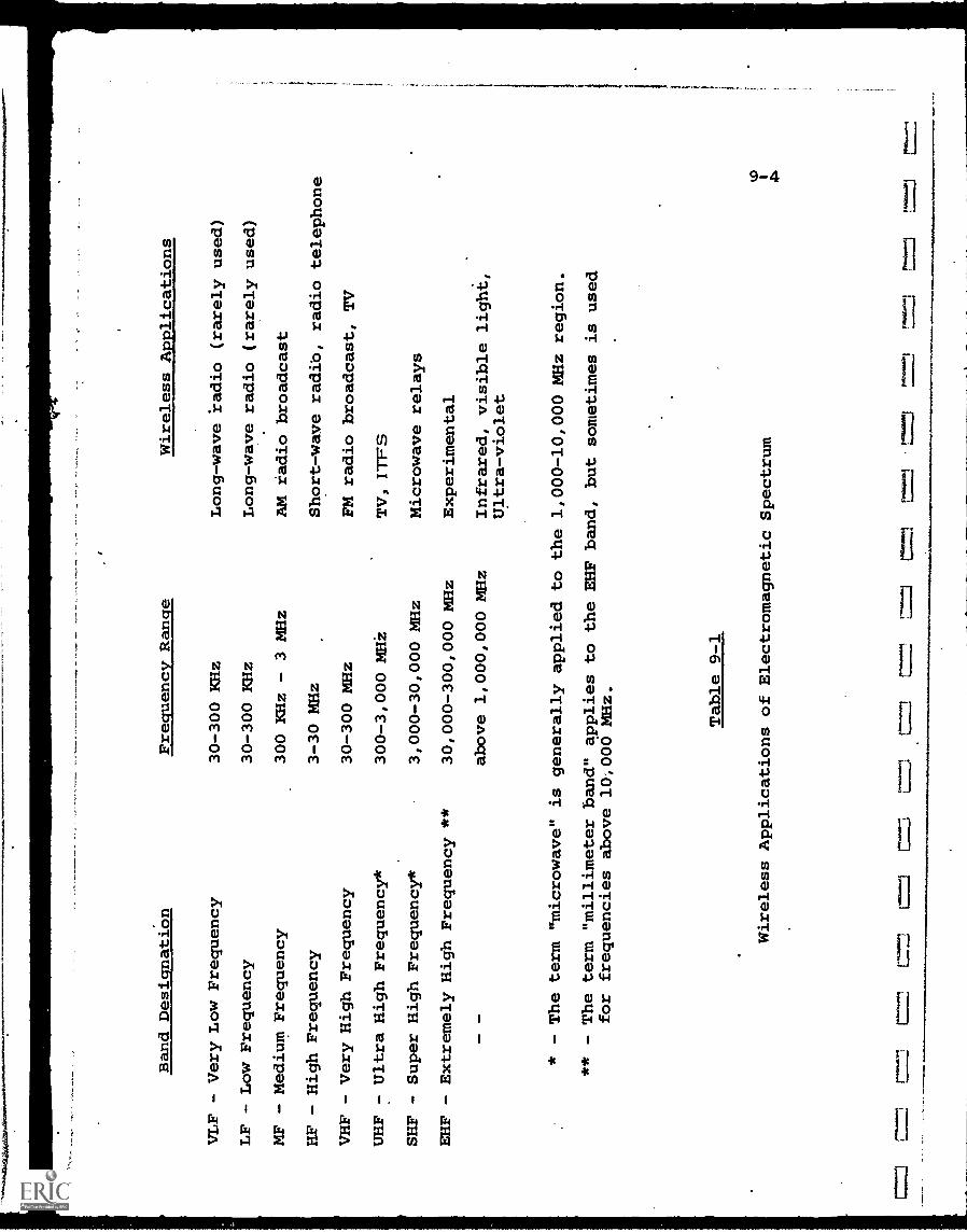
Band Designation
VLF - Very Low Frequency
LF - Low Frequency
MF - Medium Frequency
HF - High Frequency
VHF - Very High Frequency
UHF - Ultra High Frequency*
SHF - Super High Frequency*
EHF - Extremely High Frequency **
Frequency Range
30-300 KHz
30-300 KHz
300 KHz - 3 MHz
3-30 MHz
30-300 MHz
300-3,000 MHi
3,000-30,000 MHz
30,000-300,000 MHz
above 1,000,000 MHz
Wireless Applications
Long-wave radio (rarely used)
Long-wave radio (rarely used)
AM radio broadcast
Short-wave radio, radio telephone
FM radio broadcast, TV
TV, ITFS
Microwave relays
Experimental
Infrared, visible light,
Ultra-violet
* - The term "microwave" is generally applied to the 1,000-10,000MHz region.
** - The term "millimeter band" applies to the EHF band, but sometimes is
used
for frequencies above 10,000 MHz.
Table 9-1
Wireless Applications of Electromagnetic Spectrum
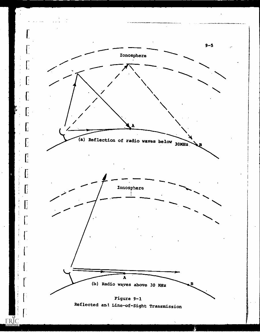
Ionosphere
(a) Reflection of radio waves below30MHz
Ionosphere
A
(b) Radio waves above 30 MHz
Figure 9-1
Reflected an3 Line-of-Sight Transmission
9-6
curvature because of the signals "bounced" off the ionosphere.
At the higher frequencies, however, the ionosphere no
longer reflects signals but permits them to pass through as
shown in Fig. 9-1 (b). Thus, there is no way for the trans-
mitter to reach receiver B, and its effective range is limited
to "line-of-sight", that is, any point which can be seen in a
straight line from the top of the transmitting antenna.
This is why VHF and UHF TV transmitting antennas, for example,
are located as high as possible, on mountains or the top of the
tallest buildings. The heightpermits maximum audience coverage.
Although line-of-sight transmission is restrictive, it offers
one advantage. Two transmitters hidden from each other by the
earth's curvature can usually operate at the same frequency
without interference. Thus, more stations can be crowded into
the same frequency band. As an example, channel 2 on VHF
television broadcasts in New York and the same frequency can also
be assigned to another TV transmitter so long as it is sufficiently
far from New York.
Communications satellites, described later, also operate
'under line-of-sight conditions but they overlook so much of the
earth's surface that they can broadcast over immense distances,
effectively negating the limitation of line-of-sight transmission.
With the exception of AM radio broadcasting (whose spectrum
is overcrowded even more than others), almost all of the bands
of interest for educational systems are in the line-of-sight
region. This includes:
(a) FM Radio, broadcast in a portion of the VHF band
(b) Educational and Instructional Television, broadcast
on any of the assigned VHF or UHF channels
(c) Instructional Television Fixed Service (described in
this chapter) which utilizes the 2500-2690 MHz portion
of the UHF band
(d) Microwave relays, which can link various elements of a
total communications system.
r.
9-7
The coverage of any of these wireless broadcast techniquescan be determined by the geographical area within line-of-sight,and by the directivity of the transmitting antenna (whether itis designed to focus the radiation in only one direction).
One point is to be noted. In considering any wireless
transmission, the fiequencies which have been discussed areinvariably the carrier frequencies, which must be modulated bythe information to be transmitted. Audio or video frequenciesare not radiated directly , due to the low-frequency limitations
mentioned.
Thus, a VHF frequency of 300 MHz, for example, might beused as the carrier for-a 6 MHz TV signal. The actual videoinformation represents, in this case, 2% of the carrier band-width.
If a carrier of 3000 MHz were used, however, 2% of thisbandwidth would be 60 MHz. This illustrates that the samepercentage of carrier bandwidth can now carry 10 TV channels
.rather than one.
Because of this, the future use of higher-frequency carriers
holds promiie of also being able to transmit much more informationthan we can at present. Optical transmission is an outstandingexample of this promise.
9-2 Instructional Television Fixed Service (ITFS)
9-2.1 Description'
In July 1963, the FCC allocated the frequency band between
2500-2690 MHz for use by educational institutions and organi-zations; The band was divided into 31 channels, each with a 6 MHzbandwidth capable of carrying television signals conforming tostandard broadcast specifications. The service was labeled
Instructional Television Fixed Service or ITFS, and is also
referred to as "2500 MHz televison".
9-8
ITFS, therefore, is not a new kind of educational or
instructional TV, but simply a designated method of transmissionwhich has been reserved for educational use. As such, it comple-ments other methods such as ETV, CCTV, etc; The specific techni-cal characteristics of ITFS, however, and also limitations imposedby the FCC, are sufficiently different from commercial broad-
casting to warrant special study. Further, the recent actionof the World Radio Conference, July 1971, in alloCating the2500 MHz band for educational purposes, including satellite
communications, indicates expanded use of the ITFS spectrum inthe future.
The major features and constraints of ITFS are:o Multi-channel capability is provided. Up td 4 channels
of the 31 are available to a licensee to serve a single
geographical area.
o The allocated frequency spectrum may be used not only
for video, but also voice and data transmissiono The upper 4 MHz of the band, from 2686-2690 MHz, may be
used for "reverse" transmission, i.e., response and/orinquiry in either voice or data form. Thus, interactive
capability can be included into any ITFS system;o Since transmission is at 2500 MHz, requiring special
receiving antennas and frequency converters before the
signal can be received by standard TV sets, ITFS is
essentially a private system, where the audience is
specifically identified. In this respect, ITFS is
similar to CCTV except that over-the-air broadcasttechniques are used.
o The power output from ITFS transmitters is normally
limited to a maximum of 10 watts. This restricts the
practical area of coverage to about a 25-mile radius
normally, and up to 40 or 50 miles with narrowly directed
transmission.
9-9
o Being an "over-the-air" broadcast, ITFS is subject to
the same problems of frequency crowding and inter-
ference as other broadcast systems, alleviated slightly
by its restricted geographical coverage.
The key differences between ITFS and standard broadcast
TV are analogous to "closed-loop" and "open-loop" systems,
respectively. Because ITFS is a multiple-addressi fixed point-
to-point service, with the receiving audience closely controlled,
feedback information on coverage, audience response, etc., can
be regarded as almost a closed-loop process. Conversely, in ETV,
the size, nature and response of the audience to educational
material are tenuous and difficult to determine.
Thus, ITFS essentially offers a reserved frequency spectrum
for limited, precisely defined educational purposes and
audiences. As such, the institution operating the ITFS facility
has close control over program content, time of presentation and
audience selection. Effectively ITFS can be considered as
performing the same function as CCTV, through point-to-point
broadcast techniques and with different technical character-
istics of coverage, cost and convenience.
9-2.2 Elements of an ITFS System
Figure 9-2 illustrates in block form the basic elements of
an ITFS system. The program originating equipment is identical
with that required for broadcast or CCTV studios, with the
quantities and kind of equipment governed by the system needs
and available funds.
The video and audio information, from whatever source, are
connected into the modulation circuitry of a low-power (10 watt
maximum) transmitter whose carrier frequency can cover the
2500-2690 MHz range. A maximum of 4 channels (each 6 MHz wide)
are assigned to any single ITFS facility, so that the transmitter
need only have 4 switchable channel settings, and broadcasts on
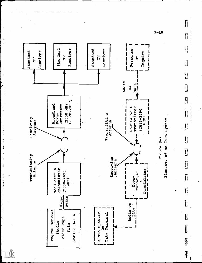
Proram Sources
Studio
Video Tape
Film
Mobile Units
Video
Audio
r__W
ON
. OM
1 Audio Speaker.
Or.
1
Data Terminal
Transmitting
Antenna
Modulator &
Transmitter
(2500-2690
MHz).
r---
Audio or
L--
411
011
GO
MM--4
Down -
Data
Converter.
Receiving
Antenna
MO
W IM
MO
IMIo
144-
11
Demodulator
=1/
16 M
IND
- O
M-
aI11
1
Receiving
Antenna
Broadband"
Down-
Converter
(2500 MHz
to VHF/UHF)
Transmitting
Antenna
Modulator &
'Transmitter
14.4 I (2686-2690
MHz)
Standard
2TV
Receiver
row
im01
1111
.111
1011
Audio
Standard
TV
Receiver
Standard
TV
Receiver
ME
MO
OM
NI M
IDO
M,
41M
11 O
MN
I MM
. IM
O
or
Data
LOM
B M
OM
MID
=II
MIN
/
Figure 9-2
Elements of an ITFS System
raii=
ileAsw
=6.
1=
011=1
1 Response
1
- -1
Or
1Inquire
9-11
a single channel at any particular time. Duplicate transmitter
facilities are used if simultaneous broadcast over more than one
channel is desired, and the transmitter-outputs may be multi-
plexed to a single transmitting antenna.
The transmitting antenna may be either omnidirectional or
highly directive, depending on the desired geographic coverage.
The highly directional output will reach receivers at a greater
distance, but only along the narrowly beamed path.
A receiving antenna is required at each receiving location,
mechanically "aimed" at the transmitter for maximum signal
strength. At or near the antenna location, a frequency "down-
converter" translates the 2500 MHz microwave carrier frequencies
to a standard VHF or UHF frequency so . .at a standard TV set
can be used as a receiver. Usually, the VHF frequency selected
is that of a channel unused in that particular geographical
area so that interference from commercial or ETV broadcasts is
minimized.
If the receiving location is a school or industrial plant,
the signal is distributed from the converter to as many class-
rooms or individual receivers as desired, via coaxial cable.
Fig. 9-2 also illustrates a "response" or"inquiry" reverse
transmission system by which the student can communicate back to
the original program source location. As noted, the 2686-2690 MHz
portion of the assigned ITFS spectrum has been designated for
this purpose.
If the inquiry is a voice signal, a microphone input is
used. If. in the form of alphanumeric data, a teleprinter might
be utilized. In either event, the audio or data signal is con-
nected into a modulator-transmitter operating in the particular
assigned section of the 2686-2690 MHz band, and broadcast in the
reverse ditection to a receiver and converter at the program
origination location. The demodulated voice or data signal is
then made available as desired.
9-12
9 -2.3 ITFS Applications
ITFS has been authorized lor over eight years as a
specialized educational broadcast service. A recent survey
(Educational Product Report No. 31, "ITFS", 1971) lists a total
of 65 operating ITFS systems located in 21 states. Of the 65,
21 are located in only two states, New York and California
Thus, to date the utilization of ITFS has been rather
meager, and there is some agitation to transfer a portion of
the assigned ITFS spectium to .other applications. The decision
of the 1971 World Radio Conference to reserve the 2500-2690 MHz
band for educational communications, both satellite and terrestrial,
will mitigate against such changes. For satellite communications,
2500 MHz is an "efficient" frequency in terms of the RF power
that can be generated and radiated to ground antennas.
In this respect, it has been proposed that the NASA
Applications Technology Satellite, Model G (ATS-G), scheduled
for launch in 1974, carry a 2500 MHz transmitter specifically
for broadcasting educational TV programs to a large number of
ITFS receiving stations (ATS-F is already scheduled to broadcast
ITV to India, using the lower 800 MHz UHF frequency). This
capability could effectively "network" many ITFS systems, allowing
them all to broadcast the same program simultaneously. If 4
channels were utilized, a choice of 4 programs would be avail-
able (more than from the 3-network commercial system at present).
Though this mass distribution capability will no doubt
expand 2500 MHz educational broadcasting, its usage runs scmewhat
contrary to the present configurations of ITFS systems, which
are essentially point-to-point, controlled audience systems.
Thus, "networking", while permitting program interchange, might
diffuse the intended audience.
The future of ITFS depends more on application than on
technology. The technology and hardware of 2500 MHz broad-
casting are essentially stable at this time, and no revolutionary
breakthroughs are expected.
zj
r.
r
9-13
As with any wireless transmission, ITFS is subject to RF
interference. If a substantial number of users in the same
geographical area apply for an ITFS license, the question of
interference becomes complex and critical. In the Los Angeles
basin, for example, a computer program was developed by an
engineering consultant firm, Hammet and Edison, to determine
optimum locations and possible interference among a number of
ITFS applicants.
Rather than a proliferation of separate ITFS systems, each
serving its own parochial function, There has been some impetus
toward "community-oriented" ITFS. In Cleveland,'when a multi-
plicity of applications reached the FCC, the Commission asked
the applicants, in effect, to settle the issue themselves. The
result was an "umbrella" agency in which all interested parties
participated on a community-wide basis. This agency, the
Educational Television Association of Metropolitan Cleveland,
was granted an ITFS license for the use of 16 channels (the FCC
waived, in this case, the 4-channel limit), which will be used
for all participants (including the Diocese of'Cleveland, the
Cleveland Commission on Higher Education, the Board of Education,
the Education Research Council, the Cleveland Academy of Medicine,
etc.).
The further formation of such consortia may stimulate the
growth of ITFS, since two functions are achieved, a wider base for
amortizing costs and the reduction of competition for a limited
number of frequencies. Barriers to this form of growth are
more political and organizational than technological.
9-3 Communications Satellites
9-3.1 Description, and Background
9-14
A communications satellite is basically an information relay,
linking terrestrial 'transmitting and receiving stations. Signals
are transmitted up to.the satellite (uplink), where they are
usually translated, in frequency to avoid interference, and retrans-
mitted down .to the earth. Retransmission (downlink), may be
directional, aimed at selected receiver locations, or designed
to provide broad coverage over a large portion of the earth's
surface.
As a communications link, the satellite competes against-
wired connections (land-line or submarine cable), terrestrial
wireless, or hybrid combination of both. In this competition,
the satellites advantages are:
o Ability to reach remote areas where terrestrial links
would be impractical or too costly. Considering the,
U.S. only, Alaska would be a prime example.
o Ability to distribute one signal to a multiplicity of
.receiving stations, with cost being independent of
transmission distance. Thus, there is an economic
advantage on the long-distance routes.
o Ability to transmit without signal loss due to line-.
of-sight barriers (e.g., mountains, earth curvature).
The offsetting disadvantages of the satellite include:
o Limited useful life and lower reliability than terrestrial
links.
o As yet, relatively low power radiating capability, neces-
sitating large and expensive ground stations.
o Increased possibility of electromagnetic interference,
both between satellite and terrestrial sources and
among satellites themselves as orbital space becomes more
crowded.
9-15
Considering that only some ten years covers the full spanof communications satellite technology, and the achievements in
that short time, it is obvious that rapid advance in development
and utilization will continue for the foreseeable future.
Excluding some military applications, the major advancesin technology have been contributed by NASA and ComSat. ECHO, apassive inflated balloon with metallized surfaces, was orbitedby NASA in 1961 and served simply as a reflector off which signalscould be "bounced". This was followed in the early 1960's byRELAY, a relatively primitive signal repeater and by the SYNCOMseries. SYNCOM was the first satellite to demonstrate thefeasibility of geostationary, or "synchronous", orbit technology,now used extensively. With this technique, the orbit is selectedsufficiently high that the satellite revolves around the earth'saxis in exactly 24 hours. If launched in a synchronous orbit
over the Equator, the satellite appears to be stationary aboveone point on earth. It can therefore continue to receive fromand transmit to the same ground stations without interruption,or change in signal strength.
In 1962 Congress passed legislation bringing the
Communications Satellite Corporation (ComSat) into existence as
a government-regulated, publicly owned corporation. ComSat'scharter to develop and operate communications satellites was
aimed primarily at international communications, and there was
no monopoly over, or prohibition from, the area of U.S. domestic
communications.
In 1964 the International Telecommunications Satellite
Consortium (INTELSAT) was formed as a multinational joint venture.
Interim agreements were concluded to permit development of satellites
whose facilities could be used by all INTELSAT members. Member-ship is open to any nation which is a member of the International
Telecommunication Union (ITU). INTELSAT membership has grown
from an initial 14 to 77 nations at present.
9-16
Under the agreements, INTELSAT owns the operational satellites,
while the ground stations are owned and operated in accordance
with the domestic law of the country in which they are located.
INTELSAT sets certain technical standards before ground stations
are permitted access to the satellites.
Four series of satellites have been launched, INTELSAT
I, II, III, IV:
(1) INTELSAT I (Early Bird)
o Became operational June 1965.
o Positioned over the Atlantic Ocean to provide
communication between Europe and northeast U.S.
o Capacity: 240-300 telephone circuits (or equivalent
bandwidth).
o Retired from service August 1969.
(2) INTELSAT II
o Four satellites were launched, two became operational
April and November 1967.
o Positioned over Atlantic and Pacific respectively.
o Capacity: 240 telephone circuits but with "multiple-
access" feature (indefinite number of earth stations
can access simultaneously).
o Still operating.
(3) INTELSAT III
o Eight satellites launched between September 1968
and July 1970, five became operational.
o Capacity: 1200 telephone circuits plus one video
channel
o Four still operating, two over Atlantic, one over
Pacific, one over Indian Ocean.
(4) INTELSAT IV
o First and second of this series launched.
o Became operational 1971-72
o Atlantic and Pacific region service'
o Capacity: 300 to 9000 telephone circuits or 12
TV channels.
f.
9 -17
All of these satellites are of the "point-to-point" type,i.e., any single message travels from the originating earthstation to only one receiving station. Because of the presentlimitations on satellite power, the earth stations requirelarge steerable antennas with diameters in the order of 90-100feet, plus sensitive receiving equipment, sometimes cryogenicallycooled. Present cost for a typical station is 3 to 4 milliondollars. This factor makes such a link cost-competitive onlyover very long land distances (although it is already competi-tive with underocean cables).
Since INTELSAT is concerned only with international
communications, many large users of communications facilitieshave considered the advantages of domestic satellites which wouldprovide links only within the confines of the U.S.
In March 1970, the FCC invited applications for the establish-ment of domestic communication satellite. facilities by "non-government" entities. In response, many applications weresubmitted for both general-purpose satellites (ComSat, MCILockheed) and for "dedicated" single-purpose satellites, suchas CATV networking (Hughes-TelePrompter) or conmercial TV(the broadcast networks). No application approvals have yet beengranted, which means at least 3-5' years will elapse before thesesatellites could become operational.
9 -3.2 Application to Education
At present, satellites depend upon large sensitive groundstation antennas and expensive facilities, because they cannottransmit much power. It is likely that when the first U.S.domestic satellites are operational, size and weight constraintson the orbiting payload will continue to limit transmitting power,although it maybe an order of magnitude higher. This means thatfairly large, commonly shared, ground stations will still be
required although the cost may be in thousands of dollars ratherthan millions.
9-18
With centralized ground stations, distribution to
individual users is made through common-carrier landline orwireless links. At high traffic density or over long distances
or over impassable terrain the satellite link becomes cost
competitive with other options. Otherwise, it is likely that
alternate terrestrial links will be cheaper for some time to come.
In terms of potential impact on education, a.series of
projected NASA experiments offer a good indication of future
applications.
The NASA Applications Technology Satellite (ATS) series of
research satellites (of which ATS-I, launched in 1966, and
ATS-III in 1967 are still operational) provide "test beds" for
improving communications satellite technology. Present plans
are for two new satellites ATS-F and -G, to be launched in
1973 and 1974, respectively. These will increase the effective
radiated power considerably over the levels of previous models.
The increased antenna directivity and power output will
permit reception-by far smaller earth stations than previously,
thus having more relevance to community-oriented applications.
Among the wide variety of experiments scheduled for ATS-F, the
so-called "India Instructional TV Experiment" is of specialinterest.
The background ofthis experiment is India's interest in
providing Instructional TV coverage to as large a segment of
its population as possible, including not only the metropolitan
areas, but most particularly the primitive outlying villages in
greater need of ITV. The Indian government conducted cost
studies of three approaches to obtaining ITV coverage:
o Rebroadcast stations with microwave interconnection
o Rebroadcast stations with satellite interconnection
o Satellite broadcasting exclusively
The studies indicated satellite broadcasting exclusively to
be the lowest-cost approach. The Indian government then con-
cluded an agreement with NASA to conduct the ITV experiment,
9-19
using ATS-F. After the first six to nine months.of operation ofATS-F, the satellite will be repositioned to about 20° eastlongitude, permitting coverage of most of India, yet minimizingthe possibility of interfering with conventional VHF/UHV servicein Europe.
During the experiment, the satellite will provide one UHF(800 MHz) TV channel for four to six hours pe.: day. The programmaterial will be transmitted to the satellite from a stationat Ahmadabad, and beamed from the satellite down to a complexof large, metropolitan-area and smaller, community-area receivers.The large receivers will be connected to rebroadcast stationswhich serve TV sets in the surrounding metropolis. The com-munity receivers (using antennas about ten feet in diameter)will be distributed among some 2000 villages, each of which mayhave only one or a few TV receivers..
India will develop, install, operate, and maintain allnecessary ground facilities and be responsible for the ITVprogram material. In return for the use of NASA's satellite,data from the experiment will be made available to the U.S.without cost. This is particularly useful, as a 6 MHz-widefrequency channel necessary for ITV is simply not available fromany other satellite on a no-charge, long-term basis.
One item of note in connection with this experiment isthat NASA, in search of low-cost ground station components, hasa developmental model of a ten-foot parabolic antenna estimatedto cost $75 in production. This consists of a parabolicframework of brass tubing, resembling the spoke structure of anextended umbrella, covered with chicken wire.
So far as U.S. education is concerned, the first impact fromcommunications satellite technology will not come before establish-ment of an operational domestic. satellite, since INTELSAT, becauseof its multinational structure and objectives, has no responsi-bility for educational applications.
9-20
The NASA-India ITV experiment in 1973 or 1974 will be of
great interest, but only as a source of information for guidancein the future. The earliest time that a domestic satellite
might be operational is about 1975, since FCC action in thisarea is still forthcoming. If the only satellites licensed by
the FCC are of the general-purpose type, the effect on education
will probably not be significant unless some educational subsidysuch as free or low-cost educational channels is included. Even
with such subsidy, the cost of access to the centralized ground
stations migh be sufficient to discourage taking full advantageof the opportunity.
Thus, the major impact on educational applications can be
expected from either of two developments:
o A satellite which can broadcast to community-type
earth stations.
o A satellite which can broadcast directly to the home
and/or school. The high power level necessary, how-
ever, to provide good signals to cheap home antennas
does not appear feasible for 5-10 years.
Of special interest in the "community" category is the
"satellite-for-CATV" proposed by Hughes-TelePrompter. The
purpose of this type is to receive TV program material from one
or a limited number of origination stations and distribute this
material simultaneously to a large number of CATV systems all
over the U.S. (Four different transmitters and antennas couldcover all U.S. time zones). It can be termed a "distribution"
satellite (rather than the point-to-point type heretofore in
general use), and in concept is similar to the Indian ITVexperiment. In the U.S., however, thousands of CATV systems are
already established, with head-end facilities and cable distri-bution networks. The ground facilities are therefore already
substantially in place and have been or are being amortized by
subscriber payments.
711
9-21
Therefore, to accomplish the "networking" of CATV systemsand allow program sharing, the communications satellite
appears to offer by far the best solution. The key consider-ation will be achieving sufficient power and directivity toreduce the cost of the receiving installation at each CATVhead-end to a reasonable figure (perhaps $10-50,000).
In any event, an operating satellite for CATV can offer newvistas for education. Local school districts would not beburdened with individual program preparation costs as theycould use "networked" ETV or ITV programs, at least for manyrequirements'if not all. Further, the availability of CATVchannel space for education, and the connections to schools,eliminate the cost of distribution either for on-campus oroff-campus instruction.
In terms of distribution to the audience, the number ofcommunities having CATV is still too small to be.considered asproviding adequate coverage to the U.S., or indeed to U.S.schools.
A more comprehensive example (which has been proposedinformally) would be a satellite broadcasting to one groundstation in each U.S. school district, about 20,000 at present.Within each district, the signal would be distributed to eachschool and perhaps also to local broadcast stations or CATVsystems so that home audiences could be reached. This concept,if implemented, would provide almost complete coverage to bothon-campus and off-campus audiences.
The most likely occurrence is a hybrid system. If, forexample, the CATV/satellite link is authorized and becomesoperational, it is conceivable that those school districts whichdo not have CATV systems in their area may find it possible
either'to establish their own ground stations or tie in, via
ITFS microwave or landline, to the closest CATV head-end.
Since public policy appears to have confirmed the requirementfor free educational channels on CATV distribution cables,
9-22
it is likely that one or more satellite channels will also beso allocated. Thus, the educational districts may be able to"piggy-back" on the satellite-for-CATV concept, whose primary
economic justification would be networking of CATV systems to
receive commercial TV broadcasts. Such an educational piggy-
back could make at least a few TV channels available for
educational purposes on a nationwide basis, permitting almost
100X coverage to schools for a relatively modest capital cost.
Further, under the given assumptions, this coverage could
conceivably take place by 1975-77. Coverage to the full at-
home population would still have to await a direct broadcast
satellite.
Summing up the current state of satellite Communications
technology, no substantial educational benefits (or even
applications) have yet ensued. The future, however, is parti-
cularly bright, especially when "community" reception can be
achieved at reasonable cost.
9-4 Electro-Optical Transmission
The pressure toward utilization of the higher portions of
the frequency spectrum, and the potential for using these higher-
frequency carriers to transmit orders-of-magnitude increases
in information, has led to exploration of electro-optical
communications.
Although no near-term educational applications are
envisioned, the long-range potential of this field is sufficiently
great to warrant a brief examination.
Electro-optical communications uses the area of the electro-
magnetic spectrum around and including the visible light region
as the carrier for the information to be transmitted.
Two types of optical transmission are possible, "incoherent"
and "coherent". Coherent light, obtainable only from lasers,
is essentially a very precise, stable, single-frequency radiation.
9-23
It can be focused sharply into very narrow beams, and because of
its"pureness" and stability of frequency, can theoretically
be modulated and combined with great accuracy in much the sameway as radio frequencies.
Incoherent light is more diffuse and contains multiplefrequencies within a restricted band. Its information-carrying
potential is much less than coherent light.
The potential advantages of optical transmission include:o The much higher carrier frequencies of the optical
band (about 1,000,000 times higher than the VHF/UHF
band) permit greater. bandwidth modulation, and there-
fore the capability to transmit much more information.
Lack of adequate modulators at present, however, prevents
full exploitation of this feature.
o Complete electrical isolation between transmitter and
receiver is achievable, if desired.
o Higher transmission security, and less stray radiation,
because of the extremely narrow signal beams.
o No generation of, or susceptibility to, electromagnetic
interference.
o Little requirement for "impedance matching".
o Generally smaller transmission/reception equipment than
for radio or microwave frequencies.
Counterbalancing these potential advantages are Some severe
limitations, at least at present:
o Optical transmission is limited to "line-of-sight" even
more stringently than microwaves. A translucent or
opaque object intersecting the light beam will inter-
rupt transmission.
o Atmospheric characteristics (e.g. rain, fog, smoke,
turbulence, etc.) strongly affect the quality of trans-
mission.
o Greater susceptibility to equipment vibration.
9-24
o Current low efficiency and power capacity of light
emitters and poor sensitivity of detectors.
These limitations will, for some time to come, constrain
optical communications links to specialized, short-range
applications. Nevertheless, the potential advantages,
particularly greater information handling capacity, remain
attractive enough to spur further development.
1
1
1
1
1
111
9-25
CHAPTER 9 - BIBLIOGRAPHY
1. "Instructional Television Fixed Service", EducationalProduct Report.No. 31, Education Products InformationExchange, New York, Jan. 1971.
2. "ITFS, A New Concept for ITV Distribution", Booklet No. 4,Maryland Center for Public Broadcasting, 1969'
3. "ITFS - Instructional Television Fixed Service (2500 megahertz):What it is - How to Plan", Division of EducationalTechnology, National Education Association, Wash., D.C., 1967
4. Kessler,W. J., "ITFS - An Assessment of Technical Require-ments", Division of Educational Technology, NationalEducation Association, Wash., D.C., 1967.
5. "Satellite Communications for .S. Schools" StanfordResearch Institute, prepared for MCI Lockheed SatelliteCorp., Feb. 1971.
6. Sielman, "Satellite Educational Television - AnEffective Form of Foreign Aid°, Presented at the AIAAConference, Oct. 1967.
7. Sielman, P.F., "Satellite Educational Television forUnderdeveloped Countries", Presented at the 19th Congressof the International Aeronautical Federation, Oct. 1968.
IV. INTEGRATED
Chapter 10Chapter 11Chapter 12
EDUCATIONAL SYSTEMS
Audio SystemsAudio/Visual SystemsComputer - Based Systems
.10-1
CHAPTER. 10 - AUDIO SYSTEMS
Because of the extensive development of audio communications
networks for commercial and public use, there are many examples
of educational audio systems, some of which have been in
operation for years. "Language laboratories", for example,
featuring the learning of foreign languages by many students
simultaneously, were developed in the 1930's and utilized
extensively during World War II, when the need for rapid
training of large numbers of students became urgent. The
use of radio for education, as another case, goes back over
50 years.
To illustrate the variety of systems possible, examples
have been selected which feature:
(1) "Individualized instruction" systems of the "learning
laboratory" type, ranging up to extensive Dial-Access
Retrieval facilities
(2) Educational Telephone (ETN) systems in which the
commercial telephone network is a key communications
element
(3) Educational Radio (ER) systems which broadcast program
material over the air, either to a general or
specialized audience.
While by no means exhausting either the kinds of systems
which are possible, or, indeed, those already tried, these
categories do utilize a broad range of components and techniques,
sufficient to indicate both what has been done and what might
be done in the future.
10-1 "Individualized Instruction" Systems
It has long been recognized by educators that the
capability for "individualized instruction", which would permit
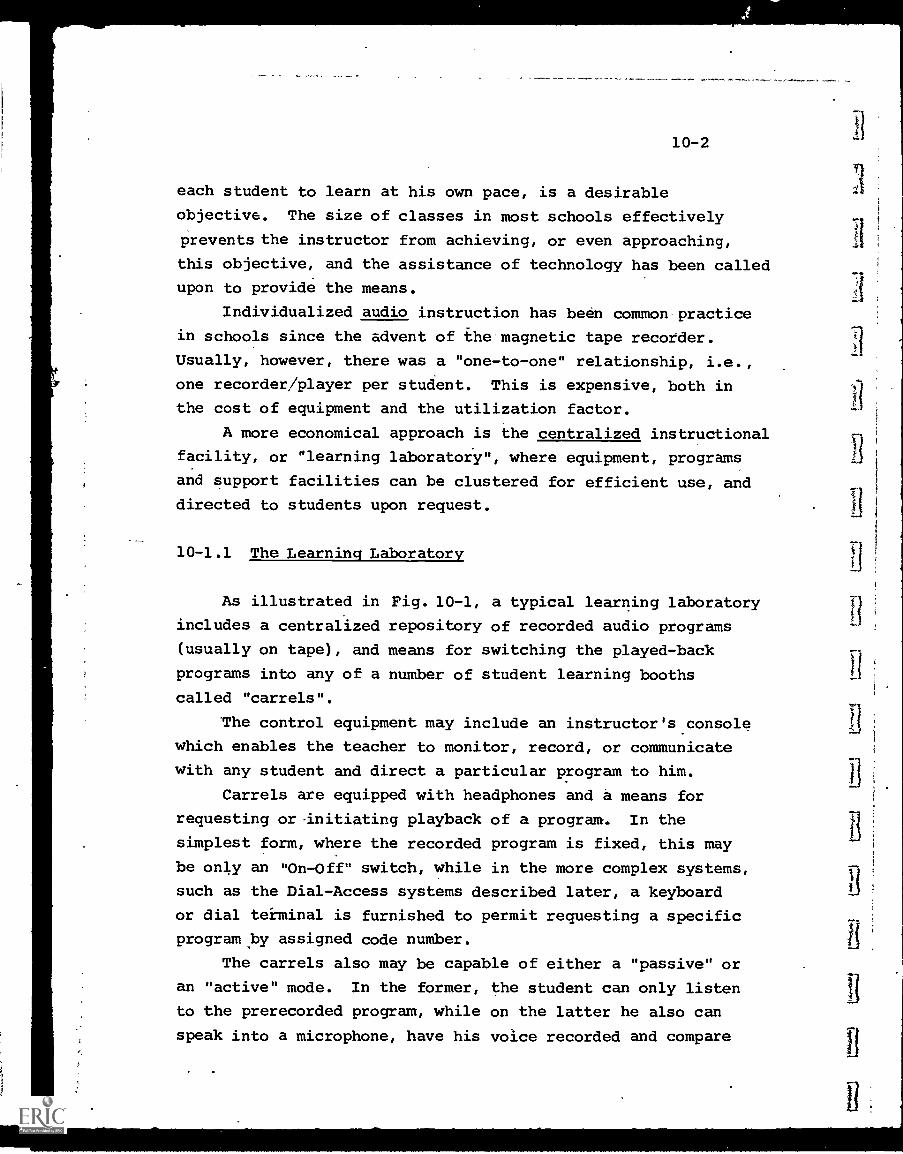
10-2
each student to learn at his own pace, is a desirable
objective. The size of classes in most schools effectively
prevents the instructor from achieving, or even approaching,
this objective, and the assistance of technology has been called
upon to provide the means.
Individualized audio instruction has been common practice
in schools since the advent of the magnetic tape recorder.
Usually, however, there was a "one-to-one" relationship, i.e.,
one recorder/player per student. This is expensive, both in
the cost of equipment and the utilization factor.
A more economical approach is the centralized instructional
facility, or "learning laboratory", where equipment, programs
and support facilities can be clustered for efficient use, and
directed to students upon request.
10-1.1 The Learning Laboratory
As illustrated in Fig. 10-1, a typical learning laboratory
includes a centralized repository of recorded audio programs
(usually on tape), and means for switching the played-back
programs into any of a number of student learning booths
called "carrels".
The control equipment may include an instructor's console
which enables the teacher to monitor, record, or communicate
with any student and direct a particular program to him.
Carrels are equipped with headphones and a means for
requesting or-initiating playback of a program. In the
simplest form, where the recorded program is fixed, this may
be only an "On -Off" switch, while in the more complex systems,
such as the Dial-Access systems described later, a keyboard
or dial terminal is furnished to permit requesting a specific
program by assigned code number.
The carrels also may be capable of either a "passive" or
an "active" mode. In the former, the student can only listen
to the prerecorded program, while on the latter he also can
speak into a microphone, have his voice recorded and compare
T-7-1
r-7-1
0.11
.mm
.,"0
.11.
1.-
I
Recorded Audio Programs
r1
Switching and Control
Equipment
Student
Learning
Booth
(Carrel)
Figure 10-1
Learning Laboratory
10-4
his response with the original. In learning languages, for
example, this feature permits him to evaluate his accent andinflections, and is very valuable.
So long as the number of recorded audio programs andthe number of students both remain low, the learning laboratorycan be a relatively simple system. With a few programs, for
example, it may be less expensive to provide a separate tape
recorder/player for each program than to incorporate the
switching facilities necessary to share one recorder.
Similarly, with a limited number of students it may be feasibleto schedule each program at a specific time, rather than uponstudent request.
As the quantity of programs and the number of users
increase, individual access becomes much more complex. As aresult, the learning laboratory has evolved .into the automated
Dial-Access information retrieval system. The concept remainsthe same, i.e.; providing individualized instruction upon
request but the storage, switching and control equipmentinvolve advanced telecommunications technology to a muchgreater degree.
10-1.2 Dial-Access Audio Information Retrieval
Dial-Access audio information retrieval systems have beenin use in the U.S. for some ten years, with about 300
installations at all educational levels from elementary schools.through universities.
The primary application to date has been as foreign
language laboratories, providing access to audio informationonly. The more recent and elaborate installations accommodateboth audio and video program material (examples of A/V Dial-
Access are given in Chapter 11). In the.A/V form, the system
makes available by electronic transmission a wide variety of
stored A/V educational materials for independent study or
classroom instruction. It also has other capabilities, ranging
r
10-5
from reception of community radio and TV stations to providinga link to a problem-solving computer.
The basic components and interconnection of a Dial-Access audio system are the same as in Figure 10 -1, exceptthat each block now contains more complex and flexible equip-ment.
The carrel retains its earphones and volume control forlistening to the program, but now incorporates a request/selection device. This may be the dial portion of a telephone(which gave rise to the term "Dial-Access"), a more recentTouch-Tone telephone keyboard, or an equivalent keyboard ofspecial design. The dial and Touch-Tone mechanisms have beenused because their volume production in telephone use hasresulted in a relatively low cost, and also because of theircompatibility with other telephone components that may be usedin the system.
In any event, the request/selection unit permits entry ofthe code number assigned to the desired program (an index ismade available to all users). A 3-digit dialed number can,for example, select any of 999 programs.
The switching and control circuitry must then select theappropriate program, start it playing back and connect it tothe carrel which inititiated the request. Since, for a systemof 20 carrels and 50 programs, 1,000 combinations are possible,just keeping track of and controlling the interconnectionsis no small task. Some Dial-Access systems use small general-purpose computers for this function, while others employspecial-purpose controllers.
Until the last few years, one drawback of Dial-Accessaudio systems was that if a program was in process of beingplayed back by a student, another student requesting thesame program either had to wait until playback was completed(which could be 15 -30 minutes) or start listening in themiddle. This was dueto the fact that the program was storedon only one tape (or, at best, two or three) and the sametape was played back.
10-6
The introduction of high-speed dubbing has alleviated this prob-
lem. In more recent systems termed "Random Access", the program
is stored on a "master" tape. When a student requests that
program, it is reproduced (dubbed) at high speed onto a
second tape which is the one played back to the carrel. The
dubbing speed is high enough so that a waiting time of less
than one minute is achieved under any circumstances. Thus,
within one minute, the requested program starts playing
back from the beginning, regardless of whether another student
is already using it. Each request for that program results
in a newly dubbed tape available to the requestor. Dubbing
tapes are later erased and reused.
Another recent inovation, the cassette, permits still
greater flexibility in using the Dial-Access system. By
providing a cassette duplicator in the system, the student
may purchase a blank cassette, insert it into the duplicator
(possibly with a coin-operated device), and request that a
specific program be dubbed onto the blank cassette. Once done,
he takes the cassette back to his own player and listens to_it at his convenience..
Figure 10-2 illustrates such a random access cassette
system, produced by Ampex. The upper portion of the diagram
shows the cassette duplicator unit. Program tapes are stored,
in incremental modules of 32, so that the configuration
illustrated can contain up to 96 programs. The student simply
inserts a blank cassette into a slot in the duplicator, selects
the program he wants, and presses a start button. Within a
few seconds the duplication is complete.
Cassette duplicators may be placed in key locations on or
off campus. A unit containing physics and chemistry programs,
may, for example, be located in the school's science building.
The centralized system, shown at the bottom of Fig 10-2,
can provide playback either to carrels or to remote locations.
In the former case the audio program is sent to t' carrel
earphones, while in the latter the duplicate cassettes themselves
it
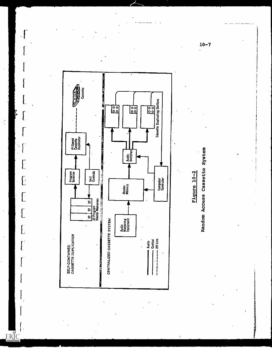
SE
LF-C
ON
TA
INE
DC
AS
SE
TT
E D
UP
LIC
AT
OR
Pro
gram
Sel
ecto
rfli
Spe
edCassette
Dup
licat
or
3232
3241
11-.
Uni
t32
Pro
gram
Con
trol
sM
aste
r M
emor
ies
CE
NT
RA
LIZ
ED
CA
SS
ET
TE
SY
ST
EM
-
rd 0 0
Cas
sette
Aud
io
Con
trol
Off
Line
Aud
ioM
aste
ring
Equ
ipm
ent
Mas
ter
Mem
ory
i111
Aud
ioS
witc
hes
Cas
sette
00 00 00 00C
ompu
ter
Con
trol
ler
Dup
licat
ing
Sta
tions
Figure 10-2
Random Access Cassette System
4
10-8
are made available. physically for playback on the user's
equipment.
Table 10-1 provides an order of magnitude estimate of
Dial-Access system equipment costs only.% this must be added
the software costs of program preparation.
10-1.2.1 Oak Park and River Forest High School System
As one of the first Dial-Access audio installations to
offer the random access feature described above, the system
at Oak Park and River Forest High. School, in suburban Chicago,
can serve as an illustrative example.
In 1966, functional specifications were drawn up by the
school's faculty for the system described Lelow. Bids were
let, and the first phase of the system was constructed and
became operational in 1968. Funding was supplied by.a U. S.
Office of Education federal grant of almost $1,500,000 (over
a 3-year period), supplemented by more than $1,000,000 in
local and private funds.
Figure 10-3 illustrates the original system which
accommodated 25 student carrels (5 to a pentagonal cluster)
for audio programs only, with a choice of up to 224 recorded
selections.
The master programs are stored on seven bin-loop tape
transports, each holding 32 programs. These tapes are normally
recorded at 3 inches per second.
The key to random access is that dubbing is accomplished
at a tape speed of 120 inches per second, whenever playbackis requested. Thus what would normally be a 15-min.::e program
is.reproduced in 1/40 the time, or about 23 seconds. Actually,
with switching time, and assuming the worst case that another
student has just previously requested the same program, the
maximum delay is less than one minute, whether one user or many
request the same program.
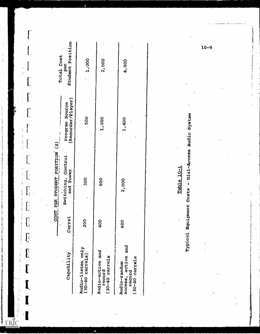
-.w
t.,...
O..
J..
MO
PO
. _PM
Mir
tfr
rr-1
7-1
r111
1ipr
Ow
liON
$
Capability
COST PER STUDENT POSITION
($)
Total Cost
.
per
Student Position
Carrel
Switching, Control
and Power
Program Source
(Recorder/Player)
Audio-listen only
(30-40 carrels)
200
300
500
1,000
Audio-active and
record
(30-40 carrels
400
600
1,000
2,000
Audio-random
access, active and
record
(30-40 carrels
600
2,000
1,400
4,000
Table 10-1
Typical Equipment Costs
- Dial-Access Audio System
0
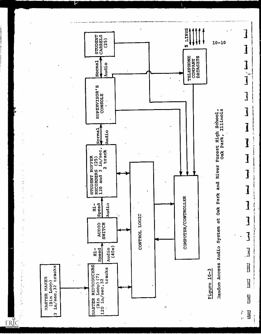
MASTER MAKER
(Bin Loop)
in/sec,32 tracks
YMASTER REPRODUCERS
(Bin Loop) (7)
120 in/sec,32 tracks
Hi-
Speed
Audio
(40x)
AUDIO
SWITCH
Hi-
STUDENT BUFFER
RECORDERS (25)
Speed
120 and 3 in/sec,
Audio
2 track
CONTROL LOGIC
COMPUTER/CONTROLLER
Normal
Audio
SUPERVISOR'-S
CONSOLE
Normal
Audio
STUDENT
CARRELS
(25)
Figure 10-3
Ilandom Access Audio System at Oak park
and River Forest High Sdhool,
Oak Park, Illinois
TELEPHONE
COMPANY
DATASETS
5LINES
LA
-4lo
wow
l1.
mov
i14
0460
,4tr
omor
iirovitil
towel
letiv
eltw
o,ef
i6,
4lo
goR
.1
Alim
IN0P
0 0
10-11
A computer/controller is used to control the selectionand switching. It also has diagnostic capability which cantest the 5,600 interconnection paths (224 program times 25carrels) and report defects.
Five telephone data communications interfaces are providedto let other schools or shut-in students connect into the
system.
The initial installation has since been expanded in a
second phase to add 50 more carrels, for a total of 75, andalso to carry video signals, although not on a random accessbasis. Phase 3 plans are for random access video, plus added
receiving stations in classrooms and conference rooms.
Further details on the system components follow:
Carrels: Illuminated push buttons select,programmaterial and control program replay, studentrecord and play, standby, and recue. Programrecording is controlled nnly by the computer, butan indicator light in the carrel shows when thesystem is in this mode. Each student has ear-phones, a microphone (for language instruction orintercom), an instruction card, and directory ofprograms.
The student does not operate the equipment directly.All student requests go from the carrel keyboardsto the computer which controls the entire system.The computer will reject an improper request orinput. Because of this hands-off operation,students can't damage the system.
Keyboard control units can also be put in classroomsor auditoriums to connect into the system for grouplistening. Remote locations, including sick studentsat home or other schools, can connect into thesystem via five telephone interfaces. A TOUCH TONEtelephone is all that is required.at a remotelocation to draw on the library of recorded material.
Supervisor Console: Unattended operation of thesystem is possible, since it is entirely automatic.Audio for each student passes through the consoleand may be monitored. A complete intercom allows
10-12
the supervisor to interrupt a program and talk with thestudent directly. An auxiliary keyboard/display uniton the console allows the supervisor to take overcontrol of any student buffer, share control with thestudent, or completely disable a given position. Thecomputer teletype, located on the console,, also logsout each requested program number with the positionthat requested it. This can be expanded to log out thestudent number, if desired.
Computer: The .computer is the nerve center of theentire system. Its program has a log of audio pro-gram numbers and student carrel numbers. The studentcan also insert his own number into the system inorder to identify himself for logging and testing.
The computer selects the proper program track andconnects it via an audio switcher to the carrelrecorder to duplicate the lesson at high speed. Thecomputer can also test the condition of the entiresystem each day using basic diagnostic programs. Oneof the test programs cycles every program source in.all student positions and logs out on the teletypeany defective paths. Any defective_ paths or unitslocated with the diagnostic program are identifiedon the computer teletype for action.
Master Recorder: Master programs are. recorded off-line on a master loop recorder which has 32 trackson one-inch tape. This unit is manually controlledand records programs at 3 inch/sec from any regularinput source such as a microphone, tape recorder,phonograph-or radio. The tracks on the masterrecorder have separate erase and record heads sothat each track is recorded independently of theother tracks and may be recorded, edited, or updatedat any time.
Master Reproducers: These are 32-track one-inch bin-loop units. After a tape is made on the masterrecorder, the bin is placed on the master reproducer.Here it ii played at 120 inch/sec to duplicate materialfor the carrel units.
Since these are loop recorders, the tape doesn't haveto be rewound before the next program can be duplicatO.Prog-ams are available from the beginning immediately
10-13
after a transfer is done. No time is lost inreversing the tape as in a conventional reel toreel recorder. Eat 7. master reproducer can trans-fer a single program to a single carrel recorder,a single program to all carrel recorders, or all32 programs simultaneously to all carrel recorders.
Carrel Recorders: The student recorder/reproducersconnected to each carrel are identical mechanicallyto the master reproducers, except they are half-inchdual track. They operate at 120 inch/sec whenreceiving a program from the master recorder, thenplay it back to the student for listening at 3 inch/sec. Transfer time is 30 seconds for a 15-minuteprogram. The student can listen to the program asmany times as he wants or record it on his ownpersonal tape recorder. Track one contains programmaterial for playback. Track two is for recordingthe student's own voice.
10-2 Telephone-Based Systems
The availability of the vast dial-up telephone networkin the United States, supplemented by leased dedicated lines
or user-installed and owned lines, makes it technologicallyfeasible to utilize telephones for many educational applications,
particularly under off-campus conditions. Where only audioinformation need be transmitted, the telephone network mayserve as the complete distribution system, while-in mixed-media applications, such as instructional television withstudent interaction, it may serve as an audio subsystem ofthe total system.
The cost, however, may be prohibitive in many cases.Even in the most favOrable case where all lines are local and
toll-free, the equivalent cost of $0.10 for a 3-minute orless call, totals $2.00 per hour for a single point -to -point
application. Unless more than one user can time-share theline facilities, few educational institutions can bear thesecosts. Current commercial computer time-sharing systems, asan example, are burdened with high line costs which can be
10-14
justified only above a substantial threshold of usage.
Where cost-effectiveness can be demonstrated, educationaltelephone can be extremely useful. ThE-I introduction of the
Touch-Tone phone provides a truly low cost terminal whichcan be used to input numeric information to a central location
where either CAI, data retrieval or computer time-sharing
functions take place. If the response to the user is in
aural form and does not require special printers or display
facilities, then all of the capital investment costs are in
the central equipment and essentially none at the users site.
.Other than cost, another practical imitation to telephone
system usage, at least in the dial-up network, is the high
volume of traffic being handled, with some consequent degradationin service. For aural applications, this is not yet significant,
but for data flow, many current users can attest to marginal
adequacy at best, in terms of line conditions leading.to
excessive noise, outages, high error rates, etc.
Massive efforts are-underway by the common carriers toimprove and expand the voice-frequency communications network,
particularly with respect to data traffic. In the latter
case, applications are pending before the FCC to authorize
the construction and operation of large-scale, new data com-
munications system by non-common-carriers. It appears at this
time that one or more of these proposed networks will be
constructed, probably in the next five years.
Simultaneously, the establishment of domestic communications
satellites will provide more relaying capacity, both point-to-point and, more importantly, on a distributed basis from one
point to many reception points.
The effect of this expanded capability will be to permit
educational applications in the future to use the voice/data
network on a more cost-effective basis, although communications
costs may.yet remain the major barrier to wider implementation.
Meanwhile, many education applications utilizing telephone
communications have taken place. Two examples are described
below.
10-15
10-2.1 Educational Telephone Network (ETN)
The Educational Telephone Network (ETN), developed by
the University of Wisconsin, links some 50 courthouses, 15
University of Wisconsin campuses and centers, and 56
hospitals throughout the state.
ETN is a private telephone network that takes the form
of a huge party line. It is designed for maximum flexibility
and practic=11 approximation to across-the-table discussion.
All of the outlying points on the network have identical
equipment, consisting of a speaker and telephone handset.
By picking up the handset, a participant can talk to all
listening points connected to the system.
ETN was originally developed to provide continuing
education to id.D.'s throughout the state; the first post-
graduate medical program was conducted via ETN in 1965. ETNhas expanded since then to include programs on law, pharmacy,
staff training and development, social work, library science,
nursing, 4H, engineering and music. College credit courses,
including home economics, library science, veterinarian science,
physics, sociology and English have been provided.
A typical program varies from 1-2 hours, normally with
a live or taped lecture followed by a question-and-answer
period. To ask a question, a listener simply lifts his handset
and speaks, and is heard over the entire network.
Visual materials are sent out to each listening station
as desired, and used in conjunction with or to supplement the
telephonic sessions.
Equipment is available .o extend the ETN concept to include
transmission of visual material in conjunction with the audio.
"Blackboard-by-wire", "Tele-class" and "Remote Blackboard"
are various designations for systems which can scan static
or slowly moving visual objects, such as a blackboard, convert
the image into electrical form; and send it over...a second
telephone line so that it can be received and reproduced at
4
10-16
the same time the audio message is heard. These systems aredescribed more fully in Chapter 11.
The key fact' 2, however, remains the line costs. .Estimatesfor equipment to provide 2-way audio-and-graphic communicationbetween two classrooms range from $5,000 - $10,000. The annulcost of a phone line, used 8 hours per day, may easily exceedthis, particularly where toll charges are involved. For anall-audio system, the discrepency is even more outstanding,since the terminal equipment cost becomes almost negligible.
10-2.2 Telephone-Based Dial-Access
Most campus-based Dial-Access retrieval systems can beexpanded off-:campus using the telephone network to permitoutside users to obtain access to the system. All that isneeded is appropriate interface equipment to insure that theoutside call is made to "look like" an internal request sofar as the system is concerned. Two limitations will restrictunlimited expansion, communication costs, and the responsecapability of the system, i.e., how many calls will "saturate"it.
One system of interest, termed "Dial-a-Drill", is beingstudied on a pilot basis in New York City. This applichticnis essentially a Computer-Assisted-Instruction project withthe phone network acting only as a communications aid, butsince it provides a voice response rather than data or graphics,it is appropriate for this section.
The "Dial-a-Drill" system can drill several thousandstudents, at home, in the fundamentals of arithmetic, usinga time-shared computer programmed to drill the students orallyat their own rate.
A student may call into a central location, or, conversely,an attendant at the central location calls a student, andafter verifying that he is ready for his lesson, transfers himto the computer. If the student needs assistance at any time,the attendant can be summoned in on any line.
10-17
The computer, using a voice-response unit, poses questionsin subtraction, addition, multiplication, division, fractions,etc., in varying degrees of difficulty depending upon studentprogress. The student responds (i.e. gives the answers) bypushing appropriate buttons on his home Touch-Tone telephone,used here as an input terminal. A cumulative record ismaintained on each student's level of achievement.
Since the student does not directly dial his program,this system may be somewhat less than a pure Dial-Access type.If implemented past the pilot stage, however, further automationis to be expected.
10-3 Educational Radio
The use of radio for educational purposes is one of theoldest applications of communications. In 1919, over fiftyyears ago, station WHA, licensed to the University of Wisconsin,began experimental operation. WHA is still broadcasting andis the originating point for a Wisconsin state network of 11educational radio stations.
In 1941, FM broadcasting was authorized and the numberof educational stations on the air grew rapidly followingWorld War II: At the beginning of 1971, more than 475 educationalradio stations were licensed by the FCC. About 40% of thistotal went on the air between 1966-70, indicating the extentof recent growth.
In addition to broadcast systems, about 500 closed-circuit carrier-current or wired- wireless campus systems areoperated by educational institutions. These require no FCClicense.
Of the 475 currently operating stations, only about 25operate in the Amlitude-Modulation (AM) band, 550-1600 KHz-No AM frequencies are reserved for educational use and. thecrowding of this ortion of the spectrum inhibits thepossibility of new stations.
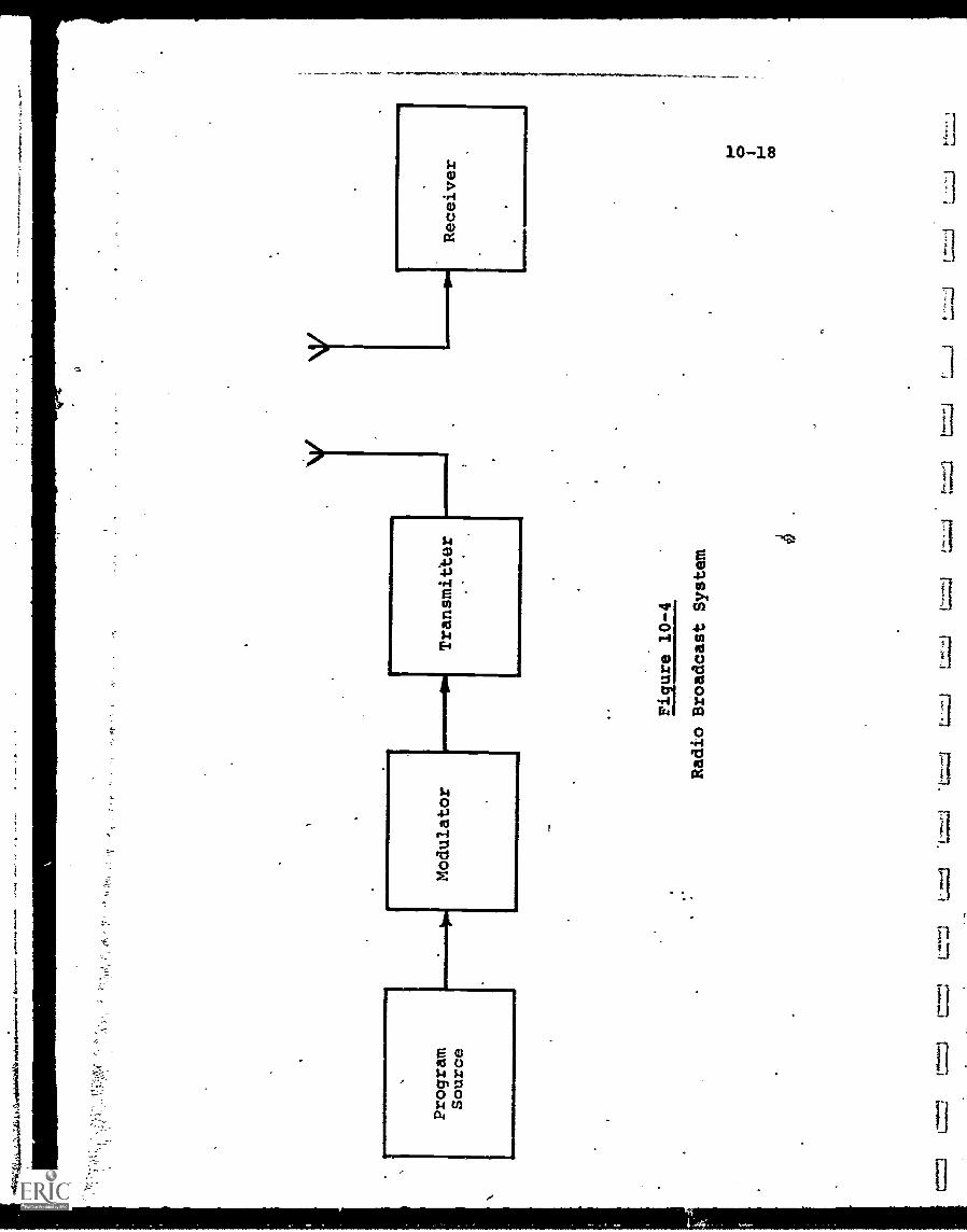
.101
;44#
4ftv
iudi
agal
iaaf
traf
taw
aftw
.
Program
Source
L1
Modulator
rom
mi=
0111
Transmitter
Figure 10-4
Radio Broadcast System
1:1
1,;.:1
Receiver
10-19
In the FM range, however, the FCC has reserved the portion
between 88 and 92 MHz for noncommercial educational stations,
and consequently this is where most educational stations
presently operate. Almost all the educational stations licensed
in the last 5 years have been FM.
About 72% of the FM educational stations are licensed
to colleges and universities, about 17% to local boards of
education and schools, 6% to churches and religious organizations,
and the remainder to community corporations, libraries and
other organizations.
About 45% of all educational FM stations are low-power
(10 watts) units, broadcasting,over'a Limited 2-5 mile radius,
and requiring a total capital investment of only a few
thdusand dollars. A higher -power FM transmitter, perhaps up
to 100 watts, might serve a radius of 10-20 miles, at an
equipment cost of perhaps $25,000.
Because of the limited availability of frequencies in
the broadcast spectrum, no startling growth is expected in
terms of number of new educational radio stations, .Restriction
to low power eases the problem of radiation interference to
some extent, but the burden is still on new applicants to
demonstrate non-interference operation, which can be difficult
and expensive.
An expansion in FM multiplexing (described in Chapter 3),
however, may be expected since this requires no new frequency
allocation and, indeed, permits the FM station to secure
income from sources other than broadcast advertisers or audience
contribution. A correspondence course, for example, can be
multiplexed only to students registering for the course (the
special receiver is furnished to them only for the course
duration), and the registration fees are used to defer costs
and hopefully produce some income.
Radio can also serve as an element in more complex
educational systems, such as a dial-access retreival of audio
10-20
program material, or the interactive "talkback" portion ofan ETV/ITV system.
10-3.1 Radio Networking
In 1950, the first national network of U.S. educationalradio stations was established. Originally the Tape Networkof the National Association of Educational Broadcasters (NAEB),and later called the National Educational Radio (NER) divisionof NAEB, it distributed recorded programs to affiliatedstations.
In September 1965, the first interconnection (networking)of some 70 NER stations took place; since then repeated manytimes for special programs.
With the formation of the Corporation for Public Broad-casting by Congress in 1967, CPB took on responsibilitiesfor stimulating the growth of educational radio as well asTV. In March 1970, CPB formed National Public Radio (NPR)as a national noncommercial radio service. NPR functionsinclude live interconnection and other prograth distributionsystems tnetworking), coverage of public events,. developmentof programs and establishment of foreign program exchange.
CPB provides some funds to those radio stations whichmeet minimum criteria with respect to broadcast hours, trans-mission power, staffing and quality of programming. A totalof 96 stations were deemed eligible for CPB grants by theend of 1970.
NPR's network is eventually to interconnect some 100public/educational radio stations, and is expected to produceextensive public affairs programming.
With the advent of domestic communications satellites,both radio and TV station networking will be enhanced, dueto the satellite's unique capacity to distribute signals overa vast geographical area. Direct broadcasting to homereceivers from satellites is anticipated around 1980, whidh
will open up a completely new era in educational and publicaffairs broadcasting.
7
rt
11
ti
[1
CHAPTER 10 - BIBLIOGRAPHY
10-21
1. Campbell, R.R. and'Honnold, G.H., "Teaching by Telephone",Bell Laboratories Record, Jan. 1970.
2. "Educational Radio", FCC Bulletin 21 -B, April, 1971.
3. Jamison, D., Jamison, M., and Hewlett, S., "SatelliteRadio: Better than ETV", Astronautics of Aeronautics,Oct. 1969.
4. Ofiesh, G.D., "Dial Access Information Retrieval Systems:Guidelines Handbook for Education", Final Report, July1968, Contract No. OEC-1-7-071042-5093 for the U.S. Officeof Education, HEW.
5. "The Hidden Medium: Educational Radio", Herman W. LandAssociates, April 1967, prepared for the NationalAssociation of Educational Broadcasters,
6. Zazzaro, J., "They've Almost Invented Instant Learning",American School Board Journal, Sept. 1968.
Chapter 11 - Audio/Visual Systems
The advent of video communications technology in general,
and television in particular, has increased the possibility
of a host of educational applications by orders of magnitude.
With the capability of remotely-located students to receive
visual as well as aural information, simulation of class-
room environment has been advanced drastically, although
there still remain some admitted shortcomings.
Since, in most A/V systems, the audio information is
transmitted by components and techniques already described
in Chapters 3 and 10, the emphasis in this chapter will be
on the visual elements of the systems reviewed.
An arbitrary classification has been used to categorize
A/V systems, in accordance with the dynamics of the visual
images being transmitted:
(1) Static - no motion of the visual image with respect
to time or space, so far as the viewer is concerned
(maps, still photographs; pages of a book, dia-
grams, etc.)
(2) Quasi-Static - some motion within the image but at
a relatively slow rate, compared to normal motion
picture or TV images.
(3) Motion - any degree of motion in the image, up to
the limitations imposed by equipment.
As is usual with systems of any complexity, there are
numerous cases of overlap among these three categories. A
standard TV system, for example, can handle images in any of
the three, but it is much lesS efficient for the first two.
Examples of specific operating systems have been selected,
as in the audio case, to be illustrative rather than compre-
hensive. They range, chronologically, from educational TV
broadcast and CCTV systems over 20 years old, to recent ITFS
installations (Stanford, 1969),pilot demonstration of advanced
retrieval techniques (TICCIT, 1971), and some systems more
conceptual than actual.
11-2
As contrasted with purely audio systems, A/V educationalapplications (including the computer-based systems reviewedin Chapter 12) are still in their infancy, with an anticipationof rapid growth in this decade.
11-1 Visual/Static Systems
The transmission of visually static information generallyoccurs (at least in educational applications) either in con-nection with the reproduction of photographic and documentarymaterial, or the display of computer-generated information.In the former case, the material can include' maps, slides,still photographs, graphs, pages from a book or magazine, oricroforms of any type.
Almost any of these visual images can be artificiallygenerated w appropriate computer-programming. The differencebetween the cases, therefore, is not in the final displaythat the viewer sees but in the relative requirements for data-bank storage and control. As an example, computer-generateddisplays are possible with an, all-electronic system, whereasretrieval and transmission of microfilm images require electro-mechanical and electro-optical retrieval and conversion. Thedesired image must be selected from the microfilm file , andmechanically brought into conjunction with a scanner whichwill convert the stored photographic information intq electricalform for transmission.
This scanning is in effect a facsimile process.' Elect-ronic scanning via a video camera is also possible, and mayutilize either slow-scan or conventional TV, with better cost-effectivity for the former.
Where the information is computer-generated, no photo -graphic-to- electronic transformation is necessary. Further, theelectrical format of the information can be more flexible, andmade to adapt to a variety of transmission systems and displaydevices.
1
11-3
11-1.1 Facsimile - Based Systems
Facsimile as a concept is particularly attractive inretrieval systems where remote hard-copy reproductions arenecessary. Its utilization, however, in education has beenrare because of the relatively long transmission times required,
and the consequent high cost of telephone line facilities.
With respect to education, one point is of particularinterest. The limitations of speed and cost introduced bythe telephone-line communications link largely disappear whenin-house systems are considered. For example, a university
campus installing facsimile transmitters and receivers onlywithin its grounds could use larger-diameter hard copper wire
(or, at more cost, coaxial cable) as a direct-connection
replacement for the telephone-line communications portionof the system. This would provide. two benefits:
(1) . Eliminate,line charges (which are the most significant
load-variable factor).
(2) Permit communications at perhaps four times the
phone-line rate due to the greater bandwidth of thecopper wire.
Thus, both a time and cost saving are achieved concurrently,
which is certainly attractive. The limitation is that such a
direct-wired system is limited to distances of a few miles
before requiring signal amplification. Thus, direct-wiredschool -to -home applications are not feasible econo-cically.
An illustration of a facsimile-based microfilm retrievaland delivery system which is a combination of available com-
ponents and subsystems is shown in Fig. 11-1. Eastman Kodakprovide6 an automated microfilm storage and display system
called "Miracode" which, upon pushbutton request by an operator
will display upon an illuminated screen an enlarged version of
any 16mm microfilm frame stored within its files.
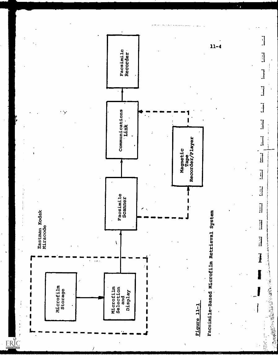
Eastman Kodak
Miracode
Microfilm
Storage
Microfilm
Selection
and
Display
Facsimile
Scanner
Communications
Link
Facsimile
Recorder-
Figure 11-1
Facsimile-Based MicrofilmRetrieval System
11-5
A facsimile scanner is located so that it is opticallycoupled to the display screen. Energizing this scannerproduces as its output the electrical signal representing thescanned microfilm image. This is communicated to the remotefacsimile recorder(s).
A magnetic'tape recorder is utilized as an intermediatestorage or communications interface device. Recording theimage and playing it back at a faster tape speed, for example,will transmit at a higher rate, if the communications link
provides sufficient bandwidth to do this. Reversing theprocess and playing back at a low speed permits the use of alow-cost, narrow bandwidth link, but consumes more time intransmission.
A system as shown in Fig. 11-1 requires practically nospecial development, since all elements are commerciallyavailable. Its cost-effectiveness for educational applications,however, remains to be demonstrated.
As an illustrative example, the U.S. Postal Servicerecently announced the initiation of facsimile mail serviceon November 1, 1971, between New York and Washington. Theservice is designed primarily for the transmission of importantbusiness documents, such as legal briefs, bids, contracts,etc. The cost will be $4.23 far the first page and $3.00per subsequent page if picked up in the lobby of the receivingpodt office, or an additional $1.00 if delivered. While useby the Postal Service certainly lends prestige to facsimile,the service offered has been variously predicted and dis-cussed some ten to fifteen years. In its present form, itoffers no new technical advance, and the cost, while notexorbitant, certainly removes the service from the majority of
non-urgent applications, including education.In the near future (possibly the next five years), the
growth of information storage and retrieval centers designedto be accessible by the public may stimulate facsimiletechnology. The "dial a document" concept, in the user
11-6
dials the phone number of. the retrieval center, enters thecode for,the desired document, and has it located and scannedby facsimile, producing a prihtout at his receiver, may becomeoperational. The barrier to implementation still will bethe relatively high transmission and terminal cost, so that
pressure will be exerted for technological solutions. Initialinstallations will probably be in universities and schools,
where the libraries might act in this capacity, transmitting
requested pages of books, reports, test papers, etc. to facultyand student recorders. (This concept was planned for the newUniversity of California, Irvine,campus.) For such in-house
systems, the elimination of phone lines could make the systemeconomically justifiable. When broadband communications
networks supplant the ubiquitous telephone line (perhaps within
a decade) facsimile will have to operate at correspondinglyhigher speeds. This probably will dictate all-electronic
scanning and printout, merging facsimile and - slow -scan
television together, possibly into only one survivor.
11-1.2 TICCIT, an Interactive Page - Retrieval TV System
An interactive page-retrieval TV system called TICCIT
(Time-shared Interactive Computer- Controlled- Information
Television) has been developed by the'MITRE Corporation andis being demonstrated on a pilot basis, in conjunction with
a cable TV system in Reston, Virginia.
TICCIT provides computer-generated or computer-controlled
information that can be selectively received and displayed bystandard TV receivers. The information is displayed ih visual/
.
static form, e.g., a page of text, a graph or a photograph.
In standard TV transmission, as has been noted, a new
picture frame is sent to the receiver 30 times per second,
allowing moving images to be presented without noticeableflicker. Each frame is made up of 2 interlaced fields, so thatfields are transmitted 60 times a second. Even when still
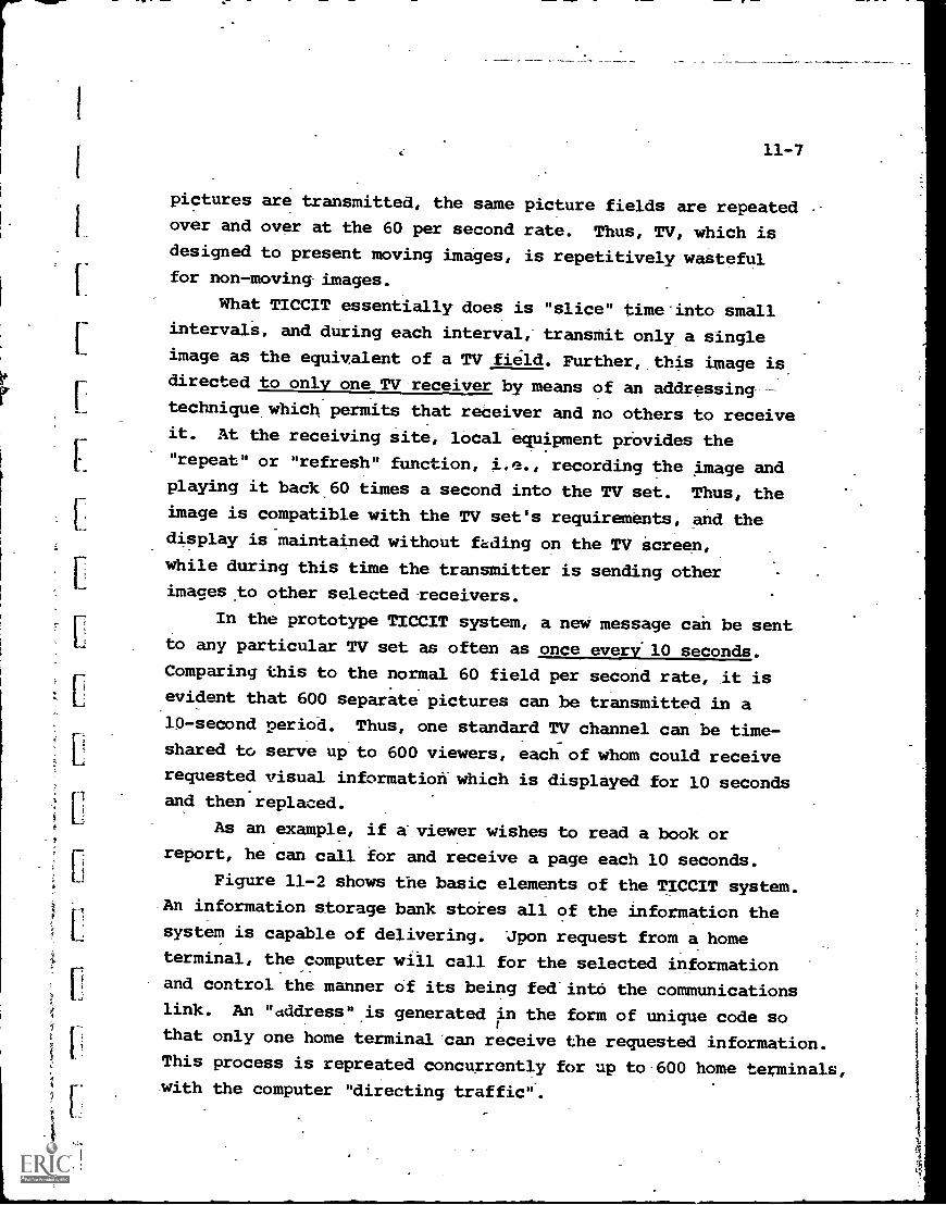
11-7
pictures are transmitted, the same picture fields are repeatedover and over at the 60 per second rate. Thus, TV, which isdesigned to present moving images, is repetitively wastefulfor non - moving images.
What TICCIT essentially does is "slice" time into smallintervals, and during each interval, transmit only a singleimage as the equivalent of a TV field. Further, this image isdirected to only one TV receiver by means of an addressing
technique which permits that receiver and no others to receiveit. At the receiving site, local equipment provides the"repeat" or "refresh" function, i.e., recording the image andplaying it back 60 times a second into the TV set. Thus, theimage is compatible with the TV set's requirements, and thedisplay is maintained without fading on the TV screen,
while during this time the transmitter is sending otherimages to other selected receivers.
In the prototype TICCIT system, a new message can be sentto any particular TV set as often as once every-10 seconds.
Comparing this to the normal 60 field per second rate, it isevident that 600 separate pictures can be transmitted in a10-second period. Thus, one standard TV channel can be time-shared to serve up to 600 viewers, each of whom could receive
requested visual information which is displayed for 10 secondsand then replaced.
As an example, if a-viewer wishes to read a book or
report, he can call for and receive a page each 10 seconds.
Figure 11-2 shows the basic elements of the TICCIT system.
An information storage bank stores all of the information the
system is capable of delivering. Upon request from a home
terminal, the computer will call for the selected information
and control the manner of its being fed'into the communicationslink. An "address" is generated in the form of unique code sothat only one home terminal can receive the requested information.This process is repreated concurrently for up to 600 home terminals,with the computer "directing traffic".
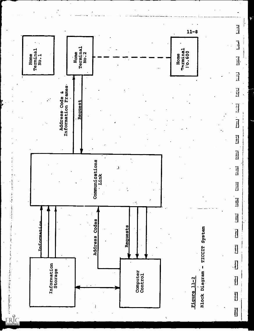
Information
Storage
Trt
feve
mm
t4on
Computer
Control
AddressCode &
Information Frames.
Home
Terminal
No.1
Address Codes
Communications
* Link
4
Requests
mud
Request
Home
Terminal
No.2
; I 1 I I 1
Lrrminal
Home
Teo.600
Figure 11-2
Block Diagram- TICCIT
System
= =
%I=
104.
,"q1
1L
tf>
=1
co
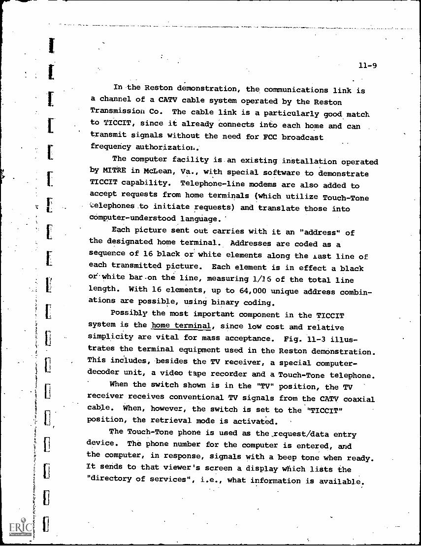
11-9
In the Reston demonstration, the communications link isa channel of a CATV cable system operated by the RestonTransmission Co. The cable link is a particularly good matchto TICCIT, since it already connects into each home and cantransmit signals without the need for FCC broadcastfrequency authorizatioL.
The computer facility is an existing installation operatedby MITRE in McLean, Va., with special software to demonstrateTICCIT capability. Telephone-line modems are also added toaccept requests from home terminals (which utilize Touch-Tonei...elephones to initiate requests) and translate those into
computer-understood langUage.'
Each picture sent out carries with it an "address" ofthe designated home terminal. Addresses are coded as asequence of 16 black or white elements along the Last line ofeach transmitted picture. Each element is in effect a blackoewhite bar-on the line, measuring 1/16 of the total linelength. With 16 elements, up to 64,000 unique address combin-ations are possible, using binary coding.
Possibly the most important component in the TICCITsystem is the home terminal, since low cost and relativesimplicity are vital for mass acceptance. Fig. 11-3 illus-trates the terminal equipment used in the Reston demonstration.
This includes, besides the TV receiver, a special computer-decoder unit, a video tape recorder and a Touch-Tone telephone.
When the switch shown is in the "TV" position, the TVreceiver receives conventional TV signals from the CATV coaxialcable. When, however, the switch is set to the "TICCIT"
position, the retrieval mode is activated.
The Touch-Tone phone is used as the request /data entrydevice. The phone number for the computer is entered, andthe computer, in response, signals with a beep tone when ready.It sends to that viewer's screen a display which lists the
"directory of services", i.e., what information is available.
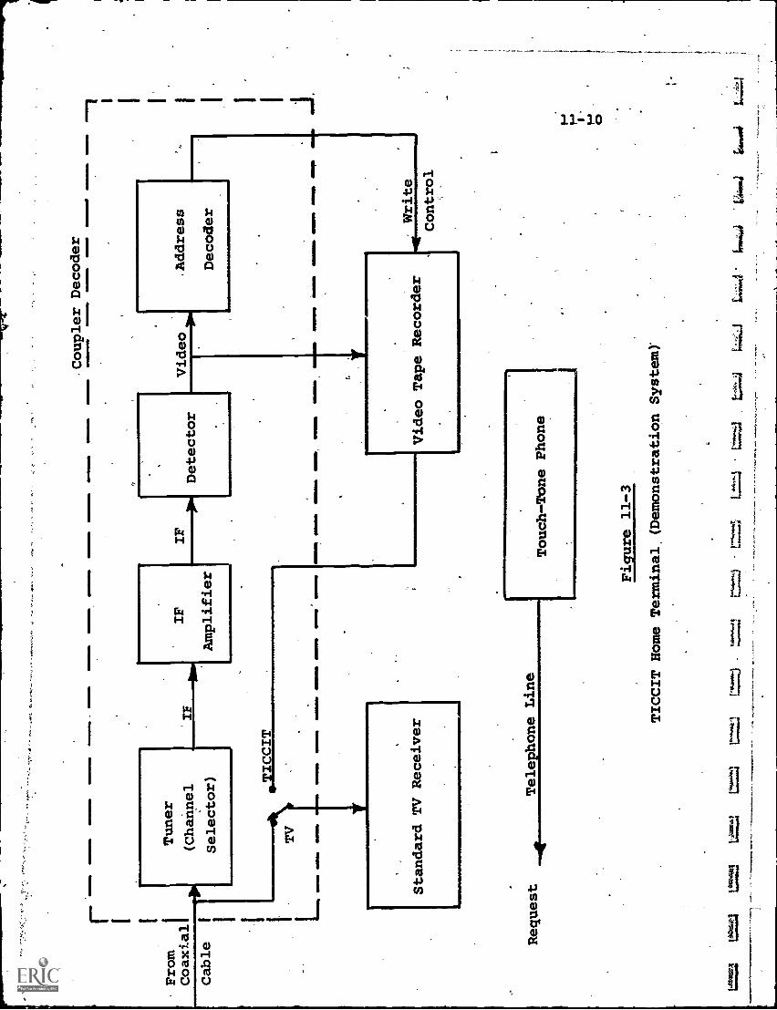
r I I
From
Coaxial
1111
1011
9
Cable
L
Tuner
(Channel
Selector)
17,11\
TIC IT
TV
INN
M M
INIM
- O
MM
MIM
MIS
M
IF
IF
Amplifier
NO
MM
EN
.M
OM
% N
IIIIM
NIM
OM
INIIN
DM
INN
OM
,
Standard TV Receiver
Request
Telephone Line
GIM
MIN
emO
NS
IMM
M.
Detector
Coupler Decoder
Video
11 M
INN
-11
11M
MIM
IO-
4111
IMIN
MM
NM
INIM
IMM
O
.Address
Decoder
MIN
NIM
IED
MIM
I=M
INIM
AM
MO
NM
I.
Video Tape Recorder
Write
Touch-Tone Phone
Figure 11-3
TICCIT Home Terminal, (Demonstration System
Control
=`,
"'
tr.;:j
te04
.04
6:44
J. 0
The viewer then enters a code on his phone biriushing theappropriate button corresponding to the information he wishes_to view, and the computer initiates the sequence of displayframes to be sent.
The computer also identifies the phone which made therequest, and generates an address code for that terminal. Thisaddress, as noted, is added .to the picture signal,as a part ofthe line-scan-pattern.
The information reque'sted (along with all requests fromother'terminals, time-sequenced 600 to a 10-second period)enters the coupler-decoder unit from the CATV cable. The firstportion of the coupler-decoder is identical to the input portionof a TV receiver (compare Fig. 4-8), and serves only toseparate the video signal from the RF carrier.
The video signal, representing the image to be displayed,is recorded on a Video tape recorder of the helical-scan type.As has been pointed out in Chapter 4, most VTR's of this kindwill" record 1 track in ,1/60 second. Ordinarily, after thisinterval; the tape is moved so that the next adjacenttrackis recorded.
If, however, the tape take-up and supply mechanism isdisabled, the VTR may be used to record for 1/60 second andthen, by switching to the playback mode and retracing therecorded track over and over, play the same information backeach 1/60 second continuously thereafter. Thus, the VTRbecomes an ideal "frame-grabbing" or refresh device.
The VTR continues to play back the information display tothe TV receiver, so that-the display is maintained, flicker-free, for the 10-second period, after which a new frame isreceived from the cable:
The address decoder section has the function of "lookingat" the line of the, display which contains the designatedaddress. If this incoming address matches a unique address codewhich` has been preset into the decoder, then and only- then willthe VTR be instructed to proceed to record and playback. Thus,even though messages are being sent over the party-line cablecontinuously, only those requested will be displayed.
11-12
It is acknowledged that the current cost of VTR's is too
high to make TICCIT immediately applicable to a mass audience..
The other two components of -the home terminal, the Touch-
Tone phone (which usually would already_be available), and
the coupler-decoder (which, in quantity, can be produced in the
$50 range) are relativelyinexpensive. r
The assumption is that with the advent of cassette video
recorders, in both black-and-white and color, the price of this
element will eventually drop drastically and thus make a full-
scale TICCIT system economically feasible. Another alternative
would be the development of a special-purpose low-cost refresh
deVIce using techniques other than video tape recording.
A major factor in determining TICC/T's eventual success
is the development of a library of software, i.e., visual
material of interest to viewers and in the necessary compixter-
compatible form. The Reston demonstration software consist of
two relatively elementary arithmetic exercises, one designed to
teach children to add 2-digit numbers, and the other a drill-
and-practice course in fourth-grade arithmetic, designed by
the Computer-Aided-Instruction Group at Stanford University.
Obviously, there is-complementarity and mutual support
between CAI and TICCIT-type systems. The generalized TICCIT
concept, however, is broader, permitting any kind of selective
information retrieval.
11-2 Quasi-Static Visual Information
A substantial amount of visual information pertinent to
education falls into the quasi- static category, i.e., images
which change at a slow rate. An example would be the material
written on a blackboard or a pad by a teacher.
Since the information is not usually in document form, and -
is varying with time, facsimile cannot be used as a telecom-
munication technique. Similary, frame or page-retrieval systems
11-13
described above are also not applicable, since they require staticimages.
On the other hand, conventional TV is "over-designed" forquasi-static material, and is inefficient in terms of bandwidthutilization and equipment cost.
As .a result, hybird approaches have been developed whichuse low or medium (voice - grade) frequency communications links
to transmit visual data.' The quasi-static nature of the datamakes, the use of limited-bandwidth transmission feasible.
Examples of this approach are described below.
11-2.1 Blackboard-by-Wire
Many schools and colleges transmit audio and quasi-staticvisual information over telephone lines to remote locations by
systems variously termed "blackboard-by-wire", "remote blackboard"or "electronic blackboard".
TWO typical systems are manufactured, respectively, bySylvania and Victor Comptometer. The Sylvania system (formallythe ECS-100 Educational Communications System) enables groupsof students in remote locations to hear a lecturer and simul-
taneously view his graphic material as it is presented.
The instructor speaks into a microphone at his desk, and
the audio information is transmitted over a phone line to each
remote location in a conventional manner. At the same time, hewrites or draws with an electronic stylus pen on a 6" X 8"
roll-up pad which ii part of a desk-top graphic transmitter.
The X-Y components of the writing motion are coded into electrical
signals, converted to FM form in the voice-band below 3KHz, andtransmitted over a phone line also. Either separate audio and
visual phone lines may be used, or the two combined on one line.
The visual information is received at the remote classroomby a giaphic receiver which includes a decoder, a CRT storage
display unit, and a video camera. The FM signals are demodulated
and used to generate a display on the screen of a long- persistence
11-14
CRT, selected so that the relatively slow moving image doesnot fade too soon.
The video camera photographs the face of the CRT, and con=verts the image to a signal capable of being displayed on astandard TV receiver in the classroom. Thus, the small CRTimage is effectively enlarged so that it may be viewed by the
entire class.
The Victor system (Victor Eiectrowriter Remote Blackboard,
or VERB) accomplishes essentially the same task. In the
receiving portion of the system, however, an electronic stylus
pen, similar to that at the teacher's desk, is used to retracethe image on transparent acetate paper. The image is then, like
a "view-graph", projected onto a screen anywhere from 3' X 5'
to 9' X 12', for immediate viewing by the class.
The cost of blackboard-by-wire transmitting and receiving
equipment is relatively moderate, and for some remote locations
may be the only realistic choice. Apart from the phyiical
limitations imposed-on the instructor (i.e., he must restrict
his activities to the proximity of the microphone and writing
tablet), it is important to realize that in many cases, the
ma or costs will'be telephone line char es. These should be
estimated accurately'before a total systei cost can be arrivedat.
There is no technical reason why wireless (radio) trans-
mission could not be used instead of telephone lines, but the
requirement for FCC broadcast frequency, allocation mitigatesagainst this approach.
11-2.2 SlW-scan TV
Slow-sCan TV is the generic term for systems which trans-
mit visual information by using the line-scanning techniques
of conventional TV, but at A much lower transfer rate. Thus;
narrower bandwidth communications links, even telephone lines,
can be used.
An example.is the Picturephone system under developmentby A.T. & T. This scans 30 frames per second, and has 2interlaced fields per frame exactly similar to TV, giving aflicker-free image since the eye does not notice.a flicker rateof 60 per second. However, only '250 lines make up a frame(less than half of TV's 525) and the resolution along each lineis poorer. Consequently, a total bandwidth per Picturephonechannel of only 1 MHz is adequate,' compared to the 4-1/2 - 6MHz used for TV.
This is satisfactory for the puipose, since Picturephonescreens generally will not be required to display rapidly-changing images. For quasi-static information, even narrowerbandwidths than 1 MHz can be used, by reducing still furthereither the number of lines per frame, the number of frames persecond, or both.
If reducing the numbei of frames per second might resultin flicker at the display, either CRT's with longer persistencescreens can be used, or a local refresh unit, such as that forthe TICCIT.system, be incorporated into the receiving terminal.
Slow-scan TV.can be accomplished also by not transmittingin real time, i.e., taking a longer time to transmit visualinformation. As an example, if a school desires to transmit avideo taped TV program to a remote location for viewing at alater time, there is no necessity for a wide-band video channel.Theoretically, it can 1.1ay back the tape at 1/10 the speedat which the program was originally recorded. Thus the 6 MHzTV bandwidth is effectively teduced to 600 KHz and a narrower-band communications link could be used.. The penalty paid isin transmission time, so that a 1/2 hour program would take 5hours to transmit. This is feasible, however, and the sendingfacility might transmit at night to a video tape recorder atthe receiving facility. The next morning: by playing back at10 times the speed of recording, the program can again be viewedin real time.
11-16
This technique for compressing or expanding bandwidth vs.
transmission time is, of course, subject to the dynamic ranges
of available equipment, and thui has definite limits. In
concept, however, it is extremely flexible, especially where
the visual information does not have to be viewed directly.
11-3 Visual/Motion Systems
To date, almost all visual/motion systems using telecom-
munications for educational applications have been television-
based, i.e:, the user's terminal has been a TV receiver. Film
and slides have been ut*lized for many years, of course, but
usually in direct projection within a classroom or auditorium.
If transmitted 'remotely: the film would be converted, first to
electrical signals and subsequently to a TV display.
The commercial TV broadcast industry has established the
basis for system performance and technical specifications, and
it has been simpler and less costly for educators to adapt to
these than to design special-purpose systems which require
development time and funds. The availability of a good-quality.
black-and-white TV receiver for $150-$300, or a color unit for
$300-$600, is possible only because'of their mass production
for the entertainment market.
In some respects, the commercially available TV equipment
is not always suitable for specific educational objectives. It
was noted, for example, in the TICCIT system that a separate
"frame-grabbing" refresh unit was necessary to keep the picture
steady on the TV screen. In that case, a VTR, costing perhaps
$1,000 (certainly more than the TV receiver) was used, admittedly
as an expedient. If a TV receiver were available with a built-in
refresh feature, which can beaccomplished at relatively low
cost, a much simpler, more practical system would result. Since
there is no requirement for this feature in commercial TV,
however, it has not been developed. Moreover, the relatively
At
23
LI
11-17
small educational market, at least at present, implies that itwill probably not be developed in the near-future.
Thus, educators must keepin mind the constraints of com-mercial TV equipment, and generally live with these constraints.
Innovative applications, however, will often require equipmentnot normally available. In some cases, modifications can bemade at reasonable cost.
11-3.1 Educational/Instructional Television (ETVATV)
"Educational Television" (ETV) is generally defined as thedelivery of audio/visual material, intended for educationalpurposes, to an audience by means of television. "InstructionalTelevision" (ITV) has a narrower focus and is intended to pro-vide instruction in a-specific subject, e.g. French, arithmetic,.etc. ITV may be considered as a subdivisioi of ETV whichincludes broader aspects such as cultural and social topics.
From a technological point of view, however, in which thecontent of the program material is not considered, there is nodifference between ETV and ITV. Indeed, the differences among
any television-based educational systems lie primarily in the
methods of transmission and distribution, with the source and
reception subsystems being almost identical.
Three delivery' aniques are currently used to distribute
educational television material:
(1) Broadcast TV - in which the TV program is broadcast
from VHF and UHF transmitters through the air tostandard home TV receivers. Any receiver within the
geographical broadcast area can receive the program,
so that there is essentially no selectivity of audience.
(2) Closed-Circuit Television jCCTV) - which transmitsthe TV material over a special wire communications
and distribution network which limits the audience
to those physically connected. Usually no over-
the -air broadcasts are involved, although point-
to-point microwave communications links may sometimes
substitute for a portion of the cable network.
(3) Instructional Television Fixed Service (ITFS) - which
really is a form of broadcast TV, but deserves special
classification because of its designationfor edu-
cational use. ITFS utilizes a microwave bromdcast
-frequency-band (2500-2690 MHz) assigned by the FCC
for instructional purposes-only. Broadcasting occurs
under sharply limited power conditions, and reception
requires special conversion equipment, which
effectively restricts the audience to a selected
group.
11-3.1.1 Broadcast and CCTV Systems
A generally used, ETV refers to the broadcasting of
educationally-oriented programs by FCC- licensed stations oper-
ating in the standard VHF and UHF frequency bands, assigned totelevision. The difference between ETV and commercial TV.
broadcasting lies in the progtam content and method of financing
operations, rather than in technology or equipment..
Television stations devoted to educational material
exclusively have existed for almost twenty years, with, for
example, EVHT beginning operations in Houston in 1953. Since
that time, more ETV stations have begun operation, sponsored or
financed by state education agencies, private foundations,
universities and colleges, or non-profit corporations relyingon audience and subscriber contributions.
By the end of 1970, a total of 198 stations (85 VHF and
113 UHF) were on the air. Estimates are that these stations
provide coverage to about 75% of the U.S. population, with
11-19
only the states of Alaska, Montana and Wyoming not containingan education/public TV station. It is also estimated that anaverage of 33,000,000 people view at least'one ETV program eachweek.
The growth of educational broadcasting was stimulatedsharply in 1967 when Congress, folloWing the recommendationsof the Carnegie Commission on Public Television, enacted thePublic Broadcasting Act. A "public corporation", named theCorporation for Public Broadcasting (CPB) was established andcharged with the following tasks:
o Facilitating the development of educational broadcastingby making available suitable program material to non-
- commercial educational stations.
o Assisting in the establishment of.one or more systemsof interconnection (neworks) for the simultaneous-distribution of programs.
o Assisting in the expansion of one or more ETV andradio systems throughout the U.S.
o Operating so az to assure maximum freedom for localstations, either from interference with or control ofprogram content or other activities.
Funded partly from the Federal Government and partly fromfoundations and private grants, CPB has achieved, in 1969-70,the initial formation Of both an ETV and educational radionetwork. The former, termed the Public Broadcasting Service(PBS), achieves interconnection through a system of leasedcommon-carrier coaxial cables and microwave links.
Technologically PBS is simply a fourth TV network devotedto educational/public programs. (The term "public broadcasting"is now used officially by CPB to supplant'"aducational broad-.
casting", to indicate a range of programs touching the culturaland social levels as well.)
11-20
Local ETV stations can accept the network's program
offering or utilize material from other sources. As with com-
mercial TV, the limitation on programming funds and personnel
usually forces most local stations toward acceptance of net-
work offerings.
Fig. 11-4 indicates the basic elements of a broadcast
TV system, whether educational or commercial.
A majority of ETV stations operate in the UHF bind.
Although modern TV receivers can receive the UHF spectrum,
reception in most areas in poorer than for VHF, with an adverse
effect on the size of the-audience. The continuous-type
tuner used to select UHF stations is also more difficult to
adjust properly than the UHF rotary-switch tuner, providing a
further handicap. Still another disadvantage is the generally
lower transmitter power levels of VHF stations, reducing
geographical coverage.'
Other than these problems (which are true for non-educa-
tional UHF stations as well), the limitations on ETV are pri-
marily financial rather than technological.
A number of ETV stations have allocated some broadcast
time (usually in the early morning or late evening, to minimize
the impact on their general audience) to ITV, designed to fur-
nish specific instruction in selected subjects. The broadcasting
of ITV from ETV stations suffers from the inherent disadvantages
of a 1-channel facility:
o the necessity to broadcast at inconvenient times
o the difficulty in reaching, holding and/or measuring
the desired audience
o the probability of only a small percentage of the total
audience being interested in the ITV material.
For these reasons, the.availability of ETV broadcast,time
for ITV purposes may not in itself be responsive to instructional
objectives.
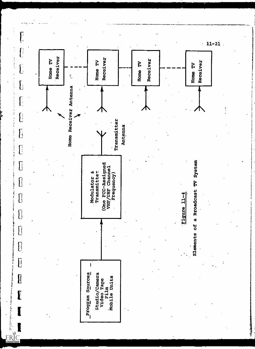
MN MAR
_47-1
,r77,n
[77-1
77 c77
Program Sources
Studio/Camera
Video Tape
Film
Mobile Units
Modulator &
Transmitter
(One FCC-Assigned
VHF/UHF Channel
Frequency)
771
:7",r1
Home Receiver Antenna
Figure 11-4
Elements of a Broadcast TVSystem
Transmitter
Antenna
Home TV
Receiver
I
11-22
In the next three to five years, even before domesticcommunications satellites are operational, it is expected thatnetworking of ETV stations will increase, in terms of more com-prehensive interconnection of transmitters via common-carrier
cable/microwave facilities. Most ETV/ITV stations shouldhave the option of using either network or local programmingby 1974-75.
CATV systems proliferation will increase audience coverage,since almost all new CATV franchises not only deliver a betterquality picture for UHF channels than is available off-the-air,but in many cases also bring non-local ETV channels into theirsubscriber community if feasible.
Closed-circuit systems (Fig. 11-5) differ from the diagramof Fig. 11-4 only in that the wireless broadcasting portion(transmitter, antennas, air medium) is replaced by a networkof cables and auxiliary equipment necessary to force thetelevision signals through the network to the receiving locations.Cables may be common-carrier or user-owned.
CCTV is a fully controlled distribution system with allreceivers identified, and total exclusion of non-participants.Further, no FCC broadcast frequency assignments are requiredsince no radiation outside the cables takes place.
Coaxial cable transmission systems may be either video orRF. In the former, picture signals are transmitted in the samefrequency range (0 - 4.5 MHz) as they emerge from the video
camera chain. The associated sound is usually transmittedseparately over a twisted wire-pair paralleling the coaxialcable. A system such as this is used only where transmissiondistances are short and where a cable can be restricted to oneTV channel.
In an RF system, more commonly used, the original videoand audio frequencies modulate a radio frequency carrier wave,which is, then sent over the cable. Many TV programs, each onits own separate RF carrier, can be transmitted simultaneouslyon the same coaxial cable.
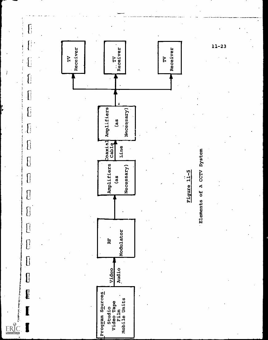
MI
PPR
Min
-t
=71
[Program
Sources.
Studio
Video Tape
Film
Mobile Units
Video
Audio
RF
Modulator
11)
Amplifiers
(as
Necessary)
Figure 11-5
oaxial
Line
'Elements of A CCTV System
Amplifiers
(as
Necessary)
TV
Receiver
TV
Receiver
TV
Receiver
11-24
The closed, controlled (both as to audience and programs)nature of CCTV, plus the availability of multichannel distri-bution over the cable, leads to many educational applications,particularly where maintaining autonomy and control of thecurriculum at the local level are desired. Several hundredCCTV systems are now in operation by educational institutionsthroughout the U.S., with the oldest dating back to the late1950's.
Since CCTV technology and equipment are tied to broadcastTV standards which have been stable for over 25 years, thetechnological changes have been evolutionary, and in generalrelated only to improvements in performance/price ratio.Modern hardware such as CCTV video cameras may be smaller andcheaper, but not significantly different in performance fromthe first solid-state units made years ago. CCTV systemsinstalled some 20 years ago or more are still operating satis-factorily.
Those areas where CCTV technology has advanced involveapplications, particularly in semiautomatic_proctram retrieval.systems. A numbei of "dial-a-program" systems are in opera-tion, combining dial-access with programmed retrieval of audio-visual material. These represent, in a sense, an expansion ofCCTV techniques, and, indeed, could function only within aself-contained wired system because of the variety of programsdistributed.
11-3.1.2 Audio/Visual Dial-Access
Audio dial-access systems have beeneiscussed in Chapter 10,with the installation at Oak Park and River Forest High Schoolused as an illustrative example. A logical expansion is theaudio/visual dial-access system which can provide either audioprograms alone, visual alone (slides, film strips) or thecombined audio/visual program (television, film with sound)..
C
11-25
The addition of visual material is more than just an
incremental expansion, however. Since the bandwidth required
for one TV channel is some thousands of times larger than for
a voice communication, the costs of storing, Switching and
distributing video are correspondingly much higher.
-Table 11-1 can be compared to Table 10-1 in this respect.
Random access for some 10 video channels can cost 4-5 times
the same capability for perhaps 100-200 audio channels.
The Oak Park and River Forest High School facility, has,
in fact, been expanded to include video dial-access. This is
"conventional" rather than random access, however, in that a
student cannot instaneously obtain access to a program starting
at its beginning, if the program is already in use. Instead
he must wait until it is completed and.can begin again, or be
content to come in at whatever point the program is at.
The reason for this is the high cost of video random access.
To dub a video tape at a high rate of speed is much more dif-
ficult and expensive than an audio tape, so the technique of
providing a newly-dubbed "temporar4tape to any student making a
request, as described in Chapter 10, is.at this point prohibitive
in cost for most educational institutions.
The "conventional" access technique at Oak Park and River
Forest provides five video sources, a video tape recorder, a
video camera and three film/slide chains. Thus, access is pro-
vided either to taped, live or film program materials.
Random access video, although expensive at present, is being
planned for many future A/V dial-access systems. Figure 11-6
illustrates the elements of a random access A/v system. Com-
paring this diagram to Fig. 10-2 shows that a video duplication
system has been added to the original audio. Thus, a dubbed
video tape is made available rapidly in response to a student
request. The video and audio information, moreover, are locked
together by control circuitry so that they are always in
sYnchr9nism.
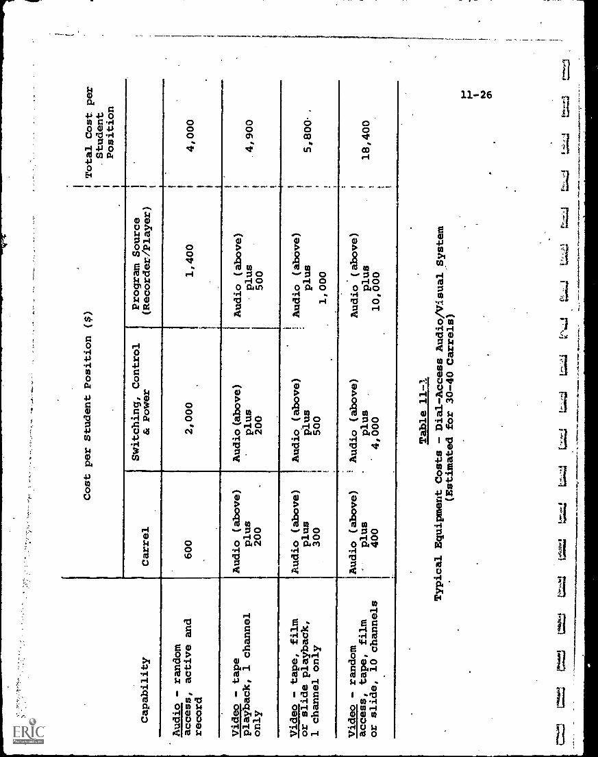
Capability
Cost per Student Position ($)
Carrel
Audio - random
access, active and
record
600
Video - tape
playback, 1 channel
only
Audio (above)
plus
200
Video - tape, film
or slide playback,
1 channel only
Audio (above)
plus
300
Video - random
!Audio (above)
access, tape, film
1-
plus
or slide, 10 channels
1400
4,000
10,000
I Total Cost per
1.Student
1 1
Position
Switching, Control
& Power
Program Source
(Recorde /Player)
2,000
1,400
14,000
Audio(above)
plus
200
Audio (above)
plus
500
1 1
4,900
Audio (above)
plus
1500
Audio (above)
plus
1,000
I 1 !5,800-
.
1 Audio (above)
Audio (above)
plus
plus
18,400
Table 11-1
Typical Equipment Costs - Dial-Access Audio/VisualSystem
(Estimated for 30-40 Carrels)
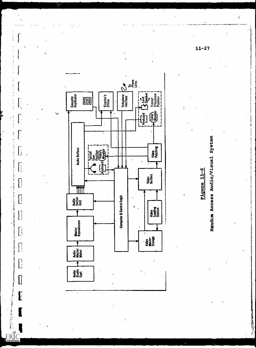
I I
Iwo
III
-r "
7'
Aud
ioSt
udio
Eqp
t.
Aud
ioM
aste
rM
aker
ry.1
.V M
.O.%
Mas
ter
Rep
rodu
cers
AU
dio
Switc
hU
nit
Aud
io B
uffe
rs
Typ
ical
1U
ser
Posi
tion
...."
"%V
ideo
IM
onito
r
Com
pute
r &
Con
trol
Log
ic
Cas
sette
Dup
licat
or
000
00C
000
Vid
eoM
aste
rSt
orag
e
ti
Vid
eoL
oadi
ngSt
atio
n
Vid
eoB
uffe
rs
rVid
eoPa
tchi
ng
Dir
ecto
r'sO
ffic
e
Tel
epho
neIn
terf
ace
Key
boar
dL
od Ake
r!
Sv1
Col
orT
ypic
alI
Mon
itor
Cla
ssro
omPo
sitio
nI
I-
To
Phon
eL
ines
Figure 11-6
Random Access Audio/Visual System
11-28
The future of dial-access A/V systems (or "informationretrieval television" as sometimes termed) appears bright ifcosts can be decreased, and if the .rca;aorqiunin task can beaccomplished successfully.
There is no doubt that with the combination of a sub-stantial program library and automated retrieval and playback,a major educational resource is established.
. The present cost of such a resource undoubtedly willinhibit establishment on a widespread basis. Two major capitalinvestment items are involved, the electronic hardware and theprogram library (software). Since either item can range upwardsof $500,000 - $1,000,000 for a single facility, educationalinstitutions find these, systems difficult to fund within presentfiscal constraints.
The issue of centralization vs. decentralization alsoemerges. Initially, decentralized in-house systems at uni-versities, schools, etc. will be most practicable becausebroad bandwidth coaxial cable capable of carrying video signalsneed only be brought to carrels in the same building as thevideotape library.
With the growth of CATV and satellite communications,however, resulting in broadband communications links to morehomes, it may become more practical to have the program library(probably computer-controlled) at one or two central locations,thus reducing the physical volume of duplicate program materialrequired.
11-3.1.3 The Stanford University ITFS Network
The ITFS network at Stanford University, in operation since1969, offers' a good illustrative example of using instructionaltelevision to reach off-campus students, while retaining ateaching environment closely simulating the on-campus classroom.
11
1
I I
I
11-29
During the 1960's, graduate enrollment at the Stanford
School of En9ineering increased sharply compared to under-
graduate, reaching a pOint where three times as many graduate
students as undergraduates were enrolled. About 1/3 of the
graduate engineering students were also employed, usually on
a full-time basis, by various companies located throughout the
San FranciscoBay and peninsula area.
Since no evening courses were offered at Stanford, the
employed students' had to be released by their employers for
sufficient time to attend on-campus. This meant not only inter-
ruption of the work day, but also loss of time in driving and
parking, which in many cases exceed the classroom instruction
time. As an example, one large company calculated 2-1/2 man-
years lost annually (which approximates a burdened cost of
$100,000) lust in the driving and parking alone.
The problem is intensifed if a student wishes to attend
two courses given at different times, so that in many cases
students would choose consecutive courses just for convenience,_
rather than suitability. Other potential students simply
could not participate at all.
To attack this problem, Stanford initiated a feasibility
study in 1967 to evaluate linking via telecommunications
Stanford classroomg with "classrooms" located at each company's
own facilities.
The objectives were to produce a remote learning environ-
ment approximating, as closely as possible, the Stanford classroom
environment. To accomplish this, it was believed that 2-way
audio communications were essential, but that video communications
could be one-way without degrading the quality of instruction.
The study ascertained that the concept was technologically
feasible, that the cost of kperating the system would represent
only about a 25* increment on tuition fees already being paid,
and that a sufficient number of companies in the area would
participate, both in the capital costs'of the Stanford portion
of the system and also in the reception facilities required in
their own plants.
Some 40-50 industrial organizations participated with
Stanford in sharing the system costs, in proportion to each
one's size and utilization. Stanford applied for.allocation
of a band of 4 ITFS channels, and received authorization from
the FCC.
A 4-channel ITFS network was installed in 1968-69, with
the capital cost about $700,000 and annual operating costs in
the order of $100,000.
Table 11-2 provides a summary of the characteristics of
the Stanford ITFS system. Up to 4 separate TV signals from
Stanford classrooms are cabled to an on-campus control room,
then relayed via microwave link to a transmitter atop Black
Mountain, 8 miles from campus. There the programs are trans-
1 ated to the 2500 ITFS MHz band and broadcast from 3 antennas.
Seven watts (of the available 10) are radiated from an
omnidirectiona5 antenna which covers an effective 20-25 mile
range throughout the peninsula. To reach San Francisco, (35
miles), 1 watt is fed into a highly directive 10-foot parabola
antenna, and 8-foot parabolas are used at the receiving sites.
To reach the Berkeley area (39 miles away), 2 watts are fed
into a 6-foot dish antenna, with 10-foot parabolas at the
receiving terminals. Thus, the ITFS system is essentially an
omnidirectional broadcast plus two narrowly directive beams
aimed at specific point targets. A simplified video information
flow diagram of the system is given in Fig. 11 -7.
Originally, 2-way audio communications were achieved by
using conventional dial-up telephone lines between the originating
classroom and each remote classroom. The lines were connected
into the audio portion of the TV system so that all students
can hear any question or answer.
Apart from the generally marginal quality of phone-line
audio links (susceptibility to noise, transients, limited
bandwidth), the line costs are relatively high. A cost-
effectiveness study at Stanford indicated that for 20-25 user
companies in the San Francisco Bay area, and 4 audio channels
1-*
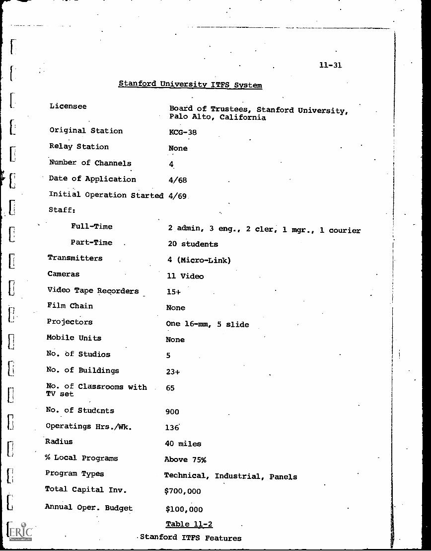
11-31
Stanford University ITFS System
Licensee Boakd of Trustees, Stanford University,Palo Alto, California
Original Station KCG -38
Relay Station None
F.: Number of Channels 4
LDate of Application 4/68
Initial Operation Started 4/69
Staff:
Full-Time 2 admin, 3 eng., 2 cler, 1 mgr., 1 courier
Part-Time 20 students
Transmitters 4 (Micro-Link)
Cameras 11 Video
Video Tape Recorders 15+
Film Chain None
Projectors One 16 -mm, 5 slide
Mobile Units None
No. of Studios 5
No. of Buildings 23+
No. of Classrooms with 65TV set
No. of Students 900
Operatings Hrs./Wk. 136
Radius 40 miles
% Local Programs Above 75%
Program Types Technical, Industrial, Panels
Total Capital Inv. $700,000
Annual Oper. Budget $100,000
Table 11-2
Stanford ITFS Features
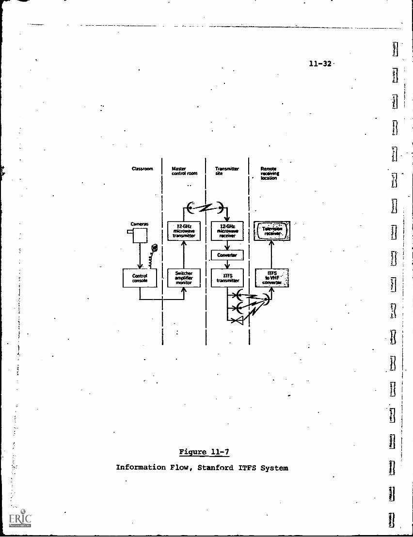
Figure 11-7
Information Flow, Stanford ITFS System
11 -32
1_1
^
11-33
per company, the use of FM radio for talk-back would cost about$1,000,000 less than phone charges, over a 10-year period.
As a result, Stanford petitioned the FCC to permit use ofthe upper end of the ITFS band (2686-2690 MHz) for FM talk-back purposes, and this was granted in June 1969. Within the4 MHz band, the FCC allocated 31 channels (one for each TVchannel in the ITFS spectrum); each 125 KHz wide, designatedas ITFS Response Stations.
These FM audio channels supplanted the dial phone linesat Stanford. Each remote classroom is equipped with an FMTransmitter (switchable to any of the four allocated frequencies
associated with the four video channels) and an antenna. Thetalk-back signal is directed to the Black Mountain antenna site,
and relayed from there to the Stanford classroom as well asall remote receiving locations.-
Functionally, the on-campus studio/classrooms are designedto resemble conventional classrooms as much as possible. Anormal-size class is accommodated during the broadCast, sothat the teaching environment basically is unchanged.
Each classroom (see Fig. 11-8) houses two video cameras,
one over the instructor's desk and the other at the rear ofthe room. Both cameras have remote-controlled tilt-pan7zoomcapability. The overhead camera is used for viewing writteninformation generated by the instructor at his desk, or view-.graphs, slides, etc. The rear camera can view the entire
classroom, or provide close-ups of the instructor or theblackboard.
Monitor picture tubes and microphones are located throughout
the classroom, one for each two students. By depressing a
"push-to-talk" switch, the student's voice is picked up andcan be heard throughout the system.
Associated with each studio/classroom is a satellite
monitor room used for overflow of large classes, seminars or
CCTV lectures. In addition, an auditorium has been equipped.
to handle panel events, large seminars, guest speakers, etc.
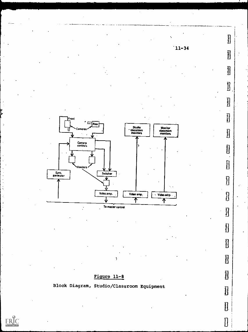
Front
Cameras
Rear
Cameracontrols
Sync.generator
Monitors
Switcher
Studioclassroommonitors
IVideo amp. 1 i Video amp.
To master control
5
11-34
Monitorclassroommonitors
Video
Figure 11-8
Block Diagram, Studio/Classroom Equipment
f.
1
11-35
The "operating staff" for each televised class consistsof one student who operates the camera and audio controls,
switching, of cameras and the talk-back system. A licensedradio/TV engineer is present in the master control room tomonitor system performance.
,
The receiving classrooms, located at each participating
company, are equipped with oneor more TV receivers and talk -}
back microphones. Appropriate ITFS receiving antennas and
equipment, and the FM talk-back transmitters are also necessary,
although these are usually located external to the classroom.
Stanford provides technical specifications and guidelines forreceiving locations to assure system uniformity and compatibility.
As an adjunc to the instructional program, a courier from
Stanford makes daily rounds to all participating organizations,
delivering class notes and handout material, and collecting
homework and examinations from the students. The Stanford honor
code has been extended to the remote classrooms.
Participants are permitted to make video recordings oflectures for the sole purpose of student make-up and review,
providing the tapes are erased within two weeks after the endof the term.
The costs borne by the participating companies are of threekinds. Initially, each company contributes a share of the
capital costs associated with the total ITFS facility, with theshare determined by anticipated usage. These capital payments
have ranged from $2,000 for small companies to $40,000 for thelargest.
Secondly, each company is responsible for equipping its
own receiving facility and classrooms. This cost can vary from$10,000 - $20,000.
Finally, there is a tuition charge for each student, on
a "per unit" basis similar to that of on-campus registration.
This includes fees to cover the normal academic departmentalcosts; and also the continuing operating expenses of the ITFS
network.
11-3.1.4 Corwrative Costs of Television Based Svetemp
11-36
Estimates of the cost of'television-based educationalsystems can be highly misleading, unless the underlying assumptionsin each case are understood precisely. For example, a broad-cast ETV system may assume that TV receivers are alreadyavailable to the intended audience and represent no added cost,
whereas a CCTV or ITFS system aimed at specific remote class-
rooms in industrial facilities cannot make such an assumption.
The major elements of cost*include:
(a) Initial Cost of Equipment and Facilities
(b) Initial Cost of Program Library
(c) Operating Cost of the System (Personnel, Maintenance,
Communications Charges, etc.)
Of these, the cost of the software, the program libriry,is probably the most difficult to estimate, since this impinges
upon educational rather than technological factors, and theremay be wide disagreement among ed'icators as to what constitutes
an adequate (or minimal) ETV curriculum.
In Table 11-3, an attempt has been made to provide a
summary of the approximate capital costs of delivering aneducational TV piogram via a variety of communications anddistribution systems.
The assumptions made in arriving at these estimates arelisted below. Program library costs are rather arbitary, andrepresent essentially 100% purchases of already available pro-grams. Any significant local-preparation of programs may vary
. this portion of the estimate substantially.
Assumptions upon which Table 11-3 is based include:(1) A.system of 80 schools, 1200 classrooms, 30,000
students centralized within a city rather thin
geographically dispersed.
(2) Costs iblude in-school wiring and a TV receiver in
each classrOom.
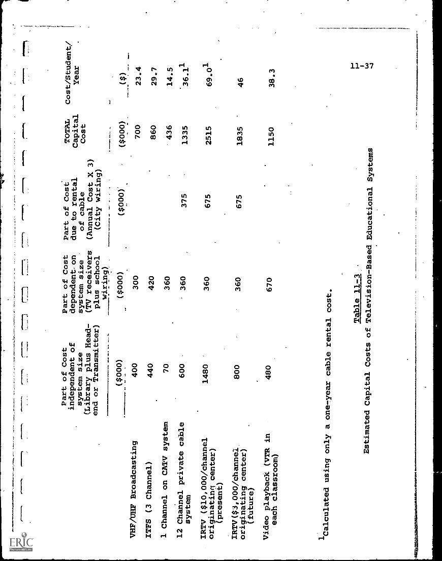
e =
1,,
010,
Part of Cost
independent
system size
(Library plus
end or Transmitter)
of Head-
Part of Cost
dependenton
system
(TV receivers
plus school
wiring)
Part of Cost
due to rental
of cable
(Annual Cost X 3)
(City wiring)
TOTAL
Capital
Cost
Cost/Student/
Year
($000)
($000)
($000)
($000)
($)
VHF/UHF Broadcasting
400
300
700
23.4
ITFS (3 Channel)
440
420
860
29.7
1 Channel on CATV
system
70
360
'436
14.5
12 Channel private cable
system
600
360
375
1335
36.11
IRTV ($10,000/channel
originating center)
(present)
1480
'
360
675
2515
69.01
IRTV($3,000/channei
originating center)
(future)
800
360
675
1835
46
Video playback (VTR in
480
670
1150
38.3
each classroom)
1Calculated using only aone-year cable rental cost.
Table 11-3
Estimated Capital Costs of Television-BasedEducational Systems
11-38
(.3) For VHF/UHF broadcasting:
- Acquisition of a small library @ $40,000
- No allowance for'program production costs
(4) For ITFS (2500 MHz)
- 3 channels, playback only, no live/studio equipment
- Acquisition of a medium sized library @ $120,000
(5) Single Channel Carried Free on CATV system:
- Playback equipment plus an ITFS-to-CATV link
(6) 12-channel private cable system:
- 1 origination center with Videotape equipment- Acquisition of a large library @ $480,000
(7) Information Retrieval Television (IRTV)
- Acquisition of a large library @ $480,000
- low-cost ($3,000 per channel) VTR assumed availablein the future (circa 1975)
(8) Video Playback:
- Acquisition of a large library @ $480,000
(9) Operating costs not estimated; dependent on use ofstudents, etc.
Since ITFS systems are of special educational interest,Table 11-4 provides a more detailed estimate of the costsassociated with an ITFS facility. Here the basic assumptionsare:
(1) Costs shown are hardware only, excluding programand operating costs.
(2) A system size of 150 classrooMs in 10 different
receiving locations, serving a' total of 3,750 studentsis used as the model. Larger systems would permitsome reduction in the cost per student per year.
It can be seen that the relatively low hardware cost perstudent, ranging from $4.34 to $10.27 per year, in most cases
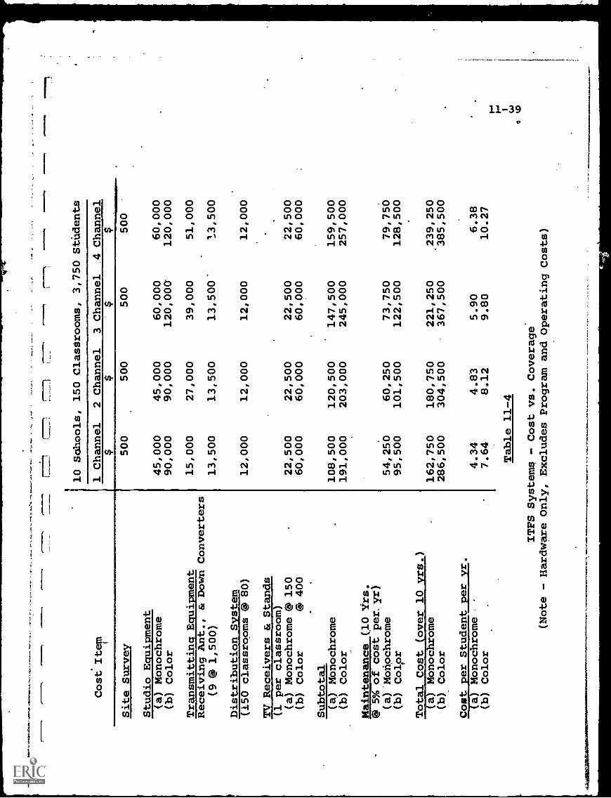
Cost Item
10 Schools,
150 Clastrooms, 3,750 Students
1 Channel
2 Channel
3 Channel
.4 Channel
$$
$$
Site Survey
500
500
500
500
Studio Equipment
(a) Monochrome
45,000
45,000
60,000
60,000
(b) Color
90,000
90,000
120,000
120,000
Transmitting Equipment
15,000
27,000
39,000
51,000
Receiving Ant., & Down Converters
(9 ® 1,500)
13,500
13,500
13,500'
13,500
Distribution System
(150 classrooms @ 80)
12,000
12,000
12,000
12,000
TV Receivers & Stands
(1 per classroom)
(a) Monochrome @ 150
22,500
22,500
22,500
22,500
(b) Color
@ 400
60,000
60,000
60,000
60,000
Subtotal
108,500
120,500
147,500
159,500
(a) Monochrome
(b) Color
191,000
203,000
245,000
257,000
Maintenance (10 Vts.
@ 5% of cost per. yr)
(a)'Monochrome
54, 250
60,250
73,750
79,750
(b) Color
95,500
101,500
122,500
128,500
Total Cost (over 10 yrs.)
162,750
180,750
221,250
239,250
'385,500
(a) Monochrome
(b) Color
286,500
304,500
367,500
Cost per Student per yr.
4.34
4.83
5.90
6.38
(a) Monochrome
(b) Color
7.64
8.12
9.80
10.27
Table 11-4
ITFS Systems - Cost vs. Coverage
(Note - Hardware Only, Excludes Program and Operating Costs)
may be over-shadowed by the initial and continuing software costsof program preparation.
Table 11-4 also.can be used as a first approximation to thecosts of a CCTV system. The elimination of transmitters, receiv-ing antennas and down-converters will probably be balanced bythe necessity for extra cable and amplifier costs. For a lcztal-
haul CCTV system, however, the cable costs will increaseproportionately.
One item which is sometimes overlooked is the cost of
duplicate copies (prints) of the program material to permit useby different facilities. Table 11-5 provides a rough comparisonof various media reproduction costs, for a 1/2-hour program ineach case.
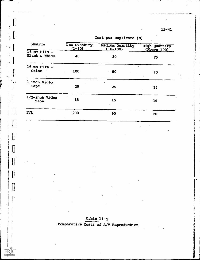
5- 4
Medium
Cost per Duplicate ($)
11-41
Low Quantity(1-10)
Medium Quantity. (10-100)
High QuantitySAbove 100)
16 mm Film -Black & White 40 30 25
16 mm Film -Color 100 80 70
1-inch VideoTape 25 25 25
1/2-inch VideoTape 15 15 15
EVR 200 60 20
Table 11-5
Comparative Costs of A/V Reproduction
CHAPTER 11 - BIBLIOGRAPHY
11-42
1. "Emerging Technology for Modern Education", Ampex Readout,Vol. 9, No. 2, 1970.
2. Lewis, W.C., "Through Cable to Classroom:. A Guide toITV Distribution Systems", National Education Association,Wash., D.C., 1967 (Library of Congress Card No. 67-30678).
3. McKune, L.E. (ed.), "Compenduim of Televised Education",Michigan State University, Continuing Education Service,Vol. 14, Sept. 1967.
4. Stetten, F.J., "Interactive Television Software for CableTelevision Applications", MTP. 354, June 1971, the MITRECorp., Wash. Operations.
5. Pettit, J.M., and Grace, D.J., "The Stanford InstructionalTelevision Network", IEEE Spectrum, Vol. 7, May 1970.
6. "University Instructional TV Networks - What They Mean toIndustry", Session 10 Papers, Western Electronic Show andConvention, 1969
7. Volk, J., "The Reston, Virginia, Test of the MITRECorporation's "Interactive Television System", MTP. 352,May 1971, The MITRE Corp., Wash. Operations.
r.
is
1
12-1
CHAPTER 12 - COMPUTER-BASED SYSTEMS
. Although the concept of machine-aisisted teaching is some46-50 years old, it is only in the last decade that computershave been applied to education on a systematic basis. Con-siderable progress has been made, both in the mechanization
techniques, and in examining and redefining educational
objectives in the light of the computer's capability. As awhole, however, the field is still in the preliminary growth
stages and evolving rather more slowly than its advocates havepredicted.
In 1960, as an example, when CAI was considered, it meanta student sitting at,a Teletype terminal interacting with acomputer. Today, more often than not, CAI still means a studentsitting at a Teletype interacting with a computer. There havebeen significant advances, of course, both in hardware and
software, but it is a fair statement that computer-based
educational applications hafe not proliferated in comparison
with other uses for the computer.
There are a number of reasons for this. The computer,
requiring precise, unambiguous instructions, has forced educators
to translate teaching techniques which have been largely sub-
jective and unstandardized into more structured form. This
may be relatively simple for drill-and-practice instruction,
but much more subject to debate for a true dialog system. Thus,
the basic step of deciding exactiv_what the computer is to do,
and how it does it, is less clear in education than, for example,accounting or record-keeping.
Computer hardware has improved substantially in this ten-year period. Performance-cost ratios of main-frames and
peripheral equipment have risen sharply, and time-sharing and
communications techniques have developed from almost academic
ppjasys2pAutconcetsintoriininodes of many computer systems.
In spite of this, however, relatively little if any
hardware has been developed specifically for educational' use
12-2
since this market is still small. Those prototype systems
used for education, some of which are described in this chapter,
almost invariably adopted general-purpose commercial computerequipment. This has not proved a barrier to proving feasibility,but it has prevented achieving optimum cost- effectiveness.
The lack of a suitable product line of low cost education-oriented user terminals is a case in point.
Software is probably even more of a barrier to effective
educational usage. The interdisciplinary gap between educationalProcedures and computer mechanization has been bridged onlyin a preliminary, relatively unsatisfactory way. Some progresstoward "natural" programming languages (i.e, those which canbe used efficiently, by a teacher or student not having computer
expertise, yet powerful and flexible enough not to act as a
constraint) has been made, but this area remains a long-termbottleneck. As educational requirements become more complexand sophisticated, it may even get worse, particularly for verylarge, multi-function computer systems.
In spite of these problem areas, the prognosis for growthof computer-based educational applications is excellent, if
only because of more critical' requirements for improvements
in education which simply cannot be met conventionally.
The systems described below offer a good cross-section
of progress to date in computer-based education, and provide
some indication of trends for the future.
12 -1.. Stanford University CAI Proiect
In January, 1963, the Institute for Mathematical Studiesin the Social Sciences at Stanford University began a research
and development program in CAI, funded initially by the CarnegieCorporation. Subsequently, further financial support came
from the National Science Foundation and the U.S. Office ofEducation.
These grants led to the establishment of a Computer-based
Laboratory for Learning and Teaching on the Stanford campus.
11
El
B
12-3
This facility has been in operation since December, 1963,serving not only Stanforr' but other schools both. in Californiaand across the country.
The initial CAI system at Stanford consisted of a medium-sized computer (Digital Equipment Corp. PDP-1) and six studentstations located within a 100-ft. radius. Each station containedtwo visual display devices. The first was an IBM-manufactured
random-access optical .display that presented microfilm sourcematerial on a 10" X 13" glass screen. Any microfilm page, or1/8 page, could be accessed randomly and displayed within onesecond. This device was subsequently phased out of the system.
The second display, still in use, was a CRT oscilloscope
screen capable of presenting a matrix of 1024 X 1024 points oflight on its 10" square surface. Since 1024 is equal to 2
10,
a 10-bit binary code for each of the X and Y axes is sufficientto identify and locate any point on the matrix. Thus the com-puter can generate any graphical pattern composed of a sequenceof matrix dots, under appropriate program command.
In addition, up to 120 alphanumeric/symbolic characters,in 5 different sizes, can be displayed. Vectors also can be
presented by identifying the beginning and end points.
A typewriter keyboard is furnished at each station, permittingthe student to communicate with the computer.
The first CAI programs, demonstrated in 1963, provided
instruction in elementary mathematical logic. In 1964-65,
programs in 1st -grade and 4th-grade arithmetic were added.
Students utilized these programs both at Stanford and_at elementary
schools connected to the CAI system by telephone lines, and using
Teletype equipment as remote terminals.
During 1965-67, the mathematics and logic programs wereexpanded, both in scope a.nd in student participation. For
example, student enrollment for the drill-and-practice mathematics
program increased, by May 1968, to 4353 students in 30 schools
throughout California, Iowa,. Kentucky and Mississippi.
IL 1967, a CAI course in elementary Russian was introduced
as a for-credit course at Stanford. The Model 35 Teletype
terminals were equipped with Cyrillic keyboards, and audio
tapes with earphones were added as the output device. Con-
ventional classroom instruction for this course was completely
eliminated.
From 1967 -70, both the number of courses and scope of
instruction continued to increase. Table 12-1 shows the extent
of the CAI curriculum by 1970 and the number of students exposed
to each course. -
In 1968-69, the system was upgraded by adding a larger
PDP-10 computer as the master unit, retaining the PDP-1 as an
auxiliary input/output controller. The new system configuration
is illustrated in Fig. 12-1. Twelve on-campus display consoles
(student stations) are shown, plus a number of remotely-located
schools tied into the system through telephone-line communications
links.
In May, 1970, a communications satellite was first used
to distribute CAI material throughout the Stanford network.
This was significant as an indication of the potential for
making CAI assessible to isolated areas where terrestrial com-
munications links might be economically unfeasible. The satellite
used was NASA'S Applications Technology Satellite ATS-1. Fig.
12-2 illustrates the distribution technique. The CAI program
material was transmitted from Stanford to the satellite ground
station (a G.E. facility operated by Stanford personnel for
this experiment), and then beamed up to the satellite and
rebroadcast down to the ground. In this case, the computer-to-
student link was through the ATS-1, but the student-t..)-computer
link used the normal inter-school phone lines. In a fully
operational system both links would go through the satellite
and the phone lines would be deleted or perhaps used only as
emergency backup. The experiment did demonstrate, however,
the feasibility of this interconnection technique.
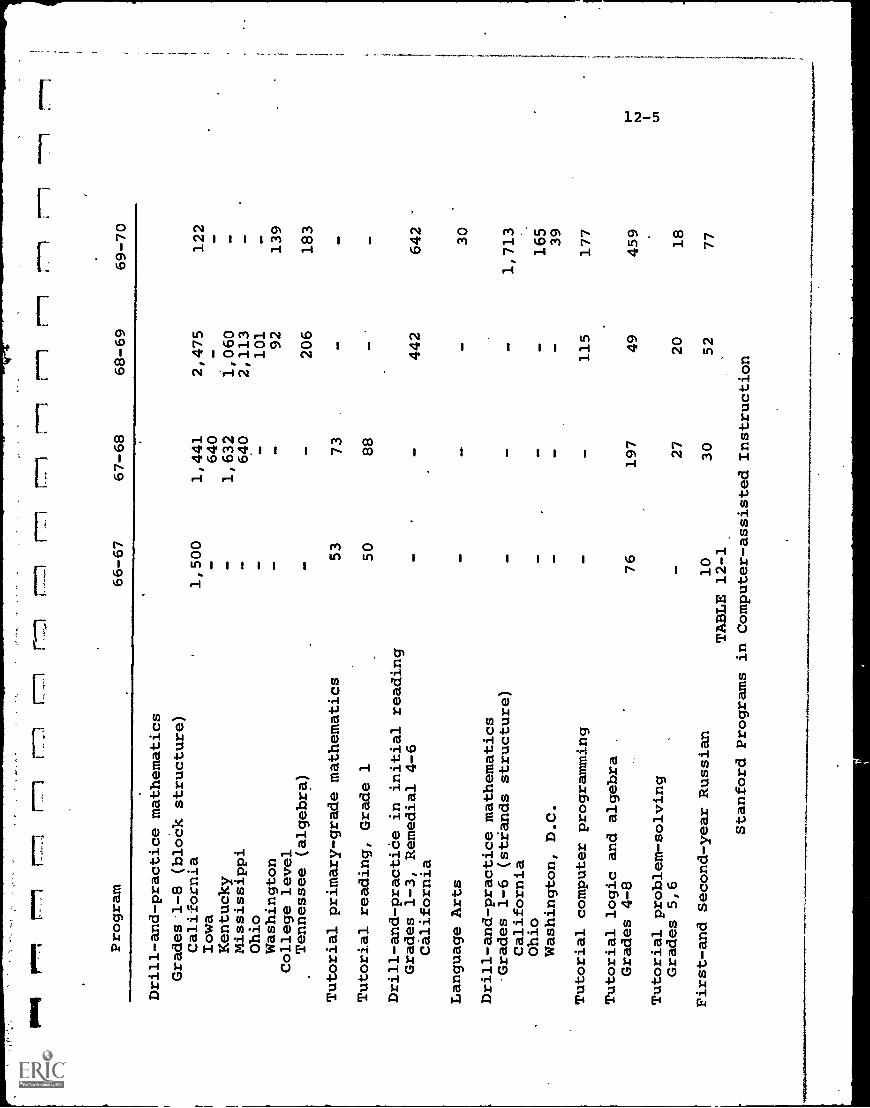
mil
pogo
rei
1-7.
77"
--1
1'7
17'1
Program
66-67
67-68
68-69
69-70
Drill-and-practice mathematics
Grades 1-8 (block structure)
California
1,500
1,441
2,475
122
Iowa
-640
Kentucky
-1,632
1,060
Mississippi
-640
2,113
Ohio
--
101
4WD
Washington
--
92
139
College level
Tennessee (algebra)
--
206
183
Tutorial primary-grade mathematics
53
73
OW
Tutorial reading, Grade 1
50
88
Drill-and-practiCe in initial reading
Grades 1-3, Remedial 4-6
442
642
California
Language Arts
30
Drill-and-practice mathematics
Grades 1-6 (strands structure)
--
-1,713
California
Ohio
--
-165
Washington, D.C.
--
-39
Tutorial computer programming
--
115
177
Tutorial logic and algebra
Grades 4-8
76
197
49
459
Tutorial problem-solving
Grades 5,6
27
20
18
First-and Second-year Russian
10
30
52
77
TABLE 12-1
Stanford Programs in Computer-assisted Instruction
tri
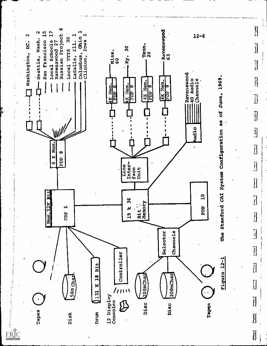
Tapes
Disk
Mem.321C'BUI
41.
41.
Washington, DC. 3
ella
PDP 1
Drum
0131
K 18 Bit
12 Display
ConsOles
Controller
AM
AO
AO
AO
Seattle, Wash. 2
San Francisco 15
Local Schools 17
Ravenswood 27
Russian Project. 6
Local TTYS
30'
LaSalle, Ill. 1
'Columbus, Ohio 1
Clinton, Iowa 1
ta-14K Mem.
PDP 8
Disc
Disc
Tapes
]Line
Inter-
face
Unit
Mt A
MA
I Mb
alb
INIP
OW
60
K Mem.
30
PDP 8
171...14K diem.I
Tenn.
PDP 8
20
4K l`i!em .
DP 8
u udio
40 Audio
Channels
Figure 12-1
The Stanford'CAI SystemConfiguration as of June, 1969.
Ravenswood
63
N Ch
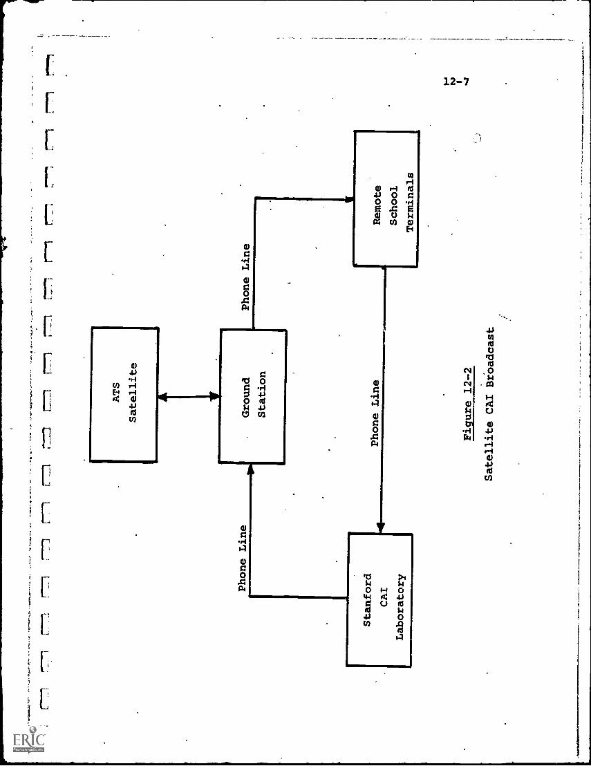
r777
7.7
777
177
17.
771
r="1
-L
.=r7
771
L'7
71r-
nr
r
Phone Line
ATS
Satellite
Stanford
CAI
Laboratory
.Ground
Station
Phone Line
Phone Line
!MIN
IMS
,
Figure 12-2
Satellite CAI Broadcast
Remote
School
Terminals
12-8
Some attempts have been made to evaluate the CAI programs
at Stanford. Pre-tests and post-tests were given to students
undergoing the CAI drill-and-practice arthmetic and the Russian
language course, and to a "control" group taking the equivalent
non-computer classroom courses. The evaluation results, while
indicating that CAI students certainly did not test out worse
than the control group and in many cases tested better, were
still unclear.
Certain conclusions were reached, however. First, it was
evident that drill-and-practice CAI, particularly in the lower
grade levels, can bring better quality control in instruction,
particularly since many teachers find little enthusiasm for
the repetitive routines involved. The computer, however, does
not become bored and has infinite patience to adjust to the
.student's rate of learning.
Secondly, CAI may be most attractive in the less affluent
school' areas since, in general,-it is there that teacher
preparation and training are least satisfacoty.
Even in the more affluent regions, and in higher education,
however, certain courses appear ideal for CAI. The Russian
program at Stanford indicated that with CAI the student is free
to. concentrate more directly to instruction without the dis-
traction of internal adjustment while listening to other student
responses. A degree of efficiency is reached that appears
difficult to achieve in a classroom, particularly if the class
is large.
12-2. University of Illinois PLATO Program
The University of Illinois' program in computer-based
education has evolved over a period of more than 10 years,
Termed PLATO (Programmed Logic for Automatic Teaching Operations),
the initial effort started in 1961 with a single terminal con-
nected to the University's ILLIAC I computer, a medium-speed,
1954-vintage unit.
12-9
In 1962-63, the system was expanded to two terminalstime-sharing a Control Data Corp. 1604 computer, and in 1964expanded again to the PLATO III configuration which featured
a "computer classroom" of 20 graphic/pictorial terminals con-nected to the CDC 1604. A network of four associated demonstrationcenters was added in 1969.
Some of the areas in which computer-based studies havebeen conducted incl?Ae electrical engineering, geometry, biology,nursing, library science, pharmacology, chemistry, algebra,
computer programming and foreign languages. Techniques haveranged from drill-and-practice to student-directed inquiry.
The components of the present PLATO III system are shownin Fig. 12-3. A student terminal consists of a likayset"(tele-printer) and a television display monitor. Information presentedon the display include fixed photographic information storedon slides and computer-generated or student-generated graphicaland/or alphanumeric material. These can be superimposed to
provide a composite picture.
The student uses the keyset for entering questions andanswers, setting up problems and controlling his rate of progressthrough programmed. instruction. System response is such thatthe computer answers student requests within one-tenth of asecond.
The computer also controls other information devices, suchas film projectors. Student terminals can interact with each
other, permitting multi-user problem-solving and simulation"games".
The computer keeps detailed records of student progress,and can provide individualized instruction based on past per-formance of each student. Feedback is provided to "open-ended"
questions, reinforcing correct approaches or encouraging a newapproach if it is indicated that the student is on the wrongtrack.
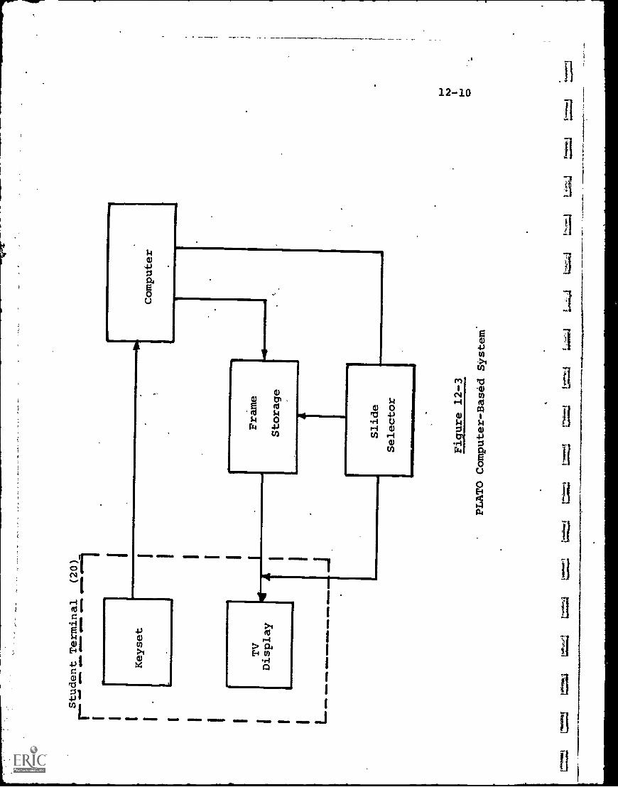
Student Terminal
(20)
Ir-
4-1
1 I I I I L
Keyset
TV
Display
411.
1110
1111
1110
Ow
e11
1101
0 W
IMP
Wal
laW
WI
Wal
e.1
1 M
EM
O
=LI
Computer
hera
ftw
o.
Frame
Storage
LSlide
Selector
Figure 12-3
PLATO Computer-Based System
=.4
12-11
As an illustration of how the system interacts with thestudent, one program consisted of 15 geometry lesSons, designedto give 7th and 8th grade stud'ents an understanding ofgeometric concepts.'
For this program, eight keys on the student keyset areused as controls to draw figures on the display screen. Theseare shown in Fig. 12-4, with the arrows on the keycaps indi-
cating the direction in which the key will move a spot on a griddisplayed on the TV monitor screen. Two other keys are usedin conjunction, a "MARK" key which initiates the communication
to the computer, and a "CLOSE° key which instructs the computer
to close the figure by connecting the selected points.
An example might be the computer asking the student todraw a quadrilaterdl with a single line of symmetry. Two possiblesolutions are an isosceles trapezoid and a kite-shape. Thestudent selects the points he wishes to use for the figure.
When four points have been selected, the student asks the computerto close the figure and judge it. If it is judged correct, tha
computer signals "OK" and the student can proceed to the nextstep of the lesson.
To date, the PLATO systems have involved computer-basededucation in over 20 fields, with more than 100,000 student-
terminal-hours (much of it for academic credit) in course work'at all educational levels ranging from elementary grades throughgraduate work.
Apart from the valuable experience gained in.developing
instructional strategies and assessing the attitudes of teachersand students, the general conclusions reached appear to be that(1) computer-based education offers valuable advantages in manystudy areas, and (2) the costs to date have been higher thancan be justified for mass acceptance.
PLATO costs have ranged from $2.00-3.00 per student-terminal-
hour, which is about in the middle of the range of costs experienced
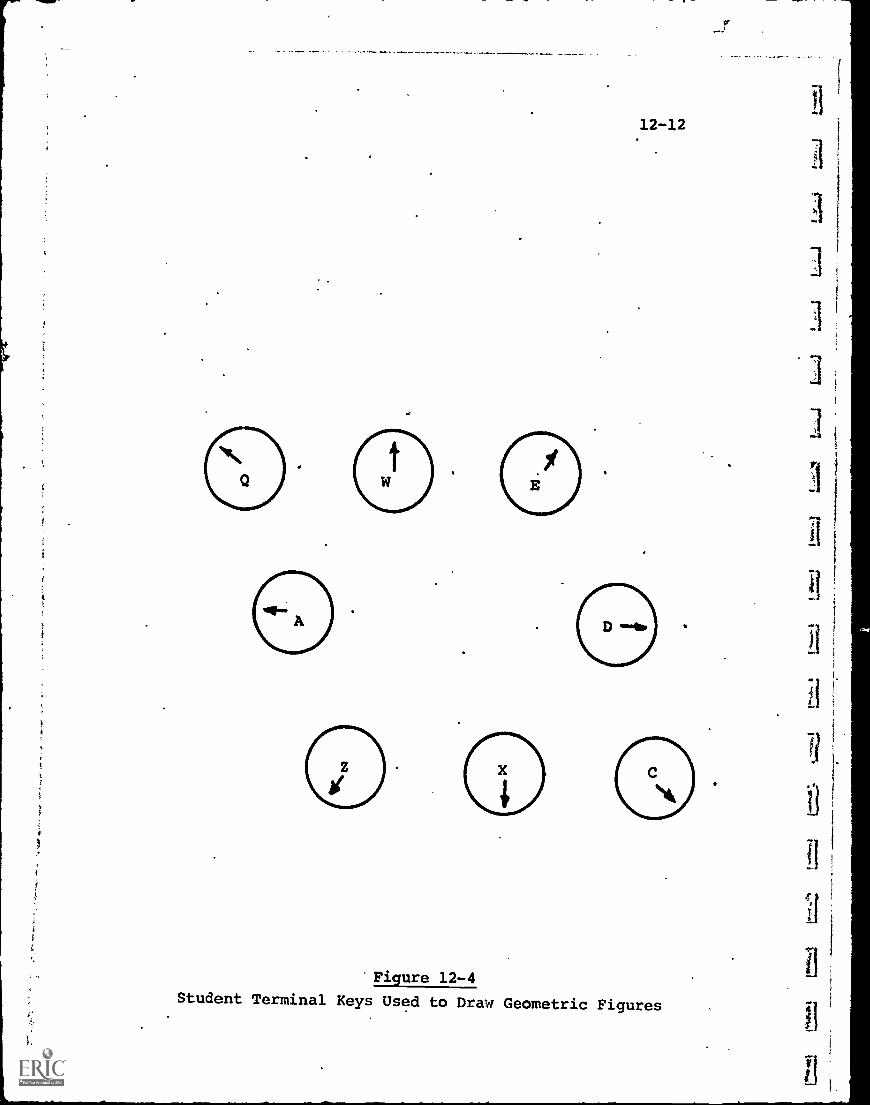
Figure 12-4
Student Terminal Keys Used to Draw Geometric Figures
12-13
fo CAI systems in general, estimated at from $1.50-5.00 per
student-terminal-hour. This contrasted with about $0.25-0.50
per student hour for conventional instructional costs in
elementary schools.
To arrive at a lower cost system more nearly approximating
conventional costs, a new conceptual design, PLATO IV, has been
proposed. The principal features of PLATO IV are:
(1) The.design of a novel student terminal, utilizing
a "plasmas!. display panel.
(2) The use of a large-scale, third-generation computer
of'the C.D.C. 6000 class, configured to serve up to
4,000 student stations and able to teach several
hundred different lessons simultaneously.
(3) Communications capability to within a 150-mile radius
of the computer center.
Of these, the key item is the student terminal, designed
to combine high performance and low cost. The plasma display
panel is a recently developed device which consists of a thin
glass panel structure containing a rectangular array of small
gas cells (about 40 to the inch). Any cell can be selectively
ignited by applying an ionizing voltage to appropriate X-Y
l.1
grid conductors which run through the cells.
Thus, a point of light can be generated at a selected
location by energizing the X-Y grid connectors which intersect
at that cell. The result is that a dot display forming any
desired graphical image is available. The image itself is
similar in appearance to that formed from a dot matrix on a CRT
screen, but in this case no CRT is required and there is no
deflection of a moving beam of electrons.
The concept can be likened to a display sign made up of
thousands of incandescent light bulbs, with images formed by
selecting the pattern of bulbs to be turned on.
Apart from the fact that the plasma panel, in volume
production, should be simpler and cheaper than equivalent Cathode-
Ray tubes, there is another advantage in that the plasma panel
t
12-14
is transparent, allowing other optically protected images tobe superimposed on the matrix image. Thus any combination ofphotographic and graphic material can be displayed.
Fig. 12-5 illustrates a proposed student's plasma displayterminal. The panel is approximately 12 inches square andcontains 512 (29 in equivalent binary) digitally addressablepositions (cells) along each axis. Thus a ma:Tix of 512 X 512or 262,144 dots is available for selection and display.
Behind the panel is a slide selector and projection system.Slides are stored on removable microfiche cards, containing 256microfilm images on each card. The card is mounted on anorthogonal slide mechanism that can move so that any of the 256microfilm slides can be brought.to the projector lens. Theimage is then projected onto the rear of the plasma panel.
Thus, the total display is the superimposition of theselected microfilm image and the digitally-controllable dot/matriximage. This provides a wide range of visual and graphiccapability.
The projected cost of such a student station, in quantity,is estimated at about $1,800, which is about the same as thecurrent cost for a teleprinter alone. If this (or lower) costcan be achieved, then the objective of a low-cost total systemmay be realizable.
Table 12-2 provides a rough estimate of the cost of asystem such as PLATO IV. The main-frame of a computer meetingsystem requirements is estimated at $2,000,000. Additionalmemory (2,000,000 words) and input-output equipment are projectedat another $2,000,000.
System software. costs, including initial course developmentprogramming, totals another $1,500,000, and the cost of 4,000student terminals of the plasma display type is estimated at$7,500,000.
The system usage was assumed at 8 hours per day,300 daysper year. For 4,000 terminals, this is approximately 10,000,000student-terminal-hours per year. The annual costs were dividedby this figure to arrive at cost per student-terminal-hour.
3
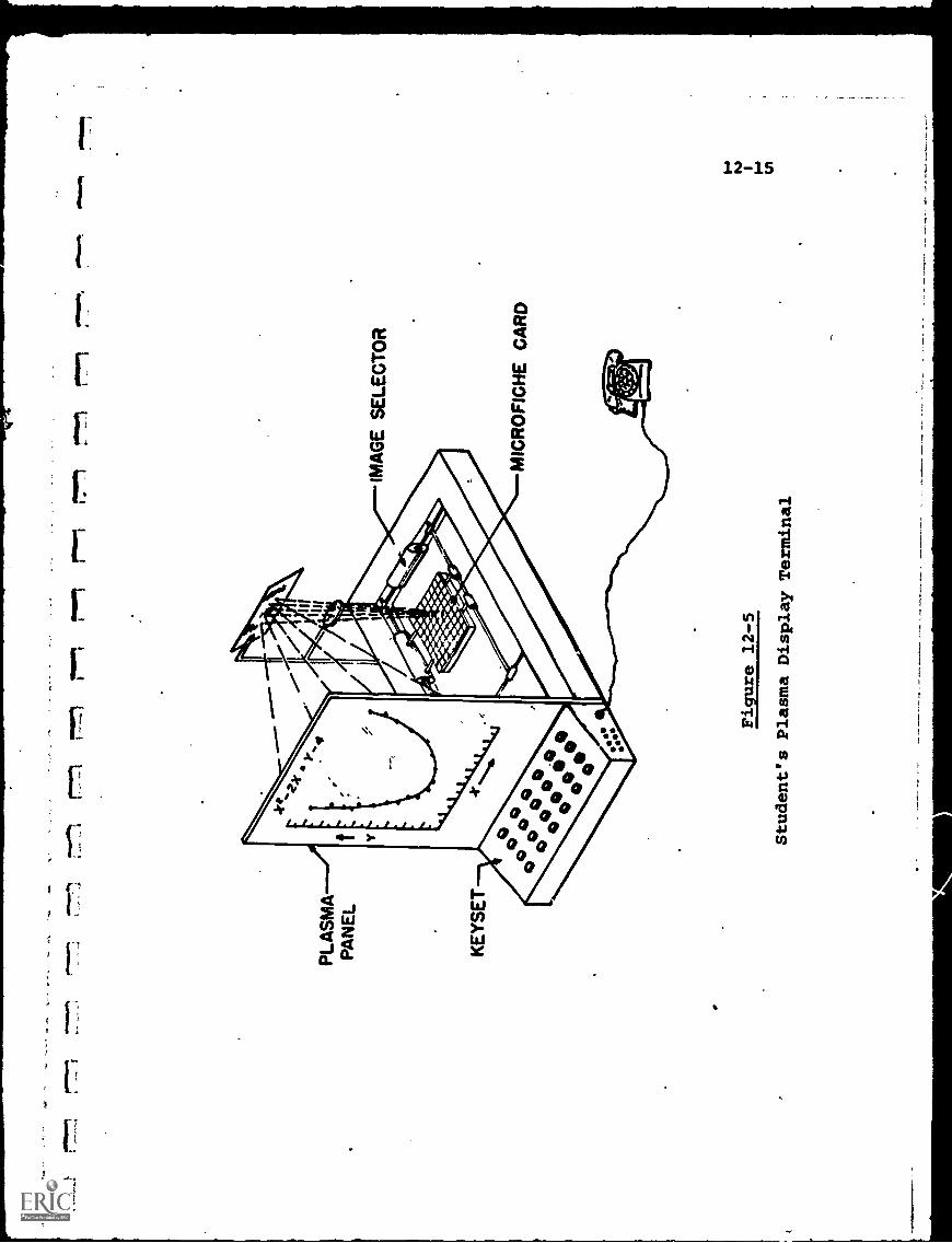
771
PLA
SM
AP
AN
EL
torin
or,
IMA
GE
SE
LEC
TO
R
MIC
RO
FIC
HE
CA
RD
Figure 12-5
Student's Plasma Display Terminal
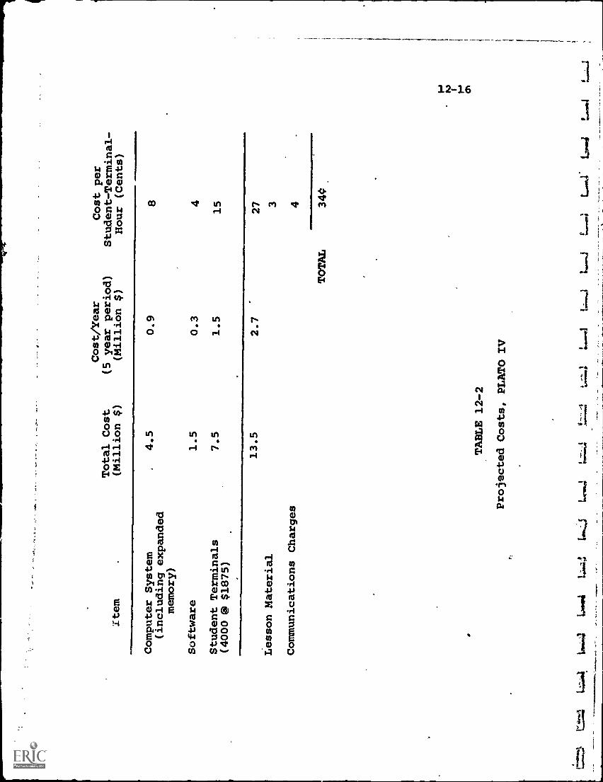
Cost/Year
Cost per
Total Cost
(5 year period)
Student-Terminal-
Item
(Million $)
(Million $)
Hour (Cents)
Computer System
(including expanded
memory)
4.5
0.9
8
Software
1.5
0.3
4
Student Terminals
7.5
1.5
15
(4000 @ $1875)
Lesson Material
13.5
2.7
27 3
Communications Charges
4
1-1...=k
4.;:joa,
LA
*04
r;
4:64
4to
.j
TABLE 12-2
Projected Costs, PLATO IV
J1.1
0,1.
1411
TOTAL
340
t
f.
f
-
12-17
It can be seen that the total $.34 per student-terminal-hourestimate is in the range of conventional instructional costsfor elementary schools. The confidence level in actually achieving
these estimates is based primarily on the cost of the terminals
($7,5G0,000 of a total $13,500,000) and to a lesser extent on
the software, since this is less accurately predictable thanthe computer hardware.
If, however, these estimates are accurate even. to within
50%, the economic justification for such a large- scale, centralized
facility would appear strong. Implicit in the conclusion is
the assumption of adequate communications links; which may ormay not be valid.
12-3. Dartmouth Time - Sharing- System (DTSS)
CAI drill-and-practice, tutorial and dialogsystems allrequire that the instructional material be completely programmed
into the computer before the student can commence instruction.
The problem-solving approach, however, permits the student access
to the computer in a less structured mode, in many cases allow-
ing the student to generate his own problems and, in effect,
"teach" the computer to solve them.
In the educational field, the Dartmouth College Time-Sharing-System (DTSS) is perhaps the outstanding example of using alarge computer on a time-shared basis to provide many remote
students with problem-solving capability. Indeed, the develop-
ments at Dartmouth contributed greatly to the growth of the
commercial time-sharing industry, since General Electric Co.used its cooperative program with Dartmouth in 1963-64 as the
springboard for large-scale commercial implementation startingin 1965, and quickly assumed a leading position in this areaof computer services.
In 1963, Dartmouth began formulating a system in which
learning to use, a high-speed computer was considered an essentialpart of liberal education. (This is not necessarily thg same.
12-18
as being instructed by the computer.) To allow a maximum numberof students access to the computer at their convenience, atime-sharing system was indicated. Further, a-simple programming
language was necessary to provent programming from being anoperational bottleneck. Convenience and ease in programming
is considerably more important in this case, where a wide varietyof applications are anticipated, than in a relatively restricted
drill-and-practice or tutorial system.
Both of these objectives were met. Through cooperationwith General Electric Co., a GE-235 ggneral-purpose medium sizecomputer and a G.E. Datanet-30 communications controller-computerwere made available to Dartmouth. Fig. 12-6 shows the originalhardware evnfiguration.
In u,- ration, the Datanet-30 serves as the "master" computer,
controlling the functions of allocation of storage space,
scheduling, and control of the GE-235. The latter processessall data, performs computation and serves as a buffer for trans-fer programs. It also carries out peripheral-to-peripheral
operations without interfering with time-sharing.
The Datanet-30 scans all user terminals on a clocked basis,at a rate of around 110 times a second. "Jobs" (requests and/orinstructions) from any user are run one at a time in the GE-235.
If a job exceeds its allotted time, it is temporarily switched
to auxiliary storage and later, when its turn reoccurs, is
switched back again for further processing. The Datanet-30
periodically queries the GE-235 to see if previous jobs havebeen completed.
User terminals are standard Taletype units. Originallythe system was an "in-house" Dartmouth facility but later, anumber of off-campus organizations, including regional secondaryschools, were tied in via telephone lines.
Perhaps the key contribution of the Dartmouth project wasthe development of a simplified programming language whichcould be learned and used in a matter of hours.
lj
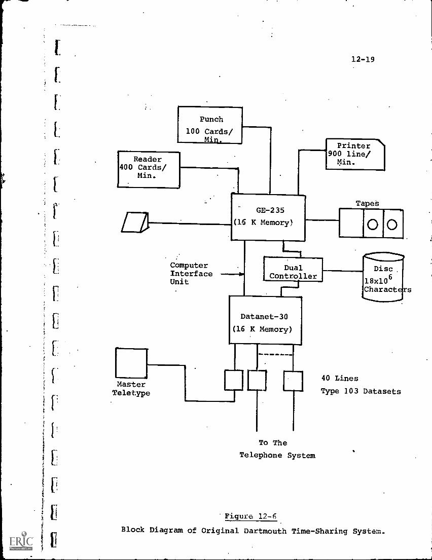
Punch
100 Cards/Min.
Reader400 Cards/
Min.
12-19
GE-235
(16 K Memory)
ComputerInterfaceUnit
MasterTeletype
Printer900 line/Min.
TapeS
DualController
Datanet-30
(16 K Memory)
OM, reIP
To The
Telephone System
O O
Disc.
18x106Characters
40 Lines
Type 103 Datasets
Figure 12-6
Block Diagram of Original Dartmouth Time-Sharing System.
-"T
S
12-20
Termed BASIC (Beginners' All-purpose Symbolic Instruction
Code) and designed originally for students, the language has
since been expanded into a more powerful, general-purpose pro-
gramming language, used in many commercial systems where
laymen must communicate with the computer. The beginner, how-
ever, may continue to use the elementary portions of BASIC
without having to learn the language expansion.
Compared to other programming languages, BASIC is a large
step in the direction of "natural language" programming; and
has permitted interactive computer usage by many users. who other-
wise might have been inhibited from "hands-on" operation. Both
in its flexibility, however, and its approximation to natural
English instructions, BASIC still leaves many features to be
desired.
Nevertheless, BASIC permitted widcspread usage of the
system at Dartmouth by both students sand faculty. In most
cases, the user, through interactive trial-and-error, developed
his own program, debugged it and modified it as required.
This approach, while rewarding user creativity, also servedto limit the system capability. All user programs were saved"
and, -as the memory storage space became exhausted, those programs
least used were "purged" by being erased. The storage period
before purging shrank from an original 3 months to some^48 hours
as the library of user programs continued to crow. As a counter-
ploy to protect their programs, users took to the habit of
calling up all their otherwise unused programs every day to avoid
having them purged. This worsened the program storage situation
tremendously.
The situation eventually was eased by the introduction of
a new, larger computer system in 1968 (although storage capacity
or "parking space" for -user- originated programs is still an
endemic problem). The new system, illustrated in Fig. 12-7
uses a much larger, more powerful data processor, the GE-635,
in conjunction with up to 4 Datanet-30 communications controllers.
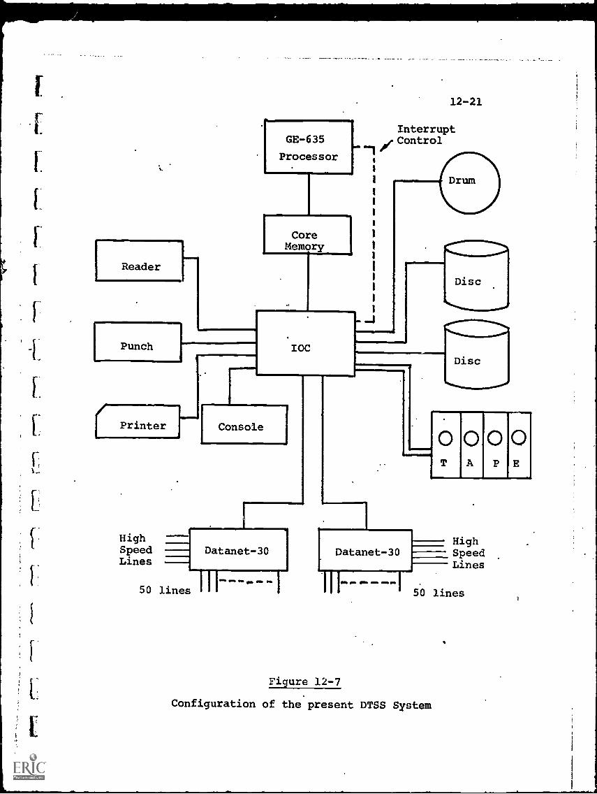
IT
f
Reader
Punch
GE-635
Processor
CoreMemory
Printer
IOC
12-21
Interrupt/ Control
Disc
444"
Console
Disc
0000A PET
High HighDatanet 30 Datanet -30Speed Speed
Lines Lines
50 lines 111------ 50 lines
Figure 12-7
Configuration of the present DTSS System

12-22
Each Datanet-30 can accept up to 50 separate inputs, so that
the system theoretically can service up to 200 simultaneous
users. In actuality, however, the increasing sophistication
of the users means a bigger average workload per user than on
the smaller system. Consequently, the maximum number of
simultaneous users is closer to 100, above that number bringing
unacceptable delay in execution of requests.
In the new DTSS, the interface to any individual user isexactly the same. Within the system, however, a number of
changes have been effected. The Datanet-30's now are concerned
only with message switching and communications control. TheGE-635 schedules jobs, composes new programs, carries out
commands and controls usage in addition to storing user programs.
Further, the "larger 635 can retain in active core memory the
jobs of several users rather than one, so that a number of jobs
can be run concurrently.
(As an outgrowth of the work at Dartmouth, the original
and expanded DTSS systems became, in effect, the prototypes
for the General Electric Mark I and Mark II commercial time-
sharing services, respectively. The Mark II, refined and upgraded
to network status, is the primary offering of General Electrictoday).
At Dartmouth, the impact of DTSS upon education may be
inferred from the following:
Some 80% of each Dartmouth class has computer training
as a formal academic requirement. About 30 courses in
14 departments use the computer in course work.
In the area of preprogrammed instruction, Dartmouth has
done little, although individual faculty members have
programmed CAI courses. In the reverse mode, llowever,
where the student programs the computer to solve his
problem (in effect "teaches" the computer), the most
experience has been gained, and it is believed this
11
7
t
12-23
process is extremely valuable in increasing the logicalpower of the student.
o The mathematics department has programmed "teaching
supplements" in logic, number theory, statistics andlinear algebra.
O Engineering students regularly use DTSS in designprojects.
o Psychology and social science students have utilizedthe computer for statistical analysis.
O The business administration school uses DTSS in con-nection with courses in.accounting, finance, productio
operations research and investment.n,
The DTSS also has had some influence upon secondary schooleducation by virtue of its use by a number of schools in theNortheast. From 1964-66, some eight high schools tied intoDTSS on an experimental basis. The preliminary results weresufficiently promising to warrant a larger-scale test program.
In 1967, with the financial support of the National Science
Foundation, a 3 -year project exploring the use of computing in
secondary school education was initiated. Eighteen schools in5 New England states, including both public and private schools,
participated and were interconnected to the DTSS facility throughtelephone lines with one or more Model 35 KSR Teletype terminals
at each school.
Average costs (9-month year) were about $7,000 per schoolfor a 1-terminal operation, with about 60 -65% representing
computer time and the remainder telephone line and Teletyperental charges. This approximates the salary of a single teacher.
Average number of users was about 90 per month, or 4 perschool day, with an average usage of 1.75 terminal hours/use/month. Thus, on a one usage a month basis, a Teletype terminal
12-24
might support 3 classes of 30 students each. Usage 3 times a
month by individual students would limit availability to the
equivalent of a single class.
Some conclusions drawn by the Dartmouth project managerswere:
o Teletype and communications time are too expensive to
"waste" by using.the computer as a teaching machine
The system is best used-in creative exploration.
O Programming, at least in BASIC, can be learned in a
few hours at the seventh-grade level.
Even very slow students can productively use the
computer.
12-4. IMS Computer-Managed Instruction System
A CMI system, called IMS (Instructional Management System),
developed by System Development Corporation, has been operating
in various Los Angeles schools.
Students a re provided with tests in a format that resembles
the usual workbook practice exercise. These tests are presented
once or twice a week, with directions preparedon audio tape
and available through earphones at a central listening center
in the school.
Each test item is keyed to a "teaching ob-lective ", and
printed on machine-readable forms. When the students have
completed the test sheets, they are collected and read into a
computer by means of an optical scanner.
The data are analyzed by computer programs that associate
student responses with teaching objectives, record individual
and group performance, and designate appropriate remedial action,
if indicated. A printout of this information is available to
the teacher the next morning, describing student learning dif-
ficulties, future alternatives and supplementary instructional
material. If additional information is required, the teacher

12-25
can use a teleprinter to query the computer. An on-line query
program allows users to formulate queries by responding to aseries of multiple-choice options, or by composing a request
in a special query language.
The advantage of such a CMI system is basically the major
cost reduction, compared to a CAI approach. Large numbers of
student terminals are not required, and the computer can operate
in a batch processing mode most of the time. Softw'are is also
much simpler, since the computer functions are basically
record-keeping and comparison.
The disadvantage, of course, is that no instruction per se
is given by the computer. As a low-cost management tool, or
an interim step before CAI, CMI offers many advantages.
12-5. USC-Operated Information Retrieval System (WESRAC)
Chapter 10 and 11 discussed dial-access retrieval systems
in which a student requests an audio or video program from a
centralized library, and the program is automatically located
and distributed to the reciuestor. While computers may be used
to control accession, they act simply as switching and routing
devices, and therefore such systems are "computer-based" only
to a very limited and specialized extent.
True computer-based information retrieval and networking
systems are those which deal with large"data-bank" management,
including file cataloging and storage, updating, access and
communisations. A large portion, though not necessarily all,
of the data-bank is in computer-compatible form (i.e., storable
and manipulable as digitally coded electrical signals).
Because the theory of large-file management is still
evolving, and acquisition and maintenance of large data-bSnks
are very expensive, educational applications range from the
conceptual to the experimental, but have not yet reached
operational status. Some semi-educational systems exist, how-
ever, which serve industry and educational clients alike. An
12-26
examination of one of these may be illuminating in terms of
techniques which can be utilized for more specialized educational
systems in the future.
NASA, stimulated by the staggering amount of aerospace-
related data accumulated during the Apollo program, has been
one of the leaders in establishing data-bank storage and
retrieval systems. A primary information bank is maintained
at NASA's Scientific and Technical Information Facility (STIP),
College Park, Md. This data-bank is also made available on a
decentralized basiS to a number of regional centers.
One such center, Western Research Application Center
(WESRAC) may be examined as typical. WESRAC, funded by NASA,
is operated by the University of Southern California to serve
both educational and industry information' needs in the Western
U.S.
WESRAC maintains computer magnetic tapes, document abstracts,
and document reproductions on microfilm, all updated monthly
from the central STIF.
Fig. 12-8 is a functional flow chart of the information
retrieval system. WESRAC's magnetic tapes contain summaries,
called "citations", of over 500,000 items in 34 subject
categories ranging from "Aerodynamics" to "Thermodynamics".
Tapes contain citations in chronological sequence, and the elements
of a citation are composed of accession number, report number,
availability,. ice, title, author source, and key descriptor
words.
Citations are also cross-indexed by key descriptor words
(average of 15 per document). The tape file is organized in
paired blocks--a coded term block and an information block.
The coded term block contains 5-character codes corresponding
to descriptor terms or a 1-to-1 basis. The informatioh block
contains the stored doimmentary information.
Retrieval is performed either by specific identification
of accession number, title, etc., or if these are not known,
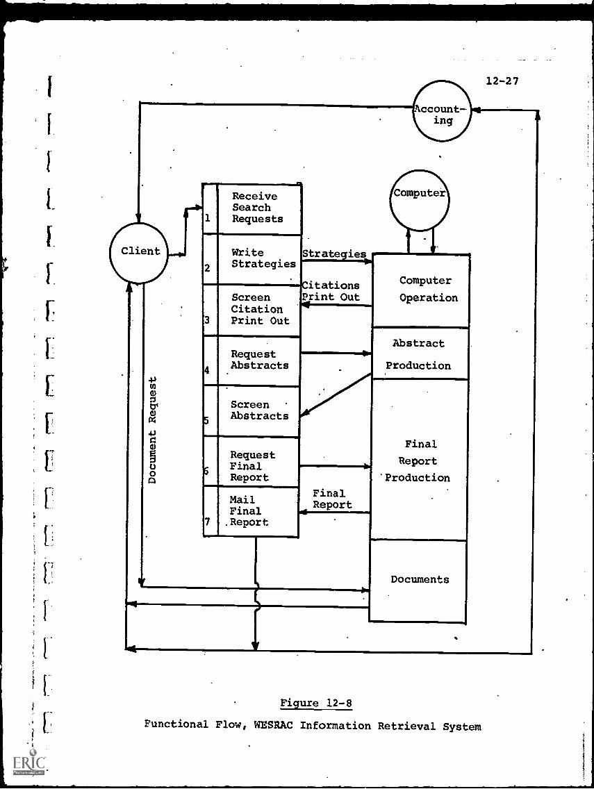
Account-ing
12-27
is
1
.
-p
ReceiveSearchRequests
.
Write
2Strategies
ScreenCitation
3 Print Out
Request
4 .
Abstracts
Screen
5Abstracts
Request
6FinalReport
MailFinal .
7 .Report
;Strategies
CitationsPrint Out
FinalReport
Computer
Operation.
...- .
Abstract.
Production
Final
Report
'Production
Documents
Figure 12-8
Functional Flow, WESRAC Information Retrieval System
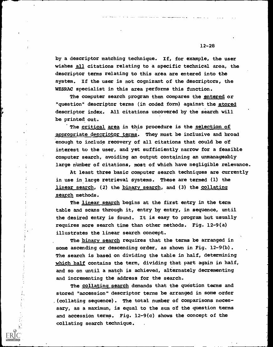
12-28
by a descriptor matching technique. If, for example, the user
wishes all citations relating to a specific technical area, the
descriptor terms relating to this area are entered into the
system. If the user is not cognizant of the descriptors, the
WESRAC specialist in this area performs this function.
The computer search program then compares the entered or
"question" descriptor terms (in coded form) against the stored
descriptor index. All citations uncovered by the search will
be printed out.
The critical area in this procedure is the selection of
appropriate descriptor terms. They must be inclusive and broad
enough to include recovery of all citations that could be of
interest to the user, and yet sufficiently narrow for a feasible
computer search, avoiding an output containing an unmanageably
large number of citations, most of which have negligible relevance.
At least three basic computer search techniques are currently
in use in large retrieval systems. These are termed (1) the
linear search, (2) the binary search, and (3) the collating
search methods.
The linear search begins at the first entry in the term
table and scans through it, entry by entry, in sequence, until
the desired entry is found. It is easy to program but usually
requires more search time than other methods. Fig. 12-9(a)
illustrates the linear search concept.
The binary search requires that the terms be arranged in
some ascending or descending order, as shown in Fig. 12-9(b).
The search is based on dividing the table in half, determining
which half contains the term, dividing that part again in half,
and so on until a match is achieved, alternately decrementing
and incrementing the address for the search.
The collating search demands that the question terms and
stored "accession" descriptor terms be arranged in some order
,(collating sequence). The total number of comparisons neces-
sary, as a maximum, is equal to the sum of the question terms
and accession terms. Fig. 12-9(c) shows the concept of the
collating search technique. .
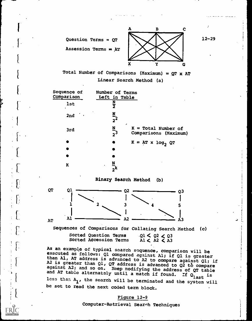
1
1
Question Terms = QT
Assession Terms 2* AT
A B C
Y G
Total Number of Comparisons (Maximum) = QT x AT
Linear Search Method (a)
Sequence ofComparison
1st
2nd
3rd
Number of TermsLeft in Table
N
N2
2
N K = Total Number of
2 Comparisons (Maximum)
K = AT x log2 QT
2
Binary Search Method (b)
12-29
QT Q1 02 Q3
I ....% I N. I
1 2 3 4 5
1
,,
AT Al . A2 A3
Sequences of Comparisons for Collating Search Method (c)
Sorted Question Terms V-4: Q2 < Q3Sorted Accession Terms Al G A2 4,A3
As an example of typical search sequence, comparison will beexecuted as follows: 01 compared against Al; if 01 is greaterthan Al, AT address is advanced to A2 to compare against 01; ifA2 is greater than Q1, QT address is advanced to Q2 to compareagainst A2; and so on. Keep modifying the address of QT tableand AT table alternately until a match if found. :f 0-last isless than A
1, the search will be terminated and the system willbe set to read the next coded term block.
Figure 12-9
Computer-Retrieval Search Techniques
12-30
In most cases, the particular search strategy at WESRACis determined by a system specialist who is knowledgeable of
the WESRAC files and also the field of interest of the
individual initiating a request. This strategy is designed to
take the given information (which may vary from a specific
document accession number to the other extreme of wishing to
see "everything" about a very general topic) and instruct the
computer in such a way that search time is minimized and yet
the requester receives an adequate response.
It is apparent that the skill'of this search specialistis a major factor in determining the efficiency of the computer's
search, so that systems such as WESRAC are quite removed from
being fully automatic. They do represent, however, the current
state of operational data-bank systems and can vastly reduce
the time necessary to retrieve pertinent information.
12-6. Information Networking Systems
An information networking system, as contrasted to a
retrieval system, implies search and retrieval in more than one
geographical location, and interchange of information resulting
in relatively high traffic flog in any direction. (A typical
example would be library-to-library interchange)
The retrieval system, on the other hard, almost alwayshas little data flow from the user to the retrieval facility.
Thus, a computer-based information network is basically
a machine-to-machine system, because the high data traffic flowin either direction is generally incompatible with a direct
interface to human beings. Information may be stored at the
receiving end in temporary buffers, or converted to permanent
hard-copy form for later use.
In addition to the machine-to-machine characteristic, an
information network implies high speed (broadband) communicationsand terminal equipment. Further, the large-file management and
Li
12-31
traffic control software requirements for any retrieval systembecome geometrically more complex for an information networkingsystem.
For these reasons, computer-based information networking
on any sizable scale, remains currently in the experimental/
development stage. Some formidable problems of standardization
and compatibility must be overcome before optimum hardware/soft-
ware configurations can even be defined.
Compatibility problems include:
(a) Standardization of information management and inter-
change techniques. Some progress, such as standard
codes for data transmission (ASCII) has been made,
in terms of Federal Information Processing Standards(FIPS). Internal computer procedures, such as file
construction, designator terms, file accessing, etc.,
are completely left to each network's or computer
manufacturer's option. Further, no standards on
man-machine and man-man interfaces have been attempted.
(b) Machine - machine incompatibility such as differences in
- Data transmission speeds and costs
- Input/output equipment .
- Reprography
- Storage equipment & media (e.g. magnetic
tapes, disks, video tapes,.etc.)
- Data handling techniques (e.g. message blocking,
headings, I.D. information, error coding and
detection, data security, etc.)
(c) Man-machine incompatibility, including:
- Assessment of user wants and needs (often 'no
correlation)
- Who requires what type of access? (e.g. to
terminals, microform viewers, hard copy, etc.)
- Human engineering and operating convenience
- Priorities and scheduling conflicts
12-32
Potential misuse, abuse
Monitoring of system effectiveness
Accuracy of descriptor terms and indexing
methods (e.g., how should pictures be
catalogued?)
Until some common agreement, either through imposed or
voluntary standards, addresses at least a substantial portion
of these compatibility problems, it is likely that information
networking, on any widespread scale at least, will be constrained.
When, as an example, it is sometimes difficult to use a tape
prepared on one computer or video recorder on another machine
of the same make and model, networking of information freely
among a wide variety of computer and peripheral equipment
appears many years off. Further, it appears likely that the
first systems will be business- oriented or sponsored by government
requirements, with educational systems some time later.
12-7. Commercial Systems
In parallel with the university-based computer educational
systems, some computer manufacturers have developed and offered
for sale standardized commercial systesm. Although the market
response has not yet been overwhelming, two typical systems are
described briefly below to indicate the degree of capability
available.
The IBM 1500 Instructional system, introduced in 1966, is
designed primarily for use in the drill -and practice and limited
tutorial or inquiry modes of instruction.. It uses an IBM 1130
or 1800 computer, together with up to 32 specially designed
terminals.
The terminal includes:
(a) A CRT display
(b) A light pen (for student graphical input or response)
12 -33
(c) A keyboard (for student alphanumeric input or response)
(d) Earphones (in conjunction with an audio play/record
system holding up to 2 hours of 5-minute instructional
messages)
(e) Image projector (a random-access film strip projector,
capable of displaying any of 1,000 stored images on
a rear-view screen)
About 15-20 IBM 1500 systems are presently in use at various
universities, programmed for a variety of subjects and educational
levels. IBM developed a special programming language, COURSE-
WRITER, for the system and.this has in some cases been expanded
and improved upon by some of the university users.
In common with other systems, the IBM 1500 stores the students'
responses and, on command, can print out a multitude of reports
on individual or group performance.
The IBM 1500 is perhaps the most sophisticated of the com-
mercial tutorial-type systems, and can still be considered as
subject to future modification and improvement. It can be likened
in concept to the Stanford CAI approach, whereas the next system
discussed is closer to the DTSS problem-solving mode.
The second commercial system is the Hewlett-Packard Series
2000 Time-Shared "BASIC" System, which has been available for
about three years. This is an expandable system, with Models
2000h, 2000B and 2000C progressing in terms of student terminal
capacity and computing capability.
The HP 2000A utilizes a standard HP computer (Model 2116)
in the upper end of the mini-computer category (16-bit word
length, 1.6.microsecond memory cycle time, 16,000 words of
magnetic core memory). Added to this are a disc memory unit
(350,000 words storage, 16 millisecond word access time) and the
user terminals, which are modified Teletype units.
Other peripheral equipment (magnetic tape, paper tape,
card,readers, printer/plotters, etc.) are available as options.
The HP 2000A can handle up to 16 terminals on a time-shared
basis. The 2000B can handle 32 terminals and has expanded
12-34
memory capacity to store CAI programs. The 2000C also is
designed for up to 32 terminals but adds the feature of running
batch processing in addition to time - sharing. This permits
record-keeping, accounting and administrative functions to be
assumed by the computer.
In the time-sharing mode, communication between the terminals
and the computer is in BASIC,the language developed at Dartmouth
for people unfamiliar with programming. In the non-time-sharing
modes, the more sophisticated languages, suchs as FORTRAN and
ALGOL, which require .programming proficiency, can be used.
The cost of the system ranges from about 790,000 for a
HP 2000A with 16 terminals and no added peripherals, to $150-200,000
for a 2000C system with options.
If usage factor of 8 hours per day per terminal is assumed
(2000 hours per year), this would be 32,000 hours per year for
a 16-terminal system. At a price of $90,000 or over, the cost
per student-terminal-hour is about $1.001 not counting sustaining
software and operating costs.
12-8. Evaluation of Current Status
A technological assessment of the current status of computer-
based educational systems indicates that, even though most
computer hardware used to date has been of general-purpose com-
mercial design and not optimized for CAI, there has been relatively
little difficulty in technical implementation. The problems
encountered (e.g., limited memory storage, marginal and/or
expensive communications, unsuitable programming languages,
etc.) are more endemic than CAI-related.
Cost-effectiveness is another matter, however, and there
is general agreement that the range of $2-5 per student-terminal-
hour is certainly too high for elementary and secondary school
instruction, and probably marginal-to-high for university-level
instruction. Even the estimates of CAI costs, moreover, are
in doubt, since most systems use the computer for both educational
and non-educational purposes, making the true educational costsdifficult to determine.
12-35
Even assuming the cost element is known, however, the .
tsecond half of the figure of merit, the effectiveness, poses
further questions. The students, after using the computer,
can be tested together with other students but this comparison
can be misleading on many counts, however, such as:
- Is the computer being used appropriately, from
an educational point of view?
Are the computer-trained students gaining in
such areas as logic, problem definition, problem
solving, precision in thinking, motivation, etc.,
over and above learning the prescribed instructional
material?
- Is the computer particularly compatible with the
rapid, normal,'or slower learner?
ThisNarea, which involves setting objectives and measure-
ment criteria on both sides of the man-machine relationship,
is still in its infancy in terms of computer-based educational
systems. Yet without some formalized, commonly accepted
evaluation structure, the "cost-effectiveness" of the system
is only a semantic term.
There is therefore, the principal problem of understanding
the learning_process more precisely, and defining CAI objectives
in that context. Secondly, the use of a computer as a "page-
turner", while achieving the desired goal of permitting
individualized rates of instruction, lacks a good deal in making
effective use of the computer's total range of 'capabilities.
In terms of reducing the'cost per student hour, the
simplest way is to increase the utilization of terminals, e.g.,
by running two 8 hour shifts per day on the computer. 'This
might be traumatic to faculty, students and parents alike, but
it drastically reduces unit costs without requiring innovation.
A second approach is the use of smaller, "dedicated"
computers for in-house CAI systems, so th'at the substantial cost
ti
of leased communications can be eliminated. kA Viumber of these
smaller systems, capable of handling from 2-32 'terminals are
now commercially available, ranging in initial price from about
$15,000-200,000. Each case must be carefully reviewed on its
own merits, however, as the savings in communications mists
can easily be outweighed by the inflexibility of the smaller
system or by the necessity for specialized programming. The
likelihood, however, for lower-cost mini-computer systems in
the near future makes the decentralized approach an attractive
prospect.
Although it is a fair statement that the growth of computer-
based educational systems in the future will depend more upon
definition of educational objectives than on technology, there
are still.technological areas which pose operational problems.
One problem already mentioned, is the lack of a low-cost
user's terminal. The ubiquitous and ancient Teletype is utilized
becadse of its comparatively reliable performance at a cost
which at least is less than competitive units. In terms of
Speed, convenience and input-output capability, however, it is
far removed from being an ideal interface between man and the
computer. More modern terminals offer improved performance
but usually at higher cost (particularly when visual display
is added) which makes these dubious for the mass educational
market. The proposed PLATO IV plasma display terminal appears
to have many advantages, but apart from-its developmental nature,
the estimated cost/of about $2,000 still poses a financial
barrier to many schools.
It is probable that no single terminal can serve equally
well in all computer-based systems. For example, the con-
ventional interactive terminal emphasizes different features
from the retrieval system terminal. Nevertheless, a newer,
more flexible and lower cost series of user terminals warrants
substantial technological effort. The latter, however, is
determined by market demand, which in turn may not be impressive
12-37
without the necessary terminals. This chicken-and-egg
syndrome has existed to date and does not appear to be decreasingin the future.
A second major problem, not restricted to educationalsystems alone, is the cost and adequacy of common-carriercommunications. It was noted previously in the DTSS experimentwith New England high schools, that about 1/3 of the totaloperating costs were for communications. If the computer wereshared with schools at a greater distance, e.g., nationally,
this percentage would increase and at some point be the dominatingcost factor.
With a centralized, large-computer concept, there is no wayout of this dilemma. Not only must the cost of communications
be met, but the adequacy and reliability of the communications
links for expanding data traffic applications are currently
marginal, and may or may not improve in the future.
Some hope is seen in this respect in the smaller,
decentralized systems. Here communications costs can be cut
drastically or even eliminated, and the cost of operation per
student decreases with increasing utilization. The loss of
"economy of scale" advantages inherent in large computers maybe more than offset by the reduced communications.
Software, itself, is another problem area. While BASICrepresents a step in that direction, the lack of a truly con-
venient, standardized, "natural" programming language, willcontinue to inhibit the use of more sophisticated computer
systems in education (e.g., dialog or "Socratic" systems).
The task of developing such a language appears years away at
this point.
Apart from the software necessary for the on-line user,
the lack of standardization of software among computer manu-
facturers and also among computer system users (e.g., with
respect to descriptor terms'and indexing techniques), poses a
formidable barrier to both information retrieval and large-scalenetworking.
12-38
CHAPTER 12 - BIBLIOGRAPHY
1. Alpert, D., and Bitzer, D.L., "Advances in Computer-BasedEducation", Science, March 20, 1970.
2. Feingold, S.L., "CAI Systems.Past, Present and Future",System Development Corp., Paper SP-3492, March 4, 1970.
3. Gordon, R.M., "Computer-Assisted Instruction: Some OperationalAspects", Datamation, Jan. 1969.
-
4. Hargraves, R.F., and Stephenson, A.G., "Design Considerationsfor an Educational Time-Sharing System", Vol. 34, ConferenceProceedings, AFIPS Spring Joint Computer Conference, 1969.
5. IBM 1500 Instructional System, Introduction to Computer-Assisted Instruction and System Summary, IBM Corp.
6. Jamison, D., Fletcher, J.D., Susses, P. and Althinson, R.,"Cost and Performance of Computer-Assisted Instruction fo3:Education of Disadvantaged Children", Research Paper No. 20,July, 1971, Graduate School of Business, Stanford University.
7. Jamison, D., Suppes, P., and Butler, C., "Estimated Costs ofComputer Assisted Instruction for Compensatory Education inUrban Areas", Educational Technology, Sept. 1970.
ti
8. Kemeny, J.G. and Kurtz, "The Dartmouth Time-Sharing LiComputing System", Final Report, June 1967, Under NationalScience Foundation Grant NSF-GE-3864.
9. Komoto, D.T., "WESRAC System", Datamation, Aug. 15, 1970.,
10. Kurtz, T.E., "The Many Roles of Computing on the Campus",Vol. 34, Conference Proceedings, AFIPS Spring Joint 'tomputerConference, 1969.
11. Mizenks, A.J. and Evans, A.A., "An Instructional Model forComputer Assisted Instruction", Technical Report 71-2, May1971, U.S. Army Signal Center and School, Ft. Monmouth, N.J.
12-39
12. Nelson, T.H., "No More Teachers' Dirty Looks", ComputerDecisions, September 1970, p. 16-23.
13. Pressman, J., "Computer-Assisted Instruction: A Survey",Institute of Electrical and Electronics Engineers Transactions,Vol. E-13, No. 2, Sept. 1970.
14. Suppes, P. and Morningstar, M., "Computer-Assisted Instruction",Science, Oct. 17, 1969.
V. TRENDS AND PROJECTIONS
Chapter 13 Future ApplicationsChapter 14 Projected Systems
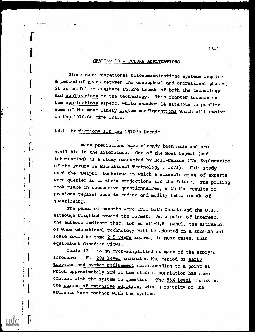
13-1
CHAPTER 13 - FUTURE APPLICATIONS
Since many educational telecommunications systems requirea period of years between the conceptual and operational phases,it is useful to evaluate future trends of both the technology
and applications of the technology. This chapter focuses onthe 'applications aspect, while chapter 14 attempts to predictsome of the most likely system configurations which will evolvein the 1970-80 time frame.
13.1 Predictions for the 1970's Decade
Many piedictions have already been made and areayailAble in the literature. One of the most recent (andinteresting) is a study conducted by Bell-Canada ("An Explorationof the Future in Educational Technology", 1971). This studyused the "Delphi" technique in which a sizeable group of expertswere queried as to their projections for the future. The pollingtook place in successive questionnaires, with the results ofprevious replies used to refine and modify later rounds ofquestioning.
The panel of experts were from both Canada and the U.S.,
although weighted toward the former. As a point of interest,
the authors indicate that, for an all-U.S. panel, the estimatesof when educational technology will be adopted on a substantialscale would be some 2-5 years sooner, in most cases, than
equivalent Canadian views.
Table is an over-simplified summary of the study'sforecasts. MI_ 20 level indicates the period of earlvadoption and system refinement corresponding to a point at
which approximately 20% of the student population has somecontact with the system in question. The 55% level indicatesthe period of extensive_ adoption, when a majority of the
students have contact with the system.
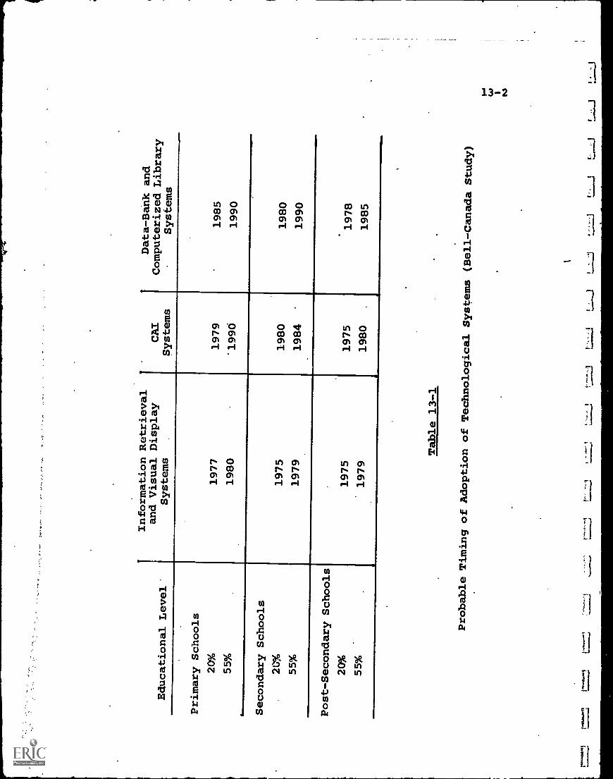
Educational Level'
Information Retrieval
and Visual Display
Systems
''
CAI
Systems
'
Data-Bank and
Computerized Library
Systems
Primary Schools
20%
1977
1979
'
1985
55%
1980
"1990
1990
Secondary Schools
20%
1975
1980
1980
55%
1979
1984
'
1990
Post-Secondary Schools
20%
1975
1975
1978
55%
m
1979
1980
.
1985
Table 13-1
Probable Timing of Adoption ofTechnological Systems (Bell-Canada
Study)
13-3
Table 13-1 predicts that automated information retrievaland visual display systems will be the first class of educa-tional telecommunications systems to achieve wide acceptanceat all school levels. This is reasonable on two counts.First, the type of instruction received from the retrievedfilm or video tape is similar to conventional methods andrepresents less of an educational and psychological departurefrom the familiar, for both. students and faculty. Secondly,the technology, while expensive, is relatively straightforward,
involving mainly storage of, and access to, the instructionalmedia. Thus, only hardware design is necessary, and essentiallyno new software must be developed.
CAI systems, on the other hand', do involve major softwareeffort. As Table 13-1 indicates, they are predicted foradoption at the college /university level first, with a sub-stantial lag before general acceptance at the primary andsecondary levels. One reason for this is that the currenthigh cost of CAI, averaging $2-5 per student-terminal-hour,
approximates conventional higher education costs much moreclosely than it does the $.30-.35 per student hour cost atthe primary school level. A second reason is the wider
availability of computers at the college level, and a thirdis the fact that undergraduate or graduate student, can beused at little .or no cost to operate or program the computersystem.
In terms of the type of'CAI systems anticipated, thestudy indicates that at the lower educational level, drill-and-practice will receive initial emphasis, with tutorial,simulation and conversational/instructional game techniqueslagging by about five years. At the higher educational level,
simulation and tutorial, followed by conversational and drill-and-practice, are the expected sequence.
13-4
At all levels, the dialog system appears to be the last
to become operational, if at all. The software problems,
which are related to an imperfect understanding of what a
desirable teacher-student dialog should be, present a formid-
able barrier in the foreseeable future.
It is interesting to compare these CAI forecasts, generatedby an interdisciplinary panel, with that of a leading practi-
tioner in the field. Patrick Suppes, who has led the Stanfordprogram for some nine years, predicts that by 1980 1596 of the
students in the U.S. at all grade levels will be in dailycontact with a computer for some aspect of their instruction.
As an indication of the costs involved, 15% of approxi-mately 1,000,000 elementary-school classrooms is 150,000. Eachclassroom averages 25-30 students, and for drill-and-practice
in mathematics or in reading, one terminal per classroom probably!Would be adequate. At an estimated cost of $3,000 a terminal,
150,000 terminals would total almost half a billion dollars.
In addition, the cost of the central computer systems, the
software and the communications links may well bring the totalto at least twice that figure, or over a billion dollars, for
15enetration of primary schools only.
The third category of Table 13-1, that of data-bank and
library-oriented information systems, is almost universallyagreed to be the farthest away from implementation. As notedin previous chapters, the technology of large data-bank
acquisition and management ia still in its infancy, a lack of
standardization inhibits computer-to-computer information
interchange and costs are simply out of reach for most
educational users. A stabilizing period of developing.and using
large data-bank systems for non-educational applications most
probably will precede their adoption in education.
13-5
13-2 Changing Role of the Teacher
If forecasts such as in Table 13-1 are even grossly correct,one key area will be the relationship of the teacher to (a) thetechnology which becomes more and more a part of the curriculum,and (b) the students impacted by this technology.
Obviously, one hopeA.s that the teacher can be relievedof much burdensome and uninspiring routine. TypeWriters donot make people into better creative writers, or adding machinesmake them into better mathematicians. They simply permitmechanization of necessary, but routine, tasks. In the sameway, a computer can probably conduct drill-and-practice trainingbetter than a teacher, and, further, the teacher would behappy to pass this task on. At this level of sophistication,technology, as a work- relieving tool, can be an unqualifiedsuccess, if the costs are reasonable.
At a higher level, the teacher's role in a technologically-oriented teaching environment becomes more complex. Withoutattempting to justify them as educationally desirable, certaintrends are evident, however.
The Bell-Canada study, for example, envisions that thetraditional teacher's role of leading and directing the classwhile imparting knowledge will begin to change around themiddle 1970's, into more of a catalyst to the learning process.Still later, the teacher is viewed as "a sympathetic resourceutilized at the student's request".
In this last role, teachers would have at their command awide range of mechanized or prepackaged informational resources(e.g., computer, media library, etc.) and it would become oneof their principal functions to select and direct students tothe appropriate resources consistent with their individualeducational needs. 'As a consequence, the teacher would be,or would have to become, a. resource specialist, able to diagnose
-student progress and needs, and prescribe accordingly.'
13-6
The more adequate and comprehensive the educationaltechnology, the more routine the teacher can be relieved of,
and simultaneously the more he will be free to be the learningdirector", the prescriber and interpreter of technologicallearning packages, and the student-technology interface.
A greater proportion of the teacher's time may also berequired in the preparation of technological program packagessuch as instructional audio/visual material. CAI programs,
progress evaluation techniques, etc. This area maybe themost difficult of all, since it requires much more preciseknowledge of the learning process than is currently available.Even after almost ten years of CAI experience at Stanford,
for' example, the project managers there admit that they arefar from being able to develop a "student learning model" whichcould be used as a base for simulating the cognitive and
learning processes of students across even a narrow range ofsubject areas.
Although this problem may well become the primaryresponsibility of educational specialists rather than the
average teacher, teachers must still adapt the generalizedprocedures to their individual student needs and responses.They will, therefore, have to have some in-depth familiarity withthe way the technology interacts with their students, and howthe interaction might produce better results.
13-3 Technology Trends
While the full impact of all the advances in telecom-munications technology over the next decade cannot be estimated,a few key trends are highlighted to provide some insight asto the general direction in which educational applicationsmay go:
(a) Electronics hardware costs, particularly when suchtechniques as Large -Scale Integration of circuits
13-7
are applicable, will go down relative to softwarecosts. This means that concepts which.arose withthe beginnings of the computer industry, such asdesigning general-purpose equipment which could beprogrammed to do anything, are leis valid and willgive way to doing as much of the total task in hard-ware as possible, and minimizing the manpower andcosts involved in the software.
Further, the hardware must no longer be procuredin large chunks (i.e., as part of a big general-
.
purpose computer) to attain the cost savings, asevidenced by the low prices of mini-computers andeven individual logic' circuit elements. This meansthat computing power, or switching capability, ormemory storatie, or communications control can bedecentralized and distributed throughout the tele-communications system.
An exag,p3e may be illustrative. SandersAssociates has de.7eloped a conceptual informationprocessing and distribution system which may holdattractive potential for applications such as CAI. .
It features the technique of distributed data processingand shared software as follows:
An information data-bank (such as all the pagesof a textbook) is stored on a modular disc file, asshows- in Figure 13-1. Together with the data arestored software programs which provide instructions'as to how to use the data, and identification codeswhich permit selection of any portion or "page" ofthe data.
All of the contents of the disc file are continu-ously transmitted over a broadband coaxial cable, on .
a party-line basis as described in the section onCATV systems. (The Sanders approach, in laot, is
,)*
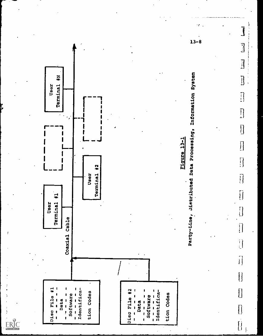
Disc rile #1
Dat
a
Software
Identifica-
tion Codes
User
Terminal #1.
Coaxial Cable
111=
111
-al
II
II
L=O
PrM
b...
II
Disc File 412
Data
Software
Identifica-
tion Codes
1111
1111
1111
1111
111M
IIIM
MIN
"s"-
- 1
V
User
Terminal #N
User
11
Terminal #2 ar
rosh
IL
alm
oar
ail
I.w
ebs.
=N
J
Figure 13 -1,
Party-Line, DistributedData Processing, InformationSystem
13-9
designed with CATV in mind, as the prime source ofbroadband channels). The data transmission is indigital form with the identification codes as partof thc. P-4rial bit stream (which is at a high rate,several million bits per second).
Each user connected into the cable has aprogrammable terminal, which is essentially a mini-computer with control and display features. Theterminal, by using the proper identification codes,can "tune in" or "call up" any portion of the data-bank, which could be pages of text, CAI instructionsor any other stored information.
Along with the data, the terminal also callsfor and receives the software which tells it howto receive, display and use the data. For instance,a set of microprogrammed
instructions could turnthe terminal into a drill-and-practice machine.
This concept of "software sharing" where anyuser does not have to store a large block of soft-ware at his terminal, but can "reach out and grabit as it goes by" is very efficient and flexible.It requires "distributed data processing" capatility,however, with a portion 3f the total system"s computa-tional and processing power located at each terminal.
As noted, this becomes most practical whencomputing haremare costs decrease, or put anotherway,-when each user can have his own mini - computer.
(b) Broadband communications channels to each user willbecome a necessity, to accommodate the multi-mediaprogram packages which educational technology candeliver.
1
13-10
Although some channels can be provided by wire-
less transmission, the vast majority of.systems will
require wired links, to bypass the problem of an
overcrowded broadcast frequency spectrum. This means
coaxial cable distribution systems, on-campus and off-
campus as determined by the location of the desired
audience. In effect, it is a reconfirmation of the
"wired-city" concept.
At present, MTV systems have provided the only
substantial start toward the goal of universally-
available broadband cable communications. Although
established for commercial reasons, they offer to
education the prospect of many, in-place, available
channels and many more to come in the near future.
The use of spare channel capacity for educational
telecommunications has already begun, and will in-
evitably expand in the future. There remain many users
not reached by CAW cables, but tying in this group
is eminently more manageable than if educators were
faced with establishing a completely new, broadband
cable network across the entire U.S. In that event,
the likelihood would be that no major progress would
be made until, perhaps, the time that satellites could
broadcast directly to schools and homes.
(c) If cable systems are indeed utilized, the potential
educational benefits may become available to a major
percentage of U.S. homes- and industrial facilities at
about the same time as to the schools. Although
initial educational telecommunications systems probably
will emphasize the on-campus applications, a vast new
student audience will be opened up. This will
include everyone from pre - kindergarten children to
mature adults, with interests and motivations ranging
from vocational training to leisure-time hobbies.
This will lead to the situation where the technologyof educational telecommunications may be developed
and stabilized for the on-campus student segment, and
then made available or expanded to the larger homeaudience. The latter, however, will be much morefragmented and if the goal is education rather than
mass entertainment, will require more diversity inprogramming.
It will then be incumbent on the educational
community to demonstrate that such specialized pro-
gramming can be made both responsive and cost effective.
(d) The availability of broadband communications channels-to a sizeable percentage of U.S. students (and later
the entire population) will sharpen the need for.
system definition and planning.
This is true not only in the technical sense,
to achieve maximum performance; but most importantlyin the educational sense. As an example, suppose
that through a combination of cable systems and
communications satellite links, it becomes possible to
interconnect every school in the U.S. to receive thesame program material.
How is such nationally centralized instruction to
be evaluated against, perhaps, school-district levelcentralization? Is the saving in prograMming cost
outweighed by the neglect of specialized communityneeds?
This leads to the general question of evaluationof an educational telecommunications system which has
been mentioned in'the introduction to this volume:
Standards for evaluation, and a measurement method-
ology:which takes account of both sides of the
"man- machine" relation, must be developed as the
technology becomes more complex. This evaluation
13-12
methodology should be established at the'time ofsystem planning, rather than after the system isimplemented, as one purpose is to guide the directionof implementation.
Some efforts have been made at establishing suchan evaluation methodology for large, on-line computer-based systems, although not in the educational field.In an aerospace system, for example, the problemmight be to determine system effectiveness on arelatively formalized, retraceable, quantitativebasis.
Involved in this determination are equipment-related factors (i.e., performance with respect tospecifications, hardware cost) which can be measuredprecisely. Also involved are factors which may beambiguous or "semi-precise" (i.e., reliability,
maintainability) which can be quantified but onlywith some lower confidence level. Finally, thereis a third set of people-related factors (personneltraining requirements, efficiency of software
preparation, convenience in using the system, etc.)which have no established measurement criteria, andwhich canbe quantified only with a very low
confidence level.
In spite of the variations in meanig andprecision, the evaluation techniques which have beenutilized do attempt to include and treat all ofthe above categories. Initial results are oftensuspect, but repeated iterations tend to produce moregenerally accepted evaluations.
Educational telecommunications systemS are inthe same category. An evaluation of the effectivenessof a CAI or an ITV system must include zleasures of
13-13
educational performance as well as equipmentperformance to have any substantive meaning.
The task of developing and utilizing suchevaluation methodology for educational systemsireAainsyet to be undertaken, but it is a' crucial one interms of best utilizing the available technology.
A simple example may be pertinent. Assume anITFS system with one-way capability to transmitinstructional TV programs to 500 off-campus studentswould cost $500,000. The capability to permit studentquestioning and "answer-back" would cost an added$250,000. Haw can it be determined that this increasedcapability is, indeed, worth (250,000? Or, perhaps,that it is not worth $250,000 but is worth $150,000?
Obviously, only an evaluation system which canblend educational value with technological cost-effect-iveness can provide an answer. It is probable thatthe decision-maker in this case might intuitivelyattempt such a correlation, but this seat -of -the- pants
technique leaves much to be desired.
The technological trend to more complex systemsideally, then, should be accompanied by a trend tomore ob'ective s stem lannin and evaluation. Thiswould require, perhaps, a new breed of interdisciplinary
educational technology specialists.
13-14
CHAPTER 13 - BIBLIOGRAPHY
1. "Communications Technolocy, for Urban Improvement", Committeeon TelecOmmunications, National Academy of Engineering, Reportto Dept. H.U.D., Contract No. H.1221, June, 1971.
2. Doyle, F.J., and Goodwill, D.Z., "An Exploration of the Futurein Educational Technology", Bell Canada, Jan. 1971.
3. Smythe, R.E., "Economically Viable CAI", Sanders Data Systems,May 1970.
4. Suppes, P. "Computer- Assisted Instruction at Stanford",Technical Report No. 174, May 19,,1971, Institute forMathematiCal-Studies.in the Social Sciences, StanfordUniversity.
71:
14-1
CHAPTER 14 - PROJECTED SYSTEMS
In any attempt to project educational technology into thefuture, and to determine which system configurations are mostlikely to emerge during the 1970-1980 decade, the critical,
stumbling-block remains as stated in the introductory pages ofthis volume, i.e., definition of educational objectives. Again,these are the responsibility of the educational community andthe public, and outside the scope of this chapter.
The technology does have a substantial inertia of its own,
however, in terms of cost and performance trends. From these
trends, projections can be drawn as-to the logical evolution ofeducational telecommunications systems. Such an evolution is,
described below, with the implicit presumption that educational
objectives will not become so restrictive as to eliminate theneed for telecommunications-assisted instruction of the type
illustrated in Chapters 10-12.
14-1 Concept of the Edudational "Telecenter"
Either the dial- access retrieval system or the'computer-
based instructional_agemwhi.zh serves many students requires
an expensive, electronically sophisticated central facility
which stores program material and responds to student requests.
As more programs are developed, it is likely that the
cost of constructing and maintaining such a central facility
will be more than a single using institution can bear, inmuch the same way that a. library is too expensive for only
one user.
Because of this, it is likely that the ?educational telecenter"concept will become more prealent. The 'telecenter would be
a "centralized storage, distribution and service facility for
a hierarchy of many users.
14-2
The concept, of course, is not unique and is based on the
economies of scale that any large centralized facility can
achieve. The Dartmouth-Time-Sharing-System, for example, uses
its large computer to serve many off-campus users.
To date, however, such facilities have been single-functioned
(e.g., dial-access or CAI but not both). In the future it is
likely that they will be multi-functional and planned for specific
community or regional entities.
Figure 14-1 illustrates the components of such a telecenter.
There would be a multi-media repository of educational software,
including films, filmstrip, slides, video and audio tape, and
documents (which could be either in original or condensed
microfilm form). There also would be studid production facilities
to broadcast live programs or to record material on any medium
for later. playback.
The telecenter would have low-cost reproduction facilities,
so that duplicate film prints or tapes could be prepared and
delivered to users who are not tied into the distribution net-
work.
Up to this point, the telecenter functions essentially as
a random-access retrieval system. Integrated with this function,.
however, there would also be a computer-based instructional and
information systeth.
The time-shared computer would be capable of acting in
i any instructional or interactive mode, and would also keep
records of student progress for CMI purposes. In addition,
the computer would provide access to a number of data-banks,
each being a library (in computer-compatible form) of informationp-
about a specialized subject.
FOr example, the data-banks could be on individual magnetic
discs, with one containing historical data for history students,
a second containing the equivalent of a Russian or French
dictionary for foreign-language students, etc.
1 0,
1
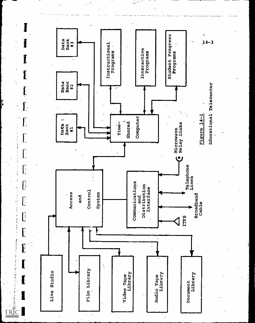
aim
ism
paws
rmal
Live Studio
--771
71_
Film Library
Video Tape
Library
Audio Tape
Library
Document
Library
Access
and
Control
System
Communications
and
Distribution
Interface
ITFS
VTelephone
VLines
Broadband
Cable
411664
6.1114
UMW
771
Data
Data
Data
Bank
Bank
Bank
#1
#2
#3
Time -
Shared
Computer
Instructional
Programs
Microwave
Relay Links
Interactive
Programs
Student Progress
Programs
Figure 14-1
Educational Telecenter
14-4
Each data-bank would contain its own "index" and modular
software so that it could provide instructions to students on
how it shoUld be used.
The computer would also serve as the master system controller,
providing access to any requested information and directing traffic.
For complex telecenters, mini-computers, under the control of a
master computer, might be used to share in any of these functions.
The telecenter's communications interface would be capable
of matching any commonly-used mode of transmission, using
broadband cable or wireless for most outgoing messages, and
narrow-band for selected incoming messages where the amount
of data involved is small.
All in all, the educational telecenter would function in
the same way a modern hospital or medical center does. The
expensive X-ray, open-heart surgery, intensive care, etc.
equipment which such a hospital maintains are beyond the
financial capability of a doctor's office, and in most cases
would not be used often enough at the local level to justify
their purchase even if funds were available.
Just as a hospital in no way obviates the necessity for
the doctor's office, however, the telecenter will not eliminate
-local instructional technology but ,supplement it.
Thus, concurrent with the growth in Centralized facilities,
there may well be a parallel growth in decentralized, special-
purpose educational systems. Small, time-shared CAI systems,
for example, appear very attractive for limited instructional
objectives. The cost and manpower of large data-banks and
multi-media libraries, however,'would force centralization of
the more ambitious systems.
The hierarchal level at which telecEnters should be
established is a subject for much future study, and will involve
educational jurisdiction as well as technological and financial
considerations. Whether, for example, a talecenter would be
3
14 -S
justified for each school district (some 20,000 odd in the U.S.)
cannot immediately be determined, but it may be a logical starting
point for feasibility studies. For higher education, it would
appear that only the very large universities and colleges
would.be able to entertain the idea of a telecenter, at least
for some years to come. The smaller colleges, however, might
find that a regional telecenter, serving some number of colleges,
would be justifiable on a cost-shared basis.
14-2 Evolving Telecommunications Networks
The concept of the educational telecenters, if implemented,
must be supported by an appropriate communications and
diStribution network.
A prime requirement of such a network is that it provide
broadband capability to each user. Since many of the programs
will be television-like in nature, the equivalent of at least
one 6 MHz TV channel must be made available to all user
locations. In most cases, several channels rather than one
will be required.
It is very doubtful that such broadband coverage can be
achieved through wireless broadcast techniques. The shortage
of frequency spectrum and the competition for those few broad-.
cast channels still available makes a significant expansion in
this area unlikely.
The alternative is distribution by coaxial cable to the
end-user; and this does appear very promising. It has been
pointed out that CATV systems are already meeting some of the
requirements in this regard:
(a) CATV systems usually have spare channel capacity.
The newer, larger systems will be required to have
this capacity and to make a substantial proportion
of it available for education.
14-6
(b) CATV systems usually, ,provide free connections to
schools within their area of operations, so that
regardless of the number of homes wired up, each
school can receive all channels of the system.
(c) Future systems will be required to have two-wav
communications capability.
For a school district to take advantage of CATV cable
communications, however, the following questions must be
addressed:
(a) Most CATV systems can transmit only from their
"head-end" studio, or from signals brought into
that point. Thus, a school district must either
originate programs at the CATV system studio, or
provide a connecting link from its own origination
facilities.
(b) The CATV systems in any area may.not provide coverage
to all schools (or homes), since municipal and school
district jurisdictions are not identical. Some means
must be provided to "plug the gaps"' in coverage.
(c) The responsibility for user terminals must, be
determined. If interactive communications are desired,
special terminals must be provided at each user
location. Schools may furnish their own, but home
terminals may provide a problem in terms of cost and
operation/maintenance responsibility.
The configuration of Figure 14-2 appears to be a logical
first step in addressing these factors, and also a natural
incremental evolution from the CATV network which will be
installed in anv event in many U.S. communities.
It is assumed in Figure 14-2 that a school district will
be the educational entity which will coordinate an overall
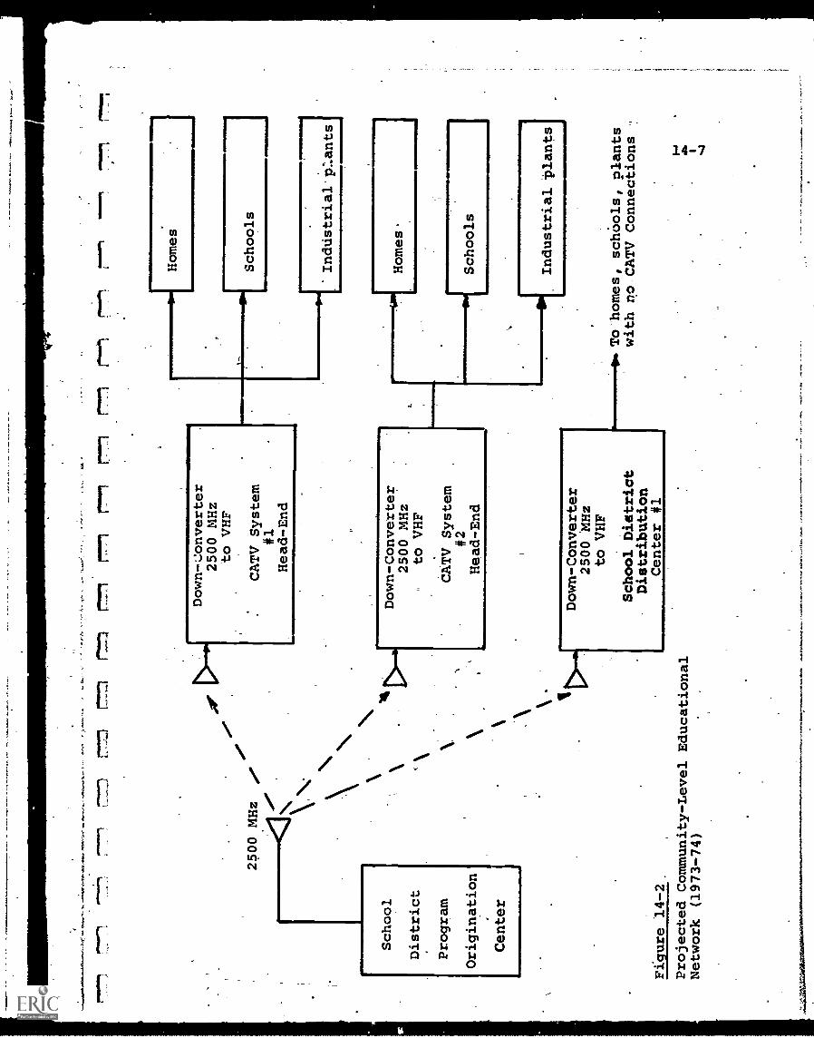
777
1.7n
r`1...--1
ran
or M
r 01
'riot
arm
"?s
wal
low
,
,e
2500 MHz
,e
School
District
Program
Origination
Center
ti
Figure 14-2,
Projected Community-Level Educational
Network (1973-74)
Down-Converter
2500 MHz
to VHF
CATV System
#1
Head-End
Homes
Down-Converter
2500 MHz
to VHF
CATV System
#2
Head-End
Schools
Down-Converter
2500 MHz
to VHF
School District
Distribution
Center #1
Industrial P:.ants
Homes.
Schools
Industrial
O. To homes, schOols, plants
with no CATV Connections
40°
14 -8
telecommunications plan. The "program origination center"
of Figure 14-2 would, in its simplest form, merely be a TV
broadcast studio, similar in capability to the CATV studiobut located at a more convenient site for the educationalcommunity. Its sole product would be educational or
instructional-TV programs, and only one-way communications
capability would be involved.
In its most sophisticated form, the program origination
center would become the telecenter of Figure 14-1, offering
a variety of interactive educational services. Since this
would require special user terminals and complex switching
and control circuitry in the CATV network, the full two-waysystem appears many years off.
As shown in Figure 14-2, communications from the school
district program center would be by ITFS broadcast to each
CATV system head-end within that district. Common-carrier
cable or microwave links, or privately-owned cable are
alternate possibilities, but in most cases ITFS would appear
to be a superior choice for two reasons:
(a) Only a small number of receiving points are involved.
(b) The ITFS signal could be beamed to antennas located
most favorably for reception.
At each CATV reception point, there would be a receiving
antenna and a "down-converter" which translates the 2500 MHz
ITFS frequency down to a standard TV channel so that a TV
receiver can acceptthe signal.
( The question of who would payfor'the cost of this antenna
and down-converter is undecided, but it is a relatively small
one-time capital expenditure. Other than that, the CATV system
operator incurs no operating and maintenance costs above those
which would normally be requiredfor his commercial subscriberactivities.
Since the CATV systems may not reach all target schools,
it may be necessary to supplement the CATV cable network with
r
4
14-9
school-owned distribution systems. Figure 14-2 shows one such
distribution center, which would be very similar to a CATVhead-end except that it would be equipped to receive c.ly the
ITFS broadcast, and distribute it to those users not part ofa CATV system. As many centers as necessary would be set upto provide 100% coverage.
The result would bea hybrid broadband telecommunicationsnetwork available for one-way educational transmission, andachieving eventually 100% coverage within a specific localizedarea.
For those communities which have operating CATV systems
already covering a major portion of the population, the incre-mental cost of a system such as shown in Figure 14-2 would be
relatively small. Of.more critical impact would be segmenting
the target audience, the.
library. If it is assumed that these tasks can be performed
satisfactorily, there is no technological reason why many
communities could not have an operational facility; such as
in Figure 14-2, by 1973-74. The availability of ITFS channelfrequencies(may be a problem, but it is likely that morewould be available with a plannedvientralized approach than
by individual educational institutions in the same geographical,
area competing for the same spectrum.
At a higher level of aggregation, it may be more efficient
to prepare, store and distribute program material from a.regional
center, embracing a number of school districts.. Such a
configuration is shown in Figure 14-3.
Because of the longer distances involved, it is probable
that low-power ITFS broadcasting would be inadequate in thiscase. Again, common-carrier microwave or cable links could be
used from the regional program center, but a more cost-effective
solution appears to be use of channels on a domestic communi-
cations satellite to relay the signals to local school districts.
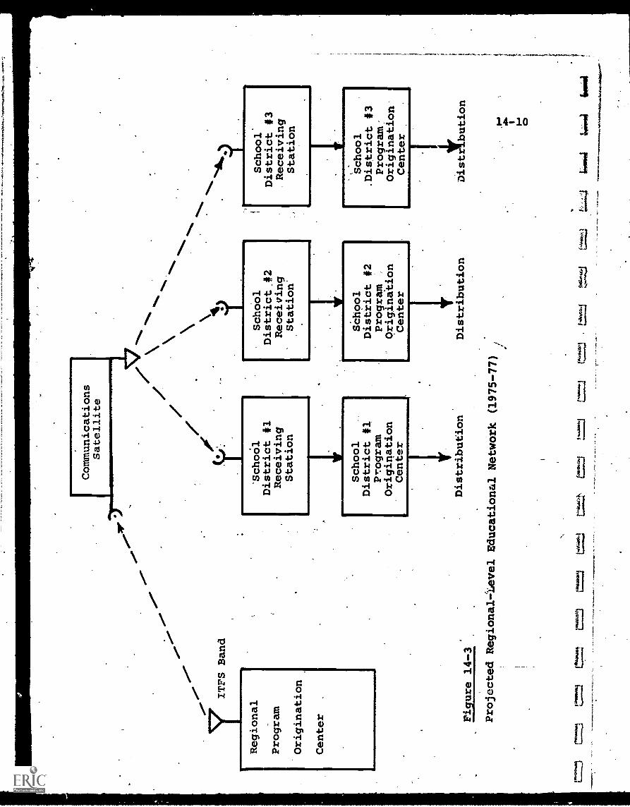
Communications
Satellite
ITFS Band
\it
Regional
`School
District #1
School
District
.#2
School*
District #3
Program
Receiving
Receiving
Receiving
Station
Station'
Station
Origination
Center Figure 14-3
Projected Regional=tevel Educational Network
(1975-77)
/
School
District 41
Program
Origination
Center
Distribution
School
District #2
Program
Origination
Center
=49
10=
14ttt-t!
!f1
41
School
.District #3
Program:
Origination
Center
Distribution
Distribution
c
(**...:=J
"f
6414
644
14-11
Since 2500 MHz is also reserved for educational use in satellite
communications, the -same frequency band can be used in thiscase as in Figure 14-2.
The regional program origination center would broadcast
the program material up to the satellite, from which it would
be retransmitted down to all school districts in that region.
Each school district receiving station would have a special
receiving antenna designed for use with the satellite. Fromthe reception point, the signal could-either be down-converted
to standard VHF/UHF TV frequencies, or rebroadcast at ITFS
frequencies over a local network as in Figure 14-2.
Implementation of such a regional network must await the
arrival of an operational domestic satellite, with 2500 MHz
educational channels and sufficient broadcast power to be
received by salativelineeiAMmit-levelrounundstations; The earliest estimate for this is about 1974-75,
assuming no further FCC delay in authorizing domestic satellites.
Consequently, the network of Figure 14-3 does not appear likelybefore 1975-77. It is possible, of course, that terrestrial
communications links might be used, but current costs are high
and not expected to decrease significantly.
A still higher aggregation level would be a national
educational telecommunications network, and a possible configur-
ation for this is illustrated in Figure 14-4.
Here, educational programs would originate from a national
center (or possibly one center for each time zone). The signals
would be broadcast, again at ITFS frequencies to any (or all) of
a variety of satellites. One would'be a regional relay,
distributing the signals to real centers, each similar toFigure 14-3. Another would distribute the programs to community_
or school-district receiving stations, and would require higher
transmitting power to reach the more widely dispersed, less
expensive ground stations. i
The most advanced satellite would be a "direct broadcast"
type with sufficient area coverage and radiated power to be
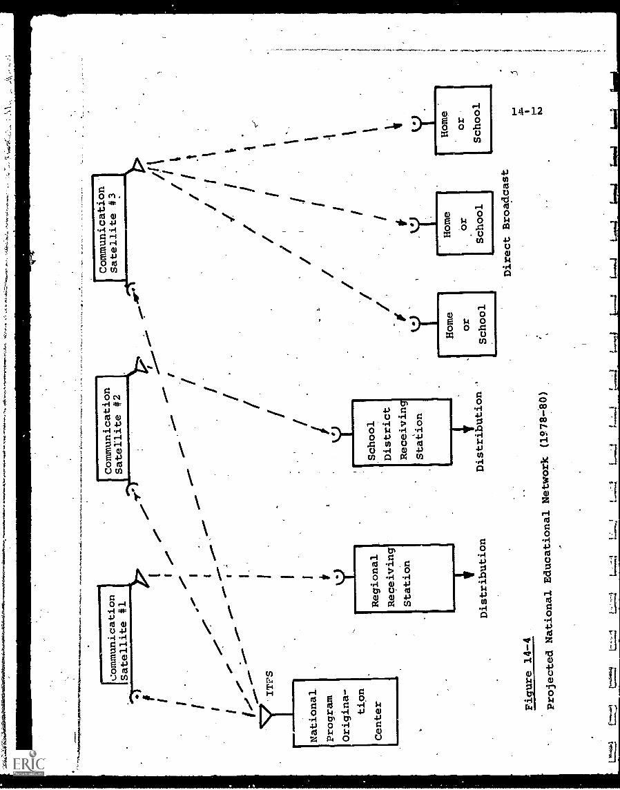
1=11
1=1,
I0.0"
I
E./ 1
.0.0'
.0"
77ITFS
National.
Program
Origina-
tion
Center
Regional
Receiving
Station
Communication
Satellite #2
4.f
'c-
C
School
District
Receiving
Station
Distribution
Distribution
Figure 14-4
Projected National
Educational Network
(1978-80)
,"
'
4
FCommunication
Satellite #3
//
I
Direct Broadcast
iL.,,T*4_
4.0,4
lama
11.1
I
14-13
received on home TV receivers, perhaps fitted with special
(but low-cost) directional receiving antennas. The achievementof such high power levels appears some 5-10 years away, so,that
this portion of the national network could not.be implementedbefore 1978-80.
The systems of Figures 14-2, 14-3-, and 14-4 would be both
evolutionary and mutually supportive. It appears reasonable
that the localized approach, being simpler and less costly,
would be tested thoroughly before proceeding to a higher
aggregation level. Software and program material could be
used at any level, if appropriate interface standards areestablished. .
14-3 Interactive Systems.
Figures 14-2, 14-3, and 14-4 have been shown as one-way
transmission networks, essentially broadcasting educational TVto an audience already equipped with standard TV receivers.
These are far from being the ultimate educational telecommuni-
cations facilities (possessing not even minimal flexibility)
but simply the easiest and most inexpensive to achieve, if 10096
coverage and TV-type instruction are the key considerations.
If interactive education is an objective, and this is
certainly mandatory for computer-based instruction or even
dial-access retrieval, then the user terminal can no longer be
a passive TV receiver and, further, the system must provide
two-way communications. These requirements substantially
increase the cost and complexity of any projected network.
Perhaps the largest total cost is the user terminal,,
since the quantities will be high. For this reason, such low-
cost devices as the Touch-tone telephone terminal have been
utilized, but this is an input device only, and severely
limited to a small number of alphanumeric code possibilities.
14-14
Similarly, the inadequacies of the Teletype terminal
have been noted, with the proposed Plato /V plasma display,
for example, considered as an alternative. Even this approach,
however, has the disadvantage that no computation capability
is available at the terminal.
With the marginal adequacy in communications links, the
software problem of large centralized computers, and the
drastic reduction in cost of small data processors such as
mini-computers, it appears logical to distribute some of the
total system computing and memory capacity at the users' location.
Consequently, a projected general-purpose, interactive,
user's terminal might be the configuration of Figure 14-5.
Here' a mini-computer with expandable modular memory is an
inherent part of the terminal
A digital tape cassette unit would also be included. The
interchangeable cassettes would contain software instructions
to the mini - computer, for any desired application, and also any
. local data-bank required by the user.
A display section would include the standard TV receiver,
but also the capability to act as an interactive CRT alpha-
numeric/graphical terminal. Queries, instructions and responses
would be entered in the keyboard.
The communications interface would be compatible with the
broadband cable input and with any narrow-band reverse com-
munications link which might be used.
It is estimated by terminal manufacturer's that the user's
terminal of Figure 14-5, if itandardized,and produced in high
volume (hundreds of thousands of units) could be sold at about
$1,500-2,000 with today's technology, and perhaps below $1,000
in. -five years. While this is not yet low-cost, it is certainly
competitive with currently used terminals without storage and,
computational capability.
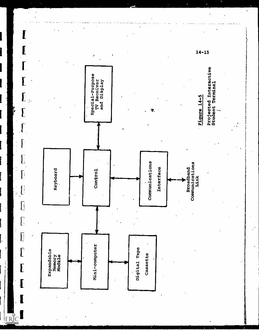
ma
woo
Pool
Expandable
Memory
Modile
Mini-computer
ir 1
1
Keyboard
1im
EN
1111
01,1
Digital Tape
Cassette
Control
Communications
Interface
Broadband
Communications
Link
!".1
rim
mt
Mug
Pool
Special-Purpose
TV Receiver
and Dibplay
Eigure
14-5
Projected Interactive
Student Terminal
Development of such a.low-cost, high-performance user'sterminal is one barrier to achieving full interactive capability.The other is the increased complexity of the distribution net-work.
Consider the system of Figure 14-2. If two-way transmissionis required,'the CATV cable network first must be capable of
accommodating bidirectional communications. This involvesone of the techniques described in Chapter 8.
Quite apart from this, however, is the problem of recognizingand controlling the messages from each user. If, for example,100 students each have terminals and send a request or responseto the computer at'the school district program origination
center, these messages must be "tagged" with the identification
eregt,oftlorecumulated in some programme4
leggensm, and transmitted to the program center. The responsesfrom the center must be handled in a similar manner.
In effect, the system becomes the equivalent of a point-
to-many-points switched-network, but even more complex than
a telephone network because broadband signals are transmitted,in at least one direction.
For any sizeable number of user terminals, a computer wouldbe required at the CATV head-end to keep track of and controlall communications. Hardware and software costs for this unit
might well approximate the costs of the program originationfacility itself.
The question of zesaonsibilitv would pose another problem,with the CATV system operators naturally reluctant to assumethis burden without adequate compensation. If the network
were owned completely by a school distiict or municipality, atleast this conflict might be obviated. Another solution is forthe educational institution automatically to accept this
responsibility, providing whatever equipment and manpower is
necessary to convert selected CATV channels to the desired two-way mode.
- TwaawsnIeWOt.
14-17
In thii Caie, lidvever, software becomes a huge burden,
since the necessary system 'and traffic control programs areadded to the task of generating instructional software, whichis formidable in itself.
For these reasons;. it is anticipated that the growth oftwo-way services may be slower than desired by the educationalcommunity. Particularly in relation to CATV systems, it is
probable that two-way services_for business and consumer use,which may generate more sizeable funding, will precede the
widespread educational applications.
14-4 Summary.
The projected systems touched upon in this chapter can
provide only a rudimentary and one-dimensional view of tele-
communications' future role in education. Even this limited
view is further in doubt since the vital question of which
techniques achieve the most desirable educational resultshas been side-stepped.
It is also obvious that many applications of educational
technology will be extremely localized, sometimes complementingand other times substituting for the broader-based, multi-mediasystems. The home video recorder is an example of this. Ifthe equipment and program costs can be made low enough, the
justification for a communications network may decrease and,in many%remote areas, may disappeai entirely.
Specialized,dedicated_local systems (such as an in-school
time-sharing computer) will also proliferate, since theirrelative inefficiencies may be outweighed in many cases by more
convenient and flexible control by the using facility.
In spite of these caveats, however, telecommunications has
the inherent capability of reaching larger audiences, at lowercost, with a wide variety of educational and instructionalMaterial. It represents the best, and perhaps the only, hope
14-18
hope of slowing and eventually reversing the educational cost-
performance spiral. As such, it warrants the full attention
of the educational community and is too vital to be delegated
to the telecommunications specialists.
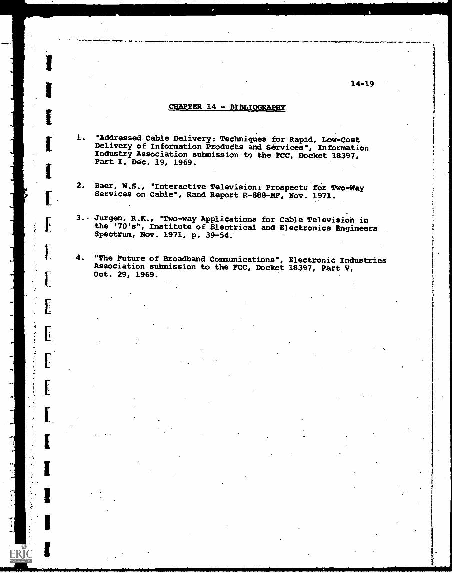
On%
1,
14-19
CHAPTER 14 - BIBLIOGRAPHY
1. "Addressed Cable Delivery: Techniques for Rapid, Low-CostDelivery of Information Products and Services", InformationIndustry Association submission to the FCC, Docket 18397,Part I, Dec. 19, 1969.
2. Baer, W.S., "Interactive Television: Prospects for TwoWayServices on Cable", Rand Report R-888-20, Nov. 1971.
3.- Jurgen, R.K., "Two-way Applications for Cable Televisioh inthe '70's", Institute of Electrical and Electronics EngineersSpectrum, Nov. 1971, p. 39-54.
4. "The Future of Broadband Communications", Electronic IndustriesAssociation submission to the FCC, Docket 18397, Part V,Oct. 29, 1969.
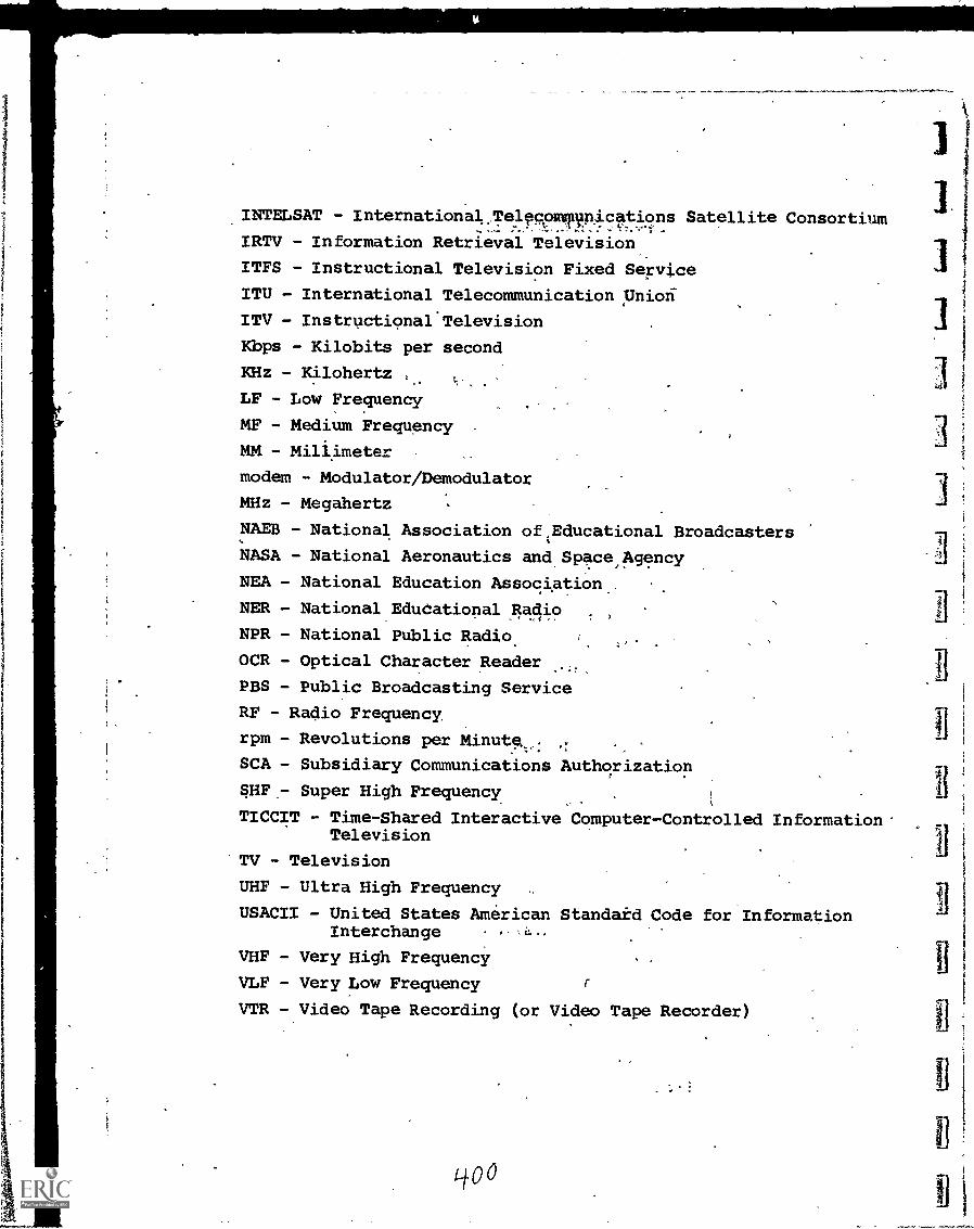
INTELSAT - Internationalle4compyRications Satellite Consortium
IRTV - Information Retrieval Television
ITFS - Instructional Television Fixed Service
ITU - International Telecommunication pniori
ITV - Instructional Television
Kbps - Kilobits per second
KHz - Kilohertz
LF - Low Frequency
MF - Medium Frequency
MM - Millimeter
modem - Modulator/Demodulator
MHz - Megahertz
NAM - National Association of ,Educational Broadcasters
NASA - National Aeronautics and Space,Agency
NEA - National Education Association
NER - National Educational Radio
NPR - National Public Radio.
OCR - Optical Character Reader
PBS - Public Broadcasting Service
RF - Radio Frequency,
rpm - Revolutions per Minute.,.,:
SCA - Subsidiary Communications Authorization
SHF - Super High Frequency
TICCIT - Time-Shared Interactive Computer-Controlled Information*Television
'TV - Television
UHF - Ultra High Frequency,
USACII - United States American Standaid Code for InformationInterchange
VHF - Very High Frequency
VLF - Very Low Frequency
VTR - Video Tape Recording (or Video Tape Recorder)
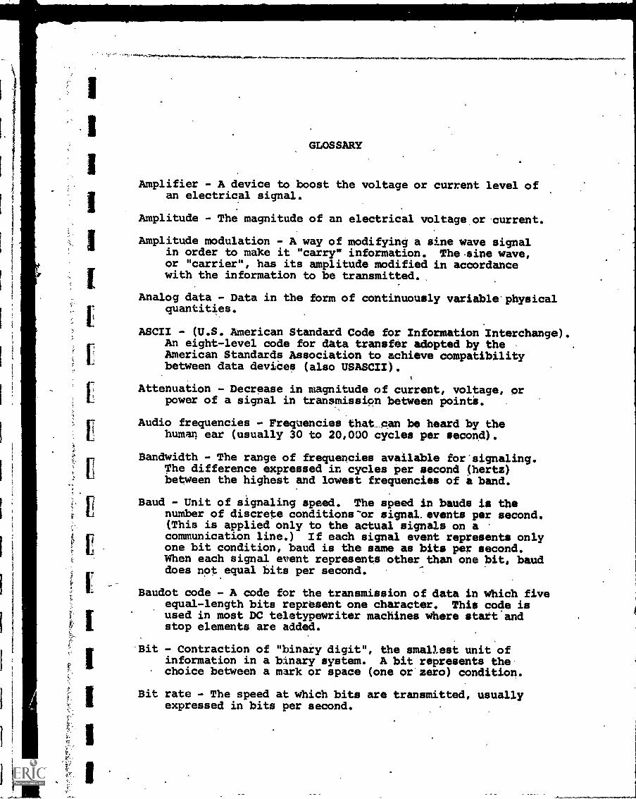
GLOSSARY
Amplifier - A device to boost the voltage or current level ofan electrical signal.
Amplitude - The magnitude of an electrical voltage or current.
Amplitude modulation - A way of modifying a sine wave signalin order to make it "carry" information. Thesine wave,or "carrier", has its amplitude modified in accordancewith the information to be transmitted.
Analog data - Data in the form of continuously variable' physicalquantities.
ASCII - (U.S. American Standard Code for Information Interchange).An eight-level code for data transfer adopted by theAmerican Standards Association to achieve compatibilitybetween data devices (also USASCII).
Attenuation - Decrease in magnitude of current, voltage, orpower of a signal in transmission between pointi.
Audio frequencies - Frequencies that can be heard by thehuman ear (usually 30 to 20,000 cycles per second).
Bandwidth - The range of frequencies available for signaling.The difference expressed in cycles per second (hertz)between the highest and lowest frequencies of a band.
Baud - Unit of signaling speed. The speed in bawls is thenumber of discrete conditions-or signal. events per second.(This is applied only to the actual signals on acommunication line.) If each signal event represents onlyone bit condition, baud is the same as bits per second.When each signal event represents other than one bit, bauddoes not equal bits per second.
Baudot code - A code for the transmission of data in which fiveequal-length bits represent one character. This code isused in most DC teletypewriter machines where start andstop elements are added.
Bit - Contraction of "binary digit", the smallest unit ofinformation in a binary system. A bit represents thechoice between a mark or space (one or zero) condition.
Bit rate - The speed at which bits are transmitted, usuallyexpressed in bits per second.
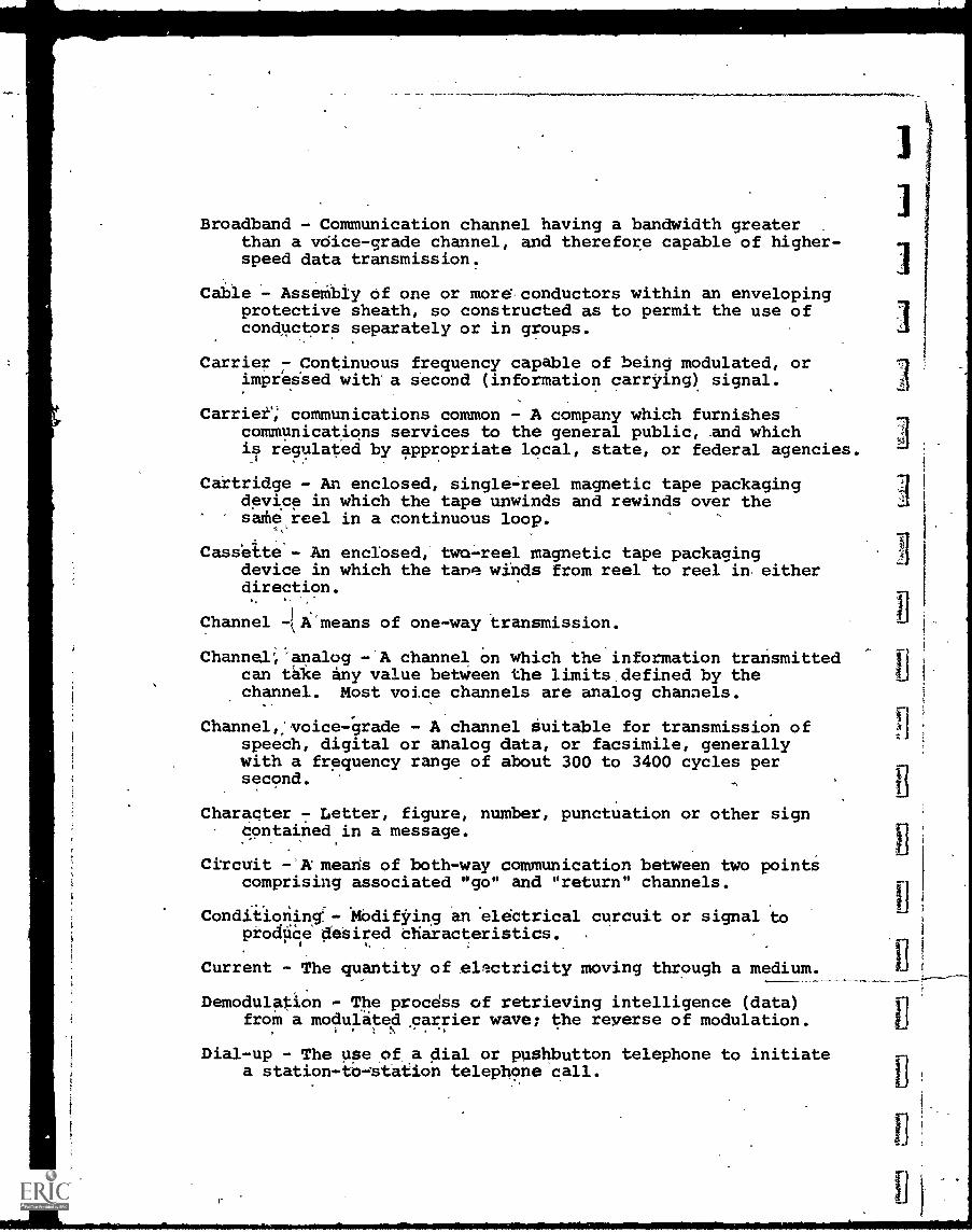
Broadband - Communication channel having a bandwidth greaterthan a voice-grade channel, and therefore capable of higher-speed data transmission.
Cable - Assembly of one or more conductors within an envelopingprotective sheath, so constructed as to permit the use ofconductors separately or in groups.
Carrier - Continuous frequency capable of being modulated, orimpressed with a second (information carrying) signal.
Carrier"; communications common - A company which furnishescommunications services to the general public, and whichis regulated by appropriate local, state, or federal agencies.
Cartridge - An enclosed, single-reel magnetic tape packagingdevice in which the tape unwinds and rewinds over thesathe reel in a continuous loop.
4 .
Cassette - An enclosed, two-reel magnetic tape packagingdevice in which the tans winds from reel to reel in eitherdirection.
Channel -['means of one-way transmission.
Channel,' analog -'A channel on which the information transmittedcan take any value between the limits,defined by thechannel. Most voice channels are analog channels.
Channel,, voice-grade - A channel suitable for transmission ofspeech, digital or analog data, or facsimile, generallywith a frequency range of about 300 to 3400 cycles persecond.
Character - Letter, figure, number, punctuation or other signContained in a message.
Circuit -`A means of both-way communication between two pointscomprising associated "go" and "return" channels.
Conditioning:- Modifying an eldctrical curcuit or signal toprodUCe desired bharacteristics.
Current - The quantity of electricity moving through a medium.
Demodulation - The procdss of retrieving intelligence (data)froM a modulated carrier wave; the reverse of modulation.
Dial-up - The use of a dial or pushbutton telephone to initiatea station -to- station telephone call.
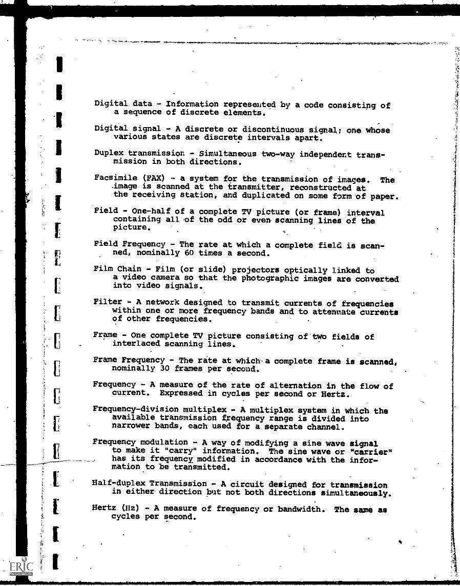
Digital data - Information represented by a code consisting ofa sequence of discrete elements.
Digital signal - A discrete or discontinuous signal; one whosevarious states are discrete intervals apart.
Duplex transmission - Simultaneous two-way independent trans-mission in both directions.
Facsimile (FAX) - a system for the transmission of images. Theimage is scanned at the transmitter, reconstructed atthe receiving station, and duplicated on some form of paper.
Field - One-half of a complete TV picture (or frame) intervalcontaining all of the odd or even scanning lines of thepicture.
Field Frequency - The rate at which a complete field is scan-ned, nominally 60 times a second.
Film Chain - Film (or slide) projectors optically linked toa video camera so that the photographic images are convertedinto video signals.
Filter - A network designed to transmit currents of frequencieswithin one or more frequency bands and to attenuate currentsof other frequencies.
Frame - One complete TV picture consisting of two fields ofinterlaced scanning lines.
Frame Frequency - The rate at which-a complete frame is scanned,nominally 30 frames per second.
Frequency - A measure of the rate of alternation in the flow ofcurrent. Expressed in cycles per second or Hertz.
Frequency-division multiplex - A multiplex system in which theavailable transmission frequency range is divided intonarrower bands, each used for a separate channel.
Frequency modulation - A way of modifying a sine wave signalto make it "carry" information. The sine wave or "carrier"has its frequency modified in accordance with the infor-mation to be transmitted.
Half-duplex Transmission - A circuit designed for transmissionin either direction but not both directions simultaneously.
Hertz (Hz) - A measure of frequency or bandwidth. The same ascycles per second.
(pi
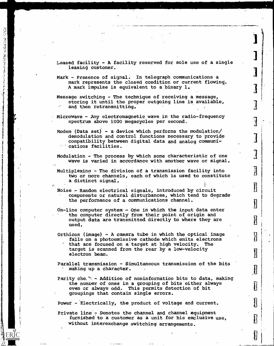
Leased facility - A facility reserved for sole use of a singleleasing customer.
Mark - Presence of signal. In telegraph communications amark represents the closed condition or current flowing.A mark impulse is equivalent to a binary 1.
Message switching - The technique of receiving a message,storing it until the proper outgoing line is available,and then retransmitting.
Microwave - Any electromagnetic wave in the radio-frequencyspectrum above 1000 megacycles per second.
Modem (Data set) - a device which performs the modulation/demodulation and control functions necessary to providecompatibility between digital data and analog communi-cations facilities.
Modulation - The process by which some characteristic of onewave is varied in accordance with another wave or signal.
Multiplexing - The division of a transmission facility intotwo or more channels, each of which is used to constitutea distinct signal.
Noise - Random electrical signals, introduced by circuitcomponents or natural disturbances, which tend to degradethe performance of a communications channel.
On-line computer system - One in which the input data enterthe computer directly from their point of origin andoutput data are transmitted directly to where they areused.
Orthicon (image) - A camera tube in which the optical imagefalls on a photoemissive cathode which emits electronsthat are focused on a target at high velocity. Thetarget is scanned from the rear by a low-velocityelectron beam.
Parallel transmission - Simultaneous transmission of the bitsmaking up a character.
Parity che.1-. - Addition of noninformation bits to data, makingthe number of ones in a grouping of bits either alwayseven or always. odd. This permits detection of bitgroupings that contain single errors.
Power -.Electrically, the product of voltage and current.
Private line'7 Denotes the channel and channel equipmentfurnished to a customer as a unit for his exclusive use,without interexchange switching arrangements.
Real time - A real-time computer system may be defined as onethat controls an environment by receiving data, 'processingthem, and returning the results sufficiently quickly toaffect the functioning of.the environment at that time.
Resistance -voltage
Resolution -
In electrical terms, a measure of how muchis necessary to force current through a medium.
The amount of resolvable detail in a picture.
Scanning - The process of breaking down an image into a seriesof elements or-groups of elements representing lightvalues and transmitting this information in time sequence.
Serial transmission - A system wherein the bits of a characteroccur serially in time. Implies only a single trans-mission channel.
Simplex transmission - A circuit permitting transmission inone specific direction only.
Space - An -impulse which causes current to flow in a directionopposite to that for a mark impulse. A space impulse isequivalent to a binary 0.
Spectrum - A continuous range of frequencies, usually wide inextent, within which waves have some specific commoncharacteristic.
Teletype - Trademark of Teletype Corporation, usually referringto a series of different types of teleprinter equipmentutilized for communications systems.
Telex service - A dial-up telegraph service enabling its sub-scribers to communicate directly among themselves by meansof circuits of the public telegraph network.
Terminal - Any device capable of sending and/or receiving infor-mation over a communication channel.
Time-division multiplex - A system in which a number of distinctsignals are connected intermittently to a common channel.
Touch-tone - AT&T term for pushbutton dialing.
Video - The bandwidth and spectrum position of the signalwhich results from' television scanning and which is usedto reproduce a picture.
Video Band*- The frequency band utilized tc transmit a com-posite video signal.
Voice-frequency - Any frequency within that part of the audio-frequency range essential for the transmission of speechof commercical quality, i.e., 300-3400 Hz.
Voltage - The electrical equivalent of pressure or forceavailable to move current through a conducting medium.
Word - In computing, a seqUence of bits or characters treatedas a unit and capable of being stored in one computerlocation.