Embed Size (px)
Citation preview
Sam Brown
Editor
Getting the Most Out of Your Abrasive Tools13th ed 1939
Forty pages packed with details about using the belt sander, the disk sander, the grinder, the buffing head, with many other details -- over 220 photographs and line-drawings -- organized in 12 chapters and an appendix. Grinding twist drills, using cuttoff-wheels, and just sharpening tools makes this manual almost as useful today as in 1939.
I admit that I'm puzzled about the “13th edition”. My inclination is to think of “13th edition” as 13th printing. By edition, publishers usually mean “editorial changes and revisions”. Instead, I think Delta simply means that this is the 13th “printing”.Regardless, whether as the 13th edition or 13th reprinting, this number is indicative of how popular this manual on abrasive tools turned out to be.
Finally, please forgive me for the lack of uniformity in the document's pages. Verythoughtfully, a website reader pointed out the document's discrepancy: it had several missing pages. Since I was occupied with another area of woodworking history at the time, I simply did a “quick-and-dirty” fix; that is, I scanned in the missing pages, but did not worry about variations in coloriation.
Book No. 4531 250
OUTING THE MOST OUT OF YOUR ABRASIVE
TOOLS • THE BELT SANDER • THE DISK SANDER • THE GRINDER • THE BUFFING HEAD
Published by DELTIV
Book No. 4531250
fr
CE1TINC THE MOSTOUT OF YOURABRASIVE
TOOLS• THE BELT SANDER• THE DISK SANDER• THE GRINDER• THE BUFFING HEAD
Published byDELTA/
ELTMIL A EE
GETTING THE MOST OUT OF YOUR
ABRASIVE TOOLS
THIRTEENTH EDITION
A DELTA-CRAFT PUBLICATION
Edited by
SAM BROWN
A Complete Manual Covering the Use of Abrasive
Tools in the Home Workshop, Illustrated with
Over Two Hundred Photographs and Line Drawings.
DELTA POWER TOOL DIVISION
ROCICM CI I MANUFACTURING COMPANY MILWAUKEE 1, WISCONSIN
Printed in U. S. A.
Form AB-9395-9-50
Copyright The Delta Manufacturing Co., 1939
DELTA POWER TOOL DIVISION
MANUFACTURING COMPANYMILWAUKEE 1, WISCONSIN
GETTING THE MOSTOUT OF YOUR
ABRASIVE TOOLSTHIRTEENTH EDITION
A DELTA-CRAFT PUBLICATION
Edited by
SAM BROWN
A Complete Manual Covering the Use of Abrasive
Tools in the Home Workshop, Illustrated with
Over Two Hundred Photographs and Line Drawings.
Printed in U. S. A.
Form AB-9395-9-50
Copyright The Delta Manufacturing Co., 1939
MAIN CONTENTS
GETTING THE MOST OUT OF YOUR ABRASIVE TOOLS CHAPTER ONE-ABRASIVE TOOLS
The Grinder—The Buffing Head—The Belt Sander—The Disk Sander—Sanding and Grinding Attachments—Mounting Sanding Disks—Fitting Abrasive Sleeves—Sane 4-6 ing Belts—Mounting Grinding Wheels
CHAPTER TWO-ABRASIVES Natural Abrasives—Artificial Abrasives—Grain Size—Grinding Wheels—Coated Abra• sives—Grinding Wheel Selection—Special Types of Abrasives 7-8
CHAPTER THREE-OPERATING THE BELT SANDER Surfacing—End Work—Sanding Inside Curves—Short Work—Use of Sanding Table— 9-12 Inside Corners—Circle Jigs—Tilting Fence—Pivoted Arm—Beveling Jig—Use of Forms
CHAPTER FOUR-OPERATING THE DISK SANDER Freehand Sanding—Pivot Jigs—Rounding Corners—Pointing Dowels—Use of Miter Gage—Grinding Metal—Large Work—Sanding with Pattern—Sanding to Width—Use 13-15 of Double Disk—Sanding Long Edges—Selection of Abrasive
CHAPTER FIVE-GENERAL GRINDING Safety Suggestions—Odd Jobs—Position of Tool Rest—Use of Guides 16
CHAPTER SIX-HOW TO SHARPEN TOOLS General—Wood Chisels—Honing—Plane Irons—Wood Turning Tools—The Skew Chisel —The Parting Tool—The Gouge—Lathe To& Bits—Circular Saws—Mortising Chisels 17-22 —Grinding Jointer Knives—Setting Jointer Knives—Grinding Knives in Head
CHAPTER SEVEN-GRINDING SHAPER CUTTERS Rake Angle—Amount of Bevel—Projected Shape—Making a Knife—Use of Shaped 23-24 Wheels—Honing Knives
CHAPTER EIGHT-GRINDING TWIST DRILLS Point Angle—Lip Clearance—Drill Grinding—Web Thinning—Drill for Brass—Special 25-27 Grinding—Wheels for Drill Grinding
CHAPTER NINE-BUFFING AND POLISHING Polishing—Polishing Wheels—Setting Up—Concerning Glue—How to Polish—Buffing 28-30 —Strapping Belts—Buffing Compounds
CHAPTER TEN-HOW TO USE SANDING DRUMS Sanding Drums—Sanding on Lathe—Narrow-Face Drums—Sanding on Drill Press- 31-32 Pattern Sanding
CHAPTER ELEVEN-HOW TO USE CUT-OFF WHEELS General Use—Cutting Tubing—Cutting Solid Stock—Cutting-off on Grinder—Diamond Blades—Cutting-off on Lathe 33-34
CHAPTER TWELVE-MISCELLANEOUS ABRADING OPERATIONS Tumbling—Spun Finish—Grinding Glass—Engine Finish — Internal Grinding — Other Lathe Operations—Grinding Keyways—Surface Grinding—Grinding on Shaper—Sand- ing on Band Saw—Sanding on Lathe 35-38
APPENDIX Abrasives and Abrasive Terms—Coated Abrasive Selection—Comparative Grain Sizes —Grinding Wheel Selection—Wheel Speeds—Belt and Drum Speeds—Grinding Wheel Speeds in R. P. M. 39-40
OTHER BOOKS IN THIS SERIES: Each .250 Postpaid
• GETTING THE MOST OUT OF YOUR LATHE • GETTING THE MOST OUT OF YOUR SHAPER • GETTING THE MOST OUT OF YOUR DRILL PRESS • GETTING THE MOST OUT OF YOUR CIRCULAR SAW AND JOINTER • GETTING THE MOST OUT OF YOUR BAND SAW AND SCROLL SAW
[2]
OTHER BOOKS IN THIS SERIES: Each .250 Postpaid
• GETTING THE MOST OUT OF YOUR LATHE• GETTING THE MOST OUT OF YOUR SHAPER• GETTING THE MOST OUT OF YOUR DRILL PRESS• GETTING THE MOST OUT OF YOUR CIRCULAR SAW AND JOINTER• GETTING THE MOST OUT OF YOUR BAND SAW AND SCROLL SAW
MAIN CONTENTS
GETTING THE MOST OUT OFYOUR ABRASIVE TOOLS
Safety Suggestions—Odd Jobs—Position of Tool Rest—Use of Guides 16
CHAPTER SIX-HOW TO SHARPEN TOOLSGeneral—Wood Chisels—Honing—Plane Irons—Wood Turning Tools—The Skew Chisel—The Parting Tool—The Gouge—Lathe To& Bits—Circular Saws—Mortising Chisels 17-22—Grinding Jointer Knives—Setting Jointer Knives—Grinding Knives in Head
CHAPTER SEVEN-GRINDING SHAPER CUTTERSRake Angle—Amount of Bevel—Projected Shape—Making a Knife—Use of Shaped 23-24Wheels—Honing Knives
CHAPTER EIGHT-GRINDING TWIST DRILLSPoint Angle—Lip Clearance—Drill Grinding—Web Thinning—Drill for Brass—Special 25-27Grinding—Wheels for Drill Grinding
CHAPTER NINE-BUFFING AND POLISHINGPolishing—Polishing Wheels—Setting Up—Concerning Glue—How to Polish—Buffing 28-30—Strapping Belts—Buffing Compounds
CHAPTER TEN-HOW TO USE SANDING DRUMSSanding Drums—Sanding on Lathe—Narrow-Face Drums—Sanding on Drill Press— 31-32Pattern Sanding
CHAPTER ELEVEN-HOW TO USE CUT-OFF WHEELSGeneral Use—Cutting Tubing—Cutting Solid Stock—Cutting-off on Grinder—DiamondBlades—Cutting-off on Lathe 33-34
CHAPTER TWELVE-MISCELLANEOUS ABRADING OPERATIONSTumbling—Spun Finish—Grinding Glass—Engine Finish — Internal Grinding — OtherLathe Operations—Grinding Keyways—Surface Grinding—Grinding on Shaper—Sand-ing on Band Saw—Sanding on Lathe 35-38
APPENDIXAbrasives and Abrasive Terms—Coated Abrasive Selection—Comparative Grain Sizes—Grinding Wheel Selection—Wheel Speeds—Belt and Drum Speeds—Grinding WheelSpeeds in R. P. M. 39-40
[2]
CHAPTER ONE-ABRASIVE TOOLSThe Grinder—The Buffing Head—The Belt Sander—The Disk Sander—Sanding andGrinding Attachments—Mounting Sanding Disks—Fitting Abrasive Sleeves—Sane 4-6ing Belts—Mounting Grinding Wheels
CHAPTER TWO-ABRASIVESNatural Abrasives—Artificial Abrasives—Grain Size—Grinding Wheels—Coated Abra•sives—Grinding Wheel Selection—Special Types of Abrasives 7-8
CHAPTER THREE-OPERATING THE BELT SANDERSurfacing—End Work—Sanding Inside Curves—Short Work—Use of Sanding Table— 9-12Inside Corners—Circle Jigs—Tilting Fence—Pivoted Arm—Beveling Jig—Use of Forms
CHAPTER FOUR-OPERATING THE DISK SANDERFreehand Sanding—Pivot Jigs—Rounding Corners—Pointing Dowels—Use of MiterGage—Grinding Metal—Large Work—Sanding with Pattern—Sanding to Width—Use 13-15of Double Disk—Sanding Long Edges—Selection of Abrasive
CHAPTER FIVE-GENERAL GRINDING
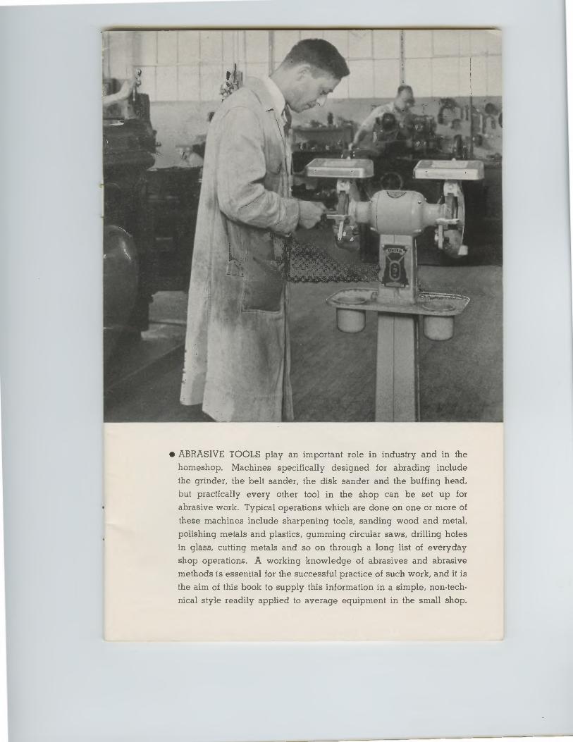
• ABRASIVE TOOLS play an important role in industry and in the homeshop. Machines specifically designed for abrading include
the grinder, the belt sander, the disk sander and the buffing head,
but practically every other tool in the shop can be set up for
abrasive work. Typical operations which are done on one or more of these machines include sharpening tools, sanding wood and metal,
polishing metals and plastics, gumming circular saws, drilling holes
in glass, cutting metals and so on through a long list of everyday
shop operations. A working knowledge of abrasives and abrasive methods is essential for the successful practice of such work, and it is
the aim of this book to supply this information in a simple, non-tech-
nical style readily applied to average equipment in the small shop.
• ABRASIVE TOOLS play an important role in industry and in the
homeshop. Machines specifically designed for abrading include
the grinder, the belt sander, the disk sander and the buffing head,
but practically every other tool in the shop can be set up for
abrasive work. Typical operations which are done on one or more of
these machines include sharpening tools, sanding wood and metal,
polishing metals and plastics, gumming circular saws, drilling holes
in glass, cutting metals and so on through a long list of everyday
shop operations. A working knowledge of abrasives and abrasive
methods is essential for the successful practice of such work, and it is
the aim of this book to supply this information in a simple, non-tech-
nical style readily applied to average equipment in the small shop.
TRACKING ADJUSTMENT
BELT TENSIONER
_T ILT SCALE
PULLEY & BELT
DUST GUARD DEFLECTOR
SPINDLE
LIGHT-DUTY BENCH GRINDER
G U ND 1/2 H,P, MOTOR
BELT SANDER
ABRASIVE DISK CEMENTED TO PLATE
T1 LT IN G TABLE
TILT AOJUSTME
MOTOR-DRIVE DISK SANDER
,MITER GAGE
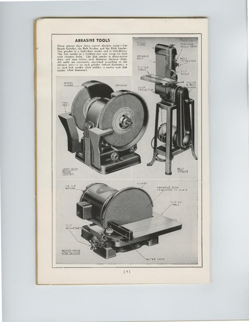
ABRASIVE TOOLS These photos show three typical abrasive tools—The Bench Grinder, the Belt Sander, and the Disk Sander. The grinder is a light-duty model and is belt-driven. The belt sander is a medium-size unit using six inch wide abrasive belts. The disk sander is direct-motor drive and uses twelve inch diameter abrasive disks. All units are commonly described according to the abrasive area—a six inch grinder (wheel diameter), a six inch belt sander (belt width), a twelve inch disk sander (disk diameter).
PULLEY GUARD
ABRASIVE BELT
TILTING TABLE
WHEEL •7:/ARD _
141
W1-4 EELGUARD
PULLEY& BELTGUARD
ABRASIVE TOOLSThese photos show three typical abrasive tools—TheBench Grinder, the Belt Sander, and the Disk Sander.The grinder is a light-duty model and is belt-driven.The belt sander is a medium-size unit using six inchwide abrasive belts. The disk sander is direct-motordrive and uses twelve inch diameter abrasive disks.All units are commonly described according to theabrasive area—a six inch grinder (wheel diameter), asix inch belt sander (belt width), a twelve inch disksander (disk diameter).
ABRASIVEBELT
PULLEYGUARD 4111ftimig, TRACKING
ADJUSTMENT
TILTINGTABLE
BELTSANDER
ABRASIVE DISKCEMENTED TO PLATE
TI LT IN GTABLE
G U ND
1•1
TILTADJUSTME
MOTOR-DRIVE DISK SANDER
\M IT ER GAGE
BELTTENSIONER
_TILTSCALE
141
CHAPTER ONE
ABRASIVE TOOLS
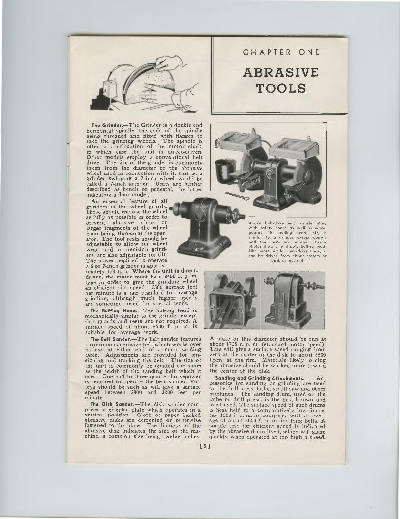
The Grinder.—The Grinder is a double end horizontal spindle, the ends of the spindle being threaded and fitted with flanges to take the grinding wheels. The spindle is of ten a continuation of the motor shaft, in which case the unit is direct-driven. Other models employ a conventional belt drive. The size of the grinder is commonly taken from the diameter of the abrasive wheel used in connection with it, that is, a grinder swinging a 7-inch wheel would be called a 7-inch grinder. Units are further described as bench or pedestal, the latter indicating a floor model.
An essential feature of all grinders is the wheel guards. these should enclose the wheel as fully as possible in order to prevent abrasive chips or larger fragments of the wheel from being thrown at the oper-ator. The tool rests should be adjustable to allow for wheel wear, and in precision grind-ers, are also adjustable for tilt. The power required to operate a 6 or 7-inch grinder is approx- imately 1/3 h. p. Where the unit is direct-driven, the motor must be a 3400 r. p. in. type in order to give the grinding wheel an efficient rim speed. 5500 surface feet per minute is a fair standard for average grinding, although much higher speeds are sometimes used for special work.
The Buffing Head.—The buffing head is mechanically similar to the grinder except that guards and rests are not required. A surface speed of about 6500 f. p. m. is suitable for average work.
The Belt Sander.—The belt sander features a continuous abrasive belt which works over pulleys at either end of a main sanding table. Adjustments are provided for ten-sioning and tracking the belt. The size of the unit is commonly designated the same as the width of the sanding belt which it uses. One-half to three-quarter horsepower is required to operate the belt sander. Pul-leys should be such as will give a surface speed between 2800 and 3200 feet per minute.
The Disk Sander.—The disk sander com-prises a circular plate which operates in a vertical position. Cloth or paper backed abrasive disks are cemented or otherwise fastened to the plate. The diameter of the abrasive disk indicates the size of the ma-chine, a common size being twelve inches.
A plate of this diameter should be run at about 1725 r. p. m. (standard motor speed). This will give a surface speed ranging from zero at the center of the disk to about 5500 f.p.m. at the rim. Materials likely to clog the abrasive should be worked more toward the center of the disk.
Sanding and Grinding Attachments. — Ac-cessories for sanding or grinding are used on the drill press, lathe, scroll saw and other machines. The sanding drum, used on the lathe or drill press, is the best known and most used. The surface speed of such drums is best held to a comparatively low figure. say 1200 f p. m. as compared with an aver-age of about 3000 f. p. m. for long belts. A simple test for efficient speed is indicated by the abrasive drum itself, which will glaze quickly when operated at too high a speed.
Above, belt-drive bench grinder fitted with safety hoods as well as wheel guards. The buffing head, left, is similar to a grinder except guards and tool rests are omitted. Lower photos show a light-duty buffing head. Like most similar belt-drive units, it can be driven from either bottom or
back as desired.
[51
CHAPTER ONE
ABRASIVETOOLS
The Grinder.—The Grinder is a double endhorizontal spindle, the ends of the spindlebeing threaded and fitted with flanges totake the grinding wheels. The spindle isof ten a continuation of the motor shaft,in which case the unit is direct-driven.Other models employ a conventional beltdrive. The size of the grinder is commonlytaken from the diameter of the abrasivewheel used in connection with it, that is, agrinder swinging a 7-inch wheel would becalled a 7-inch grinder. Units are furtherdescribed as bench or pedestal, the latterindicating a floor model.
An essential feature of allgrinders is the wheel guards.these should enclose the wheelas fully as possible in order toprevent abrasive chips orlarger fragments of the wheelfrom being thrown at the oper-ator. The tool rests should beadjustable to allow for wheelwear, and in precision grind-ers, are also adjustable for tilt.The power required to operatea 6 or 7-inch grinder is approx-imately 1/3 h. p. Where the unit is direct-driven, the motor must be a 3400 r. p. tn.type in order to give the grinding wheelan efficient rim speed. 5500 surface feetper minute is a fair standard for averagegrinding, although much higher speedsare sometimes used for special work.
The Buffing Head.—The buffing head ismechanically similar to the grinder exceptthat guards and rests are not required. Asurface speed of about 6500 f. p. m. issuitable for average work.
The Belt Sander.—The belt sander featuresa continuous abrasive belt which works overpulleys at either end of a main sandingtable. Adjustments are provided for ten-sioning and tracking the belt. The size ofthe unit is commonly designated the sameas the width of the sanding belt which ituses. One-half to three-quarter horsepoweris required to operate the belt sander. Pul-leys should be such as will give a surfacespeed between 2800 and 3200 feet perminute.
The Disk Sander.—The disk sander com-prises a circular plate which operates in avertical position. Cloth or paper backedabrasive disks are cemented or otherwisefastened to the plate. The diameter of theabrasive disk indicates the size of the ma-chine, a common size being twelve inches.
A plate of this diameter should be run atabout 1725 r. p. m. (standard motor speed).This will give a surface speed ranging fromzero at the center of the disk to about 5500f.p.m. at the rim. Materials likely to clogthe abrasive should be worked more towardthe center of the disk.
Sanding and Grinding Attachments. — Ac-cessories for sanding or grinding are usedon the drill press, lathe, scroll saw and othermachines. The sanding drum, used on thelathe or drill press, is the best known andmost used. The surface speed of such drumsis best held to a comparatively low figure.say 1200 f p. m. as compared with an aver-age of about 3000 f. p. m. for long belts. Asimple test for efficient speed is indicatedby the abrasive drum itself, which will glazequickly when operated at too high a speed.
Above, belt-drive bench grinder fittedwith safety hoods as well as wheelguards. The buffing head, left, is
similar to a grinder except guardsand tool rests are omitted. Lowerphotos show a light-duty buffing head.Like most similar belt-drive units, itcan be driven from either bottom or
back as desired.
[ 5 1
BLOTTER BIOME FLANGE
SPINDLE 11
0
ABRASIVE SLEEVE
,..„___.,c0Ro,,47.
DIST IC
RUBBER
INTERLOCK
SPINDLE NUT
CUTAWAY VIEW OF SANDING DRUM
STICK
• GRINDING WNEEL
PATCN1
BELT SPLICES
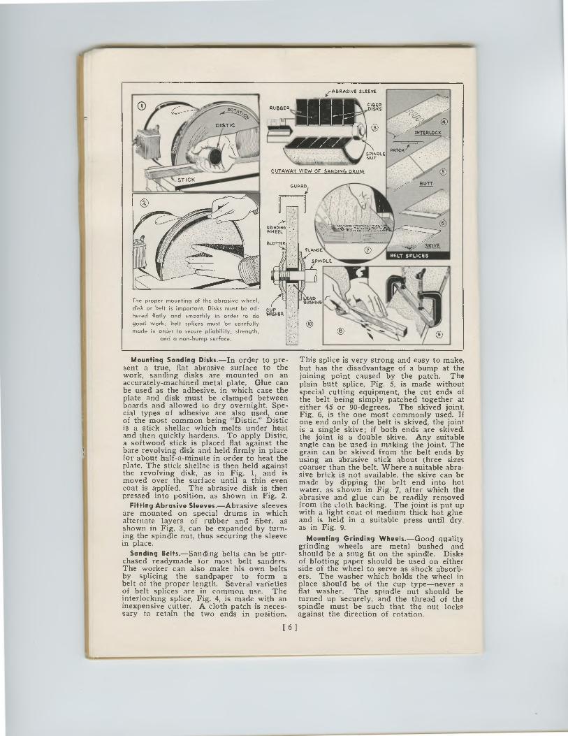
The proper mounting of the abrasive wheel,
disk or belt is important. Disks must be ad-
hered flatly and smoothly in order to do
good work; belt splices must be carefully
made in order to secure pliability, strength,
and a non-bump surface.
CUP WASHER
0
This splice is very strong and easy to make, but has the disadvantage of a bump at the joining point caused by the patch. The plain butt splice, Fig. 5, is made without special cutting equipment, the cut ends of the belt being simply patched together at either 45 or 90-degrees. The skived joint. Fig. 6, is the one most commonly used. If one end only of the belt is skived, the joint is a single skive; if both ends are skived the joint is a double skive. Any suitable angle can be used in making the joint. The grain can be skived from the belt ends by using an abrasive stick about three sizes coarser than the belt. Where a suitable abra-sive brick is not available, the skive can be made by dipping the belt end into hot water, as shown in Fig. 7, after which the abrasive and glue can be readily removed from the cloth backing. The joint is put up with a light coat of medium thick hot glue and is held in a suitable press until dry. as in Fig. 9.
Mounting Grinding Wheels.—Good quality grinding wheels are metal bushed and should be a snug fit on the spindle. Disks of blotting paper should be used on either side of the wheel to serve as shock absorb-ers. The washer which holds the wheel in place should be of the cup type—never a flat washer. The spindle nut should be turned up securely, and the thread of the spindle must be such that the nut locks against the direction of rotation.
Mounting Sanding Disks.—In order to pre-sent a true, flat abrasive surface to the work, sanding disks are mounted on an accurately-machined metal plate. Glue can be used as the adhesive, in which case the plate and disk must be clamped between boards and allowed to dry overnight. Spe-cial types of adhesive are also used, one of the most common being "Distic." Distic is a stick shellac which melts under heat and then quickly hardens. To apply Distic, a softwood stick is placed flat against the bare revolving disk and held firmly in place for about half-a-minute in order to heat the plate. The stick shellac is then held against the revolving disk, as in Fig. 1, and is moved over the surface until a thin even coat is applied. The abrasive disk is then pressed into position, as shown in Fig. 2.
Fitting Abrasive Sleeves.—Abrasive sleeves are mounted on special drums in which alternate layers of rubber and fiber, as shown in Fig. 3, can be expanded by turn-ing the spindle nut, thus securing the sleeve in place.
Sanding Belts.—Sanding belts can be pur-chased readymade for most belt sanders. The worker can also make his own belts by splicing the sandpaper to form a belt of the proper length. Several varieties of belt splices are in common use. The interlocking splice, Fig. 4, is made with an inexpensive cutter. A cloth patch is neces-sary to retain the two ends in position.
[ 6 ]
BLOTTER SKIVE
BELT SPLICESFLANGE
SPINDLE
k
ABRASIVE SLEEVE
INTERLOCK
SPINDLENUT
CUTAWAY VIEW OF SANDING DRUM
PATCF1 1
.§.1.122
GRINDING -WHEEL
The proper mounting of the abrasive wheel,
disk or belt is important. Disks must be ad-
hered flatly and smoothly in order to do
good work; belt splices must be carefully
made in order to secure pliability, strength,
and a non-bump surface.
CUPWASHER
LEAD /—BUSHING
0
Mounting Sanding Disks.—In order to pre-sent a true, flat abrasive surface to thework, sanding disks are mounted on anaccurately-machined metal plate. Glue canbe used as the adhesive, in which case theplate and disk must be clamped betweenboards and allowed to dry overnight. Spe-cial types of adhesive are also used, oneof the most common being "Distic." Disticis a stick shellac which melts under heatand then quickly hardens. To apply Distic,a softwood stick is placed flat against thebare revolving disk and held firmly in placefor about half-a-minute in order to heat theplate. The stick shellac is then held againstthe revolving disk, as in Fig. 1, and ismoved over the surface until a thin evencoat is applied. The abrasive disk is thenpressed into position, as shown in Fig. 2.
Fitting Abrasive Sleeves.—Abrasive sleevesare mounted on special drums in whichalternate layers of rubber and fiber, asshown in Fig. 3, can be expanded by turn-ing the spindle nut, thus securing the sleevein place.
Sanding Belts.—Sanding belts can be pur-chased readymade for most belt sanders.The worker can also make his own beltsby splicing the sandpaper to form abelt of the proper length. Several varietiesof belt splices are in common use. Theinterlocking splice, Fig. 4, is made with aninexpensive cutter. A cloth patch is neces-sary to retain the two ends in position.
This splice is very strong and easy to make,but has the disadvantage of a bump at thejoining point caused by the patch. Theplain butt splice, Fig. 5, is made withoutspecial cutting equipment, the cut ends ofthe belt being simply patched together ateither 45 or 90-degrees. The skived joint.Fig. 6, is the one most commonly used. Ifone end only of the belt is skived, the jointis a single skive; if both ends are skived.the joint is a double skive. Any suitableangle can be used in making the joint. Thegrain can be skived from the belt ends byusing an abrasive stick about three sizescoarser than the belt. Where a suitable abra-sive brick is not available, the skive can bemade by dipping the belt end into hotwater, as shown in Fig. 7, after which theabrasive and glue can be readily removedfrom the cloth backing. The joint is put upwith a light coat of medium thick hot glueand is held in a suitable press until dry.as in Fig. 9.
Mounting Grinding Wheels. —Good qualitygrinding wheels are metal bushed andshould be a snug fit on the spindle. Disksof blotting paper should be used on eitherside of the wheel to serve as shock absorb-ers. The washer which holds the wheel inplace should be of the cup type—never aflat washer. The spindle nut should beturned up securely, and the thread of thespindle must be such that the nut locksagainst the direction of rotation.
[ 6 ]
OBLONG POLYHEDRAL SHAPE SHAPE
12•GRAIN SCREEN
♦ I" ® 000000DOOCIO TWELVE GRA/MS
ELECTRO COATING DRUMS ,SPLICE
BELTS II COATED ABRASIVES
7 7 pockes. Al* it .11, loree0,7, • . ,,... 111.10,..- 44-40• 440P or • noyit.•47,2.• fee VI:4.W • . wft.w. •
ABRASIVE GRAINS
SECTION TFIRU GRINDING WHEEL
GRINDING WHEELS
ABRASIVE GRAINS GLUE
6 pk-lL COATING OF POLYHEDRAL GRAIN
DISKS AND SHEETS
COATING OF OBLONG GRAINS
BOND
STRA GAT CUP DISH
WHEELS
CHAPTER TWO
ABRASIVES
Natural Abrasives.—Natural abrasives are found ready made in the earth and include sandstone, emery, flint, garnet, etc. Each has its own particular use. Flint is the least expensive and is the type of abrasive commonly associated with "sandpaper." Garnet is much harder and tougher than flint and is the abrasive most used by the woodworker. Emery is commonly used for sanding metals. For a complete list of abrasives and their characteristics, see the table in the appendix.
Artificial Abrasives.—Artificial abrasives are a product of the electric furnace. The two main groups are (1) aluminum oxide abrasives, (2) silicon carbide abrasives. Aluminum oxide is made by fusing bauxite, a highly aluminous clay, in an electric arc furnace at about 3,000 degrees F. The crystals are usually brown in color, but some types are made gray and white. They are not as hard as silicon carbide but are much tougher. Silicon carbide is made by fusing sand and coke at a high temperature. The resulting crystals are next in hardness to the diamond, but are brittle as opposed to the toughness of aluminum oxide. The color ranges from black-gray to blue-green. Both aluminum oxide and silicon carbide are sold under various trade names such as Aloxite, Alundum and Lionite (aluminum oxide), and Carborundum, Crystolon and Carsilon (silicon carbide).
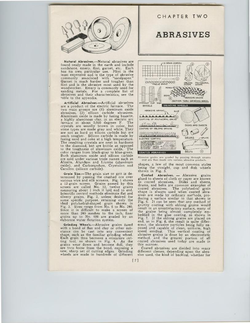
Grain Size.—The grain size or grit is de-termined by passing the crushed ore over various wire and silk screens. Fig. 1 shows a 12-grain screen. Grains passed by this screen are called No. 12, twelve grains measuring about 1 inch if laid end to end. Scientific control methods eliminate flat and slivery grains, Fig. 2, unless desired for some specific purpose, retaining only the ideal polyhedral-shaped grain shown in Fig. 3. Sizes range from No. 6 to No. 240. Since it is difficult to make a screen of more than 240 meshes to the inch, finer grains up to No. 600 are graded by an elaborate water flotation system.
Grinding Wheels.—Abrasive grains fused with a bond of flux and clay or other sub-stance can be cast into any convenient shape, such as the familiar grinding wheel. Each grain thus becomes a miniature cut-ting tool, as shown in Fig. 4. As the grains wear down and become dull, they are torn loose from the bond, exposing a new, sharp set of cutting edges. Grinding wheels are made in hundreds of different
Abrasive grains are graded by passing through screens and are then made into various abrasive products.
shapes, a few of the most common styles being the straight, cup and dish wheels shown in Fig. 5.
Coated Abrasives. — Abrasive grains glued to sheets of cloth or paper are known as coated abrasives. Disks and sheets, drums, and belts are common examples of coated abrasives. The polyhedral grain shape is always used when coated abra-sives are made by ordinary methods, pro-ducing a surface similar to that shown in Fig. 6. It can be seen that any method of gravity coating with oblong grains would result in an unsatisfactory surface, many of the grains being almost completely em-bedded in the glue coating, as shown in Fig. 7. If the oblong grains are placed on end, as in Fig. 8, the result is quite differ-erent, the abrasive particles being fully ex-posed and capable of clean, uniform, high speed sanding. This vertical coating of abrasive grains is done by an electrostatic method, and the greater portion of all coated abrasives used today are made in this manner.
Coated abrasives are divided into many different classes, depending upon the abra-sive used, the kind of backing, whether for
[ 7 ]
STRA GRT CUP DISH
WHEELS GRINDING WHEELS
ABRASIVE GRAINSGLUE
CY-1C COATING OF POLYHEDRAL GRANCD
.0911ν ZI4 1 k/111.0
COATING OF OBLONG GRAINS
ELECT RO COATING
COATED ABRASIVES
12•GRAIN SCREEN
e'ec2;1519,0
poaes. Et*Jad loves%
440-40.44,,P ois- •noit.•47,11.a foe %%0'BOND
(e,"1147CABRASIVE GRAINS•
SECTION TNRU GRINDING WHEEL
OBLONG POLYHEDRALSHAPE SHAPE
DISKS AND SHEETS
DRUMS ,SPLICE
BELTS
CHAPTER TWO
ABRASIVES
Natural Abrasives.—Natural abrasives arefound ready made in the earth and includesandstone, emery, flint, garnet, etc. Eachhas its own particular use. Flint is theleast expensive and is the type of abrasivecommonly associated with "sandpaper."Garnet is much harder and tougher thanflint and is the abrasive most used by thewoodworker. Emery is commonly used forsanding metals. For a complete list ofabrasives and their characteristics, see thetable in the appendix.
Artificial Abrasives. —Artificial abrasivesare a product of the electric furnace. Thetwo main groups are (1) aluminum oxideabrasives, (2) silicon carbide abrasives.Aluminum oxide is made by fusing bauxite,a highly aluminous clay, in an electric arcfurnace at about 3,000 degrees F. Thecrystals are usually brown in color, butsome types are made gray and white. Theyare not as hard as silicon carbide but aremuch tougher. Silicon carbide is made byfusing sand and coke at a high temperature.The resulting crystals are next in hardnessto the diamond, but are brittle as opposedto the toughness of aluminum oxide. Thecolor ranges from black-gray to blue-green.Both aluminum oxide and silicon carbideare sold under various trade names such asAloxite, Alundum and Lionite (aluminumoxide), and Carborundum, Crystolon andCarsilon (silicon carbide).
Grain Size. —The grain size or grit is de-termined by passing the crushed ore overvarious wire and silk screens. Fig. 1 showsa 12-grain screen. Grains passed by thisscreen are called No. 12, twelve grainsmeasuring about 1 inch if laid end to end.Scientific control methods eliminate flat andslivery grains, Fig. 2, unless desired forsome specific purpose, retaining only theideal polyhedral-shaped grain shown inFig. 3. Sizes range from No. 6 to No. 240.Since it is difficult to make a screen ofmore than 240 meshes to the inch, finergrains up to No. 600 are graded by anelaborate water flotation system.
Grinding Wheels. —Abrasive grains fusedwith a bond of flux and clay or other sub-stance can be cast into any convenientshape, such as the familiar grinding wheel.Each grain thus becomes a miniature cut-ting tool, as shown in Fig. 4. As thegrains wear down and become dull, theyare torn loose from the bond, exposing anew, sharp set of cutting edges. Grindingwheels are made in hundreds of different
Abrasive grains are graded by passing through screensand are then made into various abrasive products.
shapes, a few of the most common stylesbeing the straight, cup and dish wheelsshown in Fig. 5.
Coated Abrasives. — Abrasive grainsglued to sheets of cloth or paper are knownas coated abrasives. Disks and sheets,drums, and belts are common examples ofcoated abrasives. The polyhedral grainshape is always used when coated abra-sives are made by ordinary methods, pro-ducing a surface similar to that shown inFig. 6. It can be seen that any method ofgravity coating with oblong grains wouldresult in an unsatisfactory surface, many ofthe grains being almost completely em-bedded in the glue coating, as shown inFig. 7. If the oblong grains are placed onend, as in Fig. 8, the result is quite differ-erent, the abrasive particles being fully ex-posed and capable of clean, uniform, highspeed sanding. This vertical coating ofabrasive grains is done by an electrostaticmethod, and the greater portion of allcoated abrasives used today are made inthis manner.
Coated abrasives are divided into manydifferent classes, depending upon the abra-sive used, the kind of backing, whether for
[7]
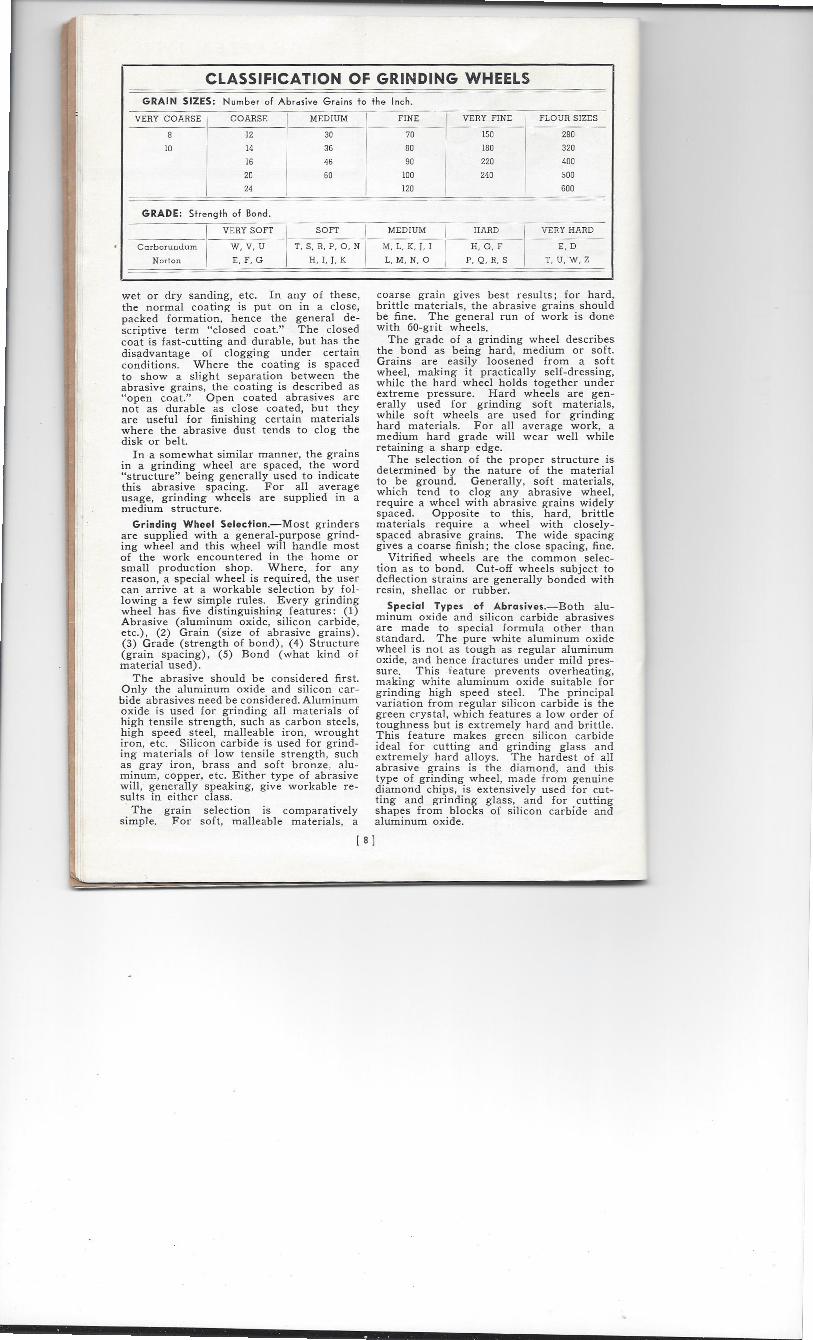
CLASSIFICATION OF GRINDING WHEELS GRAIN SIZES: Number of Abrasive Grains to the Inch.
VERY COARSE COARSE MEDIUM FINE VERY FINE FLOUR SIZES
8
10
12
14
16
20
24
30
36
46
60
70
80
90
100
120
150
180
220
240
280
320
400
500
600
GRADE: Strength of Bond.
VERY SOFT SOFT MEDIUM I HARD VERY HARD
Carborundum
Norton
W, V, U
E, F, G
T, S, R, P, 0, N
H, I, J, K
M, L, K, J, I
L, M, N, 0
H, G, F
P, Q, R, S
E, D
T, U, W, Z
wet or dry sanding, etc. In any of these, the normal coating is put on in a close, packed formation, hence the general de-scriptive term "closed coat." The closed coat is fast-cutting and durable, but has the disadvantage of clogging under certain conditions. Where the coating is spaced to show a slight separation between the abrasive grains, the coating is described as "open coat." Open coated abrasives are not as durable as close coated, but they are useful for finishing certain materials where the abrasive dust tends to clog the disk or belt.
In a somewhat similar manner, the grains in a grinding wheel are spaced, the word "structure" being generally used to indicate this abrasive spacing. For all average usage, grinding wheels are supplied in a medium structure.
Grinding Wheel Selection.—Most grinders are supplied with a general-purpose grind-ing wheel and this wheel will handle most of the work encountered in the home or small production shop. Where, for any reason, a special wheel is required, the user can arrive at a workable selection by fol-lowing a few simple rules. Every grinding wheel has five distinguishing features: (1) Abrasive (aluminum oxide, silicon carbide, etc.), (2) Grain (size of abrasive grains), (3) Grade (strength of bond), (4) Structure (grain spacing), (5) Bond (what kind of material used).
The abrasive should be considered first. Only the aluminum oxide and silicon car-bide abrasives need be considered. Aluminum oxide is used for grinding all materials of high tensile strength, such as carbon steels, high speed steel, malleable iron, wrought iron, etc. Silicon carbide is used for grind-ing materials of low tensile strength, such as gray iron, brass and soft bronze, alu-minum, copper, etc. Either type of abrasive will, generally speaking, give workable re-sults in either class.
The grain selection is comparatively simple. For soft, malleable materials, a
coarse grain gives best results; for hard, brittle materials, the abrasive grains should be fine. The general run of work is done with 60-grit wheels.
The grade of a grinding wheel describes the bond as being hard, medium or soft. Grains are easily loosened from a soft wheel, making it practically self-dressing, while the hard wheel holds together under extreme pressure. Hard wheels are gen-erally used for grinding soft materials, while soft wheels are used for grinding hard materials. For all average work, a medium hard grade will wear well while retaining a sharp edge.
The selection of the proper structure is determined by the nature of the material to be ground. Generally, soft materials, which tend to clog any abrasive wheel, require a wheel with abrasive grains widely spaced. Opposite to this, hard, brittle materials require a wheel with closely-spaced abrasive grains. The wide spacing gives a coarse finish; the close spacing, fine.
Vitrified wheels are the common selec-tion as to bond. Cut-off wheels subject to deflection strains are generally bonded with resin, shellac or rubber.
Special Types of Abrasives.—Both alu-minum oxide and silicon carbide abrasives are made to special formula other than standard. The pure white aluminum oxide wheel is not as tough as regular aluminum oxide, and hence fractures under mild pres-sure. This feature prevents overheating, making white aluminum oxide suitable for grinding high speed steel. The principal variation from regular silicon carbide is the green crystal, which features a low order of toughness but is extremely hard and brittle. This feature makes green silicon carbide ideal for cutting and grinding glass and extremely hard alloys. The hardest of all abrasive grains is the diamond, and this type of grinding wheel, made from genuine diamond chips, is extensively used for cut-ting and grinding glass, and for cutting shapes from blocks of silicon carbide and aluminum oxide.
[ 8 ]
CHAPTER THREE
OPERATING THE BELT SANDER
GOIDE z Surfacing.—The sanding table should be
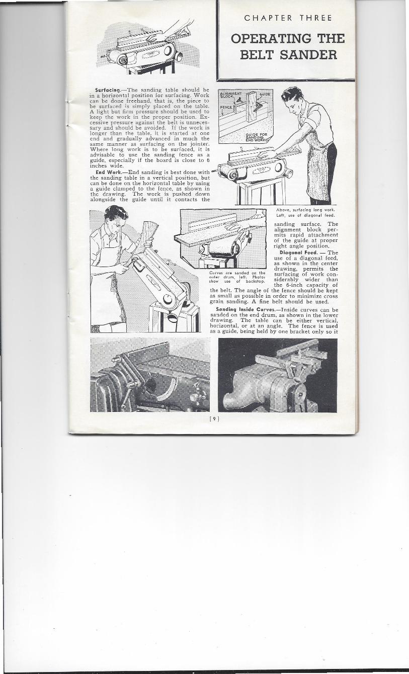
in a horizontal position for surfacing. Work can be done freehand, that is, the piece to be surfaced is simply placed on the table. A light but firm pressure should be used to keep the work in the proper position. Ex-cessive pressure against the belt is unneces-sary and should be avoided. If the work is longer than the table, it is started at one end and gradually advanced in much the same manner as surfacing on the jointer. Where long work is to be surfaced, it is advisable to use the sanding fence as a guide, especially if the board is close to 6 inches wide.
End Work.—End sanding is best done with the sanding table in a vertical position, but can be done on the horizontal table by using a guide clamped to the fence, as shown in the drawing. The work is pushed down alongside the guide until it contacts the
Above, surfacing long work.
Left, use of diagonal feed.
sanding surface. The alignment block per-mits rapid attachment of the guide at proper right angle position.
Diagonal Feed. — The use of a diagonal feed, as shown in the center drawing, permits the
Curves are sanded on the surfacing of work con- outer drum, left. Photos show use of backstop. siderably wider than
the 6-inch capacity of the belt. The angle of the fence should be kept as small as possible in order to minimize cross grain sanding. A fine belt should be used.
Sanding Inside Curves.—Inside curves can be sanded on the end drum, as shown in the lower drawing. The table can be either vertical, horizontal, or at an angle. The fence is used as a guide, being held by one bracket only so it
1 9 1
GUIDE
BOLT
NUT—
FENCE
I
Above, using the tilting table. Photo at right shows how inside
corners are sonded.
extends beyond the sanding belt.
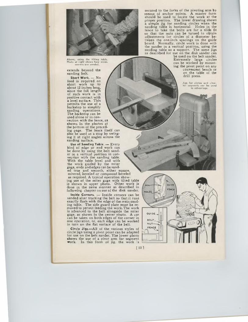
Short Work. — No feed is required on short work up to about 12 inches long, since the full length of such work is in positive contact with a level surface. This permits the use of a backstop to simplify sanding operations. The backstop can be used alone or in con-nection with the fence, as shown in the photos at the bottom of the preced-ing page. The fence itself can also be used as a stop by swing-ing it at right angles across the sanding surface.
Use of Sanding Table. — Every kind of edge or end work can be done by using the belt sand-er in a vertical position in con-nection with the sanding table. With the table level and with the work guided by the miter gage, ends and edges can be sand-ed true and smooth, either square, mitered, beveled or compound beveled as required. A typical operation show-
ing use of the miter gage with tilted table is shown in upper photo. Other work is done in the same manner as described in following chapter on use of the disk sander.
Inside Corners. — Inside corners can be sanded after tracking the belt so that it runs exactly flush with the edge of the main sand-ing table. The side guard plate must be re-moved to permit feeding the work. The work is advanced to the belt alongside the miter gage, as shown in the center photo. A cut can be taken on both edges of the corner in one operation, or, each edge can be worked in turn on the flat surface of the belt.
Circle Jigs.—All of the various styles of circle jigs using a pivot point can be adapted for use on the belt sander. The lower photo shows the use of a pivot arm for segment work. In this form of jig, the work s
[ 10 ]
secured to the forks of the pivoting arm by means of anchor points. A master form should be used to locate the work at the proper position. The lower drawing shows a simple jig for sanding circles when the sanding table is horizontal. Holes in the fence to take the bolts are for a slide fit so that the nuts can be turned to obtain adjustments for circles of a diameter be-tween the one-inch spacings on the guide board. Normally, circle work is done with the sander in a vertical position, using the sanding table as a support. The same jigs as described for use on the disk sander can
be used on the belt sander. Extremely large circles can be worked by mount-ing the pivot point on any
convenient bench or on the table of the drill press.
Jigs for circles and circu-lar segments can be used
to advantoge.
Above, using the tilting table.Photo at right shows how inside
corners are sonded.
extends beyond thesanding belt.
Short Work. — Nofeed is required onshort work up toabout 12 inches long,since the full lengthof such work is inpositive contact witha level surface. Thispermits the use of abackstop to simplifysanding operations.The backstop can beused alone or in con-nection with the fence, asshown in the photos atthe bottom of the preced-ing page. The fence itself canalso be used as a stop by swing-ing it at right angles across thesanding surface.
Use of Sanding Table. — Everykind of edge or end work canbe done by using the belt sand-er in a vertical position in con-nection with the sanding table.With the table level and withthe work guided by the mitergage, ends and edges can be sand-ed true and smooth, either square,mitered, beveled or compound beveledas required. A typical operation show-
ing use of the miter gage with tilted tableis shown in upper photo. Other work isdone in the same manner as described infollowing chapter on use of the disk sander.
Inside Corners. — Inside corners can besanded after tracking the belt so that it runsexactly flush with the edge of the main sand-ing table. The side guard plate must be re-moved to permit feeding the work. The workis advanced to the belt alongside the mitergage, as shown in the center photo. A cutcan be taken on both edges of the corner inone operation, or, each edge can be workedin turn on the flat surface of the belt.
Circle Jigs.—All of the various styles ofcircle jigs using a pivot point can be adaptedfor use on the belt sander. The lower photoshows the use of a pivot arm for segmentwork. In this form of jig, the work s
secured to the forks of the pivoting arm bymeans of anchor points. A master formshould be used to locate the work at theproper position. The lower drawing showsa simple jig for sanding circles when thesanding table is horizontal. Holes in thefence to take the bolts are for a slide fitso that the nuts can be turned to obtainadjustments for circles of a diameter be-tween the one-inch spacings on the guideboard. Normally, circle work is done withthe sander in a vertical position, using thesanding table as a support. The same jigsas described for use on the disk sander can
be used on the belt sander.Extremely large circlescan be worked by mount-ing the pivot point on any
convenient bench oron the table of thedrill press.
Jigs for circles and circu-lar segments can be used
to advantoge.
PIN
HOLES
GUIDE,
BOLT
NUT—
PENCE
[ 10 ]
ARM
ON BOLT
V°WEK PIVOT ED
STANDARD FENCE
'CLAMP
STOP FOR ARM
Ets iETN Wtel TKO SEGivav
CHAMFERING JIG
The sander affords one of the best methods of work-
ing bevels.
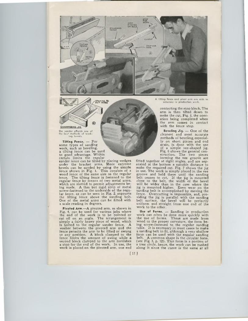
Tilting Fence. — For some types of sanding work, such as beveling, a tilting fence can be used to good advantage. Within certain limits the regular sander fence can be tilted by placing wedges under the bracket arms. More extreme bevels can be sanded by using the simple fence shown in Fig. 1. This consists of a wood fence of the same size as the regular fence. The tilting fence is fastened to the regular fence by means of two metal arms, which are slotted to permit adjustments be-ing made. A thin but rigid strip of metal screw-fastened to the underside of the regu-lar fence, as can be seen in Fig. 2, supports the tilting fence above the sanding belt. One of the metal arms can be fitted with a scale reading in degrees.
Pivoted Arm.—A pivoted arm, as shown in Fig. 4, can be used for various jobs where the end of the work is to be pointed or cut off on an angle. The arrangement is simply a fairly heavy piece of wood, which is bolted to the regular sander fence. A washer between the pivoted arm and the fence permits the arm to be tilted or swung to any position. A block clamped to the fence limits the amount of swing while a second block clamped to the arm furnishes a stop for the end of the work. In use, the work is placed on the pivoted arm, one end
A tilting fence and pivot arm are aids to accuracy in production work.
contacting the stop block. The arm is then tilted down to make the cut, Fig. 5, the oper-ation being completed when the arm comes in contact with the fence stop.
Beveling Jig. — One of the cleanest and most accurate methods of beveling, especial-ly on short pieces and end grain, is done with the use of a simple vee-shaped jig. Fig. 6 shows the general con-struction. The two pieces forming the vee groove are
fitted together at right angles, and are sep-arated at the bottom a suitable distance to make the required cut. Fig. 7 shows the jig in use. The work is simply placed in the vee groove and held there until the sanding belt ceases to cut. If the jig is mounted close to the belt, the width of the bevel will be wider than in the case where the jig is mounted higher. Even wear on the sanding belt is accomplished by moving the fence. Overcutting is impossible, and, pro-viding the jig is parallel with the sanding belt surface, the bevel will be perfectly uniform and straight from one end of the work to the other.
Use of Forms. — Sanding in production work can often be done more quickly with the use of forms. These are made from wood to the proper curvature, the form be-ing screw-fastened to the regular sanding table. It is necessary in most cases to make a sanding belt to fit, although a very shallow form can be used with the regular sanding belt. A common shape is the circular form, (see Fig. 3, p. 12). This form is a portion of a true circle, hence, the work can be pushed along it since the curve is the same at all
ARM WORKPNOTE0ON BOLT
STANDARD .
FENCE
„OPENING TOSUIT WOCIK
CI4AMFERI NG JIG
The sander affords one ofthe best methods of work-
ing bevels.
Tilting Fence. — Forsome types of sandingwork, such as beveling,a tilting fence can be usedto good advantage. Withincertain limits the regularsander fence can be tilted by placing wedgesunder the bracket arms. More extremebevels can be sanded by using the simplefence shown in Fig. 1. This consists of awood fence of the same size as the regularfence. The tilting fence is fastened to theregular fence by means of two metal arms,which are slotted to permit adjustments be-ing made. A thin but rigid strip of metalscrew-fastened to the underside of the regu-lar fence, as can be seen in Fig. 2, supportsthe tilting fence above the sanding belt.One of the metal arms can be fitted witha scale reading in degrees.
Pivoted Arm.—A pivoted arm, as shown inFig. 4, can be used for various jobs wherethe end of the work is to be pointed orcut off on an angle. The arrangement issimply a fairly heavy piece of wood, whichis bolted to the regular sander fence. Awasher between the pivoted arm and thefence permits the arm to be tilted or swungto any position. A block clamped to thefence limits the amount of swing while asecond block clamped to the arm furnishesa stop for the end of the work. In use, thework is placed on the pivoted arm, one end
A tilting fence and pivot arm are aids toaccuracy in production work.
contacting the stop block. Thearm is then tilted down tomake the cut, Fig. 5, the oper-ation being completed whenthe arm comes in contactwith the fence stop.
Beveling Jig. — One of thecleanest and most accuratemethods of beveling, especial-ly on short pieces and endgrain, is done with the useof a simple vee-shaped jig.Fig. 6 shows the general con-struction. The two piecesforming the vee groove are
fitted together at right angles, and are sep-arated at the bottom a suitable distance tomake the required cut. Fig. 7 shows the jigin use. The work is simply placed in the veegroove and held there until the sandingbelt ceases to cut. If the jig is mountedclose to the belt, the width of the bevelwill be wider than in the case where thejig is mounted higher. Even wear on thesanding belt is accomplished by moving thefence. Overcutting is impossible, and, pro-viding the jig is parallel with the sandingbelt surface, the bevel will be perfectlyuniform and straight from one end of thework to the other.
Use of Forms. — Sanding in productionwork can often be done more quickly withthe use of forms. These are made fromwood to the proper curvature, the form be-ing screw-fastened to the regular sandingtable. It is necessary in most cases to makea sanding belt to fit, although a very shallowform can be used with the regular sandingbelt. A common shape is the circular form,(see Fig. 3, p. 12). This form is a portion ofa true circle, hence, the work can be pushedalong it since the curve is the same at all
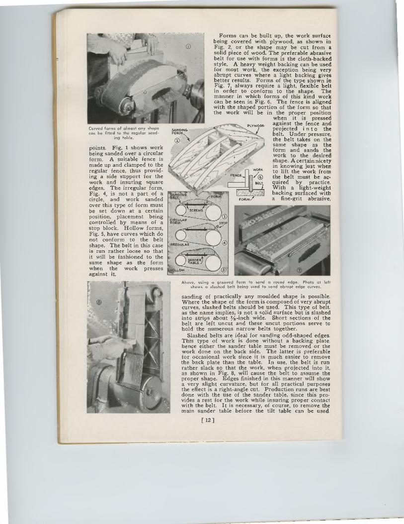
points. Fig. 1 shows work being sanded over a circular form. A suitable fence is made up and clamped to the regular fence, thus provid-ing a side support for the work and insuring square edges. The irregular form, Fig. 4, is not a part of a circle, and work sanded over this type of form must be set down at a certain position, placement being controlled by means of a stop block. Hollow forms, Fig. 5, have curves which do not conform to the belt shape. The belt in this case is run rather loose so that it will be fashioned to the same shape as the form when the work presses against it.
oLTw000 Curved forms of almost any shape can be fitted to the regular sand-
ing table.
SANDKV,
®
FORM
Forms can be built up, the work surface being covered with plywood, as shown in Fig. 2, or the shape may be cut from a solid piece of wood. The preferable abrasive belt for use with forms is the cloth-backed style. A heavy weight backing can be used for most work, the exception being very abrupt curves where a light backing gives better results. Forms of the type shown in Fig. 7, always require a light, flexible belt in order to conform to the shape. The manner in which forms of this kind work can be seen in Fig. 6. The fence is aligned with the shaped portion of the form so that the work will be in the proper position
when it is pressed against the fence and projected into the belt. Under pressure, the belt takes on the same shape as the form and sands the work to the desired shape. A certain nicety in knowing just when to lift the work from the belt must be ac-quired by practice. With a light-weight backing surfaced with a fine-grit abrasive,
FENOE
MINIU
511"474
WORK
/0 BELT
FORM
Above, using a grooved form to sand a round edge. Photo at left shows a slashed belt being used to sand abrupt edge curves.
sanding of practically any moulded shape is possible. Where the shape of the form is composed of very abrupt curves, slashed belts should be used. This type of belt. as the name implies, is not a solid surface but is slashed into strips about Y8-inch wide. Short sections of the belt are left uncut and these uncut portions serve to hold the numerous narrow belts together.
Slashed belts are ideal for sanding odd-shaped edges. This type of work is done without a backing plate hence either the sander table must be removed or the work done on the back side. The latter is preferable for occasional work since it is much easier to remove the back plate than the table. In use, the belt is run rather slack so that the work, when projected into it, as shown in Fig. 8, will cause the belt to assume the proper shape. Edges finished in this manner will show a very slight curvature, but for all practical purposes the effect is a right-angle cut. Production runs are best done with the use of the sander table, since this pro-vides a rest for the work while insuring proper contact with the belt. It is necessary, of course, to remove the main sander table before the tilt table can be used
[ 12 ]
Curved forms of almost any shapecan be fitted to the regular sand-
ing table.
points. Fig. 1 shows workbeing sanded over a circularform. A suitable fence ismade up and clamped to theregular fence, thus provid-ing a side support for thework and insuring squareedges. The irregular form,Fig. 4, is not a part of acircle, and work sandedover this type of form mustbe set down at a certainposition, placement beingcontrolled by means of astop block. Hollow forms,Fig. 5, have curves which donot conform to the beltshape. The belt in this caseis run rather loose so thatit will be fashioned to thesame shape as the formwhen the work pressesagainst it.
Forms can be built up, the work surfacebeing covered with plywood, as shown inFig. 2, or the shape may be cut from asolid piece of wood. The preferable abrasivebelt for use with forms is the cloth-backedstyle. A heavy weight backing can be usedfor most work, the exception being veryabrupt curves where a light backing givesbetter results. Forms of the type shown inFig. 7, always require a light, flexible beltin order to conform to the shape. Themanner in which forms of this kind workcan be seen in Fig. 6. The fence is alignedwith the shaped portion of the form so thatthe work will be in the proper position
when it is pressedagainst the fence andprojected into thebelt. Under pressure,the belt takes on thesame shape as theform and sands thework to the desiredshape. A certain nicetyin knowing just whento lift the work fromthe belt must be ac-quired by practice.With a light-weightbacking surfaced witha fine-grit abrasive,
Above, using a grooved form to sand a round edge. Photo at leftshows a slashed belt being used to sand abrupt edge curves.
sanding of practically any moulded shape is possible.Where the shape of the form is composed of very abruptcurves, slashed belts should be used. This type of belt.as the name implies, is not a solid surface but is slashedinto strips about Y8-inch wide. Short sections of thebelt are left uncut and these uncut portions serve tohold the numerous narrow belts together.
Slashed belts are ideal for sanding odd-shaped edges.This type of work is done without a backing platehence either the sander table must be removed or thework done on the back side. The latter is preferablefor occasional work since it is much easier to removethe back plate than the table. In use, the belt is runrather slack so that the work, when projected into it,as shown in Fig. 8, will cause the belt to assume theproper shape. Edges finished in this manner will showa very slight curvature, but for all practical purposesthe effect is a right-angle cut. Production runs are bestdone with the use of the sander table, since this pro-vides a rest for the work while insuring proper contactwith the belt. It is necessary, of course, to remove themain sander table before the tilt table can be used
[ 12 ]
CHAPTER FOUR
OPERATING THE DISK SANDER
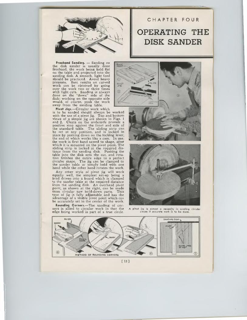
Freehand Sanding. — Sanding on the disk sander is usually done freehand, the work being held flat on the table and projected into the sanding disk. A smooth, light feed should be practiced. Avoid heavy pressure. Best results on curved work can be obtained by going over the work two or three times with light cuts. Sanding is always done on the "down" side of the disk; working on the opposite side would, of course, push the work away from the sanding table.
Pivot Jigs.—Circular work which is to be sanded should always be worked with the use of a pivot jig. Top and bottom views of a simple jig are shown in Figs. 1 and 2. Cleats on the underside provide a positive stop against the front and side of the standard table. The sliding strip can be set at any position, and is locked in place by pushing down on the locking lever, the end of which works like a cam. In use, the work is first band sawed to shape, after which it is mounted on the pivot point. The sliding strip is locked at the required dis-tance from the sanding disk. Pushing the table into the disk sets the cut, and rota-tion finishes the entire edge to a perfect circular shape. The jig can be clamped to the sander table or simply held with one hand while the other hand rotates the work.
Any other style of pivot jig will work equally well, the simplest set-up being a brad driven into a board which is clamped to the sander table at the required distance from the sanding disk. An overhead pivot point, as shown at the right, can be made from circular saw hold-down parts. This type of jig is fully adjustable and has the advantage of a visible pivot point which can be accurately set in the center of the work.
Rounding Corners.—The sanding of cor-ners is allied to circular work in that the edge being worked is part of a true circle.
PIVOT POINT"-,
Imen...-111111‘.‘111411
k`ac."'"1---
A pivot jig is almost a necessity in sanding circular pieces if accurate work is to be done.
SANDING DISK
•I PIVOT
LINES
METHOD OF ROUNDING CORNERS O
[13]
CHAPTER FOUR
OPERATING THEDISK SANDER
Freehand Sanding. — Sanding onthe disk sander is usually donefreehand, the work being held flaton the table and projected into thesanding disk. A smooth, light feedshould be practiced. Avoid heavy 0pressure. Best results on curvedTIVT S1.10E
work can be obtained by going ou
over the work two or three timeswith light cuts. Sanding is alwaysdone on the "down" side of thedisk; working on the opposite sidewould, of course, push the workaway from the sanding table.
Pivot Jigs.—Circular work whichis to be sanded should always be workedwith the use of a pivot jig. Top and bottomviews of a simple jig are shown in Figs. 1and 2. Cleats on the underside provide apositive stop against the front and side ofthe standard table. The sliding strip canbe set at any position, and is locked inplace by pushing down on the locking lever,the end of which works like a cam. In use,the work is first band sawed to shape, afterwhich it is mounted on the pivot point. Thesliding strip is locked at the required dis-tance from the sanding disk. Pushing thetable into the disk sets the cut, and rota-tion finishes the entire edge to a perfectcircular shape. The jig can be clamped tothe sander table or simply held with onehand while the other hand rotates the work.
Any other style of pivot jig will workequally well, the simplest set-up being abrad driven into a board which is clampedto the sander table at the required distancefrom the sanding disk. An overhead pivotpoint, as shown at the right, can be madefrom circular saw hold-down parts. Thistype of jig is fully adjustable and has theadvantage of a visible pivot point which canbe accurately set in the center of the work.
Rounding Corners.—The sanding of cor-ners is allied to circular work in that theedge being worked is part of a true circle.
PIVOTPOINT
I /-7 ARM
LOCKING
iftwo„,,,r1114
A pivot jig is almost a necessity in sanding circularpieces if accurate work is to be done.
[13]
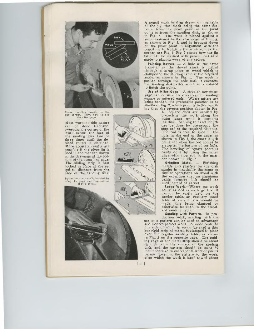
A pencil mark is then drawn on the table of the jig, this mark being the same dis-tance from the pivot point as the pivot point is from the sanding disk, as shown in Fig. 4. The work is placed against a guide fastened to the rear edge of the jig, as shown in Fig. 5, and is brought down on the pivot point in alignment with the pencil mark. Rotating the work rounds the corner, see Fig. 6. Fig. 7 shows how the jig table can be marked with pencil lines as a guide to placing work of any radius.
Pointing Dowels. — A hole of the same diameter as the dowel stock is drilled through a scrap piece of wood which is clamped to the sanding table at the required angle, as shown in Fig. 1. The work is pushed through the hole until it contacts the sanding disk, after which it is rotated to finish the point.
Use of Miter Gage.—A circular saw miter gage can be used to advantage in sanding square or mitered ends. Where miters are being sanded, the preferable position is as shown in Fig. 2, which permits better handl-ing than the reverse position shown in Fig
3. Square ends are sanded by projecting the work along the miter gage until it contacts the disk. Sanding to exact length can be done by pre-setting the stop rod at the required distance. The rod is free to slide in the hole in the end of the gage, as shown in Fig. 4, the exact length being set when the rod comes to a stop at the bottom of the hole. The beveling of square posts is easily done by using the miter gage with stop rod in the man-ner shown in Fig. 5.
Grinding Metal. — Finishing metals and plastics on the disk sander is practically the same as similar operations on wood with the exception that an aluminum oxide abrasive disk should be used instead of garnet.
Large Work.—Where the work being sanded is so large that it cannot be easily held on the sander table, an auxiliary wood table of suitable size should be made, this being clamped or otherwise fastened to the stand. and sanding table.
Sanding with Pattern.—In pro-duction work, sanding with the
use of a pattern can be used to advantage and insures perfect work. A wood table, to one side of which is screw-fastened a thin but rigid strip of metal. is clamped in place over the regular sanding table, as shown in Fig. 2 on the opposite page. The guid-ing edge of the metal strip should be about I/8 inch from the surface of the sanding disk, and the pattern should be made Ye inch undersize to correspond. Anchor points permit fastening the pattern to the work. after which the work is band sawed about
Above, pointing dowels on the disk sander. Right, how to use
the miter gage.
Most work of this nature can be done freehand, sweeping the corner of the work across the face of the sanding disk two or three times until the de-sired round is obtained. More accurate results are possible if the pivot jig is used in the manner shown in the drawings at the bot-tom of the preceding page. The sliding strip is first locked in place at the re-quired distance from the face of the sanding disk.
Square posts are easily beveled by using the gage and stop rad as
shown below.
Above, pointing dowels on thedisk sander. Right, how to use
the miter gage.
Most work of this naturecan be done freehand,sweeping the corner of thework across the face ofthe sanding disk two orthree times until the de-sired round is obtained.More accurate results arepossible if the pivot jig isused in the manner shownin the drawings at the bot-tom of the preceding page.The sliding strip is firstlocked in place at the re-quired distance from theface of the sanding disk.
Square posts are easily beveled byusing the gage and stop rad as
shown below.
A pencil mark is then drawn on the tableof the jig, this mark being the same dis-tance from the pivot point as the pivotpoint is from the sanding disk, as shownin Fig. 4. The work is placed against aguide fastened to the rear edge of the jig,as shown in Fig. 5, and is brought downon the pivot point in alignment with thepencil mark. Rotating the work rounds thecorner, see Fig. 6. Fig. 7 shows how the jigtable can be marked with pencil lines as aguide to placing work of any radius.
Pointing Dowels. — A hole of the samediameter as the dowel stock is drilledthrough a scrap piece of wood which isclamped to the sanding table at the requiredangle, as shown in Fig. 1. The work ispushed through the hole until it contactsthe sanding disk, after which it is rotatedto finish the point.
Use of Miter Gage.—A circular saw mitergage can be used to advantage in sandingsquare or mitered ends. Where miters arebeing sanded, the preferable position is asshown in Fig. 2, which permits better handl-ing than the reverse position shown in Fig
3. Square ends are sanded byprojecting the work along themiter gage until it contactsthe disk. Sanding to exact lengthcan be done by pre-setting thestop rod at the required distance.
The rod is free to slide in thehole in the end of the gage, asshown in Fig. 4, the exact lengthbeing set when the rod comes toa stop at the bottom of the hole.The beveling of square posts iseasily done by using the mitergage with stop rod in the man-ner shown in Fig. 5.
Grinding Metal. — Finishingmetals and plastics on the disksander is practically the same assimilar operations on wood withthe exception that an aluminumoxide abrasive disk should beused instead of garnet.
Large Work.—Where the workbeing sanded is so large that itcannot be easily held on thesander table, an auxiliary woodtable of suitable size should bemade, this being clamped orotherwise fastened to the stand.and sanding table.
Sanding with Pattern. —In pro-duction work, sanding with the
use of a pattern can be used to advantageand insures perfect work. A wood table, toone side of which is screw-fastened a thinbut rigid strip of metal. is clamped in placeover the regular sanding table, as shownin Fig. 2 on the opposite page. The guid-ing edge of the metal strip should be aboutI/8 inch from the surface of the sandingdisk, and the pattern should be made Yeinch undersize to correspond. Anchor pointspermit fastening the pattern to the work.after which the work is band sawed about
[
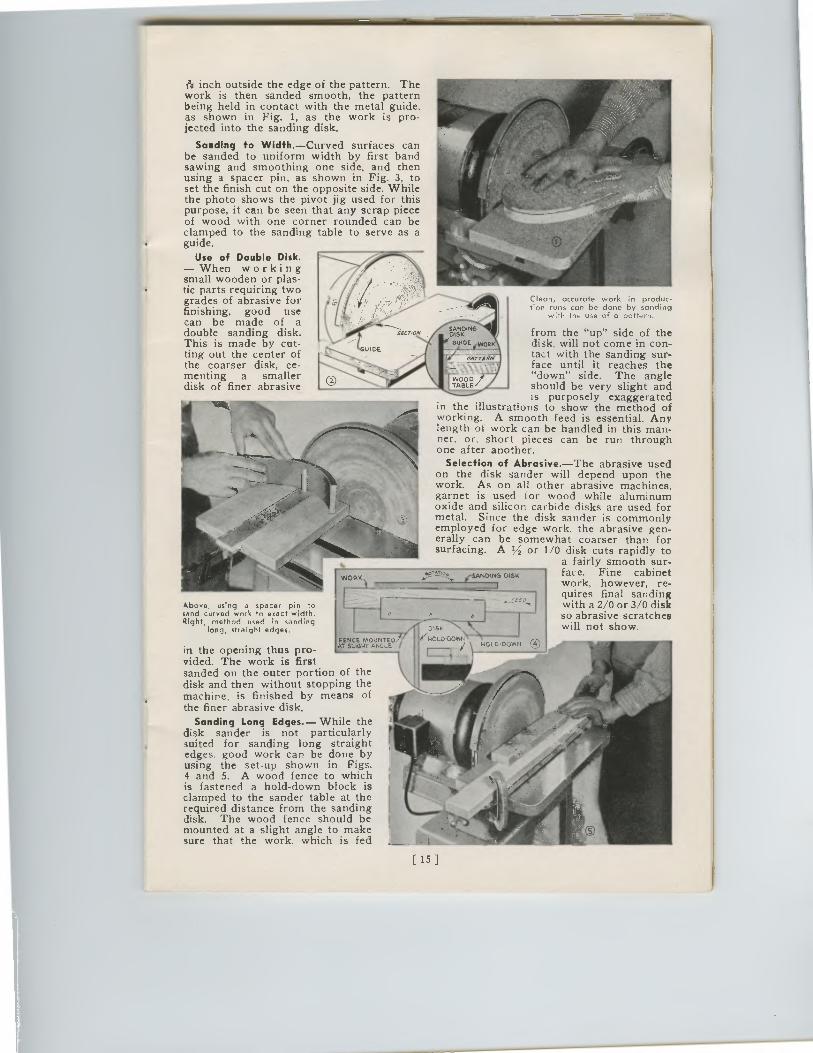
1•1‘ inch outside the edge of the pattern. The work is then sanded smooth, the pattern being held in contact with the metal guide, as shown in Fig. 1, as the work is pro-jected into the sanding disk.
Sanding to Width.—Curved surfaces can be sanded to uniform width by first band sawing and smoothing one side, and then using a spacer pin, as shown in Fig. 3, to set the finish cut on the opposite side. While the photo shows the pivot jig used for this purpose, it can be seen that any scrap piece of wood with one corner rounded can be clamped to the sanding table to serve as a guide.
Use of Double Disk. — When working small wooden or plas-tic parts requiring two grades of abrasive for finishing, good use can be made of a double sanding disk. This is made by cut-ting out the center of the coarser disk, ce-menting a smaller disk of finer abrasive
Above, using a spacer pin to sand curved work to exact width. Right, method used in sanding
long, straight edges.
Clean, accurate work in produc-tion runs can be done by sanding
with the use of a potter,
from the "up" side of the disk, will not come in con-tact with the sanding sur-face until it reaches the "down" side. The angle should be very slight and is purposely exaggerated
in the illustrations to show the method of working. A smooth feed is essential. Any length of work can be handled in this man-ner, or, short pieces can be run through one after another.
Selection of Abrasive.—The abrasive used on the disk sander will depend upon the work. As on all other abrasive machines, garnet is used for wood while aluminum oxide and silicon carbide disks are used for metal. Since the disk sander is commonly employed for edge work. the abrasive gen-erally can be somewhat coarser than for surfacing. A 1/2 or 1/0 disk cuts rapidly to
a fairly smooth sur-face. Fine cabinet work, however, re-quires final sanding with a 2/0 or 3/0 disk so abrasive scratches will not show.
in the opening thus pro-vided. The work is first sanded on the outer portion of the disk and then without stopping the machine, is finished by means of the finer abrasive disk.
Sanding Long Edges.— While the disk sander is not particularly suited for sanding long straight edges, good work can be done by using the set-up shown in Figs. 4 and 5. A wood fence to which is fastened a hold-down block is clamped to the sander table at the required distance from the sanding disk. The wood fence should be mounted at a slight angle to make sure that the work, which is fed
FENCE MOUNTED , T SlI4I4T ANGLE II
(SANDING. DISK
_
015K
NOLODOVitrIN
W401.,0•DOWN
015K
../woLo.Dover)210l,D.DOWN
with a 2/0 or 3/0 diskso abrasive scratcheswill not show.
1•1‘ inch outside the edge of the pattern. Thework is then sanded smooth, the patternbeing held in contact with the metal guide,as shown in Fig. 1, as the work is pro-jected into the sanding disk.
Sanding to Width. —Curved surfaces canbe sanded to uniform width by first bandsawing and smoothing one side, and thenusing a spacer pin, as shown in Fig. 3, toset the finish cut on the opposite side. Whilethe photo shows the pivot jig used for thispurpose, it can be seen that any scrap pieceof wood with one corner rounded can beclamped to the sanding table to serve as aguide.
Use of Double Disk.— When workingsmall wooden or plas-tic parts requiring twogrades of abrasive forfinishing, good usecan be made of adouble sanding disk.This is made by cut-ting out the center of DE
the coarser disk, ce-menting a smallerdisk of finer abrasive
Clean, accurate work in produc-tion runs can be done by sanding
with the use of a potter,
from the "up" side of thedisk, will not come in con-tact with the sanding sur-face until it reaches the"down" side. The angleshould be very slight andis purposely exaggerated
in the illustrations to show the method ofworking. A smooth feed is essential. Anylength of work can be handled in this man-ner, or, short pieces can be run throughone after another.
Selection of Abrasive.—The abrasive usedon the disk sander will depend upon thework. As on all other abrasive machines,garnet is used for wood while aluminumoxide and silicon carbide disks are used formetal. Since the disk sander is commonlyemployed for edge work. the abrasive gen-erally can be somewhat coarser than forsurfacing. A 1/2 or 1/0 disk cuts rapidly to
a fairly smooth sur-face. Fine cabinetwork, however, re-quires final sanding
SECT/ONSANDINGDISKGUIDE 1,404
vArii
WORK (SANDING DISK
Above, using a spacer pin tosand curved work to exact width.Right, method used in sanding
long, straight edges.
in the opening thus pro-vided. The work is firstsanded on the outer portion of thedisk and then without stopping themachine, is finished by means ofthe finer abrasive disk.
Sanding Long Edges. — While thedisk sander is not particularlysuited for sanding long straightedges, good work can be done byusing the set-up shown in Figs.4 and 5. A wood fence to whichis fastened a hold-down block isclamped to the sander table at therequired distance from the sandingdisk. The wood fence should bemounted at a slight angle to makesure that the work, which is fed
FENCE MOUNTIAT SLIGHT ANGL
[ 15 ]
WW
CHAPTER FIVE
GENERAL GRINDING
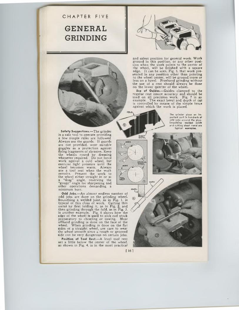
and safest position for general work. Work ground in this position, or any other posi-tion when the work points to the center of the wheel, will be finished with a square edge. It can be seen, Fig. 5, that work pre-sented in any position other than pointing to the wheel center, will be ground more or less on a bevel. Freehand grinding without the use of a rest should always be done on the lower quarter of the wheel.
Use of Guides.—Guides clamped to the regular rest insure accuracy and should be used on all precision work. Fig. 7 is an example. The exact bevel and depth of cut is controlled by means of the simple fence against which the work is placed.
FOLD The grinder plays an Im• portant part in hundreds of odd jobs around the shop. Smoothing welded joints and cutting sheet metal are
typical examples.
Safety Suggestions.—The grinder is a safe tool to operate providing a few simple rules are followed. Always use the guards. If guards are not provided, wear suitable goggles as a protection against flying fragments of abrasive. Keep the wheels round by dressing whenever required. Do not force work against a cold wheel, but exercise light pressure until the wheel becomes warm. Always use a tool rest when the work permits. Present the work to the wheel either straight in or at a "drag" angle, reserving the "gouge" angle for sharpening and other operations demanding a minimum burr.
Odd Jobs.—An almost endless number of odd jobs are done on the grinding wheel. Smoothing a welded joint, as in Fig. 1, is typical of this class of work. Cutting thin metal by first folding it, as in Fig. 2, and then grinding through the fold, as in Fig. 3, is another example. Fig. 6 shows how the edge of the wheel is used to nick rod stock preparatory to chiseling or sawing. Most offhand grinding is done on the face of the wheel. When grinding is done on the flat sides of a straight wheel, use care to wear the wheel smooth since a rough or grooved side can be very dangerous on certain jobs.
Position of Tool Rest.—A level tool rest set a little below the center of the wheel, as shown in Fig. 4, is in the most practical
[ 16 ]
CHAPTER FIVE
GENERALGRINDING
and safest position for general work. Workground in this position, or any other posi-tion when the work points to the center ofthe wheel, will be finished with a squareedge. It can be seen, Fig. 5, that work pre-sented in any position other than pointingto the wheel center, will be ground more orless on a bevel. Freehand grinding withoutthe use of a rest should always be doneon the lower quarter of the wheel.
Use of Guides.—Guides clamped to theregular rest insure accuracy and should beused on all precision work. Fig. 7 is anexample. The exact bevel and depth of cutis controlled by means of the simple fenceagainst which the work is placed.
The grinder plays an im•portant part in hundreds ofodd jobs around the shop.Smoothing welded jointsand cutting sheet metal are
typical examples.
Safety Suggestions.—The grinderis a safe tool to operate providinga few simple rules are followedAlways use the guards. If guardsare not provided, wear suitablegoggles as a protection againstflying fragments of abrasive. Keepthe wheels round by dressingwhenever required. Do not forcework against a cold wheel, butexercise light pressure until thewheel becomes warm. Alwaysuse a tool rest when the workpermits. Present the work tothe wheel either straight in or ata "drag" angle, reserving the"gouge" angle for sharpening andother operations demanding aminimum burr.
Odd Jobs.—An almost endless number ofodd jobs are done on the grinding wheel.Smoothing a welded joint, as in Fig. 1, istypical of this class of work. Cutting thinmetal by first folding it, as in Fig. 2, andthen grinding through the fold, as in Fig. 3,is another example. Fig. 6 shows how theedge of the wheel is used to nick rod stockpreparatory to chiseling or sawing. Mostoffhand grinding is done on the face of thewheel. When grinding is done on the flatsides of a straight wheel, use care to wearthe wheel smooth since a rough or groovedside can be very dangerous on certain jobs.
Position of Tool Rest. —A level tool restset a little below the center of the wheel,as shown in Fig. 4, is in the most practical
[ 16 ]
SHEET/METAL
GRINDINGWHEEL
WHEEL
HONING REMOVES THE BURR AND BRINGS CHISEL TO A KEEN EDGE
THE BURR CAN 1. BE REMOVED BY HONINGTHE CHISEL ON THE NAND
CHAPTER SIX
HOW TO SHARPEN TOOLS
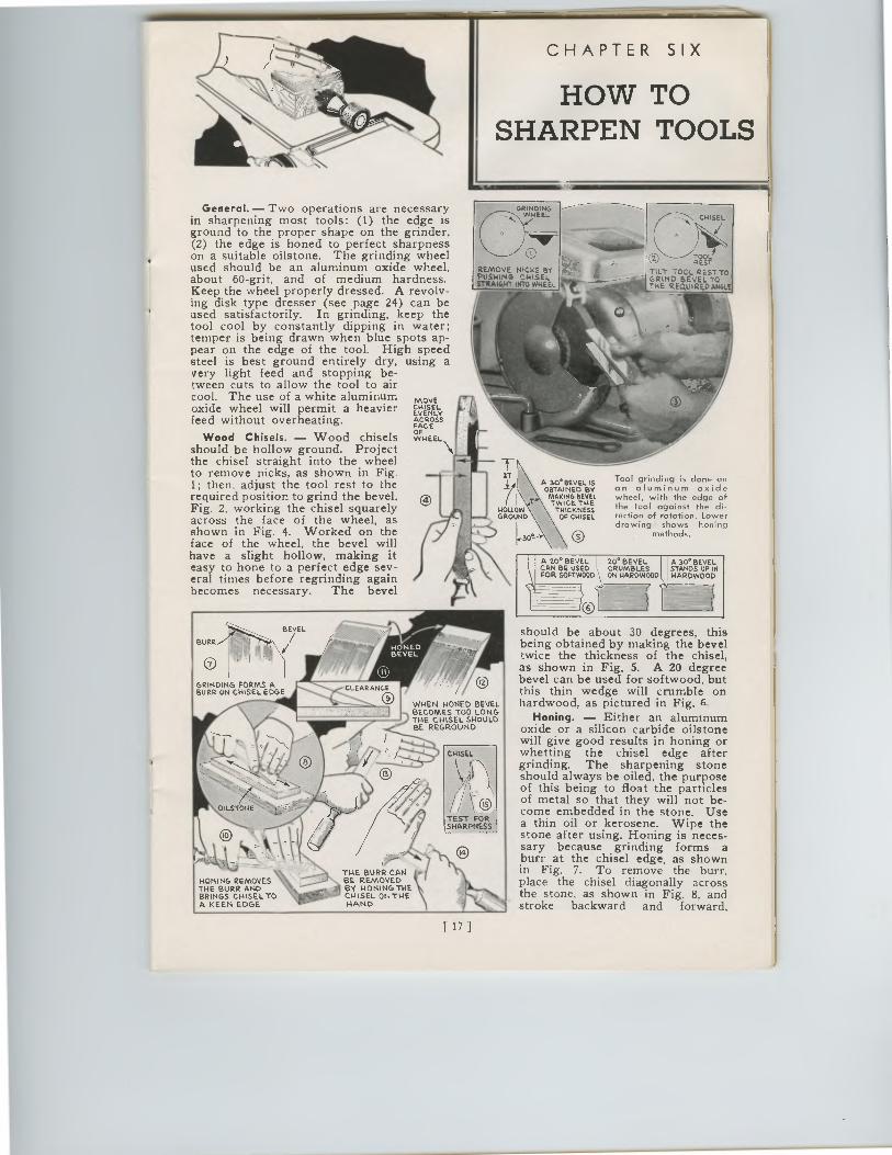
General. — Two operations are necessary in sharpening most tools: (1) the edge is ground to the proper shape on the grinder, (2) the edge is honed to perfect sharpness on a suitable oilstone. The grinding wheel used should be an aluminum oxide wheel, about 60-grit, and of medium hardness. Keep the wheel properly dressed. A revolv-ing disk type dresser (see page 24) can be used satisfactorily. In grinding, keep the tool cool by constantly dipping in water; temper is being drawn when blue spots ap-pear on the edge of the tool. High speed steel is best ground entirely dry, using a very light feed and stopping be- tween cuts to allow the tool to air cool. The use of a white aluminum MOVE oxide wheel will permit a heavier EVEN
IsEYL
feed without overheating. `ACCESS
Wood F
Wood Chisels. — Wood chisels WHEEL. should be hollow ground. Project the chisel straight into the wheel to remove nicks, as shown in Fig. 1; then. adjust the tool rest to the required position to grind the bevel, Fig. 2, working the chisel squarely across the face of the wheel, as shown in Fig. 4. Worked on the face of the wheel, the bevel will have a slight hollow, making it easy to hone to a perfect edge sev-eral times before regrinding again becomes necessary. The bevel
0 PVOTIL'T TOOL R T
Er
THE INRoeauEivREEtb TO
A Ye BEVEL IS OBTAINED BY
MAKING BEVEL TWICE. THE
THICKNESS OF CHISEL
Tool grinding is done on an aluminum oxide wheel, with the edge of the tool against the di-rection of rotation. Lower drowing shows honing
methods.
A 2e BEVEL CAN BE USED FOR SOFTWOOD
20 BEVEL CRUMBLES ON HARDWOOD
A 30*BEVEL STANDS UP IN HARDWOOD
BURR
BEVEL
GRINDING FORMS A BURR ON CHISEL EDGE
WHEN HONED BEVEL BECOMES TOO LONG THE CHISEL SHOULD BE REGROUND
should be about 30 degrees, this being obtained by making the bevel twice the thickness of the chisel, as shown in Fig. 5. A 20 degree bevel can be used for softwood, but this thin wedge will crumble on hardwood, as pictured in Fig. 6.
Honing. — Either an aluminum oxide or a silicon carbide oilstone will give good results in honing or whetting the chisel edge after grinding. The sharpening stone should always be oiled, the purpose of this being to float the particles of metal so that they will not be-come embedded in the stone. Use a thin oil or kerosene. Wipe the stone after using. Honing is neces-sary because grinding forms a burr at the chisel edge, as shown in Fig. 7. To remove the burr, place the chisel diagonally across the stone, as shown in Fig. 8, and stroke backward and forward,
[ 17 1
0 PVOTIL'T TOOL R TREST
THEINRomBuE IVREElb TO
GRINDINGWHEEL
0
REMOVE NICKS BYPUSHING CHISELirre.mort. sine WHEEL
A 20° BEVEL20° BEVELCAN BE USEDCRUMBLESFOR SOFTWOOD ON HARDWOOD
A 30° BEVELSTANDS UP INHARDWOOD
General. — Two operations are necessaryin sharpening most tools: (1) the edge isground to the proper shape on the grinder,(2) the edge is honed to perfect sharpnesson a suitable oilstone. The grinding wheelused should be an aluminum oxide wheel,about 60-grit, and of medium hardness.Keep the wheel properly dressed. A revolv-ing disk type dresser (see page 24) can beused satisfactorily. In grinding, keep thetool cool by constantly dipping in water;temper is being drawn when blue spots ap-pear on the edge of the tool. High speedsteel is best ground entirely dry, using avery light feed and stopping be-tween cuts to allow the tool to aircool. The use of a white aluminum MOVEoxide wheel will permit a heavier EVENLYfeed without overheating. ACROSS
FACEOFWHEELWood Chisels. — Wood chisels
should be hollow ground. Projectthe chisel straight into the wheelto remove nicks, as shown in Fig.1; then. adjust the tool rest to therequired position to grind the bevel,Fig. 2, working the chisel squarelyacross the face of the wheel, asshown in Fig. 4. Worked on theface of the wheel, the bevel willhave a slight hollow, making iteasy to hone to a perfect edge sev-eral times before regrinding againbecomes necessary. The bevel
CHAPTER SIX
HOW TO ISHARPEN TOOLS
27A 10° BEVEL ISOBTAINED BY
MAKING BEVELTWICE THE
HOLLOW
THICKNESSGROUND
OF CHISEL
Tool grinding is done onan aluminum oxidewheel, with the edge ofthe tool against the di-rection of rotation. Lowerdrowing shows honing
methods.
GRINDING FORMS ABURR ON CHISEL EDGE
CLEARANCE
WHEN HONED BEVELBECOMES 700 LONGTHE CHISEL SHOULDBE REGROUND
HONING REMOVESTHE BURR ANDBRINGS CHISEL TOA KEEN EDGE
THE BURR CAN IrBE REMOVED
121 BY HONINGTHECHISEL ON THEHAND
should be about 30 degrees, thisbeing obtained by making the beveltwice the thickness of the chisel,as shown in Fig. 5. A 20 degreebevel can be used for softwood, butthis thin wedge will crumble onhardwood, as pictured in Fig. 6
Honing. — Either an aluminumoxide or a silicon carbide oilstonewill give good results in honing orwhetting the chisel edge aftergrinding. The sharpening stoneshould always be oiled, the purposeof this being to float the particlesof metal so that they will not be-come embedded in the stone. Usea thin oil or kerosene. Wipe thestone after using. Honing is neces-sary because grinding forms aburr at the chisel edge, as shownin Fig. 7. To remove the burr,place the chisel diagonally acrossthe stone, as shown in Fig. 8, andstroke backward and forward,
[ 17 1
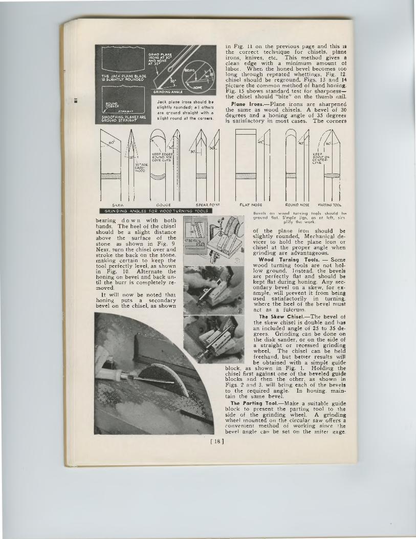
THE JACK PLANE BLADE IS SLIGHTLY ROUNDED
SMOOTHING PLANES ARE GROUND STRAIGHT
IN
1
NONE G I
Jack plane irons should be
slightly rounded; all others are ground straight with a
slight round at the corners.
SKEW
r
• 35°POR HARD-WOOD
GRINDING ANGLES FOR WOODTURNING TOOLS
25
A
KEEP EDGES ROUND FOR COVE CUTS
GOUGE SPEAR PO NT
CORNER
.T/L4111 /41
45.
KEEP POINT ON CENTER-LINE
GRIND PLANE IRONS AT 30* AND NONE AT 3S•
bearing do w n with both hands. The heel of the chisel should be a slight distance above the surface of the stone as shown in Fig. 9 Next, turn the chisel over and stroke the back on the stone. making certain to keep the tool perfectly level, as shown in Fig. 10. Alternate the honing on bevel and back un-til the burr is completely re-moved.
It will now be noted that honing puts a secondary bevel on the chisel, as shown
in Fig. 11 on the previous page and this is the correct technique for chisels, plane irons, knives, etc. This method gives a clean edge with a minimum amount of labor. When the honed bevel becomes too long through repeated whettings, Fig. 12, chisel should be reground. Figs. 13 and 14 picture the common method of hand honing. Fig. 15 shows standard test for sharpness—the chisel should "bite" on the thumb nail.
Plane Irons.—Plane irons are sharpened the same as wood chisels. A bevel of 30 degrees and a honing angle of 35 degrees is satisfactory in most cases. The corners
FLAT NOSE ROUND NOSE PARTING TOOL
Bevels on wood turning tools should be ground flat. Simple jigs, as at left, sim-
plify the work.
of the plane iron should be slightly rounded. Mechanical de-vices to hold the plane iron or chisel at the proper angle when grinding are advantageous.
Wood Turning Tools. — Some wood turning tools are not hol-low ground. Instead, the bevels are perfectly flat and should be kept flat during honing. Any sec-ondary bevel on a skew, for ex-ample, will prevent it from being used satisfactorily in turning. where the heel of the bevel must act as a fulcrum.
The Skew Chisel.—The bevel of the skew chisel is double and has an included angle of 25 to 35 de-grees. Grinding can be done on the disk sander, or on the side of a straight or recessed grinding wheel. The chisel can be held freehand, but better results will be obtained with a simple guide
block, as shown in Fig. 1. Holding the chisel first against one of the beveled guide blocks and then the other, as shown in Figs. 2 and 3. will bring each of the bevels to the required angle. In honing. main-tain the same bevel.
The Parting Tool.—Make a suitable guide block to present the parting tool to the side of the grinding wheel. A grinding wheel mounted on the circular saw offers a convenient method of working since the bevel angle can be set on the miter gage.
[ 18 ]
SKEW GOUGE SPEAR PO NT
WAD PLANC.
AT 3S•AND HONE /IRONS AT 30°
THE JACK PLANE BLADEIS SLIGHTLY ROUNDED
SMOOTHING PLANES AREGROUND STRAIGHT
GRINDING, ANGLE
Jack plane irons should be
slightly rounded; all others
are ground straight with a
slight round at the corners.
KEEP EDGESROUND FORCOVE CUTS
25
•35 ° PORHARD-WOOD
CORNER
.1. 70.4111/41
GRINDING ANGLES FOR WOODTURNING TOOLS
bearing do w n with bothhands. The heel of the chiselshould be a slight distanceabove the surface of thestone as shown in Fig. 9Next, turn the chisel over andstroke the back on the stone.making certain to keep thetool perfectly level, as shownin Fig. 10. Alternate thehoning on bevel and back un-til the burr is completely re-moved.
It will now be noted thathoning puts a secondarybevel on the chisel, as shown
in Fig. 11 on the previous page and this isthe correct technique for chisels, planeirons, knives, etc. This method gives aclean edge with a minimum amount oflabor. When the honed bevel becomes toolong through repeated whettings, Fig. 12,chisel should be reground. Figs. 13 and 14picture the common method of hand honing.Fig. 15 shows standard test for sharpness—the chisel should "bite" on the thumb nail.
Plane Irons.—Plane irons are sharpenedthe same as wood chisels. A bevel of 30degrees and a honing angle of 35 degreesis satisfactory in most cases. The corners
Bevels on wood turning tools should beground flat. Simple jigs, as at left, sim-
plify the work.
of the plane iron should beslightly rounded. Mechanical de-vices to hold the plane iron orchisel at the proper angle whengrinding are advantageous.
Wood Turning Tools. — Somewood turning tools are not hol-low ground. Instead, the bevelsare perfectly flat and should bekept flat during honing. Any sec-ondary bevel on a skew, for ex-ample, will prevent it from beingused satisfactorily in turning.where the heel of the bevel mustact as a fulcrum.
The Skew Chisel.—The bevel ofthe skew chisel is double and hasan included angle of 25 to 35 de-grees. Grinding can be done onthe disk sander, or on the side ofa straight or recessed grindingwheel. The chisel can be heldfreehand, but better results willbe obtained with a simple guide
block, as shown in Fig. 1. Holding thechisel first against one of the beveled guideblocks and then the other, as shown inFigs. 2 and 3. will bring each of the bevelsto the required angle. In honing. main-tain the same bevel.
The Parting Tool.—Make a suitable guideblock to present the parting tool to theside of the grinding wheel. A grindingwheel mounted on the circular saw offers aconvenient method of working since thebevel angle can be set on the miter gage.
45. 40t
KEEPPOINT ONCENTER-LINE
FLAT NOSE ROUND NOSEPARTING TOOL
[ 18 ]
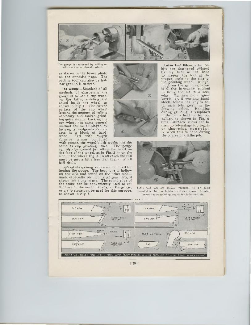
The gouge is sharpened by rolling on either a cup or straight wheel.
as shown in the lower photo on the opposite page. The Darting tool can also be hol-low ground if desired.
The Gouge.—Simplest of all methods of sharpening the gouge is to use a cup wheel on the lathe, rotating the chisel inside the wheel, as shown in Fig. 1. The curved surface of the cup wheel lessens the amount of rolling necessary and makes grind ing quite simple. Lacking the cup wheel, the same general method can be employed by turning a wedge-shaped re-cess in a block of hard-wood. Fed with 60-grit abrasive grains combined with grease, the wood block works just the same as cup grinding wheel. The gouge can also be ground by rolling the bevel on the face of the wheel, as in Fig. 2 or on the side of the wheel. Fig. 3. In all cases the roll must be just a little less than that of a full half-circle.
Special sharpening stones are required for honing the gouge. The best type is hollow on one side and round on the other side—made especially for honing gouges. Fig. 4 shows this stone in use. The round edge of the stone can be conveniently used to cut the burr on the inside flat edge of the gouge, or a slip stone can be used for this purpose. as shown in Fig. 5.
Lathe Tool Bits—Lathe tool bits are sharpened offhand, being held in the hand to present the tool at the proper angle to the side of the grinding wheel. A light touch on the grinding wheel is all that is usually required to bring the bit to a keen edge. Maintain the original bevels, or, if working blank stock, follow the angles for 1/4 inch bits given in the drawing below. Handling during grinding is simplified If the bit is held in the tool holder. as shown in Fig. 6 Small abrasive sticks can be used to advantage for touch-up sharpening, es p e ci a 1-ly when this is done during the course of a lathe job.
Lathe tool bits are ground freehand, the bit being
mounted in the tool holder as shown above. Drawing
below shows grinding angles for lathe tool bits.
_}._ _A__ 4 + _i__ TOP ViEN. .
* .1— V END
TOP VIEW Allill. .:2"5-31-1..r•— —
SIDE VIEW 1 ̀,28,?T.Y6 ' k. LEFT CORNER, SIDE VIEW R TOOL BIT
14* TOP VIEW .• merlon, ,,ROuNo
\' Secr/oN BORING TOOL e TOP VIEW
\ I_33• ....t...... //, /
1 FINISHING *4 *4 )43° TOOL BIT WV ......i), ?k,.... SIDE WV.,
3.- L — ----f— 3S1.. ,..1 \ \._90.̀
GRINDING ANGLES FOR. LATHE TOOL BITS BEST RESULTS WILL BE OBTAINED BY USING EXACT SHAVES SHOWN)
19 1
The gouge is sharpened by rolling oneither a cup or straight wheel.
as shown in the lower photoon the opposite page. TheDarting tool can also be hol-low ground if desired.
The Gouge. —Simplest of allmethods of sharpening thegouge is to use a cup wheelon the lathe, rotating thechisel inside the wheel, asshown in Fig. 1. The curvedsurface of the cup wheellessens the amount of rollingnecessary and makes grinding quite simple. Lacking thecup wheel, the same generalmethod can be employed byturning a wedge-shaped re-cess in a block of hard-wood. Fed with 60-gritabrasive grains combinedwith grease, the wood block works just thesame as cup grinding wheel. The gougecan also be ground by rolling the bevel onthe face of the wheel, as in Fig. 2 or on theside of the wheel. Fig. 3. In all cases the rollmust be just a little less than that of a fullhalf-circle.
Special sharpening stones are required forhoning the gouge. The best type is hollowon one side and round on the other side—made especially for honing gouges. Fig. 4shows this stone in use. The round edge ofthe stone can be conveniently used to cutthe burr on the inside flat edge of the gouge,or a slip stone can be used for this purpose.as shown in Fig. 5.
Lathe Tool Bits —Lathe toolbits are sharpened offhand,being held in the handto present the tool at theproper angle to the side ofthe grinding wheel. A lighttouch on the grinding wheelis all that is usually requiredto bring the bit to a keenedge. Maintain the originalbevels, or, if working blankstock, follow the angles for1/4 inch bits given in thedrawing below. Handlingduring grinding is simplifiedIf the bit is held in the toolholder. as shown in Fig. 6Small abrasive sticks can beused to advantage for touch-up sharpening, es p e ci a 1-ly when this is done duringthe course of a lathe job.
Lathe tool bits are ground freehand, the bit being
mounted in the tool holder as shown above. Drawing
below shows grinding angles for lathe tool bits.
_i__A__ 4+ _i__-1—'TOP VIEW.
.VEND
TOP VIEW All11111111/ 2"-1..r.-—.: 5-31
SIDE VIEW1,̀28,?T.Y6°.
SIDE VIEW-1— LEFT CORNER-TOOL BIT
14° TOP VIEW
••merlon,OUNO,...-
Secr/aw \ /
\
BORING TOOLe TOP VIEW
4-a2.-1
FINISHING.1...9''SiD VIEW /TOOL BIT WV—A-
....... iirg;?k,.... SIDE WV., U1 --—--f—j \ go .'"-3S1..
GRINDING ANGLES FOR LATHE TOOL BITS BEST RESULTS WILL BE OBTAINED BY USING EXACT SHAVES SHOWN)
[ 19 1
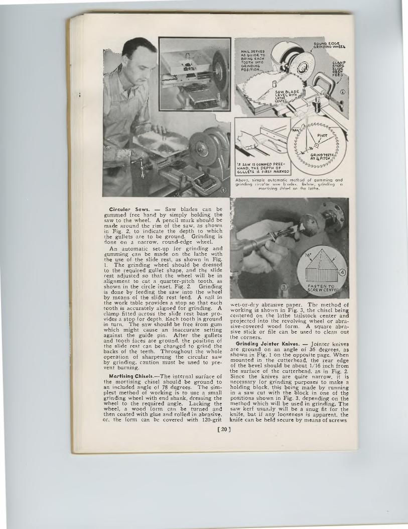
ROUND EOGE GRINDING WHEEL.
NAIL SERVES AS GUIDE TO BRING EACH TOOTH INTO GRINDING POSITION-
STOPS P
SLIDE RESIt FEED .
SAW BL W
ADE LEVEL ITH LATHE CENTE,I,
PIVOT
IF SAW IS GUMMED FREE-HAND, THE DEPTH OF GULLETS S FIRST MARKED
Above, simple automatic method of gumming and grinding circular saw blades. Below, grinding a
mortising chisel on the lathe.
Circular Saws. — Saw blades can be gummed free hand by simply holding the saw to the wheel. A pencil mark should be made around the rim of the saw, as shown in Fig. 2, to indicate the depth to which the gullets are to be ground. Grinding is done on a narrow, round-edge wheel.
An automatic set-up for grinding and gumming can be made on the lathe with the use of the slide rest, as shown in Fig. 1. The grinding wheel should be dressed to the required gullet shape, and the slide rest adjusted so that the wheel will be in alignment to cut a quarter-pitch tooth, as shown in the circle inset, Fig. 2. Grinding is done by feeding the saw into the wheel by means of the slide rest feed. A nail in the work table provides a stop so that each tooth is accurately aligned for grinding. A clamp fitted across the slide rest base pro-vides a stop for depth. Each tooth is ground in turn. The saw should be free from gum which might cause an inaccurate setting against the guide pin. After the gullets and tooth faces are ground. the position of the slide rest can be changed to grind the backs of the teeth. Throughout the whole operation of sharpening the circular saw by grinding, caution must be used to pre-vent burning.
Mortising Chisels.—The internal surface of the mortising chisel should be ground to an included angle of 78 degrees. The sim-plest method of working is to use a small grinding wheel with end shank, dressing the wheel to the required angle. Lacking the wheel, a wood form can be turned and then coated with glue and rolled in abrasive. or, the form can be covered with 120-grit
wet-or-dry abrasive paper. The method of working is shown in Fig. 3, the chisel being centered on the lathe tailstock center and projected into the revolving wheel or abra-sive-covered wood form. A square abra-sive stick or file can be used to clean out the corners.
Grinding Jointer Knives. — Jointer knives are ground on an angle of 36 degrees, as shown in Fig. 1 on the opposite page. When mounted in the cutterhead, the rear edge of the bevel should be about 1/ 16 inch from the surface of the cutterhead, as in Fig. 2. Since the knives are quite narrow, it is necessary for grinding purposes to make a holding block, this being made by running in a saw cut with the block in one of the positions shown in Fig. 3, depending on the method which will be used in grinding. The saw kerf usua.ly will be a snug fit for the knife, but if any looseness is apparent, the knife can be held secure by means of screws
[20]
I
AIL
ROUND EOGEGRINDING WHEEI.
NAIL SERVESAS GUIDE TOBRING EACHTOOTH INTOGRINDINGPOSITION-.
,
CLAMP
SLIOEREST,PEED .
SAW BLADELEVEL WITHLATHECENTC,,
PIVOT
IF SAW IS GUMMED FREE-HAND, THE DEPTH OFGULLETS IS FIRST MARKED
AT Y4 PITCHGaiNOTEETrIj44.,
2-1-6111/V
Above, simple automatic method of gumming andgrinding circular saw blades. Below, grinding a
mortising chisel on the lathe.
Circular Saws. — Saw blades can begummed free hand by simply holding thesaw to the wheel. A pencil mark should bemade around the rim of the saw, as shownin Fig. 2, to indicate the depth to whichthe gullets are to be ground. Grinding isdone on a narrow, round-edge wheel.
An automatic set-up for grinding andgumming can be made on the lathe withthe use of the slide rest, as shown in Fig.1. The grinding wheel should be dressedto the required gullet shape, and the sliderest adjusted so that the wheel will be inalignment to cut a quarter-pitch tooth, asshown in the circle inset, Fig. 2. Grindingis done by feeding the saw into the wheelby means of the slide rest feed. A nail inthe work table provides a stop so that eachtooth is accurately aligned for grinding. Aclamp fitted across the slide rest base pro-vides a stop for depth. Each tooth is groundin turn. The saw should be free from gumwhich might cause an inaccurate settingagainst the guide pin. After the gulletsand tooth faces are ground. the position ofthe slide rest can be changed to grind thebacks of the teeth. Throughout the wholeoperation of sharpening the circular sawby grinding, caution must be used to pre-vent burning.
Mortising Chisels.—The internal surface ofthe mortising chisel should be ground toan included angle of 78 degrees. The sim-plest method of working is to use a smallgrinding wheel with end shank, dressing thewheel to the required angle. Lacking thewheel, a wood form can be turned andthen coated with glue and rolled in abrasive,or, the form can be covered with 120-grit
wet-or-dry abrasive paper. The method ofworking is shown in Fig. 3, the chisel beingcentered on the lathe tailstock center andprojected into the revolving wheel or abra-sive-covered wood form. A square abra-sive stick or file can be used to clean outthe corners.
Grinding Jointer Knives. — Jointer knivesare ground on an angle of 36 degrees, asshown in Fig. 1 on the opposite page. Whenmounted in the cutterhead, the rear edgeof the bevel should be about 1/16 inch fromthe surface of the cutterhead, as in Fig. 2.Since the knives are quite narrow, it isnecessary for grinding purposes to make aholding block, this being made by runningin a saw cut with the block in one of thepositions shown in Fig. 3, depending on themethod which will be used in grinding. Thesaw kerf usua.ly will be a snug fit for theknife, but if any looseness is apparent, theknife can be held secure by means of screws
[ 20 ]
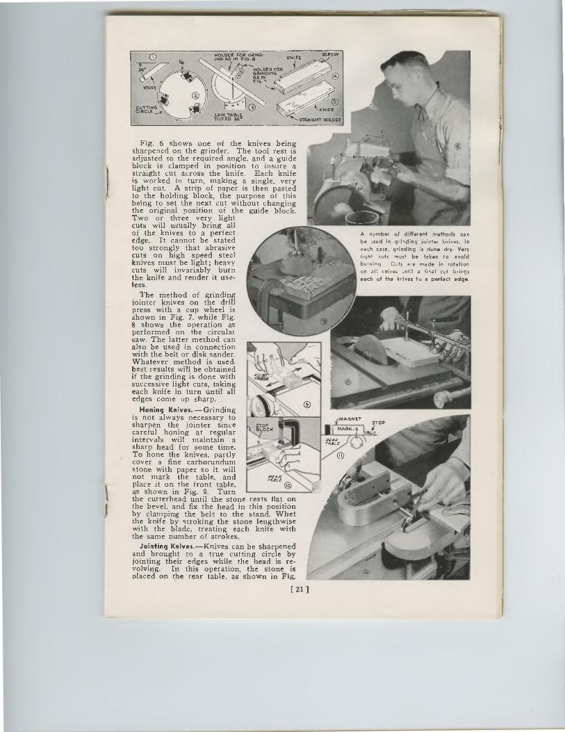
CUTTING' VETCJAW
KNIFE
KNIFE STRAIGHT STRAIGHT HOLDER-
SCREW 11.1CVAIRItfTiGn"- KNIFE HOLDER FOR 2.14A:140ING FIG.,
Fig. 6 shows one of the knives being sharpened on the grinder. The tool rest is adjusted to the required angle, and a guide block is clamped in position to insure a straight cut across the knife. Each knife is worked in turn, making a single, very light cut. A strip of paper is then pasted to the holding block, the purpose of this being to set the next cut without changing the original position of the guide block. Two or three very light cuts will usually bring all of the knives to a perfect edge. It cannot be stated too strongly that abrasive cuts on high speed steel knives must be light; heavy cuts will invariably burn the knife and render it use-less.
The method of grinding jointer knives on the drill press with a cup wheel is shown in Fig. 7, while Fig. 8 shows the operation as performed on the circular saw. The latter method can also be used in connection with the belt or disk sander. Whatever method is used, best results will be obtained if the grinding is done with successive light cuts, taking each knife in turn until all edges come up sharp.
Honing Knives.—Grinding is not always necessary to sharpen the jointer since careful honing at regular intervals will maintain a sharp head for some time. To hone the knives, partly cover a fine carborundum stone with paper so it will not mark the table, and place it on the front table, as shown in Fig. 9. Turn the cutterhead until the stone rests fiat on the bevel, and fix the head in this position by clamping the belt to the stand. Whet the knife by stroking the stone lengthwise with the blade, treating each knife with the same number of strokes.
Jointing Knives.—Knives can be sharpened and brought to a true cutting circle by jointing their edges while the head is re-volving. In this operation, the stone is placed on the rear table, as shown in Fig.
[ 21 ]
REAR TAB[
REAR TA8LE
A number of different methods can be used in grinding jointer knives. In
each case, grinding is done dry. Very
light cuts must be taken to avoid burning. Cuts are made in rotation
on all knives until a final cut brings
each of the knives to a perfect edge.
SCREWl'INCVAR tf•C'FIGn--KNIFE
HOLDER FOR2rOING
FIG.,
KNIFE
STRAIGHT HOLDER
Fig. 6 shows one of the knives beingsharpened on the grinder. The tool rest isadjusted to the required angle, and a guideblock is clamped in position to insure astraight cut across the knife. Each knifeis worked in turn, making a single, verylight cut. A strip of paper is then pastedto the holding block, the purpose of thisbeing to set the next cut without changingthe original position of the guide block.Two or three very lightcuts will usually bring allof the knives to a perfectedge. It cannot be statedtoo strongly that abrasivecuts on high speed steelknives must be light; heavycuts will invariably burnthe knife and render it use-less.
The method of grindingjointer knives on the drillpress with a cup wheel isshown in Fig. 7, while Fig.8 shows the operation asperformed on the circularsaw. The latter method canalso be used in connectionwith the belt or disk sander.Whatever method is used,best results will be obtainedif the grinding is done withsuccessive light cuts, takingeach knife in turn until alledges come up sharp.
Honing Knives. — Grindingis not always necessary tosharpen the jointer sincecareful honing at regularintervals will maintain asharp head for some time.To hone the knives, partlycover a fine carborundumstone with paper so it willnot mark the table, andplace it on the front table,as shown in Fig. 9. Turnthe cutterhead until the stone rests fiat onthe bevel, and fix the head in this positionby clamping the belt to the stand. Whetthe knife by stroking the stone lengthwisewith the blade, treating each knife withthe same number of strokes.
Jointing Knives. —Knives can be sharpenedand brought to a true cutting circle byjointing their edges while the head is re-volving. In this operation, the stone isplaced on the rear table, as shown in Fig.
STOPBLOCK
A number of different methods can
be used in grinding jointer knives. Ineach case, grinding is done dry. Verylight cuts must be taken to avoid
burning. Cuts are made in rotation
on all knives until a final cut brings
each of the knives to a perfect edge.
[ 21 ]
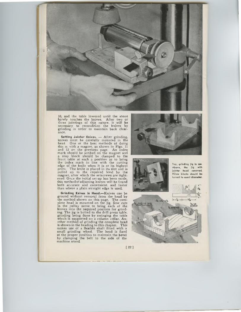
[ 22 ]
10, and the table lowered until the stone barely touches the knives. After two or three jointings of this nature, it will be necessary to recondition the knives by grinding in order to maintain back clear-ance.
Setting Jointer Knives. — After grinding, knives must be carefully mounted in the head One of the best methods of doing this is with a magnet, as shown in Figs. 11 and 12 on the previous page. An index mark should be scribed on the magnet and a stop block should be clamped to the front table at such a position as to bring the index mark in line with the cutting edge of the knife when it is at its highest point. The knife is placed in its slot and is pulled up to the required level by the magnet, after which the setscrews are tight-ened Once the initial set-up has been made, this method of adjusting knives will be found both accurate and convenient, and faster than where a plain straight edge is used.
Grinding Knives in Head.—Knives can be ground without removal from the head by the method shown on this page. The com-plete head is mounted on the jig. Saw cuts in the pulley serve to bring each of the knives into the required position for grind-ing. The jig is bolted to the drill press table, grinding being done by swinging the table which is supported on a column collar. An-other method of grinding the complete head is shown in the heading to this chapter. This makes use of a flexible shaft fitted with a small grinding wheel. The head is fixed at the proper position to maintain the bevel by clamping the belt to the side of the machine stand.
Top, grinding ilg in use
Above, the jig with
jointer head removed.
Pillow blocks should be
turned to exact diameter.
Top, grinding jig in use
Above, the jig with
jointer head removed.
Pillow blocks should beturned to exact diameter.
IY4/1
_L3/4
r443-1 -1-1%8 3
5i-24SCREW
10, and the table lowered until the stonebarely touches the knives. After two orthree jointings of this nature, it will benecessary to recondition the knives bygrinding in order to maintain back clear-ance.
Setting Jointer Knives. — After grinding,knives must be carefully mounted in thehead One of the best methods of doingthis is with a magnet, as shown in Figs. 11and 12 on the previous page. An indexmark should be scribed on the magnet anda stop block should be clamped to thefront table at such a position as to bringthe index mark in line with the cuttingedge of the knife when it is at its highestpoint. The knife is placed in its slot and ispulled up to the required level by themagnet, after which the setscrews are tight-ened Once the initial set-up has been made,this method of adjusting knives will be foundboth accurate and convenient, and fasterthan where a plain straight edge is used.
Grinding Knives in Head.—Knives can beground without removal from the head bythe method shown on this page. The com-plete head is mounted on the jig. Saw cutsin the pulley serve to bring each of theknives into the required position for grind-ing. The jig is bolted to the drill press table,grinding being done by swinging the tablewhich is supported on a column collar. An-other method of grinding the complete headis shown in the heading to this chapter. Thismakes use of a flexible shaft fitted with asmall grinding wheel. The head is fixedat the proper position to maintain the bevelby clamping the belt to the side of themachine stand.
[ 22 ]
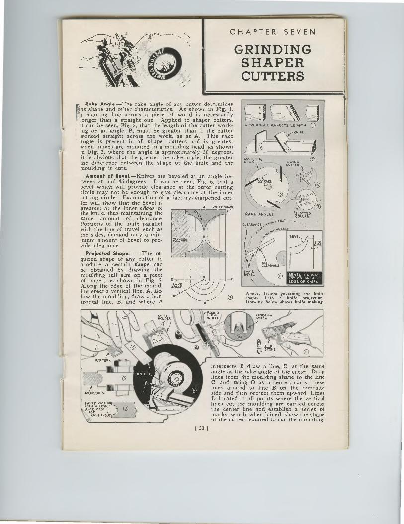
MOULDING HEAD,
- CUTTER
--- RAKE ANGLES
e6L CLEARANCE
o ;000.0.1tt 0 00
BEVEL
NO CLEARANCE -
SIDE BEAL
BEVEL IS GREAT-EST ON INNER EDGE OF KNIFE
SAME. BEVEL
30° RAKE
COLLA SLOTTE
RD
CHAPTER SEVEN
GRINDING SHAPER CUTTERS
F
Rake Angle.—The rake angle of any cutter determines ,ts shape and other characteristics. As shown in Fig. 1, a slanting line across a piece of wood is necessarily longer than a straight one. Applied to shaper cutters, it can be seen, Fig. 2, that the length of the cutter work-ing on an angle, B, must be greater than if the cutter worked straight across the work, as at A. This rake angle is present in all shaper cutters and is greatest when knives are mounted in a moulding head, as shown in Fig. 3, where the angle is approximately 30 degrees. It is obvious that the greater the rake angle, the greater the difference between the shape of the knife and the moulding it cuts.
Amount of Bevel.—Knives are beveled at an angle be-tween 30 and 45-degrees. It can be seen, Fig. 6, that a bevel which will provide clearance at the outer cutting circle may not be enough to give clearance at the inner cutting circle. Examination of a factory-sharpened cut-ter will show that the bevel is greatest at the inner edges of the knife, thus maintaining the same amount of clearance. Portions of the knife parallel with the line of travel, such as the sides, demand only a min-imum amount of bevel to pro-vide clearance.
Projected Shape. — The re-quired shape of any cutter to produce a certain shape can be obtained by drawing the moulding full size on a piece of paper, as shown in Fig. 7. Along the edge of the mould-ing erect a vertical line, A. Be-low the moulding, draw a hor-izontal line, B, and where A
ROUND IS EDGE
WHEEL ;Li
A KNIFE SNAPS
Bq
Above, factors governing the knife shape. Left, a knife projection. Drawing below shows knife melting.
FINISHED KNIFE
I
PATTERN
g SLIP STONE
MOULDING 1J,T
PAPER PATTERN WITH ALLOW. ANCE MADE;
FOR RAKE ANGL
N
intersects B draw a line, C, at the same angle as the rake angle of the cutter. Drop lines from the moulding shape to the line C and. using 0 as a center, carry these lines around to line B on the onnosite side and then nroject them upward Lines D located at all points where the vertical lines cut the moulding are carried across the center line and establish a series of marks. which, when joined, show the shape of the cutter required to cut the moulding
[ 23 ]
•••••••—
SLOTTECOLLAR
D
BEVEL
SIDEBEVEL
IS
FINISHEDKNIFE
g SLIPSTONE
CHAPTER SEVEN
GRINDINGSHAPERCUTTERS
FRake Angle.—The rake angle of any cutter determines
,ts shape and other characteristics. As shown in Fig. 1,a slanting line across a piece of wood is necessarilylonger than a straight one. Applied to shaper cutters,it can be seen, Fig. 2, that the length of the cutter work-ing on an angle, B, must be greater than if the cutterworked straight across the work, as at A. This rakeangle is present in all shaper cutters and is greatestwhen knives are mounted in a moulding head, as shownin Fig. 3, where the angle is approximately 30 degrees.It is obvious that the greater the rake angle, the greaterthe difference between the shape of the knife and themoulding it cuts.
Amount of Bevel.—Knives are beveled at an angle be-tween 30 and 45-degrees. It can be seen, Fig. 6, that abevel which will provide clearance at the outer cuttingcircle may not be enough to give clearance at the innercutting circle. Examination of a factory-sharpened cut-ter will show that the bevel isgreatest at the inner edges ofthe knife, thus maintaining thesame amount of clearance.Portions of the knife parallelwith the line of travel, such asthe sides, demand only a min-imum amount of bevel to pro-vide clearance.
Projected Shape. — The re-quired shape of any cutter toproduce a certain shape canbe obtained by drawing themoulding full size on a pieceof paper, as shown in Fig. 7.Along the edge of the mould-ing erect a vertical line, A. Be-low the moulding, draw a hor-izontal line, B, and where A
ROUNDEDGE
II• •
HOW ANGLE AFFECTS LENGTH
MOULoiNG1-WINGCUTTER
---
RAKE ANGLES
CLEARANCEc‘""ANAnW
o o ,
NOUy CLEARANCE -
SAME •ABEVEL
BEVEL IS GREAT-EST ON INNER -'EDGE OF KNIFE
Above, factors governing the knifeshape.Left, a knife projection.Drawing below shows knife melting.
KNIIIFEHOLDER IS
fMOULDING
PAPER PATTERNWITH ALLOW.ANCE MADE;, FOR
RAKE ANGL
intersects B draw a line, C, at the sameangle as the rake angle of the cutter. Droplines from the moulding shape to the lineC and. using 0 as a center, carry theselines around to line B on the onnositeside and then project them upward LinesD located at all points where the verticallines cut the moulding are carried acrossthe center line and establish a series ofmarks. which, when joined, show the shapeof the cutter required to cut the moulding
[ 23 ]
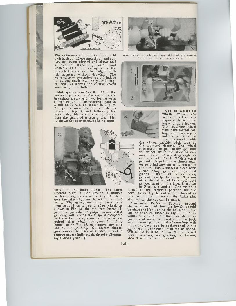
Si AR WHEEL DRESSER.„4
GRINDING WHEEL
WHEEL SHAPE FOR GENERAL WORK
TOOL. 0 REST
DRESSING WHEEL
The difference amounts to about 1/16 inch in depth where moulding head cut-ters are being plotted and about half of this for three-wing cutters and slotted collars. For average work, the projected shape can be judged with fair accuracy without drawing. The basic rules to remember are (1) knives for cutting beads must be ground deep-er, and (2) knives for cutting coves must be ground fuller.
Making a Knife.—Figs. 8 to 15 on the previous page show the various steps in making a pair of knives for use with slotted collars. The required shape is a full half-circle, as shown in Fig. 9. A paper or metal pattern is made, as shown in Fig. 8, and, following the basic rule, this is cut slightly deeper than the shape of a true circle. Fig. 10 shows the pattern shape being trans-
CUTTER MOUNTED ON SPINDLE
G G`41TLI
LOCK CUTTER AT PROPER • POS ITION
(erred to the knife blanks. The outer straight bevel is then ground, a suitable method being as shown in Fig. 11 which uses the lathe slide rest to set the required angle. The curved portion of the knife is then ground on a round edge wheel, as shown in Fig. 13, the tool rest being ad-justed to provide the proper bevel. After grinding both knives, the shape is compared and checked. readjustments made as re-quired, after which the bevel is lightly honed, as in Fig. 15, to remove any burr left by the grinding. On certain shapes. good use can be made of a cut-off wheel to remove excess knife stock, thereby eliminat-ing tedious grinding.
Use of Shaped Wheels.—Wheels can be fashioned to any required shape by us-ing a suitable dresser. The revolving wheel type is the fastest cut-ting, but does not per-
__ mit the precision which is possible with
the silicon carbide stick type or the diamond dresser. The wheel type should be pushed straight into the wheel, while the stick or dia-mond work best at a drag angle, as can be seen in Fig. 1. With a wheel
cuTTER properly shaped, it is a simple mat- ( ter to grind any cutter to the same
contour. Fig. 3 shows a three-wing cutter being ground. Stops and guides insures all wings being ground exactly the same. The use of a shaped wheel in a tool post grinder used on the lathe is shown in Figs. 4, 5 and 6. The cutter is
turned to the required position for the bevel, as in Fig. 6, and is then locked in this position by means of the index pin, after which the cut can be made.
Sharpening Knifes. — Factory - ground shaper knives with involute bevels should be sharpened by honing the flat side of the cutting edge, as shown in Fig. 7. The in-volute bevel will retain the same shape re-gardless of metal removed from the back side. Knives ground in the homeshop with a straight bevel can be resharpened in the same way, or, the bevel itself can be honed. Where the knife has an involute or curved bevel, however, no grinding or honing should be done on the bevel.
A star wheel dresser is fast-cutting while stick and diamond dressers provide for precision work.
DRESS WHEEL TO SHAPE
[ 24 ]
STARWHEELDRESSER
-
GRINDINGWHEEL
TOOL0 REST
DRESSING WHEEL ICK
DRESSER
'AuRi2 '61€
WHEEL SHAPEFOR GENERAL WORK
The difference amounts to about 1/16inch in depth where moulding head cut-ters are being plotted and about halfof this for three-wing cutters andslotted collars. For average work, theprojected shape can be judged withfair accuracy without drawing. Thebasic rules to remember are (1) knivesfor cutting beads must be ground deep-er, and (2) knives for cutting covesmust be ground fuller.
Making a Knife. —Figs. 8 to 15 on theprevious page show the various stepsin making a pair of knives for use withslotted collars. The required shape isa full half-circle, as shown in Fig. 9.A paper or metal pattern is made, asshown in Fig. 8, and, following thebasic rule, this is cut slightly deeperthan the shape of a true circle. Fig.10 shows the pattern shape being trans-
CUTTERMOUNTEDON SPINDLE
A star wheel dresser is fast-cutting while stick and diamonddressers provide for precision work.
Use of ShapedWheels.—Wheels canbe fashioned to anyrequired shape by us-ing a suitable dresser.The revolving wheeltype is the fastest cut-ting, but does not per-mit the precisionwhich is possible with
the silicon carbide stick type orthe diamond dresser. The wheel
LOCK .•CUTTER ATPROPERPOSITION
(erred to the knife blanks. The outerstraight bevel is then ground, a suitablemethod being as shown in Fig. 11 whichuses the lathe slide rest to set the requiredangle. The curved portion of the knife isthen ground on a round edge wheel, asshown in Fig. 13, the tool rest being ad-justed to provide the proper bevel. Aftergrinding both knives, the shape is comparedand checked. readjustments made as re-quired, after which the bevel is lightlyhoned, as in Fig. 15, to remove any burrleft by the grinding. On certain shapes.good use can be made of a cut-off wheel toremove excess knife stock, thereby eliminat-ing tedious grinding.
type should be pushed straight intothe wheel, while the stick or dia-mond work best at a drag angle, ascan be seen in Fig. 1. With a wheel
cuTTER properly shaped, it is a simple mat-( ter to grind any cutter to the same
contour. Fig. 3 shows a three-wingcutter being ground. Stops andguides insures all wings beingground exactly the same. The useof a shaped wheel in a tool postgrinder used on the lathe is shownin Figs. 4, 5 and 6. The cutter is
turned to the required position for thebevel, as in Fig. 6, and is then locked inthis position by means of the index pin,after which the cut can be made.
Sharpening Knifes. — Factory - groundshaper knives with involute bevels shouldbe sharpened by honing the flat side of thecutting edge, as shown in Fig. 7. The in-volute bevel will retain the same shape re-gardless of metal removed from the backside. Knives ground in the homeshop witha straight bevel can be resharpened in thesame way, or, the bevel itself can be honed.Where the knife has an involute or curvedbevel, however, no grinding or honingshould be done on the bevel.
DRESSWHEEL TO
GRiNpINGSHAPE
WHEEL
[ 24 ]
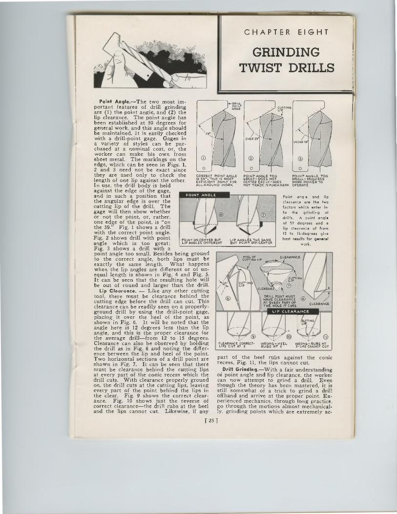
POINT GAGE
9°
0
HEEL OF CUTTING LIP
CLEARANCE
CLEARANC V1
DRILL POINT MUST HAVE CLEARANCE 1/42I AT EVERY PART OF THE HOLE IT CUTS
LIP CLEARANCE
LOTTING LIP
CUTTING LIP
O CUTTIN
O CLEARANCE CORRECT- WRONG -HEEL LIPS CUT AT X RUBS AT X
0
WRONG- RUBS AT X-LIPS CANNOT CUT
CHAPTER EIGHT
GRINDING TWIST DRILLS
Point Angle.—The two most im-portant features of drill grinding are (1) the point angle, and (2) the lip clearance. The point angle has been established at 59 degrees for general work, and this angle should be maintained. It is easily checked with a drill-point gage. Gages in a variety of styles can be pur-chased at a nominal cost, or, the worker can make his own from sheet metal. The markings on the edge, which can be seen in Figs. 1, 2 and 3 need not be exact since they are used only to check the length of one lip against the other. In use, the drill body is held against the edge of the gage, and in such a position that the angular edge is over the cutting lip of the drill. The gage will then show whether or not the point, or, rather, one edge of the point, is "on the 59." Fig. 1 shows a drill with the correct point angle. Fig. 2 shows drill with point angle which is too great; Fig. 3 shows a drill with a point angle too small. Besides being ground to the correct angle, both lips must be exactly the same length. What happens when the lip angles are different or of un-equal length is shown in Fig. 4 and Fig. 5. It can be seen that the resulting hole will be out of round and larger than the drill.
Lip Clearance. — Like any other cutting tool, there must be clearance behind the cutting edge before the drill can cut. This clearance can be readily seen on a properly-ground drill by using the drill-point gage, placing it over the heel of the point, as shown in Fig. 6. It will be noted that the angle here is 12 degrees less than the lip angle, and this is the proper clearance for the average drill—from 12 to 15 degrees. Clearance can also be observed by holding the drill as in Fig. 8 and noting the differ-ence between the lip and heel of the point. Two horizontal sections of a drill point are shown in Fig. 7. It can be seen that there must be clearance behind the cutting lips at every part of the conic recess which the drill cuts. With clearance properly ground on, the drill cuts at the cutting lips, leaving every part of the point behind the lips in the clear. Fig. 9 shows the correct clear-ance. Fig. 10 shows just the reverse of correct clearance—the drill rubs at the heel and the lips cannot cut. Likewise, if any
Point angle and Ilp
clearance are the two
factors which enter in-
to the grinding of
drills. A point angle
of 59 degrees and a
lip clearance of from
12 to I5-degrees give
best results for general
work.
part of the heel rubs against the conic recess, Fig. 11, the lips cannot cut.
Drill Grinding.—With a fair understanding of point angle and lip clearance, the worker can now attempt to grind a drill. Even though the theory has been mastered, it is still somewhat of a trick to grind a drill offhand and arrive at the proper point. Ex-perienced mechanics, through long practice, go through the motions almost mechanical-ly, grinding points which are extremely ac-
CORRECT POINT ANGLE POINT ANGLE TOO POINT ANGLE TOO S $9°. THIS IS MOST GREAT- DOES NOT SMALL- REQUIRES
EFFICIENT POINT FOR CENTER EASILY-DOES MORE DOWER TO ALL. ROUND WORK NOT TRACK IN PUNCH MARK OPERATE
POINT ON CENTER BUT LIP ANGLES TN E SAME LIP ANGLES OIFFERENT BUT POINT OFF-CENTER
[ 25 ]
EletIT ING
CuTTIN4
REEL OFCUTTING LIP
CLEARANCE
CLEARANC V1
DRILL POINT MUSTHAVE CLEARANCEAT EVERY PART OF
0 THE MOLE IT CUBSLIP CLEARANCE
• ®
CLEARANCE CORRECT-LIPS CUT AT X
WRONG -HEELRUBS AT X
WRONG- RUBS ATX-LIPS CANNOT CUT
CUTTINGLIP
OVER 59.
O0 j
CORRECT POINT ANGLES $9°. THIS IS MOSTEFFICIENT POINT FORALL•AROVND WORK
POINT ANGLE TOOGREAT- DOES NOTCENTER EASILY-DOESNOT TRACK IN PUNCH MARK
POINT ANGLE TOOSMALL- REQUIRESMORE DOWER TOOPERATE
• -DRILLPOINT
;,e-• GAGE
9„,
CHAPTER EIGHT
GRINDINGTWIST DRILLS
Point Angle.—The two most im-portant features of drill grindingare (1) the point angle, and (2) thelip clearance. The point angle hasbeen established at 59 degrees forgeneral work, and this angle shouldbe maintained. It is easily checkedwith a drill-point gage. Gages ina variety of styles can be pur-chased at a nominal cost, or, theworker can make his own fromsheet metal. The markings on theedge, which can be seen in Figs. 1,2 and 3 need not be exact sincethey are used only to check thelength of one lip against the other.In use, the drill body is heldagainst the edge of the gage,and in such a position thatthe angular edge is over thecutting lip of the drill. Thegage will then show whetheror not the point, or, rather,one edge of the point, is "onthe 59." Fig. 1 shows a drillwith the correct point angle.Fig. 2 shows drill with pointangle which is too great;Fig. 3 shows a drill with apoint angle too small. Besides being groundto the correct angle, both lips must beexactly the same length. What happenswhen the lip angles are different or of un-equal length is shown in Fig. 4 and Fig. 5.It can be seen that the resulting hole willbe out of round and larger than the drill.
Lip Clearance. — Like any other cuttingtool, there must be clearance behind thecutting edge before the drill can cut. Thisclearance can be readily seen on a properly-ground drill by using the drill-point gage,placing it over the heel of the point, asshown in Fig. 6. It will be noted that theangle here is 12 degrees less than the lipangle, and this is the proper clearance forthe average drill—from 12 to 15 degrees.Clearance can also be observed by holdingthe drill as in Fig. 8 and noting the differ-ence between the lip and heel of the point.Two horizontal sections of a drill point areshown in Fig. 7. It can be seen that theremust be clearance behind the cutting lipsat every part of the conic recess which thedrill cuts. With clearance properly groundon, the drill cuts at the cutting lips, leavingevery part of the point behind the lips inthe clear. Fig. 9 shows the correct clear-ance. Fig. 10 shows just the reverse ofcorrect clearance—the drill rubs at the heeland the lips cannot cut. Likewise, if any
Point angle and Ilp
clearance are the two
factors which enter in-
to the grinding of
drills.A point angle
of 59 degrees and a
lip clearance of from
12 to I5-degrees give
best results for general
work.
part of the heel rubs against the conicrecess, Fig. 11, the lips cannot cut.
Drill Grinding.—With a fair understandingof point angle and lip clearance, the workercan now attempt to grind a drill. Eventhough the theory has been mastered, it isstill somewhat of a trick to grind a drilloffhand and arrive at the proper point. Ex-perienced mechanics, through long practice,go through the motions almost mechanical-ly, grinding points which are extremely ac-
POINT ON CENTER BUTLIP ANGLES TN E SAMELIP ANGLES OIFFERENTBUT POINT OFF-CENTER
[ 25 ]
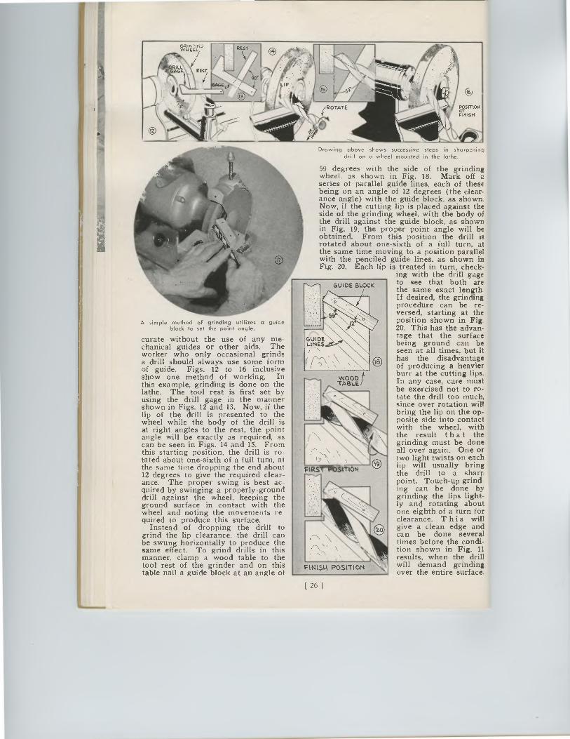
REST EIK WHEEL,
A simple method of grinding utilizes a guide block to set the point angle.
curate without the use of any me-chanical guides or other aids. The worker who only occasional grinds a drill should always use some form of guide. Figs. 12 to 16 inclusive show one method of working. In this example, grinding is done on the lathe. The tool rest is first set by using the drill gage in the manner shown in Figs. 12 and 13. Now, if the lip of the drill is presented to the wheel while the body of the drill is at right angles to the rest, the point angle will be exactly as required, as can be seen in Figs. 14 and 15. From this starting position, the drill is ro-tated about one-sixth of a full turn, at the same time dropping the end about 12 degrees to give the required clear-ance. The proper swing is best ac-quired by swinging a properly-ground drill against the wheel, keeping the ground surface in contact with the wheel and noting the movements re-quired to produce this surface.
Instead of dropping the drill to grind the lip clearance, the drill can be swung horizontally to produce the same effect. To grind drills in this manner, clamp a wood table to the tool rest of the grinder and on this table nail a guide block at an angle of
16
POSITION AT FINISH
Drawing above shows successive steps in sharpening drill on a wheel mounted in the lathe.
59 degrees with the side of the grinding wheel, as shown in Fig. 18. Mark off 2 series of parallel guide lines, each of these being on an angle of 12 degrees (the clear-ance angle) with the guide block, as shown. Now, if the cutting lip is placed against the side of the grinding wheel, with the body of the drill against the guide block, as shown in Fig. 19, the proper point angle will be obtained. From this position the drill is rotated about one-sixth of a full turn, at the same time moving to a position parallel with the penciled guide lines, as shown in Fig. 20. Each lip is treated in turn, check-
ing with the drill gage to see that both are the same exact length. If desired, the grinding procedure can be re-versed, starting at the position shown in Fig. 20. This has the advan-tage that the surface being ground can be seen at all times, but it has the disadvantage of producing a heavier burr at the cutting lips. In any case, care must be exercised not to ro-tate the drill too much, since over rotation will bring the lip on the op-posite side into contact with the wheel, with the result that the grinding must be done all over again. One or two light twists on each lip will usually bring the drill to a sharp point. Touch-up grind ing can be done by grinding the lips light-ly and rotating about one-eighth of a turn for clearance. T his will give a clean edge and can be done several times before the condi-tion shown in Fig. 11 results, when the drill will demand grinding over the entire surface.
[26 ]
POSITIONATFINISH
Drawing above shows successive steps in sharpening
drill on a wheel mounted in the lathe.
A simple method of grinding utilizes a guideblock to set the point angle.
curate without the use of any me-chanical guides or other aids. Theworker who only occasional grindsa drill should always use some formof guide. Figs. 12 to 16 inclusiveshow one method of working. Inthis example, grinding is done on thelathe. The tool rest is first set byusing the drill gage in the mannershown in Figs. 12 and 13. Now, if thelip of the drill is presented to thewheel while the body of the drill isat right angles to the rest, the pointangle will be exactly as required, ascan be seen in Figs. 14 and 15. Fromthis starting position, the drill is ro-tated about one-sixth of a full turn, atthe same time dropping the end about12 degrees to give the required clear-ance. The proper swing is best ac-quired by swinging a properly-grounddrill against the wheel, keeping theground surface in contact with thewheel and noting the movements re-quired to produce this surface.
Instead of dropping the drill togrind the lip clearance, the drill canbe swung horizontally to produce thesame effect. To grind drills in thismanner, clamp a wood table to thetool rest of the grinder and on thistable nail a guide block at an angle of
59 degrees with the side of the grindingwheel, as shown in Fig. 18. Mark off 2
series of parallel guide lines, each of thesebeing on an angle of 12 degrees (the clear-ance angle) with the guide block, as shown.Now, if the cutting lip is placed against theside of the grinding wheel, with the body ofthe drill against the guide block, as shownin Fig. 19, the proper point angle will beobtained. From this position the drill isrotated about one-sixth of a full turn, atthe same time moving to a position parallelwith the penciled guide lines, as shown inFig. 20. Each lip is treated in turn, check-
ing with the drill gageto see that both arethe same exact length.If desired, the grindingprocedure can be re-versed, starting at theposition shown in Fig.20. This has the advan-tage that the surfacebeing ground can beseen at all times, but ithas the disadvantageof producing a heavierburr at the cutting lips.In any case, care mustbe exercised not to ro-tate the drill too much,since over rotation willbring the lip on the op-posite side into contactwith the wheel, withthe result that thegrinding must be doneall over again. One ortwo light twists on eachlip will usually bringthe drill to a sharrpoint. Touch-up grinding can be done bygrinding the lips light-ly and rotating aboutone-eighth of a turn forclearance. T his willgive a clean edge andcan be done severaltimes before the condi-tion shown in Fig. 11results, when the drillwill demand grinding
over the entire surface.
[26 ]
FIN;31-4 POSITION
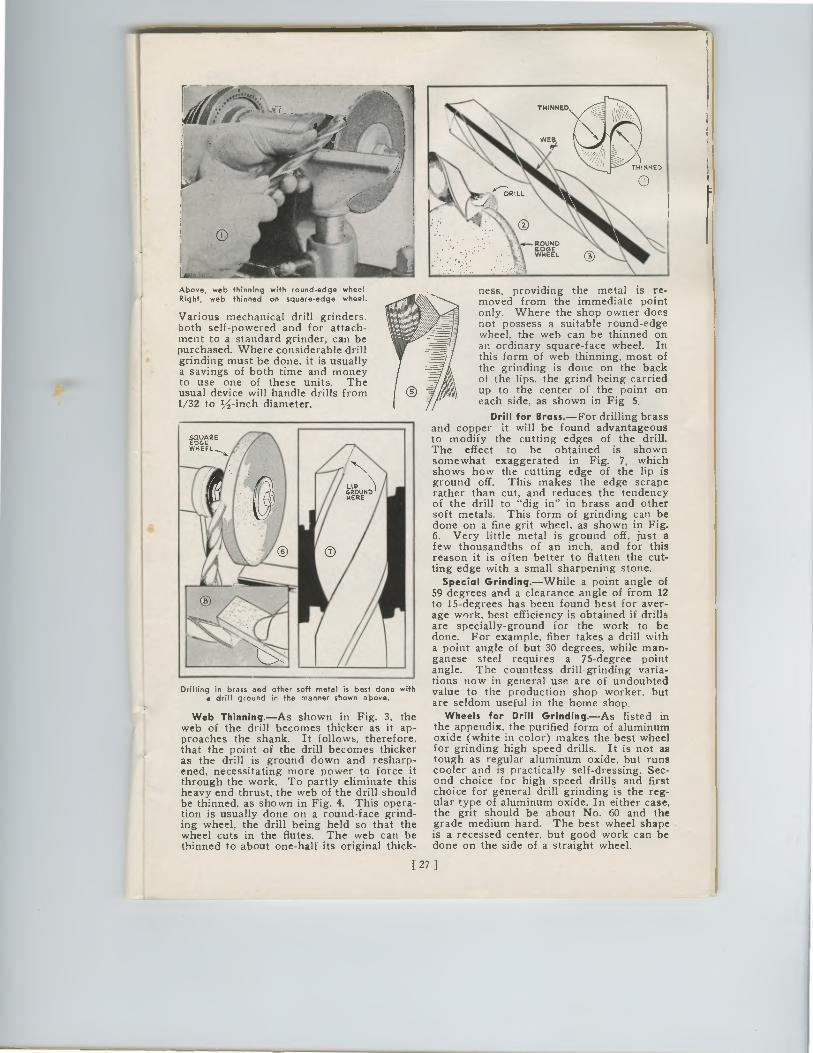
squARE EDGE WHEEL
EDGOUNED
WHEEL
Above, web thinning with round-edge wheel. Right, web thinned on square-edge wheel.
Various mechanical drill grinders. both self-powered and for attach-ment to a standard grinder, can be purchased. Where considerable drill grinding must be done, it is usually a savings of both time and money to use one of these units. The usual device will handle drills from 1/32 to 1/2-inch diameter.
Drilling in brass and other soft metal is best done with a drill ground in the manner shown above.
Web Thinning.—As shown in Fig. 3, the web of the drill becomes thicker as it ap-proaches the shank. It follows, therefore, that the point of the drill becomes thicker as the drill is ground down and resharp-ened, necessitating more power to force it through the work. To partly eliminate this heavy end thrust, the web of the drill should be thinned, as shown in Fig. 4. This opera-tion is usually done on a round-face grind-ing wheel, the drill being held so that the wheel cuts in the flutes. The web can be thinned to about one-half its original thick-
ness, providing the metal is re-moved from the immediate point only. Where the shop owner does not possess a suitable round-edge wheel, the web can be thinned on an ordinary square-face wheel. In this form of web thinning, most of the grinding is done on the back of the lips, the grind being carried up to the center of the point on each side, as shown in Fig 5.
Drill for Brass.—For drilling brass and copper it will be found advantageous to modify the cutting edges of the drill. The effect to be obtained is shown somewhat exaggerated in Fig. 7, which shows how the cutting edge of the lip is ground off. This makes the edge scrape rather than cut, and reduces the tendency of the drill to "dig in" in brass and other soft metals. This form of grinding can be done on a fine-grit wheel, as shown in Fig. 6. Very little metal is ground off, just a few thousandths of an inch, and for this reason it is often better to flatten the cut-ting edge with a small sharpening stone.
Special Grinding.—While a point angle of 59 degrees and a clearance angle of from 12 to 15-degrees has been found best for aver-age work, best efficiency is obtained if drills are specially-ground for the work to be done. For example, fiber takes a drill with a point angle of but 30 degrees, while man-ganese steel requires a 75-degree point angle. The countless drill-grinding varia-tions now in general use are of undoubted value to the production shop worker, but are seldom useful in the home shop.
Wheels for Drill Grinding.—As listed in the appendix, the purified form of aluminum oxide (white in color) makes the best wheel for grinding high speed drills. It is not as tough as regular aluminum oxide, but runs cooler and is practically self-dressing. Sec-ond choice for high speed drills and first choice for general drill grinding is the reg-ular type of aluminum oxide. In either case, the grit should be about No. 60 and the grade medium hard. The best wheel shape is a recessed center, but good work can be done on the side of a straight wheel.
[ 27 ]
EDG EDWHEEL
sqREuAEDGEWHEEL
Above, web thinning with round-edge wheel.Right, web thinned on square-edge wheel.
Various mechanical drill grinders.both self-powered and for attach-ment to a standard grinder, can bepurchased. Where considerable drillgrinding must be done, it is usuallya savings of both time and moneyto use one of these units. Theusual device will handle drills from1/32 to 1/2-inch diameter.
Drilling in brass and other soft metal is best done witha drill ground in the manner shown above.
Web Thinning.—As shown in Fig. 3, theweb of the drill becomes thicker as it ap-proaches the shank. It follows, therefore,that the point of the drill becomes thickeras the drill is ground down and resharp-ened, necessitating more power to force itthrough the work. To partly eliminate thisheavy end thrust, the web of the drill shouldbe thinned, as shown in Fig. 4. This opera-tion is usually done on a round-face grind-ing wheel, the drill being held so that thewheel cuts in the flutes. The web can bethinned to about one-half its original thick-
ness, providing the metal is re-moved from the immediate pointonly. Where the shop owner doesnot possess a suitable round-edgewheel, the web can be thinned onan ordinary square-face wheel. Inthis form of web thinning, most ofthe grinding is done on the backof the lips, the grind being carriedup to the center of the point oneach side, as shown in Fig 5.
Drill for Brass.—For drilling brassand copper it will be found advantageousto modify the cutting edges of the drill.The effect to be obtained is shownsomewhat exaggerated in Fig. 7, whichshows how the cutting edge of the lip isground off. This makes the edge scraperather than cut, and reduces the tendencyof the drill to "dig in" in brass and othersoft metals. This form of grinding can bedone on a fine-grit wheel, as shown in Fig.6. Very little metal is ground off, just afew thousandths of an inch, and for thisreason it is often better to flatten the cut-ting edge with a small sharpening stone.
Special Grinding.—While a point angle of59 degrees and a clearance angle of from 12to 15-degrees has been found best for aver-age work, best efficiency is obtained if drillsare specially-ground for the work to bedone. For example, fiber takes a drill witha point angle of but 30 degrees, while man-ganese steel requires a 75-degree pointangle. The countless drill-grinding varia-tions now in general use are of undoubtedvalue to the production shop worker, butare seldom useful in the home shop.
Wheels for Drill Grinding.—As listed inthe appendix, the purified form of aluminumoxide (white in color) makes the best wheelfor grinding high speed drills. It is not astough as regular aluminum oxide, but runscooler and is practically self-dressing. Sec-ond choice for high speed drills and firstchoice for general drill grinding is the reg-ular type of aluminum oxide. In either case,the grit should be about No. 60 and thegrade medium hard. The best wheel shapeis a recessed center, but good work can bedone on the side of a straight wheel.
[ 27 ]
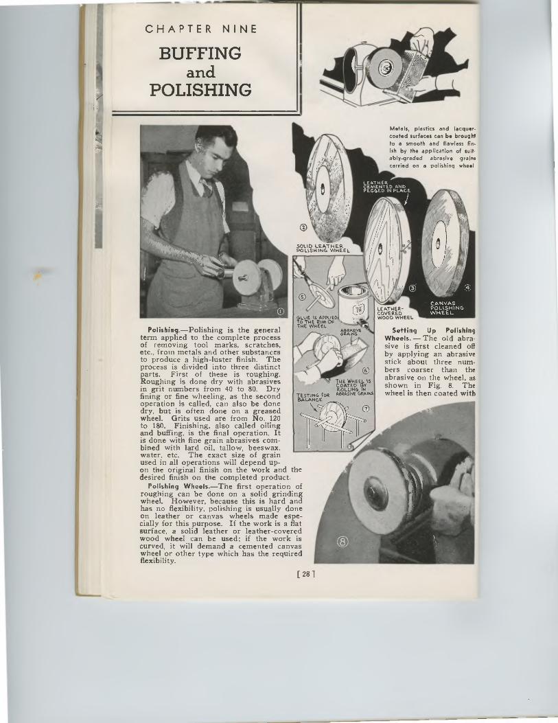
CHAPTER NINE
BUFFING and
POLISHING
SOLID LEATHER POLISHING WHEEL
GLUE IS APPLI TO THE Rion OF THE WHEEL
G2ARWEI 441/41 A
LEATHER-COVERED WOOD WHEEL
Metals, plastics and lacquer• coated surfaces can be brought to a smooth and flawless fin-ish by the application of suit-ably-graded abrasive grains carried on a polishing wheel.
LEATHER CEMENTED AND PEGGED IN PLACE
Polishing.—Polishing is the general term applied to the complete process of removing tool marks, scratches, etc., from metals and other substances to produce a high-luster finish. The process is divided into three distinct parts. First of these is roughing. Roughing is done dry with abrasives in grit numbers from 40 to 80. Dry fining or fine wheeling, as the second operation is called, can also be done dry, but is often done on a greased wheel. Grits used are from No. 120 to 180. Finishing, also called oiling and buffing, is the final operation. It is done with fine grain abrasives com-bined with lard oil, tallow, beeswax. water. etc. The exact size of grain used in all operations will depend up-on the original finish on the work and the desired finish on the completed product.
Polishing Wheels.—The first operation of roughing can be done on a solid grinding wheel. However, because this is hard and has no flexibility, polishing is usually done on leather or canvas wheels made espe-cially for this purpose. If the work is a flat surface, a solid leather or leather-covered wood wheel can be used; if the work is curved, it will demand a cemented canvas wheel or other type which has the required flexibility.
tExtetWHEE
yi5 ROLLING ABRASIVE GRAirtS
Setting Up Polishing Wheels. — The old abra-sive is first cleaned off by applying an abrasive stick about three num-bers coarser than the abrasive on the wheel, as shown in Fig. 8. The wheel is then coated with Tt5,.SLATINNt.EFOR
[ 28 ]
CHAPTER NINE
BUFFINGand
POLISHING
Metals, plastics and lacquer.
coated surfaces can be brought
to a smooth and flawless fin-
ish by the application of suit•ably-graded abrasive grains
carried on a polishing wheel
LEATHERCEMENTED ANDPEGGED IN PLACE
0
'441:' •7
SOLID LEATHERPOLISHING WHEEL
Polishing.—Polishing is the generalterm applied to the complete processof removing tool marks, scratches,etc., from metals and other substancesto produce a high-luster finish. Theprocess is divided into three distinctparts. First of these is roughing.Roughing is done dry with abrasivesin grit numbers from 40 to 80. Dryfining or fine wheeling, as the secondoperation is called, can also be donedry, but is often done on a greasedwheel. Grits used are from No. 120to 180. Finishing, also called oilingand buffing, is the final operation. Itis done with fine grain abrasives com-bined with lard oil, tallow, beeswax.water. etc. The exact size of grainused in all operations will depend up-on the original finish on the work and thedesired finish on the completed product.
Polishing Wheels.—The first operation ofroughing can be done on a solid grindingwheel. However, because this is hard andhas no flexibility, polishing is usually doneon leather or canvas wheels made espe-cially for this purpose. If the work is a flatsurface, a solid leather or leather-coveredwood wheel can be used; if the work iscurved, it will demand a cemented canvaswheel or other type which has the requiredflexibility.
GLUE Is APPLIEDTO The Rion OFTHE WHEEL
LEATHER-COVEREDWOOD WHEEL
COATED vROLLING
ABRASIVE GRAINS
Setting Up PolishingWheels. — The old abra-sive is first cleaned offby applying an abrasivestick about three num-bers coarser than theabrasive on the wheel, asshown in Fig. 8. Thewheel is then coated withTESTING FOR
[ 28 ]
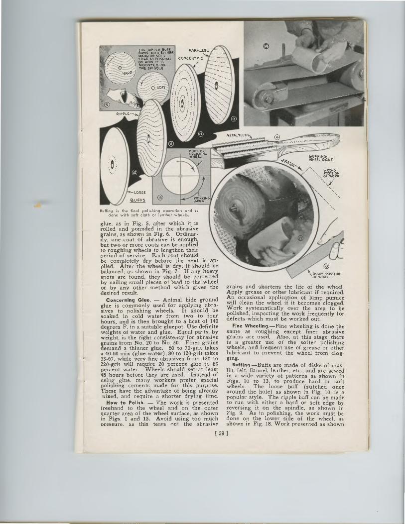
METALTEETH
THE RIPPLE BUCTI PARALLEL RUNS WITHEITHER HARD OR SOFT EDGE DEPENDING CONCENTRIC ON NOW IT IS MOUNTED ON THE SPINDLE
HARD
RIPPLE
•
110
LOOSE
WHEtL KIZ691G
BUFFS
Buffing is the final polishing operation and is clone with soft cloth or leather wheels.
glue, as in Fig. 5, after which it is rolled and pounded in the abrasive grains, as shown in Fig. 6. Ordinar-ily, one coat of abrasive is enough, but two or more coats can be applied to roughing wheels to lengthen their period of service. Each coat should be completely dry before the next is ap-plied. After the wheel is dry, it should be balanced, as shown in Fig. 7. If any heavy spots are found, they should be corrected by nailing small pieces of lead to the wheel or by any other method which gives the desired result.
Concerning Glue. — Animal hide ground glue is commonly used for applying abra-sives to polishing wheels. It should be soaked in cold water from two to four hours, and is then brought to a heat of 140 degrees F. in a suitable gluepot. Use definite weights of water and glue. Equal parts, by weight, is the right consistency for abrasive grains from No. 20 to No. 50. Finer grains demand a thinner glue. 60 to 70-grit takes a 40-60 mix (glue-water), 80 to 120-grit takes 33-67, while very fine abrasives from 150 to 220-grit will require 20 percent glue to 80 percent water. Wheels should set at least 48 hours before they are used. Instead of using glue, many workers prefer special polishing cements made for this purpose. These have the advantage of being already mixed, and require a shorter drying time.
How to Polish. — The work is presented freehand to the wheel and on the outer quarter area of the wheel surface, as shown in Figs. 1 and 15. Avoid using too much oressure. as this tears nut the abrasive
BUFFING WHEEL RAKE
WRONG •• POSITION \ OF WORK
RIGHT POSITION OF WORK
grains and shortens the life of the wheel. Apply grease or other lubricant if required. An occasional application of lump pumice will clean the wheel if it becomes clogged. Work systematically over the area to be polished, inspecting the work frequently for defects which must be worked out.
Fine Wheeling.—Fine wheeling is done the same as roughing except finer abrasive grains are used. Also, at this stage there is a greater use of the softer polishing wheels, and frequent use of grease or other lubricant to prevent the wheel from clog. ging.
Buffing.—Buffs are made of disks of mus-lin, felt, flannel, leather. etc., and are sewed in a wide variety of patterns as shown in Figs. iu to 13, to produce hard or soft wheels. The loose buff (stitched once around the hole) as shown in Fig. 10, is a popular style. The ripple buff can be made to run with either a hard or soft edge by reversing it on the spindle, as shown in Fig. 9. As in polishing, the work must be done on the lower side of the wheel, as shown in Fig. 18. Work presented as shown
WORKING AREA
[ 291
THE RIPPLE BUFFRUNS wrn4 EITHERWARD OR SOFTEDGE DEPENDINGON NOW IT ISMOUNTED ONTHE SPINDLE
PARALLEL
CONCENTRIC
BAT; INGWHEE.1
7--,724p,u0
•
BUFFINGWHEEL RAKE
WRONG••POSITION\ OF WORK
LOOSE
BUFFSWORKINGAREA
Buffing is the final polishing operation and isclone with soft cloth or leather wheels.
glue, as in Fig. 5, after which it isrolled and pounded in the abrasivegrains, as shown in Fig. 6. Ordinar-ily, one coat of abrasive is enough,but two or more coats can be appliedto roughing wheels to lengthen theirperiod of service. Each coat shouldbe completely dry before the next is ap-plied. After the wheel is dry, it should bebalanced, as shown in Fig. 7. If any heavyspots are found, they should be correctedby nailing small pieces of lead to the wheelor by any other method which gives thedesired result.
Concerning Glue. — Animal hide groundglue is commonly used for applying abra-sives to polishing wheels. It should besoaked in cold water from two to fourhours, and is then brought to a heat of 140degrees F. in a suitable gluepot. Use definiteweights of water and glue. Equal parts, byweight, is the right consistency for abrasivegrains from No. 20 to No. 50. Finer grainsdemand a thinner glue. 60 to 70-grit takesa 40-60 mix (glue-water), 80 to 120-grit takes33-67, while very fine abrasives from 150 to220-grit will require 20 percent glue to 80percent water. Wheels should set at least48 hours before they are used. Instead ofusing glue, many workers prefer specialpolishing cements made for this purpose.These have the advantage of being alreadymixed, and require a shorter drying time.
How to Polish. — The work is presentedfreehand to the wheel and on the outerquarter area of the wheel surface, as shownin Figs. 1 and 15. Avoid using too muchoressure. as this tears nut the abrasive
\ RIGHT POSITIONOF WORK
grains and shortens the life of the wheel.Apply grease or other lubricant if required.An occasional application of lump pumicewill clean the wheel if it becomes clogged.
Work systematically over the area to bepolished, inspecting the work frequently fordefects which must be worked out.
Fine Wheeling.—Fine wheeling is done thesame as roughing except finer abrasivegrains are used. Also, at this stage thereis a greater use of the softer polishingwheels, and frequent use of grease or otherlubricant to prevent the wheel from clog.ging.
Buffing.—Buffs are made of disks of mus-lin, felt, flannel, leather. etc., and are sewedin a wide variety of patterns as shown inFigs. iu to 13, to produce hard or softwheels. The loose buff (stitched oncearound the hole) as shown in Fig. 10, is apopular style. The ripple buff can be madeto run with either a hard or soft edge byreversing it on the spindle, as shown inFig. 9. As in polishing, the work must bedone on the lower side of the wheel, asshown in Fig. 18. Work presented as shown
[ 291
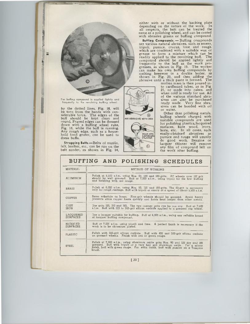
ro
MIX ABRASIVE WITH WA%
POUR INTO CARDBOARD.. CYLINDER
The buffing compound is applied lightly and frequently to the revolving buffing wheel.
by the dotted lines, Fig. 18, will be torn from the hands with con-siderable force. The edges of the buff should be kept clean and round. Frayed edges can be dressed down with a buffing wheel rake, Fig. 16, while the buff is running. Any rough edge, such as a house-hold food grater, can be used to dress buffs.
Strapping Belts.—Belts of muslin, felt, leather, etc., can be run on the belt sander, as shown in Fig. 14,
either with or without the backing plate depending on the nature of the work. In all respects, the belt can be treated the same as a polishing wheel, and can be coated with abrasive grains or buffing compound.
Buffing Compounds. — Buffing compounds. are various natural abrasives, such as emery, tripoli, pumice, crocus, lime and rouge, which are combined with a suitable wax or grease to form a mixture which can be readily applied to the revolving buff. The compound should be applied lightly and frequently to the buff as the work pro-gresses, as shown in Fig. 19. The worker can make his own buffing compounds by melting beeswax in a double boiler, as . shown in Fig. 20, and then adding the I abrasive until a thick paste is formed. The I
molten mass is then poured in- to cardboard tubes, as in Fig. 21, or made into cakes, and when cold is ready for use. All of the various standard abra-sives can also be purchased ready made. Very fine abra-sives can be bonded with oil or water.
Other than polishing metals, buffing wheels charged with suitable compounds are used for polishing plastics, lacquered surfaces, bare wood, ivory, horn, etc. In all cases, such easily-obtained abrasives as pumice and rouge will usually do good work. Benzine or lacquer thinner will remove any film of compound left on the work after buffing.
BEESWAX
BUFFING AND POLISHING SCHEDULES MATERIAL METHOD OF WORKING
ALUMINUM Polish at 5,500 s.f.m. using Nos. 80, 120 and 180-grits. All wheels over 120-grit should be well greased. Buff at 7,500 s.f.m., using tripoli for the first buffing and finishing with red rouge.
BRASS Polish at 6,000 s.f.m. using Nos. 80, 120 and 180-grits. The 80-grit is necessary only for rough castings. Buff with tripoli or emery at a speed of about 5,500 s.f.m.
COPPER Same schedule as brass. Fine-grit wheels should be greased. Avoid heavy pressure since copper heats quickly and holds heat longer than other metals.
CAST IRON
Use grits 120, 150 and 180. The two coarser grits can be run dry. Buff at 7,500 s.f.m. Buff with 220 to 240-grit silicon carbide applied to a greased rag wheel.
LACQUERED SURFACES
Use a lacquer suitable for buffing. Buff at 6,000 s.f.m., using any reliable brand of lacquer buffing compound.
NICKELED SURFACES
Buff at 7,500 s.f.m. using tripoli and lime. A perfect finish is necessary if the work is to be chromium plated.
PLASTIC Polish with 280-grit silicon carbide. Buff with 400 and 500-grit silicon carbide on greased wheels. Finish with red or green rouge.
STEEL
Polish at 7,500 s.f.m., using aluminum oxide grits Nos. 90 and 120 dry and 180 greased. Buff with tripoli or a very fine grit aluminum oxide. For a mirror finish, buff with green rouge. For satin finish, buff with pumice on a Tampico brush.
[ 30 ]
0MIX ABRASIVE WITH WA%
POUR INTO
CYLINCARDBOARD
DER
either with or without the backing platedepending on the nature of the work. Inall respects, the belt can be treated thesame as a polishing wheel, and can be coatedwith abrasive grains or buffing compound.
Buffing Compounds. — Buffing compoundsare various natural abrasives, such as emery,tripoli, pumice, crocus, lime and rouge,which are combined with a suitable wax orgrease to form a mixture which can bereadily applied to the revolving buff. Thecompound should be applied lightly andfrequently to the buff as the work pro-gresses, as shown in Fig. 19. The workercan make his own buffing compounds bymelting beeswax in a double boiler, asshown in Fig. 20, and then adding theabrasive until a thick paste is formed. The
molten mass is then poured in-to cardboard tubes, as in Fig.21, or made into cakes, andwhen cold is ready for use. Allof the various standard abra-sives can also be purchasedready made. Very fine abra-sives can be bonded with oilor water.
Other than polishing metals,buffing wheels charged withsuitable compounds are usedfor polishing plastics, lacqueredsurfaces, bare wood, ivory,horn, etc. In all cases, sucheasily-obtained abrasives aspumice and rouge will usuallydo good work. Benzine orlacquer thinner will removeany film of compound left onthe work after buffing.
The buffing compound is applied lightly and
frequently to the revolving buffing wheel.
by the dotted lines, Fig. 18, willbe torn from the hands with con-siderable force. The edges of thebuff should be kept clean andround. Frayed edges can be dresseddown with a buffing wheel rake,Fig. 16, while the buff is running.Any rough edge, such as a house-hold food grater, can be used todress buffs.
Strapping Belts.—Belts of muslin,felt, leather, etc., can be run on thebelt sander, as shown in Fig. 14
9E SWAX
. r e) )
BUFFING AND POLISHING SCHEDULESMATERIAL METHOD OF WORKING
ALUMINUMPolish at 5,500 s.f.m. using Nos. 80, 120 and 180-grits.All wheels over 120-gritshould be well greased.Buff at 7,500 s.f.m., using tripoli for the first buffingand finishing with red rouge.
BRASS Polish at 6,000 s.f.m. using Nos. 80, 120and180-grits.The 80-gritis necessaryonly for rough castings. Buff with tripoli or emery at a speed of about 5,500 s.f.m.
COPPER Same schedule as brass.Fine-grit wheels should be greased.Avoid heavypressure since copper heats quickly and holds heat longer than other metals.
CASTIRON
Use grits 120, 150 and 180.The two coarser grits can be run dry.Buff at 7,500s.f.m.Buff with 220 to 240-grit silicon carbide applied to a greased rag wheel.
LACQUEREDSURFACES
Use a lacquer suitable for buffing.Buff at 6,000 s.f.m., using any reliable brandof lacquer buffing compound.
NICKELEDSURFACES
Buff at 7,500 s.f.m. using tripoli and lime.A perfect finish is necessary if thework is to be chromium plated.
PLASTICPolish with 280-grit silicon carbide.Buff with 400 and 500-grit silicon carbideon greased wheels.Finish with red or green rouge.
STEEL
Polish at 7,500 s.f.m., using aluminum oxide grits Nos. 90 and 120 dry and 180greased.Buff with tripoli or a very fine grit aluminum oxide. For a mirrorfinish, buff with green rouge.Forsatin finish, buff with pumice on a Tampicobrush.
[ 30 ]
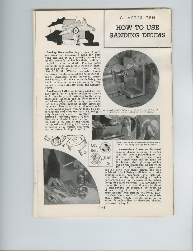
CHAPTER TEN
HOW TO USE SANDING DRUMS
Sanding Drums.—Sanding drums of vari-ous sizes are extensively used for edge work, and can be satisfactorily worked on the drill press, lathe, flexible shaft, or direct-coupled to a motor shaft. The size most commonly used measures 3 inches in diam-eter and should be run at a speed of about 1800 R. P. M. Within reasonable limits, the higher the drum speed the smoother the finish. Excessive speed, however, causes overheating, and, where wood is being fin-ished, the heat extracts a gummy pitch from the work which quickly clogs the abrasive sleeve.
Sanding on Lathe. — Drums used on the lathe are fitted with taper sh, tks or screw-on fittings to permit fastening to the lathe headstock. Sanding can be done freehand, but where edge work is being done, as in Fig. 1, a vertical support greatly simplifies the work. Drums with taper shanks should be safeguarded from coming loose by sup-porting the end with the tailstock, using a sixty degree plain center. Another method of fastening uses a 1/4 inch diameter stud which is turned into the hole in the end of the shank, the opposite end being held secure by means of a washer and wing nut, as shown in Figs. 2 and 3.
A vertical sanding table clamped to the bed of the lathe permits accurate sanding of curved edges.
Taper shank drums are securely held by means of a stud fitting through the headstock.
Narrow-Face Drums. — Standard sanding drums measure 3 inches long and have a projecting nut on the free end. Narrow-face drums are 1 inch wide and are flush on the bottom, the tightening nut be-ing on the shank end, as shown in Fig. 4. All standard operations
can be done with these drums, the face width of 1 inch being sufficient to handle average 3/4 inch thick work. The flush bot-tom also permits the finishing of inside corners, as shown in the lower photo. When doing this kind of work, it is advisable to mount the sleeve so that it projects about
inch beyond the bottom of the drum, as shown in Fig. 5, in order to prevent the drum bottom from burning the work. Nar-row-face drums are fitted with a special tri-shape shank which permits mounting in either i inch collets or three-jaw chucks, as shown in Fig. 6.
[ 31 ]
CHAPTER TEN
HOW TO USESANDING DRUMS
Sanding Drums.—Sanding drums of vari-ous sizes are extensively used for edgework, and can be satisfactorily worked onthe drill press, lathe, flexible shaft, or direct-coupled to a motor shaft. The size mostcommonly used measures 3 inches in diam-eter and should be run at a speed of about1800 R. P. M. Within reasonable limits,the higher the drum speed the smoother thefinish. Excessive speed, however, causesoverheating, and, where wood is being fin-ished, the heat extracts a gummy pitch fromthe work which quickly clogs the abrasivesleeve.
Sanding on Lathe. — Drums used on thelathe are fitted with taper sit, tks or screw-on fittings to permit fastening to the latheheadstock. Sanding can be done freehand,but where edge work is being done, as inFig. 1, a vertical support greatly simplifiesthe work. Drums with taper shanks shouldbe safeguarded from coming loose by sup-porting the end with the tailstock, using asixty degree plain center. Anothermethod of fastening uses a 1/4 inchdiameter stud which is turned intothe hole in the end of the shank,the opposite end being held secureby means of a washer and wingnut, as shown in Figs. 2 and 3.
A vertical sanding table clamped to the bed of the lathepermits accurate sanding of curved edges.
Wee i:n!F
Taper shank drums are securely held by meansof a stud fitting through the headstock.
Narrow-Face Drums. — Standardsanding drums measure 3 incheslong and have a projecting nut onthe free end. Narrow-face drumsare 1 inch wide and are flush onthe bottom, the tightening nut be-ing on the shank end, as shown inFig. 4. All standard operations
can be done with these drums, the facewidth of 1 inch being sufficient to handleaverage 3/4 inch thick work. The flush bot-tom also permits the finishing of insidecorners, as shown in the lower photo. Whendoing this kind of work, it is advisable tomount the sleeve so that it projects about
inch beyond the bottom of the drum, asshown in Fig. 5, in order to prevent thedrum bottom from burning the work. Nar-row-face drums are fitted with a special tri-shape shank which permits mounting ineither i inch collets or three-jaw chucks,as shown in Fig. 6.
[ 31 ]
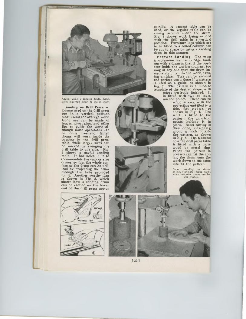
Above, using a sanding table. Right, drum mounted direct to motor shaft.
Sanding on Drill Press. —Drums used on the drill press run in a vertical position most useful for average work. Good use can be made of fences, pivot pins, and other jigs to guide the work al-though most operations can be done freehand. Small drums will work inside the opening in the drill press table, while larger sizes can be worked by swinging the drill table to one side. Fig. 1 shows a useful sanding table. It has holes in it to accommodate the various size drums, so that the whole sur-face of the drum can be util-ized by projecting the drum through the hole provided for it. Another worthy idea is shown in Fig. 2, which shows how a sanding drum can be carried on the lower end of the drill press motor
spindle. A second table can be used, or the regular table can be swung around under the drum. Fig. 3 shows work being sanded with the drill table in a vertical position. Furniture legs which are to be fitted to a round column can be cut to shape by using a sanding drum in this manner.
Pattern Sanding.—The most troublesome feature in edge sand-ing with a drum is that if the oper-ator holds the work a moment too long at any one spot, the drum im-mediately cuts into the work, caus-ing a ridge. This can be avoided and perfect work done if a pattern is used as a guide, as shown in Fig. 7. The pattern is a full-size template of the desired shape, with
edges perfectly finished. It is fitted with two or more anchor points. These can be
wood screws, with the projecting end filed to a thin, flat p o i n t, as shown in Fig. 4. The work is fitted to the pattern, the anchor points holding it in place. Band sawing is then done, keeping about 116 inch outside the pattern, as shown in Fig. 5. Fig. 6 shows how the drill press table is fitted with a hard-wood or metal ring. When the pattern is pressed against the col-lar, the drum cuts the work down to the same size as the pattern. Pattern sanding, as shown below, eliminates ridge marks when irregular curves are be.
ing worked.
[ 32 ]
spindle. A second table can beused, or the regular table can beswung around under the drum.Fig. 3 shows work being sandedwith the drill table in a verticalposition. Furniture legs which areto be fitted to a round column canbe cut to shape by using a sandingdrum in this manner.
Pattern Sanding.—The mosttroublesome feature in edge sand-ing with a drum is that if the oper-ator holds the work a moment toolong at any one spot, the drum im-mediately cuts into the work, caus-ing a ridge. This can be avoidedand perfect work done if a patternis used as a guide, as shown inFig. 7. The pattern is a full-sizetemplate of the desired shape, with
edges perfectly finished. Itis fitted with two or moreanchor points. These can be
wood screws, with theprojecting end filed to athin, flat p o i n t, asshown in Fig. 4. Thework is fitted to thepattern, the anchorpoints holding it inplace. Band sawing isthen done, keepingabout -1'-g inch outsidethe pattern, as shownin Fig. 5. Fig. 6 showshow the drill press tableis fitted with a hard-wood or metal ring.When the pattern ispressed against the col-lar, the drum cuts thework down to the samesize as the pattern.
Pattern sanding, as shownbelow, eliminates ridge markswhen irregular curves are be.
ing worked.
Above, using a sanding table. Right,
drum mounted direct to motor shaft.
Sanding on Drill Press. —Drums used on the drill pressrun in a vertical positionmost useful for average work.Good use can be made offences, pivot pins, and otherjigs to guide the work al-though most operations canbe done freehand. Smalldrums will work inside theopening in the drill presstable, while larger sizes canbe worked by swinging thedrill table to one side. Fig.1 shows a useful sandingtable. It has holes in it toaccommodate the various sizedrums, so that the whole sur-face of the drum can be util-ized by projecting the drumthrough the hole providedfor it. Another worthy ideais shown in Fig. 2, whichshows how a sanding drumcan be carried on the lowerend of the drill press motor
I
[ 32 ]
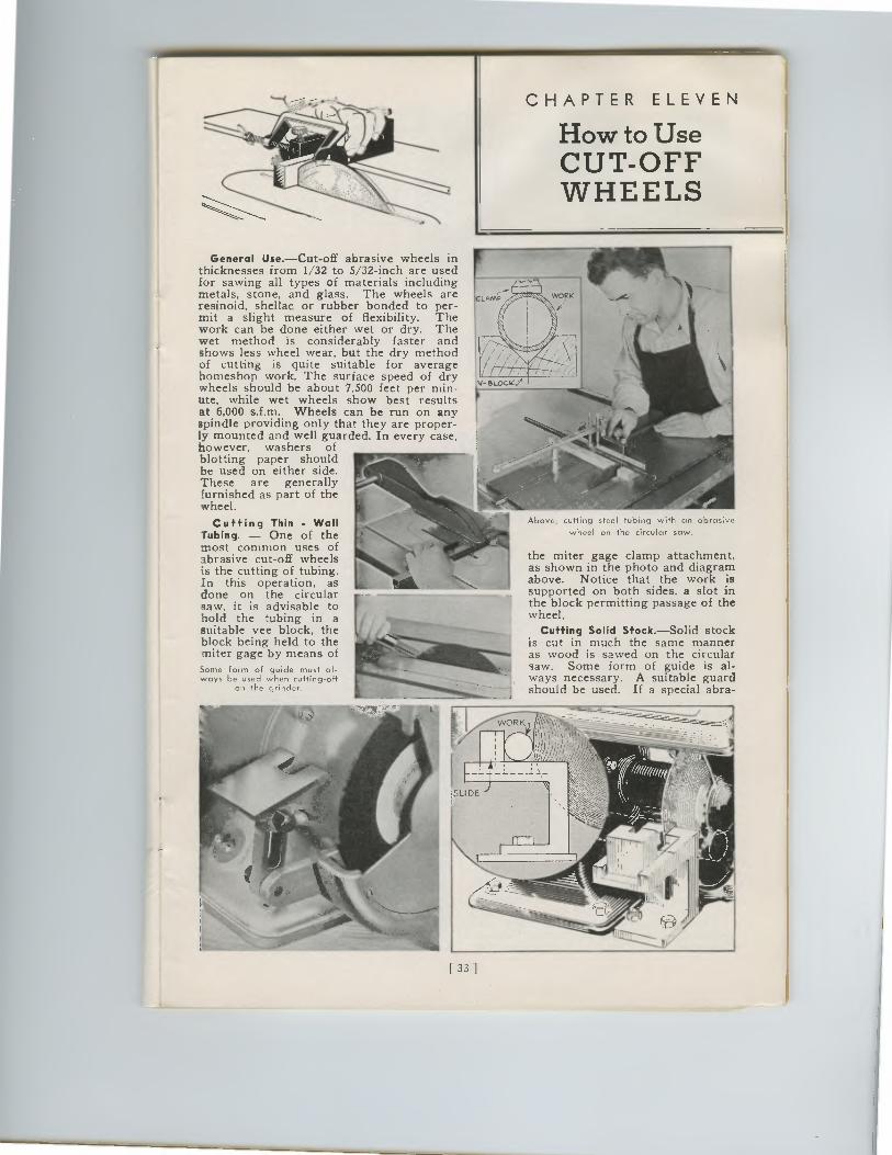
CHAPTER ELEVEN
How to Use CUT-OFF WHEELS
Above, cutting steel tubing with an abrasive
wheel on the circular saw.
General Use.—Cut-off abrasive wheels in thicknesses from 1/32 to 5/32-inch are used for sawing all types of materials including metals, stone, and glass. The wheels are resinoid, shellac or rubber bonded to per-mit a slight measure of flexibility. The work can be done either wet or dry. The wet method is considerably faster and shows less wheel wear, but the dry method of cutting is quite suitable for average homeshop work. The surface speed of dry wheels should be about 7,500 feet per min-ute, while wet wheels show best results at 6,000 s.f.m. Wheels can be run on any spindle providing only that they are proper-ly mounted and well guarded. In every case, however, washers of blotting paper should be used on either side. These are generally furnished as part of the wheel.
Cutting Thin • Wall Tubing. — One of the most common uses of abrasive cut-off wheels is the cutting of tubing. In this operation, as done on the circular saw, it is advisable to hold the tubing in a suitable vee block, the block being held to the miter gage by means of Some form of guide must al-ways be used when cutting-off
on the gr,cler.
the miter gage clamp attachment, as shown in the photo and diagram above. Notice that the work is supported on both sides, a slot in the block permitting passage of the wheel.
Cutting Solid Stock.—Solid stock is cut in much the same manner as wood is sawed on the circular saw. Some form of guide is al-ways necessary. A suitable guard should be used. If a special abra-
ill6t.......i...._ - .1
1 [ 33 ]
CHAPTER ELEVEN
How to UseCUT-OFFWHEELS
General Use.—Cut-off abrasive wheels inthicknesses from 1/32 to 5/32-inch are usedfor sawing all types of materials includingmetals, stone, and glass. The wheels areresinoid, shellac or rubber bonded to per-mit a slight measure of flexibility. Thework can be done either wet or dry. Thewet method is considerably faster andshows less wheel wear, but the dry methodof cutting is quite suitable for averagehomeshop work. The surface speed of drywheels should be about 7,500 feet per min-ute, while wet wheels show best resultsat 6,000 s.f.m. Wheels can be run on anyspindle providing only that they are proper-ly mounted and well guarded. In every case,however, washers ofblotting paper shouldbe used on either side.These are generallyfurnished as part of thewheel.
Cuffing Thin • WallTubing. — One of themost common uses ofabrasive cut-off wheelsis the cutting of tubing.In this operation, asdone on the circularsaw, it is advisable tohold the tubing in asuitable vee block, theblock being held to themiter gage by means ofSome form of guide must al-ways be used when cutting-off
on the gr,cler.
LAMP
Above, cutting steel tubing with an abrasive
wheel on the circular saw.
the miter gage clamp attachment,as shown in the photo and diagramabove. Notice that the work issupported on both sides, a slot inea. 11the block permitting passage of thewheel.
Cuffing Solid Sfock.—Solid stockis cut in much the same manneras wood is sawed on the circularsaw. Some form of guide is al-ways necessary. A suitable guardshould be used. If a special abra-
[ 33 ]
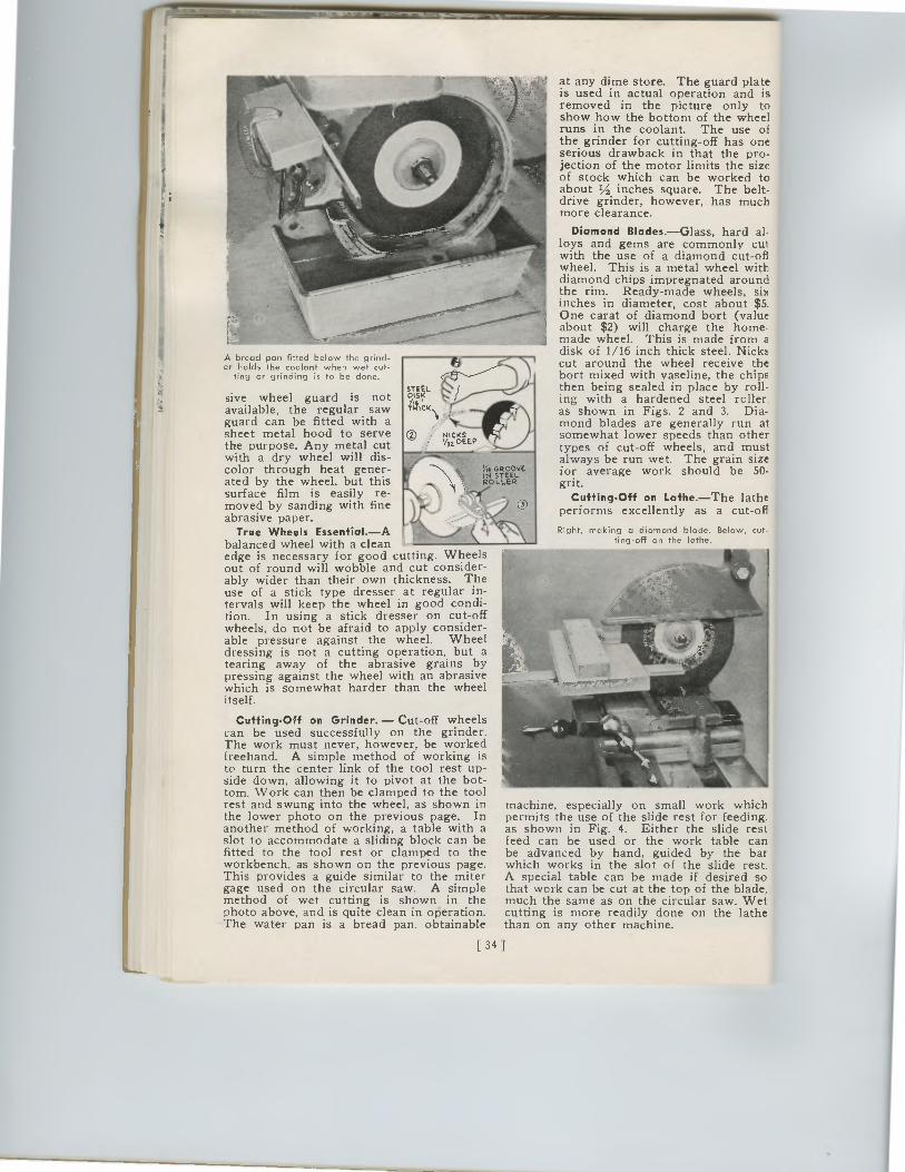
A bread pan fitted below the grind-er holds the coolant when wet cut-
ting or grinding is to be done.
sive wheel guard is not available, the regular saw guard can be fitted with a sheet metal hood to serve the purpose. Any metal cut with a dry wheel will dis-color through heat gener-ated by the wheel, but this surface film is easily re-moved by sanding with fine abrasive paper.
True Wheels Essential.—A balanced wheel with a clean edge is necessary for good cutting. Wheels out of round will wobble and cut consider-ably wider than their own thickness. The use of a stick type dresser at regular in-tervals will keep the wheel in good condi-tion. In using a stick dresser on cut-off wheels, do not be afraid to apply consider-able pressure against the wheel. Wheel dressing is not a cutting operation, but a tearing away of the abrasive grains by pressing against the wheel with an abrasive which is somewhat harder than the wheel itself.
Cutting-Off on Grinder. — Cut-off wheels can be used successfully on the grinder. The work must never, however, be worked freehand. A simple method of working is to turn the center link of the tool rest up-side down, allowing it to pivot at the bot-tom. Work can then be clamped to the tool rest and swung into the wheel, as shown in the lower photo on the previous page. In another method of working, a table with a slot to accommodate a sliding block can be fitted to the tool rest or clamped to the workbench, as shown on the previous page. This provides a guide similar to the miter gage used on the circular saw. A simple method of wet cutting is shown in the photo above, and is quite clean in operation. The water pan is a bread pan. obtainable
34
at any dime store. The guard plate is used in actual operation and is removed in the picture only to show how the bottom of the wheel runs in the coolant. The use of the grinder for cutting-off has one serious drawback in that the pro-jection of the motor limits the size of stock which can be worked to about V2 inches square. The belt-drive grinder, however, has much more clearance.
Diamond Blades.—Glass, hard al-loys and gems are commonly cut with the use of a diamond cut-off wheel. This is a metal wheel with diamond chips impregnated around the rim. Ready-made wheels, six inches in diameter, cost about $5. One carat of diamond bort (value about $2) will charge the home-made wheel. This is made from a disk of 1/16 inch thick steel. Nicks cut around the wheel receive the bort mixed with vaseline, the chips then being sealed in place by roll-ing with a hardened steel roller, as shown in Figs. 2 and 3. Dia-mond blades are generally run at somewhat lower speeds than other types of cut-off wheels, and must always be run wet. The grain size for average work should be 50-grit.
Cutting-Off on Lathe.—The lathe performs excellently as a cut-off
Right, making a diamond blade. Below, cut-ting-off on the lathe.
machine, especially on small work which permits the use of the slide rest for feeding as shown in Fig. 4. Either the slide rest feed can be used or the work table can be advanced by hand, guided by the bar which works in the slot of the slide rest. A special table can be made if desired so that work can be cut at the top of the blade, much the same as on the circular saw. Wet cutting is more readily done on the lathe than on any other machine.
-1" O VI6 GROOVE
ROLLER
A bread pan fitted below the grind-er holds the coolant when wet cut-
ting or grinding is to be done.
sive wheel guard is notavailable, the regular sawguard can be fitted with asheet metal hood to servethe purpose. Any metal cutwith a dry wheel will dis-color through heat gener-ated by the wheel, but thissurface film is easily re-moved by sanding with fineabrasive paper.
True Wheels Essential.—Abalanced wheel with a cleanedge is necessary for good cutting. Wheelsout of round will wobble and cut consider-ably wider than their own thickness. Theuse of a stick type dresser at regular in-tervals will keep the wheel in good condi-tion. In using a stick dresser on cut-offwheels, do not be afraid to apply consider-able pressure against the wheel. Wheeldressing is not a cutting operation, but atearing away of the abrasive grains bypressing against the wheel with an abrasivewhich is somewhat harder than the wheelitself.
Cutting - Off on Grinder. — Cut-off wheelscan be used successfully on the grinder.The work must never, however, be workedfreehand. A simple method of working isto turn the center link of the tool rest up-side down, allowing it to pivot at the bot-tom. Work can then be clamped to the toolrest and swung into the wheel, as shown inthe lower photo on the previous page. Inanother method of working, a table with aslot to accommodate a sliding block can befitted to the tool rest or clamped to theworkbench, as shown on the previous page.This provides a guide similar to the mitergage used on the circular saw. A simplemethod of wet cutting is shown in thephoto above, and is quite clean in operation.The water pan is a bread pan. obtainable
at any dime store. The guard plateis used in actual operation and isremoved in the picture only toshow how the bottom of the wheelruns in the coolant. The use ofthe grinder for cutting-off has oneserious drawback in that the pro-jection of the motor limits the sizeof stock which can be worked toabout V2 inches square. The belt-drive grinder, however, has muchmore clearance.
Diamond Blades.—Glass, hard al-loys and gems are commonly cutwith the use of a diamond cut-offwheel. This is a metal wheel withdiamond chips impregnated aroundthe rim. Ready-made wheels, sixinches in diameter, cost about $5.One carat of diamond bort (valueabout $2) will charge the home-made wheel. This is made from adisk of 1/16 inch thick steel. Nickscut around the wheel receive thebort mixed with vaseline, the chipsthen being sealed in place by roll-ing with a hardened steel roller,as shown in Figs. 2 and 3. Dia-mond blades are generally run atsomewhat lower speeds than othertypes of cut-off wheels, and mustalways be run wet. The grain sizefor average work should be 50-grit.
Cutting - Off on Lathe.—The latheperforms excellently as a cut-off
Right, making a diamond blade. Below, cut-ting-off on the lathe.
machine, especially on small work whichpermits the use of the slide rest for feeding .
as shown in Fig. 4. Either the slide restfeed can be used or the work table canbe advanced by hand, guided by the barwhich works in the slot of the slide rest.A special table can be made if desired sothat work can be cut at the top of the blade,much the same as on the circular saw. Wetcutting is more readily done on the lathethan on any other machine.
34
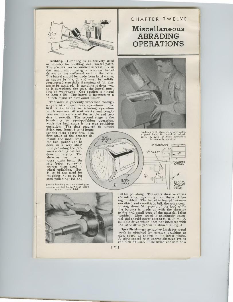
CHAPTER TWELVE
Miscellaneous ABRADING
OPERATIONS
it
Tumbling.—Tumbling is extensively used in industry for finishing small metal parts. The process can be worked successfully in the small shop, using a wooden barrel driven on the outboard end of the lathe. The barrel should be made from hard maple, as shown in Fig. 2, and must be solidly constructed, especially if castings of fair size are to be tumbled. If tumbling is done wet, as is sometimes the case, the barrel must also be watertight. One section is hinged to form a lid. The barrel is fastened to a 15-inch diameter hardwood pulley
The work is generally processed through a cycle of at least three operations. The first is an ashing or scouring operation which removes all tool marks and rough-ness on the surface of the article and ren-ders it smooth. The second stage is the burnishing or semi-polishing operation, while the final stage is the true polishing operation. The time required to tumble finish runs from 16 to 48 hours for the three operations. The first stage of the process de-mands the most time; the final polish can be done in a very short time providing the pre-vious abrading has been done thoroughly. The abrasive used is in loose grain form, the grit being somewhat coarser than used in wheel polishing. Nos. 24 to 36 are used for roughing; 40 to 80 for semi-polishing; 100 and
Scratch brushing at slaw speed pro-duces a serrated finish. A high speed
gives a satin finish.
Tumbling with abrasive grains makes a good finish for metal or plastic parts. A cycle of three operations
is generally required.
IS DIA. WOOD PULLEY
6" FACEPLATE
2° PULLEY 0
TUMBLING BARREL
2°.
60 R.P.M. COUNTER-SHAFT DRIVE
120 for polishing. The exact abrasive varies considerably, depending upon the work be-ing tumbled. The barrel is loaded between one-third and two-thirds full, the work com prising about 60 percent of the load while the balance is made up with the abrasive grains and small pegs of the material being tumbled. Slow speed is absolutely essen-tial and should never exceed 90 R. P. M. A suitable drive which does not interfere with the lathe drive proper is shown in Fig. 3.
Spun Finish.—An attractive finish for metal work is obtained by scratch brushing at slow speed, as shown in the lower photo. A stick coated with coarse abrasive grains can also be used. The finish consists of a
[ 35 ]
•
CHAPTER TWELVE
MiscellaneousABRADING
OPERATIONS
Tumbling.—Tumbling is extensively usedin industry for finishing small metal parts.The process can be worked successfully inthe small shop, using a wooden barreldriven on the outboard end of the lathe.The barrel should be made from hard maple,as shown in Fig. 2, and must be solidlyconstructed, especially if castings of fair sizeare to be tumbled. If tumbling is done wet,as is sometimes the case, the barrel mustalso be watertight. One section is hingedto form a lid. The barrel is fastened to a15-inch diameter hardwood pulley
The work is generally processed througha cycle of at least three operations. Thefirst is an ashing or scouring operationwhich removes all tool marks and rough-ness on the surface of the article and ren-ders it smooth. The second stage is theburnishing or semi-polishing operation,while the final stage is the true polishingoperation. The time required to tumblefinish runs from 16 to 48 hoursfor the three operations. Thefirst stage of the process de-mands the most time;the final polish can bedone in a very shorttime providing the pre-vious abrading has beendone thoroughly. Theabrasive used is inloose grain form, thegrit being somewhatcoarser than used inwheel polishing. Nos.24 to 36 are used forroughing; 40 to 80 forsemi-polishing; 100 and
Scratch brushing at slaw speed pro-duces a serrated finish. A high speed
gives a satin finish.
Tumbling with abrasive grains makesa good finish for metal or plasticparts. A cycle of three operations
is generally required.
6" FACEPLATE
11 %2°'PULLEY - 1
La.
TUMBLINGBARREL
60 RCOUNTER-SHAFTDRIVE
120 for polishing. The exact abrasive variesconsiderably, depending upon the work be-ing tumbled. The barrel is loaded betweenone-third and two-thirds full, the work comprising about 60 percent of the load whilethe balance is made up with the abrasivegrains and small pegs of the material beingtumbled. Slow speed is absolutely essen-tial and should never exceed 90 R. P. M. Asuitable drive which does not interfere withthe lathe drive proper is shown in Fig. 3.
Spun Finish. —An attractive finish for metalwork is obtained by scratch brushing atslow speed, as shown in the lower photo.A stick coated with coarse abrasive grainscan also be used. The finish consists of a
[ 35 ]
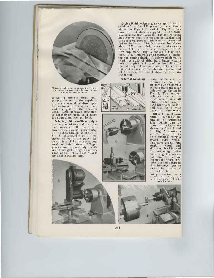
[ 36 ]
Engine Finish.—An engine or spot finish is produced on the drill press by the methods shown in Figs. 2, 3, and 4. Fig. 2 shows how a dowel stick is capped with an abra-sive disk for this purpose. Instead of using an abrasive disk, the tip can be leather and the abrasive bonded with wax or grease and fed to the work. The drill press should run about 1200 r.p.m. Solid abrasive sticks can be used, but require careful alignment. A tiny cup wheel, Fig. 3, makes a ring pat-tern. Fig. 4 shows a good method of work. ing the engine finish. A softwood dowel is used. A strip of thin, hard brass with a hole through it is located on the drill table immediately below the dowel. The work is fed with a mixture of abrasive grains and oil or water, the dowel abrading this into the metal.
Internal Grinding. —Small holes can be ground by mounting an abrasive stick in a chuck held in the lathe tailstock, as shown in Fig. 5. The setover tailstock se t s the depth of cut. A small hand grinder can be used for the same job, and also for a wide variety of other work.
Other Lathe Opera-tions. — Other ex-amples of grinding jobs which can be done on the lathe are shown in Figs. 7 and 8. Fig. 7 shows a groove being run in on a bushing, using a round edge wheel The same set-up with straight wheel and slide rest feed is used for surfacing cylin-ders. Fig. 8 shows a flat being worked on the end of a shaft. The lathe does not turn in this instance, but is locked by means of the index pin. Tool post grinders worked on the slide rest are used for a wide variety of lathe
grinding jobs.
Above, grinding glass edges. Drawing at right shows various methods used in pro-
ducing on engine finish.
series of minute rings spun around the work, the depth of the serrations depending upon the softness of the metal itself and the grit of the abrasive used. This abrasive treatment is extensively used as a finish for spun aluminum projects.
Grinding Glass.—Glass edges can be ground to an almost per-fect polish with the use of sili-con carbide abrasive papers used on the disk sander, as shown in Fig. 1. Standard 9 by 11 inch sheets of wet-or-dry paper can be cut into disks for occasional work of this nature. 120-grit gives a smooth, mat edge, while 220 to 320-grit brings up a very good polish. The glass should air cool between cuts.
Engine Finish.—An engine or spot finish isproduced on the drill press by the methodsshown in Figs. 2, 3, and 4. Fig. 2 showshow a dowel stick is capped with an abra-sive disk for this purpose. Instead of usingan abrasive disk, the tip can be leather andthe abrasive bonded with wax or grease andfed to the work. The drill press should runabout 1200 r.p.m. Solid abrasive sticks canbe used, but require careful alignment. Atiny cup wheel, Fig. 3, makes a ring pat-tern. Fig. 4 shows a good method of work.ing the engine finish. A softwood dowel isused. A strip of thin, hard brass with ahole through it is located on the drill tableimmediately below the dowel. The work isfed with a mixture of abrasive grains andoil or water, the dowel abrading this intothe metal.
Internal Grinding. —Small holes can beground by mountingan abrasive stick in achuck held in the lathetailstock, as shown inFig. 5. The setovertailstock se t s thedepth of cut. A smallhand grinder can beused for the same job,and also for a widevariety of other work.
Other Lathe Opera-tions. — Other ex-amples of grindingjobs which can bedone on the lathe areshown in Figs. 7 and8. Fig. 7 shows agroove being run inon a bushing, using around edge wheelThe same set-up withstraight wheel andslide rest feed is usedfor surfacing cylin-ders. Fig. 8 shows aflat being worked onthe end of a shaft. Thelathe does not turn inthis instance, but islocked by means ofthe index pin.Tool post grinders workedon the slide rest are usedfor a wide variety of lathe
grinding jobs.
Above, grinding glass edges. Drawing atright shows various methods used in pro-
ducing on engine finish.
series of minute rings spunaround the work, the depth ofthe serrations depending uponthe softness of the metal itselfand the grit of the abrasiveused. This abrasive treatmentis extensively used as a finishfor spun aluminum projects.
Grinding Glass.—Glass edgescan be ground to an almost per-fect polish with the use of sili-con carbide abrasive papers usedon the disk sander, as shown inFig. 1. Standard 9 by 11 inchsheets of wet-or-dry paper canbe cut into disks for occasionalwork of this nature. 120-gritgives a smooth, mat edge, while220 to 320-grit brings up a verygood polish. The glass shouldair cool between cuts.
[ 36 ]
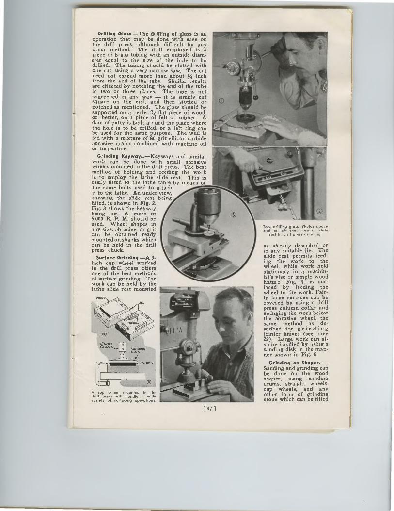
Drilling Glass.—The drilling of glass is an operation that may be done with ease on the drill press, although difficult by any other method. The drill employed is a piece of brass tubing with an outside diam-eter equal to the size of the hole to be drilled. The tubing should be slotted with one cut, using a very narrow saw. The cut need not extend more than about 1/4 inch from the end of the tube. Similar results are effected by notching the end of the tube in two or three places. The tube is not sharpened in any way — it is simply cut square on the end, and then slotted or notched as mentioned. The glass should be supported on a perfectly flat piece of wood, or, better, on a piece of felt or rubber. A dam of putty is built around the place where the hole is to be drilled, or a felt ring can be used for the same purpose. The well is fed with a mixture of 80-grit silicon carbide abrasive grains combined with machine oil or turpentine.
Grinding Keyways.—Keyways and similar work can be done with small abrasive wheels mounted in the drill press. The best method of holding and feeding the work is to employ the lathe slide rest. This is easily fitted to the lathe table by means of the same bolts used to attach it to the lathe. An under view, showing the slide rest being fitted, is shown in Fig. 2. Fig. 3 shows the keyway being cut. A speed of 5,000 R. P. M. should be used. Wheel shapes in any size, abrasive, or grit can be obtained ready mounted on shanks which can be held in the drill press chuck.
Surface Grinding.—A 3-inch cup wheel worked in the drill press offers one of the best methods of surface grinding. The work can be held by the lathe slide rest mounted
A cup wheel mounted in the drill press will handle a wide variety of surfacing operations.
[ 37 1
Top, drilling glass. Photos above and at left show use of slide
rest in drill press grinding.
as already described or in any suitable jig. The slide rest permits feed-ing the work to the wheel, while work held stationary in a machin-ist's vise or simple wood fixture, Fig. 4, is sur-faced by feeding the wheel to the work. Fair-ly large surfaces can be covered by using a drill press column collar and swinging the work below the abrasive wheel, the same method as de-scribed for grinding jointer knives (see page 22). Large work can al-so be handled by using a sanding disk in the man-ner shown in Fig. 5.
Grinding on Shaper. —Sanding and grinding can be done on the wood shaper, using sanding drums, straight wheels, cup wheels, and any other form of grinding stone which can be fitted
Drilling Glass.—The drilling of glass is anoperation that may be done with ease onthe drill press, although difficult by anyother method. The drill employed is apiece of brass tubing with an outside diam-eter equal to the size of the hole to bedrilled. The tubing should be slotted withone cut, using a very narrow saw. The cutneed not extend more than about 1/4 inchfrom the end of the tube. Similar resultsare effected by notching the end of the tubein two or three places. The tube is notsharpened in any way — it is simply cutsquare on the end, and then slotted ornotched as mentioned. The glass should besupported on a perfectly flat piece of wood,or, better, on a piece of felt or rubber. Adam of putty is built around the place wherethe hole is to be drilled, or a felt ring canbe used for the same purpose. The well isfed with a mixture of 80-grit silicon carbideabrasive grains combined with machine oilor turpentine.
Grinding Keyways.—Keyways and similarwork can be done with small abrasivewheels mounted in the drill press. The bestmethod of holding and feeding the workis to employ the lathe slide rest. This iseasily fitted to the lathe table by means ofthe same bolts used to attachit to the lathe. An under view,showing the slide rest beingfitted, is shown in Fig. 2.Fig. 3 shows the keywaybeing cut. A speed of5,000 R. P. M. should beused. Wheel shapes inany size, abrasive, or gritcan be obtained readymounted on shanks whichcan be held in the drillpress chuck.
Surface Grinding.—A 3-inch cup wheel workedin the drill press offersone of the best methodsof surface grinding. Thework can be held by thelathe slide rest mounted
A cup wheel mounted in thedrill press will handle a widevariety of surfacing operations
Top, drilling glass. Photos aboveand at left show use of slide
rest in drill press grinding.
as already described orin any suitable jig. Theslide rest permits feed-ing the work to thewheel, while work heldstationary in a machin-ist's vise or simple woodfixture, Fig. 4, is sur-faced by feeding thewheel to the work. Fair-ly large surfaces can becovered by using a drillpress column collar andswinging the work belowthe abrasive wheel, thesame method as de-scribed for grindingjointer knives (see page22). Large work can al-so be handled by using asanding disk in the man-ner shown in Fig. 5.
Grinding on Shaper. —Sanding and grinding canbe done on the woodshaper, using sandingdrums, straight wheels,cup wheels, and anyother form of grindingstone which can be fitted
[ 37 ]
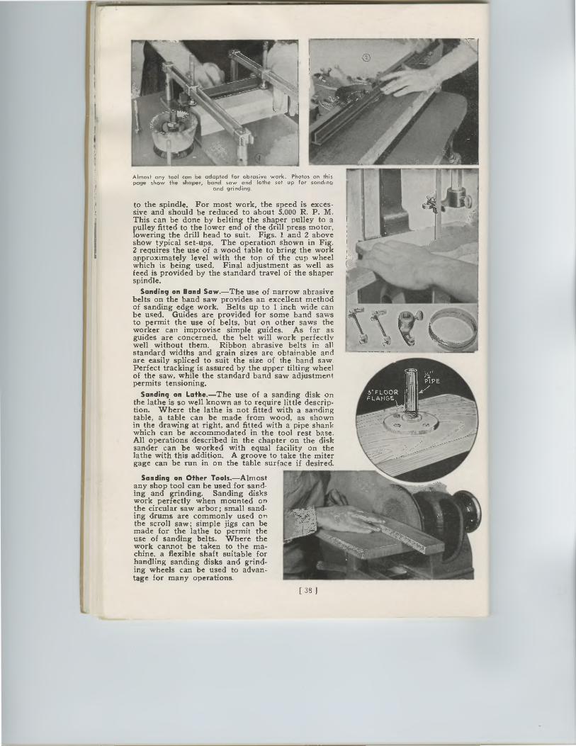
Almost any tool can be adapted for abrasive work. Photos on this page show the shaper, band saw and lathe set up for sanding
and grinding.
to the spindle. For most work, the speed is exces-sive and should be reduced to about 5,000 R. P. M. This can be done by belting the shaper pulley to a pulley fitted to the lower end of the drill press motor, lowering the drill head to suit. Figs. 1 and 2 above show typical set-ups. The operation shown in Fig. 2 requires the use of a wood table to bring the work approximately level with the top of the cup wheel which is being used. Final adjustment as well as feed is provided by the standard travel of the shaper spindle.
Sanding on Band Saw.—The use of narrow abrasive belts on the band saw provides an excellent method of sanding edge work. Belts up to 1 inch wide can be used. Guides are provided for some band saws to permit the use of belts, but on other saws the worker can improvise simple guides. As far as guides are concerned, the belt will work perfectly well without them. Ribbon abrasive belts in all standard widths and grain sizes are obtainable and are easily spliced to suit the size of the band saw. Perfect tracking is assured by the upper tilting wheel of the saw, while the standard band saw adjustment permits tensioning.
Sanding on Lathe.—The use of a sanding disk on the lathe is so well known as to require little descrip-tion. Where the lathe is not fitted with a sanding table, a table can be made from wood, as shown in the drawing at right, and fitted with a pipe shank which can be accommodated in the tool rest base. All operations described in the chapter on the disk sander can be worked with equal facility on the lathe with this addition. A groove to take the miter gage can be run in on the table surface if desired.
Sanding on Other Tools.—Almost any shop tool can be used for sand-ing and grinding. Sanding disks work perfectly when mounted on the circular saw arbor; small sand-ing drums are commonly used on the scroll saw; simple jigs can be made for the lathe to permit the use of sanding belts. Where the work cannot be taken to the ma-chine, a flexible shaft suitable for handling sanding disks and grind-ing wheels can be used to advan-tage for many operations.
[38]
%b.
Almost any tool can be adapted for abrasive work. Photos on thispage show the shaper, band saw and lathe set up for sanding
and grinding.
to the spindle. For most work, the speed is exces-sive and should be reduced to about 5,000 R. P. M.This can be done by belting the shaper pulley to apulley fitted to the lower end of the drill press motor,lowering the drill head to suit. Figs. 1 and 2 aboveshow typical set-ups. The operation shown in Fig.2 requires the use of a wood table to bring the workapproximately level with the top of the cup wheelwhich is being used. Final adjustment as well asfeed is provided by the standard travel of the shaperspindle.
Sanding on Band Saw.—The use of narrow abrasivebelts on the band saw provides an excellent methodof sanding edge work. Belts up to 1 inch wide canbe used. Guides are provided for some band sawsto permit the use of belts, but on other saws theworker can improvise simple guides. As far asguides are concerned, the belt will work perfectlywell without them. Ribbon abrasive belts in allstandard widths and grain sizes are obtainable andare easily spliced to suit the size of the band saw.Perfect tracking is assured by the upper tilting wheelof the saw, while the standard band saw adjustmentpermits tensioning.
Sanding on Lathe.—The use of a sanding disk onthe lathe is so well known as to require little descrip-tion. Where the lathe is not fitted with a sandingtable, a table can be made from wood, as shownin the drawing at right, and fitted with a pipe shankwhich can be accommodated in the tool rest base.All operations described in the chapter on the disksander can be worked with equal facility on thelathe with this addition. A groove to take the mitergage can be run in on the table surface if desired.
Sanding on Other Tools.—Almostany shop tool can be used for sand-ing and grinding. Sanding diskswork perfectly when mounted onthe circular saw arbor; small sand-ing drums are commonly used onthe scroll saw; simple jigs can bemade for the lathe to permit theuse of sanding belts. Where thework cannot be taken to the ma-chine, a flexible shaft suitable forhandling sanding disks and grind-ing wheels can be used to advan-tage for many operations.
[38]
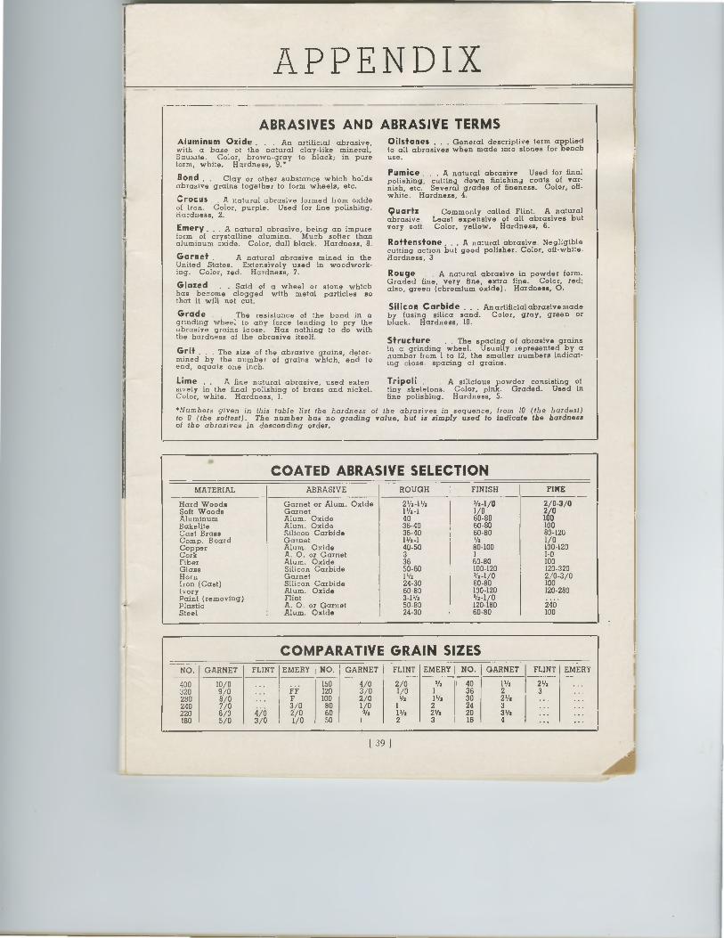
ABRASIVES AND ABRASIVE TERMS Aluminum Oxide . . . An artificial abrasive, with a base of the natural clay-like mineral, Bauxite. Color, brown-gray to black; in pure Corm, white. Hardness, 9.*
Bond . . Clay or other substance which holds abrasive grains together to form wheels, etc.
Crocus . A natural abrasive formed from oxide of iron. Color, purple. Used for fine polishing. Hardness, 2.
Emery... A natural abrasive, being an impure form of crystalline alumina. Much softer than aluminum oxide. Color, dull black. Hardness, 8.
Garnet . A natural abrasive mined in the United States. Extensively used in woodwork-ing. Color, red. Hardness, 7.
Glazed . . Said of a wheel or stone which has become clogged with metal particles so that it will not cut.
Grade . The resistance of the bond in a grinding wheel to any force tending to pry the abrasive grains loose. Has nothing to do with the hardness of the abrasive itself.
Grit . . The size of the abrasive grains, deter-mined by the number of grains which, end to end, equals one inch.
Lime .. A fine natural abrasive, used exten sively in the final polishing of brass and nickel. Color, white. Hardness, 1.
Oilstones . . General descriptive term applied to all abrasives when made into stones for bench use.
Pumice . . . A natural abrasive Used for final polishing, cutting down finishin4 coats of var-nish, etc. Several grades of fineness. Color, off-white. Hardness, 4.
Commonly called Flint. A natural Least expensive of all abrasives but Color, yellow. Hardness, 6.
Roffensfone ... A natural abrasive. Negligible cutting action but good polisher. Color, off-white. Hardness, 3
Rouge . A natural abrasive in powder form. Graded fine, very fine, extra fine. Color, red; also, green (chromium oxide). Hardness, 0.
Silicon Carbide ... An artificial abrasive made by fusing silica sand. Color, gray, green or black. Hardness, 10.
Structure . The spacing of abrasive grains in a grinding wheel. Usually represented by a number from 1 to 12, the smaller numbers indicat-ing close spacing of grains.
Tripoli . A silicious powder consisting of tiny skeletons. Color, pink. Graded. Used in fine polishing. Hardness, 5.
Quartz abrasive very soft.
*Numbers given in this fable list the hardness of the abrasives in sequence, from 10 (the hardest) fo 0 (the softest). The number has no grading value, but is simply used to indicate the hardness of the abrasives in descending order.
APPENDIX
COATED ABRASIVE SELECTION MATERIAL ABRASIVE ROUGH FINISH FINE
Hard Woods Garnet or Alum. Oxide 21/2-11/2 '/2-1/0 2/0-3/0 Soft Woods Garnet 11/2 4 1/0 2/0 Aluminum Alum. Oxide 40 60-80 100 Bakelite Alum. Oxide 36-40 60-80 100 Cast Brass Silicon Carbide 36-40 60-80 80-120 Comp. Board Garnet 11/2-1 1/2 1/0 Copper Alum. Oxide 40-50 80-100 100-120 Cork A. 0. or Garnet 3 I I-0 Fiber Alum. Oxide 36 60-80 100 Glass Silicon Carbide 50-60 100-120 120-320 Horn Garnet 11/2 1/2 -1/0 2/0-3/0 Iron (Cast) Silicon Carbide 24-30 60-80 100 Ivory Alum. Oxide 60-80 100-120 120-280 Paint (removing) Flint 3-11/2 1/2 -1/0 Plastic A. 0. or Garnet 50-80 120-180 240 Steel Alum. Oxide 24-30 60-80 100
COMPARATIVE GRAIN SIZES NO. GARNET FLINT EMERY NO. GARNET FLINT EMERY NO. GARNET FLINT EMERY
400 10/0 ... 150 4/0 2/0 VI 40 11/2 21/2 ... 320 9/0 ... Fi 120 3/0 1/0 1 36 2 3 .. 280 8/0 ... F 100 2/0 V: 11/2 30 21/2 ... 240 7/0 3/0 80 1/0 1 2 24 3 ... 220 6/0 4/0 2/0 60 W: 11/2 Vs 20 31/2 ... ... 180 5/0 3/0 1/0 50 I 2 3 I 16 4 ... ...
39 1
ABRASIVES AND ABRASIVE TERMSAluminum Oxide . . . An artificial abrasive,with a base of the natural clay-like mineral,Bauxite. Color, brown-gray to black; in pureCorm, white. Hardness, 9.*
Bond . . Clay or other substance which holdsabrasive grains together to form wheels, etc.
Crocus . A natural abrasive formed from oxideof iron. Color, purple. Used for fine polishing.Hardness, 2.
Emery... A natural abrasive, being an impureform of crystalline alumina. Much softer thanaluminum oxide. Color, dull black. Hardness, 8.
Garnet .A natural abrasive mined in theUnited States. Extensively used in woodwork-ing. Color, red. Hardness, 7.
Glazed . . Said of a wheel or stone whichhas become clogged with metal particles sothat it will not cut.
Grade.The resistance of the bond in agrinding wheel to any force tending to pry theabrasive grains loose. Has nothing to do withthe hardness of the abrasive itself.
Grit . . The size of the abrasive grains, deter-mined by the number of grains which, end toend, equals one inch.
Lime .. A fine natural abrasive, used extensively in the final polishing of brass and nickel.Color, white. Hardness, 1.
Oilstones . . General descriptive term appliedto all abrasives when made into stones for benchuse.
Pumice . . . A natural abrasive Used for finalpolishing, cutting down finishin4 coats of var-nish, etc. Several grades of fineness. Color, off-white. Hardness, 4.
Commonly called Flint. A naturalLeast expensive of all abrasives butColor, yellow. Hardness, 6.
Roffensfone ... A natural abrasive. Negligiblecutting action but good polisher. Color, off-white.Hardness, 3
Rouge . A natural abrasive in powder form.Graded fine, very fine, extra fine. Color, red;also, green (chromium oxide). Hardness, 0.
Silicon Carbide ... An artificial abrasive madeby fusing silica sand. Color, gray, green orblack. Hardness, 10.
Structure. The spacing of abrasive grainsin a grinding wheel. Usually represented by anumber from 1 to 12, the smaller numbers indicat-ing close spacing of grains.
Tripoli . A silicious powder consisting oftiny skeletons. Color, pink. Graded. Used infine polishing. Hardness, 5.
Quartzabrasivevery soft
•Numbers given in this fable list the hardness of the abrasives in sequence, from 10 (the hardest)fo 0 (the softest). The number has no grading value, but is simply used to indicate the hardnessof the abrasives in descending order.
APPENDIX
COATED ABRASIVE SELECTIONMATERIAL ABRASIVE ROUGH FINISH FINE
Hard Woods Garnet or Alum. Oxide 21/2-11/2 '/2-1/0 2/0-3/0Soft Woods Garnet 11/24 1/0 2/0Aluminum Alum. Oxide 40 60-80 1130Bakelite Alum. Oxide 36-40 60-80 100Cast Brass Silicon Carbide 36-40 60-80 80-120Comp. Board Garnet 1 1/2 - 1 1/2 1/0Copper Alum. Oxide 40-50 80-100 100-120Cork A. 0. or Garnet 3 I I-0Fiber Alum. Oxide 36 60-80 100Glass Silicon Carbide 50-60 100-120 120-320Horn Garnet 11/2 1/2-1/0 2/0-3/0Iron (Cast) Silicon Carbide 24-30 60-80 100Ivory Alum. Oxide 60-80 100-120 120-280Paint (removing) Flint 3-11/2 1/2-1/0Plastic A. 0. or Garnet 50-80 120-180 2:46 .Steel Alum. Oxide 24-30 60-80 100
COMPARATIVE GRAIN SIZESNO. GARNET FLINT EMERY NO. GARNET FLINT EMERY NO. GARNET FLINT EMERY
400 10/0 ... 150 4/0 2/0 VI 40 1 1/2 2 1/2 ...320 9/0 ... Fi 120 3/0 1/0 1 36 2 3 ..280 8/0 ... F 100 2/0 V: 1 1/2 30 2 1/2 ...240 7/0 3/0 80 1/0 1 2 24 3 ...220 6/0 4i0 2/0 60 W: 1 1/2 Vs 20 31/2 ... ...180 5/0 3/0 1/0 50 I 2 3 I 16 4 ... ...
39 1
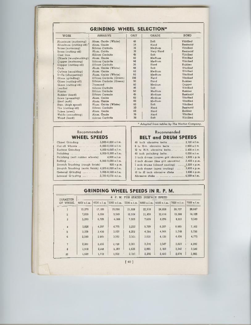
GRINDING WHEEL SELECTION* WORK ABRASIVE GRIT GRADE BOND
Aluminum (surfacing) Alum. Oxide (White) 46 Soft Vitrified Aluminum (cutting-off) ' Alum. Oxide 29 Hard Resinoid Brass (surfacing) Silicon Carbide 36 Medium Vitrified
Brass (cutting-off) Alum. Oxide 30 Very Hard Resinoid
Cast Iron Silicon Carbide 46 Soft Vitrified Chisels (woodworking) Alum. Oxide 60 Medium Vitrified Copper (surfacing) Silicon Carbide 60 Medium Vitrified Copper (cutting-off) Silicon Carbide 36 Hard Rubber
Cork Alum. Oxide (White) 60 Soft Vitrified Cutters (moulding) Alum. Oxide 60 Medium Vitrified
Drills (sharpening) Alum. Oxide (White) 60 Medium Vitrified
Glass (grinding) Silicon Carbide (Green) 150 Hard Vitrified Glass (cutting-off) Silicon Carbide (Green) 90 Hard Rubber Glass (cutting-off) Diamond 60 Medium Copper
Leather Silicon Carbide 96 Soft Vitrified
Plastic Silicon Carbide 60 Medium Rubber
Rubber (hard) Silicon Carbide 46 Medium Resinoid
Saws (gumming) Alum. Oxide 60 Medium Vitrified
Steel (soft) Alum. Oxide 60 Medium Vitrified
Stee, (high speed) Alum. Oxide (White) 60 Soft Vitrified
Tile (cutting-off) Silicor Carbide 30 Hard Resinoid
Tubes (steel) Alum. Oxide 60 Hard Rubber
Welds (smoothing) Alum. Oxide 36 Hard Vitrified
Wood (hard) Silicon Carbide 30 Soft Vitrified
* Adapted from fables by The Norton Company.
Recommended
WHEEL SPEEDS Chisel Grinding 5,000-6,000 s.f.m .
Cut-off Wheels 6,000-8,000 s.f.m
Surface Grinding 9,000-6,000 s f.m.
Polishing 6,000-9,000 s.f.m.
Polishing (soft rubber wheels) 9,000 s.f.m .
Buffing . ...... 6,000-9,000 s.f.m.
Scratch Brushing (rough finish) 600 r.p.m.
Scratch Brushing (satin finish) 9,000-6,000 s.f.m.
General Grinding ...... 5,000-6,500 s.f.m. Internal Grinding 2 000-6,000 s.f.m.
Recommended
BELT and DRUM SPEEDS 48 inch abrasive belts 3 100 s.f.m.
6 to 10-h. abrasive belts 2,800 s.f.m
10 to 16-ft. abrasive belts.. 2,900 s.f.m.
98 inch polishing belts 9,000 s.f.m
3 inch drums (coarse grit abrasive). 1,800 r.p.m
3 inch drums (fine grit abrasive) 2,900 r.p.m.
1 inch drums (closed coating) 1,200 r.p.m.
1 inch drums (open coating) 1,800 r.p.m.
10 to 12 inch abrasive disks 1,800 r.p.m.
Abrasive disks . 4 500 s.f.m.
GRINDING WHEEL SPEEDS IN R. P. M.
DIAMETER OF WHEEL
R P. M. FOR STATED SURFACE SPEED
9000 s.f.m. 9500 s.f.m 5000 s.f.m. 5500 s.f.m. 6000 aim. 6500 s.f.m. 7000 s.f.m. 7500 s.f.m
1 15,279 17,189 19,098 21,008 22,918 24,828 26,737 28,647
2 7,639 8,599 9,599 10,509 11,959 12,919 13,368 14,328
3 5,093 5,729 6,366 7,003 7,639 8,276 8,913 9,599
4 3,820 4,297 9,775 5,252 5,729 6,207 6,685 7,162
5 3,056 3.438 3,820 4,202 9,589 4,966 5,398 5,730
6 2,546 2,865 3,183 3,501 3,820 4,138 9,956 4,775
7 2,183 2,455 2,728 3,001 3,274 3,547 3,820 4,092
8 1,910 2,148 2,387 2,626 2,865 3, 103 3,392 3,580
10 1,528 1,719 1,910 2,101 2,292 2,983 2,674 2,865
[40]
GRINDING WHEEL SELECTION*WORK ABRASIVE GRIT GRADE BOND
Aluminum (surfacing) Alum. Oxide (White) 46 Soft Vitrified
Aluminum (cutting-off) ' Alum. Oxide 29 Hard Resinoid
Brass (surfacing) Silicon Carbide 36 Medium Vitrified
Brass (cutting-off) Alum. Oxide 30 Very Hard Resinoid
Cast Iron Silicon Carbide 46 Soft Vitrified
Chisels (woodworking) Alum. Oxide 60 Medium Vitrified
Copper (surfacing) Silicon Carbide 60 Medium Vitrified
Copper (cutting-off) Silicon Carbide 36 Hard Rubber
Cork Alum. Oxide (White) 60 Soft Vitrified
Cutters (moulding) Alum. Oxide 60 Medium Vitrified
Drills (sharpening) Alum. Oxide (White) 60 Medium Vitrified
Glass (grinding) Silicon Carbide (Green) 150 Hard Vitrified
Glass (cutting-off) Silicon Carbide (Green) 90 Hard Rubber
Glass (cutting-off) Diamond 60 Medium Copper
Leather Silicon Carbide 96 Soft Vitrified
Plastic Silicon Carbide 60 Medium Rubber
Rubber (hard) Silicon Carbide 46 Medium Resinoid
Saws (gumming) Alum. Oxide 60 Medium Vitrified
Steel (soft) Alum. Oxide 60 Medium Vitrified
Stee, (high speed) Alum. Oxide (White) 60 Soft Vitrified
Tile (cutting-off) Silicor Carbide 30 Hard Resinoid
Tubes (steel) Alum. Oxide 60 Hard Rubber
Welds (smoothing) Alum. Oxide 36 Hard Vitrified
Wood (hard) Silicon Carbide 30 Soft Vitrified
* Adapted from fables by The Norton Company.
Recommended
WHEEL SPEEDSChisel Grinding 5,000-6,000 s.f.m
Cut-off Wheels 6,000-8,000 s.f.m
Surface Grinding 9,000-6,000 s f.m.
Polishing 6,000-9,000 s.f.m.
Polishing (soft rubber wheels)9,000 s.f.m .
Buffing....... 6,000-9,000 s.f.m.
Scratch Brushing (rough finish)600 r.p.m.
Scratch Brushing (satin finish) 9,000-6,000 s.f.m.
General Grinding ......5,000-6,500 s.f.m.
Internal Grinding 2 000-6,000 s.f.m.
Recommended
BELT and DRUM SPEEDS48 inch abrasive belts 3 100 s.f.m.
6 to 10-h. abrasive belts 2,800 s.f.m
10 to 16-ft. abrasive belts..2,900 s.f.m.
98 inch polishing belts 9,000 s.f.m
3 inch drums (coarse grit abrasive). 1,800 r.p.m
3 inch drums (fine grit abrasive) 2,900 r.p.m.
1 inch drums (closed coating) 1,200 r.p.m.
1 inch drums (open coating) 1,800 r.p.m.
10 to 12 inch abrasive disks 1,800 r.p.m.
Abrasive disks 4 500 s.f.m.
GRINDING WHEEL SPEEDS IN R. P. M.
DIAMETEROF WHEEL
R P. M. FOR STATED SURFACE SPEED
9000 s.f.m. 9500 s.f.m 5000 s.f.m. 5500 s.f.m. 6000 s.f.m. 6500 s.f.m. 7000 s.f.m. 7500 s.f.m
I 15,279 17,189 19,098 21,008 22,918 24,828 26,737 28,647
2 7,639 8,599 9,599 10,509 11,959 12,919 13,368 14,328
3 5,093 5,729 6,366 7,003 7,639 8,276 8,913 9,599
4 3,820 4,297 9,775 5,252 5,729 6,207 6,685 7,162
5 3,056 3.438 3,820 4,202 9,589 4,966 5,398 5,730
6 2,546 2,865 3,183 3,501 3,820 4,138 9,956 4,775
7 2,183 2,455 2,728 3,001 3,274 3,547 3,820 4,092
8 1,910 2,148 2,387 2,626 2,865 3, 103 3,392 3,580
10 1,528 1,719 1,910 2,101 2,292 2,983 2,674 2,865
[ 40 ]


