Embed Size (px)
Citation preview
Instructor Notes:
Generative Part Structural Analysis Fundamentals
Copyright DASSAULT SYSTEMES �
��������������
Cop
yrig
ht D
AS
SA
ULT
SY
STE
ME
S
Generative Part Structural Analysis Fundamentals
CATIA V5 TrainingFoils
Version 5 Release 19September 2008
EDU_CAT_EN_GPF_FI_V5R19
Instructor Notes:
Generative Part Structural Analysis Fundamentals
Copyright DASSAULT SYSTEMES �
��������������
Cop
yrig
ht D
AS
SA
ULT
SY
STE
ME
S
About this courseObjectives of the courseUpon completion of this course you will be able to:- Understand the use of Finite Element Analysis- Mesh a part with different element types and shapes, and definepart properties- Apply clamp, slider, and iso-static restraints; and force, moment and displacement loads- Compute a static analysis for a single part- Visualize images of the analysis results, and produce analysis reports- Refine existing meshes in order to produce more accurate results
Targeted audienceMechanical Designers
PrerequisitesStudents attending this course should have knowledge of CATIA V5Fundamentals
1 Day
Instructor Notes:
Generative Part Structural Analysis Fundamentals
Copyright DASSAULT SYSTEMES �
��������������
Cop
yrig
ht D
AS
SA
ULT
SY
STE
ME
S
Table of Contents (1/3)
Introduction to Finite Element Analysis 6What is Finite Element Analysis 7Why to Use Finite Element Analysis 11Application of Finite Element Analysis 12
Introduction to GPS Analysis 13General FEA Process in GPS 14Accessing the GPS Analysis Workbench 15GPS Analysis Tree Structure 16
GPS Pre-Processing 17What is Pre-processing 18GPS Pre-processing Tools 19Applying Material 20Managing Mesh-Part 23Applying Physical Property 30Defining Restraints 38Defining Loads 49Pre-Processing Recap Exercise 64Model Checker 66
Instructor Notes:
Generative Part Structural Analysis Fundamentals
Copyright DASSAULT SYSTEMES �
��������������
Cop
yrig
ht D
AS
SA
ULT
SY
STE
ME
S
Table of Contents (2/3)
GPS Computation 69What is Computation 71Specifying the External Storage 73Computing a Static Case 80Computation Recap Exercise 86
GPS Post-processing 87Results Visualization 89Mesh Refinement 108Results Management 126
Managing Analysis 139About Saving an Analysis Document 140About Save As 141How to Use Save Management 142Saving Document Using ‘Send To’ Mechanism 143User Settings 144
Master Exercise: Static Analysis 148Static Analysis: Presentation 149Static Analysis on a Hanger (1): Pre-Processing 150
Instructor Notes:
Generative Part Structural Analysis Fundamentals
Copyright DASSAULT SYSTEMES �
��������������
Cop
yrig
ht D
AS
SA
ULT
SY
STE
ME
S
Table of Contents (3/3)
Static Analysis on a Hanger (2): Computation 151Static Analysis on a Hanger (3): Result Visualization 152
Instructor Notes:
Generative Part Structural Analysis Fundamentals
Copyright DASSAULT SYSTEMES �
��������������
Cop
yrig
ht D
AS
SA
ULT
SY
STE
ME
S
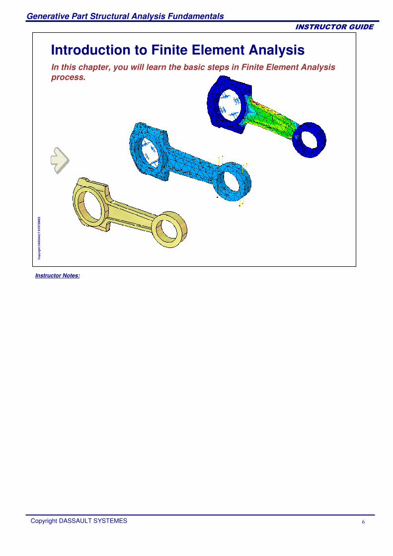
Introduction to Finite Element AnalysisIn this chapter, you will learn the basic steps in Finite Element Analysis process.
Instructor Notes:
Generative Part Structural Analysis Fundamentals
Copyright DASSAULT SYSTEMES �
��������������
Cop
yrig
ht D
AS
SA
ULT
SY
STE
ME
S
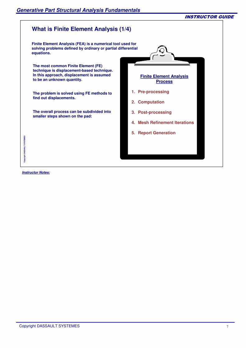
What is Finite Element Analysis (1/4)
The most common Finite Element (FE) technique is displacement-based technique. In this approach, displacement is assumed to be an unknown quantity.
The problem is solved using FE methods to find out displacements.
The overall process can be subdivided into smaller steps shown on the pad:
Finite Element Analysis (FEA) is a numerical tool used for solving problems defined by ordinary or partial differential equations.
Finite Element AnalysisProcess
1. Pre-processing
2. Computation
3. Post-processing
4. Mesh Refinement Iterations
5. Report Generation
Instructor Notes:
Generative Part Structural Analysis Fundamentals
Copyright DASSAULT SYSTEMES �
��������������
Cop
yrig
ht D
AS
SA
ULT
SY
STE
ME
S
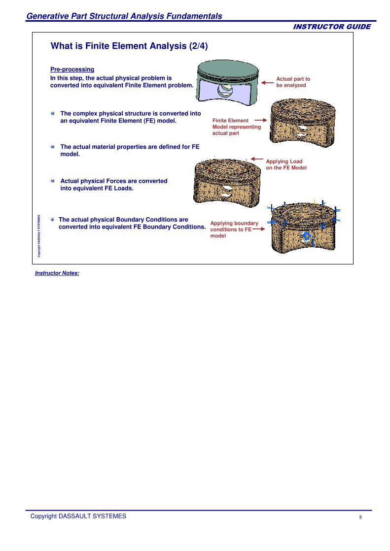
What is Finite Element Analysis (2/4)
The actual physical Boundary Conditions are converted into equivalent FE Boundary Conditions.
Pre-processingIn this step, the actual physical problem is converted into equivalent Finite Element problem.
The complex physical structure is converted into an equivalent Finite Element (FE) model.
The actual material properties are defined for FE model.
Actual physical Forces are converted into equivalent FE Loads.
Actual part to be analyzed
Finite Element Model representing actual part
Applying Load on the FE Model
Applying boundary conditions to FE model
Instructor Notes:
Generative Part Structural Analysis Fundamentals
Copyright DASSAULT SYSTEMES
��������������
Cop
yrig
ht D
AS
SA
ULT
SY
STE
ME
S
What is Finite Element Analysis (3/4)
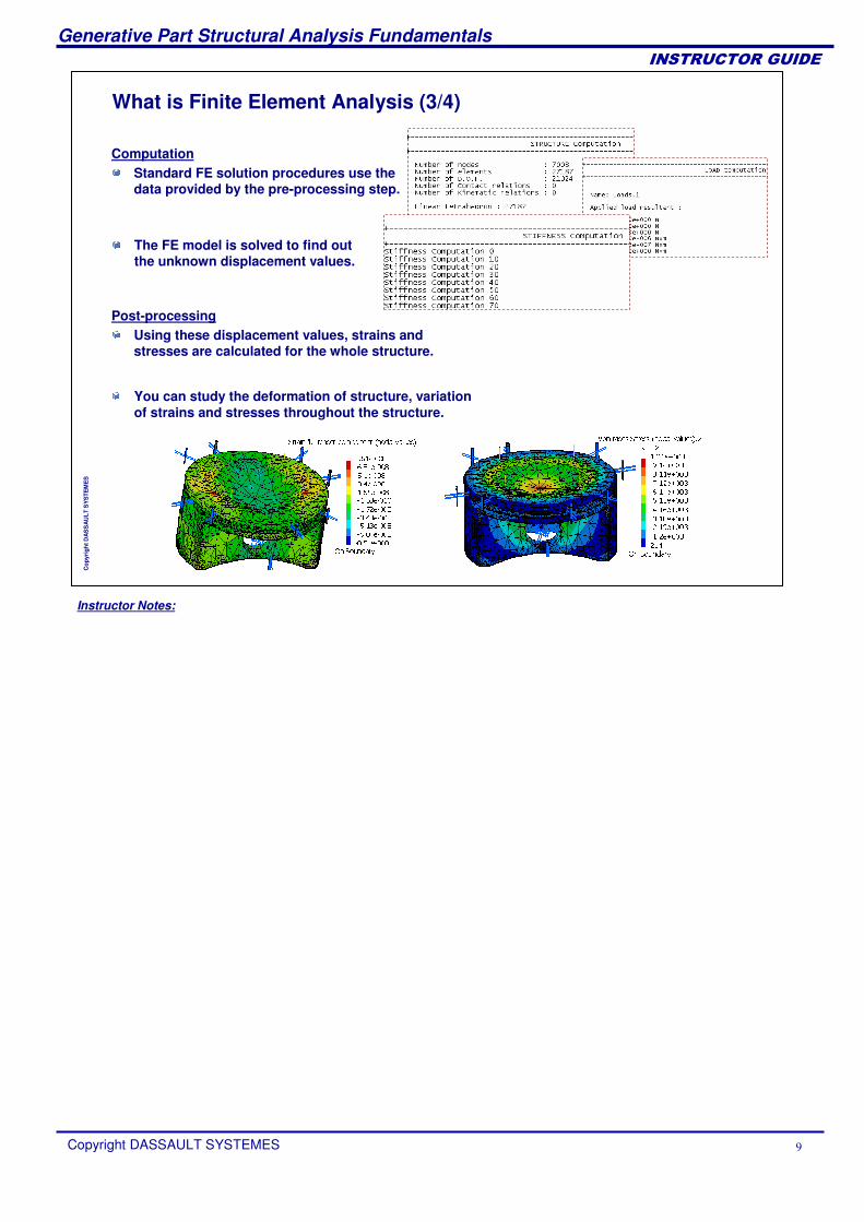
You can study the deformation of structure, variation of strains and stresses throughout the structure.
The FE model is solved to find out the unknown displacement values.
ComputationStandard FE solution procedures use the data provided by the pre-processing step.
Post-processingUsing these displacement values, strains and stresses are calculated for the whole structure.
Instructor Notes:
Generative Part Structural Analysis Fundamentals
Copyright DASSAULT SYSTEMES �
��������������
Cop
yrig
ht D
AS
SA
ULT
SY
STE
ME
S
What is Finite Element Analysis (4/4)
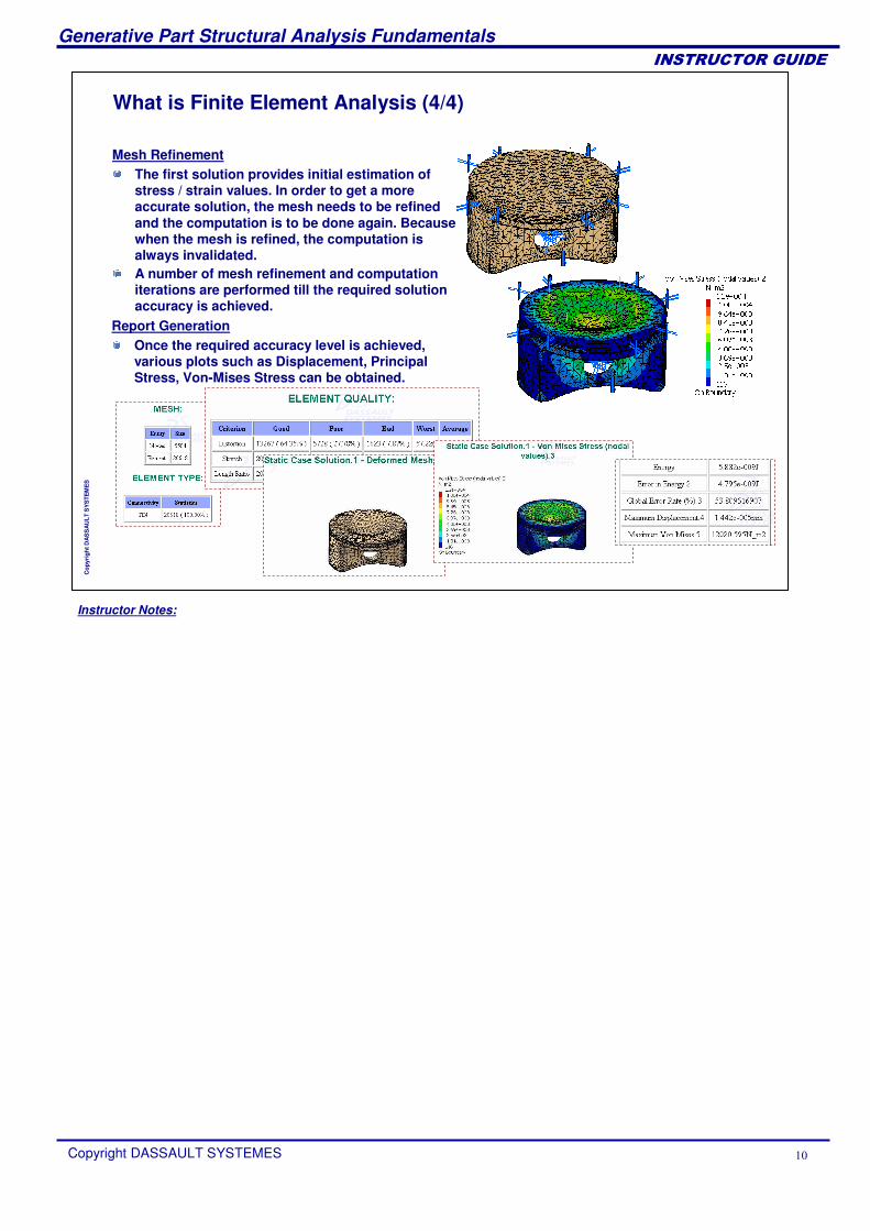
A number of mesh refinement and computation iterations are performed till the required solution accuracy is achieved.
Once the required accuracy level is achieved, various plots such as Displacement, Principal Stress, Von-Mises Stress can be obtained.
The first solution provides initial estimation of stress / strain values. In order to get a more accurate solution, the mesh needs to be refined and the computation is to be done again. Because when the mesh is refined, the computation is always invalidated.
Mesh Refinement
Report Generation
Instructor Notes:
Generative Part Structural Analysis Fundamentals
Copyright DASSAULT SYSTEMES ��
��������������
Cop
yrig
ht D
AS
SA
ULT
SY
STE
ME
S
Why to Use Finite Element Analysis
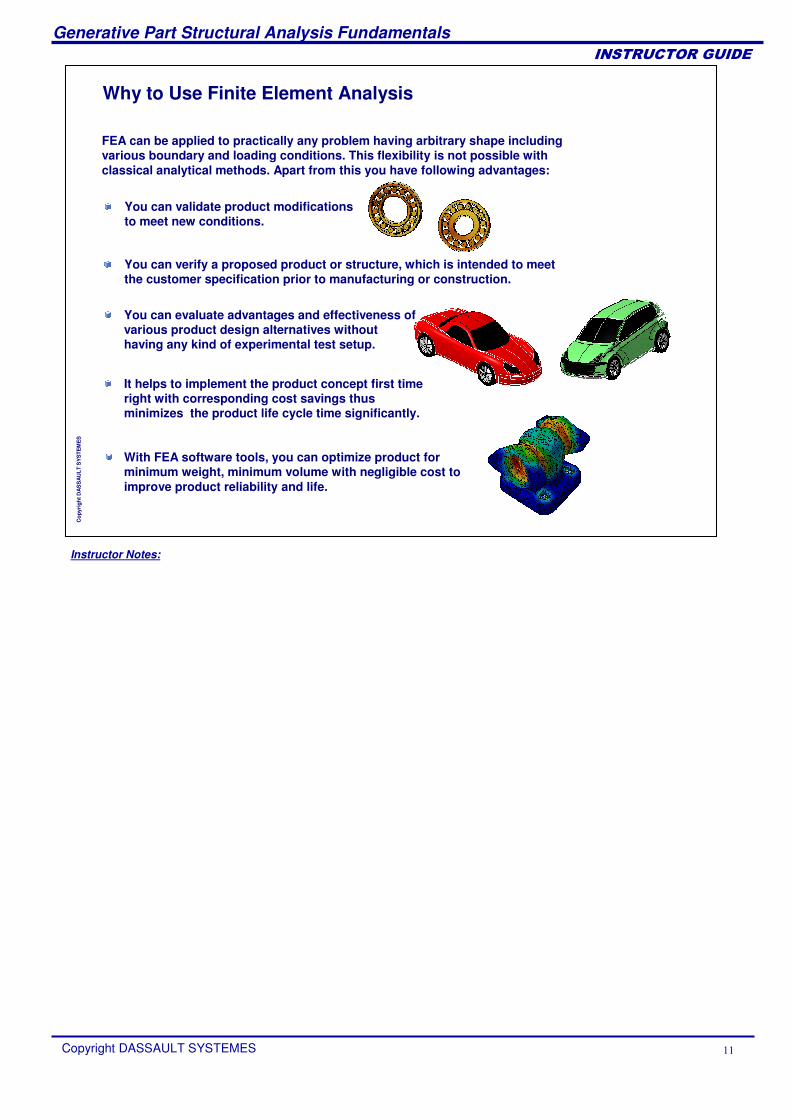
FEA can be applied to practically any problem having arbitrary shape including various boundary and loading conditions. This flexibility is not possible with classical analytical methods. Apart from this you have following advantages:
You can verify a proposed product or structure, which is intended to meet the customer specification prior to manufacturing or construction.
You can validate product modifications to meet new conditions.
You can evaluate advantages and effectiveness of various product design alternatives without having any kind of experimental test setup.
It helps to implement the product concept first time right with corresponding cost savings thus minimizes the product life cycle time significantly.
With FEA software tools, you can optimize product for minimum weight, minimum volume with negligible cost to improve product reliability and life.
Instructor Notes:
Generative Part Structural Analysis Fundamentals
Copyright DASSAULT SYSTEMES ��
��������������
Cop
yrig
ht D
AS
SA
ULT
SY
STE
ME
S
Application of Finite Element Analysis
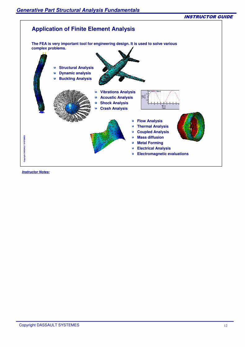
The FEA is very important tool for engineering design. It is used to solve various complex problems.
Structural AnalysisDynamic analysisBuckling Analysis
Vibrations AnalysisAcoustic AnalysisShock AnalysisCrash Analysis
Flow Analysis Thermal AnalysisCoupled AnalysisMass diffusion Metal Forming Electrical AnalysisElectromagnetic evaluations
Instructor Notes:
Generative Part Structural Analysis Fundamentals
Copyright DASSAULT SYSTEMES ��
��������������
Cop
yrig
ht D
AS
SA
ULT
SY
STE
ME
S
Introduction to GPS AnalysisIn this lesson, you will learn about the GPS Analysis Workbench and general FEA process in GPS.
General FEA Process in GPSAccessing the GPS Analysis WorkbenchGPS Analysis Tree Structure
Instructor Notes:
Generative Part Structural Analysis Fundamentals
Copyright DASSAULT SYSTEMES ��
��������������
Cop
yrig
ht D
AS
SA
ULT
SY
STE
ME
S
General FEA Process in GPS
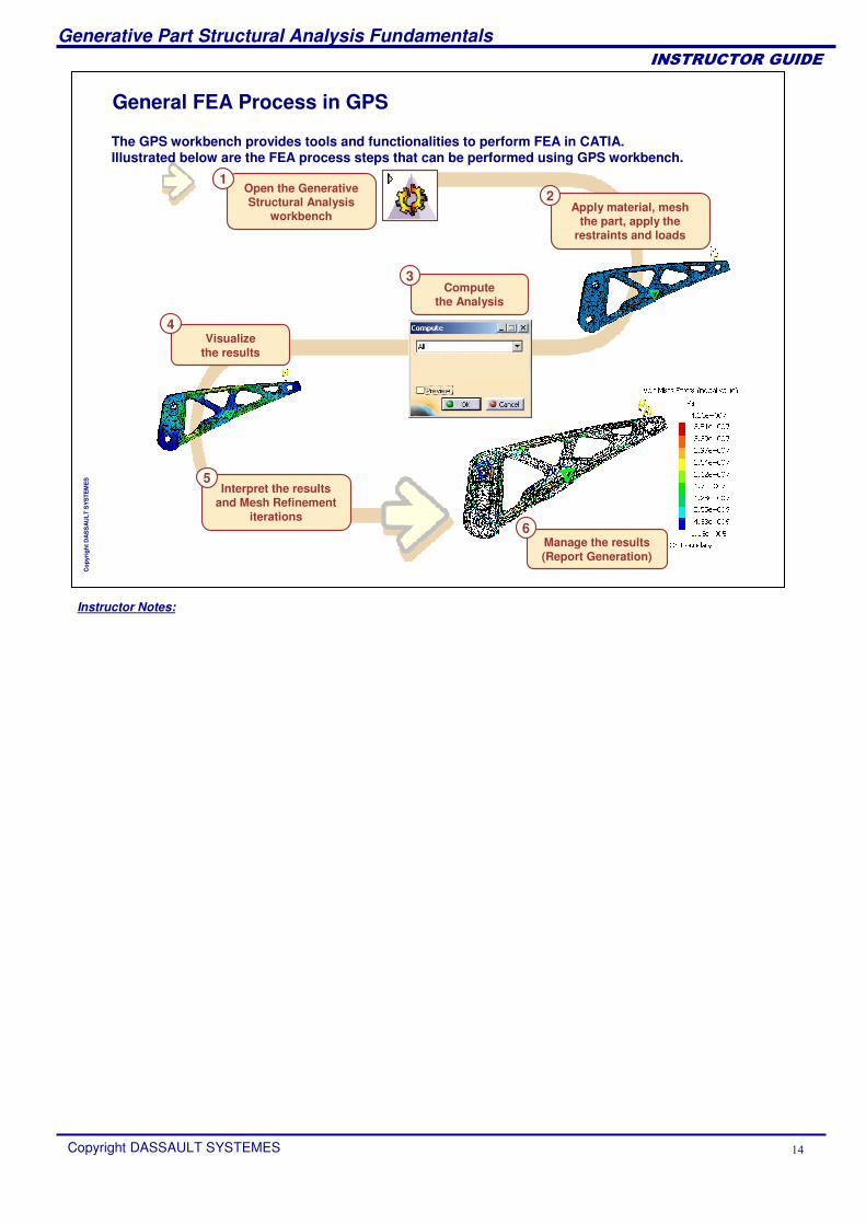
Computethe Analysis
3
Apply material, mesh the part, apply the
restraints and loads
2Open the Generative Structural Analysis
workbench
Interpret the results and Mesh Refinement
iterations
5
Visualize the results
4
1
The GPS workbench provides tools and functionalities to perform FEA in CATIA. Illustrated below are the FEA process steps that can be performed using GPS workbench.
Manage the results (Report Generation)
6
Instructor Notes:
Generative Part Structural Analysis Fundamentals
Copyright DASSAULT SYSTEMES ��
��������������
Cop
yrig
ht D
AS
SA
ULT
SY
STE
ME
S
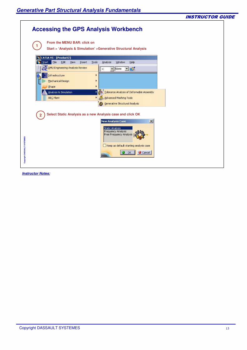
Accessing the GPS Analysis Workbench
From the MENU BAR: click on
Start > ‘Analysis & Simulation’ >Generative Structural Analysis1
Select Static Analysis as a new Analysis case and click OK2
Instructor Notes:
Generative Part Structural Analysis Fundamentals
Copyright DASSAULT SYSTEMES ��
��������������
Cop
yrig
ht D
AS
SA
ULT
SY
STE
ME
S
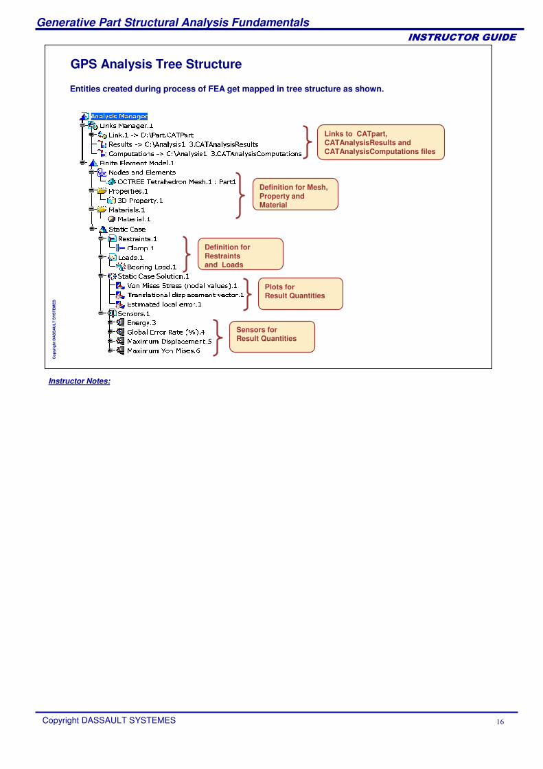
GPS Analysis Tree Structure
Links to CATpart,CATAnalysisResults and CATAnalysisComputations files
Plots for Result Quantities
Definition for Mesh, Property and Material
Entities created during process of FEA get mapped in tree structure as shown.
Definition for Restraintsand Loads
Sensors for Result Quantities
Instructor Notes:
Generative Part Structural Analysis Fundamentals
Copyright DASSAULT SYSTEMES ��
��������������
Cop
yrig
ht D
AS
SA
ULT
SY
STE
ME
S
GPS Pre-ProcessingIn this lesson, you will learn about the pre-processing steps in Static Analysis.
What is Pre-processingGPS Pre-processing ToolsApplying MaterialManaging Mesh-PartApplying Physical PropertyDefining RestraintsDefining LoadsPre-Processing Recap ExerciseModel Checker
Instructor Notes:
Generative Part Structural Analysis Fundamentals
Copyright DASSAULT SYSTEMES ��
��������������
Cop
yrig
ht D
AS
SA
ULT
SY
STE
ME
S
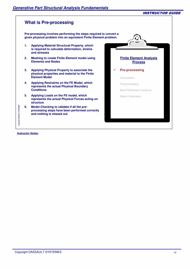
What is Pre-processing
Pre-processing involves performing the steps required to convert a given physical problem into an equivalent Finite Element problem.
6. Model Checking to validate if all the pre-processing steps have been performed correctly and nothing is missed out
1. Applying Material Structural Property, which is required to calculate deformation, strains and stresses
Finite Element AnalysisProcess
� Pre-processing
Computation
Post-processing
Mesh Refinement Iterations
Report Generation
2. Meshing to create Finite Element model using Elements and Nodes
3. Applying Physical Property to associate the physical properties and material to the Finite Element Model
4. Applying Restraints on the FE Model, which represents the actual Physical Boundary Conditions
5. Applying Loads on the FE model, which represents the actual Physical Forces acting on structure
Instructor Notes:
Generative Part Structural Analysis Fundamentals
Copyright DASSAULT SYSTEMES �
��������������
Cop
yrig
ht D
AS
SA
ULT
SY
STE
ME
S
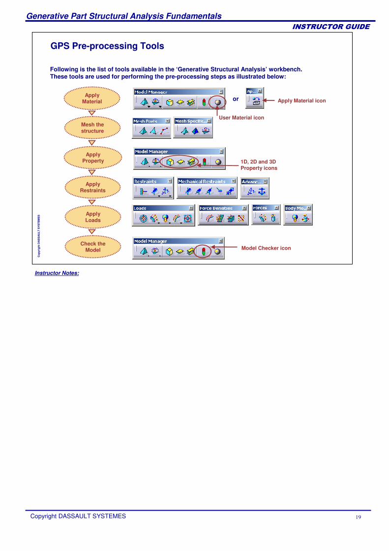
GPS Pre-processing Tools
Following is the list of tools available in the ‘Generative Structural Analysis’ workbench. These tools are used for performing the pre-processing steps as illustrated below:
orApply
Material
Mesh the structure
Check the Model
Apply Loads
Apply Restraints
ApplyProperty
Apply Material icon
User Material icon
1D, 2D and 3D Property icons
Model Checker icon
Instructor Notes:
Generative Part Structural Analysis Fundamentals
Copyright DASSAULT SYSTEMES �
��������������
Cop
yrig
ht D
AS
SA
ULT
SY
STE
ME
S
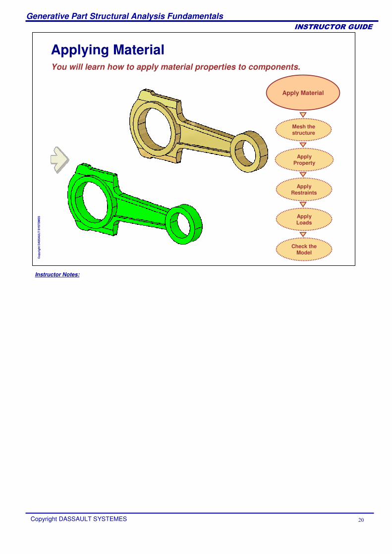
Applying MaterialYou will learn how to apply material properties to components.
Apply Material
Mesh the structure
Check the Model
Apply Loads
Apply Restraints
ApplyProperty
Instructor Notes:
Generative Part Structural Analysis Fundamentals
Copyright DASSAULT SYSTEMES ��
��������������
Cop
yrig
ht D
AS
SA
ULT
SY
STE
ME
S
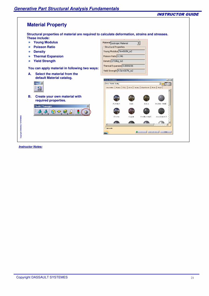
Material Property
Young ModulusPoisson RatioDensityThermal ExpansionYield Strength
Structural properties of material are required to calculate deformation, strains and stresses. These include:
You can apply material in following two ways:
B. Create your own material with required properties.
A. Select the material from the default Material catalog.
Instructor Notes:
Generative Part Structural Analysis Fundamentals
Copyright DASSAULT SYSTEMES ��
��������������
Cop
yrig
ht D
AS
SA
ULT
SY
STE
ME
S
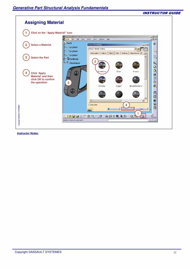
Assigning Material
2 Select a Material
3 Select the Part
4 Click ‘Apply Material’ and then click OK to confirm the operation
Click on the “Apply Material” icon1
3
2
4
1
Instructor Notes:
Generative Part Structural Analysis Fundamentals
Copyright DASSAULT SYSTEMES ��
��������������
Cop
yrig
ht D
AS
SA
ULT
SY
STE
ME
S
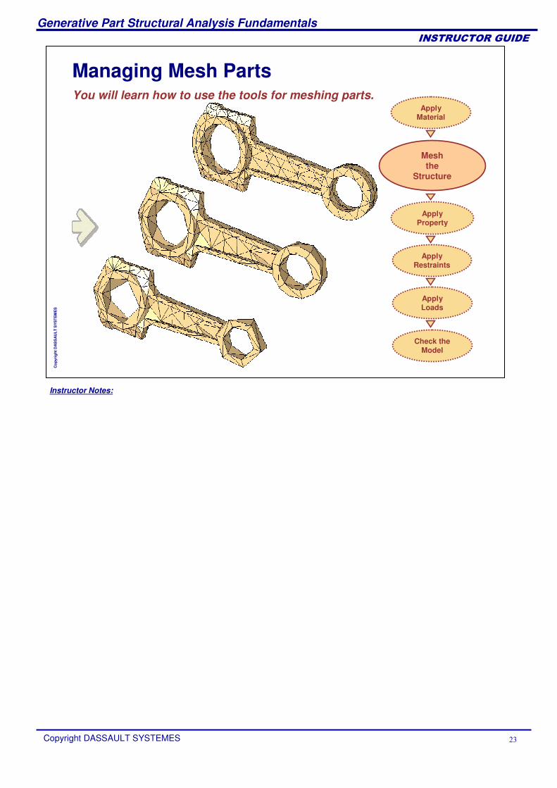
Managing Mesh PartsYou will learn how to use the tools for meshing parts.
Mesh the
Structure
Apply Material
Check the Model
Apply Loads
Apply Restraints
ApplyProperty
Instructor Notes:
Generative Part Structural Analysis Fundamentals
Copyright DASSAULT SYSTEMES ��
��������������
Cop
yrig
ht D
AS
SA
ULT
SY
STE
ME
S
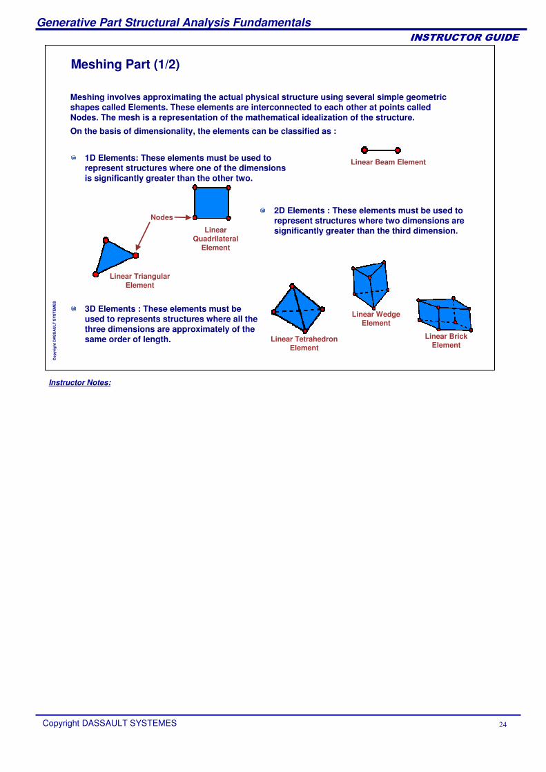
Meshing Part (1/2)
Meshing involves approximating the actual physical structure using several simple geometric shapes called Elements. These elements are interconnected to each other at points called Nodes. The mesh is a representation of the mathematical idealization of the structure.
2D Elements : These elements must be used to represent structures where two dimensions are significantly greater than the third dimension.
3D Elements : These elements must be used to represents structures where all the three dimensions are approximately of the same order of length.
On the basis of dimensionality, the elements can be classified as :
Linear Beam Element
Nodes
Linear TriangularElement
Linear Quadrilateral
Element
Linear Tetrahedron Element
Linear Wedge Element
Linear Brick Element
1D Elements: These elements must be used to represent structures where one of the dimensions is significantly greater than the other two.
Instructor Notes:
Generative Part Structural Analysis Fundamentals
Copyright DASSAULT SYSTEMES ��
��������������
Cop
yrig
ht D
AS
SA
ULT
SY
STE
ME
S
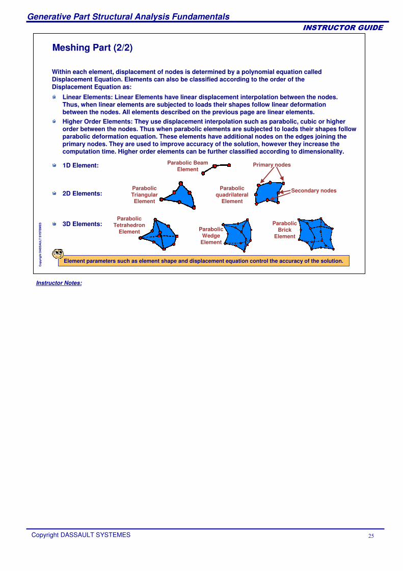
Meshing Part (2/2)
1D Element:
Higher Order Elements: They use displacement interpolation such as parabolic, cubic or higher order between the nodes. Thus when parabolic elements are subjected to loads their shapes follow parabolic deformation equation. These elements have additional nodes on the edges joining the primary nodes. They are used to improve accuracy of the solution, however they increase the computation time. Higher order elements can be further classified according to dimensionality.
Within each element, displacement of nodes is determined by a polynomial equation called Displacement Equation. Elements can also be classified according to the order of the Displacement Equation as:
Linear Elements: Linear Elements have linear displacement interpolation between the nodes. Thus, when linear elements are subjected to loads their shapes follow linear deformation between the nodes. All elements described on the previous page are linear elements.
2D Elements:
3D Elements:
Parabolic Beam Element
Parabolic TriangularElement
Parabolic quadrilateral
Element
Parabolic Tetrahedron
Element Parabolic Wedge
Element
Parabolic Brick
Element
Primary nodes
Secondary nodes
Element parameters such as element shape and displacement equation control the accuracy of the solution.
Instructor Notes:
Generative Part Structural Analysis Fundamentals
Copyright DASSAULT SYSTEMES ��
��������������
Cop
yrig
ht D
AS
SA
ULT
SY
STE
ME
S
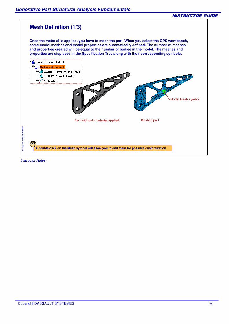
Mesh Definition (1/3)
Once the material is applied, you have to mesh the part. When you select the GPS workbench, some model meshes and model properties are automatically defined. The number of meshes and properties created will be equal to the number of bodies in the model. The meshes and properties are displayed in the Specification Tree along with their corresponding symbols.
Part with only material applied Meshed part
Model Mesh symbol
A double-click on the Mesh symbol will allow you to edit them for possible customization.
Instructor Notes:
Generative Part Structural Analysis Fundamentals
Copyright DASSAULT SYSTEMES ��
��������������
Cop
yrig
ht D
AS
SA
ULT
SY
STE
ME
S
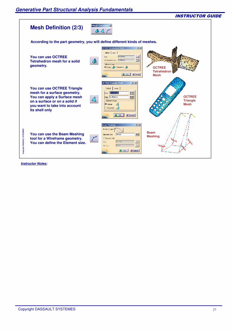
Mesh Definition (2/3)
According to the part geometry, you will define different kinds of meshes.
You can use OCTREE Tetrahedron mesh for a solid geometry.
You can use OCTREE Triangle mesh for a surface geometry. You can apply a Surface mesh on a surface or on a solid if you want to take into account its shell only
You can use the Beam Meshing tool for a Wireframe geometry. You can define the Element size.
Beam Meshing
OCTREE Triangle Mesh
OCTREE Tetrahedron Mesh
Instructor Notes:
Generative Part Structural Analysis Fundamentals
Copyright DASSAULT SYSTEMES ��
��������������
Cop
yrig
ht D
AS
SA
ULT
SY
STE
ME
S
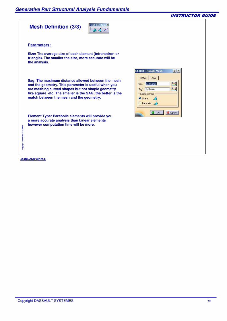
Mesh Definition (3/3)
Size: The average size of each element (tetrahedron or triangle). The smaller the size, more accurate will be the analysis.
Parameters:
Sag: The maximum distance allowed between the mesh and the geometry. This parameter is useful when you are meshing curved shapes but not simple geometry like square, etc. The smaller is the SAG, the better is the match between the mesh and the geometry.
Element Type: Parabolic elements will provide you a more accurate analysis than Linear elements however computation time will be more.
Instructor Notes:
Generative Part Structural Analysis Fundamentals
Copyright DASSAULT SYSTEMES �
��������������
Cop
yrig
ht D
AS
SA
ULT
SY
STE
ME
S
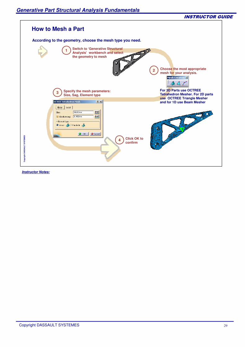
According to the geometry, choose the mesh type you need.
How to Mesh a Part
Switch to ‘Generative Structural Analysis’ workbench and select the geometry to mesh
Choose the most appropriate mesh for your analysis.
Specify the mesh parameters: Size, Sag, Element type
Click OK to confirm
1
2
3
4
For 3D Parts use OCTREE Tetrahedron Mesher. For 2D parts use OCTREE Triangle Mesher and for 1D use Beam Mesher
Instructor Notes:
Generative Part Structural Analysis Fundamentals
Copyright DASSAULT SYSTEMES �
��������������
Cop
yrig
ht D
AS
SA
ULT
SY
STE
ME
S
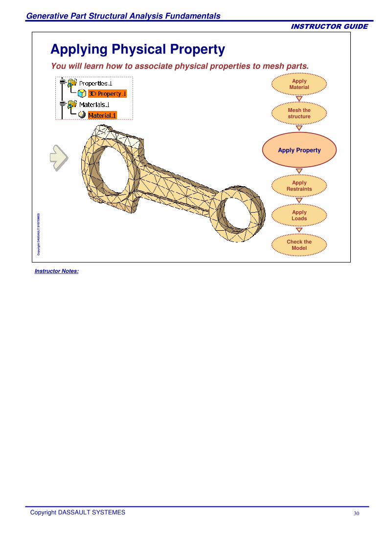
Applying Physical PropertyYou will learn how to associate physical properties to mesh parts.
Apply Property
Apply Material
Mesh the structure
Check the Model
Apply Loads
Apply Restraints
Instructor Notes:
Generative Part Structural Analysis Fundamentals
Copyright DASSAULT SYSTEMES ��
��������������
Cop
yrig
ht D
AS
SA
ULT
SY
STE
ME
S
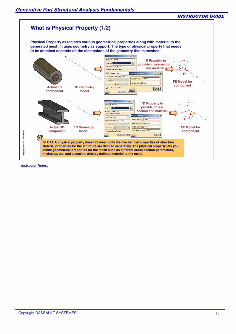
What is Physical Property (1/2)
Physical Property associates various geometrical properties along with material to the generated mesh. It uses geometry as support. The type of physical property that needs to be attached depends on the dimensions of the geometry that is meshed.
Actual 3D component
1D Geometry model
1D Property to provide cross-section
and material
FE Model for component
In CATIA physical property does not mean only the mechanical properties of structure. Material properties for the structure are defined separately. The physical property lets you define geometrical properties for the mesh such as different cross-section parameters, thickness, etc. and associate already defined material to the mesh.
Actual 3D component
1D Geometry model
1D Property to provide cross-
section and material
FE Model for component
Instructor Notes:
Generative Part Structural Analysis Fundamentals
Copyright DASSAULT SYSTEMES ��
��������������
Cop
yrig
ht D
AS
SA
ULT
SY
STE
ME
S
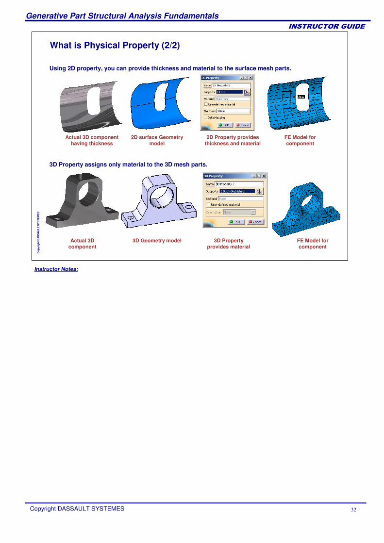
What is Physical Property (2/2)
Using 2D property, you can provide thickness and material to the surface mesh parts.
3D Property assigns only material to the 3D mesh parts.
2D Property provides thickness and material
FE Model for component
3D Property provides material
FE Model for component
Actual 3D component
3D Geometry model
Actual 3D component having thickness
2D surface Geometry model
Instructor Notes:
Generative Part Structural Analysis Fundamentals
Copyright DASSAULT SYSTEMES ��
��������������
Cop
yrig
ht D
AS
SA
ULT
SY
STE
ME
S
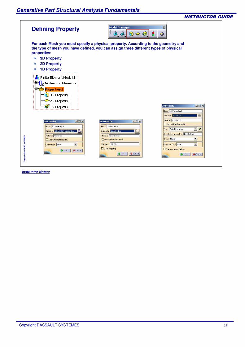
Defining Property
For each Mesh you must specify a physical property. According to the geometry and the type of mesh you have defined, you can assign three different types of physical properties:
3D Property2D Property1D Property
Instructor Notes:
Generative Part Structural Analysis Fundamentals
Copyright DASSAULT SYSTEMES ��
��������������
Cop
yrig
ht D
AS
SA
ULT
SY
STE
ME
S
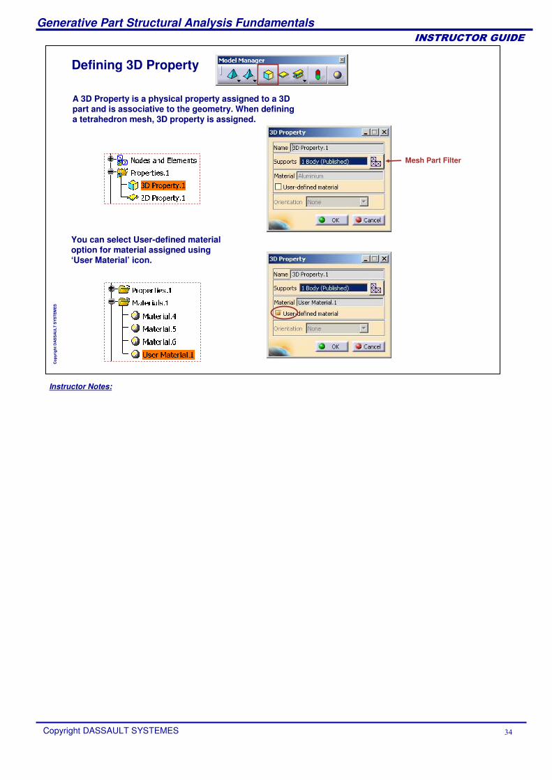
Defining 3D Property
A 3D Property is a physical property assigned to a 3D part and is associative to the geometry. When defining a tetrahedron mesh, 3D property is assigned.
You can select User-defined material option for material assigned using ‘User Material’ icon.
Mesh Part Filter
Instructor Notes:
Generative Part Structural Analysis Fundamentals
Copyright DASSAULT SYSTEMES ��
��������������
Cop
yrig
ht D
AS
SA
ULT
SY
STE
ME
S
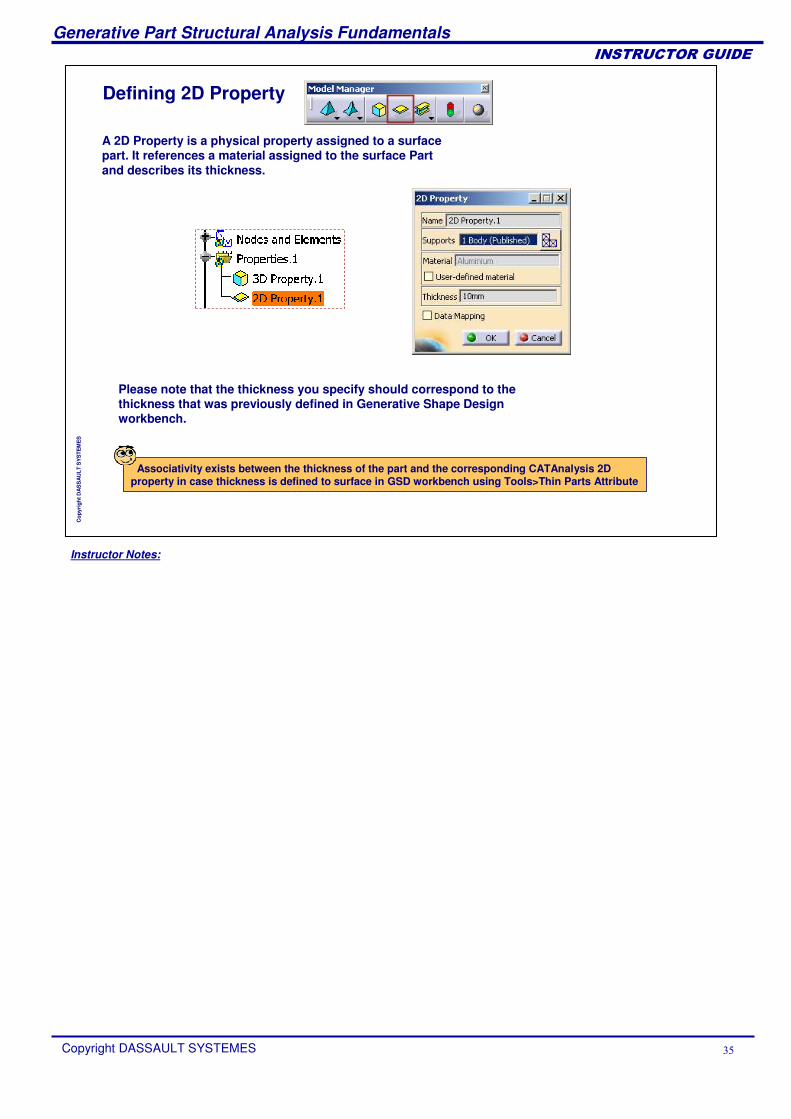
Defining 2D Property
A 2D Property is a physical property assigned to a surface part. It references a material assigned to the surface Part and describes its thickness.
Please note that the thickness you specify should correspond to the thickness that was previously defined in Generative Shape Designworkbench.
Associativity exists between the thickness of the part and the corresponding CATAnalysis 2D property in case thickness is defined to surface in GSD workbench using Tools>Thin Parts Attribute
Instructor Notes:
Generative Part Structural Analysis Fundamentals
Copyright DASSAULT SYSTEMES ��
��������������
Cop
yrig
ht D
AS
SA
ULT
SY
STE
ME
S
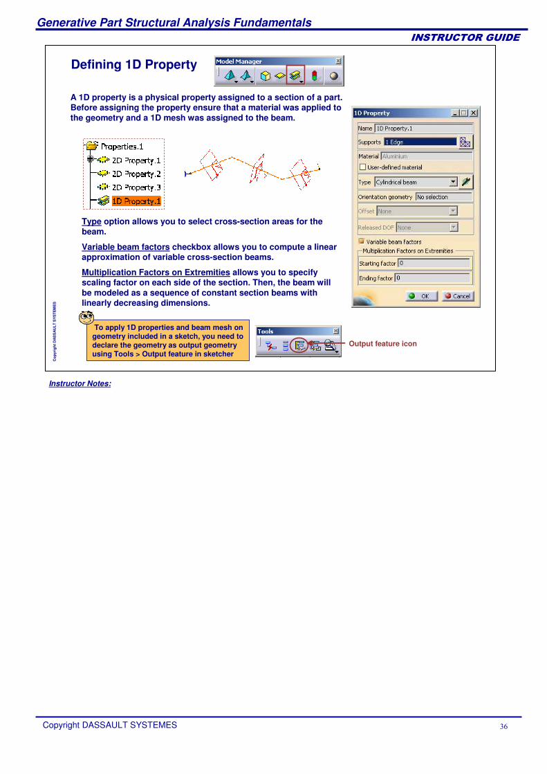
Defining 1D Property
A 1D property is a physical property assigned to a section of a part. Before assigning the property ensure that a material was applied to the geometry and a 1D mesh was assigned to the beam.
Type option allows you to select cross-section areas for the beam.
Variable beam factors checkbox allows you to compute a linear approximation of variable cross-section beams.
Multiplication Factors on Extremities allows you to specify scaling factor on each side of the section. Then, the beam will be modeled as a sequence of constant section beams with linearly decreasing dimensions.
To apply 1D properties and beam mesh on geometry included in a sketch, you need to declare the geometry as output geometry using Tools > Output feature in sketcher
Output feature icon
Instructor Notes:
Generative Part Structural Analysis Fundamentals
Copyright DASSAULT SYSTEMES ��
��������������
Cop
yrig
ht D
AS
SA
ULT
SY
STE
ME
S
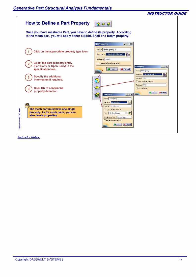
Specify the additional information if required.
Once you have meshed a Part, you have to define its property. According to the mesh part, you will apply either a Solid, Shell or a Beam property.
How to Define a Part Property
Click on the appropriate property type icon.
Select the part geometry entity (Part Body or Open Body) in the specification tree.
The mesh part must have one single property. As for mesh parts, you can also delete properties.
1
2
3
Click OK to confirm the property definition.
3
Instructor Notes:
Generative Part Structural Analysis Fundamentals
Copyright DASSAULT SYSTEMES ��
��������������
Cop
yrig
ht D
AS
SA
ULT
SY
STE
ME
S
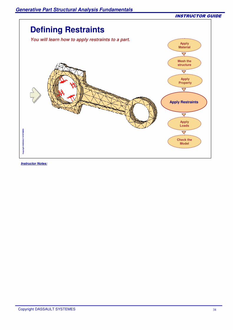
Defining RestraintsYou will learn how to apply restraints to a part.
Apply Restraints
Apply Material
Mesh the structure
Check the Model
Apply Loads
ApplyProperty
Instructor Notes:
Generative Part Structural Analysis Fundamentals
Copyright DASSAULT SYSTEMES �
��������������
Cop
yrig
ht D
AS
SA
ULT
SY
STE
ME
S
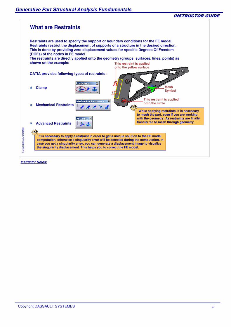
What are Restraints
Restraints are used to specify the support or boundary conditions for the FE model. Restraints restrict the displacement of supports of a structure in the desired direction. This is done by providing zero displacement values for specific Degrees Of Freedom (DOFs) of the nodes in FE model. The restraints are directly applied onto the geometry (groups, surfaces, lines, points) as shown on the example:
Clamp
Mechanical Restraints
Advanced Restraints
CATIA provides following types of restraints :
While applying restraints, it is necessary to mesh the part, even if you are working with the geometry. As restraints are finally transferred to mesh through geometry.
It is necessary to apply a restraint in order to get a unique solution to the FE model computation, otherwise a singularity error will be detected during the computation. In case you get a singularity error, you can generate a displacement image to visualize the singularity displacement. This helps you to correct the FE model.
This restraint is applied onto the yellow surface
This restraint is applied onto the circle
Mesh Symbol
Instructor Notes:
Generative Part Structural Analysis Fundamentals
Copyright DASSAULT SYSTEMES �
��������������
Cop
yrig
ht D
AS
SA
ULT
SY
STE
ME
S
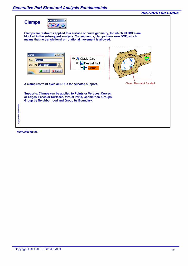
Clamps
Supports: Clamps can be applied to Points or Vertices, Curves or Edges, Faces or Surfaces, Virtual Parts, Geometrical Groups, Group by Neighborhood and Group by Boundary.
Clamps are restraints applied to a surface or curve geometry, for which all DOFs are blocked in the subsequent analysis. Consequently, clamps have zero DOF, which means that no translational or rotational movement is allowed.
Clamp Restraint SymbolA clamp restraint fixes all DOFs for selected support.
Instructor Notes:
Generative Part Structural Analysis Fundamentals
Copyright DASSAULT SYSTEMES ��
��������������
Cop
yrig
ht D
AS
SA
ULT
SY
STE
ME
S
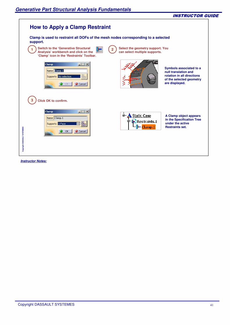
How to Apply a Clamp Restraint
Switch to the ‘Generative Structural Analysis’ workbench and click on the ‘Clamp’ icon in the ‘Restraints’ Toolbar.
Select the geometry support. You can select multiple supports.
Click OK to confirm.
A Clamp object appears in the Specification Tree under the active Restraints set.
Symbols associated to a null translation and rotation in all directions of the selected geometry are displayed.
1 2
3
Clamp is used to restraint all DOFs of the mesh nodes corresponding to a selected support.
Instructor Notes:
Generative Part Structural Analysis Fundamentals
Copyright DASSAULT SYSTEMES ��
��������������
Cop
yrig
ht D
AS
SA
ULT
SY
STE
ME
S
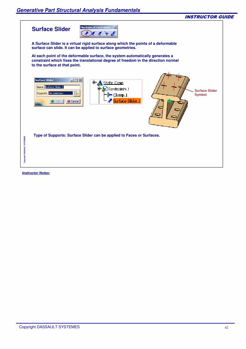
Surface Slider
Type of Supports: Surface Slider can be applied to Faces or Surfaces.
A Surface Slider is a virtual rigid surface along which the points of a deformable surface can slide. It can be applied to surface geometries.
Surface Slider Symbol
At each point of the deformable surface, the system automatically generates a constraint which fixes the translational degree of freedom in the direction normal to the surface at that point.
Instructor Notes:
Generative Part Structural Analysis Fundamentals
Copyright DASSAULT SYSTEMES ��
��������������
Cop
yrig
ht D
AS
SA
ULT
SY
STE
ME
S
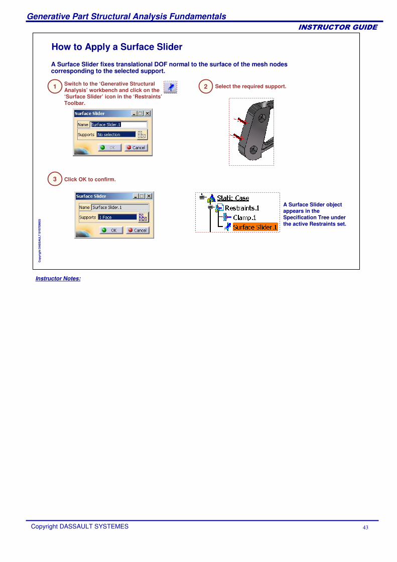
How to Apply a Surface Slider
Switch to the ‘Generative Structural Analysis’ workbench and click on the ‘Surface Slider’ icon in the ‘Restraints’Toolbar.
Select the required support.
Click OK to confirm.
A Surface Slider object appears in the Specification Tree under the active Restraints set.
1 2
3
A Surface Slider fixes translational DOF normal to the surface of the mesh nodes corresponding to the selected support.
Instructor Notes:
Generative Part Structural Analysis Fundamentals
Copyright DASSAULT SYSTEMES ��
��������������
Cop
yrig
ht D
AS
SA
ULT
SY
STE
ME
S
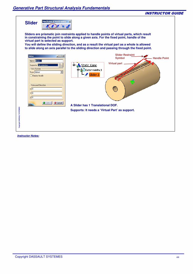
Slider
A Slider has 1 Translational DOF.
Sliders are prismatic join restraints applied to handle points of virtual parts, which result in constraining the point to slide along a given axis. For the fixed point, handle of the virtual part is selected as support.You will define the sliding direction, and as a result the virtual part as a whole is allowed to slide along an axis parallel to the sliding direction and passing through the fixed point.
Supports: It needs a ‘Virtual Part’ as support.
Virtual part
Slider Restraint Symbol Handle Point
Instructor Notes:
Generative Part Structural Analysis Fundamentals
Copyright DASSAULT SYSTEMES ��
��������������
Cop
yrig
ht D
AS
SA
ULT
SY
STE
ME
S
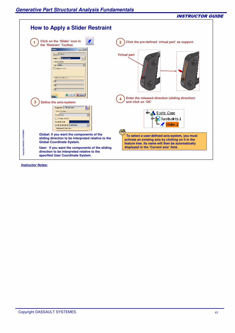
How to Apply a Slider Restraint
Virtual part
Enter the released direction (sliding direction) and click on ‘OK’
Global: if you want the components of the sliding direction to be interpreted relative to the Global Coordinate System.
User: if you want the components of the sliding direction to be interpreted relative to the specified User Coordinate System.
Click on the ‘Slider’ icon in the ‘Restrain’ Toolbar.
1 Click the pre-defined ‘virtual part’ as support.2
Define the axis-system:34
To select a user-defined axis-system, you must activate an existing axis by clicking on it in the feature tree. Its name will then be automatically displayed in the ‘Current axis’ field.
Instructor Notes:
Generative Part Structural Analysis Fundamentals
Copyright DASSAULT SYSTEMES ��
��������������
Cop
yrig
ht D
AS
SA
ULT
SY
STE
ME
S
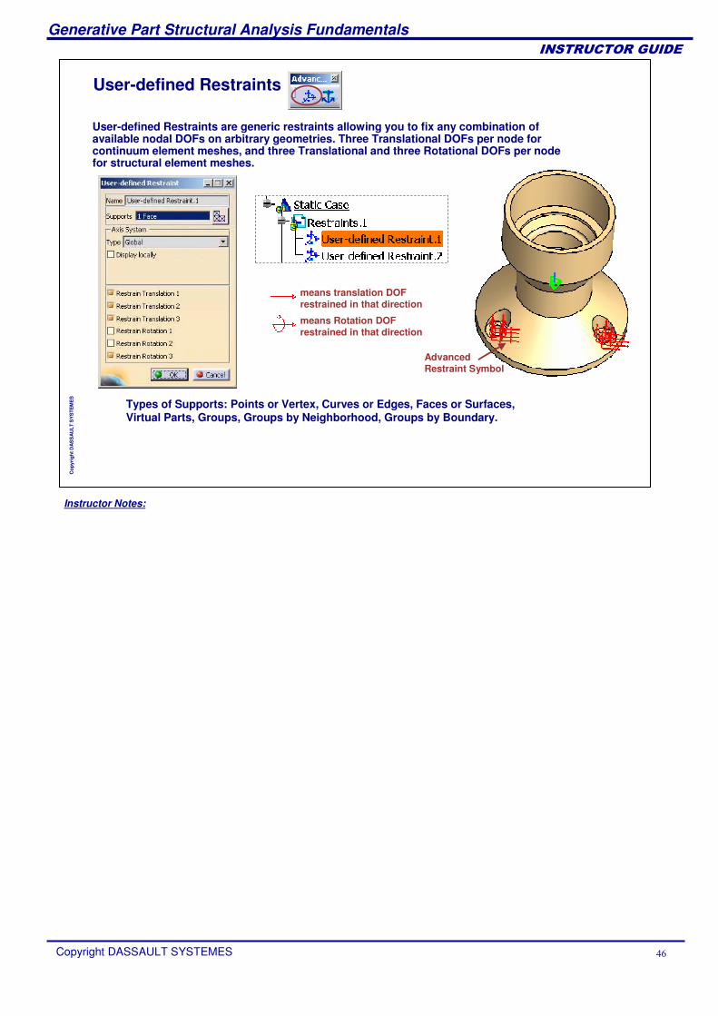
User-defined Restraints
Types of Supports: Points or Vertex, Curves or Edges, Faces or Surfaces, Virtual Parts, Groups, Groups by Neighborhood, Groups by Boundary.
User-defined Restraints are generic restraints allowing you to fix any combination of available nodal DOFs on arbitrary geometries. Three Translational DOFs per node for continuum element meshes, and three Translational and three Rotational DOFs per node for structural element meshes.
means translation DOF restrained in that direction
means Rotation DOF restrained in that direction
Advanced Restraint Symbol
Instructor Notes:
Generative Part Structural Analysis Fundamentals
Copyright DASSAULT SYSTEMES ��
��������������
Cop
yrig
ht D
AS
SA
ULT
SY
STE
ME
S
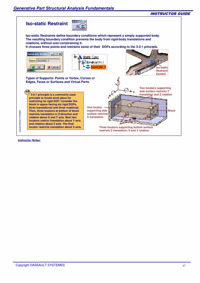
Iso-static Restraint
Types of Supports: Points or Vertex, Curves or Edges, Faces or Surfaces and Virtual Parts.
Iso-static Restraints define boundary conditions which represent a simply supported body. The resulting boundary condition prevents the body from rigid-body translations and rotations, without over-constraining it.It chooses three points and restrains some of their DOFs according to the 3-2-1 principle.
Iso-static Restraint Symbol
3-2-1 principle is a commonly used principle to locate work piece for restricting its rigid DOF. Consider the block in space having six rigid DOFs, three translational and three rotational. Then, three locators at bottom of block restricts translation in Z-direction and rotation about X and Y axis. Next two locators restrict translation about Y axis and rotation about Z axis. The final locator restricts translation about X axis.
X
Z
Y
Block
Three locators supporting bottom surface restricts Z translation, X and Y rotation
Two locators supporting side surface restricts Y translation and Z rotation
One locator supporting side surface restricts X translation
Instructor Notes:
Generative Part Structural Analysis Fundamentals
Copyright DASSAULT SYSTEMES ��
��������������
Cop
yrig
ht D
AS
SA
ULT
SY
STE
ME
S
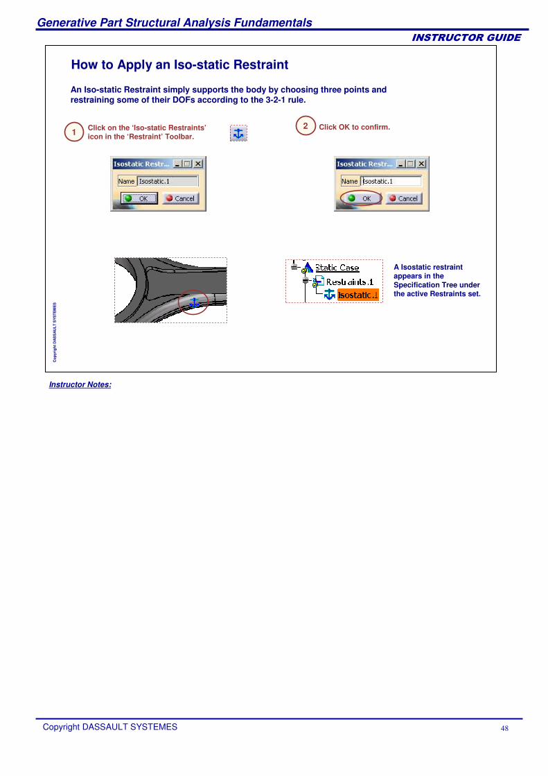
How to Apply an Iso-static Restraint
Click on the ‘Iso-static Restraints’icon in the ‘Restraint’ Toolbar.1
Click OK to confirm.2
An Iso-static Restraint simply supports the body by choosing three points and restraining some of their DOFs according to the 3-2-1 rule.
A Isostatic restraint appears in the Specification Tree under the active Restraints set.
Instructor Notes:
Generative Part Structural Analysis Fundamentals
Copyright DASSAULT SYSTEMES �
��������������
Cop
yrig
ht D
AS
SA
ULT
SY
STE
ME
S
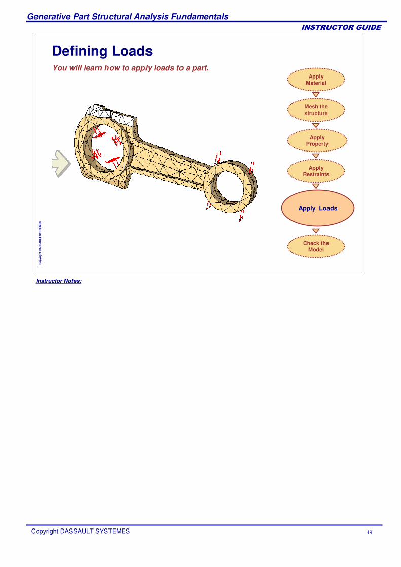
Defining LoadsYou will learn how to apply loads to a part.
Apply Loads
Apply Material
Mesh the structure
Check the Model
Apply Restraints
ApplyProperty
Instructor Notes:
Generative Part Structural Analysis Fundamentals
Copyright DASSAULT SYSTEMES �
��������������
Cop
yrig
ht D
AS
SA
ULT
SY
STE
ME
S
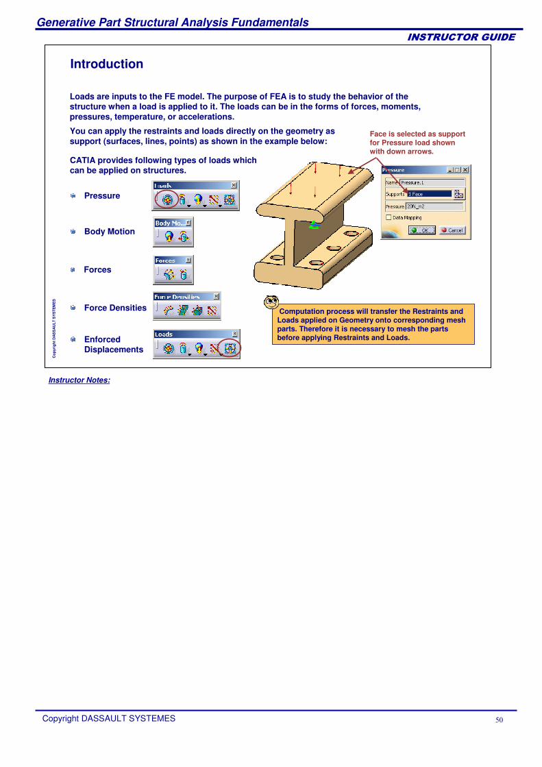
Introduction
You can apply the restraints and loads directly on the geometry as support (surfaces, lines, points) as shown in the example below:
Loads are inputs to the FE model. The purpose of FEA is to study the behavior of the structure when a load is applied to it. The loads can be in the forms of forces, moments, pressures, temperature, or accelerations.
Computation process will transfer the Restraints and Loads applied on Geometry onto corresponding mesh parts. Therefore it is necessary to mesh the parts before applying Restraints and Loads.
CATIA provides following types of loads which can be applied on structures.
Pressure
Body Motion
Forces
Force Densities
Enforced Displacements
Face is selected as support for Pressure load shown with down arrows.
Instructor Notes:
Generative Part Structural Analysis Fundamentals
Copyright DASSAULT SYSTEMES ��
��������������
Cop
yrig
ht D
AS
SA
ULT
SY
STE
ME
S
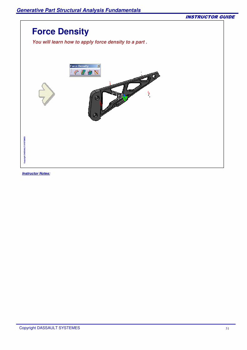
Force DensityYou will learn how to apply force density to a part .
Instructor Notes:
Generative Part Structural Analysis Fundamentals
Copyright DASSAULT SYSTEMES ��
��������������
Cop
yrig
ht D
AS
SA
ULT
SY
STE
ME
S
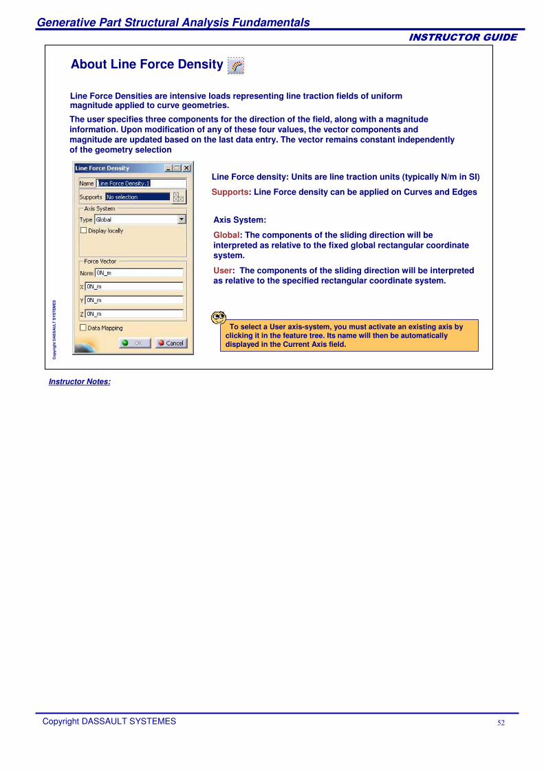
About Line Force Density
Line Force Densities are intensive loads representing line traction fields of uniform magnitude applied to curve geometries.
The user specifies three components for the direction of the field, along with a magnitude information. Upon modification of any of these four values, the vector components and magnitude are updated based on the last data entry. The vector remains constant independently of the geometry selection
Line Force density: Units are line traction units (typically N/m in SI)
Supports: Line Force density can be applied on Curves and Edges
Axis System:
Global: The components of the sliding direction will be interpreted as relative to the fixed global rectangular coordinate system.
User: The components of the sliding direction will be interpreted as relative to the specified rectangular coordinate system.
To select a User axis-system, you must activate an existing axis by clicking it in the feature tree. Its name will then be automatically displayed in the Current Axis field.
Instructor Notes:
Generative Part Structural Analysis Fundamentals
Copyright DASSAULT SYSTEMES ��
��������������
Cop
yrig
ht D
AS
SA
ULT
SY
STE
ME
S
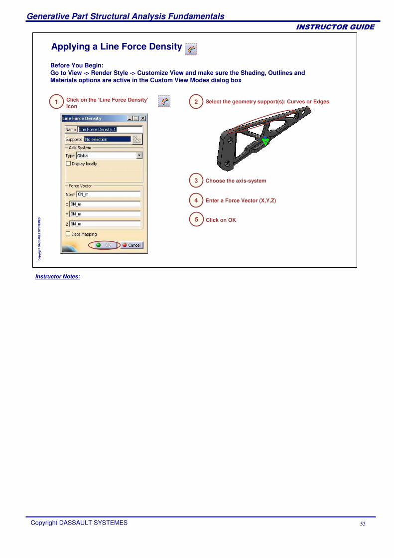
Applying a Line Force Density
Click on the ‘Line Force Density’Icon
Before You Begin:Go to View -> Render Style -> Customize View and make sure the Shading, Outlines and Materials options are active in the Custom View Modes dialog box
1 Select the geometry support(s): Curves or Edges2
Choose the axis-system3
Enter a Force Vector (X,Y,Z)4
Click on OK5
Instructor Notes:
Generative Part Structural Analysis Fundamentals
Copyright DASSAULT SYSTEMES ��
��������������
Cop
yrig
ht D
AS
SA
ULT
SY
STE
ME
S
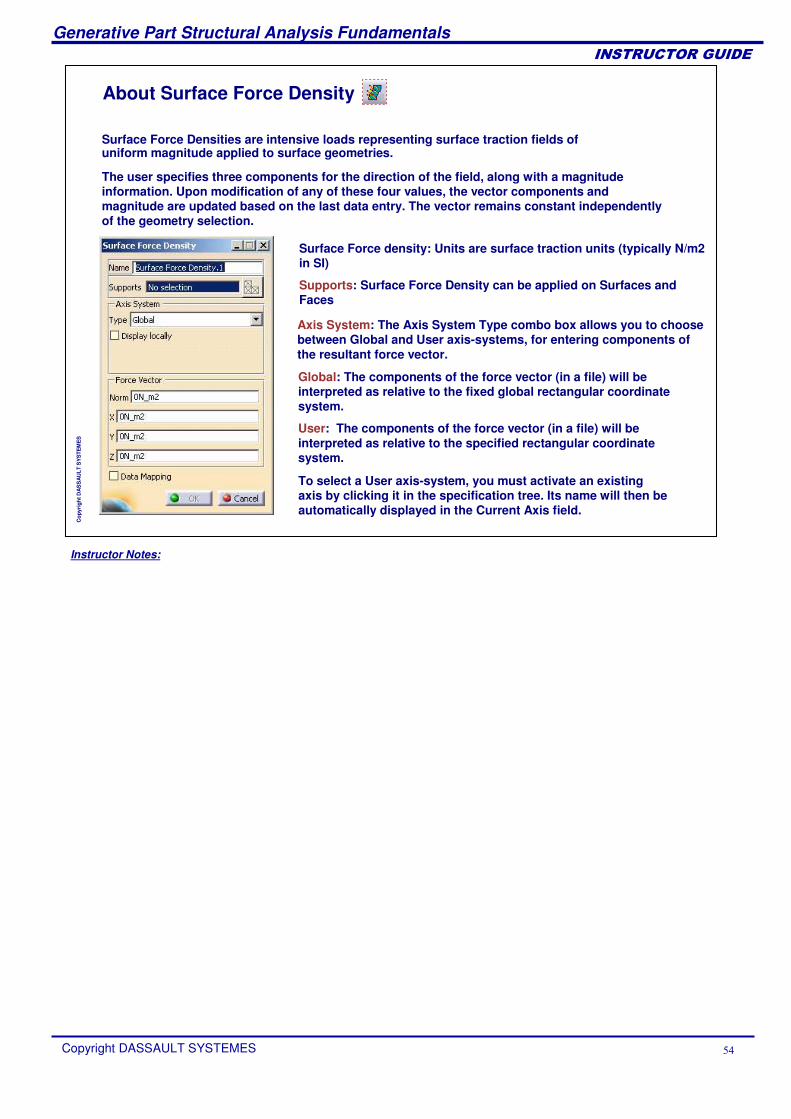
About Surface Force Density
Surface Force Densities are intensive loads representing surface traction fields of uniform magnitude applied to surface geometries.
Axis System: The Axis System Type combo box allows you to choose between Global and User axis-systems, for entering components of the resultant force vector.
Global: The components of the force vector (in a file) will be interpreted as relative to the fixed global rectangular coordinate system.
User: The components of the force vector (in a file) will be interpreted as relative to the specified rectangular coordinate system.
To select a User axis-system, you must activate an existing axis by clicking it in the specification tree. Its name will then be automatically displayed in the Current Axis field.
The user specifies three components for the direction of the field, along with a magnitude information. Upon modification of any of these four values, the vector components and magnitude are updated based on the last data entry. The vector remains constant independently of the geometry selection.
Surface Force density: Units are surface traction units (typically N/m2 in SI)
Supports: Surface Force Density can be applied on Surfaces and Faces
Instructor Notes:
Generative Part Structural Analysis Fundamentals
Copyright DASSAULT SYSTEMES ��
��������������
Cop
yrig
ht D
AS
SA
ULT
SY
STE
ME
S
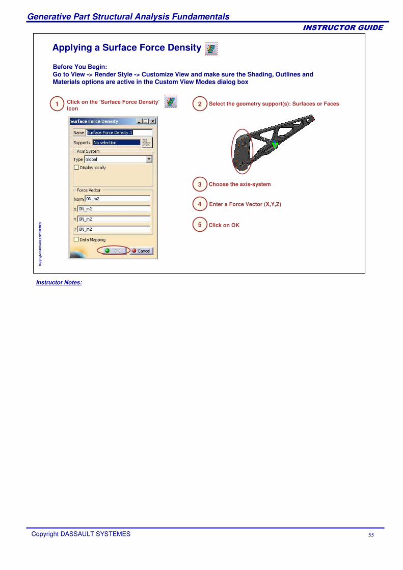
Applying a Surface Force Density
Select the geometry support(s): Surfaces or FacesClick on the ‘Surface Force Density’Icon
Before You Begin:Go to View -> Render Style -> Customize View and make sure the Shading, Outlines and Materials options are active in the Custom View Modes dialog box
Choose the axis-system
Enter a Force Vector (X,Y,Z)
Click on OK
1 2
3
4
5
Instructor Notes:
Generative Part Structural Analysis Fundamentals
Copyright DASSAULT SYSTEMES ��
��������������
Cop
yrig
ht D
AS
SA
ULT
SY
STE
ME
S
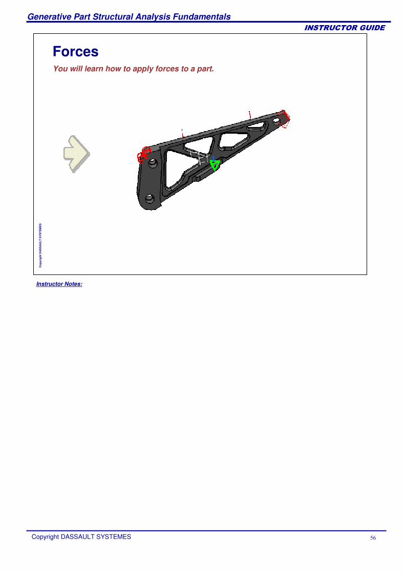
ForcesYou will learn how to apply forces to a part.
Instructor Notes:
Generative Part Structural Analysis Fundamentals
Copyright DASSAULT SYSTEMES ��
��������������
Cop
yrig
ht D
AS
SA
ULT
SY
STE
ME
S
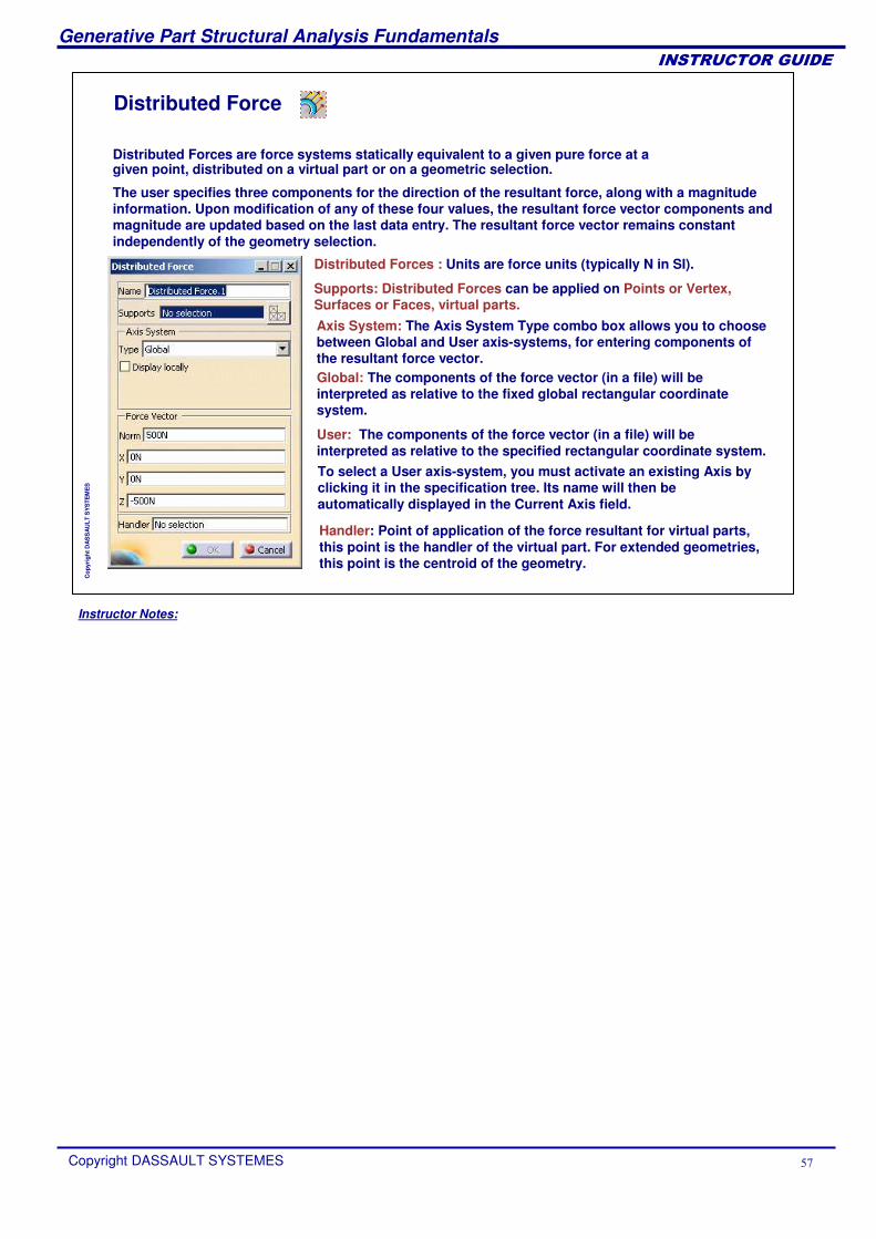
Distributed Force
Distributed Forces are force systems statically equivalent to a given pure force at a given point, distributed on a virtual part or on a geometric selection.
Distributed Forces : Units are force units (typically N in SI).
Supports: Distributed Forces can be applied on Points or Vertex, Surfaces or Faces, virtual parts.
The user specifies three components for the direction of the resultant force, along with a magnitude information. Upon modification of any of these four values, the resultant force vector components and magnitude are updated based on the last data entry. The resultant force vector remains constant independently of the geometry selection.
Axis System: The Axis System Type combo box allows you to choose between Global and User axis-systems, for entering components of the resultant force vector.Global: The components of the force vector (in a file) will be interpreted as relative to the fixed global rectangular coordinate system.
User: The components of the force vector (in a file) will be interpreted as relative to the specified rectangular coordinate system.To select a User axis-system, you must activate an existing Axis by clicking it in the specification tree. Its name will then be automatically displayed in the Current Axis field.
Handler: Point of application of the force resultant for virtual parts,this point is the handler of the virtual part. For extended geometries, this point is the centroid of the geometry.
Instructor Notes:
Generative Part Structural Analysis Fundamentals
Copyright DASSAULT SYSTEMES ��
��������������
Cop
yrig
ht D
AS
SA
ULT
SY
STE
ME
S
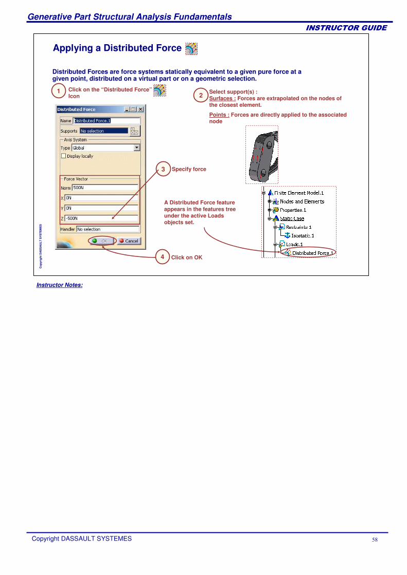
Applying a Distributed Force
Select support(s) :Surfaces : Forces are extrapolated on the nodes of the closest element.
Points : Forces are directly applied to the associated node
Distributed Forces are force systems statically equivalent to a given pure force at a given point, distributed on a virtual part or on a geometric selection.
Click on the “Distributed Force”Icon
Click on OK
Specify force
A Distributed Force feature appears in the features tree under the active Loads objects set.
12
3
4
Instructor Notes:
Generative Part Structural Analysis Fundamentals
Copyright DASSAULT SYSTEMES �
��������������
Cop
yrig
ht D
AS
SA
ULT
SY
STE
ME
S
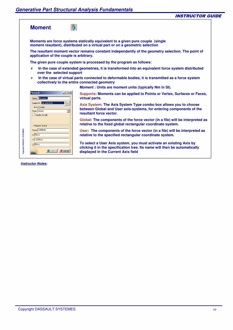
Moment
Moments are force systems statically equivalent to a given pure couple (single moment resultant), distributed on a virtual part or on a geometric selection
The resultant moment vector remains constant independently of the geometry selection. The point of application of the couple is arbitrary.
Moment : Units are moment units (typically Nm in SI).
Supports: Moments can be applied to Points or Vertex, Surfaces or Faces,virtual parts.
Axis System: The Axis System Type combo box allows you to choose between Global and User axis-systems, for entering components of the resultant force vector.
Global: The components of the force vector (in a file) will be interpreted as relative to the fixed global rectangular coordinate system.
User: The components of the force vector (in a file) will be interpreted as relative to the specified rectangular coordinate system.
To select a User Axis system, you must activate an existing Axis by clicking it in the specification tree. Its name will then be automatically displayed in the Current Axis field
The given pure couple system is processed by the program as follows:
In the case of extended geometries, it is transformed into an equivalent force system distributed over the selected supportIn the case of virtual parts connected to deformable bodies, it is transmitted as a force system collectively to the entire connected geometry
Instructor Notes:
Generative Part Structural Analysis Fundamentals
Copyright DASSAULT SYSTEMES �
��������������
Cop
yrig
ht D
AS
SA
ULT
SY
STE
ME
S
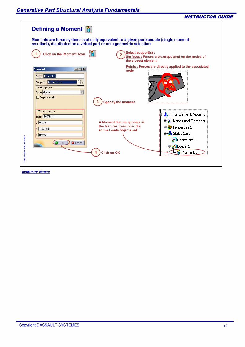
Defining a Moment
Moments are force systems statically equivalent to a given pure couple (single moment resultant), distributed on a virtual part or on a geometric selection
A Moment feature appears in the features tree under the active Loads objects set.
Click on the ‘Moment’ Icon1 Select support(s) :Surfaces : Forces are extrapolated on the nodes of the closest element.
Points : Forces are directly applied to the associated node
2
Specify the moment3
Click on OK4
Instructor Notes:
Generative Part Structural Analysis Fundamentals
Copyright DASSAULT SYSTEMES ��
��������������
Cop
yrig
ht D
AS
SA
ULT
SY
STE
ME
S
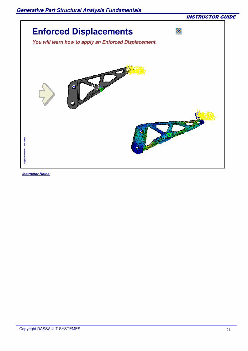
Enforced DisplacementsYou will learn how to apply an Enforced Displacement.
Instructor Notes:
Generative Part Structural Analysis Fundamentals
Copyright DASSAULT SYSTEMES ��
��������������
Cop
yrig
ht D
AS
SA
ULT
SY
STE
ME
S
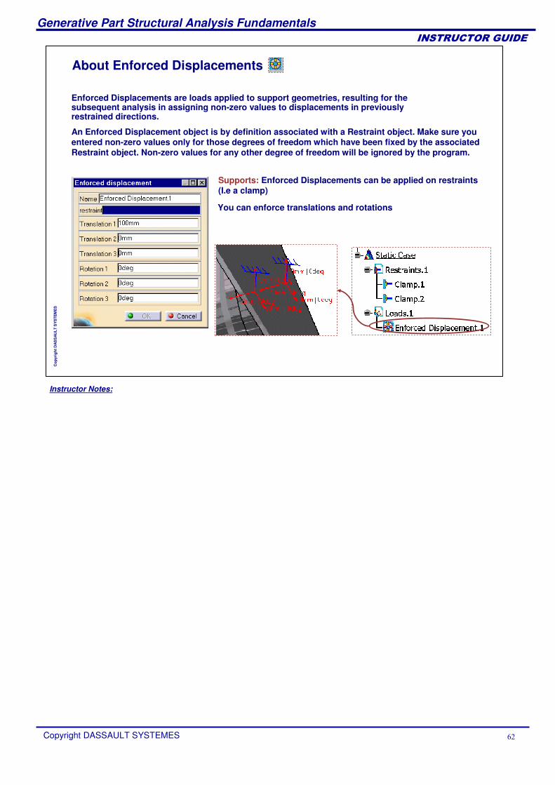
About Enforced Displacements
Enforced Displacements are loads applied to support geometries, resulting for the subsequent analysis in assigning non-zero values to displacements in previously restrained directions.
An Enforced Displacement object is by definition associated with a Restraint object. Make sure you entered non-zero values only for those degrees of freedom which have been fixed by the associated Restraint object. Non-zero values for any other degree of freedom will be ignored by the program.
Supports: Enforced Displacements can be applied on restraints (I.e a clamp)
You can enforce translations and rotations
Instructor Notes:
Generative Part Structural Analysis Fundamentals
Copyright DASSAULT SYSTEMES ��
��������������
Cop
yrig
ht D
AS
SA
ULT
SY
STE
ME
S
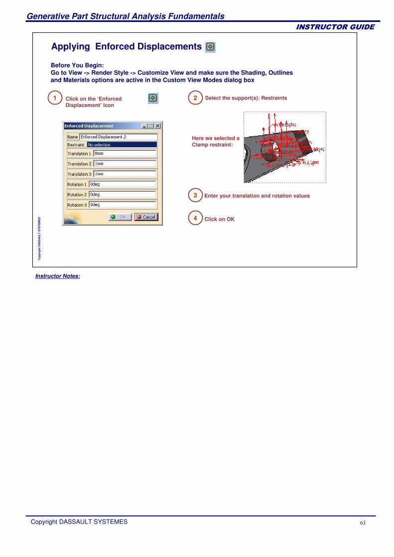
Applying Enforced Displacements
Before You Begin:Go to View -> Render Style -> Customize View and make sure the Shading, Outlines and Materials options are active in the Custom View Modes dialog box
Here we selected a Clamp restraint:
Click on the ‘Enforced Displacement’ Icon
1 Select the support(s): Restraints2
Enter your translation and rotation values3
Click on OK4
Instructor Notes:
Generative Part Structural Analysis Fundamentals
Copyright DASSAULT SYSTEMES ��
��������������
Cop
yrig
ht D
AS
SA
ULT
SY
STE
ME
S
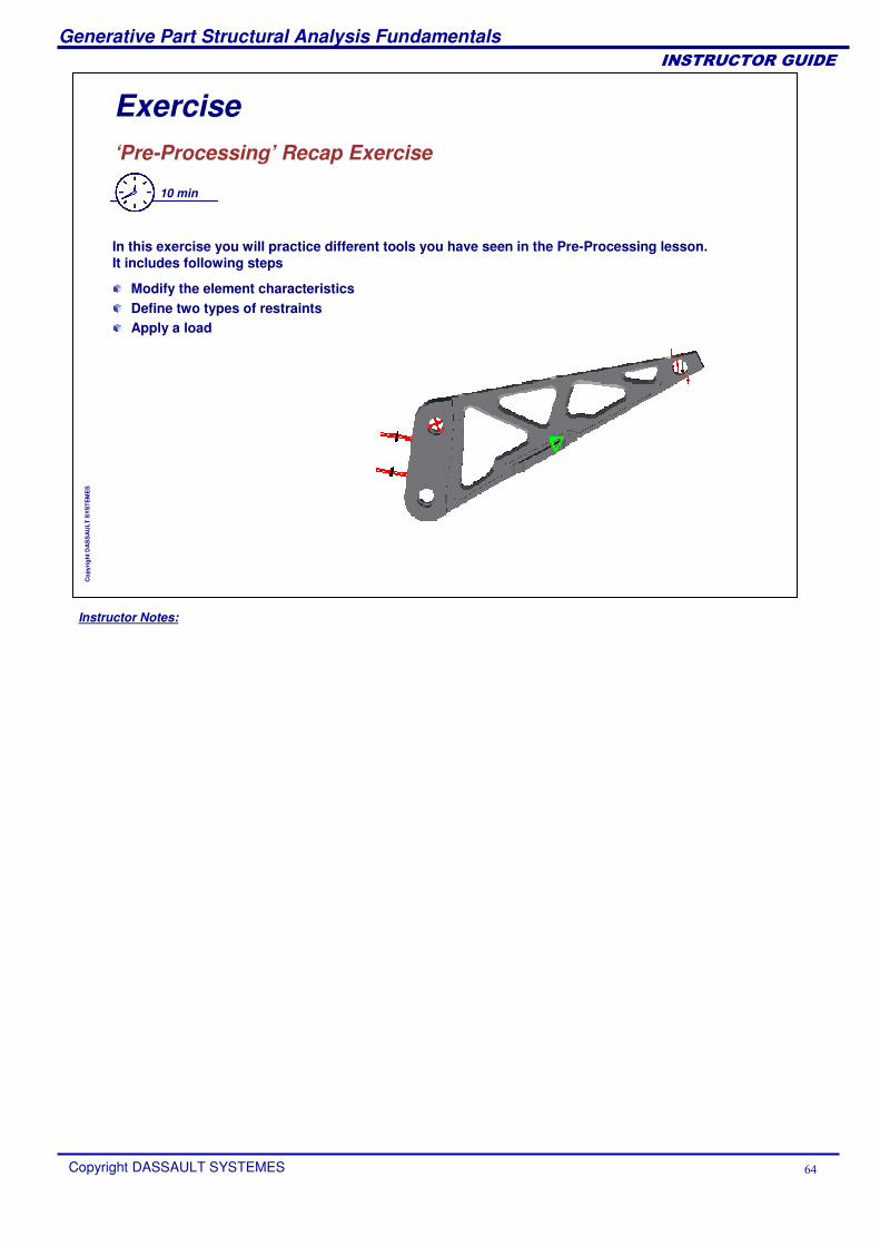
Exercise‘Pre-Processing’ Recap Exercise
10 min
In this exercise you will practice different tools you have seen in the Pre-Processing lesson. It includes following steps
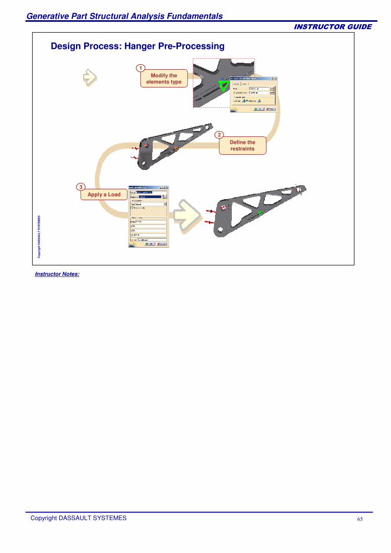
Modify the element characteristicsDefine two types of restraintsApply a load
Instructor Notes:
Generative Part Structural Analysis Fundamentals
Copyright DASSAULT SYSTEMES ��
��������������
Cop
yrig
ht D
AS
SA
ULT
SY
STE
ME
S
Design Process: Hanger Pre-Processing
Modify the elements type
1
Define the restraints
2
Apply a Load3
Instructor Notes:
Generative Part Structural Analysis Fundamentals
Copyright DASSAULT SYSTEMES ��
��������������
Cop
yrig
ht D
AS
SA
ULT
SY
STE
ME
S
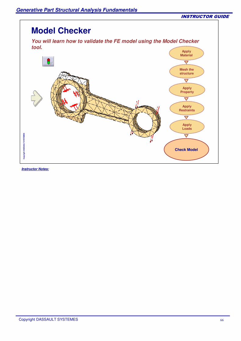
Model CheckerYou will learn how to validate the FE model using the Model Checker tool.
Check Model
Apply Material
Mesh the structure
Apply Loads
Apply Restraints
ApplyProperty
Instructor Notes:
Generative Part Structural Analysis Fundamentals
Copyright DASSAULT SYSTEMES ��
��������������
Cop
yrig
ht D
AS
SA
ULT
SY
STE
ME
S
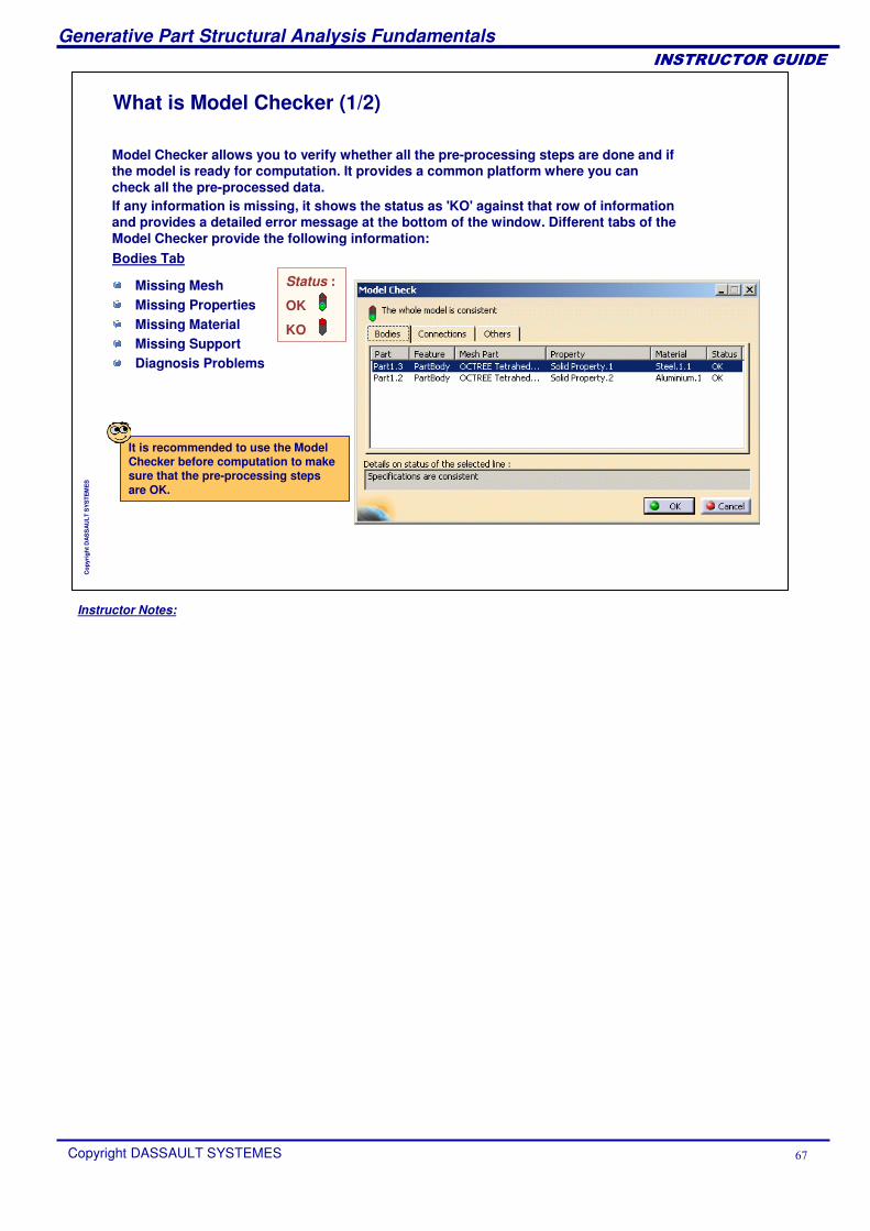
What is Model Checker (1/2)
If any information is missing, it shows the status as 'KO' against that row of information and provides a detailed error message at the bottom of the window. Different tabs of the Model Checker provide the following information:Bodies Tab
Status :
OK
KO
It is recommended to use the Model Checker before computation to make sure that the pre-processing steps are OK.
Model Checker allows you to verify whether all the pre-processing steps are done and if the model is ready for computation. It provides a common platform where you can check all the pre-processed data.
Missing MeshMissing PropertiesMissing MaterialMissing SupportDiagnosis Problems
Instructor Notes:
Generative Part Structural Analysis Fundamentals
Copyright DASSAULT SYSTEMES ��
��������������
Cop
yrig
ht D
AS
SA
ULT
SY
STE
ME
S
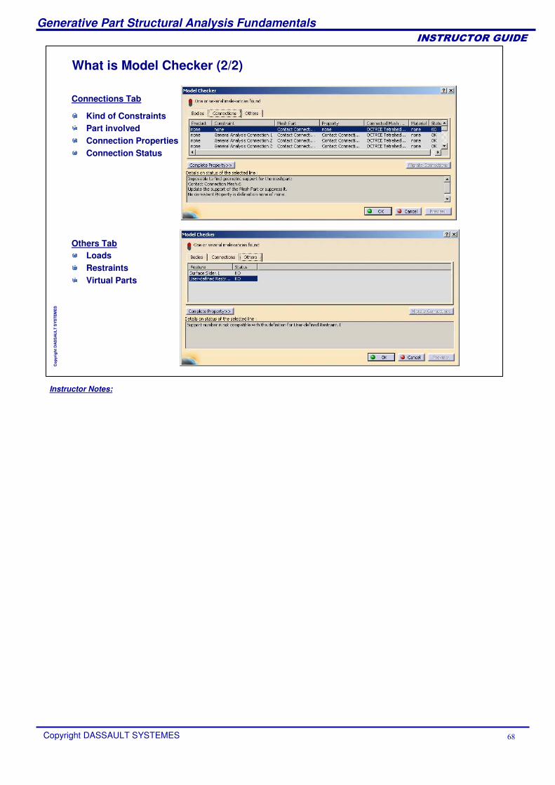
What is Model Checker (2/2)
Connections Tab
Others Tab
Kind of ConstraintsPart involvedConnection PropertiesConnection Status
LoadsRestraintsVirtual Parts
Instructor Notes:
Generative Part Structural Analysis Fundamentals
Copyright DASSAULT SYSTEMES �
��������������
Cop
yrig
ht D
AS
SA
ULT
SY
STE
ME
S
GPS ComputationOnce you have meshed the part, and applied restraints and loads, you can compute the analysis.
What is ComputationSpecifying the External StorageComputing a Static CaseComputation Recap Exercise
Instructor Notes:
Generative Part Structural Analysis Fundamentals
Copyright DASSAULT SYSTEMES �
��������������
Cop
yrig
ht D
AS
SA
ULT
SY
STE
ME
S
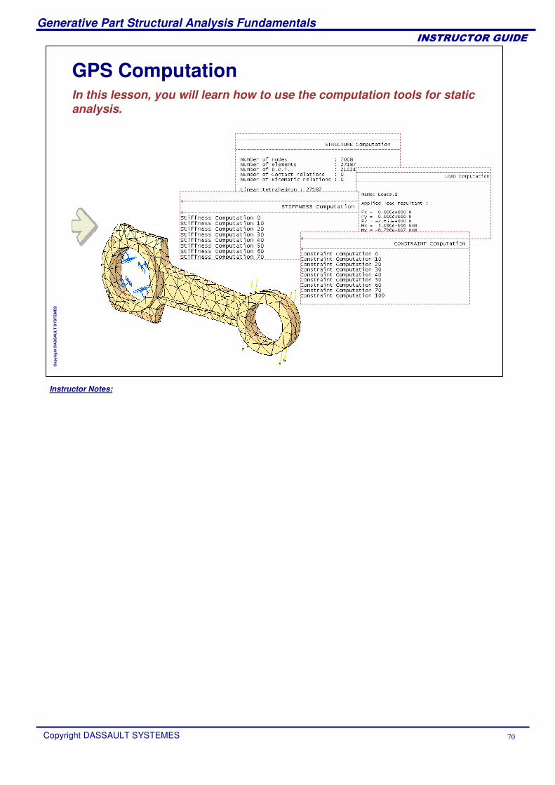
GPS ComputationIn this lesson, you will learn how to use the computation tools for static analysis.
Instructor Notes:
Generative Part Structural Analysis Fundamentals
Copyright DASSAULT SYSTEMES ��
��������������
Cop
yrig
ht D
AS
SA
ULT
SY
STE
ME
S
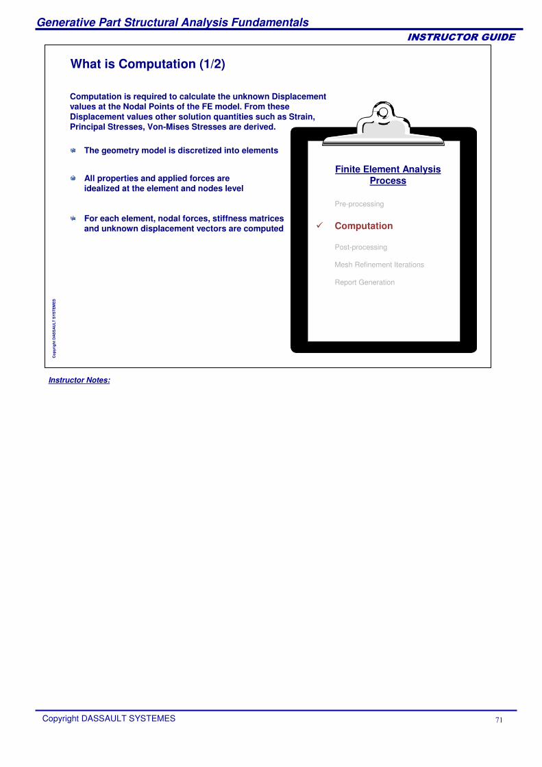
What is Computation (1/2)
Computation is required to calculate the unknown Displacement values at the Nodal Points of the FE model. From these Displacement values other solution quantities such as Strain, Principal Stresses, Von-Mises Stresses are derived.
The geometry model is discretized into elements
All properties and applied forces are idealized at the element and nodes level
For each element, nodal forces, stiffness matrices and unknown displacement vectors are computed
Finite Element AnalysisProcess
Pre-processing
� Computation
Post-processing
Mesh Refinement Iterations
Report Generation
Instructor Notes:
Generative Part Structural Analysis Fundamentals
Copyright DASSAULT SYSTEMES ��
��������������
Cop
yrig
ht D
AS
SA
ULT
SY
STE
ME
S
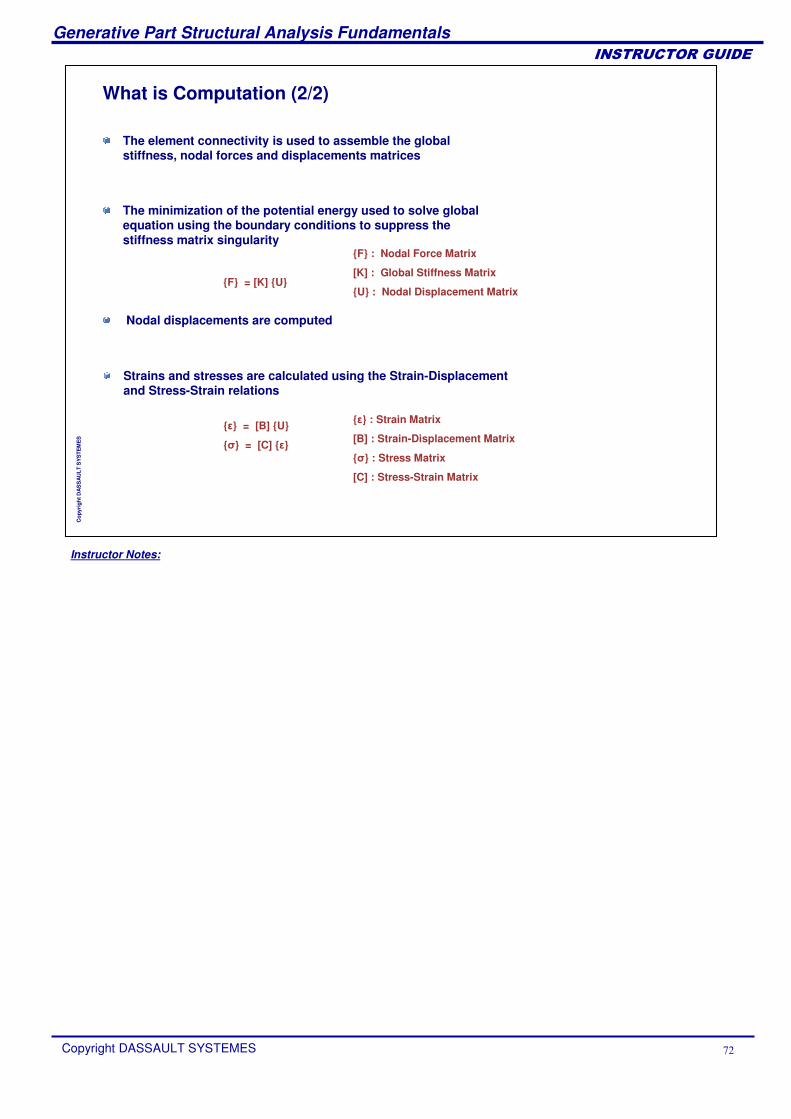
What is Computation (2/2)
{F} = [K] {U}
{�} = [B] {U}
{�} = [C] {�}
The element connectivity is used to assemble the global stiffness, nodal forces and displacements matrices
The minimization of the potential energy used to solve global equation using the boundary conditions to suppress the stiffness matrix singularity
{�} : Strain Matrix
[B] : Strain-Displacement Matrix
{�} : Stress Matrix
[C] : Stress-Strain Matrix
Nodal displacements are computed
Strains and stresses are calculated using the Strain-Displacement and Stress-Strain relations
{F} : Nodal Force Matrix
[K] : Global Stiffness Matrix
{U} : Nodal Displacement Matrix
Instructor Notes:
Generative Part Structural Analysis Fundamentals
Copyright DASSAULT SYSTEMES ��
��������������
Cop
yrig
ht D
AS
SA
ULT
SY
STE
ME
S
Specifying the External StorageYou will learn how to use the storage tools.
Instructor Notes:
Generative Part Structural Analysis Fundamentals
Copyright DASSAULT SYSTEMES ��
��������������
Cop
yrig
ht D
AS
SA
ULT
SY
STE
ME
S
Introduction
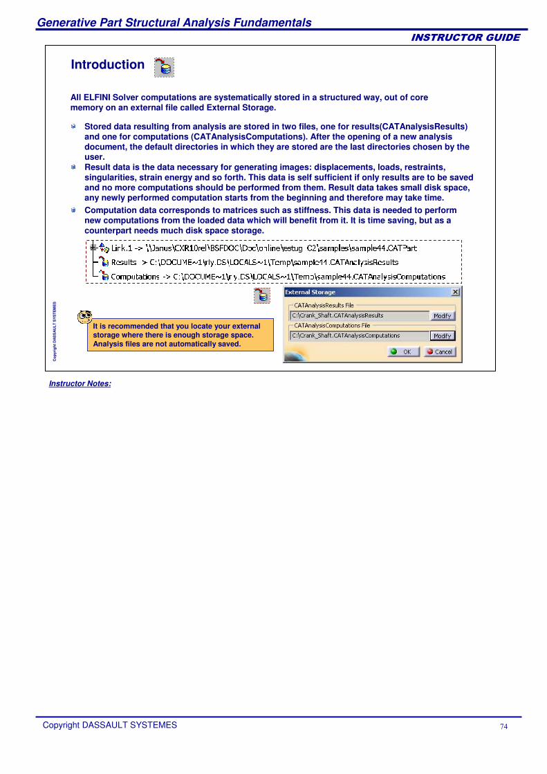
All ELFINI Solver computations are systematically stored in a structured way, out of core memory on an external file called External Storage.
It is recommended that you locate your external storage where there is enough storage space. Analysis files are not automatically saved.
Stored data resulting from analysis are stored in two files, one for results(CATAnalysisResults) and one for computations (CATAnalysisComputations). After the opening of a new analysis document, the default directories in which they are stored are the last directories chosen by the user.Result data is the data necessary for generating images: displacements, loads, restraints, singularities, strain energy and so forth. This data is self sufficient if only results are to be saved and no more computations should be performed from them. Result data takes small disk space, any newly performed computation starts from the beginning and therefore may take time.Computation data corresponds to matrices such as stiffness. This data is needed to perform new computations from the loaded data which will benefit from it. It is time saving, but as a counterpart needs much disk space storage.
Instructor Notes:
Generative Part Structural Analysis Fundamentals
Copyright DASSAULT SYSTEMES ��
��������������
Cop
yrig
ht D
AS
SA
ULT
SY
STE
ME
S
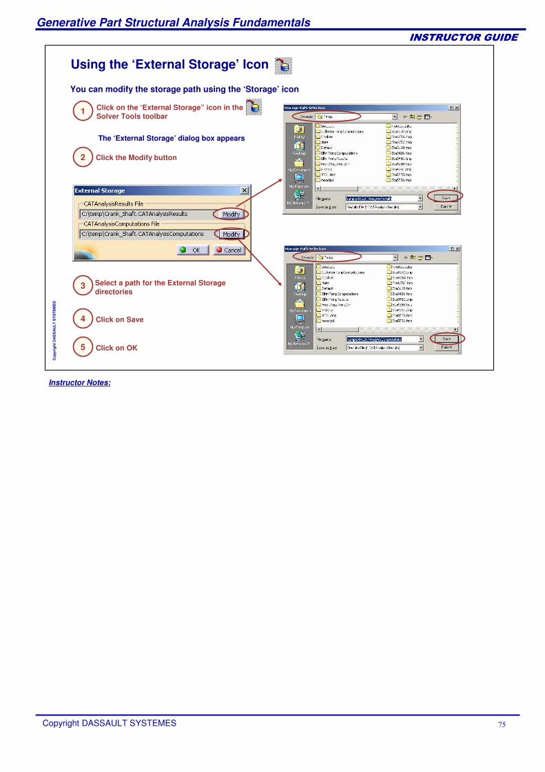
Using the ‘External Storage’ Icon
The ‘External Storage’ dialog box appears
Select a path for the External Storage directories
Click on Save
Click on the ‘External Storage” icon in the Solver Tools toolbar
Click the Modify button
Click on OK
You can modify the storage path using the ‘Storage’ icon
1
2
3
4
5
Instructor Notes:
Generative Part Structural Analysis Fundamentals
Copyright DASSAULT SYSTEMES ��
��������������
Cop
yrig
ht D
AS
SA
ULT
SY
STE
ME
S
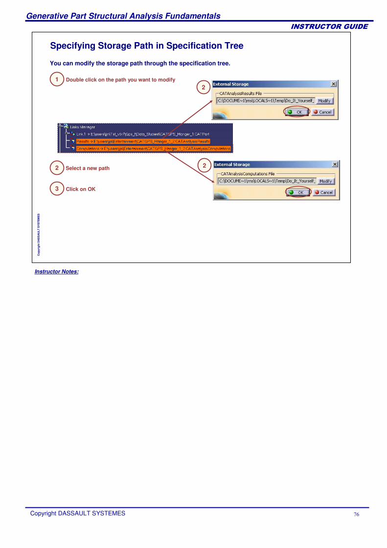
Specifying Storage Path in Specification Tree
Click on OK
You can modify the storage path through the specification tree.
Double click on the path you want to modify
Select a new path
12
22
3
Instructor Notes:
Generative Part Structural Analysis Fundamentals
Copyright DASSAULT SYSTEMES ��
��������������
Cop
yrig
ht D
AS
SA
ULT
SY
STE
ME
S
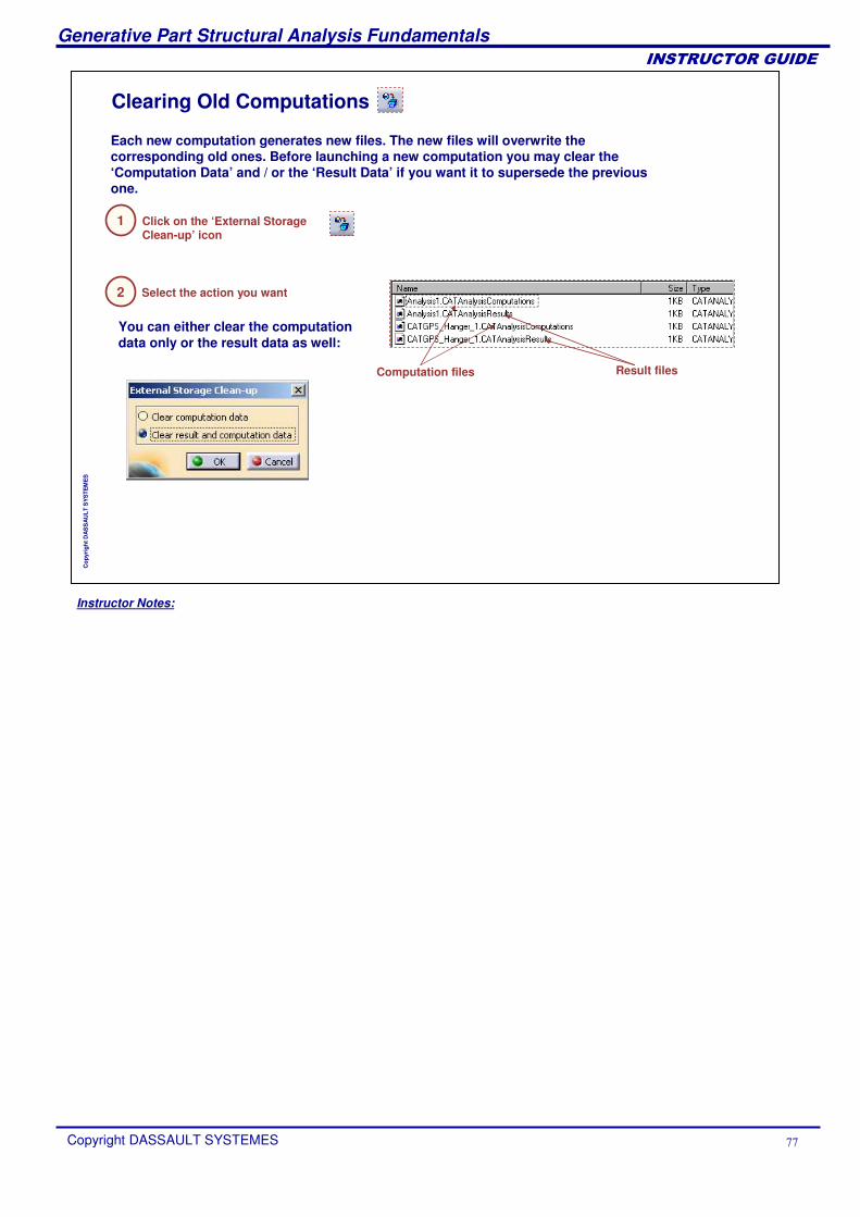
Clearing Old Computations
Select the action you want
Computation files Result files
Each new computation generates new files. The new files will overwrite the corresponding old ones. Before launching a new computation you may clear the ‘Computation Data’ and / or the ‘Result Data’ if you want it to supersede the previous one.
Click on the ‘External Storage Clean-up’ icon
You can either clear the computation data only or the result data as well:
1
2
Instructor Notes:
Generative Part Structural Analysis Fundamentals
Copyright DASSAULT SYSTEMES ��
��������������
Cop
yrig
ht D
AS
SA
ULT
SY
STE
ME
S
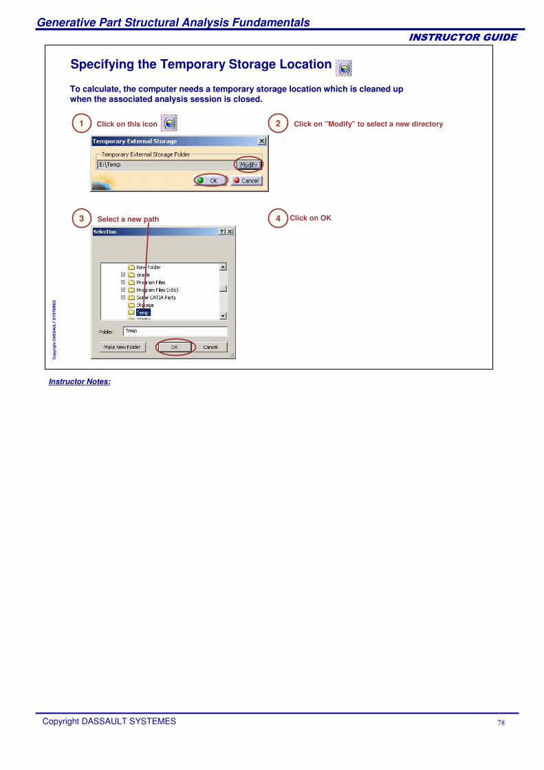
Specifying the Temporary Storage Location
To calculate, the computer needs a temporary storage location which is cleaned up when the associated analysis session is closed.
Select a new path3
Click on this icon1 Click on ”Modify” to select a new directory2
Click on OK4
Instructor Notes:
Generative Part Structural Analysis Fundamentals
Copyright DASSAULT SYSTEMES �
��������������
Cop
yrig
ht D
AS
SA
ULT
SY
STE
ME
S
Creating analysis storage
CATAnalysisResults and CATAnalysisComputations files are created :The first time you run a computationIf the user explicitly defines their location
An analysis document which contains only specifications can be stored without links to the Analysis storage.These files are not seen anymore in partner applications that do not need them.
Reading analysis storageData is copied only when it needs to be accessed by computation or post-processing. There is a significant time gain when loading a Computed Analysis Document.
Useless data no longer needs to be read (ex : read a computed document, modify the mesh, and re-computing).
Deleting analysis storageCATAnalysisResults and CATAnalysisComputations can be deleted manually (equivalent to the Clear capability).
Additional Information
Instructor Notes:
Generative Part Structural Analysis Fundamentals
Copyright DASSAULT SYSTEMES �
��������������
Cop
yrig
ht D
AS
SA
ULT
SY
STE
ME
S
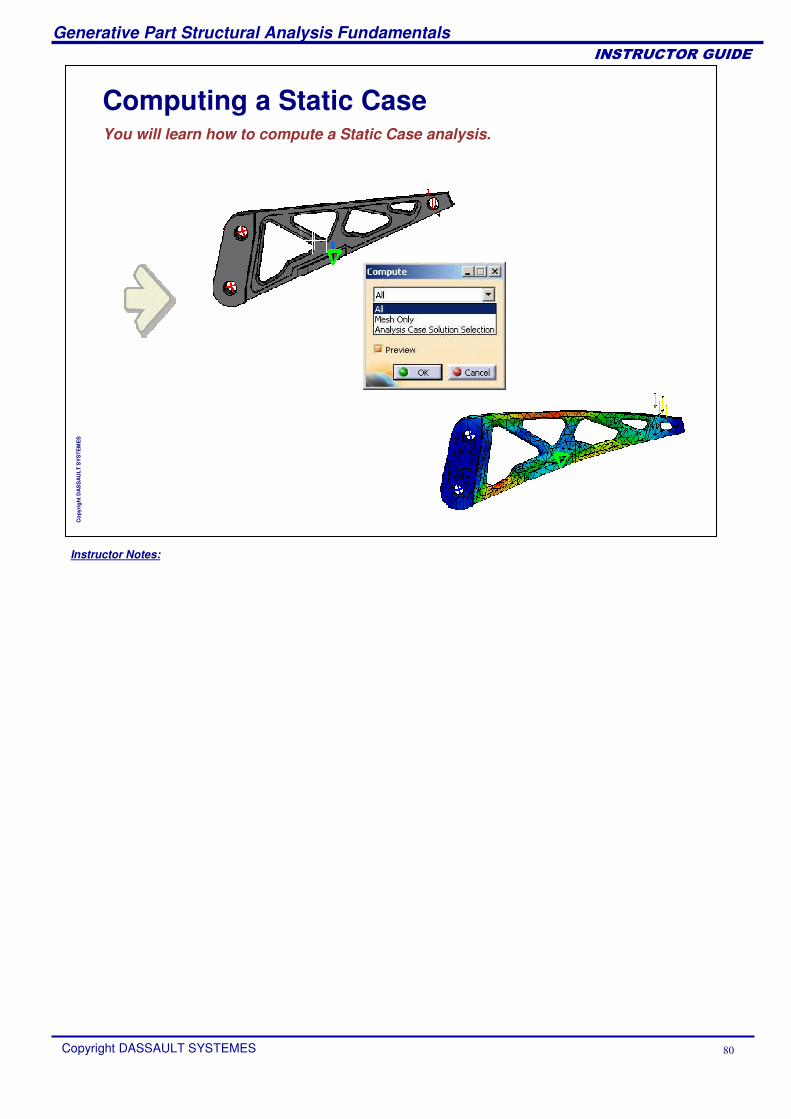
Computing a Static CaseYou will learn how to compute a Static Case analysis.
Instructor Notes:
Generative Part Structural Analysis Fundamentals
Copyright DASSAULT SYSTEMES ��
��������������
Cop
yrig
ht D
AS
SA
ULT
SY
STE
ME
S
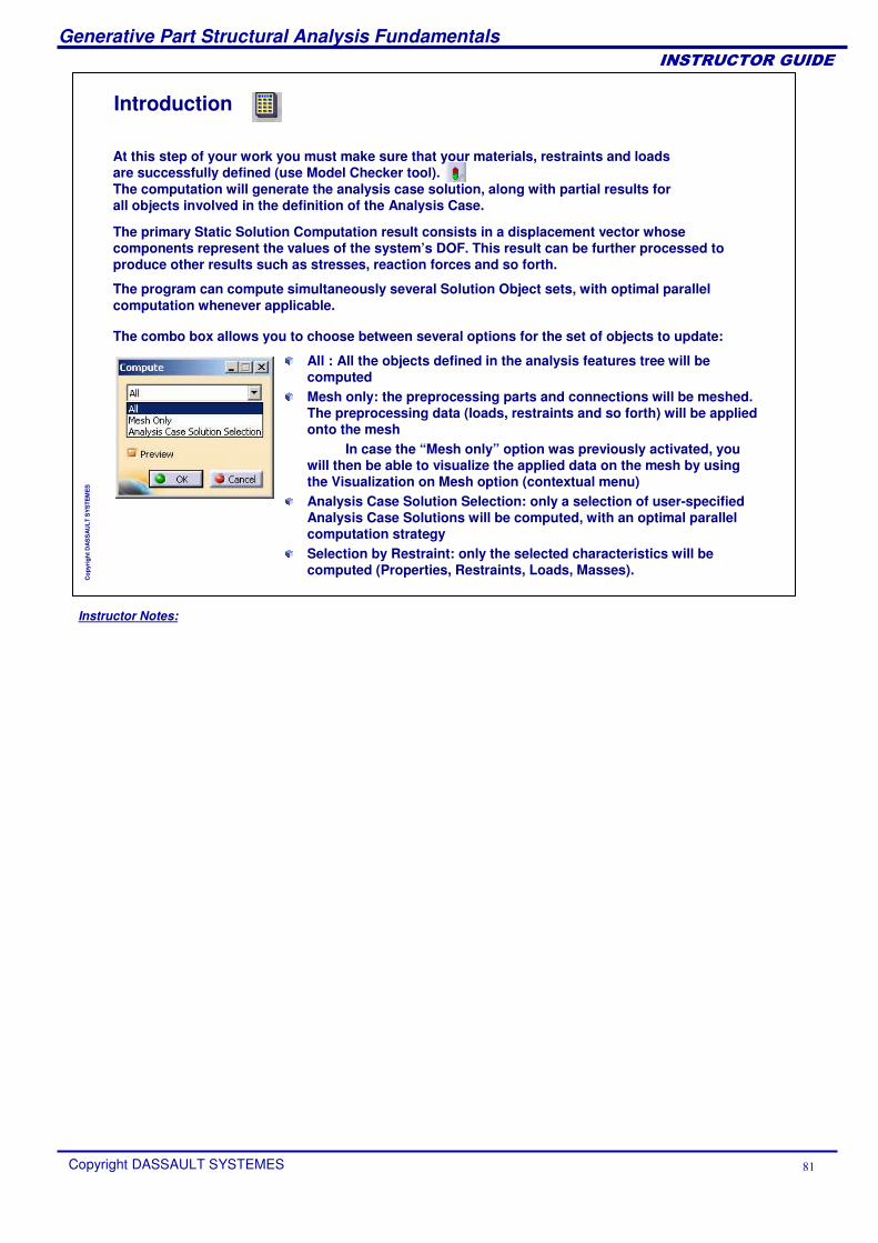
At this step of your work you must make sure that your materials, restraints and loads are successfully defined (use Model Checker tool).The computation will generate the analysis case solution, along with partial results for all objects involved in the definition of the Analysis Case.
Introduction
All : All the objects defined in the analysis features tree will be computed Mesh only: the preprocessing parts and connections will be meshed. The preprocessing data (loads, restraints and so forth) will be applied onto the mesh
In case the “Mesh only” option was previously activated, you will then be able to visualize the applied data on the mesh by using the Visualization on Mesh option (contextual menu) Analysis Case Solution Selection: only a selection of user-specified Analysis Case Solutions will be computed, with an optimal parallel computation strategy Selection by Restraint: only the selected characteristics will be computed (Properties, Restraints, Loads, Masses).
The primary Static Solution Computation result consists in a displacement vector whose components represent the values of the system’s DOF. This result can be further processed to produce other results such as stresses, reaction forces and so forth.
The program can compute simultaneously several Solution Object sets, with optimal parallel computation whenever applicable.
The combo box allows you to choose between several options for the set of objects to update:
Instructor Notes:
Generative Part Structural Analysis Fundamentals
Copyright DASSAULT SYSTEMES ��
��������������
Cop
yrig
ht D
AS
SA
ULT
SY
STE
ME
S
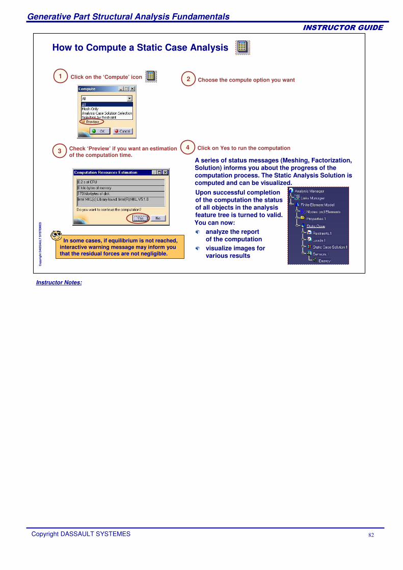
How to Compute a Static Case Analysis
Check ‘Preview’ if you want an estimation of the computation time.
Click on the ‘Compute’ icon1Choose the compute option you want2
3A series of status messages (Meshing, Factorization, Solution) informs you about the progress of the computation process. The Static Analysis Solution is computed and can be visualized.
Click on Yes to run the computation
You can now:
Upon successful completion of the computation the status of all objects in the analysis feature tree is turned to valid.
analyze the report of the computationvisualize images for various results
4
In some cases, if equilibrium is not reached, interactive warning message may inform you that the residual forces are not negligible.
Instructor Notes:
Generative Part Structural Analysis Fundamentals
Copyright DASSAULT SYSTEMES ��
��������������
Cop
yrig
ht D
AS
SA
ULT
SY
STE
ME
S
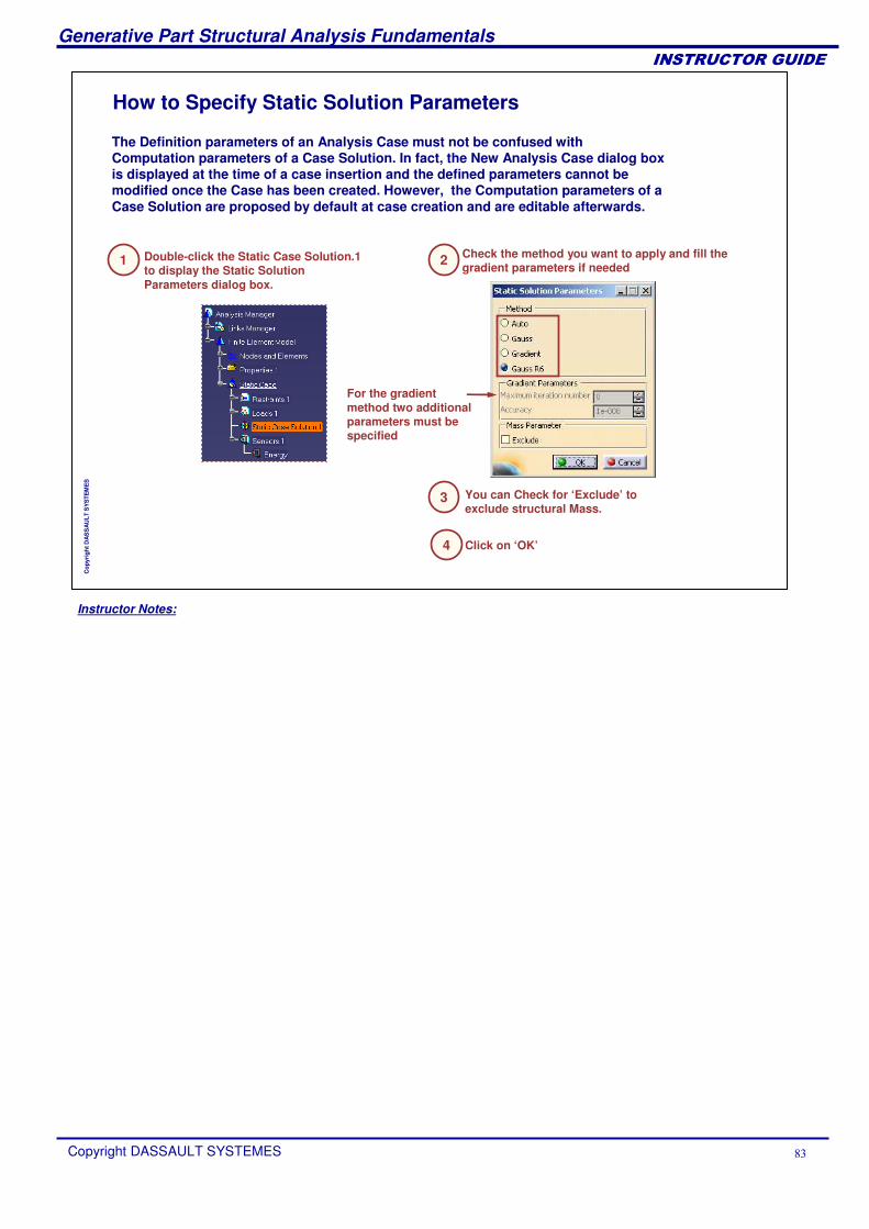
Double-click the Static Case Solution.1 to display the Static Solution Parameters dialog box.
For the gradient method two additional parameters must be specified
Check the method you want to apply and fill the gradient parameters if needed
You can Check for ‘Exclude’ to exclude structural Mass.
The Definition parameters of an Analysis Case must not be confused with Computation parameters of a Case Solution. In fact, the New Analysis Case dialog box is displayed at the time of a case insertion and the defined parameters cannot be modified once the Case has been created. However, the Computation parameters of a Case Solution are proposed by default at case creation and are editable afterwards.
1 2
3
How to Specify Static Solution Parameters
Click on ‘OK’4
Instructor Notes:
Generative Part Structural Analysis Fundamentals
Copyright DASSAULT SYSTEMES ��
��������������
Cop
yrig
ht D
AS
SA
ULT
SY
STE
ME
S
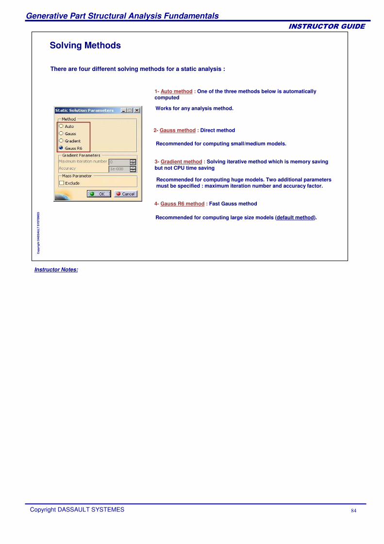
There are four different solving methods for a static analysis :
1- Auto method : One of the three methods below is automatically computed
2- Gauss method : Direct method
3- Gradient method : Solving iterative method which is memory saving but not CPU time saving
4- Gauss R6 method : Fast Gauss method
Works for any analysis method.
Recommended for computing small/medium models.
Recommended for computing huge models. Two additional parametersmust be specified : maximum iteration number and accuracy factor.
Recommended for computing large size models (default method).
Solving Methods
Instructor Notes:
Generative Part Structural Analysis Fundamentals
Copyright DASSAULT SYSTEMES ��
��������������
Cop
yrig
ht D
AS
SA
ULT
SY
STE
ME
S
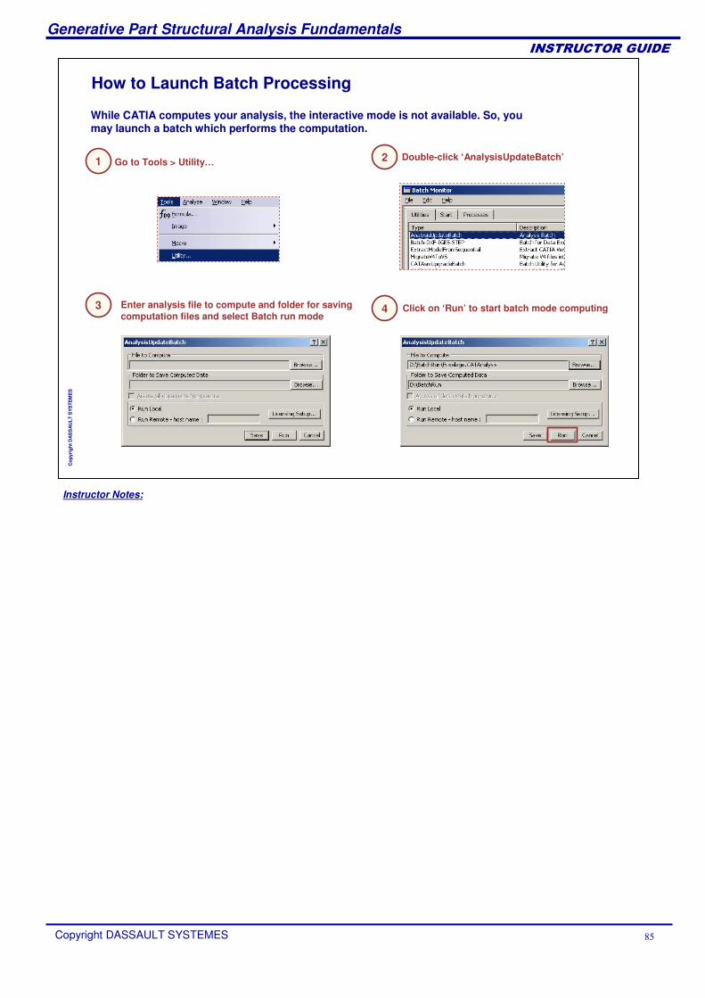
How to Launch Batch Processing
While CATIA computes your analysis, the interactive mode is not available. So, you may launch a batch which performs the computation.
Go to Tools > Utility…1 Double-click ‘AnalysisUpdateBatch’2
Enter analysis file to compute and folder for saving computation files and select Batch run mode
3 Click on ‘Run’ to start batch mode computing4
Instructor Notes:
Generative Part Structural Analysis Fundamentals
Copyright DASSAULT SYSTEMES ��
��������������
Cop
yrig
ht D
AS
SA
ULT
SY
STE
ME
S
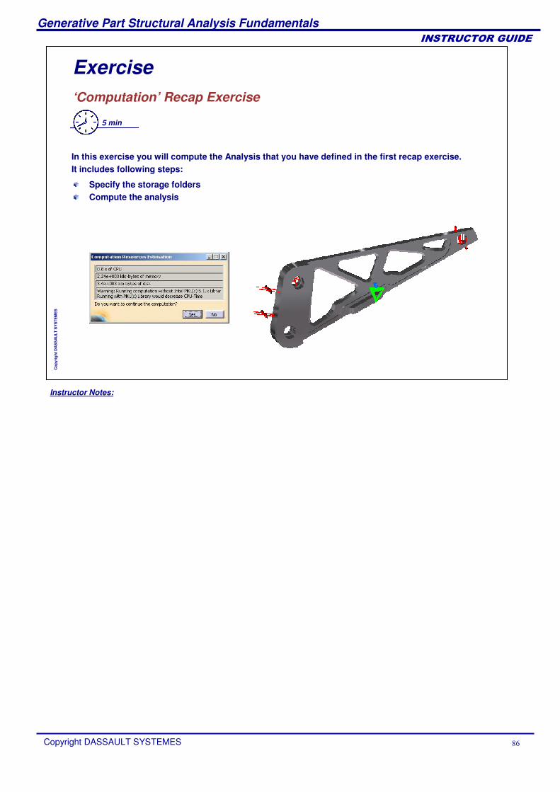
Exercise‘Computation’ Recap Exercise
5 min
In this exercise you will compute the Analysis that you have defined in the first recap exercise.It includes following steps:
Specify the storage folders Compute the analysis
Instructor Notes:
Generative Part Structural Analysis Fundamentals
Copyright DASSAULT SYSTEMES ��
��������������
Cop
yrig
ht D
AS
SA
ULT
SY
STE
ME
S
GPS Post-processingIn this lesson, you will learn about the main tools used to display and optimize the results.
Results VisualizationMesh RefinementResults Management
Instructor Notes:
Generative Part Structural Analysis Fundamentals
Copyright DASSAULT SYSTEMES ��
��������������
Cop
yrig
ht D
AS
SA
ULT
SY
STE
ME
S
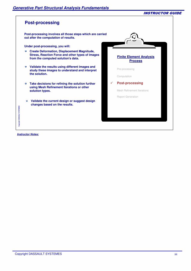
Post-processing
Post-processing involves all those steps which are carried out after the computation of results.
Under post-processing, you will:
Take decisions for refining the solution further using Mesh Refinement Iterations or other solution types.
Create Deformation, Displacement Magnitude, Stress, Reaction Force and other types of images from the computed solution's data.
Validate the results using different images and study these images to understand and interpret the solution.
Validate the current design or suggest design changes based on the results.
Finite Element AnalysisProcess
Pre-processing
Computation
� Post-processing
Mesh Refinement Iterations
Report Generation
Instructor Notes:
Generative Part Structural Analysis Fundamentals
Copyright DASSAULT SYSTEMES �
��������������
Cop
yrig
ht D
AS
SA
ULT
SY
STE
ME
S
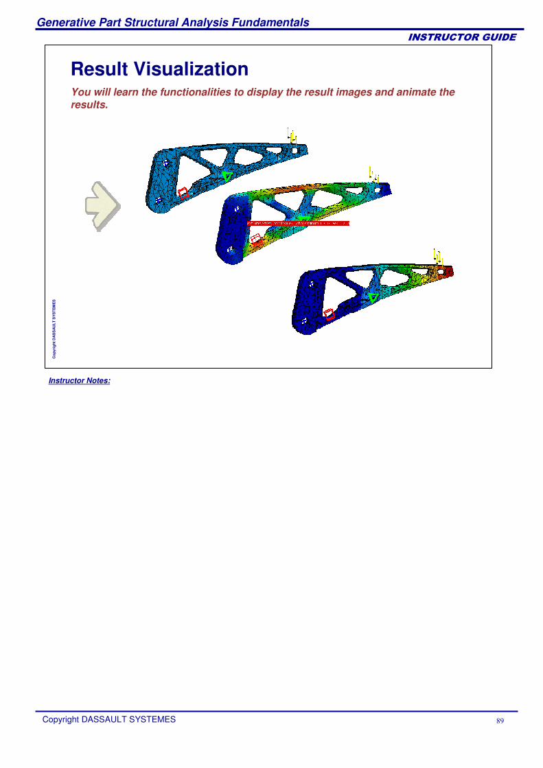
Result VisualizationYou will learn the functionalities to display the result images and animate the results.
Instructor Notes:
Generative Part Structural Analysis Fundamentals
Copyright DASSAULT SYSTEMES
��������������
Cop
yrig
ht D
AS
SA
ULT
SY
STE
ME
S
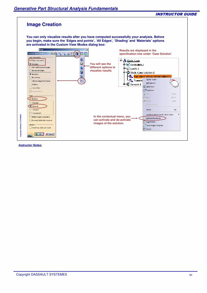
Image Creation
You can only visualize results after you have computed successfully your analysis. Before you begin, make sure the ‘Edges and points’, ‘All Edges’, ‘Shading’ and ‘Materials’ options are activated in the Custom View Modes dialog box:
Results are displayed in the specification tree under ‘Case Solution’
In the contextual menu, you can activate and de-activate images of the solution.
You will see the different options to visualize results
Instructor Notes:
Generative Part Structural Analysis Fundamentals
Copyright DASSAULT SYSTEMES �
��������������
Cop
yrig
ht D
AS
SA
ULT
SY
STE
ME
S
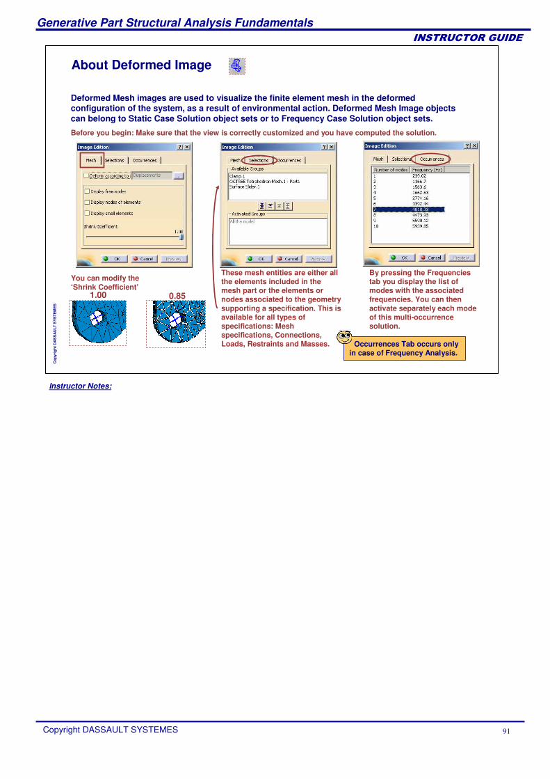
About Deformed Image
Before you begin: Make sure that the view is correctly customized and you have computed the solution.
You can modify the ‘Shrink Coefficient’
1.00 0.85
By pressing the Frequencies tab you display the list of modes with the associated frequencies. You can then activate separately each mode of this multi-occurrence solution.
Deformed Mesh images are used to visualize the finite element mesh in the deformed configuration of the system, as a result of environmental action. Deformed Mesh Image objects can belong to Static Case Solution object sets or to Frequency Case Solution object sets.
These mesh entities are either all the elements included in the mesh part or the elements or nodes associated to the geometry supporting a specification. This is available for all types of specifications: Mesh specifications, Connections, Loads, Restraints and Masses. Occurrences Tab occurs only
in case of Frequency Analysis.
Instructor Notes:
Generative Part Structural Analysis Fundamentals
Copyright DASSAULT SYSTEMES �
��������������
Cop
yrig
ht D
AS
SA
ULT
SY
STE
ME
S
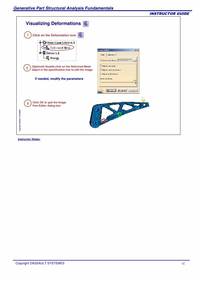
Visualizing Deformations
Click on the Deformation icon
2 (Optional) Double-click on the Deformed Mesh object in the specification tree to edit the image
3 Click OK to quit the Image Fem Editor dialog box
If needed, modify the parameters
1
Instructor Notes:
Generative Part Structural Analysis Fundamentals
Copyright DASSAULT SYSTEMES �
��������������
Cop
yrig
ht D
AS
SA
ULT
SY
STE
ME
S
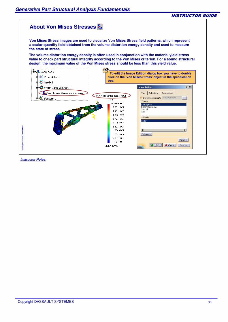
About Von Mises Stresses
The volume distortion energy density is often used in conjunction with the material yield stress value to check part structural integrity according to the Von Mises criterion. For a sound structural design, the maximum value of the Von Mises stress should be less than this yield value.
Von Mises Stress images are used to visualize Von Mises Stress field patterns, which represent a scalar quantity field obtained from the volume distortion energy density and used to measure the state of stress.
To edit the Image Edition dialog box you have to double click on the ‘Von Mises Stress’ object in the specification tree.
Instructor Notes:
Generative Part Structural Analysis Fundamentals
Copyright DASSAULT SYSTEMES �
��������������
Cop
yrig
ht D
AS
SA
ULT
SY
STE
ME
S
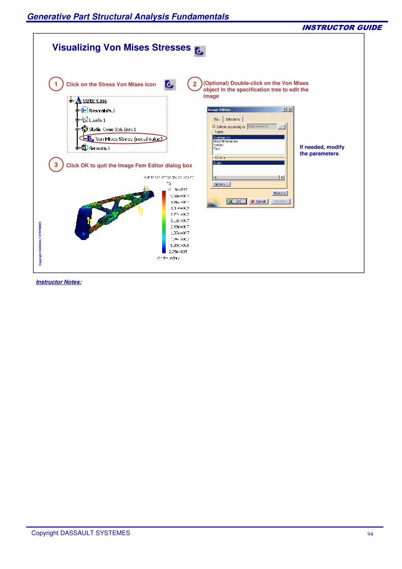
Visualizing Von Mises Stresses
(Optional) Double-click on the Von Mises object in the specification tree to edit the image
3 Click OK to quit the Image Fem Editor dialog box
If needed, modify the parameters
Click on the Stress Von Mises icon 21
Instructor Notes:
Generative Part Structural Analysis Fundamentals
Copyright DASSAULT SYSTEMES �
��������������
Cop
yrig
ht D
AS
SA
ULT
SY
STE
ME
S
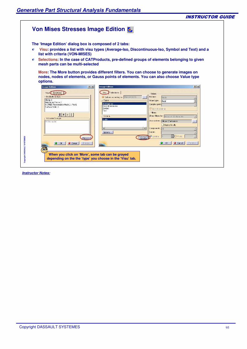
Von Mises Stresses Image Edition
The ‘Image Edition’ dialog box is composed of 2 tabs:Visu: provides a list with visu types (Average-Iso, Discontinuous-Iso, Symbol and Text) and a list with criteria (VON-MISES) Selections: In the case of CATProducts, pre-defined groups of elements belonging to given mesh parts can be multi-selected
When you click on ‘More’, some tab can be grayed depending on the the ‘type’ you choose in the ‘Visu’ tab.
More: The More button provides different filters. You can choose to generate images on nodes, nodes of elements, or Gauss points of elements. You can also choose Value type options.
Instructor Notes:
Generative Part Structural Analysis Fundamentals
Copyright DASSAULT SYSTEMES �
��������������
Cop
yrig
ht D
AS
SA
ULT
SY
STE
ME
S
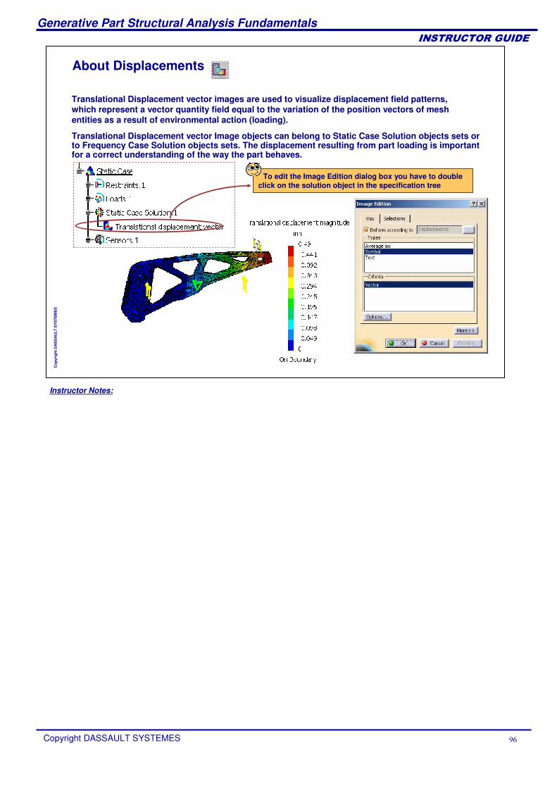
About Displacements
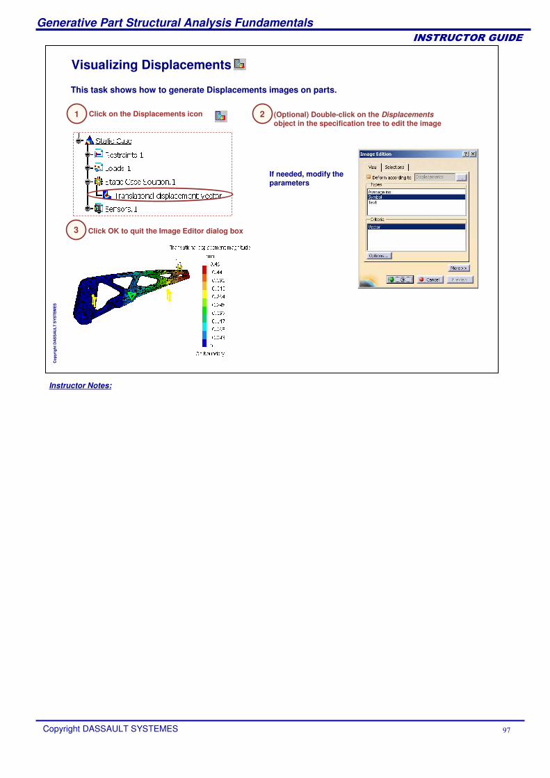
Translational Displacement vector Image objects can belong to Static Case Solution objects sets or to Frequency Case Solution objects sets. The displacement resulting from part loading is important for a correct understanding of the way the part behaves.
Translational Displacement vector images are used to visualize displacement field patterns, which represent a vector quantity field equal to the variation of the position vectors of mesh entities as a result of environmental action (loading).
To edit the Image Edition dialog box you have to double click on the solution object in the specification tree
Instructor Notes:
Generative Part Structural Analysis Fundamentals
Copyright DASSAULT SYSTEMES �
��������������
Cop
yrig
ht D
AS
SA
ULT
SY
STE
ME
S
Visualizing Displacements
(Optional) Double-click on the Displacementsobject in the specification tree to edit the image
3 Click OK to quit the Image Editor dialog box
If needed, modify the parameters
2Click on the Displacements icon
This task shows how to generate Displacements images on parts.
1
Instructor Notes:
Generative Part Structural Analysis Fundamentals
Copyright DASSAULT SYSTEMES �
��������������
Cop
yrig
ht D
AS
SA
ULT
SY
STE
ME
S
Displacement Image Edition
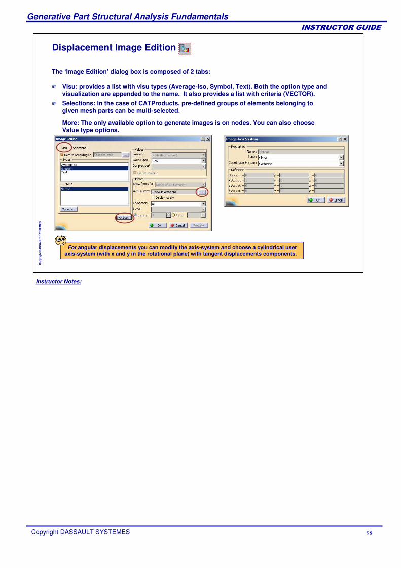
The ‘Image Edition’ dialog box is composed of 2 tabs:
For angular displacements you can modify the axis-system and choose a cylindrical user axis-system (with x and y in the rotational plane) with tangent displacements components.
Visu: provides a list with visu types (Average-Iso, Symbol, Text). Both the option type and visualization are appended to the name. It also provides a list with criteria (VECTOR). Selections: In the case of CATProducts, pre-defined groups of elements belonging to given mesh parts can be multi-selected.
More: The only available option to generate images is on nodes. You can also choose Value type options.
Instructor Notes:
Generative Part Structural Analysis Fundamentals
Copyright DASSAULT SYSTEMES
��������������
Cop
yrig
ht D
AS
SA
ULT
SY
STE
ME
S
About Principal Stresses
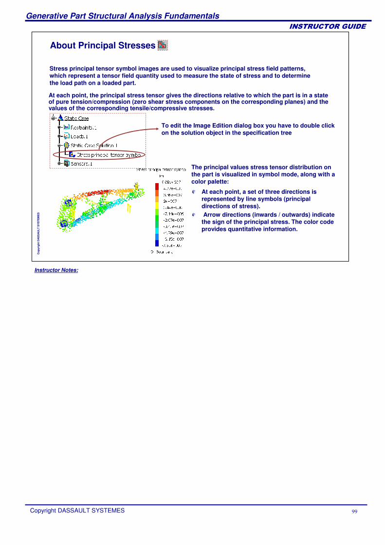
At each point, the principal stress tensor gives the directions relative to which the part is in a state of pure tension/compression (zero shear stress components on the corresponding planes) and the values of the corresponding tensile/compressive stresses.
To edit the Image Edition dialog box you have to double click on the solution object in the specification tree
The principal values stress tensor distribution on the part is visualized in symbol mode, along with a color palette:
Stress principal tensor symbol images are used to visualize principal stress field patterns, which represent a tensor field quantity used to measure the state of stress and to determine the load path on a loaded part.
At each point, a set of three directions is represented by line symbols (principal directions of stress).Arrow directions (inwards / outwards) indicate
the sign of the principal stress. The color code provides quantitative information.
Instructor Notes:
Generative Part Structural Analysis Fundamentals
Copyright DASSAULT SYSTEMES �
��������������
Cop
yrig
ht D
AS
SA
ULT
SY
STE
ME
S
Principal Stresses Image Edition
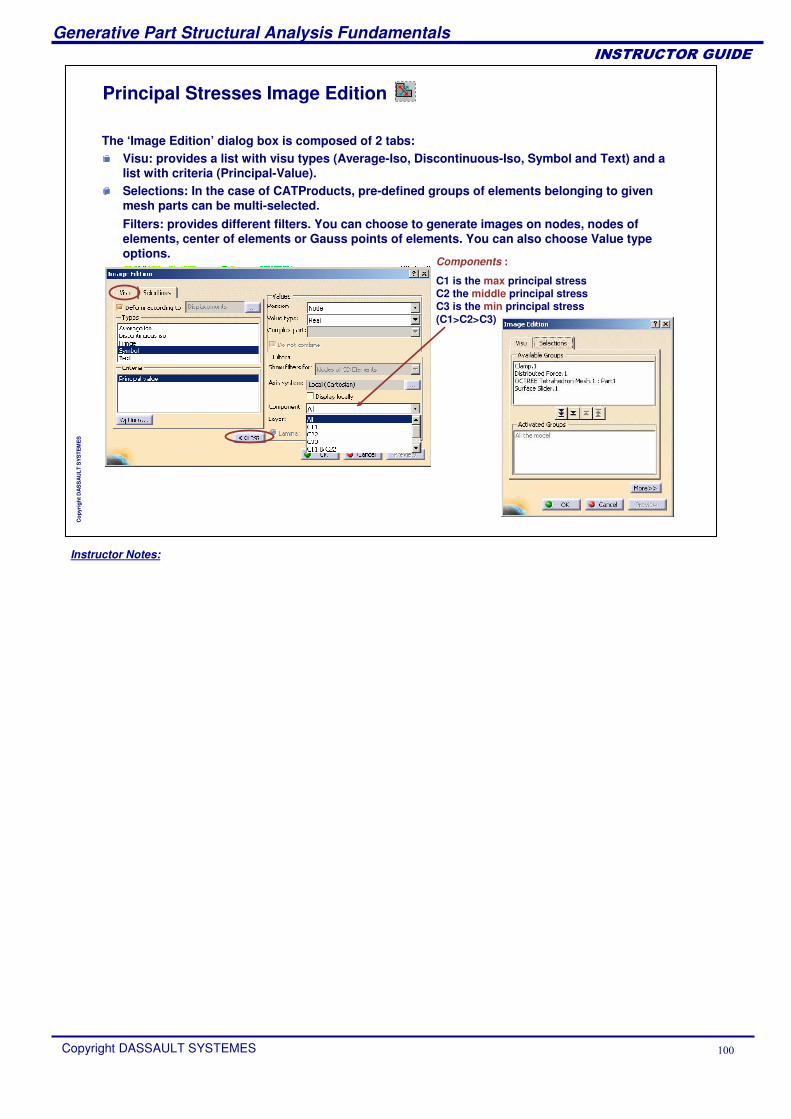
Components :
C1 is the max principal stress C2 the middle principal stress C3 is the min principal stress (C1>C2>C3)
The ‘Image Edition’ dialog box is composed of 2 tabs:Visu: provides a list with visu types (Average-Iso, Discontinuous-Iso, Symbol and Text) and a list with criteria (Principal-Value).Selections: In the case of CATProducts, pre-defined groups of elements belonging to given mesh parts can be multi-selected.Filters: provides different filters. You can choose to generate images on nodes, nodes of elements, center of elements or Gauss points of elements. You can also choose Value type options.
Instructor Notes:
Generative Part Structural Analysis Fundamentals
Copyright DASSAULT SYSTEMES ��
��������������
Cop
yrig
ht D
AS
SA
ULT
SY
STE
ME
S
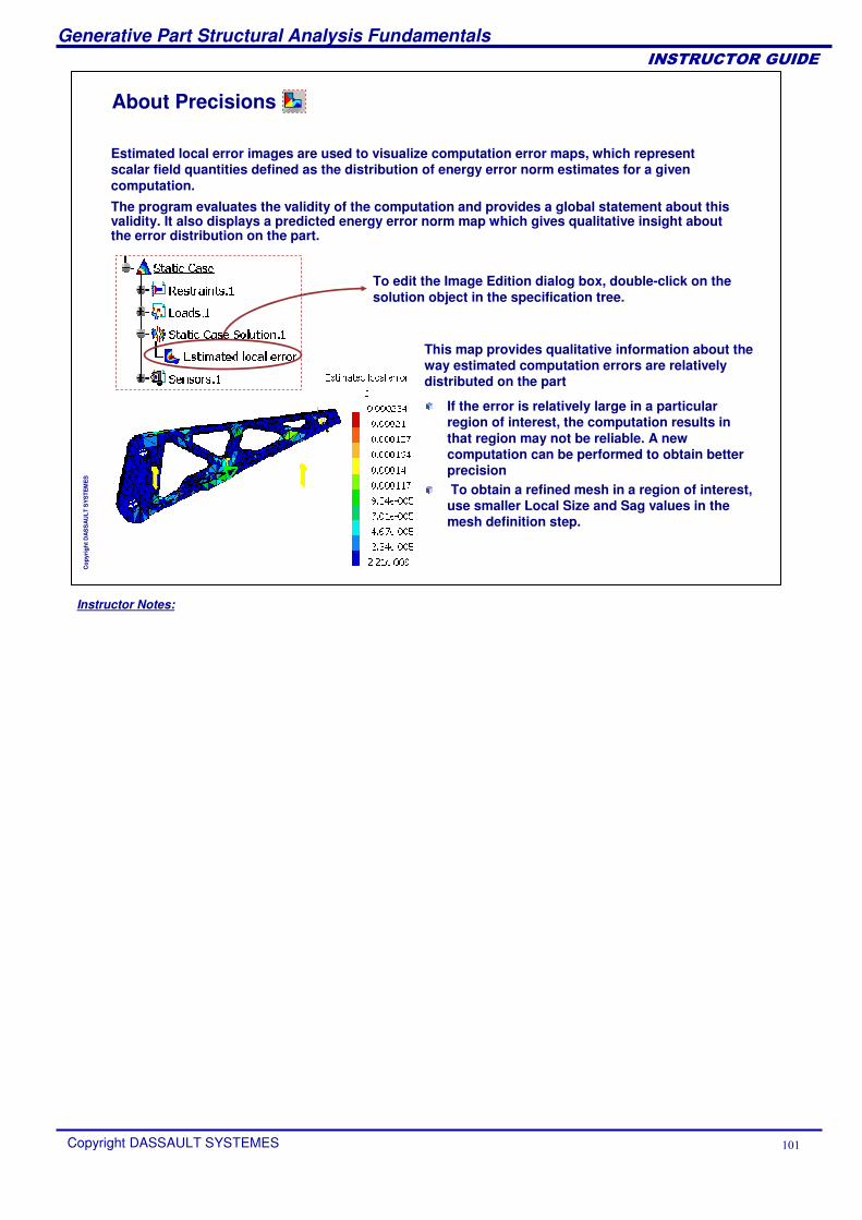
About Precisions
The program evaluates the validity of the computation and provides a global statement about this validity. It also displays a predicted energy error norm map which gives qualitative insight about the error distribution on the part.
To edit the Image Edition dialog box, double-click on the solution object in the specification tree.
This map provides qualitative information about the way estimated computation errors are relatively distributed on the part
Estimated local error images are used to visualize computation error maps, which represent scalar field quantities defined as the distribution of energy error norm estimates for a given computation.
If the error is relatively large in a particular region of interest, the computation results in that region may not be reliable. A new computation can be performed to obtain better precisionTo obtain a refined mesh in a region of interest, use smaller Local Size and Sag values in the mesh definition step.
Instructor Notes:
Generative Part Structural Analysis Fundamentals
Copyright DASSAULT SYSTEMES ��
��������������
Cop
yrig
ht D
AS
SA
ULT
SY
STE
ME
S
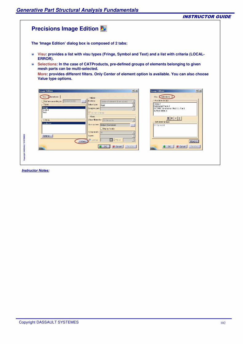
Precisions Image Edition
The ‘Image Edition’ dialog box is composed of 2 tabs:
Visu: provides a list with visu types (Fringe, Symbol and Text) and a list with criteria (LOCAL-ERROR).Selections: In the case of CATProducts, pre-defined groups of elements belonging to given mesh parts can be multi-selected.More: provides different filters. Only Center of element option is available. You can also choose Value type options.
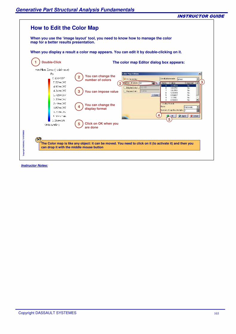
Instructor Notes:
Generative Part Structural Analysis Fundamentals
Copyright DASSAULT SYSTEMES ��
��������������
Cop
yrig
ht D
AS
SA
ULT
SY
STE
ME
S
How to Edit the Color Map
The color map Editor dialog box appears:
When you display a result a color map appears. You can edit it by double-clicking on it.
Double-Click
You can change the number of colors
You can impose value
You can change the display format
Click on OK when you are done
When you use the ‘image layout’ tool, you need to know how to manage the color map for a better results presentation.
The Color map is like any object: it can be moved. You need to click on it (to activate it) and then you can drop it with the middle mouse button
1
2
3
4
5
4
32
5
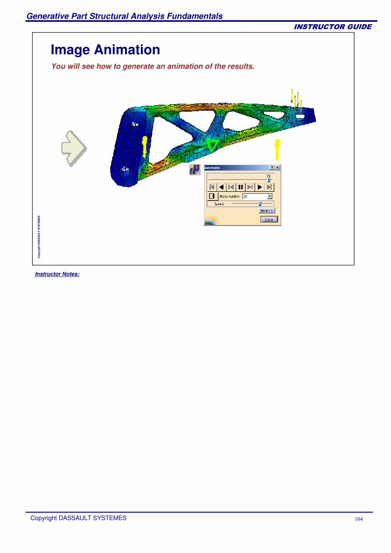
Instructor Notes:
Generative Part Structural Analysis Fundamentals
Copyright DASSAULT SYSTEMES ��
��������������
Cop
yrig
ht D
AS
SA
ULT
SY
STE
ME
S
Image AnimationYou will see how to generate an animation of the results.
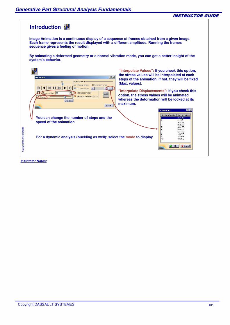
Instructor Notes:
Generative Part Structural Analysis Fundamentals
Copyright DASSAULT SYSTEMES ��
��������������
Cop
yrig
ht D
AS
SA
ULT
SY
STE
ME
S
Introduction
Image Animation is a continuous display of a sequence of frames obtained from a given image. Each frame represents the result displayed with a different amplitude. Running the frames sequence gives a feeling of motion.
By animating a deformed geometry or a normal vibration mode, you can get a better insight of the system’s behavior.
“Interpolate Displacements”: If you check this option, the stress values will be animated whereas the deformation will be locked at its maximum.
“Interpolate Values”: If you check this option, the stress values will be interpolated at each steps of the animation, if not, they will be fixed (Max. values).
You can change the number of steps and the speed of the animation
For a dynamic analysis (buckling as well): select the mode to display
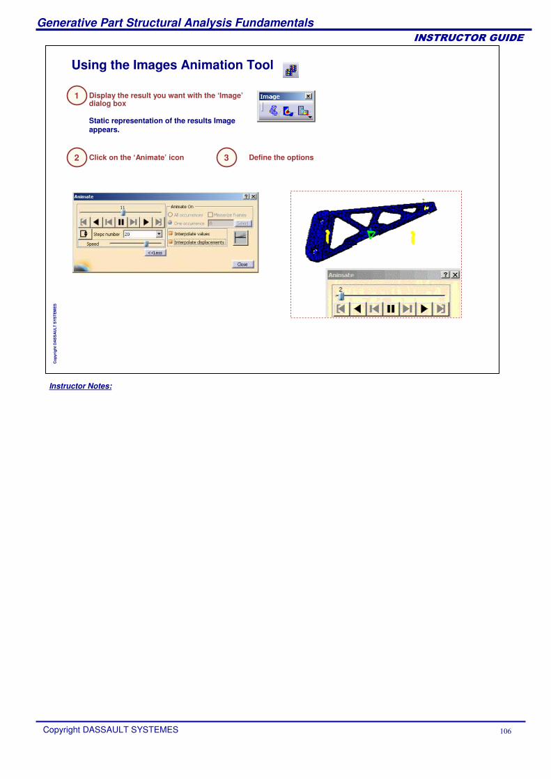
Instructor Notes:
Generative Part Structural Analysis Fundamentals
Copyright DASSAULT SYSTEMES ��
��������������
Cop
yrig
ht D
AS
SA
ULT
SY
STE
ME
S
Using the Images Animation Tool
Click on the ‘Animate’ icon 3 Define the options
Static representation of the results Image appears.
2
Display the result you want with the ‘Image’dialog box
1
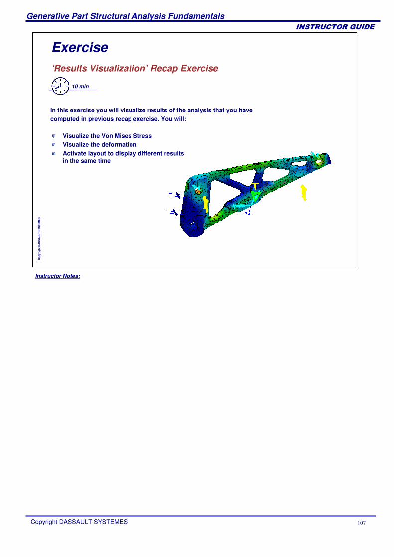
Instructor Notes:
Generative Part Structural Analysis Fundamentals
Copyright DASSAULT SYSTEMES ��
��������������
Cop
yrig
ht D
AS
SA
ULT
SY
STE
ME
S
Exercise‘Results Visualization’ Recap Exercise
10 min
In this exercise you will visualize results of the analysis that you have computed in previous recap exercise. You will:
Visualize the Von Mises StressVisualize the deformationActivate layout to display different results in the same time
Instructor Notes:
Generative Part Structural Analysis Fundamentals
Copyright DASSAULT SYSTEMES ��
��������������
Cop
yrig
ht D
AS
SA
ULT
SY
STE
ME
S
Mesh RefinementIn this lesson, you will learn about the different ways to improve the precision of your results.
What is Mesh RefinementImproving the Element CharacteristicsRefinement Recap ExerciseMesh Refinment with Precision: Recap Exercise
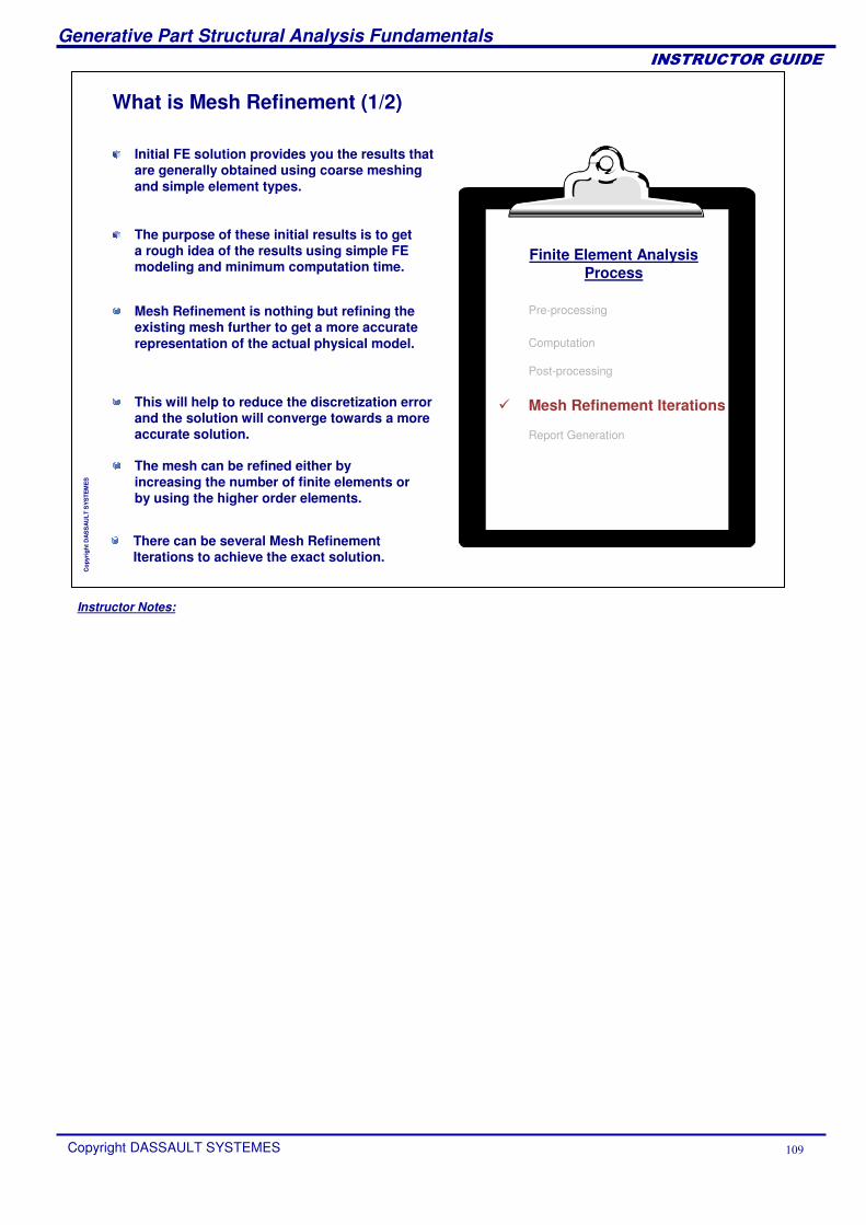
Instructor Notes:
Generative Part Structural Analysis Fundamentals
Copyright DASSAULT SYSTEMES �
��������������
Cop
yrig
ht D
AS
SA
ULT
SY
STE
ME
S
What is Mesh Refinement (1/2)
Initial FE solution provides you the results that are generally obtained using coarse meshing and simple element types.
Mesh Refinement is nothing but refining the existing mesh further to get a more accurate representation of the actual physical model.
The purpose of these initial results is to get a rough idea of the results using simple FE modeling and minimum computation time.
The mesh can be refined either by increasing the number of finite elements or by using the higher order elements.
This will help to reduce the discretization error and the solution will converge towards a more accurate solution.
Finite Element AnalysisProcess
Pre-processing
Computation
Post-processing
� Mesh Refinement Iterations
Report Generation
There can be several Mesh Refinement Iterations to achieve the exact solution.
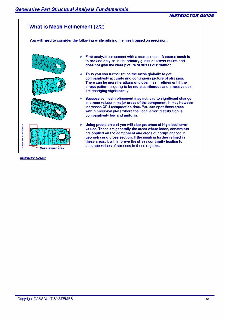
Instructor Notes:
Generative Part Structural Analysis Fundamentals
Copyright DASSAULT SYSTEMES ��
��������������
Cop
yrig
ht D
AS
SA
ULT
SY
STE
ME
S
What is Mesh Refinement (2/2)
You will need to consider the following while refining the mesh based on precision:
First analyze component with a coarse mesh. A coarse mesh is to provide only an initial primary guess of stress values and does not give the clear picture of stress distribution.
Thus you can further refine the mesh globally to get comparatively accurate and continuous picture of stresses. There can be more iterations of global mesh refinement if the stress pattern is going to be more continuous and stress values are changing significantly.
Using precision plot you will also get areas of high local errorvalues. These are generally the areas where loads, constraints are applied on the component and areas of abrupt change in geometry and cross section. If the mesh is further refined in these areas, it will improve the stress continuity leading to accurate values of stresses in these regions.
Successive mesh refinement may not lead to significant change in stress values in major areas of the component. It may howeverincreases CPU computation time. You can spot these areas within precision plots where the ‘local error’ distribution is comparatively low and uniform.
Mesh refined area
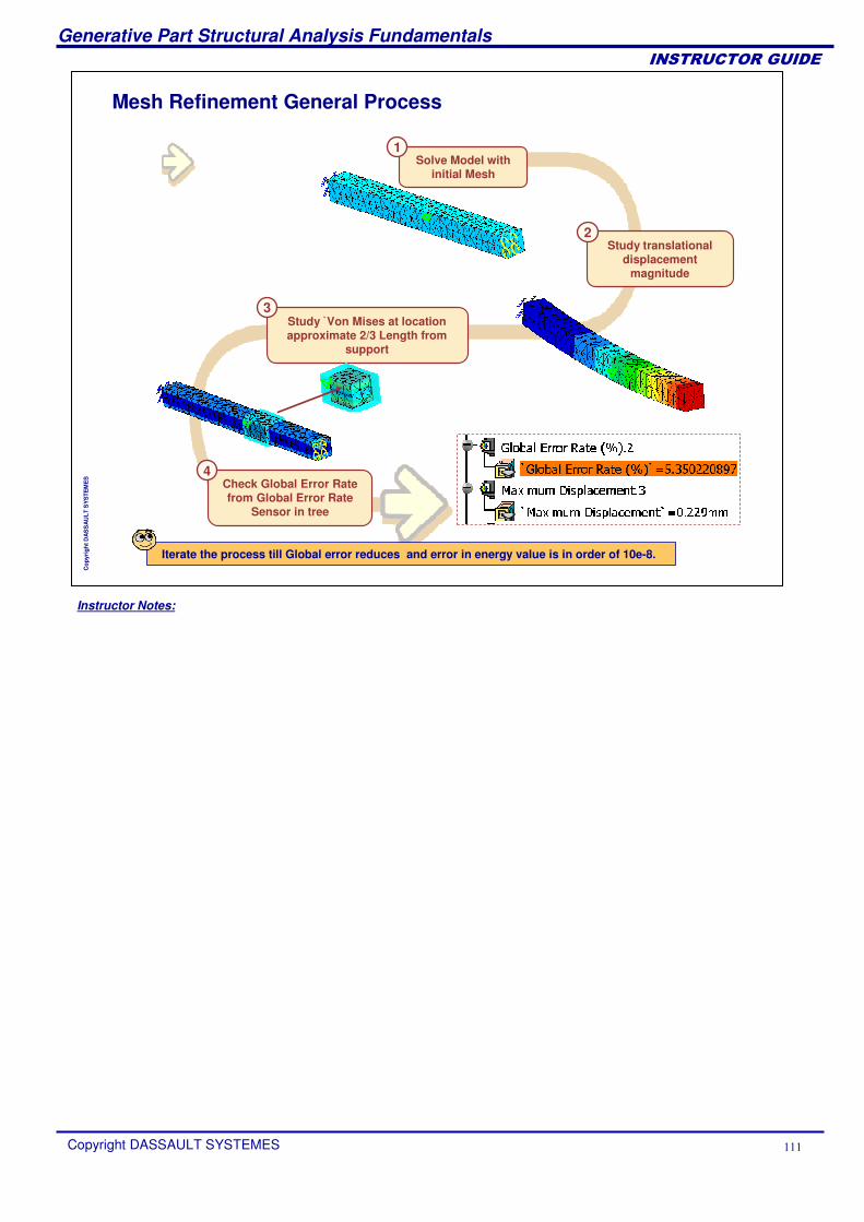
Instructor Notes:
Generative Part Structural Analysis Fundamentals
Copyright DASSAULT SYSTEMES ���
��������������
Cop
yrig
ht D
AS
SA
ULT
SY
STE
ME
S
Mesh Refinement General Process
Check Global Error Rate from Global Error Rate
Sensor in tree
4
Solve Model with initial Mesh
1
Study translational displacement
magnitude
2
Study V̀on Mises at location approximate 2/3 Length from
support
3
Iterate the process till Global error reduces and error in energy value is in order of 10e-8.
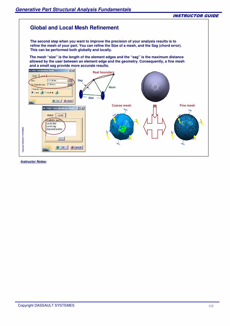
Instructor Notes:
Generative Part Structural Analysis Fundamentals
Copyright DASSAULT SYSTEMES ���
��������������
Cop
yrig
ht D
AS
SA
ULT
SY
STE
ME
S
Global and Local Mesh Refinement
The second step when you want to improve the precision of your analysis results is to refine the mesh of your part. You can refine the Size of a mesh, and the Sag (chord error). This can be performed both globally and locally.
Real boundary
Mesh
Sag
Size
The mesh “size” is the length of the element edges and the “sag” is the maximum distance allowed by the user between an element edge and the geometry. Consequently, a fine mesh and a small sag provide more accurate results.
Coarse mesh Fine mesh
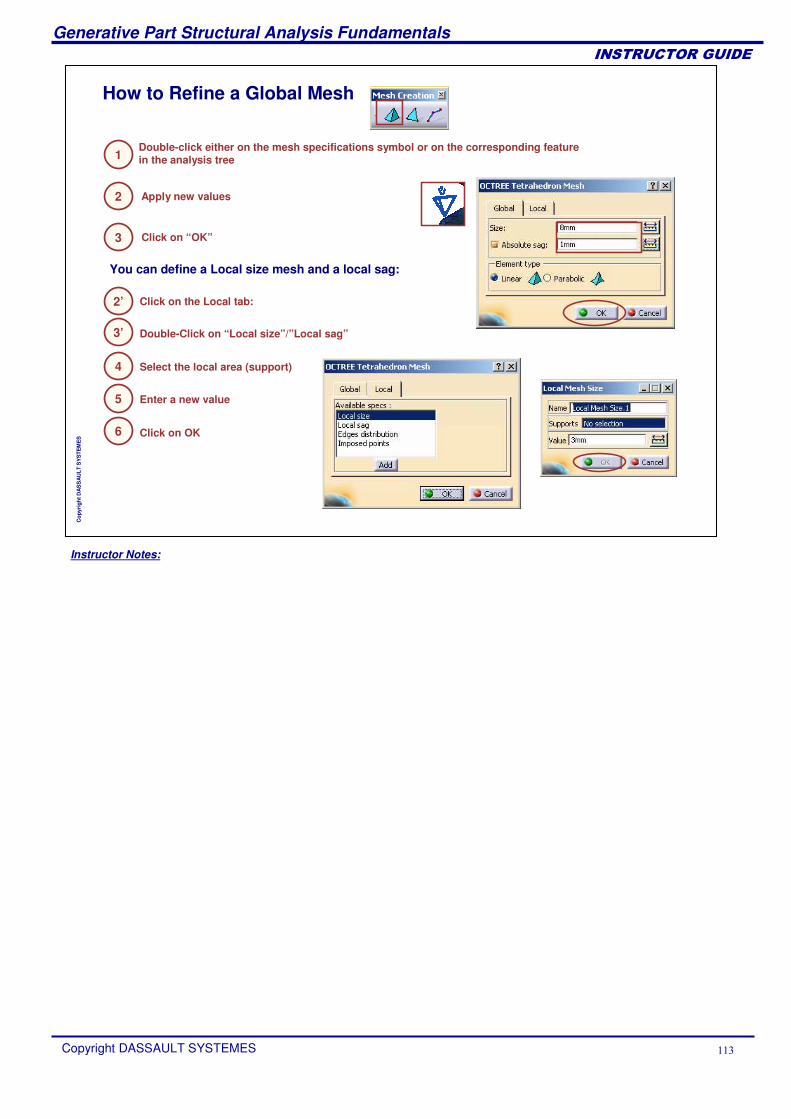
Instructor Notes:
Generative Part Structural Analysis Fundamentals
Copyright DASSAULT SYSTEMES ���
��������������
Cop
yrig
ht D
AS
SA
ULT
SY
STE
ME
S
How to Refine a Global Mesh
Double-click either on the mesh specifications symbol or on the corresponding feature in the analysis tree1
You can define a Local size mesh and a local sag:
Apply new values
Click on “OK”
2
3
4
Click on the Local tab:
Double-Click on “Local size”/”Local sag”3’
Select the local area (support)
5 Enter a new value
6 Click on OK
2’
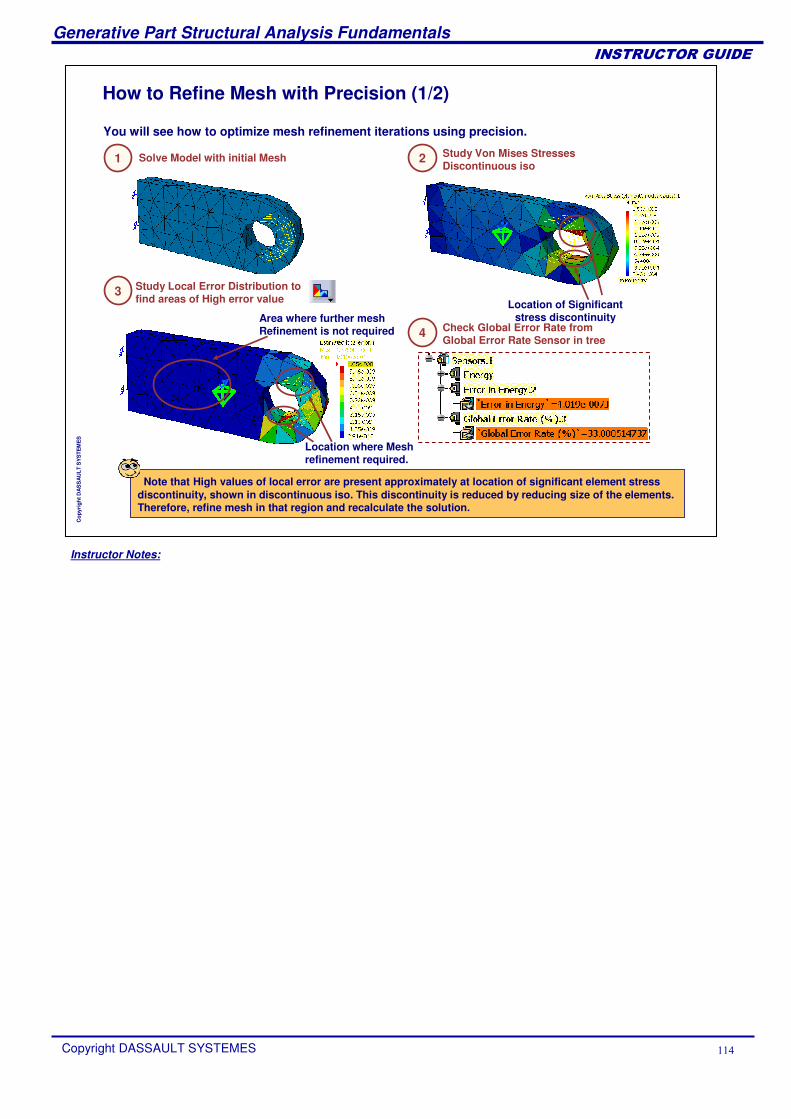
Instructor Notes:
Generative Part Structural Analysis Fundamentals
Copyright DASSAULT SYSTEMES ���
��������������
Cop
yrig
ht D
AS
SA
ULT
SY
STE
ME
S
How to Refine Mesh with Precision (1/2)
Solve Model with initial Mesh Study Von Mises Stresses Discontinuous iso
Check Global Error Rate from Global Error Rate Sensor in tree
Location where Mesh refinement required.
Location of Significant stress discontinuity
Study Local Error Distribution to find areas of High error value
Area where further mesh Refinement is not required
Note that High values of local error are present approximately at location of significant element stress discontinuity, shown in discontinuous iso. This discontinuity is reduced by reducing size of the elements. Therefore, refine mesh in that region and recalculate the solution.
You will see how to optimize mesh refinement iterations using precision.
1 2
3
4
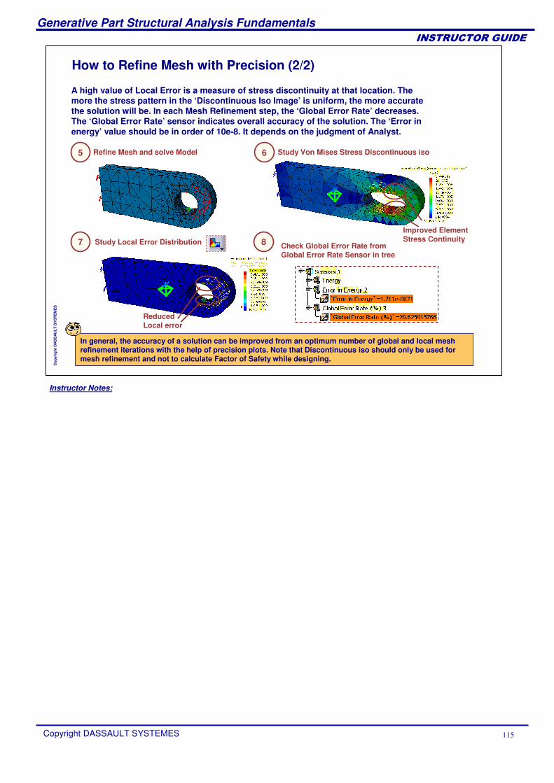
Instructor Notes:
Generative Part Structural Analysis Fundamentals
Copyright DASSAULT SYSTEMES ���
��������������
Cop
yrig
ht D
AS
SA
ULT
SY
STE
ME
S
How to Refine Mesh with Precision (2/2)
In general, the accuracy of a solution can be improved from an optimum number of global and local mesh refinement iterations with the help of precision plots. Note that Discontinuous iso should only be used for mesh refinement and not to calculate Factor of Safety while designing.
Refine Mesh and solve Model Study Von Mises Stress Discontinuous iso
Study Local Error Distribution Check Global Error Rate from Global Error Rate Sensor in tree
Improved Element Stress Continuity
Reduced Local error
A high value of Local Error is a measure of stress discontinuity at that location. The more the stress pattern in the ‘Discontinuous Iso Image’ is uniform, the more accurate the solution will be. In each Mesh Refinement step, the ‘Global Error Rate’ decreases. The ‘Global Error Rate’ sensor indicates overall accuracy of the solution. The ‘Error in energy’ value should be in order of 10e-8. It depends on the judgment of Analyst.
5 6
7 8
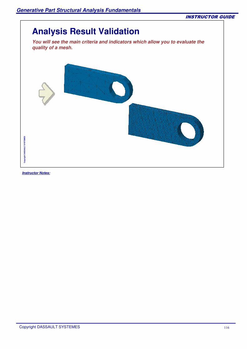
Instructor Notes:
Generative Part Structural Analysis Fundamentals
Copyright DASSAULT SYSTEMES ���
��������������
Cop
yrig
ht D
AS
SA
ULT
SY
STE
ME
S
Analysis Result ValidationYou will see the main criteria and indicators which allow you to evaluate the quality of a mesh.
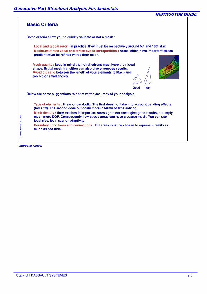
Instructor Notes:
Generative Part Structural Analysis Fundamentals
Copyright DASSAULT SYSTEMES ���
��������������
Cop
yrig
ht D
AS
SA
ULT
SY
STE
ME
S
Basic Criteria
Some criteria allow you to quickly validate or not a mesh :
Local and global error : in practice, they must be respectively around 5% and 10% Max.Maximum stress value and stress evolution/repartition : Areas which have important stress gradient must be refined with a finer mesh.
Good Bad
Below are some suggestions to optimize the accuracy of your analysis:
Type of elements : linear or parabolic. The first does not take into account bending effects (too stiff). The second does but costs more in terms of time solving.Mesh density : finer meshes in important stress gradient areas give good results, but imply much more DOF. Consequently, low stress areas can have a coarse mesh. You can use local size, local sag, or adaptivity.Boundary conditions and connections : BC areas must be chosen to represent reality as much as possible.
Mesh quality : keep in mind that tetrahedrons must keep their ideal shape. Brutal mesh transition can also give erroneous results. Avoid big ratio between the length of your elements (5 Max.) and too big or small angles.
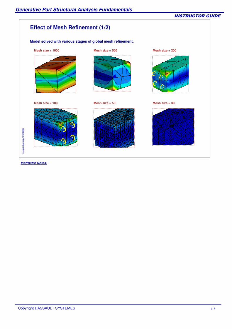
Instructor Notes:
Generative Part Structural Analysis Fundamentals
Copyright DASSAULT SYSTEMES ���
��������������
Cop
yrig
ht D
AS
SA
ULT
SY
STE
ME
S
Effect of Mesh Refinement (1/2)
Model solved with various stages of global mesh refinement.
Mesh size = 100 Mesh size = 50 Mesh size = 30
Mesh size = 200Mesh size = 1000 Mesh size = 500
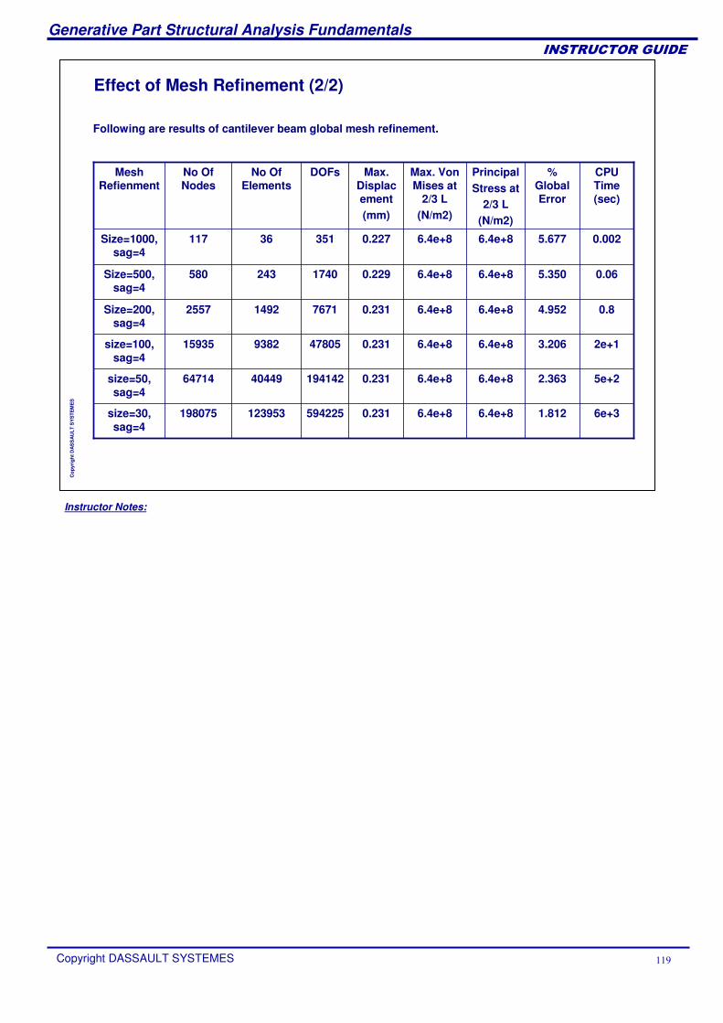
Instructor Notes:
Generative Part Structural Analysis Fundamentals
Copyright DASSAULT SYSTEMES ��
��������������
Cop
yrig
ht D
AS
SA
ULT
SY
STE
ME
S
Effect of Mesh Refinement (2/2)
Following are results of cantilever beam global mesh refinement.
0.0025.6776.4e+86.4e+80.22735136117Size=1000, sag=4
size=30, sag=4
size=50, sag=4
size=100, sag=4
Size=200, sag=4
Size=500, sag=4
Mesh Refienment
198075
64714
15935
2557
580
No Of Nodes
123953
40449
9382
1492
243
No Of Elements
594225
194142
47805
7671
1740
DOFs
0.231
0.231
0.231
0.231
0.229
Max. Displacement(mm)
6.4e+8
6.4e+8
6.4e+8
6.4e+8
6.4e+8
Max. Von Mises at
2/3 L(N/m2)
6.4e+8
6.4e+8
6.4e+8
6.4e+8
6.4e+8
PrincipalStress at
2/3 L(N/m2)
1.812
2.363
3.206
4.952
5.350
% Global Error
6e+3
5e+2
2e+1
0.8
0.06
CPU Time (sec)
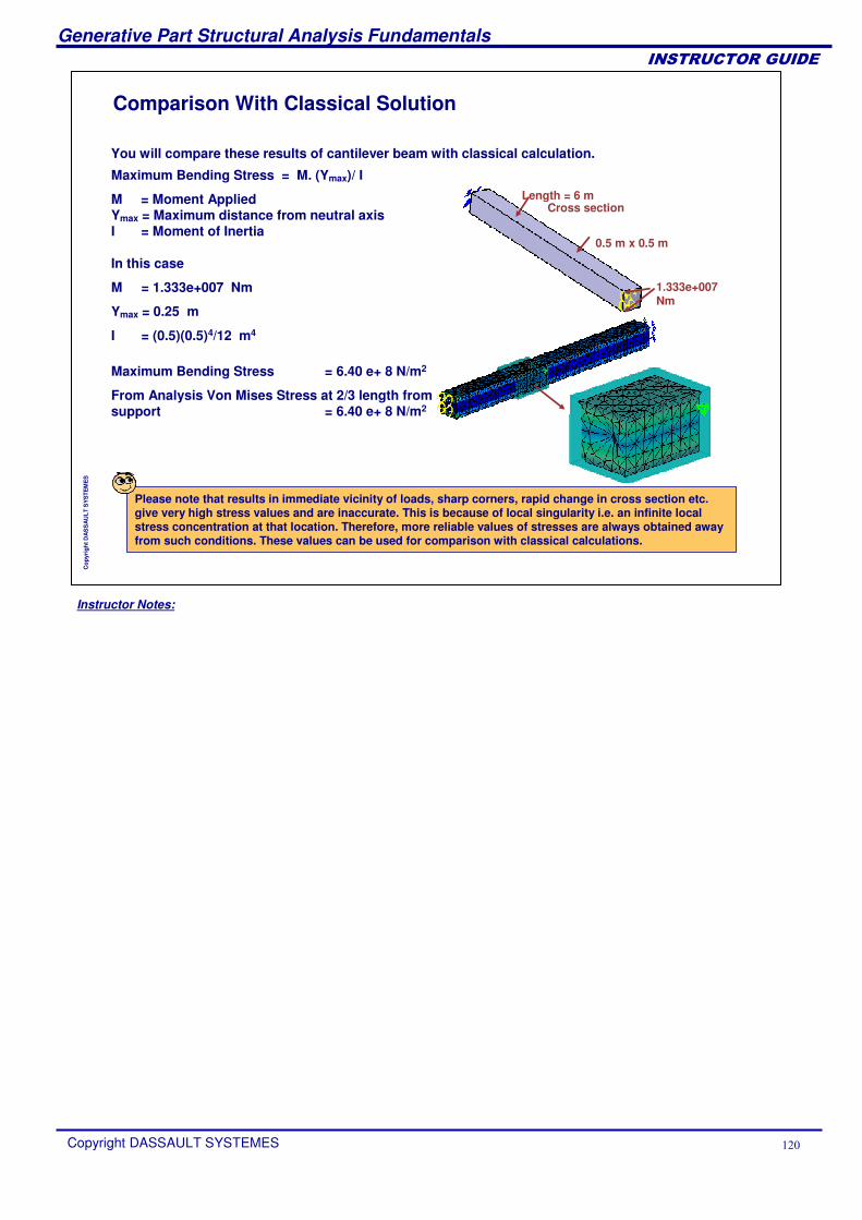
Instructor Notes:
Generative Part Structural Analysis Fundamentals
Copyright DASSAULT SYSTEMES ��
��������������
Cop
yrig
ht D
AS
SA
ULT
SY
STE
ME
S
Comparison With Classical Solution
You will compare these results of cantilever beam with classical calculation.
In this case
M = 1.333e+007 Nm
Ymax = 0.25 m
I = (0.5)(0.5)4/12 m4
Cross section
1.333e+007 Nm
Length = 6 m
0.5 m x 0.5 m
Maximum Bending Stress = M. (Ymax)/ I
M = Moment Applied Ymax = Maximum distance from neutral axis I = Moment of Inertia
Maximum Bending Stress = 6.40 e+ 8 N/m2
From Analysis Von Mises Stress at 2/3 length from support = 6.40 e+ 8 N/m2
Please note that results in immediate vicinity of loads, sharp corners, rapid change in cross section etc. give very high stress values and are inaccurate. This is because of local singularity i.e. an infinite local stress concentration at that location. Therefore, more reliable values of stresses are always obtained away from such conditions. These values can be used for comparison with classical calculations.
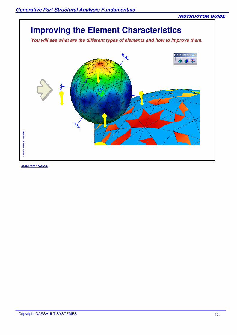
Instructor Notes:
Generative Part Structural Analysis Fundamentals
Copyright DASSAULT SYSTEMES ���
��������������
Cop
yrig
ht D
AS
SA
ULT
SY
STE
ME
S
Improving the Element CharacteristicsYou will see what are the different types of elements and how to improve them.
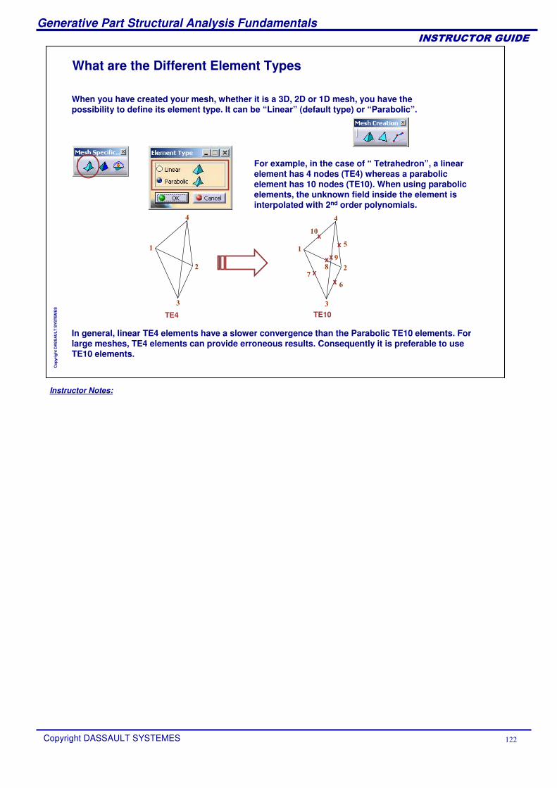
Instructor Notes:
Generative Part Structural Analysis Fundamentals
Copyright DASSAULT SYSTEMES ���
��������������
Cop
yrig
ht D
AS
SA
ULT
SY
STE
ME
S
What are the Different Element Types
When you have created your mesh, whether it is a 3D, 2D or 1D mesh, you have the possibility to define its element type. It can be “Linear” (default type) or “Parabolic”.
For example, in the case of “ Tetrahedron”, a linear element has 4 nodes (TE4) whereas a parabolic element has 10 nodes (TE10). When using parabolic elements, the unknown field inside the element is interpolated with 2nd order polynomials.
In general, linear TE4 elements have a slower convergence than the Parabolic TE10 elements. For large meshes, TE4 elements can provide erroneous results. Consequently it is preferable to use TE10 elements.
�
�
�
�
�
�
�
�
xx
x
xx
x
TE4 TE10
�
�
�
�
�
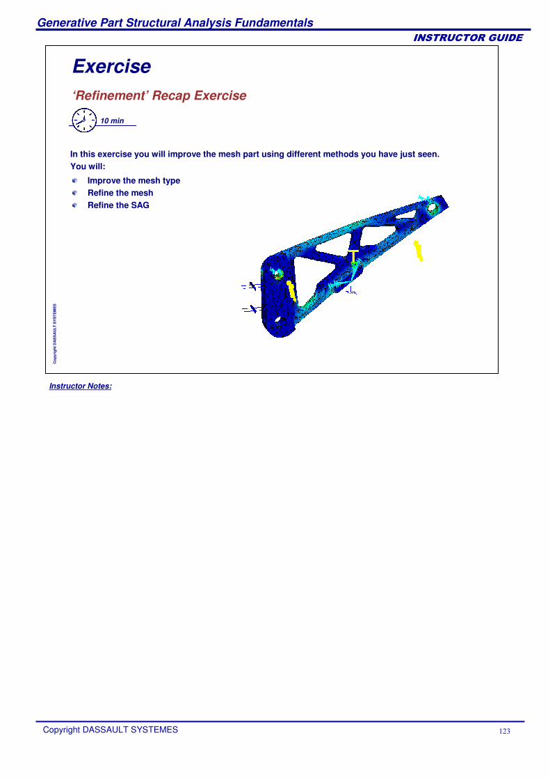
Instructor Notes:
Generative Part Structural Analysis Fundamentals
Copyright DASSAULT SYSTEMES ���
��������������
Cop
yrig
ht D
AS
SA
ULT
SY
STE
ME
S
Exercise‘Refinement’ Recap Exercise
10 min
In this exercise you will improve the mesh part using different methods you have just seen.You will:
Improve the mesh typeRefine the meshRefine the SAG
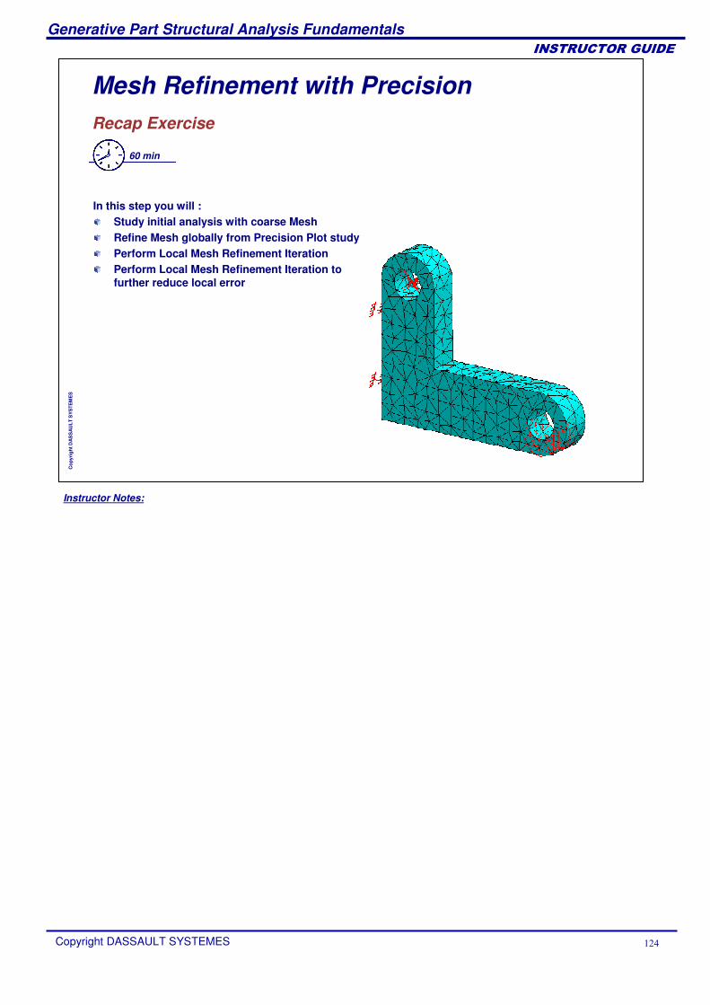
Instructor Notes:
Generative Part Structural Analysis Fundamentals
Copyright DASSAULT SYSTEMES ���
��������������
Cop
yrig
ht D
AS
SA
ULT
SY
STE
ME
S
Mesh Refinement with PrecisionRecap Exercise
60 min
In this step you will :Study initial analysis with coarse MeshRefine Mesh globally from Precision Plot studyPerform Local Mesh Refinement IterationPerform Local Mesh Refinement Iteration to further reduce local error
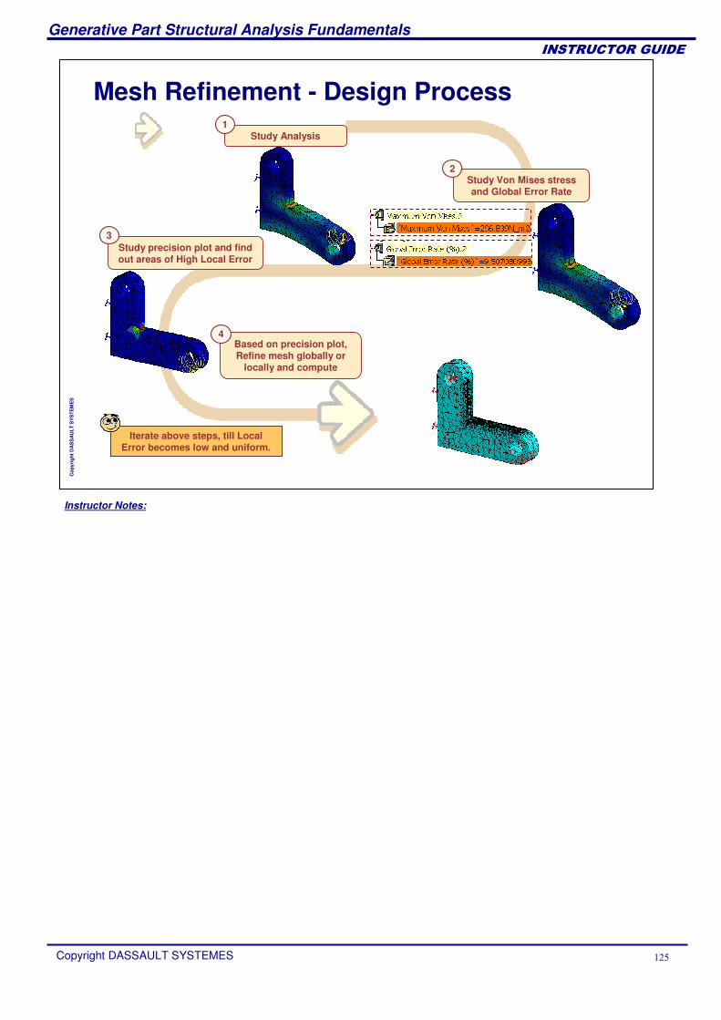
Instructor Notes:
Generative Part Structural Analysis Fundamentals
Copyright DASSAULT SYSTEMES ���
��������������
Cop
yrig
ht D
AS
SA
ULT
SY
STE
ME
S
Study Von Mises stress and Global Error Rate
Based on precision plot, Refine mesh globally or
locally and compute
Study precision plot and find out areas of High Local Error
3
Study Analysis
Mesh Refinement - Design Process
Iterate above steps, till Local Error becomes low and uniform.
1
2
4
Instructor Notes:
Generative Part Structural Analysis Fundamentals
Copyright DASSAULT SYSTEMES ���
��������������
Cop
yrig
ht D
AS
SA
ULT
SY
STE
ME
S
Results ManagementYou will learn the functionalities to get specific information regarding results and how to generate reports.
Report GenerationExtrema DetectionImages InformationPublishing ReportsResults Management Recap Exercise
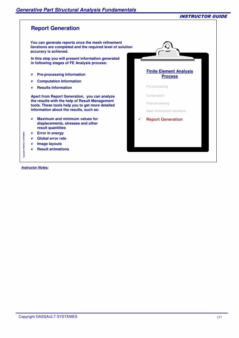
Instructor Notes:
Generative Part Structural Analysis Fundamentals
Copyright DASSAULT SYSTEMES ���
��������������
Cop
yrig
ht D
AS
SA
ULT
SY
STE
ME
S
Report Generation
You can generate reports once the mesh refinement iterations are completed and the required level of solution accuracy is achieved.
In this step you will present information generated in following stages of FE Analysis process:
Finite Element AnalysisProcess
Pre-processing
Computation
Post-processing
Mesh Refinement Iterations
� Report Generation
Pre-processing Information
Computation Information
Results Information
Apart from Report Generation, you can analyze the results with the help of Result Management tools. These tools help you to get more detailed information about the results, such as:
Maximum and minimum values for displacements, stresses and other result quantitiesError in energyGlobal error rateImage layoutsResult animations
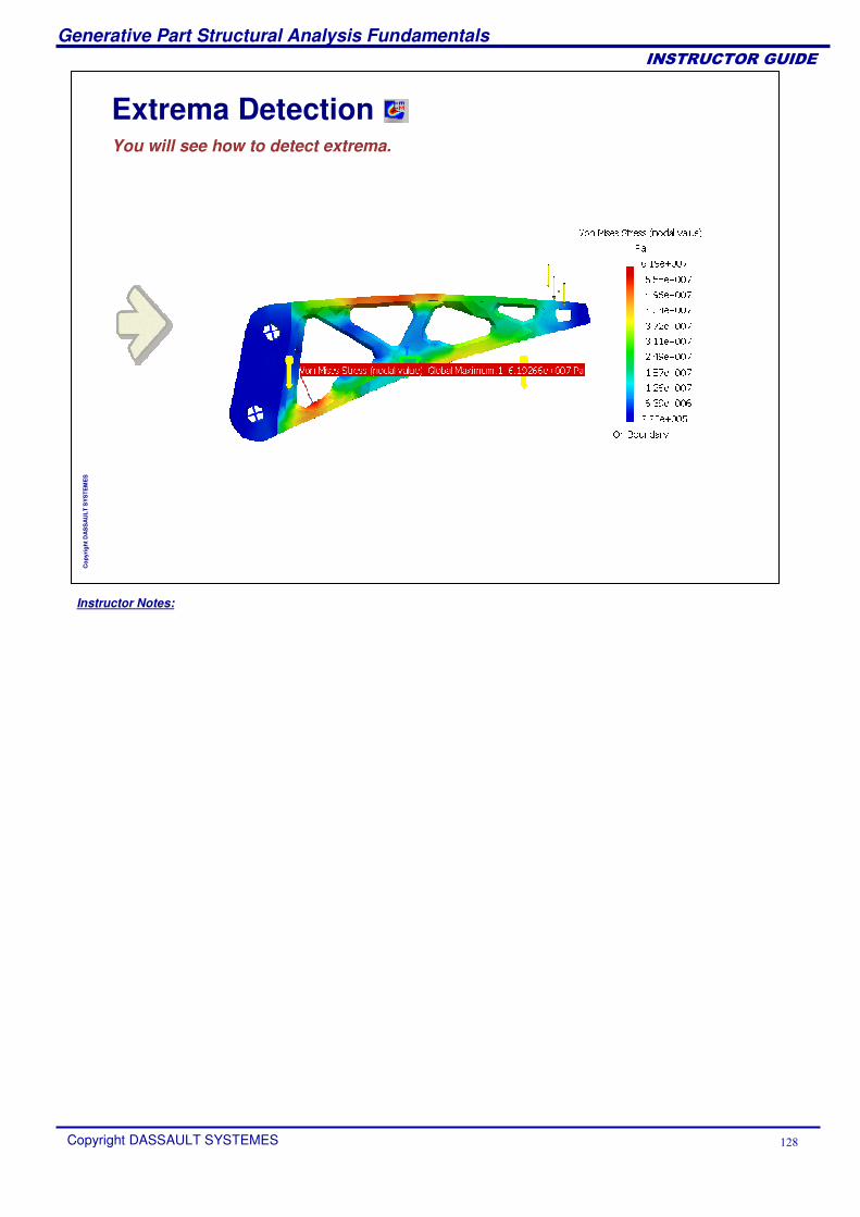
Instructor Notes:
Generative Part Structural Analysis Fundamentals
Copyright DASSAULT SYSTEMES ���
��������������
Cop
yrig
ht D
AS
SA
ULT
SY
STE
ME
S
Extrema DetectionYou will see how to detect extrema.
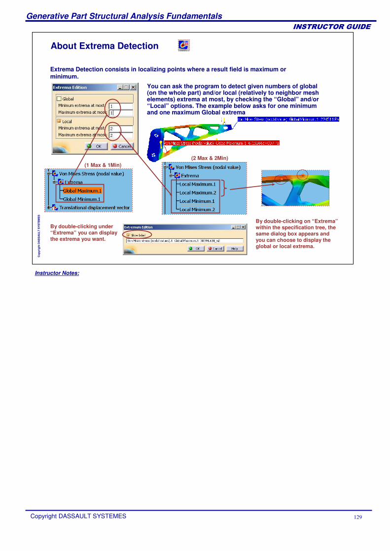
Instructor Notes:
Generative Part Structural Analysis Fundamentals
Copyright DASSAULT SYSTEMES ��
��������������
Cop
yrig
ht D
AS
SA
ULT
SY
STE
ME
S
About Extrema Detection
You can ask the program to detect given numbers of global (on the whole part) and/or local (relatively to neighbor mesh elements) extrema at most, by checking the “Global” and/or “Local” options. The example below asks for one minimum and one maximum Global extrema
By double-clicking on “Extrema”within the specification tree, the same dialog box appears and you can choose to display the global or local extrema.
(1 Max & 1Min)
By double-clicking under “Extrema” you can display the extrema you want.
(2 Max & 2Min)
Extrema Detection consists in localizing points where a result field is maximum or minimum.
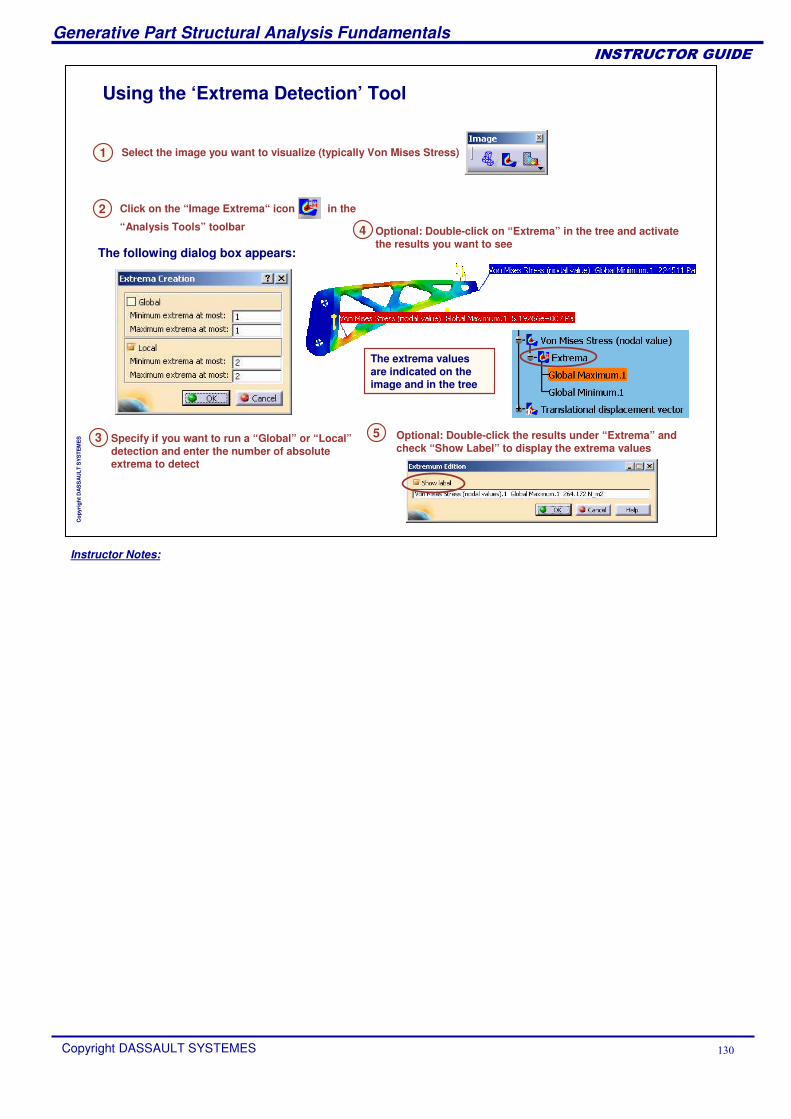
Instructor Notes:
Generative Part Structural Analysis Fundamentals
Copyright DASSAULT SYSTEMES ��
��������������
Cop
yrig
ht D
AS
SA
ULT
SY
STE
ME
S
Using the ‘Extrema Detection’ Tool
1 Select the image you want to visualize (typically Von Mises Stress)
3 Specify if you want to run a “Global” or “Local”detection and enter the number of absolute extrema to detect
Click on the “Image Extrema“ icon in the
“Analysis Tools” toolbar
2
The following dialog box appears:
The extrema values are indicated on the image and in the tree
4 Optional: Double-click on “Extrema” in the tree and activate the results you want to see
5 Optional: Double-click the results under “Extrema” and check “Show Label” to display the extrema values
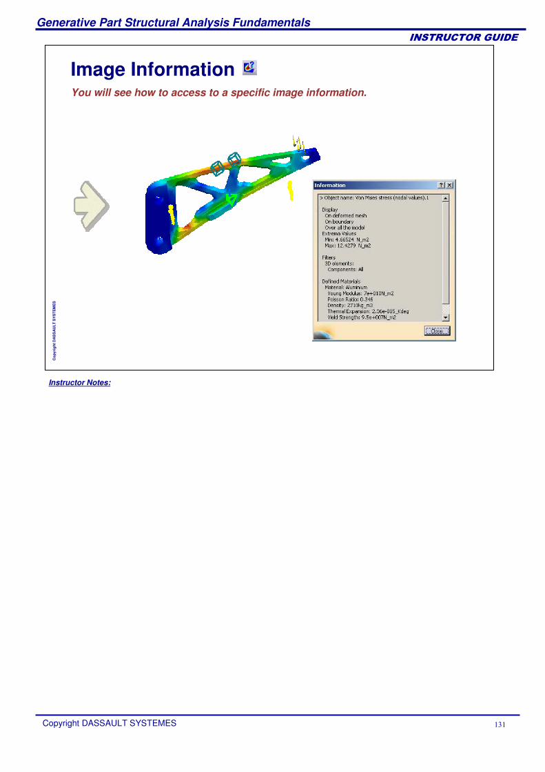
Instructor Notes:
Generative Part Structural Analysis Fundamentals
Copyright DASSAULT SYSTEMES ���
��������������
Cop
yrig
ht D
AS
SA
ULT
SY
STE
ME
S
Image InformationYou will see how to access to a specific image information.
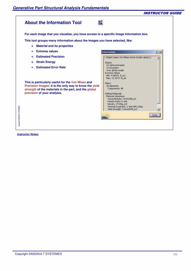
Instructor Notes:
Generative Part Structural Analysis Fundamentals
Copyright DASSAULT SYSTEMES ���
��������������
Cop
yrig
ht D
AS
SA
ULT
SY
STE
ME
S
About the Information Tool
This tool groups many information about the images you have selected, like:
Material and its properties
Extrema values
Estimated Precision
Strain Energy
Estimated Error Rate
This is particularly useful for the Von Mises and Precision images: it is the only way to know the yield strength of the materials in the part, and the global precision of your analysis.
For each image that you visualize, you have access to a specific Image Information box.
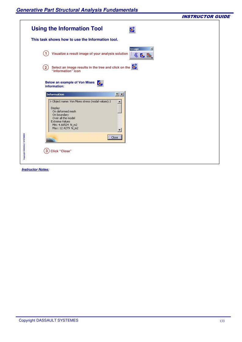
Instructor Notes:
Generative Part Structural Analysis Fundamentals
Copyright DASSAULT SYSTEMES ���
��������������
Cop
yrig
ht D
AS
SA
ULT
SY
STE
ME
S
Using the Information Tool
1 Visualize a result image of your analysis solution
3 Click “Close”
Select an image results in the tree and click on the “information” icon
2
This task shows how to use the Information tool.
Below an example of Von Mises information:
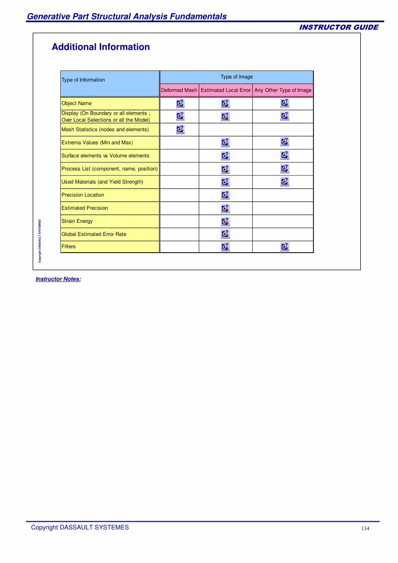
Instructor Notes:
Generative Part Structural Analysis Fundamentals
Copyright DASSAULT SYSTEMES ���
��������������
Cop
yrig
ht D
AS
SA
ULT
SY
STE
ME
S
Additional Information
Deformed Mesh Estimated Local Error Any Other Type of Image
Object Name
Display (On Boundary or all elements ; Over Local Selections or all the Model)
Mesh Statistics (nodes and elements)
Extrema Values (Min and Max)
Surface elements vs Volume elements
Process List (component, name, position)
Used Materials (and Yield Strength)
Precision Location
Estimated Precision
Strain Energy
Global Estimated Error Rate
Filters
Type of ImageType of Information
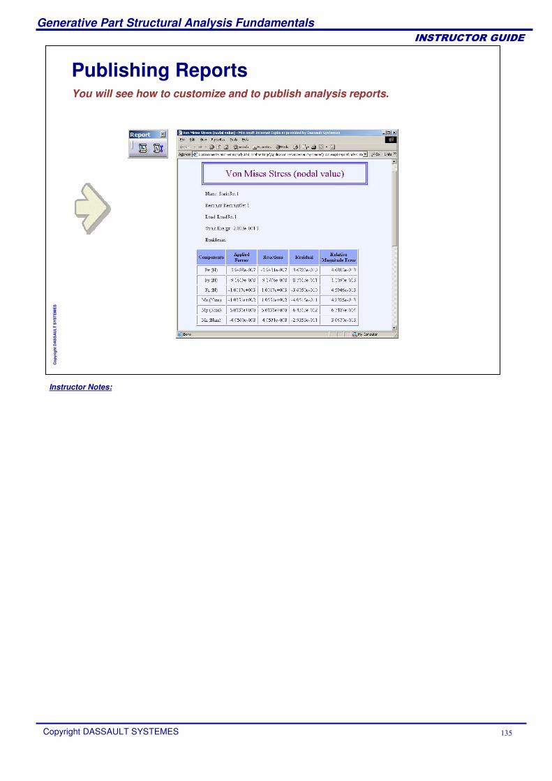
Instructor Notes:
Generative Part Structural Analysis Fundamentals
Copyright DASSAULT SYSTEMES ���
��������������
Cop
yrig
ht D
AS
SA
ULT
SY
STE
ME
S
Publishing ReportsYou will see how to customize and to publish analysis reports.
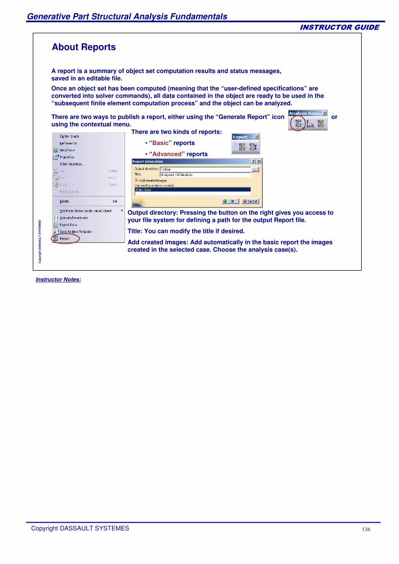
Instructor Notes:
Generative Part Structural Analysis Fundamentals
Copyright DASSAULT SYSTEMES ���
��������������
Cop
yrig
ht D
AS
SA
ULT
SY
STE
ME
S
About Reports
Once an object set has been computed (meaning that the “user-defined specifications” are converted into solver commands), all data contained in the object are ready to be used in the “subsequent finite element computation process” and the object can be analyzed.
There are two ways to publish a report, either using the “Generate Report” icon or using the contextual menu.
There are two kinds of reports:
• “Basic” reports
• “Advanced” reports
Output directory: Pressing the button on the right gives you access to your file system for defining a path for the output Report file.
Title: You can modify the title if desired.
Add created images: Add automatically in the basic report the images created in the selected case. Choose the analysis case(s).
A report is a summary of object set computation results and status messages, saved in an editable file.
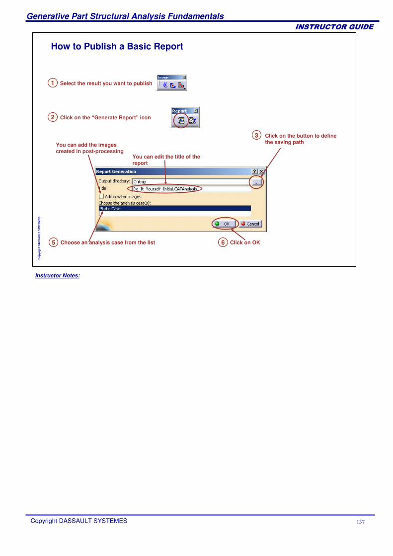
Instructor Notes:
Generative Part Structural Analysis Fundamentals
Copyright DASSAULT SYSTEMES ���
��������������
Cop
yrig
ht D
AS
SA
ULT
SY
STE
ME
S
How to Publish a Basic Report
Select the result you want to publish 1
Click on the “Generate Report” icon2
Click on the button to define the saving path
You can edit the title of the report
3
5 Choose an analysis case from the list 6 Click on OK
You can add the images created in post-processing
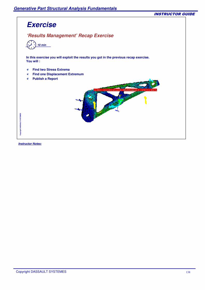
Instructor Notes:
Generative Part Structural Analysis Fundamentals
Copyright DASSAULT SYSTEMES ���
��������������
Cop
yrig
ht D
AS
SA
ULT
SY
STE
ME
S
Exercise‘Results Management’ Recap Exercise
10 min
In this exercise you will exploit the results you got in the previous recap exercise. You will :
Find two Stress ExtremaFind one Displacement ExtremumPublish a Report
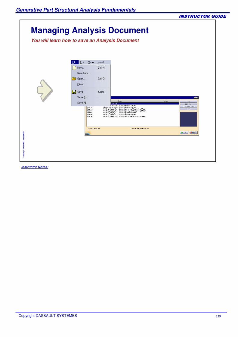
Instructor Notes:
Generative Part Structural Analysis Fundamentals
Copyright DASSAULT SYSTEMES ��
��������������
Cop
yrig
ht D
AS
SA
ULT
SY
STE
ME
S
Managing Analysis DocumentYou will learn how to save an Analysis Document
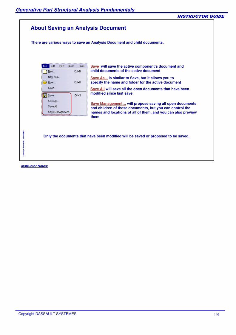
Instructor Notes:
Generative Part Structural Analysis Fundamentals
Copyright DASSAULT SYSTEMES ��
��������������
Cop
yrig
ht D
AS
SA
ULT
SY
STE
ME
S
There are various ways to save an Analysis Document and child documents.
Save will save the active component’s document and child documents of the active document
Save As... is similar to Save, but it allows you to specify the name and folder for the active document
Save All will save all the open documents that have been modified since last save
Only the documents that have been modified will be saved or proposed to be saved.
Save Management… will propose saving all open documents and children of these documents, but you can control the names and locations of all of them, and you can also preview them
About Saving an Analysis Document
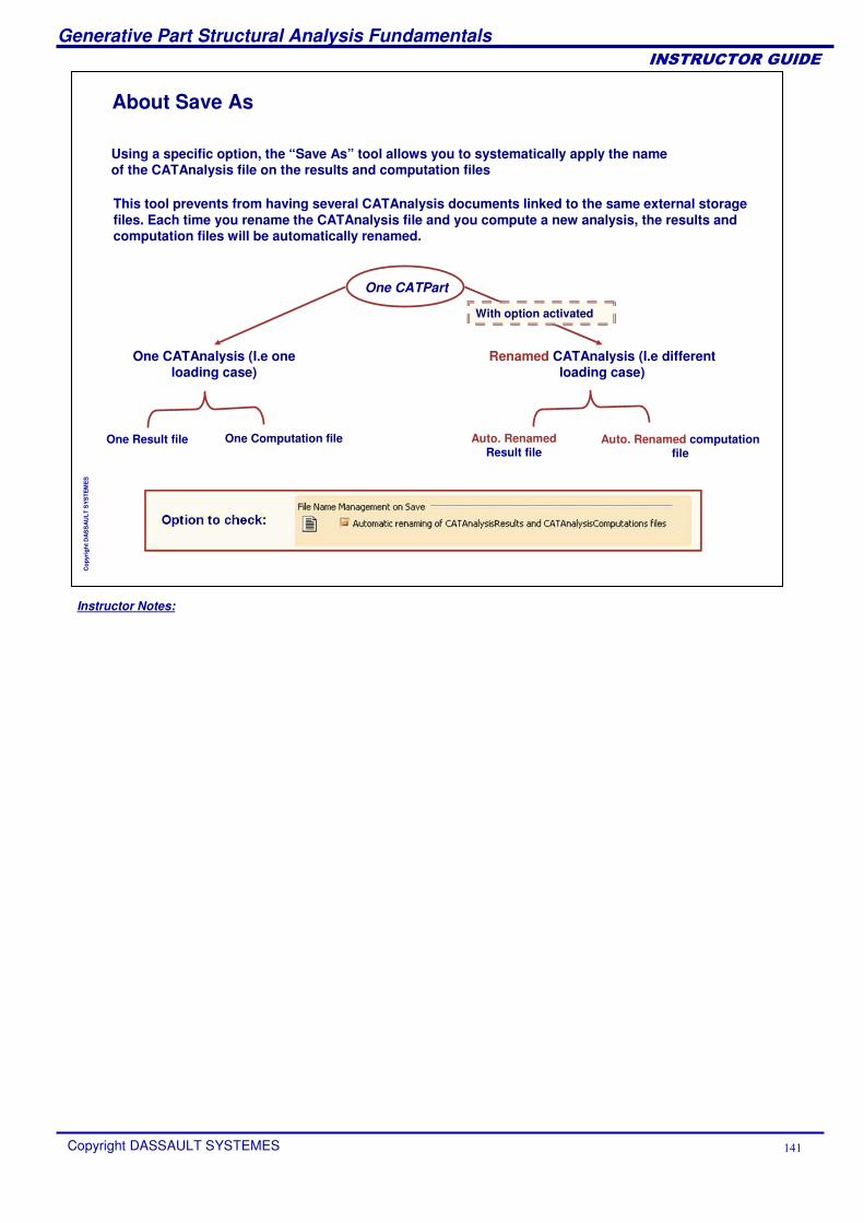
Instructor Notes:
Generative Part Structural Analysis Fundamentals
Copyright DASSAULT SYSTEMES ���
��������������
Cop
yrig
ht D
AS
SA
ULT
SY
STE
ME
S
About Save As
This tool prevents from having several CATAnalysis documents linked to the same external storage files. Each time you rename the CATAnalysis file and you compute a new analysis, the results and computation files will be automatically renamed.
Using a specific option, the “Save As” tool allows you to systematically apply the name of the CATAnalysis file on the results and computation files
One CATPart
One CATAnalysis (I.e one loading case)
One Result file One Computation file
Renamed CATAnalysis (I.e different loading case)
Auto. RenamedResult file
Auto. Renamed computation file
With option activated
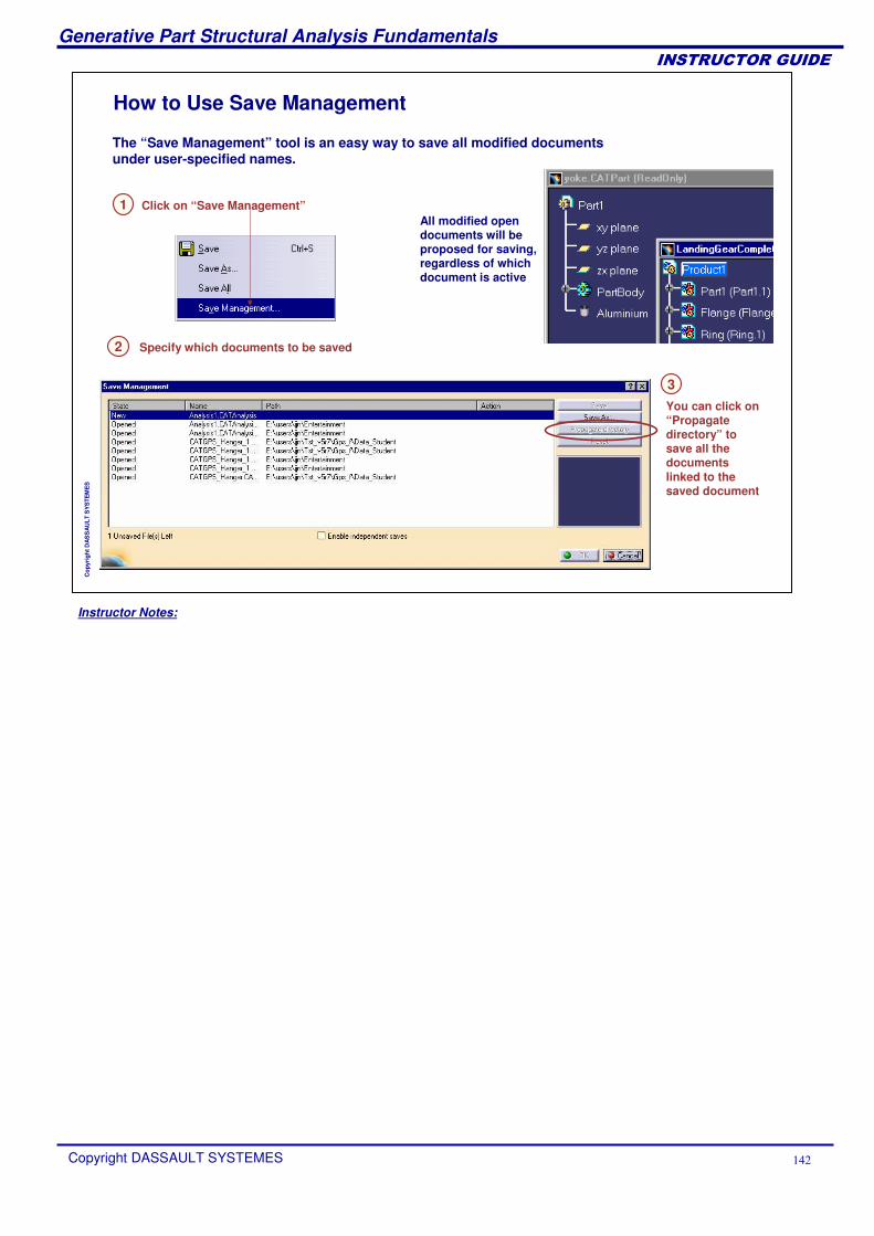
Instructor Notes:
Generative Part Structural Analysis Fundamentals
Copyright DASSAULT SYSTEMES ���
��������������
Cop
yrig
ht D
AS
SA
ULT
SY
STE
ME
S
How to Use Save Management
All modified open documents will be proposed for saving, regardless of which document is active
Click on “Save Management”
Specify which documents to be saved
1
2
3You can click on “Propagate directory” to save all the documents linked to the saved document
The “Save Management” tool is an easy way to save all modified documents under user-specified names.
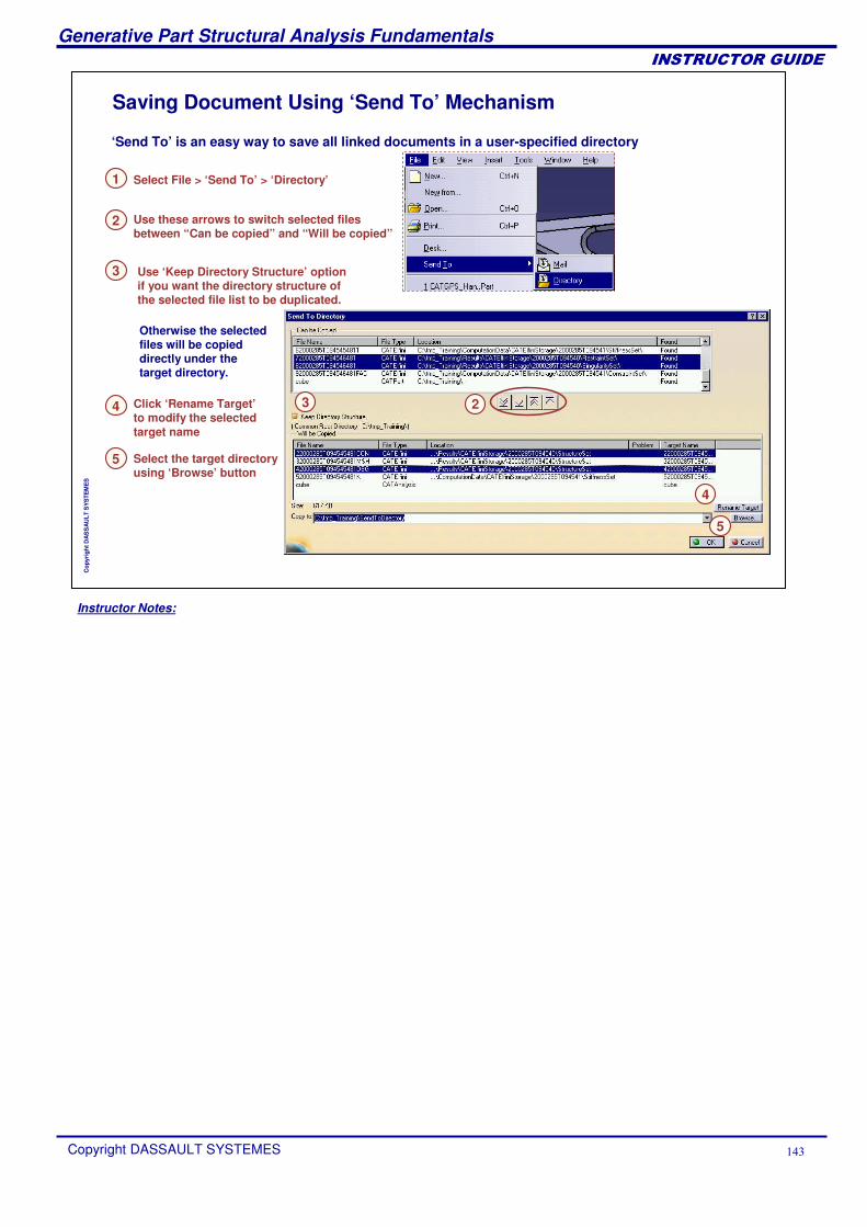
Instructor Notes:
Generative Part Structural Analysis Fundamentals
Copyright DASSAULT SYSTEMES ���
��������������
Cop
yrig
ht D
AS
SA
ULT
SY
STE
ME
S
Saving Document Using ‘Send To’ Mechanism
Use ‘Keep Directory Structure’ option if you want the directory structure of the selected file list to be duplicated.
Select File > ‘Send To’ > ‘Directory’
Select the target directory using ‘Browse’ button
1
Use these arrows to switch selected files between “Can be copied” and “Will be copied”
Click ‘Rename Target’to modify the selected target name
2
4
5
‘Send To’ is an easy way to save all linked documents in a user-specified directory
2
4
5
3
Otherwise the selected files will be copied directly under the target directory.
3
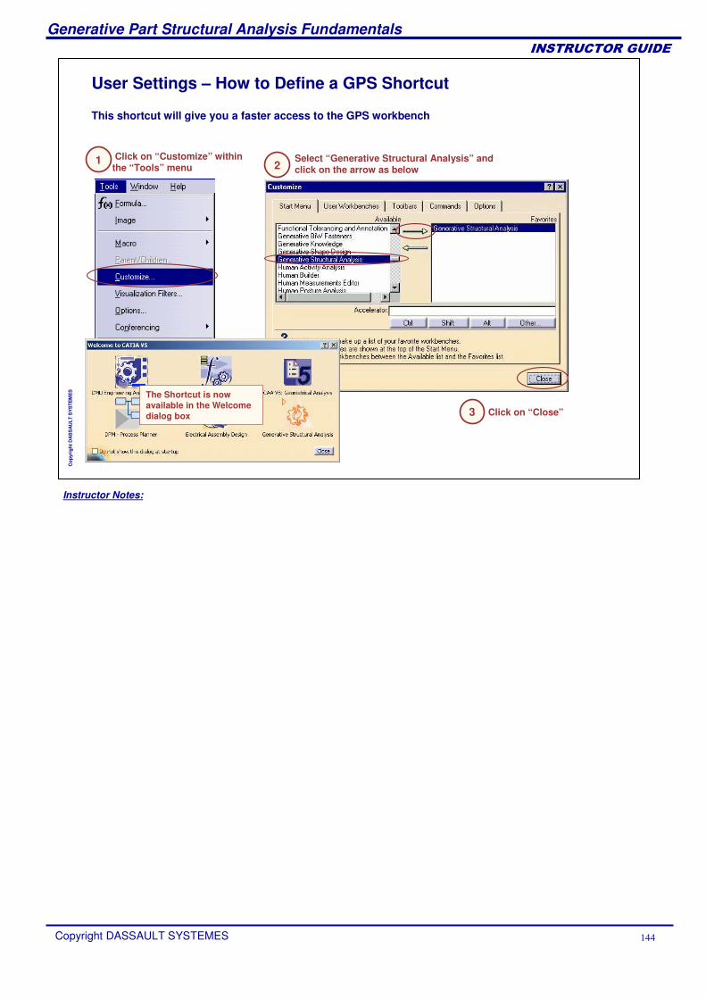
Instructor Notes:
Generative Part Structural Analysis Fundamentals
Copyright DASSAULT SYSTEMES ���
��������������
Cop
yrig
ht D
AS
SA
ULT
SY
STE
ME
S
User Settings – How to Define a GPS Shortcut
Click on “Customize” within the “Tools” menu
This shortcut will give you a faster access to the GPS workbench
1 2Select “Generative Structural Analysis” and click on the arrow as below
3 Click on “Close”
The Shortcut is now available in the Welcome dialog box
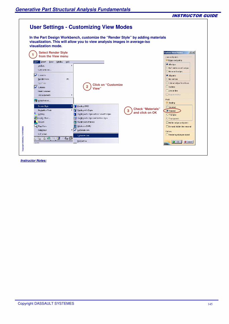
Instructor Notes:
Generative Part Structural Analysis Fundamentals
Copyright DASSAULT SYSTEMES ���
��������������
Cop
yrig
ht D
AS
SA
ULT
SY
STE
ME
S
User Settings - Customizing View Modes
Check “Materials”and click on OK
Select Render Style from the View menu
In the Part Design Workbench, customize the “Render Style” by adding materials visualization. This will allow you to view analysis images in average-iso visualization mode.
1
3
Click on “Customize View”2
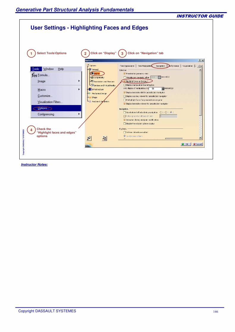
Instructor Notes:
Generative Part Structural Analysis Fundamentals
Copyright DASSAULT SYSTEMES ���
��������������
Cop
yrig
ht D
AS
SA
ULT
SY
STE
ME
S
User Settings - Highlighting Faces and Edges
Select Tools\Options Click on “Display” Click on “Navigation” tab
Check the“Highlight faces and edges”options
1 2 3
4
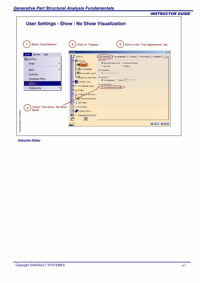
Instructor Notes:
Generative Part Structural Analysis Fundamentals
Copyright DASSAULT SYSTEMES ���
��������������
Cop
yrig
ht D
AS
SA
ULT
SY
STE
ME
S
User Settings - Show / No Show Visualization
Click on the “Tree Appearance” tab
Check Tree Show / No-Show Mode
1 3
4
Select Tools\Options Click on “Display”2
Instructor Notes:
Generative Part Structural Analysis Fundamentals
Copyright DASSAULT SYSTEMES ���
��������������
Cop
yrig
ht D
AS
SA
ULT
SY
STE
ME
S
Master Exercise: Static AnalysisYou will practice concepts learned throughout the course by building the master exercise and following the recommended process
Static Analysis: PresentationStatic Analysis on a Hanger (1): Pre-ProcessingStatic Analysis on a Hanger (2): ComputationStatic Analysis on a Hanger (3): Result Visualization
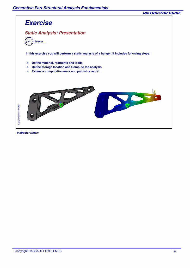
Instructor Notes:
Generative Part Structural Analysis Fundamentals
Copyright DASSAULT SYSTEMES ��
��������������
Cop
yrig
ht D
AS
SA
ULT
SY
STE
ME
S
Exercise Static Analysis: Presentation
50 min
In this exercise you will perform a static analysis of a hanger. It includes following steps:
Define material, restraints and loadsDefine storage location and Compute the analysisEstimate computation error and publish a report.
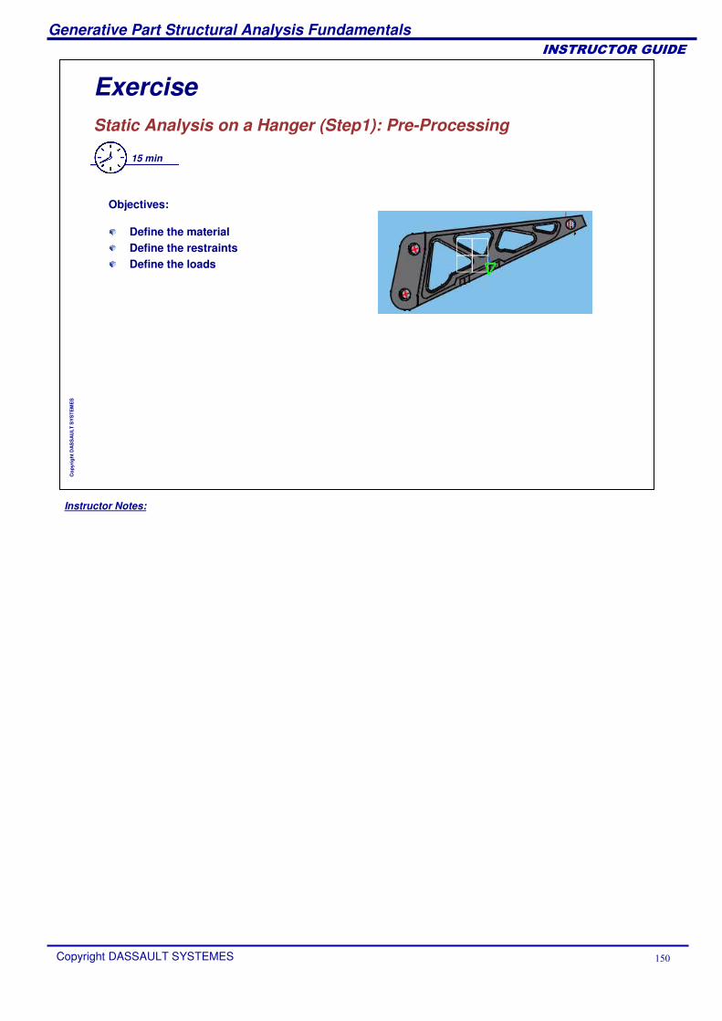
Instructor Notes:
Generative Part Structural Analysis Fundamentals
Copyright DASSAULT SYSTEMES ��
��������������
Cop
yrig
ht D
AS
SA
ULT
SY
STE
ME
S
Exercise Static Analysis on a Hanger (Step1): Pre-Processing
15 min
Objectives:
Define the material Define the restraintsDefine the loads

Instructor Notes:
Generative Part Structural Analysis Fundamentals
Copyright DASSAULT SYSTEMES ���
��������������
Cop
yrig
ht D
AS
SA
ULT
SY
STE
ME
S
Exercise Static Analysis on a Hanger (Step2): Computation
5 min
Objectives:
Define the storage locationCompute the analysis
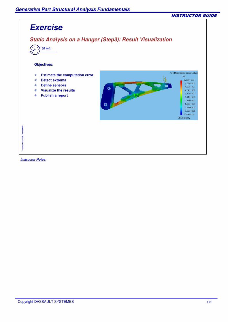
Instructor Notes:
Generative Part Structural Analysis Fundamentals
Copyright DASSAULT SYSTEMES ���
��������������
Cop
yrig
ht D
AS
SA
ULT
SY
STE
ME
S
Exercise Static Analysis on a Hanger (Step3): Result Visualization
30 min
Objectives:
Estimate the computation errorDetect extremaDefine sensors Visualize the resultsPublish a report