Embed Size (px)
Citation preview

1
GENERAL PLANT OPERATIONS
ENGINEERING

2
TABLE OF CONTENTS
SL NO. TITLE PAGE NO.
1.0 RAW MATERIAL HANDLING PLANT
1.1 INTRODUCTION 5
1.2 DIFFERENT RAW MATERIALS AND THEIR
SOURCES
6
1.3 QUALITY REQUIREMENTS OF RAW MATERIALS 10
1.4 PROCESS AND FLOW DIAGRAM OF RMHP 11
1.5 MATERIAL HANDLING EQUIPMENTS 11
1.6 CUSTOMERS 17
1.7 BENEFITS OF RMHP 18
1.8 SAFETY 18
2.0 COKE OVENS AND COAL CHEMICALS
2.1 INTRODUCTION
19
2.2 PROPERTIES OF COKING COAL 20
2.3 COAL HANDLING PLANT 21
2.4 CARBONIZATION PROCESS 23
2.5 PROPERTIES OF COKE 25
2.6 COAL CHEMICALS 25
2.7 BY-PRODUCTS OF COKE OVENS 27
2.8 POLLUTION CONTROL NORMS 28
2.9 SAFETY 32
2.10 QUALITY CONTROL- OHSAS: 18001 32
2.11 OHSAS - 18001 (Occupational Health and Safety
Assessment Series)
33
3.0 SINTER PLANT
3.1 INTRODUCTION 34
3.2 RAW MATERIALS PROPORTIONING 34
3.3 SINTERING PROCESS 35
3.4 QUALITY PARAMETERS 43
3.5 PROCESS FLOW DIAGRAM OF SINTER PLANT 44
3.6 MAIN AREAS AND EQUIPMENTS 46
3.7 SAFETY HAZARD IN SINTERING PLANT 47
4.0 BLAST FURNACE
4.1 INTRODUCTION 49
4.2 RAW MATERIALS AND THEIR QUALITY 49
4.3 BLAST FURNACE AND ACCESSORIES 54
4.4 B F ZONES AND CHEMICAL REACTIONS 62
4.5 HOT BLAST STOVES 64
4.6 CAST HOUSE AND SLAG GRANULATION PLANT 65
4.7 SAFETY & ENVIRONMENT 70

3
5.0 STEEL MAKING
5.1 INTRODUCTION 71
5.2 OPEN / TWIN HEARTH FURNACES - PROCESS 72
5.3 BASIC OXYGEN FURNACE (LD CONVERTER) 73
5.4 SECONDARY STEEL MAKING 80
5.5 CASTING 86
5.6 INGOT CASTING 96
6.0 ROLLING MILLS
6.1 BASICS OF ROLLING 98
6.2 PRODUCTS OF ROLLING MILLS OF SAIL 103
6.3 APPLICATIONS OF ROLLED PRODUCTS OF SAIL 105
6.4 HOT ROLLING 107
6.5 REHEATING FURNACES 107
6.6 ROLLING OF FLAT PRODUCTS 107
6.7 ROLLING OF LONG PRODUCTS 110
6.8 COLD ROLLING 117
6.9 MAJOR COLD ROLLING DEFECTS 123
6.10 INTRODUCTION TO PIPE PLANTS AND SILICON
STEEL PLANT
123
6.11 ROLLING OF SPECIAL STEELS (STAINLESS STEEL) 125
7.0 GENERAL MECHANICAL MAINTENANCE
7.1 INTRODUCTION 127
7.2 MAINTENANCE OBJECTIVE 130
7.3 TYPES OF MAINTENANCE SYSTEMS 131
7.4 LATEST TRENDS IN MAINTENANCE 135
7.5 LUBRICATION 136
7.6 BEARINGS & BEARING HOUSINGS 142
7.7 POWER TRANSMISSION AND POWER DRIVES 152
7.8 TECHNOLOGY OF REPAIR OF STEEL PLANT
EQUIPMENTS
156
7.9 AVAILABILITY AND RELIABILITY OF EQUIPMENTS 161
7.10 DOS, AND DONTS, & SAFETY 162
8.0 HYDRAULICS
8.1 INTRODUCTION 164
8.2 COMPONENTS OF HYDRAULIC SYSTEM &
FUNCTIONS
167
8.3 BLOCK DIAGRAM OF HYDRAULIC SYSTEM 179
8.4 APPLICATIONS OF HYD. SYSTEMS IN STEEL
PLANTS
181
8.5 MAINTENANCE OF HYDRAULIC SYSTEMS 183
8.6 SAFETY IN HYDRAULICS 185

4
9.0 ELECTRICAL AND ELECTRONICS
9.1 BASIC ELECTRICAL ENGINEERING 188
9.2 BASIC PRINCIPLES OF TRANSFORMER 193
9.3 BASIC PRINCIPLES OF MOTOR 197
9.4 POWER DISTRIBUTION 212
9.5 CIRCUIT BREAKERS 216
9.6 CABLES 225
9.7 RELAYS 229
9.8 ELECTRICAL INSULATION 232
9.9 ELECTRONIC DEVICES 234
9.10 TESTING, MEASURING INSTRUMENTS AND TOOLS 240
9.11 DRIVES AND CONTROL 241
9.12 UNINTERRUPTED POWER SUPPLY (UPS) 254
9.13 MAINTENANCE PRACTICES 256
9.14 ELECTRICAL SAFETY 259
9.15 SINGLE LINE DIAGRAM (SLD) 270
10.0 INSTRUMENTATION & PROCESS CONTROL
10.1 INSTRUMENTATION & PROCESS CONTROL FUNCTIONS
IN AN INTEGRATED STEEL PLANT 274
10.2 INSTRUMENTATION & CONTROL FOR DIFFERENT PROCESS PARAMETERS
289
10.3 HISTORY OF PROCESS CONTROL AND AUTOMATION 306
11.0 COMPUTER
11.1 INTRODUCTION TO COMPUTER 315
11.2 HARDWARE AND SOFTWARE CONCEPTS 317
11.3 APPLICATIONS OF COMPUTERS IN STEEL INDUSTRY
319
11.4 OPERATING SYSTEMS AND COMPUTER ARCHITECTURE 320
11.5 COMPUTER LANGUAGE AND APPLICATION SOFTWARE 322
11.6 DATA CENTRE MANAGEMENT 322
11.7 NETWORK AND CONNECTIVITY 323
11.8 INTRODUCTION TO WINDOWS 324
11.9 OFFICE AUTOMATION SOFTWARE (MS Office used in
SAIL)
325
11.10 DATABASE CONCEPTS 326
11.11 INTRANET AND INTERNET 326
11.12 INTRODUCTION TO ERP 328
11.13 DO’S AND DON’TS 330 11.14 INTRODUCTION TO INDUSTRY 4.0 332
12.0 MINING
12.1 INTRODUCTION 333
12.2 MINES OPERATION 338
12.3 SAFETY IN MINES 341

5
Chapter – 1
RAW MATERIAL HANDLING PLANT
1.1 Introduction :
Raw Material Handling Plant (RMHP) or Ore Handling Plant (OHP) or Ore Bedding and
Blending Plant (OBBP) play a very important role in an Integrated Steel Plant. It is the
starting point of an integrated steel plant, where all kinds of raw materials ( Except coal)
required for iron making/steel making are handled in a systematic manner, e.g., unloading,
stacking, screening, crushing, bedding, blending, reclamation, etc.
Different types of major raw materials used in an integrated steel plant are-
Iron Ore
Lime stone
Dolomite
Manganese Ore
Ferro and Silico manganese
Quartzite
Coal
For Blast Furnace route Iron Making the main raw materials required are-
Iron ore lump
Blast furnace grade lime stone
Blast furnace grade dolomite
Coke
Sinter
Scrap
LD Slag
Mn Ore
Quartzite
The main objective of raw material handling plant/ore handling plant/ore bedding and
blending plant is to:-
homogenize materials from different sources by means of blending
supply consistent quality raw materials un-interruptedly to different customers
maintain buffer stock
unloading of wagons/rakes within specified time norm as permitted by Railway.
Raw material preparation (like crushing, screening etc.).
The main functions of RMHP /OHP/OB&BP are –
1. Unloading& stacking of raw materials
2. Screening of iron ore lump & fluxes
3. Crushing & screening of coke/flux for base mix/sinter mix preparation
6
4. Dispatch of processed inputs to customer units
Different types of raw materials such as iron ore lump; iron ore fines, limestone, dolomite,
manganese ore, etc. are supplied by SAIL mines (Raw Materials Division, SAIL) or
purchased from outside parties.
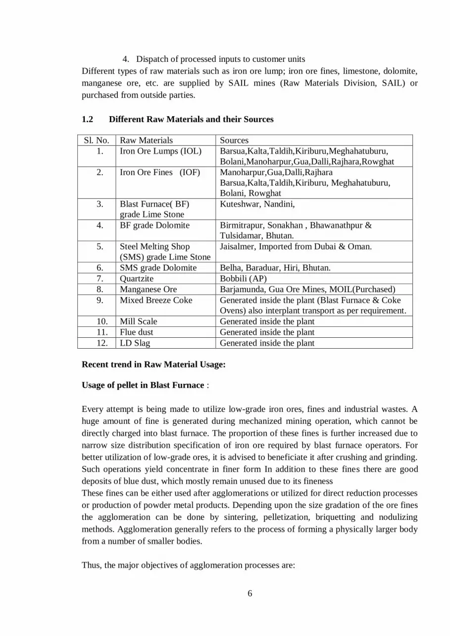
1.2 Different Raw Materials and their Sources
Sl. No. Raw Materials Sources
1. Iron Ore Lumps (IOL) Barsua,Kalta,Taldih,Kiriburu,Meghahatuburu,
Bolani,Manoharpur,Gua,Dalli,Rajhara,Rowghat
2. Iron Ore Fines (IOF) Manoharpur,Gua,Dalli,Rajhara
Barsua,Kalta,Taldih,Kiriburu, Meghahatuburu,
Bolani, Rowghat
3. Blast Furnace( BF)
grade Lime Stone
Kuteshwar, Nandini,
4. BF grade Dolomite Birmitrapur, Sonakhan , Bhawanathpur &
Tulsidamar, Bhutan.
5. Steel Melting Shop
(SMS) grade Lime Stone
Jaisalmer, Imported from Dubai & Oman.
6. SMS grade Dolomite Belha, Baraduar, Hiri, Bhutan.
7. Quartzite Bobbili (AP)
8. Manganese Ore Barjamunda, Gua Ore Mines, MOIL(Purchased)
9. Mixed Breeze Coke Generated inside the plant (Blast Furnace & Coke
Ovens) also interplant transport as per requirement.
10. Mill Scale Generated inside the plant
11. Flue dust Generated inside the plant
12. LD Slag Generated inside the plant
Recent trend in Raw Material Usage:
Usage of pellet in Blast Furnace :
Every attempt is being made to utilize low-grade iron ores, fines and industrial wastes. A
huge amount of fine is generated during mechanized mining operation, which cannot be
directly charged into blast furnace. The proportion of these fines is further increased due to
narrow size distribution specification of iron ore required by blast furnace operators. For
better utilization of low-grade ores, it is advised to beneficiate it after crushing and grinding.
Such operations yield concentrate in finer form In addition to these fines there are good
deposits of blue dust, which mostly remain unused due to its fineness
These fines can be either used after agglomerations or utilized for direct reduction processes
or production of powder metal products. Depending upon the size gradation of the ore fines
the agglomeration can be done by sintering, pelletization, briquetting and nodulizing
methods. Agglomeration generally refers to the process of forming a physically larger body
from a number of smaller bodies.
Thus, the major objectives of agglomeration processes are:

7
(i) Economize mineral use by utilizing finer fraction of the minerals.
(ii) Energy conservation by preparing the burden so as to increase the efficiency of
reduction process and decrease the coke rate.
(iii) Environment improvement by utilizing the waste in-plant fines.
Pelletising:
Pelletization is an agglomerating process by balling in the presence of moisture and suitable
additives like bentonite, lime etc. into 8-20 mm or larger size. These green pellets are
subsequently hardened for handling and transportation by firing at 1200 – 13500C. Many
times cement is added and pellet can be divided into
(a) Acidic Pellets &
(b) Basic Pellets
Low grade iron ore, iron ore fines and iron ore tailings/slimes accumulated over the years at
mine heads and generated during the existing washing processes, need to be beneficiated to
provide concentrates of required quality to the Indian steel plants. However, these
concentrates are too fine in size to be used directly in the existing iron making processes.
For utilizing this fine concentrate, pelletization is the only alternative available.
Advantages of Pellets:
Iron ore pellet is a kind of agglomerated fines which has better tumbling index as compared
to that of parent ore and can be used as a substitute for the same.
Iron ore pellets are being used for long in blast furnaces in many countries where lump iron
ore is not available. In India, the necessity of pelletisation is realized because of several
reasons and advantages. The excessive fines generated from the iron ore mining and
crushing units for sizing the feed for blast furnace and sponge iron ore plants are mostly un-
utilized. Pelletisation Technology is the only route that is going to dominate the Indian steel
industry in future.
Pellets have:-
• Good Reducibility:
Because of their high porosity that is (25-30%), pellets are usually reduced considerably
faster than hard burden sinter or hard natural ores/lump ores.
• Good Bed Permeability:
Their spherical shapes and containing open pores, gives them good bed permeability. Low
angle of repose however is a drawback for pellet and creates uneven binder distribution.
• High uniform Porosity (25-30%):
Because of high uniform porosity of pellets, faster reduction and high metallization takes
place.
• Less heat consumption than sintering.
Approx. 35-40% less heat required than sintering.
• Uniform chemical composition & very low LOI:

8
The chemical analysis is to a degree controllable in the concentration processing within
limits dictated by economics. In reality no LOI makes them cost effective.
• Easy handling and transportation.
Unlike Sinter, pellets have high strength and can be transported to long distances without
fine generation. It has also good resistance to disintegration..
Fired Pellet Good Quality
Fired PelletBad Quality
Green Balls
Pellets

9
Pellet - Blast Furnace Grade: Chemical Quality (Typical)
Parameter Specification
Fe 65% min
SiO2+Al2 O3 5% max
Al2 O3 0.60% max
Na2O 0.05% max
K20 0.05% max
TiO2 0.10% max
Mn 0.10% max
P 0.04% max
S 0.02% max
V 0.05% max
Basicity
(CaO+MgO)/(SiO2+Al2O3 ) 0.40
Moisture (free moisture loss at 1050C)
4% max (fair season) 6% max (monsoon)
Screen Analysis Specification
+16mm 5%max
-16mm ,+9mm 85%min
-9mm,+6.35mm 7.00%max
-5mm 5%max
Tumbler test (ASTM)
Tumble index (+6.35 mm) 94.00 % min
Abrasion index (+ 0.6 mm) 5.00 % max
Specification
Swelling 20% max.
Compression Strength 250 KG/PELLET min
Porosity 25.00 % min
Reducibility 60% min

10
Right quality raw material is the basic requirement to achieve maximum output at lowest
operating cost. Quality of raw materials plays a very important and vital role in entire steel
plant operation. Quality of raw materials (incoming) and processed material (outgoing) is
monitored by checking the incremental samples collected from the whole consignment.
Samples are collected at Auto Sampling Unit or Sampling Unit. The samples prepared after
quarter and coning method are sent for further analysis.
1.3 Quality Requirement of Raw Materials
Sl. No. Material Chemical Physical
1.
Iron Ore Lump Fe SiO2 Al2O3
62.3-63.2 % 1.8-2.8% 2.6-3.0 %
-10mm= 5% Max
+40mm= 5% max
2. Iron Ore Fines Fe SiO2 Al2O3
62-63% 2.3 – 3.6% 2.8 – 3.3%
+10mm= 5% Max
- 1mm= 30 % max
3. Lime Stone (BF)
grade.
CaO MgO SiO2
43 - 50% 2.25-5% 3.5-6.5%
-5mm= 5% max
+40mm= 5% max
4. Dolomite (BF)
grade.
CaO MgO SiO2
30% 18% 5%
-5mm= 5% max
+50mm= 5% max
5. Lime
Stone(SMS)
grade(Jaisalmer),
Imported(Dubai
& Oman)
CaO MgO SiO2
52% 1% 1.5 % (max.)
-40mm= 7% max
+80mm= 3% max
(30-60mm)
6. Dolomite(SMS)
grade
CaO MgO SiO2
29 % 23.5% 2.5 %
-40mm= 5% max
+70mm= 5% max
7. Mn Ore Mn= 30% (min.) 10-40mm size
8. Coke Breeze Fixed C>70%, SiO2-12-15%
Moisture- 10-15% (max.)
< 15mm

11
1.4 Process Flow Diagram of RMHP/OHP/OBBP
1.5 Material Handling Equipments
Major equipments which are used in RMHP/OHP/OBBP are-
Sl. No. Major Equipments Main Function
1. Wagon Tippler For mechanized unloading of wagons
2. Car Pusher / Side Arm
Charger.
For pushing / pulling the rakes for wagon
placement inside the wagon tippler.
3. Track Hopper For manual unloading of wagons
4. Stackers/ Stacker- cum -
Reclaimer (SCR)
For stacking material and bed formation
5. Barrel / Bucket wheel
/SCR
For reclaiming materials from the beds
6. Transfer Car For shifting equipments from one bed to another
7. Screens For screening to acquire desired size material
8. Crushers For crushing to acquire desired size material
9. Belt Conveyors For conveying different materials to the
destination /customer.
Iron Ore (Lump +Fines), Lime Stone, Dolomite (Lump + Fines), Mn Ore
From Mines
Wagon Tippler/ Track Hopper Auto Sampler/
Sampling Unit
Designated Beds Screening Unit
Bedding &
Blending
Base Mix
Preparation
Unit
Despatch to Customer

12
Logistics:
For smooth operation, the planning of Raw Material requirement for the set target is of
prime importance. Raw material requirement plan is to be made ready and communicated to
the concerned agencies well in advance to avoid any setback for the process.
The different agencies which are involved in this process are -
-RMHP/OHP/OBBP
-Traffic and Raw Material Department
-Raw Materials Division (RMD)
-Production Planning Control (PPC)
-Finance
- Materials Management (Purchase)
-Railways, etc,
Indian Railway acts as a linkage between mines and steel plant as major mode of Raw
Material transport.
Inside the plant, Traffic Department (of the Plant) plays the major role for foreign wagons
(Railways) rakes movement and the processed/waste material movement by the plant
wagons. Depending on the types of wagons, raw materials rakes supplied by the mines
through railways are being placed either in wagon tippler or track hopper for unloading. The
types of wagons for unloading in wagon tippler and /or track hopper is as given below –
For Wagon Tippler - BOXN, BOXC, BOST, NBOY
For Track Hopper - BOBS, NBOBS.
The material such as Iron Ore Lumps, Iron Ore Fines, Lime Stone, Dolomite, Quartzite etc,
unloaded in wagon tippler or track hopper is being conveyed through series of belt
conveyors to the designated bed and stacked there with the help of stackers/ SCR. Bed
formation takes place by means of to and fro movement of stacker.
Number of optimum layers in a bed is controlled by stacker speed. Number of layers in a
bed determines the homogeneity of the bed and is reflected in standard deviation of final
bed quality. More is the number of layers more is the bed homogeneity and lower the
standard deviation. Blending is the mechanized process of stacking & reclaiming to get
optimum result in physical & chemical characteristics of raw material; this means that
blending is a process of homogenization of single/different raw materials over a full length
of pile/bed. Homogenization increases rapidly as the no of layers exceeds 400 and the effect
becomes constant after 580 layers.

13
• Std dev. Of Fe against No of layers
200 400 600 800 1000
0.5
No. of Layers
Std.
Dev
. of F
e
0
1
Fig.:Change of Homogeneity of co-efficient with no. of layers after Blending
Iron Ore Lump Screening:
Screening of Iron Ore Lump is necessary because Iron Ore Lump coming from mines
contains lot of undersize fraction (-10 mm), which adversely affects the blast furnace
operation. Therefore, this undersize fraction (fines) is screened out at Iron Ore Lump
screening section and then stacked in the designated Iron Ore Lump beds, from which this
screened ore is supplied to blast furnace.
Screened Iron Ore Lump also called sized iron ore. Screening plays a very important role as
size of material is very important as far as blast furnace operation is concerned. Incoming
Iron Ore Lump contains -10 mm fraction as high as 15 to 20 %. To get rid of this -10 mm
fraction, vibratory screen of 10 X 10 mm mesh size is used.
Base Mix Preparation:

14
In some plants, base mix or sinter mix or ready mix for sinter is being prepared at
RMHP/OHP/OBBP for better and consistent quality sinter and also for increasing sinter
plant productivity. Base mix is a near homogeneous mixture of Iron Ore Fines, crushed flux
(limestone and dolomite), crushed coke, LD slag fines, mill scale, flue dust, return sinter etc,
mixed at certain proportion. Before mixing, above said materials are stored in individual
bunkers, also called proportioning bins. Prior to stacking, required ratio is to be set for Iron
Ore Fines, flux, coke fines, return sinter etc., so that prepared base mix should satisfy the
requirement of sintering plant.
Panoramic view of RMHP/OHP/OBBPSteel Plant
Panoramic view of RMHP/OHP/OBBP

15
Iron Ore Fines:
Iron Ore Fines is the base material for base mix preparation. Nearly 70-80 % Iron Ore Fines
is used in base mix preparation. Fe content in Iron Ore Fines is around 62-64%.
Flux:
Flux is a mixture of Lime Stone and Dolomite in certain proportion required in sinter
making. Fraction of (-3mm.) in crushed flux is 90% and more. The main function of flux is
to take care of gangue in blast furnace and also to increases the rate of reaction to form the
good quality slag. Flux acts as a binder in sinter making to increase the sinter strength.
Nearly 12-16% flux used in base mix preparation. Hammer crushers are used for crushing
Limestone and Dolomite Lumps to required size i.e. (-3mm.) > 90%.

16
BF Grade Dolomite
BF Grade Lime stone

17
Dolo-fines
Coke Breeze:
Another important ingredient in base mix is crushed coke of size fraction (-3mm.)
85%.(Minimum) Coke for base mix preparation is received from Coke Ovens and Blast
Furnace, called mixed breeze coke. The size fraction (+ 12.5 mm.) is screened out and sent
along with sinter to blast furnace as a nut coke. The under size material is crushed in the two
stage roll crusher i.e. primary and secondary roll crusher to achieve requisite size fraction of
(-3mm.) 85%. Nearly 5-6% crushed coke used in base mix preparation.
Plant Return & Metallurgical Waste:
Plant Return or BOF (LD) slag is used as a replacement of Blast Furnace grade Lime Stone.
Nearly 3.5 – 4 % BOF slag is used for base mix preparation. Metallurgical Waste such as
mill scale, flue dust, sludge, spillage also used in base mix preparation @ 1%.
1.6 Customers of RMHP
Sl. No. Customer Product/ Material
1. Blast Furnace Size Ore (Screen Iron Ore Lump) &
Quartzite.
2. Sinter Plant Base Mix/Sinter mix, crushed limestone
& dolomite (Flux), crushed coke & nut
coke
3. Calcining/ Refractory
Plant
SMS grade Limestone & Dolomite.

18
1.7 Benefits of RMHP/OHP/OB&BP
Provides consistent quality raw materials to its customer and also controlling the cost by:
Centralized Raw Material facility
Mechanized & faster unloading facilities
Facility for sizing of materials for base mix preparation.
Minimizing undersize in iron ore lump by means of screening
Consistency in chemical & physical properties by means of bedding &
blending.
Input quality over a time period is known.
Base mix preparation for Sinter Plants
Supply prepared Raw Materials to Units
Utilization of metallurgical waste.
1.8 Safety and Environment
RMHP/OHP/OB&BP is a dust prone department due to handling of various types of Raw
materials and conversion of lumpy mass into fines by crushing & screening, hence use of
dust mask, safety goggles, safety helmet, safety shoes etc. is of prime important. To take
care of surrounding area Dust Extraction & Dust Suppression system is installed. In some
plants dry fog dust suppression (DFDS) system is also in use. Housekeeping is a major
challenge for smooth operation in this department and requires special attention. Spillage
materials are collected & reused by effective housekeeping. Scrap conveyor belts are
regularly collected and disposed at designated place for proper disposal. This helps in
maintaining personal and equipment health and safety. It makes the surrounding operation
friendly.
---

19
Chapter – 2
COKE OVENS AND COAL CHEMICALS
2.1 Introduction
Coke making is the process to convert coking coal, through a series of operations, into
metallurgical coke. The process starts from unloading of the coal at the wagon tipplers &
ends at sizing & transportation of coke to Blast furnace.
Formation of Coal:
The plant & vegetations buried under swamp bottom during earthquakes or due to other
environmental changes were subjected to heat & pressure. During the initial period plant &
vegetations decay to form PEAT. Over a long period of time water is forced out due to
tremendous pressure of the overburden & due to heat generation, converting the mass to
LIGNITE. Continuous compaction & ageing converts the Lignite to Bituminous coal. This
process takes million of years.
Types & Sources of Coking Coal:
Coals are primarily divided into two categories i.e. coking coals and non coking coals.
Coking coals are mainly used in steel industries for coke making.
Indigenous coking coals are classified as:
Prime Coking Coal (PCC)
Medium Coking Coal (MCC)
While imported coking coals are classified as.
Hard coking coals (HCC)
Soft Coking Coal (SCC)
Coal is extracted from coal mines & processed in the coal washeries to lower down the ash
content to make it fit for coke making.
The different sources of Indigenous coking coal are named after the respective washeries
while imported coking coals are named after the name of countries and are as follows in
next page:

20
PCC - Bhojudih
- Sudamdih
- Munidih
- Patherdih
- Dugda
- Mahuda
-Chasnala
- Jamadoba
- Bhelatand
MCC - Kathara
- Swang
- Rajrappa
- Kedla
- Nandan
- Dahibari
ICC (Hard) – Australia
- USA
-Mozambique
(Benga)
- Indonesia
- Canada
SCC -Australia
-USA
2.2 Properties of Coking Coal
Percentage of Ash: Lower the ash percentage better is the coal. Indian coal normally
contains a high percentage of ash. This is reduced to some extent by suitable beneficiation
process at the washeries.
Volatile Matter (VM): This is the volatile matters present in the coal which goes out as gas
during carbonization.
Free Swelling Index (FSI): The free- swelling index is measure of the increase in volume of
coal when heated under specific conditions. It is also known as Crucible swelling number
(CSN)
Low Temperature Gray King coke Type (LTGK): The purpose of the test is to assess the
caking properties of coal or coal blend and the yield of the various byproducts during
carbonization.
Gieseler Fluidity: This test measures the rheological properties of coal. This test tells about
the initial softening temperature, temperature at which maximum fluidity occurs, Plastic
range, maximum fluidity and re-solidification temperature. This is expressed in dial division
per minute (DDPM). This test tells about the compatibility of different coals in coal blend.
Inherent Moisture: This gives a very good idea about the maturity of the coal with
advancement of rank the inherent moisture generally comes down.
Mean Max Reflectance (MMR): Rank of coal is determined by measuring the reflectance of
coal, which is determined by MMR value. MMR is directly proportional to the strength of
COKE.

21
Table -1: Properties of incoming Indigenous and Imported coking coals
Coal Ash VM FSI LTGK Inherent
moisture
MMR
PCC 19 - 23 21-23 >2.0 >E < 1.5 1.10
MCC 20 – 25 23-25 >1.0 >E < 1.5 0.85
Imported
Soft
8-10 25-30 >5.0 >G4 < 1.5 0.9
Aust Hard 8-10 18-20 >5.0 >G4 < 1.5 1.25
USA Hard 8-10 24-26 >5.0 >G4 < 1.5 1.10
Mozambique
(Benga)
12 - 14 24-26 >5.0 >G4 < 1.5 1.15
Indonesia
Hard
10-12 24-26 >5.0 >G4 < 1.5 1.10
2.3 Coal Handling Plant
Coke is one of the most important raw materials used to extract iron from the iron ore. The
success of Blast Furnace operation depends upon the consistent quality of coke, which is
used in Blast Furnace. The quality of coke depends upon the pre-carbonisation technique,
carbonization & post-carbonization techniques used in Coke ovens. Pre-carbonization
technique is controlled by Coal handling Plant.
Unloading & lifting of coal:
Washed coals from washeries are received at the Coal Handling Plant by Railways wagons.
Generally 59 wagons, called a rake, are brought to the plant at a time. These wagons get
unloaded in wagon tipplers. Here the wagons are mechanically clamped & turned up to 172°
to discharge the coal onto down below conveyors. Then through a series of conveyors the
coal is stacked in coal yard through a Stacker or directly to the silos by tripper car. The coal
yard is divided into separate segments where different types of coal can be stacked in
respective earmarked areas. It is very important to stack different types of coal separately so
as to avoid mix up of two types of coal. Mix up of coal is highly detrimental for coke
making. From the coal yard, coal is reclaimed through Reclaimer & by a series of conveyors
gets transported to either crushers or silos as per prevailing system in different SAIL plants.
In some plants, coal from different sources are tippled and carried by conveyors directly to
the silos. Care is taken to load same grade of coal in the same silos, from where it is taken
through weigh feeders to the hammer crushers and then the entire blended coal is
transported to different coal towers by conveyors.
Crushing & Blending:
The sequence of crushing & blending is different in different SAIL plants. The system of
crushing the coal & then blending is followed in RSP, whereas blending is done before
crushing in other SAIL Plants.

22
Importance of Crushing:
Coal is a heterogeneous mixture of organic and inorganic materials. Finer crushing of good
coal leads to increase in specific surface area of coal grains which will increase the quantity
of plastic material required for wetting and enveloping the inert material. Courser crushing
of inferior coals leads to generation of courser particles which are centers of weakness in
coke matrix. Due to difference in the plastic and shrinkage behavior of these inert rich
particles and rest of the charge, local stresses are developed and cracks appear adversely
affecting coke quality. Crushing should ensure minimum differences between different size
fractions. Organic materials-rich particles are softer than those of inorganic-rich or ash-rich
particles. Ash or inerts content is higher in larger size particles (>5 mm size) and such
particles needs finer crushing The mineral matter/inert reach component should be crushed
to finer sizes compared to the reactive component for even dispersion of inert particles in
the coal charge.
Fine crushing of coal is essential to homogenize the different inherent constituents of coal
blend. Crushing of coal is done by hammer crusher. Crushing also influence the bulk
density of coal charge in the ovens. Bulk density is the compactness or close packing of the
coal charge in the oven. Higher the bulk density better is the coke strength. It is desirable to
have 80% to 82% of -3.2mm size coal after crushing. This is known as crushing Index.
However over crushing is not desirable as this reduces the bulk density & increases micro
fines which cause jamming in gas off-take system.
Fig : Bulk density variation with Crushing Index and +6.3 mm content in coal charge
810
820
830
840
850
860
870
75.0 80.0 85.0 90.0
BD
, K
g/m
3
-3.2mm, %
C.I. vis a vis B.D.
830
840
850
860
870
880
4.0 5.0 6.0 7.0 8.0 9.0 10.0 11.0
BD
, K
g/m
3
+ 6.3 mm, %
Effect of +6.3mm content on BD

23
Importance of Blending:
Different coal has different properties. Some coals may be good in coking properties but
high ash and poor rank while others may have low ash and desired rank but poor coking
properties. These properties are additive in nature except Fluidity. As evidenced from the
table under properties of coal the Indigenous coals contain a relatively higher percentage of
ash and poor coking properties & Imported coals contain a relatively lower percentage of
ash and better coking properties. Hence blending of both types of coal is necessary for
obtaining the desired quality of coal blend. Blending plays a vital role in producing good
metallurgical coke. Blending is a process of mixing the different types of coal, i.e. PCC,
MCC, Imported Soft & Hard, in different percentage to obtain the desired quality of the
blend coal. However blending is to be done in a very accurate manner so that required coke
property does not get adversely affected. Blending is generally done by adjusting the
discharge of different types of coal from bunkers or silos to a common belt. The different
type of coals gets thoroughly mixed during crushing where blending is done before
crushing. In case where blending is done after crushing proper mixing takes place at several
transfer points, i.e. during discharge from one conveyor to another conveyor through a
chute, during transportation to coal towers or service bunkers.
COAL BLEND QUALITY:
ASH 12% max
VM 23 - 25%
MMR 1.15 to 1.20
SULPHUR < 0.7 %
FSI 5 to 6
MAXIMUM FLUIDITY 300 to 600
MOISTURE 7 to 9 %
2.4 Carbonization Process
The process of converting blend coal to metallurgical coke is known as carbonization. It is
defined as heating the coal in absence of air. It is also the destructive distillation of coal.
The carbonization process takes place in a series of tall, narrow, roofed chambers made of
refractory bricks called ovens. A specific number of ovens constitute a Battery. The ovens
are mechanically supported by Structural & Anchorage.
A battery can be classified as per size & design. The most common classifications are:
a. Tall Battery – 7.0 m height.
Small Battery – 4.5/5.0 m height.
b. Recovery type battery – Gas evolved during carbonization is collected and
cleaned at by-product plant. This clean gas is then used as a fuel gas throughout

24
the Plant. Different chemicals are extracted as by-products during cleaning of
gas.
Non-Recovery type battery – No by products are formed as the generated gas
acts as the fuel.
c. Top charge battery – Conventional battery with charging from the top. The
charging cars (machine that takes coal from coal tower to charge the ovens) run
over the oven top and discharge the coal into the ovens through charging holes
on the oven top.
Stamp charged battery – A cake like mass is formed by ramming the coal and
is charged by pushing the cake into the oven from Pusher/Ram side.
Blend coal from coal tower is charged from top to the ovens. Each oven is sandwiched
between two heating walls from which heat is transmitted to the coal charge inside the oven.
When coal is charged inside an oven, it gets heated up to form a plastic mass which re-
solidifies to form coke near the heating walls. The heat passes to the next layer of coal and
so on till they meet at the center. During the process of carbonization the coal charge first
undergo de-moisturisation (drying) upto a temperature of 250°C. Then it starts to soften at
around 300°C. It then reaches a plastic or swelling state during 350°C to 550°C. The
entrapped gasses are then driven out at 400°C to 700°C. The calorific value (CV) of Coke
ovens gas is around 4300 kcal/m3.The gas is cooled to 80
0C by ammonia liquor/ flushing
liquor. The mass inside the oven then re-solidifies (shrinkage) beyond 700°C. Finally coke
is produced as a hard & porous mass at around 1000°C.The total time taken for full
carbonization is called coking time or coking period. The hot coke is then pushed out from
the ovens. The hot coke is then cooled by water spray or dry nitrogen purging. This process
is called quenching of coke. Generally coke is cooled by water spray for a period of 90
seconds and termed as quenching time. The cooled coke is then sent to Coke Sorting Plant
for proper sizing & then to Blast Furnace.
Major Equipments:
Major equipment’s/machines used in the process of coke making are:
Charging car: It collects the blended coal from coal tower & charges to empty
ovens.
Pusher Car or Ram Car: Its functions are to level the charged coal inside the
oven during charging & to push out the coke mass from inside the oven after
carbonization.
Coke Guide Car: It guides the coke mass during pushing to the Quenching car.
Quenching Car: It carries the hot coke to quenching tower & dumps the coke in
the wharf after cooling.
These machines have a lot of mechanical and electrical engineering devices in them. They
have hydraulic operating systems run by VVFD (Variable voltage and variable frequency

25
drive) drives controlled by PLC (Programmable Logical Controller) system. They are
connected by radar based communication system which involves state of art technology.
Quenching of Coke:
There are two method of quenching the hot coke:
1. Wet Quenching: This is the conventional quenching system, where the red hot coke
is cooled by spraying it with water (phenolic water / BOD water). The coke thus
produced contains around 5% of moisture.
2. Dry Quenching: In this system, the red-hot coke is discharged into a closed
chamber, where it is cooled by purging nitrogen into it. The sensible heat of the hot
coke is recovered to produce steam. The coke thus produced contains around 0.2%
of moisture and is of good quality.
2.5 COKE SORTING PLANT:
The coke, after wet quenching is dumped from the quenching car to a long inclined bed
called wharf. The Quenching car operator should dump the quenched coke uniformly on the
wharf from one end to the other. Quenched coke should be allowed to remain in the wharf
for about 20 minutes (retention time) so that the heat remained inside the coke comes out &
evaporates the surface moisture. To maintain this retention time, wharf is to be emptied out
from one side & gradually progressing to the other side. If any hot coke remains after
quenching, then they are cooled by manual water spray and is known as spot quenching.
However this spot quenching is undesirable as it increases the moisture content in coke. The
cooled coke is then taken to an 80 mm screen. The +80mm coke fractions are sent to coke
cutter / crusher to bring down the size. The hard coke of size +25mm to -80mm size are then
segregated to send to Blast Furnace. Coke fraction of +15mm to -25mm, which is called Nut
coke, is also segregated & sent to Sintering Plants. The -15mm fractions, called fine breeze
or breeze coke, are also sent to Sintering Plants.
In case of dry quenching, the coke is discharged from the chamber and passes through the
same process of sizing and screening.
2.6 PROPERTIES OF COKE
ASH:
Ash in coke is inert & becomes part of the slag produced in the Blast Furnace. Hence, ash
in coke not only takes away heat but also reduces the useful volume of the furnace. Hence it
is desirable to have lower ash content in the coke. The desired ash content is less than 15%.
VOLATILE MATTER (VM):
The VM in coke is an indicator of completion of carbonization & hence the quality of coke
produced. It should be as low as possible, i.e. < 1%

26
GROSS MOISTURE (GM):
It has got no role to play in the furnace. It only takes away heat for evaporation. Hence least
moisture content is desirable. However during water quenching certain amount of moisture
is inevitable. A level around 4.5% is desirable.
MICUM INDEX:
Micum index indicates the cold strength of coke. M10 value indicates the strength of coke
against abrasion. Lower the M10 value better is the abrasion strength. A M10 value of around
8.0 indicates good coke strength. M40 value indicates the load bearing strength or strength
against impact load. Coke having lower M40 value will crumble inside the furnace which
will reduce the permeability of the burden and cause resistance to the gasses formed in the
furnace to move upwards. A good coke should have a M40 value more than 80.
COKE REACTIVITY INDEX(CRI):
Coke reactivity determines percent weight loss of coke, as a result of carbon dioxide action
on the coke at temperature 1100. It is the capacity of the coke to remain intact by
withstanding the reactive atmosphere inside the furnace. Hence less the CRI value, better is
the coke. Desirable value should be in the range of 21 - 24.
COKE STRENGTH AFTER REACTION (CSR):
It denotes the strength of the coke after passing through the reactive environment inside the
furnace. CSR for a good coke should be in range of 64-66. It is also known as hot strength
of coke.
CRI &CSR are also known as hot strength of coke.
COKE SIZE:
The size of coke is most important to maintain permeability of the burden in the furnace.
The required size for Blast Furnace is more than 25mm size & less than 80mm size. If the
undersize is more the permeability decreases as smaller coke pieces fill up the voids &
increase the resistance to the flow of outgoing gasses. If the oversize is more the surface
area of coke for the reactions reduces. Hence the size of the coke is to be maintained
between +25mm & -80mm
ROLE OF COKE IN THE BLAST FURNACE:
Coke plays a vital role in Blast Furnace operation. For stable operation of the furnace,
consistent quality of coke is most important. Variation in coke quality adversely affects the
Blast Furnace chemistry. The roles of coke in Blast Furnace are:
It acts as a fuel.

27
It acts as a reducing agent.
It supports the burden inside the furnace.
It provides permeability in the furnace.
2.7 Coal Chemicals
Process of heating coal in absence of air to produce coke is called coal carbonization or
destructive distillation. Purpose of coal carbonization is to produce coke whereas co-product
is coke oven gas. From coke oven gas, various by products like tar, benzol, naphthalene,
ammonia, phenol, anthracene etc. are produced. Generally high temperature coal
carbonization is carried out in coke oven battery of integrated steel plants at temp of 1000-
1200 deg. Centigrade.
In the by-product plant major byproducts like tar, ammonia and crude benzol are recovered
from the coke oven gas evolved during coal carbonization. The output of the gaseous
products, their composition and properties depend on the coal blend used for coking, the
heating regime & the operating condition of the battery.
Tar separated out of coke oven gas as a mixture of large quantities of various chemical
compounds. From tar, a number of products are separated in the tar distillation plant which
have market demand. Among the tar products, naphthalene is the costliest item & its yield is
50-55 % of the tar distilled. Other tar products are road tar, Anthracene, pitch creosote
mixture, medium hard pitch & extra hard pitch etc.
Ammonia in the coke oven gas is recovered as Ammonium sulphate, which is used as a
fertilizer in agriculture sector. Output of crude benzol depends on the V.M content in the
coal blend and temperature of coking. Light crude benzol is rectified in benzol rectification
plant and the benzol products obtained are benzene, toluene, xylene, solvent oil etc. Yield of
benzol products varies from 86-88% of the crude benzol processed. The by products
recovered in the process are very important and useful .Tar is used for road making and as
fuel in furnaces. Pitch is used for road making. The benzol products like benzene, toluene,
phenol, naphthalene and xylene etc. are important inputs for chemical industries producing
dyes, paint, pharmaceutical, insecticide, detergent, plasticiser and leather products.
The coke oven gas from Coke ovens contain lot of impurities, which needs to be properly
cleaned before being used as a fuel gas for Coke Oven heating as well as elsewhere in Steel
Plant. The impurities in coke oven gas are mainly tar fog, ammonia, naphthalene, hydrogen
sulphide, benzol, residual hydrocarbon and traces of HCN. Cleaning of coke oven gas is
done by passing it through a series of coolers & condensers and then treating the gas in
ammonia columns, saturators, washers, tar precipitators, naphthalene washers, benzol
scrubbers etc. for removal of these impurities. After the cleaning operation, the final coke
oven gas still contains traces of impurities. Quality of coke oven gas depends on the
contents of various impurities and its heat value. Typical analysis of impurities in good
quality coke oven gas is as follows:-Tar fog: 30 mg/Nm³ ± 10mg, Ammonia- 30 mg/Nm³ ±

28
10mg, Napthalene- 250mg/Nm³ ± 50mg, Hydrogen Sulphide- 200 mg/Nm³ ± 50mg, HCN-
Traces, CnHm- 1.5 to 2.5% .
2.8 By Products Plants of Coke Ovens
The Gas generated in the Coke oven batteries during carbonization process is handled and
cleaned in the By Product Plant. During the process of cleaning the gas some By Products
are separated out and clean Gas is used as fuel in the plant. Following process are involved
in cleaning the gas.
TAR AND LIQUOR PROCESSING PLANT
The tar and liquor processing plant process the flushing liquor that circulates between the by
product plant and the coke oven battery. It also processes the waste water that is generated
by the coke making process and which results from coal moisture and chemically bound
water in the coal. The main functions of these plants are as follows:
Continuous rapid separation of a suitable flushing liquor streams. This is the very
important function since flow is needed to cool the hot oven exit gases down to a
temperature which can be handled in the gas collecting system.
Separation of a clean and tar free excess ammonia liquor for further processing.
Separation of clean tar essentially free from water and solids.
Since the flushing liquor supply is very important, stand by equipment are normally
provided for flushing liquor decanting and recirculation. The flushing liquor flows into tar
decanters where the tar separates out from the water and is pumped to tar storage for
processing in tar distillation plant. Heavier solid particles separate out from the tar layer and
these are removed as tar decanter sludge. The aqueous liquor is then pumped back to the
battery, with a portion bled off from the circuit which is the coke plant excess liquor or
waste water. This contains ammonia and after the further removal of tar particles, it is steam
stripped in a still.
PRIMARY GAS COOLER
After separation of tar and ammonia liquor from gas, gas is fed into gas cooler where
temperature of gas is lowered down by means water sprinkling. Primary gas cooler are two
basic types, the spray type cooler and the horizontal tube type. In spray type cooler the coke
oven gas is cooled by direct contact with recirculated water spray. As the coke oven gas is
cooled, water, naphthalene and tar condensed out. The condensate collects in the primary
cooler system and is discharged to the tar and liquor processing plant.
ELECTROSTATIC TAR PRECIPITATOR
As the raw coke oven gas is cooled, tar vapour condenses and forms aerosols which are
carried along with the gas flow. These tar particles contaminate and foul downstream
processes and foul gas lines and burner nozzles if allowed to continue in downstream. The
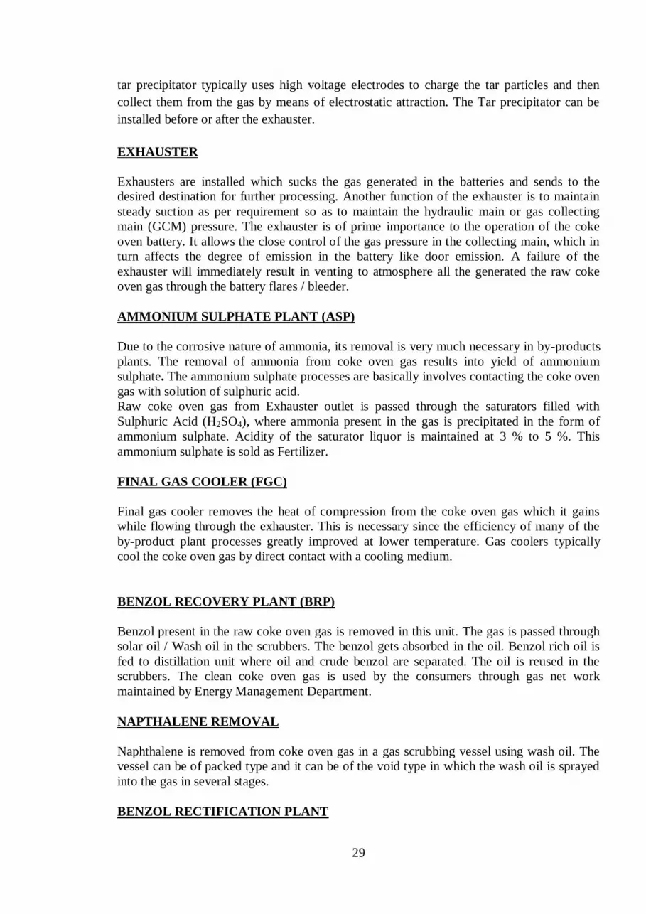
29
tar precipitator typically uses high voltage electrodes to charge the tar particles and then
collect them from the gas by means of electrostatic attraction. The Tar precipitator can be
installed before or after the exhauster.
EXHAUSTER
Exhausters are installed which sucks the gas generated in the batteries and sends to the
desired destination for further processing. Another function of the exhauster is to maintain
steady suction as per requirement so as to maintain the hydraulic main or gas collecting
main (GCM) pressure. The exhauster is of prime importance to the operation of the coke
oven battery. It allows the close control of the gas pressure in the collecting main, which in
turn affects the degree of emission in the battery like door emission. A failure of the
exhauster will immediately result in venting to atmosphere all the generated the raw coke
oven gas through the battery flares / bleeder.
AMMONIUM SULPHATE PLANT (ASP)
Due to the corrosive nature of ammonia, its removal is very much necessary in by-products
plants. The removal of ammonia from coke oven gas results into yield of ammonium
sulphate. The ammonium sulphate processes are basically involves contacting the coke oven
gas with solution of sulphuric acid.
Raw coke oven gas from Exhauster outlet is passed through the saturators filled with
Sulphuric Acid (H2SO4), where ammonia present in the gas is precipitated in the form of
ammonium sulphate. Acidity of the saturator liquor is maintained at 3 % to 5 %. This
ammonium sulphate is sold as Fertilizer.
FINAL GAS COOLER (FGC)
Final gas cooler removes the heat of compression from the coke oven gas which it gains
while flowing through the exhauster. This is necessary since the efficiency of many of the
by-product plant processes greatly improved at lower temperature. Gas coolers typically
cool the coke oven gas by direct contact with a cooling medium.
BENZOL RECOVERY PLANT (BRP)
Benzol present in the raw coke oven gas is removed in this unit. The gas is passed through
solar oil / Wash oil in the scrubbers. The benzol gets absorbed in the oil. Benzol rich oil is
fed to distillation unit where oil and crude benzol are separated. The oil is reused in the
scrubbers. The clean coke oven gas is used by the consumers through gas net work
maintained by Energy Management Department.
NAPTHALENE REMOVAL
Naphthalene is removed from coke oven gas in a gas scrubbing vessel using wash oil. The
vessel can be of packed type and it can be of the void type in which the wash oil is sprayed
into the gas in several stages.
BENZOL RECTIFICATION PLANT

30
Light crude benzol from benzol recovery plant is further processed in this unit and
following by products are recovered:
a. Benzene
b. Toluene
c. Xylene
d. Carbon di-Sulphide (CS2)
TAR DISTILLATION PLANT (TDP)
Tar recovered from GCPH is further processed in TDP. The main products of TDP are:
(a) Tar
(b) Pitch
(c) Pitch Creosote Mixture ( PCM )
(d) Naphthalene
(e) Anthracene oil
ACID PLANT
Sulphuric acid is produced in acid plant by DCDA (Double Conversion Double Absorption)
process. In this process sulphur is converted to Sulphur tri oxide (SO3) in presence of
catalyst Vanadium pentoxide (V2O5) and then to Sulphuric acid. This acid is used in
Ammonium Sulphate plant for removal of ammonia from raw coke oven gas.
PETP / BOD PLANT
In Phenolic Effluent Treatment Plant (PETP) or Biological Oxygen Demand (BOD) Plant,
the contaminated water generated from whole of coke oven is treated to make it clean from
the effluents with the help of Bacteria. The treated water is then used for quenching hot
coke in the quenching towers.
The norms for different effluent after treatment at BOD plant are:
Ammonia : 50 ppm
Phenol : 1 ppm
Cyanide : 0.2 ppm
Tar & Oil : 10 ppm
Coke Oven Gas (CO Gas):
The most important byproduct of Coke oven is the raw Coke oven gas. The basic
constituents of clean coke oven gas are:
Hydrogen - 50 to 60%
Methane - 25 to 28%
Carbon Monoxide - 6 to 8%
Carbon Dioxide - 3 to 4%
Other Hydrocarbons - 2 to 2.5%
Nitrogen - 2 to 7%
Oxygen - 0.2 to 0.4%
Calorific value - 4300 kcal / m3
31
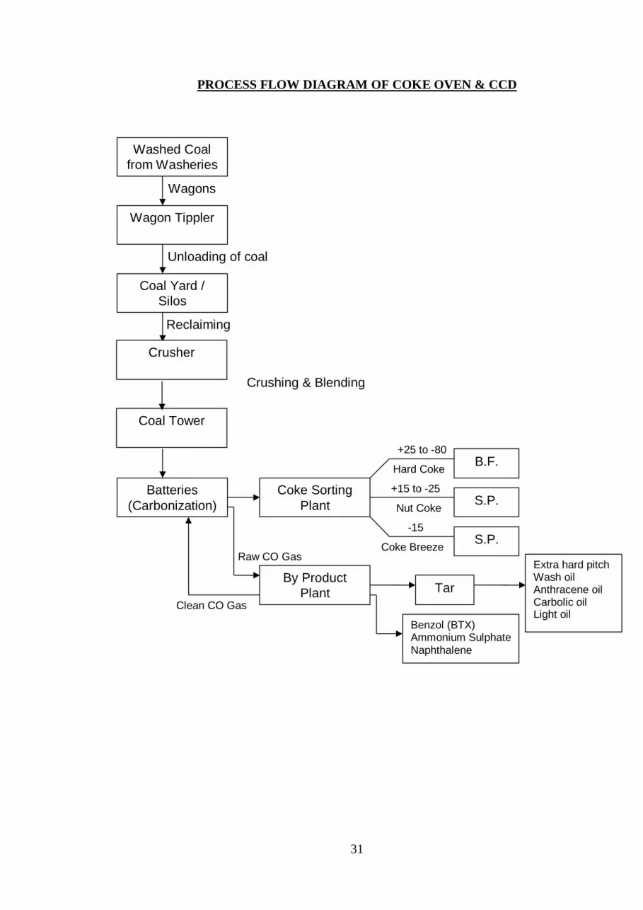
PROCESS FLOW DIAGRAM OF COKE OVEN & CCD
Washed Coal
from Washeries
Wagon Tippler
Coal Yard /
Silos
Wagons
Unloading of coal
Reclaiming
Batteries
(Carbonization)
Coke Sorting
Plant
By Product
Plant
S.P.
S.P.
B.F.
Raw CO Gas
+25 to -80
Hard Coke
+15 to -25
-15
Nut Coke
Coke Breeze
Tar
Benzol (BTX) Ammonium Sulphate Naphthalene
Clean CO Gas
Crusher
Coal Tower
Crushing & Blending
Extra hard pitch Wash oil Anthracene oil Carbolic oil Light oil

32
2.9 Pollution Control Norms
To protect the environment, Central Pollution Control Board (CPCB) has laid down strict
pollution control norms. The different norms for coke ovens with respect to PLD
(Percentage Leaking Doors), PLO (Percentage Leaking Off take), PLL (Percentage Leaking
Lids) and Stack Emission are as follows:
FACTORS NEW BATTERY EXISTING BATTERY
PLD 5 10
PLL 1 1
PLO 4 4
SO2 800 mg/Nm3 800 mg/Nm
3
Stack Emission 50 mg/Nm3 50 mg/Nm
3
Charging Emission 16 sec/charge 50 sec/charge
ISO 14001: 2004 is an environment management system which deals with the ways and
means to make the environment pollution free. Its main thrust is to make Land, Air & Water
free of pollutants.
2.10 Safety
Safety is the single most important aspect in the steel industry. This aspect covers both
personal as well as equipment safety. The use of PPE s (Personal Protective Equipment) is a
must for the employees in the shop floor. The use of PPEs like safety helmet, safety shoes,
hand gloves, gas masks, heat resistant jackets, goggles and dust masks are to be used
religiously while working in different areas of coke ovens.
Different laid down procedures like EL 20 / permit to work, as followed in different steel
plants, are to be strictly followed before taking any shut-down of equipment for
maintenance.
The stipulated SOPs (Standard Operating Procedure) and SMPs (Standard Maintenance
Procedure) should be adhered to strictly.
Persons should be cautious about the gas prone areas and should know about the gas
hazards. EMD clearance is a must before taking up any job in gas lines or gas prone areas.
A life lost due to any unsafe act is an irreparable loss to the company as well as to the
family which can not be compensated.
5-S SYSTEM (WORK PLACE MANAGEMENT):
5 S system is an integrated concept originated by the Japanese for proper work place
management. Takasi Osada, the author of this concept says 5 s activities are an important
aspect of team work applicable to all places.

33
1 S : s e i r i – It is the process of distinguishing, sorting & segregation between wanted
& unwanted items in a work place & removal of the unwanted.
2 S : s e i t o n – It is the process of systematic arrangement of all items in a suitable place.
3 S : s e i s o – It is the process of proper house keeping of the work place including
cleaning of all equipments.
4 S : s e i k e s t u – It is the process of standardization
5 S : s h i t s u k e – Literal meaning of shitsuke is discipline. It is the process of following the
system meticulously.
2.11 OHSAS - 18001 (Occupational Health and Safety Assessment Series)
OHSAS provides a formalized structure for ensuring that hazards are identified, their impact
on staff assessed and appropriate controls put in place to minimize the effect. It further
assists a company in being legally compliant, ensuring appropriate communication and
consultation with staff, ensuring staff competency and having arrangements in place to deal
with foreseeable emergencies. It is not concerned with the safety of the product or its end
user.
It is compatible with the established ISO 9001(Quality) and ISO 14001 (Environmental)
management system standards. This helps to facilitate the integration of the quality,
environmental and occupational health and safety management systems within the
organization.
Impacts of fully implemented OHSAS are:
(a) Risks and losses will be reduced and/or eliminated
(b) Reduced accidents, incidents and costs
(c) Reliable operations
(d) Compliance to rules, legislation, company standards and practices
(e) A systematic and efficient approach to health and safety at work
(f) Positive company image and reputation
---

34
Chapter – 3
SINTER PLANT
3.1 Introduction
Sinter plants agglomerate iron ore fines with other fine materials at high temperature, such
that constituent materials fuse together to make a single porous mass.
A large quantity of iron ore fines is generated in the mines which cannot be charged directly
into the Blast furnace. Moreover many metallurgical wastes are generated in the steel
industry itself, disposal of which is very difficult. In order to consume this otherwise waste
fine material, they are mixed with Iron ore fines and agglomerated into lumps by a process
known as SINTERING.
Sintering is the process for agglomeration of fine mineral particles into a Porous and lumpy
mass by incipient fusion caused by heat produced by combustion of solid fuel within the mass
itself.
Raw materials used in Sinter Plant
1. Iron ore fines 4. Coke breeze fines 7.Millscale+fines
2. Lime stone fines 5. B.O.F. Sludge 8.B.O.F.Slag /L D Slag
3. Dolomite fines 6. Burnt Lime 9.BF Return fines+ Sinter
R/fines
3.2 Raw material proportioning
The scheme for preparation of charge first envisages blending of raw materials in raw
materials yard to obtain consistency in the chemical composition and size fraction of raw
materials. After this raw materials are received in raw material receiving bins. Preliminary
proportion is done at the receiving bins and then the raw materials are transported to stock
bins where final and accurate proportioning is done. Normally constituents proportioned are
Iron ore fines, Flue dust , ,Mill scale, Lime stone fines, Dolomite fines, LD dust and Return
sinter (as Re-circulating load). It can be seen that sinter plant can make adequate use of
almost all the valuable metallurgical wastes arising in an integrated steel plant thus paving
the way for valuable conservation of minerals and techno-economic benefits..
An accurate proportioning is envisaged to be done at the stock bins. Here the constituents
proportioned may consists of :-
Ore fines comprising mixture of ore fines and mill scales.
Flux consisting of mixture of lime stone and dolomite in desired ratio to obtain
optimum MgO and CaO contents in the sinter.
Crushed Coke fines
Return sinter as re-circulating load (BF sinter return & in plant sinter)

35
Following Approximate charge proportion will be required to make one ton of sinter
(Wet basis):-
Ore fines : 750-800 kg Coke: 65- 80 kg Mill scale + fines: 16Kg
Lime stone : 86 -110kg B.O.F. Sludge: 02kg B.O.F. Slag : 20Kg
Dolomite : 80-100 kg Burnt Lime: 04 to 40 kg
Sinter return : 25 to 32 % (BF sinter return + In plant sinter return)
Note- All above mentioned data varies in different plants under SAIL unit.
3.3 Sintering process
Preparation of charge mix
Preparation of charge mix mainly consists of crushing of fluxes, solid fuels, proper sizing of
them and mixing with iron Ore fines in a certain ratio to prepare base mix. Experience of
operation of sinter plants has demonstrated that the fluxes mainly lime stone & dolomite
fines should be crushed to obtain 90% minimum(-3mm fraction).Such finely crushed fluxes
result in the formation of strong sinter due to absence of free lime.
As in the case of fluxes, careful preparation of coke breeze to the extent of 85% minimum (-
3mm fraction) is an essential pre-requisite for producing high quality sinter. Normally for
crushing of coke breeze, Roll crushers /rod mills are used which ensures better and
consistent crushing and also preferred due to easy maintenance.
Finally these finely crushed coke and fluxes are mixed with ore fines(called as a BASE
MIX) in required proportion in balling/ nodulising drum where atomized water is added
.The purpose of balling/nodulising drum are homogenizing of base mix and formation of

36
balls. This base mix (now called green mix) is then loaded on moving sinter machine pallets
through belt conveyors and segregation plates. The purpose of segregation plate is to
segregate the base mix such that coarser particles falls in the bottom of sinter machine,
medium particles in middle portion and smaller particles at the top by rolling effect.
Before loading base mix on sinter machine, a layer of return sinter(namely hearth layer) is
loaded on pallets forming the bottom most portion of the charge just above the pallet grates.
This hearth layers helps in preventing burning of grate bars apart from getting optimum
under grate suction.
Sinter making
Sintering of fines by the under grate suction method consists of the mixing of fines with
finely crushed coke as fuel and loading the mixture on the pallet grates. Ignition of the fuel
proceeds on the surface of charge by a special ignition arrangement, called ignition furnace
(where gaseous fuel is burnt to produce high temperature to ignite the fuel in sinter mix)
The gases used in ignition furnace are mainly coke oven gas and mixed gas. Mixed gas is
combination of coke oven gas and blast furnace gas. Further the combustion is continued
due to suction of air through the layers of the charge by means of Exhausters. Due to this,
the process of combustion of fuel gradually moves downwards up to the grates.
From the scheme obtained in a few minutes after ignition, it is observed that the sintering
process can be divided into six distinct zones:
1. Zone of Cold Sinter (60 to 100 0C )
2. Zone of hot Sinter (100 to 1000 0C)
3. Zone of intensive combustion of fuel (1000 to 1350 0C)
4. Heating zone (1000 to 700 0C)
5. Zone of Pre-heating of charge (700 to 60 0C)
6. Zone of Re-condensation of moisture (60 to 30 0C)
In all the zones except the zone of combustion, the reactions taking place are purely thermal
where as in the zone of combustion reactions are thermal and chemical. The maximum
temperature attained in the zone of combustion will be 1300-1350 0C. The vertical speed of
movement of the zones depends on the vertical speed of sintering.
Heat from the zone of ready sinter is intensively transmitted to the sucked air. In the zone of
combustion of fuel hot air and preheated charge comes into contact with each other which
with the burning fuel will result in the formation of high temperature. Maximum
temperature will be developed in this zone and all the physical-chemical process takes place
resulting in the formation of Sinter. In the zone of pre-heating the charge is intensively
heated up due to transfer of heat from the sucked product of combustion. In the zone of re-
condensation of moisture, the exhaust gases during cooling transfer excess moisture to the

37
charge. Temperature of this zone sharply decreases and will not increase till all the moisture
is driven off.
As the fuel in the zone of combustion is burnt away, Sinter, the height of which increases
towards the grates, is formed above this zone from the red hot semi-fluid mass, forcing out
subsequent zones. Disappearance of the zone of combustion means the end of sintering
process.
The sinter cake is then crushed, screened, cooled and dispatched to Blast furnace. The ideal
size of sinter required in blast furnace is in between 5mm to 40mm. The other sizes are
screened & returned back to sinter bin(Called inplant returnfines).
Thermal change in the sinter bed during sintering
Typical change in the sinter bed during sintering is taking place as :
Wet zone is the bottom of the sinter bed and sintered zone is the surface of sintering bed.
Between surface and bottom, temperature distribution during sintering is indicated. From
this temperature changes, reaction zone can be divided as shown in following table.
Zones

38
Classification of reaction zone of sintering bed:
Wet zone and drying zone
Vaporization in the wet zone is only 10% of the moisture. In the drying zone, there is a
rapid vaporization due to the hot gas from the pre-heating zone. After passing drying zone,
hot gas loses its sensible heat due to the vaporization of moisture. Gas temperature in the
wet zone is maintained because when the temperature in wet zone is increased, as the
equilibrium temperature, the vaporized temperature is increase and the heat loss per unit
time is increased and vaporize temperature is decrease. The temperature of the wet zone is
about 60 degree Celsius and this temperature has no relation between gas volume and
temperature. Only drying zone is affected. The thickness of the drying zone is changed by
the supply of heat and maximum thickness of this drying zone is only 5 mm.
Preheating zone
In this zone, coke breeze temperature will be increased to igniting temperature by hot gas
coming from combustion zone. Ignition temperature of coke breeze is about 600 degree
Celsius. Thickness of this preheating zone is also few millimeter. Instead of limestone, there
is a case of slaked lime or burnt lime. In this case, pores of raw mix is increased and this
characteristic is not changed during drying.
Combustion zone
Reaction
Zone
Temperature
Remark
1&2 Wet zone Constant Temp. (Increase 2-3 degree C Wet sinter raw mix
3 Drying zone Increase 100 degree C Charging material is dried.
4 Preheating zone Increase temp. due to coke combustion
5 Combustion zone Combustion of coke, rapid temp.
Increase, reduction of Fe3O4
No bonding, coke comb.
and partial reduction
6 Oxidation zone-A Increase oxidation temp. of Fe3O4 Soft bonded sinter
7 Equilibrium zone Constant equilibrium temp. of Fe3O4 and
Fe2O3
8 Oxidation zone-B Oxidation of Fe2O3 Hardened sinter
9 Cooling zone Decrease temp. Hardened sinter
10 Sintered zone Constant temp. Cooled sinter with small
cracks.

39
In this zone, coke is ignited and heat is produced same as other combustible elements such
as sulphur and graphite. This zone has a reduction atmosphere and reduction of Fe2O3 occur.
The thickness of this zone changes due to volume of coke and the suction air volume. In this
zone, raw mix is heated at certain temperature by the combustion heat of coke and suction
air and also supply the heat to the bottom area.
Oxidizing zone-A
After combustion of fuel, atmosphere become oxidizing and forms oxidizing zone and
Fe3O4 becomes Fe2O3 with 100 kcal/kg oxidation heat. Due to continuous oxidation,
temperature is increased and oxidization is reduced. The thickness of this zone is decided by
fuel quantity and suction air volume.
Equilibrium zone
The factor to occur the equilibrium zone, combustion zone speed should be faster than
cooling zone speed. In this zone, Fe2O3 and Fe3O4 equilibrium occur and oxidation of
Fe3O4 is not occur.
Oxidizing zone-B
When cooling of sinter is started by excess suction air, oxidizing of Fe3O4 to Fe2O3 started.
Some oxidizing heat occurs due to oxidation of Fe3O4 to Fe2O3 . Cooling of sintered ore
become slow.
Cooling zone
After combustion of coke, cooling zone occur.
Sinter zone
After cooling, temperature of sinter decrease and become same temperature with suction air.

40
Heat from the zone of ready sinter is intensively transmitted to the sucked air. In the zone of
combustion of fuel hot air and preheated charge comes into contact with each other which
with the burning fuel will result in the formation of high temperature. Maximum
temperature will be developed in this zone and all the physical-chemical process takes place
resulting in the formation of Sinter. In the zone of pre-heating the charge is intensively
heated up due to transfer of heat from the sucked product of combustion. In the zone of re-
condensation of moisture, the exhaust gases during cooling transfer excess moisture to the
charge. Temperature of this zone sharply decreases and will not increase till all the moisture
is driven off.
As the fuel in the zone of combustion is burnt away, Sinter, the height of which increases
towards the grates, is formed above this zone from the red hot semi-fluid mass, forcing out
subsequent zones. Disappearance of the zone of combustion means the end of sintering
process.
The sinter cake is then crushed, screened, cooled and dispatched to Blast furnace. The ideal
size of sinter required in blast furnace is in between 5mm to 40mm. The -5mm sizes are
screened & returned back to sinter bin.(-5mm size sinter called as in plant return)
Chemical reactions in sintering process:
Sinter is produced as a combined result of locally limited melting ,grain boundary diffusion
and re-crystallisation of iron oxide during sintering.The basic metallurgical reaction takes
place in sintering zone.
1. C+O2---CO2 + 4220calories
2. CO2 + C --- 2CO + 53140 calories
3. 3Fe2O3+ CO ---- 2Fe3O4 + CO2 + 8870
calories
Fe3O4 + CO ---- 3FeO + CO2 - 4990
calories

41
Factors affecting sintering process
Quality of Input raw materials
Quality of Iron ore fines :
: +10 mm should be nil
: -1mm should be 30% maximum
: Alumina(Al2O3) 2.5% maximum
: Silica (Si2O3) 2.5% maximum
Increase in +10mm fraction will result in weak sinter & low productivity
Increase in –1mm fraction will decrease bed permeability resulting in low
productivity
Increase in % of Alumina increases RDI(Reduction Degradation Index) resulting in
generation of –5mm fraction & also resulting in chute jamming.(Due to high Alumina
in B/Mix. With increase of SiO2 level in Iron ore fines ,glassy phase in sinter increases
and causes brittleness in sinter.
Quality of Flux
: -3mm fraction should be 90% minimum(Crushing index)
: less crushing index results in free lime, causing weak sinter
Quality of Coke
: -3mm fraction should be 85 % minimum(Crushing index of coke)
: +5mm fraction should be nil
: Increase in 5mm fraction decreases the productivity and causes sticker
formation in sinter machine.
: Increase in less than 0.5 mm particle size in coke causes increase in coke
consumption during sintering
Moisture :
Moisture in the form of water is added in the base mix in balling/nodulising drums.
Water acts as binder of base mix. Addition of water in base mix plays an important
role in sinter bed permeability. Ideally 7 to 8% of total base mix of water is used.
Higher % of water results in low permeability & less sintering speed. Less % of water
results in less balling, hence less permeability, resulting in low productivity.
Ignition furnace temperature:
Ignition of sinter mix is carried out through ignition hearth where a temperature of
1150 to 1350 degree Celsius is maintained by burning gaseous fuel by the help

42
optimum air/gas ratio.32.5% of CO gas & 67.5% of BF gas is used to maintain calorific
value 2100kcal/m3. Higher hearth temperature results in fusing of sinter at top layer.
This reduces the bed permeability, hence low productivity. Low heat temperature
results in improper ignition. sintering process will not be completed, hence –5mm
fraction will increase, i.e re-circulating load will increase.
Note- BF&CO gas mixing ratio and calorific value varies in different plant under SAIL
unit.
Coke rate :
Coke acts as a solid fuel in base mix in the sintering process. It is normally 6% of total
charge. Higher coke rate will fuse the top layer, thereby decreases the bed permeability.
Sticker formation will increase. Low coke rate will result in incomplete sintering.
Machine speed :
Speed of sinter machine can be varied as per the condition of sintering process. BTP
(Burn through Point) temperature decides the completion of sintering process. It is
observed normally in second last wind box from discharge end side of sinter machine
where the temperature reaches up to 400 degree Celsius (approximately). Higher
machine speed, lower BTP causes more–5mm generation, hence lower productivity.
Lower m/c speed, higher BTP temperature causes low productivity
Note: BTP : Exhaust gas temperature which indicates the completion of sintering
process is called BTP. It is approximately around 400 degree centigrade.
Crushing, Cooling & Screening of sinter
The finished sinter cake is then crushed to the size of 100mm approximately by using
crushers. Normalising of finished crushed sinter is then done on coolers by means of air
blowers (forced draught fans); so that coolers discharge end temperature is about 80
degree centigrade. For effective cooling, bigger size of sinter should be on bottom
portion & smaller size should be on top.
Finally various fractions of sinter are screened out.-5mm fraction of sinter returns back
to bunkers. 10 to 20 mm fraction is also screened out to be used as hearth layer. Rest
sizes goes to blast furnace, after screening +10mm fraction should be 65%minimum
and –5mm fraction should be 6% maximum as per requirement of blast furnace

43
3.4 Quality Parameters of Sinter (Subject to Requirement of BF) Plant
Chemical composition Physical composition
1. FeO % 8.0 to 11.0 Sinter size 5mm to
40mm
2. MgO % 2.6 to 3.0 Mean size 18mm to
21mm
3. Available
lime
(CaO- SiO2)
%
3.4 to 6 DTI 70% MIN
4.
As per BF
Requirement
RDI 30% MAX
5. SiO2 % 4.8 to 5.2 + 10 mm 65 % min.
6. Al2O3 % 3.0 +40 mm 9 % max.
7. Basicity. 1.6 to 1.9 - 5 mm 6 % max.
Note- Quality parameters of sinter vary in different plants under SAIL unit.
Quality parameter definitions:
Tumbler index (DTI): The cold strength of sinter is determined by the tumbler test ,and
depends on the strength of each individual ore component, the strength of the bonding
matrix components and the ore composition. This test determines the size reduction due to
impact and abrasion of the sinters during their handling, transportation, and in the blast
furnace process. Studies of the fracture strength of several mineral phases have allowed the
following order to be established: primary (or residual) hematite > secondary hematite >
magnetite > ferrites. Cold mechanical strength is directly related with the tendency for fines
to form during transportation and handling between the sinter machine and the blast furnace
throat.
Reduction Degradation Index(RDI)
Sinter degradation during reduction at low temperature is more usually determined by the
RDI static test ,which is carried out at 550 °C. Low values are desirable for this index. The
RDI is a very important parameter that is used as a reference in all sintering work and serves
to predict the sinter's degradation behavior in the lower part of the blast furnace stack.
Advantages of using Sinter
1 Agglomeration of fines into hard, strong and irregular porous lumps, gives
better bed permeability.
2 Utilizes the solid wastes of steel industry

44
3 To utilize the coke breeze generated in coke screening as fuel otherwise has no
metallurgical use
4 As the calcination of flux takes place in sinter strand, super-fluxing saves much
more coke in the furnace.
5 Increase of sinter percentage in Blast Furnace burden, increases the
permeability, hence reduction and heating rate of burden increases, so the productivity
also increases. Coke rate is also reduced in Blast furnace.
6 Minimal fraction of total mass of impurities, Viz. sulphur, phosphorous, zinc,
alkali is reduced.
7 Improved quality of hot metal.
8 The softening temp. of sinter is higher and melting zone is narrow. This
increases the volume of granular zone and shrinks the width of cohesive zone
consequently, the driving rate of BF become better.
3.5 Process Flow Diagram of Sinter Plant
SINTERING
CRUSHING & SCREENING
COOLING
SCREENING
EXHAUSTERS
BLOWERS
RAW MATL.STORAGE BINS MIXING & PELLETIZING
CRUSHERS
TO BLAST FURNACE

45
Some critical terms/parameters used/monitored in sinter plant
Coke crushing
index
Percentage presence of –3mm fraction of coke in any
sample is termed as coke crushing index. For better
sintering process coke crushing index should be more
than 85%
Flux crushing
index
Percentage presence of –3mm fraction of flux in any
sample is termed as Flux crushing index.For better
sintering process Flux crushing index should be more
than 90%
Burn through
point
(BTP)
Burn through point temperature indicates the
completion of sintering process. It is normally around
400 degree Celsius and is normally found in second last
of wind box from discharge end of sinter machine.
Sintering Plant Layout for Reference :

46
3.6 Main Areas & Equipments
Main Areas Equipments Functions
Sinter making &
Cooling bldg.
Balling drums
Sinter pallets
Screens
Crushers
Coolers
To mix & pelletize
Sintering takes on it
Screens out diff.
sizes
Crushes sinter cake
Cools/ Normalise
sinter
Exhausters High capacity fans
Battery cyclones
ESP
To suck air below
grates
To clean Exhaust air
To clean Exhaust air
Proportioning Bins
Electronic feeders
Conveyors
Bunkers
For adjusting feeding
Transport charge mix.
Store raw materials
Coke & Flux
Crushers
Roll crushers
Rod Mills
Hammer crushers
Grab cranes
For crushing coke
For crushing coke
For crushing Fluxes
For lifting coke
Techno Economics
1. Specific productivity : Sinter produced per square meter per hour
2. Specific heat consumption : Gas consumed per ton of sinter
3. Specific power consumption : Power consumed per ton of sinter
4. Specific coke consumption : Coke consumed per ton of sinter
5. Specific flux consumption : Flux consumed per ton of sinter
In order to produce sinter at less cost, specific productivity of sinter should be as high
as possible & all other four parameters should be as low as possible keeping quality
parameters under consideration.
Advantages of Sintering
1. Better use of the huge quantity of iron ore fines generated at mines.
2. Gainful use of various metallurgical wastes like flue dust, mill scale, lime dust,
sludge, etc.
3. Use of super fluxed sinter eliminates raw flux from the blast furnace burden. This
leads to considerable coke saving and productivity improvement in blast furnaces.
4. Due to the higher reducibility of super fluxed sinter, direct reduction of iron oxide is
enhanced, which contributes to further coke saving.

47
5. The softening temperature of sinter is higher and the softening melting zone is
narrower. This increases the volume of granular zone and shrinks the width of the
cohesive zone. Consequently, the driving rate of the blast furnace improves.
6. Hot metal quality (from the SMS point of view) improves due to lower silicon
content and higher hot metal temperature. A higher hot metal temperature contributes to
better sulphur removal from the hot metal.
7. Material handling in the charging section of the blast furnace is reduced, and fewer
logistics are needed.
8. Blast furnace operation is more reliable and efficient.
3.7 Safety Hazards at Sinter Plant
1. Dust pollution
As lots of finer particles are used in sintering, there is a Lot of dust pollution. Efficient
running of ventilation is a Must. Use of dust mask is essential. Chimney Stack
Emission should be below 30 mg/nm3.Fugitive Emission (ambient) is 2mg/nm
3.
2. Gas safety
Gases (usually mixed gas & Coke oven gas) are used for igniting charge mix, it is very
important to follow all the protocols for gas safety. Use of gas mask and Carbon mono
oxide(CO) gas monitor while working on gas line is must.
3. Noise pollution
Tremendous amount of air is sucked through exhauster fans. Slight leakages any where
in exhauster results in high level of noise.Air compressor , chiiler unit,hammer crusher,
coke crusher are also high noise generating areas in Sinter plant.Use of Ear plug is
essential.
OHSAS - 18001 (Occupational Health and Safety Assessment Series)
OHSAS provides a formalized structure for ensuring that hazards are identified, their
impact on staff assessed and appropriate controls put in place to minimize the effect. It
further assists a company in being legally compliant, ensuring appropriate
communication and consultation with staff, ensuring staff competency and having
arrangements in place to deal with foreseeable emergencies. It is not concerned with the
safety of the product or its end user.
It is compatible with the established ISO 9001(Quality) and ISO 14001
(Environmental) management system standards. This helps to facilitate the integration
of the quality, environmental and occupational health and safety management systems
within the organization
Impacts of fully implemented OHSAS are:

48
(a) Risks and losses will be reduced and/or eliminated
(b) Reduced accidents, incidents and costs
(c) Reliable operations
(d) Compliance to rules, legislation, company standards and practices
(e) A systematic and efficient approach to health and safety at work
(f) Positive company image and reputation.
5-S SYSTEM (WORK PLACE MANAGEMENT):
5 S system is an integrated concept originated by the Japanese for proper work place
management. Takashi Osada, the author of this concept says 5 S activities are an
important aspect of team work applicable to all places.
1 S : S e i r i – It is the process of distinguishing, sorting & segregation between
wanted & unwanted items in a work place & removal of the unwanted.
2 S : S e i t o n – It is the process of systematic arrangement of all items in a suitable
place.
3 S : S e i s o – It is the process of proper house keeping of the work place including
cleaning of all equipments.
4 S : S e i k e s t u – It is the process of standardization
5 S : S h i t s u k e – Literal meaning of shitsuke is discipline. It is the process of
following the system meticulously.
---

49
Chapter – 4
BLAST FURNACES
4.1 Introduction
BF is a counter current heat and mass exchanger, in which solid raw materials are charged
from the top of the furnace and hot blast, is sent through the bottom via tuyeres. The heat is
transferred from the gas to the burden and oxygen from the burden to the gas. Gas ascends
up the furnace while burden and coke descend down through the furnace. The counter
current nature of the reactions makes the overall process an extremely efficient one in
reducing atmosphere. The real growth of blast furnace technology came with the production
of high strength coke which enabled the construction of large size blast furnaces.
4.2 Raw materials and their quality
In India steel is being produced largely through the blast furnace. Iron ore, sinter and coke
are the major raw materials for blast furnace smelting.
Raw materials:
The following raw materials usedfor the production of pig iron: -
(i) Iron ore
(ii) Limestone / L D Slag
(iii) Dolomite
(iv) Quartzite
(v) Manganese ore
(vi) Sinter
(vii) Coke
(viii) Pellets
(ix) Scrap (Steel / Iron)
(x) Coal Dust / Coal Tar
Iron ore: Iron bearing materials; provides iron to the hot metal. Iron ores is available in the
form of oxides, sulphides, and carbonate, the oxide form known as hematite (red in colour)
is mostly used in SAIL plants. It is the principal mineral in blast furnace for extraction of
pig iron, generally rich in iron content varying from 62 % to 66 % associated often with
naturally occurring fines (-10 MM) to the extent of 20 %. Although relatively free from
impurities like phosphorous, sulphur and copper, they have high aluminaand silica contentas
gangue. The high alumina content makes the slag highly viscous and creates problems for
stable furnace operation.
Limestone / LD Slag: Acts as flux. Helps in reducing the melting point of gangue present
in the iron bearing material and combines effectively with acidic impurities to form slag in
iron making. LD slag is a substitute for limestone which is easily available in a steel plant.
Its usage helps in waste utilization and thus reduces production cost.

50
Quartzite: It acts as an additive.Quartzite is a mineral of SiO2 (silica) and under normal
circumstances contains about 96 – 97 % of SiO2 rest being impurities. Quartzite plays its
role in counteracting the bad effects of high alumina in slag through maintaining optimum
slag basicity.
Manganese ore: It acts as additive for the supply of Manganese in the hot metal.
Manganese ore is available in the form of combined oxides of Mn and Fe and usual content
of Mn is about 28 – 32 % for steel plant use, However Manganese ore available with SAIL
is having high alkali contents so it should be used judicially.
Coke: Itacts as a reductant and fuel, supports the burden and helps in maintaining
permeable bed. Coke (metallurgical) used in blast furnace both as fuel & reducing agent.
The Indian coal is characterized by high ash (25 – 30 %) and still worse, a wide fluctuation
in ash content, poor coke strength leading to excessive generation of fines, rapid fluctuation
in moisture content etc. The problem of poor quality coke has been tackled by adding
imported coal (75-95%) in the indigenous coal blend to get a coke ash of 13 – 16 %.
Sinter: It is iron bearing material. Fines that are generated in the plant/mines are effectively
utilized by converting them to sinter. It provides the extra lime required for the iron ore and
coke ash that is charged in the blast furnace. Sintering is the process of agglomeration of
fines (steel plant waste and iron ore fines) by incipient fusion caused by heat available from
the coke contained in the charge. The lumpy porous mass thus obtained is known as
“sinter”.
Scrap (Steel / Iron): Scrap is generrated in the process of product making in a steel plant
which is gainfully utilized by back charging in the Blast Furnaces. It increases the furnaces
productivity and reduces the production cost.
Pellets: It is also an iron bearing materials. The micro-fines which cannot be used for sinter
making can be used for pellet manufacturing and the pellets formed will be charged in the
BF.
Coal dust Injection: It acts as an auxiliary fuel, reduces coke consumption in the blast
furnaces. The coal is injected through the tuyeres.

51
Different sources of raw materials
Sl.
No.
Raw
material
BSP RSP DSP ISP BSL
1. Iron ore Dalli
Rajhara
Raoghat
Meghahatubur
u
Kiriburu
Barsua
Kalta
Meghahatuburu
Kiriburu
Bolani
GuaMeghaha
tuburu
Gua
Bolani
Meghahatubu
ru
Kiriburu
Meghahatubur
u
Bolani
Barsua
Gua
Manoharpur
2. Limestone Nandini
Kuteswar
Jaisalmer
Imported
Kuteswar
Jaisalmer
Imported
Kuteswar
Jaisalmer
Imported
Jaisalmer
Imported
Nandini
Kuteswar
Jaisalmer
Imported
3. 3
Dolomite
Hirri
Imported
Baraduar Belha
Baraduar
Imported
Belha
Baraduar
Imported
Birmitrapur
Belha
Imported

52
Quality of raw materials
Material Chemical Analysis Specification Size Other properties
Iron
Ore(Lumps)
Fe 61.0% min.
10 – 40
mm
Softening Melting
range:
SiO2 2.5 ± 0.5 % 1100 - 1400˚C
P 0.10% max.
Al2O3/SiO2 0.70 max.
Sinter
Fe 50-58%
5 – 40
mm
RDI(Reduction
Degradation Index)
<30
FeO 7-10% RI(Reducibility Index)
>65
SiO2 4-6% Tumbler Index >70
Al2O3 2-3% Softening Melting
range:
CaO 9 – 13% 1200 – 1450oC
MgO 2 – 3%
Coke
Ash 13 – 15%
25 – 80
mm
CRI(Coke Reactivity
Index): 21 -23
VM(VOLATILE
MATTER) < 1 %
CSR(Coke Strength
after Reduction) > 64
Moisture 5 ± 0.5% M40 >80%
S 0.5 - 0.6% M10 <6%
FIXED C 82- 85%
Limestone
CaO 38 % min. 10 – 40
mm
SiO2 6.5 ± 1%
MgO 8.5 ± 0.5%
LD slag
CaO 40.8 ± 1% 10 – 40
mm
MgO 10.5 ± 0.5%
SiO2 15.50%
Mn ore
Mn 30% min.
25 – 50
mm
SiO2 30% max.
Al2O3 5% max.
P 0.30% max.
CDI coal
FIXED C 60-70%
80 % <90
microns
VM(VOLATILE
MATTER) 20-25%
Ash 9 – 11%
Quartzite SiO2 96% min
25-50 mm Al2O3 1.5% max

53
Charging:
High lines and Stock House
High lines: The main responsibility of high lines section is to receive the raw materials
required for the production of hot metal from various sources, storing and transporting
them to the top of the furnace in time, for the smooth running of the furnace.
Raw materials arriving to the blast furnace department from various sources are unloaded in
the RMHP (Raw Material Handling Plant). The ore yard is meant for stocking and
averaging of materials. The materials from RMHP are transported to Blast Furnace with the
help of wagon tippler, conveyors, stakers and reclaimers.
Raw materials from the ore yard are charged by suitable means into the respective bunkers.
Alternately in some plants iron ore is received in a wagon Tripler, stack in to piles, and
reclaimed using reclaimers.
Sinter from bunker located on the extension tracks of high line is collected in transfer cars
moving on rail tracks or sinter comes by means of conveyor belt and is stored in a receiving
hopper.
Sinter is screened in stock house, and the fines are returned through conveyor belts.
Coke (25 – 80 mm) from coke sorting plant (CSP) is supplied to the coke bunkers of the
blast furnace with the help of conveyor belts and the undersize are returned through
conveyor belts.
Stock house: The bunkers are provided with a vibrofeeder, which feeds the material to the
conveyor belt/screen. The BF size material is fed to a weighing hopper through ore
discharge conveyor. The weighing hopper discharges the material into the skip. There are
conveyors to remove the return fines from the system.

54
Hoist house:
For taking charged materials to the furnace top, two-way skip hoist with 2 skips are
provided. The hoist house operates the skip that is driven by two motors. Bell hoist,
equalizing valves, test rods etc. are also operated from hoist house.
Flow of material to charging skip are
Bunkers vibro feeder conveyor belts weighing hopper skip car.
Bunkers vibro feeder weighing hopper skip car.
Raw materials including coke are transported and collected into high line bunkers/Stock
house placed near the furnaces and then properly screened and weighed. Weighing is done
either by scale car or by load cell. These batched proportions of the raw materials are
conveyed to the top of the blast furnace via skip car or conveyors and are charged in the
blast furnace. The distribution is maintained in such a fashion that alternate layers of coke
and iron-containing burden (sinter and iron ore and fluxes) are formed inside the blast
furnace.
4.3 Blast Furnace and accessories
Blast furnace is basically a counter current apparatus, composed of two truncated cones
placed base to base.
The sections from top down are:
Throat, where the top burden surface is.
The shaft or stack, where the ores are heated and reduction starts.
The bosh parallel or belly, where the softening melting takes place.
The bosh, where the reduction is completed and the ores are melted down.

55
The hearth, where the hot metal and slag is collected and is cast via the tap holes.
BF complex in a nutshell

56
BF Proper
The entire furnace is lined with suitable refractory and in addition to refractory lining,
there are water coolers, designed to enhance the life of the furnaces. In a blast furnace,
fuel, Iron ore, sinter and flux (limestone) are continuously supplied through the top
of the furnace, either through 'double bell system' or 'bell less system'. In the hearth, there
is a tap hole of suitable dimension and length, for the purpose of tapping the hot metal.
Since blast furnace is basically a counter current apparatus the descending stream of raw
materials extract heat from the ascending stream of gas generated from the burning of
coke at the tuyere level. The ascending stream of gas contains CO (carbon monoxide),
nitrogen and hydrogen.Theascending reducing gas(CO and H2) comes in contact with the
iron ore thusreduction (this reduction is called indirect reduction) of iron ore takes place at
the upper part of the stack (temp less than 900 °C). Coke in the form of C also takes part
in the reduction (temp greater than 900 °C) and this reduction is called direct reduction. In
the hearth there are multiple tapholes at about 3-4 meter below tuyeresfor flushing out hot
metal and slag at regular intervals. Tapholes are also extensively water cooled. The
number of tap holes, their positioning and dimension will depend upon the capacity of the
furnace. Many modern furnaces are having 2 – 4 tap holes.
The furnaces are equipped with tuyeres (water cooled copper construction for admission
of hot blast of air) through which preheated air blast at a temperature of about 850 °C –
OUTPUTs
Raw BF Gas + Flue Dust
OUTPUTs
Hot Metal & Slag
INPUTs
Hot Blast + Steam + Oxygen
Enrichment + CDI
INPUTs
Coke + Iron Ore + Sinter + Pellet + Scrap + LD Slag /
Limestone, Quartzite

57
1200 °C is introduced for burning of coke. Before preheating, the blast of cold air supplied
by turbo blowers from power and blowing station and it is introduced into hot blast stoves
at a pressure up to 1.8 - 4.5 kg / cm2
(gauge pressure) wherein the air is pre – heated. The
air blast then passes from the bustle pipe through gooseneck and then tuyere stocks / blow
– pipes into tuyeres. The pressure of the blast and its flow rate is dependent upon the
capacity of the furnaces and permeability ofraw material.
As the stream of the charged material descends down through different temperature zones
it gives two products:-
1. Hot Metal in the liquid condition.
2. Slag, in the liquid condition having less density thusfloats at the top of metal.
Besides, we get one more important gaseous product from the top of the furnace known as
BF gas. It generally comprises of 20 – 24 % CO; 18 - 20 % CO2, 48-52 % of N2, H2 4-5
%, O2 0.1-0.3%. The temperatures of top gases are in the range of 100 – 200 oC.
After cleaning, BF gas is used in blast furnace for stove heating and other area of plant
like coke oven heating, and as a mixture with CO gas it is used in refractory materials
plant, sintering plant, steel making shop and reheating furnace of rolling mills as a fuel.
Liquid iron collected in the hearth is taken out by opening the tap hole with power
driven/Hydraulic drill and oxygen lancing(as per requirement) after regular interval into a
train of ladles kept below the runner of the cast house. Slag that comes along with the metal
is skimmed off with the help of skimmer plate towards slag runner and collected in slag
ladles or to slag granulation plant of cast house (CHSGP). Slag ladles are then sent to the
dump yard or slag granulation plant. Metal ladles are either sent to Steel Melting Shop or
Pig Casting Machine and Foundry depending upon the requirement.
Schematic Cross Section of the Blast Furnace

58
Refractory:
Blast furnace is a vertical shaft furnace, enclosed in a welded shell, lined with fire-clay
bricks of high alumina content. The hearth bottom, hearth, bosh, belly and the shaft are
cooled by means of coolers of various designs. Steel refractory lined plates protect the walls
of the furnace top. The bigger furnaces are lined with carbon blocks in the hearth and in the
periphery of the hearth bottom. High alumina or Si-Carbide refractory are used in bosh and
lower shaft. The design and operation of blast furnace results the high productivity and long
life of blast furnaces. The safe and reliable operations are secured by state–of–the–art blast
furnace cooling and lining designs
Top charging equipment:
The burden material which reaches to the top of the furnace by skip car or by charging
conveyer is to be distributed into the furnace through double bell charging system (Fig-1),
rotating charging unit (RCU) (Fig-3) or with Paul-wurth bell less top (BLT) (Fig-2,4)
charging system. In BLT charging bells are replaced with charging bins, upper material
gate, upper sealing valve, lower material gate and lower sealing valve. This system also has
a gearbox to operate the rotating chute. The latter distributes the material inside the furnace
periphery in different rings or sector charging, point charging etc. This facilitates better
burden distribution inside the furnaceas per the “Charging Cyclogram or Pattern” desired by
the furnace operator for continuous efficient operation of the furnace.
Fig-1. Double Bell Fig-2 BLT systems

59
Fig-3 Rotary Charging Unit (RCU) Fig-4 BLTCharging
Charging Sequence: to facilitate smooth working of furnaces, the coke and the non-coke
material is to be distributed in a particular fashion in the whole circumference of the blast
furnace in accordance to the Charging Cyclogram/ Pattern as determined by the furnace
operator. For those different charging sequences is followed. A typical charging sequence
is given below:
Sequence 1: COC / COOCC / CCOCC
Sequence 2: CCOO
Each charging cycle consists of 5/6 sequences of either 1 or 2 exclusively or in combination
depending on the periphery conditions. Generally in bell-less top furnaces the 2nd
sequence
is followed i.e. CCOO. C=Coke; O=Non-coke(Ferrous burden) i.e. ore, sinter, Mn ore,
Lime Stone or Quartzite etc. The material is distributed in the bf in different rings/sectors as
per requirement
Furnace Foreman Control Room (FFCR):
All the activities burden distribution; stoves, cast house, auxiliary fuel injection etc. are
controlled from FFCR located in the furnace. Level –0, Level –1 and Level-2(Modern
furnaces) automation facilities are there in all BF. All the details regarding the furnace are
monitored using HMI/SCADA and mimic panels kept in the FFCR.
Auxiliary Sections:
The auxiliary section of blast furnace consists of following sections:
1. Ladle Repair Shop(LRS)
2. Pig Casting Machine(PCM)

60
3. Cold Pig Yard (CPY)
4. Clay Mass Shop(CMS)
5. Coal Dust injection Facility(CDI)
6. Cast House Slag Granulation Plant(CHSGP)
7. Slag Dump Yard(SDY)
8. Area Repair Shop (Mech/Elec)
9. Torpedo Ladle Repair Shop(TLRS)
Ladle Repair Shop: Ladle repair shops provided for relining, repairing and cleaning of the
iron ladles. Shop contains an EOT cranes for speeding up the job.
Pig Casting Machine: These are double strand pig casting machines. Each machine
contains no. of moulds in one belt with lime coating arrangement underneath the machine.
Moulds are filled with the hot metal from the ladle at the spout, cooled by water sprays on
the bed while on movement and the pigs are
eparated from mould chain by knockout arrangement.
EQUIPMENTS of PCM
Winch to lift the loaded liquid metal ladle.
Two stands (frames) to hold the ladle firmly, with the paws attached in both the
sides of the ladle.
Runner to receive the liquid metal and to pour into the moulds through spouts.
Lime spray units to make a thick coating of lime on the moulds to avoid sticking of
cold metal with the moulds.
Individually operated steel belt conveyors to receive the liquid metal and to dispose
after pigs are made.
Chutes to receive the cold pigs and to drop the same into Wagons/Flat car.
Capstan system at the discharge end to move the loading wagons during pigging.
Cold Pig Yard: Cold pigs from PCM come here. These are stacked according to their
quality, and loaded in box wagons with the help of EOT cranesfor dispatch to stack yards of
customers.
Clay Mass Shop: Here, refractory mass required for blast furnace department is made and
stored e.g. mud gun clay, tap hole frame mass and runner mass etc.
Slag Dump Yard: The slag ladles from BF is sent to the dump post for emptying the ladles.
Provision exists at the yard for tilting and hammering out the slag with the help of cranes.
CHSGP: Slag granulation plants are attached with the cast houses and the slag generated is
granulated at CHSGP. This granulated slag is transported via conveyor belts to the
granulated slag yard from where it is sold to the customers (i.e Cement Industries).

61
Area Repair Shop: Both Mechanical and Electrical Section have their repair shop where
necessary supporting repair works are done.
Torpedo Ladle Repair Shop:Torpedo Ladle repair shops provided for relining, repairing
and cleaning of the torpedo ladles. Shop contains an EOT cranes, tilting drives for the job.
Auxiliary Fuel Injection
In the present competitive environment, there is a lot of pressure on BF operators to lower
the operating costs and maximize productivity. One way to achieve this is by injecting
auxiliary fuel into the blast furnace. The fuels used for this purpose maybe coal dust, coal
tar, natural gas, coal bed methane etc. In SAIL generally coal dust injection (CDI) is being
used as auxiliary fuel injection.
The challenge now is to achieve high CDI rates with available quality raw materials,
without losing hot metal quality, productivity or BF availability.
Economic and operational benefits achieved by using coal dust injection (CDI) include:
Lower consumption of expensive coking coals. replacing coke with cheaper soft
coking or thermal coals reduces reductant costs;
Extended coke oven life, since less coke is required to be produced. This is
important as many coke ovens are reaching the end of their useful life and
significant investment is required to replace or maintain them;
Higher BF productivity(Ton/m3/Day), that is, the amount of hot metal produced per
day (in conjunction with other operational changes);
Greater flexibility in BF operation. for instance, CDI allows the flame temperature to
be adjusted, and the thermal condition in the furnace can be changed much faster
than would be possible by adjusting the burden charge at the top of the furnace;
Improved consistency in the quality of the hot metal and its silicon content;
Reduced overall emissions, in particular, lower emissions from coke making due to
decreased coke requirements.
Gas Cleaning Plant:
The other product BF gas contains lot of dust in it and it is cleaned in dust catcher, ventury
washer and scrubber and finally in electro static precipitator. This activity is done under the
supervision of energy management department. The cleaned BF gas is sent to the gas
network and is used as a fuel all over the plant.
Flow of BF gas to GCP is
BF Gas UptakeDown ComerDust CatcherVentury Washer Scrubber Electro
Static Precipitator Cleaned BF Gas Gas Main

62
4.4 BF Zones and chemical reactions
Reactions in the Blast Furnace:
UPPER STACK ZONE
Reduction of Oxides
3Fe 2O3 + CO = 2 Fe3O4 + CO2
Fe3O4 + CO = 3FeO + CO2
FeO + CO = Fe + CO2
Carbon Deposition
Decomposition of Carbonates
Decomposition of Hydrates Water
Gas Shift Reaction
CO + H2O = CO2 + H2
MIDDLE STACK ZONE
Indirect/Direct Reduction
FeO + CO = Fe + CO 2
CO2 + C = 2CO
FeO + C = Fe + CO
Gas utilization

63
LOWER STACK ZONE
Calcinations of Limestone
Reduction of Various elements
Reduction of unreduced Iron
Reduction of Silicon
Reduction of Mn, P, Zn etc
Formation / melting of slag, final reduction of FeO and melting of Fe.
COMBUSTION ZONE
Burning and combustion of Coke
C + O2 = CO2 + 94450 cal
CO2 + C = 2CO - 41000 cal (solution loss reaction)
Complete reduction of Iron Oxide
RACEWAY
Combustion of Coke and Hydrocarbons.
Combustion of CDI.
Large evolution of heat.
HEARTH
Saturation of Carbon with Iron
Final Reduction of P, Mn, Si and Sulphur
Reaction impurities reach their final concentrations
Falling / drop of Metal and Slag bring heat down into the Hearth.
The liquid products hot metal and slag settle in the hearth. These two products are
removed periodically from the blast furnace. The process is called tapping the blast
furnace.
The golden rule of blast furnace operation is that the furnace conditions should not be
disturbed. If for one reason or the other, the quality of charging materials fluctuates, the
furnace will be affected. The moisture of coke should be continuously measured and
corrective action to be taken. Once the tapping is opened and liquid level begins to fall, the
blast pressures drops correspondingly. During the tapping itself, burden descent is fast and
irregular. The rise and fall of blast pressure will cause raceway distortions. Similarly, the
bosh gas distribution is affected when the burden descent rate increased or decreased. As
stock line is not maintained many a time unprepared burden enters the melting zone and
increases the thermal requirements. The effect of all these is the disruption of the
configuration of the cohesive zone, increase in coke rate and decrease in productivity.
Continuous monitoring of the top gas analysis will give an indication about the furnace
efficiency.

64
Common difficulties in operation:
Furnace performance is linked with the smooth operation of the furnace which gets
disturbed very often due to various kinds of fluctuations taking place in operating
parameters.
Results the number of Irregularities may observed during the operation of furnace like:
Channelling
Scaffolding
Hanging
Slipping
Choking of Hearth
Chilling of Hearth
Burning of Tuyeres
Coke rush through tap-hole.
4.5 Hot blast stoves
The function of Hot blast stove is to preheat the air before admission into the furnace
through tuyere. Air is preheated to temperatures between 1000 and 1200 °C in the hot blast
stoves.
There are 3 or 4 stoves for each furnace. Each stove consists of a combustion chamber and
refractory checker brickwork. Combustion chamber lined with fire bricks and checkers are
by alumina brickwork.
For controlling cold and hot blast there are several valves given on the stove. They are: cold
blast valve (1), hot blast valve (5), chimney valves (11), by-pass chimney valves (14), gas
control valve (7), gas burner (8), and air fan (12).
Hot Blast Stove and its Valve Arrangement

65
There are two cycles in the stove operation.
1. On gas: stove in the heating mode
2. On blast: stove in the blast mode
In the first cycle the stoves are getting heated by using BF gas and / or coke oven gas. The
flue gases (200-350°C) will be carried out through the chimney. This stage is called ‘on-
gas’. When the dome temperature reaches to the desired level (1100-1350°C) the gas is
stopped and cold blast that is coming from the power and blowing station is sent thorough
the cold blast valve, this cycle is called ‘on blast’. The sensible heat that is stored the
checker brickwork is carried away by the cold blast and is getting heated. Thus hot blast is
produced and this blast is sent into the blast furnace through hot blast valve via hot blast
main, bustle pipe, compensator, tuyeres stock and to the tuyeres. The stove kept ‘On blast’
will continue for ¾ hrs - 1¼ hrs and will be followed by “on gas’ cycle (1½ hrs – 2½ hrs).
Thus at any point of time one or two stoves are kept ‘on blast’ and two stoves are ‘on gas’
and the cycle is repeated continuously. Heated stove kept isolated, as ready for on blast
cycle.
A snort valve is located on the cold blast main, regulates the volume of blast. The steam is
injected for the humidification of the blast before pre-heating in the stove. Oxygen
enrichment is also done whenever necessary through the blast itself. A mixer valve which
regulates the flow of cold blast enables to maintain the desired hot blast temperature.
The hot blast reacts with coke and injectants’, forming a cavity, called raceway in front of
the tuyeres and different reactions takes place in various zone to produce hot metal.
4.6 The Cast House and Slag Granulation Plant
Function
The cast house is the most labor intensive area in the entire blast furnace operation. Its
design must be fully integrated with the expected hot metal production, hearth volume, and
tapping practice whilst minimizing use of labor, maintenance, materials and improving
working environment.
The function of cast house is to tap the liquid metal and slag via the tap hole from hearth on
scheduled time and separate the metal and slag by skimmer block with siphon hole in trough
which is made up of refractory mass (Castable) and direct metal to metal ladles and slag to
the slag ladles or CHSGP.
Process and parts of cast house:
In the BF of single tap hole, there is a provision to flush the slag through the slag notch
(called monkey) situated at a height of 1400 mm - 1600 mm from the axis of the tap

66
hole. The monkey is equipped with pneumatic or manual cinder stopper. Increasing the
number of tapings can reduce flushing operation.
Cast house consist of tap hole, trough, iron and slag runner, rocking runner and their spouts
and various equipments (such as EOT crane, Pusher Car, Rocking Runner Tilting
Mechanism, Drilling Machine, Mud-gun, JCB / Poklain (excavator) etc). The hot metal is
tapped out at an interval of 1-2 hrs depending upon the furnace condition. The tapping time
will be around 90 – 120 minutes. Generally 8 -9 tapings will be done in a day. The usual
way of opening the tap hole is to drill the tap hole until the skull is reached then oxygen
lancing is carried out to melt the skull to get good flow of hot metal.
Generally the tap hole is located in such a way that after tapping minimum amount of metal
should remain in the hearth. So it is almost at the bottom most part of the hearth. After
opening the tapping hot metal will comes out first. After some time the liquid level in the
hearth decreases and the slag that will be floating on the metal comes out of the tap hole.
The skimmer plate separates the slag from the metal and diverts the slag into the slag ladles
/ SGP through slag runners. The hot metal continues to flow down the bend runner from
which it is diverted into individual metal ladles. The control of this operation is
accomplished by cutters located in the runners or with the help of rocking runner and pusher
car. At the end of the tapping the tap hole is closed with the mud gun, which is electrically
or hydraulically operated
The hot metal is collected in a refractory lined vessel called hot metal ladle/torpedo ladle
and for safety reasons it is filled up to 85 – 90 %. Using these ladles hot metal is transported
from blast furnace to mixers in SMS, PCM and foundry as per requirement.
Similarly slag is collected in slag ladles and is dumped in the dump post or sends to slag
granulation plants (SGPs) in which slag is granulated, and this granulated slag is sold to
cement manufacturers.
The equipments available at the cast house are:
1. Drill Machine Hydro-pneumatic or electric drilling machines are used for
opening the tapping
2. Mud-Gun Hydraulic or electric drilling machines are used for closing the tapping
with anhydrous or water bonded tap hole mass
3. Cast House Crane for material handling during cast house preparation
4. Rocking runner to divert the metal into a different metal ladle (tilting runner)
5. Pusher car used for local placement of the metal ladle

67
Analysis of hot metal, slag and top gas
Hot Metal Slag BF gas
Si 0.6 - 0.8 % SiO2 34 – 36 % CO 20 – 24 %
Mn 0.05 - 0.10 % Al2O3 16 – 20 % CO2 18 – 20 %
S 0.050 % max. CaO 34 – 36 % N2 48 – 52 %
P 0.05-0.15 % MgO 8 – 10 % H2 4 – 5 %
C 4 – 5 % MnO <1%
Basicity: CaO/SiO2 0.98-1.00
Modern technological developments
Some of the modern technological developments implemented at our plants are:
Beneficiation - To upgrade the quality of iron ore, special emphasis is for preferential
removal of alumina from the gangue.
Bedding, Blending, Sizing and Screening of burden - Physical and chemical
characteristic of iron ore, coal and limestone vary from deposit to deposit and also from
one mine to another. For trouble-free operation of blast furnaces, it is essential to ensure
supply of raw materials of consistent and uniform quality. The bedding and blending of
the incoming raw is adopted before processing them.
Use of 70 – 80 % sinter in the burden - It has been proved that with the use of sinter in
the burden the productivity of blast furnace increases. Along with sinter 10-15% pellet in
burden mix will also give additional benefits.
Conveyor charging - All burden materials are delivered to the furnace top by conveyor.
This is economical for bigger blast furnaces. All 3 bigger blast furnaces in SAIL i.e. BF-
5ISP (4161m3), BF-5 RSP (4060m
3) and BF-8 BSP (4060m
3) have conveyor charging
facilities.
Bell less top - In place of conventional two bell charging system, two charging hoppers
with rotating chute are installed. The rotating chute distributes the material in the desired
manner. The system is easy to maintain. The system has been adopted in BF - 4, 5, 6, 7, 8
of BSP, BF # 1, 4 & 5 of RSP, BF # 3 of DSP and all the blast furnaces of BSL.
Movable throat armour - This is installed along with two-bell system. The distribution
of material is controlled by positioning the throat armour at proper location. The system
improves the burden distribution. BF # 2 & 4 of DSP has been provided with this system.
Amanoscope - The device is fitted at the top of the furnace. It emits a beam of infrared
rays over the material surface of the stock and takes the photograph.
Furnace probes - Probes are fitted above (above burden probe) the stock level / below the
stock level (under burden probe) in order to monitor temperature distribution and collect
samples of burden material and gas.

68
Cast House Slag Granulation - In this design the liquid slag from cast house runner is
led to the granulating unit located very near to the cast house. This would eliminate the
need for maintenance of large fleet of slag ladles, reduce the cost of production, avoid
delays and increase the yield of granulated slag.BF # 4, 5, 6, 7& 8 of BSP is having cast
house slag granulation. This facility is installed in all furnaces of BSL. This facility
already exists in BF # 1, 4 & 5 of RSP and BF # 3 & 4 of DSP.
Slag Granulation Plant marked by the following features:
It facilitates dry tapping of the furnace; not being limited by ladles availability.
Utilization of molten slag is very high (98%) compared to distant granulation (70%)
and better slag granules quality. Safe, efficient and pollution free working
environment by avoiding movement of ladles etc
The main advantages of CHSGP are:
1. Very compact and requires less space.
2. Fully automatic, less manpower requirement.
3. Low electricity & compressed air consumption.
4. Completely covered installation from granulation unit to the dewatering station with
connection to stack for the collection of stream & fumes and venting out the same to
the atmosphere at high level
Coal Dust Injection - Non-coking coal is injected through tuyere using nitrogen as
carrier. This reduces the coke rate and thus saves the valuable coking coal, which is also
not abundantly available in India. Coal dust injection is normally associated with high
blast temperature and oxygen enrichment.All furnaces ofSAIL plants have been provided
with a coal dust injection system.
External Desulphurization of Hot Metal - With the introduction of continuous casting
technology and increased demand for high quality steel, requirement of low Sulphur (less
than 0.025%) hot metal has increased. For this purpose hot metal from BF is desulphurised
by injecting desulphurising agents such as calcium carbide, lime soda ash and magnesium
in the hot metal ladle. One desulphurising unit has been installed at RSP, ISP, BSP& BSL
(under installation).
Cast House Desiliconisation -Silicon from hot metal is partially removed by adding mill-
scale, iron ore, along with lime in the hot metal runner. Such installations are working in
Abroad.
De-Phosphorisation of Hot Metal – De-phosphorising agents like soda ash and lime
based flux are added in hot metal in transport vessel to reduce phosphorous content of hot
metal.
Automation & Computer control - In case of fully automatic operation, the computer
(HMI system) is connected to PLC (Programmable Logic Controller)which receives
signals from various sensors and determines the optimum point values and commands the

69
equipments to operate automatically. Automatic control of charging & stoves are provided
in furnaces.
As per the decision of SAIL management, to achieve targeted hot metal production the
following measures have been envisaged in the blast furnace area.
1. Modernization/Upgradation of the BF with respect to refractory, cooling system,
stoves ,auxiliary fuel injection and supporting equipments
2. Installation of a new and bigger furnace at a separate location along with a new
stock house and new material handling facilities with modified sinter plant and
coke ovens. New furnace has been commissioned in RSP, ISP andBSP.
3. Modification of the existing material handling system.
4. Introduction of torpedo ladles.
5. Improvement of logistics in blast furnace area etc.
6. Waste Heat Recovery System (recovery of heat from outgoing stove hot flue gases
to heat up the Combustion Air and BF Gas and thus enhance the heating of stoves).
7. TRT (Top Gas Recovery Turbine to generate Power) is provided in new furnaces at
ISP,RSP and BSP @ 14 MW power generation per day
8. Radar Stock Level Indicator enables to measure the stock level when the furnace is
off-rod (beyond 3 meters) is provided in BF # 2 of BSL, BF # 6 of BSP and new
furnaces at ISP,RSP and BSP
Techno-economics:
Productivity: the amount of hot metal produced per cubic meter of the furnace volume in
a day, tonnes/m3/day (either on working volume or useful volume basis)
Fuel rate: The amount of fuel required to produce one tone of hot metal, kg/thm. It
includes coke rate + aux. fuel rate + nut coke rate (added in sinter).Carbon rate is more
appropriate measure as carbon content of the fuel varies from time to time.
1% reduction in coke ash reduces the coke rate by 8 – 10 kg/thm(reduction of coke
rate gives an overall saving of 0.5 % of the total energy consumption of steel plant)
1% reduction in gangue of iron ore results in coke saving of 1.5 %.
100 °C increase in HBT (Hot Blast Temperature) results in coke saving of 2 – 3 %.
Energy consumption for an iron making:-
Energy Consumption Area Wise Energy Consumption
Coke Making
Iron Making & Sinter Making
Steel Making
18 – 19 %
49 – 50 %
8 – 9 %

70
4.7 Safety and environment
The use of PPEs (Personal Protective Equipment) like safety helmet, safety shoes, hand
gloves, gas masks, heat resistant jackets/coats, goggles and dust masks are to be used
religiously while working in different areas of Blast furnace
Laid down procedures like “permit to work” are to be strictly followed before taking any
shut-down of equipment for maintenance. The stipulated SOPs (Standard Operating
Practices) and SMPs (Standard Maintenance Practices) should be adhered strictly.
Persons should be cautious about the gas prone areas and should know about the gas
hazards. EMD clearance is a must before taking up any job in gas lines or gas prone areas.
Following do’s and don’ts are to be followed for safe Operation of blast furnace.
DO's
1. Ring bell/hooter during crane movement
2. Safe distance should be maintained while looking through Tuyeres (wear safety
glass)
3. Before putting any stove to gas mode if any gas leakage observed then remove the
agency working in stove platform
4. Always carry CO-GAS monitor & gas safety man while going top of the Furnace for
checking any abnormalities & during stove area inspection
5. Always monitor proper gas burning in tapholes, monkey, tuyeres, tuyere Coolers
during running of Furnace
6. Shut Down Work for repair etc should be carried as per procedure (protocols) duly
approved.
Don’ts
1. Don’t allow any unauthorized person on stove platform.
2. Don’t allow any one in Cast House area of blast furnace without safety appliances.
3. During any gas leakages don't allow anyone in the Cast House area & stove
platform.
4. Don’t Operate lift without proper knowledge of Mech./Elect. Operation of Lift,
Always ask for lift--operator.
5. MCC panels should not be operated only by authorized personnel.
---

71
Chapter – 5
STEEL MAKING
5.1 Introduction
The Hot Metal also known as molten pig iron which is produced by Blast Furnaces contains
various impurities. Main impurity present is Carbon and other impurities like phosphorus,
sulphur, silicon, non metallic inclusions etc are also present. Steel making is the process of
purification of this Hot Metal. Steel such produced is the pure form of metal. Hot Metal
contains around 4% of Carbon which is to be reduced below 0.10% as per the requirement.
Other impurities like sulphur, phosphorus are also removed and alloying elements such as
Manganese, Silicon, Nickel, Chromium and Vanadium are added to produce the exact steel
required. The schematic view and various processes involved in steel making are as follows:
HMDS—HOT METAL DESULPHURISATION
BOF—BASIC OXYGEN FURNACE
OH/THF—OPEN HEARTH/TWIN HEARTH FURNACES
ARS—ARGON RINSING STATION
LF—LADLE FURNACE
RH DEGASSER—RUHR –STAHL HERAUS (Process is named on a German town and a
German scientist)
VAD—VACCUM ARC DEGASSER
VOD—VACCUM OXYGEN DECARBURISATION
CCS/CCP—CONTINUOUS CASTING SHOP/ PLANT
The Hot Metal from Blast furnace comes in Hot metal ladles / Torpedo Ladle to Steel
Melting Shop by rail. It is poured into a vessel called Mixer. It is then taken out from mixer
as per requirement of the Converter. It can either go through Hot metal desulphurization
unit (HMDS) or directly to the process of steel making i.e. Basic Oxygen Furnace (BOF).
Advancements in Steel Making Process
Bessemer process > Open Hearth /Twin Hearth > LD Convertor
Slabs/
Bloom

72
Hot Metal Desulphurisation
Sulphur is mainly present in iron ore and coal. Reducing the sulphur content to less than
0.020% in the blast furnace is difficult from an economical standpoint. As the steel quality
often requires a sulphur content of 0.010%, the hot metal must be desulphurized in another
way. In desulphurization methods lime or calcium carbide and magnesium reagent may be
used in proper proportion. They are injected into the metal with a special designed lance
under a gaseous stream. In this way, the Sulphur content can be reduced to levels below
0.005 %. Hot metal in a ladle is brought to Desulphurization unit by *EOT cranes or rail.
After proper positioning of the ladle, injection lance is lowered deep into the metal. Then
start injection of the said material through the lance and is continued for 5 to 10 minutes
depending on sulphur content in hot metal. Sulphur impurity is removed in the form of
magnesium sulphide in a violent reaction. Ladle is then taken to slag racking machine to
remove the slag formed during the injection process. Hot metal is then sent to converter.
5.2 Open /Twin Hearth Furnaces
One of the oldest established process of steel making, most open hearth furnaces were
closed by early 1990’s, because of their fuel inefficiency, low productivity and cumbersome
operation. Basic oxygen steel making (BOF) or LD process replaced open hearth furnaces.
Twin hearth furnace consists of two hearths separated by a bridge wall with a common roof.
Twin hearth furnace works on synchronization between the two hearths, there by both the
hearths are engaged in different operations. While one is in solid period, the other will be in
liquid period.
The fundamental principle of Twin Hearth Furnace is physical and chemical heat generated
during blowing in one hearth is utilized in the adjoining hearth for preheating the charge,
making the process faster. The tap to tap time of THF is cut by half since the furnace is
tapped from both the hearth alternatively at an interval of one half of the heat duration in
one hearth. Operational efficiency of the furnace is based on the equal duration of the both
cold and hot period i.e. in one hearth when melting starts the other hearth is ready to be
tapped.
Activities in the furnace can basically be divided into two parts. Activities during cold
period and activities during hot period run parallel at the same time for one of the two
hearths in such a way that if one hearth is in cold period other will be in hot period. Cold
period includes the time given to the furnace for tapping, fettling, charging and heating of
the cold charge up to the end of pouring of hot metal in the furnace. The activities taking
place during the hot period can be categorized into melting, refining and holding.
*EOT-Electrically operated Overhead Travel

73
5.3 Basic Oxygen Furnace (BOF - LD Converter)
Sequence of operation in BOF
1. Lime/dolomite addition at converter bottom.
2. Scrap charging
3. Hot metal charging
4. Oxygen blowing
5. Addition of fluxes in batches during blow
6. After blowing oxygen lance is lifted and converter tilted for sample and temperature
recording
7. Tapping in ladle
8. Addition of de-oxidiser in ladle during tapping
Basic Oxygen Furnace is commonly known as BOF process or LD process. It is named so
because this process was developed in LINZ and DONAWITZ, two cities in Austria. The
process is also called basic because of refractory type used for lining the vessel to withstand
the high temperature of molten metal.

74
As compared to Open / Twin hearth, BOF process is fast, energy efficient and simple. It
reduces the time of smelting, and increased labor productivity. Tap to tap time in BOF is
around 45-50 minutes. The name BOF is derived from the manner in which the
compositional adjustments are achieved. Oxygen is the reagent/fuel that is used to remove
most of the undesirable elements via a number of complex oxidation processes. Basic refers
to the fact that the reaction takes place in a Vessel called converter lined with basic
refractory.
Inputs:
The major input materials in BOF or LD converter are:
Hot Metal: Hot metal containing around 4% carbon is the main input in the BOF.
Scrap: It is used as a coolant as the process is exothermic. The large thermal energy
is produced during the process so as to get targeted end/tapping temperature, it is
important to maintain the proper charge balance, the ratio of hot metal to scrap.
Fluxes: Fluxes such as calcined Lime, calcined Dolomite etc are used in the process
for slag making. Slag is required to absorb/extract impurities from metal. An
emulsion of metal and slag formed during blowing helps in refining.
Oxygen: one of the important inputs comes mainly from captive Oxygen plants in
addition to the purchased liquid oxygen. Oxygen purity should be more than 99.5%.
Nitrogen: It is not directly taking part in the process but used for purging and
ceiling purpose. It is also used for slag splashing to coat vessel refractory lining.
Ferro-Alloys: while tapping the steel Ferro-alloy such as Fe-Si, Si-Mn, Fe-Mn etc
are being added to make the desired grade of steel.
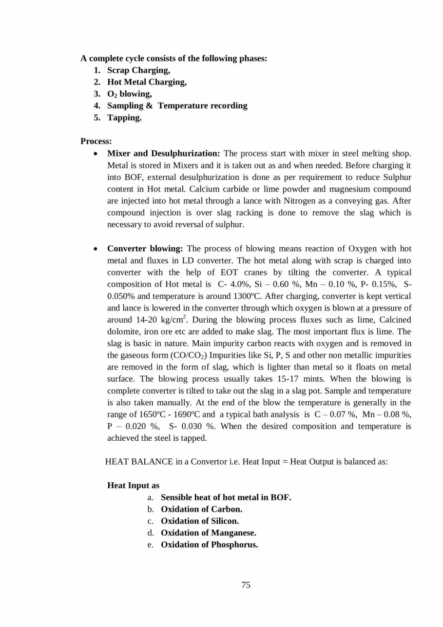
75
A complete cycle consists of the following phases:
1. Scrap Charging,
2. Hot Metal Charging,
3. O2 blowing,
4. Sampling & Temperature recording
5. Tapping.
Process:
Mixer and Desulphurization: The process start with mixer in steel melting shop.
Metal is stored in Mixers and it is taken out as and when needed. Before charging it
into BOF, external desulphurization is done as per requirement to reduce Sulphur
content in Hot metal. Calcium carbide or lime powder and magnesium compound
are injected into hot metal through a lance with Nitrogen as a conveying gas. After
compound injection is over slag racking is done to remove the slag which is
necessary to avoid reversal of sulphur.
Converter blowing: The process of blowing means reaction of Oxygen with hot
metal and fluxes in LD converter. The hot metal along with scrap is charged into
converter with the help of EOT cranes by tilting the converter. A typical
composition of Hot metal is C- 4.0%, Si – 0.60 %, Mn – 0.10 %, P- 0.15%, S-
0.050% and temperature is around 1300ºC. After charging, converter is kept vertical
and lance is lowered in the converter through which oxygen is blown at a pressure of
around 14-20 kg/cm2. During the blowing process fluxes such as lime, Calcined
dolomite, iron ore etc are added to make slag. The most important flux is lime. The
slag is basic in nature. Main impurity carbon reacts with oxygen and is removed in
the gaseous form (CO/CO2) Impurities like Si, P, S and other non metallic impurities
are removed in the form of slag, which is lighter than metal so it floats on metal
surface. The blowing process usually takes 15-17 mints. When the blowing is
complete converter is tilted to take out the slag in a slag pot. Sample and temperature
is also taken manually. At the end of the blow the temperature is generally in the
range of 1650ºC - 1690ºC and a typical bath analysis is C – 0.07 %, Mn – 0.08 %,
P – 0.020 %, S- 0.030 %. When the desired composition and temperature is
achieved the steel is tapped.
HEAT BALANCE in a Convertor i.e. Heat Input = Heat Output is balanced as:
Heat Input as
a. Sensible heat of hot metal in BOF.
b. Oxidation of Carbon.
c. Oxidation of Silicon.
d. Oxidation of Manganese.
e. Oxidation of Phosphorus.

76
Heat output as
a. Sensible heat of Steel.
b. Sensible heat of Slag.
c. Sensible heat of off gases.
d. Chemical heat of off gases.
e. Sensible heat of dust
f. Heat loses through convection and radiation of the converter
Tapping: Tapping means discharging the liquid steel into ladle through the tap hole
present in the converter by tilting it. As per the grade of steel the Ferro-alloys are
also added into ladle during tapping. As soon as the steel finishes the converter is
lifted and tapping is complete. Good tap hole maintenance and slag free tapping
devices like pre tap plugs, Slag Stopper, darts, electromagnetic slag detection
sensors etc commonly used to prevent slag carryover into the ladle.
Nitrogen Splashing: After tapping, the residual slag in the converter is splashed
with the help of nitrogen along with addition of Lime and/or coke. Converter is kept
vertical and lance is lowered. Through the same lance nitrogen is blown which
splashes the basic residual slag in the converter and gives a coating on the refractory
bricks. Main advantage of nitrogen splashing is to increase the lining life of the
converter.
Chemical Reactions: There are a lot of complex chemical reactions taking place in
the BOF during blowing. Main reactions in simplified form are given below
Fe + O = FeO
C + O = CO/CO2
Si + 2O = SiO2
Mn + O = MnO
2P + 5O =P2O5
These reactions are exothermic in nature. Lot of heat is evolved during blow. Scrap
is used as a coolant to maintain the thermal balance. Due to addition of fluxes the
chemical reaction with CaO from Lime and Dolomite and Si, Mn etc from hot metal
takes place to make complex compounds which are basic in nature thus helping in
making a basic slag which facilitates dephosphorisation.
Slag Composition: The slag formed during the BOF process is basic in nature. It is
a complex oxide compound of Ca along with Si, P and other non metallic inclusions.
A typical slag analysis at the end of the blowing is as follows:
CaO= 45-50%,
MgO= 9-11%,
FeO= 15-20%
Basicity= CaO/SiO2 ≥ 3.0

77
Functions of Slag
a. To transfer the oxygen required for refining.
b. To create favourable conditions for decarburisation of dispersed metal droplets.
c. To provide a means of removing phosphorus from the liquid pig iron.
d. To provide means of eliminating some sulphur from the bath.
Refractories: Refractory plays a very important role in BOF shop. As liquid metal is
handled in BOF Shop so all vessels like mixer, converter, ladles etc are lined with
refractory bricks. It protects the shell of vessel and retains the metal temperature.
Different types of refractory is used as per their usage are given below:
o Converter Vessel: The bricks used here are basic in nature. Dolomite bricks
or magnesia carbon bricks are commonly used in converter. In recent times
magnesia carbon bricks have replaced dolomite bricks. Number of heats
made in a converter from one new lining to next lining is known as the lining
life of the converter. Now a days all plants are trying to achieve higher lining
life. The tap hole in the converter is also made up of refractory, which wears
with number of heats tapped. It is changed from time to time.
o Mixer: The bricks used here are normally high alumina and magnesite bricks
.
o Ladles: The small vessel which carry Hot Metal for charging the converter
are called hot metal ladle. They are lined with high alumina bricks. The steel
is tapped in steel ladles. This ladle carries steel to secondary refining and
finally for casting. The bricks used are again high alumina and magnesia
carbon.
Equipments: Major equipments in BOF shop are:
Mixer: A large cylindrical or rectangular refractory lined vessel with tilting
mechanism, and it is used to store molten metal coming from Blast Furnace. Mixer
has a Charging hole from where Hot metal is being charged into the mixer with the
help of EOT cranes and a spout to take out hot metal by tilting the mixer. Main
functions of mixer are storage and homogenization. Mixed gas is supplied through
side burners in order to maintain temperature in Mixers.
Converter: A converter is an open pear shaped vessel made of steel and lined from
inside with basic refractory bricks. It can be rotated through 3600. Charging and
deslagging is done through mouth where as tapping of steel is done through a hole
called tap hole.

78
Lance: It is made of three concentric steel tubes where water is circulated in the
outer tubes and oxygen in the inner tube. Tip of the lance is made of copper.
Generally 5 or 6 holes lances are used. A stand by lance is always provided in
converter for continuous blowing operation.
Gas Cleaning Plant (GCP): A huge quantity of waste gases with high temperature
and containing dust particles, generated during the LD or BOF process is passed
through the GCP. Primarily water is sprayed over the gases to separate the solid dust
particles and to cool and collect them. Cleaned gases are either collected in a gas
holder or is burnt in the atmosphere to control air pollution.
o A large water cooled hood sits above converter. The vast quantity of waste
gas produced during steel making pass through hood and then collected and
cleaned. An ID fan is present which draws the gases up into hood. A

79
movable skirt is attached to bottom of hood which closes the gap and sits on
the converter mouth thus controlling the level of air ingress during the blow
and avoids burning of CO gas at Convertor mouth.
Safety Aspects: As we deal with liquid metal in the Shop, personal as well as equipment
safety is of large concern. We should strictly follow the safety norms.
Before charging, converter must be inspected thoroughly and make sure that no
liquid slag should be left in the converter. If there is liquid slag, it must be dried up
by adding lime before charging.
Do not allow anyone to stand in front of Converter during charging.
There should not be any water in the slag pot in which the slag is to be dumped.
Persons working in the steel melting shop should use personal protective equipment
(PPEs) like gloves, blue glass, fire retarding jackets.
Blowing should not be done if there is any water leakage in the lance/hood/skirt.
In case of excessive water logging below the converter blowing should be stopped
immediately till the water is cleared.
In case of charging and tapping of converter lot of care has to be taken to avoid any
metal splashes.
Quality Requirements: Now a day as the quality norms are quite stringent and customers
specification are becoming very strict so at all stages quality has to be monitored. In BOF
the slag decides the quality of steel. A good slag leads to good steel. Slag carry over to the
steel ladles while tapping should be minimum. Slag arrestors are used to minimize slag
carry over.
Waste and environment management:
In BOF during the steel making process, lot of wastes are generated. Some of them are as
follows:
During the blowing process lot of waste gases are generated along with dust. CO gas
evolved during blowing process is collected in a gas holder and it is further used as a
fuel in different units. The dust collected from GCP as slurry is required to be
disposed properly or re-used / recycled as input feed for BF or Sinter Plant.
Slag generated during the steel making operation is also recycled. It is dumped and
cooled then it is used by Blast Furnaces, sintering plant and Steel Melting Shop.
The slag that is disposed off can be used for making pellets / briquettes for
consumption in Sinter Plant.
Effective dog-house must be installed to capture the fugitive emissions from the
Converter.

80
Tapping practices to be performed in convertor:
Deslagging after blow finish
Sample and temperature
Reblow if required
97% straight blow practice
Tapping of steel in steel ladle
Average cast slab wt-273t
Deoxidation by aluminium and silicon
Tapping temperature-1660 to 1680 deg centigrade
Tapping time >6 mins
Tap hole life >110 heats
Practices to be followed for convertor nurturing:
• Splashing of retained slag for 3 mins by nitrogen blow through lance
• Addition of coke for better splashing
• Coating of converter
• Slag dumping in slag pot after splashing and coating before next charging
5.4 Secondary Steel Making
Objective:
Achieving the required properties of steel often requires a high degree of control over
carbon, phosphorus, sulphur, nitrogen, hydrogen and oxygen contents. Individually or in
combination, these elements mainly determine material properties such as formability,
strength, toughness, weldability, and corrosion behaviour.
There are limits to the metallurgical treatments that can be given to molten metal in high
performance melting units, such as converters or electric arc furnaces. The nitrogen and
phosphorus content can be reduced to low levels in the converter but for further reducing
carbon, sulphur, oxygen and hydrogen contents (< 2 ppm) to very levels it can only be
obtained by subsequent ladle treatment. To ensure appropriate conditioning of steel before
the casting process, the alloying of steel to target analysis and special refining treatments are
carried out at the ladle metallurgy stand.

81
The objectives of secondary steelmaking can be summarized as follows:
Refining and deoxidation
Removal of deoxidation products (Mn0, SiO2, Al2O3)
Desulphurization to very low levels (< 0,008%)
Homogenization of steel composition
Temperature adjustment for casting, if necessary by reheating (ladle furnace)
Hydrogen removal to very low levels by vacuum treatment.
The high oxygen content of the converter steel would result in large blow-hole formation
during solidification. Removal of the excess oxygen ("killing") is therefore vital before
subsequent casting of the steel. Steels treated in this way are described as killed steels. All
secondary steelmaking processes allow deoxidising agents to be added to the ladle
Deoxidation can be performed by the following elements classified by increasing
deoxidation capacity; carbon - manganese - silicon - aluminium .The most popular are
silicon and aluminium.
After addition, time must be allowed for the reaction to occur and for homogeneity to be
achieved before determination of the final oxygen content using EMF probes (electro-
chemical probe for soluble oxygen content).
Secondary Refining
Secondary steel making units can be categorized as:
a) Stirring Systems
b) Ladle Heating Systems
c) Vacuum Degassing Systems and
d) Addition Systems (RH Process and Tank degassing unit)
a. Stirring systems
These systems involve in stirring the molten steel bath for obtaining homogenous
temperature, composition, floatation of inclusions and promotion of slag-metal refining
reaction. As most of deoxidation agents form insoluble oxides, which would result in
detrimental inclusions in the solid steel, they have to be removed by one of the following
processes during the subsequent refining stage:
Argon stirring and/or injection of reactants (CaSi, and/or lime based fluxes) achieves:
Homogeneous steel composition and temperature
Removal of deoxidation products
Desulphurisation of aluminium-killed steel grades
Sulphide inclusion shape control.

82
Argon stirring can be done by refractory lined lance (Top lance) or by means of porous plug
made by high alumina material (bottom purging).
b. Ladle heating systems
These furnaces, act as buffer between the primary melting unit and the continuous casting
unit giving precise temperature and compositional control. This provides an option to the
primary melting unit to tap at low temperatures leading to saving in time and energy and
also the cost of Ferro-Alloys / De-oxidisers apart from increasing the refractory life of BOF.
Through appropriate slag composition control, de-oxidation practice and argon stirring, it is
possible to produce clean steels through Ladle furnace.
Stirring of the melt by argon or by an inductive stirring equipment and arc heating of the
melt (low electric power, typical 200 KVA/t) allows:
long treatment times
high ferro-alloy additions
high degree of removal of deoxidation products due to long treatment under
optimized conditions
homogeneous steel composition and temperature
desulphurisation, if vigorous stirring by argon.
In ladle furnace the produced exhaust waste gases are cleaned by means of bag
filters/ESP.
c. Vacuum Degassing Systems
The concept of degassing started primarily to control the hydrogen content in steels but
sooner it served many purposes for production of clean steels. The degassing systems can be
further classified as Circulation Degassers, Tank Degassers.
Vacuum-Treatment: RH process (Ruhrstahl-Heraeus)

83
In the RH process the steel is sucked from the ladle by gas injection into one leg of the
vacuum chamber and the treated steel flows back to the ladle through the second leg.
Tank degassing unit
In the tank degasser process, the steel ladle is placed in a vacuum tank and the steel melt is
vigorously stirred by argon injected through porous plugs in the bottom of the ladle.
Millibar is term used for measurement of vacuum. Steam is used for creating vacuum.
Vacuum treatment achieves:
reduction of the hydrogen content to less than 2 ppm
considerable decarburisation of steel to less than 30 ppm when oxygen is blown
by a lance (RH - OB)
alloy addition under vacuum
homogeneous steel composition, high degree of cleanliness from deoxidation
products
High temperature losses (50 - 100°C) are a disadvantage; therefore high superheat of the
melt prior to this process is essential.
Ferro alloy addition facility for trimming addition
These contain bunkers for storage of ferro alloys, weighing hoppers, conveyor belt, skip;
addition hoppers etc. Addition during vacuum is also possible.
For most secondary steelmaking techniques it is either desirable or essential to stir the liquid
steel. Gentle stirring is sufficient for inclusion removal; non-metallic inclusions are brought
into contact with liquid slag on top of the melt where they can be fixed. For degassing and
desulphurisation however, violent stirring is necessary to increase the surface of steel
exposed to vacuum (H2-removal) or to mix the steel and slag for good desulphurisation
efficiency.

84
Other Steel Refining Units

85
Metallurgical Principles
( ) means in slag. [ ] means in steel.
Deoxidation
As steel making process is an oxidation refining process, tap steel from primary furnace
contains significant amount of oxygen(400-1000 ppm).The solubility of O2 in liquid steel is
0.16% but in solid steel it is only 0.003%.Excess oxygen causes defects like blow holes and
non-metallic inclusions. Oxygen is lowered by deoxidisers like Mn, Si, Al etc. Through
vacuum treatment oxygen is removed as CO.
Decarburisation
Reaction of ‘C’ and ‘O’ removal is given by
[C] + [O] = CO
[C] +1/2O2 = CO
[C] +(FeO) = CO +Fe
‘C’ removal is controlled by vacuum level, Argon flow rate, initial level of ‘C’, bath
Oxygen content, Amount of Oxygen injected
Control is required during tapping , LF & VAD operation to avoid recarburisation.
Some other sources of recarburisation are ferro-alloys, graphite electrodes during arcing.
Desulphuristion
Removal of sulphur depends on
i) High sulphide carrying capacity of slag - high basicity
ii) High (S)/[S] - sulphur partition
iii) Fluid slag - addition of spar or synthetic slag
iv) High stirring intensity - increased slag-metal reaction.
v) Low O potential in slag and metal- low Feo+Mno < 5%
Removal of H2 & N2
Hydrogen removal
Reaction is 2[H] = H2
[H] = k*H2
i) H content varies with p H2
ii) To get very low H , vacuum level must be low and improved stirring.
So H removal is controlled by vacuum level, Ar flow rate, initial level of H.
Nitrogen removal
Reaction is 2[N] = N2
I. To get very low N vacuum level must be very low.
II. Compared to H , nitrogen removal rate is low due to low diffusibility

86
5.5 Casting
Continuous Casting of Steel: Basic Principles
Background
Continuous Casting is the process whereby molten steel is solidified into a "semifinished"
billet, bloom, or slab for subsequent rolling in the finishing mills. Prior to the introduction
of Continuous Casting in the 1950s, steel was poured into stationary moulds to form
"ingots". Since then, "continuous casting" has evolved to achieve improved yield, quality,
productivity and cost efficiency. Figure 1 shows some examples of continuous caster
configurations.
Casting of Liquid Steel
• Molten steel is continuously poured into a water cooled Cu mould that is
open at the top and bottom.
• The steel gradually cools and begins to set solid in the mould. The rate at
which molten steel is poured into the top is matched with the rate at
which the solid steel is pulled out at bottom.
• In this way, a long continuous piece is formed. So, the process is called
continuous casting. Steel formed can then be cut into length as desired.
Figure 1 - Examples of Continuous Casters

87
Steel from the electric or basic oxygen furnace is tapped into a ladle and taken to the
continuous casting machine. The ladle is raised onto a turret that rotates the ladle into the
casting position above the tundish. Referring to Figure 2, liquid steel flows out of the ladle
(1) into the tundish (2), and then into a water-cooled copper mould (3). Solidification begins
in the mould, and continues through the First Zone (4) and Strand Guide (5). In this
configuration, the strand is straightened (6), torch-cut (8), then discharged (12) for
intermediate storage or hot charged for finished rolling.
Figure 2 - General Bloom/Beam Blank Machine Configuration
1:Ladle Turret, 2:Tundish/Tundish Car, 3:Mould, 4:First Zone (Secondary Cooling),
5:Strand Guide (plus Secondary Cooling), 6:Straightener Withdrawal Units, 7:Dummy Bar
Disconnect Roll, 8:Torch Cut-Off Unit, 9:Dummy Bar Storage Area, 10:Cross Transfer
Table, 11:Product Identification System, 12:Product Discharge System
Figure 3 depicts a Slab Caster layout. Note the extended roller containment compared to
that for a Bloom/Beam Blank (as in Figure 2), required to maintain product shape through
final solidification.
Depending on the product end-use, various shapes are cast (Figure 4). In recent years, the
melting/casting/rolling processes have been linked while casting a shape that substantially
conforms to the finished product. The Near-Net-Shape cast section has most commonly
been applied to Beams and Flat Rolled products, and results in a highly efficient operation.
The complete process chain from liquid metal to finished rolling can be achieved within two
hours.

88
Figure 3 -Slab Caster Layout
Figure 4 - Continuous Cast Shapes (sizes in millimeters)
Before going into the details of CCM a brief description of the caster is given below:
<BOF> => Raw/Crude Steel from converter => <SRU> => Refining crude steel i.e.
killing, Homogeneous Temperature and Composition => <Caster> Turret, Ladle
S/Gate, Shroud => Tundish => Mould

89
Liquid steel comes from the ladle into the tundish. Tundish is a device where it collects,
accumulates liquid steel from the ladle and feeds to two or more moulds through SEN
depending on the m/c and process
The basic design of the caster is to solidify liquid steel to its solid products
uninterruptedly/continuously. For that the steel to be cast must be killed. Steel from which
oxygen (dissolved in steel during steel making in BOF) is removed at SRU deoxidising
elements like Al (Aluminum) Si (silicon) etc. is called KILLED STEEL. Oxygen in steel is
measured using Celox Temp and expressed in ppm. Steel that is to be cast should not have
high ppm of O2 otherwise casting cannot be done because O2 of steel will form unwanted
oxides viz CaO, SiO2 , MgO and will be deposited over the entry nozzle and thus will
restrict the flow of steel into the mould.
Caster Preparation:
1. Steel that is to be cast is treated well at SRU for smooth casting.
2. Tundish through which casting will be done is to be prepared.
Tundish is a device through which continuity of the casting is maintained. There are two
types of casting practices are in use namely cold tundish and hot tundish practices. Liquid
steel comes from the ladle into the tundish and in turn the tundish feeds the liquid steel into
the mould through different outlet at the bottom of the tundish. Tundish is made of steel and
inside of which is lined with refractory bricks or castable. After that tundish boards are fixed
over the refractory lined. Submerged entry nozzle (SEN) are fixed by clamping device in
each of the tundish outlet.
3. Mould Preparation:
Mould is the most important equipment in the caster m/c. primarily mould is prepared
according to the shape and size of the product. For solidification of the initial liquid steel
that enters into the mould one DUMMY BAR head is used, which is fed into the mould with
a fixed rod or flexible chain. This DUMMY BAR head is packed. Mould is made purely of
copper as copper has the most heat discharge capacity than any other metal economically
available. All sides of this mould is made up of Cu plate and heat from liquid steel
immediately discharges trough the copper plates by mould cooling system Copper plates are
cooled by circulating soft water through designed tubes in the form of coils. Here the
difference of MOULD COOLING WATER Outlet Temperature & Inlet Temperature is
monitored continuously. It is very much hazardous part in caster m/c during casting. An
alarm is provided as soon as the difference of temperature raises more. Immediate actions
are to be taken and if necessary casting should be stopped without waiting for any other
decision to be asked from anyone.
Casting Process

90
Liquid steel taken into ladle is refined at SRU is placed over the turret arm and ladle SG is
fixed. Then one shroud is fixed at the bottom of the ladle collector nozzle so that no stream
of liquid steel comes in contact with the atmosphere and no spillage occurs. This liquid steel
gradually fills the tundish and from there liquid steel leaves tundish nozzle/TSG through
SEN into the mould. Initially steel rests on the DUMMY BAR head on which some chillers
are placed to get the liquid steel freeze/solidifies quickly then the m/c starts with MOM &
casting powder is to be sprayed continuously at a certain mould level. The process continues
after the DUMMY BAR head is disconnected as it reaches at its particular position. Length
of the slab/billet is maintained by using cutting torch/ shearing blades.
To summarize, the casting process is comprised of the following sections:
A tundish, located above the mould to feed liquid steel to the mould at a regulated rate
A primary cooling zone or water-cooled copper mould through which the steel is fed
from the tundish, to generate a solidified outer shell sufficiently strong enough to
maintain the strand shape as it passes into the secondary cooling zone
A secondary cooling zone in association with a containment section positioned below the
mould, through which the still mostly-liquid strand passes and is sprayed with water or
water and air to further solidify the strand
Except straight Vertical Casters, an Unbending & Straightening section

91
A severing unit (cutting torch or mechanical shears) to cut the solidified strand into
pieces for removal and further processing
Liquid Steel Transfer
There are two steps involved in transferring liquid steel from the ladle to the moulds. First,
the steel must be transferred (or teemed) from the ladle to the tundish. Next, the steel is
transferred from the tundish to the moulds.
Tundish
The shape of the tundish is typically rectangular, but delta and "T" shapes are also common.
Nozzles are located along its bottom to distribute liquid steel to the moulds. The tundish
also serves several other key functions:
Enhances oxide inclusion separation.
Provides a continuous flow of liquid steel to the mould during ladle exchanges.
Maintains a steady metal height above the nozzles to the moulds, thereby keeping
steel flow constant and hence casting speed constant as well.
Provides more stable stream patterns to the mould(s).

92
Tundish performance largely depends on key process parameters like:
Chemistry
Fluid Flow
Temperature
Clogging of SEN due to deposit formation is a major problem and leads to:
Affects the stream flow pattern in mould.
Reduces the pouring rate.
May lead to premature changing of SENs and termination of casting operation.
Steel quality may be affected.
Factors affecting SEN clogging:
Steel chemistry (alloying elements, total inclusions, etc.)
Casting conditions (tundish depth, superheat, speed, etc.)
SEN chemical composition, geometry & design.
Argon injection rate
Air aspiration into the SEN
Oxygen provided by the refractory materials
Mould
The main function of the mould is to establish a solid shell sufficient in strength to contain
its liquid core upon entry into the secondary spray cooling zone.
The mould is basically an open-ended box structure, containing a water-cooled inner lining
fabricated from a high purity copper alloy. Mould water transfers heat from the solidifying
shell. The working surface of the copper face is often plated with chromium or nickel to

93
provide a harder working surface, and to avoid copper pickup on the surface of the cast
strand.
Mould heat transfer is both critical and complex. Mathematical and computer modeling are
typically utilized in developing a greater understanding of mould thermal conditions, and to
aid in proper design and operating practices. Heat transfer is generally considered as a series
of thermal resistances as follows:
Heat transfer through the solidifying shell
Heat transfer from the steel shell surface to the copper mould outer surface
Heat transfer through the copper mould
Heat transfer from the copper mould inner surface to the mould cooling water
Mould Oscillation
Mould oscillation is necessary to minimize friction and sticking of the solidifying shell, and
avoid shell tearing, and liquid steel breakouts, Friction between the shell and mould is
reduced through the use of mould lubricants such as oils or powdered fluxes. Oscillation is
achieved either hydraulically or via motor-driven cams or levers which support and
reciprocate (or oscillate) the mould.
Mould oscillating cycles vary in frequency, stroke and pattern. However, a common
approach is to employ what is called "negative strip", a stroke pattern in which the
downward stroke of the cycle enables the mould to move down faster than the section
withdrawal speed. This enables compressive stresses to develop in the shell that increase its
strength by sealing surface fissures and porosity.
Mould Flux

94
Functions of mould powder
Provides thermal insulation to the liquid steel meniscus to prevent premature
solidification
Prevents re-oxidation of liquid steel in the mould by atmospheric air
Absorbs inclusions
Provides a lubricating film of molten slag between solidifying shell and mould wall
Secondary Cooling
Typically, the secondary cooling system is comprised of a series of zones, each responsible
for a segment of controlled cooling of the solidifying strand as it progresses through the
machine. The sprayed medium is either water or a combination of air and water.
Figure 5 - Secondary Cooling
––
Three (3) basic forms of heat transfer occur in this region:
Radiation
Conduction
As the product passes through the rolls, heat is transferred through the shell as
conduction and also through the thickness of the rolls, as a result of the associated
contact.

95
Convection
This heat transfer mechanism occurs by quickly-moving sprayed water droplets or mist
from the spray nozzles, penetrating the steam layer next to the steel surface, which then
evaporates. Specifically, in the spray chamber (Secondary Cooling) heat transfer serves
the following functions:
i. Enhance and control the rate of solidification, and for some casters achieve full
solidification in this region
ii. Strand temperature regulation via spray-water intensity adjustment
iii. Machine Containment Cooling
Strand Containment
The containment region is an integral part of the secondary cooling area. A series of
retaining rolls contain the strand, extending across opposite strand faces. Edge roll
containment may also be required. The focus of this area is to provide strand guidance and
containment until the solidifying shell is self-supporting.
Bending and Straightening
Equally important to strand containment and guidance from the vertical to horizontal plane
are the unbending and straightening forces. As unbending occurs, the solid shell outer radius
is under tension, while the inner radius is under compression. The resulting strain is dictated
by the arc radius along with the mechanical properties of the cast steel grade. If the strain
along the outer radius is excessive, cracks could occur, seriously affecting the quality of the
steel. These strains are typically minimized by incorporating a multi-point unbending
process, in which the radii become progressively larger in order to gradually straighten the
product into the horizontal plane.
Figure 7 - Curved Section of Multi-
Strand Beam Blank Caster prior to
Unbending
Figure 8 - Straightener Withdrawal Units for
Strand Unbending

96
After straightening, the strand is transferred on roller tables to a cut off machine, which cuts
the product into ordered lengths. Sectioning can be achieved either via torches or
mechanical shears. Then, depending on the shape or grade, the cast section will either be
placed in intermediate storage, hot-charged for finished rolling or sold as a semi-finished
product.
Abnormalities:
During casting some unwanted hard oxides which gets deposited over the steel into the
mould and interrupts the steel flow and casting gets aborted. This phenomenon is called
Chocking.
In some cases temperature at which liquid steel gets solidified may be reached during
casting which caused solidification at SEN and restricts the steel flow, and then also casting
continuity gets disturbed and casting stops. This is called Freezing.
Another major problem that hinders the casting process is Break Out.
Some Casting Defects:
Types of defects:
Surface cracks
Internal cracks
Blow holes, Pin holes etc
Remedial measures:
Control of superheat of liquid steel (appropriate temperature)
Steel chemistry
Casting speed
Safety Measures:
Mould cooling temperature and its difference of temperature of Inlet water and
Outlet water is to be monitored continuously.
Tundish walls and slidegate m/c fixed on it is to be observed carefully.
5.6 Ingot Casting
A Teeming ladle is prepared for each and every heat. The liquid steel is teemed through the
nozzle present at the bottom of the teeming ladle. The flow of metal into the mould through
the nozzle can be controlled using slide gate system. Earlier stopper rod assembly was in
use.
The ingots are stripped off from these moulds. These ingots are then sent to soaking pit.
These moulds are again prepared (i.e. cooling by water, cleaning and coating) for another.

97
Teeming temperature is one of the most important parameters in ingot casting practice. High
temperature leads to sticker formation while low temperature leads to chocking of nozzle.
Care should be taken so that center pouring is done in a mould.
There are many types of defects associated with ingot casting. Surface defects such as scabs,
cracks and lappiness are common. Bottom pouring of steel into fluted ingot moulds is done
in DSP for special steel grades required for manufacturing Wheels and Axles for Railways.
Advantages of Continuous Casting over Ingot Casting:
One of the main advantages of continuous casting over ingot casting is the high
increase in yield from liquid steel to semi-finished cast product.
Ingot casting yield can be as low as 80%.
Continuous casting yield depends mainly on ladle capacity, Section sizes and
sequence length.
Yields of >95% or even higher are not uncommon.
SAFETY
LD Process or Primary Steel Making safety hazards:
Lance / Lance tip puncture to be avoided and taken care of to avoid any water
leakage inside the convertor
During blowing CO gas monitor to be always used for multilevel activities above the
convertor area
Secondary steel unit pose certain safety hazards to personnel working like:
• During argon purging metal splashes can cause burn injury.
• In ladle furnace, there is danger of metal splashes and electrocution due to very high
current of electrode.
• In VAD, VOD & RH vacuum present inside treatment area can pose serious danger
of suction. Body parts may get sucked inside if isolating plate collapse. Also fumes
coming out may cause suffocation.
• Danger of carbon monoxide is also there in vacuum treatment stations
Do & Don’t:
• Avoid going near high current line & high current cables in running ladle furnace
and in VAD
• If red spot is observed in ladle, STOP arcing. It may lead to ladle through.
• People must always be aware of the safety hazards of their areas.
---

98
Chapter – 6.0
ROLLING MILLS
6.1 Basics of Rolling
Processes of metal forming are
1. Rolling 2. Forging
3. Extrusion 4. Wire drawing
5. Deep Drawing 6. Sheet metal forming
7. Stretch Forming 8. Foundry
9. Bending 10.Shearing
Basic Definitions
Rolling
Rolling is plastic deformation of the
Metal by passing between rolls to give
it the desired shape.
Draft
Difference in height or thickness of the
material before rolling (H) and height or
thickness after rolling (h) is called draft
(H-h). It indicates how much the metal
has been pressed during rolling.
Spread
Difference in width of material after
rolling (b) and width before rolling (B) is
called spread (b-B). It indicates how
much the metal has spread during rolling.
Elongation
Difference in length material after rolling (l) and length before rolling (L) is called elongation (l-
L). It indicates the increase in length during rolling
Input Desired Output
h H

99
Reduction
Difference in area before rolling (A) and area after rolling (a) is reduction (A-a). It indicates how
much the cross section area has been reduced during rolling.
Coefficient of Reduction
Ratio of area before rolling (A) and area after rolling (a) is called coefficient of reduction (A/a).
It indicates how many times the area has been reduced during rolling.
Rolling Constant principle
It states the volume of material will remain same before and after rolling. It is useful in finding
input and output sizes.
Basic terminology used for measuring mill efficiency
Mill Availability
It indicates the availability of the mill for rolling. In this the planned shutdown and capital repairs
are subtracted from the total calendar hours.
Mill Availability = Calendar Hours- (Capital Repairs+shutdown)
x100
Calendar Hours
Calendar hours in a year means 24 x 365 days(or 366 in case of leap year)
Mill Availability is expressed in percentage
Mill Utilization
It indicates the utilisation of available mill for rolling. In this the planned delays subtracted from
the available hours.
Mill Utilization = Calendar Hours- (Planned Repair + Total Delays)
x100
Available Hour
Available hours= Calendar Hours - (Planned Shutdown + Capital Repairs)
Mill utilization is expressed in percentage
It is a measure of effective utilization of time available
Hot Hours
Hours during a day or month or year during which rolling actually took place. Its unit is hours.
Yield
It is the ratio of useful output to input expressed as percentage Yield= Output
x100 Input

100
It is a measure of efficient utilization of input and is expressed in percentage.
Rolling Rate
It is tonnage rolled in an hour. It is a measure of speed of rolling and its unit is tons/hour.
Hot and Cold Rolling
Hot Rolling:. Hot rolling is a metalworking process in which metal is heated above the
recrystallization temperature to plastically deform it in the working or rolling operation.
This process is used to create shapes with the desired geometrical dimensions and material
properties while maintaining the same volume of metal. The hot metal is passed between
two rolls to flatten it, lengthen it, reduce the cross-sectional area and obtain a uniform
thickness. Hot-rolled steel is the most common product of the hot rolling process, and is
widely used in the metal industry either as an end product or as raw material for subsequent
operations. Hot rolling breaks the grain structures and destroys the boundaries, giving rise to
the formation of new structures with strong boundaries having uniform grain structures.
Hot rolling improves:
Toughness and strength
Ductility
Resistance to vibration and shock
Formability
Weldability
Hot-rolled steel products are classified into four groups:
Flat
Long
Seamless
Specialty
Typical applications of hot-rolled steel are:
Automotive structural parts such as frames
Tabular products such as pipe and gas cylinders
Machine structures such as saws and springs
Agriculture equipment
Metal buildings
Guard rails

101
Cold Rolling: Metal forming process in which the shape and structure of steel is altered through
drawing, extruding, hammering, pressing, rolling, spinning, and/or stretching at temperatures
below the steel's recrystallization point (usually room temperature).
Cold rolling is a technique where a metal strip or sheet is passed between two rollers and then
squeezed and compressed. The level of strain present determines the properties and hardness of
the finished material.
This process is widely used for surface finish and high-quality dimensional accuracy, which can
help prevent material damage and corrosion
The typical applications of cold rolling are in the production of:
Filing cabinets
Metal furniture
Computer cabinets
Water heaters
Exhaust pipes
Steel drums
Through cold rolling of steel, the strength and hardness of the material is enhanced
significantly, which in turn improves the corrosion resistance of metal in many ways. This is
brought about by the addition of more tension and energy to the product.
Recrystallization temperature is the temperature on rolling above which we get strain free
grains and minimum residual stresses in rolled metal. It is normally 0.5 to 0.7 times of melting
point of the metal.
The difference between the two is the temperature at which they are processed. Hot Roll is
processed above the re-crystallization temperature. Its grains reform after the rolling process
and it is left in a stress-free state. Cold Roll is processed below the re-crystallization
temperature. Its grains remain flattened and elongated, leaving the material in an anisotropic
state and full of cold work.

102
FACTORS HOT ROLLED
CHARACTERISTICS
COLD ROLLED
CHARACTERISTICS
Layout Orientation The material characteristics
is identical in all directions
Care must be exercised in
layout. The grains of the
material are deformed during
the rolling process and stay
deformed. The material will be
stronger with the grain than
against the grain.
Price Less Expensive More Expensive
Strength Weaker Stronger
Weldability Excellent for welding Weldable, but the material will
take on the properties of hot roll
wherever it is welded
Machinability Experiences no warping
when machined
The removal of too many
residual stresses during
machining will throw the
material out of equilibrium and
cause deflection and wrapping
Dimensional tolerances of
stock
Fair. Deviations from the
stated size are present due to
surface scale and thermal
shrinkage
Good. It is not as accurate as
ground stock, but better than
Hot Roll.
Surface Finish Fair to Poor
The surface of the material
will be covered with carbon
scale
Good.
Not as good as ground stock,
but much better than Hot Roll.
All SAIL integrated plants have hot rolling mills whereas only Bokaro, Rourkela and Salem have
cold rolling mills.
Long and Flat Products
During rolling when the input is pressed from both directions perpendicularly (from top-bottom
and also from both sides) the length increases to keep the volume of the metal constant. This is

103
called long product rolling. If the metal is pressed from top - bottom the spreads takes place also
on the sides, it is called flat product rolling.
Examples of long products are angles, beams, channels, rails, blooms, billets, etc. Examples of
flat products are plates, sheets, strips, etc. In SAIL, integrated steel plants Bokaro and Rourkela
produce flat products, while Burnpur is a long product plant. Bhilai and Durgapur produce both
long and flat products.
6.2 Products of Rolling Mills of SAIL
Bhilai Steel Plant
Semis (Blooms, Billets, Slabs and Narrow width slabs)
Rails
Heavy Structurals (Beams, Channels, Angles, Crossing Sleepers)
Merchant Products (Angles, Channels, Rounds and TMT Bars)
Wire Rods (TMT, Plain and Ribbed)
Plates
Bokaro Steel Plant
HR coils, sheets, plates
CR coils, sheets
Galvanized plain and corrugated sheets
Durgapur Steel Plant
Semis (Blooms, Billets, Rounds)
Merchant Products (TMT Bars, Rebars)
Medium Structurals (Beam, Joists, Channels, Angles)
Wheel and axle
Rourkela Steel Plant
Semis(slabs)
Plate Mill Plates, Special plates
Long products
Flat products

104
HR Plates, Coils
CR Coils and Sheets
Galvanized plain and corrugated sheets
Silicon Steel Sheet & coils
HFW Pipes(ERW) & SW Pipes
IISCO Steel Plant, Burnpur
Structurals(Beam, Channels, Angles)
TMT Bars, Wire Rod Coils Products
Alloy Steel Plant, Durgapur
Alloy and Stainless steel Slabs, Blooms, Billets, Bars, Plates
Stainless and Hadfield Manganese steel plates
Salem Steel Plant
Hot rolled carbon and Stainless steel flat products
Cold rolled stainless steel sheets and coils
Visvesvaraya Iron and Steel Plant, Bhadrawati
Semis, Bars
Different configuration of rolls used in rolling mills
Mills are designed in different types of configurations, with the most basic being a two-high non-
reversing, which means there are two rolls that only turn in one direction. The two-high
reversing mill has rolls that can rotate in both directions, but the disadvantage is that the rolls
must be stopped, reversed, and then brought back up to rolling speed between each pass. To
resolve this, the three-high mill was invented, which uses three rolls that rotate in one direction;
the metal is fed through two of the rolls and then returned through the other pair. The
disadvantage to this system is the workpiece must be lifted and lowered using an elevator. All of
these mills are usually used for primary rolling and the roll diameters range from 60 to 140 cm
(24 to 55 in).

105
Various rolling configurations. Key: A. 2-high B. 3-high C. 4-high D. 6-high E. 12-
high cluster & F. 20-highSendzimir Mill cluster
To minimize the roll diameter a four-high or cluster mill is used. A small roll diameter is
advantageous because less roll is in contact with the material, which results in a lower force and
power requirement. The problem with a small roll is a reduction of stiffness, which is overcome
using backup rolls. These backup rolls are larger and contact the back side of the smaller rolls. A
four-high mill has four rolls, two small and two large. A cluster mill has more than 4 rolls,
usually in three tiers. These types of mills are commonly used to hot roll wide plates, most cold
rolling applications, and to roll foils.
Roll deflection during rolling
6.3 Applications of Rolled Products of SAIL
Hot Rolled Coils, Sheets
Used for construction of tanks, railway cars, bicycle frames, ships, engineering, military
equipment, LPG cylinder, automobile and truck wheels, frames, and body parts. HR coils
are also used as feedstock for pipe plants and cold rolling mills where they undergo
further processing. Hot Rolled Chequered coils and plates are being produced for using in
floor as anti-skidding.
Plates
Steel plates are used mainly for the manufacture of bridges, dams & windmills, steel
structures, ships, large diameter pipes, storage tanks, boilers, railway wagons, and pressure

106
vessels. SAIL also produces weather-proof steel plates for the construction of railcars. SAIL
is one of the major producers of wide and heavy plate products in India.
Cold Rolled Products
The products of the cold rolling mills include cold rolled sheets and coils, which are used
primarily for precision tubes, containers, bicycles, furniture ,whitegoods industry and for
use by the automobile industry to produce car body panels. Cold rolled products are also
used for further processing, including for color coating, galvanizing and tinning. Galvanized
Sheets are used in roofing, paneling, industrial sheeting; air condition ducting and structural
applications. Electrolytic Tin Plates are used in containers for packaging of various products
including edible oils, Cola, Fruit Juices, Pickles and confectionary items.
Railway Products
Rails are one of the main rolled products by SAIL. It is used primarily to upgrade and
expand railway networks.
Structurals
I-beams, channels, and angle steel are used in mining, construction of tunnels, factory
structures, transmission towers, bridges, ships, railways, and other infrastructure projects.
Bars and Rods
Reinforcement steel and wire rods are primarily used by the construction industry.
Semi-Finished Products
Semi-finished products (blooms, billets and slabs) are converted into finished products in
SAIL’s processing plant and, to a lesser extent, sold to Re-rollers for conversion to finished
products.
Alloy and Stainless Products
Alloy and special steel products with alloyed elements including chromium, nickel, vanadium
and molybdenum are primarily used for sophisticated applications, including in the
automobile, railway, aerospace, power, nuclear,submarines and defence industries.Special
alloy steel bittets and bars made for defence are used in shell making. Jackal and spade plates
are critically applied for armour and ammunition vehicle application only. Corrosion
resistance cold rolled stainless steel coils and sheets are used for diverse applications
including household utensils, automobile trims, elevators, fuel, chemical, fertiliser, LPG
tanks, atomic power, boilers, heavy engineering, dairy and food processing equipment, coin
blanks, building and interior decoration, and pharmaceutical equipment.
Speciality Products
Speciality products include electrical sheets, tin plates, and pipes. Electrical sheets are cold
rolled products of silicon steel for electrical machinery. Pipes are longitudinally or spirally
welded from hot rolled coils for transporting water, oil,slurry and gas.

107
6.4 Hot Rolling
The rolling process which is done above recrystallization temperature is called hot rolling.
More reductions are achieved in hot rolling as compared to cold rolling.
6.5 Reheating Furnaces
In the reheating furnaces the Input materials are heated to a specified temperature and
soaked for given time depending upon size of input slab and their metallurgical
requirements for which it is planned to be rolled. Ideally, it is aimed to equalize the surface
and the core temperatures of the slab. Well-soaked slabs are discharged from the furnace at
dropout temperature of 1100-1300oC. The furnace discharge temperature is also to
compensate heat losses in downstream operation and thereby it depends on it.
Types of Reheating Furnaces:
In Primary mills Soaking pits are used which are primarily batch type furnaces and at
present not in operation . In secondary (finishing) Mills, continuous reheating furnaces are
used. Continuous reheating furnaces are mainly of two type’s pusher type and walking
Beam type. These furnaces mainly have firing system with mixed gas ( mixture of coke
oven gas and blast furnace gas) which are readily available in Integrated Steel plants.
6.6 Rolling of Flat Products
Layout of a typical Hot Strip mill is shown in figure below:
Process installations shown in the figure above and operations performed are briefly
described below:
Reheating
furnace
Hydraulic
descaler
Roughing
stands
Delay
table
Crop
shear
Finishing
descaler
Finishing
stands
Run-out-
table
Cooling
water spray
Coiler

108
PROCESS:
Reheating
Walking Beam Reheating Furnaces are having 6 zones (Preheating zone top & bottom,
Heating zone top & bottom and Soaking zone top & bottom). Preheating,heating and
soaking zones have firing system with mixed gas , Slabs are heated, soaked to have uniform
temperature across the cross section of the slabs and discharged at 1100-1300oC based on
the grade of the steel and the planned dimension.
Descaling:
Layers of scales (oxides of iron) are formed on the surface of the slab during its heating
inside the furnaces. The scales are removed by using high pressure water jet. The descaling
unit consists of headers fitted with nozzles for spraying water both at top and bottom
surface. Descaling is a very important precondition for rolling for defect free products.
Roughing:
The major reduction to the input material is given at Roughing mill group to get the desired
thickness for Finishing Mill group. Main reduction in thickness is achieved at Roughing
mills and comparatively smaller draft is given at Finishing mills. . For example, if strip of 2
mm thickness is to be produced from 220 mm thick slab, typically, thickness will be
reduced from 220 mm to 26-40 mm at Roughing stands (continuous or reversible) based on
the strip width .Final drafts are given at Finishing mill to get the planned dimensions.
Finishing:
Final required dimensions of the end products are achieved in finishing process. Finishing
temperature of the strip(which is temperature at the last finishing stand) is a critical
parameter, is maintained and not being allowed to decrease below a specified temperature
for particular grades of steel . This is done to achieve the metallurgical properties.
Cooling
Before the hot rolled strips are coiled in the coiler, they are cooled at specified cooling rate
on the run-out-table to achieve the desired coiling temperature. It is very much important for
getting the desired metallurgical properties of the strip. The number of the water banks to be
operated is decided by the targeted cooling rate of the strip to achieve the required coiling
temperature.
Coiling:
The Strip moves over ROT and gets coiled in coilers. The coils are taken out of the coilers,
strapped on the body and marked for identification.

109
Coil Finishing & Dispatch
Coils are sent for further processing or directly sold as hot rolled products. Weighment of
the coils, inspection and sampling for both chemical and physical testing is done before
processing and dispatch.
Equipments:
Reheating Furnace:
Re-heating furnaces of hot Strip mill are mainly of two types- pusher type or walking beam
type. The walking beams are hydraulically operated and the movement of slabs inside the
furnace is carried out by a set of moving & stationary beams. In pusher type furnaces the
movement is achieved by pushing the slabs one after another. The combustion system is
mainly of recuperative type with heating from top and bottom. Facilities of skewed skid
system are there in the furnace to compensate for temperature variations.
Descaler:
The surface of slab moving through water hydraulic descaler and the rolling bar/strip is
impinged by high-pressure water jets. At many places, a mill stand with a pair of vertical
rolls, called vertical scale breaker, may also be provided to remove the scale from edges of
the slab.
Roughing stand:
Roughing mills are generally having one stand, two stands and multi-stands with 4-high
configuration. These stands can be reversing, non-reversing or combination types. Universal
type roughing stands are equipped with vertical edgers for controlling spread of material in
lateral direction. Rolls of roughing stands are cylindrical and are cooled simply by water.
Finishing Stands:
Finishing Stands of Hot strip mill normally have 5-7 stands in 4-high construction
(combination of work rolls and back up rolls). These stands are in tandem and strip passes
through them on continuous basis. Roll force, roll gap can be controlled through different
mechanisms such as roll bending, pair crossing, roll shifting and varying crown of rolls.
Cooling of the rolls is achieved by spraying water/water oil mixture over backup and work
rolls.
Coilers:
The coilers are used for coiling the strips mainly with the help of Pinch rolls, wrapper rolls
and mandrel.
Plate Mill
The modern plate mill of both RSP and BSP rolls out heavy and medium plate as well as
those for pipe manufacturers from the reheated slabs.

110
MAJOR Parameters and factors affecting rolled products and their control:
The following major factors affect the quality of rolled products
a) Temperature:
The desired temperature at various stages of rolling needs to be maintained for attaining
product within dimensional tolerances and properties.
b) Roll conditions:
Roll change schedule has to be strictly adhered to and roll cooling conditions need to be
monitored continuously. Shape and dimensional tolerances also depend on the above
mentioned conditions.
6.7 Rolling Of Long Products
Long products have to be hot rolled only, to facilitate the large reduction to be made in
passes. The mills can be basically classified into primary mills and secondary mills. Primary
long product mills manufacture semis mainly blooms and billets. The long product mills
which produce finished products like beams, angles, channels, bars, wires and rods, TMT
bars and rails, are called finishing mills
Rail Mills
Rails are produced either using the two-high rolling method on two-high reversing mills or on
three-high mills or, increasingly today, using the universal rolling method. The universal
rolling method has proved superior to the conventional methods due to the following
advantages: Closer rail tolerances, better surface quality and less roll wear.
Rail mill

111
Structural Rolling Mill
Rolling mills having facilities for rolling the billets, blooms, slabs and beam blanks. Input
materials are heated in reheating furnaces (Walking Beam or Pusher Type) to desired
temperature (1100 to 1300oC). The Rolling is done through Rolling Stands (Reversing or
Continuous) to achieve the desired shape and dimensions. Brand marking on finished product
is done at final stands.
Wire Rod Mill
The objective of a wire rod mill (WRM) is to roll steel billets into wire rods. The production
volume of wire rods in WRM is subject to the size of product to be rolled and
mill availability. High productivity is achieved in case of thicker size rolling.
PROCESS
The processes of rolling of long products can be basically classified into following heads.
Reheating:
The reheating of inputs is done to make the material plastically deformable and pliable for
rolling to give the desired shape and size.

112
Roughing:
Roughing is done to give the input a rough shape. The maximum reduction in cross section is
given in roughing mills.
Intermediate Rolling:
Intermediate rolling constitutes taking the roughing mill output as its input. Output of
intermediate rolling is sent to finishing mills.
Pre-Finishing & Finishing rolling:
In Pre-finishing & Finishing mills the finished profile shape is made. Pre-finishing Mills It
takes metal from intermediate stands as its input. The reduction given in these stands is lesser
as compared to roughing and intermediate mill. Finished shape is achieved in finishing mills.
Finishing rolling mills is critical as the final output shape is made in these stands. In case of
TMT bars thermo-mechanical treatment of bars is done after finishing mills area.
Cutting and stamping:
The finished bar is cut to desired lengths as per customer requirement.
In secondary mills stamping of cast number and other details are done on the rolled products
in hot condition. These are required for identification and traceability of product and
correlation with test results of destructive tests.
Finishing:
The finishing is done after the bar has been cooled to ambient temperature. Finishing
activities at different mills may involve all or few of the following steps:
Straightening either by roller straightening machines or by pulling the ends
End finishing either by milling or cold cutting
Online non-destructive testing of defects
Heat treatment
Inspection:
Inspection is carried out by the producer and/or by customer deputed agency and/or by third
party to inspect the products and ensure no defective products are sent to customer.
Depending on the specifications, customer requirement the inspection may be for all or few of
the parameters like Dimension, Straightness, Squareness, Surface Quality, Branding, colour
coding and stamping are done.
Dispatch:
The products are sent to required destinations primarily by rail and in some cases by road.
The activities involve documentation (preparation of dispatch advice (DA), test certificate
(TC) and clearance by train examiner (TXR) in case of rail dispatches. In some cases
packeting is done prior to dispatch.

113
Equipments
Reheating furnaces:
The heating of inputs is done in reheating furnaces.
Primary long product mills use batch type furnaces (Soaking pits) for reheating of ingots.
Finishing mills use continuous furnaces (either pusher type or walking beam type) for
reheating of inputs.
Stands:
Equipments in which rolling is done are called stands. They may consist of all or few of the
following components – Rolls, housings, bearings, chocks, couplings with drives,
manipulators, tilters, screw down mechanisms. The stand may have horizontal rolls or vertical
rolls or combination of both types of rolls.
Accessories of stands:
Accessories of stands consist of mainly roll cooling arrangements, guards, guides, tackles
and grease systems etc.
Automation:
Most of the rolling mills have Level-II automation and controlled with PLC for achieving
best output and reduction in down time.
Drives:
In most of the mills reversible electrical drives of high ratings are required to drive the rolls.
In certain cases the drives give their output directly to rolls through spindles.
Shears / Cutting Saws:
Shears are used to cut sections (Blooms/Billets) in primary mills. Cutting saws are used to
cut products of finishing mill to desired lengths, cut crops and samples.
Straightening machines:
Two types of straightening machines are in use in finishing mills. Roller type in which the
products are straightened by alternately bending the products in opposite directions between
rotating rollers. In case of lighter profiles the straightening is done by pulling from both the
ends.
End finishing equipments:

114
Ends with square cut and good surface finish required in some finished products is achieved
by milling or cold cutting with carbide saws.
Online testing equipment:
In some finished products online non-destructive testing is done by ultrasonic testing machine
(for inside defects) ,X- ray for subsurface defects and eddy current testing machine (for
surface defects)
Auxiliaries:
Auxiliaries such as cranes, roll tables, material handling equipments etc. are very important
for integrated functioning of mill.
Defects of hot rolled long products
Defects due to which hot rolled long products are rejected may be broadly classified as:
a) Rolling defects: Defects induced during the rolling process are classified as rolling
defects.
b) Steel defects: Defects resulting from steel making practices and getting carried
forward during the process of rolling to the end product may be classified as steel
defects.
Rolling defects:
Some defects of hot rolling are:
Fins and overfills, underfills, Slivers, Laps, Fire cracks and roll marks, Rolled-in scale,
Buckle and kink, Camber, Twist, Shear distortion, Out of square, Burnt edges, ridge-buckle
,wedge.

115
Rolling of Special Steels\ Process Flow
Ingots/slabs/blooms
Inputs for Long products (Ingots/blooms)
Inputs for Flat Products (Slabs)
Soaking Pits Reheating Furnace
Cogging Mill ( # 900 ) Primary Descaler
Hot Scarfing Roughing mill (bar –25 mm)
Bloom Shear Rotary shear
700 Mill Steckel Mill
650 Mill Laminar Cooling
Billet shear/ Hot saw Down Coiler

116
Special steels including Alloy and Stainless have both continuous cast and Ingot teeming
products. Grades having high carbon and high alloy are hot transferred. All ingots and
continuous cast slab or blooms are charged into soaking pit furnaces.
The soaked material is transferred from soaking pit to cogging mill by cranes. The scarfed
bloom is taken to bloom shear for discarding hot top and bottom end. The sheared bloom is
ready for finishing rolling either round or square sections.
The rolled bloom or billet is cut to length by shear or hot saw depending on the final
requirements. The dis positioning depends on the grades and final property requirement.
The stainless steel slabs received from Alloy Steel Plant, are heated in a walking beam
furnace in Salem Steel Plant. After this the slabs are transferred to steckel mill for hot
rolling.
Slabs are rolled in 4 high roughing mills to get required T-Bar thickness and coiled in the
down coiler.
Inspection
Rolled bars, Billets and Blooms are visually inspected in conditioning shops after exposing
the surface either by grinding (zig-zag or ring), pickling or shot blasting. After exposing the
surface, defects are removed by grinding to the allowable depth. Defective portions are
discarded by gas or saw cutting. Ultrasonic flaw detectors are used for inspection of Rail &
pipes.
Surface inspection and dimensional check of hot rolled coils are done before coiling and
disposition.
Testing
Samples are collected from rolled products for testing for both physical and chemical.
Different tests are carried out for checking internal defects, Grain size, Micro Structure,
Inclusion ,Hardness, upsetting ,toughness etc.
Input hot rolled coils testing is done as they are taken up for cold rolling.
Heat treatment for Long Products
This is done at the finished stage of processing depending on mechanical property
requirement.

117
SPECIAL PLATE PLANT (SPP)
Special Plate Plant (SPP) of Rourkela Steel Plant caters to the needs of Defence & Space
requirements. Special Plate Plants is the only unit in India producing various grades of
quenched and tempered special steel plates, Armour Plates & Components for Defence in
larger dimensions. All these steels are weldable.
6.8 Cold Rolling
COLD ROLLING MILL (CRM)
Purpose of cold reduction is to achieve, a reduction in the thickness, a desired surface finish,
desirable mechanical properties, close dimensional tolerance and producing as per customer
requirements. These thickness reductions are achieved through multi-pass rolling in a
reversing mill or tandem mill. Apart from such mills, a cold rolling mill complex may
include other facilities for pre-and post-rolling operations. The sequence of operation and
material flow in a typical cold rolling mill complex is shown in Figure 3.1.

118
Hot Rolled Strip
(Fig.3.1: Typical material flow in a Cold Rolling Mill Complex)
The input to Cold Rolling Mills is the Hot Rolled Coils (HR Coils) from HSM.
N.B. –at present Tin Plate is not being produced
Pickling Lines:
During the hot rolling process, a layer of scale (Iron oxides) is formed on the strip surface,
which must be removed prior to further processing. This removal of scale is performed by
physically breaking of scales by mechanical means & then chemically treating the surface
of hot rolled strip with an acid. The process, called ‘Pickling’, removes the remaining scale
by dissolving it in acid. Hydrochloric and Sulphuric acids are most commonly used for
pickling. Pickling rate with hydrochloric acid is 2.5 to 3 times higher than with sulphuric
acid under equivalent bath concentration and temperature conditions.
Pickling Line
Cold Reduction Mill
Electrolytic
cleaning line
Hood Annealing
Line
Continuous
Annealing Line
Galvanising
Line
Tinning Line
Skin Pass Mill
(Temper Rolling)
Shearing & Slitting
Line
Galvanised Plain
Coil
CR Sheet/Slit
Coil
Tin Plate
GP Sheet
Shearing line/
GC Sheet
Shearing line
Galvanised
Plain/Corrugated
sheets
CR Coil

119
Cold Reduction:
After pickling, the main cold rolling operation, i.e. cold reduction, is performed in cold
reduction mill where pickled strip is fed between very hard rolls. Cold rolling is done
Either in a single reversing stand, equipped with an uncoiler and a coiler, by making
several passes in reversing directions;
or
In a continuous tandem mill where the strip is engaged in several stands
simultaneously, enabling high-tension force to be applied.
Cold rolling in multi-stand tandem mill is widely used because of high speed of operation.
The roll arrangement in each stand is 4-high, 6-high and even 20-high. The 20-high miles
are used for rolling of stainless steels. Application of coolant with lubricant reduces the
friction and heat generation at the roll bite and thus reduces the roll and strip temperature
during rolling.
Cold Reversing Mill:
This is a 4-Hi reversing mill which makes 2-5 passes to reduce thickness. It consists
of a single stand with reels located on either side of the mill. Steel strip is passed back and
forth till the required thickness is obtained.
(a)
Direction
of rolling
Coiler Uncoiler/
Coiler
Coil Uncoiler
(b)
Direction
of rolling
Schematic of (a) Reversing Mill and (b) Tandem Mill

120
Tandem Mill(TM)
In Tandem rolling, the material to be rolled undergoes reduction in all the mill stands at a
time.
Each stand of tandem or reversing mills consists of a set of independently driven pair of
rolls, which come in direct contact with the strip and create a converging gap for imparting
deformation to the strip. These rolls are called work rolls. Comparatively larger diameter
backup rolls support these work rolls. When the mill is having one pair of work rolls and a
pair of backup rolls it is called 4-high mill. To impart further rigidity, in some of the mills
each work roll is supported by one additional roll (intermediate roll) between the work roll
and backup roll. This type of the mill is called 6-high mill. A mill in which each work roll is
surrounded by a cluster of backup and intermediate rolls is called Z-high mill or Sendzimir
Mill. Schematic diagrams of these mills are shown in figure 3.2.
ROLL SHOP
All Integrated Steel Plants have Roll Shops/Roll Turning Shop , which does
grinding/finishing of Rolls.
These depts supplies Work roll & Back up rolls to all mills i.e. Hot strip mill, Plate Mill,
New Plate Mill, Colld Rolling Mills, Silicon Mill, Pipe Plants., URM, Wire Rod Mill.
Quality of Finished product of all Mills is dependent upon quality of finishing of Rolls.
All rolls are changed after certain Tonnage rolled which is different for all mills.
ELECTROLYTIC CLEANING LINE
Electrolytic Cleaning is required in case material rolled with high percentage of oil while
reduction in mills goes for annealing in furnace.
Backup roll
Work roll
Backup roll
Housing
Chocks
Scre
w
(a) (b) (c)
Intermediate roll
Schematic diagrams of 3.2(a) 4-high mill, (b) 6-high
mill, and (c) Z-high mill

121
Annealing Process:
Cold rolled strip as such is not suitable for drawing and deep drawing operations due
to lack of ductility. The work hardening effects of cold reduction cause the loss.
Now these CR coils are to be annealed in protective atmosphere so as:
1. To improve the mechanical properties.
2. To increase ductility, particularly to restore the normal conditions of steel after cold
working.
3. To relieve the internal stresses.
4. To remove chemical non-uniformity.
5. To change the micro-structure of steel from the distorted structure of cold worked
steel to the equi-axed structure.
Annealing is done in either of the following two lines:
1. Hood (Batch or Box) Annealing Line (HAL)
2. Continuous Annealing Line (CAL)
Whichever method of annealing is used, the steel is maintained under a protective (non-
oxidizing) atmosphere using hydrogen and nitrogen to prevent oxidation of steel while it
is at high temperature. For cleaner and brighter coils sometimes, Hydrogen is used as
protective atmosphere though the process is costly.
Hood Annealing/Batch annealing, Box/Batch annealing is still the most common and
convenient method of annealing and a major portion of cold rolled coils are annealed in
Hood Annealing furnaces in spite of development of continuous and open coil annealing.
The main reason for its wide use is that wide range of annealing cycles can be adapted to
suit to Customers’ requirements.
Different annealing cycles are followed for different grade & thickness of cold rolled coils.
Continuous Annealing:
Continuous annealing involves passing the steel through a high temperature furnace in the
form of a continuous strip.
This is a much faster process compared to Hood annealing Process.
Figure: Schematics of (a) Batch Annealing and (b) Continuous Annealing
(a) (b)
Annealing
furnace
Over-aging
furnace
Coils
Strip

122
Skin Passing:
After annealing, the coils are given a further light rolling without strip lubrication. This
operation is called as Skin passing or tempers rolling. It is a cold reduction method and the
steel surface or skin is hardened by cold working, keeping the steel core soft & ductile. In
fact, temper rolling does impart a small amount of cold reduction, typically between 0.25
and 1.0 percent.
The Skin Pass Mill where temper rolling is carried out is normally a single stand 4-high
mill.
Both single and double stand Skin pass mills are present in BSL & RSP.
Following are the main advantages of Skin Passing.
a. Imparts different surface finishes to the strip required for painting, coating
enamelling etc.
b. Gives a flat surface to the strip.
c. Imparts the desired mechanical properties to the strip.
d. Keeps the strip free from stretcher strains and luder bands that may develop
during the forming operations.
e. The flatness is improved, and the coil is oiled with rust preventive oil.
The skin passed coils are the packed and dispatched to stock yards or Customers as
CR coils.
Sheet Sheering Line (SSL):
Some Coils are sheared into different lengths in Sheet Shearing lines and sent to
Customers as CR sheets. SSL consists of one uncoiler & a Flying Shear to cut sheets
of different lengths. Online inspection is done in most of the cases.
CR SLITTER
In slitter CR coils are slitted lengthwise and also to remove side trims to obtain uniform
width throughout the coil as customer requirement.
CUT TO LENGTH LINE (CTL)
In CTL slitted coils are sheared to the desired length as per customer requirement.
Coated Sheet
SAIL’s family of coated steel sheet products includes both hot-dipped and electrolytically-
applied coatings. The protective coatings add superior corrosion resistance to the many
other desirable properties of steel.

123
Electrolytic Tinning Line (ETL) Complex at RSP:
Here the Coating of tin is done by employing the principles of electrolysis in a acidic
medium.
The continuous Electrolytic Tinning Line produces a shining tin coated surface in a variety
of coating thickness. The tin plate shearing lines are equipped with sensitive pin hole
detectors and an automatic off gauge detection system.
Continuous Galvanizing Lines at RSP and BSL:
Galvanizing Lines in both RSP & BSL are Sendzimer type Continuous Hot Dip Galvanizing
facilities for On-line Oxidation Furnace for removing oil, grease, On-Line Reduction
Furnace for annealing in protective atmosphere, Jet Coating for better control on Zinc
coating thickness, Chemical Treatment to prevent atmospheric corrosion and Shearing
facilities.
There are also multi-roller corrugating machines which produce corrugated sheets.
Shipping Section:
All Cold Rolled products like CR Coils/Sheets, ETP & GP/GC are packed, weighed, and
despatched through Road or Rail Wagons in Shipping Section.
6.9 Major Cold Rolling Defects
Holes, Scale Pits/Scabs, Scratches, Roll Imprints / Roll Marks, Coil Breaks, Orange peel
effect, Wavy edge, Centre buckle, Pinch, Bluing or Oxidation, Water stain /quench marks.
6.10 Introduction to Pipe Plants and Silicon Steel Plant
PIPE PLANTS (PPs)
Rourkela Steel Plant has two Pipe making mills
ELECTRICAL RESISTANCE WELDING PIPE PLANT (ERWPP)
The ERWPP in RSP is modernized in the year 2005 with high frequency welder and is
named as HFW pipe plant. It is designed to produce IS ,ASTM and API grades pipes up to
grade API-5L-X70 of diameter ranging from 85/8” to 18’’(219.1 mm to 457.2mm) Outside
diameter with wall thickness from 4.8 mm to 12.7 mm. The IS grade pipes are used for
transportation of water, slurry, sewerage ,ash etc.IS 4270 grades pipes produced at ERWPP
are used for structural jobs, deep wells etc. ASTM grades pipes are also produced to cater
few orders. API 5L pipes are exclusively used for transportation of gas and petroleum
products.

124
Hot rolled coils (from Hot Strip Mill of RSP or from out side sources like BSL) are the
main input material for ERW Pipe Plant. This input material is cold formed to a tubular
shape by gradual deformation and then welded by the combination of heat and pressure.
SPIRAL WELDED PIPE PLANT(SWPP)
This mill meets the demand of handling bulk transportation of crude oil from shore to
Refineries, slurry transportation, water supply and sewerage disposal to civil engineering
pilings.. SW Pipe Plant has the capacity of producing both IS and API grade pipes in the
range of 16” to 72” (406.4 mm to 1828.6 mm) outer diameter with wall thickness of 5.6 to
14.2 mm.
Hot rolled coils (from Hot Strip Mill of RSP or from out side sources like BSL) are the main
input material for ERW Pipe Plant and SW pipe plant. This input material is formed to a
tubular shape by gradual deformation and then welded by the combination of heat and
pressure in ERW pipe plant .The HR coils are formed in spiral form and welded with filler
material in SW pipe plant.

125
SILICON STEEL MILL
Electrical steel is an iron alloy which may have from zero to 6.5% silicon (Si:5Fe).
Commercial alloys usually have silicon content up to 3.2% (higher concentrations usually
provoke brittleness during cold rolling). Manganese and aluminum can be added up to
0.5%.
Silicon significantly increases the electrical resistivity of the steel, which decreases the
induced eddy currents and narrows the hysteresis loop of the material, thus lowering
the core loss. However, the grain structure hardens and embrittles the metal, which
adversely affects the workability of the material, especially when rolling it. When alloying,
the concentration levels of carbon, sulfur, oxygen and nitrogen must be kept low, as these
elements indicate the presence of carbides, sulfides, oxides and nitrides. These compounds,
even in particles as small as one micrometer in diameter, increase hysteresis losses while
also decreasing magnetic permeability. The presence of carbon has a more detrimental
effect than sulfur or oxygen. Carbon also causes magnetic aging when it slowly leaves the
solid solution and precipitates as carbides, thus resulting in an increase in power loss over
time. For these reasons, the carbon level is kept to 0.005% or lower. The carbon level can be
reduced by annealing the steel in a decarburizing atmosphere, such as hydrogen.
The silicon mill Complex is designed to produce of Cold Rolled Non-Oriented electrical
grade Silicon Steel of various sizes and grades in the form of Coils as well as Sheets.
6.11 Rolling of Special steels (Stainless Steel)
For rolling of Stainless slabs the following activities are carried out in sequence:
Coil Build-up Line [CBL]:
Bell Annealing Furnace [BAF]
Annealing, Shot blasting and Pickling
After annealing coils are shot blasted and pickled to remove the scale for further cold
rolling. In order to remove the residual scale sticking to the surface, pickling process is
carried out.

126
Strip Grinding
Coils which require repair grinding is processed in the line using coarse emery belt to
remove the surface defects (slivers, scratches, minor scale etc) in full or in part depending
on the severity and nature of the defects.
Sendzimir Mill (Z Mill)
Sendizmir Mill is used for rolling stainless steel at Salem. This mill is a 20-high mill having
two work rolls supported by eighteen back-up rolls. Coolant oil is used during rolling which
helps in strip cooling and also lubricating the various moving parts.
Skin Pass Mill (SPM)
Skin passing is done for stainless steel coils using Mirror polish rolls to improve the shape
and have a bright surface and uniform thickness
Sheet Grinding and Polishing Line
Sheet grinding and polishing machine is used to produce special finishes and hairline finish
on stainless steel sheets.
---

127
Chapter – 7
GENERAL MECHANICAL MAINTENANCE
7.1 Introduction
Maintenance can be defined as those activities which are required to keep a facility in as-
built condition, so that it continues to have its original Productive Capacity. The
responsibility of the Maintenance function is to ensure that production plant and equipment
is available for productive use at minimum cost for the scheduled hours, operating at agreed
standard.
Therefore, the function of Maintenance Engineering of SAIL are entrusted with the
maintenance of plants to care of a regular and thorough supervision of the conditions and
functions of all operational equipments in the right time so that effects of deterioration can
be spotted early enough, before major costly breakdowns and damages occur to the
equipments.
Maintenance management:
No longer does it make sense to isolate the critical activity of maintenance management
from the rest of operations.
Manufacturing operations and maintenance management systems are now becoming highly
collaborative as well, offering feedback loops where information and processes can be
exchanged and acted upon.
It is important to have both maintenance and operations groups working closely together to
optimize both operations and maintenance processes. This will be a key step in achieving
the top two goals of minimizing downtime and maximizing asset utilization.
Every company wants to produce as much product as possible, at the lowest cost, with the
highest return, at the best efficiency rate and, of course, without running their assets to the
ground. There is also a trend in manufacturing to focus on lowering production costs
without investing in people and processes. In addition, there is too much emphasis on
reliability engineering and not enough on planning and scheduling. As organizations gain a
better understanding for maintenance management they are beginning to realize that it is not
only maintenance but total asset management that will lead them to success. As this trend
continues, the concept of “maintenance management” will be replaced by “asset
management”.

128
DIFFERENCE BETWEEN MAINTENANCE MANAGEMENT & ASSET
MANAGEMENT
We have developed a table that depicts the Functional Excellence Model (Maintenance
Management) and Asset Management Excellence Model .By comparing the two, one can
very easily see what the difference is between the models.

129
Functional Excellence Model
1. Operations owns production,
maintenance owns equipment.
2. Maintenance excellence means
efficient service (e.g. repairs) to
production. A customer service model
dominated by operations. Most work
is inside planning time horizon.
3. Repair efficiency is the best measure
of maintenance performance. No time
to do it right, but hope there is time to
do it over.
4. Production runs at any cost. Don’t
have time to turn equipment over to
maintenance as scheduled.
5. Goals are set by functional managers,
resulting in contradictory and self-
defeating reward/recognition
practices. Most measure are lagging
indicators, demonstrating past results.
6. Purchasing excellence means having
the lowest cost of items available.
7. Pressure is on individuals to do better.
No gauges or tools of “better” exist.
Asset Management Excellence Model
1. Operations owns equipment and is
responsible for equipment health.
2. Maintenance is a partnership with
operations to identify and work ways
to improve equipment health.
3. Breakdowns represent an
unacceptable management system
failure, and require failure analysis of
equipment and process.
4. Production insists on and participates
in assuring prevention and
improvement activities.
5. Goals are developed top-down in a
cascaded fashion. Functions share
lagging indicator goals (e.g. monthly
production), and have unique leading
indictor goals that support activities
(e.g. % of PMs performed to
schedule).
6. Purchasing and inventory
management’s highest goal is parts
service level and mean time between
failure for purchased parts.
7. Each piece of equipment has an
operating performance specification,
and gets the attention necessary for it.
The benefits of a successful Asset Management Strategy include:
Accurate analysis of equipment maintenance, repair, and replacement records.
Increased availability of production systems and equipment.
Fewer failures of production systems and equipment, resulting in fewer unplanned
outages.
Improved product quality associated with a reduction in costs related to losing or
reprocessing product.
Lower costs for system and equipment maintenance, spare parts inventory, and
capital replacement.

130
7.2 Maintenance Objectives
Maintenance is an integral part of an Organization in its entirety and therefore, Maintenance
Objectives should be established within the framework of the whole so that overall
organizational or corporate objectives and needs are adequately fulfilled.
The Maintenance Objectives are to:
a) Ensure maximum equipment availability for meeting APP targets;
b) Maintain plant equipments and facilities at an economic level of repairs at all
times to conserve these and increase their life span:
c) Provide desired services to operating departments at optimum levels:
d) Ensure reliability and safety of equipments for uninterrupted production;
e) Ensure operational readiness of all stand-by equipments;
f) Eliminate hazardous environment and to ensure safety of workmens.
ASSIGNMENTS OF MAINTENANCE:
The assignments of Maintenance are likely to be categorized in two big groups, one not less
important and vital than the other. These are: a) The actual maintenance at site.
b) The theoretical and organizational assignment of Maintenance.
ACTUAL SHOP MAINTENANCE:
An outsider usually sees the shop activities of the maintenance with their obvious results of
maintained and repaired equipments. These are:
i) Attending continuous running equipments such as air compressors,
central lubrication or hydraulic stations.
ii) Cleaning of equipments.
iii) Short term checking and servicing of equipments.
iv) Lubrication of equipment
v) Long term inspection and maintenance.
vi) Planned repair during Shutdowns.
vii) Capital and Major repairs.
viii) Physical elimination of weak points in Design and Materials.
ix) Unplanned repairs due to Breakdowns.
x) Emergency Manufacture of small spares on shop.

131
ORGANISATIONAL AND ADMINISTRATIVE ASSIGNMENTS OF MAINTENANCE:
Maintenance Organization group must ensure availability of equipments and services for
performance of their functions at optimum return on investments (ROI) whether this
investment be in MACHINERY, MATERIAL, MEN and MONEY.
These are:
i) Management of Men:
This includes men power planning, selection, training, evaluation and placement.
Additionally it aims at creating sufficient and capable staff groups like Design Department,
Maintenance Planning Department, Consumption Cell, Hydraulic and
Pneumatic & Lubrication groups, Repair shops etc. to meet day to day maintenance to
guide, control and evaluate activities of maintenance and services.
ii) Management of Machines:
Maintaining inventory of equipments, elaboration and application and development of short
and long term equipment checking and servicing, planning of major and Capital Repair
Plans, Breakdown and Delay Investigation and Analysis, Standardization of equipments
come under this category.
iii) Management of Material:
Inventory, Spares and Consumable categorization, implementation of manufacture and
repair of Spares, indenting of spares, consumables and tools etc. come under this category.
iv) Management of Money:
Management of Maintenance Budget, implementation of an accounting system for
evaluating cost of manufacture and repair as well as follow up of the cost of expenditure on
account of maintenance comes under this category.
7.3 Types of Maintenance Systems
Any Organization which is involved in machinery, plant, equipments and facilities must
have a clear-cut maintenance policy.
Broadly the following methods are used for carrying out maintenance activities.
a) Breakdown maintenance
b) Preventive Maintenance
c) Planned Maintenance
d) Predictive Maintenance
Breakdown Maintenance:
This is event based and carried out when breakdown of equipment takes place bringing
down production. This is firefighting and should be avoided at all cost. Cause of such
breakdowns must be analyzed and action must be taken for non-recurrence of the same.
Preventive Maintenance:
Preventive maintenance system refers to those critical systems, which have to reduce the
likely hood of failures to the absolute minimum. This is an endeavor to forestall unplanned
down time of Machines. It consists of Planned & Coordinated inspection, adjustments,
repair and replacements in maintaining equipments. Preventive maintenance of a machine or
a running line can be carried out both during operation as well as shut down.
Purpose : To make necessary and timely repair and prevent unscheduled
interruptions and deterioration of the equipments.

132
Result : Minimum operation down time, better overall maintenance planning ,
emphasizes weaknesses in equipments and accessories and reduces maintenance cost .
Planned Maintenance :
Planned maintenance is carried out with forethought, control and records to a pre-
determined plan. In the planned maintenance system the emphasis is the machine needs and
the expected requirements from the machine. It has to be centered around the original
recommendations made and prescribed by the original equipment manufacturer (OEM). The
maintenance manager has to use all his experience and expertise to super impose
refinements and improvements on manufacturers recommendations.
Essentials of Planned Maintenance:
It basically consists of the following activities: 1. Inspection
2. Planning & Execution
3. Reporting & Documentation
4. Feed back & Actions for improvements
5. Investigation
Inspection:
Inspection is the most important ingredient. A sound inspection system forms a strong base
for a good maintenance system. It must be carried out by sincere and experienced hands so
that the right problem can be detected at the right time by the right people to take timely
corrective actions. One should also look for statutory violation and unsafe working
conditions. The frequencies of inspection can be finalized depending upon the severity of
the working condition and its importance in the production environment.
Planning and Execution:
Maintenance planning is essentially based on past experience, equipment condition and the
recommendations of the OEM. There can be both Long and Short term planning for
executing any repair. Men, Materials and supporting services have to be planned to carry
out any planned execution of equipments
Documentation:
Details of Maintenance activities and all related requirements with reference to men,
materials, services should be documented both before and after execution. This is required
for future references and building up of a sound maintenance history.
Feedback:
The behavior of machines / equipments should be recorded from time to time immediately
after the repair so as to note the improvements/ changes in performance if any which will go
a long way in improving and fine tuning of future Maintenance practices.
Investigation:
Sudden or gradual failure of equipments, repetitive failures must be thoroughly investigated
and the reasons identified. This will help in prevention of unscheduled equipment

133
breakdowns. Methods such as Root Cause Analysis (RCA) etc. are adopted to determine the
causes of failures and necessary actions are taken for non-recurrence of the same in future.
Predictive Maintenance :
This is a technique to determine the condition of in service equipments in order to predict
when maintenance should be performed. This approach offers cost saving over routine or
time-based Preventive maintenance because tasks are performed only when warranted. Most
Predictive Maintenances are performed while the equipment is in service, there by
minimizing disruption of normal system operations.
Adoption of Predictive Maintenance (PdM) in the maintenance of equipments can result in
substantial cost savings and higher system reliability.
Reliability Centered Maintenance or RCM emphasizes the use of predictive maintenance
(PdM) techniques in addition to traditional preventive measures.
In recent years, the trend is for implementation of predictive maintenance activities, but it is
done without fully embracing and understanding its value. However as with any tool,
success
depends upon implementation and use of the tool.
Monitoring overall equipment effectiveness and reliability process effectiveness are no
longer enough. While important, these measures are only the first step. The results to cost
savings must be quantified and thereby increase in revenue capacity.
By doing so, reliability managers can quantify efforts in terms top managers understand.
Start with studying the asset to determine how it can fail and the repercussions of those
failures. Though it requires more work up front, efficiencies in PdM implementation pay for
the extra time quickly.
Monitoring is just part of the process. Despite all of the improvements in reliability
engineering and predictive technologies, this simple concept is still poorly understood
across industries. Large capital expenditures are made to support monitoring, but far less
attention is paid to the analysis of the data acquired through process monitoring.
Competent individuals analyze data to convert data to information.
Companies must ensure the people performing analysis are competent, adequately
resourced, and have the necessary controls within their processes to accomplish the
established objectives.
Traditional PdM practices often take process for granted. Methods for acquiring data,
analyzing data, reporting information and managing the information are rarely reconsidered
as opportunities for improvement. However, the new economic environment is forcing
everyone to reconsider conventional wisdom and accepted truths.
Technologies of Predictive Maintenance:
To evaluate equipment condition Predictive maintenance utilizes Non-destructive testing
technologies, such as infrared, acoustic (partial discharge and airborne ultrasonic), Vibration
analysis, Sound level measurements, Oil- analysis and other specific online tests.
Vibration analysis:
Every equipment in motion causes vibration and can be characterized by the frequency
amplitude and the phase of the wave. When a machine is operating normally, the pattern of
vibration is recorded as vibration signature. The deviations are registered on a vibration
analyzer and this lead to corrective action.

134
Ultrasonic:
The technique is useful to survey wall thickness of metallic vessels, piping etc to detect
cracks and to determine extent of Corrosion /Erosion at vulnerable areas.
Infrared Detection:
Use of infrared picture or thermograph is used for heated spot detection. This is particularly
useful when temperature are high and conditions cannot be known of happenings inside the
Furnaces, Vessels, Ladle walls and pipe lines including heat building up in Electrical
cables etc. .
Eddy Current:
This is useful in the inspection of defects of non-magnetic pipe tubes of heat exchangers or
other units.
Oil Analysis:
By analyzing the oil samples of the running equipments, information regarding deterioration
of components can be established. It is a long term programme but can be more predictive
than any other technologies. The concentration of metallic particles shows the extent of
wear in the equipments and this calls for timely action before any break down takes place.
Latest techniques of maintenance adopt a proactive / precision maintenance approach.the
philosophy behind this kind of technique is:” fix it once and fix it right”
Main constituents of this technique are:
1. Operating context of a particular equipment/machinery
2. Collection of historical dataof equipment’sperformance during its life time
3. Performance of special tests such as bump test, phase, lubricant,thermography etc.
Advantages and Disadvantages of proactive maintenance:
Advantages: 1. Equipment life is extended
2. Equipment reliability is improved
3. Reduction in failures
4. Downtime reduction
5. Reduced overall maintenance
Disadvantages:
1. Increased cost of instruments and services.
2. Additional skill is required for operating instruments.
3. A change in mindset and philosophy is desired.
The need of hour is to shift towards short CGT (Cleaning, Greasing & Tightening) regime
from conventional PPM schedule.

135
Benefits: Adjusting maintenance needs to higher production requirement.
Reduction in maintenance downtime.
Optimum utilization of manpower.
Increased frequency of cgt ensures greater reliability.
7.4 Latest Trends in Maintenance:
Computer Managed Maintenance System (CMMS) is adopted in some of our SAIL units
is of immense value in terms of Equipments documentation, Maintenance planning
(Schedule, Inspection and Lubrication), Costs, Material requirement, Management
Information System .
The advantages are : i) Instant communication to all levels of managements
ii) Optimisation of available resources of men and materials
iii) Improved planning and scheduling
iv) Ready accessibility to job backlogs
v) Improved inventory control due to instant access to stock data
vi) Overall improvement in system and time management for purpose of
implementation.
CMMS Module consists of the following: 1. Equipment classification
2. Maintenance Planning ,Execution ,Monitoring, Evaluation and History
3. Captive Shop schedule and Manufacture of spares for optimum utilization
4. Material planning / Purchasing & Stores Control System
Condition Based Maintenance System (CBMS):
Condition Based Maintenance has been described as a process which requires technologies
and people’s skills that integrates all available equipment conditions, indicators (Diagnostic
and performance data, Operator logged data, maintenance history and design knowledge) to
make timely decisions about maintenance requirements of equipments .
The goal of Condition Based Maintenance is to optimize reliability and availability by
determining the need for maintenance activities based on equipments condition. Using
“Predictive techniques”, technologies, condition monitoring and observations, it can be

136
used to project forward the most probable time of failure and enhance the ability of the Plant
to plan and act for prevention of the same.
Preventive maintenance jobs that are taken up are not only limited to time based frequencies
but based on conditions also. While regular inspection, monitoring of parameters like
pressure, temperature, current etc. detects many job requirements, maintenance
organizations are adopting modern methods of Condition Monitoring as detailed under
Predictive Maintenance (PdM).
7.5 Lubrication
Introduction: -
A common feature of mechanically engineered system is relative motion of one component
with respect to another. Friction results in energy dissipation. The most standard approach is
to use lubrication in the hydrodynamic range. The friction may then be considerably
reduced.
Origin of friction is very basic in nature and extreme care is required to reduce it to a low
level. It is considered as a system property with a pair of materials being specified. A few
important thumb rules apply:
1. The friction force always acts in a direction opposite to that of the relative velocity
of the surfaces.
2. The friction force is independent of the apparent geometric area of contact.
3. Rolling friction is always much less than the sliding friction
Wear is progressive loss of substances from the operating surface of a body as a result of
relative motion at the surface. For dry metals in sliding contact it is important to note that:
Wear rate is independent of the apparent area of contact.
Wear varies with load applied.
BASIC OBJECTIVES OF LUBRICANTS
The basic objectives of lubrication are to reduce friction and control wear in machine
elements which are in relative motion. In addition to these:
1. To remove the heat generated at the inter face (contact) area.
2. Flush out contaminants by carrying them to filter.
3. Resist formation of deposits on surfaces.
4. Inhibit aeration (air bubbles) and foaming of lubricant.

137
5. Dampen noise.
6. Act as a sealant.
7. Protect surfaces against corrosion.
The lubricant could be a solid, semi-solid, liquid or mist form. The use of a particular type
of lubricant depends on the nature of application. Liquid lubricants find greater usage as
compared to other forms of lubricants.
Greases
Grease is defined as a solid to semi fluid product of base oil & thickening agent widely used
because of its unique property to adhere to the contact surface. The liquid phase may be
mineral or synthetic oil or a mixture of two. The thickening agent sometime called a gelling
agent may be a metallic soap, mixture of soaps. The majority of industry’s needs are catered
for by petroleum oil greases. The most common greases are made from metallic soaps.
Among soap based greases calcium grease first appeared, followed by sodium, sodium-
calcium, lithium & complex greases. Some additives are like anti-oxidants, anti-wear, anti-
foam, rust inhibitor, corrosion inhibitor are added in grease to improve its performance
according to application.
In selection of grease temperature is an important factor. Petroleum greases are inexpensive
and adequate for temperatures between -300C and 100
0C. Some special greases may
withstand a temperature above 1000C non soap based greases in particular silicone grease &
calcium suplphonate, poly urea based is useful. For low temperature applications, synthetic
greases have proved successful.
Advantages of grease:
1. Less frequent application as it is easily retained in the system and leakage is
minimum due to less flow ability.
2. Better rust prevention characteristic compare to oil.
3. Lubrication of inaccessible parts.
4. Provides better sealing action by preventing lubricant loss and ingress of
contaminants.
5. Requires simplified housing design.
6. Simpler seals could also be very effective due to the physical property (flow ability)
of the grease.
Disadvantages:
1. Does not perform as a proper coolant.

138
2. Cannot flesh away contaminants like liquids.
3. Requires high torque to its semi solid nature.
4. Heat generation is high due to high viscosity value
Grease nomenclature is according to the thickner (soap) type, additives & its consistency in
NLGI scale from 000 (fluid) to 6 (very hard). NLGI-2 is the normal grease used. (NLGI-
National Lubrication Grease Institute)
Lubricating Oil
Oil is a liquid which is lighter than water and insoluble in it. Liquid at normal temperature
of a viscous consistence and characteristic unctuous feel, lighter than water and insoluble in
it. Oils derived from vegetable sources are generally termed as fatty oils and oils from
animal sources as well.
Today petroleum is the biggest economical source of lubricants known as mineral oils. The
normal working range for use of mineral oil is -200
C to 900C. For every 10
0C rise over the
maximum temperature limit maximum life is reduced by 50%.
Synthetic oils have high and low temperature operations and fighting fire hazards gave way
to its development. Some advantages are over mineral oil
1. Wide temperature range.
2. Prolonged life
3. Less oxidation
4. Minimum loss in consumption due to low volatility.
Oil lubrication systems are widely used in rolling mill gear box, Bearings of turbine & large
fans of sinter plant.
Lubrication methodologies
Every lubricating point has a specific lubricant requirement, lubricant schedule, working
environment and manner of lubrication. Therefore lubrication philosophies differ
accordingly as 1) Manual and 2) Automatic Lubrication systems.
Further either of the system can be categorized as 1) Single point lubrication and 2)
Centralised lubrication system.
Manual Lubrication

139
Manual Lubrication can be done either at individual lubricating points or into a particular
point from where it is centrally distributed to different points through a network of
pipelines. Here, the lubricant is manually pumped from a mobile/dedicated can/tank and the
flexible discharge hose is connected either directly onto the grease nipple or into a fixed
point from where it gets distributed into the network. Manual lubrication is preferable in
mobile systems where connecting hoses and pipelines between lubricating points and a
fixed pumping station is not always possible or economical. It is also preferred where the
lubrication schedule is not frequent. The main disadvantages of manual lubrication systems
are that the number of lubricating points that can be lubricated from a central point are
limited since the high pressure necessary will not be possible manually. Also, when it comes
to lubricating individual lubricating points, given the sheer number of bearings in a large
scale industry as well as some lubricating points being inaccessible, the chances of some
bearings missing out on lubrication are high. Moreover, it is very difficult to adequately
maintain the quantity of lubricant and the frequency of lubrication into individual
lubricating points.
Automatic Lubrication
Automatic lubrication systems negate manual involvement in the lubrication process. Here,
a pump driven by a motor pressurizes the lubricant stored in a reservoir into a pipeline. The
pressurized lubricant with the help of various distributors and pipelines reach the respective
lubricating points. The advantage of automatic lubrication systems over manual is that large
number of lubricating points can be lubricated from a single pumping system due to the
high pressures that can be attained. Moreover, the quantity of lubricant can be controlled.
Automatic lubrication may be of single point or centralized lubrication system.
The centralized lubrication systems are of 3 types
1. Single line system
2. Dual line system

140
3. Multiline system
Single Line Lubrication System
Single line lubrication systems have a motor operated pump, pumping pressurized lubricant
into pipelines to lubricating points through single line metering devices or distributors.
From the distributors, the lubricants pass through one lubricating point to another
progressively; that is only after one point is lubricated does the lubricant proceeds to the
next. The disadvantage here is that if there is a clog in the piping of any lubricating point, all
subsequent lubricating points remain un lubricated.
Dual Line Lubrication System
In the dual line lubrication system the pumping system is similar to single line; but here, the
entire lubrication is divided into two phases or cycles. The first cycle takes care of half the
number of target lubricating points and second half targets the remaining half. This
changeover is done by a change over valve (COV). Here the lubrication is not progressive
but parallel that is jamming of any one pipeline will not stop the lubrication of other
lubricating points. Also, since a single system will take care of both the cycles individually,
lubricating points of the order of 300-400 points spread over very large distances can be
brought into the network. Also, the necessary lubricating quantity, pressure and frequency
can be maintained based on requirements.
The advantage of a two-line system is that it supplies an exact metered quantity of lubricant
from one pump station over large distances. The metering devices are operated by two main
lines, whereby here the lubricant is simultaneously the control medium of the system. The
two-line system can be combined with secondary progressive metering devices, thereby
increasing the total number of lubrication points that are served by a two-line metering
device.

141
A typical dual line system flow diagram
Parts of a Dual Line Lubrication System:
1. Reservoir
2. Pumps
3. Distributors
4. Change over valves
5. End of line pressure units
6. Refilling unit
Dual line grease lubrication system is extensible used as automatic system in steel plant.
HYDRODYANAMIC LUBRICATION:
It signifies that such a lubrication mechanism is due to motion. The shape of two surfaces
being separated by the lubricant film and their relative motion is such that a pressure is
generated in the lubricant film which takes up the external load. Usually in hydrodynamic
lubrication thickness of lubricant film (film thickness) is significant and the pressure
generated is not adequate enough to deform the surfaces locally.
HYDROSTATIC LUBRICATION:
It signifies that the lubricant is supplied at such high pressures that it separates the surfaces
in relative motion, simultaneously taking up the external load and hydrodynamic action may
or may not be present.
OIL MIST LIBRICATION:
It consists of a mixture of oil and atomized oil being supplied to the bearing housing under
suitable pressure. Oil mist is formed in an atomizer.

142
7.6 Bearings & Bearing Housings
Bearings are machine element and are designed to overcome friction to provide ease of
rotation & transmit the load. Generally bearings are made of Gunmetal. One way to reduce
friction is by adding lubricant and other way is to utilize rolling elements. Friction is
reduced as things roll easier than they slide. Bearings are designed to support shafts and
allow free rotation on applied loads. There are three basic type of loads. Radial loads are
applied perpendicular to the shaft. Axial loads are applied parallel to the axis of rotation.
Combination load is encountered when the bearing simultaneously subjected to radial and
axial load.
Bearings can be categorized as:
i. Plain bearings:
Many applications require oscillating, linear movements and require accommodating
misalignment. Spherical plain bearings, rod ends and bushings in various designs and with
different sliding contact surface combinations are suitable. Bushings are also referred to as
journal or sleeve bearing. The plain bearing is cylindrical in shape and designed to fit tightly
in the housing and on the shaft. The advantages of plain bearings include:
1) Smaller outside diameter (as compared to rolling element bearings)
2) Quiet operation and absorption of shock loads.
3) Repetitive back and forth motion and low cost
4) Can take more misalignment compared to rolling element bearing
Bronze, Babbitt, PTFE are various low coefficient materials used in plain bearing
construction. Some plain bearings are maintenance free (lubrication not required).
RADIAL SPHERICAL PLAIN & ROD END BEARING

143
These bearings find applications in hydraulic cylinder clevis, large size valve. These are
available in maintenance free & requiring maintenance types.
ii. Rolling element bearings: These are also called as anti-frication bearings & more
complex than plain bearings. Its major components are: inner race, outer race, rolling
elements & cage.
Inner/Outer race and rolling elements carry the bearing load, the type, size, and
numbers of the rolling elements directly influence the bearing’s overall load capacities.
The cage is added to maintain even spacing between each rolling element and to ensure
equal distribution of load. Steel & brass cage is common. Some cases plastic is also
used.
Seals and shields keep lubricants in and keep contaminants out. While increasing the
size and quantity of rolling elements increases the overall load carrying capacity.
Bearing seals are mostly found on single and double row ball bearings. Bearing shields
are made up of steel and are affixed to the bearing’s outer ring, but unlike the seal, the
shield does not make contact with the inner ring.
DIFFERENT BEARING TYPES
There are many types of bearings, each used for different application either singularly or in
combinations. These include ball bearings, roller bearings (spherical, cylindrical, taper roller
& needle roller) & thrust bearings (ball or roller).
BALL BEARINGS
Ball bearing is a common bearing found in electric motor & centrifugal pump. These
bearings are capable of taking both radial and axial loads and are usually found in
applications where the load is light to medium and is constant in nature (ie not shock
loading). Deep groove & angular contact type are two variety of ball bearing designated as
6XXX & 7XXX.

144
ROLLER BEARINGS
SPHERICAL ROLLER
Roller bearings like the one shown are normally used in heavy duty applications such as
conveyer belt pulleys, gear boxes, industrial fans where they must hold heavy radial loads.
In these bearings the roller is a cylinder, so the contact between the inner and outer race is
not a point (like the ball bearing above) but a line. This spreads the load out over a larger
area, allowing the roller bearing to handle much greater loads than a ball bearing. However,
this type of bearing cannot handle thrust loads to any significant degree. Spherical roller
designated as 2XXXX.
Spherical roller bearing comes with plain or taper bore. Taper bore bearing is used with
adapter or withdrawal sleeve for easy mounting & dismounting. Adapter sleeve are
designated as H-XXX.
Double row spherical roller of diameter above 500 mm is used in converter trunion bearing
in single piece of split type.
CYLINDRICAL ROLLER BEARING
Cylindrical roller bearings generally are single row bearings with a cage. High-capacity
bearings, double row bearings, multi-row bearings, single, double and multi-row full
complement bearings (without a cage) and split bearings are other varieties. Bearings with a
cage can accommodate heavy radial loads, rapid accelerations and high speeds. Full

145
complement bearings incorporate a maximum number of rollers and are therefore suitable
for very heavy radial loads at moderate speeds.
Four row cylindrical roller bearings are generally used as roll neck bearing in rolling mills.
NEEDLE ROLLER BEARING
A variation of roller bearing design is called the
needle bearing. The needle roller bearing uses
cylindrical rollers like those above but with a very
small diameter. This allows the bearing to fit into
tight places such as gear boxes, cardan shafts that
rotate at higher speeds & also has a more load
carrying capacity.
THRUST BALL BEARINGS
Ball thrust bearings like the one shown are mostly
used for low-speed non precision applications.
They cannot take much radial load and are usually
found in low precision farm equipment. Thrust ball
bearing designated as 5XXX.
ROLLER THRUST BEARING
Roller thrust bearings like the one illustrated can
support very large thrust loads. They are often
found in gear sets like car transmissions between
gear sprockets, and between the housing and the
rotating shafts. The helical gears used in most
transmissions have angled teeth, this can causes a
high thrust load that must be supported by this type
of bearing. Roller thrust bearing designated as
8XXX

146
TAPER ROLLER BEARING
Tapered roller bearings are designed to support large radial and large thrust loads. These
loads can take the form of constant loads or shock loads. Tapered roller bearings are used in
many gear boxes, where they are usually mounted in pairs facing opposite directions. This
gives them the ability to take thrust loads in both directions. Taper roller designated as
3XXX in metric size & in inch size 9XX/9XX.
Four row taper roller bearings are used in rolling mills rolls.
BEARING DESIGNATION SYSTEM
The designations of most rolling bearings follow a system that may consist of a basic
designation with or without one or more prefixes and/or suffixes
Common Suffixes-
C- Plain bore
E- Internal design
K- Taper bore
W33- Oil groove with hole
Z- Metal seal on one side
ZZ/2Z- Metal seal on both side
2RS- Soft seal
MB- Machined Brass cage
Internal Clearance: C2-less than normal, C3- greater than normal, C4-greater than C3 & C5-
greater than C4

147
SPECIAL BEARING TYPES.
The above bearing types are some of the most common. Essentially further types of
bearings usually take all or some of the characteristics of the above bearings and blend them
into one design. Some of the special bearings used in steel plants are slew bearing, CARB
bearing,

148
This bearing can take radial, axial & tilting loads.
Slewing bearings are generally manufactured in
very large diameters & fixed by bolting. These are
found application in blast furnace clay gun & tap
hole drill machine, Caster ladle turret & heavy
cranes. Plain & gear (internal & external) are two
varieties.
CARB Bearing
It is a single row spherical roller bearing which can
take axial movement. This bearing finds application
in beam blank & slab casters.
Mounting and dismounting of Bearings: -
Bearing is an extremely accurate component parts which fit together with very close
clearances. The bore and the outside diameter are manufactured within close tolerance. To
fit with respective supporting members – the shaft and the housing manufacturer tolerances
limit must be followed.
Three basic mounting methods are used, the choice depending on factors such as the
number of mountings, bearing type and size, magnitude of interferences and the possible
available tools.
1) Cold mounting/dismounting: -
Mounting of a bearing without heating it first is the most basic and direct mounting method.
Force of sufficient magnitude is applied against the face of the ring having the interference
fit. This method is most suitable for cylindrical bore bearings up to about 70 mm bore and
for tapered bore bearings up to about 240 mm bore.

149
For dismounting of plain bore bearings mechanical/hydraulic bearing pullers & press should
be used. Direct hammering should be avoided as it may damage the bearing.
For mounting/dismounting of taper bore bearings adapter sleeve nut to be tightened/loosen
by C spanner.
2) Temperature mounting: -
Temperature mounting is the technique of obtaining an interference fit by first introducing a
temperature differential between the parts to be fitted. The necessary temperature
differential can be obtained in one of the three ways: -
a) Heating one part (most common)
b) Cooling one part
c) Simultaneously heating one part and cooling the other.
Heat mounting is suitable for all medium and large size straight bore bearings with
cylindrical seating arrangements. Normally a bearing temperature of 650C above shaft
temperature (not to exceed 1200C) provides sufficient expansion for mounting. As the
bearing cools, it contracts and tightly grips the shaft. It is important to heat the bearing
uniformly and to regulate heat accurately, since excess heat destroys a bearing’s
metallurgical properties (softens the bearings). Never heat a bearing using an open flame
such as a blow torch. Heat mounting reduces the risk of bearing or shaft damage during
installation because the bearing can be slide easily on to the shaft. Appropriate electric heat-
bearing mounting devices include induction heater, ovens, hot plates and heating cones. Of
these, induction heaters and ovens are the most convenient and induction heaters are the
fastest devices to use.
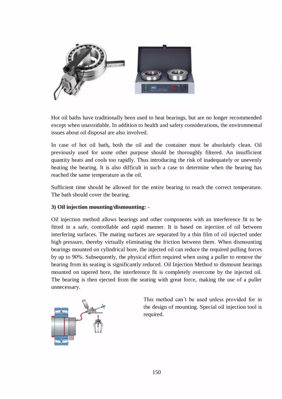
150
Hot oil baths have traditionally been used to heat bearings, but are no longer recommended
except when unavoidable. In addition to health and safety considerations, the environmental
issues about oil disposal are also involved.
In case of hot oil bath, both the oil and the container must be absolutely clean. Oil
previously used for some other purpose should be thoroughly filtered. An insufficient
quantity heats and cools too rapidly. Thus introducing the risk of inadequately or unevenly
heating the bearing. It is also difficult in such a case to determine when the bearing has
reached the same temperature as the oil.
Sufficient time should be allowed for the entire bearing to reach the correct temperature.
The bath should cover the bearing.
3) Oil injection mounting/dismounting: -
Oil injection method allows bearings and other components with an interference fit to be
fitted in a safe, controllable and rapid manner. It is based on injection of oil between
interfering surfaces. The mating surfaces are separated by a thin film of oil injected under
high pressure, thereby virtually eliminating the friction between them. When dismounting
bearings mounted on cylindrical bore, the injected oil can reduce the required pulling forces
by up to 90%. Subsequently, the physical effort required when using a puller to remove the
bearing from its seating is significantly reduced. Oil Injection Method to dismount bearings
mounted on tapered bore, the interference fit is completely overcome by the injected oil.
The bearing is then ejected from the seating with great force, making the use of a puller
unnecessary.
This method can’t be used unless provided for in
the design of mounting. Special oil injection tool is
required.

151
After mounting of bearings the axial float of the bearing should be as per OEM
recommendation.
Storage and handling:
Keep bearings in their original unopened packages until immediately prior to mounting to
prevent the ingress of contaminants and corrosion. Bearings are coated with a rust-inhibiting
compound and suitably packaged before distribution. For open bearings, the preservative
provides protection against corrosion for approximately three years. The conditions under
which bearings and seals are stored can have an adverse effect on their performance.
Inventory control can also play an important role in performance, particularly if seals are
involved. Therefore a "first in, first out" inventory policy is recommended.
Sealed bearings, the lubrication properties of the grease with which they are filled may
deteriorate with time. Lubricant deteriorates over time as a result of ageing, condensation,
and separation of the oil and thickener. Therefore, sealed bearings should not be stored for
more than three years
Large rolling bearings should only be stored lying down, preferably with the support for the
whole extent of the side faces of the rings. If kept in a standing position, the weight of the
rings and the rolling elements can give rise to permanent deformation because the rings are
relatively thin walled. For the same reason, if large and heavy bearings are moved or held in
a position using lifting tackle, they should not be suspended at a single point; rather a sling
or other suitable aid should be used. A spring between the hook of the lifting tackle and the
sling facilitates positioning the bearing when it is pushed onto a shaft.
For ease of lifting, large bearings often have threaded hole in the ring faces into which the
eye bolts can be screwed. As the hole size is limited by the ring thickness, it is only
permissible to lift the bearing itself or the individual ring by the bolts. When mounting a
large housing over a bearing that is already in position on a shaft, it is advisable to provide
three point suspensions for the housing and for the length of one sling to be adjustable. This
enables the housing bore to be exactly aligned with the bearing.
BEARING HOUSING
Bearing accommodate the bearing within it & also contain the lubricant within it. Also to
restrict the axial movement locating rings are mounted within it. For oil lubricated bearing

152
housing is different than the grease lubricated bearing housings. Bearings housings have
different types of seal according to the application like felt, rubber, labyrinth etc. Bearing
housing generally split type. Single piece type housing is also used in some application.
Take up type bearing housings are used for adjusting the equipment. Flanged housings are
find application.
Common grease lubricated bearing housings designated as SN/SNA/SNL-XXX. Oil
lubricated housings are designated as SOFN/LOE-XXX.
Bearing housings are usually made of grey cast iron. Cast steel housings are used in special
applications.
Some ball/roller bearings which are greased & sealed with housing ready to mount are
called bearing units.
7.7 Power Transmission and Power Drives
POWER is transmitted from the prime mover to a machine, from one machine to another,
or from one member of the machine to another, by means of intermediate mechanisms
called drives. These intermediate mechanisms are necessary instead of directly coupling the
machine to the prime mover, due to the following reasons:
1. The optimal speeds of the prime mover or that of the standard motors may be different
from the velocities required to operate the machines. The prime mover s usually have
higher angular velocities, while the operating members frequently require a large torque
with relatively low velocities.
2. The velocity of the driven machine may have to be frequently changed or regulated,
whereas the speed of the prime mover should be kept constant for its use to the full
advantage.
3. In some cases, several machines may have to be operated from only one prime mover.
4. Sometimes the machines are not coupled directly to the prime mover shaft due
to the considerations of safety, convenience and maintenance.
MECHANICAL DRIVES:
1) by mode of power transmission:
Transmission by
a) friction and by b) mesh
a) Transmission by friction may be further classified as:
With direct contact, e.g. friction drive
With a flexible connection, e.g. belt drives

153
b) Transmission by mesh may further be classified as:
With direct contact, e.g. toothed and worm gears
With a flexible connection, e.g. chain drives
The velocity ratio in toothed wheel gearing is limited only by size of the drive and in belt
drive, by the minimum allowable arc of contact on the smaller pulley.
From straight shot conveying systems to heavy-duty power transmission— belt and chain
drives are integral to their reliable operation.
“In today’s world there are many factors that influence the decision on whether to use belts
vs. chain drives. Many of these factors were not as important or not even considered just a
few years ago. Speeds, accuracy, safety, environmental and even noise factors now take a
high prominence in the modern decision-making process — along with the age-old factors
such as power, direction of rotation, how many axes are to be powered by the drive device,
etc. Belts have improved a lot in recent years; so have chains and their method of
lubrication, we notice that belts are the preferred method in most modern applications for
precision drives.
Belts are friction and can handle high speeds smoothly.
Speeds of 3,600 RPM are better suited for belts. Also, the fact that belts are a friction
technology means that in the event of an overload, belts will slip and avoid system damage.
For applications in conveyor transmissions or to develop torque, chains make better sense.
“Conveyors are much slower—under 350 RPM on the driver. Chains can be used with
a wide selection of sprocket ratios to achieve the desired speed. The demand for torque
gives chains an advantage due to mechanical ratios and the need for a positive drive.”
Chains are excellent for a range of speeds and loads, plus chain length is easy to adjust by
specifying the number of links required.
“The chain selection process is fairly straightforward. Key things to know are
horsepower, RPM, intensity of shock load, temperature and exposure to potential corrosive
conditions.
Both belts and chains will produce some sort of contaminant during their operation. Chains
have grease, oil, and metal particulates. Belts will shed material over time as well.
The primary differentiation between the two is in maintenance. Chains require routine
lubrication and more frequent replacement. In wash-down environments, the potential for
spread of grease and oil contamination is elevated and the maintenance requirements
skyrocket.
KEYS AND COUPLINGS:
Keys: The most common function of a key is to prevent relative rotation of a shaft
and the member to which it is connected, such as the hub of a gear, pulley, disc, or crank.
An extensive use of keys is largely due to their simple and dependable design, convenience
of assembly and disassembly, low cost etc. In a design of key, shaft and pulley, key is made
weaker so that when excess load appears key fails and it keep shaft & pulley safe.
The major disadvantages are:
Keyways not only make the effective cross-section of the part smaller but also involve
considerable stress concentration. Failures of shafts and axles are very often caused by high
local stresses arising in the area of keyway. One key cannot transmit large torques. The
greater accuracy required and complicated load conditions made the development of
SPLINES made integral with shaft.

154
Because: they can transmit greater loads at varying speeds and impact loads. But they have
uneven load distribution between the splines and they need special cutting and measuring
tools.
Couplings:
They are necessary to connect one shaft to another or to couple a drive shaft to a driven
shaft. Shaft couplings are used in machinery for several purposes:
Beyond the basic purpose of holding together two shafts, couplings accomplish the
following:
Reduction of shock loads between shafts.
Defense from overload. If a system is running too hot or too fast, a major
mechanical catastrophe could occur. Some couplings help prevent the need for
costly repairs by disconnecting or slipping when a certain level of torque is
surpassed.
Shifting vibration of turning parts. Vibration is key in industrial machinery; it is
like a heartbeat for the entire mechanical system. Some couplings can alter the
vibration output, thereby reducing the amount of repair required.
Mechanical flexibility and allowance for misalignment. Couplings can facilitate
operations even when shaft misalignment and movement are present.
G couplings, also known as gear couplings, are a specific type of coupling that is often
used in high-torque, high-horsepower situations. A G coupling does not typically include a
grid, which is a kind of net that is sometimes located within a coupling system. Compared to
universal joints, gear couplings can typically withstand more torque, while universal joints
cause lower vibrations. The basic structure of a G coupling is two hubs with external and
internal teeth and a one- or two-piece sleeve
Rigid couplings. These are perfect when misalignment is not an issue and when thrust loads
are high.
Floating shaft assemblies. These allow shaft connections across long distances. For
instance, if you have an engine that needs to operate a fan located 15 feet away and there’s
no place to mount supports for the connecting shaft, a floating shaft assembly is a good
solution.
Slide couplings. These are used in circumstances where some axial movement is needed
and thermal shaft expansion must also be accounted for.
Shear pin couplings. These are ideal in systems that tend to overload or become jammed.
When the pin inside the coupling breaks, the equipment can no longer run. This prevents
damage by stopping the system as soon as loads become dangerously high.
Disconnect couplings. These are similar to shear pin couplings in that they can disconnect
quickly according to the situation at hand. Disconnect couplings may be used in both low-
and high-speed applications.
These are only a few of the varieties of G couplings available today. One thing holds true
for all of these coupling systems: They will last much longer with proper maintenance.

155
UNIVERSAL JOINTS
A universal joint is a positive, mechanical connection
between rotating shafts, which are usually not parallel,
but intersecting. They are used to transmIt motion,
power, or both.
The simplest and most common type is called the
Cardan joint or Hooke joint. It is shown in Figure 1. It
consists of two yokes, one on each shaft, connected by
a cross-shaped intermediate member called the spider.
The angle between the two shafts is called the
operating angle
A basic characteristic of the Cardan joint is the nonuniformity of motion transmission
through the joint. The angular-velocity ratio between input and out put shafts varies
cyclically at two cycles per revolution of the input shaft.
Oldham Coupling
Oldham couplings consist of three members. A floating member is trapped by 90 displaced
grooves between the two outer members which connect to the drive shafts as shown.

156
Oldham couplings can accommodate lateral shaft misalignments up to 10% of nominal shaft
diameters and up to 3 angular misalignments.
Lubrication is a problem but can in most applications be overcome by choosing a coupling
that uses a wear resistant plastic or an elastomer in place of steel or bronze floating
members.
Oldham couplings have the following advantages: a. No velocity variation as with universal joints
b. High lateral misalignments possible
c. High torque capacity
d. Ease of dismantling
Disadvantages: a. Limited angular displacement of shafts
b. Need for periodic lubrication due to relative sliding motion
c. Possible loss of loose members during disassembly
7.8 Technology of Repair of Steel Plant Equipments
All industrial equipments are subjected to wear and tear, stress, corrosion, ageing including
mishandling and mal-operation. Systematic care and attention is required not only to keep
equipments in good working order but various technological methods are also adopted to
increase the service life of equipments.
Engineering technologies such as Machining, Welding, Fabrication, Fitting & Assembly,
Forging, Casting, Heat treatment, Balancing etc. are adopted for both manufacturing and
repair of spares and equipments. In order to cater to these needs, Captive Engineering Shops
have been established with all these facilities in our integrated steel plants.
The various facilities available with the engineering shops are :
Machine Shop :
Machining is an important method of shaping metal parts and especially of finishing them to
close dimensions. Machine Shop consists of light and heavy Machining Sections equipped
with lathes, planers, Horizontal and Vertical Boring machines, Gear cutting machines,
Slotting machines and Grinders for manufacturing and repair of equipment spares like
Shafts, Liners, Gears, rolls etc.
Simple lathe tools and operations are schematically shown below:

157
Balancing
Unbalance in a rotor is the result of an uneven distribution of mass, which causes the rotor
to vibrate. The vibration is produced by the interaction of an unbalanced mass component
with the radial acceleration due to rotation, which together generate a centrifugal force.
Since the mass component rotates, the force also rotates and tries to move the rotor along
the line of action of the force. The vibration will be transmitted to the rotor's bearings, and
any point on the bearing will experience this force once per revolution.
Balancing is the process of attempting to improve the mass distribution of a rotor, so that it
rotates in its bearings without uncompensated centrifugal forces. This is usually done by

158
adding compensating masses to the rotor at prescribed locations. It can be also be done by
removing fixed quantities of material, for example by drilling.
Forging Shop :
Forging is a manufacturing process of shaping metal through hammering, pressing or
rolling. Forging can be categorized according to temperature at which it is performed.
Basically there are two types of forging:
a) Cold forging b) hot forging.
Welding / Fabrication Shop :
Welding is a materials joining process by using high heat that melts the parts together and
allow them to cool causing fusion. A filler material is added to the joint to form a pool of
molten material that cools to form a joint. This is a highly versatile process used for day to
day and regular repair of plant equipments. The main Welding processes are :
a) Oxyfuel Gas welding – Use the heat produced by a gas flame for melting the
base metal and if used, the filler metal. Pressure may or may not be applied.
b) Arc Welding – A fusion welding process wherein union of work piece is
produced by melting the surfaces to be joined with the heat energy obtained from
an A.C. or D.C source.
c) Resistance Welding – A group welding process, which produces union of metals
with heat obtained from resistance offered by the work to the flow of electrical
current through the parts being joined.
TYPES OF WELD JOINTS
There are five basic types of joints for bringing two parts together for joining.
The five joint types are not limited to welding; they apply to other joining and
fastening techniques as well.
(a) Butt joint. In this joint type, the parts lie in the same plane and are joined at
their edges.
(b) Corner joint. The parts in a corner joint form a right angle and are joined at
the corner of the angle.
(c) Lap joint. This joint consists of two overlapping parts.
(d) Tee joint. In a tee joint, one part is perpendicular to the other in the
approximate shape of the letter ‘‘T.’’
(e) Edge joint. The parts in an edge joint are parallel with at least one of their
edges in common, and the joint is made at the common edge(s).

159
Fabrication Shop
Welding, forming and fitting are the three basic processes used mainly for fabrication of
metal structures / equipments. This is very important for repair /manufacture of steel plant
equipments and structures. Fabrication Shop is generally equipped with Profile cutting
machines, Plate Bending machines, Shears, Welding machines of different types, Hydraulic
presses, facilities for heating & Material handling etc.

160
Fitting & Assembly Shop Fitting & Assembly is an important ingredient of a Repair
shop activity. Small and big equipments need overhauling and repair after rendering
long service.
Huge repair shops under different units of SAIL cater to such needs which are equipped
with material handling facilities, Hydraulic Press, Heating arrangement, Portable machines,
besides necessary tools and tackles and trained manpower.
Besides the above facilities, Heat Treatment section, Hydraulics and Pneumatics section,
Gears and gearbox repair section, Tool room facility, Instrument Section, Inspection,
Chains and Sling Testing sections, etc. have their importance in the Engineering shops of
our steel plants.
Inspection & Measuring Instruments :
Inspection is an important wing of Engg. Shops where Measuring Instruments play vital role
in determining dimensional accuracy of spare parts repaired / manufactured not only in
these units but also in all maintenance units across the steel plant.
Some of the commonly used measuring instruments are : - Measuring tapes of different lengths,
- Scales,
- Callipers (for inside & outside sizes),
- Slide/Vernier callipers for measuring length, inside & outside diameter,
depth),
- Micrometers (for measuring outside & inside diameters),
- Dial gauges (for outside & inside diameters),
- Gear tooth verniers for measuring gear tooth vital dimensions,
etc.
Foundry & Pattern Shop :
The Shop produces ingot moulds and bottom plates vitally required for Steel Melting Shops.
They also produce Iron castings, Steel castings and Non-ferrous castings to meet regular
requirements of spares for steel plant.
In addition to Engineering Shops, departments like Crane Maintenance, Heavy
Maintenance Engineering, Design, Field Machinery Maintenance, Loco Repair Shop,
Electrical Repair Shop come within the ambit of Maintenance Organisation.
TECHNOECONOMICS
Maintenance costs:
Production unit of any magnitude cannot afford undesirable downtime. The concept of
maintenance costs deals with two aspects:
1 Costs actually related with maintenance activities.
2 Costs related with downtime of production units.
In maintenance activities, consumable products used in carrying out maintenance have
direct impact on costs. Labor costs involved in carrying out maintenance related works viz

161
repair; reclaimations, erection, testing, inspection etc. have a direct or indirect impact on
maintenance costs. The aim of maintenance crew is to:
Control maintenance cost by salvaging, generating in house spares, proper assembly &
in house repairs and reduction of downtime of equipments.
To ensure implementation of preventive maintenance, planned maintenance, shut down
maintenance, modification & design maintenance to achieve maximum equipment
availability.
Daily planning of maintenance jobs, prioritizing & execution.
Periodic maintenance of routine, preventive maintenance activities including condition
based maintenance.
7.9 Availability and Reliability of Equipments
Availability is a key performance indicator, which indicates the effectiveness of
maintenance in a work. Availability can be defined as the ratio of “NET OPERATING
TIME” to “NET AVAILABILITY TIME”.
Net operating time= net available time- unplanned downtime
Net available time= total time- planned downtime
Few other important aspects to take care are:
Mean time between failures (MTBF)
Mean down time (MDT)
IN THIS WAY WE DEFINE AVAILABILITY AS RATIO OF
MTBF to MTBF+MDT
The down time in a plant comprises of:
Reporting time, inspection time, tool and man power arrangement, troubleshooting time,
logistics time, actual repair time, spares procurement time, test run time, handing over time
etc. So, DOWNTIME SOLELY DOESNOT DEPEND UPON SKILL OF WORKERS OR
SEVERITY OF DEFECTS.
RELIABILITY stands for trust.
Reliability is the probability, that a machine when operated under a given condition, will
produce the desired output for given period of time.
A high reliable machine may have less availability; again a highly available machine may
have less reliability and high maintainability. MAINTAINABILITY is basically “the
degree of ease in maintenance”.
Total Quality Management (TQM) in Maintenance Organization:
Total quality management (TQM) is the continual process of detecting and reducing or
eliminating errors in manufacturing, streamlining supply chain management, improving the
customer experience, and ensuring that employees are up to speed with training.
Total quality management aims to hold all parties involved in the production process
accountable for the overall quality of the final product or service. Doing business in today’s
Global market calls for reduction in production cost with improvement on quality. Quality
means “Fitness for use” or “Conformation to standards”, which is the totality of features and
characteristics of a product or service. With the ongoing competition in the global scenario
it has become imperative to produce quality. Quality of Maintenance, like the quality of

162
product must be designed and built into the system, process or methods of maintenance.
Total quality of maintenance depends upon well-designed plans, systems and procedures,
use of proper tools and test equipment, adoption of correct technical practices and the
creation of conducive environment for good maintenance.
Achievement of consistent quality output over a period of time should be the main objective
of the Maintenance function. Keeping this in mind, many of SAIL steel plants have adopted
ISO-9001:2000, the Quality Hallmark of International scenario into their maintenance
organizations.
7.10 Do’s And Don’ts & Safety
DOS
1) Monitor oil contamination level regularly.
2) Oil tank temperature should be kept within specified limit to maintain desired viscosity
and prevent damage of oil seals.
3) Be careful while opening pumps or valves, cylinders containing compressed spring.
4) Keep fire extinguishers, sand, water nearby place of cutting-welding hydraulic pipes.
5) Before starting hydraulic pumps ensure opening of suction line valve.
6) Periodically clean water filters provided in inlet line of heat exchangers.
7) Keep away from repaired pipe line flanged joints at the time of testing.
8) Always Depressurize a pressure line in steam/water/hydraulic/gas system before
opening.
9) Use gas mask/ other safety appliances while working on coke oven gas pipe
line/valves.
10) Always take electrical shutdown of electrically operated equipments before start of
maintenance job.
DONTS
1) Never take up maintenance work in running equipments.
2) Never open hydraulic pipe connections without depressurizing the pipeline or
component to be removed.
3) Never fill oxygen in place of Nitrogen in pressure vessels such as hydro gas
accumulators.
4) Never touch pump coupling without proper electrical shut down.
5) Never use cotton waste in hydraulic component or pipe line repair job.
6) Never plug drain line of pump or valve.
7) Never allow welder to do welding job with wet hand or with wet hand gloves
8) Never apply sand paper to clean spool of hydraulic valves. Lapping paste can be used
to clean rusts in spools.
9) Never go alone in gas prone area/conveyor belt area./ tunnels .

163
SAFETY
Whenever system trouble-shooting/maintenance is carried out; safety should be the
foremost consideration. So, it is better to have a systematic shutdown procedure like one
given below-
1. Take proper shutdown of equipments.
2. Lower or mechanically secure suspended load.
3. Depressurize the pressure line.
4. Where ever necessary stop valves should be closed.
5. Isolate the electrical control system.
6. Drain out accumulator unit.
7. Discharge both ends of intensifier.
8. Always check and record condition of rope ladder before use.
9. Always use tested tools and tackles.
10. Always balance load on either side of rope during rope changing in cranes.
11. Use CO monitor in gas areas.
12. Use safety belts while working in height.
---

164
Chapter – 8
HYDRAULICS 8.1 Introduction
Transmission & control of forces & movements by means of fluids is called hydraulics.
Fluids under pressure can be used for Power Transmission. Fluids means gases (air) and
liquids (oil or water etc). The system which uses air as working medium is called
pneumatics and which uses oil/water is called Hydraulic system. However water as a
medium for Hydraulics is rarely used in present day applications.
Velocity of the fluid is the average speed of its fluid particles past a given point, measured
in meters/second. Velocity is an important consideration in sizing the hydraulic lines that
carry the fluid between components. Low velocities are desirable to reduce frictional losses
and turbulence.
Laminar Flow: If fluid particles are moving parallel to the flow path, then it is called
laminar flow. It is always desirable to have laminar flow, so that energy losses are
minimum.
Turbulent flow: - If the path of fluid particles is haphazard and not parallel to the flow path
then it is called as turbulent flow. This is not desirable and to be avoided at the design stage.
Lot of energy will be wasted as heat in turbulent flow.
Flow rate is the measure of volume of liquid passing through a given point in unit time. It is
generally measured in lpm (liters per minute) or gpm (gallons per minute). Flow rate
determines the speed of the actuator and therefore is important for consideration of power.
Pressure Force is the effort required to do the work. It is basically a reflection of the resistance
caused to the flow of the fluid. Pressure means or measured as the force exerted per unit
area, generally measured in psi, or kg/ cm2, or bar or MPa (1 Mega Pascal =10 bar)
Atmospheric Pressure
At sea level the whole column of atmospheric air exerts a weight or force of 14.7 pounds for
every square inch of the surface area i.e. a pressure of 14.7psi or 1.03kg/cm2. This is called
atmospheric pressure.
1 Atmospheric Pressure = 1.03 Kg/cm2= 1 bar =14.7 psi
Flow & Pressure are inter-related. Flow is responsible for causing the motion of piston in a
cylinder. It is the movement of hydraulic fluid caused by a difference in pressure at two
points. When we open the kitchen tap the pressure difference (between the water tank at
height and tap) pushes the water out, or causes the water to flow. In a hydraulic system flow
is usually produced by the action of the hydraulic pump. If the pressure is not sufficient to
take the load on the cylinder, it will not move.

165
GENERAL POINTS 1. Oil is most commonly used hydraulic fluid, because it acts as lubricant for all
moving parts of hydraulic system.
2. Generally the weight of hyd. oil is around 55-58 pounds/cubic feet. One foot of oil
causes a pressure of 0.4 psi. A 10 m column of water causes a pressure of 1 kg/sq
cm.
3. There must be a pressure drop across an orifice/restriction to cause flow. If there is
no flow, there is no pressure drop and vice versa.
4. Force exerted by a cylinder is dependent on pressure of oil supplied & piston area
5. Speed of the cylinder is dependent on piston area and the rate of fluid flow into it.
6. Fluid velocity through a pipe varies inversely to the square of inside diameter.
7. Friction in pipes results in pressure drop
8. Air is compressible, where as oil is incompressible practically.
9. Pump only transfers the fluid. It is the resistance to flow which develops pressure.
10. It is the atmospheric pressure which is responsible for pushing of oil from tank to the
suction chamber of the pump.
11. Flow takes the path of least resistance.
12. Flow always takes place from higher pressure to lower pressure.
13. Resistance in series flow adds up.
14. Rate of flow is directly proportional to the pressure difference.
15. As a the diameter of the pipe increases the pressure drop decreases.
Pascal’s Law
PRESSURE APPLIED ON A CONFINED FLUID IS TRANSMITTED UNDIMINISHED
IN ALL DIRECTIONS AND ACTS WITH EQUAL FORCE ON EQUAL AREAS AND
AT RIGHT ANGLES TO THEM (If a force F is applied on a piston of area A, (over a
confined fluid ) then it gives a pressure P = F/A. This pressure will be uniform in the entire
confined fluid at rest.
F
P = F / A
A
P

166
Hydraulic Press (BRAMAH PRESS)
Since pressure in the confined fluid is uniform throughout and by applying this pressure on
large areas large forces can be developed. This is the starting point for development of
Hydraulics (see the fig below).
If two cylindrical chambers which are connected and fitted with pistons of area Aі, A₀ and if
a Force Fі acts on piston of area Aі, it develops a pressure P in the confined fluid. This
pressure will be uniform in the entire fluid in double cylinder arrangement, and develops a
force F₀= P x A₀. Hence forces will be proportional to the area of the pistons. There is no
energy creation and work done will be same by both the pistons. The displacements (lengths
of travel of pistons dі, d₀) will be inversely proportional to the areas of the pistons. ( i.e. If
the left side small piston travels a large distance, the right side big piston will travel only a
small distance)
The length of piston travel
is inversely proportional to
area.
Work done Wi = Fi . di
Wo= Fo. do
Bernoulli’s Principle
This is nothing but law of conservation of energy. If the flow rate is constant, the total
energy at any point of continuous path of flowing fluid is same as at any other point. (Sum
of motion energy, pressure energy, and potential energy is constant.).To know the pressure
or flow velocity at any point in the circuit, this principle is used widely.
ADVANTAGES OF HYDRAULIC SYTEMS
Due to limitations of other power transmission system such as electrical, electro-
mechanical and pneumatic etc. hydraulic power transmission is preferred. Large forces can
be transmitted to long distances with high pressure stability and quick response. There are
multiple application possibilities which are suitable for use where large forces with
infinitely variable speeds are to be applied in given directions. Hydraulic equipments give
smooth operation for longer period with very less maintenance cost. Normally oil
contamination control and leakage control may give long life to hydraulic components.
d0/di = Ai/A0 F0/Fi = A0/ Ai

167
Other advantages of hydraulic system are:
1. Highly compact- Power to weight ratio is very high. A hydraulic motor weighs about
1/7 th of an electric motor of same power
2. Precise control- depending on different requirements we can get exact speed, force and
position of user,
3. In built Over load protection- in case there is over load(pressure) in pipe line or by the
user, there is provision of relief valve set at a certain maximum pressure to take care of
it,
4. Suspension of load for long period- by providing a load holding devices for example
pilot operated non-return valve in pipeline, load may be suspended for a longer period,
5. Flexibility in design- As per needs of production, scheme of hydraulic circuit may be
changed easily only with addition of a few components,
6. Easy maintenance- Its maintenance is easy. Only oil contamination control, following
some standard practices and keeping the system cool, will fulfill major portion of
maintenance work. For these purposes monitoring of set parameters and inspections of
pipe lines, religiously is necessary
7. Variable Speed Controls: - We can get infinitely variable speeds and positions as per
need of users.
8. Stalling of loads:- The loads can be stalled to zero speed without any damage to the
equipments
9. Heat is automatically carried away by the fluid
10. Minimum wear rates because components are lubricated by operating medium
11. Energy storage through accumulator, ideal for power failure requirements
RELATIVE DISADVANTAGES OF HYDRAULICS
i) Compressibility of hydraulic fluid needs to be considered. In the case of a fluid
containing no air bubbles the volume reduces by 0.7% when the pressure is increased by
100 bar. Up to 150 bar the compressibility can be neglected but beyond that, especially
when delivery rates are high, it can have an adverse effect on the functioning of the system.
If there is any air trapped in the fluid it is more compressible and can give rise to
disturbances such as noise, vibration and jerky motions at pressures as low as 50 bar.
ii) Fluid viscosity is sensitive to temperature and pressure. Viscosity decreases as the
temperature increases. The viscosity-pressure behavior of hydraulic fluids is of importance
when operating pressures are higher. Although the increase in viscosity can be low up to a
pressure of 200 bar, it can double when the pressure reaches around 400 bar.
iii) Pressure and flow losses in pipes and control devices need to be considered
meticulously while arriving at system pressure requirement of a hydraulic system
iv) Leakage problems need to be attended properly.
8.2 Components of Hydraulic System and their Functions
RESERVOIR: The tank which stores the working medium (oil), supplies to pump, takes
back the return and drains oil in a hydraulic system and protects the medium from external
contamination is called Reservoir. It also allows the oil to cool through its walls and allows
contaminants to settle and air to separate. Generally in many cases it houses cooler, return
filters, air breather( a device which allows air to move in and out of a container to maintain
atmospheric pressure), level indicator, level switches (float switches). It is also provided
with drain plugs to drain oil, manhole (for maintenance and cleaning purpose), baffle plates
which allow the return oil to settle and cool before entering the pump through suction line.

168
SUCTION LINE: The pipe line connecting tank to pump generally with a shut off valve
(preferably with interlock limit switch) in between is called suction line. Without opening
this valve, pump should not be started. Generally a hose or rubber bellows is provided in
this line to take care of minor mismatch between the tank and the pump and to take care of
the vibrations of the pump.
PUMP: The element which transfers oil/fluid from one point to another point or which
gives flow is called pump. Pump only gives flow, but the resistance to flow develops
pressure. In hydraulics only positive displacement pumps are used. In these pumps there is
positive sealing between suction and delivery. For every revolution of pump, a fixed amount
of oil is transferred from suction to delivery irrespective of load conditions. Practically there
will be minor internal leakages which are negligible. This fixed amount of oil transferred is
called Displacement of pump. The displacement (cubic cm per rev) when multiplied by
speed of the electric motor driving the pump, gives Discharge of the pump (flow of the
pump)
POSITIVE DISPLACEMENT PUMPS
Centrifugal pumps (non positive displacement type) are not generally used in hydraulic
systems. In this type of pump, if delivery is closed, pressure will not build up beyond a
particular limit. Safety valve is not required.
Most commonly used positive displacement pumps used in hydraulics are Gear, Piston and
Vane types
A positive displacement pump should never be started without opening the suction valve.
There should be sufficient oil level in tank so that air does not enter the pump. If air enters
the pump, it will run with high noise and it will be damaged very soon. This is called
aeration. Even though sufficient oil is there, aeration can occur due to any loose pipe joints
in suction line. Pump delivery line is always followed by a check valve, relief valve (safety
valve), pressure gauge, and shut off valve (These are required for pressure setting and
isolating).
CHECK VALVE/NON-RETURN VALVE: It is a valve which allows flow in one
direction only. Generally provided after the pump in most of the cases to take care of
reverse rotation of pump, it is also used in many places of the circuit as a bypass etc. Check
valve and non-return valve are same.

169
SOME CHECK VALVES
PRESSURE GAUGE: It is provided to know the pressure at any position at any instant of
time and for setting of various valves, pressure switches etc. The pressure gauge with
glycerin filled dial is preferred in the hydraulic system to take care of the damage to the
gauge due to vibration and variations
SAFETY VALVE/ RELIEF VALVE: Both are same and it is the most important
component of Hydraulic system. It limits the maximum pressure in the system so that
elements, hoses, cylinders, pipes etc does not burst due to high pressure. It also protects the
equipment and system from over loading. When the system pressure increases beyond the
set point, the safety valve opens and relieves the excess oil to tank. This is provided at many
points and at different settings to make the system literally foolproof.
RELIEF VALVES
ACCUMULATOR: It is a reservoir of pressurized hydraulic fluid i.e. storage of energy by
means of spring or compressed nitrogen, dead weight. It is basically a pressure vessel. No
welding is allowed on this. 1. Bladder type (most commonly used) 2.Piston type 3.Dead
weight type 4. Direct gas loaded type.
Nitrogen is generally used in accumulators but never use oxygen as it may result in
explosion. You should never open a pressure line with accumulator in line. Always isolate/
preferably drain the accumulator before starting the job.
Accumulator is used (a) for smooth functioning of Hydraulic System without pressure and
flow fluctuations (b) as an emergency power source for essential operations in case of
power failure. (c) for holding pressure for long times in a circuit (d) a big pump can be
replaced by a small pump ( cost & energy saving) and many other purposes.

170
ACCUMULATORS
DIRECTIONAL CONRTOL VALVES: Distributor/Master valve / DC valve are all same.
If a pump supplies oil directly to a cylinder, it is not possible or convenient to control the
load or to change the direction of motion. Hence a DC valve is provided in between pump
and the load cylinder to stop/start /reverse the motion of the load. DC valve can be activated
by a lever, cam, solenoid, pedal, pneumatic/hydraulic pressure depending on the design and
requirement. Most commonly used are solenoid operated and they are having two/ three
positions. If you are using a two position valve the cylinder will travel in between the
extremes only. You cannot stop the cylinder in between .There are many varieties of dc
valves depending upon the requirements
DC VALVES
FLOW CONTROL VALVES: To control the speed of the actuator /load, the amount of
oil flowing into the cylinder is controlled by means of these valves. Generally these are
provided before the cylinder or in branch circuits where flow is to be controlled. Simple
needle/globe valve can also be used as flow control valve in some cases.
FLOW CONTROL VALVES
SEQUENCE VALVE: These valves are used to make multiple actuations, connected
through a common system, work in a sequence of requirement. In other words these valves
provide serial operations based on pressure setting. In a simple punching machine, the job is
held in position by a clamping cylinder at low pressure and then a hole is punched by
another cylinder at a high pressure. Now these two cylinders are always to be operated in
definite sequence only. This sequence can be achieved by electrical/mechanical or by
hydraulic means through a valve called sequence valve. Hydraulic sequencing is most
common and versatile. A DC valve supplies oil to cylinder-1 and through a sequence valve
to cylinder -2. (After cylinder -1 is operated completely, pressure will buildup and then
sequence valve gets opened and oil goes to the cylinder -2 at a higher pressure. The
sequence valve is tuned and set to achieve the sequence). It is almost similar to a safety
valve but not same.

171
SEQUENCE VALVE APPLICATION
PRESSURE REDUCING VALVE: In some hydraulic systems many cylinders are
working at same pressures ,but a few cylinders do not require full pressure and can work
at a lower pressure .And since the system has to run with a common power pack which
supplies a constant system pressure, then all these selected cylinders are supplied oil at a
lower pressure through a valve known as pressure reducing valve. In pressure reducing
valve, the output pressure cannot go beyond a particular limit. This setting will be lower
than the safety valve setting. Pressure Relief valve and Pressure Reducing valve are not
same and should never be confused. This valve is also known as Pressure Regulating valve.
PRESSURE REDUCING VALVE
FILTERS: All hydraulic elements work under close tolerances and they are precision items
with mirror surface finish .Contaminants and dust are the single largest enemy of the
hydraulic system as they cause malfunctioning and jamming of valves and fast wear out of
elements. The contaminants are internally generated in the system and some are external to
the system. Working medium is to be regularly cleaned from these contaminants. Hence oil
filters are used in suction line, pressure line and return line and before an important
precision valve/pump as per the need. This will improve the performance of the system. The
coarse filter used in suction line of pump sometimes is called STRAINER .Hydraulic
systems are most reliable, if the contamination is kept under control, and breakdowns can be
minimized.
In a filter the hydraulic oil is allowed to pass through a porous medium (like paper,
wire mesh, synthetic fiber etc) so that the dust particles and other contaminants are retained
and only clean oil goes ahead into the system. Filtration can be either online or offline.
In online filtration the oil is passing through a strainer or a suction filter before it
enters in the pump. After the pump the oil passes through the pressure filters and then after
passing through the dc, flow control valve and actuators, before flowing back to the tank,
the oil passes through the return filter
Offline filtration (mostly portable) systems are also used for up keeping the system
depending on the criticality. Electrostatic Liquid cleaners are also used nowadays. These are
very simple to operate and cheap. Generally Return line filters are provided with parallel
bypass valves(check valve) to take care of clogging temporarily.

172
Location of filter in hydraulic system
FILTERS

173
PRESSURE SWITCH: These are provided in the system for safety and efficient operation
or for achieving a particular logic sequence. The pressure switch can be either plunger type
or bourdon tube type. In plunger type pressure switch the hydraulic oil under pressure
pushes small plunger which in turn makes/breaks an electrical contact. In the bourdon tube
type pressure switch with the change in the pressure of the system the bourdon tube expands
or contracts as in the pressure gauge thus making/ breaking contacts with the micro switch/
switches Contact Manometer is a pressure gauge with electrical contacts, which does almost
the same job, but they are less reliable and less robust.
PRESSURE SWITCHES
LEVEL GAUGES AND SWITCHES: Generally the reservoir is provided with low level
and high level float switches, so that they give alarm of low oil level/ high level and can be
used for interlocking purpose. Float switch operates due to buoyancy in oil. Generally the
low level switch is interlocked with the drive of pump, so that when there is no oil due to
any reason, the pump will trip or will not allow the pump to start.
LEVEL GAUGES AND SWITCHES

174
FILTERING-CUM-COOLING CIRCUIT: In hydraulics, more than 80% of problems
are due to contaminated fluid. Thus, it is important to keep system fluid very
clean. Particulate contamination and water contamination in hydraulic fluids can have
serious adverse effects on the fluids' physical and chemical properties. Oil gets heated
during operation of systems. As a result, the oil needs to be cooled to retain its
viscosity. Heat load for the cooler is considered as 40% (maximum) and 25% (minimum) of
the kW rating of all the running main pumps. Capacity of heat exchangers are usually
expressed in Kcal/hour (1kW = 860 Kcal/hour).
For the above reasons it is required to have a cooling cum filtering system which is
nothing but a combination of pump, heat exchanger and the filter as a secondary system
which runs parallel to the main system. Filters have already been discussed and in this part
we will learn a bit about the heat exchangers
HEAT EXCHANGER: Heat exchanger is the device which takes away heat from one fluid
(fluid to be cooled) and in that process heating up the cooling fluid. Heat Exchangers
require periodical maintenance. This can be of many types
1. Based on working principle a.) Recuperative Heat Exchanger
b.) Regenerative Heat Exchanger
c.) Evaporative Heat Exchanger
2. Based on construction a.) Shell & tube type
b.) Plate type
i.) Brazed type
ii.) Gasket type
In general the tube in shell type heat exchangers and plate type heat exchangers are
most commonly used
HEAT EXCHANGERS
In shell and tube type heat exchangers the cooling fluid flows in the bunch of tubes placed
inside the shell while the fluid to be cooled flows, in a reverse direction, in the shell, in the
leftover gaps between the tubes.
In the plate type heat exchangers the two fluids flow in the opposite direction in the
honeycomb shaped recess between the plates which can either be separated by brazed plates
or by gasket joints
ACTUATORS: Generally the hydraulic cylinders and hydraulic motors are called
actuators. These actuators do the actual job of lifting/lowering/pushing/rotating /holding etc.
Hydraulic motor replaces many applications of electric motors along with the gear box due
to many advantages like speed control, over load protection etc. Hydraulic motors are
almost reverse to pumps. When these are supplied with oil at pressure, they will give rotary
output. Generally gear/vane /piston motors are in use.

175
Generally two types of Hydraulic cylinders are commonly used viz.
a) Double acting cylinders, which can be used for pulling and pushing and consists of
piston, piston rod, body, covers, seals, fasteners, eye etc. Basically a sealed piston with rod
reciprocates inside a cylindrical body under the pressure of oil.
b) Single acting cylinder. These types can only push/lift a load. The single acting cylinder
cannot retract due to hydraulic force. It retracts due to weight/spring/ load. Hydraulic jacks
and clamping devices in a goggle valve are generally single acting type.
CYLINDER HYDRO MOTOR
Hydromotors are used widely in mobile equipments for winch applications and wheel
movement and nowadays very frequently used for the conveyor belt drive.
SEALS: The component which prevents the motion of the fluid in the undesired direction is
called seal/packing. This can also be defined as the component that separates two fluids.
The functions of the seal are
a) To seal the hydraulic fluid in a closed chamber,
b) Maintains pressure,
c) Stops dirt/water/contamination from entering the system,
d) Separates two fluids,
e) Performs any combination of the above functions.
In simple terms a seal stops internal or external leakages. Cost of the seal is a small fraction,
but determines the efficiency of the system.
Leather, cork, ropes are the oldest seals, which are widely used in the earlier days. Then
natural rubbers, synthetic rubber (Elastomers), PTFE, Polyurethane, POM etc are used
nowadays. In higher temperature applications, Viton seals preferred. Seals should be
handled delicately, and sharp tools should not be used.
PIPES, FITTINGS, CLAMPS: Generally pickled, flushed seamless carbon steel pipes are
used in hydraulic systems. But nowadays the stainless steel piping is more preferred because
of their resistance to the external conditions. For maintenance convenience and ease of
laying, pipe joints are provided at suitable places. For small pipes union joints are used and
in bigger pipes flange joints are used. There is large variety of pipe joints of different
standards and designs are available. Care should be taken that different fittings do not get
mixed up. Also, while doing maintenance on fittings, thread type/seat design/size etc should
be matched. Otherwise lot of problems will result. Pipes should be properly clamped and
supported; otherwise the joints get loosened during working due to vibrations. Pipe clamps

176
are made of wood/ Aluminium/ synthetic materials. Wooden clamps are to be avoided due
to environment protection. Aluminium clamps are used where high temperatures are there.
Synthetic clamps (polypropylene) are commonly used nowadays. While laying hose pipes,
the layout should be smooth, and they should not crisscross/twist/entangle and rub each
other.
PIPE CLAMPS PIPE FITTINGS
WORKING MEDIUM
Hydraulic power system may be operated with fluids produced from different base fluids:
1) Mineral oil. 2) Vegetable oil. 3) Synthetic oil. 4)Water
Mineral oil - Most hydraulic systems use hydraulic fluid based on mineral oil. Since base
oils do not have all the characteristics which a high performance hydraulic fluid should
have, different types of additives are dissolved in base oil to improve the properties
Vegetable oil - These fluids are biodegradable and so are being used more frequently in
installations that are subjected to strict antipollution regulations( Food Processing Industry)
Synthetic oil -These fluids are most commonly used in systems where there are special
demands on hydraulic fluid such as fire hazardous zones (furnace area)
Water - Pure water is seldom used as the fluid in hydraulic system. It can be used as
emulsion adding oil in it or adding water to oil.
Fire resistant oil - i) HFA Type (5% oil in 95% water emulsion)
ii) HFB (60% oil in 40% water emulsion)
iii) HFC (60% glycol in 40% water). Offers highest degree of fire resistance
iv) HFD (anhydrous synthetic fluids)
Following are the important properties which hydraulic fluid should possess:
a) Oxidation Stability b) Protection from Corrosion c) Anti Wear d) Viscosity &Viscosity
Index (viscosity index should be high so that viscosity variation with temperature will be
less), e) Demulsibility (ability to resist formation of emulsion when mixed with water) f)
Anti Foaming Characteristics, g) Thermal and high pressure stability, h) Good Lubricant,
i) Compatible with Seals and Hoses, and Metals, j) High Flash Point (the minimum
temperature at which oil just takes fire and do not burn continuously) & Fire points (the
minimum temperature at which oil catches fire and burns continuously).

177
OIL CONTAMINATION CONTROL
Oil contamination is number one enemy of hydraulic system. Therefore, oil contamination
control is the first requirement of any hydraulic system to get a trouble free smooth service.
It enhances the life of different components. To keep oil clean is part of hydraulic system
maintenance. It is just not possible to keep oil free from contamination in any industry due
to various reasons. What we can do is to monitor oil contamination level regularly by
cleanliness determination methods and take corrective steps including changing of filters. If
situation does not improve, tank oil should also be changed as hydraulic valves especially
proportional and servo valves are very dirt sensitive.
Sources of oil contamination
a) With the oil filled in the oil tank itself.
b) Due to wear and tear of internal parts of components such as pump, control valves,
cylinders.
c) Due to wear of oil seals, o-rings.
d) Due to wear of inside of pipelines.
e) Due to generated debris after welding of metallic pipes.
f) Through piston rods of hydraulic cylinders.
g) Through ambient atmosphere.
h) Due to poor upkeep of filters and reconditioning system.
i) Due to use of cotton waste in revisioning or repairing of hydraulic components.
SOME CONTAMINANTS

178
Filters should be provided in oil filling line, reconditioning line, pressure line after pump
with clogging indicator, pilot line and return line. Periodically pressure differences across
filters should be monitored otherwise in case of high pressure difference filters wall may
collapse and oil may pass without filtering or flow rate will reduce.
There are two methods of determination of oil cleanliness class: NAS1638 & ISO 4406.To
decide oil cleanliness class required for different applications, the following table may be
used as guide line-
System type/Range of application Needed Cleanliness Class
According to standards NAS 1638 ISO 4406
Heavy duty servo system, High pressure System
with long service life
4-6 15/11
Proportional valve 7-8 16/13
Medium pressure system 7-9 18/14
Low pressure system 9-11 19/15
It is to be remembered that a fresh drum of oil is not the cleanest one. In fact it may be of
class 10 or 11. So by replacing the oil is not the solution for making the system clean
Ingress of water in the oil :- Sometimes the heat exchanger may have internal leakage and
owing to this water may get mixed with oil. Water in oil can cause serious problems for the
system and can be evidently observed by the colour of the oil, which becomes whitish with
foam. Because of the water in the oil the internal components get rusted. Water in hydraulic
oil has a number of other negative effects. Water Depletes some additives and reacts with
others to form corrosive by-products which attack some metals, reduces lubricating film-
strength, which leaves critical surfaces vulnerable to wear and corrosion, reduces
filterability and clogs filters
OIL LEAKAGE CONTROL
Oil is life blood of hydraulic system, hence leakages should be prevented. Major portion of
mineral oil to be used in our country is imported for which we have to pay heavy price.
Besides loss oil leakage may damage the soil and hence ground water and plant life.
Consequently it damages animal life and human life also. Leakage in fire hazardous zones
may result in fire which may damage property besides unnecessary production delay due to
burning and damage of especially electrical wires and equipments. It is therefore necessary
to control oil leakage to the extent possible. For this regular inspection followed by
corrective measures such as tightening of loose connections and pipe supports, changing of
even partially damaged oil-rings(o-rings), hoses and corroded steel pipes is necessary.
Hydraulic hoses in fire hazardous zones should be periodically changed even though these
are not damage

179
SOME BASIC SYMBOLS
RESERVOIR / TANK SHUT-OFF VALVE
UNI-DIRECTIONAL
FIXED DISPLACEMENT
PUMP
CHECK VALVE /
NON-RETURN VALVE
PRESSURE RELIEF VALVE
P T
ACCUMULATOR
GAS CHARGED
3 POSITION 4 WAY
DIRECTIONAL CONTROL
VALVE
P T
A B
HEAT EXCHANGER /
COOLER
WATER IN
WATER OUT
PILOT OPERATED
CHECK VALVE /
NON-RETURN VALVE
SINGLE ACTING
CYLINDER
DOUBLE ACTING
CYLINDER
PRESSURE REDUCING
VALVE
P To system
FILTER WITHOUT BY-PASS
FLOW CONTROL VALVEADJUSTABLE, NON-COMPENSATED

180
8.3 Block Diagram of Hydraulic System
Every hydraulic system can be traced back to a common basic circuit containing only the
main function as under
Hydraulic Cylinders /
Hydraulic Motors
Pressure Control Valves /
Flow Control Valves
Direction Control Valves
Hydraulic Pump
User
Distributor /
Controller
Energy Source
Pressure Relief Valve

181
SIMPLE HYDRAULIC CIRCUIT (OPEN CIRCUIT) (See the Fig Below)
Here we have a hydraulic system in its most simple form. A pump 1 with fixed flow sucks
fluid from a tank 2 and feeds it into the system connected to it. In zero position of the
manually operated direction control valve the hydraulic fluid, circulates almost without
pressure from the pump to the tank 2. The dc valve is spring centered. When the dc valve 4
is operated into its left switching position, (parallel arrows) fluid reaches the piston chamber
of cylinder 5. The piston rod travels outwards. The speed of the outward travel depends on
the pump flow and the cylinder size (piston area). The force available at the piston rod is
dependent on the piston area and the maximum system pressure. The maximum system
pressure and thus the loading of the hydraulic system is set at the pressure relief valve 3.
The actual pressure available, determined by the resistance to be overcome at the user, can
be read at the pressure gauge 6.
Generally pump is always
followed by a Relief valve
and then a NON RETURN
VALVE(CHECK
VALVE).
This is a typical circuit
where check valve is not
required.
Symbol of check valve

182
SIMPLE HYDRAULIC CIRCUIT (CLOSED CIRCUIT) (See the Fig Below)
Normally the closed circuit hydraulic system is used in the places where continuous
operation of the hydro motor is there
In the closed hydraulic the oil after rotating the hydro motor doesn’t go to the tank back,
instead it goes to the pump’s suction line again. In this process the same oil is only
circulating. To take care of the mixing of cool and fresh oil from the tank a booster pump is
installed which is normally in tandem with the main pump. It mixes the oil from the tank to
the circuit through a flushing valve.
8.4 Application of Hydraulic Systems in Steel Plants
There are various applications of Hydraulics in Steel Plants. Some of the important
applications are:
1. Roll Balancing and Spindle Balancing, Hydraulic Manipulators, Slab Extractors, Walking
Beam Furnaces for Heating of Slabs and Blooms, Automatic Gauge Control for controlling
thickness of plates/sheets, Rail Welding Machine, Roll Assembly Machine etc in Rolling
Mills
2. Electrode Movement Control in Electric Arc Furnaces (VAD, Ladle Furnace)
3. Mobile Cranes and Earth Moving Equipment
4. Coke Oven Pusher Cars, Door Extractors and Charging Cars
5. Blast Furnace BLT Equipments, Mud gun, Drilling Machine
6. Stacker cum Reclaimers in Ore Handling Plants
7. Segments closing/ opening, Pinching Actions in CCS
8. Hydraulic Presses and Various Machine Tools etc.
SOME IMPORTANT TERMS
Cavitation
In any liquid flows, a localized condition within a liquid stream which occurs when the
pressure is reduced to the vapour pressure of the liquid. Lots of vapour bubbles will form
and these will be carried along with the flow and burst at some other point. This condition is

183
highly harmful to the pump and all hydraulic elements. Generally this is taken care of at
design stage that at any point of the hydraulics system the vapour pressure should not be so
low to cause cavitation. The pump gives very high sound when under cavitation and it
should be stopped immediately and eliminate the root cause. Reasons may be for example,
many bends were introduced/ lower size pipe was introduced in the suction line during the
repairs.
Aeration When air enters the suction line of the pump and passes through it, lot of sound will come,
which is similar to cavitation. This will also damage the pump and it should not be allowed
to run. If grease is applied on suction line joints, the sound of the running pump will be
suppressed immediately, confirming that particular joint is loose. That joint is to be
tightened and packing/seal to be changed if required. Excessive aeration will cause the fluid
to appear milky and the components will operate erratically.
If the air bubbles generated in the tank or air enters the pump due to low level of oil, the
same problem will come.
Compressibility
The change in volume of unit volume of a fluid when it is subjected to a unit change in
pressure.
Decompression The slow release of confined fluid under pressure to gradually reduce the pressure is called
decompression.
Hydraulic Hammering
In a hydraulic system, the sudden transition of Kinetic Energy into Potential Energy and
vice versa due to sudden opening/closing of valve, results in pressure surges and vibrations.
This may result in bursting of pipe lines etc.
Cracking Pressure The lowest pressure at which pressure relief valve starts opening. The system pressure of a
hydraulic system must be set well below the cracking pressure of a relief valve.
Pressure Override The difference between the cracking pressure of a valve and the pressure reached when the
valve is passing the full flow.
Bypass
A secondary passage for fluid flow.

184
Maintenance
Practice
In
Hydraulics
8.5 Maintenance of Hydraulic Systems
Breakdown Maintenance (Catastrophic Failure)
Safely Shutting Down the Hydraulic System
Component Replacements by Identifying Model Code
Pipe Line Replacements & Clamping.
Seal Changing
Preventive Maintenance (Schedule Repair)
General Inspection / External cleaning
Oil Changing / Pouring
Pipe Clamping, tightening of joints, Hose checking
Filter element Replacement
Heat Exchanger Cleaning
Accumulator Nitrogen filling
Leakage arresting
Proactive Maintenance (Eliminating Root Cause)
Contamination Control
Predictive Maintenance (Checking Physical Attributes)
Temperature Monitoring
Vibration checking in Pipelines
Oil Cleanliness Checking
Accumulator Gas Pressure Checking

185
General Maintenance Tips
1. Always follow the standard shut down procedure for starting any kind of repair work in
Hydraulic System.
2. Hydraulic System should be kept neat and clean so that no contamination enters the
system. The system should never be kept open unattended. (Monitoring of contamination
control is most useful)
3. Some contamination is also generated within the system. Hence regular cleaning /
changing of filters or inspection of offline filtration systems to be done. Remember oil
contamination is the major cause of troubles in hydraulic system, hence recommended ISO /
NAS value should be maintained.
4. All flange joints/union joints, clamps foundation bolts etc should be regularly tightened,
so that pipes do not vibrate excessively.
5. Hoses should be replaced condition based or time based.
6. The ports of all spare cylinders, valves, pumps and hose connections etc should be kept
closed/ capped until just prior to use to avoid contamination entry
7. Do not use Teflon tape or compound on pipe threads as far as possible especially in
precision systems with servo/proportional valves.
8. Never allow cooling water to enter the system and monitor the condition of heat
exchangers.
9. Timely replace all the seals/ packing so that oil leakages will be minimum. If not done
timely, fire accidents may take place or persons may fall down resulting in an accident.
10. Pressure gauges should be in working condition.
11. Regularly check the oil level in the tank and always maintain prescribed minimum oil
level in the tanks.
12. Ensure tank low level switch is interlocked with the pump motor and it is in working
condition.
13. Good maintenance procedures make it mandatory to keep the hydraulic fluid clean. A
daily/ weekly or monthly log should be kept on the hydraulic fluid condition.
14. Seals should be handled delicately while replacing/storing and kept in cool dry places.
15. Maintain temperature of the system within allowable limits to maintain the desired
viscosity level and prevent the damage of oil seals and also prevent faster deterioration of
oil
16. Always try to do unit replacement of valves, cylinders, pumps etc. Repair of these items
are to be done leisurely in workshop/ testing lab under good conditions.

186
17. Whenever valve/cylinder/pump is opened, try to change all the seals.
18. Always ensure that clogging indicators for filters are in place and in working conditions
for knowing the health of filters.
19. Oil topping should always be done by Portafilters to minimize contamination
20. Accumulators gas pressure should be checked periodically and Pre- charge pressure
must not be less than one quarter or preferably one third of the maximum working pressure
(Follow OEM guidelines as in manual or drawing). Remember gas to be charged is only
Nitrogen. By mistake if anybody charges Oxygen, Accumulator can explode. Nitrogen to be
charged slowly, do not fully open Nitrogen cylinder valve, Nitrogen may become cold and
solidify and may puncture the bladder.
21. Most Important- Oil Cleanliness. We can also use Electro Static Liquid Cleaners (ELC)
for critical applications. Off-line filtration systems can also be used.
22. Before starting of any hydraulic pump first time after repairs/new installation, ensure oil
is filled in pump and suction valve is also opened.(otherwise pump will be damaged)
8.6 Safety in Hydraulics
DO’S
1) Monitor oil contamination level regularly.
2) Oil tank temperature should be kept within limit to maintain desired viscosity and
prevent damage of oil seals.
3) Be careful while opening pumps or valves, cylinders containing compressed spring.
4) Keep fire extinguishers, sand, water at a nearby place of cutting-welding hydraulic
pipes.
5) Before starting of any hydraulic pump first time after repairs/new installation, ensure
oil is filled in pump and suction valve is also opened.(otherwise pump will be
damaged)
6) Periodically clean water fillers provided in inlet line of heat exchangers.
7) Keep away from repaired pipe line flanged joints, union joints at the time of testing.
DONT’S 1) Never take up maintenance work in running equipments.
2) Never open hydraulic pipe connections without depressurizing the pipeline or
component to be removed.
3) Never fill oxygen/ air in place of Nitrogen in pressure vessels such as hydraulic
accumulators.
4) Never touch pump coupling without proper electrical shut down.
5) Never use cotton waste in hydraulic component or pipe line repair job.
6) Never plug drain line of pump or drain line of any valve.

187
SAFETY
Whenever system trouble-shooting/maintenance is carried out; safety should be
the foremost consideration. So, it is better to have a systematic shutdown
procedure like one given below:
a) Lower or mechanically secure suspended load.
b) Depressurize the pressure line.
c) Where ever necessary stop valves should be closed.
d) Isolate the electrical control system.
e) Drain out accumulator unit.
f) Discharge both ends of intensifier.
g) Keep fire extinguishers, sand buckets, water buckets, near the place of
cutting/ welding of hydraulic pipes
h) If hydraulic oil falls into eye, thoroughly wash with water.
i) If high pressure hydraulic oil penetrates into blood through skin, it is
harmfull.
Hence never expose yourself directly to high pressure jets/leakages.
---

188
Chapter - 9
E L E C T R I C A L A N D E L E C T R O N I C S
9.1 Basic Electrical Engineering
Electric Circuits
An electrical circuit is an inter-connection of electrical elements.
Current (Alternating and Direct)
In a conductor, a large number of electrons are mobile or free electrons, moving about
randomly due to thermal energy. When a conductor, e.g., a metal wire, is connected across
the two terminals of a voltage source such as a battery, the source places an electric field
across the conductor. The moment voltage is applied, the free electrons of the conductor are
forced to drift toward the positive terminal under the influence of this field. The free
electron is therefore the current carrier in a typical solid conductor.
The current I can be calculated with the following equation:
I = Q/t where, Q is the electric charge in coulombs (ampere seconds) and t is the time
in seconds. The unit of current is Ampere (A).
An alternating current (AC) is an electrical current whose magnitude and direction vary
cyclically but in case of direct current (DC) the direction of the current remains constant.
The AC system is widely used to supply electricicity in domestic and industrial application
as it is cheaper in comparison to DC system. DC system is used for crane, hoist etc. where
high starting torque is required and in control and protection system where reliability is of
utmost importance, either through AC-to-DC converters (like diodes, thyristors etc.) or as a
back-up source through batteries. High Voltage DC system is used for bulk transmission of
power to minimize transmission loss.
The usual waveform of an AC power circuit is a sine wave. For example, the voltage in an
AC circuit can be represented by the following equation:
V (t) = Vmax sin ωt
where, Vmax is the amplitude or
instantaneous value, and ω is the angular frequency.
The sinusoidal waveform repeats itself after T seconds,
where T is the time period of the sinusoid.

189
As can be seen from the above waveform,
ωT = 2π or T = 2π / ω.
The rate of repetition of the sinusoid function is called its frequency, f, where
f = 1 / T or, f = ω / 2π or, ω = 2π f
Frequency is measured in Hertz (Hz), where 1 Hz = 1 cycle per second. The AC power
supply frequency in India is 50 Hz. Therefore, the time period of the sinusoidal curve is
T=1/f or T= 1/50 or T= 20 miliseconds.
Phase Angle
Both current and the voltage oscillate sinusoidally, with the same frequency, in an AC
circuit, but they are out of phase with each other.
The angle by which the sine curve of the voltage in a circuit leads or lags the sine curve of
the current in that circuit is called the phase angle Ø. If Ø is positive the voltage leads the
current.
Voltage (or Potential Difference)
Voltage (or potential difference) is the difference of electrical potential between two points
of an electrical or electronic circuit. The unit of voltage is volt (V).
Electrical potential difference is the ability to move electrical charge through a resistance.
Voltage is usually specified or measured with respect to a stable and unchanging point in
the circuit known as ground (earth) or neutral.

190
Resistance is defined as the property of a conductor to oppose or restrict the flow of
electricity (or electrons) through it. Metals, acid solutions and salt solutions are very good
conductors of electricity. Poor conductors of electricity like Bakelite, mica, glass, rubber,
paper, PVC and dry wood offer relatively greater resistance to the flow of electrons. Hence
they are used as insulators or insulating materials.
Ohm’s law states that the ratio of potential difference or voltage (v) between two
points on a conductor to the current (i) flowing through the points is a constant .
this constant is the resistance (r) of the conductor. ohm’s law can be stated by the
following equation:
V / I = R or, V = I x R. The unit of resistance is ohm (Ω).
The resistance of a conductor is defined by following equation :
R = ρ( l/A) where, ‘ρ’ is the specific resistance value, ‘l’ is the length and ‘A’ is the cross
section area of the conductor.
Power and Energy in electric circuits
The power (P) consumed by a circuit element (say a resistor R) through which a current I is
flowing is
P = V x I The unit of electrical power is watt (W).
Electrical Energy consumed over a period of time t is expressed as,
E=V x I x t or E= P x t The unit of electrical energy is watt-hour ( Wh). The common
unit of consumption of electricity ( i.e. energy ) is kWh.
Energy is measured by energy meters which take the supply voltage (V) and line current (I)
as input. In high voltage systems, voltage or potential transformer output and current
transformer output are used in the energy meter to get the energy consumed.
Real, Apparent and Reactive Power, and Power factor
The equations discussed so far for power are valid for DC circuits. In AC circuits, the
effective value of a periodic current or voltage is considered. The effective value of a
periodic current is the DC current that delivers the same average power to a resistor as the
periodic current. The effective value of a periodic signal is its root mean square (rms) value,
i.e.,
Irms = Imax / √ 2 and Vrms = Vmax / √ 2
Now let us consider, V (t) = Vmax cos (ωt + θv) and I (t) = Imax cos (ωt + θi), then the power
in terms of rms values can be expressed as
P = ½ Vmax Imax cos (θv – θi) or, P= Vrms Irms cos (θv – θi) or, P= Vrms Irms cos Φ
where Φ=(θv – θi) or the phase displacement between voltage and current.
The power absorbed by a resistor R is

191
P = I2
rms R = V2
rms / R
The Power Triangle in the adjacent
figure shows the relationship between
Real Power (P), Apparent Power (S)
And Reactive Power (Q).
The equation P= Vrms Irms cos Φ can be
also written as following
P= S cos Φ , where P is the active power
S = Vrms Irms is the Apparent Power
Q = Vrms Irms sin Φ is the Reactive power ,
represents the inductive / capacitive components
in the system.
The unit of active power is watt or W.
The unit of apparent power is VoltAmp or VA.
The unit of Reactive power is VoltAmp Reactive or VAR.
cos Φ is the power factor (pf).
Power Factor (pf) = P / S = cos Φ is the cosine of the phase difference between voltage
and current.
For a purely resistive load, the voltage and current are in phase, i.e., θv – θi = 0, and hence pf
= 1. For a purely reactive load, θv – θi = ± 90º and pf = 0. In between these two extremes,
power factor is leading or lagging. Leading power factor means that current is leading
voltage, which means a capacitive load. Lagging power factor means that current lags
voltage, indicating an inductive load. Most industrial and domestic loads are inductive and
thus have lagging power factors.
Φ = (θv – θi)
S
S
P
+Q (pf lag)
- Q (pf lead)

192
Capacitor and Capacitance
A capacitor consists of two conducting surfaces, separated by a layer of an insulating
medium (or dielectric). The conducting surface may in the form of either circular,
rectangular, spherical, or cylindrical shape. The capacitor stores electrical energy by
electrostatic stress in the dielectric. Please note that the term condenser is wrongly used for
a capacitor, because it does no condense energy.
After resistors, capacitors are the most widely used component in electrical circuit. They are
used in electronics and communication (e.g., tuning circuits of radio receivers), computers
(as dynamic memory), and power systems (for power factor correction).
A parallel plate capacitor is shown in the adjoining figure,
connected to a battery. The potential difference across the
plates of the capacitor is equal to the battery voltage, thereby
charging the capacitor. However due to the inherent nature of
a capacitor, it opposes the deposition of charge on it. Gradually a
positive charge + Q is deposited on the positive plate of the capacitor
with a negative charge – Q on its negative plate. A capacitor in an electrical circuit opposes
any change in voltage magnitude in the circuit.
Capacitance
Capacitance (C) is the property of the capacitor to store electric charge. It is defined as the
amount of charge required to create a unit potential difference between the plates.
C = Q / V
i,e., capacitance is the charge required per unit potential difference.
The unit of capacitance is Farad (F). A farad is however too large for practical purposes.
Capacitance is usually expressed in smaller units like microfarad (µF=10-6
F), nanofarad
(nF=10-9
F), or picofarad (pF=10-12
F).
The capacitance, C, is an inherent characteristic of the capacitor and does not depend on Q
and V. It depends on the physical dimensions of the capacitor. For the parallel plate
capacitor, the capacitance is
C = εA / d
where, ε is the permittivity of the dielectric; A is the cross-sectional area; and d is the
distance between the plates.
Like resistance in an electric circuit capacitance offers capacitive reactance (Xc) in ohm,
Xc = 1/ ωc or, Xc= 1/2π fc
Types of Capacitors
Capacitors can be classified

193
1. depending on the type of construction as fixed or variable; or
2. depending on the dielectric material as polyester, mica, polystyrene, or electrolytic.
Inductor and Inductance
While capacitors store energy in their electric field, inductors store energy in their magnetic
fields. Inductors are used in power supplies, transformers, radios, TVs, radar, and electric
motors. Common applications for inductors are as coils or chokes. In power systems
inductors are used in relays, delay timers, sensing devices, etc. In telecommunications, they
are used as sensing heads, in telephone circuits, and loudspeakers.
An inductor consists of a coil of conducting wire. The voltage across an inductor is given by
V = L di /dt where L is the inductance.
Inductance is the property whereby an inductor exhibits opposition to the current flowing
through it. Inductance is expressed in henrys (H).
The inductance depends on the physical dimension and
construction of the inductor. For a solenoid
L = N2µA / l
where N = number of turns; l = length; A = cross-sectional
area, and µ = permeability of the core.
Like resistance in an electric circuit inductance offers inductive reactance (XL) in ohm,
XL = ωL or, XL = 2π fL
Types of Inductors
Inductors can be classified depending on the
1. type of construction as fixed or variable; or
2. core material as iron, steel, plastic, or air.
9.2 Basic Principles of Transformer
WHAT IS A TRANSFORMER?
A transformer is an electrical static device that efficiently changes alternating voltages
from one voltage level to another using principle of electromagnetic induction (EMI). The
alternating flux produced by the primary winding links with the secondary winding and

194
induces the alternating voltage in the secondary winding depending on the ratio of number
of turns in the two windings.
Transformers are at the core of a power distribution network. They work at very high
efficiencies (95 to 99 per cent). A transformer is mostly used to step-up or step-down the
system voltage as required.
Figure-1 shows ideal single phase transformer
Basic components of an ideal transformer:
Magnetic core of laminated iron, Generally CRGO (Cold rolled grain Oriented) grade
steel.
The core is laminated to reduce Hysteresis loss and Eddy current loss.
Primary and the secondary windings which are placed around Core.
o Winding that is connected to the source is known as the primary winding and the one
connected to the load is the secondary winding.
o Winding carrying High voltage is HV or HT winding and winding carrying Low
voltage is called LV or LT winding.

195
Turns Ratio (k)
Turns Ratio (k) = Primary Voltage / Secondary Voltage
= Number of Primary Turns / Number of secondary turns
= Secondary Current / Primary Current
TAPS IN TRANSFORMER WINDING
Taps are brought out normally from Low current aka high voltage windings to the tap
changing switch. The tap points are brought out from the middle of the windings to keep the
magnetic balance and usually correspond to ±1.25%, ±2.5% and ±5.0%. If the primary
voltage is abnormally low for most of the time, it is advisable to go for -10% tapping.
A typical OLTC is shown in Figure-1 where currently tap 2 is
selected and current is going from tap-2 via diverter switch in
position A to neutral terminal. When tap-3 is selected diverter
switch changes position from A to B and the current path
completes from tap 3 to diverter switch in position B to neutral
terminal
Tap changers are mainly of 2 types OFF-LOAD type generally
used in distribution transformers and ON-LOAD type
generally used in power transformers where frequent tap
changing is required. The former (i.e. OFF LOAD TC) is
operated after switching OFF the transformer and the latter
(i.e. ON LOAD TC) is changed without interruption of power
supply.
OTHER TRANSFORMERS USED IN STEEL PLANTS
Other than conventional two winding power and distribution transformers there are other
transformers used in steel plants which are:
They can be classified as follows:
a. Auto Transformers: In an autotransformer the
secondary voltage is derived from the tapped primary

196
winding. It is used for transfer of large amounts of power, where electrical isolation
is not required.
b. Power Transformers: Used to step-down (EHV to HV) or step-up (HV to EHV)
voltage for bulk transfer of power at switchyards. They may have either one or two
secondary windings. These transformers generally show high efficiency at higher loadings
c. Distribution Transformers: Used to step-down HV to LV at sub-stations near
loads. These transformers show high efficiency at low loadings.
d. Thyristors (Converter / Inverter) Transformers: Used for drives which are in turn
used to drive AC motors via AC-to-DC (or vice versa) conversion or in thyristorized control
systems like VVVF drives. These transformers have inverter grade insulation to sustain
steep switching jerks.
e. Furnace Transformers: Used in arc furnaces where HV typically of grade 33kv is
stepped down to LV at around 440V to generate very high operating currents of the order
20-30kA used for arcing, mainly for “secondary steel-making”. Here voltage variation is
done by an On-Load Tap Changer (OLTC). This operates generally 70-80 tines in a day.
f. Instrument Transformers: CT or current transformer and PT or Potential
transformer fall in this category and are used for protection and metering. These are very
small in size as compared to conventional transformers and are basically used to tell the
amount of current or voltage flowing in the network.
g. Isolation Transformers: Their primary and secondary voltages are of same ratio
and they are used to provide electrical isolation so that a downstream fault does not affect
other components of the system. Generally they are used before lighting loads so that
primary circuit’s system surges do not get reflected into secondary circuit where lighting
load is attached thus protecting the load from getting fused.
h. Impedance Matching Transformers: Used to match the load resistance to the
source resistance, for example to connect a loudspeaker to an audio power amplifier. The
speaker’s resistance is only a few ohms while the internal resistance of the amplifier is
several thousand ohms. For impedance matching, the required number of turns of the
transformer is selected.
i. Capacitance Voltage Transformer :
Wound type Voltage Transformers above 66 KV becomes too bulky & expensive. Above
66 KV Capacitor Voltage Transformers are used. The line to ground voltage is divided by
use of calculated number of high voltage capacitors in series. The voltage across the ground
end capacitor is applied to a small wound potential transformer with atleast two secondary
windings having output 110V/√3

197
INSULATING MEDIUM IN TRANSFORMERS
Depending on the insulating medium, transformers are also classified as
i. Mineral oil-filled
ii. Synthetic liquid-filled
iii. Dry types.
Power and furnace transformers are mineral oil-filled, which acts as an insulating medium
as well as coolant.
Distribution and thyristor transformers have all three
insulating media. There are two types of dry-type
transformers – cast-resin and vacuum pressure
impregnated. However absence of an external coolant
/ insulating medium limits their capacity (up to 15
MVA).
Synthetic liquid-filled transformers have excellent
insulating properties and do not degrade like mineral
oil. However these liquids (and their fumes) are
harmful to human beings. Hence such liquids are
banned worldwide. However, we still have a large
number of liquid-filled filled transformers installed during the late 1950s to mid-1980s,
which are gradually being phased out by dry-type transformers.
9.3 Basic Principles of Motor
WHAT IS MOTOR?
A motor is nothing but an electro-mechanical device that converts electrical energy to
mechanical energy. In simple words we can say a device that produces rotational force is a
motor.
Dry Type Transformer

198
MOTOR PRINCIPLE
The very basic principal of functioning of an electrical motor lies on the fact that force is
experienced in the direction perpendicular to magnetic field and the current, when field and
current are made to interact with each other.
Magnitude is given by
F=B x I x L
Where,
F is the Force exerted (Newtons)
B is the magnetic field (weber/m2).
I is the current (Amperes), and
L is the length of the coil (meter).
The direction of mechanical force is determined by Fleming's Left-hand rule as shown.
The force, current and the magnetic field are all in perpendicular to each other
CLASSIFICATION OF MOTORS
Motors can be classified majorly on the basis of type of supply it is using to rotate its rotor.
Following diagram shows broad classification of motors.
DC MOTOR
The motors, practically used in industrial applications are multi pole D.C. Motor. When its
field magnets are excited and its armature conductors are supplied with current from the
supply mains, they experience a force tending to rotate the armature. Because all conductors
experience a force which tends to rotate the armature, the forces collectively produces a
driving torque which sets the armature rotating. It has following parts:

199
BASIC CONSTRUCTION OF DC MOTOR
A. YOKE:
The outer frame of the motor is called
yoke that serves two purposes.
1. It provides mechanical support for the
poles and act as a protecting cover for the
whole machine.
2. It carries the magnetic flux produced
by the poles.
B. POLE CORES AND POLE SHOES (FIELD):
The field magnets consists pole cores and pole shoes. The pole shoes serve two purposes
1. They spread out the flux in the air gap and also, being of larger cross section, reduce the
reluctance of the magnetic path
2. They support the exciting coils (or Field Coils).
The field coils or pole coils, which consists of copper wire or strip, are former-wound for
correct dimension. When current is passed through these coils, they magnetise the poles
which produce the necessary flux that is cut by revolving armature conductors.
C. ARMATURE CORE:
It houses the armature conductors or coils and causes them to rotate and hence cut the
magnetic flux of field magnets. In addition to this, its most important function is to provide
a path of very low reluctance to the flux through the armature from a North Pole to a South
Pole.
It is cylindrical or drum-shaped and is built up usually circular sheet steel discs or
laminations. The laminated core is made up of high silicon steel to reduce Hysteresis loss
and laminated design reduces Eddy Current loss in the armature.
D. COMMUTATOR AND BRUSHES:
The function of commutator is to facilitate collection of current from the armature
conductors. The brushes, whose function is to collect current from commutator, are usually
made of carbon and are of the shape of a rectangular block. These brushes are housed in
brush holders which hold down brushes on to the commutator by a spring. A flexible copper
pigtail mounted at the top of the brush conveys current from the brushes to the holder.

200
TYPES OF DC MOTOR AND ITS CHARACTERISTICS
Based on the type of Field excitation being used motors are classified as following
The field of DC motors can be:
1. Permanent magnet (Permanent magnet stator),
2. Electromagnets connected in series (Wound stator),
3. Shunt (Wound stator), or
4. Compound (Wound stator).
1. PERMANENT MAGNET MOTORS
The permanent magnet motor uses a magnet
to supply field flux. Permanent magnet DC
motors have excellent starting torque
capability with good speed regulation. A
disadvantage of permanent magnet DC
motors is they are limited to the amount of
load they can drive.These motors can be
found on low horsepower applications.
Another disadvantage is that torque is usually limited to 150% of rated torque to prevent
demagnetization of the permanent magnets.
2. SERIES MOTORS
In a series DC motor the field is connected in
series with the armature. The field is wound with
a few turns of large wire because it must carry the
full armature current.
A characteristic of series motors is the motor
develops a large amount of starting torque.
However, speed varies widely between no load
and full load. Series motors cannot be used where
a constant speed is required under varying loads.
Additionally, the speed of a series motor with no
load increases to the point where the motor can
become damaged. Some load must always be connected to a series-connected motor.
Series-connected motors generally are not suitable for use on most variable speed drive
applications

201
3. SHUNT MOTORS
In a shunt motor the field is connected in parallel (shunt) with the armature windings. The
shunt-connected motor offers good speed regulation. The field winding can be separately
excited or connected to the same source as the armature
An advantage to a separately excited shunt field is the ability of a variable speed drive to
provide independent control of the armature and field.
The shunt-connected motor offers simplified control for reversing. This is especially
beneficial in regenerative drives
4. COMPOUND MOTORS
Compound motors have a field connected in
series with the armature and a separately excited
shunt field. The series field provides better
starting torque and the shunt field
provides better speed regulation.
However, the series field can cause control
problems in variable speed drive
applications and is generally not used in four
quadrant drives.

202
In summary
Normally in Industries where speed variation and control
are desired, a separately excited type of DC motor is used where instead of connecting
armature and field in parallel ( as in case of a shunt motor),they are separately excited,
meaning field and armature winding are provided with supply from separate sources.
Let’s see the basic equations of D.C. motor. (Refer the drawing below)
Ia If +
+
Vf
VT Eb
_
The figure above indicates typical configuration of a separately excited DC motor.
VT is terminal voltage applied to the armature.
SERIES WOUND
Field and armature
windings are in series.
Highest starting torque.
Poor speed regulation.
Over-speeding if used at
no load or light load.
SHUNT WOUND
Field and armature
windings are in
parallel.
Medium starting
torque.
Good speed
regulation.
Can be used from low
to rated loads.
COMPOUND WOUND
One field winding is in
series and other in
parallel with armature.
Performance optimized
to suit applications.
Better than series
wound.
Can be used from low
to rated loads.
M

203
Ia the current flowing through the armature winding.
Ra is the resistance of armature winding.
Vf is voltage applied to the field winding.
If is current flowing through field winding.
If will produce magnetic flux=.
If hence Vf.
When current Ia flows through armature winding, it will also produce its own magnetic
field that will interact with field flux. The resultant magnetic field will develop torque on
the armature.
Rotation of armature in the magnetic field will induce “back E.M.F” (Eb) in the armature
due to generator action.
Considering the dynamic condition we can write the following equations.
VT =Eb +IaRa
Eb N x
(Torque) T Ia where again If Vf
(Speed of motor) N (Eb / )
Ia (Mechanical load on the motor)
(Power) P = VT x Ia ……..input power to armature
= Eb x Ia……..useful power
= 2 NT………mechanical power.

204
SUMMARY OF APPLICATIONS:
Type of Motor Characteristics Applications
Shunt Approximately constant speed
Adjustable speed
Medium Starting Torque
For driving constant speed line
shafting.
Lathes
Centrifugal pumps
Blowers and Fans
Reciprocating Pumps
Series Variable speed
Adjustable varying speed
High Starting toque
For traction work i.e. electric
Locomotives
Rapid Transit systems
Trolley cars, conveyors
Cumulative
compound
Variable speed
Adjustable varying speed
High Starting toque
For intermittent high starting
torque loads
Shear and Punches
Elevators, Conveyors
AC MOTOR
As regards to the principle of operation AC Motors are classified into following groups.
Synchronous motors
Asynchronous motors ( Induction Motor )
Squirrel cage
Slip-ring
INDUCTION MOTOR
In DC motor, the electrical power is conducted directly to the armature (i.e. rotating part)
through brushes and commutator. Hence in this case DC motor can be called as conduction
motor.

205
However in AC motors, the rotor does not receive electric power by conduction but by
induction in exactly the same way as the secondary of a transformer receives its power from
primary. That is why such motors are called as Induction motors. And electrical equivalent
diagram of transformer and induction motor are same
The poly phase induction motor is extensively used for various industrial applications. It has
following advantages and disadvantages.
Advantages:
1. It has very simple and extremely rugged construction (Especially squirrel cage Type).
2. Its cost is low and it is very reliable.
3. It has sufficiently high efficiency. In normal running condition, no brushes are needed,
hence frictional loses are reduced. It has a reasonably good power factor.
4. It requires minimum maintenance.
5. It starts up from rest and needs no extra starting motor and has not to be synchronized.
6. Its starting arrangement is simple especially for squirrel cage type motor.
Disadvantages:
1. Its speed cannot be varied without sacrificing some of its efficiency.
2. Just like a DC shunt motor, its speed decreases with increase in load.
3. Its starting torque is somewhat inferior to that of a DC shunt motor.
BASIC CONSTRUCTION
The AC induction motor comprises 2 electromagnetic parts:
Stationary part called the stator
Rotating part called the rotor, supported at each end on bearings
The stator and the rotor are each made up of:
An electric circuit, usually made of insulated copper or aluminum, to carry current
A magnetic circuit, usually made from laminated steel the core used for these are ,
to carry magnetic flux

206
A. THE STATOR
The stator is the outer stationary part of
the motor, which consists of:
The outer cylindrical frame of
the motor, which is made either of
welded sheet steel, cast iron or cast
aluminum alloy. This may include feet
or a flange for mounting.
The magnetic path, which
comprises a set of slotted steel laminations pressed into the cylindrical space inside
the outer frame. The magnetic path is laminated to reduce eddy currents, lower
losses and lower heating.
A set of insulated electrical windings, which are placed inside the slots of the
laminated magnetic path. The cross-sectional area of these windings must be large
enough for the power rating of the motor. For a 3-phase motor, 3 sets of windings
are required, one for each phase.
The stator of an induction motor is, in principle same as that of a synchronous motor. It
is made up of stampings, which are slotted to receive the windings. The stator carries a
3- phase supply. It is wound for a definite number of poles, the exact number of poles
being determined by the requirements of speed. Greater the number of poles, lesser is
the speed and vice versa. The stator winding, when supplied with three phase current,
produces a magnetic flux which is of constant magnitude but which revolves (or rotates)
at synchronous speed ( Ns = 120f / P ). This revolving magnetic flux induces an e.m.f in
the rotor by mutual induction.
B. THE ROTOR
This is the rotating part of the motor. As with the stator above, the rotor consists of a
set of slotted steel laminations pressed together in the form of a cylindrical magnetic path
and the electrical circuit. The electrical circuit of the rotor can be either:

207
Squirrel cage rotor type, which comprises a set of copper or aluminum bars installed
into the slots, which are connected to an end-ring at each end of the rotor. The
construction of these rotor windings resembles a ‘squirrel cage’. Aluminum rotor bars
are usually die-cast into the rotor slots, which results in a very rugged construction.
Even though the aluminum rotor bars are in direct contact with the steel laminations,
practically all the rotor current flows through the aluminum bars and not in the
laminations.
Motors using this type of rotor are known as squirrel-cage induction motors. Almost 90 %
of induction motors are squirrel-cage type, because this type of rotor has the simplest and
most rugged construction imaginable and is almost indestructible.
The rotor consists of a cylindrical laminated core with parallel slots for carrying conductors
which are not wires but consists of heavy bars of copper, aluminum or alloys. The rotor bars
are brazed or electrically welded or bolted to two heavy and stout short-circuiting end rings.
Therefore it is not possible to add external resistance in series with the rotor circuit for
starting for starting purpose. The rotor slots are not quite parallel to the shafts but are
purposely given a slight skew. This helps in two ways:
a. It helps to make the motor run quietly by reducing the magnetic hum and
b. It helps in reducing the locking tendency of the rotor i.e. the tendency of rotor teeth
to remain under the stator teeth due to direct magnetic attraction between the two.

208
Wound rotor type, which comprises 3 sets of insulated windings with connections
brought out to 3 slip rings mounted on the shaft. The external connections to the
rotating part are made via brushes onto the slip rings. Consequently, this type of motor
is often referred to as a slip ring motor. This type of rotor is provided with 3-phase,
double –layer, distributed winding consisting of coils. The rotor is wound for as many
poles as the number of stator poles and is always wound 3-phase even when the stator is
wound two-phase. The three phases are starred internally. The three winding terminals
are brought out and connected to three insulated slip-rings mounted on the shaft with
brushes resting on them. These three brushes are further externally connected to a 3-
phase star-connected rheostat. This makes possible the introduction of additional
resistance in the rotor circuit during the starting period for increasing the starting torque
and for changing its torque / current characteristics. When running under normal
conditions, the slip-rings are automatically short-circuited by means of a metal collar
which is pushed along the shaft and connects all the rings together. The brushes are
automatically lifted from the slip-rings to reduce frictional losses and the wear and tear.
Hence, it is seen that under normal running conditions, the wound rotor is short-
circuited on itself just like the squirrel-cage rotor.
C. THE OTHER PARTS
The other parts, which are required to complete the induction motor, are:
Two end-flanges to support the two bearings, one at the drive-end (DE) and the
other at the non-drive-end (NDE)
Two bearings to support the rotating shaft, at DE and NDE
Steel shaft for transmitting the torque to the load

209
Cooling fan located at the NDE to provide forced cooling for the stator and rotor
Terminal box on top or either side to receive the external electrical connections
AC Motor uses electrical energy in AC form to convert it into mechanical energy
SYNCHRONOUS MOTOR
Synchronous Motors are three-phase AC motors which run at synchronous speed, without
slip. A synchronous electric motor is an AC motor in which, the rotation of the shaft is
synchronized with the frequency of the supply current.
Synchronous motors contain multiphase AC electromagnets on the stator of the motor that
create a magnetic field which rotates in time with the oscillations of the line current.
The rotor with permanent magnets or electromagnets turns in step with the stator field at the
same rate and as a result, provides the second synchronized rotating magnet field of any AC
motor. A synchronous motor is only considered doubly fed if is supplied with independently
excited multiphase AC electromagnets on both the rotor and stator

210
BASIC CONSTRUCTION
(In an induction motor the rotor must have some “slip”. The rotor speed must be less than,
or lag behind, that of the rotating stator flux in order for current to be induced into the rotor.
If an induction motor rotor were to achieve synchronous speed, no lines of force would cut
through the rotor, so no current would be induced in the rotor and no torque would be
developed.)

211
Most synchronous motors are rated between 150kW and 15 MW and run at speeds ranging
from 150 to 1800 RPM.
CHARACTERISTICS OF SYNCHRONOUS MOTORS
Some characteristic features of a synchronous motor are as follows:
1. It runs either at synchronous speed or not at all i.e. while running, it maintains a constant
speed. The only way to change its speed is to vary the supply frequency (because Ns
=120f/P).
2. It is not inherently self-starting. It has to be run upto synchronous (or near synchronous)
speed by some means before it can be synchronized to supply.
Synchronous motors have the following characteristics:
A three-phase stator similar to that of an induction motor. Medium voltage stators are
often used.
A wound rotor (rotating field) which has the same number of poles as the stator, and is
supplied by an external source of direct current (DC). Both brush-type and brush less
exciters are used to supply the DC field current to the rotor. The rotor current establishes a
north/south magnetic pole relationship in the rotor poles enabling the rotor to “lock-in-step”
with the rotating stator flux.
Starts as an induction motor. The synchronous motor rotor also has a squirrel-cage
winding, known as an Amortisseur winding, which produces torque for motor starting.
Synchronous motors will run at synchronous speed in accordance with the formula:
Synchronous RPM ( NS) = 120 x Frequency ( f ) or, NS = 120 f / P
Number of Poles ( P )
Example: the speed of a 24 -Pole Synchronous Motor operating at 60 Hz would be: 120 x
60 / 24 = 7200 / 24 = 300 RPM
SYNCHRONOUS MOTOR OPERATION
The squirrel-cage Amortisseur winding in the rotor produces Starting Torque and
Accelerating Torque to bring the synchronous motor up to speed.
When the motor speed reaches approximately 97% of nameplate RPM, the DC field
current is applied to the rotor producing Pull-in Torque and the rotor will pull-in -step and
“synchronize” with the rotating flux field in the stator. The motor will run at synchronous
speed and produce Synchronous Torque.

212
After synchronization, the Pull-out Torque cannot be exceeded or the motor will pull
out-of-step. Occasionally, if the overload is momentary, the motor will “slip-a-pole” and
resynchronize. Pull-out protection must be provided otherwise the motor will run as an
induction motor drawing high current with the possibility of severe motor damage.
Advantages of Synchronous Motors
The initial cost of a synchronous motor is more than that of a conventional AC induction
motor due to the expense of the wound rotor and synchronizing circuitry. These initial costs
are often off-set by:
Precise speed regulation makes the synchronous motor an ideal choice for certain
industrial processes and as a prime mover for generators.
Synchronous motors have speed / torque characteristics which are ideally suited for
direct drive of large horsepower, low-rpm loads such as reciprocating compressors.
Synchronous motors operate at an improved power factor, thereby improving overall
system power factor and eliminating or reducing utility power factor penalties. An improved
power factor also reduces the system voltage drop and the voltage drop at the motor
terminals.
9.4 Power Distribution
As a system engineer the prerequisite knowledge that person must have is about the vastness
of network he is dealing with. As a general philosophy every SAIL Integrated steel plant has
two major categories of providing power to the plant
Non-essential load: Those loads which do not fall in the category of keeping plant alive in
the situation power outage are called non-essential loads. These loads are fed from external
power source like External power grid.
Essential Load: Those loads which fall in the category of keeping plant alive in the situation
power outage are called essential loads. These loads are fed from internal power source like
Captive power plant (CPP)
CAPTIVE POWER PLANTS:
Availability of reliable power supply is paramount to all the critical processes of an
integrated steel plant. It is vital for the safety of plant equipment and personnel because
power outage can lead to unsafe situation like gas leakage in Coke Ovens, or damage to
Blast Furnace tuyers, or melting of oxygen lances used in the steel-making process.
Furthermore, stoppage in one production shop of an integrated steel plant can seriously
affect the production of the next shop in the chain. Hence all integrated steel plants have
their own captive power plants (CPPs), to cater to these critical loads, in addition to power
supply from the state grid. A cross-sectional view of a thermal power station is shown
below.

213
CPPs in SAIL are coal / gas-based thermal power plants. In thermal power stations,
mechanical power is produced by a steam turbine, which transforms thermal energy, from
combustion of a fuel (coal or by-product gases), into rotational energy. Pulverized coal is
fed to the boiler, where its combustion takes place, thereby producing thermal energy that
heats the water inside the boiler tubes. High pressure, high temperature steam then passes
through the turbine. The dynamic pressure generated by expanding steam turns the blades of
a turbine. A generator that produces electricity is connected to this turbine. To utilize the
exhaust steam from the turbine, condensers are used to convert the exhaust steam into
condensate (water), which is pumped back to the boiler. The excess steam is used in steel
plants for certain processes, like running of steam exhausters in coke ovens. Blast Furnace
and Coke Oven gases are also used as fuel in SAIL’s CPPs to conserve coal.
Power is normally generated at 6.6 kV, 11 kV, or 25 kV. The generator is connected
through a transformer to the grid, stepping-up the voltage of the generated power to grid
voltage. It is then distributed to various production shops through step-down transformers at
11 kV, 6.6 kV, 3.3 kV and 440 V.
PLANT LOAD FACTOR
Plant Load Factor (PLF) is an important indicator of the efficiency of a power plant.
PLF = Actual Generation
Installed Capacity
If the average power generated by a 60 MW generator is 57 MW over a one-year period,
then its annual PLF is 0.95 or 95%.

214
SYNCHRONISATION OF GENERATORS
The generators in the CPPs are synchronized with the grid supply through a synchroscope
which permits closing of tie circuit breakers. The pre-requisites for synchronizing these
generators with the state grid supply are as follows:
The voltage difference should be in the range of 10 % of the rated voltage
The phase angle difference between the grid voltage and the generator voltage should
not be more than 20 degrees
The difference in frequency should be 0.11% for a system frequency of 50 Hz
PRECAUTIONS DURING PARALLELING
A majority of the equipments in a steel plant have both state grids as well CPP supply. It is
important that any paralleling operation at sub-stations is done only after ensuring that the
CPP supply is synchronized with the grid supply. If paralleling is done between two supply
sources not in synchronism, there is a danger of flashover due to circulating currents caused
by the difference in voltages of the two power sources.
ISLANDING
During system disturbances, the islanding of CPPs from the grid on Over / Under-frequency
takes place to isolate the generators from grid disturbances, so that the critical loads in the
steel plant get uninterrupted power supply. During islanding of CPP generators, they are out
of synchronism with the grid supply. Hence, utmost care has to be taken to prevent any
paralleling of the two supply sources at downstream sub-stations.
POWER WHEELING FROM DSP TO BSP, VISL AND SSP
To fully utilize the power generation potential of the 2 x 60 MW CPP of DSP, and at the
same time meeting the power requirements of BSP, DSP has been wheeling 20 MW power
to BSP since 15th July 2004. This has been made possible by the provisions of open access
in transmission systems in the Indian Electricity Act, 2003. Wheeling of DSP power has
been further extended to Viswesaraya Iron and Steel Limited, Bhadravati since 1st January
2008, and to Salem Steel Plant from 23rd
February 2008.

215
TRANSMISSION LINE (EHV)
ISOLATOR (with EARTH SWITCHES)
CURRENT TRANSFORMER
POTENTIAL TRANSFORMER
CIRCUIT BREAKER (EHV)
GENERATOR
POWER TRANSFORMER
BUS SECTION (HV)
GENERATOR TRANSFORMER
CIRCUIT BREAKER (EHV)
LIGHTNING ARRESTOR
CIRCUIT BREAKER (HV)
LIGHTNING ARRESTOR
ISOLATOR (with EARTH SWITCHES)
CIRCUIT BREAKER (HV)
BUS SECTION (EHV)
ISOLATOR (with EARTH SWITCHES)
Layout of Equipments in a Typical Power Distribution System

216
9.5 Circuit Breakers
Purpose: Circuit breakers are used for switching on and isolation of power supply. But their
more critical application is:
a. protecting the power system during faults and
b. Maintaining the control philosophy by feeding the fault upto certain
prescribed time so that the downstream breaker may clear the fault at its end,
if it fails to do so then the upstream breaker must operate at it level.
Protective relays initiate tripping command during a fault to trip the circuit breaker, thereby
isolating the system. The failure of a circuit breaker to trip can lead to catastrophe, resulting
in irreparable damage to equipments, and at times, the operating personnel.
Operation: Circuit Breakers typically have three poles. In each pole there is a fixed and a
moving part. The moving part joins the fixed part when a switching ON command is given.
During a fault, the moving part separates from the fixed part. However arcing takes place
between the fixed and moving contacts, which may re-strike if the separation of the contacts
is not at zero current in a sinusoidal waveform. The arc-quenching medium inside the poles
limits this re-striking current, thereby ensuring safe isolation.
Electrical circuit breaker is a switching device which can be operated both manually and
automatically for controlling and protection of any electrical power system. As the modern
power system deals with huge currents, the special attention should be given during
designing of circuit breaker to safe interruption of arc produced during the opening/closing
operation of circuit breaker.
According to their arc quenching (rapid cooling) media the circuit breaker can be divided
as:
1) Air circuit breaker
2) Oil circuit breaker
3) Vacuum circuit breaker
4) SF6 circuit breaker
According to their services the circuit breaker can be divided as:
1) Outdoor circuit breaker
2) Indoor circuit breaker
According to the operating mechanism of circuit breaker they can be divided as:
1) Spring operated circuit breaker
2) Pneumatic circuit breaker
3) Hydraulic circuit breaker

217
According to the voltage level of installation types of circuit breaker are referred as:
1) High voltage circuit breaker (> 72 kV)
2) Medium voltage circuit breaker (1-72 kV)
3) Low voltage circuit breaker (< 1 kV)
Short summary for breakers:
Plain-break air breakers are used in low voltage and medium voltage up to 15 kV. For low
and medium voltages fuses can be also used, but the main disadvantage is that they must be
replaced after fault clearing. In medium voltage systems minimum oil, SF6 and vacuum
breakers are also being used. For high voltages minimum oil, SF6 and blast-air breakers are
used, but always with multiple interrupters in series.
AIR CIRCUIT BREAKERS (ACB)
LV air breaker, 400V/6300A
ACB is the circuit breaker which operates in air at atmospheric pressure. The working
principle of this breaker is rather different from those in any other types of circuit breakers.
The main aim of all kind of circuit breaker is to prevent the reestablishment of arcing after
current zero by creating a situation where the contact gap will withstand the system
recovery voltage. The air circuit breaker does the same but in different manner. For
interrupting arc it creates an arc voltage in excess of the supply voltage. Arc voltage is
defined as the minimum voltage required maintaining the arc.
This circuit breaker increases the arc voltage by mainly three different ways:
It may increase the arc voltage by cooling the arc plasma. As the temperature of arc
plasma is decreased, the mobility of the particle in arc plasma is reduced; hence more
voltage gradient is required to maintain the arc.
LV air breaker;
600V/400A

218
It may increase the arc voltage by lengthening the arc path. As the length of arc path is
increased, the resistance of the path is increased, and hence to maintain the same arc
current more voltage is required to be applied across the arc path. That means arc
voltage is increased.
Splitting up the arc into a number of series arcs also increases the arc voltage.
There are mainly two types of ACB available.
Plain air circuit breaker
Air-blast circuit breaker
PLAIN BREAK
Air-break circuit breakers extinguish the arc by simply stretching it until the dielectric
strength of the gap is larger than the voltage across the gap. The longer arc has a larger
cooling surface and higher resistance, which decreases the current flow and the amount of
heat created. To stretch the arc, horn gap shaped contacts are used. Due to a natural
convection, the arc moves upwards. To further increase the length, the arc is stretched by
forcing it into an arc chute made of metal barriers or insulating material. The metal barriers
chop the arc into many smaller arcs. Used from 120 V up to 15 kV.
Air breaker - plain break Air breaker - plain break, sketch
AIR-BLAST BREAK
In the air-blast breaker the arc is not stretched. To extinguish the arc, a blast of compressed
air is directed into the arc path to cool the ionized gas and remove it from the gap between
the contacts. The contacts are held closed by a spring. A blast of air into the interrupting
head forces the contacts to open. The contacts will close as soon as the air flow stops. The
compressed air can be blown into the arc perpendicular to it (cross blast), or along its axis
(axial blast). All modern breakers use the axial blast. The air blast circuit breakers are built
up to the highest used voltages (765 kV) by connecting several interrupter heads in series.

219
a) Axial air-blast breaker b) Axial air-blast breaker
c) Cross air-blast breaker
OIL CIRCUIT BREAKERS (OCB)
Mineral oil has better insulating property than air. The oil is used to insulate between the
phases and between the phases and the ground, and to extinguish the arc. When electric arc
is drawn under oil, the arc vaporizes the oil and creates a large bubble of hydrogen that
surrounds the arc. The oil surrounding the bubble conducts the heat away from the arc and
thus also contributes to deionization and extinction of the arc. Disadvantage of the oil circuit
breakers is the flammability of the oil, and the maintenance necessary (i.e. changing and
purifying the oil). The oil circuit breaker is the one of the oldest type of circuit breakers.

220
BULK OIL CIRCUIT BREAKERS (BOCB)
Bulk oil circuit breaker (or BOCB) is a such type of the circuit breakers where oil is used as
arc quenching media as well as insulating media between current carrying contacts and
earthed parts of the breaker. The oil used here is same as transformer insulating oil. These
types of breakers are designed in all voltage ranges from 1 kV up to 330 kV.
a) 66 kV Oil Circuit Breaker b) Bulk oil circuit breaker
Modern arc-controlled oil breakers have an arc control device surrounding the breaker
contacts to improve extinction of arc. In cross blast interrupters, the arc is drawn in front of
several lateral vents. The gas formed by the arc causes high pressure inside the arc control
device. The arc is forced to bow into the lateral vents in the pot, which increases the length
of the arc and shortens the interruption time. The axial blast interrupters use similar
principle. Oil breakers are design for both three-phase and single-phase circuit brakers.
At voltages higher than 115 kV, separate tanks for each phase are used. The practical limit
for the bulk oil breakers is 275 kV.
MINIMUM OIL CIRCUIT BRAKERS (MOCB)
In minimum oil breakers the oil is used only for extinguishing of the arc. The arc control
devices are the same as for the bulk-oil breakers. However, unlike bulk oil circuit breakers,
these designs place the interrupting units in insulating chambers at live potential. To
improve breaker performance, oil is injected into the arc. The interrupter containers of the
minimum oil breakers are made of insulating material and are insulated from the ground.
This is usually referred to as live tank construction. For high voltages (above 132 kV), the
interrupters are arranged in series. It is essential to ensure that each interrupter carries its
share of the duty. Care must be taken that all breaks occur simultaneously, and that the
restriking voltage is divided equally across the breaks during the interrupting process. The
features of designing MOCB is to reduce requirement of oil, and hence these breaker are
called minimum oil circuit breaker. These designs are available in voltages ranging from 1
kV to 765 kV using the multi-break technique.

221
36 kV MOCB a) Typical design, b) Cross-section of the interrupting chamber
VACUUM CIRCUIT BREAKERS (VCB)
Vacuum circuit breakers are used mostly for low and medium voltages. Vacuum
interrupters are developed for up to 36 kV and can be connected in series for higher
voltages. The interrupting chambers are made of porcelain and sealed. They cannot be open
for maintenance, but life is expected to be about 20 years, provided that the vacuum is
maintained. Because of the high dielectric strength of vacuum, the interrupters are small.
The gap between the contacts is about 1 cm for 15 kV interrupters, 2 mm for 3 kV
interrupters.
a) Vacuum interrupter b)12 kV, 40 kA Indoor vacuum circuit breaker
Service life of the VCB is much longer than other types of circuit breakers. There is no
chance of fire hazard as oil circuit breaker. It is much environment friendly than SF6 circuit
breaker.

222
SULFUR-HEXAFLUORIDE (SF6) CIRCUIT BREAKERS
Gas properties
Sulfur-hexafluoride (SF6) is an excellent gaseous dielectric for high voltage power
applications. SF6 is a colorless non-toxic gas, with good thermal conductivity and density
approximately five times that of air (6.14 kg/m3.). It does not react with materials
commonly used in high voltage circuit breakers. It has been used extensively in high voltage
circuit breakers and other switchgear employed by the power industry. Applications for SF6
include gas insulated transmission lines and gas insulated power distribution substations.
The combined electrical, physical, chemical and thermal properties offer many advantages
when used in power switchgear. Some of the outstanding properties of SF6 which make its
use in power applications desirable are:
high dielectric strength
unique arc-quenching ability
excellent thermal stability
good thermal conductivity
The SF6 gas is identified as a greenhouse gas, safety regulation are being introduced in
many countries in order to prevent its release into atmosphere.
BREAKER PROPERTIES
The principle of operation is similar to the air blast breakers, except that SF6 is not
discharged in the atmosphere. A closed-circuit, sealed construction is used.
There are mainly three types of SF6 CB depending upon the voltage level of application:
1) Single interrupter SF6 CB applied for up to 245 kV (220 kV) system
2) Two interrupter SF6 CB applied for up to 420 kV (400 kV) system
3) Four interrupter SF6 CB applied for up to 800 kV (715 kV) system
During the opening operation the gas contained inside a part of the breaker is compressed
by a moving cylinder that supports the contacts or by a piston. This forces the SF6 through
the interrupting nozzle. When the contacts separate, an arc is established. If the current is
not very high, it is extinguished at the first zero crossing by the pushing the SF6 through the
arc by the piston. If the short circuit current is high, the arc extinction may not occur at the
first zero crossing, but the gas pressure will increase sufficiently to blow the arc out. By
connecting several interrupting heads in series, SF6 breakers can be constructed for voltages
of up to 765 kV.

223
a) SF6 CB scheme b) 40.5 kV, SF6 circuit breaker
GAS INSULATED SUBSTATION (GIS)
In
GIS the high-voltage conductors, circuit breaker interrupters, switches, current transformers,
voltage transformers and lightning arresters are encapsulated in SF6 gas inside grounded
metal enclosures. Locations where gas insulated substation is preferred:
o Large cities and towns
o Under ground stations

224
o Highly polluted and saline environment Indoor GIS occupies very little space
o Substations and power stations located Off shore
o Mountains and valley regions
Gas insulated substation has gas monitoring system. Gas inside each compartment should
have a pressure of about 3 kg/cm2.The gas density in each compartment is monitored. If the
pressure drops slightly, the gas is automatically trapped up. With further gas leakage, the
low pressure alarm is sounded or automatic tripping or lock-out occurs.
WITHDRAW ABLE HV VCB WITH PANELS
VCBs are the preferred choice at HV;
absence of air and moisture in the
arc-quenching medium (vacuum)
results in zero contact erosion. They
offer better service than SF6CBs,
which suffer from problems of SF6
gas leakage. The vacuum bottles used
in VCBs are factory-sealed and have
an operating life of up to 30,000 to
1,00,000 operations. Surge Arrestors
are used with VCBs to suppress
switching surges. Vacuum
Contactors, a variant of VCBs are
used for motors that are frequently
switched on and off.
ACBs, Moulded Case CBs (or MCCBs), Miniature CBs (MCBs), AC / DC contactors, DOL
starters, etc. at LV are also part of the switchgear family. They are installed individually at
equipment locations, e.g., near a motor or in combination with other switchgear components
as shown in the figure below.
LV distribution / control panel

225
EARTHING – CONCEPT AND IMPORTANCE
Earthing in an electrical system is not only an important safety measure for all electrical
equipment associated with it but also an important safety measure to save human life who
are on the job in an electrical premises. Earthing means connecting the electrical equipment
to the general mass of earth of low resistance. The objective is to provide under and around
the electrical premises a surface of uniform potential - at near zero or absolute earth
potential.
All electrical installations, whether a switchyard or a sub-station have an earth grid / mat.
The earthing system consists of numbers of vertically driven earth electrodes ( about 40mm
dia. and 3m long ) into the earth in layers of salt & charcoal and connecting them to earth
grid formed by GI/MS flat or MS rod laid horizontally at a depth of 500 mm beneath the top
earth surface. Any electrical equipment shall be connected to the earth grid at two points
positively. In EHV system the earth grid resistance shall be not more than 0.5 ohm and in
other HV or LV system the earth resistance shall be not more than 1.0 ohm.
An effective earthing system aims at providing protection to human life and equipment
against dangerous potentials under fault conditions. It should pass maximum earth fault
current to earth thereby operating the earth fault relays located in the control panels for
isolation of faulty feeders. The earth mat also minimizes electro-magnetic interference
between power and control / communication systems.
9.6 Cables
Though overhead lines are used for transfer of power at EHV and HV, bulk of the power in
steel plants is transferred through cables, either laid through cable tunnels or buried
underground. The cost of underground cables is invariably higher than that of overhead
lines with equivalent capacity. However the obvious advantages of an underground system
are safety, aesthetic value of localities, and stability of supply.
All cables have stranded conductors (copper or aluminum) at the core, around which are
wrapped layers of insulation. Conductor screens (shields) are employed to prevent excessive
electrical stress in voids between the conductor and the insulation. Over insulation there is
insulation screening followed by insulation tape , over sheath and finally armoring for
mechanical protection.
The desirable characteristics in any insulating material are
High dielectric strength
High insulation resistance
Low thermal resistivity
Low relative permittivity and low tan δ
Immunity to chemical attacks over a fairly wide range of temperature

226
Preferably non - hygroscopic
Classification of Cables
Depending on the type of insulation used, the cables are classified as follows:
Oil-impregnated Paper Insulated Lead Covered (PILC) – used at HV / LV
Poly Vinyl Chloride (PVC) – used at HV / LV
Cross-Linked Polyethylene (XLPE) – used from LV to EHV due to superior thermal and
insulating properties
Rubber insulated cables
PILC cables are widely used for LV and MV applications. Insulation
between the conductors and overall insulation over the cable is
provided by liquid-impregnated electrical grade paper. A lead sheath
over the paper insulation provides mechanical protection for the
insulation, encapsulating the impregnated fluid, and prevents
environmental degradation. The lead sheath also provides a ground
path under fault conditions.
PILC cables can be easily laid through tunnels, buried underground and laid aerially. PILC
cables are used in circuits with stringent service requirements, viz., highest reliability,
longest uninterrupted service life, and greatest surge, impulse and AC dielectric strength.
They have high operating temperatures (90 ºC) under normal conditions.
However this type of cable not in use nowadays.
PVC is the most widely used polymer as cable insulation. It is used at LV (power and
control), MV (up to 6.6 kV) and some specialist applications like telecommunications.
PVC cables have a number of advantages, such as:
Good electrical and insulation properties over a wide temperature range up to 80ºC
Can withstand thermal and thermo-mechanical stresses at continuous normal and short
circuit temperature condition
PILC cable
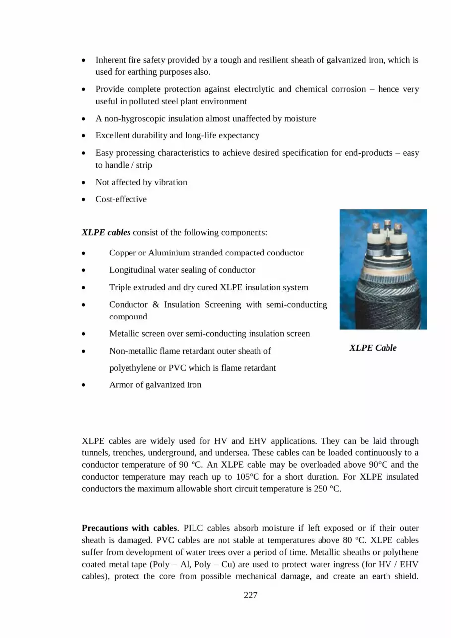
227
Inherent fire safety provided by a tough and resilient sheath of galvanized iron, which is
used for earthing purposes also.
Provide complete protection against electrolytic and chemical corrosion – hence very
useful in polluted steel plant environment
A non-hygroscopic insulation almost unaffected by moisture
Excellent durability and long-life expectancy
Easy processing characteristics to achieve desired specification for end-products – easy
to handle / strip
Not affected by vibration
Cost-effective
XLPE cables consist of the following components:
Copper or Aluminium stranded compacted conductor
Longitudinal water sealing of conductor
Triple extruded and dry cured XLPE insulation system
Conductor & Insulation Screening with semi-conducting
compound
Metallic screen over semi-conducting insulation screen
Non-metallic flame retardant outer sheath of
polyethylene or PVC which is flame retardant
Armor of galvanized iron
XLPE cables are widely used for HV and EHV applications. They can be laid through
tunnels, trenches, underground, and undersea. These cables can be loaded continuously to a
conductor temperature of 90 °C. An XLPE cable may be overloaded above 90°C and the
conductor temperature may reach up to 105°C for a short duration. For XLPE insulated
conductors the maximum allowable short circuit temperature is 250 °C.
Precautions with cables. PILC cables absorb moisture if left exposed or if their outer
sheath is damaged. PVC cables are not stable at temperatures above 80 ºC. XLPE cables
suffer from development of water trees over a period of time. Metallic sheaths or polythene
coated metal tape (Poly – Al, Poly – Cu) are used to protect water ingress (for HV / EHV
cables), protect the core from possible mechanical damage, and create an earth shield.
XLPE Cable

228
Armouring is done in all types of cables through steel tape or galvanized wire / strip or
aluminium wire / strip to prevent mechanical damage / stress. While laying or handling
cables, the minimum bending radius prescribed should be strictly followed to reduce
mechanical stress.
Marking on cables: Colour codes / tapes are used for identification of the three cores.
Standard marking is through colours (like Red, Yellow, Blue for Red phase, Yellow phase,
Blue phase respectively, or numbers (1, 2, 3). For LT cable black colour is provided for
neutral.The marking or coding is vital when connecting / jointing two cables together, or
when a new cable is being connected to an existing system, so that the phasing is matched.
At the ends of a panel or equipment (motor or transformer), the end-terminations are to be
made with special care. For long lengths of cables, the pieces have to be joined by means of
straight-through joints, as the cables are normally available in lengths of 250 m or 500 m in
cable drums. The diagrams below show a typical end-termination (when viewed from the
back-side of an MV panel and a straight-through joint in the tunnel.
View of an end-termination joint
Cross-sectional view of a Straight-through Joint
Pipe
Floor
Cable bend

229
Material Advantages Disadvantages Max Operating
Temperature
PVC Cheap, Durable, Widely
available
Highest dielectric losses, Melts at
high temperatures, Contains
halogens
70oC for general
purpose 85oC for heat
resisting purpose
PE
Lowest dielectric losses,
High initial dielectric
strength
Highly sensitive to water treeing,
Material breaks down at high
temperatures
XLPE
Low dielectric losses,
Improved material
properties at high
temperatures
Does not melt but thermal
expansion occurs, Medium
sensitivity to water treeing
(although some XLPE polymers
are water-tree resistant)
90oC
9.7 Relays
OVER CURRENT AND EARTH FAULT RELAY:
These relays operate when the magnitude of the current in its circuit, supplied directly or
from current transformers, exceeds a preset value. The relays have a number of current
settings to make them suitable for wide range of application. Mostly two over current
elements for phase faults and one earth fault element for earth fault are provided for solidly-
earthed system. Three numbers of phase fault relays are desirable on system earthed through
high impedance or unearthed. They are also necessary on delta side of delta-star
transformers as the current in one phase may be twice that in the other two phases for a
phase-to phase fault on star side. Earth fault protection may be provided by using core
balance current transformers. Core balance protection consists of a ring-core current
transformer which is designed to pass over 3 core cables. The output from this current
transformer is utilized to energize a current operated relay. The arrangement provides very
sensitive earth fault protection.
Fault currents change in magnitude and phase while being transformed in delta star
transformers. An earth fault on star side produces a circulating zero sequence current in the
delta winding but no zero sequence current in the lines of the delta side of the transformer.
An earth fault relay on delta side will not, therefore, respond to an earth fault on the star side
of the transformers. For the purpose of gradation earth fault relays of the delta and star sides
thus become independent.
Over current and earth fault relays may have any one of the time- current characteristics:
a) Time-Delay

230
b) Instantaneous
c) Combination of both.
Time Delay characteristics may be IDMT (Inverse definite minimum time) or definite time
type. In IDMT relays, the time of operation of the relay is inversely proportional to the
value of current. However after a certain value of current, say 20 times, the curve remains
constant at a minimum time for operation of the relay. For definite time relays, the time
remains constant even if the current increases considerably above the set value of the
current. Instantaneous relay operates instantaneously when current increases above the set
value.
DIFFERENTIAL RELAY
The principle of operation of differential relays is based on Merz-Price System.
Fundamentally the system of connection and operation is as follows.
The current transformers are placed on two ends of the protected zone(eg. winding of
transformer / motor) and are connected in opposition. So long as the current at two ends of
the winding is equal, equal and opposite emf’s are induced in the two current transformers
of that winding and there will be no current through the relay. Whenever a fault develops in
the winding, the current at the two ends of that winding will not be equal and the relay will
operate due to flow of differential current.
Motor Protection Relay
These relays protect the motor from five basic faults. The basic faults are:
Over-current (Short Circuit)
Earth Fault in any winding
Overload
Unbalanced supply (Negative sequence)
Rotor fails to rotate on application of voltage (Stalling Protection)
UNDER-VOLTAGE / OVER-VOLTAGE RELAY
Under-voltage / Over-voltage relay operates at a pre-determined value of voltage. The relay
is normally connected from potential transformer secondary which feeds the replica of the
primary voltage in the power circuit. Typical values of over-voltage and under-voltage are
110% and 88% respectively.

231
UNDER-FREQUENCY / OVER-FREQUENCY RELAY
Under-frequency / Over-frequency relays operate at a pre-determined value of frequency.
The relay is normally connected from potential transformer secondary and also sometimes
from 230V single phase AC mains. These relays are used to protect generators and motors.
DF/DT RELAY
This relay operates when the rate of fall (or rise) of frequency is higher than pre-determined
rate of fall (or rise) of frequency. For example, if a relay is set at 0.1 Hz/sec and the actual
rate of fall (or rise) of frequency is 0.2Hz/sec, then it operates. These relays isolate
generators when the grid is sinking. df/dt relays with rise of frequency feature are used to
protect generators from over-speeding.
PILOT WIRE RELAYS
These are differential relays used for transmission line/cable protection. There are two sets
of relays, one at sending end and the other at the receiving end connected through current
transformers at either end. The relays at either end is connected through a pilot wire loop
through which relay operating current flows and operates relays at both the ends. During
healthy condition current flowing through both the current transformers at either end will be
same and the current in the pilot loop will be zero. In the event of a fault in the zone
between the two current transformers, the magnitude of current will be different in the two
current transformers, and differential current will flow through the pilot loop and operate
relays at both the ends.
NUMERICAL RELAYS:
These are modern Microprocessor based Programmable Electronic Relays which provide a
comprehensive protection for the Motors, Feeders etc. They have a distinct advantage of
merging different types of protective relays in one single unit thereby reducing the size and
increasing the reliability. They also provide some advance features of recording of
parameters during fault which is very useful for analysis and troubleshooting. They are also
communicable type that is the data generated in the relay can be communicated to another
relay in the system, to a PC or to a SCADA system for further use and analysis. Nowadays
metering is also done from these numerical relays.

232
9.8 Electrical Insulation
INSULATING MATERIALS
Insulating materials offer high resistance to flow of current and are used in all electrical
equipments. It is the insulation part in any cable or machine that is most liable to fail. Apart
from electrical and mechanical stresses, heat plays the most important role in determining
the life and performance of the insulating materials, and as such the operating temperature
of any operating cable or machine must not be allowed to exceed the permissible
temperature rise limit. Moisture and dust also degrade the insulating materials.
The insulating materials have been classified according to their ability to withstand heat.
The recognized classes of insulating materials along with their assigned temperature as per
IS 1271-1958 as below:
Class of Insulation Material Temperature
Class Y or O Cotton Paper, Pressboard, Wood, Fibre 90°C
Class A PVC, Vulcanised rubber 105°C
Class E Epoxy Resins, Paper laminates 120°C
Class B Fibreglass, Asbestos 130°C
Class F Varnished Fibre Glass and Asbestos 155°C
Class H Silicon Elastomer 180°C
Class C Mica, Porcelain Above 180°C
CONCEPT OF INSULATION RESISTANCE (IR)
Insulation Resistance (I.R.) is the resistance of the insulation provided between live
conductor and body of the machine/cable armour/earth point. The value of insulation
resistance is measured by insulation testers and the unit of measurement is kΩ/MΩ/GΩ and
so on.
IR TESTERS (TYPES, APPLICATIONS)
For I.R. measurement a DC voltage is applied through an I.R. tester across an insulating
material. The line terminal of the I.R tester is connected to the conductor terminal and the
earth terminal is connected to the body/armour/earth and the test voltage is applied.
When this voltage is applied, a leakage current flows through the insulating material. This
leakage current is calibrated in terms of insulation resistance expressed in kΩ or MΩ or GΩ.
The I.R. value is actually the corrected ratio of the applied voltage to the leakage current
flowing through the insulating material.
233
I.R. value is a good indication of the healthiness of the insulating material. For an ideal
insulating material, the leakage current is zero; hence the I.R. value is infinite. Any
deterioration in the insulating material due to heat, dust or moisture is indicated by the
reduced I.R. value.
I.R. testers are of various types such as hand-driven, motor-driven or solid state type. The
output test voltages vary from 100V to 5 kV depending on the type of application.
Following are the preferable test voltages depending on the type of application:
I.R Testers Test voltage Application
100V Telephone Cables
500V LT Power Cables and Control Cables, LT
Motor, Transformer LT side(415V)
1000V LT Power Cable, LT Motor, Transformer
LT side(415V)
2.5kV HT Power Cable, HT Motor, Transformer
HT side(3.3 or 6.6 or 11 kV)
5.0 kV HT Power Cable, HT Motor, Transformer
HT side (33KV,11KV), EHT switchyard
equipments (132 or 220 kV)
CABLE FAULT LOCATION TECHNIQUES:
Whenever there is a cable fault, the nature of the fault is ascertained by a suitable I.R. tester.
The basic cable faults are phase to armour short circuit (earth fault), phase to phase short
circuit (short circuit), and conductor sheared (open circuit fault).
Pre-location of cable fault is done by instruments like Murray Loop Testers, Time Domain
Reflectometer (TDR) for earth fault & phase to phase fault to determine the tentative
distance of the fault from both ends of the cable. For open circuit fault only TDR is used.
Fault location in optical fiber cables are done by instrument called Optical time domain
reflectrometer (OTDR).
Pin-pointing of the fault is done by using Impulse Generator. In an Impulse Generator, a
charged capacitor at selected voltage is allowed to discharge at every 6 seconds time
interval at the fault point and the amplified discharge sound is heard through ear phones
through special probes placed on the ground. The rating of the impulse generators is
normally 0-8 kV and 0-25 kV for LT and HT cables respectively.
234
9.9 Electronic Devices
INTRODUCTION
1. Electronic devices are the backbone of the electronic industry.
2. Almost everything from children toys to life saving equipment depends upon these
components.
3. Billions of components are available in the market.
4. In a large process industry like ours, a wide variety of components are used in various
electronic systems.
TYPES
Passive components: Fixed and Variable Resistances, Fixed and Variable Capacitors,
Inductors etc.
Active Components:
i. Vacuum Tube Device: Diodes, Triodes, Pentodes etc.
These devices are obsolete due to bulky and slow repose. These are replaced buy
semi-conducteur devices are also known as Solid state devices
ii. Solid State Devices:
Discrete Devices: Diodes, Transistors, Thyristors, Field Effect Transistors, UJTs, etc.
Integrated Circuits: Linear ICs, Digital ICs, Insulated gate bipolar transistor (IGBT) etc.
RESISTANCES
1. Definition: Resistor is the electronic device that resists the flow of current.
2. Unit of Measurement: Ohms ()
3. Specifications: The resistors are specified in terms of:
a. Value: Specified in Ohms
b. Tolerance: Allowable deviation from the specified value expressed in percentage
(1%/5%/10%/20%).
c. Power: Resistors are designed to handle a particular amount of power. Same value
resistors are available in different power ratings like quarter watt, Half watt, 1 watt etc.
d. Type: Depending on the material used for fabrication, the resistors may be Carbon, Metal
Film, Wire wound type etc.

235
4. Symbol: or
5. Value Identification:
Values and Tolerance identified by Colour Coded Bands or printed on the body e.g. R33M
= 0.33 20% and 4k7F=4700 1% Tolerance.
6. Applications:
a. Current Limiting Resistor
b. Loading Resistor
c. Timing Element
d. Bleeder etc

236
CAPACITORS
1. Definition: Capacitor is the electronic device that stores electrical charge and resists
any change in voltage at its terminals.
2. Unit of Measurement: Farads (F) but generally available in microfarads (F)
3. Specification: The capacitors are specified in terms of:
a. Capacity or Value: Expressed in Farads.
b. Polarity: Polar (DC Capacitors) or Non-Polar (AC-AC Capacitors)
c. Voltage: Max voltage which the capacitor can sustain without being damaged.
d. Tolerance: Allowable deviation from the specified value expressed in percentage.
e. Packaging: Axial Lead package, radial Lead package, Solder Type Terminals,
Screwable terminals etc.
f. Type: Depending on the dielectric used to fabricate the capacitor, they can be
Electrolytic, Ceramic Disc, Paper, Mica, Metal Polyester etc
4. Symbol:
]
5. Applications:
Capacitor is a very versatile component with widespread applications for example:
a. Spark suppression on thermostats, relays etc.;
b. Reservoir and Smoothing filters in power supplies;
c. Decoupling and Coupling in amplifiers;
d. Tuning elements for multi-vibrators, delay circuits etc;
e. Filters and waveform shaping and oscillators.
Unipolar (AC/DC)
Polar (DC)

237
INDUCTORS
1. Definition: An inductor is simply a coil of wire. An inductor can store energy in its
magnetic field, and tends to resist any change in the amount of current flowing through
it.
2. Unit of Measurement: Henry (H).
3. Symbol:
4. Applications:
a. Analog circuits and Signal Processing.
b. Filters when used with capacitors and other components. (Chokes, RF Suppressors etc.).
c. Two (or more) inductors which have coupled magnetic flux form a Transformer.
d. As the energy storage device in some switch-mode power supplies.
e. Electrical transmission systems, where they are used to intentionally depress system
voltages or limit fault current. In this field, they are more commonly referred to as
reactors.
5. Materials: Almost invariably copper as coil material but core can be of different
materials.
MISCELLANEOUS COMPONENTS
In addition to the above, several other components are used in electronic circuits like
Relays, Switches, and Crystals etc.
Switches:
Definition: A switch is a device used to connect and disconnect a circuit at will.
Switches cover a wide range of types, from sub miniature up to industrial plant switching
megawatts of power on high voltage distribution lines.
Symbol: or
Types: Switches are classified on several bases. On the basis of number of contacts in the
switch, they can be Single or Double Pole and so on. If a Switch has two positions in which

238
it can be operated (say ON and OFF), it is called Single Throw Switch. If it has three
positions it is called Double Throw.
A Double Pole Double Throw Switch
Relays:
Definition: A relay is an electrical switch that opens and closes under the control of
another electrical circuit. In the original form, the switch is operated by an electromagnet
to open or close one or many sets of contacts. It was invented by Joseph Henry in 1835.
Because a relay is able to control an output circuit of higher power than the input circuit, it
can be considered to be, in a broad sense, a form of an electrical amplifier.
Principle: When a current flows through the coil, the resulting magnetic field attracts an
armature that is mechanically linked to a moving contact. The movement either makes or
breaks a connection with a fixed contact. When the current to the coil is switched off, the
armature is returned by a force approximately half as strong as the magnetic force to its
relaxed position. Usually this is a spring, but gravity is also used commonly in industrial
motor starters. Most relays are manufactured to operate quickly. In a low voltage
application, this is to reduce noise. In a high voltage or high current application, this is to
reduce arcing.
Symbol:
Crystals:
Definition: A crystal oscillator is an electronic circuit that uses the mechanical
resonance of a vibrating crystal of piezoelectric material to create an electrical signal
with a very precise frequency. This frequency is commonly used to keep track of time (as
in quartz wristwatches), to provide a stable clock signal for digital integrated circuits, and to
stabilize frequencies for radio transmitters/receivers.
Principle: When a crystal of quartz is properly cut and mounted, it can be made to distort in
an electric field by applying a voltage to an electrode near or on the crystal. This property is
known as piezoelectricity. When the field is removed, the quartz will generate an electric
field as it returns to its previous shape, and this can generate a voltage. The result is that a
quartz crystal behaves like a circuit composed of an inductor, capacitor and resistor, with a
precise resonant frequency.
239
Symbol:
HISTORY OF DEVELOPMENT OF SEMICONDUCTORS:
Point Contact Transistor developed in 1948.
BJT came into existence in1950.
Planer Process introduced in 1959.
First Integrated Circuit fabricated soon after in early 1960’s; housing less than 100
components (SSI).
MOS Transistor developed in 1962.
100 to 10,000 components incorporated on a single chip in 1966 (MSI).
Large Scale Integration (LSI) technique in 1969.
More than 10,000 components on single chip by 1975 (VLSI).
VLSI chips had more than 100000 components even by 1984!
Testing:
The thyristor can be tested at site using a Battery Tester. The positive terminal of the battery
tester should be connected to the Anode of the Thyristor and the negative terminal at the
Cathode of the thyristor. The battery lamp shall not glow until the Gate of the thyristor is
also connected to the positive of the Battery Tester. Once the lamp starts glowing, it should
continue to glow even if the Gate is made open circuited because the thyristor has latched. It
shall stop glowing only when the Anode or Cathode wire is also removed. It should be kept
in mind that sometimes thyristor does not latch because the battery is not able to supply the
latching current. In this case, at least three batteries should be used in series and the batteries
should be changed if they are old.
In laboratory the same test can be conducted using two power supplies (one for Anode
Cathode circuit and other for Gate Cathode circuit) and suitable load resistance.

240
9.10 Testing, Measuring Instruments and Tools.
DIGITAL MULTI-METERS:
A multimeter or a multitester, also known as a volt/ohm meter or VOM, is an electronic
measuring instrument that combines several functions in one unit. A standard multimeter
may include features such as the ability to measure voltage, current and resistance. There
are two categories of multimeters, analog multimeters and digital multimeters (often
abbreviated DMM.)
A multimeter can be a hand-held device useful for basic fault finding and field service work
or a bench instrument which can measure to a very high degree of accuracy. They can be
used to troubleshoot electrical problems in a wide array of industrial and household devices.
QUANTITIES MEASURED:
Contemporary multimeters can measure many quantities. The common ones are:
Voltage in volts
Current in amperes
Resistance in ohms
Additionally, they also include circuits for:
Continuity that beeps when a circuit conducts; useful for checking continuity ofwires.
Testing of Diodes
Some Multimeters may also measure:
Capacitance in farads.
Frequency in hertz
Duty cycle as a percentage.
Temperature in degrees Celsius or Fahrenheit.
Conductance in siemens.
Inductance in henrys
Audio signal levels in decibels.
Various sensors can be attached to multimeters to take measurements such as:
Light level
Acidity/Alkalinity(pH)
Wind speed
Relative humidity
DMM are specified by their resolution often specified in no of digits displayed on the
readout of the multimeter (3 ½ digit or 4½ digits etc). The half digit can display either a

241
zero or one and is the leftmost digit of the display. Thus a 3 ½ digit multimeter can display
signal levels from 0 to 1999.
CATHODE RAY OSCILLOSCOPE (CRO):
An oscilloscope (sometimes abbreviated CRO,
for cathode-ray oscilloscope, or commonly just
scope or O-scope) is a type of electronic test
equipment that allows signal voltages to be
viewed, usually as a two-dimensional graph of
one or more electrical signals (on the vertical
axis) plotted as a function of time or of some
other voltage (on the horizontal axis). A typical
CRO has a small screen on its front panel on
which the graphs are displayed when the inputs
are connected. The front panel of the CRO also has numerous buttons, switches and
connectors for setting and connection of inputs. The CRO uses a Cathode Ray Tube for
display of graphs which is similar to the picture tube of Television sets.
The CROs can have two or more channels for simultaneous display of more than one signal.
A CRO is a very useful tool in troubleshooting electrical and Electronic circuits as it gives a
graphical display of the signal which is not possible with a Voltmeter. Also, sometimes it is
important to know the precise shape of signals for analysis and design and in such
applications; CRO is a very versatile tool.
Originally, CROs were analog equipment but now digital CROs have become commonly
available and are much more advanced than their analog predecessors. They can store
waveforms and can be connected to computer for download and analysis of waveshapes.
9.11 Drives and Control
SPEED CONTROL OF DC MOTORS
Introduction to DC Drives:
DC Drives are used to control dc motor. DC drives have two main components: a converter
and a regulator. A converter is an electrical circuit that converts AC power to DC power.
DC drive converters typically use a device called a Silicon Controlled rectifier (SCR) i.e.
thyristor for this conversion process. SCRs transform AC current into a controlled form of
DC current. A regulator is the control portion of the drive. The regulator is the "smarts" or
processing logic that determines what voltage and current is supplied to the motor. The
voltage/current output from the drive can manipulate the speed or the torque of the motor
(thus, the tension of a process load can also be controlled). The changes to the power
supplied to the motor depend on the logic in the regulator and the type of feedback from the
motor. Feedback devices, such as tachos or encoders, are sensors on the motor. A
tachometer (tacho) is a device that monitors the actual speed of the motor. A tacho can send
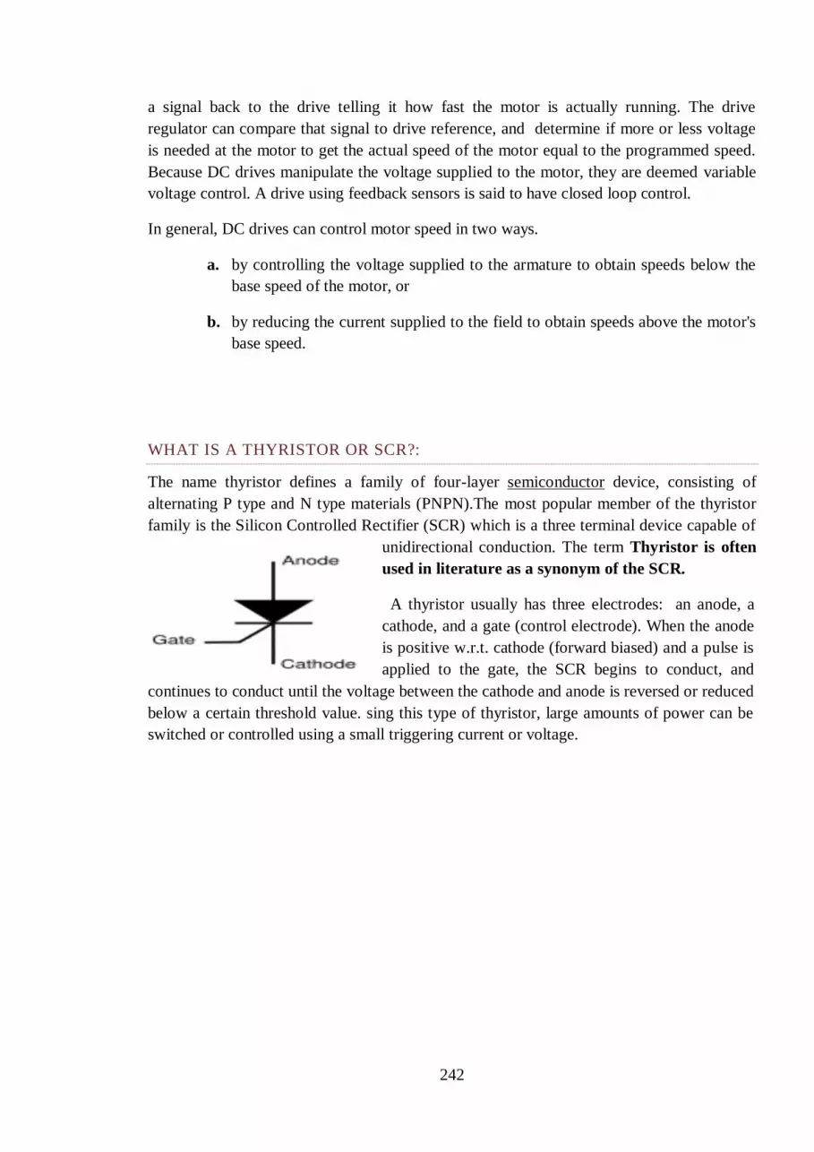
242
a signal back to the drive telling it how fast the motor is actually running. The drive
regulator can compare that signal to drive reference, and determine if more or less voltage
is needed at the motor to get the actual speed of the motor equal to the programmed speed.
Because DC drives manipulate the voltage supplied to the motor, they are deemed variable
voltage control. A drive using feedback sensors is said to have closed loop control.
In general, DC drives can control motor speed in two ways.
a. by controlling the voltage supplied to the armature to obtain speeds below the
base speed of the motor, or
b. by reducing the current supplied to the field to obtain speeds above the motor's
base speed.
WHAT IS A THYRISTOR OR SCR?:
The name thyristor defines a family of four-layer semiconductor device, consisting of
alternating P type and N type materials (PNPN).The most popular member of the thyristor
family is the Silicon Controlled Rectifier (SCR) which is a three terminal device capable of
unidirectional conduction. The term Thyristor is often
used in literature as a synonym of the SCR.
A thyristor usually has three electrodes: an anode, a
cathode, and a gate (control electrode). When the anode
is positive w.r.t. cathode (forward biased) and a pulse is
applied to the gate, the SCR begins to conduct, and
continues to conduct until the voltage between the cathode and anode is reversed or reduced
below a certain threshold value. sing this type of thyristor, large amounts of power can be
switched or controlled using a small triggering current or voltage.

243
BASIC PRINCIPLES OF THYRISTORISED CONTROL
DC DRIVES (THYRISTORISED CONTROL)- PRINCIPLES OF OPERATION
A typical adjustable speed drive using a silicon controller rectifier (SCR) power conversion'
section, is shown in Figure 2. The SCR, (also termed a thyristor) converts the fixed voltage
alternating current (AC) of the power source to an adjustable voltage, controlled direct
current (DC) output which is applied to the armature of a DC motor.
SCR's provide a controllable power output by "phase angle control",
so called because the firing angle (a point in time where the SCR
is triggered into conduction) is synchronized with the phase rotation
of the AC power source. If the device is triggered early in half cycle,
maximum power is delivered to the motor; late triggering in the half
cycle provides minimum power, as illustrated by Figure 3.
DC DRIVE TYPES
Non-regenerative DC Drives – Non-regenerative DC drives are the most conventional type
in common usage. In their most basic form they are able to control motor speed and torque
in one direction only as shown by Quadrant I in Figure 4. The addition of an
electromechanical (magnetic) armature reversing contactor or manual switch permits
reversing the controller output polarity and therefore the direction of rotation of the motor
armature as illustrated in Quadrant III. In both cases torque and rotational direction are the
same.
Regenerative DC Drives - Regenerative adjustable speed drives, also known as four-
quadrant drives, are capable of controlling not only the speed and direction of motor
rotation, but also the direction of motor torque. This is illustrated by Figure 4.
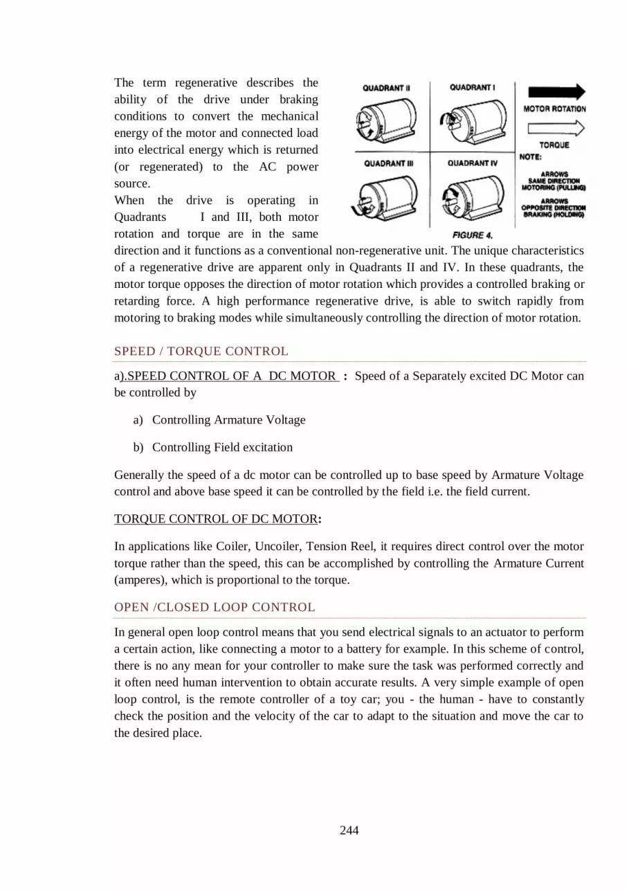
244
The term regenerative describes the
ability of the drive under braking
conditions to convert the mechanical
energy of the motor and connected load
into electrical energy which is returned
(or regenerated) to the AC power
source.
When the drive is operating in
Quadrants I and III, both motor
rotation and torque are in the same
direction and it functions as a conventional non-regenerative unit. The unique characteristics
of a regenerative drive are apparent only in Quadrants II and IV. In these quadrants, the
motor torque opposes the direction of motor rotation which provides a controlled braking or
retarding force. A high performance regenerative drive, is able to switch rapidly from
motoring to braking modes while simultaneously controlling the direction of motor rotation.
SPEED / TORQUE CONTROL
a).SPEED CONTROL OF A DC MOTOR : Speed of a Separately excited DC Motor can
be controlled by
a) Controlling Armature Voltage
b) Controlling Field excitation
Generally the speed of a dc motor can be controlled up to base speed by Armature Voltage
control and above base speed it can be controlled by the field i.e. the field current.
TORQUE CONTROL OF DC MOTOR:
In applications like Coiler, Uncoiler, Tension Reel, it requires direct control over the motor
torque rather than the speed, this can be accomplished by controlling the Armature Current
(amperes), which is proportional to the torque.
OPEN /CLOSED LOOP CONTROL
In general open loop control means that you send electrical signals to an actuator to perform
a certain action, like connecting a motor to a battery for example. In this scheme of control,
there is no any mean for your controller to make sure the task was performed correctly and
it often need human intervention to obtain accurate results. A very simple example of open
loop control, is the remote controller of a toy car; you - the human - have to constantly
check the position and the velocity of the car to adapt to the situation and move the car to
the desired place.

245
Closed loop VS Open loop
But what if you could let the electronics handle a part, if not all of the tasks performed by a
human in an open loop controller, while obtaining more accurate results with extremely
short response time? This is what is called closed loop control. In order to be able to build a
closed loop controller, you need some mean of gaining information about the rotation of the
shaft like the number of revolutions executed per second, or even the precise angle of the
shaft. This source of information about the shaft of the motor is called "feed-back" because
it sends back information from the controlled actuator to the controller.
Figure 5 shows clearly the difference between the two control schemes. Both types have a
controller that gives orders to a driver, which is a power circuit that drives the motor in the
required direction. It is clear that the closed loop system is more complicated because it
needs a ‘shaft encoder’ or tacho which is a device that will translate the rotation of the shaft
into electrical signals that can be communicated to the controller. In other words, a closed
loop controller will regulate the power delivered to the motor to reach the required velocity.
If the motor is to turn faster than the required velocity, the controller will deliver less power
to the motor.
Thus Open loop control system can be called Manual Control and Closed loop control
system can be called Automatic Control. In a closed loop system the actual and desired or
reference states are continually compared and if the actual state is different from the
reference state, an error signal is generated which the controller uses to force a change in the
controllable parameters to drive the system towards the desired operating point.

246
SINGLE LINE DIAGRAM OF THYRISTOR CONVERTER
As we know motor speed can be controlled by controlling armature voltage and field
excitation (current).This diagram shows motor speed control by controlling armature
voltage of the motor.
A converter is a circuit that changes the incoming AC power (fixed voltage, fixed
frequency) into DC power. The converter can be either single phase or three phase. A
thyristor converter is a controlled rectifier which is used to convert AC into DC.
Fig.6 Diagram showing closed loop control of a typical dc motor (armature)
In above Diagram, M stands for Armature of DC Motor, REF stands for Reference (say
speed reference) from Operator.
In the single line diagram above (Fig.6), REF (Reference) from operator or from other
system enters RAMP Generator and the signal is processed through Speed Regulator,
Current Regulator etc. The output of current regulator controls the pulses position in firing
circuit so that armature voltage can be controlled.
ANALOG / DIGITAL DRIVES
Analog Drive: An analog drive is a drive where the components used in regulation circuit
like the velocity/speed and current loops are analog components (such as op-amps). The
gains of the amplifiers are set using passive components (such as resistors, potentiometers,
and capacitors).
C U R R E N T
R E G U L A T O R
T H Y R I S T O R
C O N V E R T E R
F I R I N G
C I R C U I T
S P E E D
R E G U L A T O R
R A M P
G E N E R A T O R
C U R R E N T F E E D B A C K
F R O M C U R R E N T
T R A N S D U C E R
V O L T A G E F E E D B A C K
O R
T A C H O F E E D B A C K F R O M
T A C H O M O U N T E D O N M O T O R S H A F T
R E F
S P E E D R E F E R E N C E C U R R E N T R E F E R E N C E
A N O D E S U P P L Y
M

247
Digital Drive: In a digital drive, all the functions of the drive is performed by
microprocessor/microcomputer. In digital drive, unlike analog drive, all analog external
signals like current feedback, speed feedback are converted into digital form by Analog-to-
Digital converter. All the controlling blocks of analog Drive like Ramp function generator,
Speed controller, Current controller and firing sequence generation are realized in the
microprocessor of the digital drive through programs/ parameters .Preferably a digital tacho
(pulse tacho/encoder) is used instead of analog tacho for better accuracy. Digital drives can
also provide powerful diagnostic aids for maintenance and fault finding. It can store event
history, fault history. Digital drive provides auto tuning of speed and current control
functions.
Comparison of Analog and Digital Drives:
The analog drive offers the benefit of lower cost and, in the case of a drive using tacho
feedback, very high performance.
The digital drive, while more costly, is comparatively easy to set up and adjustments can be
quickly repeated across several units. Automatic self-tuning can be a distinct advantage
where the load parameters are unknown or difficult to measure.
The various adjustments needed to tune an analog drive are usually made with
potentiometers. With a little experience, this can usually be performed quite quickly, but in
some difficult applications it may take longer.
PROTECTION AND TROUBLE-SHOOTING:
Protections used in Thyristor Converter to protect motor and converter:
1. Protection from Over Current: Followings are the some protections from overcurrent
Instantaneous Overload Relay
Thermal Over Load Relay: In this type of relay thermal element (bimetallic strip) is
used.
In thyristor converters of higher voltage, over-current protection has been provided
relying on the gate control of thyristors, i.e., the gate shift or gate block.
2. Protection from Over Voltage: Over Voltage Relays used to protect system from
over-voltage.
3. Fuses:
Thyristor Converter uses semiconductor fuses for over-current protection of the
Thyristors.The carrying capacity of the semiconductor elements (Thyristors) is chosen
to be greater than the fusing current, so that when an overcurrent or a short circuit
occurs, the corresponding fuse or fuses are fused, interrupting the current, protecting the
semiconductor elements (Thyristors).

248
4. Protection from Surges:
Surges are a sudden and temporary increase in electrical current or voltage. ACSS
(A.C.Surge Suppressors) and DCSS (D.C.Surge Suppressors ) are used in Thyristor
Converters to protect from surges.
5. Overspeed Relay: In some drives Centrifugal Switch/Relay is mounted on the shaft of
motor which is set to trip drive in case of Overspeed of the drive.
6. Breakers on AC side and DC side: High speed Circuit Breakers on AC and DC side are
used to isolate the system when a fault occurs in the system.
Trouble Shooting:
In general, there are two types of fault messages : Alarm and Fault.
Alarm warns of some malfunction.No protective function is tripped nor is the operation of
the system interrupted. Faults switch off the system and protect it against damage. To
troubleshoot a drive, one should have a clear idea of system. He should go through the
drawings and manuals of the system. In analog drives, some limited faults/alarms are
displayed .Depending upon the type of fault/alarm, one should proceed to rectify the
problem.
In modern digital system, if an alarm or fault occurs, an error code is displayed. This error
code is stored in the fault logger together with the fault signal and event time. Previous
alarm and fault occurrences can be read from the fault logger and displayed even if the
original fault indication has been reset. In maintenance manual/troubleshooting manual,
Alarm / Fault code and its meaning along with possible error or corrective action is
suggested.
SPEED CONTROL OF AC MOTORS:
AC V/s DC DRIVE COMPARISON
AC and DC drives both continue to offer unique benefits and features that may make one
type or other better suited for certain applications.
AC DRIVES MAY BE BETTER BECAUSE. . .
They use conventional, low cost, 3-phase AC induction motors for
most applications.
AC motors require virtually no maintenance and are preferred for
applications where the motor is mounted in an area not easily reached for servicing or
replacement.

249
AC motors are smaller, lighter, more commonly available, and less expensive than DC
motors.
AC motors are better suited for high speed operation (over 2500 rpm) since there are
no brushes, and commutation is not a problem.
Whenever the operating environment is wet, corrosive or explosive and special motor
enclosures are required. Special AC motor enclosure types are more readily available
at lower prices.
Multiple motors in a system must operate simultaneously at a common
frequency/speed.
It is desirable to use an existing constant speed AC motor already mounted and wired
on a machine.
When the application load varies greatly and light loads may be encountered for
prolonged periods. DC motor commutators and brushes may wear rapidly under this
condition.
Low cost electronic motor reversing is required.
It is important to have a back up (constant speed) if the controller should fail.
DC DRIVES MAY BE BETTER BECAUSE. . .
DC drives are less complex with a single power conversion from AC to DC.
DC drives are normally less expensive for most horsepower ratings.
DC motors have a long tradition of use as adjustable speed machines and a wide range
of options have evolved for this purpose:
Cooling blowers and inlet air flanges provide cooling air for a wide speed range at
constant torque.
Accessory mounting flanges and kits for mounting feedback tachometers and
encoders.
DC regenerative drives are available for applications requiring continuous
regeneration for overhauling loads. AC drives with this capability would be more
complex and expensive.
Properly applied brush and commutator maintenance is minimal.
DC motors are capable of providing starting and accelerating torques in excess of
400% of rated.

250
Some AC drives may produce audible motor noise, which is undesirable in some
applications.
AC DRIVES - PRINCIPLES OF OPERATION
Adjustable frequency AC motor drive controllers frequently termed inverters are typically
more complex than DC controllers since they must perform two power section functions,
that of conversion of the AC line power source to DC and finally an inverter change from
the DC to a coordinated adjustable frequency and voltage output to the AC motor. The
appeal of the adjustable frequency drive is based upon the simplicity and reliability of the
AC drive motor, which has no brushes, commutator or other parts that require routine
maintenance, which more than compensates for the complexity of the AC controller. The
robust construction and low cost of the AC motor makes it very desirable for a wide range
of uses. Also, the ability to make an existing standard constant speed AC motor an
adjustable speed device simply by the addition of an adjustable frequency controller creates
a very strong incentive for this type of drive.
AC MOTOR CONTROL CHARACTERISTICS
The synchronous speed of an AC induction motor is directly proportional to the applied
frequency.
Speed = 120 x Frequency
No. of Motor Poles
The synchronous speed is the speed of the rotating electrical field, not the actual motor rotor
speed. The difference between the synchronous speed and the full-load motor speed is
called slip, which is normally expressed in percent. The percentage of slip is determined by
the design of the motor, primarily the rotor resistance. NEMA has assigned code letters (A,
B, C, D, etc.) to standardize motor characteristics including slip. The type most commonly
used is NEMA Design B with 3% slip at rated operating conditions. Figure 9 shows typical
speed/torque curves for NEMA Design Band D motors.

251
As the applied frequency is changed, the motor will
run faster or slower as shown by Figure 10. The
actual full-load motor slip (as a percent of the motor
synchronous speed) varies in inverse proportion to
the frequency, where a 3% slip motor 60 Hz would
have a 6% slip at 30 Hz or 1 1/2 % slip at 120 Hz.
Motor speed is limited only by the maximum
inverter output frequency, load torque requirements,
and the mechanical integrity of the motor.
AC CONTROLLER TYPES
A number of different types of AC motor controllers are currently in common use as general
purpose drives: Pulse Width Modulated (PWM), Current Source Input (CSI), and the Load
Commutated Inverter (LCI). Each type offers specific benefits and characteristics but the
PWM type is being popularly used.
VARIABLE FREQUENCY BASED DRIVE:
VFD : VARIABLE FREQUENCY DRIVE
what exactly is a VFD?
It stands for Variable Frequency Drive.
They are used for running an AC motor at variable speeds or let them ramp up their speed to
give them a smooth startup.

252
VFDs work by adjusting the frequency of the motor to adjust the rpms.
To do this, a VFD will actually convert the voltage twice:
1) First, it converts our three-phase AC to DC. This is accomplished with diodes.
2) Then it cleans the DC with a capacitor.
3) Next, it will convert the DC to AC. This is accomplished with transistors acting as
switches.
Utilizing these “switches” is what allows the VFD to adjust the frequency that the VFD
supplies to the motor. This, in turn, controls the speed of the motor.
Even though the drive controls the frequency and voltage of power supplied to the motor,
we often refer to this as speed control, since the result is an adjustment of motor speed.
There are many reasons why we may want to adjust this motor speed.
For example, to
Save energy and improve system efficiency
Convert power in hybridization applications
Match the speed of the drive to the process requirements
Match the torque or power of a drive to the process requirements
Improve the working environment
Lower noise levels, for example from fans and pumps
Reduce mechanical stress on machines to extend their lifetime
Shave peak consumption to avoid peak-demand prices and reduce the motor size
required
BLOCK DIAGRAM OF VFD DRIVE
VVVFD: VARIABLE VOLTAGE VARIABLE FREQUENCY DRIVE
A VVVF drive is acronym of variable voltage variable frequency drive. This is a solid state
unit having capability to deliver power with variable voltage and variable frequency. It shall
be possible to run motors at different speeds.

253
The speed of the motor shall be varied as per the process/functional requirement. The same
can be achieved by using VVVf drive. Number of Drives are used in SPP, mainly to achieve
micro speed in EOT crane and in other application like speed control of pumps, blowers,
etc.
BASICS OF VVVF DRIVE Why both voltage and frequency needs to be varied?
We know that, Speed N =120 x f/P where N is speed of the motor f is frequency of the
supply voltage P is number of poles of the motor.
The speed is proportional to frequency. By changing the frequency, we can vary the speed.
But flux Ø = v/f.
If frequency alone is changed by keeping the voltage constant, flux Øvaries, Speed also
varies along with flux. We know that Torque is proportional to product of flux (Ø) and
armature current (Ia). Since flux is changing, the torque also changes.
This is undesirable in many applications. And also, If the frequency alone is reduced, the
inductance of the motor coil will be very low. (XL = 2fl) and therefore the motor winding
draws excessive current which may result to burning of the motor.
Hence we have to vary both voltage and frequency to maintain constant flux in turn constant
torque.
Conversion of AC voltage to DC voltage is done by diodes. Inversion from DC voltage to
Ac voltage is done by Insulated Gate Bipolar Transistor (IGBT) in a simple VVVF Drive.
Advantages
Variable speed at motor shaft
Conservation of power (In case of pump loads)
Quick reversal (contactor is not required).
Reduced wear of brake liners due to application of brake at low speed using Drive.
Smooth acceleration and deceleration using Ramp Up and Ramp down time toavoid
sudden load on mechanical system and smooth handling of loads without Jerk.
Due to absence of contactors, pitting of contact tips is avoided and maintenance is
reduced.
Good reliability and availability
Reduction of inrush current
Inbuilt protection like OC/SC
Disadvantages
Initial cost
Harmonics generation.
BLOCK DIAGRAM OF VVVF DRIVE
Fixed Voltage
Fixed Frequency
Converter Inverter Variable Voltage
Variable Frequency

254
9.12 Uninterrupted Power Supply (UPS)
Introduction
Most of the industrial and even domestic processes being electricity dependent for the
operations, electricity has assumed immense important in our life.
Among the industrial activities there are many which require not only the continuous power
but also very good quality electrical power. These are listed as following:
1. Telecommunication systems.
2. Data processing equipment and systems
3. Process controls
4. Drives in continuous production processes
5. Life support systems in hospitals
6. Air Traffic control systems
7. Safety systems in power stations and many others
SOURCES OF POWER
We normally get electrical power from the public grid set up by the government agencies
like State Electricity Boards. These grids are generally powered by HYDEL power plants,
Thermal power plants, Nuclear power plants etc. The quality of power has following
considerations:
The shape of the voltage waveform should be pure sinusoidal.
It should not contain any harmonics.
It should be continuously available without any interruptions or undesired fluctuations in the
magnitude and frequency.
Unfortunately there are many problems associated with power and they include:
Spikes – Spikes are high magnitude split second events. They are mostly caused by
lightening, which strike on or near power line or even miles away causing spikes in power
system. Other cause of spikes include switching large electrical current on or off., mains
switching and static discharge

255
Effects: the most disastrous effect spikes can be actual hardware damage. High voltage
impulses can actually blow holes in delicate microchips. Less catastrophic effects include
corrupted data, printer or terminal error and data processing error.
Surges - surges are over voltages that last longer than one cycle. Surges can be caused when
device on the line that was drawing large amount of power suddenly stops or is shut off.
Surges can also be caused when utilities switch large load off the line.
Effects: Surges are most dangerous because of their duration rather than their magnitude.
Long and frequent surges can damage sensitive electronic equipments.
Sags- Sags are under voltages that last longer than cycle. Sags are, in fact opposite of
surges. Earth faults, undersized power systems and starts-ups of large electrical loads are
causes of voltage sags. Lightning is also a major cause of sags.
Effects: Sags can cause the computers to lock up. Sags can also slow the speed of disk
drives, causing read errors or disk crashes.
Noise- Noise is collective term for various kinds of frequency impulses that ride on the
normal sine-wave. Noise is caused when high frequency signals that travel on electrical
wires. High frequency noise is referred as Radio frequency (RF) noise, which can be
generated by lightning, radio transmission and power supply.
Effects: Noise can create erratic behavior in any electronic circuit. Noise can cause
computer processing errors, incorrect data transfer and printer or terminal errors.
Brownouts- Brownouts are long term under voltages , lasting
minutes or even hours. They are often instituted by utilities when peak demand exceeds
generating capacity.
Effects: Brownouts can cause computer malfunctions and hardware damage the same way
that sags do.
Blackouts: Blackouts are extended zero volt conditions, lasting for minutes, hours or even
days. Blackout can be caused by faults generation, transmission and distribution network,
earth faults, accidents, lightning strikes or other acts of nature.
Effects: Blackouts can cause damage of system components and disk drives. They can also
cause the data loss.
Harmonic distortion: Harmonic are distortion of normal sine-wave. They appear in the
form of changed shape of sine-wave. Harmonics are transmitted-back in to the mains by
nonlinear loads.
Effects: Harmonics can cause communication error and hardware damage. Harmonics can
also cause overheating of transformers and conductors generating excessive heat leading to
fire hazards.

256
9.13 Maintenance Practices
Maintenance of all equipments is a must to reduce the faults in installations under normal
and abnormal conditions. The role of maintenance is becoming more pronounced because
industries are expanding in size, and volumes of production are going up. The complexity /
inter-dependability of sub-units and functions is increasing, particularly in an integrated
steel plant, where the output of one production shop is the input of the next.
The steel market, like other industries is booming. Hence the production targets are higher
than before. There is a thrust on maximum utilization of existing assets, which in turn
means less reserve capacity to fall back upon. The consumers too are demanding
uninterrupted power supply, which is critical for a number of operations in the steel
industry.
TYPES OF MAINTENANCE
Maintenance can be classified as
1) Preventive or Scheduled Maintenance,
2) Predictive or Condition-based, and
3) Breakdown Maintenance.
PREVENTIVE OR SCHEDULED MAINTENANCE
It is carried out as per a predetermined maintenance plan or schedule. The frequency of
maintenance of various equipments is based on
Recommendations of manufacturers / suppliers of equipments
Past experience of maintenance personnel which takes into account the problems faced
and the work environment. Frequency of operation of an equipment. For example,
electrical equipments in polluted areas like Coke Ovens and Sinter Plants require more
frequent cleaning of insulators than in areas like Rolling Mills. Circuit Breakers feeding
arc furnace transformers which have more switching operations (50 to 60 per day)
require more frequent maintenance than circuit breakers feeding distribution
transformers which have lesser switching operations (2 or 3 per year).
Adherence to scheduled maintenance is a must, which serves as off-line inspection also.
Preventive measures are taken while the equipment is under shutdown, particularly for
electrical equipments for safety purposes. A record of preventive maintenance activities is
maintained and analysed to assess the health of the equipment on a long-term basis. It is
important that maximum work is done in planned maintenance than during forced outage or
breakdowns.

257
PREVENTIVE / SCHEDULED MAINTENANCE OF ELECTRICAL
EQUIPMENTS
TRANSFORMERS
For oil-filled power transformers, the operation of fans, pumps and tap changer should be
checked. In arc furnace transformers, the oil in the diverter switch should be replaced once
in three months as it gets carbonized due to large tap changing operations at high currents.
Proper oil-level should be maintained in the conservator. The colour of silica gel in the oil
breather should be blue and when it absorbs moisture it becomes pink and at that time it
shall be re-activated by heating.
For dry-type transformers, a blower or vacuum cleaner should be used for thorough cleaning
of the transformer and its enclosure. Inspection should be carried out for any physical
damage to windings, leads, connections, etc. In synthetic liquid-filled transformers, proper
care should be taken while handling the liquids as they are poisonous.
The tightness of external bolted electrical connections should also be checked for all types
of transformers. The bushings should be inspected for cracked porcelain and deterioration.
If required, cleaning of bushings should be done.
Before charging the transformer, the IR value of its winding, between phase to earth and
between phases, should be checked by an insulation tester. If oil is used for cooling oil
filtration should be done until it achieves its specified Breakdown Voltage (BDV) value.
Clearance from Regional Central Electricity Authority (CEA) is to be obtained for charging
of newly installed HT substations and HT transformers.
All transformer rooms should also have adequate number of exhaust fans to prevent ingress
of dust and also to prevent overheating. Fire Detection and Alarm (FDA) and Fire Hydrant
Systems are to be installed in Transformer Rooms as additional Fire Fighting Systems.
PANELS AND BUSBARS
Panels and busbars in sub-stations contain the circuit breakers, support insulators, CTs, Bus
PTs, and auxiliary transformers, in addition to protection and control gear. They have to be
thoroughly cleaned by blowers or vacuum cleaners. All bolted electrical and mechanical
connections should be tightened. All insulators should be inspected for cracks or tracking.
In the case of epoxy insulators, space heaters are provided with auxiliary AC supply to
prevent ingress of moisture. Space heater circuits should be checked for their healthiness.
All entry points for rats and lizards should be sealed with cotton waste / sheeting / foam /
taphole mass mud in MV and LV panels. To prevent ingress of dust into the panels, sub-
station premises should be pressurized through a good ventilation system.

258
CABLES
Cables form the backbone of power distribution. They should be laid properly inside panels,
in cable racks and trenches. Handling of cables and their joints should be done with care so
as to prevent any physical damage to their insulation. Cable terminations in panels and at
equipments (motors or isolators or transformers) should ensure adequate clearance. Bending
radius of cables should be as per standards for the type and voltage rating of the cable.
Cable tunnels have a large number of cables laid side by side in racks. Tunnels should be
adequately ventilated through exhaust fans located at suitable intervals in ventilation shafts.
Dewatering pumps installed in the tunnels to remove any seepage water should be properly
maintained.
CONSTRAINTS IN PREVENTIVE MAINTENANCE
Due to increased utilization of equipments, availability of shutdowns is lesser, resulting in
reduced equipment availability. At times, quality of repair also is compromised. Another
problem plaguing the maintenance function is the fast rate of technical obsolescence.
Maintenance personnel may not have the skills or training for proper maintenance of new
equipments. Technological obsolescence also creates the problem of non-availability of
spares. Furthermore, conventional fault diagnosis methods are time-consuming and
inaccurate. Most electrical faults are not visible to the naked eye. The cost of breakdowns is
excessive, because the fault is detected after considerable equipment damage or stoppage of
production.
There is unnecessary dismantling of equipment in scheduled maintenance. The shutdown
hours may be unnecessary irrespective of equipment health. Outage of equipment also
means production loss. There is also a danger of over-maintenance.
PREDICTIVE (CONDITION-BASED) MAINTENANCE
Merely attending defects / replacing damaged components during preventive maintenance
does not eliminate the problem. There have been instances of failure of equipments even
after maintenance. To overcome the problems mentioned above, the emphasis is shifting
from time-based preventive maintenance to conditioned-based predictive maintenance.
Through condition-based maintenance, equipment availability as well as reliability can be
enhanced. Hence tools and techniques that predict internal faults in electrical equipments
are gaining popularity because the shutdown hours are logically reduced due to better
advanced planning. Thus over / under-maintenance is also avoided and cost of maintenance
is optimized.
One of the simplest practices of condition-based maintenance is carrying out routine
inspection and tests of the critical parameters of equipment. Like we carry out various
health checkups of our body and if we find any abnormality then we get admitted in
hospital.

259
For example for a transformer regular checking and inspection of Load current, tap
position, input & output voltages, oil temperature, winding temperature, Buchholz relay gas
accumulation, oil level, condition of breather, observation of oil leakage etc. can be done.
Regular DGA (Dissolved Gas analysis) and Oil BDV and water PPM measurement are also
done in order to avoid any surprises.
Nowadays condition monitoring equipment / tools like temperature sensor, vibration sensor,
detection of partial discharge, dissolved gas analysis, residual life analysis etc. are in use
with proper diagnostics which has reduced surprise failures and helped in planning
maintenance / repair / replacement of equipment.
BREAKDOWN MAINTENANCE
Breakdown Maintenance is the most undesirable type of maintenance. As mentioned earlier,
conventional fault diagnosis method are time-consuming and inaccurate. Most electrical
faults are not visible to the naked eye. There is also a tendency of neglecting faults during
operation or by-passing controls / interlocks. Neglecting faults can lead to complete
stoppage / total breakdown of the equipment. Bypassing controls / interlocks give temporary
solution but create permanent deficiency in the system as minor defects become major ones.
Unexpected stoppage results in expensive capital investment and massive production loss,
which in turn leads to interruption in the integrated production chain. The opportunity loss
particularly in today’s booming economic scenario is also substantial. Breakdowns also
create unsafe situation for equipment / personnel due to - flashovers, fires, physical damage,
etc. Refer to the section on Electrical Safety for more information on the nature of damage
due to breakdowns.
Root Cause Failure Analysis or RCFA is the latest trend in maintenance management to
arrive at the main reason for the failure of equipment, so that they can be prevented in
future.
STANDARD OPERATING PRACTICES (SOPS) / STANDARD MAINTENANCE
PRACTICES (SMPS)
SOPs and SMPs should be strictly followed for all electrical equipment. These are available
in the operation and maintenance manuals provided by manufacturers / suppliers of
equipment. SOPs / SMPs can be modified based on past experience and plant-specific
conditions. Refer to the section on Electrical Safety for more information on safe work
practices. All maintenance activities should be carried out using the correct materials and
tools prescribed by the manufacturer.
9.14 Electrical Safety
Key Principles
Electrical hazards, specifically shock, arc flash, and arc blast, can result in serious injury or
death to electrical personnel. There also is a general tendency to by-pass standard shutdown
procedures or safety interlocks to save time. This is more so during breakdowns, with the

260
entire focus on restoration of power supply to the affected equipment. This can lead to
potentially hazardous situations. Hence all electrical hazards at the workplace must be
identified, so that action can be taken to prevent them.
It is mandatory to display requisite danger board near to live electrical equipment written in
English, Hindi & local language.
ELECTRICAL HAZARDS AT THE WORKPLACE
Some of the major hazards / unsafe situations and steps to prevent them are:
Movement of ladders, earthing rods, and discharge rods in the EHV switchyards
Line to ground clearance should be more than that prescribed by the I.E. Rules
(2.75m for 11kV, 3.70m for 33kV, 4.60m for 132kV, 5.50m for 220 kV). Carry the
items horizontally not vertically.
Opening of wrong / charged HV panel back covers, transformer HV terminal boxes,
and isolator panel doors. Correct labeling of panel No. / Feeder Name etc. for power
supply feeder should be done on covers / boxes.
Back-feeding in LV outgoing feeders having an alternate source of power supply
Testing for absence of voltage by a twin-bulb test lamp to be done.
Working at heights in EHV switchyard and overhead lines Use of safety belts /
harness, and local earthing to prevent shock from line to ground capacitance to be
done.
Work procedures, tools, and PPEs
An important electrical safety principle is to use safe
work procedures, tools, and personal protective
equipments (PPEs). The PPEs required while working
on electrical equipment are
Insulated hand-gloves
High voltage indicator or twin-bulb test lamps to
check for absence of voltage before permitting
work to be carried out
Insulated rubber mats
Insulated screw drivers and pliers

261
PLANNING FOR SAFETY
Electrical work must be planned before it is executed. All work procedures should be
reviewed, updated, and modified periodically as needed. The plan should include a
standard shutdown procedure which includes a general checklist. Safety instructions
should be given to personnel by the concerned executive / supervisor, explaining the
potential hazards, before starting work, even though it may sound too obvious or repetitive.
DESIGNING FOR SAFETY
While designing electrical systems, safety is a key concern. Safety by design focuses on
Isolation of the circuit through off-load isolators or draw out type circuit breakers.
For working on MCCBs, that cannot be drawn out, and equipment connected to
them, safety instructions should be pasted on the panels and explained to personnel.
If proper isolation is still required, then the upstream draw out-type circuit breaker
feeding the MCCB should be drawn out.
Introducing components or barriers that prevent accidental contact of live parts.
during routine maintenance and troubleshooting.
Ensuring standard phase-to-phase and phase-to-ground clearances as per the voltage
level of the equipment.
In a steel plant, the level of pollution from chemical fumes, dust or moisture, is high
in certain locations. Hence additional clearances are specified as per IPSS. For
example, the phase-to-phase clearance in an 11 kV panel should be 127 mm, as
against the standard clearance of 110 mm.
Using current-limiting over-current devices to decrease the incident energy and arc
flash hazards associated with arcing faults.
The healthiness of all protection systems should be continuously monitored through trip
circuit supervision relays and faults alarms. During shutdown of equipments, the protection
settings, along with the healthiness of instrument transformers and relays should be
checked.
The key electrical safety principles focus on the protection of owners, employers, and
employees, as well as the equipments. To ensure a safer workplace, electrical professionals
must also change their existing cultures, beliefs and practices and follow electrical safety
standards and regulations.
STANDARD SHUTDOWN PROCEDURES
All electrical shutdown procedures should follow guidelines laid down by the Indian
Electricity (I.E.) Rules, 1956. While the I.E. Rules lay down guidelines for electrical safety
and shutdowns, no standard formats have been specified for the line clear permit shutdown

262
forms. Hence different plants within SAIL itself have different shutdown forms /
procedures. These shutdown procedures lay down special precautions in specific areas to
ensure safety practices while attending to the equipment under breakdown or planned
maintenance. However maintenance in live condition is allowed for commutators / slip rings
of LV / MV motors up to 40 V. Working on live lines with hand-gloves is also permitted up
to 400 V.
TYPES OF ELECTRICAL SHUTDOWN
There are basically three types of shutdowns that have an electrical linkage:
1. Shutdown of electrical equipment for carrying out work by electrical agencies
2. Shutdown on electrically driven stationary equipment for carrying out work by other
than electrical agencies
3. Shutdown on mobile equipment for carrying out work by other than electrical agencies
PROCEDURE FOR SHUTDOWN
For Electrical Agency:
Shutdown of electrical equipment / installations (whether stationary or mobile) for carrying
out work by electrical agencies is issued on a separate form.
In case of possibility of back feed, a NO-BACKFEED form has also to be used in addition
to the normal shutdown form. The use of NO-BACKFEED form is highly important in a
steel plant like ours, because approximately 90% of the equipments have dual source of
supply and there is every possibility of back-feed if proper shutdown practices are not
followed.
For Non-Electrical Agency:
Shutdown on electrically driven stationary equipment for carrying out work by other than
electrical agencies is issued on a separate form.
For Mobile Equipment:
Shutdown on mobile equipment like cranes, charging cars, etc. for carrying out work by
other than electrical agencies is issued on a separate form.
Note: Readers are advised to acquaint themselves of the shutdown forms used in their
respective plants.
ACTIONS FOR SHUTDOWNS
For stationary as well as mobile equipment, the following basic activities have to be
performed –
1. Switch off the source of power supply

263
2. Isolate the power supply source
3. Provide earthing, if required.
4. Provide caution board like MEN AT WORK, DO NOT SWITCH ON, or
EARTHED, on the equipment closing switch or panel door.
ADDITIONAL ACTIONS FOR MOBILE EQUIPMENTS
In addition to the above mentioned actions, following additional actions are required –
1. Provide stoppers, red flags / red lights
2. Inform the operators of adjoining cranes, and operation in-charges in writing
3. Guard the area under the crane properly
4. Ensure that the operator of the crane under maintenance is available in the
crane for any operation of the crane during the shutdown
5. Isolate cut points of the bus bars properly
6. Ensure that working people are not standing / moving freely on the crane
RECORDING OF SHUTDOWNS
The following practices should be followed for keeping proper records of all shutdowns:
1. Office (carbon) copy of the shutdown form kept with the shutdown-issuing authority
2. Recording of the shutdown is done in the log-books of both the supervisor as well as the
shift / executive-in-charge
3. Recording of all the activities carried out separately in Shutdown Registers
If shutdown has been given to more than one agency on the same equipment, the shutdown
permit number issued to one agency should be mentioned on the shutdown permit of the
other agency as well.
LOSS OF SHUTDOWN SLIP
In case the original shutdown slip is missing, only one step higher level person is authorized
to cancel such shut downs.
THE INTER-PLANT STANDARDS ON SAFETY – THE PERMIT TO WORK
SYSTEM
The Permit to Work (PTW) system covers all types of shutdowns in an integrated steel
plant. The PTW system aims at the adoption of uniform shutdown permits for all types of

264
jobs, irrespective of the functional discipline. Furthermore, activities in steel plants and
mines invariably require a coordinated approach in which multiple agencies are involved.
This aspect assumes greater significance when the activity is either hazardous in nature or is
carried out in areas of hazardous ambience.
An Inter Plant Standard, namely IPSS:1-11-007-01 was prepared by the Standards
Committee on Appliances and Procedures with representatives of all member steel plants
and associated organizations. It has been adopted in June 2001, though not fully
implemented by all steel plants. It touches upon even those areas where presently no
shutdown procedures exist or where the ownership of equipments is not clear. The heads of
department are required to clarify on such grey areas and clearly fix responsibility.
In the PTW system there are two agencies releasing the shutdown – the shutdown giving
authority and the shutdown issuing authority. The PTW system lays down comprehensive
guidelines for seeking, granting, and returning of the permit. It may be noted that the permit
is valid for the same date and for a limited period only. If the job exceeds the time frame
mentioned in the permit, a fresh permit has to be obtained.
Jobs where Permit to Work is required –
a. Work on electrically operated equipments
b. Work on pipelines / equipments handling chemicals, acid gases, steam, water, oil etc, at
normal / below / above atmospheric pressure and temperature
c. Work on or in the vicinity of moving machines / equipments / gas prone areas / high
tension lines/ bare conductors
d. Work in confined spaces
e. Demolition and excavation
f. Connection and interfacing between new and old units
g. Work at height
h. Any other equipment / location / area which may be associated with hazards
Procedure for obtaining Permit to Work
1. Only authorised representative of the executing department has to ask for shutdown in
the given format
2. PTW form is in duplicate, one for the executing agency (white coloured) and other for
the issuing authority (yellow coloured)
3. Before issuing the PTW, Issuing Authority / Owner department shall ensure that:
i. The equipment has been stopped.

265
ii. CAUTION tags and MEN AT WORK boards have been displayed.
iii. Red flags, barricades, stoppers, earthing bars, etc. have been placed at
appropriate locations
iv. For air, gas, steam, hydraulic fluids, acid, chemical, water, etc., valves should be
closed and locked or blanks provided
v. Electrical fuses should be removed
vi. Sample analysis of gas / air should be done
vii. All agencies / concerned persons should be informed
viii.All persons working in vicinity should be informed
ix. Hazards of location should be explained to person seeking the permit
Check Points before granting permission:
(Write Yes / No / Not required as applicable)
1. Whether the job protocol exists?
2. Have caution boards/ tags been displayed?
3. Have fuses been removed?
4. Has earthing been done?
5. Have Hydraulic/ Air/ Gas/ Steam/ Acid valves been closed?
6. Has emergency key of the valves been put in safe custody?
7. Has Gas/ Air sample analysis been done?
8. a. Whether the department / section(s)/ individual(s) likely to be affected
have been communicated about the job/ shut down ?
b. If yes, which department / section / individual have been informed?
9. a. Have associated hazards and precautionary measures been explained to executing agencies?
b. Have all personnel / agencies in nearby vicinity been informed?
c. Any other precautions taken? If yes, their details
10. Has concerned plant / equipment been put out of operation / switched off?
Return / Withdrawal of Permit To Work
• On job completion and removal of materials, the executing authority returns the permit
to the issuing authority.
• After verifying all safety aspects, the issuing authority gives clearance. White coloured
copy is returned to the executing agency after signing by the issuing authority. Thus the
executing authority has record of completion / return of permit.
• On loss of permit – cancellation / return by one level higher person is to be done.

266
Indian Electricity (IE) Rules, 1956 – Key Provisions
The I.E. Rules, 1956 is a highly exhaustive document. Some of the key provisions from it
are being dealt with here.
Voltage Classification
The I.E. Rules defines the following voltage classification in Chapter I, Section 2 [1(av)]
Low Voltage up to 250 V + 6% variation
Medium Voltage up to 650 V + 6% variation
High Voltage up to 33 kV + 6% variation
Extra High Voltage beyond 33 kV and above
Authorisation Rules
The rules for authorization of electrical personnel to work on equipment have been specified
in Chapter I, Section 3. Personnel authorised under rules 36(2), 51(1) and 64(1) of I.E.
Rules. The authorisation form specifies the equipment / apparatus / voltage level for which a
person is authorized. The authorising person should satisfy himself that person being
authorised is competent.
Competent Persons for Issuing / Receiving Shutdowns
Competent issuer of shutdowns should be at least Chargeman / Supersvior for LV /
MV, and Executive for HV / EHV
Competent receiver of shutdowns should be at least Chargeman / Supervisor /
Switch Board Attendant for LV / MV / HV, and Executive for EHV
Persons of lower rank can be declared competent if the authority is satisfied the
person is capable
As per I.E. Rules, the minimum qualification for Supervisory staff is Degree / Diploma in
Electrical. Persons with ITI in Electrical can assist the Supervisors. The I.E. Rules also
specify a minimum of 6 months’ training in a Central Electricity Authority (CEA)-approved
institute plus visits and in-plant training. Relaxation in minimum qualification or training
duration / nature of training can be done by the appropriate authority (state or central
government) on the owner’s request.
A record of authorized persons has to be maintained by all establishments, which shall
include their name, designation, qualification, applicable rules, etc. in a register. Both the
authorizing and authorized persons should sign in the register, once a year. The records have
to made available for inspection to an appropriate inspecting authority within the
establishment or by the Electrical Inspector of the State / central government.

267
Reporting of Electrical Accidents
All electrical accidents should be reported as per Rule 44A. The report of accident should to
be sent to State / Central Electrical Inspector. Report of fatal accident has to be faxed within
24 hours. A detailed written report should be submitted within 48 hours to the Electrical
Inspector. All accidents should be reported in the prescribed forms specified in Annexure-
XIII of the I.E. Rules, 1956.
Rule 108 (1) (b) (iii) specifies that any abnormal or dangerous occurrence should also be
reported to the Electrical Inspector.
Inspection of Electrical Premises
Chapter II of the I.E. Rules deals with Inspectors, while Chapter IV Rule 46 deals with
periodic inspection of all electrical premises. All new equipments / installations have to be
compulsorily inspected and tested by CEA’s Electrical Inspector. The cost of inspection and
testing is also specified in the I.E. Rules and has to be paid to the CEA.
Safety Precautions for Maintenance / Testing
Power System Equipments
Operation, maintenance, and testing of power system equipments require elaborate
equipment-specific shutdown procedures for their safe isolation. No maintenance should be
carried out in live condition, except in certain cases (refer Working on Live Equipment
below). The equipment should be properly earthed to protect personnel and equipment from
hazards due to any accidental charging of supply.
PPEs should be used while issuing shutdowns. A cable or busbar should be tested for
absence for voltage by a HV indicator, with the person wearing hand gloves and standing on
an insulated rubber mat. After absence of voltage is established, it should be discharged and
then finally earthed. Certain shutdowns may not require earthing, depending on the type or
location of work.
All MV and some LV circuit breakers have electrical spring charging provision of closing
mechanism. While inserting such breakers into SERVICE position, the control supply
(AC/DC) should be kept off, and the spring discharged to prevent any accidental closing of
the circuit breaker while in motion, which could result in a flashover if the breaker poles are
very near the charged bus.
Though testing is normally done at low voltages, earthing of all testing instruments should
be ensured, and they should be placed on rubber mats. Testing probes should be insulated.
During HV testing, the area where the equipment is being tested should be barricaded. After
HV testing, the testing instrument as well as the tested equipment should be thoroughly
discharged.

268
Most electrical panels have low voltage 240 V AC or 110 V / 220 V DC for control and
protection circuits, which have to be kept on due to interlocks between different panels /
equipments and sub-stations. The working personnel should be aware of the control
terminals that are live. Since control and relay chamber is generally at a height, the
personnel should stand on wooden stools or benches while working.
While measuring voltage across a device, the voltmeter should be isolated from ground, and
the maximum voltage capability of the voltmeter should not be exceeded. Voltages above
230 V should be preferably measured by an Avometer and not by a multi-meter, as their
size is small and the components are placed quite close to each other.
Working on Live Equipment
• Not permitted for EHV / HV
• Authorised persons, can work on MV / LV, after taking necessary precautions
• Two authorised persons should work together - always
• Rubber gloves mandatory for working on 230 V and 400 V
• Personnel should be standing on rubber mats / dry wooden platforms
• Bare hand working with insulated tools without body touching earth / metallic parts;
when necessary to work on a "live" circuit, one should work with one hand to prevent a
deadly hand-to-hand (through the chest) shock current path
• Proper labeling of equipment likely to require inspection, or maintenance when live. The
labeling, should warn of the potential arc flash hazards and the requirement for PPEs. The
labeling should be in both English and the local language.
Electronic Card Handling:
I. Generally, a card containing ICs particularly CMOS ICs should not be touched
without using an earthing wrist band as this may damage these ICs due to static
charges. Such cards should be handled by touching only the edges of the PCB.
II. Also, generally, the cards should not be plugged in or out of the connectors while the
power is on. Although now a days, some manufactures allow this (Hot Swap
Modules) but it is a safe practice to switch off all the power to the cards before
putting it in or out whenever possible.
III. While soldering or de-soldering a component, all the inputs including the power
supply should be switched off. Care should be taken to replace the faulty
components only with exact spares. Any deviations due to any reasons like non-
availability of the exact spares should be well thought over by a competent person.
For example, if a particular resistance is burning out very often in a card, we should
not blindly put a resistor of higher wattage as this may result in failing of another
(and probably more critical) component.

269
IV. Spare cards should always be store in their original (mostly anti-static) packing. In
case this is not available, care should be taken to store them in moisture free and
dustproof environment. Rats’ excreta are very dangerous for the cards and it fatally
damages them.
Using a Digital Multimeter:
Before Connecting the Multi-meter in the circuit under test:
i. Features of the multi-meters differ depending on Make/Model. Make yourself fully
conversant with the features, Sockets arrangement and functions of the particular meter
that is being used before starting any measurement. Read the O & M manual of the
meter thoroughly and strictly follow the safety instructions given in the manual.
ii. Always ensure that the correct mode (Voltage: AC/DC, Current AC/DC or OHMs) is
selected on the meter as per the requirement. Note that the same socket is generally
provided on the meter for Voltage as well as Resistance Measurements. Ensure that
multi-meter resistance mode is not selected when it is being connected in Live circuits.
iii. Remember that two different sockets are generally provided for Low and High Current
measurements. The low current socket has internal fuse protection but the high current
socket has no protection. Ensure that the maximum current being measured is not more
than the meter rating.
iv. Never measure voltage when probes are in “Current” sockets.
v. Select the correct range depending on the expected level of Voltage/Current being
measured. If unsure about the levels, start from highest range.
vi. Ensure that the probes are in good condition and there are no joints/damage to
insulation.
vii. Always use original/standard color – coded probes. Black probe should always be in the
Common Terminal socket of the meter. Never use two probes of same color.
viii. Never use probes without proper Banana Pins that fit in the multi-meter socket. The pins
of the probes should sit firmly in the sockets and there should be no loose connections.
Also the probes should have proper measuring prods in the front for connecting to the
circuit under test.
ix. The probes should be free and not twisted, entangled or wrapped around the multi-
meter.
During Measurements:
i. Always hold the two probes of the multi-meter in different hands. Either ask another
person to hold the meter or use the stand of the meter to firmly place it on a safe place.

270
ii. Do not bend or turn your face away from the live circuit while measuring voltages to see
the reading. Keep your attention on the probes otherwise the prods may slip and cause
accidents. In case multimeter is to be used by one person, use proper alligator clips for
hooking to the circuit under measurements so that hands are free.
iii. Stand on rubber mats while making the measurements. Avoid use of digital multi-meters
to measure voltages in a highly inductive circuit like Brake Magnets or Motor Fields etc.
as high voltage develops across the inductors when the current is broken and this may
damage the internal circuitry of the meter and cause injuries to the personnel. In case
such measurements are to be done, ensure that the probes are removed from the circuit
before current is cut-off.
9.15 Single line diagram (SLD)
We usually depict the electrical distribution system by a graphic representation called
a single line diagram (SLD). A single line can show all or part of a system. It is very
versatile and comprehensive because it can depict very simple DC circuits, or a very
complicated three-phase system. We use universally accepted electrical symbols to
represent the different electrical components and their relationship within a circuit or
system. To interpret SLDs you first need to be familiar with the electrical symbols. This
chart shows the most frequently used symbols.
Individual electrical symbols
Symbol Identification Explanation
Transformer Represents a variety of transformers from liquid filled to dry
types. Additional information is normally printed next to
symbol indicating winding connections, primary /secondary
voltages and KVA or MVA ratings.
Removable or
drawout circuit
breaker
Normally represents a MV drawout circuit breaker 5kV and
above.
Future
removable or
drawout circuit
breaker position
Represents a structure equipped to accept circuit breaker in the
future, commonly known as provisions.
Cont…

271
Cont…
Individual electrical symbols
Symbol Identification Explanation
Non-drawout
circuit breaker
Represents a fixed mounted low voltage circuit breaker.
Removable or
drawout circuit
breaker
Represents a drawout low voltage circuit breaker.
Disconnect
switch
Represents a switch in low or medium/high voltage applications
(open position shown)
Fuse Represents low voltage and power fuses.
Bus duct Represents low and medium/high voltage bus duct.
Current
transformer
Represents current transformers mounted in assembled
equipment. A ratio of 4000A to 5A shown.
Potential or
voltage
transformer
Represents potential transformers usually mounted in
assembled equipment. A ratio of 480V to 120V shown.
Ground (earth) Represents a grounding (earthing) point
Battery Represents a battery in an equipment package
Motor Represents a motor and is also shown with an “M” inside the
circle. Additional motor information is commonly printed next
to symbol, such as horsepower, RPM and voltage.
Normally open
(NO) contact
Can represent a single contact or single pole switch in the open
position for motor control
Normally
closed (NC)
contact
Can represent a single contact or single pole switch in the
closed position for motor control
Cont…

272
Cont…
Individual electrical symbols
Symbol Identification Explanation
Indicating light The letter inside circle indicates the color. The color red is
indicated.
Overload relay Protects a motor should an overload condition develop.
Capacitor Represents a variety of capacitors.
Ammeter A letter is usually shown to designate the meter type (A =
ammeter, V = voltmeter, etc.)
Instantaneous
overcurrent
protective relay
The device number designates the relay type (50 =
instantaneous overcurrent, 59 = overvoltage, 86 = lockout, etc.)
Emergency
generator
The symbol is frequently shown in conjuction with a transfer
switch.
Fused
disconnect
switch
The symbol is a combination of a fuse and disconnect switch
with the switch in the open position.
Low voltage
motor control
The symbol is a combination of a normally open contact
(switch), overload relay, motor and disconnect device.
Medium
voltage motor
starter
The symbol is a combination of a drawout fuse, normally open
contact (switch) and motor.
Meter center A series of circle symbols representing meters usually mounted
in a common enclosure.
Load center or
panelboard
One circuit breaker representing a main device and other circuit
breakers representing feeder circuits usually in a common
enclosure.
Cont…

273
Cont…
Individual electrical symbols
Symbol Identification Explanation
Transfer switch • Circuit breaker type transfer switch
• Non-circuit breaker type transfer switch
Current
transformer
with connected
ammeter
The instrument connected could be a different instrument or
several different instruments identified by the letter.
Protective
relays
connected to
current
transformer
Device numbers indicate types of relays connected, such as:
• 67 – Directional overcurrent
• 51 – Time overcurrent
---

274
Chapter – 10
INSTRUMENTATION & PROCESS CONTROL
10.1 Instrumentation & Process Control functions in an Integrated Steel Plant
Instrumentation & Process Control is one of the core functions in any integrated steel
plant across various processes and equipment.
Instruments in the industry form the basic sense organs for the different parameters
and provide information about the process, production, quality, and also safety. The
acquired information is processed into workable logics and necessary outputs are delivered
to meet the quality and quantity norms. Instrumentation works to facilitate the process to
operate at optimum to maximum efficiency at reasonably low resource consumption within
the design limitations.
An integrated steel plant is a conglomeration of various industrial units operating in
a programmed mode to meet the objective of production of steel to international
standards. Application of instruments and weighing systems are spread throughout the
length and breadth of the plant. To cater to the needs of different units of the plant, the
department is functionally divided into different areas/zones:
Each section/zone has a team of engineers and technicians working in close tandem
with the operation personnel on a round-the-clock basis for meeting the department
objective to provide reliable measurements, controls, interlocks & protection systems for
safe operation and resource optimization ensuring enhanced quality and productivity.
Major activities in Instrumentation are:
1. Round the clock Measurement and Control of process parameters across all
sections of Plant.
2. Maintenance and upkeep of various instruments in different areas.
2. Evolving efficient control strategies for improvement in the product quality
and process yield.
3. Developing suitable optimization techniques and implementation of these
techniques on real time and continuous basis.
4. Emphasis on improving process efficiency and reduction in cost of production.
5. Developing methods of analysis of the process and retrofitting the suggested
actions there upon.
6. Providing innovative and cost effective solutions for various operational
problems.
7. Coordination and active involvement in implementation of all new projects.
8. Enriching the human skills by imparting technical and human values.
9. Coping up with the dynamic and challenging technological advancement.
10. Maintaining the ISO standards for testing and calibration of instruments.
11. Realization of Interlocks/Protections corresponding to process alarms/tripping
set points.
275
12. Maintenance of Fixed/Portable type CO Detectors and LEL(Methane)
Detectors.
For achieving the above, the department uses standard and proven sensors, test & master
test equipment certified by NABL Accredited Laboratories, latest microprocessor based
controllers, Programmable Logic Controllers, Distributed Digital Control Systems,
Computerized Data Acquisition Systems and Analytical equipment for the analysis of
various liquid and gases for process optimization and human safety.
Indigenous tailor made developments in the field of combating obsolescence of technology
and equipment, process modeling and advanced control systems have taken a front seat in
refining the performance of the department.
Central Instrumentation Laboratory
Instrumentation Department is equipped with a centralized laboratory to cater the repair
and calibration needs of instruments installed throughout the plant.
Process instruments and test instruments are calibrated in the Instrumentation Laboratory
against standards traceable to national/ international standards to meet the requirement of
ISO 9001:2015 Quality Management System.
Planning and Training
Planning section co-ordinates the various activities related to procurement of material and
services for the different sections of the Department. Compilation of annual requirement of
materials, preparation of specifications, process for codification, preparation of indents,
scrutiny of offers, and collection of material from store and issue to concerned sections are
handled by this section.
Training programs to refresh and update the technical knowledge of the workforce is
continuously taken up by the Department through this section. Being a specialized field,
many in house programs are designed and conducted throughout the year. These programs
are updated and upgraded depending on the technological needs. New programs are
designed to meet the increasing need of latest concepts of Instrumentation & Process
Automation.
All the aforesaid activities are carried out in SAP Platform.
Field Maintenance Wing
Field Maintenance Group carries out field jobs related to impulse pipe and cable repairs,
laying of cable & conduits, new installation of field sensors, in-situ repair and calibration
of field Instruments, mechanical jobs like fabrication of orifice plates, junction boxes and
pull boxes, cabinets for instrument protection, modification and capital repair jobs. This
wing takes up all Mechanical, Electrical, and Civil nature jobs required for
Instrumentation.
Coke Oven & Coal Chemical Section
This plant produces metallurgical coke and various by-products like Tar, Phenol,
Naphthalene, Benzene, Toluene, Xylene etc. The process consists of blending of different

276
stocks of coal, crushing to its desired fineness weighing and heating it in ovens at desired
temperature in absence of air for a given period. During the process Coke oven gas is
produced, from which valuable organic by-products are extracted.
The main areas in CO & CCD sections are Coal Handling Units, Coke Oven Batteries,
Coke Sorting Units, Exhauster House, Tar Plant, Benzol Recovery Plant, Benzol
Rectification Plant, Ammonium Sulphate Plant, Acid generation Unit, Naphthalene
Stripping Plant, Ammonia Still, Biological Oxidation & Demand (BOD) Unit etc.
This complete section of CO & CCD is equipped with various measurement and control
systems as given below. The role on Instrumentation in Coke Ovens & Coal Chemical area
is more crucial because of the complex process and handling of inflammable chemicals like
Benzene, Toluene, Xylene etc.
Electronic weigh feeding systems with monitoring, controlling and setting the flow
of coal for all the silos along with necessary protections and interlocks
Distributed Control System (DCS) or PLC based control system for Coke Oven
Batteries coking process optimization.
Hydraulic actuators like Reineke & Askania with Microprocessor based system for
CO Gas Pressure control in Battery GCM (Gas Collecting Mains)
Control of important parameters like High Pressure Ammonia Liquor and Gas
Boosting Station delivery pressure Control is done through VFD.
Distributed Control System (DCS) or Microprocessor based controllers for By
product generation units.
Pressure/Differential Pressure transmitters with remote sealing in Tar handling units
Plant.
Pneumatic Final Control elements.
Sintering Plant Section.
Raw material for sintering plant is obtained from RMHP, Coke Ovens, RMP/LDCP, Mills
Scale, Storage bins. They are mixed in proportion and fused in furnaces. Sinter is send to
Blast Furnaces.
The major measurement and control include:
1. Belt Weighing/ Rate feeder control in stock bins
2. Exhauster control through DCS/PLC.
3. Machine protection and process interlocks/protections.
4. Hammer crusher interlocks and protection.
5. Temperature & Vibration measurement in Exhausters.
6. Nucleonic type Moisture measurement Analysers.
7. Process optimization, quality & operator guidance are the key areas where
Instrumentation systems play a role in Sintering Plant.
The important measurements are as follows:

277
1. Bunker level and weighing systems of mixing station 2. Moisture measurement & control after primary mixing.
3. Water flow measurement & control
Exhauster Vibration & temp. of motor and exhauster bearings temperature
Lubricating oil pressure & temperature
Winding temperature of motor
Gas Mixing Station
CO gas & BF gas pressure & flow
Mix gas pressure measurement & control
Ratio control
Calorific Value (CV) Analyzer measurement.
Sintering Machine
Sinter Charge Bunker level measurement
Moisture measurement & control of sinter charge at secondary mixing drum
Water flow at SMD (secondary mixing drum)
Pressure measurement
Air pressure & flow measurement
Gas to air ratio control
Hearth temperature measurement & control
Exhauster outlet and collector vacuum
Vacuum and temperature measurement at wind boxes along the length of the
machine
Machine & Sinter cooler speed measurement & control along with drum feeder
speed measurement
Angle of Repose measurement & Control
ESP
Vibration and temperature measurement at IDF and bearings
Suction and discharge pressure control
Nut coke charging - Bunker level control
Calorific Value Analyser (C.V.Analyser):
For proper combustion to take place in the furnace, it is essential to have a steady and
sufficient Calorific value of the mixed gas. With fluctuations in the pressure of the BF and
CO gas, online measurement of the calorific value and adjusting the flow of the CO Gas is
essential.
Gas pressure is controlled at the point of inlet and after pressure control valve the ratio of
BF and CO gases are controlled using Calorific Value Analyzer.

278
CO Gas Analyser
a. For better process control, it is necessary to monitor exhaust gases composition.
b. The Stack analyser system is used to analyze SO2, CO, CO2 & O2 in the exhaust gases
of main ESP Stack.
Opacity meter- c. For any modern plant, it is essential to monitor dust concentration in exhaust gases.
Opacity meters are installed or continuous monitoring of dust concentration at
main ESP and Room de-dusting Units.
Moisture Measurement
d. To improve quality and productivity, it is necessary to get accurate moisture content in
raw mix.
e. Infrared moisture measurement systems are used for on line moisture measurement and
control of raw sinter mix.
f. Nucleonic Moisture Sensor is used to add correct coke in raw mix. Coke moisture
compensation is required to achieve this requirement.
g. Nucleonic moisture sensors are also installed in coke hopper.
Belt Weigh feeder
h. The quality of sinter product is directly related to accuracy of the proportioning of raw
mix. Weigh Feeders and Belt Weigher are installed to control the accurate
proportioning of Iron Ore, flux, mill scale, flue dust, lime dust, coke, in plant sinter
return.
Belt Weigher i. To measure and control material flow rate and total material passed through important
belts, Belt Weighers have been installed.
Bunker level Load Cell based bunker level measurement system and Ultra Sonic/Radar type bunker level
measurement systems are installed for bunker level.
Automatic Bunker filling and Level Control System
Capacitance/ admittance type level sensors are installed for Automatic Bunker filling and
Level Control System.
ESP Level Control System
Capacitance/Admittance type level switches are installed in ESP bunkers.

279
Vibration Monitoring System
Bently make displacement type
SPM make velocity type and
Mogensen make acceleration type
Vibration monitoring systems are installed to monitor the vibration/Axial displacement of
all HT Motors/ Equipments.
Temperature Monitoring System:
Consists of Temperature scanners with 10/12 RTD/Thermocouple input
Additionally critical RTDs are connected to DCS directly.
TC-.K type is used for wind legs temperature.
S-Type for Ignition Furnace temperature
Pyrometer is used for monitoring belt temperature
Chute Jamming Devices are installed for detection of chute jamming.
Flow measurement & Control System
For Gases like Coke Oven Gas, Mixed Gas and Blast Furnace Gas – DP based flow meters
For combustion air to furnace– DP based flow meters
For water flow meters – DP based flow meters/Electromagnetic flow measurement
Besides these the following are also installed for efficient running of the plant
Flow Switches for different parameters
Pressure Switches for different parameters & interlocks
For Belt Temperature Control System – Radiation Pyrometer
Water Level Control System.
Refractory material Preparation Section.
This shop produces calcined lime and sinter dolomite for steel melting shop and sintering
plant respectively. Lime Kiln & Rotary Kilns are used in this process. Following main
parameter are measured and controlled:
1. Kiln temperature Measurement & Control
2. Draught Measurement
3. Boiler Drum Level Measurement & Control
4. Waste gas Pressure Control system
5. Electronic Weighing System
6. Refractory Material has main areas of operation viz., Lime Kiln, Rotary Kiln and
TBDB shop.
Modern Lime Dolomite shops also use Gas Booster & non-rotary Kiln wherein Gas
pressure Control is done at Boosters.

280
For achieving better process control & quality in these are the parameters measured are as
follows:
1. Lime Kiln
Lime temperature
Calcination temperature
Channel & waste gas temperature in each shaft
LSHS oil temperature; pressure &flow measurement with oil flow counter
Shaft level measurement & control
Burning time count control system 2.
TBDB Shop
Temperature measurement for tempering Kilns
CO gas pressure measurement
3.
Rotary Kiln
Furnace temperature
CO gas pressure & flow measurement & control
Air pressure measurement
Blast Furnaces Zone.
In Blast Furnace zone, Instrumentation plays an important role in the following units.
Raw material bunkers & charging System
Blast Furnace main
Cast house and de-dusting system.
Stoves & Hot Air Preparation
Coal Dust Injection/Tar injection units
Slag granulation units
Dust Catcher & Gas cleaning Units
TRT System for Top Pressure control & Power generation
Pump Houses and water supply system
The major requirements for Blast Furnaces are Air Blast from Turbo Blower at constant
temperature, pressure and flow and proper feeding of charge material in furnace. Many of
the furnaces are operating with BLT (Bell Less Top) charging system for a controlled
charging inside the furnace to optimize the burden distribution. Optimized burden
distribution avoids hanging and slipping of burden inside the furnace and improves
productivity.
The major measurement and control includes:
1. PLC/DCS based Instrumentation &Control System for furnace and stoves.

281
2. PLC based stock house charge management system.
3. BLT based charge distribution control system
4. PLC/DCS based Coal Tar /Coal Dust Injection Control system
5. Microprocessor based Weighing System for charging in all furnaces
6. Oxygen Enrichment system
7. Stove Dome Temperature measurement & control system
8. Encoder / CMR for Burden position in Furnace
9. Gas Analysers – CO, CO2, H2, O2
10. Gas Cleaning Plant Related Instrumentation system
11. Controllers for pressure and flow of excess gas in Bleeding station.
12. Tuyere leakage detection system.
13. Hot Metal Runner Temperature through Pyrometer/Dip type measurement system
Major areas where process is monitored and controlled in Blast Furnaces are Stoves,
Furnace proper, GCPs, SGPs and Coal Dust Injection system, water supply and furnace
cooling system.
Stoves constitute the heart of blast furnace process. For controlled and efficient heating of
stoves, provision has been made for
Mix Gas Pressure control
Air/Gas ratio control
Dome Temperature control
In the furnace area, various controls and safety interlocks have been provided to run the
process efficiently and smoothly. Hot Blast Temperature control Top Pressure Control RAFT Control O2 Flow Control In Blast Furnaces, Coal Dust Injection Plant has been commissioned which has drastically
brought down the Coke Rate. This plant is highly automated and various controls and safety
interlocks have been provided.
In addition to the main units, auxiliary units like Gas Cleaning Plant and Slag Granulation
Plants are equipped with various instruments for monitoring the process.

282
Steel Melting Zone (Convertors, Casters & Refining Units like VAD, RH Degasser,
Laddle Furnace etc.
Steel is made from Hot Metal produced in Blast Furnaces in Steel Melting Shop through LD
process. The steel produced from SMS are casted in Billets/bloom/Beam Blank and slab
casters are sent to Plate mill/Rail Mill/Hot Strip Mill/Wire Rod Mill/Universal Section Mill
etc. for rolling.
The main function of Continuous Casting Shop is to produce steel slabs/blooms directly
from the molten steel coming from SMS and sending them to Mill for rolling:
In SMS zone, Instrumentation plays a very important role in the following units:
- Mixer Shop
- Convertor Shop
- Argon Rinsing Unit (ARU)
- Vacuum Arc Degassing Unit (VAD)
- Ladle Furnaces & R.H. degassing Unit
- Continuous Casting shop (CCS)
- Desulphurization Unit (DSU)
- Gas Holder for LD gas
- Propane Plant for Torch Cutting Machine
- Pump Houses for Water treatment
The important measurements and controls include temperature, Flow, Pressure, Level,
Weight of different raw materials used, Vibration of motors, analysis of the LD gas to
determine Oxygen & CO content, etc.
In Converter Shop, the entire process is monitored and controlled through DCS (Distributed
Control System)/ PLC (Programmable Logic Controller). Numerous processes as well as
safety interlocking are implemented through DCS/PLC and all the process parameters can
be monitored and controlled through the display Screens of all the three LD-Converters.
Different control loops are in operation in Convertor shop viz. Blowing Oxygen flow
control, Draught regulation, Booster fan inlet pressure regulation, etc.
O2 flow control determines the quantity of oxygen required to achieve the targeted grade of
steel.
Dry Gas Analyzers (before ID Fan) and Wet Gas Analyzers (after ID Fan) and Common
Duct Analyzers measure CO, CO2, H2 and O2.
Draught regulation keeps the Gas Cleaning Plant working perfectly within the desired
process parameters.
Booster Fan inlet pressure regulation keeps the Gas Recovery Plant operating within the
designed safety parameters.
Vibration of Induced Draft Fans and Booster Fans are monitored online and recorded.
Danger and tripping signals are provided as part of the machine protection system.

283
In Converter shop, LD gas analysis is of vital importance. Gas is analyzed for its CO and
O2 content. This analysis is a determining factor for the recovery of LD Gas. LD gas
recovered is a rich fuel and is used in reheating furnaces. Therefore its recovery greatly
helps in reducing the energy consumption per ton of steel. Gas analysers of latest
technology are installed to achieve this purpose.
Converter shop being a potential gas prone area, ambient CO is monitored at predefined
locations round the clock to prevent any gas poisoning hazard.
In ARU, Temperature Oxy probes are used for determining the temperature as well as the
bath oxygen activity. Based on this the Aluminum required for killing of steel is calculated
and displayed in “Multilab Celox” instrument. The flow and pressure measurement of
Argon gas used for stirring is also important parameter to monitor.
Vacuum Arc Degassing Unit is very important in SMS for secondary steel making. Here the
vacuum measurement is very important parameter to monitor and control. A number of
control loops and interlocking are incorporated for various process parameters. The PRDS
(pressure reducing and de-super heating) and bottom stirring argon flow control is of great
importance. The microprocessor based controllers, molten steel measurement indicator and
Multi lab-Celox instruments are installed here.
Ladle furnace and RH-degasser units is added to SMS to increase secondary steel making
facility.
In LF the liquid steel temperature, argon flow control for bottom stirring, furnace draft
control, cooling water flow/ pressure and vibration measurements are important
measurements.
In RH-Degasser the measurement and control of all the parameters is done through PLC
system. The vacuum measurement, closed and open cooling water cycle monitoring
instruments, PRDS instruments, Vessel heating and pre-heating burner instrumentation
systems, Celox and Hydris measurement are the important measurements.
The water flow control systems of mould cooling (all zones) and secondary cooling (all
zones in slab caster and all zones in bloom casters) are mainly controlled in automatic
mode. The mould differential temperature, casting speed and slab/ bloom surface
temperature measuring in instruments are important ones.
Automatic Mould Level Control is used in Casters for monitoring and controlling the Level
of Moulds in Casters. Nucleonic type/ Eddy current based Mould Level measurement &
Control is used in such cases.
The measurement of Hot metal/liquid steel temperature is the most critical in the steel
melting process/metallurgical process in SMS. The temperature measurement is being done
at all points between tapping to casting of steel. Expendable thermocouples (S/B-type) are
used for temp. measurement. These thermocouples are fixed to a lance assembly and dipped
into the bath of hot metal/liquid steel to measure the emf developed. Microprocessor / PC

284
based secondary instruments process the measured emf and display the accurate
temperature. In addition lamps indicating “Measurement Ready”, “Measurement going on”
and “Measurement complete” signals are also provided for operator
convenience.
There is a LD Gas Holder for recovery and export of LD gas generated from the steel
making process. If the gases coming out of converter process meet recovery conditions
these gases are recovered and stored in LD gas-holder. For holder operation, several
interlocking schemes are also implemented through PLC. The gas analyzers, gas-holder
volume, gas-holder pressure, Gas Holder Level, Diaphragm displacement (deviation),
export flow etc. are the parameters monitored. In few plants, a CV (calorific value) analyser
system is also commissioned in the LD gas export line to monitor the CV of recovered LD
gas.
Instrumentation in Rolling Mills & Re-heating Furnaces.
The blooms/ billets/slabs are preheated in the reheating furnaces of these mills before being
rolled into different products like angles, channels, TMT rods, plain rods, wires, rails,
structural and HR/CR Coils & Plates. The Merchant Mill, Wire Rod Mill, Rail Mill,
Medium Structural Mill, R&SM, Hot Strip Mill, Cold Rolling Mill, Hot Dip Galvanizing
Mill, Plate Mill, Wheel and Axle Plant are the finished product Mills.
The important control parameters involve d in the process of making finished products are:
Furnace Parameters:
Furnace Pressure measurement and control
Furnace Soaking zone Temperature Control
Furnace Heating Zone Temperature measurement &Control
Mixed gas press measurement and Control & Combustion Air Control
Flow optimization of fuel and air in different zones
Monitoring of O2 % in flue Gas
Cooling Water flow monitoring and Control
Rolling Mill Parameters
Temperatures before and after rolling at different heavy duty stands
Equalising temperature at cooling bed
Cooling water flow and pressure
Machine Health monitoring
Load end and free end bearing temperature of machines
Winding temperature of machines
Overhead Tank Level measurement
Liquid Analyzer (pH, Conductivity and Turbidity) measurement
Profile Gauge
Nucleonic/X-Ray based Thickness Gauge

285
Width Gauge
Flatness Gauge
Gas Mixing and Gas booster Station :
The Coke Oven and Blast Furnace gases are mixed in proper ratio to get the gas of desired
calorific value. This mixing is done at this station, subsequently the gas is boosted to higher
pressure of 1800 mmWC and delivered to the distant Mills. The critical control parameters
at this place are:
BF gas flow
Calorific Value (CV) Analyzer CO gas flow
CO enrichment flow
Mixed gas pressure before and after booster
BF and CO ratio control
Calorific Value Analyzer
Instrumentation in Energy Management Systems.
Energy Centre is equipped with centralized & computerized energy monitoring system
(CEMS) and a back-up support system for some of the critical energy parameters related to
energy such as BF, CO, LD, Liquid Fuel, Steam, Compressed Air, Nitrogen & Oxygen etc.
are monitored continuously. These signals are brought to the Energy Centre through remote
terminal units placed at different locations in the plant as mentioned below:
All these parameters are monitored & data logging is done continuously in the Energy
Centre.
The EMD department centrally controls the distribution different gases and also the network
pressure of these gas lines are maintained to avoid unsafe very low and high pressures.
A digital backbone on Ethernet and FO based protocol has been developed to collect data
about different energy inputs and consumptions from different units of plant to a centralized
server for analysis of energy consumption.
Instrumentation in Water Management Deptt:
Water management department is responsible for maintaining various Pump Houses
installed for water supply requirement for Iron & steel making and Drinking Water Supply
throughout the Plant.
The following are the major measurements and controls in Pump Houses.
Pumps Suction Pressure measurements.
Pumps Discharge Pressure measurements.
Header Flow measurements through Insertion type Flowmeters and Electromagnetic
Flowmeters, Ultrasonic flow meters
Water temperature measurements
Sump level measurements.
OHT level measurements.

286
Winding and Bearing temperature measurements for protection of Pump and motor.
Automatic changeover of duty to stand-by pumps if discharge pressure becomes
low.
Instrumentation for DM water treatment Units.
pH, conductivity, turbidity measurements to ensure water quality.
Instrumentation in Power Plants & Blowing Stations.
The role of Instrumentation in Power & Blowing Station is:
To enable reliable Monitoring of all the necessary measurements.
To ma int a in automatic controls of parameters like Boiler drum level, main steam temperature, hot well level, turbine speed etc.
To provide safety interlocks like protection against explosion through in Boilers and
axial shifts protection in Turbine.
Regular up keep of instruments during capital repairs.
Strive towards betterment of the plant by improving the level and reliability of instruments.
Potential free contact based alarm annunciation is used to bring the operators
attention to the deviating parameters. In other areas of the plant, monitoring and
control is through stand-alone indicators, recorders and controllers.
In the turbines the necessary axial shift protection system is achieved in various
machines by the Bently Nevada Turbovisory system. In the older Blowers,
hydraulic antisurge system is installed to prevent the surging of the machine. In
some of the machines, the protection is achieved through electronic anti-surge
control system and surge detector. In comparatively newer machines, electronic
speed governor through electro-hydraulic converter is also provided to control the
speed of the turbine. The following measurements have very high importance in the normal operation of the
plant:
1. Boiler Drum level 2. Boiler Drum pressure 3. Furnace draught 4. Axial shift 5. Lube oil pressure 6. Vacuum measurement
7. Turbine speed 8. BF and CO gas flow 9. Steam flow

287
Instrumentation in Oxygen Plants.
Oxygen is one of the most critical inputs in the steel making process. The customers for
oxygen are Blast Furnaces, SMS, FSNL, Medical department and cylinder filling for
welding purpose. Liquid oxygen, nitrogen and argon are also sold commercially to outside
customers.
Major units of Oxygen Plant are as follows;-
Air Separation Units
Air Turbo Compressors
Oxygen Turbo Compressors
Liquid Oxygen Tank
Cylinder filling Station.
Pressure Reducing and Metering Station.
Pump Houses In Oxygen Plant, there are air separation units (ASUs). Oxygen Plant is the place where one
can find very wide range of Instrumentation Systems from pneumatic systems(transmitters,
secondary instruments)in the older units Distributed Control System in the new units. Other
than the conventional measurements of flow, temperature, pressure, level etc. there are
measurements of vibration & axial shift etc. for machine protection as well as Oxygen
analysers measuring right from the ppm level to the 100% level. Nitrogen analysers are used
to measure the presence of Trace N2 in the argon produced from the distillation column.
CO2 analysers based on infrared absorption is used to measure the presence of CO2 in the
air entering the distillation column. Moisture analysers are used to detect the presence of
moisture in the air entering the distillation column. Other than the conventional automatic
control schemes there is anti-surge control scheme.
Instrumentation for Quality Management System
Calibration & Maintenance of
Process Instruments used for monitoring and control of various Process parameters to
ensure accuracy, quality, safety and environment.
Test instruments used for calibration of process instruments.
Getting calibrated the master instruments from NABL accredited labs with
traceability to international standard. Master instruments are used to check test
instruments.
Weighbridges, Standardized test weights, Standard weights.
Keeping calibration records in soft form for 3 years.
ISO audits.
Instrumentation in Safety & Environment Management.
Role of Instrumentation in safety and environment management these days cannot be
ignored.

288
CPCB is very strictly monitoring on line the pollution created by industries on real time
basis.
All industries are required to follow the norms and guidelines set by CPCB.
Safety is to be taken seriously these days. Our Top management is very strict about any
safety violations and any unsafe acts.
The following instruments/ analyzers are installed and maintained for safety & environment
requirement.
On line Carbon monoxide detectors in confined and gas leakage prone areas with
audio visual alarming.
SOx / NOx Analysers in chimneys/stacks
Opacity/Dust monitors in Chimneys/Stacks
pH monitor water discharge outside plant periphery.
Chlorine leakage monitoring at different Chlorine stations.
Centralised Environment management systems.
Oxygen monitors in confined/oxygen deficient areas.
Process and Commercial Weighing Systems.
Another important section in Instrumentation department is the Weighment section. It deals
with maintenance, repair and calibration of different weighing systems required for
monitoring as well as accounting purpose.
Different types weighing systems used in integrated steel plants are divided in two major
categories are
Process Weighing Systems – These weighing systems are used to weigh the
materials required for optimizing production, quality and controlling the process.
Commercial Weighing System – These weighing systems are used basically for
material receipt and dispatch purposes in the plant Modern weighing systems are highly accurate, reliable and user friendly and play a vital
role in real time process management system resulting in improved production,
productivity, product quality and operational safety.
Weighing systems installed in these areas are:
1. Mechanical type.
2. Electronic type
Some important weighing systems are: 1. Receipt and Dispatch road weigh bridges 2. Receipt and dispatch rail weigh bridges 3. BF cast house charging system 4. Bell less top bin weighing system 5. Batching system

289
6. Hopper weighing system 7. VAD tank weighing system 8. Weigh line in-motion weighing system 9. CDI injection vessel weighing system 10. Weighing system of Coal Silo 11. Bulk material charging system 12. Weigh feeders- to control the material feed rate 13. Belt conveyor weighing system 14. Bagging scale 15. Platform scale
10.2 Instrumentation & Control for different process parameters:
Temperature :
Temperature measurement in Steel Plants is having wide variety of needs and applications.
Temperature measurement is done for mediums viz. water, Lubrication oil, Hot metals,
various types of gases and chemicals. Based on these applications sensors and devices are
used. Temperature measurement can be classified into three main types:
a) Thermometers
b) Probes
c) Non-contact
Some major used temperature sensors are as following:
THERMOCOUPLES
When two wires with dissimilar electrical properties are joined at both ends and one
junction is made hot and the other cold, a small electric current is produced proportional to
the difference in the temperature. Seebeck discovered this effect. It is true no matter how the
ends are joined so the cold end may be joined at a sensitive millivolt meter. The hot junction
forms the sensor end.
Most thermocouple metals produce a relationship between the two temperatures and the
e.m.f as follows.
1 - 2 12 - 2
2)

290
Where α and β are constants for the type of thermocouple. The relationship is nearly linear
over the operating range. The actual characteristic and suitable operating temperatures
depends upon the metals used in the wires. The various types are designated in international
and national standards. Typical linear operating ranges are shown for standard types. It is
important that thermocouples are standard so that the same e.m.f will always represent the
same temperature.
RTD
An RTD is a device which contains an electrical resistance source (referred to as a “sensing
element” or “bulb”) which changes resistance value depending on it’s temperature. This
change of resistance with temperature can be measured and used to determine the
temperature of a process or material. RTD’s are purchased with 2, 3 or 4 lead wires per
element. Three-wire RTD construction is most commonly used in industrial applications.
THERMISTOR
It is a special type of resistance sensor made from a small piece of semiconductor material.
The material is special because the resistance changes a lot for a small change in
temperature and so can be made into a small sensor and it costs less than platinum wire. The
temperature range is limited.
They are only used for a typical range of -20 to 120C and are commonly used in small
hand held thermometers. The relationship between resistance and temperature is of the form
R = AeB/θ

291
LIQUID EXPANSION and VAPOUR PRESSURE SENSORS
These are thermometers filled with either a liquid
such as mercury or an evaporating fluid. Any rise
in temperature produces expansion or evaporation
of the liquid so the sensor becomes pressurised.
The pressure is related to the temperature and it
may be indicated on a simple pressure gauge.
Ways and means exist to convert the pressure into
an electrical signal. The movement may also
directly operate a thermostat. These instruments
are robust and used over a wide range. They can
be fitted with electric switches to set off alarms.
1. BIMETALLIC TYPE Here two metals are rigidly joined together as a two-layer strip and heated; the difference in
the expansion rate causes the strip to bend. In the industrial type, the strip is twisted into a
long thin coil inside a tube. One end is fixed at the bottom of the tube and the other turns and
moves a pointer on a dial. The outward appearance is very similar to the pressure type. They
can be made to operate limit switches and set off alarms or act as a thermostat.

292
2. Thermoelectric temperature measurements
To measure the temperature of hot metal applications, some noble metal thermocouples
dipped in the molten metal bath to provide the best measurement. Now a days, expendable
thermocouples such as shown in fig. are the most economical and effective way to fulfill the
required accuracy, reproducibility and reliability. Which are rigorously selected in order to
guarantee an accuracy of 0 to + 3 °C at 1554 °C (Pd melting point). Positherm
thermocouples are available in type S, R or B calibrations
Pyrometers I
7. .Infrared Pyrometers
Infrared pyrometers allow users to measure temperature in applications where conventional
sensors cannot be employed. Specifically in cases dealing with moving objects (i.e., rollers,
moving machinery, or a conveyer belt) or where non-contact measurements are required
because of contamination or hazardous reasons (such as high voltage) where distances are
too great, or where the temperatures to be measured are too high for thermocouples or other
contact sensors.
TARGET ATMOSPHERE DETECTOR DISPLAY

293
Pressure :
Pressure measurement is an important parameter in steel industry. It includes various
methods based on the criticality of the process. Some widely used pressure measuring
instruments are as following:
a) Pressure gauge
It is a mechanical type Pressure measuring Instruments used to measure and display pressure
in an integral unit.
Burdon tubes are used as the measuring element inside the Pressure gauge.
b) Manometers
Manometers are one of the oldest types of pressure
measurement. It is used to measure the gauge pressure,
differential pressure and absolute pressure. Here the U tube is
made of glass and is filled with a fluid known
as Manometer fluid. One end of the u tube is closed with
sample gas while another end is kept open to the atmosphere.
The difference between the two levels indicates the Pressure of
sample gas.
c) Pressure Transmitter
A pressure sensor measures pressure, typically of gases or liquids. It converts pressure into
analog electrical signals using piezoelectric materials. To measure other parameters e.g. flow,
level, density, viscosity Differential pressure Transmitter is
used in industrial applications. DP Flow rate measurement
is one of the most common applications for differential
pressure transmitters. By measuring the difference in fluid
pressure while the fluid flows through a pipe it is possible to
calculate the flow rate.
Differential pressure flow meters have a primary and a
secondary element. Generally the primary element is
designed to produce a difference in pressure as the flow
increases. Primary element are mainly Orifice plate,
venturi, flow nozzle and pitot tube.
The secondary element of the flow meter is the differential
pressure transmitter. It is designed to measure the differential pressure produced by the
primary element as accurately as possible.

294
Flow:
Flow measurement is an important process in steel industries. Flow measurement system
measures the movement, or flow rate, of a given volume of fluid and to express it through
an unambiguous electrical signal. Several types of methods are used for this purpose based
on the applications and medium of flow.
Some of the Flow measuring instruments used widely is as following:
a)Magnetic Flow Meter
A magnetic field is applied to the metering tube, which results in a potential difference
proportional to the flow velocity perpendicular to the flux lines.
b) Ultrasonic Flow meter
An ultrasonic flow meter is a type of flow meter that measures the velocity of a fluid with
ultrasound to calculate volume flow. Using ultrasonic transducers, the flow meter can
measure the average velocity along the path of an emitted beam of ultrasound, by averaging
the difference in measured transit time between the pulses of ultrasound propagating into
and against the direction of the flow or by measuring the frequency shift from the Doppler
effect.

295
c) Variable Area type Flow meter
A variable area type Flow meter is a meter that measures fluid flow by allowing the cross
sectional area of the device to vary in response to the flow, causing some measurable effect
that indicates the rate. Rotameter is an example of a variable area meter, where a weighted
"float" rises in a tapered tube as the flow rate increases. The float stops rising when area
between float and tube is large enough that the weight of the float is balanced by the drag of
fluid flow.
Three main Forces acting on the Float are:
The Buoyancy i.e. A, depends on density & medium of
flow along with volume of float.
The weight i.e. G, depends on mass of float
The Flow Force i.e. S, it changes transionally with change
of flow.
d) Vortex Flow meter
The vortex flowmeter is used for measuring the flow velocity of gases and liquids in
pipelines. The measuring principle is based on the development of a Karman vortex, where
an oscillating vortexes occur when a fluid such as water flow past a bluff (as opposed to
streamlined) body. The frequency that the vortexes are shed depends on the size and shape
of the body. It is ideal for applications where low maintenance costs are important.

296
Level:
In Steel Plants Level measurement is done for various purposes. Based on the applications
& processes the method of measurement is decided and selection of instruments is made
accordingly. Widely used Level measurement instruments are as following:
a) Glass Level Gauges
They are the simplest of methods available for liquid level measurement. The clear visibility
provided by their design is their biggest advantage, while the fragility of the glass that may
result in spills or compromise on the personnel safety is the disadvantage.
b) Displacers, Bubblers and Differential Pressure Transmitters
Bubblers, differential pressure transmitters and displacers are all different hydrostatic
measurement devices. Changes in temperature cause a change in a liquid's the specific
gravity of the liquid; similarly changes in pressure also affect the specific gravity of the
vapor that is present over the liquid. As a result of these changes, the accuracy of the
measurement is reduced.
c) Magnetic Level Gauges
They are similar to float devices, the communication of
the liquid surface level occurs magnetically. The float in
this case is a set of strong permanent magnets, which
move in an auxiliary column that is attached to a vessel
by two process connections.
The float is laterally confined by the column so it
remains close to the side wall of the chamber. The
position of the float moves up and down according to the
fluid level, which is indicated by a magnetized shuttle or
a bar graph that moves along with it, showing the float’s
position and thereby indicating the level.
d) Capacitance Transmitters
The basic operating principle is based on the variance in capacitance which itself is based
on the variation in the liquid level. The change in capacitance is induced by an insulated rod
coupled to the transmitter and the process fluid, or by a non- insulated rod coupled to the
transmitter and the reference probe or the vessel.
There is a proportional rise in the capacitance as the fluid level rises and fills the apace
between the plates. Using a capacitance bridge the overall capacitance is measured, which
provides a continuous Level Measurement.

297
e) Ultrasonic Level Transmitters
Ultrasonic level transmitters are capable of measuring the
distance between the transducer and the surface level
based on the time taken by the ultrasound pulse to travel
from the fluid surface to the transducer and back (TOF).
The operational frequency of these transmitters is tens of kilohertz and the transit times are
approximately 6 ms/m. The composition of the gas mixture in the headspace and its
temperature affect the speed of sound (340 m/s in air at 15°C). Even though the sensor
compensates for temperature, it is limited to atmospheric measurements in nitrogen or air.
f) Radar Level Transmitters
In Radar type level transmitters, the microwave beam is directed downward from a horn or a
rod antenna placed at the top of a vessel. The fluid surface reflects the signal back to the
antenna, and the distance is calculated by the timing circuit which measures the round trip
time (TOP).
In radar technology, the critical factor is the dielectric constant (Er)of the liquid.
Another type of transmitters is guided wave radar (GWR) transmitters, which provide
highly accurate and reliable measurements. In these transmitters, a flexible cable antenna or
a rigid probe channelizes the microwave from the top of the vessel down to the liquid level
and then back to the transmitter. The change from a lower to higher Er causes the wave to
be reflected.

298
g) Nucleonic type Mould Level Measurement System
Scintillation counter is device to detect and measure radiation (Cobalt-60 Radioactive -
Ray) by means of tiny flashes produced in crystal (made up of NaI), which is subsequently
amplified, by a sensitive photo multiplier tube and an electronic amplifier card. The signal
conditioning unit converts the signals to electrical signal which is then taken care of by
Controller Unit.
Calorific Value /Wobbe Index/CARI Meter:
In Steel Plants to ensure proper combustion and optimized utilization of fuel gases
measurement of Calorific Value/Wobbe Index/ CARI Meter is Calculated.
Calorific Value:
The amount of energy produced by the complete combustion of a material or fuel. Measured
in units of energy per amount of material.
It may be expressed with the quantities:
energy/mole of fuel (kJ/mol)
energy/mass of fuel
energy/volume of the fuel
Wobbe Index: The Wobbe Index (WI) is the main indicator of the interchangeability of fuel
gases and is frequently defined in the specifications of gas supply and transport utilities.
Wobbe Index is used to compare the combustion energy output with different composition
of fuel gases. If two fuels have identical Wobbe Indices then for given pressure and valve
settings the energy output will also be identical. The Wobbe Index is a critical factor to
minimize the impact of fluctuations in your fuel gas supply and can therefore be used to
increase the efficiency of your burner or gas turbine applications.
Wobbe Index = Heating Value
√Specific Gravity
Where, Specific Gravity = Density of Fuel
Density of Air

299
Environmental Analyzer systems:
To follow the environment related guidelines given by Central Pollution Control Board
(CPCB) number of various type of Analyzer are installed to monitor the Stack emission,
SOx, NOx, CO and Monitoring of Dust etc.
a) Opacity Monitor:
Opacity is formally defined as the measure of the impenetrability of electromagnetic
radiation through a sample. The opacity Monitors are primarily used to analyze air and
smoke. These media types can be informally described as "clear" or "dirty" depending on
their opacity. Opacity measurement largely depends on the concentration of particles within
a sample. When electromagnetic radiation, visible light or infrared radiation is emitted
toward a sample, suspended solids will scatter, reflect, and absorb the radiation, preventing
it from passing through. Opacity sensors measure the quantity of transmitted light and
convert it to a relevant value.
Radiation through clean medium Radiation through Dirty
Medium
b) Sox, Nox Analyzer
In Steel Plants units for calcinations, melting or sintering ores as well as the production of
non-ferrous metals have rough environmental conditions, such as high dust loads and strong
vibrations. The gases produced due to fuels used, such as coal, oil or gas. The pollutants like
CO, NOX ,SO2 in particular must be continuously measured during the procedures are
processed further and must be measured and monitored accordingly.
c) CO Monitor
Carbon monoxide (CO) is a colorless, odorless, and tasteless gas that is slightly less dense
than air. CO as an air pollutant originates from internal combustion engines and equipment
that burns various fuels in an incomplete or inefficient manner. CO gas analysis is required
in industries for ensuring proper combustion of fuel gases in various applications.
Measuring CO in these applications may be important for energy balance, energy recovery,

300
and maintaining product quality. In combustion applications, such as boilers, furnaces, and
heaters, CO measurement can be used with temperature and oxygen content to evaluate
efficiency and burner performance. To tune a boiler for maximum efficiency and fuel
savings.
CO Monitors works on electrochemical and infrared methodologies.
Electropneumatic Convertors:
Electro-pneumatic Converts transforms current or voltage input into proportional output
pressure. They are often paired with valves, pneumatic relays, and flow regulators
in process control applications.
Electro-pneumatic (also known as E/P or I/P) convertors typically accept a standard current
loop, often 4-20 mA, or a 0-5V or 0-10V voltage signal. As in all transducers, the device's
output values must be calibrated with the input range to ensure accurate output pressure.
Important calibration specifications include zero, the lowest possible pressure matched to
the lowest input value, and span, the numerical value between the minimum and maximum
output. Adding the span to the zero value yields the maximum output pressure for a
calibrated device. Analog E/P convertors were common in most pneumatically controlled
automation systems during the mid- to late-20th century. Digital pressure controllers are
now standard in most applications.
Electro pneumatic Positioners:
The electro-pneumatic positioner is used in Control Valves with pneumatically operated
actuators. The valve is operated by means of electrical controller or Control Systems with a
control signal of 4 to 20 mA or split ranges of 4~12/ 12~20 mA. The Electro-Pneumatic
Positioner converts this control signal into a pneumatic output in proportion to the lift of the
control valve.
This equipment works on the force balance principle and uses a flapper/ nozzle & set of
springs to bring the forces under equilibrium at the required valve position with respect to
the signal/command given to it. When the input signal from the controller is applied to the
torque motor, the armature receives a torque in counter clock wise direction, due to this

301
torque the counter weight/ flapper moves towards left side and the clearance between the
Nozzle & the Flapper increases, due to which, the back pressure in the Nozzle decreases.
Final Control Element/Actuators:
Final Control Element/Actuator is the mechanism by which an agent acts upon an
environment. The agent can be either an artificial intelligent agent or any other autonomous
being (e.g. human, other animal, etc). This mechanism puts something into automatic
action. It transforms an input signal (mainly an electrical signal) into motion. Electrical
motors, pneumatic actuators, hydraulic pistons, relays, comb drive, piezoelectric actuators
& thermal bimorphs are some examples of such actuators.
The final control element is the last element of the closed control loop that implements the
control action. It receives the output signal (control or actuating signal) from a process
controller and adjusts accordingly the value of the manipulated variable by changing the
amount of matter or energy entering the process in a way to bring the controlled variable
(process variable) to its set point.
Controller Actuator Process Sensor
Types of Actuator:
There are four principal types of actuator:
a) Pneumatic
b) Hydraulic

302
c) Solenoid
d) Electric Motor
A control valve is a valve with a pneumatic, hydraulic, electric or other externally powered
actuator that automatically, fully or partially opens or closes the valve to a position dictated
by signals transmitted from controlling instruments.
Pneumatic actuator with valve
The pneumatic valve is an air-operated device which controls the flow through an orifice by
positioning appropriately a plug (Fig. 1 and 2).
Fig.1 Air-to-close pneumatic actuator with valve
The plug (1) is placed in the orifice (2) of the valve and attached to the end of the stem (3).
The orifice is placed inside the body of the valve (4) made of cast iron, alloy steels, alloy
steels plus corrosion-resistant alloys, or bronze. The upper part of the final control element
is an actuator (5). A diaphragm (6) divides this actuator in two chambers. The upper end of
the stem is supported on the diaphragm. When the airs pressure (the output signal from a
pneumatic controller) above the diaphragm increases, the diaphragm deflects and the stem
moves downwards thus restricting by the plug flow of the fluid through the orifice. This
type of a pneumatic valve is called Air-to-close valve.
Fig.2 Air-to-open pneumatic actuator with valve

303
When the air pressure goes down the stem under the action of a spring (7) will move
upwards, thus opening the orifice. There is another type of valves, which operate in opposite
action, i.e., when the air pressure increases the plug opens the orifice. Such valves are called
Air-to-open valves. If the air pressure varies from 20 to 100 kPa the plug is moved from a
fully open to fully closed position.
Hydraulic actuators
Hydraulic valve is used when a large amount of force is required to operate a valve (for
example, the main steam-stop valves), hydraulic actuators are normally
used. Hydraulic actuators use fluid displacement to move a piston in a cylinder
positioning the valve as needed for 0-100% fluid flow. Although hydraulic actuators
come in many designs, piston types are most common. A typical piston-type Hydraulic
Actuator is shown in Fig.3
Fig. 3
Electronic Solenoid Actuators
Solenoid actuators are used on small valves and employ an electromagnet to move
the stem which allows the valve to either be fully open or fully closed. A typical electric
solenoid actuator is shown in Fig. 30.5. It consists of a coil, armature, spring, and stem.
Major advantage of solenoid actuators is their quick operation. They are much easier to
install than pneumatic or hydraulic actuators. However, solenoid actuators have
two disadvantages. First, they have only two positions: Fully open and fully closed. Second,
they don’t produce much force, so they usually only operate relatively small valves.
Fig.4
Electric motor actuators

304
An electric motor is composed of a rotating center, called the rotor and a stationary outside,
and called the stator. Electric motor actuators vary widely in their design and
applications. Some electric motor actuators are designed to operate in only two positions
(fully open or fully closed). Other electric motors can be positioned between the two
positions. A typical electric motor actuator is shown in Fig. . Its major parts include an
electric motor, clutch and gear box assembly, manual hand wheel, and stem connected to a
valve.
pH & Conductivity measurements:
Water is used in a large volume in various applications like for cooling of oils, hot metals,
making steam in Power plants etc. PH & Conductivity analysis is very important for
ensuring the water quality. To check the PH balance and maintaining the softness of water is
the prior things to do.
New technologies in process instrumentation & automation:
Foundation Field bus based field Instruments:
FOUNDATION field bus was introduced to meet different needs within the process
automation as well as a replacement for the 4-20 mA standard. Now days it is coexisting
alongside other technologies such as Modbus, Profibus, and Industrial Ethernet etc.
Foundation field bus is an all-digital, serial two-way, multi-drop communication System.
The two related FF Communication system uses different physical media and
communication speeds.
a) FOUNDATION Fieldbus H1 - Operates at 31.25 kbit/s and is generally used to connect
to field devices and host systems. It provides communication and power over standard
stranded twisted-pair wiring in both conventional and intrinsic safety applications. H1 is
currently the most common implementation.
b) HSE (High-speed Ethernet) - Operates at 100/1000 Mbit/s and generally connects
input/output subsystems, host systems, linking devices and gateways. Currently It
doesn't provide power over the cable.
A typical fieldbus segment consists of the following components.

305
H1 card - fieldbus interface card (It is common practice to have redundant H1 cards, but
ultimately this is application specific)
PS - Bulk power (Vdc) to Fieldbus Power Supply
FPS - Fieldbus Power Supply and Signal Conditioner (Integrated power supplies and
conditioners have become the standard nowadays)
T - Terminators (Exactly 2 terminators are used per fieldbus segment. One at the FPS
and one at the furthest point of a segment at the device coupler)
LD - Linking Device, alternatively used with HSE networks to terminate 4-8 H1
segments acting as a gateway to an HSE backbone network.
And fieldbus devices, (e.g. transmitters, transducers, etc.)
Profibus PA & DP based instruments:
PROFIBUS is an international fieldbus communications standard for linking process control
and plant automation modules. Instead of running individual cables from a main controller
to each sensor and actuator, a single multi-drop cable (or other communication link –
e.g. fiber or wireless) is used to connect all devices, with high speed, bi-directional, serial
messaging used for transfers of information.
There are two different versions of PROFIBUS.
PROFIBUS DP
Simplistically, PROFIBUS DP is usually run over violet sheathed, two core screened cable,
at speeds from 9.6 kbps up to 12 Mbps, using RS 485 balanced transmission. Note that the
RS 485 standard allows connection of only 32 devices – larger networks may be built by
adding more, electrically isolated, segments using repeaters and/or hubs.
PROFIBUS PA.
PROFIBUS PA is normally run over heavier gauge, two core screened cables, often with
blue outer sheath, at fixed 31.25 kbps communications speed, with near identical message
formats to those of PROFIBUS DP, but here with both slave power and communications
signals often carried over the same wires. PROFIBUS PA communication may be employed
for systems needing intrinsically safe equipment where risks of explosion must be
minimised.
Wireless Instruments:
Wireless technologies are integrated into almost every part of our daily lives. Wireless
technologies for Instrumentation offers significant cost savings such as faster
commissioning, efficient maintenance when compared to traditional wired
networks. Wireless instrumentation represents major cost savings through elimination of
local field cable, associated field-run cable trays and ease of maintenance. The production
facilities are more often subject to changes which are expensive and wireless
instrumentation provides flexibility to a larger degree compared to the traditional wired
instruments during such upgrades. For offshore facilities, weight savings is also a preferred
advantage introduced by wireless instrumentation. In Brownfield projects, the Significance
of cost savings and weight reduction by using wireless instrumentation is even higher.

306
Modern wireless networks offer a reliable upgrade path that even provides some unexpected
benefits when compared to traditional copper networks.
10.3 History of Process Control And Automation
1. Manual Control
2. Hard Wired Logic Control
3. Electronic Control Using Logic Gates
4. Discrete process control
5. Programmable Logic Controller
6. Distributed Digital Controller
Manual Control
In this all the actions related to process control and automation are taken by the operators.
One of the major drawbacks of this method is likely human errors and consequently its
effect on quality of final product. The manual control has its own limitations with regard to
mass production techniques and hence this method cannot provide the consumer with
quality goods at an affordable price.
Hard Wired Logic Control
This was considered to be the first step towards automation. Here the contactor and relays
together with timers and counters were used in achieving the desired level of automation.
It had certain limitations as listed below:
1. Bulky and complex wiring
2. Involves lot of rework to implement changes in control logic.
Electronic Control Using Logic Gates
With the advent of electronics, the digital logic gates started replacing the relays and
auxiliary contactors in the control circuits.
With incorporation of these changes, we got the benefits of:
1. reduced space requirements
2. energy saving
3. less maintenance and hence greater reliability

307
4. Even with electronics, the implementation of changes in the control logic as well as
reducing the project lead time was not possible. However, this method of control and
automation was also popular for quite some time.
Discrete process control & measurement
Discrete process control is based on Single loop controllers, Digital process indicators,
Process Parameter recorders, Alarm annunciators etc. This type of system were/are in use
before DCS came into existence. This type of process monitoring & control system required
more space and large sized instrument panels. However all the parameters were visible at a
time to the plant operators.
Programmable Logic Controller (PLC) & Distributed Digital Controller
With the coming of microprocessor and associated peripheral chips, the whole process of
control and automation underwent a radical change.
Instead of achieving the desired control or automation through physical wiring of control
devices, in PLC/DCS it is achieved through a program or software. As the desired logic
control & PID control is achieved through a ‘program’, these controllers are referred to as
Programmable Controllers.
What are the important advantages of PLC/DCS?
Reduced Space, Energy Saving, Ease of Maintenance and Logic Change, Economical,
Greater Life and Reliability
Where Do We Use PLCs/DCSs ?
- In industry, there are many production tasks that are of highly repetitive in nature.
Although repetitive and monotonous, each stage needs careful attention of operator to
ensure good quality of final product.
- Many a times, close supervision of processes cause high fatigue on operator resulting in
loss of track of process control.
- Sometimes it is hazardous also as in the case of potentially explosive chemical
processes.
- Under all such conditions we can use PLCs effectively in totally eliminating the
possibilities of human error.
In short, wherever sequential logic control and automation is desired the PLCs are best
suited to meet the task. It includes simple interlocking functions to complicated analog
signal processing.
Hardware (CPU, Power Supply, Digital and Analog I/O)
What Constitutes a PLC/DCS?
The PLC/DCS is basically a programmed interface between the field input elements like
limit switches, sensors, transducers, push-buttons etc. and the final control elements like
actuators, solenoid valves, dampers, drives, light emitting diodes (LED), hooters etc.
This interface called as PLC/DCS consists of the following:
1. Input Modules 2. CPU with processor and program memory
3. Output modules 4. Power supply Unit

308
Block schematic of a PLC/DCS
Functions of Various Blocks That Make PLC/DCS
Input Module
The input module acts as an interface between the field control inputs and the CPU.
The voltage or current signals generated by the input devices such as sensors, transducers,
limit switches, push buttons etc. are applied to the terminals of the input module.
The input module helps in the following way:
It converts the field signal into a standard control signal for processing by PLC. The
standard control signal delivered by input module could be 5V or 9V whereas the field
signal received by it could be 24V DC or 230V AC.
If required, it isolates the field signal from the CPU.
Depending upon the nature of input signal coming from the field, the input module could be
Analog Input Module
Digital Input Module
The typical analog current input modules are 4-20 mA, 0-20 mA and analog voltage
input modules are 0 -50mV, 0-500mV and 0-10 V.
The typical digital input modules are 24V DC, 115V AC and 230V AC.
(A digital input typically is like a switch and depending on the switch’s open/closed status,
the sensing device detects a voltage or no voltage condition, which in turn generates a
logical 0 or 1, on or off, or similarly defined state. An analog input is a measurable
electrical signal with a defined range that is generated by a sensor. The analog input changes
continuously in a definable manner in relation to the measured property.)
Central Processing Unit
The Central Processing Unit or CPU consists of the following blocks:
Arithmetic Logic Unit (ALU)
Program memory

309
Process image memory (i.e. internal memory of CPU)
Internal timers and counters
Flags
The heart of CPU is its microprocessor / micro-controller chip.
The working of CPU is fully controlled by the instructions/program stored in ‘user
program memory’.
The user program directs and controls the CPU’s working.
This program is prepared by the user based on the control logic required for the control
and automation task.
Output Module:
The output module acts as a link between the CPU and the output devices located in the
field.
The field output devices could be relays, contactors, lamps, actuators, solenoid valves,
etc. These devices actually control the process.
The output module converts the output signal delivered by CPU into an appropriate
voltage level suitable for the output field device. The voltage signal provided by CPU
could be 5V or 9V, but the output module converts this voltage level into say 24V DC,
or 115V AC or 230V AC etc.
Thus the output module on receiving signal from the processor switches voltage to the
respective output terminals. This makes the actuators (i.e. contactors, relays etc.) or
indicating lights etc. connected to the terminal to come ON or OFF.
Like input module, an output module could be an analog or digital. Typical analog
output modules have the ratings of 4 - 20mA or 0 -10V and the digital output
modules have 24V DC, 115V AC, 230V AC or relay output.
(A digital output typically consists of a switch (either mechanical as in a relay, or
electronic as in a transistor or triac) that either opens or closes the circuit between two
terminals depending on the binary state of the output. An analog output is a measurable
electrical signal with a defined range that is generated by a controller and sent to a
controlled device, such as a variable speed drive or actuator.)
Power Supply:
The power supply module generates the voltage required by CPU and the system.
Additional Modules:
In addition to the above listed modules, the other frequently used modules for special
functions are Interface Module, Communication Processor and Intelligent Periphery or
function Modules.
How PLC/DCS works?
1. Bringing input signal status to the internal memory of CPU
As the field signals are connected to input module, at the output of input module the field
status converted into the voltage level required by the CPU is always available.
At the beginning of each cycle, the CPU brings in all the field input signals from input
module and stores into its internal memory as process image of input signal. This internal
memory of CPU is called as PII, meaning Process Image Input.

310
The programmable controller operates cyclically meaning when complete program has been
scanned, it starts again at the beginning of the program.
2. Processing of Signals using Program:
Once the field input status is brought into the internal memory of CPU i.e. in PII, the
execution of user program, statement by statement begins. Based in the user program the
CPU performs logical and arithmetic operations on the data from PII.
3. Storing the Results of Processing in the internal memory:
The results of the user program scan are then stored in the internal memory of CPU. This
internal memory is called Process output Image or PIQ.
4. Sending Process Output Image to Output Modules
At the end of the program run i.e. at the end of scanning cycle, the CPU transfers the signal
states in the process image output to the output module that finally reaches to field controls
or actuators.
Programming of PLC/DCS
The PLC/DCS, like computer, is a software-driven equipment. How the PLC/DCS should
work or control the machine or process is decided by the user through ‘User Program’ or
‘Application Program’.
Depending upon the process control requirement the user prepares the program, i.e. ‘writes
the instructions’. These instructions are then stored in the’User Memory’ or ‘Program
Memory’ of CPU in the form of machine code.
The CPU sequentially reads these instructions and operates the control elements taking into
consideration the input status and the program instructions. In this manner the PLC controls
the process.
We can write the user program in any one of the following forms:
1. Statement List (STL)
2. Function Block Diagram (FBD)
3. Ladder Diagram (LAD).
Basic concepts of PLC/DCS Networking
Like computers in network, PLCs/DCSs can be put in a network. When many PLCs/DCSs
are put in a network so that they can exchange data among themselves to control processes
in a mill or shop, they are said to be in PLC/DCS network. Each PLC/DCS in the network is
termed as a node and is given a unique node number.
The vast majority of PLC/DCS communications is networked through Ethernet or a
propriety network and protocol with twisted pair cables or fibre optic cables. Most PLCs
/DCSs are capable of handling communications with host computers, printers, terminals,
and other devices.
Fiber-optic communications are gaining greater acceptance and are being used in more and
more installations. Fiber-optic cable is virtually impervious to harsh environmental
conditions and electrical noise. Also, these links can span extremely long distances and
transmit data at very high speeds. For example, in some LAN systems, these links can
transmit at relatively high speeds and span long distances before requiring a repeater. When
repeaters are used, virtually unlimited distances can be achieved.
To understand the PLC's/DCSs communications versatility, let's define the terms used in
describing the various systems.

311
CPU. This stands for "central processing unit," which actually is that part of a computer,
PLC, or other intelligent device where arithmetic and logical operations are performed and
instructions are decoded and executed.
I/O. This stands for "inputs and outputs," which are modules that handle data to the PLC
(inputs) or signals from the PLC (outputs) to an external device.
Kbps. This stands for "thousand bits per second," which is a rate of measure for electronic
data transfer. (Kilo bits per second)
Mbps. This stands for "million bits per second." (Mega bits per second)
Node. This term is applied to any one of the positions or stations in a network. Each node
incorporates a device that can communicate with all other devices on the network.
Protocol. Network protocols define the way messages are arranged and coded for
transmission on the LAN(Local Area Network). The following are two common types.
Proprietary protocols are unique message arrangements and coding developed by a
specific vendor for use with that vendor's product only.
Open protocols are based on industry standards such as TCP/IP or ISO/OSI models and are
openly published.
Many PLC/DCS vendors offer proprietary networking systems that are unique and will not
communicate with another make of PLC/DCS. This is because of the different
communications protocols, command sequences, error-checking schemes, and
communications media used by each manufacturer.
RS232. This is an IEEE standard for serial communications that describes specific wiring
connections, voltage levels, and other operating parameters for electronic data
communication
Serial. This is an electronic data transfer scheme in which information is transmitted one bit
at a time.
Serial port. This the communications access point on a device that is set up for serial
communications.
Can PLCs/DCSs be connected with other devices?
PLCs/DCSs also can be connected with computers or other intelligent devices. In fact, most
PLCs/DCSs, from the small to the very large, can be directly connected to a computer or
part of a multi drop host computer network. This combination of computer and controller
maximizes the capabilities of the PLC/DCS, for control and data acquisition, as well as the
computer, for data processing, documentation, and operator interface.

312
Messages / Data transmission in a PLC/DCS network :
Data/Messages are exchanged between PLCs/DCSs over a network. A LAN's (Local Area
Network) access method prevents the occurrence of more than one message on the network
at a time. There are two common access methods.
i) Collision detection is where the nodes "listen" to the network and transmit only if there
are no other messages on the network. If two nodes transmit simultaneously, the collision
is detected and both nodes retransmit until their messages get through properly.
ii) Token passing allows each node to transmit only if it's in possession of a special
electronic message called a token. The token is passed from node to node, allowing each
an opportunity to transmit without interference. Tokens usually have a time limit to
prevent a single node from tying up the token for a long period of time.
Programmable Logic Controller (PLC)
PLC were earlier developed to replace the hardware relay logic, timers and counters
employed for electrical circuits. But with the development of very powerful CPU all the
functions of process controllers, recorders, alarms process diagnostic etc, were added to the
PLC systems making a very thin line between PLC and DCS systems.
Distributed Control System (DCS)
DCS were earlier developed to replace process monitors, Single loop controllers, process
recorders alarm annunciators etc.
A distributed control system (DCS) refers to a control system usually of a manufacturing
system, process or any kind of dynamic system, in which the controller elements are not
central in location (like the brain) but are distributed throughout the system with each
component sub-system controlled by one or more controllers. The entire system of
controllers is connected by networks for communication and monitoring. DCS is a very
broad term used in a variety of industries, to monitor and control distributed equipment.
DCS typically uses custom designed processors as controllers and uses both proprietary
interconnections and communications protocol for communication. Input and output
modules form component parts of the DCS. The processor receives information from input
modules and sends information to output modules. The input modules receive information
from input instruments in the process (a.k.a. field) and transmit instructions to the output
instruments in the field. The field equipments include Pressure Transmitters, Resistance
Temperature Detectors (RTD), Valves, Flow meters etc.
Computer buses or electrical buses connect the processor and modules through multiplexer
or de-multiplexers. Buses also connect the distributed controllers with the central controller
and finally to the Human-Machine Interface (HMI) or control consoles.
A typical DCS consists of functionally and/or geographically distributed digital controllers
capable of executing from 1 to 256 or more regulatory control loops in one control box. The
input/output devices (I/O) can be integral with the controller or located remotely via a field
network. Today’s controllers have extensive computational capabilities and, in addition to

313
proportional, integral, and derivative (PID) control, can generally perform logic and
sequential control.
DCSs may employ one or several workstations and can be configured at the workstation or
by an off-line personal computer. Local communication is handled by a control network
with transmission over twisted pair, coaxial, or fiber optic cable. A server and/or
applications processor may be included in the system for extra computational, data
collection, and reporting capability.
DCS allow centralized configuration from the operator or engineering console in the control
room. You can change programming offline, and download without restarting the system for
the change to be effective.
The typical DCS has integrated diagnostics and standard display templates that
automatically extend/update when your database changes. This database is central to the
system. DCS have user-friendly configuration tools, including structured English, control
block libraries, SFC (sequential function chart). A DCS allows for more flexibility in
growing a system and additional functionality can be added and the for the most part, the
existing working system can be left alone.
PLC is used where SPEED of OPERATION is an important factor whereas DCS is used to
control a single plant with certain speed but it can handle more complex loops and large
inputs and outputs. DCS is also used where high level of redundancy / security / fault
diagnostic features are needed.
SCADA:
Full form of SCADA is Supervisory Control and Data Acquisition. The main functions of
SCADA are:
Collecting the analogue data like current, voltage, frequency, pf, MW, MVA, MVAR,
etc and digital status like CB ON/OFF, Fault Trip relay operation etc. and transferring
these data from Remote Terminal Units (RTUs) to Master Control Station for entire
network (analogue values and digital status) for further monitoring, control and
analysis. These data are called AI and DI data.
Switching ON/OFF different circuit breakers at unmanned substations at a remote
location, if required by generating digital output i.e. DO commands.
Facilitating load balancing and ensuring system stability when the CPP is islanded from
the grid with its full generation. The same is accomplished through a definitive program
running in the servers at the master control station.
DAS:
DAS is Data acquisition System for collecting Process information on real time basis and
displaying those information after processing in desired format/useful format to the plant
operators, process engineers, maintenance engineers and plant managers.
Process alarms and events are recoded with time stamping and displayed to the operator for
taking timely action. Paperless recorders are also a scaled down version of data acquisition
system. Many of the mathematical functions like totalizing, averaging, adding, multiplying
etc. are included in most of the DAS models.

314
Many of instrumentation functions like noise filtering, scaling, linearizing, compensation,
alarm setting etc. are included in DAS systems.
However DAS does not include process control, rather it is only a monitoring system for
process parameters.
Level -2 Automation System
Level-2 automation is used for complex processes to optimize the process based on software
modelling.
The level-2 system also generates plans and schedules for the production and process.
Level-2 system takes all the inputs from level-1 system and generates output and set points
for the operator as well as for level-1 system.
There are two types of software model i.e.
Off line advisory model - In this type of model the level-2 system gives advice to the
operator based on calculation fortuning the process.
On line model - In the on-line model the level-2 system directly manipulates the set
points of level-1 controller based on calculations from the model.
General makes of PLC/DCS Systems installed in SAIL Units:
1. Siemens
2. Schneider
3. ABB
4. GE Fanuc
5. Rockwell/Allen Bradley
6. Emerson
7. Yokogawa
8. Honeywell
9. Toshiba
---
315
Chapter - 11
COMPUTERS
11.1 Introduction to Computer
Digital computer is an electronic device that works on the binary number system
(base-2 number system) that represents values using two digits, 0 and 1 (known as
Binary Digit or Bit). Owing to its straightforward implementation as two state
devices in electronic circuitry, the binary system is used internally by all digital
computers.
Bit or Binary Digit is the smallest storage element for computer
One Byte consists of 8 bits. One byte is typically used to represent one character
Computer data storage capacity is expressed as KiloBytes (1024 Bytes), MegaBytes
(1024 x 1024 Bytes), GigaBytes (1024 x 1024 x 1024 Bytes)
Many components of computer are timed devices and use a clock. A clock is pulse
train of values 1 and 0 occurring at a specified frequency known as clock speed and
measured in cycles/ second or Hertz. Operations are carried out on each clock pulse.
Typical clock speed of a Personal Computer today is 3 Giga Hertz or more
Computers are able to support multimedia data consisting of text, picture and sound.
Laptop is a portable Personal Computer
a) Definition of Computer
Computer is an electronic device that
Operates under control of instructions stored in its own memory unit
Accepts data
Processes data arithmetically and logically
Produces output of processing and stores results
b) Types and Classification
Desktop or Laptop ( notebook ) Personal Computer
Palmtop or Personal Digital Assistant (PDA)
Workstation - A powerful desktop computer with enhanced capabilities for
performing 3D Graphics, game development etc
Server - A computer that has been optimized to provide special services to other
computers over a network. E.g., Database-Server, Application-Server, Proxy-Server,
http-Server, Mail-Server, File-Server etc
Mainframe – belonging to early days of computing processing millions of
transactions every day.
Supercomputer – comprise of multiple high performance computers working in
parallel as a single system. The best known supercomputers are built by Cray
Supercomputers.

316
c) Computer Characteristics and Advantages
The main characteristics of a computer are its speed, accuracy, doing variety of
tasks, doing repetitive jobs and automatic program execution
In today's world everything we do has a computer element embedded. If we have the
basic computer knowledge and training in computer, we can be up to date in the
existing environment
Using the computer, one can do in-depth analysis of data and take decision about the
future course of action, in matter of seconds. We can plug the shortcomings in
advance with appropriate measures.
Electronic mail and web-browsing have spread rapidly to cover the whole globe.
Now, a few keys on the computer would bring instant connectivity with our business
partners.
Computers provide highly accurate answers and calculations. Hence, computerized
financial estimate and balance sheet are dependable irrespective of the persons who
presented it.
Computers help in Elimination of repetitive tasks and result in higher productivity
and benefit to our Organization.
d) Computer Generations I to IV and examples
Thousands of dedicated valves (vacuum tubes) were used to create ‘First generation
computers’. One example of ‘First Generation Computer’ is ENIAC (Electronic
Numerical Integrator and Computer) built in USA around 1945. ENIAC publicly
validated the use of electronics for large-scale computing, which was crucial for the
development of modern computing
At the end of the fifties the vacuum tubes were replaced by the Transistors, giving
rise to the ‘Second Generation’ computers. By using the transistors and improving
the machines and the programs, the computers got quicker and more economical.
The explosion in the use of computers began with 'Third Generation' computers.
This was the result of invention of the integrated circuit (or microchip). Computers
built with integrated circuits came to be known as with 'Third Generation'
computers.
The invention of the microprocessor, by Intel company engineers led to the
development of 'Fourth Generation' computers, which are built on microprocessors.
These small, low-cost computers are owned by individuals and businesses and are
now dominant in most market segments.
e) Hierarchical System of Computers in Steel Industry Level-I to IV
A typical manufacturing digital control system has the following levels and achieves the
defined functions-
Level I consisting of Programmable Logic Controller (PLC), Distributed Control
System (DCS) and Instrumentation Data Acquisition / control system achieves
Direct Control

317
Level II consisting of supervisory monitoring and control, achieves process control
and optimization. Example: Supervisory control and data acquisition (SCADA)
Level III consisting of Plant level computer achieves production planning and
control, maintenance and materials planning. Example: Manufacturing execution
systems (MES)
Level IV consists of corporate computer and is used for business and finance
planning. Example: Enterprise resource planning (ERP)
Communication exists between same level computers and higher level / lower level
computers
11.2 Hardware and Software Concepts
Understanding Hardware and Software
Computer equipments including input devices, CPU, memory, output devices,
auxiliary storage is known as Computer Hardware. Hardware is what we can see and
touch. It is a set of physical components
Computer Software is a set of programs containing a detailed set of instructions that
tells computer exactly what to do
Parts of Computer and Functions
Central Processing Unit (CPU)
The computer CPU executes instructions given in a program
The instructions fall into major types of input/ output instruction, arithmetic
instruction, logic instruction, branch instruction and character manipulation
instruction
Main Memory
Read Only Memory (ROM) is storage where data is permanently written during
fabrication, whose contents can be read but cannot be altered. Hence ROM is a non-
volatile memory, which means that the memory contents are retained even when the
computer is switched off. The same contents are available when switched on.
Types of ROM
i) Mask-Programmed ROM (MPROM) – Programmed at the factory.
ii) Programmable ROM (PROM) – Can be custom-programmed by the user
(once) using special circuitry.
iii) Erasable Programmable ROM (EPROM) – Can also be programmed and
erased by the user using ultraviolet light and special circuitry external to the
computer.
iv) Electrically Erasable PROM (EEPROM) – Can be erased and reprogrammed
by special circuitry with in the computer.
Random Access Memory (RAM) is a storage where data can be repeatedly written
and read. Hence RAM is a volatile memory which means that the memory contents
are erased when computer is switched off
Types of RAM

318
i) Static RAM (SRAM) – stores binary bits in such a manner that the bits remain
in RAM as long as power to the chip is not interrupted
ii) Dynamic RAM (DRAM) – requires the stored data to be refreshed, or
rewritten, periodically to keep it from fading away. As a matter of fact, each bit
in the DRAM must be refreshed at least once every 2 milliseconds or the data
dissipates
iii) Synchronous DRAM (SDRAM) – runs in synchronization with the memory
bus. Most Pentium or Celeron systems purchased in 1999 have SDRAM.
iv) Double Data Rate RAM (DDR RAM) – is a type of SDRAM, difference
between SDRAM and DDR RAM is that instead of doubling the clock rate it
transfers data twice per clock cycle which effectively doubles the data rate.
Main memory is required to store programs and the data processed by the programs.
RAM is used as main memory in computers.
Secondary Storage
Computers load the program instructions from hard disk to main memory (RAM)
and then execute these instructions. Since RAM is volatile, the results of processing
and data needs to be stored in permanent secondary storage media like hard disk.
Hard disks are smooth metal plates coated on both sides with thin film of magnetic
material. A set of such plates is fixed to a spindle one below the other to form a disk
pack, which gets rotated. Magnetic heads do read / write operation on circular tracks.
Compact Disk Read Only Memory (CD-ROM) is a disc of special plastic with thin
layer aluminium applied to the surface. Information is created in the CD by creating
pits on the surface by laser. Any data file (for example sound, video, or text) can be
stored in a Compact disc. Many of the original Operating system and other system
software are now being distributed in CD-ROM. Normally CDs support about 700
Mega Bytes of storage. CD-R is a write-once/ read-many media, CD-RW is a media
where data can be erased and rewritten.
Digital Video Disk (DVD) is a medium where a number of disks are bound together
to offer several layers of data. Information is created in the CD by creating pits on
the surface by laser. Each disk layer is accessed by the device for read or write by
changing the intensity of the laser to different levels. Here also we have read and
read-write versions available. The capacity of a DVD is roughly four times that of a
CD-ROM. CD drives that can handle CD read, write and DVD read is known as
Combo Drive.
Magnetic tape drive consists of a spool where a magnetic tape is wound. Between 2
spools, a number of read/ write heads are mounted, for reading or storing
information on independent tracks.
Digital Data Storage (DDS) media like Digital Audio Tape (DAT) has been adopted
for general data storage, storing large volume of computer data. In appearance it is
similar to a compact audio cassette, using 4 mm magnetic tape enclosed in a
protective shell, but is roughly half the size. For example DDS2 is around 40 GB,
DDS-4 is around 72 GB etc
Pen Drives are flash memory data storage devices integrated with a USB (universal
serial bus) connector. They are typically small, lightweight, removable and
rewritable. Flash memory is non-volatile computer memory that can be electrically
erased and rewritten in large blocks. To read or write data, the pen drive must be

319
connected to a USB port and draw all necessary power from the supply provided by
that connection.
Input Devices
Input devices are used to feed data into computer. Examples of input devices are
Keyboard, mouse, bar code reader, microphone for sound recording etc. Devices like
hard disk, floppy disk, CD-ROM, pen-drive, touch-screen monitor are used for input
when they contain data. With advanced wireless networking, it is possible to have a
wireless handheld terminal with limited functionality for use in locations like slab
yard
Output Devices
Output devices give data output from computer. Examples of output devices are
monitor, printer, speaker etc. Monitor for computer can be a CRT (Cathode Ray
Tube) or TFT (Thin Film Transistor technology). TFT monitor has tiny transistor for
each picture element on screen and has very fast re-drawing of display. Devices like
hard disk, floppy disk, CD-RW, pen-drive, touch-screen monitor are used for output
when data is to be stored in them or displayed on them. Other output devices are
various types of printers like Dot matrix, laser jet, Ink jet and line printers.
Any device that we connect to our PC needs to communicate and for this software
known as driver software is necessary to be installed in the PC. Driver software is
responsible for our PC handshaking with the device. For example, If a PC-network
has a printer installed, than all PC in the network having driver software of the said
printer (Device Driver) installed in them, can take printouts.
Digital Computer Data Representation
Integer data like whole numbers are stored in blocks of 4 bytes or 8 bytes. The larger
storage is required for large numbers
Real or floating point is generally stored in 4 byte or 8 byte blocks which is split up
into mantissa and exponent portions
Character data is generally stored in ASCII (American Standard Code for
Information Interchange) based on a universal conversion table. Unicode standard is
required for using characters in other languages like Hindi, Tamil etc
11.3 Applications of Computers in Steel Industry:
Some of the functions computerized are given in the following sample list
Finance & Accounts
Bills & Claims processing
Stores & Sales accounting
Stock and Asset management
Payroll processing
Budgeting and control
Materials Management
Item Master & Vendor Master management
Indenting & Procurement
Receipt, Storage, Issue, Inventory

320
Human Resource
Employee Master & Reporting Relationship
Nomination Management
Recruitment, Promotion
Separation & Transfers
Performance Management System
Process Control Applications
Optimization of coke oven operation for minimum energy use, maximum coke
production & coke quality
Control of moisture, charge level control, composition control, minimum fuel for
Sinter Plant operations
Optimisation of stove operation, heat and mass balance of Blast Furnace
Prediction of oxygen blowing, flux additions in BoF
Secondary cooling control, cut length optimisation in caster shop
Reheating furnace control, mill setup, gauge control, width control, in-process
material tracking in Mill
Application Integration using ERP package
Enterprise Resource Planning (ERP) is a software system which is based on open
industry standards. This system is centrally deployed and globally accessed. The
database is so designed that there is no duplication of data and there will be
application to application integration. Generally ERP implementation requires
change in infrastructure like hardware, network, disaster recovery as well as training
and adoption to the new architecture. One example of ERP software package is SAP
ERP addresses all the information needs of an enterprise with the process view of
the organization to meet the organizational goals and integrates all the functions of
the enterprise.
Along with ERP, Business Process Re-engineering is implemented through
elimination of non-value adding processes, simplification and automation of
business processes
Some of the benefits of ERP are best practice solutions with customization,
enterprise-wide information sharing, better supplier - customer interactions,
optimum utilization of resources and improved profitability
11.4 Operating Systems and Computer Architecture
An Operating System (OS) is the software that manages the sharing of the resources
of a computer and provides an interface to access those resources. An operating
system works on system data and user input, and responds by allocating and
managing tasks and internal system resources. An operating system performs basic
tasks such as controlling and allocating memory, controlling input and output
devices, scheduling the processing of jobs, facilitating Computer networking and
managing files.

321
Most of the Operating systems work in timesharing mode, where all the jobs to be
done are put in queue and CPU time gets shared among these jobs.
Examples of Common Operating System are MS-DOS, Windows, Unix, Linux, and
Solaris.
Host-Centric, 2-Tier and 3-Tier Program Implementation
In-house developed programs used to be developed and stored in a server and dumb
terminals on serial connection were used for operator interface. Such systems are
known as host-centric. One example is SUN-Server machine running on Solaris
Operating system with Oracle RDBMS and text based Forms for Finance
applications
With the advent of Windows operating system, 2-Tier architecture (client / server)
was introduced where Server and clients work in LAN. Example: Supervisory
Control And Data Acquisition System (SCADA).
With advancement of internal networking of steel plants, web based programs are
developed using the three tiers i.e., application server, database server and client PC.
The program residing in the Application Server is executed by the client by using a
web browser like Internet Explorer with appropriate web-address (URL- Uniform
Resource Locator) (e.g., http://10.135.0.5/myweb/homeconew.asp). Internal mail
system, , departmental home pages are examples of this system
Online, Offline and Real-Time Processing
Batch jobs (or offline jobs) are set up so they can be run to completion without
human interaction, with all input data pre-selected through command line or
program parameters. Example of a batch job is pay slip preparation for all
employees
"Online" or interactive jobs are those which prompt the user for input. Example of
online jobs are receiving/ payment and recording of cash transactions, e-payment of
salary, various indenting systems, railway reservation system etc.
A real-time application is one in which the correctness of the computations not only
depends upon the logical correctness of the computation, but also upon the time at
which the result is produced. If the timing constraints of the system are not met,
system failure is said to have occurred. Example of such systems are optimized cut-
length set point download in caster process, plant status display etc
The applications that we execute using computer in steel industry are a mix of the
above types of jobs
Boot Procedure and Working of Computer
Bootstrapping is the process of starting up a computer from a halted or powered-down
condition. When the computer is switched on, it activates the memory-resident code which
resides on the CPU board. This procedure is referred to as bootstrapping, booting or cold
boot.
Bootstrapping typically consists of the following steps:
1. Self-test
2. Identify boot-device (normally hard disk), System start, device configuration

322
3. Do first time jobs like setting computer-name, file consistency check and connecting
network interface
4. Bring up the system for user operation
Shutdown of Computer
A computer should be switched off only after doing a proper shutdown. Commands
for shutdown are available in every operating system. The shutdown procedure stops
the running jobs and closes the open files in a systematic manner such that there is
no bad data in computer. A sudden power off of any computer will lead to
inconsistent disk data and corruption of Operating System files.
11.5 Computer Language and Application Software
Programming Concepts
To solve a problem, we need to evolve an algorithm, which is a sequence of finite
instructions.
Algorithm can also be expressed graphically as a flow-chart.
High level Programming language is a precise notation used to express algorithms
Program Development Lifecycle:
The various steps for implementing application software are as follows:
Analyze user requirements
Design a solution approach and software framework
Develop database structure and program code
Test for quality and deploy the solution / implementation
Post Implementation corrections
Continuous improvement and supportive maintenance
Examples of High Level Computer Languages
Higher level programming Languages used by the steel industry are FORTRAN, C-
Language, Visual-BASIC, COBOL, C++, JAVA, C#, Visual C++ etc.
For database related activities (like create table, select, update, delete, insert record),
SQL (Structured Query Language) is mainly used.
11.6 Data Centre Management
Data Storage in Central Server
Data Centre is a secured room that houses server computers and network
equipments. Generally these air-conditioned rooms have Uninterruptible Power
Supply (UPS) with redundancy. The data center is normally manned 24x7. All the
user programs and the data are residing in the hard disks of central servers in data
center. The hard disk is a direct-access device, which means that the location of
storage can be directly accessed in a short time. The role of the Data Centre staff is
to troubleshoot technical problem and coordinate with concerned agency for
resolving problems.

323
Backup Devices like Magnetic Tape & DAT
In addition to coordination, the Data Centre personnel are also responsible for
certain data-processing batch jobs, printing jobs and central data backup jobs. Most
of the data that we deal with falls into transaction data and master data. It is
necessary to keep latest copies of these in a different media for minimizing data loss
in case of main server hard disk failure or any eventuality in the data centre.
The backup of data are normally done in magnetic-tape and Digital Audio Tape
(DAT). In these devices the data gets written in a sequential manner in combination
of full data in the beginning and incremental data backups done at regular intervals.
Magnetic tape and DAT media are portable and can be stored in a different safe
location.
Data Restore Procedures for Recovery
In case of server hard disk failure, the data which are stored in full data and
incremental backups (in magnetic tape or DAT) are imported into the new database
so that we can revert back to a stable system on the hard disk corresponding to the
latest incremental backup.
11.7 Network and Connectivity
Local Area Network (LAN), Wide Area Network (WAN)
A local area network (LAN) is a computer network covering a small geographic
area, like an office building. The major characteristics of LANs are the higher data
transfer rates, smaller geographic range, and lack of a need for leased
telecommunication lines.
Wide Area Network (WAN) is a computer network that covers a broad area. WAN
normally is a network that uses routers and public leased telecommunication lines.
Cables and Network Equipments like Router, Modem, Switch etc
Different medium is used for connection, such as telephone cable, co-axial cable,
twisted pair cable (e.g. UTP – Unshielded Twisted Pair, STP – Shielded Twisted
Pair ), optical fiber cable (OFC- having glass as the communication medium) and
radio waves are used for wireless communication.
An IP address (Internet Protocol address) is a unique address that is given to each
network node like PC and network equipment in order to identify and communicate
with each other on a computer network. Some IP addresses are intended to be
unique within the scope of the global Internet, while others need to be unique only
within the scope of local network. Ipconfig command helps in finding out the IP
address of a PC in the network
A router is a computer device whose function is routing and forwarding of messages.
Router connects two or more logical networks which have different addresses.
A network switch is a computer networking device that connects network segments,
generally within a sub-network. For example upto 16 number of PCs in an office or
a shop-floor can be connected by means of a 16 port network switch. Each PC will
have to be wired upto the network switch using network cable

324
Modem (modulator-demodulator) is a device that is used to transmit computer data
over a long distance generally using communication cables. The data rate is
generally specified in bps (bits per second). One example Internet connection at
home using telephone line and modem.
Ports for Network Connectivity like Serial, Parallel, Ethernet, USB ports
On a Personal Computer we can find the following communication ports
Serial Port: this is normally a 9-pin or 25-pin port which helps in communicating
with serial devices like weigh-bridge controllers, modems etc. The data in serial
communication flows in a serial fashion, one bit following the other.
Parallel Port: this is normally a 25-pin port on the PC for parallel devices like Dot
Matrix Printer using special cable. The other end of the cable is having special
connector and clip for printer. Here the communication flows parallel.
Ethernet Port: Most of the current PCs have a network interface card that has an
Ethernet-port having RJ-45 standard cable connection. Generally this cable is
connected to network switch
USB Port: A number of USB (Universal Serial Bus) ports are provided on the
Personal Computer for connection of devices like Printer, keyboard, mouse, camera,
pen-drive etc
11.8 Introduction to Windows
Start Windows, Moving through Windows
When PC is powered on, Windows operating system comes up after proper
username, password as a GUI (Graphical user Interface). We need mouse as well as
keyboard to operate. Windows desktop has icons displayed for disk access, program
running etc
Several jobs like opening Word document, EXCEL document, web-access can be
run simultaneously. However we use only one screen at a time. Each of these
programs is visible at the bottom of the screen in the Task Bar. Switching over from
one program to another can be done by clicking on required task bar item
Maximize, Minimize, Exit Windows
Each program will have minimize, maximize and close buttons on right side top of
screen. Normally menu items like File, Edit, Insert Format, Help etc will be
available
File Management
Folders are places in the file system that contains more folders and files. Files are the
storage place for data. Files can be created as new, deleted, copied, moved or re-
named. Data in two or more files can be cut / copied and pasted. File has specific
format with specific extension like .doc/.docx, .xls/.xlsx, .ppt/.pptx depending on the
type of data that is stored
It is the responsibility of each user to backup their data in CD or pen-drive

325
Using Floppy, CD, Pen-Drive, Printer
Floppy disk can be used to store data up to 1.44 Mega Byte by using copy command.
However this is very low capacity and is no longer useful
We can write data once in CD-R and several times in CD-RW media. For this we
need to have CD write drive in our PC. Generally for writing into CD ( known as
burning ) we use the product software provided like Nero Express for CD burning
Generally pen-drives are automatically recognized by the operating system when
they are inserted into the USB drive and the file system is displayed. At this point,
copy, delete operations can be done. It is necessary to safely close the device by
software before physically taking out from USB port
Printers have their driver-software supplied in driver-CD and this software needs to
be installed in our PC. When we want to print from WORD, EXCEL etc the
Operating System uses the driver software to communicate with the printer
11.9 Office Automation software (MS Office used in SAIL)
MS WORD
A file created by WORD program is known as a document and contains .doc/.docx
file extension. Word program is typically used to write note-sheet, Inter-Office-
Memo etc
Command File New opens a new document, whereas File Open opens an existing
document. Document needs to be saved to retain the modifications
It is possible to give margins, insert table, align text, give text font, text colour, fill
with colours, draw shapes, insert picture, draw lines, give paragraph spacing, bullet
/ numbering, do spelling check
Command File Print helps us to print the document in a printer
Command File Exit makes us close and exit from Word program
MS EXCEL
A file created by EXCEL program is known as a Workbook and contains .xls/.xlsx
file extension. One Workbook can have a number of Worksheets. EXCEL program
is typically used to make analysis of data, do calculations using formula, create
graph etc
Command File New opens a new Workbook, whereas File Open opens an existing
Workbook. Workbook needs to be saved to retain the modifications
Data in each Worksheet is filled in cells which have row (1, 2, 3 etc) and column (A,
B, C, D etc) addressing (A23, V56 etc). Each cell can take data like numerical,
character, function or formula. The results of formula get calculated automatically
on change of data
It is possible to draw graphs like X-Y, bar-graph, line-graph, pie-chart etc, sort data,
do matrix operation, do query on data
Command File Print helps us to print the data / graph in a printer
Command File Exit makes us close and exit from EXCEL program

326
MS POWER POINT
A file created by POWERPOINT program is known as a presentation and contains
.ppt/.pptx file extension. PowerPoint program is typically used to prepare slide
presentation
Command File New opens a new presentation, whereas File Open opens an existing
presentation. Presentation needs to be saved to retain the modifications
It is possible to choose layout, background for slide, insert or duplicate slide, insert
picture from file, setup slide-show with animation and auto or manual slide
transition
PowerPoint has features to include notes as part of presentation to help the presenter
Command File Exit makes us close and exit from PowerPoint program
11.10 Database Concepts
Data and Information
Number, character, images that can be accessed by humans and computer,
capable of getting stored and processed by computer is known as data. Data is in
raw form without having meaning in itself. For example 12345, 10000.0, 1000.0
are various forms of raw data
Data when undergoes processing becomes meaningful information. Information
is data that has been given meaning by way of relational connection. For
example Personal-No= 12345, basic-pay = Rs. 10,000.0, DA = Rs. 1,000.0 is
information
Structured Storage of Data in Rows and Columns
A computer database is a structured collection of records of data that is stored in
a computer system. Database describes the objects and the relationships among
them. A database relies upon software to organize the storage of the data and to
enable us to extract desired information. The data is stored in such a way that
they are independent of the programs that use them. Each group of data items is
generally stored in a database table which has fields
11.11 Intranet and Internet
Host-Centric, 2-Tier and 3-Tier Program Implementation
In-house developed programs used to be developed and stored in a server and
dumb terminals on serial connection were used for operator interface. Such
systems are known as host-centric. One example is SUN-Server machine
running on Solaris Operating system with Oracle RDBMS and text based Forms
for Finance applications
With the advent of Windows operating system, 2-Tier architecture (client /
server) was introduced where Windows Server and clients were used in LAN.
Supervisory Data Acquisition system is an example of this system
With advancement of internal networking of steel plants, web based programs
are developed using the three tiers i.e., application server, database server and
client PC. The program residing in the Application Server is executed by the

327
client by using a web browser like Internet Explorer with appropriate web-
address (e.g., http://www.sail.co.in). Internal mail system, Oracle 9i / 10G
systems are examples of this system.
Definitions of Intranet and World-Wide-Web
An Intranet is a company-specific network that uses software programs based on
the Internet TCP/IP protocol and the web browser. Intranet is the application of
Internet technologies within an organization private LAN and web servers.
Example of intranet is the internal mail system. Intranet increases internal
communication, reduces paper distribution cost and works on open protocols
Internet is "network of networks" that consists of millions of smaller domestic,
academic, business, and government networks, which together carry various
information and services, such as electronic mail, online chat, file transfer and
web pages.
The World Wide Web ( www ) is defined as the universe of network-accessible
information, accumulation of human knowledge, consisting of all the resources
on the Internet
Web Based Search Engines and Web Surfing
E-mail: Electronic mail or e-mail is a store and forward method of composing,
sending, storing, and receiving messages over electronic communication systems
like intranet or internet. E-mail sometimes leads to unwanted messages ("spam").
E-mail contains address of the sender and the address of the receiver. We can use
internet e-mail systems like yahoomail.com, rediff.com, gmail.com etc without
extra expense. Our SAIL/ plant-based e-mail systems also allow us to send to /
receive mails from anyone in the world
A web browser is a software application that enables a user to display and
interact with text, images, videos, music and other information located on a Web
page at a website on the World Wide Web or a local area network. One example
of web browser is Internet Explorer
A web based search engine is an information retrieval software system designed
to help find information stored in a computer system on World Wide Web.
Example is www.google.co.in, www.yahoo.com etc
A website is a location on the World Wide Web, which contains a home page,
which is the first document users see when they enter the site and multiple links.
The site is invoked by giving the location address on the browser software. Each
site is owned and managed by an individual or an organization
Examples of a few important websites
o SAIL : www.sail.co.in
o Indian Railway information: www.indianrail.gov.in
o Internet railway booking: www.irctc.co.in
o The Hindu newspaper www.thehindu.com
o Searching for specific information www.google.co.in

328
o Railway eTicketing System www.irctc.co.in
Advantages of Web
Globally establish our company’s presence round-the-clock, provide technical
support
Advertising and Multimedia content
Provide quick business information and better Customer service
Product catalog, tendering, sales
Electronic payment
11.12 Introduction to ERP
ERP – Enterprise Resource Planning - is a computer software that attempts to
integrate all departments and business functions across a company or an enterprise onto a
single computer system. ERP a single, integrated software program that runs off a single
database so that the various departments can more easily share information and
communicate with each other. It is a software package that promotes seamless integration
of all information flowing through a company adopting Best Global Business Practices. An
ERP system typically has modular hardware and software units that communicate on a
Local Area Network. It enhances tracking, financial reporting, employee benefits and
business performance.
Some of the ERP products are SAP, Baan, ORACLE, Peoplesoft and JD Edwards.
SAIL Corporate Management has finalized SAP as the ERP product to be implemented by
all SAIL units embarking on ERP implementation initiative. As per the corporate approval,
we have been empowered to procure SAP licenses for SAP ECC 6.0. SAP stands for
Systems Applications and Products in Data Processing. SAP is highly integrated and
provides immediate, real-time updates of all related information to all the organisational
functions. It has multiple currency and language capabilities. SAP is also designed to
support company’s global business Operations.
In Steel industry the typical functions that are computerised include Production
Planning, Order processing, Quality, testing, certification, Road rail movement, dispatches,
invoicing, Equipment classification, repair planning, preventive maintenance, Engineering
shop activities, Material management, Marketing, Financial accounting and costing.
Plant with ERP in place, has set up ERP data centres housing servers, firewalls,
network switches, LAN, Storage system, with necessary cabling, physical access control,
etc. Generally there will be Primary Data Centre and Secondary Data Centre at different
geographical locations. ERP installations in SAIL normally have 2 data centres in the same

329
location but as separate physical installations with real time data mirroring so that in case of
one data centre going down the second data centre automatically takes over and the user is
not aware of the switchover.
For further security of data ERP systems have a backup data centre at a Disaster Recovery
Site at a separate geographical location (normally a separate seismic zone) with a
changeover time of a few hours and minimum data loss to ensure business continuity.
Redundant cables are laid for disaster recovery purpose. Each plant has also taken up
upgradation of network devices and links to support the requirements of the ERP. The
network is designed to have diverse routes to create redundancy, with network interface
points with other networks like Metal Junction, SAIL network and internet, with network
security and network management features.
Some of the benefits that are achieved through ERP are
Tangible benefits
Integration
Helps reduce operating costs as a result of improved coordination between functions
Facilitate day-to-day management
Improves productivity of process/personnel
Lead time reduction
Intangible benefits
Organisational transparency increases
Faster/Accurate Access to Information
Supports Strategic Planning
Uniform reporting according to global standards
Accessibility
Important modules available under SAP
1. FICO (Financial Accounting and Controlling)
a. FI module containing General Ledger, Accounts Receivable, Accounts
Payable, Tax and Financial Reporting, Asset Accounting
b. CO module consisting of Cost Center Accounting, Project Accounting,
Cost and Revenue Planning, Product Costing, Profitability Analysis
2. PP (Production Planning) consisting of Production Planning and execution,
annual business planning / long term planning, monthly production planning,
weekly production planning, daily production planning, production scheduling in
different departments taking into consideration capacity availability, tracking of
production orders / process orders, booking consumption of materials at each
stage, reporting production at shift ends / day end, other processes supporting
operations etc.

330
3. PM (Plant Maintenance) module includes functions of decentralized
maintenance departments and also centralized services departments. Provides
support to maintenance sections of different departments. Activities like
planning of preventive maintenance, recording breakdown maintenance,
condition based maintenance, outsourcing of some maintenance activities etc.
4. SD (Sales and Distribution) module containing Order Management, Despatches,
Pricing and Rebates, Discounts, Billing, Sales Information system, Real Estate
Management
5. MM (Material Management) module consisting of Procurement, Receiving,
Inventory Movement, Vendor Evaluation, Invoice Verification. SRM (Supplier
Relationship Management) is an internet dependent module that caters to the
tendering process and online interaction with vendors.
6. QM (Quality Management) module supports tasks associated with quality
planning, quality inspection, quality certification (example: Test certificate) and
quality control throughout an enterprise. It sets the specifications for quality and
standard testing procedures. It also stores the quality data for raw materials,
goods-in-process and finished goods.
7. PS (Project System) module having Project Registration, Project Budget
Management, Project Schedule Control, Project Cost / Resource Management,
Project Accounting, Project Reporting.
11.13 Do’s and Don’ts
Computer Standard Operating Procedures
Do’s
Input power supply with proper earthing is very essential. It is recommended to
check and correct the voltage especially neutral wire to ground voltage (should
be less than 5 volt) periodically
When switching ON computer, first start the UPS (Uninterruptible Power
Supply), then monitor and then the Computer. While switching OFF switch OFF
CPU, monitor and then UPS.
Save all work and Shutdown the PC in case of main power failure and the UPS is
giving power to PC. UPS (Uninterruptible Power Supply) takes raw AC input
power and gives output of steady 230 V AC power supply. There is a battery in
UPS which sustains power to PC for about 20 minutes after power fail. This time
is sufficient for us to save our work and do normal shutdown. It is also possible
to connect UPS port to a PC port and automatically shutdown computer in case
of power failure using a special program.
Use the Start Button on the Windows Taskbar to shutdown your computer. It is
also necessary to first save any files you were working with and close all running
applications. This is called a clean shutdown.
Connect and power on all peripherals (Printer, Monitor, Scanner and Modem)
before powering on the computer.

331
Keep keyboard, screen, printer and other peripherals clean. Use plastic covers to
protect computers and peripherals when not in use. Keep media like floppy, CD,
DVD in dust-free cover.
Logoff the computer when you have finished or are leaving for an extended
period of time.
Always report any abnormality to concerned agency and keep log.
Use an Antivirus program and update it frequently.
Backup your data like email, office documents in a pen-drive or CD regularly.
Use hard-to-guess password and do not keep password information in local
hard disk.
Don’ts
Don't Switch external devices on and off several times hoping that this may be a
cure.
Don't Eat or drink near the keyboard and mouse.
Don’t download or install any software without prior approval.
Don’t open emails or email attachments from senders you do not recognize.
Don’t move PC peripherals in power-on condition
Don’t switch off UPS while PC is working
Meaning of Computer Virus and its Effect
Computer viruses are unwanted software programs that are designed to spread from
one computer to another and to interfere with computer operation.
A virus might result in malfunction of the PC, corrupt or delete data on our
computer. Viruses are easily spread by attachments in e-mail messages and Pen
drive. It is essential that we never open e-mail attachments unless we know who it's
from and we are expecting it. Pen drive must be scanned with a antivirus software
when it is put to use.
Anti-Virus program
To help avoid viruses, it's essential that we load/install in our computer, the latest
version of antivirus software. We also have to follow a few basic rules when we surf
the Internet, download files, and open attachments. Some of the popular anti-virus
programs available are Symantec, AVG, NORTON etc
Computer Hardware Maintenance
It is essential that we know about the parts of our computer system and also follow the
Standard Operating Practices (SOPs). However, the computer maintenance is normally
carried out by a computer department. Hence as a user we have to register compliant with
the maintenance agency and get their assistance to rectify the problem
11.14 Introduction to Industry 4.0
Industry 4.0 refers to a new phase in the Industrial Revolution that focuses heavily on
interconnectivity, automation, machine learning, and real-time data. Sometimes it is referred
to as smart manufacturing. It is basically a combination of physical production and
operations with smart digital technology, machine learning, and big data to create a more

332
holistic and better-connected ecosystem for companies that focus on manufacturing and
supply chain management. This can also be called as Cyber Physical System (CPS).
While every company and organization operating today is different, they all face a common
challenge—the need for connectedness and access to real-time insights across processes,
partners, products, and people.
Understanding difference between Digitization, Digitalization and Digital
Transformation: -
Digitization refers to representation of data in digital format.
Digitalization is linked with improvement of product, automation of process,
simplification of communication, etc. This will result in saving money for the
Company.
Digital Transformation is improving business outcomes.
o This will earn money for the company in terms of improved sales, customer
experience, etc.
o The various outcomes will range from engaged customers & suppliers,
empowered employee, optimized operations, transformed products and safer
environment.
o The impact will be in terms of increased sales, optimized costs, asset
availability, reduced defects, and secure workplace.
Digital Transformation is basically the transition to Industry 4.0.
Interoperability, Virtualization, Decentralization, Real-time capability, Service orientation,
and Modularity are six Design Principles of Industry 4.0.
Some of the well-known tools/technologies of Industry 4.0 are –
The internet of things (IoT)
The industrial internet of things (IIoT)
Cyber-physical systems (CPS)
Smart manufacture.
Smart factories.
Cloud computing.
Cognitive computing.
Artificial intelligence.
Some of the proof of concept of Industry 4.0 in Steel Sector-
Use of data analytics to predict failure of equipment using artificial intelligence and
taking preventive measures using machine learning.
Usage of technology to get additional information about viewing parts by leveraging
Augmented Reality.
Modelling, control, and big data processing in production processes to improve
product quality and reduce energy consumption
Creating a digital twin of processes
---

333
Chapter – 12
MINING
12.1 Introduction
Mining is the process of extracting valuable minerals or other geological materials from the
earth.
Mining involves a number of stages which occur in a sequence. This sequence of stages is
known as the mining sequence. The mining sequence covers all aspects of mining,
including: prospecting for ore bodies, analysis of the profit potential of a proposed mine,
extraction of the desired materials and, once a mine is closed, the restoration of all lands
used for mining to their original state
To develop mines we have to understand the geology of the area.
The formation of ore body is important in this respect. An ore is considered to be an
aggregation of minerals from which a metal or metallic compound can be recovered
economically on a commercial scale. When the percentage of metal or valuable in the ore is
too low for profitable recovery, the rock ceases to be an ore.
A mineral may be regarded as a naturally occurring chemical compound having a definite
chemical composition and crystal structure. The physical properties of minerals play the
most important role in the economic processing of various ores.
Physical properties of minerals:
The physical properties of minerals can be determined without the use of chemical tests.
They depend upon the kind and arrangement of atoms in their crystal structures. The various
physical properties of minerals include transparency, luster, colour, specific gravity,
hardness, cleavage, fracture, magnetic properties, electrical properties, radioactive and
optical properties.
Transparency
This term used to describe the case with which we can see through a mineral. Three terms
for transparency are in common use i.e. opaque, transparent & translucent. The opaque
minerals are those through which no light can be seen. Transparent minerals are those which
can be seen through clearly. Translucent minerals are those through which a little light can
be seen.
Luster
This may be defined as the amount and quality of the reflection of light from mineral
surface. The luster of mineral refers to its surface appearance.

334
Colour
In most cases the colour of mineral is due to absorption of certain wavelength of light
energy by the atoms making up the crystal. The remaining wavelengths of the light that are
not absorbed give the sensation of colour to the eye.
Luminescence
This refers to the emission of light by a mineral which is not the direct result of
incandescence. Luminescence in most minerals is faint and can be seen only in the dark.
Minerals which luminance during exposure to ultraviolet light and x-rays, are called
fluorescent.
Specific Gravity
Specific gravity of a particular mineral is practically constant, it may vary a little with the
presence of some impurities. The difference in specific gravity affords one of the surest
means of separating minerals from each other and has been put to practical use. Simple
washing in water affects an efficient separation of gold grains from quartz sand, whereas
use of heavy liquids affects the separation of lighter coal from heavier shale. Difference in
specific gravities forms the basis of a class of ore-dressing process known as ‘gravity
concentration method’.
Hardness
This may be defined as the ability of a mineral to resist scratching. This is different from the
ease with which it can be broken. Diamond is one of the hardest material known, but it can
be shattered easily. Like other physical properties, the hardness is dependent on the kinds
and arrangements of atoms in mineral structures. The basis of the test is a set of minerals
selected by the Austrian mineralogist, F. Mohs to which all other minerals could be
compared to determine relative hardness. The scale numbered 1 to 10 in order of increasing
order of hardness became known as Mohs Scale of Hardness, and is very useful as a means
for identifying minerals or quickly determining hardness. The scale is not a linear scale, but
somewhat arbitrary

335
Mohs scale of Hardness
Hardness Mineral Associations and Uses
1. Talc Talcum powder
2. Gypsum Plaster of paris. Gypsum is formed when
seawater evaporates from the Earth’s
surface.
3. Calcite Limestone and most shells contain calcite.
4 Flourite Fluorine in fluorite prevents tooth decay.
5 Apatite Apatite is an inspirational stone. It develops
psychic abilities and spiritual attunement.
Use it to aid communication and self-
expression. Apatite is most often seen in
blue, but also can be found in brown, pink,
yellow, green (from Spain called asparagus
stone) and a rare variety of violet. Apatite
heals bones, aids absorption of calcium,
helps cartilage, bones, teeth and motor skills.
Relieves arthritis, joint problems.
Overcomes hypertension
6 Orthoclase Feldspar Orthoclase is a feldspar, and in German,
"feld" means "field".
7 Quartz Quartz is the most common mineral found
on the surface of the Earth. A significant
component of many igneous, metamorphic
and sedimentary rocks, this natural form of
silicon dioxide is found in an impressive
range of varieties and colours.
8 Topaz The November birthstone. Emerald and
aquamarine are varieties of beryl with a
hardness of 8.
9. Corundum Sapphire and ruby are varieties of corundum.
Twice as hard as topaz.
10 Diamond. Used in jewelry and cutting tools. Four times
as hard as corundum
Logging
The purpose of logging is to determine the thickness of ore body/coal seam and also to
ascertain the quality of the ore/coal. For this purpose a bore hole is driven down the hole
through core drilling and core is recovered which is placed in a core box with utmost care.
The geologist/mining engineer measure the core length of the earth crust carefully and a
picture is drawn on paper of the length and location of the ore body/coal seam.
Simultaneously ore/coal seam sent to laboratory for quality analysis. This provides the basic
information for the Geological and Assay database for any mining software like surpac,
datamine to be used for the Reserve estimation, establishing average quality, Ore modeling,
preparation of the mine plan and finally the mine scheduling to produce targeted quantity of
Ore with stipulated quality.

336
Bench wise excavation plan
To meet the targeted production with desired quality a systematic and scientific bench wise
excavation plan is prepared synchronizing the overburden removal to expose sufficient ore
benches for the desired production and excavation from different ore benches of different
ore quality which can be blended at the crusher level for the desired final product for
dispatches to the steel plant
Reading of excavation plan
The size and shape of topography where mining is to be carried out is depicted in a mine
surface plan which is drawn on a suitable scale together with every surface features in a
schedule manner called mine surface plan. The various surface features are shown
according to a specified schedule under the statute. Excavation plan can be prepared on the
mine surface plan or separately on mine working plan showing all the mine working
benches/faces clearly demarcating the area with the length and breadth of the planned
excavation in particular stipulated period. Normally excavation plan is prepared every
month with respect to the annual excavation plan under five year Mining Scheme approved
by Indian Bureau of Mines. Excavation plan can vary with deviations in the requirements,
but annual planned quantity shall not be increased more than the quantity stipulated in the
mining scheme without the permissions of IBM.
Short & Long term excavation plan
Long term plans
All the long term excavation plans have to be made in line with the mines plans, mining
scheme and the mine closure/progressive mine closure plans approved by IBM.
Progressive Mine Closure Plan is the essence of mine planning in which the planning starts
from the final pit limit at the end of mine life with systematic reclamation and rehabilitation
so that at the end it is restored to the original landform as far as possible.
Mine Plan is the plan of systematic excavation plan for the applied lease period normally
for 20 years with due considerations of the Environmental protection and the mineral
Conservation. There are always possibilities of the deviations from the mine plan if there
are shortages from the target or any changes in demands.
Mining Schemes;- To accommodate the deviations from the original mine plan a Mining
Scheme is prepared after every 5 years of the Mine Plan period.. Five year mining scheme
shows the modified mine excavation plan with clear details of each year excavation. All the
plans are prepared for mining of ore body/coal keeping in view the objective and mission of
our Company. In long term plan Govt. of India five years plan in the development of society
& our Country are also taken care of. For example vision 2025 have been drawn where steel
production is augmented to 100 million tones in India.
Short term plans
In order to reach the goal and to fulfill the objective of the Organization based on the long
term excavation plan like the mine plan and the mining schemes, short term plan is prepared
for annual/monthly excavations where every detail is worked out.

337
Waste dump/making of waste dump plan/slope stability/illumination
Waste dump is defined as stacking of broken waste material which do not conform to
economic value but the volume is so high that a careful assessment and planning of waste
dump is required which plays a vital role in running an open cast mine. It should be stacked
on non mineralized area on a firm ground or old mine working within the lease. It should be
so planned that re-handling of waste dump is minimum or not at all required i.e. away from
ore body/coal. With the present environment concerns dumping in the hill slopes is not
being permitted by the forest as well as the pollution control departments. It is therefore
desired that mine excavation should be planned in such a way that excavated mine working
is available for back filling of the old mined out area from where entire mineral has been
exploited.
. The waste dump can be made in different segment in 30m height so that slope
failure is minimum or not at all possible. For this purpose a horizontal length all along the
periphery is left. The draw angle i.e. the angle of repose of waste material is normally kept
at 33.5 degree from vertical to avoid slope failure. Waste dump are being manned by mining
sirder /mining mate & dump man and frequented by shift I/c. With the help of dozer/pay
loader a berm should be prepared all along the dump yard in the direction of extension of
dump. Regular water sprinkling to suppress the dust should be done. While designing a
dump utmost care should be taken that the waste is not carried away by the rain water into
the natural water course or the river stream during monsoon.
While breaking a new area if any top soil is available it should not be dumped with
the waste materials at the waste dump but it should be stacked separately for the future use
for plantation in the process of mine rehabilitation.
If the mine operation continue in the dark hours the dump shall be adequately
lighted to facilitate the free flowing movement of dumpers. Minimum illumination level as
per Mines Regulation, illumination to the level of 3.5 lux is required to be maintained.
Equipment planning/Selection of equipment
The selection of equipment for opencast mine is dependent on the size and shape of ore
body, ore reserves, volume of production desired and the time frame to close the mine. For
example if a deposit is highly erratic and selective mining is required, it has to be worked
manually. In a small deposits higher capacity of equipments are not desired whereas in big
deposits where large excavation is required, higher capacity equipments are effective and
economical in operation. So selection of equipment is an important phenomenon for open
cast mine. The following combinations are suitable and normally used as per the
rocks/minerals to be excavated.
a) Excavator dumper combination
b) In pit crusher belt conveyor combination
c) Bucket wheel excavator
d) Drag line
Bucket wheel excavator is a large capacity continuous excavator which is used in
soft formations for directly excavating material from the mine faces and transporting to the
desired locations through the conveyors. It is also being used in some mines and the ore
handling plants at the steel plants for reclamation of the lumps/fines of the Iron ore.
Dragline is a giant excavator which can be used for directly side casting the
overburden to large distances .It can be effectively used also for temporary shifting of the

338
overburden for mining and backfilling the mined out area after extraction of the entire
deposit where the thickness of the deposit are not very thick..
Equipment Equipments required for opencast mining :
a) Excavators : Shovel/ Excavator (9.5cum,7.5 cum, 4.5 cum), Front end loader,
Back hoe
b) Dumper: 35t capacity, 50t capacity, 85t capacity, 100t, 120t capacity etc.
c) Drill : Electric driven, Diesel driven
d) Dozer: D-155,D-355,D-510
e) Grader
f) Water sprinkler
Major Manufactures of Earth Moving Equipment
BEML, Caterpillar, TELCON, L&T – Komatsu, AtlasCopco etc
Combination of equipment Combination of equipment is dependent on the volume of production required with a
targeted quality. In all the SAIL mines except the manual mines, excavator-dumper
combination is used for excavation and the transport of ore to the crushing and the screening
plant large dia drills from 100mm to 200mm are used for drilling. Dozers and the road
graders are used for leveling at the mines and the mines roads respectively. Big water
sprinklers are used to suppress the dust in the mines which are very essential because no
other operation in the mine is possible unless the dust is suppressed.
12.2 Mines Operation
Drilling/Placement of drill/Sub grade drilling
Ahead of the mine production faces in different benches, a drilling block should be
maintained of sufficient length and width in all the faces to manage quantity of material at
least for one week. This enables easy weekly blasting and prevents from frequent shifting of
the machines. For good blasting efficiency effective drilling parameters should be followed.
Drilling parameters are dependent on the rock characteristics. Distance from the free face to
the first line of the holes is known as Burden, hole to hole distance in a row is called spacing
and the extra drilling more than the height of the bench is called the sub-grade drilling.
Drilling block is properly leveled with the use of a dozer and prior to start of the drilling
operations, positions of the drill holes are physically marked on the ground as per the
desired drilling parameters. Drilling parameters can be fixed on the trial and error basis
following the general prescribed thumb rules. Harder rock requires smaller burden and
spacing while the larger spacing and burden can be given in the soft rocks where less energy
is required for breaking of the rocks.
. The following thumb rule is in practice for determining the drilling parameters in the mine
a) The burden of drill holes can be 200 to400 times the dia of the holes.
b) Spacing can be 1.5 times of burden.
c) Stemming is normally 1/3 of hole depth but not less than the burden
d) Sub-grade drilling should be approx 10%to11% of the bench height.

339
Marking of holes on the surface can be on a square pattern or the staggered pattern. When
the spacing of the holes in the second row are in line with the first row making a square, it
is called the square pattern and when the holes of the second row are placed between the
two holes of the first row forming a triangle are called staggered pattern. Sub grade drilling
are required to compensate the drilling loss after the drill is removed. For good blasting,
length of the hole should be at least equal to the height of the bench or otherwise toes will
be formed at the foot of the bench which restricts the digging efficiency of the excavator
Blasting
Blasting is done to provide fragmented rock mass for shoveling. It’s the lifeline of a mines
operation because the efficiency of all other operations like excavation, loading of dumpers,
transportation and crushing and the screening are dependent on the blasting efficiency i.e.
the fragmentation of the basted mass. Different types of explosives are used for rock
fragmentation.
a) High prime charge
b) Prime charge
c) Base charge
d) Column charge
The blasting circuits used in an open cast mines :
By use of the Safety fuse—Plain detonator-Detonating fuse-High prime charge-Prime
charge –Column charge-base charge. Detonating Relays are used between the rows of the
blast holes to manage row to row delay of 17 seconds in each row in blasting for better
fragmentation than the solid blasting without delays.
By use of electric detonators
Electric plain detonator/electric delay detonators-detonating fuse-high prime charge-prime
charge-column charge-base charge. Delay sequencing is managed between the rows by use
of the electric delay detonators which are connected in series and fired by an exploder.
By use of the non-electric detonators
Above systems are old conventional system of blasting. But nowadays nonel system of
blasting is being practiced in practically all the large open cast mines. Instead of detonating
fuse, nonel tubes are used in this system (shock tube technology). Nonel is a shock tube
detonator designed to initiate explosions, generally for the purpose of blasting of rock in
mines and quarries. Instead of electric wires, a hollow plastic tube delivers the firing
impulse to the detonator, making it immune to most of the hazards associated with stray
electrical current. It consists of a small diameter, three-layer plastic tube coated on the
innermost wall with a reactive explosive compound, which, when ignited, propagates a low
energy signal, similar to a dust explosion. The reaction travels along the length of the tubing
with minimal disturbance outside of the tube. Providing a free face is the essence of the
blasting technology. In the above systems delay is provided between the rows to provide
free face between the rows. In nonel system, hole to hole delay is created and hence the hole
to hole free face is provided for efficient blasting.
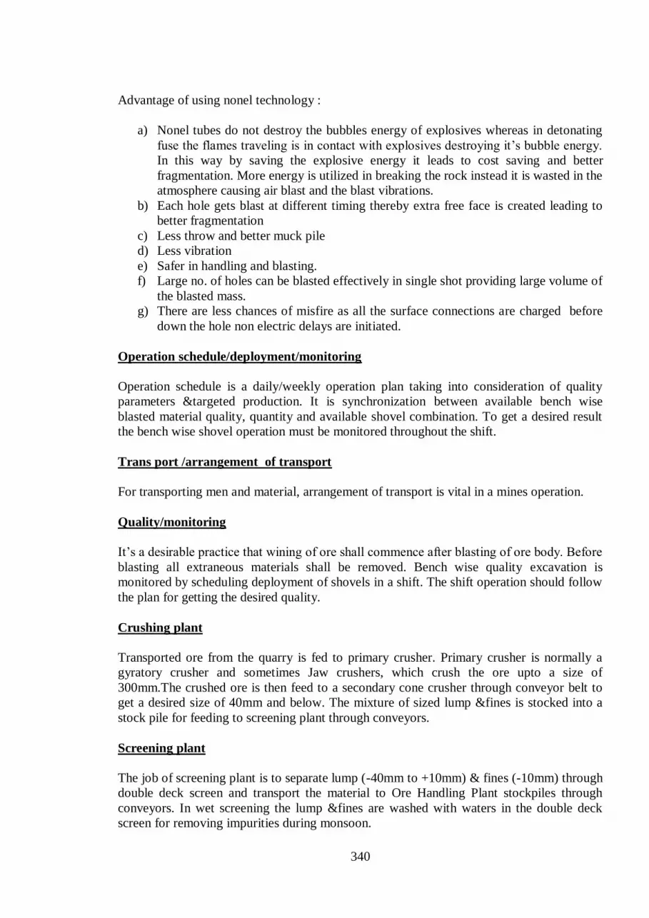
340
Advantage of using nonel technology :
a) Nonel tubes do not destroy the bubbles energy of explosives whereas in detonating
fuse the flames traveling is in contact with explosives destroying it’s bubble energy.
In this way by saving the explosive energy it leads to cost saving and better
fragmentation. More energy is utilized in breaking the rock instead it is wasted in the
atmosphere causing air blast and the blast vibrations.
b) Each hole gets blast at different timing thereby extra free face is created leading to
better fragmentation
c) Less throw and better muck pile
d) Less vibration
e) Safer in handling and blasting.
f) Large no. of holes can be blasted effectively in single shot providing large volume of
the blasted mass.
g) There are less chances of misfire as all the surface connections are charged before
down the hole non electric delays are initiated.
Operation schedule/deployment/monitoring
Operation schedule is a daily/weekly operation plan taking into consideration of quality
parameters &targeted production. It is synchronization between available bench wise
blasted material quality, quantity and available shovel combination. To get a desired result
the bench wise shovel operation must be monitored throughout the shift.
Trans port /arrangement of transport
For transporting men and material, arrangement of transport is vital in a mines operation.
Quality/monitoring
It’s a desirable practice that wining of ore shall commence after blasting of ore body. Before
blasting all extraneous materials shall be removed. Bench wise quality excavation is
monitored by scheduling deployment of shovels in a shift. The shift operation should follow
the plan for getting the desired quality.
Crushing plant
Transported ore from the quarry is fed to primary crusher. Primary crusher is normally a
gyratory crusher and sometimes Jaw crushers, which crush the ore upto a size of
300mm.The crushed ore is then feed to a secondary cone crusher through conveyor belt to
get a desired size of 40mm and below. The mixture of sized lump &fines is stocked into a
stock pile for feeding to screening plant through conveyors.
Screening plant
The job of screening plant is to separate lump (-40mm to +10mm) & fines (-10mm) through
double deck screen and transport the material to Ore Handling Plant stockpiles through
conveyors. In wet screening the lump &fines are washed with waters in the double deck
screen for removing impurities during monsoon.

341
Ore Handling Plant
The job of ore handling plant is to feed the wagon loader from stock pile by a bucket wheel
excavator. From the bucket wheel excavator the lumps &fines are transported to wagon
loader for loading into wagons by conveyors.
Loading and dispatch
Managing loading and dispatch within the free time without incurring demurrages and
loading correct weight to avoid heavy penal freight is the prime requirement and the big
challenge. There are different systems of loading in different mines. Loading are done by
wagon loader, shovels or the pay loaders. No. of the loading equipments depend on it’s
capacity and the free time provided by the railways.
12.3 Safety in Mines
Safety / Personal Protective Equipment (PPE)/Safety of men/machine
The safety of persons employed in mines and also the equipment are the responsibility of
the supervisors/ Astt. Manager / Mines Manager & other engineers working in the mine.
There are hazards associated with blasting, transportation of coal/ore, use of electrical
energy. As a general rule all persons working in mines must wear personal protective
equipments, follow general principles laid down in permission letters by the Directorate
General of Mines Safety Official as per MMR 1961/CMR1957.General condition of mines
atmosphere shall be congenial, airborne dust shall be suppressed at the place of formation
by water sprinkling.
Heavy electrical & other drills and also shovels shall be kept at a safe distance during
blasting to avoid damage from flying fragments.
Shovels shall be so placed and operated that there shall not be any undercuts and over
hangs. Quarry lighting/mine lighting shall take care of glare also. Mines shall be well
lighted so that movement of men and machine are not disturbed.
Separate walkway for men shall be established. Traffic of dumpers/truck shall be controlled
and a separate haul road shall be established for light vehicles.
---


