Embed Size (px)
Citation preview
GB745/204 INSTALLATION TOOL
GAGE BILT
MADE IN U.S.A.
GAGE BILT Inc. 44766 Centre Court (586) 226-1500
Clinton Twp. MI 48038 (586) 226-1505 Fax e-mail: [email protected] / www.gagebilt.com
GAGE BILT TOOLS ARE AVAILABLE WORLDWIDE E-MAIL US FOR A DISTRIBUTOR NEAR YOU.
2 REV. 2/14
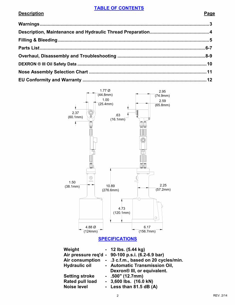
SPECIFICATIONS
Weight - 12 lbs. (5.44 kg) Air pressure req'd - 90-100 p.s.i. (6.2-6.9 bar) Air consumption - .3 c.f.m., based on 20 cycles/min. Hydraulic oil - Automatic Transmission Oil,
Dexron® III, or equivalent. Setting stroke - .500" (12.7mm) Rated pull load - 3,600 lbs. (16.0 kN) Noise level - Less than 81.5 dB (A)
TABLE OF CONTENTS Description Page Warnings ................................................................................................................................... 3
Description, Maintenance and Hydraulic Thread Preparation .............................................. 4
Filling & Bleeding ..................................................................................................................... 5
Parts List ................................................................................................................................ 6-7
Overhaul, Disassembly and Troubleshooting .................................................................... 8-9
DEXRON ® III Oil Safety Data .................................................................................................... 10
Nose Assembly Selection Chart ........................................................................................... 11
EU Conformity and Warranty ................................................................................................ 12
6.17
(156.7mm)
4.88 Ø
(124mm)
10.89
(276.6mm)
4.73
(120.1mm)
2.25
(57.2mm)
1.50
(38.1mm)
2.95
(74.9mm)
2.59
(65.8mm)
1.77 Ø
(44.8mm)
1.00
(25.4mm)
2.37
(60.1mm).63
(16.1mm)
3 REV. 2/14
WARNING
Do not pull fastener unless it is placed in an assembly, pin will eject forcibly when pintail breaks
off. Severe personal injury may result.
WARNING
Do not operate without Stat-O-Seal (S572) and cap screws (402482). Pressurized hydraulic oil may
cause severe personal injury.
WARNING
When operating, repairing or overhauling tool, wear approved eye protection. Do not look in front of
nose assembly or rear of tool when installing fastener.
WARNING
Always disconnect tool from power source before performing any maintenance to any tool or nose
assembly.
WARNING
Do not operate if deflector, bottle, catcher bag or vacuum tube is removed or damaged, broken
pintails may eject forcibly from rear of tool. Severe personal injury may result.
CAUTION
Ensure that nose assembly and tip are properly matched for the fastener being installed.
CAUTION
Keep Nose Assemblies clean and free of chips and debris.
WARNING
Be sure there is adequate clearance for tool and operator's hands before proceeding. Keep fingers clear of any moving parts. Keep fingers clear from
fasteners and installed materials. Severe personal injury may result.
WARNING
It is required to use hearing protection. A test was carried out in a simulated work environment where
the background level was 73.2 dB (A). In this condition the max level was 81.5 dB (A). Therefore,
it is required where prolonged use, hearing protection be used.
CAUTION
Do not use beyond the design intent.
WARNING
Tool must be maintained in a safe working condition at all times and examined on a daily basis for damage or wear. Any repair should be done by
qualified personnel trained on Gage Bilt procedures.
WARNING
Where prolonged use is foreseen, it is recommended a tool balancer be used. Check suspension device to ensure that it is secure.
WARNING
Do no use tool in explosive atmosphere.
CAUTION
Tool is not to be used as a hammer.
WARNING
Risk of crushing exists if nose assembly is not attached.
WARNING
It is recommended tool be operated 50 out of every 60 minutes, where prolonged use is expected.
WARNING Shock:
It is recommended operator wear a suitable glove during operation where prolonged use is expected. WARNING
Air pressure not to exceed 100 psi (6.9 bar).
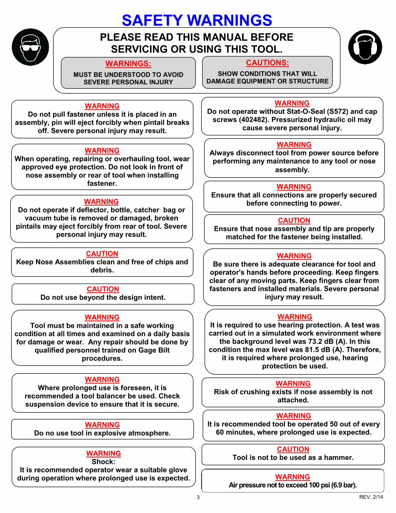
SAFETY WARNINGS PLEASE READ THIS MANUAL BEFORE
SERVICING OR USING THIS TOOL.
WARNINGS:
MUST BE UNDERSTOOD TO AVOID SEVERE PERSONAL INJURY
CAUTIONS:
SHOW CONDITIONS THAT WILL DAMAGE EQUIPMENT OR STRUCTURE
WARNING
Ensure that all connections are properly secured before connecting to power.
4 REV. 2/14
TORQUE SPECIFICATIONS Socket Head Cap Screws (A-928) = 40 inch lbs. Packing Plug (744118) = 45 foot lbs. Flexlock Nut (400059) = 40 inch lbs.
DESCRIPTION The GB745/204 Split Riveter Pneumatic-Hydraulic Installation Tool is designed specifically for the efficient installation of a wide range of blind rivet and lockbolt fasteners. This tool’s unique "split" system provides the operator with a lightweight ergonomic tool for a fraction of the cost of other cumbersome power rigs. It has a .500" (12.7mm) rivet setting stroke with a rated pull load of 3600 lbs. (16.0 kN) at 90 psi. (6.2 bar) air pressure at the air inlet.
The GB745/204 comes with 8 ft. of hose and a remote actuator. The GB204 cylinder when held in your hand, weighs just 2.0 lbs! (.91 kg) while the entire split riveter weighs 12 lbs. (5.44 kg).
The GB745/204Split Riveter operates on a wide range of air pressure, with 90 to 100 psi. (6.2-6.9 bar)providing maximum efficiency. At 90 psi. (6.2 bar) air pressure the GB745/204 does not exceed 81.5 db (A) and consumes 6.0 cfm at 20 cycles a minute.
This tool accepts all patented GB204 style nose assemblies.
MAINTENANCE
WARNING: EXCESSIVE CONTACT WITH HYDRAULIC OIL AND LUBRICANTS SHOULD BE AVOIDED.
WARNING: MAINTENANCE PERSONNEL MUST READ AND UNDERSTAND ALL WARNINGS AND CAUTIONS.
WARNING: DISCONNECT TOOL FROM ITS AIR SOURCE BEFORE PERFORMING MAINTENANCE.
The performance of any tool depends upon good maintenance practices. Following these minimal requirements for service and care will extend the life of your tool. *Only use an air supply set at 90-100 psi. (6.2-6.9 bar) equipped with a filter-regulator unit to prevent wear. *The tool will eventually lose some hydraulic oil. Keep the hydraulic system full and free of air by using the air bleeder (704153) on a regular basis. *Proper care by operator is necessary in maintaining full productivity and reducing downtime. Read all applicable tool manuals and nose assembly data sheets prior to operating tools. *Keep nose assemblies, especially jaws, clean and free of chips and debris. Lube jaws and collet surface that jaws ride on with light machine oil. *Check tool, all hoses and all couplings daily for damage or air/hydraulic leaks. Tighten or replace (if necessary). *A complete overhaul can be achieved by the use of Service Kit 745204 which contains a complete set of o'rings, back-up rings, screws, washers and gasket.
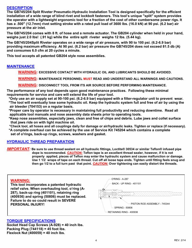
WARNING: This tool incorporates a patented hydraulic relief valve. When overhauling tool, o’ring (A-287), back-up ring (401101), retaining ring (400936) and spring (50806) must be replaced. Failure to do so could result in SEVERE PERSONAL INJURY!
PISTON ROD ASSEMBLY - 745344
SPRING - 50806
RETAINING RING - 400936
O'RING - A-287
BACK - UP RING - 401101
HYDRAULIC THREAD PREPARATION
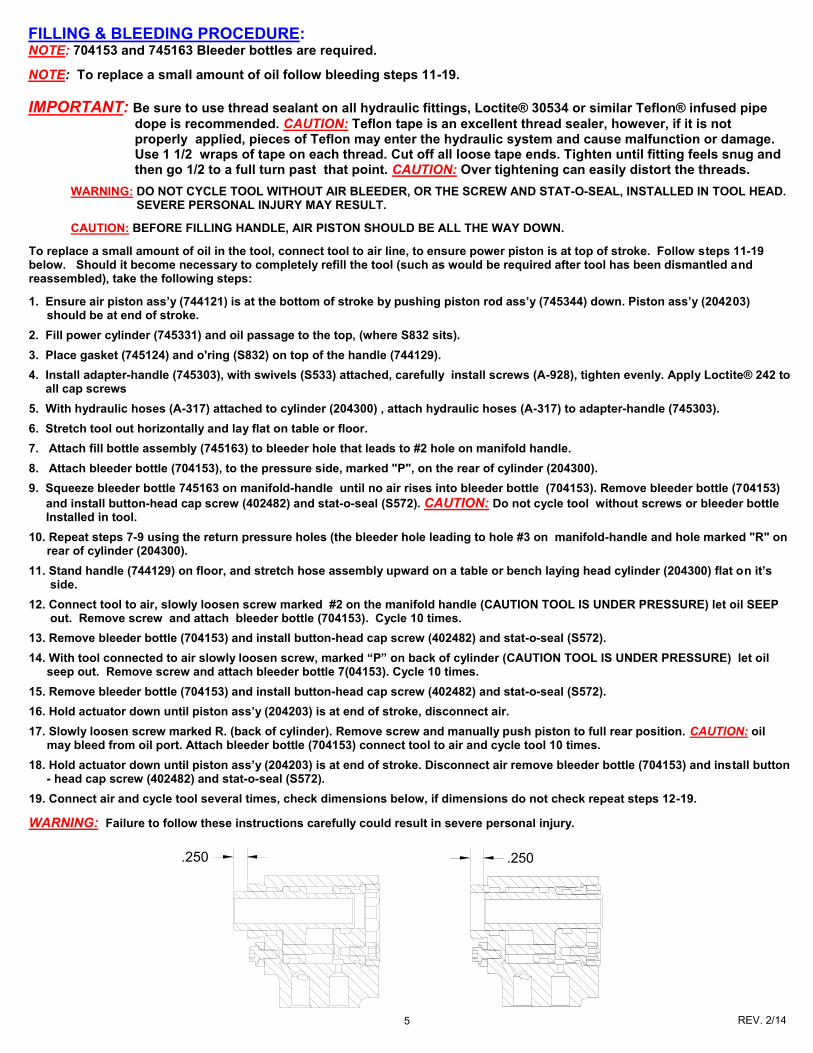
IMPORTANT: Be sure to use thread sealant on all hydraulic fittings, Loctite® 30534 or similar Teflon® infused pipe
dope is recommended. CAUTION: Teflon tape is an excellent thread sealer, however, if it is not properly applied, pieces of Teflon may enter the hydraulic system and cause malfunction or damage. Use 1 1/2 wraps of tape on each thread. Cut off all loose tape ends. Tighten until fitting feels snug and then go 1/2 to a full turn past that point. CAUTION: Over tightening can easily distort the threads.
5 REV. 2/14
WARNING: DO NOT CYCLE TOOL WITHOUT AIR BLEEDER, OR THE SCREW AND STAT-O-SEAL, INSTALLED IN TOOL HEAD. SEVERE PERSONAL INJURY MAY RESULT.
CAUTION: BEFORE FILLING HANDLE, AIR PISTON SHOULD BE ALL THE WAY DOWN.
To replace a small amount of oil in the tool, connect tool to air line, to ensure power piston is at top of stroke. Follow steps 11-19 below. Should it become necessary to completely refill the tool (such as would be required after tool has been dismantled and reassembled), take the following steps:
1. Ensure air piston ass’y (744121) is at the bottom of stroke by pushing piston rod ass’y (745344) down. Piston ass’y (204203) should be at end of stroke.
2. Fill power cylinder (745331) and oil passage to the top, (where S832 sits).
3. Place gasket (745124) and o'ring (S832) on top of the handle (744129).
4. Install adapter-handle (745303), with swivels (S533) attached, carefully install screws (A-928), tighten evenly. Apply Loctite® 242 to all cap screws
5. With hydraulic hoses (A-317) attached to cylinder (204300) , attach hydraulic hoses (A-317) to adapter-handle (745303).
6. Stretch tool out horizontally and lay flat on table or floor.
7. Attach fill bottle assembly (745163) to bleeder hole that leads to #2 hole on manifold handle.
8. Attach bleeder bottle (704153), to the pressure side, marked "P", on the rear of cylinder (204300).
9. Squeeze bleeder bottle 745163 on manifold-handle until no air rises into bleeder bottle (704153). Remove bleeder bottle (704153)
and install button-head cap screw (402482) and stat-o-seal (S572). CAUTION: Do not cycle tool without screws or bleeder bottle Installed in tool.
10. Repeat steps 7-9 using the return pressure holes (the bleeder hole leading to hole #3 on manifold-handle and hole marked "R" on rear of cylinder (204300).
11. Stand handle (744129) on floor, and stretch hose assembly upward on a table or bench laying head cylinder (204300) flat on it’s side.
12. Connect tool to air, slowly loosen screw marked #2 on the manifold handle (CAUTION TOOL IS UNDER PRESSURE) let oil SEEP out. Remove screw and attach bleeder bottle (704153). Cycle 10 times.
13. Remove bleeder bottle (704153) and install button-head cap screw (402482) and stat-o-seal (S572).
14. With tool connected to air slowly loosen screw, marked “P” on back of cylinder (CAUTION TOOL IS UNDER PRESSURE) let oil seep out. Remove screw and attach bleeder bottle 7(04153). Cycle 10 times.
15. Remove bleeder bottle (704153) and install button-head cap screw (402482) and stat-o-seal (S572).
16. Hold actuator down until piston ass’y (204203) is at end of stroke, disconnect air.
17. Slowly loosen screw marked R. (back of cylinder). Remove screw and manually push piston to full rear position. CAUTION: oil may bleed from oil port. Attach bleeder bottle (704153) connect tool to air and cycle tool 10 times.
18. Hold actuator down until piston ass’y (204203) is at end of stroke. Disconnect air remove bleeder bottle (704153) and install button - head cap screw (402482) and stat-o-seal (S572).
19. Connect air and cycle tool several times, check dimensions below, if dimensions do not check repeat steps 12-19.
WARNING: Failure to follow these instructions carefully could result in severe personal injury.
.250 .250
FILLING & BLEEDING PROCEDURE: NOTE: 704153 and 745163 Bleeder bottles are required.
NOTE: To replace a small amount of oil follow bleeding steps 11-19.
IMPORTANT: Be sure to use thread sealant on all hydraulic fittings, Loctite® 30534 or similar Teflon® infused pipe
dope is recommended. CAUTION: Teflon tape is an excellent thread sealer, however, if it is not properly applied, pieces of Teflon may enter the hydraulic system and cause malfunction or damage. Use 1 1/2 wraps of tape on each thread. Cut off all loose tape ends. Tighten until fitting feels snug and then go 1/2 to a full turn past that point. CAUTION: Over tightening can easily distort the threads.
6 REV. 2/14
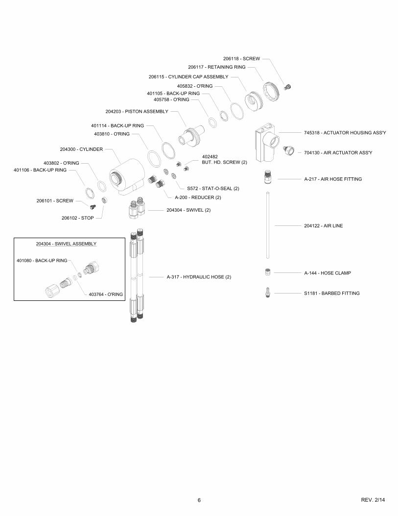
403764 - O'RING
401080 - BACK-UP RING
204304 - SWIVEL ASSEMBLY
401106 - BACK-UP RING
403802 - O'RING
204300 - CYLINDER
403810 - O'RING
401114 - BACK-UP RING
204203 - PISTON ASSEMBLY
405758 - O'RING
401105 - BACK-UP RING
405832 - O'RING
206115 - CYLINDER CAP ASSEMBLY
206117 - RETAINING RING
206118 - SCREW
206101 - SCREW
206102 - STOP
204304 - SWIVEL (2)
A-200 - REDUCER (2)
S572 - STAT-O-SEAL (2)
402482
BUT. HD. SCREW (2)
745318 - ACTUATOR HOUSING ASS'Y
704130 - AIR ACTUATOR ASS'Y
204122 - AIR LINE
A-144 - HOSE CLAMP
S1181 - BARBED FITTING
A-317 - HYDRAULIC HOSE (2)
A-217 - AIR HOSE FITTING
7 REV. 2/14
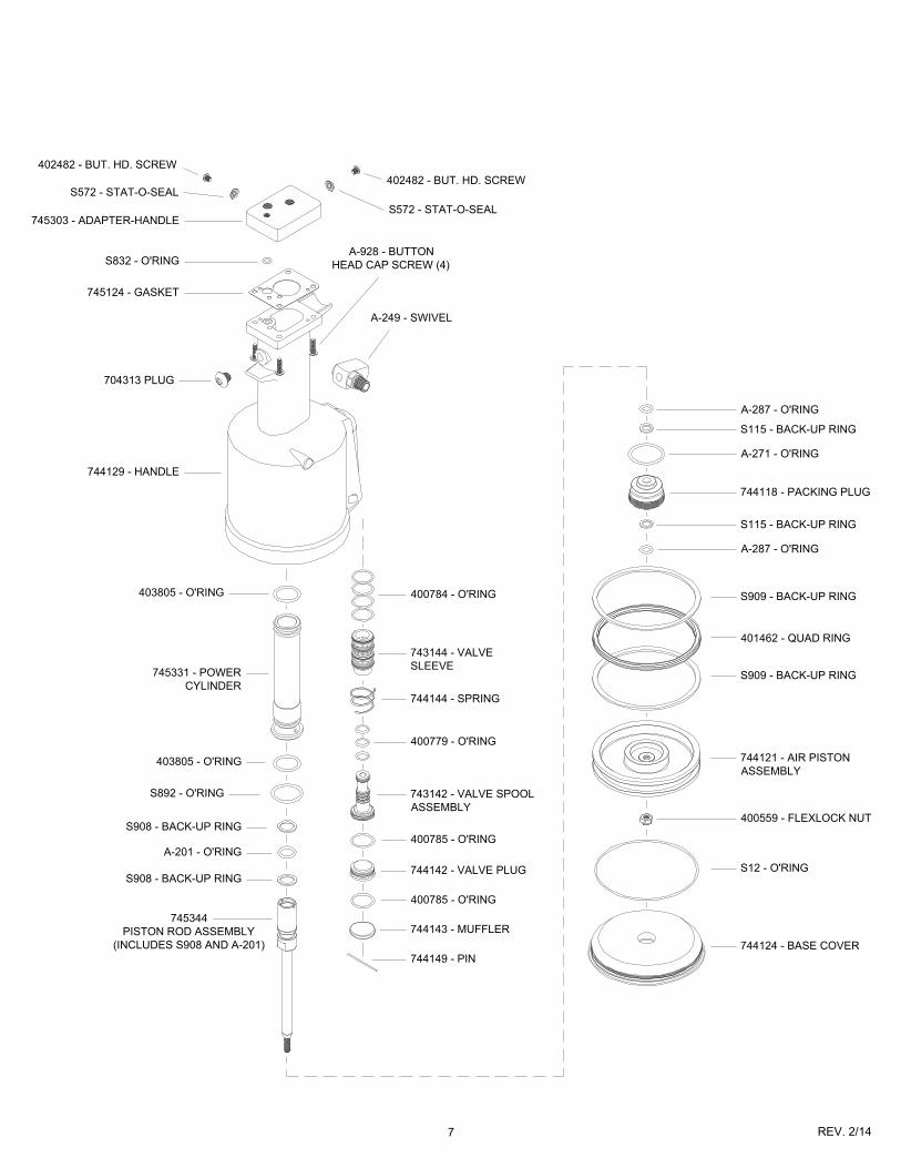
745331 - POWER
CYLINDER
403805 - O'RING
S908 - BACK-UP RING
A-201 - O'RING
S908 - BACK-UP RING
745344
PISTON ROD ASSEMBLY
(INCLUDES S908 AND A-201)
400784 - O'RING
743144 - VALVE
SLEEVE
744144 - SPRING
400779 - O'RING
743142 - VALVE SPOOL
ASSEMBLY
400785 - O'RING
744142 - VALVE PLUG
400785 - O'RING
744143 - MUFFLER
744149 - PIN
A-287 - O'RING
S115 - BACK-UP RING
A-271 - O'RING
744118 - PACKING PLUG
S115 - BACK-UP RING
A-287 - O'RING
S909 - BACK-UP RING
401462 - QUAD RING
S909 - BACK-UP RING
744121 - AIR PISTON
ASSEMBLY
400559 - FLEXLOCK NUT
S12 - O'RING
744124 - BASE COVER
744129 - HANDLE
704313 PLUG
745124 - GASKET
S832 - O'RINGA-928 - BUTTON
HEAD CAP SCREW (4)
A-249 - SWIVEL
403805 - O'RING
S892 - O'RING
745303 - ADAPTER-HANDLE
402482 - BUT. HD. SCREW
S572 - STAT-O-SEAL
S572 - STAT-O-SEAL
402482 - BUT. HD. SCREW
8 REV. 2/14
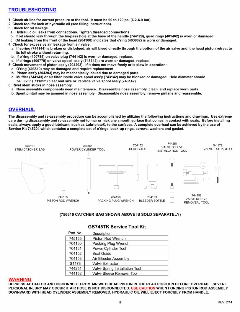
TROUBLESHOOTING 1. Check air line for correct pressure at the tool. It must be 90 to 120 psi (6.2-6.9 bar). 2. Check tool for lack of hydraulic oil (see filling instructions). 3. Check for oil leakage. a. Hydraulic oil leaks from connections. Tighten threaded connections. b. If oil should leak through the by-pass hole at the base of the handle (744129), quad rings (401462) is worn or damaged. c. Oil leaking from the front of the head (204300) indicates that o'ring (403802) is worn or damaged. 4. Check for excessive air leakage from air valve. a. If spring (744144) is broken or dislodged, air will bleed directly through the bottom of the air valve and the head piston retreat to its full stroke without returning. b. If o'ring (400785) on valve plug (744142) is worn or damaged, replace. c. If o'rings (400779) on valve spool ass’y (743142) are worn or damaged, replace. 5. Check movement of piston ass’y (204203). If it does not move freely or is slow in operation: a. O'ring (403810) may be damaged and require replacement. b. Piston ass’y (204203) may be mechanically locked due to damaged parts. c. Muffler (744143) or air filter inside valve spool ass’y (743142) may be blocked or damaged. Hole diameter should be .028" (.711mm) clear and size or replace valve spool ass’y (743142). 6. Rivet stem sticks in nose assembly. a. Nose assembly components need maintenance. Disassemble nose assembly, clean and replace worn parts. b. Spent pintail may be jammed in nose assembly. Disassemble nose assembly, remove pintails and reassemble.
WARNING DEPRESS ACTUATOR AND DISCONNECT FROM AIR WITH HEAD PISTON IN THE REAR POSITION BEFORE OVERHAUL. SEVERE PERSONAL INJURY MAY OCCUR IF AIR HOSE IS NOT DISCONNECTED. USE CAUTION WHEN FORCING PISTON ROD ASSEMBLY DOWNWARD WITH HEAD CYLINDER ASSEMBLY REMOVED, HYDRAULIC OIL WILL EJECT FORCIBLY FROM HANDLE.
OVERHAUL
The disassembly and re-assembly procedure can be accomplished by utilizing the following instructions and drawings. Use extreme care during disassembly and re-assembly not to mar or nick any smooth surface that comes in contact with seals. Before installing seals, always apply a good lubricant, such as Lubriplate®, to the surfaces. A complete overhaul can be achieved by the use of Service Kit 745204 which contains a complete set of o'rings, back-up rings, screws, washers and gasket.
(756610 CATCHER BAG SHOWN ABOVE IS SOLD SEPARATELY)
Part No. Description
745155 Piston Rod Wrench
704150 Packing Plug Wrench
704151 Power Cylinder Tool
704152 Seal Guide
704153 Air Bleeder Assembly
S1178 Valve Extractor
744251 Valve Spring Installation Tool
744152 Valve Sleeve Removal Tool
GB745TK Service Tool Kit
756610
STEM CATCHER BAG
745155
PISTON ROD WRENCH
704151
POWER CYLINDER TOOL
704152
SEAL GUIDE
704150
PACKING PLUG WRENCH
704153
BLEEDER BOTTLE
S-1178
VALVE EXTRACTOR
744251
VALVE SLEEVE
INSTALLATION TOOL
744152
VALVE SLEEVE
REMOVEAL TOOL
9 REV. 2/14
HEAD
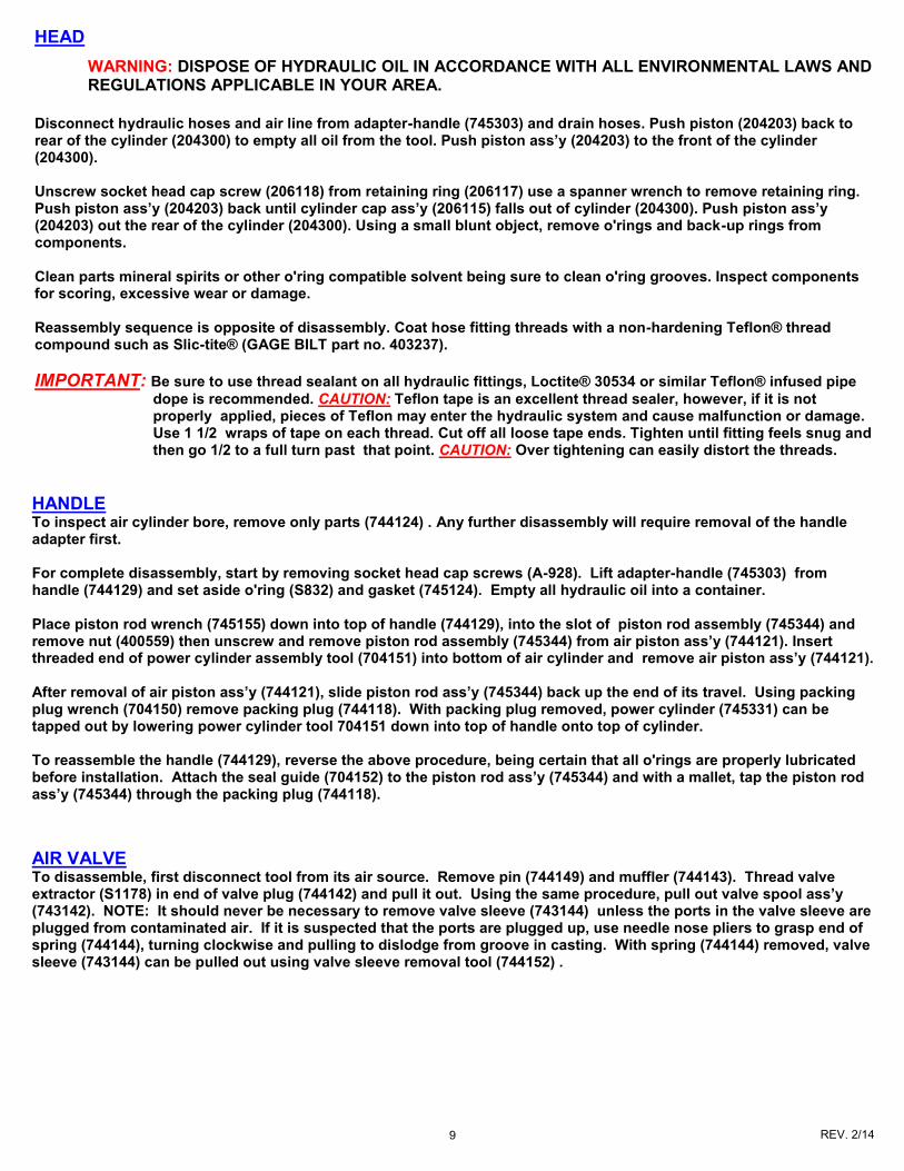
WARNING: DISPOSE OF HYDRAULIC OIL IN ACCORDANCE WITH ALL ENVIRONMENTAL LAWS AND REGULATIONS APPLICABLE IN YOUR AREA.
Disconnect hydraulic hoses and air line from adapter-handle (745303) and drain hoses. Push piston (204203) back to rear of the cylinder (204300) to empty all oil from the tool. Push piston ass’y (204203) to the front of the cylinder (204300). Unscrew socket head cap screw (206118) from retaining ring (206117) use a spanner wrench to remove retaining ring. Push piston ass’y (204203) back until cylinder cap ass’y (206115) falls out of cylinder (204300). Push piston ass’y(204203) out the rear of the cylinder (204300). Using a small blunt object, remove o'rings and back-up rings from components. Clean parts mineral spirits or other o'ring compatible solvent being sure to clean o'ring grooves. Inspect components for scoring, excessive wear or damage. Reassembly sequence is opposite of disassembly. Coat hose fitting threads with a non-hardening Teflon® thread compound such as Slic-tite® (GAGE BILT part no. 403237).
IMPORTANT: Be sure to use thread sealant on all hydraulic fittings, Loctite® 30534 or similar Teflon® infused pipe
dope is recommended. CAUTION: Teflon tape is an excellent thread sealer, however, if it is not properly applied, pieces of Teflon may enter the hydraulic system and cause malfunction or damage. Use 1 1/2 wraps of tape on each thread. Cut off all loose tape ends. Tighten until fitting feels snug and then go 1/2 to a full turn past that point. CAUTION: Over tightening can easily distort the threads.
HANDLE To inspect air cylinder bore, remove only parts (744124) . Any further disassembly will require removal of the handle adapter first. For complete disassembly, start by removing socket head cap screws (A-928). Lift adapter-handle (745303) from handle (744129) and set aside o'ring (S832) and gasket (745124). Empty all hydraulic oil into a container. Place piston rod wrench (745155) down into top of handle (744129), into the slot of piston rod assembly (745344) and remove nut (400559) then unscrew and remove piston rod assembly (745344) from air piston ass’y (744121). Insert threaded end of power cylinder assembly tool (704151) into bottom of air cylinder and remove air piston ass’y (744121). After removal of air piston ass’y (744121), slide piston rod ass’y (745344) back up the end of its travel. Using packing plug wrench (704150) remove packing plug (744118). With packing plug removed, power cylinder (745331) can be tapped out by lowering power cylinder tool 704151 down into top of handle onto top of cylinder. To reassemble the handle (744129), reverse the above procedure, being certain that all o'rings are properly lubricated before installation. Attach the seal guide (704152) to the piston rod ass’y (745344) and with a mallet, tap the piston rod ass’y (745344) through the packing plug (744118).
AIR VALVE To disassemble, first disconnect tool from its air source. Remove pin (744149) and muffler (744143). Thread valve extractor (S1178) in end of valve plug (744142) and pull it out. Using the same procedure, pull out valve spool ass’y (743142). NOTE: It should never be necessary to remove valve sleeve (743144) unless the ports in the valve sleeve are plugged from contaminated air. If it is suspected that the ports are plugged up, use needle nose pliers to grasp end of spring (744144), turning clockwise and pulling to dislodge from groove in casting. With spring (744144) removed, valve sleeve (743144) can be pulled out using valve sleeve removal tool (744152) .
10 REV. 2/14
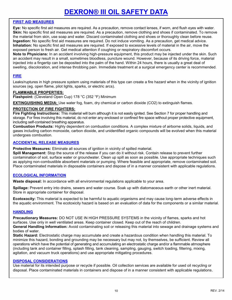
FIRST AID MEASURES
Eye: No specific first aid measures are required. As a precaution, remove contact lenses, if worn, and flush eyes with water. Skin: No specific first aid measures are required. As a precaution, remove clothing and shoes if contaminated. To remove the material from skin, use soap and water. Discard contaminated clothing and shoes or thoroughly clean before reuse. Ingestion: No specific first aid measures are required. Do not induce vomiting. As a precaution, get medical advice. Inhalation: No specific first aid measures are required. If exposed to excessive levels of material in the air, move the exposed person to fresh air. Get medical attention if coughing or respiratory discomfort occurs. Note to Physicians: In an accident involving high-pressure equipment, this product may be injected under the skin. Such an accident may result in a small, sometimes bloodless, puncture wound. However, because of its driving force, material injected into a fingertip can be deposited into the palm of the hand. Within 24 hours, there is usually a great deal of swelling, discoloration, and intense throbbing pain. Immediate treatment at a surgical emergency center is recommended. FIRE
Leaks/ruptures in high pressure system using materials of this type can create a fire hazard when in the vicinity of ignition sources (eg. open flame, pilot lights, sparks, or electric arcs).
FLAMMABLE PROPERTIES: Flashpoint: (Cleveland Open Cup) 178 °C (352 °F) Minimum
EXTINGUISHING MEDIA: Use water fog, foam, dry chemical or carbon dioxide (CO2) to extinguish flames.
PROTECTION OF FIRE FIGHTERS: Fire Fighting Instructions: This material will burn although it is not easily ignited. See Section 7 for proper handling and storage. For fires involving this material, do not enter any enclosed or confined fire space without proper protective equipment, including self-contained breathing apparatus. Combustion Products: Highly dependent on combustion conditions. A complex mixture of airborne solids, liquids, and gases including carbon monoxide, carbon dioxide, and unidentified organic compounds will be evolved when this material undergoes combustion.
ACCIDENTAL RELEASE MEASURES
Protective Measures: Eliminate all sources of ignition in vicinity of spilled material. Spill Management: Stop the source of the release if you can do it without risk. Contain release to prevent further contamination of soil, surface water or groundwater. Clean up spill as soon as possible. Use appropriate techniques such as applying non-combustible absorbent materials or pumping. Where feasible and appropriate, remove contaminated soil. Place contaminated materials in disposable containers and dispose of in a manner consistent with applicable regulations.
ECOLOGICAL INFORMATION
Waste disposal: In accordance with all environmental regulations applicable to your area.
Spillage: Prevent entry into drains, sewers and water course. Soak up with diatomaceous earth or other inert material. Store in appropriate container for disposal.
Ecotoxocity: This material is expected to be harmful to aquatic organisms and may cause long-term adverse effects in the aquatic environment. The ecotoxicity hazard is based on an evaluation of data for the components or a similar material. HANDLING
Precautionary Measures: DO NOT USE IN HIGH PRESSURE SYSTEMS in the vicinity of flames, sparks and hot surfaces. Use only in well ventilated areas. Keep container closed. Keep out of the reach of children. General Handling Information: Avoid contaminating soil or releasing this material into sewage and drainage systems and bodies of water. Static Hazard: Electrostatic charge may accumulate and create a hazardous condition when handling this material. To minimize this hazard, bonding and grounding may be necessary but may not, by themselves, be sufficient. Review all operations which have the potential of generating and accumulating an electrostatic charge and/or a flammable atmosphere (including tank and container filling, splash filling, tank cleaning, sampling, gauging, switch loading, filtering, mixing, agitation, and vacuum truck operations) and use appropriate mitigating procedures.
DISPOSAL CONSIDERATIONS Use material for its intended purpose or recycle if possible. Oil collection services are available for used oil recycling or
disposal. Place contaminated materials in containers and dispose of in a manner consistent with applicable regulations.
DEXRON® III OIL SAFETY DATA
11 REV. 2/14
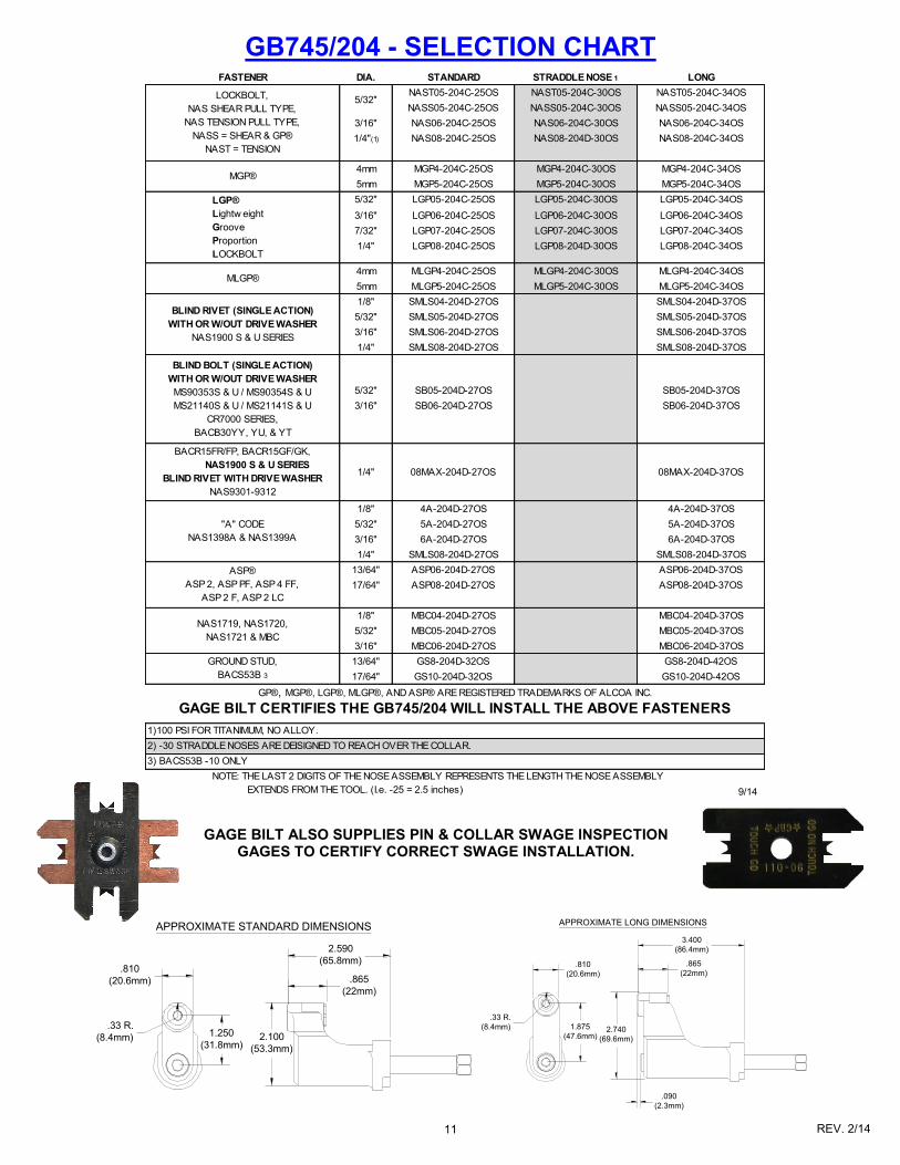
GB745/204 - SELECTION CHART
.810
(20.6mm)
1.250
(31.8mm)
.33 R.
(8.4mm)
2.590
(65.8mm)
.865
(22mm)
2.100
(53.3mm)
APPROXIMATE STANDARD DIMENSIONS3.400
(86.4mm)
.865
(22mm)
2.740
(69.6mm)
1.875
(47.6mm)
.810
(20.6mm)
.33 R.
(8.4mm)
.090
(2.3mm)
APPROXIMATE LONG DIMENSIONS
GAGE BILT ALSO SUPPLIES PIN & COLLAR SWAGE INSPECTION GAGES TO CERTIFY CORRECT SWAGE INSTALLATION.
FASTENER DIA. STANDARD STRADDLE NOSE 1 LONG
NAST05-204C-25OS NAST05-204C-30OS NAST05-204C-34OS
NASS05-204C-25OS NASS05-204C-30OS NASS05-204C-34OS
3/16" NAS06-204C-25OS NAS06-204C-30OS NAS06-204C-34OS
1/4"(1) NAS08-204C-25OS NAS08-204D-30OS NAS08-204C-34OS
4mm MGP4-204C-25OS MGP4-204C-30OS MGP4-204C-34OS
5mm MGP5-204C-25OS MGP5-204C-30OS MGP5-204C-34OS
5/32" LGP05-204C-25OS LGP05-204C-30OS LGP05-204C-34OS
3/16" LGP06-204C-25OS LGP06-204C-30OS LGP06-204C-34OS
7/32" LGP07-204C-25OS LGP07-204C-30OS LGP07-204C-34OS
1/4" LGP08-204C-25OS LGP08-204D-30OS LGP08-204C-34OS
4mm MLGP4-204C-25OS MLGP4-204C-30OS MLGP4-204C-34OS
5mm MLGP5-204C-25OS MLGP5-204C-30OS MLGP5-204C-34OS
1/8" SMLS04-204D-27OS SMLS04-204D-37OS
5/32" SMLS05-204D-27OS SMLS05-204D-37OS
3/16" SMLS06-204D-27OS SMLS06-204D-37OS
1/4" SMLS08-204D-27OS SMLS08-204D-37OS
5/32" SB05-204D-27OS SB05-204D-37OS
3/16" SB06-204D-27OS SB06-204D-37OS
1/8" 4A-204D-27OS 4A-204D-37OS
5/32" 5A-204D-27OS 5A-204D-37OS
3/16" 6A-204D-27OS 6A-204D-37OS
1/4" SMLS08-204D-27OS SMLS08-204D-37OS
13/64" ASP06-204D-27OS ASP06-204D-37OS
17/64" ASP08-204D-27OS ASP08-204D-37OS
1/8" MBC04-204D-27OS MBC04-204D-37OS
5/32" MBC05-204D-27OS MBC05-204D-37OS
3/16" MBC06-204D-27OS MBC06-204D-37OS
13/64" GS8-204D-32OS GS8-204D-42OS
17/64" GS10-204D-32OS GS10-204D-42OS
GROUND STUD,
BACS53B 3
MLGP®
NOTE: THE LAST 2 DIGITS OF THE NOSE ASSEMBLY REPRESENTS THE LENGTH THE NOSE ASSEMBLY
EXTENDS FROM THE TOOL. (I.e. -25 = 2.5 inches)
BACR15FR/FP, BACR15GF/GK,
NAS1900 S & U SERIES
BLIND RIVET WITH DRIVE WASHER
NAS9301-9312
"A" CODE
NAS1398A & NAS1399A
GAGE BILT CERTIFIES THE GB745/204 WILL INSTALL THE ABOVE FASTENERS
08MAX-204D-37OS
ASP®
ASP 2, ASP PF, ASP 4 FF,
ASP 2 F, ASP 2 LC
NAS1719, NAS1720,
NAS1721 & MBC
1/4" 08MAX-204D-27OS
MGP®
3) BACS53B -10 ONLY
2) -30 STRADDLE NOSES ARE DEISIGNED TO REACH OVER THE COLLAR.
5/32"
GP®, MGP®, LGP®, MLGP®, AND ASP® ARE REGISTERED TRADEMARKS OF ALCOA INC.
LOCKBOLT,
NAS SHEAR PULL TYPE,
NAS TENSION PULL TYPE,
NASS = SHEAR & GP®
NAST = TENSION
LGP®
Lightw eight
Groove
Proportion
LOCKBOLT
1)100 PSI FOR TITANIMUM, NO ALLOY.
BLIND RIVET (SINGLE ACTION)
WITH OR W/OUT DRIVE WASHER
NAS1900 S & U SERIES
BLIND BOLT (SINGLE ACTION)
WITH OR W/OUT DRIVE WASHER
MS90353S & U / MS90354S & U
MS21140S & U / MS21141S & U
CR7000 SERIES,
BACB30YY, YU, & YT
9/14
12 REV. 2/14
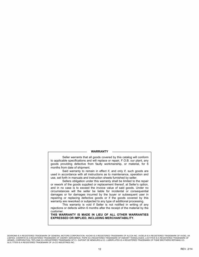
DEXRON® IS A REGISTERED TRADEMARK OF GENERAL MOTORS CORPORATION. HUCK® IS A REGISTERED TRADEMARK OF ALCOA INC. AVDEL® IS A REGISTERED TRADEMARK OF AVDEL UK LIMITED. CHERRY® IS A REGISTERED TRADEMARK OF CHERRY AEROSPACE. POP® IS A REGISTERED TRADEMARK OF EMHART TEKNOLOGIES. LOCTITE® IS A REGISTERED TRADEMARK OF HENKEL CORPORATION. TEFLON® IS A REGISTERED TRADEMARK OF E.I. DUPONT DE NEMOURS & CO. LUBRIPLATE® IS A REGISTERED TRADEMARK OF FISKE BROTHERS REFINING CO. SLIC-TITE® IS A REGISTERED TRADEMARK OF LA-CO INDUSTRIES INC.
Seller warrants that all goods covered by this catalog will conform to applicable specifications and will replace or repair, F.O.B. our plant, any goods providing defective from faulty workmanship, or material, for 6
months from date of shipment. Said warranty to remain in effect if, and only if, such goods are used in accordance with all instructions as to maintenance, operation and use, set forth in manuals and instruction sheets furnished by seller. Sellers obligation under this warranty shall be limited to the repair or rework of the goods supplied or replacement thereof, at Seller’s option, and in no case is to exceed the invoice value of said goods. Under no circumstances will the seller be liable for incidental or consequential damages or for damages incurred by the buyer or subsequent user in repairing or replacing defective goods or if the goods covered by this warranty are reworked or subjected to any type of additional processing. This warranty is void if Seller is not notified in writing of any rejections or defects within 6 months after the receipt of the material by the customer. THIS WARRANTY IS MADE IN LIEU OF ALL OTHER WARRANTIES EXPRESSED OR IMPLIED, INCLUDING MERCHANTABILITY.
WARRANTY


