Embed Size (px)
Citation preview
www.SteamPoweredRadio.Com
www.SteamPoweredRadio.Com
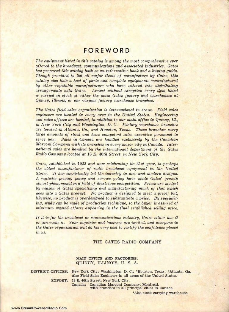
FOREWORD
The equipment listed in this catalog is among the most comprehensive ever offered to the broadcast, communications and associated industries. Gates has prepared this catalog both as an informative book and a buying guide. Though provided to list all major items of manufacture by Gates, this catalog also lists a host of parts and complete equipments manufactured by other -reputable manufacturers who have entered into distributing arrangements with Gates. Almost without exception every ~m listed is carried in stock at either the main Gates factory and warehouses at · Quincy, Illinois, or our various factory warehouse branches.
The Gates field sales organization is international in scope. Field sales engineers are located in every area in the United States. Engineering and sales offices are located, in addition to our main office in Quincy, Ill., in New York City and Washington, D. C. Factory warehouse branches are located in Atl,anta_, Ga., and Houston, Texas. These branches carry l,arge amounts of stock and have competent sales executive personnel to serve you. Sales in Canada are handled exclusively by the Canadian Marconi Company with its branches in every major city in Canada. International sales are handled by the international department of the Gates Radio Company located at 13 E. 40th Street, in New York City.
Gates, established in 1922 and now celebrating its 31st year, is perhaps the oldest manufacturer of radio broadcast equipment in the United States. It has consistently led the industry in new and modern designs. A realistic pricing policy and service policy have made Gates' growth almost phenomenal in a field of illustrious competition. Prices are modest by reason of Gates specializing and manufacturing much of that which goes into a Gates product. No product is designed to meet a price; but, likewise, no product is overdesigned to substantiate a price. By specializing, study can be made of production technique, so the buyer is assured of minimum wasted efforts appearing in the final established selling price.
If it is for the broadcast or communications industry, Gates either has it or can make it. Your inquiries and business are invited, and everyone in the Gates organization will do his very best to justify the confidence placed in us.
THE GATES RADIO COMPANY
MAIN OFFICE AND FACTORIES: QUINCY, ILLINOIS, U. S. A.
DISTRICT OFFICES: New York City; Washington, D. C.; •Houston, Texas; •Atlanta, Ga. Also Field Sales Engineers in all areas of the United States.
EXPORT : 13 E. 40th Street, New York City. Canada: Canadian Marconi Company, Montreal,
with branches in all principal cities in Canada. • Also stock carrying warehouse.
. I
www.SteamPoweredRadio.Com
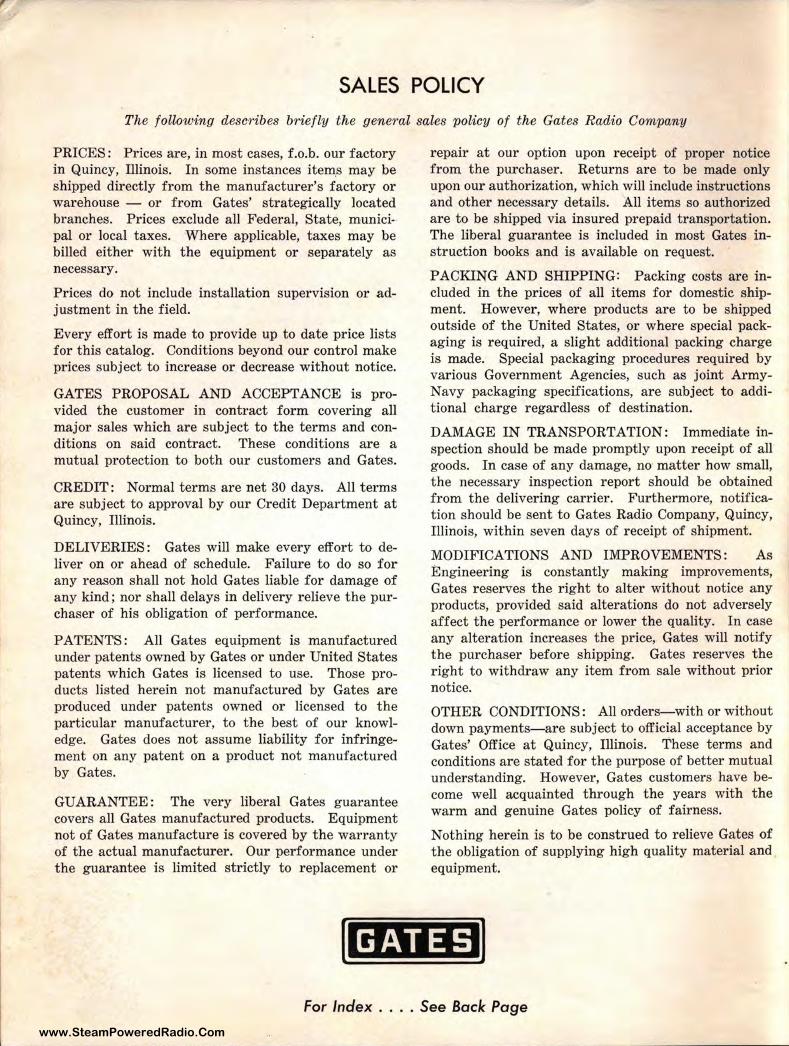
SALES POLICY The following describes briefly the general sales policy of the Gates Radio Company
PRICES: Prices are, in most cases, f.o.b. our factory in Quincy, lllinois. In some instances item_s may be shipped directly from the manufacturer's factory or warehouse - or from Gates' strategically located branches. Prices exclude all Federal, State, municipal or local taxes. Where applicable, truces may be billed either with the equipment or separately as necessary.
Prices do not include installation supervision or adjustment in the field.
Every effort is made to provide up to date price lists for this catalog. Conditions beyond our cont rol make prices subject to increase or decrease without notice.
GATES PROPOSAL AND ACCEPTANCE is provided the customer in contract form covering all major sales which are subject to the terms and conditions on said contract. These conditions are a mutual protection to both our customers and Gates.
CREDIT: Normal terms are net 30 days. All terms are subject to approval by our Credit Department at Quincy, lllinois.
DELIVERIES: Gates will make every effort to deliver on or ahead of schedule. Failure to do so for any reason shall not hold Gates liable for damage of any kind; nor shall delays in delivery relieve the purchaser of his obligation of performance.
PATENTS: All Gates equipment is manufactured under patents owned by Gates or under United States patents which Gates is licensed to use. Those products listed herein not manufactured by Gates are produced under patents owned or licensed to the particular manufacturer, to the best of our knowledge. Gates does not assume liability for infringement on any patent on a product not manufactured by Gates.
GUARANTEE: The very liberal Gates guarantee covers all Gates manufactured products. Equipment not of Gates manufacture is covered by the warranty of the actual manufacturer. Our performance under the guarantee is limited strictly to replacement or
repair at our option upon receipt of proper notice from the purchaser. Returns are to be made only upon our authorization, which will include instructions and other necessary details. All items so authorized are to be shipped via insured prepaid transportation. The liberal guarantee is included in most Gates instruction books and is available on request.
PACKING AND SHIPPING: Packing costs are included in the prices of all items for domestic shipment. However, where products are to be shipped outside of the United States, or where special packaging is required, a slight additional packing charge is made. Special packaging procedures required by various Government Agencies, such as joint ArmyNavy packaging specifications, are subject to additional charge regardless of destination.
DAMAGE IN TRANSPORTATION: Immediate inspection should be made promptly upon receipt of all goods. In case of any damage, no matter how small, the necessary inspection report should be obtained f rom the delivering carrier. Furthermore, notification should be sent to Gates Radio Company, Quincy, Illinois, within seven days of receipt of shipment.
MODIFICATIONS AND IMPROVEMENTS: As Engineering is constantly making improvements, Gates reserves the right to alter without notice any products, provided said alterations do not adversely affect the performance or lower the quality. In case any alteration increases the price, Gates will notify the purchaser before shipping. Gates reserves the right to withdraw any item from sale without prior notice.
OTHER CONDITIONS: All orders-with or without down payments-are subject to official acceptance by Gates' Office at Quincy, lllinois. These terms and conditions are stated for the purpose of better mutual understanding. However, Gates customers have become well acquainted through the years with the warm and genuine Gates policy of fairness.
Nothing herein is to be construed to relieve Gates of the obligation of supplying high quality material and equipment.
I GATES I For Index .... See Back Page
www.SteamPoweredRadio.Com
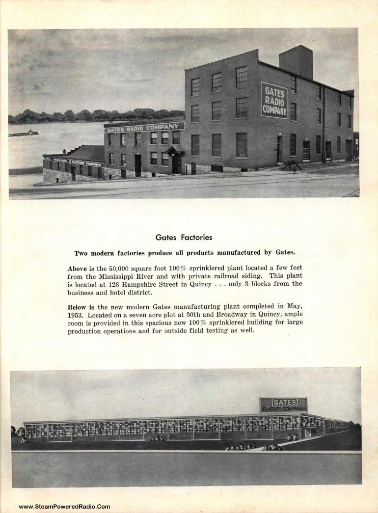
Gates Factories
Two modern factories produce all products manufactured by Gates.
Above is t he 50,000 square foot 100% sprinklered plant located a few feet from the Mississippi River and with private railroad siding. This plant is located at 123 Hampshire Street in Quincy . . . only 3 blocks from the business and hotel district.
Below is the new modern Gates manufacturing plant completed in May, 1953. Located on a seven acre plot at 30th and Broadway in Quincy, ample room is provided in t his spacious new 100 % spr inklered building for large production operations and for outside field testing as well.
www.SteamPoweredRadio.Com
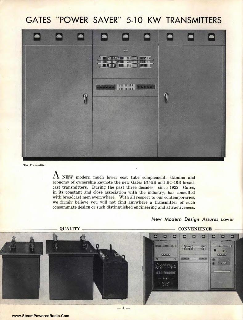
GATES "POWER SA VER" 5-10 KW TRANSMITTERS
The Transmitter
A NEW modern much lower cost tube complement, stamina and economy of ownership keynote the new Gates BC-5B and BC-lOB broadcast transmitters. During the past three decades-since 1922- Gates, in its constant and close association with the industry, has consulted with broadcast men everywhere. With all respect to our contemporaries, we firmly believe you will not find anywhere a transmitter of such consummate design or such distinguished engineering and attractiveness.
New Modern Design Assures lower
-4-
www.SteamPoweredRadio.Com
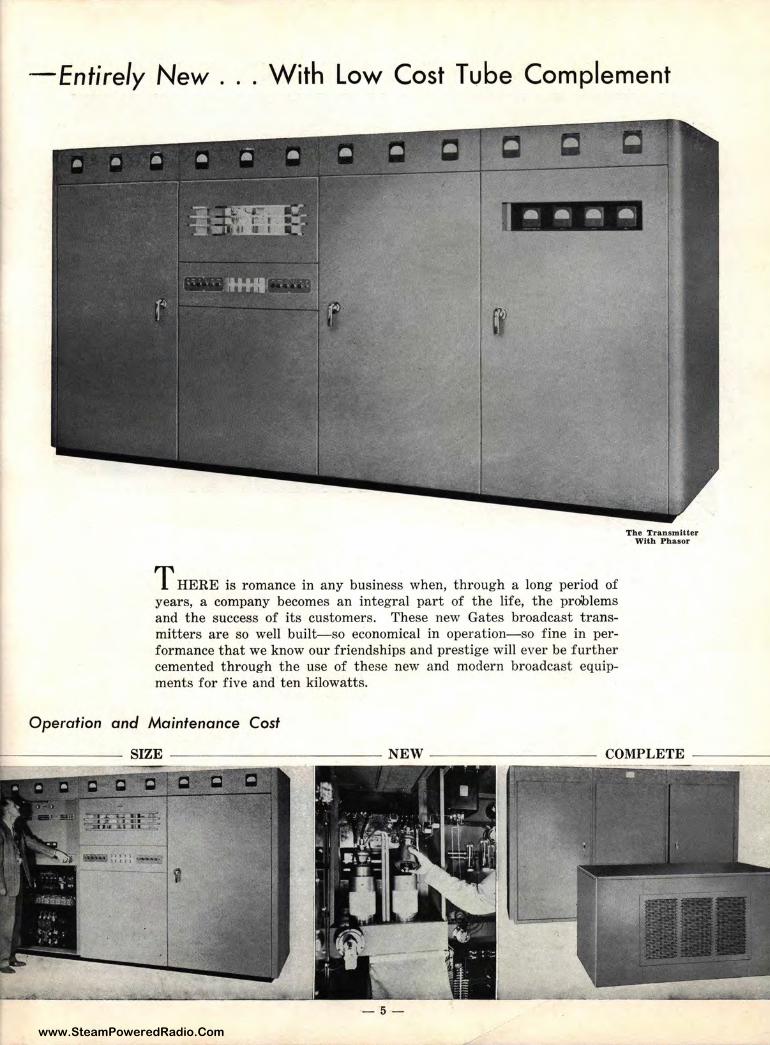
-Entirely New . . . With Low Cost Tube Complement
----
THERE is romance in any business when, through a long period of years, a company becomes an integral part of the life, the problems and the success of its customers. These new Gates broadcast transmitters are so well built-so economical in operation-so fine in performance that we know our friendships and prestige will ever be further cemented through the use of these new and modern broadcast equipments for five and ten kilowatts.
Operation and Maintenance Cost
-5-
The T:ransmitter With Phaaor
www.SteamPoweredRadio.Com
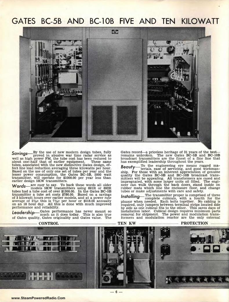
GATES BC-5B AND BC-1 OB
Savings-BY the use of ~ew modern design tubes: fully proved in abusive war time radar service as
well as high power FM, the tube cost has been reduced to about one-half tlhat of earlier equipment. These same tubes, associated 'with the new distinctive Gates design, effect line load reduction averaging three kilowatts per hour. Based on the use of only one set of tubes per year and the lesser power consumption, the Gates BC-5B, 5000 watt transmitter, will operate for $1000.00 per year less than earlier design 5KW transmitters. Words-are easy to say. To back these words all older
models 5KW transmitters using 891R or 892R tubes had a tube ,cost of over $1300.00. In the Gates BC-5B transmitter a tube set costs $786.00. Based on a savings of 3 kilowatt hours over earlier models, and at a power rate average of 2½c this is 7½c per hour or $518.00 annually on an 18 hour da.y. All this is done with much improved performance and reliability. Leadership-Gates pe~formance has neye1: meant so
much as 1t does today. This 1s also true of Gates quality, Gates originality and Gates value. The
FIVE AND TEN KILOWATT
Gates record-a priceless heritage of 31 years of the best-remains unbroken. The new Gates BC-5B and BC-l0B broadcast transmitters are the finest of a fine line that has exemplified leadership throughout the years. • B t _To the engineering eye means rugged ma-
ea u Y terials, ease of servicing, and good workmanship. For those with an inherent appreciation of genuine quality the Gates BC-5B and BC-lOB broadcast transmitters will be appealing. All transformers are cased and impregnated, with some larger units oil filled. The engineer can walk through the back doors, stand inside on rubber mats which line the enclosure floor, and change tubes or make adjustments with care and safety. Jnstal/ing-The transmitter proper is comprised of three
complete cubicals, with a fourth for the phasor when needed. Each bolts together. No cabling is required, only jumpers between terminal strips located side by side as one cubical fits to the other. This saves days of installation labor. Cubical design requires minimum parts removal for shipment. The power and modulation transformers and modulation reactor are the only external
-6-
www.SteamPoweredRadio.Com
TRANSMITTERS Lead Quality, Engineering and Results
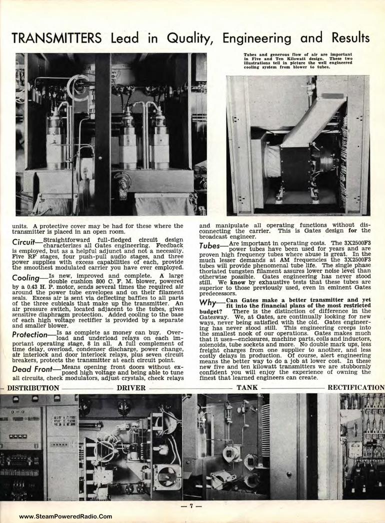
units. A protective cover may be had for these where the transmitter is placed in an open room. c· ·t Straightforward full-fledged circuit design
,rcu, -characterizes all Gates engineering. Feedback_ Is employed, but as a helpful adjunct and not a necessity. Five RF stages, four push-pull audio stages, and three power supplies with excess capabilities of each, provide the smoothest modulated carrier you have ever employed. C r Is new, improved and complete. A large
oo mg-double cushion 800 c. F . M. blower, powered by a 0.43 H. P. motor, sends several times the required air around the power tube envelopes and on their filament seals. Excess air is sent via deflecting baffles to all parts of the three cubicals that make up the transmitter. An air pressure switch, located adjacent to the tubes, gives sensitive diaphragm protection. Added cooling to the base of each high voltage rectifier is provided by a separate and smaller blower. Protection-Is as complete as money can buy. Over-
load and underload relays on each important operating stage, 8 in all. A full complement of time delay, overload, condenser discharge, power change, air interlock and door interlock relays, plus seven circuit breakers, protects the transmitter at each circuit point.
D d F f_Means opening front doors without exea ron posed high voltage and being able to tune
all circuits, check modulators, adjust crystals, check relays
Tubes and cenerous flow of air are, Important In Fhre and Ten Kilowatt deslJn. These two lllustratlons tell l.n picture the well enrlneered coollnr system from blower to tubes.
and manipulate all operating functions without disconnecting the carrier. This is Gates design for the broadcast engineer. T b Are important in operating costs. The 3X2500F3
u es-power tubes have been used for years and are proven high frequency tubes where abuse is great. In the much lesser demands at AM frequencies the 3X2500F3 tubes will provide phenomenal tube life. Tlhe single phase thoriated tungsten filament assures lower noise level than otherwise possible. Gates engineering has never stood still. We know by exhaustive tests that these tubes are superior to those previously used, even in eminent Gates predecessors. Wh Can Gates make a better transmitter and yet
y - fit into the financial plans of the most restricted budget? There is the distinction of difference in the Gatesway. we, at Gates, are continually 1,ooking for new ways, never being satisfied with the old. Gates engineering has never stood still. This engineering creeps into the smallest nook of our operations. Gates makes much that it uses-enclosures, machine parts, coil:s and inductors, solenoids, tube sockets and more. No double mark ups, less freight charges from one supplier to another, and less costly delays in production. Of course, alert engineering means the better way to do a job at lower cost. In these new five and ten kilowatt transmitters we are stubbornly confident you will enjoy the experience of owning the finest that learned engineers can create.
-7-
www.SteamPoweredRadio.Com
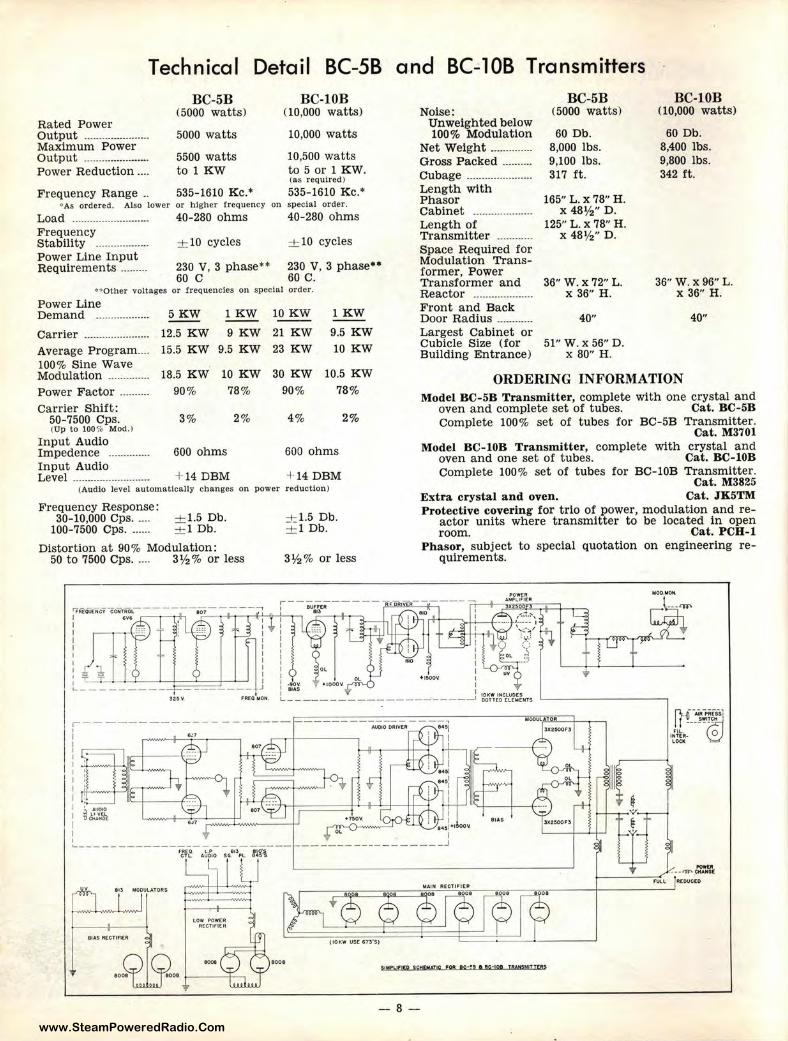
Technical Detail BC-58 a nd BC-108 Transmitters
Rated Power Output -----················· Maximum Power Output ..................... . Power Reduction ... .
Frequency Range ..
BC-5B (5000 watts)
5000 wa tts
5500 watts to 1 KW
535-1610 Kc.•
BC-l0B (10,000 watts)
10,000 watts
10,500 watts to 5 or 1 KW. (as required)
535-1610 Kc.• ' As ordered. Also lower or higher frequency on special order.
Load .......................... 40-280 ohms 40-280 ohms Frequency Stability ................. . + 10 cycles + 10 cycles
Noise: Unweighted below 100% Modulation
Net Weight ............. . Gross Packed ······--·· Cubage ..................... . Length with Phasor Cabinet ······-·---········· Length of Transmitter ........... .
BC-5B (5000 watts)
60 Db. 8,000 lbs. 9,100 lbs. 317 ft.
165" L. X 78" H. X 48½" D.
125" L. X 78" H. X 48½" D.
BC-lOB (10,000 watts)
60 Db. 8,400 lbs. 9,800 lbs. 342 ft.
Power Line Input Requirements ........ . 230 V, 3 phase** 230 V, 3 phase••
Space Required for Modulation Transformer, Power Transformer and Reactor ··-··--··--········· Front and Back
60 C 60 C. " Other voltages or frequencies on specia l order.
Power Line Demand ·--···············
Carrier ···········-·········· Average Program .... 100% Sine Wave Modulation ········-····· Power Factor ···-······ Carrier Shift :
50-7500 Cps. (Up to 1007• Mod.I
Input Audio Impedence ·····•·-······ Input Audio Level ·············-··--········
5KW
12.5 KW
1 KW 10 KW
9 KW 21 KW
lKW
9.5 KW 10 KW 15.5 KW 9.5 KW 23 KW
18.5 KW 10 KW 30 KW 10.5 KW
90% 78%
3% 2%
600 ohms
+ 14 DBM
90% 78%
4% 2%
600 ohms
+ 14DBM (Audio level au tomatically changes on power reduction )
Frequency Response: 30-10,000 Cps . ... .
100-7500 Cps . ..... . + 1.5 Db. + 1 Db.
Distort ion at 90% Modulation: 50 to 7500 Cps. .... 3 ½ % or less
± 1.5 Db. + 1 Db.
3½% or less
Door Radius ........... . Largest Cabinet or Cubicle Size (for Building Entrance)
36" W. X 72" L. X 36" H.
40"
51" W. X 56" D. X 80" H.
36" W. X 96" L. X 36" H.
40"
ORDERING INFORMATION Model BC-5B Transmitter, complete wit h one crystal and
oven and complete set of tubes. Cat. BC-5B Complete 100% set of tubes for BC-5B Transmitter.
Cat. M3701 Model BC-10B Transmitter, complete with crystal and
oven and one set of tubes. Cat. BC-10B Complete 100% set of tubes for BC-l0B Transmitter.
Cat. M3825 Extra crystal and oven. Cat. JK5TM Protective covering for trio of power, modulation and re
actor units where transmitter to be located in open room. Cat. PCB-1
Phas~r, subject to special quotation on engineering re-quirements.
r------------- -- ----- -----------------, I .41.1010 OAIVflll 84' 1
: .-----+-----=.-'----.--- r ---.--+-- --~ I I
I I I I I
I
' ' '
.• ' NJOIO
B c\!.';i\1
1001
; I : e•~I +1 00'lt
BIAS
I - ----------- _____ J
SJMPLl!l[D SCHQU.t te fQO nc-•, I !C·IOI 18WWTT£95
-8 -
www.SteamPoweredRadio.Com
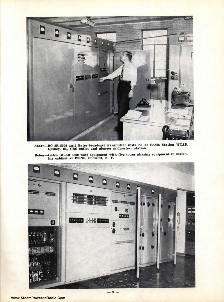
Above-BC-5B 5000 watt Gates broadcast transmitter installed at Radio Station WTAD, Quincy, Ill., CBS outlet and pioneer midwestern station.
Below-Gates BC-5B 5000 watt equipment with five tower phasing equipment in matching cabinet at WENE, Endicott, N. Y.
-9-
www.SteamPoweredRadio.Com
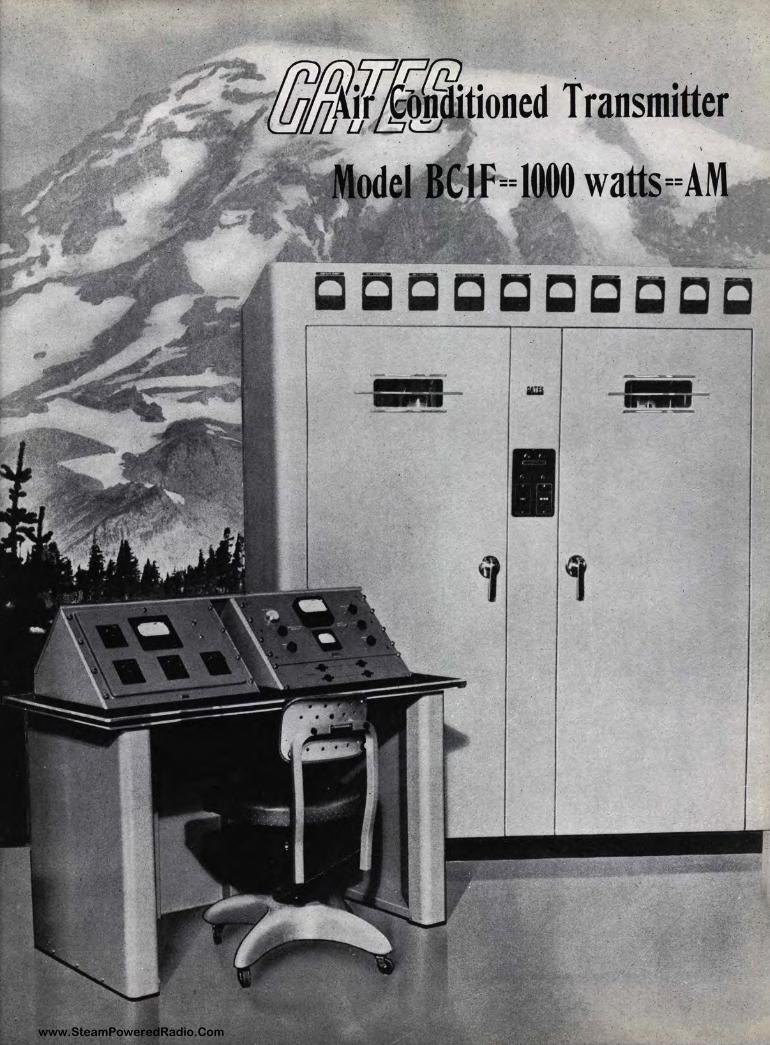
The Dependable Gates BC-1 F Air-Conditioned One KW Transmitter
,, Probably more premeditated engineering has been placed in the new Gates air conditioned one thousand watt transmitter than any similar equipment in broadcast history. Gates engineers are practical men, too. The new dependable Gates BC-11f broadcasting equipment does have, as well as near perfection electronically, good mechanical engineer ing, studied parts placement, distinguished styling and-complete air-conditioning.
A IR, when properly circulated in clean form, is a radio engineer's assurance of dependable operation void of offages. BC-lF air changes four times each minute inside a semi-pressure enclosure. This air cools not only tubes, but reaches into every nook and corner of the cabinet.
PARTS must be placed in the path of this air. Parts dissipating most heat are in the direct stream, such as power resistors, all at the top of t he enclosure. Those dissipating less heat are in the secondary air stream. As a result, one section of the cabinet enclosure is as cool as another. Cool air forces out hot air every 15 seconds. This cool air is clean filtered air. Dust cannot come in; but even the small amount that might be let in, such as when opening a back door, is immediately forced out by semi-pressure cabinet design.
ROOM is predominant. The dependable Gates BC-lF is a large t ransmitter -no scuffing the back of a hand scraping across a fuse clip or condens_er plate to reach a tube. You can't assure air cooling without room. Large oversize parts are impossible without a place to put them. Quality and size go hand in hand and the dependable Gates BC-lF is a sizable equipment.
COMPLETE as a broadcast t ransmitter can be made, adequately describes the dependable Gates BC-lF. Thirteen meters, nine relays, dual circuit breakers, veeder counter tuning, variable coil resonance control, T network loading, ten second accessibility of the smallest and most concealed part, four power supplies, feedback, impregnation and casing of all transformers large and small, welded construction, dead front control-everything with a plus. The dependable Gates BC-lF is mid-century's servant to a critical listening public.
GATES RADIO COMPANY Quincy, Illinois, U. S. A.
- 10 -
www.SteamPoweredRadio.Com
. . . . ' .
- · · =~~-.--....,.=,.,,___.. ~j@Jtioned T ran~mitt~r ; • I
·. == 00 .w . =
-1111--
I i ,
www.SteamPoweredRadio.Com
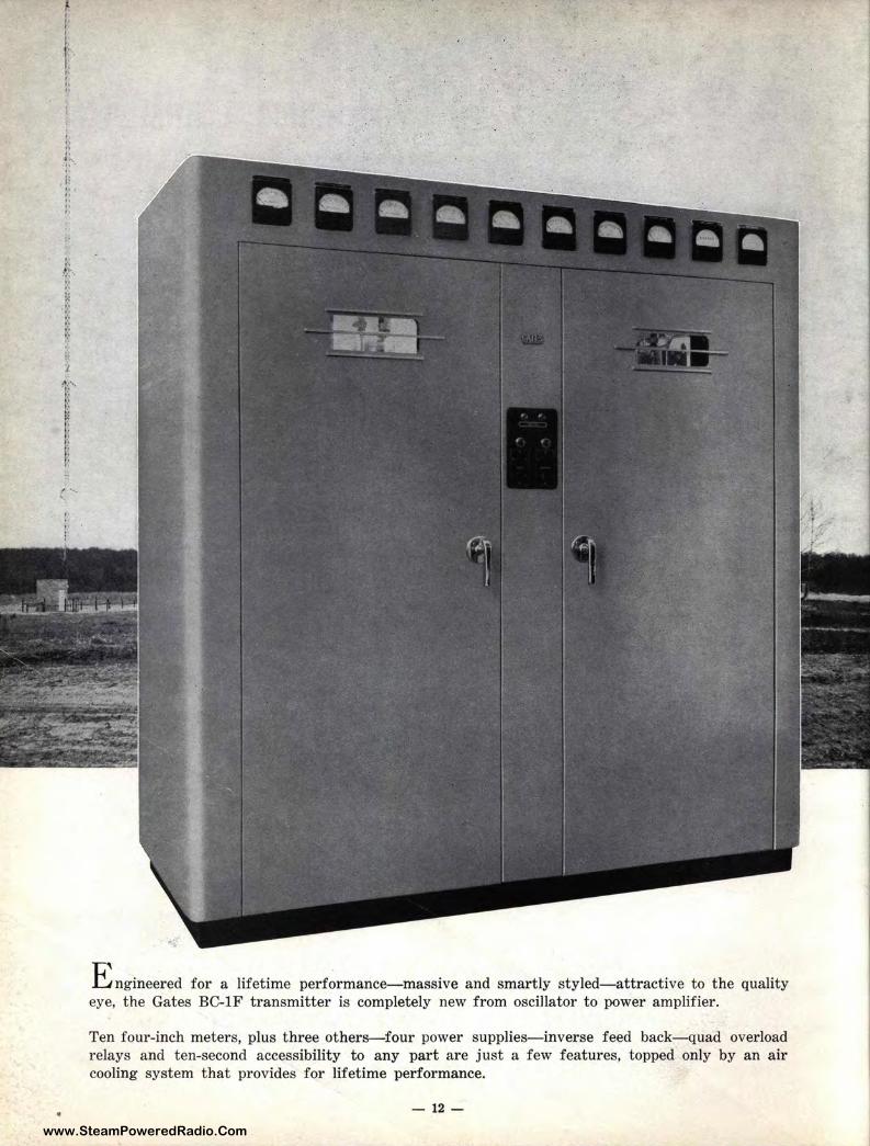
E ngineered for a lifetime performance-massive and smartly styled-attractive to the quality eye, the Gates BC-lF transmitter is completely new from oscillator to power amplifier.
Ten four-iinch meters, plus three others-four power supplies-inverse feed back-quad overload relays and ten-second accessibility to any part are just a few features, topped only by an air cooling system that provides for lifetime performance.
- 12 -
www.SteamPoweredRadio.Com
BC-1 F CONSTRUCTION DET Al L (1000/ 500 Watts A. M.)
The dependable BC-lF Transmitter is a large roomy equipment where cramping of parts fs unnecessary and where each part is located properly for best electrical position. The air condiitioning of the BC-lF Transmitter involves not only proper distribution of air throughout the cabinet, but also careful study and then proper location of each part in relation to the air stream. As :i result the clean fresh filtered air is distributed in turbulence throughout the cabinet and each part, large and small, operates at its best.
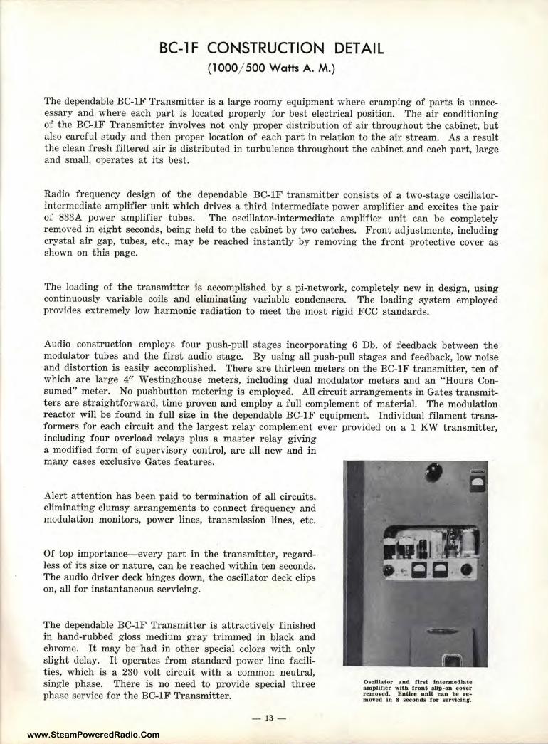
Radio frequency design of the dependable BC-lF transmitter consists of a two-stage oscillatorintermediate amplifier unit which drives a third intermediate power amplifier and excites the pair of 833A power amplifier tubes. The oscillator-intermediate amplifier unit can be completely removed in eight seconds, being held to the cabinet by two catches. Front adjustments, including crystal air gap, tubes, etc., may be reached instantly by removing the front protective c,over as shown on this page.
The loading of the transmitter is accomplished by a pi-network, completely new in design, using continuously variable coils and eliminating variable condensers. The loading system employed provides extremely low harmonic radiation to meet the most rigid FCC standards.
Audio construction employs four push-pull stages incorporating 6 Db. of feedback between the modulator tubes and the first audio stage. By using all push-pull stages and feedback, low noise and distortion is easily accomplished. There are thirteen meters on the BC-lF transmitter, ten of which are large 4" Westinghouse meters, including dual modulator meters and an "Hom·s Consumed" meter. No pushbutton metering is employed. All circuit arrangements in Gates transmitters are straightforward, time proven and employ a full complement of material. The modlulation reactor will be found in full size in the dependable BC-lF equipment. Individual filament transformers for each circuit and the largest relay complement ever provided on a 1 KW tram1mitter, including four overload relays plus a master relay giving a modified form of supervisory control, are all new and in many cases exclusive Gates features.
Alert attention has been paid to termination of all circuits, eliminating clumsy arrangements to connect frequency and modulation monitors, power lines, transmission lines, etc.
Of top importance-every par t in the transmitter, regardless of its size or nature, can be reached within ten seconds. The audio dr iver deck hinges down, the oscillator deck clips on, all for instantaneous servicing.
The dependable BC-lF Transmitter is attractively finished in hand-rubbed gloss medium gray trimmed in black and chrome. It may be had in other special colors with only slight delay. It operates from standard power line facilities, which is a 230 volt circuit with a common neutral, single phase. There is no need to provide special three phase service for the BC-lF Transmitter.
- 13 -
Oscillator and fl.rst lntermedt .. te amplltler with front slip-on cov·er removed. Entire uni&: can be r·e .. moved in 8 seconds tor servicln1,-.
www.SteamPoweredRadio.Com
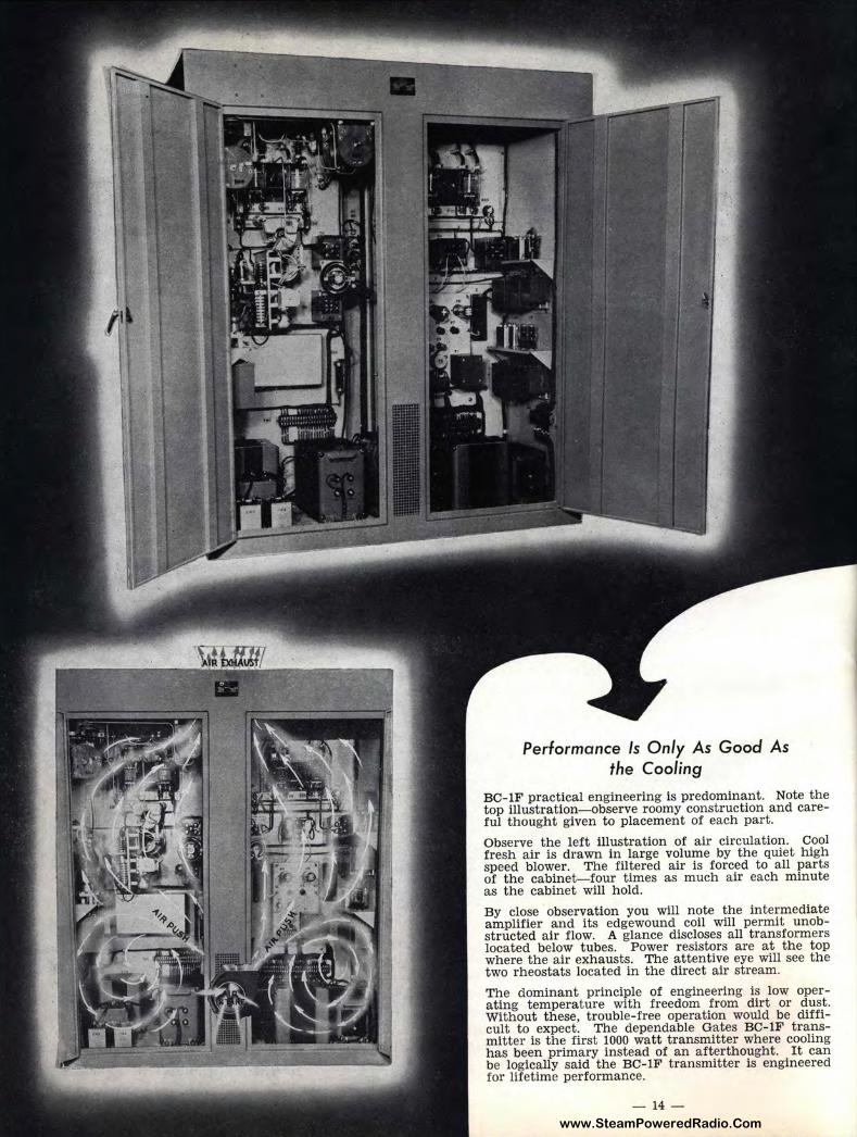
Performance Is Only As Good As the Cooling
BC-lF practical engineering is predominant. Note the top illustration- observe roomy construction and careful thought given to placement of each part.
Observe the left illustrat ion of air circulation. Cool fresh air is drawn in large volume by the quiet high speed blower. The filtered air is forced to all parts of the cabinet-four times as much air each minute as the cabinet will hold.
By close observation you will note the intermediate amplifier and its edgewound coil will permit unobstructed air flow. A glance discloses all transformers located below tubes. Power resistors are at the top where the air exhausts. The attentive eye will see the two rheostats located in the direct air stream.
The dominant principle of engineering is low operating temperature with freedom from dirt or dust. Without these, trouble-free operation would be difficult to expect. The dependable Gates BC-lF transmitter is the first 1000 watt t ransmitter where cooling has been primary instead of an afterthought. It can be logically said the BC-lF transmitter is engineered for lifetime performance.
- 14 -
www.SteamPoweredRadio.Com
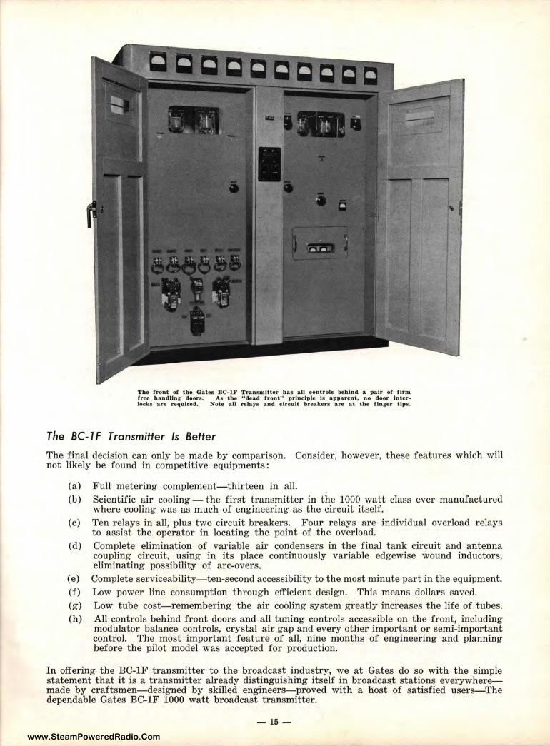
The front of the Gates BC-lF Transmitter has all controls behind a pair of firm free handling doors. As the "dead frontn principle is apparent, no door inter-locks are required. Nole a ll relays and circuit breakers are at the finger tips.
The BC-1 F Transmitter Is Better
The final decision can only be made by comparison. Consider, however, these features which will not likely be found in competitive equipments:
(a) Full metering complement-thirteen in all. (b) Scientific air cooling- the first transmitter in the 1000 watt class ever manufactured
where cooling was as much of engineering as the circuit itself. (c) Ten relays in all, plus two circuit breakers. Four relays are individual overload relays
to assist the operator in locating the point of the overload. (d) Complete elimination of variable air condensers in the final tank circuit and antenna
coupling circuit, using in its place continuously variable edgewise wound inductors, eliminating possibility of arc-overs.
(e) Complete serviceability- ten-second accessibility to the most minute part in the equtipment. (f) Low power line consumption through efficient design. This means dollars saved. (g) Low tube cost-remembering the air cooling system greatly increases the life o,f tubes. (h) All controls behind front doors and all tuning controls accessible on the front, including
modulator balance controls, crystal air gap and every other important or semi-important control. The most important feature of all, nine months of engineering and planning before the pilot model was accepted for production.
In offering the BC-lF transmitter to the broadcast industry, we at Gates do so with the simple statement that it is a transmitter already distinguishing itself in broadcast stations everywheremade by craftsmen- designed by skilled engineers-proved with a host of satisfied use:rs-The dependable Gates BC-lF 1000 watt broadcast transmitter.
- 15 -
www.SteamPoweredRadio.Com
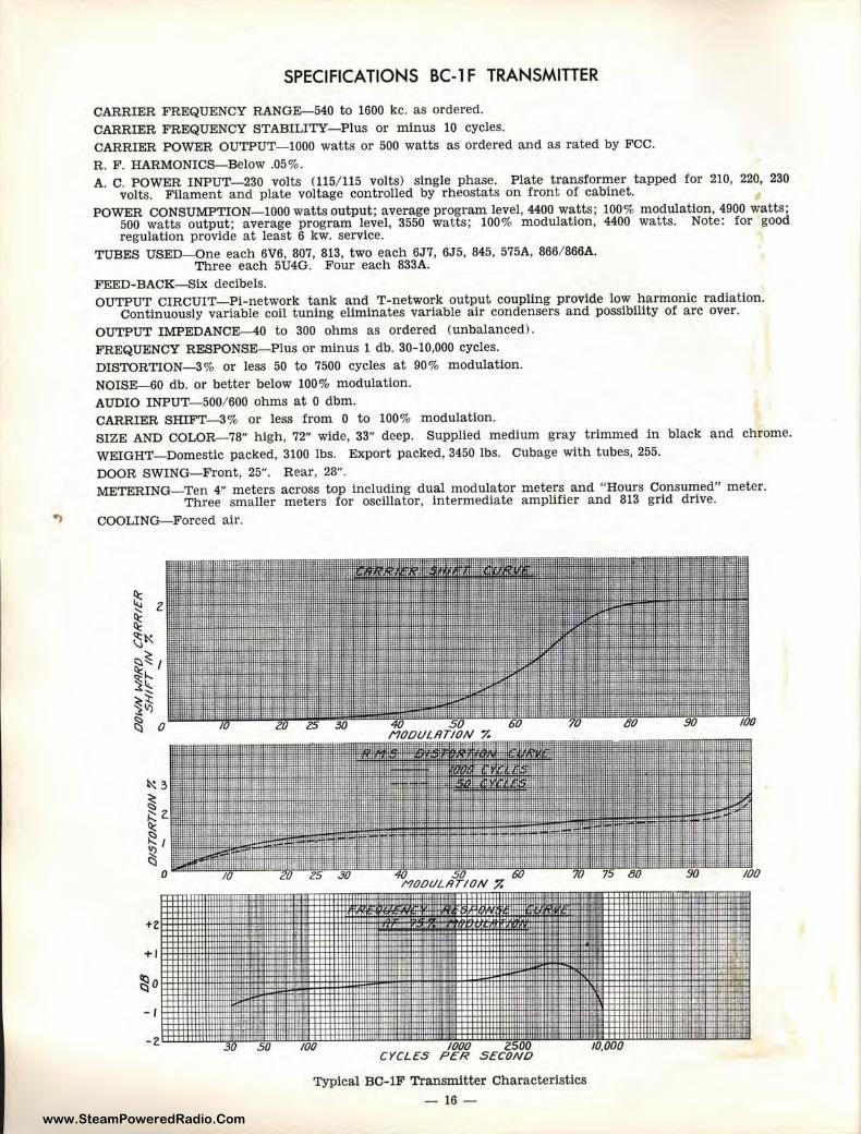
SPECIFICATIONS BC-1 F TRANSMITTER
CARRIER, FREQUENCY RANGE-540 to 1600 kc. as ordered. CARRIER. FREQUENCY STABILITY- Plus or minus 10 cycles. CARRIER: POWER OUTPUT- 1000 watts or 500 watts as ordered and as rated by FCC.
R. F. HARMONICS-Below .05%. A. C. POWER INPUT- 230 volts (115/ 115 volts) single phase. Plate transformer tapped for 210, 220, 230
volts. Filament and plate voltage controlled by rheostats on front of cabinet. POWER CONSUMPTION-1000 watts output; average program level, 4400 watts; 100% modulation, 4900 watts;
500 watts output; average program level, 3550 wat ts; 100% modulation, 4400 watts. Note: for good regulation provide at least 6 kw. service.
TUBES USED- One each 6V6, 807, 813, two each 6J7, 6J5, 845, 575A, 866/ 866A. Three each 5U4G. Four each 833A.
FEED-BACK-Six decibels. OUTPUT CIRCUIT- Pi-network tank and T-network output coupling provide low harmonic radiation.
Continuously variable coil tuning eliminates variable air condensers and possibility of arc over.
OUTPUT IMPEDANCE-40 to 300 ohms as ordered (unbalanced) . FREQUENCY RESPONSE-Plus or minus 1 db. 30-10,000 cycles.
DISTORTION- 3% or less 50 to 7500 cycles at 90 % modulation. NOISE-€i0 db. or better below 100% modulation. AUDIO INPUT-500/ 600 ohms at O dbm. CARRIER SHIFT-3% or less from O to 100% modulation. SIZE ANJD COLOR-78" high, 72" wide, 33" deep. Supplied medium gray trimmed in black and chrome. WEIGHT--Domestic packed, 3100 lbs. Export packed, 3450 lbs. Cubage with tubes, 255. DOOR SWING~ Front, 25". Rear, 28". METERING-Ten 4" meters across top including dual modulator meters and "Hours Consumed" meter.
Three smaller meters for oscillator, intermediate amplifier and 813 grid drive.
COOLING-Forced air.
-II
CYCLES
Typical BC-lF Transmitter Characteristics
-16 -
www.SteamPoweredRadio.Com
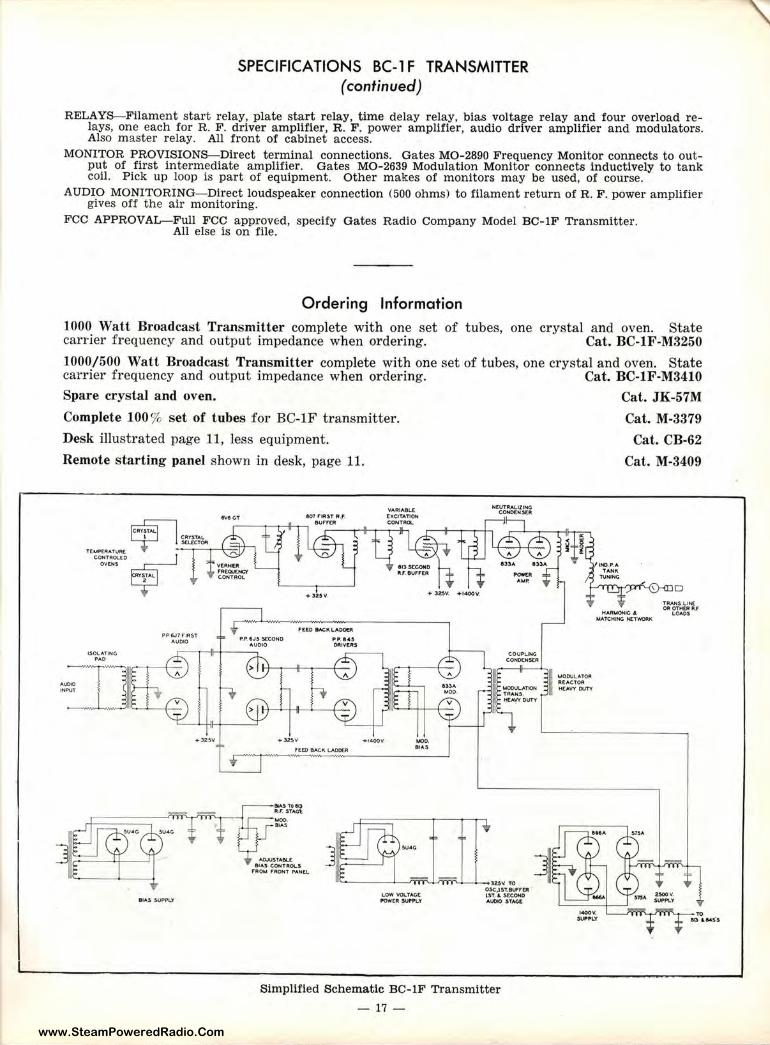
SPECIFICATIONS BC-1 F TRANSMITTER (continued)
RELAYS-Filament start relay, plate start relay, time delay relay, bias voltage relay and four overload relays, one each for R. F. driver amplifier, R. F. power amplifier, audio driver amplifier and modulators. Also master relay. All front of cabinet access.
MONITOR PROVISIONS-Direct terminal connections. Gates MO-2890 Frequency Monitor connect:s to output of first intermediate amplifier. Gates MO-2639 Modulation Monitor connects inductively to tank coil. Pick up loop is part of equipment. Other makes of monitors may be used, of course.
AUDIO MONITORING-Direct loudspeaker connection (500 ohms) to filament return of R. F. power amplifier gives off the air monitoring.
FCC APPROVAL-Full FCC approved, specify Gates Radio Company Model BC-lF Transmitter. All else is on file.
Ordering Information
1000 Watt Broadcast Transmitter complete with one set of tubes, one crystal and oven. State carrier frequency and output impedance when ordering. Cat. BC-1F-M3250
1000/500 Watt Broadcast Transmitter complete with one set of tubes, one crystal and oven. State carrier frequency and output impedance when ordering. Cat. BC-1F'-M3410
Spare crystal and oven.
Complete 100% set of tubes for BC-lF transmitter.
Desk illustrated page 11, less equipment.
Remote s tarting panel shown in desk, page 11.
l.SOt..ATING PAD
PP6J7 flfil:ST AUOOO , .P SJ~ .!£COHO
AUOJO
• 32SV ♦1400V.
n;m &ACK LAOOf.A
MOD • ....
9 tA.S SUPP\,.'f' LOW \l'Ol.TAGC POWtR Wl'JII\.Y
NCUTRALJZING CONOUI.S[R
O.SC,I !T.BlWrtR lff . .L ~tcOND AUDIO STAG£
Simplified Schematic BC-lF Transmitter
- 17 -
II ~ODULATO• Rl!:AC'TOft kl.A'M 0UT'V
Cat. .JK-57M
Cat. M-3379
Cat. CB-62
Cat. M-3409
ttARMQNIG j. MATC.HING 1',£l"1',()ftK
www.SteamPoweredRadio.Com
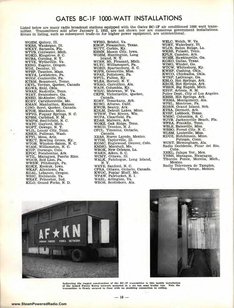
GATES BC-1 F l 000-WATT INSTALLATIONS Listed below are many radio broadcast stations equipped with the Gates BC-lF air conditioned 1000 watt transmitter. Transmitters sold after J anuary 2, 1953, are not shown nor are numerous government installations. Errors in listing, such as subsequent tra de-in for higher power equipment, are unintentional.
WGEM, Quincy, Ill. WKRS, w a ukegan, 111. WKXY, Sarasota, Fla. WTVB, Coldwater, Mich. WDK D, Kingstree, S. C. WCBA, Corning, N. Y . WYVE, Wytheville, Va. KERG, Eugene, Oregon. WDZ, Decatur, Ill. WPEP, Taunton, Mass. WKVA, Lewistown, P a. WCOJ, Coatesville, Pa. KTRM, Beaumont , T exas. CKVL, Verdun, Quebec, Canada KGWA, Enid, Okla. WNAH, Nashville, Tenn. WJAT, Swainsboro, Ga. KNED, McAlester, Okla. KCRV, Caruthersville, Mo. KMAN, Manhattan, Kansas. CJSO, Sorel, Quebec, Canada. KTOE, Mankato, Minn. WFVG, Fuquay Springs, N. C. KPBM, Carlsbad, N. M. WMPM, Smithfield, N. C. WATC, Gaylord, Mich. WOPT, Oswego, N. Y . WLIL, Lenoir City, Tenn. KBKH, Pullman, Wash. KTYL, Mesa, Ariz. WKCT, B owling Green, Ky. WTOB, Winston-Salem, N. C. WIAM, Williamston, N. C. KIUP, Durango, Colo. KPOC, P ocahontas, Ark. WTIL, Mayaguez, Puerto Rico. WGCB, Red Lion, Pa. WWSW, Pittsburgh, Pa. KOKX, K eokuk, Iowa. WKAP, Allentown, Pa. KGAL, Lebanon, Oregon. WRIC, Richla nds, Va. WRAY, Princeton, Ind. KILO, G rand F orks, N. D.
WFHG, Bristol, Va. KBOP, Pleasanton, Texas. WCTT, Corbin, Ky. KSMN, Mason City, Iowa. WGSM, Huntington, Long
Island, N. Y. WCEN, Mt. Pleasant, Mich. WLYC, Williamsport, Pa. WORD, Spartanburg, S. C. WJPR, Greenville, Miss. WPAZ, Pottstown, Pa. WFUL, Fulton, Ky. WLEA, Hornell, N. Y. WRAG, Carrollton, Ala. WAIN, Columbia, Ky. WHJC, Matewan, W. Va. CKPB, Victoriaville, Quebec,
Canada. KOSY, Texarkana, Ark. KCNO, Alturas, Calif. KWCB, Searcy, Ark. KDLM, Detroit Lakes, Minn. WTRW, Two Rivers, Wis. WCPA, Clearfield, Pa. KDAS, Malvern, Ark. WOKE, Oak Ridge, T enn. WBUD, Trenton, N. J . CFCL, Timmins, Ontario,
Canada. XEAS, Nuevo Laredo, Mexico. WTIM, Taylorville, Ill. KGMC, Englewood, Denver, Colo. KMMO, Marshall, Mo. WBOK, New Orleans, La . WAKN, Aiken, S. C. WCMY, Ottawa, Ill. WALK, P atchogue, Long Island,
N. Y. WEYE, Sanford, N. C. CFRA, Ottawa, Ontario, Canada. KWOC, Poplar Bluff, Mo. WPAW, Pawtucket, R. I. WARL, Arlington, Va. WROS, Scottsboro, Ala.
WELC, Welch, w. Va. WDEV, Waterbury, Vt. WLCS, Baton Rouge, La. WKSR, Pulaski, Tenn. KPLN, Camd en, Ark. WCEH, Hawkinsville, Ga . KOK O, Dallas, Texas. WIMO, Winder, G a. WTCW, Whitesburg, Ky. KWHP , Cushing, Okla. KWCO, Chickasha, Okla. WTRP, LaGrange, Ga. KBLO, Hot Springs, Ark. KRCH, Hot Springs, Ark. WBRN, Big Rapids, Mich. KSVP, Artesia, N. M. P ollce Dept., City of Los Angeles. KBHS, Hot Springs, Ark. WRMA, Montgomery, Ala. WPEL, Montrose, Pa. KGRN, Grand Island, Neb. KVSA, Dermott, Ark. KVSP, Lubbock, Texas. WMSC, Columbia, S. C. WJVB, Jacksonville Beach, Fla. WFRA, Franklin, Tenn. WBLE, Batesville, Miss. WBBO, Forest City, N. C. WLSM, Louisville, Miss. KDUZ, Hutchinson, Minn.
Putnam, Conn. WCRT, Birmingham, Ala . Radio Occidente, Plnar del Rio,
Cuba . XEKL, Jalapa Ver ., Mex. YNBH, Managua, Nicaragua. Tiburcio Ponce, Morelia, Mich.,
Mexico. Radio Televisora de Tampico,
Tampico, Tamps., Mexico.
lndicatlnr tbe r ugged construcllon or the BC-IF transmitter Is tbls mobile Installa tion of the Arme d Forees Korea. network mounted In a six ton semi &railer van. Note the transmitter ls firm ly secured to floor wtt:h no snubblnl' connec tion to celHnr.
- 18 -
www.SteamPoweredRadio.Com
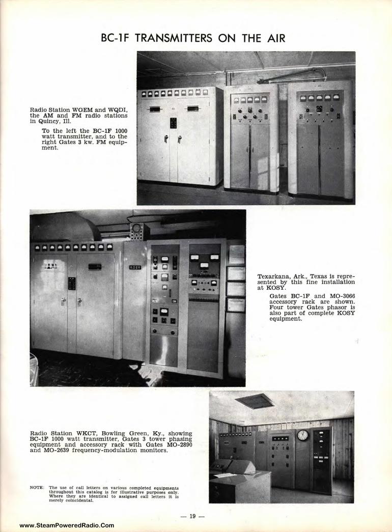
BC-lF TRANSMITTERS ON THE AIR
Radio Station WGEM and WQDI, the AM and FM radio stations in Quincy, Ill. ---· I
To the left the BC-lF 1000 watt transmitter, and to the right Gates 3 kw. FM equipment.
t' t
Radio Station WKCT, Bowling Green, Ky., showing BC-lF 1000 watt transmitter, Gates 3 tower phasing equipment and accessory rack with Gates MO-2890 and MO-2639 frequency-modulation monitors.
NOTE: The use of call letters on various completed equipments throughout this catalog Is for tllustratlve purposes only. Where they are Identical to assigned call letters It Is merely coincidental.
- 19 -
I .
Texarkana, Ark., Texas is represented by this fine installation at KOSY.
Gates BC-lF and MO-3066 accessory rack are shown. Four tower Gates phasor is also part of complete KOSY equipment.
www.SteamPoweredRadio.Com
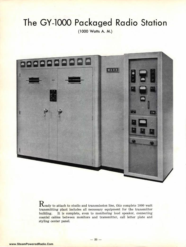
The GY-1000 Packaged Radio Station (1000 Watts A. M.)
am1
---
R eady to attach to studio and transmission line, this complete 1000 watt transmitting plant includes all necessary equipment for the transmitter building. It is complete, even to monitoring loud speaker, connecting coaxial cables between monitors and transmitter, call letter plate and styling center panel.
- 20 -
www.SteamPoweredRadio.Com
Description GY-1000 Radio Station
There is pride of ownership in a finely styled installation.-Many engineers will be quick to tell you that fine appearance and fine operation go hand in hand. Equally important is that fine appearance is usually only possible in broadcasting through symmetr ical location of accessories for best efficiency, both performance and operational-wise.
The GY-1000 radio station is a complete 1000 watt package ready to install quickly and easily. Consisting of the BC-l F 1000 watt transmitter, listed on earlier pages in this catalog, plus the Gates MO-3066 accessory cabinet which contains the Gates MO-2890 frequency monitor, Gates MO-2639 Modulation Monitor Gates Limiting amplifier of your choice plus input switching and 7~ panel. This, along with complete accessory cabinet wiring, includfng connecting coaxial cables from monitors to transmitter, assures complete radio station performance and eliminates otherwise often complicated installation problems.
Provided as bonus equipment with the GY-1000 radio station is a 12" monitoring loud speaker which operates directly from the high level output stage in the Gates modulation monitor, thus supplying direct off-theair monitor ing. Call letter plate with your call letters is also provided attached to a styling joiner panel to complete a truly massive and attract ive t ransmitting plant that is second to none .
• Ordering Detail
Complete 1000 Watt Radio Station, including BC-lF transmitter, MO-3066 accessory cabinet, joiner panel, call letter plate, monitor speaker, MO-2890 frequency monitor , MO-2639 modulation monitor, SA-38 limiting amplifier, switch panel, blank panels, complete wiring of accessory cabinet, one set of tubes, one crystal and oven. Cat. GY-1000
Complete 1000 Watt Radio Station, same as above but including an SA-39 limiting amplifier in place of model SA-38. Cat. GY-lO00A
For spare transmitter tubes and crystals see page 17. For full detail on monitors and amplifier referred to above, kindly refer to other pages in this catalog (see index) . When ordering, state carrier frequency and line impedance. For FCC filing, please file under transmitter, frequency monitor and modulation monitor type numbers which are on file--do not use the package number herein shown.
- 21-
www.SteamPoweredRadio.Com
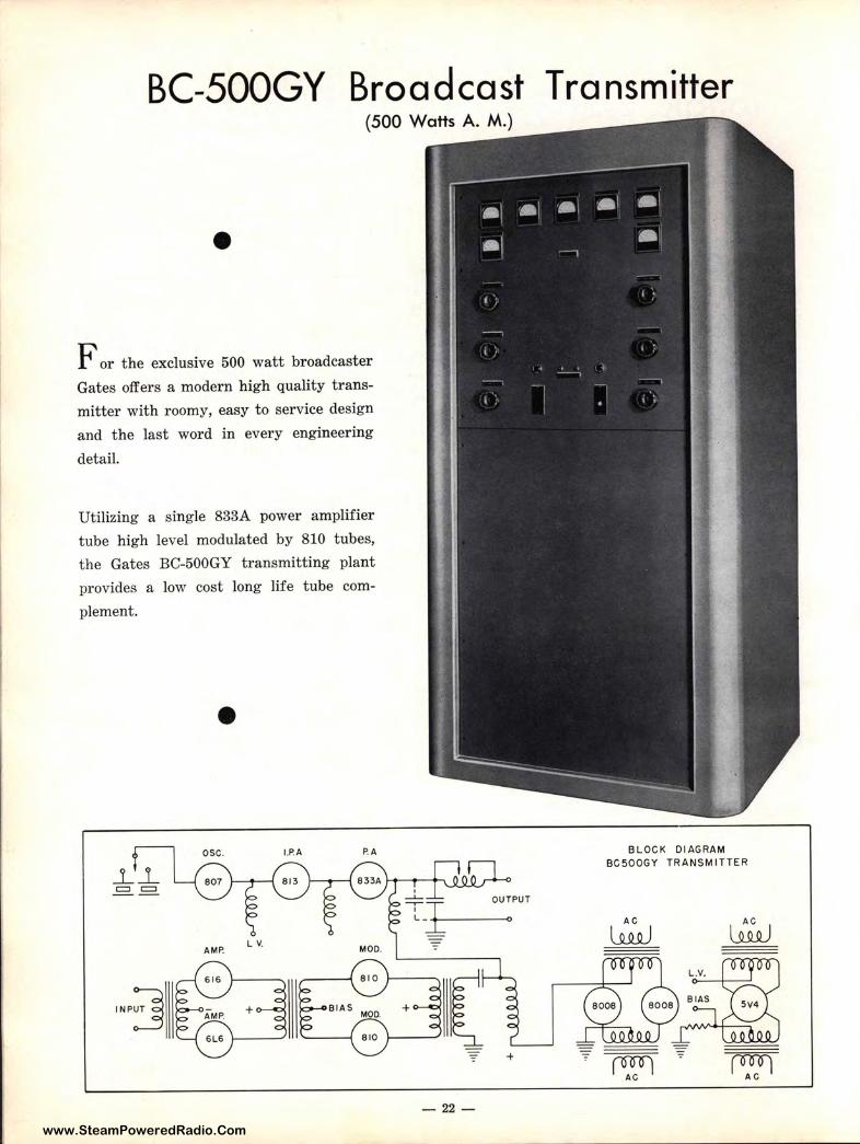
BC-500GY Broadcast Transmitter
•
f or t he exclusive 500 watt broadcaster
Gates offers a modern high quality trans
mitter with roomy, easy to service design
and the last word in every engineering
detail.
Utilizing a single 833A power amplifier
tube high level modulated by 810 tubes,
the Gates BC-500GY transmitting plant
provides a low cost long life tube com
plement.
•
!NP:] +
- 22-
BLOCK DIAGRAM BC5OOGY TRANSM ITTER
AC
~ lli.Q.)
~ ~
www.SteamPoweredRadio.Com
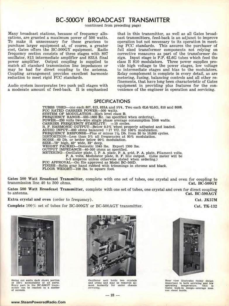
BC-500GY BROADCAST TRANSMITTER (continued from preceding page)
Many broadcast stations, because of frequency allocations, are granted a maximum power of 500 watts. To make it unnecessary for these grantees to purchase larger equipment at, of course, a greater cost, Gates offers the BC-500GY equipment. Radio frequency section consists of three stages with 807 oscillator, 813 intermediate amplifier and 833A final power amplifier. Output coupling is supplied to match all standard transmission line impedances or may be had for direct coupling to the antenna. Coupling arrangement provides excellent harmonic reduction to meet rigid FCC standards.
Audio system incorporates two push pull stages with a moderate amount of feed-back. It is emphasized
that in this transmitter, as well as all Gates broadcast transmitters, feed-back is an adjunct to improve operation but not necessary to its operation in meeting FCC standards. This assures the purchaser of full sized transformer components not relying on corrective measures as part of the transformer design. Input stage is P .P. 6L6G tubes which feed the class B 810 modulators. Three power supplies provide high voltage to the power stages, low voltage to intermediate stages and bias to the modulators. Relay complement is complete in every detail, as are metering, fusing, balancing controls and all other refinements, that have long been characteristic of Gates equipment in providing plus features for the convenience of the engineer in operation and servicing.
SPECIFICATIONS TUBES USED-one each 807, 813, 833A and 5V4 .. Two each 6L6/ 6L6G, 810 and 8008. FCC RATED CARRIER POWER-500 watts. SYSTEM OF MODULATION- High level class B. FREQUENCY RANGE------535-1800 Kc. (as specified when ordering) . POWER-230 volts two-wire single phase average consumption 3500 watts. CARRIER FREQUENCY STABILITY: + 10 cycles. R. F. HARMONIC OUTPUT- Below 0.5% when properly adjusted and loaded. AUDIO INPUT- 600 ohms ba lanced + 17 VU. for 100% modulation. FREQUENCY RESPONSE-Plus or minus 1 ½ Db. from 30 to 10,000 cycles. DISTORTION-Less than 3% all frequencies at 95% modulation. NOISE------60 Db. or better below 90% modulation. SIZE------78" high, 40" wide, 33" deep. WEIGHT PACKED-Domestic 1045 lbs. Export 1300 lbs. OUTPUT IMPEDANCE-40-300 ohms as specified. METERING-Oscillator plate, I. P. A. plate, P. A. grid, P. A. pla te, Filament volts,
P. A. volts, Modulator plate, R. F. line output. (Line meter will be 0-3 amperes unless otherwise stated when ordering.)
FCC APPROVAL-On file approved as Model BC-500D. FINISH-Satin gray hand rubbed with trimmings in chrome and black. FLOOR WEIGHT- 100 lbs. to square foot.
Gates 500 Watt Broadcast Transmitter, transmission line 40 to 300 ohms.
complete with one set of tubes, one crystal and oven for coupling to Cat. BC-S00GY
Gates 500 Watt Broadcast Transmitter, to antenna.
complete with one set of tubes, one crystal and oven for direct coupling Cat. BC-500AGY
Extra crystal and oven (order to frequency). Cat. JK57M
Cat. TK-132 Complete 100% set of tubes for BC-500GY or BC-500AGY transmitter.
swing out audio deck shows portion o! 100% accessibility o! all par ts. Every part In the BC-500GY transmitter can be reached In a matter of seconds.
Oscillator unit holds two crystals and ovens and may be removed almost instantly tor under chassis servicing.
-23 -
Rear view Illustrates roomy design Important In both servicing and low operating temperat ure. This Is Gates walk-In design- average man can stand Inside.
www.SteamPoweredRadio.Com
GY-50 Packaged Broadcast Station (For 500 Watts)
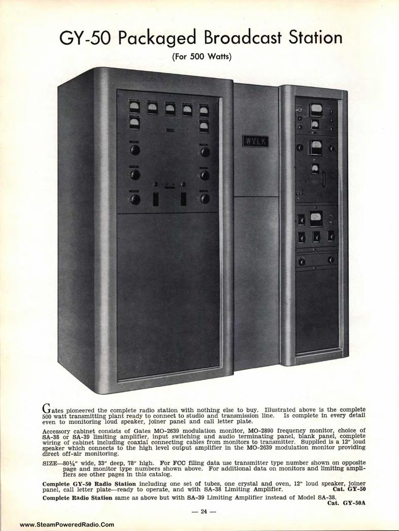
G ates pioneered the complete radio station with nothing else to buy. Illustrated above is the complete 500 watt transmitting plant ready to connect to studio and transmission line. Is complete in every detail even to monitoring loud speaker, joiner panel and call letter plate. Accessory cabinet consists of Gates MO-2639 modulation monitor, MO-2890 frequency monitor, choice of SA-38 or SA-39 limit ing amplifier, input switching and audio terminating panel, blank panel, complete wiring of cabinet including coaxial connecting cables from monitors to transmitter. Supplied is a 12" loud speaker which connects to the high level output amplifier in the MO-2639 modulation monitor providing direct off-air monitoring. SIZE-80¼" wide, 33" deep, 78" high. For FCC filing data use transmitter type number shown on opposite
page and monitor type numbers shown above. For additional data on monitors and limiting amplifiers see other pages in this catalog.
Comple te GY-50 Radio Station including one set of tubes, one crystal and oven, 12" loud speaker, joiner panel, call letter plate-ready to operate, and with SA-38 Limiting Amplifier. Cat. GY-50 Complete Radio Station same as above but with SA-39 Limiting Amplifier instead of Model SA-38.
Cat. GY-50A - 24 -
www.SteamPoweredRadio.Com
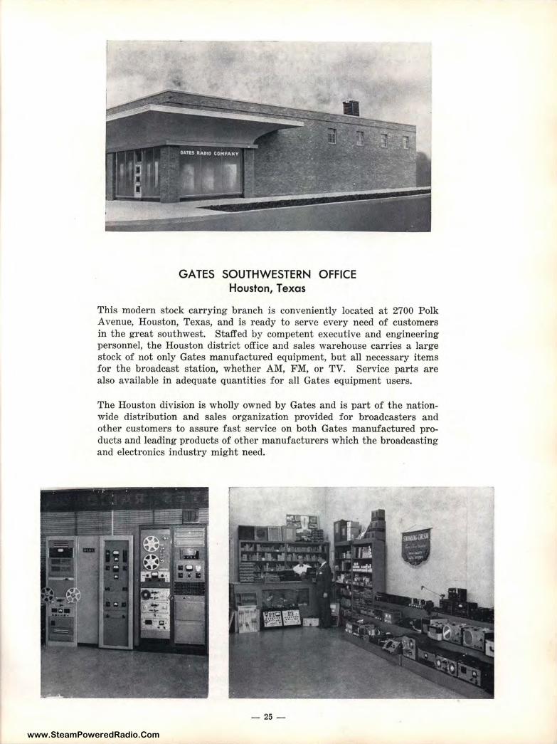
GATES SOUTHWESTERN OFFICE Houston, Texas
This modern stock carrying branch is conveniently located at 2700 Polk A venue, Houston, Texas, and is ready to serve every need of customers in the great southwest. Staffed by competent executive and engineering personnel, the Houston district office and sales warehouse carries a large stock of not only Gates manufactured equipment, but all necessary items for the broadcast station, whether AM, FM, or TV. Service parts are also available in adequate quantities for all Gates equipment users.
The Houston division is wholly owned by Gates and is part of the nationwide distribution and sales organization provided for broadcasters and other customers to assure fast service on both Gates manufactured products and leading products of other manufacturers which the broadcasting and electronics industry might need.
•
- 25-
www.SteamPoweredRadio.Com
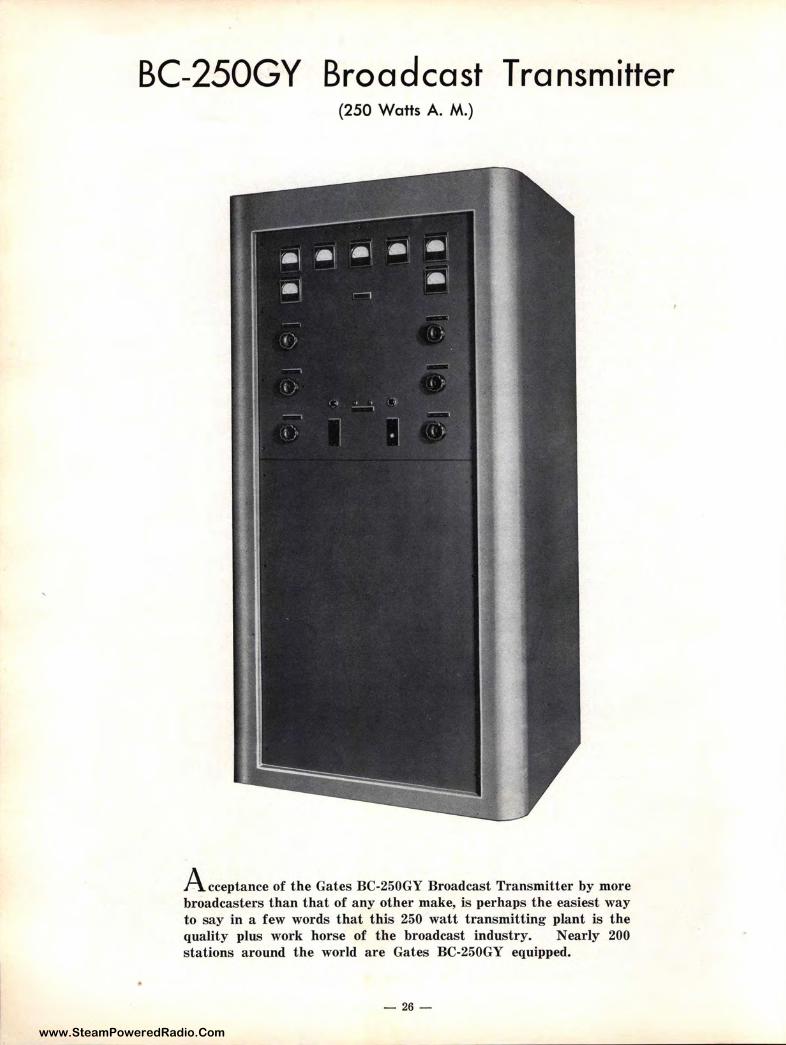
BC-250GY Broad ca st T ra nsm itter (250 Watts A. M.)
Acceptance of the Gates BC-250GY Broadcast Transmitter by more
broadcasters than that of any other make, is perhaps the easiest way
to say in a few words that this 250 watt transmitting plant is the
quality plus work horse of the broadcast industry. Nearly 200
stations around the world are Gates BC-250GY equipped.
- 26 -
www.SteamPoweredRadio.Com
BC-250GY BROADCAST TRANSMITTER
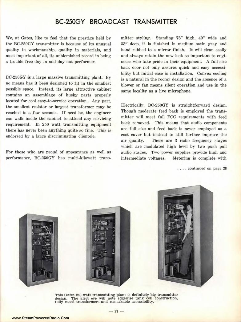
We, at Gates, like to feel that the prestige held by the BC-250GY transmitter is because of its unusual quality in workmanship, quality in materials, and most important of all, its unblemished record in being a trouble free day in and day out performer.
BC-250GY is a large massive transmitting plant. By no means has it been designed to fit in the smallest possible space. Instead, its large attractive cabinet contains an assemblage of husky parts properly located for cool easy-to-service operation. Any part, the smallest resistor or largest transformer may be reached in a few seconds. If need be, the engineer can walk inside the cabinet to attend any servicing requirement. In 250 watt transmitting equipment there has never been anything quite so fine. This is endorsed by a large discriminating clientele.
For those who are proud of appearance as well as performance, BC-250GY has multi-kilowatt trans-
mitter styling. Standing 78" high, 40" wide and 33" deep, it is finished in medium satin gray and hand rubbed to a mirror finish. It will clean easily and always retain the new look so important to engineers who take pride in their equipment. A full size back door not only assures quick and easy accessibility but initial ease in installation. Convex cooling is a natural in the roomy design and the absence of a blower or fan means silent operation and use in the same locality as a live microphone.
Electrically, BC-250GY is straightforward design. Though moderate feed back is employed the transmitter will meet full FCC requirements with feed back removed. This means that audio components are full size and feed back is never employed as a cost saver but instead to still further improve the air quality. There are 3 radio frequency stages which are modulated high level by two push pull audio stages. Two power supplies provide high and intermediate voltages. Metering is complete with
.... continued on page 28
This Gates 250 watt transmitting plant ls definitely big transmitter design. The alert eye will note edgewise tank coil construction, fully cased transformers and remarkable accessibility.
- 27 -
www.SteamPoweredRadio.Com
BC-250GY BROADCAST TRANSMITTER (continued from preceding page)
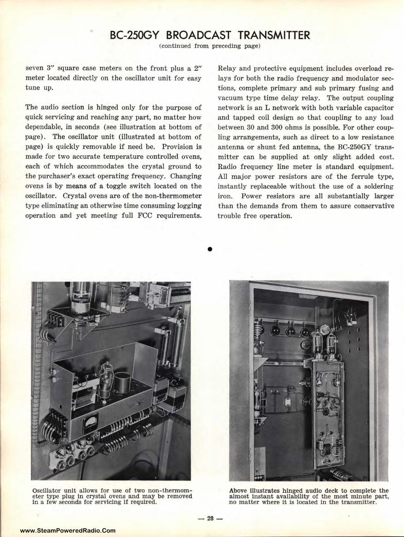
seven 3" square case meters on the front plus a 2" meter located directly on the oscillator unit for easy tune up.
The audio section is hinged only for the purpose of quick servicing and reaching any par t, no matter how dependable, in seconds (see illustration at bottom of page). The oscillator unit (illustrated at bottom of page) is quickly removable if need be. Provision is made for two accurate temperature controlled ovens, each of which accommodates the crystal ground to the purchaser's exact operating frequency. Changing ovens is by means of a toggle switch located on the oscillator. Crystal ovens are of the non-thermometer type eliminating an otherwise time consuming logging operation and yet meeting full FCC requirements.
Oscillator unit allows for use of two non-thermometer type plug in crystal ovens and may be removed in a few seconds for servicing if required.
•
Relay and protective equipment includes overload relays for both the radio frequency and modulator sections, complete primary and sub primary fusing and vacuum type time delay relay. The output coupling network is an L network with both variable capacitor and tapped coil design so that coupling to any load between 30 and 300 ohms is possible. For other coupling arr angements, such as direct to a low resistance antenna or shunt fed antenna, the BC-250GY transmitter can be supplied at only slight added cost. Radio frequency line meter is standard equipment. All major power resistors are of the ferrule type, instantly replaceable without the use of a soldering iron. Power resistors are all substantially larger than the demands from them to assure conservative trouble free operation .
Above illustrates hinged audio deck to complete the almost instant availability of the most minute part, no matter where it is located in the transmitter.
-28-
www.SteamPoweredRadio.Com
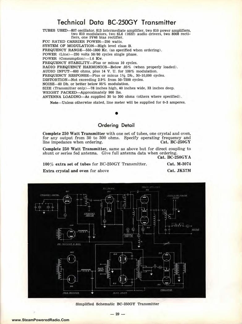
Technical Data BC-250GY Transmitter TUBES USED-807 oscillator, 813 intermediate amplifier, two 810 power amplifiers,
two 810 modulators, two 6L6 (1622) audio drivers, two 8008 rect ifiers, one 5V46 bias rectifier.
FCC RATED CARRIER POWER-250 watts. SYSTEM OF MODULATION- High level class B. FREQUENCY RANGE-550-1800 Kc. (as specified when ordering) . POWER (Line)-230 volts 50/ 60 cycles single phase. POWER (Consumption)-1.6 Kw. FREQUENCY STABILITY- Plus or minus 10 cycles. R ADIO FREQUENCY HARMONICS-Below .05% (when properly loaded) . AUDIO INPUT-600 ohms, plus 14 V. U. for 100% modulation. FREQUENCY RESPONSE-Plus or minus 1½ Db., 30-10,000 cycles. DISTORTION-Not exceeding 2.9% from 50-7500 cycles. NOISE-60 Db. or better below 95% modulation. SIZE (Transmitter only)-78 inches high, 40 inches wide, 33 inches deep. WEIGHT PACKED-Approximately 900 lbs. ANTENNA LOADING- As supplied 30 to 300 ohms (others where specified).
Note- Unless otherwise stated, line meter will be supplied for 0-3 amperes .
• Ordering Detail
Complete 250 Watt Transmitter with one set of tubes, one crystal and oven, for any output from 30 to 300 ohms. Specify operating frequency and line impedance when ordering. Cat. BC-250GY
Complete 250 Watt Transmitter, same as above but for direct coupling to shunt or series fed antenna. Give full antenna data when ordering.
100% extra set of tubes for BC-250GY Transmitter.
Extra crystal and oven for above
Cat. BC-250GY A
Cat. M-3074
Cat. JK57M
Simplified Schematic BC- 250GY Transmitter
- 29 -
www.SteamPoweredRadio.Com
USERS OF BC-250GY TRANSMITTERS OR GY-48 RADIO STATIONS
WFAX, Falls Church, Va. WGYV, Greenville, Ala. WBBQ, Augusta, Ga. WMRA, Myrtle Beach, S. C. WBBZ, Ponca City, Okla. WMDN, Midland, Mich. WSPT, Stevens Point, Wis. WJMW, Athens, Ala. KRTN, Raton, N. M. WKID, Urbana, Ill. WIDE, Biddeford, Maine. KMUR, Murray, Utah. WKBS, Oyster Bay, N. Y. KTRF, Thief River Falls, Minn. WCVA, Culpeper, Va. KNEX, McPherson, Kansas. KCOW, Alliance, Neb. WHAR, Clarksburg, W. Vn. WNOR, Norfolk, Va. KLMX, Clayton, N. M. WEAB, Greer, S. C. WNNT, Warsaw, Va. KICK, Springfield, Mo. WSDR, Sterling, Ill. KNEM, Nevada, Mo. KOFO, Ottawa, Kansas. KCNI, Broken Bow, Neb. KIFN, Phoenix, Ariz. KTKT, Tuscon, Ariz. WBLT, Bedford, Va. KLMO, Longmont, Colo. WCDL, Carbondale, Pa. KAFP, Petaluma, Calif. KDIA, Auburn, Calif.
WIRY, Plattsburg, N. Y. KENM, Portales, N. M. WPKY, Princeton, Ky. WTTN, Watertown, Wis. KLIZ, Brainerd, Minn. KCHI, Chillicothe, Mo. WJEH, Gallipolis, Ohio. KOLS, Pryor, Okla. WCLI, Corning, N. Y. WPNF, Brevard, N. C. WATW, Ashland, Wis. WKBI, St. Marys, Pa. KALG, Alamogordo, N. M. WACR, Columbus, Miss. wvsc, Somerset, Pa. KJAN, Atlantic, Iowa. WBIP, Booneville, Miss. WJQS, Jackson, Miss. KRXL, Roseburg, Oregon. KRMO, Monett, Mo. WBNL, Boonville, Ind. WSOY, Decatur, Ill. WAKE, Greenville, S. C. KSEY, Seymour, Texas. KSAM, Huntsville, Texas. KTER, Terrell, Texas. WLCK, Campbellsville, Ky. WNLC, New London, Conn. KRXK, Rexburg, Idaho. KFIR, North Bend, Oregon. KPAT, Pampa, Texas. KFLD, Floydada, Texas. WOKW, Sturgeon Bay, Wis. KFST, Ft. Stockton, Texas.
WMTE, Manistee, Mich. KOMO, Cape Girardeau, Mo. WAVA, Ava, Ill. WJET, Erie, Pa. KPUY, Puyallup, Wash. WABA, Aquadilla, Puerto Rico. KWTN, Crystal City, Texas. WMPA, Aberdeen, Miss. KDMA, Montevideo, Minn. WCMC, Wildwood, N. J. WIRO, Ironton, Ohio. WPAC, Patchogue, N. Y. KRAI, Craig, Colo. WMLT, Dublin, Ga. WABJ, Adrian, Mich. WINL, Hammond, La. WEVA, Emporia, Va. KWLC, Decorah, Iowa. WJFR, Caguas, Puerto Rico. WEPM, Martinsburg, W. Va. WIKE, Newport, Vt. WDHL, Braden town, Fla. KBWL, Blackwell, Okla. WMA W, Menominee, Mich. KNIM, Maryville, Mo. KVOM, Morrilton, Ar k. WWSC, Glen Falls, N. Y. WNOR, Petersburg, Va. KREH, Oakdale, La. CMCI, Havana, Cuba. Alejandro Diaz, Guadalajava,
Mexico.
NOTE-Above listing through December 31, 1952. Omissions are unintentional. For obvious reasons military installations cannot be shown but are substantial around the world. Also foreign installations not shown due to difficulty in obtaining call letters.
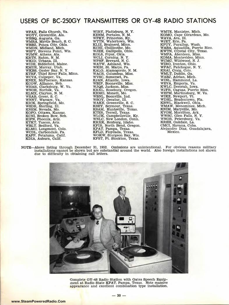
C:omplete GY-48 Radio Station with Gates Speech Equipment at Radio State KPAT, Pampa, Texas. Note massive appearance and excellent combination type installation.
- 30 -
www.SteamPoweredRadio.Com
The GY-48 Packaged Radio Station (250 Watts A. M.)
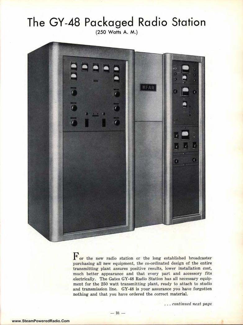
For the new radio station or the long established broadcaster purchasing all new equipment, the co-ordinated design of the entire transmitting plant assures positive results, lower installation cost, much better appearance and that every part and accessory fit s electrically. The Gates GY-48 Radio Station has all necessary equipment for the 250 watt transmitting plant, ready to attach to studio and t ransmission line. GY-48 is your assurance you have forgotten nothing and that you have ordered the correct material.
... continued next page
- 31 -
www.SteamPoweredRadio.Com
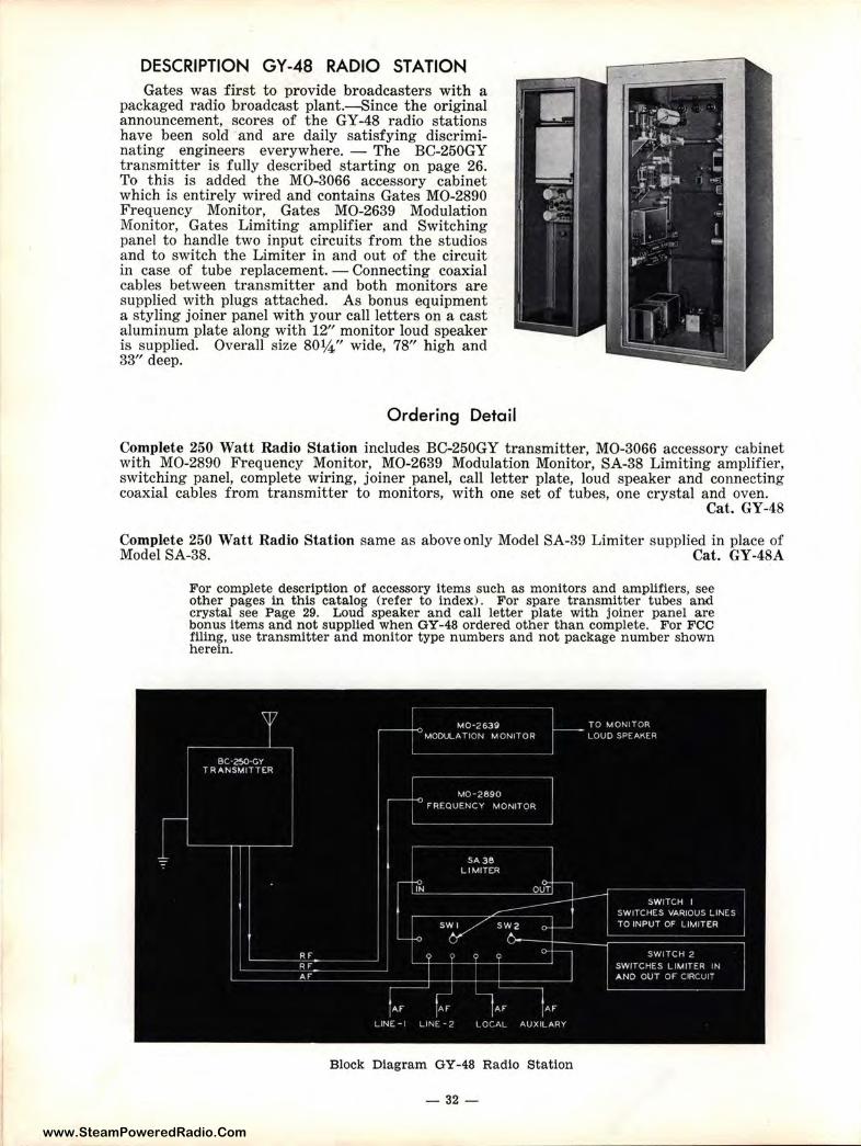
DESCRIPTION GY-48 RADIO STATION Gates was first to provide broadcasters with a
packaged radio broadcast plant.-Since the original announcement, scores of the GY-48 radio stations have been sold and are daily satisfying discriminating engineers everywhere. - The BC-250GY t ransmitter is fully described starting on page 26. To this is added the MO-3066 accessory cabinet which is entirely wired and contains Gates MO-2890 Frequency Monitor, Gates MO-2639 Modulation Monitor, Gates Limiting amplifier and Switching panel to handle two input circuits from the studios and to switch the Limiter in and out of the circuit in case of tube replacement. - Connecting coaxial cables between transmitter and both monitors are supplied with plugs attached. As bonus equipment a styling joiner panel with your call letters on a cast aluminum plate along with 12" monitor loud speaker is supplied. Overall size 80¼" wide, 78" high and 33" deep.
Ordering Detail
Complete 250 Watt Radio Station includes BC-250GY transmitter, MO-3066 accessory cabinet with MO-2890 Frequency Monitor, MO-2639 Modulation Monitor, SA-38 Limiting amplifier, switching panel, complete wiring, joiner panel, call letter plate, loud speaker and connecting coaxial cables from transmitter to monitors, with one set of tubes, one crystal and oven.
Cat. GY-48
Complete 250 Watt Radio Station same as above only Model SA-39 Limiter supplied in place of Model SA-38. Cat. GY-48A
For complete description of accessory items such as monitors and amplifiers, see other pages in this catalog (refer to index). For spare transmitter tubes and crystal see Page 29. Loud speaker and call letter plate with joiner panel are bonus items and not supplied when GY -48 ordered other than complete. For FCC filing, use transmitter and monitor type numbers and not package number shown herein.
Block Diagram GY-48 Radio Station
- 32 -
www.SteamPoweredRadio.Com
BCA-250 Auxiliary Transmitter
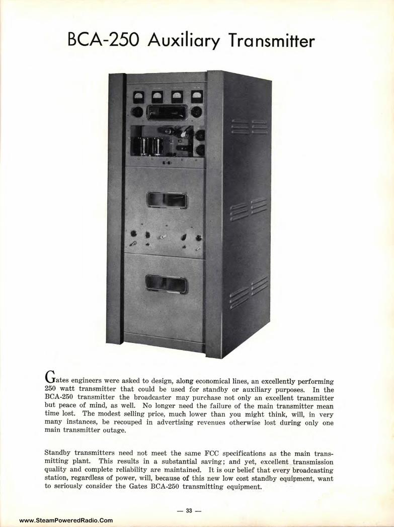
G ates engineers were asked to design, along economical lines, an excellently performing 250 watt transmitter that could be used for standby or auxiliary purposes. In the BCA-250 transmitter the broadcaster may purchase not only an excellent transmitter but peace of mind, as well. No longer need the failure of the main transmitter mean time lost. The modest selling price, much lower than you might think, will, in very many instances, be recouped in advertising revenues otherwise lost during only one main transmitter outage.
Standby transmitters need not meet the same FCC specifications as the main transmitting plant. This results in a substantial saving; and yet, excellent transmission quality and complete reliability are maintained. It is our belief that every broadcasting station, regardless of power, will, because of this new low cost standby equipment, want to seriously consider the Gates BCA-250 transmitting equipment.
- 33-
www.SteamPoweredRadio.Com
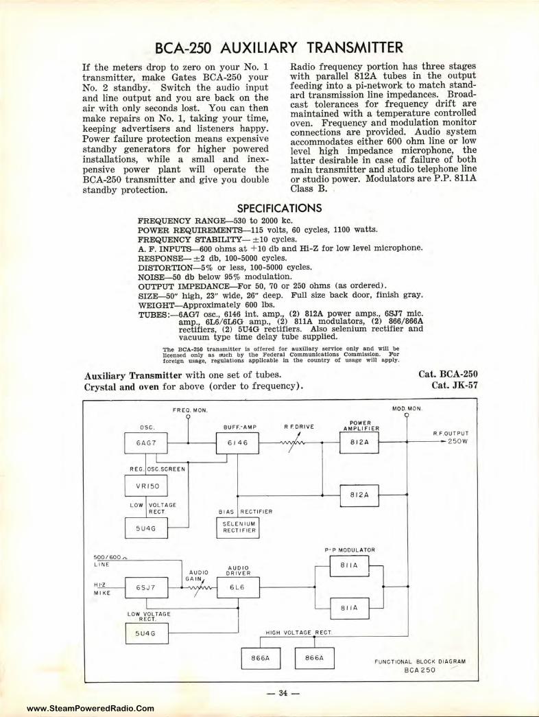
BCA-250 AUXILIARY TRANSMITTER If the meters drop to zero on your No. 1 transmitter, make Gates BCA-250 your No. 2 standby. Switch the audio input and line output and you are back on the air with only seconds lost. You can then make repairs on No. 1, taking your time, keeping advertisers and listeners happy. Power failure protection means expensive standby generators for higher powered installations, while a small and inexpensive power plant will operate the BCA-250 transmitter and give you double standby protection.
Radio frequency portion has three stages with parallel 812A tubes in the output feeding into a pi-network to match standard transmission line impedances. Broadcast tolerances for frequency drift are maintained with a temperature controlled oven. Frequency and modulation monitor connections are provided. Audio system accommodates either 600 ohm line or low level high impedance microphone, the latter desirable in case of failure of both main transmitter and studio telephone line or studio power. Modulators are P.P. 811A Class B.
SPECIFICATIONS FREQUENCY RANGE-530 to 2000 kc. POWER REQUIREMENTS-115 volts, 60 cycles, 1100 watts. FREQUENCY STABILITY- ± 10 cycles. A. F. INPUTS-600 ohms at + 10 db and Hi-Z for low level microphone. RESPONSE- ± 2 db, 100-5000 cycles. DISTORTION- 5% or less, 100-5000 cycles . NOISE-50 db below 95% modulation. OUTPUT IMPEDANCE-For 50, 70 or 250 ohms (as ordered). SIZE-50" high, 23" wide, 26" deep. Full size back door, finish gray. WEIGHT- Approximately 600 lbs. TUBES:-6AG7 osc., 6146 int. amp., (2) 812A power amps., 6SJ7 mic.
amp., 6L6/ 6L6G amp., (2) 811A modulators, (2) 866/866A rectifiers, (2) 5U4G rectifiers. Also selenium rectifier and vacuum type time delay tube supplied.
The BCA-250 transmitter Is offered tor 11uxll!ary service only 11nd will be licensed only as such by the Federal Communications Commission. For foreign usage, r egulations applicable In the country or usage will apply.
Auxiliary Transmitter with one set of tubes. Crystal and oven for above ( order to frequency).
Cat. BCA-250 Cat. JK-57
FR EO. MON.
OSC.
6AG7
REG. OSC.SCREEN
LOW VOLTAGE RECT
5U4G
500/600.,,. LI NE
Hl·Z
M I KE 6SJ7
LOW VOLTAGE RECT.
5U4G
AUDIO GA IN
BUFF.·AMP
6 I 46
B I AS RECTIFIER
SELENIUM RECTIFIER
AUDIO DRIVER
6 L6
R f. ORI VE
MOD. MON.
POWER AMPLI FIE R
81 2 A
812A
P· P MODUL ATOR
81 IA
8 1 IA
R.F.OUTPUT
1--- -+---- 2 50W
HIGH VOLTAGE RECT.
866A
- 34-
866A FUNCTIONAL BLOCK DI AGRAM
SCA 2 50
www.SteamPoweredRadio.Com
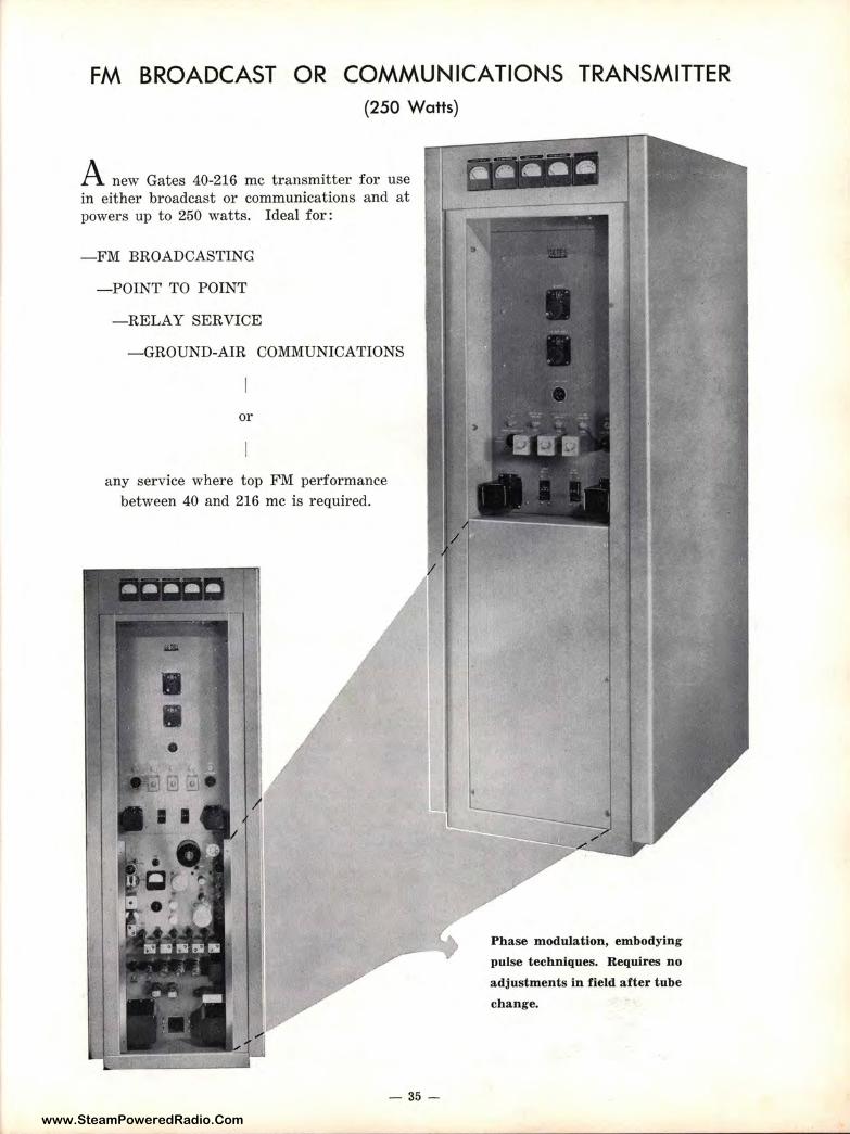
FM BROADCAST OR COMMUNICATIONS TRANSMITTER (250 Watts)
A new Gates 40-216 me t ransmitter for use in either broadcast or communications and at powers up to 250 watts. Ideal for:
- FM BROADCASTING
-POINT TO POINT
-RELAY SERVICE
-GROUND-AIR COMMUNICATIONS
or
any service where top FM performance between 40 and 216 me is required.
- 35 -
Phase modulation, embodying
pulse techniques. Requires no
adjustments in field after tube
change.
www.SteamPoweredRadio.Com
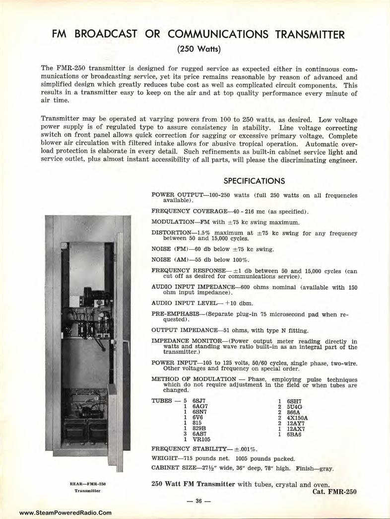
FM BROADCAST OR COMMUNICATIONS TRANSMITTER (250 Watts)
The FMR-250 transmitter is designed for rugged service as expected either in continuous communications or broadcasting service, yet its price remains reasonable by reason of advanced and simplified design which greatly reduces tube cost as well as complicated circuit components. This results in a transmitter easy to keep on the air and at top quality performance every minute of air time.
Transmitter may be operated at varying powers from 100 to 250 watts, as desired. Low voltage power supply is of regulated type to assure consistency in stability. Line voltage correcting switch on front panel allows quick correction for sagging or excessive primary voltage. Complete blower air circulation with filtered intake allows for abusive tropical operation. Automatic overload protection is elaborate in every detail. Such refinements as built-in cabinet service light and service outlet, plus almost instant accessibility of all parts, will please the discriminating engineer.
Rt:AR-FMR-250
Transmitter
SPECIFICATIONS
POWER OUTPUT- 100-250 watts (full 250 watts on all frequencies available).
FREQUENCY COVERAGE-40 - 216 me (as specified).
MODULATION- FM with ± 75 kc swing maximum.
DISTORTION- 1.5% maximum at ± 75 kc swing for any frequency between 50 and 15,000 cycles.
NOISE (FM)-60 db below ± 75 kc swing.
NOISE (AM) - 55 db below 100%.
FREQUENCY RESPONSE- ± 1 db between 50 and 15,000 cycles (can cut off as desired for communications service).
AUDIO INPUT IMPEDANCE-600 ohms nominal (available with 150 ohm input impedance).
AUDIO INPUT LEVE.L- + 10 dbm.
PRE-EMPHASIS-(Separate plug-in 75 microsecond pad when requested).
OUTPUT IMPEDANCE-51 ohms, with type N fitting.
IMPEDANCE MONITOR-(Power output meter reading directly in watts and standing wave ratio built-in as an integral part of the transmitter.)
POWER INPUT-105 to 125 volts, 50/60 cycles, single phase, two-wire. Other voltages and frequency on special order.
METHOD OF MODULATION - Phase, employing pulse techniques which do not require adjustment in the field or when tubes are changed.
TUBES - 5 6SJ 7 1 6AG7 1 6SN7 1 6V6 1 815 1 829B 3 6AS7 1 VR105
FREQUENCY STABILITY- ±.001 %.
1 6SH7 2 5U4G 2 866A 2 4X150A 2 12AY7 1 12AX7 1 6BA6
WEI GHT- 715 pounds net. 1005 pounds packed.
CABINET SIZE-27½" wide, 36" deep, 78" high. Finish-gray.
250 Watt FM Transmitter with tubes, crystal and oven. Cat. FMR-250
-36-
www.SteamPoweredRadio.Com
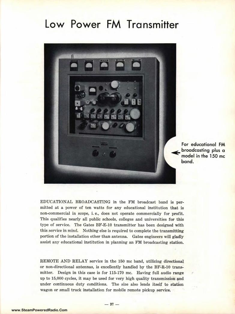
Low Power FM Transmitter
For educational FM ~ broadcasting plus a
model in the 150 me band.
EDUCATIONAL BROADCASTING in the FM broadcast band is permitted at a power of ten watts for any educational institution that is non-commercial in scope, i. e., does not operate commercially for profit. This qualifies nearly all public schools, colleges and universities for t his type of service. The Gates BF-E-10 transmitter has been designed with this service in mind. Nothing else is required to complete the transmitting portion of the installation other than antenna. Gates engineers will gladly assist any educational institution in planning an FM broadcasting station.
REMOTE AND RELAY service in the 150 me band, utilizing directional or non-directional antennas, is excellently handled by the BF-R-10 transmitter. Design in this case is for 115-170 me. Having full audio range up to 15,000 cycles, it may be used for very high quality transmission ~nd under continuous duty conditions. The size also lends itself to station wagon or small truck installation for mobile remote pickup service.
- 37 -
www.SteamPoweredRadio.Com
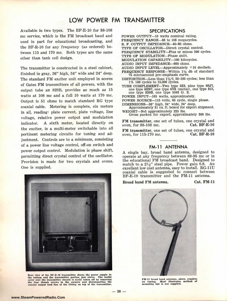
LOW POWER FM TRANSMITTER
Available in two types. The BF-E-10 for 88-108 me service, which is the FM broadcast band and used in part for educational broadcasting, and the BF-R-10 for any frequency (as ordered) between 115 and 170 me. Both types are the same other than tank coil design.
The transmitter is constructed in a steel cabinet, finished in gray, 36" high, 34" wide and 24" deep. The standard FM exciter unit employed in scores of Gates FM transmitters of all powers, with the output t ube an 829B, provides as much as 15 watts at 108 me and a full 10 watts at 170 me. Output is 51 ohms to match standard RG type coaxial cable. Metering is complete, six meters in all, reading: plate current, plate voltage, line voltage, relative power output and modulation indicator. A sixth meter, located directly on the exciter , is a multi-meter switchable into all pertinent metering circuits for tuning and adjustment. Controls are to a minimum, consisting of a power line voltage control, off-on switch and power output control. Modulation is phase shift , permitting direct crystal control of the oscillator. Provision is made for two crystals and ovens. One is supplied.
Rear view of the BF-E-10 transmitter shows the power supply 1n the bottom and the transmitte r portion just above. The Inside cover over the transmlUer ebassis is easily taken off by removing the tou.r thu mb screws in the corners and d.lsconnectinr the coaxlal output feed line at the flttlnt: on top of the transmitter.
SPECIFICATIONS POWER OUTPUT-10 watts nominal rating. FREQUENCY R ANGE-88 to 108 megacycles. R. F . OUTPUT IMPEDANCE-40-80 ohms. TYPE OF OSCILLATOR-Direct crystal control. FREQUENCY STABILITY- Plus or minus 500 cycles. TYPE OF MODULATION-Phase shift. MODULATION CAPABILITY- 100 kilocycles. AUDIO INPUT IMPEDANCE--600 ohms. AUDIO INPUT LEVEL-Approximately + 10 decibels. FREQUENCY RESPONSE-Within 1½ db of standard
75 microsecond pre-emphasis curve. DISTORTION- Less than 1½% 50-100 cycles; less than
1 % 100 cycles to 15,000 cycles. TUBE COMPLEMENT-Two type 5Z3, nine type 6SJ 7,
one type 6SN7, one type 6V6 (metal), one type 815, one type 829B, one type 5593 G. E.
POWER INPUT- 165 watts, approximately. POWER SOURCE--115 volts, 60 cycle, single phase. DIMENSIONS-36" high, 34" wide, 24" deep.
Approximately 31 cu. ft. boxed for export shipment. WEIGHT- Net approximately 225 lbs.
Gross packed for export, a pproximately 300 lbs.
FM transmitter, one set of tubes, one crystal and oven, for 88-108 me. Cat. BF-E-10 FM transmitter, one set of tubes, one crystal and oven, for 115-170 me. Cat. BF-R-10
FM-11 ANTENNA A single bay, broad band antenna, designed to operate at any frequency between 88-95 me or in the educational FM broadcast band. Designed to match to a 2½" steel pipe. Power gain 0.8. An excellent low cost ant enna, easy to install. RG-11 U coaxial cable is suggested to connect between BF-E-10 transmitter and the FM-11 antenna.
Broad band FM antenna. Cat. FM-11
FM-11 broad band antenna. above, requires no tunlnt:, Mast Illustrates method of mounting but Is n ot supplied.
- 38-
www.SteamPoweredRadio.Com
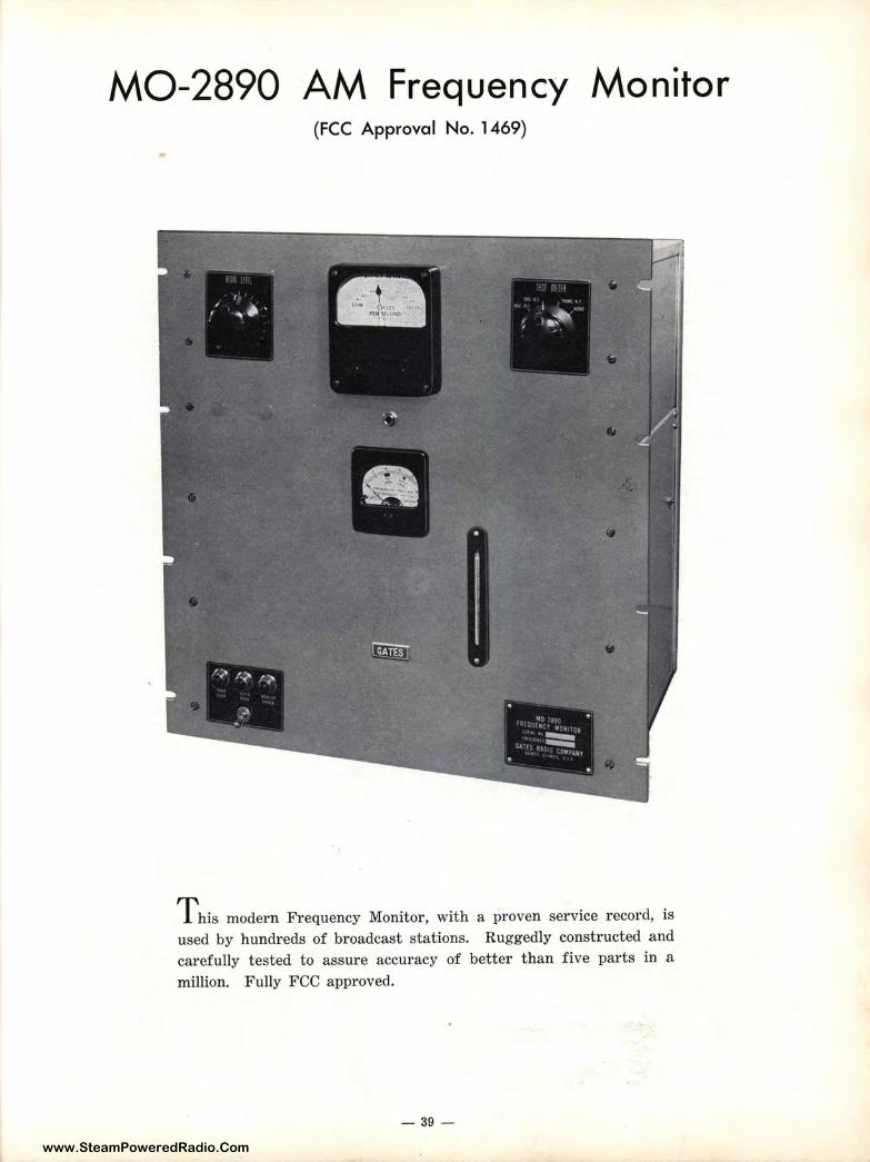
MO-2890 AM Frequency Monitor (FCC Approval No. 1469)
T his modern Frequency Monitor, with a proven service record, is used by hundreds of broadcast stations. Ruggedly constructed and carefully tested to assure accuracy of better than five parts in a million. Fully FCC approved.
- 39 -
www.SteamPoweredRadio.Com
MO-2890 FREQUENCY MONITOR For positive measurement of the frequency drift of your broadcast transmitter, the Gates MO-2890 Frequency Monitor has proven itself in daily operation in America's finest radio stations. Straightforward circuitry combined with an unusual dual oven design relieves the operator of worries both in performance and servicing requirements.
A precision crystal oscillator, operating 500 cycles below the transmitter frequency, has the output amplified by one stage and then mixed into a detector stage with a small amount of the radio frequency signal from the transmitter. The resulting beat note of 500 cycles when the transmitter is on frequency is further amplified and then applied to the frequency meter. This meter is calibrated from - 30 to + 30 cycles with zero point at center scale, which corresponds to 500 cycles. Meter is calibrated in one cycle steps. A phone jack is also provided for aural monitoring.
The smaller meter just below the frequency meter indicates the amount of R. F. signal fed into the monitor. This same meter also indicates oscillator current, oscillator signal voltage and signal voltage from transmitter.
Two ovens, one located inside the other, carefully guard the accuracy. The inside oven is controlled by a mercury column thermostat operating at temperature variations of 0.2°, with the crystal located in this oven. The outer oven operates at slightly lower temperature --operates also at close temperature tolerance and accommodates the tube and oscillator components.
Front panel equipment includes the two meters previously referred to, oven indicating pilot lamps, off-on switch with pilot lamp, input signal adjusting control and meter selector switch. All connections and adjustments are easy to make. Openings in the dust cover allows access to variable capacitor adjustment, fuses and terminal block.
SPECIFICATIONS OSCILLATOR ACCURACY- Better than 5 parts per million. FREQUENCY METER CALIBRATION-Minus 30 to plus 30 with zero at center
scale. Calibration marks are at one cycle intervals allowing deviation of less than one cycle to be observed.
TUBE COMPLEMENT-Oscmator 6AC7, RF Amplifier, 6SJ7, Current Detector 6H6, Mixer 6C5, Audio Amplifier 6SJ7, Audio Output 6V6, Rectifier 5U4G, Voltage Regulator VR150-30.
RF DRIVING POWER-.5 watts maximum. DIMENSIONS--19¼" panel space on 19" standard rack cabinet. Depth 12".
Packed for export 15½ cu. ft. WEIGHT-85 lbs. net, 125 lbs. gross. POWER REQUIREMENTS-85 watts. POWER SOURCE-115 volts 50/60 cycles. FCC APPROVAL NUMBER-1469.
Complete Frequency Monitor, with one set of tubes.
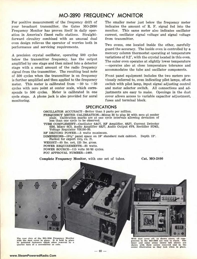
The re•r view of the MO-2800 Frequency Monitor with the dust co.er In place. It Is held In place by patented fasteners wblch al_Jow removal by a quarter turn of a screwdriver or ooln.
- 40-
Cat. MO-2890
\Vlth dust cover off, as shown above, all component s In the 1110-2890 are easy to reaeh. The Inner and outer ove~ (lower left above) are shown with their covers removed and In the center Illustration as they look when In pl&cc.
www.SteamPoweredRadio.Com
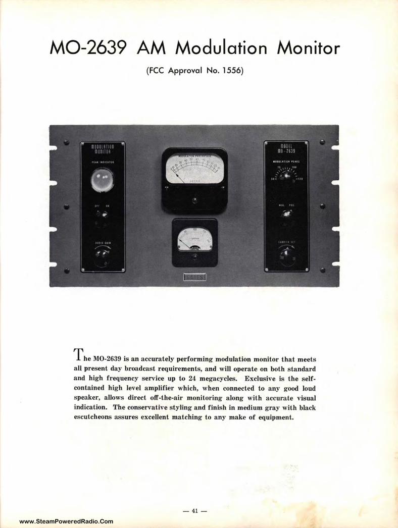
M0-2639 AM Modulation Monitor (FCC Approval No. 1556)
The M0-2639 is an accurately performing modulation monitor that meets all present day broadcast requirements, and will operate on both standard and high frequency service up to 24 megacycles. Exclusive is the selfcontained high level amplifier which, when connected to any good loud speaker, allows direct off-the-air monitoring along with accurate visual indication. The conservative styling and finish in medium gray with black escutcheons assures excellent matching to any make of equipment.
- 41-
www.SteamPoweredRadio.Com
MO-2639 MODULATION MONITOR
Designed to meet exacting FCC requirements, the M0-2639 modulation monitor indicates exact percentage of modulation. As a bonus exclusive there is also provided a self-contained high level amplifier, which may be connected to any excellent quality speaker for high fidelity off-the-air monitoring. In many cases this eliminates the need of a separate monitoring amplifier.
A 4" meter is calibrated from -15 db to 0 db and 0-110 % modulation. A neon lamp, located behind a large "bull's-eye" on the front panel, may be adjusted to flash at the maximum percentage of modulation desired. A carrier meter allows direct center scale reading for proper radio frequency input. Front panel controls include carrier set adjustment, positivenegative peak control, peak indicator adjustment, audio amplifier gain control, and off-on switch. Each monitor is carefully manufactured and tested in accordance with specifications set forth by FCC Standards of Good Engineering Practice, and has been approved by the FCC for use in all standard broadcast stations.
SPECIFICATIONS FREQUENCY RANGE-100-20,000 kilocycles. INPUT-High impedance requiring about ½ watt excitation. LOUD SPEAKER IMPEDANCE-4 to 8 ohms. TUBES-Three 6X5, three 6C5, one each 6F6, 885 and VR150, plus one
neon flasher light and two 6 volt meter lights. MODULATION PERCENTAGE RANGE-0-110%. CARRIER LEVEL METER RANGE-0-200%. DECIBEL SCALE RANGE-Calibrated to 15 db below 100% modulation. AUDIO AMPLIFIER-Range exceeds best quality speaker capabilities. POWER CONSUMPTION-65 VA. at 115 volts 50/ 60 cycles. FCC APPROVAL NUMBER-1556. WEIGHT-Net, 27 lbs. Gross, 40 lbs. DIMENSIONS-IO½" high, 19" wide, 13½" deep.
Packed for shipment, 3.7 cu. f t .
Modulation Monitor, complete with one set of tubes. Cat. M0-2639
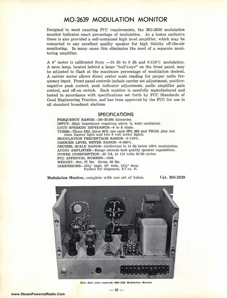
Rear dust cover removed-M0-2639 Modulation Monitor
-42-
www.SteamPoweredRadio.Com
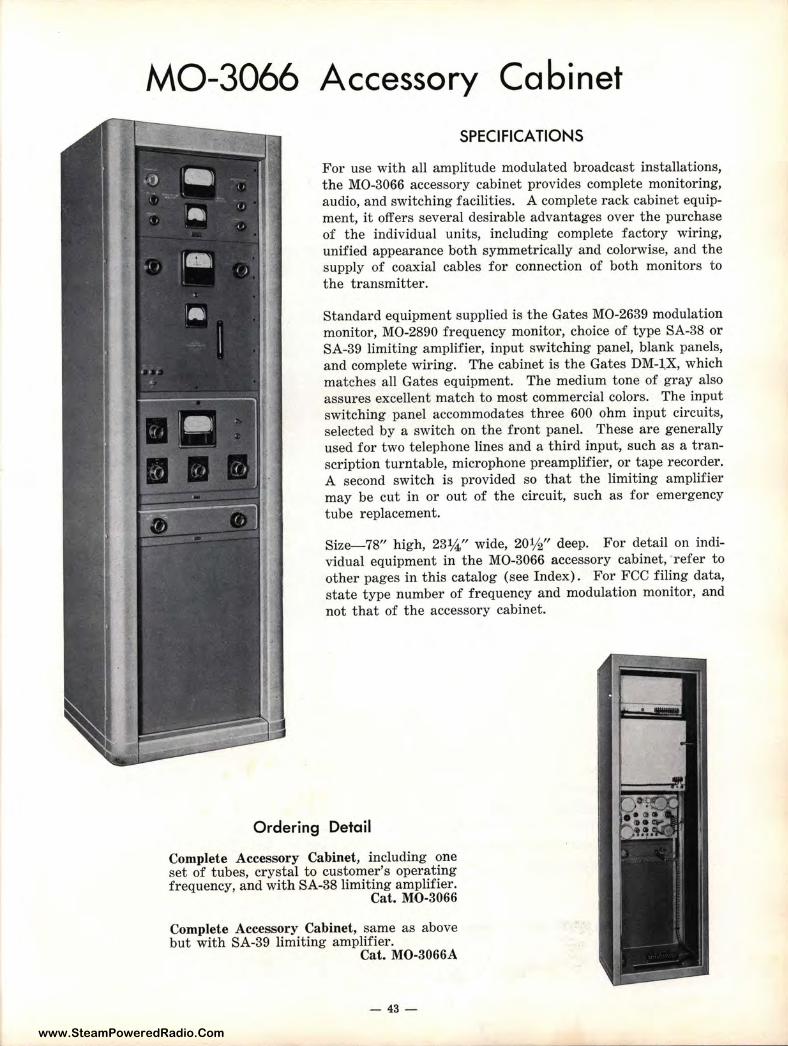
MO-3066 Accessory Cabinet SPECIFICATIONS
For use with all amplitude modulated broadcast installations, the MO-3066 accessory cabinet provides complete monitoring, audio, and switching facilities. A complete rack cabinet equipment, it offers several desirable advantages over the purchase of the individual units, including complete factory wiring, unified appearance both symmetrically and colorwise, and the supply of coaxial cables for connection of both monitors to the transmitter.
Standard equipment supplied is the Gates MO-2639 modulation monitor, MO-2890 frequency monitor, choice of type SA-38 or SA-39 limiting amplifier, input switching panel, blank panels, and complete wiring. The cabinet is the Gates DM-1,X, which matches all Gates equipment. The medium tone of gray also assures excellent match to most commercial colors. The input switching panel accommodates three 600 ohm input circuits, selected by a switch on the front panel. These are generally used for two telephone lines and a third input, such as a transcription turntable, microphone preamplifier, or tape recorder. A second switch is provided so that the limiting amplifier may be cut in or out of the circuit, such as for emergency tube replacement.
Size-78" high, 23¼" wide, 201/2" deep. For detail on individual equipment in the MO-3066 accessory cabinet, refer to other pages in this catalog (see Index). For FCC filing data, state type number of frequency and modulation monitor, and not that of the accessory cabinet.
Ordering Detail
Complete Accessory Cabinet, including one set of tubes, crystal to customer's operating frequency, and with SA-38 limiting amplifier.
Cat. MO-3066
Complete Accessory Cabinet, same as above but with SA-39 limiting amplifier.
Cat. MO-3066A
- 43 -
www.SteamPoweredRadio.Com
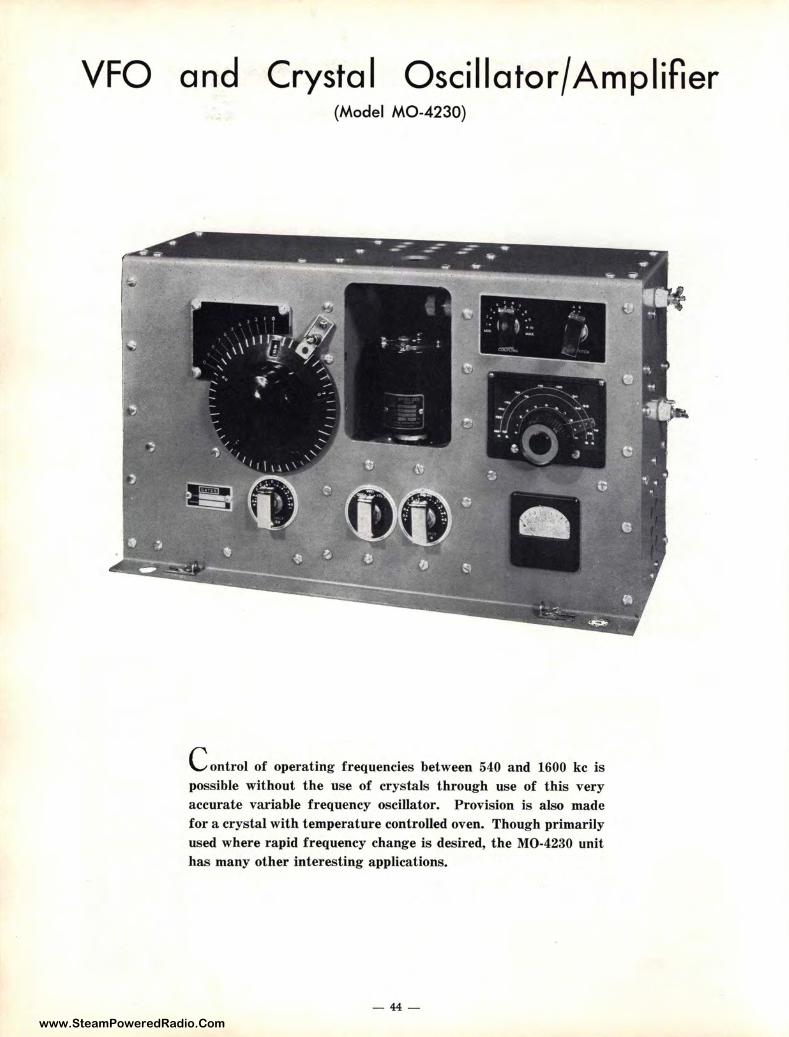
VFO and Crystal Osei I la tor/ Amplifier (Model MO-4230)
' .. · .. • &.. .......
• :· I ~-~. • J'
Control of operating frequencies between 540 and 1600 kc is possible without the use of crys tals t hrough use of this very accurate variable frequency oscillator. P rovision is also made for a crystal with temperature controlled oven. Though primarily used where rapid frequency change is desired, the MO-4230 unit has many other interesting applications.
- 44 -
www.SteamPoweredRadio.Com
MO-4230 VFO/ CRYSTAL OSCILLATOR/ AMPLI Fl ER Recent requirements for rapid change of operating frequency in the standard broadcast band, such as in mobile broadcasting where the operating frequency varies in different areas, or in military requirements, has brought forth the Gates MO-4230 combination variable frequency oscillator and crystal controlled unit.
Designed specifically to replace the oscillator unit in several types of Gates transmitters, it may, because of the conservative size, be used either internally or externally with other types of equipment operating between 540 and 1600 kc. The variable frequency oscillator, or VFO, is reactively controlled, employing a 6V6 oscillator and VR75 regular tube. Negative coefficient capacitors pad the reactive circuit to reduce effect from temperature change. Fundamental output is provided from 500 to 1100 kc, and operation above 1000 kc is provided by doubling. This allows appreciable capacity to be maintained in the reactive circuit for optimum stability.
For the VFO three stages are employeda 6V6 oscillator, 6V6 untuned intermediate amplifier, and 807 output amplifier, producing about two watts, or enough to excite one or two 813 tubes as succeeding amplifiers. When the crystal is used in-
stead of the VFO, the untuned intermediate amplifier becomes the crystal oscillator stage with ten cycle accuracy realized from a temperature controlled crystal. Output impedance is either 70 ohms for link coupling, or high impedance for capacity coupling. An output control is provided in the high impedance portion to prevent overdriving a succeeding stage.
The VFO tuning dial with vernier provided allows a reading accuracy of 1 part in 5000. Calibration is in 10 kc steps, and a chart is provided with each unit. Provision is made for a Gates type JK-57 plug-in crystal and oven, which operates at the ordered crystal frequency simply by switching into the circuit. Front panel equipment includes micrometer dial for VFO, vernier directly below, VFO/ Crystal switch in center, crystal trimmer capacitor left of meter, 807 tuning condenser above meter, output excitation control, and output band switch. The meter indicates 807 plate current. Power requirements for both filament and plate allow for easy adaptation to the existing transmitter power source or one of several Gates power supplies listed elsewhere in this catalog (see Index). Where desired, the two 6.3 volt filament circuits may be paraileled, which would then necessitate operating the tube filaments at all times.
SPECIFICATIONS OUTPUT FREQUENCY-540-1600 kc. POWER OUTPUT-Approximately 2 watts. OUTPUT IMPEDANCE-70 ohms and high impedance. POWER REQUIREMENTS--6.3 volts at 1.45 amps., 6.3 volts at 1.35 amps.,
350 volts DC at 60 ma. (6.3 volt windings may be paralleled if desired.) CALIBRATION-10 kc steps. DIAL CALIBRATION-1 :5000. DIAL DIVISION-200 cycles/ division. DIAL CURVE-Straight line. TEMPERATURE COEFFICIENT- 0.0005% degree F. STABILIZING TIME VFO-120 minutes•. VFO ACCURACY-After 120 minutes, ±200 cycles**. CRYSTAL ACCURACY-±10 cycles. TUBES-Two each 6V6, one each 807, VR75. SIZE-19" wide, 10½" high (less shock mounts if used), 6½'' deep. WEIGHT-Net 24 lbs., gross packed 50 lbs.
• Stabilizing time will vary with a.Ir strea.m conditions. but the above Is considered maximum 1n most cases.
•• Tolerance specified may be exceeded under extreme variable conditions ot temperature. Under normal conditions. tolerances stated are conservative.
VFO/Crystal Oscillator and Amplifier, with one set tubes.
Crystal and Oven (state frequency when ordering).
-45-
Cat. MO-4230
Cat. JK-57
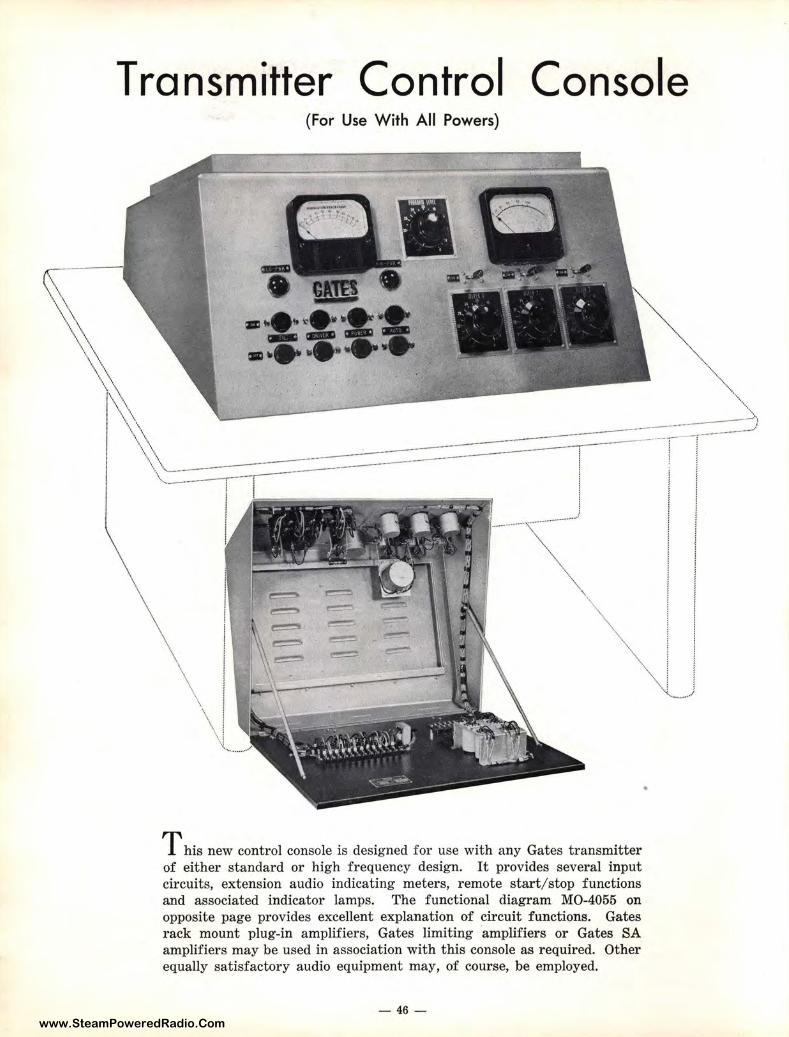
www.SteamPoweredRadio.Com
Transmitter Control Console (For Use With All Powers)
T his new control console is designed for use with any Gates transmitter of either standard or high frequency design. It provides several input circuits, extension audio indicating meters, remote start/stop functions and associated indicator lamps. The functional diagram MO-4055 on opposite page provides excellent explanation of circuit functions. Gates rack mount plug-in amplifiers, Gates limiting amplifiers or Gates SA amplifiers may be used in association with this console as required. Other equally satisfactory audio equipment may, of cour se, be employed.
-46 -
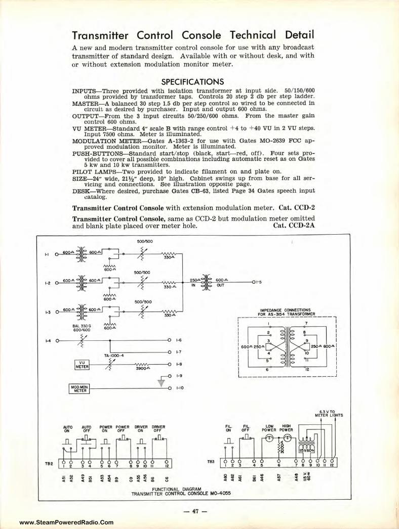
www.SteamPoweredRadio.Com
~I
1-2
1•3
Transmitter Control Console Technical Detail A new and modern transmitter control console for use with any broadcast transmitter of standard design. Available with or without desk, and with or without extension modulation monitor meter.
SPECIFICATIONS INPUTS-Three provided with isolation transformer at input side. 50/ 150/600
ohms provided by transformer taps. Controls 20 step 2 db per step ladder. MASTER-A balanced 30 step 1.5 db per step control so wired to be connected in
circuit as desired by purchaser. Input and output 600 ohms. OUTPUT- From the 3 input circuits 50/ 250/600 ohms. From the master gain
control 600 ohms. VU METER-Standard 4" scale B with range control + 4 to + 40 VU in 2 VU steps.
Input 7500 ohms. Meter is illuminated. MODULATION METER-Gates A-1363-2 for use with Gates MO-2639 FCC ap
proved modulation monitor. Meter is illuminated. PUSH-BUTTONS-Standard start/ stop (black, start-red, off). Four sets pro
vided to cover all possible combinations including automatic reset as on Gates 5 kw and 10 kw transmitters.
PILOT LAMPS-Two provided to indicate filament on and plate on. SIZE-24" wide, 21½" deep, 10" high. C2.binet swings up from base for all ser
vicing and connections. See illustration opposite page. DESK-Where desired, purchase Gates CB-63, listed Page 34 Gates speech input
catalog.
Transmitter Control Console with extension modulation meter. Cat. CCD-2
Transmitter Control Console, same as CCD-2 but modulation meter omitted and blank plate placed over meter hole. Cat. CCD-2A
500J!iOO
~ 600-"
500/500
~ 250A 600.A.
33QA IN OUT
600-" 500/500
IMPEDANCE CONNECTIONS FOR AS-3154 TRANSFORMER ~ ,---- ------------------,
BAL 330G 600/600 600.A.
7 I I
1.4 o---~~V::._ ___ _ ____ _ : 1·6
e I
Zl I 250-" 6QQA I
TB2
TA.-1000-4
3900-"
r 0
l(JTO AUTO POWER POWER DRIVER DRIVER ON OFF ON OFF ON OFF
"' .. ;;; .. ., cn:8:g.,, (.)'4<[(D "' 0
H
1-8
1-9
1-10
TB3
FUNCTIONAL DIAGRAM lRANSMITTER CONTROL CONSOLE MO-4055
;-J! I
6 12 :
L--------------- --__ .J
6.3V.TO METER LIGHTS
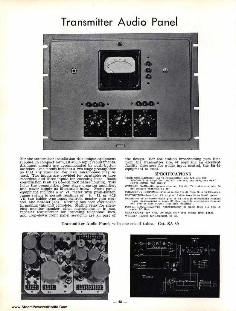
www.SteamPoweredRadio.Com
Transmitter Audio Panel
For the transmitter installation this unique equipment supplies, in compact form, all audio input requirements. Six input circuits are accommodated by push-button switches. One circuit includes a two stage preamplifier so that any standard low level microphone may be used. Two inputs are provided for turntables or tape recorders, and three inputs for incoming lines. Basic const ruction is on an SA-800 rack panel housing. This holds the preamplifier, four stage program amplifier, and power supply as illustrated below. Front panel equipment includes a 4" VU meter with push-button range switch to permit readings of + 8, + 12, or + 16 VU, two ladder type input controls, master gain control, and headset jack. Nothing has been overlooked in making this unit complete. Muting relay for silencing monitor speaker when microphone is in use, repeater transformer for incoming telephone lines, and drop-down front panel servicing are all part of
the design. For the station broadcasting part time from the transmitter site, or requiring an excellent facility elsewhere for audio input control, the SA-89 equipment is ideal.
SPECIFICATIONS TUBE COMPLEMENT-SA-70 Preamplifier: one 6J7, one 6C5.
MO-3094 Line Amplifier: one 6J7, one 6C5, one 6SJ7, one 6SN7. Power Supply: one 6X5GT.
OVERALL GAIN- Microphone channel, llO db; Turntable channels, 70 db; Remote channels, 64 db.
FREQUENCY RESPONSE- Plus or minus 1 ¾ db from 30 to 15,000 cycles. DISTORTION- Less than 1 % at p lus 16 dbm f rom 50 to 15,000 cycles. NOISE-60 db or better below plus 16 db t hrough microphone channel
(noise measurement ls made 60 dbm input to microphone channel and plus 16 dbm output from line amplifier).
POWER REQUIREMENTS-Approximately 30 watts from 115 volt 60 cycle AC J!ne.
DlMENSIONS-19" wide, 14" high, 8 ¾ " deep behind front panel. WEIGHT-Packed for shipment, 90 lbs.
Transmitter Audio Panel, with one set of tubes. Cat. SA-89
-48 -
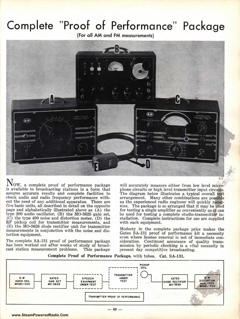
www.SteamPoweredRadio.Com
Complete "Proof of Performance" Package (For all AM and FM mea sure me nts)
---~ __,__.__~---------~·. J:; "' .. ' .
NOW, a complete proof of performance package will accurately measure either from low level micro- t is available to broadcasting stations in a form that phone circuits or high level transmitter input circuits. assures accurate results and complete facilities to The diagram below illustrates a typical overall', test check audio and radio frequency performance with- arrangement. Many other combinations are possible out the need of any additional apparatus. There are as the experienced radio engineer will quickly recog-five basic units, all described in detail on the opposite nize. The package is so arranged that it may be· used page and alphabetically illustrated above as (A) the for testing a single amplifier as conveniently as i: can type 200 audio oscillator, (B) the MO-3625 gain set, be used for testing a complete studio-transmitter in-(C) the type 400 noise and distortion meter, (D) the stallation. Complete instructions for use are supplied RF pickup coil for transmitter measurements, and with each equipment. (E) the M0-3626 diode rectifier unit for transmitter Modesty in the complete package price makes the measurements in conjunction with the noise and dis- Gates SA-131 proof of performance kit a necessity tortion equipment. even where license renewal is not of immediate con-The complete SA-131 proof of performance package sideration. Continued assurance of quality trans-has been worked out after weeks of study of broad- mission by periodic checking is a vital necessity in cast station measurement problems. This package present day competitive broadcasting.
B-W AUDIO OSC. MODEL-200
Complete Proof of Performance Package, with tubes. Cat. SA-131.
GATES GAIN SET
M0·3&25
PICKUP ,------- ----, COIL I I I I
f'" I I TRANSMITTER I I SPEECH I I UNDER I
I I TEST I I EQUIPMENT 1--, I
1 UNDER TEST I I 1 L __ _ _ ____ J I ___ _____ J
TRANSMITTER PROOF OF PERFORMANCE
- 49-
GATES DIODE RECTIFIER
M0-3626
B• W DISTORTION AHAL 'l'ZER MOOEL-4 00
www.SteamPoweredRadio.Com
REGULATIONS PERFORMANCE
SUMMARY OF FCC ON PROVING
FCC regulations sometimes become confusing, due to the necessary way that regulations of all kinds must be prepared. As a result, our engineering department has read over these regulations and discovered the following points to be of particular interest.
1. The original rule regarding proof of performance was to be established and made effective in the year 1949, but was suspended for one year due to the cost to broadcasters, and other factors.
2. Since the year 1950 all standard AM stations, as well as FM broadcast stations, have been required to make a complete proof of performance as to frequency response, noise and distortion at least once annually, and preferably the last four months of each calendar year, or coincidental with the time that any license renewal is requested.
3. This information is not posted with the FCC unless specifically requested, but the renewal forms carry a direct question asking if these measurements have been made, and if they prove that the equipment is operated in accordance with the Standards of Good Engineering Practice as set forth by the F ederal Communications Commission.
4. The measurements must be recorded as a written report, and kept at the radio transmitter building for examination by the FCC field inspectors at any time requested.
5. The FCC does not specifically approve nor disapprove any particular equipment for making the series of tests, as long as there is every evidence that the equipment being used is satisfactory and is functioning properly.
6. The FCC does not demand that broadcast stations own the equipment. This means that others who own equipment may be engaged to do the work. It is specifically pointed out, however, that the intent of the proof of performance rule is to keep all broadcast stations operating from the standpoint of top quality transmission. It is the opinion of Gates that top quality transmission cannot be maintained by an annual check. We feel that checks should be made at least once every month. Therefore, for the conscientious broadcaster, owning the equipment is desirable.
Is Proof of Performance Important?
Although the Federal Communications Commission requires proof of performance, the importance of taking regular measurements should not be judged on the basis that it is a mandatory regulation. Much more important is the resultant rich transmission quality. This means more listeners and greater respect from your advertising clientele. It totals to more income. Like the regular check of the airliner or streamliner at the end of the run, proof of performance is intangible. Few will continue to patronize the airline that neglects proving its performance. Broadcast listeners have a habit of neglecting mediocre sounding radio stations in favor of those pleasing to the ear. Keeping equipment in good repair is very important, but keeping this same equipment in a top listenable condition by regular "proof of performance" measurements is an obligation to listener, adver tiser, and broadcaster alike.
- 50-
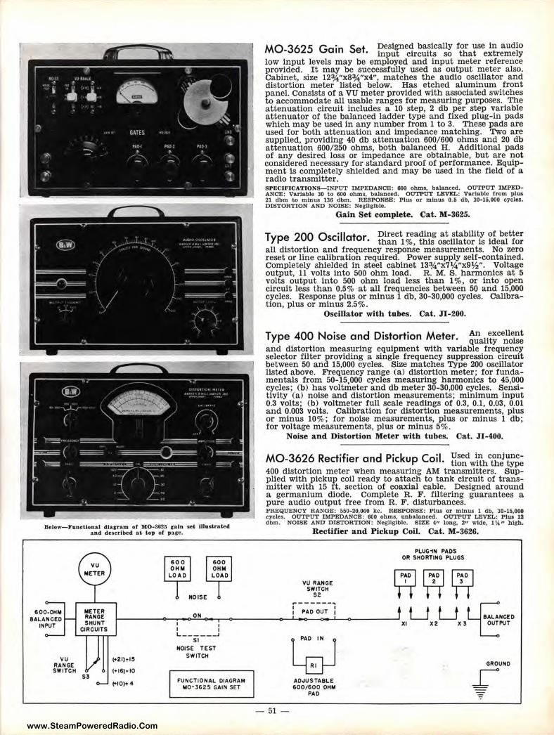
www.SteamPoweredRadio.Com
Below-Functional diagram or M0-3625 gain set Illustrated and described at top or page.
600-0HM BALANCED
INPUT
vu RANGE SWITCH
METER RANGE SHUNT
CIRCUITS
S3
(+21)+1!1
(•16)•10
ON
I I I I L - -----'
SI NOISE TEST
SWITCH
F'UNCTIONAL DIAGRAM M0·3625 GAIN SET
MO-3625 Gain Set. Designed basically for use in audio input circuits so that extremely
low input levels may be employed and input meter reference provided. It may be successfully used as output meter also. Cabinet, size 12¾"x8¾"x4", matches the audio oscillator and distortion meter listed below. Has etched aluminum front panel. Consists of a VU meter provided with associated switches to accommodate all usable ranges for measuring purposes. The attenuation circuit includes a 10 step, 2 db per step variable attenuator of the balanced ladder type and fixed plug-in pads which may be used in any number from 1 to 3. These pads are used for both attenuation and impedance matching. Two are supplied, providing 40 db attenuation 600/600 ohms and 20 db attenuation 600/250 ohms, both balanced H. Additional pads of any desired loss or impedance are obtainable, but are not considered necessary for standard proof of performance. Equipment is completely shielded and may be used in the field of a radio transmitter. SPECIFICATIONS-INPUT IMPEDANCE: 600 ohms. balanced. OUTPUT IMPEDANCE: Variable 30 to 600 ohms, balanced. OUTPUT LEVEL: Variable from plus 21 dbm to minus 136 dbm. RESPONSE: Plus or minus 0.5 db, 30-15,000 cycles. DISTORTION AND NOISE: Negligible.
Gain Set complete. Cat. M-3625.
Type 200 Oscillator Direct readit:g at _stabili~y of better • than 1 %, this oscillator 1s ideal for
all distortion and frequency response measurements. No zero reset or line calibration required. Power supply self-contained. Completely shielded in steel cabinet 13¾"x7¼"x9½". Voltage output, 11 volts into 500 ohm load. R. M. S. harmonics at 5 volts output into 500 ohm load less than 1 % , or into open circuit less than 0.5% at all frequencies between 50 and 15,000 cycles. Response plus or minus 1 db, 30-30,000 cycles. Calibrat ion, plus or minus 2.5%.
Oscillator with tubes. Cat. JI-200.
Type 400 Noise and Distortion Mete r. An excellent quality noise
and distortion measuring equipment with variable frequency selector filter providing a single frequency suppression circuit between 50 and 15,000 cycles. Size matches Type 200 oscillator listed above. Frequency range (a) distortion meter; for fundamentals from 50-15,000 cycles measuring harmonics to 45,000 cycles; (b) has voltmeter and db meter 30-30,000 cycles. Sensitivity (a) noise and distortion measurements; minimum input 0.3 volts; (b) voltmeter full scale readings of 0.3, 0.1, 0.03, 0.01 and 0.003 volts. Calibration for distortion measurements, plus or minus 10%; for noise measurements, plus or minus 1 db; for voltage measurements, plus or minus 5%.
Noise and Distortion Meter with tubes. Cat. JI-400.
Mo 3626 R rf· d p· k c ·1 Used in conjunc- ec ' ,er an ,c up 01 • tion with the type 400 distortion meter when measuring AM transmitters. Supplied with pickup coil ready to attach to tank circuit of transmitter with 15 ft. section of coaxial cable. Designed around a germanium diode. Complete R. F. filtering guarantees a pure audio output free from R. F. disturbances. FREQUENCY RANGE: 550-20,000 kc. RESPONSE: Plus or minus l db, 30-15,000 cycles. OUTPUT IMPEDANCE: 600 ohms, unbalanced. OUTPUT LEVEL: Plus 12 dbm. NOISE AND DISTORTION: Negligible. SIZE 4" long, 2" wide, 1\4" high.
- 51-
Rectifier and Pickup Coil. Cat. M-3626.
VU RANGE SWITCH
S2
.--------. : PAD OUT I
l PAD IN l LE}-J ADJUSTABL E 600/600 OHM
PAD
PLUG1N PADS OR SHORTING PLUGS
W~Y1 LJ LJ LCNCED
XI X2 X 3 LPUT
GROUND
_L
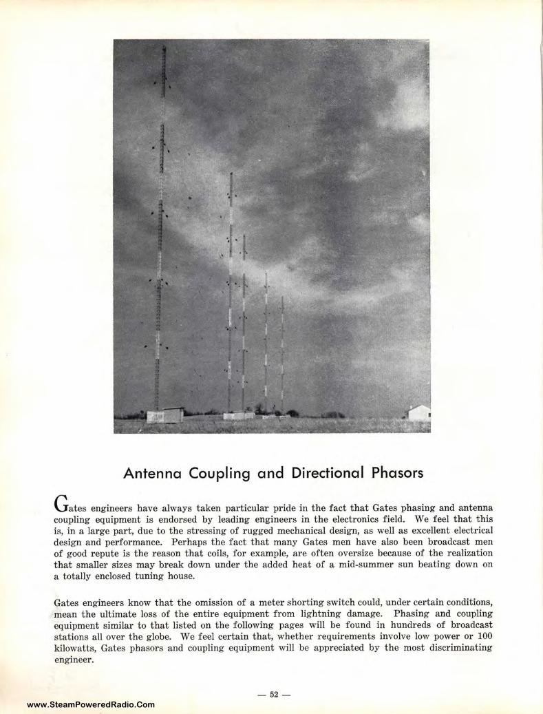
www.SteamPoweredRadio.Com
Antenna Coupling and Directional Phasors
G ates engineers have always taken particular pride in the fact that Gates phasing and antenna coupling equipment is endorsed by leading engineers in the electronics field. We feel that this is, in a large part, due to the stressing of rugged mechanical design, as well as excellent electrical design and performance. Perhaps the fact that many Gates men have also been broadcast men of good repute is the reason that coils, for example, are often oversize because of the realization that smaller sizes may break down under the added heat of a mid-summer sun beating down on a totally enclosed tuning house.
Gates engineers know that the omission of a meter shorting switch could, under certain conditions, mean the ultimate loss of the entire equipment from lightning damage. Phasing and coupling equipment similar to that listed on the following pages will be found in hundreds of broadcast stations all over the globe. We feel certain that, whether requirements involve low power or 100 kilowatts, Gates phasors and coupling equipment will be appreciated by the most discriminating engineer.
- 52-
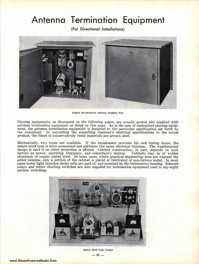
www.SteamPoweredRadio.Com
Antenna Termination Equipment (For Directional Installations)
Typical Weatherproof Antenna Coupling Unit
Phasing equipments, as illustrated on the following pages, are usually quoted and supplied with antenna termination equipment as listed on this page. As in the case of centralized phasing equipment, the antenna termination equipment is designed to the particular specification set forth by the consultant. In converting the consulting engineer's electrical specifications to the actual product, the finest of conservatively rated materials are always used.
Mechanically, two types are available. If the broadcaster provides his own tuning house, the indoor shelf type is more economical and performs the same electrical function. The weatherproof design is used if no other protection is offered. Cabinet construction, in part, depends on such factors as power, operating frequency, and consultant's desires. Cabinets may be of welded aluminum or copper plated steel. In some cases, where practical engineering does not warrant the added expense, only a portion of the cabinet is plated or fabricated of non-ferrous metal. In most cases tower light isolation choke coils are part of, and mounted in, the termination housing. Solenoid relays and meter shorting switches are also supplied for termination equipment used in day-night pattern switching.
Indoor Shelf Type Coupler
- 53 -
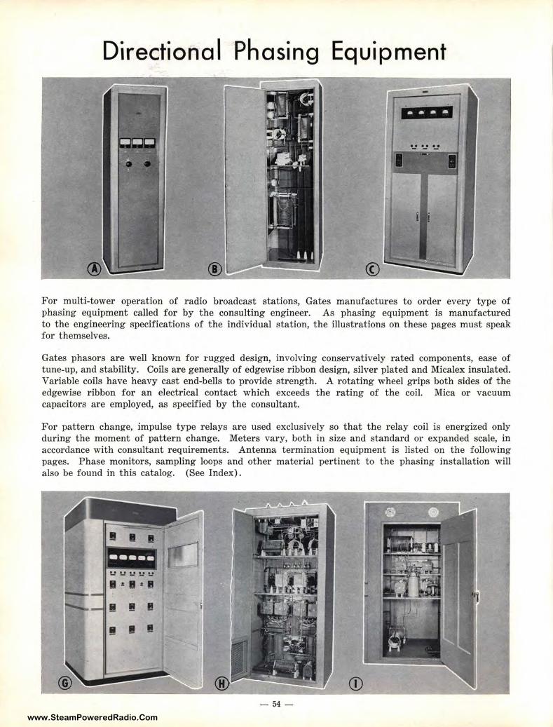
www.SteamPoweredRadio.Com
Directional Phasing Equipment
©
For multi-tower operation of radio broadcast stations, Gates manufactures to order every type of phasing equipment called for by the consulting engineer. As phasing equipment is manufactured to the engineering specifications of the individual station, the illustrations on these pages must speak for themselves.
Gates phasors are well known for rugged design, involving conservatively rated components, ease of tune-up, and stability. Coils are generally of edgewise ribbon design, silver plated and Micalex insulated. Variable coils have heavy cast end-bells to provide strength. A rotating wheel grips both sides of the edgewise ribbon for an electrical contact which exceeds the rating of the coil. Mica or vacuum capacitors are employed, as specified by the consultant.
For pattern change, impulse type relays are used exclusively so that the relay coil is energized only during the moment of pattern change. Meters vary, both in size and standard or expanded scale, in accordance with consultant r equirements. Antenna termination equipment is listed on the following pages. Phase monitors, sampling loops and other material pertinent to the phasing installation will also be found in this catalog. (See Index).
- 54 -
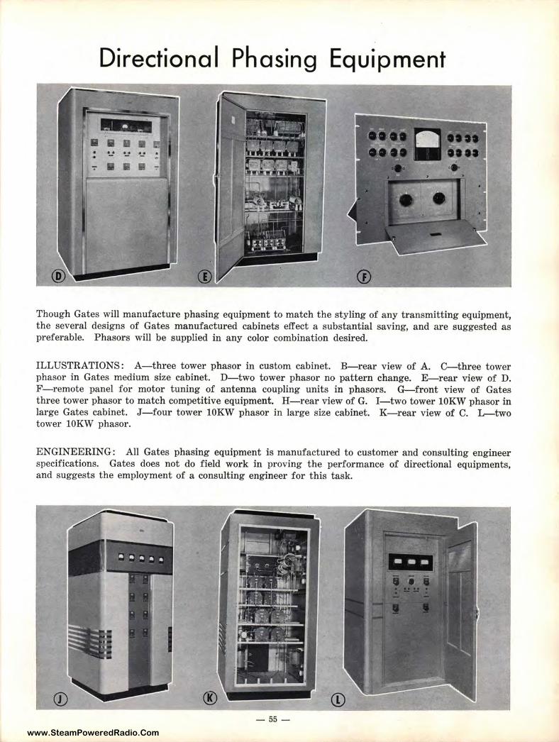
www.SteamPoweredRadio.Com
Directional Phasing Equipment
Though Gates will manufacture phasing equipment to match the styling of any transmitting equipment, the several designs of Gates manufactured cabinets effect a substantial saving, and are suggested as preferable. Phasors will be supplied in any color combination desired.
ILLUSTRATIONS: A-three tower phasor in custom cabinet. B-rear view of A. C-three tower phasor in Gates medium size cabinet. D-two tower phasor no pattern change. E-rear view of D. F-remote panel for motor tuning of antenna coupling units in phasors. G-front view of Gates three tower phasor to match competitive equipment. H-rear view of G. I-two tower lOKW phasor in large Gates cabinet. J- four tower lOKW phasor in large size cabinet. K-rear view of C. L-two tower lOKW phasor.
ENGINEERING: All Gates phasing equipment is manufactured to customer and consulting engineer specifications. Gates does not do field work in proving the performance of directional equipments, and suggests the employment of a consulting engineer for this task.
® - 55 -
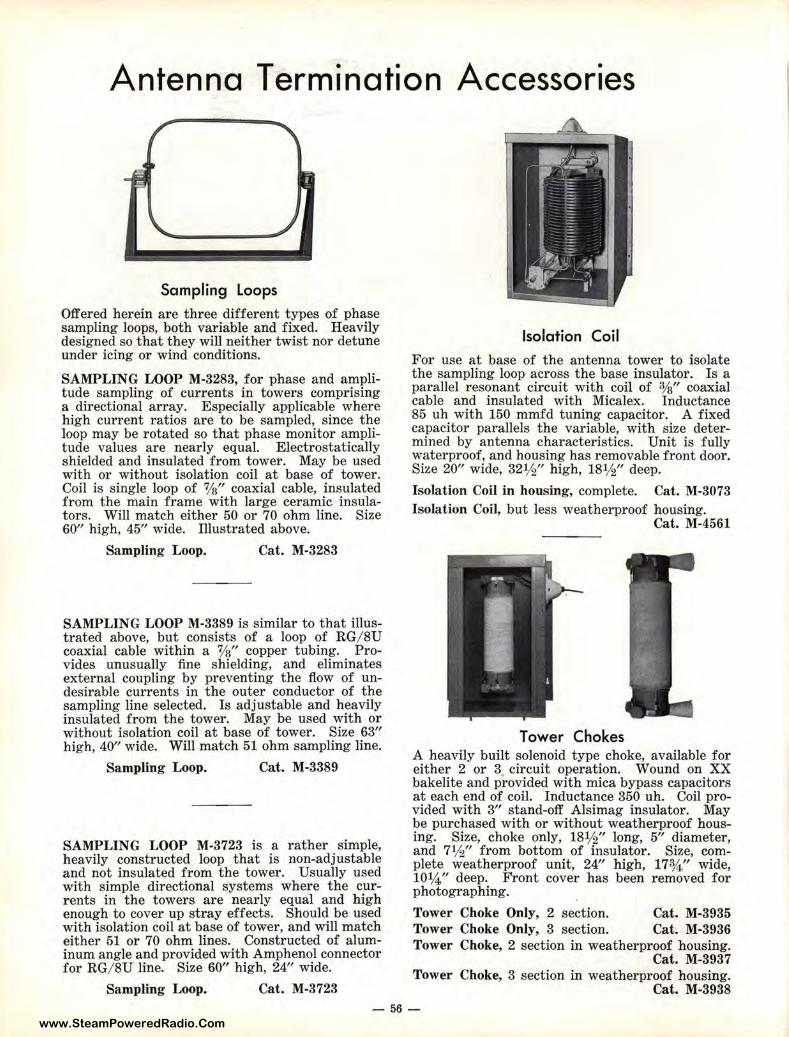
www.SteamPoweredRadio.Com
Antenna Termination Accessories
Sampling Loops
Offered herein are t hree different types of phase sampling loops, both variable and fixed. Heavily designed so that they will neit her twist nor detune under icing or wind conditions.
SAMPLING LOOP M-3283, for phase and amplitude sampling of currents in towers comprising a directional array. Especially applicable where high current ratios are to be sampled, since t he loop may be rotated so t hat phase monitor amplit ude values are nearly equal. Electrostatically shielded and insulated from tower. May be used with or without isolation coil at base of tower. Coil is single loop of %" coaxial cable, insulated from the main frame with large ceramic insulators. Will match either 50 or 70 ohm line. Size 60" high, 45" wide. Illustrated above.
Sampling Loop. Cat. M-3283
SAMPLING LOOP M-3389 is similar to that illust rated above, but consists of a loop of RG/ 8U coaxial cable within a %" copper tubing. Pr ovides unusually fine shielding, and eliminates external coupling by prevent ing the flow of undesirable currents in t he outer conductor of the sampling line selected. Is adjustable and heavily insulated from the tower. May be used with or without isolat ion coil a t base of tower. Size 63" high, 40" wide. Will match 51 ohm sampling line.
Sampling Loop. Cat. M-3389
SAMPLING LOOP M-3723 is a rather simple, heavily constructed loop that is non-adjustable and not insulated from the tower. Usually used with simple directional systems where the currents in t he towers are nearly equal and h igh enough to cover up stray effects. Should be used with isolation coil at base of tower, and will match either 51 or 70 ohm lines. Constructed of aluminum angle and provided with Amphenol connector for RG/ 8U line. Size 60" high, 24" wide.
Sampling Loop. Cat. M-3723
Isolation Coil
For use at base of the antenna tower to isolate the sampling loop across t he base insulator. Is a parallel resonant circuit with coil of %" coaxial cable and insulated with Micalex. Inductance 85 uh with 150 mmfd tuning capacitor . A fixed capacitor parallels the variable, with size determined by antenna characteristics. Unit is fully waterproof, and housing has removable front door. Size 20" wide, 32½" high, 18½" deep.
Isolation Coil in housing, complete. Cat. M-3073 Isolation Coil, but less weatherproof housing.
Cat. M-4561
Tower Chokes A heavily built solenoid type choke, available for either 2 or 3 circuit operation. Wound on XX bakelite and provided with mica bypass capacitors at each end of coil. Inductance 350 uh. Coil provided with 3" stand-off Alsimag insulator. May ~e purc~ased with or without weatherproof housing. Size, choke only, 18½ " long 5" diameter and 7½" from bottom of insulato~. Size com~ plete weatherproof unit, 24" high 17¾ " ' wide 10¾" deep. Front cover has beer: removed fo; photographing.
Tower Choke Only, 2 section. Cat. M-3935 Tower Choke Only, 3 sect ion. Cat. M-3936 Tower Choke, 2 section in weatherproof housing.
Cat. M-3937 Tower Choke, 3 section in weatherproof housing.
Cat. M-3938 - 56-
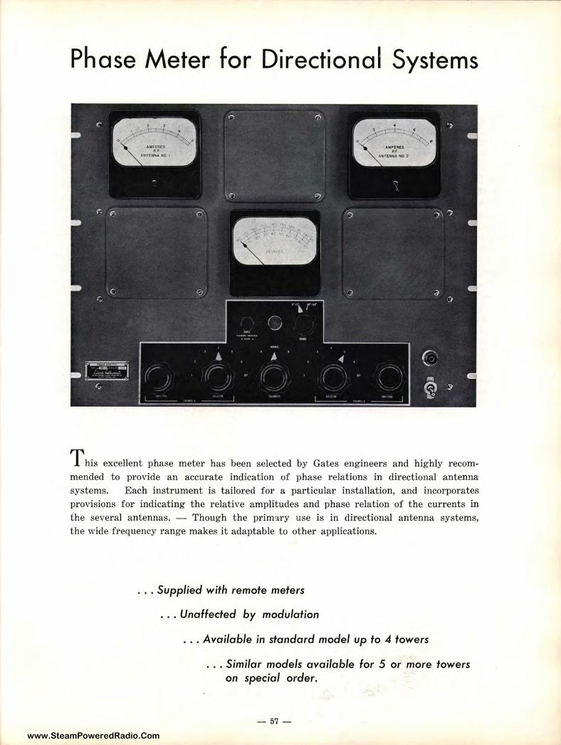
www.SteamPoweredRadio.Com
Phase Meter for Directional Systems
T his excellent phase meter has been selected by Gates engineers and highly recommended to provide an accurate indication of phase relations in directional antenna systems. Each instrument is tailored for a particular installation, and incorporates provisions for indicating the relative amplitudes and phase relation of the currents in the several antennas. - Though the primary use is in directional antenna systems, the wide frequency range makes it adaptable to other applications .
. . . Supplied w ith re mote mete rs
. .. Unaffected by modulation
.. . Available in standard mode l up to 4 towe rs .
. . . Similar models available for 5 or more towers on special order.
- 57 -
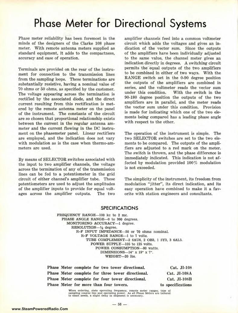
www.SteamPoweredRadio.Com
Phase Meter for Directional Systems Phase meter reliability has been foremost in the minds of the designers of the Clarke 108 phase meter. With remote antenna meters supplied as standard equipment, it adds to the compactness, accuracy and ease of operation.
Terminals are provided on the rear of the instrument for connection to the transmission lines from the sampling loops. These terminations are substantially resistive, having a nominal value of 70 ohms or 50 ohms, as specified by the customer. The voltage appearing across the termination is rectified by the associated diode, and the direct current resulting from this rectification is metered by the remote antenna meter on the panel of the instrument. The constants of the circuit are so chosen that proportional relationship exists between the current in the regular antenna ammeter and the current flowing in the DC instrument on the phasemeter panel. Linear rectifiers are employed, and the indication does not vary with modulation as is the case when thermo-ammeters are used.
By means of SELECTOR switches associated with the input to two amplifier channels, the voltage across the termination of any of the transmission lines can be fed to a potentiometer in the grid circuit of either channel's amplifier tube. These potentiometers are used to adjust the amplitudes of the amplifier inputs to provide for equal voltages across the amplifier outputs. The two
amplifier channels feed into a common voltmeter circuit which adds the voltages and gives an indication of the vector sum. Since the outputs of the amplifiers have been individually adjusted to the same value, the channel meter gives an indication directly in degrees. A switching circuit permits thE:fequal outputs of the two amplifiers to be combined in either of two ways. With the RANGE switch set in the 0-90 degree position the outputs of the amplifiers are combined in series, and the voltmeter reads the vector sum under this condition. With the switch in the 90-180 degree position the outputs of the two amplifiers are in parallel, and the meter reads the vector sum under this condition. Provision is made for indicating which one of the two elements being compared has a leading phase angle with respect to the other.
The operation of the instrument is simple. The two SELECTOR switches are set to the two elements to be compared. The outputs of the amplifiers are adjusted to a red mark on the meter. The switch is thrown, and the phase difference is immediately indicated. This indication is not affected by modulation provided 100% modulation is not exceeded.
The simplicity of the instrument, its freedom from modulation "jitter", its direct indication, and its easy operation have combined to make it a favorite with station engineers and consultants.
SPECIFICATIONS FREQUENCY RANGE-100 kc to 2 me.
PHASE ANGLE RANGE-0 to 360 degrees. MONITORING ACCURACY- I degree.
RESOLUTION- ½ degree. R-F INPUT IMPEDANCE-50 or 70 ohms n ominal.
R -F VOLTAGE RANGE-1 to 7 volts. TUBE COMPLEMENT- 2 6AU6, 2 OB3, 1 5Y3, 3 6AL5.
POWER SUPPLY-105 to 125 volts. POWER CONSUMPTION-SO watts.
DIMENSIONS-14" x 19" x 7". WEIGHT- 20 lbs.
Phase Meter complete for two tower directional. Phase Meter complete for three tower directional. Phase Meter complete for four tower directional. Phase Meter for more than four towers.
Cat. JI-108 Cat. JI-108A Cat. Jl-108B
to specifications When ordering, state operating frequency, remote meter ranges, type of sampling coaxial Une and operating power. As all Phase Meters are tailored to exact needs. a slight delay In shipment ls necessary.
- 58 -
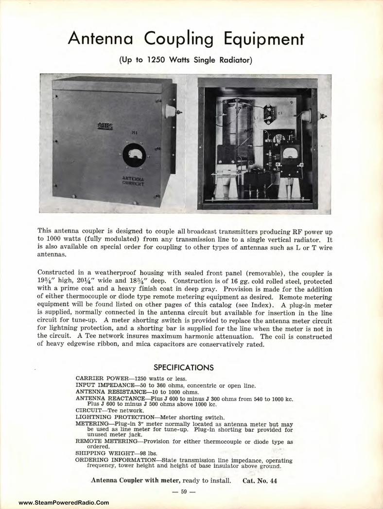
www.SteamPoweredRadio.Com
Antenna Coupling Equipment (Up to 1250 Watts Single Radiator)
This antenna coupler is designed to couple all broadcast transmitters producing RF power up to 1000 watts (fully modulated) from any transmission line to a single vertical radiator. It is also available on special order for coupling to other types of antennas such as L or T wire antennas.
Constructed in a weatherproof housing with sealed front panel (removable), the coupler is 19¾" high, 20¼" wide and 18¾" deep. Construction is of 16 gg. cold rolled steel, protected with a prime coat and a heavy finish coat in deep gray. Provision is made for the addition of either thermocouple or diode type remote metering equipment as desired. Remote metering equipment will be found listed on other pages of this catalog (see Index). A plug-in meter is supplied, normally connected in the antenna circuit but available for insertion in the line circuit for tune-up. A meter shorting switch is provided to replace the antenna meter circuit for lightning protection, and a shorting bar is supplied for the line when the meter is not in the circuit. A Tee network insur es maximum harmonic attenuation. The coil is constructed of heavy edgewise ribbon, and mica capacitors are conservatively rated.
SPECIFICATIONS CARRIER POWER-1250 watts or less. INPUT IMPEDANCE--50 to 360 ohms, concentric or open line. ANTENNA RESISTANCE--10 to 1000 ohms. ANTENNA REACTANCE-Plus J 600 to minus J 300 ohms from 540 to 1000 kc.
Plus J 600 to minus J 500 ohms above 1000 kc. CIRCUIT-Tee network. LIGHTNING PROTECTION- Meter shorting switch. METERING-Plug-in 3" meter normally located as antenna meter but may
be used as line meter for tune-up. Plug-in shorting bar provided for unused meter jack.
REMOTE METERING-Provision for either thermocouple or diode type as ordered.
SHIPPING WEIGHT-98 lbs. ORDERING INFORMATION-State transmission line impedance, operating
frequency, tower height and height of base insulator above ground.
Antenna Coupler with meter, ready to install.
- 59 -
Cat. No. 44
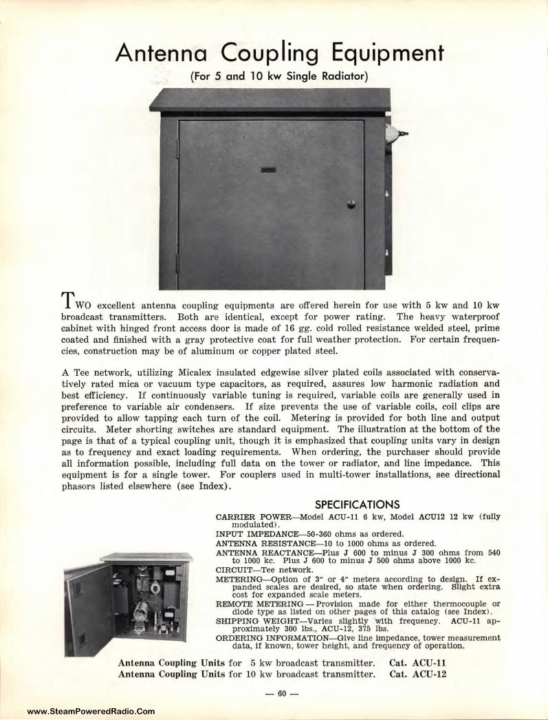
www.SteamPoweredRadio.Com
Antenna Coupling Equipment (For 5 and l O kw Single Radiator)
TWO excellent antenna coupling equipments are offered herein for use with 5 kw and 10 kw broadcast transmitters. Both are identical, except for power rating. The heavy waterproof cabinet with hinged front access door is made of 16 gg. cold rolled resistance welded steel, prime coated and finished with a gray protective coat for full weather protection. For certain frequencies, construction may be of aluminum or copper plated steel.
A Tee network, utilizing Micalex insulated edgewise silver plated coils associated with conservatively rated mica or vacuum type capacitors, as required, assures low harmonic radiation and best efficiency. If continuously variable tuning is required, variable coils are generally used in preference to variable air condensers. If size prevents the use of variable coils, coil clips are provided to allow tapping each turn of the coil. Metering is provided for both line and output circuits. Meter shorting switches are standard equipment. The illustration at the bottom of the page is that of a typical coupling unit, though it is emphasized that coupling units vary in design as to frequency and exact loading requir ements. When ordering, t he purchaser should provide all information possible, including full data on the tower or radiator, and line impedance. This equipment is for a single tower. For couplers used in multi-tower installations, see directional phasors listed elsewhere (see Index).
SPECIFICATIONS CARRIER POWER-Model ACU-11 6 kw, Model ACU12 12 kw (fully
modulated). INPUT IMPEDANCE-50-360 ohms as ordered. ANTENNA RESISTANCE-10 to 1000 ohms as or dered. ANTENNA REACTANCE-Plus J 600 to minus J 300 ohms from 540
to 1000 kc. Plus J 600 t o minus J 500 ohms above 1000 kc. CIRCUIT- Tee network. METERING-Option of 3" or 4" meters according to design. If ex
panded scales are desired, so state when ordering. Slight extra cost for expanded scale meters.
REMOTE METERING - Provision made for either thermocouple or diode type as listed on other pages of this catalog (see Index>.
SHIPPING WEIGHT-Varies slightly with frequency. ACU-11 approximately 300 lbs., ACU-12, 375 lbs.
ORDERING INFORMATION-Give line impedance, tower measurement data, if known, tower height, and frequency of operation.
Antenna Coupling Units for 5 kw broadcast transmitter. Antenna Coupling Units for 10 kw broadcast transmitter.
-60-
Cat. ACU-11 Cat. ACU-12
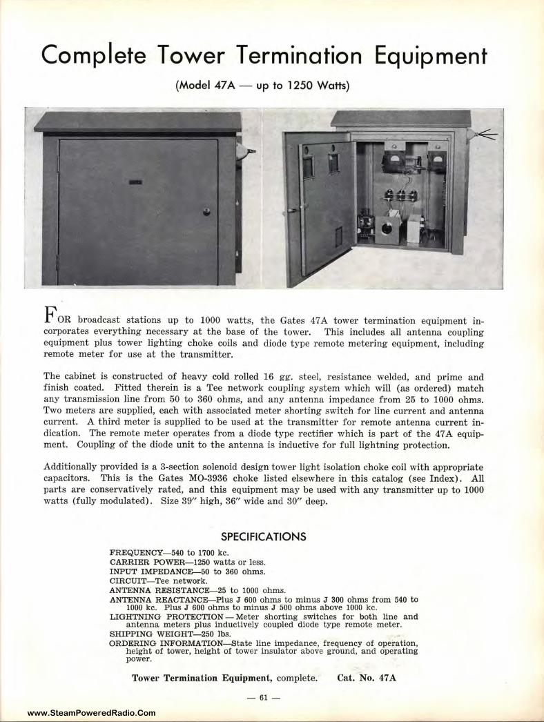
www.SteamPoweredRadio.Com
Complete Tower Termination Equipment (Model 47 A - up to 1250 Watts)
f OR broadcast stations up to 1000 watts, the Gates 47 A tower termination equipment incorporates everything necessary at the base of the tower. This includes all antenna coupling equipment plus tower lighting choke coils and diode type remote metering equipment, including remote meter for use at the transmitter.
The cabinet is constructed of heavy cold rolled 16 gg. steel, resistance welded, and prime and finish coated. Fitted therein is a Tee network coupling system which will (as ordered) match any transmission line from 50 to 360 ohms, and any antenna impedance from 25 to 1000 ohms. Two meters are supplied, each with associated meter shorting switch for line current and antenna current. A third meter is supplied to be used at the transmitter for remote antenna current indication. The remote meter operates from a diode type rectifier which is part of the 47 A equipment. Coupling of the diode unit to the antenna is inductive for full lightning protection.
Additionally provided is a 3-section solenoid design tower light isolation choke coil with appropriate capacitors. This is the Gates MO-3936 choke listed elsewhere in this catalog (see Index). All parts are conservatively rated, and this equipment may be used with any transmitter up to 1000 watts (fully modulated). Size 39" high, 36" wide and 30" deep.
SPECIFICATIONS FREQUENCY-540 to 1700 kc. CARRIER POWER-1250 watts or less. INPUT IMPEDANCE-50 to 360 ohms. CIRCUIT-Tee network. ANTENNA RESISTANCE-25 to 1000 ohms. ANTENNA REACTANCE-Plus J 600 ohms to minus J 300 ohms from 540 to
1000 kc. Plus J 600 ohms to minus J 500 ohms above 1000 kc. LIGHTNING PROTECTION - Meter shorting switches for both line and
antenna meters plus inductively coupled diode type remote meter. SHIPPING WEIGHT-250 lbs. ORDERING INFORMATION-State line impedance, frequency of operation,
height of tower, height of tower insulator above ground, and operating power.
Tower Termination Equipment, complete.
- 61 -
Cat. No. 47A
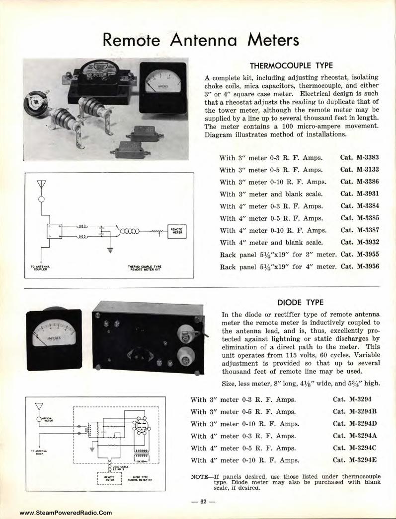
www.SteamPoweredRadio.Com
TO ANTfHtrif4 COUPLER
TO AH l (HNA
""'"
Remote Antenna Meters
THERMO CCU"\.[ TYPE R[MOTC 1«.Tf.111 l<IT
-----------------------------,
I
I
I I I
' I I
' -- ' ------~ __ J
CMOO( fYII"( lll[llfQt( M(t[II IUT
THERMOCOUPLE TYPE A complete kit, including adjusting rheostat, isolating choke coils, mica capacitors, thermocouple, and either 3" or 4" square case meter. Electrical design is such that a rheostat adjusts the reading to duplicate that of the tower meter, although the remote meter may be supplied by a line up to several thousand feet in length. The meter contains a 100 micro-ampere movement. Diagram illustrates method of installations.
With 3" meter 0-3 R. F. Amps.
With 3" meter 0-5 R. F. Amps.
With 3" meter 0-10 R. F. Amps.
With 3" meter and blank scale.
With 4" meter 0-3 R. F. Amps.
With 4" meter 0-5 R. F. Amps.
With 4" meter 0-10 R. F. Amps.
With 4" meter and blank scale.
Cat. M-3383
Cat. M-3133
Cat. M-3386
Cat. M-3931
Cat. M-3384
Cat. M-3385
Cat. M-3387
Cat. M-3932
Rack panel 5¼"x19" for 3" meter. Cat. M-3955
Rack panel 5¼"x19" for 4" meter. Cat. M-3956
DIODE TYPE In the diode or rectifier type of remote antenna meter the remote meter is inductively coupled to the antenna lead, and is, thus, excellently protected against lightning or static discharges by elimination of a direct path to the meter. This unit operates from 115 volts, 60 cycles. Variable adjustment is provided so that up to several thousand feet of remote line may be used.
Size, less meter, 8" long, 41/a" wide, and 53/4" high.
With 3" meter 0-3 R. F. Amps.
With 3" meter 0-5 R. F. Amps.
With 3" meter 0-10 R. F. Amps.
With 4" meter 0-3 R. F. Amps.
With 4" meter 0-5 R. F. Amps.
With 4" meter 0-10 R. F. Amps.
Cat. M-3294
Cat. M-3294B
Cat. M-3294D
Cat. M-3294A
Cat. M-3294C
Cat. M-3294E
NOTE-If panels desired, use those listed under thermocouple type. Diode meter may also be purchased with blank scale, if desired.
- 62-
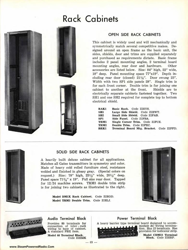
www.SteamPoweredRadio.Com
Rack Cabinets
OPEN SIDE RACK CABINETS
This cabinet is widely used and will mechanically and symmetrically match several competitive makes. Designed around an open frame as t he ha.sic unit, the sides, shields, door and trims are supplied separately and purchased as requirements dictate. Basic frame includes 2 panel mounting angles, 2 terminal board mounting angles, rear door and hardware. Other accessories are listed below. Size: 84" hi:gh, 22" wide, 18" deep. Panel mounting space 77"x19". Depth including rear door (closed) 211/a". Door swung 23". Width with two SPl side panels 28". Single trim is for each front corner. Double trim is fo:r joining one cabinet to another at t he front. Shields are to electrically separate cabinets fastened toigether. Two SHI and one SH2 required for complete top to bottom electrical shield.
RAKl SHI SH2 SPI TRMl TRM2 BRKl
Basic Ra-ck. Code ZIEVS. Large Side Shield. Code ZIEWT. Small Side Shield. Code ZIFAB. Side Panel. Code ZIFBA. Single Corner Trim. Code ZIFCE. Double Trim. Code ZIFEC. Terminal Board Mtg. Bracket. Code ZIFFD.
SOLID SIDE RACK CABINETS
A heavily built deluxe cabinet for all applications. Matches all Gates transmitters in symmetry and color. Made of heavy cold rolled furnitur e steel, resistance welded and finished in glossy gray. (Special colors on request.) Size : 78" high, 23½" wide, 20½" deep. Panel space 71¾ " x 19". Full size rear door. Tapped for 12/ 24 machine screws. TRM3 double trim strip is for joining two cabinets as illustrated to the right.
Model DMIX Ra-ck Cabinet. Code ZIEGD. Model TRM3 Double Trim. Code ZIELJ.
Audio Terminal Block Power Terminal Block Provides 80 terminals for connection of inter - rack wiring to base of cabinet. A standard PBX item. Model 46 Terminal Block.
Code ZIEMK
A heavy barrier type terminal board designed to accommodate AC vviring termination. Has 12 'terminals. Has provision for indicator strip.
Model Cll•M12 Terminal Block. Code ZIERP.
- 63 -
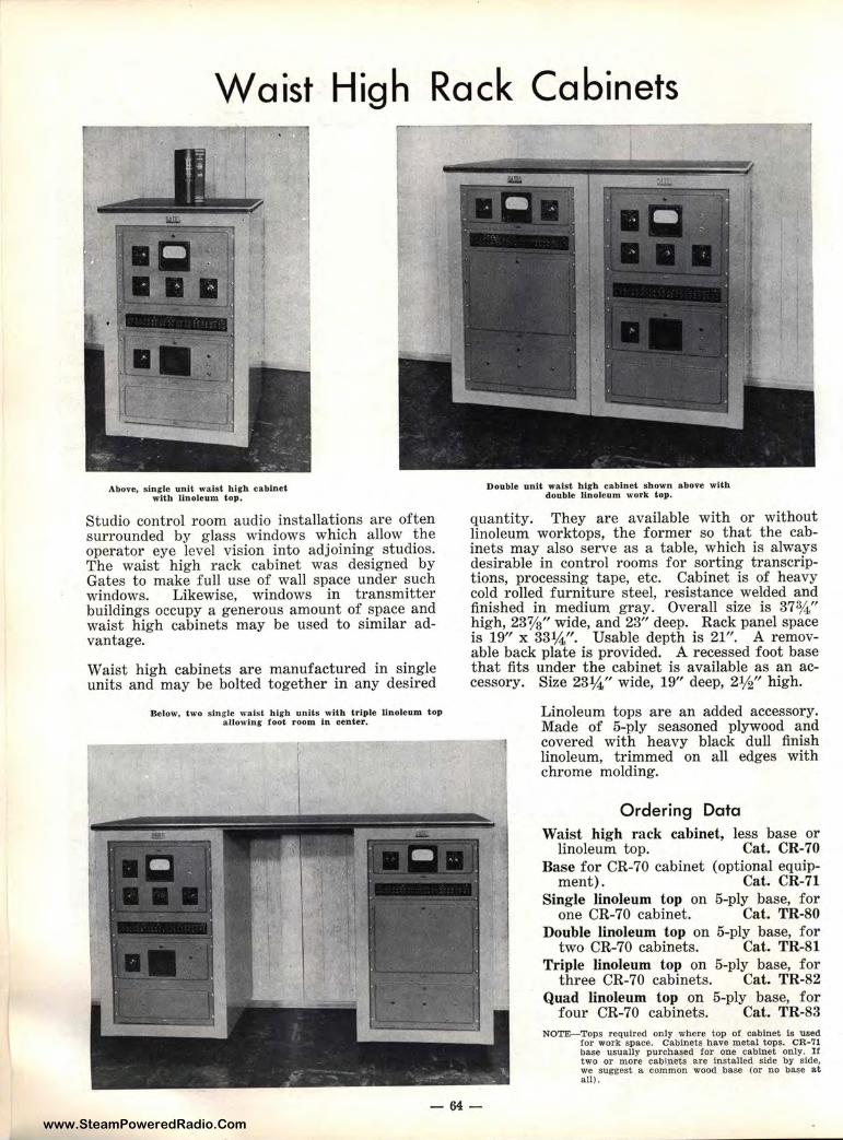
www.SteamPoweredRadio.Com
Waist High Rack Cabinets
Above, single unit waist high cabinet Double unit waist hlg-h cabinet shown above with with linoleum top, double linoleum work top.
Studio control room audio installations are often surrounded by glass windows which allow the operator eye level vision into adjoining studios. The waist high rack cabinet was designed by Gates to make full use of wall space under such windows. Likewise, windows in transmitter buildings occupy a generous amount of space and waist high cabinets may be used to similar advantage.
Waist high cabinets are manufactured in single units and may be bolted together in any desired
Below, two single waist high units with triple linoleum top allowl.ng foot room in center.
quantity. They are available with or without linoleum worktops, the former so that the cabinets may also serve as a table, which is always desirable in control rooms for sorting transcriptions, processing tape, etc. Cabinet is of heavy cold rolled furniture steel, resistance welded and finished in medium gray. Overall size is 37¾" high, 23'1/s" wide, and 23" dee]P. Rack panel space is 19" x 331/4". Usable deptlh is 21". A removable back plate is provided. A recessed foot base that fits under the cabinet is: available as an accessory. Size 23¼" wide, 19''' deep, 2½" high.
Linoleum tops are an added accessory. Made of 5-ply seasoned plywood and covered with heavy black dull finish linoleum, trimmed on all edges with chrome molding.
Ordering Data Waist high rack cabinet, less base or
linoleum top. Cat. CR-70 Base for CR-70 cabinet (optional equip-
ment). Cat. CR-71 Single linoleum top on 5-ply base, for
one CR-70 cabimit. Cat. TR-80 Double linoleum top on 5-ply base, for
two CR-70 cabirn~ts. Cat. TR-81 Triple linoleum top on 5-ply base, for
three CR-70 cabinets. Cat. TR-82 Quad linoleum top on 5-ply base, for
four CR-70 cabi1nets. Cat. TR-83 NOTE-Tops required only where top or cabinet ls used
for work space. Cabinets have metal tops. CR•?l base usually purcha,sed for one cabinet only. If two or more cabinets are Installed side by side, we suggest a comm,m wood base (or no base at all).
-64-
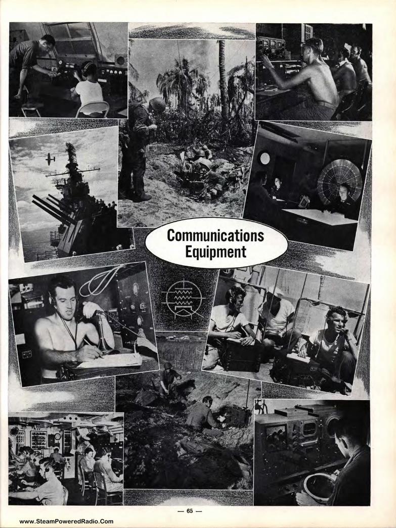
www.SteamPoweredRadio.Com
.•.·.\2~ .... --~ .., ,.'': ... ♦ -~ ---~----- ,._
Communicatio Equipment
-65 -
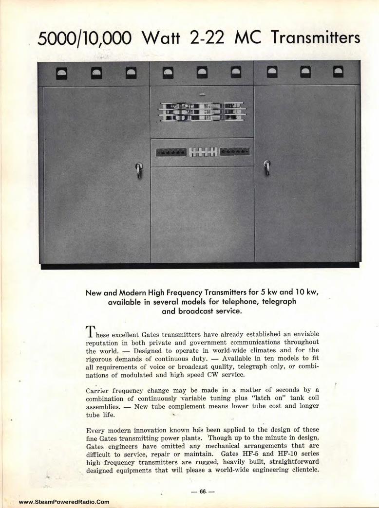
www.SteamPoweredRadio.Com
5000/10,000 Watt 2-22 MC Transmitters
New and Modern High Frequency Transmitters for 5 kw and 10 kw, available in several models for telephone, telegraph
and broadcast service.
T hese excellent Gates transmitters have already established an enviable reputation in both private and government communications throughout the world. - Designed to operate in world-wide climates and for the rigorous demands of continuous duty. - Available in ten models to fit all requirements of voice or broadcast quality, telegraph only, or combinations of modulated and high speed CW service.
Carrier frequency change may be made in a matter of seconds by a combination of continuously variable tuning plus "latch on" tank coil assemblies. - New tube complement means lower tube cost and longer tube life.
Every modern innovation known has been applied to the design of these fine Gates transmitting power plants. "Though up to the minute in design, Gates engineers have omitted any mechanical arrangements that are difficult to service, repair or maintain. Gates HF-5 and HF-10 series high frequency transmitters are rugged, heavily built, straightforward designed equipments that will please a world-wide engineering clientele.
- 66. -
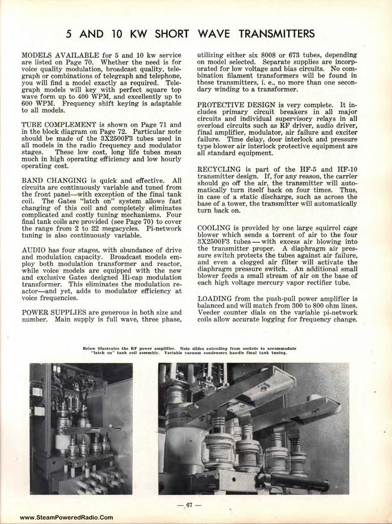
www.SteamPoweredRadio.Com
5 AND 10 KW SHORT WAVE TRANSMITTERS
MODELS AVAILABLE for 5 and 10 kw service are listed on Page 70. Whether the need is for voice quality modulation, broadcast quality, telegraph or combinations of telegraph and telephone, you will find a model exactly as required. Telegraph models will key with perfect square top wave form up to 400 WPM, and excellently up to 600 WPM. Frequency shift keying is adaptable to all models.
TUBE COMPLEMENT is shown on Page 71 and in the block diagram on Page 72. Particular note should be made of the 3X2500F3 tubes used in all models in the radio frequency and modulator stages. These low cost, long life tubes mean much in high operating efficiency and low hourly operating cost.
BAND CHANGING is quick and effective. All circuits are continuously variable and tuned from the front panel-with exception of the final tank coil. The Gates "latch on" system allows fast changing of this coil and completely eliminates complicated and costly tuning mechanisms. Four final tank coils are provided (see Page 70) to cover the range from 2 to 22 megacycles. Pi-network tuning is also continuously variable.
AUDIO has four stages, with abundance of drive and modulation capacity. Broadcast models employ both modulation transformer and reactor, while voice models are equipped with the new and exclusive Gates designed Hi-cap modulation transformer. This eliminates the modulation reactor-and yet, adds to modulator efficiency at voice frequencies.
POWER SUPPLIES are generous in both size and number. Main supply is full wave, three phase,
utilizing either six 8008 or 673 tubes, depending on model selected. Separate supplies are incorporated for low voltage and bias circuits. No combination filament transformers will be found in these transmitters, i. e., no more th~n one secondary winding to a transformer.
PROTECTIVE DESIGN is very complete. It includes primary circuit breakers in all major circuits and individual supervisory relays in all overload circuits such as RF driver, audio driver, final amplifier, modulator, air failure and exciter failure. Time delay, door interlock and pressure type blower air interlock protective equipment are all standard equipment.
RECYCLING is part of the HF-5 and HF-10 transmitter design. If, for any reason, the carrier should go off the air, the transmitter will automatically turn itself back on four times. Thus, in case of a static discharge, such as across the base of a tower, the transmitter will automatically turn back on.
COOLING is provided by one large squirrel cage blower which sends a torrent of air to the four 3X2500F3 tubes - with excess air blowing into the transmitter proper. A diaphragm air pressure switch protects the tubes against air failure, and even a clogged air filter will activate the diaphragm pressure switch. An additional small blower feeds a small stream of air on the base of each high voltage mercury vapor rectifier tube.
LOADING from the push-pull power amplifier is balanced and will match from 300 to 800 ohm lines. Veeder counter dials on the variable pi-network coils allow accurate logging for frequency change.
Be low illustrates the RF power amplifier. Note slides extending from s ockets t.o accommodate " latch on .. tank coil assembly. Variable vacuum condensers handJe f inal tank tuning.
-. 67 -
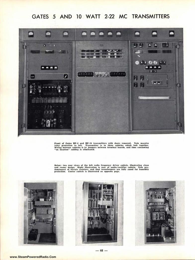
www.SteamPoweredRadio.Com
GATES 5 AND 10 WATT 2-22 MC TRANSMITTERS
F ront of Gates BF-5 and BF-10 transmitters with do,ors removed. Note massive relay protection to left. Transmitter is in three e1obieles which bolt t og-ether. \Virinr between eubfcles Is by Jumpers between terminal boards, and time consuming "on location,, cabUnr is ellmlnated.
Below: two rear views of the left radio frequency drh1er cubicle, illustrating clean and roomy design. Right illustration Is rear of audio/ reetUier cubicle. Note predominance of ferrule resistors, a nd that transformers are fuJly cased for humidity protection. Center cubicle is illustrated on opposite page.
-68-
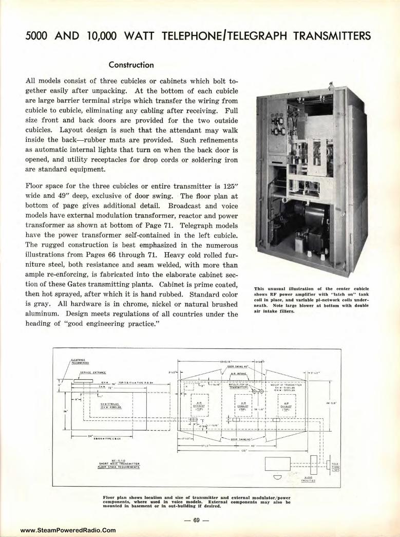
www.SteamPoweredRadio.Com
5000 AND 10,000 WATT TELEPHONE/TELEGRAPH TRANSMITTERS
Construction
All models consist of three cubicles or cabinets which bolt together easily after unpacking. At the bottom of each cubicle are large barrier terminal strips which transfer the wiring from cubicle to cubicle, eliminating any cabling after receiving. Full size front and back doors are provided for the two outside cubicles. Layout design is such that the attendant may walk inside the back-rubber mats are provided. Such refinements as automatic internal lights that turn on when the back door is opened, and utility receptacles for drop cords or soldering iron are standard equipment.
Floor space for the three cubicles or entire transmitter is 125" wide and 49" deep, exclusive of door swing. The floor plan at bottom of page gives additional detail. Broadcast and voice models have external modulation transformer, reactor and power transformer as shown at bottom of Page 71. Telegraph models have the power transformer self-contained in the left cubicle. The rugged construction is best emphasized in the numerous illustrations from Pages 66 through 71. Heavy cold rolled furniture steel, both resistance and seam welded, with more than ample re-enforcing, is fabricated into the elaborate cabinet section of these Gates transmitting plants. Cabinet is prime coated, then hot sprayed, after which it is hand rubbed. Standard color is gray. All hardware is in chrome, nickel or natural brushed aluminum. Design meets regulations of all countries under the heading of "good engineering practice."
~ ,MOll'T WAY( flll AN$111,Hr(A
f"lOOlt SftAC[ lll(OUIIUM( NTS
ThJs unusual illustration of the center eubicle shows RF power ampUtier with HJateh on'' tank coil in place, an d variable pi-network coils underneath. Note larre blower at bottom with double air Intake tllters.
Floor plan shows location and size of transmitter and es:&ern a.l modu1ator/ power components, where u.sed In voice models. External components may also be mounted In basement or In out - buUdinr If desired.
- 69-
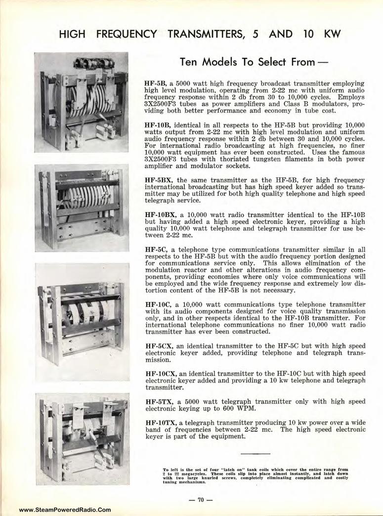
www.SteamPoweredRadio.Com
HIGH FREQUENCY TRANSMITTERS, 5 AND 10 KW
Ten Models To Select Fro1m -
HF-5B, a 5000 watt high frequency broadcast transmitter employing high level modulation, operating from 2-22 me with uniform audio frequency response within 2 db from 30 to 10,000 cycles. Employs 3X2500F3 tubes as power amplifiers and Class B modulators, providing both better performance and economy in tube cost.
HF-lOB, ident ical in all respects to the HF-5B but providing 10,000 watts output from 2-22 me with high level modulation and uniform audio frequency response within 2 db between 30 and 10,000 cycles. For international radio broadcasting at high fre1quencies, no finer 10,000 watt equipment has ever been constructed. Uses the famous 3X2500F3 t ubes with thoriated tungsten filaments in both power amplifier and modulator sockets.
HF-5BX, the same transmitter as the HF-5B, for high frequency international broadcasting but has high speed keym· added so transmitter may be utilized for both high quality telephone and high speed telegraph service.
HF-lOBX, a 10,000 watt radio transmitter identic:al to the HF-lOB but having added a high speed electronic keyer, providing a high quality 10,000 watt telephone and telegraph transmitter for use between 2-22 me.
HF-5C, a telephone type communications transmitter similar in all respects to the HF-5B but with the audio frequency portion designed for communications service only. This allows elimination of the modulation reactor and other alterations in audio frequency components, providing economies where only voice communications will be employed and the wide frequency response and ,extremely low distortion content of the HF-5B is not necessary.
HF-lOC, a 10,000 watt communications type telephone transmitter with its audio components designed for voice quality transmission only, and in other respects identical to t he HF-l0B t ransmitter. For international telephone communications no finer 10,000 watt radio transmitter has ever been constructed.
HF-5CX, an identical transmitter to the HF-5C bULt with high speed electronic keyer added, providing telephone and telegraph transmission.
HF-lOCX, an identical transmitter to the HF-lOC biut with high speed electronic keyer added and providing a 10 kw telephone and telegraph transmitter.
HF-5TX, a 5000 watt telegraph transmitter only with high speed electronic keying up to 600 WPM.
HF-lOTX, a telegraph transmitter producing 10 kw power over a wide band of frequencies between 2-22 me. The higlh. speed electronic keyer is part of the equipment.
To left is the set of four 0 Jatch on" tank coils whJeh cover the entire ranee from 2 to 22 megacycles. These coils sllp into place almost lnstantlir, and latch down with two large knurled screws, completely eUmlnatJng complicated and costly tuning mechanism s.
- 70-
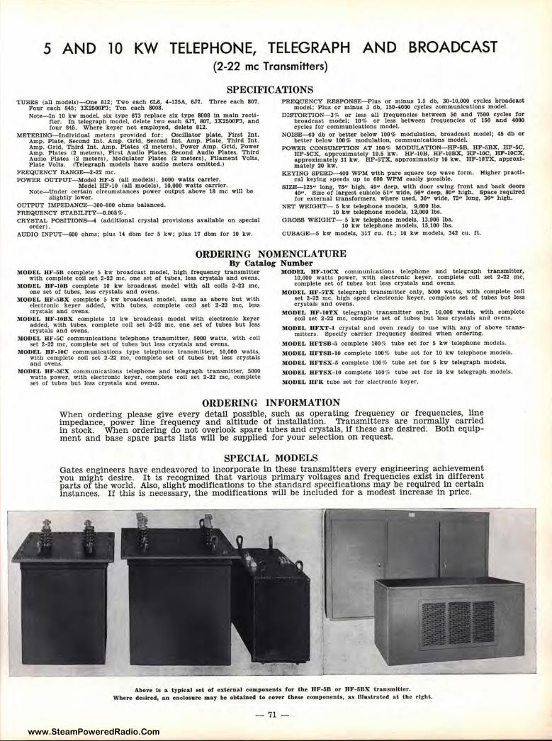
www.SteamPoweredRadio.Com
5 AND 10 KW TELEPHONE, TELEGRAPH AND BROADCAST (2-22 me Transmitters)
SPECIFICATIONS TUBES (all models)-One 812; Two each 6L6, 4•125A, 6J7. Three each 807.
Four each 845; 3X2500F3; Ten each 8008. Note-In 10 kw model, six type 673 replace six type 8008 In main recti
fier. In telegraph model, delete two each 6J7, 807, 3X2500F3, and four 845. Where keyer not employed, delete 812.
METERING-Individual meters provided !or: Osclllator plate, First Int. Amp. P late, Second Int. Amp. Grid, Second Int. Amp. Plate, Third Int. Amp. Grid. Third Int. Amp. Plates (2 meters), Power Amp. Grid, Power Amp. Plates (2 meters), First Audio Plates, Second Audio Plates, Third Audio Plates (2 meters), Modulator Plates (2 meters), Filament Volts, Plate Volts. (Telegraph models have audio meters omitted.)
FREQUENCY RANGE-2-22 me. POWER OUTPUT-Model HF-5 (all models), 5000 watts carrier.
Model HF-10 (all models), 10,000 watts carrier. Note-Under certain circumstances power output above 18 me will be
slightly lower. OUTPUT IMPEDANCE-300-800 ohms balanced. FREQUENCY STABILITY--0.005%. CRYSTAL POSITIONS---4 (additional crystal provisions available on special
order) . AUDIO INPUT-600 ohms; plus 14 dbm for 5 kw; plus 17 dbm tor 10 kw.
FREQUENCY RESPONSE-Plus or minus 1.5 db, 30-10,000 cycles broadcast model; Plus or minus 3 db, 150-4000 cycles communications model.
DISTORTION-3% or less all frequencies between 50 and 7500 cycles tor broadcast model; l0 'io or less between frequencies of 150 and 4000 cycles for communications model.
NOISE-60 db or better below 1009', modulation, broadcast model; 45 db or better below 100% modulation, communications model.
POWER CONSUMPTION AT 100% MODULATION-HF-SB, HF-5BX, HF-5C, HF-5CX, approximately 19.5 kw. HF- l0B, HF-l0BX, HF-l0C, HF-l0CX, approximately 31 kw. HF-STX, approximately 10 kw. HF-l0TX, approximately 20 kw.
KEYING SPEED--400 WPM with pure square top wave form. Higher practical keyin g speeds up to 600 WPM easily possible.
SIZE- 125" long, 78" high, 49" deep, with door swing front and back doors 40". Size of largest cubicle 51" wide, 56" deep, 80" high. Space required for external transformers, where used, 36" wide, 72" long, 36" high.
NET WEIGHT- 5 kw telephone models, 9,600 lbs. 10 kw telephone models, 12,000 lbs.
GROSS WEIGHT- 5 kw telephone models, 13,900 lbs. 10 kw telephone models, 15,100 lbs.
CUBAGE-5 kw models, 317 cu. ft.; 10 kw models, 342 cu. ft.
ORDERING NOMENCLATURE By Catalog Number
l'tlODEL HF-5B complete 5 kw broadcast model, high frequency transmitter with complete coll set 2-22 me. one set of tubes, less crystals and ovens.
l\lODEL BF-10B complete 10 kw broadcast model with all coils 2-22 me, one set of tubes, less crystals and ovens.
l\lODEL HF-5BX complete 5 kw broadcast model, same as above but with electronic keyer added, with tubes, complete coll set 2-22 me, less crystals and ovens.
l'IIODEL HF-I0BX complete 10 kw broadcast model with electronic keyer added, with t ubes, complete coll set 2-22 me, one set of tubes but less crystals and ovens.
MODEL HF-5C communications telephone t ransmitter, 5000 watts, with coll set 2·22 me, complete set of tubes but less crystals and ovens.
MODEL HF-I0C communications type telephone transmitter, 10,000 watts, with complete coll set 2-22 me, complete set or tubes but less c rystals and ovens.
MODEL HF-5CX communications telephon e and telegraph transmitter, 5000 watts power, with electronic keyer, complete coll set 2-22 me, complete set of tubes but less crystals and ovens.
ORDERING
MODEL RF-lOCX communications telephone and telegraph transmitter, 10,000 watts power, with electronic keyer, complete coll set 2-22 me, complete set of tubes but less crystals and ovens.
l\lODEL HF-5TX telegraph transmitter only, 5000 watts, with complete coll set 2-22 me, high speed electronic keyer, complete set of tubes but less crystals and ovens.
l\lODEL HF-lOTX telegraph t ransmitter only, 10,000 watts, with complete coll set 2-22 me, complete set of tubes but less crystals and ovens.
MODEL HFXT-1 crystal and oven ready to use with any of above trans• mltters. Specify carrier frequency desired when ordering.
l\lODEL BFTSB-5 complete 100% tube set for 5 kw telephone models.
l\lODEL RFTSB-1.0 complete 100% tube set for 10 kw telephone models.
l\lODEL RFTSX-5 complete 100% t ube set for 5 kw telegraph models.
IIIODEL HFTSX-10 complete 100% tube set for 10 kw telegraph models.
l'IIODEL RFK tube set for electronic keyer.
INFORMATION When ordering please give every detail possible, such as operating frequency or frequencies, line impedance, power line frequency and altitude of installation. Transmitters are normally carried in stock. When ordering do not overlook spare tubes and crystals, if these are desired. Both equipment and base spare parts lists will be supplied for your selection on request.
SPECIAL MODELS Gates engineers have endeavored to incorporate in these transmitters every engineering achievement you might desire. It is recognized that various primary voltages and frequencies exist in different parts of the world. Also, slight modifications to the standard specifications may be required in certain instances. If this is necessary, the modifications w111 be included for a modest increase in price.
l\.bove ls a typical ..,t of external componen t! for the HF-5B or HF-5BX transmitter. Where desired, an enclosure may be obtained to cover these components, as illustrated at the right.
-71 -
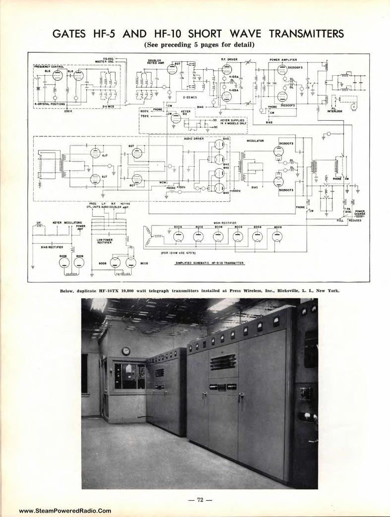
www.SteamPoweredRadio.Com
f fitaut:iie-1 I I' I I I I I I I
GATES
L- -------
HF-5
F.$..OSC. MAST( llt OSC,
AND HF-10 SHORT WAVE (See preceding 5 pages for detail)
l'l.F. DftlVtll
r---- -- -I I I I I I I I I I I I I ------------ - ---------
UV. ICEYER MODUL4TCIRS
~ µ:.·
1001 1008
I : • I ' 1 4, r-&OOV.
I ------------------ I
SIMPLi,ltD SCHt MATIC HF•S•IO TRAHSMltTEA
TRANSMITTERS
Below, duplicat e HF-I OTX 10,000 wa tt t elegraph transmitters Installed at P ress Wireless, Inc., H icksville, L. I ., New York.
- 72 -
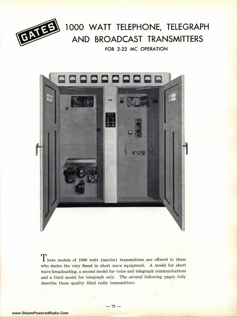
www.SteamPoweredRadio.Com
1000 WATT TELEPHONE, TELEGRAPH AND BROADCAST TRANSMITTERS
FOR 2-22 MC OPERATION
T hree models of 1000 watt (carrier) transmitters are offered to those who desire the very finest in short wave equipment. A model for short wave broadcasting, a second model for voice and telegraph communications and a third model for telegraph only. The several following pages fully describe these quality filled radio transmitters.
- 73-
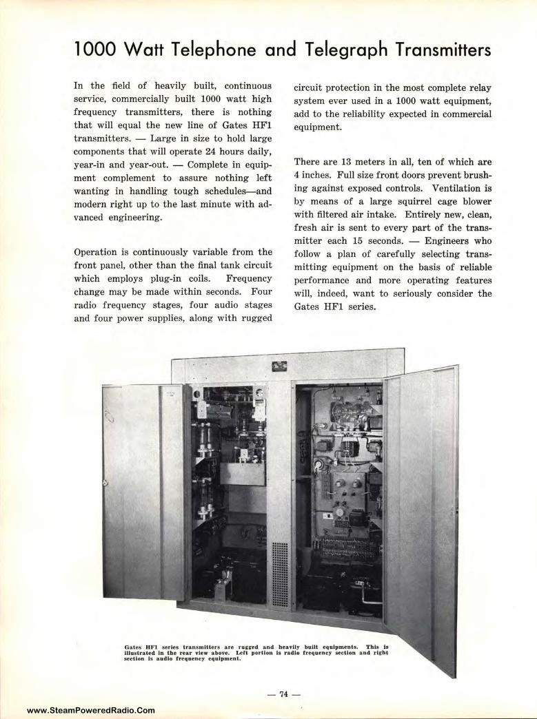
www.SteamPoweredRadio.Com
1000 Watt Telephone and Telegraph Transmitters
In the field of heavily built, continuous service, commercially built 1000 watt high frequency transmitters, there is nothing that will equal the new line of Gates HFl transmitters. - Large in size to hold large components that will operate 24 hours daily, year-in and year-out. - Complete in equipment complement to assure nothing left wanting in handling tough schedules-and modern right up to the last minute with advanced engineering.
Operation is continuously variable from t he front panel, other than the final tank circuit which employs plug-in coils. Frequency change may be made within seconds. Four radio frequency stages, four audio stages and four power supplies, along with rugged
circuit protection in the most complete relay system ever used in a 1000 watt equipment, add to the reliability expected in commercial equipment.
There are 13 meters in all, ten of which are 4 inches. Full size front doors prevent brushing against exposed controls. Ventilation is by means of a large squirrel cage blower with filtered air intake. Entirely new, clean, fresh air is sent to every part of the transmitter each 15 seconds. - Engineers who follow a plan of carefully selecting transmitting equipment on the basis of reliable performance and more operating features will, indeed, want to seriously consider the Gates HFl series.
Gates HFl series transmi&.ters are rugged and heavily built equipments. This 1s illustrated in &.he rear view above. Left portion Is radio frequency section and right section ls audio frequency equipment.
- 74 -
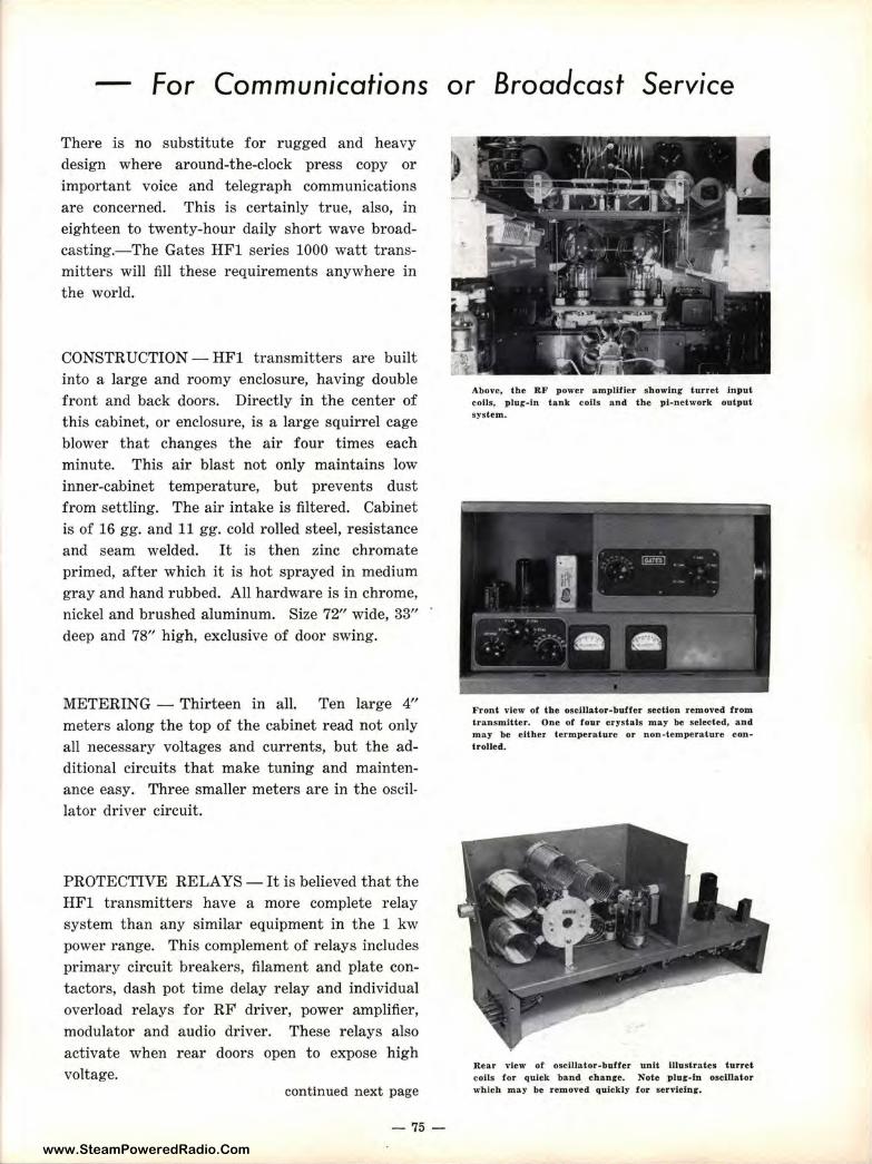
www.SteamPoweredRadio.Com
For Communications or Broadcast Service
There is no substitute for rugged and heavy design where around-the-clock press copy or important voice and telegraph communications are concerned. This is certainly true, also, in eighteen to twenty-hour daily short wave broadcasting.-The Gates HFl series 1000 watt transmitters will fill these requirements anywhere in the world.
CONSTRUCTION - HFl transmitters are built into a large and roomy enclosure, having double front and back doors. Directly in the center of this cabinet, or enclosure, is a large squirrel cage blower that changes the air four times each minute. This air blast not only maintains low inner-cabinet temperature, but prevents dust from settling. The air intake is filtered. Cabinet is of 16 gg. and 11 gg. cold rolled steel, resistance and seam welded. It is then zinc chromate primed, after which it is hot sprayed in medium gray and hand rubbed. All hardware is in chrome, nickel and brushed aluminum. Size 72" wide, 33" deep and 78" high, exclusive of door swing.
METERING - Thirteen in all. Ten large 4" meters along the top of the cabinet read not only all necessary voltages and currents, but the additional circuits that make tuning and maintenance easy. Three smaller meters are in the oscillator driver circuit.
PROTECTIVE RELAYS-It is believed that the HFl transmitters have a more complete relay system than any similar equipment in the 1 kw power range. This complement of relays includes primary circuit breakers, filament and plate contactors, dash pot time delay relay and individual overload relays for RF driver, power amplifier, modulator and audio driver. These relays also activate when rear doors open to expose high voltage.
continued next page
-75 -
Above, the RF power amplifier sh owlnr turret input coils, plug-in t.a.nk coils and the pl-network output system.
Front view of the oscl.llator-buffer section removed from transmitter. One of four c rystals may be selected, and may be either termperature or non ~tempera.ture controlled.
Rear view of oscillator-buffer unit illustrates turret coils for quick band chance. Note p lug-in osclllator which may be removed quickly for servicf.ng.
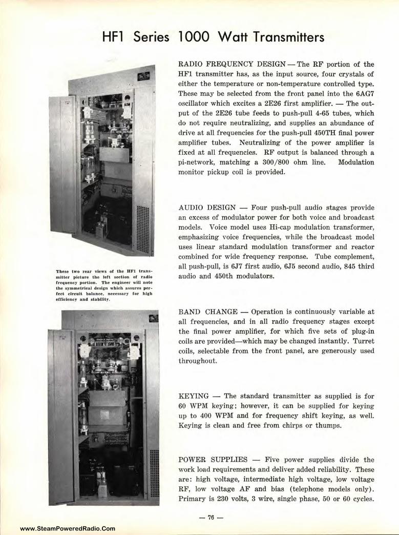
www.SteamPoweredRadio.Com
HFl Series 1000 Watt Transmitters
These two rear views of the HF1 transmitter picture the left section of radio frequency portion. The engineer will note the symmetrlca.J design which assures per ... feet circuit balance, necessary for high efllclency and stability.
RADIO FREQUENCY DESIGN-The RF' portion of the HFl transmitter has, as the input source, :four crystals of either the temperature or non-temperature controlled type. These may be selected from the front panel into the 6AG7 oscillator which excites a 2E26 first amplifier. - The output of the 2E26 tube feeds to push-pull 4-165 tubes, which do not require neutralizing, and supplies an abundance of drive at all frequencies for t he push-pull 451DTH final power amplifier tubes. Neutralizing of the power amplifier is fixed at all frequencies. RF output is balamced through a pi-network, matching a 300 /800 ohm line. monitor pickup coil is provided.
Modulation
AUDIO DESIGN - Four push-pull audio stages provide an excess of modulator power for both voice and broadcast models. Voice model uses Hi-cap modulation transformer, emphasizing voice frequencies, while the broadcast model uses linear standard modulation transformer and reactor combined for wide frequency response. Ttllbe complement, all push-pull, is 6J7 first audio, 6J5 second .audio, 845 third audio and 450th modulators.
BAND CHANGE - Operation is continuously variable at all frequencies, and in all radio frequency stages except the final power amplifier, for which five sets of plug-in coils are provided-which may be changed instantly. Turret coils, selectable from the front panel, are ;generously used throughout.
KEYING - The standard transmitter as supplied is for 60 WPM keying; however, it can be supplied for keying up to 400 WPM and for frequency shift ]keying, as well. Keying is clean and free from chirps or thumps.
POWER SUPPLIES - Five power supplies divide the work load requirements and deliver added reliability. These are: high voltage, intermediate high voltage, low voltage RF, low voltage AF and bias (telephone, models only). Primary is 230 volts, 3 wire, single phase, 50 or 60 cycles.
- 76 -
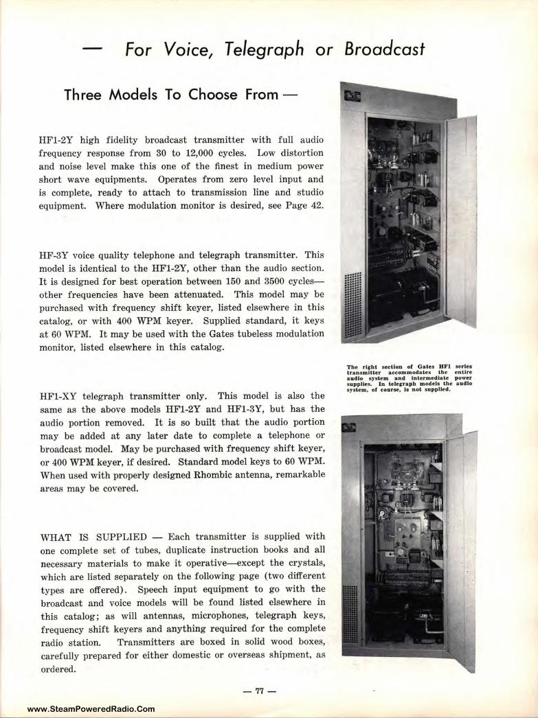
www.SteamPoweredRadio.Com
For Voice, Telegraph or Broadcast
Three Models To Choose From -
HF1-2Y high fidelity broadcast transmitter with full audio frequency response from 30 to 12,000 cycles. Low distortion and noise level make this one of the finest in medium power short wave equipments. Operates from zero level input and is complete, ready to attach to transmission line and studio equipment. Where modulation monitor is desired, see Page 42.
HF-3Y voice quality telephone and telegraph transmitter. This model is identical to the HF1-2Y, other than the audio section. It is designed for best operation between 150 and 3500 cyclesother frequencies have been attenuated. This model may be purchased with frequency shift keyer, listed elsewhere in this catalog, or with 400 WPM keyer. Supplied. standard, it keys at 60 WPM. It may be used with the Gates tubeless modulation monitor, listed elsewhere in this catalog.
HFl-XY telegraph transmitter only. This model is also the same as the above models HF1-2Y and HF1-3Y, but has the audio portion removed. It is so built that the audio portion may be added at any later date to complete a telephone or broadcast model. May be purchased with frequency shift keyer, or 400 WPM keyer, if desired. Standard model keys to 60 WPM. When used with properly designed Rhombic antenna, remarkable areas may be covered.
WHAT IS SUPPLIED - Each transmitter is supplied with one complete set of tubes, duplicate instruction books and all necessary materials to make it operative-except the crystals, which are listed separately on the following page (two different types are offered). Speech input equipment to go with the broadcast and voice models will be found listed elsewhere in this catalog; as will antennas, microphones, telegraph keys, frequency shift keyers and anything required for the complete
radio station. Transmitters are boxed in solid wood boxes, carefully prepared for either domestic or overseas shipment, as
ordered.
-77-
The right section of Gates BFll series transmitter accommodates the entire audio system and intermediate power suppUes. In telegraph models t he audio system, of course, is not supplied.
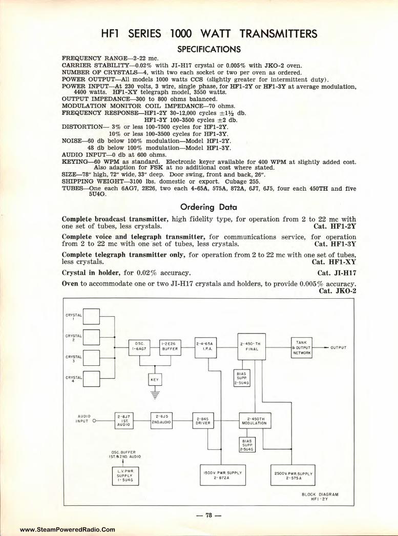
www.SteamPoweredRadio.Com
HFl SERIES 1000 WATT TRANSMITTERS SPECIFICATIONS
FREQUENCY RANGE-2-22 me. CARRIER STABILITY-0.02% with JI-H17 crystal or 0.005% with JKO-2 oven. NUMBER OF CRYSTALS-4, with two each socket or two per oven as ordered. POWER OUTPUT-All models 1000 watts CCS (slightly greater for intermittent duty). POWER INPUT- At 230 volts, 3 wire, single phase, for HF1-2Y or HF1-3Y at average modulation,
4400 watts. HFl-XY telegraph model, 3550 watts. OUTPUT IMPEDANCE-300 to 800 ohms balanced. MODULATION MONITOR COIL IMPEDANCE-70 ohms. FREQUENCY RESPONSE-HF1-2Y 30-12,000 cycles ± 1½ db.
HF1-3Y 100-3500 cycles ± 2 db. DISTORTION- 3% or less 100-7500 cycles for HF1-2Y.
10% or less 100-3500 cycles for HF1-3Y. NOISE-60 db below 100% modulation-Model HF1-2Y.
48 db below 100% modulation- Model HF1-3Y. AUDIO INPUT-0 db at 600 ohms. KEYING-60 WPM as standard. Electronic keyer available for 400 WPM at slightly added cost.
Also adaption for FSK at no additional cost where stated. SIZE-78" high, 72" wide, 33" deep. Door swing, front and back, 26". SHIPPING WEIGHT- 3100 lbs. domestic or export. Cubage 255. TUBES-One each 6AG7, 2E26, two each 4-65A, 575A, 872A, 6J7, 6J5, four each 450TH and five
5U4G.
Ordering Data Complete broadcast transmitter, high fidelity type, for operation from 2 to 22 me with one set of tubes, less crystals. Cat. HF1-2Y Complete voice and telegraph transmitter, for communications service, for operation from 2 to 22 me with one set of tubes, less crystals. Cat. HF1-3Y
Complete telegraph transmitter only, for operation from 2 to 22 me with one set of tubes, less crystals. Cat. HFl-XY
Crystal in holder, for 0.02% accuracy. Cat. JI-H17
Oven to accommodate one or two JI-H17 crystals and holders, to provide 0.005% accuracy.
CRYSTAL I
CRYSTAL 2
CRYSTAL 3
AUDI O
osc. l·GAG7
INPUT 0-----1
OSC,SUFFER I ST. 6 2NO. AUDIO
L.1/, PWR
SUPPLY I· 5U4G
2·45O·TH 1. P. A. 1----1 F I NAL
TANK
r--- - -;6 OUTPUT
NETWORK
Cat. JK0-2
OUTPUT
Z·GJ 5 2· 8 4 5 2·45OTH 2ND.AU010f-- -l DR IVER 1--1--- -; MODULATION
15OOV PWR. SUPPLY
2 · 872A
-78 -
25OOV. PWR.SUP PLY 2 • 575 A
BLOCK DIAGR AM HFI •zy
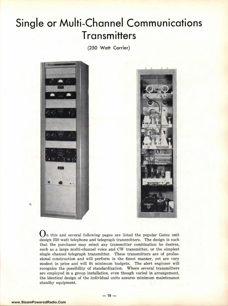
www.SteamPoweredRadio.Com
Single or Multi-Channel Communications Transmitters
(250 Watt Carrier)
On this and several following pages are listed the popular Gates unit design 250 watt telephone and telegraph transmitters. The design is such that the purchaser may select any transmitter combination he desires, such as a large multi-channel voice and CW transmitter, or the simplest single channel telegraph transmitter. These transmitters are of professional const ruction and will perform in the finest manner, yet are very modest in price and will fit minimum budgets. The alert engineer will recognize the possibility of standardization. Where several transmitters are employed in a group installation, even though varied in arrangement, t he identical design of the individual units assures minimum maintenance standby equipment.
- 79 -
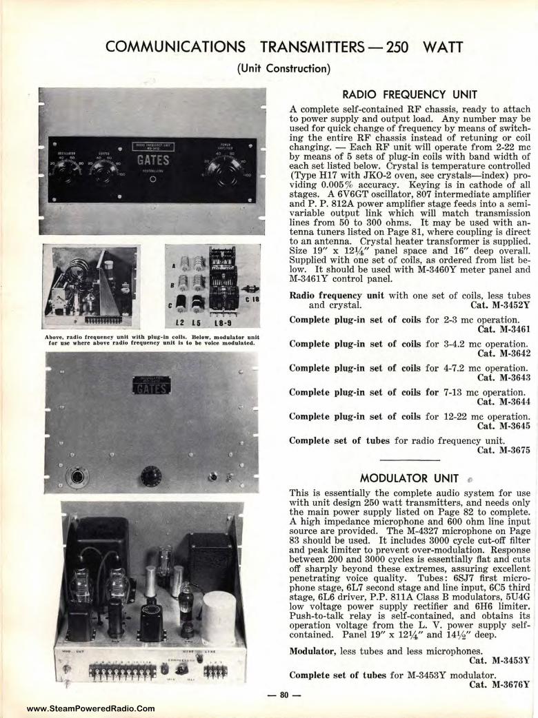
www.SteamPoweredRadio.Com
COMMUNICATIONS TRANSMITTERS - 250 WA TT (Unit Construction)
Above, radio frequency unit with ptur•ln colts, Bdow, modulator unit ror use wbere above ra dio rrequenc:, unit I• to be voice modulated.
RADIO FREQUENCY UNIT A complete self-contained RF chassis, ready to attach to power supply and output load. Any number may be used for quick change of frequency by means of switching the entire RF chassis instead of retuning or coil changing. - Each RF unit will operate from 2-22 me by means of 5 sets of plug-in coils with band width of each set listed below. Crystal is temperature control1ed (Type H17 with J KO-2 oven, see crystals-index) providing 0.005% accuracy. Keying is in cathode of all stages. A 6V6GT oscillator, 807 intermediate amplifier and P. P . 812A power amplifier stage feeds into a semivariable output link which will match transmission lines from 50 to 300 ohms. It may be used with antenna tuner s listed on Page 81, where coupling is direct to an antenna. Crystal heater transformer is supplied. Size 19" x 12¼" panel space and 16" deep overall. Supplied with one set of coils, as ordered from list below. It should be used with M-3460Y meter panel and M-3461 Y control panel.
Radio frequency unit with one set of coils, less tubes and crystal. Cat. M·3452Y
Complete plug -in set of coils for 2-3 me operation. Cat. M-3461
Complete plug-in set of coils for 3-4.2 me operation. Cat. M-3642
Complete plug-in set of coils for 4-7.2 me operation. Cat. M-3643
Complete plug-in set of coils for 7-13 me operation. Cat. M-3644
Complete plug-in set of coils for 12-22 me operation. Cat. M-3645
Complete set of tubes for r adio frequency unit. Cat. M-3675
MODULATOR UNIT , This is essentially the complete audio system for use with unit design 250 watt transmitters, and needs only the main power supply listed on Page 82 to complete. A high impedance microphone and 600 ohm line input source are provided. The M-4327 microphone on Page 83 should be used. It includes 3000 cycle cut-off filter and peak limiter to prevent over-modulation. Response between 200 and 3000 cycles is essentially flat and cuts off sharply beyond these extremes, assuring excellent penetrating voice quality. Tubes: 6SJ7 first microphone stage, 6L7 second stage and line input, 6C5 third stage, 6L6 driver, P.P. 811A Class B modulators, 5U4G low voltage power supply rectifier and 6H6 limiter. P ush-to-talk relay is self-contained, and obtains its operation voltage from the L. V. power supply selfcontained. Panel 19" x 12¼" and 14½ " deep.
Modulator, less tubes and less microphones. Cat. M-3453Y
Complete set of tubes for M-3453Y modulator. Cat. M-3676Y
-80-
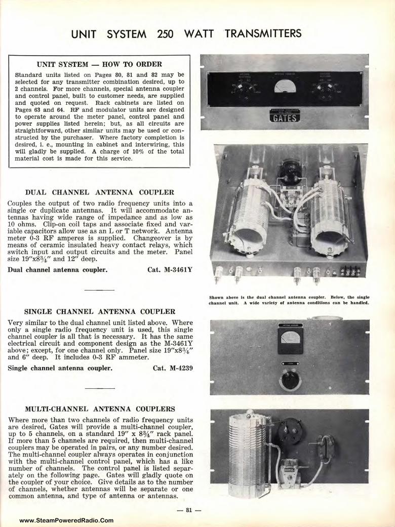
www.SteamPoweredRadio.Com
UNIT SYSTEM 250 WATT TRANSMITTERS
UNIT SYSTEM - HOW TO ORDER Standard units listed on Pages 80, 81 and 82 may be selected for any transmitter combination desired, up to 2 channels. For more channels, special antenna coupler and control panel, built to customer needs, are supplied and quoted on request. Rack cabinets are listed on Pages 63 and 64. RF and modulator units are designed to operate around the meter panel, control panel and power supplies listed herein; but, as all circuits are straightforward, other similar units may be used or constructed by the purchaser. Where factory completion is desired, i. e., mounting in cabinet and interwiring, this will gladly be supplied. A charge of 10% of the total material cost is made for this service.
DUAL CHANNEL ANTENNA COUPLER
Couples the output of two radio frequency units into a single or duplicate antennas. It will accommodate antennas having wide range of impedance and as low as 10 ohms. Clip-on coil taps and associate fixed and variable capacitors allow use as an L or T network. Antenna meter 0-3 RF amperes is supplied. Changeover is by means of ceramic insulated heavy contact relays, which switch input and output circuits and the meter. Panel size 19"x8¾." and 12" deep.
Dual channel antenna coupler. Cat. M-3461Y
SINGLE CHANNEL ANTENNA COUPLER
Very similar to the dual channel unit listed above. Where only a single r adio frequency unit is used, this single channel coupler is all that is necessary. It has the same electrical circuit and component design as the M-3461 Y above; except, for one channel only. Panel size 19"x8¾ " and 6" deep. It includes 0-3 RF ammeter.
Single channel antenna coupler. Cat. M-4239
MULTI-CHANNEL ANTENNA COUPLERS
Where more than two channels of radio frequency units are desired, Gates will provide a multi-channel coupler, up to 5 channels, on a standard 19" x 8¾ " rack panel. If more than 5 channels are required, then multi-channel couplers may be operated in pairs, or any number desired. The multi-channel coupler always operates in conjunction with the multi-channel control panel, which has a like number of channels. The control panel is listed separately on the following page. Gates will gladly quote on the coupler of your choice. Give details as to the number of channels, whether antennas will be separate or one common antenna, and type of antenna or antennas.
- 81-
Shown above is the dual cban,ne l antenna coupler. Below, the sl,nrle channel unit. A wide variety of antenn a eond.ltlons can be handled.
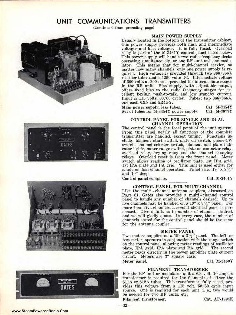
www.SteamPoweredRadio.Com
~ ~
• •
e ..
UNIT COMMUNICATIONS TRANSMITTERS
.. . . .. • ..:. ~, ' ..... • •
' w ~
(Continued from preceding page)
IP •
~ -~
MAIN POWER SUPPLY Usually located in the bottom of the transmitter cabinet, this power supply provides both high and intermediate voltages and bias voltages. It is fully fused. Overload relay is part of the M-3461Y control panel listed below. This power supply will handle two radio frequency decks operating simultaneously, or one RF unit and one modulator. This means that for multi-channel service, no matter how many channels, only one power supply is required. High voltage is provided through two 866/ 866A rectifier tubes and is 1250 volts DC. Intermediate voltage of 600 volts at 200 ma is provided for intermediate stages in the RF unit. Bias supply, with adjustable output, offers fixed bias to the radio frequency stages for excellent keying, push-to-talk, and low standby current. Input is 115 volts, 50/60 cycles. Tubes: two 866/ 866A, one each 6X5 and 5R4GY. Main power supply, less tubes. Set of tubes for M-3454Y power supply.
Cat. M-3454Y Cat. M-3677Y
CONTROL PANEL FOR SINGLE AND DUAL CHANNEL OPERATION
The control panel is the focal point of the unit system. From this panel nearly all functions of the complete transmitter are handled, except tuning. Functions include: filament start switch, plate on switch, phone-CW switch, channel selector switch, filament and plate indicator lights, meter range switch, plate on contactor relay, overload relay, keying relay and the channel changing relays. Overload reset is from the front panel. Meter switch allows reading of oscillator plate, 1st IP A grid, 1st IPA plate and PA grid. This unit is used either for single or dual channel operation. Panel size: 19" x 83/4" and 10" deep. Control panel complete. ____ Cat. M-3461 Y
CONTROL PANEL FOR MULTI-CHANNEL Like the multi - channel antenna couplers, discussed on Page 81, Gates also provides a multi - channel control panel to handle any number of channels desired. Up to five channels may be handled on a 19" x 83/4" panel. For more than five channels, a second identical panel is purchased. Give details as to number of channels desired, and we will gladly quote. In every case, the number of channels stated for the control panel should be the same for t he antenna coupler.
METER PANEL Two meters supplied on a 19" x 3¼" panel. The left, or test meter, operates in conjunction with the range switch on the control panel, allowing meter readings of oscillator plate, IP A grid, IP A plate and PA grid. The second meter reads directly in the power amplifier plate current circuit. Meters are 3" square case. Meter pane1. Cat. M-3460Y
FILAMENT TRANSFORMER For the RF unit or modulator unit a 6.3 volt, 10 ampere transformer is required for the filaments of either the 811A or 812A tubes. This transformer, fully cased, provides this voltage from a 115 volt, 50 /60 cycle input source. One is required for each unit, i. e., two would be needed for two RF units, etc. Filament transformer. Cat. AF-1994K
-82-
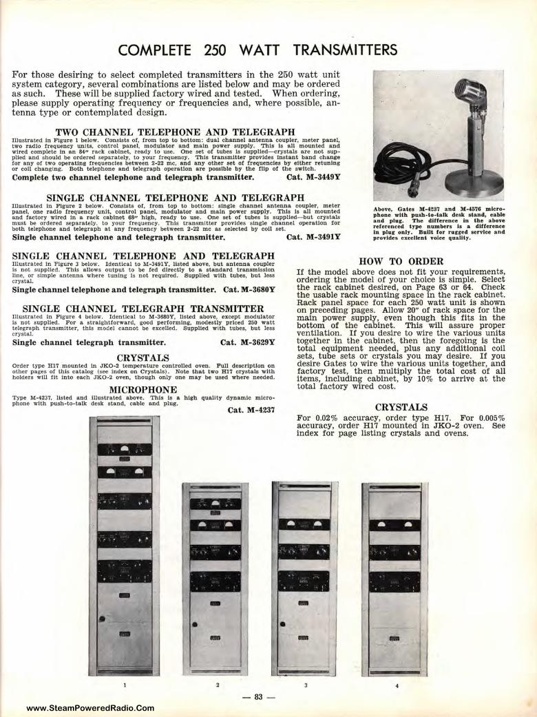
www.SteamPoweredRadio.Com
COMPLETE 250 WATT TRANSMITTERS
For those desiring to select completed transmitters in t he 250 watt unit system category, several combinations are listed below and may be ordered as such. These will be supplied factory wired and tested. When ordering, please supply operating frequency or frequencies and, where possible, antenna type or contemplated design.
TWO CHANNEL TELEPHONE AND TELEGRAPH Illustrated In Figure 1 below. Consists of, from top to bottom: dual channel antenna coupler. meter panel. two radio frequency units, control panel, modulator and main power supply. This Is all mounted and wired complete In an 84" rack cabinet, ready to use. One set of tubes Is supplied-crystals are not supplied and should be ordered separately, to your frequency. This transmitter provides Instant band change for any of two operating frequencies between 2-22 me, and any other set of frequencies by either retuning or coll changing. Both telephone and telegraph operation are possible by the flip of the switch.
Complete two channel telephone and telegraph transmitter. Cat. M-3449Y
SINGLE CHANNEL TELEPHONE AND TELEGRAPH Illustrated ln Figure 2 below. Consists of, from top to bottom: single channel antenna coupler, meter panel, one radio frequency unit, control panel, modulator and main power supply. This Is all mounted and factory wired In a rack cabinet 68" high. ready to use. One set of tubes Is supplied-but crystals must be ordered separately. to your frequency. This transmitter provides single channel operation for both telephone and telegraph at any frequency between 2-22 me as selected by con set.
Above, Gates M-4287 and M-4G76 microphone wllh push-to-talk desk s land, cable and plug. The difference in the above referenced type numbers is a difference In plug only. Bulil for rugred service and provides excellent voice quality, Single channel telephone and telegraph transmitter. Cat. M-3491Y
SINGLE CHANNEL TELEPHONE AND TELEGRAPH Illustrated in Figure 3 below. Identical to M-3491 Y, listed above, but antenna coupler Is not supplied. This allows output to be fed directly to a standard transmission line. or simple antenna where tuning Is not required. Supplied with tubes, but less crystal.
Single channel telephone and telegraph transmitter. Cat. M-3680Y
SINGLE CHANNEL TELEGRAPH TRANSMITTER Illustrat,ed In Figure 4 below. Identical to M-3680Y, listed above, except modulator Is not supplied. For a straightforward, good performing, modestly priced 250 watt telegraph transmitter, this model cannot be excelled. Supplied with tubes, but less crystal. Single channel telegraph transmitter. Cat. M-3629Y
CRYSTALS Order type Hl7 mounted In JK0-2 temperature controlled oven. Full description on other pages of tbis catalog (see Index on Crystals). Note that two Hl7 crystals with holders will tit Into each JK0-2 oven, though only one may be used where needed.
MICROPHONE Type M-4237, listed llnd Illustrated above. This is a high quality dynamic microphone with push-t-0-talk desk stand, cable and plug.
Cat. M-4237
- -• • - -- 83 -
•
HOW TO ORDER If the model above does not fit your requirements, ordering the model of your choice is simple. Select the rack cabinet desired, on Page 63 or 64. Check the usable rack mounting space in the rack cabinet. Rack panel space for each 250 watt unit is shown on preceding pages. Allow 20" of rack space for the main power supply, even though this fits in the bottom of the cabinet. This will assure proper ventilation. If you desire to wire the various units together in the cabinet, •then the foregoing is the total equipment needed, plus any additional coil sets, tube sets or crystals you may desire. If you desire Gates to wire the various units together, and factory test, then multiply the total cost of all items, including cabinet, by 10% to arrive at the total factory wired cost.
CRYSTALS For 0.02% accuracy, order type Hl7. For 0.005% accuracy, order Hl7 mounted in JK0-2 oven. See index for page listing crystals and ovens.
-- -
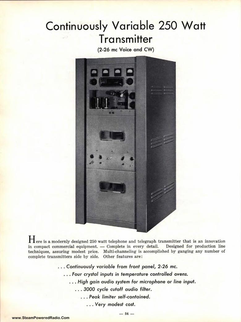
www.SteamPoweredRadio.Com
Continuously Variable 250 Watt T ra nsm itter (2-26 me Voice and CW)
Here is a modernly designed 250 watt telephone and telegraph transmitter that is an innovation in compact commercial equipment. - Complete in every detail. Designed for production line techniques, assuring modest price. Multi-channeling is accomplished by ganging any number of complete transmitters side by side. Other features are:
. .. Continuously variable from front panel, 2-26 me •
. . . Four crystal inputs in temperature controlled ovens .
. . . High gain audio system for microphone or line input .
. . . 3000 cycle cutoff audio filter .
. . . Peak limiter self-contained .
. . . Very modest cost.
- 84-
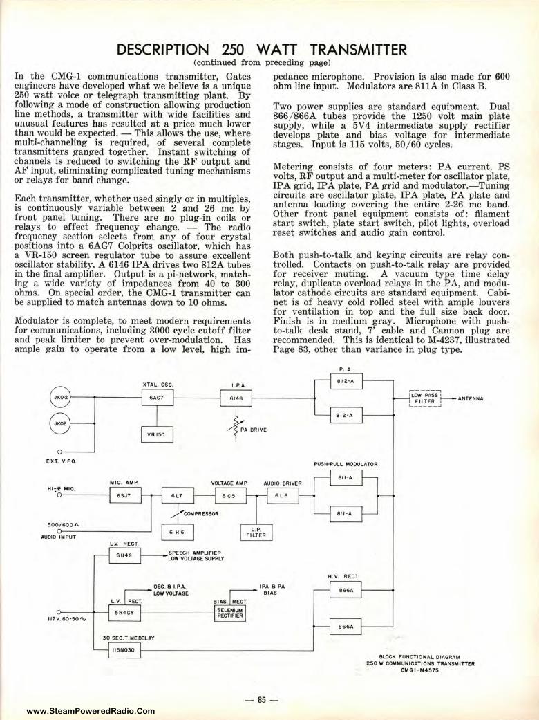
www.SteamPoweredRadio.Com
DESCRIPTION 250 WATT TRANSMITTER (continued from preceding page)
In the CMG-1 communications transmitter, Gates pedance microphone. Provision is also made for 600 engineers have developed what we believe is a unique ohm line input. Modulators are 811A in Class B. 250 watt voice or telegraph transmitting plant. By following a mode of construction allowing production line methods, a transmitter with wide facilities and unusual features has resulted at a price much lower than would be expected. - This allows the use, where multi-channeling is required, of several complete transmitters ganged together. Instant switching of channels is reduced to switching the RF output and AF input, eliminating complicated tuning mechanisms or relays for band change.
Each transmitter, whether used singly or in multiples, is continuously variable between 2 and 26 me by front panel tuning. There are no plug-in coils or relays to effect frequency change. - The radio frequency section selects from any of four crystal positions into a 6AG7 Colprits oscillator, which has a VR-150 screen regulator tube to assure excellent oscillator stability. A 6146 IP A drives two 812A tubes in the final amplifier. Output is a pi-network, matching a wide variety of impedances from 40 to 300 ohms. On special order, the CMG-1 transmitter can be supplied to match antennas down to 10 ohms.
Modulator is complete, to meet modern requirements for communications, including 3000 cycle cutoff filter and peak limiter to prevent over-modulation. Has ample gain to operate from a low level, high im-
XTAL. OSC. LP. A.
6AG7 6146
PA DRIVE VR 150
EXT. V.F.0 ,
Two power supplies are standard equipment. Dual 866 / 866A tubes provide the 1250 volt main plate supply, while a 5V4 intermediate supply rectifier develops plate and bias voltage for intermediate stages. Input is 115 volts, 50/ 60 cycles.
Metering consists of four meters: PA current, PS volts, RF output and a multi-meter for oscillator plate, IPA grid, IPA plate, PA grid and modulator.-Tuning circuits are oscillator plate, IPA plate, PA plate and antenna loading covering the entire 2-26 me band. Other front panel equipment consists of: filament start switch, plate start switch, pilot lights, overload reset switches and audio gain control.
Both push-to-talk and keying circuits are relay controlled. Contacts on push-to-talk relay are provided for receiver muting. A vacuum type time delay relay, duplicate overload relays in the PA, and modulator cathode circuits are standard equipment. Cabinet is of heavy cold rolled steel with ample louvers for ventilation in top and the full size back door. Finish is in medium gray. Microphone with pushto-talk desk stand, 7' cable and Cannon plug are recommended. This is identical to M-4237, illustrated Page 83, other than variance in plug type.
P. A .
812·A
,-.----:-\ 1LOW PASS I , F I LTER :---ANTENNA L __ ___ J
812· A
PUSH·PULL MODULATOR
8ll · A MIC. AM P. VOLTAGE AMP AUDIO DRIVER
500/600"-
AUDIO IMPUT
117V. 60·50'\,
6SJ7 6L7
6 H 6
L.V. RECT.
SU4G
~--DSC. 8 I. P.A. LOW VOLTAGE
L .V. RECT.
6 C5 6L6
L .P. FILTER
IPA 8 PA ~-- BIAS
BIAS. RECT.
5R4GY t----------1 ~~~~~
30 SEC. TIME DELAY
ll5N030
-85-
H . V . RECT.
866A
866A
BLOCK FUNCTIONAL DIAGRAM 250 W. COMMUNICATIONS TilANSMITTER
CMG I-M4575
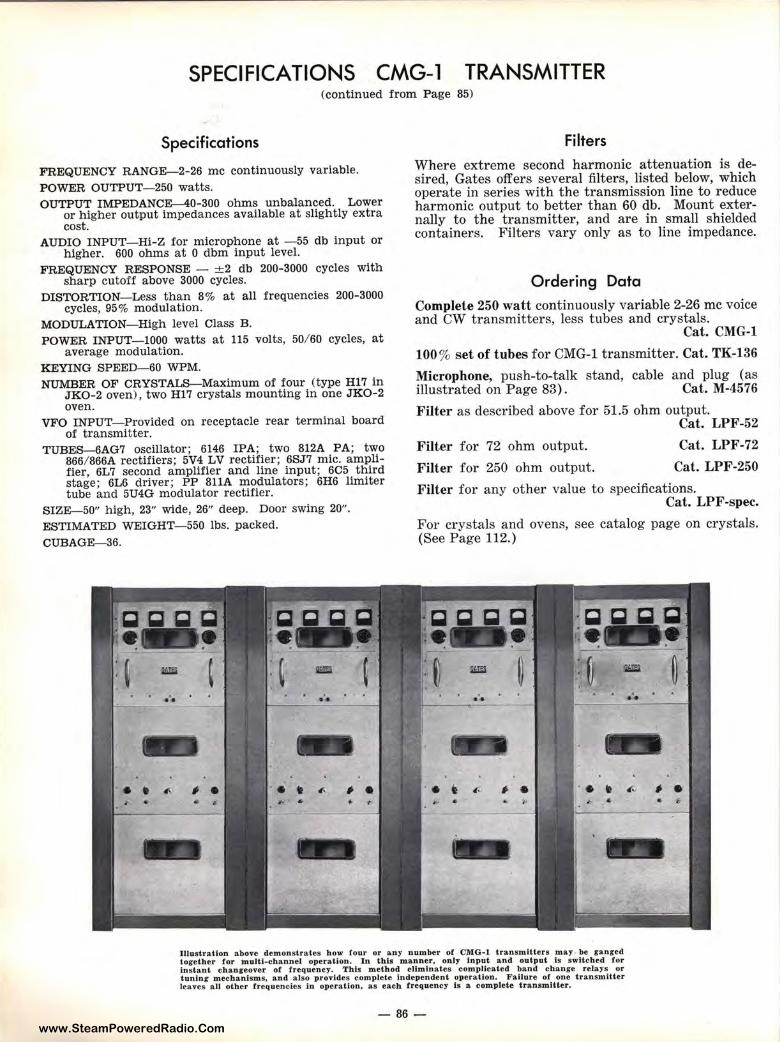
www.SteamPoweredRadio.Com
SPECIFICATIONS CMG-1 TRANSMITTER (continued from Page 85)
Specifications
FREQUENCY RANGE-2-26 me continuously variable.
POWER OUTPUT-250 watts. OUTPUT IMPEDANCE-40-300 ohms unbalanced. Lower
or higher output impedances available at slightly extra cost.
AUDIO INPUT-Hi-Z for microphone at -55 db input or higher. 600 ohms at O dbm input level.
FREQUENCY RESPONSE - ±2 db 200-3000 cycles with sharp cutoff above 3000 cycles.
DISTORTION-Less than 8% at all frequencies 200-3000 cycles, 95% modulation.
MODULATION-High level Class B. POWER INPUT-1000 watts at 115 volts, 50/ 60 cycles, at
average modulation. KEYING SPEED- 60 WPM. NUMBER OF CRYSTALS-Maximum of four (type H17 in
JKO-2 oven), two Hl 7 crystals mounting in one JKO-2 oven.
VFO INPUT- Provided on receptacle rear terminal board of transmitter.
TUBES-6AG7 oscillator; 6146 IPA; two 812A PA; two 866/ 866A rectifiers; 5V4 LV rectifier; 6SJ7 mic. amplifier, 6L7 second amplifier and line input; 605 third stage; 6L6 driver; PP 811A modulators; 6H6 limiter tube and 5U4G modulator rectifier.
SI ZE-50" high, 23" wide, 26" deep. Door swing 20". ESTIMATED WEIGHT-550 lbs. packed.
CUBAGE-36.
•
-
Filters
Where extreme second harmonic attenuation is desired, Gates offers several filters, listed below, which operate in series with the transmission line to reduce harmonic output to better than 60 db. Mount externally to the transmitter, and are in small shielded containers. Filters vary only as to line impedance.
Ordering Data
Complete 250 watt continuously variable 2-26 me voice and CW transmitters, less tubes and crystals.
Cat. CMG-1
100% set of tubes for CMG-1 transmitter. Cat. TK-136
Microphone, push-to-talk stand, cable and plug (as illustrated on Page 83). Cat. M-4576
Filter as described above for 51.5 ohm output.
Filter for 72 ohm output.
Filter for 250 ohm output.
Cat. LPF-52
Cat. LPF-72
Cat. LPF-250
Filter for any other value to specifications. Cat. LPF-spec.
For crystals and ovens, see catalog page on crystals. (See Page 112.)
U1
.. - -----
Illustration above demonstrates how four or any number ot Cl\lG-1 transmltt-ers ma.y be ganged together for muJU-cbannel operation. In th.ls manner, only input and output Is switched for instant changeover or frequency. This method eliminates complicated band change relays or tuning mechanisms, and also provides comple te l.odependent operation. Failure of one transmitter leaves all other frequencies In operation. as eaeh frequency Is a complete transm.ltter.
- 86 -
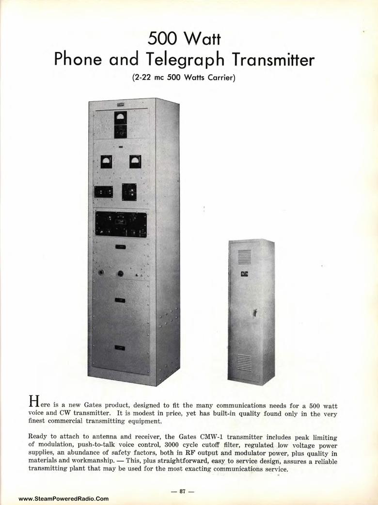
www.SteamPoweredRadio.Com
500 Watt Phone and Telegraph Transmitter
(2-22 me 500 Watts Carrier)
-
■
Here is a new Gates product, designed to fit the many communications needs for a 500 watt voice and CW transmitter. It is modest in price, yet has built-in quality found only in the very finest commercial transmitting equipment.
Ready to attach to antenna and receiver, the Gates CMW-1 transmitter includes peak limiting of modulation, push-to-talk voice control, 3000 cycle cutoff filter, regulated low voltage power supplies, an abundance of safety factors, both in RF outpµt and modulator power, plus quality in materials and workmanship. - This, plus straightforward, easy to service design1 assures a reliable transmitting plant that may be used for the most exacting communications service.
-87-
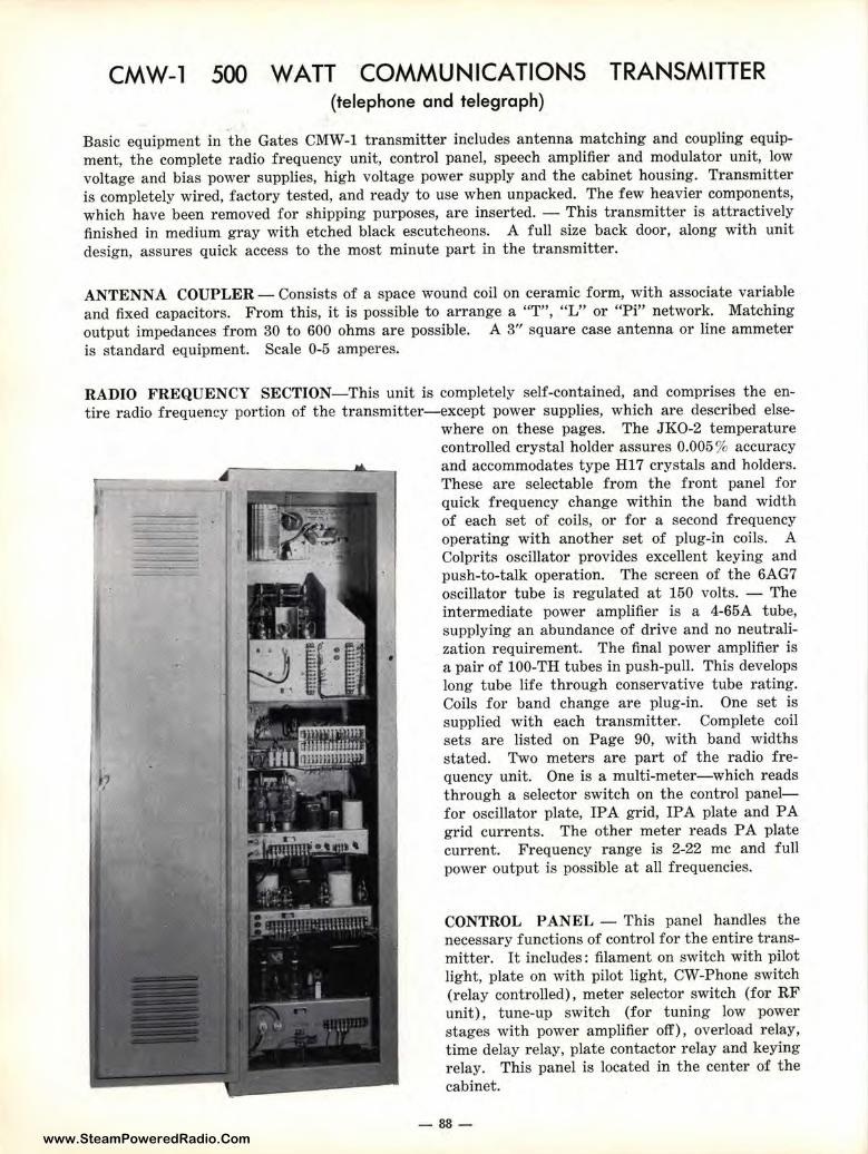
www.SteamPoweredRadio.Com
CMW-1 500 WATT COMMUNICATIONS TRANSMITTER (telephone and telegraph)
Basic equipment in the Gates CMW-1 transmitter includes antenna matching and coupling equipment, the complete radio frequency unit, control panel, speech amplifier and modulator unit, low voltage and bias power supplies, high voltage power supply and the cabinet housing. Transmitter is completely wired, factory tested, and ready to use when unpacked. The few heavier components, which have been removed for shipping purposes, are inserted. - This transmitter is attractively finished in medium gray with etched black escutcheons. A full size back door, along with unit design, assures quick access to the most minute part in the transmitter.
ANTENNA COUPLER- Consists of a space wound coil on ceramic form, with associate variable and fixed capacitors. From this, it is possible to arrange a "T", "L" or "Pi" network. Matching output impedances from 30 to 600 ohms are possible. A 3" square case antenna or line ammeter is standard equipment. Scale 0-5 amperes.
RADIO FREQUENCY SECTION-This unit is completely self-contained, and comprises the entire radio frequency portion of t he transmitter-except power supplies, which are described else
where on these pages. The JK0-2 temperature controlled crystal holder assures 0.005 % accuracy and accommodates type Hl 7 crystals and holders. These are selectable from the front panel for quick frequency change within the band width of each set of coils, or for a second frequency operating with another set of plug-in coils. A Colprits oscillator provides excellent keying and push-to-talk operation. The screen of the 6AG7 oscillator tube is regulated at 150 volts. - The intermediate power amplifier is a 4-65A tube, supplying an abundance of drive and no neutralization requirement. The final power amplifier is a pair of 100-TH tubes in push-pull. This develops long tube life through conservative tube rating. Coils for band change are plug-in. One set is supplied with each transmitter. Complete coil sets are listed on Page 90, with band widths stated. Two meters are part of the radio frequency unit. One is a multi-meter-which reads through a selector switch on the control panelfor oscillator plate, IPA grid, IP A plate and PA grid currents. The other meter reads PA plate current. Frequency range is 2-22 me and full power output is possible at all frequencies.
CONTROL PANEL - This panel handles the necessary functions of control for the entire transmitter. It includes: filament on switch with pilot light, plate on with pilot light, CW-Phone switch (relay controlled), meter selector switch (for RF unit), tune-up switch (for tuning low power stages with power amplifier off) , overload relay, time delay relay, plate contactor relay and keying relay. This panel is located in the center of the cabinet.
- 88-
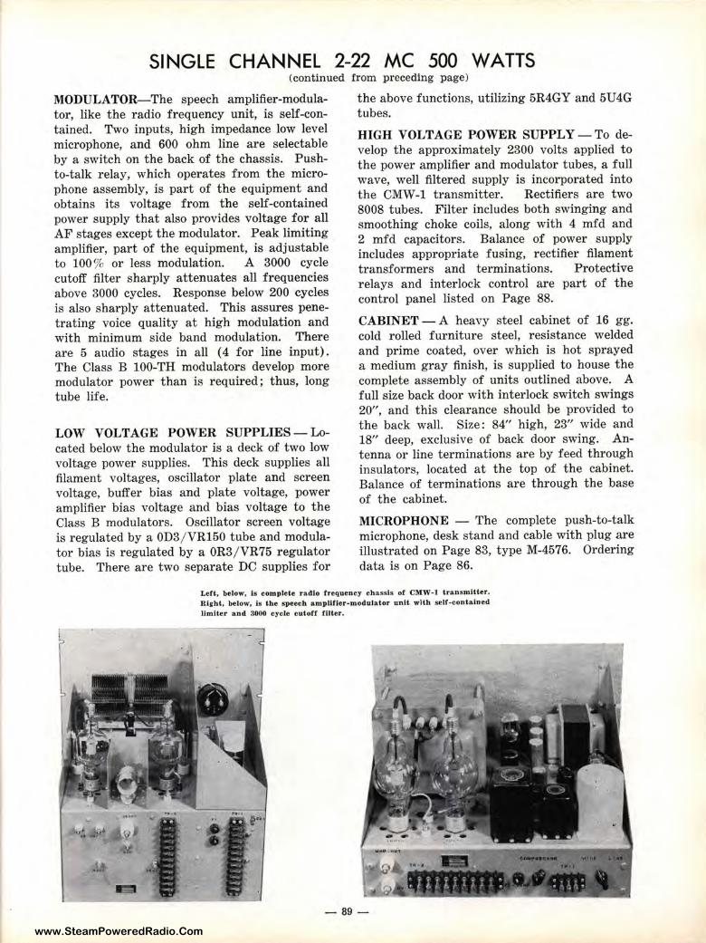
www.SteamPoweredRadio.Com
SINGLE CHANNEL 2-22 MC 500 WATTS (continued from preceding page)
MODULATOR-The speech amplifier-modulator, like t he radio frequency unit, is self-contained. Two inputs, high impedance low level microphone, and 600 ohm line are selectable by a switch on the back of the chassis. Pushto-talk relay, which operates from the microphone assembly, is part of the equipment and obtains its voltage from the self-contained power supply that also provides voltage for all AF stages except the modulator. Peak limiting amplifier, part of the equipment, is adjustable to 100 % or less modulation. A 3000 cycle cutoff filter sharply attenuates all frequencies above 3000 cycles. Response below 200 cycles is also sharply attenuated. This assures penetrating voice quality at high modulation and with minimum side band modulation. There are 5 audio stages in all ( 4 for line input). The Class B 100-TH modulators develop more modulator power than is required; thus, long tube life.
LOW VOLTAGE POWER SUPPLIES- Located below the modulator is a deck of two low voltage power supplies. This deck supplies all filament voltages, oscillator plate and screen voltage, buffer bias and plate voltage, power amplifier bias voltage and bias voltage to the Class B modulators. Oscillator screen voltage is regulated by a 0D3/ VR150 tube and modulator bias is regulated by a 0R3/ VR75 regulator tube. There are two separate DC supplies for
the above functions, utilizing 5R4GY and 5U4G tubes.
HIGH VOLTAGE POWER SUPPLY-To develop the approximately 2300 volts applied to the power amplifier and modulator tubes, a full wave, well filtered supply is incorporated into the CMW-1 transmitter. Rectifiers are two 8008 tubes. Filter includes both swinging and smoothing choke coils, along with 4 mfd and 2 mfd capacitors. Balance of power supply includes appropriate fusing, rectifier filament transformers and terminations. Protective relays and interlock control are part of the control panel listed on Page 88.
CABINET- A heavy steel cabinet of 16 gg. cold rolled furniture steel, resistance welded and prime coated, over which is hot sprayed a medium gray finish, is supplied to house the complete assembly of units outlined above. A full size back door with interlock switch swings 20", and this clearance should be provided to the back wall. Size: 84" high, 23" wide and 18" deep, exclusive of back door swing. Antenna or line terminations are by feed through insulators, located at the top of the cabinet. Balance of terminations are through the base of the cabinet.
MICROPHONE - The complete push-to-talk microphone, desk stand and cable with plug are illustrated on Page 83, type M-4576. Ordering data is on Page 86.
Left, below, Is complete r adio f requency chassis of CMW-1 transmitter. Right, below, is the speech amplltler-modulator unit with self-contained limiter and 3000 cycle cutoff tilter.
-89-
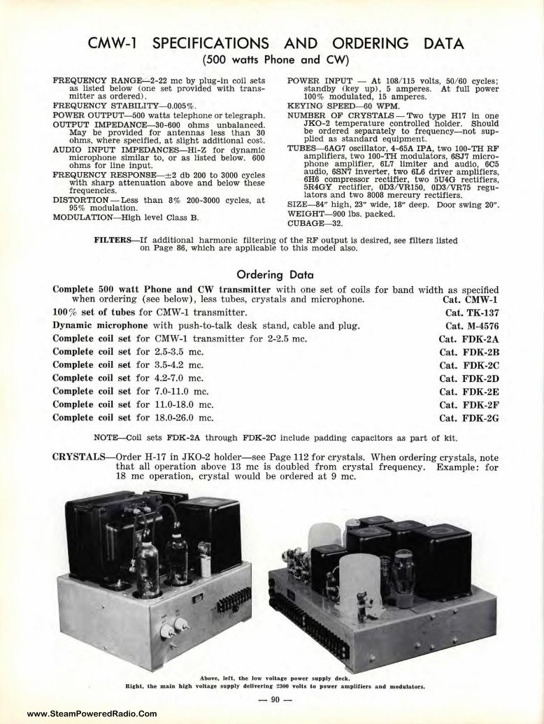
www.SteamPoweredRadio.Com
CMW-1 SPECIFICATIONS AND ORDERING (500 watts Phone and CW)
DATA
FREQUENCY RANGE-2-22 me by plug-in coil sets as list ed below (one set provided with transmitter as ordered).
FREQUENCY STABILITY-0.005%. POWER OUTPUT- 500 watts telephone or telegraph. OUTPUT IMPEDANCE-30-600 ohms unbalanced.
May be provided for antennas less than 30 ohms, where specified, at slight additional cost.
AUDIO INPUT IMPEDANCES-Hi-Z for dynamic microphone similar to, or as listed below. 600 ohms for line input.
FREQUENCY RESPONSE-± 2 db 200 to 3000 cycles with sharp attenuation above and below these frequencies.
DISTORTION - Less than 8% 200-3000 cycles, at 95% modulation.
MODULA TI ON-High level Class B.
POWER INPUT - At 108/ 115 volts, 50/ 60 cycles; standby (key up), 5 amperes. At full power 100% modulated, 15 amperes.
KEYING SPEED-60 WPM. NUMBER OF CRYSTALS-Two type H17 in one
JKO-2 temperature controlled holder. Should be ordered separately to frequency-not supplied as standard equipment.
TUBES- 6AG7 oscillator, 4-65A IPA, two 100-TH RF amplifiers, two 100-TH modulators, 6SJ7 microphone amplifier, 6L7 limiter and audio, 6C5 audio, 6SN7 inverter, two 6L6 driver amplifiers, 6H6 compressor rectifier, two 5U4G rectifiers, 5R4GY rectifier, 0D3/ VR150, 0D3/ VR75 regulators and two 8008 mercury rectifiers.
SIZE-84" high, 23" wide, 18" deep. Door swing 20'' . WEIGHT- 900 lbs. packed. CUBAGE-32.
FILTERS-If additional harmonic filtering of the RF output is desired, see filters listed on Page 86, which are applicable to this model also.
Ordering Data Complete 500 watt Phone and CW transmitter with one set of coils for band width as specified
when ordering (see below), less tubes, crystals and microphone. Cat. CMW-1 100% set of t ubes for CMW-1 transmitter. Cat. TK-137 Dynamic microphone with push-to-talk desk stand, cable and plug. Complete coil set for CMW-1 transmitter for 2-2.5 me. Complete coil set for 2.5-3.5 me. Complete coil set for 3.5-4.2 me. Complete coil set for 4.2-7.0 me. Complete coil set for 7.0-11.0 me. Complete coil set for 11.0-18.0 me. Complete coil set for 18.0-26.0 me.
Cat. M-4576 Cat. FDK-2A Cat. FDK-2B Cat. FDK-2C Cat. FDK-2D Cat. FDK-2E Cat. FDK-2F Cat. FDK-2G
NOTE-Coil sets FDK-2A through FDK-2C include padding capacitors as part of kit.
CRYSTALS-Order H-17 in JKO-2 holder-see Page 112 for crystals. When ordering crystals, note that all operation above 13 me is doubled from crystal frequency. Example: for 18 me operation, crystal would be ordered at 9 me.
Above, left, the low volta.g-e power supply deck. Right, the main high voltare supply dellverinr 23-00 volts to power amplifiers and modulators.
- 90-
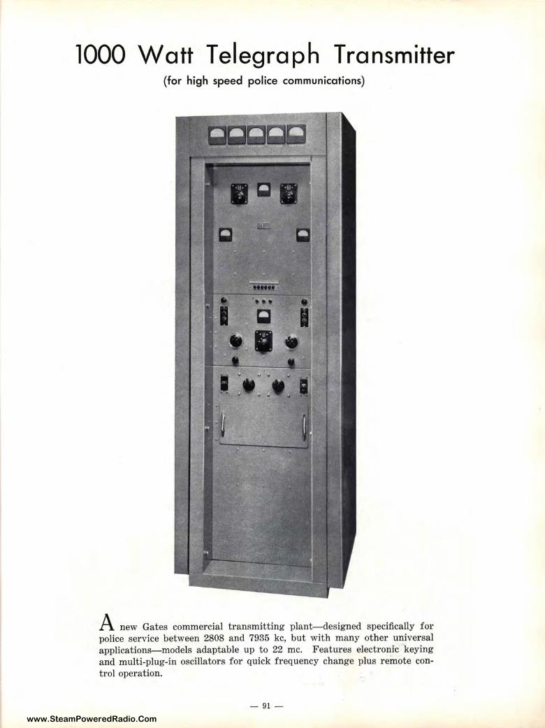
www.SteamPoweredRadio.Com
1000 Watt Telegraph Transmitter (for high speed police communications)
A new Gates commercial transmitting plant-designed specifically for police service between 2808 and 7935 kc, but with many other universal applications-models adaptable up to 22 me. Features electronic keying and multi-plug-in oscillators for quick frequency change plus remote control operation.
- 91 -
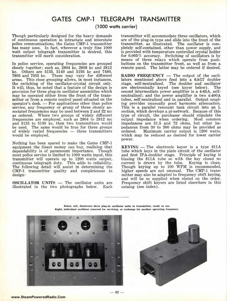
www.SteamPoweredRadio.Com
GATES CMP-1 TELEGRAPH TRANSMITTER (1000 watts carrie:r)
Though particularly designed for the heavy demands of continuous operation in intrastate and interstate police communications, the Gates CMP-1 transmitter has many uses. In fact, wherever a truly fine 1000 watt output telegraph transmitter is desired, this transmitter will merit consideration.
In police service, operating frequencies are grouped closely together; such as, 2804 kc, 2808 kc and 2812 kc. Others are 5135, 5140 and 5195 kc and 7480, 7805 and 7935 kc. These may vary for different areas. This close grouping allows, in most instances, the switching of the oscillator-crystal circuit only. It will, thus, be noted that a feature of the design is provision for three plug-in oscillator assemblies which may be operated either from the front of the transmitter or from a remote control panel situated on the operator's desk. - For applications other than police service, any frequency or group of three closely associated frequencies may be used between 2 and 22 me as ordered. Where two groups of widely different frequencies are employed, such as 2804 to 2812 me and 5135 to 5195 kc, then two transmitters would be used. The same would be true for three groups of widely varied frequencies - three transmitters would be employed.
Nothing has been spared to make the Gates CMP-1 equipment the finest money can buy, realizing that dependability is of paramount importance. Though most police service is limited to 1000 watts input, this transmitter will operate up to 1200 watts output, continuous telegraph duty. This adds to reliability. The following detail will assist in determining the CMP-1 transmitter quality and completeness in design:
OSCILLATOR UNITS - The oscillator units are illustrated in the two photographs below. Each
transmitter will accommodate three oscillators, which are of the plug-in type and slide into the front of the transmitter, as illustrated. The oscillator is completely self-contained, other than power supply, and is provided with temperature controlled crystal holder for 0.005 % accuracy. Switching of oscillators is by means of three relays which operate from pushbuttons on the transmitter front, as well as from a remote: panel. The latter may be ordered if desired.
RADIO FREQUENCY - The output of the oscillators mentioned above feed into a 6AG7 doubler stage, self-neutralized. The doubler and oscillator are el1ectronically keyed ( see key er below). The second intermediate power amplifier is a 4-65A, selfneutralized; and the power amplifier is two 4-400A tubes, self-neutralized and in parallel. Output coupling provides unusually good harmonic attenuation. This i:s a parallel resonant tank circuit into an L sectiolll, which develops a pi-network. Because of this type oif circuit, the purchaser should stipulate the output impedance when ordering. Most common impedances are 51.5 and 72 ohms, but other impedanees from 30 to 300 ohms may be provided as ordered. Maximum carrier output is 1200 watts, which may be reduced as desired for lower carrier power.
KEYING - The electronic keyer is a type 811A tube which keys in the plate circuit of the oscillator and first IP A-doubler stage. Principle of keying is biasing t he 811A tube so with the key closed no current is drawn by the tube. Keying is clean. Though keying up to 100 WPM is recommended, higher speeds are not unusual. The CMP-1 transmitter may also be adapted to frequency shift keying, and will be so supplied when stated on the order. Frequency shift keyers are listed elsewhere in this catalog (see index).
Below. left, illustrates three plug-in oscillator unJts tn transmitter, ready to use. Right, individual osctUator removed for servicinr, or exehanire for anoth er opera.tin g frequency.
0 0
••
- 92-
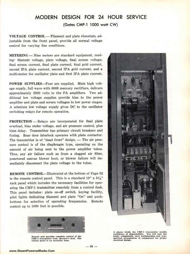
www.SteamPoweredRadio.Com
MODERN DESIGN FOR 24 HOUR SERVICE (Gates CMP-1 1000 watt CW)
VOLTAGE CONTROL - Filament and plate rheostats, adjustable from the front panel, provide all normal voltage control for varying line conditions.
METERING - Nine meters are standard equipment, reading: filament voltage, plate voltage, final screen voltage, final screen current, final plate current, final grid current, second IP A plate current, second IP A grid current, and a multi-meter for oscillator plate and first IPA plate current.
POWER SUPPLIES-Four are supplied. Main high voltage supply, full wave with 8008 mercury rectifiers, delivers approximately 2500 volts to the PA amplifiers. Two additional low voltage supplies provide bias to the power amplifier and plate and screen voltages to low power stages. A selenium low voltage supply gives DC to the oscillator switching relays for remote operation.
PROTECTION - Relays are incorporated for final plate overload, bias under voltage, and air pressure control, plus time delay. Transmitter has primary circuit breakers and fusing. Rear door interlock operates with plate contactor. The transmitter is of "dead front" design. - The air pressure control is of the diaphragm type, operating on the amount of air being sent to the power amplifier tubes. Thus, any air failure such as from a clogged air filter, punctured canvas blower boot, or blower failure will immediately disconnect the plate voltage to the tubes.
REMOTE CONTROL-Illustrated at the bottom of Page 92 is the remote control panel. This is a standard 19" x 5¼" rack panel which includes the necessary facilities for operating the CMP-1 transmitter remotely from a control desk. This panel includes : plate on-off switch, keying facility, pilot lights indicating filament and plate "On" and push-buttons for selection of operating frequencies. control up to 1000 feet is possible.
Remote unit provides complete control of the CMP-1 transmitter from operator's desk. The remote p a ne l is a.n accessory Item.
Remote
- 93-
A glance Inside the CMP-1 transmitter instiJJs con.fldence of dependability. You will note the husky components. neat. workmanship and symmetrical arrangement of component s for proper electrical desl1r11.
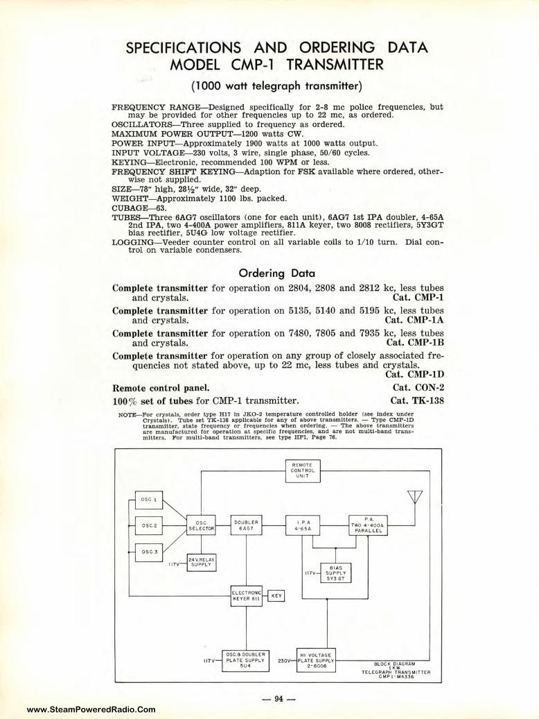
www.SteamPoweredRadio.Com
ORDERING TRANSMITTER
SPECIFICATIONS AND MODEL CMP-1
(1000 watt te legraph transmitter)
DATA
FREQUENCY RANGE-Designed specifically for 2-8 me police frequencies, but may be provided for other frequencies up to 22 me, as ordered.
OSCILLATORS- Three supplied to frequency as ordered. MAXIMUM POWER OUTPUT- 1200 watts cw. POWER INPUT-Approximately 1900 watts at 1000 watts output. INPUT VOLTAGE--230 volts, 3 wire, single phase, 50/ 60 cycles. KEYING- Electronic, recommended 100 WPM or less. FREQUENCY SfilFT KEYING-Adaption for FSK available where ordered, other-
wise not supplied. SIZE--78" high, 28½" wide, 32" deep. WEIGHT- Approximately 1100 lbs. packed. CUBAGE--63. TUBES-Three 6AG7 oscillators (one for each unit), 6AG7 1st IPA doubler, 4-65A
2nd IPA, two 4-400A power amplifiers, 811A keyer, two 8008 rectifiers, 5Y3GT bias rectifier, 5U4G low voltage rectifier.
LOGGING- Veeder counter control on all variable coils to 1/ 10 turn. Dial control on variable condensers.
Ordering Data Complete transmitter for operation on 2804, 2808 and 2812 kc, less tubes
and crystals. Cat. CMP-1 Complete transmitter for operation on 5135, 5140 and 5195 kc, less tubes
and crystals. Cat. CMP-lA Complete transmitter for operation on 7480, 7805 and 7935 kc, less tubes
and crystals. Cat. CMP-lB Complete transmitter for operation on any group of closely associated fre
quencies not stated above, up to 22 me, less tubes and crystals. Cat. CMP-1D
Remote control panel. 100% set of tubes for CMP-1 transmitter.
Cat. CON-2 Cat. TK-138
NOTE-For crystals, order type Hl 7 In JK0-2 temperature controlled holder (see Index under Crystals). Tube set TK-138 applicable for any of above transmitters. - Type CMP-1D transmitter, state frequency or frequencies when ordering. - The above transmitters are manufactured for operation at specific frequencies, and are not multi-band transmitters. For multi-band transmitters, see type HFl. Page 76.
OSC I
OSC.2
OSC.3
osc SEL ECTOR
24V.RELAY SUPPLY
DOUBLER 6AG7
REMOTE CONTROL ,__ __________ _
UNI T
BIAS 117V SUPPLY
5V3 GT
OSC.6 DOUBLER HI VOLTAGE 117V PLATE SUPPLY 230V PLATE SUPPLYI------------'
5U4 2· 8008 BLOC ~ ~.::.GRAM
- 94-
TELEGRAPH TRANS MITTER C MP t • M4336
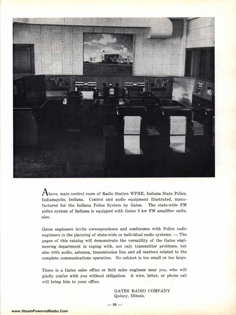
www.SteamPoweredRadio.Com
Above, main control room of Radio Station WPHE, Indiana State Police, Indianapolis, Indiana. Control and audio equipment illustrated, manufactured for the Indiana Police System by Gates. The state-wide FM police system of Indiana is equipped with Gates 3 kw FM amplifier units, also.
Gates engineers invite correspondence and conference with Police radio engineers in the planning of state-wide or individual radio systems. - The pages of this catalog will demonstrate the versatility of the Gates engineering department in coping with, not only transmitter problems, but also with audio, antenna, t ransmission line and all matters r elated to the complete communications operation. No subject is too small or too large.
There is a Gates sales office or field sales engineer near you, who will gladly confer with you without obligation. A wire, letter, or phone call will bring him to your office.
GATES RADIO COMPANY Quincy, Illinois.
-95-
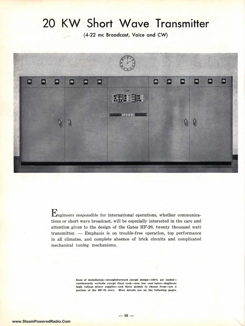
www.SteamPoweredRadio.Com
20 KW Short Wave Transmitter (4-22 me Broadcast, Voice and CW)
E ngineers responsible for international operations, whether communications or short wave broadcast, will be especially interested in the care and attention given to the design of the Gates HF-20, twenty thousand watt transmitter. - Emphasis is on trouble-free operation, top performance in all climates, and complete absence of trick circuits and complicated mechanical tuning mechanisms.
Ease of lnst,allatlon-slralrht forward circuit desirn-100% air cooledcontt.nuous ly· variable except final tank- new tow cost tubes-dup11cate high voltag-o power suppHes-and three models to choose from-are a portion of t;he H F-20 stor y. !\lore de tails are on the following pares.
- 96 -
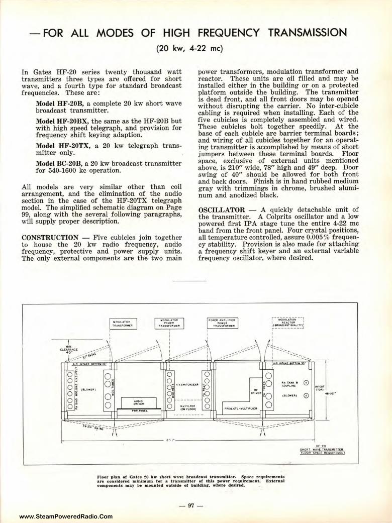
www.SteamPoweredRadio.Com
- FOR ALL MODES OF HIGH FREQUENCY TRANSMISSION (20 kw, 4-22 me)
In Gates HF-20 series twenty thousand watt transmitters three types are offered for short wave, and a fourth type for standard broadcast frequencies. These are:
Model HF-20B, a complete 20 kw short wave broadcast transmitter.
Model HF-20BX, the same as the HF-20B but with high speed telegraph, and provision for frequency shift keying adaption.
Model HF-20TX, a 20 kw telegraph transmitter only.
Model BC-20B, a 20 kw broadcast transmitter for 540-1600 kc operation.
All models are very similar other than coil arrangement, and the elimination of the audio section in the case of the HF-20TX telegraph model. The simplified schematic diagram on Page 99, along with the several following paragraphs, will supply proper description.
CONSTRUCTION - Five cubicles join together to house the 20 kw radio frequency, audio frequency, protective and power supply units. The only external components are the two main
I
U O()Ul.&fliOfllll TIU,HSFOftW R
M00U\..lt0R ll>O'W[lt
T AANSF(l ltM[lt
I
power transformers, modulation transformer and reactor. These units are oil filled and may be installed either in the building or on a protected platform outside the building. The transmitter is dead front, and all front doors may be opened without disrupting the carrier. No inter-cubicle cabling is required when installing. Each of the five cubicles is completely assembled and wired. These cubicles bolt together speedily. At the base of each cubicle are barrier terminal boards ; and wiring of all cubicles together for an operating transmitter is accomplished by means of short jumpers between these terminal boards. Floor space, exclusive of external units mentioned above, is 210" wide, 78" high and 49" deep. Door swing of 40" should be allowed for both front and back doors. Finish is in hand rubbed medium gray with trimmings in chrome, brushed aluminum and anodized black.
OSCILLATOR - A quickly detachable unit of the transmitter. A Colprits oscillator and a low powered first IPA stage tune the entire 4-22 me band from the front panel. Four crystal positions, all temperature controlled, assure 0.005 % frequency stability. Provision is also made for attaching a frequency shift keyer and an external variable frequency oscillator, where desired.
P'OW[R .U~Jll1,. IFICR illQW[R
f1UNSF0RM £R
r- MODULATION - •, I ACACTOR 1 1(8RO&OCA.ST 0UAL,I TT)1
r·--------:i I I I
M'N _ ... :, ' ,-::::\
J,-::::::::-::-::::::::: ::::: i -:::::::::::::::::::::'-~-----
J _ CL EARANCE __ -- j--.:::-~~-40~ --:. .,,,.- I
... --:::~~:::-:::::::::.~-! .. ~~ ~,7' ,,..,11~ I I -... -....-:..--:.. ........ , ' - I
0 ,. ' . J L I
I., l l'f A K • L -t ,...J ,_J_ _l L 0~ 0~ 0 0 - 0 0 3 0 0 O! iO PA f UK $ 0 0
~
Oj H. V 5WITGHCEAR ro coo,1.1NG
" (ILOWClll: I ., ~ Ofll 'l[R 4• •v2 • 0 oi ()g i) :o 0 ( 9LOWl!RI
0 ~
I I o· ------- 0 • AUOIO
o· 0 OlltlY[R
0 ..Q I fOEO. OTl.: MULT"' '-' '" r 0 _:: M.V,F!LT[R
'--r; PWR PAN(L r CON 'LOORI rr- r -- --------
- -- -- --- -- -- - -- -- - --1-------_,i,-;_;.;-~~._::::::.-::A:::-:..--.:.:.:.:.:-_--- ,, .. ,. _ _ ---:::-:::::::::.::.-:::_-__ -~===_.:----.:-------..;-IJ
Floor plan of Gates 20 kw short wave broadcast transmitter. Space requirements are considered mt.nimum for a. transmitter of t h is power requ.lrement. External components may be mounted outside of bulldlnf, where des ired.
-97-
HF·20 SHORT wiyf'TRANSMITT£R FLOOR SPACE REOUIRCMENT
www.SteamPoweredRadio.Com
GATES 20 KW HIGH FREQUENCY TRANSMITTERS
RADIO FREQUENCY - Including the oscillator, there are five stages. The second IP A-doubler is a 6146 tube self-neutralized, the RF driver a pair of 4-250A tubes self-neutralized, and the final power amplifer contains four 3X2500F3 tubes in push-pull parallel. On short wave models, output is balanced into a 300-800 ohm line. On broadcast models, output is from 50 to 270 ohms, as ordered. The entire operation is continuously variable from the front panel on the short wave models, except the power amplifier tank circuit. For this service, Gates has developed the latch-on tank coil system and tank coils may be changed in a matter of seconds, eliminating all complicated tuning and band change mechanisms in t he high power stage. Veeder counter type dials are used on all variable coils for split turn logging for frequency change. Of particular importance is the use of the thoriated tungsten filament 3X2500F3 tubes in the power amplifier, assuring long tube life and very low noise.
AUDIO FREQUENCY - Has four stages with push-pull parallel Class B 3X3000A3 tubes as modulators. Feedback is employed as an adjunct for improved noise reduction and less distortion. However, the HF-20 series transmitters will meet all acceptable standards without feedback. This means t hat feedback is not employed as a substitute for component size but, instead, to fur ther improve the excellent performance possible without feedback.
METERING - No multi-metering is employed, and a full meter complement is supplied to measure all necessary circuits both for tune-up and general operation. Individual plate currnnt meters are provided for each of the power amplifier and modulator tubes.
PROTECTION - Again Gates engineers have provided protection to the point that no power consuming circuit of importance has been overlooked. Primary thermal breakers are inserted in all main primary lines. Individual super-
visory overload relays are incorporated for, not only the transmitter main overload, but also for separate protection; exciter failure, air failure, RF driver, power amplifier, audio driver and modulators. Included are secondary relays for door interlock and air cooling interlock. Automatic condenser discharge relay switch immediately discharges the main filter capacitors when the door interlocks are disengaged.
RECYCLING - Automatic recycling relay cont rols automatically where the carrier is disrupted, and attempts to reset the carrier four times before remaining off. As many t imes carrier interruption is caused by static discharges across the transmission line or tower base, this recycling feature is indispensable.
POWER SUPPLIES - Five major power supplies deliver plate and bias voltage to the HF-20 transmitter. Featured are the two complete high voltage supplies. One is used for the radio frequency power amplifier and the other for the modulators. The resulting almost perfect regulation is quickly recognized by the engineer. Likewise, in case of failure of one power supply, the remaining one can be bussed in, operating the transmitter on reduced power until repairs are made. Each of these power supplies are full wave, three phase, six tube supplies. Other individual supplies provide modulator bias voltage, power amplifier bias voltage and intermediate voltage for driver stages. All power supplies are generously protected by circuit breakers, overload relays, etc. (see PROTECTION above).
KEYER - In the HF-20BX and HF-20TX models, electronic keying is t hrough an 812A tube so biased that with key closed no current is drawn. This operates in conjunction with the oscillator and IP A doubler stage. Keying speeds up to 400 WPM are possible, with excellent square top wave form.
Specifications on Page 100
- 98-
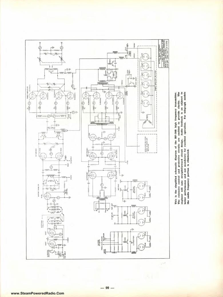
www.SteamPoweredRadio.Com
<O
'°
• .,;ov
o\"Jlt
.\,.'4
t11to
.C.T
1.l1
.~.w
(MO
=;~
l\f'i-
.,fl'tr
vl!l
l
y' f1
Tr•
'IIA
L
Oil
"' '"
'L
,.,.r:~
ot
-... • ~
oov
-· r--
-t----
--1
' I
I ...
.•.
...
,--
, __ ,-
-, ...
r t1
:
t'O
Dut
.AT
Olt
111
1u1r
1£11
: 1 1
11
u~
•s -1
•••,
. I
•ttt
1lt
f•I
I
I I I
I I
L---
----
---'
~ _
__
__
__
__
__
__
_ ------
PO
W(
Jlt
ll,M
IJ\.
JnU
I lll(
(t1
,1t:
fl -------
__
_ ---
~
Th
is
Is lh
e
sim
pli
fied
sc
hem
ati
c d
iag
ram
o
f lh
e
HF
-ZO
B
hig
h fr
equ
ency
lr
an
smlU
er.
T
he
exte
nsJ
ve
co
ntr
ol
an
d
pro
tect
ive
circ
uit
s a.
re
om
itte
d to
p
rov
ide
cla
rity
, T
he
en
rJn
eer
wlJ
I n
ote
str
aig
htf
orw
ard
cir
cu
it
des
ign
. A
ud
io
feed
back
ls
an
ad
jun
ct
to
bet
t.er
p
erf
orm
an
ce an
d
no
t m
and
ato
ry
for
e.xc
el1e
nt
op
era
tio
n.
Fo
r te
lerr
ap
b
mo
del
s th
e au
dio
fr
equ
ency
p
ort
ion
is
eli
min
ate
d.
www.SteamPoweredRadio.Com
MODEL HF-20 AND BC-20 TRANSMITTERS (20,000 watts)
SPECIFICATIONS FREQUENCY RANGE-4-22 me standard HF-20 models. May be provided to 2 me
on special order. Model BC-20B range, 550-1600 kc. POWER OUTPUT-20 kw at 100% modulation 2-18 me and 550-1600 kc. From
18-22 me, 16 kw. Telegraph models may be operated at slight excess to above ratings, depending on mode of keying.
POWER INPUT- Key down, no modulation, approximately 37 kw. Average program modulation, approximately 43 kw. At 100% modulation, approximately 55 kw.
INPUT VOLTAGE-230 volt, 3 phase, 50 cycles (60 cycles available where stated). Other primary voltages on special order.
INPUT IMPEDANCE-600 ohms at + 14 dbm. OUTPUT IMPEDANCE-300- 800 ohms into balanced line for high frequency
models. 51.5, 72 or 250 ohms, as ordered, for BC-20B. CRYSTALS-Provision for four in two ovens, selectable from front panel. 0.005%
accuracy. TUBES-6AG7 oscillat or, 6AG7 first IPA, 6146 buffer doubler, two 4-250A RF
drivers, four 3X2500F3 power amplifiers, two 6SJ 7 audio amplifiers, two 807 amplifiers, two 845 driver amplifiers, four 3X3000A3 modulators, twelve 673 rectifiers, two 866/ 866A modulator bias rectifiers, two 8008 PA bias rectifiers and two 8008 low voltage rectifiers.
RESPONSE-± 1½ db 50-10,000 cycles. NOISE-55 db or better below 100% modulation. DISTORTION-3% or better 100-5000 cycles. 4% or better 50-7500 cycles. KEYING--400 WPM or less, as required. Also provision for frequency shift keying
(see FSK units elsewhere in this catalog-see index) . SIZE-210" wide, 78" high, 49" deep. Door swing 40". WEI GHT- Approximately 23,000 lbs. packed. CUBAGE-720.
■
Ordering Data
Complete 20 kw high frequency broadcast transmitter, 4-22 me, less tubes and crystals. Cat. HF-20B
Complete 20 kw high frequency broadcast, voice and telegraph transmitter, less t ubes and crystals. Cat. HF-20BX
Complete 20 kw medium frequency broadcast transmitter for any frequency between 550 and 1600 kc, less tubes and crystals. Cat. BC-20B
Complete 20 kw telegraph transmitter (modulator and modulator power supply removed), 4-22 me, less tubes and crystals. Cat. HF-20TX
100% set of tubes for HF-20B, HF-20BX or BC-20B.
100 % set of tubes for HF-20TX transmitter.
Cat. TK-139
Cat. TK-140
CRYSTALS-Order Hl 7 in JKO-2 temperature controlled oven (see index under Crystals) ror all high frequency models. Order JK57M to rrequency for BC-20B.
- 100 -
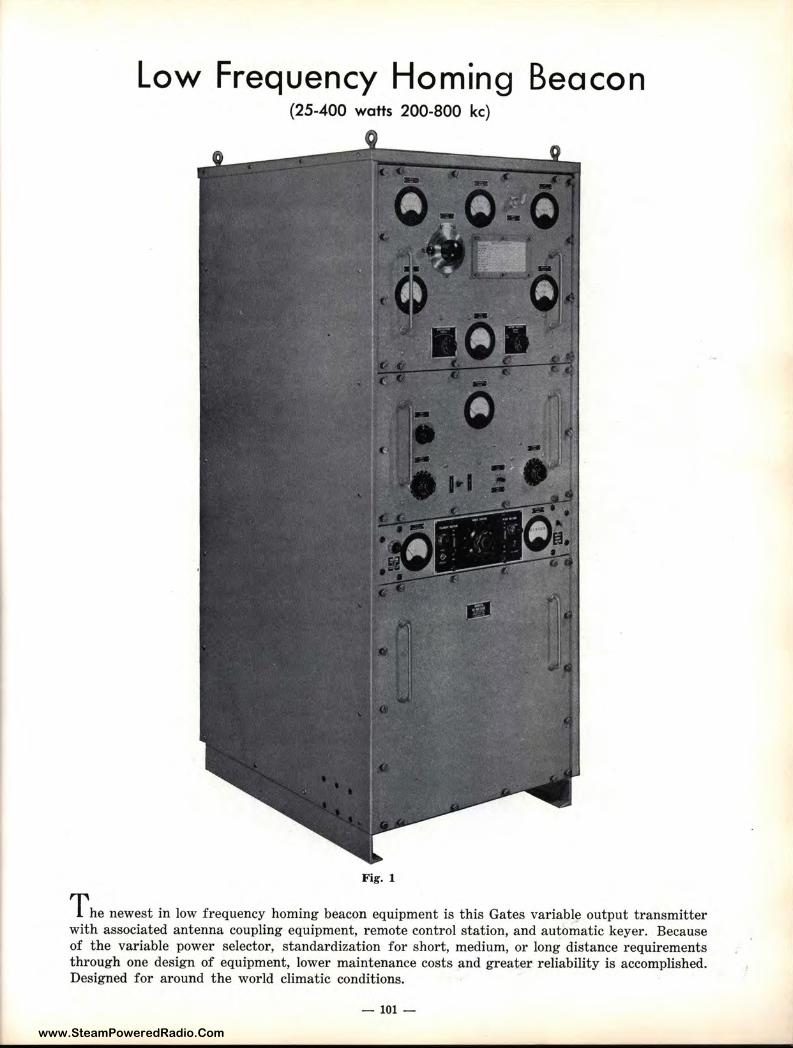
www.SteamPoweredRadio.Com
Low Frequency Homing Beacon (25-400 watts 200-800 kc)
Fig. 1
The newest in low frequency homing beacon equipment is this Gates variabl~ output transmitter with associated antenna coupling equipment, remote control station, and automatic keyer. Because of the variable power selector, standardization for short, medium, or long distance requirements through one design of equipment, lower maintenance costs and greater reliability is accomplished. Designed for around the world climatic conditions.
- 101-
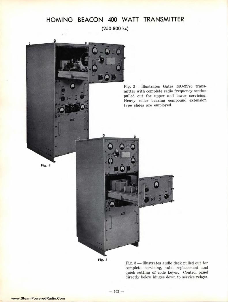
www.SteamPoweredRadio.Com
HOMING BEACON 400 WATT TRANSMITTER (250-800 kc)
Fig. 3
Fig. 2 - illustrates Gates M0-3975 transmitter with complete radio frequency section pulled out for upper and lower servicing. Heavy roller bearing compound extension type slides are employed.
- 102 -
Fig. 3 - illustrates audio deck pulled out for complete servicing, tube replacement and quick setting of code keyer. Control panel directly below hinges down to service relays.
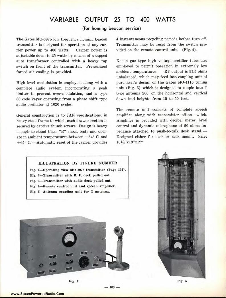
www.SteamPoweredRadio.Com
VARI ABLE OUTPUT 25 TO 400 WATTS (for homing beacon service)
The Gates MO-3975 low frequency homing beacon transmitter is designed for operation at any carrier power up to 400 watts. Carrier power is adjustable down to 25 watts by means of a tapped auto transformer controlled with a heavy tap switch on front of the transmitter. Pressurized forced air cooling is provided.
High level modulation is employed, along with a complete audio system incorporating a peak limiter to prevent over-modulation, and a type 36 code keyer operating from a phase shift type audio oscillator at 1020 cycles.
General construction is to JAN specifications, in heavy steel frame to which each drawer section is secured by captive thumb screws. Design is heavy enough to stand Class "B" shock tests and operate in ambient temperatures between - 54° C. and + 65° C. -Automatic reset of the carrier provides
4 instantaneous recycling periods before turn off. Transmitter may be reset from the switch provided on the remote control unit. (Fig. 4) .
Xenon gas type high voltage rectifier tubes are employed to permit operation in extremely low ambient temperatures. - RF output is 51.5 ohms unbalanced, which may feed into coupling unit of purchaser's design or the Gates MO-4116 tuning unit (Fig. 5) which is designed to couple into T type antenna 200' on the horizontal and vertical down lead heights from 15 to 50 feet.
The remote unit consists of complete speech amplifier along with transmitter off-on switch. Amplifier is provided with decibel meter, level control and dynamic microphone of 50 ohms impedance attached to push-to-talk desk stand. -Designed either for desk or rack mount. Size: 10½"x19"x12".
ILLUSTRATION BY FIGURE NUMBER
Fig. I-Operating view M0-3975 transmitter (Page 101).
Fig. 2-Transmitter with R. F. deck pulled out.
Fig. 3- Transmitter with audio deck pulled out.
Fig. 4-Remote control unit and speech amplifier.
Fig. 5-Antenna coupling unit for T antenna.
Fig. 4
- 103 -
Fig. 5
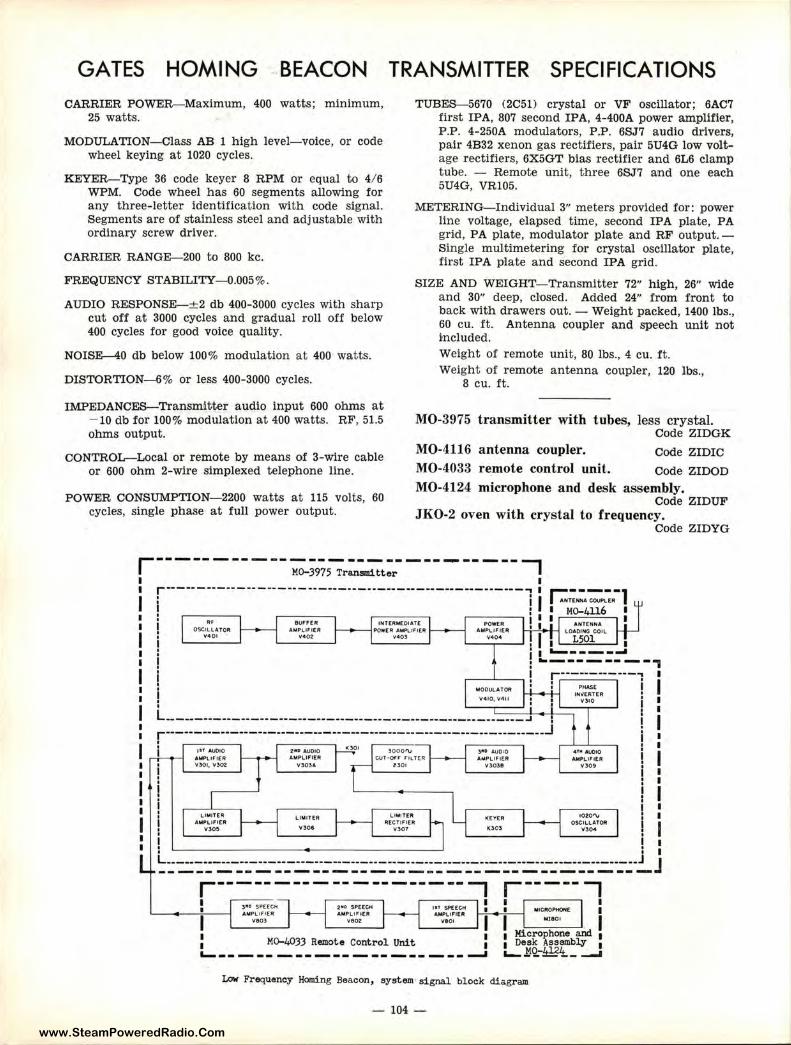
www.SteamPoweredRadio.Com
GATES HOMING BEACON CARRIER POWER-Maximum, 400 watts; minimum,
25 watts.
MODULATION-Class AB 1 high level-voice, or code wheel keying at 1020 cycles.
KEYER-Type 36 code keyer 8 RPM or equal to 4/ 6 WPM. Code wheel has 60 segments a llowing for any three-letter identification with code signal. Segments are of stainless steel and adjustable with ordinary screw driver.
CARRIER RANGE-200 to 800 kc.
FREQUENCY STABILITY--0.005%.
AUDIO RESPONSE-±2 db 400-3000 cycles with sharp cut off at 3000 cycles and gradual roll off below 400 cycles for good voice quality.
NOISE-40 db below 100% modulation at 400 watts.
DISTORTION-6% or less 400-3000 cycles.
IMPEDANCES-Transmitter audio input 600 ohms at - 10 db for 100% modulation at 400 watts. RF, 51.5 ohms output.
CONTROL-Local or remote by means of 3-wire cable or 600 ohm 2-wire simplexed telephone line.
POWER CONSUMPTION-2200 watts at 115 volts, 60 cycles, single phase at full power output.
TRANSMITTER SPECI Fl CATIONS TUBES--5670 (2051) crystal or VF oscillator; 6AC7
first IPA, 807 second IPA, 4-400A power amplifier , P .P. 4-250A modulators, P.P. 6SJ7 audio drivers, pair 4B32 xenon gas rectifiers, pair 5U4G low voltage rectifiers, 6X5GT bias rectifier and 6L6 clamp tube. - Remote unit, three 6SJ7 and one each 5U4G, VR105.
METERING-Individual 3" meters provided for: power line voltage, elapsed time, second IPA plate, PA grid, PA plate, modulator plate and RF output. -Single mul-timetering for crystal oscillator plate, first IPA plate and second IPA grid.
SIZE AND WEIGHT- Transmitter 72" high, 26" wide and 30" deep, closed. Added 24" from front to back with drawers out. - Weight packed, 1400 lbs., 60 cu. ft. Antenna coupler and speech unit not included. Weight of r emote unit, 80 lbs., 4 cu. ft. Weigh t of remote antenna coupler, 120 lbs.,
8 cu. ft.
MO-3975 transmitter with tubes, less crystal. Code ZIDGK
MO-4116 antenna coupler. Code ZIDIC
MO-4033 r~mote control unit. code ZIDOD
MO-4124 microphone and desk assembly. Code ZIDUF
JKO-2 oven with crystal to frequency. Code ZIDYG
r--- --- --- --~;9;;-;r:i:U--:-t:r- - - - - - - - - - 7 I r------ ---·-- ------ -·-·•----•--··----------------••-----, I
i I ••
OSCILl ATOR V401 '
ill~PLIF IER 't'402:
lNTERMECHATt PO#(R .t.Wl.lF'l[ft
V4103
~--~ • I ! I
V404 I I ----------,
. '
MODULATOI'
V410, V4 11
L __ --------------·---------------------------------------- ..I •
r··--------------------------------------·-··------------------.J 1n AUDIO AWLtFtEllt V301, Y302
LIMIT[JI AMPLIFIER
v:,o~
2•0 AUDIO .t,Mpt,.i,l [R
V303.t.
LIMI TER
Y>O<
}0001'\J C:.VT•O,r F'tLTtR
!)01
LIMl!l[llt A(C.TIF l(A
V30f
3 11.0 AUDIO AMPLIFIER
Y3038
l([ V[A
00:5
PHA$( INV[RT[R
V!IO
4'"' AUOIO &MPLl~ l[R
V309
1020'\, OSCILlATOA v,.,.
L------------------··-··-··-------·------·-··-··-·--·------------------------- J ---------------------------------------
: M0-4033 Remote Control Unit :
L------ ---------------_. Low Frequency Homing Beacon, system•signal block diagram
- 104 -
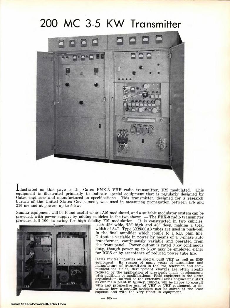
www.SteamPoweredRadio.Com
200 MC 3-5 KW Transmitter
l nustrated on this page is the Gates FMX-3 VHF radio transmitter, FM modulated. This equipment is illustrated primarily to indicate special equipment that is regularly designed by Gates engineers and manufactured to specifications. This transmitter, designed for a research bureau of the United States Government, was used in measuring propagation between 175 and 216 me and at powers up to 5 kw.
Similar equipment will be found useful where AM modulated, and a suitable modulator system can be provided, with power supply, by adding cubicles to the two shown. - The FBX-3 radio transmitter provides full 100 kc swing for high fidelity FM modulation. It is constructed in two cubicles,
each 42" wide, 78" high and 48" deep, making a total width of 84". Type 3X2500A3 tubes are used in push-pull in the final amplifier which couple to a 51.5 ohm line. Output is variable in power by means of a 3-phase auto transformer, continuously variable and operated from the front panel. Power output is rated 3 kw continuous duty, though power up to 5 kw may be employed either for ICCS or by acceptance of reduced power tube life.
Gates invites inquiries on special built VHF as well as UHF equipment. By reason of many years of association and manufacture of transmLtters in the FM, television and communications fields, development charges are often greatly reduced by the application of previously 'made developments with additions or modifications. Field engineers in the Gates organization, as well as the e>0tensive Gates engineering staff at our main plant in Quincy, Illinois, wlll be happy to consult with any prospective user of VHF or UHF equipment to determine how a specific problem can be solved at the least expense and with the very finest in equipment.
- 105 -
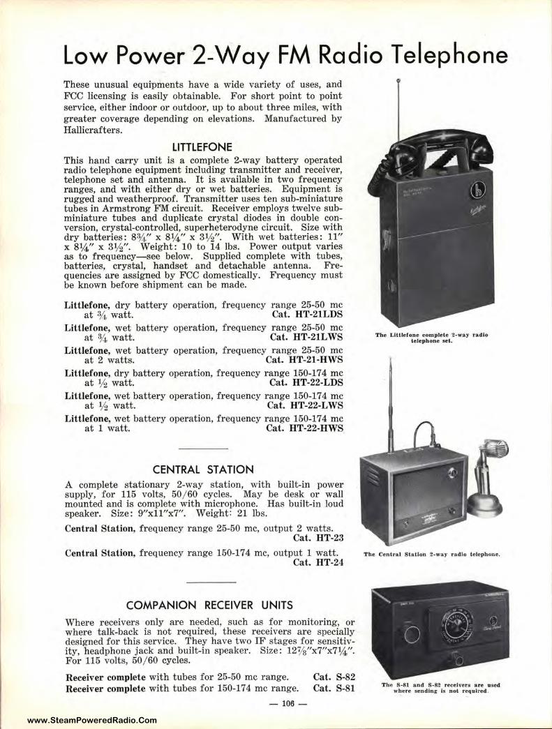
www.SteamPoweredRadio.Com
Low Power 2-Way FM Radio Telephone These unusual equipments have a wide variety of uses, and FCC licensing is easily obtainable. For short point to point service, either indoor or outdoor, up to about three miles, with greater coverage depending on elevations. Manufactured by Hallicrafters.
LITTLEFONE This hand carry unit is a complete 2-way battery operated radio telephone equipment including transmitter and receiver, telephone set and antenna. It is available in two frequency ranges, and with either dry or wet batteries. Equipment is rugged and weatherproof. Transmitter uses ten sub-miniature tubes in Armstrong FM circuit. Receiver employs twelve subminiature tubes and duplicate crystal diodes in double conversion, crystal-controlled, superheterodyne circuit. Size with dry batteries : 83/~" x 8¼" x 31/2". With wet batteries: 11" x 8¼" x 31/2". Weight: 10 to 14 lbs. Power output varies as to frequency-see below. Supplied complete with tubes, batteries, crystal, handset and detachable antenna. Frequencies are assigned by FCC domestically. Frequency must be known before shipment can be made.
Littlefone, dry battery operation, frequency range 25-50 me at ¾ watt. Cat. HT-21LDS
Littlefone, wet battery operation, frequency range 25-50 me at % watt. Cat. HT-21LWS
Littlefone, wet battery operation, frequency range 25-50 me at 2 watts. Cat. HT-21-HWS
Littlefone, dry battery operation, frequency range 150-17 4 me at ½ watt. Cat. HT-22-LDS
Littlefone, wet battery operation, frequency range 150-174 me at ½ watt. Cat. HT-22-LWS
Littlefone, wet battery operation, frequency range 150-174 me at 1 watt. Cat. HT-22-HWS
CENTRAL ST A TION A complete stationary 2-way station, with built-in power supply, for 115 volts, 50/ 60 cycles. May be desk or wall mounted and is complete with microphone. Has built-in loud speaker. Size : 9"xll"x7". Weight: 21 lbs.
Central Station, frequency range 25-50 me, output 2 watts. Cat. HT-23
Central Station, frequency range 150-174 me, output 1 watt. Cat. HT-24
COMPANION RECEIVER UNITS Where receivers only are needed, such as for monitoring, or where talk-back is not required, these receivers are specially designed for this service. They have two IF stages for sensitivity, headphone jack and built-in speaker. Size: 12%"x7"x7¼"For 115 volts, 50/ 60 cycles.
Receiver complete with tubes for 25-50 me range. Receiver complete with tubes for 150-174 me range.
- 106 -
Cat. S-82 Cat. S-81
The LIIUelone complete 2-way radio te lephone set.
The Central Station 2-w:.y radio telephone.
The S-81 and S-82 receivers are used where sending is not required.
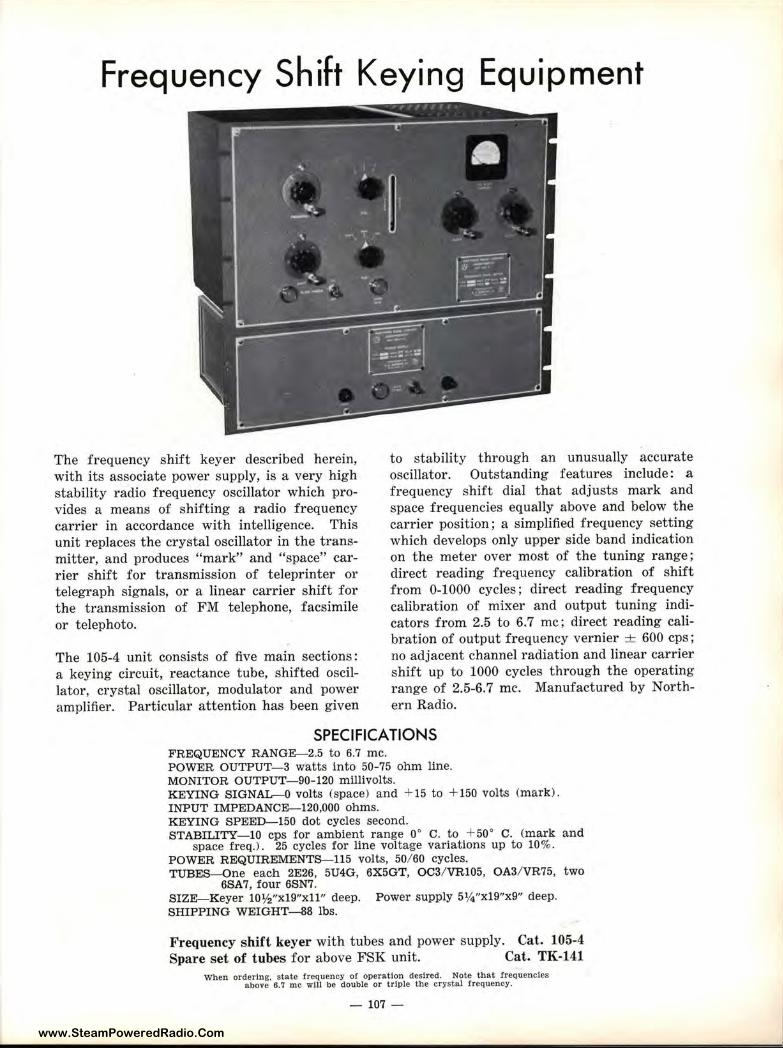
www.SteamPoweredRadio.Com
Frequency Shift Keying Equipment
The frequency shift keyer described herein, with its associate power supply, is a very high stability radio frequency oscillator which provides a means of shifting a radio frequency carrier in accordance with intelligence. This unit replaces the crystal oscillator in the transmitter, and produces "mark" and "space" carrier shift for transmission of teleprinter or telegraph signals, or a linear carrier shift for the transmission of FM telephone, facsimile or telephoto.
The 105-4 unit consists of five main sections: a keying circuit, reactance tube, shifted oscillator, crystal oscillator, modulator and power amplifier. Particula1· attention has been given
to stability through an unusually accurate oscillator. Outstanding features include: a frequency shift dial that adjusts mark and space frequencies equally above and below the carrier position; a simplified frequency setting which develops only upper side band indication on the meter over most of the tuning range; direct reading frequency calibration of shift from 0-1000 cycles; direct reading frequency calibration of mixer and output tuning indicators from 2.5 to 6.7 me; direct reading calibration of output frequency vernier ± 600 cps; no adjacent channel radiation and linear carrier shift up to 1000 cycles through the operating range of 2.5-6.7 me. Manufactured by Northern Radio.
SPECIFICATIONS FREQUENCY RANGE-2.5 to 6.7 me. POWER OUTPUT-3 watts into 50-75 ohm line. MONITOR OUTPUT-90-120 millivolts. KEYING SIGNAL-0 volts (space) and + 15 to + 150 volts (mark). INPUT IMPEDANCE-120,000 ohms. KEYING SPEED-150 dot cycles second. STABILITY-IO cps for ambient range 0° C. to +50° C. (mark and
space freq.). 25 cycles for line voltage variations up to 10%. POWER REQUIREMENTS-115 volts, 50/ 60 cycles. TUBES-One each 2E26, 5U4G, 6X5GT, OC3/ VR105, OA3/ VR75, two
6SA7, four 6SN7. SIZE-Keyer 10½"xl9"xll" deep. Power supply 5¼"x19"x9" deep. SHIPPING WEIGHT-88 lbs.
Frequency shift keyer with tubes and power supply. Cat. 105-4 Spare set of t ubes for above FSK unit. Cat. TK-141
When ordering, state frequency of operation desired. Note that frequencies above 6.7 me will be double or triple the crystal frequency.
- 107 -
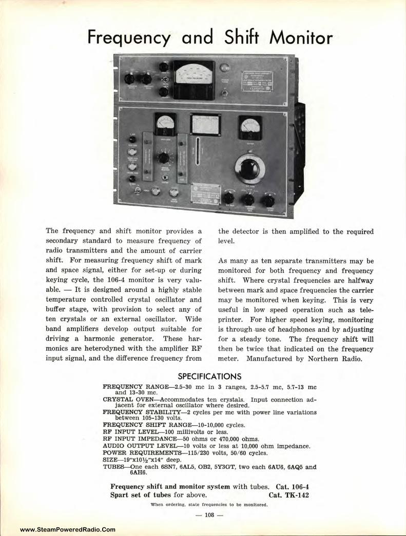
www.SteamPoweredRadio.Com
Frequency and
The frequency and shift monitor provides a secondary standard to measure frequency of radio transmitters and the amount of carrier shift. For measuring frequency shift of mark and space signal, either for set-up or during keying cycle, the 106-4 monitor is very valuable. - It is designed around a highly stable temperature controlled crystal oscillator and buffer stage, with provision to select any of ten crystals or an external oscillator. Wide band amplifiers develop output suitable for driving a harmonic generator. These harmonics are heterodyned with the amplifier RF input signal, and the difference frequency from
Shift Monitor
the detector is then amplified to the required level.
As many as ten separate transmitters may be monitored for both frequency and frequency shift. Where crystal frequencies are halfway between mark and space frequencies the carrier may be monitored when keying. This is very useful in low speed operation such as teleprinter. For higher speed keying, monitoring is through use of headphones and by adjusting for a steady tone. The frequency shift will then be twice that indicated on the frequency meter. Manufactured by Northern Radio.
SPECIFICATIONS FREQUENCY RANGE-2.5-30 me in 3 ranges, 2.5-5.7 me, 5.7-13 me
and 13-30 me. CRYSTAL OVEN- Accommodates ten crystals. Input connection ad
jacent for external oscillator where desired. FREQUENCY STABILITY- 2 cycles per me with power line variations
between 105-130 volts. FREQUENCY SHIFT RANGE-10-10,000 cycles. RF INPUT LEVEL-100 millivolts or less. RF INPUT IMPEDANCE-50 ohms or 470,000 ohms. AUDIO OUTPUT LEVEL--10 volts or less at 10,000 ohm impedance. POWER REQUIREMENTS- 115/230 volts, 50/ 60 cycles. SIZE-19"xl0½"xl4" deep. TUBES-One each 6SN7, 6AL5, OB2, 5Y3GT, two each 6AU6, 6AQ5 and
6AH6.
Frequency shift and monitor system with tubes. Cat. 106-4 Spart set of tubes for above. Cat. TK-142
When ordering, state frequencies to be monitored.
- 108 -
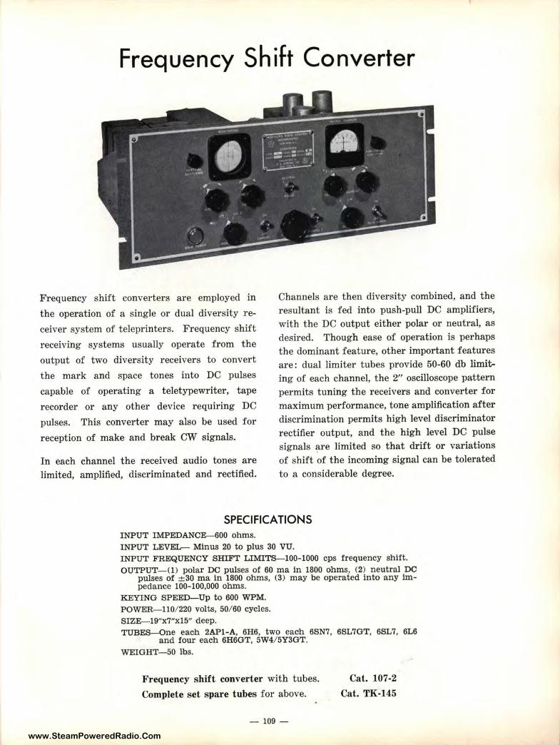
www.SteamPoweredRadio.Com
Frequency Shift Converter
Frequency shift converters are employed in
the operation of a single or dual diversity re
ceiver system of teleprinters. Frequency shift
receiving systems usually operate from the
output of two diversity receivers to convert
the mark and space tones into DC pulses
capable of operating a teletypewriter, tape
recorder or any other device requiring DC
pulses. This converter may also be used for
reception of make and break CW signals.
In each channel the received audio tones are limited, amplified, discriminated and rectified.
Channels are then diversity combined, and the resultant is fed into push-pull DC amplifiers, with the DC output either polar or neutral, as desired. Though ease of operation is perhaps the dominant feature, other important features are: dual limiter tubes provide 50-60 db limiting of each channel, the 2" oscilloscope pattern permits tuning the receivers and converter for maximum performance, tone amplification after discrimination permits high level discriminator rectifier output, and the high level DC pulse signals ~re limited so that drift or variations of shift of the incoming signal can be tolerated to a considerable degree.
SPECIFICATIONS INPUT IMPEDANCE-600 ohms. INPUT LEVEL-- Minus 20 to plus 30 VU. INPUT FREQUENCY SHIFT LIMITS-100-1000 cps frequency shift. OUTPUT- O) polar DC pulses of 60 ma in 1800 ohms, (2) neutral DC
pulses of ± 30 ma in 1800 ohms, (3) may be operated into any impedance 100-100,000 ohms.
KEYING SPEED-Up to 600 WPM. POWER-110/ 220 vol ts, 50/ 60 cycles. SIZE-19"x7"x15" deep. TUBES-One eac,h 2AP1-A, 6H6, two each 6SN7, 6SL7GT, 6SL7, 6L6
and four each 6H6GT, 5W4/ 5Y3GT. WEIGHT- 50 lbs.
Frequency shift converter with tubes.
Complete set spare tubes for above.
- 109 -
Cat. 107-2
Cat. TK-145
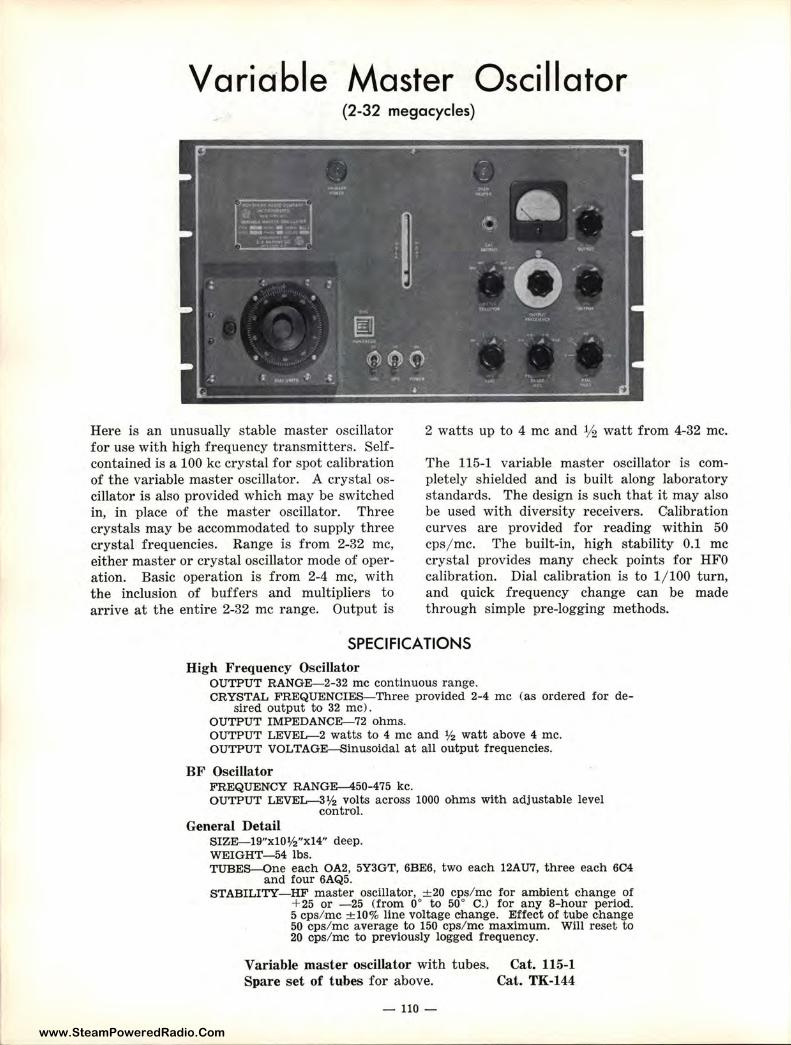
www.SteamPoweredRadio.Com
Variable Master Oscillator (2-32 megacycles)
Here is an unusually stable master oscillator for use with high frequency transmitters. Selfcontained is a 100 kc crystal for spot calibration of the variable master oscillator. A crystal oscillator is also provided which may be switched in, in place of the master oscillator. Three crystals may be accommodated to supply three crystal frequencies. Range is from 2-32 me, either master or crystal oscillator mode of operation. Basic operation is from 2-4 me, with the inclusion of buffers and multipliers to arrive at the entire 2-32 me range. Output is
2 watts up to 4 me and 1/2 watt from 4-32 me.
The 115-1 variable master oscillator is completely shielded and is built along laboratory standards. The design is such that it may also be used with diversity receivers. Calibration curves are provided for reading within 50 cps/ me. The built-in, high stability 0.1 me crystal provides many check points for HFO calibration. Dial calibration is to 1/ 100 turn, and quick frequency change can be made through simple pre-logging methods.
SPECIFICATIONS High Frequency OsciJJator
OUTPUT RANGE-2-32 me cont inuous range. CRYSTAL FREQUENCIES-Three provided 2-4 me (as ordered for de-
sired output to 32 me) . OUTPUT IMPEDANCE-72 ohms. OUTPUT LEVEL--2 watts to 4 me and ½ watt a bove 4 me. OUTPUT VOLTAGE-Sinusoidal at all output frequencies.
BF Oscillator FREQUENCY RANGE-450-475 kc. OUTPUT LEVEL--3½ volts across 1000 ohms with adjustable level
control. General Detail
SIZE-19"xl0½"xl4" deep. WEIGHT-54 lbs. TUBES-One each OA2, 5Y3GT, 6BE6, two each 12AU7, three each 6C4
and four 6AQ5. STABILITY-HF master oscillator, ± 20 cps/ me for ambient change of
+ 25 or - 25 (from o• to so• C.l for any 8-hour period. 5 cps/ me ± 10% line voltage change. Effect of tube change 50 cps/.mc average to 150 cps/ me maximwn. Will reset to 20 cps/ me to previously logged frequency.
Variable master oscillator with tubes. Spare set of tubes for above.
- 110-
Cat. 115-1 Cat. TK-144
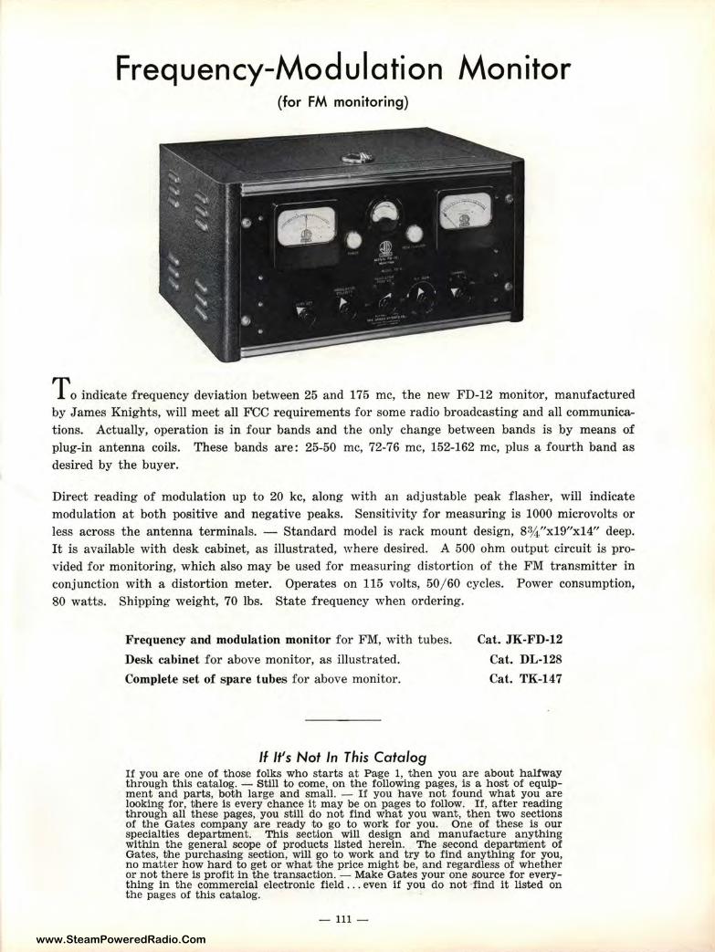
www.SteamPoweredRadio.Com
Frequency-Modulation Monitor (for FM monitoring)
To indicate frequency deviation between 25 and 175 me, the new FD-12 monitor, manufactured by James Knights, will meet all FCC requirements for some radio broadcasting and all communications. Actually, operation is in four bands and the only change between bands is by means of plug-in antenna coils. These bands are: 25-50 me, 72-76 me, 152-162 me, plus a fourth band as desired by the buyer.
Direct reading of modulation up to 20 kc, along with an adjustable peak flasher, will indicate modulation at both positive and negative peaks. Sensitivity for measuring is 1000 microvolts or less across the antenna terminals. - Standard model is rack mount design, 8¾ "xl9"xl4" deep. It is available with desk cabinet, as illustrated, where desired. A 500 ohm output circuit is provided for monitoring, which also may be used for measuring distortion of the FM transmitter in conjunction with a distortion meter. Operates on 115 volts, 50/ 60 cycles. Power consumption, 80 watts. Shipping weight, 70 lbs. State frequency when ordering.
Frequency and modulation monitor for FM, with tubes.
Desk cabinet for above monitor, as illustrated.
Complete set of spare tubes for above monitor.
If It's Not In This Catalog
Cat. JK-FD-12
Cat. DL-128
Cat. TK-147
If you are one of those folks who starts at Paige 1, then you are about halfway through this catalog. - Still to come, on the following pages, is a host of equipment and parts, both large and small. - If you have not found what you are looking for, there is every chance it may be on pages to follow. If, after reading through all these pages, you still do not find what you want, then two sections of the Gates company are ready to go to work for you. One of these is our specialties department. This section will design and manufacture anything within the general scope of products listed herein. The second department of Gates, the purchasing seotion, will go to work and try to find anything for you, no matter how hard to get or what the price might be, and regardless of whether or not there is profit in the transaction. - Make Gates your one source for everything in the commercial electronic field ... even if you do not find it Us,ted on the pages of this catalog.
- 111 -
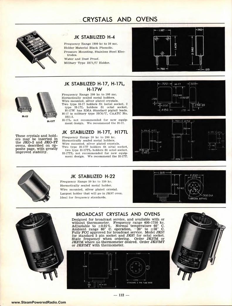
www.SteamPoweredRadio.Com
H-17
H -17T
These crystals and holders may •be inserted in the JKO-2 and JK0-2T ovens, described on opposite page, with greatly improved stability.
CRYSTALS AND OVENS
JK STABILIZED H-4 Frequency R ange 1800 kc to 20 me. H older Material B lack Phe nolic. P r essure Mounting, Stainless Steel E lec-
trodes. W ater a nd D ust Proof. Militar y Type HCl/U Holder.
JK STABILIZED H-17, H-17L, H-17W
Frequency Range 200 kc to 100 me. H e rmetically sealed metal holder s. Wire moun ted, silver plated c rystals . Two type H-17 holders fit loctal socket, 2
type H -17L holders fit octal socket, H -17W has RMA Standar d pigtail leads.
H-17 is military type HC6/U, CAATC N o . 3Rl-3.
H-17L not recommended for new equipmen t design. We recommend t he H-17.
JK STABILIZED H-17T, Hl7TL Frequency Range 20 kc to 200 kc. Hermetically sealed metal holder s. Wir e mounted, silve1· plated cr ystals . Two type H-17T holders fl t octal socket,
two type H-17TL holders fl t octal socket. H-17TL not recommended for n ew equip ,
ment design. v'i'e recommend the H-17T.
JK STABILIZED H-22 F requency Range 50 kc to 150 kc. He1·metically sealed metal holder. W h'e mounted, silver p lated c rystal. Largest holder that will go in JK07 oven. Ideal for f requency standa1·ds.
BROADCAST CRYSTALS AND OVENS Designed for broadcast service, and available with or without thermometer. Frequency range 400-1750 kc. Adjustable to ± 0.01 %. Normal temperature 60° C. Ambient range 60° C. operation, - 20° to ± 58° C. Fully FCC approved for broadcast service. Model J K57 for standard 5 pin socket and JK87 for octal socket. State frequency when ordering. Order JK57M or JK87M where no thermometer desired. Order JK57MT or JK87MT with thermometer.
112 -
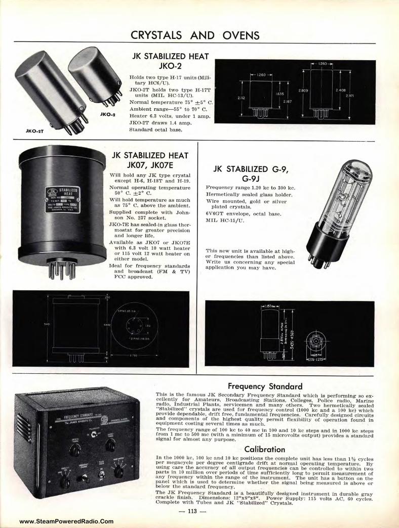
www.SteamPoweredRadio.Com
Jl<0-2
CRYSTALS AND OVENS
JK STABILIZED HEAT JK0-2
Holds two type H-17 units (Military HC6/U).
JKO-2T holds two type H -l 7T units (MIL HC-13/U).
Normal temperature 75° ±5° C. Ambient range-55° to 70° C. Heater 6.3 volts, under l amp. JKO-2T draws 1.4 amp. Standard octal base.
JK STABILIZED HEAT JK07, JK07E JK STABILIZED G-9,
"\'V'ill hold any JK type crystal except H-6, H-18T and H-19.
Normal operating temperature 50° C. ±2° C.
Will hold temperature as much as 75° C. above the ambient.
Supplied complete with Johnson No. 237 socket.
JKO-7E has sealed-in g lass thet·· mostat for greater precision and longer life.
Available as JKO7 or JKO7E with 6.3 volt 10 watt heater or 115 volt 12 watt heater o n either mode l.
Ideal for frequency standards a nd brnadcast (FM & 1'V) FCC approved.
G-9J Frequency range 1.20 kc to 300 kc. Hermetically sealed g lass holder. Wire mounted, gold or silver
plated crystals. 6V6GT envelope, octal base. MIL HC-15/U.
This new unit is available at higher frequencies than listed above. Wt•ite us concerning any special application you may have.
Frequency Standard This is the famous JK Secondary Frequency Standard which is performing so excellently for Amateurs, Broadcasting S'tations, Colleges, Police radio, Marine radio, Industrial Plants, servicemen and many others. Two hermetically sealed "Stabili:o1ed" crystals are used for frequency control (1000 kc and a 100 kc) which provide dependable, drift free, fundamental frequencies. Carefully designed ci rcuits and compo nents of the highest quality permit flexibility of operation found in equipment costing several times as much. The frequency range of 100 kc to 40 me in 100 and 10 kc steps and in 1000 kc steps from 1 me to 500 me (with a minimum of 15 microvolts output) provides a standard signal for alm ost any purpose.
Calibration In the 1000 kc, 100 kc and 10 kc positions the complete unit has less than 1½ cycles per megacycle per degree centigrade drift at normal operating temperatm·e. By using care the accuracy of all output frequencies can be controlled to within two parts in 10 million over pet·iods of time sufficiently long to permit measurement of any frequency within the range of the instrument. The unit has a button on the panel which is used to determine whether the signal being measured is above or below the standard frequency. The JK Frequency Standard is a beautifully designed instrument in durable gray crackle finish. Dimensions: 12"x8"x8". Power Supply: 115 volts AC, 60 cycles. Complete with Tubes and JK "Stabilized" Crystals.
- 113 -
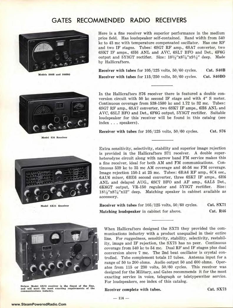
www.SteamPoweredRadio.Com
GATES RECOMMENDED RADIO RECEIVERS
Models S408 and S4080
Model S76 Receiver
Model sxn Receiver
Deluxe Model SX73 receiver is the finest of the fJ.ne, and wlll meet the most exacting requirements of the communJcatlons industry.
Here is a fine receiver with superior performance in the medium price field. Has loudspeaker self-contained. Band width from 540 kc to 43 me with temperature compensated oscillator. Has one RF and two IF stages. Tubes: 6SG7 RF amp., 6SA7 converter, two 6SK7 IF amps., 6H6 ANL and A VC, 6SL7 BFO and Det., 6F6G output and 5Y3GT rectifier. Size: 18½"x8%"x9½" deep. Made by Hallicrafters.
Receiver with tubes for 105/ 125 volts, 50/ 60 cycles.
Receiver with tubes for 115/ 250 volts, 50/ 60 cycles.
Cat. S40B
Cat. S40BO
In the Hallicrafters S76 receiver there is featured a double conversion circuit with 50 kc second IF stage and with 4" S meter. Continuous coverage from 538-1580 kc and 1.72 to 32 me. Tubes: 6SG7 RF amp., 6SA 7 converter, two 6SK7 IF amps., 6H6 ANL and A VC, 6SL7 BFO and Det., 6F6G output, 5Y3GT rectifier. Suitable loudspeaker for t his .receiver will be found in this catalog (see index ... speakers).
Receiver with tubes for 105 / 125 volts, 50 / 60 cycles. Cat. S76
Extra sensitivity, selectivity, stability and superior image rejection is provided in the Hallicrafters S71 receiver. A double superheterodyne circuit along with narrow band FM service makes this a fine receiver, ideal for both AM and FM communications. Continuous 539 kc to 35 me AM coverage and 46-56 me FM coverage. Image rejection 150-1 at 25 me. Tubes: 6BA6 RF amp., 6C4 osc., 6AU6 mixer, 6BE6 second converter, three 6SK7 IF amps., 6H6 ANL and delayed AUG., 6SC7 BFO and AF amp., 6AL5 Det ., 6K6GT output, VR-150 regulator and 5Y3GT rectifier. Size: 181//'x81/s"x12" deep. Matching speaker in cabinet available as accessory.
Receiver with tubes for 105/ 125 volts, 50/ 60 cycles.
Matching loudspeaker in cabinet for above.
Cat. SX71
Cat. R46
When Hallicrafters designed the SX73 they provided the communications industry with a product unequalled in their entire line. For ruggedness, sensitivity, stability, selectivity, restability, image and IF rejection, the SX73 has no peer. Continuous coverage from 540 kc to 54 me. Dual RF and IF stages plus dual conversion above 7 me. The 2nd beat oscillator is crystal controlled. Tube complement totals 17 tubes. Antenna input for a range of 50 to 200 ohms. Audio output 50 and 600 ohms. Operates from 115 or 230 volts, 50 / 60 cycles. This receiver was designed for the Military, and Gates recommends it for the most exacting service in voice, telegraph or teletypewriter service. For loudspeakers, see index of this catalog.
Receiver complete with tubes.
-114 -
Cat. SX73
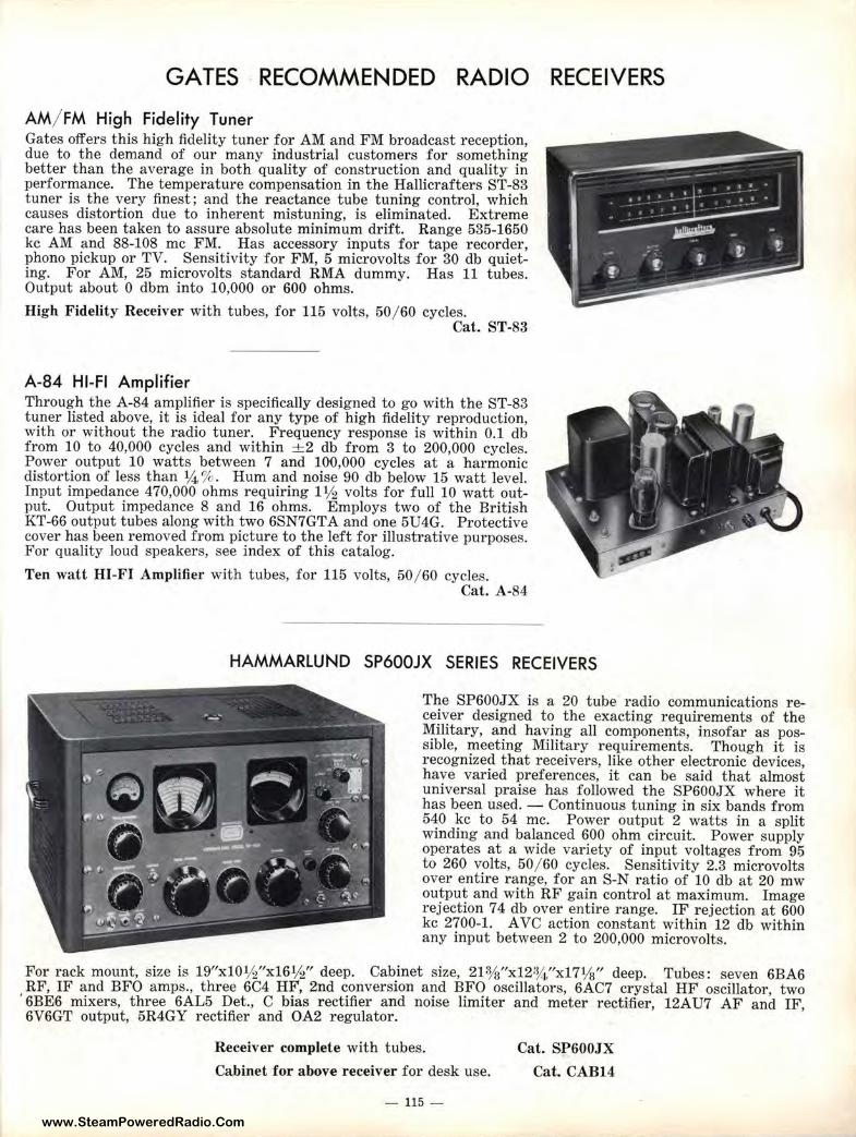
www.SteamPoweredRadio.Com
GATES RECOMMENDED RADIO RECEIVERS
AM/ FM High Fidelity Tuner Gates offers this high fidelity tuner for AM and FM broadcast reception, due to the demand of our many industrial customers for something better than the average in both quality of construction and quality in performance. The temperature compensation in the Hallicrafters ST-83 tuner is the very finest; and the reactance tube tuning control, which causes distortion due to inherent mistuning, is eliminated. Extreme care has been taken to assure absolute minimum drift. Range 535-1650 kc AM and 88-108 me FM. Has accessory inputs for tape recorder, phono pickup or TV. Sensitivity for FM, 5 microvolts for 30 db quieting. For AM, 25 microvolts standard RMA dummy. Has 11 tubes. Output about O dbm into 10,000 or 600 ohms.
High Fidelity Receiver with tubes, for 115 volts, 50/ 60 cycles. Cat. ST-83
A-84 HI-Fl Amplifier Through the A-84 amplifier is specifically designed to go with the ST-83 tuner listed above, it is ideal for any type of high fidelity reproduction, with or without the radio tuner. Frequency response is within 0.1 db from 10 to 40,000 cycles and within +2 db from 3 to 200,000 cycles. Power output 10 watts between 7 and 100,000 cycles at a harmonic distortion of less than ¼ % . Hum and noise 90 db below 15 watt level. Input impedance 470,000 ohms requiring 1 ½ volts for full 10 watt output. Output impedance 8 and 16 ohms. Employs two of the British KT-66 output tubes along with two 6SN7GTA and one 5U4G. Protective cover has been removed from picture to the left for illustrative purposes. For quality loud speakers, see index of this catalog.
Ten wa.tt HI-FI Amplifier with tubes, for 115 volts, 50/ 60 cycles. Cat. A-84
HAMMARLUND SP600JX SERIES RECEIVERS
The SP600JX is a 20 tube radio communications receiver designed to the exacting requirements of the Military, and having all components, insofar as possible, meeting Military requirements. Though it is recognized that receiver s, like other electronic devices, have varied preferences, it can be said that almost universal praise has followed the SP600JX where it has been used. - Continuous tuning in six bands from 540 kc to 54 me. Power output 2 watts in a split winding and balanced 600 ohm circuit. Power supply operates at a wide variety of input voltages from 95 to 260 volts, 50/ 60 cycles. Sensitivity 2.3 microvolts over entire range, for an S-N ratio of 10 db at 20 mw output and with RF gain control at maximum. Image rejection 74 db over entire range. IF rejection at 600 kc 2700-1. A VC action constant within 12 db within any input between 2 to 200,000 microvolts.
For rack mount, size is 19"xlO½"xl6½" deep. Cabinet size, 21%"x12¾."xl 71/s" deep. Tubes : seven 6BA6 RF, IF and BFO amps., three 6C4 HF, 2nd conversion and BFO oscillators, 6AC7 crystal HF oscillator, two
' 6BE6 mixers, three 6AL5 Det., C bias rectifier and noise limiter and meter rectifier, 12AU7 AF and IF, 6V6GT output, 5R4GY rectifier and OA2 regulator.
Receiver complete with tubes.
Cabinet for abov,e receiver for desk use.
- 115 -
Cat. SP600JX
Cat. CAB14
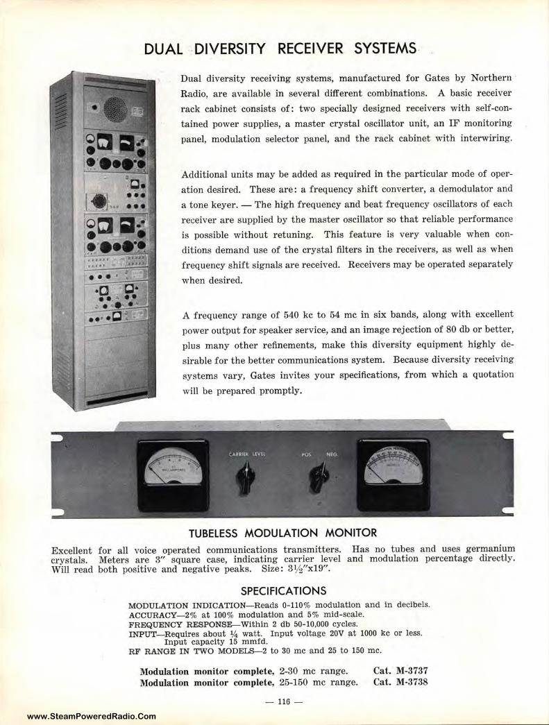
www.SteamPoweredRadio.Com
DUAL DIVERSITY RECEIVER SYSTEMS-
Dual diversity receiving systems, manufactured for Gates by Northern ·
Radio, are available in several different combinations. A basic receiver
rack cabinet consists of: two specially designed receivers with self-con
tained power supplies, a master crystal oscillator unit, an IF monitoring
panel, modulation selector panel, and the rack cabinet with interwiring.
Additional units may be added as required in the particular mode of oper
ation desired. These are: a frequency shift converter, a demodulator and
a tone keyer. - The high frequency and beat frequency oscillators of each
receiver are supplied by the master oscillator so that reliable performance
is possible without retuning. This feature is very valuable when con
ditions demand use of the crystal filters in the receivers, as well as when
frequency shift signals are received. Receivers may be operated separately
when desired.
A frequency range of 540 kc to 54 me in six bands, along with excellent
power output for speaker service, and an image rejection of 80 db or better,
plus many other refinements, make this diversity equipment highly de
sirable for the better communications system. Because diversity receiving
systems vary, Gates invites your specifications, from which a quotation
will be prepared promptly.
TUBELESS MODULATION MONITOR
Excellent for all voice operated communications transmitters. Has no tubes and uses germanium crystals. Meters are 3" square case, indicating carrier level and modulation percentage directly. Will read both positive and negative peaks. Size: 3 ½"x19".
SPECIFICATIONS MODULATION INDICATION- Reads 0-110% modulation and in decibels. ACCURACY- 2% at 100% modulation and 5% mid-scale. FREQUENCY RESPONSE-Within 2 db 50-10,000 cycles. INPUT-Requires about ¼ watt. Input voltage 20V at 1000 kc or less.
Input capacity 15 mmfd. RF RANGE IN TWO MODELS-2 to 30 me and 25 t o 150 me.
Modulation monitor complete, 2-30 me range. Modulation monitor complete, 25-150 me range.
- 116 -
Cat. M-3737 Cat. M-3738
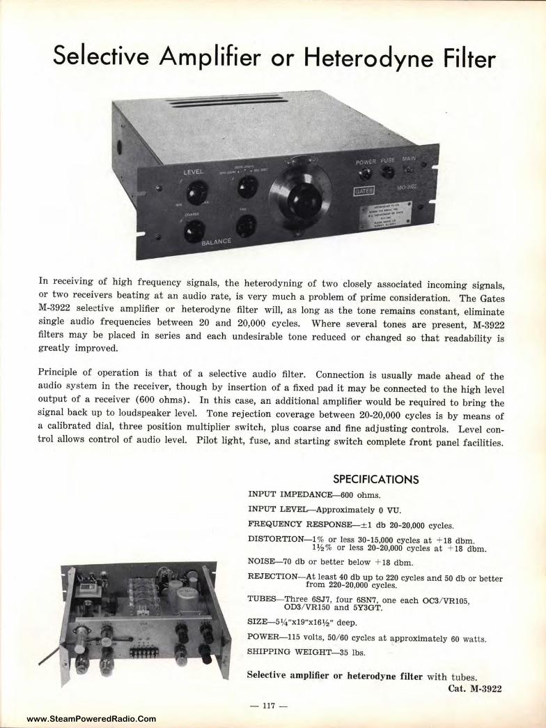
www.SteamPoweredRadio.Com
Selective Amplifier or Heterodyne Filter
In receiving of high frequency signals, the heterodyning of two closely associated incoming signals, or two receivers beating at an audio rate, is very much a problem of pr ime consideration. The Gates M-3922 selective amplifier or heterodyne filter will, as long as the tone remains constant, eliminate single audio frequencies between 20 and 20,000 cycles. Where several tones are present, M-3922 filters may be placed in series and each undesirable tone reduced or changed so t hat readability is greatly improved.
Principle of operation is that of a selective audio filter. Connection is usually made ahead of the audio system in the receiver, though by insertion of a fixed pad it may be connected to the high level output of a receiver (600 ohms). In this case, an additional amplifier would be required to bring the signal back up to loudspeaker level. Tone rejection coverage between 20-20,000 cycles is by means of a calibrated dial, three position multiplier switch, plus coarse and fine adjusting controls. Level control allows control of audio level. Pilot light, fuse, and starting switch complete front panel facilities.
SPECIFICATIONS INPUT IMPEDANCE-600 ohms.
INPUT LEVEL-Approximately O VU.
FREQUENCY RESPONSE-± 1 db 20-20,000 cycles.
DISTORTION-1 % or less 30-15,000 cycles at + 18 dbm. 1½% or less 20-20,000 cycles at + 18 dbm.
NOISE-70 db or better below + 18 dbm.
REJECTION-At least 40 db up to 220 cycles and 50 db or better from 220-20,000 cycles.
TUBES- Three 6SJ 7, four 6SN7, one each OC3/ VR105, OD3/ VR150 and 5Y3GT.
SIZE-5¼"xl9"xl6½" deep.
POWER-115 volts, 50/60 cycles at approximately 60 watts.
SHIPPING WEIGHT-35 lbs.
Selective amplifier or heterodyne filter with tubes. Cat. M-3922
- 117 -
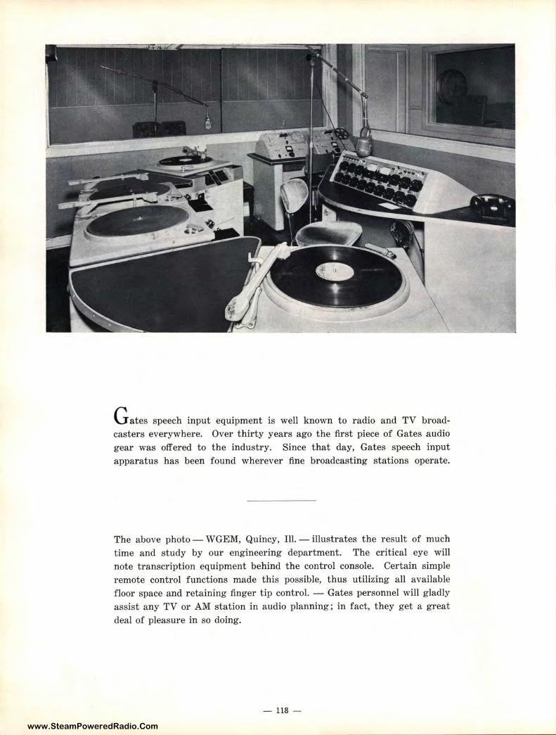
www.SteamPoweredRadio.Com
G ates speech input equipment is well known to radio and TV broadcasters everywhere. Over thirty years ago the first piece of Gates audio gear was offered to the industry. Since that day, Gates speech input apparatus has been found wherever fine broadcasting stations operate.
The above photo - WGEM, Quincy, Ill. - illustrates the result of much time and study by our engineering department. The critical eye will note transcription equipment behind the control console. Certain simple remote control functions made this possible, thus utilizing all available floor space and retaining finger tip control. - Gates personnel will gladly assist any TV or AM station in audio planning; in fact, they get a great deal of pleasure in so doing.
- 118 -
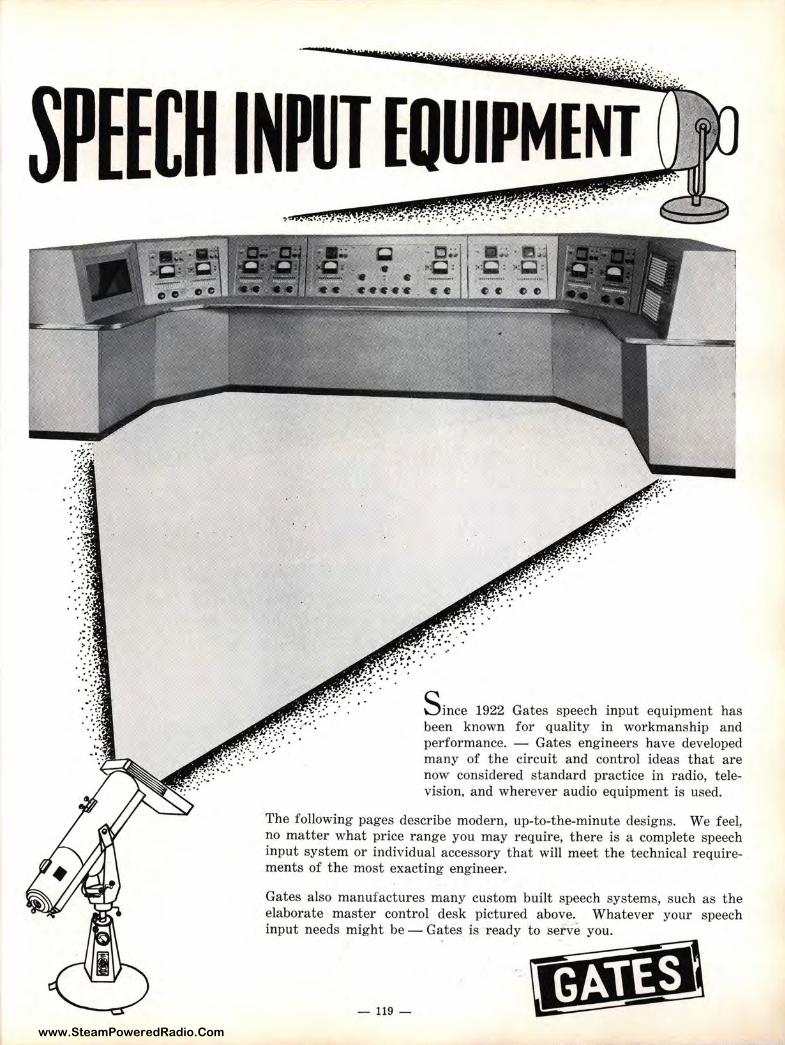
www.SteamPoweredRadio.Com
.. ,. , >: . ' ...... . . ~ ...
NPUT EQUIPMENT , • ~•-•:•. ,-,.: .. !~.'.' -,~ ...•. ·. ~:=)tf ?':.~~ .~_:f_f.:-<: ·::. . .:_ .. _.: : .. t~., ... ,, _✓• :··· • ~===::::::;;,
. ■:..:.. · IJ;,1 ~:~ : ~=~ = -....... , .............. .,. • e e e
S ince 1922 Gates speech input equipment has been known for quality in workmanship and performance. - Gates engineers have developed many of the circuit and control ideas that are now considered standard practice in radio, television, and wherever audio equipment is used.
The following pages describe modern, up-to-the-minute designs. We feel, no matter what price range you may require, there is a complete speech input system or individual accessory that will meet the technical requirements of the most exacting engineer.
Gates also manufactures many custom built speech systems, such as the elaborate master control desk pictured above. Whatever your speech input needs might be - Gates is ready to serve you.
- 119 -IJtl;.li:t:
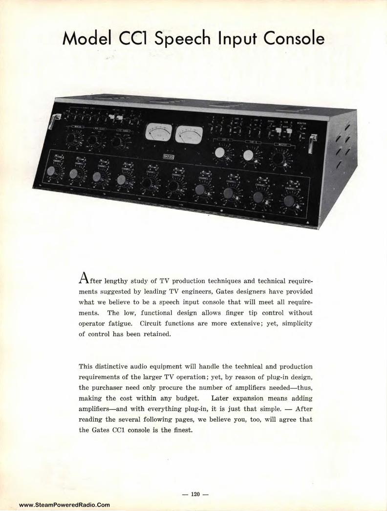
www.SteamPoweredRadio.Com
Model CCl Speech Input Console
A fter lengthy study of TV production techniques and technical require
ments suggested by leading TV engineers, Gates designers have provided
what we believe to be a speech input console that will meet all require
ments. The low, functional design allows finger tip control without
operator fatigue. Circuit functions are more extensive; yet, simplicity
of control has been retained.
This distinctive audio equipment will handle the technical and production
requirements of the larger TV operation; yet, by reason of plug-in design,
the purchaser need only procure the number of amplifiers needed-thus,
making the cost within any budget. Later expansion means adding
amplifier s-and with everything plug-in, it is j ust that simple. - After
reading the several following pages, we believe you, too, will agree that
the Gates CCl console is the finest.
- 120 -
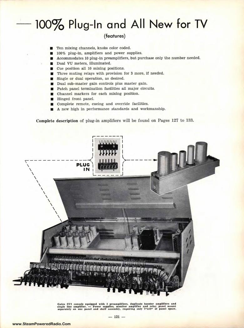
www.SteamPoweredRadio.Com
100% Plug-In and All New for TV (features)
■ Ten mixing ch'annels, knobs color coded. ■ 100% plug-in, ,amplifiers and power supplies. ■ Accommodates 10 plug-in preamplifiers, but purchase only the number needed. ■ Dual VU meters, illuminated. ■ Cue position all 10 mixing positions. ■ Three muting relays with provision for 3 more, if needed. ■ Single or dual operation, as desired. ■ Dual sub-master gain controls plus master gain. ■ Patch panel termination facilities all major circuits. ■ Channel markers for each mixing position. ■ Hinged front panel. ■ Complete remote, cueing and override facilities. ■ A new high in performance standards and workmanship.
Complete description of plug-in amplifiers will be found on Pages 127 to 133.
Gates CCl console equipped with 5 preamplifler s, duplicate booster amplltlers an d s inr le Une amplifier. - Power supplies, monitor a.mpJlfler and rela.y panel mount separately on one panel and shelf assembly, requiring- only '711xl 9" of panel s pace.
- 121 -
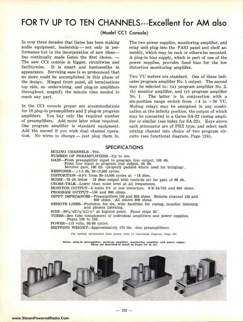
www.SteamPoweredRadio.Com
FOR TV UP TO TEN CHANNELS---Excellent for AM also (Model CCl Console)
In over three decades that Gates has been making audio equipment, leadership - not only in performance but in the incorporation of new ideashas continually made Gates the first choice. -The new CCl console is bigger, circuitwise and facilitywise. It is smart and businesslike in appearance. Servicing ease is so pronounced that no more could be accomplished in this phase of the design. Hinged front panel, all terminations top side, no underwiring, and plug-in amplifiers throughout, magnify the minute time needed to reach any part.
In the CCl console proper are accommodations for 10 plug-in preamplifiers and 2 plug-in program amplifiers. You buy only the required number of preamplifiers. Add more later when required. One program amplifier is standard equipment. Add the second if you wish dual channel operation. No wires to change -just plug them in.
The two power supplies, monitoring amplifier, and relay unit plug into the P ASl panel and shelf assembly, which may be rack or otherwise mounted. A plug-in bias supply, which is part of one of the power supplies, provides fixed bias for the low distortion monitoring amplifier.
Two VU meters are standard. One of these indicates program amplifier No. 1 output. The second may be selected to: (a) program amplifier No. 2, (b) monitor amplifier, and (c) program amplifier No. 1. The latter is in conjunction with a six-position range switch from + 4 to + 30 VU. Muting relays may be energized in any combination at the infinity position, the output of which may be connected to a Gates SA-22 cueing amplifier or similar (see index for SA-22). Keys above each attenuator are of PBX type, and select each mixing channel into choice of two program circuits (see functional diagram, Page 124).
SPECIFICATIONS MIXING CHANNELS-Ten. NUMBER OF PREAMPLIFIERS--Up to ten. GAIN- From preamplifier input to program line output, 106 db.
From line input to program line output, 65 db. Monitor gain, 100 db. (properly padded where used for bridging) .
RESPONSE- ::t:1.5 db, 30-15,000 cycles. DISTORTION-0.5% from 30-15,000 cycles at + 18 dbm. NOISE-70 db below - 18 dbm output with controls set for gain of 68 db. CROSS-TALK-Lower than noise level at all frequencies. MONITOR OUTPUT-8 watts 3% or less distortion. 4/ 8/ 16/150 and 600 ohms. PROGRAM OUTPUT-150 and 600 ohms. INPUT IMPEDANCES- Preamplifier,s 150 and 600 ohms. Remote channel 150 and
600 ohms. All others 600 ohms. REMOTE LINES--Provision for six, with facilities for cueing, monitor listening
and phones listening. SIZE-39¼ "x21 ½"xll ¾" at highest point. Panel slope 30°. TUBES-See tube complement of individual amplifiers and power supplies,
Pages 128 to 132. POWER-115 volts, 50/ 60 cycles. SHIPPING WEIGHT- Approximately 175 lbs. (less preamplifiers).
For fur th er Informative d ata p lease refer to function a l diagram, Page 124.
Below, plug.in preamplifier, program amplifier, monltorlng- a.mplitier and power supply. These are described In detail on Pai es 127 to 132.
- 122 -
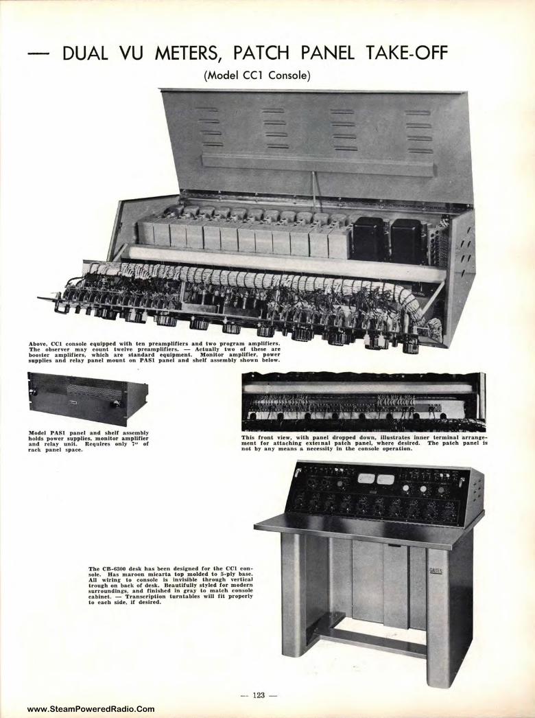
www.SteamPoweredRadio.Com
DUAL VU METERS, PATCH PANEL TAKE-OFF (Mode l CCl Console)
Above, CC1 consoJe equipped with ten preamplitiers and two program amplifiers. The observer may count twelve preampUfiers. - Actually two of these are booster amplifJers, which are standard equipment. MonJtor amplifier, power supplies and relay pane l mount on PAS l panel and shelf assembly shown below.
Model PASl panel and shelf assembly holds power supplies, monitor amplifier and reJa.y unit. Requires only 7" of r ack panel space.
This front view, with panel dropped down, illust rates Inner terminal arranc-e• ment for attachinJ exte1 nal patch panel, where desired. The patch panel is not by any means a necessity in th e console operation.
The CB-6300 desk has been designed ror the CC\ console. Has maroon mlcarta. top molded to 3-ply base. All wtrlng to consote is invisible through vertica.J trou1rh on back of desk. Beautlrully styled for modern sur roundi.ngs. a.nd finished in gray to match console cabinet. - Transcription turntables wUJ lit properly to each side, if desired.
- 123 -
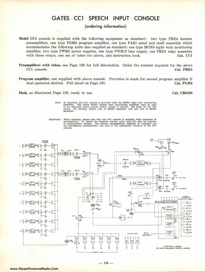
www.SteamPoweredRadio.Com
GATES . CCl SPEECH INPUT CONSOLE ( ordering information)
Model CCI console is supplied with t he following equipment as standard: two type PRE4 booster preamplifiers, one type PGM4 program amplifier, one type PASl panel and shelf assembly which accommodates t he following units also supplied as standard: one type MON4 eight watt monitoring amplifier, two type PWR3 power supplies, one type PWRlO bias supply, one PRDl relay assembly with three relays, one set of tubes for above, and instruction book. Cat. CCI
Preamplifiers with tubes, see Page 128 for full description. CCl console.
Order the number required for the above Cat. PRE4
Program amplifier, one supplied with above console. dual operation desired. Full detail on Page 130.
Provision is made for second program amplifier if Cat. PGM4
Desk, as illustrated Page 123, ready to use.
000,000 UOO£.R
Note: As standard, the CCl console Is provided with the MON4 eight watt monitoring amplifier. The Gates MON! sixteen watt monltorlng amplifier may be used as an alternate where greater power output ls desired. See Page 131 for full detall. For pricing, deduct cost 1of MON4 ampUfler and add cost of MON! amplifier.
Important: When ordering, please note that the CCI console ls complete with exception of preampllflers. To obtain the complete console, order type CCl plus the number of preampllfiers needed. The booster preampllflers supplied as standard are not microphone preampliflers, but part of the subsequent circuitry or the CCI console.
. I Orf
tt f PA£-.l 8 :._____. I .... J CUE
~ • . ~• o '1 . ;. 0--J CUf
Gf AMP-C AC
Hf(• 8D
0--J CU<
..... 6 IOK
Cat. CB6300
.... L_k,~ ~ 2000• .... , ••• To,,
0-J CU£
! :,,o .. ~~_;._ L~ ~
~t
~o_;'"iMP:r1_~~ " , ~~it:.~ a o ~ -;.
0--., CUE
~~ iMP:-G~~--,,S,~e,_-t4 , ~~E_:~ e o '1
G ,o
-J CUE
600/600 lA.00£R
9 "l'°f ,--0 ~' -'0"' ,--0
1111 H(c.t l-0
•-0 --a
"'%oo
°%0'
AMP I
'------ R[MOtt llNCS ----~
- 124-
,ooo.
1001!1
UTIUTY l'iEYS Bt,rll-
AJ3._i}'ifAs
°" fOOJiOO .... ••• To,,
ON
6001600
LUii[ t
U NE't
'" WL ... • .L
SPIC.
W. L.. ... L ____ _., -
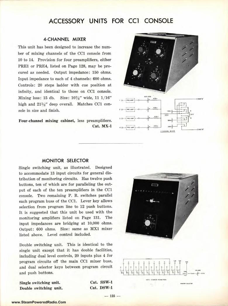
www.SteamPoweredRadio.Com
ACCESSORY UNITS FOR CCl CONSOLE
4-CHANNEL MIXER
This unit has been designed to increase the num
ber of mixing channels of the CCI console from
10 to 14. Provision for four preamplifiers, either
PREl or PRE4, listed on Page 128, may be pro
cured as needed. Output impedance: 150 ohms.
Input impedance to each of 4 channels: 600 ohms.
Controls: 20 steps ladder with cue position at
infinity, and identical to those on CCI console.
Mixing loss: 15 db. Size: 10%" wide, 11 1/ 16"
high and 21 %" deep overall. Matches CCI con
sole in size and finish.
Four-channel mixing cabinet, less preamplifiers. Cat. MX-1
MONITOR SELECTOR Single switching unit, as illustrated. Designed to accommodate 13 input circuits for general distribution of monitoring circuits. Has twelve push buttons, ten of which are for paralleling the output of each of the ten preamplifiers in the CCI console. Two remaining P. B. switches parallel each program buss of the CCL Lever key allows selection from program line to 12 push buttons. It is suggested that this unit be used with the monitoring amplifiers listed on Page 131. The input impedances are bridging at 10,000 ohms. Output: 600 ohms. Size: same as MXl mixer listed above. Level control included.
Double switching unit. This is identical to the single unit except that it has double facilities, including dual level controls, 20 inputs plus 4 for program circuits off the main CCI mixer buss, and dual selector keys between program circuit and push buttons.
Single switching unit. Double switching unit.
Cat. SSW-1 Cat. DSW-1
'°°'"'° r----- , 4)0A 1 0--,~Jll•AMP :---o-~S,C--WvVv-~ 1,,. ____ .,
,.------, t 0--.Jt~-~~A-M~_t--<>----,F----_,.,,,,,,~
) 0--r;--~~.:.;1- --0--.,¥,--'W''°:;.;;,•-4 '------·J
r-----, •30• ~ • Cr-'(~~-~~~-<>--c¥---__,,,.,,,.,.,....., ltol\r-- L_______,ows·s·
4 tHAHMEl MIKEii!
- 125 -
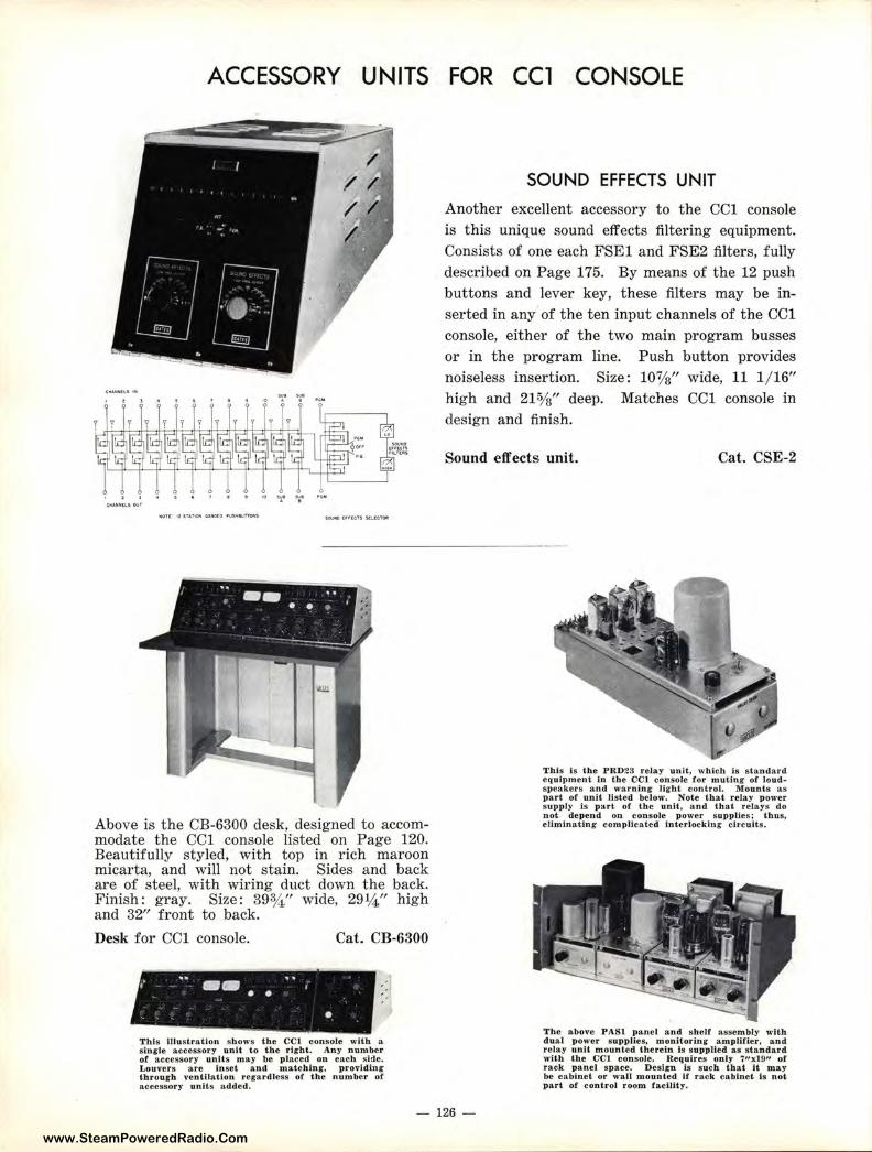
www.SteamPoweredRadio.Com
ACCESSORY UNITS
Above is the CB-6300 desk, designed to accommodate the CCI console listed on Page 120. Beautifully styled, with top in rich maroon micarta, and will not stain. Sides and back are of steel, with wiring duct down the back. Finish: gray. Size: 39% " wide, 29¼" high and 32" front to back.
Desk for CCI console. Cat. CB-6300
,~ •• -- 1111 I '
• • •
This Illustration shows the CCl console with a single accessory unit to the right. Any n umber of accessory units may be placed on each side. Louvers are Inset and matching. providing th.rourh ventilation regardless of the number of accessory units added.
FOR CCl CONSOLE
SOUND EFFECTS UNIT
Another excellent accessory to the CCI console is this unique sound effects filtering equipment. Consists of one each FSEl and FSE2 filters, fully described on Page 175. By means of t he 12 push buttons and lever key, these filters may be inserted in any of the ten input channels of the CCI console, either of the two main program busses or in the program line. Push button provides noiseless insertion. Size: 107/s" wide, 11 1/ 16" high and 215/s" deep. Matches CCI console in design and finish.
Sound effects unit. Cat. CSE-2
This Is the PR023 relay unit, which is standard equipment in the CCI console for muting of loudspeakers and warning light contro l. Mounts as part of unit listed below. Note that relay power s upply ls part or the unit. and that relays do not depend on con.sole power supplies; thus, elimlnating complicated interlocking circuits.
The above PASl panel and shelf assembly with dual power supplles, monitoring amplifier, and relay unit mounted thereln Is supplie d as stan dard with the CCl console. Requires only 711xl911 of rack panel s pace. Desifll is s uch that it ma.y be cabinet or wall mou.nted if rack cabinet Is not part of control room facility.
- 126 -
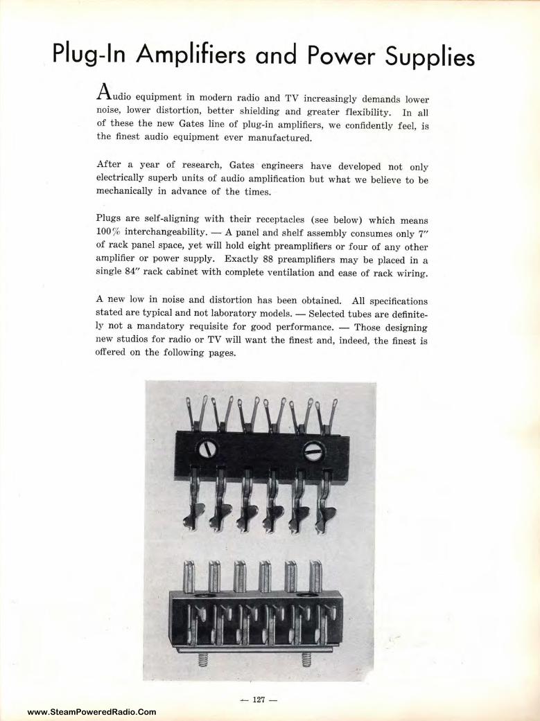
www.SteamPoweredRadio.Com
Plug-In Amplifiers and Power Supplies A udio equipment in modern radio and TV increasingly demands lower noise, lower distortion, better shielding and greater flexibility. In all of these the new Gates line of plug-in amplifiers, we confidently feel, is the finest audio equipment ever manufactured.
After a year of research, Gates engineers have developed not only electrically superb units of audio amplification but what we believe to be mechanically in advance of the times.
Plugs are self-aligning with their receptacles (see below) which means 100 % interchangeability. - A panel and shelf assembly consumes only 7" of rack panel space, yet will hold eight preamplifiers or four of any other amplifier or power supply. Exactly 88 preamplifiers may be placed in a single 84" rack cabinet with complete ventilation and ease of rack wiring.
A new low in noise and distortion has been obtained. All specifications stated are typical and not laboratory models. - Selected tubes are definitely not a mandatory requisite for good performance. - Those designing new studios for radio or TV will want the finest and, indeed, the finest is offered on the following pages.
- 127 -
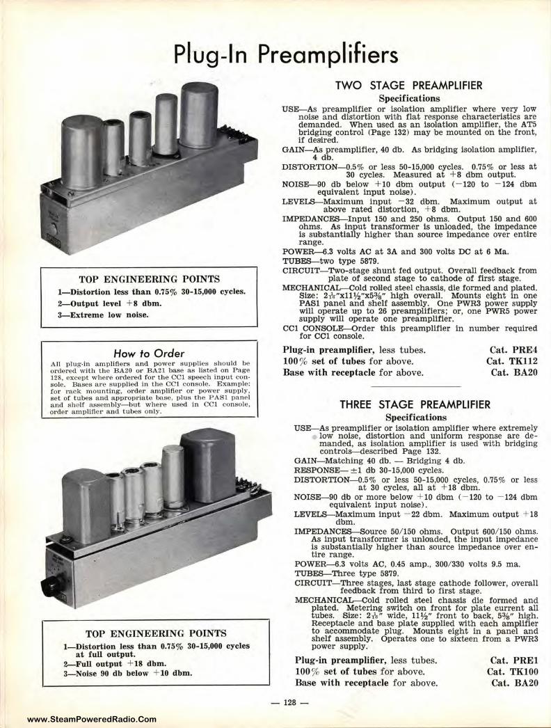
www.SteamPoweredRadio.Com
Pl·ug-ln Preamplifiers
TOP ENGINEERING POINTS I-Distortion less than 0.75% 30-15,000 cycles.
2-Output level + 8 dbm. 3-Extreme low noise.
How to O rder All plug-in amplifie rs a nd power supplies s hould be or dered with the BA20 or BA21 base as listed on Page 128. except where ordered for the CCl speech input console . Bases are supplied in the CCl console. Example: for rack mounting, order a mplifier or power supply, set of tubes and appropriate base, plus the PASl panel and shelf assem bly- but where used in CCl co nsole , order amplifie r and t ubes only.
TOP ENGINEERING POINTS I-Distortion less than 0.75% 30-15,000 cycles
at full output. 2-Full output + 18 dbm. 3- Noise 90 db below + IO dbm.
TWO ST AGE PREAMPLIFIER Specifications
USE-As preampMfier or isolation amplifier where very low noise and distortion witlh flat response characteristics are demanded. When used as an isola,tion amplifier, the AT5 bridging control (Page 132) may be mounted on the front, if desired.
GAIN-As preamplifier, 40 db. As bridging isolation amplifier, 4 <l<b.
DISTORTION-0.5% or less 50-15,000 cycles. 0.75% or less at 30 cycles. Measured at + 8 dbm output.
NOISE-90 db below + 10 dbm output (- 120 to - 124 dbm equiva,lent input noise).
LEVELS-Maximum input - 32 dbm. Maximum output at aibove rated distortion , +8 dbm.
IMPEDANCES-Input 150 and 250 ohms. Outiput 150 and 600 ohms. As input transformer is unloaded, the impedance is substantially higher than source impedance over entire range.
POWE.R-6.3 volts AC at 3A and 300 volts DC at 6 Ma. TUBES-two type 5879. CIRCUIT-Two-stage shunt fed output. Overall feedback from
plate of second stage to cathode of first stage. MECHANICAL-Cold roliled steel chassis, die formed and plated.
Size: 2-h-"xll½"x5%" high overall. Mounts eight in one PAS! panel and shelf assembly. One PWR3 power supply will operate up to 26 preamplifiers; or, one PWR5 power supply will operate one preamplifier.
CCI CONSOLE-Order this preamplifier in number required for CCl console.
Plug-in preamplifier, less t ubes. 100 % set of tubes for above. Base with receptacle for above.
Cat. PRE4 Cat . TKI I2 Cat. BA20
THREE STAGE PREAMPLIFIER Specifications
USE-As preamplifier or isolation amplifier where extremely low noise, distortion an'd uniform response are demanded, as isolation amplifier is used with bridging controls-described Page 132.
GAIN- Matching 40 db. - Bridging 4 db. RESPONSE- ± 1 db 30-15,000 cycles. DISTORTION-0.5% or less 50-15,000 cycles, 0.75% or less
at 30 cycles, all at + 18 dbm. NOISE-90 db or more below + 10 dbm ( - 120 to - 124 dbm
equivailent input noise). LEVELS-Maximum input - 22 dbm. Maximum output + 18
dbm. IMPEDANCES-Source 50/ 150 ohms. Output 600/ 150 ohms.
As input transformer is unloaded, the input impedance is substantially higher than source impedance over entire range.
POWER-6.3 volts AC, 0.45 amp., 300/ 330 volts 9.5 ma. TUBES-Three type 5879. CIRCUIT-Three stages, last stage cathode follower, overall
feedback from third to first stage. MECHANICAL-Cold rolled steel chassis die formed and
plated. Metering switch on front for plate current all tubes. Size : 2-h-" wide, 11½" front to back, 5%" high. Receptacle and base plate supplied with each amplifier to accommodate plug. Mounts eight in a panel and shelf assembly. Operates one to sixteen from a PWR3 power supply.
Plug-in pr-eamplifi~r, less tubes. 100% set of tubes for above. Base with receptacle for above.
-128 -
Cat. PREl Cat. TKI00 Cat. BA20
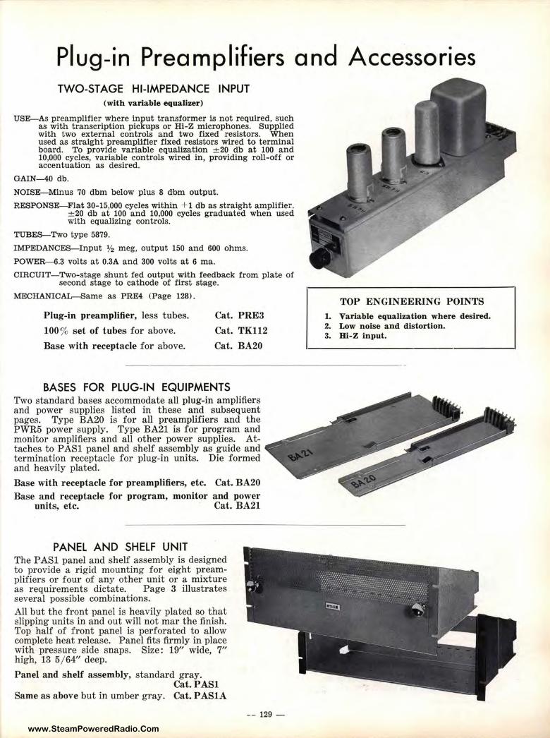
www.SteamPoweredRadio.Com
Plug-in Preamplifiers and Accessories TWO-ST AGE HI-IMPEDANCE INPUT
(with variable equalizer)
USE-As preamplifier where input transformer is not required, such as with transcription pickups or Hi-Z microphones. Supplied with two external controls and two fixed resistors. When used as stmight preamplliifier fixed resistors wired to terminal board. To provide variaible equalization ± 20 db at 100 and 10,000 cycles, variable controls wired in, providing roll-off or accentuation as desired.
GAIN---40 db.
NOISE-Minus 70 dbm below plus 8 dbm output.
RESPONSE-Fla,t 30-15,000 cycles within + 1 db as straight amplifier. ±20 db at 100 and 10,000 cycles graduated when used with equalizing controls.
TUBES-Two type 5879.
IMPEDANCES-Input ½ meg, output 150 and 600 ohms.
POWER-6.3 volts at 0.3A and 300 volts at 6 ma.
CIRCUIT-Two-stage shunt fed output with feedback from plate of second stage to cathode of first stage.
MECHANICAL-Same as PRE4 (Page 128).
Plug-in preamplifier, less tubes.
100% set of tubes for above.
Base with receptacle for above.
Cat. PRE3
Cat. TKII2
Cat. BA20
BASES FOR PLUG-IN EQUIPMENTS Two standard bases accommodate all plug-in amplifiers and power supplies listed in these and subsequent pages. Type BA20 is for all preamplifiers and the PWR5 power supply. Type BA21 is for program and monitor amplifiers and all other power supplies. Attaches to PASl panel and shelf assembly as guide and termination receptacle for plug-in units. Die formed and heavily plated.
Base with receptacle for preamplifiers, etc. Cat. BA20 Base and receptacle for program, monitor and power
units, etc. Cat. BA21
PANEL AND SHELF UNIT The P ASl panel and shelf assembly is designed to provide a rigid mounting for eight preamplifiers or four of any other unit or a mixture as requirements dictate. Page 3 illustrates several possible combinations. All but the front panel is heavily plated so that slipping units in and out will not mar the finish. Top half of front panel is perforated to allow complete heat release. Panel fits firmly in place with pressure side snaps. Size: 19" wide, 7" high, 13 5/ 64" deep.
Panel and shelf assembly, standard gray. Cat. PASl
Same as above but in umber gray. Cat. PASlA
-- 129 -
TOP ENGINEERING POINTS 1. Variable equalization where desired. 2. Low noise and distortion. 3. Hi-Z input.
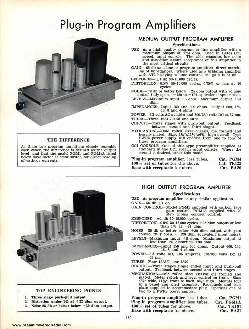
www.SteamPoweredRadio.Com
Plug-in Program Amplifiers
THE DIFFERENCE
As these two program amplifiers closely resemble each other, the difference is defined as the output level; and that the model PGMl and PGMlA listed below have meter seleotor switch for direct reading of cathode currents.
TOP ENGINEERING POINTS
1. Three stage push-pull output. 2. Distortion under 1 % at + 33 dbm output. 3.
0
Noise 85 db or better below + 30 dbm output.
MEDIUM OUTPUT PROGRAM AMPLIFIER Specifications
USE-As a high quality program or line amplifier wi,th a maximum output of +24 dbm. Used in Gates OCl speech input console. The wide response, low noise and distortion assure acceptance of this amplifier in the most critical circuits.
GAIN- 65 db as a line or program amplifier, direct matching of impedances. Where used as a bridging amplifier with AT2 bridging volume control, the gain is 33 db.
RESPONSE- ±1 db 30-15,000 cycles. DISTORTION-0.5% 50-15,000 cycles, 0.75% or less at 30
cycles. NOISE- 79 db or better below - 24 dbm output with volume
control fully open. ( - 120 to - 124 equivalent input noise) . LEVELS-Maximum input + 8 dbm. Maximum output + 24
dbm. IMPEDANCES-Input 150 and 600 ohms. Output 600, 150,
16, 8 and 4 ohms. POWER-6.3 volts AC at 1.05A and 300/ 330 volts DC at 37 ma. TUBES-Three 12AU7 and one 5879. CIRCUIT- Three stages with push-pull output. Feedback
between second and third stages. MECHANICAL-Cold rolled steel chassis, die formed and
heavily plated. Size: 4¾"xll½"x6%" high overall. Type PWR3 power supply will operate from one to four of these program amplifiers.
CCl CONSOLE-One of this type preamplifier supplied as standard in the CCl speech input console. Where the second is desired, order this model.
Plug-in program amplifier, less tubes. 100% set of tubes for the above. Base with receptacle for above.
Cat. PGM4 Cat. TKI22 Cat. BA20
HIGH OUTPUT PROGRAM AMPLIFIER Specifications
USE-As program amplifier or any similar application. GAIN- 65 db ±1 db. GAI N CONTROL-Model PGMl supplied with carbon tyipe
gain control, PGMlA supplied with 20 step wiping contact control.
RESPONSE- ± 1 db 30-15,000 cycles. DISTORTION-0.5% 30-15,000 cycles + 25 dbm output or less
than 1 % at + 33 dbm. NOISE- 85 db or better below + 30 dbm output with gain
control fully open. (- 120 dbm equivalent input noise) . LEVELS-Maximum input + 8 dbm. Maximum output a t
less than 1 % distortion +33 dbm. IMPEDANCES-Input 150 and 600 ohms. Output 600, 150,
16, 8 and 4 ohms. POWER-6.3 volts AC, 1.35 amperes, 330/ 360 volts DC at
65 ma. TUBES-Four 12AU7, one 5879. CIRCUIT- Three stages single ended input and push-pull
output. Feedback between second and third stages. MECHANICAL-Cold rolled steel chassis die formed and
plated. Meter switch and level control on front. Size: 4¾" wide, 11½" front to back, 6%" high. Mounts four in a panel and shelf assembly. Receptacle and base plate supplied to accommodate plug. Operates one or two to a PWR3 power supply.
Plug-in program amplifier less tubes. Plug-in program amplifier less tubes. 100 % set of tubes for above. Base with receptacle for above.
- 130 -
Cat. PGMl Cat. PGMlA
Cat. TKlOl Cat. BA21
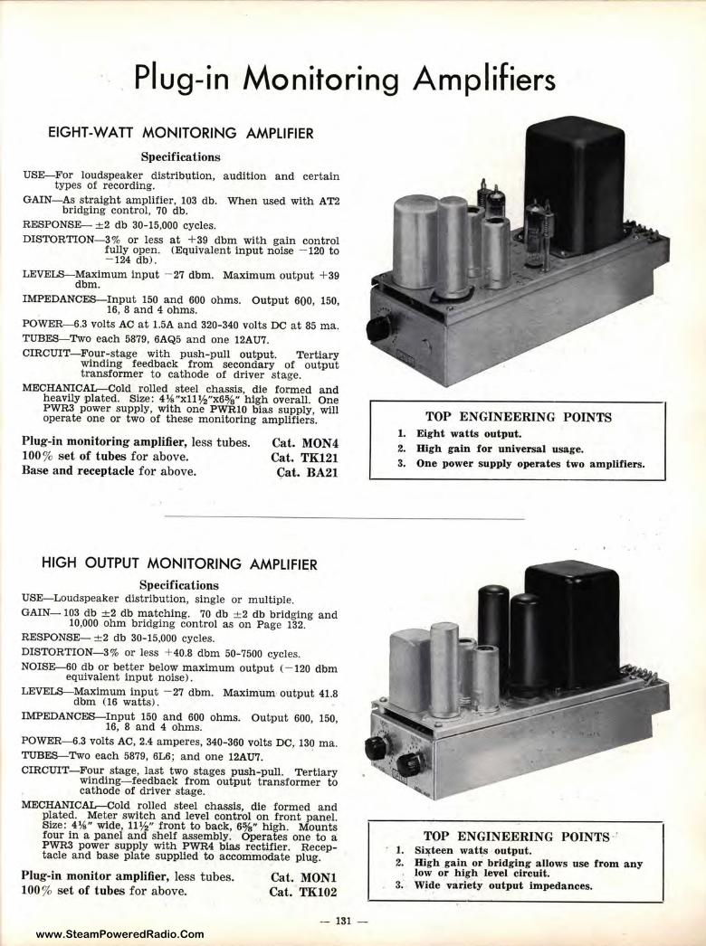
www.SteamPoweredRadio.Com
-. Plug-in Monitoring Amplifiers
EIGHT-WATT MONITORING AMPLIFIER
Specifications USE-For loudspeaker distribution, audition and certain
types of recording. GAIN- As straight amplifier, 103 db. When used with AT2
bridging control, 70 db. RESPONSE- ± 2 db 30-15,000 cycles. DISTORTION-3% or less at +39 dbm with gain control
fully open. (Equivalent input noise - 120 to - 124 dbl.
LEVELS-Maximum input - 27 dbm. Maximum output + 39 dbm.
IMPEDANCES-Input 150 and 600 ohms. Output 600, 150, 16, 8 and 4 ohms.
POWER-6.3 volts AC at 1.5A and 320-340 volts DC at 85 ma. TUBES- Two each 5879, 6AQ5 and one 12AU7. CIRCUIT-Four-stage with push-pull output. Tertiary
winding feedback from secondary of output transformer to cathode of driver stage.
MECHANICAL-Cold rolled steel chassis, die formed and heavily plated. Size : 4¾"xll½"x6%" high overall. One P WR3 power supply, with one PWRl0 bias supply, will operate one or two of these monitoring amplifiers.
Plug-in monitoring amplifier, less tubes. 100 % set of tubes for above. Base and receptacle for above.
Cat. MON4 Cat. TK121 Cat. BA21
HIGH OUTPUT MONITORING AMPLIFIER
Specifications USE-Loudspeaker distribution, single or multiple. GAIN- 103 d•b ±2 db matching. 70 db ±2 db bridging and
10,000 ohm bridging control as on Page 132. RESPONSE- ± 2 d'b 30-15,000 cycles. DISTORTION-3% or less + 40.8 dbm 50-7500 cycles. NOISE-60 db or better below maximum output (- 120 dbm
equivalent input noise).
LEVELS-Maximum input - 27 dbm. Maximum output 41.8 dbm (16 watts).
IMPEDANCES-Input 150 and 600 ohms. Output 600, 150, 16, 8 and 4 ohms.
POWER-6.3 volts AC, 2.4 amperes, 340-360 volts DC, 13~ ma. TUBES-Two each 5879, 6L6; and one 12AU7. CIRCUIT- Four stage, last two stages push-pull. Tertiary
wind.Ing- feedback from output transformer to cathode of driver stage.
MECHANICAL-Cold rolled steel chassis, die formed and plated. Meter switch and level control on front panel. Size: 4¾" wide, 11½" front to back, 6%" h igh . Mounts four in a panel and shelf assembly. Operates one to a PWR3 power supply with PWR4 bias rectifier. E,eceptacle and base plate supplied to accommodate plug.
Plug-in monitor amplifier, less tubes. 100 % set of t ubes for above.
Cat. MON l Cat. TK102
- 131 -
TOP ENGINEERING POINTS 1. Eight watts output. 2. High gain f or universal usage. 3. One power supply operates two amplifiers.
TOP ENGINEERING POINTS ' 1. Si,i:teen wat ~s output . 2. High gain or bridging a llows use from a n y
low or h igh level circuit. 3. Wide variety output impeda nces.
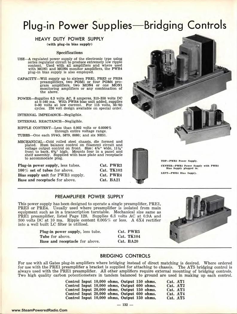
www.SteamPoweredRadio.Com
Plug-in Power Supplies-Bridging Controls HEAVY DUTY POWER SUPPLY
(with plug-in bias supply)
Specifications USE-A regulated power supply of the electronic type using
series regulator circuit to produce extremely low ripple content. Used with all amplifiers and where used with MONl and MON4 monitor amplifiers, the PWR4 plug-in bias supply ls also employed.
CAPACITY- Will supply up to sixteen PREl, PRE3 or PRE4 preamplifiers, two PGMl or four PGM4 program amplifiers, two MON4 or one MONl monitoring amplifiers or any combination of the above.
PO\\-'ER-Supplies 6.3 volts AC, 8 amperes, 310-350 volts DC at 0-160 ma. With PWR4 bias unit added, supplies 0-90 volts at low current. For 115 volts, 50/ 60 cycles. 230 volt design available on special order.
INTERNAL IMPEDANCE-Negligible.
INTERNAL REACTANCE-Negligible.
RIPPLE CONTENT-Less than 0.002 volts or 0.0006% through entire voltage range.
TUBES-One each 5V4G, 5879, 6080; and six NE51.
MECHANICAL-Cold rolled steel chassis, die formed and plated. Hum balance control on filament circuit and voltage output control on front. Size: 4¾" wide, 11½" front to back, 63/a" high. Mounts four in a panel and sh elf assembly. Supplied with base plate and receptacle to accommodate plug.
TOP-PWR3 Power Supply.
CENTER,-PWR3 Power Supply with PWR-t Blas Supply plun ed In.
Plug-in power s upply, less tubes. 100% set of tubes for above. Bias supply unit for PWR3 supply. Base and receptacle for above.
Cat. PWR3 Cat. TK103 Cat. PWR4 Cat. BA21
LEFT-PWR4 Blas Supply.
PREAMPLIFIER POWER SUPPLY This power supply has been designed to operate a single preamplifier, PREl, PRE3 or PRE4. Usually used where preamplifier is isolated from main equipment such as in a transcription turntable. Mechanical size same as PREI preamplifier, listed Page 128. Supplies 6.3 volts AC at 0.9A and 300 volts DC at 10 ma. Ripple content 0.005% or less. A 6X4 rectifier into a well built LC filter is utilized.
Plug-in power supply, less tube. Tube for above. Base and receptacle for above.
Cat. PWR5 Cat. TK104 Cat. BA20
BRIDGING CONTROLS
For use with all Gates plug-in amplifiers where bridging instead of direct matching is desired. Where ordered for use with t he PR.El preamplifier a bracket is supplied for attaching to chassis. The AT5 bridging control is always used with the PRE! preamplifier. All other amplifiers require external mounting of bridging controls. Two high quality carbon potentiometers in tandem balanced to ground are used in making up each control.
Control Input 10,000 ohms, Output 150 ohms. Cat. ATl Control Input 10,000 ohms, Output 600 ohms. Cat. AT2 Control Input 20,000 ohms, Output 150 ohms. Cat. AT3 Control Input 20,000 ohms, Output 600 ohms. Cat. AT4 Control Input 10,000 ohms, Output 150 ohms. Cat. ATS
- 132 -

www.SteamPoweredRadio.Com
Typical Plug-in Assemblies
A
A-Front of Gates PASl panel and shelf assembly. Requires only 7 inches rack panel space. - Available in standard or umber grey. Front panel held in position by pressure snaps-instantly removable to release any aimplifier.
B-Shelf assembly with panel removed. Entirely plated so that insertion or removal of amplifiers will not mar and will retain electrical ground at all times. Exact mechanical design prevents sagging in middle from amplifier weight.
(-Here are eight PRE! plug-in preamplifiers consuming only 7"xl9" rack space. Use of seU-aligning plugs provides for complete interchangeability and no jamming of receptacle contacts.
D-Two amplifiers and two power supplies are shown utilizing only 7"xl9" of rack space. Four program amplifiers, three power supplies and one monitoring amplifier now require 14"x19" of rack space-less than that required for one program amplifier only a short time ago.
E--Two panels and shelves of 16 preamplifiers featuring rear view to indicate extreme simplicity of wiring. C3ible harness clamps and trough are all part of panel and shelf assembly.
E
- 133 -
B
C
D
GATES SELF-ALIGNING PLUGS
MAKE PLUG-INS A PLEASURE
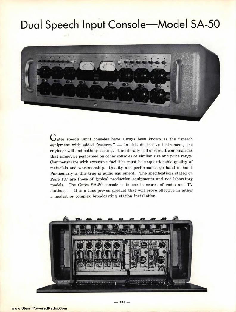
www.SteamPoweredRadio.Com
Dual Speech Input Console-Model SA-50
G ates speech input consoles have always been known as the "speech equipment with added features." - In this distinctive instrument, the engineer will find nothing lacking. It is literally full of circuit combinations that cannot be performed on other consoles of similar size and price range. Commensurate with extensive facilities must be unquestionable quality of materials and workmanship. Quality and performance go hand in hand. Particularly is this true in audio equipment. The specifications stated on Page 137 are those of typical production equipments and not laboratory models. The Gates SA-50 console is in use in scores of radio and TV stations. - It is a time-proven product that will prove effective in either a modest or complex broadcasting station installation.
- 134 -
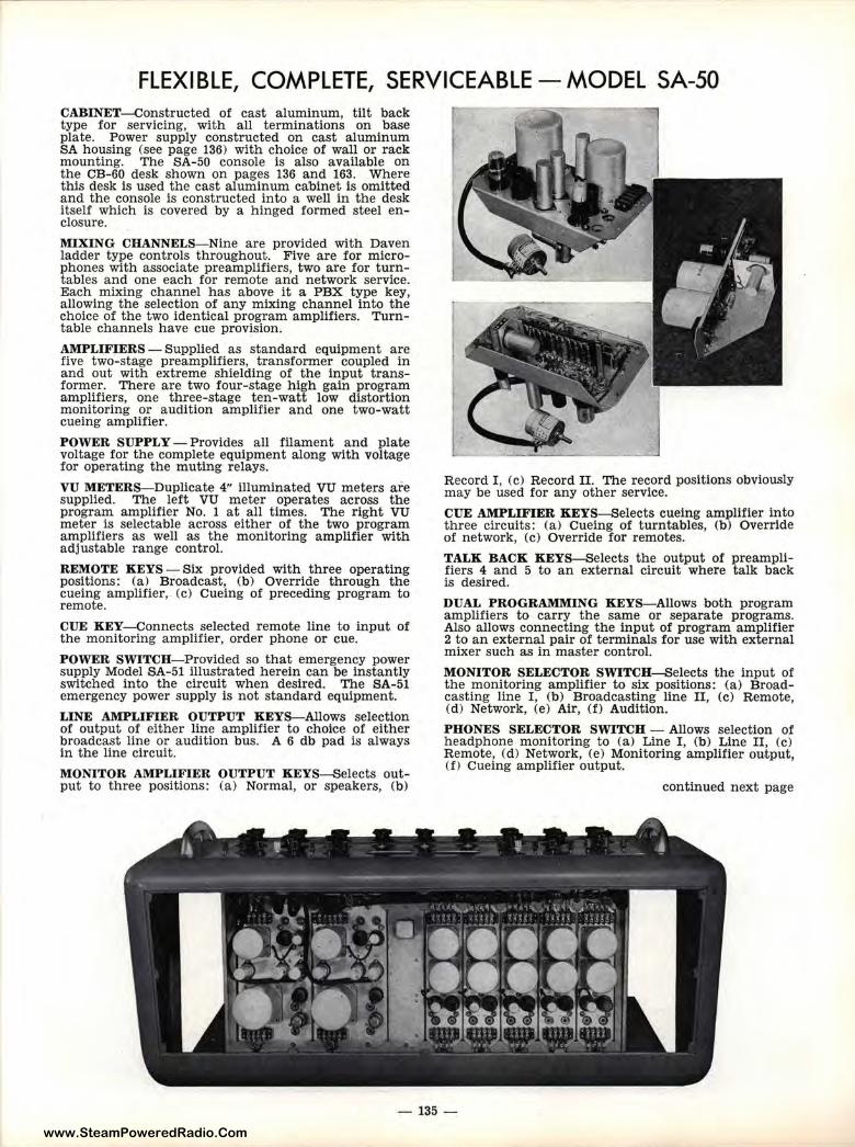
www.SteamPoweredRadio.Com
FLEXIBLE, COMPLETE, SERVICEABLE - MODEL SA-50 CABINET-Constructed of cast aluminum, tilt back type for servicing, with all terminations on base plate. Power supply constructed on cast aluminum SA housing (see page 136) with choice of wall or rack mounting. The SA-50 console is also available on the CB-60 desk shown on pages 136 and 163. Where this desk is used the cast aluminum cabinet is omitted and the console is constructed into a well in the desk itself which is covered by a hinged formed steel enclosure.
MIXING CHANNELS-Nine are provided with Daven ladder type controls throughout . Five are for microphones with associate preamplifiers, two are for turntables and one each for remote and network service. Each mixing channel has above it a PBX type key, allowing the selection of any mixing channel into the choice of the two identical program amplifiers. Turntable channels have cue provision.
AMPLIFIERS - Supplied as standard equipment are five two-stage preamplifiers, transformer coupled in and out with extreme shielding of the input transformer. There are two four-stage high gain program amplifiers, one three-stage ten-watt low distortion monitoring or audition amplifier and one two-watt cueing amplifier.
POWER SUPPLY - Provides all filament and plate voltage for the complete equipment along with voltage for operating the muting relays.
VU METERS-Duplicate 4" illuminated VU meters are supplied. The left VU meter operates across the program amplifier No. 1 at all times. The r ight VU meter is selectable across either of the tiwo program amplifiers as well as the monitoring amplifier with adjustable range control.
REMOTE KEYS - Six provided with three operating positions: (a) Broadcast, (b) Override through the cueing amplifier, (c) Cueing of preceding program to remote.
CUE KEY- Connects selected remote line to input of the monitoring amplifier, order phone or cue.
POWER SWITCH- Provided so that emergency power supply Model SA-51 illustrated herein can be instantly switched into the circuit when desired. The SA-51 emergency power supply is not standard equipment.
LINE AMPLIFIER OUTPUT KEYS-Allows selection of output of either line amplifier to choice of either broadcast line or audition bus. A 6 db pad is always in the line circuit.
MONITOR AMPLIFIER OUTPUT KEYS-Selects output to three positions: (a) Normal, or speakers, (b)
Record I, (c) Record II. The record positions obviously may be used for any other service.
CUE AMPLIFIER KEYS-Selects cueing amplifier into three circuits: (a) Cueing of turntables, (b) Override of network, (c) Override for remotes.
TALK BACK KEYS-Selects the output of preamplifiers 4 and 5 to an external circuit where talk back is desired.
DUAL PROGRAMMING KEYS-Allows both program amplifiers to carry the same or separate programs. Also allows connecting the input of program amplifier 2 to an external pair of terminals for use with external mixer such as in master control.
MONITOR SELECTOR SWITCH-Selects the input of the monitoring amplifier to six positions: (a) Broadcasting line I, (b) Broadcasting line II, (c) Remote, (d) Network, (e) Air, (f) Audition.
PHONES SELECTOR SWITCH - Allows selection of headphone monitoring to (a) Line I , ('b) Line II, (c) Remote, (d) Network, (e) Monitoring amplifier output, ( f) Cueing amplifier output.
continued next page
-135-
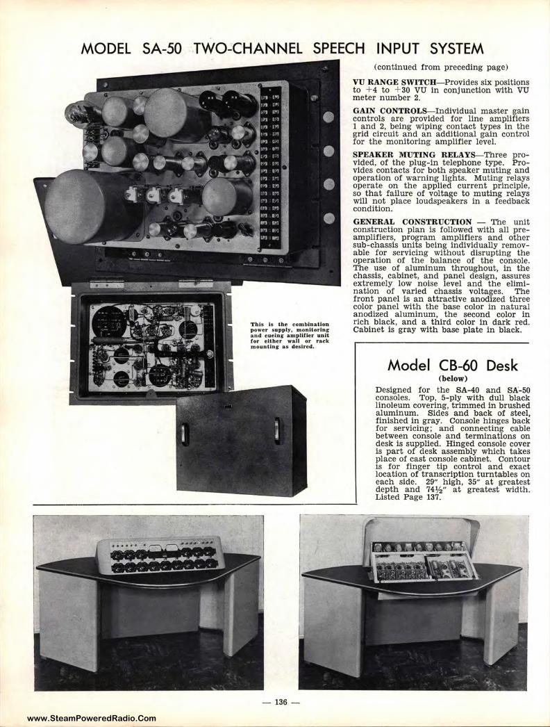
www.SteamPoweredRadio.Com
MODEL SA-50 TWO~CHANNEL SPEECH INPUT SYSTEM
This Is the combination power supply, monitoring and cuelnr amplUler unit for either wall or rack mounting as desired.
- 136 -
(continued from preceding page)
VU RANGE SWITCH-Provides six positions to + 4 to + 30 VU in conjunction with VU meter number 2.
GAIN CONTROLS-Individual master gain controls are provided for line amplifiers 1 and 2, being wiping contact types in the grid circuit and an additional gain control for the monitoring amplifier level.
SPEAKER MUTING RELAYS-Three provided, of the plug-in telephone type. Provides contacts for both speaker muting and operation of warning lights. Muting relays operate on the applied current principle, so that failure of voltage to muting relays will not place loudspeakers in a feedback condition.
GENERAL CONSTRUCTION - The unit construction plan is followed with all preamplifiers, program amplifiers and other sub-chassis units being individually removable for servicing without disrupting the operation of the balance of the console. The use of aluminum throughout, in the chassis, cabinet, and panel design, assures extremely low noise level and the elimination of varied chassis voltages. The front panel is an attractive anodized three color panel with the base color in natural anodized aluminum, the second color in rich black, and a third color in dark red. Cabinet is gray with base plate in black.
Model CB-60 Desk (below)
Designed for the SA-40 and SA-50 consoles. Top, 5-ply with dull black linoleum covering, trimmed in brushed aluminum. Sides and back of steel, finished in gray. Console hinges back for servicing; and connecting cable between console and terminations on desk is supplied. Hinged console cover is part of desk assembly which takes place of cast console cabinet. Contour is for finger tip control and exact location of transcription turntables on each side. 29" high, 35" at greatest depth and 74½" at greatest width. Listed Page 137.
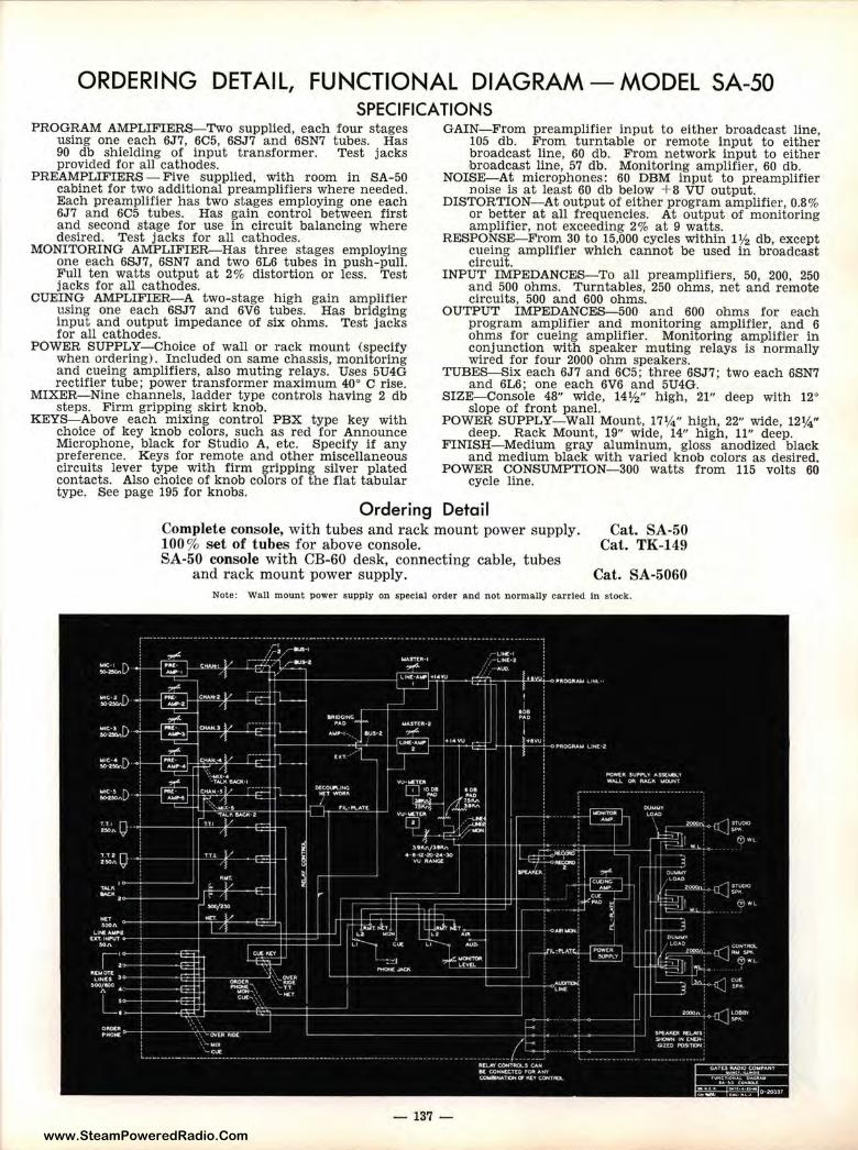
www.SteamPoweredRadio.Com
ORDERING DET Al L, FUNCTIONAL DIAGRAM - MODEL SA-50 SPECIFICATIONS
PROGRAM AMPLIFIERS-Two supplied, each four stages using one each 6J7, 6C5, 6SJ7 and 6SN7 tubes. Has 90 db shielding of input transformer. Test jacks provided for all cathodes.
PREAMPLIFIERS- Five supplied, with room in SA-50 cabinet for two additional preamplifiers where needed. Each preamplifier has two stages employing one each 6J7 and 6C5 tubes. Has gain control between first and second stage for use in circuit balancing where desired. Test jacks for all cathodes.
MONITORING AMPLIFIER-Has three stages employing one each 6SJ7, 6SN7 and two 6L6 tubes in push-pull. Full ten wat ts output at 2% distortion or less. Test jacks for all cathodes.
CUEING AMPLIFIER-A two-stage high gain amplifier using one each 6SJ7 and 6V6 tubes. Has bridging input and output impedance of six ohms. Test jacks for all cathodes.
POWER SUPPLY-Choice of wall or rack mount (specify when ordering). Included on same chassis, monitoring and cueing amplifiers, also muting relays. Uses 5U4G rectifier tube; power transformer maximum 40° Crise.
MIXER-Nine channels, ladder type controls having 2 db steps. Firm gripping skirt knob.
KEYS-Above each mixing control PBX type key with choice of key knob colors, such as red for Announce Microphone, black for Studio A, etc. Specify if any preference. Keys for remote and other miscellaneous circuits lever type with firm gripping silver plated contacts. Also choice of knob colors of the flat tabular type. See page 195 for knobs.
GAIN-From preamplifier input to either broadcast line, 105 db. From turntable or remote input to either broadcast line, 60 db. From network input to either broadcast line, 57 db. Monitoring amplifier, 60 db.
NOISE- At microphones: 60 DBM input to preamplifier noise is at least 60 db below + B VU out put.
DISTORTION-At output of either program amplifier, 0.8% or better at all frequencies. At output of monitoring amplifier, not exceeding 2% at 9 watts.
RESPONSE-From 30 to 15,000 cycles within 1½ db, except cueing amplifier which cannot be used in broadcast circuit.
INPUT IMPEDANCES-To all preamplifiers, 50, 200, 250 and 500 ohms. Turntables, 250 ohms, net and remote circuits, 500 and 600 ohms.
OUTPUT IMPEDANCES-500 and 600 ohms for each program amplifier and monitoring amplifier, and 6 ohms for cueing amplifier. Monitoring amplifier in conjunction with speaker muting relays is normally wired for four 2000 ohm speakers.
TUBES-Six each 6J7 and 6C5; three 6SJ7; two each 6SN7 and 6L6; one each 6V6 and 5U4G.
SIZE- Console 48" wide, 14½" high, 21" deep with 12° slope of front panel.
POWER SUPPLY- Wall Mount, 17¼" high, 22" wide, 12¼" deep. Rack Mount, 19" wide, 14" high, 11" deep.
FINISH-Medium gray aluminum, gloss anodized black and medium black with varied knob colors as desired.
POWER CONSUMPTION-300 watts from 115 volts 60 cycle line.
Ordering Detail Complete console, with tubes and rack mount power supply. 100% set of tubes for above console. SA-50 console with CB-60 desk, connecting cable, tubes
and rack mount power supply.
Cat. SA-50 Cat. TK-149
Cat. SA-5060 Note: Wall mount power supply on special order and not normally carried In stock.
-137 -
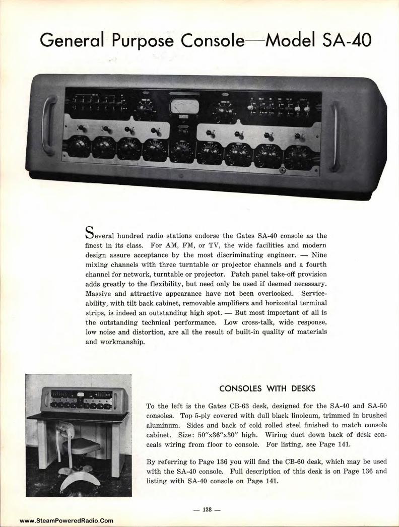
www.SteamPoweredRadio.ComL
General Purpose Console-Model SA-40
S everal hundred radio stations endorse the Gates SA-40 console as the finest in its class. For AM, FM, or TV, the wide facilities and modern design assure acceptance by the most discriminating engineer. - Nine mixing channels with three turntable or projector channels and a fourth channel for network, turntable or projector. Patch panel take-off provision adds greatly to the flexibility, but need only be used if deemed necessary. Massive and attractive appearance have not been overlooked. Serviceability, with tilt back cabinet, removable amplifiers and horizontal terminal strips, is indeed an outstanding high spot. - But most important of all is the outstanding technical performance. Low cross-talk, wide response, low noise and distortion, are all t he result of built-in quality of materials and workmanship.
CONSOLES WITH DESKS
To the left is the Gates CB-63 desk, designed for the SA-40 and SA-50 consoles. Top 5-ply covered with dull black linoleum, trimmed in brushed aluminum. Sides and back of cold rolled steel finished to match console cabinet. Size: 50"x36"x30" high. Wiring duct down back of desk conceals wiring from floor to console. For listing, see Page 141.
By referring to Page 136 you will find the CB-60 desk, which may be used with the SA-40 console. Full description of this desk is on Page 136 and listing with SA-40 console on Page 141.
- 138-
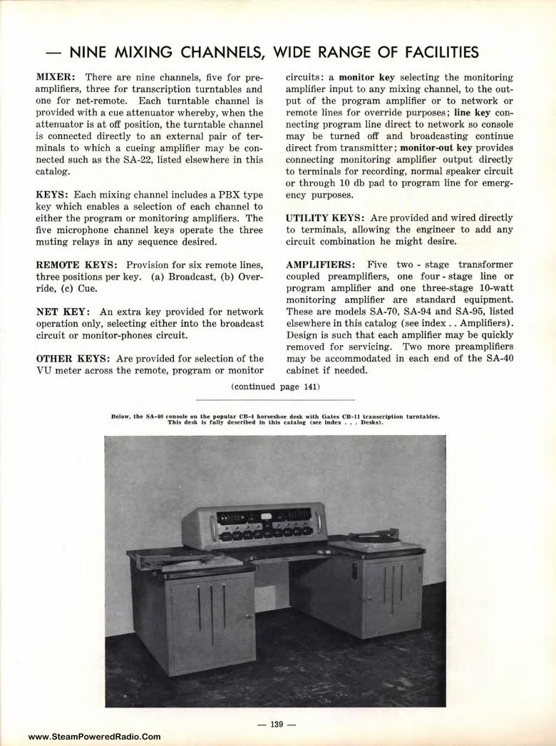
www.SteamPoweredRadio.Com
- NINE MIXING CHANNELS, WIDE RANGE OF FACILITIES
MIXER: There are nine channels, five for preamplifiers, three for transcription turntables and one for net-remote. Each turntable channel is provided with a cue attenuator whereby, when the attenuator is at off position, the turntable channel is connected directly to an external pair of terminals to which a cueing amplifier may be connected such as the SA-22, listed elsewhere in this catalog.
KEYS: Each mixing channel includes a PBX type key which enables a selection of each channel to either the program or monitoring amplifiers. The five microphone channel keys operate the three muting relays in any sequence desired.
REMOTE KEYS: Provision for six remote lines, three positions per key. (a) Broadcast, (b) Override, ( c) Cue.
NET KEY: An extra key provided for network operation only, selecting either into the broadcast circuit or monitor-phones circuit.
OTHER KEYS: Are provided for selection of t he VU meter across the remote, program or monitor
circuits: a monitor key selecting the monitoring amplifier input to any mixing channel, to the output of the program amplifier or to network or remote lines for override purposes ; line key connecting program line direct to network so console may be turned off and broadcasting continue direct from transmitter ; monitor-out key provides connecting monitoring amplifier output directly to terminals for r ecording, normal speaker circuit or through 10 db pad to program line for emergency purposes.
UTILITY KEYS: Are provided and wired directly to terminals, allowing the engineer to add any circuit combination he might desire.
AMPLIFIERS: Five two - stage transformer coupled preamplifiers, one four - stage line or program amplifier and one three-stage 10-watt monitoring amplifier ar e standard equipment. These are models SA-70, SA-94 and SA-95, listed elsewhere in this catalog (see index .. Amplifiers). Design is such that each amplifier may be quickly removed for servicing. Two more preamplifiers may be accommodated in each end of the SA-40 cabinet if needed.
(continued page 141)
Below, the SA-40 console on the p opular CB-4 horseshoe desk with Gates CB-11 transcription turntables. This desk Is fully described In this catalog (see Index •.. Desks) .
- 139 -
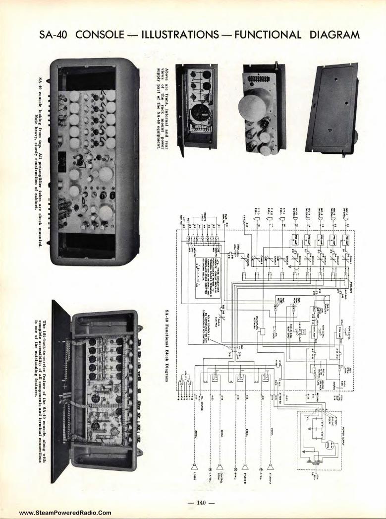
www.SteamPoweredRadio.Com
~
<(
a::::
~ 0 _J
<(
z 0 1-
u z ::, L
L
V)
z 0 1-
<(
a:::: 1
-V
) ::, _
J
_J
I· w
_
J
0 V)
z 0 u 0 ...._,. I
<(
V)
Above
a.re fro
nt,
intern
al an
d
rear v
iews
of
the
rack
mo
un
t p
ower
sup
ply
part o
f the S
A-4.0 eq
uip
men
t.
::.',~-
►• : ,.
.~....;;·-~---·-;;.:;,~------------
---------------~
---
-~
MM
_,•
~G
lot 6°" t I
ru
"IC
IIO
Wltlt~
Y
LIOO
J_
__.n
._ _
__ ,2
I
: ~
! ··~
-::::;.-;=
-:
~--. --------------------------··1 .
,....,. ,;::=
:::;i:
; /,a•L~
A
:'h
II l I
:,.ic,;,!j)-~
• 11:>v
~.o
-
1 ..
~-:o~~ ~
--------------------------· ___ j
!!: o .. ►• i I
Av
E:!.! T
T
. .l n.. ►T
~ ~~
!>i:,...U
L I
-, .•• --------------~
~-----·······-· .. -<J
>H
o 'I ..
I I
X
I c:::tl
;~! o-~· i X
I
E::U •-n
TT
<U
t
'holT.
H'
-·-~ -.o
c.A
T(
G-.u
rT IIIW
AIII· .
.
...,.. ,,o.,,rucocc.J1♦ IIC
'VI• T
O
T~
90
,liM>
Jl,T
tAW
W..•.
~W
.-K
llllliOl'm
,._
t=:':::! .,. ---------------------------------······-@
,. .• Lo
C::
! ... , .................. tOO
OI\ ---·--·········,a::J s""°°''
.:::.. ! •·•-----------------·---···-·--···--· ........ -(?) •·•·'-·
®
i :::: ------·---------_________ · -·--~ ~~~
~.
.... I .... _,, .. ,_,,. .... ~
~.I
A(.A
.$lfll~
T'C
0
AJI JI"°'""
NL
.OW
. ~
:~
>O:
w,""""'
I -.---"---
--
--
----
: ..,. · -------------------------------------------------_ --~j_ J 1r ------------~------------"1
-1'-~-! .!:!. ~
>~
ors
-;
. ., --·-·
SA
-40 Fu
nction
al
Blo
ck D
iag
ram
SA
-40 con
sole lo
ok
ing
from
top
. A
ll pream
plifie
r tubes a
re sh
ock
mo
un
ted.
Th
e tut-b
aek
-to-serv
lce featu
re o
f the
SA
-40 con
sole, alo
ng
with
co
mp
lete accessib
ility or a
ll com
po
nents a
nd
termin
al co
nnectio
ns
is one
of th
e o
utsta
nd
ing fea
ture
s. N
ote h
eavy
, sturd
y con
structio
n o
f cabin
et.
0 st< .....
www.SteamPoweredRadio.Com
SPECIFICATIONS AND ORDERING DETAIL-MODEL SA-40 (from page 139)
CONSTRUCTION: The SA-40 console is constructed on a single-piece chassis. All input transformers have high shielding and no unorthodox circuits of any kind are employed. It should be particular ly noted that all preamplifiers and other amplifiers are fully t ransformer coupled both input and output. By viewing the underchassis design the unusual workmanship and generous use of shielded wire throughout will be noted. All tubes may be measured at their cathodes by jacks adjacent to each tube. The heavy cast aluminum tilt-back cabinet is standard equipment, while the power supply is constructed in the popular cast aluminum SA housing with front panel servicing.
PATCH PANEL TAKE-OFF: All major circuits such as preamplifier outputs, line and monitoring amplifier inputs, etc., are brought to terminal boards and bussed back into the normal console circuit. For greater flexibility an external patch
panel may be used in any of these circuits. Several types of patch panels are listed in this catalog (see index ... Patch Panels).
TERMINATIONS: All terminations are to the base of the cabinet and immediately accessible. Care is taken to group input and output circuits to guide the installing engineer in external cabling, and to assure elimination of cross-talk or feedback. All terminals are numbered or lettered for easy identification.
VU METER: Large 4" illuminated scale B design.
MUTING RELAYS: Three are supplied, to mute loudspeakers and operate a break circuit for studio warning lights. These are so wired that relays will not activate loudspeaker circuits, causing feedback, in case of failure of the relay supply. Relays will oper ate from any of the five microphone channels and in any desired sequence by terminal arrangement and straps.
SPECIFICATIONS AMPLIFIERS-Five two-stage preamplifiers with ac
commodation in cabinet for two additional model SA-70 preamplifiers (see page 151). Also one fourstage program amplifier and one three-stage 10 watt monitoring amplifier.
MIXING CHANNELS-Nine; ladder type controls, two decibels per step. Turntable attenuators have cue position.
GAIN-From preamplifier input to program line, 105 db.
From preamplifier input to monitoring amplifier output, 95 db.
From turntable, remote or net input to program line, 58 db.
From turntable, remote or net input to monitoring amplifier output, 68 db.
From turntable, remote or net input to program line when using monitoring amplifier and emergency pad, 38 db.
DISTORTION- Less than 1 % from 50 to 15,000 cycles overall from microphone to program line. 2% from microphone to monitoring amplifier output.
NOISE-From preamplifier input measured at minus 60 dbm to program line measured at plus 8 dbm; 65 db below output level. All other circuit combinations equal or superior to above.
RESPONSE-Within 1.5 db 30-15,000 cycles.
INPUT IMPEDANCES-Preamplifiers, 50, 200, 250 and 500 ohms. Turntables, 250 ohms. Remote and net lines, 500 and 600 ohms.
TUBES-7 type 6J7, 6 type 6C5, 2 type 6SN7 and 6L6; 1 each 6SJ7 and 5U4G.
SIZE-40'' wide, 14½" high, 21" deep. Power supply: 19" wide, 8¾" high, 11" deep (rack mount).
FINISH-Medium gray with base trim in black, handles in brushed aluminum, panel anodized natural aluminum and gloss black with varied color key knobs.
CUE LEVEL CONTROL-Provided on chassis so that the amount of signal fed to remote lines may be adjusted.
Ordering Detail Complete console with tubes and rack mount power supply. 100 % set of t ubes for above. Desk as illustra t ed Page 128, less chair . SA-40 console with tubes and power supply and with CB-60
desk as illustrated Page 136, includes joiner cable.
Cat. SA-40 Cat . TK.-118 Cat. CB-63
Cat . SA-4060 Note: For cueing amplifiers, warning lights, microphones, speakers and other
accessories, please rerer to index ror listing.
- 141 -
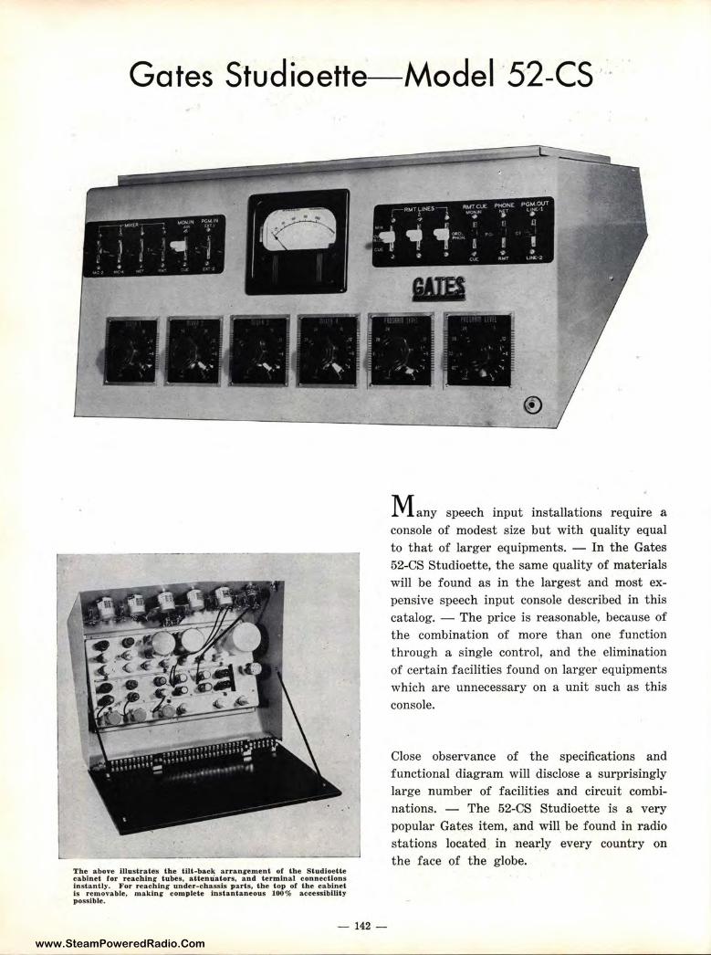
www.SteamPoweredRadio.Com
Gates Studioette- Model ·52-cs
The above illustrates the tilt-back arrangement of the Studloetle cabinet for reachin g tubes, attenu'.ators, and terminal connections instantly. F or reachinr under-chassis parts, the top ot the cabinet Is removable, making- complete instantaneous 100% acces-slbillty possible.
- 142 -
Many speech input installations require a console of modest size but with quality equal to that of larger equipments. - In the Gates 52-CS Studioette, the same quality of materials will be found as in the largest and most expensive speech input console described in this catalog. - The price is reasonable, because of the combination of more than one function through a single control, and the elimination of certain facilities found on larger equipments which are unnecessary on a unit such as this console.
Close observance of the specifications and functional diagram will disclose a surprisingly large number of facilities and circuit combinations. - The 52-CS Studioette is a very popular Gates item, and wiH be found in radio stations located in neai:Iy every country on the face of t he globe.
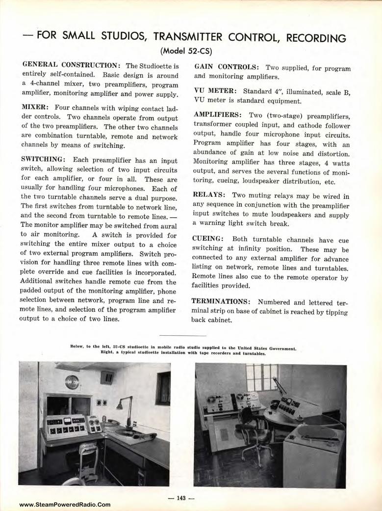
www.SteamPoweredRadio.Com
FOR SMALL STUDIOS, TRANSMITTER CC)NTROL, RECORDING (Model 52-CS)
GENERAL CONSTRUCTION: The Studioette is entirely self-contained. Basic design is ar ound a 4-channel mixer, two preamplifiers, program amplifier, monitoring amplifier and power supply.
MIXER: Four channels with wiping contact ladder controls. Two channels operate from output of the two preamplifiers. The other two channels are combination turntable, remote and network channels by means of switching.
SWITCHING: Each preamplifier has an input switch, allowing selection of two input circuits for each amplifier, or four in all. These are usually for handling four microphones. Each of the two turntable channels serve a dual purpose. The first switches from turntable to network line, and the second from turntable to remote lines. -The monitor amplifier may be switched from aural to air monitoring. A switch is provided for switching the entire mixer output to a choice of two external program amplifiers. Switch provision for handling three remote lines with complete override and cue facilities is incorporated. Additional switches handle remote cue from the padded output of the monitoring amplifier, phone selection between network, program line and remote lines, and selection of the program amplifier output to a choice of two lines.
GAIN CONTROLS : Two supplied, for program and monitoring amplifiers.
VU METER: Standard 4", illuminated, scale B, VU meter is standard equipment.
AMPLIFIERS: Two (two-stage) preamplifiers, t ransformer coupled input, and cathode follower output, handlEi four microphone input circuits. Program amplifier has four stages, with an abundance of gain at low noise and distortion. Monitoring amplifier has three stages, 4 watts output, and serves the several functions of monitoring, cueing, loudspeaker distribution, etc.
RELAYS: Two muting relays may be wired in any sequence i11 conjunction with t he preamplifier input switches to mute loudspeakers and supply a warning light switch break.
CUEING : Both turntable channels have cue switching at iinfinity position. These may be connected to any external amplifier for advance listing on network, remote lines and turntables. Remote lines a lso cue to the remote operator by facilities provided.
TERMINATIONS: Numbered and lettered terminal strip on base of cabinet is reached by tipping back cabinet.
Be low, to the left, 62-CS s tudloeUe In mobile radio • tudlo s upplied l o the U nited Stales G overnment. R iehl, a t 7plcal studloelte lns tallallon with tape recorders ancl turntables.
- 143 -
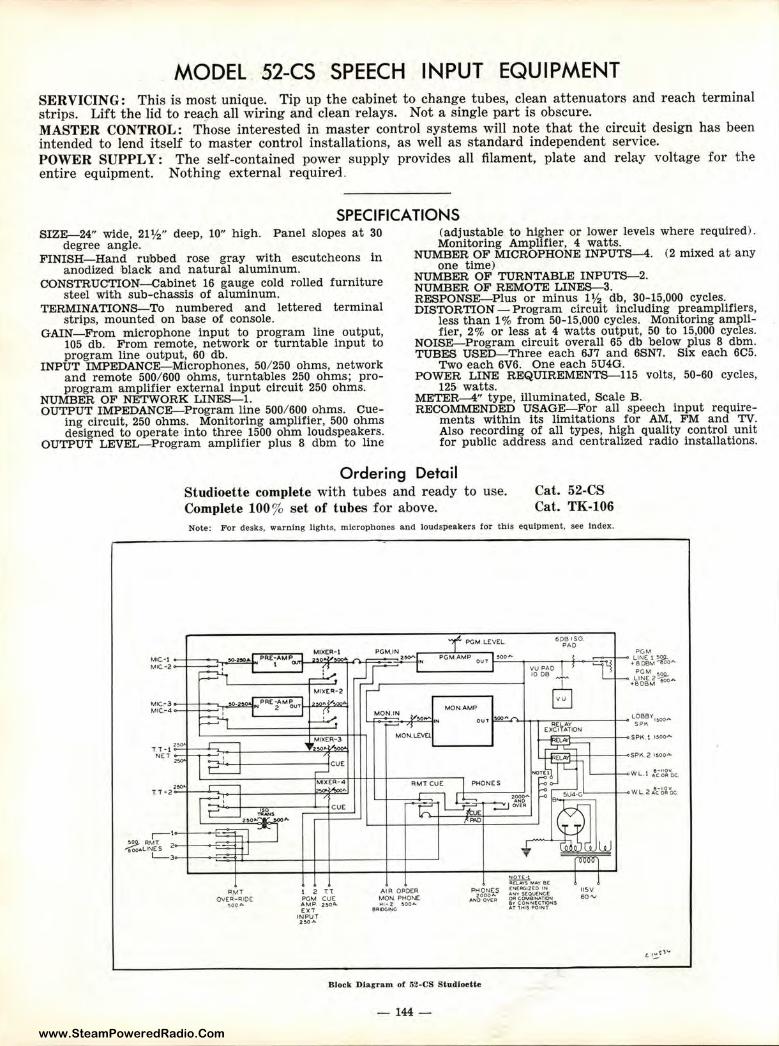
www.SteamPoweredRadio.Com
MODEL 52-CS SPEECH INPUT EQUIPMENT SERVICING: This is most unique. Tip up the cabinet to change tubes, clean attenuators and reach terminal strips. Lift the lid to rea~h all wiring and clean relays. Not a single part is obscure. MASTER CONTROL: Those interested in master control systems will note that the circuit design has been intended to lend itself to master control installations, as well as standard independent service. POWER SUPPLY: The self-contained power supply provides all filament, plate and relay voltage for the entire equipment. Nothing external requiretl.
SPECIFICATIONS SIZE-24" wide, 21½" deep, 10" high. Panel slopes at 30
degree angle. FINISH- Hand rubbed rose gray with escutcheons in
anodized black and natural aluminum. CONSTRUCTION-Cabinet 16 gauge cold rolled furniture
steel with sub-chassis of aluminum. TERMINATIONS-To numbered and lettered terminal
strips, mounted on base of console. GAIN-From microphone input to program line output,
105 db. From remote, network or turntable input to program line output, 60 db.
INPUT IMPEDANCE-Microphones, 50/ 250 ohms, network and remote 500/ 600 ohms, turnta!bles 250 ohms; proprogram amplifier external input circuit 250 ohms.
NUMBER OF NETWORK LINES-1. OUTPUT IMPEDANCE-Program line 500/ 600 ohms. Cue
ing circuit, 250 ohms. Monitoring amplifier, 500 ohms designed to operate into three 1500 ohm loudspeakers.
OUTPUT LEVEL-Program amplifier plus 8 dbm to line
(adjustable to higher or lower levels where required) . Monitoring Amplifier, 4 watts.
NUMBER OF MICROPHONE INPUTS-4. (2 mixed at any one time)
NUMBER OF TURNTABLE INPUTS-2. NUMBER OF REMOTE LINES-3. RESPONSE-Plus or minus 1½ db, 30-15,000 cycles. DISTORTION - Program circuit including preamplifiers,
less than 1 % from 50-15,000 cycles. Monitoring amplifier, 2% or less at 4 watts output, 50 to 15,000 cycles.
NOISE-Program circuit overall 65 db below plus 8 dbm. TUBES USED-Three each 6J7 and 6SN7. Six each 6C5.
Two each 6V6. One each 5U4G. POWER LINE REQUIREMENTS-115 volts, 50-60 cycles,
125 watts. METER-4" type, illuminated, scale B. RECOMMENDED USAGE-For all speech input require
ments within its limitations for AM, FM and TV. Also recording of all types, high quality control unit for public address and centralized radio installations.
Ordering Detail Studioette complete with tubes and r eady to use. Complete 100% set of tubes for above.
Cat. 52-CS Cat. TK-106
Note: For desks, warning lights, microphones and loudspeakers for t his equipment, see Index.
PGM LtVEL 608 ISO. PAO
PGM AMI? OUT i-:•.:..:oo_- ---~~....=n3 VU PAO 1-i
12 n PGM cue AMP. 2:»0"[ XT
INP\JT 2,0A
AIR. OROCF\ MON PMONC ... 1-z :!IOO"-
s•OGIN~
™ONES 2000"
AND ovtP
Block Dlagum of 52-CS StudloeUe
-144-
10 OB
EJ
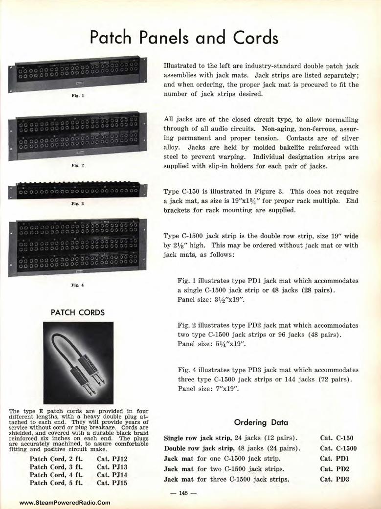
www.SteamPoweredRadio.Com
Patch Panels and Cords
Fig-. 1
Fig. 2
Fig-. S
PATCH CORDS
The type E patch cords are provided in four different lengths, with a heavy double plug attached to each end. They will provide years of service without cord or plug breakage. Cords are shielded, and covered with a duraible black braid reinforced six inches on each end. The plugs are accurately machined, to assure comforta,ble fitting and positive circuit make.
Patch Cord, 2 ft. Patch Cord, 3 ft. Patch Cord, 4 ft. Patch Cord, 5 ft.
Cat. PJ12 Cat. PJ13 Cat. PJ14 Cat. PJ15
Illustrated to the left are industry-standard double patch jack assemblies with jack mats. Jack strips are listed separately; and when ordering, the proper jack mat is procured to fit the number of jack strips desired.
All jacks are of the closed circuit type, to allow normalling through of all audio circuits. Non-aging, non-feirrous, assuring permanent and proper tension. Contacts 21re of silver alloy. Jacks are held by molded bakelite reimforced with steel to prevent warping. Individual designation strips are supplied with slip-in holders for each pair of jaclks.
Type C-150 is illustrated in Figure 3. This does: not require a jack mat, as size is 19"xl¾" for proper rack mlllltiple. End brackets for rack mounting are supplied.
Type C-1500 jack strip is the double row strip, size 19" wide by 21/s" high. This may be ordered without jack mat or with jack mats, as follows:
Fig. 1 illustrates type PDl jack mat which accommodates a single C-1500 jack strip or 48 jacks (28 pairs). Panel size: 31/2"x19".
Fig. 2 illustrates type PD2 jack mat which accommodates two type C-1500 jack strips or 96 jacks (48 pairs). Panel size: 5¼"x19".
Fig. 4 illustrates type PD3 jack mat which accommodates th1·ee type C-1500 jack strips or 144 jacks 1:12 pairs). Panel size: 7"x19".
Ordering Data
Single row jack strip, 24 jacks (12 pairs) .
Double row jack strip, 48 jacks (24 pairs).
Jack mat for one C-1500 jack strip.
Jack mat for two C-1500 j~ck strips.
Jack mat for three C-1500 jack strips.
- 145 -
Cat. C-150
Cat. C-1500 Cat. PDl
Cat. PD2
Cat. PD3
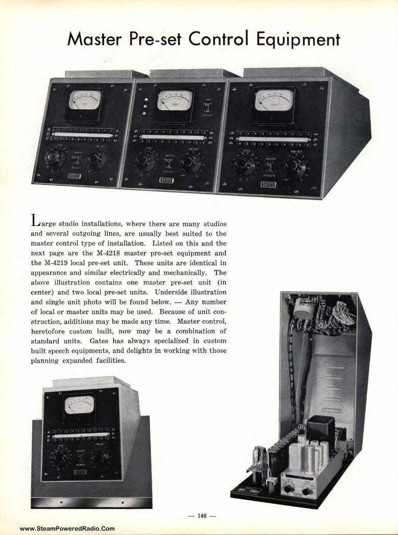
www.SteamPoweredRadio.Com
Master Pre-set Control Equipment
L arge studio installations, where t here are many studios and several outgoing lines, are usually best suited to the master control type of installation. Listed on this and the next page are the M-4218 master pre-set equipment and the M-4219 local pre-set unit. These units are identical in appearance and similar electrically and mechanically. The above illustration contains one master pre-set unit (in center) and two local pre-set units. Underside illustration and single unit photo will be found below. - Any number of local or master units may be used. Because of unit construction, additions may be made any time. Master control, heretofore custom built, now may be a combination of standard units. Gates has always specialized in custom built speech equipments, and delights in working with those planning expanded facilities.
- 146 -
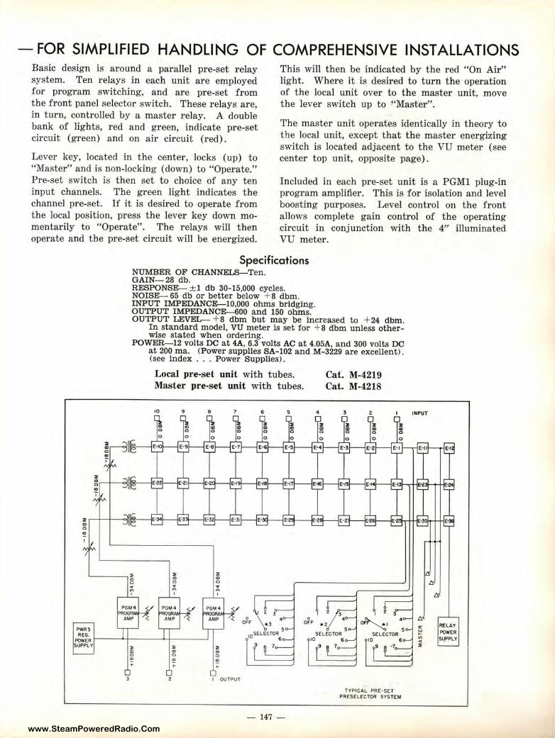
www.SteamPoweredRadio.Com
- FOR SIMPLIFIED HANDLING OF COMPREHENSIVE INSTALLATIONS Basic design is around a parallel pre-set relay system. Ten relays in each unit are employed for program switching, and are pre-set from the front panel selector switch. These relays are, in turn, controlled by a master relay. A double bank of lights, red and green, indicate pre-set circuit (green) and on air circuit (red).
This will then be indicated by the red "On Air" light. Where it is desired to turn the operation of the local unit over to the master unit, move the lever switch up to !'Master".
Lever key, located in the center, locks (up) to "Master" and is non-locking (down) to "Operate." Pre-set switch is then set to choice of any ten input channels. The green light indicates the channel pre-set. If it is desired to operate from the local position, press the lever key down momentarily to "Operate". The relays will then operate and the pre-set circuit will be energized.
The master unit operates identically in theory to the local unit, except that the master energizing switch is located adjacent to the VU meter (see center top unit, opposite page).
Included in each pre-set unit is a PGMl plug-in program amplifier. This is for isolation and level boosting purposes. Level control on the front allows complete gain control of the operating circuit in conjunction with the 4" illuminated VU meter.
Specifications NUMBER OF CHANNELS-Ten. GAIN-28 db. RESPONSE--- :±;l db 30-15,000 cycles. NOISE-- 65 db or better below + 8 dbm. INPUT IMPEDANCE---10,000 ohms bridging. OUTPUT IMPEDANCE---600 and 150 ohms. OUTPUT LEVEL- +8 dbm but may be increased to +24 dbm.
In standard model, VU meter is set for + 8 dbm unless otherwise stated when ordering.
POWER-12 volts DC at 4A, 6.3 volts AC at 4.05A, and 300 volts DC at 200 ma. (Power supplies SA-102 and M-3229 are excellent). (see index . . . Power Supplies).
Local pre-set unit with tubes. Master pre-set unit with tubes.
10 9 8 6 5 4
Cat. M-4219 Cat. M-4218
3 2 INPUT
" r-f---lf--"""111~ ~' Cl)
0 Cl)
I
PWR3
~~ii i-----'>-+---- ---'>-+--------' SUPPLY
3 I OUTPUT
- 147 -
I 2 3
o~, 45
SELECTOR 10 6
9 ,7
TYPICAL PRE·SET PRESELECTOR SYSTEM
t:I.
t:I.
RELAY POWER SU_PPLY
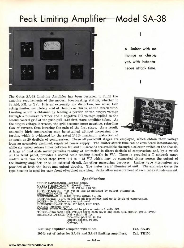
www.SteamPoweredRadio.Com
Peak Limiting Amplifier-Model SA-38
The Gates SA-38 Limiting Amplifier has been designed to fulfill the exacting requirements of the modern broadcasting station, whether it be AM, FM, or TV. It is an extremely low distortion, low noise, fast acting limiter, completely void of thumps or chirps, at the attack time. Limiting action is obtained by feeding a portion of the output voltage through a full-wave rectifier and a negative DC voltage applied to the second control grid of the push-pull 1612 first stage amplifier tubes. As the output voltage increases, the grid becomes more negative, retarding flow of current, thus lowering the gain of the first stage. As a result, unusually high compression may be attained without increasing distortion, which is evidenced by the rated 1½ % maximum distortion at
A Limiter with no
thumps or chirps;
yet, with instanta
neous attack time.
as much as 20 decibels of compression. Three all push-pull stages are employed, which obtain their voltage from an accurately designed, regulated power supply. The limiter attack time can be considered instantaneous, while six varied release times between 0.2 and 1.2 seconds are available through a selector switch on the chassis. A large 4" dual scale meter provides reading of limitation in direct decibels of compression, and, by a switch on the front panel, provides a second scale reading directly in VU. There is provided a T network range control with two decibel steps from + 4 to + 42 VU which may be connected either across the output of the limiting amplifier, or to an external circuit, for other measuring purposes. Ladder type attenuators are provided at both t he input and output circuits. The meter is a 4" illuminated unit. The exclusive Gates SA type housing is used for easy front-of-cabinet servicing. Jacks allow measurement of each tube cathode current.
Specifications INPUT IMPEDANCE-500/ 600 ohms. OUTPUT IMPEDANCE-500/ 600 ohms. INPUT LEVEL-From - 20 VU to + 20 VU. OU'l1PUT LEVEL- + 25 VU or less as adjusted by output attenuator. MAXIMUM GAIN- 60 db. REJSPONSE-30 to 15,000 cycles within 1 ½ db. DISTORTION- 1½% or less at all frequencies and up to 20 db of compression. NOISE- 70 db below any output level. DIMENSIONS-19" wide, 14" high, 9½" deep. FINISH-Medium gray. POWER SUPPLY-Regulated to plus or minus 5 volts DC. TUBES-Two each 1612, 6V6GT; three each 6SJ7; one each 6H6, 6S5GT, 6Y6G, 5V4G. smPPING DETAIL-Net weight, 38 lbs.
Domestic packed, 74 lbs. Export packed, 96 lbs. Cubage, 12.
Limiting amplifier complete with tubes. 100% set of tubes for SA-38 and SA-39 limiting amplifiers.
- 148 -
Cat. SA-38 Cat. TK150
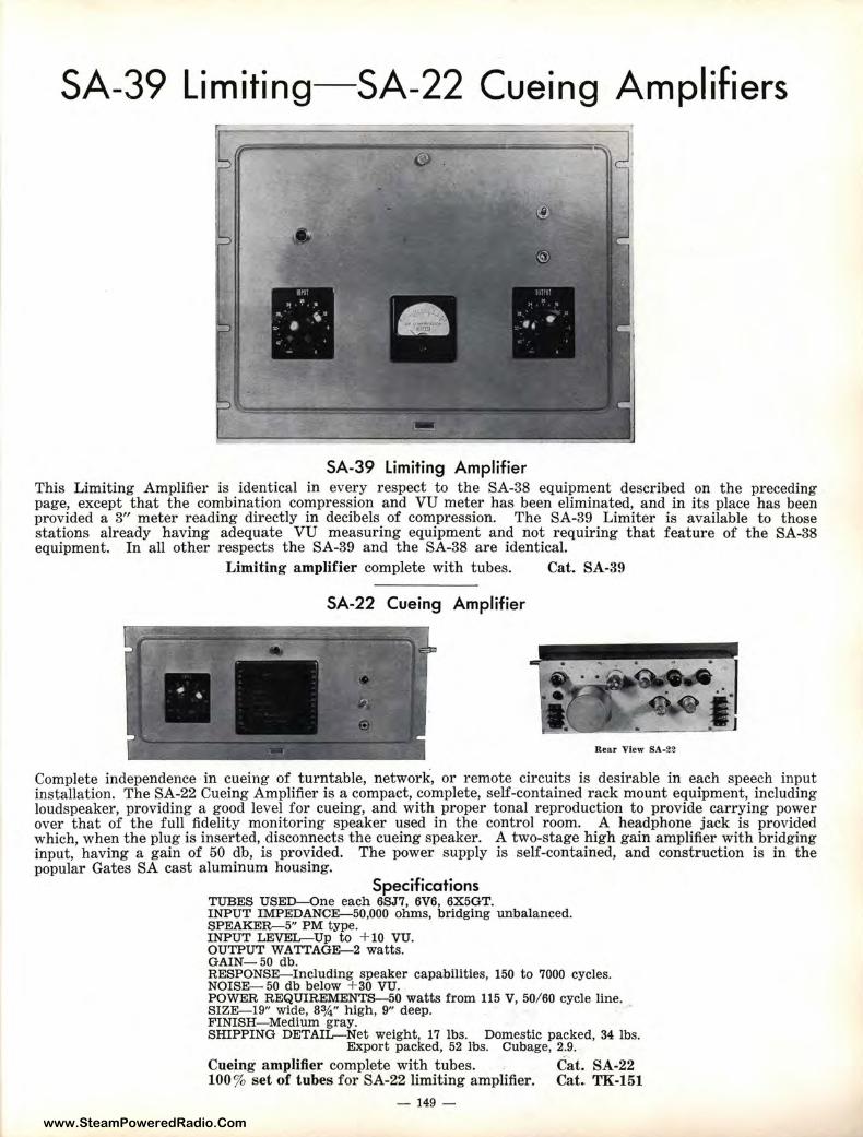
www.SteamPoweredRadio.Com
SA-39 Limiting-SA-22 Cueing Amplifiers
SA-39 Limiting Amplifier This Limiting Amplifier is identical in every respect to the SA-38 equipment described on the preceding page, except that the combination compression and VU meter has been eliminated, and in its place has been provided a 3" meter reading directly in decibels of compression. The SA-39 Limiter is available to those stations already having adequate VU measuring equipment and not requiring that feature of the SA-38 equipment. In all other respects t he SA-39 and the SA-38 are identical.
Limiting amplifier complete with tubes. Cat. SA-39
SA-22 Cueing Amplifier
Rear View SA-22
Complete independence in cueing of turntable, network, or r emote circuits is desirable in each speech input installation. The SA-22 Cueing Amplifier is a compact, complete, self-contained rack mount equipment, including loudspeaker, providing a good level for cueing, and with proper tonal reproduction to provide carrying power over that of the full fidelity monitoring speaker used in the control room. A headphone jack is provided which, when the plug is inserted, disconnects the cueing speaker. A two-stage high gain amplifier with bridging input, having a gain of 50 db, is provided. The power supply is self-contained, and construction is in the popular Gates SA cast aluminum housing.
Specifications TUBES USED-One each 6SJ7, 6V6, 6X5GT. INPUT IMPEDANCE-50,000 ohms, bridging unbalanced. SPEAKER-5" PM type. INPUT LEVEL-Up to + 10 VU. OUTPUT WATTAGE-2 watts. GAIN- 50 db. RESPONSE-Including speaker capabilities, 150 to 7000 cycles. NOISE- 50 db below + 30 VU. POWER REQUIREMENTS-50 watts from 115 V, 50/ 60 cycle line. SIZE-19" wide, 83/4" high, 9" deep. FINISH-Medium gray. SHIPPING DETAIL-Net weight, 17 lbs. Domestic packed, 34 lbs.
Export packed, 52 l'bs. Cubage, 2.9.
Cueing amplifier complete with tubes. Cat. SA-22 100% set of tubes for SA-22 limiting amplifier. Ca.t. TK-151
- 149 -
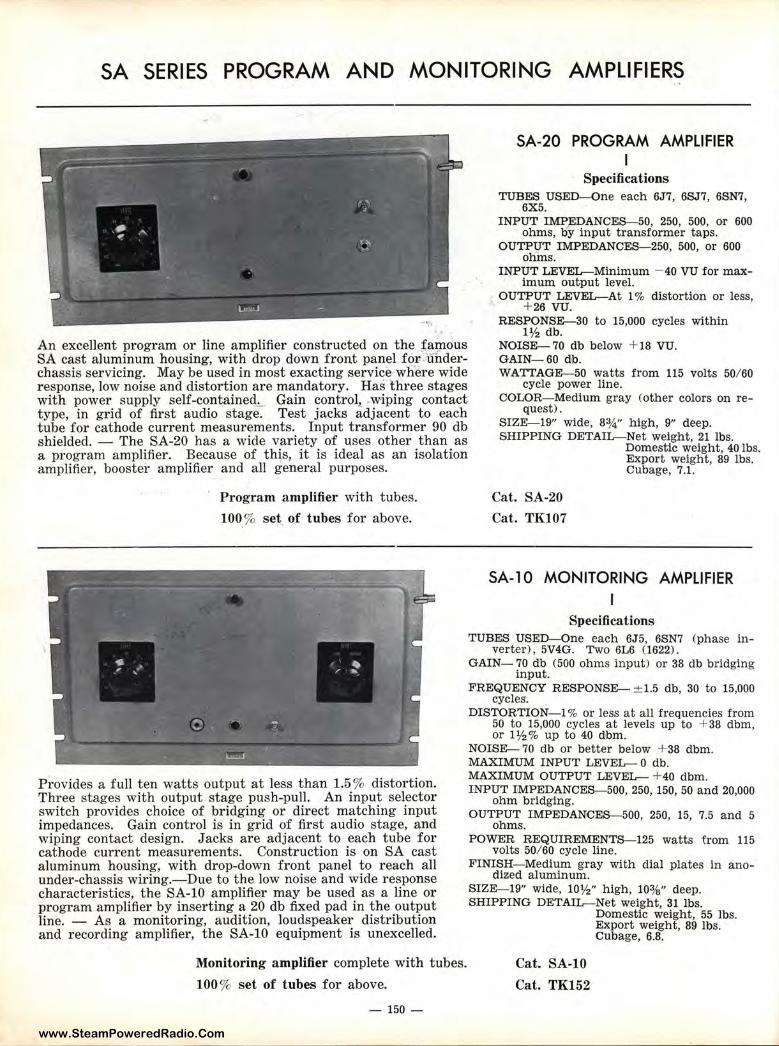
www.SteamPoweredRadio.Com
SA SERIES PROGRAM AND MONITORING AMPLIFIERS
An excellent program or line amplifier constructed on the fa:gious SA cast aluminum housing, with drop down front panel for- -Uhderchassis servicing. May be used in most exacting service where wide response, low noise and distortion are mandatory. Has three stages with power supply self-contained,__ Gain control,_ wiping contact type, in grid of first audio stage. Test jacks adjacent to each tube for cathode current measurements. lnp~t transformer 90 db shielded. - The SA-20 has a wide variety of uses other than as a program amplifier. Because of this, it is ideal as an isolation amplifier, booster amplifier and all general purposes.
Program amp1ifier with tubes.
100% set of tubes for above.
SA-20 PROGRAM AMPLIFIER I
Specifications TUBES USED-One each 6J7, 6SJ7, 6SN7,
6X5. INPUT IMPEDANCES-50, 250, 500, or 600
ohms, by input transformer taps. OUTPUT IMPEDANCEs-250, 500, or 600
ohms. INPUT LEVEL-Minimum - 40 VU for max
imum output level. OUTPUT LEVEL-At 1 % distortion or less,
+ 26 vu. RESPONSE-30 to 15,000 cycles within
l½ db. NOISE- 70 db below + 18 VU. GAIN-60 db. WATTAGE-50 watts from 115 volts 50/ 60
cycle power line. COLOR-Medium gray (other colors on re
quest). SIZE-19" wide, 83/4" high, 9" deep. SHIPPING DETAIL-Net weight, 21 lbs.
Cat. SA-20
Cat. TK107
Domestic weight, 40 lbs. Export weight, 89 lbs. Cubage, 7.1.
SA-10 MONITORING AMPLIFIER
Specifications TUBES USED-One each 6J5, 6SN7 (phase in
verter), 5V4G. Two 6L6 (1622). GAIN- 70 db (500 ohms input) or 38 db bridging
input. FREQUENCY RESPONSE- ±1.5 db, 30 to 15,000
cycles. DISTORTION- ! % or less at all frequencies from
50 to 15,000 cycles at levels up to + 38 dbm, or 1½% up to 40 dbm.
Provides a full ten watts output at less than 1.5% distortion. Three stages with output stage push-pull. An input selector switch provides choice of bridging or direct matching input impedances. Gain control is in grid of first audio stage, and wiping contact design. Jacks are adjacent to each tube for cathode current measurements. Construction is on SA cast aluminum housing, with drop-down front panel to reach all under-chassis wiring.-Due to the low noise and wide response characteristics, the SA-10 amplifier may be used as a line or program amplifier by inserting a 20 db fixed pad in the output line. - As a monitoring, audition, loudspeaker distribution and recording amplifier, the SA-10 equipment is unexcelled.
NOISE- 70 db or better below + 38 dbm. MAXIMUM INPUT LEVEL- 0 db. MAXIMUM OUTPUT LEVEL- +40 dbm.
Monitoring ampJifier complete with tubes.
100 % set of tubes for above.
- 150 -
INPUT IMPEDANCES-500, 250, 150, 50 and 20,000 ohm bridging.
OUTPUT IMPEDANCES-500, 250, 15, 7.5 and 5 ohms.
POWER REQUIREMENTS-125 watts from 115 volts 50/ 60 cycle line.
FINISH-Medium gray with dial plates in anodized aluminum.
SIZE-19" wide, 10½" high, 103/s" deep. SHIPPING DETAIL-Net weight, 31 lbs.
Cat. SA-10
Cat. TK152
Domestic weight, 55 lbs. Export weight, 89 lbs. Cubage, 6.8.
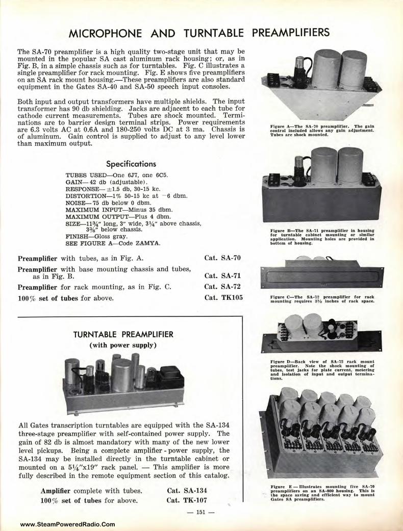
www.SteamPoweredRadio.Com
MICROPHONE AND TURNTABLE PREAMPLIFIERS
The SA-70 preamplifier is a high quality two-stage unit that may be mounted in the popular SA cast aluminum rack housing; or, as in Fig. B, in a simple chassis such as for turntables. Fig. C illustrates a single preamplifier for rack mounting. Fig. E shows five preamplifiers on an SA rack mount housing.-These preamplifiers are also standard equipment in the Gates SA-40 and SA-50 speech input consoles.
Both input and output transformers have multiple shields. The input transformer has 90 db shielding. Jacks are adjacent to each tube for cathode current measurements. Tubes are shock mounted. Terminations are to barrier design terminal strips. Power requirements are 6.3 volts AC at 0.6A and 180-250 volts DC at 3 ma. Chassis is of aluminum. Gain control is supplied to adjust to any level lower than maximum output.
Specifications TUBES USED-One 6J7, one 6C5. GAIN- 42 db (adjustable) . RESPONSE- ± 1.5 db, 30-15 kc. DISTORTION-1 % 50-15 kc at - 6 dbm. NOISE- 75 db below O dbm. MAXIMUM INPUT-Minus 35 dbm. MAXIMUM OUTPUT- Plus 4 dbm. SIZE-11¾" long, 3" wide, 3¼" above chassis,
33/s" below chassis. FINISH- Gloss gray. SEE FIGURE A-Code ZAMYA.
Preamplifier with tubes, as in Fig. A.
Preamplifier with base mounting chassis and tubes, as in Fig. B.
Preamplifier for rack mounting, as in Fig. C.
100% set of tubes for above.
TURNTABLE PREAMPLIFIER (with power supply )
Cat. SA-70
Cat. SA-71
Cat. SA-72
Cat. TK105
All Gates transcription turntables are equipped with t he SA-134 three-stage preamplifier with self-contained power supply. The gain of 82 db is almost mandatory with many of the new lower level pickups. Being a complete amplifier - power supply, the SA-134 may be installed directly in the turntable cabinet or mounted on a 5¼"xl9" rack panel. - This amplifier is more fully described in the remote equipment section of this catalog.
Amplifier complete with tubes. 100 % set of tubes for above.
Cat. SA-134 Cat. TK-107
- 151 -
Figure A-The SA-70 preamplifier. The gain control Included allows a n y gain adjustment . Tubes are shock mounted.
Figure II-Th e SA-71 preamplifier In h ouslnr for turntable cabinet moun ting or similar a pplication. Mounting holes are provided In bottom or housing",
Figure C-The SA-72 p reampllrter tor rack mounting- requires 3¥~ lnches of rack space.
Figure D-Back view or SA-72 rack mount preamplitler. Note the sh ock mounting or tubes, test Jacks for plate cu.rrent, metering and isolation of Input and output termination s.
Figure E - Illustrates moun ting five SA-70 preampllflers on an SA-800 housing. This ls the space saving and ertlclent way to mount Oates SA preampllflers.
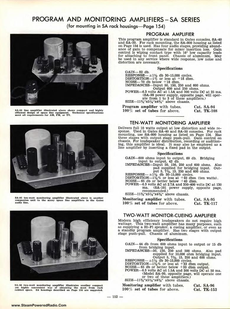
www.SteamPoweredRadio.Com
PROGRAM ANO MONITORING AMPLIFIERS-SA SERIES (for mounting in SA rack housings- Page 154)
SA-94 line amplifier Illustrated above shows compact a nd h lrhly efficient design or space line equipment. Technical specifications meet all requirements for AM, FM, or TV.
SA-95 ten-watt monltorlnr amplifier Illustrate d above Is anoth er companion unit to the many space line amplifiers In th e Gates audi o line .
SA-96 two-watt monitorln r amplifier Illustrates another compact yet highly conve.nlent way of obtaining the mosl from rack cabinet s pace. SA. housinrs described on Page 154 are sunested.
PROGRAM AMPLIFIER This program amplifier is standard in Gates consoles, SA-40 and SA-50. For rack mounting, the SA-800 housing as listed on Page 154 is used. Has four audio stages, providing abundance of gain to compensate for mixer insertion loss. Gain control is wiping contact type with 16" low capacity leads for attaching to front panel. Chassis of aluminum. May be used in any service where wide response, low noise and distortion are necessary.
Specifications GAIN-82 db. RESPONSE- ± 1½ d·b 30-15,000 cycles. DISTORTION-!% or less at +18 dbm. NOISE- 70 db below + 18 dbm. IMPEDANCES-Input 50, 150, 250 and 600 ohms.
Output 600 and 250 ohms. POWER-6.3 volts AC at 1.5A and 300 volts DC at 25 ma.
(SA-99 power supply, opposite page, will operate from 1 to 3 of these amplifiers.)
SIZE-ll¾"x5¼"x4¾" above chassis. Program amplifier with tubes. 100 % set of tubes for above.
Cat. SA-94 Cat. TK-108
TEN-WATT MONITORING AMPLIFIER Delivers full 10 watts output at low distortion and wide response. Used in Gates SA-40 and SA-50 consoles. For rack mounting, use SA-800 housing as listed on Page 154. Has three stages with output stage push-pull. Gain control on chassis. For loudspeaker distribution, recording or auditioning, this amplifier is ideal. It may also be employed as a line amplifier by inserting a fixed pad in the output.
Specifications GAIN-600 ohms input to output, 69 db. Bridging
input to output, 42 db. IMPEDANCES-Input 50, 150, 250 and 600 ohms. Also
pad supplied for bridging input. Output 5, 7½, 15, 250 and 600 ohms.
RESPONSE- ± 1½ db 30-15,000 cycles. DISTORTION-!½% or less at + 40 dbm (ten watts). NOISE- 65 db or better below + 40 dbm. POWER-6.3 volts AC at 2.7A and 350-400 volts DC at 130
ma. (SA-101 power supply, opposite page, recommended.)
SIZE-ll¾"x5¼"x4¾" above chassis. Monitoring amplifier with tubes. 100 % set of tubes for above.
Cat. SA-95 Cat. TK-117
TWO-WATT MONITOR-CUEING AMPLIFIER Modern high efficiency loudspeakers do not require high wattage. This two-watt amplifier has many purposes, such as supplying a Hi-Fi speaker, a cueing amplifier, or even as a standby program amplifier. Has two stages with output stage push-pull. Chassis of alumin um.
Specifications GAIN- 44 db from 600 ohms input to output or 15 db
from bridging input. IMPEDANCES--50, 150, 250 and 500 ohms. Also pad
supplied for 10,000 ohm bridging input. Output 5, 7½, 15, 250 and 600 ohms.
RESPONSE- ± 1½ db 30-15,000 cycles. DISTORTION- ! ½% or less at +33 dbm output. NOISE- 65 db or better below + 33 dbm output. POWER-6.3 volts AC at 1.5A and 300 volts DC at 50 ma.
(Model SA-99, opposite page, will operate one or two of these amplifiers.)
SIZE-ll¾"x5¼"x4¾" above chassis.
Monitoring amplifier with tubes. 100 % set of tubes for above.
Cat. SA-96 Cat. TK-153
- 152 -
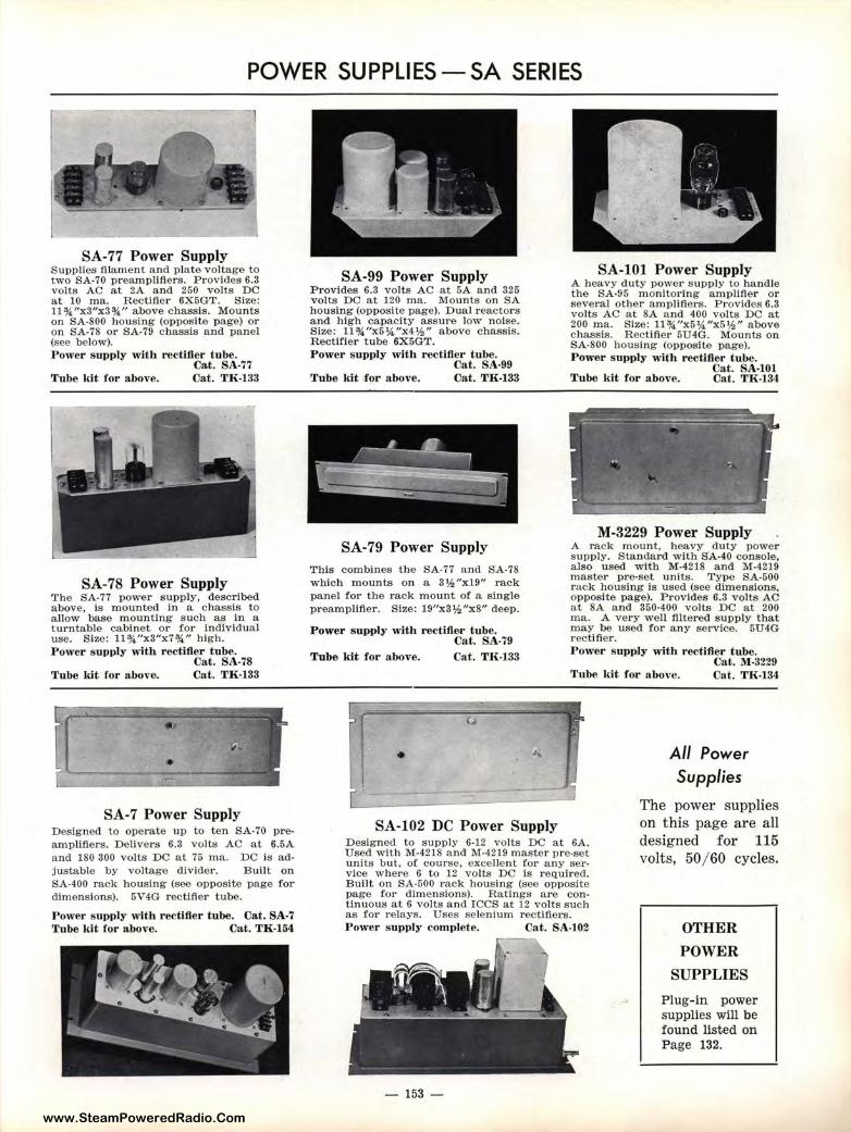
www.SteamPoweredRadio.Com
POWER SUPPLIES-SA SERIES
SA-77 Power Supply Supplies filament and plate voltage to two SA-70 preampllflers. Provides 6.3 volts AC at 2A and 250 volts DC at 10 ma. Rectifier 6X5GT. Size: ll¾"x3"x3¾" above chassis . Mounts on SA-800 housing (opposite page) or on SA-78 or SA-79 chassis and panel (see below). Power supply with rectifier tube.
Cat. SA-77 Tube kit for above. Cat. TK-133
SA-78 Power Supply The SA-77 power supply, described above, is mounted in a chassis to a llow base m ounting such as in a turntable cabinet or for Individual use. Size: ll¾"x3"x7¾" high. Power s upply with rectifier tube.
Cat. SA-78 Tube kit for above. Cat. TH-133
SA-7 Power Supply Designed to operate up to ten SA-70 preamplifiers. Delivers 6.3 volts AC at 6.5A and 180 300 volts DC at 75 ma. DC is adjustable by voltage divider . Built on SA-400 rack housing (see opposite page for dimensions). 5V4G rectifier tube.
Power supply with rectifier tube. Cat. SA-7 Tube kit for above. Cat. TH-154
SA-99 Power Supply Provide:3 6.3 volts AC at 5A and 325 volts D<C at 120 ma. Mounts on SA housing (opposite page). Dual reactors and high capacity assure low noise. Size: 11 ¾"x5¼"x4½" above chassis. Rectifier tube 6X5GT. Power s:upply with rectifier tube.
Cat. SA-99 Tube ldt for above. Cat. TH-133
SA-79 Power Supply This combines the SA-77 and SA-78 which 1nounts on a 3½"x19" rack panel for the rack mount of a single preampUfier. Size: 19"x 3½"x8" deep.
Power E1upply with rectifier tube. Cat. SA-79
Tube kit for above. Cat. TK-133
SA-101 Power Supply A heavy duty power supp ly to handle the SA-95 monitoring amplifier or several other amplifiers. Provides 6.3 volts AC at 8A and 400 volts DC at 200 ma. Size: ll¾"x5¼"x5½" above chassis. Rectifier 5U4G. Mounts on SA-800 housing (opposite page). Power supply with rectifier tube.
Cat. SA-101 Tube ldt for above. Cat. TJ{-134
M-3229 Power Supply A rack mount, heavy duty power supply. Standard with SA-40 console, also used w ith M-4218 and M-4219 master pre-set u nits. Type SA-500 rack housing is used (see dimensions. opposite page). Provides 6.3 volts AC at SA a nd 350-400 volts DC at 200 ma. A very well filtered supply that may be used for any service. 5U4G rectifier. Power supply with rectifier tube.
Cat. M-3229 Tube kit for above. Cat. TK-134
All Power Supplies
SA-102 DC Power Supply Designed to supply 6-12 volts DC a.t 6A. Used with M-4218 and M-4219 m a ster pre-set u:nits but, of course, excellent for any serviice where 6 to 12 volts DC is required. Built on SA-500 rack housing (see opposite page for dimensions). Ratings are continuous at 6 volts and ICCS at 12 volts such as for relays. Uses selenium rectifiers.
The power supplies on this page are all designed for 115 volts, 50/ 60 cycles.
P,ower supply complete. Cat. SA-102
- 153 -
OTHER
POWER
SUPPLIES
Plug-in power supplies will be found list ed on Page 132.
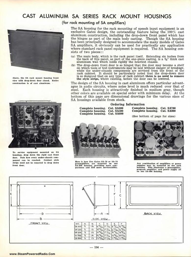
www.SteamPoweredRadio.Com
r E
CAST ALUMINUM SA SERIES RACK MOUNT HOUSINGS
Above, the SA rack mount housing front view with drop-down door closed. Entire construction ls or cast a luminum. •
To service equipment mounted on SA houslnrs, drop d own the rigid cast f ront door, Note how every under-chassis component can be reached. Cabinet style strips need not be removed to drop down front door.
I ... 0
.... I
l= · - 0
B F'B,01,i"T Y1EW
(for rack mounting of SA amplifiers)
The SA housing for the rack mounting of speech input equipment is an exclusive Gates design, the outstanding feature being the 100 % cast aluminum construction, including the drop-down front panel which has the hinges as part of the main body casting. Though the SA housing has been principally designed to accommodate the many rp.odels of Gates SA amplifiers, it obviously can be used for practically any application where standard rack panel equipment is required. The SA housing consists of two pieces: : (a) The main body, which is the rack panel itself. Extending six inches from
the back of this panel, as part of the one-piece casting, is a %" thick cast aluminum wall which holds rigidly the heaviest chassis.
(b) The drop-down front door is so hinged that the door may become a shelf on which tools or test instruments may be laid without danger of breakage, while the under-chassis components are serviced from the front of the rack cabinet. It should be particularly noted that the drop-down door is so designed that on any type of rack cabinet there is no need to remove the style strips, where existing, before the door can be lowered.
The design of the SA housing in cast aluminum offers particular advantages in audio circuits, where noise level is much reduced over that of steel. Each housing is attractively finished in medium gray, though other colors are available on special order with mirtimum delay. At the bottom of this page are dimensional drawings for the various sizes of SA housings available from stock.
C
C
. I
Ordering Information Complete housing. Complete housing. Complete housing.
Cat. SA400 Complete housing. Cat. SA700 Cat. SA500 Complete housing. Cat. SA800 Cat. SA600
Here Is b ow five Gales SA-70 or SA-74 preampl.lflers are mounted on one SA-800 housing-, provid.lng more compactness and st.Ill more servicea billt y.
1 rb ---
\ ' C I Jir :,J J ~A
s1oe: y1E,!.J
>JO. p, e. C. 0 £. ... ~l\·~•o 5 \~ G '1/-,,,_ 11 '/,c. 4'1/..,, ~'""Ii<. ~"·S00 5 I';) e.~Y.,,1. 11 '/1c. c;,"/1<;. <,, .. /,,:-,,
~A-~00 5 \~ 101"1.,,,. i, 'l,c. e 'l,1o eo/i1o
Y\·100 5 l':l 11.Y-,,,. 17 1/,c. 1o"'Ac. 101/,c;, Sl\·800 5 l°:l n,"''f.., 11 '/\,-,, 11 1s,r,.,, 11'""/i"'
- 154 -
(See bottom of page for sizes)
Any combination of amplifiers or power supplies may be mounted on one rack housing. This illustrates a preamplifier, prorram amplifier, and power supply alt on one S A-800 h ousing.
~
l i
BP.CK V IEW
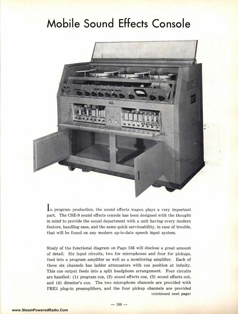
www.SteamPoweredRadio.Com
Mobile Sound Effects Console
I n program production, the sound effects wagon plays a very important part. The CSE-9 sound effects console has been designed with the thought in mind to provide the sound department with a unit having every modern feature, handling ease, and the same quick serviceability, in case of trouble, that will be found on any modern up-to-date speech input system.
Study of the functional diagram on Page 156 will disclose a great amount of detail. Six input circuits, two for microphones and four for pickups, feed into a program amplifier as well as a monitoring amplifier. Each of these six channels has ladder attenuators wit h cue position at infinity. This cue output feeds into a split headphone arrangement. Four circuits are handled: (1) program cue, (2) sound effects cue, (3) sound effects out, and ( 4) director's cue. The two microphone channels are provided with PREl plug-in preamplifiers, and the four pickup channels are provided
(continued next page)
- 155 -
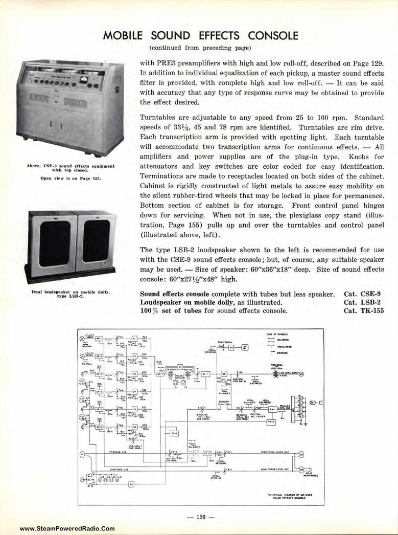
www.SteamPoweredRadio.Com
MOBILE SOUND EFFECTS CONSOLE
Above, CSE-9 sound effects equipment with top closed.
Open vJew Is on Pare 155.
Dual loudspeaker on mobile dolly, type LSB-2.
(continued from preceding page)
with PRE3 preamplifiers with high and low roll-off, described on Page 129. In addition to individual equalization of each pickup, a master sound effects filter is provided, with complete high and low roll-off. - It can be said with accuracy that any type of response curve may be obtained to provide the effect desired.
Turntables are adjustable to any speed from 25 to 100 rpm. Standard speeds of 331/a, 45 and 78 rpm are identified. Turntables are rim drive. Each transcription arm is provided with spotting light. Each turntable will accommodate two transcription arms for continuous effects. - All amplifiers and power supplies are of the plug-in type. Knobs for attenuators and key switches are color coded for easy identification. Terminations are made to receptacles located on both sides of the cabinet. Cabinet is rigidly constructed of light metals to assure easy mobility on the silent rubber-tired wheels that may be locked in place for permanence. Bottom section of cabinet is for storage. Front control panel hinges down for servicing. When not in use, the plexiglass copy stand (illustration, Page 155) pulls up and over the turntables and control panel (illustrated above, left).
The type LSB-2 loudspeaker shown to the left is recommended for use with the CSE-9 sound effects console; but, of course, any suitable speaker may be used. - Size of speaker: 60"x36"x18" deep. Size of sound effects console : 60"x27½"x48" high.
Sound e.ff.ects console complete with tubes but less speaker. Loudspeaker on mobile dolly, as illustrated. 100% set of tubes for sound effects console.
CD-(1
Cat. CSE-9 Cat. LSB-2 Cat. TK-155
-,,...,.++ .... - _-,_-.... = __ =~- -----+------, .... -=r~~-------~"""' .. J·~·l r:-. ..c~rs
•1t1DCti.G
- 156 -
,vHCTIIOfMl OIA(MNIII 0, lllo-4l0t 500M) 11:mcrs ~
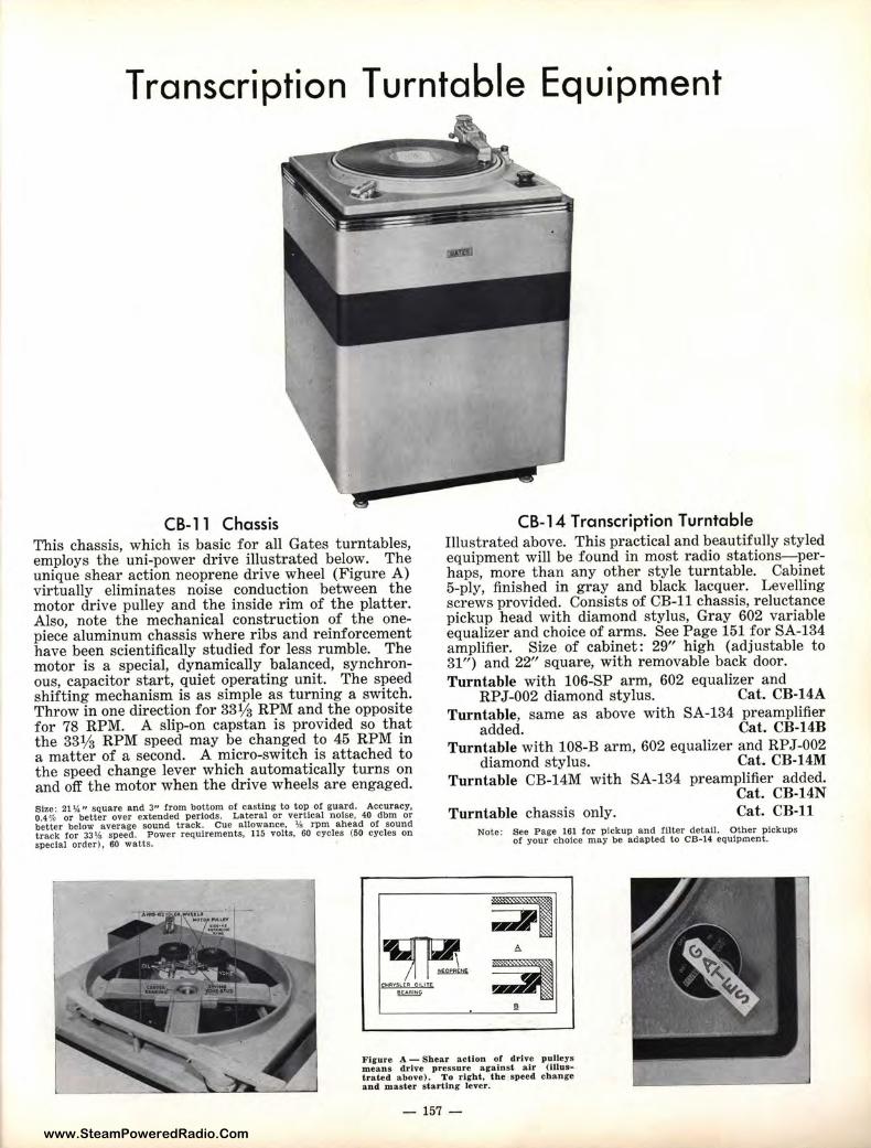
www.SteamPoweredRadio.Com
Transcription Turntable Equipment
CB-11 Chassis This chassis, which is basic for all Gates turntables, employs the uni-power drive illustrated below. The unique shear action neoprene drive wheel (Figure A) virtually eliminates noise conduction between the motor drive pulley and the inside rim of the platter. Also, note the mechanical construction of the onepiece aluminum chassis where ribs and reinforcement have been scient ifically studied for less rumble. The motor is a special, dynamically balanced, synchronous, capacitor start, quiet operating unit. The speed shifting mechanism is as simple as turning a switch. Throw in one direction for 331/a RPM and the opposite for 78 RPM. A slip-on capstan is provided so that the 331/a RPM speed may be changed to 45 RPM in a matter of a second. A micro-switch is attached to the speed change lever which automatically turns on and off the motor when the drive wheels are engaged. Size: 21 ¼" square and 3" from bottom of casting to top of guard. Accuracy. 0.4 % or better over extended periods. Lateral or vertical noise. 40 dbm or better below average sound track. Cue allowance. ¼ rpm ahead of sound track for 33¼ speed. Power requirements, 115 volts. 60 cycles (50 cycles on special order), 60 watts.
CB-14 Transcription Turntable Illustrated above. This practical and beautifully styled equipment will be found in most radio stations- perhaps, more than any other style turntable. Cabinet 5-ply, finished in gray and black lacquer. Levelling screws provided. Consists of CB-11 chassis, reluctance pickup head with diamond stylus, Gray 602 variable equalizer and choice of arms. See Page 151 for SA-134 amplifier. Size of cabinet : 29" high (adjustable to 31") and 22" square, with removable back door. Turntable with 106-SP arm, 602 equalizer and
RPJ-002 diamond stylus. Cat. CB-14A Turntable, same as above with SA-134 preamplifier
added. Cat. CB-14B Turntable with 108-B arm, 602 equalizer and RPJ-002
diamond stylus. Cat. CB-14M Turntable CB-14M with SA-134 preamplifier added.
Cat. CB-14N Turntable chassis only. Cat. CB-11
Note: See Page 161 for pickup and filter detail. Other p ickups of your choice may be adapted to CB-14 equipment.
Figure A - Shear action of drive pulleys means drive pressure arains·t. air (Illust rated above). To rlfht, the speed change and master s ta-rUng lever.
- 157 -
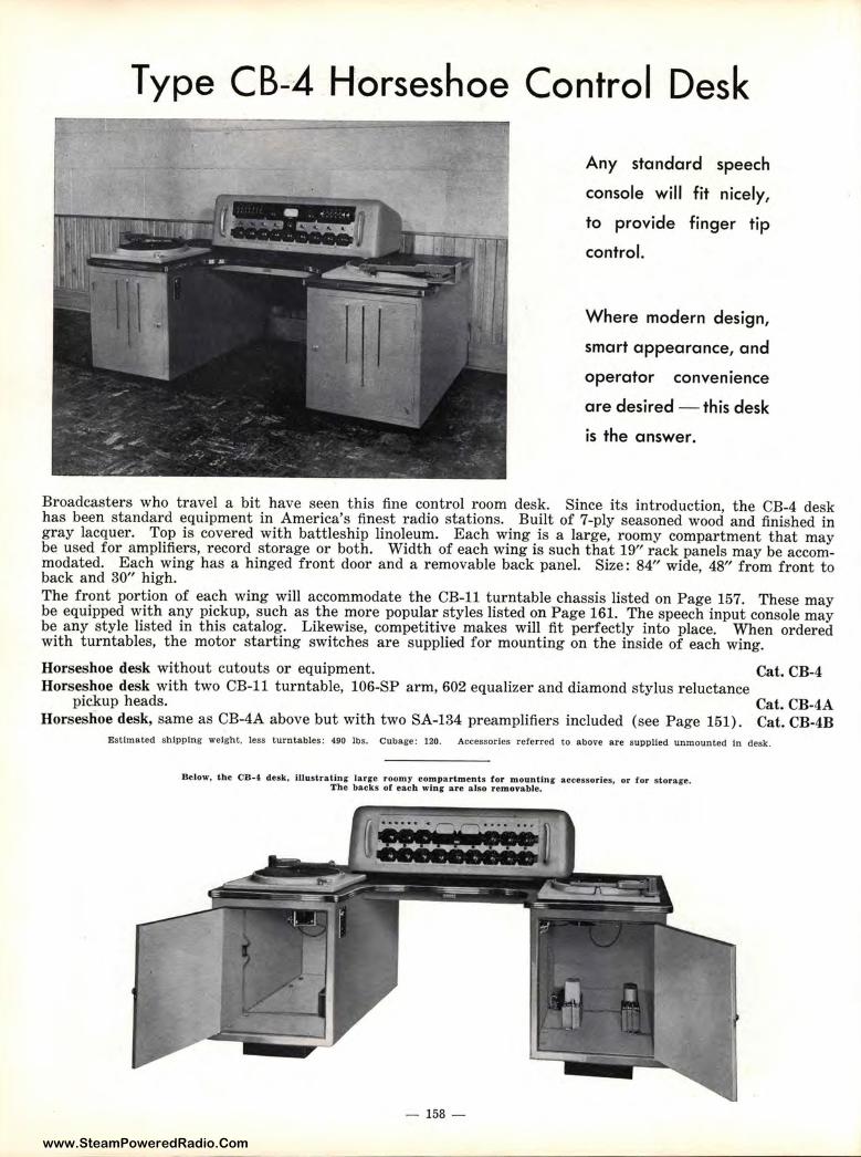
www.SteamPoweredRadio.Com
Type CB-4 Horseshoe Control Desk
Any standard speech
conso le will fit nicely,
to provide finger t ip
control.
Where modern design,
smart appearance, and
operator convenience
are desired - this desk
is the answer.
Broadcasters who travel a bit have seen this fine control room desk. Since its introduction, the CB-4 desk has been standard equipment in America's finest radio stations. Built of 7-ply seasoned wood and finished in gray lacquer. Top is covered with battleship linoleum. Each wing is a large, roomy compart ment that may be used for amplifiers, record storage or both. Widt h of each wing is such that 19" rack panels may be accommodated. Each wing has a hinged front door and a removable back panel. Size: 84" wide, 48" from front t o back and 30" high. The front portion of each wing will accommodate t he CB-11 turntable chassis listed on Page 157. These may be equipped with any pickup, such as the more popular styles listed on Page 161. The speech input console may be any style listed in this catalog. Likewise, competitive makes will fit perfectly into place. When ordered with turntables, the motor starting switches are supplied for mounting on the inside of each wing.
Horseshoe desk without cutouts or equipment. Cat. CB-4 Horseshoe desk with two CB-11 turntable, 106-SP arm, 602 equalizer and diamond stylus reluctance
pickup heads. Cat. CB-4A Horseshoe desk, same as CB-4A above but with two SA-134 preamplifiers included (see Page 151). Cat. CB-4B
Estimated shipping weight, less turntables: 490 lbs. Cubage: 120. Accessories referred to above are supplied unmounted In desk.
Below, the CB-4 desk, i.Llustrating large roomy compartments for mounting accessories, or for stora ge. The backs of each wing' a r e also r em ovable.
- 158 -
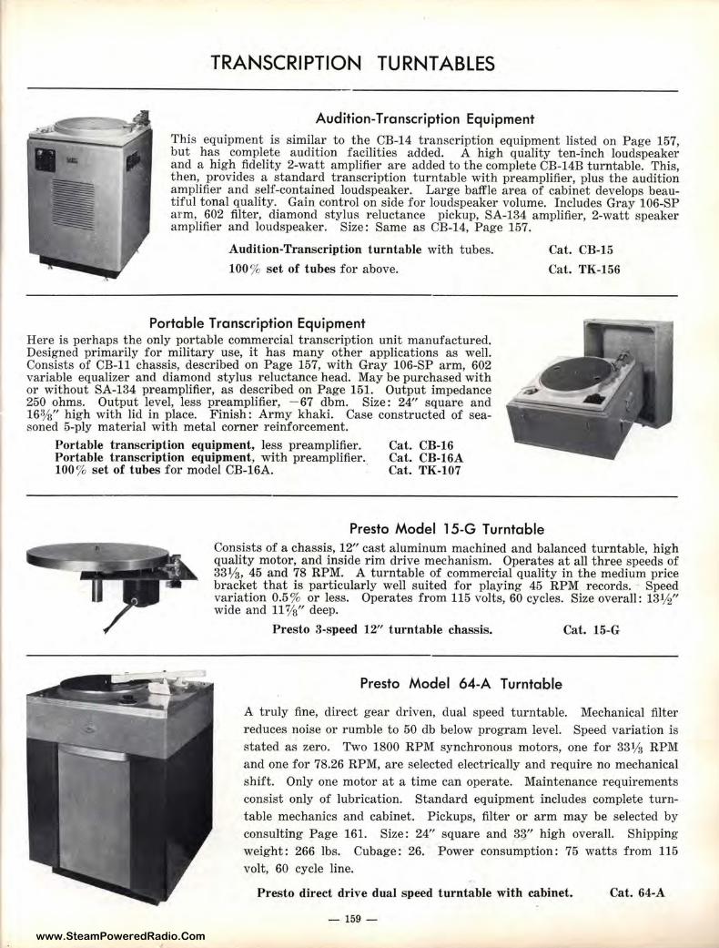
www.SteamPoweredRadio.Com
TRANSCRIPTION TURNTABLES
Audition-Transcription Equipment
This equipment is similar to the CB-14 t ranscription equipment listed on Page 157, but has complete audition facilities added. A high quality ten-inch loudspeaker and a high fidelity 2-watt amplifier are added to the complete CB-14B turntable. This, then, provides a standard t ranscription turntable with preamplifier, plus the audition amplifier and self-contained loudspeaker. Large baffle area of cabinet develops beaut iful tonal quality. Gain control on side for loudspeaker volume. Includes Gray 106-SP arm, 602 filter, diamond stylus reluctance pickup, SA-134 amplifier, 2-watt speaker amplifier and loudspeaker. Size: Same as CB-14, Page 157.
Audition-Transcription turntable with tubes.
100% set of tubes for above.
Portable Transcription Equipment Here is perhaps the only portable commercial transcription unit manufactured. Designed primarily for military use, it has many other applications as well. Consists of CB-11 chassis, described on Page 157, with Gray 106-SP arm, 602 variable equalizer and diamond stylus reluctance head. May be purchased with or without SA-134 preamplifier, as described on Page 151. Output impedance 250 ohms. Output level, less preamplifier, - 67 dbm. Size: 24" square and 161/s" high with lid in place. Finish : Army khaki. Case constructed of seasoned 5-ply material with metal corner reinforcement.
Portable transcription equipment, less preamplifier. Portable transcription equipment, with preamplifier. 100 % set of tubes for model CB-16A. ·
Cat. CB-16 Cat. CB-16A Cat. TK-107
Presto Model 15-G Turntable
Cat. CB-15
Cat. TK-156
Consists of a chassis, 12" cast aluminum machined and balanced turntable, high quality motor, and inside rim drive mechanism. Operates at all three speeds of 33½, 45 and 78 RPM. A turntable of commercial quality in the medium price bracket that is par t icularly well suited for playing 45 RPM records. Speed variation 0.5 % or less. Operates from 115 volts, 60 cycles. Size overall: 13½" wide and 11 %" deep.
Presto 3-speed 12" turntable chassis. Cat. 15-G
Presto Model 64-A Turntable
A truly fine, direct gear driven, dual speed turntable. Mechanical filter reduces noise or rumble to 50 db below program level. Speed variation is stated as zero. Two 1800 RPM synchronous motors, one for 331/a RPM and one for 78.26 RPM, are selected electrically and require no mechanical shift. Only one motor at a t ime can operate. Maintenance requirements consist only of lubrication. Standard equipment includes complete turntable mechanics and cabinet. Pickups, filter or arm may be selected by consulting Page 161. Size: 24" square and 33" high overall. Shipping weight: 266 lbs. Cubage: 26. Power consumption: 75 watts from 115 volt, 60 cycle line.
Presto direct drive dual speed turntable with cabinet.
- 159 -
Cat. 64-A
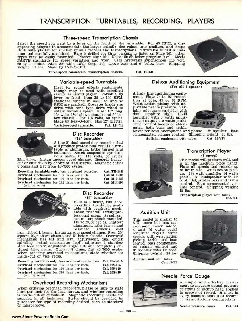
www.SteamPoweredRadio.Com
TRANSCRIPTION TURNTABLES, RECORDING, PLAYERS
Three-speed Transcription Chassis Select the speed you want by a lever on the front of the turntable. For 45 RPM, a disappearing adapter to accommodate the larger spindle size raises into position, and drops flush with platter for smaller spindle records and transcriptions. Turntable is cast aluminum and carefully machined. Base is drilled for Gray pickups as listed on Page 161- other types may be easily mounted. Platter size: 16". Noise: 50 db below program level. Meets NARTB standards for speed variation and wow. Uses hysteresis synchronous 116 volt, 60 cycle motor. Size: 20" wide, 183/4" deep, l ½" above base and 6" below base. Shipping weight: 30 lbs. Made by Rek-O-Kut.
Three-speed commercial trnnscription chassis .
Variable-speed Turntable Ideal for sound effects equipments, though may be used with excellent results as record player. Variable, by lever on front, from 25 to 100 RPM. Standard speeds of 33½, 45 and 78 RPM are marked. Operates inside rim drive with cone type drive wheel to obtain variable speed. Size: 16" long, 12" wide, 1 ½" above chassis and 5" below chassis. For 115 volts, 60 cycles. Made by Rek-O-Kut. Has 12" platter. Variable-speed turntable. Cat. LP-743
Disc Recorder (12" t urntable)
A fine 2" dual-speed disc recorder that will produce professional results. Turntable is aluminum, lathe turned and balanced. Shock suspended synchronous motor for 115 volts, 60 cycles.
Rim drive. Instantaneous speed change. Records insideout or outside-in ,by choice of lead screws. Magnetic cutter 8 ohms and flat from 40-7000 cycles. Recording turntable only , less overhead r ecorder. Overhead m edumi sm tor 108 lines per Inch. Over h ead m echanism for 120 lines per Inch. Overhead mochartlsm for 192 lines per Inch.
Cat.TR-12H Cat. 1\112-108 Cat. M12-120 Cat. l\U 2-l92
(microgroove)
Disc Recorde r (16" turntable)
Here is a heavy, rim drive recording turntable, available with overhead mechanism, that will satisfy professional users. Synchronous motor; shock mounted, 115 volts, 60 cycles. Platter: aluminum, lathe turned and balanced. Chassis: cast
iron, ribbed L beam. Instantaneous speed change. Size: 20" square, 2½" above chassis and 5" below chassis. Overhead mechanism has tilt and level adjustment, dual clutch spiraling control, micrometer depth adjustment, stainless steel lead screw, adjustable angle cut, and completely enclosed drive gears. Cutter: 8 ohms, f lat 40-7000 cycles. When ordering overhead mechanisms, state whether for Inside-out or vice versa. Recording turntable only, less overhead mechanism. Over head m ech anism tor 105 lines per Inch. Overh ead mechanism tor 120 lines per Inch. Overh eacl mech artlsm for 210 lines pet· Inch.
(microgrO(>Ve)
Cat.Model V Cat. l\1S-105 Cat. MS-120 Cat. lll S-210
Overhead Recording Mechanisms When ordering overhead recorders, please be sure to state lines per inch for the lead screws, and whether recording is inside-out or outside-in. Magnetic recording heads are supplied In all instances. Stylus should be provided by purchaser for type of recording desired, such as standard or microgroove.
Cat. B-16H
Deluxe Auditioning Equipment (For a ll 3 speeds) .~. •
A truly fine auditioning equipment. Plays 7" to 16" recordings at 33½, 45 or 78 RPM. Wrist action pickup with adjustable needle pressure. variable reluctance cartridge with dual sapphire styli. HI-Fi amplifier with 6 watts undistorted output (10 watts peak). Tone control boosts or attenuates, both bass and treble. Mixer for both microphone and phone. 12" speaker. Bass compensated volume control. Shipping weight: 25 lbs.
A udition equipment with tubes. Cat. 12-VP2
Audition Unit This model is similar to 6-U above but has microphone mixer added_ 4 watt (6 watts peak) amplifier. Plays all three speeds, with wrist action pickup, t reble and bass control, bass compensated volume control and 8" speaker with 10' cord. Shipping weight: 20 lbs.
Audition unit with tubes. Cat. l0-P 2
Transcription Player (3-speed)
This model will perform well, and is In the medium price range. Plays all speeds and records up to 16" in size. Wrist action pickup. 2½ watt amplifier (4 watts peak) . 8" loudspeaker with 10' cord. Adjustable bass and treble control. Bass compensated volume control. Shipping weight: 15 lbs. Transcription player with tubes.
Cat. 6-U
Needle Force Gauge A simple and effective instrument to measure actual pressure of stylus or pickup head applied to groove of record. A must in every business that uses records or transcriptions commercially.
Needle pressure gauge. Cat. 301
- 160 -
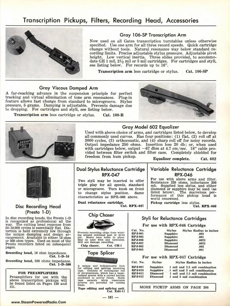
www.SteamPoweredRadio.Com
Transcription Pickups, Filters, Recording Head, Accessories
Gray 106-SP Transcription Arm Now used on all Gates transcription turntables unless otherwise specified. Use one arm for all three record speeds. Quick cartridge change without tools. Natural resonance way below standard recording limits. Precise adjustable stylus pressure. Adjustable pivot height. Low vertical inertia. Three slides provided, to accommodate GE 1 mil, 2½ mil or 3 mil car t ridges. For cartridges and styli, see listing below. For records up to 16".
Transcription arm less car t ridge or stylus. Cat. 106-SP
Gray Viscous Damped Arm A far-reaching advance in the suspension principle for perfect t racking and virtual elimination of tone arm resonances. Plug-in feature allows fast change from standard to microgroove. Stylus pressure, 5 grams. Damping is adjustable. Prevents damage due to dropping. For cartridges and styli, see listing below.
Transcription arm less cartridge or stylus. Cat. 108-B
Disc Recording Head (Presto 1-D)
In disc recording heads, the Presto 1-D is recognized as professional all the way. The cutting head response from 50-10,000 cycles is essentially flat. Distortion is held extremely low through the unique damping and design arrangement. Available in either 16 ohm or 500 ohm types. Used on most of the Presto recorders listed on subsequent pages.
Recording h ead, 16 ohm impedance. Cat. l-D-16
Recording head, 500 ohms impedance. Cat. l-D-500
FOR PREAMPLIFIERS Preamplifiers for use with the. above transcription pickups will be found listed on Pages 129 and 151.
Gray Model 602 Equalizer Used with above choice of arms, and cartridges listed below, to develop all commonly used curves. Has four positions: (1) flat, (2) roll off at 3000 cycles, (3) orthocoustic, and (4) sharp roll off for noisy records. Output impedance 250 ohms. Insertion loss 20 db; or, when used with cartridges below, output -67 dbm at 4.7 cm/ sec. 18" cable provided between filter switch and filter case. Completely shielded for freedom from hum pickup. Equalizer complete. Cat. 602
Dual Stylus Reluctance Cartridge RPX-047
Two styli may be inserted to offer triple play for all speeds, standard or microgroove. Turn knob on front to change stylus position. Same characteristics as RPX-046 above.
Dual reluctance cartridge. Cat. RPX-047
Variable Reluctance Cartridge RPX-046
For use with above arms and filter. Resistance 220 ohms, inductance 250 mh. Supplied less stylus, and either diamond or sapphire may be used (as listed below). The marvelous performance of this pickup head is world renowned. Pickup cartridge less stylus.
Cat. RPX- 046
Chip Chaser
~ Styli for Reluctance Cartridges
For use with RPX-046 Cartridge
Prevents recording chips from windIng around overhead post or drive pin. Heavy base holds In place. May be used with any turntable. Will not damage recording.
Chip chaser. Cat. CH-1
Tape Splicer
A unique and Indispensable Item for edlting and spllclng recording tape. Consists of rectangular rod or duralumlnum, which has a longitudinal groove with a curved bottom machined to mirror !lnlsh. Holds tape securely while transverse grooves are provided !or cutting blade. Tape editing and splicing unit.
Cat. Edit-11
-161-
Cat. No. RPJ-001 RPJ-005 RPJ-006 RPJ-002 RPJ-003 RPJ-004
Stylus Sapphire Sapphire SappWre Diamond Diamond Diamoncl
Stylus Radius in inches .003 .001 .0025 .0025 .003 .001
For use with RPX-047 Cartridge Cat. No.
RPJ-007 RPJ-010 RPJ-011 RPJ-012
Stylus
Sappbire Sappbire Diamond Diamond
Stylus Ra.dins in inches
1 mil ancl 2.5 mil combina tion l mil and 3 mil combination 1 mil a nd 2.5 mil combination 1 and 3 mil combina tion
MORE PICKUP ARMS ON PAGE 206
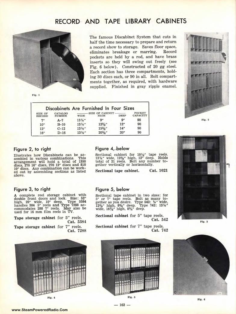
www.SteamPoweredRadio.Com
RECORD· AND TAPE LIBRARY CABINETS
Fig. 1
The famous Discabinet System that cuts in half the time necessary to prepare and return a record show to storage. Saves floor space, eliminates breakage or marring. Record pockets are held by a rod, and have brass inserts so they will swing out freely (see Fig. 6 below). Constructed of 20 gg steel. Each section has three compartments, holding 30 discs each, or 90 in all. Bolt compartments together, as required, with hardware supplied. Finished in gray ripple enamel.
Discabinets Are Furnished In Four Sizes SIZiE OF CATALOG - - SIZE OF CABINET-- POCKET RE•CORD NUMBER WIDE
7" A-7 13¼" 10" B-10 13¾" 12" C-12 13¼" 16" D-16 13¼"
f igure 2, to right Illustrates how- Discabinets can be assembled in various combinations. This arrangement vlill hold a total of 1350 discs, 270 16" discs, 270 12" discs and 810 10" discs. Any combination can be worked out by assembling sections as listed above.
figure 3, to right A complete reel storage cabinet vlith double front doors and lock. Size: 52" high, 29" vlid,e, 10" deep. Type 5384 handles 384 5"' reels and Type 7288 accommodates 288 7" reels. May also be used for 16 mm film reels in TV.
Tape storage cabinet for 5" reels. Cat. 5384
Tape storage cabinet for 7" reels. Cat. 7288
HIGH DEEP CAPACITY
9" 9" 90 12%" 12" 90 15%" 14" 90 203/s" 20" 90
Figure 4, .below Sectional cabinet for 10½" tape reels. 13¼" wide, 12%" high, 12" deep. Holds total of 21 reels. Bolt any number together vertically or horizontally.
Sectional tape cabinet. Cat. 1021
figure 5, below Sectional tape cabinet in two sizes: for 5" or 7" tape reels. Bolt as many together as you desire. Type 542: ¼" vlide, 12%" high, 8%" deep. Type 742: 13¼" wide, 16½" high, 8%" deep.
Sectional cabinet for 5" tape reels. Cat. 542
Sectional cabinet for 7" tape reels. Cat. 742
Fig. 5
- 162 -
Fig. 2
F ir. 3
Fir. 6
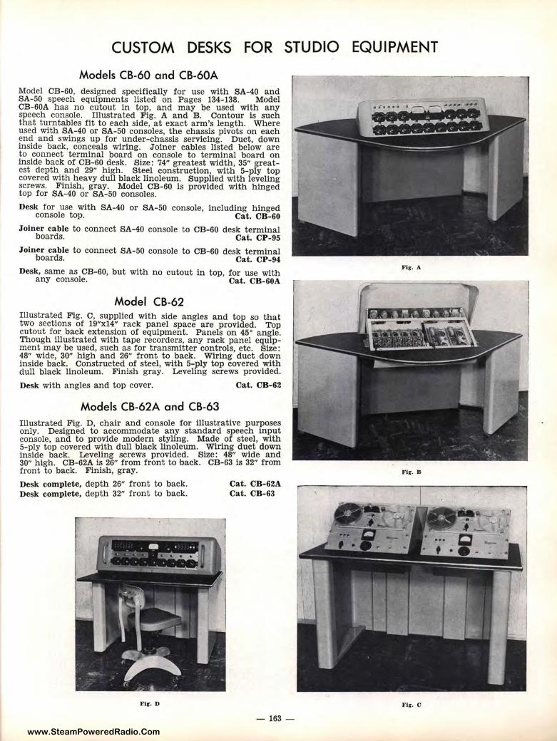
www.SteamPoweredRadio.Com
CUSTOM DESKS FOR STUDIO EQUIPMENT
Models CB-60 and CB-60A Model CB-60, designed specifically for use with SA-40 and SA-50 speech equipments listed on Pages 134-138. Model CB-60A has no cutout in top, and may be used with any speech console. Illustrated Fig. A and B. Contour is such t.hat turntables fit to each side, at exact arm's length. Where used with SA-40 or SA-50 consoles, the chassis pivots on each end and swings up for under-chassis servicing. Duct, down inside back, conceals wiring. Joiner cables listed below are to connect terminal board on console to terminal board on inside back of CB-60 desk. Size: 74" greatest width, 35" greatest depth and 29" high. Steel construction, with 5-ply top covered with heavy dull black linoleum. Supplied with leveling screws. Finish, gray. Model CB-60 is provided with hinged top for SA-40 or SA-50 consoles.
Desk for use with SA-40 or SA-50 console, including hinged console top. Cat. CB-60
Joiner cable to connect SA-40 console to CB-60 desk terminal boards. Cat. CP -95
Joiner cable to connect SA-50 console to CB-60 desk terminal boards. Cat. CP-94
Desk, same as CB-60, but with no cutout in top, for use with any console. Cat. CB-GOA
Model CB-62 Illust rated Fig. C, supplied with side angles and top so that two sections of 19"xl4" rack panel space are provided. Top cutout for back extension of equipment. Panels on 45• angle. Though illustrated with tape recorders, any rack panel equipment may be used, such as for transmitter controls, etc. Size: 48" wide, 30" high and 26" front to back. Wiring duct down inside back. Constructed of steel, with 5-ply top covered with dull black linoleum. Finish gray. Leveling screws provided.
Desk with angles and top cover. Cat. CB-62
Models CB-62A and CB-63 Illustrated Fig. D, chair and console for illustrative purposes only. Designed to accommodate any standard speech input console, and to provide modern styling. Made of steel, with 5-ply top covered with dull black linoleum. Wiring duct down inside back. Leveling screws provided. Size: 48" wide and 30" high. CB-62A is 26" from front to back. CB-63 is 32" from front to back. Finish, gray.
Desk complete, depth 26" front to back. Desk complete, depth 32" front to back.
F ig. D
Cat. CB-62A Cat. CB- 63
- 163 -
Fig. A
Fig. B
Fig. C
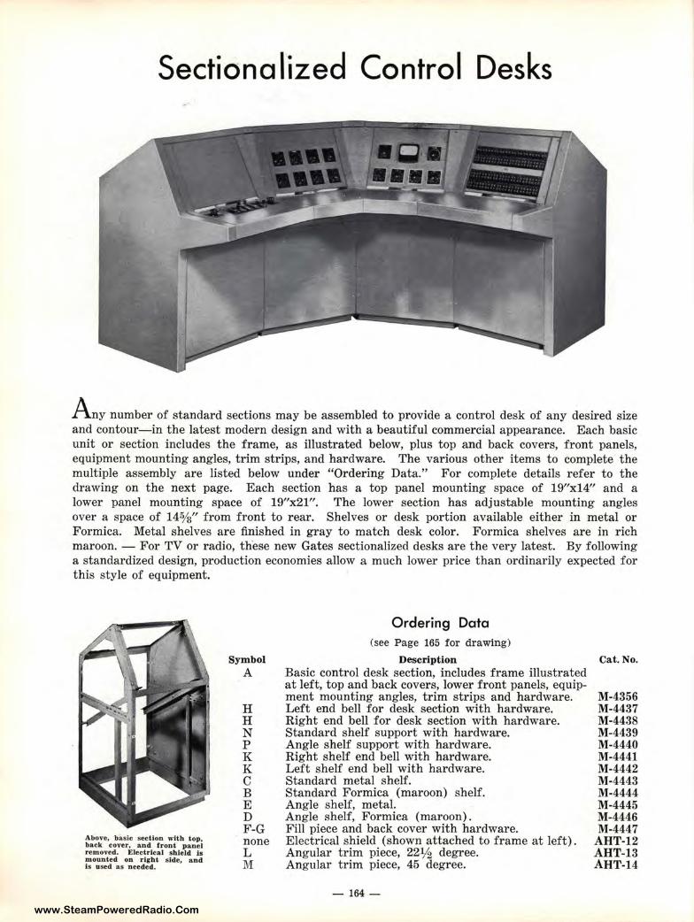
www.SteamPoweredRadio.Com
Sectionalized Control Desks
A ny niumber of standard sections may be assembled to provide a control desk of any desired size and contour-in the latest modern design and with a beautiful commercial appearance. Each basic unit or section includes the frame, as illustrated below, plus top and back covers, front panels, equipment mounting angles, trim strips, and hardware. The various other items to complete the multiple assembly are listed below under "Ordering Data." For complete details refer to the drawing on t he next page. Each section has a top panel mounting space of 19"xl4" and a lower panel mounting space of 19"x21". The lower section has adjustable mounting angles over a space of 14%" from front to rear. Shelves or desk portion available either in metal or Formica. Metal shelves are finished in gray to match desk color. Formica shelves are in rich maroon. - For TV or radio, th·ese new Gates sectionalized desks are the very latest. By following a standa.rdized design, production economies allow a much lower price than ordinarily expected for this stY:le of equipment.
Above, basic section with top. back co,rer, and front panel removed. ElectrJcal shield is mounted on right side, and ls used a1s needed.
Symbol A
H H N p K K C B E D F-G none L M
Ordering Data (see Page 165 for drawing)
Description Basic control desk section, includes frame illustrated at left, top and back covers, lower front panels, equipment mounting angles, trim strips and hardware. Left end bell for desk section with hardware. Right end bell for desk section with hardware. Standard shelf support with hardware. Angle shelf support with hardware. Right shelf end bell with hardware. Left shelf end bell with hardware. Standard metal shelf. Standard Formica (maroon) shelf. Angle shelf , metal. Angle shelf, Formica (maroon). Fill piece and back cover with hardware. Electrical shield (shown attached to frame at left). Angular trim piece, 22½ degree. Angular trim piece, 45 degree.
- 164 -
Cat.No.
M-4356 M-4437 M-4438 M-4439 M-4440 M-4441 M-4442 M-4443 M-4444 M-4445 M-4446 M-4447
AHT-12 AHT-13 AHT-14
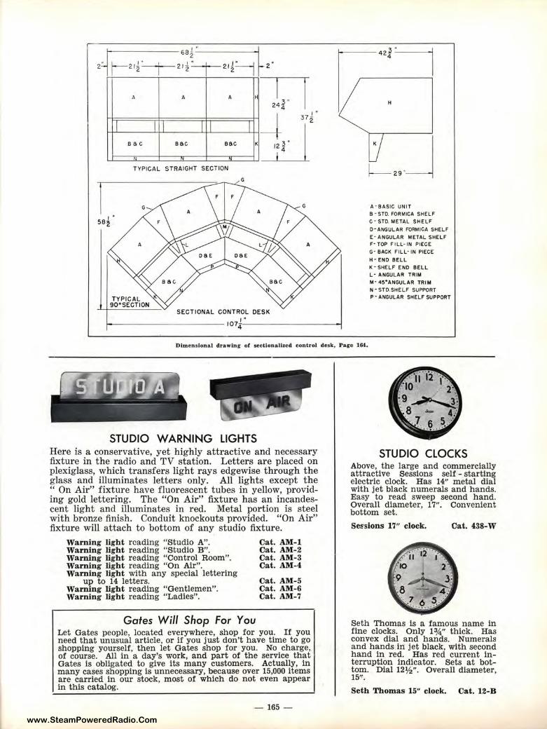
www.SteamPoweredRadio.Com
212 2 12 212
"' A A ►
I I l I I I sac sac sac K
.. ~ " TYPICAL STRAIGHT SECTION
SECTIONAL CONTROL DESK
- ----------- 107::,,1-0
---------4
A· BASIC UNIT B • STD. FORMICA SHELF C ·STD. METAL SHELF
O·ANGULAR FORMICA SHELF
E • ANGULAR METAL SHELF F· TOP FI LL· IN PIECE G· BACK FILL· IN PIECE
H • ENO BELL K • SHELF ENO BELL L- ANGULAR TRIM M· 45"ANGULAR TRIM N • STD.SHELF SUPPORT P·ANGULAR SHELF SUPPORT
Di.mensional drawl.n~ ot sectionalized control desk, Pace l&I.
STUDIO WARNING LIGHTS Here is a conservative, yet highly attractive and necessary fixture in the radio and TV station. Letters are placed on plexiglass, which transfers light rays edgewise through the glass and illuminates letters only. All lights except the " On Air" fixture have fluorescent tubes in yellow, providing gold lettering. The "On Air" fixture has an incandescent light and illuminates in red. Metal portion is steel with bronze finish. Conduit knockouts provided. "On Air" fixture will attach to bottom of any studio fixture.
Warning light reading "Studio A". Warning light reading "Studio B". Warning light reading "Control Room". Warning light reading "On Air". Warning light with any special lettering
up to 14 letters. Warning light reading "Gentlemen". Warning light reading "Ladles".
Cat. AM-1 Cat. AM-2 Cat. AM-3 Cat. AM-4
Cat. AM-5 Cat. AM-6 Cat. AM-7
Gates Will Shop For You Let Gates people, located everywhere, shop for you. If you need that unusual article, or if you just don't have time to go shopping yourself, then let Gates shop for you. No charge, of course. All in a day's work, and part of the service that Gates is obligated to give its many customers. Actually, in many cases shopping is unnecessary, because over 15,000 items are carried in our stock, most of which do not even appear in this catalog.
-165 -
STUDIO CLOCKS Above, the large and commercially attractive Sessions self - starting electric clock. Has 14" metal dial with jet black numerals and hands. Easy to read sweep second hand. Overall diameter, 17". Convenient bottom set.
Sessions 17" clock. Cat. 438-W
Seth Thomas is a famous name in fine clocks. Only 1 ¾" thick. Has convex dial and hands. Numerals and hands in jet black, with second hand in red. Has red current interruption indicator. Sets at bottom. Dial 12½"- Overall diameter, 15'!.
Seth Thomas 15" clock. Cat. 12-B
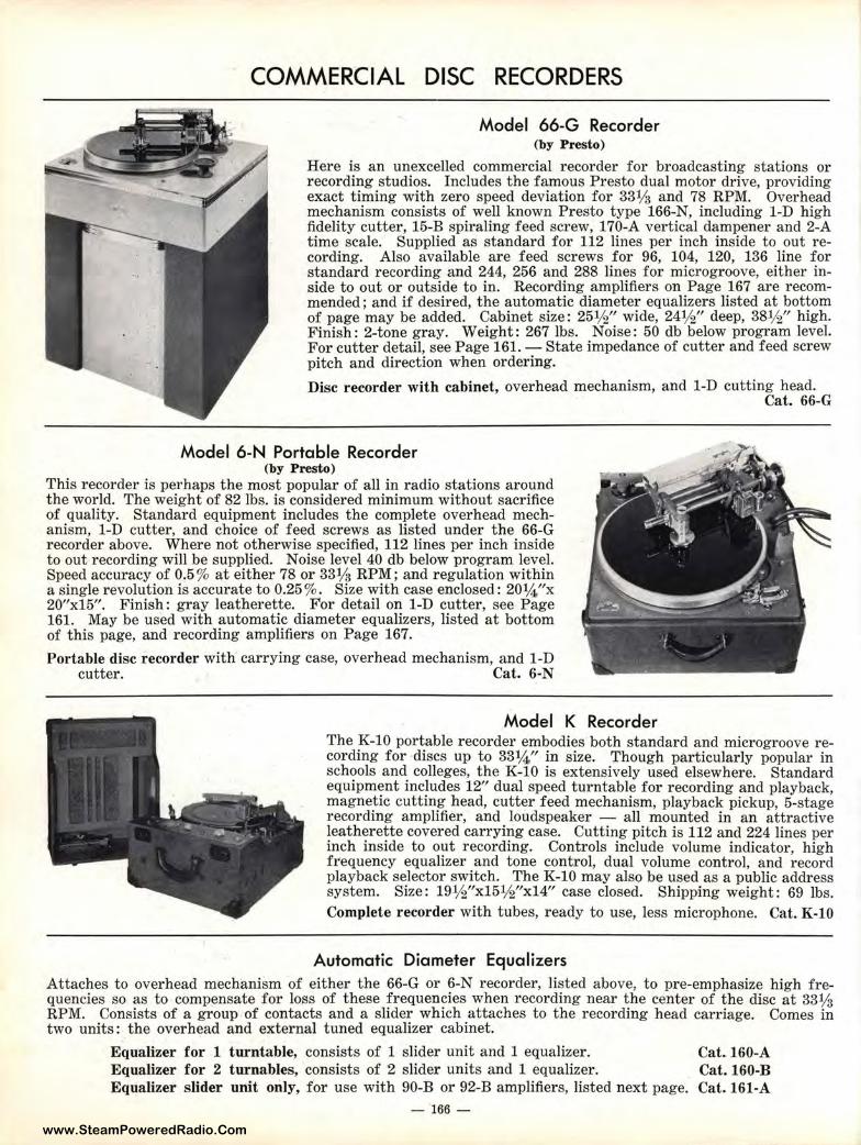
www.SteamPoweredRadio.Com
COMMERCIAL DISC RECORDERS
Model 66-G Recorder (by Presto)
Here is an unexcelled commercial recorder for broadcasting stations or recording studios. Includes the famous Presto dual motor drive, providing exact timing with zero speed deviation for 331/g and 78 RPM. Overhead mechanism consists of well known Presto type 166-N, including 1-D high fidelity cutter, 15-B spiraling feed screw, 170-A vertical dampener and 2-A time scale. Supplied as standard for 112 lines per inch inside to out recording. Also available are feed screws for 96, 104, 120, 136 line for standard recording and 244, 256 and 288 lines for microgroove, either inside to out or outside to in. Recording amplifiers on Page 167 are recommended; and if desired, the automatic diameter equalizers listed at bottom of page may be added. Cabinet size: 25½" wide, 24½" deep, 38½" high. Finish: 2-tone gray. Weight: 267 lbs. Noise: 50 db below program level. For cutter detail, see Page 161. - State impedance of cutter and feed screw pitch and direction when ordering.
Disc recorder with cabinet, overhead mechanism, and 1-D cutting head.
Model 6-N Portable Recorder (by Presto)
This recorder is perhaps the most popular of all in radio stations around the world. Thti weight of 82 lbs. is considered minimum without sacrifice of quality. Standard equipment includes the complete overhead mechanism, 1-D cutter, and choice of feed screws as listed under the 66-G recorder above,. Where not otherwise specified, 112 lines per inch inside to out recordinig will be supplied. Noise level 40 db below program level. Speed accuracy of 0.5% at either 78 or 331/2 RPM; and regulation within a single revolution is accurate to 0.25%. Size with case enclosed: 20¼"x 20"x15". Finish: gray leatherette. For detail on 1-D cutter, see Page 161. May be used with automatic diameter equalizers, listed at bottom of this page, and recording amplifiers on Page 167.
Portable disc recorder with carrying case, overhead mechanism, and 1-D cutter. Cat. 6-N
Model K Recorder
Cat. 66-G
The K-10 portable recorder embodies both standard and microgroove recording for discs up to 33¼" in size. Though particularly popular in schools and colleges, the K-10 is extensively used elsewhere. Standard equipment includes 12" dual speed turntable for recording and playback, magnetic cutting head, cutter feed mechanism, playback pickup, 5-stage recording amplifier, and loudspeaker - all mounted in an attractive leatherette covered carrying case. Cutting pitch is 112 and 224 lines per inch inside to out recording. Controls include volume indicator, high frequency equalizer and tone control, dual volume control, and record playback selector switch. The K-10 may also be used as a public address system. Size: 19½"xl5½"xl4" case closed. Shipping weight : 69 lbs. Complete recorder with tubes, ready to use, less microphone. Cat. K-10
Automatic Diameter Equalizers Attaches to overhead mechanism of either the 66-G or 6-N recorder, listed above, to pre-emphasize high frequencies so as to compensate for loss of these frequencies when recording near the center of the disc at 331/2 RPM. Consists of a group of contacts and a slider which attaches to the recording head carriage. Comes in two units: the overhead and external tuned equalizer cabinet.
Equa:tizer for 1 turntable, consists of 1 slider unit and 1 equalizer. Equa lizer for 2 turnables, consists of 2 slider units and 1 equalizer. Equalizer slider unit only, for use with 90-B or 92-B amplifiers, listed next page.
- 166 -
Cat.160-A Cat.160-B Cat. 161-A
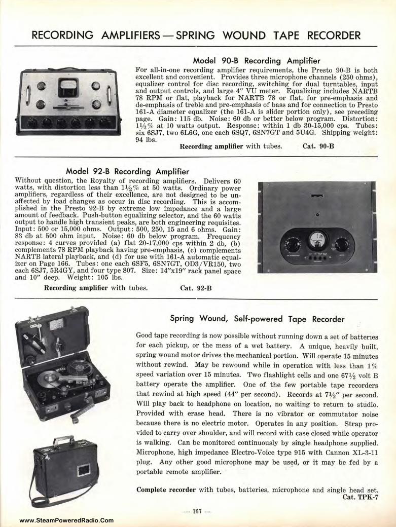
www.SteamPoweredRadio.Com
RECORDING AMPLIFIERS-SPRING WOUND TAPE RECORDER
• ••
Model 90-B Recording Amplifier For all-in-one recording amplifier requirements, the Presto 90-B is both excellent and convenient. Provides three microphone channels (250 ohms), equalizer control for disc recording, switching for dual turntables, input and output controls, and large 4" VU meter. Equalizing includes NARTB 78 RPM or flat, playback for NARTB 78 or flat, for pre-emphasis and de-emphasis of treble and pre-emphasis of bass and for connection to Presto 161-A diameter equalizer (the 161-A is slider portion only), see preceding page. Gain: 115 db. Noise: 60 db or better below program. Distortion: 1½% at 10 watts output. Response: within 1 db 30-15,000 cps. Tubes: six 6SJ7, two 6L6G, one each 6SQ7, 6SN7GT and 5U4G. Shipping weight: 94 lbs.
Recording amplifier with tubes. Cat. 90-B
Model 92-B Recording Amplifier Without question, the Royalty of recording amplifiers. Delivers 60 watts, with distortion less than 1½ % at 50 watts. Ordinary power amplifiers, regardless of their excellence, are not designed to be unaffected by load changes as occur in disc recording. This is accomplished in the Presto 92-B by extreme low impedance and a large amount of feedback. Push-button equalizing selector, and the 60 watts output to handle high transient peaks, are both engineering requisites. Input: 500 or 15,000 ohms. Output: 500, 250, 15 and 6 ohms. Gain : 83 db at 500 ohm input. Noise: 60 db below program. Frequency response: 4 curves provided (a) flat 20-17,000 cps within 2 db, (b) complements 78 RPM playback having pre-emphasis, (c) complements NARTB lateral playback, and (d) for use with 161-A automatic equalizer on Page 166. Tubes: one each 6SF5, 6SN7GT, OD3/ VR150, two each 6SJ7, 5R4GY, and four type 807. Size: 14"x19" rack panel space and 10" deep. Weight: 105 lbs.
Recording amplifier with tubes. Cat. 92-B
Spring Wound, Self-powered Tape Recorder
Good tape recording is now possible without running down a s~t of batteries for each pickup, or the mess of a wet battery. A unique, heavily built, spring wound motor drives the mechanical portion. Will operate 15 minutes without rewind. May be rewound while in operation with less than 1 % speed variation over 15 minutes. Two flashlight cells and one 67½ volt B battery operate the amplifier. One of the few portable tape recorders that rewind at high speed (44" per second) . Records at 7½" per second. Will play back to headphone on location, no waiting to return to studio. Provided with erase head. There is no vibrator or commutator noise because there is no electric motor. Operates in any position. Strap provided to carry over shoulder , and will record with case closed while operator is walking. Can be monitored continuously by single headphone supplied. Microphone, high impedance Electro-Voice type 915 with Cannon XL-3-11 plug. Any other good microphone may be used, or it may be fed by a portable remote amplifier.
Complete recorder with tubes, batteries, microphone and single head set. Cat. TPK-7
- 167 -
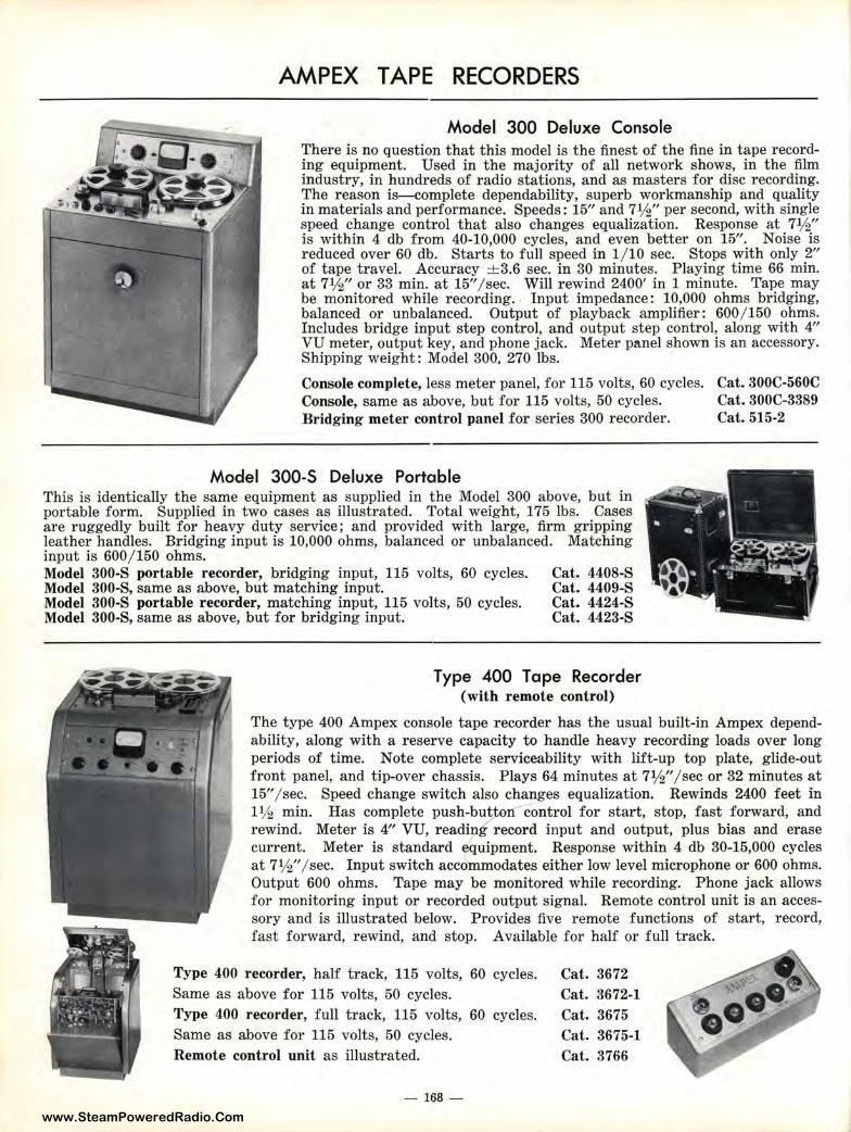
www.SteamPoweredRadio.Com
AMPEX TAPE RECORDERS
Model 300 Deluxe Console There is no question that this model is the finest of the fine in tape recording equipment. Used in the majority of all network shows, in the film industry, in hundreds of radio stations, and as masters for disc recording. The reason is- complete dependability, superb workmanship and quality in materials and performance. Speeds : 15" and 7½" per second, with single speed change control that also changes equalization. Response at 7½" is within 4 db from 40-10,000 cycles, and even better on 15". Noise is reduced over 60 db. Starts to full speed in 1/ 10 sec. Stops with only 2" of tape travel. Accuracy ± 3.6 sec. in 30 minutes. Playing time 66 min. at 7½" or 33 min. at 15" / sec. Will rewind 2400' in 1 minute. Tape may be monitored while recording. Input impedance: 10,000 ohms bridging, balanced or unbalanced. Output of playback amplifier: 600 / 150 ohms. Includes bridge input step control, and output step control, along with 4" VU meter, output key, and phone jack. Meter panel shown is an accessory. Shipping weight: Model 300. 270 lbs.
Console complete, less meter panel, for 115 volts, 60 cycles. Cat. 300C-560C Console, same as above, but for 115 volts, 50 cycles. Cat. 300C-3389 Bridging meter control panel for series 300 recorder. Cat. 515-2
Model 300-S Deluxe Portable This is identically the same equipment as supplied in the Model 300 above, but in portable form. Supplied in two cases as illustrated. Total weight, 175 lbs. Cases are ruggedly built for heavy duty service; and provided with large, firm gripping leather handle8. Bridging input is 10,000 ohms, balanced or unbalanced. Matching input is 600 / 1150 ohms. Model 300-S portable recorder, bridging input, 115 volts, 60 cycles. Model 300-S, s:ame as above, but matching input.
Cat. 4408-S Cat. 4409-S Cat. 4424-S Cat. 4423-S
Model 300-S portable recorder, matching input, 115 volts, 50 cycles. Model 300-S, s:ame as above, but for bridging input.
Type 400 Tape Recorder (with remote control)
The type 400 Ampex console tape recorder has the usual built-in Ampex dependability, along with a reserve capacity to handle heavy recording loads over long periods of time. Note complete serviceability with lift-up top plate, glide-out front panel, and tip-over chassis. Plays 64 minutes at 7½" / sec or 32 minutes at 15" / sec. Speed change switch also changes equalization. Rewinds 2400 feet in 1½ min. Has complete push-bu~en control for start, stop, fast forward, and rewind. Meter is 4" VU, reading record input and output, plus bias and erase current. Meter is standard equipment. Response within 4 db 30-15,000 cycles at 7½" / sec. Input switch accommodates either low level microphone or 600 ohms. Output 600 ohms. Tape may be mon itored while recording. Phone jack allows for monitoring input or recorded output signal. Remote control unit is an accessory and is illustrated below. P rovides five remote functions of start, record, fast forward, rewind, and stop. Available for half or full track.
Type 400 recorder, half track, 115 volts, 60 cycles. Same as above for 115 volts, 50 cycles. Type 400 recorder, full track, 115 volts, 60 cycles. Same as above for 115 volts, 50 cycles. Remote control unit as illustrated.
- 168 -
Cat . 3672 Cat. 3672-1 Cat. 3675 Cat. 3675-1 Cat. 3766
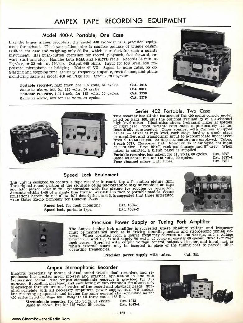
www.SteamPoweredRadio.Com
AMPEX TAPE RECORDING EQUIPMENT
Model 400-A Portable, One Case Like the larger Ampex recorders, the model 400 recorder is a precision equipment throughout. The lower selling price is possible because of unique design. Built in one case and weighing only 80 lbs., which is modest for such a quality instrument. Has push-button operation for record, playback, fast forward, rewind, start and stop. Handles both RMA and NARTB reels. Records 64 min. at 7½"/ sec, or 32 min. at 15"/ sec. Output 600 ohms. Input for low level, low impedance microphone or bridging. Meter 4" VU. Signal to noise ratio, 55 db. Starting and stopping time, accuracy, frequency response, rewind time, and phone monitoring same as model 400 on Page 168. Size: 20"x17½"x15".
Portable recorder, half track, for 115 volts, 60 cycles. Same as above, but for 115 volts, 50 cycles. Portable recorder, full track, for 115 volts, 60 cycles. Same as above, but for 115 volts, 50 cycles.
Cat. 1048 Cat. 3377 Cat. 1996 Cat. 3379
Series 402 Portable, Two Case This recorder has all the features of the 400 series console model, listed on Page 168, plus the optional availability of a 4-channel high level mixer. Illustration shows 4-channel mixer at bottom of right case. Total weight: both cases, approximately 132 lbs. Beautifully constructed. Cases connect with Cannon equipped cables. - Mixer is high level, each stage having a single stage preamplifier, and transformer input to accommodate impedances from 50 to 600 ohms. 20 step attenuators are employed. Tubes: 4 each 5879. Response: flat. Noise: 68 db below signal for input of - 50 dbm. Si.ze: 19"x7" rack panel space and 9" deep. When mixer is omitted, a blank panel is supplied. Portable recorder, less mixer, for 115 volts, 60 cycles. Same as above, but for 115 volts, 50 cycles. Four-channel mixer with tubes.
Speed Lock Equipment This unit is designed to operate a tape recorder in exact step with motion picture film. The original sound por tion of the sequence being photographed may be recorded on tape and later played back in full -synchronism with the picture for copying or projection. Accurate within 1/ 40 of a single film frame. Available in rack or portable models. Space limitations herein do not allow full description, and it is suggested that those interested write Gates Radio Company for Bulletin P-219.
Speed lock for rack moun ting. Speed lock, portable type.
Cat. 2535-1 Cat. 2535-2
Precision Power Supply or Tuning Fork Amplifier
Cat. 3677 Cat. 3677-1 Cat. 3761
The Ampex tuning fork amplifier is suggested where absolute voltage and frequency must be maintained, such as in driving recording motors and stroboscopic timin g devices. When operated from a source frequency between 50 and 400 cps, and a voltage between 90 and 135, it will supply 70 watts of power at exactly 60 cycles. Size: 19"x12¼" rack space. Supplied with output voltage control, output voltmeter, and input jack in wh ich external source may be inserted in place of the tuning fork to provide other operating frequencies.
Precision power supply with tubes.
Ampex Stereophonic Recorder Binaural recording by means of dual sound tracks, dual recorders and reproducers has created much interest and practical application in line with 3-dimension sound. The Ampex stereophonic recorder is provided for this purpose. Recording, playback, and monitoring of two channels simultaneously is developed through unusual location of the record and playback heads. Supplied complete with all necessary amplifiers, power supply, dual VU meters, and recording equipment; and having the same general characteristics as the 400 series listed on Page 168. Weight : all three cases, 138 lbs.
Stereophonic recorder, for 115 volts, 60 cycles. Cat. 4043 Same as above, but for 115 volts, 50 cycles. Cat. 4043-1
-169 -
Cat. 841
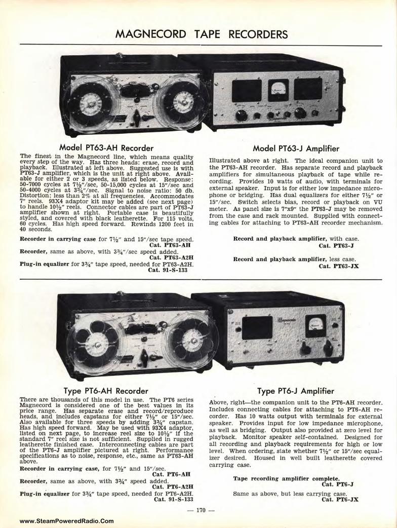
www.SteamPoweredRadio.Com
MAGNECORD TAPE RECORDERS
Mc>del PT63-AH Recorder The finest in tlhe Magnecord line, which means quality every step of the way. Has three heads: erase, record and playback. Illustrated at left above. Suggested use is with PT63-J amplifier, which is the unit at right above. Available for either :~ or 3 speeds, as listed below. Response: 50-7000 cycles a1t 7½" /sec, 50-15,000 cycles at 15" /sec and 50-4000 cycles at 3¾" /sec. Signal to noise ratio: 50 db. Distortion: less t;han 2 % at all frequencies. Accommodates 7" reels. 93X4 a,daptor kit may be added (see next page) to handle 10½" reels. Connector cables are part of PT63-J amplifier shown at right. Portable case is beautifully styled, and covered with black leatherette. For 115 volts, 60 cycles. Has high speed forward. Rewinds 1200 feet in 40 seconds.
Recorder in can ·ying case for 7½" and 15" / sec tape speed. Cat. PT63-AH
Recorder, same as above, with 3¾" / sec speed added. Cat. PT63-A2H
Plug-in equalizer for 3¾" tape speed, needed for PT63-A2H. Cat. 91-S-133
Type PT6-AH Recorder There are thousands of this model in use. The PT6 series Magnecord is considered one of the best values in its price range. Has separate erase and record/ reproduce heads, and incl1udes capstans for either 7½" or 15"/sec. Also available for three speeds by adding 3¾" capstan. Has high speed lforward. May be used with 93X4 adaptor, listed on next page, to increase reel size to 10½" if the standard 7" reel size is not sufficient. Supplied in rugged leatherette finished case. Interconnecting cables are part of the PT6-J amplifier pictured at right. Performance specifications as • to noise, response, etc., same as PT63-AH above. Recorder in car1rying case, for 7½" and 15"/ sec.
Cat. PT6-AB Recorder, same as above, with 3¾" speed added.
Cat. PT6-A2H Plug-in equalize1r for 33/4" tape speed, needed for PT6-A2H.
Cat. 91-S-133
Model PT63-J Amplifier Illustrated above at right. The ideal companion unit to the PT63-AH recorder. Has separate record and playback amplifiers for simultaneous playback of tape while recording. Provides 10 watts of audio, with terminals for external speaker. Input is for either low impedance microphone or bridging. Has dual equalizers for either 7½" or 15" / sec. Switch selects bias, record or playback on VU meter. As panel size is 7"x9" the PT63-J may be removed from the case and rack mounted. Supplied with connecting cables for attaching to PT63-AH recorder mechanism.
Record and playback amplifier, with case. Cat. PT63-J
Record and playback amplifier, less case. Cat. PT63-JX
Type PT6-J Amplifier Above, right--the companion unit to the PT6-AH recorder. Includes connecting cables for attaching to PT6-AH recorder. Has 10 watts output with terminals for external speaker. Provides input for low impedance microphone, as well as bridging. Output also provided at zero level for playback. Monitor speaker self-contained. Designed for all recording and playback requirements for high or low level. When ordering, state whether 7½" or 15"/ sec equalizer desired. Housed in well built leatherette covered carrying case.
Tape recording amplif ier complete. Cat. PT6-J
Same as above, but less carrying case. Cat. PT6-JX
- 170 -
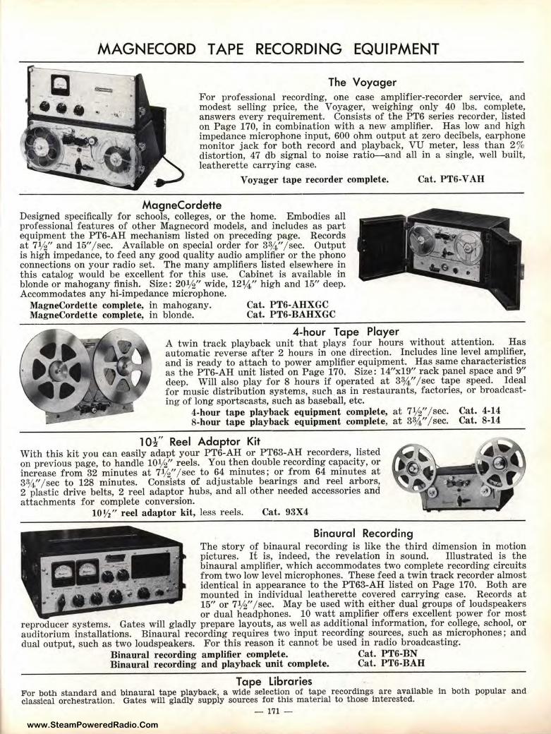
www.SteamPoweredRadio.Com
MAGNECORD TAPE RECORDING EQUIPMENT
The Voyager For professional recording, one case amplifier-r ecorder service, and modest selling price, the Voyager, weighing only 40 lbs. complete, answers every requirement. Consists of the PT6 series recorder, listed on Page 170, in combination with a new amplifier. Has low and high impedance microphone input, 600 ohm output at zero decibels, earphone monitor jack for both record and playback, VU meter, less than 2% distortion, 47 db signal to noise ratio--and all in a single, well built, leatherette carrying case.
Voyager tape recorder complete. Cat. PT6-V AH
MagneCordette Designed specifically for schools, colleges, or t he home. Embodies all professional features of other Magnecord models, and includes as part equipment the PT6-AH mechanism listed on preceding page. Records at 7½" and 15" / sec. Available on special order for 3¾ " / sec. Output is high impedance, to feed any good quality audio amplifier or the phono connections on your radio set. The many amplifiers listed elsewhere in this catalog would be excellent for this use. Cabinet is available in blonde or mahogany finish. Size: 20½" wide, 12¼" high and 15" deep. Accommodates any hi-impedance microphone.
MagneCordette complete, in mahogany. Cat. PT6-AHXGC MagneCordette complete, in blonde. Cat. PT6-BAHXGC
4-hour Tape Player A twin track playback unit that plays four hours without attention. Has automatic reverse after 2 hours in one direction. Includes line level amplifier, and is ready to attach to power amplifier equipment. Has same characteristics as the PT6-AH unit listed on Page 170. Size: 14"xl9" rack panel space and 9" deep. Will also play for 8 hours if operated at 33/4" / sec tape speed. Ideal for music distr ibution systems, such.as in restaurants, factories, or broadcasting of long sportscasts, such as baseball, etc.
4-hour tape playback equipment complete, at 7½ " / sec. Cat. 4-14 8-hour tape playback equipment complete, at 33/4" / sec. Cat. 8-14
1 O½" Reel Adaptor Kit With this kit you can easily adapt your PT6-AH or PT63-AH recorders, listed on previous page, to handle 10½" reels. You then double recording capacity, or increase from 32 minutes at 7½" / sec to 64 minutes; or from 64 minutes at 3¾ " / sec to 128 minutes. Consists of adjustable bearings and reel arbors, 2 plastic drive belts, 2 reel adaptor hubs, and all other needed accessories and attachments for complete conversion.
10 ½" reel adaptor kit, less reels. Cat. 93X4
Binaural Recording The story of binaural recording is like the third dimension in motion pictures. It is, indeed, the revelation in sound. Illustrated is the binaural amplifier, which accommodates two complete recording circuits from two low level microphones. These feed a twin track recorder almost identical in appearance to the PT63-AH listed on Page 170. Both are mounted in individual leatherette covered carrying case. Records at 15" or 7½" / sec. May be used with either dual groups of loudspeakers or dual headphones. 10 watt amplifier offers excellent power for most
reproducer systems. Gates will gladly prepare layouts, as well as additional information, for college, school, or auditor ium installations. Binaural recording requires two input recording sour ces, such as microphones; and dual output, such as two loudspeakers. For this reason it cannot be used in radio broadcasting.
Binaural recording amplifier complete. Cat. PT6-BN Binaural recording and playback unit complete. Cat. PT6-BAH
. Tape Libraries For both standard and binaural tape playback, a wide selection of tape recordings are available in both popular and classical orchestration. Gates will gladly supply sources for this material to those interested.
- 171 -
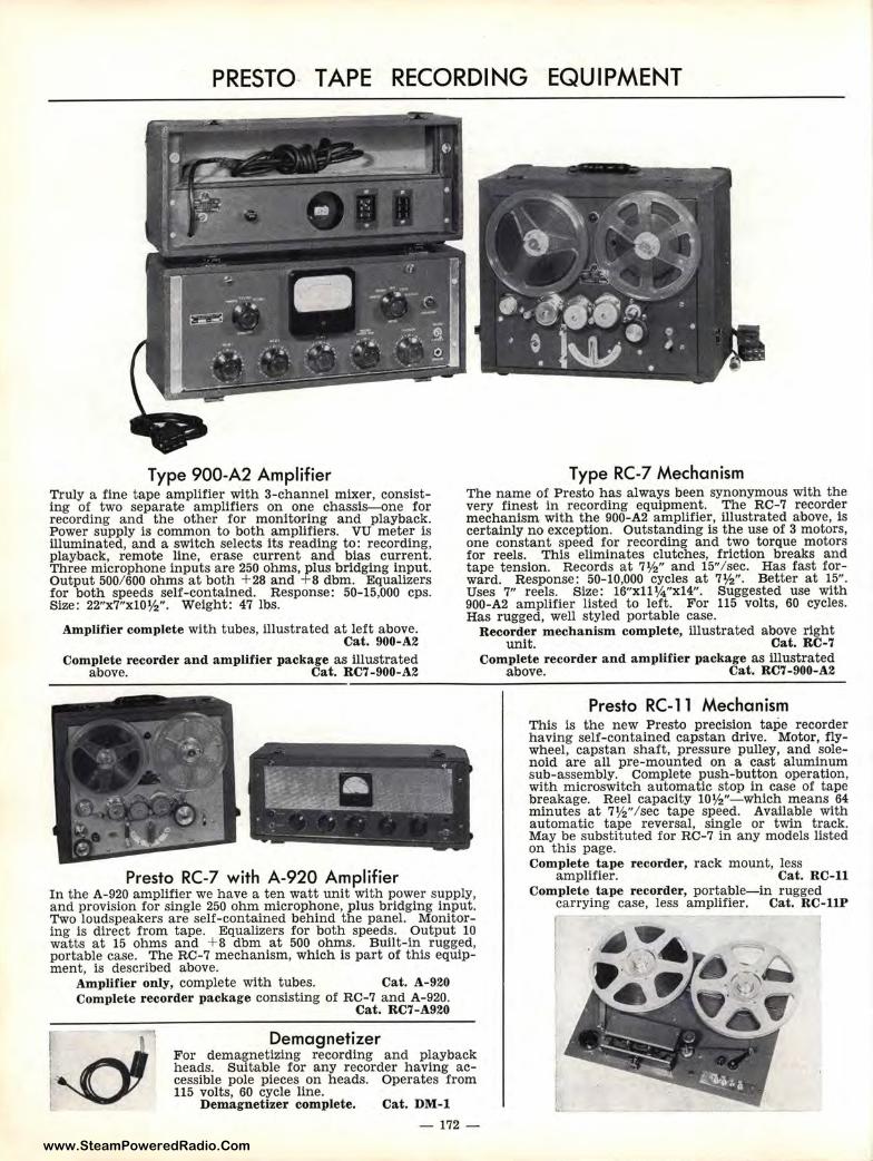
www.SteamPoweredRadio.Com
PRESTO- TAPE RECORDING EQUIPMENT
Type 900-A2 Amplifier Truly a fine tape amplifier with 3-channel mixer, consisting of two sep,arate amplifiers on one chassis--0ne for recording and the other for monitoring and playback. Power supply is common to both amplifiers. VU meter is illuminated, and a switch selects its reading to: recording, play,back, remo1te line, erase current and bias current. Three micropho,ne inputs are 250 ohms, plus bridging input. Output 500/ 600 ohms at both + 28 and + 8 dbm. Equalizers for both speeds self-contained. Response: 50-15,000 cps. Size: 22"x7"x10l½". Weight: 47 lbs.
Amplifier complete with tubes, illustrated at left above. Cat. 900-A2
Complete recorder and amplifier package as illustrated above. Cat. RC7-900-A2
Pre!sto RC-7 with A-920 Amplifier
Type RC-7 Mechanism The name of Presto has always been synonymous with the very finest in recording equipment. The RC-7 recorder mechanism with the 900-A2 amplifier, illustrated above, is certainly no exception. Outstanding is the use of 3 motors, one constant speed for recording and two torque motors for reels. This eliminates clutches, friction breaks and tape tension. Records at 7½" and 15"/ sec. Has fast forward. Response: 50-10,000 cycles at 7½"- Better at 15". Uses 7" reels. Size: 16"xll¼"x14". Suggested use with 900-A2 amplifier listed to left. For 115 volts, 60 cycles. Has rugged, well styled portable case.
Recorder mechanism complete, illustrated above right unit. Cat. RC-7
Complete recorder and amplifier package as illustrated above. Cat. RC7-900-A2
Presto RC-11 Mechanism This is the new Presto precision tape recorder having self-contained capstan drive. Motor, flywheel, capstan shaft, pressure pulley, and solenoid are all pre-mounted on a cast aluminum sub-assembly. Complete push-button operation, with microswitch automatic stop in case of tape breakage. Reel capacity 10½"- which means 64 minutes at 7½"/ sec tape speed. Available with automatic tape reversal, single or twin track. May be substituted for RC-7 in any models listed on this page. Complete tape recorder, rack mount, less
amplifier. Cat. RC-11 In the A-920 amplifier we have a ten watt unit with power supply, and provision for single 250 ohm microphone, plus bridging input. Two loudspeakers are self-contained behind the panel. Monitoring is direct fr,om tape. Equalizers for both speeds. Output 10 watts at 15 ohms and + 8 dbm at 500 ohms. Built-in rugged, portable case. 'The RC-7 mechanism, which is part of this equipment, is described above.
Complete tape recorder, portable-in rugged carrying case, less amplifier. Cat. RC-llP
Amplifier only, complete with tubes. Cat. A-920 Complete recorder package consisting of RC-7 and A-920.
Cat. RC7-A920
~ Demagnetizer
For demagnetizing recording and playback heads. Suitable for any recorder having accessible pole pieces on heads. Operates from 115 volts, 60 cycle line.
Demagnetizer complete. Cat. DM-1
- 172 -
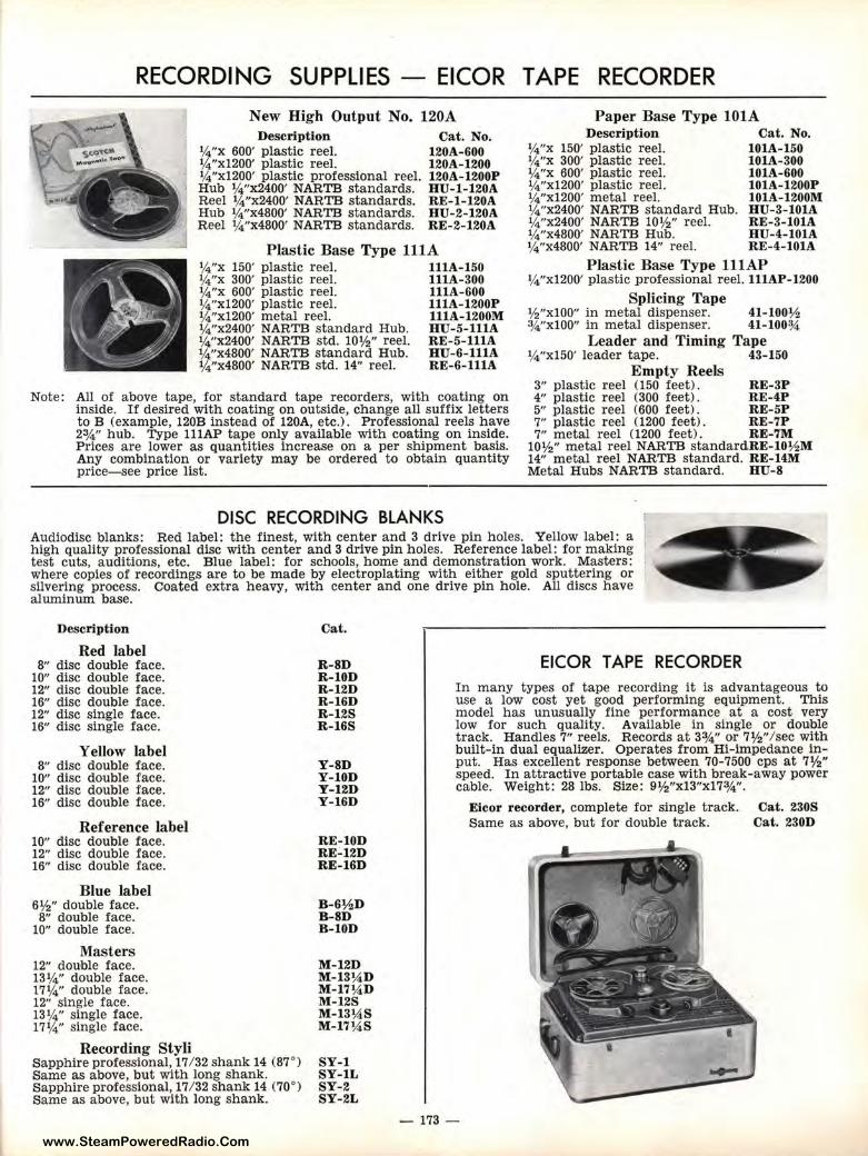
www.SteamPoweredRadio.Com
RECORDING SUPPLIES - EICOR TAPE RECORDER
New High Output No. 120A Description Cat. No.
¼"x 600' plastic reel. 120A-600 ¼"xl200' plastic reel. 120A-1200 ¼"xl200' plastic professional reel. 120A-1200P Hub ¼"x2400' NARTB standards. HU-l-120A Reel ¼"x2400' NARTB standards. RE-l-120A Hub ¼"x4800' NARTB standards. HU-2-120A Reel ¼"x4800' NARTB standards. RE-2-120A
Plastic Base Type lllA ¼"x 150' plastic reel. lllA-150 ¼"x 300' plastic reel. lllA-300 ¼"x 600' plastic reel. lllA-600 ¼"xl200' plastic reel. 111A-1200P ¼"xl200' metal reel. 111A-1200M ¼"x2400' NARTB standard Hub. HU-5- IUA ¼"x2400' NARTB std. 10½" reel. RE-5-lllA ¼"x4800' NARTB standard Hub. HU-6-lllA ¼"x4800' NARTB std. 14" reel. RE-6-lllA
Note: All of above tape, for standard tape recorders, with coating on inside. If desired with coating on outside, change all suffix letters to B (example, 120B instead of 120A, etc.). Professional reels have 2¾" hub. Type lllAP tape only available with coating on inside. Prices are lower as quantities increase on a per shipment basis. Any combination or variety may be ordered to obtain quantity price-see price list.
DISC RECORDING BLANKS
Paper Base Type 101A Description Cat. No.
¼"x 150' plastic reel. l0lA-150 ¼"x 300' plastic reel. I0IA-300 ¼"x 600' plastic reel. I0IA-600 ¼"xl200' plastic reel. I0IA-1200P ¼"x1200' metal reel. 101A-1200M ¼"x2400' NARTB standard Hub. HU-3-l0IA ¼"x2400' NARTB 10½" reel. RE-3-I0IA ¼"x4800' NARTB Hub. HU-4-lOlA ¼"x4800' NARTB 14" reel. RE-4-I0IA
Plastic Base Type lllAP ¼"xl200' plastic professional reel. lllAP-1200
Splicing Tape ½"xl00" in metal dispenser. 41-100½ ¾"xl00" in metal dispenser. 41-100¾
Leader and Timing Tape ¼"xl50' leader tape. 43-150
Empty Reels 3" plastic reel (150 feet). RE-3P 4" plastic reel (300 feet). RE-4P 5" plastic reel (600 feet). RE-5P 7" plastic reel (1200 feet). RE-7P 7" metal reel (1200 feet). RE-7M
10½" metal reel NARTB standardRE-I0½ M 14" metal reel NARTB standard. RE-HM Metal Hubs NARTB standard. HU-8
Audiodisc blanks: Red label: the finest, with center and 3 drive pin holes. Yellow label: a high quality professional disc with center and 3 drive pin holes. Reference label: for making test cuts, auditions, etc. Blue label: for schools, home and demonstration work. Masters: where copies of recordings are to be made by electroplating with either gold sputtering or silvering process. Coated extra heavy, with center and one drive pin hole. All discs have aluminum base.
Description
Red label 8" disc double face.
10" disc double face. 12" disc double face. 16" disc double face. 12" disc single face. 16" disc single face.
YeUow label 8" disc double face.
10" disc double face. 12" disc double face. 16" disc double face.
Reference label 10" disc double face. 12" disc double face. 16" disc double face.
Blue label 6½" double face. 8" double face.
10" double face.
Masters 12" double face. 13¼" double face. 17 ¼" double face. 12" single face . 13¼" single face. 17¼" single face.
Recording Styli Sapphire professional, 17 / 32 shank 14 (87°) Same as above, but with long shank. Sapphire professional, 17/ 32 shank 14 (70°) Same as above, but with long shank.
Cat.
R-8D R-10D R-12D R-IGD R- 12S R- 16S
Y-8D Y-10D Y-12D Y-16D
RE- I0D RE-12D RE-16D
B-G½D B-8D B-l0D
M-12D M-13¼D M-17¼ D M-12S M-13¼.S M-17¼ S
SY-1 SY-IL SY-2 SY-2L
EICOR TAPE RECORDER In many types of tape recording it is advantageous to use a low cost yet good performing equipment. This model has unusually fine performance at a cost very low for such quality. Available in single or douible track. Handles 7" reels. Records at 3¾" or 7½"/ sec with built-in dual equalizer. Operates from Hi-impedance input. Has excellent response between 70-7500 cps at 7½" speed. In attractive portable case with break-away power cable. Weight: 28 lbs. Size: 9½"xl3"x17¾".
- 173 -
Eicor recorder, complete for single track. Same as above, but for double track.
Cat. 230S Cat. 230D
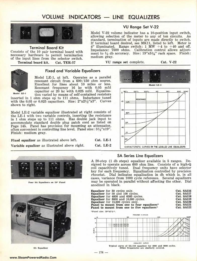
www.SteamPoweredRadio.Com
VOLUME . INDICATORS - LINE EQUALIZERS
Terminal Board Kit Consists of the 10 pair terminal board with necessary hardware to permit termination of the input lines from the selector switch.
Terminal board kit. Cat. TER-37
VU Range Set V-22
Model V-22 volume indicator has a 10-position input switch, allowing selection of the meter to any of ten circuits. As standard, termination of inputs are made directly to switch. If terminal board desired, see MKll, listed to left. Meter is 4" illuminated. Range switch: 1 MW + 4 to + 40 and off. Impedance: 7500 ohms. Calibration control allows adjustment to ½ db accuracy. Size: 19"x5¼" · rack space. Finish: medium gray.
VU range set complete. Cat. V-22
Fixed and Variable Equalizers
k . . . . : ;:
Model LE-1, at left. Operates as a parallel resonant circuit from a 600 / 150 ohm source. Excellent for lines about 10 miles or less. Resonant frequency 16 kc with 0.05 mfd capacitor or 20 kc with 0.025 mfd. Equaliza-
. ~o • • • • oo
Modet LE-i tion varied by means of self-contained resistors inserted in 1 ohm steps up to 111 ohms. Inductance tuned with the 0.05 or 0.025 capacitors. Size : 2"x2½"x3". Curves shown to right.
Model LE-2 variable equalizer illustrated at right consists of the LE-1 with two variable controls, inserting the resistance in 1 ohm steps up to 111 ohms. Has double jack input to accommodate standard double plug patch cord as listed on Page 145. Panel has provision for mounting an attenuator, often convenient in controlling line level. Panel size: 3½"x19". Finish : medium gray.
•• Model LE-2
IOO'\J lOO'\J 3KC IOKC 20KC
Fixed equalize,r as illustrated above left.
Variable equallizer as illustrated above right.
Cat. LE-1
Cat. LE-2 CKARACTERISTIC CURVES ON THE L£l6LE2 LINE EQUALIZERS
Four SA Equalizers on 19" Panel
SA Equalizer
SA Series Line Equalizers A 20-step (1 db steps) equalizer available in 5 ranges. Designed to operate across 600 ohm line. Consists of a high-Q coil capacitively tuned. Dual frequency units have selector key for each frequency. Equalization controlled by precision rheostat. Dial indicates equalization in db which is, in all cases, variance from 1000 cycle reference. Several equalizers may be operated in parallel without affecting the other. Dial anodized in black.
Equalizer for 30 cycles only. Equalizer for 50 and 100 cycles. Equalizer for 4000 and 6000 cycles. Equalizer for 8000 and 10,000 cycles. Equalizer for 15,000 cycles only. Panel to mount from one to four equalizers* Panel to mount from one to five equalizers* •Panel size; 19"x5¼ ".
0 ,. . ··--
.... "" iw1!CN ·
,ooo
• Clo< ~ .. • ' ... hi,,
Cat. SA116 Cat. SA117 Cat. SA118 Cat. SA119 Cat. SA120 Cat. SA121 Cat. SA122
, , , I>',
/ /,~ .., 1- •
/ 1/ v. , , . _,-/ ,-:,,v vc ..
0
EQUALIZE~ Cl.lAVE:S
T ypical curve of SA-ll8 equalizer for 4000 and 6000 cycles. Other frequencies are sJmilarly co,•ered.
- 174 -
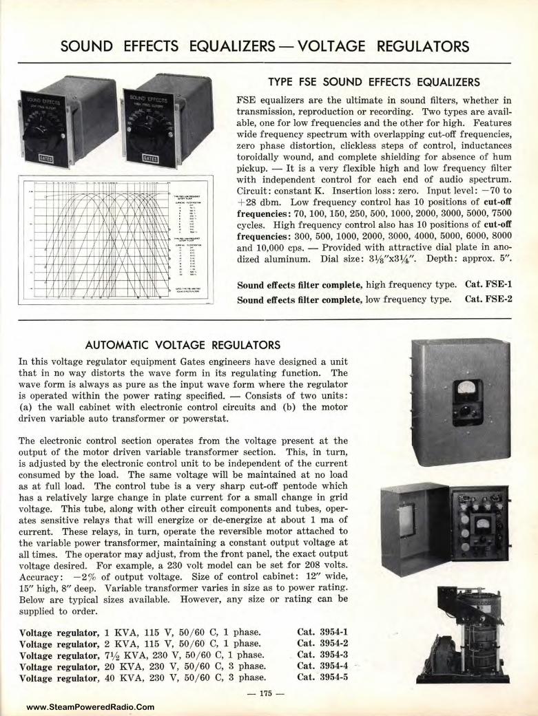
www.SteamPoweredRadio.Com
SOUND EFFECTS EQUALIZERS-VOLTAGE REGULATORS
.. >--t-1-
. I/ .
I/ Ii __ L II
I
- I
I I/ . I
-:'
1/,; ,,,, IX
I/ j\ 1\/ ')( I I\
I I t :/ r\/
1/\ I X i
I I IV I/VI\
I /\ I J I/
I/ I \
-!i< I\
!/ ,; I\\ ,\ \
~ I\\\ ,\\ \ \' I\\
\ I\\
\ I\ \
I\
-·-·
. --..,_ ......
.. ,.. ...
_,, .. , ..... _
TYPE FSE SOUND EFFECTS EQUALIZERS
FSE equalizers are the ultimate in sound filters, whether in transmission, reproduction or recording. Two types are available, one for low frequencies and the other for high. Features wide frequency spectrum with overlapping cut-off frequencies, zero phase distortion, clickless steps of control, inductances toroidally wound, and complete shielding for absence of hum pickup. - It is a very flexible high and low frequency filter with independent control for each end of audio spectrum. Circuit: constant K. Insertion loss: zero. Input level: -70 to + 28 dbm. Low frequency control has 10 positions of cut-off frequencies: 70,100,150,250,500, 1000,2000, 3000, 5000, 7500 cycles. High frequency control also has 10 positions of cut-off frequencies: 300, 500, 1000, 2000, 3000, 4000, 5000, 6000, 8000 and 10,000 cps. - Provided with attractive dial plate in anodized aluminum. Dial size: 31/a"x3¼". Depth: approx. 5".
Sound effects filter complete, high frequency type. Cat. FSE-1
Sound effects filter complete, low frequency type. Cat. FSE-2
AUTOMATIC VOLTAGE REGULATORS In this voltage regulator equipment Gates engineers have designed a unit that in no way distorts the wave form in its regulating function. The wave form is always as pure as the input wave form where the regulator is operated within the power rating specified. - Consists of two units : (a) the wall cabinet with electronic control circuits and (b) the motor driven variable auto transformer or powerstat.
The electronic control section operates from the voltage present at the output of the motor driven variable transformer section. This, in turn, is adjusted by the electronic control unit to be independent of the current consumed by the load. The same voltage will be maintained at no load as at full load. The control tube is a very sharp cut-off pentode which has a relatively large change in plate current for a small change in grid voltage. This tube, along with other circuit components and tubes, operates sensitive relays that will energize or de-energize at about 1 ma of current. These relays, in turn, operate the reversible motor attached to the variable power transformer, maintaining a constant output voltage at all times. The operator may adjust, from the front panel, the exact output voltage desired. For example, a 230 volt model can be set for 208 volts. Accuracy: -2 % of output voltage. Size of control cabinet: 12" wide, 15" high, 8" deep. Variable transformer varies in size as to power rating. Below are typical sizes available. However, any size or rating can be supplied to order.
Voltage regulator, 1 KVA, 115 V, 50/ 60 C, 1 phase. Voltage regulator, 2 KVA, 115 V, 50/ 60 C, 1 phase. Voltage regulator, 7½ KVA, 230 V, 50/ 60 C, 1 phase. Voltage regulator, 20 KV A, 230 V, 50 / 60 C, 3 phase. Voltage regulator, 40 KVA, 230 V, 50/ 60 C, 3 phase.
- 175 -
Cat. 3954-1 Cat. 3954-2 Cat. 3954-3 Cat. 3954-4 Cat. 3954-5
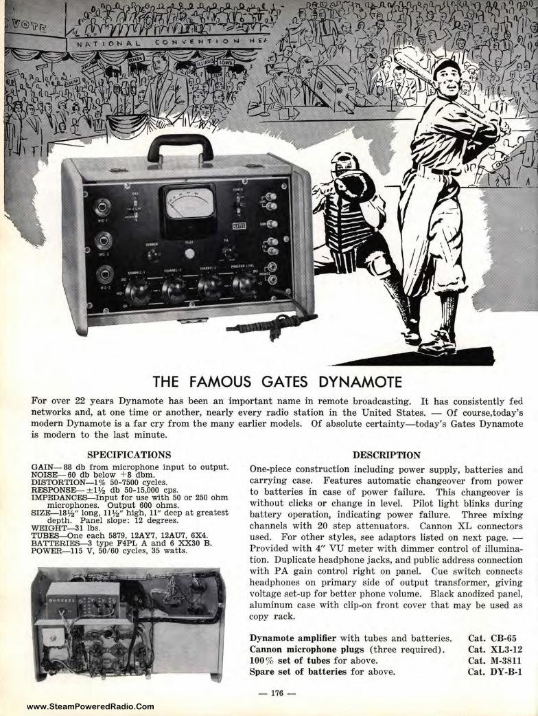
www.SteamPoweredRadio.Com
THE FAMOUS GATES DYNAMOTE For over 22 years Dynamote has been an important name in remote broadcasting. It has consistently fed networks and,, at one t ime or another, nearly every radio station in the United States. - Of course,today's modern Dynamote is a far cry from the many earlier models. Of absolute certainty-today's Gates Dynamote is modern to the last minute.
S;PECIFICATI-ONS GAIN- 88 db from microphone input to output. NOISE-60 ctb below + 8 dbm. DISTORTION--! % 50-7500 cycles. RESPONSE- ± :1½ db 50-15,000 cps. IMPEDANCES--Input for use with 50 or 250 ohm
microphones. Output 600 ohms. SIZE-18½" long, 11½" high, 11" deep at greatest
depth. Panel slope: 12 degrees. WEIGHT-31 lbs. TUBES-One e:ach 5879, 12AY7, 12AU7, 6X4. BA TI'ERIES-3 type F4PL A and 6 XX30 B. POWER-115 V', 50/60 cycles, 35 watts.
DESCRIPTION One-piece construction including power supply, batteries and carrying case. Features automatic changeover from power to batteries in case of power failure. This changeover is without clicks or change in level. Pilot light blinks during battery operation, indicating power failure. Three mixing channels with 20 step attenuators. Cannon XL connectors used. For other styles, see adaptors listed on next page. -Provided with 4" VU meter with dimmer control of illumination. Duplicate headphone jacks, and public address connection with PA gain control right on panel. Cue switch connects headphones on primary side of output transformer, giving voltage set-up for better phone volume. Black anodized panel, aluminum case with clip-on front cover that may be used as copy rack.
Dynamote amplifier with tubes and batteries. Cannon microphone plugs (three required). 100 % set of tubes for above. Spa.re set of batteries for above.
- 176 -
Cat. CB-65 Cat. XL3-12 Cat. M-3811 Cat. DY-B-1
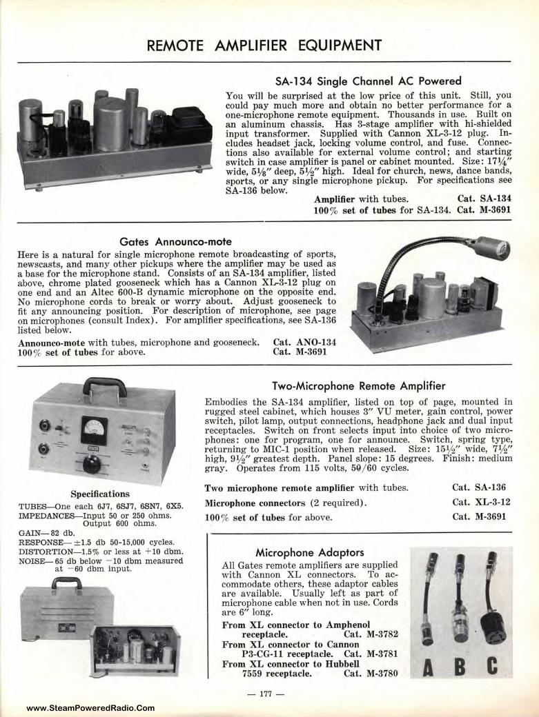
www.SteamPoweredRadio.Com
REMOTE AMPLIFIER EQUIPMENT
SA-134 Single Channel AC Powered You will be surprised at the low price of this unit. Still, you could pay much more and obtain no better performance for a one-microphone remote equipment. Thousands in use. Built on an aluminum chassis. Has 3-stage amplifier with hi-shielded input transformer. Supplied with Cannon XL-3-12 plug. Includes headset jack, locking volume control, and fuse. Connections also available for external volume control; and starting switch in case amplifier is panel or cabinet mounted. Size: 17¼" wide, 51/s" deep, 5½" high. Ideal for church, news, dance bands, sports, or any single microphone pickup. For specifications see SA-136 below.
Amplifier with tubes. Cat. SA-134 100% set of tubes for SA-134. Cat. M-3691
Gates Announco-mote Here is a natural for single microphone remote broadcasting of sports, newscasts, and many other pickups where the amplifier may be used as a base for the microphone stand. Consists of an SA-134 amplifier, listed above, chrome plated gooseneck which has a Cannon XL-3-12 plug on one end and an Altec 600-B dynamic microphone on the opposite end. No microphone cords to break or worry about. Adjust gooseneck to fit any announcing position. For description of microphone, see page on microphones ( consult Index). F:or amplifier specifications, see SA-136 listed below. Announco-mote with tubes, microphone and gooseneck. 100 % set of tubes for above.
Cat. ANO-134 Cat. M-3691
Two-Microphone Remote Ampiifier
Embodies the SA-134 amplifier, listed on top of page, mounted in rugged steel cabinet, which houses 3" VU meter, gain control, power switch, pilot lamp, output connections, headphone jack and dual input receptacles. Switch on front selects input into choice of two microphones : one for program, one for announce. Switch, spring type, returning to MIC-1 position when released. Size: 15½" wide, 7½" high, 91/2" greatest depth. Panel slope: 15 degrees. Finish: medium gray. Operates from 115 volts, 5Q/ 60 cycles.
Specifications TUBES-One each 6J7, 6SJ7, 6SN7, 6X5. IMPEDANCES-Input 50 or 250 ohms.
Output 600 ohms. GAIN-82 db. RESPONSE-- ±1.5 db 50-15,000 cycles. DISTORTION-1.5% or less at + 10 dbm. NOISE- 65 db below - 10 dbm measured
at - 60 dbm input.
m . ,· ,! • / · 1 -t
T . -1 -
Two microphone remote amplifier with tubes.
Microphone connectors (2 required).
100% set of tubes for above.
Microphone Adaptors All Gates remote amplifiers are supplied with Cannon XL connectors. To accommodate others, these adaptor cables are available. Usually left as part of microphone cable when not in use. Cords are 6" long. From XL connector to Amphenol
receptacle. Cat. M-3782 From XL connector to Cannon
P3-CG-11 receptacle. Cat. M-3781 From XL connector to Hubbell
7559 receptacle. Cat. M-3780
- 177 -
A
Cat. SA-136
Cat. XL-3-12
Cat. M-3691
B C
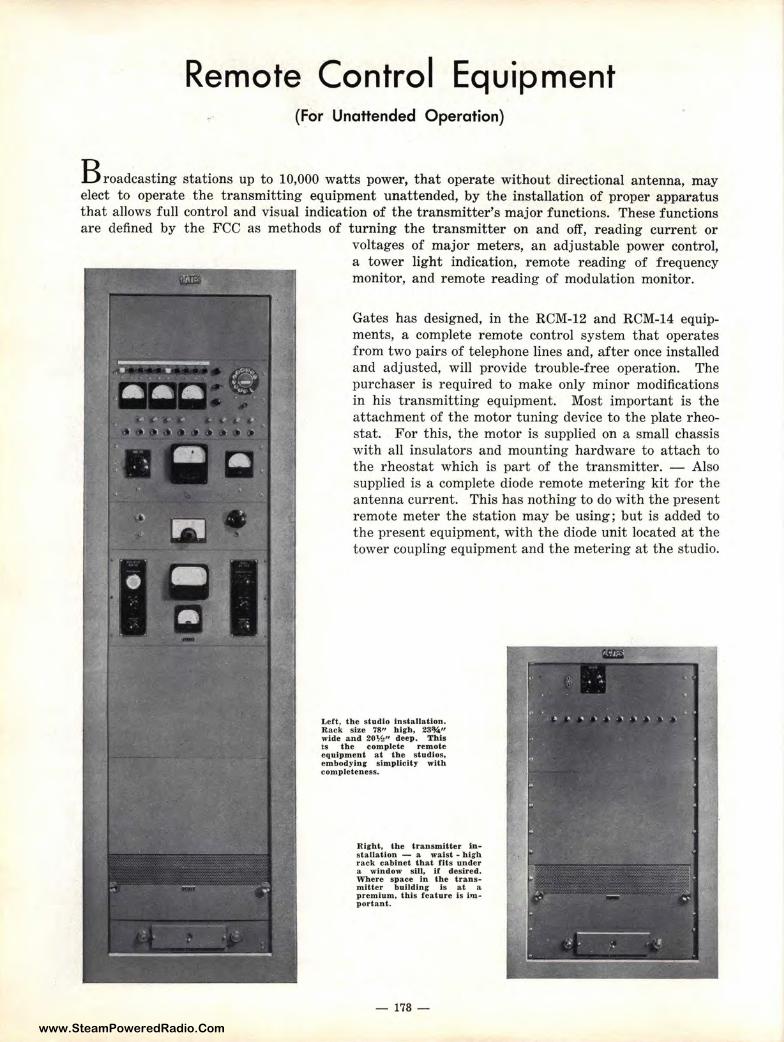
www.SteamPoweredRadio.Com
Remote Control Equipment (For Unattended Operation)
B roadcasting stations up to 10,000 watts power, that operate without directional antenna, may elect to operate the t ransmitting equipment unattended, by the installation of proper apparatus that allows full control and visual indication of the transmitter 's major functions. These functions are defined by the FCC as methods of t urning the transmitter on and off, reading current or
voltages of major meters, an adjustable power control, a tower light indication, remote reading of frequency monitor, and remote reading of modulation monitor.
Gates has designed, in the RCM-12 and RCM-14 equipments, a complete remote control system that operates from two pairs of telephone lines and, after once installed and adj usted, will provide trouble-free operat ion. The purchaser is required to make only minor modifications in his transmitting equipment. Most important is the attachment of the motor tuning device to the plate rheostat. For this, the motor is supplied on a small chassis with all insulators and mounting hardware to attach to the rheostat which is part of the transmitter. - Also supplied is a complete diode remote metering kit for the antenna current. This has nothing to do with the present remote meter the station may be using; but is added to the present equipment, with the diode unit located at the tower coupling equipment and the metering at the studio.
Left, the studio Installation. Rack size 78" high, 23¾" wide and 20%" deep. Th is is the complete remote equipment at t h e s t udios, embodying simplicity with completeness.
Right, the t ransmitter installation - a wa.lst - high rack cabinet t hat fits under a window sill, if desired. Where space In the transmitter building Is at " premium. this feature Is important.
- 178 -
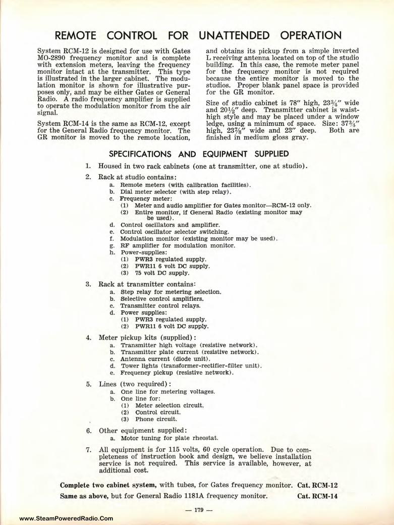
www.SteamPoweredRadio.Com
REMOTE CONTROL FOR UNATTENDED OPERATION System RCM-12 is designed for use with Gates MO-2890 frequency monitor and is complete with extension meters, leaving the frequency monitor intact at the transmitter. This type is illustrated in the larger cabinet. The modulation monitor is shown for illustrative purposes only, and may be either Gates or General Radio. A radio frequency amplifier is supplied to operate the modulation monitor from the air signal.
System RCM-14 is the same as RCM-12, except for the General Radio frequency monitor. The GR monitor is moved to the remote location,
and obtains its pickup from a simple inverted L receiving antenna located on top of the studio building. In this case, the remote meter panel for the frequency monitor is not required because the entire monitor is moved to the studios. Proper blank panel space is provided for the GR monitor.
Size of studio cabinet is 78" high, 23¾ " wide and 20½" deep. Transmitter cabinet is waisthigh style and may be placed under a window ledge, using a minimum of space. Size: 37¾ " high, 23'1/s" wide and 23" deep. Both are finished in medium gloss gray.
SPECIFICATIONS AND EQUIPMENT SUPPLIED
1. Housed in two rack cabinets (one at transmitter, one at studio).
2. Rack at studio contains: a. Remote meters (with calibration facilities) . b. Dial meter selector (with step relay). c. Frequency meter:
(1) Meter and audio amplifier for Gates monitor-RCM-12 only. (2) Entire monitor, if General Rad1o (existing monitor may
be used). d. Control oscillat·ors and amplifier. e. Control oscillator selector switching. f. Modulation monitor (existing monitor may be used). g. RF amplifier for modulation monitor. h. Power-supplies:
(1) PWR3 regulated supply. (2) PWRll 6 volt DC supply. (3) 75 volt DC supply.
3. Rack at transmitter contains: a. Step relay for metering selection. b. Selective control amplifiers. c. Transmitter control relays. d. Power supplies:
(1) PWR3 regulated supply. (2) PWRll 6 volt DC supply.
4. Meter pickup kits (supplied) : a. Transmitter high voltage (resistive network). b. Transmitter plate current (resistive network). c. Antenna current (diode unit). d. Tower lights (transformer-rectifier-filter unit). e. Frequency pickup (resistive network).
5. Lines (two required): a. One line for metering voltages. b. One line for:
(1) Meter selection circuit. (2) Control circuit. (3) Phone circuit.
6. Other equipment supplied: a. Motor tuning for plate rheostat.
7. All equipment is for 115 volts, 60 cycle operation. Due to completeness of instruction book and design, we believe installation service is not required. This service is available, however, at additional cost.
Complete two cabinet system, with tubes, for Gates frequency monitor. Cat. RCM-12
Same as above, but for General Radio 1181A frequency monitor. Cat. RCM-14
- 179 -
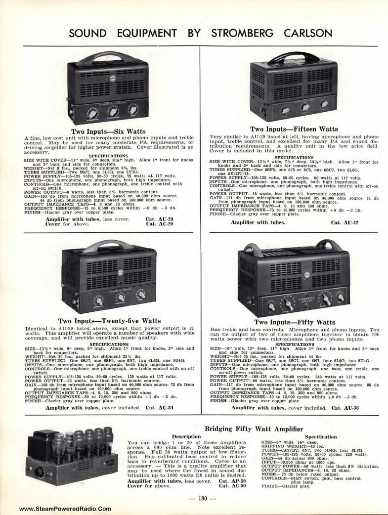
www.SteamPoweredRadio.Com
SOUND EQUIPMENT BY
.Two Inputs-Six Watts A fine, low cost unit with microphone and phono inputs and treble control. May be used for many moderate PA requirements, or dl"iving amplifier for higher power system. Cover illustrated is an accessory.
SPECIFICATIONS SIZE WITH COVER-11" wide, 6" deep, 9½" high. Allow l" front for knobs
and 2" be.ck and side ror connectors. WEIOJ'IT- Net 8 lbs., pa.eked for shipment 9¾ lbs. TUBES SUPPLIED-Two 6SJ7, one 6L6O, one 5Y3O. POWER SUPPLY- 105-125 volts, 50-60 cycles, 75 watts e.t 117 volts. INPUTS-One microphone, one phonograph, both high Impedance. CONTROLS-One microphone, one phonograph, one treble control with
off-on switch. POWER OUTPUT- 6 watts, less than 5 % harmonic content. OAIN- 103 db from microphone input based on 40,000 ohm source,
64 db from phonograph Input based on 100,000 ohm source. OUTPUT IMPEDANCE TAPS-4, 8 and 15 ohms. FREQUENCY RESPONSE-75 to 8,500 cycles within + o db -3 db. FINISH-Glacier gray over copper plate.
AmpHfier with tu bes, less cover. Cover fot· above.
Cat. AU-29 Cat. AC-29
Two Inputs-Twenty-five Watts Identical to AU-29 listed above, except that power output is 25 watts. This amplifiet· will operate a n umber of speakers with wide coverage, and will provide excellent music quality.
SPECIFICATIONS SIZE-13 ½" wide, 9" deep, 9" high. Allow l" f ront for knobs, 2" side and
back for connectors. WEIGHT-Net 20 lbs., packed for shipment 22 ½ lbs. TUBES SUPPLIED-On e 6SJ 7, one 6SF5, one 6N7, two 6L6G, one 5U4G. INPUTS-One microphone, one phonograph, both high Impedance. CONTROLS-One microphone, one phonograph, one treble control with on-off
switch. POWER SUPPLY- 105-125 volts, 50-60 cycles. 125 watts at 117 volts. POWER OUTPUT-25 watts, less than 5% harmon ic conten t. G AIN- 109 db from microph one Input ba sed on 40,000 oh m source, 72 db from
phonograph Input based on 100,000 ohm source. OUTPUT IMPEDANCE TAPS-4, 8, 15, 250 and 500 ohms. FREQUENCY RESPONSE-SO to 10,000 cycles within + 1 db - 2 db. FINISH-Glacier gray over copper plate.
Amplifier with tubes, cover included. Cat . AU-34
Description
STROMBERG CARLSON
Two Inputs-Fifteen Watts Very similar to AU-29 listed at left, having microphone and phono input, treble control, and excellent for many PA and sound distt·ibution requirements. A quality unit in the low pl'ice fie ld . Cover is included in this model.
SPECIF ICATIONS SIZE WITH COVER--13½ " wide, 7 ½ " deep, 10¼" high. Allow I" front for
knobs and 2" back and side for connectors. TUBES SUPPLIED-One 6SF5, one 6J5 or 6C5, one 6SC7, two 6L6G,
one 5Y3OT/0. POWER SUPPLY- 105-125 volts, 50-60 cycles. 90 watts at 117 volts. 1NPUT5-----0ne microphone, one phonograph, both high impedance. CONTROLS-One microphone, one phonograph, one treble control with off-on
switch. POWER OUTPUT- 15 watts, less than 5 % harmonic content. OAIN-111 db from microphone Input based on 40,000 ohm source, cl db
from phonograph Input based on 100,000 ohm source. OUTPUT IMPEDANCJ;: TAPS-4, 8, 15 and 500 ohms. FREQUENCY RESPONSE-75 to 10,000 cycles within + 0 db - 3 db. FINISH-Glacier gray over copper plate.
Amplifier with tubes. Cat. AU-42
Two Inputs-Fifty Watts Has treble and bass controls. Microphone and phono inputs . You can tie output of two of these amplifiers together to obtain 100 watts power with two microphones and two phono inputs.
SPECIFICATIONS SIZE-16" wide, 12" deep, 11" high. Allow 1" front for knobs and 2" back
and side for connectors. WEIGHT-Net 35 lbs., packed for shipment 44 lbs. TUBES SUPPLIED-One 6SJ7, one 6SC7, one 6N7, four 6L60, two 5U4G. INPUTS-One microphone, one phonograph, both h igh impedance. CONTROLS-One microphone, one phonograph, one bass, one treble, one
on-off power switch. POWER SUPPLY-105- 125 volts, 50-60 cycles. 245 watts at 117 volts. POWER OUTPUT-50 watts, less than 5 % harmonic content. GAIN- 117 db from microphone Input based on 40,000 ohm source, 85 db
from phonograph Input based on 100,000 ohm source. OUTPUT IMPEDANCE TAPS-4, 8, 15, 250 a nd 500 ohms. FREQUENCY R ESPONSE-SO to 12,000 cycles within + o db - 3 db. FINISH-Glacler gray over copper plate.
Amplifier with t ubes, cover included. Cat. AU-36
Bridging Fifty Watt Amplifier
You can bridge l or 20 of t hese amplifiers across a 600 ohm line. Note excellent response. Full 50 watts output at low d istort ion. Has calibrated bass control to reduce bass in reverberant conditions. Cover is an a ccessory. - This is a quality amplifier that may be used where the finest in sound distribution up to 1000 watts (20 units) Is desired. Amplilier with tubes, less cover. Cat. Al'-50 Cover for above. Ca.t. AC-50
Specification SIZE-8" wide, 14" deep. SHIPPING WEIGHT-42 lbs. T UBES-6SN7GT, 6N7, two 5U4G, four 6L6G. POWJ;:R--105-125 volts, 50-60 cycles; 220 watts. GAIN-4 db across 600 ohms. INPUT-30,000 ohms at 1000 cps. OUTPUT POWER--50 watts, less than 5% distortion. OUTPUT IMPEDANCES-8, 16, 32 ohms. NOISE- 70 db below rated output. CONTROLS-Start switch, gain, bass control,
pilot lamp. FINISH-Glacier gray.
- 180 -
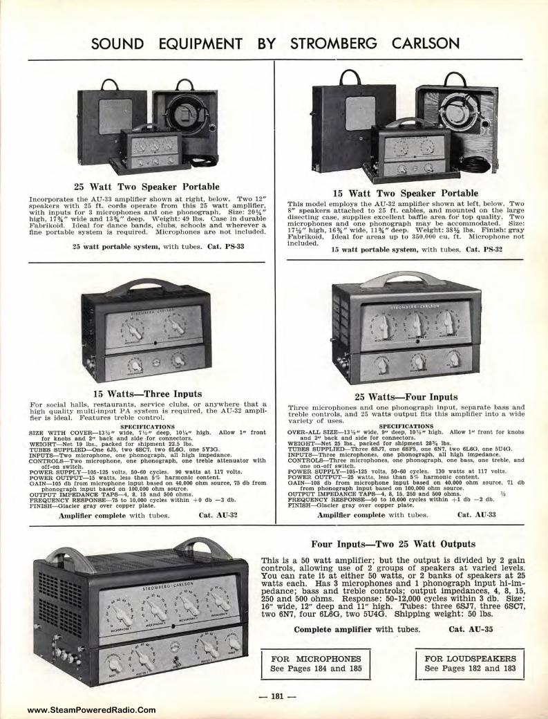
www.SteamPoweredRadio.Com
SOUND EQUIPMENT BY STROMBERG CARLSON
25 Watt Two Speaker Portable Incorporates the AU-33 amplifier shown at right, below. T wo 12" speakers with 25 ft. cords operate from this 25 watt amplifier, with inputs for 3 mic rophones and one phonograph. Size: 20¼" high, 17¾" wide and 13¾" deep. Weight: 49 lbs. Case in durable Fabriko id . Ideal for dance bands, clubs, schools and wherever a fine portable system is required. Microphones are not inc luded.
25 ,vatt p0rtable system, with tubes. Cat. PS-33
15 Watts-Three Inputs For socia l halls, restaurants, service c lubs, or anywhere that a h igh quality multi-input PA system is required, the AU-32 amplifier is ideal. Features treble control.
SPECIFICATIONS SIZE WITH COVER-13 ½ " wide, 7 ½ " deep, 10¼" high. Allow 1" f ron t
for knobs and 2" back and sld<1 -for connectors. WEIGHT- Net 19 lbs .. packed for sh ipment 22.5 lbs. TUBES SUPPLIED-One 6J5, two 6$07, two 6L6G, one 5Y3G. INPUTS-Two microphone, one phonograph, all high Impedance. CONTROLS-Two microphone, one phonograph, one treble attenuator with
off-on switch. POWER SUPPLY- 105-125 volts, 50-60 cycles. 90 watts at 117 volts. POWER OUTPUT-IS watts, Jess than 5% harmonic con tent. GAIN- 105 db from microphone Input based on 40,000 ohm source, 75 db from
phonograph Input based on 100,000 ohm source. OUTPUT IMPEDANCE TAP8-4, 8, 15 and 500 ohms. FREQUENCY RESPONSE-75 to 10,000 cycles within + o db -3 db. FINISH-Glacier gray over copper plate.
A:mplifler com plete with tubes. Cat. AU-32
15 Watt Two Speaker Portable This model employs the AU-32 ampllfler shown at left, below. Two 8" speakers attached to 25 ft. cables, and mounted on the large dlsectlng case, supplies excellent baffle area fo1' top qua lity. Two microphones and one phonograph may be accommodated. Size: 17½" high, 16'¾," wide, 11'¾," deep. Weight: 38½ lbs. Finish: gray Fabrikoid. Ideal fot· areas up to 350,000 cu. ft. Microphone not Included.
15 watt portable syst-em, with tubes. Cat. PS-32
25 Watts-Four Inputs Three microphones and one phonograph input, separate bass and treble controls, a nd 25 watts output fits this amplifier into a wide variety of uses.
SPECIFICATIONS OVER-ALL SIZE-13½" wide. 9" deep, 10½ " high. Allow I" front for knobs
and 2" back and side tor connectors. WEIGHT- Net 25 lbs., packed for shipment 28¾ lbs. TUBES SUPPLIED-Three 6SJ7, one 6SF5, one 6N7, two 6L6G, one 5U4G. INPUTS-Three microphones. one phonograph, all high Impedance. CONTROLS-Three microphones, on e phonograph, one bass, one treble, and
one on-off switch. POWER SUPPLY-105-125 volts. 50-60 cycles. 130 watts at 117 volts. POWER OUTPUT-25 watts, less than 5 % harmonic content. GAIN- 108 db from microphone Input based on 40,000 ohm source, 71 db
from phonograph Input based on 100.000 ohm source. OUTPUT IMPEDANCE TAP8-4, 8, 15, 250 and 500 ohms. ½ FREQUENCY RESPONSE-SO to 10,000 cycles within + 1 db -2 db. FINISH-Glacier gray over copper plate.
Ampilfier complete with tubes. Cat. AU-33
Four Inputs-Two 25 Watt Outputs
This is a 50 watt ampllfier; but the output is divided by 2 gain controls, allowing use of 2 groups of speakers at varied levels. You can rate it at either 50 watts, or 2 banks of speakers at 25 watts each. Has 3 microphones and 1 phonograph input hi-impedance; bass and treble controls; output impedances, 4, 8, 15, 250 and 500 ohms. Response: 50-12,000 cycles within 3 db. Size: 16" wide, 12" deep and 11" high. Tubes: three 6SJ7, three 6SC7, two 6N7, four 6L6G, two 5U4G. Shipping weight: 50 lbs.
Complete amplifier with tubes. Cat. AU-35
FOR MICROPHONES See Pages 184 and 185
- 181-
I FOR LOUDSPEAKERS See Pages 182 and 183
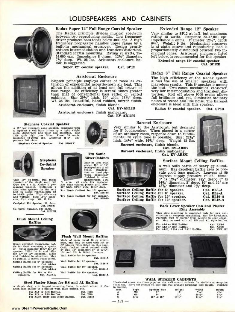
www.SteamPoweredRadio.Com
LOUDSPEAKERS AND CABINETS Radax Super 12" Full Range Coaxial Speaker The .Radax principle divides musical spectrum between two reproducing media. Low frequency driver produces bass tones below 4000 cps. A high frequency propagator handles upper range by a built-In mechanical crossover. Design greatly reduces intermodulation and transient distortion. Standard RTMA mounting. Rating 25 watts, 35-14,000 cps. Impedance 8 ohms. 12¼" diameter, 7½" deep. Wt. 25 lbs. Aristocrat enclosure, below, is suggested.
Super 12" coaxial speaker. Cat. SP12
Aristocrat Enclosure Klipsch principle employs corner of room as extension of exponential acoustic-horn air load. This allows the addition of at least one full octave of bass range. Its efficiency is several times greater than that of conventional bass reflex or vented cabinets. Size 29½" high, 19" wide, 16½" deep. Wt. 35 lbs. Beautiful, hand rubbed, mirror finish.
Aristocrat enclosure, finish blonde. Cat. EV-AR12B
Aristocrat enclosure, finish mahogany. Cat. EV-AR12M
Extended Range 12" Speaker Very similar to SP12 at left, but maximum rating 18 watts. Response 35-13,000 cps. Impedance 8 ohms. Diameter 12¼", depth 63/s". Weight 9 lbs. Mechanical crossover is at sixth octave and reproducing load is proportionately distributed between two individual cones. Aristocrat enclosure, listed left below, is recommended for this speaker.
Extended range 12" coaxial speaker. Cat. SP12B
Radax 8" Full Range Coaxial Speaker The high efficiency of the Radax system allows the use of smaller speakers with marvelous results. This 8" speaker is among the best. Two cones, mechanical crossover, very low intermodulation and transient distortion. Roll off above 9000 cycles allows full brilliance and, yet, eliminates ordinary noises of record and line noise. The Baronet enclosure is ideal with this speaker.
Radax 8" coaxial speaker. Cat. SPSB
Stephens Coaxial Speaker Baronet Enclosure A 15" low resonant cone speaker, combined with a separa te 8 cell horn driven by a light weight metal diaphragm and voice coll assembly. Has 1200 cycle high pass filter. Power 20 watts. Response 40-20,000 cps. Diameter 15Yo". Im• pedance 500 ohms.
Stephens Coa.xlal Speaker, Cat. 6106/1.X
Stephens Co-Spiral Speaker
This 15" co-spiral full range speaker, of the single voice coll type, has a 4 lb. Alnico V permanent magnet. Definitely a first class speaker for the very best In sound reproduction up to 14,000 cycles. High efficiency and wattage. Size: 15%" diameter, 8 ½" deep. Wt. 12 lbs.
Co-Spiral 15" Speaker, 12 ohms. Cat. 102FR
Co-Spiral Speaker, 500 ohms. Cat, 5102FR
Flush Mount Ceiling Baffles
Small, compact, Inexpensive battle for flush mounting a speaker. Total diameter 10¾" for 6" speaker, 12¼" tor 3,, a.nd 16½" tor 10" or 12" speakers. Made and finished In aluminum. May be painted to match room colors. Celling- Baffle for 6" speakers.
Cat. AL6-A Celling- Ballle for 8" speakers.
Cal. AL8-/I.
Tru Sonic Silver Cabinet May be used with either 1211 or 15" loudspeakers of all types. Construction - hard plywood, beautifully finished In silver hammertone. 6 cu.
ft. area. 42 cycle low response. Has wine colored plastic grill. Size: 32,, high, 23¾" wide, 16½ " deep. Tru Sonic Ca.bluet for 12" speaker.
Cal. 52S-12 Tru Sonic Cabinet for 15" speaker.
Cat. 52S-16
Flush Wall Mount Baffles Made o! spun metal 18 gg aluminum, and may be used with PR or CP plaster rings listed on this page. Grill, flocked metal colored cloth. s,, size, 10" diameter; a,, ts 12o/a": 10" and 1211 1s 16½" diameter. Wall Baffle for 6" s peaker.
Cat. RS6-A Wall Baffle for 811 .speaker.
Cat. RS8-A Wall Baffle for 10,, speaker.
Cat. RSl 0- /1. Ceiling Baffle for 1011 or 1211 WaU Baffle for J.211 speaker.
speakers. Cat. ALlO-A Cat. RS12-A
Steel Plaster Rings for RS and AL Baffles A simple ring, with tapped mounting holes, to attach either of the flush type baffles t& a plaster wall, false celling. etc.
For /I.LG or RS6 Baffles. Cal. PR6 For /I.LS or RS8 Baffles. Cat. PR8 For /1.LlO, RSlO and RS12 Baffles. Cat. PR12
Very similar to the Aristocrat, but designed for 8" loudspeaker. When placed in a corner of an ordinary room, response down to fundamental 30 cycle tone is possible. Size: 22¼" high, 14½" wide, 14¾" deep. Weight 18 lbs.
Baronet enclosure, finish blonde. Cat. EV-AR8B
Baronet enclosure, finish mahogany. Cat. EV-ARSM
Surface Mount Ceiling Baffles A well built baffle of heavy gg aluminum. Has excellent baffle area to provide good tone quality. Louvers at 90 degrees supply pressure relief. Sizes: 6" is 121/4" diameter, 7¼" deep; 8" is 143/4" diameter, 8" deep; 10" and 12" are 18%" diameter and 9¼" deep.
Surface Ceiling Baffle for 6" speaker. Cat. BL6-A Surface Ceiling Baffle for 8" speaker. Cat. BL8-A Surface Ceiling Baffle for 10" speaker. Cat. BLlO-A Surface Ceiling Baffle for 12" speaker. Cat. BL12-A
A
Back Cover Speaker Can and Plaster Ring Assembly
This style mounting Is suggested only for new construction or complete remodeling. Has ¾" knockouts. Prevents dust or mortar from getting In cone speaker. May be used with all RS and AL style baffles.
For /I.LG or RS6 Baffles. Cat. XCP6 For /lL8 or RS8 Baffles. Cal. XCP8 For ALlO, RSJO and RS12 Baffles. Cat. XCPJ012
• WALL SPEAKER CABINETS
Illustrated above are three popular s ize wall mount cabinets tor studio and reception room use. Have air release on s ide and wlll produce unusually fine results. Finished In walnut.
ruus. A B C
- 182
Type M6 MS M12
Speaker Size 6"
lle i,rht 8"
11" 16½ "
Width 7¼"
10½" 14'Ya"
Depth 4%" 6½" 8½"
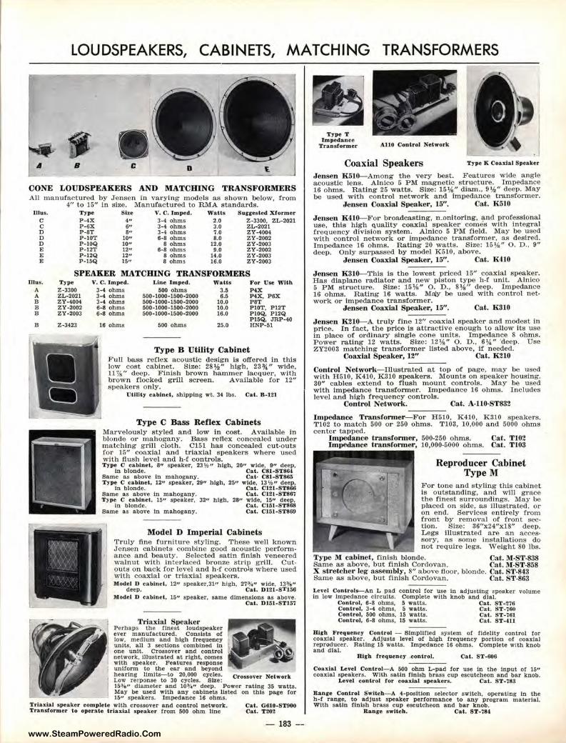
www.SteamPoweredRadio.Com
LOUDSPEAKERS, CABINETS, MATCHING TRANSFORMERS
A B C D t.
CONE LOUDSPEAKERS AND MATCHING TRANSFORMERS All manufactured by Jensen in varying m odels as shown below, from
Illus. C C D D D E E E
rn .... A A B B B
B
4" to 15" in size. Manufactured to RMA standards. T yp e Slze V. C. Imped. Watts Sur;rested Xformer P-4X 4" 3-4 ohms 2.0 Z-3300, ZL-2021 P -6X 6" 3-4 oh.ms 3.0 ZL-2021 P-ST 8" 3-4 ohms ~.o ZY-4004 P-l OT 10" 6-8 ohms 8.0 ZY -2002 P-IOQ 10" 8 ohms 12.0 zy -2003 P -12T 12" 6-8 ohms 9.0 ZY-2002 P-12Q 12" 8 ohms 14.0 ZY-2003 P-15Q 15" 8 ohms 16.0 ZY-2003
SPEAKER MATCHING TRANSFORMERS Type Z-3300 ZL-2021 ZY-4004 ZY-2002 ZY-2003
Z-3423
V. C. lmped. L.lne Imped. Watts For Use With 3-4 ohms 500 ohms 3.5 P4X 3-4 ohms 500-1000-1500-2000 6.5 P4X, P6X 3-4 ohms 500-1000-1500-2000 10.0 PST 6-8 ohms 500-1000-1500-2000 10.0 PlOT, Pl2T 6-8 ohms 500- 1000-1500-2000 16.0 PlOQ, Pl2Q
16 ohms 500 ohms 25.0 Pl5Q, JRP-40 HNP-51
Type B Utility Cabinet Full bass reflex acoustic design is offered in this low cost cabinet. Size: 28½" high, 23¾" wide, 11¾" deep. Finish brown hammer lacquer, with brown flocked grill screen. Available for 12" speakers only.
Utilit y cabinet , shipping wt. 34 lbs. Cal. B-121
Type C Bass Reflex Cabinets Marvelously styled a nd low in cost. Available in blonde o r mahogany. Bass reflex concealed under matching g rill c loth. C151 has concealed cut-outs for 15" coaxial and triaxial speakers where used with flush level and h-f controls. T·ype O cabinet, 8'' speaker, 23 ½ " high, 20" wide, 9" deep,
In blonde. Cat. C81-ST864 Same as above In mahogany. Cat• C81-ST8r>G Type C c abinet, 12,, speaker, 29" high, 25" wlde, 13 ½ ,, deep,
In blonde. Cat. C121-ST866 Same as above In mahogany. Cat. Cl21-ST867 Typ~n C br::~~~t, 15" speaker, 32" h igh, 28" ;!t•c~~;-s<::m Same as above In mahogany. Cal. Cl51-ST8GO
Model D Imperial Cabinets Truly fine furnitur e styling. These well known ,Tensen cabinets combine good acoustic performance and beauty. Selected satin finish veneered walnut with interlaced bronze strip g rill. Cutouts on back for level and h·f controls where used with coaxial ot· triaxial speakers. llfodel D cabine t. 12" speaker,31" high. 27¾" wide, 13¾"
deep. Cal . 0121-$'1'156 Model D cabinet, 15" speaker, same dimen sion s as above.
T,;axia l Speaker Perhaps the fin est loudspeaker ever manufactured. Consists of low, medium and high frequency units, an 3 sections combined In one unit. Crossover and control network , Illustrated at right, comes with speaker. Feat ures response uniform to the ear and beyond
Cat. Dl51-ST157
hearing ltmlts-to 20,000 cycles. Cr ossover Network Low reeponse to 30 cycles. Size: 153/e" diameter and 10¾ " deep. Power rating 35 watts. May be used with any cabinets listed on this page for 15" speakers. Impedance 16 ohms.
Trlaxlal speaker complete with crossover and control network. Cal. 0 610-STOOO Transformer lo operate lria,dal s peaker Crom 500 ohm line Cal. T202
- 183 --
Type T Impedance
Trans former AllO Contr ol Network
Coaxial Speakers Type K Coaxial Speaker
Jensen K510-Among the very best. Features wide angle acoustic lens. Alnico 5 PM magnetic structure. Impedance 16 ohms. Rating 25 watts. Size: 15¼" diam., 9½" deep. May be used with control network and Impedance transformer.
Jensen Coaxial Speaker , 15". Cat. K 510
Jensen K410--For broadcasting, n.onltorlng, and professional use, this high <\Uality coaxial speaker comes with integral frequency division system. Alnico 5 P M field. May be used with control network or impedance transformer, as desired. Impedance 16 ohms. Rating 20 watts. Size: 15¼" 0. D., 9" deep. Only surpassed by m odel K510, above.
Jensen Coa.xial Speaker, 15". Cat. K410
Jensen K310--Thls is the lowest priced 15" coa..xlal speaker. Has din.plane radiator and new piston type h•f unit. Alnico 5 PM structure. S ize: 15¼" o. D., 8¼" deep. Impedance 16 ohms. Rating 16 watts. Ma/y be used with control network or impedance transformer.
Jensen Coaxial Speaker, 15". Cat. 1{310
Jensen K210--A truly fine 12" coaxial speaker and modest in price. In fact, the pl"ice is attractive enough to a llow its use in place of ordinary single cone u nits. Impedance 8 ohm s. Power rating 12 watts. Size: 12¼" 0. D., 6¼.'' "deep. Use ZY2003 matching t ransformer listed above, if needed.
Coaxial Speaker, 12" Oat. K210
Control Network-Illustrated at top of page, may be used with H510, K410, K310 speakers. Mounts on speaker housing. 30" cables extend to flush mount controls. May be used with impedance transformer. Impedance 16 ohms. Includes level a nd high frequency controls.
Control Networlt. ____ Cat. A·110-ST832
Impedance Transformer-For H510, K410, K310 speakers. T102 to match 500 or 250 ohms. T 103, 10,000 and 5000 ohms center tapped.
Impedance transformer, 500-250 ohms. Cat. Tl02 Impedance transformer, 10,000-5000 ohms. Cat. T103
Reproducer Cabinet Type M
For tone and styling this cabinet Is outstanding, and will g race the finest surroundings. May be placed on side, as illustrated, ot· on end. s ·ervlces entire ty from front by removal of front section. Size: 36"x24"x18" deep. Legs illustrated are an accessory, as some insta.Jlations do not require legs. Weight 80 lbs.
'l'ype M cabinet, finish blonde. Cat. M-ST-838 Same as above, but finish Cordovan. Cat. M-ST-858 X stret.cbe r leg assembly, 8" above floor, b loncle. Cat. ST-843 Same as above, but finish Corclovan. Cat. S'f-863
Lenl Controls-An L pad control ror use In adjusting speaker volume In low Impedance circuits. Complete with knob and dial.
Control, 6-8 ohms, 5 watts. Cat. ST -276 Control, 3-4 ohms, 5 watts. Cal. ST -760 Control, 500 ohms, 15 watts. Cat. ST -761 Control, 6-8 ohms, 15 watts. Cat. ST-4ll
High F requency Control - Slmpl!fled system of fldel!ty control for coaxial speaker. Adjusts level of high frequency portion or coaxial reproducer. Rating 15 watts. Impedance 16 ohms. Complete with knob and dial.
High frequency .contr ol. Cal. ST-606
Coaxial Level Control- A 500 ohm L-pad ror use In the Input or 15" coaxia l speakers. With satin finish brass cup escutcheon a nd bar knob.
Level control for coax.Jal speakers. Cat. ST•783
Range Control !fwltch-A 4-posltlon selector switch, operating in the h-f r ange, to adjust speaker performance to any program material. With s a tin finish brass cup escutcheon and bar knob.
Range s witch . Cat. ST-784
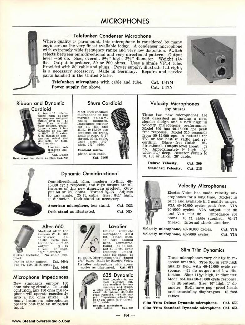
www.SteamPoweredRadio.Com
MICROPHONES
Telefunken Condenser Microphone Where quality is paramoun t , this microphone is considered by many engineers as the very finest available today. A condenser microphone with extremely wide frequency range and very low distortion. Switch selects between omnidirectional and very directional pattern. Output level - 56 db. Size, overall, 9%" high , 2%" diameter. Weight 1½ lbs. Output impedance, 50 or 200 ohms. Uses a single VF14 tube. Provided with 30' cable and plugs. Power supply, illustrated at r ight, is a necessary accessory. Made in Germany. Repairs and service par ts handled in the United States.
Telefunken microphone with cable and tube. Power supply for above.
Cat. U47M Cat. U47N
Ribbon and Dynamic Cardioid
A beautiful microphone with 50-8000 cps response and good output level of - 53 db. True cardioid polar pattern. Transformer allows 3 Impedances of 50, 250 or HI-Z. 25 ft. cable. ¾-27 thread on combination swivel and side lock. 6" high,
diameter. American nticrophone less stand.
Cat. DR332 Desk stand for above as Illus. Cat. ND
Shure Cardioid
Most used cardioid microphone on the market t o day . Shock mounted. Impedance selector for 50, 150 a nd Hl·Z. 40-15,000 cps r esponse on front. Dead on rear. %-27 t hread. 20 ft. cable. Case size: 3¼'' high, 2¼" wide.
Cardioid microphone with cable .
Cat . 556S
Dynamic Omnidirectional
Omnidirectional, slim, modern styling, 40-15,000 cycle r esponse, and high output are all features of this new American product. Output 50 or 250 ohms. Thread %-27. Adjusts to any angle. 25 ft. cable. Size: 8¼" high, l " diameter. Desk stand an accessory.
American microph one, less stand.
Desk stand as illustrated.
Cat. D33
Cat. ND
Altec 660 Modeled after the famous W. E. 633 saltshaker. 40-10,000 cycle performance. -57 db output. % · 27 thread. 4" high, 1¾" diameter.
Swivel Included. No cable supplied. For 30 ohms output. Cat. 660A For 30, 150, Hi-Z output.
Cat. 660B
Microphone Impedances New standards employ 150 ohm mixing circuits. To avoid confusion, any 150 ohm microphone will operate excellently into a 250 ohm mixer. In many instances microphones operate best into an unloaded input.
Lavalier Unique complete microphone a n d kit. Hand, desk, or cord around neck. Omnidirectional -55 db output 60-13,000 cycle response. Impedance 150 ohms. 18
ft. cable. Microphone 4"xl". Stand 2¾" base. Made by Electro-Voice. Lavalier microphone with acces-
sories as illustrated. Cat. 64 7
635 Dynamic Most popular In remote pickups; but, also excellent !or an-nouncing and studio.
A truly fine, low priced, dynamic microphone. 60-13,000 cycle response. -55 db output. Impedance selector for 50 or 250 ohms. ¾ -27 thread. 18 ft. cable. Dyn amic microphone
with swivel. Cat . 6ao
- 184-
Velocity Microphones (By Shure)
These two new microphones are best described as having a new, slender design and a new high in velocity microphon e performance. Model 300 has 40-15,000 cps peak free response. Model 315 responds from 50-12,000 cps. A natura l for TV, or the best in radio and recording. Glare - free finish. Bidirectional. Output level about - 59 db. .A:pproximately 9" high, l ½" wide; l¼" deep. Selector switch to 50, 160 or Hi-Z. 20' cable.
Deluxe Velocity. Cat. 300 Standard Velocity. Cat. 315
Velocity Microphones Electro-Voice has made velocity microphones for a long time. Modest in price and available in 2 quality ranges. V2A 40-10,000 cycles peak free. VlA 40-9000 cycles. V2A output - 53 db and VIA - 63 db. Impedance 250 ohms. 18 ft. cable supplied. %-27 thread. Internal shock absorber.
Velocity microphone, 40-10,000 cycles. Velocity microphone, 40- 9000 cycles.
Cat. V2A Cat. VIA
654
Slim Trim Dynamics
These microphones vary chiefly in response breadth. Type 655 in very high quality field with 40-15,000 cycle response, - 51 db output and low distortion. Size: 113/s" h igh, 1" diameter. Model 654 has 50-13,000 cycle response, - 55 db output. Size: 10" high, l" diameter. Both have pop - proof heads and acoustalloy diaphragms. 18 foot cables.
Slim Trim Deluxe Dynami c microphone. Cat. 655 Slim Trim Standard Dynamic microphone. Cat. 654
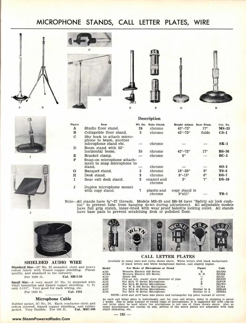
www.SteamPoweredRadio.Com
A
I
J
MICROPHONE ST ANDS, CALL LETTER PLATES, WI RE
B
.g ..
C
ffl I
rn .. D
E F 0 H
Description Ficure Item Wt. lbs. Tube Finish Height Adjust. Base Diam. Cat. No.
A Studio floor stand. 24 chrome 42"-72" 17" MS-25 B Collapsible floor stand. 5 chrome 42"-72" folds CS-1 C Sky hook to attach micro-
phone to beam, another microphone stand etc. chrome SK- 1
D Boom stand with 63" horizontal boom. 35 chrome 42"-72" 17" BS-36
E Bracket clamp. chrome 6" BC-1 F Snap-on microphone attach-
ment to snap microphone to stand. chrome SO-1
G Banquet stand. 5 chrome 18"-32" 8" TS-6 H Desk stand. 3 chrome 8"-13" 6" DS-7 I Rear exit desk stand. 3 enamel and 3" 7" DS-10
chrome J Duplex microphone mount
with copy stand. 7 plastic and copy stand is chrome 9"xll" TB-1
Note-All stands have %"-27 threads. Models MS-25 and BS-36 have "Safety air lock cushion" to prevent tube from banging down during adjustment. All adjustable models have full grip clutch, inner-lined with wear proof bakelite locking collet. All stands have base pads to prevent scratching desk or polished floor.
CALL LETTER PLATES SHIELDED AUDIO WIRE Available Ln many sizes and styles shown above. White letters with black background.
If black letters and white background desired, cost slightly higher. Starulard S ize-2C No. 20 stranded, cloth and heavy cotton fabric with tinned copper shielding. Finest quality, and standard in the industry.
Model A125 A118A All0 A105 All5 A118 A127 A117 A116
F or Make or Microphone or Stand Fir ure Code Western Electric 618 Serles. E ZEJDO Western Electric 633 Serles. B, D ZEJEB
Per 1000 ft. Cat. S H-2-20
Small Size-A very small 2C No. 24 stranded with 'vinyl insulation and tinned copper shielding. 0. D. only 0.116". Very good for rack wiring, etc.
Per 1000 ft. Cat. 1261
Microphone Cable Rubber jacket, 2C No. 20. Each conductor cloth and cotton covered, tinned copper shielding, and rubber jacket. Very flexible. P er 100 ft. Cat . MIC-100
Shure 556. ZEJIC Clip-on mlc. stand; state diameter or pipe. C ZEJOD For RCA 77 Serles Microphone. A ZEFUF For RCA 88 Serles Microphone. F ZEJYG For w. E. 639 series Microphone. ZEJZA For RCA 44 Serles Microphone. Similar to A ZEKAB For RCA 74 Serles Microphone. Similar to A ZEKBA
NOTE-A116 and A117 have side plates and rectangular top plate Instead or curved.
As each call letter plate ls Individually .cast for your call letters, delay In shipping Is about 3 weeks. Due to large number of varied types of microphones, it Is suggested the Al05 clip-on call letter plate be used where the microphone Is not one or those shown above. Also, as many microphones are s imilar In size, several of the above plates are adaptable with only slight shimming, etc.
- 185 -
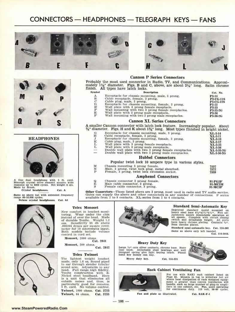
www.SteamPoweredRadio.Com
M .,, a
CONNECTORS - .HEADPHONES - TELEGRAPH KEYS - FANS
B E
~ • N p
"' ,=, ' Q
4f R s
HEADPHONES
" G a J
f- C H L I Cannon P Series Connectors
Probably the most used connector in Radio, TV, and Communications. Approximately 11/8 " diameter. Figs. B and C, above, are about 2¼" long. Satin chrome finish. All types have latch locks.
Symbol
A B C D Et F E F
Description Receptacle for chassis mounting, male, 3 prong. Cable receptacle, female, 3 prong. Cable plug, male, 3 prong. Receptacle for chassis mounting, female, 3 prong. Wall plate with 3 prong female receptacle. Wall mounting with two 3 prong fema le receptacles. Wall plate with 3 prong male receptacle. Wall mounting with two 3 prong male receptacles.
Cannon XL Series Connectors
Cat. No.
P 3-14 P3-CG-11S P3-CG·12S P 3-13 p3.35 P3-35-2G P3-36 P3-36-2G
A smaller Cannon connector with latch lock feature. Increasingly popular. About ¾" diameter. Figs.Hand K about 1¾" long. Most types finished in bright nickel.
G Receptacle for chassis mounting, male, 3 prong. XL-3-14 H Cable receptacle, female, 3 prong. XL-3-11 J Receptacle for chassis mounting, female, 3 prong. XL-3-13 K Cable plug, male, 3 p1·ong. XL-3-12 L w·an plate with 3 prong female receptacle. XL-3-35 L Wall plate with 3 p rong male r eceptacle. XL-3-36
M N p
Double wall plate with two 3 prong female 1·eceptacles. XL·3-35-2G Double wall plate with two 3 prong male receptacles. XL-3-36-2G
Hubbel Connectors Popular twist lock 10 ampere type in various styles.
Chassis mounting 3 prong female. Male, 3 prong, twist lock plug, metal sheathed. Female, 3 prong, twist lock extension socket.
7557 7572 7559
A fine dual headphone with 5 ft. cord. Blmorph crystal drive element assures wide response up to 8000 cycles. Net weight 6 ozs. Made by Brush.
Q R s
Amphenol Connectors Chassis connector 3 prong female. Male cable connector , 3 prong. Female cable connector, 3 prong.
91-PG3F 91-MC3!\'I 91-MC3F
Crysta l headphones. Cat. A
Same as above but with extended frequency range 60-10,000 cycles.
Other Connectors-Those listed above are 3 prong, most used in radlo and 'l'V audio service. Gates can supply the above and other connectors in any number of connections. P series available from 2 to 8 contacts. XL series from 1 to 4 contacts.
Deluxe crystal headphones. Cat. Al
Telex Monoset New comfort in headset moni· toring. Wear under the chin instead of over the head. Made of durable Tenite. Weight 1.2 ozs. Sensitivity 88 db above . 000204 dynes per square centimeter for 10 microwatts input. Both models Include volume control in cord set.
Monoset, 2000 ohms. Cat. 2841
Monoset, 500 ohms. Cat. 2842
Telex Twinset The lightest weight headset made, only 1.6 oz. Sound piped to ear through slender tubular sound arm. Adjustable to any head. Full range high fidelity. T enlte construction with z. Nickel steel headband. Here is a unit that eliminates all outside noises and. thus, is particula rly good for 1·emotes. 5 ft. cord. No volume control. Twin set, 1000 ohms . Cat. 3725 Twinset, 64 ohms. Cat. 3735
Heavy Duty Key
Standard Semi-Automatic Key Improved standard model mounted on heavy steel base 61/,.11xJ ½ "X½ '1 • Five adjustments assure dependable operation at all speeds. Complete with circuit closing switch and adjustable weight. All parts have heavy chrome plating. Contacts ¼ ". Base chrome plated . Standard •~ml-automatic key. Cat. U4-501 same as above only left handed.
Cat. 1J 4-501 L
Large ¼11 coin silver contacts, chrome base. Navy type knob. Adjustable steel bearings and well designed spring give llght keying touch. Finest hand key money can buy.
Heny duty key. Cat. 114-321
- 186 -
Rack Cabinet Ventilating Fan For use with RAK I rack cabinet listed on Page 63. Mounts In top to withdraw hot air where heat dissipation or rack mounted equipment is greater than convex venUlatlon will handle, such as large number of plug-In amplifiers In one cabinet. etc. Fan, quiet operating for continuous duty. 115 volt, 50-60 cycles.
Fan and plate as illustrated. Cat. RAK-F-l
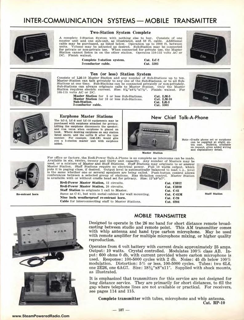
www.SteamPoweredRadio.Com
INTER-COMMUN I CATION SYSTEMS - MOBILE TRANSMITTER
Re-entrant horn
Two-Station System Complete A complete 2-Statlon System with nothing else to buy. Consists of one master unit and one sub-unit, as illustrated, and 50 ft. cable. Additional cable may be purchased, as listed below. Operation up to 2000 ft. between units. Volume may be adjusted as desired. Sub-Station may be connected for private or non-priva te use. When connected for private use, the Master , Station cannot lis t en in on the other station. Operates 110-115 volts AC or DC. Finish walnut.
Complete 2-station system. 3-conductor cable.
Cat. LC-2 Cat. 5303
Ten (or less) Station System Consists of LM-10 Master Station and any number of Sub-Stations up to ten. Master•S'tatlon can talk privately to any one of the Sub-Stations, or to all SubStations at one time. Sub-Stations can be connected privately or non-privately. Sub-Stations can always originate calls to Master Station. Only the Master Station requires e lectric current. S"ize: 8¼"x6¼"x7¾". Finish: walnut. For 105-115 volts AC or DC.
Master Station for 5 or less Sub-Stations. Master Station for 10 or less Sub-Stations. Sub-Station. 3-conductor cable.
Cat. LM-5 Cat. LM-10 Cat. LR-3 Cat. 5303
Earphone Master Stations The LC-2, LC-5 and LC-10 equipments may be purchased with earphone attached for privacy. Lifting the earphone disconnects the speaker; and visa versa when earphone ts placed on hook. Where desiring earphone on any station listed above, add the suffix X after the type number. For example, (LM-SX) would give you a 5-statlon master unit with earphone added.
New Chief Talk-A-Phone
Note-Cradle phone set or earphone can be supplled a t sllght extra cost. Bulletin, available on request, gives added wiring and explanatory detail.
Master Station
For office or factory, the Redi-Power Talk-A-Phone is as comple te as intercoms can be made. Avallable in six, twelve, twenty and thirty unit capacity. Any number of Masters may be used, or a mixture of Master and Staff' Stations. Staff Stations may originate to or answer Master S'tation. S'taff Stations require no electrical power. Full 10 watts output, which puts It In paging class, if desired. Output level is automatically balanced to load; i. e., level is the same whether one or several speakers are being called. Push,button control allows conferences between a selected group of stations. Has 'dictation control. Master Station is available with or without cradle head set for privacy. Size: 12"x9"x7".
Re<li-Power Master Station, 12 circuits. Re dl-Power Master Station, 20 circuits. Staft' Station to originate 1 call to Master. Same as C-41, but with metal cabinet for wall mounting, Nine inch weatherproof re-entrant horn. Cable for interconnecting staff t o Master Stations.
Cat. C5912 Cat. C5920 Cat. C-41 Cat. C-41M Cat. C-20 Cat. 6204
MOBILE TRANSMITTER
7 r
Staff Station
Designed to operate in the 26 me band for short distance remote broadcasting between studio and remote point. This AM transmitter comes with whip antenna and hand type carbon microphone. May be used with remote amplifier for multiple microphone mixing, or higher quality reproduction.
Operates from 6 volt battery with current drain approximately 25 amps. Output: 10 watts. Crystal controlled. Modulates 100% class AB. In~ put: 600 ohms O db, with current provided where carbon microphone is used. Response : 100-5000 cycles with 2 db. Noise: 45 db below 100 % modulation. Distortion: 5 % or less, 100-5000 cycles. Tubes: two 6L6, one 2E26, one 6AG7. Size: 18¾ "x8"xll". Supplied with shock mounts, as illustrated.
It is emphasized that transmitters for this service are not designed for long distance service. They are primarily for short distances, to fill the gap where telephone lines are not available or practical. For receivers, see pages 114 and 115.
Complete transmitter with tubes, microphone and whip antenna. Cat. RP-10
- 187 -
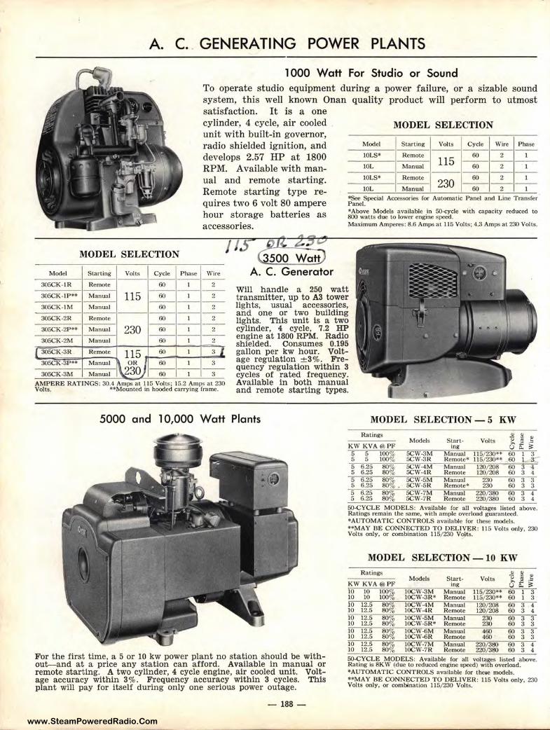
www.SteamPoweredRadio.Com
Model
305CK-lR
305CK-1P**
305CK-1M
305CK-2R
305CK-2P**
305CK-2M
( 305CK-3R
305CK-3P**
305CK-3M
A. C . . GENERATING POWER PLANTS
1000 Watt For Studio or Sound To operate studio equipment during a power failure, or a sizable sound system, this well known Onan quality product will perform to utmost satisfaction. It is a one cylinder, 4 cycle, air cooled unit with built-in governor, radio shielded ignition, and develops 2.57 HP at 1800 RPM. Available with manual and remote starting. Remote starting type requires two 6 volt 80 ampere hour storage batteries as accessories.
MODEL SELECTION
Model Starting Volts Cycle Wire Phase ----l0LS* Remote
115 60 2 l
------ -lOL Manual 60 2 I ----l0LS* Remote
230 60 2 l -------
l0L Manual 60 2 l
*See Special Accessories for Automatic Panel and Line Transfer Panel. *Above Models available in 50-cycle with capacity reduced to 800 watts due to lower engine speed. Maximum Amperes: 8.6 Amps at 115 Volts; 4.3 Amps at 230 Volts.
MODEL SELECTION / IS Gf,P. 2$"'
500 waii) A. C. Generator Starting Volls Cycle Phase Wire
----Remote 60 1 2
- - - - - - -Manual 115 60 1 2
-------Manual 60 1 2 - - - -Remote 60 1 2
--------Manual 230 60 l 2
----- - -Manual 60 1 2
Remote 115 60 1 3 I Manual \ OR)) 60 1 3 Manual v3o -60--1---3-
AMPERE RATINGS: 30.4 Amps at 115 Volts : 15.2 Amps at 230 Volts. ••Mounted in hooded carrying frame.
Will handle a 250 watt transmitter, up to A3 tower lights, usual accessories, and one or two building lights. This unit is a two cylinder, 4 cycle, 7.2 HP engine at 1800 RPM. Radio shielded. Consumes 0.195 gallon per kw hour. Voltage regulation ± 3%. Frequency regulation •within 3 cycles of rated frequency. Available in both manual and remote starting types.
5000 and l 0,000 Watt Plants
For the first time, a 5 or 10 kw power plant no station should be without-and at a price any station can afford. Available in manual or remote starting. A two cylinder, 4 cycle engine, air cooled unit. Voltage accuracy within 3%. Frequency accuracy within 3 cycles. This plant will pay for itself during only one serious power outage.
-188-
MODEL SELECTION - 5 KW Ratings
KW KVA @ PF 5 5 100% 5 5 100% 5 6 .25 80'.11, 5 6.25 80o/o 5 6.25 5 6.25 5 6.25 5 6.25
80% 80%. 80~ 80'10
Models
SCW-3M SCW-3R SCW-4M SCW-4R SCW-5M SCW-5R SCW-7M SCW-7R
Start• ing
Manual Remote• Manual Remote Manual Remote* Manual Remote
Volts
115/ 230** 115/ 230** 120/ 208 120/ 208
230 230
220/ 380 220/ 380
60 I 3 60 I :i::::-60 3 4 60 3 4 60 3 3 60 3 3 60 3 4 60 3 4
50-CYCLE MODELS: Available for all voltages listed above. Ratings remain the same, with ample overload guaranteed. *AUTOMATIC CONTROLS available for these models. **MAY BE CONNECTED TO DELIVER: 115 Volts only, 230 Volts only, or combination 115/ 230 Vo,{s.
MODEL SELECTION - 10 KW
Ratings Models Start- Volts ~ * .t KWKVA @ PF ing Gf :'! 10 10 100% 10CW-3M Manual 115/ 230•• 60 1 3 10 10 100% LOCW-3R* Remote 115/ 230** 60 1 3 10 12.5 80% 10CW-4M Manual 120/ 208 60 3 4 10 12.5 80% IOCW-4R Remote 120/ 208 60 3 4 10 12.5 80% 10CW-5M Manual 230 60 3 3 10 12.5 80% IOCW-5R* Remote 230 60 3 3 10 12.5 80% 10CW-6M Manual 460 60 3 3 10 12.5 80% 10CW-6R Remote 460 60 3 3 10 12.5 80'.11, IOCW-7M Manual 220/ 3&) 60 3 4 10 12.5 80'1o 10CW-7R Remote 220/ 380 60 3 4 50-CYCLE MODELS: Available for all voltages listed above. Rating is 8KW (due to reduced engine speed) with overload. *AUTOMATIC CONTROLS available for the,;e models. ••MAY BE CONNECTED TO DELIVER: 115 Volts only, 230 Volls only, or combination 115/ 230 Volts.
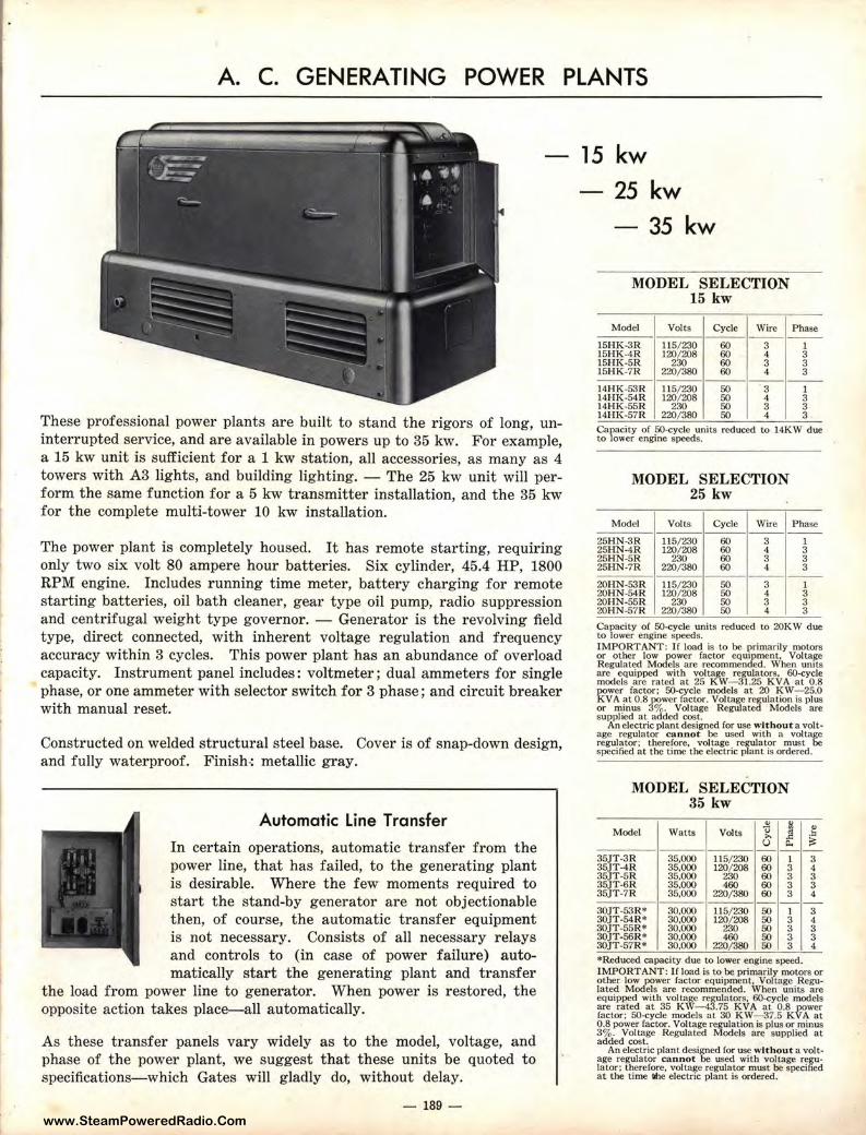
www.SteamPoweredRadio.Com
A. C. GENERATING POWER PLANTS
These professional power plants are built to stand the r igors of long, uninterrupted service, and are available in powers up to 35 kw. For example, a 15 kw unit is sufficient for a 1 kw station, all accessories, as many as 4 towers with A3 lights, and building lighting. - The 25 kw unit will perform the same function for a 5 kw transmitter installation, and the 35 kw for the complete multi-tower 10 kw installation.
The power plant is completely housed. It has remote starting, requiring only two six volt 80 ampere hour batteries. Six cylinder, 45.4 HP, 1800 RPM engine. Includes running time meter, battery charging for remote starting batteries, oil bath cleaner, gear type oil pump, radio suppression and centrifugal weight type governor. - Generator is the revolving field type, direct connected, with inherent voltage regulation and frequency accuracy within 3 cycles. This power plant has an abundance of overload capacity. Instrument panel includes: voltmeter; dual ammeters for single phase, or one ammeter with selector switch for 3 phase; and circuit breaker with manual reset.
Constructed on welded structural steel base. Cover is of snap-down design, and fully waterproof. Finish-: metallic gray.
Automatic Line Transfer
In certain operations, automatic transfer from the power line, t hat has failed, to the generating plant is desirable. Where the few moments required to start the stand-by generator are not objectionable then, of course, the automatic transfer equipment is not necessary. Consists of all necessary relays and controls to (in case of power failure) automatically start the generating plant and transfer
the load from power line to generator. When power is restored, the opposite action takes place-all automatically.
As these transfer panels vary widely as to the model, voltage, and phase of the power plant, we suggest that these units be quoted to specifications-which Gates will gladly do, without delay.
- 189 -
15 kw 25 kw - 35 kw
MODEL SELECTION 15 kw
Model Volts Cycle Wire Phase
15HK-3R 115/ 230 60 3 l 15HK-4R 120/ 208 60 4 3 15HK-5R 230 60 3 3 15HK-7R 220/ 380 60 4 3
----14HK-53R 115/230 50 3 1 l4HK-54R 120/ 208 50 4 3 14HK-55R 230 50 3 3 l4HK-57R 220/ 380 50 4 3
Capacity of 50-cycle units reduced to 14KW due to lower engine speeds.
MODEL SELECTION 25 kw
Model Volts Cycle Wire Phase
25HN-3R 115/230 60 3 1 25HN-4R 120/ 208 60 4 3 25HN-5R 230 60 3 3 25HN-7R 220/380 60 4 3
----20HN-53R 115/ 230 50 3 l 20HN-54R 120/ 208 50 4 3 20HN-55R 230 50 3 3 20HN-57R 220/ 380 50 4 3 Capacity of 50-cycle units reduced Lo 20KW due to lower engine speeds. IMPORTANT: If load is to be primarily motors or other low power factor equipment, Voltajie Regulated Models are recommended. When umts
~~.:ft!P,~at:iit~t 2i1~~1\'"istoi'v A60a"fY<f~
power factor: 50-cycle models at 20 K W- 25.0 KVA at 0.8 p0wer factor. Voltage regulation is plus or minus 3%. Voltage Regulated Models are supplied at added cost.
An electric plant designed for use without a voltage regulator cannot be used with a voltage regulator: therefore, voltage regulator must be specified at the time the electric plant is ordered.
MODEL SELECTION 35 kw
., it Model Watts Volts <) .,
>, .e u ll.
35JT-3R 35,000 115/ 230 60 1 35JT-4R 35,000 120/ 208 60 3 35JT-5R 35,000 230 60 3 35JT-6R 35,000 460 60 3 35JT-7R 35,000 220/380 60 3
30JT-53R* 30,000 115/230 50 1 30JT -54R* 30,000 120/208 50 3 30JT-55R* 30,000 230 50 3 30JT-56R* 30,000 460 50 3 30JT-57R* 30,000 220/380 50 3
., ·= Si: -3 4 3 3 4
-3 4 3 3 4
*Reduced capacity due to lower engine speed. IMPORTANT: If load is to be primarily motors or other low power factor equipment, Voltage Regulated Models are recommended. When units are equipped with voltage regulators, 60-cycle models are rated at 35 KW-43.75 KVA al 0.8 power factor; SO-cycle models at 30 KW-37.5 KVA at 0.8 power factor_ Voltage regulation is plus or minus 3% . Voltage Regulated Models are supplied at added cost.
An electric plant designed for use without a volt• age regulator can not be used with voltage regulator: therefore, voltage regulator must be specified at the time lihe electric plant is ordered.
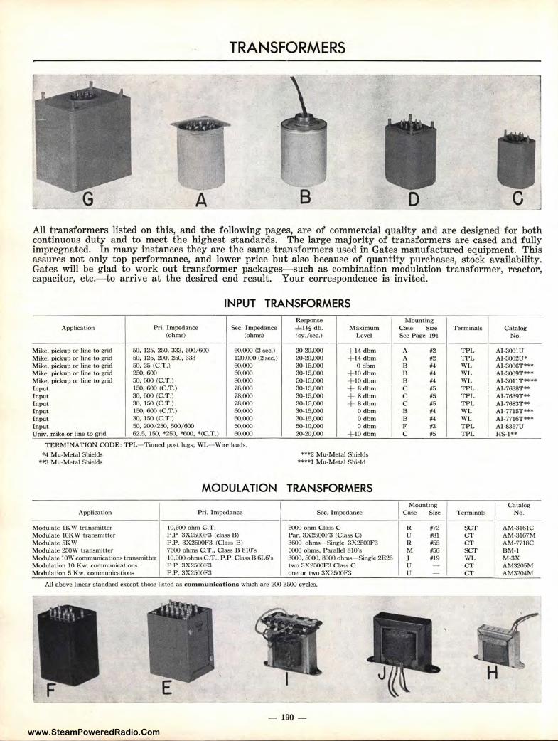
www.SteamPoweredRadio.Com
TRANSFORMERS
A 8 D C All transformers listed on this, and the following pages, are of commercial quality and are designed for both continuous duty and to meet the highest standards. The large majority of transformer s are cased and fully impregnated. In many instances they are the same transformers used in Gates manufactured equipment. This assures not only top performance, and lower price but also because of quantity purchases, stock availability. Gates will be glad to work out transformer packages-such as combination modulation transformer, reactor , capacitor, etc.-to arrive at the desired end result. Your correspondence is invited.
INPUT TRANSFORMERS
Application Pri. Impedance Sec. Impedance (ohms) (ohms)
Mike, pickup or line to grid so. 125, 250, 333, 500/ 600 60,000 (2 sec.) M ike, pickup or line to grid 50, 125.200, 250,333 120,000 (2 sec.) Mike, pickup or line to grid 50, 25 (C.T.) 60,000 Mike, pickup or line to grid 250,600 60.000 Mike, pickup or line to grid 50, 600 (C.T .) 80,000 Input 150, 600 (C.T .) 78,000 Input 30, 600 (C .T.) 78,000 Input 30, 150 (C.T .) 78,000 Input 150, 600 (C.T.) 60,000 Input 30, 150 (C.T.) 60,000 Input so. 200/250. 500/ 600 50,000 Univ. mike or line to grid 62.5, 150, •250, '"600. *(C.T .) 60.000
TERMINATION CODE: TPL- Tinned post lugs; WL-Wire leads.
*4 Mu-Metal Shields *'"3 Mu-Metal Shields
MODULATION
Application Pri. Impedance
Modulate !KW transmitter 10,500 ohm C.T. Modulate IOKW transmitter P .P 3X2500F3 (class B) Modulate 5KW P .P. 3X2500F3 (Class B) Modulate 250W transmitter 7500 ohms C.T., Class B 810's Modulate IOW communications transmitter 10,000 ohms C.T., P .P. Class B 6L6's Modulation 10 Kw. communications P.P. 3X2500F3 Modulation 5 Kw. communicat.ions P .P . 3X2500F3
Response ~ l½db. Maximum (cy_/sec.) Level
20-20,000 + 14 dbm 20-20,000 + 14dbm 30-15,000 0dbm 30-15,000 + IOdbm 50-15,000 + 10 dbm 30-15,000 + 8dbm 30-15,000 + 8dbm 30-15,000 + 8dbm 30-15,000 0dbm 30-15,000 0dbm 50-10,000 0dbm 20-20.000 + 10dbm
**"2 Mu-Metal Shields ••••t Mu-Metal Shield
TRANSFORMERS
Sec. Impedance
5000 ohm Class C Par. 3X2500F3 (Class C) 3600 ohms- Single 3X2500F3 5000 ohms. Parallel 810's 3000, 5000, 8000 ohms-Single 2E26 two 3X2500F3 Class C one or two 3X2500F3
All above linear standard except those listed as communications which are 200-3500 cycles.
- 190 -
Mounting Case Size Terminals Catalog See Page 191 No.
A #2 TPL AI-3001U A #2 TPL AI-3002U* B #4 WL Al-3006T•** B #4 WL AI-3009T*** B #4 WL Al-3011T**'* C #5 TPL Al-7638T** C #5 T PL AI-7639T** C #5 T PL Al-768.1T•• B #4 WL Al-7715T••• B #4 WL Al-7716T••• F #3 T P L AI-8357U C #5 TPL HS-I**
I Mounting Catalog Case Size Terminals No.
R #72 SCT AM-3161C u #81 CT AM-3167M R #55 CT AM-7718C M #56 SCT BM-1 J #19 WL M-3X u CT AM3205M u CT AM3204M
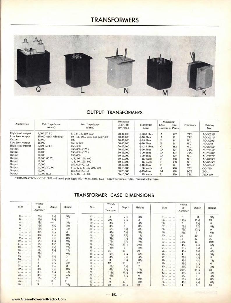
www.SteamPoweredRadio.Com
TRANSFORMERS
N
OUTPUT TRANSFORMERS
Response Mounting Application Pri. Impedance Sec. Impedance ='=I½ db. Maximum Case Size Terminals Catalog
(ohms) (ohms) (cy./sec.) Level (Bottom of Page) No.
High level output 7,000 (C.T.) 5, 7.5, 15, 250, 500 30-15,000 ,-40.8 dbm A #22 TPL AO-3033U Low level output 15,000 (split winding) 50,125,200,250.333, 500/600 30-15,000 + 10 dbm A #2 TPL AO-3037U Output 12,000 600 30-15,000 + 25dbm B #4 WL AO-3039T Low level output 15,000 250 or 600 30-15,000 + JOdbm B #4 WL AO-3040 High level output 5,500 (C.T.) 250/600 30-15,000 ,-42.5 dbm. G #82 WL AO-3045T Output 12,000 250/600 (C.T.) 50-15,000 + 20ctbm D #27 TPL AO-7244T Output 12,000 150/600 (C.T.) 50-15,000 + 20dbm D #27 TPL AO-7640T Output 12,000 150/600 50-15,000 +20 dbm D #27 WL AO,7717T Output 12,000 (C.T.) 4, 8, 16, 150, 600 50-10,000 15 watts N #83 WL AO-8459C Output 12,000 4, 8, 16, 150, 600 50-10,000 15 watts N #83 WL AO-8549C Output 15,000 150/600 (C.T.) 30-15,000 +JO dbm B #4 WL AO-8554T Output 14,000/ 20.000 l½, 3, 5, 8, 16, 200, 500 40-10,000 20 watts A #26 TPL CG-710 Output 15,000 150/600 (C.T.) 30-20,000 + 15dbm M #28 SCT BO-1 Output J0.000 (C.T.) 4. 8, 16, 150, 600 50-10.000 15 watts L #29 TSL PSO-150
TERMINATION CODE: TPL-Tinned post Jugs; WL-Wire leads; SCT-Screw terminals; TSL--Tinned solder lugs.
TRANSFORMER CASE DIMENSIONS
Width Width Width Size or Depth Height Size or Depth Height Size or Depth Height
Diameter Diameter Diameter
2 ...... .. 2½ 2½ 3¼ 27 .. . .. . .. 2 2¼ 2¾ 64 ... .. . . . 7 8 9¼ 3 ...... .. l½ l½ 2 28 .. ... ... 21/, 2½ 3 65 . .. . . . .. 11½ 11½ 13 4 ........ I¾ - 3¼ 29. .. .. ... 3¼ 4 4¼ 66 .... .. .. 7 7½ 8 5 .. ... ... l½ I¾ 2½ 30 .. . . .... 3¼ 4 3¼ 67. ·· · •·· · 7¾ 7¼ 8½ 6 ..... ... l½ 2½ l½ 31 ........ 51/, 5¼ 6¼ 68 .....•. . 7¼ 10½ 9 7 .... . ... 2½ 3½ 3 33 ... .. . .. 4½ 5¼ 5¼ 69. ...... . 5¼ 6 6½ 8 .. . .. ... 2¼ 3¼ 2¾ 34 .. . ·· • · l½ 2¼ l¾ 70. .... .. , 21 29 43 9 .... . · •· 2¾ 3¾ 3¼ 35 . . . .. .. . 3½ 4½ 5¼ 71 . , ..... . 15 27 36
10 ........ l ¾ I¾ 2¼ 36 .. ...... 7¼ 7¼ 8¼ 72 . ' . . ' . . . 11¼ 16 10½ 11 . ... .... l¾ I¾ 2½ 38 .. . ·• •· · 23¼ 23¼ 291/, 73. ·· · · •· · 4¼ 5¼ 5¾ 12 ..... 2¼ 2¼ 2¼ 39 ........ 8½ 9 8¼ 74. , ...... 2¼ 3½ 4 13 ...... .. I¼ I½ 21/, 40 .. . .. . .. 21 23 30 75 ........ 4½ 5½ 4¼ 14 .... ... . 5% 6 6¼ 45 . . ... • . . 5¼ 5¼ 5½ 76. · •·•· 4 4½ 5½ 15 ........ 2¼ 2¾ 3 46 ...... .. 3¾ 3¾ 4½ 77 ........ 3¾ 4½ 5 16 .... .. .. 2 21/, 3 50 .... . . .. 3 3¼ 3½ 78 .... ... , 4¼ 41/, 7½ 17 .. . .. ... 2 2¾ 3½ 55 .... .. .. 22 30 32 79 .... . .. . 3¾ 4½ 6 18 ....... . 2 3¼ 2 56 ........ 5¼ 6¼ 7 80 . .. . •· · · 2½ 3¾ 3¼ 19 ........ 2¼ 3¾ 2¼ 57 . .. .. . .. 6¼ 7½ 7¼ 81. .... . ... 21½ 34½ 52 21. ···· ··· 3¼ 4½ 4¾ 59 ... ... .. 11½ 11½ 10½ 82. · • · · · 3½ 3¾ 4½ 22 ... ·· • · 31/, 3¾ 4¼ 60 ... ' . ~ . 4½ 5¼ 6 83 ... . ··• · 3¾ 4 4¼ 24 ....... . 11/, 3¼ 2 61. . .... .. 6 7 9½ 84 ....... . 2½ 2½ 3¾ 25 .... . ..
1
11 12 11 62 ... . · • ·. 9 10 8½ 85. ., ... 4¼ 4½ 6½ 26 .. ...... 3 3 3¾ 63 ........ 28 35½ 42 86 ........ 14 8 18
- 191 -
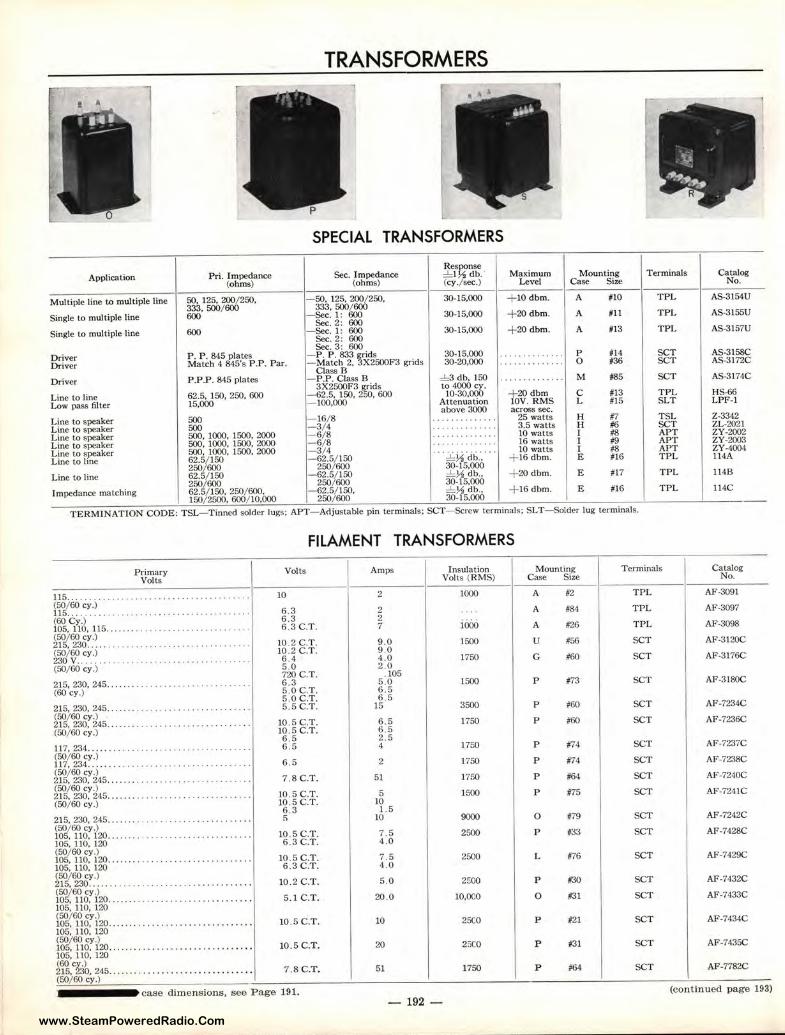
www.SteamPoweredRadio.Com
TRANSFORMERS
SPECIAL TRANSFORMERS
Res9.:nse Application Pri. Impedance Sec. Impedance :!::I db. Maximum Mounting Terminals
(ohms) (ohms) (cy. sec.) Level Case Size
Multiple line to multiple line 50, 125, 200/250, - 50. 125. 200/250, 30-15,000 + 10dbm. A #10 TPL 333, 500/ 600 333. 500/ 600
Single to multiple line 600 - Sec. 1: 600 30-15,000 + 20dbm. A #11 TPL Sec. 2: 600
Single to multiple line 600 - Sec. 1: 600 30-15,000 + 20dbm. A #13 TPL Sec. 2: 600 Sec. 3: 600
- P. P. 833 grids 30-15,000 - . . . . . . . . . . . . p #14 SCT Driver P. P . 845 plates Driver Match 4 845's P.P. Par. - Match 2, 3X2500F3 grids 30-20,000 . ......... .... 0 #36 SCT
Class B Driver P.P.P. 845 plates - P.P. Clas.s B :!::3 db, 150 . . . . . ' . . . . ... M #85 SCT
3X2500F3 grids to 4000 cy.
Line to line 62.5, 150, 250, 600 - 62.5, 150, 250, 600 10-30.000 + 20dbm C #13 TPL
Low pass fitter 15,000 - 100,000 Attenuation J0V. RMS L #15 SLT above 3000 across sec.
Line to speaker 500 - 16/ 8 .. ..... .. ... .. 25 watts H #7 TSL
Line to speaker 500 - 3/ 4 . ' . . . . . . . .. · · • 3.5 watts H #6 SCT
Line to speaker 500, 1000, 1500. 2000 -6/8 . . . . . . . ' . . . . . . 10 watts I #8 APT
Line to speaker 500, 1000, 1500, 2000 -6/8 ........ . . . ' . . 16 watts I #9 APT
Line to speaker 500, 1000. 1500, 2000 - 3/ 4 .. :!::½ .cib.·. ···
10 watts I 18 APT
Line to line 62.5/ 150 -62.5/ 150 + 16 dbm. E #16 TPL 250/ 600 250/ 600 30-15,000
Line to line 62.5/ 150 - 62.5/ 150 :!::½ db., + 20dbm. E #17 TPL 250/600 250/600 30-15,000
Impedance matching 62.5/150, 250/600, - 62.5/ 150, :!::½db., + 16dbm. E #16 TPL 150/ 2500. 600/ 10,000 250/ 600 30-15.000
TERMINATION CODE: TSL-Tinned solder lugs: APT- Adjustable pin terminals; SCT-Screw terminals: SLT- Solder lug terminals.
Primary Volts
115.. ........ ... . ... ...... . •. .. , ......•.• (50/ 60 cy.) 115 ... .. ..... · ·· • ···········-'········· · · · (60 Cy.) 105, llO, 115 ..... . . .......... , .. . , . . .. .. . .. . (50/60 cy.) 215, 230 ... .. . ............. ............. .. . (50/60 cy.) 230V ......... ...................... _ . .. .. . (50/60 cy.)
215, 230, 245 ... . ... . , , ........ . • .. . ... . •. . . (60 cy.)
215, 230, 245 . . ..... ..•.... ... ...•...•.• . .. • . (50/60 cy.) 215, 230, 245 . ..... ... ... , . . .•...•.•.• . . ... . . (50/ 60 cy.)
117, 234 ..... · ··• . . . ... ··· --·•- • ·· .... .... . (50/60 cy.) 117, 234 ... .. .. . . .. . ..........•. , .•... . ..... (50/60 cy.) 215, 230, 245 .. .... • . ......• , •...•.... . .....•
~r✓-~w:J45 .......... .. ...... ..... ........ . (50/60 cy.)
215, 230, 245 ..... .. .. ... .... . ........ . ..... . (50/60 Cy.) 105, 110, 120....... .. .......... . .. ..... . . . . 105. I 10, 120 (50/60 cy.) 105, 110, 120 .. . .... ... . . ... . .. .. .......... .. 105, 110, 120
~r/.64W.-~ . . . .. _ ... , .... ... ...... ... ..... . 1~ttWr20 ............ .... ..... ..... .... . . 105, l 10, 120 (50/60 cy.) 105, 110, 120 ...... . ... . ... . ... . ... ......... . 105, 110, 120
11>°/.6:18:120 ... .. .. ................... ..... . 105, 110, 120
~tt~:ib. 245 ........ ... .. ... ............... . (50/ 60 cy.)
FILAMENT TRANSFORMERS
Volts
10
6 .3 6.3 6.3 C.T.
10.2 C.T. 10 .2 C.T. 6.4 5 .0 720 C.T. 6.3 5.0C.T. 5.0C.T. 5.SC.T.
10.SC.T. 10.5 C.T. 6 .5 6.5
6.5
7.8C.T.
10.5 C.T . 10 .5 C.T. 6.3 !)
10.5 C.T. 6 .3C_T.
10 .5 C.T. 6.3 C.T.
10.2 C.T.
5.1 C.T.
10.5 C.T.
10.5 C.T.
7.BC.T.
Amps
2
2 2 7
9.0 9.0 4 .0 2 .0
. 105 5 .0 6 .5 6 .5
15
6 . 5 6 .5 2 .5 4
2
51
5 JO 1.5
10
7.5 4.0
7.5 4 .0
5 .0
20.0
10
20 51
Insulation Volts (RMS)
1000
iooo 1500
1750
1500
3500
1750
1750
] 750
1750
1500
9000
2500
2500
2SOO
10,000
25CO
1750
Mounting Case Size
A
A
A
u G
p
p
p
p
p
p
p
0
p
L
p
0
p
p
p
#2
184
#26
#56
#60
#73
#60
#60
#74
#74
#64
#75
#79
#33
#76
#30
#31
#21
#31
#64
Terminals
TPL
TPL
TPL
SCT
SCT
SCT
SCT
SCT
SCT
SCT
SCT
SCT
SCT
SCT
SCT
SCT
SCT
SCT
SCT
SCT
Catalog No.
AS-3154U
AS-3155U
AS-3157U
AS-3158C AS-3172C
AS-3174C
HS-66 LPF-1
2 -3342 ZL-2021 ZY-2002 ZY-2003 ZY-4004 114A
114B
114C
Catalog No.
AF-3091
AF-3097
AF-3098
AF-3120C
AF--3176C
AF-3180C
AF-7234C
AF-7236C
AF-7237C
AF-7238C
AF-7240C
AF-7241C
AF-7242C
AF-7428C
AF-7429C
AF-7432C
AF-7433C
AF-7434C
AF-7435C
AF-7782C
case dimensions, see Page 191. (continued page 193) -192 -
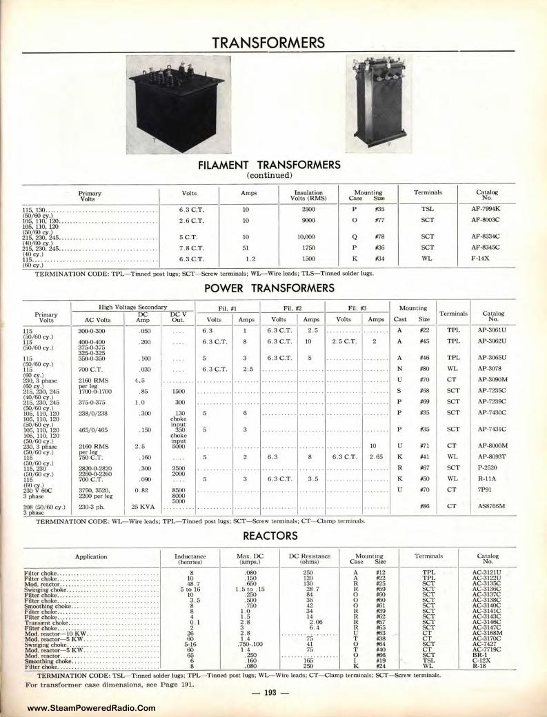
www.SteamPoweredRadio.Com
TRANSFORMERS
1
FILAMENT TRANSFORMERS (continued)
Primary Volts Ami'$ Insulation Mounting Terminals Catalog Volts Volts (RMS) Case Size No.
ll5, 130 ...... . .. ...... . . . . . . . . . . . . . . . . 6 .3 C.T. 10 2500 p #35 TSL AF-7994K (50/60 cy.) . 105, 110, 120 ........ .. .. ..... .. . . . . . . . . . . . .. 2 .6C.T. 10 9000 0 #77 SCT AF-8003C 105,110.120
~lf/~:i45 ........ ..... ...... .. ... . .... · • · 5C.T. 10 10,000 Q #78 SCT AF-8334C (40/60 cy.)
7.8C.T. 51 1750 p 136 SCT AF-8345C 215, 230. 245 ....... .... .. .... . .. . . .... . .. . .. (40 cy.) 115 .... . . ... . . ········· · ·· ··· . ... . .... . .. 6 .3C.T. 1.2 1500 K #34 WL F-14X (60 cy.)
TERMINATION CODE: TPL- Tinned post lugs; SCT- Screw terminals; WL-Wire leads; T LS-Tinned solder lugs.
POWER TRANSFORMERS
High Voltage Secondary Fil. #1 Fil. #2 Fil. #3 Mounting Primary DC DCV T erminals Catalog
Volts AC Volts Amp Out. Volts Amps Volts Amps Volts Amps Cast Size No.
115 300-0-300 .050 .... 6.3 1 6 .3 C.T . 2 .5 ... ... , .. , . ... , ... A #22 TPL AP-3061U (50/60 cy.) 115 400-0-400 .200 .... 6.3C.T. 8 6 .3 C.T. 10 2 .5C.T . 2 A #45 TPL AP-3062U (50/60 cy.) 375-0-375
325-0-325 115 350-0-350 . 100
I • · • · 5 3 6.3C.T. 5 .. ......... ···· ··· · A #46 TPL AP-3065U
(50/ 60 Cy.) 700 C.T . 6.3 C.T . N #80 WL AP-3078 ll5 .030 ·• · · 2.5 .. ......... ······ ··
<60 T) 230, phase 2160 RMS 4.5 . . . .. .. .. .. ,., .. ... .... . ·· •··· .., . . ........ . ... ... .... ······ u #70 CT AP-3090M
~Ettlih.245 per leg
SCT 1700-0-1700 .85 1500 . . . . . . . ' . . . .... · • · .. ·· • · · · · • . ....... · ·········· .... .. s #58 AP-7235C (40/60 cy.) 215, 230, 245 375-0-375 1.0 300 .. ...... ... . .. . . . . . . . .. . ... ... ... ····· .... ······· . ..... .. p #69 SCT AP-7239C (50/60 cy.)
238/0/ 238 6 #35 SCT AP-7430C 105, 110, 120 .300 130 5 .... .. ..... •·• ·•• · · • · .. ······· . . ... ... p 105, 110, 120 choke (50/ 60 cy.) input
#35 SCT 105, 110, 120 465/ 0/465 . 150 350 5 3 . . . . . . . . . . . ...... .. .... . .. .... · ··· · •· p AP-743!C 105, 110, 120 choke ~60cy.)
2160 RMS 2 .5 i~t 10 u #71 CT AP-8000M , 3 phase · · ·• · ...... ...... , .... .... .. . .. . .. . .. . , . .. .. .
(50/60 cy .) per leg II 750 C.T. . 160 .. , . 5 2 6 3 8 6 .3C.T. 2.65 K #41 WL AP-8093T (50/ 60 Cy.)
2820-0-2820 .300 R #67 SCT P-2520 115,230 2500 , .. , ...... ... .. . . .. . . .. . · ••· .. ... ... ·•··· · ..... . . . .. , .. (50/ 60 cy.) 2260-0-2260 2000 115 700 C.T. .090 ... 5 3 6 .3C.T. 3 .5 .. . ... ··· ·· ·· ···· · K 150 WL R-I IA
(60 v-> 230 60C 3750, 3520, 0.82 8500 . ' . . ' . . ' ... .. . ... . . . . .. . .. . .. ... .. .. ... , .. , . .. ..... u #70 CT 7P91 3 phase 2200 per leg 8000
5000 208 (50/ 60 cy .) 230-3 ph.
I 25 KVA . . ..... . . ' . . . . . . . . . ... .. . , . .... .. . , ... . ... . , . ... . . . .. .. #86 CT AS8766M
3 phase TERMINATION CODE: WL-Wire leads; TPL- Tinned post lugs; SCT- Screw terminals; CT- Clamp terminals.
REACTORS
Application Inductance Max. DC DC Resistance Mounting Terminals Catalog (henries) (amps.) (ohms) Case Size No.
Filter choke .... . ...... . .. .. ................ . Filter choke .... . .... • ....... . ... . ... . ... , . . . Mod. reactor . ....... . ... ...... , . •. .. ... .. .. Swinging choke ........ • . • . • .. . .. , .... ...... . Filter choke ... . .... .. .. . • ....... , .. .. .. . . .. . Filter choke . . .. . . . . ..... •. ..... . . . ... . . . • .. . Smoothing choke... . . .. • ...•. • . • . • .... . •. .. Filter choke . .. ..... . Filter choke.. ..... . . . ......... . Transient choke ...... .. . ... . ... . Filter choke . ........ ............. . . Mod. reactor- JO KW .. .. . Mod. reactor-5 KW . . . ........... . Swinging choke ........ ............ . Mod. reactor-5 KW . .. . .. . ... • .... Mod. reactor ........ ... ... . ... . ... .
~\i':rt~i;:,t;.~~~:: : : : : : : : : : : : : : : : : :
8 .080 250 A 112 TPL AC-3!21U 10 . 150 120 A #22 TPL AC-3122U 48.7 .650 130 R #25 SCT AC-3 l35C
5 to 16 l .5to . l5 28.7 R #59 SCT AC-3!36C 10 .250 81 0 #60 SCT AC-3 l37C 3 . 5 . 500 36 0 #60 SCT AC-3138C 8 .750 42 0 #61 SCT AC-3140C 8 1.0 34 R #39 SCT AC-3141C 4 1.5 14 R #62 SCT AC-3l43C 0 .1 2 .8 2.06 R #57 SCT AC-3!46C 2 3 6,4 R 165 SCT AC-3147C
26 2 .8 u 163 CT AC-3168M 60 1.4 75 T #38 CT AC-3170C
5-16 .750-.100 41 0 164 SCT AC-7427 60 1.4 75 T 140 CT AC-7719C 65 . 250 iss· 0 166 SCT BR-I 6 . 160 I 119 TSL C-12X 8 .080 250 K #24 WL R-18
TERMINATION CODE: TSL-Tinned solder lugs; TPL- Tinned post lugs; WL- Wire leads; CT- Clamp terminals; SCT- Screw terminals.
For transformer case dimensions, see Pa.ge 191. - 193 -
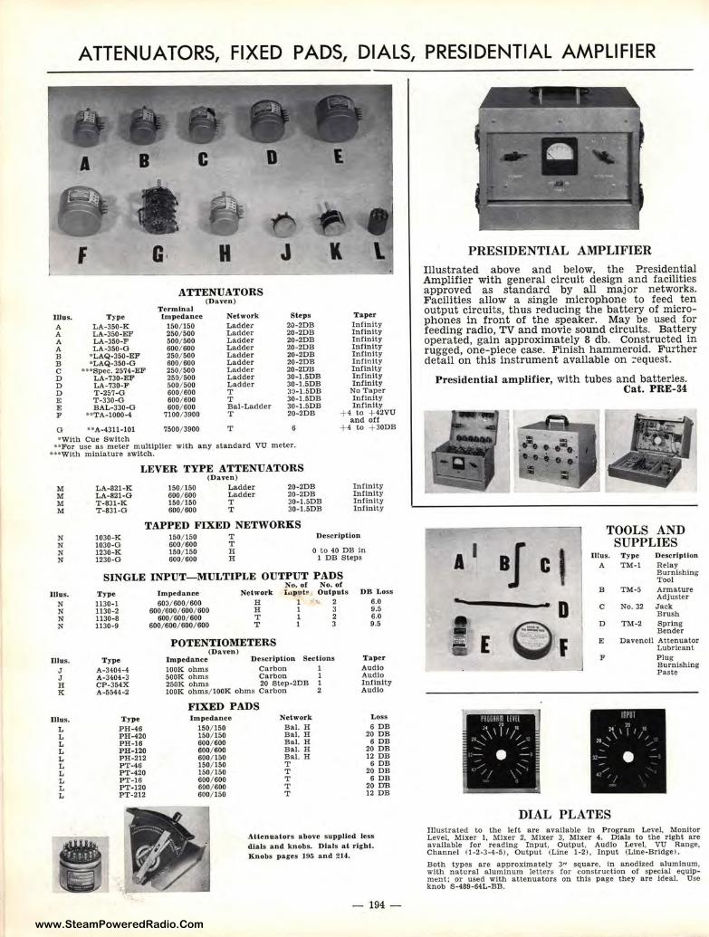
www.SteamPoweredRadio.Com
ATTENUATORS, FIXED PADS, DIALS, PRESIDENTIAL AMPLIFIER
Illus. A A A A B B C D D D E E F
Type LA-350-K LA-350-EF LA-350-F LA-350-O
•LAQ-350-EF •LAQ-350-0
... Spec. 2574-EF LA-730-EF LA-730-F T-257-O T -330-G BAL-330-O
U TA-1000-4
ATTENUATORS Terminal Impedan ce
150/ 150 250/ 500 500/ 500 600/ 600 250/ 500 600/ 600 250/ 500 250/ 500 500/ 500 600/ 600 600/ 600 600/ 600
7100/ 3900
(Daven)
Network Ladder Ladder Ladder Ladder Ladder Ladder Ladder Ladder Ladder T T Bal-Ladder T
Step s 20-2DB 20-2DB 20-2DB 20-2DB 20-2DB 20-2DB 20-2DB 30- l.5DB 30-l.5DB 30-1.5DB 30-1.5DB 30-1.5DB 20-2DB
Taper Infinity Infinity Infinity Inlinity Infinity Infinity Infinity Infinity Infinity
No Taper Infinity Infinity
+ 4 to + 42VU and ott
G .. A-4311-101 7500/ 3900 T 6 + 4 to + 30DB
• With Cue Switch ••For use as meter multiplier with any standard VU meter.
•uw1th miniature switch.
M M M M
N N N N
lllus. N N N N
Illus. J J H K
Illus. L L L L L L L L L L
LEVER TYPE ATTENUATORS (Daven)
LA-821 -K 150/ 150 Ladder 20-2DB Infinity LA-821-O 600/ 600 Ladder 20-2DB Infinity T -831-K 150/ 150 T 30-1.5DB Infinity T-831-O 600/ 600 T 30- l.5DB Infinity
TAPPED FIXED NETWORKS 1030-K 150/ 150 T Description 1030-0 600/ 600 T 1230-K 150/ 150 H 0 to 40 DB In 1230-0 600/ 600 H l DB Steps
SINGLE INPUT-MULTIPLE OUTPUT PADS
T ype 1130-1 1130-2 1130-8 1130-9
Type A-3404-4 A-3404-3 CP-354X A-5544-2
Type PH-46 PH-420 PH-16 PH-120 PH-212 PT·46 PT-420 PT-16 PT-120 PT-212
No. of No. of Impedance Network l lllput , Outpu ts DB L oss
60l/ 600/ 600 H I ... 2 6.0 600/ 600/ 600/ 600 H I 3 9.5
600/ 600/ 600 T l 2 6.0 600/ 600/ 600/ 600 T l 3 9,5
POTENTIOMETERS (Daven)
Impedance Description Sections Taper
l00K ohms Carbon l Audio SOOK ohms Carbon l Audio 250K ohms 20 Step-2DB l Infinity I00K ohms/ l00K ohms carbon 2 Audio
FIXED PADS Impedance Network Loss
150/ 150 Bal. H 6 DB 150/ 150 Bal. H 20 DB 600/ 600 Bal. H 6 DB 600/ 600 Bal. H 20 DB 600/ 150 Bal. H 12 DB 150/ 150 T 6 DB 150/ 150 T 20 DB 600/ 600 T 6 DB 600/ 600 T 20 DB 600/ 150 T 12 DB
At tenuators above supplied less dials and knobs. Dials at right. Knobs p ages 195 and 2U.
- 194 -
PRESIDENTIAL AMPLIFIER Illustrated above and below, the Presidential Amplifier with general circuit design and facilities approved as standard by all major networks. Facilities allow a single microphone to feed ten output circuits, thus reducing the battery of microphones in front of the speaker. May be used for feeding radio, TV and movie sound circuits. Battery operated, gain approximately 8 db. Constructed in rugged, one-piece case. Finish hammeroid. Further detail on this instrument available on :equest.
Presidential amplifier, with tubes and batteries. Cat. PRE-34
A I
I -E
aJ C' D
O F ----~.!
TOOLS AND SUPPLIES
Illus. T ype Description A TM-I Relay
Burnishing Tool
B TM-5 Armature Adjuster
C No. 32 Jack Brush
D TM-2 Spring Bender
E Davenoil Attenuator Lubricant
F Plug Burnishing Paste
DIAL PLATES Illust rated to the left are available In Program Level, Monitor Level, Mixer 1, Mixer 2, Mixer 3, Mixer 4. Dials to the right are available for reading Input, Output. Audio Level, VU Range, Channel (1-2-3-4-5). Output (Line 1-2), Input (Line-Bridge) .
Both types are approximately 3" square, in anodized aluminum, with natural aluminum letters for construction of special eQulpment; or used with attenuators on this page they are Ideal. Use knob S-489-64L-BB.
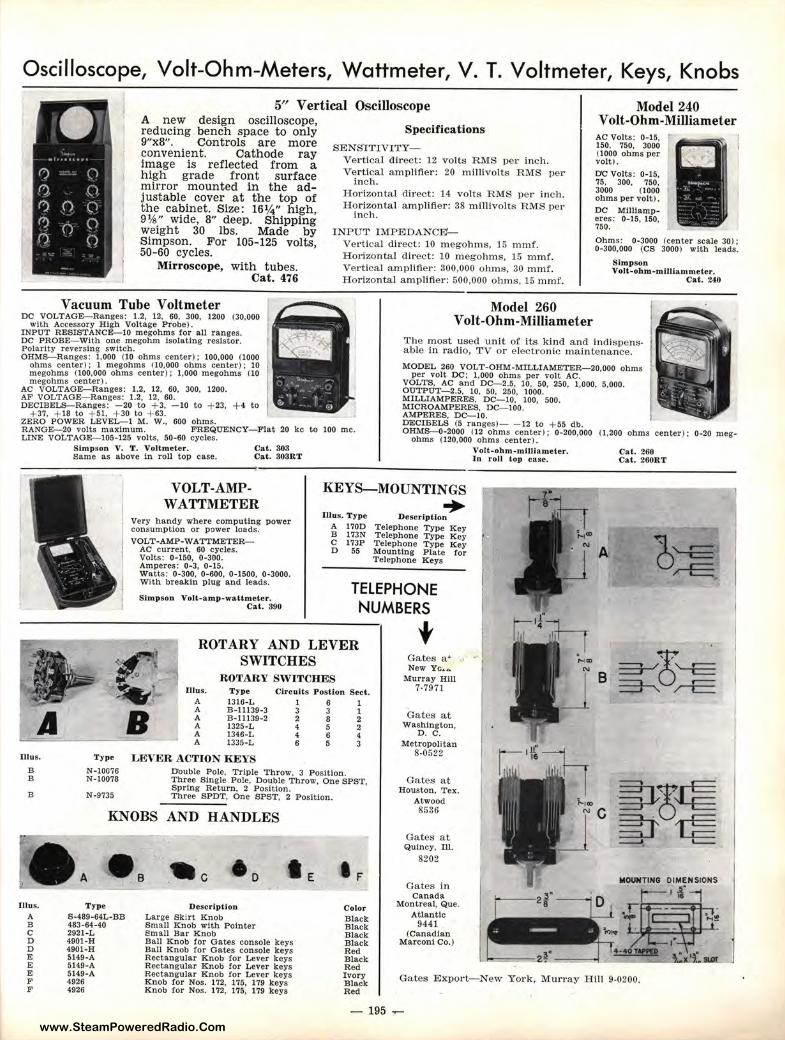
www.SteamPoweredRadio.Com
Oscilloscope, Volt-Ohm-Meters, Wattmeter, V . T. Voltmeter, Keys, Knobs
• 5" Vertical Oscilloscope
()
{), ()
f')
()
(")
()
0 ()
0 ()
0
A new design oscilloscope, reducing bench space to only 9"x8", Controls are more convenient. Cathode ray image is reflected from a high grade front surface mirror mounted in the adjustable cover at the top of the cabinet. Size: 16¼" high, 9¼" wide, 8" deep. Shipping weight 30 lbs. Made by Simpson. For 105- 125 volts, 50-60 cycles.
Mirroscope, with tubes. Cat. 476
Vacuum Tube Voltmeter DC VOLTAGE-Ranges: 1.2, 12, 60, 300, 1200 (30,000
with Accessory High Voltage Probe).
Specifications
SENSlTIVITY-Vertical direct: 12 volts RMS per inch. Vertical amplifier: 20 millivolts RMS per
inch. Horizontal direct: 14 volts ]RMS per inch. Horizontal amplifier: 38 millivolts RMS per
inch.
INPUT IMPEDANCE'-Vert ical d irect: 10 megohms, 15 mmL Hot·izontal direct: 10 megohms, 15 mmf. Ve1·tical amplifier: 300,000 ohms, 30 mmf. Horizontal amplifier: 500,000 ohms, 15 mmf.
Model 260 Volt-Ohm-Milliameter
Model 240 Volt-Ohm -Milliameter
AC Volts: 0-15. ,. 150, 750. 3000 0000 ohms per volt).
DC Volts: 0-15, 75. 300, 750, 3000 (1000 ohms per volt).
DC Milliamperes: 0-15, 150, 750.
Ohms: 0-3000 (center scale 30): 0•300,000 (CS 3000) with leads.
Slmpson Volt-ohm-mlltlammeter.
Cat. 240
INPUT RESISTANCE-10 megohms for all ranges. DC PROBE-With one megohm isolating resistor. Polarity reversing switch. OHMS-Ranges: 1,000 (10 ohms center); 100,000 (1000
ohms center) : I megohms (10,000 ohms center); 10 megohms (100.000 ohms center): 1,000 megohms 00 megohms center).
The most used unit of its kind and indispensable in radio, TV or electronic maintenance.
AC VOLTAGE-Ranges: 1.2, 12, 60, 300, 1200. AF VOLTAGE-Ranges: 1.2, 12, 60. DECIBELS-Ranges: - 20 to + 3, - 10 to + 23, + 4 to
+ 37, + 18 to + 51, +30 to + 63. ZERO POWER LEVEL-I M. W., 600 ohms. RANGE-20 volts maximum. FREQUENCY- Flat 20 kc to 100 me. LINE VOLTAGE-105-125 volts, 50-60 cycles.
Simpson V. T. Voltmeter. Same as above In roll top case.
Cat. 303 Cat. 303RT
MODEL 260 VOLT-OHM-MILLIAMETER-20,000 ohms per volt DC; 1,000 ohms per volt AC.
VOLTS, AC and DC- 2.5, 10, 50, 250, 1,000, 5,000. OUTPUT-2.5, 10, f;O, 250, 1000. MILLIAMPERES, D•C- 10, 100, 500. MICROAMPERES, DC- 100. AMPERES, DC- 10. DECIBELS (5 rang.,s)- - 12 to + 55 db. OHMS-0-2000 (12 ,ohms center ): 0-200,000 (1,200 ohms center); 0-20 meg-
ohms (120,000 ohims center). VoU;-ohm -mlJUameter. In :roll top ca.se.
Cat. 200 Cat. 260RT
VOLT-AMPWATI'METER
KEYS-MOUNTINGS
• A Illus.
B B
B
Type
N-10076 N-10078
N-9735
Very handy where computing power consumption or power loads. VOLT-AMP-WA 'ITMETER-
AC current, 60 cycles. Volts: 0-150, 0-300. Amperes: 0·3, 0•15.
Illus. Type A 170D B 173N C 173P D 55
• Description Telephone Type Key Telephone Type Key Telephone Type Key Mounting Plate for Telephone Keys
Watts: 0-300, 0-600. 0•1500, 0-3000. With breakln plug and leads.
Simpson Volt-amp-wattmeter. Cal. 390
TELEPHONE NUMBERS
ROTARY AND LEVER SWITCHES
ROTARY SWITCHES Illus.
A A A A A A
Type 1316-L B-11139-3 B-11139-2 1325-L 1346-L 1335-L
LEVER ACTION REYS
Circuits Posllon Seel. 1 6 1 3 3 1 2 8 2 4 5 2 4 6 4 6 5 3
D'ouble Pole, Triple Throw. 3 Position. Three Single Pole, Double Throw, One SPST, Spring Return. 2 Position. Three SPOT, One SPST, 2 Position.
t Gates a• New Yc ... A.
Murray Hill 7.7971
Gates at Washington,
0. C. Metropolitan
8-0522
Gates at Houston, Tex.
A
B
I' ~,~ ~~~
KNOBS AND HANDLES Atwood 8536
Ne -!to~
Illus. A B C D D E E E F F
A
Type S-489-64L-BB 483-64-40 2921-L 4901-H 4901-H 5149-A 5149-A 5149-A 4926 4926
.• . c
Description Large Skirt Knob Small Knob with Pointer Small Bar Knob Ball Knob for Gates console keys Ball Knob for Gates console keys Rectangular Knob for Lever keys Rectangular Knob for Lever keys Rectangular Knob for Lever keys Knob for Nos. 172, 175, 179 keys Knob for Nos. 172, 175, 179 keys
Color Black B lack Black Black Red Black Red Ivory Black Red
- 195
Gates at Quincy, Ill.
8202
Gates in Canada
Montreal, Que. Atlantic
9441 (Canadian
Marconi Co.)
~ L._
MOUNTING
Ga tes Export-New York, Murray Hill 9-0200.
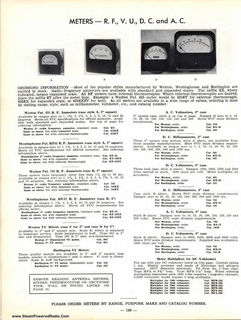
www.SteamPoweredRadio.Com
METERS - R. F., V. U., D. C. and A. C.
B C D
ORDERING INFORMATION -Most of the popular styles manufactured by Weston, Westinghouse and Burlington are carried in stock. Radio frequency ammeters are available with standard and expanded scales. The suffix EX, where indicated, means expanded scale. All RF meters have internal thermocouples. Where external thermocouples are desired, place the suffix ET after the meter type. Example: a Weston Pat. 425 meter would be 425ET for external thermocouple, 425EX for expanded scale, or 425EXET for both. As all meters are available in a wide range of values, ordering is done by stating range, style, such as milliammeter, voltmeter, etc., and catalog number.
, veston Pat. 425 R. F. Ammeters (case style A, 3" square) Available in ranges ze ro to 1, 1½, 2, 2½, 3, 4, 6, 8, 10, 15 and 20 amperes. Meets all FCC specifications for official ammeter. Avail• able with standard and expanded scales. See top of page for ordering information.
Weston 311 rad.lo frequency ammet.er, standard scale. Same as above, but with expanded scale. Same as abo,•e, but with external thermocouple.
Cat . 425 Cat . 425EX Cat. 425ET
West.inghouse Pat. RT35 R. F. Ammeters (case style A, 3" square) Available in ranges zero to l, 1 ½, 2, 3, 5, 8, 10, 15 and 20 amperes. Meets all FCC specifications for official ammeter. See ordering infonnation above.
Westinghouse 3" radio frequency a-mmeter, standard sea.le. Same as above, but with expanded scale. Same as above, but with external thermocouple.
Cat. RT-35 Cal. RT-MEX Cal. RT-35ET
West-on Pat. 743 R. F. Ammete rs (case B, 4" square) These meters have frequency error less than 1 % up to 50 me. Available in ranges zero to l, l'h, 2, 2½, 3, 4, 5, 6, 7½, 8, 10, 15 and 20 amperes. See ordering information above.
Weston 4,, radio frequency ammeter, standard scale. Same as above, but with expanded scale. Same as above, but with external thermocouple.
Cal· 743 Cat. 743EX Cat. 743ET
Westing house Pat. RT-37 R . F. Ammeters (case B, 4") Available in ranges 1, l½, 2, 3, 5, 8, 10, 15 and 20 amperes. orde1ing information above. Meets all FCC r equirements official meter.
See for
\Vestingbouse 4-" radio frequency ammeter, standard scale. Same as above, but with expanded scale. Same as above, but with external thermocouple.
Cat. RT-37 Cat. RT-37EX Cat. RT- 37ET
Weston VU Meters (case C for 3" anil case D for 4") Available in 3" and 4" square case. Scale B, which is standard in broadcast service. Scale background in buff. Type 862 is 4" s ize and illuminated. Type 301 is 3" size, non-illuminated.
Weston 411 lllumlnaled VU meter. Cat. 862 Weston 8" VU meter. Cat . 301
B ul"ljugtou VlJ Meters These quality meters are available in 3" and 4" square case models, similar to illustrations C and D above. 4" type is illuminated. Scale B, buff background.
Bur lington 4,, VU meter, Illuminated scale. Cat . 745 Burllnr ton 3'• VU meter. Cat. 535
REMOTE READING ANTENNA METERS, EITHER THERMOCOUPLE OR RECTIFIER TYPE, WIL L BE' FOUND LISTED ON PAGE 62.
A. C. Voltm eters, 3" case 3" square case, style A at top of page. Ranges of zero to 5, 10, 15, 30, 50, 100, 130, 150, 260 and 500. Meets FCC scale division requirement.
For Weston, order For Westlnghouse, order For Burlington, order
Cat. 476 Cat. RA-35 Cat. 532
D. C. Milli.umneters, 3" case These 3" square case meters, style A above, are available from three popular manufac turers. Meet FCC scale division r equirements. Available in ranges zero to 1, 5, 10, 15, 20, 30, 50, 100, 150, 200, 300, 500, 800 and 1000 ma.
For \Yeston, order For Westinghouse, order For B urlington, order
Cat· 301 Cat. RX-3.5 Cat. 531
D. C. Voltmeters, 3" case 1'hree inch case, style A above. Ranges: 1500, 2000, 2500 and 3000 volts carried in stoclc 1000 ohms pe r volt. Meter multiplier an acces::,ory.
For ·weston, order F or Wesllnrhouse, order For BurUngton, order
Cat. 301 Cal. RX-35 Cat. 031
D. C. l\Ullhunmeters , 4" case Case style B above. Meets FCC scale division requirements. Ranges: zero to 10, 25, 50, 100, 200, 300, 600 and 1000 ma.
For Weston, order For Westinghouse, order For Burlington , order
Cat. 741 Cal. RX-37 Cat. 7U
A. C. Voltmeters, 4" case Style B above. Ranges: zero to 10, 15, 20, 100, 130, 150, 260 and 300 volts. Meets FCC scale division requirements.
For Weston, order Cal. 744 For Westinghouse, order Cat. RA-37 For Burlington, order Cat. 742B
D. C. Voltmeters, 4" case Style B above. Ranges: zero to 3000, 5000, 6000 and 8000 volts. Meets FCC scale division requirements. Supplied less multipliers. 1000 ohms per volt.
For Weston, order For Westinghouse, order For Burlington, order
Cat• 741 Cat. RX-31 Cat . 741-B
Met~r Multipliers for DC Voltmeters For use with any DC voltmeter listed on this page. Current rating 1 ma. Highly accurate and made of Nichrome and advance enamel. .0016" diameter minimum. Fit form No. 1 fuse clips. Type MFA is 9¾" long. Type MFB 5½" long . When ordering multipUers remember each 1000 volts requires 1 megohm; example, 0-2000 voltmeter would require 2 meg multiplier.
Multiplier for 1500 voltmeter. Cat . MFB-155 Multiplier for 2-000 voltmeter. Cal . MFB-201> Multiplier for 2/IOO voltmeter. Cal. MFB-255 Multlpller for 3000 voltm eter. Cat. MFB-305 Multiplier for 5000 voltmeter. Cat. MFA-505 l\lullipller for 6000 voltmeter. Cal . MFA-605
PLEASE ORDER METERS BY RANGE, PURPOSE, MAKE AND CATALOG NUMBER.
- 196 -
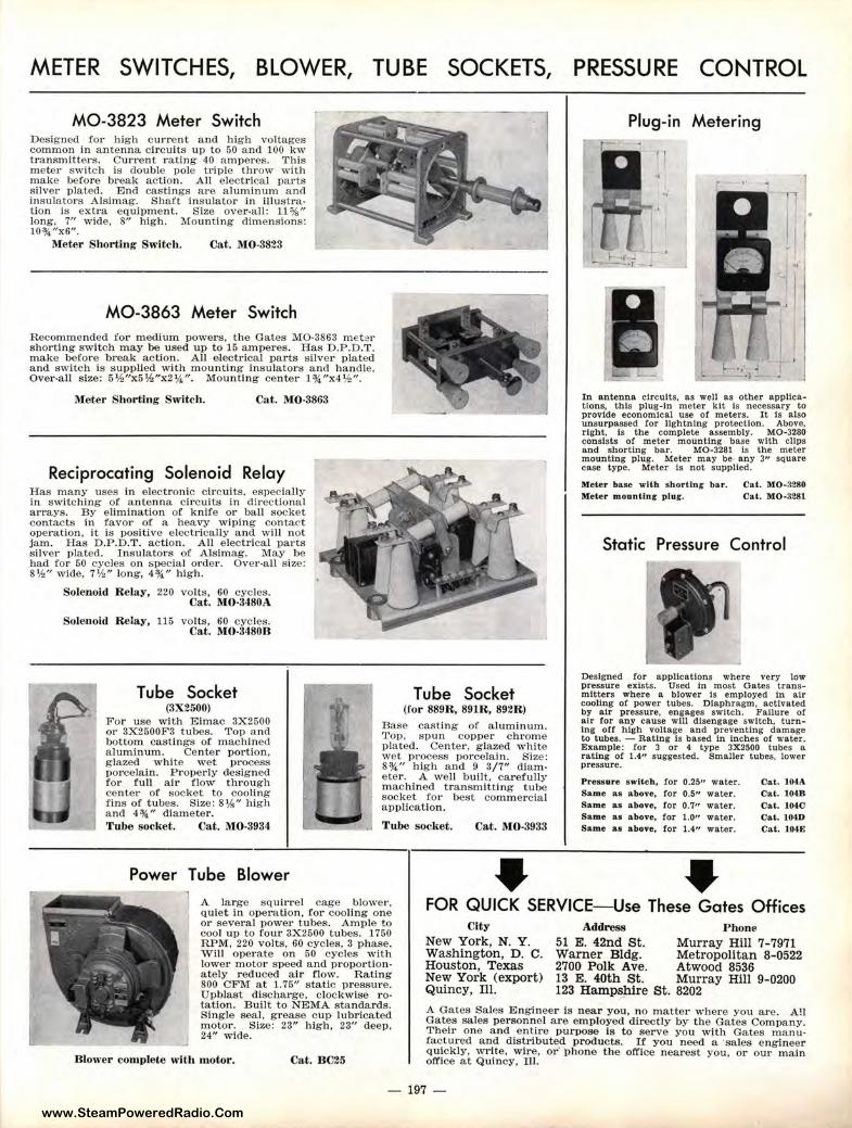
www.SteamPoweredRadio.Com
METER SWITCHES, BLOWER, TUBE SOCKETS,
M0-3823 Meter Switch Designed for high current and high voltages common in a ntenna circuits up to 50 and 100 kw transmitt ers. Current rating 40 amperes. This meter switch is double pole triple throw with make before break action. All e lectrical parts s ilver plated. End castings are aluminum a nd insulators Alslmag. Shaft insulator in illustration is extra equipm ent. Size over-all: 11%" Jong, 7" wide, 8" high. Mounting dimensions: 10¾"x6".
Meter Shorting Switch. Cat. MO-3823
M0-3863 Meter Switch Recommended for medium powers, the Gates MO-3863 mebr shorting switch may be used up to 15 amperes. Has D.P.D.T. make before break action. All e lectrical parts silver plated and switch is s upplied with m o unting insulators a nd handle. Over-all size: 5½"x5',l~"x2¼". Mounting center l ¾ "x4 ½".
i\feter Shorting Switch. Cat. MO-3863
Reciprocating Solenoid Relay Has many uses in electronic c irc uits, especially in switching of a ntenna circuits in directional arrays. By eliminatio n of knife or ball socket con tacts in favor of a heavy wiping contact operation, it is positive electrically and will not jam. Has D .P.D.T . action. All electrical parts silver 1>lated. I ns ulators of Als!mag. May be had for 50 cycles on &pecial order. Ove1•-a1J size: 8½" wide, 7½" long, 4¾" high.
Solenoid Relay, 220 volts, 60 cycles. Cat . MO·3480A
Solenoid Relay, 115 volts, 60 cycles. Cat. MO-34808
Tube Socket (3X2500)
F or use with Eimac 3X2500 or 3X2500F3 tubes. Top and bottom castings of machined a luminum. Center portion, g la zed white wet process porcelain. Properly designed for full a ir f low through center or socket to cooling fins of tubes. Size: 8¼" high and 4¾" diameter.
Tube Socket (for 889R, 891R, 892R)
Base casting of aluminum. Top, spun coppe r chrome plated. Center , glazed white wet p,·ocess porcelain. S:lze: 8¾" high a nd 9 3/7" diam• eter. A well built, carefully machined t ransmitting tube socket for best comm ercia l application.
Tube socket. Cat. MO-3934 -~-- .i Tube socket. Cat. 1\l0-3:933
Power Tube Blower •
PRESSURE CONTROL
Plug-in Metering
In a ntenna circuits, as well as other applications, this plug-In meter kit Is necessary to provide economical use o! meters. It Is also unsurp assed for lightning protection. Above, right, Is the complete · assembly. MO-3280 consists o! met er mounting base with clips and shorting bar. MO-3281 Is the meter mounting plug. Meter may be any 3" square case type . Meter Is not supplied.
Meter base wlth sh ortin g bar. Cat . MO-3280 Meter moun ting plur. Ca t . MO-3281
Static Pressure Control
Designed !or applications where very low pressure exists. Used In most Gates transmitters where a blower Is employed In air cooling or power tubes. Diaphragm, activated by air pressure, engages switch. Failure o! air for any cause will disengage s witch, turnIng o!! high voltage and preventing damage to tubes. - Rating Is based In Inches or -.•ater. Example: for 3 or 4 type 3X2500 tubes a rating or 1.4" suggested. Smaller tubes, lower pressure.
Pressure switch , for 0.25,, water. Cat. 104.A Same as above, for 0.5" water. Cat. 104B Same as above, tor 0.7" water. Cat. 104C Same as a bove, for 1.0" water. Cat. 104D Same a s a bove, for 1.4" water . Cal. 104E
• 1 A large squirrel cage b lower, quiet in operation , for cooling one or several power tubes. Ample to cool up to four 3X2500 tubes . 1750 RPM, 220 volts, 60 cycles, 3 phase. Will operate on 50 cycles with lower m otor speed and proportionately reduced air flow. Rating 800 CFM at 1.75" static pressure . U pblast dischar ge, clockwise rotation. Built to NEMA standards. Single seal, g 1·ease cu1> lubricat ed motor. Size: 23" high, 23" deep , 24" wide.
FOR QUICK SERVICE-Use These Gates Offices
Blower complete with motor. Cat. B C25
City New York, N. Y. Washington, D. C. Houston, Texas New York (export) Quincy, Ill.
Address Phone
51 E. 42nd S t. Murray Hill 7-7971 Wa rner Bldg. Metr opolitan 8-0522 2700 Polk Ave. Atwood 8536 13 E. 40th St. Murray Hill 9-0200 123 Hamps~ire St. 8202
A Gates SalP,s Engineer is near you, no matte r where you a.re. A!I Gates sales person:nol are employed directly by the Gates Company. Their one a nd entire purpose Is to serve you with Ga tes m a nu• factured and distributed products. If you need a ·sales e nginee r quic kly, write, wir·e, o r· p hone the office nearest you , or o ur ma in office at Quincy, llll.
197 -
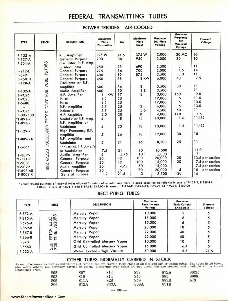
www.SteamPoweredRadio.Com
FED~RAL TRANSMITTING TUBES
POWER TRIODES-AIR COOLED Maximum
Maximum M aximum Maximum frequency Filament TYrE , a1cE DESCRI PTION Plate Mu Plate DC Plate f or Voltage
Dissipation Input Voltage Ma ximum Ratings
F- 123-A R.F. Amplifier 125W 14.5 375W 2,000 30MC 10 F-127-A General Purpose 200 38 950 3,000 30 10 F-204-A (/) Oscillator, R. F. Amp.
~ (.) or Modulator 250 23 690 2,500 3 11
F-212-E H General Purpose 275 16 700 2,000 4.5 14
F-849 ~ General Purpose 400 19 875 2,500 3.0 11
F-450TH iil General Purpose 450 38 3KW 6,000 40 7.5 F-128-A
~ Oscillator or R.F. :=> E-< Amplifier 600 36 3 3,500 30 11
F-132-A ~ Audio Amplifier 600 10 1.8 3,500 11
F-7C26 0 H.F. Amplifier 1 KW 17 3 3,000 150 9 .0 rz.. F-7C23 fjj
Pulse 1.2 25 17,000 5 11.0
F-5680 H Pulse 1.2 25 17,000 5 13.0
" ,-..=I R.F. Amplifier 2.5 25 12 6,000 5 13.0
F-7C25 µ'.l Industrial 2.5 25 5.6 4,500 50 11
F-3X2500 0 H.F. Amplifier 2.5 20 8 4,000 110 7.5 •F-891-R
H Modul'r or R.F. Amp. 4 8 15 10,000 1.6 11 / 22 8:: *F-892-R R.F. Amplifier or 0 Modulator 4 50 18 10,000 1.5 11 / 22
*F-129-R ~ High Frequency R.F. V) Amplifier 5 26 18 12,000 30 18 H
*F-889-RA ,-:i R.F. Amplifier and m ~
Modulator 5 21 16 8,500 25 11
F-5667 Industrial , R.F. Ampl'r Cl) or Modulator 7.5 21 20 10,000 11.0 ~
F-8C25 ~
Audio Amplifier 5 5.75 10 5,000 7
*F-124-R General Purpose 20 42 100 20,000 20 13.6 per section
• F-9C31 til General Purpose 20 42 100 15,000 20 7 .5 per section
• f-9C29 iil Audio Amplifier 20 4.75 50 15,000 7.5 per section • F-893-AR
Cl) General Purpose 20 36 70 20,000 5 10 per section
F-8002-R General Purpose 1.2 21.5 3 3,500 120 16
• Credit toward purchase of renewal tubes allowed for return of radiator and crate in good condition as follows: in case of F- 129-R, F-889-RA $30.00 in cose of F-891-R and F-892-R, $45.00; in cose of F-114-R, F-893-AR, F-9(29 ad F-9C31 , $150.00
RECTIFYING TUBES
Maxirnurn Ma ximum TYPE PRICE DESCRIPTION Peak Inverse Peak Current filament
Voltage IAmpatHl Voltage
F-872-A (/) Mercury Vapor 10,000 5 5
F-315-A E-< til Mercury Vapor 15,000 6 5 Cl) (.)
F-575-A H~ Mercury Vapor 15,000 6 5 F-869-B
,.::t p... Mercury Vapor 20,000 10 5 F-857-B
µ'.l ~ Mercury Vapor 22,000 40 5 F-266-B ~§ Mercury Vapor 22,000 40 5
p... E-< F-873
&5 @5 Grid Controlled Mercury Vapor 10,000 10 5
F-5563 Grid Controlled Mercury Vapor 15,000 6.4 5 C/ll:r..
F-222-A Water Cooled - High Vacuum 50,000 5.5 21.5
OTHER TUBES NORMALLY CARRIED IN STOCK As manufact ure rs, a s w ell as distributors of ra dio t ubes. we carry a large stock of a ll la te a nd earlier design tubes. T he tubes lis t ed below. plus many other s, a re nor mally carried in s tock. R eceiving type t ubes a re not list ed, but a re s tocked a nd available at the lowest established price.
802 803 805 806
807 810 811A 812A
813 814 828 833A
- 198 -
838 845 849 866A
872A 885 889R 891R
892R 8008 673
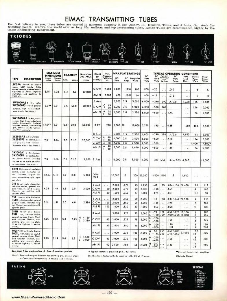
www.SteamPoweredRadio.Com
EIMAC TRANSMITTING TUBES For fast delivery t o you, these tubes are carried in generous quantity in our Quincy, Ill., Houston, Texas, a nd Atlanta, Ga., stock distributing points. Known the world over as long life, uniform and top perfo1·ming tubes, Eimac Tubes are recommended highly by the Gates Engineering Department.
MAXIM UM FILA MENT TRANSCON. CLASS M••· MAX.P'LATU A TINGS TYP'ICAL OP'EU.TING CONDITIONS
DIMfNSIO N S 0UCTANCE OF Ft•qw• nc.'f' DC DC P• • kA.F. DC "··· O,ivi,i9 ,o••r TYP'E DESCIIIP'TION t•"'•'" Di•M• ttr
SERVICE FvU k eti"9 DC DC Oiutpation ,. ... Grid
5 "..,~:t''t ,1 ••• Lo.cl ,o••r Olitpu♦ lflC:lriH liKhH Volh Amp,. /tmho, Me. Voth Amp, W.th Volts Volh re,Tw,IN Ampt.. O~m, W att, w . .. ,
2C3t A Forced . •i, coof.d,
pl•"•' UHF t,:ode. 0 1ide CCW 2,500 1,000 . 1251 100 BOO - 20 .080 6 27 coeted c . .athode, H♦errief .uod•- ... ...
Opet.th, • • po••r •Mpfifier, 2.75 1.26 6.3 1.0 22,000 m1,1ltiplier, ••• oicillefor to AM Pl 2,500 600 . 1001 70 600 -16 .075 6 18 2500 Mc, .. . ...
3WS000A3 ~ . Kw . 8 Aud 6,000 2.5 5,000 6 ,000 - 240 390 .4/ 3.0 4,650 I IS I 3,000 ....... ,
A 3WS000F3 ,ool••· 9•••,.1 a.o•• 3.0 7.5 51.0 20,000 75 C CW F 30 6 ,JOO 2.5 5,000 6,000 - 500 208 . .. . .. 136 10,000 p\lrpo,•. hiqh tr•11icoflduc-t• . ,,u1 triode. Su No1, 2. AM Pl A 75 5,000 2.0 3,350 5,000 - 550 1.45 76 5,580 F 30
... ...
3W10000A3 10-Kw., w•te,-cooled. high fr•"1co11cf11ct•nce t,iode. U11ipot•nti•I thori•t•d 13,0 .. 5.0 10.0t 30.0 55,000 8 TV tu"git♦n c•thode, "on-emitting 9,id, • •••,n•I •nod•. Cottcen• h ie VHF termiuli.
220 5,000 10 10,000 ] ,250 - 190 ... 4.25 560 400 s ,5oo•
B A ud . . . 6,000 2.5 2,500 6,000 - 240 390 .4/ 3.0 4 ,650 11 J 13,000 3X2500A3 l .5,Kw. fo" •d- ccw A 40 6,000 2.5 2,500 6,000 - 500 2.08 136 10,000 3X2500F3 •ir coored, 9•"· 9,0 4.1 6 7,5 51 .0 20,000 F 30 .. . ... •r•I p11rpo,e , l,igh tr,uucon• C CW A 110 4 ,000 2.0 2,500 4 ,000 - 500 . · : , I.BS ... 1,900 7,500• ducto1nce triod e. Su Noh 2.
AM Pl A 40 5 ,000 2.0 1,670 5,000 - 550 1.45 76 5,580 F 30 ... ' . . 3X3000Al 3. J(""·• forced-3X3000Fl • ir cool.d, low. m, power triod•, inh"ded 9.0 4.16 7.5 51.0 11 ,000 B Aud , . ' 6,000 2.5 3,000 6,000 -1300 1250 .335/ 2.65 4,560 ... 16,000 for us• •1 ,in • 1.1dio •mplifier o, moduldtor . See Note 2.
6C21 Hiqh.v•cu1o1M, r•di•tion cooled. p uls• modulo1tor lri,
ode-. Tlto,i•ted tu"91,ten m •. 12.6] 5.13 8.2 16.8 5,800 Pulse 30,000 15 300 2:7,000 - 1500 3100 15 1,600 ... Mod . . . ., .
ml!t"t, "on-emitting grid , pyro-,,.< pl♦te
25T 2S,wett pl•t• diuip•tion, B Aud .. .. 2,000 .075 25 11,250 - 42 135 .024/. 130 21 ,400 3.4 I 12 r•dl•tion cool•d , gener•I p11r• pou1 hiod • . Tho,i•ted lun9stu 4 ]8 1.44 6.3 3.0 2,500 ccw 60 2,000 .075 25 :! ,000 - I 30 ... .063 ... 4 100 fil.ment, non• emittir,q qrid,
AM Pl 60 1,600 .060 17 1,600 - 170 .05] 3. 1 68 pyro,.•c pl•t•. . . . . . . 35T SO.w•H pl•t• diuip•tion, B Aud 2,000 .150 50 l',000 - 40 130 .034/.1 67 27,500 4 235 35TG ,.di.tio,i cooled. qeHr•I
. . , .
purpOH hie.de, Thori•ted luAq• 5.5 I.SI 5.0 4,0 2,850 ccw 100 2,000 .150 so :!,000 - 135 ... .1 25 . . , 13 200 1ten filemenl, no11-emitti119 q rid, AM Pl 100 1,600 . 120 33 1,500 - 150 , . . .090 ... 11 105 pyro,.• c pl• te.
75TH 7S-w•♦t ple te diu ip•• B Aud 3,000 ,225 75 •',000 H - 90 175 .050/.225 19,300 3 300
75TL t ion, ,.di.tion coored, .... L -190 300 .050/ .250 18,000 5 350 qener•I purpoH triode. Thori-
7.25 2.81 5.0 6.25 H 4, 150 ccw 40 3,000 .225 75 .!,000 H - 200 . .. .I 50 . '. 10
22S eted hinq,ten fil•ment. non- L 3,350 L - 300 8 emittinq qrid. pyto .. c. pl•t•. .. H ·union hi9h,mu, L veuio" AM Pl 40 2,400 .I 80 so :!,000 H -300 . . . .1 10 ... 6 170 low-mu. l - S00 .. , .130 .. ' 14 210 100TH 100-wett pl•+• diu.tp••
B Aud 2:,soo H -50 155 .060/ .280
22,000 7.5
425 l 00TL t ion, , .di•tio" cool•d. .. . 3,000 .225 100 L - 145 290 .048/ .250 10
9•"•'•1 p111pote h iod•. TI.ori• 7.75 ) .19 5.0 6,3 H 4,500 ccw 40 3,000 .225 100 ,1,000 H -200 ... .165 18
400 eted t11n91t•n fil•m•nt, non- L 3,000 L -400 ' . . 20 effliftil'l9 g,ld, pl•t•. ... pyronc H - 250 17 H veuion high-mu, L •venion AM Pl 40 2,500 , 180 65 2:,500 ... .140 285 low-mu. L - 500
... 23 . ..
SH page 5 /or explanation ol c/ou of service symbols. ♦ Typic.ol oper•tion, grourided q rid ,1f full retiri9 . ••Dots not include w•t•r c:oupJi,_q,.
$C•thode C11rrt1ftt Note 2: Tho,i•+•d t1,1l'lg1te" fil•m•nt, t11ori,etnil-tin9 9 rid , utern•I ,1node.
"- Coricenfric; VHF te,min• ls. F Fle,ible lead termin.tr,, t Bombardment huted c.thod • . ,equires 1600v. DC .. ♦ 1.9 •mp,,
- 199 -
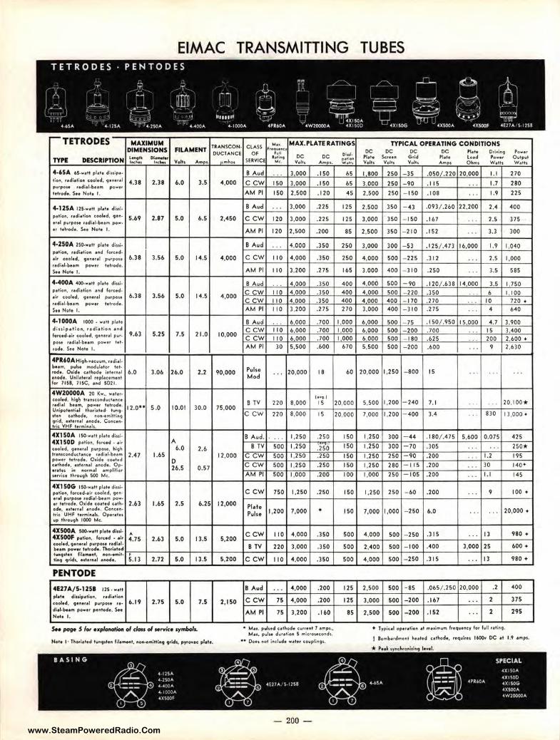
www.SteamPoweredRadio.Com
EIMAC TRANSMITTING
.-TETRODES MAXIMUM DIMENSIONS FILAMENT
TYl'E DESCRIPTION ...... IM. .... t
o;_,.., l.c.lte, Volts A mps
4-65A U -w•tt pl,te diniP•· t ioa, recliet:011 coolM, 91tne,,f
◄.38 2.38 6.0 3.5 purpot• ,,di•l•be..n power
tet,ode. S., Note f ,
4-12SA llS•••tt pf,te diui, petio", ,,d;etio11 cooltd, , . ,,. 5.69 2.87 5.0 6.5 erel p1,1rpoH Hdie l,IM•m pow•
er te''t,ode. s .. Not, I.
4-250A 250,w•tt pl•t• d;»t• JNlio11. redi•tio,i ud fo,ud, eir cooled, 9•"•'•, pwrpo,, 6.38 3.56 5.0 14.5 ,,di,l,bum powe, t,♦,ocf •• Sn Not, I.
•·◄OOA 400-wett , , • •• diui, petion, redielio" ud fore.cf. .1, cooled, 9•11e,el purpOH 6.38 3.56 s.o 14.5 recfiel0 bHm power tetrode. SH Nott- I.
4-IOOOA 1000 . w•tt plete
dhtipetlon, redi•tlon ettd 9.63 5.25 fo,ud-et, cooled, 9e11e,el pwt• 7.5 21.0
po1-e ,ediel•bHrn i,ower let• ,ode. s .. Note I .
4PR60AHi9h.vtc11vM, ,ediel-bHm, pul" fflod11leto, ltl• ,ode. Oride c.ethoclt iflt•rnel 6.0 3.06 26.0 2.2 ,node. Unil•te,,I ,epleument lo, 7156, 71SC, ud 5021.
4W20000A 10 Kw., w••••· coole-cl. lugh truuco"dvct•nce ,.,r. t b.. m, power tetrode. 12.0 .. 5 .0 10.01 30.0 UAi!)otH"fiil thori.,ttd 11.N\9• dtft cathode, t11)1'1•eMifti,i9 9,id. ed•r"•' uode. Co,icu• h f<. VMF t♦fminel,.
4X1 SQA IS0,w•tl pl•I• d;.,;, 4X1 SOD peti.,., to,ud • ,;, A
:,::1,ecd~":=:.::!/::;;~:h:~!
6.0 2.6 2.47 1.6S
power tehode. O1.ide co•ted 0 cethocft, • •ltr1tel enodt. Op•
26.5 0.57 e,etH i111 "°'"'•' tMplifi.-, nniu th,ou9h 500 Mc.
4X1 SOG ,so.wet♦ plelt cfini~ petio111. forced,tir cooled, 9H · erel pvrpoH udiel, bHm p,ow-er tetrode. O •idt coeted uth• 2.63 1.6S 2.5 6.25 od,. e•+•tnel tftodt. Concen• t,ic UHF te,mineh. OPf'retu wp throw9h 1000 Mc.
4XS00A 500-w•tt pl•t• d:.,,. A
4X500F p.iiti011, forced • ei, 4.75 2.63 5.0 I 3.5 coolect, geauel pu,po1t rediel• bu m powe, tetrodt, Tho,lettd tvn9ttH fil.emut, ftOft••ffllf, ' ti"t 9,fd,, t1le,,..I •""•• S. I 3 2.72 5.0 13.5
PENTODE 4E27A/5-12SI 12s . w.tt ,, ... diuipetio11, , ,.d;,.tion c.ool, d, ,.,..,.1 6. 19 2.7S s.o 7.5 ,._,,poi. ... diel-bum powe, pentod•. S. .. Not• I.
S.e _. 5 /o, explanation ol class ol Hrvic• ,ym&olL
TIAHSCON- CLASS .... MAX.PLATE RATINGS
F,•qw•-.c:r 0UCIANCE OF ... •. ,.It. oc DC
...,1nho,
◄,000
2,◄50
4,000
4,000
10,000
90,000
75.000
12,000
12,000
5,200
5,200
2,1S0
SERVICI "'· Voth A,,..,p,.
B Aud ... 3 000 .1 50
CCW 150 3,000 .150
AM Pl 150 2,500 .120
B Aud ... 3,000 .225
ccw 120 3,000 .225
AM Pl 120 2,500 .200
B Aud ... 4,000 .350
ccw 110 4,000 .350
AM Pl II 0 3,200 .275
B Aud ',. 4 000 .350 ccw II 0 4 000 .350 ccw 110 4.000 .350 AM Pl 110 3,200 .275
B Aud . .. 6,000 .700 ccw 110 6 000 .700 ccw II 0 6 000 .700 AM Pl 30 5,500 .600
Pulse ... 20,000 18 Mod
C••• I S TV 220 8,000 15
ccw 220 8,000 15
B Aud. ... 1,250 .250
8 TV 500 1,2S0 .250 ccw 500 I ,2SO .250
ccw 500 1,250 .2SO
AM Pl 500 1,000 .200
ccw 750 1,250 .250
Pl•I• 1,200 7,000 .
Pulse
ccw 110 4,000 .350
B TV 220 3,000 .350
ccw II 0 4,000 .)SO
B Aud ... 4,000 .200
ccw 7S 4,000 .200
AM Pl 75 3,200 .160
• Mu. pu!Hd c.eth.oci• cwnent 7 emp1., Me•. pvtte duretioft S mic.,oHCOftd1.
•• Oo-t, l'!<i-t i .. cl1,1,d• weter cowpli1119L
- 200 -
o;w. P40fi.,., W..,JH
b5
65
45
125
125
85
250
250
165
400 400 400 270
1,000 1,000 I 000
670
60
20,000
20,000
150
150
150
150
100
150
ISO
500
500
SOO
125
125
85
TUBES
TYPICAL OPERATING CONDITIONS oc oc oc oc "··· o.,;.,j,i9 Pow•r "•+• Ser••" Grid Ple•t lo,d Power 011,1tput Volh Volh v., .. Amp\ Oh,.,, W,th W,th
I 800 250 -35 .050/.220 20,000 I. I 270
3,000 250 - 90 .115 . . . 1.7 280
2,500 250 - 150 .108 '. ' 1.9 225
2,500 350 - 43 .093/.260 22,200 2.◄ 400
3,000 350 - 150 .167 ... 2.5 375
2,500 350 - 210 .152 ... 3.3 300
3,000 300 - 53 ,1 25/ .~73 16,000 1.9 1,040
4,000 500 - 225 .312 . .. 2.5 1,000
3,000 400 - 310 .2SO . .. 3.5 58S
4,000 500 -90 .120/ .638 14,000 3.5 1.7SO 4.000 500 - 220 .3SO . . . 6 I 100 4 000 400 - 170 .270 .. . 10 720 + 3,000 400 -310 .27S ' . . 4 640
6,000 500 - 75 .150/ .950 IS 000 4.7 3,900 6 000 SOO - 200 .700 . , . 15 3,400 6,000 500 - 180 .b2S ... 200 2,600 • 5,SOO 500 - 200 .600 . .. 9 2,b30
20,000 1,250 - 800 15 .. ... . ..
S,500 1,200 - 240 7. 1 . .. ... 20,100•
7,000 1,200 -400 3.4 . .. 830 13,000 •
1,250 300 - 44 .1 80/ .47S S,bOO 0.075 425
1,250 300 -70 .305 .. . ... 2SO*
1,250 2SO -90 .200 .. , 1.2 195
1,250 280 -I 15 .200 ... 30 140•
1,000 250 -1 05 .200 . .. I. I 145
1,250 250 - 60 .200 ... 9 100 •
7,000 1,000 - 2SO 6.0 .. ' ... 20,000 +
4,000 500 - 250 .l IS ... 13 980 •
2,400 500 - 100 .400 3,000 25 600 •
4,000 500 -250 .315 ... I 3 980 +
2,SOO 500 -as .06S/ .250 20,000 .2 400
3,000 500 - 200 . 167 ... 2 37S
2,SOO 500 - 200 .1S2 ... 2 29S
♦ Typiul op• r•f;on- et m••imurn lreqwncy lo, fvll '•""9·
f Bomberdmot hut•d c•tl,ode, r-eqwirtt 1600¥ DC et 1.9 • mp,.
* P'tel 1yftclo.,o"itln9 I•••'-
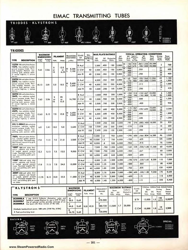
www.SteamPoweredRadio.Com
EIMAC TRANSMITTING TUBES TRIODES KLYSTRON s
.1, C' ,.. ,J: ),~, ,,
'; A ,
\_. -l '6i ' ._; ~ '
q
' rn / ;:::
'A· ,ts:-i,: ·;{) ''i ) -n/ $db'
f J{Jt, ~-i ~ ~~:;; .. •' .hie> -J!c,i
P' HOO-OOOLA (J L. 3IOOOOOLF
~ ,sn ---=- 2SOT 'rf 304T ..,_, 450T i •--_~ · S'l2/l-200Al y7SOT IOOOT 1500T ·~ "'2000T )K200O0LK
TRIODES
TYPE DESCRIPTION
MAXIMUM DIMENSIONS L111qllri D l•m• ttr h1clln h1th11
FILAMENT
Voht. Afflp1.
B Aud
MAX. l'LATE RATINGS
DC DC Oiu ip1 t io11 Volh Amp1 W •th
TYl'ICAL Ol'EltATING CONDITIONS OC • • • k A .F. 0C Plat, O,ioiit19
G rid G.,~~:::''' Pt1t1 Loacl Power Volts ,,,Tub• Amp,. O hrt11 Wath
O H -1 50 430 .067 / .335 20,300 3
Power Ovtpvt w."'
700 152TH 150 • .,,tt pl••• diu ip• •
152TL tio11, r.cl i1tio11 cooled, 910,,I p1.1,pou t,iod, . T"-o,i. •••d 11,1119 111"' fil,"'' "'• Min.• 1mittin9 9,-icf, pyrov1, pl1t1. H vituio11 "-i9IH""• L ..,, ,1i(ln low-mv,
7.63 2.56 5 or 10
3,000 .45 150 3,000 L - 260 675 .100/ .500 20 400 12.5 H 2
or 9,3oo C CW 40 3,000 .450 150 3,000 ~ =!~~ · ·' .250 . . . 2~ 600 6.25 L 7. 150 1-- --1-- -+--1----1---11--+H,.._-=3:uo"'o+-~ +-----4--+~30'--+---I
AM Pl 40 2,500 .350 I 00 2,000 L _550 : : : .250 . . . 25 400
250TH 250 • ..,,tt pl111t 1 diuip,. 250TL tio11, r•di•tio11 cooled, 9e" •rel purpo1e t riode. Thoriet•d tvMJll• n fil•me,it, "0"· • mittin9 q rid, pyrove, pl•te. ~ weoio" l,iqh-mv, L versio,i low-mu.
304TH 300.w. tt pl• t• diuip•-304TL lio"', ,edietio" cooled, quer•I purpoH t,iod•. Thori•••d h1"q, tet1 f'ileme l'lt , 11011-emitti,iq 9,id, py,ov.,c pl•t• . H "•"io" hiq h-mu, L .... ,1io11 low-mu.
450TH 4SO•••tt pl• t• cfiu ip•· 450TL t io11, r•di.tio" cooled, 9e r,erotl purpoa t riode. Tho,ieted 111119,ten fileme"t, r,on• emitting 9,id, p yro .... c pie+• . H "•rtion hiqh,mw, l we, ,io" low-mu.
S92/3-200A3 200.. ,tt pl••• diu ip• lion, , . di•tion cooled , 9•"• ' •1 pvrpoH triode. l ho,i• •ted tu1191♦•" filemer,t , t1onemittit19 qrid, pyro .... c pt..te.
750TL 750-w•tt ple te diu ipetion, r•dietio" cooled, 9erie,,el putpoui triode . l hori• t•d tur,9 • , tu fil•mer,t, 110,i,e mittil'lq grid, pyrovec: pl•t• .
1O0OT 1000-w•tt pie♦• dinip•t;ori, r•dietio11 end forc:ed • • ir cooled, 9ener•I p"rpou, triod e . Thorieted lut191te n fil• meflt , 11011••tnitt;flqi grid , pyro"•t: pl•t•.
1 SOOT 1500-w,dt pl•te Giuipetion, ,.dietio11 • nd fCM"ced• . ;, cooled, 9 enetel p1ltpOH triod e . Tho,l•ted tung,t•" fi1em eflt , l"IOtl•emittinq 9rid , pyrow• c: pl•••·
2OOOT 2000-wett plete dlu lp.tion, ,.di•tion •"d forc:ed•ir cooled, 9 et1erel p11rpo1• t rioc-Je. U.CM"ieted t wn9,te l"I file• m•"•• 11on•111mittln9 9,id, pyro• v•c plete.
10.13
7.63
12.63
6.0
17.0
12.3
17.0
17.75
-KLY STRONS
TYl'E DESCRIPTION
3.8 I
3.56
5. 13
3.4 1
7. 13
5.13
7. 13
8. 13
5.0
5 or
10
7.5
10.0
7.S
7.5
7.5
10.0
10.S
25 or 12.S
12.0
s.o
21.0
15.5
24.0
23.S
3K20000LA 3 9•p 20-KW. C ollector diuip et ion, weler end
3K20000LF forced -a ir cooled Klydro" for vse itt UHF TV be rid.
3K20000LK UH of uter11el c•witiH p rovidH c:oureqe of U •
t.,. b•nd with th, .. vert;on, of t he t 1,1be.
f Cethod• bomb.e,dment power, 16,00 we th 12100 Vdc, 0.7SA)
* , ... ~ 1ynchrol"litin9 level.
BASING
~ ~ 450TH 250TH 450ll 250Tl 10001
- -4 •
H - 65 260 . I 00/ .560 12,250 42 I, 180 B Aud . . . 4.000 .350 250 3,000 L -170 400 . IOOl.500 13.000 16 I 000
t t!~g 1-c_c_w-+ _ _ 4_o -+-_4_.o_oo--+_· J_s_o-+_2_5_0-+4_.0_0_0-11_,,H L,-cc-"'~~,c.,g<+·~·~·+-. 3_1_3 _ _, __ . _· ·--~.;.i --1-_1_.o_o_o--1 H - 200 .. . 14
AM Pl 40 ).000 .280 165 3,000 L _520 ... . 200 . . . I I 435
B Aud 3 0 H - 150 2 10 . 134/ .667 10,200 6 1,400
3,000 .900 300 • OO L - 290 390 . 1301.800 9 I 00 55 I 800 H - JOO · · · 53
16.100 .... c_ c _w ___ 40--1_3._o_oo-+-_.9_o_o-+_3_0_0-+-3-·o_o_o+...,_L ""4-"0"'0+-'.~·~· +-.s_o_o ____ · ----+--"'40._+-1_,2_00--1
AM Pl 40 2,500 .700 200 2,500 r ::.:~g : : : .450 . . . :g n5
H -115 267 18,600 10 B Aud . . . . 6,000 .600 450 5,000 L _ 240 410 .120/ .620 18 SOO 28 2,200
t ~:~~g ~c_ c_ w_1-_4_0_._6_._00_0+_·6_00_1--4-50-1~5-·o_o_o_,,~i,,....;=::::"!ge:<g-+-c:~: ~: +-._4_5o __ +--·""· :..,,:+_ 4""4
~!.....+-1 _.8_0_0-1
4.500 .500 300 4,500 t =:~g : : : .345 : : : :f 1,250 AM Pl 40
B Aud 3,500 .250 200 3,000 - 90 270 .080/ .400 18,000 20 820
3.600 C CW
AM Pl
150
ISO
3,500 .250 200 3,500 -270 . . .. 228 . . . 15 600
2,600 .200 130 2.500 -JOO . . . .200 . . . 19 375
B Aud
3,500 C CW
AM Pl
B Aud
9,050 C CW
AM Pl
B Aud
10,000 C CW
AM Pl
B Aud
11 ,000 C CW
AM Pl
MAXIMUM
10,000
40 10,000
40 8,000
50
so
40
40
40
40
7,500
7,500
6,000
8.000
8,000
6,000
8,000
8,000
6,000
1.0
1.0
.8
.750
.750
.600
1.25
1.25
1.00
1.75
1.75
1.40
DIMENSIONS FILAM ENT FREQUENCY
RANGE Le1114tll Oi• m•t•r lt1tJ1u I IK~ l
Volts Amp1 Mc.
A A 50.5 S.69 470-580
F F 44 .0 5.69 9 .01 42.0 580-720
K K 36.75 5.69 720-890
750
750
500
1,000
1,000
665
1,500
1.500
1,000
2,000
2,000
1,350
6,000
6.000
6,000
6,000
6,000
6,000
6,000
7,000
6,000
7,000
7,000
6,000
- 390 650 .166/.B34 16,300
- 700
-950
.625
.41 S
- 160 335 .220/ 1.05 13,300
-350 . .
-500
- 1'10 570
- 500
- 750
.667
.600
.330/ 1.65
.860
.835
- 280 600 .300/ I.SO
-600
-800
I. IS
1.13
8,200
9,200
46
125
75
60
60
75
115
85
120
175
115
225
l ,500
3,000
2,000
4,600
3,000
2,935
7,000
4,500
4,000
8,600
6,000
5,400
MAXIMUM RATINGS CLASS TYPICAL OPERATING CONDITIONS
Bum Collec:tor a .. m O,ivi"9 Power OF
DC DC Oiu ipetion DC DC Power O..+p11t
Volh Amp1 W•th SER YI CE
Volh Amp, W eth Weth
100 B TV 13,000 1.5 •pPfOI, 5.ooo*
13,500 1.7 20,000
ccw 10,000 1.0 10 2,500 epp,OI.
~ ff SPECIAL
7501L 152TH
15001 l52TL JIOCCJD.A
104TH ~.,,,,,. :;,,: ::,:X•:Jlf'
2000T l K ;'C :)CL K 304TL
-' 4
'
- 201
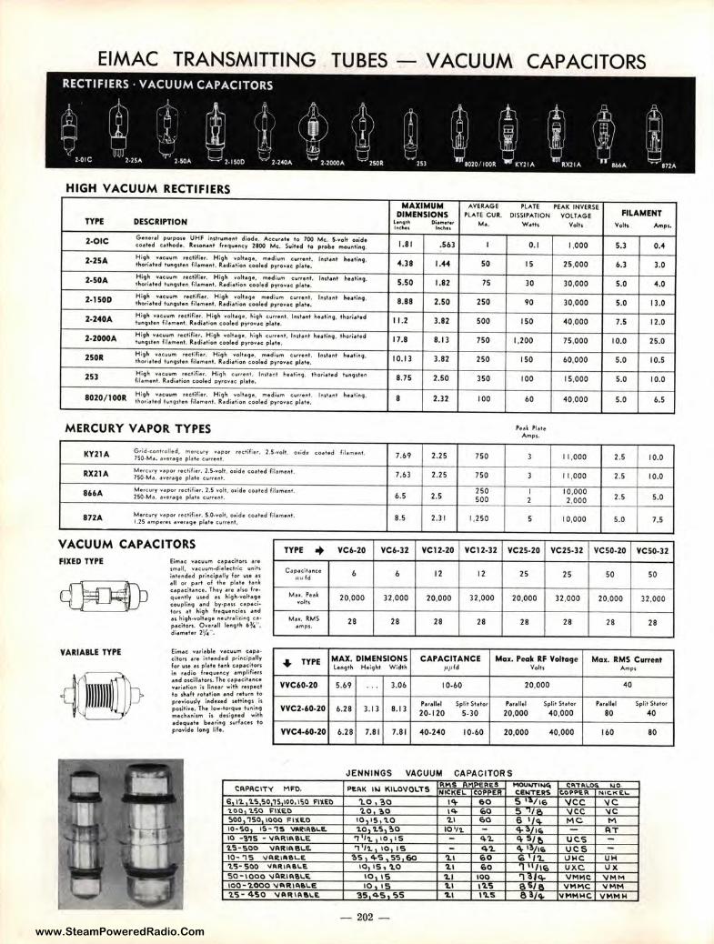
www.SteamPoweredRadio.Com
EIMAC TRANSMITTlNG TUBES - VACUUM CAPACITORS
HIGH VACUUM RECTIFIERS
TYP'E DESCRIPTION
2-OIC G •nerel p i.irp cn• UHF instrument diod•. ACC\lt♦t♦ to 700 Mc. 5-voft ot id• coeted u thode. ReioP!♦nt frequel'lcy 1800 Mc. Suit•d to p rob e moul'lti1"19,
2-25A High "'• cuum rec tifiu . medium H;9h ,..0Jte9e . cu,,e,it. tho,ieted twngdu f ilement. Red ietion cool♦d pyrow•c plete .
lnster,t huti"9·
2-SOA High wec1.1.,,n r ectifier. H igh me d iut'I' cwr,e,it. YOftegt, tho,ieted twng,ten filemtnt. ft.edietion cooled pyrovae plate.
J,istent ., .. ,;"9·
2-IS0D H;9h •ec1,1um rectifiu . Hiq" med ium c urttnt, voltage t"o,ieted t1,t1uJdtn fttemeft♦• Red ie tion cooled pytovee plete. '"'''•"' >iutiftg ,
2-240A High YtCV\lm r• c tilie, . Hi9h volt•g • . high cvHent. l,ut•r,t huting , thorie ted tu"g,teft fil• me nt. R,1dletio" cooled p y,o v•c p lete.
2-2000A High v•c vum rectifter. H i9h voh•g•, hi9 h c.vrrel'lt, IMtent hHtin9, t l,ori• ted tu,,9den f.l•ment. R.dietio" cooled pyro ... • c. pl•••·
250R Hi9h "'<IC \lllffl red i(ier. H igh votleq• , med ium c.urrel"l t. thorie ted f wn91ten fileme"t. Ro1di<1t ior, cooled py, ovac pla te.
lnsteflt hutir,9,
253 Hi9h vecuum , e,,a;.,_ Hig h c.11rr♦nl ,
fil•m•"*· R.adi• t ion cooled o y,o..,ac. ple te . hutenl h .. ti,.9 , thori•l♦d tv" g,ten
8020/ I 00R High ""<ICUUffl r♦etifie,. High voltage, medium c urre nt , tho,i•t♦d lwnq,te" lil.tme nt. R•di• tior1 cooled pyrovec pfe te,
l" 1te l"l t h .. tiflq ,
MERCURY VAPOR T YPES
KY21A G ,id -c.oflt rotled, mo,c1,11y ""•por 7S0, Me, •"'•ri11qe plo1 te C1,1rrent,
rectifier. 2.s .... 011. o , ide coe ted
RX21A M ercur y "'• po, rectifier. 2.S.voft, 01:de coeted fila me l"II. 7S0 -M.e • .everage p l•+• C.1,1rrent .
866A Merc.ury "'.tpor rectifie r. 2,S ... oh, 0 1id e c.oe ted filamtflf , 250-Md. •..,e,e9 e plete cv.rrent ,
872A Me re.wry "'•por rectifier, S.O .... clt. 0 1ide c<ieted fil•ment. 1.1S ampere s d""erage pl• t• cvrr♦ l"I I .
VACUUM CAPACITORS TYPE +
FIXED TYPE Eil"l'le <: v•c.uvl"l'I c.• p •eiio,s • r• , m.11, "'• c uu1"1'1°dielectric unih inte"ded p ri,"ipelly for uit H
e ll or p art of the pl•t• t u • cepeeit•nu . Thev • '• . 1,o fre, quer,t ly u, ed u hi9h-volt•9• coupling •"d b y•p•n cap• c.i• tors •t high frequ• neie1 .tfld .,, hi9h 0 volt• 9• " e vh • li1in9 Cd •
p•c.iton , 0 .,.,.11 len9 01 0 1/4", d i• m•t•r 11/4" .
C a pac.ilanc.e .u;; fd
M••· Pu l l'Clh
M••· RMS • mp$.
filo1 mH t.
VC6-20
I,
20,000
28
MAXIMUM AVERAGE PLATE PEAK INVERSE DIMENSIONS PLATE C U R. DISSIPATION VOLTAGE FILAMENT
le119th Di•m•t..- M•. W•th Volts Volts Ampi. I/IC~I lnc:hu
1.8 1 .51,3 I 0.1 1,000 5.3 0.-4
4.38 , ..... 50 I 5 25,000 1,.3 3.0
5.50 1.82 75 30 30,000 5.0 4.0
8.88 2.50 250 90 30,000 5.0 13.0
11 . 2 3.82 S00 ISO 40,000 7.5 12.0
17.8 8.13 750 1. 200 75 ,000 10.0 2S.O
10.13 3.82 2S0 150 60,000 s.o 10.5
8.7S 2.50 350 100 15,000 s.o 10.0
8 2.32 100 60 40,000 s.o 1,.5
7.69 2.25 750 3 11,000 2.5 10.0
7 .63 2.2S 750 3 11 ,000 2.5 10.0
2.5 250 I 10,000
2.5 5.0 6.5 500 2 2,000 -8.S 2.31 1,250 s 10,000 5.0 7.S
VC6-32 VC12-20 VC12-32 VC2S-20 VC2S-32 VC S0-20 VCS0-32
I, 12 12 25 25 50 so
32,000 20,000 32,000 20,000 32,000 20.000 32,000
28 28 28 28 28 28 28
VARIABLE TYP'E Eim•c v• ti•bl• v,tc.\lum u p•• citon • r• intended prineipelly for vse u pl•te t•nl cap• citon in , .dio freqw•flCY •l"l'lplif:ers • " d oieill•tou . The upeci♦.nce .... , i•tion is li,,or with rup. et to sh• ft rot•tion ♦ind , a turfl to previoudy i11dued settin91 is p ositive. The lo w-torqu. tuning mechuiim is clu i9ned with ecfequ•t• b .. ,i,,9 Jurf♦ce, to provid♦ lo ng life.
• TYPE MAX. DIMENSIO NS CAPACITANCE Mo1. Peok RF Volto9e Mo1. RMS Current Lengt h Height W idt h i,p ld Voh s Amps
VVC60-20 5.1,9 ' .' 3.01, 10-1,0 20,000 40
p.,.11.1 Split St.tor Perellel Split St•tc , ,.,.11.1 Split St•tor vvc2.1,o.20 6.28 3. 13 8.13
20-120 5-30 20,000 40,000 80 40
VVC4-60-20 1,.28 1.81 7.81 40-240 10-60 20,000 40,000 11,0 80
JENNINGS VACUUM CAPACITORS Rl'\S PERES MOU"'1'11ojC:, C: .. T~l..00. 1,,10.
CAPACITY MFQ. PEAK II.I KII.OVOI.TS NICKEL COPPER C:l!MTCRS t.OPPli.A NIC.K £\..
6, \'2. '2.'> ':>O 1S 100, ISO FllEO 'l.O, ?.o l'+ 60 S ·~116 \ICC 'IC 1.00 'l.'!10 l'"l)(Et> 1.0 ~o I'+ ~o ... '1/ 0.. 'IJC.C -vc ':>00 150 1000 FIY.li.O 10,,s,'l.O '2.l 60 6 1 /<+ MC M 10•50, 15 • '15 'IM,IA!l'-1!. '2.0, 'I.'!>, ?,O 10 11. - 4 ~,,c. AT 10 · MS · VAAIA!ll.E 'I f'l. 10 1 I S - <+'2. ~ S/p, ucs -'2.'S • SOO VARIA8LE. '1 l'I. , 10 IS - 4'2. <I,. 13/1. ucs 10- '1'5 '1/ARlll!lL.E 'Z>'S, 4-'S • ss 60 '2.1 6 0 Ci:, /'2. UMC UH 'l.'5· 'SOO '11lR IA 111.E 10 15 , '2.0 '2.1 60 'l II /l(o uxc vx so-1000 '1/ARIAe.l., 10 IS 1.1 100 'l .;j , <+- VM'1C "VMM 100•'2.000 'l/t11RIA6LE 10, IS '2.1 1'2.S R 5/i-. -VMMC V MI-\ '2.'S· 4'50 -VAA IA6 l.E '35 45 'I>S 1.1 l'l.S l'I 3 / Q. VMMMC VMMM
- 202 -
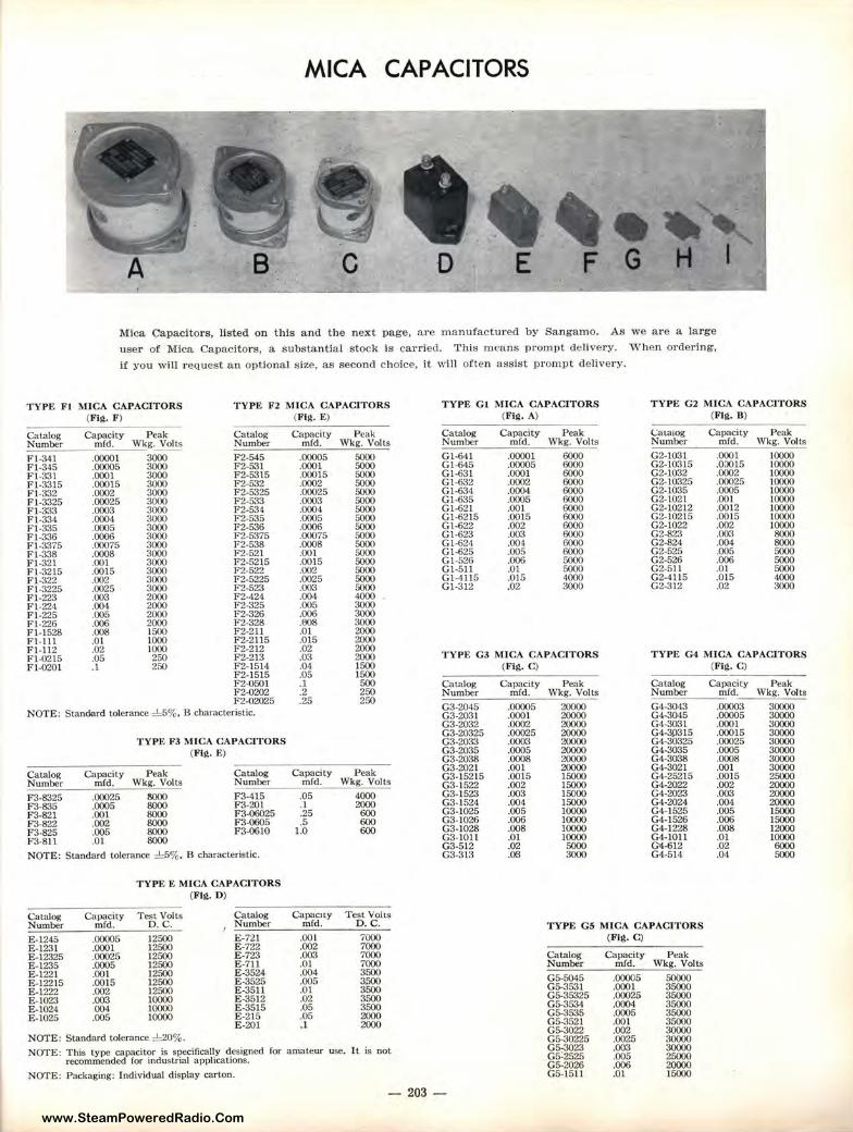
www.SteamPoweredRadio.Com
MICA CAPACITORS
B. C D
Mica Capacitors, listed on this and the next page, are manufactured by Sangamo. As we are a large
user of Mica Capacitors, a substantial stock is carried. This means prompt delivery. W'hen ordering,
if you will request an optional size, as second choice, it will often assist prompt delivery.
TYPE F l MICA CAPACITORS TYPE F 2 MICA CAPACITORS TYPE GI MICA CAPACITORS TYPE G2 MICA CAPACITORS (Fig . F) (Fill, E) (Fig. A) (Fig , B)
Catalog Capacity Peak Catalog Capacity Peak Catalog Capacity Peak Caw1og Capacity Peak Number mfd. Wkg. Volts Number mfd. Wkg. Volts Number mfd. Wkg. Volts Number mrd. Wkg. Volts
Fl-341 .00001 3000 F2-545 .00005 5000 Gl-641 .00001 6000 G2-1031 .000 I 10000 Fl-345 .00005 3000 F2-531 .0001 5000 Gl-645 .00005 6000 G2-10315 .00015 10000 Fl-331 .0001 3000 F2-5315 .00015 5000 Gl-631 .0001 6000 G2-l032 .0002 10000 Fl-3315 .00015 3000 F2-532 .0002 5000 Gl-632 .0002 6000 G2-10325 .00025 10000 Fl-332 .0002 3000 F2-5325 .00025 5000 Gl-634 .0004 6000 G2-l035 .0005 10000 Fl-3325 .00025 3000 F2-533 .0003 5000 Gl-635 .0005 6000 G2-1021 .001 10000 Fl-333 .0003 3000 F2-534 .0004 5000 Gl-621 .001 6000 G2-102l2 .0012 10000 Fl-334 .0004 3000 F2-535 .0005 5000 Gl-6215 .0015 6000 G2-10215 .0015 10000 Fl-335 .0005 3000 F2-536 .0006 5000 Gl-622 .002 6000 G2-1022 .002 10000 Fl-336 .0006 3000 F2-5375 .00075 5000 Gl-623 .003 6000 G2-823 .003 8000 Fl-3375 .00075 3000 F2-538 .0008 5000 Gl-624 .004 6000 G2-824 .004 8000 Fi-338 .0008 3000 F2-521 .001 5000 Gl-625 .005 6000 G2-525 .005 5000 Fl-321 .001 3000 F2-52l5 .0015 5000 Gl-526 .006 5000 G2-526 .006 5000 Fl-3215 .0015 3000 F2-522 .002 5000 Gl-511 .01 5000 G2-511 .OJ 5000 Fl-322 .002 3000 F2-5225 .0025 5000 Gl-4115 .015 4000 G2-4115 .015 4000 Fl-3225 .0025 3000 F2-523 .003 5000 Gl-312 .02 3000 G2-312 .02 3000 Fl-223 .003 2000 F2-424 .004 4000 Fl-224 .004 2000 F2-325 .005 3000 Fl-225 .005 2000 F2-326 .006 3000 Fl-226 .006 2000 F2-328 .808 3000 FI-1528 .008 1500 F2-211 .OJ 2000 Fl-Ill .01 1000 F2-2115 .015 2000 Fl-112 .02 1000 F2-212 .02 2000 Fl-0215 .05 250 F2-213 .03 2000 TYPE G3 M ICA CAPACITORS TYPE G4 MICA CAPACITORS Fl-0201 .1 250 F2-1514 .04 1500 (F ill, C) (Fig . C)
F2-15!5 .05 1500 F2-050l . I 500 Catalog Capacity Peak Catalog Capacity Peak F2-0202 .2 250 Number mfd. Wkg. Volts Number mfd. Wkg. Volts F2-02025 .25 250
NOTE: Stand<ilrd tolerance ~%. 8 characteristic. G3-2045 .00005 20000 G4-3043 .00003 30000 G3-2031 .0001 20000 G4-3045 .00005 30000 G3-2032 .0002 20000 G4-3031 .0001 30000
TYP E F3 MICA CAPACITORS G3-20325 .00025 20000 G4-3ll315 .00015 30000 G3-2033 .0003 20000 G4-30325 .00025 30000
(Fig. E) G3-2035 .0005 20000 G4-3035 .0005 30000 G3-2038 .0008 20000 G4-3038 .0008 30000
Catalog Capacity Peak Catalog Capacity Peak G3-2021 .001 20000 G4-3021 .001 30000 G3-152l5 .0015 15000 G4-25215 .0015 25000
Number mfd. Wkg. Volts Number mfd. Wkg. Volts G3-!522 .002 15000 G4-2022 .002 20000 F3-8325 .00025 woo F3-415 .05 4000 G3-1523 .003 15000 G4-2023 .003 20000 F3-835 .0005 8000 F3-201 .1 2000 G3-I524 .004 15000 G4-2024 .004 20000 F3-821 .001 8000 F3-06025 .25 600 G3-1025 .005 10000 G4-1525 .005 15000 F3-822 .002 8000 F3-0605 .5 600 G3-J026 .006 10000 G4-I526 .006 15000 F3-825 .005 8000 F3-06JO 1.0 600 G3-1028 .008 10000 G4-1228 .008 12000 F3-8!l .01 8000 G3-1011 .01 10000 G4-IOII .01 10000
G3-512 .02 5000 G4-612 .02 6000 NOTE: Standard tolerance ~%. B characteristic. G3-3 l3 .OS 3000 G4-514 .04 5000
TYPE E MICA CAPACITORS (Fig. D)
Catalog Capacity Test Volt.., Catalog Capacity Test Volts Number mfd. D.C. Number mfd. D.C. TYPE GS MICA CAPACITORS E-1245 .00005 12500 E-721 .001 7000 (FIil, C) E-1231 .0001 12500 E-722 .002 7000 E-12325 .00025 12500 E-723 .003 7000 Catalog Capacity Peak E-1235 . 0005 12500 E-711 .01 7000 Number mfd . Wkg. Volts E -1221 .001 12500 E-3524 .004 3500 GS-5045 .00005 50000 E-12215 .0015 12500 E-3525 .005 3,500 E-1222 .002 12500 E-3511 .01 3500 GS-3531 .0001 35000 E-1023 .003 10000 E-3512 .02 3500 GS-35325 .00025 35000 E-1024 .004 10000 E-3515 .05 3500 G5-3534 .0004 35000 E-1025 .005 10000 E-215 _05 2000 GS-3535 .0005 35000
E-201 .1 2000 GS-3521 .001 35000
NOTE: Standard tolerance :!::20%. GS-3022 .002 30000 G5-30225 .0025 30000
NOTE: This type capacitor is specifically designed for amateur use. I t is not GS-3023 .003 30000 recommended for industrial applications. c5:2525 .005 25000
GS-2026 .006 20000 NOTE: Packaging: Individual display carton. G5-1511 .01 15000
- 203 -
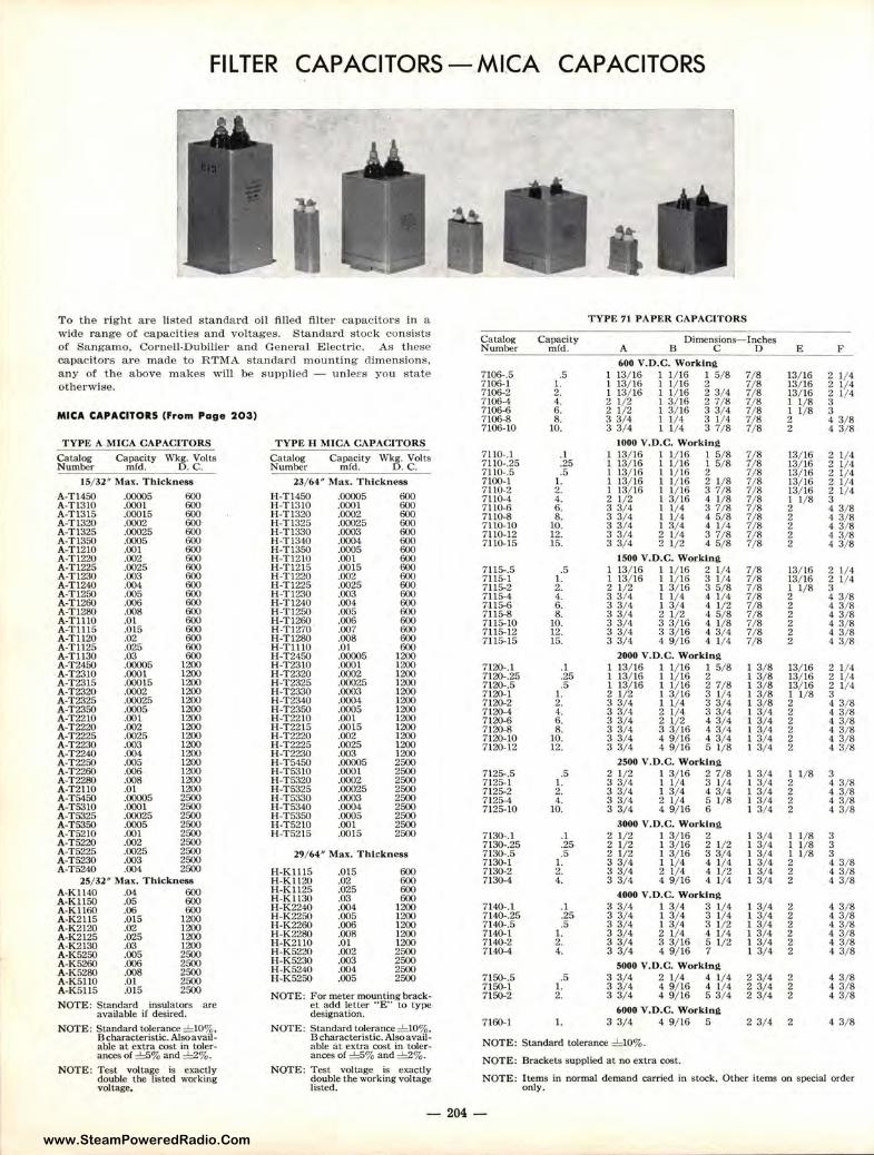
www.SteamPoweredRadio.Com
FILTER CAPACITORS-MICA CAPACITORS
To the right are listed standard oil filled filter capacitors in a TYPE 71 PAPER CAPACITORS
wide range of capaci ties and voltages. Standard stock consists Cata!og Capacity Dimensions- Inches
of Sangamo, Cornell-Dubllier and General Electric. As these Number mfd. A B C D E F capacitors are made to RTMA standard mounting dimensions, 600 V.D.C. Working any of the above makes w ill be supplied - unlel's you state 7106-.5 .5 13/ 16 1 1/ 16 I 5/ 8 7/ 8 13/ 16 2 1/ 4 otherwise. 7106-1 I. 13/ 16 I 1/ 16 2 7/ 8 13/ 16 2 1/ 4
7106-2 2. 1 13/ 16 I 1/ 16 2 3/ 4 7/ 8 13/16 ~ 1/ 4 7106-4 4. 2 l/2 I 3/ 16 2 7/ 8 7/ 8 I 1/ 8 MICA CAPACITORS (From Poge 20 3) 7106-6 6. 2 1/2 I 3/ 16 3 3/ 4 7/ 8 I 1/ 8 3
7106-8 8. 3 3/ 4 I 1/ 4 3 1/ 4 7/ 8 2 4 3/ 8 7106-10 10. 3 3/ 4 I 1/ 4 3 7/ 8 7/ 8 2 4 3/ 8
TYPE A MICA CAPACITORS TYPE H MICA CAPAC ITORS 1000 V. O.C. Working
Catalog Capacity Wki§. Volts Catalog Capacity Wkg. Volts 7110-.l .1 1 13/ 16 1 1/ 16 1 5/ 8 7/ 8 13/ 16 2 1/ 4 7110-.25 .25 1 13/ 16 I 1/ 16 I 5/ 8 7/ 8 13/ 16 2 1/ 4 Number m{d. . c. Number mfd. o.c . 7110-.5 .5 1 13/ 16 I 1/ 16 2 7/ 8 13/ 16 2 1/ 4
15/ 32" Mar. T hickness 23/ 64" Mas. Thickness 7100- 1 1. 1 13/ 16 I 1/16 2 J / 8 7/8 13/ 16 2 1/ 4 7110-2 2. 1 1½ 16 1 1/ 16 3 7/ 8 7/ 8 13/ 16 2 1/ 4 A-Ti450 .00005 600 H-Tl450 .00005 600 7110-4 4. 2 1 2 1 3/ 16 4 1/ 8 7/ 8 1 1/ 8 3
A-Tl310 .0001 600 H-T1310 .0001 600 7110-6 6 . 3 3/ 4 I l / 4 3 7/ 8 7/ 8 2 4 3/ 8 A-Tl315 .00015 600 H-Tl320 .0002 600 7110-8 8. 3 3/ 4 1 1/ 4 4 5/ 8 7/8 2 4 3/ 8 A-Tl320 .0002 600 H-Tl325 .00025 600 7110-10 10. 3 3/ 4 I 3/ 4 4 1/ 4 7/ 8 2 4 3/ 8 A-T l325 .00025 600 H-Tl330 .0003 600 7110-12 12. 3 3/ 4 2 1/ 4 3 7/8 7/8 2 4 3/ 8 A-Tl350 .0005 600 H-Tl340 .0004 600 7110-15 15. 3 3/ 4 2 1/ 2 4 5/ 8 7/ 8 2 4 3/ 8 A-Tl210 .001 600 H-Tl350 .0005 600 A-Tl220 .002 600 H-T 1210 .001 600 1500 V.O.C. Working A-Tl225 .0025 600 H-Ti215 .0015 600 71 15-.5 .5 I 13/16 I 1/ 16 2 1/4 7/ 8 13/ 16 2 1/ 4 A-T1230 .003 600 H-T 1220 .002 600 7115-1 1. l 13/ 16 I 1/ 16 3 1/ 4 7/ 8 13/ 16 2 1/4 A-Tl240 .004 600 H-Tl225 .0025 600 7115-2 2. 2 1/ 2 I 3/ 16 3 5/ 8 7/8 ~ 1/ 8 3 A-T1250 .005 600 H -T1230 .003 600 7115-4 4. 3 3/ 4 I 1/ 4 4 1/ 4 7/ 8 4 3/ 8 A-Tl260 .006 600 H-Tl240 .004 600 7115-6 6. :1 3/ 4 I 3/ 4 4 1/ 2 7/ 8 2 4 3/ 8 A-T1280 .008 600 H-T l250 .005 600 7115-8 8. 3 3/ 4 2 1/ 2 4 5/ 8 7/8 2 4 3/ 8 A-TlllO .01 600 H-Tl260 .006 600 7115-10 10. 3 3/ 4 3 3/ 16 4 1/8 7/ 8 2 4 3/ 8 A-Tl 115 .015 600 H -T1270 .007 600 7115-12 12. 3 3/ 4 3 3/ 16 4 3/ 4 7/ 8 2 4 3/ 8 A-Tll20 .02 600 H-Tl280 .008 600 7115-15 15. 3 3/ 4 4 9/ 16 4 1/ 4 7/8 2 4 3/ 8 A-Tl 125 .025 600 H-T l!IO .01 600
2000 V.D.C. Working A-T1130 .03 600 H-T2450 .00005 1200 A-T24S0 .00005 1200 H-T 2310 .0001 1200 7120-.1 . I l 13/ 16 1 1/16 1 5/ 8 I 3/ 8 13/ 16 2 1/ 4 A-T2310 .0001 1200 H-T2320 .0002 1200 7120-.25 .25 I 13/ 16 I 1/ 16 2 I 3/8 13/ 16 2 l / 4 A-T2315 .00015 1200 H-T2325 .00025 1200 7 120-.5 .5 I 13/ 16 1 l / 16 2 7/8 l 3/ 8 13/ 16 2 1/ 4 A-T2320 .0002 1200 H-T2330 .0003 1200 7120-l 1. 2 1/ 2 I 3/ 16 3 1/ 4 I 3/8 I 1/ 8 3 A-T2325 .00025 1200 H-T2340 .0004 1200 7120-2 2. 3 3/ 4 1 1/ 4 3 3/ 4 I 3/ 8 2 4 3/ 8 A-T2350 .0005 1200 H-T2350 .0005 1200 7120-4 4. 3 3/ 4 2 1/ 4 3 3/ 4 I 3/ 4 2 4 3/ 8 A-T2210 .001 1200 H-T2210 .001 1200 7120-6 6. 3 3/ 4 2 1/ 2 4 3/ 4 1 3/ 4 2 4 3/ 8 A-T2220 .002 1200 H-T2215 .0015 1200 7120-8 8. 3 3/ 4 3 3/ 16 4 3/ 4 I 3/4 2 4 3/ 8 A-T2225 .0025 1200 H-T2220 .002 1200 7120-10 10. 3 3/ 4 4 9/ 16 4 3/ 4 1 3/ 4 2 4 3/ 8 A-T2230 .003 1200 H-T2225 .0025 1200 7120-12 12. 3 3/ 4 4 9/ 16 5 1/8 I 3/ 4 2 4 3/ 8 A-T2240 .004 1200 H-T2230 .003 1200
2500 V.D.C. Worklnit A-T2250 .005 1200 H-T54SO .00005 2500 A-T2260 .006 1200 H-T5310 .0001 2500 7125-.5 .5 2 1/ 2 I 3/ 16 2 7/ 8 I 3/ 4 I 1/ 8 3 A-T2280 .008 1200 H-T5320 .0002 2500 7125-1 1. 3 3/ 4 I 1/4 3 1/ 4 1 3/ 4 2 4 3/ 8 A-T2110 .01 1200 H-T5325 .00025 2500 7125-2 2. 3 3/ 4 1 3/ 4 4 3/ 4 I 3/ 4 2 4 3/ 8 A-T5450 .00005 2500 H-T5330 .0003 2500 7125-4 4. 3 3/ 4 2 1/4 5 1/8 I 3/ 4 2 4 3/ 8 A-T5310 .0001 2500 H -T5340 .0004 2500 7125-10 10. 3 3/ 4 4 9/ 16 6 l 3/ 4 2 4 3/ 8 A-T5325 .00025 2500 H-T53S0 .0005 2500
3000 V.O.C. Working A-T5350 .0005 2500 H -T5210 .001 2500 A-T5210 .001 2500 H-T5215 .0015 2500 7130-.l .1 2 1/ 2 1 3/ 16 2 1 3/ 4 1 1/ 8 3 A-T5220 .002 2500 7130-.25 .25 2 1/ 2 I 3/ 16 2 1/2 I 3/ 4 I l/8 3 A-T5225 .0025 2500 29/ 64" M a x. Thickness 7130-.5 .5 2 1/ 2 1 3/ 16 3 3/ 4 1 3/ 4 I 1/ 8 3 A-T 5230 .003 2500 7130-1 I. 3 3/ 4 I 1/ 4 4 1/ 4 I 3/ 4 2 4 3/ 8 A-T5240 .004 2500 H-K1115 .Ql5 600 7130-2 2. 3 3/ 4 2 1/ 4 4 1/ 2 1 3/ 4 2 4 3/ 8
25/ 32" Max. Thickness H-K1120 .02 600 7130-4 4. 3 3/ 4 4 9/ 16 4 1/ 4 I 3/ 4 2 4 3/ 8 A-K1140 .04 600 H-K1125 .025 600 4000 V.O.C. Working H-K1130 .03 600 A-Kl!S0 .05 600
H-K2240 .004 1200 7140-.1 .1 3 3/ 4 l 3/ 4 3 1/ 4 l 3/4 2 4 3/ 8 A-K1160 .06 600 H-K2250 .005 1200 7140-.25 .25 3 3/ 4 1 3/ 4 3 1/ 4 1 3/4 2 4 3/ 8 A-K2115 .0 15 1200 H-K2260 .006 1200 7140-.5 .5 3 3/ 4 I 3/ 4 3 1/ 2 I 3/4 2 4 3/ 8 A-K2120 .02 1200 H-K2280 .008 1200 7140-1 1. 3 3/ 4 2 1/ 4 4 1/ 4 1 3/ 4 2 4 3/ 8 A-K2125 .025 1200 H-K2110 .01 1200 7140-2 2. 3 3/ 4 3 3/ 16 5 1/ 2 l 3/ 4 2 4 3/ 8 A-K2130 .03 1200 H-K5220 .002 2500 7140-4 4 . 3 3/ 4 4 9/ 16 7 1 3/ 4 2 4 3/ 8 A-K5250 .005 2500
A-K5260 .006 2500 H-K5230 .003 2500 5000 V.O.C. Working H-K5240 .004 2500 A-K5280 .008 2500 H-K5250 .005 2500 7150-.5 .5 3 3/ 4 2 l/4 4 1/ 4 2 3/ 4 2 4 3/ 8 A-K5110 .01 2500
7150-1 1. 3 3/ 4 4 9/ 16 4 1/4 2 3/4 2 4 3/ 8 A-K 5ll5 .015 2500 NOTE: For meter mounting brack- 7150-2 2. 3 3/ 4 4 9/ 16 5 3/ 4 2 3/4 2 4 3/ 8
NOTE: Standard insulators are et add letter " E " to type 6000 V.'O.C. Working available if desired. designation. 7160-1 1. 3 3/ 4 4 9/ 16 5 2 3/ 4 2 4 3/ 8
NOTE: Standard tolcrance ± IO% , NOTE: Standard tolerance ± l0% . B characteristic. Also avail- Bcharacteristic. Also avail-
NOTE: Standard tolerance ±10% . able at extra cost in toler- able at extra cost in tolcr-ances of =c!::5% and ±2%. ances of =c!::5% and ±2%. NOTE: Brackets supplied at no extra cost.
NOTE: Test volta~e is exacUy NOTE: Test voltage is exactly NOTE: Items in normal demand carried in stock. Other items on special order double the isted working double t he working voltage
voltage. listed. only.
204 -
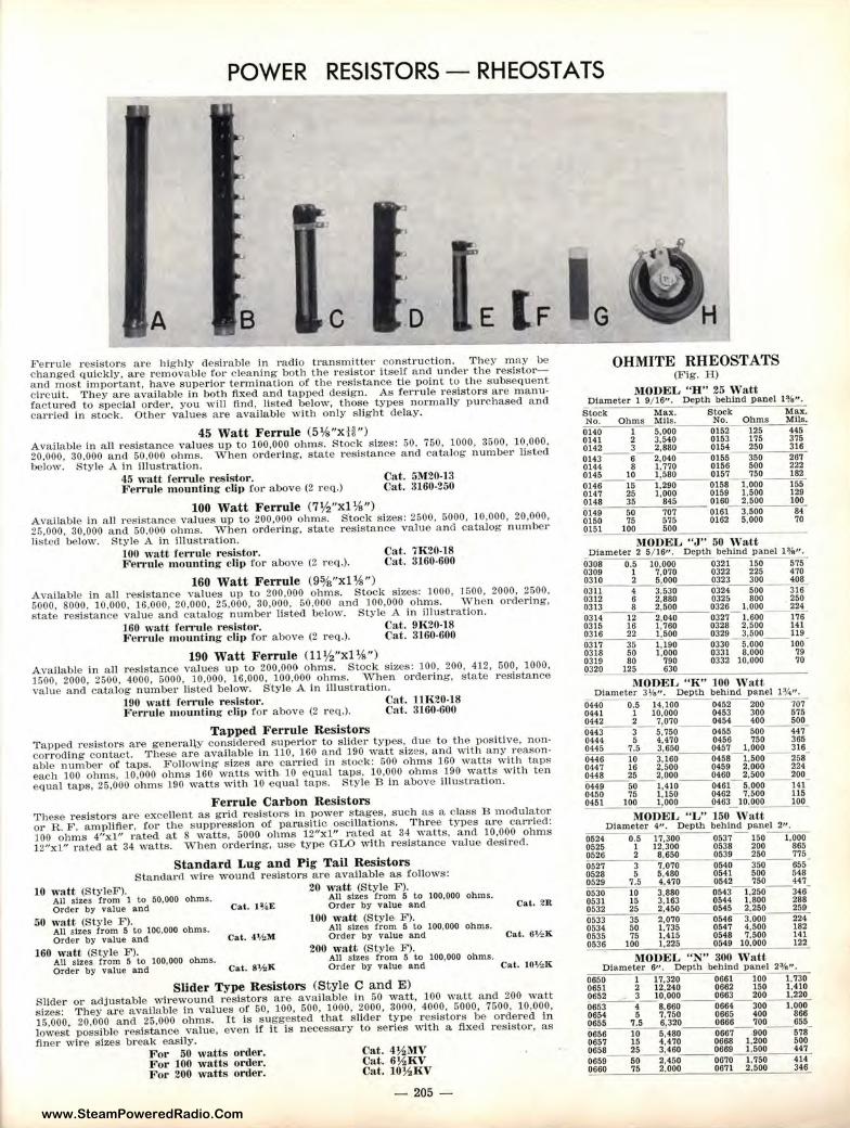
www.SteamPoweredRadio.Com
POWER RESISTORS - RHEOSTATS
l<'errule re~ls to rs are highly desirable in radio transmitte1· construction. They may be changed quickly, are removable for cleaning both the res istor Itself a.nd under the resis to ra nd most important, have superior te rmination or the resistance tie point to the subsequent circuit. They are a\'ailable in both fixed and tapped design. As ferrule resistors are manufactured to special orde1', you will find, listed below, those types normally purchased and carried in s tock. Other values a re available with only slight delay.
45 Watt Ferrule (5¼"x H") Available in all resistance values up to 100,000 ohms. Stock sizes: 50. 750. 1000. 3500, 10.000.
20,000. 30,000 and 50.000 ohms. When o rdering, state resistance a.nd catalog number listed below. Style A in illus tration.
45 watt ferrule r esist-Or . Ferrule m ounting cUp for above (2 req.)
Cat. 5:\120-13 Cat. 3160-250
100 Watt Ferrule (7½"xl ¾") Available in all resistance values up to 200,000 ohms. Stock sizes: 2500, 5000, 10,000, 20,000.
25.000, 30,000 and 50.000 ohms. When ordering, state resistance value and catalog number listed below. Style A in Illustration.
JOO watt re1T1de resistor . Cat. 7K20-18 F errule mounting clip for above (2 req.). Cat. 3160-600
160 Watt Ferrule (9%"xl ¾") Available in a ll resistance ,·alues up to 200.000 ohms. Stock sizes: 1000, 1600, 2000, 2500, 5000. 8000. 10.000, 16,000. 20.000, 25.000. 30,000, 50,000 a nd 100,000 ohms. When ordering, state resistance value a n() catalog numbe1· listed below. Style A in illustration.
160 watt ren ·ule r esistor . Cat. 9R20-18 Ferrule m ounting clit> for above (2 req.). Cat. 3160-600
190 Watt Ferrule ( ll½"xl%") A,·ailable in all resistance values u1> to 200,000 ohms. Stock sizes: 100, 200, 412, 500, 1000,
1500, 2000, 2500, 4000, 5000. 10,000, 16,000, 100,000 ohms. '\Vhen ordering. state r esistance value and catalog number listed below. Style A In illustration.
190 watt ren"t1le resistor . Cat. 11K20-18 Ferrule m ounting cli1> for above (2 req.). Cat . 3160-600
Tapped Ferrule Resistors Tapped resistors are generally cons idered superior to s lider types. due to the positive, noncorroding contact. These a re available in 110, 160 and 190 watt sizes. ancl with any reasonable number of taps. Following sizes are carriecl In stock: 500 ohms 160 watts with taps each 100 ohms, 10,000 ohms 160 wa tts with. 10 equa l taps. 10.000 ohms 190 watts with ten equa l taps, 25.000 ohms 190 watts with 10 equal taps. Style B In above lllu,;tralion.
Ferrule Carbon Resistors These resistors are excellent as grid resistors in power stages, such as a class B modulator or R . F. amplifier. for the suppression of parasitic oscillations. Three types are carried: JOO ohms 4"xl" rated at 8 watts, 5000 ohms 12"xl" ra ted at 34 watts. and 10,000 ohms 12"xl" rated at 34 watts . When ordering, use type GLO with resis tance value desired.
Standard Lug and Pig Tail Resistors Standard wire wound resistors a.re avaHable as follows:
JO watt (StyleF). All sizes from 1 to 50,000 ohms. Order by value and
50 watt, (Style F). All sizes from 5 to 100,000 ohms. Order by value and
160 watt (Style F). AU sizes from 5 to 100,000 ohms. Order by value and
Cat. l¾E
Cat. 4'r,M
Cal . 8Y,K
20 watt (Style F). All sizes from 5 to 100,000 ohms. Order by value and
100 watt (Style F). All s izes from 5 to 100,000 ohms. Order by value and
200 watt (Style F). AU sizes from 5 t.o 100,000 ohms. Order by value and
Slider Type Resistors (Style C and E )
Cat. 2R
Cat. 011,K
Cat. 10':l,K
Slider or adjustable wirewound r esis t ors are avai lable in 50 watt, 100 watt and 200 watt sizes: They are available In values of 60, 100, 500, l 000, 2000, 3000, 4000, 5000, 7500, 10,000,
15,000. 20,000 and 25,000 ohms. It is suggested that slide r type resis tors be ordered In lowest possible resistance value, even tr it is necessary to series with a flxed resistor, as
finer wire s izes break easily. For 50 watts order. For 100 watts order. For 200 w atts order.
Cat. 4½1\IV Cnt. 6 ½KV Cat. lO½ KV
- 205
OHMITE RHEOSTATS Wig. H)
MODEL " H" 25 W utt Diameter 1 9/ 16". Depth behind panel 1¾ ".
S~ock ___ Max. Stock Max. No. Ohms Mils . No. Ohms Mila.
0140--1 5,000 ___ 015~ 2-5--445
0141 2 3,540 0153 175 375 0142 3 2,880 0154 250 316 0143 - 6- 2,040--0155 350 267 0144 8 I, 770 01S6 500 222 0145 10 1,580 0157 750 182 0146--15--1.290 ___ 0158 1,000 ~
0147 25 1,000 0159 1.500 129 0148 35 845 0160 2,500 100 0149 50 707--0161- 3.500 84 0150 75 575 0162 5,000 70 0151 100 __ 500
l\lOOEL "J" 50 Watt Diameter 2 5/ 16". Depth behind panel lo/a".
0308--0.-S- 10,000 ___ 032I 150 575 0309 1 7,070 0322 225 470 0310 2 5,000 0323 300 408 0311 4 3,530 ___ 0324 500--316 0312 6 2,880 0325 800 250 0313 8 2,500 0326 1.000 224 0314 --12--2,040 ___ 0327 1,600--176
0315 16 1,760 0328 2,500 141 0316 22 1,500 0320 3,500 119 0317 --35--1,190 0330 5,000--100° 0318 50 1,000 0331 8,000 79 0319 80 790 0332 10,000 70
0320 125 630 ----------
MODEL "K " JOO W att Diameter 31/,". Depth behind panel I ¾".
0440 0~ 14,100 ___ 0452 200 707 0441 1 10,000 0453 300 575 0442 2 7,070 0454 400 500 0443 --3--5,750 ___ 0455 500- - 447
0444 5 4,470 0456 750 365 0445 7.5 3,650 0457 1,000 316 0446--10--3, 160 ___ 0458 1.500--258 0447 16 2,500 0459 2,000 224 0448 25 2,000 0460 2.500 200 0449--50- 1,410 ___ 0461 5,000--141 0450 75 1,150 0462 1,500 115 ~51~ __ 1.ooo ___ 0463 10.000 _ _ _ 100
MODEL "L" 150 Watt Diameter 4", Depth behind panel 2".
0524 0.517,300 --0537 150- 1,000 0525 I 12,300 0538 200 865 0526 2 8,650 0539 250 775 0527 3 7,070 ___ 0540 350--655 0528 5 5,480 0541 SOO 548 0529 7.5 4,470 0542 750 447 0530 10 3,880 ___ 0543 1,250--346 0531 15 3,163 0544 1,800 288 0532 25 2,450 0545 2,250 250 0533 --35--2.070 ___ 0546 3.000 224 0534 50 1,735 0547 4,500 182 0535 75 1,415 0548 7.500 141 ~536 100 1,225 _ _ _ 0549 10.000 _ _ _ 1_22
MODEL "N" 300 Watt Diameter 6". Depth behind panel 23/a".
0650--117,320 ___ 0661 100 1,730 0651 2 12.240 0662 150 1.410 0652 3 10,000 0663 200 1,220 0653- - 4- 8,680 _ __ 0664 300--1.000-
0654 5 7,750 0665 400 866 0655 7.5 6,320 0666 700 655 0656 10 5,480 _ _ _ 0667 1100- -5,a 0657 15 4,470 0668 1,200 500 0658 25 3,460 0669 1.500 441 0659- - 50- 2,450 ___ 0670 1, 7~14 0660 75 2,000 0671 2,500 346
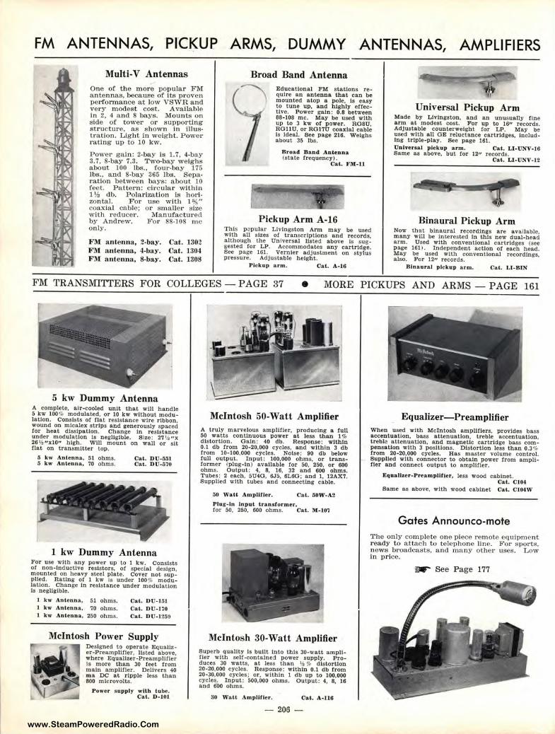
www.SteamPoweredRadio.Com
FM ANTENNAS, PICKUP ARMS, DUMMY ANTENNAS, AMPLIFIERS
Multi-V Antennas One of the more popular FM antennas, because of Its proven performance at low VSWR and very modest cost. Available in 2, 4 and 8 bays. Mounts on side of tower or s upporting structure, as shown in illustration. Light In weight. Power rating up to 10 kw.
Power gain: 2-bay is 1.7, 4-bay 3.7, 8-bay 7.3. Two-bay weighs about 100 lbs., four-bay 175 lbs., and 8-bay 365 lbs. s ·eparation between bays: about 10 feet. Pattern: cil·cular within 1 ½ db. Polarization is ho,;. zon tal. For use with 1 ¾" coaxial cable: or smaller size with reducer. Manufactured by Andrew. For 88-108 m e only.
F M: antenna, 2-bay. FM an tenna, 4-bay . FM antenn a, 8-bay .
Cat. 1302 Cat . 1304 Cat. 1308
Broad Band Antenna Educational F M stations require an antenn a that can be mounted atop a pole, Is easy to tune up , a n d highly effective. Power gain: 0.8 between 88-108 me. May be used with up to 3 kw of p ower. ROSU, RO11U. or RO17U coaxial cable Is Ideal. See page 216. Weighs about 35 lbs.
Broad Ba nd Antenna (state frequency).
Cat. FM-11
Pickup Arm A-16 This p opular Livingston Arm may be used with all sizes of transcriptions and records. although the Universal listed above is suggested for LP. Accommodates any cartridge. See page 161. Vernier adjustment on stylus pressure. Adjustable height.
Pickup a rm. Cat. A-16
Universal Pickup Arm Made by Livingston, and an unusually fine arm at modest cost. For up to 16" records. Adjustable counterweight !or LP. May be used with all GE reluctance cartridges, including triple-play. See page 161. Univer sal pickup a rm. Cat. LI-UNV-16 Same as above, but for 1211 records.
Ca t. LI-UNV-12
Binaural Pickup Arm Now that binaural r ecordings are available. many will be Interested In this new dual-bead arm. Used with conventional cartridges (see page 161). Independent action of each bead. May be used with conventional recordings, also. For 12" records.
Binaura.J pickup a rm. Cat. LI- BIN
FM TRANSMITTERS FOR COLLEGES - PAGE 37 • MORE PICKUPS AND ARMS - PAGE 161
5 kw Dummy Antenna A complete. air-cooled unit that will handle 5 kw 100% modulated, or 10 kw without modulation . Consists of flat resistance wire ribbon. wound on micalex strips and generously spaced for heat dissipation. Change In resistance under modulation Is negligible. Size: 27 ½ "X 26 ½ "xl0" high. Will mount on wall or sit flat on transmitter top.
5 k w Antenna, 51 ohms. 5 k w Antenna, 70 ohms.
Ca t. DU-Ml Cat. D U-rt70
1 kw Dummy Antenna For use with any power up to 1 kw. Consists of non-inductive resistors, ol special design. mounted on heavy steel plate. Cover not supplied. Rating of 1 kw is under 1007c modulation. Change In resistance under modulation Is negligible.
1 kw Antenna. 51 ohms. 1 kw Antenna. 70 ohms.
kw Antenna, 250 ohms.
Cat. D U-HH Cat. DU- 170 Cat. D U-1250
McIntosh Power Supply Designed to operate Equalizer-Preamplifier, listed above, where Equallzer-Preampllfler Is more than 30 feet from main ampllJler. Delivers 40 m a DC at ripple less than 800 microvolts.
Power s upply wllh tube. Cat. D -101.
McIntosh 50-Watt Amplifier A truly marvelous amplifier, producing a full 50 watts continuous power at less than 1 % distortion. Gain: 40 db. Response: within 0.1 db from 20-20,000 cycles, a nd with in 3 db from 10- 100.000 cycles. Noise: 90 db below lull output. Input: 100,000 ohms. or transformer (p lug-In ) available for 50, 250. or 600 ohms. Output: 4. 8. 16. 32 and 600 oh ms. Tubes: 2 each. 5U4G, 6J5, 6L6O; and 1, 12AX7. Supplied with tubes and connecting cable.
50 Watt Amplifier. Cat. 50W-A2 Plug-in l_nput tra n s former, for 50, 250, 600 ohms. Cat. M-1.07
McIntosh 30-Watt Amplifier Superb quality Is built into this 30-watt amplifier with sell-contained power supply. Produces 30 watts, at less than \I,% d istortion 20-20.000 cycles. Response: within 0.1 db f rom 20-30,000 cycles; or, within 1 db up to 100,000 cycles, Input: 500,000 ohms. Output: 4, 8, 16 and 600 ohms.
30 Wa tt Amplirter. Cat. A-116
206
Equalizer-Preamplifier When used with McIntosh ampllflers, provides bass accentuation, bass attenuation, tr eble accentuation, trebl3 a ttenuation. and magnetic cartridge bass compensation with 3 positions. Distortion less than 0.3 % from 20-20,000 cycles. Has master volume control. Supplled with connector to obtain power from amplifier and connect output to amplifier.
Eqaa lbe r•PreampJlf ier , less wood cabt.net. Cat. CIOt
Same as above. with wood cabinet Cat. Cl04W
Gates Announco-mote 'l'he only comple te one piece remote equipment ready to attach to telephone line. For sports . news broadcasts, and m ,1ny other uses. Low in price.
~ See P age 177
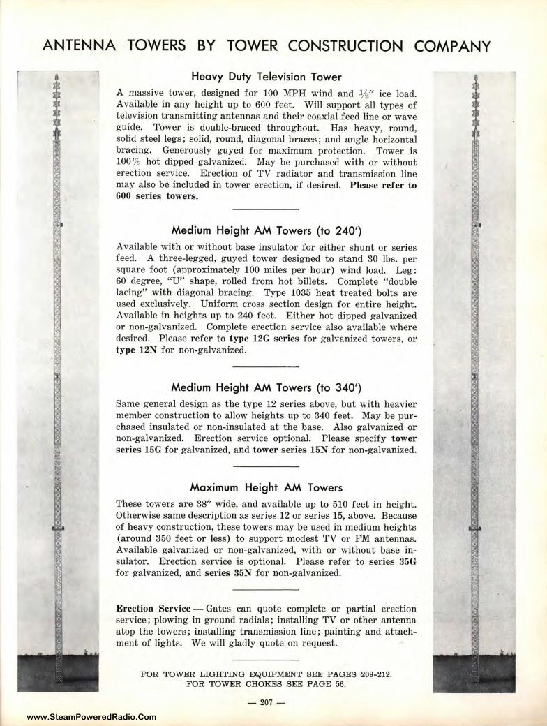
www.SteamPoweredRadio.Com
ANTENNA TOWERS BY TOWER CONSTRUCTION COMPANY
Heavy Duty Television Tower A massive tower, designed for 100 MPH wind and ½" ice load. Available in any height up to 600 feet. Will support all types of television transmitting antennas and their coaxial feed line or wave guide. Tower is double-braced throughout. Has heavy, round, solid steel legs; solid, round, diagonal braces; and angle horizontal bracing. Generously guyed for maximum protection. Tower is 100% hot dipped galvanized. May be purchased with or without erection service. Erection of TV radiator and transmission line may also be included in tower erection, if desired. Please refer to 600 series towers.
Medium Height AM Towers (to 240')
Available with or without base insulator for either shunt or series feed. A three-legged, guyed tower designed to stand 30 lbs. per square foot (approximately 100 miles per hour) wind load. Leg: 60 degree, "U" shape, rolled from hot billets. Complete "double lacing" with diagonal bracing. Type 1035 heat treated bolts are used exclusively. Uniform cross section design for entire height. Available in heights up to 240 feet. Either hot dipped galvanized or non-galvanized. Complete erection service also available where desired. Please refer to type 12G series for galvanized towers, or type 12N for non-galvanized.
Medium Height AM Towers (to 340')
Same general design as the type 12 series above, but with heavier member construction to allow heights up to 340 feet. May be purchased insulated or non-insulated at the base. Also galvanized or non-galvanized. Erection service optional. Please specify tower series 15G for galvanized, and tower series 15N for non-galvanized.
Maximum Height AM Towers
These towers are 38" wide, and available up to 510 feet in height. Otherwise same description as series 12 or series 15, above. Because of heavy construction, these towers may be used in medium heights (around 350 feet or less) to support modest TV or FlVI antennas. Available galvanized or non-galvanized, with or without base insulator. Erection service is optional. Please refer to series 35G for galvanized, and series 35N for non-galvanized.
Erection Service - Gates can quote complete or partial erection service; plowing in ground radials; installing TV or other antenna atop the towers; installing transmission line; painting and attachment of lights. We will gladly quote on request.
FOR TOWER LIGHTING EQUIPMENT SEE PAGES ·209-212. FOR TOWER CHOKES SEE PAGE 56.
- 207 -
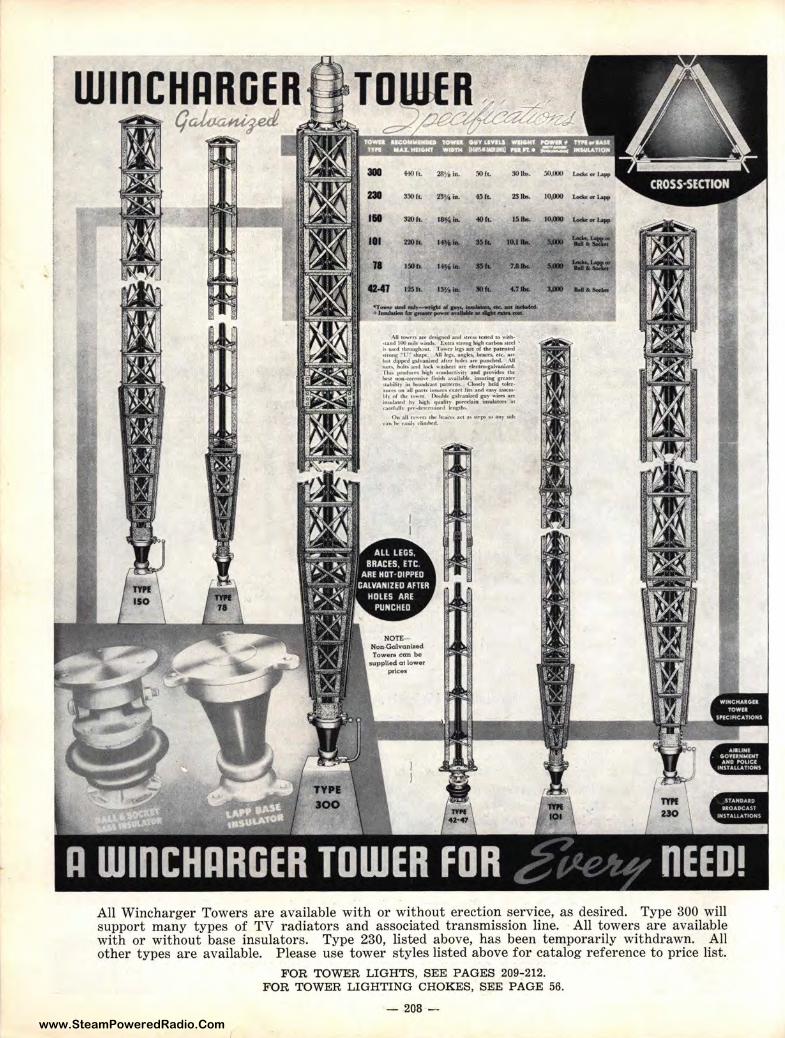
www.SteamPoweredRadio.Com
.. +M)fc. 281/1 ia. !JOfL ~Ibo.
DI l!IOI!. 2'1/, ... OfL 2Slb,. ,. :13)ft. ls,4-. 4111L u ...
Ill 2:IOft.
,_ .. ... .... 11 UOft. 1 ..... .. 7.a ..
41-41 IZft. l'Y,lo. .... 4.7k
AJI '°"'·tts tttt ,k-~ ao;od Ml(» JCMe4 10 .,.,,h•U.-.d JOO ••le .. ieib .. t:_,1r.a ,u_,. w,.h ca,bou M.ttl • k U"'d 1b.nlu,:l.o,1u. To,,,.u kV iut el the ~k•~4 ~~ .,l- .. pt. AU Irr, utkftt bf.a-, tic, 11«
::,d•~~ ~,~«d .. :!:.::i ~ ::~~!.· Thi,, l)f$dllN'1 IJch .-ondffC"li~il) and pr~~ I~ t,. " -~,o,t,., f~ .aoibbk, int,.rifts !Jft.llrf ,u,l..ti1i in l>l:lloMk,11"' pallt'rlt\. ClrDKlt· ~dd tok-r• aiu-n oa a,lJ JIii.ib in"Wtt~ h"'4111'1 r .. , .ahd ~)· a..t••
~:_~,;:, t!:'"r~h •;.-::, ~.,::~ t!w~: a: c.1ff'f'11lh ,.,..,dt,u,.,A'd k111:t:th"
(),. :ioll ,o ... n, ,...,. 1..-,...~ M1 •• ,u-,- ,.., .a.,,),.& r.>,.bt-r-.-il• tli.ni,litd.
!IO.oo>
I0,000 t..c0c•1-
10,000 ..-..i..,.
,_ .......
All Winebarger Towers are available with or without erection service, as desired. Type 300 will support many types of TV radiators and associated transmission line. All towers are available with or without base insulators. Type 230, listed above, has been temporarily withdrawn. All other types are available. Please use tower styles listed above for catalog reference to price list.
FOR TOWER LIGHTS, SEE PAGES 209-212. FOR TOWER LIGHTING CHOKES, SEE PAGE 56.
- 208 -
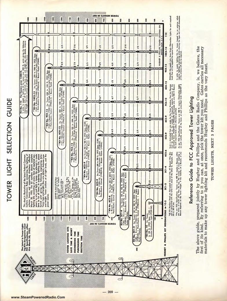
www.SteamPoweredRadio.Com
~
0 <D
:m~
.. ~y~
TOW
ER
LI
GH
T S
ELE
CTI
ON
G
UID
E
... T
he l
ate.
st in
To
wer
ligh
tIn
g K
its
des
ign
ed t
o m
eet
fC
C S
pec
ific
atio
ns,
eff
ec: ..
tl
ve
Mar
ch 3
0, 1
_ 95
3.
·-T
I,is
ehar
t is
illu
drat
ive
of
the
late
·d F
ede;
,, C
omm
u~
icat
ions
Com
mis
sion
Rul
es c
once
rnin
g th
e li
ghti
ng o
f an
tenn
a to
weN
an
d su
ppor
ting
dru
ctur
e1,
effe
cfrw
·e
Mu
ch
30,
1953
. Th
e •i
t n
um
be
rs d
enot
e co
mpS
.te
ligh
ting
~ih
con
sist
ing
of
ever
y i
tem
of
met
erit
l ne
e;
enar
y t
o w
ire
and
light
• to
wer
. N
o •
++
empt
i1 m
ade
here
to
list
all
item
s. I
n or
deri
ng l
ight
ing
•ih:
, p
leu
e fu
rnis
h pr
int
givi
ng t
he
follo
win
g en
gine
eri
ng d
ata:
7 -\.
~•:,
~.~
•.~
~~
pty
'.0 ri::
;:.•r1!
fo:•.~
...1.!0 o~
•~is
oo f
t.,
prinh 9
f~i119 t
h•
f0U
owi11
.9
' •t
19i111
Htif
19
d•f
• wi
ll 1,
. H
q11ir
..d:
Tow
•, t
y~
•lk
:l h
•i,;i
ht,
9v
y w
lr•
d•+•
~••
A111
t.111
11•
/ !!
~• 1
'i .• i9
Jrtt,
.n
d fo
••t_
,uti
o,u
•f
•II
li,;,h
t a.v
.1,
, •n
d t
h•
Pow
ff S
owtu
·. ■
_1
-y
1--
1--·-
; TO
W!R
LI
GH
TIN
G
KIT
5
5AV
I T
IMI
& M
ON
EY
ENG
INEE
RIN
G
TIM
E PU
RCH
A.S
INO
TI
ME
EREC
TIO
N
TIM
E
(
uoo
1----
c ••k
it N
o,
10
C5
-15
Mn
Tow•n
13$
0 to
150
0 ft
. (F
CC
Sp•
c.
: 7 ti!!
to\1
~~~1:
"c!:
+~
't( •:J
k:~~~;~
': ~.1
,:::
v:~
:.~
~h[~
!~r.
lOE
I'
1--
u-A-
-1 1--
.... 1
40
0
• h
Tow
er t
yp
e an
d h
eigh
t, G
uy w
ire
det
ails
, A
nten
na ty
pe,
and
hei
ght,
Tow
er s
ecti
ons
at
all
ligh
t Jt.
..-el
s, an
d t
he
po
we
r so
urce
. -c ••
Kit
No
. 9
(4. 1
5
For
To•
•r-s
1200
lo
13
50 f
t.
(FC
C
Sp-
c .
J------
17.3
2). 4
1 .. co
1u (
#K
Gll
41,
15 S
i,i9l
• O
b1tr
11ct.
011
U9
hh
(#
OII
0E),
t
Pho
to0E
l•cM
c C
ontr
ol (
lfPE
CA
-71.
I
IHco
11
ff•1
h•r
lliS
FIS
).
:'\
Jl
J L--1
••oo-
lJ-lf 9/10
-7
r.-~.~
13
00
--I
•.~
EH
Ui:.
.HlY
I
ffll
LL
i,S
rifN
-1
1.n
ue •
rriu
d et
I• I
.lie fol
•------
----
----
--------------
----
...•--
--~N
:. zie;
;'· 1 °"
...
..._.
: • •
Kit
No
. 8
(4
-12
!=or
To
••n
IOSO
to
12
00 f
t.
fFC
C
Sp•
c.
... M
. 1
20
0
'!:oo
tti:,
towe
t,'?4l•~
·r:·
· --------
-17
,JI)
. 4
& .. co
nt l
b.:K
Gll
4j,
12 S
in9l
•O
l»f1
1i1c
lio11
U9
hh
j1!
Q&
IOE
),a
---V
8/9
---
&oek
i.'~
'""1
19
''i
I PM
lto--
El•c
hic
Con
trol
(#
PSC
A-7
l, I
IHco
n An
h.•,.-(
#S
HS)
. f 1
:•;:,~
d~~!
l:., of
lf
f. _
__
__
__
__
_ ..
,_ _
__
__
__
__
___
__
__
__
_
com
. (M
f.ftlf
fl9ff
l N
o, l
ff.
l.
4/5
1-- , __ 1
1!~-~
1
10
01
•----
·-••--
--.,rf
:i)1~.
:;~
~ Ob
-(
-~--
....
I 11
,vc~
L
l.tht
,. (M
r,i"
'"""
---
:!:;.!,•
~·.!·:::
11 ~~,
."~dd
....
, ..... c
, -.~.,
-.
_.,
. ...
r• t
owu}
.
-I
I ~ ~
----
}}.O
O ••
Kit
No
. 7
(3
-12
For
Tow
e"
900
to
IOSO
ft
. (F
CC
S
pK,
' ·
17.3
0].
l l•
.cot
11 (
=tl
(Gll
4],
12 S
in9I
• O
b1tr1
1dio
11 l
i9h
h J
#O
II0
E),
6
__
_ £7
/8
--
. 7
/9 -
-7
/1
0--
--
1 P
hoto
-Ele
ct,ic
.C
o11o
trol
j#PE
CA-6
),
I IH
c:on
,Fle
ihtr
I
S~0J
. e,.
____
J: __
__
• __
__ -
-1
!.~
3/4
--
2/3
--
-(
••K
it N
o. 6
(3-9
Fo
, Tow
o,,
1SO
to
900
ft.
(FC
C S
pK.
11.2
9).
) ,
I• 9
00
J
•••c
o"'
l#
KG
114/
, t
Sl11
9I•
O1,
tt,v
ct.0
• U
glih
(J
tOII
0E).
I
----1
'3
6/7
--
IE . -~
,t
.o,~
El0
<hk
Co,
t,o
(#
PE
C"'
_.),
1
""''" "''~
" (=
moJ
.. f
I j
·•i;"
2 l
,oo
. ----
-IO
O 4
=:
-J .-
••K
it N
o.
SC
2•9
Fo
r T
oweu
600
to
750
ft.
fF
CC
~•c
:. 1
7.21
1.
, ~
•,:z:
-~
-( 2
..
....
. (#
KG
114)
. 9
s,.,,.
Ob
, ...
. ,, •
•
Ll9h
l,
(-O
BI0
E).
I
---
! ~ 5/
6 --
' 8
5/7
--
5/U
--
1 8 5
/9 -
-t/
2 --
d-~
P,-.
to-E
l•ct
ric
Co1
1tro
l j#
PE
CA
-SI.
I le
.co
n
R.1
1af
(#S
fl0
).
r!·
! , ~0
0~
----
-_ -_
-_ -_
-_ -_
-_ -_
70
0 .
i
; r
••K
ltN
o.4
C2
-6
Fo
,To
w•n
4S
Oto
60
01
4.IF
CC
Spo
c.17
.l1)
. 1) l
1 1
l ~
! ;t
60
0 2
t.e<
o1u
(#K
Gll
4).
6
Sfng
l•
Ob1
ftwct
lott
l19h
f1
(~O
II0E
),
I ---·f
8 4'
/!S --
2/3
---
4/7---
1/2
---
4/9
---
2/5
--
--
'"
2 \..
, Ph
oto-
Ele
e:trk
. C
ontr
ol
(t:P
EC
A"'
4),
I a.
.•co
n R
•1h•
r p
tSF
J0).
----
-~
,ool
__
__
, 0
0 ..
Kit
No
. 3
C1
•4
f.or
Tow
ers
300
to
450
ft.
(FC
C S
pec.
)
17.2
6).
I •••co
n
(1tK
Gl1
4).
4 Sl
11t•
O
bdri
.cllo
n U
thh
6
__
_
314 --·~
~
l/S
__
t/
2 _
_
3/7
__
3
/8
1/3
--
3/IO
--
---
~~::
o,EJ
,SF~or.o♦
o--El•
ctric
Co1
1t,o
l •P
EC
A-4
1,
I ... CO
III 6
....
3/5
--M
---1
~
, __
-iJ
,21
3--
§ 11
2--
§2
15
--
§ V
3--
§2
11
--
Kit
No
, 2
(1 •
2 f.o
r To
w•,
1 IS
O
to
30
0 ~
. (F
CC
S
p•c·
D
H
O
17.2
5).
I 1 .. c
ot1
l*
KG
ll4
1,
2 S1
11~1
• O
b1tN
Kfi
ot1
Lig
hh j
8 ~~
~,'o~
Srio
~lw
to-
tee.
Mc
Co,
-t,.-
1:PE
CA
-41,
I
l•u
on
g ·-=
==~:-
1-
-t/4
--
•oo
200
I •K
itN
o.
lC
F
o,
Tow
e"
----
to
ISO
ft
. IF
CC
S
poc
. 17
.141
, I
,y ---.
ft_t/2--
! !ji
l,1
3--6
11
• -
61
15
-61
/&--
G,1
1-·
£\,v
e-
1
2/9-1
=3-
:l,v,---1
~--1 r
20
0
O,.
bk O
b,t
,o,l
io• ~:htt=
: 1 _____________
--~
0 H
UG
HEY
• ~~
,!~~sc1e
re: :i:
.HT
ING
DIV
.I
10
0
HU
OH
IY &
PH
ILLI
PS
KIT
.DES
IGN
AT
ION
S +
-1C
-2
2C
1-2
3C
1•4
4
C2
-6
5C
2•9
6C3-
9 7
C3
-12
ac
c.12
9
C4
.15
lO
CS
-15
·1
IC
•AU
Kit
N11
Mb.
n U1t♦e
f •'
• G
alu1
tite
d C
ondw
a IC
lh.
All &po1♦
ef W
I,•
Krh
wi
n be
cf•
,it"
•t.d
wil
l. t
it.
I.H
er E
In
pl.
o o
f th
• '-
tt•r
C.
&am
ple
: IE
.2,
2El0
2, U
:1"'4
, •tc
. 0
A,
P•'
FC
C S
p•ci
fic•tl
o111
1:
Tow
•t1
ov•
r 45
0 ft
. r•
q11i
,e e
•••c
o,.,
with
in
tt..
tow
et.
•+ 1
e~•l1
otlr
l•r
tlrle
n th
e to
p.
ff.•
n1
1mbe
r o
f 1•
~•11
re
q11l
,int
• 1 .
. co1
1 de
p•,.
d• o
n th
.• T
ow•r
H•i
9h
t. II
the
viti
biU
ty o
f •
IH<O
fll,
•t u
y
leve
l. I,
olut
n,ct♦ef
f,o
m a
ny •
ngle
, a,.,
tfte
Tow
e, S
bwct
vr•,
the
n tw
o IH
cons
"°'
'"' N
Mo
11nt♦e
f o"
t'-
• 01
1hld
e of
di
•901
1•lty
op
po,f
te
corfl
•U ••
th
h
prH
crib
.d ~
vel
HU
GH
EY &
PH
ILU
PS U
h i
11el1
1de
0J1.l
y O
H K
GI 1
4 &
.. ,0
11
lo,
Heh
r•q
11~♦e
f l•
v•J.
i.l'llH
1 ot
he,..
.i1e
1ped
fi•d
.
:: :
:: .. ~
1J:-
:!~
!!!l
oof1
:1~0 1
:~!,
, .... ~
, .!~
'~.=~
t:d ftt
niH''7G
Hl~h
.~
Ref
eren
ce G
uid
e to
FC
C A
pp
rove
d T
ow
er L
ight
ing
PHIL
LIPS
Kih
11
1pj:.-
fy ~
11ly
tla
r••
Si11
9I•
Obd
t111
itlon
ll9
lih
fo
, ..
ch ,~
11lr
..d'
l•Yel
. Fo
11, w
ill M
111
pp1ie
d fo
r 1q1
1•t•
lo
••"·
1 11 o
tdff
to
,11p
ply
li9ht
i119
ljh
fo
r to
w.,,
to
pped
by
o
•t1t♦t1
fle,
w
hk'-
:;1
t:•:
,.~i
:111~!"
?'itt
:~:t
'i1n
~::r i
how
it19
tk•
tvP
• •n
d o
v•re
ll dl
m•11
11lo
H
Th
e ab
ove
guid
e, p
repa
red
join
tly
by
Hu
gh
ey a
nd
Phi
llip
s an
d t
he
Gat
es R
adio
Com
pany
, is
, w
e be
liev
e, t
he
firs
t o
f it
s ki
nd.
By
ref
erri
ng
to
it
you
can,
at
once
, pi
ck t
he
tow
er k
it y
ou n
eed.
G
ates
car
ries
all
nec
essa
ry
mat
eria
ls t
o m
ake
up
an
y t
ower
lig
ht~n
g k
it a
nd
rec
omm
ends
Hug
hey
and
Phi
llip
s as
th
e v
ery
fin
est.
TO
WE
R L
IGH
TS
, N
EX
T 3
P
AG
ES
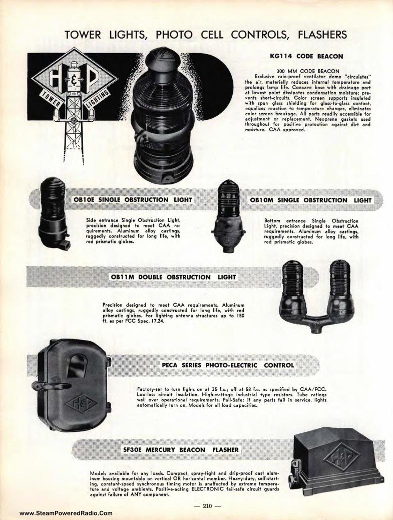
www.SteamPoweredRadio.Com
TOWER LIGHTS, PHOTO CELL CONTROLS, FLASHERS
' i
Side entrance Single Obstruction light, precision designed to meet CAA re• quirements. Aluminum alloy castings, ruggedly constructed for long life, wit h red prismatic globes.
Precision designed to meet CAA re quirements. Aluminum alloy castings, ,uggedly constructed for long life, with red prismatic globes. For lighting antenna structures up to 150 ft. as per FCC Spec. 17 .24.
KG 114 CODE BEACON
300 MM CODE BEACON Exclusive rain-proof ventilator dome "circulates"
the air, materially reduces internal temperature and prolongs lamp life. Concave base with drainage port at lowest point dissipates condensation moisture; prevents short-circuits. Color screen supports insulated with spun glass shielding for glass-to-glass contact, equalizes reaction to te mperature changes, eliminates color screen breakage. All parts readily accessible for adjustment or replacement. Neoprene gaskets used throughout for positive protection against dirt and moisture. CAA approved.
Bottom entrance Single Obstruction light, precision designed to meet CAA requirements. Aluminum alloy castings, ruggedly constructed for long life, with red prismatic globes.
Factory-set to turn lights on at 35 f.c.; off at 58 f.c. as specified by CAA/ FCC. Low-loss circuit insulation. High-wattage industrial type resistors. Tube ratings well over operational requirements. Fail-Safe: if any parts fail in service, lights automatically turn on. Models for al l load capacities.
ERCURY BEACON :.:~l£!1Kf.®Wtlflltm]tl1f:titft.1tmt~Uilm1it: ... :-:-.❖:❖:•:-.-.
Models available for any loads. Compact, spray-tight and drip-proof cast aluminum housing mountable on vertical OR horizontal member. Heavy-duty, self-starting, constant-speed synchronous t iming motor is unaffected by extreme temperature a nd voltage ambie nts. Positive-acting ELECTRONIC fail-safe circuit guards agftinst failure of ANY component.
- 210 -
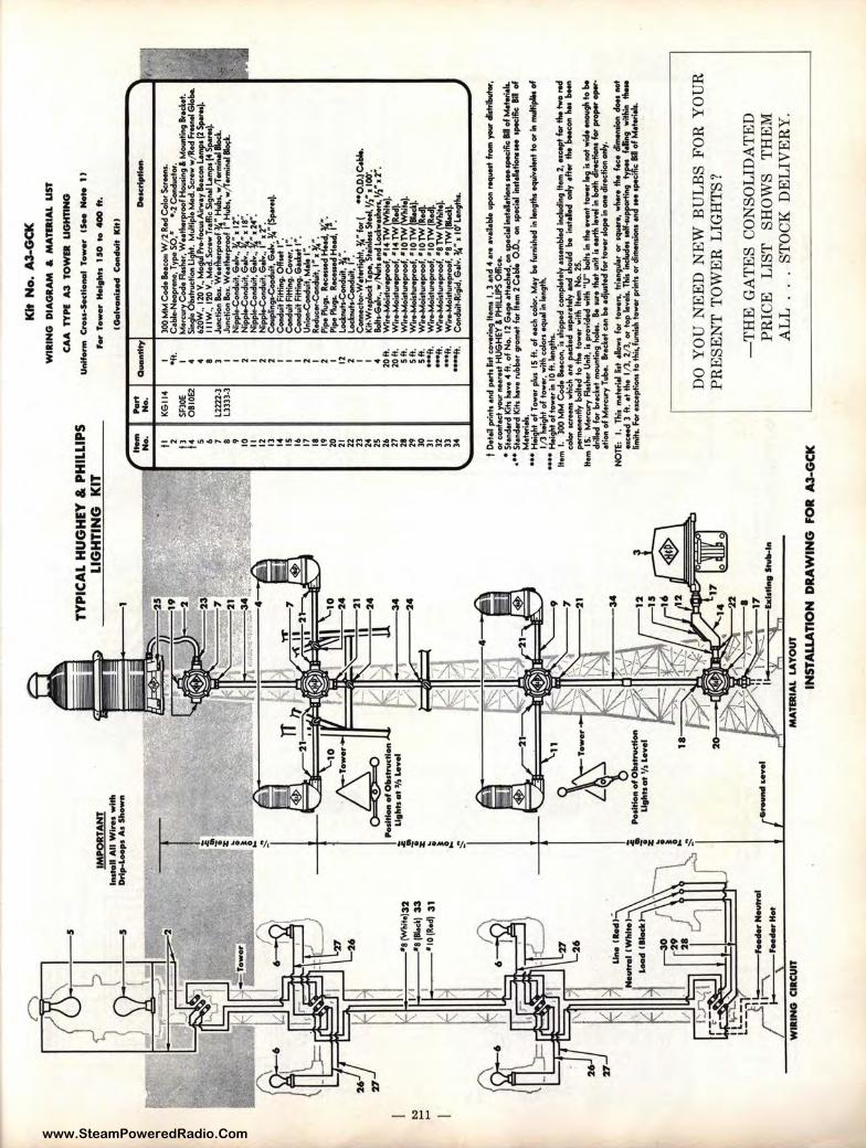
www.SteamPoweredRadio.Com
i,-:
, ,_.
,_.
\ ,?
I
5
) !
5
IMP
OR
TA
NT
in
-nA
HW
lro
sw
ltll
D
rip
-Lo
op
s A
s $
Ito-
T
:; ~
TY
PIC
AL
HU
GH
EY
& P
HIL
LIP
S
LIG
HT
ING
K
IT
-P
art
No.
N
o.
I I
KG
ll4
2 I!
SF30
E O
BI0
E2
5 6 7 I Ll
222-
) 8
Lll
ll-3
Kit
No.
.A
3-G
CK
WIR
ING
D
IAG
RA
M &
M
AT
DIA
L U
ST
CA
A T
YP
I A
3 T
OW
a U
GH
TIN
G
Un
i'-
C..
Oss
-Sec-1
To
-IS
--
1 I
f,w
To
wo
r H
olt
f,ts
1 $
0 t
o <
IOO
ft.
au
on
ttty
l
I Oft.
I 4 4 8 ) I
IGal
Yan
lzec
l C
-..
it K
ltl
DeK
rt ..
....
..
300
MM
Cod
e S
.oco
,, W
/2 R
.d C
olo
, Se
r-.
Cob
le-N
__
, Typ
o S
O.•
•-
2 Co
.duct«
. M
o,,:,
wy
Co
d•
Flo
sho,
, w ..
the,
e,oo
f Hou
ti119
& ~ ..
....
...
Sin9
'o O
bdn,
cm,n
Ugl
,t. M
ultip
le M
.d. S
crew
w/R
.d F
r...
. Glo
be.
620W
., 12
0V.,
Mog
,.,I P
r.-f
ocus
Afr
woy
S.-
!Am
pt (
2 s,
,.,.
.j.
11 IW
., 12
0 V
., M
.d. S
c,_
T,e
flic
Sig
nel L
emp,
(4 s
-..i
J-t
ton
Box
. We.
tl.e
,p,o
of ~
• H
ub.,
w/T
erm
iNI W
. ~ •
c=
ib
lw,
'j 9 10
II
I 2 I
Jone
tion
Box.
WH
the,
p,oo
f I
Hub
s, w
/Ter
mio
el ~
N
ippl
e-C
ondu
it. G
elv.
, i", 12".
Nip
plo-
Con
du;t,
Gel
v.,
~•,
18"
. N
ippl
o-C
ondu
;t, G
elv.
, •,
24".
I{ I'
•"'
•a (W
l,it
e)32
I/
I •a
(Le
k) 3
3
I •1
o(R
ed)
31
D.
6 •7
Un
ol-
1·
,I I
Wh
lto
&eo
dlU
ock
:
,-3
0
29
2
1
. I--
"\
,...
.., N
ov
tnl
I•
• •--
WIR
ING
CIR
CU
IT
;;.
~!
P-
of O
bs
tru
<tl
on
;i;
Li
9hts
ot
,1, I
Av
ol
.!'
~ 1 ;;.
)-(l
Li
-~ &
)a
_")
.c:t-
-
i -r z
~:: ~
·•-
.... 1
...__
--b
II ,
; ,'
y<<i
b
lsfl
oltl
,_
In
MA
TD
IAL
LA
YO
UT
12
13
14
15
16
17
18
19
20
21
22
23
24
25
26
27
29
2
9
30
31
32
))
)-4
2 2 I I I 2 I 2 I 12
2 I I 4 20
ft.
20
ft.
5
ft.
5ft
. 5
ft.
... f
t. ·••
ft.
·••ft.
··•~
. Nip
ple-
Con
duit.
Gol
v ..
I , 2
".
Cou
plin
gs-C
oodu
it, G
elv.
¾ • (
S,-
.).
Con
duit
Fitt
iftg.
Of/
sot
1·.
Co
nd
uit
Fitti
119.
c.,
• .,,
1·.
Co
nd
uit
Rffi
119.
6M
lcot
I".
U
nlon
-Coo
duit,
Ma
I•.
R.d
ueo,
.Con
duit,
I",
¾ •.
P
ipe
Plu
g,.
ROCO
SMd
Hffc
l, 1'
<.
Pip
e Pl
ug,.
ROCO
SMd
Ho.
d, 1
•. Lo
cl:n
ut.-C
ondu
il, 1
/. ••
L
oeln
uh..C
ondu
it, /2
. C
onne
eto,
.Wet
0ffi
9ht,
¾"lo
,(
°"O
.D.)
C.W
.. K
a.w
,...io
a r_.,,.,
Stoi
nloa
StN
I. 1/
2, 1
00·.
llolt>
-6 ...
... w
,IN
uh
•ncl
lod
w ..
....
.. '/
2". r
. W
ir..M
oist
urop
,oof
, • 1
4 T
W ~
i
Wir
.-M
oist
urop
,oof
, • 1
4 T
W R
H).
W
ir.-
Moi
stur
op,o
of,
• 10
TW
•♦oi
Wi..
-.M
ois!
,npr
oof,
•1
orw
lle
cli
Wir.
.Moi
stur
opro
of, •
IO
TW
R~
W
ir.-
Moi
stur
op,o
of. •
10
TW
(It
~
Wir
.-M
oist
urop
,oof
, •a T
W (W
hitoi
W-w
.-Moi
stur
op,o
of. •
a TW
(lle
cli
Con
clui
t-R;g
id, G
elv.
¾",
10' L
engt
l,,.
I O
.t.,1
pri
nl>
encl
por
h &
st co
veri
ng ll
o,n,
I,
) en
d 4
ore
••ei
lebl
e _
, roq
-fTom
-cl
lstrlb
utot
, or
con
toct
yo,
w ...
,.,t H
UG
HEY
l P
HIU
IPS
Off
ice.
•
Sto
nd•r
d K
in h
o ..
4 It
. of N
o. 1
2 G
•go
•tto
cl,o
d, ..
, spe
cie!
;,,,t
.. tt..
., -~
•o
f M
otor
iels
. ••
• s1
.ncl
erd
K;t,
""··
Nbb
or g
rolJI
OI
for
Item
2 C
oble
0.D
., o
n ,p
ee;.
! ..
....
....
. -~ I
I o
f M
otor
iel,.
••
• H
o.9h
t o
f T
owe,
plu
s 15
It.
of
Nd
, co
lo,.
Moy
bo
fum
i!M
d ;,,
lon9
'hs equiv-♦
to
or
;,, n
dtl
plio
of
I /3
hei
ght o
f !o
we,
, wil
l, c
olo
n o
quel
in le
ngth
. ••
•• H
•igh
t of t
ow
er in
IO
ft. '"
9tfK
. llo
,n f
. 30
0 M
M C
od
e S.
.eO
ft, i
, ,h
ipp.
d co
mpl
etel
y .,
....
bled
ir,c
lud;
ng ll
o,n
2, o
•c~
lo, t
he tw
o r.
d
eolo
< ..
,...
. w
hich
.,.
-1
.d s
epor
•tol
y on
d sh
oJd
bo i
ftsto
l.d o
rly
ofte
r th
e J,
o.eo
n he
s b
Mft
po
rmen
ontly
bo
lt.d
to
ti,
. ♦-
with
lto
,n N
o. 2
5.
llo,n
15;
M
o,eu
ry F
luh
er U
nit,
i, p
rovi
d.d
wit
l, "
U"
bo
lt, i
n th
o ov
ont ♦-~,ride -th
to b
o dn
lod
fo,
brod
tot
mount
--a ho
les.
Bo "
"' !
ho
t ..,
it is
Mrl
h le
vel ;
,, bo
th
· s
lo, ,,,_
_.
otio
n of
Mor
cury
Tub
e. l
todt
ot u
n b
o oc
l'ius
t.d lo
,to
we, ,l
ope"
'°"" d
iroct
ion
orly
. N
OTE
: I.
Tl,
;, m
otor
iel
~st
elow
s fo
r lo
wo,
.._ l
hon9
1Mt o
r sq
u...
o, w
l,.,
o th
o fo
co d
i-.o
n d
oes
oo
t o,
eo.d
) f
t. e
t the
1/3
, 2
/3,
or t
op lo
v.i.
. T
hi,
inel
ud.o
,el
/-su
ppor
ti,,g
ty
pos
felli
ng
wil
l,;,
, th
oto
&m
its. F
or H
eopt
ions
to
11,
is, fu
rnis
h to
-p
rin
h o
r &m
onsi
ons ...
.I -
spoc
ifie II o
f Mot
ori.
i..
DO
YO
U N
EE
D N
EW
BU
LB
S F
OR
YO
UR
P
RE
SE
NT
TO
WE
R L
IGH
TS
?
-T
HE
GA
TE
S C
ON
SO
LID
AT
ED
P
RIC
E
LIS
T
SH
OW
S
TH
EM
A
LL
...
ST
OC
K D
EL
IVE
RY
.
INS
TA
LL
AT
ION
DR
AW
ING
FO
R A
3-G
CK

www.SteamPoweredRadio.Com
ls:> .... ls:>
,0
) •
~ :
5
uJ ~
27
1 u
!/1 ---
=}32
~ .... ~~
U...lh
d~
---· ·~
~
.._,
......
-----
--•
1 ·•
••••
■rHot
wa
1N
O a
acur
r
1M
'9!T
AN
T
1,u
tell
AII
WIN
ow
llh
D
rip
-L-A
oS
IMw
t1
'$-
'-1
0
~-•
·
-01,o
--ll
...,_
':,'.
'I> L
eff
l •
LJth
to
-:. • z i :. :;: I
'-1
1
.
~·-
I li ~ • z ~ ! ~
left
l
Kit
No.
A3-
EW
K
TY
PIC
AL
HU
GH
EY
& P
HIL
LIP
S
LIG
HT
ING
K
IT
Wll
llN
O D
IAG
RA
M &
M
AT
&IA
L U
ST
CA
A T
YP
I A
3 T
OW
& U
Gtf
flN
O
"""-
c--.
....
_. ,_
, ...
-11
,.,.,_
......
,...U
Ote
-ft,
llx..
....
, _
IOtl
~ra ..
~
/ ~.
!
fll
½
._~•~
'....;'-
--
c...
:::.
.--b
lttl
fttt
S~
~~
MA
TER
IAL
LA
YO
UT
ti 2 tl
f4 s 6 7 • " 10 II
12
13
14
IS
16
17
It "' 20 21
2
2
23
24
25
26
2
7
28
'2
9
30
)I 32
,.,, - KE.114 SF
JOE
0BIO
E2
l222
2·3
l333
3-3
-.tty
I Oft.
I 4 4 8 3 I I 2 I 2 2 I I I 2 I 2 I 12
2 I I 4 20
ft.
20ft
. S
it.
s11:
S
it.
6 .-...
_....
..,
30
0M
MC
od
.a.-
WJ2
R.d
Co
lo,S
..-.
C
.~
. T
ype
SO
,•
•.2
eo..
duct
or.
Mo
,cw
ye
od
.~. W
Nll
,o,p
,oof
Ho,
,,i,
,gl M
-....
a h
cb
t~
Si,,c
,lo O
b.!r
ucfi
on~
. M1'
ttplo
Med
. Sct
ew w
/Rod
mtM
I E.l
ol,e
. 62
0W.,
120V
., ,,
..._
Air
wo
ye.-
..L
.om
po
(2-s
,,.,
.j.
IIIW
., 1
20V
.,M
.'S
...W
T,&
Si9
ftO
l ...
....
. f4St
,oieo
l. Ju
nct
;on
loa.
WN
ll,o
,p,o
of ~
• H
ubs.
wjT
.,,,
,;..
.i lll
ocl..
Ju
ncti
on lo
a. W
NIM
tpro
of
j•H
ul,
s, w
/T..
..i.
.l a
ocl.
N;p
pl.C
ondu
it, E
..lv.
, i", 1r.
lf,pp
le-C
o,,d
u;t,
E..l
v.
• •
, ...
N
;ppl
.Con
duit.
E..l
v .. r '
24"
. N
lppl
.Con
duit
, E..l
v.,
• r.
C
oupl
ing,
c-l
uit
. E..l
v. ¾
• (S
pe
,.I.
C
oodu
itfi
ffio
g, 0
11..
i 1·.
Con
duit
Fittl
119.
Co-
. 1·.
C
ondu
it fit
tlnt.
G..
.t 1
•. u
..-.
co.d
uit
, M.lo
,·.
R
~,1
•1
~•
. P
ipe,.
.. R
~tf
.od
.~•.
Pi
pe ""
91, R
....
...i
HN
d, 1
~.
~:~~-
c-t
o,.
Wo
t.tt
i9h
t, y
.• lo
, (
"0
.0.l
C.W
.. K
it-W
,aol
ocl T
_or,
Sto
lolo
u 51
..a, V
2" 11
00'.
~ ..
wfN
uh
oo
dl.
och
,..i
.n.V
2"1
2".
w~
.•1
4T
Wi~
W
in.M
oid\
npfo
of, •
14
TW
od
). W
i~
.•1
0T
W
· I,
Wi~
,•1
0T
W
~ W
-~
,•I0
TW
Rod
). C
oooo
ctor
-Wot
..t;t
f,t,
¾"l
ot(
-0
.0.l
c.b
lo.
Cob
lo-W
NIM
tpro
of, 3
eo.
.duc
tor,
Typ
e (S
ae K
it I
I o
f Mo
t.ri
al~
.
I o
.to
ll p
rio
h o
od p
om C
st .,.
,.,..;
119 .._
I, 3
ood
4 .,.
.-,o
ilob{
o up
on ,_
st ft
OM
you
r dl
drib
utw
, o
t co
nta
ct .,
..,,
... ..st
HU
GH
EY
& P
HIL
LIPS
ow
;..,
•
Sto
odo,
d K
m h
ovo
4ft
. o
f No.
12
G.,
. ot
toch
od, o
n s
pe
clo
lio
rto
L!l
oM
-~•o
fMo
teri
ol&
. ••
Sta
ndar
d K
m h
o••
n,b
b.r
gt-♦
fo,
M...
, 2 C
.W.
0.0
., o
n ,
pocl
ol .
,...
..._
_ ~ •
o
f M
oton
ols.
..
. C
oo..
cton
..a
ho
•• n
,bbo
t gt-♦
fofi
t 0.0
. o
flto
ml2
C.W
..F
ot.
--~
llo
fMm
rio
la.
•-
Hoi
ql,t
of i-
pb
15
ft.,
colo
, cod
ocl.
Moy
be
lv,,
,;,h
od lo
'""9
tf,s
eq.i
..i.
..t +
. or'
lo .
....
....
. o
f 1/
3 l,
oitf
,t o
f i-.
M.,.
I.
300
MM
Co
d. I
Nco
o, i
, ,i,
lppe
d co
mol
o+.I
, • ..
...,b
lod
iocl
udlo
g lto
m 2
, _.,
.. fo
r th
t tw
o ,o
d
colo
, JC
iffo
J w
t.ich
.,.
-1
<o
d -•
+.Iv
·ooc1 "-I
d b
o ln
stol
lod
ooly
.fl
w t
ht "-"" h
os b
Nft
.,
..,.
,.._
+ly
.boM
od t
o tf.
o ._
., w
itl,
lto
m N
o. 2
5.
ltom
15.
1
,1.,
_.,
Ro.
her U
nit,
i, p
«>Yi
decl
wit
l, "
U"
bo
lt. ., th
t ...
.t -~
:.::.:""-.. to
l,e
dr
illed
lo
, b
rod
ot .
.-,t
;,,9
hol
.s.
Be
..,.
. th
at •••♦
i, e
ri .
....
lo b
oth
for,
,,_
-ot
ioo
of M
OfC
"'Y T
ubo.
·•d
tot c
oo b
o od
'ium
d lo
, '-
,lope
i,, ~ cl
itect
ioo
ooly
. N
OT
E:
I. n
., m
olo,
iol
&st
olo
w,
fo,
tow
..._
lriof
tgul
o, o
, _
., w
+,.
,. t
ht f_
..,
__
,,,
dooo
Mt
01c.
od 3
ft.
ot t
l,o
1/3
, 2
/3, o
r to
p lo
veh.
n..
iocl
udex
Mlf
._+
iot
..,.
,..
f ...
.. w
lllilo
t'
C..
a..
For
OIC
opti
oos
19 ti
,;,,
i..,
,;.t
, fo
w•
p,t
nh
o, &
....
...-
ooic
l,.. ,
pocl
fic •
o
f Mo+
.riol
L
OR
DE
R
TO
WE
R
LIG
HT
S
FR
OM
G
AT
ES
.
DE
LIV
ER
Y
DIR
EC
T
OU
T
OF
Q
UIN
CY
,
ILL
., H
OU
ST
ON
, T
EX
AS,
AT
LA
NT
A,
GA
.,
OR
LO
S A
NG
EL
ES
ST
OC
K.
INST
AL
LA
TIO
N
DR
AW
ING
FO
R A
3-E
WK
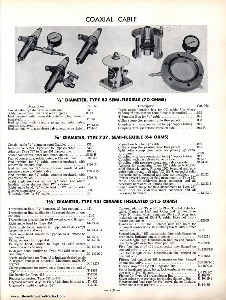
www.SteamPoweredRadio.Com
COAXIAL CABLE
3/a" DIAMETER, TYPE 83 SEMI-FLEXIBLE (70 OHMS) Description Cat. No.
Coxial cable%" diameter semi-flexible ............... 83 Solder connectors, inner and outer, (pair) .... . ....... 8319 End terminal with removable exhaust plug, ceramic insulated ................... . ................. .... 1701-P End terminal with pressure gauge and inlet valve, ceramic insulated ........... ............ . .......... 1701-GV End terminal with gas release valve, ceramic insulated .. 1701-R
Description Cat. No. Right angle junction box for %" cable. Use where bending radius sharper than 6 inches is required . ..... 853 T Junction Box for %" cable ....... .. ........ . . . . .. 825 Collar clamp (for passing cable thru panel) . ... . ...... 830 Coupling with side connection for ¼" copper tubing ... 915 Coupling with gas release valve on side . ............. 915-R
¥a" DIAMETER, TYPE 737, SEMI-FLEXIBLE (64 OHMS)
Coaxial cable ½" diameter semi-flexible .............. 737 Reducer connector, Type 737 to Type 83 cable .. ... .. . 8329 Adaptor, Type 737 to Type 451 flanged line . ....... . .4876-1 Solder connectors, outer and inner, (pair) ... .... ... . . 8328-B Pair of connectors, solder outer, solder less inner ...... 8328-C End terminal for ½" cable, ceramic insulated, with removable exhaust plug ..... .............. . .. ...... 1703-P End terminal for ½" cable, ceramic insulated with pressure gauge and inlet valve ..... ..... . .......... . 1703-GV End terminal for ½" cable, ceramic insulated, with gas release valve . ................. . .......... . . . .. 1703-R Right angle junction box for ½" cable. Use where bending radius sharper than 12" is desired .. ........ 61 Right angle bend, ½" cable bent to 12" radius, with 2 solder connectors ......................... ... .. .. 6500 T junction box for ½" cable ..... . .. . . . ............. 65
Y junction box for ½" cable .... .. .......... . ..... . . 859 Collar clamp (for passing cable thru panel) .... ... ... . 829 Split collar clamp (two piece, for passing ½" cable thru panel) ..... ... . .. . ...... ...... ... .. . ......... 4878 Coupling with side connection for ¼" copper tuQing ... 917 Coupling with gas release valve on side ... .......... . 917-R Coupling with pressure gauge and valve on side . .... . 917-GV Adaptor for connecting Type 737 cable to RG-17 / U solid dielectric cable. Fits on 1703 terminal and pro-vides male thread to fit plug UG-154/ U on end of solid dielectric cable. Terminal and plug not included . ..... L-12423 Pair of swivel flanges for field attachment to Type 737 cable. Includes solderless inner connector and all necessary hardware for joining flanges .. .. ... ........ L-13223-1 Single swivel flange for field attachment to Type 737 cable. Includes solderless inner connector and all necessary hardware ........ .. .. .. .............. . ... L-13223-2
11/a" DIAMETER, TYPE 451 CERAMIC INSULATED (51.5 OHMS)
Transmission line. 1%" diameter, 20 foot section .. ... .451 Transmission line, similar to 451 except flange on one end only ... ........ . ...... ... . ..... . ............ .451-1 Transmission line, similar to 451 except no end flanges .. 451-2 Right angle bend for Type 451. . ... ................. M-13941 Right angle bend, similar to Type M-13941 except flanged on one end only .. ... ....................... M-13941-1 Right angle bend, similar to Type M-13941 except no end flanges...... . ......... . ......... ..... .. M-13941-2 45 degree bend for Type 451 .. .......... .. ........ .. M-14216 45 degree bend, similar to Type M-14216 except flanged on one end only .. ....... . .................. M-14216-1 45 degree bend, similar to Type M-14216 except no end flanges ...... ..... .. ........ . ... .. ............ M-14216-2 Special angle bend for Type 451. Indicate desired angle in degrees change of direction. Maximum angle, 90 degrees ...... ... .................. . . . ........... K-13273 Clamp connector for providing a flange on cut end of Type 451......... ... .... . . . . . . . . . . .. . . . . . . . . . ... T-1551 Gas barrier for Type 451. ... . ............ . . ....... . T-1251 Reducer connector, Type 452 to 451. ................ T-1851 Ungassed reducer, 3¼" to 1%", 51.5 ohms both sides .. T-4831 Ungassed straight coupling 1%" . ...... . .. .. .... . ... T-4832
Tapered adaptor, Type 451 to RG-8/ U solid dielectric cable. Flange on 1%" end. Other end terminates in Type N fitting which requires UG-21/ U plug (not included) on end of RG-8/ U cable. Does not incor-porate gas barrier. . . . . . . . . . . . . . . . . . . . . . . . . . . . ... L-12859 Hardware kit for 451. Includes nuts and bolts for 6 flanged connections, 10 rubber gaskets, and 2 inner connectors.... . . . . . . . . . . . . . . . . . . . . . . . . . . . . . . 2451 Special length of 451 transmission line with flanges on both ends. Indicate length in inches . ... ... .......... M-12211 Special length 1%" transmission line, no end flanges. Specify length in inches. Price per inch ............... M-13280 Five foot length of 451 transmission line, flanged on one end only ............. ... .. ... ................. M-12843-5 Ten foot length of 451 transmission line, flanged on one end only ........ ... . .......................... M-12843-10 Fifteen foot length of 451 transmission line, flanged on one end only ....... ... . ........... . . . .. . .. . .... M-12843-15 Extra clamp for 1%" OD ungassed line ... ........... L-11809-2 Set of hardware (nuts, bolts, lock-washers) for joining one pair of 1%" flanges .. ............... . .. .. .. . . . . L-11381-2 Flange for Type 451 transmission line . ... . .. ......... K-10875 Silver solder nng preform, for brazing flange to line .... K-10419-2 Rotating and fixed ring for 1%" swivel flange. Includes silver solder ring preform ........ ...... . ............ K-14485
- 213 -
www.SteamPoweredRadio.Com
COAXIAL CABLE 11/a" DIAMETER, TYPE 451 CERAMIC INSULATED (Continued)
Description Cat. No. Inner conductor tube 0.647/t OD x 12 feet long . ... . . .. K-12233-2 Rubber gasket for 451 line . .. .......... . ..... . ..... L-10683-2 Blank cover plate for capping 1¾0 flange. With ½0
pipe plug ... . .... ........... . ............. . . . .. .. . K-12234-1 Clamp connector ungassed, for outer conductor only. Provides flange on cut end of Type 451. . ... . ...... . . T-4837 Gas inlet coupling for 451 line ..... . ................ 1351
Description Cat. No. Inner connector, used in joining adjacent sections of 11/s" transmission line. Not recommended for con-nection to fittings because of mechanical interference .. K-13944 Inner connector, used in connecting l~f' line to fit-tings. Not recommended for joining sections of trans-mission line ... . : ... . ...... . ...... . ...... . .... .. . . . K-14156 Clamp and grounding strap for connecting line to tower in quarter wave isolation systems .............. K-12430
11/a" DIAMETER, TYPE 551-4 TEFLON INSULATED (51.5 OHMS)
Description Cat. No. Transmission line, 11/slt diameter, 20 foot section . . . .. . 551-4 Special length Type 551-4 transmission line with flanges on both ends. Indicate length in inches .... . .. . M-13981
Description Cat. No. Reducer connector, Type 552-1 to Type 551-4 line . . .. M-12514 Clamp connector for providing a flange on cut end of Type 551-4 line... . . . . . . . . . . . . . . . . . . . . . . . . . . .. 1551
The following fittings, as described under Type 451, may also be used with Type 551-4 line.
Description Cat. No. Description Cat. No. Description Cat. No. 90 degree bend .. . . ...... .. . . M-13941 Gas barrier .. ... . .... . .. . ... T-1251 Hardware kit . ........ . .... . L-11381-2 90 degree bend . ... .. .... .. .. M-13941-1 Reducer .. .. . ............... T-1851 Flange .. . ...... . ...... . .... K-10875 90 degree bend . .. ... ..... . . . M-13941-2 Rubber gasket. . ... . ........ 1-10683-2 Solder ring . . ..... ... . ....... K-10419-2 45 degree bend . ... . .... ... . . M-14216 Blank flange .... .. . . ....... . K-12234-1 Swivel flange .... . . ......... . K-14485 45 degree bend . . .......... . . M-14216-1 Gas inlet. . ................. 1351 Inner connector. . ....... ... . K-13944 45 degree bend . . ... . .... .. .. M-14216-2 Reducer . . . .. ... .. .. ... . ... . L-12859 Inner connector. .. .... . . . ... L-14156 Special bend ... ......... .... K-13273 Hardware kit. . . .. . .. . ..... . 2451 Grounding strap ... ... ....... K-12430
31/a" DIAMETER, TYPE 452 CERAMIC INSULATED (51.5 OHMS)
Description Cat. No. Transmission line 3½0 diameter, 20 foot section . .. ... 452 Transmission line, similar to 452, except flange on one end only ... . . .. . .. . .. . . . .. .. ....... . . . . . ......... 452-1 Transmission line, similar to 452, except no end flanges .. . .. ...... . .. . ................. . ....... . . .452-2 Right angle bend for 452 . ... ........ .. . .. .... . . .. . . T-1052 Right angle bend similar to T-1052 except flange on one end only . ....... . .... . ...... . ... . ............. T-1052-1 Right angle bend similar to T-1052 except no end flanges . .... ... ... .. . . . .... .. ...... .. ...... . ...... T-1052-2 45 degree bend for 452 . . .... . .. .... ... . . . .......... T-1152 45 degree bend, similar to T-1152 except flange on one end only .. . ... . . ...... .. .... . ........ . ........ T-1152-1 45 degree bend, similar to T-1152 except no end flanges ... .... ... ........... . ............... . ..... T-1152-2 Special angle bend for Type 452. Indicate desired angle in degrees change of direction. Maximum angle 90 degrees .. .. .. . . ... . ....... . . . . .. . . .. . . . ... ... . . T-1952 Clamp connector, for providing a flange on cut end of 452 ..... . ................ . . . .. . ........ . ...... T-1552 Gas barrier. . . . . . . . . . . . . . . . . ... . .... . ........ T-1252 Reducer connector, Type 452 to 451. .. .. ... . ... . .. .. T-1851 Reducer connector, ungassed, 3½n to 11/s" . .. ........ T-4831 Straight coupling 3½" ungassecl .. .. . . . . . ............ T-4838 Special length of 3½/t OD 51.5 ohms transmission line flanged both ends. Specify length in inches . .......... M-12173 Special length of 3½0 transmission line, no end flanges. Specify length in inches. Price per inch . . .. . . . M-13278 F ive foot length of 452 transmission line, flanged on one end only . . ... . .. .. . .. . . . ...... . .... . ....... ... M-12844-5
Description Cat. No. Ten foot length of 452 transmission line, flanged on one end only .. . . . . . . ...... . ....... .. .............. M-12844-10 Fifteen foot length of 452 transmission line, flanged on one end only ... . . .. . . . ...... . ... ... .. .. .... . . .. M-12844-15 Extra clamp for 3½n OD ungassed line ............. . L-11809-1 Inner conductor tube 1.282 OD x 12 feet long . .... .. . K-12233-3 Rubber gasket for 452 line ........ . .. . . . . .......... L-10683-3 Blank cover plate for capping 3½ n flange. With ½ " pipe plug .. . . .. ........ . .. . . ........ . ........ . .. . . K-12234-2 Gas inlet coupling for 452 line. . . ... . ..... . ... . 1352 Hardware kit for Type 452. Includes nuts and bolts for 4 flanged connections, 10 rubber gaskets, and 2 inner connectors .................. . .. . .... . ..... .. 2452 Inner connector, used in joining adjacent sections of 3½" transmission line. Not recommended for con-nection to fittings because of mechanical interference .. K-14417 Inner connector, used in joining 3½n line to fittings. Not recommended for joining sections of t ransmission line .. . .. . . ..... .. ...... . . . . .... . . . .... .. .. ... . . .. L-12650-2 Rotatin~ and fixed _ring for 3½" swivel flange. In-cludes silver solder nng preform .. . .. . .. . . .. . . ..... .. K-14486 Inner conductor adaptor, to adapt fittings designed for Type 452 line to fit Type 552-1 line or vice versa . . . K-13244-1 ~et of hardware (nuts, bolts, lock-washers) for joining one pair of 3½" flanges .. .. . .. ... . ....... . ...... . .. L-11381-3 Flange for Type 452 transmission line . . . ...... . ..... . L-10881 Silver ring preform for brazing 3½n flange .. .. . ... . .. K-10419-11 Clamp and grounding strap for connecting line to tower in quarter wave isolation systems . .. . ..... . .. . K-12431
31/a" DIAMETER, TYPE 552-1 TEFLON INSULATED (51.5 OHMS)
Description Cat . No. Description Cat. No. Transmission line, 3 ½ It diameter, 20 foot section . . .... 552-1 Right angle bend for Type 552-1 line .. .............. M-12512 45 degree bend for T ype 552-1 line . . .. . . ... . . . . . . . .. M-12513 Special angle bend for T ype 552-1. Indicate desired angle in degrees change of direction. Maximum angle 90 degrees . . , ............. ... .... . . , . . .... . .... .. . M-13928 Reducer connector, Type 552-1 to 551-1 or 451. .. . ... M-12514 Clamp connector, for providing a flange on cut end of 552-1. ...... . .. . ..... . .. . ............ .. . . . . . .. . L-12515
Special length T ype 552-1 transmission line with flanges on both ends. Indicate length in inches . .... . . . M-13325 Inner connector, used in connecting 3½" line to fit-tings. Not recommended for joining sections of trans-mission line .... . . .. . . ... . ......... .. . . .. . , .. . . .... L-12650-3 Inner connector, used in joining adjacent sections of 3½/t transmission line. Not recommended for con-nection to fittings because of mechanical interference .. K-13946
Gas barrier for 552-1. . . ..................... . .. . .. L-13163 Reducini inner connector to !idapt fittings designed for 452 hne to fit Type 552-1 hne ...... . .. . .... ...... K-13244-1
Hardware kit for Type 552. Includes nuts and bolts for four flanged connections, ten rubber gaskets and two inner connectors ...... .. ..... .... . . ....... . . .. . 2552
- 214 -
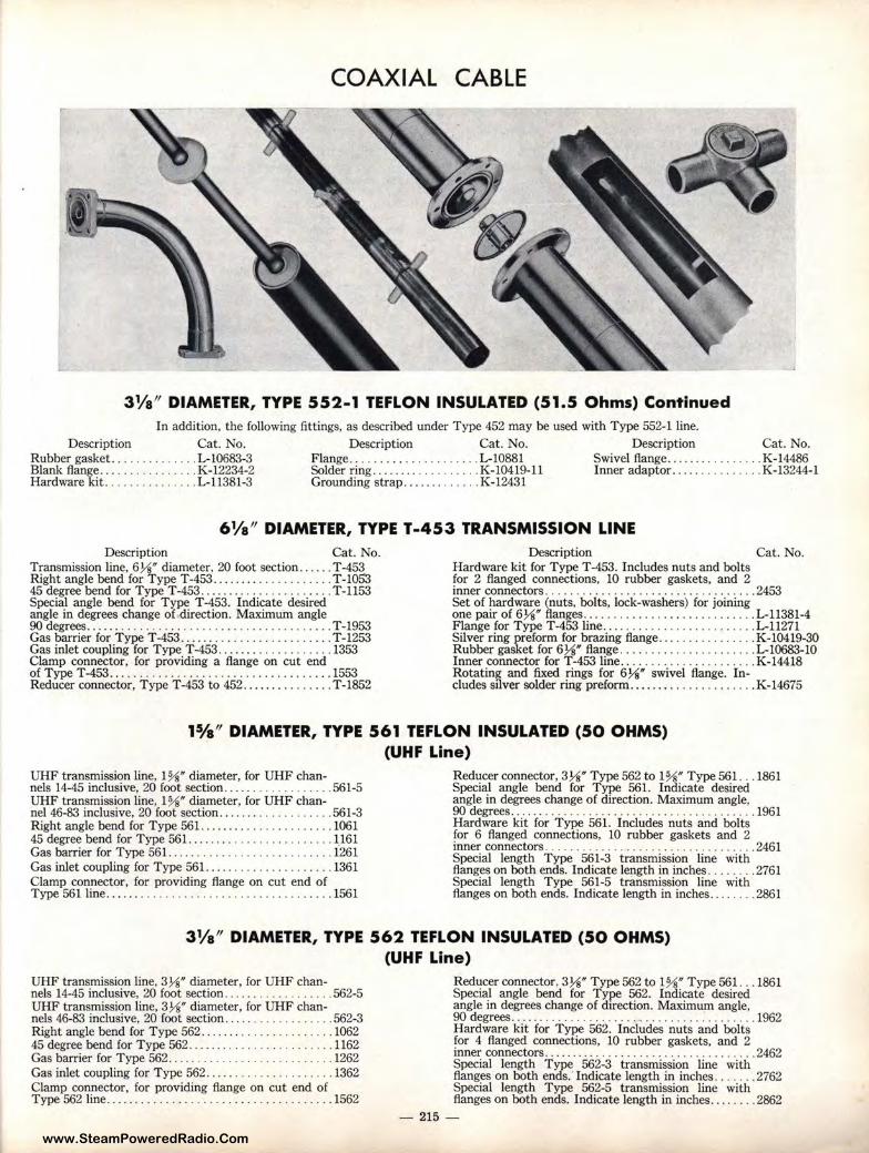
www.SteamPoweredRadio.Com
COAXIAL CABLE
31/a" DIAMETER, TYPE 552-1 TEFLON INSULATED (51.5 Ohms) Continued In addition, the following fittings, as described under Type 452 may be used with Type 552-1 line.
Description Cat. No. Description Cat. No. Description Cat. No. Rubber gasket. . ..... . . . .... L-10683-3 Flange ......... . . ... . .. .. .. L-10881 Swivel flange.... . .. ... . . . . . K-14486 Blank flang~ . .. .. . .. . . .... . . K-12234-2 Solder r_ing ... . ...... . ...... . K-10419-11 Inner adaptor. .... .. . . . ... . K-13244-1 Hardware ktt . ..... . . ....... L-11381-3 Grounding strap ....... ... . .. K-12431
61/a" DIAMETER, TYPE T-453 TRANSMISSION LINE Description Cat. No.
Tf:'ansmission line, 6Y~ diameter, 20 foot section ..... . T-453 Right angle bend for Type T-453 ......... ...... . .. .. T-1053 45 degree bend for Type T-453 ........ . . ... . .. .... .. T-1153 Special angle bend for Type T-453. Indicate desired angle in degrees change of direction. Maximum angle 90 degrees ........ . .. .. . . . ... .. . ... .. . . . . ..... . . .. T -1953 Gas barrier for Type T-453 ......... . .. . .. . .... .. . . . T-1253 Gas inlet coupling for Type T-453 ........ .. .. .. . .. . . 1353 Clamp connector, for providing a flange on cut end of Type T-453 .... . .. .. ..... ... ....... .. .... . . . ... 1553 Reducer connector, Type T-453 to 452 ........ .. ..... T-1852
Description Cat. No. Hardware kit for Type T-453. Includes nuts and bolts for 2 flanged connections, 10 rubber gaskets, and 2 inner connectors . . .... .. ................. . ........ 2453 Set of hardware (nuts, bolts, lock-washers) for joining one pair of 6¼" flanges ...... . ..... . ....... . ... .. .. L-11381-4 Flange for Type T-453 line .... .. . . .. ... . . .. ....... . L-11271 Silver ring preform for brazing flange ... .. . .. .. . . . ... K-10419-30 Rubber gasket for 6¼" flange ......... .... ... ...... L-10683-10 Inner connector for T-453 line ....... . ... . . . ....... . K-14418 Rotating and fixed rings for 6¼" swivel flange. In-cludes silver solder ring preform ......... .. ....... .. . K-14675
11/a" DIAMETER, TYPE 561 TEFLON INSULATED (50 OHMS) (UHF Line)
UHF transmission line, 1%" diameter, for UHF chan-nels 14-45 inclusive, 20 foot section ..... ......... .. .. 561-5 UHF transmission line, 1%" diameter, for UHF chan-nel 46-83 inclusive, 20 foot section ....... ..... . .. . . .. 561-3 Right angle bend for Type 561 ........ ... . .. ..... ... 1061 45 degree bend for Type 561 ........ .. . .. . .. . ... . .. . 1161 Gas barrier for Type 561 ..... . ....... . . . . . . ....... . 1261 Gas inlet coupling for Type 561. .... ..... .. ..... . . . . 1361 Clamp connector, for providing flange on cut end of Type 561 line .............. . .. . ...... . .. . ......... 1561
Reducer connector, 3¼" Type 562 to 1%" Type 561 . .. 1861 Special angle bend for T ype 561. Indicate desired angle in degrees change of direction. Maximum angle, 90 degrees ........ . . .. .. .. .. .. ..... . ..... . . .... ... 1961 Hardware kit for T ype 561. Includes nuts and bolts for 6 flanged connections, 10 rubber gaskets and 2 inner connectors . ..... .. .. .. .. . .... . . . ..... ..... . . 2461 Special length Type 561-3 transmission line with flanges on both ends. Indicate length in inches .. .... . . 2761 Special length Type 561-5 transmission line with flanges on both ends. Indicate length in inches ....... . 2861
31/a" DIAMETER, TYPE 562 TEFLON INSULATED (50 OHMS) (UHF Line)
UHF transmission line, 3¼" diameter, for UHF chan-nels 14-45 inclusive, 20 foot section .... . .. . . . . . . . .. .. 562-5 UHF transmission line, 3¼" diameter, for UHF chan-nels 46-83 inclusive, 20 foot section ....... ........ . .. 562-3 Right angle bend for Type 562 ..... . . ... . . . . . . . . .. . . 1062 45 degree bend for Type 562 . . ..... . . .. . . . . .. .... . .. 1162 Gas barrier for T ype 562 .. . .. .. . ...... .. ........ . .. 1262 Gas inlet coupling for Type 562 ... . . . . . . .. .. . . ..... . 1362 Clamp connector, for providing flange on cut end of Type 562 line ........ . . . ... .. . .. .... .. .... ..... ... 1562
Reducer connector, 3¼" Type 562 to 1%" Type 561. .. 1861 Special angle bend for Type 562. Indicate desired angle in degrees change of direct ion. Maximum angle, 90 degrees ...... ..... . .. . . .. __ . .. . _ .. .. . .. . .. .. .... 1962 Hardware kit for Type 562. Includes nuts and bolts for 4 flanged connections, 10 rubber gaskets, and 2 inner connectors . ........ .. .. . ..... .. .. .. . .. . . .. ... 2462 Special length Type 562-3 transmission line with flanges on both ends." Indicate length in inches . .. .... 2762 Special length Type 562-5 transmission line with flanges on both ends. Indicate length in inches .... . . .. 2862
- 215 -
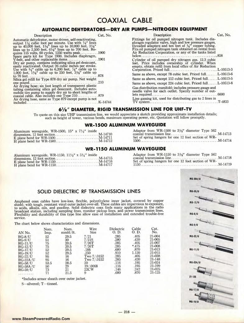
www.SteamPoweredRadio.Com
COAXIAL CABLE AUTOMATIC DEHYDRATORS-DRY AIR PUMPS-NITROGEN EQUIPMENT
Description Cat. No. Automatic dehydrator, motor driven, self-reactivating, output 1¼ cubic foot per minute. Use with ½" lines up to 40,000 feet, 11/s" lines up to 10,000 feet, 3½" lines up to 2,500 feet, 6½" lines up to 700 feet. Re-quires 115 volts, 60 cycles, 1250 watts peak ....... .... 1900 Spare parts kit for Type 1900. Includes diaphragm, V-belt, and other replaceable items ........ . ........ . 1901 Dry air pump, contains indicating silica gel desiccant, easily reactivated. Output 26 cubic inches per stroke. Use with ¾" cable up to 6,200 feet, ½" cable up to 1,000 feet, 11/s" cable up to 250 feet, 3½" cable up to 70 feet .. ...... .. .... . ..... .... . . . ........ .... . 878 Silica gel refill for Type 878 dry air pump. Net weight one pound ...... . . . .. . . ....... .... ...... . ..... . ... 210 Air drying hose; six foot length of transparent plastic tubing containing silica gel desiccant. Includes automobile tire pump to supply dry air to short lengths of coaxial cable. Also includes one Type 210 .... .. .. .... 879 Air drying hose, same as Type 879 except pump is not included ..... .. ................. .... ... .. ........ K-14744
Description Cat. No. Fittings for oil pumped nitrogen tank. Includes diaphragm regulator valve, high and low pressure gauges, threaded adapters and ten feet of ¼" copper tubing. Fits oil pumped nitrogen tank obtained on rental from Air Reduction Corporation, or any of the tanks listed below ... . . ... . ..... ... ...... . . . ...... . . .. ... ..... 858 Cylinder of oil pumped dry nitrogen gas. 12.3 cubic feet. Price includes ownership of cylinder. When empty, obtain refill from local office of Air Reduction Corporation. Priced full ...... . . . ...... . .. ......... . L-10513-3 Same as above, except 78 cubic feet. Priced full. . ... .. L-10513-6 Same as above. except 112 cubic feet. Priced full . ... . . L-10513-5 Same as above, except 224 cubic feet. Priced fu11 ... ... L-10513-8 Gas distribution manifold; includes pressure gauge and needle valve for each outlet. Specify number of out-lets required ..... . ... . . . ... .... ... ..... ...... . .. .. 6600 Line gassing kit, used for distributing gas to 2 lines in TV system .. . ... ...... . . . ....... . ............ .. . . T-4833
6 1/a" DIAMETER, RIGID TRANSMISSION LINE FOR UHF-TV To quote on this size UHF transmission line, we would appreciate a sketch providing approximate installation details;
such as height of tower, various bends, maximum operating power, etc. Quotation will follow promptly.
WR-1500 ALUMINUM WAVEGUIDE Aluminum waveguide, WR-1500, 15" x 7½ " inside dimensions, 12 foot section ........ .. . ......... . .... M-14710 E plane bend for WR-1500.... . ... ..... ... .. .. . .. M-14711 H plane bend for WR-1500 ..... ...... ......... .. ... M-14712
Adaptor from WR-1500 to 3½" diameter Type 562 coaxial transmission line .. . . . .... . . .. ..... .. ... . ... M-14713 Set of spring hangers for one 12 foot section of WR-1500 ......... . . ....... ... . . .. . ... . .... . .. ... ... .. M-14714
WR-1150 ALUMINUM WAVEGUIDE Aluminum waveguide, WR-1150, 11½ " x 5¾ " inside dimensions, 12 foot section .. . . .. ...... ... ....... ... M-14715 E plane bend for WR-USO .......... . ..... ...... .. . M-14716 H plane bend for WR-1150 .. . . ... . .......... . . .. . .. M-14717
Adaptor from WR-1150 to 3½" diameter Type 562 coaxial transmission line . .. .. .... .... .. . . . . .. ... .. . M-14718 Set of spring hangers for one 12 foot section of WR-1150.. ..... .. ...... . . . . . . . . . . . . . . . ... .. ... M-14719
SOLID DIELECTRIC RF TRANSMISSION LINES
Amphenol coax cables have low-loss, flexible, polyethylene inner jacket, covered by copper shield; with tough, resistant vinyl outer jacket over-all. These cables are impervious to exposure, to acids, alkalis, oils, and gasoline. Solid dielectric coax finds many applications in the radio broadcast station, including sampling lines, monitor pickup lines, and power transmission lines. Flexibility and durability of this type line allow ease of installation and extended trouble-free service.
The chart below shows characteristics and dimensions.
Norn. Norn. Wire Dielectric Cable Cat. AN No. Imp. mmfd/ ft. Size 0.D. O.D. No. RG-8/ U 52 29.5 7/ 21 .285 .405 21-004 RG-9/ U 51 30 7/ 21S .280 .420 21-005 RG-11/ U 75 20.5 7/ 26T .285 .405 21-007 RG-12/ U 75 20.5 7/ 26T .285 *.475 21-008 RG-17/ U 52 29.5 .188 .680 .870 21-013 RG-19/ U 52 29.5 .250 .910 1.120 21-015 RG-22/ U 95 16 Two 7 / .0152 .285 .405 21-038 RG-22A/ U 95 16 Two 7/ .0152 .285 .420 21-148 RG-58/U 53.5 28.5 20 .116 .195 21-024 RG-58A/ U 50 29 19/ .0068 .116 .195 21-199 RG-59/ U 73 21 22CW .146 .242 21-025 .... ..... 71 21.5 9 .680 .870 21-125
*Includes armor sheath over outer jacket. S--silvered; T- tinned.
- 216-
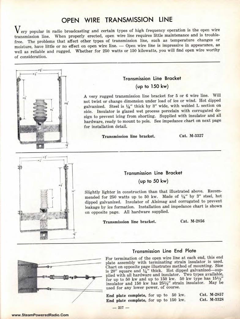
www.SteamPoweredRadio.Com
OPEN WIRE TRANSMISSION LINE
V ery popular in r adio broadcasting and certain types of high frequency operation is the open wire
transmission line. When properly erected, open wire line requires little maintenance and is trouble
free. The problems that affect other types of transmission line, such as temperature changes or
moisture, have little or no effect on open wire line. - Open wire line is impressive in appearance, as
well as reliable and rugged. Whether for 250 watts or 150 kilowatts, you will find open wire worthy
of consideration.
r,f
•f
----~f----1 ~
1 ---••f --------.
e
u·
Transmission Line Bracket
(up to 150 kw)
A very rugged transmission line bracket for 5 or 6 wire line. Will
not twist or change dimension under load of ice or wind. Hot dipped
galvanized. Steel is ¼" thick by 3" wide, with welded L section on
side. Insulator is glazed wet process porcelain with corrugated de
sign to prevent icing from shorting. Supplied with insulator and all
hardware, ready to mount to pole. See impedance chart on next page
for installation detail.
Transmission line bracket. Cat. M-3327
Transmission Line Bracket
(up to 50 kw)
Slightly lighter in construction than that illustrated above. Recom
mended for 250 watts up to 50 kw. Made of ¼" by 3" steel, hot
dipped galvanized. Insulator of Alsimag and corrugated to prevent
leakage by ice formation. Installation and impedance chart is shown
on opposite page. All hardware supplied.
Transmission line bracket. Cat. M-2856
Transmission Line End Plate
For termination of the open wire line at each end, this end plate assembly with terminating strain insulator is used. Chart on opposite page illustrates method of mounting. Size is 20" square and ¼," thick. Hot dipped galvanized-supplied with all hardware and insulator. Two types available, for up to 50 kw and up to 150 kw. 50 kw type has 15½" insulator and 150 kw has 25½" strain insulator. May be used for any lower power, of course.
End plate complete, for up to 50 kw.
End plate complete, for up to 150 kw.
- 217 -
Cat. M-2857 Cat. M-3328
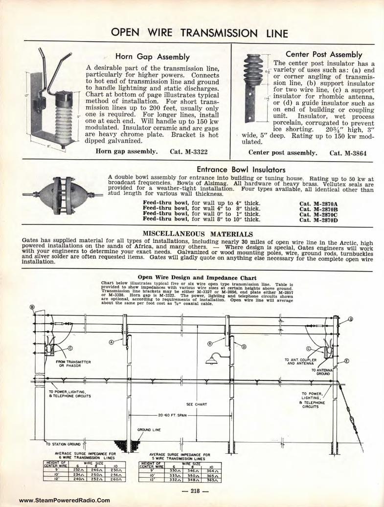
www.SteamPoweredRadio.Com
12·
OPEN WIRE TRANSMISSION LINE
Horn Gap Assembly A desirable part of the transmission line, particularly for higher powers. Connects to hot end of transmission line and ground to handle lightning and static discharges. Chart at bottom of page illustrates typical method of installation. For short transmission lines up to 200 feet, usually only
9• one is required. For longer lines, install
one at each end. Will handle up to 150 kw modulated. Insulator ceramic and arc gaps are heavy chrome plate. Bracket is hot dipped galvanized.
Horn gap assembly. Cat. M-3322
-, Center Post Assembly I The center post insulator has a
&.t" variety of uses such as: (a) end 1 or corner angling of transmis
-1 sion line, (b) support insulator I for two wire line, (c) a support
11r insulator for rhombic antenna,
J or (d) a guide insulator such as on end of building or coupling unit. Insulator, wet process porcelain, corrugated to prevent ice shorting. 20¾." high, 3"
wide, 5" deep. Rating up to 150 kw modulated.
Center post assembly. Cat. M-3864
Entrance Bowl Insulators A double bowl assembly for entrance into building or tuning house. Rating up to 50 kw at broadcast frequencies. Bowls of Alsimag. All hardware of heavy brass. Vellutex seals are provided for a weather-tight installation. Four types available, all identical other than stud length for various wall thickness.
Feed- thru bowl, for wall up to 4" thick. Feed-thru bowl, for wall 4" to 8" thick. Feed-thru bowl, for wall 0" to l" thick. Feed-thru bowl, for wall 8" to 10" thick.
MISCELLANEOUS MATERIALS
Cat. M-2870A Cat. M-2870B Cat. M-2870C Cat. M-2870D
Gates has supplied material for all types of installations, including nearly 30 miles of open wire line in the Arctic, high powered installations on the sands of Africa, and many others. - Where design is special, Gates engineers will work with your engineers to determine your exact needs. Galvanized or wood mounting poles, wire, ground rods, turnbuckles and silver solder are often requested items. Gates will gladly quote on anything else necessary for the complete open wire installation.
B
TO POWER. LIGHTING, 6 TELEPHONE CIRCUITS
Open Wire Design and Impedance Chart Chart below Illustrates typical five or six wire open type transmission line. Table ls provided to show Impedances with various wire alzes at certain heights above ground. Transmission line brackets may be either M-3327 or M-2856, end plate either M-2857 or M-3328. Horn gap Is M-3322. The power, lighting and telephone circuits shown are optional, according to requirements of lnatallaUon. Open wire line will average about the same per root cost aa ¼" coaxial cable.
A
SEE CHART
----20·60 FT. SPAN--+-----~
AVERAGE SURGE IMPEIWCE FOR 6 WIRE TRAN$1,USSION LINES
AVERAGE SURGE IMPEDANCE FOR S WIRE TRANSMISSION LINES
260J'\.
- 218-
TO POWER. LIGHTING,
6 TELEPHONE CIRCUITS
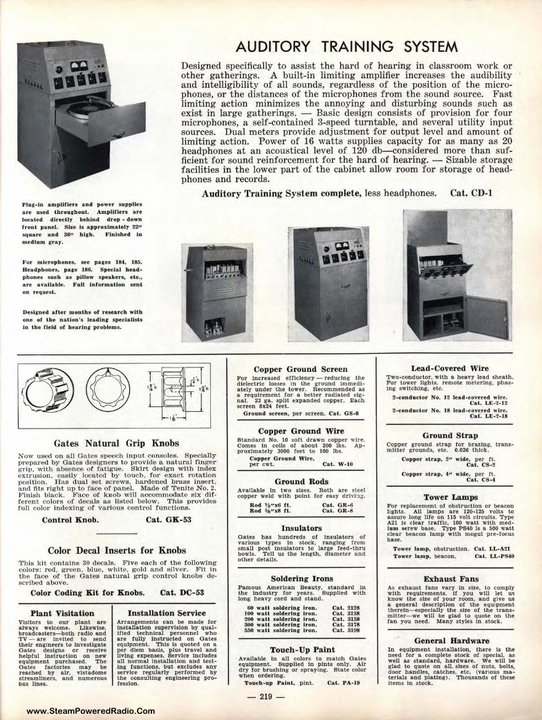
www.SteamPoweredRadio.Com
AUDITORY TRAINING SYSTEM Designed specifically to assist t he hard of hearing in classroom work or other gatherings. A built-in limiting amplifier increases the audibility and intelligibility of all sounds, regardless of the position of the microphones, or the distances of the microphones from the sound source. Fast limiting action minimizes the annoying and disturbing sounds such as exist in large gatherings. - Basic design consists of provision for four microphones, a self-contained 3-speed turntable, and several utility input sources. Dual meters provide adjustment for output level and amount of limiting action. Power of 16 watts supplies capacity for as many as 20 headphones at an acoustical level of 120 db-considered more than sufficient for sound reinforcement for the hard of hearing. - Sizable storage facilities in the lower part of t he cabinet allow room for storage of headphones and records.
Auditory Training System complete, less headphones. Cat. CD-1 Plur-in ampUfiers and power s upplies are used throughout. Amplifiers are located directly behlnd drop - down front panel. Size b approximately 22" square and 36" hlfh. Finished In medium gray.
For microphones, sec pages 184, 185. Headphones, page 186. Special headphones such as pillow speakers, etc., are available. Full Information sen l on request.
Desirned after months of research with one of the nation's leadlnr speclallsls in the field of hearlnr problems.
:~.-~1-~-16 4.-. 1 1110,
iii
Gates Natural Grip Knobs Now used on all Gates speech input consoles. Specially prepared by Gates designers to provide a natural finger grip, with absence of fatigue. Skirt design with index extrusion, easily located by touch, for exact rotation position. Has dual set screws, hardened brass Insert, and fits right up to face of panel. Made of Tenite No. 2. Finish black. Face of knob will accommodate six different colors of decals as listed below. This provides full color indexing of various control functions.
Control Knob. Cat. GK-53
Color Decal Inserts for Knobs This kit contains 30 decals. Five each of the following colors: red, green. blue, white, gold and silver. Fit In the face of the Gates natural grip control knobs described above.
Color Coding Kit for Knobs. Cat. DC-53
Plant Visitation Visitors to our plant are always welcome. Likewise, broadcasters-both radio and TV - are Invited to send their engineers to Investigate Gates designs or receive helpful Instruction on new equipment purchased. The Gates factories may be reached by air. vlstadome strea.mltners, and numerous bus lines.
Installation Service Arrangements can be made for installation supervision by qualified technical personnel who are fully Instructed on Gates equipment. This is quoted on a per diem basis, plus travel and living expenses. Service Includes all normal Installation and testIng functions, but excludes any service regularly performed by the consulting engineering profession.
Copper Ground Screen For Increased efficiency - reducing the dielectric losses In the ground Immediately under the tower. Recommended as a requirement for a better radiated signal. 23 ga. split expanded copper. Each screen 8x24 feet.
Ground screen, per screen. Cat. GS·8
Copper Ground Wire Standard No. 10 soft drawn copper wire. Comes In coils of about 200 lbs. AP· proximately 3000 feet to 100 lbs.
Copper Ground Wire, per cwt. Cat. W •l0
Ground Rods Available In two sizes. Both are steel copper weld with point for easy drlvi:,~.
Rod \i"x6 rt. Cat. GR-0 Rod ~l,nx8 ft. Cat. GR-8
Insulators Oates has hundreds of Insulators of various types In stock, ranging from small post Insulators to large feed-thru bowls. Tell us the length, diameter and other details.
Soldering Irons Famous American Beauty, standard In the Industry for years. Supplied with long heavy cord and stand.
68 watt soldering Iron. 100 watt soJderl.n g iron. 200 watt soldering- iron. 300 watt solderlnr Iron. 550 wall soldering- Iron.
Cat. 21.28 Cat. 3138 Cat. 3158 Cat. 3178 Cat. 3108
Touch-Up Paint Avallable In all colors to match Oates equipment. Supplied In pints only. Air dry for brushing or spraying. State color when ordering.
Touch-up Paint, pint. Cat. PA-19
- 219 -
Lead-Covered Wire Two-conductor, with a heavy lead sheath. For tower lights. remote metering, phasing switching, etc.
2-conductor No. 12 lead-covered wire. Cat . LE-2-12
2-conductor No. 18 lead-covered wire. Cat . LE-2-18
Ground Strap Copper ground strap for brazing, trans• mltter grounds, etc. 0.026 thick.
Copper s trap, 211 wide, per ft. Cat. CS-2
Copper strap, 411 wide, per ft. Cat. CS-4
Tower Lamps For replacement or obstruction or beacon lights. All lamps are 120-125 volts to assure long ll!e on 115 volt circuits. Type A21 Is clear traffic, 100 watt with medium screw base. Type PS40 Is a 500 watt clear beacon lamp with mogul pre-focus base.
Tower lamp, obstruction. Cat. LL-A21 Tower lamp, beacon. Cat. LL-PS40
Exhaust Fans As exhaust fans vary In size, to comply with requirements, If you wlll let u• know the size or your room, and give us a general description or the equipment therein-especially the size or the transmitter-we wlll be glad to quote on the fan you need. Many styles In stock.
General Hardware In equipment Installation, there Is the need for a complete stock of special, as well as standard, hardware. We will be glad to quote on all. sizes or nuts, bolts, door bandies, catches, etc. (various materials and plating). Thousands or these items In stock.
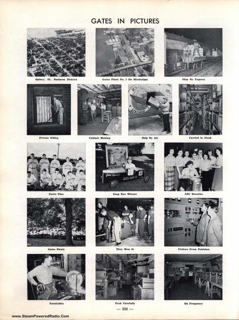
www.SteamPoweredRadio.Com
GATES IN PICTURES
Quincy, Ill., Business District Gates Plant No. 1 On Mississippi Ship By Express
Private Siding Cabinet Making Ship By Air Carried ln Stock
Gates Nine Soap Box Winner ABC Beauties
Gates Picnic They Won It Visitors From Pakistan
Turntables Pack Carefully On Frequency
- 220 -
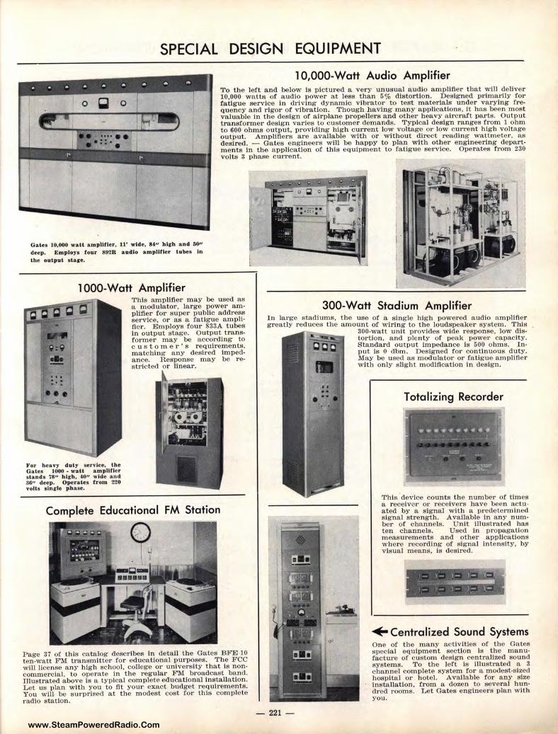
www.SteamPoweredRadio.Com
SPECIAL DESIGN EQUIPMENT
l 0,000-Watt Audio Amplifier T o the left and below is p ictured a very u nusual audio amplifier that will deliver 10,000 watts of audio power at less than 5% distortion. Designed primarily for fatigue service in driving dynamic v ibrator to test mater ials under varying frequency and rigor of v ibration. Though having many applications, it has been most valuable in the design of airplane propeller s and other heavy aircraft parts. Output transformer design varies to customer demands. Typical design ranges from 1 ohm to ~00 ohms out_put, providing high current low voltage or low current high voltage output. Amplifiers are available wit h or without direct reading wattmeter, as desired. - Gates engin eers will be happy to plan with other engineering departmen ts in the application of this equipment to fatigue ser vice. Operates from 230 volts 3 phase current.
Gates 10,000 wa.tt am p\itier, 11' wide, 84-" hich an d 50" deep. Emp loys four 892R audio amplifier tubes l.n the output s t ar•-
l 000-Watt Amplifier
For heavy duty service, the Gates 1000 - watt amplif ie r s tands 78" high, 40" w ide and 36" deep. Operates from 220 volts slnr le phase.
This amplifier may be used as a modulator, large power amplifier fo1· super public address service, or as a fatigue ampli· fter. Employs four 833A tubes in output stage. Output t ransformer may be accor ding to customer's requirements, matching any desired impedance. Response may be restricted or linear.
Complete Educational FM Station
Page 37 of this catalog describes in detail the Gates BFE 10 ten-watt FM transmitter for educational purposes. The FCC will license any h igh school, college or university that is noncommercial, to operate in the regular FM broadcast band. I llustrated above is a typical complete educational installa tion. Let us plan with you to flt your exact budget requir ements. You wlll be surprised at the modest cost for this complete radio station.
300-Watt Stadium Amplifier In large stadiums, the use of a s ingle h ig h powered audio amplifier greatly reduces the amount of wiring to the loudspeaker system. This
- 221 -
300-watt unit provides wide response, low distortion, and plenty of peak power capacity. Standard output impedance ls 500 ohms. Input is O dbm. Designed for continuous duty. May be used as modulator or fatigue amplifier with only s light modification in design.
Totalizing Recorder
This device counts the number of times a r eceive r or receivers have been actuated by a signal with a predetermined signal strength. Available in any number of channels. Unit illustrated has ten channels. Used in propagation measurements and other applications where 1·ecording of s ignal intensity, by visual means, is desired.
- 1- I- )·_: )-, ._ _
, __ 1_- l- l.- 1-.
+ Centralized Sound Systems One of the many activities of the Gates special equipment section is the manufacture of custom design centralized sound systems. To the left is illustrated a 3 channel complete system for a modest-sized hospital or hotel. Avai lable for a ny size Installation, from a dozen to several hun· dred rooms. Let Gates engineers plan with you.
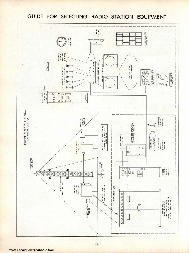
www.SteamPoweredRadio.Com
~ ~ ~
RE
MO
TE
M
ET
ER
S
PA
GE
62
/
TOW
ER
LI
TE
S ,
PAG
E zo
,
EQ
UIP
ME
NT
FO
R
TH
E
TY
PIC
AL
AM
R
AD
IO
ST
AT
ION
TO
WE
R
CH
OK
ES
P
AGE
56
NO
TE
· D
IRE
CT
ION
AL
PH
AS
ING
E
OU
IPM
EN
T,
IF R
EQ
UIR
ED
P
AG
ES
5
2·
57
,---
-----------------------
7 T
RA
NS
MIT
TE
R
1 I I I I I I I I I I I
@§
}e
)e
)e
)fg
@@
e)@
-E3
-~
ti l
<W
ogo
g (9
g
og
o
~o
1121g
I
[QI [
QI [
QI
0 0
I T
RA
NS
MIT
TE
RS
M
0·3
06
6
5/1
0 l<
W.
PA
GE
4
AC
CE
SS
OR
Y
LO
UD
SP
EA
KE
RS
P
AG
E 1
82
UN
AT
TE
ND
ED
OP
ER
AT
ION
(O
PT
ION
AL
) P
AG
E 1
78
oc:=
Jo t;!)
KJJ
(J)
'oo
oo
f:a
ftil
:i/
TRA
N$
. CO
NT
RO
L
CO
NS
OL
E
(OP
TIO
NAL
) P
AG
E 4
6
MIC
ROP
HO
NE
(O
PT
ION
AL
} PA
GE
18
4
I I I
I K
W,
PA
GE
10
AN
O 2
0
CA
BIN
ET
I 5
00
WA
TT
PA
GE
22
AN
O 2
4
PA
GE
4J
I 2
50
WA
TT
PA
GE
26
AN
O 3
1
L _
__
__
__
__
__
__
__
__
__
__
__
__
__
J
,
I U
NA
TT
EN
OE
O -----
----------
7 R
EM
OT
E (
OP
TIO
NAL
) I
I P
AG
E
178
.§
..I.!.
!..Q
.lQ
I I se
e@
I 0
[99
WA
RN
ING
L
tGH
TS
I
o (a
] 0
MIC
RO
PH
ON
ES
P
AG
E
184
P
AG
E 1
65
I oa
D '{J
'if
'if
'{J
'if
C
LO
CK
S
ST
AN
DS
P
AG
E
18
5 TN
A
IR
I II
11
II ~
~ P
AG
E
16
5
0~
'cO
NS
OLE
S·P
AG
ES
12
0·
144
TU
RN
TA
8L£S
PA
Gt
157
\ I
0 C
ON
TR
OL
D
ES
K
PA
GE
158
AN
O '6
3
TA
PE
R
EC
OR
DE
RS
P
AG
ES
1
67
·17
2
LOU
O
SP
EA
KE
RS
P
AG
E 1
82
RE
CO
RO
CA
BIN
ET
S
•PA
GE
1
62
I I I I I I I I I I I I I I D
ISC
R
EC
OR
DE
RS
I L
PA
GE
166
J
-------------------
C)
C
0 m
'Tl
0 :::ti
CJ'
) m
r m
()
~
z C)
:::ti
)>
0 - 0 CJ'
) ~
)>
~ - 0 z m
D
C
-0
~
m z ~
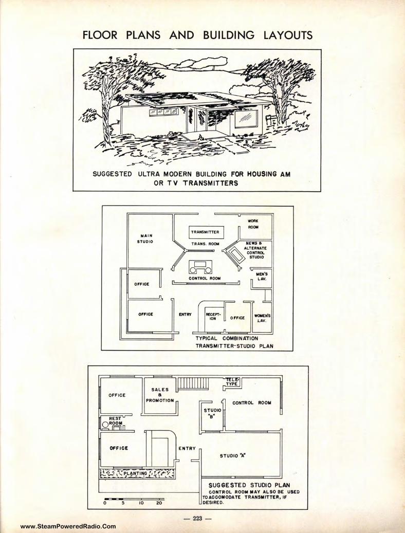
www.SteamPoweredRadio.Com
FLOOR PLANS AND BUILDING LAYOUTS
(
/'"-~
_. ,,.,..,.,,,~ - ----....... ---..-;: --TJ.. ·7 ~ ~-.. ~ .,,, c... ... <:.-,., ~
~ ----"? ~ SUGGESTED ULTRA MODERN BUILDING FOR HOUSING AM
OR TV TRANSMITTERS
OFFICE
0 5
M.A.IN
STUDIO
O,FICE
10
SALES a
PROMOTION
20
I TR.A.NSM ITTER
TR.A.NS. ROOM
B-4] CONTROL ROOM
ENTRY RECEPT-ION OfFICE
WORK
ROOII
MEN'S L.A.V.
WOMEN'S l..A.V.
TYPICAL COMBIN~ION
TRANSMITTER-STUDIO PLAN
CONTROL ROOM
STUDIO NBN
STUDIO "A"
SUGGESTED STUDIO PLAN CONTROL ROOM MAY ALSO BE USED
TOACCOMODATE TRANSMITTER, IF DESIRED.
- 223 -
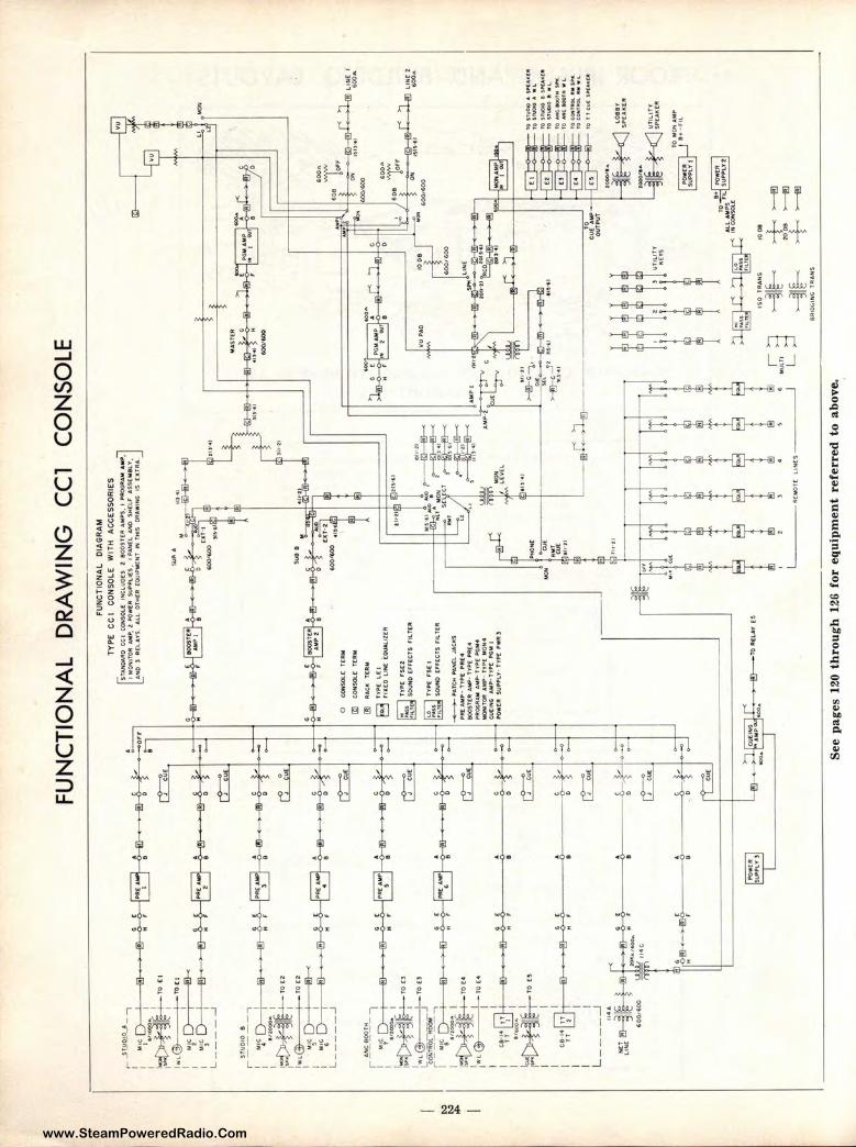
www.SteamPoweredRadio.Com
w
w ""
FU
NC
TIO
NA
L
DR
AW
ING
C
Cl
CO
NS
OL
E
r-
JTJ.
1121
.0J
_ 7
...
: M
IC
ill
C.
[ P
fl(
A
-O
rr
I ',
, "
I N
r
l 8
D
•
• . "
·:
~!&
_!__
_l TO
'I
-
1~l~
~
lwL
(2)
I ro
c1
: u
ic[)
-}--
©-<
I
tA)C
~
L _
__
_ ..
.J
STU
DIO
8
i---
-7
I M
IC
I I
• .,
1-
-J'.n
l,..
. ~~
H
F
lii~
~T
0[2
lw,{
3)
I
FU
NC
TIO
NA
L
OIA
GR
AM
TY
PE
C
C I
CO
NS
OL
E
WIT
H
AC
CE
SS
OR
IES
DTAN
DA
RO
C
CI
CO
HS
OU
: IN
C;I
.U0
£$
2
80
0S
T£
R A
MP
$,
I PR
OG
RA
M A
Mll
J
MO
N'IT
OA
A
MP
. l
PO
WC
R $
4.l
~L
l(S
I
PA
N(L
AN
D S
HC
LF
U
SE
MB
.LV
, A
NO
)
RE
LA
YS
A
LL
OT
HE
R co
u1P
MIE
HT
IN
' TH
IS
DR
AW
ING
,s
[l
CT
RA
"'".
-------4
--------------1
--'='
r ·"""
I I
TO
EZ
I ••<
~
I M!
C D
-}
H ;
I ..
... ~~
60
0•
&0
8 'tr
_L
_.6
~.,.,,
~
!'!,
1)•
4t
6()
0A
60
(>,6
00
L _
__
__
.J
0 C
ON
SO
lE
TE
AM
~
C.O
HS
Ol.E
T
'tR
M
AN
C-
BO
OT
H
r-----7
I
MIC
~
I 7.,~
I
" F
:~H
--TOD
~
~~
---J
TO
U
t,O
HT
A:0
.. R
OO
M
1-~
,-~
I .,lO
OC)...
I
:~
~T
OE
•
lwL
G)
: T
OE
4
ffi}
II
AC
I(
T(R
M
TY
PE
rs
t I
SO
VM
) [F
r[C
TS
FIL
T[R
I I
J C
9•f
4 ,
, G,
C
•
.,_
v-
i lT
I
I "
f
~~~i
~To<•
I I
I C
B-1
4 T
T
I G
[
A
G
) IT
2
H
,-
1 I
I I
L _
__
_ _J
~"•1~
•.
GC
A
N
CT
· l
lH[
I lO
ICa/6
00
,,,
H
F 8
60
01&
00
--
-==
-11
4C
:~T
OR
IEI.A
"t[~
t1,.r
11
lll'
!,·6
1
10lt
•ZI
VU
PA
O
I ~ -
J j
-M
-~
-I
I _
. LI
NC
2
~
6Q
0A
• -
----
ID--
-!}-
<
t4i•
,J J
, "':'
I ~
----
I I @
:,•,f~
cT •
,~
.,,,.;
~
AM
P I
._ L
tVE
L
►
C,·
•J
[PM
ON
£
i~
·-•
1"
L::
-.---~
1->-i
!r'~·;,
0 eu
c C
d--
-...
.o
•~c
~~ _
Jz
M,,u
--
,-i;,.1
,il-
•1
-~
~---
~=
-
ti t{1 tt,,
~· TO
~
,t,LlA
MP
$
IHO
ON
SO
I..[
I ' 1$
0 1
AA
N$
,ooe
~,~
10
$1
VO
N)
A
Sl"
U,I
ICt:
11
TO i
;NQ
IO J
I W
L
10
1,f
\lOIO
8
1,,
C:A
o<
(lt
~ r
o S
TU
DIO
•
•L
-
~ ::
:~=~
: !'~·
~ :g
=::::
::~~
~ 1
0 T
I C
UC
: S
H:,t
..11(
11
~
TOM
Ofl
lAM
P
th-,
u.
I
~-----
AC
MO
TC
L
IN
($
-----
~ ·f
§ >-
ii~
±
+ >
---@
)
>--
--t!
l >
--1!
1 B
lbO
GIN
Q;
TR
AN
S
See
pag
es 1
20 t
hro
ugh
12
6 fo
r eq
uip
men
t re
ferr
ed t
o a
bo
ve.
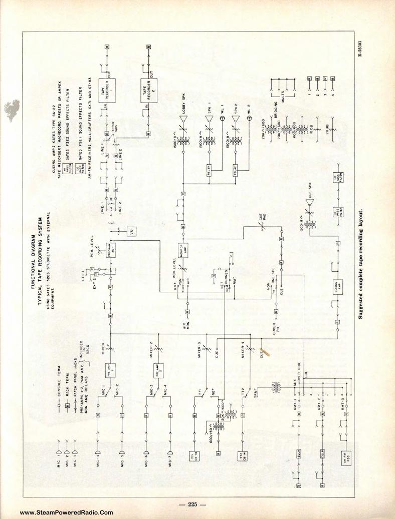
www.SteamPoweredRadio.Com
"' "' (.11
MIG
ID
---<
Mlr
,•
2 D-
----<
M
IG ·l D-
----<
--0
--
CO
NS
OL
( T
ER
M
-@
-R
AG
k T
ER
M
~ P
AT
CH
P
6N
fl
.JA
CK
S
PA
(·A
MP
S
1·2
PG
M A~~ IN
CL
UD
ED
'
' IN
M
ON
, A
MP.
R
f'L
AV
$
52
CS
Ml G
• 4
~
FU
NC
TIO
NA
L
DIA
GR
AM
TY
PIC
AL
T
AP
E
RE
CO
RD
ING
S
YS
TE
M
US
ING
G
AT
ES
S
2C
S
ST
UO
IOE
TT
E
WIT
H
EX
TE
RN
AL
C
OU
IPM
FN
T.
Pr.
M
LE
VE
L
1&
CU
EIN
G
AM
P:
GA
TE
S
TY
PE
S
A·
22
TA
PE
R
EC
OR
OE
R:
MA
GN
EC
OR
O,
PR
ES
TO
O
R
AM
PE
X
GA
TE
S
fSE
Z
SO
UN
D
EF
'f[C
TS
FI
LT
ER
GA
TE
S
FS
E I
SO
UN
O
EF
FE
CT
S
FIL
TE
R
AM
-f
M R
EC
[IV
CR
: H
AI.
LIC
RA
F'T
ER
S
$)(
71
AN
O S
T·8
3
MIG
· ~
~M
IG • 2
L•
IN[
I >
''1--
-4'~
~~
-i~
t----~ j--
~ or
r •
~R
~
~
R
P&O
<;.
"'
LIN
E
2 -
l---<
L
INE
2
vu
Rt~
~~
ER
L l
<
,
r
MIC
• 6 ~ M
IC•3
MIG
· 7 ~ M I
C·4
fTI
I ,,
... -
-Ic
e· ••
~
TT
I M
l,(
[R •
3
GU
£
t ~ T
T 2
M
nE
R-4
~
1 I
I "M
'"' :]
MIX
[~
(
) ff
i E
)
®-o
'
,ov[R
·RIO
(
cur
RM
T•2
°
TA
PE
R
EG
OR
OE
R I
I E
•
fiil
2
AIR
M
ON
>
---I
Rl-
o-+
-I-.
15-0
0,e
.r..
'~~ L0
88
Y
SP
I(
RM
T
MO
N
CA
DER
~ m
l ~ ~ R
~l
CUE
PH
~
~I
CU
[ PA
O
CU
[ ~
S-0
01
8J
'\.
CU
( S
PK
I l
' ,
fRl ~
s .. S
ugge
sted
com
plet
e ta
pe
reco
rdin
g la
you
t.
15
00
/tt
..h
.
SP
K
I
WL
I
SP
K 2
--{
3)
Wl
2
~h
R,O
GIN
G I =
l ~
r~
"'Ts:=
1 ~~
100
8 t
20
08
t
I >
---@
>--
@
3 >
-@
• >
--@
E-2
5301
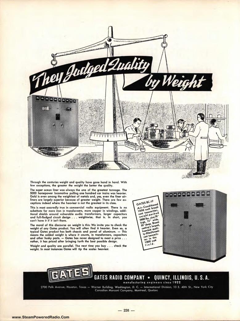
www.SteamPoweredRadio.Com
Through the centuries weight and quality have gone hand in hand. Wilh few exceptions, the greater the weight the better the quality.
The super ocean liner was always the one of the greatest tonnage. The 5000 horsepower locomotive pulling one hundred car trains was heavier. Gold is even among the weightiest of metals and, yes, even the finer airliners are largely superior because of greater weight. There are few exceptions indeed where the heavieot is not the greatest in its class.
This is most assuredly true in commercial radio equipment. There is no substitute for more iron in transformers, more copper in windings, additional sh,ields around vulnerable audio transformers, larger capacitors and full--fledged circuit design •.• weightwise, that is. In short, you can't have it if it isn't ·there.
The moral of this discourse on weight is this: We invite you to check the weight of any Gates product. You will often find it heavier. Even so, a typical Gates product ·has both chassis and panel of aluminum. - This means the added weight is where ii counts, in transformers, capacitors and other husky parts. - Gates has never designed to meet a price .. . rather, it has priced after bringing forth the best possible design.
Weight and quality a re parallel. The next time you buy ... check the weight. In most instances Gctes will tip the scales heaviest.
- 226-
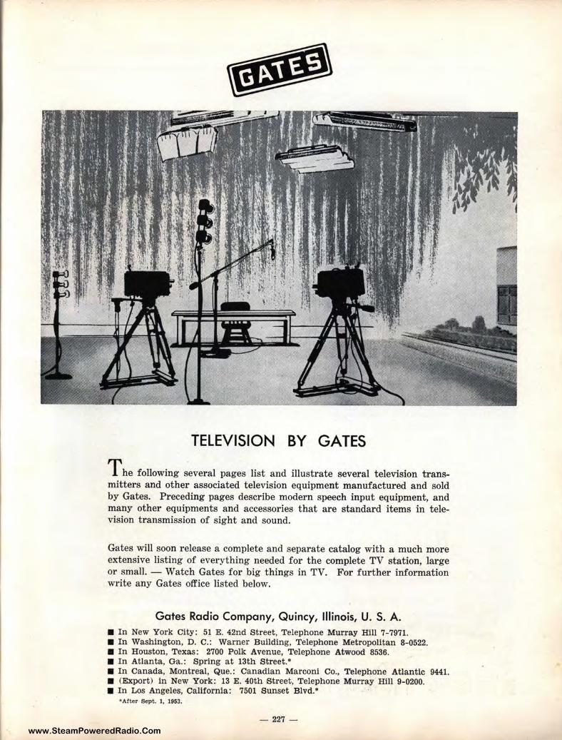
www.SteamPoweredRadio.Com
TELEVISION BY GATES
The following several pages list and illustrate several television transmitters and other associated television equipment manufactured and sold by Gates. Preceding pages describe modern speech input equipment, and many other equipments and accessories that are standard items in television transmission of sight and sound.
Gates will soon release a complete and separate catalog with a much more extensive listing of everything needed for the complete TV station, large or small. - Watch Gates for big things in TV. For further information write any Gates office listed below.
Gates Radio Company, Quincy, Illinois, U. S. A. ■ In New York City: 51 E. 42nd Street, Telephone Murray Hill 7-7971. ■ In Washington, D. c.: Warner Building, Telephone Metropolitan 8-0522. ■ In Houston, Texas: 2700 Polk Avenue, Telephone Atwood 8536. ■ In Atlanta, Ga.: Spring at 13th Street.• ■ In Canada, Montreal, Que.: Canadian Marconi Co., Telephone Atlantic 9441. ■ (Export) in New York: 13 E. 40th Street, Telephone Murray Hill 9-0200. ■ In Los Angeles, California: 7501 Sunset Blvd.•
• After Sept. 1, 1953.
- 227 -
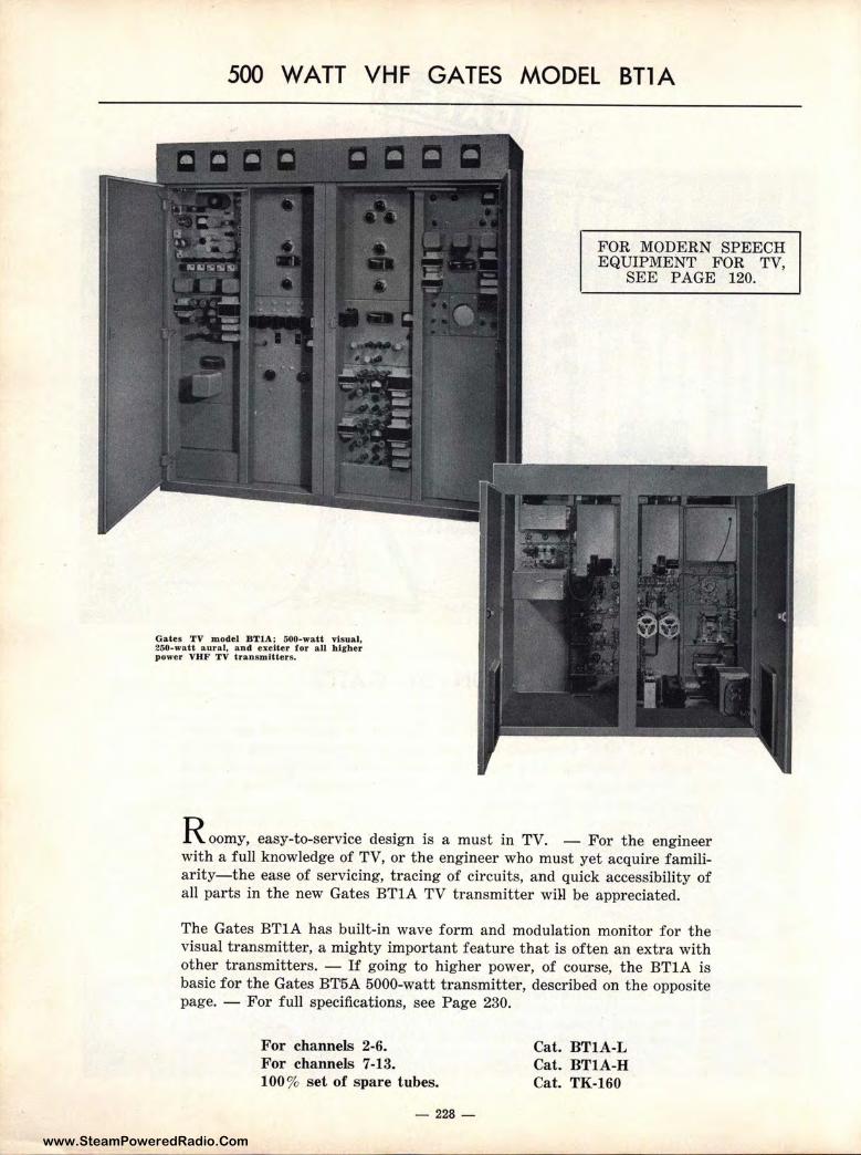
www.SteamPoweredRadio.Com
500 WATT VHF GATES MODEL BTlA
Gates TV model BTlA; GOO-watt visual, 260-watt aural, and exciter tor au hlrher power VHF TV transmitters.
FOR MODERN SPEECH EQUIPMENT FOR TV,
SEE PAGE 120.
R oomy, easy-to-service design is a must in TV. - For the engineer with a full knowledge of TV, or the engineer who must yet acquire familiarity-the ease of servicing, tracing of circuits, and quick accessibility of all parts in the new Gates BTlA TV transmitter wrn be appreciated.
The Gates BTlA has built-in wave form and modulation monitor for the visual transmitter, a mighty important feature that is often an extra with other transmitters. - If going to higher power, of course, the BTlA is basic for the Gates BT5A 5000-watt transmitter, described on the opposite page. - For full specifications, see Page 230.
For channels 2-6. For channels 7-13. 100% set of spare t ubes.
- 228-
Cat. BTIA-L Cat. BTIA-H Cat. TK-160
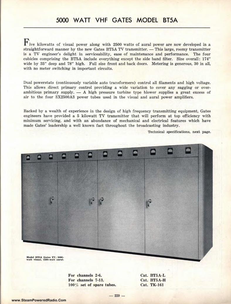
www.SteamPoweredRadio.Com
5000 WATT VHF GATES MODEL BT5A
F ive kilowatts of visual power along with 2500 watts of aural power are now developed in a straightforward manner by the new Gates BT5A TV transmitter. - This lar ge, roomy t ransmitter is a TV engineer's delight in serviceability, ease of maintenance and performance. The four cubicles comprising the BT5A include everything except the side band filter. Size overall: 174" wide by 35" deep and 78" high. Full size front and back doors. Meter ing is generous, 30 in all, with no meter switching in important circuits.
Dual powerstats (continuously variable auto transformers) control all filaments and high voltage. This allows . direct primary control providing a wide variation to cover any sagging or overambitious primary supply. - A high pressur e turbine type blower supplies a great excess of air to the four 3X2500A3 power tubes used in the visual and aural power amplifiers.
Backed by a wealth of experience in the design of high frequency transmitting equipment, Gates engineers have provided a 5 kilowatt TV transmitter that will perform at top efficiency with minimum servicing, and with an' abundance of mechanical and electrical features which have made Gates' leadership a well known fact throughout the broadcasting industry. ·
Model BT5A Gates TV; 5000-watt visual, 2500-watt aural.
For channels 2-6. For channels 7-13. 100% set of spare t ubes.
- 229 -
Technical specifications, next page.
,
Cat. BT5A-L Cat. BT5A-H Cat. TK-161
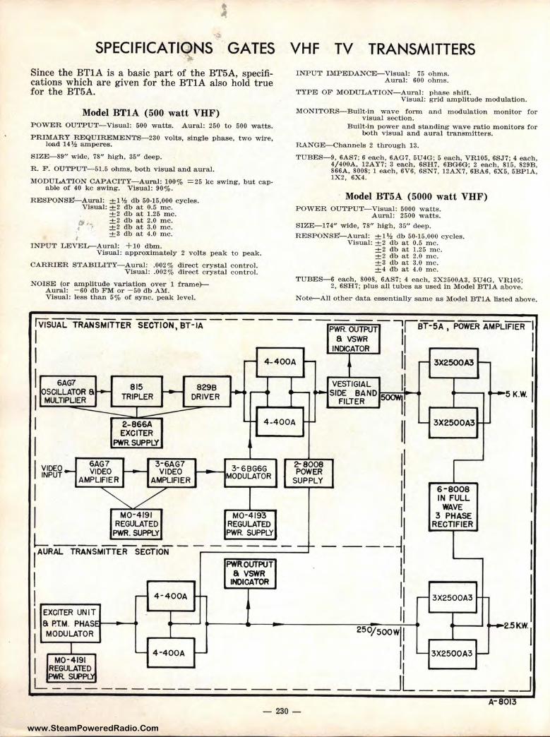
www.SteamPoweredRadio.Com
SPECIFICATI NS GATES Since the BTl A is a basic part of t he BT5A, specifications which are given for the BTIA also hold true for the BT5A.
VHF TV TRANSMITTERS INPUT IMP EDANCE-Visual: 75 ohms.
Aural: 600 ohms.
TYPE OF MODULATI ON-Aural: phase shift. Visual: grid amplitude modulation.
Model BTIA (500 watt VHF) MONITORS-Built-in wave form and moduJation monitor for v isual section.
POWER OUTPUT-Visual: 500 watts. Aural: 250 to 500 watts.
PRIMARY REQUlREMENTS-230 volts, single phase, two wire, load 14½ amperes.
Built-in power a nd standing wave ratio monitors for both visual and aural transmitters.
RANGE-Channels 2 through 13.
SIZE--89" wide, 78" high, 35" deep.
R. F. OUTPUT-51.5 ohms, both visual and aural.
MODULATION CAPACITY-Aural: 100% =25 kc swing, but capable of 40 kc swing. Visual: 90%.
TUBES-9, 6AS7; 6 each, 6AG7. 5U4G; 5 each, VR.105, 6SJ7; 4 each, 4/400A, 12AY7; 3 each, 6SH7, 6BG6G; 2 each, 815, 829B, 866A, 8008; 1 each, 6V6, 6SN7, 12AX7, 6BA6, 6X6, 5BP1A, 1X2, 6X4.
RESPONSE1-Aural: ±l'h db 50-15,000 cycles.
I
Visual: -+-2 db at 0.5 me. +2 db at 1.25 me. ±2 db at 2.0 me. ±2 db at 8.0 me. ±3 db at 4.0 me.
INPU T LEVEL-Aural: +10 dbm. Visual: a pproximately 2 volts peak to peak.
CARRIER STABILITY-Aural: .002% direct crystal control. Visual: .002% direct crystal control.
Model BT5A ( 5000 watt VHF) POWER OUTPUT-Visual: 5000 watts.
Aural: 2600 watts. SIZE-174" wide, 78" h igh, 35" cleep.
RESPONSE'-Aural: ±l'h db 50-15,000 cycles. Visual: ±2 db at 0.5 me.
-+-2 db at 1.25 me. ±2 db at 2.0 me. ±3 db at 3.0 me. ±4 db at 4.0 me.
NOI SE (or amplitude variation over 1 frame}Aural: -60 db FM or -50 db AM.
TUBES-6 each, 8008, 6AS7; 4 each, 3X2500A3, 5U4G, VR105; 2, 6SH7; plus all tubes as used in Model BTlA above.
Visual: less than 5% of sync. peak level. Note-All other data essentially same as Model BTlA listed above.
m5UALTRANSMITTER SECTION, BT-iA - - - - - - -.,,.,.,.,~-..,,..:::;-'::!!.-~- •rsT-5A, POWER AMPLIFIER \ I P~R.~:T ,, I
INDICATOR
I - 4-400A - f 11 - 3X2500A3 ~ I I 6AG7 815 829B -. ...... -........ VESTIGIAL I! I
OSCILLATOR 6 ~ TRIPLER ~ DRIVER ~ ,......... •-- .. SIDE BAND SOOWJI MULTIPLIER :;;::::~: -=----- _..____.....,. FILTER II
I 2-866A 4 -400A I- II EXCITER I PWR SUPPLY , ,
I VIDEO 6AG7 3-6AG7 3-6BG6G 2-8008
1
e<PUT - AM~:'.'iz ;,~.. MODULATOR s~~ 11
I M0-4I9I M0-4I93 ,
1
1 REGULATED REGULATED
PWR. SUPPLY PWR. SUPPLY
LI AURALTR_A_N-SM-1T~T-E=R=-s-E=-c-=-r-10N - - - "'"_::~-:._-:._-_--,J - - -- - -- -- -~,
PWA.OllTPUT I I &VSWR I
1-
--- N>ICATOR ,
1 - 4-400A ,-
1
EXCITER UNIT 11 6 P.T.M. PHAS:Fl---t_... 2501/ I MODULATOR 500W I
._ 3X2500A3 ...
6-8008 IN FULL
WAVE 3 PHASE
RECTIFIER
.-- 3X2500A3 ...
.,__5 K.W. ,
I I I I I I I I
~2.5KW.I
1-1- I ~ 4-400A - I - 3X2500A3 -- I
I M0-4191 I REGULATED ~=-~---------------_JL ______ J
A-8013 - 230 -
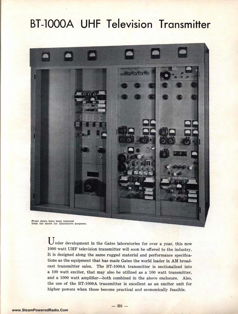
www.SteamPoweredRadio.Com
BT-lOOOA UHF Television Transmitter
Front doors have been removed from t he above tor Illustrative purposes.
U nder development in the Gates laboratories for over a year, this new 1000 watt UHF television transmitter will soon be offered to the industry. It is designed along the same rugged material and performance specifications as the equipment that has made Gates the world leader in AM broadcast transmitter sales. The BT-l000A transmitter is sectionalized into a 100 watt exciter, that may also be utilized as a 100 watt transmitter, and a 1000 watt amplifier-both combined in the above enclosure. Also, the use of the BT-lO00A transmitter is excellent as an exciter unit for higher powers when these become practical and economically feasible.
- 231 -
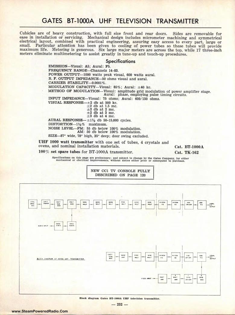
www.SteamPoweredRadio.Com
GATES BT-lOOOA UHF TELEVISION TRANSMITTER
Cubicles are of heavy construction, with full size front and rear doors. Sides are removable for ease in installation or· servicing. Mechanical design includes micrometer machining and symmetrical electrical layout, combined with practical engineering, assuring easy access to every part, large or small. Particular attention has been given to cooling of power tubes so these tubes will provide maximum life. Metering is generous. Six large major meters are across the top, while 17 three-inch meters eliminate multimetering to assist greatly in tune-up and touch-up procedures.
Specifications EMISSION-Visual: A5; Aural: F5. FREQUENCY RANGE-Channels 14-83. POWER OUTPUT-1000 watts peak visual, 600 watts aural. R. F. OUTPUT IMPEDANCE-50 ohms visual and aural. CARRIER STABILITY-0.0001 % . MODULATION CAPACITY-Visual: 85%; Aural: ±40 kc. METHOD OF MODULATION- Visual: amplitude grid modulation of power amplifier stage.
Aural: phase, employing pulse timing circuits. INPUT IMPEDANCE-Visual: 75 ohms ; Aural: 600/150 ohms. VISUAL RESPONSE-± 2 db at 500 kc.
± 2 db at 1.5 me. ± 2 db at 2 me. ±2 db at 3 me. ±3 db at 4 me.
AURAL RESPONSE- ± !½ db 50-15,000 cycles. DISTORTION-I½% maximum. NOISE LEVEL-FM: 55 db below 100% modulation.
AM: 50 db below 100% modulation. SIZE-87" wide, 78" high, 35" deep; door swing excluded.
UHF 1000 watt transmitter with one set of tubes, 4 crystals and ovens, and nominal installation materials. Cat. BT-l000A 100% set spare tubes for BT-l000A transmitter. Cat. TK-162
Specifications on this page are preliminary; and subject to change by the Oates Company, for either mechanical or electrical Improvements. without notice either prior or subsequent to purchase.
91..oci.: D• AGRAM B f 19091, IJHI' UU,NSNITf(R
NEW CCI TV CONSOLE FULLY DESCRIBED ON PAGE 120
Block diagram Gates BT-1000/\ UHF television transmitter.
- 232 -
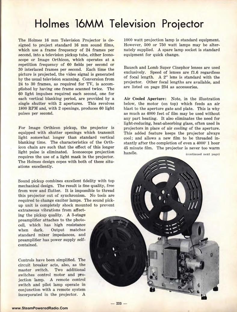
www.SteamPoweredRadio.Com
Holmes 16MM Television Proiector The Holmes 16 mm Television Projector is designed to project standard 16 mm sound films, which use a frame frequency of 24 frames per second, into a television pickup tube, either Iconoscope or Image Orthicon, which operates at a repetition frequency of 60 fields per second or 30 interlaced frames per second. Each time the picture is projected, the video signal is generated by the usual television scanning. Conversion from 24 to 30 frames, as required for TV, is accompiished by having one frame scanned twice. The 60 light impulses required each second, one for each vertical blanking period, are provided by a single shutter with 2 apertur es. This revolves 1800 RPM and, with 2 openings, produces 60 light pulses per second.
For Image Orthicon pickup, the projector is equipped with shutter openings which transmit light somewhat longer t han standard vertical blanking t ime. The characteristics of the Orthicon chain are such that the effect of this longer light pulse is eliminated. Iconoscope projection requires the use of a light mask in the projector. The Holmes design copes with both of t hese situations excellently.
Sound pickup combines excellent fidelity with top mechanical design. The result is fine quality, free from wow and flutter. It is impossible to thread this projector out of synchronism. No tools are required to change exciter lamps. The sound pickup unit is completely shock mounted to prevent extraneous vibrations from affecting the pickup quality. A 3-stage preamplifier attaches to the photocell, which has high resistance when dark. Output matches standard mixer impedances, and preamplifier has power supply selfcontained.
Controls have been simplified. The circuit breaker acts, also, as the master switch. Two additional switches control motor and p'i"ojection lamp. A remote control switch and pilot lamp operate in conjunction with a remote system incorporated in t he projector. A
1000 watt projection lamp is standard equipment. However, 500 or 750 watt lamps may be alternately supplied. A spare lamp socket is standard equipment for quick change.
Bausch and Lomb Super Cinephor lenses are used exclusively. Speed of lenses are fl.6 regardless of focal length. A 2" lens is standard with the projector. Other focal lengths are available, and are listed on page 234 as accessories.
Air Cooled Aperture: Note, in the illustration below, the motor (on top) which feeds an air blast to the aperture gate and plate. This is why as much as 4000 feet of film may be used without any part heating. It also eliminates the need for light-reducing, heat-absorbing glass, often used in projectors in place of air cooling of the aperture. This added feature keeps the projector always cool ; and allows a new film to be threaded instantly after the completion of even a 4000' 1 hour 45 minute film. The projector is never too warm handle. (continued n ext page)
- 233 -
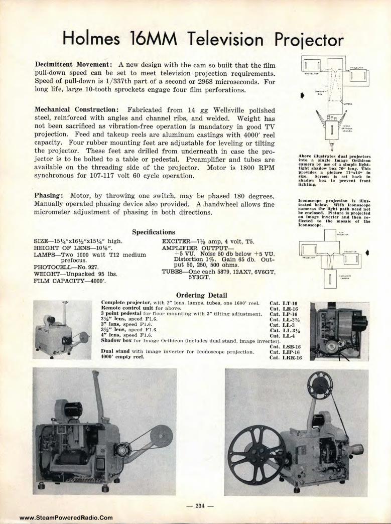
www.SteamPoweredRadio.Com
Holmes l6MM Television Proiector Decimittent Movement: A new design with the cam so built that the film pull-down speed can be set to meet television projection requirements. Speed of pull-down is 1/ 337th par t of a second or 2968 microseconds. For long life, large IO-tooth sprockets engage four film perforations.
Mechanical Construction: Fabricated from 14 gg Wells ville polished steel, reinforced with angles and channel ribs, and welded. Weight has not been sacrificed as vibration-free operation is mandatory in good TV projection. Feed and takeup reels are aluminum castings with 4000' reel capacity. Four rubber mounting feet are adjustable for leveling or tilting the projector. These feet are drilled from underneath in case the projector is to be bolted to a table or pedestal. Preamplifier and tubes are available on the threading side of the projector. Motor is 1800 RPM synchronous for 107-117 volt 60 cycle operation.
Phasing: Motor, by throwing one switch, may be phased 180 degrees. Manually operated phasing device also provided. A ,handwheel allows fine micrometer adjustment of phasing in both directions.
Specifications SIZE-15¼"xl 6½"xl5¼" high. HEIGHT OF LENS-10¾". LAMPS-Two 1000 watt T12 medium
prefocus. PHOTOCELL-No. 927. WEIGHT- Unpacked 95 lbs. FILM CAPACITY-4000'.
EXCITER- 7½ amp, 4 volt, T5. AMPLIFIER OUTPUT-
+ 5 VU. Noise 50 db below + 5 VU. Distortion 1 %. Gain 65 db. Output 50, 250, 500 ohms.
TUBES-One each 5879, 12AX7, 6V6GT, 5Y3GT.
Ordering Detail Complete projector, with 2" lens, lamps, tubes, one 1600' r eel. Cat. LT-16 ~ mote control unit for above. Cat. LR-16
Above illustrates dual projectors Into a. single l mare Orlhlcon camera by use of a simple Urhlllght shadow box ?6" long. Tills provides a picture ll"x14" in sl.ze. Screen is set back in shadow box to prevent front lighting.
lconoscope projection is illustrated below. \Yitb Iconoscope cameras the light path need not be enclosed. Picture Is projected on Image inverter and then reflected to the mosaic or the Iconoscope.
3 point pedestal for floor m ounting with 3" tilting adjustment. Cat. LP-16 2½" lens, speed Fl.6. Cat. LL-2½ 3" lens, speed Fl.6. Cat. LL-3 3½" lens, speed Fl.6. Cat. LL-3½ 4" lens, speed Fl.6. Cat. LL-4 Shadow box for Image Orthicon (includes dual stand, image inverte r).
Cat. LSB-16 Dual stand with image inverter for Iconoscope projection. Cat. LIP-16 4000' empty reel. Cat. LRR-16
- 234 -
•
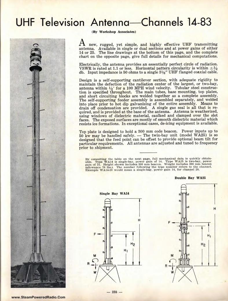
www.SteamPoweredRadio.Com
r
UHF Television Antenna-Channels 14-83 (By Workshop Associates)
A new, rugged, yet simple, and highly effective UHF transmitting antenna. Available in single or dual sections and at power gains of either 14 or 25. The line drawings at the bottom of this page, and t he complete chart on the opposite page, give full details for mechanical computations.
Electrically, the antenna provides an essentially perfect circle of radiation. VSWR is rated at 1.1 or less. Horizontal pattern circularity is within +lh db. Input impedance is 50 ohms to a single 31/s" UHF flanged coaxial cable.
Design is a self-supporting cantilever section, with adequate rigidity to maintain the defection of the radiation center of the largest, or two-bay, antenna within ½ 0 for a 100 MPH wind velocity. Tubular steel construction is specified t hroughout . The main tubes, base mounting, top plates, and short circuiting blocks are welded together as a complete assembly. The self-supporting feeder assembly is assembled separately, and welded into place prior to hot dip galvanizing of the entire assembly. Means to drain off condensation are provided. A single gas seal is all that is required, and is provided at the base of the antenna. Antenna is weatherized, using windows of dielectric material, caulked and clamped over t he slot faces. The exposed surfaces are mostly of smooth dielectric material which resists ice formations. In exceptional cases, de-icing equipment is available.
Top plate is designed to hold a 300 mm code beacon. Power inputs up to 50 kw may be handled safely. - The twin-bay unit (model W A25) is so designed that t he feed point can be offset to provide optional beam tilt for particular requirements. All antennas are adjusted and tuned to frequency prior to shipment.
By consulting the table on the next page. full mechanical data is quickly obtain• able. Type WA14 is single-bay, power gain of 14. Type WA25 Is two-bay, power gain of 25. Height shown Includes 300 mm beacon. Weight includes 300 mm beacon (allowance 70 lbs.). The number following the type number refers to the channel. Example WA14-20 would mean a single-bay, power gain 14, for chanpel 20.
Double Bay WA25
Single Bay WA14
H
- 235 -
H
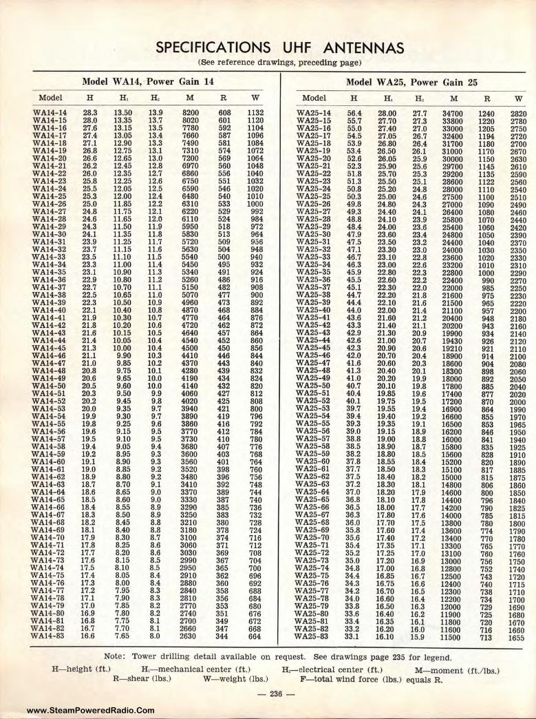
www.SteamPoweredRadio.Com
SPECIFICATIONS UHF ANTENNAS (See reference drawings, preceding page)
Model W A14, · Power Gain 14 Model W A25, Power Gain 25
Model H H , H , M R w Model H H, H, M R w WA14-14 28 .. 3 13.50 13.9 8200 608 1132 WA25-14 56.4 28.00 27.7 34700 1240 2820 WA14-15 28.0 13.35 13.7 8020 601 1120 WA25-15 55.7 27.70 27.3 33800 1220 2780 WA14-16 27.6 13.15 13.5 7780 592 1104 WA25-16 55.0 27.40 27.0 33000 1205 2750 WA14-17 27.4 13.05 13.4 7660 587 1096 WA25-17 54.5 27.05 26.7 32400 1194 2720 WA14-18 27.1 12.90 13.3 7490 581 1084 WA25-18 53.9 26.80 26.4 31700 1180 2700 WA14-19 26.8 12.75 13.1 7310 574 1072 WA25-19 53.4 26.50 26.1 31000 1170 2670 WA14-20 26.6 12.65 13.0 7200 569 1064 WA25-20 52.6 26.05 25.9 30000 1150 2630 WA14-21 26.2 12.45 12.8 6970 560 1048 WA25-21 52.3 25.90 25.6 29700 1145 2610 WA14-22 26.0 12.35 12.7 6860 556 1040 WA25-22 51.8 25.70 25.3 29200 1135 2590 WA14-23 25.8 12.25 12.6 6750 551 1032 WA25-23 51.3 25.50 25.1 28600 1122 2560 WA14-24 25.5 12.05 12.5 6590 546 1020 WA25-24 50.8 25.20 24.8 28000 1110 2540 WA14-25 25.:3 12.00 12.4 6480 540 1010 WA25-25 50.3 25.00 24.6 27500 1100 2510 WA14-26 25.0 11.85 12.2 6310 533 1000 WA25-26 49.8 24.80 24.3 27000 1090 2490 WA14-27 24.,8 11.75 12.1 6220 529 992 WA25-27 49.3 24.40 24.1 26400 1080 2460 WA14-28 24.6 11.65 12.0 6110 524 984 WA25-28 48.8 24.10 23.9 25800 1070 2440 WA14-29 24.3 11.50 11.9 5950 518 972 WA25-29 48.4 24.00 23.6 25400 1060 2420 WA14-30 24.1 11.35 11.8 5830 513 964 WA25-30 47.9 23.60 23.4 24800 1050 2390 WA14-31 23.9 11.25 11.7 5720 509 956 WA25-31 47.5 23.50 23.2 24400 1040 2370 WA14-32 23.7 11.15 11.6 5630 504 948 WA25-32 47.1 23.30 23.0 24000 1030 2350 WA14-33 23.5 11.10 11.5 5540 500 940 WA25-33 46.7 23.10 22.8 23600 1020 2330 WA14-34 23.3 11.00 11.4 5450 495 932 WA25-34 46.3 23.00 22.6 23200 1010 2310 WA14-35 23.1 10.90 11.3 5340 491 924 WA25-35 45.9 22.80 22.3 22800 1000 2290 WA14-36 22.9 10.80 11.2 5260 486 916 WA25-36 45.5 22.60 22.2 22400 990 2270 WA14-37 22.7 10.70 11.1 5150 482 908 WA25-37 45.1 22.30 22.0 22000 985 2250 WA14-38 22.5 10.65 11.0 5070 477 900 WA25-38 44.7 22.20 21.8 21600 975 2230 WA14-39 22.3 10.50 10.9 4960 473 892 WA25-39 44.4 22.10 21.6 21500 965 2220 WA14-40 22.1 10.40 10.8 4870 468 884 WA25-40 44.0 22.00 21.4 21100 957 2200 WA14-41 21.9 10.30 10.7 4770 464 876 WA25-41 43.6 21.60 21.2 20400 948 2180 WA14-42 21.8 10.20 10.6 4720 462 872 WA25-42 43.3 21.40 21.1 20200 943 2160 WA14-43 21.6' 10.15 10.5 4640 457 864 WA25-43 42.9 21.30 20.9 19900 934 2140 WA14-44 21.4 10.05 10.4 4540 452 860 WA25-44 42.6 21.00 20.7 19430 926 2120 WA14-45 21.3 10.00 10.4 4500 450 856 WA25-45 42.3 20.90 20.6 19210 921 2110 WA14-46 21.l 9.90 10.3 4410 446 844 WA25-46 42.0 20.70 20.4 18900 914 2100 WA14-47 21.0 9.85 10.2 4370 443 840 WA25-47 41.6 20.60 20.3 18600 904 2080 WA14-48 20.8 9.75 10.1 4280 439 832 WA25-48 41.3 20.40 20.1 18300 898 2060 WA14-49 20.6 9.65 10.0 4190 434 824 WA25-49 41.0 20.20 19.9 18000 892 2050 WA14-50 20.5 9.60 10.0 4140 432 820 WA25-50 40.7 20.10 19.8 17800 885 2040 WA14-51 20.3 9.50 9.9 4060 427 812 WA25-51 40.4 19.85 19.6 17400 877 2020 WA14-52 20.2 9.45 9.8 4020 425 808 WA25-52 40.1 19.75 19.5 17200 870 2000 WA14-53 20.0 9.35 9.7 3940 421 800 WA25-53 39.7 19.55 19.4 16900 864 1990 WA14-54 19.9 9.30 9.7 3890 419 796 WA25-54 39.4 19.40 19.2 16600 855 1970 WA14-55 19.8 9.25 9.6 3860 416 792 WA25-55 39.3 19.35 19.1 16500 853 1965 WA14-56 19.6 9.15 9.5 3770 412 784 WA25-56 39.0 19.15 18.9 16200 846 1950 WA14-57 19.5 9.10 9.5 3730 410 780 WA25-57 38.8 19.00 18.8 16000 841 1940 WA14-58 19.4 9.05 9.4 3680 407 776 WA25- 58 38.5 18.90 18.7 15800 835 1925 WA14-59 19.2 8.95 9.3 3600 403 768 WA25-59 38.2 18.80 18.5 15600 828 1910 WA14-60 19.!1. 8.90 9.3 3560 401 764 WA25-60 37.8 18.55 18.4 15200 820 1890 WA14-61 19.0 8.85 9.2 3520 398 760 WA25-61 37.7 18.50 18.3 15100 817 1885 WA14-62 18.9 8.80 9.2 3480 396 756 WA25-62 37.5 18.40 18.2 15000 815 1875 WA14-63 18.7 8.70 9.1 3410 392 748 WA25-63 37.2 18.30 18.1 14800 806 1860 WA14-64 18.6 8.65 9.0 3370 389 744 WA25-64 37.0 18.20 17.9 14600 800 1850 WA14-65 18.5 8.60 9.0 3330 387 740 WA25-65 36.8 18.10 17.8 14400 796 1840 WA14-66 18.4 8.55 8.9 3290 385 736 WA25-66 36.5 18.00 17.7 14200 790 1825 WA14-67 18.3 8.50 8.9 3250 383 732 WA25-67 36.3 17.80 17.6 14000 785 1815 WA14-68 18.2 8.45 8.8 3210 380 728 WA25-68 36.0 17.70 17.5 13800 780 1800 WA14-69 18.1 8.40 8.8 3180 378 724 WA25-69 35.8 17.60 17.4 13600 774 1790 WA14-70 17.9 8.30 8.7 3100 374 716 WA25-70 35.6 17.40 17.2 13400 770 1780 WA14-71 17.8 8.25 8.6 3060 371 712 WA25-71 35.4 17.35 17.1 13300 765 1770 WA14-72 17.7 8.20 8.6 3030 369 708 WA25-72 35.2 17.25 17.0 13100 760 1760 WA14-73 17.6 8.15 8.5 2990 367 704 WA25-73 35.0 17.20 16.9 13000 756 1750 WA14-74 17.5 8.10 8.5 2950 365 700 WA25-74 34.8 17.00 16.8 12800 752 1740 WA14-75 17.4 8.05 8.4 2910 362 696 WA25-75 34.4 16.85 16.7 12500 743 1720 WA14-76 17.3 8.00 8.4 2880 360 692 WA25-76 34.3 16.75 16.6 12400 740 1715 WA14-77 17.2 7.95 8.3 2840 358 688 WA25-77 34.2 16.70 16.5 12300 738 1710 WA14-78 17.1 7.90 8.3 2810 356 684 WA25-78 34.0 16.60 16.4 12200 734 1700 WA14-79 17.0 7.85 8.2 2770 353 680 WA25-79 33.8 16.50 16.3 12000 729 1690 WA14-80 16.9 7.80 8.2 2740 351 676 WA25-80 33.6 16.40 16.2 11900 725 1680 WA14-81 16.8 7.75 8.1 2700 349 672 WA25-81 33.4 16.35 16.1 11800 720 1670 WA14-82 16.7 7.70 8.1 2660 347 668 WA25-82 33.2 16.20 16.0 11600 716 1660 WA14-83 16.6 7.65 8.0 2630 344 664 WA25-83 33.1 16.10 15.9 11500 713 1655
Note : Tower drilling detail available on request. See drawings page 235 for legend.
H- helght (ft.) H,-mechanical center (ft. ) H,-electrical center (ft.) M-moment (ft./lbs.) R-shear Obs.) W-weight (lbs.) F- total wind force (lbs.) equals R.
- 236 -
www.SteamPoweredRadio.Com
IND EX Description Page Description Page
Accessory cabinet, MO-3066 ................................................ 43 A. C. generators ...................................................................... 188 Adapters, remote microphone ............................................ 177 Air pressure control ................................................................ 197 Ampex precision power supply .......................................... 169 Ampex speed lock .................................................................. 169 Ampex tape recorders .................................................. 168, 169 Amplifiers
Aircraft homing beacon transmitter ........................ 101 Amplifier power supplies .................................... 132, 153 Announco-mote ................................................................ 177 Cueing amplifiers ............................................................ 149 Fatigue ................................................................................ 221 Intercommunication ...................................................... 187 Limiting amplifiers ................................................ 148, 149 McIntosh ............................................................................ 206 Monitoring amplifiers ................................ 131, 150, 152 Plug-in amplifiers .................................................. 127- 133 Preamplifiers .................................................. 128, 129, 151 Presidential ........................................................................ 194 Program amplifiers ...................................... 130, 150, 152 Public address ........................................ 180, 181, 206, 221 Recording (disc) .............................................................. 167 Recording (tape) .................................................... 170, 172 Remote ............................................ see remote amplifiers Selective amplifiers ...................... ·.................................. 117 Speech input consoles ........ see speech input consoles Totalizing .......................................................................... 221
Andrew coaxial cable .................................................... 213-216 Antenna ammeters ........................................................ 62, 196 Antenna couplers ................................................ 53, 59, 60, 61 Antenna isola tion coils ........................................................ 56 Antenna meter shorting switches .................................... 197 Antenna meters, remote reading .................................... 62 Antenna tower chokes .......................................................... 56 Antenna tower lights ............................................................ 209 Antenna towers .............................................................. 207, 208 Antennas, dummy .................................................................. 206 Antennas (FM) ........................................................................ 206 Arms, transcription ........................................................ 161, 206 Attenuator dials ...................................................................... 194 Attenuator knobs .......................................................... 195, 219 Attenuators ................................................................................ 194 Audio oscillator ........................................................................ 50 Audio panel, transmitter .................................................... 48 Audio terminal board ............................................................ 63 Audio transformers ........................................................ 190-193 Audition turntables ................................................................ 160 Auditory t raining unit .......................................................... 219 Auxiliary transmitter ............................................................ 33
Broadcast transmitters (short wave) 1000 watt, HFl-2 transmitter .............................. 73-78 5000 watt, HF-5B transmitter ............................ 66-72
10,000 watt, HF-l0B transmitter .......................... 66-72 20,000 watt, HF-20B transmitter ........................ 96-100
Cabinets, disc ............................................................................ 162 Cabinets, loudspeaker .................................................. 182, 183 Cabinets, rack ............................................................ 63, 64, 197 Cable, microphone .................................................................. 185 Call letter plates ...................................................................... 185 Cannon connectors ................................................................ 186 Capacitors, filter .................................................................... 204 Capacitors, mica ...................................................................... 203 Capacitors, vacuum ................................................................ 202 Cathode ray oscilloscope ...................................................... 195 Center post insulator .................................................... 217, 218 Centralized sound systems .................................................... 221 Chokes, filter .................................................................... 190-193 Chokes, tower ......................... ................................................... 56 Clocks .......................................................................................... 165 Coaxial cable .................................................................... 213-216 Coaxial speakers ........................... ,.................................. 182, 183 Coils, antenna isolation ........................................................ 56 Communications receivers ............................................ 114, 115 Communications transmitters (FM)
10 watt, 150 me, BF-E-10 transmitter ............ 99,100 250 watt, FMR-250 transmitter ............................ 35, 36 3000/ 5000 watt, 200 me, transmitter ........................ 105 FM Littlefone .................................................................... 106
Communications transmitters (short wave) 250 watt, unit system ............................................ 79-83 250 watt, CMG-1 ............................................ 84, 85, 86 500 watt, CMW- 1 .................................... 78, 79, 80, 81
1000 watt, police ........................................ 91, 92, 93, 94 1000 watt, HF-1 series ............................................ 73-78 5000 watt, HF-5 series ............................................ 66-72
10,000 watt, HF-10 series .......................................... 66-72 20,000 watt, HF-20 series ........................................ 96-100 Two-way communications ............................................ 106
Compressors, volume .............................................................. 148 Cone speakers .................................................................. 182, 183 Connectors, microphone ........................................................ 186 Consoles .......................................... see speech input consoles Control console, transmitter .............................................. 46 Control, master ........................................................................ 146 Controls, bridging .................................................................... 132 Converter, frequency shift .................................................. 109 Cordette, Magnecord .............................................................. 171 Cords, patch .............................................................................. 145 Couplers, antenna ................................................ 53, 59, 60, 61 Crystals and holders .................................................... 112, 113 Cueing amplifier ...................................................................... 149 Custom desks .................................................................. 162, 163
Bass reflex speakers ...................................................... 182, 183 Beacon, 300 MM ................................................................ 210-212 Beacon transmitter ................................................................ 101 Binaural recorders .......................................................... 169, 171 Blank panels .............................................................................. 154 Blowers ........................................................................................ 197 Boards, terminal ............................................................. ......... 63 Boom stand, microphone .................................................... 185 Bowls, feed-thru ...................................................................... 218 Brackets, transmission line ........................................ 217, 218 Branching equipment (phasors) ........................................ 52 Bridging controls .................................................................... 132 Broadcast station layout ...................................................... 222 Broadcast transmitters, AM (540-1600 kc)
250 watt, BC-250GY transmitter .................... 26-30 250 watt, GY-48 radio station .......................... 31-32 250 watt, BCA-250 auxiUary transmitter ...... 33-34 500 watt, BC-500GY transmitter .................... 22-23 500 watt, GY-50 radio station ................................ 26
1000 watt, BC-lF transmitter ............................ 10-18 1000 watt, GY-1000 radio station ...................... 20-21 5000 watt, BC-5B transmitter ................................ 4-9 Eicor tape recorders .............................................................. 1:73
10,000 watt, BC- l0B transmitter .............................. 4-9 Eimac tubes .............................................................................. 199 20,000 watt, BC-20B transmitter ........................ 96-100 End plates, open wire transmission line .............. 217, 218 Unattended operation, remote control .................... 178 Entrance insulators ................................................................ 218
Broadcast transmitters, FM Equalizers, automatic (disc recording) .......................... 166 10 watt educational BF-E-10 transmitter ...... 37-38 Equalizers, line · ........................................................................ 174
250 watt, FMR-250 transmitter ............................ 35-36 Equalizers, pickup .................................................................. 161 Portable FM equipment ................................................ 106 Equalizers, sound effects ...................................................... 175
Daven attenuators .................................................................. 194 Demagnetizer, t ape ................................................................ 172 Desk stands, microphone .................................................... 185 Desks-Model CB-4 horseshoe ............................................ 158
Model CB-60, CB-62, etc. ...................................... 163 Sectionalized control desk .................................... 164
Dials ............................................................................................ 194 Diode type remote reading antenna meter .................... 62 Directional phase monitors ................................................ 57 Directional phasors ............................................................ 52-55 Disc cabinets ............................................................................ 162 Disc recorders .................................................................... 160, 166 Disc recording amplifiers .................................................... 167 Discs, blank recording .......................................................... 173 Distortion measuring equipment ...................................... 50 Dual diversity receiver .......................................................... 116 Dummy antennas .................................................................... 206
- 237 -
www.SteamPoweredRadio.Com
IND EX (continued)
Description Page Description Page Fan, rack cabinet ventilating ............................................ 186
i:~~~~! ti%~!i~~~~~ ... :::::::::::::::::::::::::::::::::::::::::::::::::::::::::::::::::: i~~ Feed-thru bowls ...................................................................... 218
Monosets ..................................... ............. ................................ 186
Noise and distortion meter ................................................ 50
Ferrule resistors ....... ............ ....... ............................................ 205 Filter capacitors ...................................................................... 204 Filters, pickup .......................................................................... 161 Floor stands, microphone .................................................... 185 FM antennas ............................................................................ 206 Foreword .................................................................................... 1 Four-hour tape recorder ...................................................... 171 Frequency and modulation monitor (FM) .................... 111 Frequency and shift monitor .............................................. 108 Frequency monitor (AM) ....................................... ......... 39-40 Frequency shift converter .................................................... 109 Frequency shift keyer .......................................................... 107
Obstruction lights for towers ......... .................. 209-212, 219 Oil-filled capacitors ................................................................ 204 Onan, A. C. generators ........................................................ 188 Open wire transmission line ........................................ 217, 218 Oscillator, audio ...................................................................... 50 Oscillator, variable master .................................................. 110 Oscilloscope ................................................................................ 195 Ovens, crystal .................................................................... 112, 113
Packaged radio stations 250 watt ............................................................................ 31 500 watt ............................................................................ 26
Gain set ...................................................................................... 50 1000 watt ............................................................................ 20
i:i~i: !~:if i;:i;:::::::::::::::::::::::::::::::::::::::::::::::::::::::::::::::::::: 22g Generating plants, alternating current .................. 188, 189 Ground screen -········································································· 219 Ground wire .............................................................................. 219 Hallicrafters Littlefone ........................................................ 106 Hallicrafters receivers .................................................. 114-115 Hammarlund receivers .................................................. 114-115 Headphones ................................................................................ 186 Hearing, auditory training unit .......................................... 219 Homing beacon transmitter ........................................ 101-104
S~~1i!r-;:l!~::a~~ii:::::::::::::::::::::::::::::::::::::::::::::::::::::::::: iii Hughey & Phillips, tower lighting .................................... 209
i~t:;~J~se;iI::nt··:::::::::::::::::::::::::::::::::::::::::::::::::::::::::::::: ~~i Isolation chokes (tower light) .......................................... 56 Isolation colls (antenna) .................................................... 56 Jacks, patch .............................................................................. 145 Jennings, vacuum capacitors .............................................. 202 Keyer, frequency shift .......................................................... 107
li:~ff?:\ ••:•••••·••••••••••••••••••••••••••••••••••••••••••• ;~~: lH Lamps, for tower lights ........................................................ 219 Li'brary, tape ............................................................................ 171 Lights, studio warning .......................................................... 165 Lights, tower ............................................................................ 209 Limiting amplifiers ........................................................ 148, 149 Line equalizers ........................................................................ 174 Littlefone, 2-way radio ........................................................ 106 Loops, phase sampling .......................................................... 56 Loudspeaker cabinets .................................................... 182, 183 Loudspeakers, cone ................................... .,.................... 182, 183
Pads, fixed ................................................................................ 194 Panels, ,blank ............................................................................ 154 Panels, patch .............................................................. : ............. 145 Peak limiting amplifiers .............................................. 148, 149 Phase monitors ........................................................................ 57 Phase sampling loops ............................................................ 56 Phasors ........................................................................................ 52 Phones (headphones) ............................................................ 186 Pickup coil with rectifier ...................................................... 50 Pickups, transcription .................................................... 161, 206 Plans
Broadcast station ............................................................ 222 CCl console wiring plan ................................................ 224 Floor plans .............................. .................... ..... ................. 223 Tape recorder wiring plan .......................................... 225
Plates, call letter .................................................................... 185 Plug-in amplifiers .................................................................. 127 Plug- in power supplies ........................................................ 132 Portable audition equipment .............................................. 160 Portable remote amplifier ............................................ 176, 177 Portable tape recorders ............................ see tape recorders Portable transmitters ............................................................ 187 Power rheostats ...................................................................... 205 Power supplies .......................................................... 132, 153, 169 Power supplies, A. C. generating ........................................ 188 Power terminal ·board ............................................................ 63 Power transformers .................... , ................................... 190-193 Presidential amplifier ............................................................ 194 Pressure control, static ........................................................ 197 Presto amplifier , disc recording ........................................ 167 Presto recorders, disc .................................................. .......... 166 Presto tape recorders ............................................................ 172 Presto turntables .................................................................... 159 Projectors, television ...................................................... 233,234 Proof of performance package ........................................ 49-51 Public address systems .................................................. 180-206
Quincy, Illinois, picture of .................................................. 220
Magnecord tape recorders .......................................... 170, 171 Master control ................................................................ 146, 147 Master oscillator, varia,ble .................................................... 110
~i!tEs~c~m:i:iifrieis·:::::::::::::::::::::::::::::::::::::::::::::::::::::::::::::::: ~i~ Meter shorting switches ........................................................ 197 Meters .......................................................................................... 197 Meters, remote reading ........................................................ 62 Mica capacitors ........................................................................ 203 Microphone cable .................................................................... 185 Microphone call letter plates ............................................ 185 Microphones .................................................................... 184, 185 Mobile transmitters ................................................................ 187 Modulation monitor ............................................................ 41-42 Modulation transformers .................................................... 192 Monitors
Complete monitor accessory cabinet ........................ 43 Frequency -········································································· 39 Frequency and modulation (FM) ............................ 111 Frequency and shift ...................................................... 108 Modulation ........................................................................ 41 Phase .................................................................................. 57
Rack cabinets .............................................................. 63, 64, 197 Rack cabinet ventilating fan ............................................ 186 Rack housings .......................................................................... 154 Radiators, vertical .......................................................... 207, 208 Radio tubes ................................................................................ 198 Receiver, selective amplifier ................................................ 117 Receivers, communications .......................................... 114, 115 Receivers, dual diversity ...................................................... 116 Receptacles, microphone ...................................................... 186 Record cabinets ........................................................................ 162 Recorders, disc ................................................................ 160, 166 Recorders, tape ............................................ see tape recorders Recording amplifiers, disc .................................................... 167 Recording discs ..................................... .... ......... ..... ........ ......... 173 Recording equalizers, disc .................................................... 166 Recording supplies .................................................................. 173 Recording tape ........................................................................ 173 Rectifier for RF (proof of performance) ........................ 50 Reel adapter, Magnecord .................................................... 171 Regulators, voltage ............................................. : .................. 175 Relay panel, plug-in .............................................................. 126 Relays, solenoid ........................................................................ 197
- 238 -
www.SteamPoweredRadio.Com
I NDEX ccontlnued)
Description Paite Description Page
Remote amplifiers Adapter kits ...................................................................... 177 Announco-mote ................................................................ 177 Dynamote, 3-cha.nnel .................................................... 176 Presidential amplifier .................................................... 194 SA-134 amplifier .............................................................. 151 SA-136 amplifier .............................................................. 177
Remote control for unattended operation .................... 178 Remote meters for phasors ...................................... .......... 57 Remote reading antenna meters ...................................... 62 Resistors ...................................................................................... 205 Rheostats .................................................................................... 205 Rotary and lever switches .................................................... 195
Test set, volt ohmmeter ........................................................ 195 Thermocouple antenna meters .................................... 62, 196 Thermocouple type remote reading antenna meters 62 Three-channel remote amplifier ........................................ 176 Tools, burnishing .................................................................... 194 Totalizing amplifiers .............................................................. 221 Tower chokes ............................................................................ 56 Tower lights .............................................................. 209-212, 219 Tower termination equipment, 47A .................................. 61 Towers, antenna .............................................................. 207,208 Transcription cabinets .......................................................... 162 Transcription turntables
CB-4 desk with turntables .......................................... 158 CB-11 chassis .................................................................... 157
Sales policy .............................................................................. 2 Sampling loops ........................................................................ 56 SA rack housings .............................................. ............ .......... 154 Screen, ground ........................................................................ 219 Sectionalized control desk .................................................... 164
CB-14 transcription equipment .................................. 157 CB-15 turntable .............................................................. 159 Portable transcription unit ........................................ 159 Presto Model 15G ............................................................ 159 Presto Model 64A ............................................................ 159
Selective amplifier .................................................................. 117 Shielded wire ............................................................................ 185 Short wave transmitters . .
.................................... see communications transmitters
Rek-O-Kut turntables .................................................. 160 Turntable pickups .................................................. 161, 206 Turntable equalizers ...................................................... 161
Transformers .................................................................... 190-193 Signal generator, audio frequency .................................... 50 Sockets, transmitting tube .................................................. 197 Solenoid relays ........................................................................ 197 Solid dielectric coaxial cable .............................................. 216 Sound effects consoles .......................................................... 155 Sound effects equalizers ...................................................... 175 Sound equipment .................................................................... 180 Sound systems, centralized .................................................. 221 Southwestern office .............................................................. 25 Speakers, loud .................................................................. 182, 183 Speech input consoles
Transmitter accessory cabinet ............................................ 43 Transmitter audio panel ...................................................... 48 Transmitter control console ............................................ 46-47 Transmitters, broadcast .......... see broadcast transmitters Transmitters, communications
.................................... see communications transmitters Transmitters, homing beacon .................................... 101- 104 Transmitters, mobile portable ............................................ 187 Transmitters, television
500 watt VHF .................................................................. 228 5000 watt VHF .................................................................. 229
Accessories for 001 console ................................ 125, 126 CCl console ................................................................ 120-124 Master control .......................................................... 146, 147 SA-40 console ............................................................ 141, 142 SA-40 console on CB-4 desk ........................................ 139
1000 watt UHF .......................................................... 231,232 Transmitters, unattended operation equipment .... 178, 179 Transmission line, coaxial ............................................ 213- 216 Transmission line, open wire ...................................... 217, 218 Tubes .................................................................................... 198-202
SA-40 console on CB-63 desk ...................................... 138 Tube sockets .............................................................................. 197 SA-50 dual channel console ................................ 134, 137 52-CS studioette .............................................. 142, 143, 144
Speed lock, Alnpex ................................................................ 169 Spring-wound tape recorder ................................................ 167 Stands, microphone ........................................................ 184, 185 Static pressure control ........................................................ 197 Stereophonic tape recorder ................................................ 169 Stethoscope type headphones ............................................ 186 Studio clocks ............................................................................ 165
Tuners, antenna .................................................... 53, 59, 60, 61 Tuners, Hi-Fi ............................................................................ 115 Turntable preamplifier, SA- 134 ........................................ 151 Twin-track recorders ................................ see tape recorders Twinset headphones .............................................................. 186
UHF television transmitters ........................................ 231, 232 Unattended operation, remote control ............................ 178
Switches, audio ........................................................................ 195 Switches, meter shorting .................................................... 197
Vacuum capacitors ................................................................ 202 Vacuum tube voltmeter ........................................................ 195 Variable attenuators .............................................................. 194
Taking proof of performance ............................................ 51 Tape recorders
Ampex .......................................................................... 168, 169 Demagnetizer .................................................................... 172 Eicor .................................................................................... 173
Variable equalizers, disc ...................................................... 166 Variable equalizers, line ...................................................... 174 Variable equalizers, pickup .................................................. 161 Variable equalizers, sound effects .................................... 175 Variable frequency oscillator ........................................ 44-45 Variable master oscillator .................................................... 110
Magnecord ................................................................ 170,171 Reel adapter, 10½" ........................................................ 171 TaPak, spring-wound .................................................... 16'.1
Tape, leader .............................................................................. 173 Tape library .............................................................................• 171 Tape, recording tape .............................................................. 173 Tape, reels .................................................................................. 173
Ventilating fan, rack cabinet ............................................ 186 VHF television transmitters ........................................ 228-230 Voltage regulators .................................................................. 175 Volt-amp wattmeter .............................................................. 195 Voltmeter, vacuum tube ...................................................... 195 Voltmeters .................................................................................. 196 Volt ohmmeters ........................................................................ 195
Tapped resistors ...................................................................... 205 Telegraph keys ........................................................................ 186 Telephone keys ........................................................................ 195
Volume indicators .................................................................. 174 Voyager, Magnecord .............................................................. 171 VU meters .................................................................................. 196
Television, CCl speech console .......................................... 120 Television, projectors .................................................... 233, 234 Television, sound effects console ...................................... 155 Television, UHF antenna ............................................ 235, 236 Temperature controlled ovens .................................... 112, 113 Terminal boards ...................................................................... 63 Test equipment (proof of performance) ........................ 49
Wagons, sound effects ............................................................ 155 Waist-high rack cabinets .................................................... 64 Warning lights, studio .......................................................... 165 Wattmeters ................................................................................ 195 Wire, ground ............................................................................ 219 Wire, shielded studio ............................................................ 185
NOTICE-,It ha.s been the continuing policy ot Gates t-0 maintain each and every equipment manu(actured to very highest standards of modern engineering design. Because ot this, the Gates Radio Company reserves the r ight to modify any specification stated In this catalog where it Is for the Improvement ot the equipment quality, either electrical or mechanical. Equipment sold by Gates, but not manufactured by Oates, ls supplied with the same understanding.
- 239 -
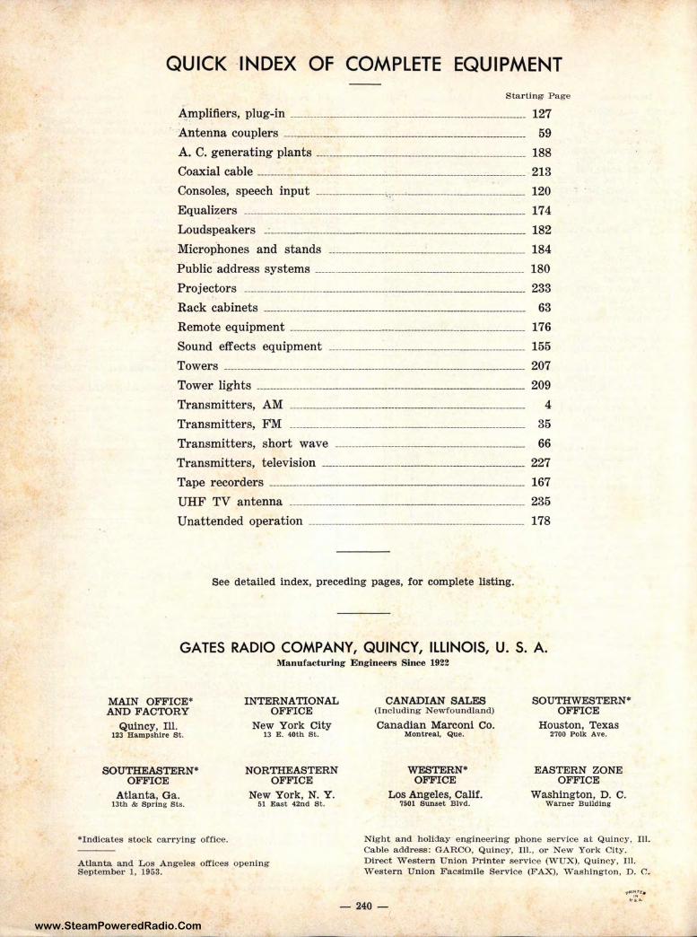
www.SteamPoweredRadio.Com
QUICK ·INDEX OF COMPLETE EQUIPMENT
S tar ti n!l) Page
Amp 1 ifi ers, plug-in ________ -------------------------------------------------------------- 127
Antenna coupl•~rs ---------------------------------------------------- 59
A. C. generating plants -------------------------------------- ·--- 188
Coaxial cab 1 e ______ -------------------------------------------------------------------------- 213
Consoles, speech input __________________ .. -----·---------------------- 120
Equalizers --------------------------------- ____ ____________________ 17 4
Loudspeakers _ · ----------------------------------------------------------------------- 182
Microphones and stands ------------------------------------------------------------ 184
Public address systems ______ ·-------------------------------·--- -------- 180
Projectors -------·---------------·------------------------·--- __________________ 233
Rack cabinets -------------------------------------------------------------------------- 63
Remote equipment ------------------------------------------------------------- 176 Sound effect s ,equipment ________________________ 155
Towers ---------------------··········-····· .. -·. 207
Tower lights -··········-··--··--·-·-···-··-····--·-- 209
Transmit ters, .AM ·-------------- ---------------------- 4
Transmitters, :FM ········--·······-··--···----·------------Transmit ters, :short wave __________________________________ _
Transmitters, television Tape recorders ______________ _ ______________ _
UHF TV anteinna --············-·····--·-·--·-··------
35
66 227
167
235
Unattended op,erat ion -------------------------------- ------------------------------ 178
See det ailed index, p receding pages, for complete listing.
GATES RADIO COMPANY, QUINCY, ILLINOIS, U. S. A. Manu facturing Engineers Since 1922
MAIN OFFICE* AND FACTORY
Quincy, Ill. 123 Hampshire St.
SOUTHEASTERN* OFFICE
Atlanta, Ga . 13t h & Spr in g S ts.
*I ndicates stock carrying office.
INTERNATIONAL OFFICE
Nuw York City 13 E . 40th St.
NOJRTHEASTERN OFFICE
New York, N. Y . 5:1 East 42nd S t.
Atla nta and Los A ngeles offices opening September 1, 1953.
CANADIAN SALES (Including Newfoundland)
Ca nadia n Marconi Co. Montreal, Que.
WESTERN* OFFICE
Los Angeles, Calif. 7501 s un set Blvd.
SOUTHWESTERN• OFFICE
Houston, Texas 2700 Polk Ave.
EASTERN ZONE OFFICE
Washingt on, D. c. w arne r Building
N ight a nd holiday engineering phone service at Quincy, Ill. Ca ble address: GARCO, Quincy, Ill., or New York City. D irect Western U nion P rinte r serv ice (W UX), Quincy, Ill. Western U nion F acsimile Service (FAX), Washington , D. c_
- 240 -
www.SteamPoweredRadio.Com
Customer's
CUSTOMER'S PURCHASE ORDER
placed with
GATES RADIO COMPANY Quincy, Illinois, U. S. A.
Attached Check or Order No. ____________ _ Money Order - - - $--------Date ______________ _
Please ship the following:
Quantity Type No. IT EM
- -
Ship via ___________ _ State whether Ezpreu, Parcel Pon,
Truck or aau Prel&)lL
Unit Price Extension
Date Wanted Signed _____________________ _
company
street
CltJ Zone State
By ____________________ _ Peraon Authorized to Purchue
.
www.SteamPoweredRadio.Com
PRICE . LIST BF MASTER CATALO<b
'.
GATES
· Effective July 15, 1.253
le ~ ~
GATES RADIO COMPANY MANUFACTURING ENGINEERS SINCE 1922
QUINCY, ILLINOIS, U. S. A.
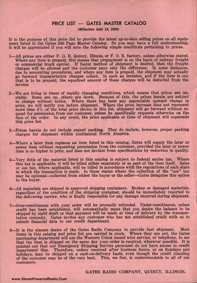
www.SteamPoweredRadio.Com
PRICE LIST - GATES MASTER CATALOG (Effective July 15, 1953)
It is the purpose of this price list to provide the latest up-to-date selling prices on all equipment listed in the Gates 240 Page Master Catalog. So you may have a full understanding, it will be appreciated if you will note the following simple conditions pertaining to prices.
1-All prices are either F. 0. B. Quincy, Illinois, or F. 0. B. factory, unless otherwise stated. Where any item is prepaid, this means that prepayment is on the basis of railway freight or commercial truck carrier. If faster method of shipment is desired, then the freight charges will be allowed and the customer pays only the difference. In some instances, due to accounting procedures, and where any item is prepaid, the shipment may actually go forward transportation charges collect. In such an instance, and if the item is one that is to be prepaid, the equalized amount of these charges will be deducted from the invoice.
2-We are living in times of rapidly changing conditions, which means that prices are unstable. Some are up, others are down. Because of this, the prices herein are subject to change without notice. Where there has been any appreciable upward change in price, we will notify you before shipment. Where the price incr ease does not represent more than 5% of the total price shown in t his list, shipment will go forward without request for permission from our customer, unless he specifically requests otherwise on the face of the order. In any event, the price applicable at time of shipment will supersede this price list.
3- Prices herein do not include export packing. They do include, however, proper packing charges for shipment within continental North America.
4-Where a later item replaces an item listed in this catalog, Gates will supply the later or newer item without requesting permission from the customer, provided the later or newer item is no higher in price, and does not deviate from specifications by reduction in quality.
5-Very little of the material listed in this catalog is subject to federal excise tax. Where this tax is applicable, it will be billed either separately or as part of the item itself. Sales or use tax, where applicable, will be billed in accordance with the regulations of each state in which the transaction is made. In those states where the collection of the "use" tax may be optional-collected from either the buyer or the seller- Gates delegates this option to the buyer.
6-All materials are shipped in approved shipping containers. Broken or damaged materials, regardless of the condition of the shipping container, should be immediately reported to the delivering carrier, who is finally responsible for any damage incurred during shipment.
7-Over-remittances with your order will be promptly refunded. Under-remittances, unless credit has been established, will automatically mean that you desire the balance to be shipped by sight draft or that payment will be made at time of delivery by the transportation company. Gates invites any customer who has not established credit with us to submit financial data to our credit department.
8-It is the sincere desire of the Gates Radio Company to provide fast shipment. Most items in this catalog and price list are carried in stock. Where they are not, the Gates purchasing department will use the Western Union leased wire service, or telephone, to see that the item is shipped on the same day your order is received, wherever possible. It is pointed out that our Emergency Shipping Service personnel do not have access to credit department files. Therefore, orders received after business hours, or on Sundays and holidays, may be shipped on a cash-on-delivery basis, even though the credit standing of the customer may be of the very best. This, we feel, is understandable to all of our customers.
GATES RADIO COMPANY, QUINCY, ILLINOIS.
1
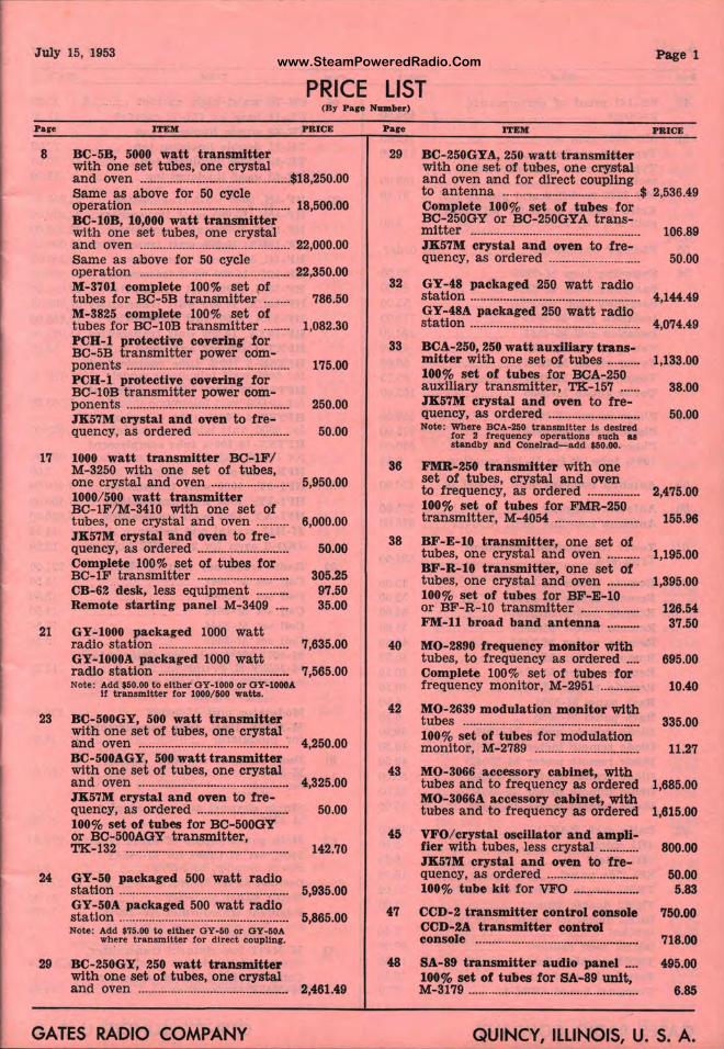
www.SteamPoweredRadio.ComJuly 15, 1953 Page 1
PRICE LIST (B1 Pare N■mber)
Pare
8
17
21
23
24
29
ITEM PRICE
BC-SB, 5000 watt transmitter with one set tubes, one crystal and oven .............................................. $18,250.00 Same as above for 50 cycle operation .............................................. 18,500.00 BC-l0B, 10,000 watt transmitter with one set tubes, one crystal and oven .............................................. 22,000.00 Same as above for 50 cycle operation .............................................. 22,350.00 M-3701 complete 100% set pf tubes for BC-5B transmitter ........ 786.50 M-3825 complete 100% set of tubes for BC-10B transmitter ........ 1,082.30 PCR-1 protective covering for BC-5B transmitter power com-ponents .................................................. 175.00 PCR-i. protective covering for BC- 10B transmitter power com-ponents .................................................. 250.00 JK57M crystal and oven to fre-quency, as ordered ............................ 50.00
1000 watt transmitter BC-lF/ M-3250 with one set of tubes, one crystal and oven ....................... . 1000/ 500 watt transmitter BC-lF/M-3410 with one set of tubes, one erystal and ·oven ......... . JK57M crystal and oven to fre-quency, as ordered ........................... . Complete 100% set of tubes for BC-lF transmitter ........................... . CB-62 desk, less equipment ......... . Remote starting panel M- 3409 ... .
GY-1000 packaged 1000 watt
5,950.00
6,000.00
50.00
305.25 97.50 35.00
radio station ........................................ 7,635.00 GY-l000A packaged 1000 watt radio station ........................................ 7,565.00 Note: Add $50.00 to either OY-1000 or OY-lOOOA
If transmitter for 1000/500 watts.
BC-500GY, 500 watt transmitter with one set of tubes, one crystal and oven .............................................. 4,250.00 BC-500AGY, 500 watt transmitter with one set of tubes, one crystal and oven .............................................. 4,325.00 JK57M crystal and oven to fre-quency, as ordered ............................ 50.00 100% set of tubes for BC-500OY or BC-500AOY transmitter , TK-132 .................................................. 142.70
GY-50 packaged 500 watt radio station .................................................... 5,935.00 GY-50A packaged 500 watt radio station .................................................... 5,865.00 Note: Add $75.00 to either OY-50 or OY· 50A
where transmitter for direct coupllnr.
BC-250GY, 250 watt transmitter with one set of tubes, one crystal and oven .............................................. 2,461.49
GATES RADIO COMPANY
Paro
29
32
33
36
38
40
42
43
45
47
48
ITEM PRICE
BC-250GYA, 250 ~att transmitter with one set of tulpes, one crystal and oven a,nd for direct coupling to antenna .......................................... $ 2,536.49 Complete 100% s1~t of tubes for BC-250OY or BC- f 50OYA trans-: ~t;:. ·;;;;~·~···;J~··~;;; ··t~··f~;~·· 106.89 quency, as orderec, ............................ 50.00
GY-48 packaged ~50 watt radio station .................................................. . GY-48A packaged 250 watt radio station ................................................... .
BCA-250, 250 watt l~uxlliary trans-mitter with one s~it of tubes ......... . 100% set of tube!! for BCA-250 auxiliary transmij
1ter, TK-157 ..... .
JK57M crystal atj~ oven to frequency, as orderei~ ···············-··········· Note: Where BCA-250 ti anamlt ter Is desired
for 2 frequency operations such &a standby and Con µrad-add $50.00.
FMR-250 transml ;ter with one set of tubes, crysl~ l and oven to f requency, as c rdered ............... . 100% set of tube~ for FMR-250 transmitter, M-40!~ ......................... .
BF-E-10 transmit·~er, one set of tubes, one crystal and oven ......... . BF-R-10 transmi1 ter, one set of tubes, one crystal and oven ......... . 100% set of tubes for BF-E-10 or BF-R-10 t rans pttter ................. . FM-11 broad bant:• antenna ......... .
MO-2890 frequenc:r monitor with tubes, to frequenc~ as ordered .... Complete 100%. SE1t of tubes for frequency momto11, M- 2951 ........... .
MO-2639 modulatijon monitor with tubes ...................... ............................. . 100% set of tubes 'or modulation monitor, M-2789 ............................. .
MO-3066 accessol'l[ cabinet, with tubes and to freq~1ency as ordered MO-3066A aceesso1r,r cabinet, with tubes and to freq 'lency as ordered
VFO/ crystal oscilli~tor and ampli-fier with tubes, le!f. crystal ........... . JK57M crystal an'1 oven to fre-quency, as orderec ........................... . 100% tube kit for iVFO ................... .
CCD-2 transmitte~ control console CCD-2A transmit~er control console ............................................... .
SA-89 transmitter audio panel ... . 100% set of tubes for SA-89 unit, M-3179 .................... 11 ••••• •••••••••••••••••••••••••
4,144.49
4,074.49
1,133.00
38.00
50.00
2,475.00
155.96
1,195.00
1,395.00
126.54 37.50
695.00
10.40
335.00
11.27
1,685.00
1,615.00
800.00
50.00 5.83
'150.00
718.00
495.00
6.85
QUINC' , ILLINOIS, U. S. A.
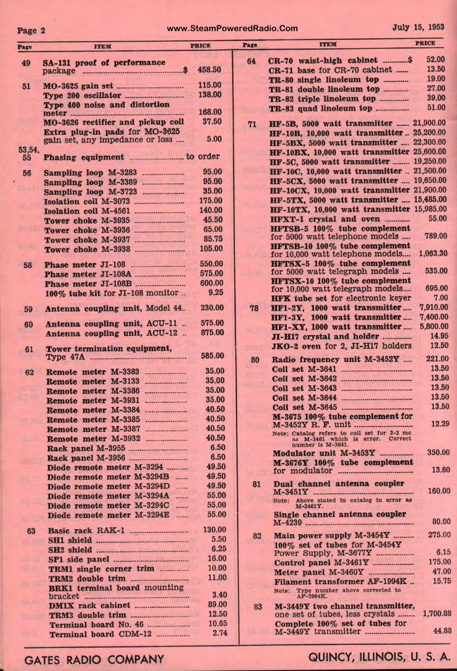
www.SteamPoweredRadio.ComPage 2
Pare I TEM PRICE
49 SA-131 proof of performance package ···-··-··································-···$ 458.50
51 MO-3625 gain set ................................ 115.00 Type 200 oscillator ............................ 138.00 Type 400 noise and distortion meter ...................................................... 168.00 MO-3626 rectifier and pickup coil 37.50 Extra plug-in pads for MO-3625 gain set, any Impedance or loss .... 5.00
53,54, 55 Phasing equipment .......................... to order
56
58
59
60
61
62
63
Sampling loop M- 3283 .....•.............. Sa mpling loop M-3389 ................... . Sampling loop M-3723 ................... .
I solation coil M-3073 ······················-Isolatlon coil M-4561 ....................... . Tower choke M-3935 ....................... . Tower choke M-3936 ....................... .
Tower choke M-3937 ···-··················· Tower choke M-3938 ....................... .
Phase meter J I-108 ......................... . Phase meter JI-108A ....................... . Phase m eter JI-108B ....................... . 100% tube kit for JI-108 monitor ..
Antenna coupling unit, Model 44 ..
Antenna coupling unit, ACU-11 .. Antenna coupling unit, ACU-12 ..
Tower termination equipment, Type 47A ............................................. .
Remote meter M-3383 Remote meter M-3133 Remote meter M-3386 ................... . Remote meter M-3931 ................... . Remote meter M-3384 ................... . Remote meter M-3385 ................... . Remote meter M-3387 ................... . Remote meter M-3932 ................... . Rack panel M-3955 ........................... . Rack panel M- 3956 ........................... . Diode remote m eter M-3294 ......... . Diode r emote m et er M-3294B Diode remote m et er M-3294D Diode remote meter M-3294A Diode remote meter M-32940 Diode remote m et er M-3294E
Basic rack RAK-1 ........................... . SBl shield ........................................... . SB2 shield ........................................... . SPl side panel ................................... . TRMl single comer trim ............. . TRM2 double trim ........................... . BRKl termina l board mounting bracket ................................................. . DMlX rack ca binet ......................... . TRM3 double t rim ........................... . Terminal board No. 46 ................... . Terminal board CDM-12 ............... .
GATES RADIO COMPANY
95.00 95.00 35.00
175.00 140.00 45.50 65.00 85.75
105.00
550.00 575.00 600.00
9.25
230.00
575.00 875.00
585.00
35.00 35.00 35.00 35.00 40.50 40.50 40.50 40.50 6.50 6.50
49.50 49.50 49.50 55.00 55.00 55.00
130.00 5.50 6.25
16.00 10.00 11.00
3.40 89.00 12.50 10.65
2.74
Pare
64
71
78
80
81
82
83
J uly 15, 1953
ITEM PR ICE
CR-70 waist-hlrh cabinet ·--··....$ 52.00 CR-71 base for CR-70 cabinet ···- · 13.50 TR-80 single linoleum top ............ 19.00 TR-81 double llnoleum top ............ 27 .00 TR-82 triple linoleum top .............. 39.00 TR-83 quad linoleum top ................ 51.00
BF-SB, 5000 watt transmitter ··-·· 21,900.00 BF- 10B, 10,000 watt transmitter .. 25,200.00 BF-SBX, 5000 watt transmitter -· 22,300.00 BF- l0BX, 10,000 watt transmitter 25,600.00 BF-SC, 5000 watt transmitter ··-·-· 19,250.00 BF-l0C, 10,000 watt transmitter .. 21,500.00 BF-SCX, 5000 watt transmitter .... 19,650.00 BF- l0CX, 10,000 watt tra.nsmltter 21,900.00 BF-5TX, 5000 watt transmitter _ 15,485.00 BF- l0TX, 10,000 watt transmitter 15,985.00 BFXT-1 crystal and oven ............ 55.00 BFTSB-5 100% tube complement for 5000 watt telephone models .... 789.00 BFTSB-10 100% tube complement for 10,000 watt telephone models.... 1,063.30 BFTSX-5 100% tube complement for 5000 watt telegra ph models .... 535.00 BFTSX- 10 100% tube complement for 10,000 watt telegraph models .... BFK tube set for electronic keyer BF1-2Y, 1000 watt transmitter ... . BF1-3Y, 1000 watt transmitter ... . BFl-XY, 1000 watt transmitter ... . n-Bl7 crystal and holder ............. . JK0-2 oven for 2, n-H17 holders
Radio frequency unit M-3452Y ... . Coll set M-3641 ................................. .
Coll set M-3642 ································C-011 set M-3643 ···-··········-···············-Coll set M-3644 ····················-·····-····· Coil set M-3645 ...............................•.. M-3675 100% tube complement for M-3452Y R. F . unit ·······-··············-·Note: Catator r efera to coll set for 2-3 me
,.. M-3461 which la error. Correct number Is M-3641.
Modulator unit M-3453Y ............... . M-3676Y 100% tube complement for modulator .......... ·-·-·· .. ···············
Dua l channel antenna coupler M-3451Y ............................................... . Note: Above stated In catalog In error as
M-3461Y.
Single channel a n tenna coupler M-4239 ···························-····-····-··········· Main power supply M-3454Y ......... . 100% set of t ubes for M-3454Y Power Supply, M-3677Y ................. .
Control panel M-3461Y ·················-· Meter pa nel M-3460Y ···················-· Filament transformer AF-1994K .. Note: Type number above corrected to
AF-7994K.
M-3449Y two channel transmitter, one set of t ubes, less crystals ....... . Complete 100% set of tubes for M-3449Y t ransmitter ....................... .
695.00 7.00
7,910.00 7,400.00 5,800.00
14.95 12.50
221.00 13.50 13.50 13.50 13.50 13.50
12.29
350.00
13.60
160.00
80.00
275.00
6.15 175.00 47.00 15.75
1,700.88
44.88
QUINCY, ILLINOIS, U. S. A.
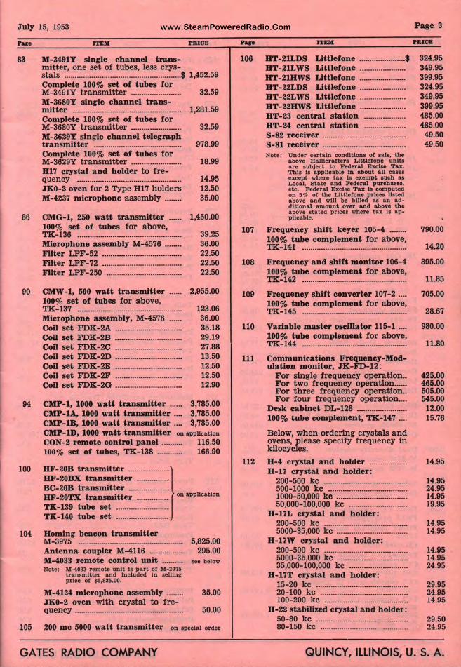
www.SteamPoweredRadio.ComJuly 15, 1953
Pace
83
86
90
ITEM RICE
M-3491Y single channel transmitter, one set of tubes, less crys-stals ........................................................ $ 1,452.59 Complete 100% set of tubes for M-3491Y transmitter ....................... . 32.59 M-3680Y single channel trans-IDitter .................................................... 1,281.59 Complete 100% set of tubes for M-3680Y transmitter ....................... . 32.59 M-3629Y single channel telegraph transIDitter .......................................... 978.99 Complete 100% set of tubes for M-3629Y t ransmitter ....................... . B17 crystal and holder to fre-quency ................................................. . JK0-2 oven for 2 Type Hl 7 holders M-4237 microphone assembly ....... .
CMG-1, 250 watt transmitter ······ 100% set of tubes for above, TK-136 ................................................... Microphone assembly M-4576 --------Filter LPF-52 ··································•··• Filter LPF-72 ····················•················· Filter LPF-250 ....................................
CMW-1, 500 watt transIDitter ······ 100% set of tubes for above, TK-137 .................................................. Microphone assembly, M-4576 ...... Coil set FDK-2A ................................. Coil set FDK-2B ................................. Coil set FDK-2C ................................. Coil set FDK-2D ····························· .. · Coil set F'DK-2E ................................ Coil set FDK-2F ••••••••••••••u•u•u•••••••n•
Coil set FDK-2O .................................
18.99
14.95 12.50 35.00
1,450.00
39.25 36.00 22.50 22.50 22.50
2,955.00
123.06 36.00 35.18 29.19 27.88 13.50 12.50 12.50 12.90
94 CMP-1, 1000 watt transmitter ...... 3,785.00
100
104
105
CMP-lA, 1000 watt transmitter .... 3,785.00 CMP-1B, 1000 watt transmitter .... 3,785.00 CMP-lD, 1000 watt transmitter on appllcatton
CON-2 remote control panel .......... 116.50 100% set of tubes, TK-138 ............ 166.90
BF-20B transmitter .................... } BF-20BX transIDitter ............. .. BC-20B transIDitter ................... . BF-20TX transmitter ................ on application
TK-139 tube set ........................• TK-140 tube set ........................ .
BoIDing beacon transmitter M-3975 .................................................. 5,825.00 Antenna coupler M-4116 ................ 295.00 M-4033 remote control unit .......... see below Note: M-4033 remote unit Is part of M-3975
transmitter and Included In selling price of $5,825.00.
M-4124 microphone assembly ........ 35.00 JK0-2 oven with crystal to fre-quen-cy .................................................... 50.00
200 me 5000 watt transmitter on special order
GATES RADIO COMPANY
Pase
106
107
108
109
110
111
112
ITEM
BT-21LDS Littlefc ne ...................... $ BT-21LWS Littlef, ne ..................... . BT-21BWS Littlef, ne ..................... . BT-22LDS Littleft•ne ..................... . BT-22LWS Littlefone ..................... . BT-22BWS Littlef, ine ..................... . BT-23 central sta fion ................... . BT-24 central sta hon ................... . S-82 receiver ....................................... . S-81 receiver ...................................... . Note: :;r:o~e: ~!:1t~~ .. i~~~lt~ i:1e~~::
1•uni : are subject to l'eder al Excise Tax. This Is app!lcabl In about all cases except where tax Is exempt such as Local, State and Pederal pur chases, etc. Federal Exe ~e Tax Is computed on 5 9', of the Lit f.1efone prices listed above and will ~~ billed as an addltlonal amount 11ver and above the above stated prlc1•s where tax Is appllcable.
Page 3
PRICE
324.95 349.95 399.95 324.95 349.95 399.95 485.00 485.00
49.50 49.50
Frequency shift k eyer 105-4 ........ 790.00 100% tube comple1 nent for a'bove, TK-141 ................... ............................. 14.20
Frequency and shi t monitor 106-4 895.00 100% tube comple1 nent for above, TK-142 ................... .............................. 11.85
Frequency shift co nerter 107-2 .... 705.00 100% tube comple1 nent for above, TK-145 ................... .............................. 28.67
Variable master ~cillator 115-1 .... 980.00 100% tube comple1nent for above, TK-144 ................... ............................. 11.80
Communications ~~uency-Modulation monitor, J jf -FD-12:
For single frequ~~ncy operation .. For two frequen cy opemtlon ..... . For three frequ [ncy oper-ation .. For four freque~r.cy operation ... .
Desk cabinet DL-~~8 ....................... . 100% tube comple11 ent, TK-147 ... .
Below, when ordej n g crystals and ovens, please spedtry frequency in kilocycles.
B-4 cry'stal and 11 older ................. . B-17 crystal and lb.older:
200- 500 kc ...................................... . 500-1000 kc .................................... . 1000-50,000 kc ···'·r······························ 50,000-100,000 kc ........................... .
B-17L crystal and holder: 200-500 kc ......... .............................. . 5000- 35,000 kc ................................. .
B-17W crystal a11 ti holder: 200-500 kc ...................................... . 5000-35,000 kc ................................ . 35,000-100,000 kc ........................... .
B-17T crystal an<ll holder: 15-20 kc .......................................... . 20-100 k-c ........................................ . 100-200 kc ......... ............................. .
B-22 stabilized cry stal and holder: 50-80 kc ........................................ .. 80-150 kc ....................................... .
425.00 465.00 505.00 545.00
12.00 15.76
14.95
14.95 24.95 14.95 19.95
14.95 14.95
14.95 14.95 24.95
29.95 24.95 14.95
29.50 24.95
QUINC 1, ILLINOIS, U. S. A.
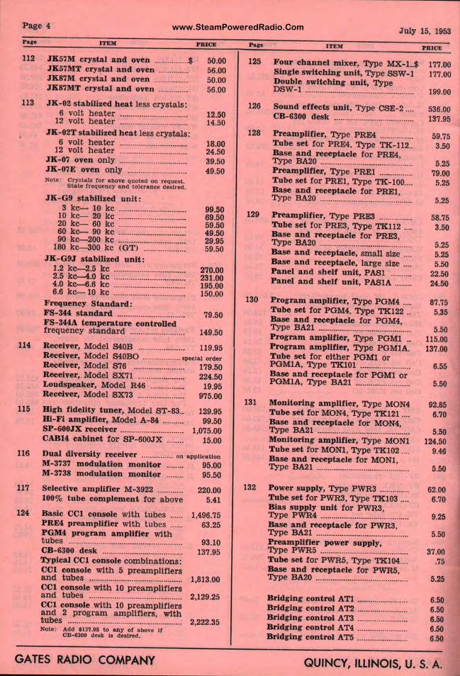
www.SteamPoweredRadio.ComPage 4
Pare
112
113
114
115
116
ITEM:
JK57M crystal and oven ................ $ JK57MT crystal and oven ............. . JK87M crystal and oven ............... . JK87MT crystal and oven ............. .
JK-02 stabilu:ed heat less crystals:
PBICS
50.00 56.00 50.00 56.00
6 volt heater ................................ 12.50 12 volt heater ............. ................. 14.50
JK-02T stabilized heat less crystals: 6 volt heater ................................ 18.00
12 volt heater ................................ 24.50 JK-07 oven on ly ................................ 39.50 JK- 07E oven only ........ .. ................ 49.50 Note: cryalals for above quoted on request.
Sta le frequency and tolerance de•lred .
JK-G9 stabilized unit: 3 kc-- 10 kc ............................... .
10 kc-- 20 kc ............................... . 20 kc- 60 kc ............................... . 60 kc-- 90 kc ............................... . 90 kc--200 kc ............................... .
180 kc-300 kc (GT) ................... . JK-G9J stabilized unit:
1.2 kc--2.5 kc ................................. . 2.5 kc--4.0 kc ................................. . 4.0 kc--6.6 kc ................................. . 6.6 kc- 10 kc ................................. .
Frequency Standard: FS-344 standard ............................... . FS- 344A temperature controlled frequency standard ......................... .
99.50 69.50 59.50 49.50 29.95 59.50
270.00 231.00 195.00 150.00
79.50
149.50
Receiver, Model S40B ...................... 119.95 Receiver, Model S40BO ................. 1pec1a1 or<ler Receiver, Model S76 ........................ 179.50 Receiver, Model SX71 ...................... 224.50 Loudspeaker, Model R46 ................ 19.95 Receiver, Model SX73 ...................... 975.00
High fidelity tuner, Model ST- 83 .. Bi-Fi amplifier, Model A-84 ......... . SP-600JX receiver ............................. . CABH cabinet for SP- 600JX ....... .
129.95 99.50
1,075.00 15.00
Dual diversity receiver ............... on a ppUcaUon M-3737 modulation monitor 95.00 M-3738 modulation monitor ........ 95.50
117 Selective amplifier M- 3922 ............ 220.00 100% tube complement for a bove 5.41
124 Basic CCI console with tubes ...... 1,496.75 PRE4 preamplifier with tubes ...... 63.25 PGM4 program amplifier with tubes .. ................................................... 93.10 CB-6300 desk ...................................... 137.95 Typical CCl console combinations: CCl console with 5 p reamplifiers and t ubes ............................................ 1,813.00 CCl console with 10 p reamplifiers and t ubes ............................................ 2,129.25 CCl console wit h 10 p reamplifiers and 2 program amplifiers, wit h tubes ...................................................... 2,222.35 Nole: Add $137 .95 to any of a bove II
CB-8300 dealt la desired.
GATES RADIO COMPANY
Pare
125
126
128
129
130
131
July 15, 1953
ITEH
Four channel mixer , Type MX.-1..$ Single switching unit, Type SSW-1 Double switching unit, Type DSW-1 ···········-·······································
Sound effects unit, Type CSE-2 ... . CB-6300 desk ..................................... .
Preamplifier, Type PRE4 ............... . Tube set for PRE4, Type TK-112 .. Base and receptacle for P RE4, Type BA20 ........................................... . Preamplifier, Type PREl ............... . Tube set for PREl, Type TK-100 ... . Base and receptacle for PREl, Type BA20 ........................................... .
Preamplifier, Type PRE3 ............... . Tube set for PRES, Type TK112 ... . Base and receptacle for PRE3, Type BA.20 ........................................ . Base and receptacle, sma ll size ... . Base and receptacle, large size ... . Panel and shelf unit, PASl ........ .. Panel and shelf unit, PASlA ....... .
Program amplifier, Type PGM4 ... . Tube set for POM4, Type TK122 .. Base and receptacle for PGM4, Type BA21 .......................................... .. Program amplifier, Type PGMl .. Program a mplifier, Type PGMlA. Tube set for either PGMl or POMlA, Type TK101 ....................... . Base and receptacle for PGMl or POMlA, Type BA21 ......................... .
Monitoring amplifier , Type MON4 Tube set for MON4, Type TK121 .... Base and receptacle for MON4, Type BA21 ........................................... . Monitoring amplifier, Type MONl Tube set for MONl, Type TK102 .... Base and receptacle for MONl, Type BA21 ........................................... .
PRICE
177.00 177.00
199.00
536.00 137.95
59.75 3.50
5.25 79.00
5.25
5.25
58.75 3.50
5.25 5.25 5.50
22.50 24.50
87.75 5.35
5.50 115.00 137.00
6.55
5.50
92.85 6.70
5.50 124.50
9.46
5.50
132 Power supply, Type PWR3 ............. . 62.00 6.70 Tube set for P WR3, Type TK103 ... .
Bias supply unit for PWR3, Type PWR4 .......................................... . Base and receptacle for PWR3, Type BA.21 ........................................... . Preamplifier power supply, Type PWR5 ......................................... . Tube set for PWR5, Type TK:104 ... . Base and receptacle for PWR5, Type BA20 ···································-·······
Bridging control ATl ....................... . Bridging control AT2 ....................... . Bridging control A T3 ....................... . Bridging control AT4 ....................... . Bridging control ATS ....................... .
9.25
5.50
37.00 .75
5.25
6.50 6.50 6.50 6.50 6.50
QUINCY, ILLINOIS, U. S. A.
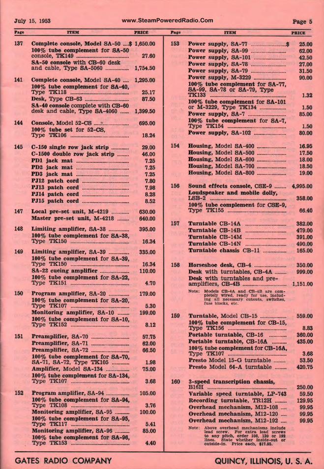
www.SteamPoweredRadio.ComJuly 15, 1953
Pare
137
141
144
145
147
148
149
150
151
152
ITEM PBICE
Complete console, Model SA-50 .... $ 1,650.00 100% tube complement for SA-50 console, TK149 .................................... 27.60 SA-50 console with OB-60 desk and cable, Type SA-5060 .............• 1,754.50
Complete console, Model SA-40 .... 100% tube complement for SA-40, Type TK118 ....................................... . Desk, Type CB-63 ............................. . SA-40 console complete with CB-60 desk and cable, Type SA-4060 ..... .
Console, Model 52-CS ..... L .............. . 100% tube set for 52-CS, Type TK106 ....................................... .
C-150 single row Jack strip ........... . C-1500 double row jack strip ....... . PDI jack mat ................................... . PD2 jack mat ................................... . PD3 jack mat ................................... . PJ12 patch cord ............................... . PJ13 patch cord ............................... . PJH patch cord ............................... . PJ15 patch cord ............................... .
Local pre-set unit, M-4219 ........... . Master pre-set unit, M-4218 ....... .
Limiting ampll!ier, SA-38 ............. . 100% tube complement for SA-38, Type TK150 ....................................... .
Limiting a mplifier, SA-39 ............. . 100% tube complement for SA-39, Type TK150 ....................................... . SA-22 cueing amplifier ................... . 100% tube complement for SA-22, Type TK151 ....................................... .
P rogram amplifier , SA-20 ............. . 100% tube complement for SA-20, Type TK107 ....................................... . Monitoring amplifier, SA-10 ....... . 100% tube complement for SA- 10, Type TK152 ....................................... .
Preamplifier, SA-70 ......................... . Preamplifier, SA-71 ......................... . Preamplifier , SA-72 ......................... . 100% tube complement for SA-70, SA-71, SA-72, Type TK105 ........... . Amplifier, Model SA-134 ............... . 100% tube complement for SA- 134, Type TK107 ....................................... .
Program amplif ier, SA-94 ............... . 100% tube complement for SA-94, Type TK108 ....................................... . Monitoring amplifier, SA-95 ......... . 100% tube complement for SA-95, Type TK117 ....................................... . Monitoring amplllier, SA-96 ......... . 100% tube complement for SA-96, Type TK153 ....................................... .
1,295.00
25.17 87.50
1,399.50
695.00
18.24
29.00 46.00 7.25 7.25 7.25 7.80 7.98 8.28 8.52
630.00 640.00
395.00
16.34
335.00
16.34 110.00
4.70
179.00
5.30 199.00
8.12
57.75 62.00 66.50
1.98 75.00
3.68
105.00
3.76 100.00
5.41 85.00
4.40
GATES RADIO COMPANY
Pare
153
154
156
157
158
159
160
ITEM
Power supply, SA- 77 ........................ $ Power supply, SA f99 ....................... . Power supply, SA· 101 ..................... . Power supply, SA 78 ....................... . Power supply, SA-179 ....................... .
~:O~\:::p~!~1:i~~!~i·:r~~··sA=;;;;; SA-99, SA-78 or i; A-79, Type TK133 ..................... ............................. . 100% tube comple1;nent for SA-101 or M-3229, Type 1rK134 ................. .
~:O~r t~1:,!p~.:p~;t~~t··r"~~--sA:1: Type TK154 ..................................... . Powe~ supply, SA·l·102 ..................... .
HoUSing, Model S~ - 400 ................... . Housing, Model s1t-500 ................... . Housing, Model S4 - 600 ................... . Housing, Model S~ - 700 ................... . Housing, Model s l- 800 ····················
Sound effects corulole, CSE-9 ....... . Loudspeaker and ·mobile dolly, LSB-2 .................... .............................. . 100% tube comple "1ent for CSE-9, Type TK155 ........ ............................. .
Turntable CB-14 ........................... . Turntable CB-14 ........................... . Turntable CB-14M ........................... . Turntable CB-14N ........................... . Turntable chassis CB-11 ............... .
Horsesh oe desk, CB-4 ..................... . Desk with turnta~fles, CB-4A ....... .
~::i1m:~. ~~:~e~.-~~~-.~~~·~······ Note: Models CB-4A ~d CB-4B are com
pletely wired, r ady for use, Including all necessar y cutouts, switches, fuse blocks, etc.
Turntable, Model CB-15 ................. . 100% tube comple1ment for CB-15, Type TK156 ....................................... . Portable turntable~ CB-16 ........... . Portable t urntable•, CB-16A ......... . 100% tube comple~ ent f or CB-16A,
~~ ~i~~1 "is~cl t~~t~bi;··::::::::· Presto Model 64-J!t t urntable ....... .
3-speed transcrip on chassis, B16H .................................................... . Variable speed t u table, LP-743 Recording t urnta l1Ie, TR12H ....... . Overhead mechanlism, M12-108 ... . Overhead mecha; ~sm , M12-120 ... . Overhead mecha ism , M12-192 ... . Note: Above overhead mechanisms Include
lead screw. FoJ. extra lead screws to any pitch, o~lder 108, 120 or 192 lines. S tate w fether Inside-out or outslde•ln. Pr! ~ each, $17.95.
Page 5
25.00 62.00 42.50 27.00 31.50 90.00
1.32
1.50 85.00
1.50 80.00
16.95 17.50 18.00 18.50 19.00
4,995.00
358.00
66.40
382.00 479.00 391.00 490.00 165.00
350.00 999.00
1,151.00
559.00
8.83 360.00 435.00
3.68 53.50
420.75
250.00 59.50
129.95 99.95 99.95 99.95
QUINCr, ILLINOIS, U. S. A.
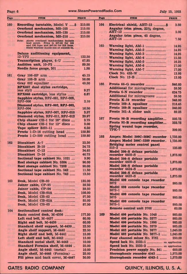
www.SteamPoweredRadio.ComPage 6
Pare
160
161
162
163
164
ITElll
Recording turntable, Model V ...... $ Overhead mecha nism, MS-105 ..... . Overhead mechanism, MS-120 ..... . Overhead m echanism, MS-210 ..... . Note: Above overhead mechanisms Include
lea.d screw. Price Is $37.50 for 1011 and 120 ltnes a.nd $47.50 for 210 llnea. Sta.te whether Inside-out or outside-in.
Deluxe auditioning equipment, 12-VP2 ................................................... . Transcription player, 6- U ............. . Audition unit, 10- P2 ....................... . Needle force gauge, 301 ................... .
Gray 106-SP arm ............................. . Gray 108-B arm ............................... . Gray 602 e qualizer ........................... . RPX047 dual stylus cartridge, less styli ............................................... . RPX046 cartridge, less stylus ....... . Sapphire stylus, RPJ-001, RPJ-005, RPJ- 006 ............................................... . Dia mond stylus, RPJ-002, RPJ- 003, RPJ-004 ............................................... . Sapphire stylus, RPJ-007, RPJ-010 Diamond stylus, RPJ-011, RiPJ-012 Chip chaser CH-1 for 16" discs ... . Chip chaser CH-1 for 12" discs ... . Ta pe splicer Edit-11 ....................... . Presto 1-D-16 cutting head ......... . Presto 1-D-500 cutting head ....... .
Discabinet A-7 ................................. . Discabinet B-10 ............................... . Discabinet C-12 ............................... . Discabinet D-16 ............................... . Sectional tape cabinet No. 1021 ... . Reel storage cabinet No. 5384 ....... . Reel storage cabinet No. 7288 ....... . Sectional tape cabinet No. 542 ..... . Sectional t a pe cabinet No. 742 .... ..
Desk, Model CB-60 ........................... . Joiner cable, CP-95 ......................... . Joiner cable, CP-94 ......................... . Desk, Model OB-60A ....................... . Desk, Model CB-62 ........................... . Desk, Model CB-62A ....................... . Desk, Model CB-63 ........................... .
Sectiona lized con trol desk: Basic control desk, M-4356 ........... . Left end bell, M-4437 ....................... . Right end bell, M-4438 ................... . Standard shelf support, M-4439 ... . Angle shelf support, M-4440 ......... . Right shelf end bell, M-4441 ....... . Left shelf end bell, M-4442 ........... . Standard m etal shelf, M- 4443 ..... . Standard Formica shelf, M-4444 .. Angle shelf, M-4445 (metal) ....... . Angle shelf, M-4446 (Formica) ... . Fill piece and back cover, M-4447
GATES RADIO COMPANY
PBICE
215.00 215.00 215.00 215.00
122.50 67.95 89.50 1.50
45.15 56.00 49.50
9.27 6.87
2.10
16.50 3.57
29.97 3.75 3.00 6.50
159.80 159.80
22.50 24.75 34.65 46.75
9.90 96.00 90.00 11.50 13.50
135.00 39.50 39.50
108.00 97.50 85.00 87.50
177.50 60.00 60.00 22.50 22.50 15.00 15.00 10.00 25.00 10.00 25.00 30.00
Pap
164
165
166
167
168
169
July 15, 1953
ITBIII O P&ICB
Electrical shield, b -12 .............. $ 3.50 Angular trim piece~ 22½ d egree, AHT-13 .................... ............................ 5.00 Angular trim piece 45 degree, AHT-14 .................... ............................ 7.50
Warning light, AM· 1 ....................... . Warning light, AM·-2 ...................... .. Warning light, AM·-3 ....................... . Warning light, AM· 4 ....................... . Warning light, AM•-5 ....................... . Wa rning light, AM -6 ....................... . Warning light, AM•-7 ....................... . Clock No. 438-W ... ........................... . Clock No. 12-B ................................... .
Presto 66- G record r ....................... . Additional for mic , ogroove ........... . Presto 6-N recordeif: ......................... . Additional for m1d ogroove ........... . Presto K-10 record er ..................... . Presto 160-A equal~ er ................... . Presto 160-B equa ' er ................... . P r esto 161-A slide unit .............. ..
Presto 90-B recordllng amplifier ... . Presto 92-B recordllng amplifier ... . Spring wound talM! recorder, TPK-7 ................................................... .
Ampex Model 300 -560C recorder Ampex Model 300C-3389 recorder .. Bridging meter co trol panel 515-2 ......................... ·····················•······· Model 300-S delux , portable recorder 4408-S ... . ........................... . Model 300-S delux1, portable
:CO::~e;o:.:~9;!1~·k··~~bl;·········· recorder 4424-S ····-r .. ···················· ...... Model 300-S delux , portable r ecorder 4423-S .................................. . Model 400 console tape recorder 3672 .......................... ............................ . Model 400 console tape recorder 3672-1 ...................... ,·················· .......... . Model 400 console
1t ape recorder
3675 ....................................................... . Model 400 console tape recorder 3675-1 ...................... 1 .......... .................. .
Remote control u 'It 3766 ............... .
14.95 14.95 14.95 15.50 16.25 17.00 17.00 13.95 13.95
846.60 59.50
624.75 59.50
348.00 218.45 340.00
89.25
505.75 333.75
309.95
1,735.00 1,735.00
125.00
1,875.00
1,875.00
1,875.00
1,875.00
995.00
995.00
995.00
995.00 60.00
Model 400 portable No. 1048 .......... 985.00 Model 400 portable No. 3377 .......... 985.00 Model 400 portable No. 1996 .......... 985.00 Model 400 portable No. 3379 .......... 985.00 Model 402 portable No. 3677 .......... 1,045.00 Model 402 portable No. 3677- 1 ...... 1,045.00 Four channel mixer No. 3761 ........ 250.00 Speed lock No. 2531~-1 .................. on application
Speed lock No. 2531>-2 .................. on application
Precision power su'~ply No. 841 .... 600.00 Stereophonic reco ~er 4043 ............ 1,575.00 Stereophonic reco a.er 4043-1 ........ 1,575.00
QUINcif, ILLINOIS, U.S. A.
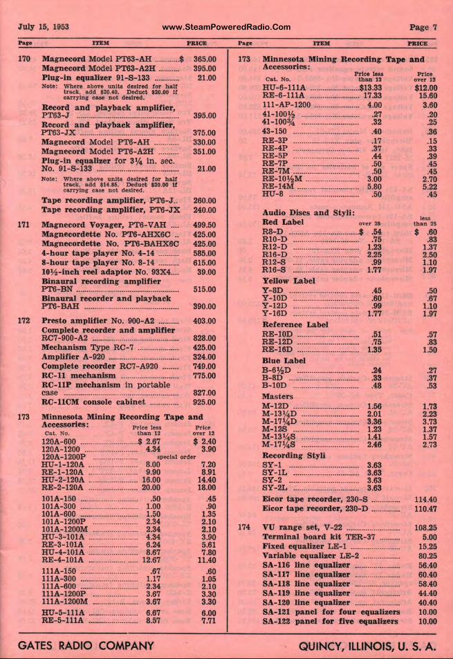
www.SteamPoweredRadio.ComJuly 15, 1953
Pare
170
ITEM
Magnecord Model PT63-AH ............ $ Magnecord Model PT63-A2H ........ .. Plug-in equalizer 91-S-133 .......... .. Note: Where above unit s desired for h alf
t rack, add $20.40. Deduct $20.00 If carrying case not desired.
Record and playback amplifier, PT63-J ................................................. . Record and playback amplifier, PT63-JX ............................................... . Magnecord Model PT6-AH ........... . Magnecord Model PT6-A2H ........ .. Plug-in equalizer for 3¼ in. sec. No. 91-S-133 ...................................... .. Note: Where above units desired for h alt
track, add $14.85. Deduct $20.00 If carrying case not desired.
Tape recording amplifier, PT6-J .. Tape recording amplifier, PT6-JX
171 Magnecord Voyager, PT6-VAH ....
172
Magnecordette No. PT6-AHX6C .. Magnecordetile No. PT6-BAHX6C 4-hour tape player No. 4- 14 ......... . 8-hour tape player No. 8-14 ........ .. 10½ -inch reel adaptor No. 93X4 ... . Binaural recording amplifier PT6-BN ................................................. . Binaural recorder and playback PT6-BAH ............................................. .
Presto amplifier No. 900-A2 ......... . Complete recorder and amplifier RC7-900-A2 ......................................... . Mechanism Type RC-7 ................... . Amplifier A-920 ................................. . Complete recorder RC7-A920 ...... .. RC-11 mechanism ........................... . RC-llP mechanism in portable case ....................................................... . RC-llCM console cabinet ............. .
PRICE
365.00 395.00 21.00
395.00
375.00 330.00 351.00
21.00
260.00 240.00
499.50 425.00 425.00 585.00 615.00 39.00
515.00
390.00
403.00
828.00 425.00 324.00 749.00 775.00
827.00 925.00
173 Minnesota Mining Recording Tape and Accessories : Price less Cat . No. than 12
120A-600 ............................ $ 2.67 120A-1200 .......................... 4.34
Price over 12
$ 2.40 3.90
120A-1200P ...................... , peclal order HU-1-120A ........................ 8.00 RE-1-120A ........................ 9.90 HU- 2-120A ........................ 16.00 RE-2-120A ........................ 20.00 l 0lA-150 ............................ .50 l0lA-300 ............................ 1.00 lOlA- 600 ............................ 1.50 101A-1200P ...................... 2.34 101A-1200M ...................... 2.34 HU-3-lOIA ........................ 4.34 RE-3-l0l A ........................ 6.24 HU-4-lOlA ........................ 8.67 RE-4- l0l A ....................... 12.67 l llA-150 ............................ .67 lllA-300 ............................ 1.17 lllA-600 ............................ 2.34 111A-1200P ...................... 3.67 111A-1200M ...................... 3.67 HU-5-lllA ........................ 6.67 RE-5- l llA ........................ 8.57
GATES RADIO COMPANY
7.20 8.91
14.40 18.00
.45
.90 1.35 2.10 2.10 3.90 5.61 7.80
11.40 .60
1.05 2.10 3.30 3.30 6.00 7.71
Pare
173
Page 7
ITEM I PR.ICE
Minnesota Mining Recording Tape and Accessories:
Price less Cat . No. than 12
HU- 6- lllA ...................... $13.33 RE-6-lllA ...................... 17.33 111-AP-1200 .......... .......... 4.00 41-100½ ................ .......... .27 41-100¾ ................. .......... .32 43-150 .................... ........... .40 RE- 3P ..................... .......... .17 RE-4P ..................... .......... .37 RE-5P ..................... .......... .44 RE-7P ..................... .......... .50 RE-7M ..................... .......... .50 RE-lO½M ............... ........... 3.00 RE-14M ................... .......... 5.80 HU-8 .................................. .50
Audio Discs and ~ tyli : Red Label over 25
R8-D ................................. $ .54 Rl0-D ..................... .......... .75 R12-D ..................... .......... 1.23 R16-D ................................ 2.25 R12-S .................... .I!.......... .99 R16-S .................... .!!.......... 1.77 Yellow Label Y-8D .................................. .45 Y- l0D ..................... .......... .60 Y-12D ................................ .99 Y-16D ..................... .......... 1.77 Reference Label RE-lOD .............................. .51 RE-12D ................... .......... .75 RE-16D .............................. 1.35 Blue Label B-6½D ................... ......... .. B-8D .............................. .. B-10D ............................. .. Masters M-12D .............................. . M-13¼ D ................. " ....... .. M-17¼ D ................. ! ........ .. M-12S ..................... IL ........ . M- 13¼S ................. ......... . M-17¼ S ........................... . Recording Styli SY-1 ................................ . SY- IL ............................. .. SY-2 ....................... ......... . SY-2L ..................... ......... .
.24
.33
.48
1.56 2.01 3.36 1.23 1.41 2.46
3.63 3.63 3.63 3.63
Eicor tape recorde ,:-, 230-S ............. . Eicor tape recorder, 230-D ............ ..
Price over 12
$12.00 15.60 3.60
.20
.25
.36
.15
.33
.39
.45
.45 2.70 5.22
.45
less than 25
$ .60 .83
1.37 2.50 1.10 1.97
.50
.67 1.10 1.97
.57
.83 1.50
.27
.37
.53
1.73 2.23 3.73 1.37 1.57 2.73
114.40 110.47
174 VU ran ge set, V- : 2 ......................... . 108.25 Terminal board kit TER- 37 ........ .. Fixed equalizer LE'-1 ....................... . Variable equalizer LE-2 ................ .. SA-116 line equall er ..................... . SA-117 line equall
1Er .................... ..
SA-118 line equa ll er ..................... . SA-119 line equaU er ..................... . SA-120 line equall r .................... .. SA-121 pa nel for four equalizers SA-122 panel for five equalizers
5.00 15.25 80.25 56.40 60.40 58.40 44.40 40.40 10.00 10.00
QUINcf ILLINOIS, U. S. A.
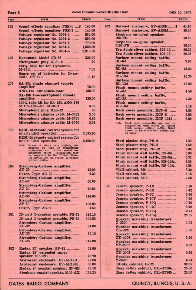
www.SteamPoweredRadio.ComPage 8
Pace
175
176
177
179
180
ITEM
Sound effects equalizer FSE-1 .... $ Sound effects equalizer FSE-2 Voltage regulator No. 3954-1 Voltage regulator No. 3954-2 Voltage regulator No. 3954-3 Voltage regulator No. 3954-4 Voltage regulator No. 3954-5
Dynamote, Model CB-65 ................. . Microphone plug XL3-12 ............... . 100% tube kit for Dynamote, M-3811 ................................................. . Spare set of batteries for Dyna-mote, DY-B-1 ..................................... .
SA-134 single channel remote amplifier ............................................. . ANO-134 Announco-mote ............. . SA-136 two-microphone remote amplifier ............................................. . 100% tube kit for SA-134, ANO-134 or SA-136-No. M-3691 ................... . Microphone plug XL3-12 ............... . Microphone adaptor cable, M-3782 Microphone adaptor cable, M- 3781 Microphone adaptor cable, M-3780
RCM-12 remote control system for unat t ended operation ..................... . RCM-14 remote control system for unattended opera tion ..................... . Note: Prices of above vary slightly, de•
pending on type of t r aumlttlug equipment, etc. Prices stated are maximum prices. Installation may be anywhere In the United States tor $300.00 flat fee, subject to change without notice.
Stromberg-Carlson amplifier, AU-29 ................................................... . Cover, Type AC-29 ........................... . Stromberg-Carlson amplifier, AU-42 ................................................... . Stromberg-Carlson amplifier, AU-34 ................................................... . Stromberg-Carlson amplifier, AU-36 ................................................... . Stromberg-Carlson amplifier, AP-50 ................................................... . Cover, Type AC-50 ........................... .
181 25-watt 2-speaker portable, PS-33 15-watt 2-speaker portable, PS-32 Stromberg-Carlson amplifier, AU-32 ................................................... . Stromberg-Carlson amplifier, AU- 33 ................................................... . Stromberg-Carlson amplifier, AU- 35 ................................................... .
182 Radax 12" speaker, SP-12 ............. . Radax 12" extended range speaker, SP-12B ................................. . Aristocrat enclosure, EV-AR12B .. Aristocrat enclosure, EV-AR12M .. Radax 8" coaxial speaker, SP-SB Stephens coaxial speaker, 5106-AX
GATES RADIO COMPANY
PRICE
145.00 145.00 534.00 590.00 770.00
1,522.00 2,317.00
325.00 .90
7.08
11.10
75.00 135.00
125.00
3.68 .90
2.50 4.82 3.54
2,335.00
2,195.00
42.00 4.20
60.00
70.50
114.00
108.00 4.50
149.10 109.80
64.80
89.10
147.00
57.00
29.70 72.00 66.00 28.50
134.25
Pace
182
July 15, 1953
ITEM
Baronet enclosure, EV-ARBB ........ $ Baronet enclosure, EV-AR8M ....... . Stephens co-spiral speaker, 102-FR ................................................. . Stephens co-spiral speaker, 5102-FR ............................................... . Tru Sonic silver cabinet, 525-12 ... . Tru Sonic silver cabinet, 525-15 ... . Surface mount ceiling baffle, BL-6A ................................................... . Surface mount ceiling baffle, BL-SA ................................................... . Surface mount ceiling baffle, BL-l0A ................................................. . Surface mount ceiling baffle, BL-12A ................................................. . Flush mount ceiling baffle, AL-6A ................................................... . Flush mount ceiling baffle, AL-SA ................................................... . Flush mount ceiling baffle, AL-l0A ................................................. . Back cover assembly, XCP-6 ....... . Back cover assembly, XCP-8 ....... . Back cover assembly, XCP-1012 .. Note: Back cover assemblies are used 111
conjunction with either AL Serles flush mount celling baffles Jlsted above, or RS model wan battles llsted below.
Steel plaster ring, PR-6 ................. . Steel plaster ring, PR-8 ................. . Steel plaster ring, PR-12 ............... . Flush mount wall baffle, RS-6A ... . Flush mount wa ll baffle, RS-BA ... . Flush mount wall baffle, RS-lOA .. Flush mount wall baffle, RS-12A .. Wall cabinet, M6 ............................... . Wall cabinet, MS ............................... . Wall cabinet, M12 ............................. .
PRICE
41.40 39.00
70.50
76.50 59.25 59.25
7.80
13.20
16.20
16.20
4.50
7.30
9.18 3.60 4.50 6.00
1.20 1.59 3.00 3.00 3.33 4.56 4.56 3.30 4.15 7.50
183 Jensen speaker, P-4X ..................... . 3.10 3.42 6.90 7.65
Jensen speaker, P-6X ..................... . Jensen speaker, P-8T ..................... . Jensen speaker, P-l0T ................... . Jensen speaker, P-l0Q ................... . Jensen speaker, P - 12T ................... . Jensen speaker, P-12Q ................... . J ensen speaker, P-15Q ................... . Speaker matching transformer, Z-3300 ................................................... . Speaker matching transformer, ZL-2021 ................................................. . Speaker matching transformer, ZY-4004 ............................................... . Speaker matching transformer, ZY- 2002 ............................................... . Speaker matching transformer, ZY-2003 ............................................... . Speaker matching transformer, Z-3423 ................................................... . Utility cabinet, B-121 ..................... . Bass reflex cabinet, C81-ST864 ... . Bass reflex cabinet, O81-ST865 ... .
17.40 8.70
19.74 26.55
1.08
1.55
3.60
3.60
5.18
6.24 32.65 25.00 25.00
QUINCY, ILLINOIS, U. S. A.
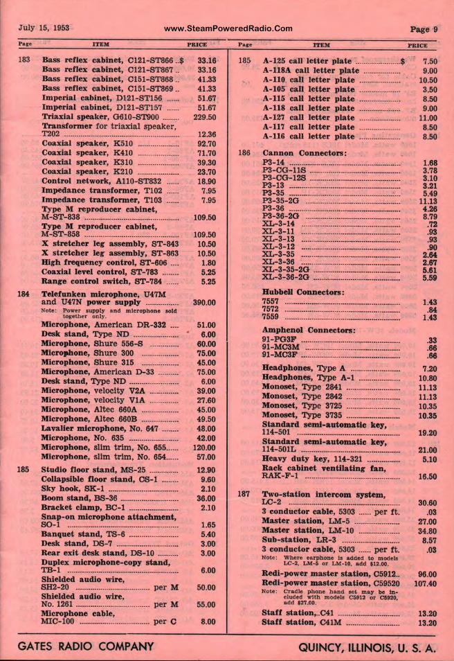
www.SteamPoweredRadio.ComJuly 15, 1953
183
184
ITEM
Bass reflex cabinet, C121-ST866 .. $ Bass reflex cabinet, Cl21-ST867 .. Bass reflex cabinet, C151-ST868 .. Bass reflex cabinet, C151-ST869 .. Imperial cabinet, Dl21-ST156 ..... . Imperial cabinet, Dl 21-ST157 ..... . Triaxial speaker, G610-ST900 ....... . Transformer for t riaxial speaker, T202 ....................................................... . Coaxial speaker, K510 ................... . Coaxial speaker, K410 ................... . Coaxial speaker, K310 ................... . Coaxial speaker, K210 ................... . Control network, Al10-ST832 Impedance transformer, Tl02 Impedance transformer, Tl03 Type M reproducer cabinet, M-ST-838 ............................................. . Type M reproducer cabinet, M-ST-858 ............................................. . X streteher leg assembly, ST-843 X streteher leg assembly, ST-863 High frequency control, ST-606 ... . Coaxial level control, ST-783 ....... . Range control switch, ST-784 ..... .
Telefunken microphone, U47M and U47N power supply ............... . Note: Power s upply and microphon e sold
together only.
Microphone, &nerlcan DR-332 ... .
PRICE
33.16 33.16 41.33 41.33 51.67 51.67
229.50
12.36 92.70 71.70 39.30 23.70 18.90 7.95 7.95
109.50
109.50 10.50 10.50
1.80 5.25 5.25
390.00
51.00 Desk stand, Type ND ...................... • 6.00
60.00 75.00 45.00 75.00
Microphone, Shure 556-S ............. . Microimone, Shure 300 ................. . Microphone, Shure 315 ................. . Microphone, American D-33 ......... . Desk stand, Type ND ....................... . Microphone, velocity V2A ............. . Microphone, velocity VlA ............. . Microphone, Altec 660A ................. . Microphone, Altec 660B ................. . Lavalier microphone, No. 647 ....... . Microphone, No. 635 ....................... . Microphone, slim trim, No. 655 ..... . Microphone, slim trim, No. 654 ..... .
185 Studio floor stand, MS-25 ............. . Collapsible Ooor stand, CS-1 ....... . Sky hook, SK-1 ................................. . Boom stand, BS-36 ........................... . Bracket clamp, BC-1 ....................... . Snap-on microphone attachment, SO-1 ..................................................... . Banquet stand, TS-6 ....................... . Desk stand, DS-7 ............................. . Rear exit desk stand, DS-10 ......... . Duplex microphone-copy stand, TB-1 ..................................................... . Shielded audio wire, SH2-20 .................................... per M Shielded audio wire, No. 1261 .................................... per M Microphone cable, MIC-100 .................................. per C
GATES RADIO COMPANY
6.00 39.00 27.60 45.00 49.50 48.00 42.00
120.00 57.00
12.90 9.60 2.10
36.00 2.10
1.65 5.40 3.00 3.00
6.00
50.00
55.00
8.00
185
186
187
ITEM
A-125 call letter p te ...................... $ A-118A call letter plate ................. . A-110 call letter ~ late ................... . A-105 call letter ~late .................. .. A-115 call letter 1late ................... . A-118 call letter ~ late ................... . A-127 call letter ~late ................... . A-117 call letter ~late ................... . A-116 call letter 1.iate ................... .
Cannon Connecto1rs: P3-14 .................................................... .
~=gg=g~ :::::::::::::i ::::::::::::::::::::::::::::: P3-13 ....................... J ............................ . P3-35 ....................... ............................. . P3-35-2G ............................................ . P3-36 ....................... ............................ . P3-36-2O ............... ............................ . XL-3-14 ................. ............................ . XL-3-11 ............................................. . XL-3-13 ............................................. . XL-3-12 ............................................. .
it=t;~ ::::::::::::::::: 1::::::::::::::::::::::::::::: XL-3-35-2O ........................................ . XL-3-36-2O ........... . ........................... .
Hubbell Connecto : 7557 ..................................................... .
~~i~ ::::::::::::::::::::::::: c::::::::::::::::::::::::::: Amphenol Connec rs: 91-PG3F ................. ............................ .. 91-MC3M ............................................ . 91-MC3F ............................................ ..
Headphones, Type A ...................... .. Headphones, Type A-1 .................. .. Monoset, Type 2 ......................... . Monoset, Type 2M~ ......................... . Monoset, Type 37; 5 ......................... . Monoset, Type 3735 ......................... . Standard semi-au · matic key, 114-501 ................................................ . Standard semi-au · matic key, 114-501L ............................................. . Heavy duty key, j 4-321 ............... . Rack cabinet ven ' ting fan,
::::io~···~~=~· ··=···~;:=:······· ~~!ductor. cabie, I·· 303 · ....... per. ft. Master station, ~r-5 ..................... . Master station, uJ1-10 ................... . Sub-station, LR-3 1 ........................... . 3 conductor cable, 5303 ...... per f t. Note: Where earphone !• added to models
LC-2, L M-5 or -10, add $12.00.
Redi-power maste station, 05912 .. Redi-power maste station, 059520 Note: Cradle phone h ~d •et m ay be In -
cluded with mod •Is C5912 or C5920, add $27.00.
Staff station, .. C41 ,··················--········· Staff station, C41 l ......................... .
Page 9
PRICE
7.50 9.00
10.50 3.50 8.50 9.00
11.00 8.50 8.50
1.68 3.78 3.10 3.21 5.49
11.13 4.26 8.79
.72
.93
.93
.90 2.64 2.67 5.61 5.59
1.43 .84
1.43
.33
.66
.66
7.20 10.80 11.13 11.13 10.35 10.35
19.20
21.00 5.10
16.50
30.60 .03
27.00 34.80 8.57
.03
96.00 107.40
13.20 13.20
i QUINC r, ILLINOIS, U. S. A.
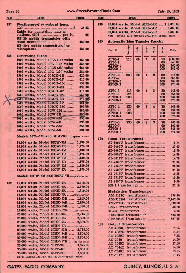
www.SteamPoweredRadio.ComP age 10
ITEM PR.ICE
187 Weatherproof re-entrant hom,
188
189
C20 .......................................................... $ 26.98 Cable for connecting master st ations, 6204 ........................ per ft. .06 RP-10 mobile transmitter with hand microphone .............................. 450.00 RP-lOA mobile transmitter, less m icrophone .......................................... 435.00
Generating Plants 1000 watts, Model l0LS (115 volts) 1000 watts, Model l0L (115 volts) 1000 wa tts, Model lOLS (230 volts) 1000 watts, Model l 0L (230 volts) 3580 watts, Model 305CK-1R ....... . 3500 watts, Model 305CK-1P ....... . 3500 watts, Model 305CK-1M ....... . 3500 watts, Model 305CK- 2R ....... . 3500 watts, Model 305CK-2P ....... . 3500 watts Model 305CK -2M ....... .
461.00 384.00 461.00 384.00 625.00 615.00 550.00 625.00 615.00
Models 5CW-7M and 5CW-7R ..... special order
10,000 watts, Model 10CW-3M 10,000 wa tts, Model 10CW-3R 10,000 watts, Model 10CW-4M 10,000 watts, Model 10CW-4R 10,000 wa t ts, Model 10CW-5M 10,000 wa tts, Model 10CW-5R 10,000 wat ts, Model 10CW-6M 10,000 wat ts, Model 10CW-6R
1,130.00 1,175.00 1,130.00 1,175.00 1,130.00 1,175.00 1,130.00 1,175.00
Models 10CW-7M and 10CW-7R ... special or d&r
15,000 watts, Model 15HK- 3R ........ 2,415.00 15,000 watts, Model 15HK-4R ........ 2,470.00 15,000 watts, Model 15HK-5R ........ 1,810.00 15,000 watts, Model 15HK-7R ....... special order
14,000 watts, Model 14HK- 53R ...... 2,415.00 14,000 watts, Model 14HK-54R ...... 2,470.00 14,000 watts, Model 14HK-55R ...... 1,810.00 14,000 watts, Model 14HK- 57R ..... special order
25,000 watts, Model 25HN-3R ........ 2,745.00 25,000 watts, Model 25HN-4R ........ 2,800.00 25,000 watts, Model 25HN-5R ........ 2,800.00 25,000 watts, Model 25HN-7R ....... special order
20,000 watts, Model 20HN-53R ...... 2,745.00 20,000 watts, Model 20HN-54R ...... 2,800.00 20,000 watts, Model 20HN-55R ...... 2,800.00 20,000 watts, Model 20HN-57R ..... special order
35,000 watts, Model 35JT-3R ........ 3,625.00 35,000 watts, Model 35JT-4R ........ 3,680.00 35,000 wat ts, Model 35JT-5R ........ 3,680.00 Note: Models 35JT•6R and 35JT-7R-specla l or der.
GATES RADIO COMPANY
July 15, 1953 .... ITEM PBICE
189 30,000 watts, Model 30JT-53R ...... $ 3,625.00 30,000 watts, Model 30JT-54R ...... 3,680.00 30,000 watts, Model 30JT-55R ...... 3,680.00 Note: Models 30JT-56R and 30JT-57R-speclal order.
189 Automatic Line Transfer Panels:
190
191
t ~
.,
i ,;
! .. 0, cat. No. " 'o .. ,= ~ > 0 "' -- - - - - --AFl0-1 115 60 1 2 10 AF60-l 60 AFl00-1 100 AF200-1 200
-- -- - - - -AF30- 2 230 60 1 2 30 AF60- 2 60 AFl00-2 100 AF200- 2 200
-- -- - - - -AF30-3 115 60 1 3 30 AF60-3 or 60 AFl00-3 230 100 AF200-3 200
-- -- - - - -AF30-4 120 60 3 4 30 AF60-4 or 60 AFl00-4 208 100 AF200-4 200
-- -- - - --AF30-5 230 60 3 3 30 AF60-5 60 AFl00-5 100 AF200-5 200
Input Transformers : AI-3001U transformer .............. : ........ . AI-3002U tra nsformer ....................... . AI-3006T t ransformer ....................... . AI-3009T transformer ...................... .. AI-3011T transformer ....................... . AI-7638T transformer ....................... . AI -7639T transformer ....................... . AI-7683T t ransformer ....................... . AI-7715T transformer ....................... . AI -7716T transformer ....................... . AI -8357U transformer ....................... . HS-1 transformer ............................. .
Modulation Transformers: AM-3161C transformer ................... . AM- 3167M transformer ................... . AM-7718O t ra nsformer ................... . BM-1 transformer ............................. . M-3X transformer ............................. . AM3205M transformer ................... . AM3204M transformer ................... .
Output Transformers: AO-3033U tra nsformer ..................... . AO-3037U transformer ..................... . AO- 3039T transformer ..................... . AO-3040 transformer ..................... . AO-3045T transformer ..................... . AO-7244T transformer ..................... . AO- 7640T transformer ..................... . AO-7717T transformer ..................... .
Price
- - -$ 85.00 145.00 265.00 465.00
- --145.00 265.00 365.06 675.00
---145.00 265.00 365.00 675.00 ---
165.00 265.00 365.00 675.00
- - -165.00 265.00 365.00 675.00
16.74 23.05 10.50 14.80 14.70 21.95 22.00 24.40 10.35 10.20 9.90
23.10
286.20 2,142.00 1,638.00
40.20 3.75
502.60 397.45
17.55 14.14 7.15
14.90 23.00 14.50 13.25 11.45
QUINCY, ILLINOIS, U. S. A.
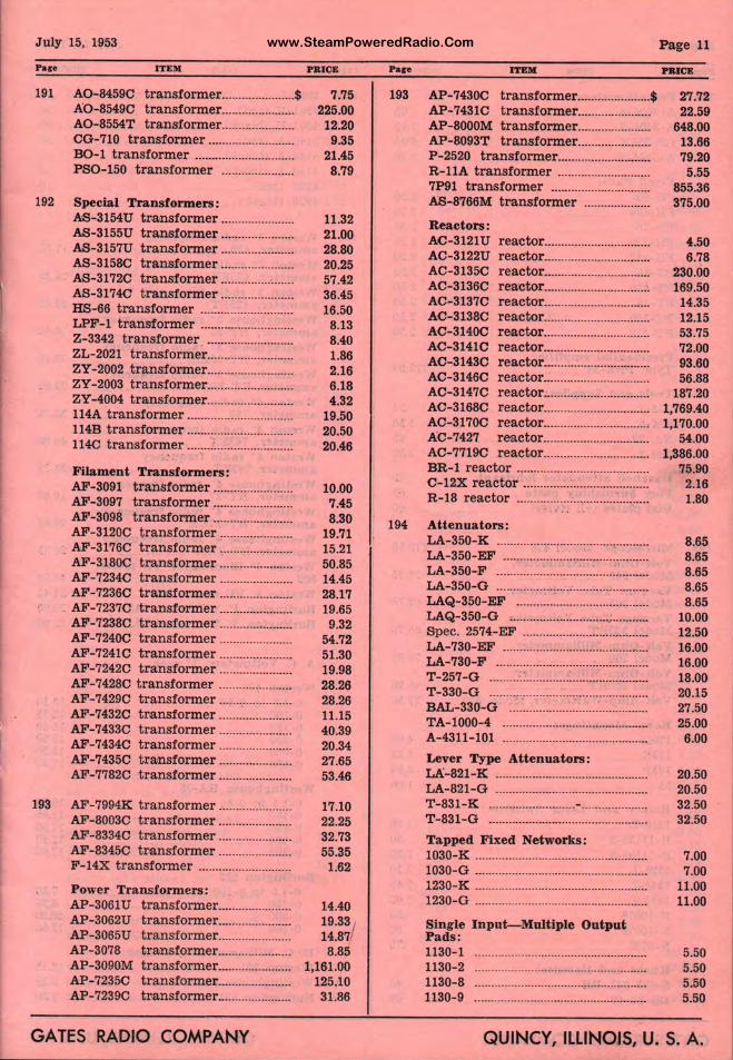
www.SteamPoweredRadio.ComJuly 15, 1953
Pare ITEM
191 A0-8459C transformer ...................... $ A0-8549C transformer ..................... . A0-8554T transformer ..................... . CG-710 transformer ......................... . B0-1 transformer ............................. . PS0-150 transformer ..................... .
192 Special Transformers: AS-3154U transformer ..................... . AS-3155U tran,sformer ..................... . AS-3157U transformer ..................... . AS-31580 transformer ..................... . AS-3172C transformer ..................... . AS-31740 transformer ..................... . HS-66 transformer ........................... . LPF-1 transformer ........................... . Z-3342 transformer ......................... . ZL-2021 transformer ......................... . ZY-2002 transformer ......................... . ZY-2003 transformer ......................... . ZY-4004 transformer ......................... . 114A transformer ............................... . 114B transformer ............................... . 1140 transformer ....... ~ ...................... .
Filament Transformers: AF-3091 transformer ....................... . AF-3097 transformer ....................... . AF-3098 transformer ....................... . AF-3120C transformer , .................... .
. AF-3176C transformer ......... : ........... . AF-31800 transformer ..................... . AF-72340 transformer ..................... . AF-7236C transformer ..................... .
. AF-72370 transformer ..................... . AF-7238C transformer ..................... . AF-72400 transformer ..................... . AF-7241C transformer ..................... . AF-7242C transformer ..................... . AF-7428C transformer ..................... . AF-7429C transformer ..................... . AF-7432C t ransformer ..................... . AF-74330 transformer ..................... . AF-74340 transformer ..................... . AF-7435C t ransformer ..................... . AF-7782C transformer ..................... .
193 AF-7994K tr ansformer ..................... . AF-8003C transformer ..................... . AF-8334C t ransformer ..................... . AF-83450 transformer ..................... . F-14X transformer ........................... .
Power Transformers: AP-3061U transformer ..................... . AP-3062U transformer ..................... . AP-3065U transformer ..................... . AP-3078 transformer ..................... . AP-3090M t ransformer ..................... . AP-72350 tra nsformer ..................... . AP-7239C transformer ..................... .
GATES RADIO COMPANY
PRICE
7.75 225.00
12.20 9.35
21.45 8.79
11.32 21.00 28.80 20.25 57.42 36.45 16.50 8.13 8.40 1.86 2.16 6.18 4.32
19.50 20.50 20.46
10.00 7.45 8.30
19.71 15.21 50.85 14.45 28.17 19.65 9.32
54.72 51.30 19.98 28.26 28.26 11.15 40.39 20.34 27.65 53.46
17.10 22.25 32.73 55.35
1.62
14.40 19.33 / 14.87 8.85
1,161.00 125.10 31.86
Pare
193
194
ITEM 11
AP-74300 transformer ...................... $ AP-74310 transf9nner ..................... . AP-8000M transformer ..................... . AP-8093T transf9 rmer ..................... . P-2520 transfo~er ........................... . R-llA transformer ........................... . 7P91 tram,former ............................. . AS-8766M transfo er ................... .
Reactors: AC-3121U AC-3122U AC-31350 AC-3136C AC-3137C AC-31380 AC-31400 AC-31410 AC-3143C AC-3146C
reacto ............................... . reacto ............................... . reactolj .............................. . reacto~ .............................. : reactorL ............................. . reactor
1
.............................. .
reactor ............................... . reactor ............................... . reactor
1
....................... : ....... .
reactor .............................. . AC-3147C reactor ............................. .
!~=:~;~ ;::~:;1 ::::::::::::::::::::::::::::::: AC-7427 reactor ......................... ·-··· AC-7719C . reactor
1 .............................. .
BR-1 reactor ....................................... . C-12X reactor ............. : ...... .' ............... . R-18 reactor ........ ....... '.· ............ : ......... .
Attenuators: LA-350-K .................................. ........ . LA-350-EF ................ : .......................... . LA-350-F ....... : ............ ." ... : ......... : ......... . LA-350-G .............. ··;···························· LAQ-350-EF ....................................... . LAQ-350-G , ............... : ........................ . Spec. 2574-EF ······················: .............. . LA-730-EF ............ .............................. . LA-730-F ............................................. . T-257-G ......... : ................................... . T-330-G ................ ............................. . BAL-330-G .... · .............. '. ...................... . TA-1000-4 ............ .............................. . A-4311-101 ......................................... .
Lever Type Atte uators: LA-821-K ............................................ . LA-821-G ........................................... . T-831-K ................. ........ - ................... . T-831-G .............................................. .
Tapped Fixed Ne orks: 1030-K .................... ............................. . 1030-G ................................................. . 1230-K ..................... ............................. . 1230-G ..................... ............................. .
Single Input-Mu iple Output Pads:
Page 11
PRICE
27.72 22.59
648.00 13.66 79.20 5.55
855.36 375.00
'-50 6.78
230.00 169.50 14.35 12.15 53.75 72.00 93.60 56.88
187.20 1,769.40 1,170.00
54.00 1,386.00
75.90 2.16 1.80
8.65 8.65 8.65 8.65 8.65
10.00 12.50 16.00 16.00 18.00 20.15 27.50 25.00 6.00
20.50 20.50 32.50 32.50
7.00 7.00
11.00 11.00
1130-1 1130-2 1130-8 1130-9
····················· ······························ 5.50 ····················· ······························ 5.50 ····················· ............................. 5.50 ····················1······························ 5.50
QUINC ~, ILLINOIS, U. S. A.
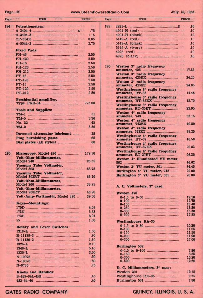
www.SteamPoweredRadio.ComPage 12
Pare ITEM PR ICE
194 Potentiometers: A-3404-4 ........................................... :· ..... $ .75 A- 3404-3 ................... : ............................ 1.15 CP-354X ................................................ 8.65 A- 5544-2 ................................................ 2.70
Fixed Pads : PH- 46 ·········································•······"'· 2.50 PH-420 .................................................. 2.50 PH-16 ................................................ , ... · 2.50 PH-120 .................................................. 2.50 PH-212 .................................................. 2.50 PT-46 .................................................... 2.50 PT-420 ....................... :.......................... 2.50 PT-16 .................................................... 2.50 PT-120 ................................... :.............. 2.50 PT-212 ....................................... : ...... : ... · 2.50
Presidential amplifier, Type PRE-34 ...................................... 775.00
Tools and Supplies: TM- 1 ...................................................... .51 TM-5 ...................................................... 3.36 No. 32 .................................................... .45 TM- 2 ...................................................... 3.36
Davenoil attenuator lubricant ...... .25 Plug burnishing paste .................... .65 Dial plates (all styles ) ...................... .60
195 Mirroscope, Model 476 ...................... 179.50 Volt-Ohm-MlWammeter, Model 240 .............................................. 26.35 Vacuum Tube Voltmeter, Model 303 .............................................. 58.75 Vacuum Tube Voltmeter, Model 303RT ........................................ 66.70 Volt-Ohm-Milllammeter, Model 260 .............................................. 38.95 Volt-Ohm-Milllammeter, Model 260RT ........................................ 46.90 Volt-Amp-Wattmeter, Model 390 .. 39.50
Keys-Mountings : 170D ........................................................ 4.09 173N ........................................................ 5.83 173P ........................................................ 8.94
55 ···························································· 1.00
Rotary and Lever Switches: 1316- L .................................................... 1.50 B-11139-3 .............................................. .90 B-11139-2 .............................................. 1.30 1325-L .................................................... 2.10 1346-L .................................................... 5.45 1335-L .................................................... 3.00 N-10076 .................................................. .50 N-10078 .................................................. .80 N-9735 .................................................... .75
Knobs and Handles: S -489-64L-BB ...................................... .45 483-64-40 ·················•···························· .40
GATES RADIO COMPANY
July 15, 19.53
Pare ITEM
195 2921-L .................................................... $ 4901-H (red) ....................................... . 4901-H (black) ................................... . 5149-A (r ed ) ....................................... . 5149-A (black ) ................................... . 5149-A (ivory) ................................... . 4926 (red) ........................................... . 4926 (black) ....................................... .
196 Weston 3" radio frequency ammeter, 425 ..................................... . Weston 3" radio frequency ammeter, 425EX ............................... . Weston 3" radio frequency ammeter, 425ET ............................... . Westinghouse 3" radio frequency ammeter, RT-35 ............................... . Westinghouse 3" radio frequency ammeter, RT-35EX ......................... . Westinghouse 3" radio frequency ammeter, RT-35ET ........................... . Weston 4" radio frequency ammeter, 743 ...................................... · Weston 4" radio frequency ammeter, 743EX ............................... . Weston 4" radio frequency· ammeter, 743ET ................................. . Westinghouse 4" radio frequency ammeter, RT- 37 ............................... . Westinghouse 4" radio frequency ammeter, RT-37EX ......................... . Westinghouse 4" radio frequency ammeter, RT-37ET ........................... . Weston 4" illuminated VU meter, 862 ......................................................... . Weston 3" VU meter, 301 ............... . Burlington 4" VU meter, 745 ....... . Burlington 3" VU meter, 535 ....... .
A. C. Voltmeters, 3" case:
Weston 476 0- 1.5 to 0- 50 ···································· 0-100 ·················································· 0-150 ................................................. . 0-250 ................................................. . 0- 300 ·················································· 0-500 ············································•·····
Westinghouse RA-35 0-1.5 to 0-80 ................................... . 0-100 ................................................. . 0-150 ·················································· 0- 200 •··••············································· 0-300 ··················································
Burlington 532 0- 1.5 to 0-100 ................................. . 0-150 ·················································· 0-300 ................................................. . 0-500 ................................................. .
D. C. Milliammeters, 3" case: Weston 301 ......................................... . Westingh ouse RX-35 ....................... . Burlington 531 ................................... .
PRICE
.10
.10
.10
.10
.10
.10
.10
.10
17.85
24.25
24.85
14.45
18.70
22.95
33.15
40.80
38.25
16.58
20.83
26.35
46.62 34.45 22.00 20.00
12.10 12.75 13.40 13.80 15.30 17.85
10.20 11.05 11.50 11.90 17.00
7.80 8.55
10.20 12.60
12.15 9.35 7.80
QUINCY, ILLINOIS, U. S. A.
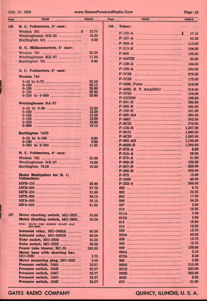
www.SteamPoweredRadio.Com
I
July· 15, 1953 .
Pare
196
197
ITEM
D. C. Voltmeters, 3"· case: Weston 301 .......................................... $ Westinghouse RX-35 ....................... . Burlington 531 ................................... .
D. C. Milliammeters, 4" case: Weston 741 ......................................... . Westinghouse RX-37 ....................... . Burling ton 741 ................................... .
A. C. Voltmeters, 4" case:
Weston 744 0-10 to 0-75 ..................................... . 0-100 ................................................. . 0-130 ·················································· 0-150 ········································•······•·· 0-250 t.o 0-300 ······················:·········
Westinghouse RA-37
0-10 to 0-80 ................................... . 0-100 ................................................. . 0-130 ................................................. . 0-150 ................................................. . 0-250 ................................................. . 0-300 ................................................. .
Burlington 742B
0-10 to 0-100 ................................. . 0-150 ··········•······································· 0-250 t.o 0-300 ·················•···•··········
D. C. Voltmeters, 4" case: Weston 741 ......................................... . Westinghouse RX-37 ....................... . Burlington 741B ............................... .
Meter Multipliers for D. C. Voltmeters: MFB-155 ............................................... . MFB-205 ............................................... . MFB-255 ............................................... . MFB-305 ............................................... . MFA-505 ............................................... . :MFA-605 ............................................... .
Meter shorting switch, M0-3823 ... . Meter shorting switch, M0-3863 ... . Note: Above type number should r ead
M0-2863.
Solenoid relay, M0-3480A ............. . Solenoid relay, M0-3480B ............. . Tube socket, M0-3934 ..................... . Tube socket, M0-3933 ..................... . Power tube blower, BC-25 ............. . Meter base with shorting bar, M0-3280 ............................................... . Meter mounting plug, M0-3281 ... . Pressure switch, 104A ..................... . Pressure switch, 104B ..................... . Pressure switch, 104C ..................... . Pressure switch, 104D ..................... . Pressure switch, 104E ..................... .
GATES RADIO COMPANY
PRICE
12.75 10.20 9.00
25.50 11.50 8.85
25.50 26.15 26.80 26.80 33.80
12.35 13.20 13.20 13.60 13.60 19.15
8.85 9.60
11.25
25.50 14.50 10.20
23.40 27.70 31.90 36.15 53.15 61.65
55.00 20.00
60.00 60.00 35.00 39.50
295.85
3.75 6.00
32.57 32.57 32.57 32.57 32.57
Pare
198
ITEM
Tubes:
F-123-A .................. ............................. $ F-127-A
F-204-A F-212-E
F-849 ......................... ............................ .
F-450TH ................................................ . F-128-A ................................................ .
Page 13.
PRICE
17.15 55.20
115.00 104.00 138.00
60.00 184.00
F-132-A .................. .............................. 230.00 F-7C26 ................................................. . F-7C23 ................................................ .
F - 5680, Pulse ....................................... .
F-5680, R . F . Ampll fier ................... . F-7C25 ................................................ . F-3X2500 .............................................. . F-891-R .............................................. . F-892-R .................. ............................ . F-129-R .............................................. . F-889-RA ............................................ . F -5667 ....................... ............................ . F -8C25 ................................................. . F-124-R .............................................. . F-9C31 ...................•............................... F-9C29 ................................................ . F-893-AR ................. ............................ . F-8002-R .............................................. . F-872-A ................... ............................ . F-315-A ................................................ . F-575-A ............................................... . F-869-B ................... ............................ . F-857-B .............................................. . F-266-B ............................................. . F-873 .................................................... . F -5563 ...................... ............................ . F-222-A ................................................ .
802 ····························· ····························· 803 ............................ ............................ .
805 ···························· ····························· 806 ···························-- ····························· 807 ........................................................ .
810 •··························--······························ 811A ........................................................ . 812A ......................... ............................ . 813 ···························· ............................ . 814 ·····••··················································· 828 ........................... ····························· 833A .......................... ............................ .
838 ···························· ······························ 845 ··························· ............................. . 849 ........................................................ . 866A .......................... ............................ . 872A ...................................................... . 885 ........................... ····························· 889R ...................................................... . 891R .......................... ............................. . 892R ....................................................... . 8008 ·························· ............................ . 673 ··························································
272.00
173.00 214.00 214.00 154.00 198.00 385.00 385.00 431.00 285.00 302.50 576.00
1,357.00 1,460.00 1,505.00 1,150.00 1,300.00
8.20 38.60 21.00
132.00 209.00 209.00
12.00 40.00
300.00 4.75
24.25 17.50 34.25 2.50
16.25 5.00 5.00
18.00 14.25 13.75 49.50 13.75 13.75
138.00 2.10 8.20 2.00
210.00 385.00 385.00
8.20 21.00
QUINC , ILLINOIS, U. S. A.
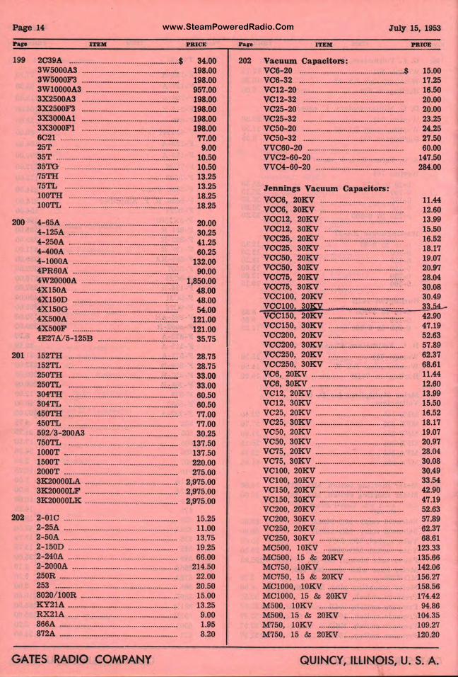
www.SteamPoweredRadio.ComPage 14
Pap ITEM
199 2C39A .................................................... $ 3W5000A3 ............................................. . 3W5000F3 ............................................ .. 3Wl0000A3 ........................................... . 3X2500A3 ............................................. .
3X2500F3 ·············································· 3X3000Al ............................................. . 3X3000Fl ............................................. .
6C21 ························································ 25T ......................................................... . 35T ......................................................... . 35TG ..................................................... .
75TH: ······················································ 75TL ..................................................... .
100TH: ·······················•···························· l00TL ....................... ~: .......................... .
200 4-65A .................................................. · .. 4-125A ................................................... . 4-250A ................................................... . 4-400A ................................................... . 4- l000A ................................................. . 4PR60A ................................................. . 4W20000A ............................................. . 4X150A ..............................................•... 4Xl50D ................................................. . 4X150G ............................................ : .... . 4X500A .......................................... : ...... . 4X500F .......................................... , ...... . 4E27A/5-125B ..................................... .
201 152TH: ············································•······· 152TL ................................................... .
250TH: ···················································• 250TL ................................................... .
304TH: ···················································· 304TL ................................................... .
450TH: ···················································· 450TL ................................................... . 592/ 3-200A3 ......................................... . 750TL ................................................... . 1000T ..................................................... . 1500T ..................................................... . 2000T ..................................................... . 3K20000LA ........................................... . 3K20000LF ........................................... . 3K20000LK ........................................... .
202 2-010 ······················································ 2-25A ..................................................... . 2- 50A ..................................................... . 2-150D ................................................... . 2-240A ................................................... . 2-2000A ................................................. . 250R ....................................................... .
253 ·························································· 8020/ l 00R ............................................. . KY21A ................................................... . RX21A ................................................... . 866A ....................................................... . 872A ....................................................... .
GATES RADIO COMPANY
PRICE
34.00 198.00 198.00 957.00 198.00 198.00 198.00 198.00 77.00 9.00
10.50 10.50 13.25 13.25 18.25 18.25
20.00 30.25 41.25 60.25
132.00 90.00
1,850.00 48.00 48.00 54.00
121.00 121.00 35.75
28.75 28.75 33.00 33.00 60.50 60.50 77.00 77.00 30.25
137.50 137.50 220.00 275.00
2,975.00 2,975.00 2,975.00
15.25 11.00 13.75 19.25 66.00
214.50 22.00 20.50 15.00 13.25 9.00 1.95 8.20
Pare
202
July 15, 1953
ITEM
Vacuum Capacitors: VC6- 20 ................................................. $ VC6-32 ............................................... . VC12-20 ............................................. . VC12- 32 .............................................. . VC25-20 ............................................. . VC25-32 ............................................. . VC50-20 ............................................. . VC50-32 ............................................. . VVC60-20 ........................................... . VVC2- 60-20 .............. . ........................ . VVC4-60-20 ........................................ .
~~t~:;c~.~: ... ~t~~~.~~:.'. ...... . VCC6, 30KV ...................................... . VCC12, 20K V ..................................... . V0012, 30KV .................................... . VCC25, 20KV ................................... . VCC25, 30K V .......... . ........................ . VCC50, 20KV ........... ......................... . VCC50, 30KV .......... . ........................ . VCC75, 20KV ..................................... . VOC75, 30KV .......... . ........................ . VOCl00, 20KV ................................. . VCCl00, 30K:y ...... _ . . ................. . VCC150, 20KV ........ . ....... : .. .-.......... : .. . VCC150, 30KV ........ ...................... .-.. VCC200, 20KV ........ . ........................ . VCC200, 30KV ...... ,. . ........................ . VOC250, 20KV ........ . ........................ . VCC250, 30KV ........ . ........................ . VC6, 20KV ................ ......................... . VC6, 30KV ......................................... . VC12, 20KV ....................................... . VC12, 30KV ........................................ . VC25, 20KV ....................................... . VC25, 30KV ............... ......................... . VC50, 20K V ........................................ . VC50, 30KV .............. ················~········ VC75, 20KV ........................................ . VC75, 30KV ........................................ . VCl00, 20KV ............. ......................... . VCl00, 30K V ...................................... . VC150, 20KV ...................................... . VC150, 30KV ............. ............ : ............ . VC200, 20KV ........ .' ................... _ ........... . VC200, 30KV ...................................... . VC 250, 20KV ..................................... . VC250, 30KV ...................................... . MC500, l0KV ........... ......................... . MC500, 15 & 20KV , ........................ . MC750, l0KV ..................................... . MC750, 15 & 20KV ......................... . MCl000, l 0KV ................................. . MClO00, 15 & 20~ ....................... . M500, l 0KV ........................................ . M500, 15 & 20KV .......................... . M750, l0K V ...................................... . M750, 15 & 20KV ........................... .
PRICE
15.00 17.25 16.50 20.00 20.00 23.25 24.25 27.50 60.00
147.50 284.00
11.44 12.60 13.99 15.50 16.52 18.17 19.07 20.97 28.04 30.08 30.49 3354_ 42.90 47.19 52.63 57.89 62.37 68.61 11.44 12.60 13.99 15.50 16.52 18.17 19.07 20.97 28.04 30.08 30.49 33.54 42.90 47.19 52.63 57.89 62.37 68.61
123.33 135.66 142.06 156.27 158.56 174.42 . 94.86 104.35 109.27 120.20
QUINCY,I ILLINOIS, u. s. A.
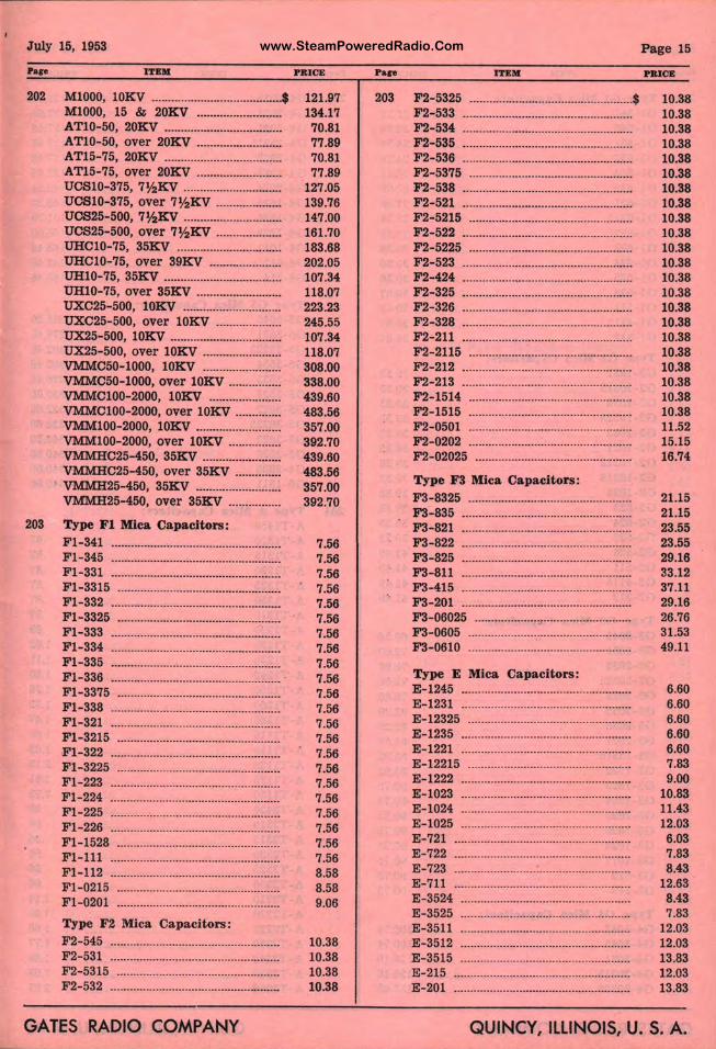
www.SteamPoweredRadio.ComJuly 15, 1953
ITEM
202 Ml000, l0KV ........................................ $ Ml000, 15 & 20KV ......................... . ATl0-50, 20KV ................................... . ATl0-50, over 20KV ......................... . AT15-75, 20KV ................................... . AT15-75, over 20KV ......................... . UCSl0-375, 7½KV ............................. . UCSl 0-375, over 7½KV ···················· UCS25-500, 7½KV ............................. . UCS25-500, over 7½KV ................... . UHCl0-75, 35KV ............................... . UHCl0-75, over 39KV ..................... . UHl0-75, 35KV ................................... . UHl0-75, over 35KV ......................... . UXC25-500, lOKV ............................. . UXC25-500, over l0KV ................... . UX:25-500, l0KV ................................. . UX:25-500, over l0KV ....................... . VMMC50-1000, l0KV ....................... . VMMC50-1000, over l0KV ............... . VMMCl00-2000, l0KV ..................... . VMMCl00-2000, over lOKV ............. . VMMl00-2000, l0KV ......................... . VMMl00-2000, over l0KV ················ VMMHC25-450, 35KV ....................... . VMMHC25-450, over 35KV ............. . VMMH25-450, 35KV ......................... . VMMH25-450, over 35KV ............... .
203 Type Fl Mica Capacitors: Fl-341 ................................................... . F l -345 ................................................... . Fl-331 ................................................... . Fl-3315 ................................................. . Fl-332 ................................................... . Fl-3325 ................................................. . Fl-333 ................................................... . Fl-334 ................................................... . Fl-335 ................................................... . Fl-336 ................................................... . Fl-3375 ................................................. . Fl-338 ................................................... . Fl-321 ................................................... . Fl- 3215 ................................................. . Fl-322 ................................................... . Fl-3225 ................................................. . Fl-223 ................................................... . Fl-224 ................................................... . Fl-225 ................................................... . Fl-226 ................................................... . Fl-1528 ................................................. . Fl-111 ................................................... . Fl-112 ................................................... . Fl-0215 ................................................. . F l-0201 ................................................. .
Type F2 Mica Capacitors : F2-545 ................................................... . F2-531 ······•·•··········································· F 2-5315 ................................................. . F 2-532 ................................................... .
GATES RADIO COMPANY
PRICE
121.97 134.17 70.81 77.89 70.81 77.89
127.05 139.76 147.00 161.70 183.68 202.05 107.34 118.07 223.23 245.55 107.34 118.o7 308.00 338.00 439.60 483.56 357.00 392.70 439.60 483.56 357.00 392.70
7.56 7.56 7.56 7.56 7.56 7.56 7.56 7.56 7.56 7.56 7.56 7.56 7.56 7.56 7.56 7.56 7.56 7.56 7.56 7.56 7.56 7.56 8.58 8.58 9.06
10.38 10.38 10.38 10.38
Pace
203
ITEM
F2- 5325 .................................................. $ F2-533 ................................................... .
F2-534 ················•··································· F2-535 ................................................... . F2-536 ................................................... .
F2-5375 ·················································· F2-538 ···················································· F2-521 ................................................... . F2-5215 ................................................. . F2-522 ................................................... .
F2-5225 ·················································· F2-523 ................................................... .
F2- 424 ···················································· F2-325 ................................................... . F2-326 ................................................... . F2-328 ................................................... . F2-211 ................................................... . F2-2115 ................................................. . F2-212 ................................................... . F2-213 ·································•··••·············· F2-1514 ................................................. . F2-1515 ................................................. . F2-0501 ................................................. . F2-0202 ·················································· F2-02025 ............................................... .
Type F3 Mica Capacitors: F3-8325 ................................................. . F3-835 ···················································· F3-821 ................................................... . F3-822 ................................................... . F3-825 ········································•··········· F3-811 ···················································· F3-415 ................................................... . F3- 201 ................................................... . F3-06025 ............................................... . F3-0605 ................................................. . F3-0610 ...................... · ........................... .
Type E Mica Capacitors: E-1245 ................................................... . E-1231 ................................................... . E-12325 ................................................. . E-1235 ................................................... . E-1221 ................................................... . E-12215 ................................................. . E-1222 ................................................... . E-1023 ................................................... . E-1024 ................................................... . E-1025 ................................................... . E-721 ..................................................... . E-722 ..................................................... . E-723 ..................................................... . E-711 ..................................................... . E-3524 ................................................... . E -3525 ................................................... . E -3511 ................................................... . E-3512 ................................................... . E-3515 ................................................... . E-215 ..................................................... . E-201 ..................................................... .
Page 15
PRICE
10.38 10.38 10.38 10.38 10.38 10.38 10.38 10.38 10.38 10.38 10.38 10.38 10.38 10.38 10.38 10.38 10.38 10.38 10.38 10.38 10.38 10.38 11.52 15.15 16.74
21.15 21.15 23.55 23.55 29.16 33.12 37.11 29.16 26.76 31.53 49.11
6.60 6.60 6.60 6.60 6.60 7.83 9.00
10.83 11.43 12.03 6.03 7.83 8.43
12.63 8.43 7.83
12.03 12.03 13.83 12.03 13.83
QUINCY, ILLINOIS, U. S. A.
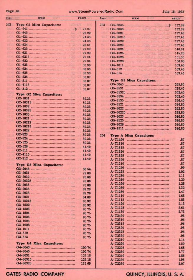
www.SteamPoweredRadio.ComP a ge 16
Pare
203
ITEM
Type GI Mica Capacitors : Gl-641 .................................................... $ Gl-645 ................................................... . Gl-631 ................................................... . Gl-632 ................................................... . Gl-634 ................................................... . Gl-635 ................................................... . Gl-621 ................................................... . Gl-6215 ................................................. . Gl-622 ............................... ' .................... . Gl-623 ................................................... . Gl-624 ................................................... . Gl-625 ................................................... . Gl-526 ................................................... . Gl-511 ................................................... . Gl-4115 ................................................. . Gl-312 ................................................... .
Type G2 Mica Capacitors: 02-1031 ·················································· 02- 10315 ················································ G2-1032 ................................................. . G2-10325 ............................................... . G2-1035 ................................................. . G2-1021 ................................................. . G2-10212 ............................................... . G2-10215 ............................................... . G2-1022 ................................................. . G2-823 ................................................... . G2-824 ................................................... . G2-525 ................................................... . G2-526 ................................................... . G2-511 ................................................... . 02-4115 ................................................. .
02-312 ····················································
Type G3 Mica Capacitors: G3-2045 ................................................. . G3-2031 ................................................. . G3-2032 ................................................. . G3-20325 ............................................... .
03-2033 ·················································· 03-2035 ·················································· G3-2038 ................................................. . G3-2021 ................................................. . 03-15215 ............................................... . G3-1522 ................................................. . G3-1523 ................................................. . G3-1524 ................................................. . G3-1025 ................................................. . G3-1026 ................................................. . G3-1028 ................................................. .
03-1011 ·················································· 03-512 ................................................... .
03-313 ····················································
Type G4 Mica Ca pacitors: 04-3043 ................................................. .
04-3045 ·················································· 04-3031 ···········•······································ G4-30315 ···········································-··· 04-30325 ····························•···················
GATES RADIO COMPANY
PRICE
21.27 22.92 24.36 24.36 26.61 27.99 27.99 29.34 29.34 30.36 30.36 30.36 30.87 30.87 30.87 30.87
39.33 39.33 39.33 39.33 39.33 39.33 39.33 39.33 39.33 39.33 39.33 39.33 41.49 41.49 41.49 41.49
66.54 72.60 78.66 78.66 78.66 82.29 82.29 84.69 85.92 85.92 90.75 90.75 90.75 90.75 90.75 90.75 90.75 90.75
100.74 100.74 126.18 126.18 132.69
203
204
July 15, 1953
ITEM
04-3035 ··················································$ G4-3038 ................................................. .
04-3021 ······························•··••··············· 04-25215 ························•·•·····•··••··········· 04-2022 ·················································· 04-2023 ·················································· 04-2024 ·················································· 04-1525 ··········••·•···································· 04-1526 ·················································· 04-1228 ························•··•······················ 04-1011 ·················································· 04-612 ···················································· 04-514 ··························•·····•···················
Type G5 Mica Capacitors: G5-5045 ................................................. . 05-3531 ................................................. . G5-35325 ............................................... .
05-3534 ·················································· 05-3535 ................................................. . G5-3521 ................................................. . G5-3022 ................................................. . 05-30225 ............................................... .
05-3023 ·················································· 05-2525 ................................................. . G5-2026 ................................................. .
05-1511 ··················································
Type A Mica Capacitors: A-Tl450 ............................................... . A-Tl310 ............................................... . A-Tl315 ............................................... . A-Tl320 ............................................... . A-T1325 ............................................... . A-Tl350 ............................................... . A-Tl210 ............................................... . A-Tl220 ............................................... . A-Tl225 ............................................... . A-Tl230 ............................................... . A-Tl240 ............................................... . A-Tl250 A-T1260 A-Tl280 A-Tlll0 A-T1115 A-Tll20 A-Tll25 A-Tll30 A- '1'2450 A-'1'2310 A-'1'2315 A- '1'2320 A- '1'2325 A-'1'2350 A-'1'2210 A-'1'2220 A-'1'2225 A-'1'2230 A-'1'2240 A-'1'2250 A-'1'2260
PRICE
132.69 132.69 137.46 137.46 137.46 137.46 140.61 145.20 151.35 156.00 163.46 163.46 163.46
265.80 278.40 302.40 302.40 326.40 336.80 322.80 328.80 340.80 340.80 340.80 340.80
.87
.87
.87
.87
.87
.87
.87
.99 1.02 1.11 1.20 1.26 1.32 1.47 1.68 1.83 2.13 2.61 2.73
.96
.96
.96
.96
.96
.96 1.14 1.50 1.68 1.77 1.86 1.98 2.07
QUINCY, ILLINOIS, U. S. A.
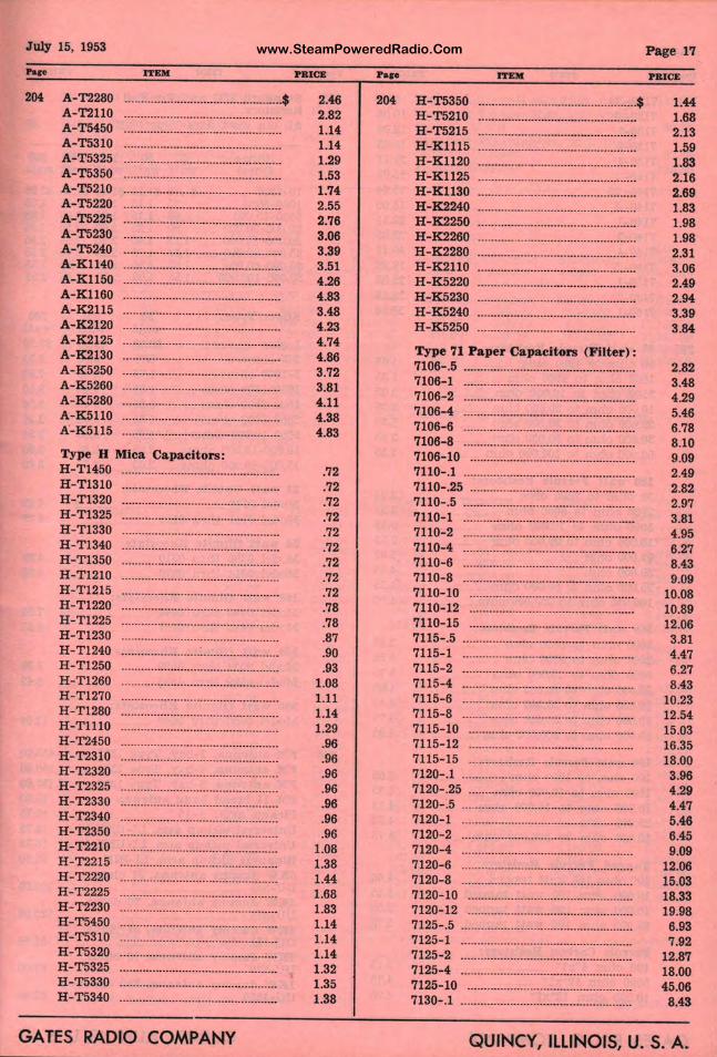
www.SteamPoweredRadio.ComJuly 15, 1953
Pap
204 A-'1'2280 A- '1'2110 A-T5450 A-T5310 A-T5325 A-T5350 A-T5210 A- T5220 A- T5225 A-T5230 A-T5240 A-Kl140 A- Kll50 A-Kll60 A- K2115 A-K2120 A-K2125 A-K2130 A-K 5250 A- K 5260 A- K 5280 A-K5110 A- K5115
ITEM
················································$
Type H Mica Capacitors: H-Tl450 ............................................... . H-Tl310 ............................................... . H-Tl320 ............................................... . H -Tl325 ............................................... . H -Tl330 ............................................... . H -T l 340 ............................................... . H-Tl350 ............................................... . H -Tl210 ............................................... . H- T l 215 ............................................... . H- Tl220 ............................................... . H-Tl225 ............................................... . H-Tl 230 ............................................... . H-Tl240 ............................................... . H-Tl250 ............................................... . H -Tl260 ............................................... . H -Tl270 ............................................... . H- T 1280 ............................................... . H-Tll l0 ............................................... . H- '1'2450 ............................................... . H- '1'2310 ............................................... . H- '1'2320 ............................................... . H - '1'2325 ............................................... . H-T2330 ............................................... . H -T2340 ............................................... . H-'1'2350 ............................................... . H- '1'2210 ............................................... . H -T2215 ............................................... . H-T 2220 ............................................... . H -T2225 ............................................... . H-T2230 ............................................... . H -T 5450 ............................................... . H -T5310 ............................................... . H-T5320 ............................................... . H-T5325 ............................................... . H-T5330 ............................................... . H -T5340 ............................................... .
GATES RADIO COMPANY
PBICE
2.46 2.82 1.14 1.14 1.29 1.53 1.74 2.55 2.76 3.06 3.39 3.51 4.26 4.83 3.48 4.23 4.74 4.86 3.72 3.81 4.11 4.38 4.83
.72
.72
.72
.72
.72
.72
.72
.72
.72
.78
.78
.87
.90
.93 1.08 1.11 1.14 1.29
.96
.96
.96
.96
.96
.96
.96 1.08 1.38 1.44 1.68 1.83 1.14 1.14 1.14 1.32 1.35 1.38
Pase
204
ITEM
H-T5350 ............................................... $ H-T5210 .............................................. . H-T5215 ............................................. . H-Klll5 .................. ............................ . H-K ll20 .................. ............................ . H-K1125 ............................................. . H-K1130 ............................................. . H-K2240 ............................................. . H-K2250 ............................................. . H-K2260 ............................................... .
:=!~!~~ :::::::::::::::] :::::::::::::::::::::::::::: H-K 5220 ............................................. . H-K5230 ............................................. . H-K5240 .............................................. . H -K 5250 .............................................. .
Type 71 Paper Cap: rtCi tors (Filter) :
Page 17
1.44 1.68 2.13 1.59 1.83 2.16 2.69 1.83 1.98 1.98 2.31 3.06 2.49 2.94 3.39 3.84
7106- .5 ...................... ····························· 2.82 7106- 1 ······················· · ··························· 3.48 7106-2 ....................... ····························· 4.29 7106-4 ···················································· 5.46
~~~:=: ::::::::::::::::::::::r :::::::::::::::::::::::::: ::I~ 7106-10 .................................................. 9.09
7110-.1 ···················································· 2.49 7110-.25 ···················· ····························· 2.82 7110-.5 ···················································· 2.97
im~i i: :=. : i:~1 7110-8 ..................................................... 9.09
10.08 10.89 12.06 3.81 4.47 6.27 8.43
10.23
~i~E!~ ··::::::::::::::::::::~:::::::::::::::::::::::::::: ~~:i: 7115-15 ..................... ........................... 18.00
7120-.1 ······················· ···························· 3.96 7120-.25 ·················································· 4.29 7120-:5 ....................... ........................... 4.47 7120-1 ....................... ··························· 5.46 7120-2 ....................... ···························· 6.45 7120-4 ....................... ........................... 9.09
~!:t: ::::::::::::::::::::] ::::::::::::::::::::::::::: ~::~: 7120-10 ········•············ ··························· 18.33 7120-12 ·····•··············· ···························· 19.98 7125- .5 ······················· ........................... 6.93 7125-1 ······················· •···•······················ 7 .92 7125-2 ....................... ··························· 12.87 7125-4 ······················· ···························· 18.00
;:~:•,• : : : j :: •~:~ QUINcvJ ILLINOIS, u. s. A.
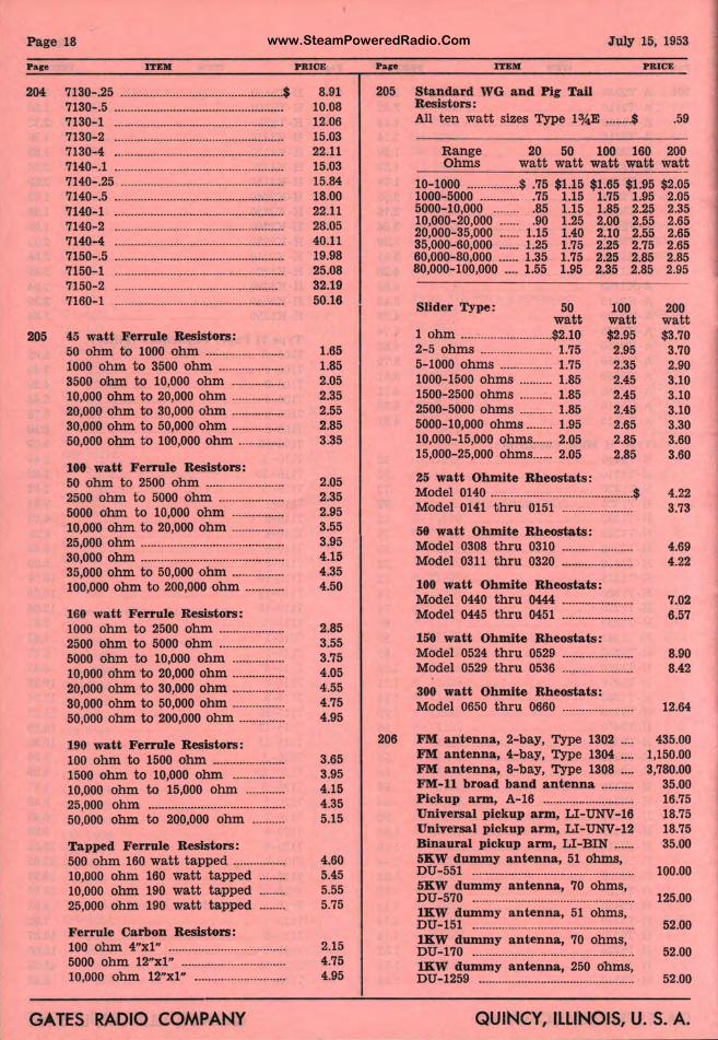
www.SteamPoweredRadio.ComPage 18
Pare
204
205
ITEM
7130-.25 ··················································$ 7130-.5 ···························-······················· 7130-1 ···················································· 7130-2 ................................................... . 7130-4 ................................................... . 7140-.1 ................................................... . 7140-.25 ................................................. . 7140-.5 ................................................... . 7140-1 ................................................... .
7140-2 ···················································· 7140-4 ···················································· 7150-.5 ................................................... . 7150-1 ···················································· 7150-2 ·················································· 7160-1 ····················································
45 watt Ferrule Resistors: 50 oh m to 1000 ohm ....................... . 1000 ohm to 3500 ohm ....... ............ . 3500 ohm to 10,000 ohm ............... . 10,000 ohm to 20,000 ohm ............... . 20,000 ohm to 30,000 ohm ............... . 30,000 ohm to 50,000 ohm ............... . 50,000 ohm to 100,000 ohm ............. .
100 watt Ferrule Resistors: 50 ohm t o 2500 ohm ....................... . 2500 ohm to 5000 ohm ................... . 5000 ohm t o 10,000 ohm ............... . 10,000 ohm t o 20,000 ohm ............... . 25,000 ohm ........................................... .
30,000 ohm ······································-···· 35,000 ohm to 50,000 ohm ............... . 100,000 ohm to 200,000 ohm ........... .
160 watt Ferrule Resistors: 1000 ohm to 2500 ohm ................... . 2500 ohm to 5000 ohm ................... . 5000 ohm to 10,000 ohm ............... . 10,000 ohm to 20,000 ohm ............... . 20,000 ohm t o 30,000 ohm ............... . 30,000 ohm to 50,000 ohm ............... . 50,000 ohm to 200,000 ohm ............. .
190 watt Ferrule Resistors: 100 ohm to 1500 ohm ..................... . 1500 ohm to 10,000 ohm ............... . 10,000 ohm to 15,000 ohm ........... . 25,000 ohm ......................................... . 50,000 ohm to 200,000 ohm ......... .
Tapped Ferrule Resistors: 500 ohm 160 watt tapped ............... . 10,000 ohm 160 watt tapped ....... . 10,000 ohm 190 watt tapped ....... . 25,000 ohm 190 watt tapped ....... .
Ferrule Carbon Resistors: 100 ohm 4"xl" ................................... . 5000 ohm 12"xl" ............................... . 10,000 ohm 12"xl" ........................... .
GATES RADIO COMPANY
PRICE
8.91 10.08 12.06 15.03 22.11 15.03 15.84 18.00 22.11 28.05 40.11 19.98 25.08 32.19 50.16
1.65 1.85 2.05 2.35 2.55 2.85 3.35
2.05 2.35 2.95 3.55 3.95 4.15 4.35 4.50
2.85 3.55 3.75 4.05 4.55 4.75 4.95
3.65 3.95 4.15 4.35 5.15
4.60 5.45 5.55 5.75
2.15 4.75 4.95
Pare
205
206
July 15, 1953
ITEM
Standard WG and Pig Tail Resistors:
PRICE
All ten watt sizes Type l¾E ....... .$ .59
Range 20 50 100 160 200 Ohms watt watt watt wat t wat t
10-1000 ................ $ .75 $1.15 $1.65 $1.95 $2.05 1000-5000 ............ .75 1.15 1.75 1.95 2.05 5000-10,000 .85 1.15 1.85 2.25 2.35 10,000-20,000 ...... .90 1.25 2.00 2.55 2.65 20,000-35,000 ...... 1.15 1.40 2.10 2.55 2.65 35,000-60,000 ...... 1.25 1.75 2.25 2.75 2.65 60,000-80,000 ...... 1.35 1.75 2.25 2.85 2.85 80,000-100,000 .... 1.55 1.95 2.35 2.85 2.95
Slider Type: 50 watt
1 ohm ............................ $2.10 2-5 ohms ...................... 1.75 5-1000 ohms ................ 1.75 1000-1500 ohms .......... 1.85 1500-2500 ohms .......... 1.85 2500-5000 ohms .......... 1.85 5000-10,000 ohms ........ 1.95 10,000-15,000 ohms ...... 2.05 15,000-25,000 ohms ...... 2.05
25 watt Ohmite Rheostats:
100 wat t $2.95 2.95 2.35 2.45 2.45 2.45 2.65 2.85 2.85
200 watt $3.70 3.70 2.90 3.10 3.10 3.10 3.30 3.60 3.60
Model 0140 ............................................ $ 4.22 Model 0141 thru 0151 ...................... 3.73
se watt Ohmite Rheostats: Model 0308 thru 0310 ...................... 4.69 Model 0311 thru 0320 ...................... 4.22
100 watt Ohmite Rheostats: Model 0440 thru 0444 ...................... 7.02 Model 0445 thru 0451 ...................... 6.57
150 watt Ohmite Rheostats: Model 0524 thru 0529 ...................... 8.90 Model 0529 thru 0536 ...................... 8.42
300 watt Ohmite Rheostats: Model 0650 thru 0660 ...................... 12.64
FM antenna, 2-bay, Type 1302 ... . FM antenna, 4-bay, Type 1304 ... . FM antenna, 8-bay, Type 1308 ... . FM-11 broad band antenna ......... . Pickup arm, A-16 ........................... . Universal pickup arm, LI-UNV-16 Universal pickup arm, LI-UNV-12 Binaural pickup arm, LI-BIN ..... . 5KW dummy antenna, 51 ohms, DU-551 ................................................. . 5KW dummy antenna, 70 ohms, DU-570 ................................................. . lKW dummy antenna, 51 ohms, DU-151 ................................................. . lKW dummy antenna, 70 ohms, DU-170 ................................................. . lKW dummy antenna, 250 ohms, DU-1259 ............................................... .
435.00 1,150.00 3,780.00
35.00 16.75 18.75 18.75 35.00
100.00
125.00
52.00
52.00
52.00
QUINCY, ILLINOIS, U. S. A.
l
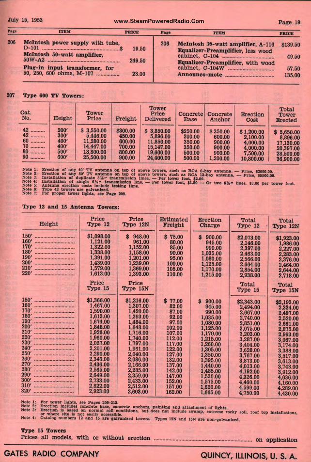
www.SteamPoweredRadio.ComJuly 15 1953 ' Page 19
Par•
206
207
ITEM PIUOE Pare ITEM PRIOE
McIntosh power supply with t ube, 206 McIntosh 39-watt amplifier, A-116 $139.50 D-101 ..................................................... $ 19.50 Equallzer-PreampWrier, less wood McIntosh SO-watt amplifier, cabinet, C-104 ...... OOOOO OOOOOOOOOOOOOOH0000o00 49.50 50W-A2 .................................................. 249.50 Equallzer-Preampll ier, with wood Plug-in input transformer, for cabinet, C-104W ... II 57.50 50, 250, 600 ohms, M-107 ................ 23.00 Announco-mote ···- 11 ••••••••••••••••••••••••••• 135.00
Type 600 TV Towers:
Tower Total cat. Tower Price Concrete Concrete Erect1on Tower No. Height Price Freight Delivered Base Anchor Cost Erected
42 ·········· 200' $ 3,550.00 $300.00 $ 3,850.00 $250.00 $350.00 $1,200.00 $ 5,650.00 42 .......... 300' 5,446.00 450.00 5,896.00 300.00 600.00 2,100.00 8,896.00 60 .......... 400' 11,280.00 600.00 11,850.00 350.00 900.00 4,000.00 17,130.00 70 .......... 400' 14,447.00 700.00 15,147.00 350.00 900.00 4,000.00 20,397.00 80 .......... 500' 18,800.00 800.00 19,600.00 500.00 900.00 I 7,500.00 28,500.00 90 .......... 600' 25,500.00 900.00 24,400.00 500.00 1,200.00 . 10,800.00 36,900.00 I
Note 1: Note 2: Note 3:
Erection of any 40' TV antenna on WP of abon w wera, aucb aa RCA 8-ba7 antenna. - Prlu, $3000.00. Erection of any 80' TV antenna on top of above towers, aucb aa RCA 12-ba7 antenna - Priu, $$500.00. Inatallatlon of duplicate 3\j," t.ranam.lsalon lines. - Per wwer foot, t2.00. Note 4 : Note 5:
Installation of aln1le 8 ¾ " tranamlaslon line. - Per tower foot, •1.50 - Or two 8¾" lines, $3.00 per tower foot. Antenna erection coats Include teattn1 time. Note B: Note 7:
TJ'pe 42 towers are 1alvanlzed. Por proper tower ll1bta, aee Pa1e 209.
Type 12 and 15 Antenna Towers:
Price Price Estimated Height Type 12 Type 12N Freight
150' ............................ $1,098.00 $ 948.00 $ 75.00 160' ............................ 1,121.00 961.00 80.00 170' ............................ 1,322.00 1,152.00 85.00 180' ···························· 1,338.00 1,158.00 90.00 190' ···························· 1,391.00 1,201.00 95.00 200' ···········-··············· 1,439.00 1,239.00 100.00 210' ···-··················-··· 1,579.00 1,369.00 105.00 220' ···························· 1,613.00 1,393.00 110.00
Price Price Type 15 Type 15N
150' ···········-··············· $1,366.00 $1,216.00 $ 77.00 160' ················•··········· 1,467.00 1,307.00 82.00 170' ............................ 1,590.00 1,420.00 87.00 180' ···························· 1,613.00 1,393.00 92.00 190' ............................ 1,674.00 1,484.00 97.00 200' ···········-··············· 1,848.00 1,648.00 102.00 210' ···········-··-··-······· 1,926.00 1,716.00 107.00 220' ···························· 1,960.00 1,740.00 112.00 230' ···························· 2,027.00 1,797.00 117.00 240' ............................ 2,201.00 1,961.00 122.00 250' ···························· 2,290.00 2,040.00 127.00 260' ............................ 2,346.00 2,086.00 132.00 270' ···············-··········· 2,436.00 2,166.00 137.00 280' ............................ 2,565.00 2,285.00 142.00 290' ···························· 2,649.00 2,359.00 147.00 300' ···························· 2,733.00 2,433.00 152.00 310' ............................ 2,822.00 2,512.00 157.00 320' ···············-··········· 2,923.00 2,603.00 162.00
Note 1: Por tower llgbta, aee Pa1ea 209-21.2.
Erection Charge
$ 900.00 945.00 990.00
1,035.00 1,080.00 1,125.00 1,170.00 1,215.00
$ 900.00 945.00 990.00
1,035.00 1,080.00 1,125.00 1,170.00 1,215.00 1,260.00 1,305.00 1,350.00 1,395.00 1,440.00 1,485.00 1,530.00 1,575.00 1,620.00 1,665.00
,. II Total
Type 1 2
00 00 00 00 00 00 00 00
.
-
$2,073. 2,146. 2,397. 2,463. 2,566. 2,664. 2,854. 2,938.
Tot al Type 1 5
$2,343. 2,494. 2,667. 2,740. 2,851. 3,075. 3,203. 3,287. 3,404. 3,628. 3,767. 3,873. 4,013. 4,192. 4,326. 4,460. 4,599. 4,750.
00 00 00 00 00 00 00 00 00 00 00 00 00 00 00 00 00 00
Total Type 12N
$1,923.00 1,986.00 2,227.00 2,283.00 2,376.00 2,464.00 2,644.00 2,718.00
Total Type 15N
$2,193.00 2,334.00 2,497.00 2,520.00 2,661.00 2,875.00 2,993.00 3,067.00 3,174.00 3,388.00 3,517.00 3,613.00 3,743.00 3,912.00 4,036.00 4,160.00 4,289.00 4,430.00
Note 2: Erection Include• concrete baae, concrete anchors, painting and attachment of llghta. Note 3: Erection la based on nor mal 1011 conditions, but does not Include swamp, extreme roe! y soil, r oof top lnatallatlons, or where site la not easily acce11lble. Note 4: catato1 number. 12 and 15 are 1atvantzed towers. TJ'pea 12N and l&N are non-gatvanl .ed.
Type 15 Towers Prices a ll models , with or withou t erection ...................................................... ............ on application
GATES RADIO COMPANY QUINCY, ILLINOIS, U. S. A .
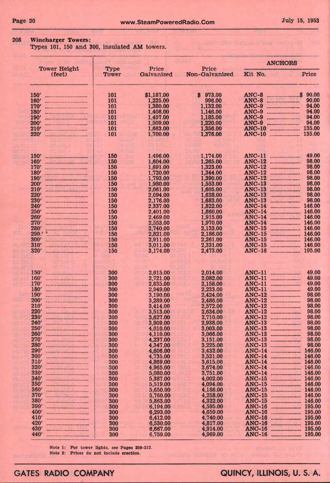
www.SteamPoweredRadio.ComPage 20
208 Winebarger Towers: Types 101, 150 and 300, in sulated AM towers.
Tower Heigh t (feet)
Type Tower :;JI G .d
150' ............................ 101 $1,187.00 160' · · ·····················••.o• 101 1,225.00 170' ............................ 101 1,380.0d 180' -··························- 101 1,408.00 190' ............................ 101 1,457.0~ 200' •........................... 101 1,509.00 210' ............................ 101 1,663.0~ 220' ............................ 101 1,700.0
150' ............................ 150 1,496.0 160' ······················-····· 150 1,604.0 170' ···························· 150 1,691.0C 180' ·····················--····· 150 1,720.0~ 190' ............................ 150 1,793.0 200' .............................. 150 1,980.0CI 210' •········•·················· 150 2,061.0CI 220' ............................ 150 2,094.0C, 230' ............................ 150 2,176.0CI 240' ············-·······---·--·· 150 2,337.0<I 250' ········-·-----·--·-·····-·· 150 2,401.ocl 260' --------···················· 150 2,469.o~I 270' ............................ 150 2,553.0() 280' ··························-· 150 2,740.0~, 290.' ~ 150 2,821.0 ! ............................ 300' ............................ 150 2,911.0( 310' ............................ 150 3,011.0~ 320' ·············-···········--· 150 3,174.0(
150' ............................ 300 2,615.01 160' ·········-···· · ··- ··-·-····- 300 2,721.00 170' --· ························· 300 2,835.00 180' ···························· 300 2,949.0(, 190' ............................ 300 3,190.01, 200' .............................. 300 3,289.00 210' ··········-·-··············· 300 3,414.01) 220' ·················-·········· 300 3,513.08 230' ··························•· 300 3,627.0 : 240' ·········-····--··-···--···· 300 3,909.0(, 250' ............................ 300 4,010.0(~ 260' ............................ 300 4,110.0(1
270' ···············----··--·-··· 300 4,237.0(1 280' ............................ 300 4,347.0(~ 290' ·····················-······ 300 4,606.ol~ 300' ............................ 300 4,735.ol' 310' ························--·- 300 4,869.0 ~ 320' ............................. 300 4,965.0() 330' ···························· 300 5,080.ol~ 340' ···························· 300 5,387.00 350' ···························· 300 5,519.~ ~ 360' ···············--··········· 300 5,650. ~ 370' ............................. 300 5,760. 0 380' ............................ 300 5,863.~~ 390' ···········-··············· 300 6,194. ~ 400' ............................ 300 6,293.00 410' ···························· 300 6,412.0 ~ 420' ............................ 300 6,530.00 430' ····················-·-··-·- 300 6,667.00 440' ········-··················· 300 6,759.00
Note 1: For tower lights, see Pages 209-212. Note 2: Prices do not Include erection.
GATES RADIO COMPANY
July 15, 1953
ANCHORS Price
Non-Galvanized Kit No. Price
$ 973.00 ANC-8 ······················$ 90.00 996.00 ANC-8 ........................ 90.00
1,132.00 ANC-9 ....................... 94.00 1,146.00 ANC-9 ...................... 94.00 1,185.00 ANC- 9 ...................... 94.00 1,220.00 ANC-9 ...................... 94.00 1,356.00 ANC-10 .................... 135.00 1,376.00 ANC-10 .................... 135.00
1,174.00 ANC- 11 •••••••••uo■o■u■■■ 49.00 1,265.00 ANC-12 ..................... 98.00 1,323.00 ANC- 12 .................... 98.00 1,344.00 ANC- 12 .................... 98.00 1,390.00 ANC-12 ···············•·•·· 98.00 1,553.00 ANC-13 .................... 98.00 1,605.00 ANC-13 ....................... 98.00 1,628.00 ANC-13 .................... 98.00 1,683.00 ANC-13 ···················· 98.00 1,822.00 ANC-14 .................... 146.00 1,860.00 ANC- 14 .................... 146.00 1,915.00 ANC-14 .................... 146.00 1,970.00 ANC-14 .................... 146.00 2,133.00 ANC- 15 ............•....... 146.00 2,186.00 ANC- 15 146.00 ..................... 2,261.00 ANC-15 ---················· 146.00 2,331.00 ANC-15 ···················· 146.00 2,473.00 ANC- 16 ···················· 195.00
2,014.00 ANC-11 ···········--······· 49.00 2,082.00 ANC- 11 ..................... 49.00 2,158.00 ANC-11 .................... 49.00 2,233.00 ANC-11 ···················· 49.00 2,424.00 ANC- 12 ············-······· 98.00 2,486.00 ANC-12 ..................... 98.00 2,572.00 ANC- 12 .................... 98.00 2,634.00 ANC-12 .................... 98.00 2,710.00 ANC-12 ··-················· 98.00 2,938.00 ANC-13 ···················· 98.00 3,003.00 ANC-13 .................... 98.00 3,066.00 ANC-13 .................... 98.00 3,151.00 ANC- 13 .................... 98.00 3,225.00 ANC- 13 ..................... 98.00 3,432.00 ANC-14 ...................... 146.00 3,521.00 ANC-14 .................... 146.00 3,615.00 ANC-14 ···················· 146.00 3,674.00 ANC- 14 ···················· 146.00 3,751.00 ANC-14 ...................... 146.00 4,002.00 ANC-15 ············•······· 146.00 4,094.00 ANC- 15 ····•··············· 146.00 4,186.00 ANC- 15 •••••••••••••••n••• 146.00 4,258.00 ANC-15 ···················· 146.00 4,322.00 ANC-15 . ................... 146.00 4,595.00 ANC- 16 ..................... 195.00 4,659.00 ANC-16 ..................... 195.00 4,740.00 ANC-16 ..................... 195.00 4,817.00 ANC-16 ..................... 195.00 4,914.00 ANC- 16 ······•---··-······· 195.00 4,969.00 ANC-16 ···········•·•··••·· 195.00
QUINCY, ILLINOIS, U. S. A.
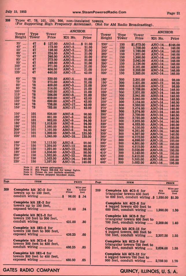
www.SteamPoweredRadio.ComJuly 15, 1953 Page 21
208 Types 47, 78, 101, 150, 300, non-insulated t owers. (For Supportin g High Frequency Antennas) . (Not for AM Radio Broad easting).
Pare
209
ANCHOR Tower Type T ower Heigh t Tower Price Kit No. Price
- -35' .... 47 $ 127.00 ANC-5 ........ $ 21.00 45' .... 47 173.00 ANC-5-...... 21.00 55' .... 47 198.00 ANC-5 ........ 21.00 65' .... 47 224.00 ANC- 5 ........ 21.00 75' .... 47 246.00 ANC-5 ........ 21.00 85' .... 47 273.00 ANC-5 ........ 21.00 95' .... 47 348.00 ANC-5 ........ 21.00
105' .... 47 371.00 ANC-5 ........ 21.00 115' .... 47 404.00 ANC-5 ........ 21.00 125' .... 47 446.00 ANC-17 ...... 42.00
65' .... 78 339.00 ANC-5 ........ 21.00 75' .... 78 375.00 ANC-5 ........ 21.00 85' .... 78 409.00 ANC-5 ........ 21.00 95' .... 78 514.00 ANC-5 ........ 21.00
105' .... 78 549.00 ANC-5 ........ 21.00 115' .... 78 584.00 ANC-5 ....•... 21.00 125' .... 78 659.00 ANC-17 ...... 42.00 135' .... 78 699.00 ANC-17 ...... 42.00 145' .... 78 738.00 ANC-17 ...... 42.00 155' .... 78 783.00 ANC-17 ...... 42.00
150' .... 101 826.00 ANC-8 ........ 90.00 160' .... 101 861.00 ANC-8 ........ 90.00 170' .... 101 982.00 ANC-9 .. ·-··· 94.00 180' .... 101 1,018.00 ANC-9 ........ 94.00 190' .... 101 1,060.00 ANC-9 ........ 94.00 200' .... 101 1,101.00 ANC-9 ........ 94.00 210' .... 101 1,209.00 ANC-10 ...... 135.00 220' .... 101 1,245.00 ANC-10 ...... 135.00
160' .... 150 1,113.00 ANC-8 ........ 90.00 170' .... 150 1,264.00 ANC-12 ...... 98.00 180' .... 150 1,291.00 - ANC-12 ...... 98.00 190' .... 150 1,356.00 ANC-12 ...... 98.00 200' .... 150 1,382.00 ANC-12 ...... 98.00 210' .... 150 1,563.00 ANC-14 ...... 146.00 220' .... 150 1,597.00 ANC-14 ...... 146.00
Note 1: All towers galvanized. Note 2: See Pagea 209-212 tor tower llght,i.
: Prl Note 3 cea do not lnclude erection . Note t : Towera ahlpped tnoelce<I down.
ITEM P R IC£
Wire per Complete kit l C- 2 for Kit tower towers up to 150 feet, Price toot conduit wiring .......................... $ 96.00 $ .54
Complete kit lE-2 for towers up to 150 feet, exposed wiring .......................... 91.00 .24
Complete kit 2Cl-2 for towers 150 feet to 300 feet, conduit wiring .......................... 431.00 .80
Complete kit 2El-2 for towers 150 feet to 300 feet, exposed wiring .......................... 426.25 .60
Complete kit 3Cl-4 for towers 300 feet to 450 feet, conduit wiring .......................... 486.25 .85
Complete kit 3El-4 for towers 300 feet to 450 feet, exposed wiring .......................... 480.50 .65
GATES RADIO COMPANY
T oJier ANCHOR
Tower Type Height Tower P1!ce Kit No. Price
230' .... 150 $1,6~3.00 ANC-14....-$146.00 240' .... 150 1,708.00 ANC-14 ...... 146.00 250' .... 150 1,785.00 ANC-14 ...... 146.00 260' .... 150
'·~I" ANC-14 ...... 146.00 270' .... 150 1,99 .oo ANC-14 ...... 146.00 280' .... 150 2, 2.00 ANC-14 ...... 146.00 290' .... 150 2,1 8.00 ANC-14 ...... 146.00 300' .... 150 2,16.1.00 ANC-14 ...... 146.00 310' .... 150 2,25;s.oo ANC-14 ...... 146.00 320' .... 150 2,3813.00 ANC-14 ...... 146.00
180' .... 300 2,301.00 ANC-12 ...... 98.00 190' .... 300 2,42;1.00 ANC-12 ...... 98.00 200' .... 300 2,51:s.oo ANC-12 ...... 98.00 210' .... 300 2,721,.00 ANC-14 ...... 146.00 220' .... 300 2,83il-00 ANC-14 ...... 146.00 230' .... 300 2,94, .00 ANC-14 ...... 146.00 240' .... 300 3,04li.00 ANC-14 ...... 146.00 250' .... 300 3,1511.00 ANC-14 ...... 146.00 260' .... 300 3,36().00 ANC-14 ...... 146.00 270' .... 300 3,47il.00 ANC-14 ...... 146.00 280' .... 300 3,57!~.oo ANC-14 ...... 146.00 290' .... 300 3,701 .00 ANC-14 ...... 146.00 300' .... 300 3,791>.00 ANC-14 ...... 146.00 310' .... 300 3,92!i.00 ANC-14 ...... 146.00 320' .... 300 4,03~ .00 ANC-lL ... 146.00 330' .... 300 4,15l .oo ANC-14 ...... 146.00 340' .... 300 4,26 .00 ANC-14 ...... 146.00 350' .... 300 4,36 .00 ANC-14 ...... 146.00 360' .... 300 4,57 .. oo ANC-16 ...... 195.00 370' .... 300 4,69U.OO ANC-16 ...... 195.00 380' .... 300 4,8011.00 ANC-16 ...... 195.00 390' .... 300 4,9ll 00 ANC-16 ...... 195.00 400' .... 300 5,02~.oo ANC-16 ...... 195.00 410' .... 300 5,14 •. 00 ANC-16 ...... 195.00 420' .... 300 5,413,.00 ANC-16 ...... 195.00 430' .... 300 5,555,.00 ANC-16 ...... 195.00 440' .... 300 5,683 .00 ANC-16·-··· 195.00
Page ITEM PRICE
Wire per 209 Complete kit 4C2-6 for Kit tower t riangular towers 4 o feet Price toot to 600 feet, cond uit wiring .. $ 1,930.00 $1.20
Complete kit 4C2-8 for 4 legged towers 450 feet to 600 feet, conduit g ...... 1,990.00 1.30
Complete kit 5C2-9 tor triangular towers 600 feet to 700 feet, conduit lng ...... 2,209.00 1.40
Complete kit 5C2-1 for 4 legged towers, 600 feet to 750 feet, conduit wi1rlng ...... 2,357.50 1.55
Complete kit 6C3-9 for triangular towers 75 feet to 900 feet, cond uit ring ...... 2,624.00 1.55
Complete kit 6C3-1Z for 4 legged towers 750 tleet to 900 feet , conduit wiji1ng ...... 2,759.50 1.70
QUINCY ILLINOIS, U. S. A.
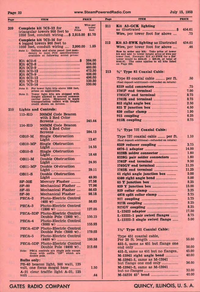
www.SteamPoweredRadio.ComPage 22
Pare
209
210
ITEM
Complete kit 7C3-12 for Kit
PRICE
Wire per tower foot triangular towers 900 feet to Prtce
1050 feet , conduit wiring ...... $ 2,815.00 $1.70
Complete kit 7C3-16 for 4 legged towers 900 feet to 1050 feet, conduit wiring .... 2,990.00 Note 1: Tellt ale and alarm panel (not man-
datory to meet FCC specifications) avallable a t following added prices:
Kit 4C2-6 .............................................. $ Kit 4C2-8 ............................................. . Kit 5C2-9 ·············································· Ktt 5C2-12 ........................................... . Kit 603-9 ............................................. . Kit 6C3-12 ........................................... . Kit 7C3-12 ........................................... . Kit 7C3-16 ........................................... . Note 2: For tower light kits above 1050 feet,
prices on application. · Note 3: Tower light kits are shipped with
f reight allowed to nearest common carrier point. Shipment ls made t rangportatlon collect with freight credit shown on Invoice.
Lights and Controls: 113-KG 300MM Code Beacon
with 2 Red Color
114-KG
OBl0-M
Screens ........................... . 300MM Code Beacon with 2 Red Color Screens ........................... . Single Obstruction Light ............................... .
OBlO-MP Single Obstruction Light ............................... .
OBl0-S Single Obstruction Light ............................... .
OBll-M Double · Obstruction Light ............................... .
OBll-MP Double Ol'struction
OBll-S
SF-30E SF-80 SF-85 SF-90 PECA-2
PECA-3
Light ............................... . Double Obstruction Light ............................... . Mercury Flasher ......... . Mechanical Flasher ... . Mechanical Flasher ... . Mechanical Flasher ... . Photo-Electric Control (400 W) ............. ..... .•... .. ...
Photo-Electric Control (1800 w) ......................... .
PECA-3DP Photo-Electric Control
PECA-4 Double Pole (1800 w) .. Photo-Electric Control (3000 W) .....................•....
PECA-4DP Photo-Electric Control
PECA-5 Double Pole (3000 w) ..
Photo-Electric Control (4400 W) ......................... .
PECA-5DP P hoto-Electric Control Double Pole ( 4400 w) ..
Note: PECA controls ar e single pole except those with suffix "DP" which are double pole.
Bulbs only: PS-40 beacon light, 500 watt, 125 volt, one focus mogul base ........... . A-21 clea r traffic llght A-21, 125 volt ......................................................... .
1.85
384.00 394.00 460.00 472.50 486.00 496.00 520.50 530.00
245.44
284.13
12.47
14.55
18.48
24.95
29.11
49.90 57.58 77.96 86.63 98.18
86.63
127.05
150.15
155.93
179.03
190.58
213.68
1.50
.44
GATES RADIO COMPANY
Pap
211
212
213
July 15, 1953
ITEM
Kit A3-GCK lighting as illustrated ...................................... $ Wire, per tower foot for above ... .
Kit A3-EWK lightin.g as illustrated Wire, per tower foot for above .... How to order any kU: Take price of tower kit and add to tower height price of wire per tower foot. Example: Kit A.3-EWK for a 200' t ower would be $454.61 + $92.00, or total of $546.61. The same applies to all kits listed on Page 209.
%" Type 83 Coaxial Cable:
Type 83 coaxial cable .......... per ft. (Reel deposit additional-refunded on return)
8319 solid connectors ....................... . 1701P end terminal ......................... . 1701GV end terminal ..................... . 1701R end terminal ......................... . 853 right angle box ........................... . 825 T junction box ........................... . 830 collar clamp ............................... . 915 coupling ....................................... . 915R coupling ..................................... .
%" Type 737 Coaxial Cable:
Type 737 coaxial cable ........ per ft. (Reel deposit additional- refunded on return)
8329 reducer coupling ..................... . 4876-1 adaptor ................................... . 8328B solder connector ................... . 8328G pair solder conneetors ....... . 1703P end terminal ......................... . 1703GV end terminal ....................... . 1703R end terminal ......................... . 61 right angle junction box ......... . 6500 right angle bend ..................... . 65 T junction box ............................. . 859 Y junction box ........................... . 829 collar clamp ............................... . 4878 split collar clamp ................... . 917 coupling ....................................... . 917R coupling ..................................... . 917GV coupling ................................. . L-12423 adaptor ................................. . L-13223-1 pair swivel flanges ....... . L-13223-2 single swivel flange ..... .
1%" Type 451 Coaxial Cable:
Type 451 coaxial ca,ble, Per 20 ft. length ............................... . 451-1, same as 451 but flange one end only ............................................... . 451-2, same as 451 but no flanges .. M-13941 right angle bend ............. . M-13941-1, same as M-13941 but flange one end only ................. . M-13941-2, same a s M-13941 but no flanges ..................................... . M-14216 45° bend ............................. .
PRICE
454.61 .75
454.61 .46
.50
.75 7.00 8.75 8.75 2.50 4.50 1.90 6.25 8.75
1.10
3.75 14.00 1.60 1.60 9.50
11.25 11.25 5.00 5.00 8.25
15.00 3.25 3.75 5.75 8.25 8.25
17.50 8.75 5.00
55.00
50.00 45.00 40.00
36.00
32.00 40.00
QUINCY, ILLINOIS, U. S. A.
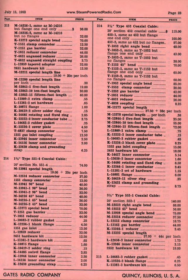
www.SteamPoweredRadio.ComJuly 15, 1953
Pap
213
214
ITEM
M-14216-1, Sanle as M-14216 but flange one end only ................ $ 36.00 M-14216-2, same as M- 14216 but no flanges ................................... . K-13273 specia l angle bend ........... . T -1551 clamp connector ................. . T-1251 gas barrier ........................... . T-1851 reducer connector ............... . T-4831 ungassed reducer ................. . T-4832 ungassed straight coupling L-12859 tapered adaptor ................. . 2451 hardware kit ............................. .
32.00 70.00 12.50 32.00 44.00 26.00
3.75 32.00 12.50
M-12211 special length line ............................................ 19.00 + 20c per inch M-13280 special length line per ,inch ............................................... . M-12843-5 five-foot length ........... . M-12843-10 ten-foot length ........... . M-12843-15 fifteen-foot length ... . L-11809-2 extra clamp ................... . L-11381-2 set h ardware ................... . K-10875 flange ................................... . K-10419-2 silver solder ring ......... . K-14485 rotating a nd fixed ring .. K-12233-2 Inner conductor tube ... . L-10683-2 rubber gasket ................. . K-12234-1 cover plate ..................... . T-483'7 clamp connector ................. . 1351 gas inlet coupling ................... . K-13944 inner connector ............... . K-14156 inner connector ............... . K-12430 clamp and grounding strap ..................................................... .
l ¾" Type 551-4 Coaxial Cable:
.20 19.00 30.00 40.00
.55
.65 1.60 .15
2.85 3.75
.25 4.50 7.50
12.50 2.50 2.00
6.25
20' section No. 551-4 .......................... 74.00 M-13981 special length ........................................ 19.00 + 25c per inch M-12514 reducer connector ............ 37.00 1551 clamp connector ...................... 12.00 M-13941 90° bend .............................. 40.00 M-13941-1 90° bend .......................... 36.00 M-13941-2 90° bend .......................... 32.00 M-14216 45° bend .............................. 40.00 M-14216-1 45° bend .......................... 36.00 M-14216-2 45° bend .......................... 32.00 K-13273 special bend ........................ 70.00 T-1251 gas ba rrier ............................ 32.00 T-1851 reducer .................................... 44.00 L-10683-2 r ubber gasket .................. .25 K-12234-1 bla nk fla nge .................. 4.50 1351 gas inle t ...................................... 12.50 L-12859 reducer .................................. 32.00 2451 hardware kit .............................. 12.50 L-11381-2 hardware kit .................... .65 K-108'75 fla nge .................................... 1.60 K-10419-2 solder ring ...................... .15 K-14485 swivel flange ...................... 2.85 K-13944 inner connector ................ 2.50 L-14156 inner connector ................ 2.00 K-12430 grounding strap ................ 6.25
GATES RADIO COMPANY
Pa&'e
214
215
Page 23
ITEM II PRICE
31/s" Type 452 Coaxl 1 Cable: 20' section 452 co~lal cab le ........ $ 115.00 452-1, same as 452 ~ t flange one end only ............ . .....................•... 452-2, same as 452 bpt no flanges .. T -1052 right angleJ~end ............... .
~~~;;-~h!a:i~ ainif1.~.~.~ .. ~.~~········· T -1052-2, same as 'I1 1052 bu t no flanges ......................................... . T-1152 45° bend .............................. . T-1152-1, same as '11 1152 but flange one end onljf ....................... . T-1152-2, sam e as ~-1152 but no flanges .......................................... . T-1952 specia l a ngIJ ben d ............. . T -1552 clamp conn l tor ............... . T-1252 gas barrier . ......................... . T-1851 reducer ......... ......................... . T -4831 reducer ................................... .
105.00 97.00 48.00
43.00
38.00 70.00
65.00
60.00 85.00 20.00 42.00 44.00 26.00
T-4838 coupling ....... ......................... . M-12173 special len lrth •······································i • 37.50 + 38c per inch M-13278 specia l len h .... per inch .38
8.25
M-12844-5 five-foot length ............ 35.00 M-12844-10 t en-foot length ............ 55.00 M-12844-15 fifteen-~~oot length .... 72.00 L-11809-1 extra cla1 p .................... .75 K-12233-3 inner con uctor tube .• .15 L-10683-3 rubber Pl ket .................. .45 K-12234-2 blank co~er plate .......... 6.25 1352 gas inlet coup~ g .................... 15.00 2452 hardware kit .. J........................... 18.00 K-1441'7 inner conn◄r:tor ................ 5.14 L-12650-2 inner con~~ector .............. 1.60 K-14486 rotating an il fixed ring .. 6.50 K-13244-1 inner co ~uctor ............ 3.45 L-11381-3 set of hariflware .............. 1.15 L-10881 flange .................................... 6.00 K-10419-11 silver ri1rg .................... .25 K-12431 clamp and irrounding strap .................................................... .
31/s" Type 552-1 Coainal Cable:
20' section 552-1 ..... ·-······················· M-12512 right a ngle bend ............. . M-12513 45° bend .............................. . M-13928 special ang;le bend ......... . M-12514 reducer con~ ector ........... . L-12515 clamp conn ,ctor ............... . L-13163 gas ba rrier •......................... K-13244-1 r educer . ......................... .
8.75
140.00 66.00 56.00 75.00 37.50 18.75 44.00
3.45 M-13325 special Jen h ........................................ 37.00 + 44c per inch L-12650-~ inner co~ !ector .............. 1.75 K-13946 inner connl tor ................ 3.15 2552 ha r dwar e kit ............................ 19.00
L-10683-3 rubber gas et .................. .45 K-12234-2 blank fla~ge .................... 6.25 L-11381-3 ha rdwa re I ·t .................... 6.50,
QUINCY, ILLINOIS, U. S. A.
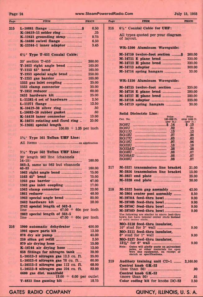
www.SteamPoweredRadio.ComPage 24
Pace ITEM P R ICE
215 L-10881 flange .................................... $ 6.50
216
K-10419-11 solder ring ..................... . K -124U grounding strap ............... . K-14486 swivel flange ..................... . K-13244-1 inner adaptor ............... .
6 ¼" Type T-453 Coaxial Cable:
20' section T-453 ............................... . T-1053 right angle bend ............... . T- 1153 45° bend ............................... . T- 1953 special angle bend ............. . T-1253 gas barrier ........................... . 1353 gas inlet coupling ................... . 1553 clamp connector ..................... . T-1852 reducer ................................... . 2453 hardware kit ........................... . L-11381-4 set of hardware ............. . L-11271 flange ................................... . K- 10419-30 silver ring ................... . L-10683-10 rubber gasket ............... . K-14418 inner connector ............... . K-14675 rotating and fixed ring ..
.25 8.75 6.50 3.45
380.00 165.00 165.00 250.00 105.00
25.00 35.00 60.00 25.00 2.50
12.50 . 50 .60
13.00 25.00
N-12681 special length ........................................ 100.00 + 1.25 per inch
1%" Type 561 Teflun UHF Line: All items ........................................... on application
3¼" Type 562 Teflun UHF Line: 20' length 562 line (channels 14-15) ·················•·································· 160.00 562-3, same· as 562 but chainnels 46-83 ..................................................... . 1062 right angle bend ..................... . 1162 45° bend ................................... . 1262 gas ba rrier ............................... . 1362 gas inlet coupling ................. . 1562 clamp connector ..................... . 1861 reducer ....................................... . 1962 special angle bend ................. . 2462 hardware kit ........................... .
160.00 75.00 75.00 47.00 17.00 22.00 48.00 85.00 28.00
2762 special length of 562-3 line ................................ 47.00 + 60c per inch 2862 special length of 562- 5 line ................................ 47.00 + 60c per inch
1900 automatic dehydrator ......... . 1901 spare parts kit ......................... . 878 dry air pump ............................. . 210 silica gel refill ........................... . 879 air drying hose ........................... . K-14744 air drying hose ............... . 858 fittings for nitrogen tank ..... . L-10513-3 nitrogen gas 12.3 cu. ft. L-10513-6 nitrogen gas 78 cu . f t ... L-10513-5 nitrogen gas 112 cu. ft. L-10513-8 nitrogen gas 224 cu . ft. 6600 gas dist. manifold .................................... 13.00 + 6.00 per T-4833 line gassing kit ................... .
450.00 12.50 45.00 2.50
15.00 12.00 39.00 25.00 60.00 68.00 83.00
outlet 18.75
GATES RADIO COMPANY
July 15, 1953
Pace ITBlll PB.ICE
216 6¼" Coaxial Cable for UHF:
217
218
219
All types quoted per your dia gram of layout.
WR-1500 Aluminum Waveguide:
M-14710 twelve-foot section .......... $ 260.00 330.00 330.00 300.00
M-14711 E plane bend ................... . M-14712 H plane bend ................... . M- 14713 adaptor ............................... . M-14714 spring h angars ................. .
WR-1150 Aluminum Wavegui de:
M-14715 twelve-foot section ....... . M- 14716 E plane bend ................... . M-14717 B plane bend ................... . M-14718 adaptor ............................... . M-14719 spring hangars ............... .
Solid Dielectric Line : Price
Cat. No. 100·999 f t . (per ft.)
RG8U .................................... $ .14 RG9U .................................... . 32 RGll U .................................. . 13 RG12U .................................. . 27 RG17U .................................. . 63 RG19U .................................. . 97 RG22U .................................. . 16 RG22AU ................................. 28 RG58U .................................. . 08 RG58AU ................................ . 08 RG59U ................................... 08
M-3327 transmission line bracket M-2856 transmission line bracket M-2857 end plate ............................. . M-3328 end plate ............................. .
M-3322 horn gap assembly ........... . M-3864 center post assembly ....... . M-2870A f eed-thru bowl ···········-····· M-2870B feed-thru bowl ................. . M-2870C feed-thru bowl ................. . M- 2870D feed-thru bowl ................. . The followlng are similar to above feed-thru bowls but have tubular center studs Instead of solid center studs.
MO-3110 feed-thru insulator, 10" st ud for 3" wall ......................... . MO-3111 feed-thru insulator, 8" stud for l " wall ........................... . MO-3137 feed-thru insulator, 13½" for 6" wall ............................... . Note: Oates will gladlJ quote on galvanized
poles, or other materials !or open wire line equipment, on r eceipt of sketch or speclflcaitons.
Auditory training unit CD-1 ....... . Control knob GK-53 (less than 50) ................................... . Control knob GK-53 (more than 50) ·······························-· Color coding kit for knobs DC-53
33.00
235.00 280.00 280.00 225.00
30.00
Price over 1000 ft
(per ft . ) $ .13
.31
.12
.26
.62
.96
.16
.28
.07
.07
.07
21.00 15.00 25.00 38.00
42.00 8.50 9.00 9.00 9.00 9.00
9.00
9.00
9.00
2,160.00
.90
.81 2.50
QUINCY, ILLINOIS, U. S. A.
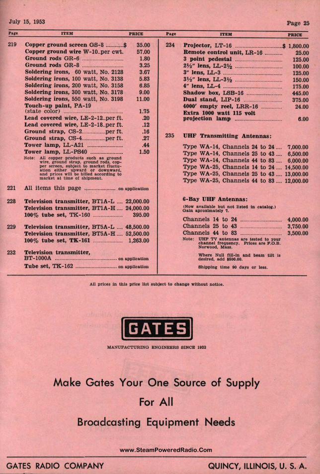
www.SteamPoweredRadio.Com
July 15, 1953 Page 25
Pare ITEM PRICE Pare ITEM PRICE
219 Copper ground screen GS-8 ............ $ 35.00 57.00
1.80 3.25 3.67 5.83 6.85 9.00
234 Projector, LT-16 ............................... $ 1,800.00 Copper ground wire W-10 .. per cwt. Ground rods GR- 6 ........................... . Ground rods GR-8 ........................... . Soldering irons, 60 watt, No. 2128 Soldering irons, 100 watt, No. 3138 Soldering irons, 200 watt, No. 3158 Soldering irons, 300 watt, No. 3178 Soldering irons, 550 watt, No. 3198 Touch-up paint, PA- 19 (s tate color) ....................................... . Lead covered wire, LE- 2-12 .. per ft. Lead covered wire, LE-2-18 .. per ft. Ground strap, CS-2 ................ per ft. Ground strap, CS- 4 ................ per ft. Tower lamp, LL-A21 ....................... . Tower lamp, LL-PS40 ..................... . Note: All copper products such as ground
wire. ground strap. ground rods. cop• per screen, subject t o market fluctu• ation either upwa rd or downwa rd, and prices will be billed according to market at time of shipment.
11.00
1.75 .20 .12 .16 .27 .44
1.50
235
Remote control uni , LR-16 ........... . 3 point pedestal ... . ......................... . 2½" lens, LL-2½ ...
1 .......................... .
3" lens, LL-3 ........... . ......................... . 3½" lens, LL-3½ ............................. . 4" lens, LL-4 ........... r ·························• Shadow box, LSB-1 6 ....................... . Dual stand, LIP-16 ......................... . 4000' empty reel, L R-16 ............. . Extra 1000 watt 115 volt projection lamp .............................. .
UHF Transmitting :Antennas:
25.00 125.00 100.00 125.00 150.00 175.00 445.00 375.00
24.00
6.00
Type WA-14, Chan 1els 24 to 24 .... 7,000.00 Type WA- 14, Channrels 25 to 43 .... 6,500.00 1, Type WA-14, Chan~~els 44 to 83 .... 6,000.00 Type WA-25, Chan~iels 14 to 24 .... 14,500.00 Type WA- 25, Ch anq~els 25 to 43 .... 13,000.00 Type WA-25, Chann els 44 to 83 .... 12,000.00
221 All items this page ..................... on application
228 Television t ransmitter, BTlA-L .... 22,000.00 Television t ransmitter, BT lA-H .... 24,000.00 100% tube set, TK-160 .................... 395.00
229 Television transmitter, BT5A-L .... 48,500.00 Television transmitter , BT5A-H .... 52,500.00 100% tube set, TK-161 .................... 1,263.00
6-Bay UHF Anten nns: (Now available but not II ted In catalog.) Gain aproxlmately 7.
Channels 14 to 24 Channels 25 to 43 Chan nels 44 to 83 Note: UHF TV antennas
channel frequency. Norwood, Mass.
re tested to your Prices are F.O.B.
232 Television transmitter, Where Null fill-In and beam tilt ls desir ed, add $500. BT-l000A .......................................... on application
Tube set, TK- 162 ............................ on application Shipping time 90 ays or less.
AU prices 1n this price lis t subject to change without notice.
I GATES I MANUFACTURING ENGINEERS SINCE 1922
Make Gates Your One Source of Su ,, ply
For All
Broadcasting Equipment Needs
4,000.00 3,750.00 3,500.00
GATES RADIO COMPANY QUINCY ILLINOIS, U. S. A.
www.SteamPoweredRadio.Com
V) WW .... u <(-c., f
€You Can Order from
Gates Radio Company 123 Hampshire Street
Quincy, Ill. Tel. 8202
Gates Radio Company 51 E. 42nd Street
New York 17, N. Y. Tel. Mu-Hill 7-7971
Gates Radio ~ompany 7501 Sunset Blvd.
Los Angeles 46, Calif. Tel. Hollywood 2-6351
Canadian Marconi Company 2442 Trenton Ave.
Montreal, Que., Canada Tel. Atlantic 9441
Gates Radio Company Warner B ilding
Washingto 4, D. C. Tel. Metropol
Gates Radio Company 2700 Pol Ave.
Houston Texas Tel. Atwo 8536
Gates Radio Company* 13th & Spri Streets
Atlanta Ga.
Gates Radio Company InternaUona Dhl•lon
13 E. 40t Street
New York 6, N. Y. Tel. Mu- 1 9-0200
•Atlanta. ,Branch Open September 1, 1953.
• Quincy, Houston, Los Angeles and Atlanta all stock carrying and distributing branche
GATES RADIO COMPANY MANUFACTURING ENGINEERS SINCE 1922
QUINCY, ILLINOIS, U. S. A.
/