Embed Size (px)
Citation preview

*Corresponding author: [email protected]
Friction welding of Aluminium Alloy 6063 with copper
Yashwant Chapke1,*, Dinesh Kamble ,and Saoud Md. Salim Shaikh 1 Vishwakarma Institute of Information Technology, Pune 411048, India
Sinhgad Academy of Engineering, Pune 411048, India.
Abstract Friction welding process is a forging welding process in which work piece are joined due to heat
produced by friction between two joining surfaces and upset pressure is applied by non-rotating work piece.
Joining of aluminum alloy with dissimilar material is important research area to focus on as maximum aircraft
structures havexx Aluminum alloy frame and aerospace designers familiar with Aluminum alloy and its design
considerations. After comparison of mechanical properties and application of light weight alloys aluminum
alloys, tungsten, stainless steel and copper, copper selected as dissimilar material to join with Aluminum alloy
AA6063. AA 6063 also known as architectural alloy selected based upon its properties. This dissimilar joint of
AA6063 and Copper has application in electrical conductors as copper is good electrical conductivity and used
in maximum electrical conductors. In this research work AA6063 joined with Copper successfully using
Rotary Friction Welding process. Through process study effective process parameters like Friction Pressure,
Upset Pressure, Spindle Speed, and Friction Time identified and their effect on weld joint strength were
studied.Testing for measuring UTS of friction welded joint conducted. Using DOE tool optimized set process
parameters for friction welding identified and their effect on weld joint strength studied experimentally.
Maximum UTS of 222.787 MPa for Friction welded joint achieved, bend test also performed on friction welded samples.
1. Introduction Rotary friction welding is used for joining of round
parts like engine valves, steering rod, shafts and other
parts in aerospace application. Bimetallic valves are
produced using RFW process.
RFW process is solid state joining approach hence
limitation of fusion welding of joining different material
of different melting point overcome using Friction
Welding. In this friction welding process despite of
different melting point both AA 6063 and Copper joined
which was not feasible earlier by fusion welding process.
Aerospace Industry use Aluminum alloy as primary
material for structure and frame due to its light weight
and mechnaical properties hence Aluminium alloy
selected as one material for this research work [1].
Also in aerospace, automobile, marine, defense
equipment appliances for joining various copper
electrical parts to Aluminum Alloy alloy frame. Mainly
in aerospace structures frames made up of Aluminum
Alloy and various other metals parts to be joined to
Aluminum Alloy frame using friction welding.
2. Literature Review Various Researchers aimed at achieving maximum UTS
for friction welded joint through parametric optimization
of friction welding process.[1-17] While doing
parametric optimization following parameters are
considered by researchers,
Friction Time (FT), Friction Pressure (FP), Spindle
Speed (SS), Burn of length (BOL)[1-9]. Further sub
branching of friction welding parameters can be done in
form of upset time, upset pressure, breaking time [1-7].
Researchers focused on study of microstructure of
friction weld joint under electron microscope and micro
structural characterization done for friction welded
dissimilar metal joints. Researchers also stated interested
observations by microstructure study of joints in regards
to new layer formation and grain structure at welded
joint. Mumin Sachin et al found Friction Time, Friction
Pressure have direct effect on tensile strength of joint[5].
C. Meengam et al joined semi solidAA7077 using
RFWprocess[2]. L.Zhou et al in their research work
considered Rotational Speed as dominant parameter and
studied its effect on mechanical properties, on
microstructure of Ti-6Al-4V. They have observed along
E3S Web of Conferences 170, 0 (2020)EVF'2019
2004 https://doi.org/10.1051/ conf/202017002004e3s
© The Authors, published by EDP Sciences. This is an open access article distributed under the terms of the Creative Commons Attribution License 4.0
(http://creativecommons.org/licenses/by/4.0/).
1 2
2

with increase in rotational speed hardness in weld zone
decreases. In conclusion remark made by researcher
through this study in regards to defect free welds are
produced by employing rotational speed ranging from
400 to 600 rpm. Researchers through this research work
found that 6061 T6 Aluminum can be successfully
joined with steel AISI 1018 Steel getting tensile strength
in range of 170 Mpa to 250Mpa for welded joint.
J. Romero et al in their research work have done
investigation on effect of forging pressure on
microstructure and micro hardness of welding joint Ti-
6Al-4V [11].
2.1 Difficulty in joining AA6063 with Copper
Aluminum Alloy 6063and copper has different melting
point temperature , Aluminum Alloy 6063 has 610°C
Melting Point where as Copper has 1024°C Melting
temperature.
Melting Temperature difference and other factors like
formation of intermetallic layer and oxides makes
conventional fusion welding of Aluminum Alloy 6063
copper joining obsolete and impractical.
Table 1.0 Material Comparison
Material
Mechanical Properties
Chemical composition
Industrial application
Stainless steel
SS304
Toughness
Durability
Corrosion
resistance
Cryogenic
resistance
Ductility
SS304 minimum
of 18%
chromium 8%
nickel, combined
with a maximum
of 0.08% carbon
Aerospace
Automotive
oil & gas
industries
kitchenware
consumer
products
Titanium alloy Very high tensile
strength and
toughness at high
temperature also
Titanium alloy
has 6% aluminum
and 4%
vanadium, 0.25
% maximum
iron,0.2% oxygen
and remaining
titanium
Military
Aircraft
Spacecraft
Bicycle
Connecting rod
Consumer
electronics
Medical
Copper Soft
Malleable
Ductile
High thermal
electrical
conductivity
Copper available
in nature in
directly usable
metal form
Widely used
nonferrous
metal.
Electronics
Electric power
Machineries
Stainless Steel, titanium, Copper and Magnesium
materials are identified for joining with aluminum alloy.
Material comparison done based upon its material
properties, chemical composition and industrial
application.
Parameters have dominant effect on tensile strength of
friction welded joint identified through study.
Following process parameters identified related to
RFW process,
Friction Pressure (FP), Upset Pressure (UP), Friction
Time (FT) and Spindle Rotation Speed (SS). Following
inferences were drawn based upon literature study and
pilot experimentation.
1. High Spindle Speed results in good tensile
strength of joint
2. High upset pressure will increase hardness of
joint
3. Increasing Friction Pressure value results in
increase in tensile strength of joint.
3. Experimentation
3.1 Design of Experiments (RSM)
Three levels low medium and High identified for
selected process parameters and Using Response Surface
Methods (RSM) optimum set of process parameters
obtained and used for conduction of experiments.
For performing DOE Design Expert Tool used and
optimum values of Friction Time (FT) 1 second,
Spindle Rotation speed (SS) 1800 RPM Friction
Pressure (FP) 39 and 48 Kg/mm2 and Upset pressure 97
kg/mm2 obtained.
3.2 Experimentation
Total Nine Trial runs conducted on Rotary Friction
Welding Machine. Optimized process parameters sets
used for conduction of experiments as per parameters
sets obtained from DOE tool. In first two trails
Aluminum Alloy 6063couldn’t joined with copper alloy
due to less Friction Pressure (39Mpa and 48Mpa) and
upset pressure (80Mpa and 97MPa). Then for next four
trail run as per process parameter obtained from design
expert tool and expert advice Friction Pressure and Upset
Pressure. Again four more trails are taken using and
maximum tensile strength achieved through variation of
process parameters. Experimentation performed on
Rotary Friction welding Machine having maximum
forge force 120 KN, maximum spindle speed of 2000
RPM.
3.2.1 First trail run Experiments
In this trail run Friction Pressure is used 39 MPa and 48
MPa respectively, Upset Pressure used 80 MPa and 98
MPa and Spindle Speed maintained at 1800 RPM.
E3S Web of Conferences 170, 0 (2020)EVF'2019
2004 https://doi.org/10.1051/ conf/202017002004e3s
2

Fig.1.0 First two trailsrunAA6063- Cu Failed
Table 2.0 Process Parameters Set 1 (Failed to join)
Parameters Run 1 Run 2
Spindle length L1 141.6 141.6
Slider side L2 141.2 141.2
Total= L1+L2 282.8 282.8
Final length (after
welding)
264.2 266.2
Loss(actual measured) 18.6 16.2
Shrinkage range 18 18
Friction time t1b 0.5 1
Break delay t2 0.1 0.6
Upset delay t3 0.3 0.1
Upset time t4 2 3
Soft friction 0 25
Upset
pressure@13kg/mm2
80 97
Feed 75 75
Rpm 1800 1800
Trail run taken with two sets of process parameters. In
first run Aluminium Alloy 6063 not welded with copper
and this runs become void run. Following process
parameters used for first trail run and it is observed that
selected values of Friction Pressure needs to be increased
for successful weld joint between Aluminium Alloy
6063 and Copper.Aluminium Alloy 6063 not welded
with copper and this runs become void run. Following
process parameters used for first trail run and it is
observed that selected values of Friction Pressure needs
to be increased for successful weld joint between
Aluminium Alloy 6063 and Copper.
3.2.2 Second and third trail run Experiments
With second set of parameters four runs were conducted
under second and third trail run. From Parameter set 2
sound friction welded joints produced. But after welding
final length received was less hence more losses
observed. To reduce losses with same set further trail
taken.
In third trial four more trail run with same set of
parameters used in second trail run performed. Here
actual measured loss was less than second trail run. Final
length received after weld also was more than previous
trail run which reduces the losses and saving material.
Second and third trial run total eight experiments
performed with following set of parameters given in
Table No. 3.0
Table 3.0 Process Parameters set 2(successful joining)
Parameters 1 2 3 4
Spindle length 1 140 141.6 142.3 140.8
Slider side L2 140.7 141 140.8 140.1
Total= L1+L2 280.7 282.6 283.1 280.9
Final length
welding)
268.4 267.2 276.4 277.5
Loss(actual
measured)
12.3 15.4 6.7 3.4
Friction time t1b 1 1 1 1
Break delay t2 0.6 0.6 0.6 0.6
Upset delay t3 0.1 0.1 0.1 0.1
Upset time t4 3 3 3 3
Soft Friction P 25 25 48 48
Upset Pressure 97 97 97 97
Feed 75 75 75 75
Rpm 1800 1800 1800 1800
E3S Web of Conferences 170, 0 (2020)EVF'2019
2004 https://doi.org/10.1051/ conf/202017002004e3s
3
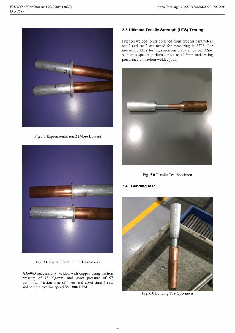
Fig.2.0 Experimental run 2 (More Losses)
Fig. 3.0 Experimental run 3 (less losses)
AA6063 successfully welded with copper using friction
pressure of 48 Kg/mm2
and upset pressure of 97
kg/mm2at Friction time of 1 sec and upset time 3 sec.
and spindle rotation speed SS 1800 RPM.
3.3 Ultimate Tensile Strength (UTS) Testing
Friction welded joints obtained from process parameters
set 2 and set 3 are tested for measuring its UTS. For
measuring UTS testing specimen prepared as per ASM
standards specimen diameter set to 12.5mm and testing
performed on friction welded joint.
Fig. 5.0 Tensile Test Specimen
3.4 Bending test
Fig. 6.0 Bending Test Specimen
E3S Web of Conferences 170, 0 (2020)EVF'2019
2004 https://doi.org/10.1051/ conf/202017002004e3s
4
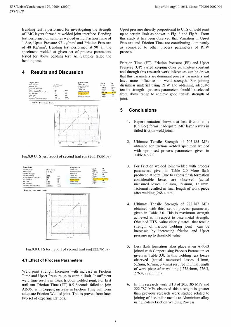
Bending test is performed for investigating the strength
of IMC layers formed at welded joint interface. Bending
test performed on samples welded using Friction Time of
1 Sec, Upset Pressure 97 kg/mm2 and Friction Pressure
of 48 Kg/mm2. Bending test performed at 90
° all the
specimens welded at given set of process parameters
tested for above bending test. All Samples failed the
bending test.
4 Results and Discussion
Fig.8.0 UTS test report of second trail run (205.185Mpa)
Fig.9.0 UTS test report of second trail run(222.7Mpa)
4.1 Effect of Process Parameters
Weld joint strength Increases with increase in Friction
Time and Upset Pressure up to certain limit. Insufficient
weld time results in weak friction welded joint. For first
trail run Friction Time (FT) 0.5 Seconds failed to join
Al6063 with Copper, increase in Friction Time will form
adequate Friction Welded joint. This is proved from later
two set of experimentations.
Upset pressure directly proportional to UTS of weld joint
up to certain limit as shown in Fig. 8 and Fig.9. From
this study it has been observed that Variation in Upset
Pressure and Friction Time are contributing dominantly
as compared to other process parameters of RFW
process.
Friction Time (FT), Friction Pressure (FP) and Upset
Pressure (UP) varied keeping other parameters constant
and through this research work inferences can be drawn
that this parameters are dominant process parameters and
have more influence on weld strength. For joining
dissimilar material using RFW and obtaining adequate
tensile strength process parameters should be selected
from above range to achieve good tensile strength of
joint.
5 Conclusions
1. Experimentation shows that less friction time
(0.5 Sec) forms inadequate IMC layer results in
failed friction weld joints.
2. Ultimate Tensile Strength of 205.185 MPa
obtained for friction welded specimen welded
with optimised process parameters given in
Table No.2.0.
3. For Friction welded joint welded with process
parameters given in Table 2.0 More flash
produced at joint. Due to excess flash formation
considerable losses are observed (actual
measured losses 12.3mm, 15.4mm, 15.3mm,
16.6mm) resulted in final length of work piece
after welding (268.4 mm, .
4. Ultimate Tensile Strength of 222.787 MPa
obtained with third set of process parameters
given in Table 3.0. This is maximum strength
achieved as in respect to base metal strength.
Obtained UTS value clearly states that tensile
strength of friction welding joint can be
increased by increasing friction and Upset
pressure up to threshold value.
5. Less flash formation takes place when Al6063
joined with Copper using Process Parameter set
given in Table 3.0. In this welding less losses
observed (actual measured losses 4.3mm,
5.2mm, 6.7mm, 3.4mm) resulted in Final length
of work piece after welding ( 278.4mm, 276.3,
276.4, 277.5 mm).
6. In this research work UTS of 205.185 MPa and
222.787 MPa observed this strength is greater
than previous research work studied related to
joining of dissimilar metals to Aluminium alloy
using Rotary Friction Welding Process.
E3S Web of Conferences 170, 0 (2020)EVF'2019
2004 https://doi.org/10.1051/ conf/202017002004e3s
5

Authors would like to express their sincere gratitude towards
FWT Friction Welding Technology and Mr.YatinTambe for
providing support for conduction of Experiments.
References 1. Radosław Winiczenkoa, Olgierd Gorochb, Anna
Krzynska , Mieczysław Kaczorowski 2017,
Friction welding of tungsten heavy alloy with
Aluminum Alloy 6063alloy , Journal of
Materials Processing Technology 246, 42–55,
(2017).
2. C. Meengam, S. Chainarong, P. Muangjunburee,
Friction Welding of Semi-Solid Metal 7075
Aluminum Alloy 6063Alloy, Materials Today Proceedings, 4 ,1303–1311, (2017).
3. M. Meisnar, S. Baker, J.M. Bennett, A. Bernad,
A. Mostafa, S. Rescha, N. Fernandes, A.
Norman Microstructural characterization of
rotary friction welded AA6082 and Ti-6Al-4V
dissimilar joints, Materials and Design, 132,
188–197, (2017).
4. Tolga Dursun, Costas Soutis, Recent
developments in advanced aircraft Aluminum
Alloy 6063alloys, Materials and Design 56
(2014) 862–871, (2014).
5. MuminSahin, Joining of Aluminum Alloy
6063and copper materials with friction welding,
Springer-Verlag London Limited, (2010).
6. R.Paventhan,P.R.Lakshminarayanan,
V Balasubramanian, Optimization of Friction
Welding Process Parameters for Joining Carbon
Steel and Stainless Steel, Science Direct International Journal of Iron and steel, 19: 66-
71,(2012).
7. Wenya Li, Achilles Vairis, Michael
Preuss&Tiejun Ma, Linear and rotary friction
welding review , Taylor &francis International Materials Reviews,(2016).
8. Nirmal S. Kalsi, Vishal S. Sharma, A statistical
analysis of rotary friction welding of steel with
varying carbon in workpieces, Springer-Verlag London Limited,(2011).
9. S.D. Meshram,T. Mohandas, G. Madhusudhan,
Reddy Friction welding of dissimilar pure
metals, Journal of Materials Processing Technology,184 330–337.
10. J.Romero, M.M. Attallah,M. Preuss, M. Karadge
S.E. Bray Effect of the forging pressure on the
microstructure and residual stress development
in Ti–6Al–4V linear friction welds, Science
direct Acta Materialia, 57, 5582–5592,
(2009).
11. EmelTaban, Jerry E. Gould, John C. Lippold,
Dissimilar friction welding of 6061-T6
Aluminum Alloy 6063and AISI 1018 steel:
Properties and microstructural characterization,
Materials and Design 31 , 2305–2311, (2010).
12. Mumin Sahin, Evaluation of the joint-interface
properties of austenitic-stainlesssteels (AISI 304)
joined by friction welding, Mater. Des. 28,
2244–2250, (2007).
13. Fukumoto S., Tsubakino H., Okita K., Aritoshi
M., Tomita T., Friction welding process of 5052
aluminium alloy to 304 stainless steel.
Materials Science and Technology, 15(9), 1080-1086,(1999).
14. Li P,Li X, Xiong J, Zhang F, Liang L, A study of
the mechanisms involved in initial friction
process of continuous drive friction welding,
Journal of Adhesion Science and Technology
29(12), 1246-12,(2015).
15. Lee WB, Bang KS, Jung SB, Effects of
intermetallic compound on the electrical and
mechanical properties of friction welded Cu/Al
bimetallic joints during annealing, J Alloy Compd, 390(1–2), 212–219,(2005).
16. M. Sahin, Evaluation of the joint-interface
properties of austenitic-stainless steels (AISI
304) joined by friction welding, Mat. Design,
28(7), 2244–2250, (2007).
17. C. Shanjeevi, S. Satish Kumar, P. Sathiya,
Multi-objective optimization of friction welding
parameters in AISI 304L austenitic stainless
steel and copper Joints, Proc. Inst. Mech. Eng.
Part B 230, 449–457, (2014).
E3S Web of Conferences 170, 0 (2020)EVF'2019
2004 https://doi.org/10.1051/ conf/202017002004e3s
6