Embed Size (px)
Citation preview

Earthquakes and Structures, Vol. 10, No. 5 (2016) 1181-1212
DOI: http://dx.doi.org/10.12989/eas.2016.10.5.1181 1181
Copyright © 2016 Techno-Press, Ltd. http://www.techno-press.com/journals/eas&subpage=7 ISSN: 2092-7614 (Print), 2092-7622 (Online)
Fragility curves and loss functions for RC structural components with smooth rebars
Donatello Cardone
School of Engineering, University of Basilicata, Viale Ateneo Lucano 10, 85100 Potenza, Italy
(Received July 7, 2015, Revised February 5, 2016, Accepted February 27, 2016)
Abstract. Fragility and loss functions are developed to predict damage and economic losses due to
earthquake loading in Reinforced Concrete (RC) structural components with smooth rebars. The attention is
focused on external/internal beam-column joints and ductile/brittle weak columns, designed for gravity loads
only, using low-strength concrete and plain steel reinforcing bars. First, a number of damage states are
proposed and linked deterministically with commonly employed methods of repair and related activities.
Results from previous experimental studies are used to develop empirical relationships between damage
states and engineering demand parameters, such as interstory and column drift ratios. Probability
distributions are fit to the empirical data and the associated statistical parameters are evaluated using
statistical methods. Repair costs for damaged RC components are then estimated based on detailed quantity
survey of a number of pre-70 RC buildings, using Italian costing manuals. Finally, loss functions are derived
to predict the level of monetary losses to individual RC components as a function of the experienced
response demand.
Keywords: fragility functions; damage states; RC frame buildings; beam-column joints; weak
columns; smooth reinforcing bars; repair methods; repair costs; loss functions; FEMA P-58
1. Introduction
Past earthquakes have shown that seismic events may incur large economic losses due to
damage in buildings and other structures, which in many cases were unexpected to owners and
other stakeholders. One of the most promising tools that can be used to estimate damage, hence
losses, resulting from an earthquake is the so-called Performance-Based Earthquake Engineering
(PBEE) (Bozorgnia and Bertero 2004). PBEE is emerging as the next-generation design and
evaluation framework under which new and existing structures will be analyzed for seismic
adequacy. PBEE implies design, evaluation, and construction of engineered facilities whose
performance, under service and extreme loads, responds to the diverse needs and objectives of
owners and other stakeholders. Recently, FEMA contracted with ATC the development of a
seismic performance assessment methodology. The work was completed in 2012 with the
publication of two volumes collectively referred to as FEMA P-58 (ATC 2012a, b). For practical
Corresponding author, Professor, E-mail: [email protected]

Donatello Cardone
implementation of the methodology, work included the development of an electronic tool, referred to as the Performance Assessment Calculation Tool (PACT). The PBEE approach implemented in FEMA-P-58 appears to be very attractive and promising, because it utilizes performance measures that can be understood by decision makers. In FEMA-P-58, indeed, future seismic performance of buildings is expressed in terms of repair costs, fatalities, and repair duration (dollars, deaths, and downtime).
In the probabilistic framework proposed in FEMA-P-58, estimation of economic losses is performed in three steps. In the first step, a probabilistic description of the seismic demand to the structure is obtained from results of response-time history analyses at increasing levels of ground motion intensity. In the second step, damage to individual structural and nonstructural components is estimated as a function of the engineering demand parameters (e.g., peak interstory drifts, etc.) computed in the first step. This requires fragility functions for various damage states for each component in the facility. In the third step, economic losses to individual components are estimated as a function of the level of damage sustained by each component. This approach requires loss functions for various damage states for each component in the facility.
At the moment, specific tools (i.e., fragility and loss functions) for the PBEE analysis of older RC frame buildings are missing. The buildings under consideration include those realized before ‘70s (i.e., before the introduction of modern seismically oriented codes), which were designed for gravity loads only, using low-strength concrete and plain steel reinforcing bars, and that feature masonry infills as non-structural exterior walls and internal partitions. Such buildings represent a large part of the building stock of Italy* and many other European countries. The scope of this paper is to partly fill this gap, developing fragility and loss functions for the typical structural components of pre-70 RC frame buildings, which can be implemented in PACT for PBEE analysis. Similar studies concerning masonry infills and partitions are presented in (Cardone and Perrone 2015).
2. Fragility Groups The main objective of this study is to summarize results from previous experimental studies on
laboratory RC specimens with design details representative of pre-70 RC frame buildings, in order to develop fragility functions that permit the estimation of damage in critical components of pre-70 RC frame buildings as a function of attained peak interstory drift. The year 1970 is taken as a reference for the appearance of modern seismic codes, aiming at a ductile design of the structural components. In the US, for instance, seismic design provisions were introduced into the 1967 Uniform Building Code (ICBO 1967) and in the 1971 ACI-318 code (ACI 1971). Similarly, in Italy, the first seismic design provisions were introduced with the issue of the Law n. 64 (GU 1974) in February 1974.
Reinforced concrete (RC) structures built before ‘70s (i.e., before the introduction of modern seismically oriented codes) were usually designed for gravity loads only, using low-strength concrete and plain steel reinforcing bars. As a consequence of the absence of any capacity design criterion and poor reinforcement details, a significant lack of ductility - at both local and global level - is expected for these structures, resulting in inadequate structural performance even under
*More than 60% of the buildings in Italy, some 7 million, was built before 1972. Large part of this building stock consists of RC frame buildings (Source: ANCE processing of ISTAT data)
1182

Fragility curves and loss functions for RC structural components with smooth rebars
moderate seismic excitations. Past experimental investigations (Calvi et al. 2002, El-Attar et al. 1997, Bracci et al. 1995) and
damage observed following recent earthquakes indicate that damage/collapse mechanisms of pre-70 RC frame buildings can be related to one or more of the following aspects: (i) Deficiencies in detailing of beam-column joints, which often lead to brittle failure of connection; Different damage/failure modes are expected to occur depending on the typology (exterior or interior joint) and adopted structural details (e.g., total lack of transverse reinforcement, alternative anchorage solutions, etc.); (ii) Effects of bar slippage (fixed-end rotation mechanism), which are particularly relevant in presence of plain reinforcing bars due to the poor concrete-steel bond properties associated with this type of steel; (iii) Insufficient anchorage and lap lengths and (iv) Strong interaction between masonry infills and RC frame.
All that considered, five different Fragility Groups (FGs) of structural components have been identified for typical pre-70 RC frame buildings, i.e., (1) External beam-column joints, with Weak Joints and beam flexural response (EWJs), (2) Internal beam-column joints, with Weak Beams and column flexural response (IWBs), (3) Internal beam-column joints, with Weak Columns and beam flexural response (IWCs), (4) Ductile Weak Columns (DWCs), with strong joints and end-hook rebars (e.g., base columns), liable to flexural failure and (5) Brittle Weak Columns (BWCs), liable to shear failure before developing plastic hinges (e.g., short columns around staircase). The expected behavior under cyclic loading of the aforesaid five FGs is first examined, to identify typical crack/damage patterns to be considered for repair interventions.
It is widely recognized that exterior beam-column joints play a fundamental role in the seismic performance of older moment resisting RC frames, due to lack of a reliable joint shear transfer mechanism (Pampanin et al. 2002, Braga et al. 2009). This poor behavior is mainly due to: inadequate reinforcement detailing (lack of transverse reinforcement in the joint region), poor bond properties of the reinforcement (use of plain round bars) and deficiencies in the anchorage details (bars with end-hooks). External beam-column joints, with Weak Joints and beam flexural response (EWJs) exhibit a brittle hybrid failure mechanism due to joint shear damage combined with slippage of longitudinal beam bars within the joint region, combined with concentrated compressive force at the end-hook anchorage. As a result, a concrete “wedge” forms, which tend to spall off, leading to brittle local failure and loss of bearing-load capacity.
Interior beam-column joints show a completely different behavior, with significant resources of plastic deformation, even without specific ductile structural details (Fernandes et al. 2013). This is due to the concentration of flexural cracks at the beam-joint (IWBs) or column-joint (IWCs) interfaces, which act as a structural fuse for the joint panel zone, which does not suffer any damage. In both cases, a fundamental role is played by the poor bond between plain longitudinal reinforcing bars and surrounding concrete, which leads to marked pinching effects and cyclic deterioration. From this point of view, the anchorage solutions with lapped splices and end hooks show a better behavior compared to continuous reinforcement (Fernandes et al. 2013).
Dimensional proportioning of columns and beams in old buildings was usually carried out in a way that beams have much more flexural stiffness and strength than columns. Consequently, failure mode of old RC buildings is often due to soft story mechanisms (Hakuto et al. 2000). In many cases, the soft storey is the first storey due to the lack (or lower effectiveness) of masonry infills. Deformation mechanism of concrete columns with smooth bars is much different from those with deformed bars (Arani et al. 2013). The differences are mostly due to the development of a fixed-end rotation collapse mechanism. Once again, the bond properties and reinforcement detailing play a relevant role in the development of the rotation capacity of plastic hinges of base
1183

Donatello Cardone
columns with plain rebars. In particular, rotational deformations develop through the opening of large flexural cracks, localized at the interface between column and foundation block, in case of overlapped longitudinal bars, while they spread over the column length when continuous longitudinal bars are used.
Past earthquakes, moreover, pointed out that older substandard RC structural elements are often more liable to fail in shear than in flexure, due to the low amount of stirrups. This is the case of the short columns framed by the knee beams of the stairs in older RC buildings. Recent experimental tests (Henkhausus 2010) confirmed that short columns experience premature inclined cracks followed by the loss of lateral-force capacity (shear failure). Shear failure may lead to axial column failure. Based on observations from tests performed by Lynn (2001) and Sezen (2002), the ability of columns to sustain axial load after shear failure appears to be closely related to the portion of the load carried by the longitudinal reinforcement. When the axial load reaches a critical value, steel rebars fail, resulting in the axial failure of the column.
The aforesaid considerations emphasize the peculiarity of each FG and the need of defining specific fragility functions for each of them, also taking into account possible further differentiations related to different structural details.
3. Definition of damage states For each FG, a number of Damage States (DSs) has been defined to characterize damage
progression in the RC components under scrutiny. Damage states are defined by the extent and severity of concrete cracking, concrete crushing, yielding of reinforcing steel, buckling of reinforcing steel, etc., supported or complemented by other macroscopic damage indicators, such as the attainment of the peak force or given ratios of strength reduction.
In this study, in particular, three discrete DSs have been defined for each FG, based on specific repair actions that would have to be taken as a result of the observed damage. This approach facilitates the estimation of economic losses and other types of consequences (e.g., repair time, etc.) resulting from the occurrence of damage.
The first DS is basically associated with light cracking of concrete. Generally speaking, at DS1, damage results in slight opening of well-localized concrete cracks and first yielding of longitudinal bars. Concrete repair (typically with epoxy injections) may be required to restore component stiffness and strength as well as to ensure that earthquake damage does not make the component vulnerable to water infiltration, corrosion, fire damage, etc. Expected crack patterns for each FG are defined as follows:
- EWJs (see Fig. 1(a)): light cracking (residual crack width <1-1.5 mm) at beam-joint (or less likely column-joint) interfaces, and possible first inclined joint cracks. A second crack on beam is also expected at a distance equal to half beam height, due to yielding of beam rebars.
- IWBs (see Fig. 2(a)): cracking onset at beam-joint interfaces (residual crack width <1-1.5 mm), due to the combined effect of slippage and yielding of steel rebars. Flexural cracks in beams develop both at top and bottom edges and may extend over the entire height of the beam under cyclic loading. Further cracks may develop up to a distance of the order of half the beam height. Possible minor cracks in the columns (at the column-joint interface and at a distance equal to half the column depth) may be observed.
- IWCs: The crack pattern is similar to that described above for IWB, with the only difference that it involves columns instead of beams.
1184

Fig
Fragility
Fig. 1 Dam
g. 2 Damage s
Fig. 3 Dam
Fig. 4 D
y curves and lo
mage states of e
states of intern
mage states of
Damage states
oss functions f
external RC b
nal beam-colum
f ductile weak
of brittle wea
DS1
(a)
for RC structu
beam-column j
umn joints with
columns featu
ak columns (e
ural compone
joints with pla
h weak beams
uring strong jo
.g., short colu
DS2
(b)
nts with smoo
ain rebars with
s and column
oint and end-h
umns around st
DS3
(c
oth rebars
h end-hooks
flexural respo
hook rebars
staircase)
3
c)
onse
1185

Donatello Cardone
- DWCs (see Fig. 3(a)): yielding of column rebars, light opening (<1-1.5 mm) of concrete cracks at the base of the column. In presence of lap-spliced bars, further cracks may develop up to at a distance of the order of half the column depth.
- BWCs (see Fig. 4(a)): development of light horizontal cracks in the upper and lower thirds of the column.
The second DS is basically associated with onset of concrete spalling. Generally speaking, at DS2, the concrete cracks developed at DS1 tend to widen. Minor new cracks may form in beams, columns or joints. In many cases, damage includes spalling of small portions of cover concrete that expose beam or column transverse reinforcement. In that case, replacement of spalled concrete is required to avoid that exposed rebars are vulnerable to corrosion, fire damage, etc., as well as to restore component lateral strength and stiffness. Calculation of loss associated with structural repair for DS2 requires calculation of the length of cracks to be injected as well as the surface of concrete area to be patched. The following damage patterns have been assumed in this study for the DS2 of the RC components under consideration:
- EWJs (see Fig. 1(b)): existing cracks, at beam-joint interface, widen (3 mm<residual crack width <5 mm). Further cracks at a distance of the order of 3/4 the beam height may develop. Spalling of cover concrete is expected in the joint, involving an area of the order of 10% the area of the joint panel.
- IWBs (see Fig. 2(b)): existing cracks at beam-joint interfaces widen (3 mm< residual crack width <5mm). Further cracks at a distance of the order of the beam height may develop. Minor cracks at the column-joint interfaces may occur. Spalling of beam cover concrete is expected, near the joint, both at top and bottom beam edge, for a length of the order of 10% the beam depth.
- IWCs: The damage pattern is similar to that described above for IWB, with the only difference that it involves columns instead of beams.
- DWCs (see Fig. 3(b)): the existing crack at the base of the column widen (3 mm< residual crack width <5 mm), according to the fixed-end rotation mechanism. Additional column cracks are possible up to a distance of the order of the column height. Spalling of cover concrete is expected at the base of the column, near the section corners, for a length of the order of 10% the column depth.
- BWCs (see Fig. 4(b)): development of extensive double diagonal cracks along the entire height of the column, corresponding to the shear failure (attainment of the lateral strength) of the column.
It is worth noting that the crack width limits mentioned in the description of the crack patterns associated with DS1 and DS2 have been defined summarizing experimental findings from a number of experimental studies (e.g., Braga et al. 2009 for EWJ, Verderame et al. 2008 for DWC, Fernandes et al. 2013 for IWB/IWC) in which local deformation and crack evolution were monitored during the tests using LVDTs.
The third DS is basically associated with onset of concrete crushing. Generally speaking, at DS3, spalling of cover concrete is diffused and exposes both transverse and longitudinal reinforcement. Concrete damage may involve crushing of concrete core. It may be necessary to remove and recast concrete portions of some RC members. Bar buckling may also occur. Calculation of loss associated with structural repair for DS3 requires evaluation of the extension of concrete cracking to be epoxy injected, as well as evaluation of the volume of concrete to be removed and recast, and eventually the number of bars to be replaced. In the first approximation, it has been assumed that the concrete cracks to be injected were the same as DS2. In addition, the following damage pattern has been assumed:
1186

Fragility curves and loss functions for RC structural components with smooth rebars
- EWJs (see Fig. 1(c)): Damage tends to concentrate in the joint, through the appearance of interconnected cracks, progressive spalling of cover concrete and activation of a concrete wedge expulsion collapse mechanism. Spalling of concrete is expected to involve an area of the order of 30% the joint panel. Buckling of column longitudinal rebars may also occur.
- IWBs (see Fig. 2(c)): Extensive spalling of cover concrete at the beam intrados is expected, over an area involving the whole depth of the beam, for a length of the order of 20% the beam depth. Possible crushing of concrete at beam-joint interfaces. Further minor cracks may develop in the beams at a distance from the joint up to twice the beam height.
- IWCs: The damage pattern is similar to that described above for IWB, with the only difference that it involves columns instead of beams. In addition, possible buckling of longitudinal rebars is expected.
- DWCs (see Fig. 3(c)): Loss of strength due to extensive spalling of cover concrete is expected, along the whole section perimeter, for a length equal to the column depth. Crushing of concrete core in the section corners is likely to occur. Concrete cracking may extend further, involving a column length (from the base of the column) twice the column height. Buckling of longitudinal rebars may also occur.
- BWCs (see Fig. 4(c)): Opening of large cracks. Buckling of steel rebars. Attainment of residual lateral strength. Possible significant loss of gravity load capacity, due to incipient failure of distorted longitudinal reinforcement.
The fourth DS can be associated with the (incipient) collapse of the RC component. In particular, the collapse of EWJs can be ascribed to loss of vertical carrying capacity due to the development of the concrete wedge expulsion collapse mechanism. The collapse of IWBs, on the other hand, can be ascribed to either fracture or pull-out of steel rebars. Buckling of longitudinal rebars is expected to trigger collapse for IWCs. Finally, the collapse of DWCs and BWCs can be ascribed to loss of vertical carrying capacity due to the significant reduction of the resistant concrete section, as a consequence of concrete crushing and spalling, buckling or fracture of longitudinal rebars, P-Delta effects. Economic losses associated with DS4 are not considered because structural repair for DS4 is very difficult to be realized in practice and costs are very high.
4. Experimental results used in this study Two criteria have been adopted to select experimental data sets for this study. First, only
laboratory tests on specimens with design details representative of pre-70 RC buildings (use of plain rebars, lack of stirrups in the joint, etc.) have been considered. Second, only laboratory test specimens with the same basic configuration and load pattern have been selected. In particular, two types of laboratory specimens have considered: (i) sub-assemblages from two-dimensional building frames, comprising the joint, the beam(s) framing into the joint and extending to mid-span, and the columns framing into the joint and extending to mid-height, (ii) cantilever schemes consisting in half-height column specimens restrained by a rigid foundation block.
It is worth noting that test specimens represent bare frames, and the impact of masonry infills (as well as concrete floor slab) on the sub-assemblage response and damage progression is not considered, in accordance with current practice (e.g., see Annex A of FEMA-P-58). Obviously, in case of a real structure, masonry infills (and floor slabs) also are present within frames and they do affect its seismic response, especially at low-to-moderate seismic intensities. However, this is implicitly taken into account with the introduction of an additional contribution to fragility
1187

Donatello Cardone
dispersion, as explained in paragraph 5.4. In the experimental tests, lateral loading was applied as a shear force lumped at the top of the
column and reacted by shear forces at the base of the column and beam end(s). The lateral force was applied pseudostatically through a prescribed cyclic displacement history, consisting of one or more cycles at increasing displacement amplitudes. A constant axial load was applied at the top of the column to simulate gravity load.
In this study, Interstory Drift Ratio (IDR) or Column Drift Ratio (CDR) have been chosen as engineering demand parameters, to describe the evolution of earthquake damage in RC members.
Generally speaking, in many cases, there was not enough information to establish the drift ratios at which all three damage states take place. This occurs either because the damage state did not occur or because the research report does not document in detail information to properly establish the level of drift at which the damage state was observed. The later situation was particularly common for the first two damage states (light cracking and severe cracking), primarily because experimental test are typically concerned with peak strength and ultimate displacement capacity rather than damage control. As a matter of fact, only a few investigations have reported detailed information about cracking patterns and crack widths at various levels of lateral deformation.
Previous studies (Pan and Moehle 1988) suggest that cracking levels where concrete repair with epoxy injection is needed, typically occurs when top steel reinforcement is at yield or close to yielding. Therefore, in order to gather more data points associated with the first damage state, it was assumed that when no specific information on crack patterns and crack widths was available, DS1 occurs at peak interstory drifts at which top steel reinforcement was reported to yield or at peak interstorey/column drifts at which first significant residual drift in the hysteresis loop was observed after unloading.
Similar problems were faced when trying to determine the interstorey/column drifts associated with the second damage state. As a consequence, in order to expand the number of data points associated with the second damage state, reference to either the interstorey/column drift at which clearly visible concrete spalling was reported by the investigators or, alternatively, the interstorey/column drift at which the peak strength in the hysteresis loop was attained, has been made. Finally, for DS3, reference to either the interstorey/column drift at which extensive concrete spalling and first significant signs of concrete crushing (or steel buckling) was reported by the investigators or, alternatively, the interstorey/column drift at which a strength loss of 20% in the hysteresis loop was observed, has been made. It should be noted that a similar approach was followed also in previous studies (e.g., Pagni and Lowes 2006, Aslani and Miranda 2005, etc.). Moreover, the assumptions made in this study are empirically substantiated by the examined hysteresis loops. In other words, when specific information on the damage pattern was available, concrete spalling was observed to begin around the interstorey/column drift at which the peak strength was attained; Similarly, concrete crushing was reported to occur around the interstorey/column drift at which a strength loss of 20% was observed, etc.
4.1 External beam-column joints Information about the material properties and characteristics of all external beam-column jont
specimens considered in this study is summarized in Table 1, which includes results from seven different experimental investigations on seventeen laboratory specimens. Two types of specimens have to be distinguished (see column labeled with “Long. reinf. details” in Table 1), i.e., specimens in which the longitudinal bars were anchored in the joint with end-hooks and specimens
1188

in whiIn T
beams as Asl/the secAst/bs,spacinis the paper/r
Tab(concrbased occursof DS20.9(1.7end-howith re
4.2 Info
Fragility
ch the longitTable 1, coluand column
/bh, where Action height) where Ast ig), fym and faverage comreport for eable 5 presenrete spalling)on the avail
s at interstory2(DS3) exhi75)% or as looks, the inteebars bent in
2 Internal be
formation abo
Fig. 5
y curves and lo
tudinal bars wumns with hns, ρlong is theAsl is the area
, ρtransv is theis the transvftm are the avmpressive strch experiments the inter) and DS3 (clable experimy drift ranginibit a larger arge as 2.39erstory drift
n the joint. Th
am-column
out the mate
5 Frame sub-a
oss functions f
were bent ineader “sectioe longitudinaa of the longe transverse rerse reinforc
verage yield rength of contal investigrstory driftsconcrete crusmental data,ng from 0.4%dispersion, b
9(4)%. In preassociated w
he contrary h
joints
erial properti
assemblage de
for RC structu
the joint. on” provideal reinforcemgitudinal reinreinforcemencement areastrength and
oncrete, andgation is repo
associatedshing) of extthe first dam
% to 1%. Intebeing reporteesence of lonwith DS1 resholds for inte
es and chara
eformation due
ural compone
the section wment ratio ofnforcement,nt ratio of bein the direc
d ultimate strP is the app
orted in the sewith DS1 (ternal beam-mage state ierstory driftsed to occur ngitudinal results, on avererstory drifts
acteristics of
e to bending o
nts with smoo
width and hebeams and cb is the sectams and colution of loadirength of steeplied axial lecond colum(light concre-column joinin external bs associated wfor interstory
ebars anchorerage, higher associated w
f all internal
of column and
oth rebars
eight dimenscolumns (comtion width, aumns (comping and s is
eel, respectivload. The re
mn of Table 1ete crackingnts. As can bbeam-columnwith the attay drifts as smed in the joithan for spe
with DS2 and
beam-colum
d beam
sions of mputed
and h is puted as
the tie ely, fcm ference
1. g), DS2 be seen, n joints ainment mall as nt with
ecimens d DS3.
mn joint
1189

Donatello Cardone
specimens considered in this study is summarized in Table 2, which includes results from four different experimental investigations for a total of ten laboratory specimens. All the specimens feature continuous reinforcement in the joint (no specimens with lapped spliced bars with hooked- end anchorage outside the joint region). Table 5 summarizes the interstory drifts associated with DS1, DS2 and DS3 of internal beam-column joints. As can be seen, based on the available experimental data, the first damage state in internal beam-column joints occurs at interstory drift ranging from 0.46% to 0.875%. For two specimens it was not possible to identify the interstory drift associated with DS1. Interstory drifts associated with DS2 range between 1.5% and 2.25% of the story height. Finally, the interstory drifts corresponding to the attainment of DS3 is reported to occur for interstory drifts ranging from 2.1% to 3.3%.
4.3 Ductile and brittle weak columns Information about the material properties and characteristics of ductile column specimens
(experiencing flexural failure) considered in this study is summarized in Table 3, which includes results from six different experimental investigations on twenty four laboratory specimens. Two types of specimens can be distinguished (see column labeled with “Long. reinf. details” in Table 3), i.e., specimens with continuous longitudinal reinforcement bars and specimens with overlapped longitudinal reinforcement bars.
For BWCs, the main characteristics of the specimens considered in this study are summarized in Table 4, which includes results from five different experimental investigations on eighteen laboratory specimens, including short (hc/dc<3) and slender columns (hc/dc≥3). All specimens, tested in single or double curvature, were designed to experience shear failure before developing plastic hinges. During the tests, a constant axial compressive load was applied to columns while being subjected to lateral deformations with increasing amplitude, till loss of axial load capacity.
Table 6 summarizes the column drift ratios associated with DS1, DS2 and DS3 of ductile and brittle columns. It should be noted that the column drift ratio (i.e., the chord rotation in the column) differs from the interstory drift ratio, depending on the relative stiffness of the beams with respect to the columns (see Fig. 5). Strictly speaking, therefore, it is not correct to enter the fragility curves proposed in this study with the interstory drift ratios derived from structural analysis, since not all of this drift demand generates deformation in the columns, part of it being associated with deformation of beams (see Fig. 5).
Looking at Table 5, negligible differences (on average less than 10%), in terms of column drift ratios associated with DS1 and DS2, are observed between columns with continuous and overlapped rebars. For RC columns with overlapped rebars, the column drift ratios associated with DS3 result higher (on average by 25%) than in presence of continuous rebars.
5. Evaluation of fragility functions As shown in the previous tables, the drift ratios at which each damage state is reported to occur
show important variations from one specimen to another. In order to estimate how likely it is that a given damage state will occur in a structure undergoing a specific level of drift, it is necessary to take into account this specimen-to-specimen variability. This uncertainty can be explicitly taken into account by developing drift-based fragility functions.
1190

Table 1 Properties of RC exterior beam-column joint specimens considered in this study
Speci
men
ID
Reference Label fym
(MPaa)
ftm
(MPa)
fcm
(MPa)
Beam
section
(cm*cm)
long,b
(%)
transv,b
(%)
Column
section
(cm*cm)
long,c
(%)
transv,c
(%) Lb/Lc
transv,j
(%)
P
(KN)
Long.
reinf.
details
Loading
protocol
1 Braga et al.
(2009) T23-1 350 460 14.5 20*33
0.49 (+)
0.32 (-) 0.12 20*20 1.13 0.12 1.4 0.0 120 Anchor
ed with
end-
hook in
the
joint
Cyclic 2 Pampanin
et al.
(2003)
T1 345 458 23.9 20*33 0.49 (+)
0.49 (-) 0.11 20*20 0.75 0.10 1.5 0.0 100
3 T1 345 458 23.9 20*33 0.49 (+)
0.49 (-) 0.11 20*20 0.75 0.10 1.5 0.0 100
4
Bedirhanog
lu et al.
(2010)
JO1 333 470 8.3 25*50 0.64 (+)
0.64 (-) 0.4 25*50 1.28 0.26 1.12 0.0 130
Bent
in the
joint
Cyclic
5 JO2 333 470 8.3 25*50 0.64 (+)
0.64 (-) 0.4 25*50 1.28 0.26 1.12 0.04 -
6 JO3 333 470 8.3 25*50 0.64 (+)
0.64 (-) 0.4 25*50 1.28 0.26 1.12 0.16 -
7 JO4 333 470 8.3 25*50 0.64 (+)
0.64 (-) 0.4 25*50 1.28 0.26 1.12 0.0 520
8 JO5 333 470 8.3 25*50 0.64 (+)
0.64 (-) 0.4 25*50 1.28 0.26 1.12 0.0 130
9 JO6 333 470 8.3 25*50 0.64 (+)
0.64 (-) 0.4 25*50 1.28 0.26 1.12 0.0 -
10 JO7 333 470 8.3 25*50 0.64 (+)
0.64 (-) 0.4 25*50 1.28 0.26 1.12 0.0 520
11 Chen
(2005)
TDP1 348 464 21.3 20*33 0.52 (+)
0.26 (-) 0.21 23*23 0.89 0.28 1.7 0.075 75±35
End-
hook Cyclic
12 TDP2 348 464 23.3 20*33 0.52 (+)
0.52 (-) 0.21 23*23 0.89 0.28 1.7 0.075 75±35
13 Hertanto
(2006) DD1 344 478 24.8 20*33
0.52 (+)
0.52 (-) 0.21 23*23 0.89 0.28 1.7 0.075 75±35
End-
hook
Biax-
cyclic

Table 1 Continued
Speci
men
ID
Reference Label fym
(MPaa)
ftm
(MPa)
fcm
(MPa)
Beam
section
(cm*cm)
long,b
(%)
transv,b
(%)
Column
section
(cm*cm)
long,c
(%)
transv,c
(%) Lb/Lc
transv,j
(%)
P
(KN)
Long.
reinf.
details
Loading
protocol
14
Liu (2001)
EJ2 321 - 29.2 30*50 1.0 (+)
0.66 (-) 0.05 46*46 0.85 0.04 1.0 0.025 -
Bent Cyclic
15 EJ4 321 - 36.5 30*50 1.0 (+)
0.66 (-) 0.05 46*46 0.85 0.04 1.0 0.025 1700
16 Beschi et
al. (2012) CJ1
365
445
558
546 38.7 30*50
0.42 (+)
0.28 (-) 0.16 30*30 0.89 0.12 1.42 0.0 206
End-
hook Cyclic
Table 2 Properties of RC interior beam-column joint specimens considered in this study
Specim
en ID Reference Label
fym
(MPa)
ftm
(MPa)
fcm
(MPa)
Beam
section
(cm*cm)
long,b
(%)
transv,b
(%)
Column
section
(cm*cm)
long,c
(%)
transv,c
(%) Lb/Lc
transv,j
(%)
P
(KN)
Long.
reinf.
details
Loading
type
1
Braga et al.
(2009)
C23-1 350 460 14.5 20*33 0.49 (+)
0.32 (-) 0.12 20*20 1.13 0.12 1.4 0.0 120
Continu
ous Cyclic 2 C23-1 350 460 14.5 20*33
0.49 (+)
0.32 (-) 0.12 20*20 1.13 0.12 1.4 0.0 120
3 C11-1 350 460 14.5 30*50 0.49 (+)
0.32 (-) 0.12 30*30 1.13 0.12 1.4 0.0 270
4
Fernandes
et al.
(2013)
JPA-1 590 640 19.8 30*40 0.18 (+)
0.37 (-) 0.17 30*30 0.5 0.13 1.35 0.0 200
Continu
ous Cyclic
5 JPA-2 590 640 19.8 30*40 0.18 (+)
0.37 (-) 0.17 30*30 0.5 0.13 1.35 0.0 200
6 JPB 590 640 19.8 30*40 0.18 (+)
0.37 (-) 0.17 30*30 1.0 0.13 1.35 0.0 450
7 JPD 590 640 19.8 30*40 0.18 (+)
0.37 (-) 0.34 30*30 1.0 0.34 1.35 0.0 450

Table 2 Contined
Specim
en ID Reference Label
fym
(MPa)
ftm
(MPa)
fcm
(MPa)
Beam
section
(cm*cm)
long,b
(%)
transv,b
(%)
Column
section
(cm*cm)
long,c
(%)
transv,c
(%) Lb/Lc
transv,j
(%)
P
(KN)
Long.
reinf.
details
Loading
type
8
Pampanin
et al.
(2003)
C2 345 458 23.9 20*33 0.49 (+)
0.32 (-) 0.11 20*20 0.75 0.10 1.5 0.0 120
Continu
ous Cyclic
9
Liu (2001)
Unit 1 321 - 44 30*50 1.3 (+)
0.68 (-) 0.05 30*46 2.0 0.08 1.2 0.0 -
Continu
ous Cyclic
10 Unit 2 321 - 49 30*50 1.3 (+)
0.68 (-) 0.05 30*46 2.0 0.08 1.2 0.0 750
Table 3 Properties of ductile RC column specimens considered in this study
Specimen ID Reference Label Section
(cm*cm) long
(%)
transv
(%) fym (MPa) ftm (MPa) fcm (MPa) P (KN) V (KN)
Long. reinf.
detail
Loading
protocol
1
Verderame
et al. (2008a)
M270a-1 30*30 0.75 0.33 355 470 25 270 40.8
Overlapped
Monotonic
2 M270a-2 30*30 0.75 0.33 355 470 25 270 39.2
3 M540a-1 30*30 0.75 0.33 355 470 25 270 62.6
4 M270b-1 30*30 0.75 0.33 355 470 25 540 41.6
Continuous 5 M270b-2 30*30 0.75 0.33 355 470 25 540 42.4
6 M540b-1 30*30 0.75 0.33 355 470 25 540 63.2
7
Verderame
et al.
(2008b)
C270a-1 30*30 0.75 0.33 355 470 25 270 42.9
Overlapped
Cyclic
8 C270a-2 30*30 0.75 0.33 355 470 25 270 43.0
9 C540a-1 30*30 0.75 0.33 355 470 25 270 64.9
10 C270b-1 30*30 0.75 0.33 355 470 25 540 39.9
Continuous 11 C540b-1 30*30 0.75 0.33 355 470 25 540 61.1
12 C540b-2 30*30 0.75 0.33 355 470 25 540 64.6
13 Marefat
et al. (2008) CCB9a 30*25 0.83 0.23 356 490 17.8 225 41.7 Continuous Cyclic

Table 3 Continued
Specimen ID Reference Label Section
(cm*cm) long
(%)
transv
(%) fym (MPa) ftm (MPa) fcm (MPa) P (KN) V (KN)
Long. reinf.
detail
Loading
protocol
14
Arani
et al. (2013)
WOS-M 25*25 0.72 0.20 370 529 23.9 230 49.7 Continuous
Cyclic 15 WOS-C 25*25 0.72 0.20 370 529 22.9 230 57.1
16 SOS-C 25*25 0.72 0.20 370 529 24.0 230 59.6 Overlapped
17 HOS-C 25*25 0.72 0.20 370 529 24.8 230 59.2
18 Diludovico
et al. (2014)
S300P-c 30*30 1.0 0.22 330 445 18.9 340 54.1
Continuous Cyclic 19 R300P-c 30*50 0.9 0.22 330 445 18.9 280 67.7
20 R500P-c 50*30 0.9 0.14 330 445 18.9 280 119.5
21
Diludovico
et al. (2013)
S45P-1 30*30 1.0 0.22 330 445 21.1 380 44.5
Continuous Biaxial
cyclic
22 S30P-1 30*30 1.0 0.22 330 445 21.1 380 52.2
23 S45P-2 30*30 1.0 0.22 330 445 21.1 380 42.3
24 S30P-2 30*30 1.0 0.22 330 445 21.1 380 58.4
Table 4 Properties of brittle RC column specimens considered in this study
Specimen
ID Reference Label
Section
(cm*cm)
ρlong
(%)
ρtransv
(%) fym (MPa) ftm (MPa) fcm (MPa) P (kN) V (kN)
Transv. reinf.
detail *
Loading
protocol
Column
type **
1
Henkhaus
(2010)
# 1
≈ 45*45
1.50 0.07 455 655 19.98 1513 565
Type A
Cyclic
Short
2 # 2 1.50 0.07 455 655 19.29 1513 521 Cyclic
3 # 3 1.50 0.07 455 655 22.05 979 561 Biaxial
4 # 4 2.50 0.07 441 634 24.12 2225 716 Cyclic
5 # 5 2.50 0.07 441 634 23.43 2225 699 Biaxial
6 Henkhaus
(2010)
# 6
≈ 45*45
2.50 0.18 489 710 27.56 668 334 Type B
Biaxial Slender 7 # 7 2.50 0.18 489 710 28.25 668 334 Type A
8 # 8 2.50 0.10 489 710 28.94 668 338
9 Woods and
Matamoros
(2010)
S3 ≈ 45*45
3.1 0.07 448 - 17.72 2225 312 Type A Cyclic Slender
10 S4 2.5 0.18 448 - 19.79 668 316 Type B

Table 4 Continued
Specimen
ID Reference Label
Section
(cm*cm)
ρlong
(%)
ρtransv
(%) fym (MPa) ftm (MPa) fcm (MPa) P (kN) V (kN)
Transv. reinf.
detail *
Loading
protocol
Column
type **
11 Matchulat
(2009)
S1 ≈ 45*45
2.5 0.07 441 - 34.54 2225 414 Type A Cyclic Slender
12 S2 2.5 0.07 441 - 32.41 1513 360 Type B
13 Sezen
(2002)
2CHD12 ≈ 45*45
2.5 0.18 441 - 21.10 2670 360 Type B Cyclic Slender
14 2CLD12 2.5 0.18 441 - 21.10 668 312
15
Lynn
(2001)
3CLH18
≈ 45*45
3.1 0.07 331 - 26.89 503 271 Type A
Cyclic Slender 16 3CMH18 3.1 0.07 331 - 25.75 1513 338
17 3CMD12 3.1 0.18 331 - 25.75 1513 356 Type B
18 2CMH18 1.9 0.07 331 - 27.66 1513 316 Type A
*Type A: 90-degree hooks; Type B: 90-degree hooks + diamond ties
**Short: hc/dc<3; Slender: hc/dc≥3

Fragility curves and loss functions for RC structural components with smooth rebars
Drift-based fragility functions provide information about the probability of experiencing (or exceeding) a particular damage state as a function of the peak interstory (or column) drift ratio experienced by the RC member. In other words, they provide the probability of experiencing or exceeding a particular damage state conditioned on the peak interstory (or column) drift.
Table 5 Interstory drift ratios used to develop fragility functions for exterior/interior beam-column joints
Component type
Specimen ID
IDRDS1
(%)
IDRDS2
(%)
IDRDS3
(%)Component
type Specimen
ID IDRDS1
(%) IDRDS2
(%) IDRDS3
(%)
External beam-
column joints
1 0.85 1.25 1.75
Internal beam-
column joints
1 0.875 2.25 3
2 - 0.9 2.2 2 0.75 1.75 2.75
3 0.65 1.1 1.5 3 0.75 2 3
4 0.4 1.53 3 4 0.83 2.3 3.3
5 0.6 2.39 4 5 0.64 1.8 3
6 0.6 1.72 3 6 0.46 1.5 2.3
7 0.7 1.61 4 7 0.48 1.6 3.3
8 0.4 1.42 3 8 0.6 2.1 3.1
9 0.6 2.23 4 9 - 1.8 2.8
10 0.4 1.51 3 10 - 2 2.1
11 0.8 1.33 2.5
12 0.6 1.75 2.25
13 0.75 1.25 1.375
14 1 1.75 2.5
15 - 1.3 2.25
16 0.6 1.1 2
Table 6 Column drift ratios used to develop fragility functions for ductile/brittle weak columns
Component type
Specimen ID
CDRDS1
(%)
CDRDS2
(%)
CDRDS3
(%)Component
type Specimen
ID CDRDS1
(%) CDRDS2
(%) CDRDS3
(%)
Ductile weak
columns
1 0.77 2.45 3.07
Brittle weak columns
1 0.69 1.1 1.3
2 0.72 1.84 4.19 2 0.60 0.86 2.3
3 0.71 1.25 - 3 0.85 0.9 1.33
4 0.95 2.69 - 4 0.7 0.7 1.8
5 0.96 1.44 3.02 5 0.53 0.68 1.0
6 0.89 1.1 2.69 6 1.3 1.8 2.2
7 0.79 1.75 3.4 7 1.25 1.75 2.8
8 0.77 1.97 3.7 8 1.1 1.3 2.0
1196

Donatello Cardone
Table 6 ContinuedComponent
type Specimen
ID CDRDS1
(%)
CDRDS2
(%)
CDRDS3
(%)Component
type Specimen
ID CDRDS1
(%) CDRDS2
(%) CDRDS3
(%)
Ductile weak
columns
9 0.89 2.05 3.45
Brittle weak columns
9 0.75 1.05 1.1
10 0.95 1.72 5.35 10 0.8 1.2 2.1
11 0.99 2.1 3.5 11 0.77 1.08 1.6
12 0.97 1.85 2.45 12 0.82 2.0 3.1
13 1.17 1.88 3 13 0.88 0.96 3.0
14 0.63 1.33 2.5 14 0.86 1.0 2.15
15 1 2.2 3.12 15 0.9 1.6 2.05
16 1.1 1.97 3.12 16 0.98 0.98 0.95
17 0.8 1.97 4 17 0.95 0.85 1.9
18 - 2.2 - 18 1.0 2.4 -
19 - 2.15 -
20 - 1.9 -
21 0.9 1.15 2
22 0.8 1.2 2
23 0.98 1.47 2.45
24 1.05 1.47 2.45
- - - -
- - - -
Usually, fragility functions take the form of lognormal cumulative distribution functions,
having a median value, θ, and logarithmic standard deviation, or dispersion, β. The mathematical form for such a fragility function is
Fi( DS ds
id IDR )
ln d / i
i
(1)
where Fi(DS>dsi|d=IDR) is the conditional probability that the component will experience or exceed the i-th damage state as a function of the attained interstory drift, d; Φ denotes the standard normal (Gaussian) cumulative distribution function; θi is the median value of the probability distribution of drift ratios (i.e., the value of demand at which there is a 50% probability that a component will reach or exceed that damage state) and βi is the logarithmic standard deviation, which accounts for uncertainty in the value of demand at which a component reaches a given damage state. To establish θi and βi for each component type and damage state, the procedure described below has been followed.
In the first step, cumulative frequency distributions of interstory drift ratios corresponding to
1197

Fragility curves and loss functions for RC structural components with smooth rebars
each damage state have been obtained by plotting ascending-ordered drift ratios at which each damage state was experimentally observed to occur against (i-0.5)/n, where “i” is the position of the drift ratio in the ordered list of drift ratios and “n” is the number of specimens in which the drift associated with that damage state was identified. These cumulative frequency distributions provide information about the portion of the data set corresponding to each damage state that does not exceed a particular value of drift and represent empirically derived cumulative distribution functions.
In the second step, the ordered data have been revised to eliminate possible outliers from the bulk of data (i.e., values of drift that result significantly above or below θi). Indeed, it is possible that one or more tests have reported spurious values of demand that reflect experimental errors or misinterpretation of experimental results rather than true value of drift at which the specimen attained a given DS. According to the Annex H of FEMA P-58, the Peirce’s criterion (Ross 2003) has been applied to test and eliminate doubtful observations of drift ratio.
In the next step, the Method of Maximum Likelihood has been used to fit cumulative probability functions to the final data sets, assuming that the data were lognormally distributed. According to this method, the median value of the demand at which a given damage state is likely to initiate, θi, can be computed with the following equation
i exp
1
Nln d
j j1
N
(2)
where N is the total number of data, dj is the drift ratio in the j-th test at which the damage state under consideration occur.
For experimental tests in which specimens were subjected to slowly increasing displacement demand and where the interstory drift ratio corresponding to the onset of a given damage state was actually recorded or properly documented by the investigators, dj is the observed data.
For experimental tests where specimens were subjected to increments of displacement demand, and the damage state was observed in the first cycle of the next demand increment, dj is the interstory drift ratio at the midpoint of the demand increment that caused the attainment of that damage state.
(a) (b)
Fig. 6 Fragility functions fitted to interstory drift ratios corresponding to DS1, DS2, DS3 for external beam-column joints with (a) end-hook and (b) bent rebars
0.0
0.1
0.2
0.3
0.4
0.5
0.6
0.7
0.8
0.9
1.0
0.0 0.5 1.0 1.5 2.0 2.5 3.0 3.5 4.0
P(D
S ≥
ds i
)
Interstory drift ratio (%)
DS1DS2DS3
0.0
0.1
0.2
0.3
0.4
0.5
0.6
0.7
0.8
0.9
1.0
0.0 0.5 1.0 1.5 2.0 2.5 3.0 3.5 4.0
P(D
S ≥
ds i
)
Interstory drift ratio (%)
DS1DS2DS3
1198

Donatello Cardone
The value of the random dispersion, βr,i for the i-th DS, is given by
r ,i 1
N 1ln
dj
i
2
j1
N
(3)
where N, dj, and θi are as defined above. It is worth noting that the computed values and r are approximately, but not exactly, equal to the median and c.o.v. for each data set.
In the next step, Lilliefors goodness-of-fit testing (Lilliefors 1967) was carried out to verify the assumption of the lognormal distribution and evaluate the accuracy of the fragility parameters derived in the previous step. In accordance with Annex H of FEMA P-58, the fragility parameters have been deemed acceptable if the Lilliefors test passes, considering a 5% significance level.
In the last step, the computed distribution parameters have been adjusted to facilitate application in practice and account for uncertainty associated with the size of the data sets and differences between tests and actual building behavior, as discussed in detail in Section 5.5.
5.1 External beam-column joints Fig. 6 shows the empirical cumulative distribution functions for three DSs of external beam-
column joints with bars anchored in the joint with end-hooks (Fig. 6(a)) and bars bent in the joint (Fig. 6(b)), respectively. Also plotted in the graphs of Fig. 6 are the fitted lognormal cumulative distribution functions of interstory drift.
As can be seen, the lognormal distributions fit the data relatively well. In order to further verify if the cumulative distribution functions could be assumed as lognormally distributed, a Lilliefors goodness-of-fit test has been conducted. Also shown in Fig. 6 are graphical representations of this test for 5% significance levels. The hypothesis that the assumed cumulative probability distributions adequately fit the empirical data is accepted since all data points lie between the two thin lines.
The fragility function parameters for external RC beam-column joints are given in Table 7. The median values () of interstory drift ratio have been rounded to the nearest 0.05% to facilitate use. As can be seen, the longitudinal reinforcement details play a not negligible role, determining greater values of (%) in presence of end-hooks at DS1 and in presence of bent bars at DS2 and DS3. On the contrary, the dispersion parameter (r) is almost the same (around 0.23-0.26), regardless reinforcement details and selected DS. Generally speaking, Fig. 6 points out that DS1 (light cracking) is not likely to be observed if the interstory drift is smaller than about 0.5% for end-hook bars and 0.25% for bent bars, and would be almost certain to occur if the peak interstory drift ratio is larger than 1.1% for end-hook bars and 0.9% for bent bars. Similarly, DS2 (severe cracking) would not be likely to be observed if the peak interstory drift is smaller than 0.7% for end-hook bars and 0.8% for bent bars, but it is almost certain to occur if the peak interstory drift ratio exceeds 2.2% for end-hook bars and 2.8% for bent bars. Finally, DS3 (spalling and crushing) would be not expected to occur for interstory drifts less than 1.0% for end-hook bars and 1.5% for bent bars, while it is almost certain to occur for interstory drifts greater than 3.5% for end-hook bars and 5.0% for bent bars.
In order to obtain an estimate of the probability of experiencing loss of vertical carrying capacity, for each specimen that was subjected to further cyclic loading after the development of the concrete wedge expulsion collapse mechanism, the following ratio was computed
1199

Fragility curves and loss functions for RC structural components with smooth rebars
IDRDS 4
IDRDS 3
(4)
where IDRDS3 is the interstory drift ratio at which DS3 is deemed to occur and IDRDS4 is the interstory drift ratio at which the test was stopped. The parameter provides a conservative estimate of the drift at which loss of vertical carrying capacity occurs. Based on the available data (relevant to nine specimens), ranges from 1.17 to 2.55 with an average value of 1.68. In first approximation, the interstory drift ratio at which loss of vertical carrying capacity occurs in external beam-column joints can be assumed to be lognormally distributed (for brevity not shown in the paper) with median IDRDS4=1.56*IDRDS3 and logarithmic standard deviation equal to 0.264. The fragility function computed using these statistics provides a conservative estimate of the probability of losing vertical carrying capacity at a given drift.
5.2 Internal beam-column joints Fig. 7 shows cumulative distribution functions for DS1, DS2 and DS3 of internal beam-column
joints. Minor differences between IWBs and IWCs fragility groups are observed. For that reason,
Fig. 7 Fragility functions fitted to interstory drift ratios corresponding to DS1, DS2, DS3 for internal beam-column joints
(a) (b)
Fig. 8 Fragility functions fitted to column drift ratios corresponding to DS1, DS2, DS3 of ductile weakcolumns with (a) continuous and (b) lap-spliced rebars
0.0
0.1
0.2
0.3
0.4
0.5
0.6
0.7
0.8
0.9
1.0
0.0 0.5 1.0 1.5 2.0 2.5 3.0 3.5 4.0
P(D
S ≥
ds i
)
Interstory drift ratio (%)
DS1DS2DS3
0.00.10.20.30.40.50.60.70.80.91.0
0.0 0.5 1.0 1.5 2.0 2.5 3.0 3.5 4.0 4.5 5.0
P(D
S ≥
ds i
)
Column drift ratio (%)
DS1DS2DS3
0.0
0.1
0.2
0.3
0.4
0.5
0.6
0.7
0.8
0.9
1.0
0.0 0.5 1.0 1.5 2.0 2.5 3.0 3.5 4.0 4.5 5.0
P(D
S ≥
ds i
)
Column drift ratio (%)
DS1DS2DS3
1200

Donatello Cardone
(a) (b) Fig. 9 Fragility functions fitted to column drift ratios corresponding to DS1, DS2, DS3 of (a) slender and (b)short brittle weak columns the relevant interstory drift ratios are plotted together in Fig. 7. Also plotted in Fig. 7 are the fitted lognormal cumulative distributions and a graphical representation of the Lilliefors goodness-of-fit test for 5% significance levels that verifies the adequacy of the lognormal distribution assumption. The fragility function parameters for internal RC beam-column joints are given in Table 7.
5.3 Ductile weak columns Fig. 8 shows the empirical cumulative distribution functions for the three DSs of ductile weak
columns with continuous (Fig. 8(a)) and overlapped (Fig. 8(b)) bars, respectively. Also plotted in the figures are the fitted lognormal cumulative distribution functions together with a graphical representation of the Lilliefors goodness-of-fit test for 5% significance levels. The fragility function parameters, rounded to the nearest 0.05%, are listed in Table 7.
For DS1 negligible differences between columns with overlapped and continuous bars are found. In particular, DS1 (light cracking) would not be observed for drift ratios smaller than about 0.6-0.7%, while it would be almost certain to occur for drift ratios greater than 1.0-1.1%. DS2 (severe cracking) is not expected to occur for drift ratios smaller than 0.9% for continuous bars and 1.5% for overlapped bars, while it is almost certain to occur if the drift ratio exceeds 3% for continuous bars and 2.5% for overlapped bars. Similarly, DS3 (spalling and crushing) is unlikely to occur for drift ratios smaller than 1.7% for continuous bars and 2.5% for overlapped bars while it is almost certain to occurs for drift ratios greater than 4% for continuous bars and 4.5% for overlapped bars.
5.4 Brittle weak columns Fig. 9 shows the empirical cumulative distribution functions for (a) short and (b) slender brittle
weak columns, respectively. Also plotted in the same figure are the fitted lognormal cumulative distribution functions and a graphical representation of the Lilliefors goodness-of-fit test for 5% significance levels. The fragility function parameters, rounded to the nearest 0.05%, are listed in Table 7.
For DS1 negligible differences between short and slender columns are observed. In particular,
0.0
0.1
0.2
0.3
0.4
0.5
0.6
0.7
0.8
0.9
1.0
0.0 0.5 1.0 1.5 2.0 2.5 3.0 3.5
P(D
S ≥
dsi
)
Column drift ratio (%)
DS1DS2DS3
0.00.10.20.30.40.50.60.70.80.91.0
0.0 0.5 1.0 1.5 2.0 2.5 3.0 3.5
P(D
S ≥
dsi
)
Column drift ratio (%)
DS1DS2DS3
1201

Fragility curves and loss functions for RC structural components with smooth rebars
Table 7 Proposed fragility parameters for performance-based seismic evaluation of pre-70 RC frame buildings
Structural component
Fragility groups Damage states
Fragility function parametersMedian
IDR/CDR (%)
Dispersion
βr βu β
External beam-column joints
Weak joints, beam flexural response (a),(b)
DS1: light cracking at beam/column-joint interfaces, yielding of beam rebars,
possible first inclined crack in the joint
0.75% (a) 0.55% (b)
0.17(a) 0.23(b)
0.35 0.40
DS2: severe beam and joint cracking, possible spalling of joint cover concrete
1.25% (a) 1.50% (b)
0.24(a) 0.25(b)
0.30 0.40
DS3: spalling of joint cover concrete, possible crushing of concrete at beam-joint
interface, possible buckling of rebars
2.00% (a) 2.75% (b)
0.25(a) 0.26(b)
0.30 0.40
Internal beam-column joints
Weak beams (columns),
with columns (beams) flexural response
DS1: light cracking at beam-joint interfaces 0.65% 0.24 0.30 0.40DS2: extensive cracking, possible spalling
of cover concrete 1.75% 0.14 0.30 0.35
DS3: concrete cover spalling on beams, possible crushing of concrete at beam-joint
interface 3.00% 0.07 0.30 0.30
Columns
Ductile columns (c),(d)
DS1: yielding of column rebars, light opening of crack at the base of the column
(fixed-end rotation mechanism)
0.75% (c) 0.90% (d)
0.07(c) 0.07(d)
0.35 0.40
DS2: opening of large cracks due to fixed-end rotation at the base of the column,
possible spalling of cover concrete
1.75% (c) 1.65% (d)
0.10(c) 0.27(d)
0.30(c) 0.25(d)
0.35
DS3: loss of strength due to cover concrete spalling, possible concrete crushing,
possible buckling of steel rebars
3.0% (c)
2.5% (d)0.12(c) 0.15(d)
0.30 0.35
Brittle columns (e),(f)
DS1: light cracking in the upper and lower thirds of the column
0.65% (e)
0.95% (f) 0.17(e)
0.18(f) 0.25 0.30
DS2: extensive diagonal cracks along the entire height of the column
0.85% (e)
1.25% (f) 0.19(e)
0.29(f) 0.35(e) 0.25(f) 0.40
DS3: Opening of large cracks. Buckling of steel rebars. Residual lateral strength.
Possible significant loss of gravity load capacity.
1.5% (e)
2.0% (f)0.28(e)
0.33(f) 0.25 0.40
(a) Beam bars anchored in the joint with end-hooks, (b) Beam bars bent in the joint, (c) Columns with overlapped longitudinal reinforcement, (d) Columns with continuous longitudinal reinforcement. (e)Short Columns, (f) Slender Columns.
DS1 (light cracking) would not be observed for drift ratios smaller than about 0.3-0.4%, while it would be almost certain to occur for drift ratios greater than 1.25% for short columns and 1.5% for slender columns. DS2 (shear failure) is not expected to occur for drift ratios smaller than 0.4-0.5%, while it is almost certain to occur if the drift ratio exceeds 1.5% for short columns and 2.5% for
1202

Donatello Cardone
slender columns. Similarly, DS3 (loss of gravity load capacity) is unlikely to occur for drift ratios smaller than 0.6-0.7% while it is almost certain to occurs for drift ratios greater than 3.5% for short columns and 4.5% for slender columns.
5.5 Adjusting fragility functions to account for epistemic uncertanties The dispersion β in Eq. (1) represents uncertainty in the actual value of interstory drift ratio at
which a damage state is likely to occur. When fragility parameters are determined on the basis of a limited number of test data, two contributors to uncertainty must be considered. The first contribution, termed βr, represents the random variability that is observed in the test data from which the fragility parameters have been derived (see Eq. (3)). It has been computed in the previous paragraphs, for each structural component, following the Method of Maximum Likelihood. The second contribution, termed βu, takes into account uncertainty that the tests represent actual conditions of construction/installation and loading of components in a building, and uncertainty that the available data are an adequate sample size to accurately represent the true random variability. In this paragraph the values selected for βu are discussed. The total dispersion, β, is then computed as
r2
u2 (5)
The dispersion parameter βu has been assigned to account for uncertainty associated with actual building conditions and lack of data, following the recommendations provided in Appendix F of FEMA-P-58. As shown in Table 5, the values selected for βu range from 0.25 to 0.35, with larger values assigned where data sets are smaller and to maintain consistent trends in dispersion across damage states and fragility groups. As a result, values of the total dispersion ranging from 0.3 to 0.4 have been obtained. It should be noted that the total dispersion values have been rounded to the nearest 0.05 to facilitate use.
The fragility functions developed before can be used to estimate the probability that a given RC component is at a specific damage state when it is subjected to a certain level of interstory (or
(a) (b) (c)
Fig. 10 Probability of being at each damage state for (a) EWJs, (b) IWBs and (c) DWCs
0.0
0.2
0.4
0.6
0.8
1.0
0% 1% 2% 3% 4% 5% 6%
P(D
S=d
s i)
Drift (%)
0.0
0.2
0.4
0.6
0.8
1.0
0% 1% 2% 3% 4% 5% 6%
P(D
S=d
s i)
Drift (%)
0.0
0.2
0.4
0.6
0.8
1.0
0% 1% 2% 3% 4% 5% 6%
P(D
S=d
s i)
Drift (%)
DS1 DS2 DS3 NO DAMAGE
1203
Fragility curves and loss functions for RC structural components with smooth rebars
column) drift ratio. This probability can be estimated as the arithmetic difference between fragility functions corresponding to two consecutive damage states as follows
P DS dsi,IDR
k 1 P DS ds
1IDR IDR
k P DS ds
1IDR IDR
k P DS ds2
IDR IDRk
P DS ds3
IDR IDRk
(6)
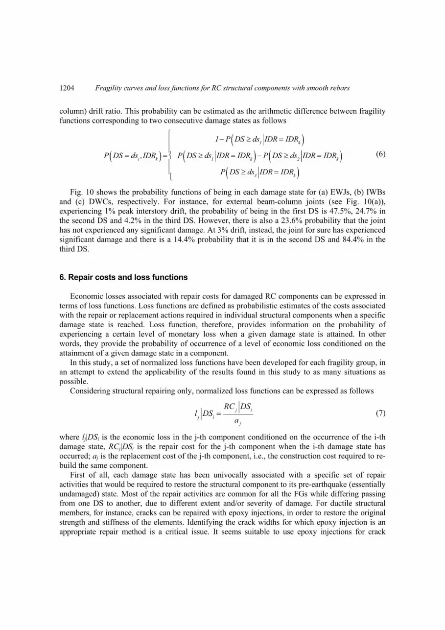
Fig. 10 shows the probability functions of being in each damage state for (a) EWJs, (b) IWBs and (c) DWCs, respectively. For instance, for external beam-column joints (see Fig. 10(a)), experiencing 1% peak interstory drift, the probability of being in the first DS is 47.5%, 24.7% in the second DS and 4.2% in the third DS. However, there is also a 23.6% probability that the joint has not experienced any significant damage. At 3% drift, instead, the joint for sure has experienced significant damage and there is a 14.4% probability that it is in the second DS and 84.4% in the third DS.
6. Repair costs and loss functions Economic losses associated with repair costs for damaged RC components can be expressed in
terms of loss functions. Loss functions are defined as probabilistic estimates of the costs associated with the repair or replacement actions required in individual structural components when a specific damage state is reached. Loss function, therefore, provides information on the probability of experiencing a certain level of monetary loss when a given damage state is attained. In other words, they provide the probability of occurrence of a level of economic loss conditioned on the attainment of a given damage state in a component.
In this study, a set of normalized loss functions have been developed for each fragility group, in an attempt to extend the applicability of the results found in this study to as many situations as possible.
Considering structural repairing only, normalized loss functions can be expressed as follows
lj
DSi
RCj
DSi
aj
(7)
where lj|DSi is the economic loss in the j-th component conditioned on the occurrence of the i-th damage state, RCj|DSi is the repair cost for the j-th component when the i-th damage state has occurred; aj is the replacement cost of the j-th component, i.e., the construction cost required to re-build the same component.
First of all, each damage state has been univocally associated with a specific set of repair activities that would be required to restore the structural component to its pre-earthquake (essentially undamaged) state. Most of the repair activities are common for all the FGs while differing passing from one DS to another, due to different extent and/or severity of damage. For ductile structural members, for instance, cracks can be repaired with epoxy injections, in order to restore the original strength and stiffness of the elements. Identifying the crack widths for which epoxy injection is an appropriate repair method is a critical issue. It seems suitable to use epoxy injections for crack
1204

Donatello Cardone
widths smaller than 5 mm (Pagni and Lowes 2006). Patching of concrete is adopted to replace spalled concrete. For wider crack widths (>5 mm) patching of concrete can be used instead of epoxy injections. Patching is accomplished removing loosened concrete and cleaning the adjacent surface. The critical issue is to identify the extent of spalled concrete for which patching is inadequate and a more effective repair method is required. Patching is considered to be inadequate if beam or column longitudinal reinforcement is exposed (Pagni and Lowes 2006), since patching would not be expected to restore concrete steel bond. In that case, removal and recast of damaged (and potentially damaged) concrete should be selected as repair method. In removing concrete, the objective is to ensure that only undamaged concrete remains as well as to ensure that a substantial volume of new material is placed around beam and/or column reinforcement to ensure that full bond capacity is recovered. Typically, the replacement material will be rheoplastic concrete mix, or special high-performance mortar mix. In some circumstances, it may be also necessary to replace a number of steel rebar(s), when either buckling or fracture occurs.
Generally speaking, repair activities are not limited to a series of specific repair actions for each RC member but they also include a number of preliminary and supplementary activities that can be summarizes as follows:
- Safety operations. They include a number of preliminary operations carried out for safety reasons, such as: access protection, application of dust curtains, installation of scaffoldings and/or work platforms, installation of shoring adjacent to the columns to support gravity loads, etc..
- Demolition activities. This activity consists in the removal of furnishings and floor finishes, demolition of partition obstructing RC members to be repaired, isolation of mechanical, electrical and plumbing systems (as necessary) close to the intervention area. The extension of these preliminary works depends on the extension and severity of the structural damage, hence attained DS. For instance, the area of intervention for IWBs increases from 1.5 to 2.5 squared meters passing from DS1 to DS3.
- Cleaning operations. This activity consists in the removal of debris and clean of the area adjacent to main cracks and spalled/damaged concrete to be repaired. Obviously, the extension of these works depends on the extension and severity of the structural damage, hence attained DS. For example, the cleaning area for IWBs increases from half to total beam height passing from DS1 to DS3.
- Replacement and Restoration. This activity includes replacement of furnishings, restoration of partitions and floor finishes, replacement of mechanical, electrical and plumping systems, as necessary.
- Technical Costs. Technical cost includes fees for structural engineer, project engineer, construction manager, etc. In first approximation, they have been assumed around 8% the total cost of the intervention.
Considering the total costs associated with structural repairing, normalized loss functions can be expressed as follows
Lj DSi TCj DSi
b Vj
(8)
where Lj|DSi is the total economic loss for the j-th component conditioned on the occurrence of the i-th damage state; TCj|DSi is the total repair cost for the j-th component when the i-th damage state has occurred; b is the nominal cost per cubic meter of the building and Vj is the average volume surrounding the j-th component affected by the intervention. In first approximation, Vj has been taken equal to approximately 8 m3 for EWJs, 11 m3 for IWBs/IWCs and 6 m3 for DWCs/BWCs.
1205

Fragility curves and loss functions for RC structural components with smooth rebars
Table 8 summarizes the methods of repair considered for each DS of ductile RC members, together with a description of the related repair activities.
In the next step, the unit costs (ck) for each repair action (see Table 9) have been estimated considering the Price List of Public Works in Basilicata Region, Italy (BUR 2013). Reference to the same document has been also made to estimate the additional costs related to the preliminary and complementary activities listed before. Within this context, further improvements and refinements could be achieved, for instance, by surveying designers and building firms to obtain a larger sample of repair methods and a more accurate database of repair costs.
In the next step, normalized repair cost ratios (LCj,DSi(50th)) have been derived, based on quantity survey and cost estimate of a number of pre-70 RC frame buildings, including three archetype buildings, with number of storeys ranging from 4 to 8, and one 8-storeys real building, featuring perimeter frames and internal frames in one direction only.
LCj,DSi(50th) is defined as the average of the total repair cost (including all the preliminary and supplementary activities necessary to realize the intervention) for the j-th fragility group, due to the attainment of the i-th damage state, normalized by the nominal cost of the volume of the building affected by the intervention. From an analytic point of view, it can be expressed as follows
LCj ,DSi50th AVERAGE
1 2 3 4 5 1 ckuk
k
b Vj
(9)
where ck is the unit cost for the k-th repair action, uk is the associated quantity or extension of damage for the j-th fragility group, k is the total number of repair actions necessary for that
Table 8 Methods of repair and repair activities for ductile RC members
Damage State
Method of repair
Repair activities
DS1 Epoxy
injection of concrete cracks
Install scaffolding and shoring systems. Remove furnishings, electrical and plumbing systems, as necessary. Demolish partitions, as necessary. Clean area
adjacent to cracks. Prepare cracks. Inject cracks with epoxy resin. Restore finishes and partitions. Restore furnishings, electrical and plumping systems as necessary.
Remove scaffolding and shoring systems.
DS2 Patch concrete
with mortar mix
Install scaffolding and shoring systems. Remove furnishings, electrical and plumbing systems, as necessary. Demolish partitions, as necessary. Remove
loosened concrete and clean adjacent area. Inject cracks with epoxy resin. Patch concrete with mortar mix. Restore finishes and partitions. Restore furnishings, electrical and plumping systems as necessary. Remove scaffolding and shoring
systems.
DS3
Replace concrete (and
rebars, if necessary)
Install scaffolding and shoring systems. Remove furnishings, electrical and plumbing systems, as necessary. Demolish partitions, as necessary. Remove damaged and potentially damaged concrete and clean adjacent area. Replace
distorted rebars, if necessary. Inject cracks with epoxy resin. Replace concrete with rheoplastic concrete mix or high-performance mortar mix. Restore finishes and partitions. Restore furnishings, electrical and plumping systems as necessary.
Remove scaffolding and shoring systems.
1206

Donatello Cardone
Table 9 Unit costs for repair actions required for different damage states of RC members
Damage state Repair Actions Unit Unit cost (€)
(€/unit)
DS1 (Light cracking)
Clean area adjacent to cracks m2 6.61
Prepare cracks to be injected m2 27.01Inject cracks with epoxy resin m 156.00
DS2 (Severe
cracking)
Remove loosened concrete, clean area adjacent to cracks m2 6.61
Prepare cracks/surfaces to be injected /patched m2 27.01Inject cracks with epoxy resin m 156.00
Patch spalled concrete (if any) with mortar mix m2 88.35Steel jacketing * m 216.87
DS3 (Spalling,
crushing of concrete,
buckling of rebars)
Remove damaged and potentially damaged concrete and clean adjacent area
m2 6.61
Prepare concrete surface to ensure full bond between new and existing concrete m2 27.01
Inject cracks with epoxy resin m 156.00Replace distorted bars (if any) each 50
Replace damaged concrete with rheoplastic concrete mix or high-performance mortar mix m2 109.26
Demolition and re-construction * m3 668
*Only for Brittle Weak Columns (BWCs) damage state; α1, α2, α3, α4 and α5 are magnification factors of the repair cost to account for all the preliminary and complementary activities involved in the intervention (see Fig. 11); b is the nominal cost per cubic meter of the building and Vj is an estimate of the volume of the building, surrounding the RC component, affected by the intervention.
To derive the nominal cost per cubic meter of the building (b) the following procedure has been followed. First, the replacement cost of the selected buildings has been estimated, assuming an average unit cost of 730 euro/m2 for each floor of the building (Bassi 2014) less 90 euro/m2 for shallow foundation. An additional cost of 44 euro/m3 has been then considered to account for demolition and waste disposal (CIAM 2014). The building cost per cubic meter (b) has been computed dividing the replacement cost of each building by its volume.
The repair cost ratio for each fragility group and damage state, has been disaggregated in different cost items (i.e., repair, safety, demolition, etc.). This way, the contribution of each repair activity to the total repair cost can be evaluated. The breakdown of the total repair cost for EWJs, IWBs and DWCs is shown in Fig. 11, for each DS. As expected, repair costs increase while increasing the severity and extension of damage (i.e., passing from DS1 to DS3), however, they do not exceed 15% of the total costs for repair at DS1 and 30% at DS3. The most important cost items are related to replace/restore activities and safety operations, which together represent approximately 50% of the total repair cost, regardless of the DS considered.
Eq. (9) provides reasonable estimates of the expected values of total repair costs (i.e., the 50th percentile levels), which are appropriate for estimating economic losses for many pre-70 RC frame buildings (see third column of Table 10). Eq. (9), however, does not provide information on how large economic losses can become in a given scenario. In other words, Eq. (9) does not provide
1207

informRep
be assinformon thestates ibelow frame b
Firspercendamagpercenbe inje10th) a
C
F
Fragility
mation on thepair costs, indsumed that
mation are avae correlation in individualhas been fo
buildings. st, 10th and 9
ntile values oge patterns, ntile) of the rected, more/land higher (s
Component group
EWJs
IWBs
DWCs
Fig. 11 Disag
y curves and lo
dispersion adeed, are ranrepair costs ailable on thecoefficients
l componentsollowed to de
90th percentilobtained befodiffering frorepair cost raless cover cosay 90th) per
gregation of t
33.49%
7
Replace/Restore
TechC
9
34.33%
7
Replace/Restore
TecC
Re
6.27%
30.37%
7
Replace/Restore
TechC
Repair
oss functions f
around the avndom variable
follow a ce statistics ofbetween dif
s. As a conseerive loss fu
le levels of tore, based onom the referatio, in the eoncrete to bercentile value
DS1
otal repair cos
16.99%
17.68%
8.51%15.91%
7.41%
hnical Cost
Safety
Demoliti
CleaningRepair
19.57%
20.63%
8.84%9.22%
7.41%
hnical Cost
Safety
Demoliti
Cleaningepair
21.99%
22.27%
11.70%
7.41%
hnical Cost
Safety
Demolitio
Cleaning
for RC structu
verage valuees. Based oncumulative lf specific repafferent repairequence, in t
unctions for t
the total repan engineerinrence patter
extent and see patched, ees of repair c
sts for (a) EW
%
on 28.60%
Replace/Restore
T
ion
1
28.74%
Replace/Restore
T
Re
on
8
10.47%
22.02%
Replace/Restore
T
Cleaning
Repair
ural compone
. the recomm
ognormal diair actions atr actions corthis study, thtypical struct
air costs havg judgment.
rn, used to deverity of daetc.), have excost.
DS2
WJs, (b) IWBs
25.06%
15.2
5.60%18.13%
7.41%
Technical Cost
Safety
Demo
C
Repair
26.98%
17.36
5.64%3.88%
7.41%
Technical Cost
Safety
Demolit
Cl
epair
36.48%
15.53%.09%
7.41%
/
Technical Cost
Safet
Demolition
nts with smoo
mendations of istribution. Ut the componresponding t
he simplified tural compon
ve been estimMore precis
derive the bmage (e.g., m
xamined to e
and (c) DWC
%
0%
y
olition
Cleaning
27.40
ReplacResto
%
%
tion
eaning
%
y
2
20.03
ReplacResto
Re
oth rebars
f FEMA P-58Unfortunatelynent level, as to different dapproach de
nents of pre-
mated, from tsely, two addbest estimatemore/less crestimate low
DS3
Cs, respectively
25.0
4.3021.25%
0%
7.41%
ce/ore
Technical Cost
Safe
De
Repair
29.
13
6.77%
23.01%
3%
7.41%
ce/ore
Technical Cost
Saf
Demepair
8, it can y, poor well as
damage escribed -70 RC
the 50th ditional e (50th racks to
wer (say
y
04%
14.60%
0%
ty
molition
Cleaning
.57%
3.21%
fety
molition
Cleaning
1208

Donatello Cardone
Cumulative lognormal distributions of the total repair cost ratios (LCj|DSi) have been then derived by fitting the 10th, 50th, and 90th percentile estimates obtained in the previous step (see Fig. 12). The resultant median λCj,DSi and dispersion βCj,DSi are reported in Table 10, for each fragility group and associated DS. As can be seen in Table 10, as the damage state level increases, the total repair cost ratio tends quickly to one meaning that for that type of RC components the repair costs are relatively high even for low levels of damage.
Finally, loss functions to be implemented in PACT have been drawn assuming, in line with the recommendation of FEMA P-58, a lower/upper quantity of components (qmin/qmax) below/above which there is no discount reflecting economies of scale or efficiencies in operation. Values of qmin/qmax and the associated maximum/minimum normalized total repair costs λmax/λmin are reported in Table 10.
The normalized expected loss for the j-th fragility group (E(LCj,IDRk)) can be computed as the sum of the products between the median value of the distribution of repair cost ratios associated with each DS (λCj,DSi in Table 10) and the probability of being in each DS (see Fig. 10)
m
ikiDS,CkC IDRdsDSPλIDRLE
ijj1
,, (11)
where m=3 is the number of damage states for the j-th fragility group, P(DS=dsi, IDRk) is the probability of the component being in the i-th damage state, when it is subjected to an interstory (or column) drift ratio IDRk (CDRk). Fig. 13 shows the expected loss for the main fragility groups considered in this study, as a function of the peak interstory (or column) drift ratio attained during an earthquake.
Table 10 (i) 50th percentile values of repair cost ratio LCj,DSi(50th), (ii) fitted median λCj,DSi and dispersion βCj,DSi relevant to lognormal distributions of total repair cost ratios, and (iii) parameters to be implemented in PACT to describe loss functions of pre-70 RC frame buildings
Fragility Groups
Damage State LCj,DSi(50th) λCj,DSi βCj,DSi λmax λmin qmax qmin
EWJs
DS1 0.71 0.74 0.45 0.96 0.59 20 5
DS2 1.12 1.16 0.40 1.39 0.99 20 5
DS3 1.51 1.57 0.42 1.88 1.33 20 5
IWBs
DS1 0.60 0.62 0.46 0.81 0.50 20 5
DS2 0.98 1.02 0.41 1.22 0.86 20 5
DS3 1.53 1.59 0.42 1.91 1.35 20 5
IWCs
DS1 0.67 0.70 0.46 0.81 0.50 20 5
DS2 0.97 1.00 0.38 1.22 0.86 20 5
DS3 1.27 1.32 0.42 1.91 1.35 20 5
DWCs
DS1 0.65 0.67 0.47 0.88 0.54 20 5
DS2 0.97 0.99 0.37 1.19 0.85 20 5
DS3 1.21 1.25 0.41 1.50 1.07 20 5
BWCs
DS1 0.54 0.54 0.30 0.70 0.43 5 3
DS2 1.05 1.06 0.34 1.27 0.90 5 3
DS3 10.67 10.92 0.29 13.11 9.28 5 3
1209

Fragility curves and loss functions for RC structural components with smooth rebars
(a) (b) (c)
Fig. 12 Cumulative lognormal distributions of the total cost ratios for (a) EWJs, (b) IWBs and (c) DWCs
(a) (b) (c)
Fig. 13 Expected loss for (a) EWJs, (b) IWBs and (c) DWCs, respectively, for different levels of drift ratio 7. Conclusions
Fragility functions for the main structural components of pre-70 RC frame buildings have been
derived, based on results of previous experimental studies. The attention has been focused on external/internal beam-column joints and ductile/brittle weak columns, designed for gravity loads only, using low-strength concrete and plain steel reinforcing bars. Repair costs for damaged RC structural components have been then estimated based on detailed quantity survey and cost estimate of a number of pre-70 RC buildings, using suitable costing manuals. Finally, loss functions that provide economic losses for individual RC components, as a function of the experienced peak interstory (or column) drift ratios, have been derived.
The fragility curves and loss function derived in this study have been implemented in the Performance Assessment Calculation Tool (PACT) of FEMA-P-58 for the loss assessment of older RC frame buildings (Cardone and Perrone 2016).
Acknowledgements
0.0
0.2
0.4
0.6
0.8
1.0
0 1 2 3 4
P(L
Cj<
l|DS
i)
LCj
DS1
DS2
DS3
0.0
0.2
0.4
0.6
0.8
1.0
0 1 2 3 4
P(L
Cj<
l|DS
i)LCj
DS1
DS2
DS3
0.0
0.2
0.4
0.6
0.8
1.0
0 1 2 3 4
P(L
Cj<
l|DS
i)
LCj
DS1
DS2
DS3
0.0
0.2
0.4
0.6
0.8
1.0
1.2
1.4
1.6
0% 1% 2% 3% 4% 5% 6%
E[L
Cj,
IDR
]
Drift (%)0.0
0.2
0.4
0.6
0.8
1.0
1.2
1.4
1.6
0% 1% 2% 3% 4% 5% 6%
E[L
Cj,
IDR
]
Drift (%)0.0
0.2
0.4
0.6
0.8
1.0
1.2
1.4
1.6
0% 1% 2% 3% 4% 5% 6%
E[L
Cj,
CD
R]
Drift (%)
1210

Donatello Cardone
This work has been carried out within the Line 7 of the ReLUIS/DPC 2014-2018 research
program, dealing with direct displacement approaches for the evaluation of seismic losses of buildings in pre- and post- rehabilitation conditions. The author gratefully acknowledges the support of the RELUIS Consortium for this research. The author is also grateful to Dr. G. Perrone for his valuable assistance in evaluating repair costs and bill of quantities.
References
ACI - Committee 318 (1971), ACI 318-71: Building Code Requirements for Reinforced Concrete, American Concrete Inst., Farmington Hills, MI.
Arani, K.K., Marefat, M.S., Amrollahi-Biucky, A. and Khanmohammadi, M. (2013), “Experimental seismic evaluation of old concrete columns reinforced by plain bars”, Struct. Des. Tall Spec. Build., 22(3), 267-290.
Aslani, H. and Miranda, E. (2005), “Probabilistic earthquake loss estimation and loss disaggregation in buildings”, Report No. 157. Stanford, CA: John A. Blume Earthquake Engineering Center, Stanford University.
ATC (2012), Applied Technology Council, FEMA P-58 Next-generation Seismic Performance Assessment for Buildings, Vol. 1- Methodology, Federal Emergency Management Agency, Washington, DC.
ATC (2012), Applied Technology Council, FEMA P-58 Next-generation Seismic Performance Assessment for Buildings, Vol. 2 - Implementation Guide, Federal Emergency Management Agency, Washington, DC.
Bassi, A. (2014), Costi per tipologie edilizie. La valutazione economica dei progetti in fase preliminare, Ed. Maggioli, Santarcangelo di Romagna (RN), Italy. (in Italian)
Bedirhanoglu, I., Ilki, A., Pujol, S. and Kumbasar, N. (2010), “Behavior of deficient joints with plain bars and low-strength concrete”, ACI Struct. J., 107(3), 300-310.
Beschi, C., Riva, P. and Meda, A. (2012), “Corner beam-column joints retrofitting with HPFRC jacketing”, 3rd International Conference on Concrete Repair, Rehabilitation and Retrofitting, Cape Town, South Africa.
Bozorgnia, Y. and Bertero, V.V. (2004), Earthquake Engineering: From Engineering Seismology to Performance-Based Earthquake Engineering, CRC Press.
Bracci, J.M., Reinhorn, A.M. and Mander, J.B. (1995), “Seismic resistance of reinforced concrete frame structures designed for gravity loads: performance of structural system”, ACI Struct. J., 92(5), 597-609.
Braga, F., Gigliotti, R. and Laterza, M. (2009), “Existing RC structures with smooth bars: Experimental behavior of beam-column joints subject to cyclic lateral loads”, Open Construct. Build. Technol. J., 3(1), 52-67.
BUR (2013), Price List of Public Works in Basilicata Region, Official Journal of Regione Basilicata, Potenza. (in Italian)
Calvi, G.M., Magenes, G. and Pampanin, S. (2002), “Relevance of beam-column joint damage and collapse in Rc frame assessment”, J. Earthq. Eng., 6(S1), 75-100.
Cardone, D. and Perrone, G. (2015), “Developing fragility curves and loss functions for masonry infill walls”, Earthq. Struct., 9(1), 257-279.
Cardone, D. and Perrone, G. (2016), “Damage and loss assessment of Pre-70 RC frame buildings with FEMA P-58”, J. Earthq. Eng., doi: 10.1080/13632469.2016.1149893.
Chen, T.H. (2006), “Retrofit strategy of non-seismically designed frame systems”, Master thesis, University of Canterbury, Christchurch, New Zealand.
CIAM (2014), Prezzi tipologie edilizie, Ed., DEI, Collegio degli Ingegneri e degli Architetti di Milano, Roma, Italy. (in Italian)
Di Ludovico, M., Verderame, G., Prota, A., Manfredi, G. and Cosenza, E. (2013), “Experimental behavior of non-conforming RC columns with plain bars under constant axial load and biaxial bending”, J. Struct. Eng., 139(6), 897-914.
Di Ludovico, M., Verderame, G.M., Prota, A., Manfredi, G. and Cosenza, E. (2014), “Cyclic behavior of non
1211

Fragility curves and loss functions for RC structural components with smooth rebars
conforming full-scale RC columns”, J. Struct. Eng., 140(5), 897-914. El-Attar, A.G., White, R.N. and Gergely, P. (1997), “Behaviour of gravity load designed reinforced concrete
buildings subjected to earthquakes”, ACI Struct. J., 94(2), 133-145. Fernandes, C., Melo, J., Varum, H. and Costa, A. (2013), “Cyclic behaviour of substandard reinforced concrete
beam-column joints with plain bars”, ACI Struct. J., 110(1), 137-147. GU - Gazzetta Ufficiale (1974), Provvedimenti per le costruzioni con particolari prescrizioni per le zone
sismiche, Legge 2 febbraio 1974, n. 64, published on GU n. 076 on 21/03/1974. (in Italian) Hakuto, S., Park, R. and Tanaka, H. (2000), “Seismic load tests on interior and exterior beam-column joints
with substandard reinforcing details”, ACI Struct. J., 97(1), 11-25. Henkhausus, E. (2010), “Axial failure of vulnerable reinforced concrete columns damaged by shear reversals”,
Ph.D. thesis, Purdue University, West Lafayette Indiana. Hertanto, E. (2005), “Seismic assessment of pre-1970s reinforced concrete structures”, Ph.D. thesis, New
Zealand: University of Canterbury. ICBO - International Conference of Building Officials (1967), Uniform Building Code, Vol. 1, Whittier, CA. Lilliefors, H. (1967), “On the Kolmogorov-Smirnov test for normality with mean and variance unknown”, J.
Am. Statistic. Assoc., 62(318), 399-402. Liu, A. and Park, R. (2001), “Seismic behaviour and retrofit of pre-1970’s as-built exterior beam-column joints
reinforced by plain round bars”, Bull. NZ. Soc. Earthq. Eng., 34(1), 68-81. Lynn, A. (2001), “Seismic evaluation of existing reinforced concrete building columns”, Ph.D. thesis,
University of California, Berkeley, California. Marefaf, M.S., Karbasi, K., Arani, S., Hassanzadeh, M.S. and Amrollahi, A. (2008), “Seismic behavior and
retrofit of concrete columns of old R.C. buildings reinforced with plain bars”, Seismic Engineering Conference commemorating the 1908 Messina and Reggio Calabria Earthquake.
Matchulat, L. (2009), “Mitigation of collapse risk in vulnerable concrete buildings”, MSc. thesis, University of Kansas, Lawrence.
Pagni, C.A. and Lowes, L.N. (2006), “Fragility functions for older reinforced concrete beam-column joints”, Earthq. Spectra, 22(1), 215-238.
Pampanin, S., Calvi, G.M. and Moratti, M. (2002), “Seismic behavior of R.C. beam-column joints designed for gravity loads”, Proceeding of 12th European Conference on Earthquake Engineering, London, UK.
Pan, A.D. and Moehle, J.P. (1988), “Reinforced concrete flat plates under lateral loading: an experimental study including biaxial effects”, Report UCB/EERC-88/16, University of California, Berkeley, CA.
Ross, S.M. (2003), “Peirce’s criterion for the elimination of suspect experimental data”, J. Eng. Technol., 20(2), 38-41.
Verderame, G.M., Fabbrocino, G. and Manfredi, G. (2008a), “Seismic response of RC columns with smooth reinforcement, part I: monotonic tests”, Eng. Struct., 30(9), 2277-2288.
Verderame, G.M., Fabbrocino, G. and Manfredi, G. (2008b), “Seismic response of RC columns with smooth reinforcement, part II: Cyclic tests”, Eng. Struct., 30(9), 2289-2300.
Woods, C. and Matamoros, A.B. (2010), “Effect of longitudinal reinforcement ratio on the failure mechanism of R/C columns most vulnerable to collapse”, Ninth US National Conference and Tenth Canadian Conference on Earthquake Engineering, Toronto, Canada.
SA
1212


![output RC N16 [146pag]](https://img.dokumen.tips/doc/110x75/631ddc5c85e2495e150fa703/output-rc-n16-146pag.jpg)


