Embed Size (px)
Citation preview
Aararoiouaoiporamr�
1IoiacsrTglIai
pcf
PA1
1
Journal of Electronic Imaging 19(2), 021106 (Apr–Jun 2010)
J
Focused plenoptic camera and rendering
Todor GeorgievAdobe Systems Inc.345 Parke Avenue
San Jose, California 95110E-mail: [email protected]
Andrew LumsdaineIndiana University
Computer Science Department215 Lindley Hall
Bloomington, Indiana 47405
bstract. Plenoptic cameras, constructed with internal microlensrrays, capture both spatial and angular information, i.e., the full 4-Dadiance, of a scene. The design of traditional plenoptic camerasssumes that each microlens image is completely defocused withespect to the image created by the main camera lens. As a result,nly a single pixel in the final image is rendered from each microlens
mage, resulting in disappointingly low resolution. A recently devel-ped alternative approach based on the focused plenoptic camerases the microlens array as an imaging system focused on the im-ge plane of the main camera lens. The flexible spatioangular trade-ff that becomes available with this design enables rendering of final
mages with significantly higher resolution than those from traditionallenoptic cameras. We analyze the focused plenoptic camera inptical phase space and present basic, blended, and depth-basedendering algorithms for producing high-quality, high-resolution im-ges. We also present our graphics-processing-unit-based imple-entations of these algorithms, which are able to render full screen
efocused images in real time. © 2010 SPIE and IS&T.DOI: 10.1117/1.3442712�
Introductionntegral photography, introduced by Ives and Lippmannver 100 years ago1,2 has more recently reemerged with thentroduction of the plenoptic camera. Originally presenteds a technique for capturing 3-D data and solvingomputer-vision problems,3,4 the plenoptic camera was de-igned as a device for recording the distribution of lightays in space, i.e., the 4-D plenoptic function or radiance.he light field and lumigraph, introduced to the computerraphics community, respectively, in Refs. 5 and 6, estab-ished a framework for analyzing and processing these data.n 2005, Ng et al.7 and Ng8 improved the plenoptic camerand introduced new methods of digital processing, includ-ng refocusing.
Because it captured the full 4-D radiance, Ng’s handheldlenoptic camera could produce effects well beyond theapabilities of traditional cameras. Image properties such asocus and depth of field could be adjusted after an image
aper 10039SSRR received Mar. 5, 2010; revised manuscript receivedpr. 9, 2010; accepted for publication Apr. 20, 2010; published online Jun.
1, 2010.
017-9909/2010/19�2�/021106/11/$25.00 © 2010 SPIE and IS&T.
ournal of Electronic Imaging 021106-
Downloaded from SPIE Digital Library on 29 Sep 2011 to 150
had been captured. Unfortunately, traditional plenopticcameras suffer from a significant drawback; they renderimages at disappointingly low resolution. For example, im-ages rendered from Ng’s camera data have a final reso-lution of 300�300 pixels.
A different approach, called “full-resolution lightfieldrendering,”9 can produce final images at much higher res-olution based on a modified plenoptic camera �the “focusedplenoptic camera”10�. This modified camera is structurallydifferent from the earlier plenoptic camera with respect tomicrolens placement and microlens focus. These structuraldifferences in turn result in different assumptions about thesampling of the 4-D radiance. The traditional plenopticcamera focuses the main lens on the microlenses and fo-cuses the microlenses at infinity. The focused plenopticcamera instead focuses the main camera lens well in frontof the microlenses and focuses the microlenses on the im-age formed inside the camera—i.e., each microlens forms arelay system with the main camera lens. This configurationproduces a flexible trade-off in the sampling of spatial andangular dimensions and enables positional information inthe radiance to be sampled more effectively. As a result, thefocused plenoptic camera can produce images of muchhigher resolution than can traditional plenoptic cameras.
Other radiance-capturing cameras similar to the focusedplenoptic camera include the following: the microlens ap-proach of Lippmann,2 the thin observation model by boundoptics11 �TOMBO�, the handheld plenoptic camera,7 Fife etal.’s multiaperture image sensor architecture,12,13 and thePanoptes sensor.14
This paper presents the design and analysis of the fo-cused plenoptic camera and associated image rendering al-gorithms. In particular, it describes
1. the background of the plenoptic camera 2.0, includ-ing basic radiance theory and modeling, the plenopticcamera 1.0, and other radiance-capturing cameras
2. a complete development of the focused plenopticcamera, including derivation of its sampling in opti-cal phase space, basic rendering algorithms, and adetailed description of the hardware
Apr–Jun 2010/Vol. 19(2)1
.135.223.93. Terms of Use: http://spiedl.org/terms
2Ftatr
mr
x
Rr
L
fLittoTsyf
r
idr
I
3
3TmwlfE�t
Georgiev and Lumsdaine: Focused plenoptic camera and rendering
J
3. a development of high-quality rendering algorithmsthat provide high-resolution realistic camera effects,such as depth of field and refocusing
4. a presentation of a computational framework forworking with focused plenoptic camera data, includ-ing implementations of rendering algorithms andtheir efficient realization on modern GPU �graphicsprocessing unit� hardware.
Radiance Theory and Modelingollowing the development in Refs. 9 and 10, we denote
he radiance at a given plane perpendicular to the opticalxis by r�q , p�, where q and p represent position and direc-ion in ray space, respectively. Compactly, a coordinate inay space is represented by x= �q , p�T.
Rays are transformed by the application of optical ele-ents. An arbitrary ray transfer matrix A transforms each
ay according to
� = Ax . �1�
efraction by a lens and travel of rays in free space are,espectively, described by the matrix transforms L and T:
= � 1 0
−1
f1 �, T = �1 t
0 1� . �2�
Optical transforms of rays induce corresponding trans-orms of functions �such as radiance� defined on ray space.et A be an optical transform of Eq. �1�, and consider the
nduced transformation of r�x� to r��x�. Since all opticalransfer matrices satisfy det A=1, and assuming conserva-ion of energy, we have the radiance conservation propertyf all optical systems, i.e., we must have r��x��=r�x�.aken with x�=Ax, we must also have r��Ax�=r�x�. Con-idering a ray y=Ax, we thus obtain r��y�=r�A−1y�. Sinceis an arbitrary ray, we obtain the radiance transformation
ormula:
��x� = r�A−1x� . �3�
Finally, an image is related to the radiance in the follow-ng way. The intensity of an image at a given spatial point,enoted I�q� is the integral of the radiance over all of theays incident at that point, i.e.,
�q� = �p
r�q,p�dp . �4�
Plenoptic Cameras
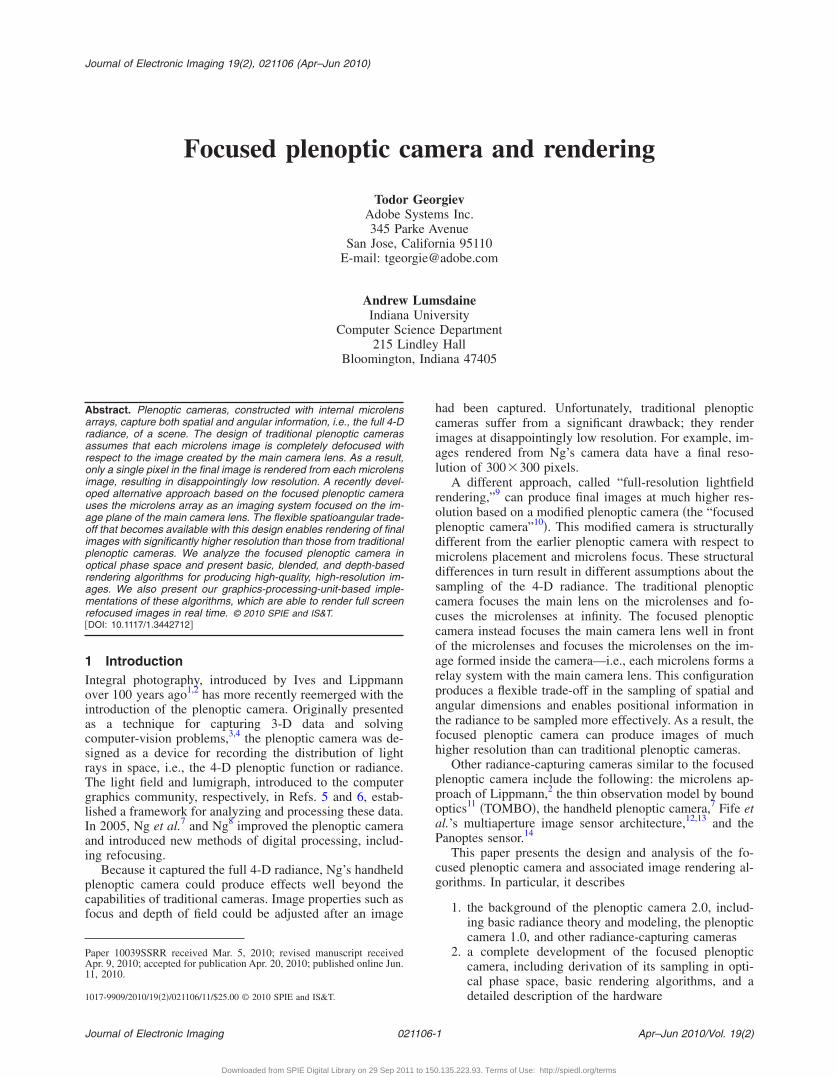
.1 Plenoptic Camera 1.0he traditional plenoptic camera is based on an array oficrolenses at the image plane of the main camera lens,ith the sensor placed one focal length behind the micro-
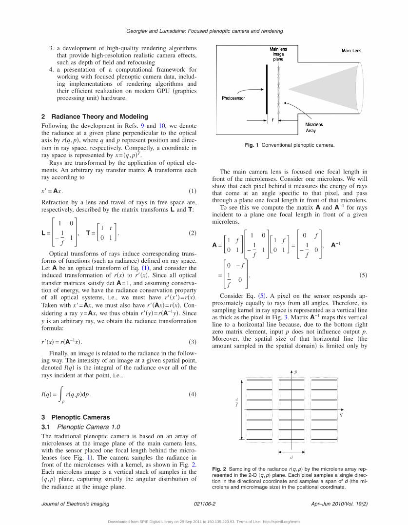
enses �see Fig. 1�. The camera samples the radiance inront of the microlenses with a kernel, as shown in Fig. 2.ach microlens image is a vertical stack of samples in the
q , p� plane, capturing strictly the angular distribution ofhe radiance at the image plane.
ournal of Electronic Imaging 021106-
Downloaded from SPIE Digital Library on 29 Sep 2011 to 150
The main camera lens is focused one focal length infront of the microlenses. Consider one microlens. We willshow that each pixel behind it measures the energy of raysthat come at an angle specific to that pixel, and passthrough a plane one focal length in front of that microlens.
To see this we compute the matrix A and A−1 for raysincident to a plane one focal length in front of a givenmicrolens.
A = �1 f
0 1�� 1 0
−1
f1 ��1 f
0 1� = � 0 f
−1
f0 �, A−1
= �0 − f
1
f0 � . �5�
Consider Eq. �5�. A pixel on the sensor responds ap-proximately equally to rays from all angles. Therefore, itssampling kernel in ray space is represented as a vertical lineas thick as the pixel in Fig. 3. Matrix A−1 maps this verticalline to a horizontal line because, due to the bottom rightzero matrix element, input p does not influence output p.Moreover, the spatial size of that horizontal line �theamount sampled in the spatial domain� is limited only by
Fig. 1 Conventional plenoptic camera.
p
q
d
d
f
Fig. 2 Sampling of the radiance r�q ,p� by the microlens array rep-resented in the 2-D �q ,p� plane. Each pixel samples a single direc-tion in the directional coordinate and samples a span of d �the mi-crolens and microimage size� in the positional coordinate.
Apr–Jun 2010/Vol. 19(2)2
.135.223.93. Terms of Use: http://spiedl.org/terms
tkc
tspvdowta
apHbe
3Aottsilr
i
Fa
Georgiev and Lumsdaine: Focused plenoptic camera and rendering
J
he microlens’ diameter. This large size of the samplingernel is the reason for the low resolution of the plenopticamera �1.0�.
Images are rendered from the radiance captured by theraditional plenoptic camera by integrating all angularamples at a particular spatial point. However, each spatialoint is sampled by a single microlens, so rendering in-olves integrating all of the pixels in each microimage. Asesigned, rendering from the plenoptic camera producesnly 1 pixel per microlens, resulting in a rendered imageith very low resolution. Even with 100,000 microlenses,
he handheld plenoptic camera reported in Ref. 7 producesfinal image of only 300�300 pixels.An example of an image rendered with the plenoptic 1.0
lgorithm is shown in Fig. 4. Note that in this case, thelenoptic data was captured with a plenoptic 2.0 camera.owever, the rendered image is equivalent to what woulde rendered from data captured with a plenoptic 1.0 cam-ra.
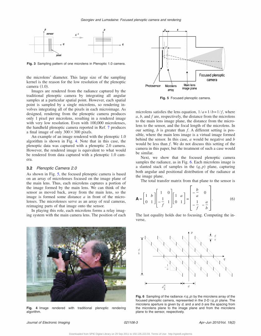
.2 Plenoptic Camera 2.0s shown in Fig. 5, the focused plenoptic camera is basedn an array of microlenses focused on the image plane ofhe main lens. Thus, each microlens captures a portion ofhe image formed by the main lens. We can think of theensor as moved back, away from the main lens, so themage is formed some distance a in front of the micro-enses. The microlenses serve as an array of real cameras,eimaging parts of that image onto the sensor.
In playing this role, each microlens forms a relay imag-ng system with the main camera lens. The position of each
Fig. 3 Sampling pattern of one microlens in Plenoptic 1.0 camera.
ig. 4 Image rendered with traditional plenoptic renderinglgorithm.
ournal of Electronic Imaging 021106-
Downloaded from SPIE Digital Library on 29 Sep 2011 to 150
microlens satisfies the lens equation, 1 /a+1 /b=1 / f , wherea, b, and f are, respectively, the distance from the microlensto the main lens image plane, the distance from the micro-lens to the sensor, and the focal length of the microlens. Inour setting, b is greater than f . A different setting is pos-sible, where the main lens image is a virtual image formedbehind the sensor. In this case, a would be negative and bwould be less than f . We do not discuss this setting of thecamera in this paper, but the treatment of such a case wouldbe similar.
Next, we show that the focused plenoptic camerasamples the radiance, as in Fig. 6. Each microlens image isa slanted stack of samples in the �q , p� plane, capturingboth angular and positional distribution of the radiance atthe image plane.
The total transfer matrix from that plane to the sensor is
A = �1 b
0 1�� 1 0
−1
f1 ��1 a
0 1� = �−
b
a0
−1
f−
a
b� . �6�
The last equality holds due to focusing. Computing the in-verse,
Fig. 5 Focused plenoptic camera.
p
q
d
b
da
b
−1a
d
a
d
Fig. 6 Sampling of the radiance r�q ,p� by the microlens array of thefocused plenoptic camera, represented in the 2-D �q ,p� plane. Themicrolens aperture is given by d, and a and b are the spacing fromthe microlens plane to the image plane and from the microlensplane to the sensor, respectively.
Apr–Jun 2010/Vol. 19(2)3
.135.223.93. Terms of Use: http://spiedl.org/terms
A
TrvrnCtr
tmmeb
dcphswaaa
Fc
Fhcmos
Georgiev and Lumsdaine: Focused plenoptic camera and rendering
J
−1 = �−a
b0
1
f−
b
a� . �7�
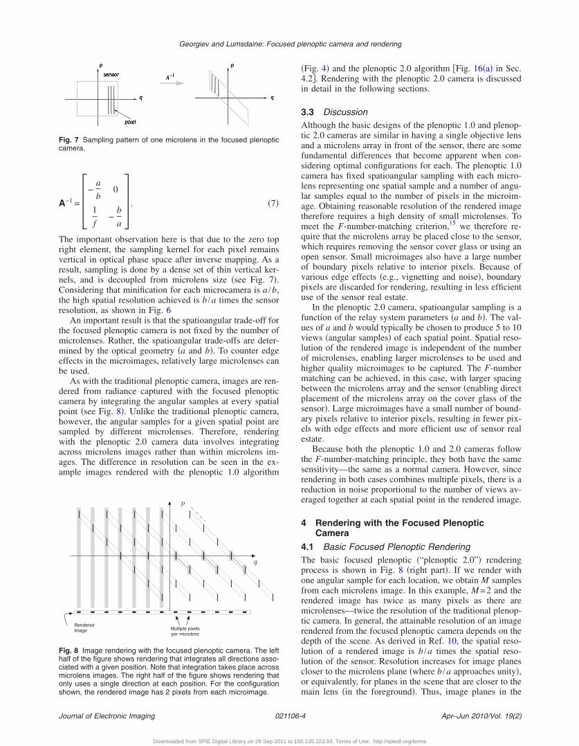
he important observation here is that due to the zero topight element, the sampling kernel for each pixel remainsertical in optical phase space after inverse mapping. As aesult, sampling is done by a dense set of thin vertical ker-els, and is decoupled from microlens size �see Fig. 7�.onsidering that minification for each microcamera is a /b,
he high spatial resolution achieved is b /a times the sensoresolution, as shown in Fig. 6
An important result is that the spatioangular trade-off forhe focused plenoptic camera is not fixed by the number of
icrolenses. Rather, the spatioangular trade-offs are deter-ined by the optical geometry �a and b�. To counter edge
ffects in the microimages, relatively large microlenses cane used.
As with the traditional plenoptic camera, images are ren-ered from radiance captured with the focused plenopticamera by integrating the angular samples at every spatialoint �see Fig. 8�. Unlike the traditional plenoptic camera,owever, the angular samples for a given spatial point areampled by different microlenses. Therefore, renderingith the plenoptic 2.0 camera data involves integrating
cross microlens images rather than within microlens im-ges. The difference in resolution can be seen in the ex-mple images rendered with the plenoptic 1.0 algorithm
ig. 7 Sampling pattern of one microlens in the focused plenopticamera.
p
q
RenderedImage Multiple pixels
per microlens
ig. 8 Image rendering with the focused plenoptic camera. The leftalf of the figure shows rendering that integrates all directions asso-iated with a given position. Note that integration takes place acrossicrolens images. The right half of the figure shows rendering thatnly uses a single direction at each position. For the configurationhown, the rendered image has 2 pixels from each microimage.
ournal of Electronic Imaging 021106-
Downloaded from SPIE Digital Library on 29 Sep 2011 to 150
�Fig. 4� and the plenoptic 2.0 algorithm �Fig. 16�a� in Sec.4.2. Rendering with the plenoptic 2.0 camera is discussedin detail in the following sections.
3.3 DiscussionAlthough the basic designs of the plenoptic 1.0 and plenop-tic 2.0 cameras are similar in having a single objective lensand a microlens array in front of the sensor, there are somefundamental differences that become apparent when con-sidering optimal configurations for each. The plenoptic 1.0camera has fixed spatioangular sampling with each micro-lens representing one spatial sample and a number of angu-lar samples equal to the number of pixels in the microim-age. Obtaining reasonable resolution of the rendered imagetherefore requires a high density of small microlenses. Tomeet the F-number-matching criterion,15 we therefore re-quire that the microlens array be placed close to the sensor,which requires removing the sensor cover glass or using anopen sensor. Small microimages also have a large numberof boundary pixels relative to interior pixels. Because ofvarious edge effects �e.g., vignetting and noise�, boundarypixels are discarded for rendering, resulting in less efficientuse of the sensor real estate.
In the plenoptic 2.0 camera, spatioangular sampling is afunction of the relay system parameters �a and b�. The val-ues of a and b would typically be chosen to produce 5 to 10views �angular samples� of each spatial point. Spatial reso-lution of the rendered image is independent of the numberof microlenses, enabling larger microlenses to be used andhigher quality microimages to be captured. The F-numbermatching can be achieved, in this case, with larger spacingbetween the microlens array and the sensor �enabling directplacement of the microlens array on the cover glass of thesensor�. Large microimages have a small number of bound-ary pixels relative to interior pixels, resulting in fewer pix-els with edge effects and more efficient use of sensor realestate.
Because both the plenoptic 1.0 and 2.0 cameras followthe F-number-matching principle, they both have the samesensitivity—the same as a normal camera. However, sincerendering in both cases combines multiple pixels, there is areduction in noise proportional to the number of views av-eraged together at each spatial point in the rendered image.
4 Rendering with the Focused PlenopticCamera
4.1 Basic Focused Plenoptic RenderingThe basic focused plenoptic �“plenoptic 2.0”� renderingprocess is shown in Fig. 8 �right part�. If we render withone angular sample for each location, we obtain M samplesfrom each microlens image. In this example, M =2 and therendered image has twice as many pixels as there aremicrolenses—twice the resolution of the traditional plenop-tic camera. In general, the attainable resolution of an imagerendered from the focused plenoptic camera depends on thedepth of the scene. As derived in Ref. 10, the spatial reso-lution of a rendered image is b /a times the spatial reso-lution of the sensor. Resolution increases for image planescloser to the microlens plane �where b /a approaches unity�,or equivalently, for planes in the scene that are closer to themain lens �in the foreground�. Thus, image planes in the
Apr–Jun 2010/Vol. 19(2)4
.135.223.93. Terms of Use: http://spiedl.org/terms
fnb
tsdps
rEceItasveo
rrpttm9iTl��ctvb
a�psta
F�
Georgiev and Lumsdaine: Focused plenoptic camera and rendering
J
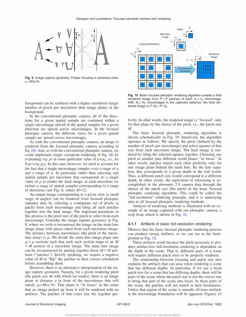
oreground can be rendered with a higher resolution �largerumber of pixels per microlens� than image planes in theackground.
In the conventional plenoptic camera, all of the direc-ions for a given spatial sample are contained within aingle microimage and all of the spatial samples for a givenirection are spread across microimages. In the focusedlenoptic camera, the different views for a given spatialample are spread across microimages.
As with the conventional plenoptic camera, an image isendered from the focused plenoptic camera according toq. �4�. And, as with the conventional plenoptic camera, weould implement single viewpoint rendering of Eq. �4� byvaluating r�q , p� at some particular value of p= p0, i.e., let�q�=r�q , p0�. In this case, however, we need to account forhe fact that a single microimage samples over a range of qnd a range of p. In particular, rather than selecting onepatial sample per microlens that corresponds to a singlealue of p to render the final image, at each microlens wextract a range of spatial samples corresponding to a rangef directions �see Fig. 8, where M =2�.
An output image corresponding to a given view �a smallange of angles� can be rendered from focused plenopticadiance data by selecting a contiguous set of pixels �aatch� from each microimage and tiling all such patchesogether into the final image. The important parameter inhis process is the pixel size of the patch to select from eachicroimage. Consider the image capture geometry in Fig.
, where we wish to reconstruct the image on the main lensmage plane with pieces taken from each microlens image.he distance between microlenses �the pitch of the micro-
ens array� is �. We divide the main lens image plane into�� sections such that each such section maps to an MM portion of a microlens image. The main lens image
an be reconstructed by putting together those M �M por-ions �“patches”�. Strictly speaking, we require a negativealue of M to “flip” the patches to their correct orientationefore assembling them.
However, there is an alternative interpretation of the im-ge capture geometry. Namely, for a given rendering pitchthe patch size M with which we render�, there is an imagelane at distance a in front of the microlenses that willatisfy �=M�a /b�. That plane is “in focus” in the sensehat an image picked up from it will be rendered with nortifacts. The patches of that exact size tile together per-
ig. 9 Image capture geometry. Proper focusing is achieved when=M�a /b�.
ournal of Electronic Imaging 021106-
Downloaded from SPIE Digital Library on 29 Sep 2011 to 150
fectly. In other words, the rendered image is “focused” onlyfor that plane by the choice of the pitch, i.e., the patch sizeM.
The basic focused plenoptic rendering algorithm isshown schematically in Fig. 10. Intuitively, the algorithmoperates as follows. We specify the pitch �defined by thenumber of pixels per microimage� and select squares of thatsize from each microlens image. The final image is ren-dered by tiling the selected squares together. Choosing onepitch or another puts different world planes “in focus.” Inother words, patches match each other perfectly only forone image plane behind the main lens. By the lens equa-tion, this corresponds to a given depth in the real world.Thus, a different patch size would correspond to a differentdepth. In other words, the equivalent of refocusing is ac-complished in the plenoptic 2.0 camera data through thechoice of the patch size �the pitch� in the basic focusedplenoptic rendering algorithm. This could be called the“full-resolution” rendering principle, and it is underlyingidea in all focused plenoptic rendering methods.
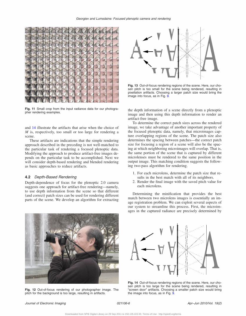
Analysis of rendering methods is illustrated with an ex-ample of an image captured with our plenoptic camera, acrop from which is shown in Fig. 11.
4.1.1 Artifacts in basic full-resolution renderingObserve that the basic focused plenoptic rendering processcan produce strong artifacts, as we can see in the back-ground in Fig. 12.
These artifacts result because the pitch necessary to pro-duce artifact-free full-resolution rendering is dependent onthe depth in the scene. That is, different parts of a scenewill require different patch sizes to be properly rendered.
The relationship between focusing and patch size alsoexplains the artifacts that can arise when rendering a scenethat has different depths. In particular, if we use a fixedpatch size for a scene that has differing depths, there will beparts of the scene where the patch size is not the correct oneto bring that part of the scene into focus. In those parts ofthe scene, the patches will not match at their boundaries.Unless that region of the scene is smooth, obvious artifactsat the microimage boundaries will be apparent. Figures 13
Nx
Ny
nx
ny
P
P
Full ResolutionRendering
RenderedImage
Captured Radiance
P · Nx
P · Ny
PatchMicrolensImage
Fig. 10 Basic focused plenoptic rendering algorithm creates a finalrendered image from P�P patches of each nx�ny microimage.With Nx�Ny microimages in the captured radiance, the final ren-dered image is P ·Nx�P ·Ny.
Apr–Jun 2010/Vol. 19(2)5
.135.223.93. Terms of Use: http://spiedl.org/terms
a
s
atMpwa
4Dst�p
Fp
Fp
Georgiev and Lumsdaine: Focused plenoptic camera and rendering
J
nd 14 illustrate the artifacts that arise when the choice ofM is, respectively, too small or too large for rendering acene.
These artifacts are indications that the simple renderingpproach described in the preceding is not well-matched tohe particular task of rendering a focused plenoptic data.
odifying the approach to produce artifact-free images de-ends on the particular task to be accomplished. Next weill consider depth-based rendering and blended rendering
s basic approaches to reduce artifacts.
.2 Depth-Based Renderingepth-dependence of focus for the plenoptic 2.0 camera
uggests one approach for artifact-free rendering—namely,o use depth information from the scene so that differentand correct� patch sizes can be used for rendering differentarts of the scene. We develop an algorithm for extracting
ig. 11 Small crop from the input radiance data for our photogra-her rendering examples.
ig. 12 Out-of-focus rendering of our photographer image. Theitch for the background is too large, resulting in artifacts.
ournal of Electronic Imaging 021106-
Downloaded from SPIE Digital Library on 29 Sep 2011 to 150
the depth information of a scene directly from a plenopticimage and then using this depth information to render anartifact-free image.
To determine the correct patch sizes across the renderedimage, we take advantage of another important property ofthe focused plenoptic data, namely, that microimages cap-ture overlapping regions of the scene. The patch size alsodetermines the spacing between patches—the correct patchsize for focusing a region of a scene will also be the spac-ing at which neighboring microimages will overlap. That is,the same portion of the scene that is captured by differentmicrolenses must be rendered to the same position in theoutput image. This matching condition suggests the follow-ing two-pass algorithm for rendering.
1. For each microlens, determine the patch size that re-sults in the best match with all of its neighbors.
2. Render the final image with the saved pitch value foreach microlens.
Determining the minification that provides the bestmatch between two microlens images is essentially an im-age registration problem. We can exploit several aspects ofour system to streamline this process. First, the microim-ages in the captured radiance are precisely determined by
Fig. 13 Out-of-focus rendering regions of the scene. Here, our cho-sen pitch is too small for the scene being rendered, resulting inpixellation artifacts. Choosing a larger patch size would bring theimage into focus, as in Fig. 9.
Fig. 14 Out-of-focus rendering regions of the scene. Here, our cho-sen pitch is too large for the scene being rendered, resulting in“screen door” artifacts. Choosing a smaller patch size would bringthe image into focus, as in Fig. 9.
Apr–Jun 2010/Vol. 19(2)6
.135.223.93. Terms of Use: http://spiedl.org/terms
tdhhboTp
ast
4
ptbpg
a
Georgiev and Lumsdaine: Focused plenoptic camera and rendering
J
he microlens geometry, and precisely aligned. Thus, theifference between neighboring microimages along theorizontal and vertical axes of the lens array will be onlyorizontal and vertical translations, respectively. Moreover,ased on the optical design of the camera, there are boundsn how large the shift between microlens images can be.hese characteristics of the captured radiance greatly sim-lify the depth estimation algorithm.
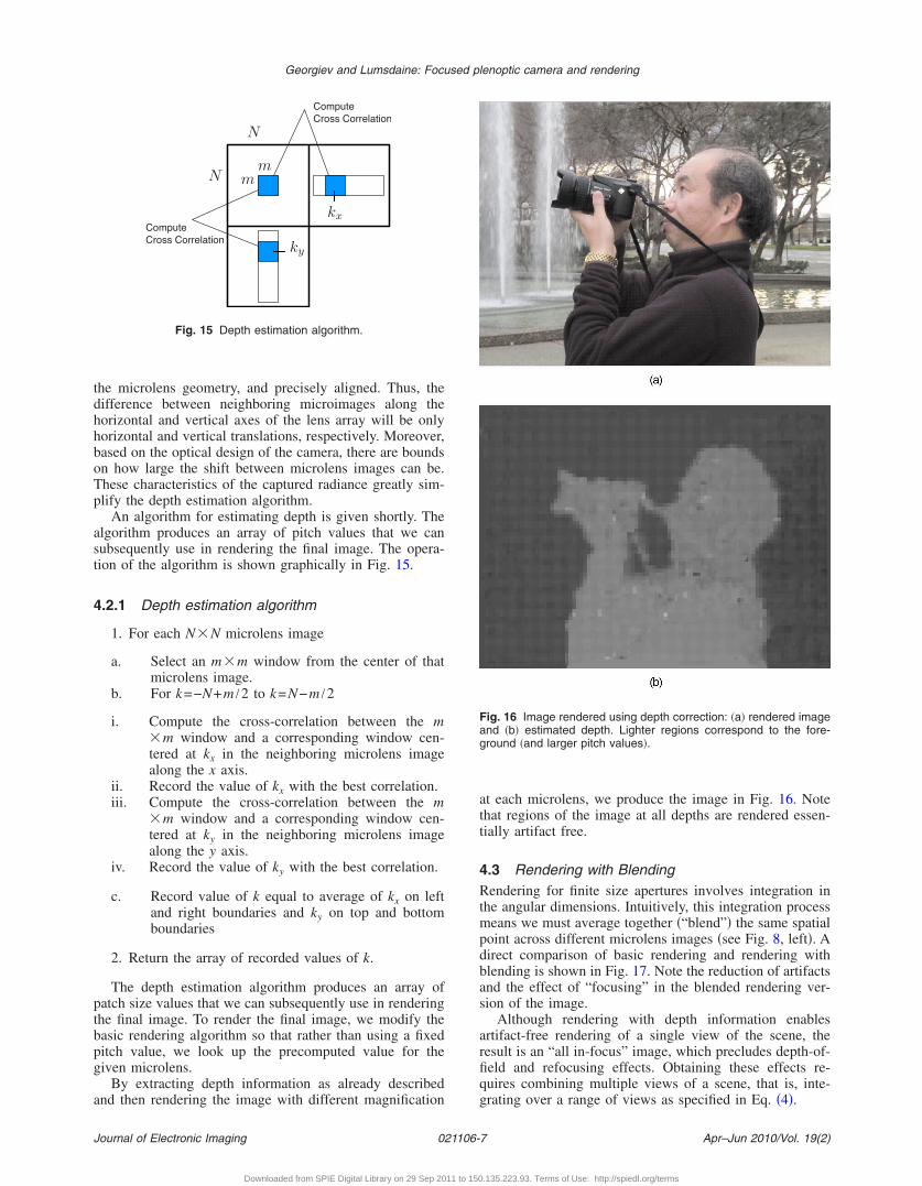
An algorithm for estimating depth is given shortly. Thelgorithm produces an array of pitch values that we canubsequently use in rendering the final image. The opera-ion of the algorithm is shown graphically in Fig. 15.
.2.1 Depth estimation algorithm
1. For each N�N microlens image
a. Select an m�m window from the center of thatmicrolens image.
b. For k=−N+m /2 to k=N−m /2
i. Compute the cross-correlation between the m�m window and a corresponding window cen-tered at kx in the neighboring microlens imagealong the x axis.
ii. Record the value of kx with the best correlation.iii. Compute the cross-correlation between the m
�m window and a corresponding window cen-tered at ky in the neighboring microlens imagealong the y axis.
iv. Record the value of ky with the best correlation.
c. Record value of k equal to average of kx on leftand right boundaries and ky on top and bottomboundaries
2. Return the array of recorded values of k.
The depth estimation algorithm produces an array ofatch size values that we can subsequently use in renderinghe final image. To render the final image, we modify theasic rendering algorithm so that rather than using a fixeditch value, we look up the precomputed value for theiven microlens.
By extracting depth information as already describednd then rendering the image with different magnification
mmN
N
kx
ky
ComputeCross Correlation
ComputeCross Correlation
Fig. 15 Depth estimation algorithm.
ournal of Electronic Imaging 021106-
Downloaded from SPIE Digital Library on 29 Sep 2011 to 150
at each microlens, we produce the image in Fig. 16. Notethat regions of the image at all depths are rendered essen-tially artifact free.
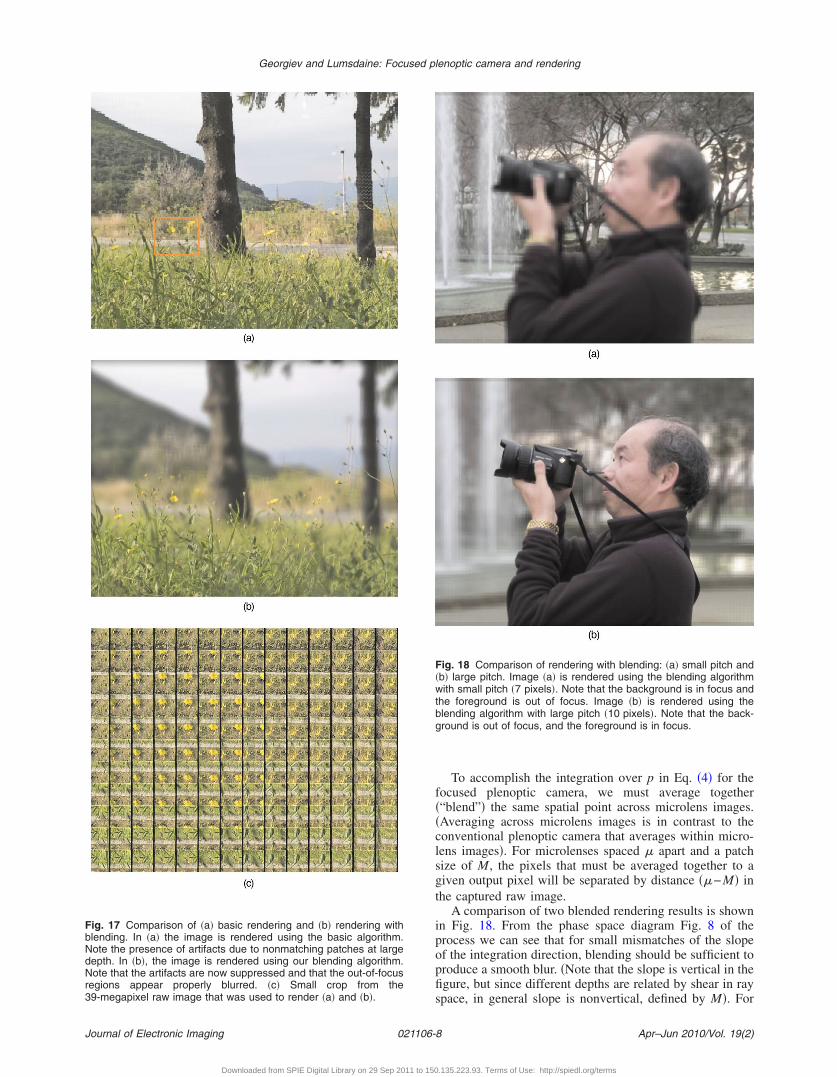
4.3 Rendering with BlendingRendering for finite size apertures involves integration inthe angular dimensions. Intuitively, this integration processmeans we must average together �“blend”� the same spatialpoint across different microlens images �see Fig. 8, left�. Adirect comparison of basic rendering and rendering withblending is shown in Fig. 17. Note the reduction of artifactsand the effect of “focusing” in the blended rendering ver-sion of the image.
Although rendering with depth information enablesartifact-free rendering of a single view of the scene, theresult is an “all in-focus” image, which precludes depth-of-field and refocusing effects. Obtaining these effects re-quires combining multiple views of a scene, that is, inte-grating over a range of views as specified in Eq. �4�.
Fig. 16 Image rendered using depth correction: �a� rendered imageand �b� estimated depth. Lighter regions correspond to the fore-ground �and larger pitch values�.
Apr–Jun 2010/Vol. 19(2)7
.135.223.93. Terms of Use: http://spiedl.org/terms
FbNdNr3
Georgiev and Lumsdaine: Focused plenoptic camera and rendering
Journal of Electronic Imaging 021106-
Downloaded from SPIE Digital Library on 29 Sep 2011 to 150
To accomplish the integration over p in Eq. �4� for thefocused plenoptic camera, we must average together�“blend”� the same spatial point across microlens images.�Averaging across microlens images is in contrast to theconventional plenoptic camera that averages within micro-lens images�. For microlenses spaced � apart and a patchsize of M, the pixels that must be averaged together to agiven output pixel will be separated by distance ��−M� inthe captured raw image.
A comparison of two blended rendering results is shownin Fig. 18. From the phase space diagram Fig. 8 of theprocess we can see that for small mismatches of the slopeof the integration direction, blending should be sufficient toproduce a smooth blur. �Note that the slope is vertical in thefigure, but since different depths are related by shear in rayspace, in general slope is nonvertical, defined by M�. For
Fig. 18 Comparison of rendering with blending: �a� small pitch and�b� large pitch. Image �a� is rendered using the blending algorithmwith small pitch �7 pixels�. Note that the background is in focus andthe foreground is out of focus. Image �b� is rendered using theblending algorithm with large pitch �10 pixels�. Note that the back-ground is out of focus, and the foreground is in focus.
ig. 17 Comparison of �a� basic rendering and �b� rendering withlending. In �a� the image is rendered using the basic algorithm.ote the presence of artifacts due to nonmatching patches at largeepth. In �b�, the image is rendered using our blending algorithm.ote that the artifacts are now suppressed and that the out-of-focus
egions appear properly blurred. �c� Small crop from the9-megapixel raw image that was used to render �a� and �b�.
Apr–Jun 2010/Vol. 19(2)8
.135.223.93. Terms of Use: http://spiedl.org/terms
lwr
4AacgvdtdWtptsw
5Icmdaitt3ctt
TcaempwiF�
aplrdtd
owbf
6Wcd
Georgiev and Lumsdaine: Focused plenoptic camera and rendering
J
arger mismatches, we might not have enough views ande may instead see ghostlike artifacts due to features being
epeated across multiple patches.
.3.1 Focusingn important characteristic of the plenoptic 2.0 camera was
lready mentioned: refocusing is accomplished throughhoice of the pitch size in the full-resolution rendering al-orithm. That pitch is related to shear in ray space. Con-ersely, the value of the pitch determines the plane �theepth� in the image that is in focus. Images captured withhe focused plenoptic camera can therefore refocus ren-ered images by choosing different values of the pitch size.hen multiple microlens images are integrated �blended�,
he out-of-focus regions appear blurred, as would be ex-ected. Because the microlenses have a very small aperture,here is a significant depth of field, i.e., portions of thecene that are in focus for a given value of the pitch sizeill extend for a large depth.
Camera Prototypen this section, we present details of our current physicalamera along with rationale for its design. The camera isedium format with an 80-mm lens and a 39-Mpixel P45
igital back from Phase One. To produce square microim-ges that tile together with little loss of sensor space wentroduced a square aperture at the original aperture loca-ion. Since the microlenses are focused on the image ratherhan the main lens aperture, there is a blur of approximately
pixels at the boundary of each microimage, which pixelsannot be used in rendering. Also, we mounted the lens onhe camera with a 13-mm extension tube, which provideshe needed spacing a.
The microlens array is custom made by Leister Axetris.he microlenses have focal length of 1.5 mm so that theyan be placed directly on the cover glass of the sensor. Were able to provide additional spacing of up to 0.5 mm tonable fine-tuning of the microlens focus. The pitch of theicrolenses is 500 �m with precision 1 �m. The sensor
ixels are 6.8 �m. The value of b1.6 mm was estimatedith precision 0.1 mm from known sensor parameters and
ndependently from the microlens images at different-numbers. Captured plenoptic images are 73085494 pixels.Our microlens apertures are circular, with 100-�m di-
meters, and are formed by the black chromium mask de-osited on the microlenses. This small aperture provides aarger depth of field for the microimages, enabling a greaterange for refocusing. While the small apertures extendepth of field and make microlenses diffraction limited,hey also introduce high F-number and, associated with it,iffraction blur and longer exposure times.
The relatively large pitch of the microlenses is chosen inrder to match the F-number of the main camera lens,hich can be as low as F /3. This large pitch is neededecause our microlenses are at large distance �1.6 mm�rom the sensor, defined by the cover glass.
Conclusione showed that a modified, 2.0 version of the plenoptic
amera can be used to capture higher spatial resolution ra-iance data. By analyzing the ray space model of the cam-
ournal of Electronic Imaging 021106-
Downloaded from SPIE Digital Library on 29 Sep 2011 to 150
era we derived an algorithm for synthesizing all-in-focusimages from different viewpoints, and a method for reduc-ing the artifacts that are well known for this type of imag-ing. Another algorithm, for synthesizing shallow-depth-of-field images and refocusing on different depths was alsopresented. All these algorithms are implemented on theGPU, as shaders in OpenGL, and used to render refocusedviews at interactive rates at full screen resolution.
Looking into the future, our ongoing work indicates thatvery promising results are possible. We can improve thequality of rendering by applying more sophisticated �butstill interactive� algorithms for blending and filtering theradiance data. Such algorithms can produce perfect-qualityrefocused images from even sparser, in the angular dimen-sions, input data captured with our camera. Such data havehigher spatial resolution that could reach 5 to 10 Mpixelswith our 39-Mpixel input, meeting the needs of modernphotographers, while being refocusable and generating dif-ferent views.
Appendix A: GPU Implementation of BasicRenderingOur GLSL implementations of lightfield rendering are car-ried out completely in OpenGL fragment shaders. Althoughour examples were implemented in Python �via the Py-OpenGL library16�, interfaces to OpenGL are similar acrosslanguages. Other than providing support for creating andinstalling the shader, the main functionality provided byOpenGL were the following:
1. Read in the plenoptic image data �from a stored im-age�.
2. Serialize the lightfield data to a format suitable forOpenGL.
3. Create a 2-D OpenGL texture object for the plenopticimage data.
4. Define the texture in OpenGL, using the serializedimage data.
Rendering the plenoptic image data is then accom-plished by rendering the installed texture, using our customshader. To explain the operation of the basic shader, wediscuss some of the details of the optical image capturegeometry as interpreted by OpenGL.
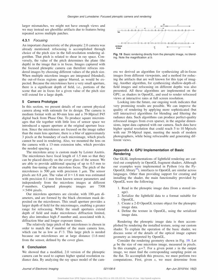
Consider the rendering geometry shown in Fig. 19. Let� be the size of one microlens image, measured in pixels.In this example, �=7. For a given point x in the outputimage, we must find the corresponding sampling point onthe flat. To accomplish this process, we must perform twocomputations. First, given x, we must determine from
Fig. 19 Basic rendering directly from the plenoptic image, no blend-ing. Note the magnification a /b.
Apr–Jun 2010/Vol. 19(2)9
.135.223.93. Terms of Use: http://spiedl.org/terms
wm
to
Tflt
cboflrb
q
tcpiro
q
t
r
uP
u
u
u
v
�
xx
=
Georgiev and Lumsdaine: Focused plenoptic camera and rendering
J
hich microlens we will render x. Second, we must deter-ine where in the region of size M the point x lies.To compute which microlens corresponds to x, we take
he integer part of x divided by �, which gives us the indexf the microlens. In other words, this number �let us call it
p� is given by
p = � x
� � . �8�
he pixel location of the beginning of that microlens in theat is then given by multiplying the microlens number by
he size of one microlens image, i.e., p�.Next, we compute the offset within the region of size M
orresponding to x. To do this, we compute the differenceetween x and the start of microlens �p�. This will give theffset in the rendered image, but we need the offset in theat. Since we are scaling a region of size M in the flat to aegion of size � in the final image, the offset must be scaledy M /�. That is, the offset q is given by
= �x − � x
� ���M
�= � x
�− p�M . �9�
Finally, we must make one more adjustment. We wanthe center of the M �M region of the flat to render to theenter of the corresponding region of the final image. Thereceding formulas will map the left edge of the microlensmage to the left edge of the corresponding region in theendered image. To accomplish this centering, we add anffset of ��−M� /2 to q:
� = q +� − M
2= � x
�− p�M +
� − M
2. �10�
Combining Eqs. �8� and �10�, the corresponding point inhe flat for a given point x in the output image is given byf�x�, where
f�x� = p� + q�. �11�
The GLSL fragment shader code to carry out this algo-ithm is as follows:
niform sampler2DRect flat; //lenoptic image
niofrm float M, mu;
niform float XOffset;
niform float YOffset;
oid main��
vec2_mu=gl_TexCoord�0 .st/mu; ///�
vec2 p=floor�x_mu�; // p�x /��
ournal of Electronic Imaging 021106-1
Downloaded from SPIE Digital Library on 29 Sep 2011 to 150
vec2 q= �x_mu−p��M; //�x /�−p�M
vec2qp=q+0.5� �mu−M�; // q�=q+ ��−M� /2
vec2offset=vec2�XOffset,YOffset�� �mu−M�;
vec2fx=p�mu+qp+offset; // f�x�=p�+q�
gl_FragColor= texture2DRect�flat, fx�;
�
The plenoptic image, as well as the values for � and M,are provided by the user program via uniform variables.The shader program computes q, q�, and f�x� as q, qp, andfx, respectively. Changing the viewpoint of a synthesizedimage is enabled by adding user-specified offsets, XOffsetand XOffset �both equal to 0 by default�, to the coordinatesfx. Finally, we look up the value of the pixel in the flat andassign that value to the requested fragment color.
AcknowledgmentsThe authors gratefully acknowledge the support fromAdobe Systems, Inc., for this work. The authors also thankthe anonymous reviewers for their helpful comments.
References1. F. Ives, “Parallax sterogram and the process of making sameU.S.
Patent No. 725,567 �1903�.2. G. Lippmann, “Epreuves reversibles. Photographies integrales,”
Acad. Sci. 146, 446–451 �Mar. 1908�.3. T. Adelson and J. Bergen, “The plenoptic function and the elements
of early vision,” in Computational Models of Visual Processing, MITPress, Cambridge, MA �1991�.
4. T. Adelson and J. Wang, “Single lens stereo with a plenoptic cam-era,” IEEE Trans. Pattern Anal. Mach. Intell. 14, 99–106 �1992�.
5. M. Levoy and P. Hanrahan, “Light field rendering,” ACM Trans.Graphics 23, 31–42 �1996�.
6. S. J. Gortler, R. Grzeszczuk, R. Szeliski, and M. F. Cohen, “Thelumigraph,” ACM Trans. Graphics 23, 43–54 �1996�.
7. R. Ng, M. Levoy, M. Bredif, G. Duval, M. Horowitz, and P. Hanra-han, “Light field photography with a hand-held plenoptic camera,”Computer Science Technical Report CSTR �Jan 2005�.
8. R. Ng, “Fourier slice photography,” ACM Trans. Graphics 24�3�,735–744 �2005�.
9. A. Lumsdaine and T. Georgiev, “Full resolution lightfield rendering,”Tech. Rep., Adobe Systems �2008�.
10. A. Lumsdaine and T. Georgiev, “The focused plenoptic camera,” inProc. Int. Conf. on Computational Photography, pp. 1-11, StanfordUniversity �2009�.
11. J. Tanida, T. Kumagai, K. Yamada, and S. Miyatake, “Thin observa-tion module by bound optics �tombo�: concept and experimental veri-fication,” Appl. Opt. 40�11�, 1806–1813 �Jan. 2001�.
12. K. Fife, A. El Gamal, and H.-S. Wong, “A 3d multi-aperture imagesensor architecture,” in Proc. Custom Integrated Circuits Conf., pp.281–284, IEEE �2006�.
13. K. Fife, A. El Gamal, and H.-S. P. Wong, “A 3mpixel multi-apertureimage sensor with 0.7 um pixels in 0.11 um CMOS,” in IEEE ISSCCDigest of Technical Papers pp. 48–49 �2008�.
14. M. Christensen, M. Haney, D. Rajan, S. Douglas, and S. Wood, “Pan-optes: a thin agile multi-resolution imaging sensor,” in Proc. Govern-ment Microcuircuit Applications and Critical Technology Conf.(GOMACTech-05), pp. 1–8, IEEE �Jan. 2005�.
15. R. Ng, “Digital light field photography,” PhD thesis, Stanford Uni-versity, Stanford, CA �2006�.
16. “PyOpenGL,” http://pyopengl.sourceforge.net/, http://pyopengl.sourceforge.net/.
Apr–Jun 2010/Vol. 19(2)0
.135.223.93. Terms of Use: http://spiedl.org/terms
fapmp
Georgiev and Lumsdaine: Focused plenoptic camera and rendering
J
Todor Georgiev is a senior research sci-entist with Adobe Systems, working closelywith the Photoshop group. Having exten-sive background in theoretical physics, heconcentrates on applications of mathemati-cal methods taken from physics to imageprocessing, graphics, and vision. He is theauthor of the award-winning Healing Brushtool in Photoshop �2002�, the method bet-ter known as Poisson image editing. Hehas published a number of papers on dif-
erent applications of mathematical methods to image processingnd vision. Currently he is focusing on a range of theoretical andractical ideas related to optics for plenoptic cameras and capture/anipulations of the optical field. He holds 25 U.S. and Internationalatents.
ournal of Electronic Imaging 021106-1
Downloaded from SPIE Digital Library on 29 Sep 2011 to 150
Andrew Lumsdaine received his PhD de-gree in electrical engineering and computerscience from the Massachusetts Institute ofTechnology in 1992. He is currently a pro-fessor of computer science at Indiana Uni-versity, where he is also directs the OpenSystems Laboratory. His research interestsinclude computational science and engi-neering, parallel and distributed computing,mathematical software, numerical analysis,and radiance photography. He was a re-
cipient of the National Science Foundation �NSF� CAREER awardand is a member of the IEEE, the IEEE Computer Society, the ACM,and SIAM.
Apr–Jun 2010/Vol. 19(2)1
.135.223.93. Terms of Use: http://spiedl.org/terms


