Embed Size (px)
Citation preview

1 23
Bulletin of Engineering Geology andthe EnvironmentThe official journal of the IAEG ISSN 1435-9529 Bull Eng Geol EnvironDOI 10.1007/s10064-014-0588-6
Flyrock in bench blasting: a comprehensivereview
A. K. Raina, V. M. S. R. Murthy &A. K. Soni

1 23
Your article is protected by copyright and
all rights are held exclusively by Springer-
Verlag Berlin Heidelberg. This e-offprint is
for personal use only and shall not be self-
archived in electronic repositories. If you wish
to self-archive your article, please use the
accepted manuscript version for posting on
your own website. You may further deposit
the accepted manuscript version in any
repository, provided it is only made publicly
available 12 months after official publication
or later and provided acknowledgement is
given to the original source of publication
and a link is inserted to the published article
on Springer's website. The link must be
accompanied by the following text: "The final
publication is available at link.springer.com”.

ORIGINAL PAPER
Flyrock in bench blasting: a comprehensive review
A. K. Raina • V. M. S. R. Murthy • A. K. Soni
Received: 20 June 2013 / Accepted: 25 February 2014
� Springer-Verlag Berlin Heidelberg 2014
Abstract Flyrock is unwanted throw of rock fragments
during bench blasting in mines and civil constructions.
Perfunctory attempts by researchers to predict the flyrock
range using mathematical, empirical and ANN based
models do not address the issue in totality. Thus, flyrock
continues to haunt the blaster. The research on the subject
is, thus, still in its infancy. This paper identifies the lacu-
nae, through a comprehensive review of the existing
models, and suggests measures for better prediction and
understanding of the problem on a holistic plane. One of
the main reasons for improper predictions is the lack of
data on flyrock in comparison to blast vibrations owing to
statutory restrictions, avoidance of reporting and conse-
quent constraints on experimentation. While fragmentation
and throw of rock accompanied by subsequent vibration
and air overpressure are essential constituents of the
blasting, flyrock is not. This probably is one of the main
errors in predictive domains. In addition, rock mass prop-
erties play a major role in heaving of rock fragments during
blasting. Barring density of the rock, other rock mass
properties have practically been ignored in all the models.
At the end of this paper, for future investigations, a
methodology for prediction of flyrock is also given.
Keywords Surface bench blasting � Flyrock prediction �Safety � Danger zone � Literature review
Introduction
Blasting is a rock-explosive interaction system. The explo-
sive after detonation releases gases, which in turn produces
pressures to the order of a few GPa. The outcome of blasting
is primarily dependent upon the rock mass, explosive prop-
erties, blast design, and execution of blast according to the
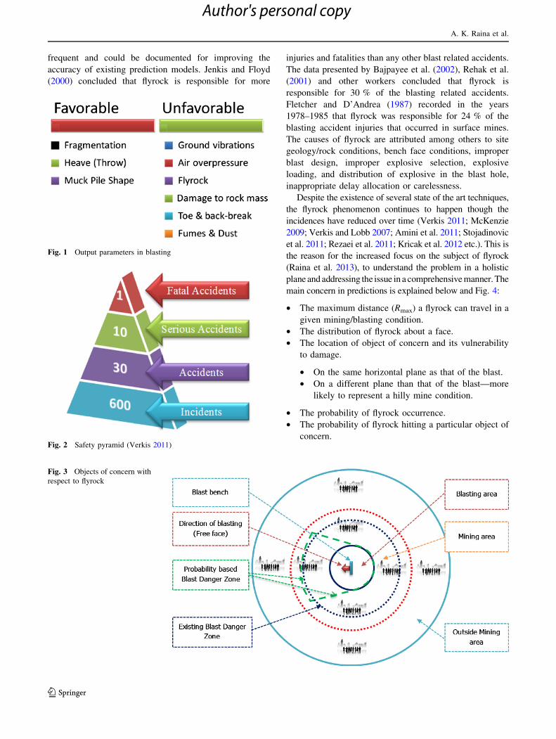
standard design procedures. Fragmented rock, heap, ground
vibrations, air overpressure, noise, fumes, dust, and flyrock
(Fig. 1) are some of the outcomes of a blast, further classified
into favourable and unfavourable parameters.
The ground vibrations and air overpressure have
received significant attention from the researchers. Thus,
the regulations and guidelines for prediction and control of
vibrations and air overpressure are, more or less, defined.
There is, however, a degree of subjectivity in assessing the
absolute effects of ground vibrations and air overpressure
and the investigations are markedly different in terms of
response of the people living in nearby areas. One of the
major concerns—the flyrock, in contrast, cannot be sub-
jective as no one can be hit by an imaginary flyrock (Ro-
senthal and Morlock 1987). Flyrock is defined as the
excessive random throw of rock fragments from a blast that
can travel distances beyond desired values and present a
serious threat to people and property in and around the
mine. There can be small to fatal accidents (Verkis 2011;
Fig. 2) due to flyrock and is, thus, a subject of concern.
Flyrock is one of the contentious issues in surface blast-
ing. The phenomenon of flyrock is important since it
involves risk to people and structures (Objects of concern;
Fig. 3) within and outside the mining area. The vulnerability
of different objects of concern is explained in Table 1.
The accidents due to flyrock are rarely reported (Davies
1995) and is one of the major problems in prediction
regime. However, the flyrock that cause no damage are
A. K. Raina (&) � A. K. Soni
Regional Centre Unit-I, CSIR—Central Institute of Mining and
Fuel Research, 3rd Floor MECL Complex, Seminary Hills,
Nagpur 440 006, India
e-mail: [email protected]
V. M. S. R. Murthy � A. K. Soni
Department of Mining Engineering, Indian School of Mines,
Dhanbad 826 008, India
123
Bull Eng Geol Environ
DOI 10.1007/s10064-014-0588-6
Author's personal copy
frequent and could be documented for improving the
accuracy of existing prediction models. Jenkis and Floyd
(2000) concluded that flyrock is responsible for more
injuries and fatalities than any other blast related accidents.
The data presented by Bajpayee et al. (2002), Rehak et al.
(2001) and other workers concluded that flyrock is
responsible for 30 % of the blasting related accidents.
Fletcher and D’Andrea (1987) recorded in the years
1978–1985 that flyrock was responsible for 24 % of the
blasting accident injuries that occurred in surface mines.
The causes of flyrock are attributed among others to site
geology/rock conditions, bench face conditions, improper
blast design, improper explosive selection, explosive
loading, and distribution of explosive in the blast hole,
inappropriate delay allocation or carelessness.
Despite the existence of several state of the art techniques,
the flyrock phenomenon continues to happen though the
incidences have reduced over time (Verkis 2011; McKenzie
2009; Verkis and Lobb 2007; Amini et al. 2011; Stojadinovic
et al. 2011; Rezaei et al. 2011; Kricak et al. 2012 etc.). This is
the reason for the increased focus on the subject of flyrock
(Raina et al. 2013), to understand the problem in a holistic
plane and addressing the issue in a comprehensive manner. The
main concern in predictions is explained below and Fig. 4:
• The maximum distance (Rmax) a flyrock can travel in a
given mining/blasting condition.
• The distribution of flyrock about a face.
• The location of object of concern and its vulnerability
to damage.
• On the same horizontal plane as that of the blast.
• On a different plane than that of the blast—more
likely to represent a hilly mine condition.
• The probability of flyrock occurrence.
• The probability of flyrock hitting a particular object of
concern.
Fig. 1 Output parameters in blasting
Fig. 2 Safety pyramid (Verkis 2011)
Fig. 3 Objects of concern with
respect to flyrock
A. K. Raina et al.
123
Author's personal copy
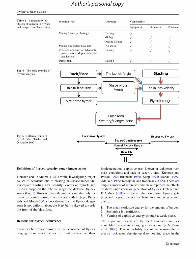
Definition of flyrock security zone (danger zone)
Fletcher and D’Andrea (1987) while investigating major
causes of accidents due to blasting in surface mines viz.
inadequate blasting area security, excessive flyrock and
misfires proposed the relative ranges of different flyrock
zones (Fig. 5). However, their definition is suitable only for
throw, excessive throw, since several authors (e.g., Rich-
ards and Moore 2004) have shown that the flyrock danger
zone is not uniform about the blast but is skewed towards
the front of the blast face.
Reasons for flyrock occurrence
There can be several reasons for the occurrence of flyrock
ranging from abnormalities in blast pattern or their
implementation, explosive use, known or unknown rock
mass conditions and lack of security area (Kuberan and
Prasad 1992; Bhandari 1994; Kopp 1994; Mandal 1997;
Adhikari 1999; Kecojevic and Radomsky 2005). There are
ample numbers of references that have reported the effects
of above said factors on generation of flyrock. Fletcher and
D’Andrea (1987) explained that excessive flyrock gets
projected beyond the normal blast area and is generated
due to:
1. Too much explosive energy for the amount of burden,
2. Stemming is insufficient,
3. Venting of explosive energy through a weak plane.
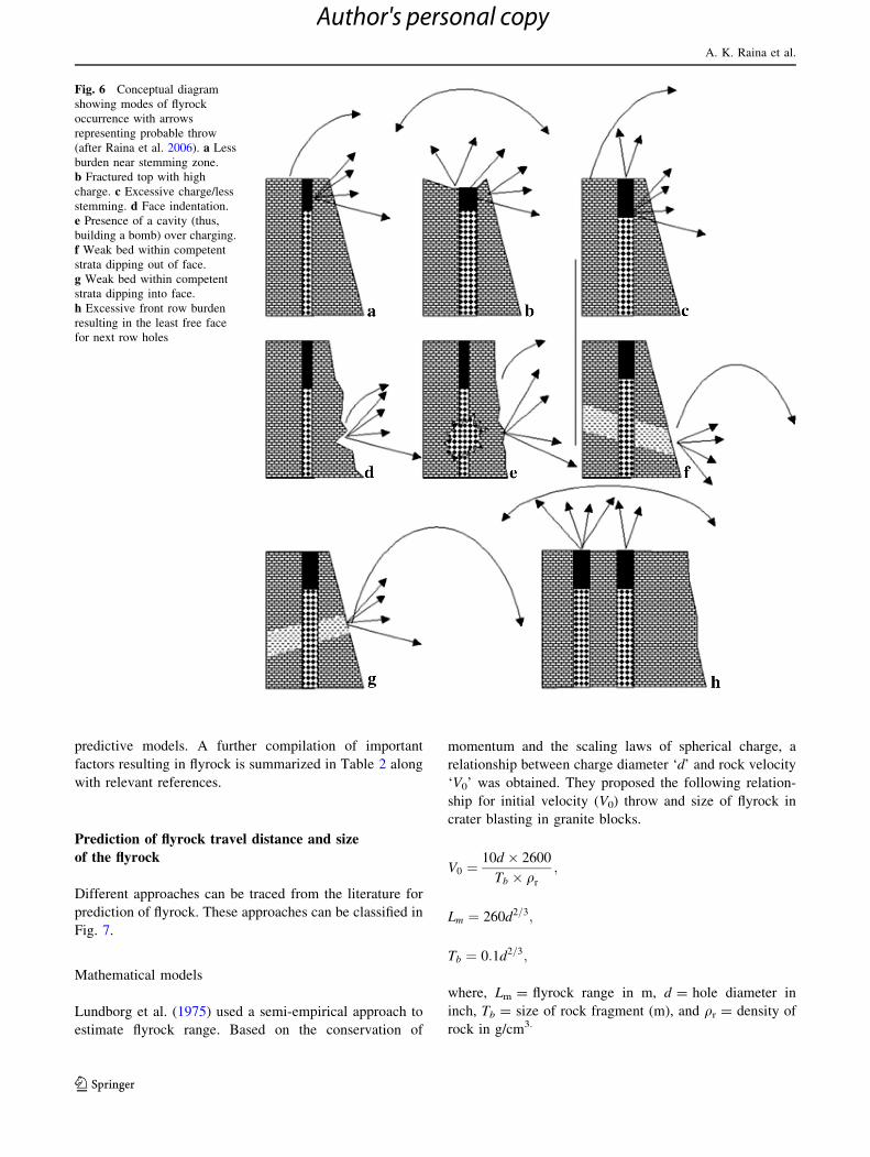
The important reasons are the local anomalies in rock
mass, blast pattern and charging as shown in Fig. 6 (Raina
et al. 2006). This is probably one of the reasons that a
precise rock mass description does not find place in the
Fig. 4 The basic premise of
flyrock analysis
Table 1 Vulnerability of
objects of concern to flyrock
and danger zone demarcation
Working type Area/zone Vulnerability
Equipment Structures Personnel
Mining (primary blasting) Blasting H
Mining H H H
Outside Mining H H H
Mining (secondary blasting) (As above) H H H
Civil and construction (channels,
power houses, slopes, industrial
installations)
Blasting H H H
Demolition Blasting H H H
Fig. 5 Different zones of
flyrock (after Fletcher and
D’Andrea 1987)
Flyrock in bench blasting
123
Author's personal copy
predictive models. A further compilation of important
factors resulting in flyrock is summarized in Table 2 along
with relevant references.
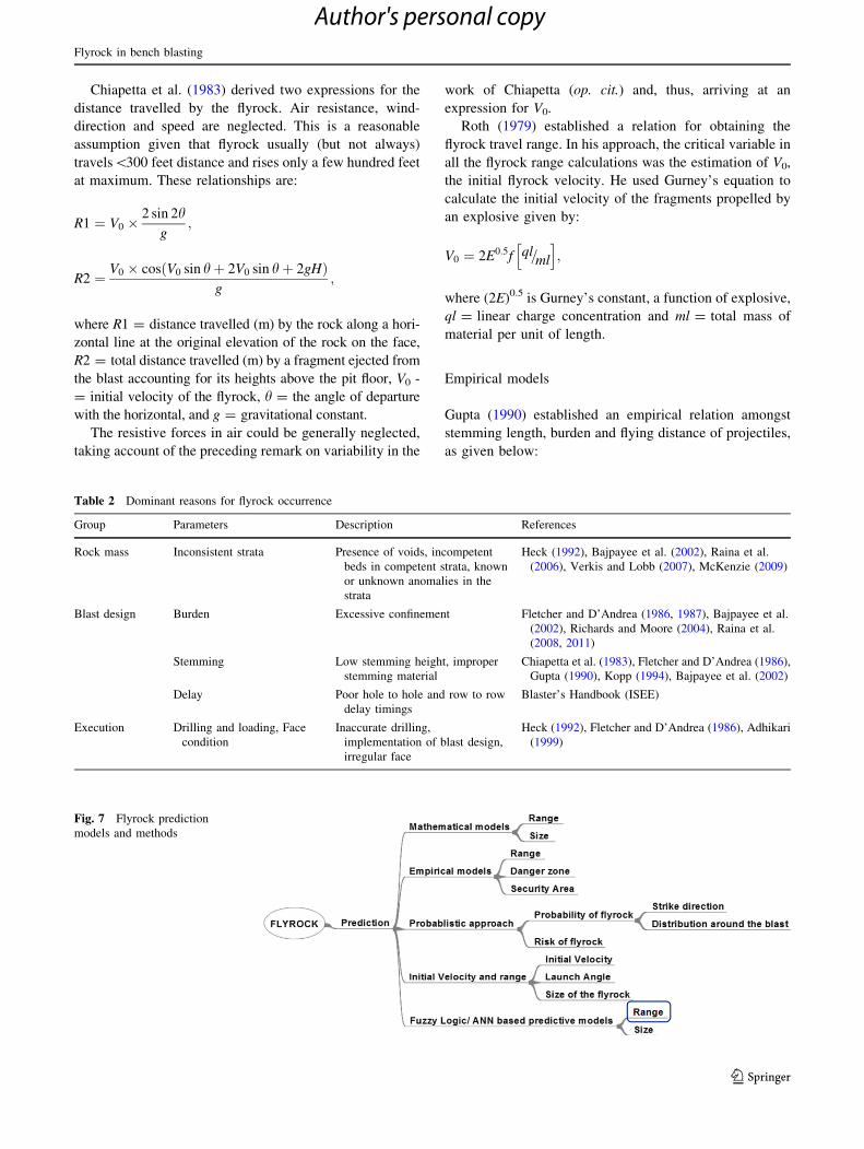
Prediction of flyrock travel distance and size
of the flyrock
Different approaches can be traced from the literature for
prediction of flyrock. These approaches can be classified in
Fig. 7.
Mathematical models
Lundborg et al. (1975) used a semi-empirical approach to
estimate flyrock range. Based on the conservation of
momentum and the scaling laws of spherical charge, a
relationship between charge diameter ‘d’ and rock velocity
‘V0’ was obtained. They proposed the following relation-
ship for initial velocity (V0) throw and size of flyrock in
crater blasting in granite blocks.
V0 ¼10d � 2600
Tb � qr
;
Lm ¼ 260d2=3;
Tb ¼ 0:1d2=3;
where, Lm = flyrock range in m, d = hole diameter in
inch, Tb = size of rock fragment (m), and qr = density of
rock in g/cm3.
Fig. 6 Conceptual diagram
showing modes of flyrock
occurrence with arrows
representing probable throw
(after Raina et al. 2006). a Less
burden near stemming zone.
b Fractured top with high
charge. c Excessive charge/less
stemming. d Face indentation.
e Presence of a cavity (thus,
building a bomb) over charging.
f Weak bed within competent
strata dipping out of face.
g Weak bed within competent
strata dipping into face.
h Excessive front row burden
resulting in the least free face
for next row holes
A. K. Raina et al.
123
Author's personal copy
Chiapetta et al. (1983) derived two expressions for the
distance travelled by the flyrock. Air resistance, wind-
direction and speed are neglected. This is a reasonable
assumption given that flyrock usually (but not always)
travels\300 feet distance and rises only a few hundred feet
at maximum. These relationships are:
R1 ¼ V0 �2 sin 2h
g;
R2 ¼ V0 � cos V0 sin hþ 2V0 sin hþ 2gHð Þg
;
where R1 = distance travelled (m) by the rock along a hori-
zontal line at the original elevation of the rock on the face,
R2 = total distance travelled (m) by a fragment ejected from
the blast accounting for its heights above the pit floor, V0 -
= initial velocity of the flyrock, h = the angle of departure
with the horizontal, and g = gravitational constant.
The resistive forces in air could be generally neglected,
taking account of the preceding remark on variability in the
work of Chiapetta (op. cit.) and, thus, arriving at an
expression for V0.
Roth (1979) established a relation for obtaining the
flyrock travel range. In his approach, the critical variable in
all the flyrock range calculations was the estimation of V0,
the initial flyrock velocity. He used Gurney’s equation to
calculate the initial velocity of the fragments propelled by
an explosive given by:
V0 ¼ 2E0:5f ql=ml
h i;
where (2E)0.5 is Gurney’s constant, a function of explosive,
ql = linear charge concentration and ml = total mass of
material per unit of length.
Empirical models
Gupta (1990) established an empirical relation amongst
stemming length, burden and flying distance of projectiles,
as given below:
Table 2 Dominant reasons for flyrock occurrence
Group Parameters Description References
Rock mass Inconsistent strata Presence of voids, incompetent
beds in competent strata, known
or unknown anomalies in the
strata
Heck (1992), Bajpayee et al. (2002), Raina et al.
(2006), Verkis and Lobb (2007), McKenzie (2009)
Blast design Burden Excessive confinement Fletcher and D’Andrea (1986, 1987), Bajpayee et al.
(2002), Richards and Moore (2004), Raina et al.
(2008, 2011)
Stemming Low stemming height, improper
stemming material
Chiapetta et al. (1983), Fletcher and D’Andrea (1986),
Gupta (1990), Kopp (1994), Bajpayee et al. (2002)
Delay Poor hole to hole and row to row
delay timings
Blaster’s Handbook (ISEE)
Execution Drilling and loading, Face
condition
Inaccurate drilling,
implementation of blast design,
irregular face
Heck (1992), Fletcher and D’Andrea (1986), Adhikari
(1999)
Fig. 7 Flyrock prediction
models and methods
Flyrock in bench blasting
123
Author's personal copy
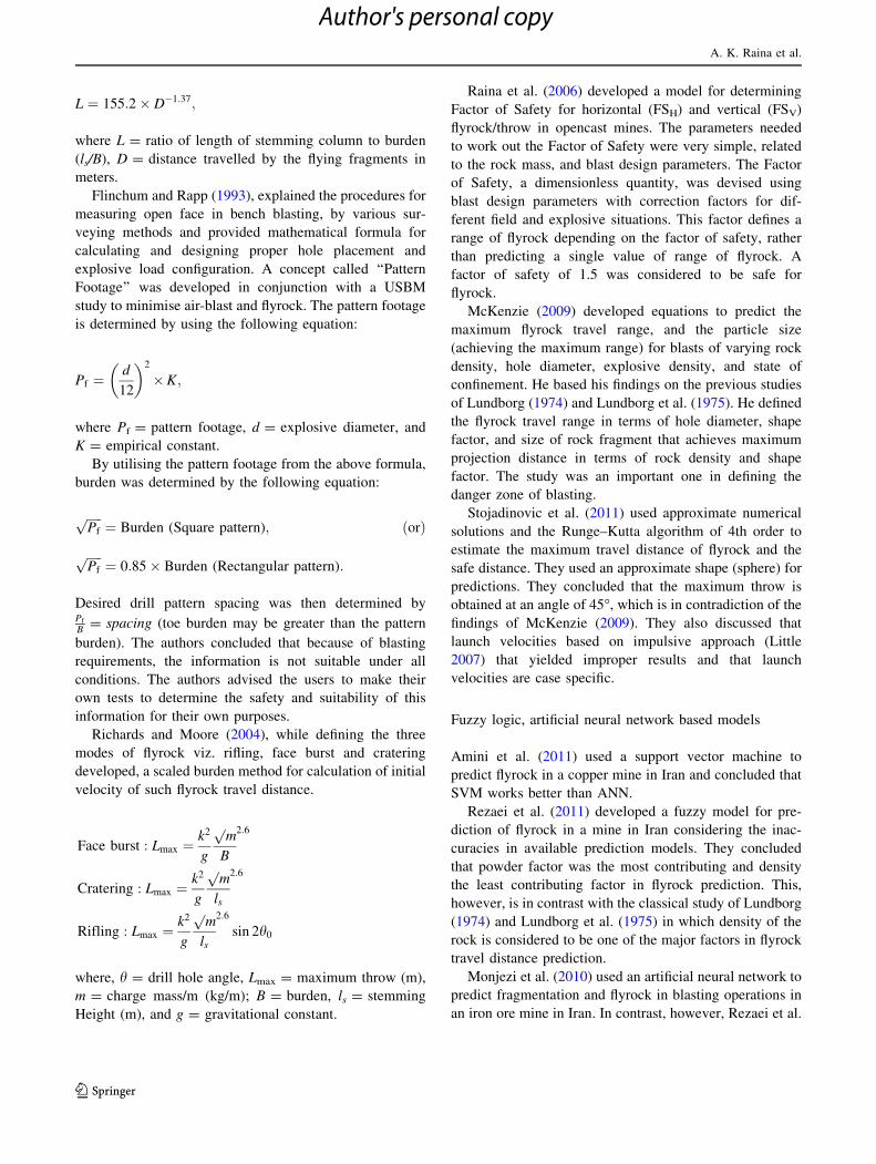
L ¼ 155:2� D�1:37;
where L = ratio of length of stemming column to burden
(ls/B), D = distance travelled by the flying fragments in
meters.
Flinchum and Rapp (1993), explained the procedures for
measuring open face in bench blasting, by various sur-
veying methods and provided mathematical formula for
calculating and designing proper hole placement and
explosive load configuration. A concept called ‘‘Pattern
Footage’’ was developed in conjunction with a USBM
study to minimise air-blast and flyrock. The pattern footage
is determined by using the following equation:
Pf ¼d
12
� �2
�K;
where Pf = pattern footage, d = explosive diameter, and
K = empirical constant.
By utilising the pattern footage from the above formula,
burden was determined by the following equation:
ffiffiffiffiffiPf
p¼ Burden (Square pattern); ðorÞ
ffiffiffiffiffiPf
p¼ 0:85� Burden (Rectangular pattern):
Desired drill pattern spacing was then determined byPf
B= spacing (toe burden may be greater than the pattern
burden). The authors concluded that because of blasting
requirements, the information is not suitable under all
conditions. The authors advised the users to make their
own tests to determine the safety and suitability of this
information for their own purposes.
Richards and Moore (2004), while defining the three
modes of flyrock viz. rifling, face burst and cratering
developed, a scaled burden method for calculation of initial
velocity of such flyrock travel distance.
Face burst : Lmax ¼k2
g
pm
B
2:6
Cratering : Lmax ¼k2
g
pm
ls
2:6
Rifling : Lmax ¼k2
g
pm
ls
2:6
sin 2h0
where, h = drill hole angle, Lmax = maximum throw (m),
m = charge mass/m (kg/m); B = burden, ls = stemming
Height (m), and g = gravitational constant.
Raina et al. (2006) developed a model for determining
Factor of Safety for horizontal (FSH) and vertical (FSV)
flyrock/throw in opencast mines. The parameters needed
to work out the Factor of Safety were very simple, related
to the rock mass, and blast design parameters. The Factor
of Safety, a dimensionless quantity, was devised using
blast design parameters with correction factors for dif-
ferent field and explosive situations. This factor defines a
range of flyrock depending on the factor of safety, rather
than predicting a single value of range of flyrock. A
factor of safety of 1.5 was considered to be safe for
flyrock.
McKenzie (2009) developed equations to predict the
maximum flyrock travel range, and the particle size
(achieving the maximum range) for blasts of varying rock
density, hole diameter, explosive density, and state of
confinement. He based his findings on the previous studies
of Lundborg (1974) and Lundborg et al. (1975). He defined
the flyrock travel range in terms of hole diameter, shape
factor, and size of rock fragment that achieves maximum
projection distance in terms of rock density and shape
factor. The study was an important one in defining the
danger zone of blasting.
Stojadinovic et al. (2011) used approximate numerical
solutions and the Runge–Kutta algorithm of 4th order to
estimate the maximum travel distance of flyrock and the
safe distance. They used an approximate shape (sphere) for
predictions. They concluded that the maximum throw is
obtained at an angle of 45�, which is in contradiction of the
findings of McKenzie (2009). They also discussed that
launch velocities based on impulsive approach (Little
2007) that yielded improper results and that launch
velocities are case specific.
Fuzzy logic, artificial neural network based models
Amini et al. (2011) used a support vector machine to
predict flyrock in a copper mine in Iran and concluded that
SVM works better than ANN.
Rezaei et al. (2011) developed a fuzzy model for pre-
diction of flyrock in a mine in Iran considering the inac-
curacies in available prediction models. They concluded
that powder factor was the most contributing and density
the least contributing factor in flyrock prediction. This,
however, is in contrast with the classical study of Lundborg
(1974) and Lundborg et al. (1975) in which density of the
rock is considered to be one of the major factors in flyrock
travel distance prediction.
Monjezi et al. (2010) used an artificial neural network to
predict fragmentation and flyrock in blasting operations in
an iron ore mine in Iran. In contrast, however, Rezaei et al.
A. K. Raina et al.
123
Author's personal copy

(2011) and Amini et al. (2011) showed that fuzzy and SVM
models work better than ANN models. Mohamad et al.
(2012) used ANN to predict the flyrock range due to
blasting of boulders.
The uncertainty with ANN predictions is that the
explicit model is not known and that variation in the
number of data sets defines the boundary conditions for the
models. It is not clear whether such models can be exten-
ded by extending the learning. Moreover, the validation of
the models in the same data set does not improve despite
significant learning cycles. However, such models are an
easy way to find the importance and sensitivity of the
contributing parameters.
Setting of danger zone
Consequence based method
In this method, danger zones have been solely set based on
consequence, i. e., the maximum distance of rock projection
or expected ground vibration plus a defined safety margin. A
flyrock zone (danger zone) is between two and eight times
the calculated rock throw distances. On the assumption that
any impact on the target by flyrock is unacceptable, the fly-
rock danger zone will be more than 300 m. In India, the
flyrock danger zone set by the DGMS is 500 m and based on
consequence. This approach is satisfactory where the
requirements for distance can easily be accommodated.
Increasingly, with the development of sites in ever-closer
locations to potentially sensitive areas (human settlements),
danger zone distances are imposing severe constraints on
blasting operations. This method is quite subjective and raw
in nature and needs a scientific basis.
Rosenthal and Morlock (1987; OSMRE regulations),
states that Flyrock travelling in the air or along the ground
shall not be cast from the blasting site:
1. More than one-half the distance to the nearest dwelling
or other occupied structure,
2. Beyond the area of access control of mine for the given
blast,
3. Beyond the permitted boundary of the mine.
Risk based method
Davies (1995) gave an approach to the setting of ‘‘Danger
zones’’ by considering the incidence of flyrock, which is
calculated from the available data, and the probability that
a predicted distance will be exceeded. The frequency of
impact by ‘‘wild flyrock’’, at a constant distance, for single
shot is given as follows:
I ¼ Nf pdpppe
� �;
where I = target impact frequency (impact/year);
N = total number of blasts per year, pd = probability of
wild flyrock travelling the target distance, pp = probability
of wild flyrock travelling on an impact trajectory, and
pe = probability of target exposure.
Assuming the targets are people, an impact frequency of
10-6 per year compares with the risk that is incurred by
population resident around a major industrial area (a
potential upper bound for tolerable societal risk from major
industrial hazards is between 10-3 and 10-5). For under
reporting of flyrock incidents, the risk figures calculated
above should be increased by a factor of 2–3. The setting of
danger zone on the basis of risk requires information on the
frequency of flyrock occurrence and realisation of hazards.
The risk analysis method given by Davis (1995) is a
comprehensive one but is very complicated in assessment.
Hence, it is difficult to adopt the same. The adoption of this
criterion can be cumbersome, as most of the time, the
incidence of flyrock is not reported or is unnoticed many
times (as mentioned by Davis also) and requires a huge
database to arrive at some conclusions.
St. George and Gibson (2001) developed a stochastic
model with a probabilistic approach to simulate the blasting
with respect to flyrock ejection from the face and collar. They
concluded that the boulder size and drag had a major effect
on the maximum travel distance of the flyrock.
Richards and Moore (2004), while defining the flyrock
range, showed that the flyrock danger zone should be based
on probability and should assume an ellipsoidal shape (see
Fig. 3) about the blast face. Raina et al. (2013) demon-
strated that the flyrock zone is not isotropic in nature, and
there are at least two green zones along the strike of the
blast bench where the probabilities of flyrock are minimal.
Bandopadhyay et al. (2003) discussed the potential
application of fuzzy set theory in evaluating risk using
linguistic variables/values. They used the Yager’s meth-
odology for ordinal multi-objective decision based on
fuzzy sets to evaluate risk due to environmental factors of
blasting in mines including flyrock.
Little (2007) and Little and Blair (2010) defined and pre-
sented the consequences and risk matrix based approaches for
flyrock risk assessment while simulating conditions as per the
criterion of Richards and Moore (2004) and Davies (1995).
They defined the qualitative and quantitative risk assessment
methods for flyrock. They concluded that the reasons for
flyrock in a blast are mainly because of the mismatch between
the energy available and the work to be done.
Raina et al. (2011) devised a risk based criterion using
the Factor of Safety concept and threat ratio (acceptable
Flyrock in bench blasting
123
Author's personal copy

distance of flyrock to the distance of object of concern) and
concluded that the risk criterion can be used to devise a
dynamic danger zone for blasting. The concept was ini-
tially validated with data of three mines (Raina et al. 2008).
The concept of the development is shown in Fig. 8.
Blanchier (2013) proposed a methodology, based on pyro-
technic risk studies, to estimate the range and risk due to fly-
rock while taking into account the rock mass and blast patterns.
Some intricacies in flyrock prediction
Air-drag prediction and its importance
All bodies moving in gaseous or fluid medium experience a
resistance to their movement. The resistive force depends
on the viscosity of the medium as well as the pressure,
which develops on the surface of the body due to the
deflection and retardation of the flow medium. Viscosity
resistance is called friction drag. The pressure developed
due to the retarded flow resistance is called pressure drag.
The effect of each of these components depends on the
correlation between velocity, linear dimensions of the
moving body and viscosity. The correlation is characterised
by the Reynolds criterion (Chernigovskii 1985).
The air drag jair can be given by following relationship.
jair ¼ bdv2;
where,
bd ¼cxqairsf
2m
Fig. 8 Risk based criterion for
flyrock (Raina et al. 2011)
Fig. 9 Flyrock—a holistic view
A. K. Raina et al.
123
Author's personal copy
cx = drag coefficient, and qair = density of air (g/cm3).
The drag factor bd depends on the shape and mass of
fragments. The drag coefficient for fragments of different
shapes varies between 1.2 and 1.8.
Actual initial velocity: calculation
To calculate the error in the calculated range of rock
movement due to inaccuracy in obtaining the initial
velocity of projection, considered for a particular
instance of projection of rock fragment with initial
velocity V0 and the launch angle h0 = 45� without
considering air-drag. Also, assume that the point at
which the rock fragment is blown away and that point at
which it falls on the free face are on the same horizontal
plane. The range of movement (D) in this case will be
given by: D ¼ V20
sin 2hg
; after differentiating, we get DDD¼
2 DVV0þ cot 2h0 � Dh0
� �: Hence, for h0 = 45� DD
D¼ 2 DV
V0:
In this manner, error in velocity of projection (DV/
V0) = ±0.1, leads to the error in the range of DD/
D = ±0.2. However, the movement of a rock fragment
in the air predetermines the possibility of wide errors in
the calculated range of rock displacement. The reason for
this can be found in the uncertain shape, mass of frag-
ment and translational movement.
Availability of data
One of the major issues is the data pertaining to the flyrock
that is quite negligible (Raina et al. 2013) or unreported
(Davies 1995). This poses a major constraint in the
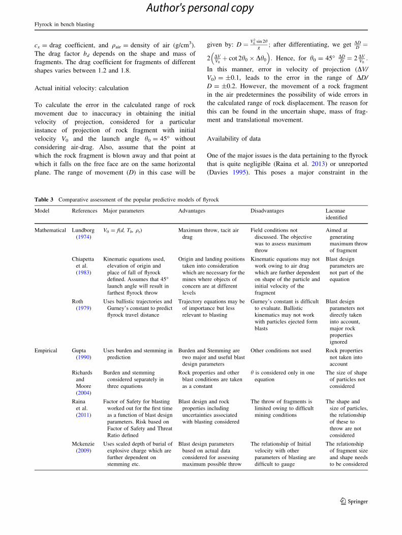
Table 3 Comparative assessment of the popular predictive models of flyrock
Model References Major parameters Advantages Disadvantages Lacunae
identified
Mathematical Lundborg
(1974)
V0 = f(d, Tb, qr) Maximum throw, tacit air
drag
Field conditions not
discussed. The objective
was to assess maximum
throw
Aimed at
generating
maximum throw
of fragment
Chiapetta
et al.
(1983)
Kinematic equations used,
elevation of origin and
place of fall of flyrock
defined. Assumes that 45�launch angle will result in
farthest flyrock throw
Origin and landing positions
taken into consideration
which are necessary for the
mines where objects of
concern are at different
levels
Kinematic equations may not
work owing to air drag
which are further dependent
on shape of the particle and
initial velocity of the
fragment
Blast design
parameters are
not part of the
equation
Roth
(1979)
Uses ballistic trajectories and
Gurney’s constant to predict
flyrock travel distance
Trajectory equations may be
of importance but less
relevant to blasting
Gurney’s constant is difficult
to evaluate. Ballistic
kinematics may not work
with particles ejected form
blasts
Blast design
parameters not
directly taken
into account,
major rock
properties
ignored
Empirical Gupta
(1990)
Uses burden and stemming in
prediction
Burden and Stemming are
two major and useful blast
design parameters
Other conditions not used Rock properties
not taken into
account
Richards
and
Moore
(2004)
Burden and stemming
considered separately in
three equations
Rock properties and other
blast conditions are taken
as a constant
h is considered only in one
equation
The size of shape
of particles not
considered
Raina
et al.
(2011)
Factor of Safety for blasting
worked out for the first time
as a function of blast design
parameters. Risk based on
Factor of Safety and Threat
Ratio defined
Blast design and rock
properties including
uncertainties associated
with blasting considered
The throw of fragments is
limited owing to difficult
mining conditions
The shape and
size of particles,
the relationship
of these to
throw are not
considered
Mckenzie
(2009)
Uses scaled depth of burial of
explosive charge which are
further dependent on
stemming etc.
Blast design parameters
based on actual data
considered for assessing
maximum possible throw
The relationship of Initial
velocity with other
parameters of blasting are
difficult to gauge
The relationship
of fragment size
and shape needs
to be considered
Flyrock in bench blasting
123
Author's personal copy
prediction of flyrock travel distance. The reason for non-
availability of data is non-reporting of the issue because of
underlying legalities. This is a lacuna in the prediction of
flyrock range and size and needs attention to achieve a
plausible solution.
Discussion
It is quite evident from the above that blast design
parameters play a significant role in the generation of the
flyrock. The placement of explosive charge in relation to
the borehole configuration plays a major role in conjunc-
tion with weak planes in the rock mass, and other face
conditions including damaged front or top of the blast face.
The paper is aimed at presenting a holistic view of the
flyrock phenomenon ranging from the source, factors
affecting the origin of flyrock, the predictive models,
probability, and risk associated with the most contentious
issue in blasting. A summary of the issues discussed in the
paper is shown in Fig. 9.
There have been significant developments in the pre-
diction of flyrock on different lines as discussed above.
However, the holistic solution to the problem is still
lacking. The prediction of flyrock range as explained in
Fig. 3 is dependent on the initial velocity of the flyrock and
its launch angle. However, the air drag comes into picture
owing to the shape and size of the flyrock. This compli-
cates the issue of prediction. In order to ascertain the
requirements for further developments, a relative assess-
ment of the most discussed predictive models has been
provided in Table 3.
As is evident from the above table and discussions, there
is a need to:
1. Generate significant data and log the same for predic-
tive purposes while monitoring maximum parameters
relating to rock mass and blast design.
2. Develop equations that precisely predict the initial
velocity of the flyrock fragments considering the
properties of rock mass (including the face indenta-
tions, presence of incompetent strata, etc.) and blast
design parameters.
3. Develop relationships, which address the relationship
of flyrock fragment shape to that of the in situ block
size.
4. Use the above data with the ANN or other advance
statistical methods to ascertain the importance and
sensitivity of rock mass and blast design parameters.
5. Develop a comprehensive model for flyrock fragment
throw or range using the above details.
With the above approach, it is expected that an acceptable
model of flyrock range prediction will be developed in the
future. The Danger Zone or Area Security Zone will then
be easy to demarcate.
Acknowledgments This paper forms part of the Ph.D. work of the
first Author. Authors are thankful to the Director CSIR-CIMFR for his
permission to publish the paper. The help rendered by colleagues and
other staff at CSIR-CIMFR is duly acknowledged.
References
Adhikari GR (1999) Studies on flyrock at limestone quarries. Rock
Mech Rock Eng 32(4):291–301
Amini H, Gholami R, Monjezi M, Torabi SR, Zadhesh J (2011)
Evaluation of flyrock phenomenon due to blasting operation by
support vector machine. Neural Comput Appl 21(8):1–9
Bajpayee T, Rehak T, Mowrey G, Ingram D (2002) A summary of
fatal accidents due to flyrock and lack of blast area security in
surface mining, 1989 to 1999. In: Proceedings of the 28th annual
conference on explosives and blasting technique, ISEE, vol 2,
pp 105–118
Bandopadhyay PK, Roy SC, Sen SN (2003) Risk assessment in open
cast mining—an application of Yager’s methodology for ordinal
multi-objective decision based on fuzzy sets. Jpn J Ind Appl
Math 20(3):311–319
Bhandari S (1994) Flyrock during blasting operations: controllable
environmental hazards. In: Proceedings of the 2nd National
Seminar on Minerals and Ecology. Oxford and IBH Publishing,
New Delhi, pp 279–308
Blanchier A (2013) Quantification of the levels of risk of flyrock.
Rock fragmentation by blasting—Singh and Sinha (eds). Taylor
and Francis Group, London, pp 549–553
Chernigovskii AA (1985) Application of directional blasting in
mining and civil engineering. Oxidian Press India Pvt. Ltd., New
Delhi, pp 91–112
Chiapetta RF, Bauer A, Dailey PJ, Burchell SL (1983) The use of
high-speed motion picture photography in blast evaluation and
design. In: Proceedings of 9th conference on explosives and
blasting techniques, Dallas, USA, pp 31–40
Davies PA (1995) Risk based approach to setting of flyrock danger
zones for blasting sites. Transactions of the institution of mining
and metallurgy, May–August 1995, pp 96–100
Fletcher LR, D’Andrea DV (1987) Reducing accident through
improved blasting safety. USBM IC, 9135. In: Proceedings of
bureau of mines technology transfer sem., Chicago, IL, pp 6–18
Fletcher LR, D’Andrea DV (1986) Control of flyrock in blasting.
Proceedings of the 12th annual conference on explosives and
blasting technique, February 9–14, Cleveland, OH. International
society of explosives engineers, pp 167–175
Flinchum R, Rapp D (1993) Reduction of air blast and flyrock. http://
docs.isee.org/ISEE/Support/Proceed/General/93Gen/9315g.PDF
Gupta RN (1990) Surface blasting and its impact on environment. In:
Trivedy NJ, Singh BP (eds) Impact of mining on environment.
Ashish Publishing House, New Delhi, pp 23–24
Heck JH (1992 Computer-aided blast designs using laser surveying
technology. In: Proceedings of 4th high tech seminar on blasting
technology, instrumentation and explosives applications, Nash-
ville, Tennessee, USA, June 20–25, 1992
Jenkins SS Jr., Floyd J (2000) Stemming enhancement tests. In:
Proceedings of the 26th annual conference on explosives and
blasting technology, February 13–16, Anaheim, vol 2,
pp 191–204
Kecojevic V, Radomsky M (2005) Flyrock phenomena and area
security in blasting-related accidents. Saf Sci 43(9):739–750
A. K. Raina et al.
123
Author's personal copy
Kopp JW (1994) Observation of flyrock at several mines and quarries.
http://docs.isee.org/ISEE/Support/Proceed/General/94Gen/9407g.
Kricak L, Kecojevic V, Negovanovic M, Jankovic I, Zekovic D
(2012) Environmental and safety accidents related to blasting
operation. Am J Environ Sci 8(4):360–365
Kuberan R, Prasad KK (1992) Environmental effects of blasting and
their control. In: Proceedings of the workshop on blasting
technology for civil engineering projects, ISRMTT, November
16–18, Delhi, vol 2, pp 145–159
Little TN, Blair DP (2010) Mechanistic Monte Carlo models for
analysis of flyrock risk. In: Sanchidrian JA (ed) Rock fragmen-
tation by blasting. Taylor and Francis, London, pp 641–647
Little TN (2007) Flyrock risk. In: Proceedings of EXPLO conference,
Wollongong, NSW, September 3–4, pp 35–43
Lundborg N (1974) The hazards of fly rock in rock blasting. Swedish
detonic research foundation, report DS1974, p 12
Lundborg N, Persson N, Ladegaard-Pedersen A, Holmberg R,
Holmberg R (1975) Keeping the lid on flyrock in open pit
blasting. Eng Min J, Swedish Detonic Res Found. 176:95–100
Mandal SK (1997) Causes of flyrock damages and its remedial
measures. Course on: recent advances in blasting techniques in
mining and construction projects, HRD-CMRI Dhanbad,
pp 130–136
McKenzie CK (2009) Flyrock range and fragment size prediction.
http://docs.isee.org/ISEE/Support/Proceed/General/09GENV2/09
v206g.pdf
Mohamad ET, Armaghani DJ, Noorani SA, Saad R, Alvi SV, Abad
NK (2012) Prediction of flyrock in boulder blasting using
artificial neural network. EJGE 17(2012):2585-2595
Monjezi M, Bahrami A, Varjani AY (2010) Simultaneous prediction
of fragmentation and flyrock in blasting operation using
artificial neural networks. Int J Rock Mech Min Sci 47(2010):
476–480
Raina AK, Chakraborty AK, More R, Choudhury PB (2006) Design
of factor of safety based criterion for control of flyrock/throw
and optimum fragmentation. J Inst Eng India 87(2007):13–17
Raina AK, Chakraborty AK, Choudhury PB, Sinha A (2011) Flyrock
danger zone demarcation in opencast mines: a risk based
approach. Bull Eng Geol Environ 70:163–172
Raina AK, Chakraborty AK, Choudhury PB, Ramulu M (2008)
Application of factor of safety concept for evaluation of flyrock
risk in some limestone mines. J Blast Fragm 2(2):147–166
Raina AK, Soni AK, Murthy VMSR (2013) Spatial distribution of
flyrock using EDA: an insight from concrete model tests. In:
Singh PK, Sinha A (eds) Rock fragmentation by blasting. Taylor
and Francis Group, London, pp 563–570
Rehak TR, Bajpayee TS, Mowrey GL, Ingram DK (2001) Flyrock
issues in blasting. In: Proceedings of the 27th annual conference
on explosives and blasting technique, vol. 1. International
society of explosives engineers, Cleveland, pp 165–175
Rezaei M, Monjezi M, Yazdian Varjani A (2011) Development of a
fuzzy model to predict flyrock in surface mining. Saf Sci
49:298–305
Richards A, Moore A (2004) Flyrock control—by chance or design.
In: Proceedings of the 30th annual conference on explosives and
blasting technique. http://docs.isee.org/ISEE/Support/Proceed/
General/04GENV1/04v133g.pdf
Rosenthal MF, Morlock GL (1987) Blasting guidance manual. US
Department of Interior, OSMRE, p 201
Roth JA (1979) A model for the determination of flyrock range as a
function of shot condition. US department of commerce. NTIS
report no. PB81222358
St. George JD, Gibson MFL (2001) Estimation of flyrock travel
distances: a probabilistic approach. In: AusIMM EXPLO 2001
conference, Hunter Valley, pp 409–415
Stojadinovic S, Pantovic R, Zikic M (2011) Prediction of flyrock
trajectories for forensic applications using ballistic flight equa-
tions. Int J Rock Mech Min Sci 48(2011):1086–1094
Verkis H (2011) Flyrock: a continuing blast safety threat. http://docs.
isee.org/ISEE/Support/Proceed/General/11GENV1/11v161g.pdf
Verkis H, Lobb T (2007) Flyrock revisited: an ever present danger in
mine blasting. http://docs.isee.org/ISEE/Support/Proceed/Gen
eral/07GENV1/07v109g.pdf
Flyrock in bench blasting
123
Author's personal copy


