Embed Size (px)
Citation preview

ADDIS ABABA UNIVERSITY
SCHOOL OF GRADUATE STUDIES
ADDIS ABABA UNIVERSITY INSTITUTE OF TECHNOLOGY
SCHOOL OF CIVIL AND ENVIRONMENTAL
FLEXURAL PERFORMANCE OF CONCRETE MEMBERS
REINFORCED WITH MECHANICALLY SPLICED BAR
BY:
SHEMSEDIN LEJA NEZHINE
SEPTEMBER 2020
ADDIS ABABA

FLEXURAL PERFORMANCE OF CONCRETE MEMBERS REINFORCED WITH MECHANICALLY SPLICED BARS
MSc Thesis In Structural Engineering, School of Civil And Environmental Addis Ababa Institute of Technology, AAiT i
ADDIS ABEBA UNIVERSITY
SCHOOL OF GRADUATE STUDIES
FACULTY OF TECHNOLOGY
SCHOOL OF CIVIL AND ENVIRONMENTAL ENGINEERING
FLEXUR PALERFORMANCE OF CONCRETE MEMBERS REINFORCED
WITH MECHANICALLY SPLICED BARS
BY:
SHEMSEDIN LEJA NEZHINE
SEPTEMBER 2020
Approved by Board of Examiners
1. Dr. Girma.ZeraYohannes _______________ _____________
Advisor Signature Date
2. Dr. Shifferaw Taye _______________ _____________
Internal examiner Signature Date
3. Dr. Bedilu Habte _______________ _____________
Internal examiner Signature Date
4. _______________ _______________ _____________
Chairman Signature Date

FLEXURAL PERFORMANCE OF CONCRETE MEMBERS REINFORCED WITH MECHANICALLY SPLICED BARS
MSc Thesis In Structural Engineering, School of Civil And Environmental Addis Ababa Institute of Technology, AAiT ii
FLEXURE PERFORMANCE OF CONCRETE MEMBERS REINFORCED
MECHANICALLY SPLICED BARS
A Thesis Submitted to the School of Graduates Studies in Partial Fulfillment
of the Requirements for the Degree of Master of Science in
Civil Engineering (Structures)
BY:
SHEMSEDIN LEJA NEZHINE
SEPTEMBER 2020

FLEXURAL PERFORMANCE OF CONCRETE MEMBERS REINFORCED WITH MECHANICALLY SPLICED BARS
MSc Thesis In Structural Engineering, School of Civil And Environmental Addis Ababa Institute of Technology, AAiT iii

FLEXURAL PERFORMANCE OF CONCRETE MEMBERS REINFORCED WITH MECHANICALLY SPLICED BARS
MSc Thesis In Structural Engineering, School of Civil And Environmental Addis Ababa Institute of Technology, AAiT iv
STATEMENT OF DECLARATION
I hereby declare that this thesis is my original work; it has not been submitted for any
Degree/Diploma in any university. Different online documents and hard copies used in the
preparation of this thesis have been duly acknowledged.
Name: Shemsedin Leja
Signature: ___________________
Department: School of Civil and Environmental Engineering
Date: September 2020

FLEXURAL PERFORMANCE OF CONCRETE MEMBERS REINFORCED WITH MECHANICALLY SPLICED BARS
MSc Thesis In Structural Engineering, School of Civil And Environmental Addis Ababa Institute of Technology, AAiT v
ACKNOWLWDGEMENTS Primarily I would like to express my deepest gratitude to my study sponsorship,
Ethiopian Road Authority (ERA) and Addis Ababa University institute of
technology (AAiT). I would also like to thanks my advisor Dr.-Eng. Girma
ZeraYohannes for his professional and technical advice; and AAiT supervision
staff at commercial bank of Ethiopia, new head quarter design build project such as
Eyoel Bezabh, Dr.Girmay Kahssay, Dr.Adil Zakarya, Mohammed Siraj and
Tesfaye Molla for their valuable assistance and advice on specimen fabrication
process and technical advice during this study.
Finally, I would like to thanks my friends Nuhamin Getachew and Nejib
Abdurezak their cooperation in doing this research in terms of logistics and paper
work and also Laboratory class representatives Demessew Melaku and Fikru
Bedada for their cooperation.
Shemsedin Leja
September 2020

FLEXURAL PERFORMANCE OF CONCRETE MEMBERS REINFORCED WITH MECHANICALLY SPLICED BARS
MSc Thesis In Structural Engineering, School of Civil And Environmental Addis Ababa Institute of Technology, AAiT vi
ABSTRACT
Flexural performance test was conducted on five reinforced concrete beams. The
beams were reinforced with steel bars which were connected using couplers. All the
connections were at mid-span. This investigation incorporates two types of
mechanical connection detailing. Three of the beams were reinforced with all the bars
connected by couplers, one beam was reinforced with 50% of the reinforcing steel
bars connected by coupler and at constant moment region of the mid span while the
remaining beam was a control member with no mechanical splicers.
All the beams were subjected to cyclic loading. The range of stress was the
predominant factor to determine the flexural behavior of mechanically connected bars
at the joint within the concrete beams specimens. Beams reinforced with 100%
mechanically connected bars developed similar flexural performance and failure
modes. Five reinforced concrete beams were cast for this research purpose. The beams
were loaded with cyclic loading and all specimens had almost the same general
behavior at respective maximum loading. Furthermore, it was observed that
spliced longitudinal re-bars caused the yield load to be reduced by 13.5% and
yielding displacement increased by 10.33% with different maximum capacity.
In addition to these the ductility of specimens decreased by 9.5% compared to
B1. As per the observations of this study parallel threaded coupler connected
bars satisfying the manufacturer criteria’s can be considered as a continuous bar
with increased strain, deflection and cracking properties at the joint.

FLEXURAL PERFORMANCE OF CONCRETE MEMBERS REINFORCED WITH MECHANICALLY SPLICED BARS
MSc Thesis In Structural Engineering, School of Civil And Environmental Addis Ababa Institute of Technology, AAiT vii
TABLE OF CONTENTS STATEMENT OF DECLARATION .................................................................................................................... iv
ACKNOWLWDGEMENTS ............................................................................................................................... v
ABSTRACT ..................................................................................................................................................... vi
LIST OF FIGURES ............................................................................................................................................ x
LIST OF TABLES ............................................................................................................................................. xi
LIST OF ABBREVIATIONS ............................................................................................................................. xii
1. INTRODUCTION ..................................................................................................................................... 1
1.1. STATEMENT OF THE PROBLEM ..................................................................................................... 1
1.2. BACKGROUND OF THE STUDY ....................................................................................................... 1
1.3. OBJECTIVE OF THE RESEARCH ....................................................................................................... 2
1.4. LIMITATION OF THE STUDY ........................................................................................................... 3
1.5. SIGNIFICANCE OF THE STUDY ....................................................................................................... 3
1.6. RESEARCH METHODOLOGY .......................................................................................................... 3
1.7. DOCUMENTATION ........................................................................................................................ 5
2. LITERATURE OF REVIEW ........................................................................................................................ 6
2.1. MECHANICAL BAR SPLICERS ......................................................................................................... 6
2.2. TYPES OF MECHANICAL BAR SPLICES ............................................................................................ 7
2.2.1. THREADED COUPLERS ........................................................................................................... 8
2.2.2. NON-THREADED COUPLERS .................................................................................................. 9
2.3. CODE RECOMMENDATIONS FOR COUPLER SPLICED BARS......................................................... 10
2.3.1. AMERICAN CONCRETE INSTITUTE (ACI) BUILDING CODE 318, 2008 .................................. 10
2.3.2. INDIAN CODE (IS) – SP: 34 (S&T) – 1987 SECTION 4 ........................................................... 11
2.3.3. BRITISH STANDARD (BS) 8110 - PART 1 SECTION 3:1989 ................................................... 12
2.4. ADVANTAGES OF USING COUPLERS ........................................................................................... 12
2.5. RESEARCHES ON MECHANICALLY SPLICED BAR .......................................................................... 13
2.6. RC MEMBERS INCORPORATING MECHANICAL BAR SPLICES ...................................................... 15
3. EXPERIMENTAL PROGRAM ................................................................................................................. 17
3.1. INTRODUCTION ........................................................................................................................... 17
3.2. MATERIALS AND SPECIMEN FABRICATION ................................................................................. 17
3.2.1. CONCRETE MATERIALS ........................................................................................................ 17

FLEXURAL PERFORMANCE OF CONCRETE MEMBERS REINFORCED WITH MECHANICALLY SPLICED BARS
MSc Thesis In Structural Engineering, School of Civil And Environmental Addis Ababa Institute of Technology, AAiT viii
3.2.2. MECHANICAL COUPLERS ..................................................................................................... 17
3.2.3. REINFORCING STEEL BARS .................................................................................................. 18
3.3. PREPARATION OF TEST SPECIMENS ................................................................................................ 19
3.3.1. MECHANICAL COUPLED (SPLICED) DEFORMED STEEL BARS .............................................. 19
3.3.2. DETAILED RE-BAR SPECIMENS FOR BEAM .......................................................................... 20
3.4. FLEXURAL BEAM TEST PROGRAM ............................................................................................... 21
3.5. INSTRUMENTAL SETUP .................................................................................................................... 22
3.6. FLEXURAL BEAM TEST SETUP ........................................................................................................... 23
4. EXPERIMENTAL PROGRAM TEST RESULTS .......................................................................................... 25
4.1 INTRODUCTION ........................................................................................................................... 25
4.2 OBSERVATIONS OF PRIMARY RESULTS ....................................................................................... 25
4.3. RESULT AND DISCUSSION OF EXPERIMENTAL PROGRAM .......................................................... 26
4.3.1. LOAD-DISPLACEMENT CURVES ........................................................................................... 26
4.3.2. FAILURE MODE OF THE SPECIMENS ................................................................................... 29
4.3.3. CRACK BEHAVIOUR OF THE SPECIMENS ............................................................................. 31
4.3.4. ULTIMATE LOAD OF THE SPECIMENS.................................................................................. 33
4.3.5. ESTIMATION OF DUCTILITY ................................................................................................. 33
5. CONCLUSIONS AND RECOMMENDATIONS ......................................................................................... 36
5.1. CONCLUSIONS ............................................................................................................................. 36
5.2. RECOMMENDATIONS....................................................................................................................... 37
REFERENCES ................................................................................................................................................ 38
APPENDICES ................................................................................................................................................ 40
APPENDIX A ............................................................................................................................................. 40
TERMS AND DEFINITIONS ................................................................................................................... 40
APPENDIX B ............................................................................................................................................. 41
DESIGN OF REINFORCED BEAM SECTION ........................................................................................... 41
MATERIAL PROPERTIES ....................................................................................................................... 41
DESIGNING FOR FLEXURE AND BEAM SECTION.................................................................................. 41
DESIGN FOR SHEAR LOAD ................................................................................................................... 44
APPENDIX C ........................................................................................................................................... 46
PROCEDURES IN SPECIMEN PREPAREION........................................................................................... 46

FLEXURAL PERFORMANCE OF CONCRETE MEMBERS REINFORCED WITH MECHANICALLY SPLICED BARS
MSc Thesis In Structural Engineering, School of Civil And Environmental Addis Ababa Institute of Technology, AAiT ix
APPENDIX D ........................................................................................................................................... 47
MATERIAL STRENGTH OF THE TEST RESULTS ..................................................................................... 47

FLEXURAL PERFORMANCE OF CONCRETE MEMBERS REINFORCED WITH MECHANICALLY SPLICED BARS
MSc Thesis In Structural Engineering, School of Civil And Environmental Addis Ababa Institute of Technology, AAiT x
LIST OF FIGURES
FIGURE 2-1: DIFFERENCES BETWEEN LAP & MECHANICAL SPLICING (LENTON, 2017) ..................................................................... 6
FIGURE 2-2: TYPES OF MECHANICAL BAR SPLICE COUPLERS (HTTP://WWW.ERICO.COM) ................................................................ 7
FIGURE 2-3: PARALLEL THREAD STANDARD BAR COUPLER ....................................................................................................... 10
FIGURE 2-4: SCHEMATIC DIAGRAM OF QUALITY TEST SPECIMENS BY MUTSUYOSHI....................................................................... 14
FIGURE 3-1: TYPE-1 PARALLEL THREADED MECHANICAL SPLICERS (COUPLERS) ............................................................................ 18
FIGURE 3-2: REINFORCING DEFORMED STEEL BAR SPECIMENS .................................................................................................. 19
FIGURE 3-3: SCHEMATIC DIAGRAM OF MECHANICALLY COUPLED BARS ...................................................................................... 20
FIGURE 3-4: PHOTOGRAPHY OF COUPLER CONNECTED REINFORCEMENT SPECIMEN ...................................................................... 21
FIGURE 3-5: REINFORCEMENT ARRANGEMENT IN THE SPECIMEN BEAM ...................................................................................... 21
FIGURE 3-6: PHOTOGRAPH OF FLEXURAL BEAM TEST SPECIMENS .............................................................................................. 22
FIGURE 3-7: PHOTOGRAPH OF INSTRUMENTAL SETUP ............................................................................................................. 22
FIGURE 3-8: PHOTOGRAPH OF FLEXURAL BEAM TEST SETUP..................................................................................................... 24
FIGURE 4-1: DISPLACEMENT CURVES AT MID-SPAN UNDER CYCLIC LOADING ............................................................................... 27
FIGURE 4-2: REPRESENTATIVE COMBINED LOAD-DISPLACEMENT CURVES OF THE SPECIMENS AT MID-SPAN ...................................... 28
FIGURE 4-3: MODE OF FAILURE OF CONTROL BEAM SPECIMEN ................................................................................................. 29
FIGURE 4-4: MODE OF FAILURE FOR CIB-1 ........................................................................................................................... 29
FIGURE 4-5: MODE OF FAILURE FOR CIB-2 ........................................................................................................................... 30
FIGURE 4-6: CRACKING BEHAVIORS OF B-1 AND CIB-1 ........................................................................................................... 31
FIGURE 4-7: CRACK BEHAVIOR OF THE SPECIMENS CIB-2 ........................................................................................................ 32
FIGURE 1B: ASSUMPTION FOR SINGLY REINFORCED BEAM SECTION ........................................................................................... 42
FIGURE 1D: CUBE STRENGTH TEST SAMPLING ........................................................................................................................ 47

FLEXURAL PERFORMANCE OF CONCRETE MEMBERS REINFORCED WITH MECHANICALLY SPLICED BARS
MSc Thesis In Structural Engineering, School of Civil And Environmental Addis Ababa Institute of Technology, AAiT xi
LIST OF TABLES
TABLE 3-1: PHYSICAL PROPERTIES OF THE Ø16 THREADED COUPLER .......................................................................................... 18
TABLE 3-2: DETAILS AND SPECIFICATION OF TESTED BEAMS ..................................................................................................... 20
TABLE 4-1: CRACK WIDTH AND AVERAGE CRACK SPACING ....................................................................................................... 32
TABLE 4-2: LOADING AND DISPLACEMENT RESULTS OF SAMPLES ............................................................................................... 33
TABLE 4-3: DUCTILITY ESTIMATION OF SPECIMENS ................................................................................................................. 34
TABLE 1D: 14TH DAY COMPRESSIVE STRENGTH RESULT OF THE SPECIMEN’S SAMPLES .................................................................. 48
TABLE 2D: TENSILE STRENGTH TEST RESULT OF THE BAR.......................................................................................................... 49
TABLE 3D: EXPERIMENTALLY DETERMINED CONCRETE AND REINFORCING STEEL PROPERTIES .......................................................... 49

FLEXURAL PERFORMANCE OF CONCRETE MEMBERS REINFORCED WITH MECHANICALLY SPLICED BARS
MSc Thesis In Structural Engineering, School of Civil And Environmental Addis Ababa Institute of Technology, AAiT xii
LIST OF ABBREVIATIONS
AAIT Addis Ababa Institute of Technology
ACI American Concrete Institute
BS British Standards
BBA British Board of Agreement
CARES Certification Authority for Reinforcing Steels
CBE Commercial Bank of Ethiopia
IEC International Electro technical Commission
IS Indian Standards
ISO International Organization for Standardization
JSCE Japan Society of Civil Engineers
MS Mechanical Splicers
PPC Portland Pozzolana Cement
RC Reinforced Concrete
UK United Kingdom
CIB Coupler incorporated beam

FLEXURAL PERFORMANCE OF CONCRETE MEMBERS REINFORCED WITH MECHANICALLY SPLICED BARS
MSc Thesis, Department of civil and environmental Engineering Addis Ababa Institute of Technology, AAiT Page 1
1. INTRODUCTION
1.1. STATEMENT OF THE PROBLEM
This study aims to assess the flexural performance of reinforced concrete beams with mechanical
coupler spliced re-bars and to examine the behavior and seismic performance of reinforced
concrete structures with mechanically spliced bars.
1.2. BACKGROUND OF THE STUDY
The design of reinforced concrete structures is based on several basic assumptions. Among these
fundamental concepts is that reinforcement will be provided to resist any tension that possibly
exists in the member. Moreover, it is assumed that the reinforcement should be anchored
properly and be continuous in the regions of tensile stress. But the length of the reinforcing bar is
limited by fabricating, transporting and storage capacities as well as simplicity of construction,
all of which make splicing necessary. The standard length of steel bars cannot ensure the
integrity of reinforcement throughout any sizeable members or flat slabs and one way slabs.
Additionally, when the span length of the member is less than 12 meters, splicing off
unnecessary length is required. Thus, in most situations where splices of reinforcement are
involved, the splice choice may be lap splice or mechanical splice (coupler connection or
welding).
Lap splice is straightforward concept with the length of lap assumed to be directly related to the
concrete grade. However, there may be significant problems in fixing the location of splices, as it
may not be applicable to tension zone of the member. For example, in dome structures, beams
are sometimes in tension throughout the span. Furthermore, additional cover or confinement
required to control the lap length so as to reach the capacity needed in the length provided which
also depends on concrete compressive strength. Nonetheless, even after meeting all of the code
requirements, there are further challenges upon construction.
The splicing of large diameter bars can lead to required lengths easily over a meter in length, a
requirement that is not easily met in many situations. Therefore the contractor/designer may look

FLEXURAL PERFORMANCE OF CONCRETE MEMBERS REINFORCED WITH MECHANICALLY SPLICED BARS
MSc Thesis, Department of civil and environmental Engineering Addis Ababa Institute of Technology, AAiT Page 2
at other alternatives of splice technology, such as welding and coupler connectors. The welding
option needs special tests and is very technical. It is required to produce a ductile weld.
Moreover, the cost and practicality are also factors of consideration. This leads clients and
contractors that are wary of the risks of these options to consider coupler connection technology
as a superior alternative as it connects steel bars end to end. This method ensures the
reinforcement behave in a manner similar to continuous length bars. In order to ensure the
performance of coupler connected steel bar, several tests and researches have been done by
scholars of different levels from post graduate to undergraduate. Nowadays, countries codes
incorporate this splicing system as one way of connecting two separate bars end to end; but
requirements like staggering length, coupler positions and yield strength of the joints are
excessively limited. In order to investigate the limitation of those requirements, this study has
focused on the flexural performance of thread coupler connected steel bar reinforced members.
1.3. OBJECTIVE OF THE RESEARCH
1.3.1. GENERAL OBJECTIVE OF THE RESEARCH
The objective of this study is primarily to investigate the influence of mechanically connected
reinforcement bars on flexural performance of concrete members. The flexural behavior of
coupler connected steel bar reinforced concrete beams would then be investigated.
1.3.2. SPECIFIC OBJECTIVE OF THE RESEARCH
To identify the major problems of locally produced bar connected by parallel thread
coupler reinforced beams, if any.
To provide comparative analysis of flexural behavior of coupler incorporated steel
bar reinforced concrete beams and equivalent non-spliced steel reinforced concrete
beam for cyclic loading (asses the seismic feasibility).
Evaluating test results comparing with other data obtained from literature.
To introduce the topic for future researches and areas that may need detail
investigations.

FLEXURAL PERFORMANCE OF CONCRETE MEMBERS REINFORCED WITH MECHANICALLY SPLICED BARS
MSc Thesis, Department of civil and environmental Engineering Addis Ababa Institute of Technology, AAiT Page 3
1.4. LIMITATION OF THE STUDY
There are different types of coupler (Mechanical connectors) available in the construction
industry. But this study focuses only on parallel threaded coupler connected bar reinforced
beams, as parallel threaded coupler was the modified widely used mechanical connectors on high
rise buildings and stadiums. This experimental study was also carried out only on simply
supported beams, thus it requires detailed investigation for other support cases and frame
structures on local materials.
1.5. SIGNIFICANCE OF THE STUDY
This study aimed to discuss the flexural performance of the coupler connected bar reinforced
members, the effectiveness of the system on seismic zones by doing experimental investigation,
and introduce the advantage or disadvantages of using parallel threaded coupler technology to
local construction industry. It will also serve as an introductory research for readers and
professionals who wish to study the seismic performance of the system on frame structures.
1.6. RESEARCH METHODOLOGY
In order to achieve the aforementioned objectives, experimental analysis was conducted to study
the failure mode, crack pattern, crack width and load to displacement response of the coupler
incorporated steel bar reinforced concrete members. Flexural test for members was performed.
The difference in the behavior of reinforced concrete members with conventional reinforcing
bars and coupler incorporated bars were investigated through an experimental study.
Experimental study included load testing of five reinforced concrete beam specimens which had
mechanically coupled reinforcement while one of the specimens was reinforced with
conventional reinforcing bars as a control specimen. The reinforcing bar yield strength was
measured and used in the analysis.
The compressive strength of concrete designed was C-30. The maximum moment due to live
loading of 200KN through spreader beam was determined as 45.5KNm and the maximum shear
on the span due to live load was found to be 101.4KN. The reinforced concrete beams were
designed and produced using C-30 class concrete and locally available deformed steel bars. The

FLEXURAL PERFORMANCE OF CONCRETE MEMBERS REINFORCED WITH MECHANICALLY SPLICED BARS
MSc Thesis, Department of civil and environmental Engineering Addis Ababa Institute of Technology, AAiT Page 4
actual strength of concrete and steel has been used in the analysis of the experimental result. For
laboratory testing convenience and simplicity purpose, the span length of the beam was limited
to 1500mm, with width of 200mm and a depth of 280mm. The beams were designed for flexure
and shear. The flexural reinforcement area was 402.12mm2 was used to investigate the flexural
behavior, considering that the beams are required to fail by flexure. Web reinforcement is
provided as two leg ø8@100mm spacing for constant shear area of the span on both sides in
order to avoid shear failure before flexural failure.
The beam is also designed for deflection limits according to EBCS-2, provided that the minimum
depth required for deflection specified by the code is maintained. Also minimum depth
requirement for beams and one-way slabs according to ACI code has been checked and satisfied.
In terms of span length, EBCS-2 provides minimum effective depth, d, to be used to control
deflection as follows:-
d = (0.4 +fy/400)*le/βa , where βa = 20 for simply supported members [9]
Therefore, the assumed depth of specimens was sufficient for both codes’ deflection control
requirements. The beams had a constant moment length between two loading points of 433mm.
The ends of the reinforcing bars were 900 hooked in order to improve the anchorage to concrete,
and the shear reinforcing stirrups were anchored at 1350 with open loop and closed loop
staggering for simplicity while placing concrete.
The beam specimens were cast at commercial bank of Ethiopia new head quarter compound
using ready mix concrete that had a target compressive strength of 30Mpa. The concrete
compressive strength at the day of test is given in the appendix (Table 1D). Beam specimens
were instrumented with displacement transducers prior to load testing. Moreover, before placing
the specimens in the testing machine, the bearing surfaces of the supporting and loading rollers
were wiped clean, and all loose sand or other material were removed from the surfaces of the
specimens that would make contact with the rollers. The specimens were then placed in the
machine in such a manner that the load is applied to the uppermost surface as cast in the
formwork. The axes of the specimens were carefully aligned with the axis of the loading device.
The load would then be increased cyclically until the specimen fails, and the maximum load

FLEXURAL PERFORMANCE OF CONCRETE MEMBERS REINFORCED WITH MECHANICALLY SPLICED BARS
MSc Thesis, Department of civil and environmental Engineering Addis Ababa Institute of Technology, AAiT Page 5
applied to the specimen during the test would be recorded. The appearance of the fractured faces
of concrete and any unusual features in the type of failure were also recorded.
A lower limit of 0.25kN was selected to represent an applied dead load due to spreader beam; the
upper limit was selected to develop the desired strain and therefore stress levels in the 2ø16
reinforcing bar and across the splice. Crack widths were measured along pure flexure region by
using millimeter ruler and deflections were measured using displacement transducers. After the
yielding of the beam, the test was continued by applying load controlled by displacement
proportinal to control beam displacement until failure. All of the data was recorded on each step
by data decoder and detail investigation of the results are presented on chapter four.
1.7. DOCUMENTATION
This study contains experimental investigation carried out on mechanically spliced steel
reinforced concrete beams to determine the effect of couplers on flexural performance of the
beams. Chapter 1 contains background of the study, objective of the study and a brief overview
of the work done. Chapter 2 presents review of literature on reinforcement coupler systems;
typically addressed are general characteristics, categories, benefits and engineering
considerations as well as the use of couplers for high rise buildings, related cost benefits and
different journals on mechanically coupled bars and reinforced concrete beams with a review on
mechanically spliced steel bar reinforced beam specimens. Chapter 3 presents the experimental
program in detail including material fabrication and specimen preparation. Chapter 4 presents the
result of the experimental program i.e. beam test output with primary results, discussions on the
cracking behavior of the beams and failure modes. Chapter five includes conclusions and
recommendations to be considered in design and additional investigation to be carried out by
future researchers. Finally, references used to carry out this experimental study are cited and
acknowledged, while sections which are not included in main body are presented and explained
at the end in the appendix.

FLEXURAL PERFORMANCE OF CONCRETE MEMBERS REINFORCED WITH MECHANICALLY SPLICED BARS
MSc Thesis, Department of civil and environmental Engineering Addis Ababa Institute of Technology, AAiT Page 6
2. LITERATURE OF REVIEW
While researchers tried to find out each and every documents to study the influence of using
mechanical coupler to connect reinforcing bars, some national publications currently evaluating
couplers for the splicing of steel bars, which are mainly tested in isolation [4], i.e. without being
inserted into a reinforced concrete structure. Even internationally, the subject is quite new and it
is only in the last 20 years that mechanical splices have been studied more frequently [4], due to
the growing worldwide demand for this type of solution in major infrastructure projects. This
section covers the definition and types of mechanical bar splices available in the market as well
as advantages of using couplers.
2.1. MECHANICAL BAR SPLICERS
Mechanical splice/joint is the common terminology for the complete assembly, including the
coupler or sleeve fitted to provide a splice of two reinforcement bars. They are mechanical
devices that connect two or more bars end to end. Mechanical couplers are relatively, a new
concept in the current Ethiopian construction industry. Reinforcing steel bars need to be spliced
to provide continuity in RC members. Bars can be spliced either through overlapping two
adjoining reinforcements, also known as “lap splicing or using mechanical connector known as
coupler splice’’[16]. Figure 2.1 below shows a sample of lap and mechanical splices.
Figure 2-1: Differences between Lap & Mechanical Splicing [16]
Steel bars are generally spliced by lapping, by welding or through mechanical systems using
steel couplers. “The lap splice is a solution already consolidated in the world market, being the
most used system in reinforced concrete structures. However, there are situations where this type
of splice cannot be used, such as in the case of execution errors in the length of pillar starters, or

FLEXURAL PERFORMANCE OF CONCRETE MEMBERS REINFORCED WITH MECHANICALLY SPLICED BARS
MSc Thesis, Department of civil and environmental Engineering Addis Ababa Institute of Technology, AAiT Page 7
waits, and especially in cases of structural restoration or reinforcement interventions, or even
when it is desired to splice steel bars with diameters greater than the limit established for the lap
splicing system. In such cases, designers may employ welded steel bars seams or steel
couplers”[4]. The effectiveness of the coupler splicing system must be ensured through proper
installation. The manufacturers of these splices assert that when properly installed, mechanical
splices offer performance that can be better than that of lapped bars.
2.2. TYPES OF MECHANICAL BAR SPLICES
Different manufacturers produce different types of couplers. “The choice of the mechanical
coupler system for the project depends on various factors. Selection of the most suited coupler
system should be made after considering all advantages and limitations of the coupler system,
the project parameters, and location of coupler joint and the preferences of the structural
consultant for the project”[7]. Available couplers in the market are: shear screw, headed bar,
grouted sleeve, threaded, and swaged as shown below (Fig. 2.2). Note that couplers with the
same anchoring mechanism may be entitled differently by manufacturers.
(A) Threaded Coupler (B) Thread Weld Able Coupler (C) Grouted Sleeve Coupler
(D) Thread Headed Anchors (D) Swaged Coupler (E) Shear Screw
Figure 2-2: Types of Mechanical Bar Splice Couplers [14]

FLEXURAL PERFORMANCE OF CONCRETE MEMBERS REINFORCED WITH MECHANICALLY SPLICED BARS
MSc Thesis, Department of civil and environmental Engineering Addis Ababa Institute of Technology, AAiT Page 8
Mechanical couplers can be classified in the following two main categories, threaded and non-
threaded couplers.
2.2.1. THREADED COUPLERS
Threaded couplers are sub-categorized into Tapered Threaded Couplers, Roll Threaded Couplers
and Parallel Threaded couplers. The cross-section and length of the coupler is determined by the
grade of rebar for which it is designed. The general coupler systems are described below but one
should note that certain modifications are possible in each system as per manufacturer and
application requirements.
A. TAPERED THREADED COUPLERS
A mechanical splicing system with tapered threaded couplers is one where the threading carried
out on the rebar is at a slight incline. The slope of the threading and the coupler is kept the same
to ensure engagement of all threads simultaneously in the coupler joint. Tapered couplers are
generally longer in length as compared to parallel couplers and number of threads is generally
mentioned as a range. There is a tolerance allowance in tapered couplers for length of threading
to be carried out on rebar.
Tapered threaded couplers are the simplest type of threaded couplers where the threads are cut
out on the rebar at an angle. These types of couplers are suitable for columns in general and can
be used in horizontal applications but it is necessary to ensure tightening of the joint. These
couplers require that the rebar be turned for tightening and hence it is difficult to use such
couplers in rafts or other applications where it is not possible to turn the rebar and tighten the
same.
B. ROLL THREADED COUPLERS
Roll Threaded couplers are a type of parallel threaded couplers where threads are formed by
pressing the ends of the rebar using a set of rollers and are then connected by a coupler with
matching parallel threads. The rebar end need to be cut perpendicular prior to threading as there
is no allowance for additional threads inside the coupler in parallel threaded systems.
Roll Threaded couplers are suitable for both horizontal and vertical application. Due to parallel
threads, in columns, more turns are required for tightening the coupler and hence installation

FLEXURAL PERFORMANCE OF CONCRETE MEMBERS REINFORCED WITH MECHANICALLY SPLICED BARS
MSc Thesis, Department of civil and environmental Engineering Addis Ababa Institute of Technology, AAiT Page 9
takes more time as compared to tapered system. Roll Threaded couplers provide an option of
position threading – where one side of the joint can be threaded to the coupler length and the
coupler can be turned to tighten the joint in location instead of rotating the rebar. However
suitability of this application is to be determined based on the rebar available, as there will be a
reduction in joint strength for this specific application. For vertical applications, full strength
joint is achieved.
The machine for Roll Threaded splicing is more portable and such systems can be recommended
for projects with coupler requirements in both raft/beams and columns. In such a system, it
becomes necessary to ensure proper threading. Gauges are to be provided to ensure tolerance
limits for threading on site. There can be situations where the splicing may have a play if the bars
provided are undersized. In such case, it may become necessary to consider alternatives.
C. PARALLEL THREAD STANDARD BAR COUPLERS
Parallel Thread Standard Bar couplers offer a full strength connection together with enhanced
fatigue resistance. They are suitable for projects of any size, including those requiring a high
volume of couplers, such as road and rail bridges. Each end of the rebar to be joined is cut square
and enlarged using a cold forge process. A thread is then formed on the enlarged bar end using a
thread rolling machine. The thread is such that the cross sectional area of the bar ends are not
reduced ensuring the strength of the connection matches or exceeds that of the parent bars. It is
the application of the rolled thread that differentiates Parallel Thread Plus from other threaded
rebar systems.
Each thread-rolled bar end is proof-loaded to a force equal to the characteristic yield strength of
the rebar. It is the combination of these processes that provide the connection with enhanced
fatigue resistance. The Type 1 connection utilizes an internally threaded coupler to join two cold-
forged and thread-rolled bar ends together. Each bar end is threaded to half the length of the
coupler. Type 1 connections are used where the continuation bar can be rotated. Type 1 Bar
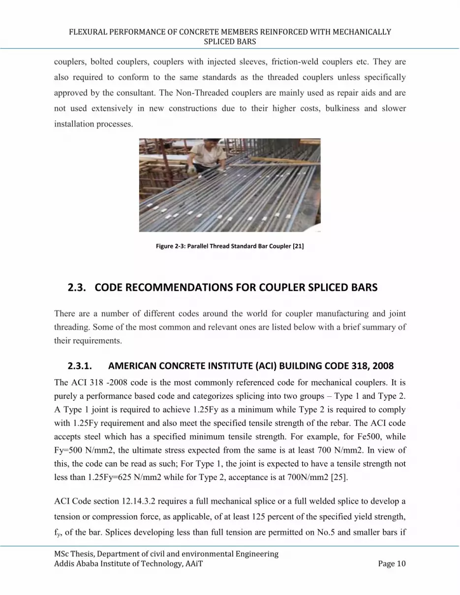
Coupler is shown in Figure 2.3 below.
2.2.2. NON-THREADED COUPLERS
There are various sub-types of non-threaded couplers which are used mainly for installation of
couplers in locations where it is not possible to use threaded couplers or for specialized
applications. This category includes but is not limited to crimple/swaged couplers, welded
FLEXURAL PERFORMANCE OF CONCRETE MEMBERS REINFORCED WITH MECHANICALLY SPLICED BARS
MSc Thesis, Department of civil and environmental Engineering Addis Ababa Institute of Technology, AAiT Page 10
couplers, bolted couplers, couplers with injected sleeves, friction-weld couplers etc. They are
also required to conform to the same standards as the threaded couplers unless specifically
approved by the consultant. The Non-Threaded couplers are mainly used as repair aids and are
not used extensively in new constructions due to their higher costs, bulkiness and slower
installation processes.
Figure 2-3: Parallel Thread Standard Bar Coupler [21]
2.3. CODE RECOMMENDATIONS FOR COUPLER SPLICED BARS
There are a number of different codes around the world for coupler manufacturing and joint
threading. Some of the most common and relevant ones are listed below with a brief summary of
their requirements.
2.3.1. AMERICAN CONCRETE INSTITUTE (ACI) BUILDING CODE 318, 2008
The ACI 318 -2008 code is the most commonly referenced code for mechanical couplers. It is
purely a performance based code and categorizes splicing into two groups – Type 1 and Type 2.
A Type 1 joint is required to achieve 1.25Fy as a minimum while Type 2 is required to comply
with 1.25Fy requirement and also meet the specified tensile strength of the rebar. The ACI code
accepts steel which has a specified minimum tensile strength. For example, for Fe500, while
Fy=500 N/mm2, the ultimate stress expected from the same is at least 700 N/mm2. In view of
this, the code can be read as such; For Type 1, the joint is expected to have a tensile strength not
less than 1.25Fy=625 N/mm2 while for Type 2, acceptance is at 700N/mm2 [25].
ACI Code section 12.14.3.2 requires a full mechanical splice or a full welded splice to develop a
tension or compression force, as applicable, of at least 125 percent of the specified yield strength,
fy, of the bar. Splices developing less than full tension are permitted on No.5 and smaller bars if

FLEXURAL PERFORMANCE OF CONCRETE MEMBERS REINFORCED WITH MECHANICALLY SPLICED BARS
MSc Thesis, Department of civil and environmental Engineering Addis Ababa Institute of Technology, AAiT Page 11
the splices of adjacent bars are staggered by at least 24in. In this sense, for No.5 and smaller
bars, even if full tension requirement is developed, mechanical splice can’t be used without
staggering. And ACI Code section 12.15.6 requiers that splice in tension-tie members be made
with full mechanical splices or welded splices and that splices of adjacent bars be staggerd by at
least 30in. Consequently, this study trys to verify the perfomance of unstaggerd full insertion(full
tension developing) bar mechanical splices in differernt cases [25].
2.3.2. INDIAN CODE (IS) – SP: 34 (S&T) – 1987 SECTION 4
This code specifies various types of mechanical splices and provides recommendations for usage
of splicing systems and strength requirements. Acceptance of the results has been left to the
structural consultant. Compliance is usually verified against IS 1786 steel code. Fe500 is
considered acceptable for use anywhere in the structure if it meets ultimate strength of 545
N/mm2 which is much lesser than the 1.25Fy requirement of the ACI code. In India, the Type 2
condition becomes at least 625N/mm2 as well. If the joint could sustain the ultimate design
requirement, it could be used freely anywhere in the structure. In this case, if the steel meets
625N/mm2 criteria, it is much greater than the acceptance criteria of 545 N/mm2 as per IS 1786.
They do meet minimum acceptance criteria as per IS 1786 but sometimes do fall short of the
ACI requirement of 625N/mm2 which makes the applicability of the ACI 318 code is
questionable. In such instances, it is usually up to the structural consultant to decide if
acceptance criteria should be as per ACI 318 or as per IS 1786. The IS 16172:2014 is a
manufacturers code for production of couplers only and is not meant for site execution. It is
recommended that the coupler be designed for Fe550 grade as a standard. The performance of
the mechanical splice is to be determined with reference to IS 1786:2008 and IS 456:2000. The
drawback of this classification is that even if the coupler is designed for a higher grade of rebar
and has sufficient capacity, the cyclic and tensile tests will not reflect the site conditions.
The only tests recommended for acceptance on projects as per this code are static tensile tests
which are considered as per IS 1786:2008 code. So for example, while a Fe500 rebar breaking at
a stress of 580N/mm2 would be rejected as per the ACI code criteria of 625N/mm2, the same
sample would be considered acceptable as per the IS 1786 requirement of 545N/mm2. This will
encourage the use of relatively sub-standard rebar for preparation of joints effectively reducing
the factor of safety for the joint. It is up to contractors and consultants to ensure that such a
practice is not promoted [13].

FLEXURAL PERFORMANCE OF CONCRETE MEMBERS REINFORCED WITH MECHANICALLY SPLICED BARS
MSc Thesis, Department of civil and environmental Engineering Addis Ababa Institute of Technology, AAiT Page 12
2.3.3. BRITISH STANDARD (BS) 8110 - PART 1 SECTION 3:1989
While the British code has lower acceptance criteria as compared to the ACI code and is almost
similar to IS standard, it specifies tensile testing and Slip Test for the joint for acceptance of the
sample. At the beginning of the project, the product certification taken from an authorized body
of certification by a company holding a valid third party technical approval (e.g. CARES UK,
BBA etc.) and should be processed by fabricators being a member of the CARES UK third party
certification scheme or equivalent is presented to the employer. The certification institution
controls the company’s management system and coupler product regularly. According to the
relevant standards of BS8110, for the couplings of Fe460B quality of steel, 497MPa and
couplings of Fe500B quality of steel, 540MPa tensile strength is searched [13].
2.4. ADVANTAGES OF USING COUPLERS
The main advantages of using couplers over conventional bar splicing are broadly discussed as
follows.
I. STRUCTURAL INTEGRITY
Mechanical connections offer greater structural integrity, strength and toughness during man-
made, seismic or other natural events. Couplers enable the reinforcement to behave as a
continuous bar in the connecting region. Loading path and structural integrity are improved as a
result. In the case of overlap, the load transfer mechanism takes advantage of the bond between
the steel and the concrete to transfer the load here. Mechanical splices or couplers transfer load
directly from one bar to other without indirect interaction of concrete which enhances the
structural integrity and thus overall reliability of the reinforcement system. Spliced bars behave
as continuous lengths of reinforcing steel bars by providing full strength in tension and
compression and stress reversal applications.
II. Easy to Implement
The threads are made in the steel end where automatic threading machines are used for precise
and optimum pitched threads. Due to involvement of machinery, the workmanship is improved
and time is reduced.
III. Reduced Congestion

FLEXURAL PERFORMANCE OF CONCRETE MEMBERS REINFORCED WITH MECHANICALLY SPLICED BARS
MSc Thesis, Department of civil and environmental Engineering Addis Ababa Institute of Technology, AAiT Page 13
Although the diameter of couplers are a little larger than that of the reinforcement but not as
large as when rebars are overlapped or contact (weld) spliced. Therefore, congestion is reduced
to almost 50% due to use of couplers; hence less congestion of reinforcement at joints. The
amount of reinforcement used in a particular structure is lower when couplers are incorporated.
Moreover, bar couplers may be used in precast member connections to accelerate construction.
Building codes stipulate a steel ratio for columns of less than 8% and this makes it nearly
impossible to achieve a balanced design with lap splicing. Mechanical splices allow the designer
to achieve an ideal balance of steel and concrete by eliminating the additional rebar in the lap
zone.
IV. Cost Efficient Solution
As per the personal experience and observation of the author of this research on CBE New Head
Quarter Building Project, tons of reinforcement is saved because of re-bar couplers; wastage and
overlap are entirely avoided and in comparison to that, coupler splicers are much cheaper and
economical. For bars larger than 16mm diameter, it costs approximately ¥3 per piece in China. In
addition to the aforementioned advantages, it provides the possibility of joining bars of any
diameter together.
2.5. RESEARCHES ON MECHANICALLY SPLICED BAR
Different codes and standard stipulate that mechanical splices should be staggered in the
longitudinal direction. It means that staggering must be ensured in all cases. However, it is
demonstrated that no or some splice staggering may be the best solution for the actual site
condition (constructability) [26]. Those researchers say that “staggering requirement was first
established in JSCE Standard 1982 and has not been modified until now. It maintains an old
practice and must be improved for the new condition. The strength of the beams using
mechanical splices that could develop over 120% yield strength of rebar (03 thread pitches and
06 thread pitches) does not depend on the staggering length. The staggering length has an effect
on improving cracking behavior and ductility of the beams. The full insertion mechanical splices
(06 thread pitches insertion) that could develop over 140% yield strength of rebar can be used at
the same cross section with almost no difference with the beam without mechanical splice’’[26].

FLEXURAL PERFORMANCE OF CONCRETE MEMBERS REINFORCED WITH MECHANICALLY SPLICED BARS
MSc Thesis, Department of civil and environmental Engineering Addis Ababa Institute of Technology, AAiT Page 14
The research carried out an experiment on deformed steel bars with nominal strength 345
N/mm2 test. The bars had rolled-on deformations with the profile similar to the shape of a
threaded coupler so that the bars can be mechanically spliced using the couplers.
To produce some qualities of mechanical splices, “insertion length of the bar into the coupler
was controlled”. There were four types of insertion lengths studied (Figure 2.4), including: 2
thread pitches (MS-16), 3 thread pitches (MS-24) and 6 thread pitches (MS-48). The strains were
measured over 180 mm length (included the mechanical splice) of the specimens. Observably,
“specimen MS-48e has the same behavior with the MS -48 specimens, with the same yield
strength, yield strain, ultimate strength and failure mode and has almost the same as the specimen
MS-48, the failure mode is also bar-break type but with a lower stiffness. Specimen MS-24 could
obtain the yield strength of the bar but with had a lower ultimate strength and stiffness and failed
due to slipping out of the bar from the coupler. Specimen MS-16 could not obtain the yield
strength of the bar (about 80%), had very low stiffness and also failed due to slipping out of the
bar from the coupler” [20].
Figure 2-4: Schematic Diagram of Quality Test Specimens by [26]
FLEXURAL PERFORMANCE OF CONCRETE MEMBERS REINFORCED WITH MECHANICALLY SPLICED BARS
MSc Thesis, Department of civil and environmental Engineering Addis Ababa Institute of Technology, AAiT Page 15
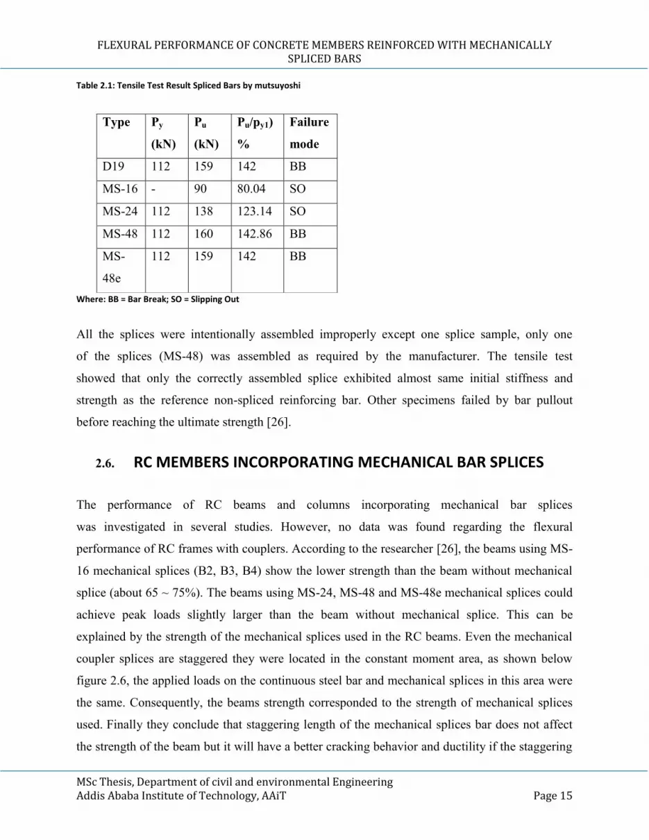
Table 2.1: Tensile Test Result Spliced Bars by mutsuyoshi
Where: BB = Bar Break; SO = Slipping Out
All the splices were intentionally assembled improperly except one splice sample, only one
of the splices (MS-48) was assembled as required by the manufacturer. The tensile test
showed that only the correctly assembled splice exhibited almost same initial stiffness and
strength as the reference non-spliced reinforcing bar. Other specimens failed by bar pullout
before reaching the ultimate strength [26].
2.6. RC MEMBERS INCORPORATING MECHANICAL BAR SPLICES
The performance of RC beams and columns incorporating mechanical bar splices
was investigated in several studies. However, no data was found regarding the flexural
performance of RC frames with couplers. According to the researcher [26], the beams using MS-
16 mechanical splices (B2, B3, B4) show the lower strength than the beam without mechanical
splice (about 65 ~ 75%). The beams using MS-24, MS-48 and MS-48e mechanical splices could
achieve peak loads slightly larger than the beam without mechanical splice. This can be
explained by the strength of the mechanical splices used in the RC beams. Even the mechanical
coupler splices are staggered they were located in the constant moment area, as shown below
figure 2.6, the applied loads on the continuous steel bar and mechanical splices in this area were
the same. Consequently, the beams strength corresponded to the strength of mechanical splices
used. Finally they conclude that staggering length of the mechanical splices bar does not affect
the strength of the beam but it will have a better cracking behavior and ductility if the staggering
Type Py
(kN)
Pu
(kN)
Pu/py1)
%
Failure
mode
D19 112 159 142 BB
MS-16 - 90 80.04 SO
MS-24 112 138 123.14 SO
MS-48 112 160 142.86 BB
MS-
48e
112 159 142 BB

FLEXURAL PERFORMANCE OF CONCRETE MEMBERS REINFORCED WITH MECHANICALLY SPLICED BARS
MSc Thesis, Department of civil and environmental Engineering Addis Ababa Institute of Technology, AAiT Page 16
length is increased, Full strength mechanical splices (48mm of insertion length and injected
epoxy) that could develop 140% yield strength of rebar can be arranged at the same cross section
without significant changes from the beam without mechanical splices [26].

FLEXURAL PERFORMANCE OF CONCRETE MEMBERS REINFORCED WITH MECHANICALLY SPLICED BARS
MSc Thesis, Department of civil and environmental Engineering Addis Ababa Institute of Technology, AAiT Page 17
3. EXPERIMENTAL PROGRAM
3.1. INTRODUCTION
In this study, a C-30 concrete was selected for the specimens. The mixture included cement,
coarse aggregate, sand and tap water. The coarse aggregate was well-graded gravel and the water
was clean tap municipal water. The mix design was prepared referring to the specification for
mix proportion design of ordinary concrete for target strength of 30MPa strength. Experiments
were conducted at Addis Ababa institute of technology (AAiT) materials laboratory. Cubes (150
mm) were cast at the same time with the beams, and all were cured outdoors together. The
compressive strength was tested with beam loading tests, which were 14 days after casting. The
average 14 day strength was 30.5MPa.
3.2. MATERIALS AND SPECIMEN FABRICATION
3.2.1. CONCRETE MATERIALS
Water: Water from municipality was used to prepare concrete mix and cure the test specimens.
Cement: For the purposes of this study, Portland pozzolana cement (PPC) from Mugger Cement
Factory was used for the concrete mix.
Aggregates: Fine aggregate (sand) and coarse aggregates (gravel) were used in this test
specimen preparation. The nominal maximum size of coarse aggregate was as large as possible
within the limits specified but in no case greater than one-fourth of the minimum thickness of the
member, provided that the concrete can be placed without difficulty so as to surround all
reinforcement thoroughly and fill the corners of the form.
3.2.2. MECHANICAL COUPLERS
Mechanical splice/joint is the common terminology for the complete assembly including the
coupler or sleeve fitted to provide a splice of two reinforcement bars. There are various types of
mechanical splicing methods that have been developed and implemented in reinforced concrete
structure projects to transfer tension forces from one bar to the other spliced bar and to ensure the
continuity of the reinforcement but this study was restricted to threaded couplers (couplers with

FLEXURAL PERFORMANCE OF CONCRETE MEMBERS REINFORCED WITH MECHANICALLY SPLICED BARS
MSc Thesis, Department of civil and environmental Engineering Addis Ababa Institute of Technology, AAiT Page 18
parallel threads) where the mechanical connectors with threaded portion had a cross sectional
area equal or greater than the nominal size of the bar. It is the most common type of coupler and
incidentally, the type of coupler used in CBE new head quarter design and build project. It can
develop yield strength of 625MPa as shown in Figure 3.1
Figure 3-1: Type-1 Parallel Threaded Mechanical Splicers (Couplers)
Table 3-1: Physical Properties of the ø16 Threaded Coupler
Bar Size
(mm)
Diameter Of
Coupler (mm)
Internal
Diameter Of
Coupler (mm)
Length Of
Coupler
(mm)
Internal
Thread
(No.)
16 24 14.2 40 14
3.2.3. REINFORCING STEEL BARS
Locally manufactured and commonly used deformed bars were used to evaluate the local
rebar’s performance by using parallel threaded connectors. Three types of diameters were
adopted for beam specimen reinforcement, and the tensile strength of the bars were
determined by testing three identical specimens from each diameter using tensile strength

FLEXURAL PERFORMANCE OF CONCRETE MEMBERS REINFORCED WITH MECHANICALLY SPLICED BARS
MSc Thesis, Department of civil and environmental Engineering Addis Ababa Institute of Technology, AAiT Page 19
testing machine. Threads were made on the reinforcement at end of the bar for coupling and
properly anchored at the other end of the beam (Figure 3.2).
Figure 3-2: Reinforcing Deformed Steel Bar Specimens
3.3. PREPARATION OF TEST SPECIMENS
In the preparation of test specimens, ISO was used as a guideline along with other considerations
such as AAiT laboratory restrictions. For example, sections of the specimen were decided
depending on the laboratory conditions in AAiT and manual cyclic load applying frames
available.
3.3.1. MECHANICAL COUPLED (SPLICED) DEFORMED STEEL BARS
To understand the flexural effect of the member with coupled steel reinforcement, two types of
coupler detailing arrangements were used. The layout of the beams included a reference beam
with no splice (B1), three beams (CIB-2) with correctly installed threaded coupler (100% spliced
at the constant moment region of the span) and one beam (CIB-1), 50% of the bar spliced at
constant moment region of the span. Figure 3.3 shows a schematic diagram of rebar detailing for
each specimen and mechanically coupled reinforcing bars. The splice specimens have identical
couplers and ø16 identical bars. The coupling system has a threaded internal anchorage to
develop the required bond strength, yield strength of the bar and to transfer of axial tension or
compression from one bar to the other. The couplers used in this study were commonly available
in the market with specified tensile strength of greater than 625 Mpa and 3% relative elongation.
The profile made it easy to embed bars by torque and ensure the quality of coupling splice. In

FLEXURAL PERFORMANCE OF CONCRETE MEMBERS REINFORCED WITH MECHANICALLY SPLICED BARS
MSc Thesis, Department of civil and environmental Engineering Addis Ababa Institute of Technology, AAiT Page 20
fabrication of the splices, the bars were carefully inserted in to the coupler from their two ends to
make the two bars line up accurately.
(a) Specimen With Bars 100% Connected By Coupler At Constant Moment Region (CIB-2)
(b) Specimen with 50% of the bars connected by coupler at constant moment zone (CIB-1)
Figure 3-3: Schematic Diagram of Mechanically Coupled Bars
Table 3-2: Details and Specification of Tested Beams
No. Specimen Details
1 B-1 Beam as Reference (without splice)
2 CIB-1 Specimen with bar clustered at mid span 50%
3 CIB-2 Specimen with 100% of the bars clustered at point of maximum
constant moment region (mid span).
3.3.2. DETAILED RE-BAR SPECIMENS FOR BEAM
Stirrups of the reinforcing steel bar were hooked at 135 degrees at the end of the beams’ diagonal
bars to enhance the bond strength between the bar and concrete. The reinforcing area required for
the beam was calculated from two points lading of 300KN and provided with 2ø16 bars as
shown above on the figure. 2ø12 bars were used for compression-zone reinforcement to ensure
the beams would not be damaged during handling. Closed loop stirrups were used in areas where
shear force is pronounced i.e. areas between the support and the point of load application. A total
of 12 steel stirrups were used per specimen with the arrangement as shown in the Figure 3.4 and
3.5 below. Reinforcing steel bars were hooked at 90 degrees at the end of the beams to enhance

FLEXURAL PERFORMANCE OF CONCRETE MEMBERS REINFORCED WITH MECHANICALLY SPLICED BARS
MSc Thesis, Department of civil and environmental Engineering Addis Ababa Institute of Technology, AAiT Page 21
the bond strength between the bar and concrete. Mechanical splices were located in the 500 mm
uniform bending moment region which was obtained by applying two symmetric concentrated
loads 280 mm away from mid span. No stirrup was used in this region in order not to disturb the
crack patterns.
Figure 3-4: Photography of Coupler Connected Reinforcement Specimen
Figure 3-5: Reinforcement Arrangement in the Specimen Beam
3.4. FLEXURAL BEAM TEST PROGRAM
To examine the flexural performance of the reinforced concrete beams, a total of five reinforced
concrete beams were cast. For this test, each specimen was 280 mm deep, 200 mm wide and
1500 mm long.
(a) Fresh Concrete Pouring (b) Compacting in the Mold

FLEXURAL PERFORMANCE OF CONCRETE MEMBERS REINFORCED WITH MECHANICALLY SPLICED BARS
MSc Thesis, Department of civil and environmental Engineering Addis Ababa Institute of Technology, AAiT Page 22
(C) RC Beams
Figure 3-6: Photograph of Flexural Beam Test Specimens
3.5. INSTRUMENTAL SETUP
Initially, the two supports were adjusted with equal distance from center of loading cell i.e. the
supports were fixed at 650mm from center. Afterwards, the beam was placed on the testing
machine with respect to the side in which the reinforcement laid correctly. The instrumental
setup is shown in Figure 3.7.
Figure 3-7: Photograph of Instrumental Setup

FLEXURAL PERFORMANCE OF CONCRETE MEMBERS REINFORCED WITH MECHANICALLY SPLICED BARS
MSc Thesis, Department of civil and environmental Engineering Addis Ababa Institute of Technology, AAiT Page 23
3.6. FLEXURAL BEAM TEST SETUP
With two lower pin supports positioned on the lower part of the middle frame cross beam, the
upper roller steel rectangular solid section was made to transfer the load from spreader beam to
RC beam. After that, upper roller was positioned 433mm apart by placing them in equal distance
from the center. The load was applied acting through a spreader beam; the spreader beam rested
on steel rollers and the steel rollers were placed on the RC beam. The setup is shown in figure
3.8 below. Test procedure listed on IS was used to perform flexural test.
The beams were restrained against out-of-plane deformation and were pin supported at both the
right and left sides of the beam. The beams were tested under two points bending test.
Displacement transducers were used to measure the deflections of beams at mid span.
Load was applied using a 300kN hydraulic actuator, to examine the performance of mechanical
splices in the RC beams; the beams were investigated cyclically by three stages,10 cycles were
applied for each of the three load amplitudes: 100, 150 and 200KN respectively and finaly to
Pmax to get the failure load where the design load was 200KN.
(a) Photograph of Flexural Beam Setup

FLEXURAL PERFORMANCE OF CONCRETE MEMBERS REINFORCED WITH MECHANICALLY SPLICED BARS
MSc Thesis, Department of civil and environmental Engineering Addis Ababa Institute of Technology, AAiT Page 24
(b) Displacement Measuring Transducer
Figure 3-8: Photograph of Flexural Beam Test Setup

FLEXURAL PERFORMANCE OF CONCRETE MEMBERS REINFORCED WITH MECHANICALLY SPLICED BARS
MSc Thesis, Department of civil and environmental Engineering Addis Ababa Institute of Technology, AAiT Page 25
4. EXPERIMENTAL PROGRAM TEST RESULTS
4.1 INTRODUCTION
This chapter presents the experimental program test results of flexural beam tests. First test was
conducted to get the strength of each material and then taking those properties and material
strength, the flexural test program was conducted. The first experimental test was on a non-
spliced beam (control unit). Remaining five beam tests were on beams with two types of splice
connections Type 1 (CIB-1) and Type 2 (CIB-2). These tests were conducted to investigate
behavior of coupler splice connections at constant bending moment region.
To assess the flexural performance of the mechanically spliced steel bar reinforced concrete
members, the spliced bars were embedded in concrete beam, and then tested under cyclic load to
point of failure. The behavior of the splice in laboratory was assessed and compared to the
behavior of a straight un-spliced steel bar reinforced beams. Finally, the results are presented to
demonstrate the performance of mechanically spliced steel bar reinforced concrete beams.
4.2 OBSERVATIONS OF PRIMARY RESULTS
The analysis of observations and obtained results of experimental works are main stage of a
research to get essential information. Observation results including load-displacement and load-
strain curves, general behavior and crack pattern, ultimate strength and failure modes are
presented in this section. Load - displacement curves of the samples are depicted in Figure 4.1.
The maximum capacities of the samples were 259.85, 215.59, 249.85, 243.35, and 223.26KN,
for the B-1, CIB-1, CIB-2-1, CIB-2-2 and CIB-2-3 sample beams respectively. Cracking pattern
of the specimens is shown in Figure 4.3. Initial cracking of the B-1, CIB-1, CIB-2-1, CIB-2-2
and CIB-2-3 samples were recorded at forces of 82.78, 75.03, 72.28, 68.03 and 62.02KN,
respectively.

FLEXURAL PERFORMANCE OF CONCRETE MEMBERS REINFORCED WITH MECHANICALLY SPLICED BARS
MSc Thesis, Department of civil and environmental Engineering Addis Ababa Institute of Technology, AAiT Page 26
4.3. RESULT AND DISCUSSION OF EXPERIMENTAL PROGRAM
The specimens subjected to cyclic loading and for each loading scheme, the loading procedure
and residual deformations were recorded. Using 300KN servo hydraulic actuater. As the frame
can not apply load in cyclic way, the way to obtain the required results was manual way of cyclic
loading. The results of the exiperimental investigation of each specimens are presented below.
4.3.1. LOAD-DISPLACEMENT CURVES
Load-deformation response of the specimens and typical curves are presented in the figures
below. One can identify the three stages from the figures; the yielding stage, the no underside
brittle failure stage and the brittle failure stages. The load–displacement curves of the specimens
have been briefly discussed. With regard to the stiffness, at earlier stages (before flexural
cracking), the load–displacement curves of all specimens are close to each other for the first
100KN loading cycles, regardless of the using mechanical splices. This is because the behavior
of un-cracked beams is determined by the gross moment of inertia of the concrete cross section.
Upon cracking, since the flexural stiffness of specimens is mainly dependent on the
reinforcement, the specimens using mechanical splices experience distinct degradation of
flexural stiffness whereas the stiffness of the specimen without mechanical splice reduces
slightly. It can be observed from figure 4.3 that as the load increases the rate of stiffness
degradation after the initial flexural crack of the specimen with mechanical splices increases and
is higher than that of specimen B1. Although the mechanical splices used in each specimen had
different load-strain relationship as shown in the test results, the beams using them exhibit quite
the same stiffness. It means that the location of mechanical splices inside the concrete is
improved due to the restraining effect of the concrete on the mechanical splices. Another reason
is that the mechanical splice occupies only a very small part compared to the whole length of the
beam so its effect to the beam stiffness is not significant.

FLEXURAL PERFORMANCE OF CONCRETE MEMBERS REINFORCED WITH MECHANICALLY SPLICED BARS
MSc Thesis, Department of civil and environmental Engineering Addis Ababa Institute of Technology, AAiT Page 27
1. SPECIMEN B1
Specimen B1 (Figure 4.1) had a highest recorded applied load of the beam tests at the last cyclic
load. At this cycle, the beam is loaded to sustain a load greater than its design load. Additionally,
this beam performed better than others – having higher yield stiffness than the other beam
specimens. The peak load was near 259.85KN, although this specimen was loaded to a deflection
closer to -16.51 mm.
Figure 4-1: Displacement Curves at Mid-Span under Cyclic Loading
2. SPECIMENS CIB-1-1
During testing of the CIB-1 specimen, the peak load was 215.59KN with corresponding
deflection of -9.65mm. After this peak load, the beam increasingly deflected without any
increase in the load. Deflection was increasing even when the load intensity was decreasing at a
deflection of -16.755mm. After this point, for sake of safety the load cell and hydraulic jacks
were removed.

FLEXURAL PERFORMANCE OF CONCRETE MEMBERS REINFORCED WITH MECHANICALLY SPLICED BARS
MSc Thesis, Department of civil and environmental Engineering Addis Ababa Institute of Technology, AAiT Page 28
Specimen CIB-1 performed less than that of B1 and the stiffness degradation behavior of
specimens is evident of this fact. At the end of the test at displacements exceeding 9.65mm, this
series had a lower stiffness than the control specimen and a peak load of 215.59KN. The
apparent degradation of behavior of the CIB-1 specimen as compared to the control specimen
may be attributed to the expected response of the mechanical splice as compared to the
continuous bar. In this mechanical splice, relative slip of bars was noticed in addition to steel bar
strain, which contributed to the measured elongation across the splice.
3. Specimen CIB-2-1, CIB2-2 and CIB-2-3
Specimen CIB-2-1 and CIB-2-2 performed similarly with B1 in stiffness performing comparable
to specimen B1 with increased deflection. A little degradation in the behavior of specimens is
evident at the end of the test at displacements exceeding 12mm, and this series had
approximately the same stiffness with that of the control specimen and a peak load of 249.85 for
CIB-2-1, 243.35 for CIB-2-2 and 223.26kN for CIB-2-3 respectively. The load-displacement
curves are shown in Figure 4.2.
Figure 4-2: Representative Combined Load-Displacement Curves of the Specimens at Mid-Span

FLEXURAL PERFORMANCE OF CONCRETE MEMBERS REINFORCED WITH MECHANICALLY SPLICED BARS
MSc Thesis, Department of civil and environmental Engineering Addis Ababa Institute of Technology, AAiT Page 29
4.3.2. FAILURE MODE OF THE SPECIMENS
The failure modes of the beams are shown in Figure 4.3. The beam without mechanical splicers
(control beam) failed after significant cyclic loading, with wide flexural crack at bottom face and
the crack developed above the neutral axis with compression zone crushing between the two
point loading (at constant moment zone). As it is noticed on all beams, after reaching peak load
and flexural failure ends, the beams’ top surface concrete failed by compression as shown on
photographs below.
Figure 4-3: Mode of Failure of Control Beam Specimen
For the CIB-1 beam using 50% mechanical splices, the failure modes are a little different as the
cracks suddenly widen due to slipping of the bar within the coupler. Here in this case, slipping
occurred. Similarly, when the deflection is continuously increased compression failure on top
surface ensued as shown on the picture.
Figure 4-4: Mode of Failure for CIB-1

FLEXURAL PERFORMANCE OF CONCRETE MEMBERS REINFORCED WITH MECHANICALLY SPLICED BARS
MSc Thesis, Department of civil and environmental Engineering Addis Ababa Institute of Technology, AAiT Page 30
The beams using 50% Mechanical splices were of lesser quality and failed with a breaking sound
but when the failure inside the concrete is checked by chiseling concrete around the coupler, it is
noticed that the failure mode clearly shows a greater strain/slip from the mechanical splices with
lesser peak load of 215.59kN. For the beams using 100% of mechanically spliced bars, the first
breaking sound was heard after the peak load (249.85KN) was reached and with further loading,
crushing of the beam. Brittle failure occurred with the sound of the second bar breaking nearly
followed by the sound of the first bar breaking. The compression crushing of concrete occurred
due to bar yielding on all beams similar to the one shown on the control specimen.
Figure 4-5: Mode of Failure for CIB-2 beams
Similarly for the CIB-2 beams with 100% mechanical splices, the failure modes were completely
different from the control beam. Initially, the cracks widened bit and suddenly the bars were
breaking near the couplers and within the coupler after reaching peak load of 249.85KN. Also,
the crack widths observed in members with these types of mechanical splices were wider than
the control beam. The cracks initiated on both sides of the couplers and had straight path
between the face of the two couplers; finally, brittle failure occurred.

FLEXURAL PERFORMANCE OF CONCRETE MEMBERS REINFORCED WITH MECHANICALLY SPLICED BARS
MSc Thesis, Department of civil and environmental Engineering Addis Ababa Institute of Technology, AAiT Page 31
4.3.3. CRACK BEHAVIOUR OF THE SPECIMENS
Cracking of concrete should not adversely affect the appearance or durability of the structure; the
acceptable limits of cracking would vary with the type of structure and environment, where a
specific attention is required to limit the designed crack width to a particular value. The “surface
width of the cracks should not, in general, exceed 0.3 mm in members where cracking is not
harmful and does not have any serious adverse effects up on the preservation of reinforcing steel
not up on the durability of the structures.” In this experimental investigation, there was no crack
until the cracking moment was reached in the pure bending zone. These first cracks were
predominantly vertical and perpendicular to the direction of the maximum stress induced by the
bending moment. After the first cycle of loading, Mcr creating load, no more new cracks
appeared and only the extension of the existing cracks was observed. The experimental crack
width (w) measured at the level of longitudinal reinforcement is shown in Table 4.1. As shown in
the table, the large crack widths observed were near coupler positions. The reason may be that
the strains near the mechanical splices had higher values than other locations and the concrete
cover at mechanical splices were smaller than the control specimen. Therefore, the important
factors affecting crack width are slip out of the bar from the coupler, increasing strain in that
specific location and concrete cover around the joint.
1. Cracking Behavior of B1 (B) Cracking Behavior of CIB-1
Figure 4-6: Cracking Behaviors of B-1 and CIB-1

FLEXURAL PERFORMANCE OF CONCRETE MEMBERS REINFORCED WITH MECHANICALLY SPLICED BARS
MSc Thesis, Department of civil and environmental Engineering Addis Ababa Institute of Technology, AAiT Page 32
After initial cracking, no new cracks were initiated until the third cyclic load. At this cycle, two
other new cracks developed and at 150KN cyclic loading, the initial crack intensified becoming
wider with new fine cracks appearing. As it is shown on the diagram, this specimen is weaker
than the other two beams.
For CIB-2-1 specimen, extending and widening of the middle crack was observed after the cyclic
load reached 200kN. At this point, other fine cracks were developing while the maximum
measured crack was 54.6mm. The beam was still loaded cyclically in order to investigate the
final failure mode, and a brittle failure of the beam occurred as a result of bar breaking.
(C) Crack behavior of CIB-2
Figure 4-7: Crack Behavior of the Specimens CIB-2
Table 4-1: Crack Width and Average Crack Spacing
Specimen Max crack width Max crack
spacing
Average
width
Average crack
spacing
At bar At coupler
B-1 3.4mm - 37.8mm 2.54mm 133.45mm
CIB-1 3.5mm 6.7mm 44.6mm 2.55mm 94.1mm
CIB-2-1 3.23mm 8.6mm 59.3mm 2.957mm 125.6mm
CIB-2-2 3.12mm 7.32mm 56.7mm 3.45mm 108.34mm
CIB-2-3 4.4mm 8.2mm 46.7mm 3.15mm 110.2mm

FLEXURAL PERFORMANCE OF CONCRETE MEMBERS REINFORCED WITH MECHANICALLY SPLICED BARS
MSc Thesis, Department of civil and environmental Engineering Addis Ababa Institute of Technology, AAiT Page 33
Additionally, there is a general consensus [11]“for cyclic loading conditions, the effects of
confinement reinforcement are insignificant.” and for the tests conducted in this study, no
transverse confinement was provided at constant moment span in order to not disturb the flexural
cracks. And shear critical zones were confined with ø10 stirrups and no diagonal cracks
developed. The confined sections of the beams have a better crack resisting performance as
observed on the experimental investigation.
4.3.4. ULTIMATE LOAD OF THE SPECIMENS
Failure modes have revealed that the ultimate load of a specimen depends on two factors;
ultimate tensile strength of the beam reinforcement and the resistance force of the coupler.
Accordigly, the ultimate load for B-1, CIB-1, CIB-2-1, CIB-2-2 and CIB-2-3 was 259.85,
215.59, 249.85, 243.35 and 223.26KN, respectively.
Table 4-2: Loading and Displacement Results of Samples
Name Pcr ∆cr Pyr ∆yr Pmax ∆max Pu ∆u
B-1 82.78 0.43 234.59 3.77 259.6 9.925 220.66 5.730
CIB-1 75.03 0.85 204.83 6.788 214.84 14.51 182.614 7.470
CIB-2-1 62.02 0.61 223.84 6.815 249.85 9.765 212.372 6.052
CIB-2-2 68.03 0.73 202.88 5.335 243.84 11.775 208.964 6.390
CIB-2-3 72.28 0.81 193.33 5.545 201.75 9.705 191.888 5.243
The cracking, yielding, maximum (peak) and ultimate loads are denoted by Pcr, Py, Pmax, and Pu
(kN unit) with their corresponding displacements of Δcr, Δy, Δmax and Δu (mm), respectively. Pu
was defined as 0.85 Pmax and its related displacement is Δu, which was read from the curves in
Figure 4.5.
4.3.5. ESTIMATION OF DUCTILITY
Ductility is defined as “the ability of a material, component, connection or structure to undergo
inelastic deformations with acceptable stiffness and strength reduction. It is also the capability of
a structure to undergo deformation after yielding without any significant reduction in yield
strength”[10]. Figure 4.5 compares the structural response of brittle and ductile systems. A
margin of safety against failure of a splice is required and it is also desirable that a degree of

FLEXURAL PERFORMANCE OF CONCRETE MEMBERS REINFORCED WITH MECHANICALLY SPLICED BARS
MSc Thesis, Department of civil and environmental Engineering Addis Ababa Institute of Technology, AAiT Page 34
ductility is available at the splice location in the members. Lack of ductility could result in little
warning of possible sudden failure of the connection. Ductility is particularly important when
designing couplers for use in structures subject to seismic loading, especially if their intended
use is within the plastic hinge zones. Therefore, a reinforced concrete should have good ductility,
good energy dissipation, low stiffness degradation and strength degradation during cyclic
loading. The results show that the ductility of RC beam reduced when using mechanical splices.
Factors such as strength of mechanical splices joint and staggering length of mechanical splices
have effects on ductility. Table 4.3 shows the ductility ratio of each beam. The collapse of brittle
systems occurs suddenly beyond the maximum resistance, denoted as Pmax, because of lack of
ductility. Curve 1 corresponds to large inelastic deformations representing specimen B1 on figure
4.2, which is typical of ductile systems. Whereas the other response curves are identical up to the
maximum resistance Pmax with a little difference, they should be treated differently under seismic
loads.
Table 4-3: Ductility Estimation of Specimens
Beam
Specimen
Yield Failure Ductility
∆U/∆Y
Deflection at
design load Load Displacement Load Displacement
B-1 234.59 3.77 262.34 16.53 4.384 -2.355mm
CIB-1-1 204.83 6.788 218.08 14.51 2.138 -7.505
CIB-2-1 223.84 5.815 252.34 10.995 1.891 -5.345
CIB-2-2 202.88 5.335 245.44 11.775 2.207 -5.795
CIB-2-3 193.33 5.545 203.45 9.765 1.761 -5.545
As it shown above, the control beam is more ductile than the remaining beams. Two of the beam
with 100% mechanical splices at the same cross section and the beam with 50% at the same
cross section, have almost the same ductility. But the beam with 50% mechanical splices
increased in yielding and its failure point was earlier than CIB-2. Also, to increase the ductility
of the structure, confinement reinforcement may be needed around the coupler to avoid wide
cracks.

FLEXURAL PERFORMANCE OF CONCRETE MEMBERS REINFORCED WITH MECHANICALLY SPLICED BARS
MSc Thesis, Department of civil and environmental Engineering Addis Ababa Institute of Technology, AAiT Page 35
B-1 CIB-2
Figure 4. 1: Crack Behavior and Deflection at Design Load
Specimen CIB-1 performed well initially, reaching a peak load of 215.59KN. However, upon
reloading and holding at this peak (to record cracking), the specimen never regained its previous
capacity. As the load began to decrease, the deflection continued to increase indicating the
failure of the specimen. The test was stopped at a deflection of 16.35 mm. Following testing, the
splice was recovered and inspected. The splice exhibited clear signs of failure due to joint
failure. The bar slipped approximately 6.7 mm through the splice. The slip is clearly visible in
Figure 4.4.
In each of the bar splice beams the concrete was unable to properly confine the splice. There was
cracking evident on the bottom face of the specimens caused by the excessive strain due to
section reduction at the face of the coupler. This also occurs in part because the thickness of the
concrete cover around the splice is lesser in size. This cracking demonstrates a particular
problem with mechanically spliced re-bars. Such kinds of cracking of the concrete members
would cause particular problems in structural elements.
The beams using mechanical splices could achieve peak loads slightly smaller than the beam
without mechanical splice. This can be explained by the strength of the mechanical splices used
in the RC beams. The CIB-1 mechanical splices could develop about 82.97% and CIB-2 could
develop 91.91% of the performance of B1 beam specimen. The yield strength reduction of the
specimens occurred due to threading, which reduces the actual diameter of the bar at face of the
joint. And as it is shown on table above, the deflection at design load is almost double as
compared to control beams for CIB-2 specimens.

FLEXURAL PERFORMANCE OF CONCRETE MEMBERS REINFORCED WITH MECHANICALLY SPLICED BARS
MSc Thesis, Department of civil and environmental Engineering Addis Ababa Institute of Technology, AAiT Page 36
5. CONCLUSIONS AND RECOMMENDATIONS
This chapter includes conclusion of the experimental program, recommendations and area of
study for future researchers.
5.1. CONCLUSIONS
Flexural performance of reinforced concrete members reinforced with locally manufactured
coupler connected steel bars (at mid span of constant moment region) was tested by two point
loading and the following conclusion had developed from experimental program test result:-
Parallel threaded coupler connected bar reinforced concrete beams had reduced stiffness
in comparison to conventionally reinforced beam.
Fully inserted bars into threaded parallel couplers (the connected steel bars) can be
considered as a continuous bar, keeping in mind that degradation of deflection capacity
and cracking behavior of the beams at the joint. Safety factors for deflection and
cracking issues may need to be considered in the design stage of the parallel threaded
coupler connected bar reinforced concrete members.
Past researcher has shown that the stiffness of the coupler splicing region is even higher
than that of a continuous reinforcement, due to the increased cross section at coupler
splice section. However, in this study it was noticed that the splice joint reduced stiffness
behavior due to thread lines at the face of the joint. Breaking failure of the bars was a
result of section deduction due to threading of the bar.
The connection had impact on the displacements, ductility and stiffness if it is used on
flexure critical zone
Brittle failure occurs due to bar breaking at threading lines of the bar.
Beam specimens reinforced with mechanically connected bar had a good ultimate
strength as; but its displacement and ductility were increased by 10.33% and decreased
by 9.5% respectively.
The crack widths of mechanically connected bar reinforced beams are wider than the
control beam at the coupler region.

FLEXURAL PERFORMANCE OF CONCRETE MEMBERS REINFORCED WITH MECHANICALLY SPLICED BARS
MSc Thesis, Department of civil and environmental Engineering Addis Ababa Institute of Technology, AAiT Page 37
Finally, the comparison of continuous bar and mechanically spliced bar reinforced
concrete beams indicated that the beams could sustain the ultimate design load with
increased deflection and crack width.
5.2. RECOMMENDATIONS
As mechanical splicers are a better way to join two separate bars with different diameters as well
same diameter bars for continuity purposes, they are a viable option. Ethiopian building
construction standards should include splicers as a primary alternative to other old and traditional
ways of connecting reinforcement bars.
The design standards, specifications and safety factors on yielding strength of the splicing
mechanical coupler depends on each country’s seismic load and design guidelines. Different
countries have different factor of safety and design considerations. The National design code of
Ethiopia should incorporate this technology considering the national seismic load assessments in
past years and local steel bar strengths.
5.3 AREA OF FURTHER STUDY
All test investigation in this study focused on ø16 locally local bars and only flexural behavior of
the specimens under cyclic loading. Future researchers should investigate the behavior of larger
bars which may help to develop a general specification of mechanically spliced reinforcing bars.
With the first cycle of loading, no visible difference was observed (Initial loading of 100KN), but with
further cyclic loading, the deflection of the beams was completely different from the control beam.
Therefore, future researchers may need further detail investigation on different loading and support
condition.
FLEXURAL PERFORMANCE OF CONCRETE MEMBERS REINFORCED WITH MECHANICALLY SPLICED BARS
MSc Thesis, Department of civil and environmental Engineering Addis Ababa Institute of Technology, AAiT Page 38
REFERENCES
[1] Farmington Hills, MI, Building code requirements for structural concrete (ACI 318-95) and
commentary – ACI 318R-95, American concrete institute - ACI committee 318 (1995), American
concrete institute.
[2] Farmington Hills, MI, building code requirements for structural concrete (ACI 318-99) and
commentary – ACI 318R-99, American concrete institute - ACI Committee 318 (1999),
American concrete institute.
[3] Flexural response of reinforced concrete beam based on multidimensional data analysis,
Indian journal of engineering and material sciences, vol. 7, pp. 292 -298, August 2005.
[4] K.D.P. Damsara and D.D.T.K. Kulathunga, analysis on effectiveness of rebar couplers in
splicing of reinforcement bars, [online document], https://eprints.lib.hokudai.ac.jp/dspace/.
[5] P L Ng, G X Guan, and A K H Kwan, Role of reinforcement couplers in serviceability
performance of concrete members, the university of Hong Kong, Hong Kong, China, 2017.
[6] Mohammad Sharbatdar, Omid Mohammadi Jafaria and Mohammad Karimi, experimental
evaluation of splicing of longitudinal bars with forging welding in flexural reinforced concrete
beams, Semnan University, Semnan, Iran, 2018.
[7] Research paper, seismic performance and application of mechanical splices in dissipative rc
structures, cited on (2018), institute of structural engineers, imperial college, London
[8] Vasilij Klimenov, Artem Ovchinnikov, Artem Ustinov and Artem Danilson, stress-strain
state of mechanical rebar couplings, national research Tomsk polytechnic university, Russia,
2016.
[9] Ministry of works and urban development, Ethiopian building code standard EBCS-2:
structural uses of concrete, Addis Ababa, Ethiopia, 1995.
[10] Reinforced concrete mechanics and design, sixth edition, James G. Mac Gregor. 2012.
[11] Online document Viwathanatepa et al. 1979 and Lukose et al. 1982; MacKay et al. 1998.
[12] ACI committee 318, building code requirements for reinforced concrete (ACI 318-89) and
commentary - ACI 318R-89. American concrete institute, detroit (1989); pp.353.
[13] Behavior of mechanical coupler in reinforcement, international journal of innovative
research in science, engineering and technology, April 2017.
[14] Assessing the seismic performance of reinforcement coupler systems in Turkey, conference
paper, May 2015.

FLEXURAL PERFORMANCE OF CONCRETE MEMBERS REINFORCED WITH MECHANICALLY SPLICED BARS
MSc Thesis, Department of civil and environmental Engineering Addis Ababa Institute of Technology, AAiT Page 39
[15] BMA engineering, inc. -5000, code of detailing of coupler and reinforcing steel splice
options, p 27-42, [Online document], http://google scholar.com.
[16] Concrete construction article, mechanical vs. lap splicing, by M.K. Hurd, 1998.
[17] Role of reinforcement couplers in serviceability performance of concrete members, IOP
conference series: materials science and engineering, 2017.
[18] Effects of mechanical bar splices on seismic performance of reinforced concrete buildings,
Al Hashib, Abdullah, theses and dissertations, South Dakota state university, 2017.
[19] Experimental evaluation of coupler behavior for mechanical rebar splices in reinforced
concrete structures, IBRACON structures and materials journal, Volume 11, p. 1326 – 1353,
University of Campinas, , Campinas, SP, Brazil, December 2018.
[20] Experimental study on RC beams using mechanical splices with different quality and
staggering length, proceedings of the thirteenth east Asia-pacific conference on structural
engineering and construction (EASEC-13), Sapporo, Japan, September 2013.
[21] Dextra group rebar splicing (coupler) manufacturer handbook, 13 Nov 2017,
www.dextragroup.com/rebarcouplers.
[22] Australian earthquake engineering society conference, Hobart, Tasmania Nov 15-17, 2013
[23] IS standard mix design 456.2000, plain and reinforced concrete - code of practice, fourth
revision, April 2007.
[24] Fundamental of earthquake engineering, Amr S. Elnashai and Luigi Di Sarno, first edition,
2008.
[25] ACI committee, types of mechanical splices for reinforcing bars ACI 439.3R-07
(Farmington Hills, Michigan, USA: American concrete institute), 2007.
[26] Phuong N D and Mutsuyoshi H, experimental study on performance of mechanical splices
in reinforced concrete beams, structural journal, 2015.
[27] Fatigue behavior of welded and mechanical splices in reinforcing steel, C. Paulson and
J.M. Hanson, December 1991.

FLEXURAL PERFORMANCE OF CONCRETE MEMBERS REINFORCED WITH MECHANICALLY SPLICED BARS
MSc Thesis, Department of civil and environmental Engineering Addis Ababa Institute of Technology, AAiT Page 40
APPENDICES
APPENDIX A
TERMS AND DEFINITIONS
For the purposes of this document, the terms and definitions given
in ISO 16020 and the following apply. ISO and IEC maintain terminological
databases for use in standardization:
Coupler:- Coupling sleeve or threaded coupler for mechanical splicing of
reinforcing bars for the purpose of providing transfer of axial tension or
compression from one bar to the other, where;
Threaded coupler is a threaded device for joining reinforcing bars with
matching threads.
Mechanical splice:- Complete assembly of a coupler, including any additional
intervening material or other components providing a splice of two reinforcing
bars.
Slip: - Relative displacement between the components of a mechanical splice while
being loaded to a defined load level.
Coupler length: - Actual length of the coupler including all load-transferring parts,
if more than one, and including lock nuts, if any.

FLEXURAL PERFORMANCE OF CONCRETE MEMBERS REINFORCED WITH MECHANICALLY SPLICED BARS
MSc Thesis, Department of civil and environmental Engineering Addis Ababa Institute of Technology, AAiT Page 41
APPENDIX B
DESIGN OF REINFORCED BEAM SECTION
The reinforced concrete beams were designed and produced using C-30 class
concrete and locally available steel bars. The actual strengths of concrete and steel
have been used in the analysis of the experimental result.
In order to do this experimental investigation, it is required to carry out the analysis
to decide the section of the beam. Nominal moment strength, Mn, for any beam
section with the corresponding moment strength equal to or exceeds Mu. The
primary thing in this section analysis is to start with known moment value of Mu,
and design of the beam cross section capable of to resist that moment and shear
(ɸMn >Mu and ɸVn > Vu) and also the section should satisfy all the requirement of
national codes. For section analysis and flexural and shear design of this study, the
ACI code requirement had used.
MATERIAL PROPERTIES
fcu = 30Mpa, fck = 24Mpa, fctd = 1.165Mpa, fyk =499.8Mpa for main bars and fyk = 500Mpa
for stirrups. Due to the 300KN loading from the hydraulic jack, a design load of
Mu = 43.33 KNm and Vu =100KN.
DESIGNING FOR FLEXURE AND BEAM SECTION
The design problem in this section involves finding b and d/h as a preliminary
estimate of the self-weight of the beam, selection of a target steel percentage, and
final selection of the section dimension b and h. The weight of rectangular beam
will be roughly 10 to 15% of the un-factored load, and the width of the beam in
this study is kept to be 0.8 of the depth.
Assume b is approximately 0.8h; then next step is to select the reasonable starting
value for reinforcement ratio, Ƿ =
(1)
To start the design process, the target strain diagram was selected as shown on
Figure 1B. As the tension reinforcement is needed to be in single layer, the strain at

FLEXURAL PERFORMANCE OF CONCRETE MEMBERS REINFORCED WITH MECHANICALLY SPLICED BARS
MSc Thesis, Department of civil and environmental Engineering Addis Ababa Institute of Technology, AAiT Page 42
the centroid of the tension reinforcement, ɛs, is equal to ɛt. To justify the use of ɸ =
0.9, ɛt, must or exceed 0.005 for the final section design.
Figure 1B: Assumption for Singly Reinforced Beam Section [10]
Let’s ɛt = 0.0075,
C =
= 0.286d,
Using this value of c the expression for concrete compression force Cc is,
Cc = 0.85fckbβ1c substituting the value of c, Cc = 0.24β1fckbd,
Equating equilibrium of the forces from figure above:
T= Cc, Asfy = 0.24β1fckbd, and steel reinforcement ratio Ƿ =
=
approximately
with an initial target reinforcement ratio that will be used for the design of singly
reinforced rectangular section and an expression for balanced reinforcement ratio
where:
Ƿb =
(2)
The maximum value of ɛcu = 0.003 and the steel yield strain for fy-500 steel is
0.0021 thus the equation
, using 50% of balanced reinforcement ratio
as target value for Ƿ result. Ƿ(target) = 0.75Ƿb = 0.255
now reinforcements.
The reinforcement index Ѡ =
(3)

FLEXURAL PERFORMANCE OF CONCRETE MEMBERS REINFORCED WITH MECHANICALLY SPLICED BARS
MSc Thesis, Department of civil and environmental Engineering Addis Ababa Institute of Technology, AAiT Page 43
The nominal flexural strength of singly reinforced rectangular section was given
in:
Mn = Asfy(d-a/2) (4)
The expression for depth of compression stress block, a was given and as modified
below
a = Asfy/0.85fckb = Ѡd*
putting the expression for a, to equation (4) and
simplifying the expression one can get the following expression for Mn.
Mn = Ѡfck(1-0.59Ѡ)bd2
(5)
The symbol R commonly referred to as the flexural resistance factor R= Ѡfck(1-0.59Ѡ)
ɸMn = ɸR(bd2) (6)
fcu = 30Mpa, fck = 24Mpa, fctd = 1.165Mpa, fyk =499.8Mpa, fyd = 499.8Mpa
β1 = 0.85, K1 =1+50Ƿmin < 2, = 1+50*0.6/fyk = 1.07143
Ƿ =
=
= 0.010625, Ѡ = Ƿ
= 0.2125, R = Ѡfck(1-0.59Ѡ) = 5.021,
Because this R factor is for tension controlled beam section and the section
required to failed by tension reinforcement yielding, use ɸ = 1, and calculate for
bd2
bd2 =
, bd2 = 9.68575*10^6, now set b and d are equal and d = 217mm and h = d
+ 41, hence h = 258 and used h = 280mm, as b= 0.8h it can be approximated to
200mm.
Now determine the required flexural reinforcement, As =
, a = Ѡd*
= 52.25
As = 592.36mm2 or 2.95ø16; but to investigate the flexural behavior of concrete
beam with reinforcement connected at mid span with parallel threaded coupler, use
2ø16 flexural bars.
To conform that the tension steel is yielding, lets calculate the stress block depth a,
for the selected steel area a, with new area 402.12mm2 provided.

FLEXURAL PERFORMANCE OF CONCRETE MEMBERS REINFORCED WITH MECHANICALLY SPLICED BARS
MSc Thesis, Department of civil and environmental Engineering Addis Ababa Institute of Technology, AAiT Page 44
Check for minimum moment to prevent sudden failure with little or no warning
when the beam cracks in flexure. ACI code section 10.5 requires a minimum
amount of flexural reinforcement equal to that shown in the equation below.
Asmin= √
>
where fy and fck are in MPa,
From these two values, the governing value is 117.04mm2 but As provided is
already greater than this value hence proceed to next steps.
a =
= 47.31mm, c = a/β1 = 55.657mm
Then to calculate the steel strain at the one level of tension steel ɛs = ɛt =
=
0.008265, this value is greater than that of the yield strain of steel (ɛy =0.002) and
strain limit of tension controlled strain (0.005), so the assumption is that the steel is
yielding and valid.
Finally using equation (6) to calculate the nominal moment strength and including
the strength reduction factor ɸ, [Mn = ɸ*R*(bd2)], Mn = 46.47KNm.
DESIGN FOR SHEAR LOAD
According to ACI code section 11.4.6.1, the stirrup is not required if Vn < Vc/2
where:
Vc = √
= 1*
√
*200*209 = 34.83KN, because Vu/ɸ =133.3KN which
exceeds 17.4KN stirrups are required, where 𝛌 =1, and ɸ = 0.75.
Check if the cross section is large enough as per ACI code section 11.4.7.9 which
gives that the maximum shear in the stirrup is Vsmax =
√ thus the
maximum allowable Vu/ɸ is
max = Vc +Vsmax = 5Vc = 174.15KN because
Vu/ɸ is 133.3KN which is less than 174.15KN; the section is large enough.
Check anchorage of stirrups and maximum spacing of two leg stirrups, fyt
=300MPa and Av = 100.53mm2, for ø8 two leg stirrups.

FLEXURAL PERFORMANCE OF CONCRETE MEMBERS REINFORCED WITH MECHANICALLY SPLICED BARS
MSc Thesis, Department of civil and environmental Engineering Addis Ababa Institute of Technology, AAiT Page 45
(a) The anchorage of stirrups as per ACI code section 12.13.2.1 allows for
smaller stirrups to be anchored by a standard 90 or 135 degree hook stirrup
around the longitudinal bars.
(b) Find the maximum stirrup spacing.
Based on the beam depth, ACI code section 11.4.5.1 requires the smaller of 0.5d or
600mm, ACI code section 11.4.5.3 requires half those spacing is Vs exceeds 1/3*
√ *bwd = 69.67KN, Vsmax =
√ bwd = 139.33KN, as Vn (133.3) <
139.33KN, provide a stirrup based on governing spacing of the following
equations:-
{
√
}
, hence use ø8@100mm
Compute the stirrup spacing required to resist the shear force for vertical stirrups:
S =
=
= 110.14mm, hence use fyt > 400MPa ø8 bar @100,
Finally for Msd = 45.5kNm, Vsd = 101.688KN.
Finally the length of the beam was decided to be1500mm and width and depth
were computed as shown above as 200m and 280mm, respectively.
Hence use 2ø16 bars for diagonal reinforcements and 2ø12bars for compression
reinforcement to ensure there is no damage during handling of the beam. And also
use ø8@100 and staggered stirrup of closed loop.

FLEXURAL PERFORMANCE OF CONCRETE MEMBERS REINFORCED WITH MECHANICALLY SPLICED BARS
MSc Thesis, Department of civil and environmental Engineering Addis Ababa Institute of Technology, AAiT Page 46
APPENDIX C
PROCEDURES IN SPECIMEN PREPAREION
1. Sampling of materials - Samples of aggregates for each batch of concrete shall
be of the desired grading and shall be in an air-dried condition. The cement
samples, on arrival at the laboratory, shall be thoroughly mixed dry either by hand
or in a suitable mixer in such a manner as to ensure the greatest possible blending
and uniformity in the material.
2. Proportioning - The proportions of the materials, including water, in concrete
mixes used for determining the suitability of the materials available, shall be
similar in all respects to those to be employed in the work.
3. Weighing - The quantities of cement, each size of aggregate, and water for each
batch, shall be determined by weight, to an accuracy of 0.1kg of the total weight of
the batch.
4. Mixing concrete - The concrete shall be mixed manually by hand,
5. Formwork - The size of the formworks used was 28 × 20 × 150 cm.
6. Compacting - The test specimens were placed as soon as practicable after
mixing, and in such a way as to produce full compaction of the concrete with
neither segregation nor excessive laitance.
7. Curing - The test specimens were stored in a place, free from vibration with
moist air of a good humidity.

FLEXURAL PERFORMANCE OF CONCRETE MEMBERS REINFORCED WITH MECHANICALLY SPLICED BARS
MSc Thesis, Department of civil and environmental Engineering Addis Ababa Institute of Technology, AAiT Page 47
APPENDIX D
MATERIAL STRENGTH OF THE TEST RESULTS
COMPRESSIVE STRENGTH OF THE CONCRETE
This section covers the determination of compressive strength of reinforced concrete specimens.
Compression tests were conducted on cubic specimens; it consisted of applying a compressive
axial load to molded cubes at a rate which is within a prescribed range until failure occurs. From
the test, the ultimate compression resistance of the specified specimen was recorded as shown on
Table 1D below.
Table 1D: 14th Day Compressive Strength Result of the Specimen’s Samples
Samples Sections (Lxwxd) Area (mm2) Load (KN) Compressive Strength
(Mpa)
1 150X150X150 22500 674.23 30.8
2 150X150X150 22500 712.07 31.6
3 150X150X150 22500 670.92 29.8
Averege 685.74 30.5
Figure 1D: Cube Strength Test Sampling
The average compressive strength at 14 days was found to be 30.5Mpa.

FLEXURAL PERFORMANCE OF CONCRETE MEMBERS REINFORCED WITH MECHANICALLY SPLICED BARS
MSc Thesis, Department of civil and environmental Engineering Addis Ababa Institute of Technology, AAiT Page 48
TENSILE STRENGTH OF THE STEEL BAR
Tensile tests were conducted on three specimens to determine the tensile strength of the
specified bar diameter shows on table 2D below.
Previous studies also show that bars spliced with mechanical connectors fail by bar breakage,
given that the splice samples were assembled as required by the manufacturer.
Table 2D: Tensile Strength Test Result of the Bar
Diameter of the Bar
(mm)
Yield Strength
(Mpa)
Ultimate Strength
(Mpa)
16 420 499.8
Table 3D: Experimentally Determined Concrete and Reinforcing Steel Properties
Specimen
Compressive Strength
(MPa) Age at time of Beam
Test in Days
Reinforcing Steel
Strength 14 28
B-1(1pcs) 30.0 33.28 30 Fy = 420Mpa
Fu = 499.8Mpa CIB-1(1pcs) 31.6 35.25 31& 35
CIB-2(3pcs) 29.8 33.18 31
The 28th
day average concrete compressive strength was 33.9Mpa and the individual concrete
compressive strengths of each of the beam specimens are tabulated above on table 3D.


