Embed Size (px)
Citation preview
FLEET72-500
REV 10.0 - TOTAL JUL 20
Kg
AFM Airplane Flight Manual
APPROVED
The content of this document is the property of AVIONS DE TRANSPORT REGIONAL. It is supplied in confidenceand commercial security on its content must be maintained. It must not be used for any purpose other than that forwhich it is supplied, nor may information contained in it be disclosed to unauthorized persons. It must notreproduced in whole or in part without permission in writing from the owners of the copyright. ©2020. All rightsreserved
PK1_AFM_75_EASA_L_SI_full_Rev10.0

LTR...............................................................................................................page 01
LNR.............................................................................................................. page 01
RNR..............................................................................................................page 01
LEDM............................................................................................................page 01
LOM..............................................................................................................page 01
CRT.............................................................................................................. page 01
GENERAL INFORMATION.............................................................................. page 03
LIMITATIONS................................................................................................. page 03
PROCEDURES.............................................................................................. page 03
PERFORMANCE............................................................................................page 03
DEVIATION GUIDE.........................................................................................page 03
APPENDICES................................................................................................ page 03
AFM.
PK / 75 TOCAFM Table of Content Page n°01

PAGE
INTENTIONALLY
LEFT BLANK
AFM.
PK / 75 TOCAFM Table of Content Page n°02
No Temporary Revision
AFM
PK / 75 LTRAFM List of Temporary Revisions Page n°01

PAGE
INTENTIONALLY
LEFT BLANK
AFM
PK / 75 LTRAFM List of Temporary Revisions Page n°02
N° Rev Edition Date Authority Reference Insertion Date(Should be
integrated inAirline
documentation atthat date)
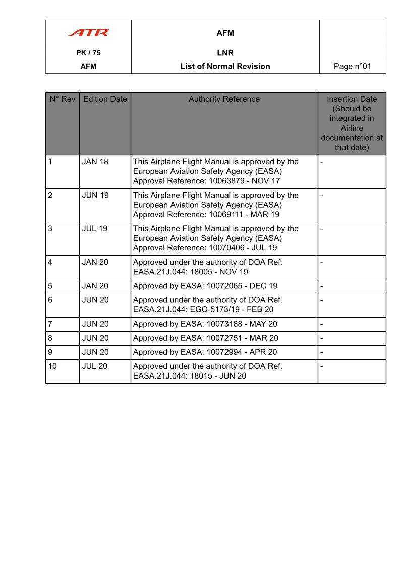
1 JAN 18 This Airplane Flight Manual is approved by theEuropean Aviation Safety Agency (EASA)Approval Reference: 10063879 - NOV 17
-
2 JUN 19 This Airplane Flight Manual is approved by theEuropean Aviation Safety Agency (EASA)Approval Reference: 10069111 - MAR 19
-
3 JUL 19 This Airplane Flight Manual is approved by theEuropean Aviation Safety Agency (EASA)Approval Reference: 10070406 - JUL 19
-
4 JAN 20 Approved under the authority of DOA Ref.EASA.21J.044: 18005 - NOV 19
-
5 JAN 20 Approved by EASA: 10072065 - DEC 19 -
6 JUN 20 Approved under the authority of DOA Ref.EASA.21J.044: EGO-5173/19 - FEB 20
-
7 JUN 20 Approved by EASA: 10073188 - MAY 20 -
8 JUN 20 Approved by EASA: 10072751 - MAR 20 -
9 JUN 20 Approved by EASA: 10072994 - APR 20 -
10 JUL 20 Approved under the authority of DOA Ref.EASA.21J.044: 18015 - JUN 20
-
AFM
PK / 75 LNRAFM List of Normal Revision Page n°01
PAGE
INTENTIONALLY
LEFT BLANK
AFM
PK / 75 LNRAFM List of Normal Revision Page n°02
N° Rev RevisionDate
Reason For Issue Impacted DM
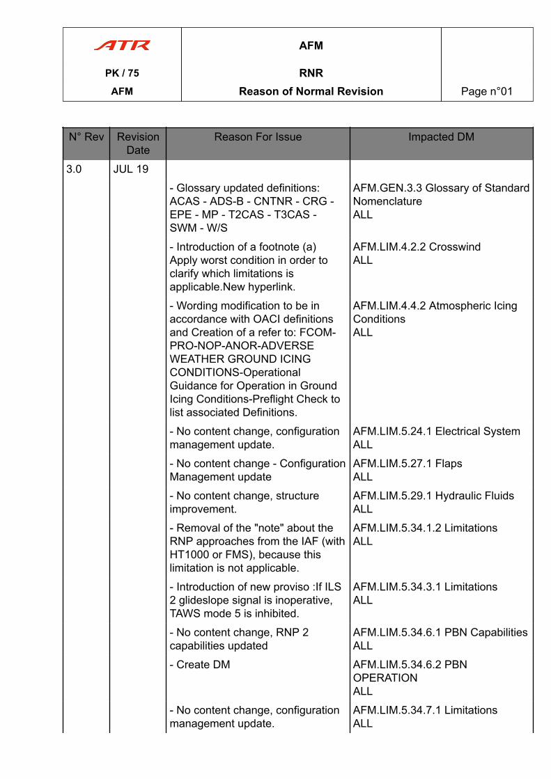
3.0 JUL 19
- Glossary updated definitions:ACAS - ADS-B - CNTNR - CRG -EPE - MP - T2CAS - T3CAS -SWM - W/S
AFM.GEN.3.3 Glossary of StandardNomenclatureALL
- Introduction of a footnote (a)Apply worst condition in order toclarify which limitations isapplicable.New hyperlink.
AFM.LIM.4.2.2 CrosswindALL
- Wording modification to be inaccordance with OACI definitionsand Creation of a refer to: FCOM-PRO-NOP-ANOR-ADVERSEWEATHER GROUND ICINGCONDITIONS-OperationalGuidance for Operation in GroundIcing Conditions-Preflight Check tolist associated Definitions.
AFM.LIM.4.4.2 Atmospheric IcingConditionsALL
- No content change, configurationmanagement update.
AFM.LIM.5.24.1 Electrical SystemALL
- No content change - ConfigurationManagement update
AFM.LIM.5.27.1 FlapsALL
- No content change, structureimprovement.
AFM.LIM.5.29.1 Hydraulic FluidsALL
- Removal of the "note" about theRNP approaches from the IAF (withHT1000 or FMS), because thislimitation is not applicable.
AFM.LIM.5.34.1.2 LimitationsALL
- Introduction of new proviso :If ILS2 glideslope signal is inoperative,TAWS mode 5 is inhibited.
AFM.LIM.5.34.3.1 LimitationsALL
- No content change, RNP 2capabilities updated
AFM.LIM.5.34.6.1 PBN CapabilitiesALL
- Create DM AFM.LIM.5.34.6.2 PBNOPERATIONALL
- No content change, configurationmanagement update.
AFM.LIM.5.34.7.1 LimitationsALL
AFM
PK / 75 RNRAFM Reason of Normal Revision Page n°01
N° Rev RevisionDate
Reason For Issue Impacted DM
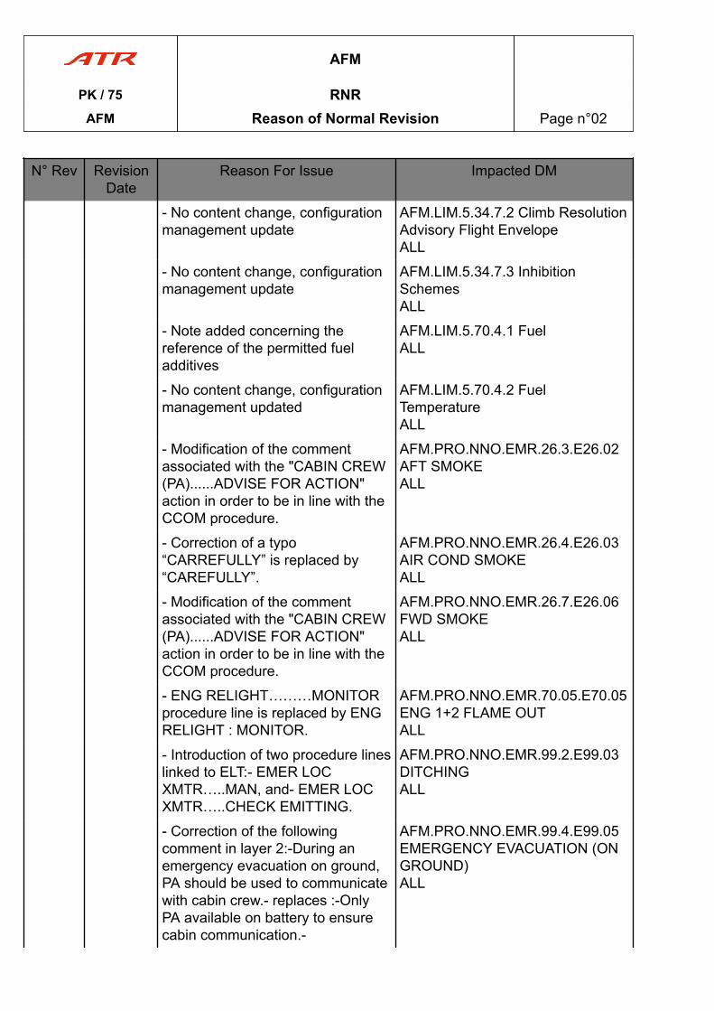
- No content change, configurationmanagement update
AFM.LIM.5.34.7.2 Climb ResolutionAdvisory Flight EnvelopeALL
- No content change, configurationmanagement update
AFM.LIM.5.34.7.3 InhibitionSchemesALL
- Note added concerning thereference of the permitted fueladditives
AFM.LIM.5.70.4.1 FuelALL
- No content change, configurationmanagement updated
AFM.LIM.5.70.4.2 FuelTemperatureALL
- Modification of the commentassociated with the "CABIN CREW(PA)......ADVISE FOR ACTION"action in order to be in line with theCCOM procedure.
AFM.PRO.NNO.EMR.26.3.E26.02AFT SMOKEALL
- Correction of a typo“CARREFULLY” is replaced by“CAREFULLY”.
AFM.PRO.NNO.EMR.26.4.E26.03AIR COND SMOKEALL
- Modification of the commentassociated with the "CABIN CREW(PA)......ADVISE FOR ACTION"action in order to be in line with theCCOM procedure.
AFM.PRO.NNO.EMR.26.7.E26.06FWD SMOKEALL
- ENG RELIGHT………MONITORprocedure line is replaced by ENGRELIGHT : MONITOR.
AFM.PRO.NNO.EMR.70.05.E70.05ENG 1+2 FLAME OUTALL
- Introduction of two procedure lineslinked to ELT:- EMER LOCXMTR…..MAN, and- EMER LOCXMTR…..CHECK EMITTING.
AFM.PRO.NNO.EMR.99.2.E99.03DITCHINGALL
- Correction of the followingcomment in layer 2:-During anemergency evacuation on ground,PA should be used to communicatewith cabin crew.- replaces :-OnlyPA available on battery to ensurecabin communication.-
AFM.PRO.NNO.EMR.99.4.E99.05EMERGENCY EVACUATION (ONGROUND)ALL
AFM
PK / 75 RNRAFM Reason of Normal Revision Page n°02
N° Rev RevisionDate
Reason For Issue Impacted DM
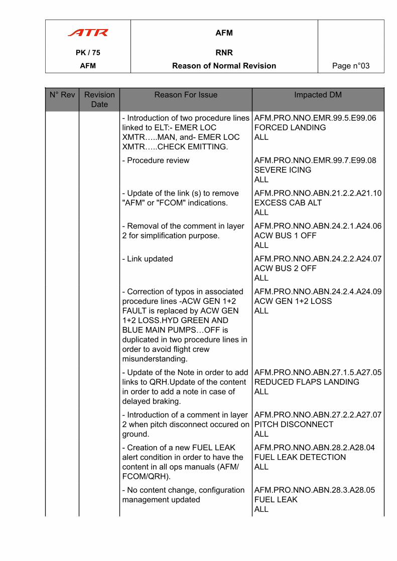
- Introduction of two procedure lineslinked to ELT:- EMER LOCXMTR…..MAN, and- EMER LOCXMTR…..CHECK EMITTING.
AFM.PRO.NNO.EMR.99.5.E99.06FORCED LANDINGALL
- Procedure review AFM.PRO.NNO.EMR.99.7.E99.08SEVERE ICINGALL
- Update of the link (s) to remove"AFM" or "FCOM" indications.
AFM.PRO.NNO.ABN.21.2.2.A21.10EXCESS CAB ALTALL
- Removal of the comment in layer2 for simplification purpose.
AFM.PRO.NNO.ABN.24.2.1.A24.06ACW BUS 1 OFFALL
- Link updated AFM.PRO.NNO.ABN.24.2.2.A24.07ACW BUS 2 OFFALL
- Correction of typos in associatedprocedure lines -ACW GEN 1+2FAULT is replaced by ACW GEN1+2 LOSS.HYD GREEN ANDBLUE MAIN PUMPS…OFF isduplicated in two procedure lines inorder to avoid flight crewmisunderstanding.
AFM.PRO.NNO.ABN.24.2.4.A24.09ACW GEN 1+2 LOSSALL
- Update of the Note in order to addlinks to QRH.Update of the contentin order to add a note in case ofdelayed braking.
AFM.PRO.NNO.ABN.27.1.5.A27.05REDUCED FLAPS LANDINGALL
- Introduction of a comment in layer2 when pitch disconnect occured onground.
AFM.PRO.NNO.ABN.27.2.2.A27.07PITCH DISCONNECTALL
- Creation of a new FUEL LEAKalert condition in order to have thecontent in all ops manuals (AFM/FCOM/QRH).
AFM.PRO.NNO.ABN.28.2.A28.04FUEL LEAK DETECTIONALL
- No content change, configurationmanagement updated
AFM.PRO.NNO.ABN.28.3.A28.05FUEL LEAKALL
AFM
PK / 75 RNRAFM Reason of Normal Revision Page n°03
N° Rev RevisionDate
Reason For Issue Impacted DM
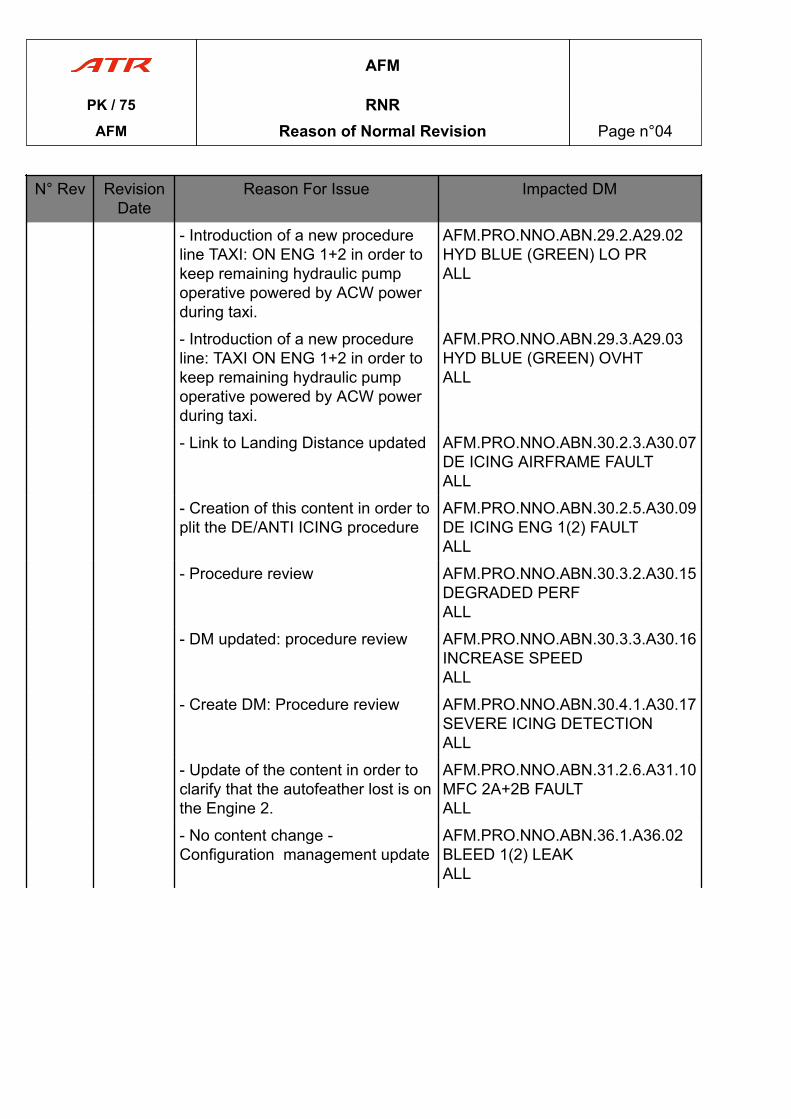
- Introduction of a new procedureline TAXI: ON ENG 1+2 in order tokeep remaining hydraulic pumpoperative powered by ACW powerduring taxi.
AFM.PRO.NNO.ABN.29.2.A29.02HYD BLUE (GREEN) LO PRALL
- Introduction of a new procedureline: TAXI ON ENG 1+2 in order tokeep remaining hydraulic pumpoperative powered by ACW powerduring taxi.
AFM.PRO.NNO.ABN.29.3.A29.03HYD BLUE (GREEN) OVHTALL
- Link to Landing Distance updated AFM.PRO.NNO.ABN.30.2.3.A30.07DE ICING AIRFRAME FAULTALL
- Creation of this content in order toplit the DE/ANTI ICING procedure
AFM.PRO.NNO.ABN.30.2.5.A30.09DE ICING ENG 1(2) FAULTALL
- Procedure review AFM.PRO.NNO.ABN.30.3.2.A30.15DEGRADED PERFALL
- DM updated: procedure review AFM.PRO.NNO.ABN.30.3.3.A30.16INCREASE SPEEDALL
- Create DM: Procedure review AFM.PRO.NNO.ABN.30.4.1.A30.17SEVERE ICING DETECTIONALL
- Update of the content in order toclarify that the autofeather lost is onthe Engine 2.
AFM.PRO.NNO.ABN.31.2.6.A31.10MFC 2A+2B FAULTALL
- No content change -Configuration management update
AFM.PRO.NNO.ABN.36.1.A36.02BLEED 1(2) LEAKALL
AFM
PK / 75 RNRAFM Reason of Normal Revision Page n°04
N° Rev RevisionDate
Reason For Issue Impacted DM
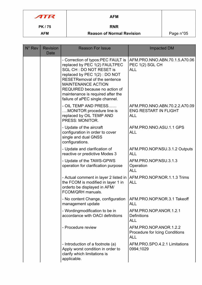
- Correction of typos:PEC FAULT isreplaced by PEC 1(2) FAULTPECSGL CH : DO NOT RESET isreplaced by PEC 1(2) : DO NOTRESETRemoval of the sentenceMAINTENANCE ACTIONREQUIRED because no action ofmaintenance is required after thefailure of aPEC single channel.
AFM.PRO.NNO.ABN.70.1.5.A70.06PEC 1(2) SGL CHALL
- OIL TEMP AND PRESS……….MONITOR procedure line isreplaced by OIL TEMP ANDPRESS: MONITOR.
AFM.PRO.NNO.ABN.70.2.2.A70.09ENG RESTART IN FLIGHTALL
- Update of the aircraftconfiguration in order to coversingle and dual GNSSconfigurations.
AFM.PRO.NNO.ASU.1.1 GPSALL
- Update and clarification ofreactive or predictive Modes 3
AFM.PRO.NOP.NSU.3.1.2 OutputsALL
- Update of the TAWS-GPWSoperation for clarification purpose
AFM.PRO.NOP.NSU.3.1.3OperationALL
- Actual comment in layer 2 listed inthe FCOM is modified in layer 1 inorderto be displayed in AFM/FCOM/QRH manuals.
AFM.PRO.NOP.NOR.1.1.3 TrimsALL
- No content Change, configurationmanagement update
AFM.PRO.NOP.NOR.3.1 TakeoffALL
- Wordingmodification to be inaccordance with OACI definitions
AFM.PRO.NOP.ANOR.1.2.1DefinitionsALL
- Procedure review AFM.PRO.NOP.ANOR.1.2.2Procedure for Icing ConditionsALL
- Introduction of a footnote (a)Apply worst condition in order toclarify which limitations isapplicable.
AFM.PRO.SPO.4.2.1 Limitations0994;1029
AFM
PK / 75 RNRAFM Reason of Normal Revision Page n°05
N° Rev RevisionDate
Reason For Issue Impacted DM
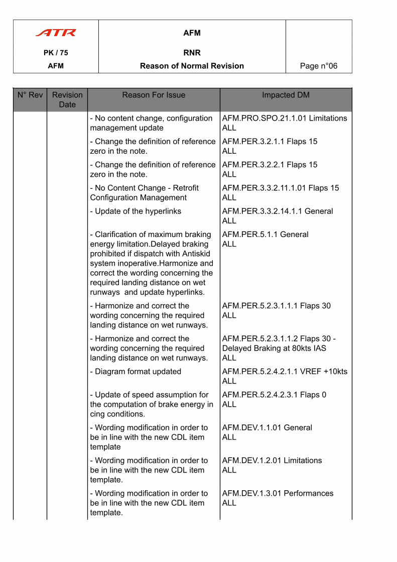
- No content change, configurationmanagement update
AFM.PRO.SPO.21.1.01 LimitationsALL
- Change the definition of referencezero in the note.
AFM.PER.3.2.1.1 Flaps 15ALL
- Change the definition of referencezero in the note.
AFM.PER.3.2.2.1 Flaps 15ALL
- No Content Change - RetrofitConfiguration Management
AFM.PER.3.3.2.11.1.01 Flaps 15ALL
- Update of the hyperlinks AFM.PER.3.3.2.14.1.1 GeneralALL
- Clarification of maximum brakingenergy limitation.Delayed brakingprohibited if dispatch with Antiskidsystem inoperative.Harmonize andcorrect the wording concerning therequired landing distance on wetrunways and update hyperlinks.
AFM.PER.5.1.1 GeneralALL
- Harmonize and correct thewording concerning the requiredlanding distance on wet runways.
AFM.PER.5.2.3.1.1.1 Flaps 30ALL
- Harmonize and correct thewording concerning the requiredlanding distance on wet runways.
AFM.PER.5.2.3.1.1.2 Flaps 30 -Delayed Braking at 80kts IASALL
- Diagram format updated AFM.PER.5.2.4.2.1.1 VREF +10ktsALL
- Update of speed assumption forthe computation of brake energy incing conditions.
AFM.PER.5.2.4.2.3.1 Flaps 0ALL
- Wording modification in order tobe in line with the new CDL itemtemplate
AFM.DEV.1.1.01 GeneralALL
- Wording modification in order tobe in line with the new CDL itemtemplate.
AFM.DEV.1.2.01 LimitationsALL
- Wording modification in order tobe in line with the new CDL itemtemplate.
AFM.DEV.1.3.01 PerformancesALL
AFM
PK / 75 RNRAFM Reason of Normal Revision Page n°06
N° Rev RevisionDate
Reason For Issue Impacted DM
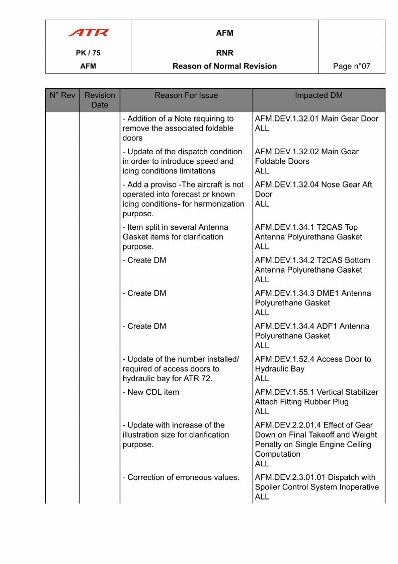
- Addition of a Note requiring toremove the associated foldabledoors
AFM.DEV.1.32.01 Main Gear DoorALL
- Update of the dispatch conditionin order to introduce speed andicing conditions limitations
AFM.DEV.1.32.02 Main GearFoldable DoorsALL
- Add a proviso -The aircraft is notoperated into forecast or knownicing conditions- for harmonizationpurpose.
AFM.DEV.1.32.04 Nose Gear AftDoorALL
- Item split in several AntennaGasket items for clarificationpurpose.
AFM.DEV.1.34.1 T2CAS TopAntenna Polyurethane GasketALL
- Create DM AFM.DEV.1.34.2 T2CAS BottomAntenna Polyurethane GasketALL
- Create DM AFM.DEV.1.34.3 DME1 AntennaPolyurethane GasketALL
- Create DM AFM.DEV.1.34.4 ADF1 AntennaPolyurethane GasketALL
- Update of the number installed/required of access doors tohydraulic bay for ATR 72.
AFM.DEV.1.52.4 Access Door toHydraulic BayALL
- New CDL item AFM.DEV.1.55.1 Vertical StabilizerAttach Fitting Rubber PlugALL
- Update with increase of theillustration size for clarificationpurpose.
AFM.DEV.2.2.01.4 Effect of GearDown on Final Takeoff and WeightPenalty on Single Engine CeilingComputationALL
- Correction of erroneous values. AFM.DEV.2.3.01.01 Dispatch withSpoiler Control System InoperativeALL
AFM
PK / 75 RNRAFM Reason of Normal Revision Page n°07
N° Rev RevisionDate
Reason For Issue Impacted DM
- No Content Change - RetrofitConfiguration Management.
AFM.DEV.2.4.01.01 Dispatch withFlaps RetractedALL
- No Content Change - RetrofitConfiguration Management
AFM.DEV.2.5.01.1 Dispatch withOne Wheel Brake Deactivated orRemovedALL
- Introduction of theANTISKID….OFF procedure line toshutoff the antiskid system wheninoperative for aircraft dispatch.Addinformation for landing brakeenergy in the Limitations andPerformances/Landing paragraphs.
AFM.DEV.2.6.01.1 Dispatch withAntiskid System InoperativeALL
- Landing Break energy correctionfor Operation on Dry or WetRunway- Note EFP-2613/18
AFM.DEV.2.6.01.3 Antiskid OffEffect on Landing Brake EnergyALL
- Editorial correction AFM.DEV.2.10.01.1 Dispatch withTQ Indications Inoperative (BothPointer Digital Counter on theSame ENG)ALL
- No content change, configurationmanagement only
AFM.DEV.2.11.1.1 DISPATCHWITH UPTRIM FUNCTIONINOPERATIVEALL
- Introduction of "TCAS….TAONLY" procedure line in conditionBefore takeoff.
AFM.DEV.2.13.01.1 Dispatch withLanding Gear DownALL
- No Content Change - RetrofitConfiguration Management
AFM.DEV.2.16.01.1 Flight withPitch Elevators DisconnectedALL
10.0 JUL 20
- No content change, RetrofitConfiguration Management
AFM.LIM.2.1.1 StructuralLimitations
AFM
PK / 75 RNRAFM Reason of Normal Revision Page n°08
N° Rev RevisionDate
Reason For Issue Impacted DM
- Update of the content in order toreplace -Center of GravityEnvelope- by -Certified Center ofGravity Envelope- and RetrofitConfiguration Management
AFM.LIM.2.2.1 Certified Center ofGravity Envelope
- Wording modification to be inaccordance with OACI definitionsand Creation of a refer to: FCOM-PRO-NOP-ANOR-ADVERSEWEATHER GROUND ICINGCONDITIONS-OperationalGuidance for Operation in GroundIcing Conditions-Preflight Check tolist associated Definitions.
AFM.LIM.4.4.2 Atmospheric IcingConditions
- Improvement of the content incase of Resolution Advisory.Deletion of the Warning (followingEASA SIB 2013-11R1).
AFM.LIM.5.34.7.1 Limitations
- Addition of a footnote linked toTransient case.
AFM.LIM.5.70.1.1 EngineParameters
- addition of a hyperlink referenceto BUS Equipment List section.
AFM.PRO.NNO.EMR.24.01.E24.01DC GEN 1+2 FAULT
- No content change, configurationmanagement updated
AFM.PRO.NNO.EMR.26.3.E26.02AFT SMOKE
- For NAMS system options and preNAMS: ENG BLEED replacesBLEED VALVE
AFM.PRO.NNO.EMR.26.7.E26.06FWD SMOKE
- Create new PITCH CONTROLJAM at TAKEOFF or LANDINGprocedure
AFM.PRO.NNO.EMR.27.1.E27.01PITCH CONTROL JAM ATTAKEOFF OR LANDING
- FIRE HANDLE (affected ENG)replaces FIRE HANDLE (red lighton).
AFM.PRO.NNO.EMR.70.01.E70.01ENG 1(2) FIRE AT TAKEOFF
- ENG RELIGHT………MONITORprocedure line is replaced by ENGRELIGHT : MONITOR.
AFM.PRO.NNO.EMR.70.05.E70.05ENG 1+2 FLAME OUT
- No content change, configurationmanagement updated
AFM.PRO.NNO.EMR.99.1.E99.01BOMB ON BOARD
AFM
PK / 75 RNRAFM Reason of Normal Revision Page n°09
N° Rev RevisionDate
Reason For Issue Impacted DM
- Addition of a comment linked to -AUTO PRESS DUMP...ON- actionline (FCOM impact only)
AFM.PRO.NNO.EMR.99.3.E99.03DITCHING
- Addition of a comment linked to -AUTO PRESS DUMP...ON- actionline (FCOM impact only)
AFM.PRO.NNO.EMR.99.5.E99.05EMERGENCY EVACUATION (ONGROUND)
- Addition of a comment linked to -AUTO PRESS DUMP...ON- actionline (FCOM impact only)
AFM.PRO.NNO.EMR.99.6.E99.06FORCED LANDING
- Procedure review AFM.PRO.NNO.EMR.99.8.E99.08SEVERE ICING
- Introduction of the FCOMprocedure in AFM
AFM.PRO.NNO.ABN.21.1.3.A21.03PACK 1+2 VALVES FAULT
- Update of the table: 6700 replaces6800 in FL 250 column.
AFM.PRO.NNO.ABN.21.2.1.A21.10AUTO PRESS FAULT
- PACK 1+2 replace by PACKVALVE 1+2
AFM.PRO.NNO.ABN.21.2.3.A21.14EXCESS CAB DELTA P
- Modification of a comment (ImpactFCOM only). Deletion of the CAPTstick information.
AFM.PRO.NNO.ABN.24.3.1.A24.11DC BUS 1 OFF
- Addition of - DC SVCE-UTLY BUSpb : MAINTAIN ON - action line,and an associated comment(Impact FCOM only).
AFM.PRO.NNO.ABN.24.3.2.A24.12DC BUS 2 OFF
- Create new DM : PITCHCONTROL JAM IN FLIGHT
AFM.PRO.NNO.ABN.27.2.1.A27.06PITCH CONTROL JAM IN FLIGHT
- Pitch Disconnect Procedure ismodified to take into account themodifications of Elevator JamProcedure
AFM.PRO.NNO.ABN.27.2.2.A27.07PITCH DISCONNECT
- No content change, configurationmanagement updated
AFM.PRO.NNO.ABN.28.3.A28.05FUEL LEAK
- Aircraft configuration managementupdate. Addition of a layer in orderto inform that the feeder jet pump ofthe affected tank is unavailable(FCOM). Replace EACH TANK byAFFECTED TANK.
AFM.PRO.NNO.ABN.28.4.A28.06FUEL LO LVL
AFM
PK / 75 RNRAFM Reason of Normal Revision Page n°10
N° Rev RevisionDate
Reason For Issue Impacted DM
- No content change, configurationmanagement update.
AFM.PRO.NNO.ABN.30.3.2.A30.15DEGRADED PERF
- No content change, strutureimprovement.
AFM.PRO.NNO.ABN.30.3.3.A30.16SEVERE ICING DETECTION
- No content change, configurationmanagement updated
AFM.PRO.NNO.ABN.31.2.1.A31.05MFC 1A+1B FAULT
- Update of the AHRS1 comment,in order to describe the effect ofAHRS1 malfunction on thestabilization signal (Impact FCOMonly)
AFM.PRO.NNO.ABN.34.2.1.A34.05AHRS 1(2) FAILURE
- Replace PFD with EADI/EHSI. AFM.PRO.NNO.ABN.34.2.6.A34.10EFIS COMP
- Modification content : Deleted BLEED VALVE - Added ENGBLEED
AFM.PRO.NNO.ABN.36.1.A36.02BLEED LEAK 1(2)
- Content Modification ENG BLEEDinstead of BLEED VALVE
AFM.PRO.NNO.ABN.36.2.A36.03BLEED 1(2) OVHT
- Modification Title and content :Deleted BLEED VALVE - Added :ENG BLEED
AFM.PRO.NNO.ABN.36.3.A36.04ENG BLEED 1(2) FAULT
- The EEC FAULT light conditionand EEC RESET procedure lineare moved just after START A & Bselection. Configurationmanagement update.
AFM.PRO.NNO.ABN.70.2.2.A70.09ENG RESTART IN FLIGHT
- No content change, configurationmanagement update
AFM.PRO.NNO.ABN.99.2.03Approach and Landing
- No content change,Retrofit management update
AFM.PRO.NOP.NOR.1.1.1 ATPCSDynamic Test
- Addition of FDAU check. AFM.PRO.NOP.NOR.1.1.5 APM
- Uniformization of FUEL SO REDlight wording
AFM.PRO.NOP.NOR.1.2.1 EngineFire Protection
- No content change, Configurationmanagement update
AFM.PRO.NOP.NOR.1.2.3 ATPCSStatic Test
- Procedure review AFM.PRO.NOP.ANOR.1.2.2Procedure for Icing Conditions
AFM
PK / 75 RNRAFM Reason of Normal Revision Page n°11
N° Rev RevisionDate
Reason For Issue Impacted DM
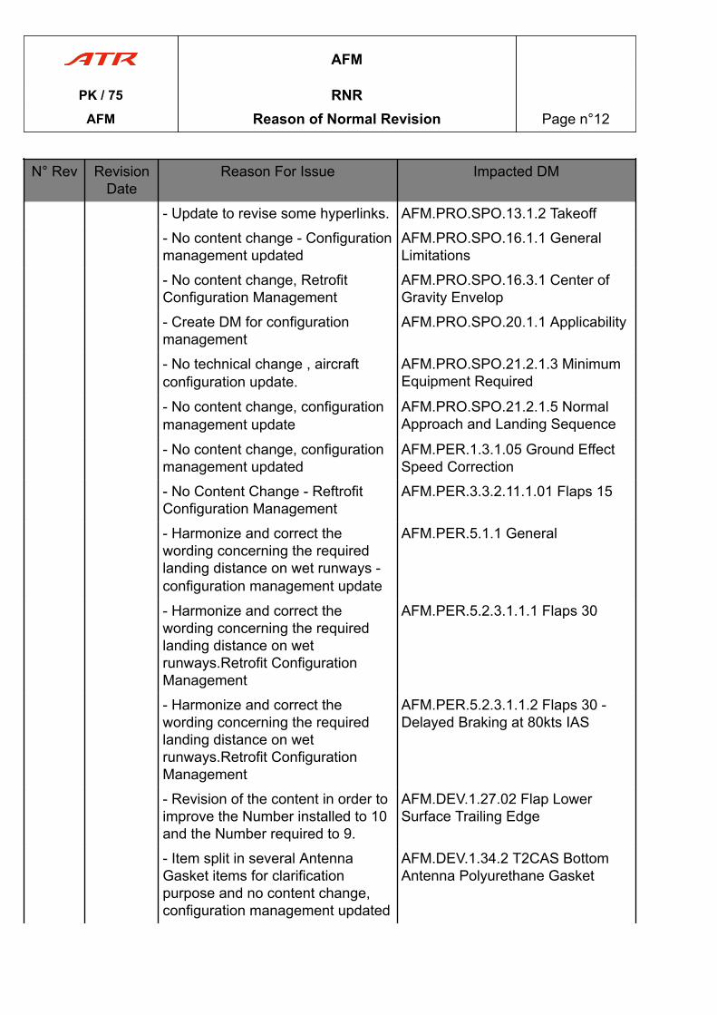
- Update to revise some hyperlinks. AFM.PRO.SPO.13.1.2 Takeoff
- No content change - Configurationmanagement updated
AFM.PRO.SPO.16.1.1 GeneralLimitations
- No content change, RetrofitConfiguration Management
AFM.PRO.SPO.16.3.1 Center ofGravity Envelop
- Create DM for configurationmanagement
AFM.PRO.SPO.20.1.1 Applicability
- No technical change , aircraftconfiguration update.
AFM.PRO.SPO.21.2.1.3 MinimumEquipment Required
- No content change, configurationmanagement update
AFM.PRO.SPO.21.2.1.5 NormalApproach and Landing Sequence
- No content change, configurationmanagement updated
AFM.PER.1.3.1.05 Ground EffectSpeed Correction
- No Content Change - ReftrofitConfiguration Management
AFM.PER.3.3.2.11.1.01 Flaps 15
- Harmonize and correct thewording concerning the requiredlanding distance on wet runways -configuration management update
AFM.PER.5.1.1 General
- Harmonize and correct thewording concerning the requiredlanding distance on wetrunways.Retrofit ConfigurationManagement
AFM.PER.5.2.3.1.1.1 Flaps 30
- Harmonize and correct thewording concerning the requiredlanding distance on wetrunways.Retrofit ConfigurationManagement
AFM.PER.5.2.3.1.1.2 Flaps 30 -Delayed Braking at 80kts IAS
- Revision of the content in order toimprove the Number installed to 10and the Number required to 9.
AFM.DEV.1.27.02 Flap LowerSurface Trailing Edge
- Item split in several AntennaGasket items for clarificationpurpose and no content change,configuration management updated
AFM.DEV.1.34.2 T2CAS BottomAntenna Polyurethane Gasket
AFM
PK / 75 RNRAFM Reason of Normal Revision Page n°12
N° Rev RevisionDate
Reason For Issue Impacted DM
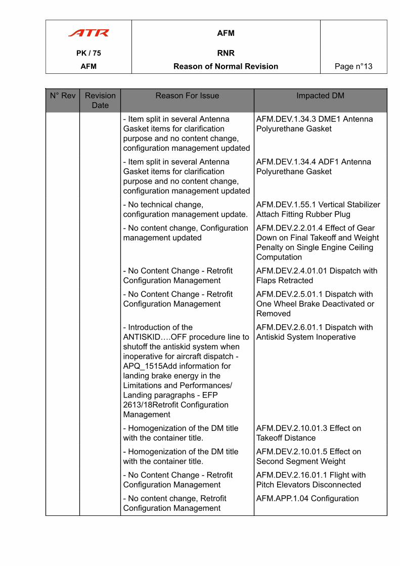
- Item split in several AntennaGasket items for clarificationpurpose and no content change,configuration management updated
AFM.DEV.1.34.3 DME1 AntennaPolyurethane Gasket
- Item split in several AntennaGasket items for clarificationpurpose and no content change,configuration management updated
AFM.DEV.1.34.4 ADF1 AntennaPolyurethane Gasket
- No technical change,configuration management update.
AFM.DEV.1.55.1 Vertical StabilizerAttach Fitting Rubber Plug
- No content change, Configurationmanagement updated
AFM.DEV.2.2.01.4 Effect of GearDown on Final Takeoff and WeightPenalty on Single Engine CeilingComputation
- No Content Change - RetrofitConfiguration Management
AFM.DEV.2.4.01.01 Dispatch withFlaps Retracted
- No Content Change - RetrofitConfiguration Management
AFM.DEV.2.5.01.1 Dispatch withOne Wheel Brake Deactivated orRemoved
- Introduction of theANTISKID….OFF procedure line toshutoff the antiskid system wheninoperative for aircraft dispatch -APQ_1515Add information forlanding brake energy in theLimitations and Performances/Landing paragraphs - EFP2613/18Retrofit ConfigurationManagement
AFM.DEV.2.6.01.1 Dispatch withAntiskid System Inoperative
- Homogenization of the DM titlewith the container title.
AFM.DEV.2.10.01.3 Effect onTakeoff Distance
- Homogenization of the DM titlewith the container title.
AFM.DEV.2.10.01.5 Effect onSecond Segment Weight
- No Content Change - RetrofitConfiguration Management
AFM.DEV.2.16.01.1 Flight withPitch Elevators Disconnected
- No content change, RetrofitConfiguration Management
AFM.APP.1.04 Configuration
AFM
PK / 75 RNRAFM Reason of Normal Revision Page n°13
N° Rev RevisionDate
Reason For Issue Impacted DM
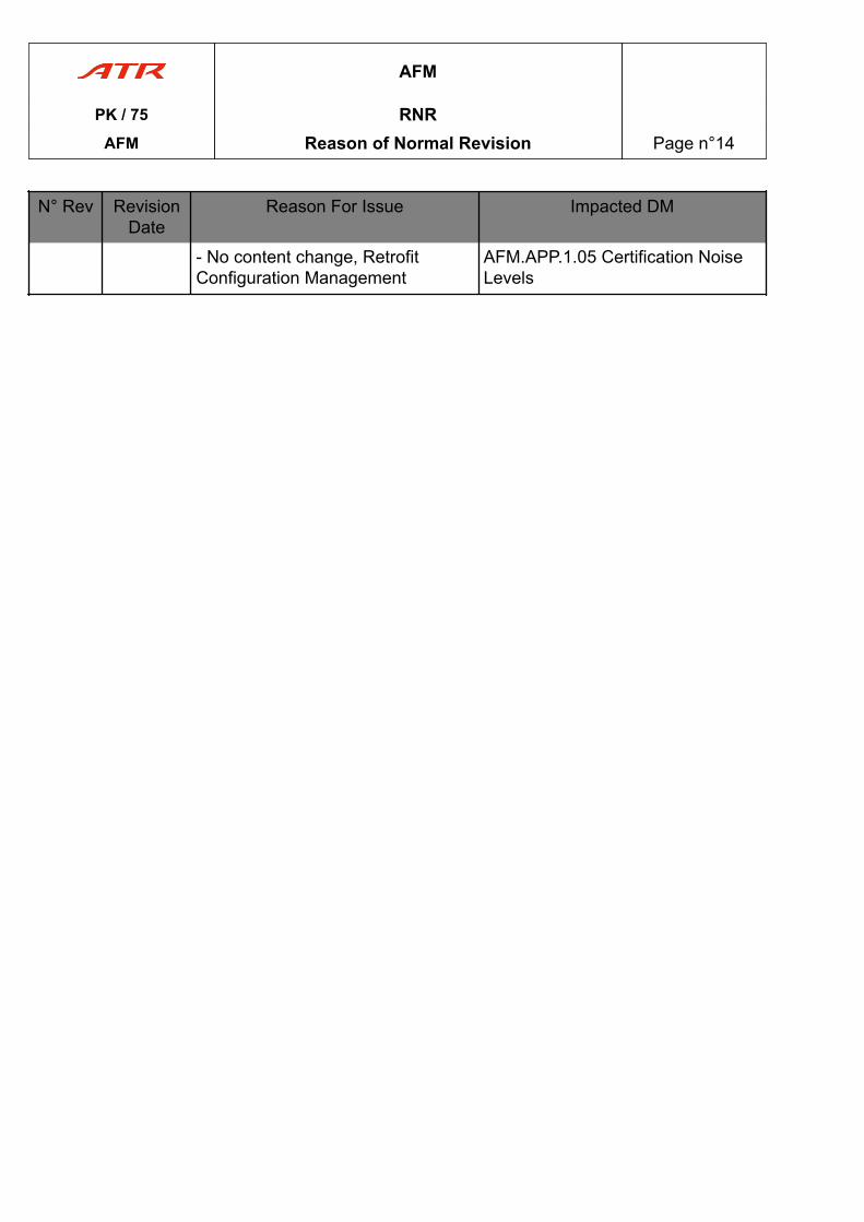
- No content change, RetrofitConfiguration Management
AFM.APP.1.05 Certification NoiseLevels
AFM
PK / 75 RNRAFM Reason of Normal Revision Page n°14
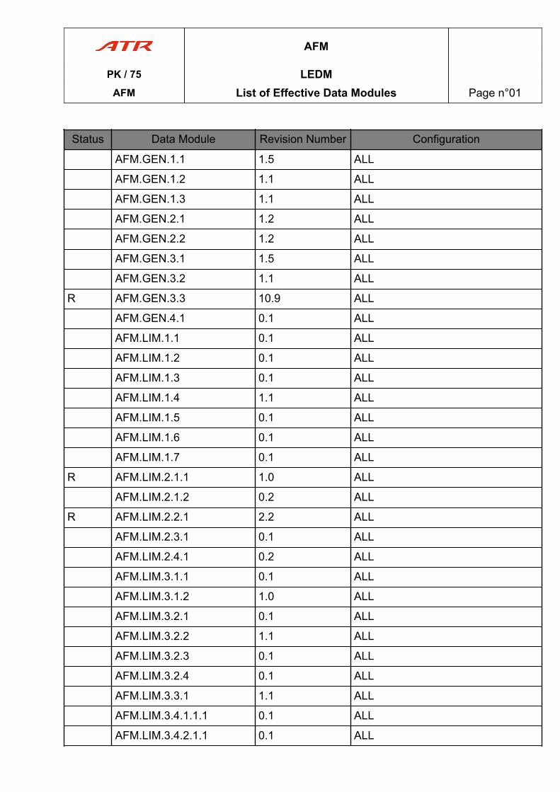
Status Data Module Revision Number Configuration
AFM.GEN.1.1 1.5 ALL
AFM.GEN.1.2 1.1 ALL
AFM.GEN.1.3 1.1 ALL
AFM.GEN.2.1 1.2 ALL
AFM.GEN.2.2 1.2 ALL
AFM.GEN.3.1 1.5 ALL
AFM.GEN.3.2 1.1 ALL
R AFM.GEN.3.3 10.9 ALL
AFM.GEN.4.1 0.1 ALL
AFM.LIM.1.1 0.1 ALL
AFM.LIM.1.2 0.1 ALL
AFM.LIM.1.3 0.1 ALL
AFM.LIM.1.4 1.1 ALL
AFM.LIM.1.5 0.1 ALL
AFM.LIM.1.6 0.1 ALL
AFM.LIM.1.7 0.1 ALL
R AFM.LIM.2.1.1 1.0 ALL
AFM.LIM.2.1.2 0.2 ALL
R AFM.LIM.2.2.1 2.2 ALL
AFM.LIM.2.3.1 0.1 ALL
AFM.LIM.2.4.1 0.2 ALL
AFM.LIM.3.1.1 0.1 ALL
AFM.LIM.3.1.2 1.0 ALL
AFM.LIM.3.2.1 0.1 ALL
AFM.LIM.3.2.2 1.1 ALL
AFM.LIM.3.2.3 0.1 ALL
AFM.LIM.3.2.4 0.1 ALL
AFM.LIM.3.3.1 1.1 ALL
AFM.LIM.3.4.1.1.1 0.1 ALL
AFM.LIM.3.4.2.1.1 0.1 ALL
AFM
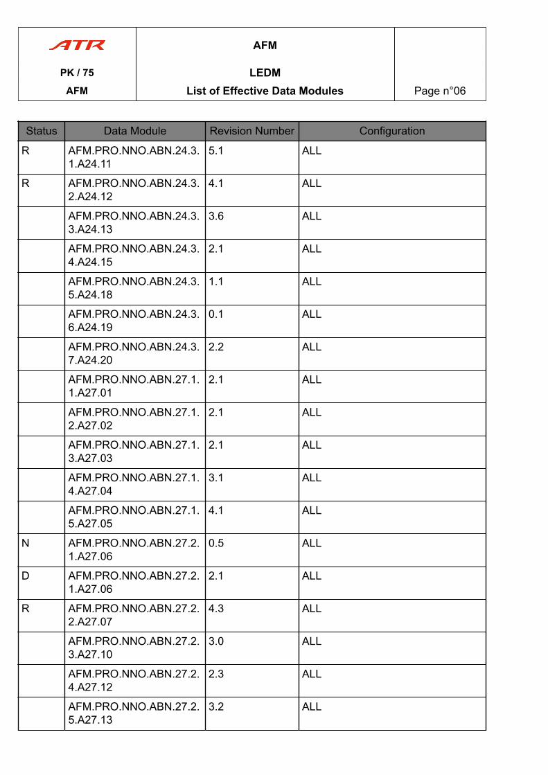
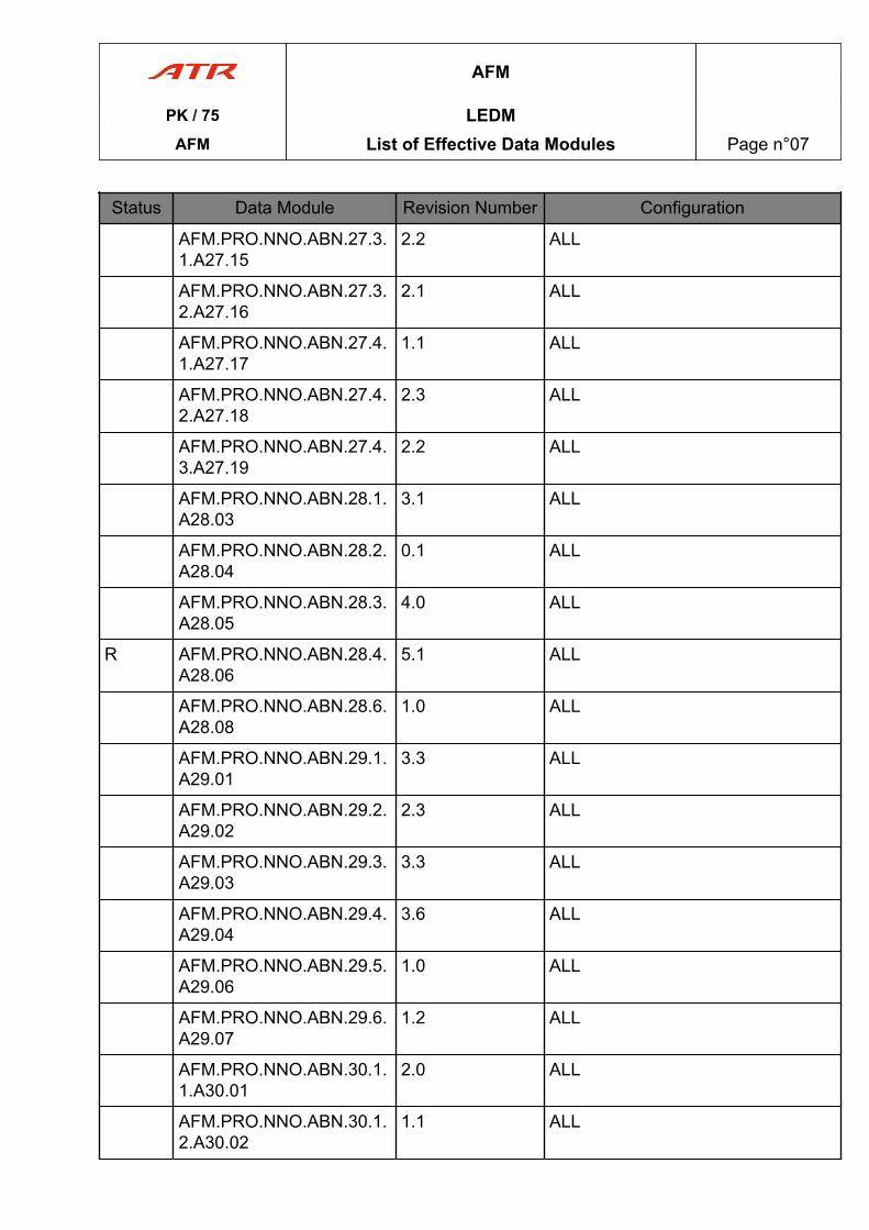
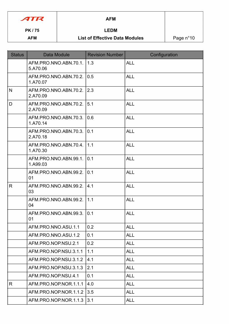
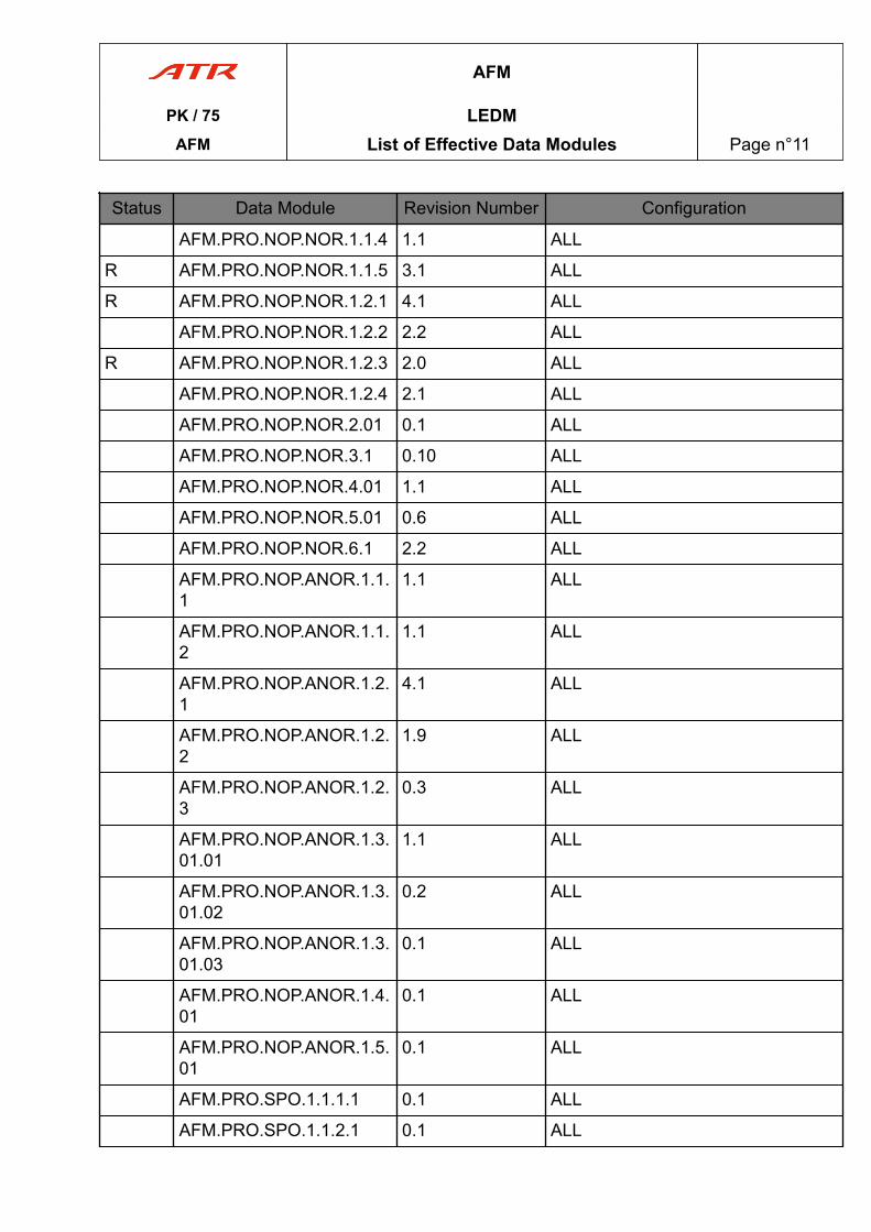
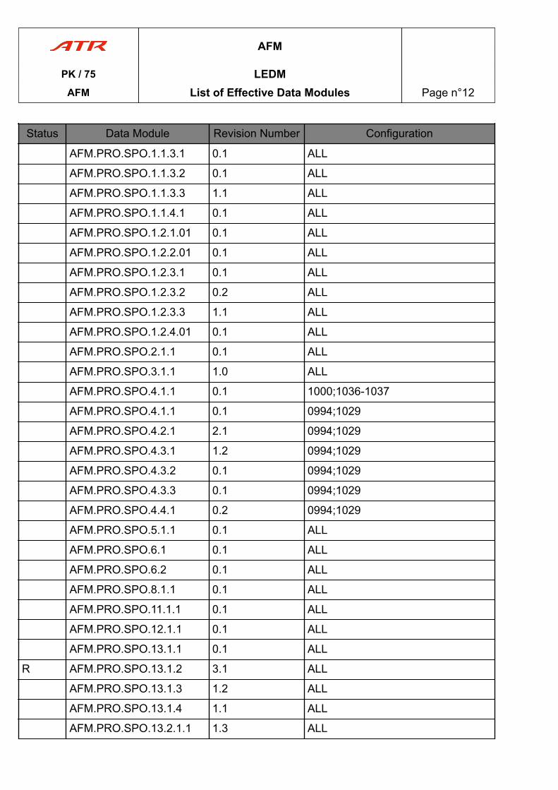
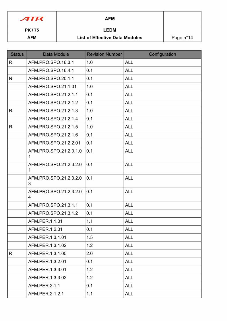
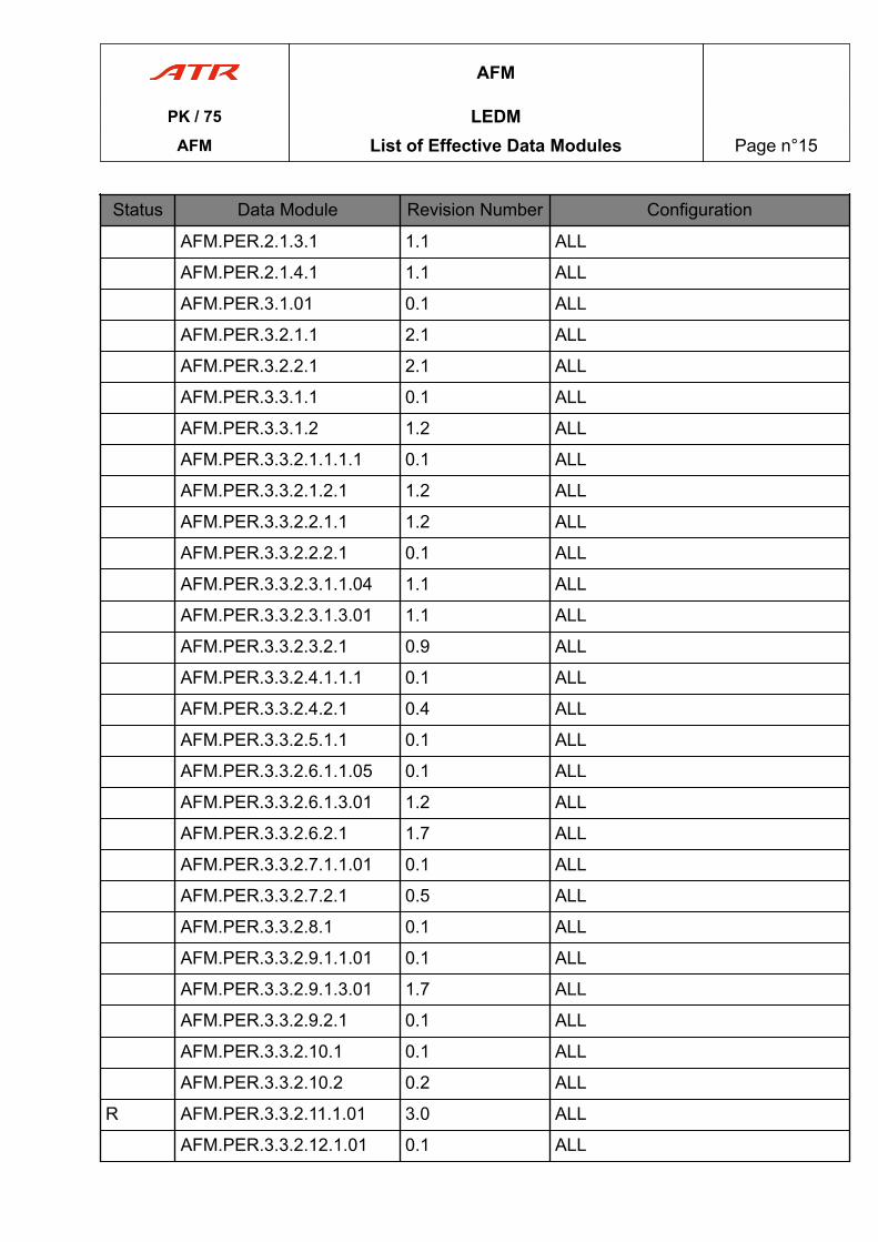
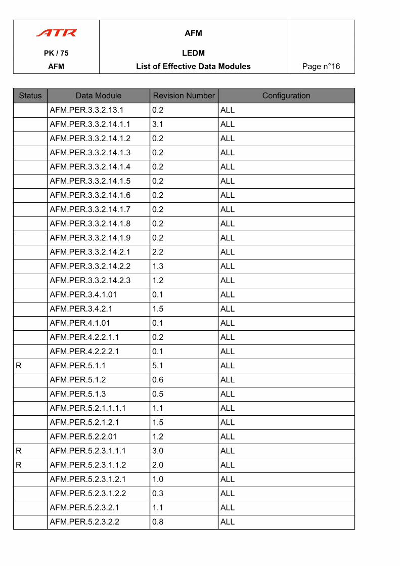
PK / 75 LEDMAFM List of Effective Data Modules Page n°01
Status Data Module Revision Number Configuration
AFM.LIM.3.4.3.1 0.1 ALL
AFM.LIM.3.5.1 1.2 ALL
AFM.LIM.3.5.2 0.1 ALL
AFM.LIM.3.5.3 0.2 ALL
AFM.LIM.4.1.1 2.0 ALL
AFM.LIM.4.2.1 0.2 ALL
AFM.LIM.4.2.2 4.3 ALL
AFM.LIM.4.3.1 1.3 ALL
AFM.LIM.4.4.1 3.1 ALL
AFM.LIM.4.4.2 7.1 ALL
AFM.LIM.4.4.3 1.3 ALL
AFM.LIM.5.21.1 0.1 ALL
AFM.LIM.5.22.1 2.1 ALL
AFM.LIM.5.24.1 1.0 ALL
AFM.LIM.5.27.1 1.2 ALL
AFM.LIM.5.29.1 3.2 ALL
AFM.LIM.5.30.1 0.2 ALL
AFM.LIM.5.31.1 1.1 ALL
AFM.LIM.5.32.1 0.2 ALL
AFM.LIM.5.33.1 0.1 ALL
AFM.LIM.5.34.1.1 0.1 ALL
AFM.LIM.5.34.1.2 2.1 ALL
AFM.LIM.5.34.3.1 1.1 ALL
AFM.LIM.5.34.4.1 2.0 ALL
AFM.LIM.5.34.6.1 2.1 ALL
AFM.LIM.5.34.6.2 1.1 ALL
R AFM.LIM.5.34.7.1 6.1 ALL
AFM.LIM.5.34.7.2 2.0 ALL
AFM.LIM.5.34.7.3 2.0 ALL
AFM.LIM.5.52.1 0.1 ALL
AFM
PK / 75 LEDMAFM List of Effective Data Modules Page n°02
Status Data Module Revision Number Configuration
AFM.LIM.5.52.2 0.1 ALL
R AFM.LIM.5.70.1.1 3.1 ALL
AFM.LIM.5.70.1.2 0.1 ALL
AFM.LIM.5.70.2.1 1.1 ALL
AFM.LIM.5.70.3.1 0.1 ALL
AFM.LIM.5.70.4.1 2.1 ALL
AFM.LIM.5.70.4.2 3.1 ALL
AFM.LIM.5.70.4.3 0.1 ALL
AFM.LIM.5.70.4.4 0.1 ALL
AFM.LIM.5.70.4.5 1.1 ALL
AFM.LIM.5.70.4.6 0.1 ALL
AFM.LIM.5.70.5.1 1.1 ALL
AFM.PRO.GEN.1.1 0.1 ALL
AFM.PRO.GEN.1.2 0.1 ALL
AFM.PRO.GEN.1.3 0.1 ALL
AFM.PRO.GEN.1.4 1.0 ALL
AFM.PRO.GEN.1.5 0.1 ALL
AFM.PRO.NNO.EMR.01.01
0.1 ALL
R AFM.PRO.NNO.EMR.24.01.E24.01
6.1 ALL
AFM.PRO.NNO.EMR.26.2.E26.01
3.2 ALL
R AFM.PRO.NNO.EMR.26.3.E26.02
5.1 ALL
AFM.PRO.NNO.EMR.26.4.E26.03
4.1 ALL
AFM.PRO.NNO.EMR.26.6.E26.05
2.1 ALL
R AFM.PRO.NNO.EMR.26.7.E26.06
6.1 ALL
AFM
PK / 75 LEDMAFM List of Effective Data Modules Page n°03
Status Data Module Revision Number Configuration
MT AFM.PRO.NNO.EMR.27.1.E27.01Move From PITCH CONTROL JAM ATTAKEOFF OR LANDINGMove To PITCH CONTROL JAM ATTAKEOFF OR LANDING
0.5 ALL
R AFM.PRO.NNO.EMR.70.01.E70.01
3.1 ALL
AFM.PRO.NNO.EMR.70.02.E70.02
1.2 ALL
AFM.PRO.NNO.EMR.70.03.E70.03
2.1 ALL
AFM.PRO.NNO.EMR.70.05.E70.05
7.0 ALL
MT AFM.PRO.NNO.EMR.99.1.E99.01Move From BOMB ON BOARDMove To BOMB ON BOARD
1.1 ALL
AFM.PRO.NNO.EMR.99.2.E99.02
2.3 ALL
R AFM.PRO.NNO.EMR.99.3.E99.03
5.1 ALL
AFM.PRO.NNO.EMR.99.4.E99.04
0.4 ALL
R AFM.PRO.NNO.EMR.99.5.E99.05
3.1 ALL
R AFM.PRO.NNO.EMR.99.6.E99.06
6.1 ALL
AFM.PRO.NNO.EMR.99.8.E99.08
1.15 ALL
AFM.PRO.NNO.EMR.99.9.E99.09
2.1 ALL
AFM.PRO.NNO.EMR.99.10.E99.10
3.1 ALL
AFM.PRO.NNO.ABN.01.1 1.1 ALL
AFM.PRO.NNO.ABN.21.1.1.A21.01
4.2 ALL
AFM
PK / 75 LEDMAFM List of Effective Data Modules Page n°04
Status Data Module Revision Number Configuration
AFM.PRO.NNO.ABN.21.1.2.A21.02
2.5 ALL
N AFM.PRO.NNO.ABN.21.1.3.A21.03
0.5 ALL
R AFM.PRO.NNO.ABN.21.2.1.A21.10
4.1 ALL
AFM.PRO.NNO.ABN.21.2.2.A21.13
7.1 ALL
R AFM.PRO.NNO.ABN.21.2.3.A21.14
3.1 ALL
AFM.PRO.NNO.ABN.22.1.A22.01
2.1 ALL
AFM.PRO.NNO.ABN.22.2.A22.02
1.1 ALL
AFM.PRO.NNO.ABN.22.3.A22.03
0.1 ALL
AFM.PRO.NNO.ABN.22.4.A22.04
2.2 ALL
AFM.PRO.NNO.ABN.22.5.A22.05
1.2 ALL
AFM.PRO.NNO.ABN.22.6.A22.10
2.1 ALL
AFM.PRO.NNO.ABN.22.7.A22.13
1.2 ALL
AFM.PRO.NNO.ABN.24.1.1.A24.01
1.1 ALL
AFM.PRO.NNO.ABN.24.1.2.A24.02
1.0 ALL
AFM.PRO.NNO.ABN.24.2.1.A24.06
4.2 ALL
AFM.PRO.NNO.ABN.24.2.2.A24.07
4.2 ALL
AFM.PRO.NNO.ABN.24.2.3.A24.08
0.1 ALL
AFM.PRO.NNO.ABN.24.2.4.A24.09
3.2 ALL
AFM
PK / 75 LEDMAFM List of Effective Data Modules Page n°05
Status Data Module Revision Number Configuration
R AFM.PRO.NNO.ABN.24.3.1.A24.11
5.1 ALL
R AFM.PRO.NNO.ABN.24.3.2.A24.12
4.1 ALL
AFM.PRO.NNO.ABN.24.3.3.A24.13
3.6 ALL
AFM.PRO.NNO.ABN.24.3.4.A24.15
2.1 ALL
AFM.PRO.NNO.ABN.24.3.5.A24.18
1.1 ALL
AFM.PRO.NNO.ABN.24.3.6.A24.19
0.1 ALL
AFM.PRO.NNO.ABN.24.3.7.A24.20
2.2 ALL
AFM.PRO.NNO.ABN.27.1.1.A27.01
2.1 ALL
AFM.PRO.NNO.ABN.27.1.2.A27.02
2.1 ALL
AFM.PRO.NNO.ABN.27.1.3.A27.03
2.1 ALL
AFM.PRO.NNO.ABN.27.1.4.A27.04
3.1 ALL
AFM.PRO.NNO.ABN.27.1.5.A27.05
4.1 ALL
N AFM.PRO.NNO.ABN.27.2.1.A27.06
0.5 ALL
D AFM.PRO.NNO.ABN.27.2.1.A27.06
2.1 ALL
R AFM.PRO.NNO.ABN.27.2.2.A27.07
4.3 ALL
AFM.PRO.NNO.ABN.27.2.3.A27.10
3.0 ALL
AFM.PRO.NNO.ABN.27.2.4.A27.12
2.3 ALL
AFM.PRO.NNO.ABN.27.2.5.A27.13
3.2 ALL
AFM
PK / 75 LEDMAFM List of Effective Data Modules Page n°06
Status Data Module Revision Number Configuration
AFM.PRO.NNO.ABN.27.3.1.A27.15
2.2 ALL
AFM.PRO.NNO.ABN.27.3.2.A27.16
2.1 ALL
AFM.PRO.NNO.ABN.27.4.1.A27.17
1.1 ALL
AFM.PRO.NNO.ABN.27.4.2.A27.18
2.3 ALL
AFM.PRO.NNO.ABN.27.4.3.A27.19
2.2 ALL
AFM.PRO.NNO.ABN.28.1.A28.03
3.1 ALL
AFM.PRO.NNO.ABN.28.2.A28.04
0.1 ALL
AFM.PRO.NNO.ABN.28.3.A28.05
4.0 ALL
R AFM.PRO.NNO.ABN.28.4.A28.06
5.1 ALL
AFM.PRO.NNO.ABN.28.6.A28.08
1.0 ALL
AFM.PRO.NNO.ABN.29.1.A29.01
3.3 ALL
AFM.PRO.NNO.ABN.29.2.A29.02
2.3 ALL
AFM.PRO.NNO.ABN.29.3.A29.03
3.3 ALL
AFM.PRO.NNO.ABN.29.4.A29.04
3.6 ALL
AFM.PRO.NNO.ABN.29.5.A29.06
1.0 ALL
AFM.PRO.NNO.ABN.29.6.A29.07
1.2 ALL
AFM.PRO.NNO.ABN.30.1.1.A30.01
2.0 ALL
AFM.PRO.NNO.ABN.30.1.2.A30.02
1.1 ALL
AFM
PK / 75 LEDMAFM List of Effective Data Modules Page n°07

Status Data Module Revision Number Configuration
AFM.PRO.NNO.ABN.30.2.1.A30.05
2.2 ALL
AFM.PRO.NNO.ABN.30.2.2.A30.06
3.1 ALL
AFM.PRO.NNO.ABN.30.2.3.A30.07
0.4 ALL
AFM.PRO.NNO.ABN.30.2.4.A30.08
2.1 ALL
AFM.PRO.NNO.ABN.30.2.5.A30.09
0.2 ALL
AFM.PRO.NNO.ABN.30.3.1.A30.14
1.2 ALL
R AFM.PRO.NNO.ABN.30.3.2.A30.15
7.0 ALL
MT AFM.PRO.NNO.ABN.30.3.3.A30.16Move From SEVERE ICINGDETECTIONMove To SEVERE ICING DETECTION
0.1 ALL
AFM.PRO.NNO.ABN.30.3.4.A30.17
3.2 ALL
D AFM.PRO.NNO.ABN.30.4.1.A30.17
0.1 ALL
AFM.PRO.NNO.ABN.31.1.1.A31.01
1.0 ALL
AFM.PRO.NNO.ABN.31.1.2.A31.02
2.1 ALL
AFM.PRO.NNO.ABN.31.1.3.A31.03
2.1 ALL
AFM.PRO.NNO.ABN.31.1.4.A31.04
2.1 ALL
R AFM.PRO.NNO.ABN.31.2.1.A31.05
1.3 ALL
AFM.PRO.NNO.ABN.31.2.2.A31.06
1.2 ALL
AFM.PRO.NNO.ABN.31.2.3.A31.07
2.1 ALL
AFM
PK / 75 LEDMAFM List of Effective Data Modules Page n°08

Status Data Module Revision Number Configuration
AFM.PRO.NNO.ABN.31.2.4.A31.08
3.1 ALL
AFM.PRO.NNO.ABN.31.2.5.A31.09
3.2 ALL
AFM.PRO.NNO.ABN.31.2.6.A31.10
6.1 ALL
AFM.PRO.NNO.ABN.32.1.A32.01
2.4 ALL
AFM.PRO.NNO.ABN.32.2.A32.02
2.5 ALL
AFM.PRO.NNO.ABN.32.3.A32.03
2.3 ALL
AFM.PRO.NNO.ABN.32.4.A32.04
2.2 ALL
AFM.PRO.NNO.ABN.32.5.A32.05
2.1 ALL
AFM.PRO.NNO.ABN.34.1.1.A34.01
1.1 ALL
AFM.PRO.NNO.ABN.34.1.2.A34.02
2.1 ALL
AFM.PRO.NNO.ABN.34.1.3.A34.03
3.1 ALL
R AFM.PRO.NNO.ABN.34.2.1.A34.05
4.1 ALL
R AFM.PRO.NNO.ABN.34.2.6.A34.10
4.1 ALL
R AFM.PRO.NNO.ABN.36.1.A36.02
5.4 ALL
R AFM.PRO.NNO.ABN.36.2.A36.03
5.3 ALL
R AFM.PRO.NNO.ABN.36.3.A36.04
4.3 ALL
AFM.PRO.NNO.ABN.70.1.3.A70.03
0.2 ALL
AFM.PRO.NNO.ABN.70.1.4.A70.05
2.4 ALL
AFM
PK / 75 LEDMAFM List of Effective Data Modules Page n°09
Status Data Module Revision Number Configuration
AFM.PRO.NNO.ABN.70.1.5.A70.06
1.3 ALL
AFM.PRO.NNO.ABN.70.2.1.A70.07
0.5 ALL
N AFM.PRO.NNO.ABN.70.2.2.A70.09
2.3 ALL
D AFM.PRO.NNO.ABN.70.2.2.A70.09
5.1 ALL
AFM.PRO.NNO.ABN.70.3.1.A70.14
0.6 ALL
AFM.PRO.NNO.ABN.70.3.2.A70.18
0.1 ALL
AFM.PRO.NNO.ABN.70.4.1.A70.30
1.1 ALL
AFM.PRO.NNO.ABN.99.1.1.A99.03
0.1 ALL
AFM.PRO.NNO.ABN.99.2.01
0.1 ALL
R AFM.PRO.NNO.ABN.99.2.03
4.1 ALL
AFM.PRO.NNO.ABN.99.2.04
1.1 ALL
AFM.PRO.NNO.ABN.99.3.01
0.1 ALL
AFM.PRO.NNO.ASU.1.1 0.2 ALL
AFM.PRO.NNO.ASU.1.2 0.1 ALL
AFM.PRO.NOP.NSU.2.1 0.2 ALL
AFM.PRO.NOP.NSU.3.1.1 1.1 ALL
AFM.PRO.NOP.NSU.3.1.2 4.1 ALL
AFM.PRO.NOP.NSU.3.1.3 2.1 ALL
AFM.PRO.NOP.NSU.4.1 0.1 ALL
R AFM.PRO.NOP.NOR.1.1.1 4.0 ALL
AFM.PRO.NOP.NOR.1.1.2 3.5 ALL
AFM.PRO.NOP.NOR.1.1.3 3.1 ALL
AFM
PK / 75 LEDMAFM List of Effective Data Modules Page n°10
Status Data Module Revision Number Configuration
AFM.PRO.NOP.NOR.1.1.4 1.1 ALL
R AFM.PRO.NOP.NOR.1.1.5 3.1 ALL
R AFM.PRO.NOP.NOR.1.2.1 4.1 ALL
AFM.PRO.NOP.NOR.1.2.2 2.2 ALL
R AFM.PRO.NOP.NOR.1.2.3 2.0 ALL
AFM.PRO.NOP.NOR.1.2.4 2.1 ALL
AFM.PRO.NOP.NOR.2.01 0.1 ALL
AFM.PRO.NOP.NOR.3.1 0.10 ALL
AFM.PRO.NOP.NOR.4.01 1.1 ALL
AFM.PRO.NOP.NOR.5.01 0.6 ALL
AFM.PRO.NOP.NOR.6.1 2.2 ALL
AFM.PRO.NOP.ANOR.1.1.1
1.1 ALL
AFM.PRO.NOP.ANOR.1.1.2
1.1 ALL
AFM.PRO.NOP.ANOR.1.2.1
4.1 ALL
AFM.PRO.NOP.ANOR.1.2.2
1.9 ALL
AFM.PRO.NOP.ANOR.1.2.3
0.3 ALL
AFM.PRO.NOP.ANOR.1.3.01.01
1.1 ALL
AFM.PRO.NOP.ANOR.1.3.01.02
0.2 ALL
AFM.PRO.NOP.ANOR.1.3.01.03
0.1 ALL
AFM.PRO.NOP.ANOR.1.4.01
0.1 ALL
AFM.PRO.NOP.ANOR.1.5.01
0.1 ALL
AFM.PRO.SPO.1.1.1.1 0.1 ALL
AFM.PRO.SPO.1.1.2.1 0.1 ALL
AFM
PK / 75 LEDMAFM List of Effective Data Modules Page n°11
Status Data Module Revision Number Configuration
AFM.PRO.SPO.1.1.3.1 0.1 ALL
AFM.PRO.SPO.1.1.3.2 0.1 ALL
AFM.PRO.SPO.1.1.3.3 1.1 ALL
AFM.PRO.SPO.1.1.4.1 0.1 ALL
AFM.PRO.SPO.1.2.1.01 0.1 ALL
AFM.PRO.SPO.1.2.2.01 0.1 ALL
AFM.PRO.SPO.1.2.3.1 0.1 ALL
AFM.PRO.SPO.1.2.3.2 0.2 ALL
AFM.PRO.SPO.1.2.3.3 1.1 ALL
AFM.PRO.SPO.1.2.4.01 0.1 ALL
AFM.PRO.SPO.2.1.1 0.1 ALL
AFM.PRO.SPO.3.1.1 1.0 ALL
AFM.PRO.SPO.4.1.1 0.1 1000;1036-1037
AFM.PRO.SPO.4.1.1 0.1 0994;1029
AFM.PRO.SPO.4.2.1 2.1 0994;1029
AFM.PRO.SPO.4.3.1 1.2 0994;1029
AFM.PRO.SPO.4.3.2 0.1 0994;1029
AFM.PRO.SPO.4.3.3 0.1 0994;1029
AFM.PRO.SPO.4.4.1 0.2 0994;1029
AFM.PRO.SPO.5.1.1 0.1 ALL
AFM.PRO.SPO.6.1 0.1 ALL
AFM.PRO.SPO.6.2 0.1 ALL
AFM.PRO.SPO.8.1.1 0.1 ALL
AFM.PRO.SPO.11.1.1 0.1 ALL
AFM.PRO.SPO.12.1.1 0.1 ALL
AFM.PRO.SPO.13.1.1 0.1 ALL
R AFM.PRO.SPO.13.1.2 3.1 ALL
AFM.PRO.SPO.13.1.3 1.2 ALL
AFM.PRO.SPO.13.1.4 1.1 ALL
AFM.PRO.SPO.13.2.1.1 1.3 ALL
AFM
PK / 75 LEDMAFM List of Effective Data Modules Page n°12

Status Data Module Revision Number Configuration
AFM.PRO.SPO.13.2.2.1 1.1 ALL
AFM.PRO.SPO.13.2.3.1 1.1 ALL
AFM.PRO.SPO.13.2.3.2 1.1 ALL
AFM.PRO.SPO.13.2.5.1 0.2 ALL
AFM.PRO.SPO.13.2.5.2 1.1 ALL
AFM.PRO.SPO.13.2.6.1 1.2 ALL
AFM.PRO.SPO.13.2.7.1 1.1 ALL
AFM.PRO.SPO.13.2.7.2 1.1 ALL
AFM.PRO.SPO.13.2.8.1 1.1 ALL
AFM.PRO.SPO.13.2.8.2 1.1 ALL
AFM.PRO.SPO.13.2.9.1 1.1 ALL
AFM.PRO.SPO.13.2.9.2 0.4 ALL
AFM.PRO.SPO.13.3.1.1 1.1 ALL
AFM.PRO.SPO.13.3.2.1 1.1 ALL
AFM.PRO.SPO.13.3.3.1.1 1.1 ALL
AFM.PRO.SPO.13.3.4.1.1 1.1 ALL
AFM.PRO.SPO.13.3.5.1.1 1.2 ALL
AFM.PRO.SPO.13.3.6.1 1.1 ALL
AFM.PRO.SPO.13.3.7.1.1 1.1 ALL
AFM.PRO.SPO.13.4.1.1 1.1 ALL
AFM.PRO.SPO.13.4.2.1 1.1 ALL
AFM.PRO.SPO.13.4.3.1.1 1.1 ALL
AFM.PRO.SPO.13.4.4.1.1 1.1 ALL
AFM.PRO.SPO.13.4.5.1.01
1.3 ALL
AFM.PRO.SPO.13.4.6.1 1.3 ALL
AFM.PRO.SPO.13.4.7.1.1 1.1 ALL
R AFM.PRO.SPO.16.1.1 1.0 ALL
AFM.PRO.SPO.16.2.1.1 0.1 ALL
AFM.PRO.SPO.16.2.2.1 0.1 ALL
AFM
PK / 75 LEDMAFM List of Effective Data Modules Page n°13
Status Data Module Revision Number Configuration
R AFM.PRO.SPO.16.3.1 1.0 ALL
AFM.PRO.SPO.16.4.1 0.1 ALL
N AFM.PRO.SPO.20.1.1 0.1 ALL
AFM.PRO.SPO.21.1.01 1.0 ALL
AFM.PRO.SPO.21.2.1.1 0.1 ALL
AFM.PRO.SPO.21.2.1.2 0.1 ALL
R AFM.PRO.SPO.21.2.1.3 1.0 ALL
AFM.PRO.SPO.21.2.1.4 0.1 ALL
R AFM.PRO.SPO.21.2.1.5 1.0 ALL
AFM.PRO.SPO.21.2.1.6 0.1 ALL
AFM.PRO.SPO.21.2.2.01 0.1 ALL
AFM.PRO.SPO.21.2.3.1.01
0.1 ALL
AFM.PRO.SPO.21.2.3.2.01
0.1 ALL
AFM.PRO.SPO.21.2.3.2.03
0.1 ALL
AFM.PRO.SPO.21.2.3.2.04
0.1 ALL
AFM.PRO.SPO.21.3.1.1 0.1 ALL
AFM.PRO.SPO.21.3.1.2 0.1 ALL
AFM.PER.1.1.01 1.1 ALL
AFM.PER.1.2.01 0.1 ALL
AFM.PER.1.3.1.01 1.5 ALL
AFM.PER.1.3.1.02 1.2 ALL
R AFM.PER.1.3.1.05 2.0 ALL
AFM.PER.1.3.2.01 0.1 ALL
AFM.PER.1.3.3.01 1.2 ALL
AFM.PER.1.3.3.02 1.2 ALL
AFM.PER.2.1.1 0.1 ALL
AFM.PER.2.1.2.1 1.1 ALL
AFM
PK / 75 LEDMAFM List of Effective Data Modules Page n°14
Status Data Module Revision Number Configuration
AFM.PER.2.1.3.1 1.1 ALL
AFM.PER.2.1.4.1 1.1 ALL
AFM.PER.3.1.01 0.1 ALL
AFM.PER.3.2.1.1 2.1 ALL
AFM.PER.3.2.2.1 2.1 ALL
AFM.PER.3.3.1.1 0.1 ALL
AFM.PER.3.3.1.2 1.2 ALL
AFM.PER.3.3.2.1.1.1.1 0.1 ALL
AFM.PER.3.3.2.1.2.1 1.2 ALL
AFM.PER.3.3.2.2.1.1 1.2 ALL
AFM.PER.3.3.2.2.2.1 0.1 ALL
AFM.PER.3.3.2.3.1.1.04 1.1 ALL
AFM.PER.3.3.2.3.1.3.01 1.1 ALL
AFM.PER.3.3.2.3.2.1 0.9 ALL
AFM.PER.3.3.2.4.1.1.1 0.1 ALL
AFM.PER.3.3.2.4.2.1 0.4 ALL
AFM.PER.3.3.2.5.1.1 0.1 ALL
AFM.PER.3.3.2.6.1.1.05 0.1 ALL
AFM.PER.3.3.2.6.1.3.01 1.2 ALL
AFM.PER.3.3.2.6.2.1 1.7 ALL
AFM.PER.3.3.2.7.1.1.01 0.1 ALL
AFM.PER.3.3.2.7.2.1 0.5 ALL
AFM.PER.3.3.2.8.1 0.1 ALL
AFM.PER.3.3.2.9.1.1.01 0.1 ALL
AFM.PER.3.3.2.9.1.3.01 1.7 ALL
AFM.PER.3.3.2.9.2.1 0.1 ALL
AFM.PER.3.3.2.10.1 0.1 ALL
AFM.PER.3.3.2.10.2 0.2 ALL
R AFM.PER.3.3.2.11.1.01 3.0 ALL
AFM.PER.3.3.2.12.1.01 0.1 ALL
AFM
PK / 75 LEDMAFM List of Effective Data Modules Page n°15
Status Data Module Revision Number Configuration
AFM.PER.3.3.2.13.1 0.2 ALL
AFM.PER.3.3.2.14.1.1 3.1 ALL
AFM.PER.3.3.2.14.1.2 0.2 ALL
AFM.PER.3.3.2.14.1.3 0.2 ALL
AFM.PER.3.3.2.14.1.4 0.2 ALL
AFM.PER.3.3.2.14.1.5 0.2 ALL
AFM.PER.3.3.2.14.1.6 0.2 ALL
AFM.PER.3.3.2.14.1.7 0.2 ALL
AFM.PER.3.3.2.14.1.8 0.2 ALL
AFM.PER.3.3.2.14.1.9 0.2 ALL
AFM.PER.3.3.2.14.2.1 2.2 ALL
AFM.PER.3.3.2.14.2.2 1.3 ALL
AFM.PER.3.3.2.14.2.3 1.2 ALL
AFM.PER.3.4.1.01 0.1 ALL
AFM.PER.3.4.2.1 1.5 ALL
AFM.PER.4.1.01 0.1 ALL
AFM.PER.4.2.2.1.1 0.2 ALL
AFM.PER.4.2.2.2.1 0.1 ALL
R AFM.PER.5.1.1 5.1 ALL
AFM.PER.5.1.2 0.6 ALL
AFM.PER.5.1.3 0.5 ALL
AFM.PER.5.2.1.1.1.1 1.1 ALL
AFM.PER.5.2.1.2.1 1.5 ALL
AFM.PER.5.2.2.01 1.2 ALL
R AFM.PER.5.2.3.1.1.1 3.0 ALL
R AFM.PER.5.2.3.1.1.2 2.0 ALL
AFM.PER.5.2.3.1.2.1 1.0 ALL
AFM.PER.5.2.3.1.2.2 0.3 ALL
AFM.PER.5.2.3.2.1 1.1 ALL
AFM.PER.5.2.3.2.2 0.8 ALL
AFM
PK / 75 LEDMAFM List of Effective Data Modules Page n°16
Status Data Module Revision Number Configuration
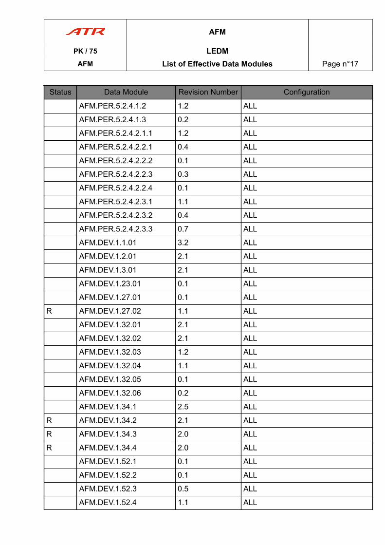
AFM.PER.5.2.4.1.2 1.2 ALL
AFM.PER.5.2.4.1.3 0.2 ALL
AFM.PER.5.2.4.2.1.1 1.2 ALL
AFM.PER.5.2.4.2.2.1 0.4 ALL
AFM.PER.5.2.4.2.2.2 0.1 ALL
AFM.PER.5.2.4.2.2.3 0.3 ALL
AFM.PER.5.2.4.2.2.4 0.1 ALL
AFM.PER.5.2.4.2.3.1 1.1 ALL
AFM.PER.5.2.4.2.3.2 0.4 ALL
AFM.PER.5.2.4.2.3.3 0.7 ALL
AFM.DEV.1.1.01 3.2 ALL
AFM.DEV.1.2.01 2.1 ALL
AFM.DEV.1.3.01 2.1 ALL
AFM.DEV.1.23.01 0.1 ALL
AFM.DEV.1.27.01 0.1 ALL
R AFM.DEV.1.27.02 1.1 ALL
AFM.DEV.1.32.01 2.1 ALL
AFM.DEV.1.32.02 2.1 ALL
AFM.DEV.1.32.03 1.2 ALL
AFM.DEV.1.32.04 1.1 ALL
AFM.DEV.1.32.05 0.1 ALL
AFM.DEV.1.32.06 0.2 ALL
AFM.DEV.1.34.1 2.5 ALL
R AFM.DEV.1.34.2 2.1 ALL
R AFM.DEV.1.34.3 2.0 ALL
R AFM.DEV.1.34.4 2.0 ALL
AFM.DEV.1.52.1 0.1 ALL
AFM.DEV.1.52.2 0.1 ALL
AFM.DEV.1.52.3 0.5 ALL
AFM.DEV.1.52.4 1.1 ALL
AFM
PK / 75 LEDMAFM List of Effective Data Modules Page n°17
Status Data Module Revision Number Configuration
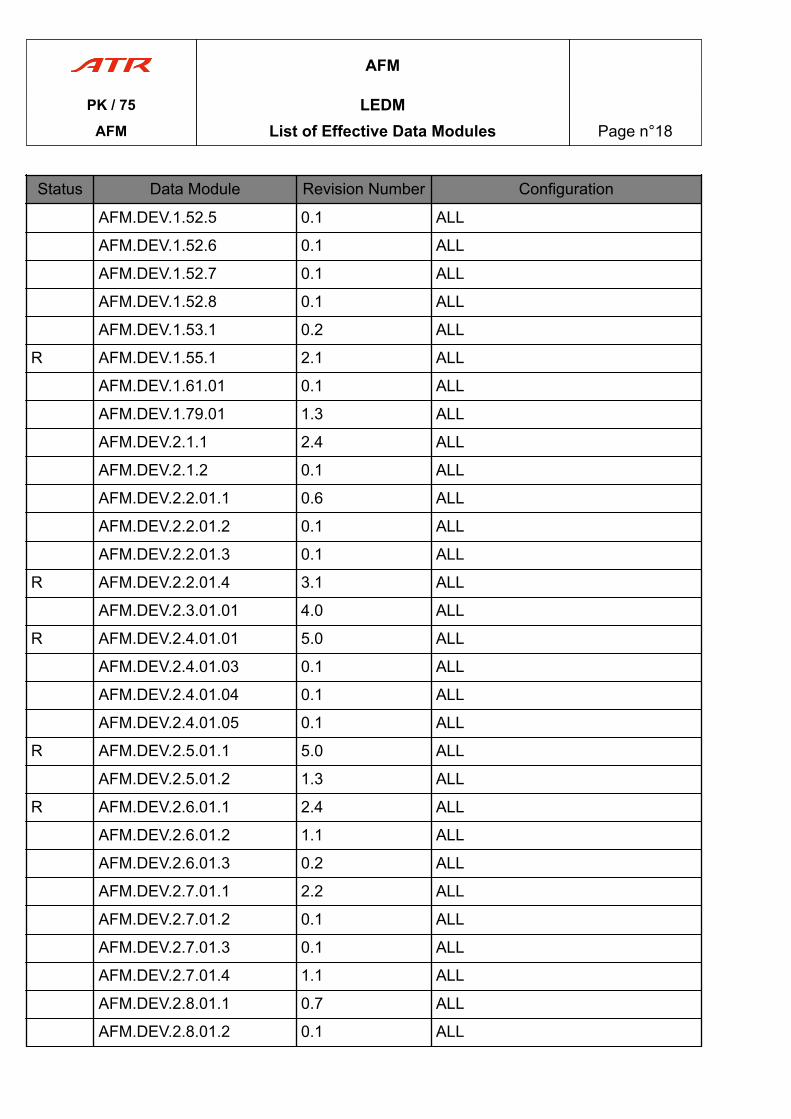
AFM.DEV.1.52.5 0.1 ALL
AFM.DEV.1.52.6 0.1 ALL
AFM.DEV.1.52.7 0.1 ALL
AFM.DEV.1.52.8 0.1 ALL
AFM.DEV.1.53.1 0.2 ALL
R AFM.DEV.1.55.1 2.1 ALL
AFM.DEV.1.61.01 0.1 ALL
AFM.DEV.1.79.01 1.3 ALL
AFM.DEV.2.1.1 2.4 ALL
AFM.DEV.2.1.2 0.1 ALL
AFM.DEV.2.2.01.1 0.6 ALL
AFM.DEV.2.2.01.2 0.1 ALL
AFM.DEV.2.2.01.3 0.1 ALL
R AFM.DEV.2.2.01.4 3.1 ALL
AFM.DEV.2.3.01.01 4.0 ALL
R AFM.DEV.2.4.01.01 5.0 ALL
AFM.DEV.2.4.01.03 0.1 ALL
AFM.DEV.2.4.01.04 0.1 ALL
AFM.DEV.2.4.01.05 0.1 ALL
R AFM.DEV.2.5.01.1 5.0 ALL
AFM.DEV.2.5.01.2 1.3 ALL
R AFM.DEV.2.6.01.1 2.4 ALL
AFM.DEV.2.6.01.2 1.1 ALL
AFM.DEV.2.6.01.3 0.2 ALL
AFM.DEV.2.7.01.1 2.2 ALL
AFM.DEV.2.7.01.2 0.1 ALL
AFM.DEV.2.7.01.3 0.1 ALL
AFM.DEV.2.7.01.4 1.1 ALL
AFM.DEV.2.8.01.1 0.7 ALL
AFM.DEV.2.8.01.2 0.1 ALL
AFM
PK / 75 LEDMAFM List of Effective Data Modules Page n°18
Status Data Module Revision Number Configuration
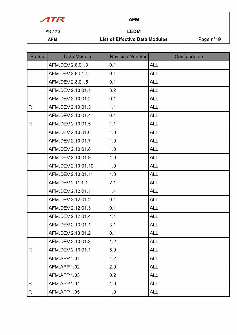
AFM.DEV.2.8.01.3 0.1 ALL
AFM.DEV.2.8.01.4 0.1 ALL
AFM.DEV.2.8.01.5 0.1 ALL
AFM.DEV.2.10.01.1 3.2 ALL
AFM.DEV.2.10.01.2 0.1 ALL
R AFM.DEV.2.10.01.3 1.1 ALL
AFM.DEV.2.10.01.4 0.1 ALL
R AFM.DEV.2.10.01.5 1.1 ALL
AFM.DEV.2.10.01.6 1.0 ALL
AFM.DEV.2.10.01.7 1.0 ALL
AFM.DEV.2.10.01.8 1.0 ALL
AFM.DEV.2.10.01.9 1.0 ALL
AFM.DEV.2.10.01.10 1.0 ALL
AFM.DEV.2.10.01.11 1.0 ALL
AFM.DEV.2.11.1.1 2.1 ALL
AFM.DEV.2.12.01.1 1.4 ALL
AFM.DEV.2.12.01.2 0.1 ALL
AFM.DEV.2.12.01.3 0.1 ALL
AFM.DEV.2.12.01.4 1.1 ALL
AFM.DEV.2.13.01.1 3.1 ALL
AFM.DEV.2.13.01.2 0.1 ALL
AFM.DEV.2.13.01.3 1.2 ALL
R AFM.DEV.2.16.01.1 5.0 ALL
AFM.APP.1.01 1.2 ALL
AFM.APP.1.02 2.0 ALL
AFM.APP.1.03 0.2 ALL
R AFM.APP.1.04 1.0 ALL
R AFM.APP.1.05 1.0 ALL
AFM
PK / 75 LEDMAFM List of Effective Data Modules Page n°19
PAGE
INTENTIONALLY
LEFT BLANK
AFM
PK / 75 LEDMAFM List of Effective Data Modules Page n°20
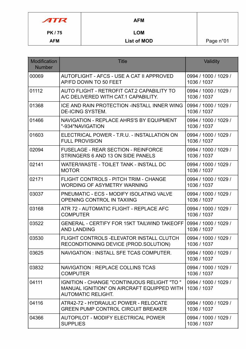
ModificationNumber
Title Validity
00069 AUTOFLIGHT - AFCS - USE A CAT II APPROVEDAP/FD DOWN TO 50 FEET
0994 / 1000 / 1029 /1036 / 1037
01112 AUTO FLIGHT - RETROFIT CAT.2 CAPABILITY TOA/C DELIVERED WITH CAT.1 CAPABILITY.
0994 / 1000 / 1029 /1036 / 1037
01368 ICE AND RAIN PROTECTION -INSTALL INNER WINGDE-ICING SYSTEM.
0994 / 1000 / 1029 /1036 / 1037
01466 NAVIGATION - REPLACE AHRS'S BY EQUIPMENT"-934"NAVIGATION
0994 / 1000 / 1029 /1036 / 1037
01603 ELECTRICAL POWER - T.R.U. - INSTALLATION ONFULL PROVISION
0994 / 1000 / 1029 /1036 / 1037
02094 FUSELAGE - REAR SECTION - REINFORCESTRINGERS 6 AND 13 ON SIDE PANELS
0994 / 1000 / 1029 /1036 / 1037
02141 WATER/WASTE - TOILET TANK - INSTALL DCMOTOR
0994 / 1000 / 1029 /1036 / 1037
02171 FLIGHT CONTROLS - PITCH TRIM - CHANGEWORDING OF ASYMETRY WARNING
0994 / 1000 / 1029 /1036 / 1037
03037 PNEUMATIC - ECS - MODIFY ISOLATING VALVEOPENING CONTROL IN TAXIING
0994 / 1000 / 1029 /1036 / 1037
03168 ATR 72 - AUTOMATIC FLIGHT - REPLACE AFCCOMPUTER
0994 / 1000 / 1029 /1036 / 1037
03522 GENERAL - CERTIFY FOR 15KT TAILWIND TAKEOFFAND LANDING
0994 / 1000 / 1029 /1036 / 1037
03530 FLIGHT CONTROLS -ELEVATOR INSTALL CLUTCHRECONDITIONING DEVICE (PROD.SOLUTION)
0994 / 1000 / 1029 /1036 / 1037
03625 NAVIGATION : INSTALL SFE TCAS COMPUTER. 0994 / 1000 / 1029 /1036 / 1037
03832 NAVIGATION : REPLACE COLLINS TCASCOMPUTER
0994 / 1000 / 1029 /1036 / 1037
04111 IGNITION - CHANGE "CONTINUOUS RELIGHT "TO "MANUAL IGNITION" ON AIRCRAFT EQUIPPED WITHAUTOMATIC RELIGHT.
0994 / 1000 / 1029 /1036 / 1037
04116 ATR42-72 - HYDRAULIC POWER - RELOCATEGREEN PUMP CONTROL CIRCUIT BREAKER
0994 / 1000 / 1029 /1036 / 1037
04366 AUTOPILOT - MODIFY ELECTRICAL POWERSUPPLIES
0994 / 1000 / 1029 /1036 / 1037
AFM
PK / 75 LOMAFM List of MOD Page n°01
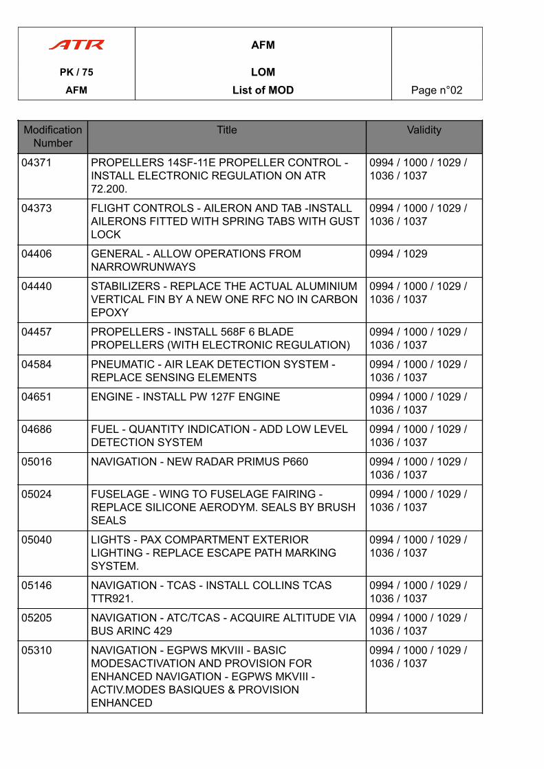
ModificationNumber
Title Validity
04371 PROPELLERS 14SF-11E PROPELLER CONTROL -INSTALL ELECTRONIC REGULATION ON ATR72.200.
0994 / 1000 / 1029 /1036 / 1037
04373 FLIGHT CONTROLS - AILERON AND TAB -INSTALLAILERONS FITTED WITH SPRING TABS WITH GUSTLOCK
0994 / 1000 / 1029 /1036 / 1037
04406 GENERAL - ALLOW OPERATIONS FROMNARROWRUNWAYS
0994 / 1029
04440 STABILIZERS - REPLACE THE ACTUAL ALUMINIUMVERTICAL FIN BY A NEW ONE RFC NO IN CARBONEPOXY
0994 / 1000 / 1029 /1036 / 1037
04457 PROPELLERS - INSTALL 568F 6 BLADEPROPELLERS (WITH ELECTRONIC REGULATION)
0994 / 1000 / 1029 /1036 / 1037
04584 PNEUMATIC - AIR LEAK DETECTION SYSTEM -REPLACE SENSING ELEMENTS
0994 / 1000 / 1029 /1036 / 1037
04651 ENGINE - INSTALL PW 127F ENGINE 0994 / 1000 / 1029 /1036 / 1037
04686 FUEL - QUANTITY INDICATION - ADD LOW LEVELDETECTION SYSTEM
0994 / 1000 / 1029 /1036 / 1037
05016 NAVIGATION - NEW RADAR PRIMUS P660 0994 / 1000 / 1029 /1036 / 1037
05024 FUSELAGE - WING TO FUSELAGE FAIRING -REPLACE SILICONE AERODYM. SEALS BY BRUSHSEALS
0994 / 1000 / 1029 /1036 / 1037
05040 LIGHTS - PAX COMPARTMENT EXTERIORLIGHTING - REPLACE ESCAPE PATH MARKINGSYSTEM.
0994 / 1000 / 1029 /1036 / 1037
05146 NAVIGATION - TCAS - INSTALL COLLINS TCASTTR921.
0994 / 1000 / 1029 /1036 / 1037
05205 NAVIGATION - ATC/TCAS - ACQUIRE ALTITUDE VIABUS ARINC 429
0994 / 1000 / 1029 /1036 / 1037
05310 NAVIGATION - EGPWS MKVIII - BASICMODESACTIVATION AND PROVISION FORENHANCED NAVIGATION - EGPWS MKVIII -ACTIV.MODES BASIQUES & PROVISIONENHANCED
0994 / 1000 / 1029 /1036 / 1037
AFM
PK / 75 LOMAFM List of MOD Page n°02
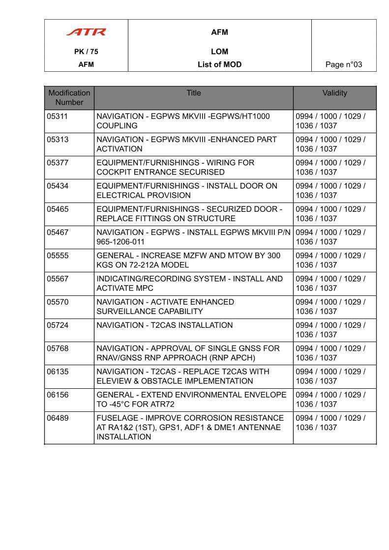
ModificationNumber
Title Validity
05311 NAVIGATION - EGPWS MKVIII -EGPWS/HT1000COUPLING
0994 / 1000 / 1029 /1036 / 1037
05313 NAVIGATION - EGPWS MKVIII -ENHANCED PARTACTIVATION
0994 / 1000 / 1029 /1036 / 1037
05377 EQUIPMENT/FURNISHINGS - WIRING FORCOCKPIT ENTRANCE SECURISED
0994 / 1000 / 1029 /1036 / 1037
05434 EQUIPMENT/FURNISHINGS - INSTALL DOOR ONELECTRICAL PROVISION
0994 / 1000 / 1029 /1036 / 1037
05465 EQUIPMENT/FURNISHINGS - SECURIZED DOOR -REPLACE FITTINGS ON STRUCTURE
0994 / 1000 / 1029 /1036 / 1037
05467 NAVIGATION - EGPWS - INSTALL EGPWS MKVIII P/N965-1206-011
0994 / 1000 / 1029 /1036 / 1037
05555 GENERAL - INCREASE MZFW AND MTOW BY 300KGS ON 72-212A MODEL
0994 / 1000 / 1029 /1036 / 1037
05567 INDICATING/RECORDING SYSTEM - INSTALL ANDACTIVATE MPC
0994 / 1000 / 1029 /1036 / 1037
05570 NAVIGATION - ACTIVATE ENHANCEDSURVEILLANCE CAPABILITY
0994 / 1000 / 1029 /1036 / 1037
05724 NAVIGATION - T2CAS INSTALLATION 0994 / 1000 / 1029 /1036 / 1037
05768 NAVIGATION - APPROVAL OF SINGLE GNSS FORRNAV/GNSS RNP APPROACH (RNP APCH)
0994 / 1000 / 1029 /1036 / 1037
06135 NAVIGATION - T2CAS - REPLACE T2CAS WITHELEVIEW & OBSTACLE IMPLEMENTATION
0994 / 1000 / 1029 /1036 / 1037
06156 GENERAL - EXTEND ENVIRONMENTAL ENVELOPETO -45°C FOR ATR72
0994 / 1000 / 1029 /1036 / 1037
06489 FUSELAGE - IMPROVE CORROSION RESISTANCEAT RA1&2 (1ST), GPS1, ADF1 & DME1 ANTENNAEINSTALLATION
0994 / 1000 / 1029 /1036 / 1037
AFM
PK / 75 LOMAFM List of MOD Page n°03
PAGE
INTENTIONALLY
LEFT BLANK
AFM
PK / 75 LOMAFM List of MOD Page n°04
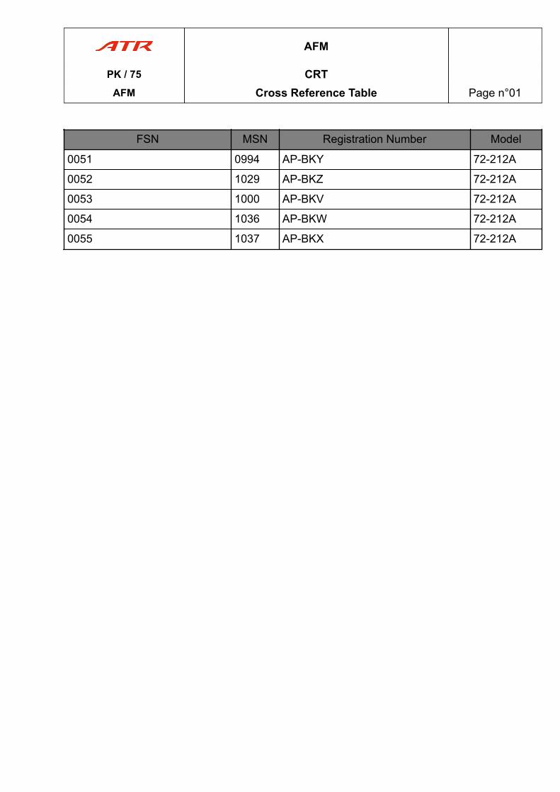
FSN MSN Registration Number Model
0051 0994 AP-BKY 72-212A
0052 1029 AP-BKZ 72-212A
0053 1000 AP-BKV 72-212A
0054 1036 AP-BKW 72-212A
0055 1037 AP-BKX 72-212A
AFM
PK / 75 CRTAFM Cross Reference Table Page n°01

PAGE
INTENTIONALLY
LEFT BLANK
AFM
PK / 75 CRTAFM Cross Reference Table Page n°02
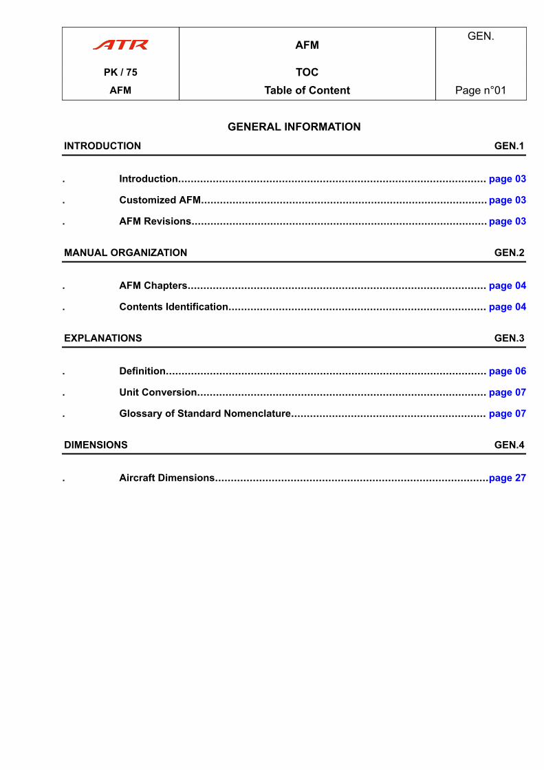
GENERAL INFORMATIONINTRODUCTION GEN.1
. Introduction.................................................................................................. page 03
. Customized AFM........................................................................................... page 03
. AFM Revisions.............................................................................................. page 03
MANUAL ORGANIZATION GEN.2
. AFM Chapters............................................................................................... page 04
. Contents Identification.................................................................................. page 04
EXPLANATIONS GEN.3
. Definition...................................................................................................... page 06
. Unit Conversion............................................................................................ page 07
. Glossary of Standard Nomenclature.............................................................. page 07
DIMENSIONS GEN.4
. Aircraft Dimensions.......................................................................................page 27
AFMGEN.
PK / 75 TOCAFM Table of Content Page n°01

PAGE
INTENTIONALLY
LEFT BLANK
AFMGEN.
PK / 75 TOCAFM Table of Content Page n°02
1 Introduction_04c86bc6-47e4-4192-9d9a-e522a393523a 1.5
ALLAPPROVED
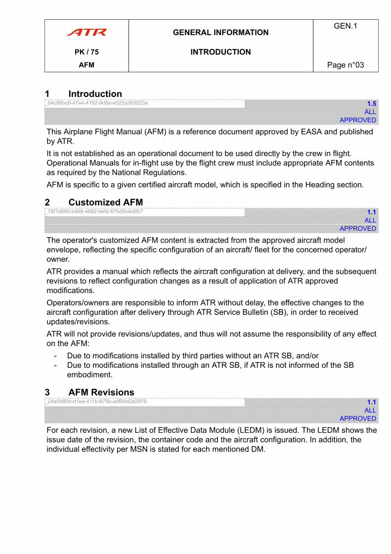
This Airplane Flight Manual (AFM) is a reference document approved by EASA and publishedby ATR.It is not established as an operational document to be used directly by the crew in flight.Operational Manuals for in-flight use by the flight crew must include appropriate AFM contentsas required by the National Regulations.AFM is specific to a given certified aircraft model, which is specified in the Heading section.
2 Customized AFM_78f7d890-b469-4682-befd-67bd9c4c6fc7 1.1
ALLAPPROVED
The operator's customized AFM content is extracted from the approved aircraft modelenvelope, reflecting the specific configuration of an aircraft/ fleet for the concerned operator/owner.ATR provides a manual which reflects the aircraft configuration at delivery, and the subsequentrevisions to reflect configuration changes as a result of application of ATR approvedmodifications.Operators/owners are responsible to inform ATR without delay, the effective changes to theaircraft configuration after delivery through ATR Service Bulletin (SB), in order to receivedupdates/revisions.ATR will not provide revisions/updates, and thus will not assume the responsibility of any effecton the AFM:
- Due to modifications installed by third parties without an ATR SB, and/or- Due to modifications installed through an ATR SB, if ATR is not informed of the SB
embodiment.
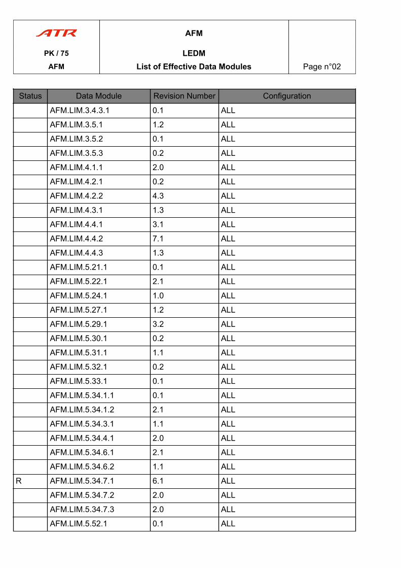
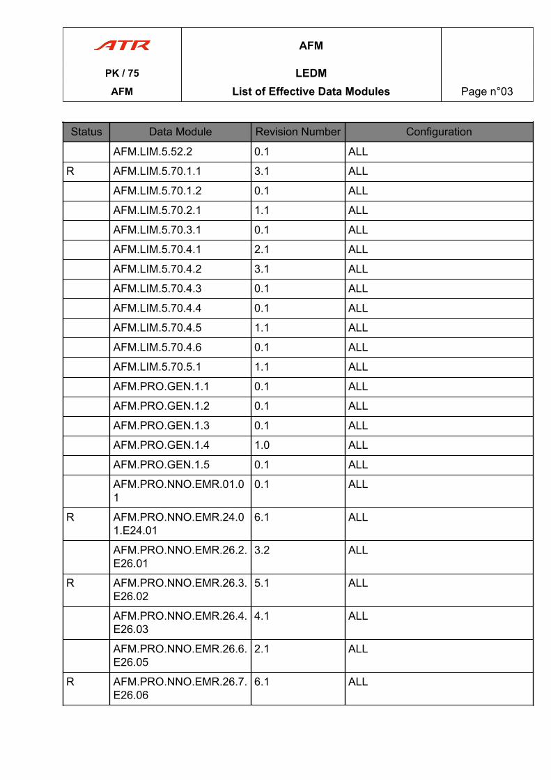
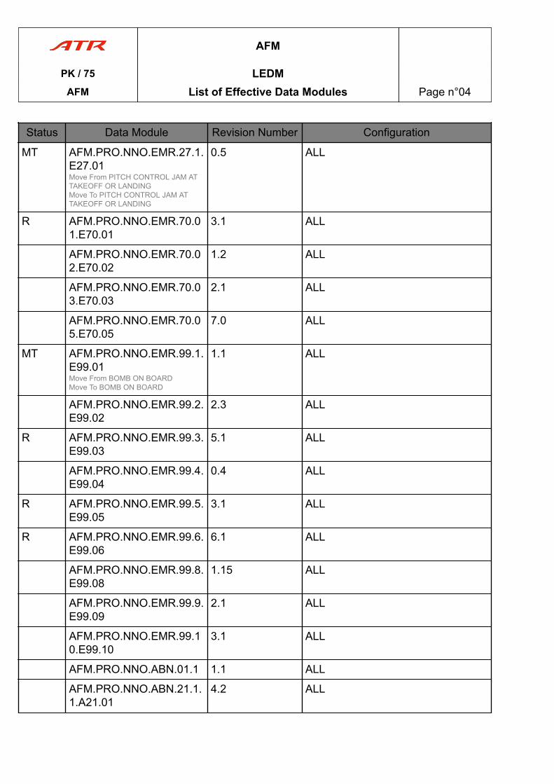
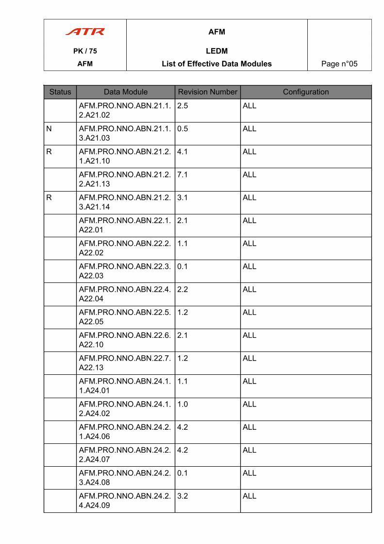
3 AFM Revisions_24a5d80d-d1ee-411b-875b-adf94d2a2979 1.1
ALLAPPROVED
For each revision, a new List of Effective Data Module (LEDM) is issued. The LEDM shows theissue date of the revision, the container code and the aircraft configuration. In addition, theindividual effectivity per MSN is stated for each mentioned DM.
GENERAL INFORMATIONGEN.1
PK / 75 INTRODUCTIONAFM Page n°03
1 AFM Chapters_51422fbf-1b55-4155-b81f-687230865c02 1.2
ALLAPPROVED
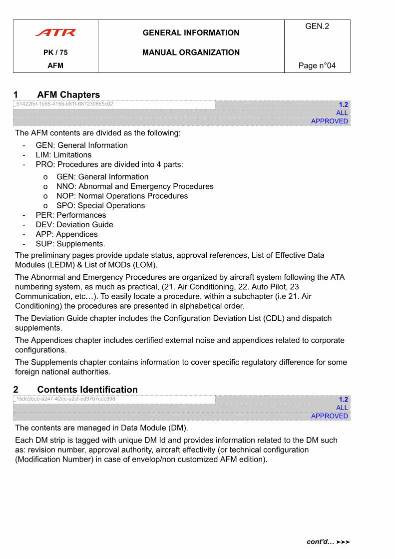
The AFM contents are divided as the following:- GEN: General Information- LIM: Limitations- PRO: Procedures are divided into 4 parts:
o GEN: General Informationo NNO: Abnormal and Emergency Procedureso NOP: Normal Operations Procedureso SPO: Special Operations
- PER: Performances- DEV: Deviation Guide- APP: Appendices- SUP: Supplements.
The preliminary pages provide update status, approval references, List of Effective DataModules (LEDM) & List of MODs (LOM).The Abnormal and Emergency Procedures are organized by aircraft system following the ATAnumbering system, as much as practical, (21. Air Conditioning, 22. Auto Pilot, 23Communication, etc…). To easily locate a procedure, within a subchapter (i.e 21. AirConditioning) the procedures are presented in alphabetical order.The Deviation Guide chapter includes the Configuration Deviation List (CDL) and dispatchsupplements.The Appendices chapter includes certified external noise and appendices related to corporateconfigurations.The Supplements chapter contains information to cover specific regulatory difference for someforeign national authorities.
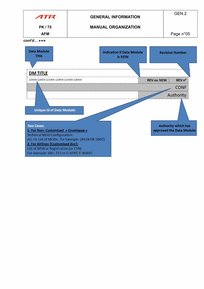
2 Contents Identification_15de2ecb-a247-42ee-a2cf-ed97b7cdc998 1.2
ALLAPPROVED
The contents are managed in Data Module (DM).Each DM strip is tagged with unique DM Id and provides information related to the DM suchas: revision number, approval authority, aircraft effectivity (or technical configuration(Modification Number) in case of envelop/non customized AFM edition).
GENERAL INFORMATIONGEN.2
PK / 75 MANUAL ORGANIZATIONAFM Page n°04
cont'd…
GENERAL INFORMATIONGEN.2
PK / 75 MANUAL ORGANIZATIONAFM Page n°05
cont'd…
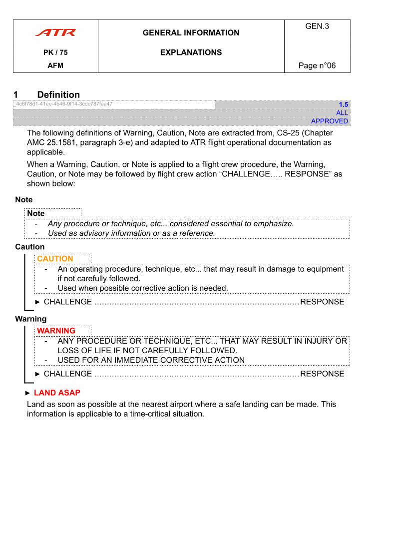
1 Definition_4c6f78d1-41ee-4b46-9f14-3cdc787faa47 1.5
ALLAPPROVED
The following definitions of Warning, Caution, Note are extracted from, CS-25 (ChapterAMC 25.1581, paragraph 3-e) and adapted to ATR flight operational documentation asapplicable.When a Warning, Caution, or Note is applied to a flight crew procedure, the Warning,Caution, or Note may be followed by flight crew action “CHALLENGE….. RESPONSE” asshown below:
NoteNote
- Any procedure or technique, etc... considered essential to emphasize.- Used as advisory information or as a reference.
CautionCAUTION
- An operating procedure, technique, etc... that may result in damage to equipmentif not carefully followed.
- Used when possible corrective action is needed.
▶ CHALLENGE ......................................... .........................................RESPONSE
WarningWARNING
- ANY PROCEDURE OR TECHNIQUE, ETC... THAT MAY RESULT IN INJURY ORLOSS OF LIFE IF NOT CAREFULLY FOLLOWED.
- USED FOR AN IMMEDIATE CORRECTIVE ACTION
▶ CHALLENGE ......................................... .........................................RESPONSE
▶ LAND ASAPLand as soon as possible at the nearest airport where a safe landing can be made. Thisinformation is applicable to a time-critical situation.
GENERAL INFORMATIONGEN.3
PK / 75 EXPLANATIONSAFM Page n°06
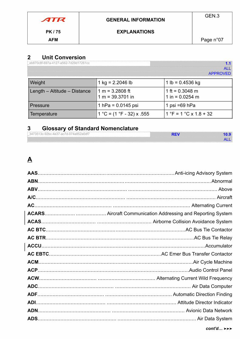
2 Unit Conversion_eb870c8f-697a-4127-a562-7d29d17261cc 1.1
ALLAPPROVED
Weight 1 kg = 2.2046 lb 1 lb = 0.4536 kg
Length – Altitude – Distance 1 m = 3.2808 ft1 m = 39.3701 in
1 ft = 0.3048 m1 in = 0.0254 m
Pressure 1 hPa = 0.0145 psi 1 psi =69 hPa
Temperature 1 °C = (1 °F - 32) x .555 1 °F = 1 °C x 1.8 + 32
3 Glossary of Standard Nomenclature_3473513c-92bc-4e37-ac7d-074a852a0df7 REV 10.9
ALL
A
AAS............................................. .............................................Anti-icing Advisory System
ABN..................................................................................................................Abnormal
ABV........................................................... ........................................................... Above
A/C........................................................... ........................................................... Aircraft
AC................................................... ................................................... Alternating Current
ACARS.................... .................... Aircraft Communication Addressing and Reporting System
ACAS.................................... .................................... Airborne Collision Avoidance System
AC BTC............................................................................................AC Bus Tie Contactor
AC BTR..................................................................................................AC Bus Tie Relay
ACCU............................................................................................................Accumulator
AC EBTC..........................................................................AC Emer Bus Transfer Contactor
ACM......................................................................................................Air Cycle Machine
ACP....................................................................................................Audio Control Panel
ACW...................................... ...................................... Alternating Current Wild Frequency
ADC.................................................. .................................................. Air Data Computer
ADF............................................ ............................................ Automatic Direction Finding
ADI.............................................. .............................................. Attitude Director Indicator
ADN................................................ ................................................ Avionic Data Network
ADS.................................................... .................................................... Air Data System
GENERAL INFORMATIONGEN.3
PK / 75 EXPLANATIONSAFM Page n°07
cont'd…
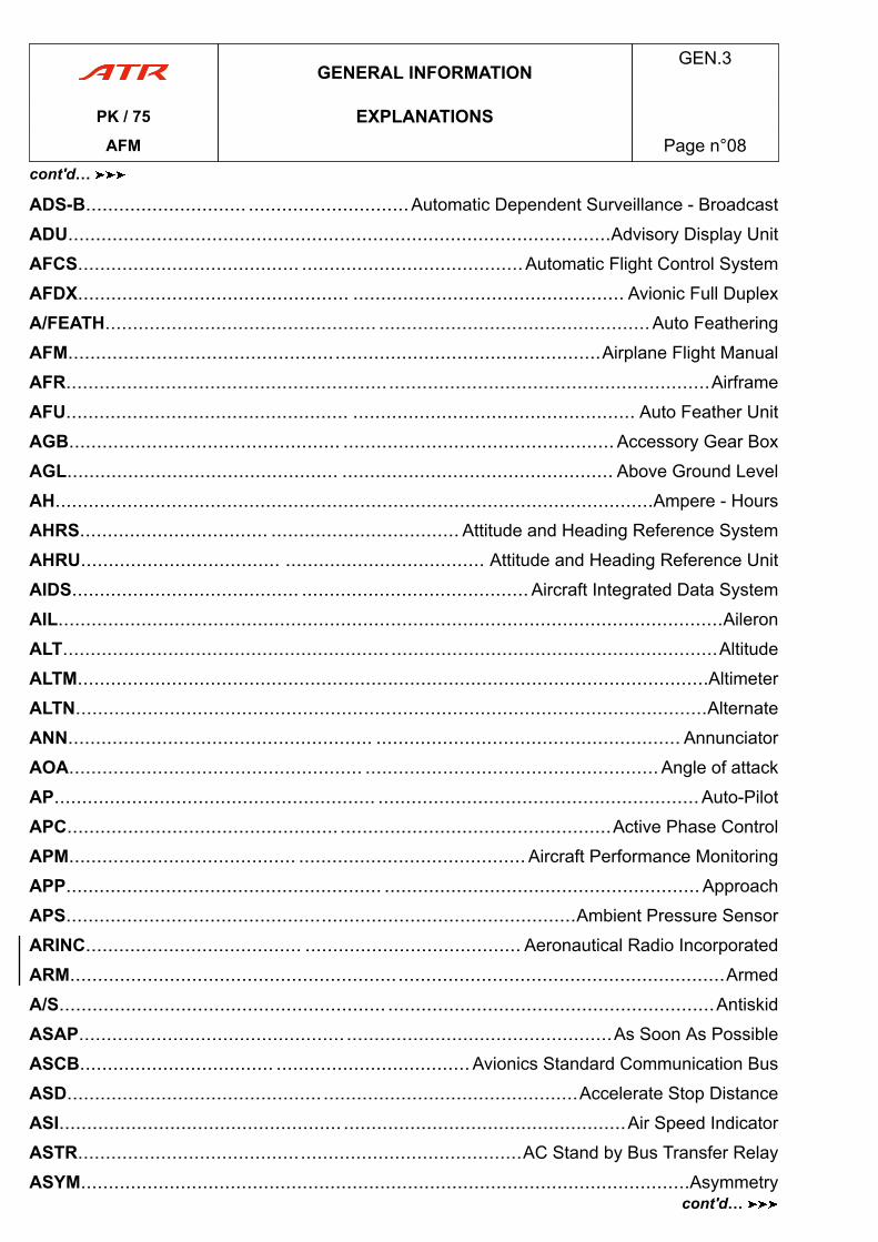
ADS-B............................. .............................Automatic Dependent Surveillance - Broadcast
ADU..................................................................................................Advisory Display Unit
AFCS........................................ ........................................Automatic Flight Control System
AFDX................................................. ................................................. Avionic Full Duplex
A/FEATH................................................. .................................................Auto Feathering
AFM................................................................................................Airplane Flight Manual
AFR....................................................................................................................Airframe
AFU................................................... ................................................... Auto Feather Unit
AGB................................................. ................................................. Accessory Gear Box
AGL................................................. ................................................. Above Ground Level
AH............................................................................................................Ampere - Hours
AHRS.................................. .................................. Attitude and Heading Reference System
AHRU.................................... .................................... Attitude and Heading Reference Unit
AIDS......................................... ......................................... Aircraft Integrated Data System
AIL........................................................................................................................Aileron
ALT......................................................................................................................Altitude
ALTM..................................................................................................................Altimeter
ALTN..................................................................................................................Alternate
ANN....................................................... ....................................................... Annunciator
AOA..................................................... ..................................................... Angle of attack
AP.......................................................... ..........................................................Auto-Pilot
APC..................................................................................................Active Phase Control
APM......................................... ......................................... Aircraft Performance Monitoring
APP......................................................... .........................................................Approach
APS............................................................................................Ambient Pressure Sensor
ARINC....................................... ....................................... Aeronautical Radio Incorporated
ARM......................................................................................................................Armed
A/S........................................................... ...........................................................Antiskid
ASAP................................................ ................................................As Soon As Possible
ASCB................................... ...................................Avionics Standard Communication Bus
ASD............................................................................................Accelerate Stop Distance
ASI................................................... ...................................................Air Speed Indicator
ASTR................................................................................AC Stand by Bus Transfer Relay
ASYM..............................................................................................................Asymmetry
GENERAL INFORMATIONGEN.3
PK / 75 EXPLANATIONSAFM Page n°08
cont'd…
cont'd…
ATC........................................................................................................Air Traffic Control
ATE............................................. ............................................. Automatic Test Equipment
ATPCS................................ ................................ Automatic Take off Power Control System
ATT......................................................................................................................Attitude
ATTND....................................................... .......................................................Attendant
AUTO................................................................................................................Automatic
AUX....................................................................................................................Auxiliary
AVAIL........................................................ ........................................................ Available
AZ........................................................... ........................................................... Azimuth
AZWF............................................. ............................................. Actual Zero Fuel Weight
B
BARO..............................................................................................................Barometric
BAT........................................................... ...........................................................Battery
BC................................................................................................................Back Course
BITE............................................... ............................................... Built in Test Equipment
BLW........................................................... ........................................................... Below
BPCU.............................................. ..............................................Bus Power Control Unit
BPU................................................................................................Battery Protection Unit
BRG.......................................................... .......................................................... Bearing
BRK........................................................... ........................................................... Brake
B-RNAV............................................. ............................................. Basic Aera Navigation
BSC............................................... ............................................... Battery Start Contactor
BTC................................................... ................................................... Bus Tie Contactor
BTR...................................................... ......................................................Bus Tie Relay
BXR................................................................................................Battery Transfer Relay
C
CAB........................................................... ........................................................... Cabin
CAC..............................................................................................Crew Alerting Computer
CAN..............................................................................................Controller Area Network
GENERAL INFORMATIONGEN.3
PK / 75 EXPLANATIONSAFM Page n°09
cont'd…
cont'd…
CAP....................................................................................................Crew Alerting Panel
CAPT......................................................... ......................................................... Captain
CAS....................................................................................................Calibrated Airspeed
CAT......................................................... ......................................................... Category
C/B............................................................................................................Circuit Breaker
CCAS..............................................................................Centralized Crew Alerting System
CCW.................................................. .................................................. Counter clockwise
CD........................................................................................................Coefficient of Drag
CDI............................................................................................Course Deviation Indicator
CDL............................................ ............................................ Configuration Deviation List
CDLS....................................................................................Cockpit Door Locking System
CDS............................................... ...............................................Cockpit Display System
CDU......................................................................................................Cabin Display Unit
CFC.......................................... .......................................... Constant Frequency Contactor
CFR........................................... ........................................... Code of Federal Regulations
CG..........................................................................................................Center of Gravity
CHAN..................................................................................................................Channel
CHC................................................... ................................................... Charge Contactor
CHG.......................................................... .......................................................... Charge
C/L......................................................... ......................................................... Check List
CL................................................................................Condition Lever or Coefficient of Lift
CLA................................................ ................................................ Condition Lever Angle
CLB........................................................................................................................Climb
CLR............................................................ ............................................................ Clear
CM..............................................................................................................Crew Member
CNTNR..............................................................................................................Container
CNTR................................................................................................................Contactor
CNTRS................................................................................................................Contrast
COM.................................................... .................................................... Communication
COMPT........................................................................................................Compartment
COMPTR..................................................... ..................................................... Computer
CONFIG................................................... ................................................... Configuration
CONT..............................................................................................................Continuous
CORRECT.................................................... ....................................................Correction
GENERAL INFORMATIONGEN.3
PK / 75 EXPLANATIONSAFM Page n°10
cont'd…
cont'd…
CPA............................................. ............................................. Closest Point of Approach
CPCS........................................ ........................................ Cabin Pressure Control System
CPL.................................................. .................................................. Auto Pilot Coupling
CPM.............................................. .............................................. Core Processing Module
CRC........................................... ...........................................Continuous Repetitive Chime
CRG........................................................... ........................................................... Cargo
CRS......................................................................................................................Course
CRT.................................................. .................................................. Cathode Ray Tube
CRZ........................................................... ........................................................... Cruise
CTL........................................................... ...........................................................Control
CVR............................................... ............................................... Cockpit Voice Recorder
CW......................................................... ......................................................... Clockwise
D
DADC............................................ ............................................ Digital Air Data Computer
DADS.............................................. .............................................. Digital Air Data System
DC....................................................... .......................................................Direct Current
DCA....................................................................................Data Concentration Application
DEC......................................................... .........................................................Decrease
DELTA P.............................................. .............................................. Differential Pressure
DEV......................................................... ......................................................... Deviation
DFDR........................................... ........................................... Digital Flight Data Recorder
DGAC........................................................................Direction Générale de l'Aviation Civile
DGR..................................................................................................................Degraded
DH............................................................................................................Decision Height
DIFF........................................................ ........................................................Differential
DIM..............................................................................................................Light Dimmer
DISC....................................................... ....................................................... Disconnect
DISCH....................................................... .......................................................Discharge
DIST......................................................... ......................................................... Distance
DM................................................................................................................Data Module
DME......................................... ......................................... Distance Measuring Equipment
GENERAL INFORMATIONGEN.3
PK / 75 EXPLANATIONSAFM Page n°11
cont'd…
cont'd…
DN..........................................................................................................................Down
DSPL....................................................................................................................Display
DU........................................................ ........................................................ Display Unit
E
EADI............................................................................Electronic Attitude Director Indicator
EASA....................................... .......................................European Aviation Safety Agency
EBCC.................................... ....................................Emergency Battery Charge Contactor
EBTC.......................................... .......................................... Emer Bus Transfer Contactor
ECL.................................................. ..................................................Electronic Checklist
ECS.......................................... .......................................... Environmental Control System
ECU................................................ ................................................Electronic Control Unit
E/E......................................................................................................Electrical/Electronic
EEC............................................................................................Electronic Engine Control
EFB................................................. ................................................. Electronic Flight Bag
EFCP................................................. ................................................. EFIS Control Panel
EFIS...................................... ...................................... Electronic Flight Instrument System
EFOB..........................................................................................Estimated Fuel On Board
EFVS......................................... .........................................Enhanced Flight Vision System
EGHR................................................................................External Ground Handling Relay
EGPWS............................. ............................. Enhanced Ground Proximity Warning System
EHSI................................... ................................... Electronic Horizontal Situation Indicator
EHV............................................... ............................................... Electro Hydraulic Valve
ELEC........................................................ ........................................................ Electrical
ELEV......................................................... ......................................................... Elevator
ELV....................................................................................................................Elevation
EMER...................................................... ...................................................... Emergency
ENG......................................................................................................................Engine
EPC............................................................................................External Power Contactor
EPE..............................................................................................Estimated Position Error
EQPT....................................................... ....................................................... Equipment
ERIU........................................... ........................................... Engine Rating Interface Unit
GENERAL INFORMATIONGEN.3
PK / 75 EXPLANATIONSAFM Page n°12
cont'd…
cont'd…
ERP................................................. ................................................. Eye Reference Point
ESS......................................................... ......................................................... Essential
ET....................................................... ....................................................... Elapsed Time
ETOPS................ ................ Extended-range Twin Engine Operations Performance Standard
EVS.............................................. .............................................. Enhanced Vision Sensor
EWD........................................... ........................................... Engine and Warning Display
EXC..........................................................................External Power/Service Bus Contactor
EXH.......................................................... .......................................................... Exhaust
EXT.......................................................... .......................................................... External
F
FAA.......................................... ..........................................Federal Aviation Administration
FAF......................................................................................................Final Approach Fix
FAIL............................................................................................................Failed, Failure
FAR........................................................................................Federal Aviation Regulations
FCOC.............................................. .............................................. Fuel Cooled Oil Cooler
FCOM......................................... ......................................... Flight Crew Operating Manual
FCU.................................................... ....................................................Fuel Control Unit
FD....................................................... ....................................................... Flight Director
FDA.............................................. .............................................. Flight Display Application
FDAU........................................... ........................................... Flight Data Acquisition Unit
FDEP.............................................. .............................................. Flight Data Entry Panel
FEATH..............................................................................................................Feathered
FF.......................................................... .......................................................... Fuel Flow
FGCP...................................... ...................................... Flight Guidance and Control Panel
FGS............................................... ...............................................Flight Guidance System
FI......................................................................................................................Flight Idle
FL......................................................... ......................................................... Flight Level
FLT............................................................ ............................................................ Flight
FMA............................................................................................Flight Mode Annunciators
FMS............................................ ............................................ Flight Management System
F/O........................................................ ........................................................ First Officer
GENERAL INFORMATIONGEN.3
PK / 75 EXPLANATIONSAFM Page n°13
cont'd…
cont'd…
FOB..................................................... ..................................................... Fuel On Board
FODU........................................ ........................................ Feeder Overheat detection Unit
FOS............................................. .............................................Flight Operations Software
FOV..............................................................................................................Field of View
FPA.................................................... ....................................................Flight Path Angle
FPLN....................................................... ....................................................... Flight Plan
FPV................................................... ................................................... Flight Path Vector
FQI................................................................................................Fuel Quantity Indication
FSN....................................................................................................Fleet Serial Number
FTO...................................................... ...................................................... Final Take Off
FTR......................................................................................................................Feather
FU....................................................................................................................Fuel Used
FWA............................................. ............................................. Flight Warning Application
FWD....................................................................................................................Forward
FWS................................................................................................Flight Warning System
G
GA......................................................... .........................................................Go Around
GAL........................................................... ........................................................... Galley
GC.................................................. .................................................. Generator Contactor
GCR............................................. ............................................. Ground Clutter Reduction
GCU............................................... ............................................... Generator Control Unit
GDM................................................................................................Group of Data Module
GEN........................................................ ........................................................ Generator
GI......................................................... ......................................................... Ground Idle
GMT................................................................................................Greenwich Mean Time
GND.......................................................... .......................................................... Ground
GNSS...................................... ...................................... Global Navigation Satellite System
GPS............................................. ............................................. Global Positioning System
GPU.................................................. .................................................. Ground Power Unit
GPWS............................................................................Ground Proximity Warning System
G/S........................................................ ........................................................ Glide Slope
GENERAL INFORMATIONGEN.3
PK / 75 EXPLANATIONSAFM Page n°14
cont'd…
cont'd…
GS...................................................... ...................................................... Ground Speed
GXS.................................... .................................... ACW Generator/Service Bus Contactor
H
HBOV....................................... ....................................... Handling Bleed Overboard Valve
HBV..................................................................................................Handling Bleed Valve
HD........................................................ ........................................................ Head Down
HDG....................................................................................................................Heading
HDLG........................................................ ........................................................ Handling
HEBTC........................................................................Hot Emer Battery Transfer Contactor
HF............................................................................................................High Frequency
HFOM............................................ ............................................ Horizontal Figure Of Merit
HI.............................................................. .............................................................. High
HLD..........................................................................................................................Hold
HMBTC........................................................................Hot Main Battery Transfer Contactor
HMD............................................... ............................................... Head Mounted Display
HMU................................................ ................................................Hydromechanical Unit
HOBV............................................ ............................................Handling Overboard Valve
HP..............................................................................................................High Pressure
HSI............................................ ............................................ Horizontal Situation Indicator
HTG.......................................................... .......................................................... Heating
HU......................................................................................................................Head Up
HYD......................................................... ......................................................... Hydraulic
I
IAF................................................... ................................................... Initial Approach Fix
IAS......................................................................................................Indicated Air Speed
ICAO................................... ................................... International Civil Aviation Organisation
ICP.................................................. .................................................. Index Control Panel
IDT............................................................. ............................................................. Ident
IEP......................................................................................................Ice Evidence Probe
GENERAL INFORMATIONGEN.3
PK / 75 EXPLANATIONSAFM Page n°15
cont'd…
cont'd…
IESI................................... ................................... Integrated Electronic Standby Instrument
I.F................................................ ................................................ Intermediate Frequency
IFR................................................ ................................................ Instrument Flight Rules
IGN........................................................... ........................................................... Ignition
ILS............................................. ............................................. Instrument Landing System
IMC..........................................................................Instrumental Meteorological Conditions
IMU.............................................. .............................................. Inertial Measurement Unit
IN..........................................................................................................Inertial Navigation
INC.......................................................... .......................................................... Increase
IND.......................................................... .......................................................... Indicator
IN/HG.................................................. .................................................. Inches of Mercury
INHIB......................................................................................................................Inhibit
INOP....................................................... ....................................................... Inoperative
INS.............................................. .............................................. Inertial Navigation System
INST........................................................ ........................................................ Instrument
INT......................................................... ......................................................... Interphone
INU................................................ ................................................ Inertial Navigation Unit
INV........................................................... ........................................................... Inverter
IOM....................................................................................................Input Output Module
IPD................................................ ................................................ Inter-Pupillary Distance
IRS.............................................. .............................................. Inertial Reference System
ISA................................................................................International Standard Atmosphere
ISOL......................................................... ......................................................... Isolation
ISV................................................ ................................................ Isolation Shut-off Valve
ITT.............................................. .............................................. Inter Turbine Temperature
J
JAA.............................................. .............................................. Joint Aviation Authorities
JAR............................................ ............................................ Joint Aviation Requirements
JIC.................................................. .................................................. Job Instruction Card
GENERAL INFORMATIONGEN.3
PK / 75 EXPLANATIONSAFM Page n°16
cont'd…
cont'd…
L
LAT........................................................... ........................................................... Lateral
LAV.......................................................... ..........................................................Lavatory
LBA....................................................................................................Lowest Blade Angle
LDG.......................................................... .......................................................... Landing
LEDM.......................................... .......................................... List of Effective Data Module
L/G..............................................................................................................Landing Gear
LH.......................................................... .......................................................... Left Hand
LIM....................................................................................................................Limitation
LMG..................................................... ..................................................... Left Main Gear
LMU................................................. ................................................. Light Managing Unit
LNAV.................................................. .................................................. Lateral Navigation
LO.............................................................. .............................................................. Low
LOC......................................................... ......................................................... Localizer
LOM...................................................... ...................................................... List of MODs
LOS..............................................................................................................Line Of Sight
LP....................................................... ....................................................... Low Pressure
LRU................................................ ................................................ Line Replaceable Unit
LT............................................................................................................................Light
LVL............................................................ ............................................................ Level
M
MAC............................................. .............................................Mean Aerodynamic Chord
MAN.......................................................... .......................................................... Manual
MAP........................................................................................................Ground Mapping
MAX..................................................................................................................Maximum
MBCC........................................ ........................................ Main Battery Charge Contactor
MBTC.......................................... .......................................... Main Bus Transfer Contactor
MC............................................................................................................Master Caution
MCDU............................................................................Multi Function Control Display Unit
MCP........................................... ........................................... Multi Function Control Panel
MCT..............................................................................................Maxi Continuous Thrust
GENERAL INFORMATIONGEN.3
PK / 75 EXPLANATIONSAFM Page n°17
cont'd…
cont'd…
MDA............................................. .............................................Minimum Descent Altitude
MEA............................................. ............................................. Minimum en route Altitude
MECH................................................................................................................Mechanic
MEL.............................................. .............................................. Minimum Equipment List
MFC.............................................. .............................................. Multi Function Computer
MFCU.......................................... ..........................................Mechanical Fuel Control Unit
MFD................................................ ................................................ Multi Function Display
MGT...................................................... ...................................................... Management
MIC........................................................ ........................................................Microphone
MIN....................................................................................................................Minimum
MIP............................................... ............................................... Main Instruments Panel
MISC..................................................... ..................................................... Miscellaneous
MKR......................................................................................................................Marker
MLG.................................................. ..................................................Main Landing Gear
MLS............................................ ............................................ Microwave Landing System
MLW............................................. .............................................Maximum Landing Weight
MMEL........................................ ........................................ Master Minimum Equiment List
MMO............................................ ............................................ Maximum Operating Mach
MMPU............................................................................................Multi Media Player Unit
MOD....................................................... .......................................................Modification
MP................................................................................................Maintenance Procedure
MPC.............................................. .............................................. Multi Purpose Computer
MPU..................................................................................................Micro Processor Unit
MSA................................................................................................Minimum Safe Altitude
MSG........................................................ ........................................................ Messages
MSIS.......................................... .......................................... Minimum Severe Icing Speed
MSN........................................... ........................................... Manufacturer Serial Number
MTOW............................................ ............................................ Maximum Takeoff Weight
MW..................................................... ..................................................... Master Warning
MZFW......................................................................................Maximum Zero Fuel Weight
GENERAL INFORMATIONGEN.3
PK / 75 EXPLANATIONSAFM Page n°18
cont'd…
cont'd…
N
NAC.......................................................... .......................................................... Nacelle
NACA..............................................................National Advisory Committee for Aeronautics
NAV........................................................ ........................................................ Navigation
ND........................................................................................................Navigation Display
NDB......................... .........................Non Directional Beacon or Navigation Database (GPS)
NEG......................................................... ......................................................... Negative
NG......................................................... .........................................................Nose Gear
NH..............................................................................High Pressure Spool Rotation Speed
NIL................................................... ................................................... Nothing, No Object
NL....................................... ....................................... Low Pressure Spool Rotation Speed
NLG.................................................. ..................................................Nose Landing Gear
NM....................................................... ....................................................... Nautical Mile
NORM......................................................... ......................................................... Normal
NOTAM................................................. ................................................. Notice To Airmen
NP............................................... ............................................... Propeller Rotation Speed
NPU............................................. ............................................. Navigation Processor Unit
NUC............................................. ............................................. Non Uniformity Correction
NVM..................................................................................................Non Volatile Memory
N/W....................................................... ....................................................... Nose Wheel
NWS................................................ ................................................ Nose Wheel Steering
O
OAT..............................................................................................Outside Air Temperature
OBS................................................................................................Omni Bearing Selector
OT........................................................ ........................................................ Other Traffic
OTF.............................................. .............................................. Optical tracker Fixed unit
OUTB........................................................ ........................................................Outboard
OVBD....................................................... .......................................................Overboard
OVERTEMP.............................................. .............................................. Overtemperature
OVHD....................................................... ....................................................... Overhead
OVHP......................................................................................................OverHead Panel
GENERAL INFORMATIONGEN.3
PK / 75 EXPLANATIONSAFM Page n°19
cont'd…
cont'd…
OVHT........................................................ ........................................................ Overheat
OVLY......................................................... ......................................................... Overlay
OVRD........................................................ ........................................................ Override
OVSPD............................................................................................................Overspeed
OXY.......................................................... .......................................................... Oxygen
P
PA................................................... ................................................... Passenger Address
PAX........................................................ ........................................................ Passenger
PBN....................................................................................Performance Based Navigation
PCU................................................ ................................................ Propeller Control Unit
PEBMV..............................................................Parking/Emergency Braking Metering Valve
PEC............................................ ............................................ Propeller Electronic Control
PF......................................................... ......................................................... Pilot Flying
PFD................................................ ................................................ Primary Flight Display
PFTS......................................... ......................................... Power Feeder Thermal Sensor
PIU................................................ ................................................ Propeller Interface Unit
PL........................................................ ........................................................ Power Lever
PLA.................................................. .................................................. Power Lever Angle
PM............................................................................................................Pilot Monitoring
PNL............................................................ ............................................................Panel
POS.......................................................... .......................................................... Position
PR......................................................................................................................Pressure
PRESS........................................................................................................Pressurization
PRIM....................................................................................................................Primary
PRKG......................................................... ......................................................... Parking
P-RNAV......................................................................................Precision Area Navigation
PROC....................................................... ....................................................... Procedure
PROP........................................................ ........................................................ Propeller
PROX SW................................................ ................................................Proximity Switch
PRV............................................. ............................................. Pressure Regulating Valve
PSEU........................................ ........................................ Proximity Switch Electronic Unit
GENERAL INFORMATIONGEN.3
PK / 75 EXPLANATIONSAFM Page n°20
cont'd…
cont'd…
PSI................................................ ................................................ Pound per Square Inch
PSU............................................... ............................................... Passenger Service Unit
PSV..................................................................................................Propeller Servo Valve
PT............................................................. ............................................................. Point
PT................................................. ................................................. Proximity traffic TCAS
PTB..........................................................................................................Power Trim Box
PTT.............................................. .............................................. Push to talk, Push to test
PTW....................................................................................................Pitch Thumb Wheel
PVCU....................................................................................Power and Video Control Unit
PVM............................................... ............................................... Propeller Valve Module
PWM.............................................. .............................................. Pulse Width Modulation
PWR........................................................... ...........................................................Power
Q
QAR............................................... ...............................................Quick Access Recorder
QRC................................................................................................Quick Release Control
QRH............................................ ............................................Quick Reference Handbook
QRT................................................................................................Quick Reference Table
QT............................................................. .............................................................Quart
QTY.......................................................... ..........................................................Quantity
R
RA..................................................................Resolution Advisory TCAS or Radio Altimeter
RAD/ALT.................................................. .................................................. Radio Altitude
RAD/INT................................................ ................................................ Radio/Interphone
RAIM................................. ................................. Receiver Autonomous Integrity Monitoring
RCAU........................................... ........................................... Remote Control Audio Unit
RCDR........................................................ ........................................................Recorder
RCL........................................................... ........................................................... Recall
RCP................................................. .................................................Refuel Control Panel
RCT............................. ............................. Rain Echo Attenuation Compensation Technique
GENERAL INFORMATIONGEN.3
PK / 75 EXPLANATIONSAFM Page n°21
cont'd…
cont'd…
RCU............................................. ............................................. Releasable Centering Unit
RECIRC........................................................................................................Recirculation
REV.......................................................... ..........................................................Reverse
RGA................................................. ................................................. Reserve Go-Around
RGB................................................. ................................................. Reduction Gear Box
RH..................................................................................................................Right Hand
RLY............................................................ ............................................................Relay
RMA......................................... ......................................... Radio Management Application
RMG........................................................................................................Right Main Gear
RMI..............................................................................................Radio Magnetic Indicator
RMS............................................ ............................................Radio Management System
RNAV................................................... ................................................... Area Navigation
RNP................................................................................Required Navigation Performance
RPM................................................ ................................................Revolution Per Minute
RQD......................................................... ......................................................... Required
RQRD........................................................ ........................................................Required
RTO.................................................... .................................................... Reserve Takeoff
RTOW......................................................................................Regulatory Take-Off Weight
RUD.......................................................... .......................................................... Rudder
RVDT................................... ................................... Rotary Variable Differential Transducer
RWS................................................. ................................................. Reactive Windshear
RWY....................................................................................................................Runway
S
SAT................................................ ................................................ Static Air Temperature
SB...................................................... ......................................................Service Bulletin
SBAS.................................... ....................................Satellite Based Augmentation System
SBTC................................................................................Stand By bus Transfer Contactor
SBY......................................................... ......................................................... Stand By
SC.......................................... .......................................... Single Chime, Starter Contactor
SCU..............................................................................................Signal Conditioning Unit
SD...................................................... ......................................................System Display
GENERAL INFORMATIONGEN.3
PK / 75 EXPLANATIONSAFM Page n°22
cont'd…
cont'd…
SDTC..................................................................Static Inverter Override Transfer Contactor
SEC........................................................ ........................................................ Secondary
SELCAL................................................. .................................................Selective Calling
SG.................................................... ....................................................Symbol Generator
SGL........................................................... ........................................................... Single
SGU............................................... ............................................... Symbol Generator Unit
SHP.................................................. .................................................. Shaft Horse Power
SID.......................................... .......................................... Standard Instrument Departure
SMK......................................................................................................................Smoke
SMKG........................................................ ........................................................ Smoking
SO........................................................... ...........................................................Shut-Off
S.O........................................................... .......................................................... Shut-Off
SOV............................................................................................................Shut Off Valve
SPD........................................................... ........................................................... Speed
SPLR.......................................................... ..........................................................Spoiler
SPLY.......................................................... .......................................................... Supply
SPS....................................... ....................................... Single-point Performance Software
SSR.......................................... .......................................... Secondary Surveillance Radar
STAB........................................................ ........................................................ Stabilizer
STAR................................................... ................................................... Standard Arrival
STBY......................................................... .........................................................Standby
STR..........................................................................................Service Bus Transfer Relay
STRG..................................................................................................................Steering
SURV...................................................... ...................................................... Surveillance
SVCE......................................................... ......................................................... Service
SVS..............................................................................................Synthetic Vision System
SWM..........................................................................................................Switch Module
SYNPHR....................................................................................................Synchrophaser
SYS......................................................................................................................System
T
T2CAS............................. .............................Traffic and Terrain Collision Avoidance System
GENERAL INFORMATIONGEN.3
PK / 75 EXPLANATIONSAFM Page n°23
cont'd…
cont'd…
T3CAS............................. ............................. TAWS, TCAS and Transponder combined unit
TA................................................. ................................................. Traffic Advisory TCAS
TAD............................................. ............................................. Terrain Awareness Display
TAS..................................................... ..................................................... True Air Speed
TAT................................................. ................................................. Total Air Temperature
TAWS..................................... ..................................... Terrain Awareness Warning System
TBD................................................... ................................................... To be Determined
TCAS............................... ............................... Traffic Alert and Collision Avoidance System
TCF............................................... ............................................... Terrain Clearance Floor
TCS................................................................................................Touch Control Steering
T/D..................................................................................................................Time Delay
TEMP............................................................................................................Temperature
TGT........................................................... ........................................................... Target
TIC.................................................. .................................................. Turbine Inlet Control
TK............................................................................................................................Tank
TLU........................................................................................Travel Limiting Unit (Rudder)
TM....................................................... ....................................................... Torque Motor
T.O........................................................................................................................Takeoff
TOD................................................... ................................................... Take-Off Distance
TOR...................................................... ...................................................... Take-Off Run
TOW.................................................... .................................................... Take Off weight
TQ............................................................ ............................................................ Torque
TRU............................................................................................Transformer Rectifier Unit
TSCU........................................ ........................................ Torque Signal Conditioning Unit
TTG................................................................................................................Time To Go
U
UBC................................................. ................................................. Utility Bus Contactor
U/F......................................................... ......................................................... Underfloor
UHF..................................................................................................Ultra High Frequency
UNCPL....................................................... .......................................................Uncouple
UNDV..................................................... ..................................................... Undervoltage
GENERAL INFORMATIONGEN.3
PK / 75 EXPLANATIONSAFM Page n°24
cont'd…
cont'd…
UNLK....................................................................................................................Unlock
USB.................................................... .................................................... Upper SideBand
UTLY........................................................... ........................................................... Utility
V
V1...................................................... ......................................................Decision Speed
V2................................................ ................................................Second Segment Speed
VCCU......................................................................................Video Cabin Command Unit
VCP................................................. ................................................. Virtual Control Panel
VENT....................................................... ....................................................... Ventilation
VERT....................................................................................................................Vertical
VFOM.............................................. .............................................. Vertical Figure Of Merit
VFR......................................................................................................Visual Flight Rules
VHF................................................. ................................................. Very High Frequency
VMC........................................ ........................................ Visual Meteorological Conditions
VMO............................................ ............................................ Maximum Operating Speed
VNAV....................................................................................................Vertical Navigation
VOR......................................................................................VHF OMNI Directional Range
VPRL......................................................................................Vertical Path Reference Line
VR...................................................... ......................................................Rotation Speed
VS..............................................................................................................Vertical Speed
VSI................................................................................................Vertical Speed Indicator
VU......................................................... ......................................................... Visual Unit
W
WARN........................................................ ........................................................ Warning
WAT........................................................................................Weight Altitude Temperature
WBM........................................... ........................................... Weight and Balance Manual
WOW.................................................. .................................................. Weight On Wheel
WPT......................................................... .........................................................Waypoint
W/S........................................................ ........................................................ Windshear
GENERAL INFORMATIONGEN.3
PK / 75 EXPLANATIONSAFM Page n°25
cont'd…
cont'd…
WX...................................................... ...................................................... Weather Mode
WXR..........................................................................................................Weather Radar
X
X.............................................................. ..............................................................Cross
XFEED...................................................... ...................................................... Cross feed
XFR.......................................................... .......................................................... Transfer
XPDR............................................................................................................Transponder
Y
YD................................................................................................................Yaw Damper
Z
ZA...................................................... ...................................................... Aircraft Altitude
Z CAB.................................................... .................................................... Cabin Altitude
ZCTH..........................................................................................Theoretical Cabin Altitude
ZFW................................................... ................................................... Zero Fuel Weight
ZP..................................................... .....................................................Pressure Altitude
ZPRL............................................ ............................................ Zero Pitch Reference Line
ZRA............................................... ............................................... Radio Altimeter Altitude
GENERAL INFORMATIONGEN.3
PK / 75 EXPLANATIONSAFM Page n°26
cont'd…
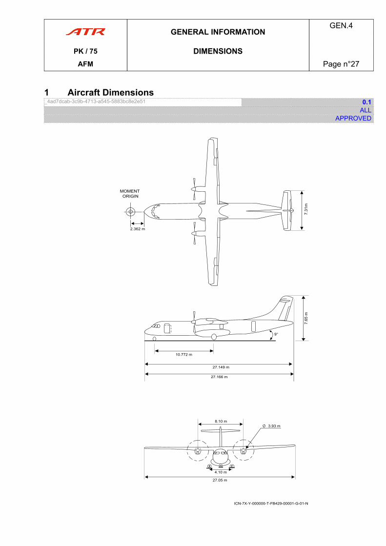
1 Aircraft Dimensions_4ad7dcab-3c9b-4713-a545-5883bc8e2e51 0.1
ALLAPPROVED
MOMENT ORIGIN
9°
2.362 m
10.772 m
27.149 m
27.166 m
8.10 m3.93 m
4.10 m
27.05 m
ICN-7X-Y-000000-T-FB429-00001-G-01-N
GENERAL INFORMATIONGEN.4
PK / 75 DIMENSIONSAFM Page n°27

PAGE
INTENTIONALLY
LEFT BLANK
GENERAL INFORMATIONGEN.4
PK / 75 DIMENSIONSAFM Page n°28
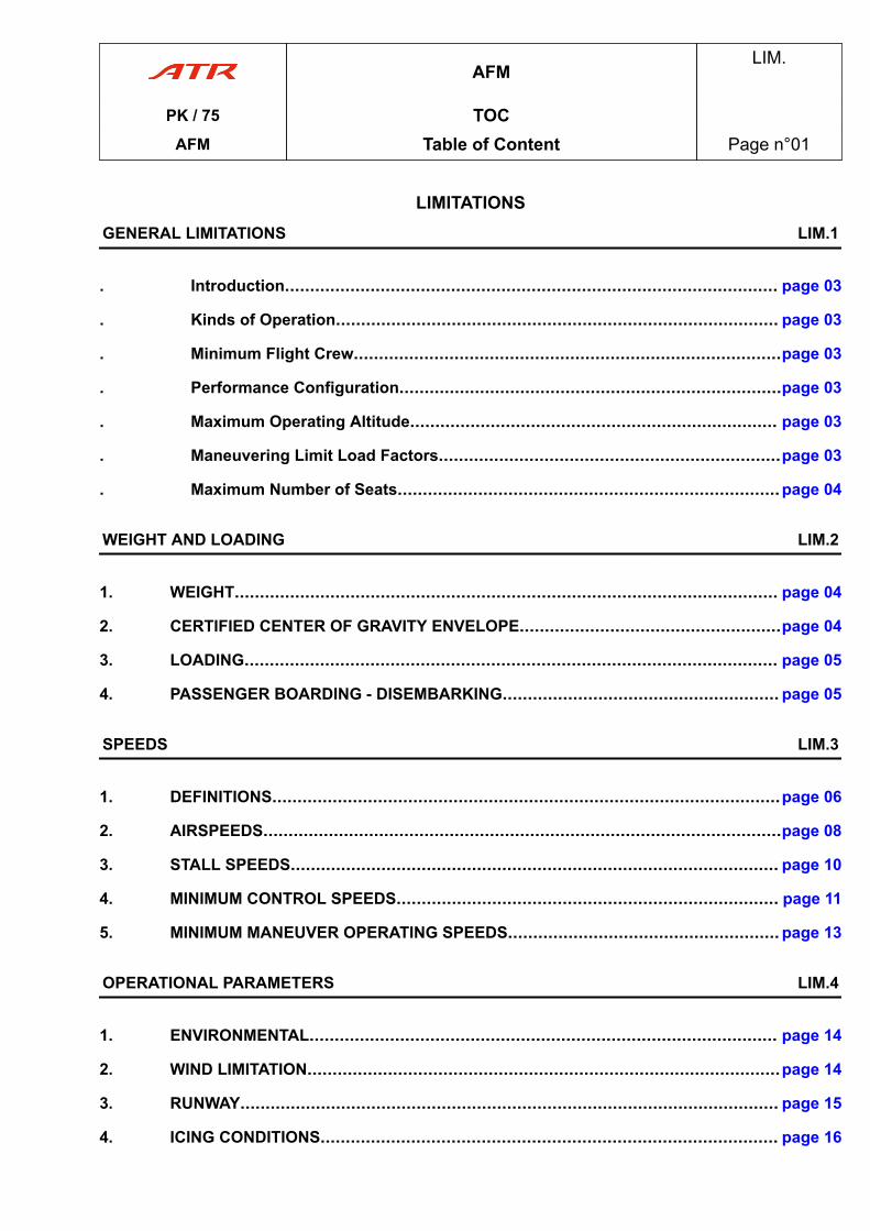
LIMITATIONSGENERAL LIMITATIONS LIM.1
. Introduction.................................................................................................. page 03
. Kinds of Operation........................................................................................ page 03
. Minimum Flight Crew.....................................................................................page 03
. Performance Configuration............................................................................page 03
. Maximum Operating Altitude......................................................................... page 03
. Maneuvering Limit Load Factors....................................................................page 03
. Maximum Number of Seats............................................................................page 04
WEIGHT AND LOADING LIM.2
1. WEIGHT............................................................................................................ page 04
2. CERTIFIED CENTER OF GRAVITY ENVELOPE....................................................page 04
3. LOADING.......................................................................................................... page 05
4. PASSENGER BOARDING - DISEMBARKING....................................................... page 05
SPEEDS LIM.3
1. DEFINITIONS.....................................................................................................page 06
2. AIRSPEEDS.......................................................................................................page 08
3. STALL SPEEDS................................................................................................. page 10
4. MINIMUM CONTROL SPEEDS............................................................................ page 11
5. MINIMUM MANEUVER OPERATING SPEEDS...................................................... page 13
OPERATIONAL PARAMETERS LIM.4
1. ENVIRONMENTAL............................................................................................. page 14
2. WIND LIMITATION..............................................................................................page 14
3. RUNWAY........................................................................................................... page 15
4. ICING CONDITIONS........................................................................................... page 16
AFMLIM.
PK / 75 TOCAFM Table of Content Page n°01
SYSTEMS LIM.5
21. AIR CONDITIONING........................................................................................... page 18
22. AUTO FLIGHT....................................................................................................page 18
24. ELECTRICAL POWER........................................................................................page 18
27. FLIGHT CONTROLS...........................................................................................page 19
29. HYDRAULIC POWER......................................................................................... page 19
30. ICE AND RAIN PROTECTION............................................................................. page 19
31. INDICATING AND RECORDING SYSTEMS.......................................................... page 19
32. LANDING GEAR................................................................................................ page 20
33. LIGHTS............................................................................................................. page 20
34. NAVIGATION......................................................................................................page 20
52. DOORS............................................................................................................. page 28
70. POWER PLANT..................................................................................................page 29
AFMLIM.
PK / 75 TOCAFM Table of Content Page n°02
1 Introduction_3e920159-6867-4bdb-809a-5059f15e96e7 0.1
ALLAPPROVED
Law requires the observance of the limitations.When operating in accordance with an approved appendix or supplement to this AFM, theselimitations apply, unless amended by such appendix or supplement.
2 Kinds of Operation_39c36470-bd17-4491-9888-80a05bc67d9a 0.1
ALLAPPROVED
The aircraft is certified in the transport category for day and night operations, in the followingconditions when the appropriate equipment and instruments required by the airworthinessand operating regulations are approved, installed and in an operable condition:
- VFR and IFR- Flight in icing conditions- Reverse thrust taxi (single or twin engine).
3 Minimum Flight Crew_4e716386-fd2a-4057-8be2-86720ae8d222 0.1
ALLAPPROVED
2 Pilots.
4 Performance Configuration_a6294274-7351-4b3c-aec2-be2f9c726bcd 1.1
ALLAPPROVED
Refer to PER.1.2.01 Performance Configuration for aircraft configuration associated withcertified performances.
5 Maximum Operating Altitude_5e0f199b-a433-4e46-8d33-496abde00c11 0.1
ALLAPPROVED
Maximum Operating Altitude................................................................................25 000 ft
6 Maneuvering Limit Load Factors_50f667d9-e2a5-4754-b6ff-2f59e971a16f 0.1
ALLAPPROVED
Gear and flaps retracted....................................... ....................................... +2.5 g to -1 gGear and/or flaps extended....................................... ....................................... +2 g to 0 g
LIMITATIONSLIM.1
PK / 75 GENERAL LIMITATIONSAFM Page n°03
7 Maximum Number of SeatsMaximum Number of Passenger Seats_3aa06c79-256d-4522-a2ab-31c8d54cd9b6 0.1
ALLAPPROVED
74 as limited by emergency exits configuration.
1 WEIGHT1.1 Structural Limitations_19fc371d-83fe-414b-8d19-700ac1ac82a9 REV 1.0
ALLAPPROVED
MAXIMUM WEIGHT kg
TAXI 22 970
TAKEOFF 22 800
LANDING 22 350
ZERO FUEL 20 800
1.2 Performance Limitations_d9fdcf93-3353-474a-b6fc-fbf2883a62e3 0.2
ALLAPPROVED
Maximum takeoff weight and maximum landing weight may be reduced by performancerequirements related to the following (Refer to PERFORMANCE) :
- Climb performance (first and second segment, final takeoff and en route, approach andlanding climb)
- Available runway length (takeoff and landing)- Tyre limit speed- Brake energy limit, observe BRK TEMP alert for takeoff- Obstacle clearance (takeoff and en route)- En route and landing weight.
2 CERTIFIED CENTER OF GRAVITY ENVELOPE2.1 Certified Center of Gravity Envelope_335c07b5-5cc3-4254-9e68-b7eec8eeadc7 REV 2.2
ALLAPPROVED
For definition of reference (Mean Aerodynamic Chord ( MAC ) and moments origin) : Refer toGENERAL INFORMATION.
LIMITATIONSLIM.1
PK / 75 GENERAL LIMITATIONSAFM Page n°04
cont'd…
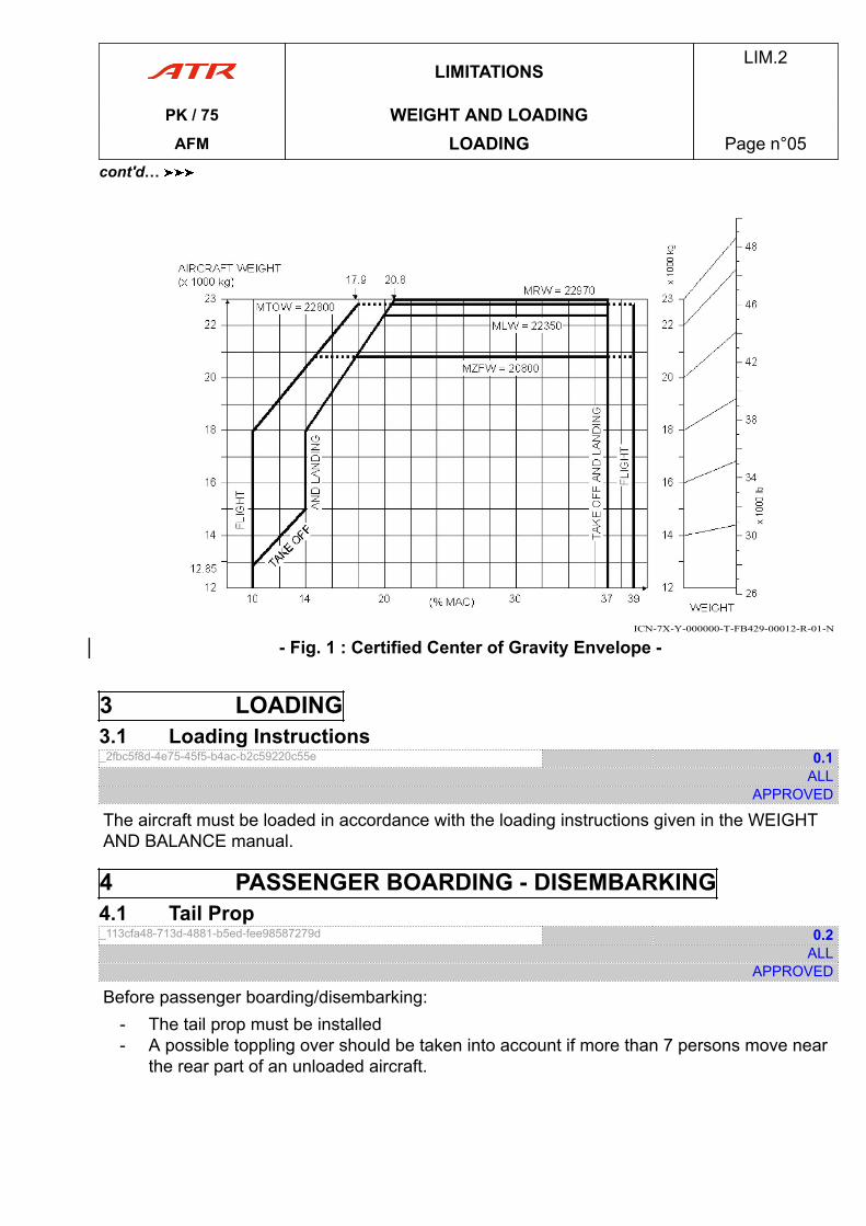
ICN-7X-Y-000000-T-FB429-00012-R-01-N
- Fig. 1 : Certified Center of Gravity Envelope -
3 LOADING3.1 Loading Instructions_2fbc5f8d-4e75-45f5-b4ac-b2c59220c55e 0.1
ALLAPPROVED
The aircraft must be loaded in accordance with the loading instructions given in the WEIGHTAND BALANCE manual.
4 PASSENGER BOARDING - DISEMBARKING4.1 Tail Prop_113cfa48-713d-4881-b5ed-fee98587279d 0.2
ALLAPPROVED
Before passenger boarding/disembarking:- The tail prop must be installed- A possible toppling over should be taken into account if more than 7 persons move near
the rear part of an unloaded aircraft.
LIMITATIONSLIM.2
PK / 75 WEIGHT AND LOADINGAFM LOADING Page n°05
cont'd…
1 DEFINITIONS1.1 Operating Speeds_a3463c00-c4db-4f73-a10f-76655c0f3580 0.1
ALLAPPROVED
V1 V1 is the maximum speed at which the flight crewcan decide to reject the takeoff and is ensured tostop the aircraft within the limits of runway.
VLOF Speed at which the lift overcomes the weight.
VR Speed at which rotation is initiated to reach V2 at35 ft height.
V2 Takeoff, safety speed reached at 35 ft height withone engine failed and providing second segmentclimb gradient not less than the minimum (2.4 %).
Vmin OPS Minimal flight speed based on flying conditionsand aircraft configuration.
VmLB Minimum maneuver speed, in Low Bank (15 °MAX), depending on flaps configuration (VmLB0,VmLB15….) and phase of flight.
VmHB Minimum maneuver speed, in High Bank (27 °MAX), depending on flaps configuration (VmHB0,VmHB15…) and phase of flight.
VFTO Final Takeoff speed used during Final Segmentwith one engine inoperative and providing climbgradient not less than the minimum (1.2 %).
VREF Final approach reference speed for thedetermination of the certified landing distance.
VAPP Final Approach speed is the operational speedused during landing taking into accountcorrections (Wind/Gust/Failure).
VGA Go-Around Speed
VFGA Final Go-Around Speed. Best climb gradientspeed after the go-around acceleration altitude.The higher value between Final Takeoff (VFTO)and Drift-down speed.
LIMITATIONSLIM.3
PK / 75 SPEEDSAFM DEFINITIONS Page n°06
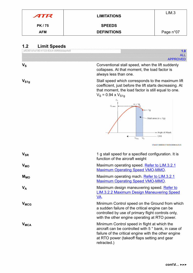
1.2 Limit Speeds_ef0361cf-e190-4133-83c4-06f66ddaa4e8 1.0
ALLAPPROVED
VS Conventional stall speed, when the lift suddenlycollapses. At that moment, the load factor isalways less than one.
VS1g Stall speed which corresponds to the maximum liftcoefficient, just before the lift starts decreasing. Atthat moment, the load factor is still equal to one.VS = 0.94 x VS1g
VSR 1 g stall speed for a specified configuration. It isfunction of the aircraft weight
VMO Maximum operating speed. Refer to LIM.3.2.1Maximum Operating Speed VMO-MMO.
MMO Maximum operating mach. Refer to LIM.3.2.1Maximum Operating Speed VMO-MMO.
VA Maximum design maneuvering speed. Refer toLIM.3.2.2 Maximum Design Maneuvering SpeedVA.
VMCG Minimum Control speed on the Ground from whicha sudden failure of the critical engine can becontrolled by use of primary flight controls only,with the other engine operating at RTO power.
VMCA Minimum Control speed in flight at which theaircraft can be controlled with 5 ° bank, in case offailure of the critical engine with the other engineat RTO power (takeoff flaps setting and gearretracted.)
LIMITATIONSLIM.3
PK / 75 SPEEDSAFM DEFINITIONS Page n°07
cont'd…
VMCL Minimum flight speed at which aircraft can becontrolled with 5 ° bank in case of failure of thecritical engine, the other being set at GA power(landing flaps setting, gear extended) and whichprovides rolling capability specified by regulations.Refer to LANDING VMCL.
VFE Maximum speed for each Flaps Extended. Referto LIM.3.2.3 Maximum Flaps Extended OperatingSpeeds VFE.
VLE Maximum speed with Landing gear ExtendedRefer to LIM.3.2.4 Maximum Landing GearExtended and Operating Speeds VLE-VLO.
VLO Maximum speed to Operate Landing gears(Lowering, Retracting). Refer to LIM.3.2.4Maximum Landing Gear Extended and OperatingSpeeds VLE-VLO.
2 AIRSPEEDS2.1 Maximum Operating Speed VMO-MMO_89d33190-1b50-4bfc-b68a-8b47eac9c488 0.1
ALLAPPROVED
The flight crew shall not intentionally exceed this limit, in any flight phase.VMO................................................................................................................250 kt CASMMO............................................................ ............................................................ 0.55
2.2 Maximum Design Maneuvering Speed VA_a482d996-e8d5-42ae-92d4-70b67bc19b97 1.1
ALLAPPROVED
Full application of roll and yaw controls should be confined to speeds below VA. Maneuversinvolving angles of attack near the stall should be confined to speeds below VA.
VA ........................................................ ........................................................ 175 kt CAS
CAUTIONRapid and large alternating controls inputs, especially in combination with large changes inpitch, roll or yaw (e.g. large sideslip angles) may result in structural damage at any speed,including below maneuvering speed VA.
CAUTIONWhen elevators are uncoupled, dual opposite inputs from left and right control columns arestrictly forbidden as it may result in structural damage at any speed, including belowmaneuvering speed VA.
LIMITATIONSLIM.3
PK / 75 SPEEDSAFM AIRSPEEDS Page n°08
cont'd…
2.3 Maximum Flaps Extended Operating Speeds VFE_af9d8caa-7d06-43e2-a8d4-a5dad991eb71 0.1
ALLAPPROVED
FLAPS 15................................................... ................................................... 185 kt CASFLAPS 30................................................... ................................................... 150 kt CAS
2.4 Maximum Landing Gear Extended and Operating Speeds VLE-VLO_46778557-2874-4321-bcd5-58cf2e48c437 0.1
ALLAPPROVED
VLE ................................................................................................................185 kt CASVLO during extension........................................................................................170 kt CASVLO during retraction............................................ ............................................ 160 kt CAS
LIMITATIONSLIM.3
PK / 75 SPEEDSAFM AIRSPEEDS Page n°09
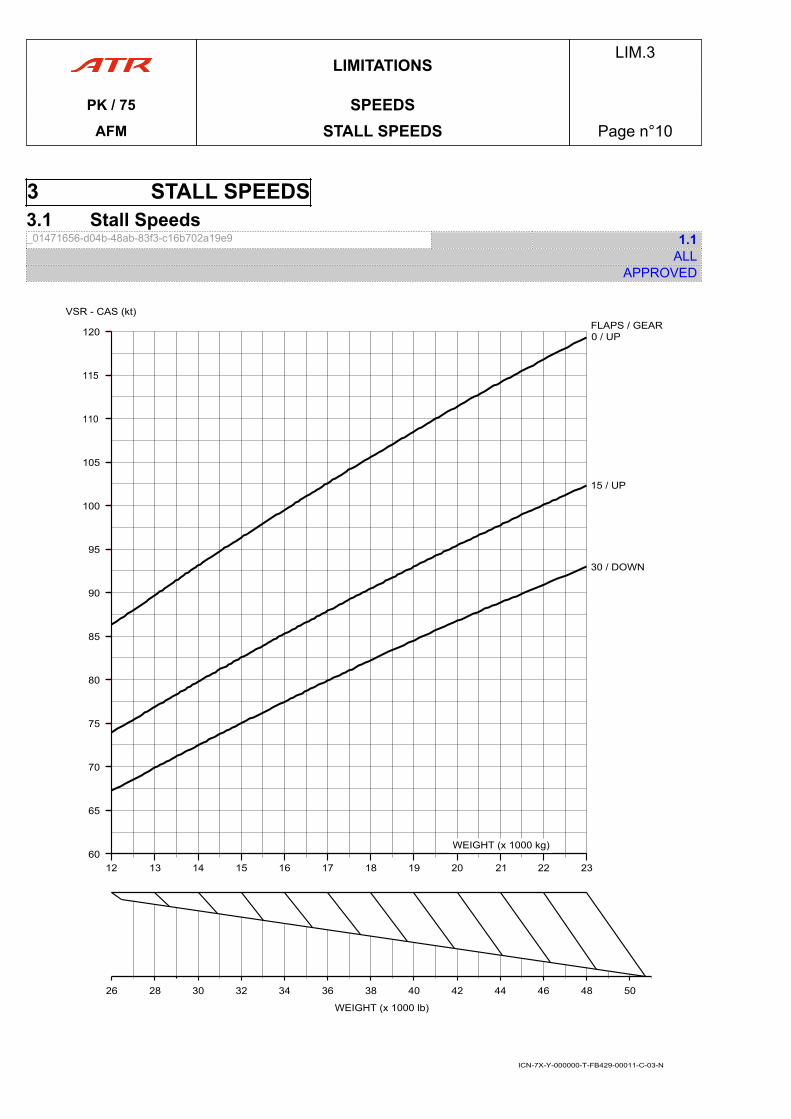
3 STALL SPEEDS3.1 Stall Speeds_01471656-d04b-48ab-83f3-c16b702a19e9 1.1
ALLAPPROVED
40 44 48
WEIGHT (x 1000 lb)
VSR - CAS (kt)
26 30 3428 32 36 38 42 46 50
15 / UP
30 / DOWN
0 / UPFLAPS / GEAR
60WEIGHT (x 1000 kg)
19 21 2312 14 1613 15 17 18 20 22
65
70
75
80
85
90
95
100
105
110
115
120
ICN-7X-Y-000000-T-FB429-00011-C-03-N
LIMITATIONSLIM.3
PK / 75 SPEEDSAFM STALL SPEEDS Page n°10
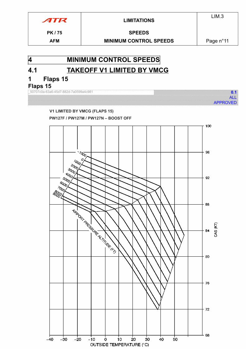
4 MINIMUM CONTROL SPEEDS4.1 TAKEOFF V1 LIMITED BY VMCG1 Flaps 15Flaps 15_50707c0a-63a6-45d7-882d-7a0599a4c981 0.1
ALLAPPROVED
ICN-7X-Y-000000-T-FB429-00019-C-02-N
LIMITATIONSLIM.3
PK / 75 SPEEDSAFM MINIMUM CONTROL SPEEDS Page n°11
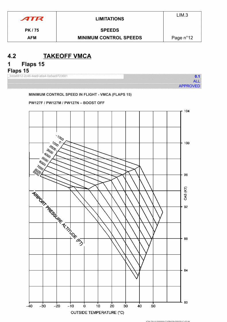
4.2 TAKEOFF VMCA1 Flaps 15Flaps 15_3dda6612-2c46-4ee9-a6a4-0a5ae9723681 0.1
ALLAPPROVED
ICN-7X-Y-000000-T-FB429-00020-C-02-N
LIMITATIONSLIM.3
PK / 75 SPEEDSAFM MINIMUM CONTROL SPEEDS Page n°12
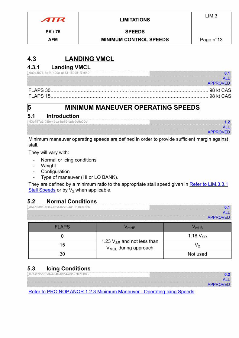
4.3 LANDING VMCL4.3.1 Landing VMCL_0a9b3e76-5e14-409e-ac33-159981f7c640 0.1
ALLAPPROVED
FLAPS 30.................................................... .................................................... 98 kt CASFLAPS 15.................................................... .................................................... 98 kt CAS
5 MINIMUM MANEUVER OPERATING SPEEDS5.1 Introduction_53b197a2-08fe-43da-be76-fade6e9e00c1 1.2
ALLAPPROVED
Minimum maneuver operating speeds are defined in order to provide sufficient margin againststall.They will vary with:
- Normal or icing conditions- Weight- Configuration- Type of maneuver (HI or LO BANK).
They are defined by a minimum ratio to the appropriate stall speed given in Refer to LIM.3.3.1Stall Speeds or by V2 when applicable.
5.2 Normal Conditions_a64d53d1-1683-4f8a-b276-4a1051b97326 0.1
ALLAPPROVED
FLAPS VmHB VmLB
01.23 VSR and not less than
VMCL during approach
1.18 VSR
15 V2
30 Not used
5.3 Icing Conditions_b7e4f722-53d6-4940-bdc4-edb27fcd6885 0.2
ALLAPPROVED
Refer to PRO.NOP.ANOR.1.2.3 Minimum Maneuver - Operating Icing Speeds
LIMITATIONSLIM.3
PK / 75 SPEEDSAFM MINIMUM CONTROL SPEEDS Page n°13
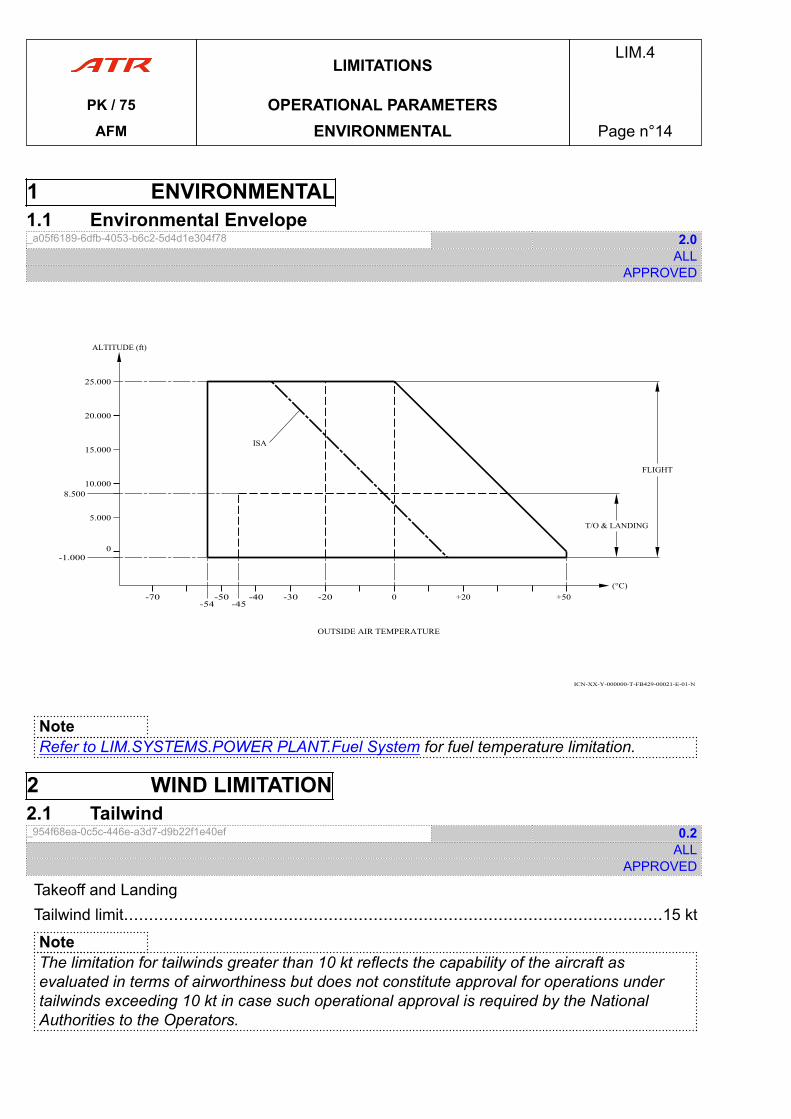
1 ENVIRONMENTAL1.1 Environmental Envelope_a05f6189-6dfb-4053-b6c2-5d4d1e304f78 2.0
ALLAPPROVED
ICN-XX-Y-000000-T-FB429-00021-E-01-N
-70 -50 -40-54
-20 0 +20 +50
10.000
20.000
25.000
0
-45
(°C)
ALTITUDE (ft)
ISA
FLIGHT
OUTSIDE AIR TEMPERATURE
-30
-1.000
8.500
T/O & LANDING5.000
15.000
NoteRefer to LIM.SYSTEMS.POWER PLANT.Fuel System for fuel temperature limitation.
2 WIND LIMITATION2.1 Tailwind_954f68ea-0c5c-446e-a3d7-d9b22f1e40ef 0.2
ALLAPPROVED
Takeoff and LandingTailwind limit............................................................................................................15 kt
NoteThe limitation for tailwinds greater than 10 kt reflects the capability of the aircraft asevaluated in terms of airworthiness but does not constitute approval for operations undertailwinds exceeding 10 kt in case such operational approval is required by the NationalAuthorities to the Operators.
LIMITATIONSLIM.4
PK / 75 OPERATIONAL PARAMETERSAFM ENVIRONMENTAL Page n°14
2.2 Crosswind_a3a0d0c7-3579-4b2b-84b2-1d156cb6a349 4.3
ALLAPPROVED
The maximum demonstrated crosswind is:Takeoff......................................................... ......................................................... 35 ktLanding FLAPS 30.................................................................................................. 35 kt
Braking Action T.O LDGMaximum Crosswind
(T.O and LDG)
GOOD 1 1 35 kt
GOOD/MEDIUM 2 2 28 kt
MEDIUM 3/6 6 22 kt
MEDIUM/POOR 4 5 16 kt
POOR 7 7 10 kt
Runway Status
1 Dry runway
2 Wet up to 3 mm depth
3 Slush or water from 3 to 6 mma depth
4 Slush or water from 6a to 12.7 mm depth
5 Slush or water from 3 to 12.7 mm depth
6 Compact snow
7 Icea Apply worst condition.
For crosswind operations, Refer to FCOM OPERATIONS IN WIND CONDITIONS
3 RUNWAY3.1 Runway Slope_12c30841-cefa-466f-b78b-45bbe6fd7787 1.3
ALLAPPROVED
Maximum mean runway slope......................................... ......................................... ±2 %For operations on runways slope beyond 2 %, Refer to RUNWAYS SLOPE BEYOND 2 %.
LIMITATIONSLIM.4
PK / 75 OPERATIONAL PARAMETERSAFM WIND LIMITATION Page n°15
4 ICING CONDITIONS4.1 Ground Icing Conditions_70b81fac-b235-4cc1-b62f-12ba722dc327 3.1
ALLAPPROVED
● Ground Icing conditions exist when:- OAT on the ground is at or below 5 °C and,- Surface snow, standing water or slush is present on the ramps, taxiways and runways.
● Operation in ground icing conditions:- For associated procedures Refer to ATMOSPHERIC ICING CONDITIONS.- For advisory information on contaminated runways penalties Refer to CONTAMINATED
RUNWAY (ADVISORY MATERIAL) and Refer to FCOM.PERFORMANCES.
4.2 Atmospheric Icing Conditions_09e3cbc1-f76c-4904-9f05-780a4032208b 7.1
ALLAPPROVED
● Atmospheric icing conditions exist when:- OAT on the ground and for takeoff is at or below 5 °C- TAT in flight is at or below 7 °C- Visible moisture in any form is present (such as clouds, fog, mist, rain, snow, sleet, or
ice crystals).● Operation in atmospheric icing conditions:Takeoff is prohibited when frost, snow or ice is adhering to the wing, tail, controlsurfaces, engine air inlets or propellers.For more information about aircraft surfaces contamination, Refer to FCOM - Preflight Check.NP setting below 82 % is prohibited.
- For associated procedures Refer to IN FLIGHT ICING CONDITIONS- For performance data Refer to PER.Takeoff.
Some systems must be operative in icing conditions Refer to LIM.5.30.1 Ice and RainProtection.
LIMITATIONSLIM.4
PK / 75 OPERATIONAL PARAMETERSAFM ICING CONDITIONS Page n°16
4.3 Severe Icing Conditions_d9df816a-de30-4524-8883-420eea0d990d 1.3
ALLAPPROVED
WARNINGSEVERE ICING MAY RESULT FROM ENVIRONMENTAL CONDITIONS OUTSIDE OFTHOSE FOR WHICH THE AIRCRAFT IS CERTIFICATED.FLIGHT IN FREEZING RAIN, FREEZING DRIZZLE, OR MIXED ICING CONDITIONS(SUPER COOLED LIQUID WATER AND ICE CRYSTALS) MAY RESULT IN ICE BUILD UPON PROTECTED SURFACES EXCEEDING THE CAPABILITY OF THE ICE PROTECTIONSYSTEM, OR MAY RESULT IN ICE FORMING AFT OF THE PROTECTED SURFACES.THIS ICE MAY NOT BE SHED USING THE ICE PROTECTION SYSTEMS, AND MAYSERIOUSLY DEGRADE THE PERFORMANCE AND CONTROLLABILITY OF THEAIRCRAFT.
● The following weather conditions may be conducive to severe in-flight icing:- Visible rain at temperatures close to 0 °C ambient air temperature (SAT)- Droplets that splash or splatter on impact at temperatures close to 0 °C ambient air
temperature (SAT)● During flight, severe icing conditions that exceed those for which the aircraft iscertificated are determined by the following:
- Ice covering all or a substantial part of the unheated section of either side window,and/or
- Unable to reach or maintain target speed,and/or
- The following secondary indications:o Water splashing and streaming on the windshieldo Unusually extensive ice accumulated on the airframe in areas not normally
observed to collect iceo Accumulation of ice on the lower surface of the wing, aft of the protected areao Accumulation of ice on the propeller spinner farther aft than normally observed.
● Operations in severe icing conditionsIf one of these fact is observed, immediately request priority handling from Air Traffic Controlto facilitate a route or an altitude change to exit the icing conditions. Apply procedurespecified in the Emergency Procedures chapter, Refer to EMERGENCY PROCEDURES.The autopilot may mask tactile cues that indicate adverse changes in handling characteristics.So, the use of the autopilot is prohibited when:
- Severe icing defined above exists, or- Unusual lateral trim requirements are encountered while the aircraft is in icing
conditions, or- Autopilot trim warnings are encountered while the aircraft is in icing conditions.
LIMITATIONSLIM.4
PK / 75 OPERATIONAL PARAMETERSAFM ICING CONDITIONS Page n°17
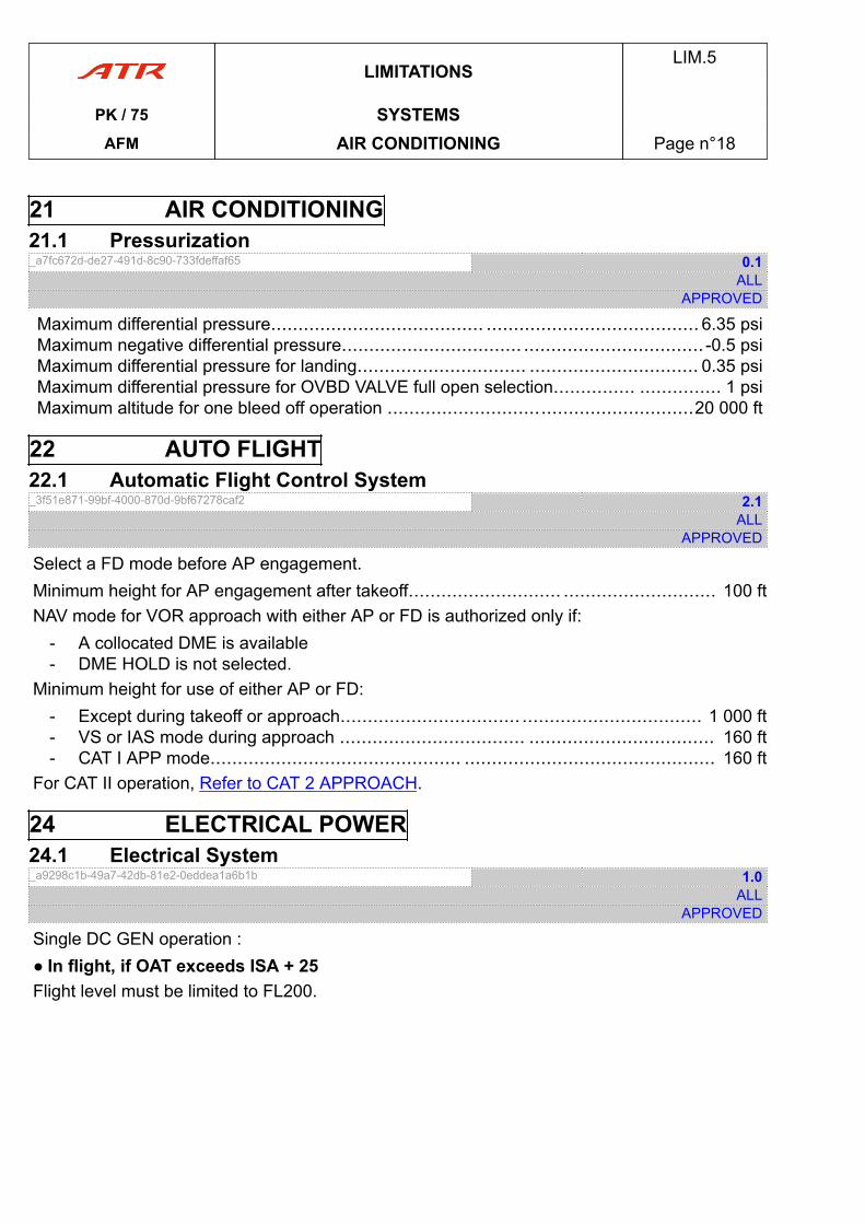
21 AIR CONDITIONING21.1 Pressurization_a7fc672d-de27-491d-8c90-733fdeffaf65 0.1
ALLAPPROVED
Maximum differential pressure....................................... ....................................... 6.35 psiMaximum negative differential pressure................................. ................................. -0.5 psiMaximum differential pressure for landing............................... ............................... 0.35 psiMaximum differential pressure for OVBD VALVE full open selection............... ............... 1 psiMaximum altitude for one bleed off operation ........................................................20 000 ft
22 AUTO FLIGHT22.1 Automatic Flight Control System_3f51e871-99bf-4000-870d-9bf67278caf2 2.1
ALLAPPROVED
Select a FD mode before AP engagement.Minimum height for AP engagement after takeoff............................ ............................ 100 ftNAV mode for VOR approach with either AP or FD is authorized only if:
- A collocated DME is available- DME HOLD is not selected.
Minimum height for use of either AP or FD:- Except during takeoff or approach................................. ................................. 1 000 ft- VS or IAS mode during approach .................................. .................................. 160 ft- CAT I APP mode.............................................. .............................................. 160 ft
For CAT II operation, Refer to CAT 2 APPROACH.
24 ELECTRICAL POWER24.1 Electrical System_a9298c1b-49a7-42db-81e2-0eddea1a6b1b 1.0
ALLAPPROVED
Single DC GEN operation :● In flight, if OAT exceeds ISA + 25Flight level must be limited to FL200.
LIMITATIONSLIM.5
PK / 75 SYSTEMSAFM AIR CONDITIONING Page n°18
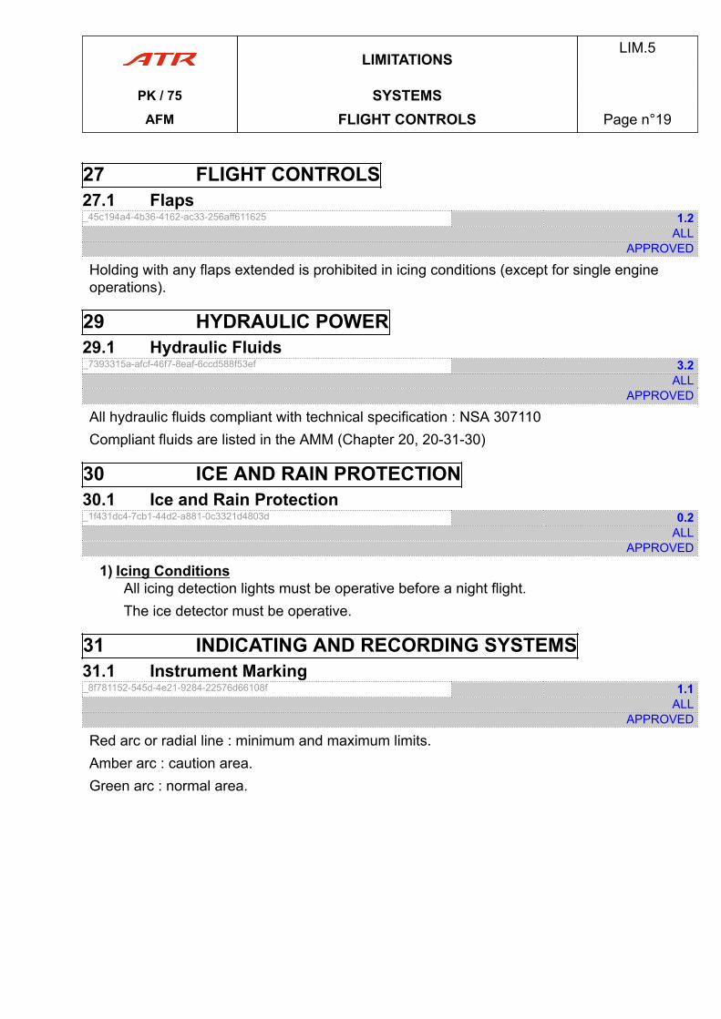
27 FLIGHT CONTROLS27.1 Flaps_45c194a4-4b36-4162-ac33-256aff611625 1.2
ALLAPPROVED
Holding with any flaps extended is prohibited in icing conditions (except for single engineoperations).
29 HYDRAULIC POWER29.1 Hydraulic Fluids_7393315a-afcf-46f7-8eaf-6ccd588f53ef 3.2
ALLAPPROVED
All hydraulic fluids compliant with technical specification : NSA 307110Compliant fluids are listed in the AMM (Chapter 20, 20-31-30)
30 ICE AND RAIN PROTECTION30.1 Ice and Rain Protection_1f431dc4-7cb1-44d2-a881-0c3321d4803d 0.2
ALLAPPROVED
1) Icing ConditionsAll icing detection lights must be operative before a night flight.The ice detector must be operative.
31 INDICATING AND RECORDING SYSTEMS31.1 Instrument Marking_8f781152-545d-4e21-9284-22576d66108f 1.1
ALLAPPROVED
Red arc or radial line : minimum and maximum limits.Amber arc : caution area.Green arc : normal area.
LIMITATIONSLIM.5
PK / 75 SYSTEMSAFM FLIGHT CONTROLS Page n°19
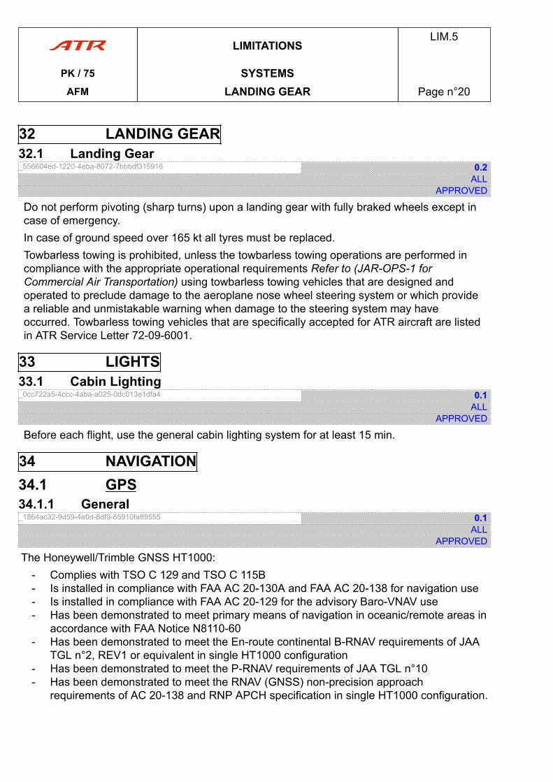
32 LANDING GEAR32.1 Landing Gear_556604ed-1220-4eba-8072-7bbbdf315916 0.2
ALLAPPROVED
Do not perform pivoting (sharp turns) upon a landing gear with fully braked wheels except incase of emergency.In case of ground speed over 165 kt all tyres must be replaced.Towbarless towing is prohibited, unless the towbarless towing operations are performed incompliance with the appropriate operational requirements Refer to (JAR-OPS-1 forCommercial Air Transportation) using towbarless towing vehicles that are designed andoperated to preclude damage to the aeroplane nose wheel steering system or which providea reliable and unmistakable warning when damage to the steering system may haveoccurred. Towbarless towing vehicles that are specifically accepted for ATR aircraft are listedin ATR Service Letter 72-09-6001.
33 LIGHTS33.1 Cabin Lighting_0cc722a5-4ccc-4aba-a025-0dc013e1dfa4 0.1
ALLAPPROVED
Before each flight, use the general cabin lighting system for at least 15 min.
34 NAVIGATION34.1 GPS34.1.1 General_1864ac32-9d59-4e0d-8df9-85910fa89555 0.1
ALLAPPROVED
The Honeywell/Trimble GNSS HT1000:- Complies with TSO C 129 and TSO C 115B- Is installed in compliance with FAA AC 20-130A and FAA AC 20-138 for navigation use- Is installed in compliance with FAA AC 20-129 for the advisory Baro-VNAV use- Has been demonstrated to meet primary means of navigation in oceanic/remote areas in
accordance with FAA Notice N8110-60- Has been demonstrated to meet the En-route continental B-RNAV requirements of JAA
TGL n°2, REV1 or equivalent in single HT1000 configuration- Has been demonstrated to meet the P-RNAV requirements of JAA TGL n°10- Has been demonstrated to meet the RNAV (GNSS) non-precision approach
requirements of AC 20-138 and RNP APCH specification in single HT1000 configuration.
LIMITATIONSLIM.5
PK / 75 SYSTEMSAFM LANDING GEAR Page n°20
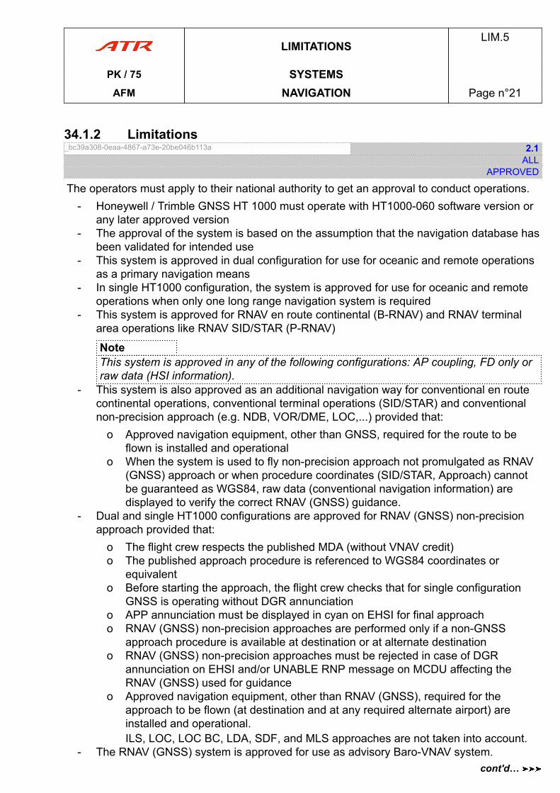
34.1.2 Limitations_bc39a308-0eaa-4867-a73e-20be046b113a 2.1
ALLAPPROVED
The operators must apply to their national authority to get an approval to conduct operations.- Honeywell / Trimble GNSS HT 1000 must operate with HT1000-060 software version or
any later approved version- The approval of the system is based on the assumption that the navigation database has
been validated for intended use- This system is approved in dual configuration for use for oceanic and remote operations
as a primary navigation means- In single HT1000 configuration, the system is approved for use for oceanic and remote
operations when only one long range navigation system is required- This system is approved for RNAV en route continental (B-RNAV) and RNAV terminal
area operations like RNAV SID/STAR (P-RNAV)
NoteThis system is approved in any of the following configurations: AP coupling, FD only orraw data (HSI information).
- This system is also approved as an additional navigation way for conventional en routecontinental operations, conventional terminal operations (SID/STAR) and conventionalnon-precision approach (e.g. NDB, VOR/DME, LOC,...) provided that:
o Approved navigation equipment, other than GNSS, required for the route to beflown is installed and operational
o When the system is used to fly non-precision approach not promulgated as RNAV(GNSS) approach or when procedure coordinates (SID/STAR, Approach) cannotbe guaranteed as WGS84, raw data (conventional navigation information) aredisplayed to verify the correct RNAV (GNSS) guidance.
- Dual and single HT1000 configurations are approved for RNAV (GNSS) non-precisionapproach provided that:
o The flight crew respects the published MDA (without VNAV credit)o The published approach procedure is referenced to WGS84 coordinates or
equivalento Before starting the approach, the flight crew checks that for single configuration
GNSS is operating without DGR annunciationo APP annunciation must be displayed in cyan on EHSI for final approacho RNAV (GNSS) non-precision approaches are performed only if a non-GNSS
approach procedure is available at destination or at alternate destinationo RNAV (GNSS) non-precision approaches must be rejected in case of DGR
annunciation on EHSI and/or UNABLE RNP message on MCDU affecting theRNAV (GNSS) used for guidance
o Approved navigation equipment, other than RNAV (GNSS), required for theapproach to be flown (at destination and at any required alternate airport) areinstalled and operational.ILS, LOC, LOC BC, LDA, SDF, and MLS approaches are not taken into account.
- The RNAV (GNSS) system is approved for use as advisory Baro-VNAV system.
LIMITATIONSLIM.5
PK / 75 SYSTEMSAFM NAVIGATION Page n°21
cont'd…
VDEV function must be continuously cross-checked by appropriate functional groundbased navigation aids (VOR, VOR/DME, VORTAC, NDB, NDB/DME, ILS, LOC, LOC/DME)
- If GNSS must be used in oceanic/remote area, B-RNAV (if DME are not available), P-RNAV or for approach phases, the availability of the GPS integrity (RAIM or FDEfunctions) must be checked by the operator using prediction tool available in the GNSSduring the preflight planning phase or any other approved tool.
34.3 TAWS34.3.1 LimitationsTAWS_a7b84c74-9a7a-4817-8a65-b86b79a8eb49 1.1
ALLAPPROVED
1) Navigation is not to be predicted on the use of the terrain display.
NoteThe Terrain display is designed to serve as a situational awareness tool only. It doesnot have the integrity, accuracy or fidelity on which to solely base decisions for terrainor obstacle avoidance.
2) To avoid giving nuisance alerts, the predictive TAWS functions must be inhibited whenlanding at an airport that is not included in the airport database.
3) The current local QNH must be entered in the flight crew altimeter for correct terrainalerting
4) QFE operation is prohibited with TAWS.5) If ILS 2 glideslope signal is inoperative,TAWS mode 5 alert is inhibited.
34.4 ATC - XPDR34.4.1 SSR Mode S Enhanced Surveillance_b02a05f9-c6fd-40fe-9c3d-df233e204284 2.0
ALLAPPROVED
The installed Mode S system satisfies the data requirements of ICAO Doc 7030/4, RegionalSupplementary Procedures for SSR Mode S Enhanced Surveillance in designated Europeanairspace. The capability to transmit data parameters is shown in column 2:
LIMITATIONSLIM.5
PK / 75 SYSTEMSAFM NAVIGATION Page n°22
cont'd…
cont'd…
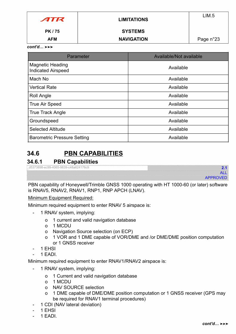
Parameter Available/Not available
Magnetic HeadingIndicated Airspeed Available
Mach No Available
Vertical Rate Available
Roll Angle Available
True Air Speed Available
True Track Angle Available
Groundspeed Available
Selected Altitude Available
Barometric Pressure Setting Available
34.6 PBN CAPABILITIES34.6.1 PBN Capabilities_d5373898-ec99-4065-9839-c48a624176c9 2.1
ALLAPPROVED
PBN capability of Honeywell/Trimble GNSS 1000 operating with HT 1000-60 (or later) softwareis RNAV5, RNAV2, RNAV1, RNP1, RNP APCH (LNAV).Minimum Equipment Required:Minimum required equipment to enter RNAV 5 airspace is:
- 1 RNAV system, implying:o 1 current and valid navigation databaseo 1 MCDUo Navigation Source selection (on ECP)o 1 VOR and 1 DME capable of VOR/DME and /or DME/DME position computation
or 1 GNSS receiver- 1 EHSI- 1 EADI.
Minimum required equipment to enter RNAV1/RNAV2 airspace is:- 1 RNAV system, implying:
o 1 Current and valid navigation databaseo 1 MCDUo NAV SOURCE selectiono 1 DME capable of DME/DME position computation or 1 GNSS receiver (GPS may
be required for RNAV1 terminal procedures)- 1 CDI (NAV lateral deviation)- 1 EHSI- 1 EADI.
LIMITATIONSLIM.5
PK / 75 SYSTEMSAFM NAVIGATION Page n°23
cont'd…
cont'd…
Minimum required equipment to enter RNP1 airspace is:- 1 RNAV system, implying:
o 1 Current and valid navigation databaseo 1 MCDUo Navigation Source selection (on ECP)o 1 DME capable of DME/DME position computation AND 1 GNSS receiver
- 1 CDI (NAV lateral deviation)- 1 EHSI- 1 EADI.
Minimum required equipment to start an RNP APCH (LNAV) operations:- 1 RNAV system, implying:
o 1 Current and valid navigation databaseo 1 MCDUo Navigation Source selection (on ECP)o 1 GNSS receiver
- 1 CDI (NAV lateral deviation)- 1 EHSI- 1 EADI- 1 AHRS- 1 ADC.
34.6.2 PBN OPERATION_2dfeb892-b8e3-4614-9928-6ac99b33cc18 1.1
ALLAPPROVED
For all PBN operations listed here-in:- If the missed approach procedure is based on conventional means (NDB, VOR, DME),
all related navigation equipment must be installed and serviceable.- The associated ground based navaids must also be operational.
NoteFor all RNAV operations listed here bellow, the Fault Detection & Exclusion (FDE) or theReceiver autonomous integrity monitoring (RAIM) must be functional.For all RNP operations described here bellow, the FDE (or RAIM) and the on-boardperformance monitoring and alerting capabilities must be functional.
LIMITATIONSLIM.5
PK / 75 SYSTEMSAFM NAVIGATION Page n°24
cont'd…
34.7 TCAS34.7.1 Limitations_baf7140b-c97a-4f8a-8914-3901a73b77c3 REV 6.1
ALLAPPROVED
The limitations in Section LIM are applicable with the addition of the following:1) TCAS operation is approved for use in VFR meteorological conditions (VMC) and IFR
meteorological conditions (IMC).2) The flight crew must not initiate escape maneuvers using information from the traffic
display only or from a traffic advisory (TCAS) only.These displays and advisory are designed only for assistance in visually locating thetraffic and do not have the resolution necessary for use in evasive maneuvering.
3) When an RA occurs, the pilot flying shall respond immediately to RA displays and auralalerts, maneuvering as indicated, unless doing so would jeopardize the safe operation ofthe aircraft.
CAUTIONOnce a non crossing RA has been issued the vertical speed should be accuratelyadjusted to comply with the RA, in order to avoid negating the effectiveness of acoordinated maneuver by the intruder.
4) Escape maneuvering should be made with the autopilot disengaged, and limited to theminimum required to comply with the RA. The flight crew must immediately return to theprevious ATC clearance when the TCAS “CLEAR OF CONFLICT“ voice message isannounced.
5) Before performing RA’s climb or increase climb, the flight crew should select theappropriate engine power setting on the power MGT selector and, if necessary, manuallyadjust CL 1+2.
6) When a climb or increase climb RA occurs with the aircraft in the landing configuration orin the go-around phase, a normal procedure of go-around should be followed includingthe appropriate power increase and configuration changes.
7) Because of the limited number of inputs to TCAS for determination of aircraftperformance inhibits, there are instances where inhibiting RA’s would be appropriate,however it is not possible to do so. In these cases, TCAS may command maneuverswhich may significantly reduce stall margins or result in stall warning. Conditions wherethis may occur include operations with a bank angle (wings level is assumed), weight,altitude, and temperature combinations outside those noted below, leaving aircraft inlanding configuration during climb RA on approach, engine out operation, and abnormalconfigurations such as landing gear not retracted or stick pusher/shaker failure.The table (Refer to LIM.5.34.7.2 Climb Resolution Advisory Flight Envelope) outlines theparameters used in the development of the performance inhibits. This table does notconsider worst turboprop flight conditions particularly operation using minimum operationairspeeds as are sometimes required (e.g. obstacle clearance or ATC constraints). In allcases, stall warning must be given in priority over climb RA commands.
LIMITATIONSLIM.5
PK / 75 SYSTEMSAFM NAVIGATION Page n°25
cont'd…
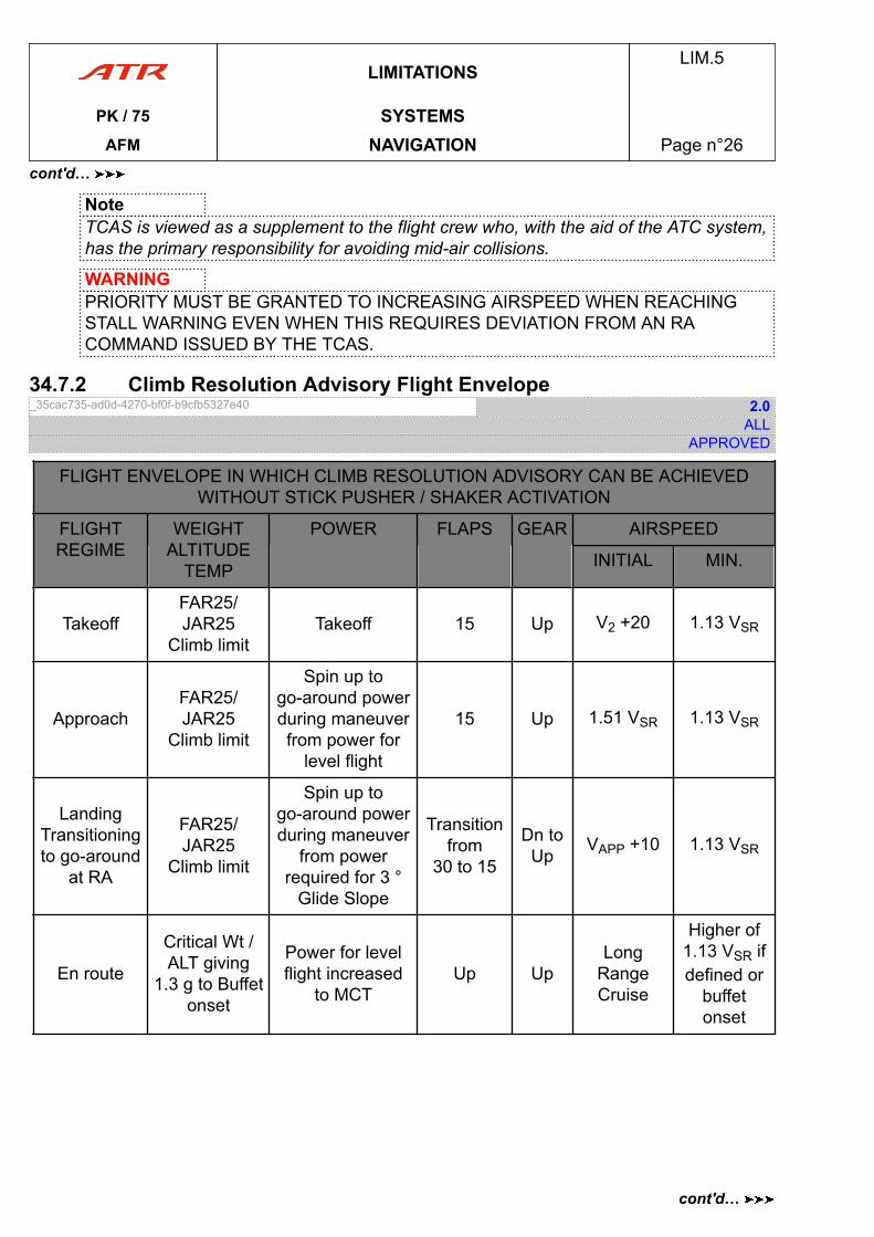
NoteTCAS is viewed as a supplement to the flight crew who, with the aid of the ATC system,has the primary responsibility for avoiding mid-air collisions.
WARNINGPRIORITY MUST BE GRANTED TO INCREASING AIRSPEED WHEN REACHINGSTALL WARNING EVEN WHEN THIS REQUIRES DEVIATION FROM AN RACOMMAND ISSUED BY THE TCAS.
34.7.2 Climb Resolution Advisory Flight Envelope_35cac735-ad0d-4270-bf0f-b9cfb5327e40 2.0
ALLAPPROVED
FLIGHT ENVELOPE IN WHICH CLIMB RESOLUTION ADVISORY CAN BE ACHIEVEDWITHOUT STICK PUSHER / SHAKER ACTIVATION
FLIGHTREGIME
WEIGHTALTITUDE
TEMP
POWER FLAPS GEAR AIRSPEED
INITIAL MIN.
TakeoffFAR25/JAR25
Climb limitTakeoff 15 Up V2 +20 1.13 VSR
ApproachFAR25/JAR25
Climb limit
Spin up togo-around powerduring maneuverfrom power for
level flight
15 Up 1.51 VSR 1.13 VSR
LandingTransitioningto go-around
at RA
FAR25/JAR25
Climb limit
Spin up togo-around powerduring maneuver
from powerrequired for 3 °
Glide Slope
Transitionfrom
30 to 15
Dn toUp
VAPP +10 1.13 VSR
En route
Critical Wt /ALT giving
1.3 g to Buffetonset
Power for levelflight increased
to MCTUp Up
LongRangeCruise
Higher of1.13 VSR ifdefined or
buffetonset
LIMITATIONSLIM.5
PK / 75 SYSTEMSAFM NAVIGATION Page n°26
cont'd…
cont'd…
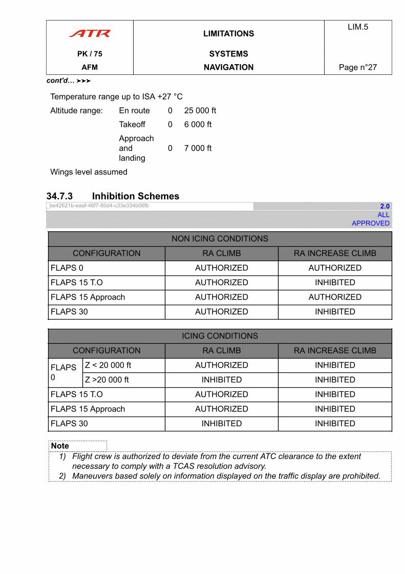
Temperature range up to ISA +27 °C
Altitude range: En route 0 25 000 ft
Takeoff 0 6 000 ft
Approachandlanding
0 7 000 ft
Wings level assumed
34.7.3 Inhibition Schemes_be42621b-eaaf-46f7-80d4-c33e334b06fb 2.0
ALLAPPROVED
NON ICING CONDITIONS
CONFIGURATION RA CLIMB RA INCREASE CLIMB
FLAPS 0 AUTHORIZED AUTHORIZED
FLAPS 15 T.O AUTHORIZED INHIBITED
FLAPS 15 Approach AUTHORIZED AUTHORIZED
FLAPS 30 AUTHORIZED INHIBITED
ICING CONDITIONS
CONFIGURATION RA CLIMB RA INCREASE CLIMB
FLAPS0
Z < 20 000 ft AUTHORIZED INHIBITED
Z >20 000 ft INHIBITED INHIBITED
FLAPS 15 T.O AUTHORIZED INHIBITED
FLAPS 15 Approach AUTHORIZED INHIBITED
FLAPS 30 INHIBITED INHIBITED
Note1) Flight crew is authorized to deviate from the current ATC clearance to the extent
necessary to comply with a TCAS resolution advisory.2) Maneuvers based solely on information displayed on the traffic display are prohibited.
LIMITATIONSLIM.5
PK / 75 SYSTEMSAFM NAVIGATION Page n°27
cont'd…
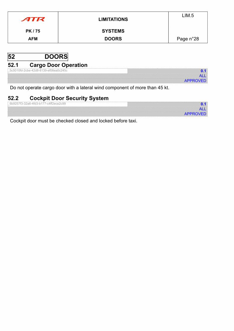
52 DOORS52.1 Cargo Door Operation_5c5010fd-2cbe-42d8-8139-ef06ea0c245c 0.1
ALLAPPROVED
Do not operate cargo door with a lateral wind component of more than 45 kt.
52.2 Cockpit Door Security System_6b9257f3-32a6-4fd3-b177-c4ff2ece2c99 0.1
ALLAPPROVED
Cockpit door must be checked closed and locked before taxi.
LIMITATIONSLIM.5
PK / 75 SYSTEMSAFM DOORS Page n°28
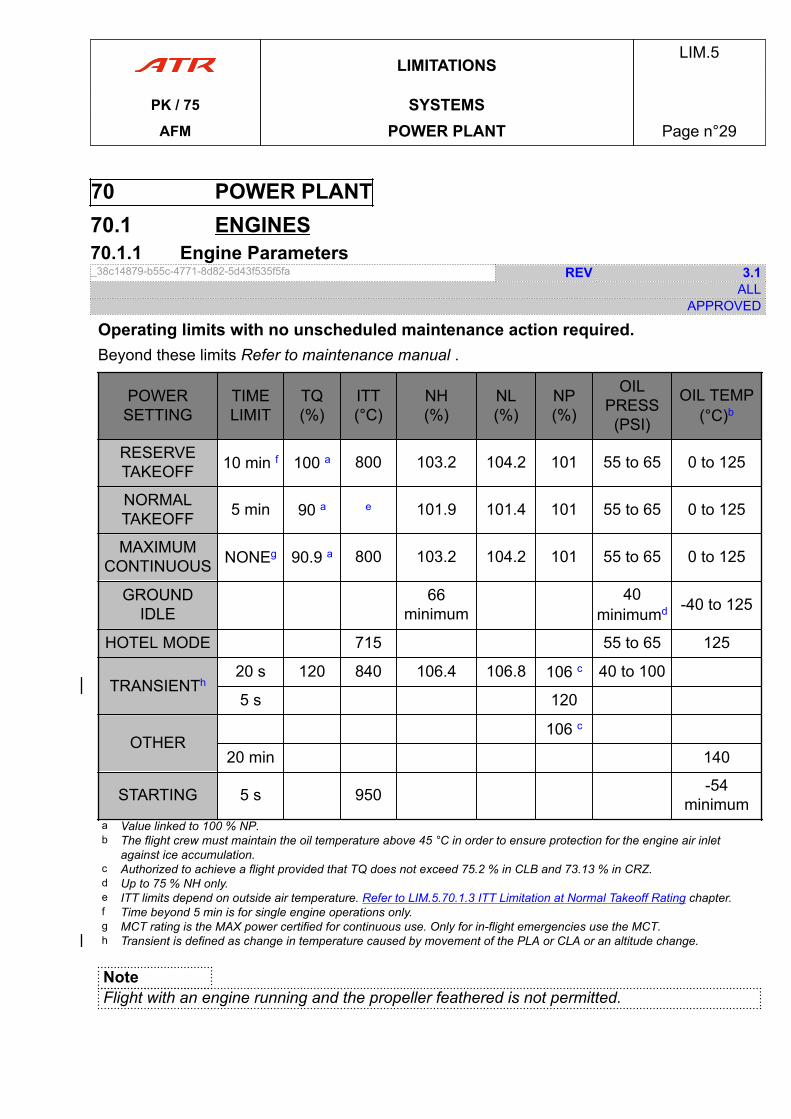
70 POWER PLANT70.1 ENGINES70.1.1 Engine Parameters_38c14879-b55c-4771-8d82-5d43f535f5fa REV 3.1
ALLAPPROVED
Operating limits with no unscheduled maintenance action required.Beyond these limits Refer to maintenance manual .
POWERSETTING
TIMELIMIT
TQ(%)
ITT(°C)
NH(%)
NL(%)
NP(%)
OILPRESS
(PSI)
OIL TEMP(°C)b
RESERVETAKEOFF 10 min f 100 a 800 103.2 104.2 101 55 to 65 0 to 125
NORMALTAKEOFF 5 min 90 a e 101.9 101.4 101 55 to 65 0 to 125
MAXIMUMCONTINUOUS NONEg 90.9 a 800 103.2 104.2 101 55 to 65 0 to 125
GROUNDIDLE
66minimum
40minimumd -40 to 125
HOTEL MODE 715 55 to 65 125
TRANSIENTh20 s 120 840 106.4 106.8 106 c 40 to 100
5 s 120
OTHER106 c
20 min 140
STARTING 5 s 950 -54minimum
a Value linked to 100 % NP.b The flight crew must maintain the oil temperature above 45 °C in order to ensure protection for the engine air inlet
against ice accumulation.c Authorized to achieve a flight provided that TQ does not exceed 75.2 % in CLB and 73.13 % in CRZ.d Up to 75 % NH only.e ITT limits depend on outside air temperature. Refer to LIM.5.70.1.3 ITT Limitation at Normal Takeoff Rating chapter.f Time beyond 5 min is for single engine operations only.g MCT rating is the MAX power certified for continuous use. Only for in-flight emergencies use the MCT.h Transient is defined as change in temperature caused by movement of the PLA or CLA or an altitude change.
NoteFlight with an engine running and the propeller feathered is not permitted.
LIMITATIONSLIM.5
PK / 75 SYSTEMSAFM POWER PLANT Page n°29

70.1.2 ITT Limitation at Normal Takeoff Rating_5e1a21d5-83a6-40e5-8655-9e656dc37a0d 0.1
ALLAPPROVED
ICN-4X-Y-000000-T-FB429-00025-F-01-N
4010
720
OAT (° C)
-10
ITT T6 (° C)
740
30-40 -30 -20 0 15
760
780
765
50
LIMITATIONSLIM.5
PK / 75 SYSTEMSAFM POWER PLANT Page n°30
70.2 OIL SYSTEM70.2.1 Oil System_1d528ba4-ca6a-4f90-95e0-7aeda8c07461 1.1
ALLAPPROVED
Refer to specification PWA 521 type II .
70.3 STARTER70.3.1 Starter_a67b7d33-cb4f-458c-abea-8de9db88f2d8 0.1
ALLAPPROVED
3 starts within 1 min 30 s maximum combined starter running time followed by 4 min OFF.
70.4 FUEL SYSTEM70.4.1 Fuel_23fd279d-e6f9-4dfb-beb6-9669a2b225c3 2.1
ALLAPPROVED
Acceptable fuels : Jet A, Jet A1, JP5 and RT, TS1.Use of JP4 and Jet B is prohibited.
NoteRefer to Consumable Material Data (CMD) to check permitted fuel additives.
70.4.2 Fuel Temperature_0243e85b-8bb4-4336-9028-4837871679b2 3.1
ALLAPPROVED
- For flight preparation, a minimum fuel temperature must be taken into account to ensureadequate relight:
o -34 °C JET A, JET A1 and RT, TS1.o -26 °C for fuel type JP5.
- Maximum temperature:o 57 °C for fuel types JET A, JET A1, JP 5 and RT, TS1.
70.4.3 Refueling_dec9d2ab-9c2a-4037-85b7-0846c0f408df 0.1
ALLAPPROVED
Maximum pressure....................................................................................3.5 bar (50 psi)
LIMITATIONSLIM.5
PK / 75 SYSTEMSAFM POWER PLANT Page n°31
70.4.4 Usable Fuel_5dceee0e-517b-499f-9e41-11b71f6faba3 0.1
ALLAPPROVED
Total quantity of fuel usable in each tank ............................... ............................... 2 500 kg
NoteFuel remaining in the tanks when quantity indicators show zero is not usable in flight.
70.4.5 Fuel Unbalance_8d835b5d-9830-40b7-a357-9d68a2a82357 1.1
ALLAPPROVED
Maximum fuel unbalance........................................... ........................................... 730 kg
70.4.6 Fuel Feeding_0ee0db76-b99a-492f-b017-cdb704674acc 0.1
ALLAPPROVED
Each electrical pump is able to supply one engine in the whole flight envelope.One electrical pump and associated jet pump are able to supply both engines in the wholeflight envelope.
70.5 PROPELLERS70.5.1 Propellers_18888a3a-628d-4b3f-b358-0721a5904c7f 1.1
ALLAPPROVED
TWO HAMILTON STANDARD HS 568 F-1
1) Ground Operation- Avoid static operation between 41.6 % and 62.5 % NP- Avoid use of feather above 66.6 % TQ- Perform engine run up into the wind.
2) Ground or Flight OperationRefer to the propeller maintenance manual in case of propeller overspeed or overtorque.
3) Flight OperationATR aircraft are protected against a positioning of power levers below the flight idle stopin flight by an IDLE GATE device.Any attempt to override this protection is prohibited.Such positioning may result in loss of aircraft control or may result in an engineoverspeed condition and consequent loss of engine power.
LIMITATIONSLIM.5
PK / 75 SYSTEMSAFM POWER PLANT Page n°32
GEN - GENERAL INFORMATIONSGENERAL INFORMATIONS PRO.GEN
1. PROCEDURE EXPLANATION............................................................................. page 03Introduction.................................................................................... page 03Definition - Flight Crew.....................................................................page 03Procedure Application......................................................................page 03Procedures Initiation........................................................................page 03Procedure Presentation................................................................... page 04
AFMPRO.GEN.
PK / 75 TOCAFM Table of Content Page n°01

PAGE
INTENTIONALLY
LEFT BLANK
AFMPRO.GEN.
PK / 75 TOCAFM Table of Content Page n°02
1 Introduction_b99b42cf-93ce-4261-8930-efa4b7e8327f 0.1
ALLAPPROVED
The procedures contained in this chapter have been established and recommended by theaircraft manufacturer and approved by the Airworthiness Authorities as acceptable proceduresfor a correct use of the aircraft.
2 Definition - Flight Crew_67adecf8-3b52-486b-a150-d05f8a13250a 0.1
ALLAPPROVED
CAPT Refers to Captain, occupying the left hand seat.
F/O Refers to First Officer, occupying the right handseat.
PF PF is the Pilot Flying.
PM PM is the Pilot Monitoring.
3 Procedure Application_31d590ac-b885-4ab2-9eca-f56afb56ca0e 0.1
ALLAPPROVED
The Emergency and Abnormal Procedures represent the actions applicable in an event offailures to ensure adequate safety for the completion of the flight.They are applied based on the “Read and Do” principle except for the memory items.Generally, the associated alerts warn the flight crew of aircraft system failures:
- Master Warning + Continuous Repetitive Chime + local alert light- Master Caution + Single Chime + local alert light
Normal Procedures consist of basic system test for flight preparations and only particularinformation considered useful for a phase of flight.ATR provides expanded normal procedures in the FCOM.
4 Procedures Initiation_2f7864eb-b1c1-46b3-b99e-b8d16473820f 1.0
ALLAPPROVED
No action shall be initiated (apart from depressing MW pb):- Until flight path is stabilized- Under 400 ft above runway (except for propeller feathering after engine failure during
approach at reduced power if go-around is considered).Before procedure initiation, flight crew must assess the situation as a whole, taking intoconsideration the failures (when fully identified) and the constraints imposed.
PROCEDURESPRO.GEN.1
PK / 75 GENERAL INFORMATIONSAFM PROCEDURE EXPLANATION Page n°03
5 Procedure Presentation_3e76a972-5342-4c12-8e8a-bd72d9561ee9 0.1
ALLAPPROVED
The procedures titles are arranged as much as practical, in this order: name of system, thenfunction, then system’s state and finally the phase (when applicable).When a procedure applies to either one of the two identical aircraft systems it is indicated asSYSTEM 1(2).When procedure is applicable to dual system failure then it is indicated as SYSTEM 1+2.As much as practical, nomenclature to identify a push buttons, switches, selectors, lights…, inthe procedures follow the cockpit panels’ cerograph/labeling.
1) Memory ItemMemory item are BOXED.Boxed actions are considered time-critical and should be memorized and executed frommemory.
2) ActionsActions are identified by the symbol ►Actions can be immediate in the form of ►CHALLENGE………RESPONSEOr lasting in the form of ► SYSTEM STATE or ACTION or VALUE : DESCRIPTIONA lasting action can be for the remaining of flight, phase, or as long as a condition exist.
3) ConditionsWhen an action(s) is dependent of a condition the condition is identified by the symbol ■
4) PhasesWhen actions have to be applied at phase of procedure/flight is identified by the symbol ●
5) InformationApplicable information associated with an action of failure situation is presented in all capitalletters without any symbol e.g. MAINTENANCE ACTION REQUIRED, AP CAN BEREENGAGED.
PROCEDURESPRO.GEN.1
PK / 75 GENERAL INFORMATIONSAFM PROCEDURE EXPLANATION Page n°04
EMERGENCY PROCEDURES .NNO.EMR
EMR. EMERGENCY PROCEDURES............................................................................. page 03EMR.01 INTRODUCTION...................................................................................page 03EMR.24 ELECTRICAL SYSTEM..........................................................................page 04EMR.26 SMOKE................................................................................................page 05EMR.27 FLIGHT CONTROLS............................................................................. page 10EMR.70 POWER PLANT.................................................................................... page 10EMR.99 MISCELLANEOUS................................................................................ page 13
AFMPRO.NNO.EMR
PK / 75 TOCAFM Table of Content Page n°01

PAGE
INTENTIONALLY
LEFT BLANK
AFMPRO.NNO.EMR
PK / 75 TOCAFM Table of Content Page n°02
01.01 Introduction_49827bca-d1ef-4584-93c8-ad2cb0a4124b 0.1
ALLAPPROVED
- The recommended procedures contained in this chapter have been established by theaircraft manufacturer and approved by the Airworthiness Authorities for application in theevent of a serious failure
- It is assumed that in general, all failures are indicated by the operation of specific systemwarnings and/or by direct observation
- Actions recommended may result in the loss of systems not associated with the failure- Whenever fire is encountered on the aircraft, landing at the nearest suitable airport is
recommended.After any fire suppression or smoke evacuation procedure (even though smoke has beendissipated), fire suppression shall be confirmed visually. Else land as soon as possible
- Whenever a fire extinguisher is discharged in the cockpit, the flight crew should go to100 % oxygen.
PROCEDURESPRO.NNO.EMR
PK / 75 NON NORMAL OPERATIONSAFM EMERGENCY PROCEDURES Page n°03
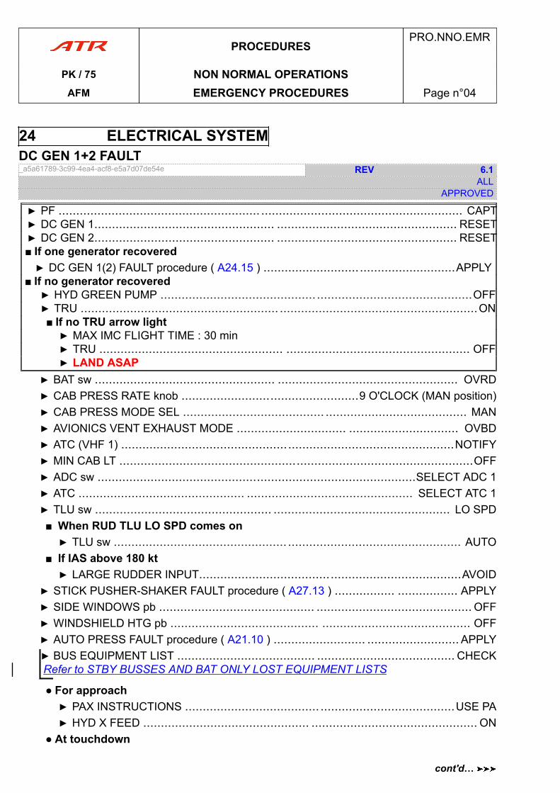
24 ELECTRICAL SYSTEMDC GEN 1+2 FAULT_a5a61789-3c99-4ea4-acf8-e5a7d07de54e REV 6.1
ALLAPPROVED
▶ PF ......................................................... ......................................................... CAPT▶ DC GEN 1................................................... ................................................... RESET▶ DC GEN 2................................................... ................................................... RESET■ If one generator recovered▶ DC GEN 1(2) FAULT procedure ( A24.15 ) ......................................................APPLY
■ If no generator recovered▶ HYD GREEN PUMP ........................................................................................OFF▶ TRU ........................................................ ........................................................ON■ If no TRU arrow light▶ MAX IMC FLIGHT TIME : 30 min▶ TRU .................................................... .................................................... OFF▶ LAND ASAP
▶ BAT sw ................................................... ................................................... OVRD▶ CAB PRESS RATE knob ..................................................9 O'CLOCK (MAN position)▶ CAB PRESS MODE SEL ........................................ ........................................ MAN▶ AVIONICS VENT EXHAUST MODE ............................... ............................... OVBD▶ ATC (VHF 1) ..............................................................................................NOTIFY▶ MIN CAB LT ....................................................................................................OFF▶ ADC sw ..........................................................................................SELECT ADC 1▶ ATC ............................................... ............................................... SELECT ATC 1▶ TLU sw .................................................. .................................................. LO SPD■ When RUD TLU LO SPD comes on▶ TLU sw ................................................. ................................................. AUTO
■ If IAS above 180 kt▶ LARGE RUDDER INPUT..........................................................................AVOID
▶ STICK PUSHER-SHAKER FAULT procedure ( A27.13 ) ................. ................. APPLY▶ SIDE WINDOWS pb ............................................ ............................................ OFF▶ WINDSHIELD HTG pb .......................................... .......................................... OFF▶ AUTO PRESS FAULT procedure ( A21.10 ) .......................... .......................... APPLY▶ BUS EQUIPMENT LIST ....................................... ....................................... CHECKRefer to STBY BUSSES AND BAT ONLY LOST EQUIPMENT LISTS
● For approach▶ PAX INSTRUCTIONS ...................................... ......................................USE PA▶ HYD X FEED ............................................... ............................................... ON
● At touchdown
PROCEDURESPRO.NNO.EMR
PK / 75 NON NORMAL OPERATIONSAFM EMERGENCY PROCEDURES Page n°04
cont'd…
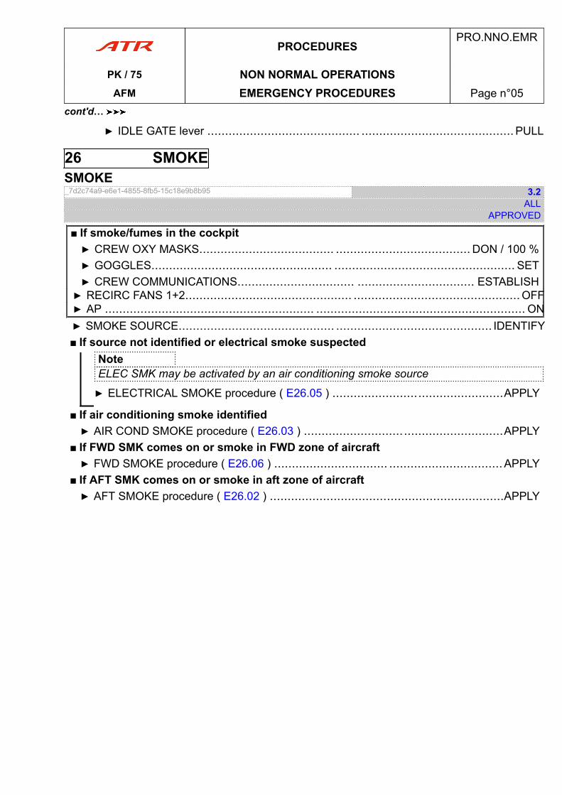
▶ IDLE GATE lever ........................................... ...........................................PULL
26 SMOKESMOKE_7d2c74a9-e6e1-4855-8fb5-15c18e9b8b95 3.2
ALLAPPROVED
■ If smoke/fumes in the cockpit▶ CREW OXY MASKS...................................... ...................................... DON / 100 %▶ GOGGLES................................................... ................................................... SET▶ CREW COMMUNICATIONS................................. ................................. ESTABLISH▶ RECIRC FANS 1+2............................................... ...............................................OFF▶ AP ........................................................... ........................................................... ON▶ SMOKE SOURCE............................................ ............................................ IDENTIFY■ If source not identified or electrical smoke suspected
NoteELEC SMK may be activated by an air conditioning smoke source
▶ ELECTRICAL SMOKE procedure ( E26.05 ) ................................................APPLY
■ If air conditioning smoke identified▶ AIR COND SMOKE procedure ( E26.03 ) ........................................................APPLY
■ If FWD SMK comes on or smoke in FWD zone of aircraft▶ FWD SMOKE procedure ( E26.06 ) ................................ ................................APPLY
■ If AFT SMK comes on or smoke in aft zone of aircraft▶ AFT SMOKE procedure ( E26.02 ) ..................................................................APPLY
PROCEDURESPRO.NNO.EMR
PK / 75 NON NORMAL OPERATIONSAFM EMERGENCY PROCEDURES Page n°05
cont'd…
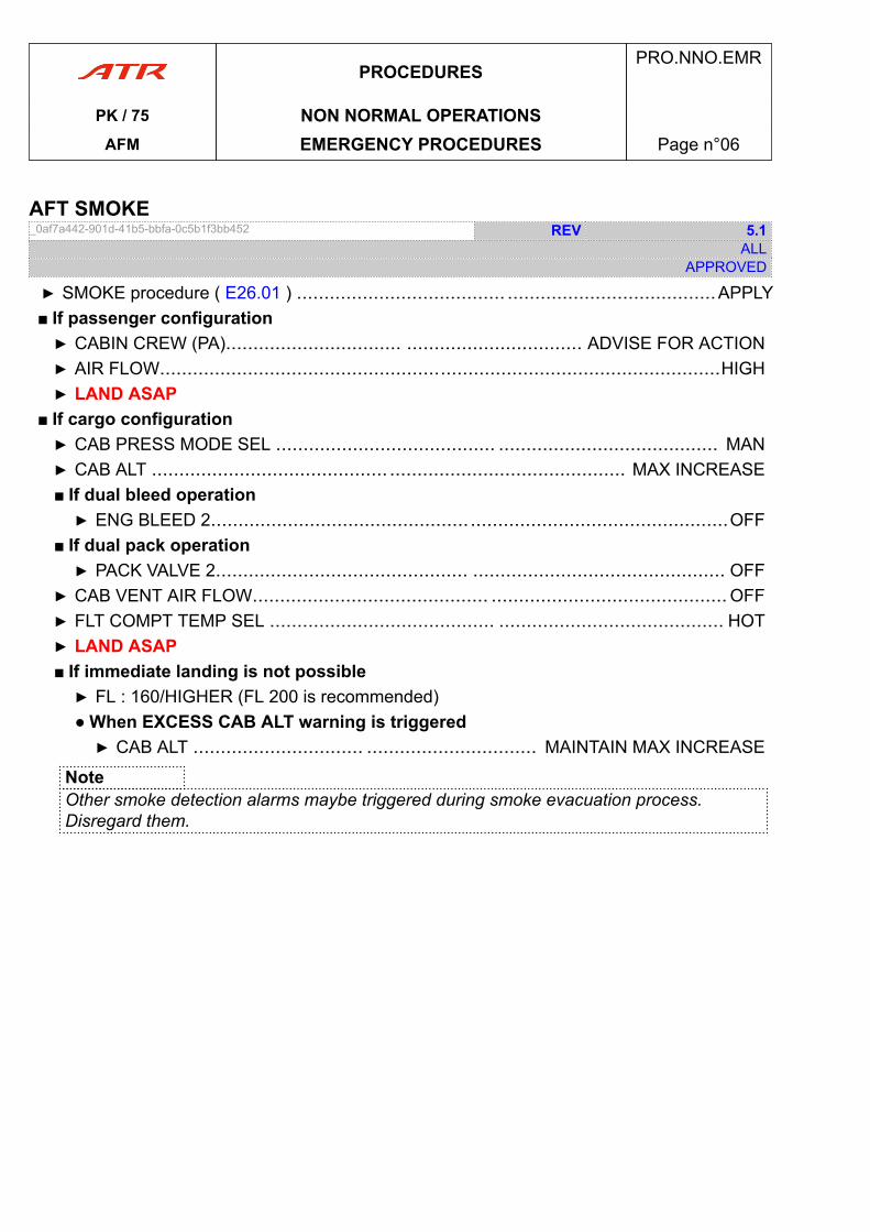
AFT SMOKE_0af7a442-901d-41b5-bbfa-0c5b1f3bb452 REV 5.1
ALLAPPROVED
▶ SMOKE procedure ( E26.01 ) ...................................... ......................................APPLY■ If passenger configuration▶ CABIN CREW (PA)................................ ................................ ADVISE FOR ACTION▶ AIR FLOW......................................................................................................HIGH▶ LAND ASAP
■ If cargo configuration▶ CAB PRESS MODE SEL ........................................ ........................................ MAN▶ CAB ALT ........................................... ........................................... MAX INCREASE■ If dual bleed operation▶ ENG BLEED 2............................................... ...............................................OFF
■ If dual pack operation▶ PACK VALVE 2.............................................. .............................................. OFF
▶ CAB VENT AIR FLOW........................................... ........................................... OFF▶ FLT COMPT TEMP SEL ......................................... ......................................... HOT▶ LAND ASAP■ If immediate landing is not possible▶ FL : 160/HIGHER (FL 200 is recommended)● When EXCESS CAB ALT warning is triggered▶ CAB ALT ............................... ............................... MAINTAIN MAX INCREASE
NoteOther smoke detection alarms maybe triggered during smoke evacuation process.Disregard them.
PROCEDURESPRO.NNO.EMR
PK / 75 NON NORMAL OPERATIONSAFM EMERGENCY PROCEDURES Page n°06
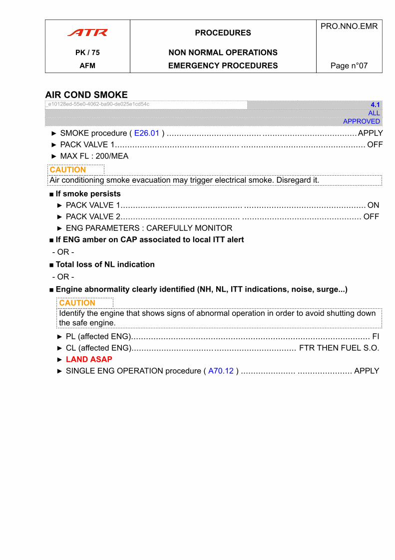
AIR COND SMOKE_e10128ed-55e0-4062-ba90-de025e1cd54c 4.1
ALLAPPROVED
▶ SMOKE procedure ( E26.01 ) ...................................... ......................................APPLY▶ PACK VALVE 1.................................................. .................................................. OFF▶ MAX FL : 200/MEA
CAUTIONAir conditioning smoke evacuation may trigger electrical smoke. Disregard it.
■ If smoke persists▶ PACK VALVE 1................................................. ................................................. ON▶ PACK VALVE 2................................................ ................................................ OFF▶ ENG PARAMETERS : CAREFULLY MONITOR
■ If ENG amber on CAP associated to local ITT alert- OR -
■ Total loss of NL indication- OR -
■ Engine abnormality clearly identified (NH, NL, ITT indications, noise, surge...)CAUTIONIdentify the engine that shows signs of abnormal operation in order to avoid shutting downthe safe engine.
▶ PL (affected ENG)................................................................................................ FI▶ CL (affected ENG).................................................................. FTR THEN FUEL S.O.▶ LAND ASAP▶ SINGLE ENG OPERATION procedure ( A70.12 ) ...................... ...................... APPLY
PROCEDURESPRO.NNO.EMR
PK / 75 NON NORMAL OPERATIONSAFM EMERGENCY PROCEDURES Page n°07
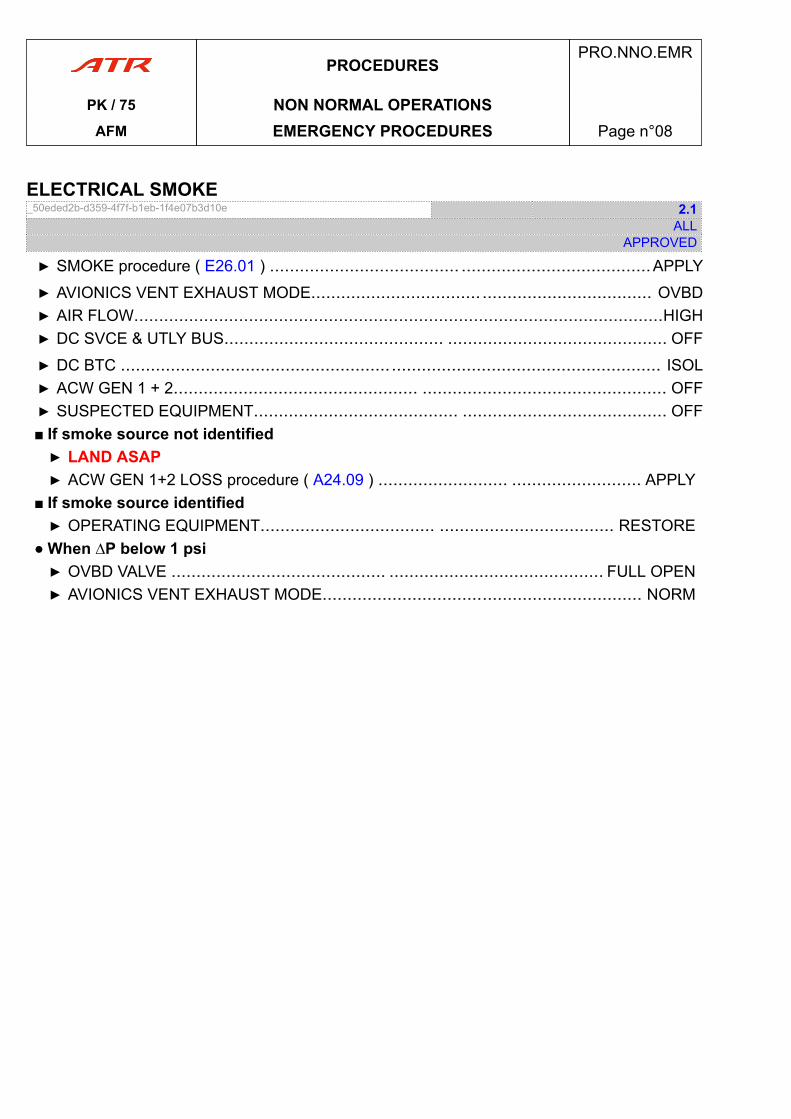
ELECTRICAL SMOKE_50eded2b-d359-4f7f-b1eb-1f4e07b3d10e 2.1
ALLAPPROVED
▶ SMOKE procedure ( E26.01 ) ...................................... ......................................APPLY
▶ AVIONICS VENT EXHAUST MODE.................................. .................................. OVBD▶ AIR FLOW..........................................................................................................HIGH▶ DC SVCE & UTLY BUS............................................ ............................................ OFF
▶ DC BTC ............................................................................................................ ISOL▶ ACW GEN 1 + 2................................................. ................................................. OFF▶ SUSPECTED EQUIPMENT......................................... ......................................... OFF■ If smoke source not identified▶ LAND ASAP▶ ACW GEN 1+2 LOSS procedure ( A24.09 ) .......................... .......................... APPLY
■ If smoke source identified▶ OPERATING EQUIPMENT................................... ................................... RESTORE
● When ∆P below 1 psi▶ OVBD VALVE ........................................... ........................................... FULL OPEN▶ AVIONICS VENT EXHAUST MODE................................................................ NORM
PROCEDURESPRO.NNO.EMR
PK / 75 NON NORMAL OPERATIONSAFM EMERGENCY PROCEDURES Page n°08
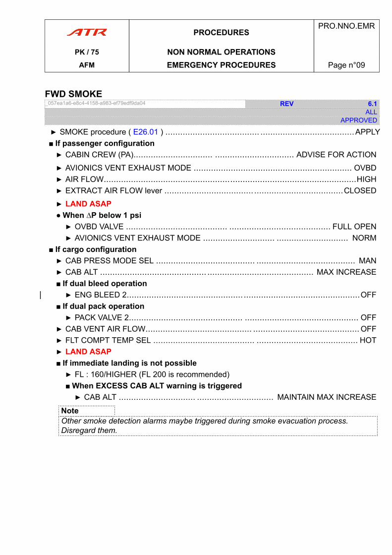
FWD SMOKE_057ea1a6-e8c4-4158-a983-ef79edf9da04 REV 6.1
ALLAPPROVED
▶ SMOKE procedure ( E26.01 ) ...................................... ......................................APPLY■ If passenger configuration▶ CABIN CREW (PA)................................ ................................ ADVISE FOR ACTION
▶ AVIONICS VENT EXHAUST MODE ................................................................ OVBD▶ AIR FLOW......................................................................................................HIGH▶ EXTRACT AIR FLOW lever .................................... ....................................CLOSED
▶ LAND ASAP● When ∆P below 1 psi▶ OVBD VALVE ......................................... ......................................... FULL OPEN▶ AVIONICS VENT EXHAUST MODE ............................. ............................. NORM
■ If cargo configuration▶ CAB PRESS MODE SEL ........................................ ........................................ MAN▶ CAB ALT ........................................... ........................................... MAX INCREASE■ If dual bleed operation▶ ENG BLEED 2............................................... ...............................................OFF
■ If dual pack operation▶ PACK VALVE 2.............................................. .............................................. OFF
▶ CAB VENT AIR FLOW........................................... ........................................... OFF▶ FLT COMPT TEMP SEL ......................................... ......................................... HOT▶ LAND ASAP■ If immediate landing is not possible▶ FL : 160/HIGHER (FL 200 is recommended)■ When EXCESS CAB ALT warning is triggered▶ CAB ALT ............................... ............................... MAINTAIN MAX INCREASE
NoteOther smoke detection alarms maybe triggered during smoke evacuation process.Disregard them.
PROCEDURESPRO.NNO.EMR
PK / 75 NON NORMAL OPERATIONSAFM EMERGENCY PROCEDURES Page n°09
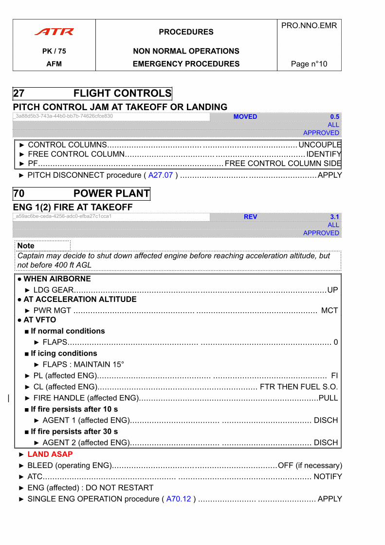
27 FLIGHT CONTROLSPITCH CONTROL JAM AT TAKEOFF OR LANDING_3a88d5b3-743a-44b0-bb7b-74626cfce830 MOVED 0.5
ALLAPPROVED
▶ CONTROL COLUMNS....................................... .......................................UNCOUPLE▶ FREE CONTROL COLUMN..................................... ..................................... IDENTIFY▶ PF...................................... ...................................... FREE CONTROL COLUMN SIDE▶ PITCH DISCONNECT procedure ( A27.07 ) ............................ ............................APPLY
70 POWER PLANTENG 1(2) FIRE AT TAKEOFF_a59ac6be-ceda-4256-adc0-efba27c1cca1 REV 3.1
ALLAPPROVED
NoteCaptain may decide to shut down affected engine before reaching acceleration altitude, butnot before 400 ft AGL
● WHEN AIRBORNE▶ LDG GEAR........................................................................................................UP
● AT ACCELERATION ALTITUDE▶ PWR MGT .................................................. .................................................. MCT
● AT VFTO■ If normal conditions▶ FLAPS...................................................... ...................................................... 0
■ If icing conditions▶ FLAPS : MAINTAIN 15°
▶ PL (affected ENG)............................................... ............................................... FI▶ CL (affected ENG).................................................................. FTR THEN FUEL S.O.▶ FIRE HANDLE (affected ENG)..........................................................................PULL■ If fire persists after 10 s▶ AGENT 1 (affected ENG)..................................... ..................................... DISCH
■ If fire persists after 30 s▶ AGENT 2 (affected ENG)..................................... ..................................... DISCH
▶ LAND ASAP▶ BLEED (operating ENG)....................................................................OFF (if necessary)▶ ATC....................................................... ....................................................... NOTIFY▶ ENG (affected) : DO NOT RESTART▶ SINGLE ENG OPERATION procedure ( A70.12 ) ........................ ........................ APPLY
PROCEDURESPRO.NNO.EMR
PK / 75 NON NORMAL OPERATIONSAFM EMERGENCY PROCEDURES Page n°10
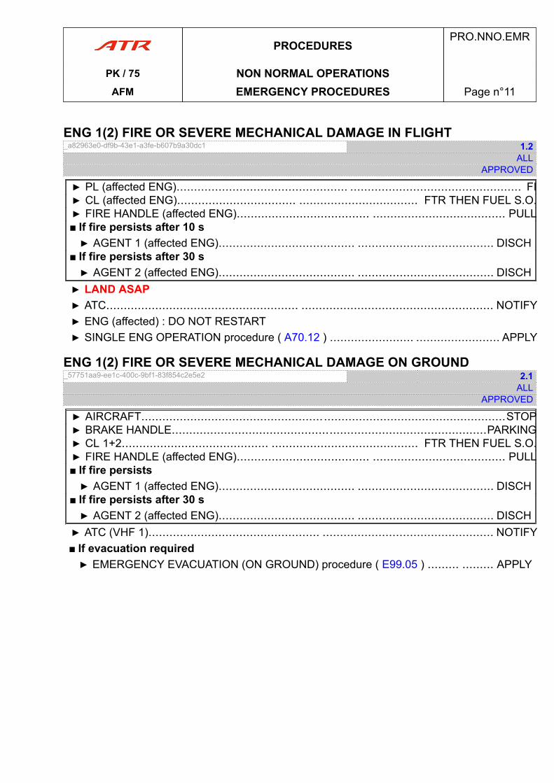
ENG 1(2) FIRE OR SEVERE MECHANICAL DAMAGE IN FLIGHT_a82963e0-df9b-43e1-a3fe-b607b9a30dc1 1.2
ALLAPPROVED
▶ PL (affected ENG)................................................. ................................................. FI▶ CL (affected ENG).................................. .................................. FTR THEN FUEL S.O.▶ FIRE HANDLE (affected ENG)...................................... ...................................... PULL■ If fire persists after 10 s▶ AGENT 1 (affected ENG)....................................... ....................................... DISCH
■ If fire persists after 30 s▶ AGENT 2 (affected ENG)....................................... ....................................... DISCH▶ LAND ASAP▶ ATC....................................................... ....................................................... NOTIFY▶ ENG (affected) : DO NOT RESTART▶ SINGLE ENG OPERATION procedure ( A70.12 ) ........................ ........................ APPLY
ENG 1(2) FIRE OR SEVERE MECHANICAL DAMAGE ON GROUND_57751aa9-ee1c-400c-9bf1-83f854c2e5e2 2.1
ALLAPPROVED
▶ AIRCRAFT........................................................................................................STOP▶ BRAKE HANDLE..........................................................................................PARKING▶ CL 1+2.......................................... .......................................... FTR THEN FUEL S.O.▶ FIRE HANDLE (affected ENG)...................................... ...................................... PULL■ If fire persists▶ AGENT 1 (affected ENG)....................................... ....................................... DISCH
■ If fire persists after 30 s▶ AGENT 2 (affected ENG)....................................... ....................................... DISCH▶ ATC (VHF 1)................................................. ................................................. NOTIFY■ If evacuation required▶ EMERGENCY EVACUATION (ON GROUND) procedure ( E99.05 ) ......... ......... APPLY
PROCEDURESPRO.NNO.EMR
PK / 75 NON NORMAL OPERATIONSAFM EMERGENCY PROCEDURES Page n°11
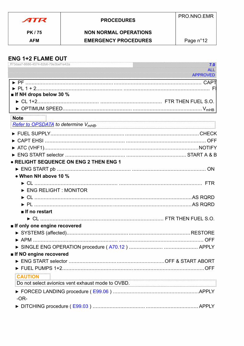
ENG 1+2 FLAME OUT_ff73daa7-8686-4574-82b6-79e3bef1e42a 7.0
ALLAPPROVED
▶ PF ......................................................... ......................................................... CAPT▶ PL 1 + 2........................................................ ........................................................ FI■ If NH drops below 30 %▶ CL 1+2........................................ ........................................ FTR THEN FUEL S.O.▶ OPTIMUM SPEED............................................. ............................................. VmHB
NoteRefer to OPSDATA to determine VmHB.
▶ FUEL SUPPLY................................................ ................................................CHECK▶ CAPT EHSI .................................................... .................................................... OFF▶ ATC (VHF1)....................................................................................................NOTIFY▶ ENG START selector ....................................... ....................................... START A & B● RELIGHT SEQUENCE ON ENG 2 THEN ENG 1▶ ENG START pb ................................................ ................................................ ON● When NH above 10 %▶ CL ...................................................... ...................................................... FTR▶ ENG RELIGHT : MONITOR▶ CL ......................................................................................................AS RQRD▶ PL ................................................... ...................................................AS RQRD■ If no restart▶ CL ................................................................................ FTR THEN FUEL S.O.
■ If only one engine recovered▶ SYSTEMS (affected)........................................ ........................................RESTORE▶ APM ....................................................... ....................................................... OFF▶ SINGLE ENG OPERATION procedure ( A70.12 ) ...................... ...................... APPLY
■ If NO engine recovered▶ ENG START selector ..............................................................OFF & START ABORT▶ FUEL PUMPS 1+2.............................................. ..............................................OFF
CAUTIONDo not select avionics vent exhaust mode to OVBD.
▶ FORCED LANDING procedure ( E99.06 ) ........................................................APPLY-OR-▶ DITCHING procedure ( E99.03 ) .................................. .................................. APPLY
PROCEDURESPRO.NNO.EMR
PK / 75 NON NORMAL OPERATIONSAFM EMERGENCY PROCEDURES Page n°12
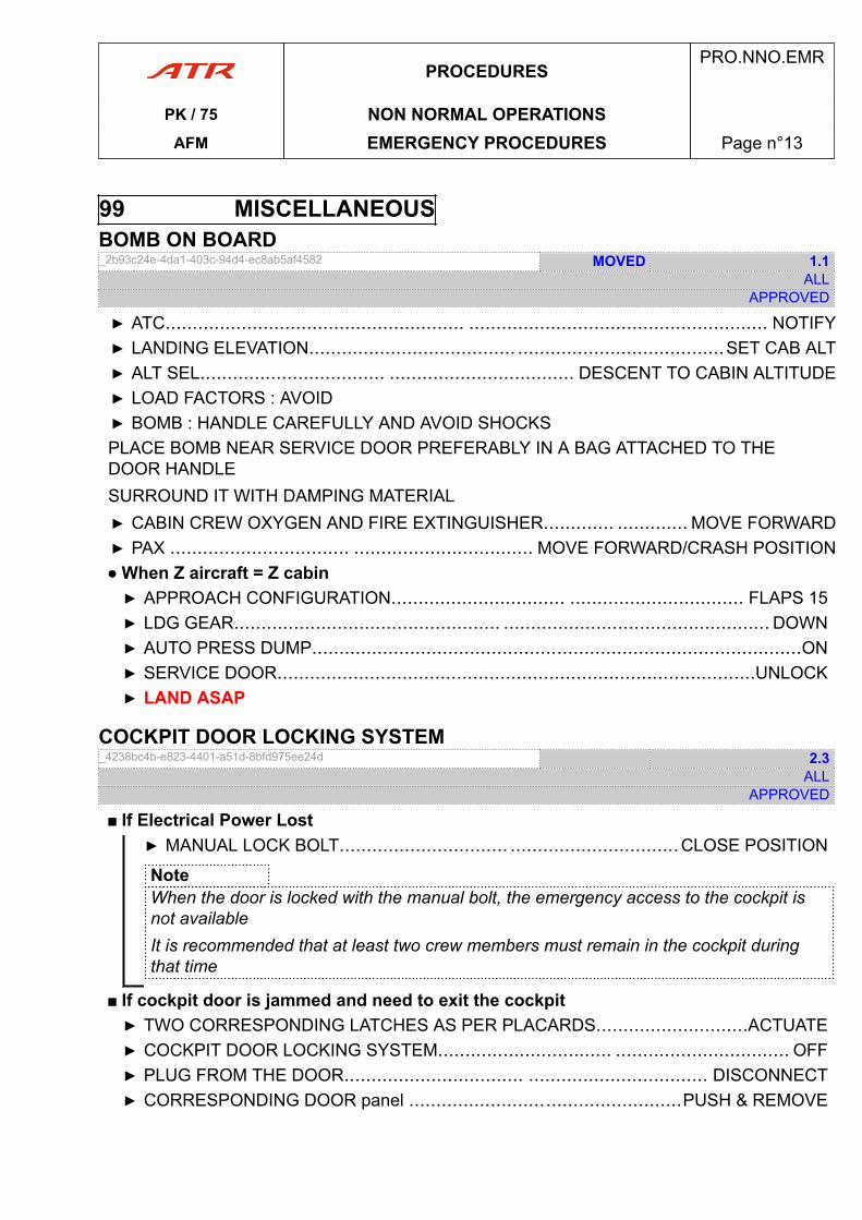
99 MISCELLANEOUSBOMB ON BOARD_2b93c24e-4da1-403c-94d4-ec8ab5af4582 MOVED 1.1
ALLAPPROVED
▶ ATC....................................................... ....................................................... NOTIFY▶ LANDING ELEVATION...................................... ......................................SET CAB ALT▶ ALT SEL.................................. .................................. DESCENT TO CABIN ALTITUDE▶ LOAD FACTORS : AVOID▶ BOMB : HANDLE CAREFULLY AND AVOID SHOCKSPLACE BOMB NEAR SERVICE DOOR PREFERABLY IN A BAG ATTACHED TO THEDOOR HANDLESURROUND IT WITH DAMPING MATERIAL▶ CABIN CREW OXYGEN AND FIRE EXTINGUISHER............. ............. MOVE FORWARD▶ PAX ................................. ................................. MOVE FORWARD/CRASH POSITION● When Z aircraft = Z cabin▶ APPROACH CONFIGURATION................................ ................................ FLAPS 15▶ LDG GEAR................................................. ................................................. DOWN▶ AUTO PRESS DUMP..........................................................................................ON▶ SERVICE DOOR........................................................................................UNLOCK▶ LAND ASAP
COCKPIT DOOR LOCKING SYSTEM_4238bc4b-e823-4401-a51d-8bfd975ee24d 2.3
ALLAPPROVED
■ If Electrical Power Lost▶ MANUAL LOCK BOLT............................... ...............................CLOSE POSITION
NoteWhen the door is locked with the manual bolt, the emergency access to the cockpit isnot availableIt is recommended that at least two crew members must remain in the cockpit duringthat time
■ If cockpit door is jammed and need to exit the cockpit▶ TWO CORRESPONDING LATCHES AS PER PLACARDS............................ACTUATE▶ COCKPIT DOOR LOCKING SYSTEM................................ ................................ OFF▶ PLUG FROM THE DOOR................................. ................................. DISCONNECT▶ CORRESPONDING DOOR panel ..................................................PUSH & REMOVE
PROCEDURESPRO.NNO.EMR
PK / 75 NON NORMAL OPERATIONSAFM EMERGENCY PROCEDURES Page n°13
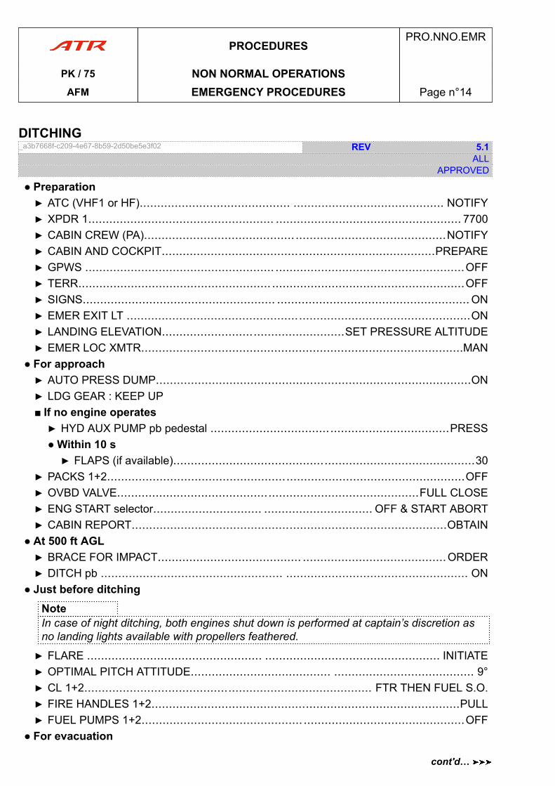
DITCHING_a3b7668f-c209-4e67-8b59-2d50be5e3f02 REV 5.1
ALLAPPROVED
● Preparation▶ ATC (VHF1 or HF)........................................... ........................................... NOTIFY▶ XPDR 1..................................................... ..................................................... 7700▶ CABIN CREW (PA)......................................................................................NOTIFY▶ CABIN AND COCKPIT..............................................................................PREPARE▶ GPWS ...................................................... ......................................................OFF▶ TERR....................................................... .......................................................OFF▶ SIGNS....................................................... ....................................................... ON▶ EMER EXIT LT ..................................................................................................ON▶ LANDING ELEVATION....................................................SET PRESSURE ALTITUDE▶ EMER LOC XMTR............................................................................................MAN
● For approach▶ AUTO PRESS DUMP..........................................................................................ON▶ LDG GEAR : KEEP UP■ If no engine operates▶ HYD AUX PUMP pb pedestal ....................................................................PRESS● Within 10 s▶ FLAPS (if available)......................................................................................30
▶ PACKS 1+2......................................................................................................OFF▶ OVBD VALVE......................................................................................FULL CLOSE▶ ENG START selector............................... ............................... OFF & START ABORT▶ CABIN REPORT..........................................................................................OBTAIN
● At 500 ft AGL▶ BRACE FOR IMPACT......................................... .........................................ORDER▶ DITCH pb .................................................... .................................................... ON
● Just before ditchingNoteIn case of night ditching, both engines shut down is performed at captain’s discretion asno landing lights available with propellers feathered.
▶ FLARE .................................................. .................................................. INITIATE▶ OPTIMAL PITCH ATTITUDE........................................ ........................................ 9°▶ CL 1+2.................................................................................. FTR THEN FUEL S.O.▶ FIRE HANDLES 1+2........................................................................................PULL▶ FUEL PUMPS 1+2.............................................. ..............................................OFF
● For evacuation
PROCEDURESPRO.NNO.EMR
PK / 75 NON NORMAL OPERATIONSAFM EMERGENCY PROCEDURES Page n°14
cont'd…
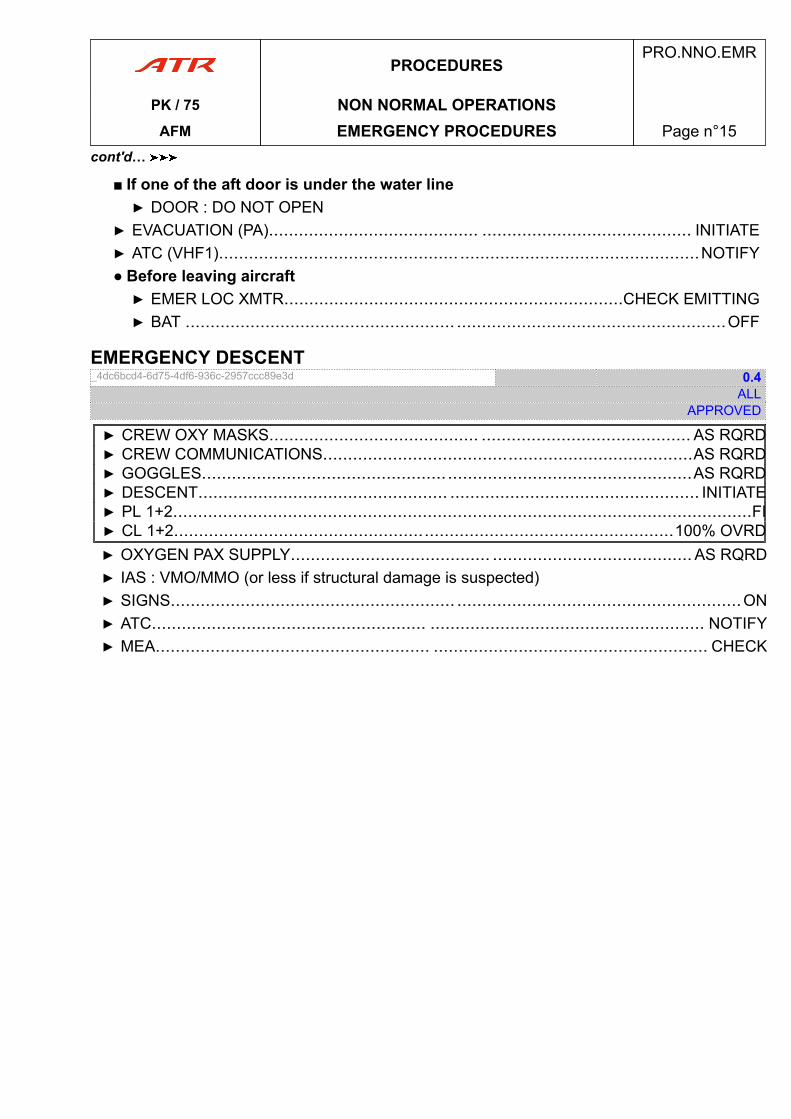
■ If one of the aft door is under the water line▶ DOOR : DO NOT OPEN
▶ EVACUATION (PA).......................................... .......................................... INITIATE▶ ATC (VHF1)................................................ ................................................NOTIFY● Before leaving aircraft▶ EMER LOC XMTR....................................................................CHECK EMITTING▶ BAT ...................................................... ......................................................OFF
EMERGENCY DESCENT_4dc6bcd4-6d75-4df6-936c-2957ccc89e3d 0.4
ALLAPPROVED
▶ CREW OXY MASKS.......................................... .......................................... AS RQRD▶ CREW COMMUNICATIONS..........................................................................AS RQRD▶ GOGGLES..................................................................................................AS RQRD▶ DESCENT.................................................. .................................................. INITIATE▶ PL 1+2....................................................................................................................FI▶ CL 1+2....................................................................................................100% OVRD▶ OXYGEN PAX SUPPLY........................................ ........................................ AS RQRD▶ IAS : VMO/MMO (or less if structural damage is suspected)▶ SIGNS......................................................... .........................................................ON▶ ATC....................................................... ....................................................... NOTIFY▶ MEA....................................................... ....................................................... CHECK
PROCEDURESPRO.NNO.EMR
PK / 75 NON NORMAL OPERATIONSAFM EMERGENCY PROCEDURES Page n°15
cont'd…
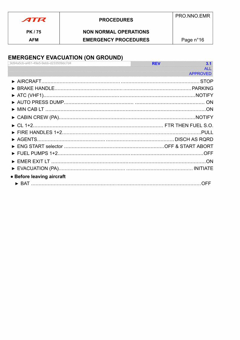
EMERGENCY EVACUATION (ON GROUND)_9d94a5cb-a461-49e5-9ebb-d233509dc7d4 REV 3.1
ALLAPPROVED
▶ AIRCRAFT.................................................... ....................................................STOP▶ BRAKE HANDLE............................................. .............................................PARKING▶ ATC (VHF1)....................................................................................................NOTIFY▶ AUTO PRESS DUMP.............................................. .............................................. ON▶ MIN CAB LT ..........................................................................................................ON
▶ CABIN CREW (PA)..........................................................................................NOTIFY
▶ CL 1+2...................................................................................... FTR THEN FUEL S.O.▶ FIRE HANDLES 1+2............................................................................................PULL▶ AGENTS............................................. ............................................. DISCH AS RQRD▶ ENG START selector ..................................................................OFF & START ABORT▶ FUEL PUMPS 1+2................................................................................................OFF
▶ EMER EXIT LT ......................................................................................................ON▶ EVACUATION (PA)............................................ ............................................ INITIATE
● Before leaving aircraft▶ BAT ................................................................................................................OFF
PROCEDURESPRO.NNO.EMR
PK / 75 NON NORMAL OPERATIONSAFM EMERGENCY PROCEDURES Page n°16
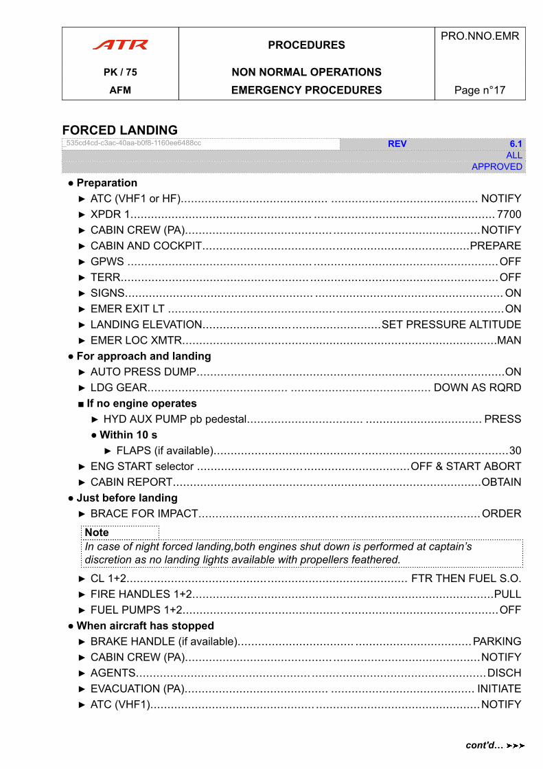
FORCED LANDING_535cd4cd-c3ac-40aa-b0f8-1160ee6488cc REV 6.1
ALLAPPROVED
● Preparation▶ ATC (VHF1 or HF)........................................... ........................................... NOTIFY▶ XPDR 1..................................................... ..................................................... 7700▶ CABIN CREW (PA)......................................................................................NOTIFY▶ CABIN AND COCKPIT..............................................................................PREPARE▶ GPWS ...................................................... ......................................................OFF▶ TERR....................................................... .......................................................OFF▶ SIGNS....................................................... ....................................................... ON▶ EMER EXIT LT ..................................................................................................ON▶ LANDING ELEVATION....................................................SET PRESSURE ALTITUDE▶ EMER LOC XMTR............................................................................................MAN
● For approach and landing▶ AUTO PRESS DUMP..........................................................................................ON▶ LDG GEAR......................................... ......................................... DOWN AS RQRD■ If no engine operates▶ HYD AUX PUMP pb pedestal.................................. .................................. PRESS● Within 10 s▶ FLAPS (if available)......................................................................................30
▶ ENG START selector ..............................................................OFF & START ABORT▶ CABIN REPORT..........................................................................................OBTAIN
● Just before landing▶ BRACE FOR IMPACT......................................... .........................................ORDER
NoteIn case of night forced landing,both engines shut down is performed at captain’sdiscretion as no landing lights available with propellers feathered.
▶ CL 1+2.................................................................................. FTR THEN FUEL S.O.▶ FIRE HANDLES 1+2........................................................................................PULL▶ FUEL PUMPS 1+2.............................................. ..............................................OFF
● When aircraft has stopped▶ BRAKE HANDLE (if available).................................. ..................................PARKING▶ CABIN CREW (PA)......................................................................................NOTIFY▶ AGENTS................................................... ...................................................DISCH▶ EVACUATION (PA).......................................... .......................................... INITIATE▶ ATC (VHF1)................................................ ................................................NOTIFY
PROCEDURESPRO.NNO.EMR
PK / 75 NON NORMAL OPERATIONSAFM EMERGENCY PROCEDURES Page n°17
cont'd…
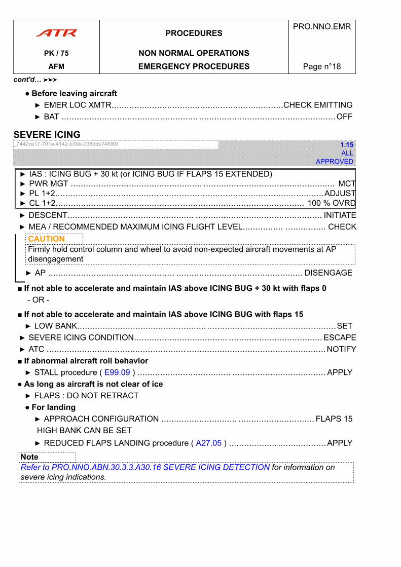
● Before leaving aircraft▶ EMER LOC XMTR....................................................................CHECK EMITTING▶ BAT ...................................................... ......................................................OFF
SEVERE ICING_7442ce17-701e-4142-b39e-038dde74f989 1.15
ALLAPPROVED
▶ IAS : ICING BUG + 30 kt (or ICING BUG IF FLAPS 15 EXTENDED)▶ PWR MGT .................................................... .................................................... MCT▶ PL 1+2..........................................................................................................ADJUST▶ CL 1+2................................................. ................................................. 100 % OVRD▶ DESCENT.................................................. .................................................. INITIATE▶ MEA / RECOMMENDED MAXIMUM ICING FLIGHT LEVEL................ ................ CHECK
CAUTIONFirmly hold control column and wheel to avoid non-expected aircraft movements at APdisengagement
▶ AP .................................................. .................................................. DISENGAGE
■ If not able to accelerate and maintain IAS above ICING BUG + 30 kt with flaps 0- OR -
■ If not able to accelerate and maintain IAS above ICING BUG with flaps 15▶ LOW BANK................................................... ...................................................SET▶ SEVERE ICING CONDITION..................................... ..................................... ESCAPE▶ ATC ....................................................... .......................................................NOTIFY■ If abnormal aircraft roll behavior▶ STALL procedure ( E99.09 ) ..................................... ..................................... APPLY
● As long as aircraft is not clear of ice▶ FLAPS : DO NOT RETRACT● For landing▶ APPROACH CONFIGURATION .............................. .............................. FLAPS 15HIGH BANK CAN BE SET▶ REDUCED FLAPS LANDING procedure ( A27.05 ) ................... ...................APPLY
NoteRefer to PRO.NNO.ABN.30.3.3.A30.16 SEVERE ICING DETECTION for information onsevere icing indications.
PROCEDURESPRO.NNO.EMR
PK / 75 NON NORMAL OPERATIONSAFM EMERGENCY PROCEDURES Page n°18
cont'd…
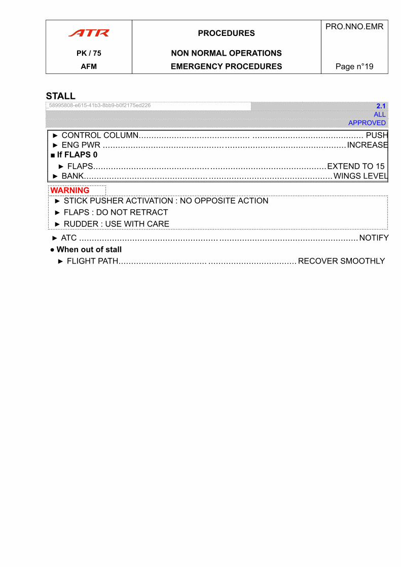
STALL_58995808-e615-41b3-8bb9-b0f2175ed226 2.1
ALLAPPROVED
▶ CONTROL COLUMN............................................ ............................................ PUSH▶ ENG PWR ................................................ ................................................ INCREASE■ If FLAPS 0▶ FLAPS............................................................................................EXTEND TO 15▶ BANK................................................. .................................................WINGS LEVEL
WARNING▶ STICK PUSHER ACTIVATION : NO OPPOSITE ACTION▶ FLAPS : DO NOT RETRACT▶ RUDDER : USE WITH CARE
▶ ATC ....................................................... .......................................................NOTIFY● When out of stall▶ FLIGHT PATH................................... ................................... RECOVER SMOOTHLY
PROCEDURESPRO.NNO.EMR
PK / 75 NON NORMAL OPERATIONSAFM EMERGENCY PROCEDURES Page n°19
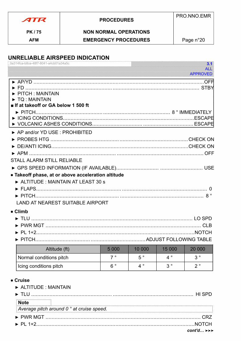
UNRELIABLE AIRSPEED INDICATION_0a314fca-b8ce-48f7-8041-a4cb01a34a5c 3.1
ALLAPPROVED
▶ AP/YD ................................................................................................................OFF▶ FD ......................................................... ......................................................... STBY▶ PITCH : MAINTAIN▶ TQ : MAINTAIN■ If at takeoff or GA below 1 500 ft▶ PITCH............................................ ............................................ 8 ° IMMEDIATELY▶ ICING CONDITIONS......................................................................................ESCAPE▶ VOLCANIC ASHES CONDITIONS................................. ................................. ESCAPE
▶ AP and/or YD USE : PROHIBITED▶ PROBES HTG ............................................. .............................................CHECK ON▶ DE/ANTI ICING..........................................................................................CHECK ON▶ APM ......................................................... ......................................................... OFFSTALL ALARM STILL RELIABLE▶ GPS SPEED INFORMATION (IF AVAILABLE)............................ ............................ USE● Takeoff phase, at or above acceleration altitude▶ ALTITUDE : MAINTAIN AT LEAST 30 s▶ FLAPS........................................................ ........................................................ 0▶ PITCH....................................................... ....................................................... 8 °LAND AT NEAREST SUITABLE AIRPORT
● Climb▶ TLU .......................................................................................................... LO SPD▶ PWR MGT ...................................................................................................... CLB▶ PL 1+2........................................................................................................NOTCH▶ PITCH.................................... ....................................ADJUST FOLLOWING TABLE
Altitude (ft) 5 000 10 000 15 000 20 000
Normal conditions pitch 7 ° 5 ° 4 ° 3 °
Icing conditions pitch 6 ° 4 ° 3 ° 2 °
● Cruise▶ ALTITUDE : MAINTAIN▶ TLU ..................................................... ..................................................... HI SPD
NoteAverage pitch around 0 ° at cruise speed.
▶ PWR MGT ...................................................................................................... CRZ▶ PL 1+2........................................................................................................NOTCH
PROCEDURESPRO.NNO.EMR
PK / 75 NON NORMAL OPERATIONSAFM EMERGENCY PROCEDURES Page n°20
cont'd…
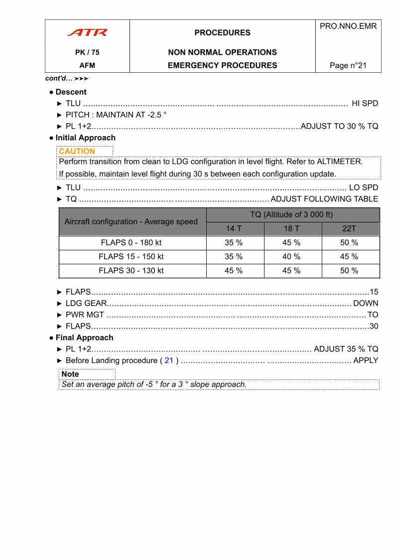
● Descent▶ TLU ..................................................... ..................................................... HI SPD▶ PITCH : MAINTAIN AT -2.5 °▶ PL 1+2....................................................................................ADJUST TO 30 % TQ
● Initial ApproachCAUTIONPerform transition from clean to LDG configuration in level flight. Refer to ALTIMETER.If possible, maintain level flight during 30 s between each configuration update.
▶ TLU .......................................................................................................... LO SPD▶ TQ ...................................... ...................................... ADJUST FOLLOWING TABLE
Aircraft configuration - Average speedTQ (Altitude of 3 000 ft)
14 T 18 T 22T
FLAPS 0 - 180 kt 35 % 45 % 50 %
FLAPS 15 - 150 kt 35 % 40 % 45 %
FLAPS 30 - 130 kt 45 % 45 % 50 %
▶ FLAPS................................................................................................................15▶ LDG GEAR................................................. ................................................. DOWN▶ PWR MGT .................................................... .................................................... TO▶ FLAPS................................................................................................................30
● Final Approach▶ PL 1+2............................................ ............................................ ADJUST 35 % TQ▶ Before Landing procedure ( 21 ) .................................. .................................. APPLY
NoteSet an average pitch of -5 ° for a 3 ° slope approach.
PROCEDURESPRO.NNO.EMR
PK / 75 NON NORMAL OPERATIONSAFM EMERGENCY PROCEDURES Page n°21
cont'd…

PAGE
INTENTIONALLY
LEFT BLANK
PROCEDURESPRO.NNO.EMR
PK / 75 NON NORMAL OPERATIONSAFM EMERGENCY PROCEDURES Page n°22
ABNORMAL PROCEDURES .NNO.ABN
ABN. ABNORMAL PROCEDURES............................................................................... page 03ABN.01 INTRODUCTION...................................................................................page 03ABN.21 AIR CONDITIONING..............................................................................page 03ABN.22 AUTOPILOT......................................................................................... page 06ABN.24 ELECTRICAL........................................................................................page 08ABN.27 FLIGHT CONTROLS............................................................................. page 14ABN.28 FUEL................................................................................................... page 23ABN.29 HYDRAULIC SYSTEM...........................................................................page 26ABN.30 ICE AND RAIN...................................................................................... page 28ABN.31 INDICATING AND RECORDING SYSTEM............................................... page 31ABN.32 LANDING GEAR................................................................................... page 41ABN.34 NAVIGATION........................................................................................ page 43ABN.36 PNEUMATIC.........................................................................................page 45ABN.70 POWER PLANT.................................................................................... page 47ABN.99 MISCELLANEOUS................................................................................ page 53
AFMPRO.NNO.ABN
PK / 75 TOCAFM Table of Content Page n°01

PAGE
INTENTIONALLY
LEFT BLANK
AFMPRO.NNO.ABN
PK / 75 TOCAFM Table of Content Page n°02
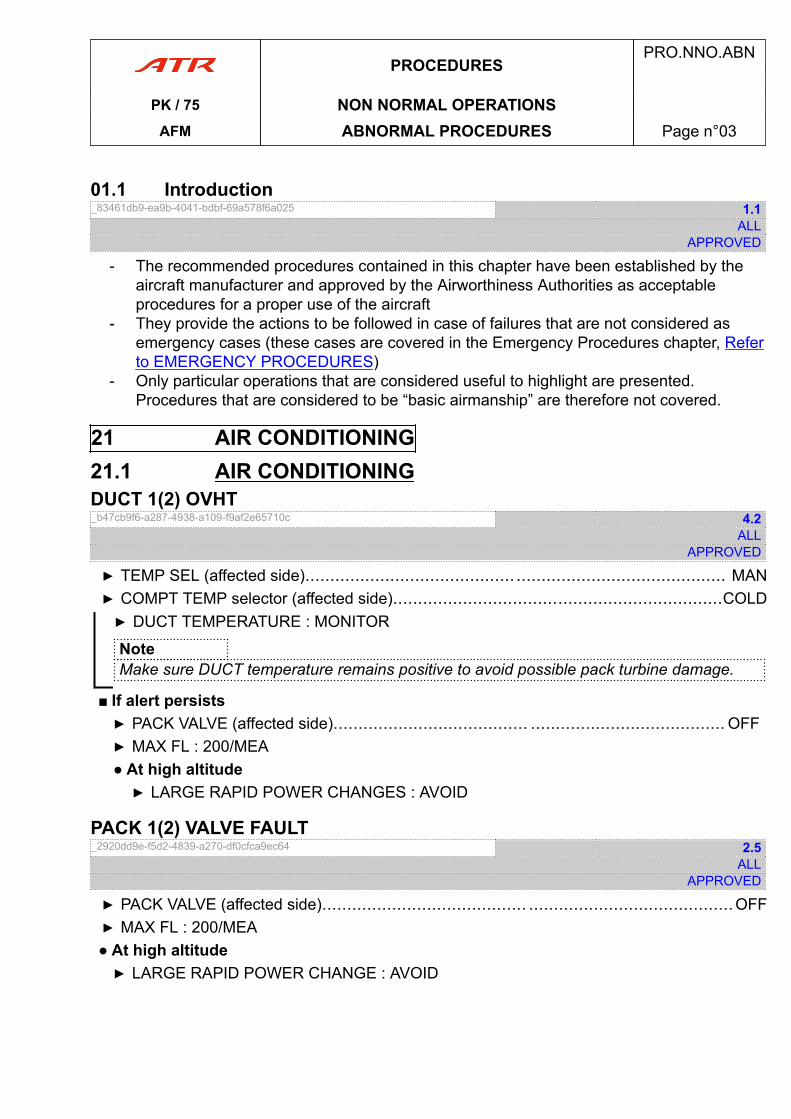
01.1 Introduction_83461db9-ea9b-4041-bdbf-69a578f6a025 1.1
ALLAPPROVED
- The recommended procedures contained in this chapter have been established by theaircraft manufacturer and approved by the Airworthiness Authorities as acceptableprocedures for a proper use of the aircraft
- They provide the actions to be followed in case of failures that are not considered asemergency cases (these cases are covered in the Emergency Procedures chapter, Referto EMERGENCY PROCEDURES)
- Only particular operations that are considered useful to highlight are presented.Procedures that are considered to be “basic airmanship” are therefore not covered.
21 AIR CONDITIONING21.1 AIR CONDITIONINGDUCT 1(2) OVHT_b47cb9f6-a287-4938-a109-f9af2e65710c 4.2
ALLAPPROVED
▶ TEMP SEL (affected side).......................................... .......................................... MAN▶ COMPT TEMP selector (affected side)..................................................................COLD▶ DUCT TEMPERATURE : MONITOR
NoteMake sure DUCT temperature remains positive to avoid possible pack turbine damage.
■ If alert persists▶ PACK VALVE (affected side)....................................... ....................................... OFF▶ MAX FL : 200/MEA● At high altitude▶ LARGE RAPID POWER CHANGES : AVOID
PACK 1(2) VALVE FAULT_2920dd9e-f5d2-4839-a270-df0cfca9ec64 2.5
ALLAPPROVED
▶ PACK VALVE (affected side)......................................... .........................................OFF▶ MAX FL : 200/MEA● At high altitude▶ LARGE RAPID POWER CHANGE : AVOID
PROCEDURESPRO.NNO.ABN
PK / 75 NON NORMAL OPERATIONSAFM ABNORMAL PROCEDURES Page n°03
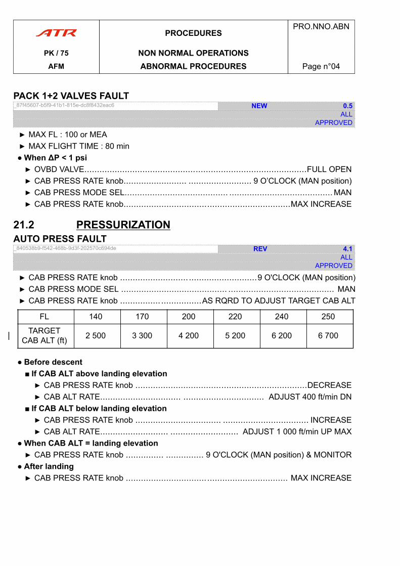
PACK 1+2 VALVES FAULT_87f45607-b5f9-41b1-815e-dc8f8432eac6 NEW 0.5
ALLAPPROVED
▶ MAX FL : 100 or MEA▶ MAX FLIGHT TIME : 80 min● When ΔP < 1 psi▶ OVBD VALVE........................................................................................FULL OPEN▶ CAB PRESS RATE knob......................... ......................... 9 O’CLOCK (MAN position)▶ CAB PRESS MODE SEL......................................... .........................................MAN▶ CAB PRESS RATE knob..................................................................MAX INCREASE
21.2 PRESSURIZATIONAUTO PRESS FAULT_840538b9-f542-468b-9d3f-202570c694de REV 4.1
ALLAPPROVED
▶ CAB PRESS RATE knob ......................................................9 O'CLOCK (MAN position)▶ CAB PRESS MODE SEL .......................................... .......................................... MAN▶ CAB PRESS RATE knob ................................AS RQRD TO ADJUST TARGET CAB ALT
FL 140 170 200 220 240 250
TARGETCAB ALT (ft) 2 500 3 300 4 200 5 200 6 200 6 700
● Before descent■ If CAB ALT above landing elevation▶ CAB PRESS RATE knob ....................................................................DECREASE▶ CAB ALT RATE................................ ................................ ADJUST 400 ft/min DN
■ If CAB ALT below landing elevation▶ CAB PRESS RATE knob .................................. .................................. INCREASE▶ CAB ALT RATE........................... ........................... ADJUST 1 000 ft/min UP MAX
● When CAB ALT = landing elevation▶ CAB PRESS RATE knob ............... ............... 9 O'CLOCK (MAN position) & MONITOR
● After landing▶ CAB PRESS RATE knob ................................................................ MAX INCREASE
PROCEDURESPRO.NNO.ABN
PK / 75 NON NORMAL OPERATIONSAFM ABNORMAL PROCEDURES Page n°04
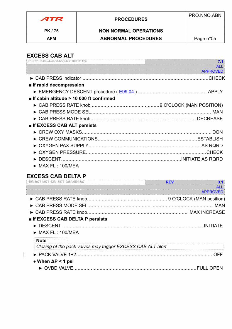
EXCESS CAB ALT_51062107-8c24-4ed8-bf29-b3510963112e 7.1
ALLAPPROVED
▶ CAB PRESS indicator ......................................................................................CHECK■ If rapid decompression▶ EMERGENCY DESCENT procedure ( E99.04 ) ....................... ....................... APPLY
■ If cabin altitude > 10 000 ft confirmed▶ CAB PRESS RATE knob ..............................................9 O'CLOCK (MAN POSITION)▶ CAB PRESS MODE SEL.................................................................................. MAN▶ CAB PRESS RATE knob ........................................................................DECREASE
■ If EXCESS CAB ALT persists▶ CREW OXY MASKS............................................ ............................................ DON▶ CREW COMMUNICATIONS....................................................................ESTABLISH▶ OXYGEN PAX SUPPLY...................................... ...................................... AS RQRD▶ OXYGEN PRESSURE..................................................................................CHECK▶ DESCENT..................................................................................INITIATE AS RQRD▶ MAX FL : 100/MEA
EXCESS CAB DELTA P_40fe8e77-b971-42fb-8877-9a6fa6f918a7 REV 3.1
ALLAPPROVED
▶ CAB PRESS RATE knob........................... ........................... 9 O'CLOCK (MAN position)▶ CAB PRESS MODE SEL .......................................... .......................................... MAN▶ CAB PRESS RATE knob.................................. .................................. MAX INCREASE■ If EXCESS CAB DELTA P persists▶ DESCENT ................................................ ................................................ INITIATE▶ MAX FL : 100/MEA
NoteClosing of the pack valves may trigger EXCESS CAB ALT alert
▶ PACK VALVE 1+2.............................................. .............................................. OFF● When ΔP < 1 psi▶ OVBD VALVE....................................................................................FULL OPEN
PROCEDURESPRO.NNO.ABN
PK / 75 NON NORMAL OPERATIONSAFM ABNORMAL PROCEDURES Page n°05

22 AUTOPILOTABNORMAL FLIGHT CHARACTERISTICS IN ROLL_462544ce-8518-4979-8578-8d2c06b887a7 2.1
ALLAPPROVED
▶ CONTROL COLUMN & WHEEL............................... ...............................HOLD FIRMLY▶ AP..........................................................................................................DISENGAGE▶ AIL TRIM................................................... ................................................... ADJUST● When lateral trims adjusted
AP CAN BE REENGAGED
ADU FAILURE_486ede53-6814-4fe9-bd49-1ad347605a57 1.1
ALLAPPROVED
▶ IAS & VS MODE............................................. ............................................. USE TCSALT SEL MODE LOST■ If amber AP MSG appears on EADI- OR -
■ If composite mode▶ CONTROL COLUMN & WHEEL............................. .............................HOLD FIRMLY▶ AP .................................................. .................................................. DISENGAGE
AILERON MISTRIMAILERON MISTRIM (ADU MESSAGE)_b3ddeb48-0e5a-45d0-bfcb-3e90d3a94191 0.1
ALLAPPROVED
▶ CONTROL COLUMN & WHEEL............................... ...............................HOLD FIRMLY▶ AP .................................................... .................................................... DISENGAGE▶ LATERAL TRIMS............................................................................................ADJUST● When lateral trims adjusted
AP CAN BE REENGAGED
AP PITCH TRIM FAILAP PITCH TRIM FAIL (ADU MESSAGE)_357f812f-0771-4927-8c81-e6d58229ff82 2.2
ALLAPPROVED
▶ CONTROL COLUMN & WHEEL............................... ...............................HOLD FIRMLY▶ AP .................................................... .................................................... DISENGAGE
PROCEDURESPRO.NNO.ABN
PK / 75 NON NORMAL OPERATIONSAFM ABNORMAL PROCEDURES Page n°06
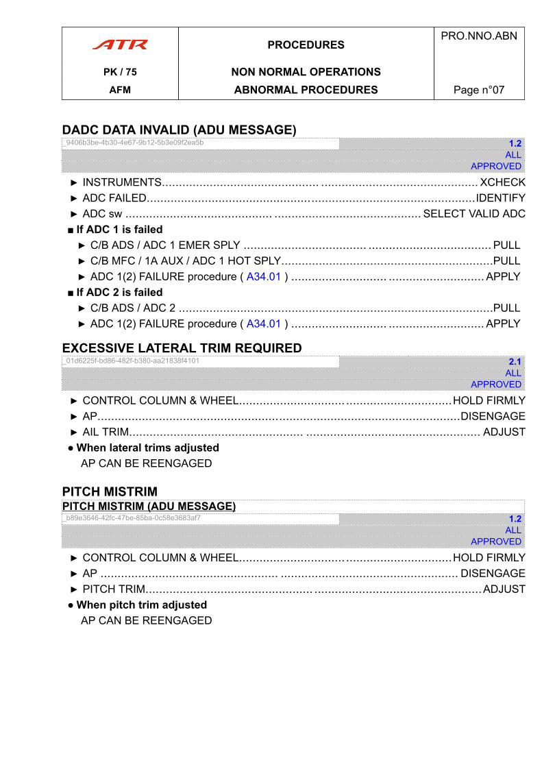
DADC DATA INVALID (ADU MESSAGE)_9406b3be-4b30-4e67-9b12-5b3e09f2ea5b 1.2
ALLAPPROVED
▶ INSTRUMENTS.............................................. .............................................. XCHECK▶ ADC FAILED................................................................................................IDENTIFY▶ ADC sw ........................................... ........................................... SELECT VALID ADC■ If ADC 1 is failed▶ C/B ADS / ADC 1 EMER SPLY .................................... .................................... PULL▶ C/B MFC / 1A AUX / ADC 1 HOT SPLY..............................................................PULL▶ ADC 1(2) FAILURE procedure ( A34.01 ) ............................ ............................ APPLY
■ If ADC 2 is failed▶ C/B ADS / ADC 2 ............................................................................................PULL▶ ADC 1(2) FAILURE procedure ( A34.01 ) ............................ ............................ APPLY
EXCESSIVE LATERAL TRIM REQUIRED_01d6225f-bd86-482f-b380-aa21838f4101 2.1
ALLAPPROVED
▶ CONTROL COLUMN & WHEEL............................... ...............................HOLD FIRMLY▶ AP..........................................................................................................DISENGAGE▶ AIL TRIM................................................... ................................................... ADJUST● When lateral trims adjusted
AP CAN BE REENGAGED
PITCH MISTRIMPITCH MISTRIM (ADU MESSAGE)_b89e3646-42fc-47be-85ba-0c58e3683af7 1.2
ALLAPPROVED
▶ CONTROL COLUMN & WHEEL............................... ...............................HOLD FIRMLY▶ AP .................................................... .................................................... DISENGAGE▶ PITCH TRIM................................................. .................................................ADJUST● When pitch trim adjusted
AP CAN BE REENGAGED
PROCEDURESPRO.NNO.ABN
PK / 75 NON NORMAL OPERATIONSAFM ABNORMAL PROCEDURES Page n°07
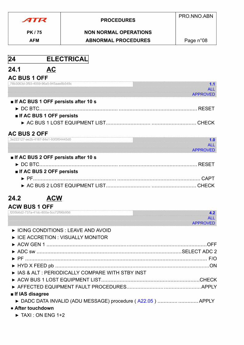
24 ELECTRICAL24.1 ACAC BUS 1 OFF_78b3063d-3f93-4059-96a5-945aae8b549c 1.1
ALLAPPROVED
■ If AC BUS 1 OFF persists after 10 s▶ DC BTC................................................... ................................................... RESET■ If AC BUS 1 OFF persists▶ AC BUS 1 LOST EQUIPMENT LIST............................. ............................. CHECK
AC BUS 2 OFF_3e222127-ae2b-4167-84e1-93f3f04445d0 1.0
ALLAPPROVED
■ If AC BUS 2 OFF persists after 10 s▶ DC BTC................................................... ................................................... RESET■ If AC BUS 2 OFF persists▶ PF...................................................... ...................................................... CAPT▶ AC BUS 2 LOST EQUIPMENT LIST............................. ............................. CHECK
24.2 ACWACW BUS 1 OFF_f205b6d2-737a-41dc-800a-5cc72f96b956 4.2
ALLAPPROVED
▶ ICING CONDITIONS : LEAVE AND AVOID▶ ICE ACCRETION : VISUALLY MONITOR▶ ACW GEN 1 ........................................................................................................OFF▶ ADC sw ..............................................................................................SELECT ADC 2▶ PF ...................................................................................................................... F/O▶ HYD X FEED pb ....................................................................................................ON▶ IAS & ALT : PERIODICALLY COMPARE WITH STBY INST▶ ACW BUS 1 LOST EQUIPMENT LIST................................................................CHECK▶ AFFECTED EQUIPMENT FAULT PROCEDURES........................ ........................APPLY■ If IAS disagree▶ DADC DATA INVALID (ADU MESSAGE) procedure ( A22.05 ) ............. ............. APPLY
● After touchdown▶ TAXI : ON ENG 1+2
PROCEDURESPRO.NNO.ABN
PK / 75 NON NORMAL OPERATIONSAFM ABNORMAL PROCEDURES Page n°08
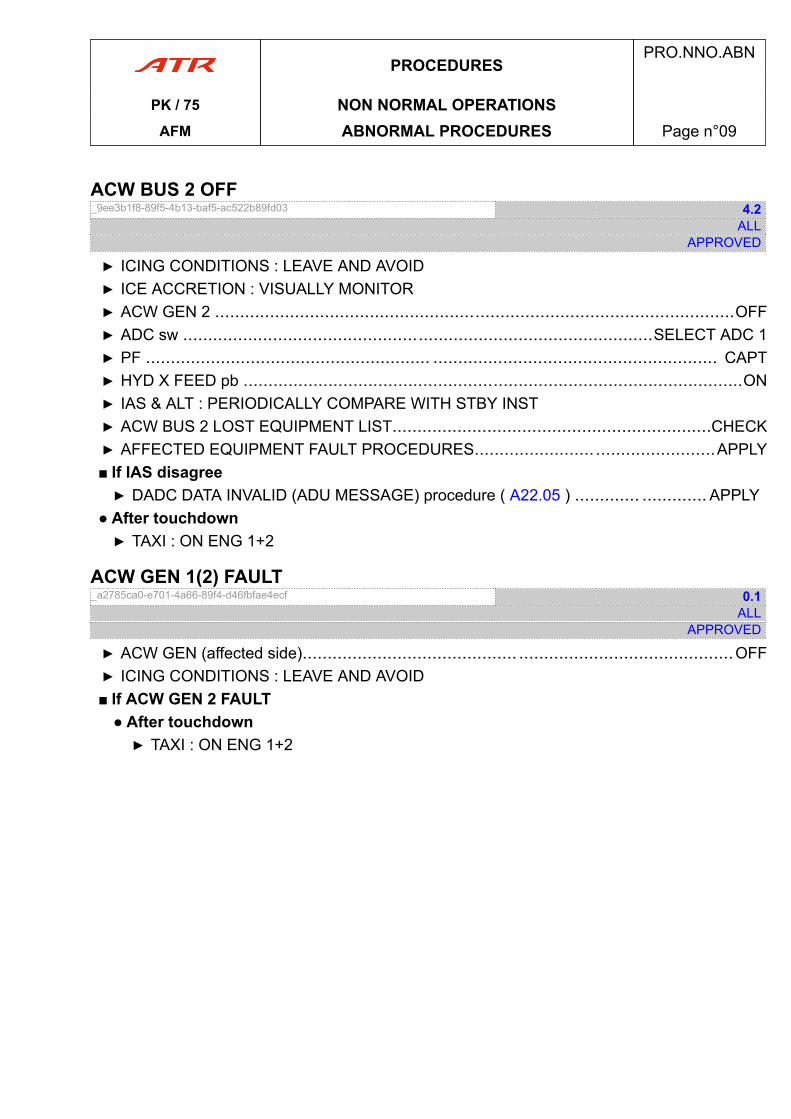
ACW BUS 2 OFF_9ee3b1f8-89f5-4b13-baf5-ac522b89fd03 4.2
ALLAPPROVED
▶ ICING CONDITIONS : LEAVE AND AVOID▶ ICE ACCRETION : VISUALLY MONITOR▶ ACW GEN 2 ........................................................................................................OFF▶ ADC sw ..............................................................................................SELECT ADC 1▶ PF ......................................................... ......................................................... CAPT▶ HYD X FEED pb ....................................................................................................ON▶ IAS & ALT : PERIODICALLY COMPARE WITH STBY INST▶ ACW BUS 2 LOST EQUIPMENT LIST................................................................CHECK▶ AFFECTED EQUIPMENT FAULT PROCEDURES........................ ........................APPLY■ If IAS disagree▶ DADC DATA INVALID (ADU MESSAGE) procedure ( A22.05 ) ............. ............. APPLY
● After touchdown▶ TAXI : ON ENG 1+2
ACW GEN 1(2) FAULT_a2785ca0-e701-4a66-89f4-d46fbfae4ecf 0.1
ALLAPPROVED
▶ ACW GEN (affected side)........................................... ...........................................OFF▶ ICING CONDITIONS : LEAVE AND AVOID■ If ACW GEN 2 FAULT
● After touchdown▶ TAXI : ON ENG 1+2
PROCEDURESPRO.NNO.ABN
PK / 75 NON NORMAL OPERATIONSAFM ABNORMAL PROCEDURES Page n°09
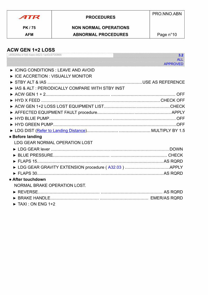
ACW GEN 1+2 LOSS_c858266e-b1b6-4aec-b623-1a40c9700866 3.2
ALLAPPROVED
▶ ICING CONDITIONS : LEAVE AND AVOID▶ ICE ACCRETION : VISUALLY MONITOR▶ STBY ALT & IAS ........................................................................USE AS REFERENCE▶ IAS & ALT : PERIODICALLY COMPARE WITH STBY INST▶ ACW GEN 1 + 2................................................. ................................................. OFF▶ HYD X FEED ............................................. ............................................. CHECK OFF▶ ACW GEN 1+2 LOSS LOST EQUIPMENT LIST..................................................CHECK▶ AFFECTED EQUIPMENT FAULT procedure............................ ............................APPLY▶ HYD BLUE PUMP................................................ ................................................ OFF▶ HYD GREEN PUMP..............................................................................................OFF▶ LDG DIST (Refer to Landing Distance)........................ ........................ MULTIPLY BY 1.5● Before landing
LDG GEAR NORMAL OPERATION LOST▶ LDG GEAR lever ..........................................................................................DOWN▶ BLUE PRESSURE........................................... ........................................... CHECK▶ FLAPS 15................................................ ................................................AS RQRD▶ LDG GEAR GRAVITY EXTENSION procedure ( A32.03 ) ..................................APPLY▶ FLAPS 30................................................ ................................................AS RQRD
● After touchdownNORMAL BRAKE OPERATION LOST.▶ REVERSE............................................... ............................................... AS RQRD▶ BRAKE HANDLE..................................... ..................................... EMER/AS RQRD▶ TAXI : ON ENG 1+2
PROCEDURESPRO.NNO.ABN
PK / 75 NON NORMAL OPERATIONSAFM ABNORMAL PROCEDURES Page n°10
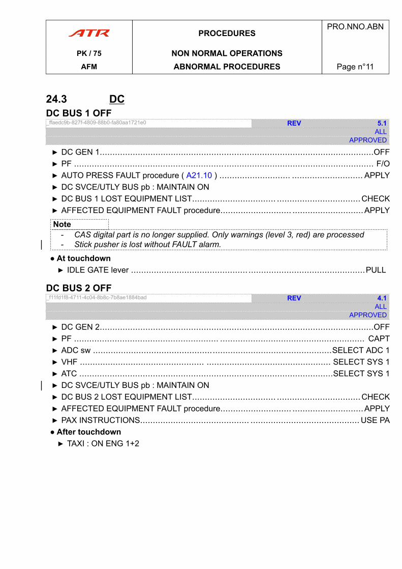
24.3 DCDC BUS 1 OFF_ffaedc9b-827f-4809-88b0-fa80aa1721e0 REV 5.1
ALLAPPROVED
▶ DC GEN 1............................................................................................................OFF▶ PF ...................................................................................................................... F/O▶ AUTO PRESS FAULT procedure ( A21.10 ) ............................ ............................ APPLY▶ DC SVCE/UTLY BUS pb : MAINTAIN ON▶ DC BUS 1 LOST EQUIPMENT LIST................................. .................................CHECK▶ AFFECTED EQUIPMENT FAULT procedure............................ ............................APPLY
Note- CAS digital part is no longer supplied. Only warnings (level 3, red) are processed- Stick pusher is lost without FAULT alarm.
● At touchdown▶ IDLE GATE lever ............................................................................................PULL
DC BUS 2 OFF_f11fd1f8-4711-4c04-8b8c-7b8ae1884bad REV 4.1
ALLAPPROVED
▶ DC GEN 2............................................................................................................OFF▶ PF ......................................................... ......................................................... CAPT▶ ADC sw ..............................................................................................SELECT ADC 1▶ VHF ................................................. ................................................. SELECT SYS 1▶ ATC ....................................................................................................SELECT SYS 1▶ DC SVCE/UTLY BUS pb : MAINTAIN ON▶ DC BUS 2 LOST EQUIPMENT LIST................................. .................................CHECK▶ AFFECTED EQUIPMENT FAULT procedure............................ ............................APPLY▶ PAX INSTRUCTIONS........................................... ........................................... USE PA● After touchdown▶ TAXI : ON ENG 1+2
PROCEDURESPRO.NNO.ABN
PK / 75 NON NORMAL OPERATIONSAFM ABNORMAL PROCEDURES Page n°11
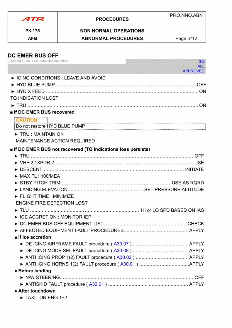
DC EMER BUS OFF_0058e085-94f7-4125-a4c4-6b004026db1a 3.6
ALLAPPROVED
▶ ICING CONDITIONS : LEAVE AND AVOID▶ HYD BLUE PUMP................................................ ................................................ OFF▶ HYD X FEED .................................................... ....................................................ONTQ INDICATION LOST▶ TRU .......................................................... .......................................................... ON■ If DC EMER BUS recovered
CAUTIONDo not restore HYD BLUE PUMP
▶ TRU : MAINTAIN ONMAINTENANCE ACTION REQUIRED
■ If DC EMER BUS not recovered (TQ indications loss persists)▶ TRU ....................................................... ....................................................... OFF▶ VHF 2 / XPDR 2............................................... ............................................... USE▶ DESCENT................................................ ................................................ INITIATE▶ MAX FL : 100/MEA▶ STBY PITCH TRIM............................................................................USE AS RQRD▶ LANDING ELEVATION....................................................SET PRESSURE ALTITUDE▶ FLIGHT TIME : MINIMIZEENGINE FIRE DETECTION LOST▶ TLU ..................................... ..................................... HI or LO SPD BASED ON IAS▶ ICE ACCRETION : MONITOR IEP▶ DC EMER BUS OFF EQUIPMENT LIST............................ ............................ CHECK▶ AFFECTED EQUIPMENT FAULT PROCEDURES...................... ......................APPLY■ If ice accretion▶ DE ICING AIRFRAME FAULT procedure ( A30.07 ) ......................................APPLY▶ DE ICING MODE SEL FAULT procedure ( A30.08 ) ......................................APPLY▶ ANTI ICING PROP 1(2) FAULT procedure ( A30.02 ) .................. ..................APPLY▶ ANTI ICING HORNS 1(2) FAULT procedure ( A30.01 ) ..................................APPLY
● Before landing▶ N/W STEERING............................................................................................OFF▶ ANTISKID FAULT procedure ( A32.01 ) ........................... ........................... APPLY
● After touchdown▶ TAXI : ON ENG 1+2
PROCEDURESPRO.NNO.ABN
PK / 75 NON NORMAL OPERATIONSAFM ABNORMAL PROCEDURES Page n°12
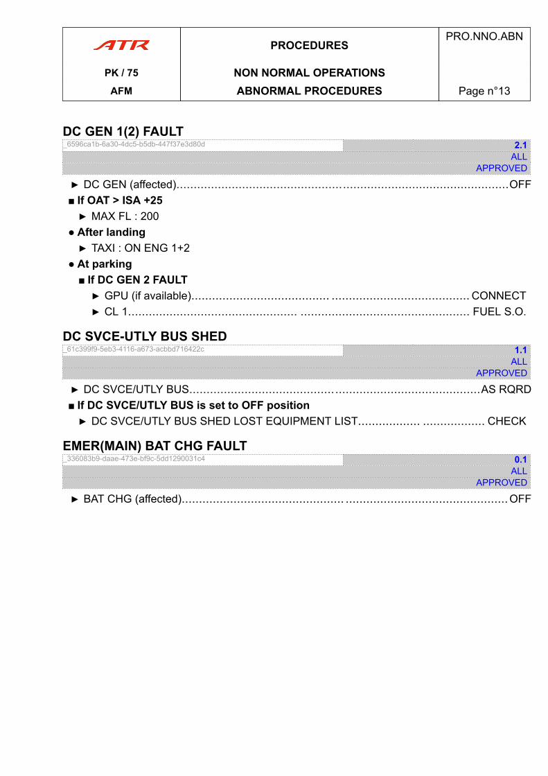
DC GEN 1(2) FAULT_6596ca1b-6a30-4dc5-b5db-447f37e3d80d 2.1
ALLAPPROVED
▶ DC GEN (affected)................................................................................................OFF■ If OAT > ISA +25▶ MAX FL : 200
● After landing▶ TAXI : ON ENG 1+2
● At parking■ If DC GEN 2 FAULT▶ GPU (if available)........................................ ........................................ CONNECT▶ CL 1................................................. ................................................. FUEL S.O.
DC SVCE-UTLY BUS SHED_61c399f9-5eb3-4116-a673-acbbd716422c 1.1
ALLAPPROVED
▶ DC SVCE/UTLY BUS....................................................................................AS RQRD■ If DC SVCE/UTLY BUS is set to OFF position▶ DC SVCE/UTLY BUS SHED LOST EQUIPMENT LIST.................. .................. CHECK
EMER(MAIN) BAT CHG FAULT_336083b9-daae-473e-bf9c-5dd1290031c4 0.1
ALLAPPROVED
▶ BAT CHG (affected)............................................... ...............................................OFF
PROCEDURESPRO.NNO.ABN
PK / 75 NON NORMAL OPERATIONSAFM ABNORMAL PROCEDURES Page n°13
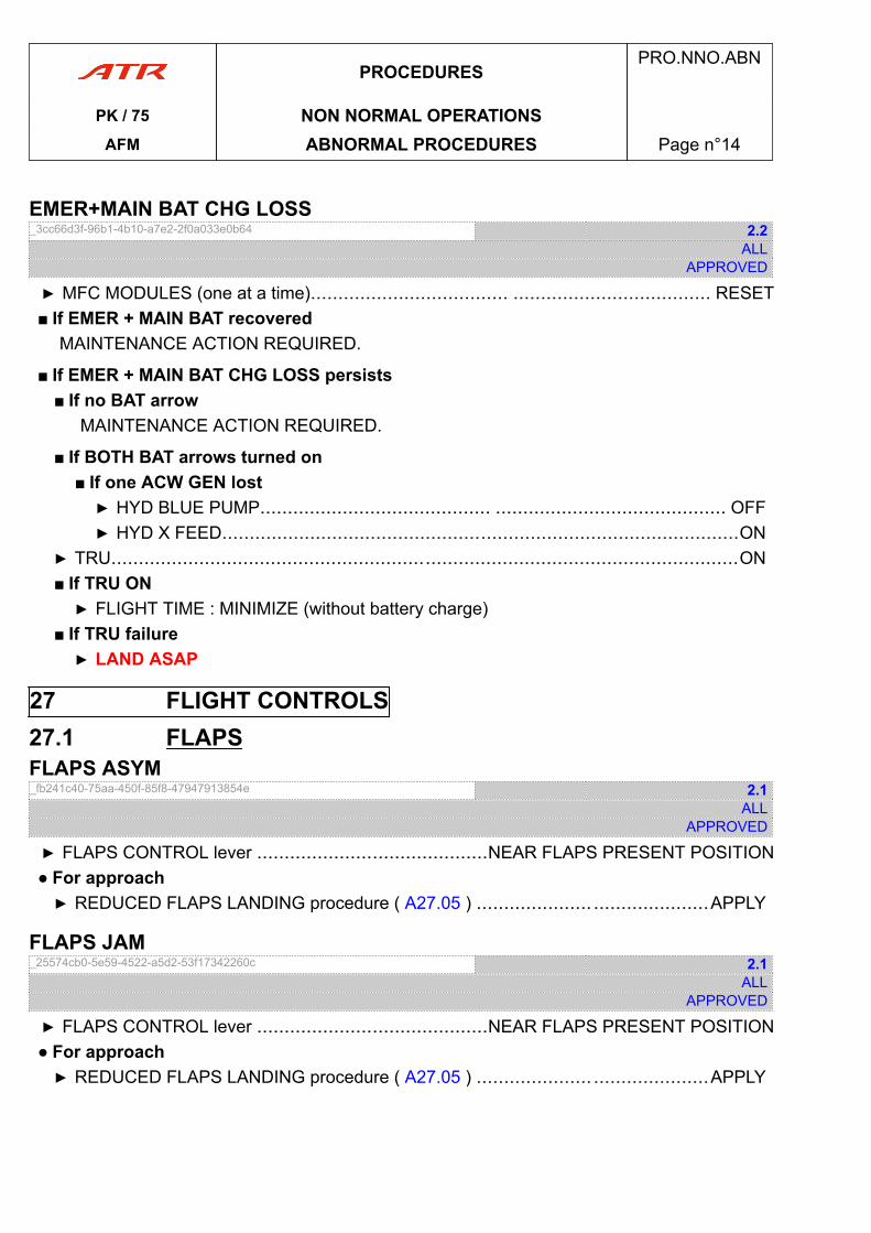
EMER+MAIN BAT CHG LOSS_3cc66d3f-96b1-4b10-a7e2-2f0a033e0b64 2.2
ALLAPPROVED
▶ MFC MODULES (one at a time).................................... .................................... RESET■ If EMER + MAIN BAT recovered
MAINTENANCE ACTION REQUIRED.
■ If EMER + MAIN BAT CHG LOSS persists■ If no BAT arrow
MAINTENANCE ACTION REQUIRED.
■ If BOTH BAT arrows turned on■ If one ACW GEN lost▶ HYD BLUE PUMP.......................................... .......................................... OFF▶ HYD X FEED..............................................................................................ON
▶ TRU..................................................................................................................ON■ If TRU ON▶ FLIGHT TIME : MINIMIZE (without battery charge)
■ If TRU failure▶ LAND ASAP
27 FLIGHT CONTROLS27.1 FLAPSFLAPS ASYM_fb241c40-75aa-450f-85f8-47947913854e 2.1
ALLAPPROVED
▶ FLAPS CONTROL lever ..........................................NEAR FLAPS PRESENT POSITION● For approach▶ REDUCED FLAPS LANDING procedure ( A27.05 ) ..................... .....................APPLY
FLAPS JAM_25574cb0-5e59-4522-a5d2-53f17342260c 2.1
ALLAPPROVED
▶ FLAPS CONTROL lever ..........................................NEAR FLAPS PRESENT POSITION● For approach▶ REDUCED FLAPS LANDING procedure ( A27.05 ) ..................... .....................APPLY
PROCEDURESPRO.NNO.ABN
PK / 75 NON NORMAL OPERATIONSAFM ABNORMAL PROCEDURES Page n°14
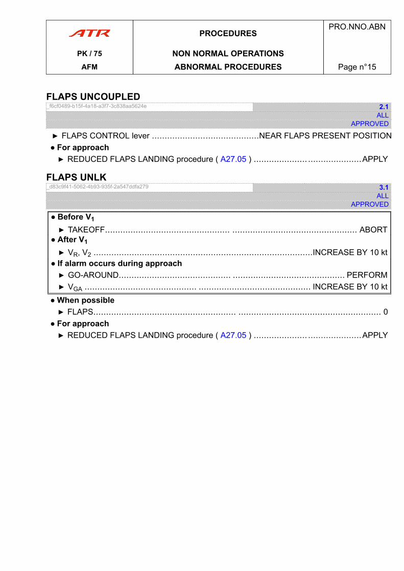
FLAPS UNCOUPLED_f6cf0489-b15f-4a18-a3f7-3c838aa5624e 2.1
ALLAPPROVED
▶ FLAPS CONTROL lever ..........................................NEAR FLAPS PRESENT POSITION● For approach▶ REDUCED FLAPS LANDING procedure ( A27.05 ) ..................... .....................APPLY
FLAPS UNLK_d83c9f41-5062-4b93-935f-2a547ddfa279 3.1
ALLAPPROVED
● Before V1
▶ TAKEOFF................................................. ................................................. ABORT● After V1
▶ VR, V2 ......................................................................................INCREASE BY 10 kt● If alarm occurs during approach▶ GO-AROUND............................................ ............................................ PERFORM▶ VGA ............................................ ............................................ INCREASE BY 10 kt
● When possible▶ FLAPS........................................................ ........................................................ 0
● For approach▶ REDUCED FLAPS LANDING procedure ( A27.05 ) ..................... .....................APPLY
PROCEDURESPRO.NNO.ABN
PK / 75 NON NORMAL OPERATIONSAFM ABNORMAL PROCEDURES Page n°15
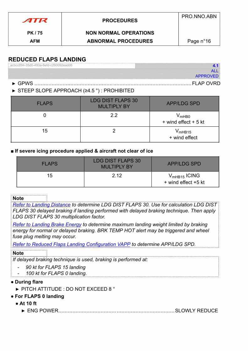
REDUCED FLAPS LANDING_acbcc094-35d0-493a-8efd-c260092eadd6 4.1
ALLAPPROVED
▶ GPWS .................................................. ..................................................FLAP OVRD▶ STEEP SLOPE APPROACH (≥4.5 °) : PROHIBITED
FLAPS LDG DIST FLAPS 30MULTIPLY BY APP/LDG SPD
0 2.2 VmHB0+ wind effect + 5 kt
15 2 VmHB15+ wind effect
■ If severe icing procedure applied & aircraft not clear of ice
FLAPS LDG DIST FLAPS 30MULTIPLY BY APP/LDG SPD
15 2.12 VmHB15 ICING+ wind effect +5 kt
NoteRefer to Landing Distance to determine LDG DIST FLAPS 30. Use for calculation LDG DISTFLAPS 30 delayed braking if landing performed with delayed braking technique. Then applyLDG DIST FLAPS 30 multiplication factor.Refer to Landing Brake Energy to determine maximum landing weight limited by brakingenergy for normal or delayed braking. BRK TEMP HOT alert may be triggered and wheelfuse plug melting may occur.Refer to Reduced Flaps Landing Configuration VAPP to determine APP/LDG SPD.
NoteIf delayed braking technique is used, braking is performed at:
- 90 kt for FLAPS 15 landing- 100 kt for FLAPS 0 landing.
● During flare▶ PITCH ATTITUDE : DO NOT EXCEED 8 °
● For FLAPS 0 landing● At 10 ft▶ ENG POWER..................................... .....................................SLOWLY REDUCE
PROCEDURESPRO.NNO.ABN
PK / 75 NON NORMAL OPERATIONSAFM ABNORMAL PROCEDURES Page n°16
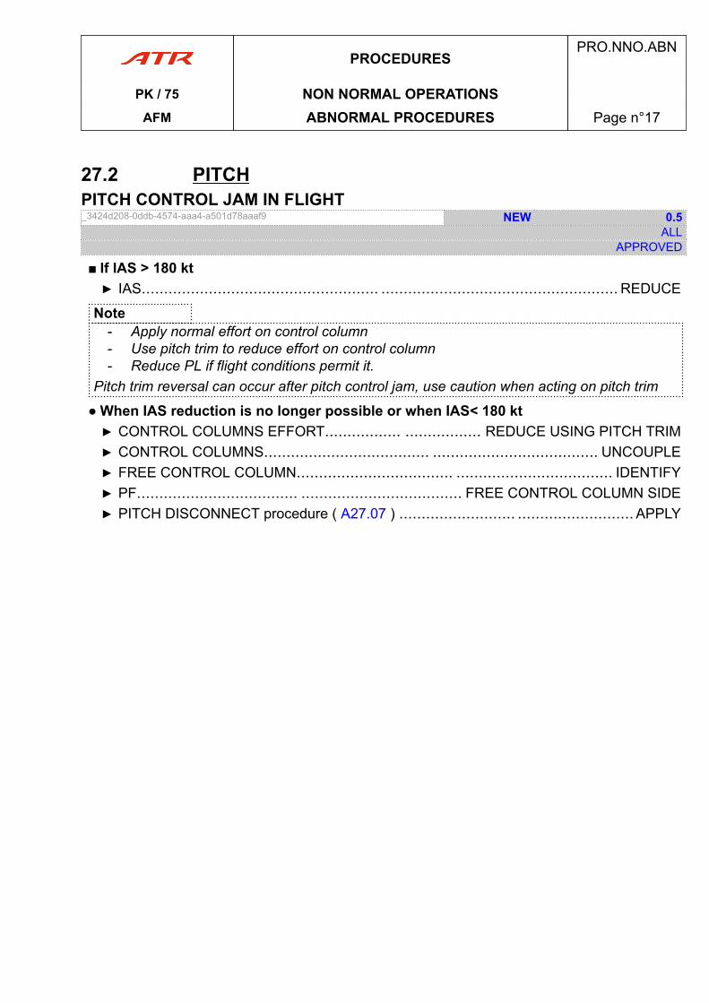
27.2 PITCHPITCH CONTROL JAM IN FLIGHT_3424d208-0ddb-4574-aaa4-a501d78aaaf9 NEW 0.5
ALLAPPROVED
■ If IAS > 180 kt▶ IAS..................................................... ..................................................... REDUCE
Note- Apply normal effort on control column- Use pitch trim to reduce effort on control column- Reduce PL if flight conditions permit it.
Pitch trim reversal can occur after pitch control jam, use caution when acting on pitch trim
● When IAS reduction is no longer possible or when IAS< 180 kt▶ CONTROL COLUMNS EFFORT................. ................. REDUCE USING PITCH TRIM▶ CONTROL COLUMNS..................................... ..................................... UNCOUPLE▶ FREE CONTROL COLUMN................................... ................................... IDENTIFY▶ PF.................................... .................................... FREE CONTROL COLUMN SIDE▶ PITCH DISCONNECT procedure ( A27.07 ) .......................... .......................... APPLY
PROCEDURESPRO.NNO.ABN
PK / 75 NON NORMAL OPERATIONSAFM ABNORMAL PROCEDURES Page n°17
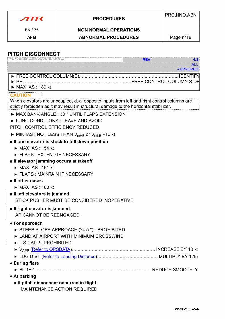
PITCH DISCONNECT_7097bc84-1837-4948-9e23-3ffb09f016e9 REV 4.3
ALLAPPROVED
▶ FREE CONTROL COLUMN(S)......................................................................IDENTIFY▶ PF ............................................................................FREE CONTROL COLUMN SIDE▶ MAX IAS : 180 kt
CAUTIONWhen elevators are uncoupled, dual opposite inputs from left and right control columns arestrictly forbidden as it may result in structural damage to the horizontal stabilizer.
▶ MAX BANK ANGLE : 30 ° UNTIL FLAPS EXTENSION▶ ICING CONDITIONS : LEAVE AND AVOIDPITCH CONTROL EFFICIENCY REDUCED▶ MIN IAS : NOT LESS THAN VmHB or VmLB +10 kt■ If one elevator is stuck to full down position▶ MAX IAS : 154 kt▶ FLAPS : EXTEND IF NECESSARY
■ If elevator jamming occurs at takeoff▶ MAX IAS : 161 kt▶ FLAPS : MAINTAIN IF NECESSARY
■ If other cases▶ MAX IAS : 180 kt
■ If left elevators is jammedSTICK PUSHER MUST BE CONSIDERED INOPERATIVE.
■ If right elevator is jammedAP CANNOT BE REENGAGED.
● For approach▶ STEEP SLOPE APPROACH (≥4.5 °) : PROHIBITED▶ LAND AT AIRPORT WITH MINIMUM CROSSWIND▶ ILS CAT 2 : PROHIBITED▶ VAPP (Refer to OPSDATA)............................. ............................. INCREASE BY 10 kt▶ LDG DIST (Refer to Landing Distance)..................... ..................... MULTIPLY BY 1.15
● During flare▶ PL 1+2......................................... ......................................... REDUCE SMOOTHLY
● At parking■ If pitch disconnect occurred in flight
MAINTENANCE ACTION REQUIRED
PROCEDURESPRO.NNO.ABN
PK / 75 NON NORMAL OPERATIONSAFM ABNORMAL PROCEDURES Page n°18
cont'd…
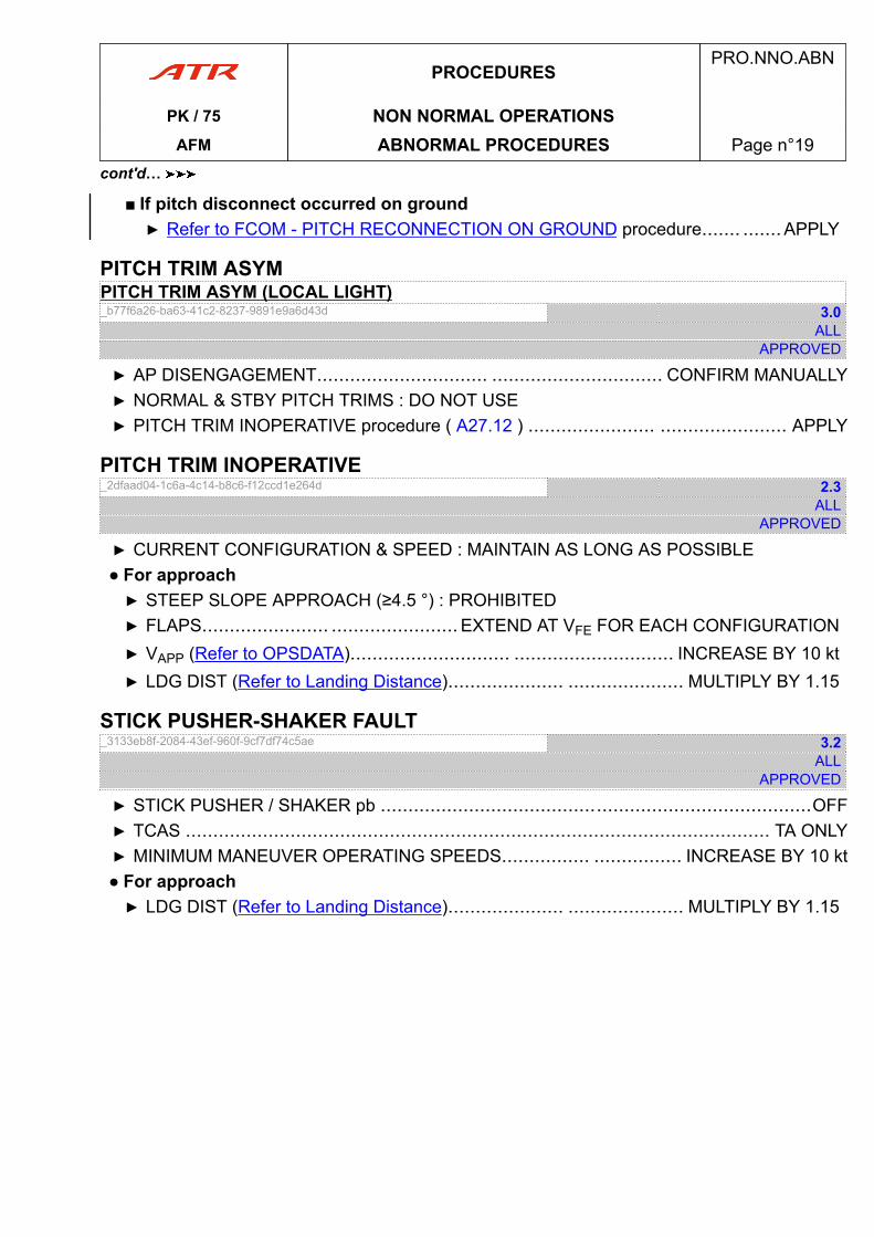
■ If pitch disconnect occurred on ground▶ Refer to FCOM - PITCH RECONNECTION ON GROUND procedure....... .......APPLY
PITCH TRIM ASYMPITCH TRIM ASYM (LOCAL LIGHT)_b77f6a26-ba63-41c2-8237-9891e9a6d43d 3.0
ALLAPPROVED
▶ AP DISENGAGEMENT............................... ............................... CONFIRM MANUALLY▶ NORMAL & STBY PITCH TRIMS : DO NOT USE▶ PITCH TRIM INOPERATIVE procedure ( A27.12 ) ....................... ....................... APPLY
PITCH TRIM INOPERATIVE_2dfaad04-1c6a-4c14-b8c6-f12ccd1e264d 2.3
ALLAPPROVED
▶ CURRENT CONFIGURATION & SPEED : MAINTAIN AS LONG AS POSSIBLE● For approach▶ STEEP SLOPE APPROACH (≥4.5 °) : PROHIBITED▶ FLAPS....................... ....................... EXTEND AT VFE FOR EACH CONFIGURATION▶ VAPP (Refer to OPSDATA)............................. ............................. INCREASE BY 10 kt▶ LDG DIST (Refer to Landing Distance)..................... ..................... MULTIPLY BY 1.15
STICK PUSHER-SHAKER FAULT_3133eb8f-2084-43ef-960f-9cf7df74c5ae 3.2
ALLAPPROVED
▶ STICK PUSHER / SHAKER pb ..............................................................................OFF▶ TCAS .......................................................................................................... TA ONLY▶ MINIMUM MANEUVER OPERATING SPEEDS................ ................ INCREASE BY 10 kt● For approach▶ LDG DIST (Refer to Landing Distance)..................... ..................... MULTIPLY BY 1.15
PROCEDURESPRO.NNO.ABN
PK / 75 NON NORMAL OPERATIONSAFM ABNORMAL PROCEDURES Page n°19
cont'd…
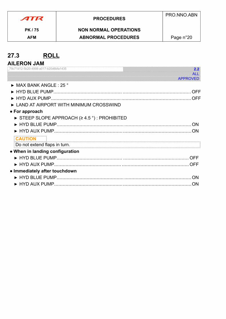
27.3 ROLLAILERON JAM_79c71d12-5b20-4998-a017-b20d6bfa1435 2.2
ALLAPPROVED
▶ MAX BANK ANGLE : 25 °▶ HYD BLUE PUMP................................................ ................................................ OFF▶ HYD AUX PUMP................................................. .................................................OFF▶ LAND AT AIRPORT WITH MINIMUM CROSSWIND● For approach▶ STEEP SLOPE APPROACH (≥ 4.5 °) : PROHIBITED▶ HYD BLUE PUMP............................................... ...............................................ON▶ HYD AUX PUMP................................................ ................................................ON
CAUTIONDo not extend flaps in turn.
● When in landing configuration▶ HYD BLUE PUMP.............................................. .............................................. OFF▶ HYD AUX PUMP............................................... ............................................... OFF
● Immediately after touchdown▶ HYD BLUE PUMP............................................... ...............................................ON▶ HYD AUX PUMP................................................ ................................................ON
PROCEDURESPRO.NNO.ABN
PK / 75 NON NORMAL OPERATIONSAFM ABNORMAL PROCEDURES Page n°20
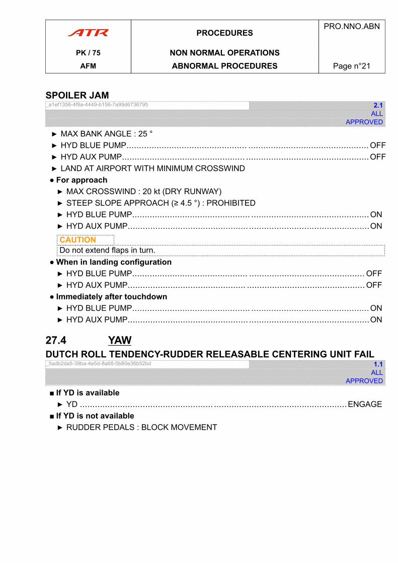
SPOILER JAM_a1ef1356-4f9a-4449-b156-7a99d6736795 2.1
ALLAPPROVED
▶ MAX BANK ANGLE : 25 °▶ HYD BLUE PUMP................................................ ................................................ OFF▶ HYD AUX PUMP................................................. .................................................OFF▶ LAND AT AIRPORT WITH MINIMUM CROSSWIND● For approach▶ MAX CROSSWIND : 20 kt (DRY RUNWAY)▶ STEEP SLOPE APPROACH (≥ 4.5 °) : PROHIBITED▶ HYD BLUE PUMP............................................... ...............................................ON▶ HYD AUX PUMP................................................ ................................................ON
CAUTIONDo not extend flaps in turn.
● When in landing configuration▶ HYD BLUE PUMP.............................................. .............................................. OFF▶ HYD AUX PUMP............................................... ............................................... OFF
● Immediately after touchdown▶ HYD BLUE PUMP............................................... ...............................................ON▶ HYD AUX PUMP................................................ ................................................ON
27.4 YAWDUTCH ROLL TENDENCY-RUDDER RELEASABLE CENTERING UNIT FAIL_5adb2da5-39ba-4e5d-8a68-0b80e36b52bd 1.1
ALLAPPROVED
■ If YD is available▶ YD ..................................................... .....................................................ENGAGE
■ If YD is not available▶ RUDDER PEDALS : BLOCK MOVEMENT
PROCEDURESPRO.NNO.ABN
PK / 75 NON NORMAL OPERATIONSAFM ABNORMAL PROCEDURES Page n°21
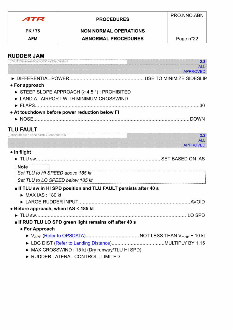
RUDDER JAM_574d1539-ade9-40a8-8851-fe33ec599bc7 2.3
ALLAPPROVED
▶ DIFFERENTIAL POWER......................... ......................... USE TO MINIMIZE SIDESLIP● For approach▶ STEEP SLOPE APPROACH (≥ 4.5 °) : PROHIBITED▶ LAND AT AIRPORT WITH MINIMUM CROSSWIND▶ FLAPS................................................................................................................30
● At touchdown before power reduction below FI▶ NOSE..........................................................................................................DOWN
TLU FAULT_0f6850f9-84f7-455c-a1bb-79e6b8f84e05 2.2
ALLAPPROVED
● In flight▶ TLU sw.......................................... .......................................... SET BASED ON IAS
NoteSet TLU to HI SPEED above 185 ktSet TLU to LO SPEED below 185 kt
■ If TLU sw in HI SPD position and TLU FAULT persists after 40 s▶ MAX IAS : 180 kt▶ LARGE RUDDER INPUT............................................................................AVOID
● Before approach, when IAS < 185 kt▶ TLU sw...................................................................................................... LO SPD■ If RUD TLU LO SPD green light remains off after 40 s
● For Approach▶ VAPP (Refer to OPSDATA).................. ..................NOT LESS THAN VmHB + 10 kt▶ LDG DIST (Refer to Landing Distance)....................................MULTIPLY BY 1.15▶ MAX CROSSWIND : 15 kt (Dry runway/TLU HI SPD)▶ RUDDER LATERAL CONTROL : LIMITED
PROCEDURESPRO.NNO.ABN
PK / 75 NON NORMAL OPERATIONSAFM ABNORMAL PROCEDURES Page n°22
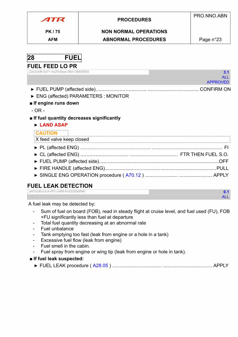
28 FUELFUEL FEED LO PR_22e3cbf6-0d71-4a29-8eac-96e138406950 3.1
ALLAPPROVED
▶ FUEL PUMP (affected side).................................. .................................. CONFIRM ON▶ ENG (affected) PARAMETERS : MONITOR■ If engine runs down- OR -
■ If fuel quantity decreases significantly▶ LAND ASAPCAUTIONX feed valve keep closed
▶ PL (affected ENG) ............................................... ............................................... FI▶ CL (affected ENG) ................................ ................................ FTR THEN FUEL S.O.▶ FUEL PUMP (affected side)................................................................................OFF▶ FIRE HANDLE (affected ENG)..........................................................................PULL▶ SINGLE ENG OPERATION procedure ( A70.12 ) ...................... ...................... APPLY
FUEL LEAK DETECTION_e4f1bcf6-a1c4-4f7c-b4f9-91d32d0ef846 0.1
ALL
A fuel leak may be detected by:- Sum of fuel on board (FOB), read in steady flight at cruise level, and fuel used (FU), FOB
+FU significantly less than fuel at departure- Total fuel quantity decreasing at an abnormal rate- Fuel unbalance- Tank emptying too fast (leak from engine or a hole in a tank)- Excessive fuel flow (leak from engine)- Fuel smell in the cabin.- Fuel spray from engine or wing tip (leak from engine or hole in tank).
■ If fuel leak suspected:▶ FUEL LEAK procedure ( A28.05 ) ................................. ................................. APPLY
PROCEDURESPRO.NNO.ABN
PK / 75 NON NORMAL OPERATIONSAFM ABNORMAL PROCEDURES Page n°23
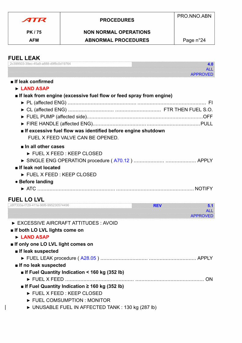
FUEL LEAK_2c399503-39ec-45a9-a888-d9f8c0d19764 4.0
ALLAPPROVED
■ If leak confirmed▶ LAND ASAP■ If leak from engine (excessive fuel flow or feed spray from engine)▶ PL (affected ENG) ............................................. ............................................. FI▶ CL (affected ENG) .............................. .............................. FTR THEN FUEL S.O.▶ FUEL PUMP (affected side)............................................................................OFF▶ FIRE HANDLE (affected ENG)................................... ...................................PULL■ If excessive fuel flow was identified before engine shutdown
FUEL X FEED VALVE CAN BE OPENED.
■ In all other cases▶ FUEL X FEED : KEEP CLOSED
▶ SINGLE ENG OPERATION procedure ( A70.12 ) .................... .................... APPLY■ If leak not located▶ FUEL X FEED : KEEP CLOSED
● Before landing▶ ATC ................................................... ................................................... NOTIFY
FUEL LO LVL_c6f7333a-f729-411e-96f6-995230574496 REV 5.1
ALLAPPROVED
▶ EXCESSIVE AIRCRAFT ATTITUDES : AVOID■ If both LO LVL lights come on▶ LAND ASAP
■ If only one LO LVL light comes on■ If leak suspected▶ FUEL LEAK procedure ( A28.05 ) ............................... ............................... APPLY
■ If no leak suspected■ If Fuel Quantity Indication < 160 kg (352 lb)▶ FUEL X FEED ............................................. ............................................. ON
■ If Fuel Quantity Indication ≥ 160 kg (352 lb)▶ FUEL X FEED : KEEP CLOSED▶ FUEL COMSUMPTION : MONITOR▶ UNUSABLE FUEL IN AFFECTED TANK : 130 kg (287 lb)
PROCEDURESPRO.NNO.ABN
PK / 75 NON NORMAL OPERATIONSAFM ABNORMAL PROCEDURES Page n°24
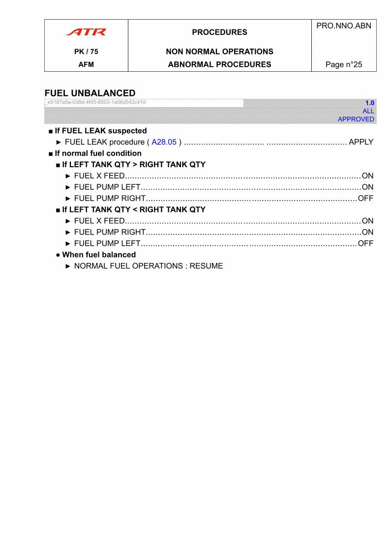
FUEL UNBALANCED_e5187a5a-038d-4f45-8503-1a06d542c41d 1.0
ALLAPPROVED
■ If FUEL LEAK suspected▶ FUEL LEAK procedure ( A28.05 ) ................................. ................................. APPLY
■ If normal fuel condition■ If LEFT TANK QTY > RIGHT TANK QTY▶ FUEL X FEED................................................................................................ON▶ FUEL PUMP LEFT..........................................................................................ON▶ FUEL PUMP RIGHT......................................................................................OFF
■ If LEFT TANK QTY < RIGHT TANK QTY▶ FUEL X FEED................................................................................................ON▶ FUEL PUMP RIGHT........................................................................................ON▶ FUEL PUMP LEFT........................................................................................OFF
● When fuel balanced▶ NORMAL FUEL OPERATIONS : RESUME
PROCEDURESPRO.NNO.ABN
PK / 75 NON NORMAL OPERATIONSAFM ABNORMAL PROCEDURES Page n°25
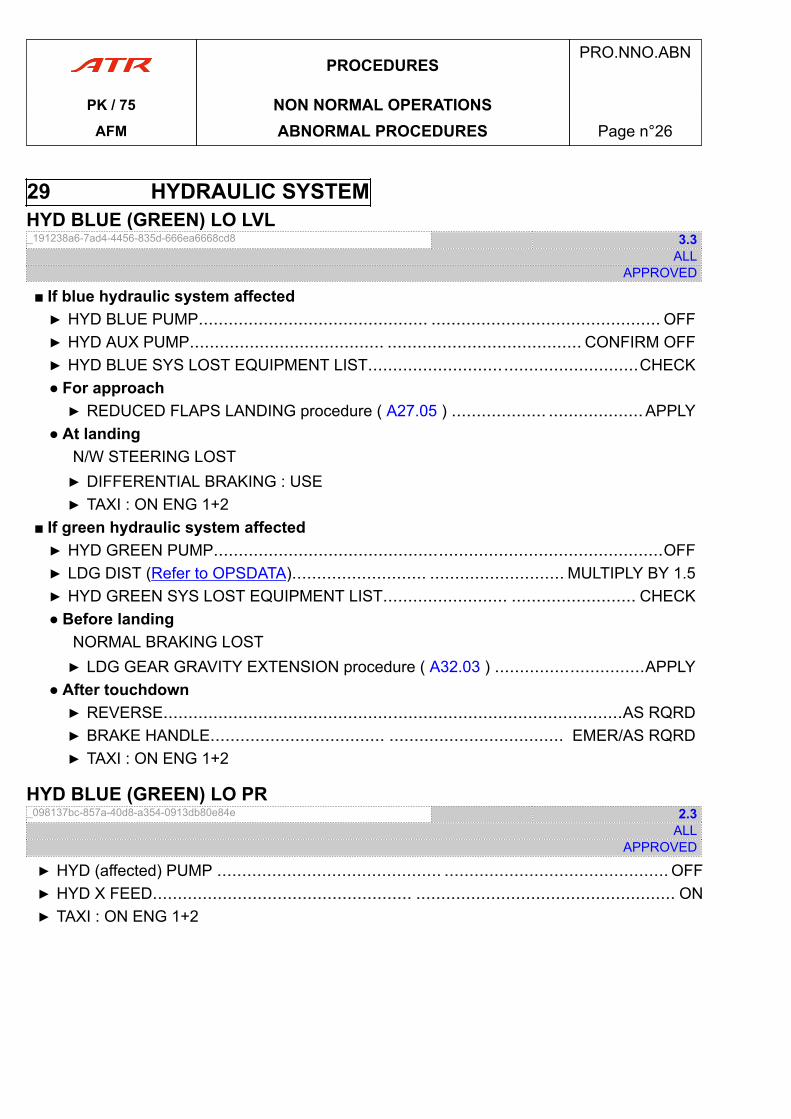
29 HYDRAULIC SYSTEMHYD BLUE (GREEN) LO LVL_191238a6-7ad4-4456-835d-666ea6668cd8 3.3
ALLAPPROVED
■ If blue hydraulic system affected▶ HYD BLUE PUMP.............................................. .............................................. OFF▶ HYD AUX PUMP....................................... ....................................... CONFIRM OFF▶ HYD BLUE SYS LOST EQUIPMENT LIST......................................................CHECK● For approach▶ REDUCED FLAPS LANDING procedure ( A27.05 ) ................... ...................APPLY
● At landingN/W STEERING LOST▶ DIFFERENTIAL BRAKING : USE▶ TAXI : ON ENG 1+2
■ If green hydraulic system affected▶ HYD GREEN PUMP..........................................................................................OFF▶ LDG DIST (Refer to OPSDATA)........................... ........................... MULTIPLY BY 1.5▶ HYD GREEN SYS LOST EQUIPMENT LIST......................... ......................... CHECK● Before landing
NORMAL BRAKING LOST▶ LDG GEAR GRAVITY EXTENSION procedure ( A32.03 ) ..............................APPLY
● After touchdown▶ REVERSE............................................................................................AS RQRD▶ BRAKE HANDLE................................... ................................... EMER/AS RQRD▶ TAXI : ON ENG 1+2
HYD BLUE (GREEN) LO PR_098137bc-857a-40d8-a354-0913db80e84e 2.3
ALLAPPROVED
▶ HYD (affected) PUMP ............................................. ............................................. OFF▶ HYD X FEED.................................................... .................................................... ON▶ TAXI : ON ENG 1+2
PROCEDURESPRO.NNO.ABN
PK / 75 NON NORMAL OPERATIONSAFM ABNORMAL PROCEDURES Page n°26
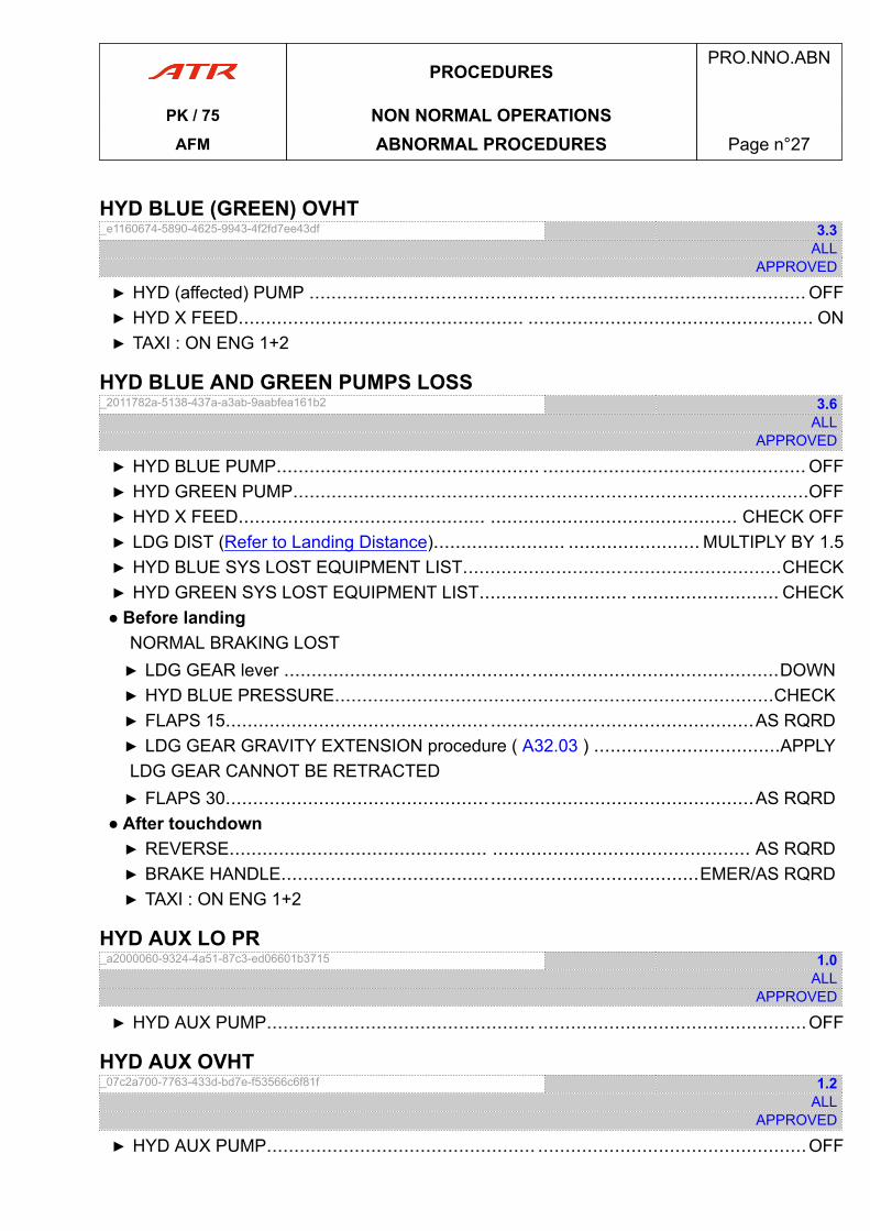
HYD BLUE (GREEN) OVHT_e1160674-5890-4625-9943-4f2fd7ee43df 3.3
ALLAPPROVED
▶ HYD (affected) PUMP ............................................. ............................................. OFF▶ HYD X FEED.................................................... .................................................... ON▶ TAXI : ON ENG 1+2
HYD BLUE AND GREEN PUMPS LOSS_2011782a-5138-437a-a3ab-9aabfea161b2 3.6
ALLAPPROVED
▶ HYD BLUE PUMP................................................ ................................................ OFF▶ HYD GREEN PUMP..............................................................................................OFF▶ HYD X FEED............................................. ............................................. CHECK OFF▶ LDG DIST (Refer to Landing Distance)........................ ........................ MULTIPLY BY 1.5▶ HYD BLUE SYS LOST EQUIPMENT LIST..........................................................CHECK▶ HYD GREEN SYS LOST EQUIPMENT LIST........................... ........................... CHECK● Before landing
NORMAL BRAKING LOST▶ LDG GEAR lever ..........................................................................................DOWN▶ HYD BLUE PRESSURE................................................................................CHECK▶ FLAPS 15................................................ ................................................AS RQRD▶ LDG GEAR GRAVITY EXTENSION procedure ( A32.03 ) ..................................APPLYLDG GEAR CANNOT BE RETRACTED▶ FLAPS 30................................................ ................................................AS RQRD
● After touchdown▶ REVERSE............................................... ............................................... AS RQRD▶ BRAKE HANDLE............................................................................EMER/AS RQRD▶ TAXI : ON ENG 1+2
HYD AUX LO PR_a2000060-9324-4a51-87c3-ed06601b3715 1.0
ALLAPPROVED
▶ HYD AUX PUMP................................................. .................................................OFF
HYD AUX OVHT_07c2a700-7763-433d-bd7e-f53566c6f81f 1.2
ALLAPPROVED
▶ HYD AUX PUMP................................................. .................................................OFF
PROCEDURESPRO.NNO.ABN
PK / 75 NON NORMAL OPERATIONSAFM ABNORMAL PROCEDURES Page n°27
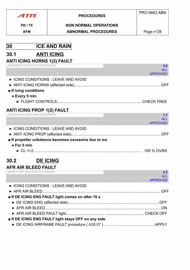
30 ICE AND RAIN30.1 ANTI ICINGANTI ICING HORNS 1(2) FAULT_6d786588-d174-4815-8719-f57398c6c063 2.0
ALLAPPROVED
▶ ICING CONDITIONS : LEAVE AND AVOID▶ ANTI ICING HORNS (affected side)........................................................................OFF■ If icing conditions
● Every 5 min▶ FLIGHT CONTROLS................................... ................................... CHECK FREE
ANTI ICING PROP 1(2) FAULT_54c30b8a-391c-4267-8e6b-a52e783893e2 1.1
ALLAPPROVED
▶ ICING CONDITIONS : LEAVE AND AVOID▶ ANTI ICING PROP (affected side)..................................... ..................................... OFF■ If propeller unbalance becomes excessive due to ice
● For 5 min▶ CL 1+2............................................. ............................................. 100 % OVRD
30.2 DE ICINGAFR AIR BLEED FAULT_deef5c13-8f91-4dd9-8029-70cca940046a 2.2
ALLAPPROVED
▶ ICING CONDITIONS : LEAVE AND AVOID▶ AFR AIR BLEED................................................. ................................................. OFF■ If DE ICING ENG FAULT light comes on after 10 s▶ DE ICING ENG (affected side)............................................................................OFF▶ AFR AIR BLEED................................................ ................................................ ON▶ AFR AIR BLEED FAULT light................................ ................................ CHECK OFF
■ If DE ICING ENG FAULT light stays OFF on any side▶ DE ICING AIRFRAME FAULT procedure ( A30.07 ) ..........................................APPLY
PROCEDURESPRO.NNO.ABN
PK / 75 NON NORMAL OPERATIONSAFM ABNORMAL PROCEDURES Page n°28
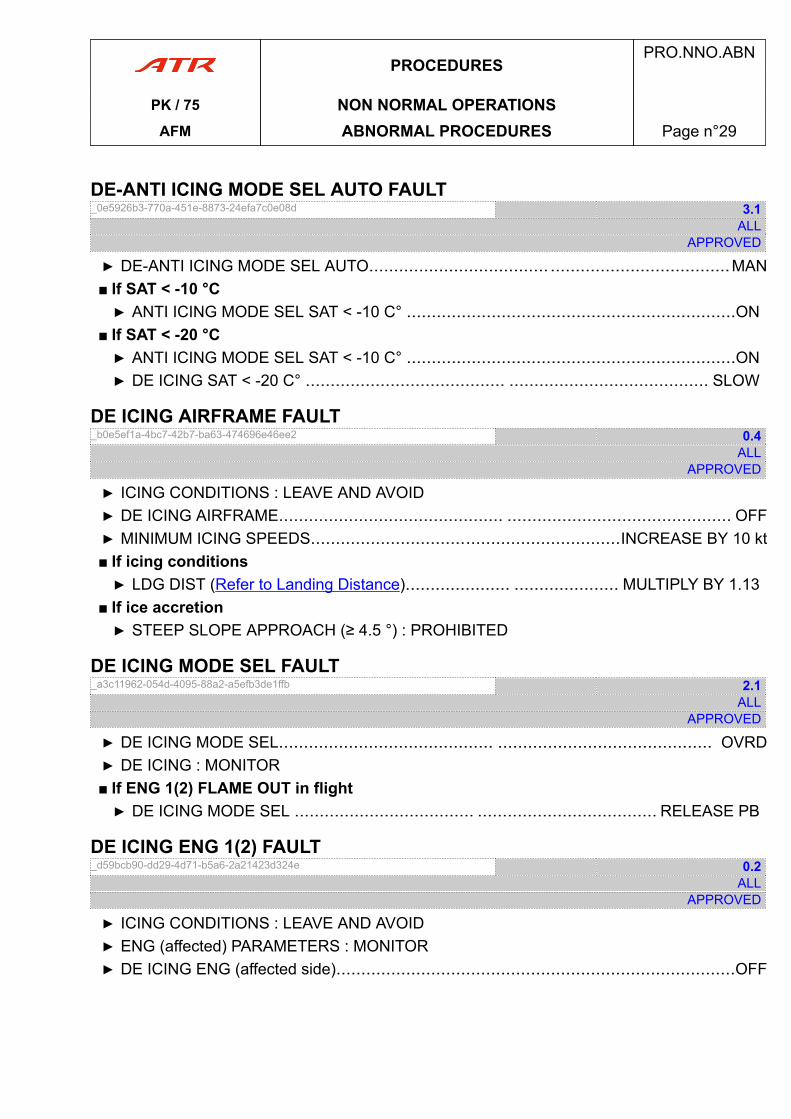
DE-ANTI ICING MODE SEL AUTO FAULT_0e5926b3-770a-451e-8873-24efa7c0e08d 3.1
ALLAPPROVED
▶ DE-ANTI ICING MODE SEL AUTO.................................... ....................................MAN■ If SAT < -10 °C▶ ANTI ICING MODE SEL SAT < -10 C° ..................................................................ON
■ If SAT < -20 °C▶ ANTI ICING MODE SEL SAT < -10 C° ..................................................................ON▶ DE ICING SAT < -20 C° ........................................ ........................................ SLOW
DE ICING AIRFRAME FAULT_b0e5ef1a-4bc7-42b7-ba63-474696e46ee2 0.4
ALLAPPROVED
▶ ICING CONDITIONS : LEAVE AND AVOID▶ DE ICING AIRFRAME............................................. ............................................. OFF▶ MINIMUM ICING SPEEDS..............................................................INCREASE BY 10 kt■ If icing conditions▶ LDG DIST (Refer to Landing Distance)..................... ..................... MULTIPLY BY 1.13
■ If ice accretion▶ STEEP SLOPE APPROACH (≥ 4.5 °) : PROHIBITED
DE ICING MODE SEL FAULT_a3c11962-054d-4095-88a2-a5efb3de1ffb 2.1
ALLAPPROVED
▶ DE ICING MODE SEL........................................... ........................................... OVRD▶ DE ICING : MONITOR■ If ENG 1(2) FLAME OUT in flight▶ DE ICING MODE SEL .................................... .................................... RELEASE PB
DE ICING ENG 1(2) FAULT_d59bcb90-dd29-4d71-b5a6-2a21423d324e 0.2
ALLAPPROVED
▶ ICING CONDITIONS : LEAVE AND AVOID▶ ENG (affected) PARAMETERS : MONITOR▶ DE ICING ENG (affected side)................................................................................OFF
PROCEDURESPRO.NNO.ABN
PK / 75 NON NORMAL OPERATIONSAFM ABNORMAL PROCEDURES Page n°29
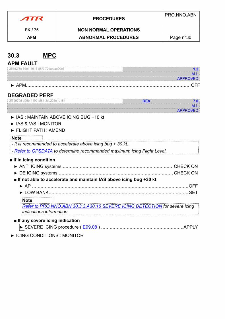
30.3 MPCAPM FAULT_251d2f3c-39e1-4615-88f0-72faeeae90c6 1.2
ALLAPPROVED
▶ APM....................................................................................................................OFF
DEGRADED PERF_2f79979d-d05b-4192-af81-3dc226e1b184 REV 7.0
ALLAPPROVED
▶ IAS : MAINTAIN ABOVE ICING BUG +10 kt▶ IAS & V/S : MONITOR▶ FLIGHT PATH : AMEND
Note- It is recommended to accelerate above icing bug + 30 kt.- Refer to OPSDATA to determine recommended maximum icing Flight Level.
■ If in icing condition▶ ANTI ICING systems ..............................................................................CHECK ON▶ DE ICING systems ........................................ ........................................ CHECK ON■ If not able to accelerate and maintain IAS above icing bug +30 kt▶ AP ..............................................................................................................OFF▶ LOW BANK................................................. .................................................SET
NoteRefer to PRO.NNO.ABN.30.3.3.A30.16 SEVERE ICING DETECTION for severe icingindications information
■ If any severe icing indication▶ SEVERE ICING procedure ( E99.08 ) ..........................................................APPLY
▶ ICING CONDITIONS : MONITOR
PROCEDURESPRO.NNO.ABN
PK / 75 NON NORMAL OPERATIONSAFM ABNORMAL PROCEDURES Page n°30
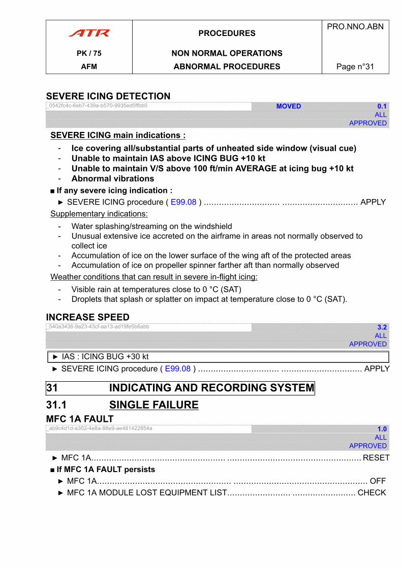
SEVERE ICING DETECTION_0542fc4c-6eb7-439a-b570-9935ed5ffbb0 MOVED 0.1
ALLAPPROVED
SEVERE ICING main indications :- Ice covering all/substantial parts of unheated side window (visual cue)- Unable to maintain IAS above ICING BUG +10 kt- Unable to maintain V/S above 100 ft/min AVERAGE at icing bug +10 kt- Abnormal vibrations
■ If any severe icing indication :▶ SEVERE ICING procedure ( E99.08 ) .............................. .............................. APPLY
Supplementary indications:- Water splashing/streaming on the windshield- Unusual extensive ice accreted on the airframe in areas not normally observed to
collect ice- Accumulation of ice on the lower surface of the wing aft of the protected areas- Accumulation of ice on propeller spinner farther aft than normally observed
Weather conditions that can result in severe in-flight icing:- Visible rain at temperatures close to 0 °C (SAT)- Droplets that splash or splatter on impact at temperature close to 0 °C (SAT).
INCREASE SPEED_540a3436-9a23-43cf-aa13-ad19fe5b6abb 3.2
ALLAPPROVED
▶ IAS : ICING BUG +30 kt▶ SEVERE ICING procedure ( E99.08 ) ................................ ................................ APPLY
31 INDICATING AND RECORDING SYSTEM31.1 SINGLE FAILUREMFC 1A FAULT_ab9c4d1d-a302-4e8a-88e9-ae481422854a 1.0
ALLAPPROVED
▶ MFC 1A..................................................... ..................................................... RESET■ If MFC 1A FAULT persists▶ MFC 1A..................................................... ..................................................... OFF▶ MFC 1A MODULE LOST EQUIPMENT LIST......................... ......................... CHECK
PROCEDURESPRO.NNO.ABN
PK / 75 NON NORMAL OPERATIONSAFM ABNORMAL PROCEDURES Page n°31
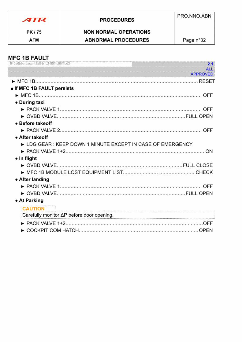
MFC 1B FAULT_640a6b9a-baca-42a8-b1c2-55f4c96f1bd3 2.1
ALLAPPROVED
▶ MFC 1B..................................................... ..................................................... RESET■ If MFC 1B FAULT persists▶ MFC 1B..................................................... ..................................................... OFF● During taxi▶ PACK VALVE 1.............................................. .............................................. OFF▶ OVBD VALVE....................................................................................FULL OPEN
● Before takeoff▶ PACK VALVE 2.............................................. .............................................. OFF
● After takeoff▶ LDG GEAR : KEEP DOWN 1 MINUTE EXCEPT IN CASE OF EMERGENCY▶ PACK VALVE 1+2............................................. ............................................. ON
● In flight▶ OVBD VALVE......................................... .........................................FULL CLOSE▶ MFC 1B MODULE LOST EQUIPMENT LIST....................... ....................... CHECK
● After landing▶ PACK VALVE 1.............................................. .............................................. OFF▶ OVBD VALVE....................................................................................FULL OPEN
● At ParkingCAUTIONCarefully monitor ΔP before door opening.
▶ PACK VALVE 1+2..........................................................................................OFF▶ COCKPIT COM HATCH....................................... .......................................OPEN
PROCEDURESPRO.NNO.ABN
PK / 75 NON NORMAL OPERATIONSAFM ABNORMAL PROCEDURES Page n°32
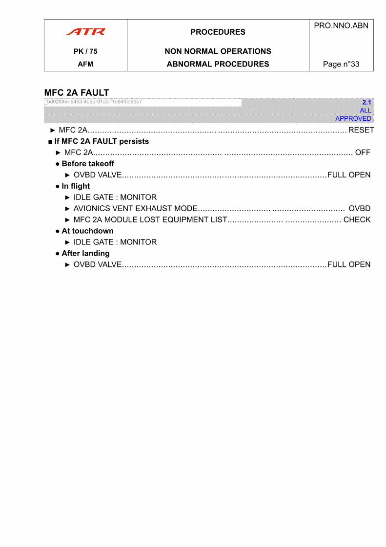
MFC 2A FAULT_bd02f06e-9453-4d3a-91a0-f1e94f0d6db7 2.1
ALLAPPROVED
▶ MFC 2A..................................................... ..................................................... RESET■ If MFC 2A FAULT persists▶ MFC 2A..................................................... ..................................................... OFF● Before takeoff▶ OVBD VALVE....................................................................................FULL OPEN
● In flight▶ IDLE GATE : MONITOR▶ AVIONICS VENT EXHAUST MODE.............................. .............................. OVBD▶ MFC 2A MODULE LOST EQUIPMENT LIST....................... ....................... CHECK
● At touchdown▶ IDLE GATE : MONITOR
● After landing▶ OVBD VALVE....................................................................................FULL OPEN
PROCEDURESPRO.NNO.ABN
PK / 75 NON NORMAL OPERATIONSAFM ABNORMAL PROCEDURES Page n°33
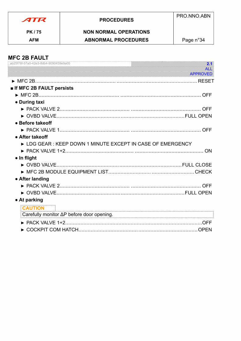
MFC 2B FAULT_ab25f78f-57a0-42e3-8db4-9090459e9a05 2.1
ALLAPPROVED
▶ MFC 2B..................................................... ..................................................... RESET■ If MFC 2B FAULT persists▶ MFC 2B..................................................... ..................................................... OFF● During taxi▶ PACK VALVE 2.............................................. .............................................. OFF▶ OVBD VALVE....................................................................................FULL OPEN
● Before takeoff▶ PACK VALVE 1.............................................. .............................................. OFF
● After takeoff▶ LDG GEAR : KEEP DOWN 1 MINUTE EXCEPT IN CASE OF EMERGENCY▶ PACK VALVE 1+2............................................. ............................................. ON
● In flight▶ OVBD VALVE......................................... .........................................FULL CLOSE▶ MFC 2B MODULE EQUIPMENT LIST............................ ............................ CHECK
● After landing▶ PACK VALVE 2.............................................. .............................................. OFF▶ OVBD VALVE....................................................................................FULL OPEN
● At parkingCAUTIONCarefully monitor ΔP before door opening.
▶ PACK VALVE 1+2..........................................................................................OFF▶ COCKPIT COM HATCH....................................... .......................................OPEN
PROCEDURESPRO.NNO.ABN
PK / 75 NON NORMAL OPERATIONSAFM ABNORMAL PROCEDURES Page n°34
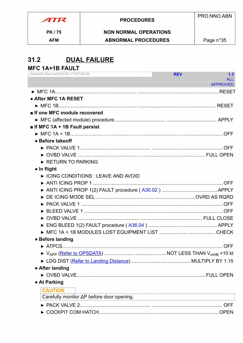
31.2 DUAL FAILUREMFC 1A+1B FAULT_2a24d06c-6ae3-4dc8-8120-171fb735ecf0 REV 1.3
ALLAPPROVED
▶ MFC 1A..................................................... ..................................................... RESET● After MFC 1A RESET▶ MFC 1B................................................... ................................................... RESET
■ If one MFC module recovered▶ MFC (affected module) procedure................................. ................................. APPLY
■ If MFC 1A + 1B Fault persist▶ MFC 1A + 1B....................................................................................................OFF● Before takeoff▶ PACK VALVE 1.............................................. .............................................. OFF▶ OVBD VALVE ......................................... ......................................... FULL OPEN▶ RETURN TO PARKING
● In flight▶ ICING CONDITIONS : LEAVE AND AVOID▶ ANTI ICING PROP 1 .......................................... .......................................... OFF▶ ANTI ICING PROP 1(2) FAULT procedure ( A30.02 ) .................. ..................APPLY▶ DE ICING MODE SEL ................................ ................................OVRD AS RQRD▶ PACK VALVE 1 .............................................. ..............................................OFF▶ BLEED VALVE 1 ............................................. .............................................OFF▶ OVBD VALVE ........................................ ........................................ FULL CLOSE▶ ENG BLEED 1(2) FAULT procedure ( A36.04 ) ...................... ...................... APPLY▶ MFC 1A + 1B MODULES LOST EQUIPMENT LIST .................. .................. CHECK
● Before landing▶ ATPCS.................................................... .................................................... OFF▶ VAPP (Refer to OPSDATA) .................... ....................NOT LESS THAN VmHB +10 kt▶ LDG DIST (Refer to Landing Distance) ................... ...................MULTIPLY BY 1.15
● After landing▶ OVBD VALVE....................................................................................FULL OPEN
● At ParkingCAUTIONCarefully monitor ΔP before door opening.
▶ PACK VALVE 2.............................................. .............................................. OFF▶ COCKPIT COM HATCH....................................... .......................................OPEN
PROCEDURESPRO.NNO.ABN
PK / 75 NON NORMAL OPERATIONSAFM ABNORMAL PROCEDURES Page n°35
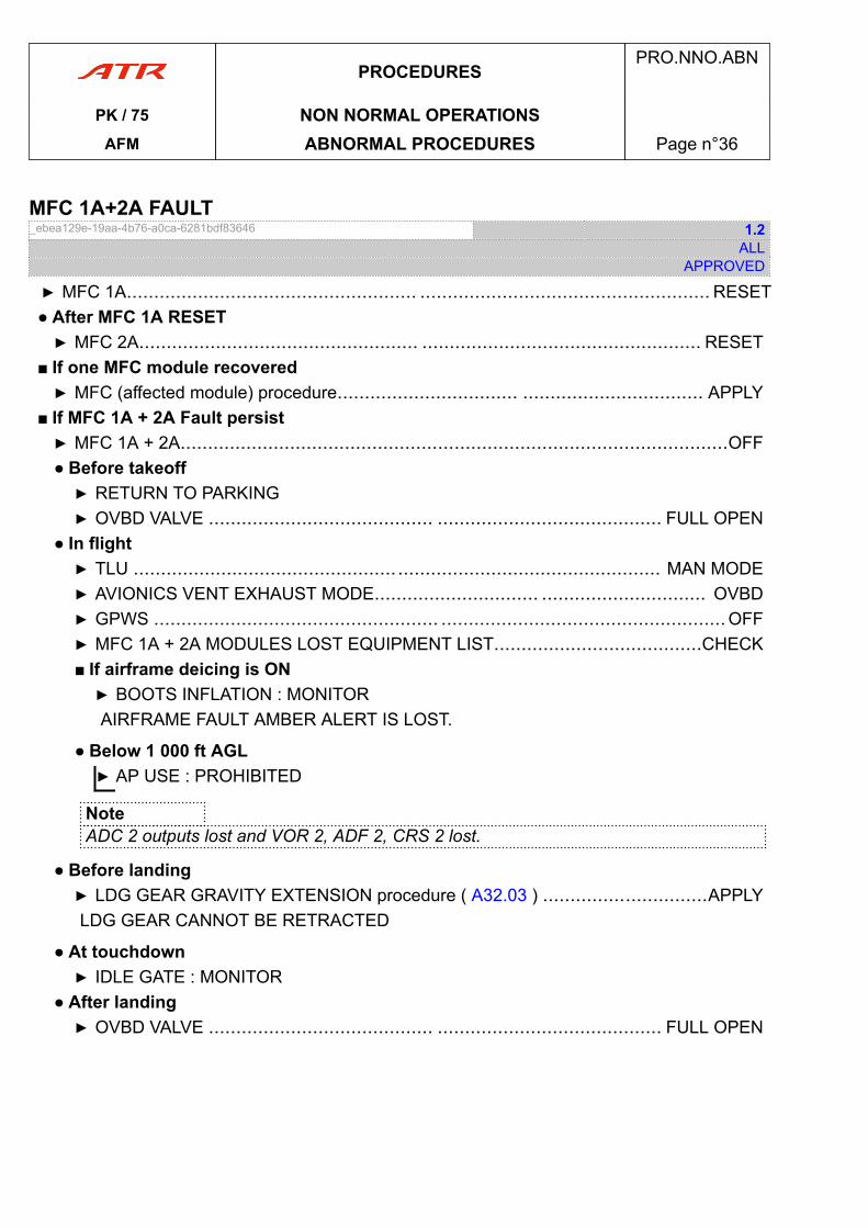
MFC 1A+2A FAULT_ebea129e-19aa-4b76-a0ca-6281bdf83646 1.2
ALLAPPROVED
▶ MFC 1A..................................................... ..................................................... RESET● After MFC 1A RESET▶ MFC 2A................................................... ................................................... RESET
■ If one MFC module recovered▶ MFC (affected module) procedure................................. ................................. APPLY
■ If MFC 1A + 2A Fault persist▶ MFC 1A + 2A....................................................................................................OFF● Before takeoff▶ RETURN TO PARKING▶ OVBD VALVE ......................................... ......................................... FULL OPEN
● In flight▶ TLU ................................................................................................ MAN MODE▶ AVIONICS VENT EXHAUST MODE.............................. .............................. OVBD▶ GPWS .................................................... ....................................................OFF▶ MFC 1A + 2A MODULES LOST EQUIPMENT LIST......................................CHECK■ If airframe deicing is ON▶ BOOTS INFLATION : MONITORAIRFRAME FAULT AMBER ALERT IS LOST.
● Below 1 000 ft AGL▶ AP USE : PROHIBITED
NoteADC 2 outputs lost and VOR 2, ADF 2, CRS 2 lost.
● Before landing▶ LDG GEAR GRAVITY EXTENSION procedure ( A32.03 ) ..............................APPLYLDG GEAR CANNOT BE RETRACTED
● At touchdown▶ IDLE GATE : MONITOR
● After landing▶ OVBD VALVE ......................................... ......................................... FULL OPEN
PROCEDURESPRO.NNO.ABN
PK / 75 NON NORMAL OPERATIONSAFM ABNORMAL PROCEDURES Page n°36
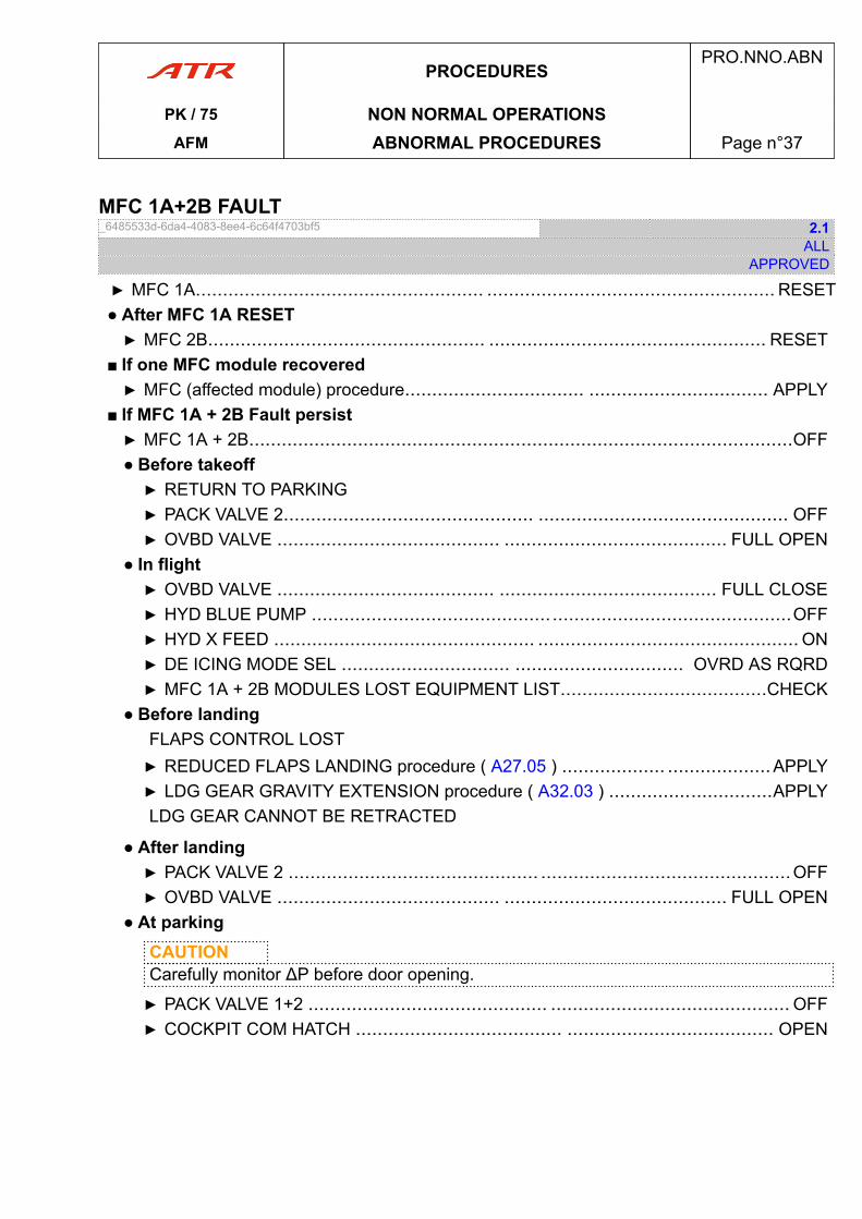
MFC 1A+2B FAULT_6485533d-6da4-4083-8ee4-6c64f4703bf5 2.1
ALLAPPROVED
▶ MFC 1A..................................................... ..................................................... RESET● After MFC 1A RESET▶ MFC 2B................................................... ................................................... RESET
■ If one MFC module recovered▶ MFC (affected module) procedure................................. ................................. APPLY
■ If MFC 1A + 2B Fault persist▶ MFC 1A + 2B....................................................................................................OFF● Before takeoff▶ RETURN TO PARKING▶ PACK VALVE 2.............................................. .............................................. OFF▶ OVBD VALVE ......................................... ......................................... FULL OPEN
● In flight▶ OVBD VALVE ........................................ ........................................ FULL CLOSE▶ HYD BLUE PUMP ........................................................................................OFF▶ HYD X FEED ................................................ ................................................ ON▶ DE ICING MODE SEL ............................... ............................... OVRD AS RQRD▶ MFC 1A + 2B MODULES LOST EQUIPMENT LIST......................................CHECK
● Before landingFLAPS CONTROL LOST▶ REDUCED FLAPS LANDING procedure ( A27.05 ) ................... ...................APPLY▶ LDG GEAR GRAVITY EXTENSION procedure ( A32.03 ) ..............................APPLYLDG GEAR CANNOT BE RETRACTED
● After landing▶ PACK VALVE 2 .............................................. ..............................................OFF▶ OVBD VALVE ......................................... ......................................... FULL OPEN
● At parkingCAUTIONCarefully monitor ΔP before door opening.
▶ PACK VALVE 1+2 ............................................ ............................................ OFF▶ COCKPIT COM HATCH ...................................... ...................................... OPEN
PROCEDURESPRO.NNO.ABN
PK / 75 NON NORMAL OPERATIONSAFM ABNORMAL PROCEDURES Page n°37
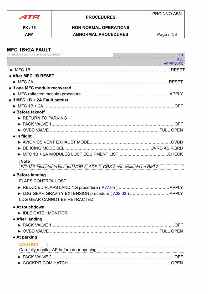
MFC 1B+2A FAULT_213bd2d9-5e9b-4045-a195-aa7a53863dc7 3.1
ALLAPPROVED
▶ MFC 1B..................................................... ..................................................... RESET● After MFC 1B RESET▶ MFC 2A................................................... ................................................... RESET
■ If one MFC module recovered▶ MFC (affected module) procedure................................. ................................. APPLY
■ If MFC 1B + 2A Fault persist▶ MFC 1B + 2A....................................................................................................OFF● Before takeoff▶ RETURN TO PARKING▶ PACK VALVE 1.............................................. .............................................. OFF▶ OVBD VALVE ......................................... ......................................... FULL OPEN
● In flight▶ AVIONICS VENT EXHAUST MODE..............................................................OVBD▶ DE ICING MODE SEL ............................... ............................... OVRD AS RQRD▶ MFC 1B + 2A MODULES LOST EQUIPMENT LIST......................................CHECK
NoteF/O IAS indicator is lost and VOR 2, ADF 2, CRS 2 not available on RMI 2.
● Before landingFLAPS CONTROL LOST▶ REDUCED FLAPS LANDING procedure ( A27.05 ) ................... ...................APPLY▶ LDG GEAR GRAVITY EXTENSION procedure ( A32.03 ) ..............................APPLYLDG GEAR CANNOT BE RETRACTED
● At touchdown▶ IDLE GATE : MONITOR
● After landing▶ PACK VALVE 1 .............................................. ..............................................OFF▶ OVBD VALVE ......................................... ......................................... FULL OPEN
● At parkingCAUTIONCarefully monitor ΔP before door opening.
▶ PACK VALVE 2 .............................................. ..............................................OFF▶ COCKPIT COM HATCH ...................................... ...................................... OPEN
PROCEDURESPRO.NNO.ABN
PK / 75 NON NORMAL OPERATIONSAFM ABNORMAL PROCEDURES Page n°38
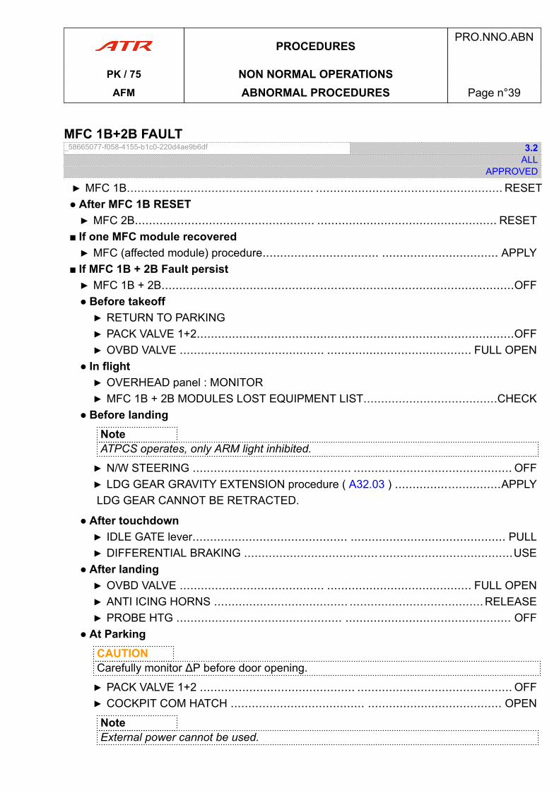
MFC 1B+2B FAULT_58665077-f058-4155-b1c0-220d4ae9b6df 3.2
ALLAPPROVED
▶ MFC 1B..................................................... ..................................................... RESET● After MFC 1B RESET▶ MFC 2B................................................... ................................................... RESET
■ If one MFC module recovered▶ MFC (affected module) procedure................................. ................................. APPLY
■ If MFC 1B + 2B Fault persist▶ MFC 1B + 2B....................................................................................................OFF● Before takeoff▶ RETURN TO PARKING▶ PACK VALVE 1+2..........................................................................................OFF▶ OVBD VALVE ......................................... ......................................... FULL OPEN
● In flight▶ OVERHEAD panel : MONITOR▶ MFC 1B + 2B MODULES LOST EQUIPMENT LIST......................................CHECK
● Before landingNoteATPCS operates, only ARM light inhibited.
▶ N/W STEERING ............................................. ............................................. OFF▶ LDG GEAR GRAVITY EXTENSION procedure ( A32.03 ) ..............................APPLYLDG GEAR CANNOT BE RETRACTED.
● After touchdown▶ IDLE GATE lever............................................ ............................................ PULL▶ DIFFERENTIAL BRAKING ............................................................................USE
● After landing▶ OVBD VALVE ......................................... ......................................... FULL OPEN▶ ANTI ICING HORNS ...................................... ......................................RELEASE▶ PROBE HTG ............................................... ............................................... OFF
● At ParkingCAUTIONCarefully monitor ΔP before door opening.
▶ PACK VALVE 1+2 ............................................ ............................................ OFF▶ COCKPIT COM HATCH ...................................... ...................................... OPEN
NoteExternal power cannot be used.
PROCEDURESPRO.NNO.ABN
PK / 75 NON NORMAL OPERATIONSAFM ABNORMAL PROCEDURES Page n°39
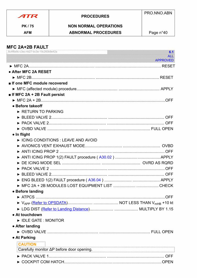
MFC 2A+2B FAULT_6c4f6e9c-c3ec-4d27-bc3e-19c260b9e42a 6.1
ALLAPPROVED
▶ MFC 2A..................................................... ..................................................... RESET● After MFC 2A RESET▶ MFC 2B................................................... ................................................... RESET
■ If one MFC module recovered▶ MFC (affected module) procedure................................. ................................. APPLY
■ If MFC 2A + 2B Fault persist▶ MFC 2A + 2B....................................................................................................OFF● Before takeoff▶ RETURN TO PARKING▶ BLEED VALVE 2............................................. ............................................. OFF▶ PACK VALVE 2.............................................. .............................................. OFF▶ OVBD VALVE ......................................... ......................................... FULL OPEN
● In flight▶ ICING CONDITIONS : LEAVE AND AVOID▶ AVIONICS VENT EXHAUST MODE.............................. .............................. OVBD▶ ANTI ICING PROP 2 .......................................... .......................................... OFF▶ ANTI ICING PROP 1(2) FAULT procedure ( A30.02 ) .................. ..................APPLY▶ DE ICING MODE SEL ............................... ............................... OVRD AS RQRD▶ PACK VALVE 2 .............................................. ..............................................OFF▶ BLEED VALVE 2............................................. ............................................. OFF▶ ENG BLEED 1(2) FAULT procedure ( A36.04 ) ...................... ...................... APPLY▶ MFC 2A + 2B MODULES LOST EQUIPMENT LIST .................. .................. CHECK
● Before landing▶ ATPCS ........................................................................................................OFF▶ VAPP (Refer to OPSDATA).................... .................... NOT LESS THAN VmHB +10 kt▶ LDG DIST (Refer to Landing Distance)................... ................... MULTIPLY BY 1.15
● At touchdown▶ IDLE GATE : MONITOR
● After landing▶ OVBD VALVE ......................................... ......................................... FULL OPEN
● At ParkingCAUTIONCarefully monitor ΔP before door opening.
▶ PACK VALVE 1.............................................. .............................................. OFF▶ COCKPIT COM HATCH....................................... .......................................OPEN
PROCEDURESPRO.NNO.ABN
PK / 75 NON NORMAL OPERATIONSAFM ABNORMAL PROCEDURES Page n°40
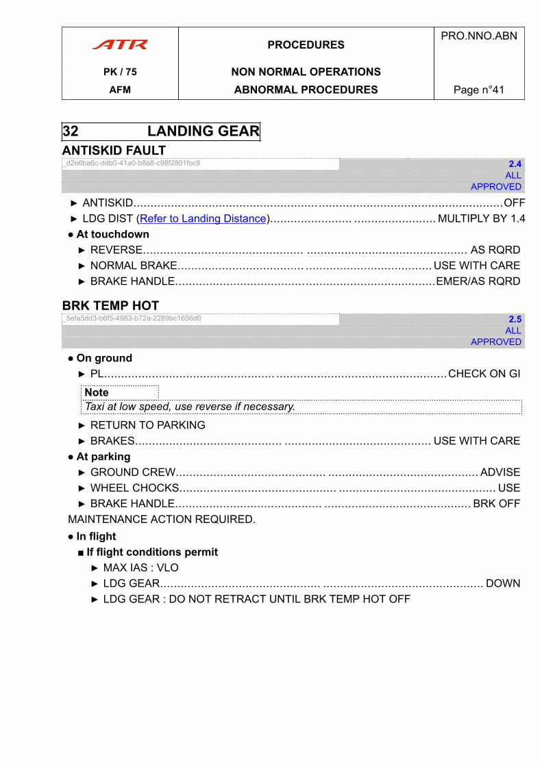
32 LANDING GEARANTISKID FAULT_d2e6ba6c-ddb0-41a0-b8a8-c98f2801fcc9 2.4
ALLAPPROVED
▶ ANTISKID............................................................................................................OFF▶ LDG DIST (Refer to Landing Distance)........................ ........................ MULTIPLY BY 1.4● At touchdown▶ REVERSE............................................... ............................................... AS RQRD▶ NORMAL BRAKE..................................... ..................................... USE WITH CARE▶ BRAKE HANDLE............................................................................EMER/AS RQRD
BRK TEMP HOT_5efa5dd3-b6f5-4983-b72a-2289bc1656d0 2.5
ALLAPPROVED
● On ground▶ PL.................................................. ..................................................CHECK ON GI
NoteTaxi at low speed, use reverse if necessary.
▶ RETURN TO PARKING▶ BRAKES........................................... ........................................... USE WITH CARE
● At parking▶ GROUND CREW............................................ ............................................ ADVISE▶ WHEEL CHOCKS.............................................. .............................................. USE▶ BRAKE HANDLE........................................... ........................................... BRK OFF
MAINTENANCE ACTION REQUIRED.● In flight
■ If flight conditions permit▶ MAX IAS : VLO▶ LDG GEAR............................................... ............................................... DOWN▶ LDG GEAR : DO NOT RETRACT UNTIL BRK TEMP HOT OFF
PROCEDURESPRO.NNO.ABN
PK / 75 NON NORMAL OPERATIONSAFM ABNORMAL PROCEDURES Page n°41
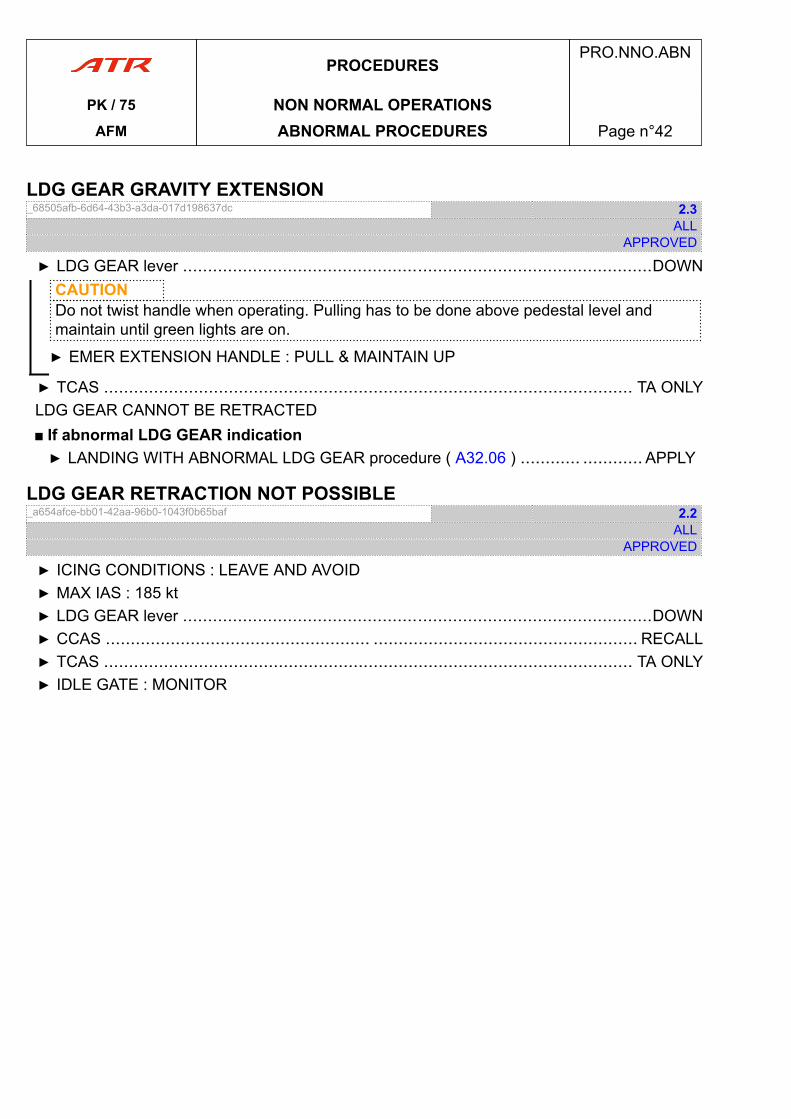
LDG GEAR GRAVITY EXTENSION_68505afb-6d64-43b3-a3da-017d198637dc 2.3
ALLAPPROVED
▶ LDG GEAR lever ..............................................................................................DOWNCAUTIONDo not twist handle when operating. Pulling has to be done above pedestal level andmaintain until green lights are on.
▶ EMER EXTENSION HANDLE : PULL & MAINTAIN UP
▶ TCAS .......................................................................................................... TA ONLYLDG GEAR CANNOT BE RETRACTED■ If abnormal LDG GEAR indication▶ LANDING WITH ABNORMAL LDG GEAR procedure ( A32.06 ) ............ ............ APPLY
LDG GEAR RETRACTION NOT POSSIBLE_a654afce-bb01-42aa-96b0-1043f0b65baf 2.2
ALLAPPROVED
▶ ICING CONDITIONS : LEAVE AND AVOID▶ MAX IAS : 185 kt▶ LDG GEAR lever ..............................................................................................DOWN▶ CCAS ..................................................... ..................................................... RECALL▶ TCAS .......................................................................................................... TA ONLY▶ IDLE GATE : MONITOR
PROCEDURESPRO.NNO.ABN
PK / 75 NON NORMAL OPERATIONSAFM ABNORMAL PROCEDURES Page n°42
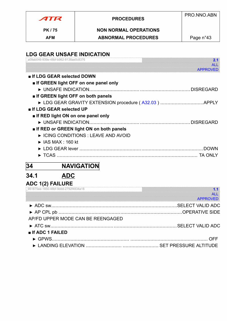
LDG GEAR UNSAFE INDICATION_a09ab046-939e-48bf-b962-8138ae0c8376 2.1
ALLAPPROVED
■ If LDG GEAR selected DOWN■ If GREEN light OFF on one panel only▶ UNSAFE INDICATION................................... ...................................DISREGARD
■ If GREEN light OFF on both panels▶ LDG GEAR GRAVITY EXTENSION procedure ( A32.03 ) ..............................APPLY
■ If LDG GEAR selected UP■ If RED light ON on one panel only▶ UNSAFE INDICATION................................... ...................................DISREGARD
■ If RED or GREEN light ON on both panels▶ ICING CONDITIONS : LEAVE AND AVOID▶ IAS MAX : 160 kt▶ LDG GEAR lever ........................................... ...........................................DOWN▶ TCAS .................................................................................................. TA ONLY
34 NAVIGATION34.1 ADCADC 1(2) FAILURE_951875ee-1850-48bf-9ddd-2792f4834a18 1.1
ALLAPPROVED
▶ ADC sw........................................................................................SELECT VALID ADC▶ AP CPL pb ......................................................................................OPERATIVE SIDEAP/FD UPPER MODE CAN BE REENGAGED▶ ATC sw............................................ ............................................SELECT VALID ADC■ If ADC 1 FAILED▶ GPWS...................................................... ...................................................... OFF▶ LANDING ELEVATION ......................... ......................... SET PRESSURE ALTITUDE
PROCEDURESPRO.NNO.ABN
PK / 75 NON NORMAL OPERATIONSAFM ABNORMAL PROCEDURES Page n°43
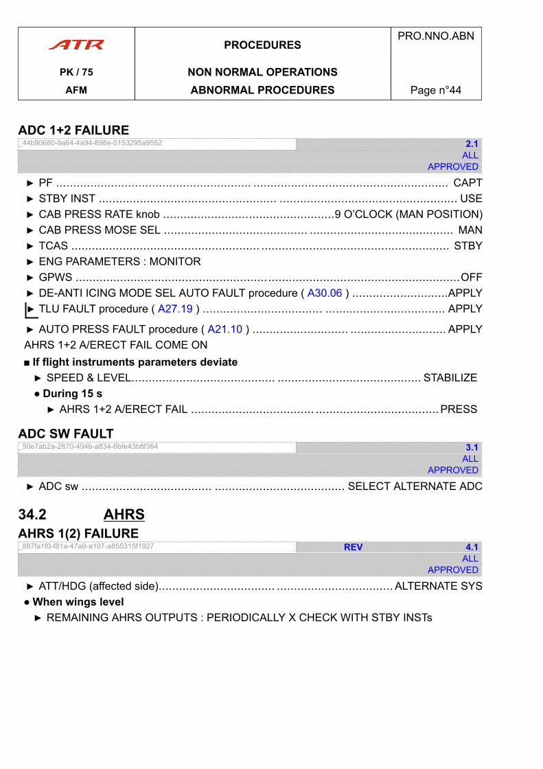
ADC 1+2 FAILURE_44b90680-9a64-4a94-898e-5153295a9552 2.1
ALLAPPROVED
▶ PF ......................................................... ......................................................... CAPT▶ STBY INST .................................................... .................................................... USE▶ CAB PRESS RATE knob ..................................................9 O’CLOCK (MAN POSITION)▶ CAB PRESS MOSE SEL .......................................... .......................................... MAN▶ TCAS ....................................................... ....................................................... STBY▶ ENG PARAMETERS : MONITOR▶ GPWS ................................................................................................................OFF▶ DE-ANTI ICING MODE SEL AUTO FAULT procedure ( A30.06 ) ............................APPLY▶ TLU FAULT procedure ( A27.19 ) ................................... ................................... APPLY
▶ AUTO PRESS FAULT procedure ( A21.10 ) ............................ ............................ APPLYAHRS 1+2 A/ERECT FAIL COME ON■ If flight instruments parameters deviate▶ SPEED & LEVEL.......................................... .......................................... STABILIZE● During 15 s▶ AHRS 1+2 A/ERECT FAIL .................................... ....................................PRESS
ADC SW FAULT_50e7ab2a-2870-494b-a834-6bfe43b8f364 3.1
ALLAPPROVED
▶ ADC sw ...................................... ...................................... SELECT ALTERNATE ADC
34.2 AHRSAHRS 1(2) FAILURE_887fa1f0-f81a-47a9-a107-a855315f1927 REV 4.1
ALLAPPROVED
▶ ATT/HDG (affected side).................................. .................................. ALTERNATE SYS● When wings level▶ REMAINING AHRS OUTPUTS : PERIODICALLY X CHECK WITH STBY INSTs
PROCEDURESPRO.NNO.ABN
PK / 75 NON NORMAL OPERATIONSAFM ABNORMAL PROCEDURES Page n°44
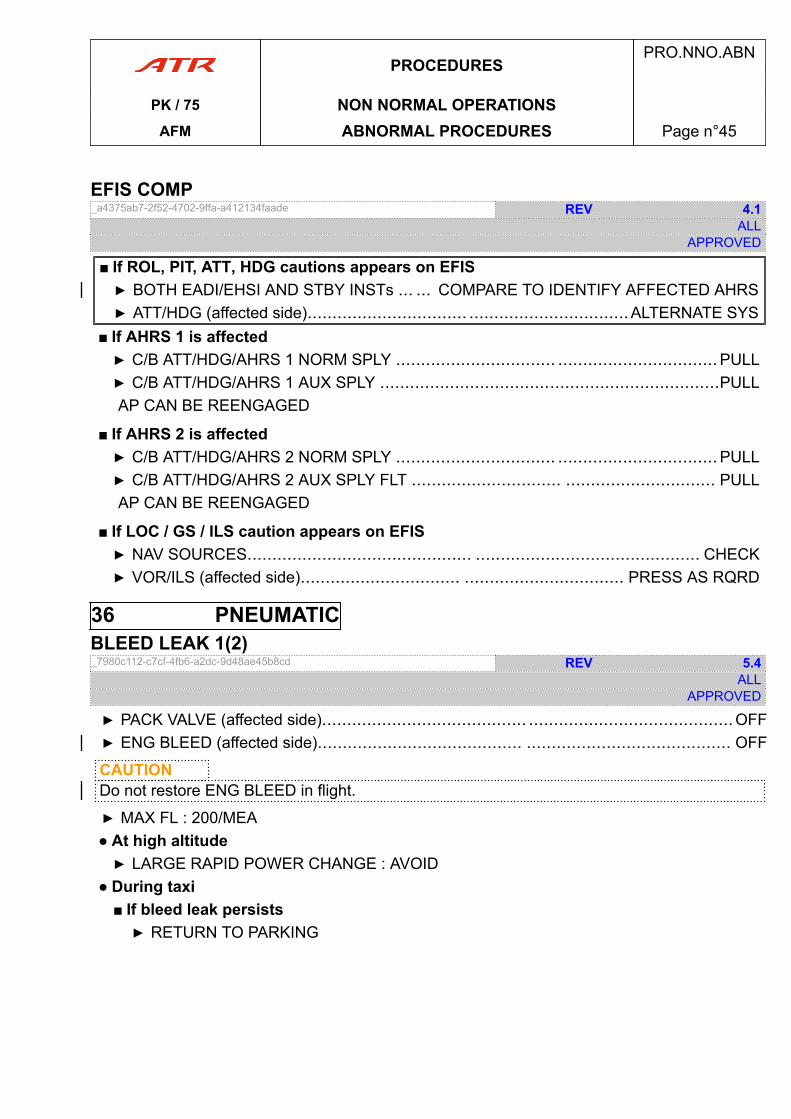
EFIS COMP_a4375ab7-2f52-4702-9ffa-a412134faade REV 4.1
ALLAPPROVED
■ If ROL, PIT, ATT, HDG cautions appears on EFIS▶ BOTH EADI/EHSI AND STBY INSTs ... ... COMPARE TO IDENTIFY AFFECTED AHRS▶ ATT/HDG (affected side)................................ ................................ALTERNATE SYS
■ If AHRS 1 is affected▶ C/B ATT/HDG/AHRS 1 NORM SPLY ................................ ................................PULL▶ C/B ATT/HDG/AHRS 1 AUX SPLY ....................................................................PULLAP CAN BE REENGAGED
■ If AHRS 2 is affected▶ C/B ATT/HDG/AHRS 2 NORM SPLY ................................ ................................PULL▶ C/B ATT/HDG/AHRS 2 AUX SPLY FLT .............................. .............................. PULLAP CAN BE REENGAGED
■ If LOC / GS / ILS caution appears on EFIS▶ NAV SOURCES............................................. ............................................. CHECK▶ VOR/ILS (affected side)................................ ................................ PRESS AS RQRD
36 PNEUMATICBLEED LEAK 1(2)_7980c112-c7cf-4fb6-a2dc-9d48ae45b8cd REV 5.4
ALLAPPROVED
▶ PACK VALVE (affected side)......................................... .........................................OFF▶ ENG BLEED (affected side)......................................... ......................................... OFF
CAUTIONDo not restore ENG BLEED in flight.
▶ MAX FL : 200/MEA● At high altitude▶ LARGE RAPID POWER CHANGE : AVOID
● During taxi■ If bleed leak persists▶ RETURN TO PARKING
PROCEDURESPRO.NNO.ABN
PK / 75 NON NORMAL OPERATIONSAFM ABNORMAL PROCEDURES Page n°45
BLEED 1(2) OVHT_d7dcac37-a180-451a-b1e0-89cd6cc2fe6f REV 5.3
ALLAPPROVED
▶ PACK VALVE (affected side)......................................... .........................................OFF▶ ENG BLEED (affected side)......................................... ......................................... OFF▶ MAX FL : 200/MEA● At high altitude▶ LARGE RAPID POWER CHANGE : AVOID
ENG BLEED 1(2) FAULTENG BLEED 1(2) FAULT_e84dba68-0197-4c73-aecf-1894e77fc9ed REV 4.3
ALLAPPROVED
▶ PACK VALVE (affected side)......................................... .........................................OFF▶ ENG BLEED (affected side)......................................... ......................................... OFF▶ MAX FL : 200/MEA● At high altitude▶ LARGE RAPID POWER CHANGE : AVOID
PROCEDURESPRO.NNO.ABN
PK / 75 NON NORMAL OPERATIONSAFM ABNORMAL PROCEDURES Page n°46
70 POWER PLANT70.1 CONTROLSEEC 1(2) FAULT_d721c653-1ce3-469c-9aa7-fc3065222491 0.2
ALLAPPROVED
▶ ATPCS........................................................ ........................................................OFF
CAUTIONDo not reset EEC Flashing
● When flight conditions permit▶ PL (affected ENG)........................................................RETARD IN GREEN SECTOR▶ EEC (affected ENG)......................................................................................RESET■ If EEC recovered▶ ATPCS..................................................... .....................................................ON▶ PL (affected ENG)................................. ................................. RESTORE POWER
■ If EEC fault persists▶ EEC (affected ENG)........................................... ...........................................OFF▶ PL (affected ENG)................................. ................................. MOVE WITH CARE▶ PL (affected ENG)................................. ................................. RESTORE POWER■ In the following cases : icing conditions, engine(s) flame out, emergency descent,severe turbulence, heavy rain▶ MAN IGN................................................. ................................................. ON
● In final approach▶ CL 1 + 2........................................... ........................................... 100 % OVRD
● After landing▶ TAXI : ENG (affected) FEATHERED▶ ACW BTC..............................................................................CHECK CLOSED
PROCEDURESPRO.NNO.ABN
PK / 75 NON NORMAL OPERATIONSAFM ABNORMAL PROCEDURES Page n°47
PEC 1(2) FAULT_a2f727b9-f20f-464c-b445-4da290f34f7d 2.4
ALLAPPROVED
■ If in short final approach (below 400 ft RA)▶ GO-AROUND............................................ ............................................ PERFORM
● Above 400 ft or when flight conditions permit▶ CL (affected ENG)....................................... ....................................... 100 % OVRD▶ PEC (affected ENG)......................................................................................RESET■ If PEC recovered▶ CL(affected ENG)........................................... ........................................... AUTO
■ If PEC fault persists▶ PEC (affected ENG)........................................... ...........................................OFF▶ PL (affected ENG)................................. ................................. MOVE WITH CARE● For landing▶ CL 1+2 ........................................... ........................................... 100 % OVRD▶ PL : KEEP AT OR ABOVE FI UNTIL NOSE WHEEL ON GROUND▶ REVERSE (affected ENG) : NOT AVAILABLE
● After landing▶ TAXI : ON ENG 1+2▶ ACW BTC ...................................... ...................................... CHECK CLOSED
PEC 1(2) SGL CH_fad4caf4-f077-4d91-adb0-f0a64d09be50 1.3
ALLAPPROVED
● In flight▶ PEC 1(2) : DO NOT RESET
● For landing▶ PEC 1(2) FAULT......................................... ......................................... ANTICIPATE
PROCEDURESPRO.NNO.ABN
PK / 75 NON NORMAL OPERATIONSAFM ABNORMAL PROCEDURES Page n°48
70.2 ONE ENGINE INOPERATIVEENG 1(2) FLAME OUT IN FLIGHT_ed6c37d4-1713-47ed-9a05-503f67d19c63 0.5
ALLAPPROVED
▶ PL (affected ENG)....................................................................................................FI■ If NH drops below 30 % (no immediate relight)▶ CL (affected ENG)................................. ................................. FTR THEN FUEL S.O.
■ If damage suspected▶ FIRE HANDLE (affected ENG)..........................................................................PULL▶ LAND ASAP▶ SINGLE ENG OPERATION procedure ( A70.12 ) ...................... ...................... APPLY
■ If no damage suspected▶ ENG RESTART IN FLIGHT procedure ( A70.09 ) ...................... ...................... APPLY■ If not successful▶ LAND ASAP▶ SINGLE ENG OPERATION procedure ( A70.12 ) .................... .................... APPLY
PROCEDURESPRO.NNO.ABN
PK / 75 NON NORMAL OPERATIONSAFM ABNORMAL PROCEDURES Page n°49
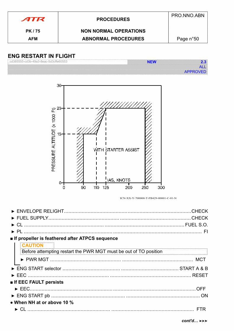
ENG RESTART IN FLIGHT_cd385555-cd3b-49a3-8eac-5d3cffe60553 NEW 2.3
ALLAPPROVED
ICN-XX-Y-700000-T-FB429-00001-C-01-N
▶ ENVELOPE RELIGHT......................................................................................CHECK▶ FUEL SUPPLY................................................ ................................................CHECK▶ CL ...................................................... ...................................................... FUEL S.O.▶ PL ............................................................ ............................................................ FI■ If propeller is feathered after ATPCS sequence
CAUTIONBefore attempting restart the PWR MGT must be out of TO position
▶ PWR MGT ................................................ ................................................ MCT
▶ ENG START selector ....................................... ....................................... START A & B▶ EEC ....................................................... ....................................................... RESET■ If EEC FAULT persists▶ EEC........................................................ ........................................................OFF▶ ENG START pb .................................................. .................................................. ON● When NH at or above 10 %▶ CL ........................................................ ........................................................ FTR
PROCEDURESPRO.NNO.ABN
PK / 75 NON NORMAL OPERATIONSAFM ABNORMAL PROCEDURES Page n°50
cont'd…
▶ ENG RELIGHT............................................ ............................................ MONITOR■ If engine fails to restart within 10 s▶ CL .................................................. .................................................. FUEL S.O.▶ ENG START selector ............................. .............................OFF & START ABORT
NoteWait at least 30 s before attempting a new RESTART. Refer to LIM.5.70.1.2Overtemperature Limit for Starting
■ If no restart▶ LAND ASAP▶ SINGLE ENG OPERATION procedure ( A70.12 ) ......................................APPLY
■ If engine recovered▶ CL ............................................................................................................AUTO▶ PL ....................................... ....................................... ADJUST TO OTHER ENG▶ ENG START selector ............................. .............................OFF & START ABORT▶ SYSTEMS AFFECTED.................................... .................................... RESTORE▶ APM...................................................... ......................................................OFF
PROCEDURESPRO.NNO.ABN
PK / 75 NON NORMAL OPERATIONSAFM ABNORMAL PROCEDURES Page n°51
cont'd…
70.3 PARAMETERSENG 1(2) OIL LO PR_610b79eb-4bb4-48bd-9405-ac68a9992fa5 0.6
ALLAPPROVED
▶ PL (affected ENG).................................................. ..................................................FI■ If both OIL LO PR alert on CAP and local alert are activated▶ CL (affected ENG)................................. ................................. FTR THEN FUEL S.O.▶ LAND ASAP▶ SINGLE ENG OPERATION procedure ( A70.12 ) ...................... ...................... APPLY
■ If only local alert is activated▶ CL (affected ENG)................................. ................................. FTR THEN FUEL S.O.● After engine shut down▶ CL (affected ENG)............................................ ............................................ FTR■ If CCAS activated after 30 s (normal warning delay)▶ CL (affected ENG)............................................................................FUEL S.O.▶ ENG RESTART IN FLIGHT procedure ( A70.09 ) ......................................APPLY
■ If CCAS not activated after 30 s▶ CL (affected ENG)............................................................................FUEL S.O.▶ LAND ASAP▶ SINGLE ENG OPERATION procedure ( A70.12 ) ......................................APPLY
■ If OIL LO PR alert only activated on CAP▶ ALERT : DISREGARDMAINTENANCE ACTION REQUIRED▶ OIL PRESS LOCAL ALERT : MONITOR
■ If single engine operation▶ NP (feathered ENG) : MONITOR■ If NP (feathered ENG) above 10 %▶ IAS : LIMIT NOT TO EXCEED NP 101 %▶ VAPP.......................................... .......................................... INCREASE BY 10 kt
PROCEDURESPRO.NNO.ABN
PK / 75 NON NORMAL OPERATIONSAFM ABNORMAL PROCEDURES Page n°52
ENG NAC OVHT_d239ce99-8b7b-41b9-8759-ee3045ad2cf7 0.1
ALLAPPROVED
● During hotel mode operation▶ PL 2......................................................... ......................................................... GI▶ CL 2........................................... ...........................................FTR THEN FUEL S.O.
● During taxi▶ AIRCRAFT.................................................. .................................................. STOP▶ PL 2.................................... .................................... SLIGHTLY INCREASE POWER■ If NAC OVHT persist within 30 s▶ PL 2................................................................................................................GI▶ CL 2......................................... ......................................... FTR THEN FUEL S.O.
70.4 OTHERSFIRE LOOP 1A (1B) (2A) (2B) FAULT_0a3f20ab-f634-483d-a156-091eba772bec 1.1
ALLAPPROVED
▶ LOOP (affected side).............................................. .............................................. OFF
99 MISCELLANEOUS99.1 DETECTION-INDICATIONOXYGEN LO PR_d19796d8-f720-409a-96f8-cc83cc2da03b 0.1
ALLAPPROVED
▶ OXY MAIN SUPPLY..............................................................................................OFF● After 2 seconds▶ OXY MAIN SUPPLY............................................................................................ON
■ If oxygen LO PR light persists▶ OXY MAIN SUPPLY..........................................................................................OFF▶ OXYGEN PORTABLE UNIT................................................................USE AS RQRD
PROCEDURESPRO.NNO.ABN
PK / 75 NON NORMAL OPERATIONSAFM ABNORMAL PROCEDURES Page n°53
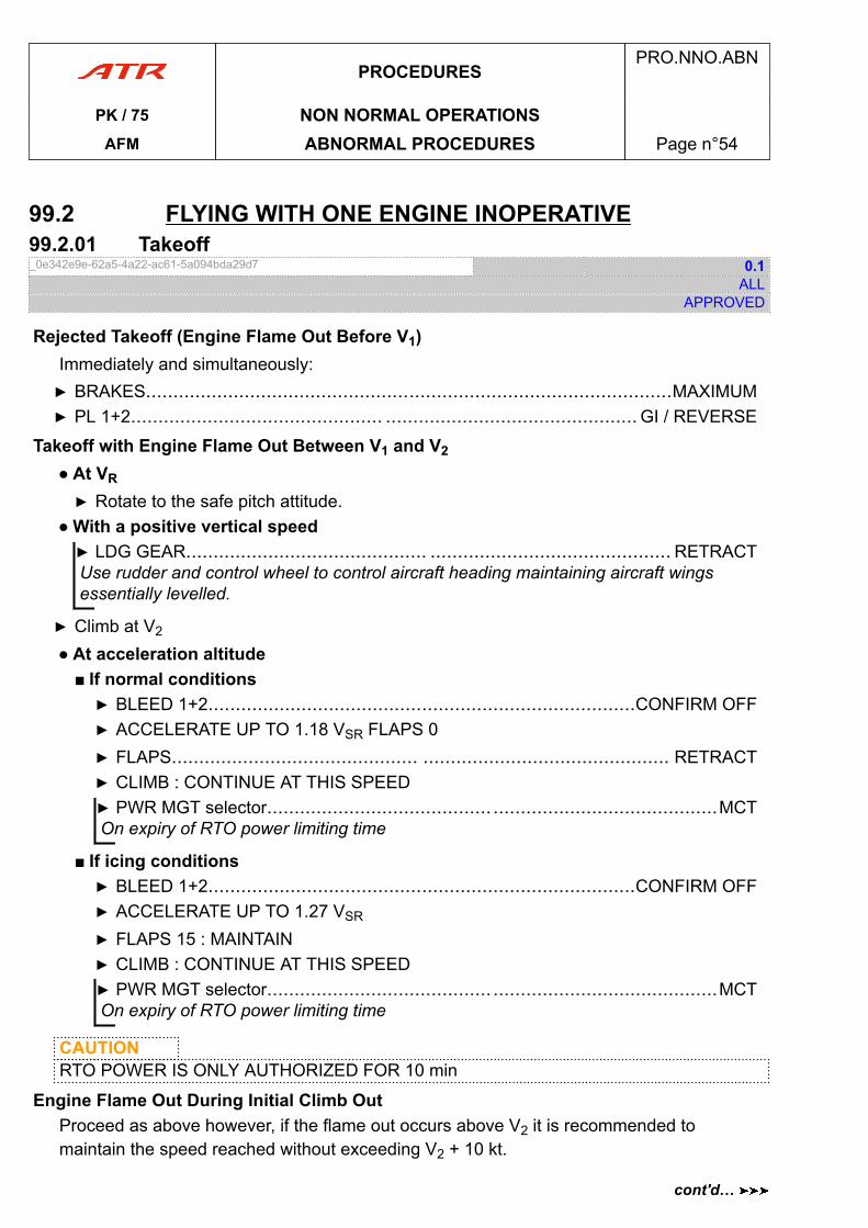
99.2 FLYING WITH ONE ENGINE INOPERATIVE99.2.01 Takeoff_0e342e9e-62a5-4a22-ac61-5a094bda29d7 0.1
ALLAPPROVED
Rejected Takeoff (Engine Flame Out Before V1)Immediately and simultaneously:▶ BRAKES................................................................................................MAXIMUM▶ PL 1+2.............................................. .............................................. GI / REVERSE
Takeoff with Engine Flame Out Between V1 and V2
● At VR
▶ Rotate to the safe pitch attitude.● With a positive vertical speed▶ LDG GEAR............................................ ............................................ RETRACTUse rudder and control wheel to control aircraft heading maintaining aircraft wingsessentially levelled.
▶ Climb at V2
● At acceleration altitude■ If normal conditions▶ BLEED 1+2..............................................................................CONFIRM OFF▶ ACCELERATE UP TO 1.18 VSR FLAPS 0▶ FLAPS............................................. ............................................. RETRACT▶ CLIMB : CONTINUE AT THIS SPEED▶ PWR MGT selector......................................... .........................................MCTOn expiry of RTO power limiting time
■ If icing conditions▶ BLEED 1+2..............................................................................CONFIRM OFF▶ ACCELERATE UP TO 1.27 VSR
▶ FLAPS 15 : MAINTAIN▶ CLIMB : CONTINUE AT THIS SPEED▶ PWR MGT selector......................................... .........................................MCTOn expiry of RTO power limiting time
CAUTIONRTO POWER IS ONLY AUTHORIZED FOR 10 min
Engine Flame Out During Initial Climb OutProceed as above however, if the flame out occurs above V2 it is recommended tomaintain the speed reached without exceeding V2 + 10 kt.
PROCEDURESPRO.NNO.ABN
PK / 75 NON NORMAL OPERATIONSAFM ABNORMAL PROCEDURES Page n°54
cont'd…
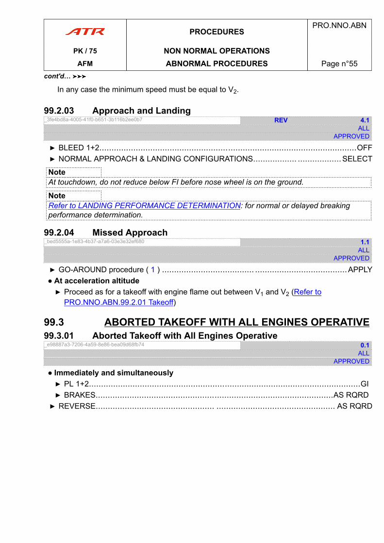
In any case the minimum speed must be equal to V2.
99.2.03 Approach and Landing_3fe4bd8a-4005-41f0-b651-3b116b2ee0b7 REV 4.1
ALLAPPROVED
▶ BLEED 1+2..........................................................................................................OFF▶ NORMAL APPROACH & LANDING CONFIGURATIONS.................. ..................SELECT
NoteAt touchdown, do not reduce below FI before nose wheel is on the ground.
NoteRefer to LANDING PERFORMANCE DETERMINATION: for normal or delayed breakingperformance determination.
99.2.04 Missed Approach_bed5555a-1e83-4b37-a7a6-03e3e32ef680 1.1
ALLAPPROVED
▶ GO-AROUND procedure ( 1 ) ...................................... ......................................APPLY● At acceleration altitude▶ Proceed as for a takeoff with engine flame out between V1 and V2 (Refer to
PRO.NNO.ABN.99.2.01 Takeoff)
99.3 ABORTED TAKEOFF WITH ALL ENGINES OPERATIVE99.3.01 Aborted Takeoff with All Engines Operative_e98887a3-7206-4a59-8e86-bea09d68fb74 0.1
ALLAPPROVED
● Immediately and simultaneously▶ PL 1+2................................................................................................................GI▶ BRAKES..................................................................................................AS RQRD▶ REVERSE................................................. ................................................. AS RQRD
PROCEDURESPRO.NNO.ABN
PK / 75 NON NORMAL OPERATIONSAFM ABNORMAL PROCEDURES Page n°55
cont'd…

PAGE
INTENTIONALLY
LEFT BLANK
PROCEDURESPRO.NNO.ABN
PK / 75 NON NORMAL OPERATIONSAFM ABNORMAL PROCEDURES Page n°56
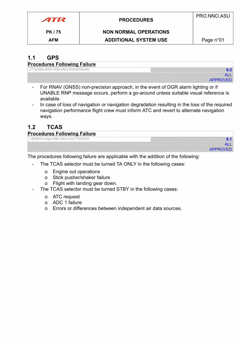
1.1 GPSProcedures Following Failure_211a026a-4993-490b-bfb2-9b20d5f4e99d 0.2
ALLAPPROVED
- For RNAV (GNSS) non-precision approach, in the event of DGR alarm lighting or ifUNABLE RNP message occurs, perform a go-around unless suitable visual reference isavailable
- In case of loss of navigation or navigation degradation resulting in the loss of the requirednavigation performance flight crew must inform ATC and revert to alternate navigationways.
1.2 TCASProcedures Following Failure_14bf6543-a4ae-468c-9dd3-0cc71354fb3d 0.1
ALLAPPROVED
The procedures following failure are applicable with the addition of the following:- The TCAS selector must be turned TA ONLY in the following cases:
o Engine out operationso Stick pusher/shaker failureo Flight with landing gear down.
- The TCAS selector must be turned STBY in the following cases:o ATC requesto ADC 1 failureo Errors or differences between independent air data sources.
PROCEDURESPRO.NNO.ASU
PK / 75 NON NORMAL OPERATIONSAFM ADDITIONAL SYSTEM USE Page n°01

PAGE
INTENTIONALLY
LEFT BLANK
PROCEDURESPRO.NNO.ASU
PK / 75 NON NORMAL OPERATIONSAFM ADDITIONAL SYSTEM USE Page n°02
NORMAL SYSTEM USE .NOP.NSU
NSU. NORMAL SYSTEM USE......................................................................................page 03NSU.2 DOORS................................................................................................page 03NSU.3 NAVIGATION........................................................................................ page 03NSU.4 FLIGHT CONTROLS............................................................................. page 05
AFMPRO.NOP.NSU
PK / 75 TOCAFM Table of Content Page n°01

PAGE
INTENTIONALLY
LEFT BLANK
AFMPRO.NOP.NSU
PK / 75 TOCAFM Table of Content Page n°02
2 DOORS2.1 CDLS Use Policy_da95fcf8-f1da-49a6-bc56-5f38591b8f40 0.2
ALLAPPROVED
The CDLS must be set to ON before passengers boarding starts.The CDLS can be set to OFF after all passengers disembark.
3 NAVIGATION3.1 TAWS - GPWS3.1.1 General_f2787ace-7df7-4744-8f5b-ff48d07be3dd 1.1
ALLAPPROVED
Following a TAWS warning, the flight crew must immediately focus their attention on terrainproximity or excessive lateral attitude.Positive action to alter the flight path or/and to change the configuration should be initiatedimmediately.
3.1.2 Outputs_47a2cafb-ba00-424c-a652-d1422c3c328a 4.1
ALLAPPROVED
PULL UP red warning lights will come on whenever a TAWS warning is in progress (PULL UPor AVOID TERRAIN).GPWS amber lights will come on whenever a TAWS caution is in progress.
1) Reactive Modes- For modes 1 to 4
o Aural alert:- Mode 1: SINK RATE (caution level) / PULL UP (warning level)- Mode 2: TERRAIN (caution level) / PULL UP (warning level)- Mode 3: DON’T SINK- Mode 4: Based on speed and/or flaps/gear setting:
o TOO LOW TERRAIN, oro TOO LOW GEAR, oro TOO LOW FLAPS.
- For mode 5o Aural alert: GLIDE SLOPE
- For mode 6o Decision Height (DH) aural alert: MINIMUM, MINIMUMo Altitude Callouts Aural alert : Corresponding radio altitudeo Bank Angle Aural alert: BANK ANGLE
PROCEDURESPRO.NOP.NSU
PK / 75 NORMAL OPERATIONSAFM NORMAL SYSTEM USE Page n°03
cont'd…
2) Predictive ModesEFIS display: Conflicting terrain in yellow and red.The TAWS generates three basic types of terrain alerts and/or warnings.
a) Terrain/Obstacle Caution AlertThis alert is generated whenever the caution clearance sensor detects a potential terrainhazard.
- Visual alert: GPWS amber lights come on- Aural alert:
o TERRAIN AHEAD, oro TOO LOW TERRAIN (if level off maneuver sufficient to avoid the hazard), oro OBSTACLE AHEAD
b) Pull Up WarningThis alert is generated whenever the TAWS detects an imminent CFIT situation with apotential terrain hazard.
- Visual alert: PULL UP red lights come on- Aural alert:
o TERRAIN AHEAD, PULL UP, oro OBSTACLE AHEAD, PULL UP.
c) Avoid Terrain/Obstacle WarningThis alert is generated whenever the TAWS determines the current flight path will lead theaircraft into high terrain that cannot be cleared with only a vertical escape maneuver.
- Visual alert: PULL UP red lights come on- Aural alert:
o AVOID TERRAIN, oro AVOID OBSTACLE.
PROCEDURESPRO.NOP.NSU
PK / 75 NORMAL OPERATIONSAFM NORMAL SYSTEM USE Page n°04
cont'd…
3.1.3 Operation_ad82d9a2-bb04-47b6-9997-ec4f8e6c2652 2.1
ALLAPPROVED
- During normal operations GPWS sw should be always set on NORM position andTERR pb ligth off must be pressed in.
- In case of emergency conditions GPWS sw and TERR pb may be turned on OFFposition. Refer to chapter PRO-NNO-EMR-05 Ditching and Forced Landing
- In case of landing in abnormal flaps conditions GPWS sw may be turned on OVRDposition. Refer to chapter PRO-NNO-ABN-06, Flight Controls
- Terrain Awareness Caution:o When a terrain awareness CAUTION occurs, verify the aircraft flight path and
correct it if required. If in doubt, perform a climb until the CAUTION alert stops- Terrain Awareness Warning:
1) Terrain escape maneuver following TERRAIN AHEAD, PULL UP: Immediatelyinitiate and continue a climb that will provide maximum terrain clearance until allalerts stop. Only vertical maneuvers are recommended, unless operating in visualmeteorological conditions (VMC), and/or the pilot determines, based on availableinformation, that turning in addition to the vertical escape manoeuvre is a safercourse of action.
2) Terrain escape maneuver following AVOID TERRAIN: Immediately initiate a CLIMBAND A TURN, based on any available information but preferably external visualreference. Continue to maneuver until warning stops.
Note- All modes are inhibited by stall warning- Mode 5 is active if the PF side ILS is tuned on the correct frequency and if the gear is
down- GPWS or TERR FAULT lighting indicates that some or all reactive or predictive
warnings are lost.In that case, the remaining alerts must be considered as valid and taken into account.
- If the WX radar control is selected OFF, no terrain information will be displayed on theEHSI and TERR FAULT amber light will be came on.Even in case of a radar failure, select the STBY position.
4 FLIGHT CONTROLS4.1 Pitch_10376166-5bce-4e8e-b4ab-5fb0c45aaeb8 0.1
ALLAPPROVED
In flight aggressive or large elevators input should be avoided. Such inputs may lead to highloads and result in structural damage.
CAUTIONThe aircraft must be controlled from one control column only. Dual input in opposite directionmay result in a pitch disconnect.
PROCEDURESPRO.NOP.NSU
PK / 75 NORMAL OPERATIONSAFM NORMAL SYSTEM USE Page n°05
PAGE
INTENTIONALLY
LEFT BLANK
PROCEDURESPRO.NOP.NSU
PK / 75 NORMAL OPERATIONSAFM NORMAL SYSTEM USE Page n°06
NORMAL PROCEDURES .NOP.NOR
NOR. NORMAL PROCEDURES....................................................................................page 03NOR.1 SYSTEM TEST..................................................................................... page 03NOR.2 BEFORE TAXI.......................................................................................page 08NOR.3 TAKEOFF.............................................................................................page 08NOR.4 IN FLIGHT............................................................................................ page 08NOR.5 NORMAL LANDING...............................................................................page 09NOR.6 GO-AROUND........................................................................................page 09
AFMPRO.NOP.NOR
PK / 75 TOCAFM Table of Content Page n°01
PAGE
INTENTIONALLY
LEFT BLANK
AFMPRO.NOP.NOR
PK / 75 TOCAFM Table of Content Page n°02
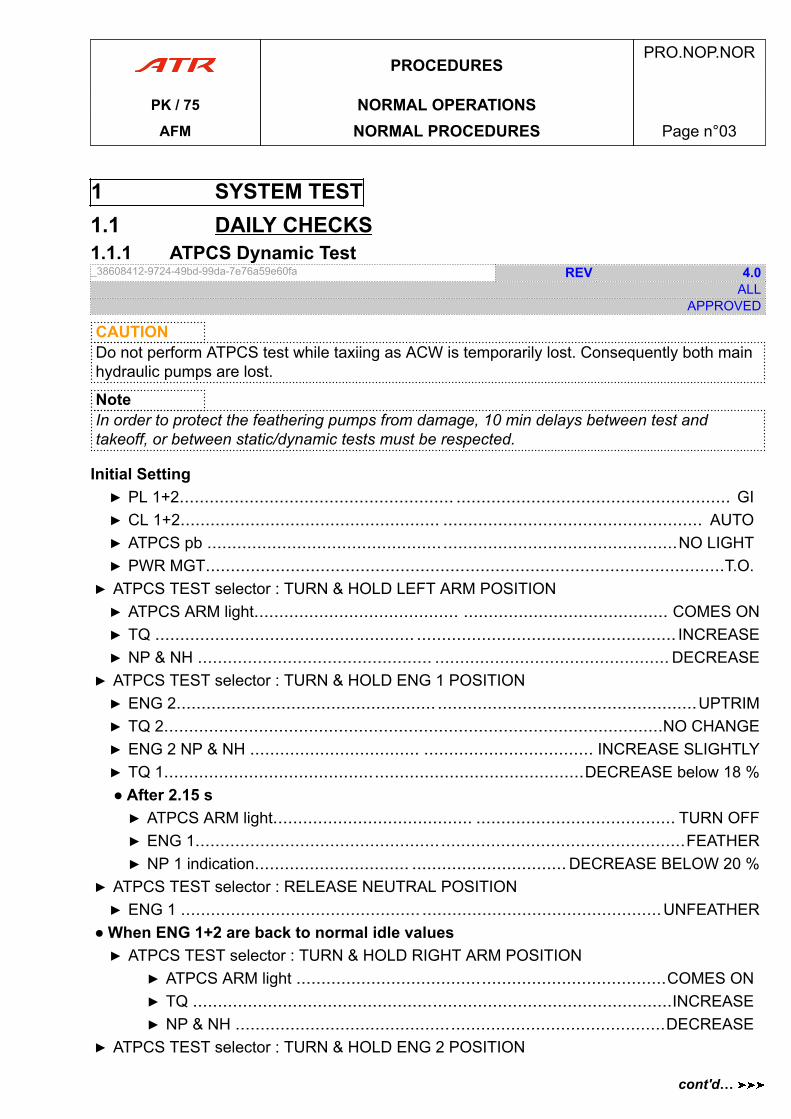
1 SYSTEM TEST1.1 DAILY CHECKS1.1.1 ATPCS Dynamic Test_38608412-9724-49bd-99da-7e76a59e60fa REV 4.0
ALLAPPROVED
CAUTIONDo not perform ATPCS test while taxiing as ACW is temporarily lost. Consequently both mainhydraulic pumps are lost.
NoteIn order to protect the feathering pumps from damage, 10 min delays between test andtakeoff, or between static/dynamic tests must be respected.
Initial Setting▶ PL 1+2....................................................... ....................................................... GI▶ CL 1+2.................................................... .................................................... AUTO▶ ATPCS pb ..............................................................................................NO LIGHT▶ PWR MGT........................................................................................................T.O.
▶ ATPCS TEST selector : TURN & HOLD LEFT ARM POSITION▶ ATPCS ARM light......................................... ......................................... COMES ON▶ TQ .................................................... .................................................... INCREASE▶ NP & NH ............................................... ............................................... DECREASE
▶ ATPCS TEST selector : TURN & HOLD ENG 1 POSITION▶ ENG 2.................................................... ....................................................UPTRIM▶ TQ 2....................................................................................................NO CHANGE▶ ENG 2 NP & NH .................................. .................................. INCREASE SLIGHTLY▶ TQ 1....................................................................................DECREASE below 18 %● After 2.15 s▶ ATPCS ARM light........................................ ........................................ TURN OFF▶ ENG 1..................................................................................................FEATHER▶ NP 1 indication............................... ............................... DECREASE BELOW 20 %
▶ ATPCS TEST selector : RELEASE NEUTRAL POSITION▶ ENG 1 ................................................ ................................................UNFEATHER
● When ENG 1+2 are back to normal idle values▶ ATPCS TEST selector : TURN & HOLD RIGHT ARM POSITION
▶ ATPCS ARM light ..........................................................................COMES ON▶ TQ ................................................................................................INCREASE▶ NP & NH ......................................................................................DECREASE
▶ ATPCS TEST selector : TURN & HOLD ENG 2 POSITION
PROCEDURESPRO.NOP.NOR
PK / 75 NORMAL OPERATIONSAFM NORMAL PROCEDURES Page n°03
cont'd…
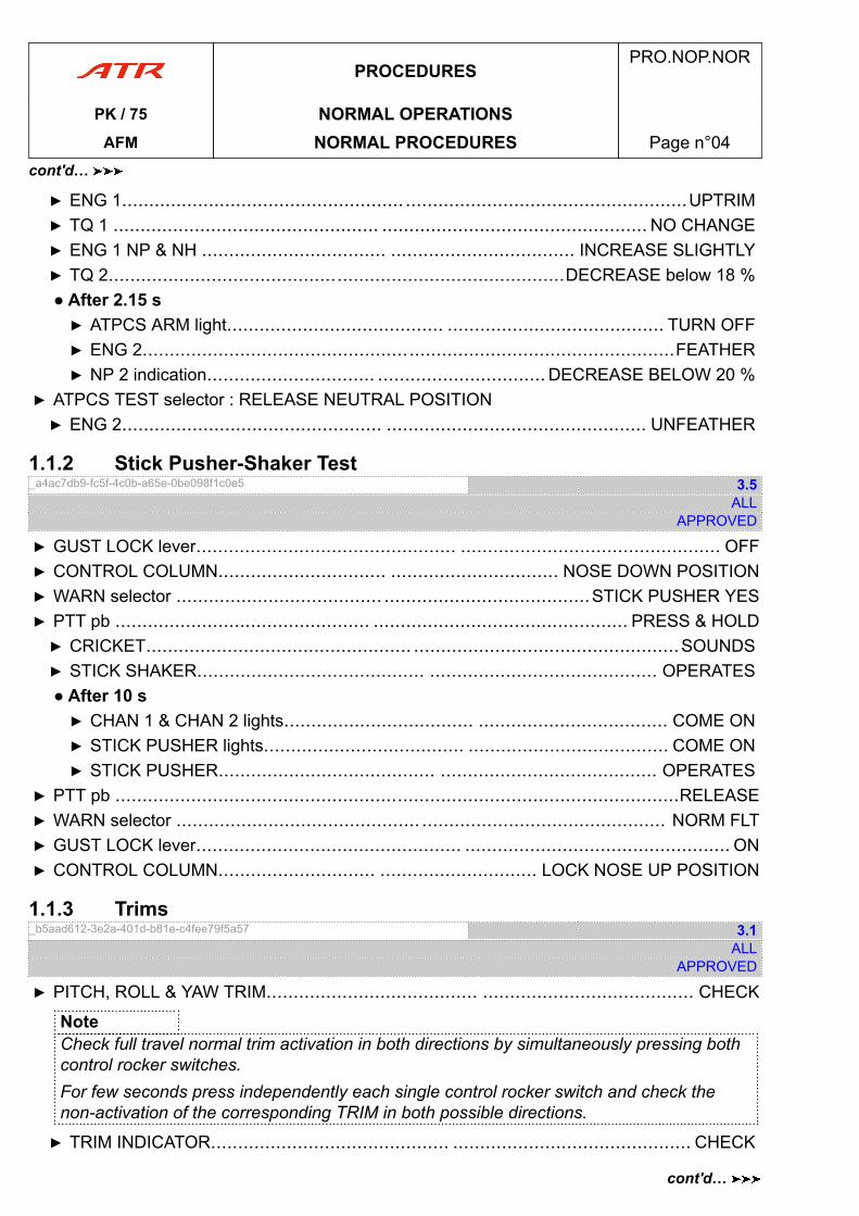
▶ ENG 1.................................................... ....................................................UPTRIM▶ TQ 1 ................................................. ................................................. NO CHANGE▶ ENG 1 NP & NH .................................. .................................. INCREASE SLIGHTLY▶ TQ 2....................................................................................DECREASE below 18 %● After 2.15 s▶ ATPCS ARM light........................................ ........................................ TURN OFF▶ ENG 2..................................................................................................FEATHER▶ NP 2 indication............................... ............................... DECREASE BELOW 20 %
▶ ATPCS TEST selector : RELEASE NEUTRAL POSITION▶ ENG 2................................................ ................................................ UNFEATHER
1.1.2 Stick Pusher-Shaker Test_a4ac7db9-fc5f-4c0b-a65e-0be098f1c0e5 3.5
ALLAPPROVED
▶ GUST LOCK lever................................................ ................................................ OFF▶ CONTROL COLUMN............................... ............................... NOSE DOWN POSITION▶ WARN selector ...................................... ......................................STICK PUSHER YES▶ PTT pb ............................................... ............................................... PRESS & HOLD▶ CRICKET................................................. .................................................SOUNDS▶ STICK SHAKER.......................................... .......................................... OPERATES● After 10 s▶ CHAN 1 & CHAN 2 lights................................... ................................... COME ON▶ STICK PUSHER lights..................................... ..................................... COME ON▶ STICK PUSHER........................................ ........................................ OPERATES
▶ PTT pb ........................................................................................................RELEASE▶ WARN selector ............................................. ............................................. NORM FLT▶ GUST LOCK lever................................................. ................................................. ON▶ CONTROL COLUMN............................. ............................. LOCK NOSE UP POSITION
1.1.3 Trims_b5aad612-3e2a-401d-b81e-c4fee79f5a57 3.1
ALLAPPROVED
▶ PITCH, ROLL & YAW TRIM....................................... ....................................... CHECK
NoteCheck full travel normal trim activation in both directions by simultaneously pressing bothcontrol rocker switches.For few seconds press independently each single control rocker switch and check thenon-activation of the corresponding TRIM in both possible directions.
▶ TRIM INDICATOR............................................ ............................................ CHECK
PROCEDURESPRO.NOP.NOR
PK / 75 NORMAL OPERATIONSAFM NORMAL PROCEDURES Page n°04
cont'd…
cont'd…
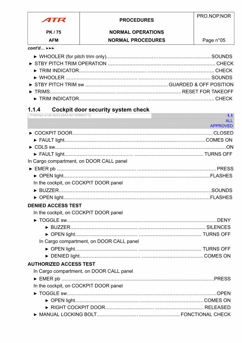
▶ WHOOLER (for pitch trim only).................................. .................................. SOUNDS▶ STBY PITCH TRIM OPERATION ................................... ................................... CHECK▶ TRIM INDICATOR............................................ ............................................ CHECK▶ WHOOLER ............................................... ............................................... SOUNDS
▶ STBY PITCH TRIM sw ........................... ...........................GUARDED & OFF POSITION▶ TRIMS........................................... ...........................................RESET FOR TAKEOFF▶ TRIM INDICATOR............................................ ............................................ CHECK
1.1.4 Cockpit door security system check_f74053a2-a1d5-4b43-b542-8413068b5712 1.1
ALLAPPROVED
▶ COCKPIT DOOR............................................................................................CLOSED▶ FAULT light.............................................. ..............................................COMES ON
▶ CDLS sw................................................................................................................ON▶ FAULT light............................................. ............................................. TURNS OFF
In Cargo compartment, on DOOR CALL panel▶ EMER pb .................................................... ....................................................PRESS▶ OPEN light................................................................................................FLASHESIn the cockpit, on COCKPIT DOOR panel▶ BUZZER....................................................................................................SOUNDS▶ OPEN light................................................................................................FLASHES
DENIED ACCESS TESTIn the cockpit, on COCKPIT DOOR panel▶ TOGGLE sw..................................................................................................DENY
▶ BUZZER............................................ ............................................ SILENCES▶ OPEN light......................................... ......................................... TURNS OFF
In Cargo compartment, on DOOR CALL panel▶ OPEN light......................................... ......................................... TURNS OFF▶ DENIED light........................................ ........................................ COMES ON
AUTHORIZED ACCESS TESTIn Cargo compartment, on DOOR CALL panel▶ EMER pb ....................................................................................................PRESSIn the cockpit, on COCKPIT DOOR panel▶ TOGGLE sw..................................................................................................OPEN
▶ OPEN light.......................................... ..........................................COMES ON▶ RIGHT COCKPIT DOOR................................ ................................ RELEASED
▶ MANUAL LOCKING BOLT........................... ........................... FONCTIONAL CHECK
PROCEDURESPRO.NOP.NOR
PK / 75 NORMAL OPERATIONSAFM NORMAL PROCEDURES Page n°05
cont'd…
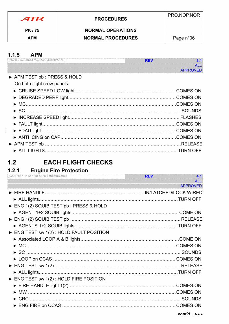
1.1.5 APM_3fec0cdb-c9f0-4475-9b52-34d40f21d745 REV 3.1
ALLAPPROVED
▶ APM TEST pb : PRESS & HOLDOn both flight crew panels.▶ CRUISE SPEED LOW light......................................................................COMES ON▶ DEGRADED PERF light..................................... .....................................COMES ON▶ MC........................................................................................................COMES ON▶ SC ..................................................... ..................................................... SOUNDS▶ INCREASE SPEED light...................................... ...................................... FLASHES▶ FAULT light.............................................. ..............................................COMES ON▶ FDAU light.............................................. .............................................. COMES ON▶ ANTI ICING on CAP................................................................................COMES ON
▶ APM TEST pb ..............................................................................................RELEASE▶ ALL LIGHTS............................................................................................TURN OFF
1.2 EACH FLIGHT CHECKS1.2.1 Engine Fire Protection_020e7657-14c2-4fee-8e7e-3305768780e7 REV 4.1
ALLAPPROVED
▶ FIRE HANDLE.................................. .................................. IN/LATCHED/LOCK WIRED▶ ALL lights................................................................................................TURN OFF
▶ ENG 1(2) SQUIB TEST pb : PRESS & HOLD▶ AGENT 1+2 SQUIB lights..................................... .....................................COME ON
▶ ENG 1(2) SQUIB TEST pb ...................................... ......................................RELEASE▶ AGENTS 1+2 SQUIB lights................................... ................................... TURN OFF
▶ ENG TEST sw 1(2) : HOLD FAULT POSITION▶ Associated LOOP A & B lights....................................................................COME ON▶ MC........................................................................................................COMES ON▶ SC ..................................................... ..................................................... SOUNDS▶ LOOP on CCAS .......................................... .......................................... COMES ON
▶ ENG TEST sw 1(2)........................................................................................RELEASE▶ ALL lights................................................................................................TURN OFF
▶ ENG TEST sw 1(2) : HOLD FIRE POSITION▶ FIRE HANDLE light 1(2)..................................... .....................................COMES ON▶ MW ......................................................................................................COMES ON▶ CRC .................................................... .................................................... SOUNDS▶ ENG FIRE on CCAS ....................................... .......................................COMES ON
PROCEDURESPRO.NOP.NOR
PK / 75 NORMAL OPERATIONSAFM NORMAL PROCEDURES Page n°06
cont'd…
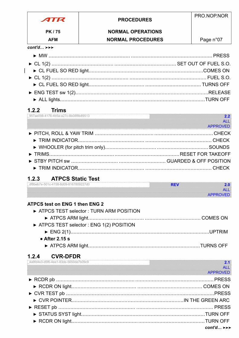
▶ MW ...................................................... ...................................................... PRESS
▶ CL 1(2) ......................................... ......................................... SET OUT OF FUEL S.O.▶ CL FUEL SO RED light............................................................................COMES ON
▶ CL 1(2) ................................................... ................................................... FUEL S.O.▶ CL FUEL SO RED light..................................... ..................................... TURNS OFF
▶ ENG TEST sw 1(2)........................................................................................RELEASE▶ ALL lights................................................................................................TURN OFF
1.2.2 Trims_957ae098-4176-4b5a-a27c-8b08f8b89513 2.2
ALLAPPROVED
▶ PITCH, ROLL & YAW TRIM ....................................... ....................................... CHECK▶ TRIM INDICATOR............................................ ............................................ CHECK▶ WHOOLER (for pitch trim only).................................. .................................. SOUNDS
▶ TRIMS........................................... ...........................................RESET FOR TAKEOFF▶ STBY PITCH sw ............................... ............................... GUARDED & OFF POSITION▶ TRIM INDICATOR............................................ ............................................ CHECK
1.2.3 ATPCS Static Test_df8beb7e-501c-4158-8d09-8167809227d0 REV 2.0
ALLAPPROVED
ATPCS test on ENG 1 then ENG 2▶ ATPCS TEST selector : TURN ARM POSITION
▶ ATPCS ARM light..................................... ..................................... COMES ON▶ ATPCS TEST selector : ENG 1(2) POSITION
▶ ENG 2(1)............................................................................................UPTRIM● After 2.15 s▶ ATPCS ARM light..........................................................................TURNS OFF
1.2.4 CVR-DFDR_4a9fd4e3-d5f6-4ee1-83de-5650de7b09c9 2.1
ALLAPPROVED
▶ RCDR pb .................................................... ....................................................PRESS▶ RCDR ON light........................................... ........................................... COMES ON
▶ CVR TEST pb ..................................................................................................PRESS▶ CVR POINTER..........................................................................IN THE GREEN ARC
▶ RESET pb ................................................... ................................................... PRESS▶ STATUS SYST light..................................................................................TURN OFF▶ RCDR ON light............................................ ............................................TURN OFF
PROCEDURESPRO.NOP.NOR
PK / 75 NORMAL OPERATIONSAFM NORMAL PROCEDURES Page n°07
cont'd…
cont'd…
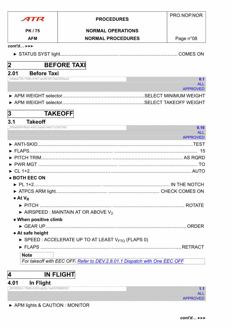
▶ STATUS SYST light........................................ ........................................ COMES ON
2 BEFORE TAXI2.01 Before Taxi_c40ea730-756b-4167-ac59-0615a2350ea3 0.1
ALLAPPROVED
▶ APM WEIGHT selector........................................................SELECT MINIMUM WEIGHT▶ APM WEIGHT selector........................................................SELECT TAKEOFF WEIGHT
3 TAKEOFF3.1 Takeoff_30bebf09-f6a5-44f2-baa4-d4e71c3d316d 0.10
ALLAPPROVED
▶ ANTI-SKID..........................................................................................................TEST▶ FLAPS......................................................... ......................................................... 15▶ PITCH TRIM................................................ ................................................ AS RQRD▶ PWR MGT ...................................................... ...................................................... TO▶ CL 1+2....................................................... ....................................................... AUTO● BOTH EEC ON▶ PL 1+2.............................................. .............................................. IN THE NOTCH▶ ATPCS ARM light................................... ................................... CHECK COMES ON● At VR
▶ PITCH ................................................. ................................................. ROTATE▶ AIRSPEED : MAINTAIN AT OR ABOVE V2
● When positive climb▶ GEAR UP................................................ ................................................ORDER
● At safe height▶ SPEED : ACCELERATE UP TO AT LEAST VFTO (FLAPS 0)▶ FLAPS ................................................ ................................................RETRACT
NoteFor takeoff with EEC OFF, Refer to DEV.2.8.01.1 Dispatch with One EEC OFF
4 IN FLIGHT4.01 In Flight_291853b1-79d9-4333-ab2c-1e4525868391 1.1
ALLAPPROVED
▶ APM lights & CAUTION : MONITOR
PROCEDURESPRO.NOP.NOR
PK / 75 NORMAL OPERATIONSAFM NORMAL PROCEDURES Page n°08
cont'd…
cont'd…
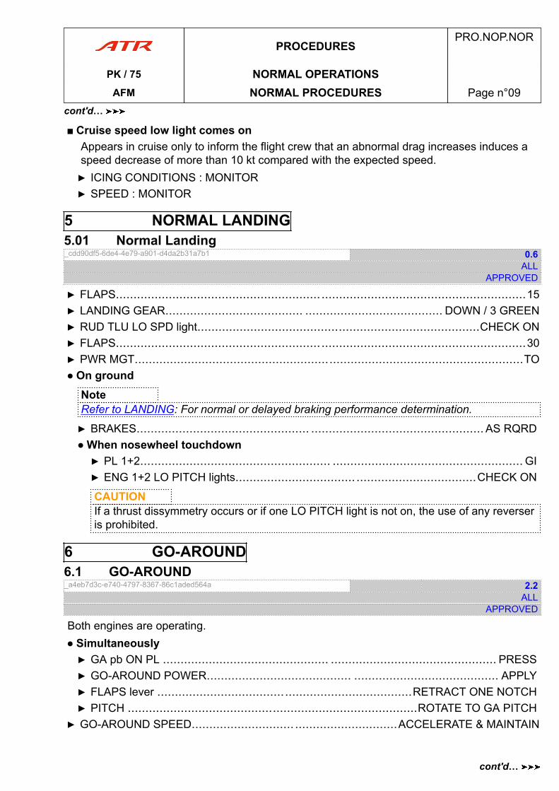
■ Cruise speed low light comes onAppears in cruise only to inform the flight crew that an abnormal drag increases induces aspeed decrease of more than 10 kt compared with the expected speed.▶ ICING CONDITIONS : MONITOR▶ SPEED : MONITOR
5 NORMAL LANDING5.01 Normal Landing_cdd90df5-6de4-4e79-a901-d4da2b31a7b1 0.6
ALLAPPROVED
▶ FLAPS.......................................................... ..........................................................15▶ LANDING GEAR....................................... ....................................... DOWN / 3 GREEN▶ RUD TLU LO SPD light................................................................................CHECK ON▶ FLAPS.......................................................... ..........................................................30▶ PWR MGT..............................................................................................................TO● On ground
NoteRefer to LANDING: For normal or delayed braking performance determination.
▶ BRAKES................................................. ................................................. AS RQRD● When nosewheel touchdown▶ PL 1+2...................................................... ...................................................... GI▶ ENG 1+2 LO PITCH lights.................................. ..................................CHECK ON
CAUTIONIf a thrust dissymmetry occurs or if one LO PITCH light is not on, the use of any reverseris prohibited.
6 GO-AROUND6.1 GO-AROUND_a4eb7d3c-e740-4797-8367-86c1aded564a 2.2
ALLAPPROVED
Both engines are operating.● Simultaneously▶ GA pb ON PL ............................................... ............................................... PRESS▶ GO-AROUND POWER......................................... ......................................... APPLY▶ FLAPS lever ........................................................................RETRACT ONE NOTCH▶ PITCH ..................................................................................ROTATE TO GA PITCH
▶ GO-AROUND SPEED............................. .............................ACCELERATE & MAINTAIN
PROCEDURESPRO.NOP.NOR
PK / 75 NORMAL OPERATIONSAFM NORMAL PROCEDURES Page n°09
cont'd…
cont'd…
● When positive rate of climb▶ LDG GEAR lever ................................................ ................................................UP
PROCEDURESPRO.NOP.NOR
PK / 75 NORMAL OPERATIONSAFM NORMAL PROCEDURES Page n°10
cont'd…
ADDITIONAL NORMAL PROCEDURES .NOP.ANOR
ANOR. ADDITIONAL NORMAL PROCEDURES............................................................... page 03ANOR.1 ADVERSE WEATHER............................................................................page 03
ANOR.1.1 GROUND ICING CONDITIONS.........................................page 03
ANOR.1.2 ATMOSPHERIC ICING CONDITIONS................................page 03
ANOR.1.3 TAKEOFF AFTER USE OF FLUIDS II OR IV.......................page 08
ANOR.1.4 SEVERE TURBULENCE.................................................. page 10
ANOR.1.5 HEAVY RAIN...................................................................page 10
AFMPRO.NOP.ANOR
PK / 75 TOCAFM Table of Content Page n°01

PAGE
INTENTIONALLY
LEFT BLANK
AFMPRO.NOP.ANOR
PK / 75 TOCAFM Table of Content Page n°02
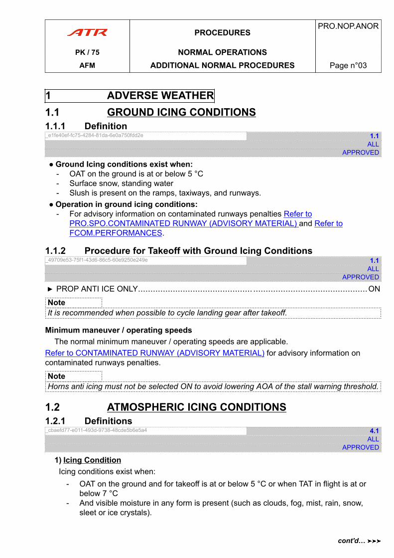
1 ADVERSE WEATHER1.1 GROUND ICING CONDITIONS1.1.1 Definition_e1fe40ef-fc75-4284-81da-6e0a750fdd2e 1.1
ALLAPPROVED
● Ground Icing conditions exist when:- OAT on the ground is at or below 5 °C- Surface snow, standing water- Slush is present on the ramps, taxiways, and runways.
● Operation in ground icing conditions:- For advisory information on contaminated runways penalties Refer to
PRO.SPO.CONTAMINATED RUNWAY (ADVISORY MATERIAL) and Refer toFCOM.PERFORMANCES.
1.1.2 Procedure for Takeoff with Ground Icing Conditions_49709e53-75f1-43d6-86c5-60e9250e249e 1.1
ALLAPPROVED
▶ PROP ANTI ICE ONLY.............................................. ..............................................ON
NoteIt is recommended when possible to cycle landing gear after takeoff.
Minimum maneuver / operating speedsThe normal minimum maneuver / operating speeds are applicable.
Refer to CONTAMINATED RUNWAY (ADVISORY MATERIAL) for advisory information oncontaminated runways penalties.
NoteHorns anti icing must not be selected ON to avoid lowering AOA of the stall warning threshold.
1.2 ATMOSPHERIC ICING CONDITIONS1.2.1 Definitions_cbaefd77-e011-493d-9738-48cde5b6e5a4 4.1
ALLAPPROVED
1) Icing ConditionIcing conditions exist when:
- OAT on the ground and for takeoff is at or below 5 °C or when TAT in flight is at orbelow 7 °C
- And visible moisture in any form is present (such as clouds, fog, mist, rain, snow,sleet or ice crystals).
PROCEDURESPRO.NOP.ANOR
PK / 75 NORMAL OPERATIONSAFM ADDITIONAL NORMAL PROCEDURES Page n°03
cont'd…
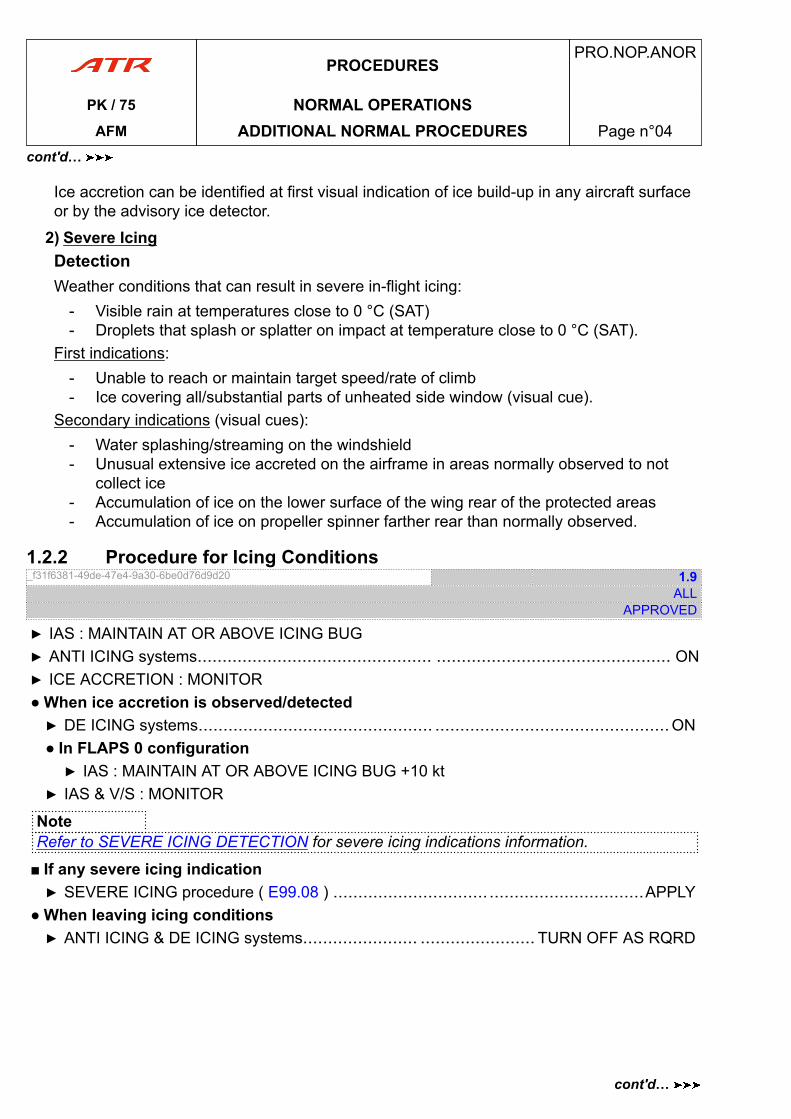
Ice accretion can be identified at first visual indication of ice build-up in any aircraft surfaceor by the advisory ice detector.
2) Severe IcingDetectionWeather conditions that can result in severe in-flight icing:
- Visible rain at temperatures close to 0 °C (SAT)- Droplets that splash or splatter on impact at temperature close to 0 °C (SAT).
First indications:- Unable to reach or maintain target speed/rate of climb- Ice covering all/substantial parts of unheated side window (visual cue).
Secondary indications (visual cues):- Water splashing/streaming on the windshield- Unusual extensive ice accreted on the airframe in areas normally observed to not
collect ice- Accumulation of ice on the lower surface of the wing rear of the protected areas- Accumulation of ice on propeller spinner farther rear than normally observed.
1.2.2 Procedure for Icing Conditions_f31f6381-49de-47e4-9a30-6be0d76d9d20 1.9
ALLAPPROVED
▶ IAS : MAINTAIN AT OR ABOVE ICING BUG▶ ANTI ICING systems............................................... ............................................... ON▶ ICE ACCRETION : MONITOR● When ice accretion is observed/detected▶ DE ICING systems............................................... ...............................................ON● In FLAPS 0 configuration▶ IAS : MAINTAIN AT OR ABOVE ICING BUG +10 kt
▶ IAS & V/S : MONITOR
NoteRefer to SEVERE ICING DETECTION for severe icing indications information.
■ If any severe icing indication▶ SEVERE ICING procedure ( E99.08 ) ..............................................................APPLY
● When leaving icing conditions▶ ANTI ICING & DE ICING systems....................... ....................... TURN OFF AS RQRD
PROCEDURESPRO.NOP.ANOR
PK / 75 NORMAL OPERATIONSAFM ADDITIONAL NORMAL PROCEDURES Page n°04
cont'd…
cont'd…

● When aircraft is visually verified clear of iceNoteThe aircraft is considered clear of ice when IEP is free of ice.
▶ ICING AOA pb ..................................................................................................OFF▶ NORMAL SPEED : USE
PROCEDURESPRO.NOP.ANOR
PK / 75 NORMAL OPERATIONSAFM ADDITIONAL NORMAL PROCEDURES Page n°05
cont'd…
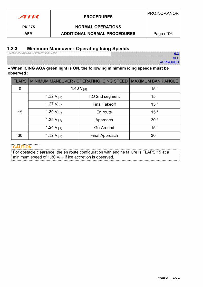
1.2.3 Minimum Maneuver - Operating Icing Speeds_1a02d1d5-fd23-4dcc-9f68-37f3164f4433 0.3
ALLAPPROVED
● When ICING AOA green light is ON, the following minimum icing speeds must beobserved :
FLAPS MINIMUM MANEUVER / OPERATING ICING SPEED MAXIMUM BANK ANGLE
0 1.40 VSR 15 °
15
1.22 VSR T.O 2nd segment 15 °
1.27 VSR Final Takeoff 15 °
1.30 VSR En route 15 °
1.35 VSR Approach 30 °
1.24 VSR Go-Around 15 °
30 1.32 VSR Final Approach 30 °
CAUTIONFor obstacle clearance, the en route configuration with engine failure is FLAPS 15 at aminimum speed of 1.30 VSR if ice accretion is observed.
PROCEDURESPRO.NOP.ANOR
PK / 75 NORMAL OPERATIONSAFM ADDITIONAL NORMAL PROCEDURES Page n°06
cont'd…
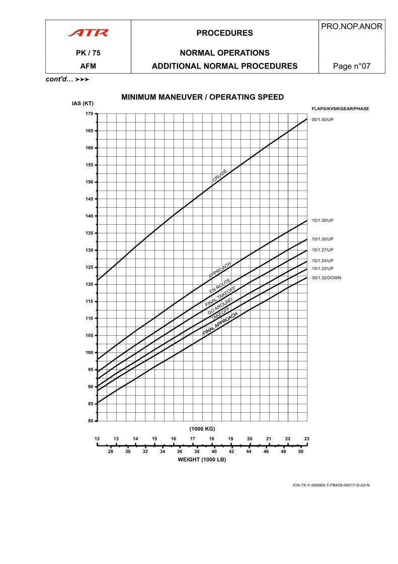
1212 13 14 15 16 17 18 19 20 21 22 23
(1000 KG)
28 30 32 34 36 38 40 42 44 46 48 50
WEIGHT (1000 LB)
8080
85
90
95
100
105
110
115
120
125
130
135
140
145
150
155
160
165
170
IAS (KT)MINIMUM MANEUVER / OPERATING SPEED
FLAPS/KVSR/GEAR/PHASE
00/1.40/UP
15/1.35/UP
15/1.30/UP
15/1.27/UP
15/1.24/UP
15/1.22/UP
30/1.32/DOWN
ICN-7X-Y-000000-T-FB429-00017-D-03-N
PROCEDURESPRO.NOP.ANOR
PK / 75 NORMAL OPERATIONSAFM ADDITIONAL NORMAL PROCEDURES Page n°07
cont'd…
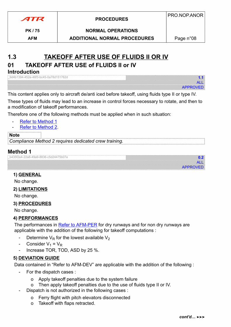
1.3 TAKEOFF AFTER USE OF FLUIDS II OR IV01 TAKEOFF AFTER USE of FLUIDS II or IVIntroduction_9d4b1394-452e-46f3-bc45-0a78d151762d 1.1
ALLAPPROVED
This content applies only to aircraft de/anti iced before takeoff, using fluids type II or type IV.These types of fluids may lead to an increase in control forces necessary to rotate, and then toa modification of takeoff performances.Therefore one of the following methods must be applied when in such situation:
- Refer to Method 1- Refer to Method 2.
NoteCompliance Method 2 requires dedicated crew training.
Method 1_b435f2e4-22a8-49a9-8836-c5d24475b07e 0.2
ALLAPPROVED
1) GENERALNo change.
2) LIMITATIONSNo change.
3) PROCEDURESNo change.
4) PERFORMANCESThe performances in Refer to AFM-PER for dry runways and for non dry runways areapplicable with the addition of the following for takeoff computations :
- Determine VR for the lowest available V2- Consider V1 = VR- Increase TOR, TOD, ASD by 25 %.
5) DEVIATION GUIDEData contained in “Refer to AFM-DEV” are applicable with the addition of the following :
- For the dispatch cases :o Apply takeoff penalties due to the system failureo Then apply takeoff penalties due to the use of fluids type II or IV.
- Dispatch is not authorized in the following cases :o Ferry flight with pitch elevators disconnectedo Takeoff with flaps retracted.
PROCEDURESPRO.NOP.ANOR
PK / 75 NORMAL OPERATIONSAFM ADDITIONAL NORMAL PROCEDURES Page n°08
cont'd…
6) APPENDICESNo change.
7) SUPPLEMENTSNo change.
Method 2_72023028-246c-440e-b7d9-f7aae39f0970 0.1
ALLAPPROVED
1) GENERALNo change.
2) LIMITATIONSNo change.
3) PROCEDURESa) Normal ProceduresThe Captain must be the PF and the pre-takeoff briefing must include below abnormalprocedures impact.
b) Emergency ProceduresNo change.
c) Abnormal ProceduresThe procedures in “Refer to AFM-PRO” are applicable with the addition of the following:
- In case of difficulties to rotate, the Captain should require PM assistance- In that case, on Captain order, PM pulls the control column until 5 ° pitch attitude is
reached, then PM releases the controls.
4) PERFORMANCESThe performances in ‘Refer to AFM-PER’ for dry runways and in ‘Refer to AFM-Appendiceand supplement-non dry runways’ for non dry runways are applicable with the addition of thefollowing for takeoff computations :
- Increase TOD by 70 m.
5) DEVIATION GUIDEData contained in “Refer to AFM-DEV” are applicable with the addition of the following :
- For the dispatch cases :o Apply takeoff penalties due to the system failureo Then apply takeoff penalties due to the use of fluids type II or IV.
- Dispatch is not authorized in the following cases :o Ferry flight with pitch elevators disconnectedo Takeoff with flaps retracted.
6) APPENDICESNo change.
PROCEDURESPRO.NOP.ANOR
PK / 75 NORMAL OPERATIONSAFM ADDITIONAL NORMAL PROCEDURES Page n°09
cont'd…
cont'd…
7) SUPPLEMENTSNo change.
1.4 SEVERE TURBULENCE1.4.01 Severe Turbulence_f17586a5-4f05-4074-8af8-645e13c589cf 0.1
ALLAPPROVED
▶ SIGNS......................................................... ......................................................... ON▶ SPEED : MAINTAIN AT or BELOW VRA 180 kt CAS
1.5 HEAVY RAIN1.5.01 Heavy Rain_0adfcd5c-1345-478c-9e86-f577a212e354 0.1
ALLAPPROVED
Not applicable
PROCEDURESPRO.NOP.ANOR
PK / 75 NORMAL OPERATIONSAFM ADDITIONAL NORMAL PROCEDURES Page n°10
cont'd…
SPO - SPECIAL OPERATIONSSPECIAL OPERATIONS PRO.SPO
1. STEEP SLOPE APPROACH................................................................................page 03
2. HIGH ALTITUDE RUNWAYS................................................................................page 05
3. ETOPS.............................................................................................................. page 05
4. OPERATION ON NARROW RUNWAYS................................................................ page 05
5. RUNWAYS SLOPE BEYOND 2 %........................................................................ page 08
6. HIGH LATITUDE OPERATIONS...........................................................................page 08
8. DRY UNPAVED RUNWAYS..................................................................................page 09
11. 20 KT TAILWIND TAKEOFF.................................................................................page 09
12. OPERATION ON CORAL RUNWAY......................................................................page 09
13. CONTAMINATED RUNWAY (ADVISORY MATERIAL)............................................ page 09
16. OPERATION WITHOUT FORWARD LH PARTITION.............................................. page 65
20. CONTAINER TRANSPORTATION........................................................................ page 66
21. CAT 2 APPROACH.............................................................................................page 66
AFMPRO.SPO
PK / 75 TOCAFM Table of Content Page n°01

PAGE
INTENTIONALLY
LEFT BLANK
AFMPRO.SPO
PK / 75 TOCAFM Table of Content Page n°02
1 STEEP SLOPE APPROACH1.1 STEEP SLOPE APPROACH1.1.1 APPLICABILITY1.1.1.1 STEEP SLOPE APPROACHApplicability_90317a05-6d93-4791-8dae-0804d8de06fd 0.1
ALLAPPROVED
(APPROACH SLOPE > 4.5 °)NOT APPLICABLE.
1.1.2 LIMITATIONS1.1.2.1 Limitations_98a9ae39-0813-4c9e-889c-bce2c51a5dae 0.1
ALLAPPROVED
(APPROACH SLOPE > 4.5 °)NOT APPLICABLE.
1.1.3 PROCEDURES1.1.3.1 Emergency Procedures_a6290fbe-d52f-491b-b3d4-f80b4577da45 0.1
ALLAPPROVED
(APPROACH SLOPE > 4.5 °)NOT APPLICABLE.
1.1.3.2 Abnormal Procedures_41b58321-a863-4ae2-8fbb-a9af64d8c594 0.1
ALLAPPROVED
(APPROACH SLOPE > 4.5 °)NOT APPLICABLE.
1.1.3.3 Normal Procedures_7fb15325-d909-4dd8-ae03-dc61be353230 1.1
ALLAPPROVED
(APPROACH SLOPE > 4.5 °)NOT APPLICABLE.
PROCEDURESPRO.SPO
PK / 75 SPECIAL OPERATIONSAFM STEEP SLOPE APPROACH Page n°03
1.1.4 PERFORMANCES1.1.4.1 Performances_c54494ec-2b0c-4675-8411-45c8f14b47e6 0.1
ALLAPPROVED
(APPROACH SLOPE > 4.5 °)NOT APPLICABLE.
1.2 MANUAL APPROACH WITH PERFORMANCE CREDIT1.2.1 APPLICABILITY1.2.1.01 Applicability_44f4dbbe-175b-4b9b-a1f0-af4e600874ac 0.1
ALLAPPROVED
(APPROACH SLOPE > 4.5 °)NOT APPLICABLE
1.2.2 LIMITATIONS1.2.2.01 Limitations_e5f6978b-14f8-44c3-93b0-b0b9a72ebfd6 0.1
ALLAPPROVED
(APPROACH SLOPE > 4.5 °)NOT APPLICABLE
1.2.3 PROCEDURES1.2.3.1 Emergency Procedures_905fd0eb-6b18-44fc-92be-c4c9d5303931 0.1
ALLAPPROVED
(APPROACH SLOPE > 4.5 °)NOT APPLICABLE
1.2.3.2 Abnormal Procedures_356c88f3-051c-4bf9-b6d2-993348ec8f9c 0.2
ALLAPPROVED
(APPROACH SLOPE > 4.5 °)NOT APPLICABLE
PROCEDURESPRO.SPO
PK / 75 SPECIAL OPERATIONSAFM STEEP SLOPE APPROACH Page n°04
1.2.3.3 Normal Procedures_4fc16447-b6f6-409d-921f-8ef1485ad533 1.1
ALLAPPROVED
(APPROACH SLOPE > 4.5 °)NOT APPLICABLE
1.2.4 PERFORMANCES1.2.4.01 Performances_83611ad4-3c01-44ff-814b-3a06c4a1c4d0 0.1
ALLAPPROVED
(APPROACH SLOPE > 4.5 °)NOT APPLICABLE
2 HIGH ALTITUDE RUNWAYS2.1 APPLICABILITY2.1.1 Applicability_0d3de3fb-de6b-48d1-8b97-1e66322e9aa5 0.1
ALLAPPROVED
(Runways altitude above 8 500 ft and up to 11 000 ft)NOT APPLICABLE
3 ETOPS3.1 GENERAL3.1.1 Applicability_46dc77ac-ab21-4f73-8efe-aac85d51fb9e 1.0
ALLAPPROVED
NOT APPLICABLE
4 OPERATION ON NARROW RUNWAYS4.1 APPLICABILITY4.1.1 Applicability_2156ff0a-de93-4e51-8935-e33fa3d69571 0.1
1000;1036-1037APPROVED
Runway width < 30 m (98 ft)NOT APPLICABLE
PROCEDURESPRO.SPO
PK / 75 SPECIAL OPERATIONSAFM STEEP SLOPE APPROACH Page n°05
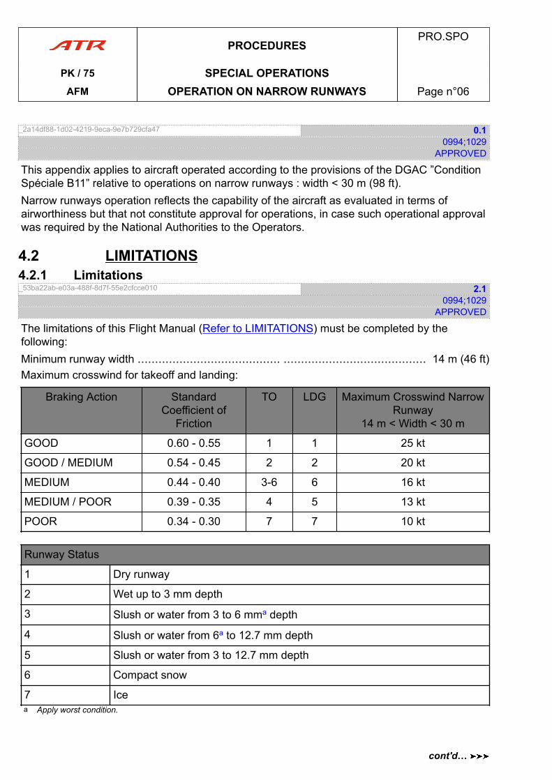
_2a14df88-1d02-4219-9eca-9e7b729cfa47 0.10994;1029
APPROVED
This appendix applies to aircraft operated according to the provisions of the DGAC ”ConditionSpéciale B11” relative to operations on narrow runways : width < 30 m (98 ft).Narrow runways operation reflects the capability of the aircraft as evaluated in terms ofairworthiness but that not constitute approval for operations, in case such operational approvalwas required by the National Authorities to the Operators.
4.2 LIMITATIONS4.2.1 Limitations_53ba22ab-e03a-488f-8d7f-55e2cfcce010 2.1
0994;1029APPROVED
The limitations of this Flight Manual (Refer to LIMITATIONS) must be completed by thefollowing:Minimum runway width ......................................... ......................................... 14 m (46 ft)Maximum crosswind for takeoff and landing:
Braking Action StandardCoefficient of
Friction
TO LDG Maximum Crosswind NarrowRunway
14 m < Width < 30 m
GOOD 0.60 - 0.55 1 1 25 kt
GOOD / MEDIUM 0.54 - 0.45 2 2 20 kt
MEDIUM 0.44 - 0.40 3-6 6 16 kt
MEDIUM / POOR 0.39 - 0.35 4 5 13 kt
POOR 0.34 - 0.30 7 7 10 kt
Runway Status
1 Dry runway
2 Wet up to 3 mm depth
3 Slush or water from 3 to 6 mma depth
4 Slush or water from 6a to 12.7 mm depth
5 Slush or water from 3 to 12.7 mm depth
6 Compact snow
7 Icea Apply worst condition.
PROCEDURESPRO.SPO
PK / 75 SPECIAL OPERATIONSAFM OPERATION ON NARROW RUNWAYS Page n°06
cont'd…
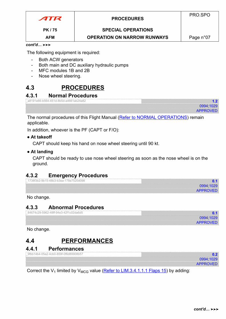
The following equipment is required:- Both ACW generators- Both main and DC auxiliary hydraulic pumps- MFC modules 1B and 2B- Nose wheel steering.
4.3 PROCEDURES4.3.1 Normal Procedures_a8191e66-b564-451d-8b5d-a4661ab24a82 1.2
0994;1029APPROVED
The normal procedures of this Flight Manual (Refer to NORMAL OPERATIONS) remainapplicable.In addition, whoever is the PF (CAPT or F/O):● At takeoff
CAPT should keep his hand on nose wheel steering until 90 kt.
● At landingCAPT should be ready to use nose wheel steering as soon as the nose wheel is on theground.
4.3.2 Emergency Procedures_1738f3b2-9b15-48b3-b3ea-178e7520d098 0.1
0994;1029APPROVED
No change.
4.3.3 Abnormal Procedures_84674c29-5962-48ff-94e3-42f1c02da6d5 0.1
0994;1029APPROVED
No change.
4.4 PERFORMANCES4.4.1 Performances_9fbb14b4-05a2-4cb0-859f-0f6d89908b57 0.2
0994;1029APPROVED
Correct the V1 limited by VMCG value (Refer to LIM.3.4.1.1.1 Flaps 15) by adding:
PROCEDURESPRO.SPO
PK / 75 SPECIAL OPERATIONSAFM OPERATION ON NARROW RUNWAYS Page n°07
cont'd…
cont'd…
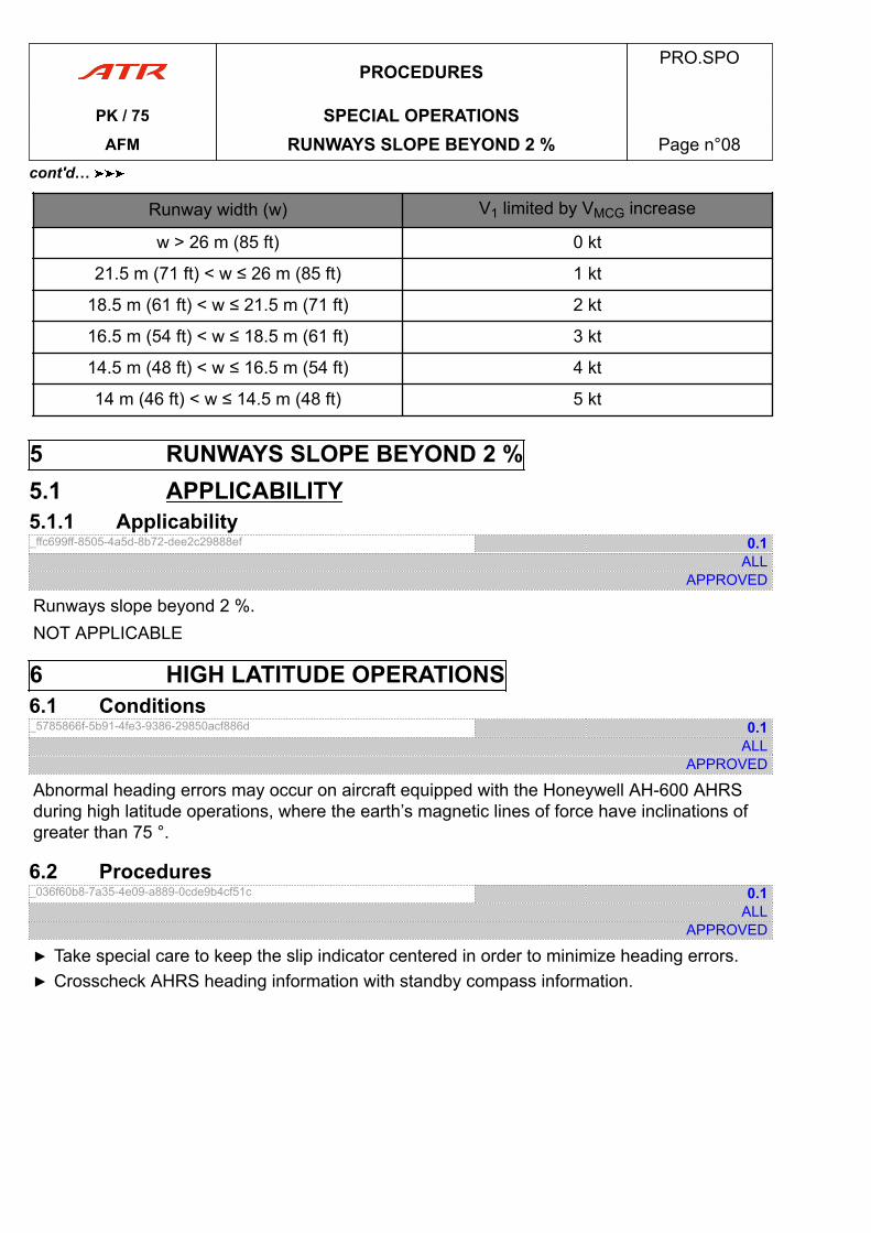
Runway width (w) V1 limited by VMCG increase
w > 26 m (85 ft) 0 kt
21.5 m (71 ft) < w ≤ 26 m (85 ft) 1 kt
18.5 m (61 ft) < w ≤ 21.5 m (71 ft) 2 kt
16.5 m (54 ft) < w ≤ 18.5 m (61 ft) 3 kt
14.5 m (48 ft) < w ≤ 16.5 m (54 ft) 4 kt
14 m (46 ft) < w ≤ 14.5 m (48 ft) 5 kt
5 RUNWAYS SLOPE BEYOND 2 %5.1 APPLICABILITY5.1.1 Applicability_ffc699ff-8505-4a5d-8b72-dee2c29888ef 0.1
ALLAPPROVED
Runways slope beyond 2 %.NOT APPLICABLE
6 HIGH LATITUDE OPERATIONS6.1 Conditions_5785866f-5b91-4fe3-9386-29850acf886d 0.1
ALLAPPROVED
Abnormal heading errors may occur on aircraft equipped with the Honeywell AH-600 AHRSduring high latitude operations, where the earth’s magnetic lines of force have inclinations ofgreater than 75 °.
6.2 Procedures_036f60b8-7a35-4e09-a889-0cde9b4cf51c 0.1
ALLAPPROVED
▶ Take special care to keep the slip indicator centered in order to minimize heading errors.▶ Crosscheck AHRS heading information with standby compass information.
PROCEDURESPRO.SPO
PK / 75 SPECIAL OPERATIONSAFM RUNWAYS SLOPE BEYOND 2 % Page n°08
cont'd…
8 DRY UNPAVED RUNWAYS8.1 APPLICABILITY8.1.1 Applicability_910f98ae-701e-4d7a-81fb-79437f02f7db 0.1
ALLAPPROVED
NOT APPLICABLE.
11 20 KT TAILWIND TAKEOFF11.1 APPLICABILITY11.1.1 Applicability_48699420-1c3f-425a-a1a7-1bcbfdef2e22 0.1
ALLAPPROVED
NOT APPLICABLE
12 OPERATION ON CORAL RUNWAY12.1 APPLICABILITY12.1.1 Applicability_ce24572e-3ceb-428f-a529-98e40b25b380 0.1
ALLAPPROVED
NOT APPLICABLE
13 CONTAMINATED RUNWAY (ADVISORY MATERIAL)13.1 GENERAL13.1.1 Introduction_6d100fa0-b5ec-4574-8122-ace29086e0fa 0.1
ALLAPPROVED
This information has been prepared by the manufacturer and approved by the Authority in theform of guidance material, to assist operators in developing appropriate guidance,recommendations or instructions for use by their flight crews when operating on wet/contaminated runway surface conditions.Unless otherwise stated, this information does not in any way replace or amend the operatinglimitations and performance information listed in other parts of this approved Airplane FlightManual.
PROCEDURESPRO.SPO
PK / 75 SPECIAL OPERATIONSAFM DRY UNPAVED RUNWAYS Page n°09
cont'd…
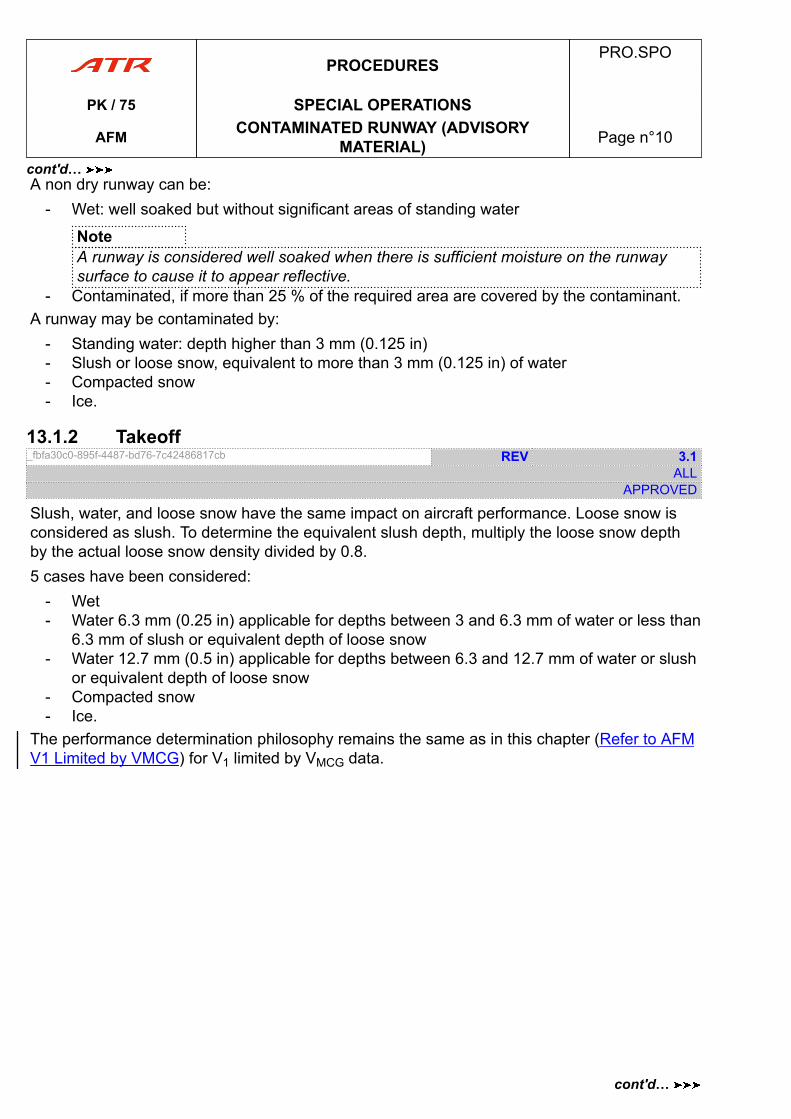
A non dry runway can be:- Wet: well soaked but without significant areas of standing water
NoteA runway is considered well soaked when there is sufficient moisture on the runwaysurface to cause it to appear reflective.
- Contaminated, if more than 25 % of the required area are covered by the contaminant.A runway may be contaminated by:
- Standing water: depth higher than 3 mm (0.125 in)- Slush or loose snow, equivalent to more than 3 mm (0.125 in) of water- Compacted snow- Ice.
13.1.2 Takeoff_fbfa30c0-895f-4487-bd76-7c42486817cb REV 3.1
ALLAPPROVED
Slush, water, and loose snow have the same impact on aircraft performance. Loose snow isconsidered as slush. To determine the equivalent slush depth, multiply the loose snow depthby the actual loose snow density divided by 0.8.5 cases have been considered:
- Wet- Water 6.3 mm (0.25 in) applicable for depths between 3 and 6.3 mm of water or less than
6.3 mm of slush or equivalent depth of loose snow- Water 12.7 mm (0.5 in) applicable for depths between 6.3 and 12.7 mm of water or slush
or equivalent depth of loose snow- Compacted snow- Ice.
The performance determination philosophy remains the same as in this chapter (Refer to AFMV1 Limited by VMCG) for V1 limited by VMCG data.
PROCEDURESPRO.SPO
PK / 75 SPECIAL OPERATIONS
AFM CONTAMINATED RUNWAY (ADVISORYMATERIAL) Page n°10
cont'd…
cont'd…
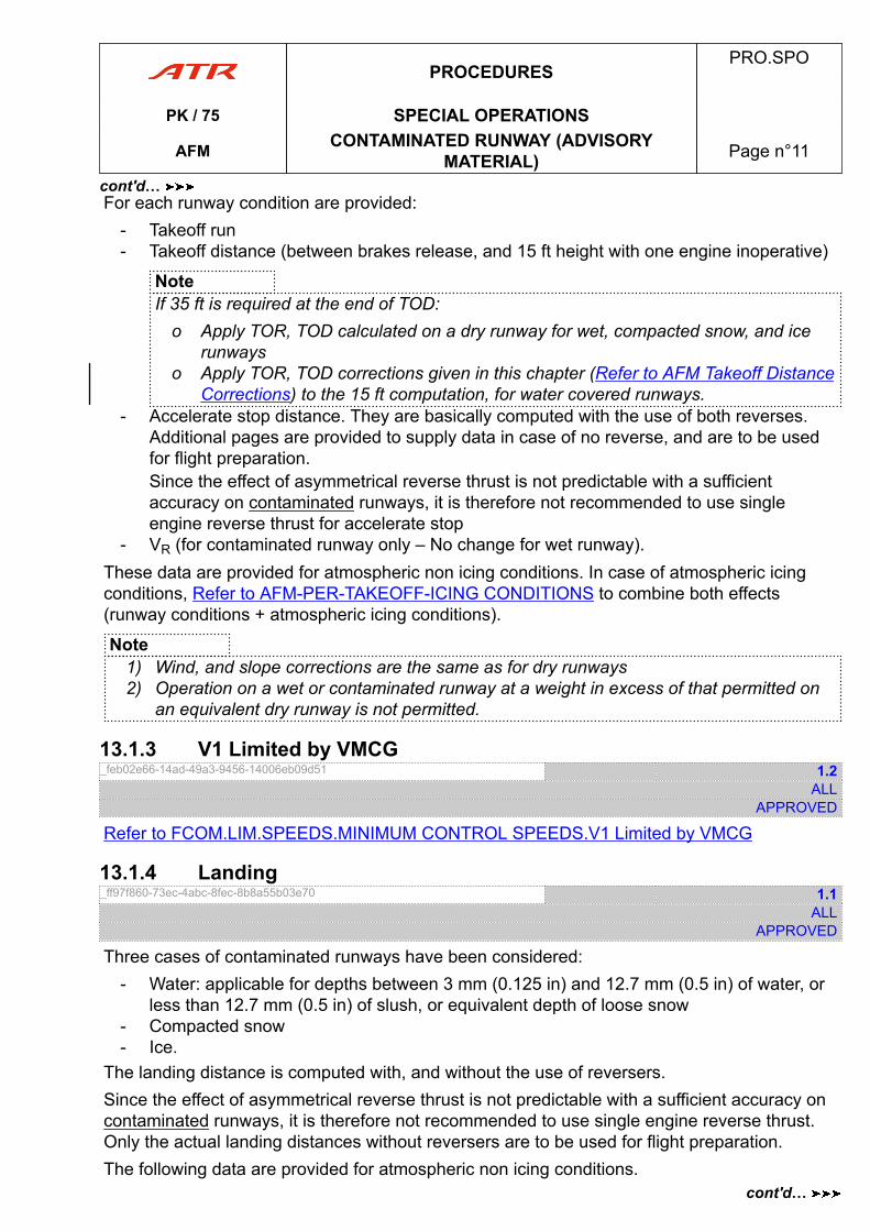
For each runway condition are provided:- Takeoff run- Takeoff distance (between brakes release, and 15 ft height with one engine inoperative)
NoteIf 35 ft is required at the end of TOD:
o Apply TOR, TOD calculated on a dry runway for wet, compacted snow, and icerunways
o Apply TOR, TOD corrections given in this chapter (Refer to AFM Takeoff DistanceCorrections) to the 15 ft computation, for water covered runways.
- Accelerate stop distance. They are basically computed with the use of both reverses.Additional pages are provided to supply data in case of no reverse, and are to be usedfor flight preparation.Since the effect of asymmetrical reverse thrust is not predictable with a sufficientaccuracy on contaminated runways, it is therefore not recommended to use singleengine reverse thrust for accelerate stop
- VR (for contaminated runway only – No change for wet runway).These data are provided for atmospheric non icing conditions. In case of atmospheric icingconditions, Refer to AFM-PER-TAKEOFF-ICING CONDITIONS to combine both effects(runway conditions + atmospheric icing conditions).
Note1) Wind, and slope corrections are the same as for dry runways2) Operation on a wet or contaminated runway at a weight in excess of that permitted on
an equivalent dry runway is not permitted.
13.1.3 V1 Limited by VMCG_feb02e66-14ad-49a3-9456-14006eb09d51 1.2
ALLAPPROVED
Refer to FCOM.LIM.SPEEDS.MINIMUM CONTROL SPEEDS.V1 Limited by VMCG
13.1.4 Landing_ff97f860-73ec-4abc-8fec-8b8a55b03e70 1.1
ALLAPPROVED
Three cases of contaminated runways have been considered:- Water: applicable for depths between 3 mm (0.125 in) and 12.7 mm (0.5 in) of water, or
less than 12.7 mm (0.5 in) of slush, or equivalent depth of loose snow- Compacted snow- Ice.
The landing distance is computed with, and without the use of reversers.Since the effect of asymmetrical reverse thrust is not predictable with a sufficient accuracy oncontaminated runways, it is therefore not recommended to use single engine reverse thrust.Only the actual landing distances without reversers are to be used for flight preparation.The following data are provided for atmospheric non icing conditions.
PROCEDURESPRO.SPO
PK / 75 SPECIAL OPERATIONS
AFM CONTAMINATED RUNWAY (ADVISORYMATERIAL) Page n°11
cont'd…
cont'd…
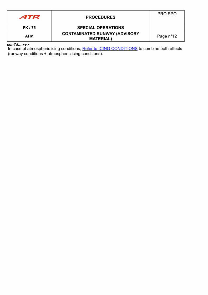
In case of atmospheric icing conditions, Refer to ICING CONDITIONS to combine both effects(runway conditions + atmospheric icing conditions).
PROCEDURESPRO.SPO
PK / 75 SPECIAL OPERATIONS
AFM CONTAMINATED RUNWAY (ADVISORYMATERIAL) Page n°12
cont'd…
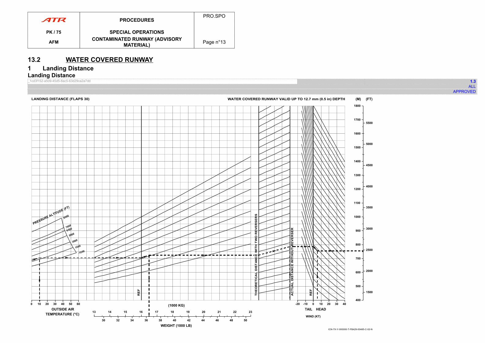
13.2 WATER COVERED RUNWAY1 Landing DistanceLanding Distance_1cd3f152-a509-45d5-8ac5-63d29ca2a7dd 1.3
ALLAPPROVED
00 10 20 30 40 50 60
OUTSIDE AIRTEMPERATURE (°C) 1313 14 15 16 17 18 19 20 21 22 23
(1000 KG)
30 32 34 36 38 40 42 44 46 48 50
WEIGHT (1000 LB)
-20-20 -10 0
TAIL 00 10 20 30 40
HEAD
400400
500
600
700
800
900
1000
1100
1200
1300
1400
1500
1600
1700
1800
(M)
1500
2000
2500
3000
3500
4000
4500
5000
5500
(FT)
WIND (KT)
ICN-7X-Y-000000-T-FB429-00485-C-02-N
WATER COVERED RUNWAY VALID UP TO 12.7 mm (0.5 in) DEPTHLANDING DISTANCE (FLAPS 30)
PROCEDURESPRO.SPO
PK / 75 SPECIAL OPERATIONS
AFM CONTAMINATED RUNWAY (ADVISORYMATERIAL) Page n°13

PAGE
INTENTIONALLY
LEFT BLANK
PROCEDURESPRO.SPO
PK / 75 SPECIAL OPERATIONS
AFM CONTAMINATED RUNWAY (ADVISORYMATERIAL) Page n°14
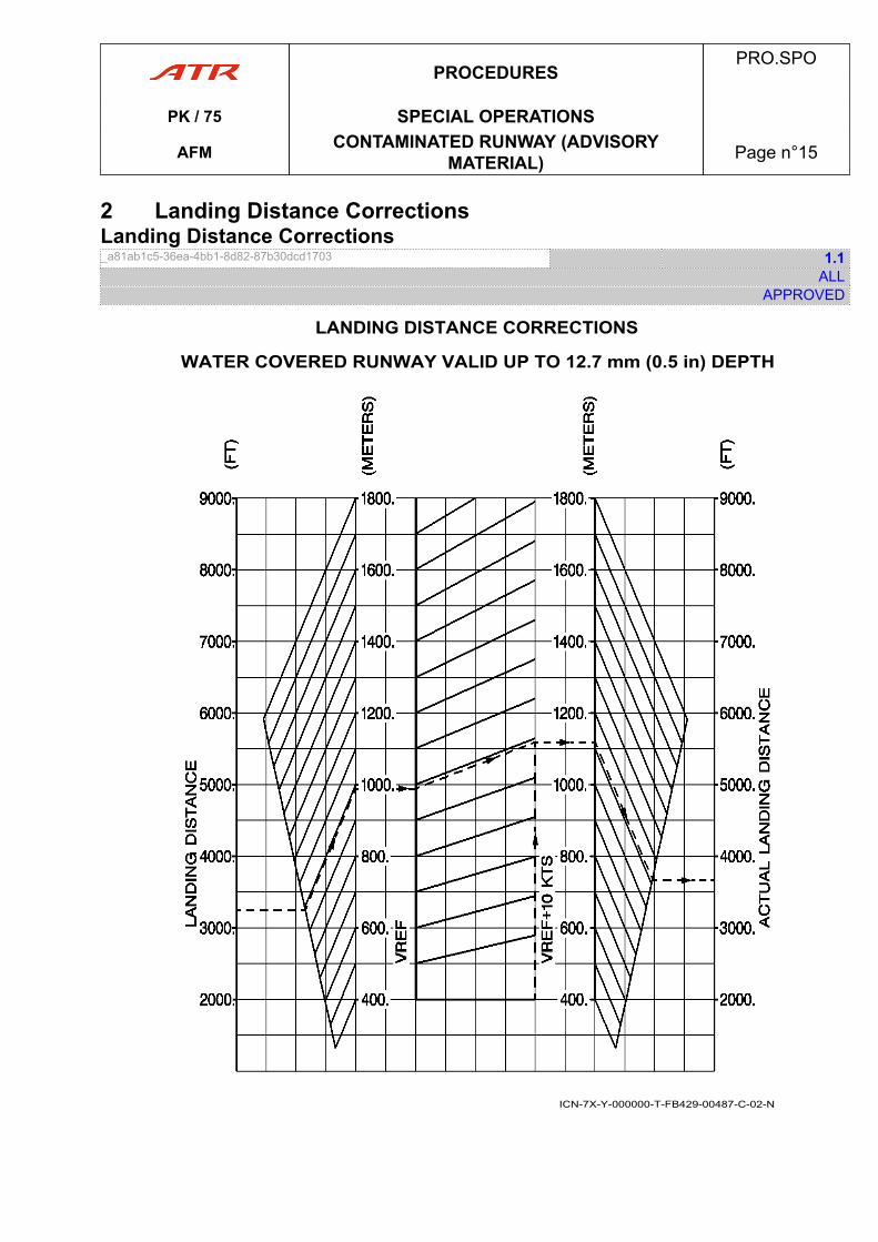
2 Landing Distance CorrectionsLanding Distance Corrections_a81ab1c5-36ea-4bb1-8d82-87b30dcd1703 1.1
ALLAPPROVED
LANDING DISTANCE CORRECTIONS
WATER COVERED RUNWAY VALID UP TO 12.7 mm (0.5 in) DEPTH
ICN-7X-Y-000000-T-FB429-00487-C-02-N
PROCEDURESPRO.SPO
PK / 75 SPECIAL OPERATIONS
AFM CONTAMINATED RUNWAY (ADVISORYMATERIAL) Page n°15

PAGE
INTENTIONALLY
LEFT BLANK
PROCEDURESPRO.SPO
PK / 75 SPECIAL OPERATIONS
AFM CONTAMINATED RUNWAY (ADVISORYMATERIAL) Page n°16
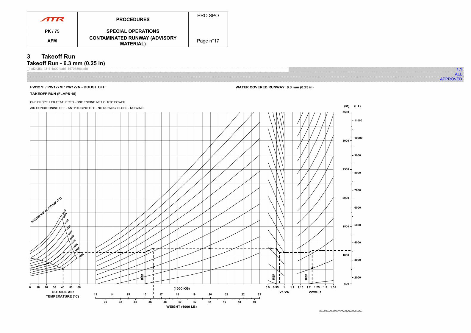
3 Takeoff RunTakeoff Run - 6.3 mm (0.25 in)_1cd2c35a-4311-4e02-bab6-167068f6ad5d 1.1
ALLAPPROVED
00 10 20 30 40 50 60
OUTSIDE AIRTEMPERATURE (°C) 1313 14 15 16 17 18 19 20 21 22 23
(1000 KG)
30 32 34 36 38 40 42 44 46 48 50
WEIGHT (1000 LB)
0.90.9 0.95 1
V1/VR1.11.1 1.15 1.2 1.25 1.3 1.35
V2/VSR
500500
1000
1500
2000
2500
3000
3500
(M)
2000
3000
4000
5000
6000
7000
8000
9000
10000
11000
(FT)
ICN-7X-Y-000000-T-FB429-00488-C-02-N
TAKEOFF RUN (FLAPS 15)
ONE PROPELLER FEATHERED - ONE ENGINE AT T.O/ RTO POWER
AIR CONDITIONING OFF - ANTI/DEICING OFF - NO RUNWAY SLOPE - NO WIND
WATER COVERED RUNWAY: 6.3 mm (0.25 in)PW127F / PW127M / PW127N - BOOST OFF
PROCEDURESPRO.SPO
PK / 75 SPECIAL OPERATIONS
AFM CONTAMINATED RUNWAY (ADVISORYMATERIAL) Page n°17

PAGE
INTENTIONALLY
LEFT BLANK
PROCEDURESPRO.SPO
PK / 75 SPECIAL OPERATIONS
AFM CONTAMINATED RUNWAY (ADVISORYMATERIAL) Page n°18
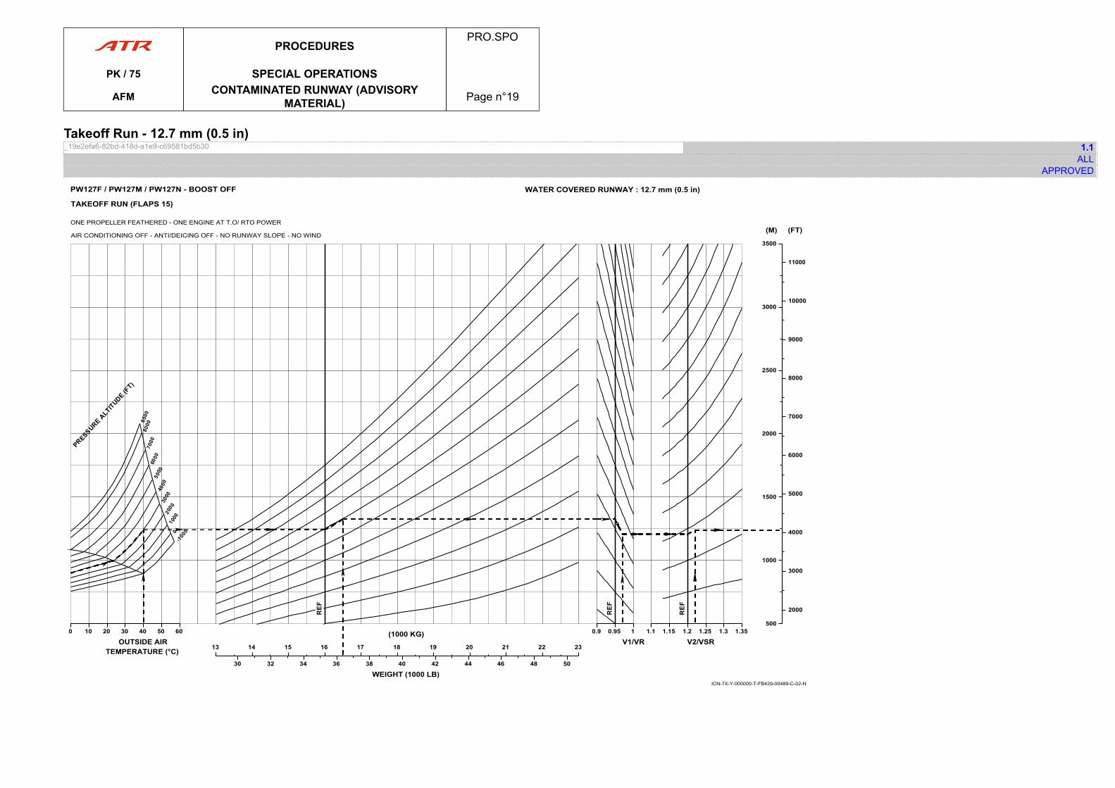
Takeoff Run - 12.7 mm (0.5 in)_19e2efa6-82bd-418d-a1e9-c69581bd5b30 1.1
ALLAPPROVED
00 10 20 30 40 50 60
OUTSIDE AIRTEMPERATURE (°C) 1313 14 15 16 17 18 19 20 21 22 23
(1000 KG)
30 32 34 36 38 40 42 44 46 48 50
WEIGHT (1000 LB)
0.90.9 0.95 1
V1/VR1.11.1 1.15 1.2 1.25 1.3 1.35
V2/VSR
500500
1000
1500
2000
2500
3000
3500
(M)
2000
3000
4000
5000
6000
7000
8000
9000
10000
11000
(FT)
ICN-7X-Y-000000-T-FB429-00489-C-02-N
TAKEOFF RUN (FLAPS 15)
ONE PROPELLER FEATHERED - ONE ENGINE AT T.O/ RTO POWER
AIR CONDITIONING OFF - ANTI/DEICING OFF - NO RUNWAY SLOPE - NO WIND
PW127F / PW127M / PW127N - BOOST OFF WATER COVERED RUNWAY : 12.7 mm (0.5 in)
PROCEDURESPRO.SPO
PK / 75 SPECIAL OPERATIONS
AFM CONTAMINATED RUNWAY (ADVISORYMATERIAL) Page n°19

PAGE
INTENTIONALLY
LEFT BLANK
PROCEDURESPRO.SPO
PK / 75 SPECIAL OPERATIONS
AFM CONTAMINATED RUNWAY (ADVISORYMATERIAL) Page n°20
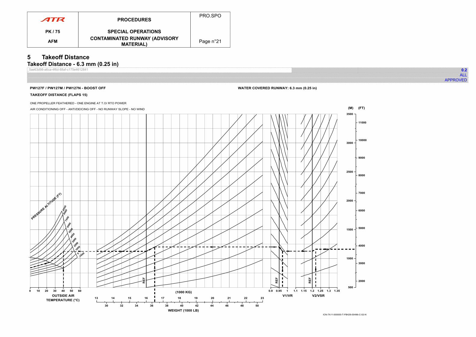
5 Takeoff DistanceTakeoff Distance - 6.3 mm (0.25 in)_0ae63d98-a6ca-4f6d-88af-c175e4612841 0.2
ALLAPPROVED
00 10 20 30 40 50 60
OUTSIDE AIRTEMPERATURE (°C) 1313 14 15 16 17 18 19 20 21 22 23
(1000 KG)
30 32 34 36 38 40 42 44 46 48 50
WEIGHT (1000 LB)
0.90.9 0.95 1
V1/VR1.11.1 1.15 1.2 1.25 1.3 1.35
V2/VSR
500500
1000
1500
2000
2500
3000
3500
(M)
2000
3000
4000
5000
6000
7000
8000
9000
10000
11000
(FT)
ICN-7X-Y-000000-T-FB429-00496-C-02-N
TAKEOFF DISTANCE (FLAPS 15)
ONE PROPELLER FEATHERED - ONE ENGINE AT T.O/ RTO POWER
AIR CONDITIONING OFF - ANTI/DEICING OFF - NO RUNWAY SLOPE - NO WIND
WATER COVERED RUNWAY: 6.3 mm (0.25 in)PW127F / PW127M / PW127N - BOOST OFF
PROCEDURESPRO.SPO
PK / 75 SPECIAL OPERATIONS
AFM CONTAMINATED RUNWAY (ADVISORYMATERIAL) Page n°21

PAGE
INTENTIONALLY
LEFT BLANK
PROCEDURESPRO.SPO
PK / 75 SPECIAL OPERATIONS
AFM CONTAMINATED RUNWAY (ADVISORYMATERIAL) Page n°22
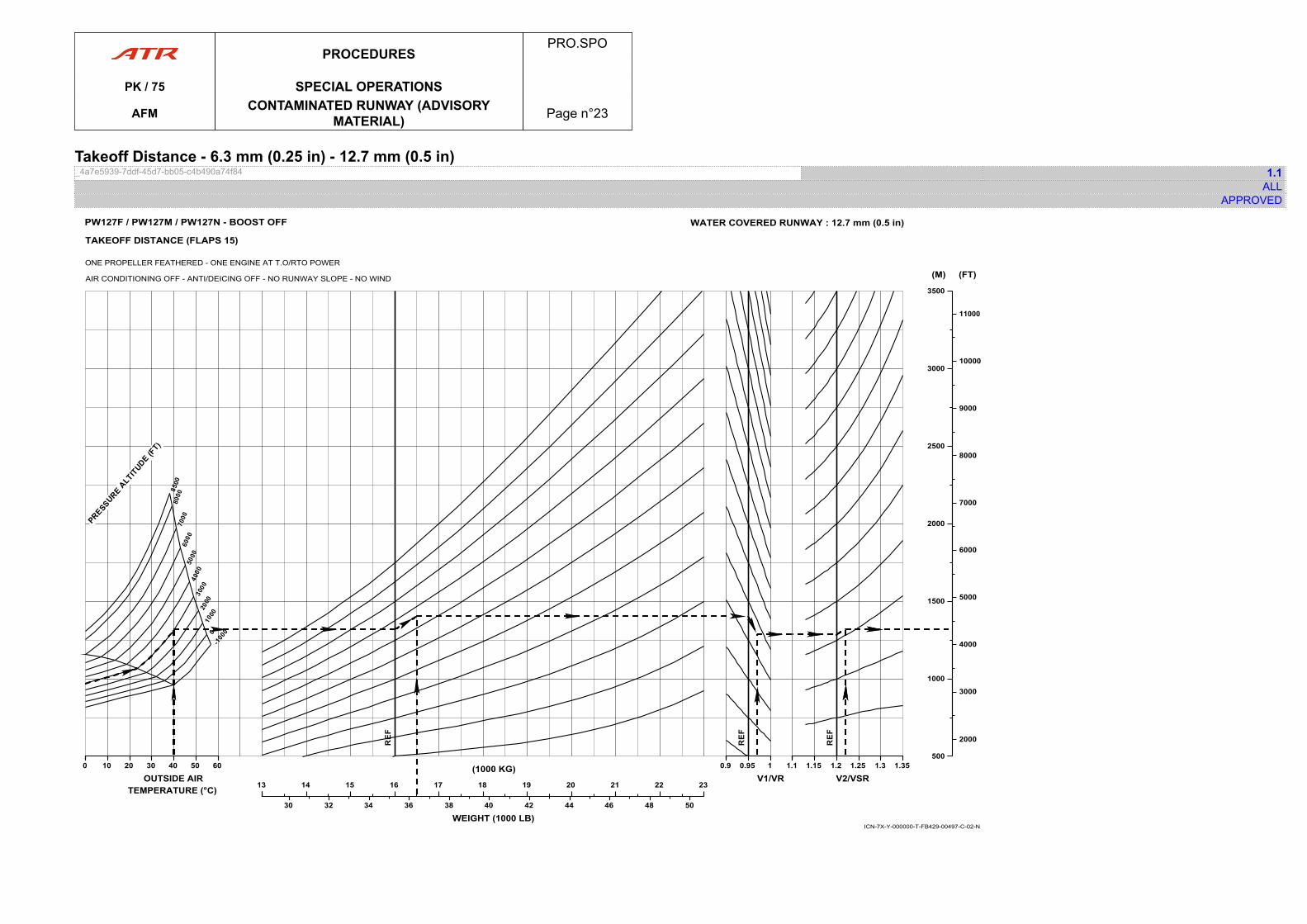
Takeoff Distance - 6.3 mm (0.25 in) - 12.7 mm (0.5 in)_4a7e5939-7ddf-45d7-bb05-c4b490a74f84 1.1
ALLAPPROVED
00 10 20 30 40 50 60
OUTSIDE AIRTEMPERATURE (°C) 1313 14 15 16 17 18 19 20 21 22 23
(1000 KG)
30 32 34 36 38 40 42 44 46 48 50
WEIGHT (1000 LB)
0.90.9 0.95 1
V1/VR1.11.1 1.15 1.2 1.25 1.3 1.35
V2/VSR
500500
1000
1500
2000
2500
3000
3500
(M)
2000
3000
4000
5000
6000
7000
8000
9000
10000
11000
(FT)
PW127F / PW127M / PW127N - BOOST OFF WATER COVERED RUNWAY : 12.7 mm (0.5 in)
ICN-7X-Y-000000-T-FB429-00497-C-02-N
TAKEOFF DISTANCE (FLAPS 15)
ONE PROPELLER FEATHERED - ONE ENGINE AT T.O/RTO POWER
AIR CONDITIONING OFF - ANTI/DEICING OFF - NO RUNWAY SLOPE - NO WIND
PROCEDURESPRO.SPO
PK / 75 SPECIAL OPERATIONS
AFM CONTAMINATED RUNWAY (ADVISORYMATERIAL) Page n°23

PAGE
INTENTIONALLY
LEFT BLANK
PROCEDURESPRO.SPO
PK / 75 SPECIAL OPERATIONS
AFM CONTAMINATED RUNWAY (ADVISORYMATERIAL) Page n°24
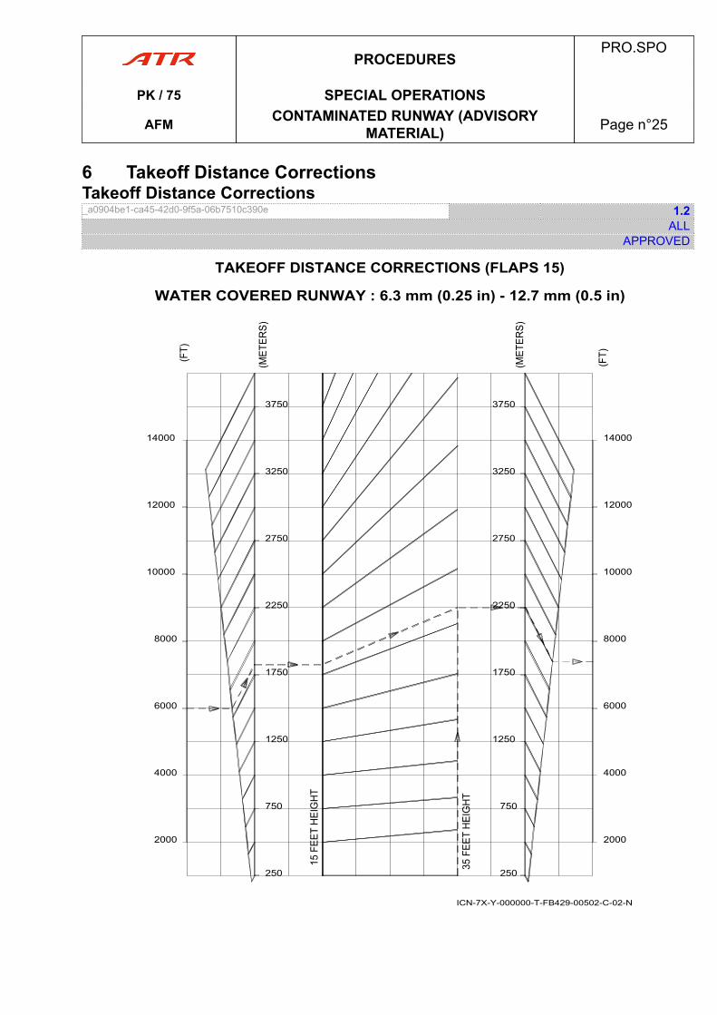
6 Takeoff Distance CorrectionsTakeoff Distance Corrections_a0904be1-ca45-42d0-9f5a-06b7510c390e 1.2
ALLAPPROVED
2000
4000
6000
8000
10000
12000
14000
250
750
1250
1750
2250
2750
3250
3750
2000
4000
6000
8000
10000
12000
14000
250
750
1250
1750
2250
2750
3250
3750
TAKEOFF DISTANCE CORRECTIONS (FLAPS 15)
WATER COVERED RUNWAY : 6.3 mm (0.25 in) - 12.7 mm (0.5 in)
ICN-7X-Y-000000-T-FB429-00502-C-02-N
PROCEDURESPRO.SPO
PK / 75 SPECIAL OPERATIONS
AFM CONTAMINATED RUNWAY (ADVISORYMATERIAL) Page n°25

PAGE
INTENTIONALLY
LEFT BLANK
PROCEDURESPRO.SPO
PK / 75 SPECIAL OPERATIONS
AFM CONTAMINATED RUNWAY (ADVISORYMATERIAL) Page n°26
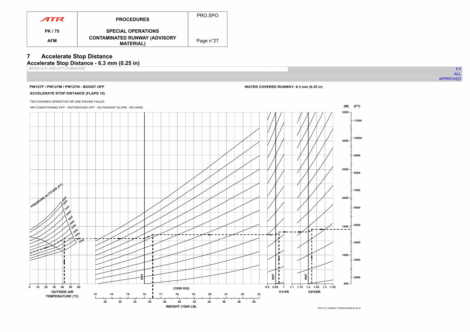
7 Accelerate Stop DistanceAccelerate Stop Distance - 6.3 mm (0.25 in)_dffd2f3c-2c31-4d55-b677-d7cf89a83d98 1.1
ALLAPPROVED
00 10 20 30 40 50 60
OUTSIDE AIRTEMPERATURE (°C) 1313 14 15 16 17 18 19 20 21 22 23
(1000 KG)
30 32 34 36 38 40 42 44 46 48 50
WEIGHT (1000 LB)
0.90.9 0.95 1
V1/VR1.11.1 1.15 1.2 1.25 1.3 1.35
V2/VSR
500500
1000
1500
2000
2500
3000
3500
(M)
2000
3000
4000
5000
6000
7000
8000
9000
10000
11000
(FT)
ICN-7X-Y-000000-T-FB429-00504-D-02-N
PW127F / PW127M / PW127N - BOOST OFF
ACCELERATE STOP DISTANCE (FLAPS 15)
TWO ENGINES OPERATIVE OR ONE ENGINE FAILED
AIR CONDITIONING OFF - ANTI/DEICING OFF - NO RUNWAY SLOPE - NO WIND
WATER COVERED RUNWAY: 6.3 mm (0.25 in)
PROCEDURESPRO.SPO
PK / 75 SPECIAL OPERATIONS
AFM CONTAMINATED RUNWAY (ADVISORYMATERIAL) Page n°27

PAGE
INTENTIONALLY
LEFT BLANK
PROCEDURESPRO.SPO
PK / 75 SPECIAL OPERATIONS
AFM CONTAMINATED RUNWAY (ADVISORYMATERIAL) Page n°28
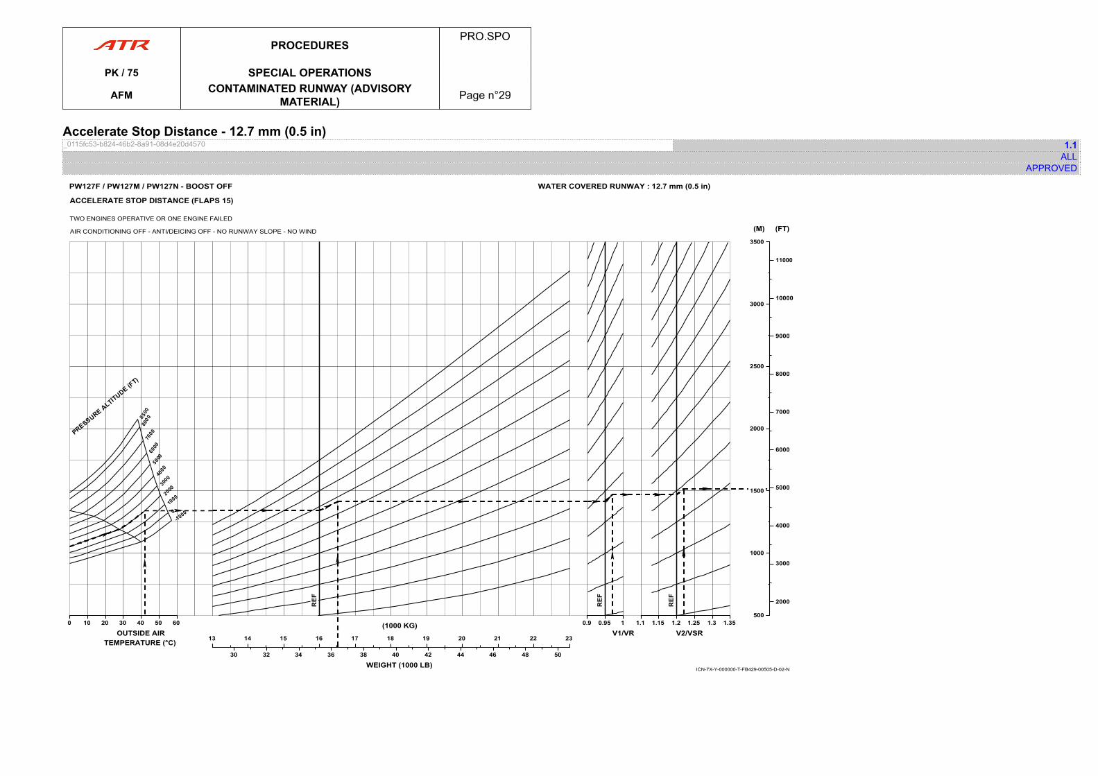
Accelerate Stop Distance - 12.7 mm (0.5 in)_0115fc53-b824-46b2-8a91-08d4e20d4570 1.1
ALLAPPROVED
00 10 20 30 40 50 60
OUTSIDE AIRTEMPERATURE (°C) 1313 14 15 16 17 18 19 20 21 22 23
(1000 KG)
30 32 34 36 38 40 42 44 46 48 50
WEIGHT (1000 LB)
0.90.9 0.95 1
V1/VR1.11.1 1.15 1.2 1.25 1.3 1.35
V2/VSR
500500
1000
1500
2000
2500
3000
3500
(M)
2000
3000
4000
5000
6000
7000
8000
9000
10000
11000
(FT)
ICN-7X-Y-000000-T-FB429-00505-D-02-N
PW127F / PW127M / PW127N - BOOST OFF WATER COVERED RUNWAY : 12.7 mm (0.5 in)
ACCELERATE STOP DISTANCE (FLAPS 15)
TWO ENGINES OPERATIVE OR ONE ENGINE FAILED
AIR CONDITIONING OFF - ANTI/DEICING OFF - NO RUNWAY SLOPE - NO WIND
PROCEDURESPRO.SPO
PK / 75 SPECIAL OPERATIONS
AFM CONTAMINATED RUNWAY (ADVISORYMATERIAL) Page n°29

PAGE
INTENTIONALLY
LEFT BLANK
PROCEDURESPRO.SPO
PK / 75 SPECIAL OPERATIONS
AFM CONTAMINATED RUNWAY (ADVISORYMATERIAL) Page n°30
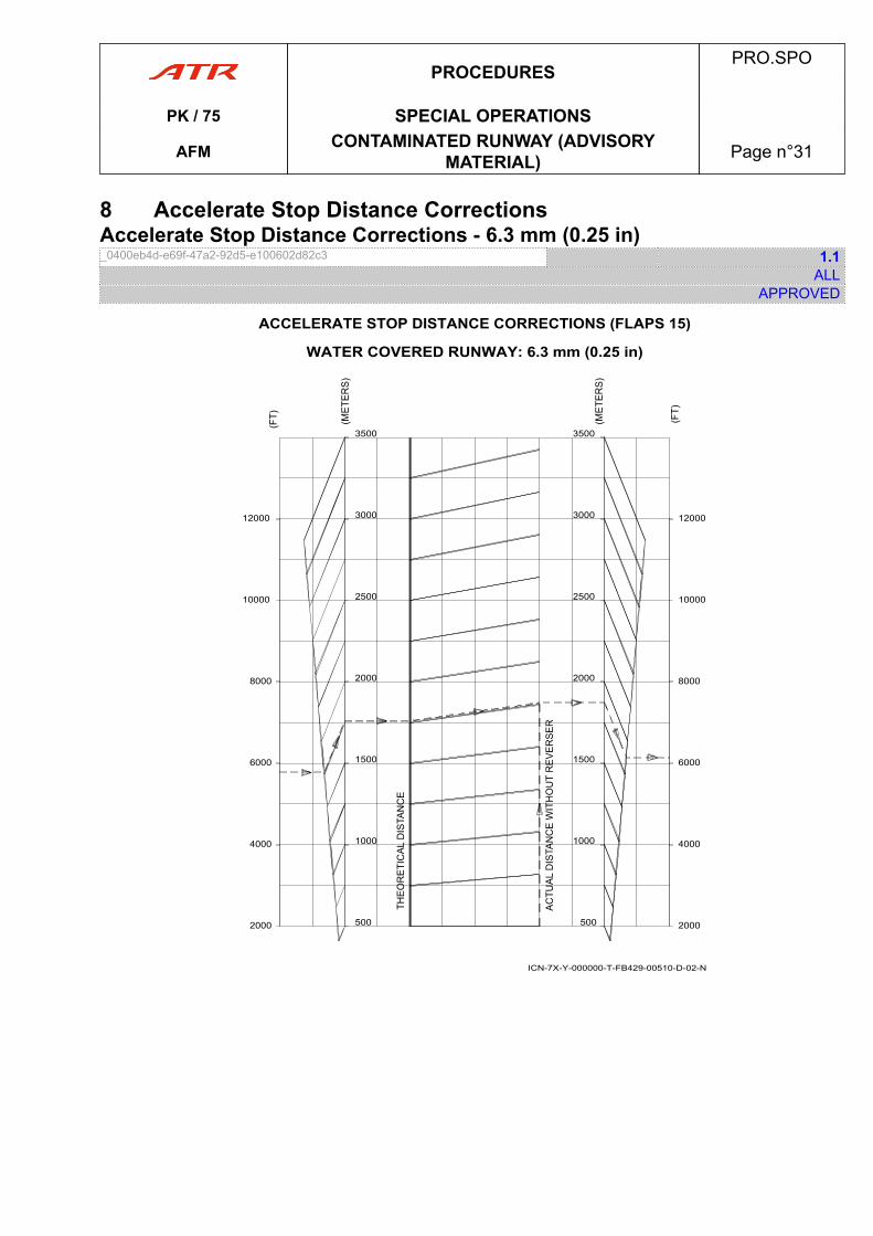
8 Accelerate Stop Distance CorrectionsAccelerate Stop Distance Corrections - 6.3 mm (0.25 in)_0400eb4d-e69f-47a2-92d5-e100602d82c3 1.1
ALLAPPROVED
2000
4000
6000
8000
10000
12000
500
1000
1500
2000
2500
3000
3500
2000
4000
6000
8000
10000
12000
500
1000
1500
2000
2500
3000
3500
ACCELERATE STOP DISTANCE CORRECTIONS (FLAPS 15)
WATER COVERED RUNWAY: 6.3 mm (0.25 in)
ICN-7X-Y-000000-T-FB429-00510-D-02-N
PROCEDURESPRO.SPO
PK / 75 SPECIAL OPERATIONS
AFM CONTAMINATED RUNWAY (ADVISORYMATERIAL) Page n°31
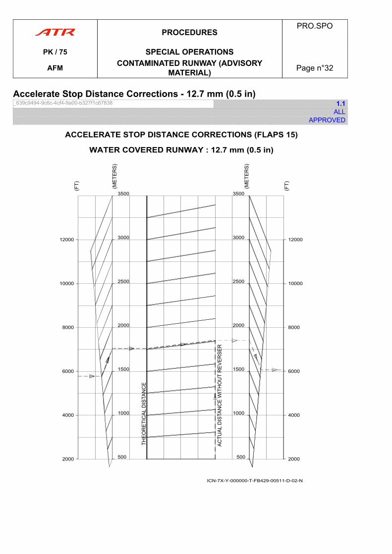
Accelerate Stop Distance Corrections - 12.7 mm (0.5 in)_639c9494-9c6c-4cf4-9a00-b327f1c67838 1.1
ALLAPPROVED
ACCELERATE STOP DISTANCE CORRECTIONS (FLAPS 15)
WATER COVERED RUNWAY : 12.7 mm (0.5 in)
2000
4000
6000
8000
10000
12000
500
1000
1500
2000
2500
3000
3500
2000
4000
6000
8000
10000
12000
500
1000
1500
2000
2500
3000
3500
ICN-7X-Y-000000-T-FB429-00511-D-02-N
PROCEDURESPRO.SPO
PK / 75 SPECIAL OPERATIONS
AFM CONTAMINATED RUNWAY (ADVISORYMATERIAL) Page n°32
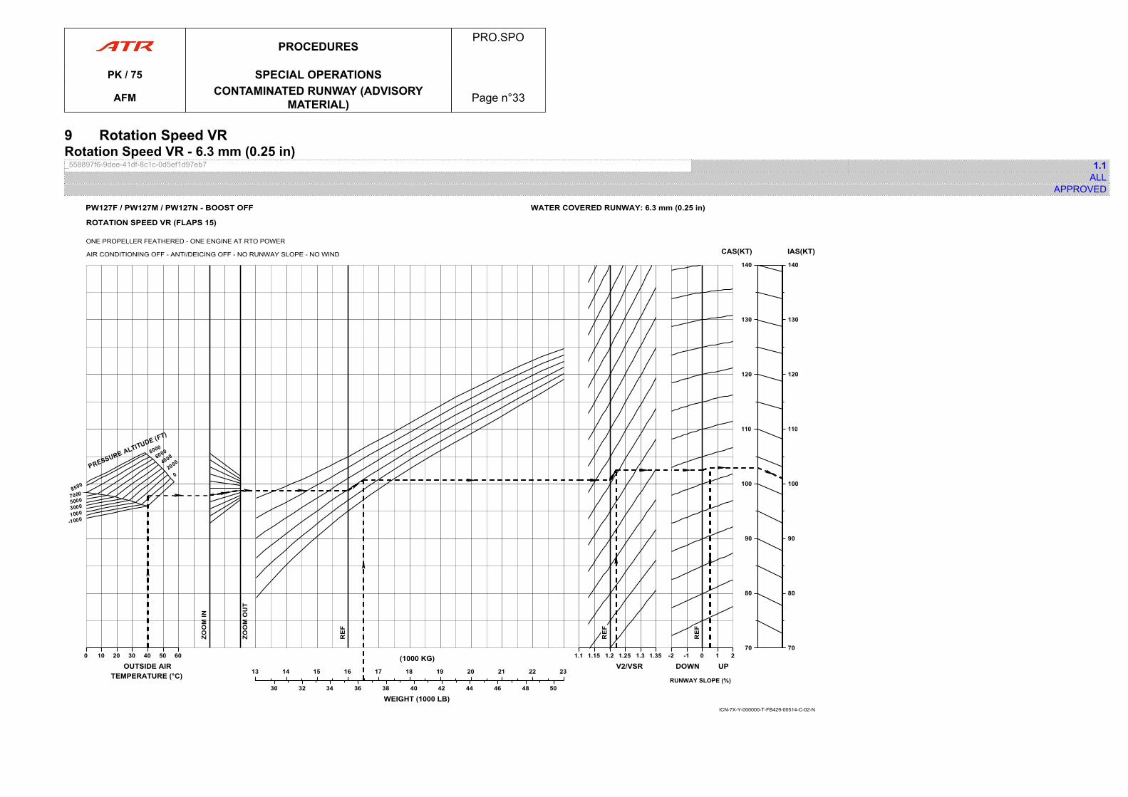
9 Rotation Speed VRRotation Speed VR - 6.3 mm (0.25 in)_558897f6-9dee-41df-8c1c-0d5ef1d97eb7 1.1
ALLAPPROVED
00 10 20 30 40 50 60
OUTSIDE AIRTEMPERATURE (°C) 1313 14 15 16 17 18 19 20 21 22 23
(1000 KG)
30 32 34 36 38 40 42 44 46 48 50
WEIGHT (1000 LB)
1.11.1 1.15 1.2 1.25 1.3 1.35
V2/VSR-2-2 -1 0 1 2
DOWN UP
RUNWAY SLOPE (%)
7070
80
90
100
110
120
130
140
CAS(KT)
7070
80
90
100
110
120
130
140
IAS(KT)
ICN-7X-Y-000000-T-FB429-00514-C-02-N
ROTATION SPEED VR (FLAPS 15)
ONE PROPELLER FEATHERED - ONE ENGINE AT RTO POWER
AIR CONDITIONING OFF - ANTI/DEICING OFF - NO RUNWAY SLOPE - NO WIND
WATER COVERED RUNWAY: 6.3 mm (0.25 in)PW127F / PW127M / PW127N - BOOST OFF
PROCEDURESPRO.SPO
PK / 75 SPECIAL OPERATIONS
AFM CONTAMINATED RUNWAY (ADVISORYMATERIAL) Page n°33

PAGE
INTENTIONALLY
LEFT BLANK
PROCEDURESPRO.SPO
PK / 75 SPECIAL OPERATIONS
AFM CONTAMINATED RUNWAY (ADVISORYMATERIAL) Page n°34
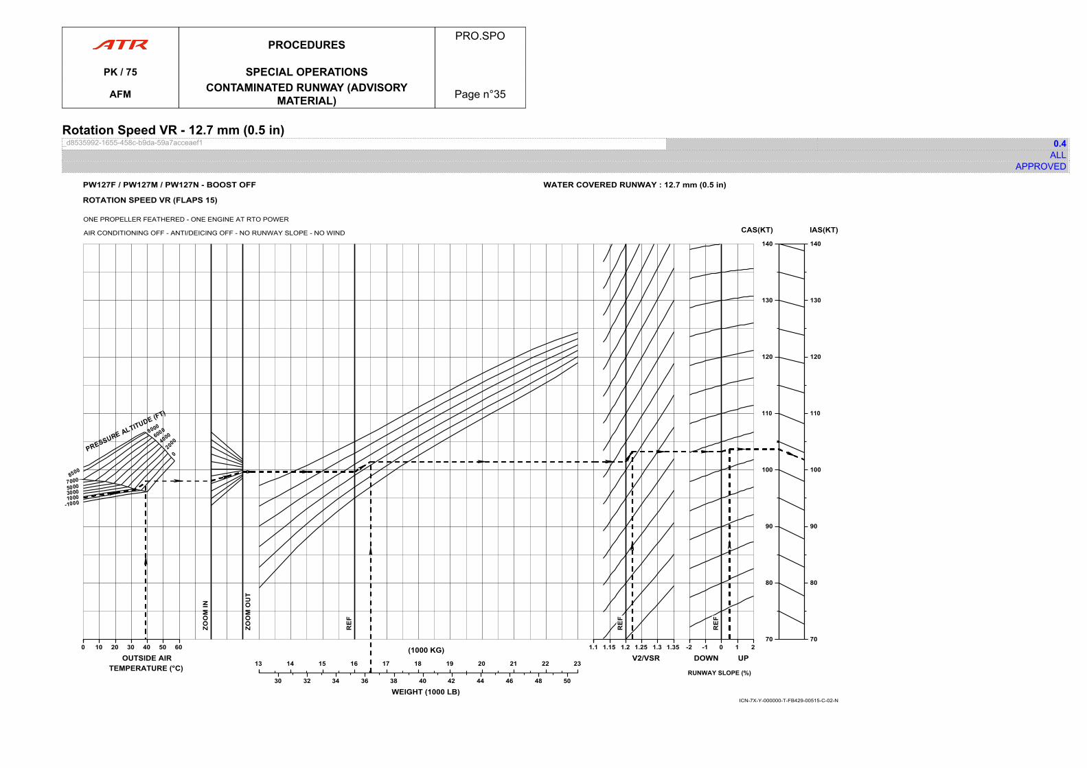
Rotation Speed VR - 12.7 mm (0.5 in)_d8535992-1655-458c-b9da-59a7acceaef1 0.4
ALLAPPROVED
00 10 20 30 40 50 60
OUTSIDE AIRTEMPERATURE (°C) 1313 14 15 16 17 18 19 20 21 22 23
(1000 KG)
30 32 34 36 38 40 42 44 46 48 50
WEIGHT (1000 LB)
1.11.1 1.15 1.2 1.25 1.3 1.35
V2/VSR-2-2 -1 0 1 2
DOWN UP
RUNWAY SLOPE (%)
7070
80
90
100
110
120
130
140
CAS(KT)
7070
80
90
100
110
120
130
140
IAS(KT)
ICN-7X-Y-000000-T-FB429-00515-C-02-N
ROTATION SPEED VR (FLAPS 15)
ONE PROPELLER FEATHERED - ONE ENGINE AT RTO POWER
AIR CONDITIONING OFF - ANTI/DEICING OFF - NO RUNWAY SLOPE - NO WIND
WATER COVERED RUNWAY : 12.7 mm (0.5 in)PW127F / PW127M / PW127N - BOOST OFF
PROCEDURESPRO.SPO
PK / 75 SPECIAL OPERATIONS
AFM CONTAMINATED RUNWAY (ADVISORYMATERIAL) Page n°35

PAGE
INTENTIONALLY
LEFT BLANK
PROCEDURESPRO.SPO
PK / 75 SPECIAL OPERATIONS
AFM CONTAMINATED RUNWAY (ADVISORYMATERIAL) Page n°36
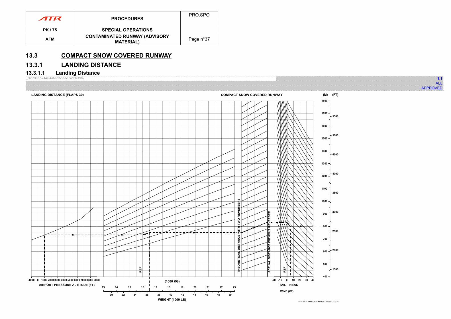
13.3 COMPACT SNOW COVERED RUNWAY13.3.1 LANDING DISTANCE13.3.1.1 Landing Distance_ebc730e7-744a-4aba-9553-5e3ad5fc1982 1.1
ALLAPPROVED
800
-1000-1000 0 1000 2000 3000 4000 5000 6000 7000 8000 9000
AIRPORT PRESSURE ALTITUDE (FT)1313 14 15 16 17 18 19 20 21 22 23
(1000 KG)
30 32 34 36 38 40 42 44 46 48 50
WEIGHT (1000 LB)
-20-20 -10 0
TAIL 00 10 20 30 40
HEAD
400400
500
600
700
900
1000
1100
1200
1300
1400
1500
1600
1700
1800
(M)
1500
2000
2500
3000
3500
4000
4500
5000
5500
(FT)
WIND (KT)
COMPACT SNOW COVERED RUNWAYLANDING DISTANCE (FLAPS 30)
ICN-7X-Y-000000-T-FB429-00520-C-02-N
PROCEDURESPRO.SPO
PK / 75 SPECIAL OPERATIONS
AFM CONTAMINATED RUNWAY (ADVISORYMATERIAL) Page n°37

PAGE
INTENTIONALLY
LEFT BLANK
PROCEDURESPRO.SPO
PK / 75 SPECIAL OPERATIONS
AFM CONTAMINATED RUNWAY (ADVISORYMATERIAL) Page n°38
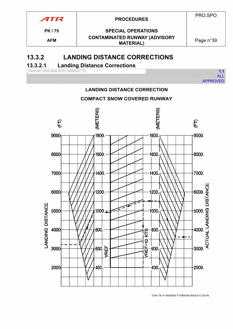
13.3.2 LANDING DISTANCE CORRECTIONS13.3.2.1 Landing Distance Corrections_3aeac441-2f49-4ed2-875d-7e6ff8ab7718 1.1
ALLAPPROVED
LANDING DISTANCE CORRECTION
COMPACT SNOW COVERED RUNWAY
ICN-7X-Y-000000-T-FB429-00522-C-02-N
PROCEDURESPRO.SPO
PK / 75 SPECIAL OPERATIONS
AFM CONTAMINATED RUNWAY (ADVISORYMATERIAL) Page n°39

PAGE
INTENTIONALLY
LEFT BLANK
PROCEDURESPRO.SPO
PK / 75 SPECIAL OPERATIONS
AFM CONTAMINATED RUNWAY (ADVISORYMATERIAL) Page n°40
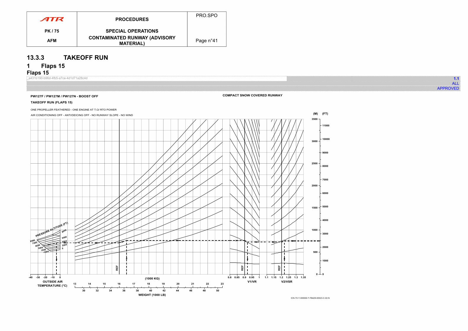
13.3.3 TAKEOFF RUN1 Flaps 15Flaps 15_a431b190-b96d-4fb5-a7ce-4d1d71a28c4d 1.1
ALLAPPROVED
-40-40 -30 -20 -10 0
OUTSIDE AIRTEMPERATURE (°C) 1313 14 15 16 17 18 19 20 21 22 23
(1000 KG)
30 32 34 36 38 40 42 44 46 48 50
WEIGHT (1000 LB)
0.80.8 0.85 0.9 0.95 1
V1/VR1.11.1 1.15 1.2 1.25 1.3 1.35
V2/VSR
00
500
1000
1500
2000
2500
3000
3500
(M)
00
1000
2000
3000
4000
5000
6000
7000
8000
9000
10000
11000
(FT)
ICN-7X-Y-000000-T-FB429-00523-C-02-N
COMPACT SNOW COVERED RUNWAY
TAKEOFF RUN (FLAPS 15)
ONE PROPELLER FEATHERED - ONE ENGINE AT T.O/ RTO POWER
AIR CONDITIONING OFF - ANTI/DEICING OFF - NO RUNWAY SLOPE - NO WIND
PW127F / PW127M / PW127N - BOOST OFF
PROCEDURESPRO.SPO
PK / 75 SPECIAL OPERATIONS
AFM CONTAMINATED RUNWAY (ADVISORYMATERIAL) Page n°41

PAGE
INTENTIONALLY
LEFT BLANK
PROCEDURESPRO.SPO
PK / 75 SPECIAL OPERATIONS
AFM CONTAMINATED RUNWAY (ADVISORYMATERIAL) Page n°42
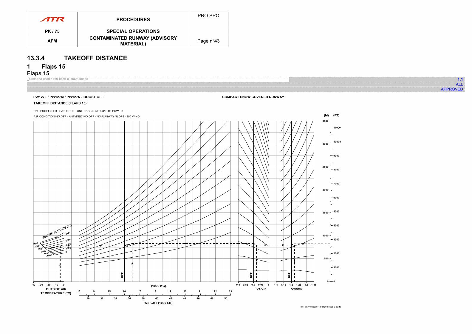
13.3.4 TAKEOFF DISTANCE1 Flaps 15Flaps 15_51bf4e3a-cced-4b69-b885-c0d56d05ea6c 1.1
ALLAPPROVED
WEIGHT (1000 LB)
-40-40 -30 -20 -10 0
OUTSIDE AIRTEMPERATURE (°C) 1313 14 15 16 17 18 19 20 21 22 23
(1000 KG)
30 32 34 36 38 40 42 44 46 48 50
0.80.8 0.85 0.9 0.95 1
V1/VR1.11.1 1.15 1.2 1.25 1.3 1.35
V2/VSR
00
500
1000
1500
2000
2500
3000
3500
(M)
00
1000
2000
3000
4000
5000
6000
7000
8000
9000
10000
11000
(FT)
ICN-7X-Y-000000-T-FB429-00526-C-02-N
TAKEOFF DISTANCE (FLAPS 15)
ONE PROPELLER FEATHERED - ONE ENGINE AT T.O/ RTO POWER
AIR CONDITIONING OFF - ANTI/DEICING OFF - NO RUNWAY SLOPE - NO WIND
COMPACT SNOW COVERED RUNWAYPW127F / PW127M / PW127N - BOOST OFF
PROCEDURESPRO.SPO
PK / 75 SPECIAL OPERATIONS
AFM CONTAMINATED RUNWAY (ADVISORYMATERIAL) Page n°43

PAGE
INTENTIONALLY
LEFT BLANK
PROCEDURESPRO.SPO
PK / 75 SPECIAL OPERATIONS
AFM CONTAMINATED RUNWAY (ADVISORYMATERIAL) Page n°44
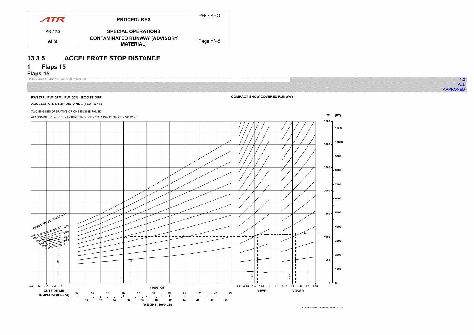
13.3.5 ACCELERATE STOP DISTANCE1 Flaps 15Flaps 15_fc1c5844-f0f3-4b1d-8764-783f1b1e836a 1.2
ALLAPPROVED
-40-40 -30 -20 -10 0
OUTSIDE AIRTEMPERATURE (°C) 1313 14 15 16 17 18 19 20 21 22 23
(1000 KG)
30 32 34 36 38 40 42 44 46 48 50
WEIGHT (1000 LB)
0.80.8 0.85 0.9 0.95 1
V1/VR1.11.1 1.15 1.2 1.25 1.3 1.35
V2/VSR
00
500
1000
1500
2000
2500
3000
3500
(M)
00
1000
2000
3000
4000
5000
6000
7000
8000
9000
10000
11000
(FT)
ICN-7X-Y-000000-T-FB429-00529-D-02-N
COMPACT SNOW COVERED RUNWAY
ACCELERATE STOP DISTANCE (FLAPS 15)
TWO ENGINES OPERATIVE OR ONE ENGINE FAILED
AIR CONDITIONING OFF - ANTI/DEICING OFF - NO RUNWAY SLOPE - NO WIND
PW127F / PW127M / PW127N - BOOST OFF
PROCEDURESPRO.SPO
PK / 75 SPECIAL OPERATIONS
AFM CONTAMINATED RUNWAY (ADVISORYMATERIAL) Page n°45

PAGE
INTENTIONALLY
LEFT BLANK
PROCEDURESPRO.SPO
PK / 75 SPECIAL OPERATIONS
AFM CONTAMINATED RUNWAY (ADVISORYMATERIAL) Page n°46
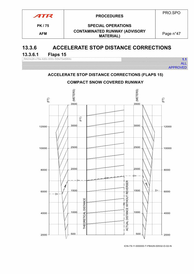
13.3.6 ACCELERATE STOP DISTANCE CORRECTIONS13.3.6.1 Flaps 15_f9423c28-c78a-4d0c-930c-50fa70e8984c 1.1
ALLAPPROVED
2000
4000
6000
8000
10000
12000
500
1000
1500
2000
2500
3000
3500
2000
4000
6000
8000
10000
12000
500
1000
1500
2000
2500
3000
3500
(FT
)
ACCELERATE STOP DISTANCE CORRECTIONS (FLAPS 15)
COMPACT SNOW COVERED RUNWAY
ICN-7X-Y-000000-T-FB429-00532-D-02-N
PROCEDURESPRO.SPO
PK / 75 SPECIAL OPERATIONS
AFM CONTAMINATED RUNWAY (ADVISORYMATERIAL) Page n°47

PAGE
INTENTIONALLY
LEFT BLANK
PROCEDURESPRO.SPO
PK / 75 SPECIAL OPERATIONS
AFM CONTAMINATED RUNWAY (ADVISORYMATERIAL) Page n°48
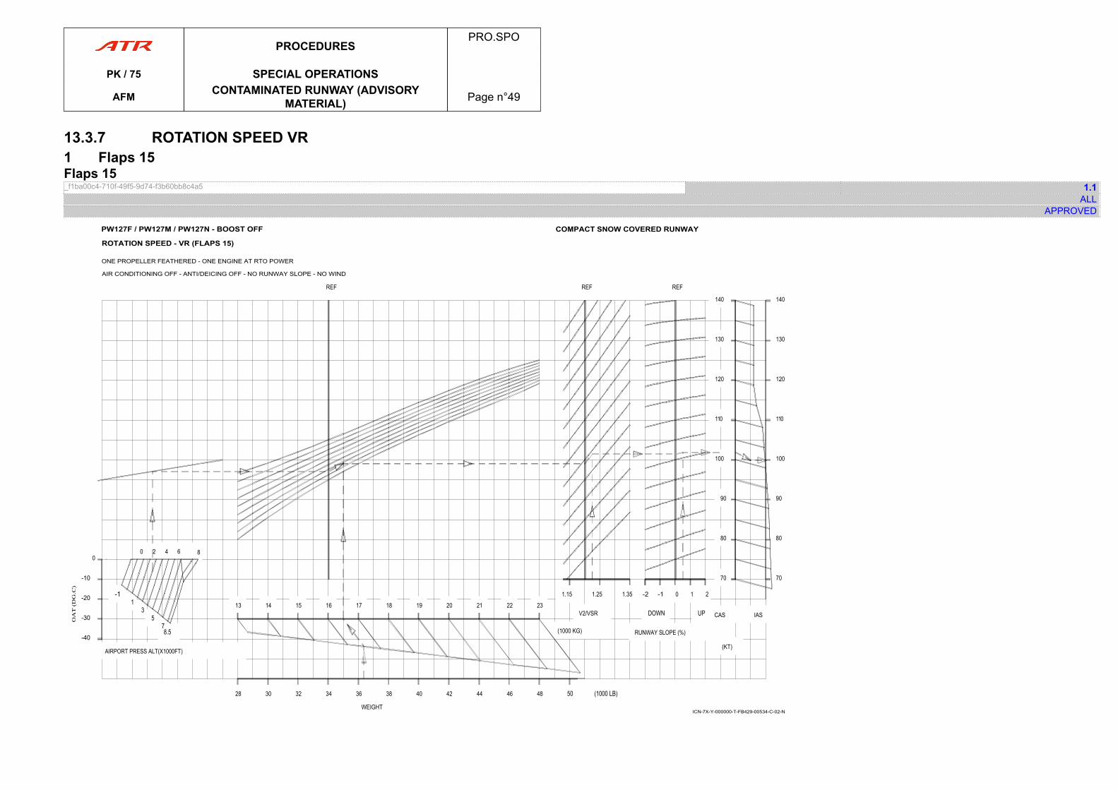
13.3.7 ROTATION SPEED VR1 Flaps 15Flaps 15_f1ba00c4-710f-49f5-9d74-f3b60bb8c4a5 1.1
ALLAPPROVED
-40
-30
-20
-10
00 2 4 6 8
AIRPORT PRESS ALT(X1000FT)
WEIGHT
REF
13 14 15 16 17 18 19 20 21 22 23
(1000 KG)
28 30 32 34 36 38 40 42 44 46 48
1.15 1.25 1.35
V2/VSR
REF
-2 -1 0 1 2
RUNWAY SLOPE (%)
REF
70
80
90
100
110
120
130
140
70
80
90
100
110
120
130
140
(KT)
CAS IAS
ICN-7X-Y-000000-T-FB429-00534-C-02-N
PW127F / PW127M / PW127N - BOOST OFF
ROTATION SPEED - VR (FLAPS 15)
ONE PROPELLER FEATHERED - ONE ENGINE AT RTO POWER
AIR CONDITIONING OFF - ANTI/DEICING OFF - NO RUNWAY SLOPE - NO WIND
COMPACT SNOW COVERED RUNWAY
PROCEDURESPRO.SPO
PK / 75 SPECIAL OPERATIONS
AFM CONTAMINATED RUNWAY (ADVISORYMATERIAL) Page n°49

PAGE
INTENTIONALLY
LEFT BLANK
PROCEDURESPRO.SPO
PK / 75 SPECIAL OPERATIONS
AFM CONTAMINATED RUNWAY (ADVISORYMATERIAL) Page n°50
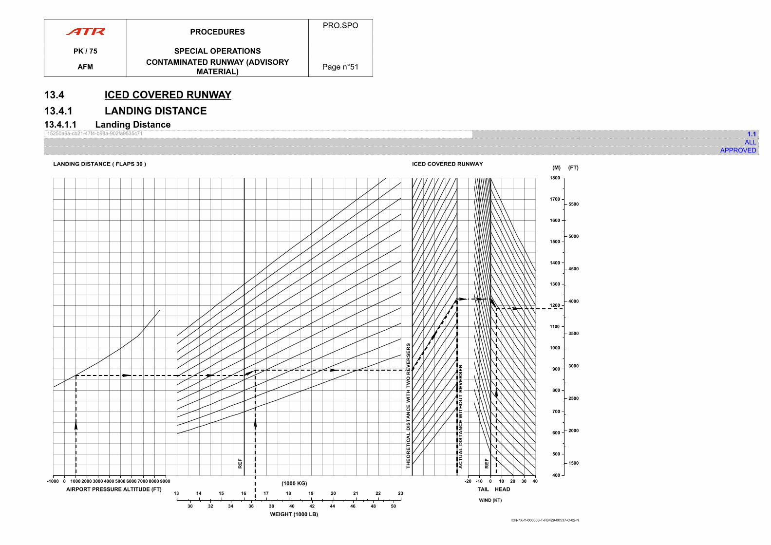
13.4 ICED COVERED RUNWAY13.4.1 LANDING DISTANCE13.4.1.1 Landing Distance_15250a6a-cb21-47f4-b98a-902fa9535c71 1.1
ALLAPPROVED
ICED COVERED RUNWAYLANDING DISTANCE ( FLAPS 30 )
ICN-7X-Y-000000-T-FB429-00537-C-02-N
-1000-1000 0 1000 2000 3000 4000 5000 6000 7000 8000 9000
AIRPORT PRESSURE ALTITUDE (FT)1313 14 15 16 17 18 19 20 21 22 23
(1000 KG)
30 32 34 36 38 40 42 44 46 48 50
WEIGHT (1000 LB)
-20-20 -10 0
TAIL 00 10 20 30 40
HEAD
400400
500
600
700
800
900
1000
1100
1200
1300
1400
1500
1600
1700
1800
(M)
1500
2000
2500
3000
3500
4000
4500
5000
5500
(FT)
WIND (KT)
PROCEDURESPRO.SPO
PK / 75 SPECIAL OPERATIONS
AFM CONTAMINATED RUNWAY (ADVISORYMATERIAL) Page n°51

PAGE
INTENTIONALLY
LEFT BLANK
PROCEDURESPRO.SPO
PK / 75 SPECIAL OPERATIONS
AFM CONTAMINATED RUNWAY (ADVISORYMATERIAL) Page n°52
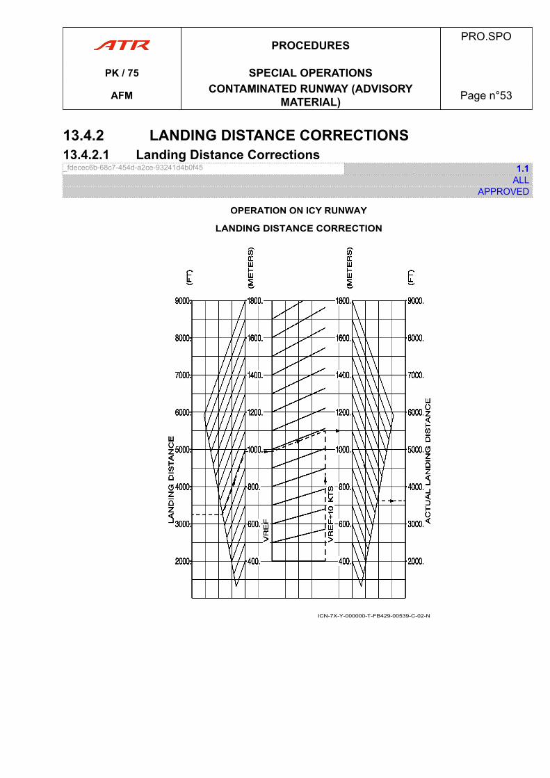
13.4.2 LANDING DISTANCE CORRECTIONS13.4.2.1 Landing Distance Corrections_fdecec6b-68c7-454d-a2ce-93241d4b0f45 1.1
ALLAPPROVED
ICN-7X-Y-000000-T-FB429-00539-C-02-N
OPERATION ON ICY RUNWAY
LANDING DISTANCE CORRECTION
PROCEDURESPRO.SPO
PK / 75 SPECIAL OPERATIONS
AFM CONTAMINATED RUNWAY (ADVISORYMATERIAL) Page n°53

PAGE
INTENTIONALLY
LEFT BLANK
PROCEDURESPRO.SPO
PK / 75 SPECIAL OPERATIONS
AFM CONTAMINATED RUNWAY (ADVISORYMATERIAL) Page n°54
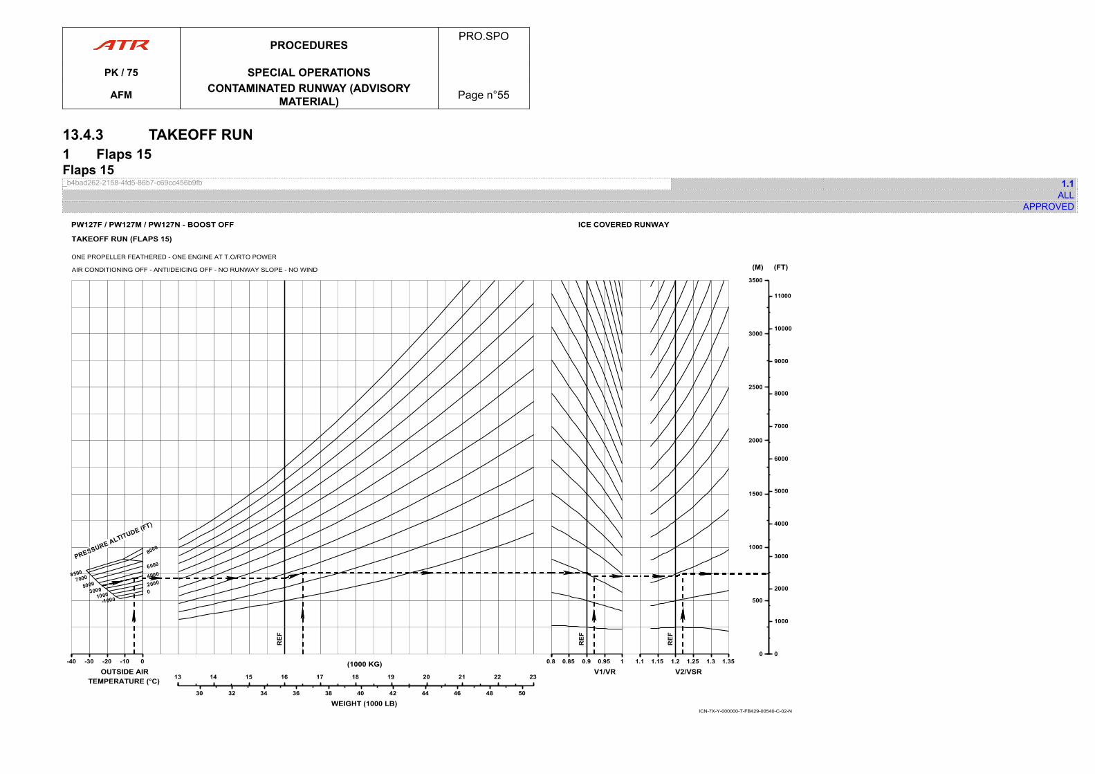
13.4.3 TAKEOFF RUN1 Flaps 15Flaps 15_b4bad262-2158-4fd5-86b7-c69cc456b9fb 1.1
ALLAPPROVED
ICN-7X-Y-000000-T-FB429-00540-C-02-N
-40-40 -30 -20 -10 0
OUTSIDE AIRTEMPERATURE (°C) 1313 14 15 16 17 18 19 20 21 22 23
(1000 KG)
30 32 34 36 38 40 42 44 46 48 50
WEIGHT (1000 LB)
0.80.8 0.85 0.9 0.95 1
V1/VR1.11.1 1.15 1.2 1.25 1.3 1.35
V2/VSR
00
500
1000
1500
2000
2500
3000
3500
(M)
00
1000
2000
3000
4000
5000
6000
7000
8000
9000
10000
11000
(FT)
PW127F / PW127M / PW127N - BOOST OFF
TAKEOFF RUN (FLAPS 15)
ONE PROPELLER FEATHERED - ONE ENGINE AT T.O/RTO POWER
AIR CONDITIONING OFF - ANTI/DEICING OFF - NO RUNWAY SLOPE - NO WIND
ICE COVERED RUNWAY
PROCEDURESPRO.SPO
PK / 75 SPECIAL OPERATIONS
AFM CONTAMINATED RUNWAY (ADVISORYMATERIAL) Page n°55

PAGE
INTENTIONALLY
LEFT BLANK
PROCEDURESPRO.SPO
PK / 75 SPECIAL OPERATIONS
AFM CONTAMINATED RUNWAY (ADVISORYMATERIAL) Page n°56
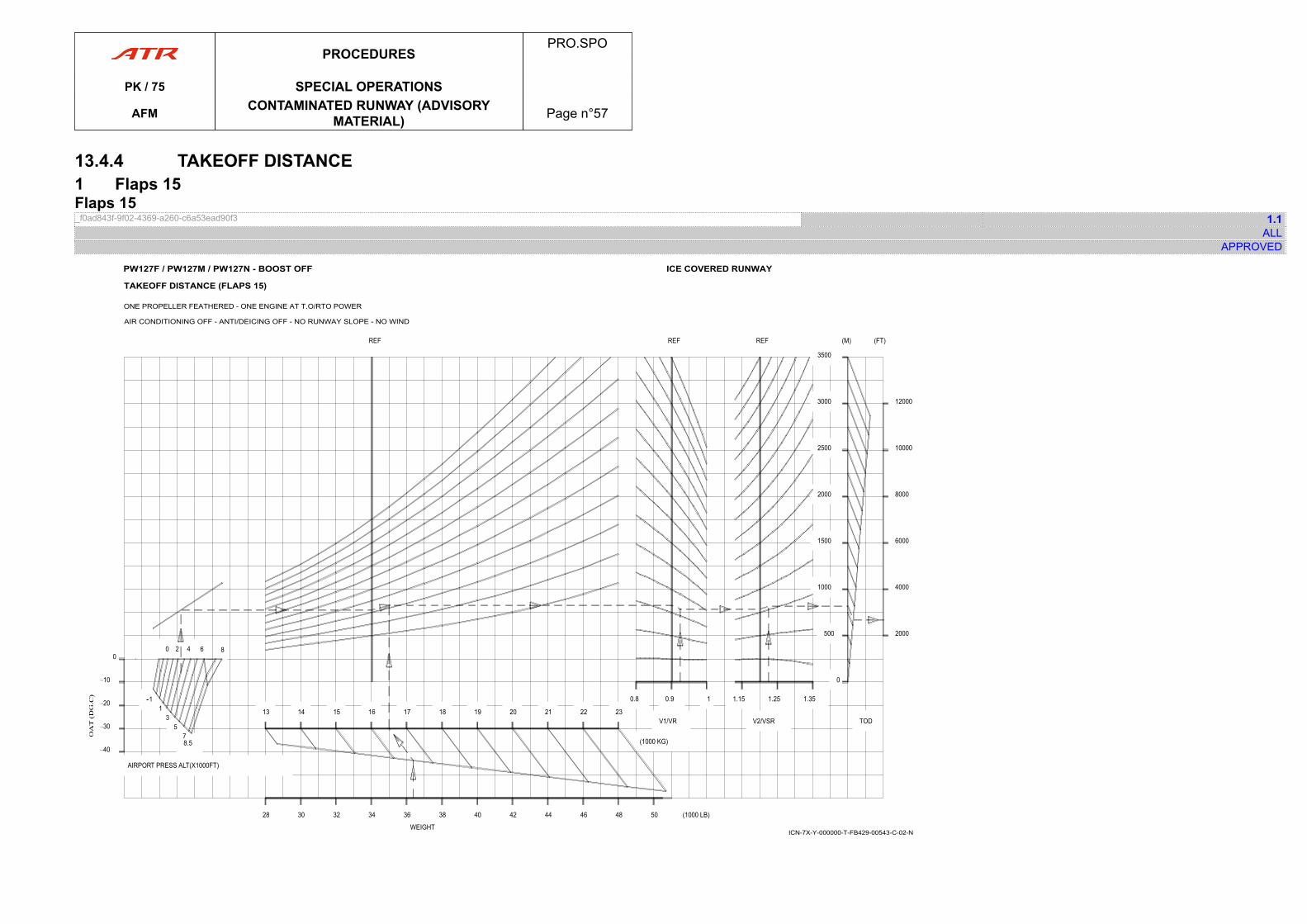
13.4.4 TAKEOFF DISTANCE1 Flaps 15Flaps 15_f0ad843f-9f02-4369-a260-c6a53ead90f3 1.1
ALLAPPROVED
TAKEOFF DISTANCE (FLAPS 15)
ONE PROPELLER FEATHERED - ONE ENGINE AT T.O/RTO POWER
AIR CONDITIONING OFF - ANTI/DEICING OFF - NO RUNWAY SLOPE - NO WIND
ICE COVERED RUNWAYPW127F / PW127M / PW127N - BOOST OFF
ICN-7X-Y-000000-T-FB429-00543-C-02-N
PROCEDURESPRO.SPO
PK / 75 SPECIAL OPERATIONS
AFM CONTAMINATED RUNWAY (ADVISORYMATERIAL) Page n°57

PAGE
INTENTIONALLY
LEFT BLANK
PROCEDURESPRO.SPO
PK / 75 SPECIAL OPERATIONS
AFM CONTAMINATED RUNWAY (ADVISORYMATERIAL) Page n°58
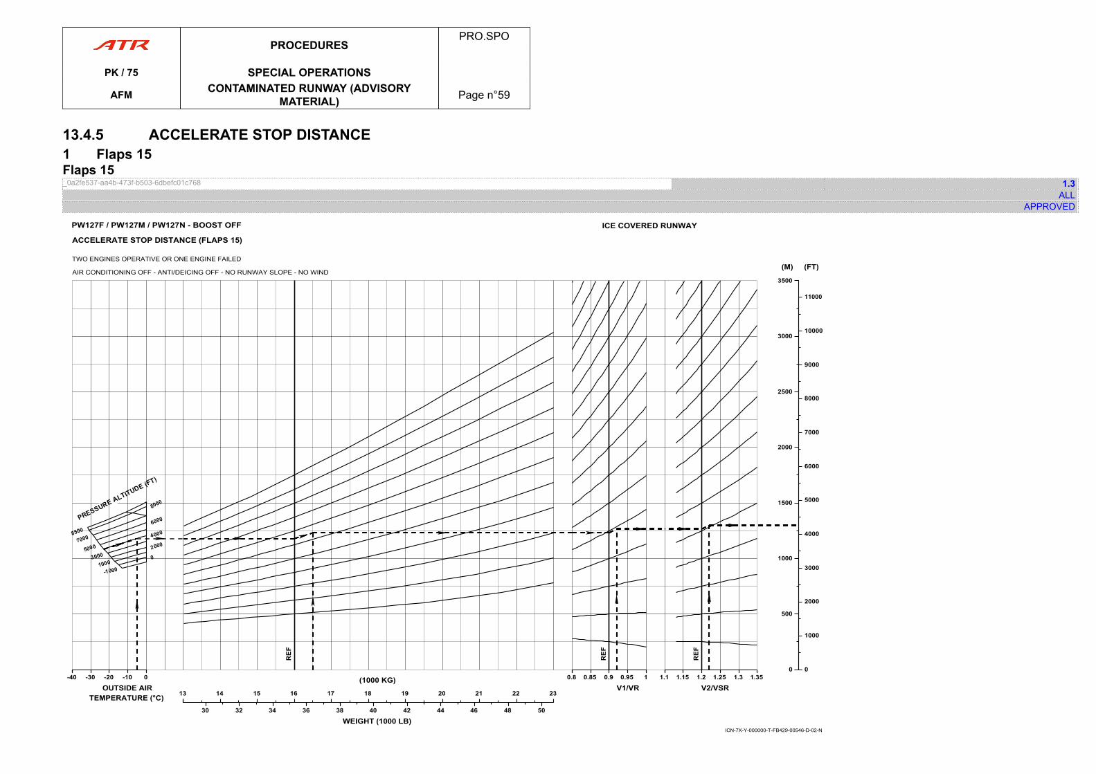
13.4.5 ACCELERATE STOP DISTANCE1 Flaps 15Flaps 15_0a2fe537-aa4b-473f-b503-6dbefc01c768 1.3
ALLAPPROVED
-40-40 -30 -20 -10 0
OUTSIDE AIRTEMPERATURE (°C) 1313 14 15 16 17 18 19 20 21 22 23
(1000 KG)
30 32 34 36 38 40 42 44 46 48 50
WEIGHT (1000 LB)
0.80.8 0.85 0.9 0.95 1
V1/VR1.11.1 1.15 1.2 1.25 1.3 1.35
V2/VSR
00
500
1000
1500
2000
2500
3000
3500
(M)
00
1000
2000
3000
4000
5000
6000
7000
8000
9000
10000
11000
(FT)
ICN-7X-Y-000000-T-FB429-00546-D-02-N
ACCELERATE STOP DISTANCE (FLAPS 15)
TWO ENGINES OPERATIVE OR ONE ENGINE FAILED
AIR CONDITIONING OFF - ANTI/DEICING OFF - NO RUNWAY SLOPE - NO WIND
PW127F / PW127M / PW127N - BOOST OFF ICE COVERED RUNWAY
PROCEDURESPRO.SPO
PK / 75 SPECIAL OPERATIONS
AFM CONTAMINATED RUNWAY (ADVISORYMATERIAL) Page n°59

PAGE
INTENTIONALLY
LEFT BLANK
PROCEDURESPRO.SPO
PK / 75 SPECIAL OPERATIONS
AFM CONTAMINATED RUNWAY (ADVISORYMATERIAL) Page n°60
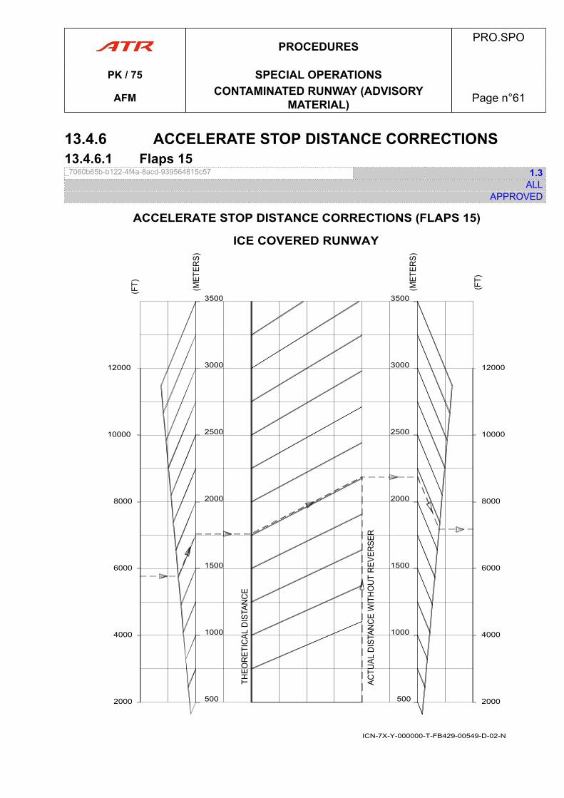
13.4.6 ACCELERATE STOP DISTANCE CORRECTIONS13.4.6.1 Flaps 15_7060b65b-b122-4f4a-8acd-939564815c57 1.3
ALLAPPROVED
2000
4000
6000
8000
10000
12000
500
1000
1500
2000
2500
3000
3500
2000
4000
6000
8000
10000
12000
500
1000
1500
2000
2500
3000
3500
ICN-7X-Y-000000-T-FB429-00549-D-02-N
ACCELERATE STOP DISTANCE CORRECTIONS (FLAPS 15)
ICE COVERED RUNWAY
PROCEDURESPRO.SPO
PK / 75 SPECIAL OPERATIONS
AFM CONTAMINATED RUNWAY (ADVISORYMATERIAL) Page n°61
PAGE
INTENTIONALLY
LEFT BLANK
PROCEDURESPRO.SPO
PK / 75 SPECIAL OPERATIONS
AFM CONTAMINATED RUNWAY (ADVISORYMATERIAL) Page n°62
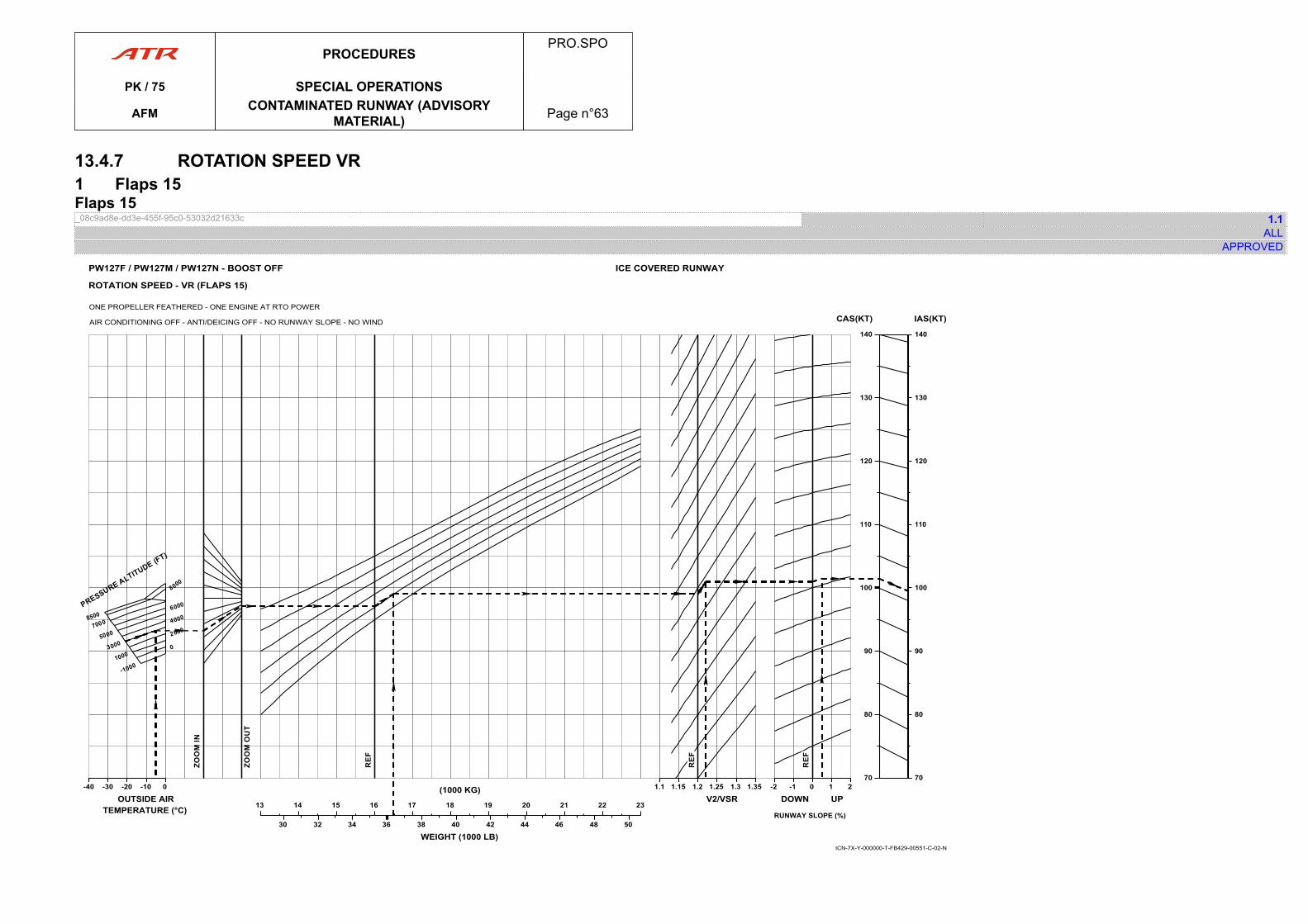
13.4.7 ROTATION SPEED VR1 Flaps 15Flaps 15_08c9ad8e-dd3e-455f-95c0-53032d21633c 1.1
ALLAPPROVED
-40-40 -30 -20 -10 0
OUTSIDE AIRTEMPERATURE (°C) 1313 14 15 16 17 18 19 20 21 22 23
(1000 KG)
30 32 34 36 38 40 42 44 46 48 50
WEIGHT (1000 LB)
1.11.1 1.15 1.2 1.25 1.3 1.35
V2/VSR-2-2 -1 0 1 2
DOWN UP
RUNWAY SLOPE (%)
7070
80
90
100
110
120
130
140
CAS(KT)
7070
80
90
100
110
120
130
140
IAS(KT)
ICN-7X-Y-000000-T-FB429-00551-C-02-N
ROTATION SPEED - VR (FLAPS 15)
ONE PROPELLER FEATHERED - ONE ENGINE AT RTO POWER
AIR CONDITIONING OFF - ANTI/DEICING OFF - NO RUNWAY SLOPE - NO WIND
ICE COVERED RUNWAYPW127F / PW127M / PW127N - BOOST OFF
PROCEDURESPRO.SPO
PK / 75 SPECIAL OPERATIONS
AFM CONTAMINATED RUNWAY (ADVISORYMATERIAL) Page n°63
PAGE
INTENTIONALLY
LEFT BLANK
PROCEDURESPRO.SPO
PK / 75 SPECIAL OPERATIONS
AFM CONTAMINATED RUNWAY (ADVISORYMATERIAL) Page n°64
16 OPERATION WITHOUT FORWARD LH PARTITION16.1 GENERAL LIMITATIONS16.1.1 General Limitations_637ec490-3d15-4977-a464-22e660b7be45 REV 1.0
ALLAPPROVED
Not applicable
16.2 WEIGHT LIMITATIONS16.2.1 STRUCTURAL LIMITATIONS16.2.1.1 Structural Limitations_45696f25-e522-40a7-bd90-0501d297ffd1 0.1
ALLAPPROVED
Not applicable
16.2.2 PERFORMANCE LIMITATIONS16.2.2.1 Performance Limitations_bfcd28e2-f61a-4f87-a27c-443e44d13fda 0.1
ALLAPPROVED
Not applicable
16.3 CENTER OF GRAVITY ENVELOP16.3.1 Center of Gravity Envelop_bcdfae6d-fa83-4c4c-abab-1af56c260dc4 REV 1.0
ALLAPPROVED
Not applicable
16.4 LOADING16.4.1 Loading_7d39d4eb-000a-4e75-b3aa-4287ceb717b1 0.1
ALLAPPROVED
Not applicable.
PROCEDURESPRO.SPO
PK / 75 SPECIAL OPERATIONS
AFM OPERATION WITHOUT FORWARD LHPARTITION Page n°65
20 CONTAINER TRANSPORTATION20.1 APPLICABILITY20.1.1 Applicability_2d75f76d-8f7f-430b-9f20-7816d2cc1a98 NEW 0.1
ALLAPPROVED
Not applicable
21 CAT 2 APPROACH21.1 LIMITATIONS21.1.01 Limitations_9c829c59-741b-4c29-81b8-c8e00b454fd6 1.0
ALLAPPROVED
This content is designed to provide necessary information to authorise the use of the aircraft inCategory II.Limitations, procedures and performances included in this chapter replace or complete thecorresponding information of the basic Flight Manual.The Automatic Flight Control System (AFCS) with the associated equipment has been foundto meet the airworthiness and performance criteria of :
- ACJ 25-1329 for AutoPilot- Special Condition F2: AP engagement at takeoff- JAR AWO subpart 2 for Category II.
NoteCompliance with the standards noted above does not constitute approval to conductCategory II operations. Aircraft operators must apply to their Authority to get an approval toconduct Category II operations.
Minimum height for use of AutoPilot in approach mode .................................................. 50 ftMinimum decision height .......................................................................................... 100 ftCertified configuration ............................................ ............................................FLAPS 30Maximum demonstrated wind:Headwind ................................................................................................................ 30 ktTailwind ......................................................... ......................................................... 10 ktCrosswind ....................................................... ....................................................... 15 kt
PROCEDURESPRO.SPO
PK / 75 SPECIAL OPERATIONSAFM CONTAINER TRANSPORTATION Page n°66
21.2 PROCEDURES21.2.1 NORMAL PROCEDURES21.2.1.1 Approved Configurations_3d677fad-d67d-4cd0-b1b8-4b0cab10c96a 0.1
ALLAPPROVED
● ApproachAP and FD are approved with use of approach mode for CAT II precision ILS approaches.The CAT II capability must be displayed on ADU.
● Go-AroundFD is approved with use of GA mode.
21.2.1.2 Performance Envelope in Approach_11d580f4-8397-4d34-b57a-8a3336dd4a82 0.1
ALLAPPROVED
- LOC capture: distance ≥ 6 Nm – Capture angle ≤ 90 °- GLIDE capture:
o height ≥ 1 500 fto VC ≤ 180 kt at 1 500 ft.
- Approach speed:When the aircraft is stabilized on GLIDE slope the selected approach speed VAPP is1.23 VSR (FLAPS 30) + wind correction and not less than VMCL.The wind correction is equal to the highest of 1/3 of the reported headwind or the gust infull, with a maximum correction of 15 kt.
PROCEDURESPRO.SPO
PK / 75 SPECIAL OPERATIONSAFM CAT 2 APPROACH Page n°67
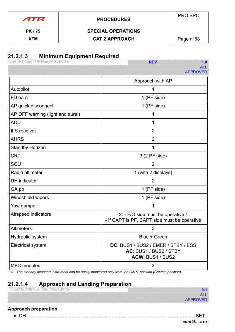
21.2.1.3 Minimum Equipment Required_bcb8de47-0ebd-4776-81ac-67f18b473f53 REV 1.0
ALLAPPROVED
Approach with AP
Autopilot 1
FD bars 1 (PF side)
AP quick disconnect 1 (PF side)
AP OFF warning (light and aural) 1
ADU 1
ILS receiver 2
AHRS 2
Standby Horizon 1
CRT 3 (2 PF side)
SGU 2
Radio altimeter 1 (with 2 displays)
DH indicator 2
GA pb 1 (PF side)
Windshield wipers 1 (PF side)
Yaw damper 1
Airspeed indicators 2: - F/O side must be operative a- If CAPT is PF, CAPT side must be operative
Altimeters 3
Hydraulic system Blue + Green
Electrical system DC: BUS1 / BUS2 / EMER / STBY / ESSAC: BUS1 / BUS2 / STBY
ACW: BUS1 / BUS2
MFC modules 3a The standby airspeed instrument can be easily monitored only from the CAPT position (Captain position).
21.2.1.4 Approach and Landing Preparation_5d1e727e-7226-4cc4-bb8e-635ba1a8805e 0.1
ALLAPPROVED
Approach preparation▶ DH ........................................................ ........................................................ SET
PROCEDURESPRO.SPO
PK / 75 SPECIAL OPERATIONSAFM CAT 2 APPROACH Page n°68
cont'd…
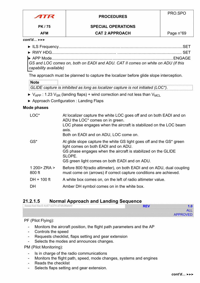
▶ ILS Frequency..................................................................................................SET▶ RWY HDG................................................... ................................................... SET▶ APP Mode................................................................................................ENGAGEGS and LOC comes on, both on EADI and ADU. CAT II comes on white on ADU (if thiscapability available)
The approach must be planned to capture the localizer before glide slope interception.
NoteGLIDE capture is inhibited as long as localizer capture is not initiated (LOC*).
▶ VAPP : 1.23 VSR (landing flaps) + wind correction and not less than VMCL
▶ Approach Configuration : Landing Flaps
Mode phases
LOC* At localizer capture the white LOC goes off and on both EADI and onADU the LOC* comes on in green.LOC phase engages when the aircraft is stabilized on the LOC beamaxis.Both on EADI and on ADU, LOC come on.
GS* At glide slope capture the white GS light goes off and the GS* greenlight comes on both EADI and on ADU.GS phase engages when the aircraft is stabilized on the GLIDESLOPE.GS green light comes on both EADI and on ADU.
1 200> ZRA >800 ft
Before 800 ft(radio altimeter), on both EADI and on ADU, dual couplingmust come on (arrows) if correct capture conditions are achieved.
DH + 100 ft A white box comes on, on the left of radio altimeter value.
DH Amber DH symbol comes on in the white box.
21.2.1.5 Normal Approach and Landing Sequence_4eeac4ed-6ec5-4c67-b374-d7dfc9fafd4f REV 1.0
ALLAPPROVED
PF (Pilot Flying):- Monitors the aircraft position, the flight path parameters and the AP- Controls the speed- Requests checklist, flaps setting and gear extension- Selects the modes and announces changes.
PM (Pilot Monitoring):- Is in charge of the radio communications- Monitors the flight path, speed, mode changes, systems and engines- Reads the checklist- Selects flaps setting and gear extension.
PROCEDURESPRO.SPO
PK / 75 SPECIAL OPERATIONSAFM CAT 2 APPROACH Page n°69
cont'd…
cont'd…
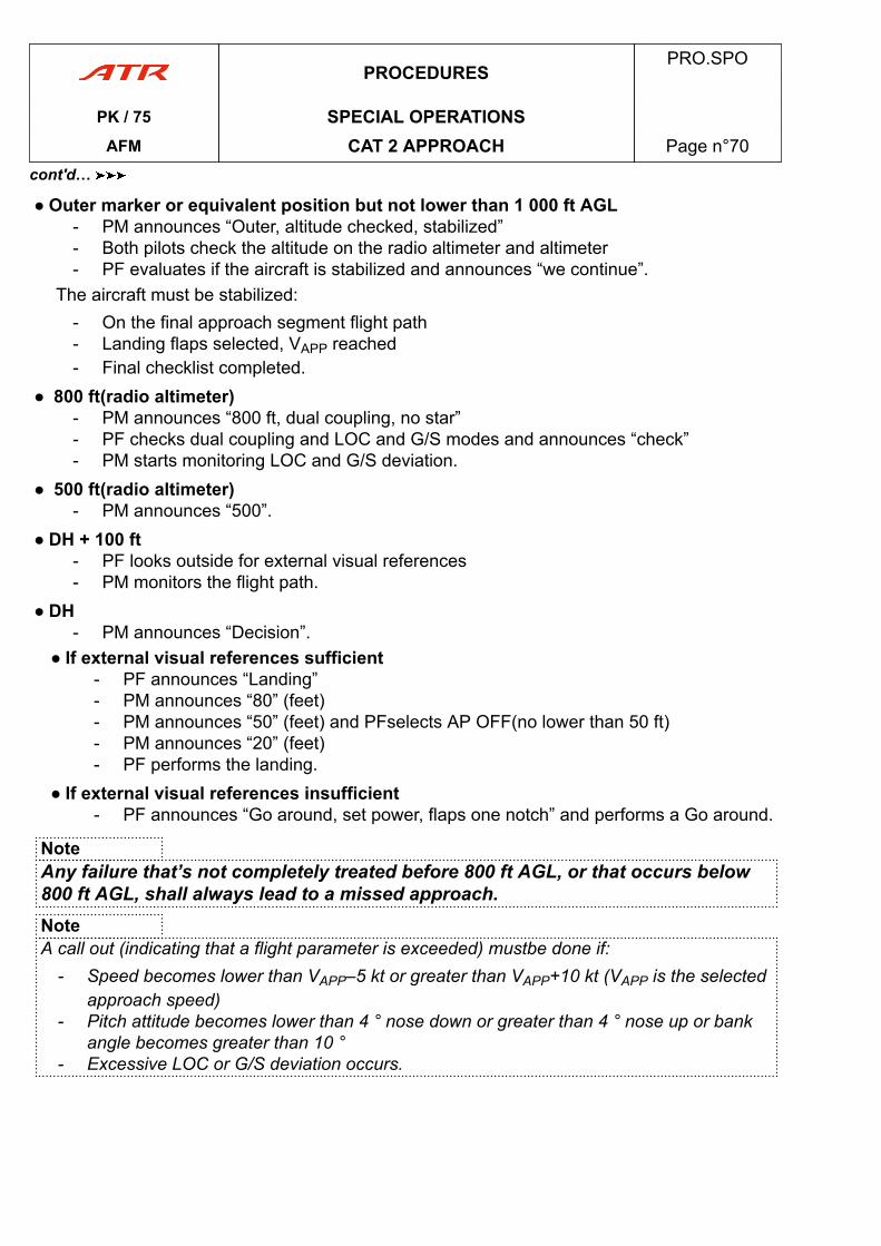
● Outer marker or equivalent position but not lower than 1 000 ft AGL- PM announces “Outer, altitude checked, stabilized”- Both pilots check the altitude on the radio altimeter and altimeter- PF evaluates if the aircraft is stabilized and announces “we continue”.
The aircraft must be stabilized:- On the final approach segment flight path- Landing flaps selected, VAPP reached- Final checklist completed.
● 800 ft(radio altimeter)- PM announces “800 ft, dual coupling, no star”- PF checks dual coupling and LOC and G/S modes and announces “check”- PM starts monitoring LOC and G/S deviation.
● 500 ft(radio altimeter)- PM announces “500”.
● DH + 100 ft- PF looks outside for external visual references- PM monitors the flight path.
● DH- PM announces “Decision”.
● If external visual references sufficient- PF announces “Landing”- PM announces “80” (feet)- PM announces “50” (feet) and PFselects AP OFF(no lower than 50 ft)- PM announces “20” (feet)- PF performs the landing.
● If external visual references insufficient- PF announces “Go around, set power, flaps one notch” and performs a Go around.
NoteAny failure that’s not completely treated before 800 ft AGL, or that occurs below800 ft AGL, shall always lead to a missed approach.NoteA call out (indicating that a flight parameter is exceeded) mustbe done if:
- Speed becomes lower than VAPP–5 kt or greater than VAPP+10 kt (VAPP is the selectedapproach speed)
- Pitch attitude becomes lower than 4 ° nose down or greater than 4 ° nose up or bankangle becomes greater than 10 °
- Excessive LOC or G/S deviation occurs.
PROCEDURESPRO.SPO
PK / 75 SPECIAL OPERATIONSAFM CAT 2 APPROACH Page n°70
cont'd…
21.2.1.6 Go-Around Sequence_b806bd28-aee7-4005-a702-842a13448926 0.1
ALLAPPROVED
No change.
21.2.2 EMERGENCY PROCEDURES21.2.2.01 Emergency Procedures_afcd4aab-681b-4378-af23-ea652e7522ba 0.1
ALLAPPROVED
NO CHANGE.
21.2.3 ABNORMAL PROCEDURES21.2.3.1 DEMONSTRATED ALT LOSS WITH AP-FD SYST
MALFCTN21.2.3.1.01 Demonstrated Altitude Loss with AP System Malfunction_acd0974f-6283-47f6-a5c7-051f7b57a052 0.1
ALLAPPROVED
Maximum path deviation with take over occurring 1 s after failure recognition : 16 ft.
PROCEDURESPRO.SPO
PK / 75 SPECIAL OPERATIONSAFM CAT 2 APPROACH Page n°71
cont'd…
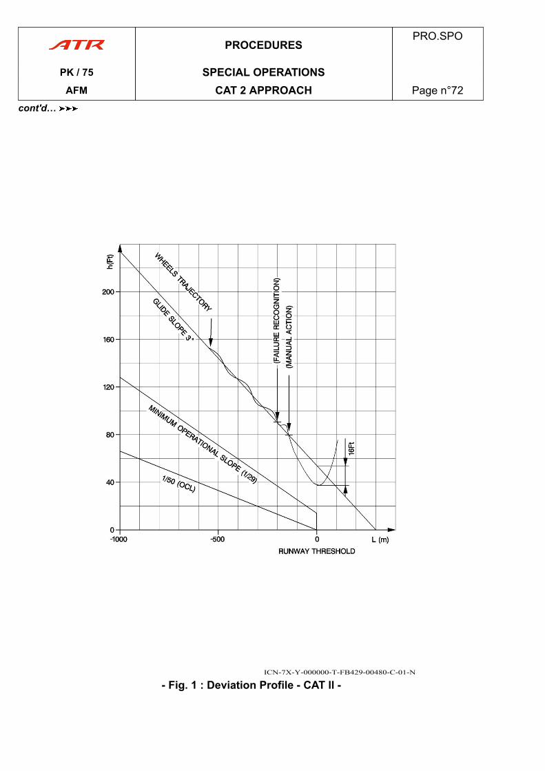
ICN-7X-Y-000000-T-FB429-00480-C-01-N
- Fig. 1 : Deviation Profile - CAT ll -
PROCEDURESPRO.SPO
PK / 75 SPECIAL OPERATIONSAFM CAT 2 APPROACH Page n°72
cont'd…
21.2.3.2 FAILURES AND ASSOCIATED ACTIONS DURINGAPPROACH
21.2.3.2.01 General_bffe9729-dcb1-4d74-bf8c-8917e07be7e1 0.1
ALLAPPROVED
Any failure that is not completely treated before 800 ft AGL, or that occurs below 800 ft AGL,must always lead to a missed approach.
1) ENGINE FAILUREProvided lateral trimming is properly achieved before 800 ft, single engine approach maybe performed with autopilot engaged, but must be restricted to CAT I.
2) AFCS failure and trajectory deviationIn case of CAT II INVALID, excess deviations and AFCS failure, go around must beperformed with STBY HORIZON : initial missed approach attitude : 10 °.
PROCEDURESPRO.SPO
PK / 75 SPECIAL OPERATIONSAFM CAT 2 APPROACH Page n°73
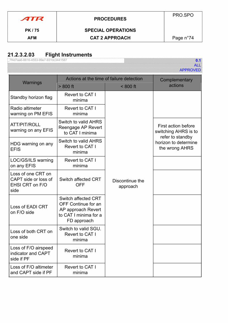
21.2.3.2.03 Flight Instruments_7f4d7aa6-8816-4553-99e7-9310c3441587 0.1
ALLAPPROVED
WarningsActions at the time of failure detection Complementary
actions> 800 ft < 800 ft
Standby horizon flag Revert to CAT Iminima
Discontinue theapproach
Radio altimeterwarning on PM EFIS
Revert to CAT Iminima
ATT/PIT/ROLLwarning on any EFIS
Switch to valid AHRSReengage AP Revert
to CAT I minimaFirst action before
switching AHRS is torefer to standby
horizon to determinethe wrong AHRS
HDG warning on anyEFIS
Switch to valid AHRSRevert to CAT I
minima
LOC/GS/ILS warningon any EFIS
Revert to CAT Iminima
Loss of one CRT onCAPT side or loss ofEHSI CRT on F/Oside
Switch affected CRTOFF
Loss of EADI CRTon F/O side
Switch affected CRTOFF Continue for anAP approach Revertto CAT I minima for a
FD approach
Loss of both CRT onone side
Switch to valid SGU.Revert to CAT I
minima
Loss of F/O airspeedindicator and CAPTside if PF
Revert to CAT Iminima
Loss of F/O altimeterand CAPT side if PF
Revert to CAT Iminima
PROCEDURESPRO.SPO
PK / 75 SPECIAL OPERATIONSAFM CAT 2 APPROACH Page n°74
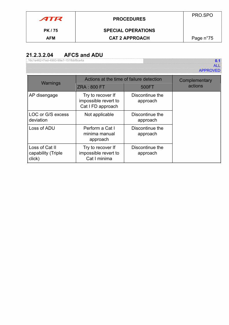
21.2.3.2.04 AFCS and ADU_16c1e462-f7ed-4993-99e7-151fbbf8ce4a 0.1
ALLAPPROVED
WarningsActions at the time of failure detection Complementary
actionsZRA : 800 FT 500FT
AP disengage Try to recover Ifimpossible revert toCat I FD approach
Discontinue theapproach
LOC or G/S excessdeviation
Not applicable Discontinue theapproach
Loss of ADU Perform a Cat Iminima manual
approach
Discontinue theapproach
Loss of Cat IIcapability (Tripleclick)
Try to recover Ifimpossible revert to
Cat I minima
Discontinue theapproach
PROCEDURESPRO.SPO
PK / 75 SPECIAL OPERATIONSAFM CAT 2 APPROACH Page n°75

PAGE
INTENTIONALLY
LEFT BLANK
PROCEDURESPRO.SPO
PK / 75 SPECIAL OPERATIONSAFM CAT 2 APPROACH Page n°76
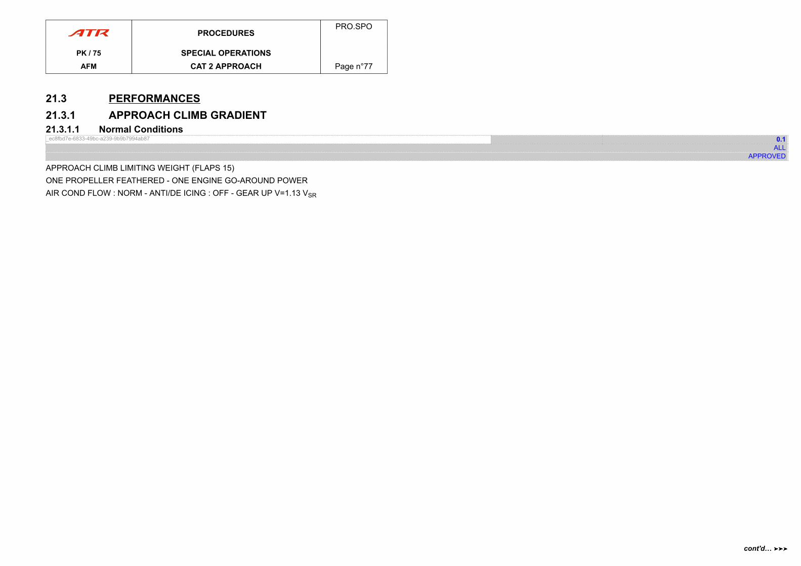
21.3 PERFORMANCES21.3.1 APPROACH CLIMB GRADIENT21.3.1.1 Normal Conditions_ec8fbd7e-6833-49bc-a239-9b9b7994ab87 0.1
ALLAPPROVED
APPROACH CLIMB LIMITING WEIGHT (FLAPS 15)ONE PROPELLER FEATHERED - ONE ENGINE GO-AROUND POWERAIR COND FLOW : NORM - ANTI/DE ICING : OFF - GEAR UP V=1.13 VSR
PROCEDURESPRO.SPO
PK / 75 SPECIAL OPERATIONSAFM CAT 2 APPROACH Page n°77
cont'd…
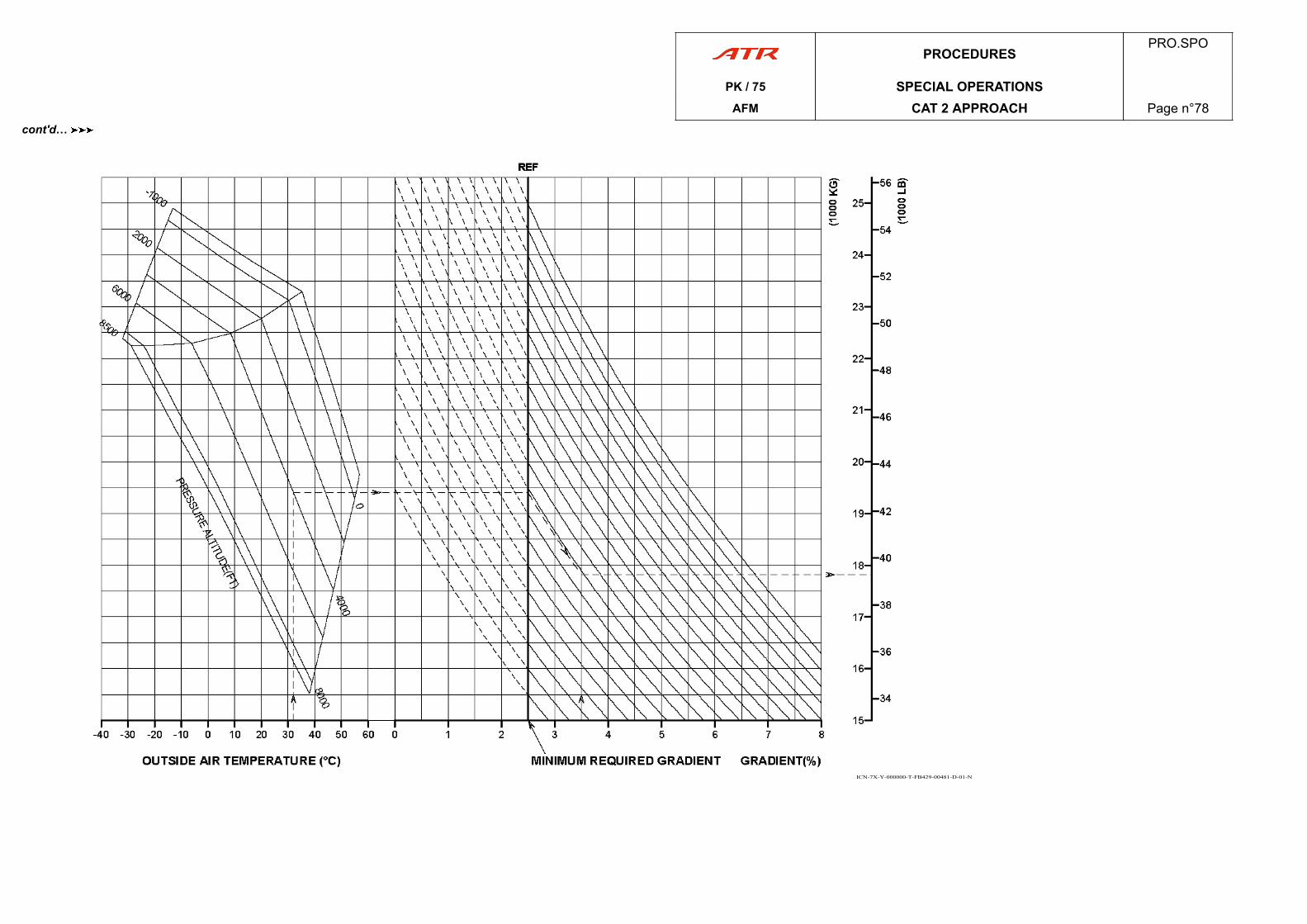
ICN-7X-Y-000000-T-FB429-00481-D-01-N
PROCEDURESPRO.SPO
PK / 75 SPECIAL OPERATIONSAFM CAT 2 APPROACH Page n°78
cont'd…
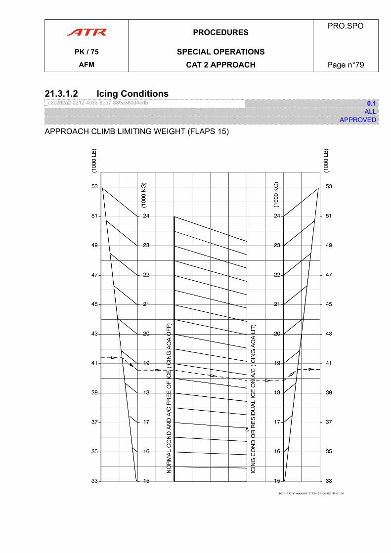
21.3.1.2 Icing Conditions_e2c262a2-2212-4033-8e37-889a380d4edb 0.1
ALLAPPROVED
APPROACH CLIMB LIMITING WEIGHT (FLAPS 15)
ICN-7X-Y-000000-T-FB429-00483-E-01-N
PROCEDURESPRO.SPO
PK / 75 SPECIAL OPERATIONSAFM CAT 2 APPROACH Page n°79
PAGE
INTENTIONALLY
LEFT BLANK
PROCEDURESPRO.SPO
PK / 75 SPECIAL OPERATIONSAFM CAT 2 APPROACH Page n°80
PERFORMANCEGENERAL PER.1
1. INTRODUCTION.................................................................................................page 03
2. AIRCRAFT CONFIGURATION............................................................................. page 03
3. AIRSPEED AND ALTITUDE CALIBRATION..........................................................page 04
ENGINE MANAGEMENT PER.2
1. TORQUES TABLES............................................................................................page 09
TAKEOFF PER.3
1. DEFINITIONS.....................................................................................................page 15
2. TAKEOFF FLIGHT PATH IN CASE OF ENGINE FAILURE......................................page 16
3. TOW DETERMINATION METHODOLOGY............................................................ page 18
4. ALTITUDE SPEED-BANK ANGLE-TURN RADIUS................................................ page 93
SINGLE ENGINE CRUISE PER.4
1. INTRODUCTION.................................................................................................page 96
2. EN ROUTE STRATEGY.......................................................................................page 97
LANDING PER.5
1. PERFORMANCE DETERMINATION................................................................... page 101
2. LANDING PERFORMANCE CHARTS.................................................................page 105
AFMPER.
PK / 75 TOCAFM Table of Content Page n°01
PAGE
INTENTIONALLY
LEFT BLANK
AFMPER.
PK / 75 TOCAFM Table of Content Page n°02
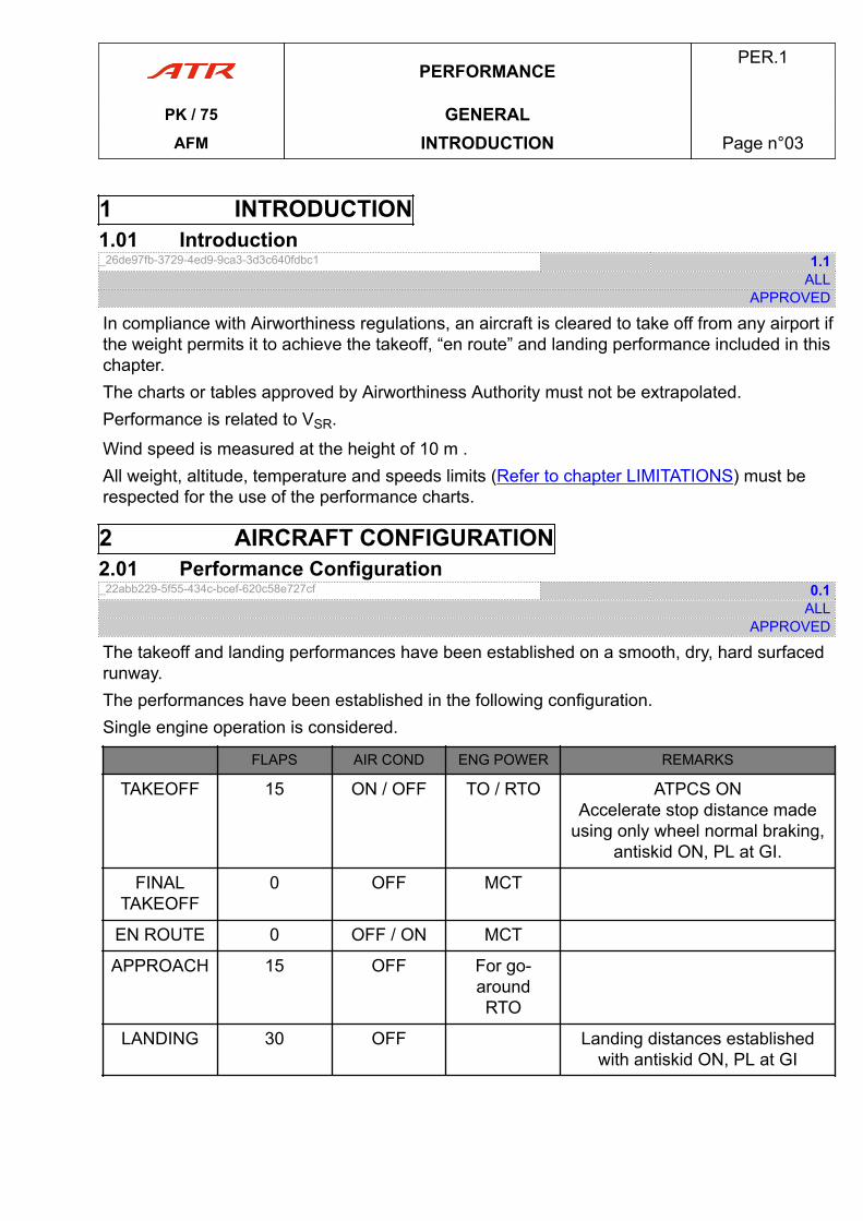
1 INTRODUCTION1.01 Introduction_26de97fb-3729-4ed9-9ca3-3d3c640fdbc1 1.1
ALLAPPROVED
In compliance with Airworthiness regulations, an aircraft is cleared to take off from any airport ifthe weight permits it to achieve the takeoff, “en route” and landing performance included in thischapter.The charts or tables approved by Airworthiness Authority must not be extrapolated.Performance is related to VSR.
Wind speed is measured at the height of 10 m .All weight, altitude, temperature and speeds limits (Refer to chapter LIMITATIONS) must berespected for the use of the performance charts.
2 AIRCRAFT CONFIGURATION2.01 Performance Configuration_22abb229-5f55-434c-bcef-620c58e727cf 0.1
ALLAPPROVED
The takeoff and landing performances have been established on a smooth, dry, hard surfacedrunway.The performances have been established in the following configuration.Single engine operation is considered.
FLAPS AIR COND ENG POWER REMARKS
TAKEOFF 15 ON / OFF TO / RTO ATPCS ONAccelerate stop distance made
using only wheel normal braking,antiskid ON, PL at GI.
FINALTAKEOFF
0 OFF MCT
EN ROUTE 0 OFF / ON MCT
APPROACH 15 OFF For go-aroundRTO
LANDING 30 OFF Landing distances establishedwith antiskid ON, PL at GI
PERFORMANCEPER.1
PK / 75 GENERALAFM INTRODUCTION Page n°03
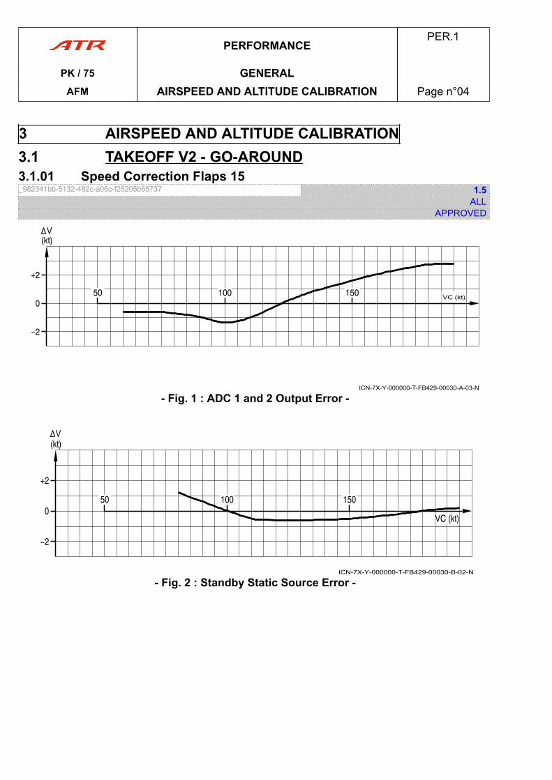
3 AIRSPEED AND ALTITUDE CALIBRATION3.1 TAKEOFF V2 - GO-AROUND3.1.01 Speed Correction Flaps 15_982341bb-5132-482c-a06c-f25205b65737 1.5
ALLAPPROVED
ICN-7X-Y-000000-T-FB429-00030-A-03-N
VC (kt)
- Fig. 1 : ADC 1 and 2 Output Error -
ICN-7X-Y-000000-T-FB429-00030-B-02-N
- Fig. 2 : Standby Static Source Error -
PERFORMANCEPER.1
PK / 75 GENERALAFM AIRSPEED AND ALTITUDE CALIBRATION Page n°04
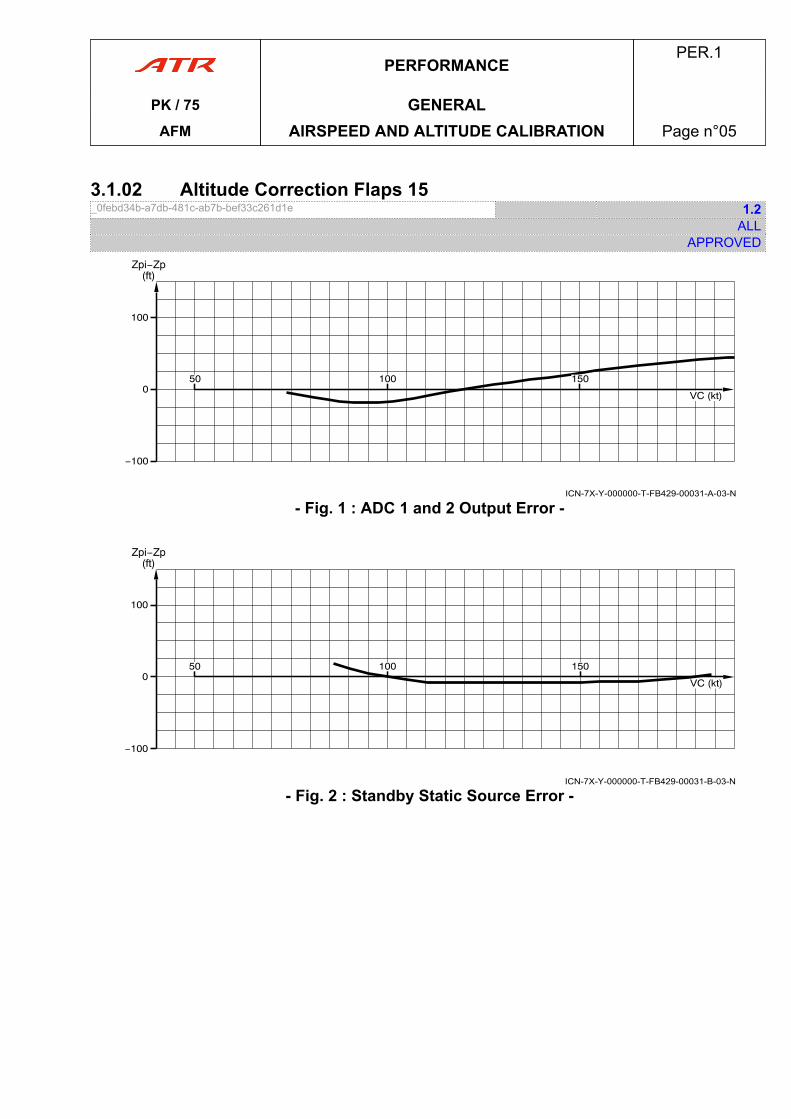
3.1.02 Altitude Correction Flaps 15_0febd34b-a7db-481c-ab7b-bef33c261d1e 1.2
ALLAPPROVED
ICN-7X-Y-000000-T-FB429-00031-A-03-N
- Fig. 1 : ADC 1 and 2 Output Error -
ICN-7X-Y-000000-T-FB429-00031-B-03-N
- Fig. 2 : Standby Static Source Error -
PERFORMANCEPER.1
PK / 75 GENERALAFM AIRSPEED AND ALTITUDE CALIBRATION Page n°05
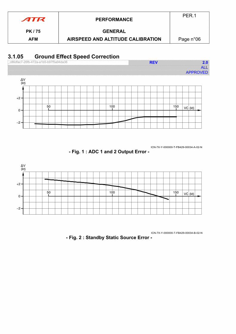
3.1.05 Ground Effect Speed Correction_c86dfac7-26fb-472a-a1b5-b97f5a94da36 REV 2.0
ALLAPPROVED
ICN-7X-Y-000000-T-FB429-00034-A-02-N
- Fig. 1 : ADC 1 and 2 Output Error -
ICN-7X-Y-000000-T-FB429-00034-B-02-N
- Fig. 2 : Standby Static Source Error -
PERFORMANCEPER.1
PK / 75 GENERALAFM AIRSPEED AND ALTITUDE CALIBRATION Page n°06
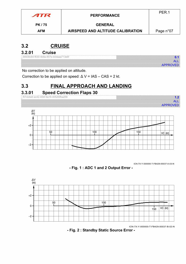
3.2 CRUISE3.2.01 Cruise_68938c64-f630-4b9a-857e-b0daaa713e6f 0.1
ALLAPPROVED
No correction to be applied on altitude.Correction to be applied on speed: Δ V = IAS – CAS = 2 kt.
3.3 FINAL APPROACH AND LANDING3.3.01 Speed Correction Flaps 30_f07cb4e0-ac42-40bf-9a16-4052f2fba258 1.2
ALLAPPROVED
ICN-7X-Y-000000-T-FB429-00037-A-03-N
- Fig. 1 : ADC 1 and 2 Output Error -
ICN-7X-Y-000000-T-FB429-00037-B-02-N
- Fig. 2 : Standby Static Source Error -
PERFORMANCEPER.1
PK / 75 GENERALAFM AIRSPEED AND ALTITUDE CALIBRATION Page n°07
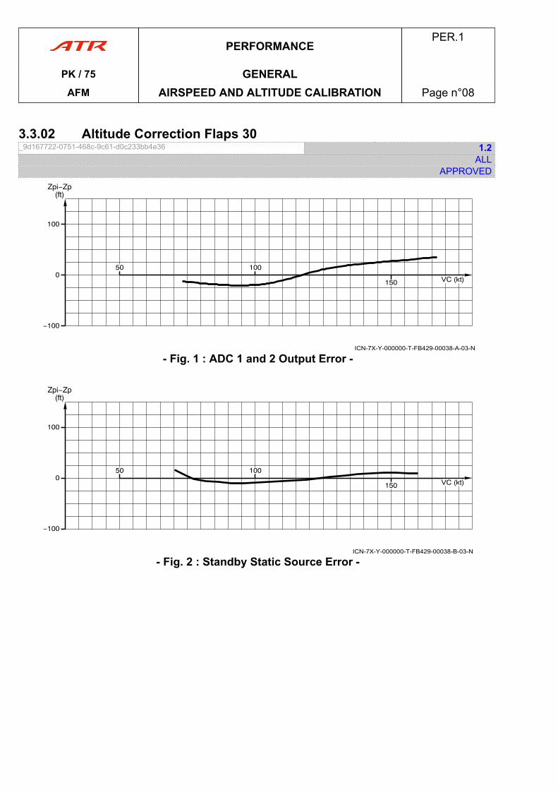
3.3.02 Altitude Correction Flaps 30_9d167722-0751-468c-9c61-d0c233bb4e36 1.2
ALLAPPROVED
ICN-7X-Y-000000-T-FB429-00038-A-03-N
- Fig. 1 : ADC 1 and 2 Output Error -
ICN-7X-Y-000000-T-FB429-00038-B-03-N
- Fig. 2 : Standby Static Source Error -
PERFORMANCEPER.1
PK / 75 GENERALAFM AIRSPEED AND ALTITUDE CALIBRATION Page n°08
1 TORQUES TABLES1.1 Introduction_2789eb4a-643b-49cb-8ab8-fd3e0da84dcb 0.1
ALLAPPROVED
The following torque tables have a highlighted line.The part above the line is the flat rated area: engine mechanical limit.The part below the line is the area where the thermodynamical limit is reached first.
PERFORMANCEPER.2
PK / 75 ENGINE MANAGEMENTAFM TORQUES TABLES Page n°09
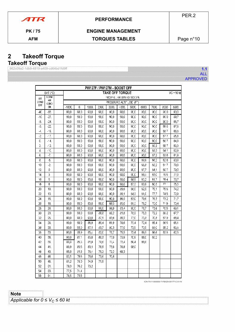
2 Takeoff TorqueTakeoff Torque_662c09a2-1db9-4819-a409-cd64bd1fd9ff 1.1
ALLAPPROVED
ICN-7X-Y-000000-T-FB429-00177-C-01-N
NoteApplicable for 0 ≤ VC ≤ 60 kt
PERFORMANCEPER.2
PK / 75 ENGINE MANAGEMENTAFM TORQUES TABLES Page n°10
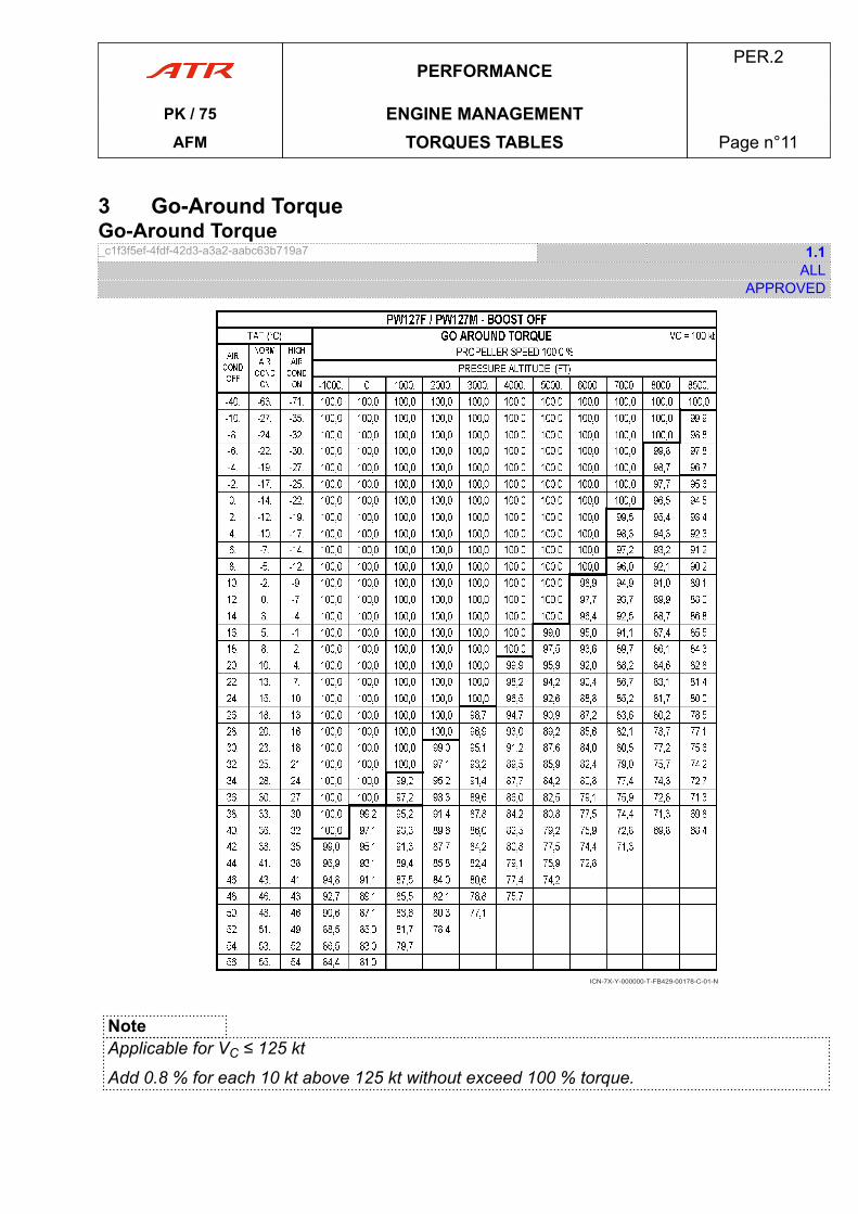
3 Go-Around TorqueGo-Around Torque_c1f3f5ef-4fdf-42d3-a3a2-aabc63b719a7 1.1
ALLAPPROVED
ICN-7X-Y-000000-T-FB429-00178-C-01-N
NoteApplicable for VC ≤ 125 kt
Add 0.8 % for each 10 kt above 125 kt without exceed 100 % torque.
PERFORMANCEPER.2
PK / 75 ENGINE MANAGEMENTAFM TORQUES TABLES Page n°11

PAGE
INTENTIONALLY
LEFT BLANK
PERFORMANCEPER.2
PK / 75 ENGINE MANAGEMENTAFM TORQUES TABLES Page n°12
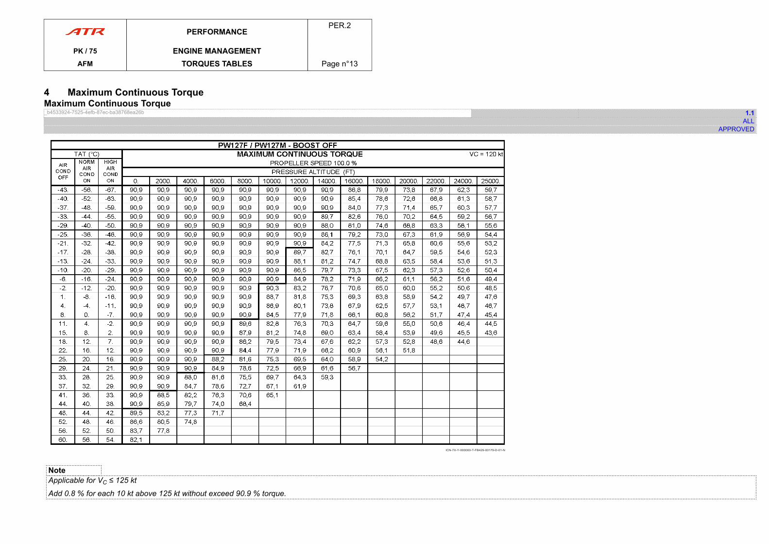
4 Maximum Continuous TorqueMaximum Continuous Torque_b4533924-7525-4efb-87ec-ba38768ea26b 1.1
ALLAPPROVED
ICN-7X-Y-000000-T-FB429-00179-D-01-N
NoteApplicable for VC ≤ 125 kt
Add 0.8 % for each 10 kt above 125 kt without exceed 90.9 % torque.
PERFORMANCEPER.2
PK / 75 ENGINE MANAGEMENTAFM TORQUES TABLES Page n°13

PAGE
INTENTIONALLY
LEFT BLANK
PERFORMANCEPER.2
PK / 75 ENGINE MANAGEMENTAFM TORQUES TABLES Page n°14
1 DEFINITIONS1.01 Distances_dc3331ab-28c5-49c7-8c21-1edaa9ec362f 0.1
ALLAPPROVED
AVAILABLE RUNWAY LENGTH Length of the paved runway surface, able toaccept aircraft weight in all normal operatingconditions.
STOPWAY Extension of runway, sometimes used for taxiingbut adequate for deceleration of the aircraft incase of aborted takeoff.
CLEARWAY Clear area at the end of the runway which can betaken into account for takeoff distance calculation.
AVAILABLE ACCELERATION STOPLENGTH
Sum of the available runway length and thestopway (if any).
TAKEOFF DISTANCE (TOD) Distance between brakes release and 35 ft height.It has to be equal to or less than the sum ofavailable runway length and authorized clearway(if any).
TAKEOFF RUN (TOR) Distance between brakes release point and half ofthe segment between VLOF and 35 ft height.It has to be equal to or less than the availablerunway length.Note: Wind scales are not uniform on correctionscurves associated to takeoff distances.
PERFORMANCEPER.3
PK / 75 TAKEOFFAFM DEFINITIONS Page n°15
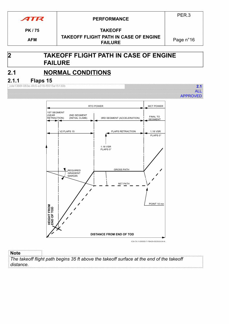
2 TAKEOFF FLIGHT PATH IN CASE OF ENGINEFAILURE
2.1 NORMAL CONDITIONS2.1.1 Flaps 15_cde1366f-083e-4fc5-a318-f5515a15130b 2.1
ALLAPPROVED
RTO POWER
1ST SEGMENT(GEAR RETRACTION)
2ND SEGMENT(INITIAL CLIMB) 3RD SEGMENT (ACCELERATION) FINAL TO
SEGMENT
FLAPS RETRACTIONV2 FLAPS 15
1.18 VSRFLAPS 0°
1.18 VSR
FLAPS 0°
MCT POWER
REQUIREDGRADIENTMARGIN
GROSS PATH
NET PATH
POINT 10 mn
ICN-7X-Y-000000-T-FB429-00239-B-04-N
NoteThe takeoff flight path begins 35 ft above the takeoff surface at the end of the takeoffdistance.
PERFORMANCEPER.3
PK / 75 TAKEOFF
AFM TAKEOFF FLIGHT PATH IN CASE OF ENGINEFAILURE Page n°16
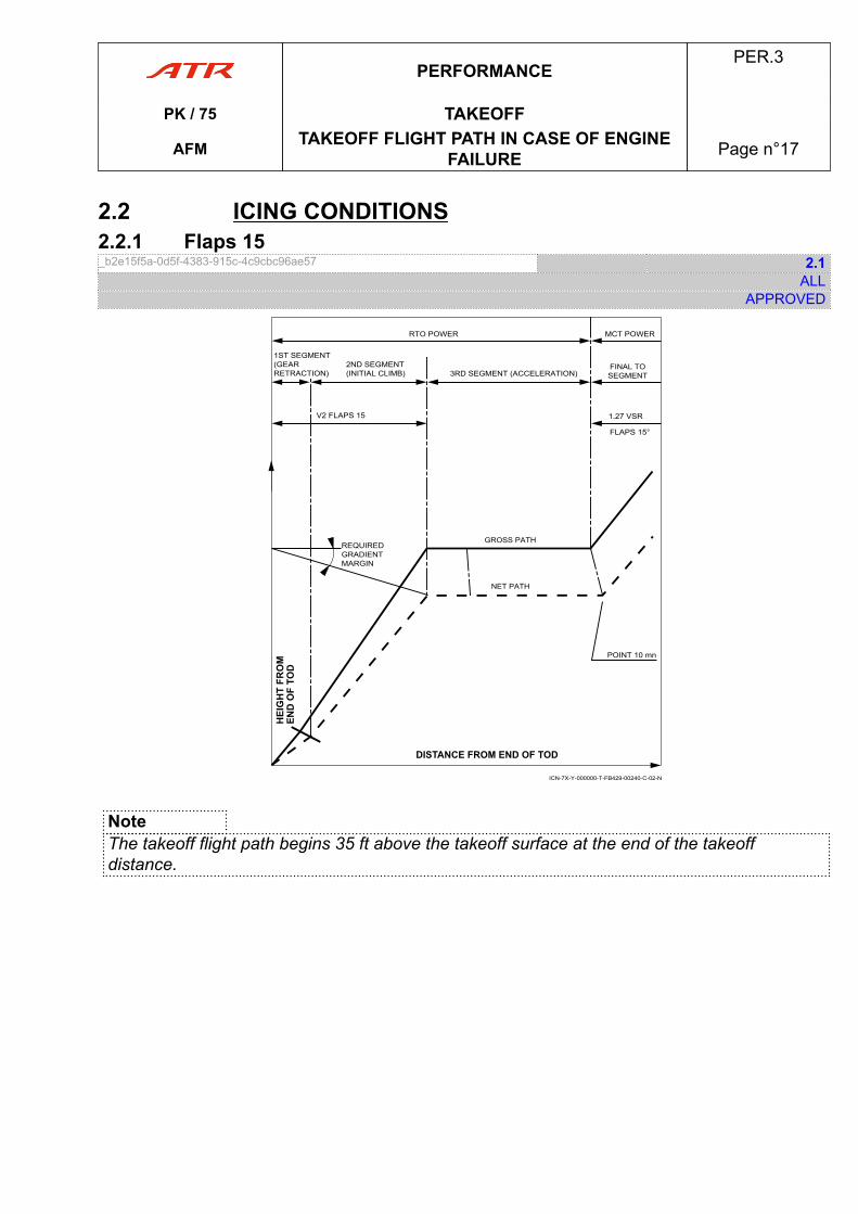
2.2 ICING CONDITIONS2.2.1 Flaps 15_b2e15f5a-0d5f-4383-915c-4c9cbc96ae57 2.1
ALLAPPROVED
RTO POWER
1ST SEGMENT(GEAR RETRACTION)
2ND SEGMENT(INITIAL CLIMB) 3RD SEGMENT (ACCELERATION)
FINAL TO SEGMENT
V2 FLAPS 15 1.27 VSR
FLAPS 15°
MCT POWER
REQUIREDGRADIENTMARGIN
GROSS PATH
NET PATH
POINT 10 mn
ICN-7X-Y-000000-T-FB429-00240-C-02-N
NoteThe takeoff flight path begins 35 ft above the takeoff surface at the end of the takeoffdistance.
PERFORMANCEPER.3
PK / 75 TAKEOFF
AFM TAKEOFF FLIGHT PATH IN CASE OF ENGINEFAILURE Page n°17
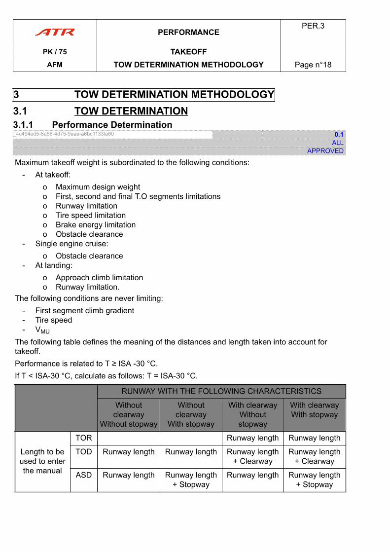
3 TOW DETERMINATION METHODOLOGY3.1 TOW DETERMINATION3.1.1 Performance Determination_4c494ad5-8a58-4d75-9aaa-a6bc1133fa60 0.1
ALLAPPROVED
Maximum takeoff weight is subordinated to the following conditions:- At takeoff:
o Maximum design weighto First, second and final T.O segments limitationso Runway limitationo Tire speed limitationo Brake energy limitationo Obstacle clearance
- Single engine cruise:o Obstacle clearance
- At landing:o Approach climb limitationo Runway limitation.
The following conditions are never limiting:- First segment climb gradient- Tire speed- VMU
The following table defines the meaning of the distances and length taken into account fortakeoff.Performance is related to T ≥ ISA -30 °C.If T < ISA-30 °C, calculate as follows: T = ISA-30 °C.
RUNWAY WITH THE FOLLOWING CHARACTERISTICS
Withoutclearway
Without stopway
Withoutclearway
With stopway
With clearwayWithoutstopway
With clearwayWith stopway
Length to beused to enterthe manual
TOR Runway length Runway length
TOD Runway length Runway length Runway length+ Clearway
Runway length+ Clearway
ASD Runway length Runway length+ Stopway
Runway length Runway length+ Stopway
PERFORMANCEPER.3
PK / 75 TAKEOFFAFM TOW DETERMINATION METHODOLOGY Page n°18
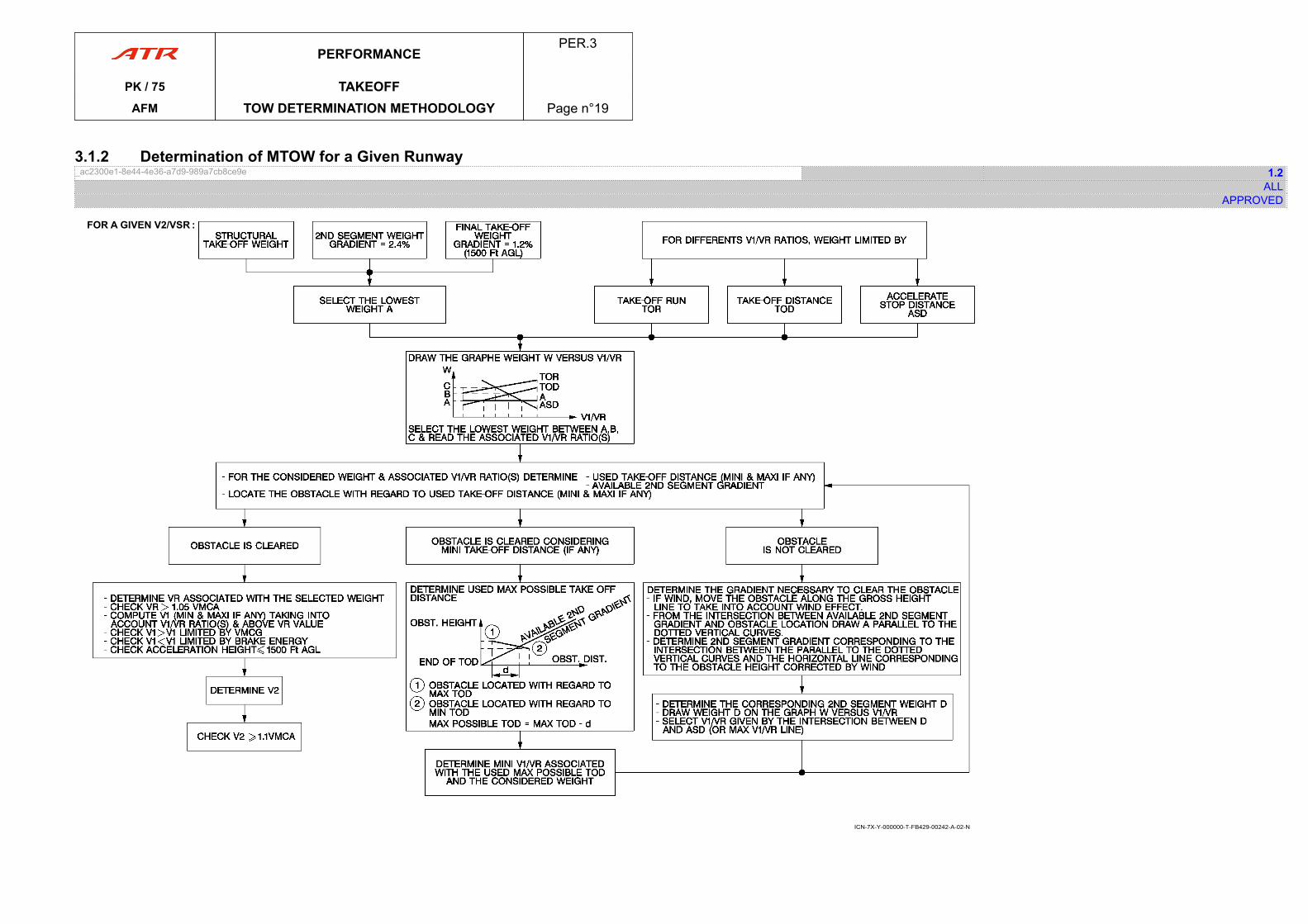
3.1.2 Determination of MTOW for a Given Runway_ac2300e1-8e44-4e36-a7d9-989a7cb8ce9e 1.2
ALLAPPROVED
ICN-7X-Y-000000-T-FB429-00242-A-02-N
PERFORMANCEPER.3
PK / 75 TAKEOFFAFM TOW DETERMINATION METHODOLOGY Page n°19
PAGE
INTENTIONALLY
LEFT BLANK
PERFORMANCEPER.3
PK / 75 TAKEOFFAFM TOW DETERMINATION METHODOLOGY Page n°20
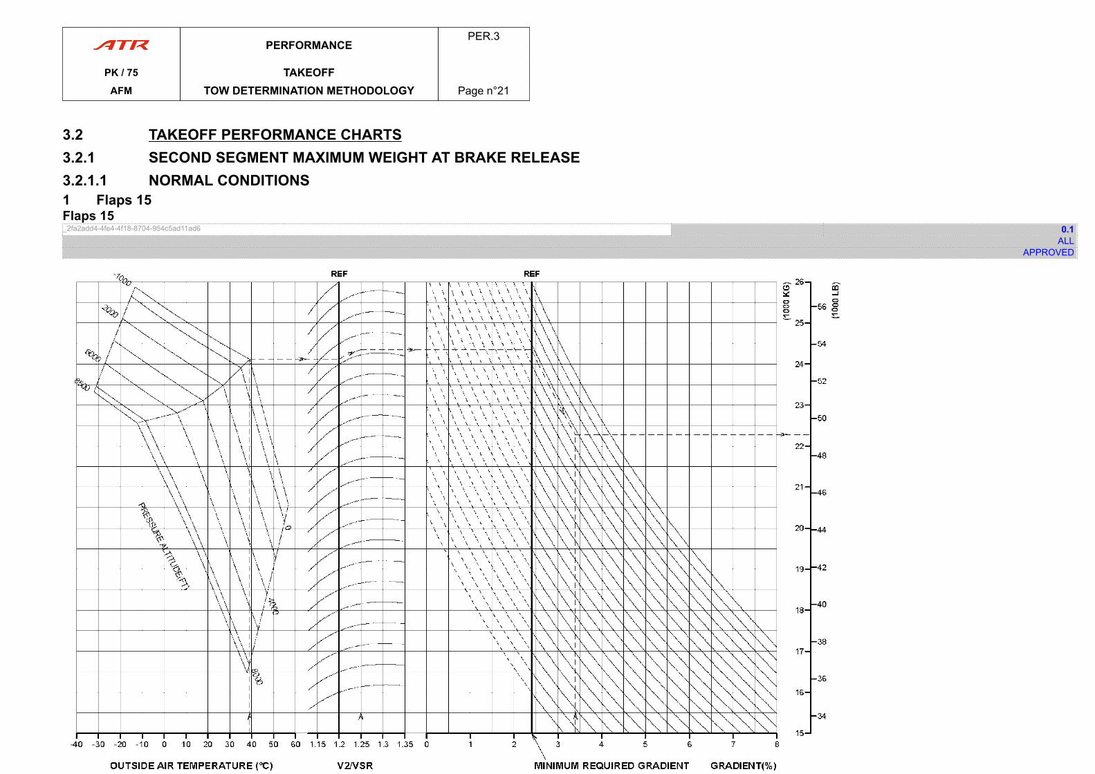
3.2 TAKEOFF PERFORMANCE CHARTS3.2.1 SECOND SEGMENT MAXIMUM WEIGHT AT BRAKE RELEASE3.2.1.1 NORMAL CONDITIONS1 Flaps 15Flaps 15_2fa2add4-4fe4-4f18-8704-954c5ad11ad6 0.1
ALLAPPROVED
ICN-7X-Y-000000-T-FB429-00243-C-01-N
PERFORMANCEPER.3
PK / 75 TAKEOFFAFM TOW DETERMINATION METHODOLOGY Page n°21

PAGE
INTENTIONALLY
LEFT BLANK
PERFORMANCEPER.3
PK / 75 TAKEOFFAFM TOW DETERMINATION METHODOLOGY Page n°22
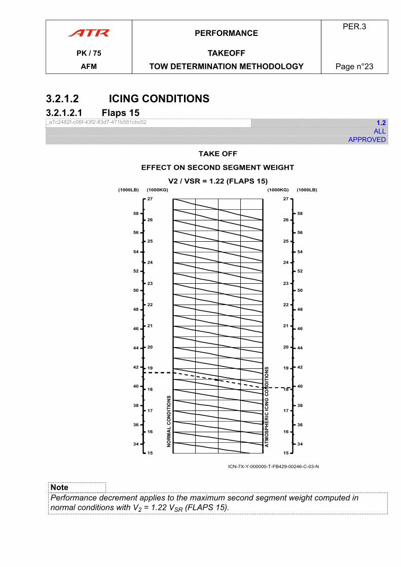
3.2.1.2 ICING CONDITIONS3.2.1.2.1 Flaps 15_a7c2482f-c06f-43f2-83d7-471b581cbc02 1.2
ALLAPPROVED
ICN-7X-Y-000000-T-FB429-00246-C-03-N
1515
16
17
18
19
20
21
22
23
24
25
26
27
(1000KG)
34
36
38
40
42
44
46
48
50
52
54
56
58
(1000LB)
1515
16
17
18
19
20
21
22
23
24
25
26
27
(1000KG)
34
36
38
40
42
44
46
48
50
52
54
56
58
(1000LB)
TAKE OFF
EFFECT ON SECOND SEGMENT WEIGHT
V2 / VSR = 1.22 (FLAPS 15)
NotePerformance decrement applies to the maximum second segment weight computed innormal conditions with V2 = 1.22 VSR (FLAPS 15).
PERFORMANCEPER.3
PK / 75 TAKEOFFAFM TOW DETERMINATION METHODOLOGY Page n°23

PAGE
INTENTIONALLY
LEFT BLANK
PERFORMANCEPER.3
PK / 75 TAKEOFFAFM TOW DETERMINATION METHODOLOGY Page n°24
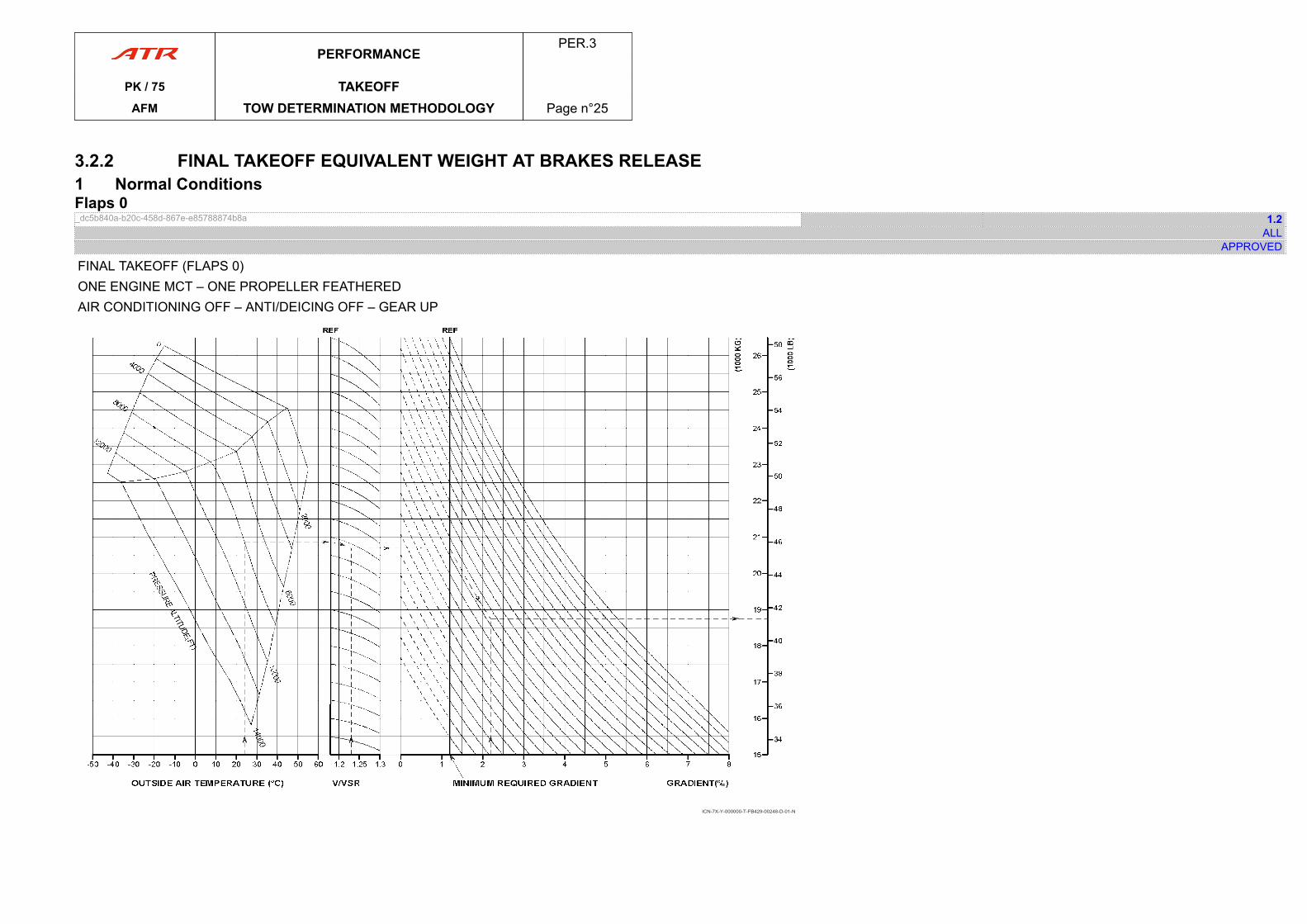
3.2.2 FINAL TAKEOFF EQUIVALENT WEIGHT AT BRAKES RELEASE1 Normal ConditionsFlaps 0_dc5b840a-b20c-458d-867e-e85788874b8a 1.2
ALLAPPROVED
FINAL TAKEOFF (FLAPS 0)ONE ENGINE MCT – ONE PROPELLER FEATHEREDAIR CONDITIONING OFF – ANTI/DEICING OFF – GEAR UP
ICN-7X-Y-000000-T-FB429-00248-D-01-N
PERFORMANCEPER.3
PK / 75 TAKEOFFAFM TOW DETERMINATION METHODOLOGY Page n°25

PAGE
INTENTIONALLY
LEFT BLANK
PERFORMANCEPER.3
PK / 75 TAKEOFFAFM TOW DETERMINATION METHODOLOGY Page n°26
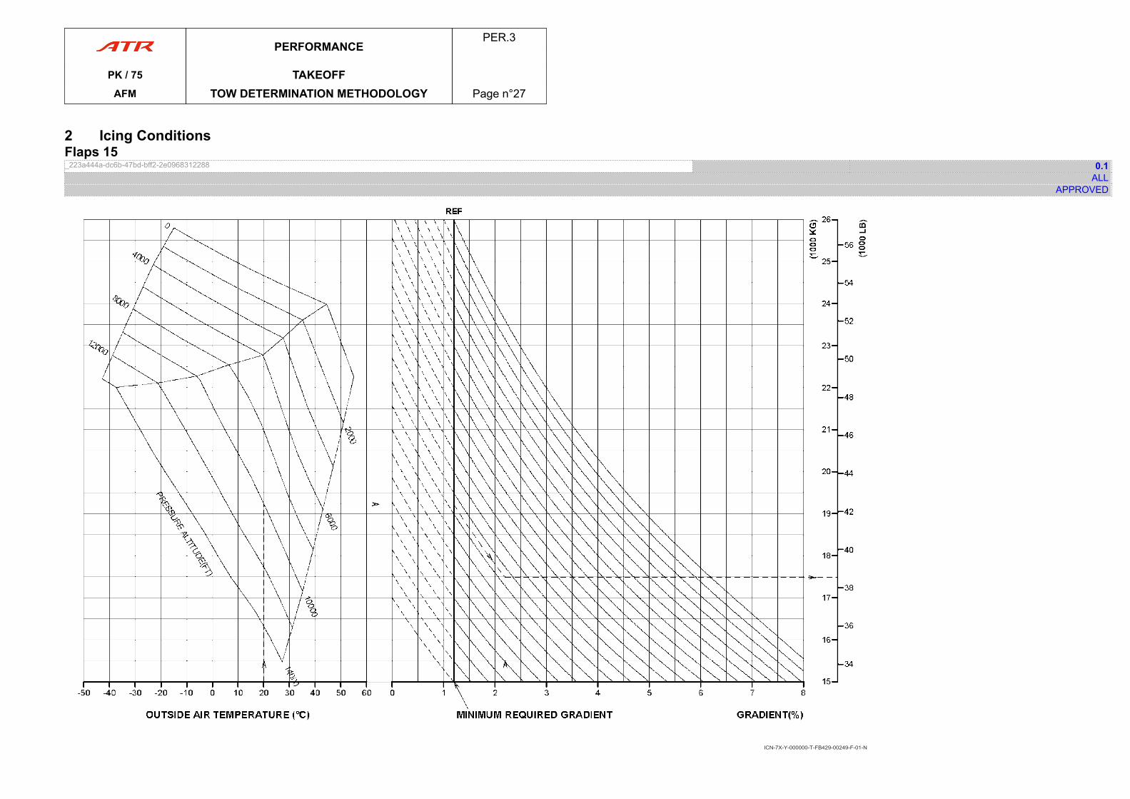
2 Icing ConditionsFlaps 15_223a444a-dc6b-47bd-bff2-2e0968312288 0.1
ALLAPPROVED
ICN-7X-Y-000000-T-FB429-00249-F-01-N
PERFORMANCEPER.3
PK / 75 TAKEOFFAFM TOW DETERMINATION METHODOLOGY Page n°27

PAGE
INTENTIONALLY
LEFT BLANK
PERFORMANCEPER.3
PK / 75 TAKEOFFAFM TOW DETERMINATION METHODOLOGY Page n°28
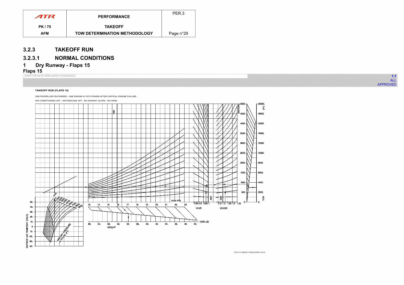
3.2.3 TAKEOFF RUN3.2.3.1 NORMAL CONDITIONS1 Dry Runway - Flaps 15Flaps 15_5c607728-bb75-4955-b429-b1f03dd52523 1.1
ALLAPPROVED
TAKEOFF RUN (FLAPS 15)
ONE PROPELLER FEATHERED - ONE ENGINE AT RTO POWER AFTER CRITICAL ENGINE FAILURE -
AIR CONDITIONING OFF - ANTI/DEICING OFF - NO RUNWAY SLOPE - NO WIND
ICN-7X-Y-000000-T-FB429-00455-C-02-N
PERFORMANCEPER.3
PK / 75 TAKEOFFAFM TOW DETERMINATION METHODOLOGY Page n°29

PAGE
INTENTIONALLY
LEFT BLANK
PERFORMANCEPER.3
PK / 75 TAKEOFFAFM TOW DETERMINATION METHODOLOGY Page n°30
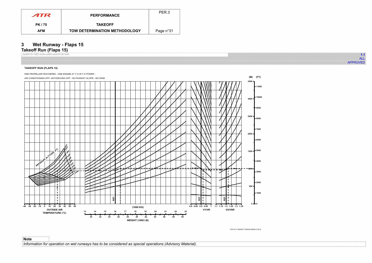
3 Wet Runway - Flaps 15Takeoff Run (Flaps 15)_feef8419-1582-4e5e-ad66-a4eb57d81b08 1.1
ALLAPPROVED
-40-40 -30 -20 -10 0 10 20 30 40 50 60
OUTSIDE AIRTEMPERATURE (°C) 1313 14 15 16 17 18 19 20 21 22 23
(1000 KG)
30 32 34 36 38 40 42 44 46 48 50
WEIGHT (1000 LB)
0.80.8 0.85 0.9 0.95 1
V1/VR1.11.1 1.15 1.2 1.25 1.3 1.35
V2/VSR
00
500
1000
1500
2000
2500
3000
3500
(M)
00
1000
2000
3000
4000
5000
6000
7000
8000
9000
10000
11000
(FT)
TAKEOFF RUN (FLAPS 15)
ONE PROPELLER FEATHERED - ONE ENGINE AT T.O./R.T.O POWER -
AIR CONDITIONING OFF- ANTI/DEICING OFF - NO RUNWAY SLOPE - NO WIND
ICN-7X-Y-000000-T-FB429-00946-C-02-N
NoteInformation for operation on wet runways has to be considered as special operations (Advisory Material).
PERFORMANCEPER.3
PK / 75 TAKEOFFAFM TOW DETERMINATION METHODOLOGY Page n°31

PAGE
INTENTIONALLY
LEFT BLANK
PERFORMANCEPER.3
PK / 75 TAKEOFFAFM TOW DETERMINATION METHODOLOGY Page n°32
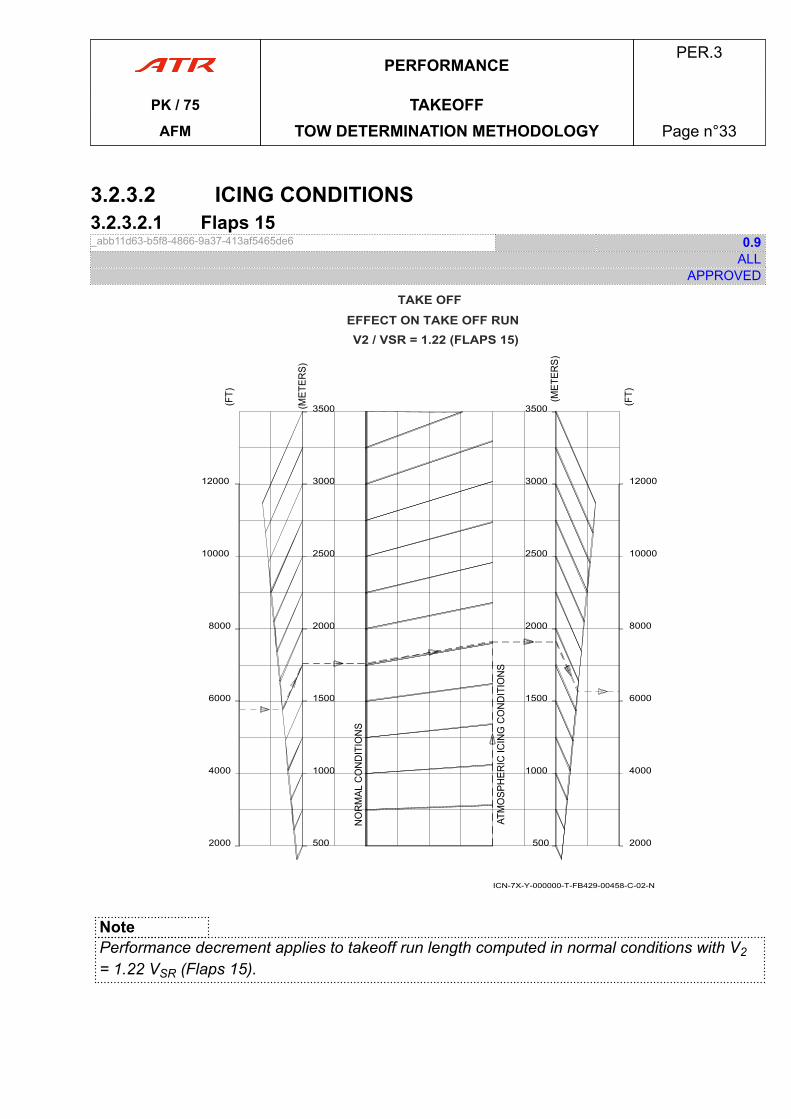
3.2.3.2 ICING CONDITIONS3.2.3.2.1 Flaps 15_abb11d63-b5f8-4866-9a37-413af5465de6 0.9
ALLAPPROVED
TAKE OFFEFFECT ON TAKE OFF RUNV2 / VSR = 1.22 (FLAPS 15)
ICN-7X-Y-000000-T-FB429-00458-C-02-N
2000
4000
6000
8000
10000
12000
500
1000
1500
2000
2500
3000
3500
2000
4000
6000
8000
10000
12000
500
1000
1500
2000
2500
3000
3500
NotePerformance decrement applies to takeoff run length computed in normal conditions with V2= 1.22 VSR (Flaps 15).
PERFORMANCEPER.3
PK / 75 TAKEOFFAFM TOW DETERMINATION METHODOLOGY Page n°33

PAGE
INTENTIONALLY
LEFT BLANK
PERFORMANCEPER.3
PK / 75 TAKEOFFAFM TOW DETERMINATION METHODOLOGY Page n°34
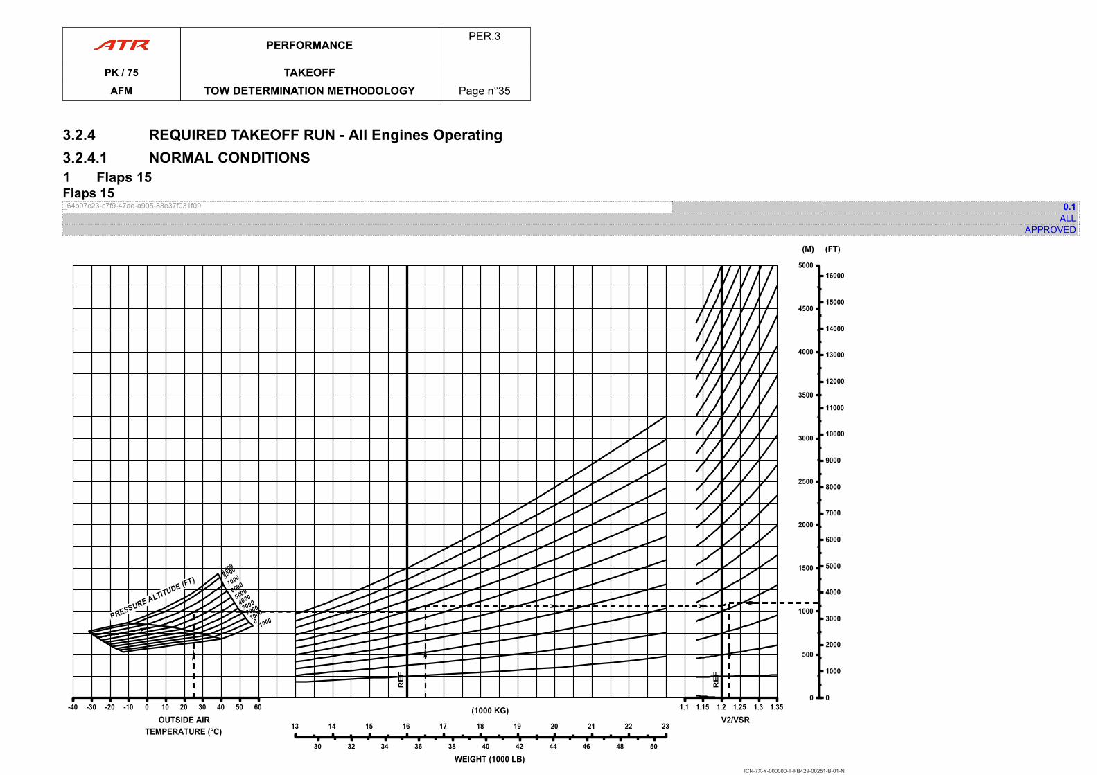
3.2.4 REQUIRED TAKEOFF RUN - All Engines Operating3.2.4.1 NORMAL CONDITIONS1 Flaps 15Flaps 15_64b97c23-c7f9-47ae-a905-88e37f031f09 0.1
ALLAPPROVED
-40-40 -30 -20 -10 0 10 20 30 40 50 60
OUTSIDE AIRTEMPERATURE (°C) 1313 14 15 16 17 18 19 20 21 22 23
(1000 KG)
30 32 34 36 38 40 42 44 46 48 50
WEIGHT (1000 LB)
1.11.1 1.15 1.2 1.25 1.3 1.35
V2/VSR
00
500
1000
1500
2000
2500
3000
3500
4000
4500
5000
(M)
00
1000
2000
3000
4000
5000
6000
7000
8000
9000
10000
11000
12000
13000
14000
15000
16000
(FT)
ICN-7X-Y-000000-T-FB429-00251-B-01-N
PERFORMANCEPER.3
PK / 75 TAKEOFFAFM TOW DETERMINATION METHODOLOGY Page n°35

PAGE
INTENTIONALLY
LEFT BLANK
PERFORMANCEPER.3
PK / 75 TAKEOFFAFM TOW DETERMINATION METHODOLOGY Page n°36
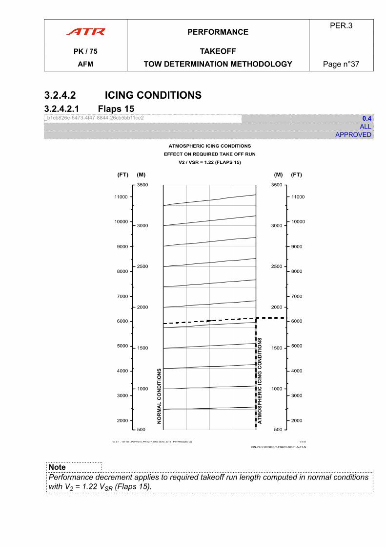
3.2.4.2 ICING CONDITIONS3.2.4.2.1 Flaps 15_b1cb826e-6473-4f47-8844-26cb5bb11ce2 0.4
ALLAPPROVED
ICN-7X-Y-000000-T-FB429-00651-A-01-N
ATMOSPHERIC ICING CONDITIONS
EFFECT ON REQUIRED TAKE OFF RUN
V2 / VSR = 1.22 (FLAPS 15)
V3.0.1 - 141105 - PDFV210_PW127F_Effet Givre_2014 - P1TRRG22D0 (0) V3.44
500500
1000
1500
2000
2500
3000
3500
(M)
2000
3000
4000
5000
6000
7000
8000
9000
10000
11000
(FT)
500500
1000
1500
2000
2500
3000
3500
(M)
2000
3000
4000
5000
6000
7000
8000
9000
10000
11000
(FT)
NotePerformance decrement applies to required takeoff run length computed in normal conditionswith V2 = 1.22 VSR (Flaps 15).
PERFORMANCEPER.3
PK / 75 TAKEOFFAFM TOW DETERMINATION METHODOLOGY Page n°37

PAGE
INTENTIONALLY
LEFT BLANK
PERFORMANCEPER.3
PK / 75 TAKEOFFAFM TOW DETERMINATION METHODOLOGY Page n°38
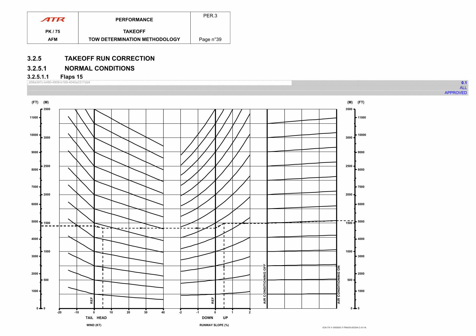
3.2.5 TAKEOFF RUN CORRECTION3.2.5.1 NORMAL CONDITIONS3.2.5.1.1 Flaps 15_858a397c-b480-4909-b169-4040a3317dd4 0.1
ALLAPPROVED
-20-20 -10 0
TAIL
00
500
1000
1500
2000
2500
3000
3500
(M)
00
1000
2000
3000
4000
5000
6000
7000
8000
9000
10000
11000
(FT)
00 10 20 30 40
HEAD
WIND (KT)
-2-2 -1 0 1 2
DOWN UP
RUNWAY SLOPE (%)
00
500
1000
1500
2000
2500
3000
3500
(M)
00
1000
2000
3000
4000
5000
6000
7000
8000
9000
10000
11000
(FT)
ICN-7X-Y-000000-T-FB429-00254-C-01-N
PERFORMANCEPER.3
PK / 75 TAKEOFFAFM TOW DETERMINATION METHODOLOGY Page n°39

PAGE
INTENTIONALLY
LEFT BLANK
PERFORMANCEPER.3
PK / 75 TAKEOFFAFM TOW DETERMINATION METHODOLOGY Page n°40
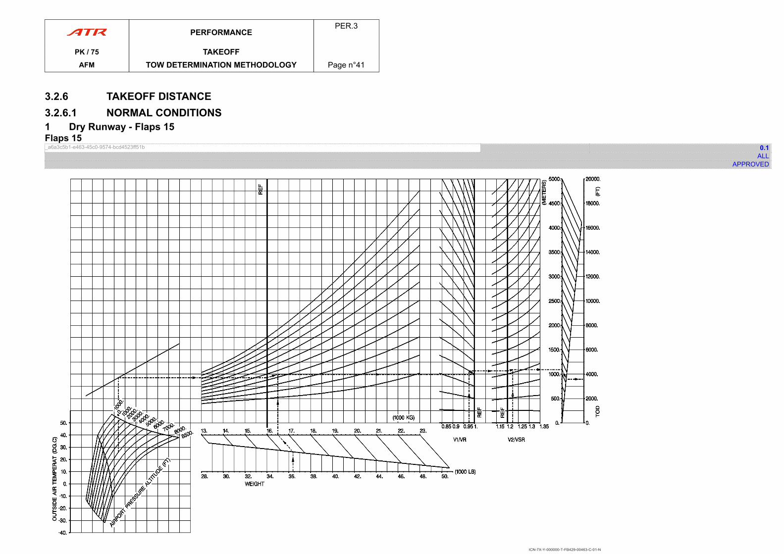
3.2.6 TAKEOFF DISTANCE3.2.6.1 NORMAL CONDITIONS1 Dry Runway - Flaps 15Flaps 15_a6a3c5b1-e463-45c0-9574-bcd4523ff51b 0.1
ALLAPPROVED
ICN-7X-Y-000000-T-FB429-00463-C-01-N
PERFORMANCEPER.3
PK / 75 TAKEOFFAFM TOW DETERMINATION METHODOLOGY Page n°41

PAGE
INTENTIONALLY
LEFT BLANK
PERFORMANCEPER.3
PK / 75 TAKEOFFAFM TOW DETERMINATION METHODOLOGY Page n°42
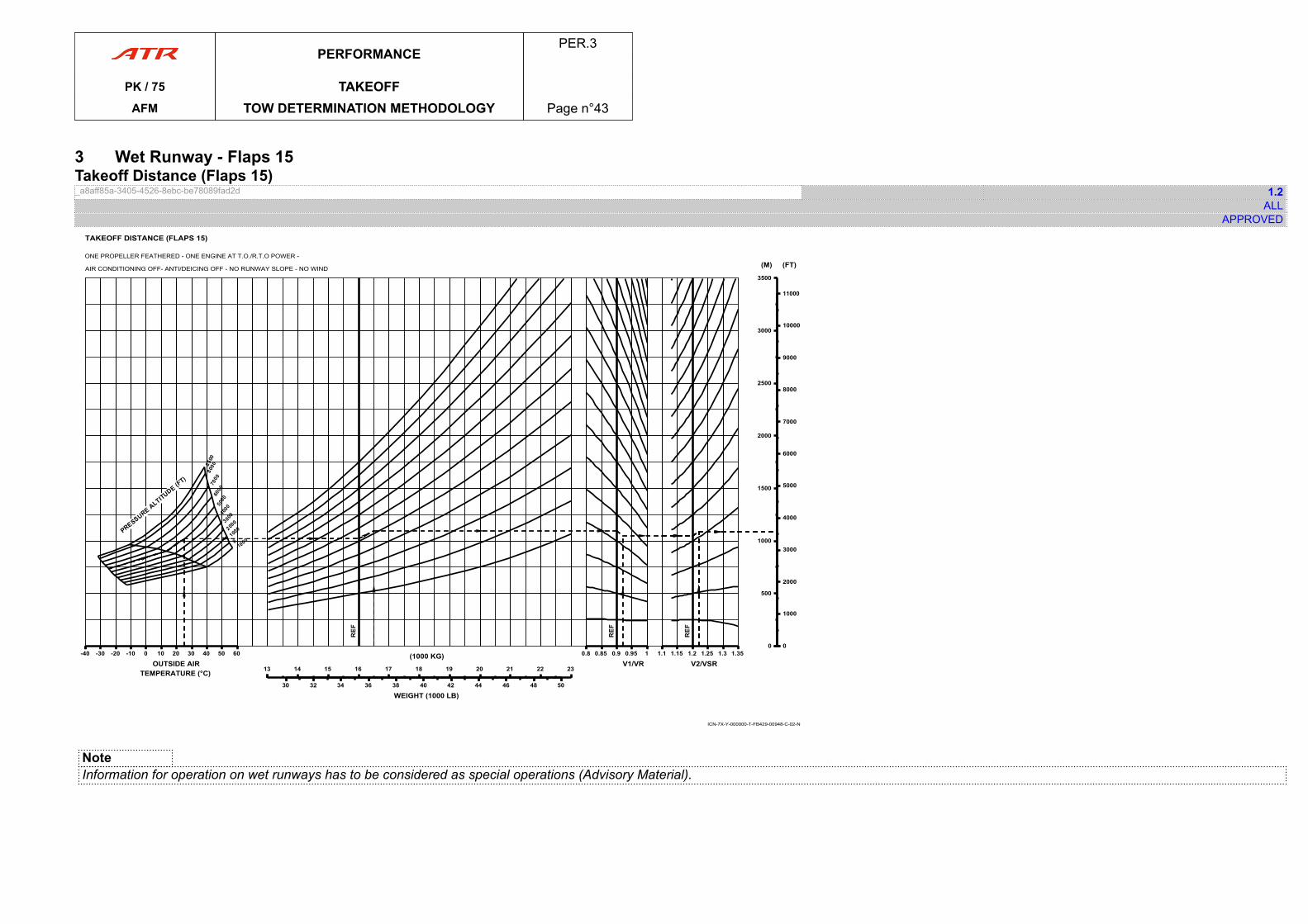
3 Wet Runway - Flaps 15Takeoff Distance (Flaps 15)_a8aff85a-3405-4526-8ebc-be78089fad2d 1.2
ALLAPPROVED
-40-40 -30 -20 -10 0 10 20 30 40 50 60
OUTSIDE AIRTEMPERATURE (°C) 1313 14 15 16 17 18 19 20 21 22 23
(1000 KG)
30 32 34 36 38 40 42 44 46 48 50
WEIGHT (1000 LB)
0.80.8 0.85 0.9 0.95 1
V1/VR1.11.1 1.15 1.2 1.25 1.3 1.35
V2/VSR
00
500
1000
1500
2000
2500
3000
3500
(M)
00
1000
2000
3000
4000
5000
6000
7000
8000
9000
10000
11000
(FT)
TAKEOFF DISTANCE (FLAPS 15)
ONE PROPELLER FEATHERED - ONE ENGINE AT T.O./R.T.O POWER -
AIR CONDITIONING OFF- ANTI/DEICING OFF - NO RUNWAY SLOPE - NO WIND
ICN-7X-Y-000000-T-FB429-00948-C-02-N
NoteInformation for operation on wet runways has to be considered as special operations (Advisory Material).
PERFORMANCEPER.3
PK / 75 TAKEOFFAFM TOW DETERMINATION METHODOLOGY Page n°43

PAGE
INTENTIONALLY
LEFT BLANK
PERFORMANCEPER.3
PK / 75 TAKEOFFAFM TOW DETERMINATION METHODOLOGY Page n°44
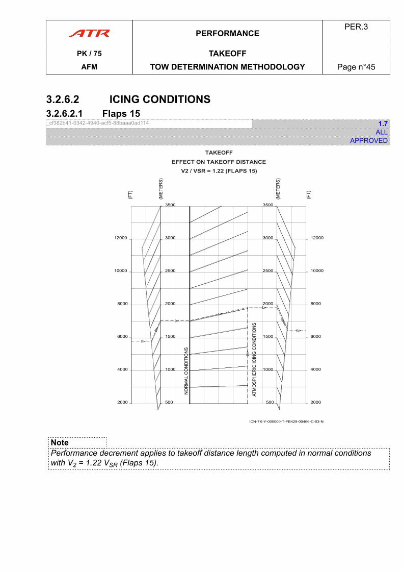
3.2.6.2 ICING CONDITIONS3.2.6.2.1 Flaps 15_cf382b41-0342-4940-acf5-88baaa0ad114 1.7
ALLAPPROVED
2000
4000
6000
8000
10000
12000
500
1000
1500
2000
2500
3000
3500
2000
4000
6000
8000
10000
12000
500
1000
1500
2000
2500
3000
3500
TAKEOFFEFFECT ON TAKEOFF DISTANCE
V2 / VSR = 1.22 (FLAPS 15)
ICN-7X-Y-000000-T-FB429-00466-C-03-N
NotePerformance decrement applies to takeoff distance length computed in normal conditionswith V2 = 1.22 VSR (Flaps 15).
PERFORMANCEPER.3
PK / 75 TAKEOFFAFM TOW DETERMINATION METHODOLOGY Page n°45

PAGE
INTENTIONALLY
LEFT BLANK
PERFORMANCEPER.3
PK / 75 TAKEOFFAFM TOW DETERMINATION METHODOLOGY Page n°46
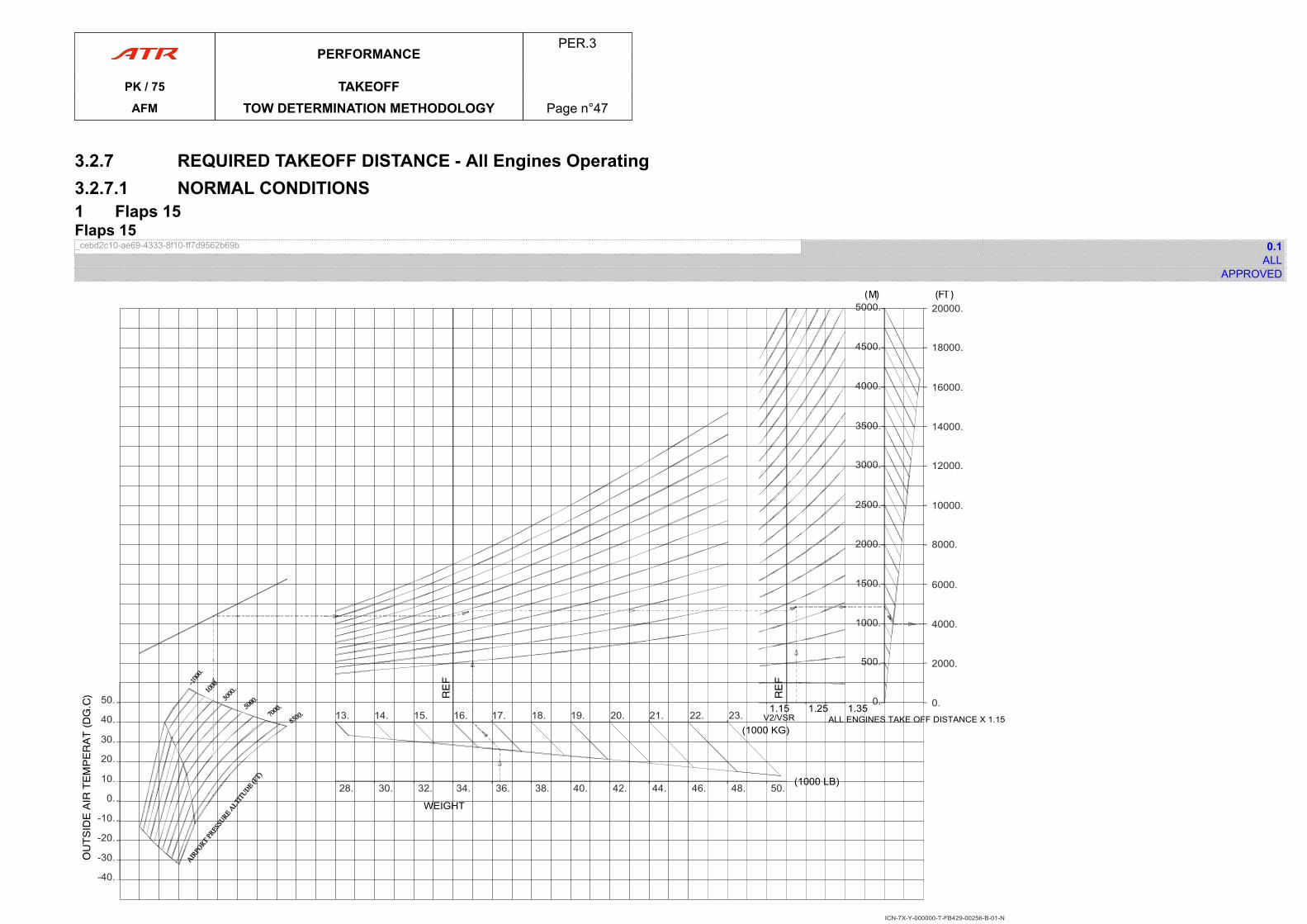
3.2.7 REQUIRED TAKEOFF DISTANCE - All Engines Operating3.2.7.1 NORMAL CONDITIONS1 Flaps 15Flaps 15_cebd2c10-ae69-4333-8f10-ff7d9562b69b 0.1
ALLAPPROVED
ICN-7X-Y-000000-T-FB429-00256-B-01-N
ALL ENGINES TAKE OFF DISTANCE X 1.15V2/VSR
20000.
18000.
16000.
14000.
12000.
10000.
8000.
6000.
4000.
2000.
0.0.
500.
1000.
1500.
2000.
2500.
3000.
3500.
4000.
4500.
5000.
1.351.251.15
(1000 KG)
(1000 LB)50.48.46.44.42.40.38.36.34.32.30.28.
23.22.21.20.19.18.17.16.15.14.13.50.
40.
30.
20.
10.
0.
-10.
-20.
-30.
WEIGHT
-40.
PERFORMANCEPER.3
PK / 75 TAKEOFFAFM TOW DETERMINATION METHODOLOGY Page n°47

PAGE
INTENTIONALLY
LEFT BLANK
PERFORMANCEPER.3
PK / 75 TAKEOFFAFM TOW DETERMINATION METHODOLOGY Page n°48
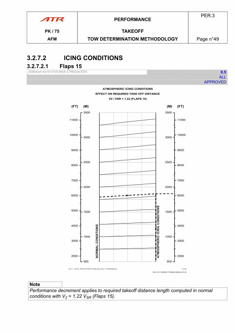
3.2.7.2 ICING CONDITIONS3.2.7.2.1 Flaps 15_f298c0a4-de16-47b5-89c6-27f662ee3050 0.5
ALLAPPROVED
ICN-7X-Y-000000-T-FB429-00650-A-01-N
ATMOSPHERIC ICING CONDITIONS
EFFECT ON REQUIRED TAKE OFF DISTANCE
V2 / VSR = 1.22 (FLAPS 15)
V3.0.1 - 141105 - PDFV210_PW127F_Effet Givre_2014 - P1TDRG22D0 (0) V3.44
500500
1000
1500
2000
2500
3000
3500
(M)
2000
3000
4000
5000
6000
7000
8000
9000
10000
11000
(FT)
500500
1000
1500
2000
2500
3000
3500
(M)
2000
3000
4000
5000
6000
7000
8000
9000
10000
11000
(FT)
NotePerformance decrement applies to required takeoff distance length computed in normalconditions with V2 = 1.22 VSR (Flaps 15).
PERFORMANCEPER.3
PK / 75 TAKEOFFAFM TOW DETERMINATION METHODOLOGY Page n°49

PAGE
INTENTIONALLY
LEFT BLANK
PERFORMANCEPER.3
PK / 75 TAKEOFFAFM TOW DETERMINATION METHODOLOGY Page n°50
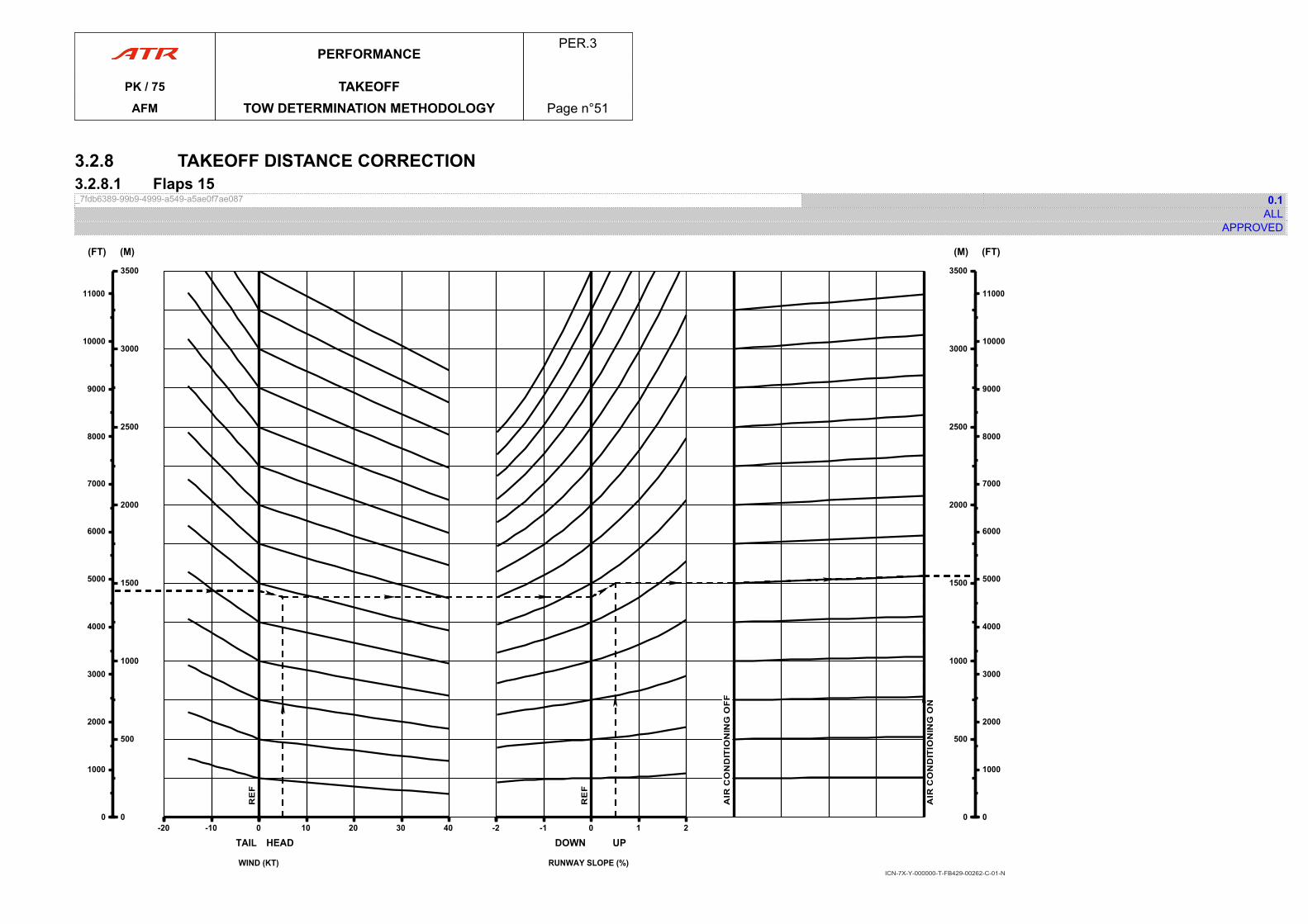
3.2.8 TAKEOFF DISTANCE CORRECTION3.2.8.1 Flaps 15_7fdb6389-99b9-4999-a549-a5ae0f7ae087 0.1
ALLAPPROVED
-20-20 -10 0
TAIL
00
500
1000
1500
2000
2500
3000
3500
(M)
00
1000
2000
3000
4000
5000
6000
7000
8000
9000
10000
11000
(FT)
00 10 20 30 40
HEAD
WIND (KT)
-2-2 -1 0 1 2
DOWN UP
RUNWAY SLOPE (%)
00
500
1000
1500
2000
2500
3000
3500
(M)
00
1000
2000
3000
4000
5000
6000
7000
8000
9000
10000
11000
(FT)
ICN-7X-Y-000000-T-FB429-00262-C-01-N
PERFORMANCEPER.3
PK / 75 TAKEOFFAFM TOW DETERMINATION METHODOLOGY Page n°51

PAGE
INTENTIONALLY
LEFT BLANK
PERFORMANCEPER.3
PK / 75 TAKEOFFAFM TOW DETERMINATION METHODOLOGY Page n°52
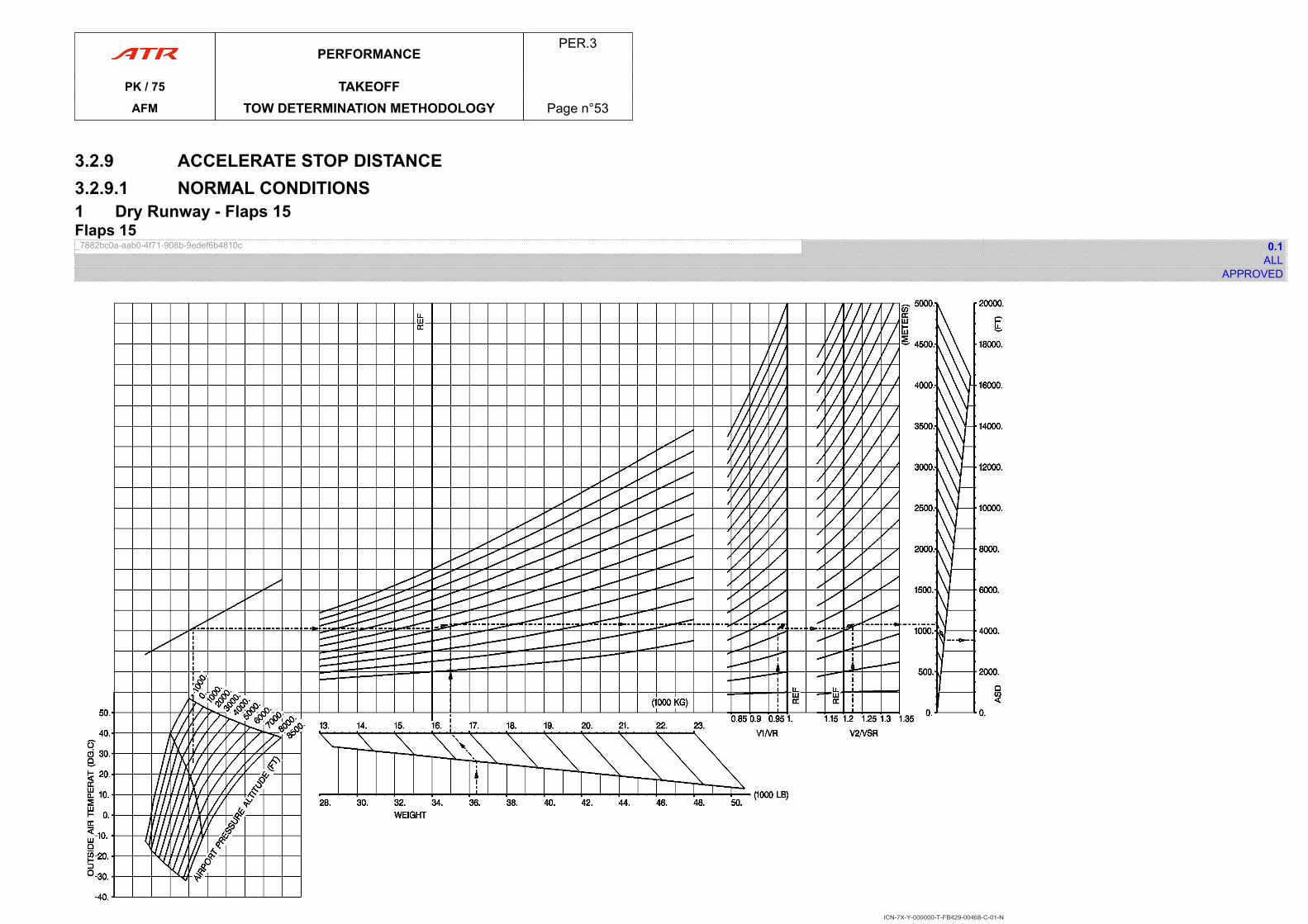
3.2.9 ACCELERATE STOP DISTANCE3.2.9.1 NORMAL CONDITIONS1 Dry Runway - Flaps 15Flaps 15_7882bc0a-aab0-4f71-908b-9edef6b4810c 0.1
ALLAPPROVED
ICN-7X-Y-000000-T-FB429-00468-C-01-N
PERFORMANCEPER.3
PK / 75 TAKEOFFAFM TOW DETERMINATION METHODOLOGY Page n°53

PAGE
INTENTIONALLY
LEFT BLANK
PERFORMANCEPER.3
PK / 75 TAKEOFFAFM TOW DETERMINATION METHODOLOGY Page n°54
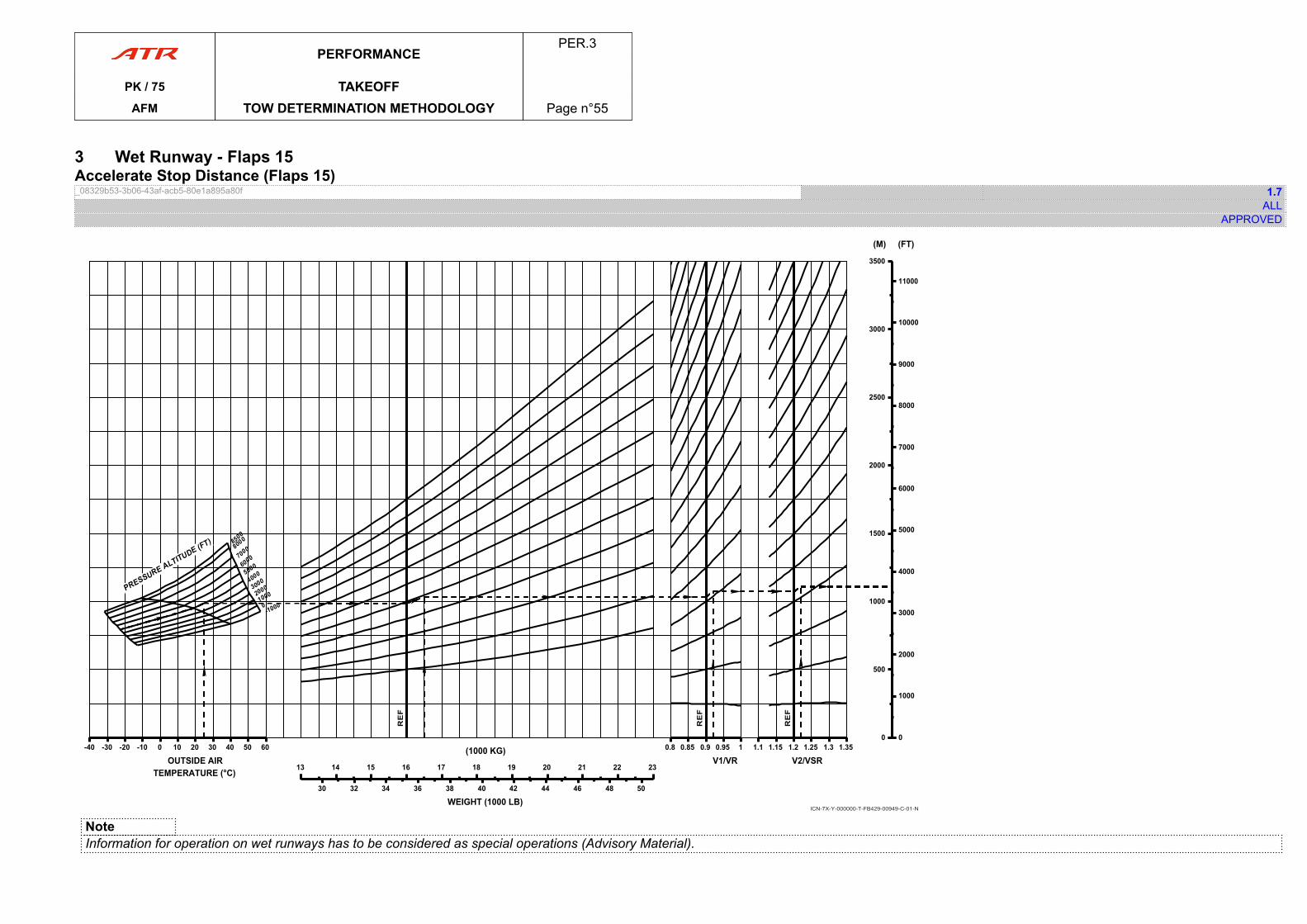
3 Wet Runway - Flaps 15Accelerate Stop Distance (Flaps 15)_08329b53-3b06-43af-acb5-80e1a895a80f 1.7
ALLAPPROVED
-40-40 -30 -20 -10 0 10 20 30 40 50 60
OUTSIDE AIRTEMPERATURE (°C) 1313 14 15 16 17 18 19 20 21 22 23
(1000 KG)
30 32 34 36 38 40 42 44 46 48 50
WEIGHT (1000 LB)
0.80.8 0.85 0.9 0.95 1
V1/VR1.11.1 1.15 1.2 1.25 1.3 1.35
V2/VSR
00
500
1000
1500
2000
2500
3000
3500
(M)
00
1000
2000
3000
4000
5000
6000
7000
8000
9000
10000
11000
(FT)
ICN-7X-Y-000000-T-FB429-00949-C-01-N
NoteInformation for operation on wet runways has to be considered as special operations (Advisory Material).
PERFORMANCEPER.3
PK / 75 TAKEOFFAFM TOW DETERMINATION METHODOLOGY Page n°55

PAGE
INTENTIONALLY
LEFT BLANK
PERFORMANCEPER.3
PK / 75 TAKEOFFAFM TOW DETERMINATION METHODOLOGY Page n°56
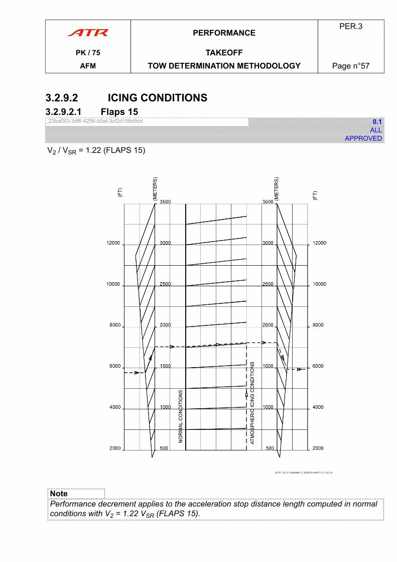
3.2.9.2 ICING CONDITIONS3.2.9.2.1 Flaps 15_23baf3f3-3df6-4256-b0af-3cf2d158d9cd 0.1
ALLAPPROVED
V2 / VSR = 1.22 (FLAPS 15)
ICN-7X-Y-000000-T-FB429-00471-C-01-N
NotePerformance decrement applies to the acceleration stop distance length computed in normalconditions with V2 = 1.22 VSR (FLAPS 15).
PERFORMANCEPER.3
PK / 75 TAKEOFFAFM TOW DETERMINATION METHODOLOGY Page n°57

PAGE
INTENTIONALLY
LEFT BLANK
PERFORMANCEPER.3
PK / 75 TAKEOFFAFM TOW DETERMINATION METHODOLOGY Page n°58
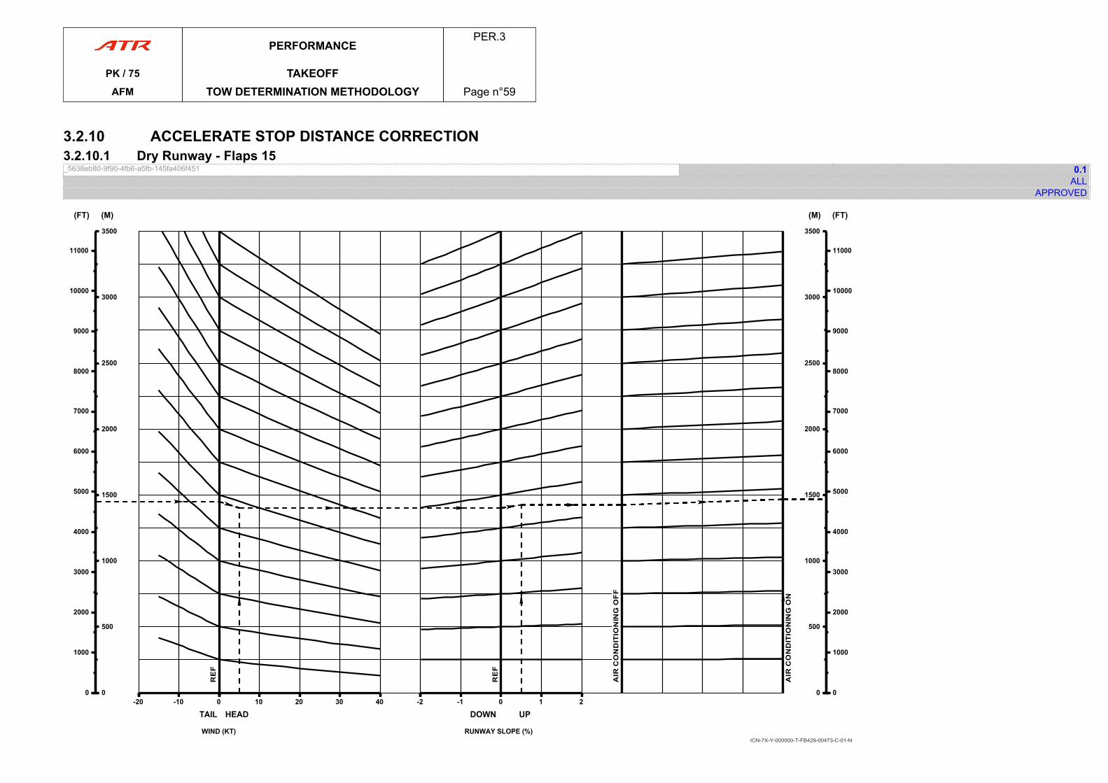
3.2.10 ACCELERATE STOP DISTANCE CORRECTION3.2.10.1 Dry Runway - Flaps 15_5638eb80-9f90-4fb6-a5fb-145fa406f451 0.1
ALLAPPROVED
-20-20 -10 0
TAIL
00
500
1000
1500
2000
2500
3000
3500
(M)
00
1000
2000
3000
4000
5000
6000
7000
8000
9000
10000
11000
(FT)
00 10 20 30 40
HEAD
WIND (KT)
-2-2 -1 0 1 2
DOWN UP
RUNWAY SLOPE (%)
00
500
1000
1500
2000
2500
3000
3500
(M)
00
1000
2000
3000
4000
5000
6000
7000
8000
9000
10000
11000
(FT)
ICN-7X-Y-000000-T-FB429-00473-C-01-N
PERFORMANCEPER.3
PK / 75 TAKEOFFAFM TOW DETERMINATION METHODOLOGY Page n°59

PAGE
INTENTIONALLY
LEFT BLANK
PERFORMANCEPER.3
PK / 75 TAKEOFFAFM TOW DETERMINATION METHODOLOGY Page n°60
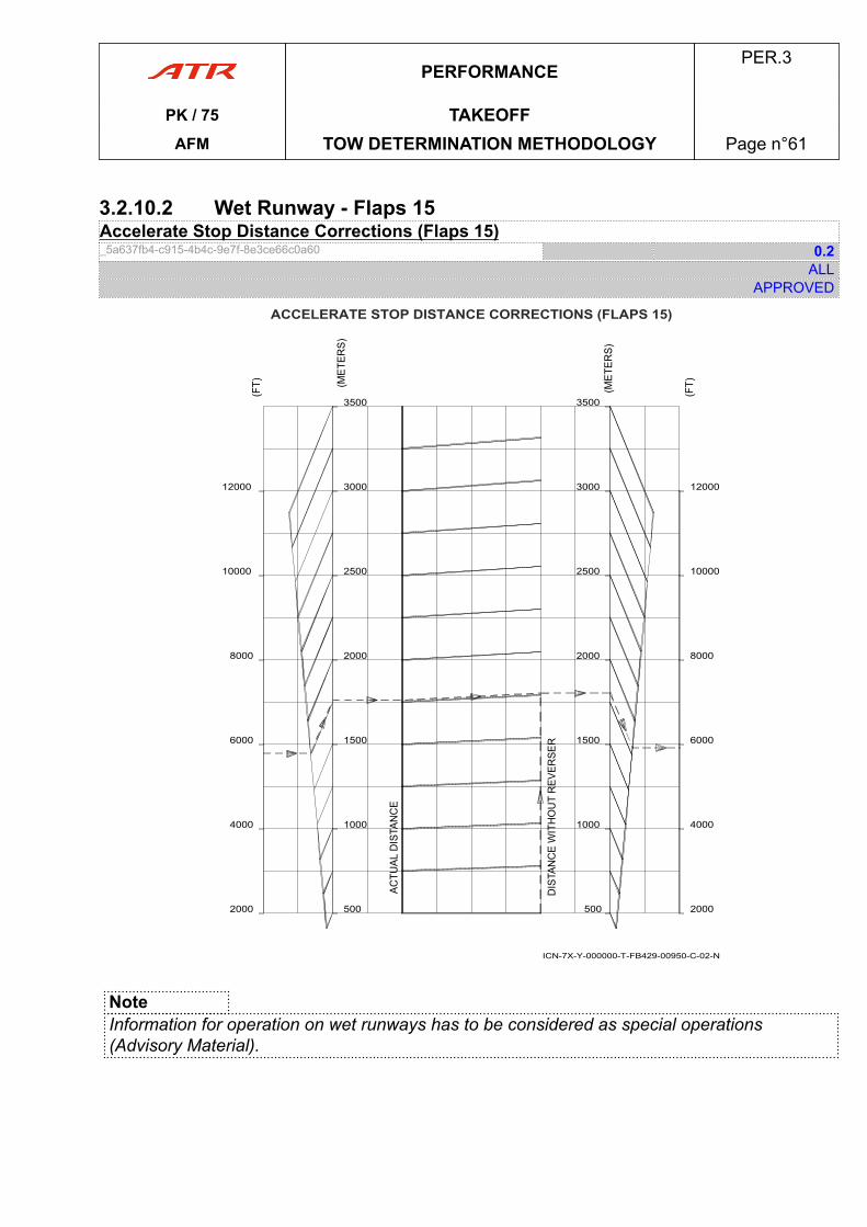
3.2.10.2 Wet Runway - Flaps 15Accelerate Stop Distance Corrections (Flaps 15)_5a637fb4-c915-4b4c-9e7f-8e3ce66c0a60 0.2
ALLAPPROVED
ACCELERATE STOP DISTANCE CORRECTIONS (FLAPS 15)
2000
4000
6000
8000
10000
12000
500
1000
1500
2000
2500
3000
3500
2000
4000
6000
8000
10000
12000
500
1000
1500
2000
2500
3000
3500
ICN-7X-Y-000000-T-FB429-00950-C-02-N
NoteInformation for operation on wet runways has to be considered as special operations(Advisory Material).
PERFORMANCEPER.3
PK / 75 TAKEOFFAFM TOW DETERMINATION METHODOLOGY Page n°61

PAGE
INTENTIONALLY
LEFT BLANK
PERFORMANCEPER.3
PK / 75 TAKEOFFAFM TOW DETERMINATION METHODOLOGY Page n°62
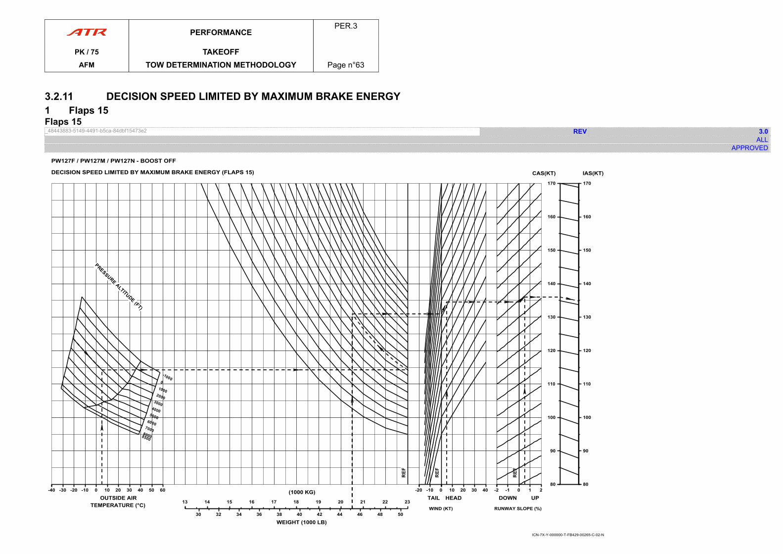
3.2.11 DECISION SPEED LIMITED BY MAXIMUM BRAKE ENERGY1 Flaps 15Flaps 15_48443883-5149-4491-b5ca-84dbf15473e2 REV 3.0
ALLAPPROVED
-40-40 -30 -20 -10 0 10 20 30 40 50 60
OUTSIDE AIRTEMPERATURE (°C) 1313 14 15 16 17 18 19 20 21 22 23
(1000 KG)
30 32 34 36 38 40 42 44 46 48 50
WEIGHT (1000 LB)
-20-20 -10 0
TAIL 00 10 20 30 40
HEAD
WIND (KT)
-2-2 -1 0 1 2
DOWN UP
RUNWAY SLOPE (%)
8080
90
100
110
120
130
140
150
160
170
CAS(KT)
8080
90
100
110
120
130
140
150
160
170
IAS(KT)DECISION SPEED LIMITED BY MAXIMUM BRAKE ENERGY (FLAPS 15)
PW127F / PW127M / PW127N - BOOST OFF
ICN-7X-Y-000000-T-FB429-00265-C-02-N
PERFORMANCEPER.3
PK / 75 TAKEOFFAFM TOW DETERMINATION METHODOLOGY Page n°63

PAGE
INTENTIONALLY
LEFT BLANK
PERFORMANCEPER.3
PK / 75 TAKEOFFAFM TOW DETERMINATION METHODOLOGY Page n°64
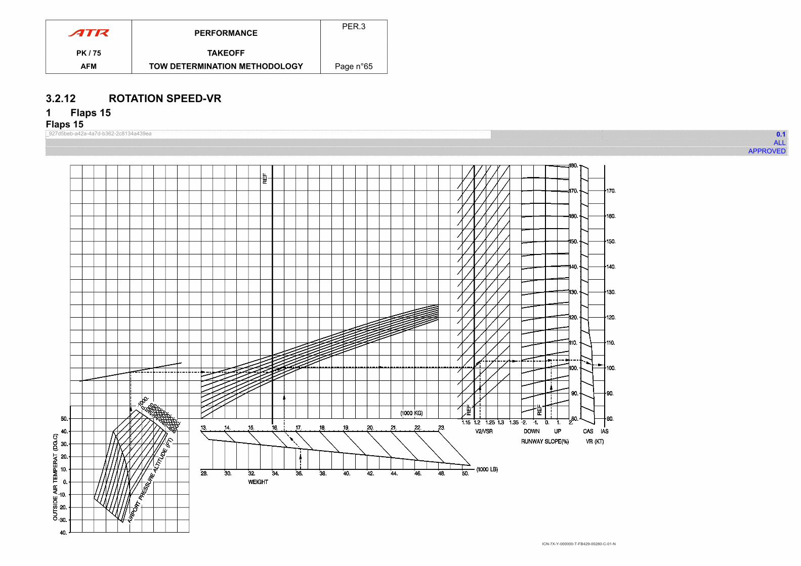
3.2.12 ROTATION SPEED-VR1 Flaps 15Flaps 15_927d5beb-a42a-4a7d-b362-2c8134a439ea 0.1
ALLAPPROVED
ICN-7X-Y-000000-T-FB429-00280-C-01-N
PERFORMANCEPER.3
PK / 75 TAKEOFFAFM TOW DETERMINATION METHODOLOGY Page n°65

PAGE
INTENTIONALLY
LEFT BLANK
PERFORMANCEPER.3
PK / 75 TAKEOFFAFM TOW DETERMINATION METHODOLOGY Page n°66
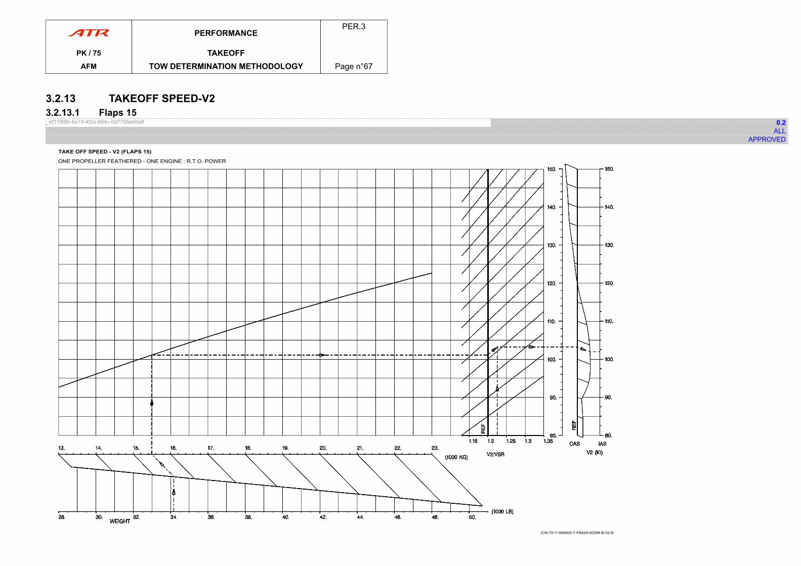
3.2.13 TAKEOFF SPEED-V23.2.13.1 Flaps 15_ef31f88b-6e19-4f2a-884c-0d775feefda9 0.2
ALLAPPROVED
TAKE OFF SPEED - V2 (FLAPS 15)
ONE PROPELLER FEATHERED - ONE ENGINE : R.T.O. POWER
ICN-7X-Y-000000-T-FB429-00288-B-02-N
PERFORMANCEPER.3
PK / 75 TAKEOFFAFM TOW DETERMINATION METHODOLOGY Page n°67

PAGE
INTENTIONALLY
LEFT BLANK
PERFORMANCEPER.3
PK / 75 TAKEOFFAFM TOW DETERMINATION METHODOLOGY Page n°68
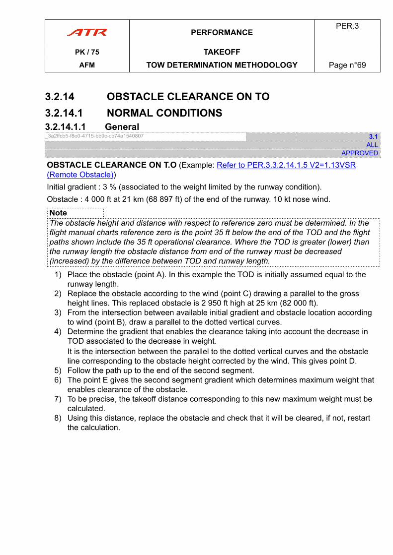
3.2.14 OBSTACLE CLEARANCE ON TO3.2.14.1 NORMAL CONDITIONS3.2.14.1.1 General_3a2ffcb5-f8e0-4715-bb9c-cb74a1540807 3.1
ALLAPPROVED
OBSTACLE CLEARANCE ON T.O (Example: Refer to PER.3.3.2.14.1.5 V2=1.13VSR(Remote Obstacle))Initial gradient : 3 % (associated to the weight limited by the runway condition).Obstacle : 4 000 ft at 21 km (68 897 ft) of the end of the runway. 10 kt nose wind.
NoteThe obstacle height and distance with respect to reference zero must be determined. In theflight manual charts reference zero is the point 35 ft below the end of the TOD and the flightpaths shown include the 35 ft operational clearance. Where the TOD is greater (lower) thanthe runway length the obstacle distance from end of the runway must be decreased(increased) by the difference between TOD and runway length.
1) Place the obstacle (point A). In this example the TOD is initially assumed equal to therunway length.
2) Replace the obstacle according to the wind (point C) drawing a parallel to the grossheight lines. This replaced obstacle is 2 950 ft high at 25 km (82 000 ft).
3) From the intersection between available initial gradient and obstacle location accordingto wind (point B), draw a parallel to the dotted vertical curves.
4) Determine the gradient that enables the clearance taking into account the decrease inTOD associated to the decrease in weight.It is the intersection between the parallel to the dotted vertical curves and the obstacleline corresponding to the obstacle height corrected by the wind. This gives point D.
5) Follow the path up to the end of the second segment.6) The point E gives the second segment gradient which determines maximum weight that
enables clearance of the obstacle.7) To be precise, the takeoff distance corresponding to this new maximum weight must be
calculated.8) Using this distance, replace the obstacle and check that it will be cleared, if not, restart
the calculation.
PERFORMANCEPER.3
PK / 75 TAKEOFFAFM TOW DETERMINATION METHODOLOGY Page n°69

PAGE
INTENTIONALLY
LEFT BLANK
PERFORMANCEPER.3
PK / 75 TAKEOFFAFM TOW DETERMINATION METHODOLOGY Page n°70
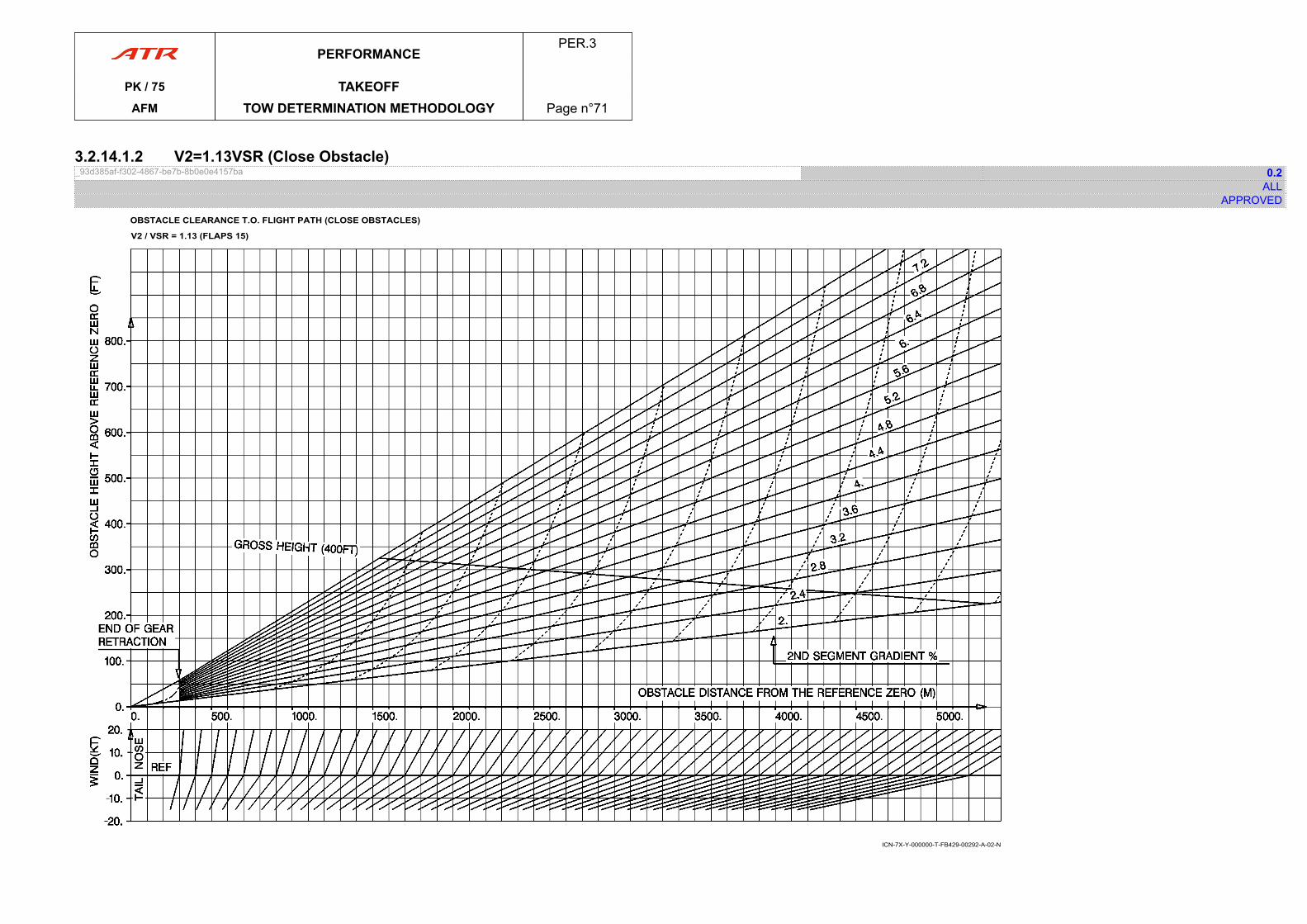
3.2.14.1.2 V2=1.13VSR (Close Obstacle)_93d385af-f302-4867-be7b-8b0e0e4157ba 0.2
ALLAPPROVED
OBSTACLE CLEARANCE T.O. FLIGHT PATH (CLOSE OBSTACLES)
V2 / VSR = 1.13 (FLAPS 15)
ICN-7X-Y-000000-T-FB429-00292-A-02-N
PERFORMANCEPER.3
PK / 75 TAKEOFFAFM TOW DETERMINATION METHODOLOGY Page n°71

PAGE
INTENTIONALLY
LEFT BLANK
PERFORMANCEPER.3
PK / 75 TAKEOFFAFM TOW DETERMINATION METHODOLOGY Page n°72
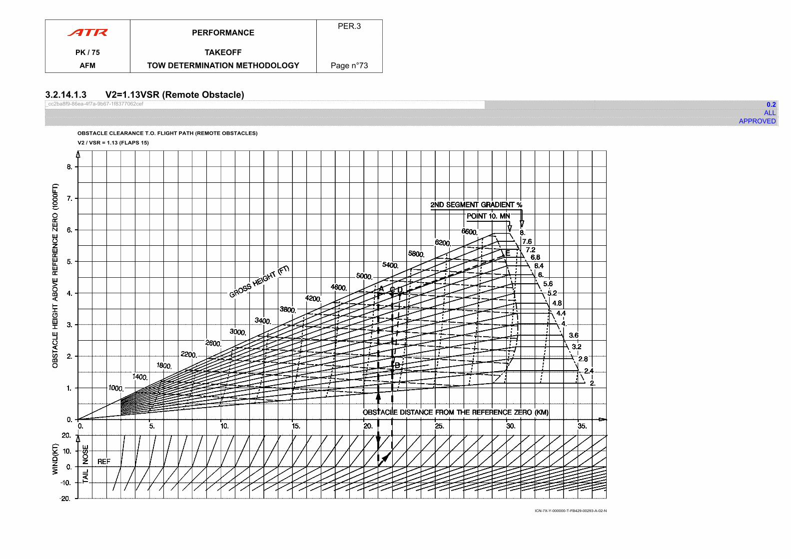
3.2.14.1.3 V2=1.13VSR (Remote Obstacle)_cc2ba8f9-86ea-4f7a-9b67-1f8377062cef 0.2
ALLAPPROVED
OBSTACLE CLEARANCE T.O. FLIGHT PATH (REMOTE OBSTACLES)
V2 / VSR = 1.13 (FLAPS 15)
ICN-7X-Y-000000-T-FB429-00293-A-02-N
PERFORMANCEPER.3
PK / 75 TAKEOFFAFM TOW DETERMINATION METHODOLOGY Page n°73

PAGE
INTENTIONALLY
LEFT BLANK
PERFORMANCEPER.3
PK / 75 TAKEOFFAFM TOW DETERMINATION METHODOLOGY Page n°74
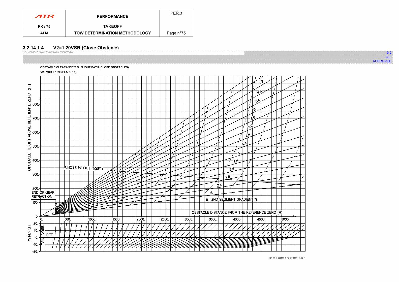
3.2.14.1.4 V2=1.20VSR (Close Obstacle)_f3bd5b13-7c9a-4f21-835a-6fc356667abe 0.2
ALLAPPROVED
OBSTACLE CLEARANCE T.O. FLIGHT PATH (CLOSE OBSTACLES)
V2 / VSR = 1.20 (FLAPS 15)
ICN-7X-Y-000000-T-FB429-00301-A-02-N
PERFORMANCEPER.3
PK / 75 TAKEOFFAFM TOW DETERMINATION METHODOLOGY Page n°75

PAGE
INTENTIONALLY
LEFT BLANK
PERFORMANCEPER.3
PK / 75 TAKEOFFAFM TOW DETERMINATION METHODOLOGY Page n°76
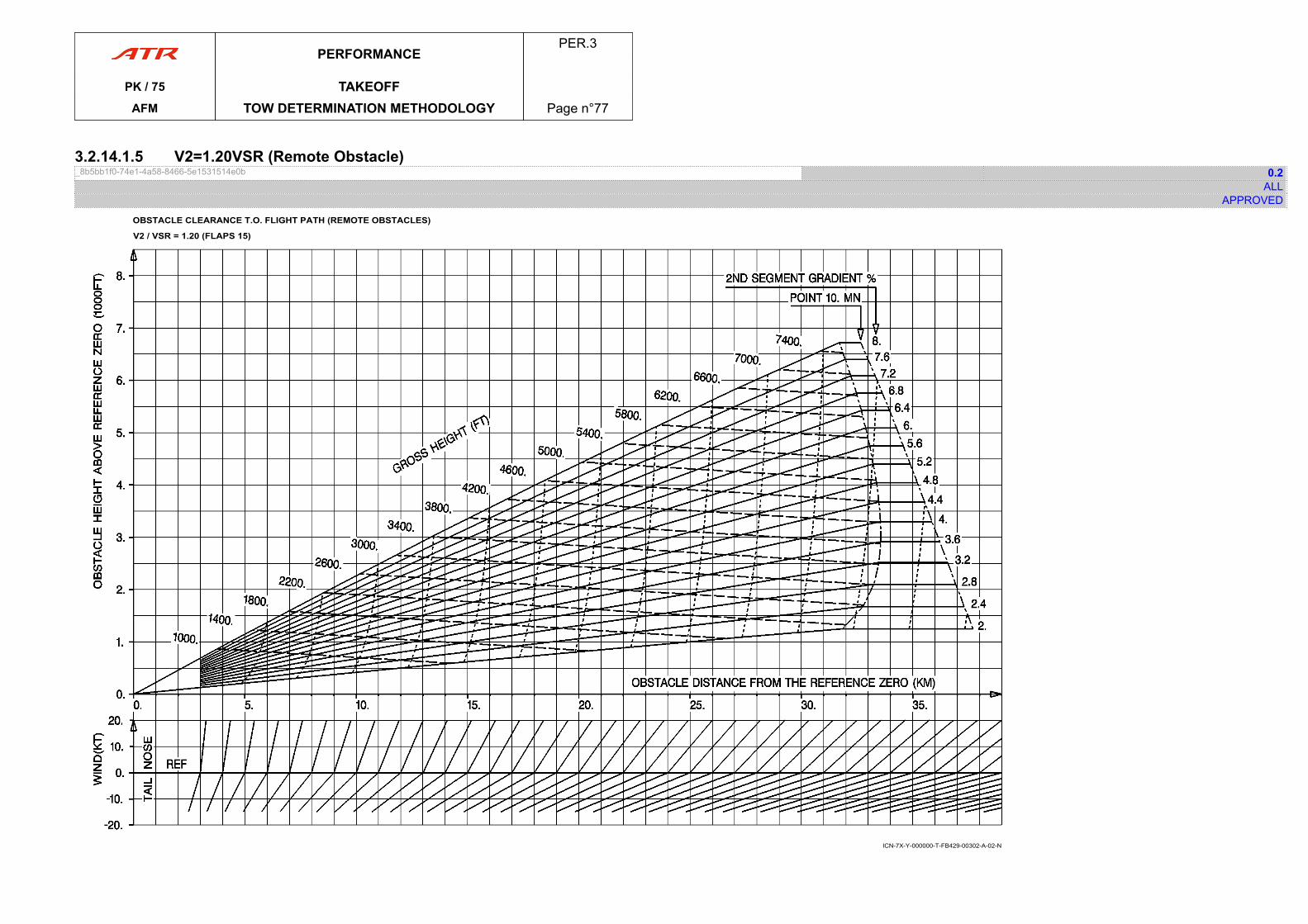
3.2.14.1.5 V2=1.20VSR (Remote Obstacle)_8b5bb1f0-74e1-4a58-8466-5e1531514e0b 0.2
ALLAPPROVED
OBSTACLE CLEARANCE T.O. FLIGHT PATH (REMOTE OBSTACLES)
V2 / VSR = 1.20 (FLAPS 15)
ICN-7X-Y-000000-T-FB429-00302-A-02-N
PERFORMANCEPER.3
PK / 75 TAKEOFFAFM TOW DETERMINATION METHODOLOGY Page n°77

PAGE
INTENTIONALLY
LEFT BLANK
PERFORMANCEPER.3
PK / 75 TAKEOFFAFM TOW DETERMINATION METHODOLOGY Page n°78
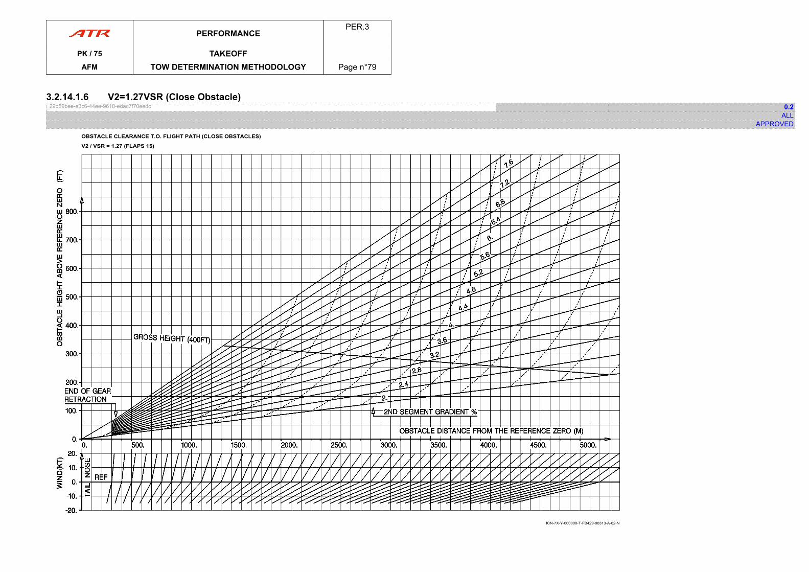
3.2.14.1.6 V2=1.27VSR (Close Obstacle)_29b59bee-e3c6-44ee-9618-edac7f70eedc 0.2
ALLAPPROVED
OBSTACLE CLEARANCE T.O. FLIGHT PATH (CLOSE OBSTACLES)
V2 / VSR = 1.27 (FLAPS 15)
ICN-7X-Y-000000-T-FB429-00313-A-02-N
PERFORMANCEPER.3
PK / 75 TAKEOFFAFM TOW DETERMINATION METHODOLOGY Page n°79

PAGE
INTENTIONALLY
LEFT BLANK
PERFORMANCEPER.3
PK / 75 TAKEOFFAFM TOW DETERMINATION METHODOLOGY Page n°80
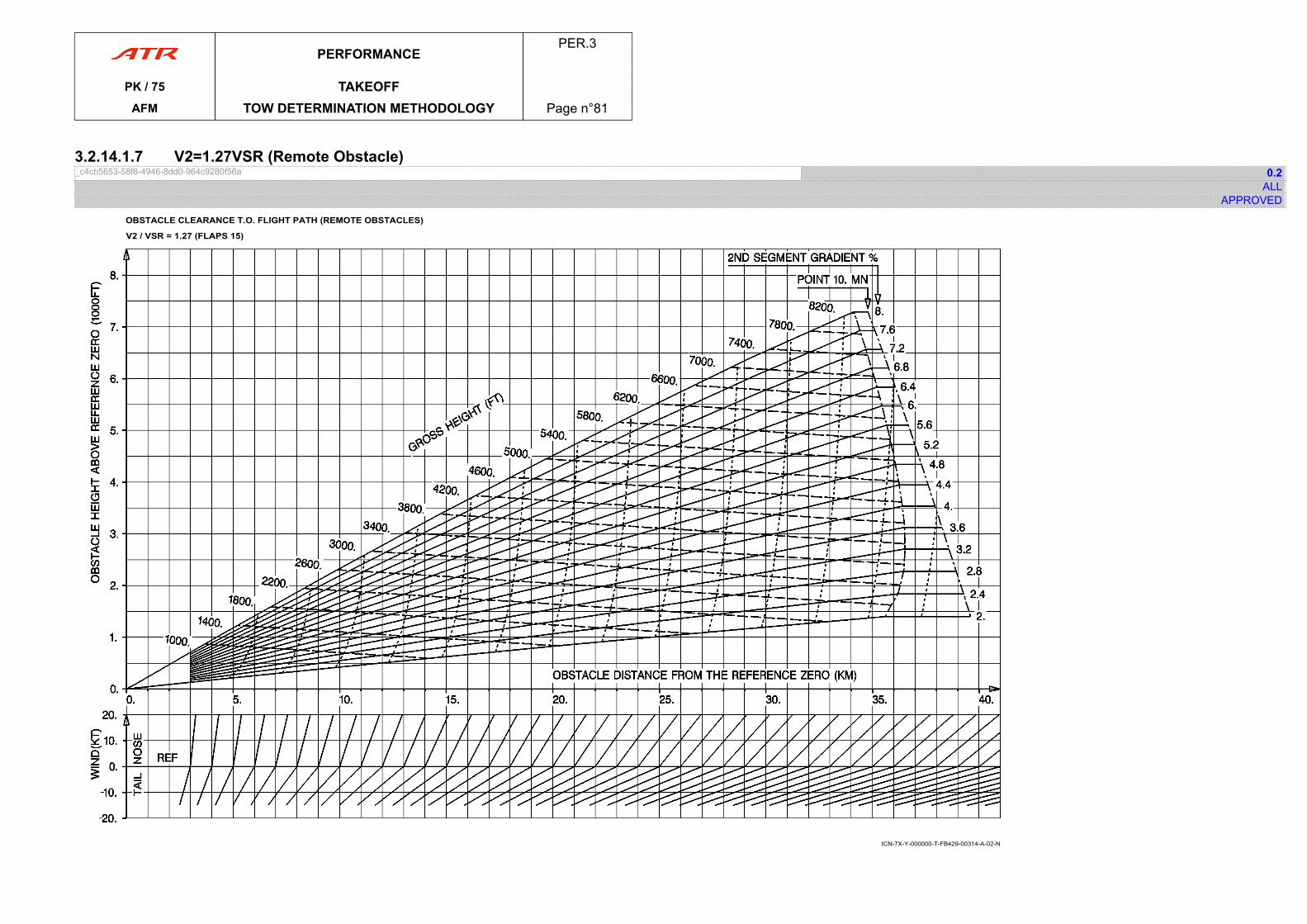
3.2.14.1.7 V2=1.27VSR (Remote Obstacle)_c4cb5653-58f8-4946-8dd0-964c9280f56a 0.2
ALLAPPROVED
OBSTACLE CLEARANCE T.O. FLIGHT PATH (REMOTE OBSTACLES)
V2 / VSR = 1.27 (FLAPS 15)
ICN-7X-Y-000000-T-FB429-00314-A-02-N
PERFORMANCEPER.3
PK / 75 TAKEOFFAFM TOW DETERMINATION METHODOLOGY Page n°81

PAGE
INTENTIONALLY
LEFT BLANK
PERFORMANCEPER.3
PK / 75 TAKEOFFAFM TOW DETERMINATION METHODOLOGY Page n°82
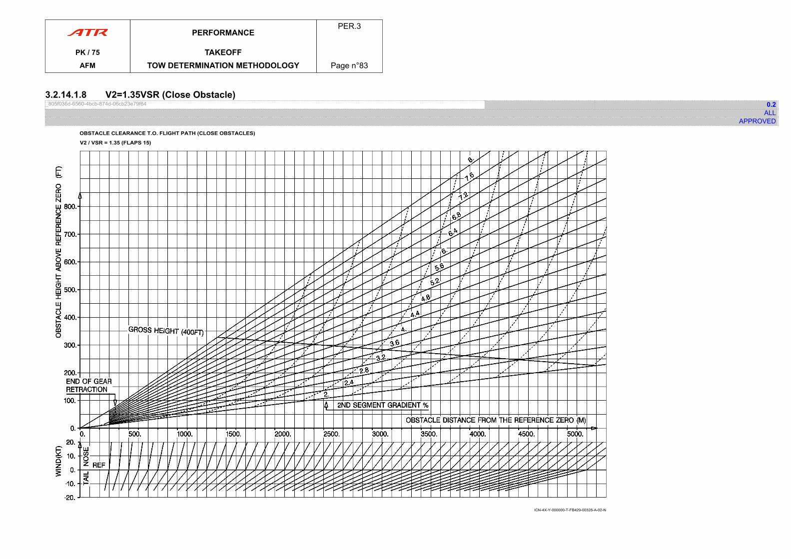
3.2.14.1.8 V2=1.35VSR (Close Obstacle)_805f036d-6560-4bcb-874d-06cb23e79f64 0.2
ALLAPPROVED
OBSTACLE CLEARANCE T.O. FLIGHT PATH (CLOSE OBSTACLES)
V2 / VSR = 1.35 (FLAPS 15)
ICN-4X-Y-000000-T-FB429-00328-A-02-N
PERFORMANCEPER.3
PK / 75 TAKEOFFAFM TOW DETERMINATION METHODOLOGY Page n°83

PAGE
INTENTIONALLY
LEFT BLANK
PERFORMANCEPER.3
PK / 75 TAKEOFFAFM TOW DETERMINATION METHODOLOGY Page n°84

3.2.14.1.9 V2=1.35VSR (Remote Obstacle)_2b68981a-cb55-4595-9909-8c0e23ee94e3 0.2
ALLAPPROVED
OBSTACLE CLEARANCE T.O. FLIGHT PATH (REMOTE OBSTACLES)
V2 / VSR = 1.35 (FLAPS 15)
ICN-4X-Y-000000-T-FB429-00329-A-02-N
PERFORMANCEPER.3
PK / 75 TAKEOFFAFM TOW DETERMINATION METHODOLOGY Page n°85

PAGE
INTENTIONALLY
LEFT BLANK
PERFORMANCEPER.3
PK / 75 TAKEOFFAFM TOW DETERMINATION METHODOLOGY Page n°86
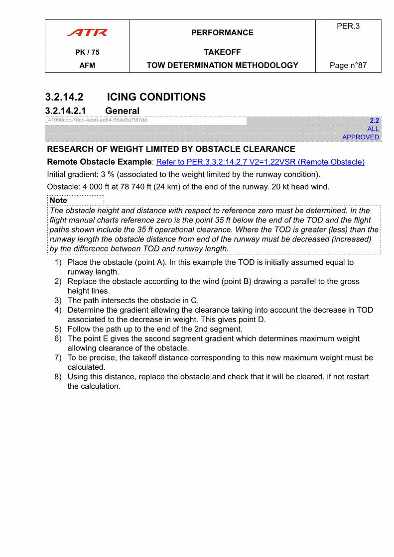
3.2.14.2 ICING CONDITIONS3.2.14.2.1 General_41050cdc-7dce-4eb0-ad64-564e6a79f7dd 2.2
ALLAPPROVED
RESEARCH OF WEIGHT LIMITED BY OBSTACLE CLEARANCERemote Obstacle Example: Refer to PER.3.3.2.14.2.7 V2=1.22VSR (Remote Obstacle)Initial gradient: 3 % (associated to the weight limited by the runway condition).Obstacle: 4 000 ft at 78 740 ft (24 km) of the end of the runway. 20 kt head wind.
NoteThe obstacle height and distance with respect to reference zero must be determined. In theflight manual charts reference zero is the point 35 ft below the end of the TOD and the flightpaths shown include the 35 ft operational clearance. Where the TOD is greater (less) than therunway length the obstacle distance from end of the runway must be decreased (increased)by the difference between TOD and runway length.
1) Place the obstacle (point A). In this example the TOD is initially assumed equal torunway length.
2) Replace the obstacle according to the wind (point B) drawing a parallel to the grossheight lines.
3) The path intersects the obstacle in C.4) Determine the gradient allowing the clearance taking into account the decrease in TOD
associated to the decrease in weight. This gives point D.5) Follow the path up to the end of the 2nd segment.6) The point E gives the second segment gradient which determines maximum weight
allowing clearance of the obstacle.7) To be precise, the takeoff distance corresponding to this new maximum weight must be
calculated.8) Using this distance, replace the obstacle and check that it will be cleared, if not restart
the calculation.
PERFORMANCEPER.3
PK / 75 TAKEOFFAFM TOW DETERMINATION METHODOLOGY Page n°87

PAGE
INTENTIONALLY
LEFT BLANK
PERFORMANCEPER.3
PK / 75 TAKEOFFAFM TOW DETERMINATION METHODOLOGY Page n°88
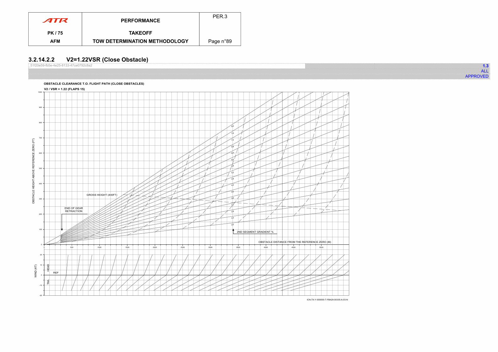
3.2.14.2.2 V2=1.22VSR (Close Obstacle)_51f20e59-fb5e-4e25-8133-47ce0792c8a2 1.3
ALLAPPROVED
OBSTACLE CLEARANCE T.O. FLIGHT PATH (CLOSE OBSTACLES)
V2 / VSR = 1.22 (FLAPS 15)
ICN-7X-Y-000000-T-FB429-00335-A-03-N
-20
-10
0
10
20
0
100
200
300
400
500
600
700
800
900
1000
END OF GEARRETRACTION
GROSS HEIGHT (400FT)
0 500 1000 1500 2000 2500 3000 3500 4000 4500 5000
OBSTACLE DISTANCE FROM THE REFERENCE ZERO (M)
2ND SEGMENT GRADIENT %
REF
PERFORMANCEPER.3
PK / 75 TAKEOFFAFM TOW DETERMINATION METHODOLOGY Page n°89

PAGE
INTENTIONALLY
LEFT BLANK
PERFORMANCEPER.3
PK / 75 TAKEOFFAFM TOW DETERMINATION METHODOLOGY Page n°90
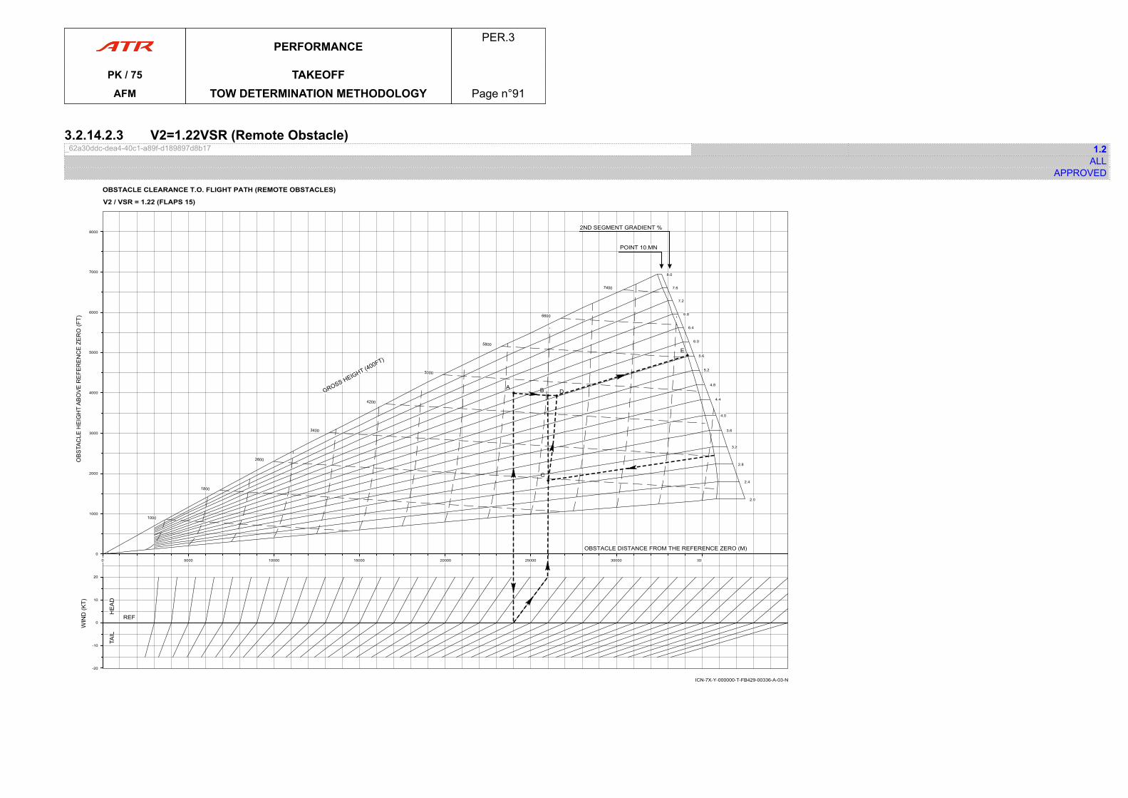
3.2.14.2.3 V2=1.22VSR (Remote Obstacle)_62a30ddc-dea4-40c1-a89f-d189897d8b17 1.2
ALLAPPROVED
OBSTACLE CLEARANCE T.O. FLIGHT PATH (REMOTE OBSTACLES)
V2 / VSR = 1.22 (FLAPS 15)
ICN-7X-Y-000000-T-FB429-00336-A-03-N
2ND SEGMENT GRADIENT %
POINT 10.MN
2.0
2.4
2.8
3.2
3.6
4.0
4.4
4.8
5.2
5.6
6.0
6.4
6.8
7.2
7.6
8.0
-20
-10
0
10
20
REF
0 5000 10000 15000 20000 25000 30000 35000
OBSTACLE DISTANCE FROM THE REFERENCE ZERO (M)
E
DBA
C
0
1000
2000
3000
4000
5000
6000
7000
8000
PERFORMANCEPER.3
PK / 75 TAKEOFFAFM TOW DETERMINATION METHODOLOGY Page n°91

PAGE
INTENTIONALLY
LEFT BLANK
PERFORMANCEPER.3
PK / 75 TAKEOFFAFM TOW DETERMINATION METHODOLOGY Page n°92
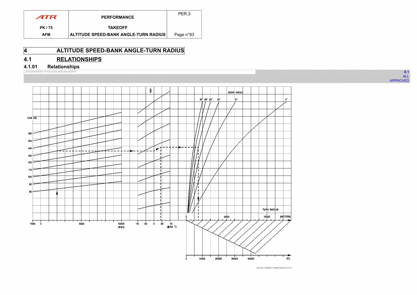
4 ALTITUDE SPEED-BANK ANGLE-TURN RADIUS4.1 RELATIONSHIPS4.1.01 Relationships_81525edf-fd91-4103-b2fa-ec9cebca0434 0.1
ALLAPPROVED
ICN-XX-Y-000000-T-FB429-00345-A-01-N
PERFORMANCEPER.3
PK / 75 TAKEOFFAFM ALTITUDE SPEED-BANK ANGLE-TURN RADIUS Page n°93
PAGE
INTENTIONALLY
LEFT BLANK
PERFORMANCEPER.3
PK / 75 TAKEOFFAFM ALTITUDE SPEED-BANK ANGLE-TURN RADIUS Page n°94
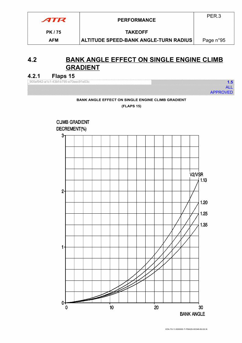
4.2 BANK ANGLE EFFECT ON SINGLE ENGINE CLIMBGRADIENT
4.2.1 Flaps 15_905ef942-a1c1-43bf-b795-e70eec91e03c 1.5
ALLAPPROVED
BANK ANGLE EFFECT ON SINGLE ENGINE CLIMB GRADIENT
(FLAPS 15)
ICN-7X-Y-000000-T-FB429-00346-B-02-N
PERFORMANCEPER.3
PK / 75 TAKEOFFAFM ALTITUDE SPEED-BANK ANGLE-TURN RADIUS Page n°95
1 INTRODUCTION1.01 Introduction_a9cfc7b7-2aee-4568-aa3a-5bcdc3ae7e00 0.1
ALLAPPROVED
The ”En route” gradient given in this chapter are established by decreasing the availablegradient at each point with a margin of 1.1 %.The single engine cruise configuration is FLAPS 0.The speed to be maintained is 1.18 VSR.
The operative engine is set at MCT power.Air conditioning is ON when aircraft is above 10 000 ft.Air conditioning is OFF when aircraft is below 10 000 ft.
PERFORMANCEPER.4
PK / 75 SINGLE ENGINE CRUISEAFM INTRODUCTION Page n°96
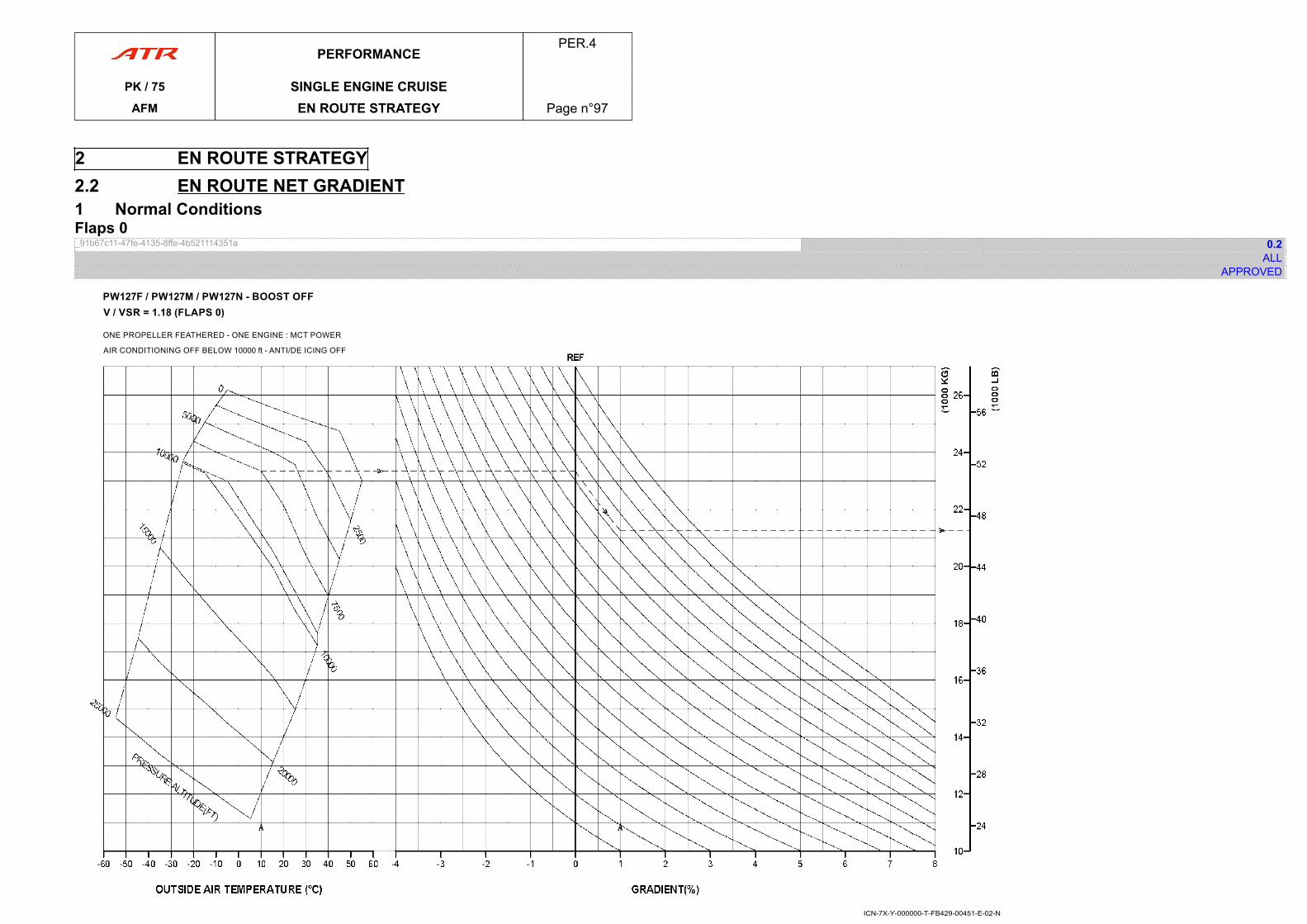
2 EN ROUTE STRATEGY2.2 EN ROUTE NET GRADIENT1 Normal ConditionsFlaps 0_91b67c11-47fe-4135-8ffe-4b521114351a 0.2
ALLAPPROVED
ICN-7X-Y-000000-T-FB429-00451-E-02-N
PERFORMANCEPER.4
PK / 75 SINGLE ENGINE CRUISEAFM EN ROUTE STRATEGY Page n°97

PAGE
INTENTIONALLY
LEFT BLANK
PERFORMANCEPER.4
PK / 75 SINGLE ENGINE CRUISEAFM EN ROUTE STRATEGY Page n°98
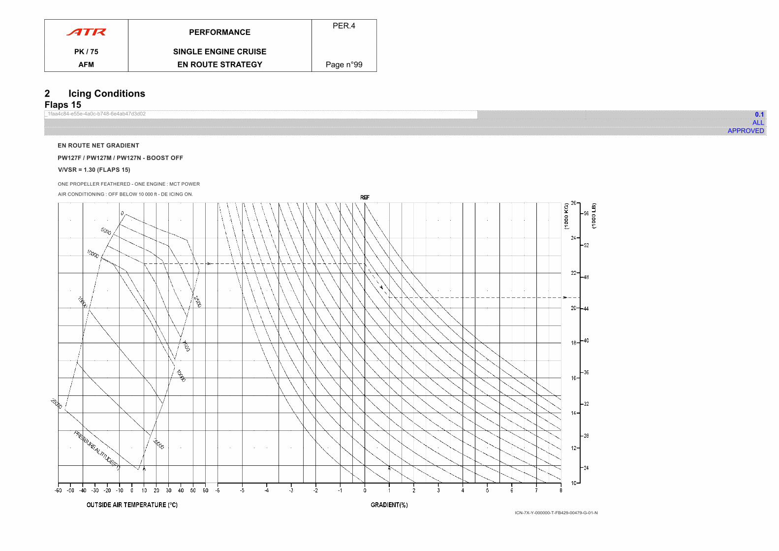
2 Icing ConditionsFlaps 15_1faa4c84-e55e-4a0c-b748-6e4ab47d3d02 0.1
ALLAPPROVED
ICN-7X-Y-000000-T-FB429-00479-G-01-N
PERFORMANCEPER.4
PK / 75 SINGLE ENGINE CRUISEAFM EN ROUTE STRATEGY Page n°99
PAGE
INTENTIONALLY
LEFT BLANK
PERFORMANCEPER.4
PK / 75 SINGLE ENGINE CRUISEAFM EN ROUTE STRATEGY Page n°100
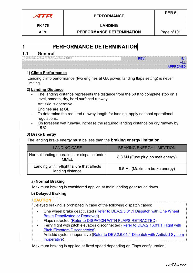
1 PERFORMANCE DETERMINATION1.1 General_ccd08ea4-7426-4f2a-9298-2ca5adac8409 REV 5.1
ALLAPPROVED
1) Climb PerformanceLanding climb performance (two engines at GA power, landing flaps setting) is neverlimiting.
2) Landing Distance- The landing distance represents the distance from the 50 ft to complete stop on a
level, smooth, dry, hard surfaced runway.Antiskid is operative.Engines are at GI.
- To determine the required runway length for landing, apply national operationalregulations.
- On foreseen wet runway, increase the required landing distance on dry runway by15 %.
3) Brake EnergyThe landing brake energy must be less than the braking energy limitation:
LANDING CASE BRAKING ENERGY LIMITATION
Normal landing operations or dispatch underMMEL 8.3 MJ (Fuse plug no melt energy)
Landing with in-flight failure that affectslanding distance 9.5 MJ (Maximum brake energy)
a) Normal BrakingMaximum braking is considered applied at main landing gear touch down.
b) Delayed BrakingCAUTIONDelayed braking is prohibited in case of the following dispatch cases:
- One wheel brake deactivated (Refer to DEV.2.5.01.1 Dispatch with One WheelBrake Deactivated or Removed)
- Flaps retracted (Refer to DISPATCH WITH FLAPS RETRACTED)- Ferry flight with pitch elevators disconnected (Refer to DEV.2.16.01.1 Flight with
Pitch Elevators Disconnected)- Antiskid system inoperative (Refer to DEV.2.6.01.1 Dispatch with Antiskid System
Inoperative)
Maximum braking is applied at fixed speed depending on Flaps configuration:
PERFORMANCEPER.5
PK / 75 LANDINGAFM PERFORMANCE DETERMINATION Page n°101
cont'd…
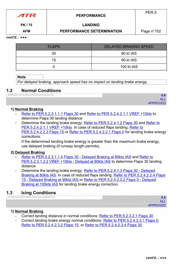
FLAPS DELAYED BRAKING SPEED
30 80 kt IAS
15 90 kt IAS
0 100 kt IAS
NoteFor delayed braking, approach speed has no impact on landing brake energy.
1.2 Normal Conditions_49fdb991-2f14-40cc-913d-b3d1cfacc218 0.6
ALLAPPROVED
1) Normal Braking- Refer to PER.5.2.3.1.1.1 Flaps 30 and Refer to PER.5.2.4.2.1.1 VREF +10kts to
determine Flaps 30 landing distance- Determine the landing brake energy: Refer to PER.5.2.4.1.2 Flaps 30 and Refer to
PER.5.2.4.2.1.1 VREF +10kts. In case of reduced flaps landing, Refer toPER.5.2.4.2.2.3 Flaps 15 or Refer to PER.5.2.4.2.2.1 Flaps 0 for landing brake energycorrections.If the determined landing brake energy is greater than the maximum brake energy,use delayed braking (if runway length permits).
2) Delayed Braking- Refer to PER.5.2.3.1.1.4 Flaps 30 - Delayed Braking at 80kts IAS and Refer to
PER.5.2.3.1.2.2 VREF +10kts - Delayed at 80kts IAS to determine Flaps 30 landingdistance
- Determine the landing brake energy: Refer to PER.5.2.4.1.3 Flaps 30 - DelayedBraking at 80kts IAS. In case of reduced flaps landing, Refer to PER.5.2.4.2.2.4 Flaps15 - Delayed Braking at 90kts IAS or Refer to PER.5.2.4.2.2.2 Flaps 0 - DelayedBraking at 100kts IAS for landing brake energy correction.
1.3 Icing Conditions_d172b12f-c653-4d65-b61a-5a1a7a567417 0.5
ALLAPPROVED
1) Normal Braking- Correct landing distance in normal conditions: Refer to PER.5.2.3.2.1 Flaps 30- Correct landing brake energy normal conditions: Refer to PER.5.2.4.2.3.1 Flaps 0,
Refer to PER.5.2.4.2.3.2 Flaps 15, or Refer to PER.5.2.4.2.3.4 Flaps 30.
PERFORMANCEPER.5
PK / 75 LANDINGAFM PERFORMANCE DETERMINATION Page n°102
cont'd…
cont'd…
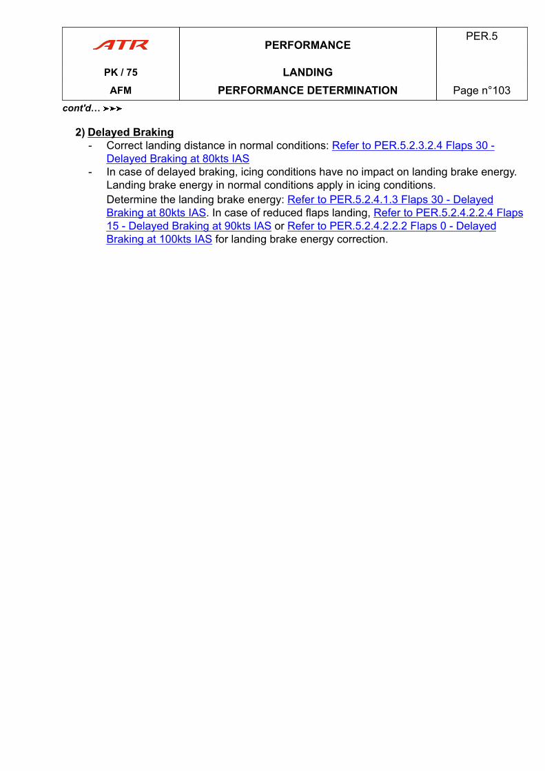
2) Delayed Braking- Correct landing distance in normal conditions: Refer to PER.5.2.3.2.4 Flaps 30 -
Delayed Braking at 80kts IAS- In case of delayed braking, icing conditions have no impact on landing brake energy.
Landing brake energy in normal conditions apply in icing conditions.Determine the landing brake energy: Refer to PER.5.2.4.1.3 Flaps 30 - DelayedBraking at 80kts IAS. In case of reduced flaps landing, Refer to PER.5.2.4.2.2.4 Flaps15 - Delayed Braking at 90kts IAS or Refer to PER.5.2.4.2.2.2 Flaps 0 - DelayedBraking at 100kts IAS for landing brake energy correction.
PERFORMANCEPER.5
PK / 75 LANDINGAFM PERFORMANCE DETERMINATION Page n°103
cont'd…
PAGE
INTENTIONALLY
LEFT BLANK
PERFORMANCEPER.5
PK / 75 LANDINGAFM PERFORMANCE DETERMINATION Page n°104
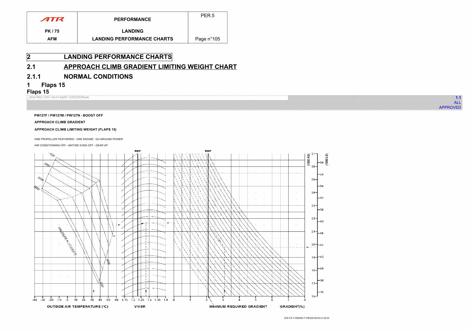
2 LANDING PERFORMANCE CHARTS2.1 APPROACH CLIMB GRADIENT LIMITING WEIGHT CHART2.1.1 NORMAL CONDITIONS1 Flaps 15Flaps 15_c92e78e2-7b51-4a14-8a06-122052926eae 1.1
ALLAPPROVED
ICN-7X-Y-000000-T-FB429-00434-C-02-N
PERFORMANCEPER.5
PK / 75 LANDINGAFM LANDING PERFORMANCE CHARTS Page n°105

PAGE
INTENTIONALLY
LEFT BLANK
PERFORMANCEPER.5
PK / 75 LANDINGAFM LANDING PERFORMANCE CHARTS Page n°106
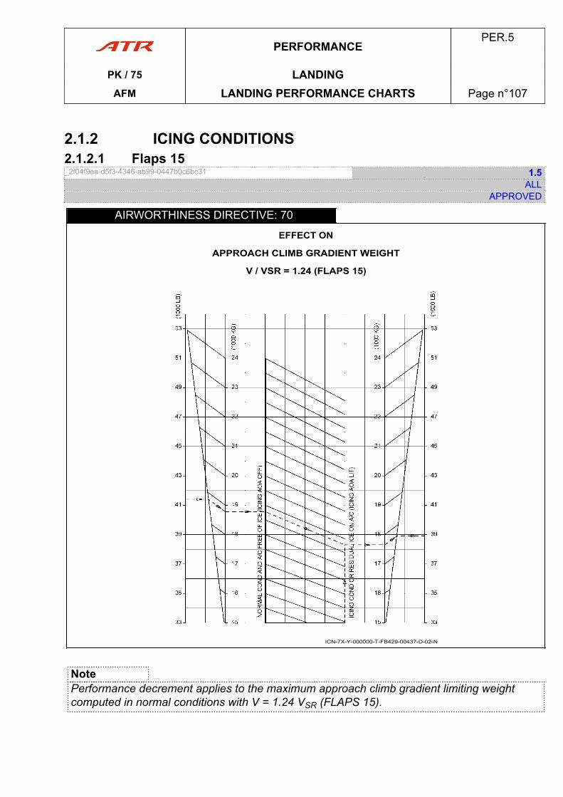
2.1.2 ICING CONDITIONS2.1.2.1 Flaps 15_2f04f9ea-d5f3-4346-ab99-0447b0c6bc31 1.5
ALLAPPROVED
AIRWORTHINESS DIRECTIVE: 70
EFFECT ON
APPROACH CLIMB GRADIENT WEIGHT
V / VSR = 1.24 (FLAPS 15)
ICN-7X-Y-000000-T-FB429-00437-D-02-N
NotePerformance decrement applies to the maximum approach climb gradient limiting weightcomputed in normal conditions with V = 1.24 VSR (FLAPS 15).
PERFORMANCEPER.5
PK / 75 LANDINGAFM LANDING PERFORMANCE CHARTS Page n°107
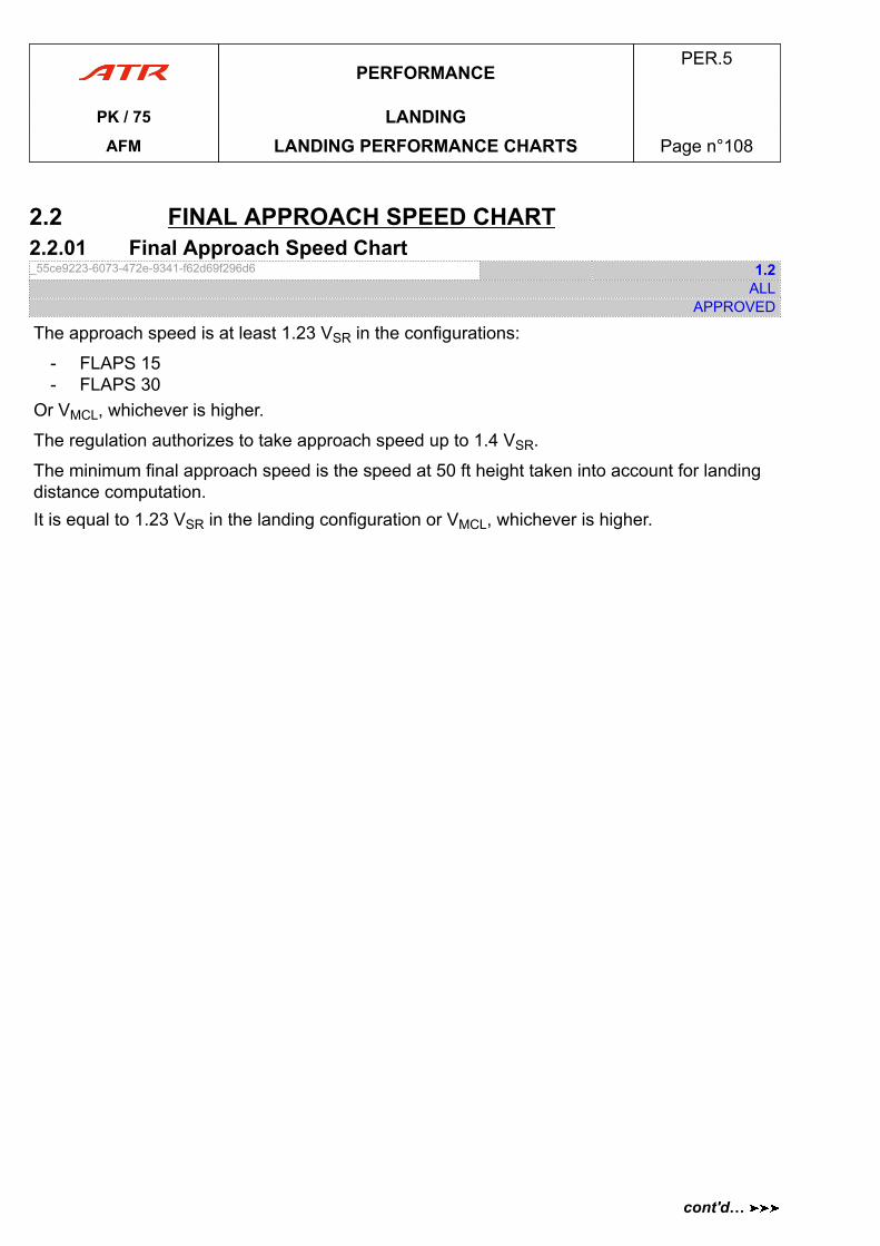
2.2 FINAL APPROACH SPEED CHART2.2.01 Final Approach Speed Chart_55ce9223-6073-472e-9341-f62d69f296d6 1.2
ALLAPPROVED
The approach speed is at least 1.23 VSR in the configurations:
- FLAPS 15- FLAPS 30
Or VMCL, whichever is higher.
The regulation authorizes to take approach speed up to 1.4 VSR.
The minimum final approach speed is the speed at 50 ft height taken into account for landingdistance computation.It is equal to 1.23 VSR in the landing configuration or VMCL, whichever is higher.
PERFORMANCEPER.5
PK / 75 LANDINGAFM LANDING PERFORMANCE CHARTS Page n°108
cont'd…
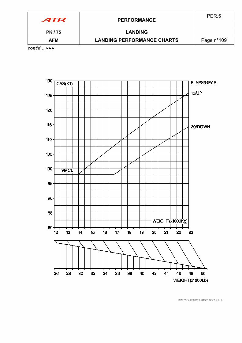
ICN-7X-Y-000000-T-FB429-00439-E-01-N
PERFORMANCEPER.5
PK / 75 LANDINGAFM LANDING PERFORMANCE CHARTS Page n°109
cont'd…

PAGE
INTENTIONALLY
LEFT BLANK
PERFORMANCEPER.5
PK / 75 LANDINGAFM LANDING PERFORMANCE CHARTS Page n°110
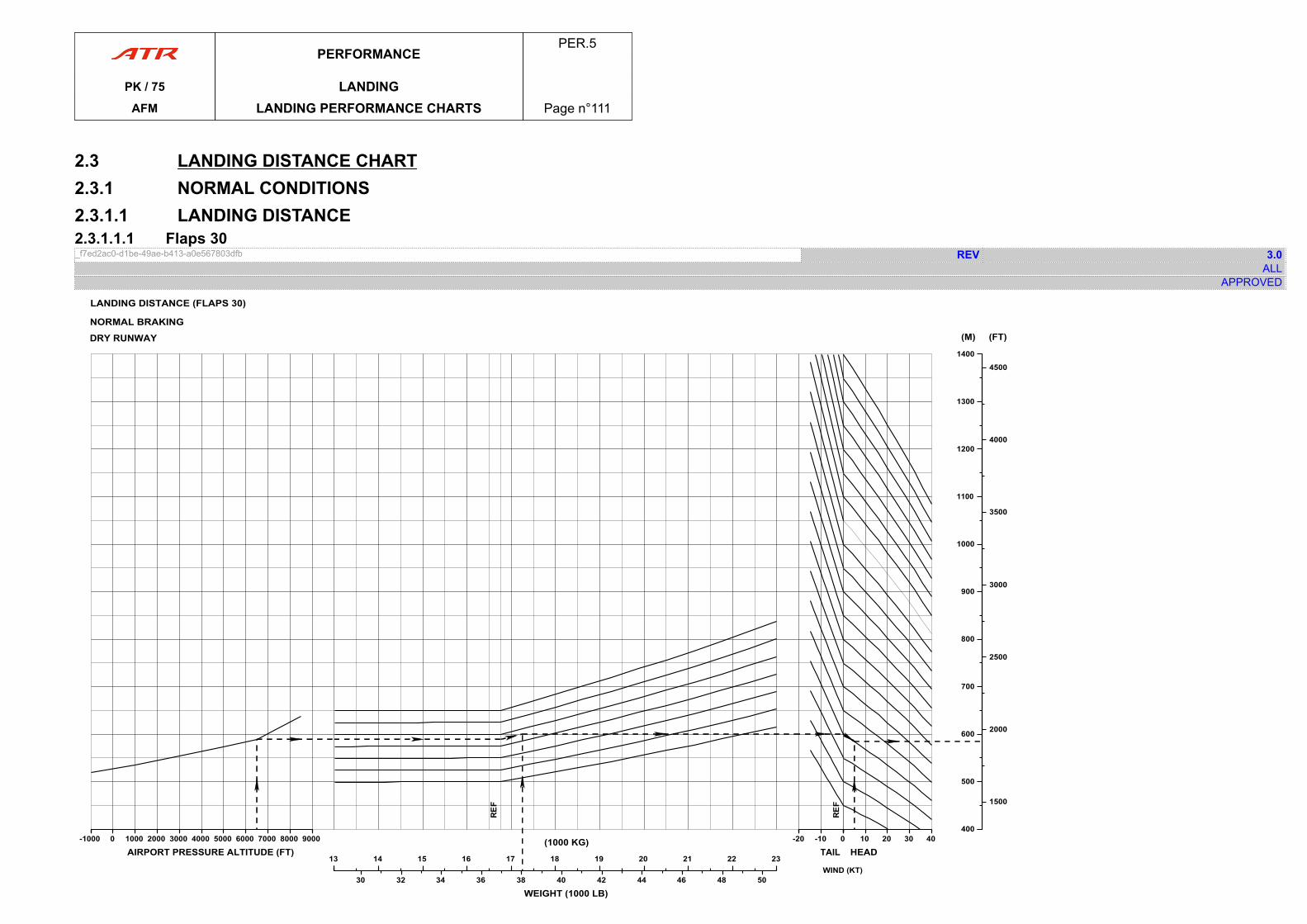
2.3 LANDING DISTANCE CHART2.3.1 NORMAL CONDITIONS2.3.1.1 LANDING DISTANCE2.3.1.1.1 Flaps 30_f7ed2ac0-d1be-49ae-b413-a0e567803dfb REV 3.0
ALLAPPROVED
-1000-1000 0 1000 2000 3000 4000 5000 6000 7000 8000 9000
AIRPORT PRESSURE ALTITUDE (FT)1313 14 15 16 17 18 19 20 21 22 23
(1000 KG)
30 32 34 36 38 40 42 44 46 48 50
WEIGHT (1000 LB)
-20-20 -10 0
TAIL 00 10 20 30 40
HEAD
400400
500
600
700
800
900
1000
1100
1200
1300
1400
(M)
1500
2000
2500
3000
3500
4000
4500
(FT)
WIND (KT)
LANDING DISTANCE (FLAPS 30)
NORMAL BRAKING
DRY RUNWAY
ICN-75-Y-000000-T-FB429-00440-A-0 -N3
PERFORMANCEPER.5
PK / 75 LANDINGAFM LANDING PERFORMANCE CHARTS Page n°111

PAGE
INTENTIONALLY
LEFT BLANK
PERFORMANCEPER.5
PK / 75 LANDINGAFM LANDING PERFORMANCE CHARTS Page n°112
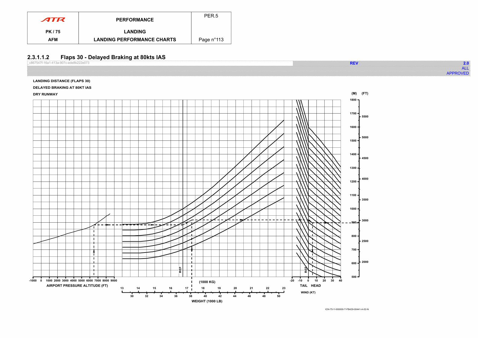
2.3.1.1.2 Flaps 30 - Delayed Braking at 80kts IAS_c867547f-16a1-413a-907c-ede8b222e073 REV 2.0
ALLAPPROVED
LANDING DISTANCE (FLAPS 30)
DELAYED BRAKING AT 80KT IAS
DRY RUNWAY
ICN-75-Y-000000-T-FB429-00441-A-02-N
-1000-1000 0 1000 2000 3000 4000 5000 6000 7000 8000 9000
AIRPORT PRESSURE ALTITUDE (FT)1313 14 15 16 17 18 19 20 21 22 23
(1000 KG)
30 32 34 36 38 40 42 44 46 48 50
WEIGHT (1000 LB)
-20-20 -10 0
TAIL 00 10 20 30 40
HEAD
500500
600
700
800
900
1000
1100
1200
1300
1400
1500
1600
1700
1800
(M)
2000
2500
3000
3500
4000
4500
5000
5500
(FT)
WIND (KT)
PERFORMANCEPER.5
PK / 75 LANDINGAFM LANDING PERFORMANCE CHARTS Page n°113

PAGE
INTENTIONALLY
LEFT BLANK
PERFORMANCEPER.5
PK / 75 LANDINGAFM LANDING PERFORMANCE CHARTS Page n°114
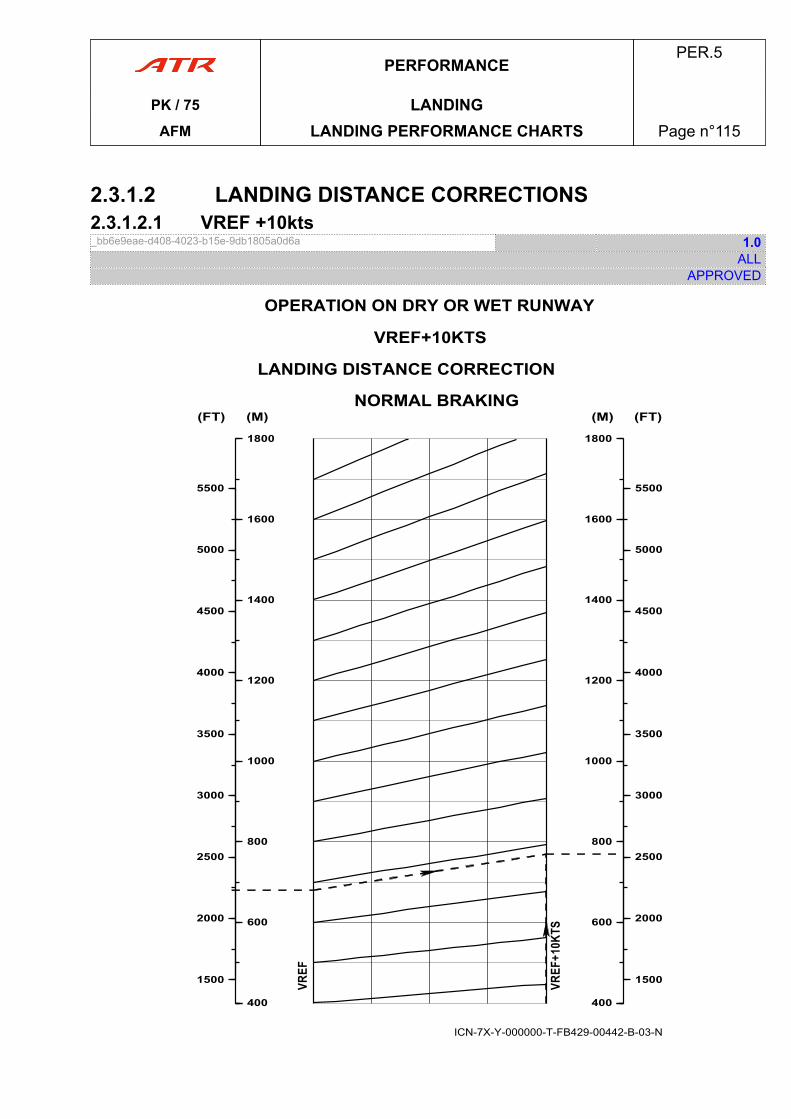
2.3.1.2 LANDING DISTANCE CORRECTIONS2.3.1.2.1 VREF +10kts_bb6e9eae-d408-4023-b15e-9db1805a0d6a 1.0
ALLAPPROVED
400400
600
800
1000
1200
1400
1600
1800
(M)
1500
2000
2500
3000
3500
4000
4500
5000
5500
(FT)
400400
600
800
1000
1200
1400
1600
1800
(M)
1500
2000
2500
3000
3500
4000
4500
5000
5500
(FT)
OPERATION ON DRY OR WET RUNWAY
VREF+10KTS
LANDING DISTANCE CORRECTION
NORMAL BRAKING
ICN-7X-Y-000000-T-FB429-00442-B-03-N
PERFORMANCEPER.5
PK / 75 LANDINGAFM LANDING PERFORMANCE CHARTS Page n°115
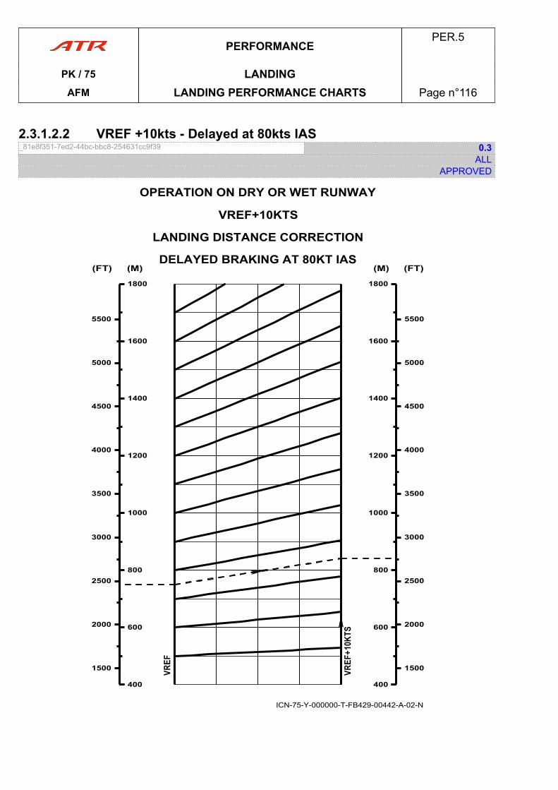
2.3.1.2.2 VREF +10kts - Delayed at 80kts IAS_81e8f351-7ed2-44bc-bbc8-254631cc9f39 0.3
ALLAPPROVED
OPERATION ON DRY OR WET RUNWAY
VREF+10KTS
LANDING DISTANCE CORRECTION
DELAYED BRAKING AT 80KT IAS
ICN-75-Y-000000-T-FB429-00442-A-02-N
400400
600
800
1000
1200
1400
1600
1800
(M)
1500
2000
2500
3000
3500
4000
4500
5000
5500
(FT)
400400
600
800
1000
1200
1400
1600
1800
(M)
1500
2000
2500
3000
3500
4000
4500
5000
5500
(FT)
PERFORMANCEPER.5
PK / 75 LANDINGAFM LANDING PERFORMANCE CHARTS Page n°116
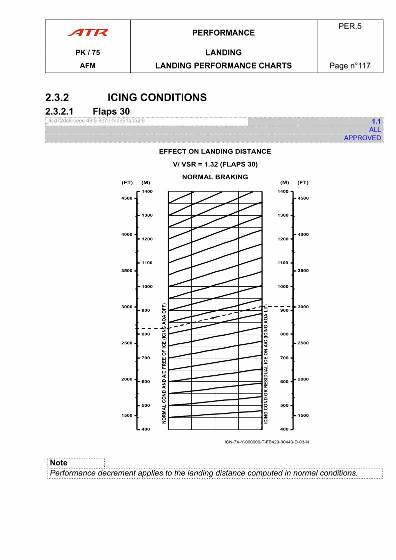
2.3.2 ICING CONDITIONS2.3.2.1 Flaps 30_4cd72dc6-ceec-49f5-9e7e-fea961ab52f9 1.1
ALLAPPROVED
400400
500
600
700
800
900
1000
1100
1200
1300
1400
(M)
1500
2000
2500
3000
3500
4000
4500
(FT)
400400
500
600
700
800
900
1000
1100
1200
1300
1400
(M)
1500
2000
2500
3000
3500
4000
4500
(FT)
EFFECT ON LANDING DISTANCE
V/ VSR = 1.32 (FLAPS 30)
NORMAL BRAKING
ICN-7X-Y-000000-T-FB429-00443-D-03-N
NotePerformance decrement applies to the landing distance computed in normal conditions.
PERFORMANCEPER.5
PK / 75 LANDINGAFM LANDING PERFORMANCE CHARTS Page n°117
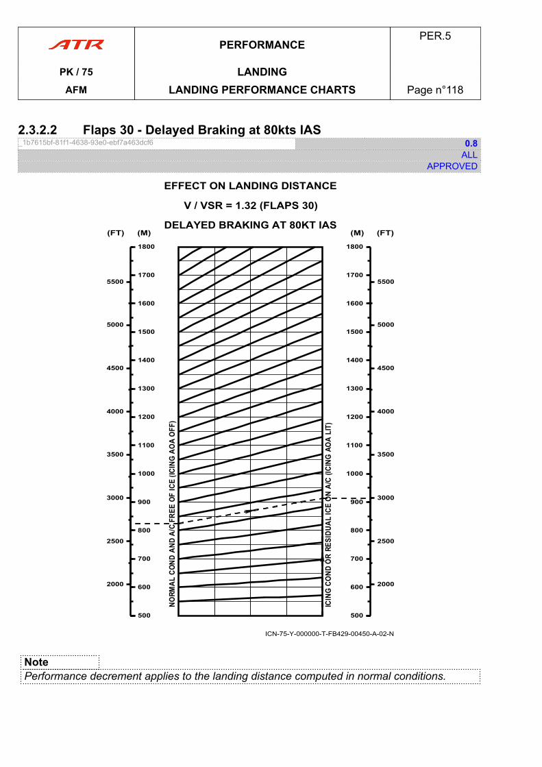
2.3.2.2 Flaps 30 - Delayed Braking at 80kts IAS_1b7615bf-81f1-4638-93e0-ebf7a463dcf6 0.8
ALLAPPROVED
ICN-75-Y-000000-T-FB429-00450-A-02-N
EFFECT ON LANDING DISTANCE
V / VSR = 1.32 (FLAPS 30)
DELAYED BRAKING AT 80KT IAS
500500
600
700
800
900
1000
1100
1200
1300
1400
1500
1600
1700
1800
(M)
2000
2500
3000
3500
4000
4500
5000
5500
(FT)
500500
600
700
800
900
1000
1100
1200
1300
1400
1500
1600
1700
1800
(M)
2000
2500
3000
3500
4000
4500
5000
5500
(FT)
NotePerformance decrement applies to the landing distance computed in normal conditions.
PERFORMANCEPER.5
PK / 75 LANDINGAFM LANDING PERFORMANCE CHARTS Page n°118
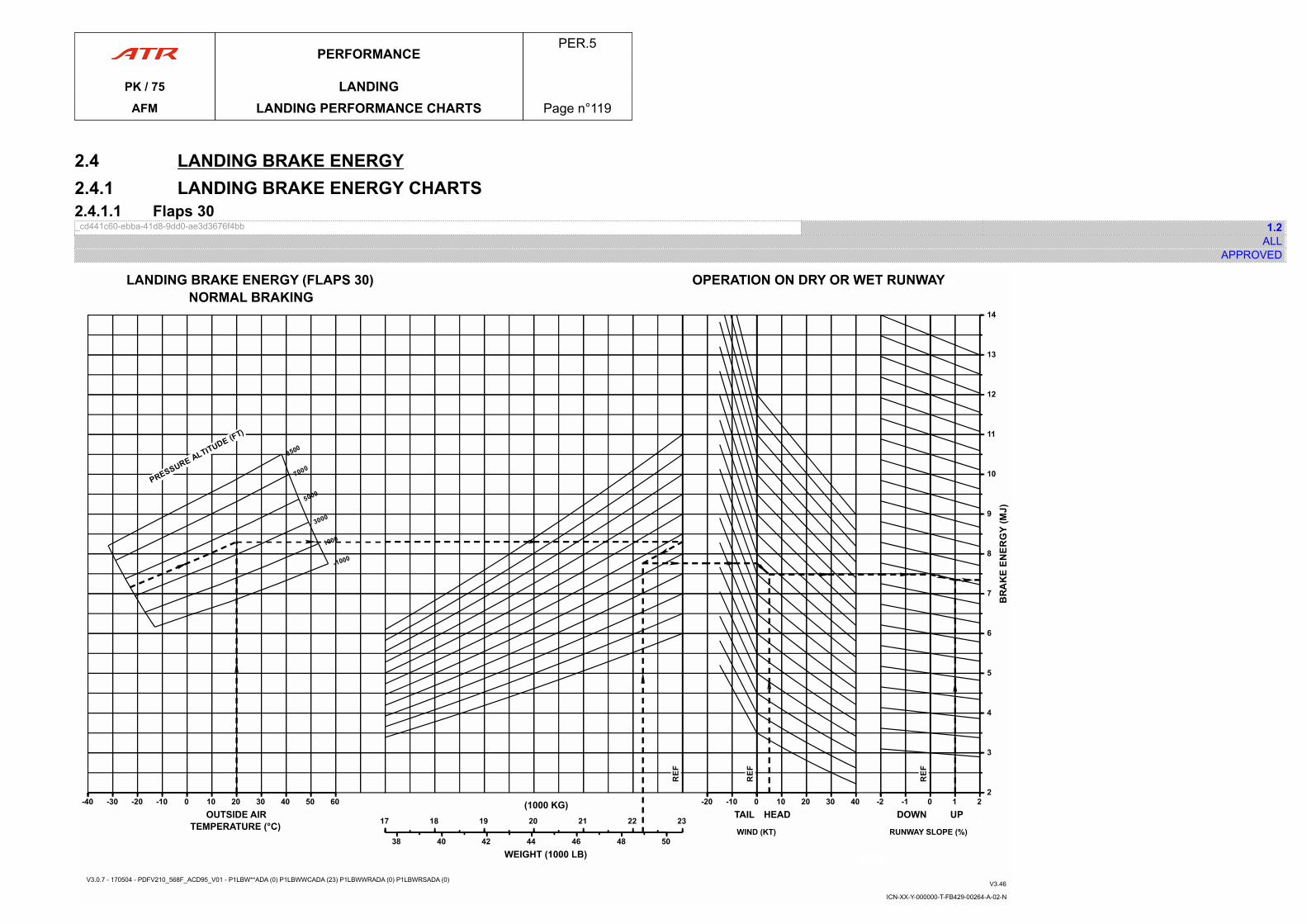
2.4 LANDING BRAKE ENERGY2.4.1 LANDING BRAKE ENERGY CHARTS2.4.1.1 Flaps 30_cd441c60-ebba-41d8-9dd0-ae3d3676f4bb 1.2
ALLAPPROVED
ICN-XX-Y-000000-T-FB429-00264-A-02-N
V3.0.7 - 170504 - PDFV210_568F_ACD95_V01 - P1LBW**ADA (0) P1LBWWCADA (23) P1LBWWRADA (0) P1LBWRSADA (0) V3.46
PERFORMANCEPER.5
PK / 75 LANDINGAFM LANDING PERFORMANCE CHARTS Page n°119
PAGE
INTENTIONALLY
LEFT BLANK
PERFORMANCEPER.5
PK / 75 LANDINGAFM LANDING PERFORMANCE CHARTS Page n°120
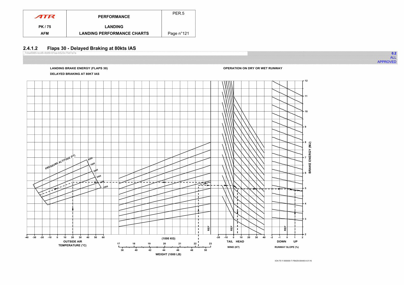
2.4.1.2 Flaps 30 - Delayed Braking at 80kts IAS_7cba5985-bcd8-4b89-97ea-b523c75d7a7a 0.2
ALLAPPROVED
LANDING BRAKE ENERGY (FLAPS 30)
DELAYED BRAKING AT 80KT IAS
ICN-75-Y-000000-T-FB429-00449-A-01-N
OPERATION ON DRY OR WET RUNWAY
-40-40 -30 -20 -10 0 10 20 30 40 50 60
OUTSIDE AIRTEMPERATURE (°C) 1717 18 19 20 21 22 23
(1000 KG)
38 40 42 44 46 48 50
WEIGHT (1000 LB)
-20-20 -10 0
TAIL 00 10 20 30 40
HEAD
WIND (KT)
-2-2 -1 0 1 2
DOWN UP
22
3
4
5
6
7
8
9
10
11
12
RUNWAY SLOPE (%)
PERFORMANCEPER.5
PK / 75 LANDINGAFM LANDING PERFORMANCE CHARTS Page n°121

PAGE
INTENTIONALLY
LEFT BLANK
PERFORMANCEPER.5
PK / 75 LANDINGAFM LANDING PERFORMANCE CHARTS Page n°122
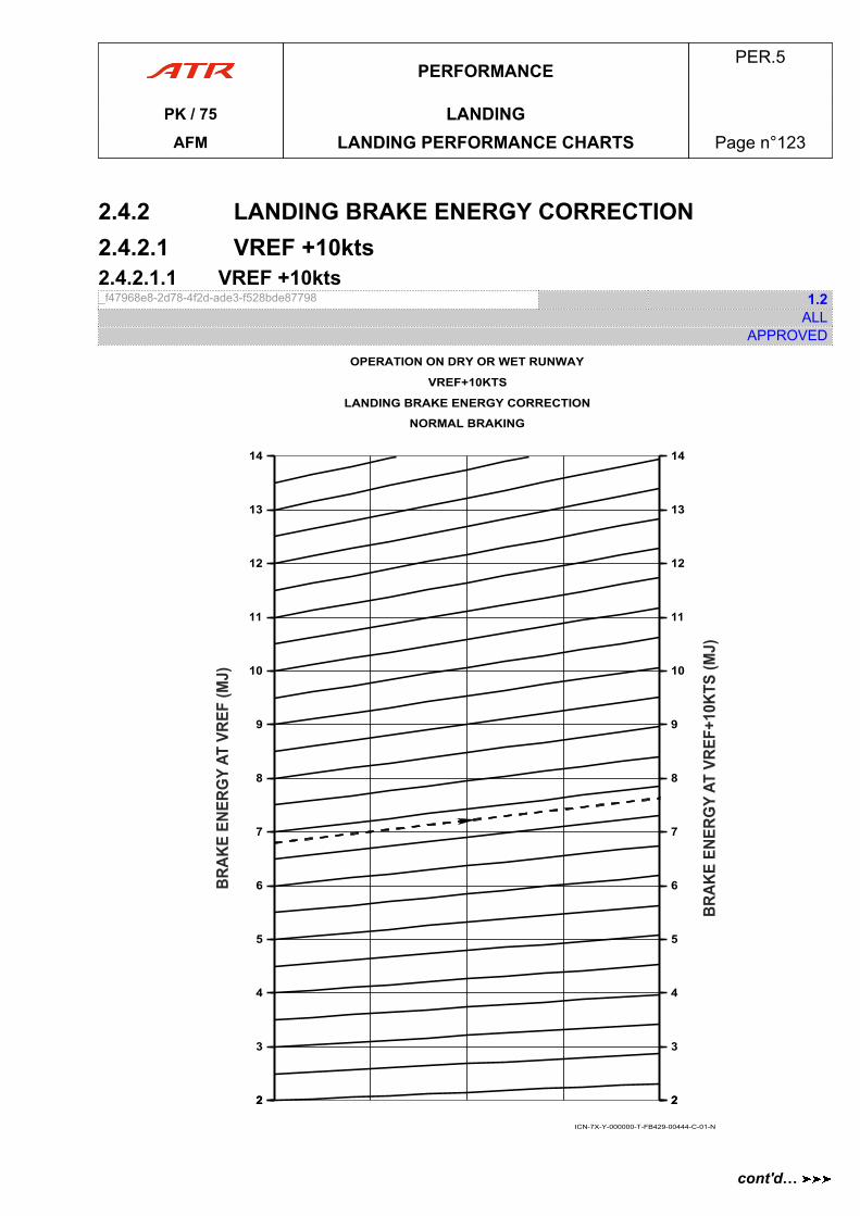
2.4.2 LANDING BRAKE ENERGY CORRECTION2.4.2.1 VREF +10kts2.4.2.1.1 VREF +10kts_f47968e8-2d78-4f2d-ade3-f528bde87798 1.2
ALLAPPROVED
OPERATION ON DRY OR WET RUNWAY
VREF+10KTS
LANDING BRAKE ENERGY CORRECTION
NORMAL BRAKING
22
3
4
5
6
7
8
9
10
11
12
13
14
22
3
4
5
6
7
8
9
10
11
12
13
14
ICN-7X-Y-000000-T-FB429-00444-C-01-N
PERFORMANCEPER.5
PK / 75 LANDINGAFM LANDING PERFORMANCE CHARTS Page n°123
cont'd…
NoteApproach speed has no impact on landing brake energy in case of delayed braking.
PERFORMANCEPER.5
PK / 75 LANDINGAFM LANDING PERFORMANCE CHARTS Page n°124
cont'd…
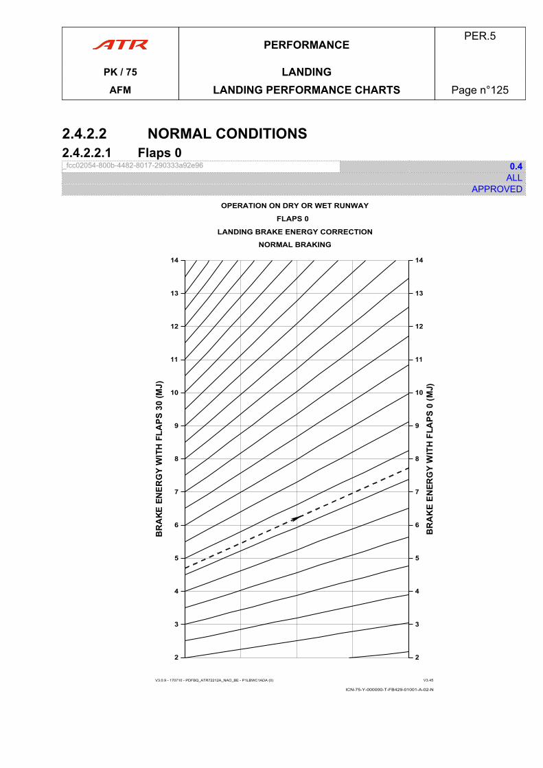
2.4.2.2 NORMAL CONDITIONS2.4.2.2.1 Flaps 0_fcc02054-800b-4482-8017-290333a92e96 0.4
ALLAPPROVED
ICN-75-Y-000000-T-FB429-01001-A-02-N
OPERATION ON DRY OR WET RUNWAY
FLAPS 0
LANDING BRAKE ENERGY CORRECTION
V3.0.9 - 170710 - PDFBQ_ATR72212A_NAO_BE - P1LBWC1ADA (0) V3.45
NORMAL BRAKING
22
3
4
5
6
7
8
9
10
11
12
13
14
22
3
4
5
6
7
8
9
10
11
12
13
14
PERFORMANCEPER.5
PK / 75 LANDINGAFM LANDING PERFORMANCE CHARTS Page n°125
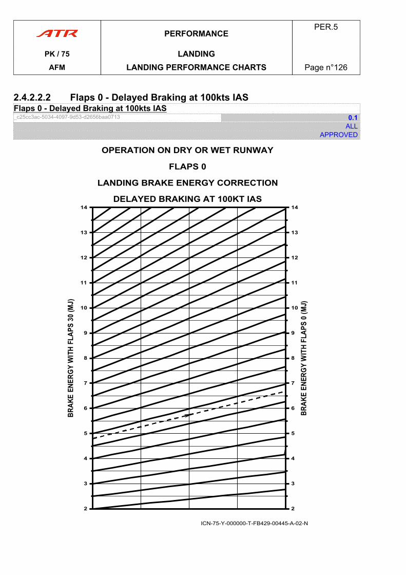
2.4.2.2.2 Flaps 0 - Delayed Braking at 100kts IASFlaps 0 - Delayed Braking at 100kts IAS_c25cc3ac-5034-4097-9d53-d2656baa0713 0.1
ALLAPPROVED
OPERATION ON DRY OR WET RUNWAY
FLAPS 0
LANDING BRAKE ENERGY CORRECTION
DELAYED BRAKING AT 100KT IAS
ICN-75-Y-000000-T-FB429-00445-A-02-N
22
3
4
5
6
7
8
9
10
11
12
13
14
22
3
4
5
6
7
8
9
10
11
12
13
14
PERFORMANCEPER.5
PK / 75 LANDINGAFM LANDING PERFORMANCE CHARTS Page n°126
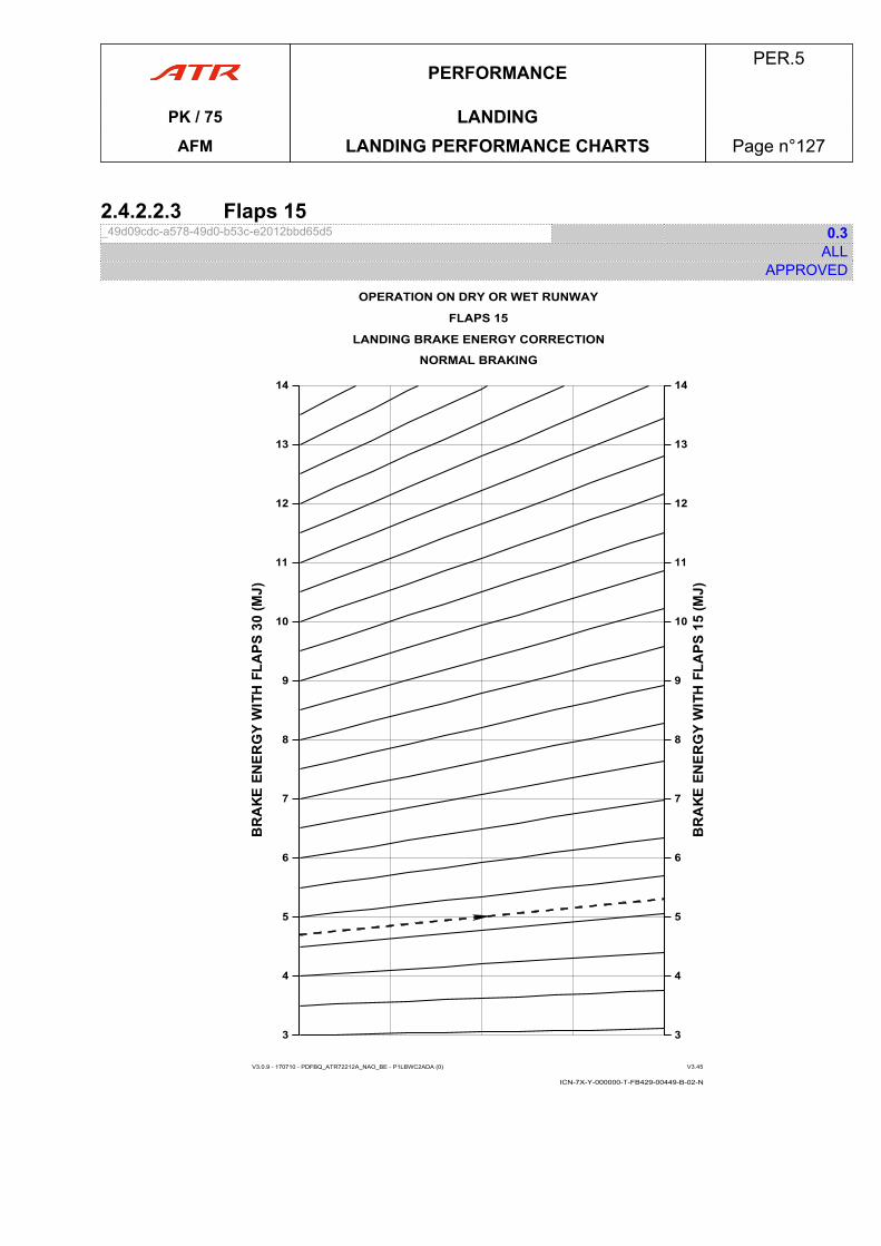
2.4.2.2.3 Flaps 15_49d09cdc-a578-49d0-b53c-e2012bbd65d5 0.3
ALLAPPROVED
ICN-7X-Y-000000-T-FB429-00449-B-02-N
OPERATION ON DRY OR WET RUNWAY
FLAPS 15
LANDING BRAKE ENERGY CORRECTION
V3.0.9 - 170710 - PDFBQ_ATR72212A_NAO_BE - P1LBWC2ADA (0) V3.45
33
4
5
6
7
8
9
10
11
12
13
14
33
4
5
6
7
8
9
10
11
12
13
14
NORMAL BRAKING
PERFORMANCEPER.5
PK / 75 LANDINGAFM LANDING PERFORMANCE CHARTS Page n°127

2.4.2.2.4 Flaps 15 - Delayed Braking at 90kts IASFlaps 15 - Delayed Braking at 90kts IAS_5286c3af-4dc2-4cce-a508-de3952adbcd4 0.1
ALLAPPROVED
OPERATION ON DRY OR WET RUNWAY
FLAPS 15
LANDING BRAKE ENERGY CORRECTION
DELAYED BRAKING AT 90KT IAS
ICN-75-Y-000000-T-FB429-00443-A-02-N
22
3
4
5
6
7
8
9
10
11
12
13
14
22
3
4
5
6
7
8
9
10
11
12
13
14
PERFORMANCEPER.5
PK / 75 LANDINGAFM LANDING PERFORMANCE CHARTS Page n°128
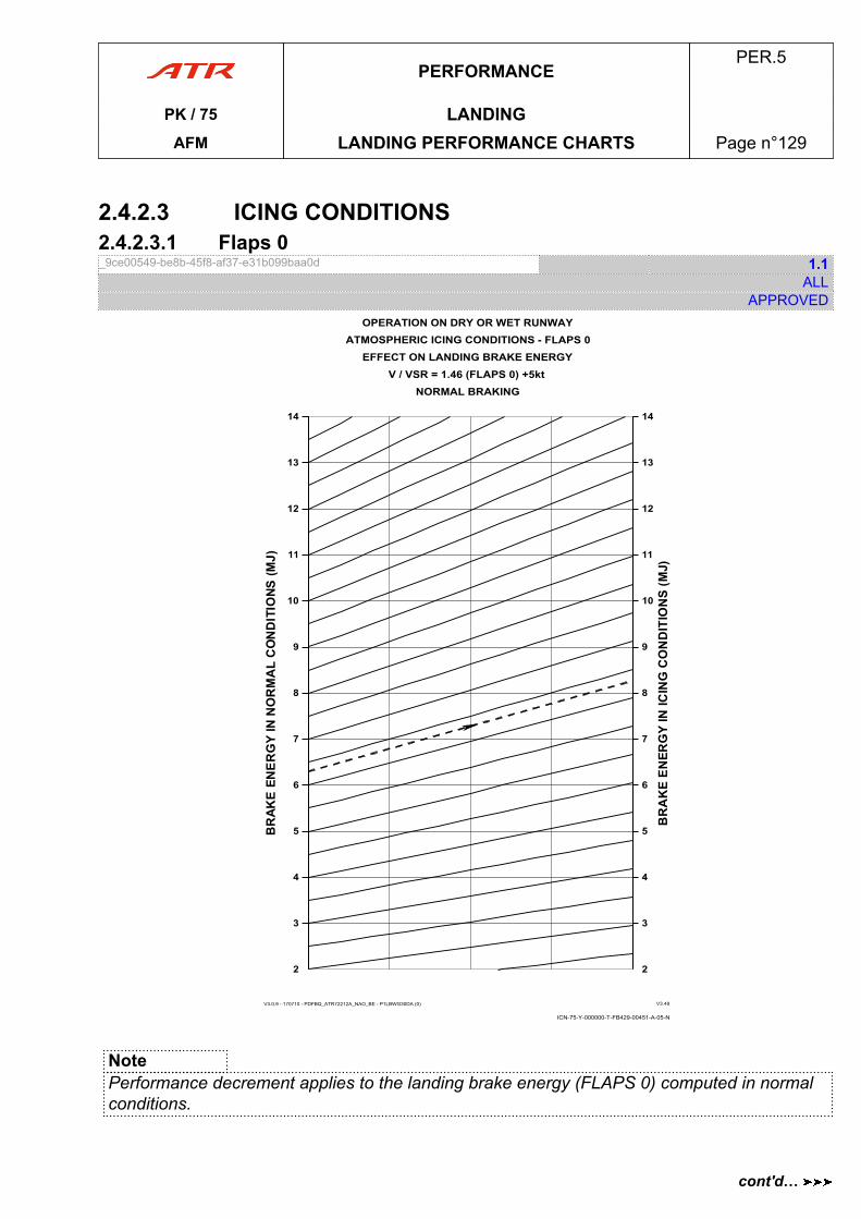
2.4.2.3 ICING CONDITIONS2.4.2.3.1 Flaps 0_9ce00549-be8b-45f8-af37-e31b099baa0d 1.1
ALLAPPROVED
V3.0.9 - 170710 - PDFBQ_ATR72212A_NAO_BE - P1LBWG30DA (0) V3.48
ICN-75-Y-000000-T-FB429-00451-A-05-N
OPERATION ON DRY OR WET RUNWAYATMOSPHERIC ICING CONDITIONS - FLAPS 0
EFFECT ON LANDING BRAKE ENERGYV / VSR = 1.46 (FLAPS 0) +5kt
NORMAL BRAKING
22
3
4
5
6
7
8
9
10
11
12
13
14
22
3
4
5
6
7
8
9
10
11
12
13
14
NotePerformance decrement applies to the landing brake energy (FLAPS 0) computed in normalconditions.
PERFORMANCEPER.5
PK / 75 LANDINGAFM LANDING PERFORMANCE CHARTS Page n°129
cont'd…

NoteIcing conditions have no impact on landing brake energy in case of delayed braking.
PERFORMANCEPER.5
PK / 75 LANDINGAFM LANDING PERFORMANCE CHARTS Page n°130
cont'd…
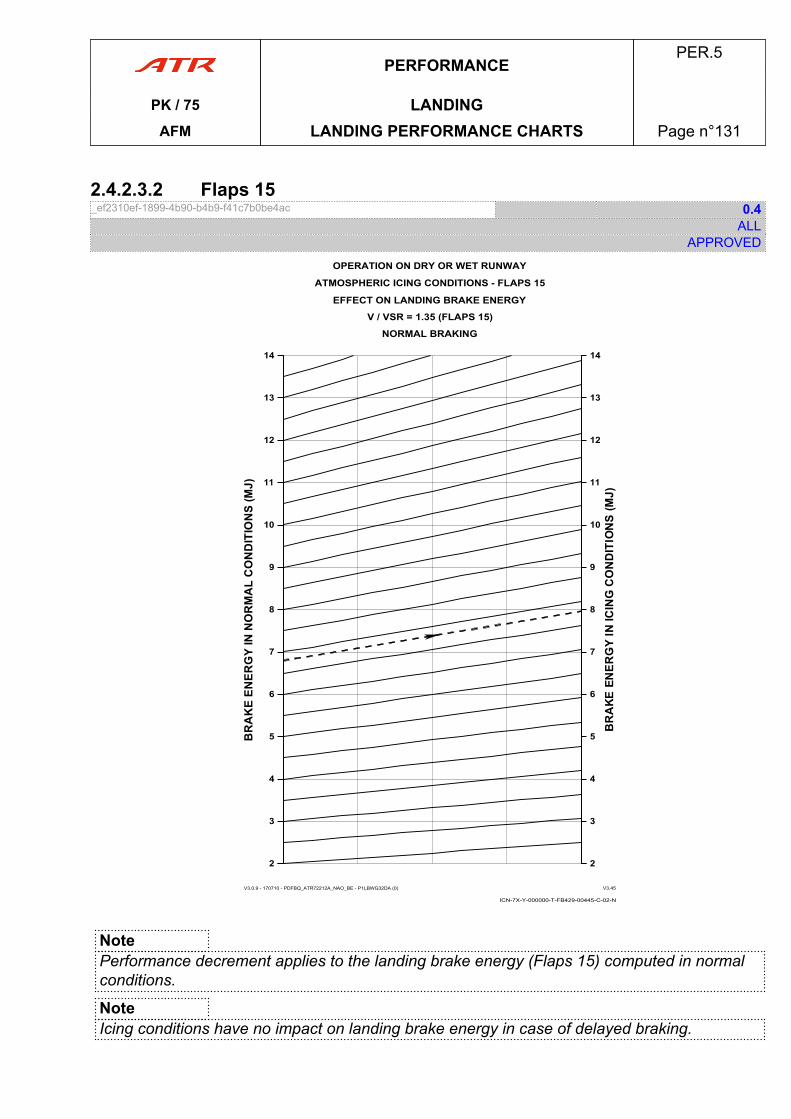
2.4.2.3.2 Flaps 15_ef2310ef-1899-4b90-b4b9-f41c7b0be4ac 0.4
ALLAPPROVED
ICN-7X-Y-000000-T-FB429-00445-C-02-N
OPERATION ON DRY OR WET RUNWAY
ATMOSPHERIC ICING CONDITIONS - FLAPS 15
EFFECT ON LANDING BRAKE ENERGY
V3.0.9 - 170710 - PDFBQ_ATR72212A_NAO_BE - P1LBWG32DA (0) V3.45
V / VSR = 1.35 (FLAPS 15)
22
3
4
5
6
7
8
9
10
11
12
13
14
22
3
4
5
6
7
8
9
10
11
12
13
14
NORMAL BRAKING
NotePerformance decrement applies to the landing brake energy (Flaps 15) computed in normalconditions.
NoteIcing conditions have no impact on landing brake energy in case of delayed braking.
PERFORMANCEPER.5
PK / 75 LANDINGAFM LANDING PERFORMANCE CHARTS Page n°131
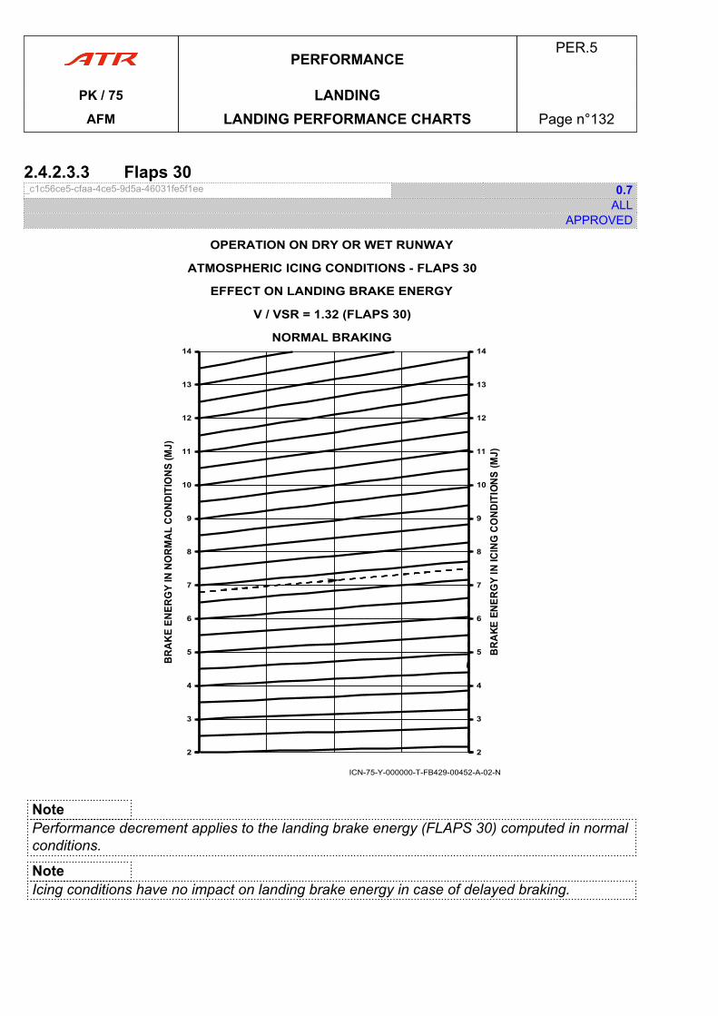
2.4.2.3.3 Flaps 30_c1c56ce5-cfaa-4ce5-9d5a-46031fe5f1ee 0.7
ALLAPPROVED
ICN-75-Y-000000-T-FB429-00452-A-02-N
OPERATION ON DRY OR WET RUNWAY
ATMOSPHERIC ICING CONDITIONS - FLAPS 30
EFFECT ON LANDING BRAKE ENERGY
V / VSR = 1.32 (FLAPS 30)
22
3
4
5
6
7
8
9
10
11
12
13
14
22
3
4
5
6
7
8
9
10
11
12
13
14NORMAL BRAKING
NotePerformance decrement applies to the landing brake energy (FLAPS 30) computed in normalconditions.
NoteIcing conditions have no impact on landing brake energy in case of delayed braking.
PERFORMANCEPER.5
PK / 75 LANDINGAFM LANDING PERFORMANCE CHARTS Page n°132
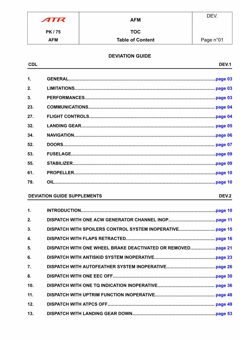
DEVIATION GUIDECDL DEV.1
1. GENERAL..........................................................................................................page 03
2. LIMITATIONS..................................................................................................... page 03
3. PERFORMANCES..............................................................................................page 03
23. COMMUNICATIONS........................................................................................... page 04
27. FLIGHT CONTROLS...........................................................................................page 04
32. LANDING GEAR................................................................................................ page 05
34. NAVIGATION......................................................................................................page 06
52. DOORS............................................................................................................. page 07
53. FUSELAGE........................................................................................................page 09
55. STABILIZER.......................................................................................................page 09
61. PROPELLER......................................................................................................page 10
79. OIL....................................................................................................................page 10
DEVIATION GUIDE SUPPLEMENTS DEV.2
1. INTRODUCTION.................................................................................................page 10
2. DISPATCH WITH ONE ACW GENERATOR CHANNEL INOP..................................page 11
3. DISPATCH WITH SPOILERS CONTROL SYSTEM INOPERATIVE.......................... page 15
4. DISPATCH WITH FLAPS RETRACTED................................................................ page 16
5. DISPATCH WITH ONE WHEEL BRAKE DEACTIVATED OR REMOVED..................page 21
6. DISPATCH WITH ANTISKID SYSTEM INOPERATIVE............................................page 23
7. DISPATCH WITH AUTOFEATHER SYSTEM INOPERATIVE................................... page 26
8. DISPATCH WITH ONE EEC OFF..........................................................................page 30
10. DISPATCH WITH ONE TQ INDICATION INOPERATIVE......................................... page 36
11. DISPATCH WITH UPTRIM FUNCTION INOPERATIVE........................................... page 48
12. DISPATCH WITH ATPCS OFF............................................................................. page 49
13. DISPATCH WITH LANDING GEAR DOWN............................................................page 53
AFMDEV.
PK / 75 TOCAFM Table of Content Page n°01
16. FLIGHT WITH PITCH ELEVATORS DISCONNECTED............................................page 56
AFMDEV.
PK / 75 TOCAFM Table of Content Page n°02
1 GENERAL1.01 General_ef2d04fd-9a87-45a4-889c-21cb9e7ad667 3.2
ALLAPPROVED
Dispatch of the aircraft with some secondary airframe missing parts is possible as indicated inthis Configuration Deviation List (CDL). Any part not included in this list must be considered asnecessary.Repairs or replacements must be done at the first station where they can reasonably be made,as additional deviations may require the aircraft not to be used as revenue service.The value in the “NI” column indicates the number of installed parts. A Dash “-” symbolindicates a variable quantity installed on the aircraft.The value in the “NR” column specifies the minimum quantity of parts that must be installed fora CDL dispatch, under the conditions listed in the dispatch conditions. A Dash “-” symbolindicates a variable quantity, minimal required for the dispatch of the aircraft.A “YES” in the “M” column indicates that a maintenance procedure must be performed in orderto enable the dispatch of the aircraft. Refer to the related section of the Maintenance Manualfor this information.
2 LIMITATIONS2.01 Limitations_f3d45008-f99d-4c3e-abe3-81e4e2a8771d 2.1
ALLAPPROVED
Dispatch is prohibited with more than two (2) missing CDL items.No more than one (1) item per ATA chapter in this CDL may be missing unless specificdedicated combinations are indicated (Except static dischargers that are not to be accountedfor in both limitations).When missing part introduces additional limitation, this limitation is indicated in the dispatchconditions. This limitation comes in addition to limitations of Flight Manual. It must be clearlyindicated by a placard.
3 PERFORMANCES3.01 Performances_65bff441-bb6b-46f2-a09a-b1b10442b64b 2.1
ALLAPPROVED
Performance penalties, if any, are indicated in the dispatch conditions.Performance penalties are cumulative unless specific penalties for particular combinations ofmissing parts are indicated.These takeoff, en route, and landing penalties apply to the most limiting corresponding weight.
DEVIATION GUIDEDEV.1
PK / 75 CDLAFM GENERAL Page n°03

23 COMMUNICATIONS23.01 Static Dischargers_e8e93f6f-fda3-46aa-b123-0b8ef4e27e97 0.1
ALLAPPROVED
NI NR PLACARD M25 17 NO NO
Any in excess of 17 may be missing provided that:(a) Each aileron is equipped with at least 4 operative static dischargers, and(b) Rudder is equipped with at least 4 operative static dischargers, and(c) Each elevator is equipped with at least 2 operative static dischargers, and(d) Tail cone is equipped with at least 1 operative static discharger.
27 FLIGHT CONTROLS27.01 Flap Hinge Fairing_c3892664-58b4-4122-9029-22854238ec01 0.1
ALLAPPROVED
NI NR PLACARD M8 6 NO NO
One or two may be missing provided that:(a) Aircraft is not operated into known or forecast icing conditions, and(b) Only one fairing may be missing per half wing (left and right), and(c) In case of FWD part of the fairing missing, it is necessary to remove aft
parts of the fairing at the same location.
27.02 Flap Lower Surface Trailing Edge_235aa040-de56-45a1-851e-74fcc3472c37 REV 1.1
ALLAPPROVED
NI NR PLACARD M10 9 NO NO
One may be missing.
DEVIATION GUIDEDEV.1
PK / 75 CDLAFM COMMUNICATIONS Page n°04
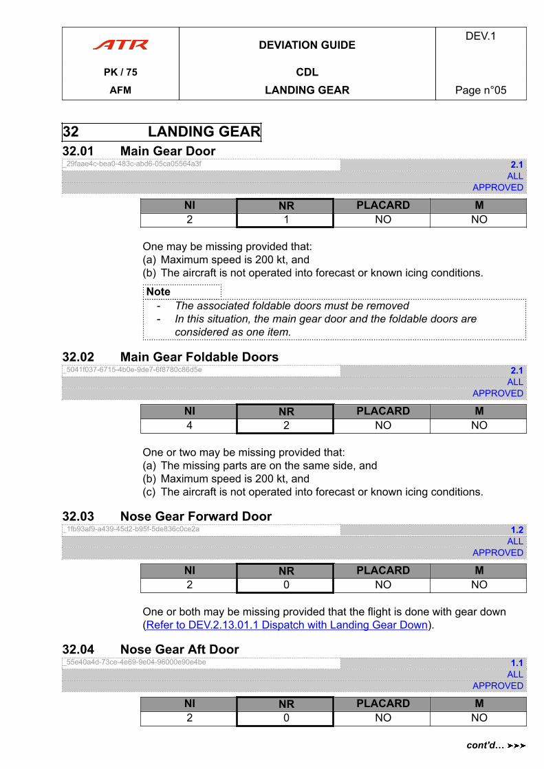
32 LANDING GEAR32.01 Main Gear Door_29faae4c-bea0-483c-abd6-05ca05564a3f 2.1
ALLAPPROVED
NI NR PLACARD M2 1 NO NO
One may be missing provided that:(a) Maximum speed is 200 kt, and(b) The aircraft is not operated into forecast or known icing conditions.
Note- The associated foldable doors must be removed- In this situation, the main gear door and the foldable doors are
considered as one item.
32.02 Main Gear Foldable Doors_5041f037-6715-4b0e-9de7-6f8780c86d5e 2.1
ALLAPPROVED
NI NR PLACARD M4 2 NO NO
One or two may be missing provided that:(a) The missing parts are on the same side, and(b) Maximum speed is 200 kt, and(c) The aircraft is not operated into forecast or known icing conditions.
32.03 Nose Gear Forward Door_1fb93af9-a439-45d2-b95f-5de836c0ce2a 1.2
ALLAPPROVED
NI NR PLACARD M2 0 NO NO
One or both may be missing provided that the flight is done with gear down(Refer to DEV.2.13.01.1 Dispatch with Landing Gear Down).
32.04 Nose Gear Aft Door_55e40a4d-73ce-4e69-9e04-96000e90e4be 1.1
ALLAPPROVED
NI NR PLACARD M2 0 NO NO
DEVIATION GUIDEDEV.1
PK / 75 CDLAFM LANDING GEAR Page n°05
cont'd…
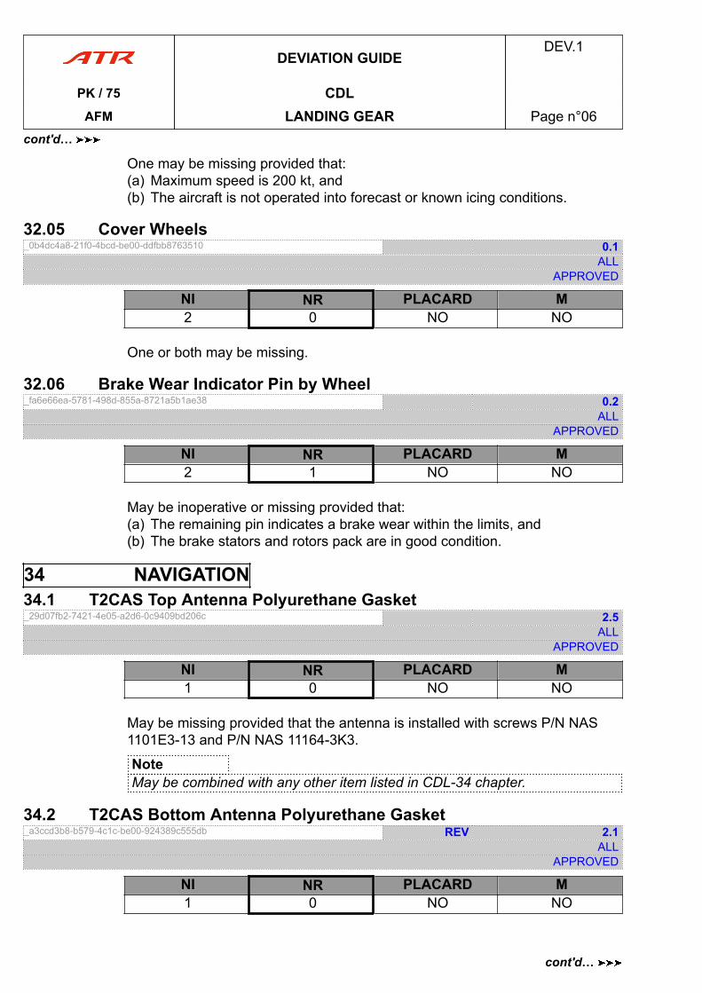
One may be missing provided that:(a) Maximum speed is 200 kt, and(b) The aircraft is not operated into forecast or known icing conditions.
32.05 Cover Wheels_0b4dc4a8-21f0-4bcd-be00-ddfbb8763510 0.1
ALLAPPROVED
NI NR PLACARD M2 0 NO NO
One or both may be missing.
32.06 Brake Wear Indicator Pin by Wheel_fa6e66ea-5781-498d-855a-8721a5b1ae38 0.2
ALLAPPROVED
NI NR PLACARD M2 1 NO NO
May be inoperative or missing provided that:(a) The remaining pin indicates a brake wear within the limits, and(b) The brake stators and rotors pack are in good condition.
34 NAVIGATION34.1 T2CAS Top Antenna Polyurethane Gasket_29d07fb2-7421-4e05-a2d6-0c9409bd206c 2.5
ALLAPPROVED
NI NR PLACARD M1 0 NO NO
May be missing provided that the antenna is installed with screws P/N NAS1101E3-13 and P/N NAS 11164-3K3.
NoteMay be combined with any other item listed in CDL-34 chapter.
34.2 T2CAS Bottom Antenna Polyurethane Gasket_a3ccd3b8-b579-4c1c-be00-924389c555db REV 2.1
ALLAPPROVED
NI NR PLACARD M1 0 NO NO
DEVIATION GUIDEDEV.1
PK / 75 CDLAFM LANDING GEAR Page n°06
cont'd…
cont'd…
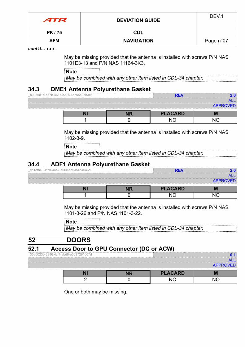
May be missing provided that the antenna is installed with screws P/N NAS1101E3-13 and P/N NAS 11164-3K3.
NoteMay be combined with any other item listed in CDL-34 chapter.
34.3 DME1 Antenna Polyurethane Gasket_b993581d-d67b-461c-a278-6c755e9eb3cf REV 2.0
ALLAPPROVED
NI NR PLACARD M1 0 NO NO
May be missing provided that the antenna is installed with screws P/N NAS1102-3-9.
NoteMay be combined with any other item listed in CDL-34 chapter.
34.4 ADF1 Antenna Polyurethane Gasket_cb1efa43-4f70-44a2-a06c-ce5354e4646d REV 2.0
ALLAPPROVED
NI NR PLACARD M1 0 NO NO
May be missing provided that the antenna is installed with screws P/N NAS1101-3-26 and P/N NAS 1101-3-22.
NoteMay be combined with any other item listed in CDL-34 chapter.
52 DOORS52.1 Access Door to GPU Connector (DC or ACW)_35b50230-2386-4cf4-abd6-e5537291667d 0.1
ALLAPPROVED
NI NR PLACARD M2 0 NO NO
One or both may be missing.
DEVIATION GUIDEDEV.1
PK / 75 CDLAFM NAVIGATION Page n°07
cont'd…
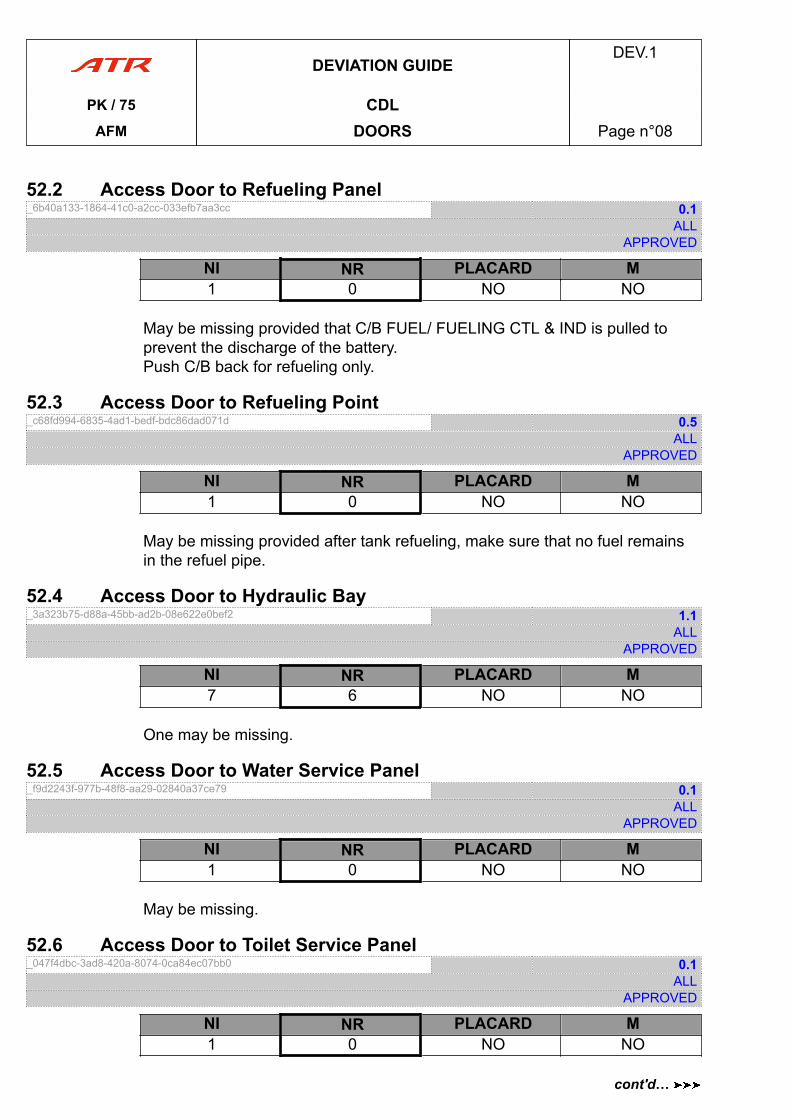
52.2 Access Door to Refueling Panel_6b40a133-1864-41c0-a2cc-033efb7aa3cc 0.1
ALLAPPROVED
NI NR PLACARD M1 0 NO NO
May be missing provided that C/B FUEL/ FUELING CTL & IND is pulled toprevent the discharge of the battery.Push C/B back for refueling only.
52.3 Access Door to Refueling Point_c68fd994-6835-4ad1-bedf-bdc86dad071d 0.5
ALLAPPROVED
NI NR PLACARD M1 0 NO NO
May be missing provided after tank refueling, make sure that no fuel remainsin the refuel pipe.
52.4 Access Door to Hydraulic Bay_3a323b75-d88a-45bb-ad2b-08e622e0bef2 1.1
ALLAPPROVED
NI NR PLACARD M7 6 NO NO
One may be missing.
52.5 Access Door to Water Service Panel_f9d2243f-977b-48f8-aa29-02840a37ce79 0.1
ALLAPPROVED
NI NR PLACARD M1 0 NO NO
May be missing.
52.6 Access Door to Toilet Service Panel_047f4dbc-3ad8-420a-8074-0ca84ec07bb0 0.1
ALLAPPROVED
NI NR PLACARD M1 0 NO NO
DEVIATION GUIDEDEV.1
PK / 75 CDLAFM DOORS Page n°08
cont'd…
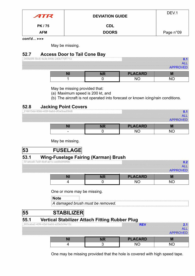
May be missing.
52.7 Access Door to Tail Cone Bay_045fa5f8-5bc6-4a3e-849b-2d0b770f7713 0.1
ALLAPPROVED
NI NR PLACARD M1 0 NO NO
May be missing provided that:(a) Maximum speed is 200 kt, and(b) The aircraft is not operated into forecast or known icing/rain conditions.
52.8 Jacking Point Covers_216015dd-958d-409f-9a6d-df0a0bad58d8 0.1
ALLAPPROVED
NI NR PLACARD M- 0 NO NO
May be missing.
53 FUSELAGE53.1 Wing-Fuselage Fairing (Karman) Brush_f31a4ce8-7a5f-4bdf-a01c-ced0b0f48f9b 0.2
ALLAPPROVED
NI NR PLACARD M4 0 NO NO
One or more may be missing.
NoteA damaged brush must be removed.
55 STABILIZER55.1 Vertical Stabilizer Attach Fitting Rubber Plug_603caba2-40f4-42ef-ba0d-a20e3cf4e12c REV 2.1
ALLAPPROVED
NI NR PLACARD M4 3 NO NO
One may be missing provided that the hole is covered with high speed tape.
DEVIATION GUIDEDEV.1
PK / 75 CDLAFM DOORS Page n°09
cont'd…
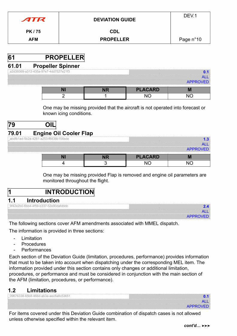
61 PROPELLER61.01 Propeller Spinner_a2d39369-a312-435a-97e7-4dd7527e21f3 0.1
ALLAPPROVED
NI NR PLACARD M2 1 NO NO
One may be missing provided that the aircraft is not operated into forecast orknown icing conditions.
79 OIL79.01 Engine Oil Cooler Flap_abdfb1ad-5b2a-4281-a253-f8838b154ede 1.3
ALLAPPROVED
NI NR PLACARD M4 3 NO NO
One may be missing provided Flap is removed and engine oil parameters aremonitored throughout the flight.
1 INTRODUCTION1.1 Introduction_9f42e2b0-6bb4-4f59-b337-52e90dafdbbb 2.4
ALLAPPROVED
The following sections cover AFM amendments associated with MMEL dispatch.The information is provided in three sections:
- Limitation- Procedures- Performances
Each section of the Deviation Guide (limitation, procedures, performance) provides informationthat must to be taken into account when dispatching under the corresponding MEL item. Theinformation provided under this section contains only changes or additional limitation,procedures, or performance and must be considered in conjunction with the main section ofthe AFM (limitation, procedures, or performance).
1.2 Limitations_09676338-65b8-466d-ab3a-aec8a8c53651 0.1
ALLAPPROVED
For items covered under this Deviation Guide combination of dispatch cases is not allowedunless otherwise specified within the relevant item.
DEVIATION GUIDEDEV.1
PK / 75 CDLAFM PROPELLER Page n°10
cont'd…
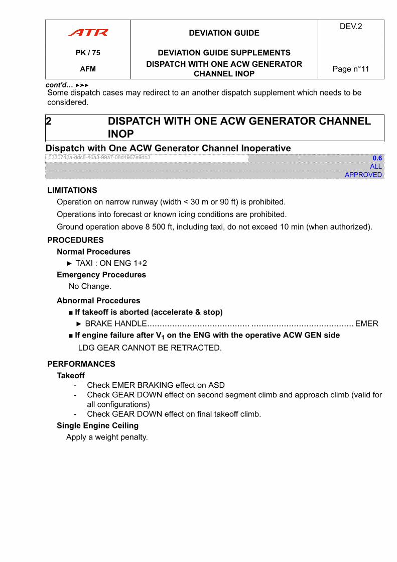
Some dispatch cases may redirect to an another dispatch supplement which needs to beconsidered.
2 DISPATCH WITH ONE ACW GENERATOR CHANNELINOP
Dispatch with One ACW Generator Channel Inoperative_0330742a-ddc8-46a3-99a7-08d4967e9db3 0.6
ALLAPPROVED
LIMITATIONSOperation on narrow runway (width < 30 m or 90 ft) is prohibited.Operations into forecast or known icing conditions are prohibited.Ground operation above 8 500 ft, including taxi, do not exceed 10 min (when authorized).
PROCEDURESNormal Procedures▶ TAXI : ON ENG 1+2
Emergency ProceduresNo Change.
Abnormal Procedures■ If takeoff is aborted (accelerate & stop)▶ BRAKE HANDLE......................................... ......................................... EMER
■ If engine failure after V1 on the ENG with the operative ACW GEN sideLDG GEAR CANNOT BE RETRACTED.
PERFORMANCESTakeoff
- Check EMER BRAKING effect on ASD- Check GEAR DOWN effect on second segment climb and approach climb (valid for
all configurations)- Check GEAR DOWN effect on final takeoff climb.
Single Engine CeilingApply a weight penalty.
DEVIATION GUIDEDEV.2
PK / 75 DEVIATION GUIDE SUPPLEMENTS
AFM DISPATCH WITH ONE ACW GENERATORCHANNEL INOP Page n°11
cont'd…
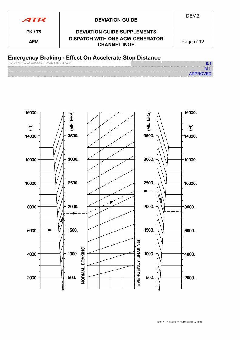
Emergency Braking - Effect On Accelerate Stop Distance_bb717433-ce1e-45b4-8852-9e18b3017ec0 0.1
ALLAPPROVED
ICN-7X-Y-000000-T-FB429-00078-A-01-N
DEVIATION GUIDEDEV.2
PK / 75 DEVIATION GUIDE SUPPLEMENTS
AFM DISPATCH WITH ONE ACW GENERATORCHANNEL INOP Page n°12
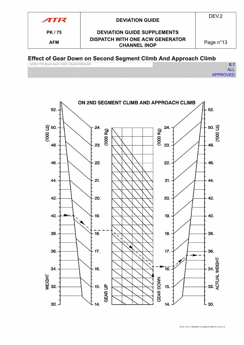
Effect of Gear Down on Second Segment Climb And Approach Climb_b09b179f-6bab-4e01-bfd7-3ba549966e58 0.1
ALLAPPROVED
ICN-7X-Y-000000-T-FB429-00079-A-01-N
DEVIATION GUIDEDEV.2
PK / 75 DEVIATION GUIDE SUPPLEMENTS
AFM DISPATCH WITH ONE ACW GENERATORCHANNEL INOP Page n°13
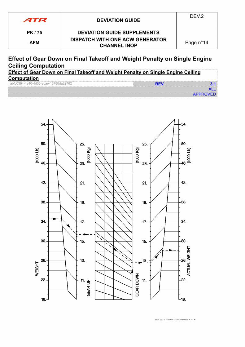
Effect of Gear Down on Final Takeoff and Weight Penalty on Single EngineCeiling ComputationEffect of Gear Down on Final Takeoff and Weight Penalty on Single Engine CeilingComputation_abfc0394-4a40-4d05-acae-16788da22762 REV 3.1
ALLAPPROVED
ICN-7X-Y-000000-T-FB429-00080-A-01-N
DEVIATION GUIDEDEV.2
PK / 75 DEVIATION GUIDE SUPPLEMENTS
AFM DISPATCH WITH ONE ACW GENERATORCHANNEL INOP Page n°14
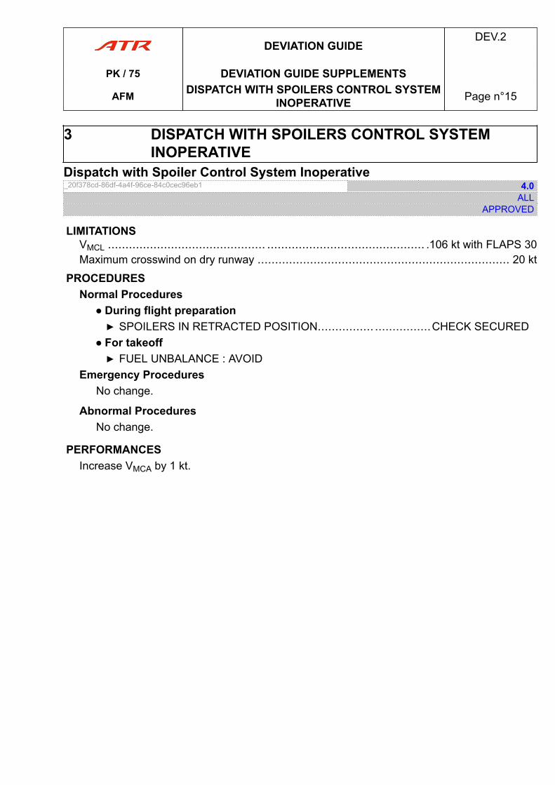
3 DISPATCH WITH SPOILERS CONTROL SYSTEMINOPERATIVE
Dispatch with Spoiler Control System Inoperative_20f378cd-86df-4a4f-96ce-84c0cec96eb1 4.0
ALLAPPROVED
LIMITATIONSVMCL ............................................. ............................................. .106 kt with FLAPS 30Maximum crosswind on dry runway ........................................................................ 20 kt
PROCEDURESNormal Procedures
● During flight preparation▶ SPOILERS IN RETRACTED POSITION................ ................CHECK SECURED
● For takeoff▶ FUEL UNBALANCE : AVOID
Emergency ProceduresNo change.
Abnormal ProceduresNo change.
PERFORMANCESIncrease VMCA by 1 kt.
DEVIATION GUIDEDEV.2
PK / 75 DEVIATION GUIDE SUPPLEMENTS
AFM DISPATCH WITH SPOILERS CONTROL SYSTEMINOPERATIVE Page n°15
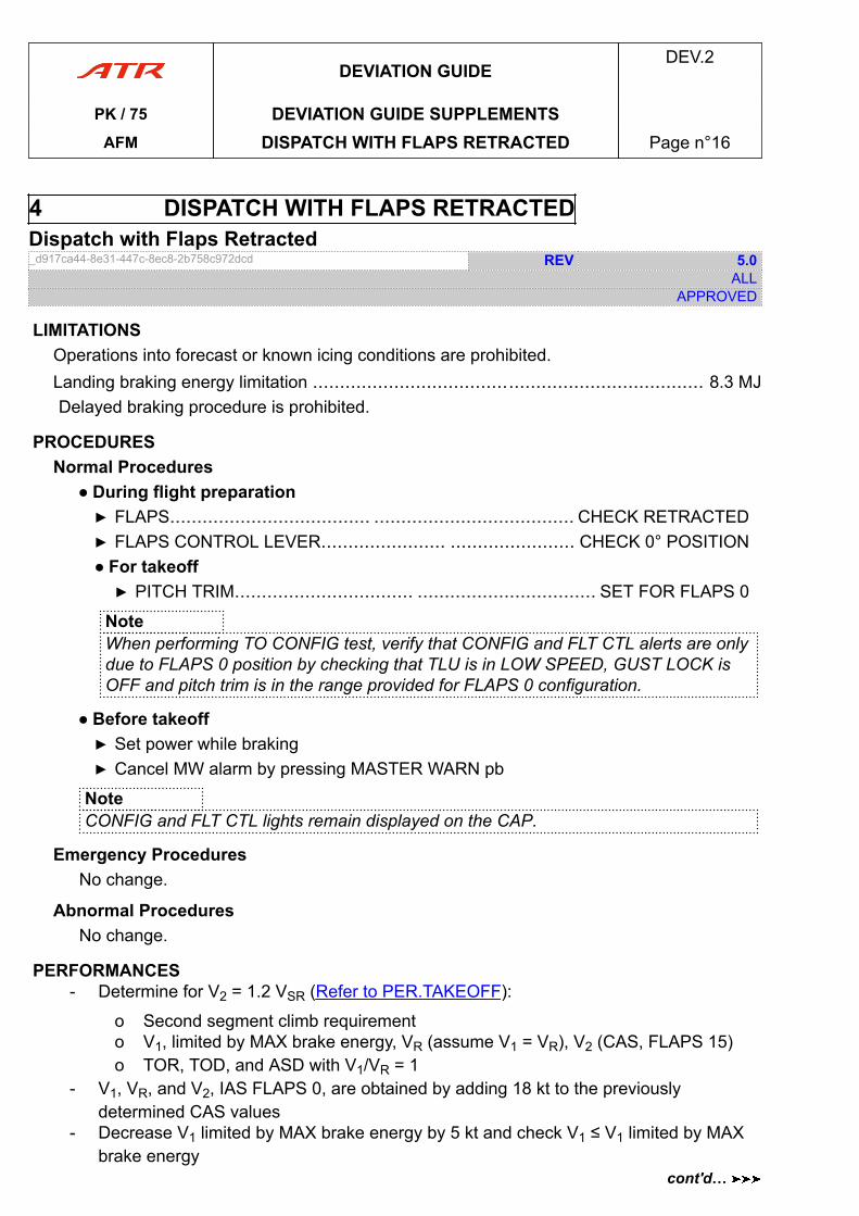
4 DISPATCH WITH FLAPS RETRACTEDDispatch with Flaps Retracted_d917ca44-8e31-447c-8ec8-2b758c972dcd REV 5.0
ALLAPPROVED
LIMITATIONSOperations into forecast or known icing conditions are prohibited.Landing braking energy limitation ........................................................................ 8.3 MJDelayed braking procedure is prohibited.
PROCEDURESNormal Procedures
● During flight preparation▶ FLAPS..................................... ..................................... CHECK RETRACTED▶ FLAPS CONTROL LEVER....................... ....................... CHECK 0° POSITION● For takeoff▶ PITCH TRIM................................. ................................. SET FOR FLAPS 0
NoteWhen performing TO CONFIG test, verify that CONFIG and FLT CTL alerts are onlydue to FLAPS 0 position by checking that TLU is in LOW SPEED, GUST LOCK isOFF and pitch trim is in the range provided for FLAPS 0 configuration.
● Before takeoff▶ Set power while braking▶ Cancel MW alarm by pressing MASTER WARN pb
NoteCONFIG and FLT CTL lights remain displayed on the CAP.
Emergency ProceduresNo change.
Abnormal ProceduresNo change.
PERFORMANCES- Determine for V2 = 1.2 VSR (Refer to PER.TAKEOFF):
o Second segment climb requiremento V1, limited by MAX brake energy, VR (assume V1 = VR), V2 (CAS, FLAPS 15)o TOR, TOD, and ASD with V1/VR = 1
- V1, VR, and V2, IAS FLAPS 0, are obtained by adding 18 kt to the previouslydetermined CAS values
- Decrease V1 limited by MAX brake energy by 5 kt and check V1 ≤ V1 limited by MAXbrake energy
DEVIATION GUIDEDEV.2
PK / 75 DEVIATION GUIDE SUPPLEMENTSAFM DISPATCH WITH FLAPS RETRACTED Page n°16
cont'd…
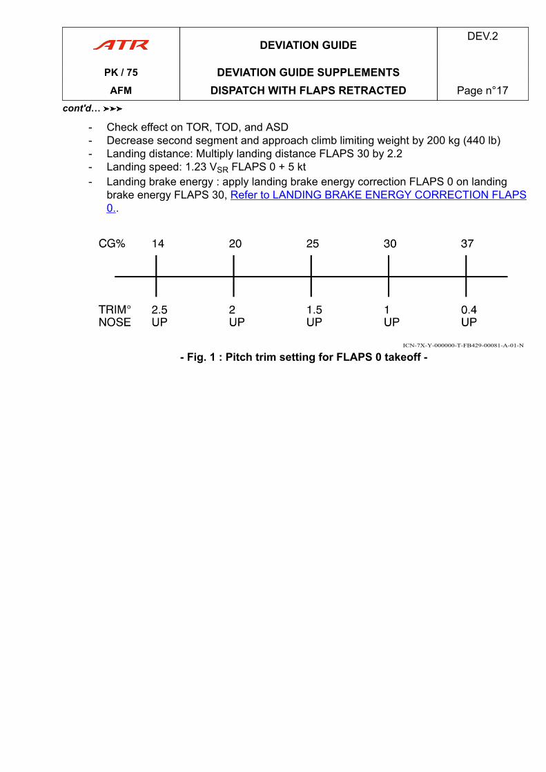
- Check effect on TOR, TOD, and ASD- Decrease second segment and approach climb limiting weight by 200 kg (440 lb)- Landing distance: Multiply landing distance FLAPS 30 by 2.2- Landing speed: 1.23 VSR FLAPS 0 + 5 kt- Landing brake energy : apply landing brake energy correction FLAPS 0 on landing
brake energy FLAPS 30, Refer to LANDING BRAKE ENERGY CORRECTION FLAPS0..
ICN-7X-Y-000000-T-FB429-00081-A-01-N
- Fig. 1 : Pitch trim setting for FLAPS 0 takeoff -
DEVIATION GUIDEDEV.2
PK / 75 DEVIATION GUIDE SUPPLEMENTSAFM DISPATCH WITH FLAPS RETRACTED Page n°17
cont'd…
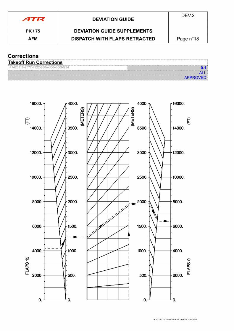
CorrectionsTakeoff Run Corrections_41426318-2577-4922-888e-d00eb66bf294 0.1
ALLAPPROVED
ICN-7X-Y-000000-T-FB429-00083-B-01-N
DEVIATION GUIDEDEV.2
PK / 75 DEVIATION GUIDE SUPPLEMENTSAFM DISPATCH WITH FLAPS RETRACTED Page n°18
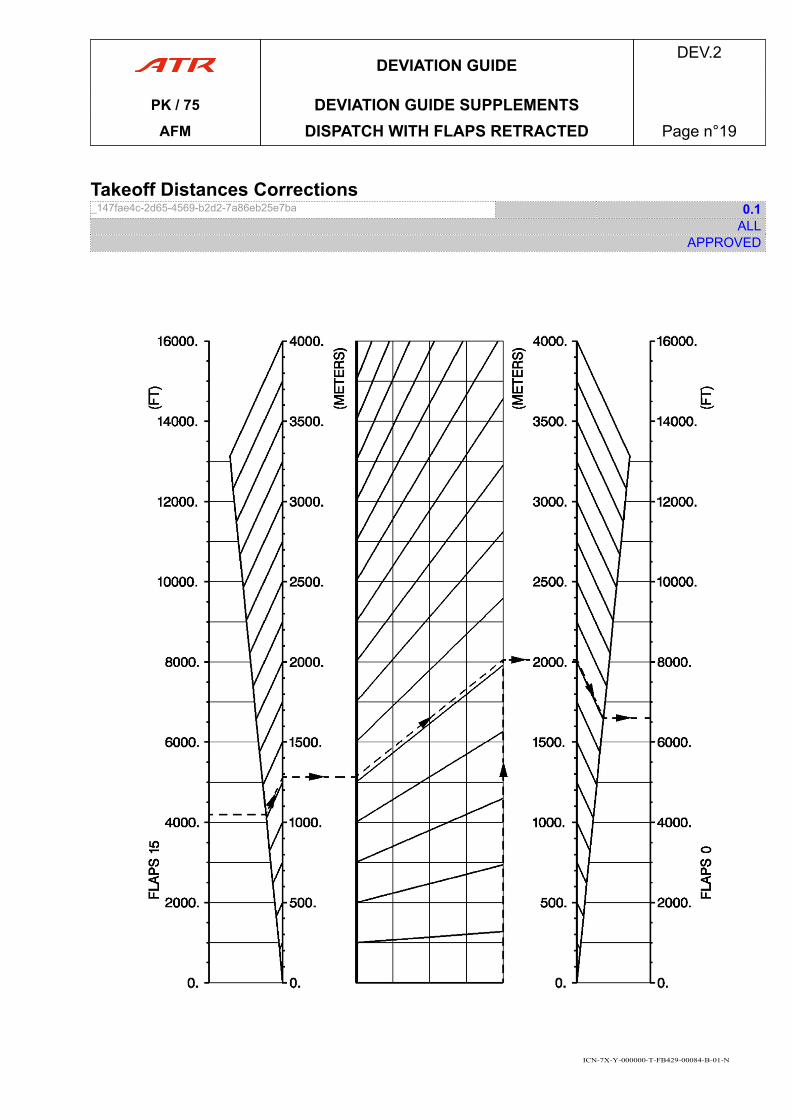
Takeoff Distances Corrections_147fae4c-2d65-4569-b2d2-7a86eb25e7ba 0.1
ALLAPPROVED
ICN-7X-Y-000000-T-FB429-00084-B-01-N
DEVIATION GUIDEDEV.2
PK / 75 DEVIATION GUIDE SUPPLEMENTSAFM DISPATCH WITH FLAPS RETRACTED Page n°19
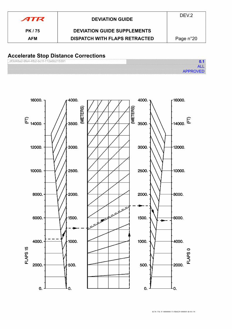
Accelerate Stop Distance Corrections_df3d48a2-9fe4-4fb2-bc1f-772e6b215391 0.1
ALLAPPROVED
ICN-7X-Y-000000-T-FB429-00085-B-01-N
DEVIATION GUIDEDEV.2
PK / 75 DEVIATION GUIDE SUPPLEMENTSAFM DISPATCH WITH FLAPS RETRACTED Page n°20
5 DISPATCH WITH ONE WHEEL BRAKE DEACTIVATEDOR REMOVED
Dispatch with One Wheel Brake Deactivated or Removed_abb4bb11-4b41-4d3d-b461-fded9ebdd482 REV 5.0
ALLAPPROVED
LIMITATIONSOperation on contaminated runways is prohibited.Landing braking energy limitation ........................................................................ 8.3 MJDelayed braking procedure is prohibited.
PROCEDURESNo change.
PERFORMANCESTakeoff
- Multiply ASD by 1.1.- Check V1 < 0.8 of V1 MAX brake energy.
Landing- Multiply landing distance by 1.1 (valid for all configurations).- Landing brake energy: Apply landing dispatch with one wheel brake deactivated
correction (Refer to DEV.2.5.01.3 Operation on Dry or Wet Runway) on landingbrake energy (Flaps 30)
DEVIATION GUIDEDEV.2
PK / 75 DEVIATION GUIDE SUPPLEMENTS
AFM DISPATCH WITH ONE WHEEL BRAKEDEACTIVATED OR REMOVED Page n°21
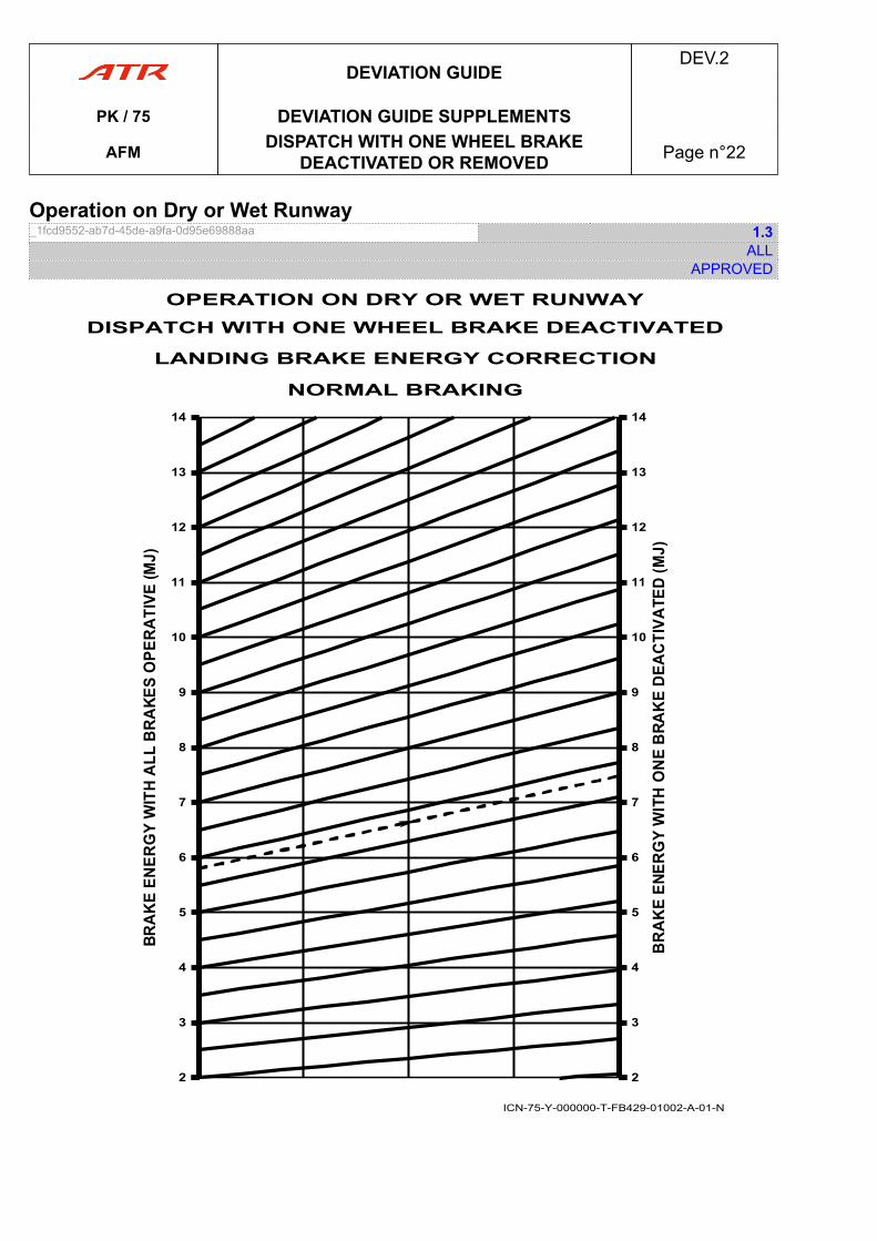
Operation on Dry or Wet Runway_1fcd9552-ab7d-45de-a9fa-0d95e69888aa 1.3
ALLAPPROVED
ICN-75-Y-000000-T-FB429-01002-A-01-N
22
3
4
5
6
7
8
9
10
11
12
13
14
22
3
4
5
6
7
8
9
10
11
12
13
14
OPERATION ON DRY OR WET RUNWAYDISPATCH WITH ONE WHEEL BRAKE DEACTIVATED
LANDING BRAKE ENERGY CORRECTION
NORMAL BRAKING
DEVIATION GUIDEDEV.2
PK / 75 DEVIATION GUIDE SUPPLEMENTS
AFM DISPATCH WITH ONE WHEEL BRAKEDEACTIVATED OR REMOVED Page n°22
6 DISPATCH WITH ANTISKID SYSTEM INOPERATIVEDispatch with Antiskid System Inoperative_6ea1068d-ad57-4e72-a3e8-31613007b043 REV 2.4
ALLAPPROVED
LIMITATIONSOperation on contaminated runways is prohibited.Landing braking energy limitation..........................................................................8.3 MJDelayed braking procedure is prohibited.
PROCEDURES▶ ANTISKID................................................. ................................................. OFF
For Ground Deceleration▶ REVERSE............................................. ............................................. AS RQRD▶ NORMAL BRAKE......................................................................USE WITH CARE▶ BRAKE HANDLE...................................................................... EMER/AS RQRD
PERFORMANCESTakeoff
Check antiskid OFF effect on ASD.
Landing- Multiply landing distance by 1.4 (valid for all configurations).- Landing brake energy: Apply landing dispatch with antiskid inoperative correction
on landing brake energy (Flaps 30) (Refer to Antiskid Off Effect on Landing BrakeEnergy).
Antiskid Off Effect on Accelerate Stop Distance_28f61f9a-cef8-4bbd-b306-9a94339a2220 1.1
ALLAPPROVED
FLAPS 15
DEVIATION GUIDEDEV.2
PK / 75 DEVIATION GUIDE SUPPLEMENTS
AFM DISPATCH WITH ANTISKID SYSTEMINOPERATIVE Page n°23
cont'd…
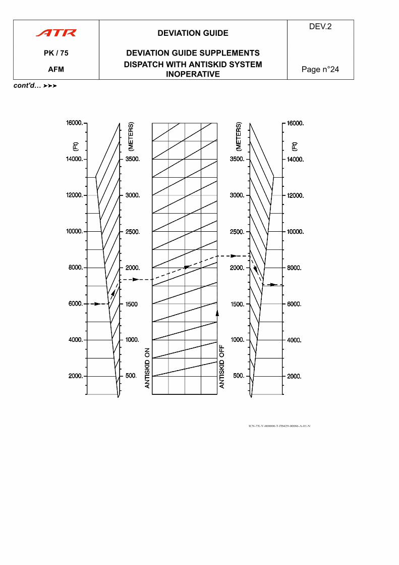
ICN-7X-Y-000000-T-FB429-00086-A-01-N
DEVIATION GUIDEDEV.2
PK / 75 DEVIATION GUIDE SUPPLEMENTS
AFM DISPATCH WITH ANTISKID SYSTEMINOPERATIVE Page n°24
cont'd…
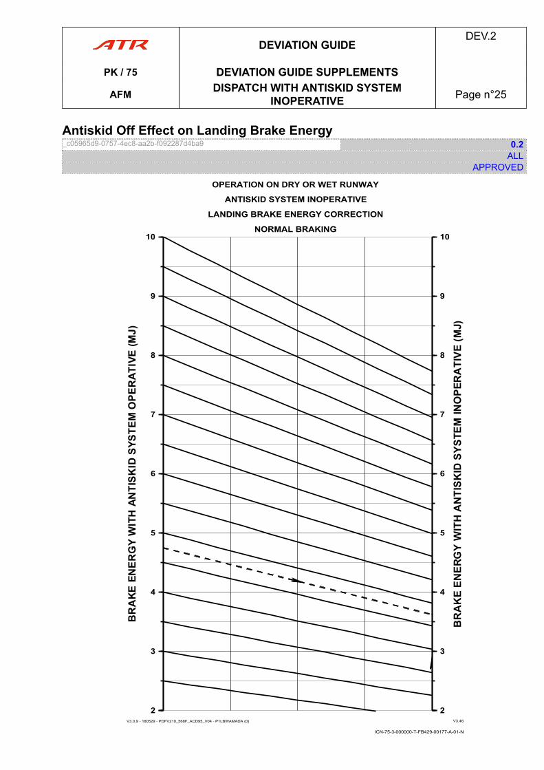
Antiskid Off Effect on Landing Brake Energy_c05965d9-0757-4ec8-aa2b-f092287d4ba9 0.2
ALLAPPROVED
OPERATION ON DRY OR WET RUNWAY
ANTISKID SYSTEM INOPERATIVE
V3.0.9 - 180529 - PDFV210_568F_ACD95_V04 - P1LBWAMADA (0) V3.46
ICN-75-3-000000-T-FB429-00177-A-01-N
22
3
4
5
6
7
8
9
10
22
3
4
5
6
7
8
9
10
LANDING BRAKE ENERGY CORRECTION
NORMAL BRAKING
DEVIATION GUIDEDEV.2
PK / 75 DEVIATION GUIDE SUPPLEMENTS
AFM DISPATCH WITH ANTISKID SYSTEMINOPERATIVE Page n°25
7 DISPATCH WITH AUTOFEATHER SYSTEMINOPERATIVE
Dispatch with Autofeather System Inoperative_5e26ae4d-e1b8-4b6d-b810-955ec4a9ea79 2.2
ALLAPPROVED
LIMITATIONSNo change.
PROCEDURESNormal Procedures
No change.
Emergency ProceduresNo change.
Abnormal Procedures■ If engine fails after V1:▶ PL (affected ENG) : DO NOT REDUCE BELOW PLA 45 ° UNTIL FEATHERING
PERFORMANCESTakeoff
- Increase V1 limited by VMCG by 5 kt- Increase VR by 2 kt- Increase VMCA by 3 kt- Check VR and V2- Check effect on TOR, TOD, and second segment climb.
ApproachIncrease VMCL by 7 kt.
DEVIATION GUIDEDEV.2
PK / 75 DEVIATION GUIDE SUPPLEMENTS
AFM DISPATCH WITH AUTOFEATHER SYSTEMINOPERATIVE Page n°26
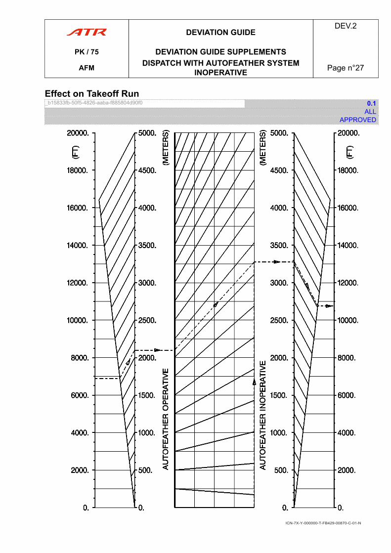
Effect on Takeoff Run_b15833fb-50f5-4826-aaba-f885804d90f0 0.1
ALLAPPROVED
ICN-7X-Y-000000-T-FB429-00870-C-01-N
DEVIATION GUIDEDEV.2
PK / 75 DEVIATION GUIDE SUPPLEMENTS
AFM DISPATCH WITH AUTOFEATHER SYSTEMINOPERATIVE Page n°27
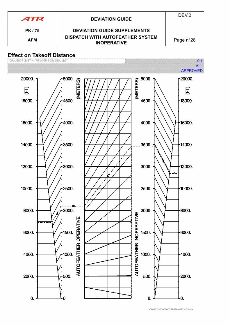
Effect on Takeoff Distance_05eb6807-2c87-4470-b468-658c95bdab7f 0.1
ALLAPPROVED
ICN-7X-Y-000000-T-FB429-00871-C-01-N
DEVIATION GUIDEDEV.2
PK / 75 DEVIATION GUIDE SUPPLEMENTS
AFM DISPATCH WITH AUTOFEATHER SYSTEMINOPERATIVE Page n°28
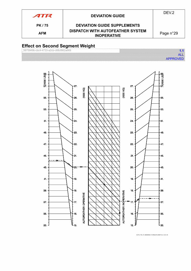
Effect on Second Segment Weight_5875949b-cbc4-4733-a2cb-c68cf862a669 1.1
ALLAPPROVED
ICN-7X-Y-000000-T-FB429-00872-C-01-N
DEVIATION GUIDEDEV.2
PK / 75 DEVIATION GUIDE SUPPLEMENTS
AFM DISPATCH WITH AUTOFEATHER SYSTEMINOPERATIVE Page n°29
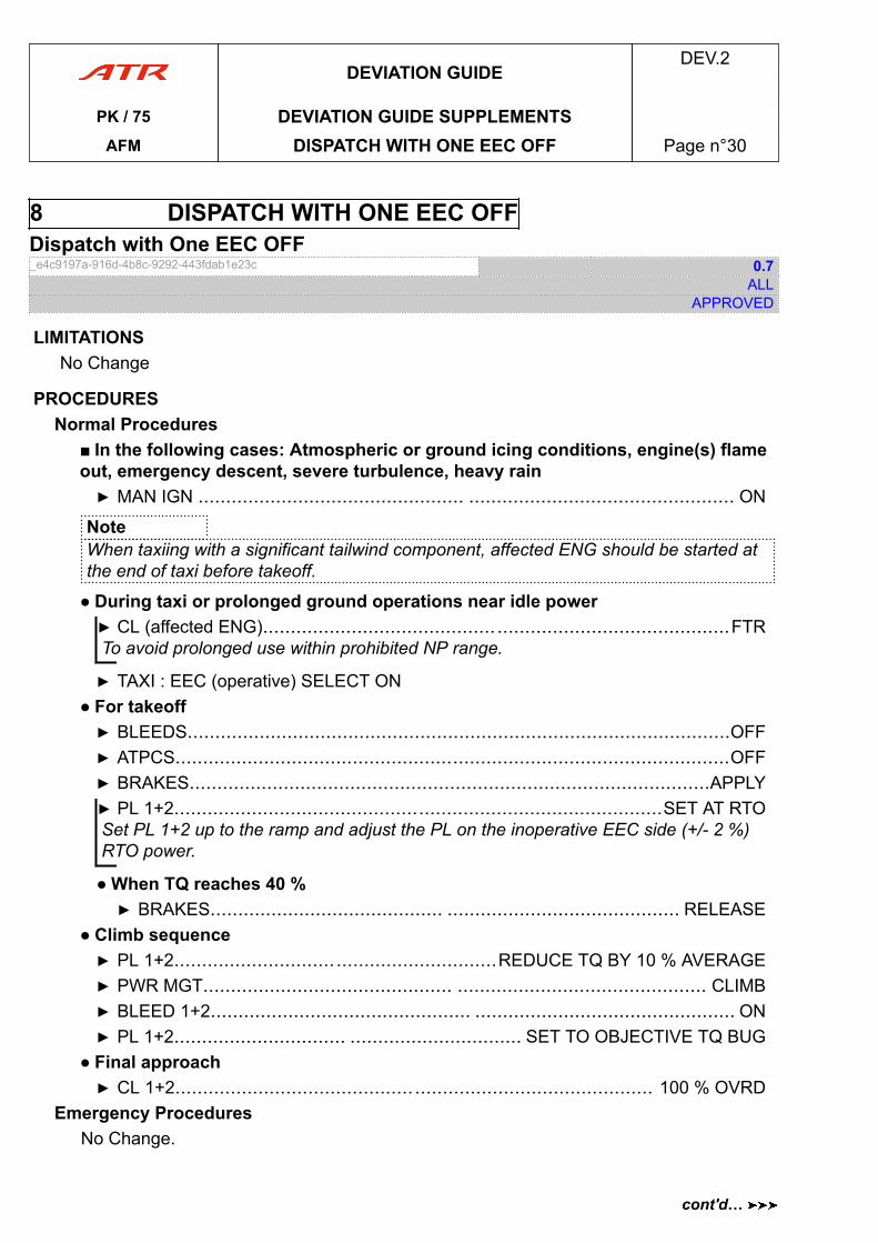
8 DISPATCH WITH ONE EEC OFFDispatch with One EEC OFF_e4c9197a-916d-4b8c-9292-443fdab1e23c 0.7
ALLAPPROVED
LIMITATIONSNo Change
PROCEDURESNormal Procedures
■ In the following cases: Atmospheric or ground icing conditions, engine(s) flameout, emergency descent, severe turbulence, heavy rain▶ MAN IGN ................................................ ................................................ ON
NoteWhen taxiing with a significant tailwind component, affected ENG should be started atthe end of taxi before takeoff.
● During taxi or prolonged ground operations near idle power▶ CL (affected ENG).......................................... ..........................................FTRTo avoid prolonged use within prohibited NP range.
▶ TAXI : EEC (operative) SELECT ON● For takeoff▶ BLEEDS..................................................................................................OFF▶ ATPCS....................................................................................................OFF▶ BRAKES..............................................................................................APPLY▶ PL 1+2........................................................................................SET AT RTOSet PL 1+2 up to the ramp and adjust the PL on the inoperative EEC side (+/- 2 %)RTO power.
● When TQ reaches 40 %▶ BRAKES.......................................... .......................................... RELEASE
● Climb sequence▶ PL 1+2..........................................................REDUCE TQ BY 10 % AVERAGE▶ PWR MGT............................................. ............................................. CLIMB▶ BLEED 1+2............................................... ............................................... ON▶ PL 1+2............................... ............................... SET TO OBJECTIVE TQ BUG
● Final approach▶ CL 1+2...................................................................................... 100 % OVRD
Emergency ProceduresNo Change.
DEVIATION GUIDEDEV.2
PK / 75 DEVIATION GUIDE SUPPLEMENTSAFM DISPATCH WITH ONE EEC OFF Page n°30
cont'd…
Abnormal Procedures■ If takeoff is aborted (accelerate & stop)▶ BRAKE HANDLE......................................... ......................................... EMER▶ PL 1+2..........................................................................................FI THEN GIReduce power to FI for 1 s before setting below, as the asymmetric protection is lost.
■ If engine fails after V1
▶ PL (affected ENG) : DO NOT REDUCE BELOW PLA 45 ° UNTIL FEATHERING
PERFORMANCESTakeoff
- Increase V1 limited by VMCG by 5 kt- Increase VR by 2 kt- Increase VMCA by 3 kt- Check VR and V2- Check EEC OFF and ATPCS OFF effect on performances.
ApproachIncrease VMCL by 7 kt.
DEVIATION GUIDEDEV.2
PK / 75 DEVIATION GUIDE SUPPLEMENTSAFM DISPATCH WITH ONE EEC OFF Page n°31
cont'd…
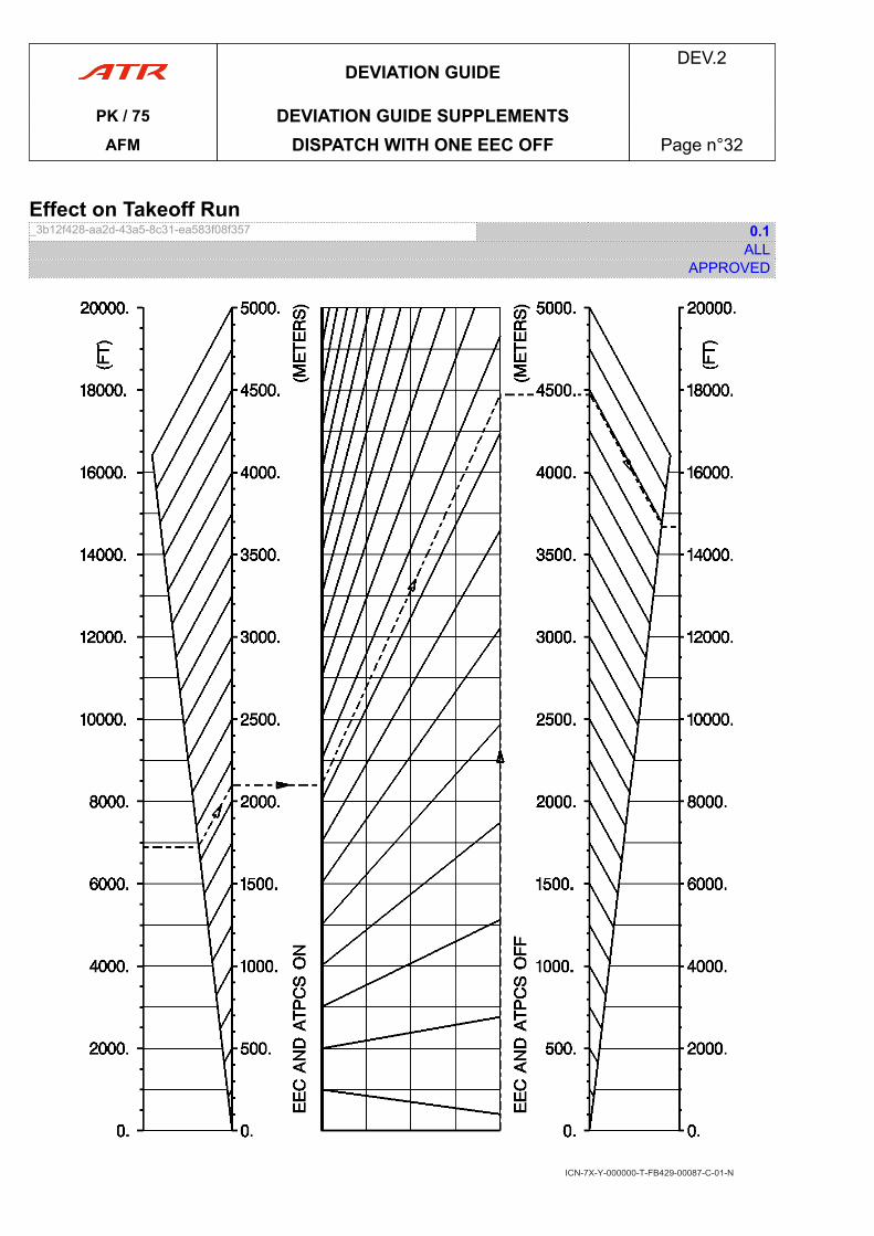
Effect on Takeoff Run_3b12f428-aa2d-43a5-8c31-ea583f08f357 0.1
ALLAPPROVED
ICN-7X-Y-000000-T-FB429-00087-C-01-N
DEVIATION GUIDEDEV.2
PK / 75 DEVIATION GUIDE SUPPLEMENTSAFM DISPATCH WITH ONE EEC OFF Page n°32
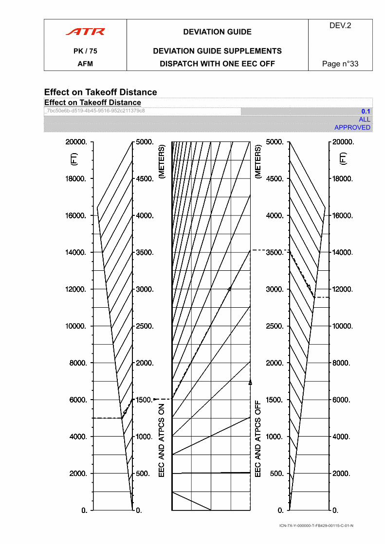
Effect on Takeoff DistanceEffect on Takeoff Distance_7bc50e6b-d519-4b45-9516-952c211379c8 0.1
ALLAPPROVED
ICN-7X-Y-000000-T-FB429-00115-C-01-N
DEVIATION GUIDEDEV.2
PK / 75 DEVIATION GUIDE SUPPLEMENTSAFM DISPATCH WITH ONE EEC OFF Page n°33
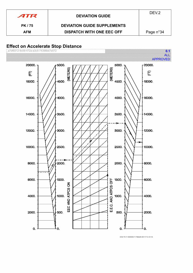
Effect on Accelerate Stop Distance_a7df9312-9c09-472a-a3c5-74398bb7e572 0.1
ALLAPPROVED
ICN-7X-Y-000000-T-FB429-00117-C-01-N
DEVIATION GUIDEDEV.2
PK / 75 DEVIATION GUIDE SUPPLEMENTSAFM DISPATCH WITH ONE EEC OFF Page n°34
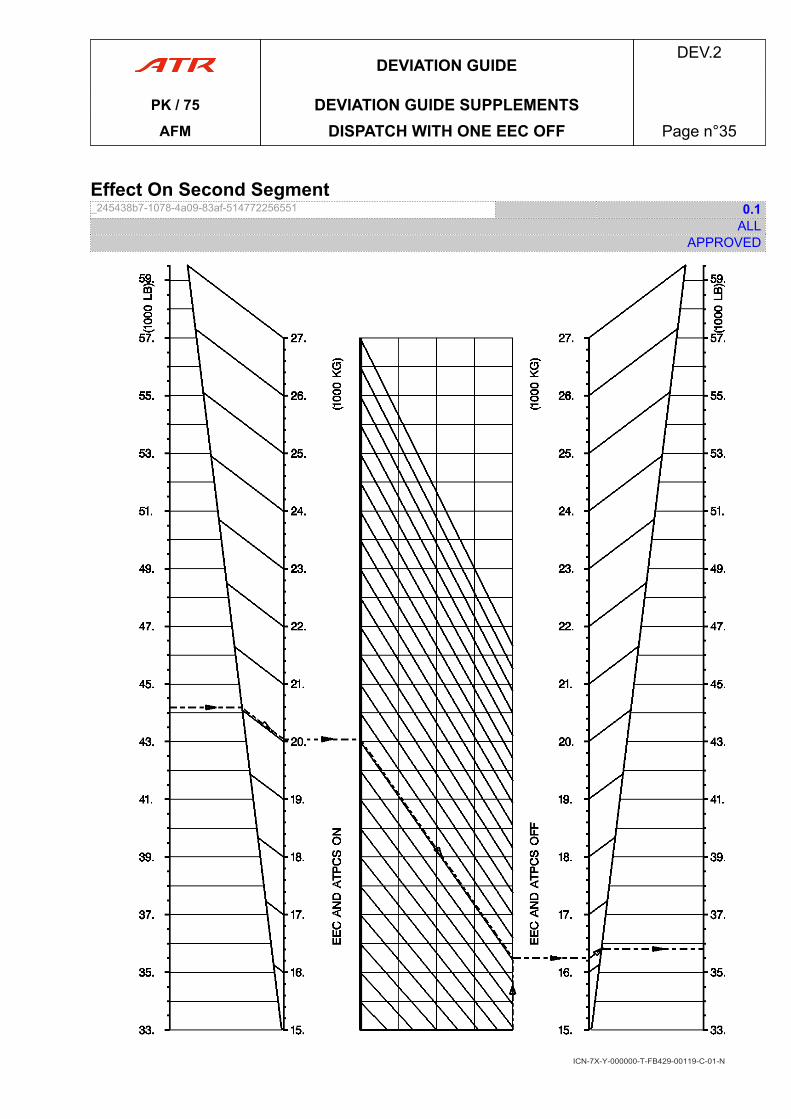
Effect On Second Segment_245438b7-1078-4a09-83af-514772256551 0.1
ALLAPPROVED
ICN-7X-Y-000000-T-FB429-00119-C-01-N
DEVIATION GUIDEDEV.2
PK / 75 DEVIATION GUIDE SUPPLEMENTSAFM DISPATCH WITH ONE EEC OFF Page n°35
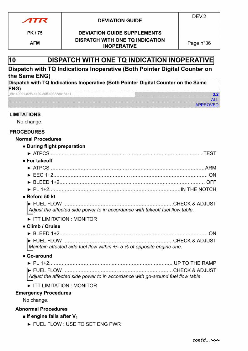
10 DISPATCH WITH ONE TQ INDICATION INOPERATIVEDispatch with TQ Indications Inoperative (Both Pointer Digital Counter onthe Same ENG)Dispatch with TQ Indications Inoperative (Both Pointer Digital Counter on the SameENG)_5b149991-d2f8-4420-86ff-40333d8181e1 3.2
ALLAPPROVED
LIMITATIONSNo change.
PROCEDURESNormal Procedures
● During flight preparation▶ ATPCS ................................................ ................................................ TEST
● For takeoff▶ ATPCS ................................................. .................................................ARM▶ EEC 1+2................................................. ................................................. ON▶ BLEED 1+2.............................................. .............................................. OFF▶ PL 1+2....................................................................................IN THE NOTCH
● Before 50 kt▶ FUEL FLOW ......................................................................CHECK & ADJUSTAdjust the affected side power to in accordance with takeoff fuel flow table.
▶ ITT LIMITATION : MONITOR● Climb / Cruise▶ BLEED 1+2............................................... ............................................... ON▶ FUEL FLOW ......................................................................CHECK & ADJUSTMaintain affected side fuel flow within +/- 5 % of opposite engine one.
● Go-around▶ PL 1+2....................................... ....................................... UP TO THE RAMP▶ FUEL FLOW ......................................................................CHECK & ADJUSTAdjust the affected side power to in accordance with go-around fuel flow table.
▶ ITT LIMITATION : MONITOREmergency Procedures
No change.
Abnormal Procedures■ If engine fails after V1
▶ FUEL FLOW : USE TO SET ENG PWR
DEVIATION GUIDEDEV.2
PK / 75 DEVIATION GUIDE SUPPLEMENTS
AFM DISPATCH WITH ONE TQ INDICATIONINOPERATIVE Page n°36
cont'd…
PERFORMANCES- Increase VR by 1 kt- Check effect on TOR, TOD, and ASD- Check effect on second segment climb- Check fuel flow table.
Effect on Takeoff Run_5b23aae3-5638-4113-98af-5400f75e226b 0.1
ALLAPPROVED
FLAPS 15
DEVIATION GUIDEDEV.2
PK / 75 DEVIATION GUIDE SUPPLEMENTS
AFM DISPATCH WITH ONE TQ INDICATIONINOPERATIVE Page n°37
cont'd…
cont'd…
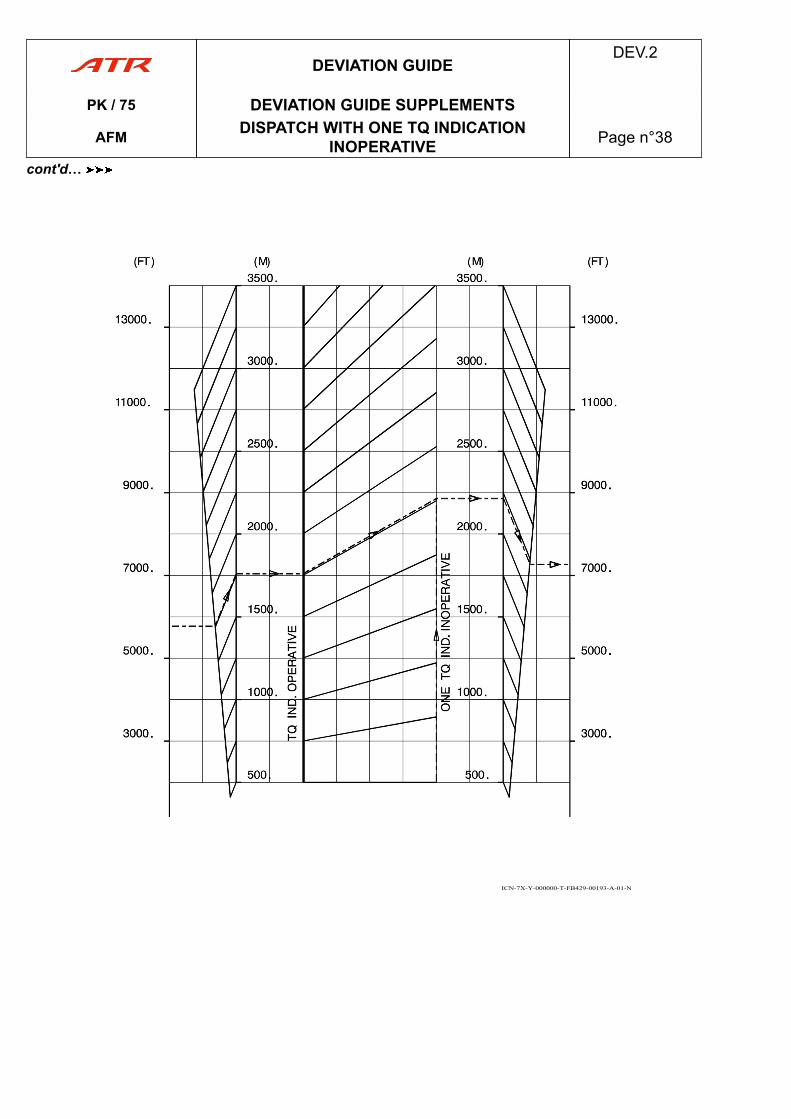
ICN-7X-Y-000000-T-FB429-00193-A-01-N
DEVIATION GUIDEDEV.2
PK / 75 DEVIATION GUIDE SUPPLEMENTS
AFM DISPATCH WITH ONE TQ INDICATIONINOPERATIVE Page n°38
cont'd…
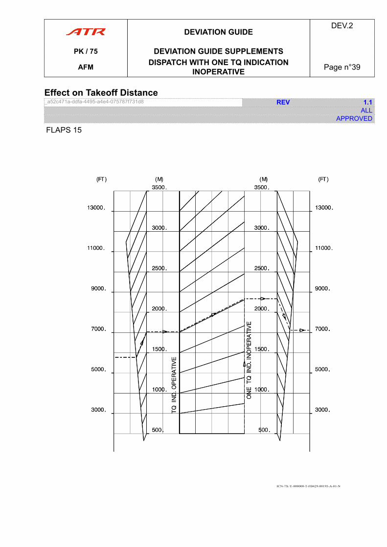
Effect on Takeoff Distance_a52c471a-ddfa-4495-a4e4-075787f731d8 REV 1.1
ALLAPPROVED
FLAPS 15
ICN-7X-Y-000000-T-FB429-00195-A-01-N
DEVIATION GUIDEDEV.2
PK / 75 DEVIATION GUIDE SUPPLEMENTS
AFM DISPATCH WITH ONE TQ INDICATIONINOPERATIVE Page n°39
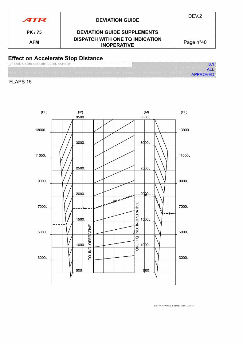
Effect on Accelerate Stop Distance_717d8f7c-62d8-4852-ab13-225f75c41128 0.1
ALLAPPROVED
FLAPS 15
ICN-7X-Y-000000-T-FB429-00197-A-01-N
DEVIATION GUIDEDEV.2
PK / 75 DEVIATION GUIDE SUPPLEMENTS
AFM DISPATCH WITH ONE TQ INDICATIONINOPERATIVE Page n°40
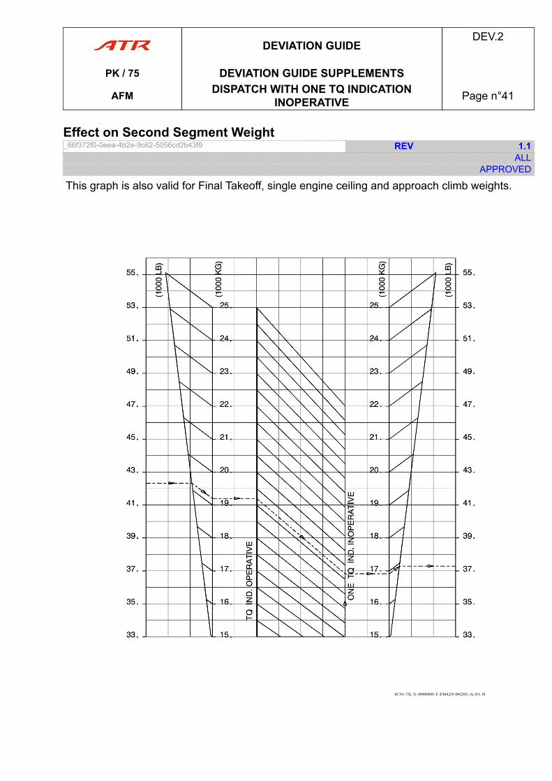
Effect on Second Segment Weight_66f372f0-0eea-4b2e-9c62-5056cd2b43f9 REV 1.1
ALLAPPROVED
This graph is also valid for Final Takeoff, single engine ceiling and approach climb weights.
ICN-7X-Y-000000-T-FB429-00201-A-01-N
DEVIATION GUIDEDEV.2
PK / 75 DEVIATION GUIDE SUPPLEMENTS
AFM DISPATCH WITH ONE TQ INDICATIONINOPERATIVE Page n°41
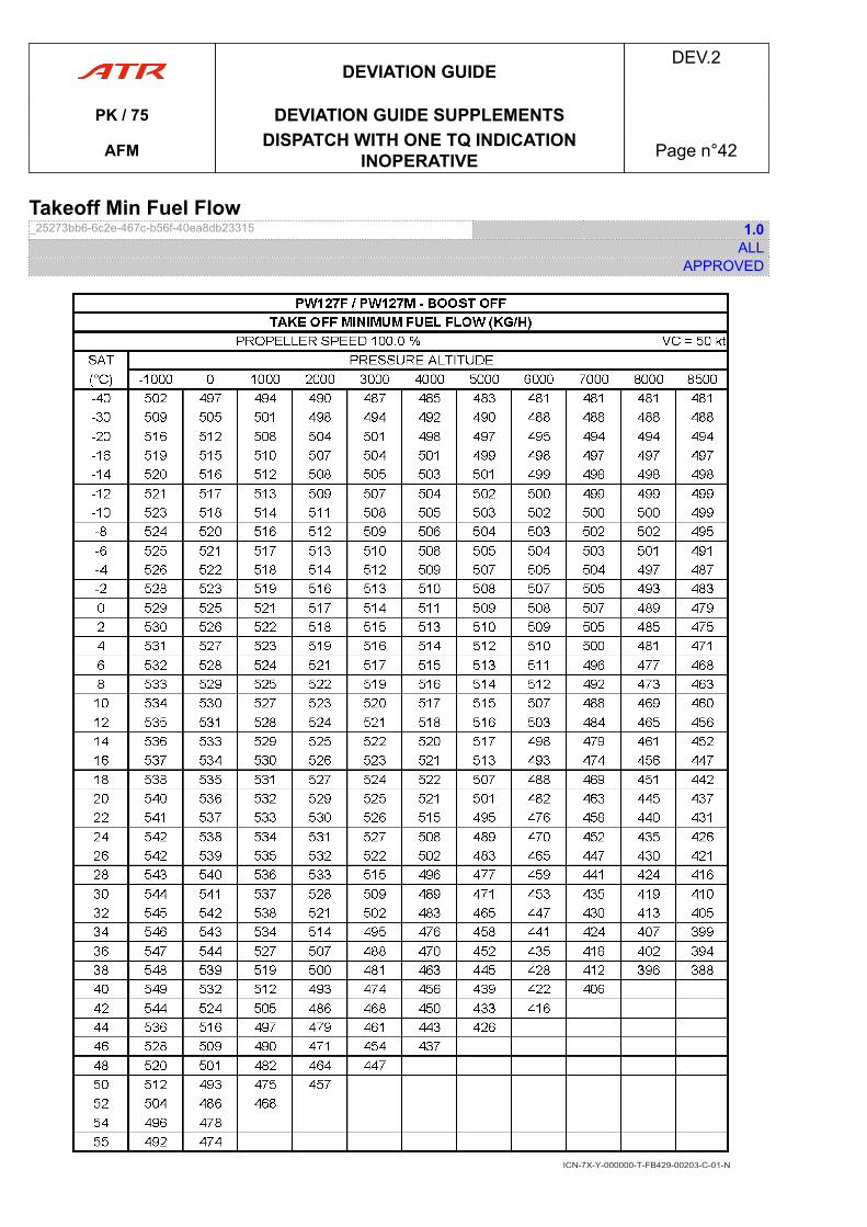
Takeoff Min Fuel Flow_25273bb6-6c2e-467c-b56f-40ea8db23315 1.0
ALLAPPROVED
ICN-7X-Y-000000-T-FB429-00203-C-01-N
DEVIATION GUIDEDEV.2
PK / 75 DEVIATION GUIDE SUPPLEMENTS
AFM DISPATCH WITH ONE TQ INDICATIONINOPERATIVE Page n°42
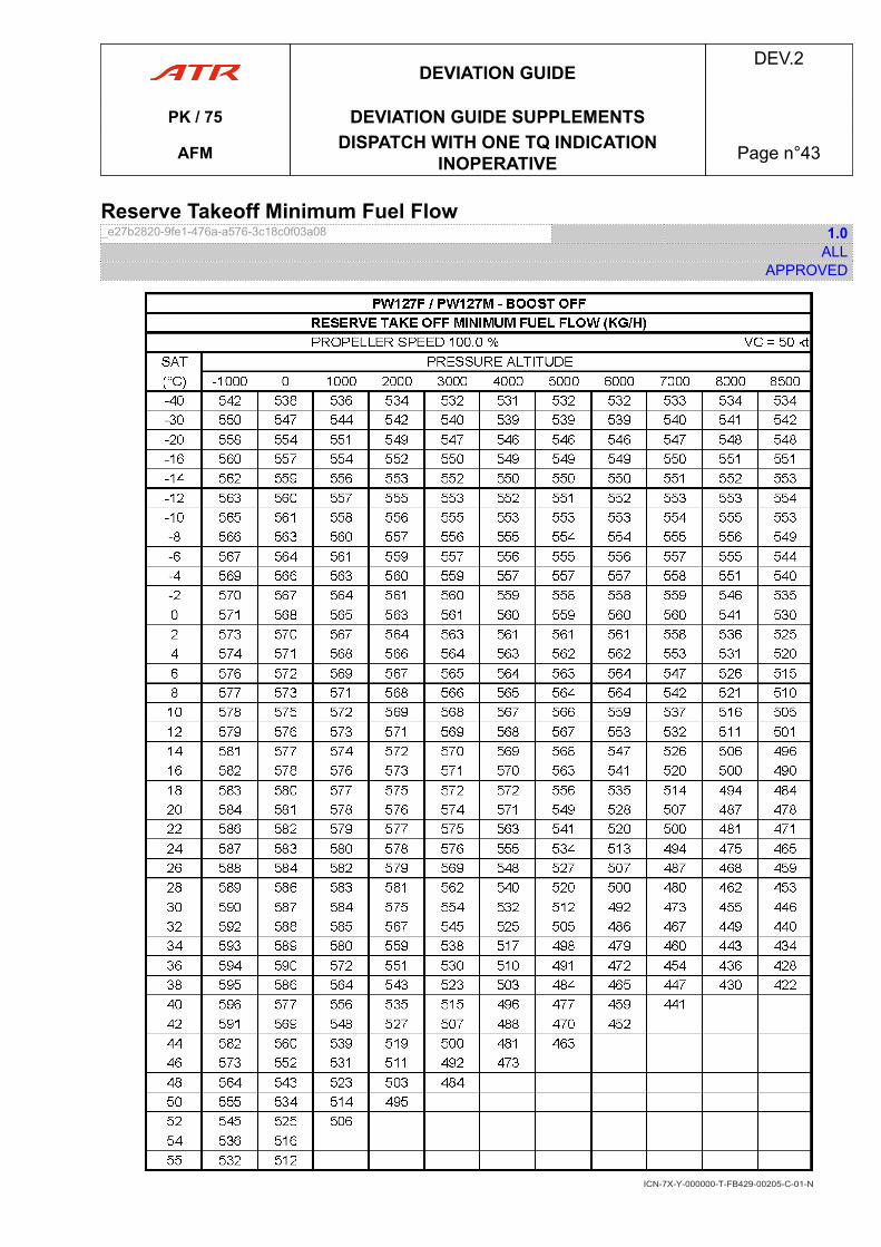
Reserve Takeoff Minimum Fuel Flow_e27b2820-9fe1-476a-a576-3c18c0f03a08 1.0
ALLAPPROVED
ICN-7X-Y-000000-T-FB429-00205-C-01-N
DEVIATION GUIDEDEV.2
PK / 75 DEVIATION GUIDE SUPPLEMENTS
AFM DISPATCH WITH ONE TQ INDICATIONINOPERATIVE Page n°43
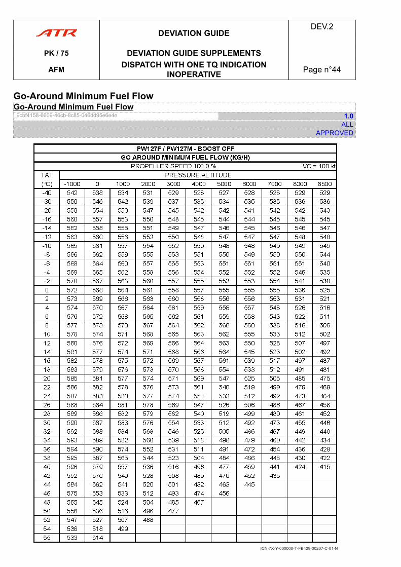
Go-Around Minimum Fuel FlowGo-Around Minimum Fuel Flow_9cbf4158-6609-46cb-8c85-046dd95e6e4e 1.0
ALLAPPROVED
ICN-7X-Y-000000-T-FB429-00207-C-01-N
DEVIATION GUIDEDEV.2
PK / 75 DEVIATION GUIDE SUPPLEMENTS
AFM DISPATCH WITH ONE TQ INDICATIONINOPERATIVE Page n°44
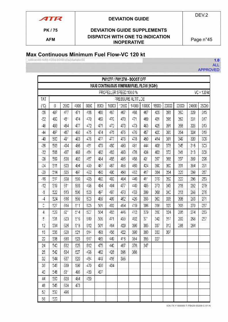
Max Continuous Minimum Fuel Flow-VC 120 kt_cd8cacdd-4dfd-435d-b048-c0a34a4abc50 1.0
ALLAPPROVED
ICN-7X-Y-000000-T-FB429-00209-C-01-N
DEVIATION GUIDEDEV.2
PK / 75 DEVIATION GUIDE SUPPLEMENTS
AFM DISPATCH WITH ONE TQ INDICATIONINOPERATIVE Page n°45
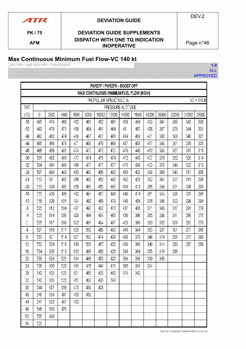
Max Continuous Minimum Fuel Flow-VC 140 kt_6b318f5c-1ee8-4b5a-9fb1-17dfe36cdec6 1.0
ALLAPPROVED
ICN-7X-Y-000000-T-FB429-00211-C-01-N
DEVIATION GUIDEDEV.2
PK / 75 DEVIATION GUIDE SUPPLEMENTS
AFM DISPATCH WITH ONE TQ INDICATIONINOPERATIVE Page n°46
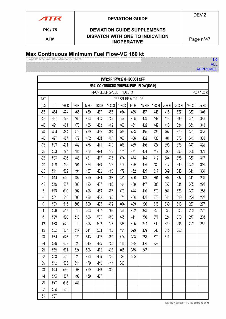
Max Continuous Minimum Fuel Flow-VC 160 kt_6ea4f011-7a6a-4b08-8e07-8e00cf8f4c3c 1.0
ALLAPPROVED
ICN-7X-Y-000000-T-FB429-00213-C-01-N
DEVIATION GUIDEDEV.2
PK / 75 DEVIATION GUIDE SUPPLEMENTS
AFM DISPATCH WITH ONE TQ INDICATIONINOPERATIVE Page n°47
11 DISPATCH WITH UPTRIM FUNCTION INOPERATIVEDISPATCH WITH UPTRIM FUNCTION INOPERATIVE_426b5cdf-04e3-494c-90fe-b363973f7a6d 2.1
ALLAPPROVED
LIMITATIONSNo change.
PROCEDURESNormal Procedures
● During flight preparation, before each takeoff▶ ATPCS (dynamic test)...................................... ...................................... TESTIn order to protect the feathering pumps from damage, 10 min delays between testand takeoff, or between static/dynamic tests must be respected.
● For takeoff▶ BLEEDS..................................................................................................OFF▶ PL 1+2........................................................................................SET AT RTOSet PL 1+2 up to the ramp and adjust the PL on the inoperative EEC side (+/- 2 %)RTO power.
● After takeoff▶ PL 1+2............................................... ............................................... NOTCH▶ BLEEDS................................................. ................................................. ON
PERFORMANCES- Increase V1 limited by VMCG by 3 kt
DEVIATION GUIDEDEV.2
PK / 75 DEVIATION GUIDE SUPPLEMENTS
AFM DISPATCH WITH UPTRIM FUNCTIONINOPERATIVE Page n°48
12 DISPATCH WITH ATPCS OFFDispatch with ATPCS Off_8f338b22-616a-492e-b687-11f3d4a98575 1.4
ALLAPPROVED
LIMITATIONSNo change.
PROCEDURESNormal Procedures
● For takeoff▶ BLEEDS..................................................................................................OFF▶ ATPCS ................................................. ................................................. OFF▶ FLAPS................................................... ................................................... 15▶ PL 1+2............................................................................ADVANCE TO RAMP
● Climb sequence▶ PL 1+2............................................................................RETARD TO NOTCH▶ BLEED 1+2............................................... ............................................... ON
Emergency ProceduresNo change.
Abnormal Procedures■ If engine fails after V1
▶ PL (affected ENG) : DO NOT REDUCE BELOW PLA 45 ° UNTIL FEATHERING
PERFORMANCES- Increase V1 limited by VMCG by 5 kt- Increase VR by 2 kt- Increase VMCA by 3 kt- Check VR and V2- Increase VMCL by 7 kt- Check ATPCS inoperative effect on TOR, TOD and second segment.
DEVIATION GUIDEDEV.2
PK / 75 DEVIATION GUIDE SUPPLEMENTSAFM DISPATCH WITH ATPCS OFF Page n°49
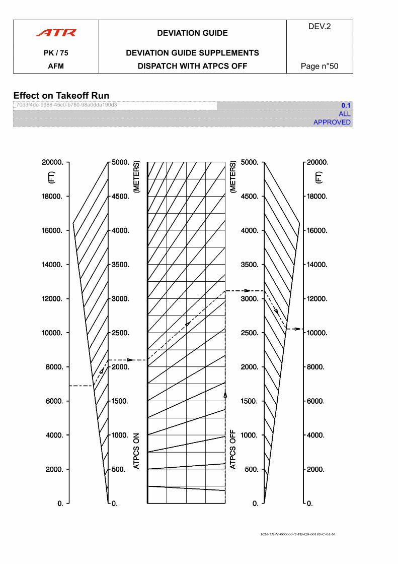
Effect on Takeoff Run_70d3f4de-9988-45c0-b780-98a0dda190d3 0.1
ALLAPPROVED
ICN-7X-Y-000000-T-FB429-00183-C-01-N
DEVIATION GUIDEDEV.2
PK / 75 DEVIATION GUIDE SUPPLEMENTSAFM DISPATCH WITH ATPCS OFF Page n°50
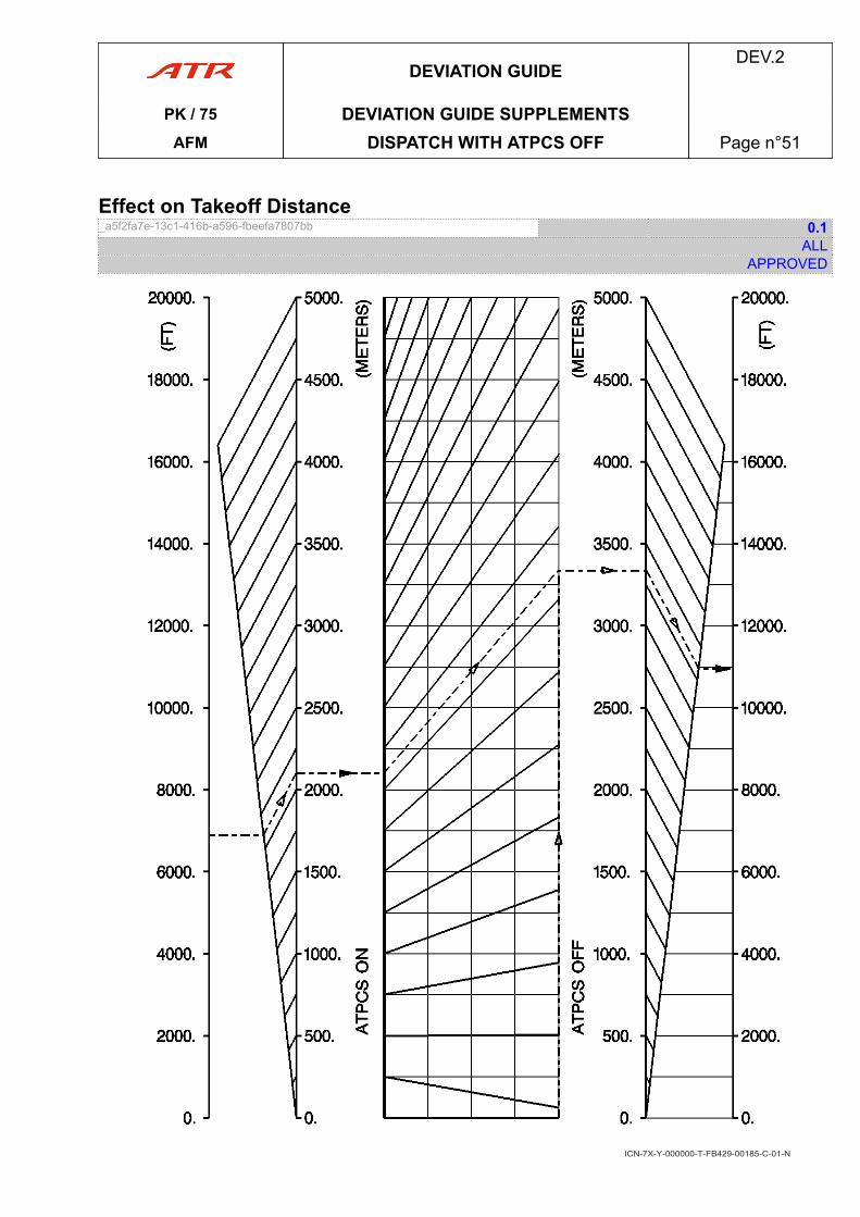
Effect on Takeoff Distance_a5f2fa7e-13c1-416b-a596-fbeefa7807bb 0.1
ALLAPPROVED
ICN-7X-Y-000000-T-FB429-00185-C-01-N
DEVIATION GUIDEDEV.2
PK / 75 DEVIATION GUIDE SUPPLEMENTSAFM DISPATCH WITH ATPCS OFF Page n°51
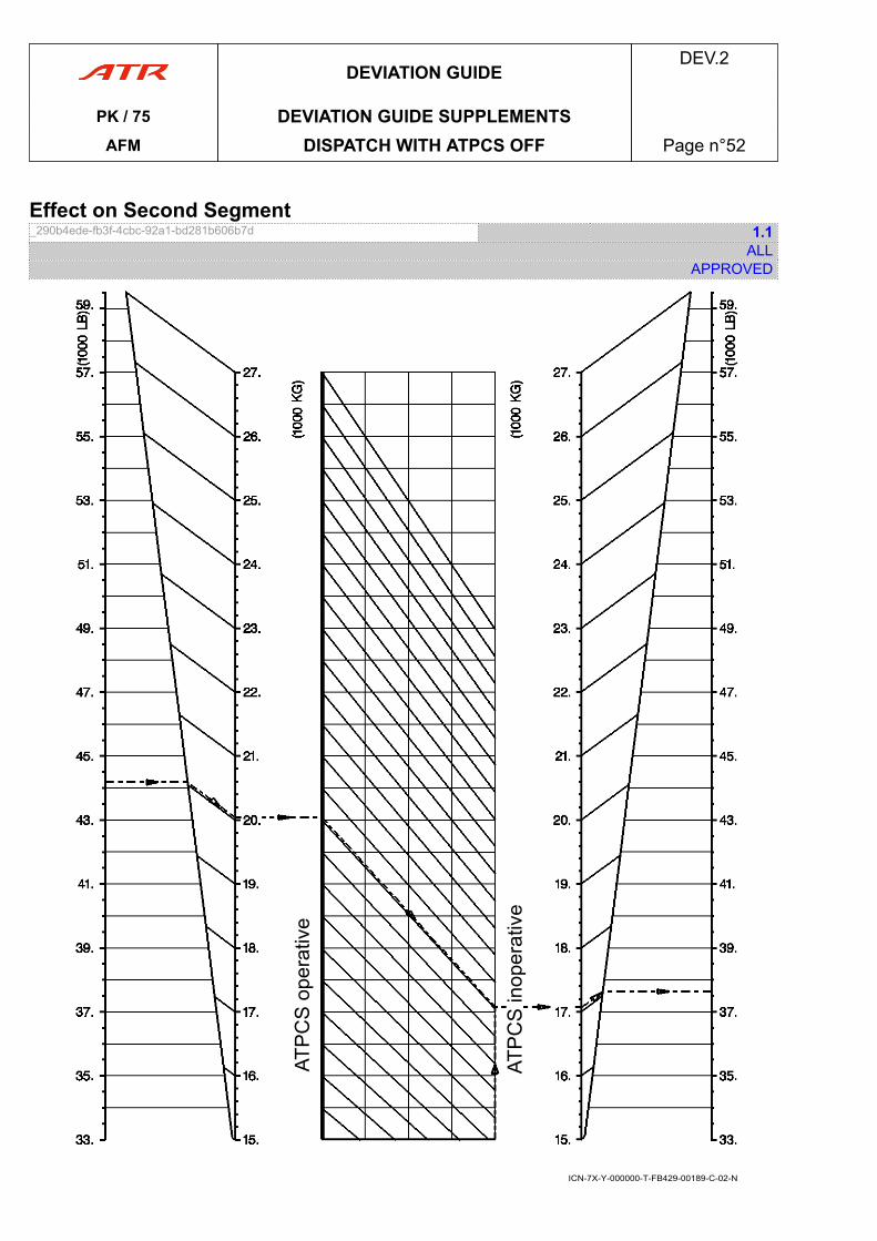
Effect on Second Segment_290b4ede-fb3f-4cbc-92a1-bd281b606b7d 1.1
ALLAPPROVED
ICN-7X-Y-000000-T-FB429-00189-C-02-N
DEVIATION GUIDEDEV.2
PK / 75 DEVIATION GUIDE SUPPLEMENTSAFM DISPATCH WITH ATPCS OFF Page n°52
13 DISPATCH WITH LANDING GEAR DOWNDispatch with Landing Gear Down_980159a9-b0b6-430d-81d7-918e7ce031a3 3.1
ALLAPPROVED
LIMITATIONSOperations into forecast or known icing conditions are prohibited.Maximum speed................................................ ................................................ 160 kt
PROCEDURESNormal Procedures
● Before takeoff▶ TCAS............................................... ............................................... TA ONLY
● During the climb sequence▶ CCAS ................................................ ................................................ RecallTo turn off TO INHIB light.
Emergency ProceduresNo change.
Abnormal ProceduresNo change.
PERFORMANCESTakeoff
- Check GEAR DOWN effect on second segment climb and approach climb (valid forall configurations)
- Check GEAR DOWN effect on final takeoff climb.Single Engine Ceiling
Apply a weight penalty on single engine ceiling computation.
DEVIATION GUIDEDEV.2
PK / 75 DEVIATION GUIDE SUPPLEMENTSAFM DISPATCH WITH LANDING GEAR DOWN Page n°53
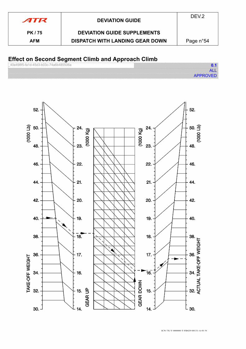
Effect on Second Segment Climb and Approach Climb_40e498f5-fa1d-45d3-b03c-74a6b485506a 0.1
ALLAPPROVED
ICN-7X-Y-000000-T-FB429-00131-A-01-N
DEVIATION GUIDEDEV.2
PK / 75 DEVIATION GUIDE SUPPLEMENTSAFM DISPATCH WITH LANDING GEAR DOWN Page n°54
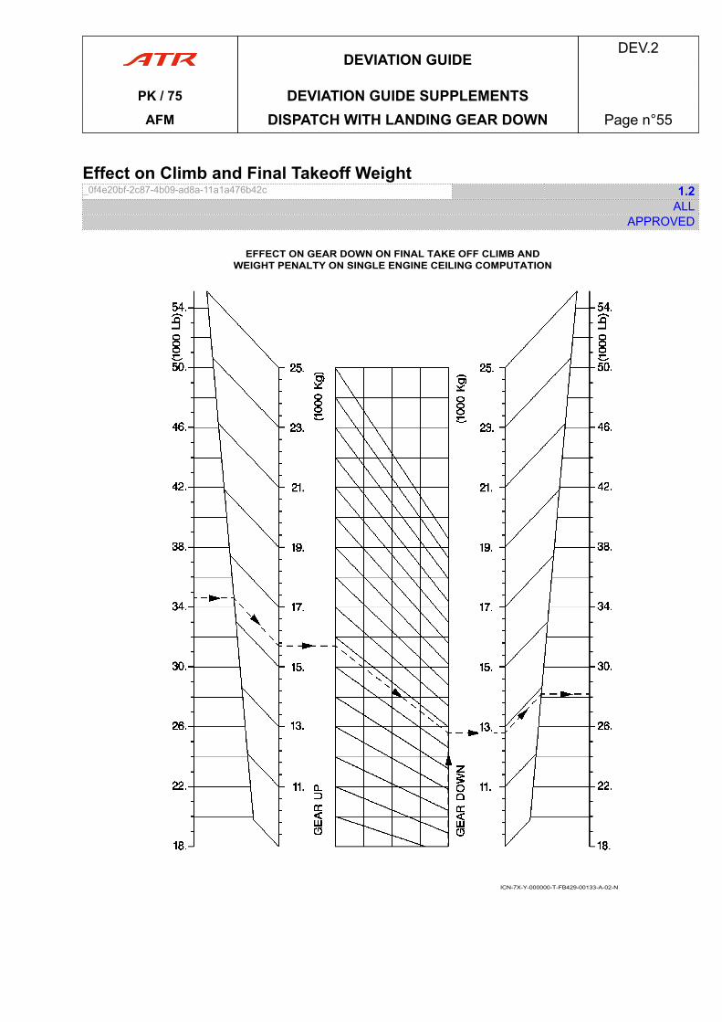
Effect on Climb and Final Takeoff Weight_0f4e20bf-2c87-4b09-ad8a-11a1a476b42c 1.2
ALLAPPROVED
EFFECT ON GEAR DOWN ON FINAL TAKE OFF CLIMB ANDWEIGHT PENALTY ON SINGLE ENGINE CEILING COMPUTATION
ICN-7X-Y-000000-T-FB429-00133-A-02-N
DEVIATION GUIDEDEV.2
PK / 75 DEVIATION GUIDE SUPPLEMENTSAFM DISPATCH WITH LANDING GEAR DOWN Page n°55
16 FLIGHT WITH PITCH ELEVATORS DISCONNECTEDFlight with Pitch Elevators Disconnected_50166868-9f79-4bca-b202-f7dde15c6b8a REV 5.0
ALLAPPROVED
LIMITATIONSOperations into forecast or known icing conditions are prohibited.MAINTENANCE ACTION IS REQUIRED WHEN PITCH DISCONNECTION OCCURREDIN FLIGHT
Maximum crosswind at landing .............................................................................. 15 ktMaximum load factor ............................................... ............................................... 2 gMaximum speed ................................................ ................................................ 180 ktMaximum takeoff weight ................................... ................................... 18 T (39 600 lb)Landing braking energy limitation ........................................................................ 8.3 MJCG ..........................................................................................between 25 % and 32 %Delayed braking procedure is prohibited.STEEP SLOPE APPROACH >4.5° : PROHIBITED.
PROCEDURESNormal Procedures
● During flight preparation▶ BOTH CONTROL COLUMNS......................................................CHECK FREE
CAUTIONWhen elevators are uncoupled, dual opposite inputs from left and right control columnsare strictly forbidden as it may result in structural damage to the horizontal stabilizer.
▶ For approach and landing, Refer to FCOM.PRO.NOR.NSU.Flight Controls and Referto PRO.NNO.ABN.FLIGHT CONTROLS.PITCH.PITCH DISCONNECT
Emergency ProceduresNo change.
Abnormal ProceduresNo change.
PERFORMANCESPerformance computed with V2 = 1.21 VSR.
DEVIATION GUIDEDEV.2
PK / 75 DEVIATION GUIDE SUPPLEMENTS
AFM FLIGHT WITH PITCH ELEVATORSDISCONNECTED Page n°56
APPENDICESEXTERNAL NOISE APP.1
. Noise Characteristics.................................................................................... page 03
. Noise Levels................................................................................................. page 03
. Noise Certification Procedures...................................................................... page 03
. Configuration................................................................................................ page 03
. Certification Noise Levels..............................................................................page 03
AFMAPP.
PK / 75 TOCAFM Table of Content Page n°01

PAGE
INTENTIONALLY
LEFT BLANK
AFMAPP.
PK / 75 TOCAFM Table of Content Page n°02
01 Noise Characteristics_5c6cebb4-acdc-49cc-b2db-e24dd25cdb5d 1.2
ALLAPPROVED
No determination has been made by the EASA that the noise levels of this aircraft are orshould be acceptable or unacceptable for operation at, into, or out of any airport.
02 Noise Levels_77a550ca-62b7-4e36-b88d-1c15bcc34613 2.0
ALLAPPROVED
Noise levels shown here after comply with ICAO annex 16 Chapter 4, noise requirements andwere obtained by analysis of approved data from approved noise tests.Refer to LIM.WEIGHT AND LOADING chapter for identification of the maximum takeoff andlanding weights applicable to a particular aircraft.
03 Noise Certification Procedures_d52dcf36-9903-4b7b-8cf5-fba36e338acb 0.2
ALLAPPROVED
Compliance with ICAO annex 16 included the following procedures:- An all-engine takeoff at FLAPS 15 configuration was used with a constant climb speed
greater than V2 + 10 kt but less than V2 + 20 kt, with a cutback procedure initiated priorto overflight of the takeoff noise measuring station, with air conditioning OFF, mid centerof gravity, and gear retracted.
- Landing approach at FLAPS 30 configuration on a 3 ° glide slope, at a speed of 1.23 VSR+ 10 kt was used with air conditioning ON, forward center of gravity and gear extended.
04 Configuration_53e6c5c0-f06a-4130-9db7-f1ca38e377a9 REV 1.0
ALLAPPROVED
Engines: Pratt & Whitney of Canada Ltd PW127F or PW127M or PW127NPropeller: Hamilton Standard HS 568F-1
05 Certification Noise Levels_aec4b0b8-95cc-49ac-b068-70ecafbb887f REV 1.0
ALLAPPROVED
Takeoff: 80.2 EPNdBSide line: 82.5 EPNdBApproach: 92.2 EPNdB
APPENDICESAPP.1
PK / 75 EXTERNAL NOISEAFM Page n°03

PAGE
INTENTIONALLY
LEFT BLANK
APPENDICESAPP.1
PK / 75 EXTERNAL NOISEAFM Page n°04