Embed Size (px)
Citation preview
38 Concrete in Australia Vol 40 No 3
FEATURE: CONCRETE PERFORMANCE IN FIRE
Fire design of high strength concrete walls
Priyan Mendis, Quynh Thuy Nguyen, Tuan Ngo, University of Melbourne, Victoria, Australia
High-strength concrete (HSC) is becoming very popular around the world due to its many advantages over normal strength concrete (NSC). � ere are signifi cant behavioural diff erences between HSC and NSC, most notably the brittleness and sudden spalling under elevated temperatures, whereby pieces of hardened concrete explosively dislodge. � e spalling of high strength concrete walls in fi re has generally been ignored by the designers and the fi re-resistance of walls has been calculated using the rules specifi ed for normal strength concrete. Major design codes including the Australian Code do not cover spalling adequately. After a brief discussion on the status of research, general observations on spalling are summarised. Relevant results from a comprehensive study conducted at the University of Melbourne are briefl y discussed. � is is the fi rst systematic testing program covering the fi re behaviour of NSC and HSC walls exposed not only to standard fi res but also hydrocarbon fi res. It is shown that fi re-induced spalling may lead to serious reduction in the cross-section of structural elements and could lead to early catastrophic failure.
1.0 INTRODUCTION
� e performance of concrete structures in fi re has become increasingly signifi cant in the past decade. � is is due in part to the increased incidence of accidental fi res, explosions and the trend to build high-rise structures. � e types of fi res evident have exceeded the scope of standard fi re tests and in many recent events are those of the hydrocarbon type. � ere is an increasing use of load-bearing reinforced high-strength concrete (HSC) walls in the design of buildings. � e increase in HSC (f ’c > 50 MPa) use is because it has many advantages and it has also become easier to manufacture, due to the availability of a variety of pozzolanic admixtures such as micro-silica and high-range super-plasticisers. � e reason for the popularity of using load-bearing reinforced HSC walls is mainly due to the trend towards reinforced concrete core walls in high-rise buildings and the increased acceptance of tilt-up and other types of precast structures. In addition to providing a load-bearing function, these walls usually provide a fi re separating function between compartments in modern structures, and they must therefore satisfy all three fi re safety requirements, namely integrity, insulation and structural adequacy, at high temperatures.1
Despite the increasing use of load-bearing HSC walls in buildings, there have been only very few investigations reported on HSC walls subjected to fi re conditions, both locally and internationally.2-5
1.1 Fire resistance of high-strength concrete
According to the wide ranging research studies conducted over a number of years, the material properties of HSC vary diff erently with temperature as compared to those of normal strength concrete (NSC).6-11 Meda et al.12 studied the ultimate behaviour of HSC sections at high temperature and after cooling subjected to several fi re durations. � ey concluded that HSC sections are more temperature-sensitive than NSC sections. Results indicated that losses in relative strength due to high-temperature exposure were aff ected by the test
condition and water/cement ratio, but there were signifi cant interactions among other main factors that resulted in complex behaviours.13 � ese complex behaviours were believed to be linked to heat-induced transformations and transport of free and chemically combined water. � e diff erences are more pronounced in the temperature range of between 25 °C to about 400 °C, where higher strength concretes have higher rates of strength loss than lower strength concretes. � ese diff erences become less signifi cant at temperatures above 400 °C. Compressive strengths of HSC at 800 °C decrease to about 30% of the original room temperature strengths. � e diff erence between the compressive strength versus temperature relationships of normal weight and lightweight aggregate appears to be insignifi cant, based on the limited amount of existing test data. � e tensile strength versus temperature relationships decreases similarly and almost linearly with temperature for HSC and NSC. HSC mixtures with micro-silica have higher strength loss with increasing temperatures than HSC mixtures without micro-silica. � e failure of HSC is more brittle than NSC at temperatures up to 300 °C. With further increase in temperature, specimens exhibit a more gradual failure mode.
Adverse eff ects of HSC elements in fi re have been described by many researchers (e.g. Sanjayan).14 According to the results of laboratory focused fi re tests in these research studies, there are remarkable diff erences between the properties of HSC and NSC in terms of the loss of cross-section, the timing of loss of strength, and the degrees of deformation and spalling at elevated temperatures. � e most notable fi nding is that HSC is considered to suff er more seriously from spalling due to fi re than NSC. Fire-induced spalling of concrete is a phenomenon whereby pieces of hardened concrete explosively dislodge or fall-off the fi re exposed surface of a concrete member during rapid high temperature exposure. � e risk of concrete spalling at elevated temperature should be considered when designing structural elements especially high-strength concrete (f ’c >50 MPa). Disintegration of concrete parts due to spalling can cause serious reduction in the cross-section of structural elements and
Concrete in Australia Vol 40 No 3 39
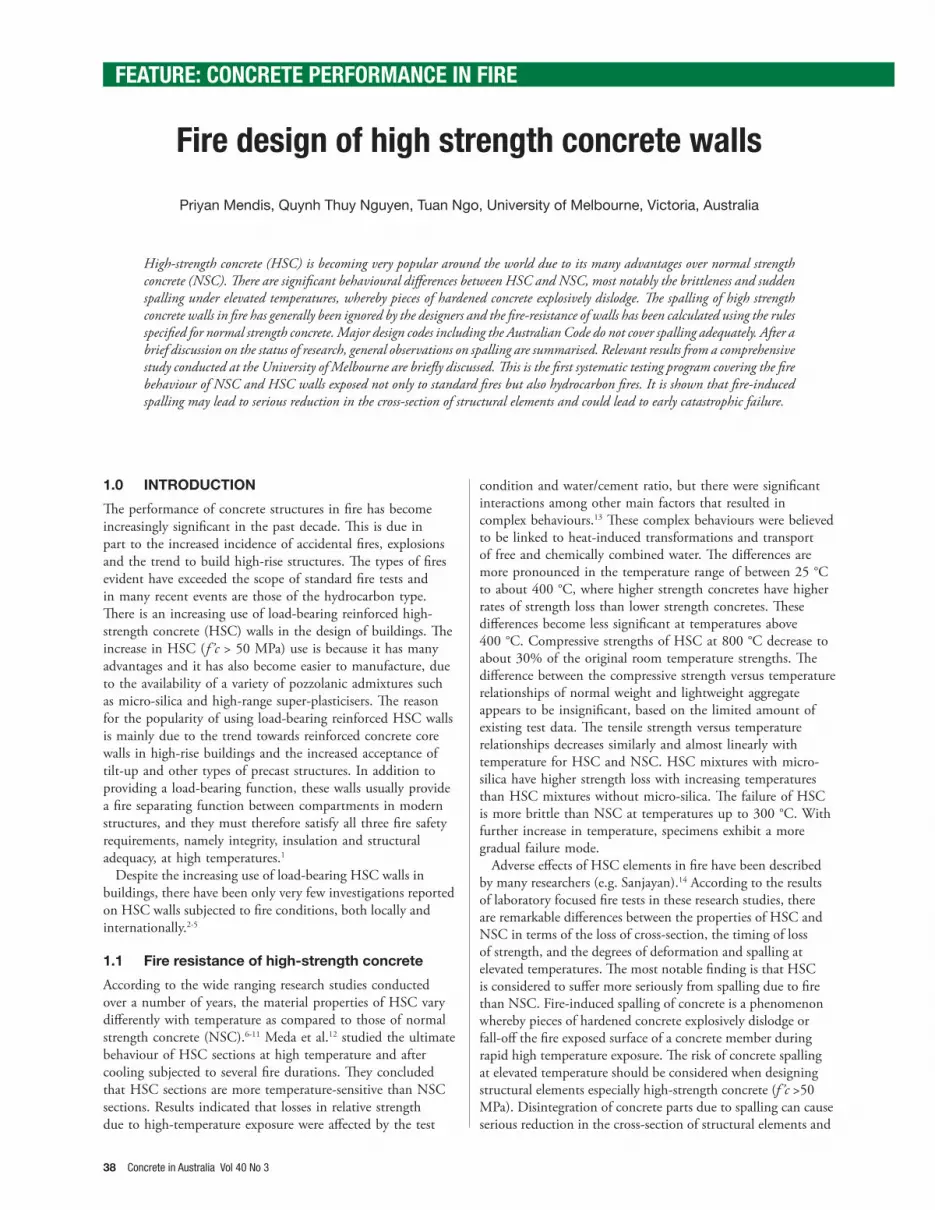
could lead to early catastrophic failure. � e depth of spalled concrete often far exceeds the cover to the main reinforcement. � e pieces can be large or small and detachment can either occur explosively or pieces may dislodge and subsequently fall (Figure 1). � e pore pressure generated during fi re exposure in typical high strength concrete columns can reach about 4.5 MPa, while the corresponding pore pressure in conventional normal strength concrete columns is only about 1 MPa.15 Spalling can take place over the whole surface area of a member or in localised areas. � e risk of spalling is higher in high-strength concrete due to the following reasons:(i) Low permeability of HSC retains the moisture inside
the concrete resulting in a high moisture content being present for prolonged periods.
(ii) Low porosity of HSC creates higher pore pressure.(iii) HSC tends to be subject to higher compressive stresses
than lower strength concrete.Whether spalling occurs or not in a particular situation and the extent of spalling have a random element in them. � erefore, although the investigations on high-strength concrete started in mid 1990s, still no comprehensive design rules are included in design codes. HSC specimens heated at higher heating rates, such as hydrocarbon fi re which occurred in WTC collapse on September 11, and larger specimens are more prone to spalling than specimens heated at lower rates and of smaller size. Ta16 showed that, for HSC, hydrocarbon fi re produces explosive spalling compared to standard fi re.Ko et al.17 investigated the spalling properties of concrete in relation to surface moisture content. � ey found that spalling of high-strength concrete was signifi cantly aff ected by moisture transfer in the surface region of concrete and moisture transfer was found to be closely related to the temperature profi les resulting from the characteristics of pore structures, which are the main passages for moisture. � ey also found that in high-strength (80 MPa) concrete, the probability of spalling and scale of damage could be reduced according to dryness in the surface region (0-30 mm depth).� ere are some general observations on spalling,1, 5, 14 summarised below.
� e tendency for spalling is high when:
• the element is made of high-strength concrete rather than normal strength concrete
• cover to reinforcement is increased, especially more than about 40 mm
• moisture content of the concrete is high
• the temperature rise of the fi re is rapid and concrete is subjected to a high thermal gradient
• concrete is subjected to compressive stress
• when concrete is subjected to a hydrocarbon fi re compared to a standard fi re.
Many experimental studies (e.g. Ngo et al.)5 have shown that the use of polypropylene fi bres in the concrete mix reduces the tendency for spalling. � is is due to the fact that the polypropylene fi bres melt during the fi re, thus increasing the internal voids of the concrete and decreasing the vapour pressure build-up within the concrete. A dosage rate of 1.2 kg/m3 of 6 mm monofi lament polypropylene fi bres is
recommended to reduce the level of spalling1, although EN1992-1-2 2004 recommends a higher dosage as stated below.
1.2 Rules for high-strength concrete in Eurocode
Although not proven by systematic testing, the rules given in Section 6 of EN1992-1-2 2004 can be used as an initial guide for high-strength concrete. Strength properties are given in three classes (f ’c, 50 to 70 MPa, 70 to 90 MPa and equal to 90 MPa) and recommendations against spalling are given for two ranges of HSC. Where the actual characteristic strength of concrete is likely to be of a higher class than that specifi ed in design, the relative reduction in strength for the higher class should be used for fi re design.
Simplifi ed Calculation Method presented in Appendix B of EN1992-1-2 2004 (500 degree isotherm method, zone method, curvature method) can be applied for high-strength concrete with some modifi cation factors.
� e following methods are suggested for spalling:(1) For concrete strengths between 55 to 80 MPa, fi re
design rules provided for normal strength concrete apply if the maximum content of micro-silica is less than 6% by weight of cement. For higher contents of silica fume the rules given in (2) apply.
(2) For concrete strengths between 80 and 90 MPa (and can be assumed to extrapolate up to 100 MPa) spalling can occur in any situation for concrete exposed directly to the fi re and at least one of the following methods should be provided:
• Method A: A reinforcement mesh with a nominal cover of 15 mm. � is mesh should have wires with a diameter ≥ 2 mm with a pitch ≤ 50 x 50 mm. � e nominal cover to the main reinforcement should be ≥ 40 mm.
• Method B: A type of concrete for which it has been demonstrated (by local experience or by testing) that no spalling of concrete occurs under fi re exposure.
• Method C: Protective layers for which it is demonstrated that no spalling of concrete occurs under fi re exposure.
• Method D: Include in the concrete mix more than 2 kg/m3 of monofi lament propylene fi bres.
Figure 1: Behaviour of HSC in Fire.18
Sudden burst due to the
steam-pressure
Water bound chemically and
physically in cement pasteSudden burst due to the
steam-pressure
Water bound chemically and
physically in cement paste
40 Concrete in Australia Vol 40 No 3
FEATURE: CONCRETE PERFORMANCE IN FIRE
2. TESTING OF HSC WALLS UNDER
STANDARD AND HYDROCARBON FIRE
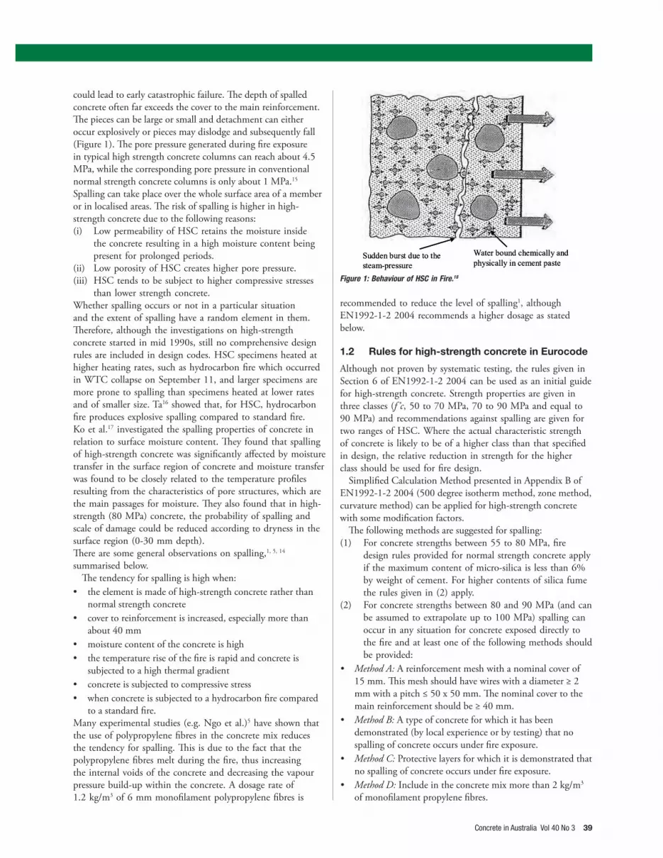
Previous research on concrete walls focused on standard fi re testing only. Compared to a standard fi re, a hydrocarbon fi re creates a signifi cant increase in temperature in the initial period of the fi re (i.e. it reaches 1000 °C in only eight minutes). As a result, hydrocarbon fi res could have the potential to create violent explosive spalling in concrete structures, especially in HSC. � e results from fi re tests on 10 reinforced concrete wall panels subjected to both standard or hydrocarbon fi res fi re, conducted in a PhD project are briefl y discussed here. Two walls were of NSC were axially loaded at an eccentricity of 10 mm and exposed to both types of fi res. Two identically dimensioned HSC walls were also tested using these variables. One further HSC wall with polypropylene fi bres (2 kg/m3) added was tested under hydrocarbon fi re. � e water/binder ratio was maintained to be 0.59 for NSC mixes and 0.24 for HSC mixes. 10% micro-silica was used for HSC specimens. Emphasis was given to observing failure mode, spalling characteristics, thermal transfer, and wall displacements. Initial moisture content and slump were also measured.
Five specimens of 240 x 1000 x 150 mm (height x width x
Parameter Specimen code
NSC-SD NSC-HC HSC-SD HSC-HC HSC-PP
Fire test condition Standard
! re
Hydro-carbon
! re
Standard
! re
Hydro-carbon
! re
Hydro-carbon
! re
Test load (kN) 485 485 970 970 970
Eccentricity (mm) 10 10 10 10 10
Initial moisture content (%) 8.4 8.4 5.7 5.7 5.7
28-day compressive
strength (MPa)31.8 31.5 81.8 81.8 84.6
Test day compressive
strength (MPa)35.6 36.2 87.6 87.6 89.3
Figure 2: Positions of thermocouples through the specimen thickness (dimensions in mm). Figure 3: Standard and hydrocarbon fi re curves.
Table 1: Compressive test and loading details of specimens.
thickness) were prepared. � e details are presented in Table 1. Reinforcement was placed in two layers in both vertical and horizontal (N16@300mm) directions, with clear cover of 25 mm. All walls were tested in a vertical position in a large furnace, and supported top and bottom only. Full-scale fi re tests were done with a constant eccentric load of approximately 15-20% of axial load capacity. � e loading device consisted of 1000 kN hydraulic jacks mounted on top of the chamber and transferring the load through a steel beam to the top of the wall. Temperatures inside the specimens were measured every minute. Crack propagation, defl ections and the occurrence of spalling were monitored during fi re testing via four small portal openings on the furnace. � ermocouples were secured into specimen at designed locations as illustrated in Figure 2. Two diff erent test conditions of standard fi re (ISO834) and hydrocarbon fi re were applied to the relevant specimen as given in Figure 3.
� e temperature profi les were more signifi cantly diff erent when identical HSC and NSC walls were subjected to a hydrocarbon fi re. Figures 4 and 5 show a comparison of heat transfer within NSC and HSC walls subjected to standard and hydrocarbon fi re. Temperatures were taken throughout the

Concrete in Australia Vol 40 No 3 41
thickness of the specimen as indicated in Figure 2. Figure 4(a) shows the temperature curves recorded at thickness respective to point 1, 2, and 3 in Figure 2 while fi gure 4(b) shows the temperature curves recorded at thickness respective to point 4, 5, 6 and 7 in Figure 2, for standard fi re. Figure 5 shows the temperature curves inside the furnace and temperature recorded at thickness respective to (a) point 1; (b) point 2 and 3; (c) point 4 and 5; (d) point 6 and 7 in Figure 2, for hydrocarbon fi re. In general, the temperatures at thermocouples 1, 2, 3, 4,
5, 6 and 7 in specimen HSC were higher than in specimen NSC. Probable reasons for this diff erence are HSC spalled earlier than NSC when the walls were subjected to fi re and the thermal conductivity of HSC is usually higher than that for NSC. Severe spalling occurred in the fi rst period of the fi re test HSC-HC, resulting in the temperatures of layers 1, 2, 3 and 4 increasing very quickly. After being subjected to 30 minutes of hydrocarbon fi re, the HSC-HC wall had a spalling depth of more than 50mm (Figure 6 and Figure 7).
Figure 4: Comparison of heat transfer within NSC wall (NSC-SD) and HSC wall (HSC-SD) when subjected to standard fi re.
Figure 5: Comparison of heat transfer within NSC wall (NSC-HC), HSC wall (HSC-HC) and HSC wall with PPF (HSC-PP) when subjected to hydrocarbon fi re.

42 Concrete in Australia Vol 40 No 3
FEATURE: CONCRETE PERFORMANCE IN FIRE
� e results indicate that all concrete wall panels (NSC and HSC) exposed to the standard fi re tests survived the 120 minute fi re period, with low to moderate spalling evident. � e NSC walls exposed to hydrocarbon fi res also survived the 120 minute test whereas the HSC walls experienced severe spalling under these fi re conditions (Figure 6) with failure at 31 minutes. � e addition of polypropylene fi bres in the concrete improved the fi re resistance of HSC walls in hydrocarbon fi re to 65 minutes. � is result was typical when comparing identical HSC and NSC test panels subjected to a standard fi re test. � e possible reason for the signifi cant diff erences under hydrocarbon fi re, is that the HSC wall suff ered more from early concrete spalling than its NSC counterpart and therefore was exposed to increased temperatures within its section at a much earlier time. Some form of spalling was found to occur within 3 to 25 minutes of the wall being exposed to fi re and when the temperature at the spalling point was in the range 200 °C to 400 °C.
� e experimentally observed time-temperature curves show that there is a reduction in the rate of temperature increase once the temperature reaches around 100 °C up to approximately 130 °C. � is can be explained by the production of water vapour at 100 °C, which requires energy to transform from liquid to gas. In addition, at this point the water from the cooler inner layers travels to the outside layer, thereby reducing the heat energy at the outer layer. � e results show that specimen HSC walls failed due to a loss in axial load capacity. � ere was a signifi cant loss of cross-section at the point of fracture because of spalling.
Observations on spalling are also applicable to high-strength concrete columns. Although not covered in this test program, it has been found that the combination of polypropylene (PP) fi bre and steel fi bre (hybrid) exhibited the best performance for spalling reduction. � e hybrid fi bre reduced the spalling activity to minor non explosive occurrence with the degree of spalling between 8.6-12.4% of the initial column weight. It is believed that this reduction can be attributed to the steel fi bre resisting the initiation and expansion of cracks in the concrete matrix while the melting action of the polypropylene fi bre created micro channels in the concrete mass which alleviated vapour tension. Kodur et al.15 concluded that spalling occurs only outside the reinforcement cage when the ties are bent at 135° into the concrete core. � ey also found that the extent of spalling is dependent on the type of aggregate, and spacing of ties. � e extent of spalling is higher (100%) in the siliceous aggregate HSC than that for carbonate aggregate HSC (40%).
A research team led by Prof Jannie Van Deventer at the University of Melbourne has conducted several studies to show that Geopolymer Concrete possesses superior fi re-resistant properties. Four half-scale E-CreteTM panels (produced by Zeobond) with dimensions of 1200 x 1200 x 150 mm (5 panels) and a full-scale 3300 x 3300 x 150 mm were tested at Victoria University’s fi re facility. None of the E-CreteTM panels showed any evidence of spalling. � is is due to the fact that geopolymer concrete has more connected pores, than Portland cement concrete when compared at the same strength level. Hence, the water vapour can escape from the geopolymer matrix quicker than in Portland cement concrete, resulting in lower internal pore pressure.
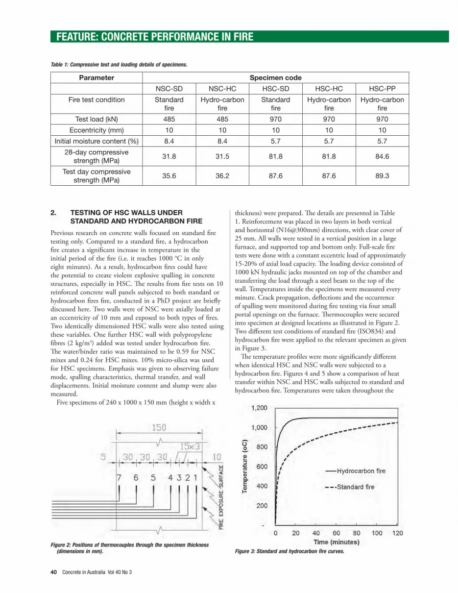
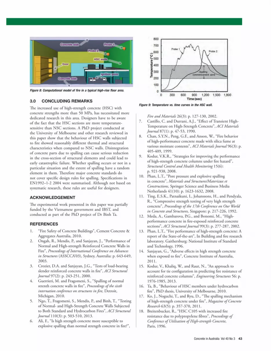
• A very effi cient way of designing concrete walls is using advanced computational dynamics techniques to fi nd the exact temperature predictions. A computational model developed by the authors for a typical fl oor area in a high-rise building is shown in Figure 8. A natural fi re is developed through the burning of furniture and the ignition point is indicated in Figure 8. � e maximum temperature in the HSC wall reached only about 700 °C (Figure 9), although the maximum temperature in a standard fi re is more than 1000 °C. � erefore the wall can be designed for a lower maximum temperature. However, as can be seen from Figure 9, the wall is within the spalling commencement zone and design for spalling is essential.
Figure 6: Depth of spalling of (a-left) NSC-HC (in mm) and (b-right) HSC-HC (in mm).
Figure 7: Spalling observed in the HSC specimens.
0-5 5-10 10-15 15-20 20-25 25-30 30-35 35-40
0-10 10-20 20-30 30-40 40-50 50-60 60-70 70-80
80-90 90-100 100-110 110-120 120-130 130-140 140-150
Concrete in Australia Vol 40 No 3 43
3.0 CONCLUDING REMARKS
� e increased use of high-strength concrete (HSC) with concrete strengths more than 50 MPa, has necessitated more dedicated research in this area. Designers have to be aware of the fact that the HSC sections are more temperature-sensitive than NSC sections. A PhD project conducted at the University of Melbourne and other research reviewed in this paper show that the behaviour of HSC walls subjected to fi re showed reasonably diff erent thermal and structural characteristics when compared to NSC walls. Disintegration of concrete parts due to spalling can cause serious reduction in the cross-section of structural elements and could lead to early catastrophic failure. Whether spalling occurs or not in a particular situation and the extent of spalling have a random element in them. � erefore major concrete standards do not cover specifi c design rules for spalling. Specifi cations in EN1992–1-2 2004 were summarised. Although not based on systematic research, these rules are useful for designers.
ACKNOWLEDGEMENT
� e experimental work presented in this paper was partially funded by the Vietnamese government and IBST, and conducted as part of the PhD project of Dr Binh Ta.
REFERENCES
1. “Fire Safety of Concrete Buildings”, Cement Concrete & Aggregates Australia, 2010.
2. Ongah, R., Mendis, P., and Sanjayan, J., “Performance of Normal and High-strength Reinforced Concrete Walls in Fire”, Proceedings of International Conference on Advances in Structures (ASSCCA’03), Sydney, Australia: p. 643-649, 2003.
3. Crozier, D.A. and Sanjayan, J.G., “Tests of load-bearing slender reinforced concrete walls in fi re”, ACI Structural Journal 97(2): p. 243-251, 2000.
4. Guerrieri, M. and Fragomeni, S., “Spalling of normal strenth concrete walls in fi re”, Proceedings of the sixth internation conference on structures in fi re, Detroit, Michigan, 2010.
5. Ngo, T., Fragomeni, S., Mendis, P., and Binh, T., “Testing of Normal- and High-Strength Concrete Walls Subjected to Both Standard and Hydrocarbon Fires”, ACI Structural Journal 110(3): p. 503-510, 2013.
6. Ali, F., “Is high strength concrete more susceptible to explosive spalling than normal strength concrete in fi re?”,
Figure 9: Temperature vs. time curves in the HSC wall.
Figure 8: Computational model of fi re in a typical high-rise fl oor area.
Fire and Materials 26(3): p. 127-130, 2002.7. Castillo, C. and Durrani, A.J., “Eff ect of Transient High-
Temperature on High-Strength Concrete”, ACI Materials Journal 87(1): p. 47-53, 1990.
8. Chan, S.Y.N., Peng, G.F., and Anson, W., “Fire behavior of high-performance concrete made with silica fume at various moisture contents”, ACI Materials Journal 96(3): p. 405-409, 1999.
9. Kodur, V.K.R., “Strategies for improving the performance of high-strength concrete columns under fi re hazard”, Structural Control and Health Monitoring 15(6): p. 921-938, 2008.
10. Phan, L.T., “Pore pressure and explosive spalling in concrete”, Materials and Structures/Materizux et Constructions, Springer Science and Business Media Netherlands 41(10): p. 1623-1632, 2008.
11. Ting, E.S.K., Patnaikuni, I., Johanssons, H., and Pendyala, R., “Compressive strength testing of very high strength concrete”, Proceedings of the 17th Conference on Our World in Concrete and Structures, Singapore: p. 217-226, 1992.
12. Meda, A., Gambarova, P.G., and Bonomi, M., “High-performance concrete in fi re-exposed reinforced concrete sections”, ACI Structural Journal 99(3): p. 277-287, 2002.
13. Phan, L.T., “Fire performance of high-strength concrete: A report of the State-of-the-art”, In Building and fi re research laboratory. Gaithersburg: National Institute of Standard and Technology, 1996.
14. Sanjayan, G., “Adverse eff ects in high strength concrete when exposed to fi re”, Concrete Institute of Australia, 2011.
15. Kodur, V., Khaliq, W., and Raut, N., “An approach to account for tie confi guration in predicting fi re resistance of reinforced concrete columns”, Engineering Structures 56: p. 1976-1985, 2013.
16. Ta, B., “Behaviour of HSC members under hydrocarbon fi re”, PhD thesis, University of Melbourne, 2010.
17. Ko, J., Noguchi, T., and Ryu, D., “� e spalling mechanism of high-strength concrete under fi re”, Magazine of Concrete Research 63(5): p. 357-370, 2011.
18. Breitenbucker, R., “HSC C105 with increased fi re resistance due to polypropylene fi bres”, Proceedings of Conference of Utilisation of High-strength Concrete, Paris, 1996.


