Embed Size (px)
Citation preview
�
Filter Elements and Filter HousingsEdition 2007

�
A Clear Business
„We are committed to transparency, openness and doing businessin the spirit of partnership. You can count on ‘Wolftechnik Filter Systems’to provide you with lasting top value – thanks to our products andour employees, who work with your benefits in mind.”
Your Partner for Economic Filtration.
Our Teams
Every time we receive an inquiry or order, we respond with intensive advice and service – for identifying the technical requirements, preparing offers, andcompleting jobs. To make sure that you’re consistently well supported and cared for, we have organized ourselves into teams. Each team includes sales employees for processing orders, technical consultants who go into the field, and technical specialists. This approach guarantees that you get optimum quality fast.
Your Partner
Do you like to work with reliable, innovative partners? Are you looking for a partner who will meet your special requirements on time? Do you expect quality and flexibility, as well as fast, friendly handling of your orders?
If so, you’ve found the right partner in Wolftechnik Filter Systems.
Wolftechnik has been specializing in filter systems since 1966. Several teams of highly trained employees take care in meeting your wishes andmaking sure you benefit from our innovations. When you do business with Wolftechnik Filter Systems, you’ll discover that our actions are driven by the desire to optimally meet your requirements.
Northern TeamRalf Münzberg, Order processingKristiane Kager, Order processingRonald Franz, Field consultantDirk Hahlweg, Field consultantGeorg Hudy, Technical specialist
„We do our utmost to understand you and your particular situation. That‘s why it is so important for us to trust and communicate with one another.”
Southern TeamDieter Meschik, Order processingJulia Schaal, Order processingDirk Weiler, Field consultantChristian Zitzl, Field consultantMichael Kessler, Technical specialist
“Finding payable solutions for your special needs has always been our strength. So that it remains that way, we must communicate and learn from each other.”
Direct/InternationalWera Schaal, Order processingKarin Krause, Order processingClaudia Beck, Order processingHeinz Öhlschläger, Field consultant and Technical specialistPeter Krause, Field consultant and Technical specialist
„We want to improve our service and gear ourselves more precisely to meeting your unique needs. This is only possible in direct contact with you.”
�
Chem
ical
s &
Cos
met
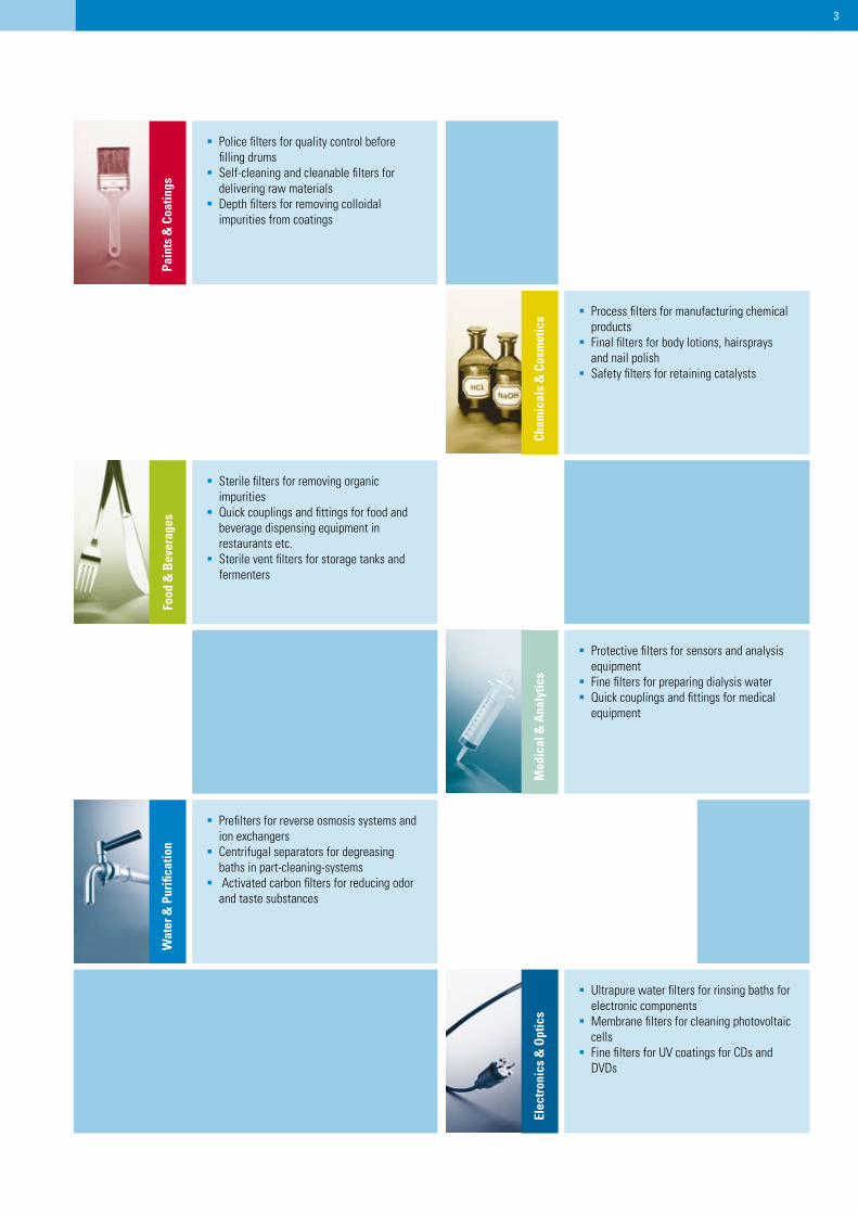
ics Process filters for manufacturing chemical
productsFinal filters for body lotions, hairsprays
and nail polishSafety filters for retaining catalysts
Police filters for quality control before filling drums
Self-cleaning and cleanable filters for delivering raw materials
Depth filters for removing colloidal impurities from coatings
Elec
tron
ics
& O
ptic
s
Ultrapure water filters for rinsing baths for electronic components
Membrane filters for cleaning photovoltaic cells
Fine filters for UV coatings for CDs and DVDs
Med
ical
& A
naly
tics
Protective filters for sensors and analysis equipment
Fine filters for preparing dialysis waterQuick couplings and fittings for medical
equipment
Food
& B
ever
ages
Sterile filters for removing organic impurities
Quick couplings and fittings for food and beverage dispensing equipment in restaurants etc.
Sterile vent filters for storage tanks and fermenters
Wat
er &
Pur
ifica
tion
Prefilters for reverse osmosis systems and ion exchangers
Centrifugal separators for degreasing baths in part-cleaning-systems
Activated carbon filters for reducing odor and taste substances
�
Pain
ts &
Coa
tings
�
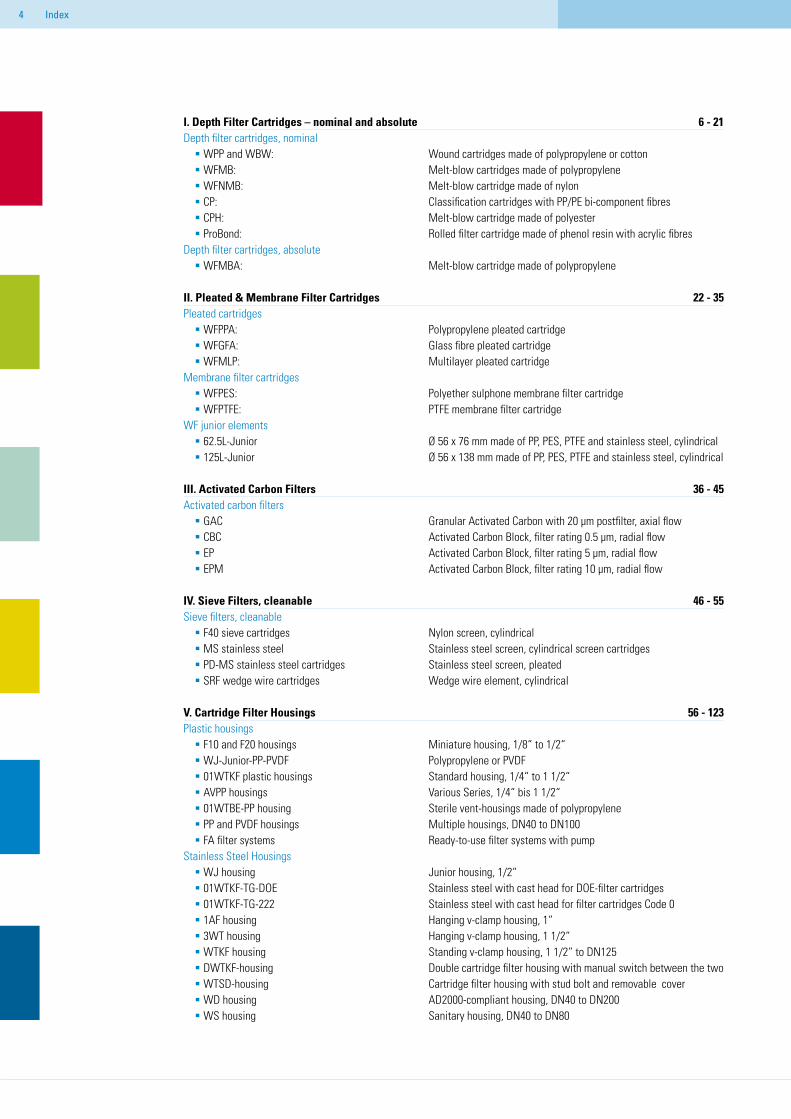
I. Depth Filter Cartridges – nominal and absoluteDepth filter cartridges, nominal WPP and WBW: Wound cartridges made of polypropylene or cotton WFMB: Melt-blow cartridges made of polypropylene WFNMB: Melt-blow cartridge made of nylon CP: Classification cartridges with PP/PE bi-component fibres CPH: Melt-blow cartridge made of polyester ProBond: Rolled filter cartridge made of phenol resin with acrylic fibresDepth filter cartridges, absoluteWFMBA: Melt-blow cartridge made of polypropylene
II. Pleated & Membrane Filter CartridgesPleated cartridgesWFPPA: Polypropylene pleated cartridgeWFGFA: Glass fibre pleated cartridge WFMLP: Multilayer pleated cartridgeMembrane filter cartridgesWFPES: Polyether sulphone membrane filter cartridgeWFPTFE: PTFE membrane filter cartridgeWF junior elements 62.5L-Junior Ø 56 x 76 mm made of PP, PES, PTFE and stainless steel, cylindrical 125L-Junior Ø 56 x 138 mm made of PP, PES, PTFE and stainless steel, cylindrical III. Activated Carbon FiltersActivated carbon filtersGAC Granular Activated Carbon with 20 μm postfilter, axial flowCBC Activated Carbon Block, filter rating 0.5 μm, radial flowEP Activated Carbon Block, filter rating 5 μm, radial flowEPM Activated Carbon Block, filter rating 10 μm, radial flow
IV. Sieve Filters, cleanableSieve filters, cleanableF40 sieve cartridges Nylon screen, cylindricalMS stainless steel Stainless steel screen, cylindrical screen cartridgesPD-MS stainless steel cartridges Stainless steel screen, pleatedSRF wedge wire cartridges Wedge wire element, cylindrical
V. Cartridge Filter HousingsPlastic housingsF10 and F20 housings Miniature housing, 1/8“ to 1/2“WJ-Junior-PP-PVDF Polypropylene or PVDF01WTKF plastic housings Standard housing, 1/4“ to 1 1/2“AVPP housings Various Series, 1/4“ bis 1 1/2“01WTBE-PP housing Sterile vent-housings made of polypropylenePP and PVDF housings Multiple housings, DN40 to DN100FA filter systems Ready-to-use filter systems with pumpStainless Steel HousingsWJ housing Junior housing, 1/2“01WTKF-TG-DOE Stainless steel with cast head for DOE-filter cartridges01WTKF-TG-222 Stainless steel with cast head for filter cartridges Code 01AF housing Hanging v-clamp housing, 1“3WT housing Hanging v-clamp housing, 1 1/2“WTKF housing Standing v-clamp housing, 1 1/2“ to DN125DWTKF-housing Double cartridge filter housing with manual switch between the twoWTSD-housing Cartridge filter housing with stud bolt and removable coverWD housing AD2000-compliant housing, DN40 to DN200WS housing Sanitary housing, DN40 to DN80
6 - 21
22 - 35
36 - 45
46 - 55
56 - 123
Index
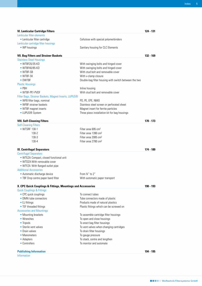
VI. Lenticular Cartridge FiltersLenticular filter elements Lenticular filter cartridge Cellulose with special polymerbindersLenticular cartridge filter housingsWP housings Sanitary housing for CLC Elements
VII. Bag Filters and Strainer BasketsStainless Steel HousingsWTBF20/35-KD With swinging bolts and hinged coverWTBF40/85-KD With swinging bolts and hinged coverWTBF-SB With stud bolt and removable cover WTBF-SK With v-clamp closureDWTBF Double-bag filter housing with switch between the twoPlastic HousingsPBH Inline housingWTBF-PP/-PVDF With stud bolt and removable coverFilter Bags, Strainer Baskets, Magnet Inserts, LUPUS®WFB filter bags, nominal PO, PE, EPE, NMOWFBF strainer baskets Stainless steel screen or perforated sheet WTBF magnet inserts Magnet insert for ferrite particlesLUPUS® System Three piece installation kit for bag housings
VIII. Self-Cleaning FiltersSelf-Cleaning FiltersWTSRF 130-1 Filter area 695 cm² 130-2 Filter area 1390 cm² 130-3 Filter area 2085 cm² 130-4 Filter area 2780 cm²
IX. Centrifugal SeparatorsCentrifugal SeparatorsWTEZA Compact, closed functional unit WTDZA With removable coverWTFZA With flanged outlet pipeAdditional Accessories Automatic discharge device From ¾“ to 2“TBF Drop centre paper band filter With automatic paper transport
X. CPC Quick Couplings & Fittings, Mountings and Accessories Quick Couplings & FittingsCPC quick couplings To connect tubes DMfit tube connectors Tube connectors made of plasticEJ fittings Products made of natural plasticsTEF threaded fittings Plastic fittings which can be screwed onAccessories and MountingsMounting brackets To assemble cartridge filter housingsWrenches To open and close housingsTripods To erect bag filter housingsSterile vent valves To vent valves when changing cartridgesDrain valves To drain filter housingsManometers To gauge pressure Adapters To stack, centre and lengthenControllers To monitor and automate
Publishing InformationInformation
124 - 131
132 - 169
170 - 173
174 - 189
190 - 193
194 - 195
Index �
�
�
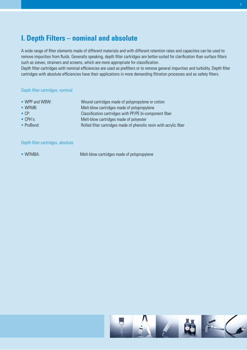
I. Depth Filters – nominal and absolute
A wide range of filter elements made of different materials and with different retention rates and capacities can be used to remove impurities from fluids. Generally speaking, depth filter cartridges are better-suited for clarification than surface filters such as sieves, strainers and screens, which are more appropriate for classification.Depth filter cartridges with nominal efficiencies are used as prefilters or to remove general impurities and turbidity. Depth filter cartridges with absolute efficiencies have their applications in more demanding filtration processes and as safety filters.
Depth filter cartridges, nominal
WPP and WBW: Wound cartridges made of polypropylene or cottonWFMB: Melt-blow cartridges made of polypropyleneCP: Classification cartridges with PP/PE bi-component fiberCPH‘s: Melt-blow cartridges made of polyesterProBond: Rolled filter cartridges made of phenolic resin with acrylic fiber
Depth filter cartridges, absolute
WFMBA: Melt-blow cartridges made of polypropylene
�
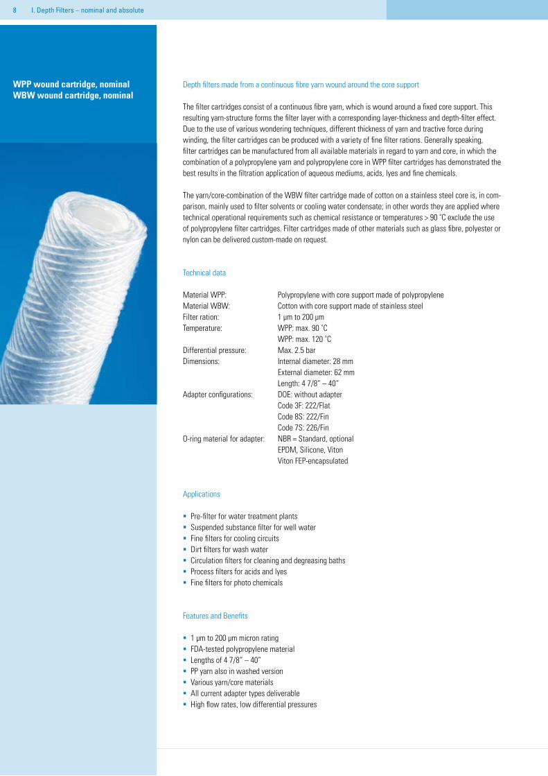
Depth filters made from a continuous fibre yarn wound around the core support
The filter cartridges consist of a continuous fibre yarn, which is wound around a fixed core support. This resulting yarn-structure forms the filter layer with a corresponding layer-thickness and depth-filter effect. Due to the use of various wondering techniques, different thickness of yarn and tractive force during winding, the filter cartridges can be produced with a variety of fine filter rations. Generally speaking, filter cartridges can be manufactured from all available materials in regard to yarn and core, in which the combination of a polypropylene yarn and polypropylene core in WPP filter cartridges has demonstrated the best results in the filtration application of aqueous mediums, acids, lyes and fine chemicals.
The yarn/core-combination of the WBW filter cartridge made of cotton on a stainless steel core is, in com-parison, mainly used to filter solvents or cooling water condensate; in other words they are applied where technical operational requirements such as chemical resistance or temperatures > 90 ˚C exclude the use of polypropylene filter cartridges. Filter cartridges made of other materials such as glass fibre, polyester or nylon can be delivered custom-made on request.
Technical data
Material WPP: Polypropylene with core support made of polypropyleneMaterial WBW: Cotton with core support made of stainless steelFilter ration: 1 μm to 200 μmTemperature: WPP: max. 90 ˚C WPP: max. 120 ˚CDifferential pressure: Max. 2.5 barDimensions: Internal diameter: 28 mm External diameter: 62 mm Length: 4 7/8“ – 40“Adapter configurations: DOE: without adapter Code 3F: 222/Flat Code 8S: 222/Fin Code 7S: 226/FinO-ring material for adapter: NBR = Standard, optional EPDM, Silicone, Viton Viton FEP-encapsulated
Applications
Pre-filter for water treatment plantsSuspended substance filter for well waterFine filters for cooling circuits Dirt filters for wash waterCirculation filters for cleaning and degreasing bathsProcess filters for acids and lyesFine filters for photo chemicals
Features and Benefits
1 μm to 200 μm micron ratingFDA-tested polypropylene materialLengths of 4 7/8“ – 40“PP yarn also in washed versionVarious yarn/core materialsAll current adapter types deliverable High flow rates, low differential pressures
WPP wound cartridge, nominalWBW wound cartridge, nominal
I. Depth Filters – nominal and absolute
�
Flow
rate
Flow
rate
Surf
ace
(Wou
ndin
g of
car
trid
ge)
I. Depth Filters – nominal and absoluteI. Depth Filters – nominal and absolute �
Ord
er In
form
atio
n
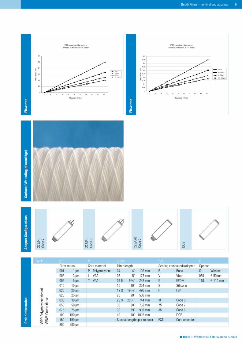
010 P 093/4 B3F GFilter ration Core material Filter length Sealing compound/Adapter Options001 1 μm P Polypropylene 04 4“ 102 mm B Buna G Washed003 3 μm L V2A 05 5“ 127 mm V Viton 050 Ø 50 mm005 5 μm T V4A 09 ¾ 9 ¾“ 248 mm E EPDM 110 Ø 110 mm010 10 μm 10 10“ 254 mm S Silicone020 20 μm 19 ½ 19 ½“ 496 mm F FEP025 25 μm 20 20“ 508 mm030 30 μm 29 ¼ 29 ¼“ 744 mm 3F Code 0050 50 μm 30 30“ 762 mm 7S Code 7075 75 μm 39 39“ 992 mm 3S Code 5100 100 μm 40 40“ 1016 mm - DOE150 150 μm Special lengths per request EXT Core extended200 200 μm
WPP
WPP
: Pol
ypro
pyle
ne th
read
W
BW: C
otto
n th
read
226/
Fin
Code
7
222/
Fin
Code
5
DOE
Ada
pter
Con
figur
atio
ns
222/
Cap
Code
0
WPP wound cartridge, nominalflow rate in reference to 10“ (water)
Flow rate (l/min)
Pres
sure
loss
(bar
)
WBW wound cartridge, nominalflow rate in reference to 10“ (water)
Pres
sure
loss
(bar
)
Flow rate (l/min)
�0
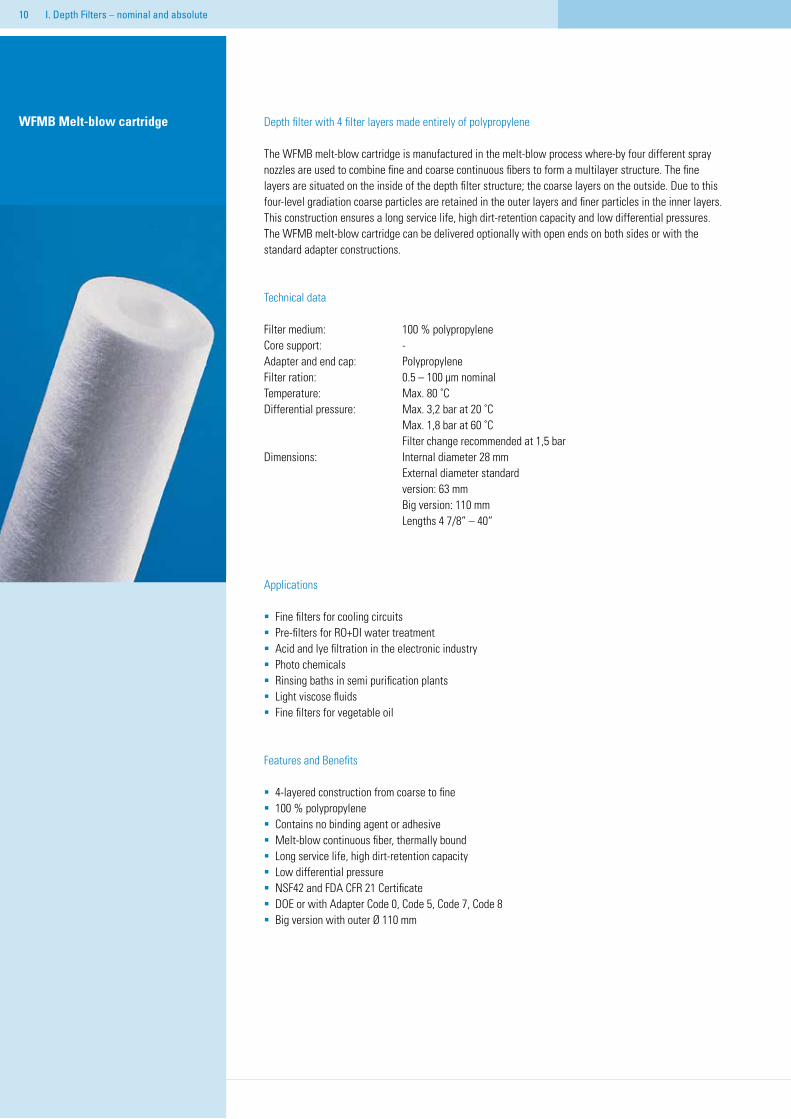
WFMB Melt-blow cartridge Depth filter with 4 filter layers made entirely of polypropylene
The WFMB melt-blow cartridge is manufactured in the melt-blow process where-by four different spray nozzles are used to combine fine and coarse continuous fibers to form a multilayer structure. The fine layers are situated on the inside of the depth filter structure; the coarse layers on the outside. Due to this four-level gradiation coarse particles are retained in the outer layers and finer particles in the inner layers. This construction ensures a long service life, high dirt-retention capacity and low differential pressures. The WFMB melt-blow cartridge can be delivered optionally with open ends on both sides or with the standard adapter constructions.
Technical data
Filter medium: 100 % polypropyleneCore support: -Adapter and end cap: PolypropyleneFilter ration: 0.5 – 100 μm nominal Temperature: Max. 80 ˚CDifferential pressure: Max. 3,2 bar at 20 ˚C Max. 1,8 bar at 60 ˚C Filter change recommended at 1,5 barDimensions: Internal diameter 28 mm External diameter standard version: 63 mm Big version: 110 mm Lengths 4 7/8“ – 40“
Applications
Fine filters for cooling circuitsPre-filters for RO+DI water treatmentAcid and lye filtration in the electronic industryPhoto chemicalsRinsing baths in semi purification plantsLight viscose fluidsFine filters for vegetable oil
Features and Benefits
4-layered construction from coarse to fine100 % polypropyleneContains no binding agent or adhesive Melt-blow continuous fiber, thermally boundLong service life, high dirt-retention capacityLow differential pressureNSF42 and FDA CFR 21 CertificateDOE or with Adapter Code 0, Code 5, Code 7, Code 8Big version with outer Ø 110 mm
I. Depth Filters – nominal and absolute
226/
Fin
Code
7
222/
Fin
Code
5
DOE
Ada
pter
Con
figur
atio
n
222/
Cap
Code
0
Ass
embl
y
Schm
utza
ufna
hme
mit
Test
stau
b (G
ram
m)
Effic
ienc
y (%
)
Flow
rate
Ord
er in
form
atio
n
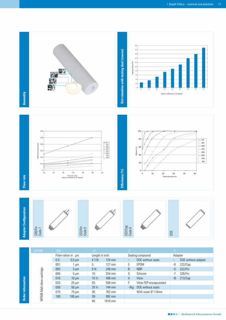
-005 -20 -E -0Filter ration in μm Length in inch Sealing compound Adapter 0.5: 0,5 μm 4 7/8: 124 mm -: DOE without seals -: DOE without adapter001: 1 μm 5: 127 mm E: EPDM -0: 222/Cap003: 3 μm 9 ¾: 248 mm B: NBR -5: 222/Fin005: 5 μm 10: 254 mm S: Silicone -7: 226/Fin010: 10 μm 19 ½: 496 mm V: Viton -B: 213/Cap 025: 25 μm 20: 508 mm F: Viton-FEP-encapsulated050: 50 μm 29 ¼: 744 mm - Big: DOE without seals 075: 75 μm 30: 762 mm With outer Ø 110mm100: 100 μm 39: 992 mm 40: 1016 mm
I. Depth Filters – nominal and absolute
WFMB
��
Dir
t ret
entio
n w
ith te
stin
g du
st (c
oars
e)
WFM
B M
elt-b
low
car
tridg
e
��
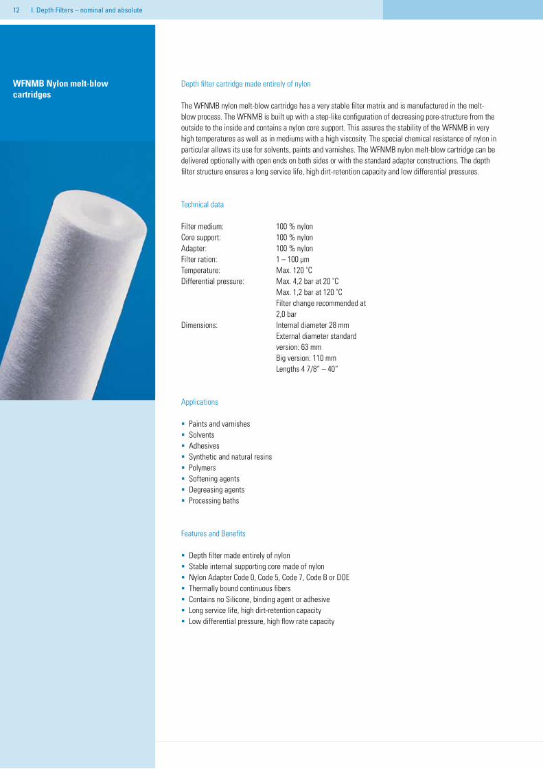
Depth filter cartridge made entirely of nylon
The WFNMB nylon melt-blow cartridge has a very stable filter matrix and is manufactured in the melt-blow process. The WFNMB is built up with a step-like configuration of decreasing pore-structure from the outside to the inside and contains a nylon core support. This assures the stability of the WFNMB in very high temperatures as well as in mediums with a high viscosity. The special chemical resistance of nylon in particular allows its use for solvents, paints and varnishes. The WFNMB nylon melt-blow cartridge can be delivered optionally with open ends on both sides or with the standard adapter constructions. The depth filter structure ensures a long service life, high dirt-retention capacity and low differential pressures.
Technical data
Filter medium: 100 % nylonCore support: 100 % nylonAdapter: 100 % nylonFilter ration: 1 – 100 μm Temperature: Max. 120 ˚CDifferential pressure: Max. 4,2 bar at 20 ˚C Max. 1,2 bar at 120 ˚C Filter change recommended at 2,0 barDimensions: Internal diameter 28 mm External diameter standard version: 63 mm Big version: 110 mm Lengths 4 7/8“ – 40“
Applications
Paints and varnishesSolventsAdhesivesSynthetic and natural resinsPolymersSoftening agentsDegreasing agentsProcessing baths
Features and Benefits
Depth filter made entirely of nylonStable internal supporting core made of nylonNylon Adapter Code 0, Code 5, Code 7, Code B or DOEThermally bound continuous fibersContains no Silicone, binding agent or adhesive Long service life, high dirt-retention capacityLow differential pressure, high flow rate capacity
WFNMB Nylon melt-blow cartridges
I. Depth Filters – nominal and absolute
��I. Depth Filters – nominal and absolute
226/
Fin
Code
7
222/
Fin
Code
5
DOE
Ada
pter
Con
figur
atio
ns
222/
Cap
Code
0
Ord
er in
form
atio
n
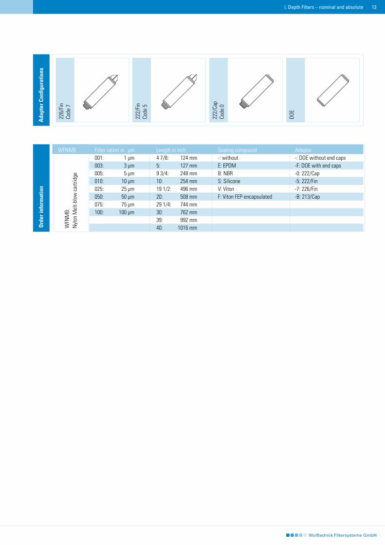
Filter ration in μm Length in inch Sealing compound Adapter 001: 1 μm 4 7/8: 124 mm -: without -: DOE without end caps003: 3 μm 5: 127 mm E: EPDM -F: DOE with end caps005: 5 μm 9 3/4: 248 mm B: NBR -0: 222/Cap010: 10 μm 10: 254 mm S: Silicone -5: 222/Fin025: 25 μm 19 1/2: 496 mm V: Viton -7: 226/Fin050: 50 μm 20: 508 mm F: Viton FEP-encapsulated -B: 213/Cap075: 75 μm 29 1/4: 744 mm 100: 100 μm 30: 762 mm 39: 992 mm 40: 1016 mm
WFNMB
WFN
MB:
Nyl
on M
elt-b
low
car
tridg
e

��
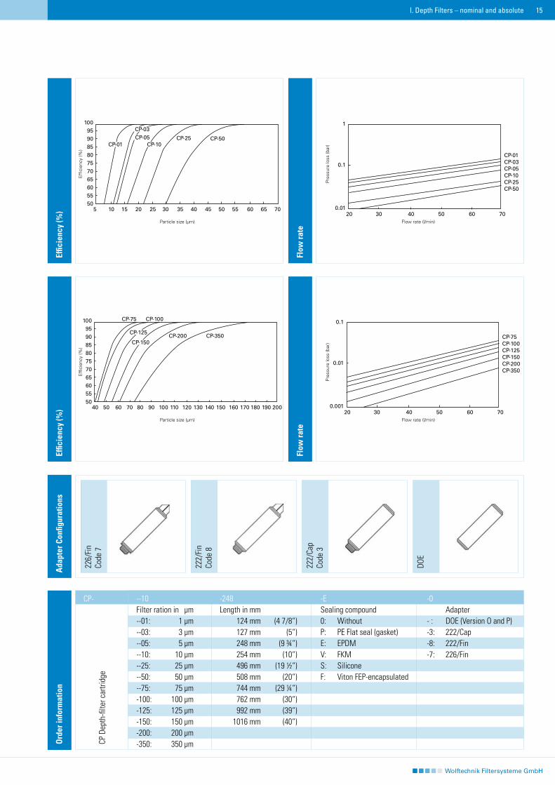
CP Depth filter cartridge, nominal Depth filter cartridges with a constant perforation structure made of PE-coated PP fiber
The CP Depth filter cartridge consists of 100 % polyethylene-coated polypropylene fiber soldered together at their cross points. The attained ultrapure and exceptionally compact filter matrix assures a repetitious accuracy of filtration characteristics for top quality applications. The CP Depth filter cartridge is a typical classification cartridge with a consistent pore-structure and filter ration from the outside to the inside. In addition the depth filter structure assures a high flow rate and long service life.
Technical data
Filter medium: 100 % polypropylene, Polyethylene coatedCore support: -Adapter and end cap: PolypropyleneFilter ration: 1 – 350 μm, nominal Temperature: Max. 80 ˚CDifferential pressure: Max. 5,5 bar at 20 ˚C Max. 2,5 bar at 80 ˚C Filter change recommended at 1,5 barDimensions: Internal diameter 28 mm External diameter standard version: 63 mm Big version: 110 mm Lengths 4 7/8“ – 40“
Applications
Varnishes, paints and inksMagnet-dispersion agents Fine chemicalsSolventsAcids and lyesCosmeticsUltrapure waterFood and beverages
Features and Benefits
Consistent pore-structureCompact filter matrix due to the PE/PP threadsThermally affixed threadsNo thread lossNo use of binding agentsExtensive chemical durabilityLow pressure loss, high flow rateLong filter service life
I. Depth Filters – nominal and absolute
��
226/
Fin
Code
7
222/
Fin
Code
8
DOE
Ada
pter
Con
figur
atio
ns
222/
Cap
Code
3
Effic
ienc
y (%
)
Flow
rate
Effic
ienc
y (%
)
Flow
rate
Ord
er in
form
atio
n
--10 -248 -E -0Filter ration in μm Length in mm Sealing compound Adapter--01: 1 μm 124 mm (4 7/8“) 0: Without - : DOE (Version O and P)--03: 3 μm 127 mm (5“) P: PE Flat seal (gasket) -3: 222/Cap--05: 5 μm 248 mm (9 ¾“) E: EPDM -8: 222/Fin--10: 10 μm 254 mm (10“) V: FKM -7: 226/Fin--25: 25 μm 496 mm (19 ½“) S: Silicone --50: 50 μm 508 mm (20“) F: Viton FEP-encapsulated --75: 75 μm 744 mm (29 ¼“) -100: 100 μm 762 mm (30“) -125: 125 μm 992 mm (39“) -150: 150 μm 1016 mm (40“)-200: 200 μm-350: 350 μm
I. Depth Filters – nominal and absolute
CP-
CP D
epth
-filte
r car
tridg
e
1
0.1
0.0120 30 40 50 60 70
CP-01CP-03CP-05CP-10CP-25CP-50
0.1
0.01
0.00120 30 40 50 60 70
CP-75CP-100CP-125CP-150CP-200CP-350
10095908580757065605550
40 60 80 100 120 140 160 180 20050 70 90 110 130 150 170 190
CP-75 CP-100
CP-200 CP-350CP-150
CP-125
10095908580757065605550
5 10 15 20 25 30 35 40 45 50 55 60 65 70
CP-25 CP-50
CP-03CP-05
CP-01 CP-10
Effi
cien
cy (%
)E
ffici
ency
(%)
Particle size (µm)
Pres
sure
loss
(bar
)
Flow rate (l/min)
Particle size (µm)
Pres
sure
loss
(bar
)
Flow rate (l/min)
��
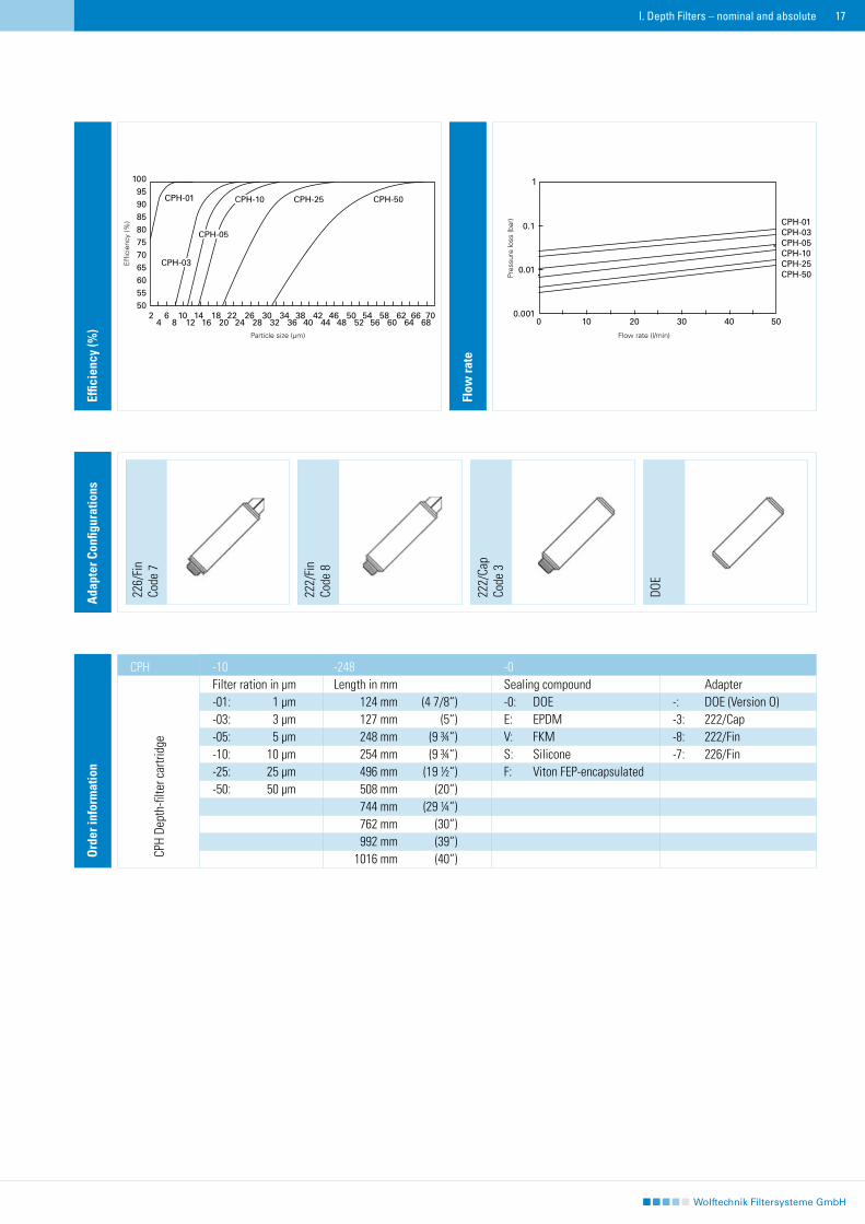
CPH Depth filter cartridge, nominal Depth filter made of polyester
The CPH Depth filter cartridge consists of 100 % polyester fibres, therefore retaining an excellent chemical resistance to solvents. The thermal durability ranges to 120 ˚C. The CPH Depth filter cartridge is equipped with an ultrapure and exceptionally compact filter matrix and guarantees repeatable filter characteristics for high quality applications. CPH Depth filter cartridges can also be delivered with an adapter and end caps made of polyester Code 3, Code 8 and Code 7. Additional outstanding CHP Depth filter cartridge characteristics are a high flow rate as well as a long service life.
Technical data
Filter medium: 100 % polyester fibres Core support: -Adapter and end cap: PolyesterFilter ration: 1 – 50 μm, nominal Temperature: Max. 120 ˚CDifferential pressure: Max. 5,5 bar at 20 ˚C Max. 2,5 bar at 80 ˚C Filter change recommended at 1,5 barDimensions: Internal diameter 28 mm External diameter 68 mm Lengths 4 7/8“ – 40“
Applications
SolventsVarnishes, paints and inksMagnet-dispersion agentsHot water > 80 ˚C Fine chemicalsCosmetics
Characteristics and Advantages
100 % polyesterPolyester adapter and end caps Code 3, Code 8, Code 7 deliverableExcellent solvent durabilityHigh temperature durabilityCompact filter matrix due to polyester fibresNo use of binding agentsLow pressure loss, high flow capacityLong filter service life
I. Depth Filters – nominal and absolute
��
-10 -248 -0 Filter ration in μm Length in mm Sealing compound Adapter-01: 1 μm 124 mm (4 7/8“) -0: DOE -: DOE (Version O) -03: 3 μm 127 mm (5“) E: EPDM -3: 222/Cap -05: 5 μm 248 mm (9 ¾“) V: FKM -8: 222/Fin-10: 10 μm 254 mm (9 ¾“) S: Silicone -7: 226/Fin-25: 25 μm 496 mm (19 ½“) F: Viton FEP-encapsulated-50: 50 μm 508 mm (20“) 744 mm (29 ¼“) 762 mm (30“) 992 mm (39“) 1016 mm (40“)
Flow
rate
Effic
ienc
y (%
)
226/
Fin
Code
7
222/
Fin
Code
8
DOE
Ada
pter
Con
figur
atio
ns
222/
Cap
Code
3
I. Depth Filters – nominal and absolute
CPH
Ord
er in
form
atio
n
CPH
Dept
h-fil
ter c
artri
dge
110095908580757065605550
Effi
cien
cy (%
)
Particle size (µm)
Pres
sure
loss
(bar
)
Flow rate (l/min)
0.1
0.01
0.0010 10 20 30 40 50
CPH-01CPH-03CPH-05CPH-10CPH-25CPH-50
CPH-01
CPH-03
CPH-05
CPH-10 CPH-25 CPH-50
2 6 10 14 18 22 26 30 34 38 42 46 50 54 58 62 66 70 4 8 12 16 20 24 28 32 36 40 44 48 52 56 60 64 68
��
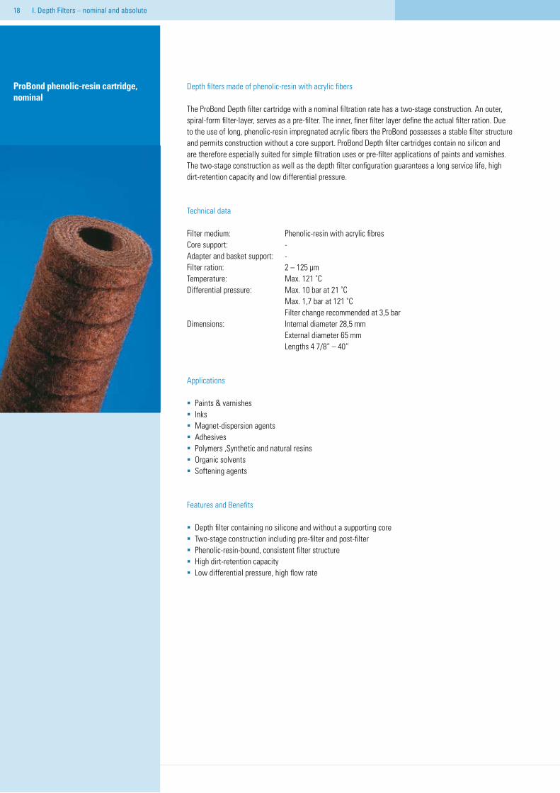
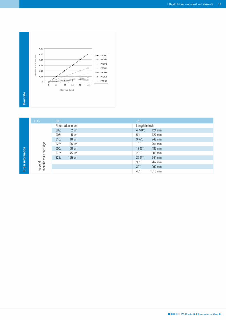
ProBond phenolic-resin cartridge, nominal
Depth filters made of phenolic-resin with acrylic fibers
The ProBond Depth filter cartridge with a nominal filtration rate has a two-stage construction. An outer, spiral-form filter-layer, serves as a pre-filter. The inner, finer filter layer define the actual filter ration. Due to the use of long, phenolic-resin impregnated acrylic fibers the ProBond possesses a stable filter structure and permits construction without a core support. ProBond Depth filter cartridges contain no silicon and are therefore especially suited for simple filtration uses or pre-filter applications of paints and varnishes. The two-stage construction as well as the depth filter configuration guarantees a long service life, high dirt-retention capacity and low differential pressure.
Technical data
Filter medium: Phenolic-resin with acrylic fibres Core support: -Adapter and basket support: -Filter ration: 2 – 125 μm Temperature: Max. 121 ˚CDifferential pressure: Max. 10 bar at 21 ˚C Max. 1,7 bar at 121 ˚C Filter change recommended at 3,5 barDimensions: Internal diameter 28,5 mm External diameter 65 mm Lengths 4 7/8“ – 40“
Applications
Paints & varnishesInksMagnet-dispersion agentsAdhesives Polymers ,Synthetic and natural resinsOrganic solventsSoftening agents
Features and Benefits
Depth filter containing no silicone and without a supporting coreTwo-stage construction including pre-filter and post-filterPhenolic-resin-bound, consistent filter structureHigh dirt-retention capacityLow differential pressure, high flow rate
I. Depth Filters – nominal and absolute
��
Flow
rate
Ord
er in
form
atio
n
005 -20Filter ration in μm Length in inch002: 2 μm 4 7/8“: 124 mm005: 5 μm 5“: 127 mm010: 10 μm 9 ¾“: 248 mm025: 25 μm 10“: 254 mm050: 50 μm 19 ½“: 496 mm075: 75 μm 20“: 508 mm125: 125 μm 29 ¼“: 744 mm 30“: 762 mm 39“: 992 mm 40“: 1016 mm
I. Depth Filters – nominal and absolute
PRO-
ProB
ond
phen
olic
-resi
n ca
rtrid
ge
Diff
eren
tial p
ress
ure
(bar
)
Flow rate (l/min)
�0
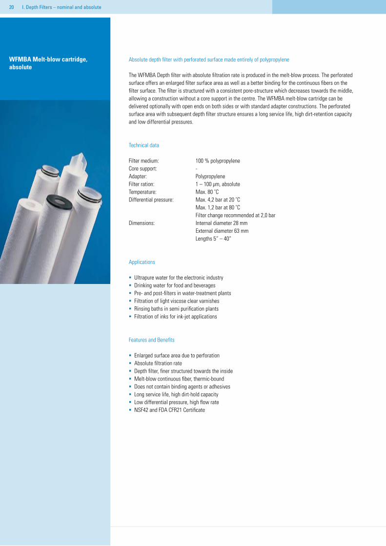
WFMBA Melt-blow cartridge, absolute
Absolute depth filter with perforated surface made entirely of polypropylene
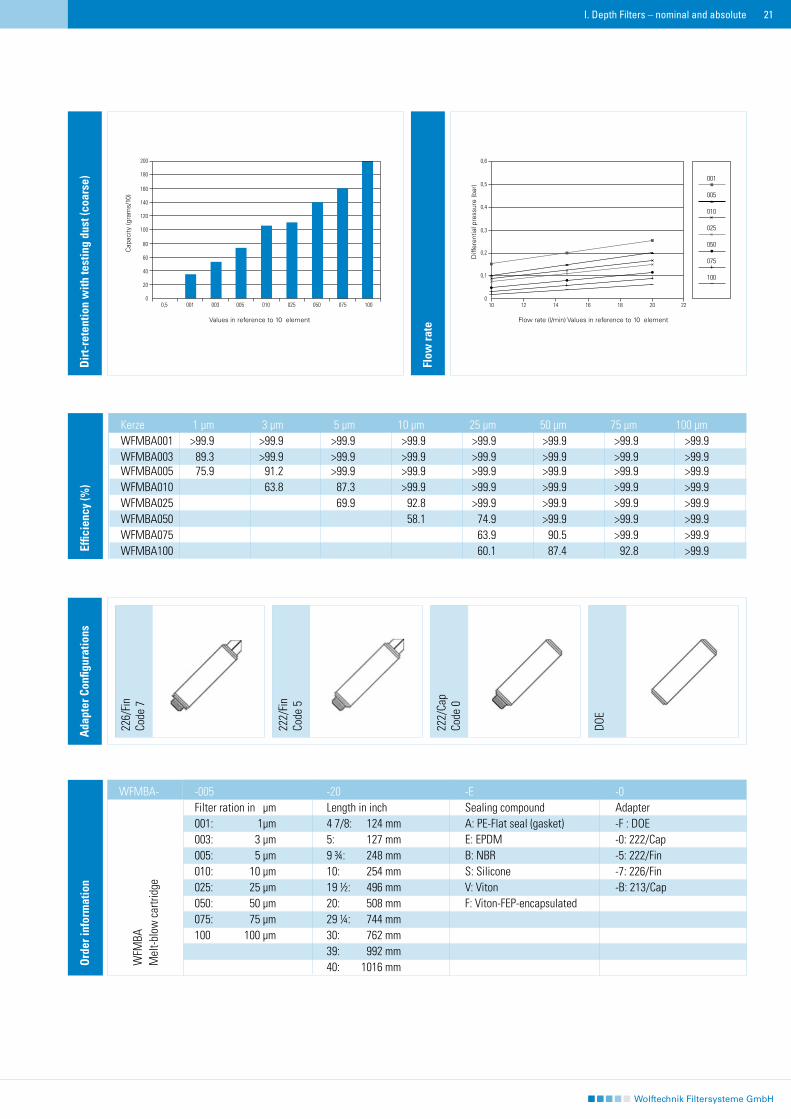
The WFMBA Depth filter with absolute filtration rate is produced in the melt-blow process. The perforated surface offers an enlarged filter surface area as well as a better binding for the continuous fibers on the filter surface. The filter is structured with a consistent pore-structure which decreases towards the middle, allowing a construction without a core support in the centre. The WFMBA melt-blow cartridge can be delivered optionally with open ends on both sides or with standard adapter constructions. The perforated surface area with subsequent depth filter structure ensures a long service life, high dirt-retention capacity and low differential pressures.
Technical data
Filter medium: 100 % polypropylene Core support: -Adapter: Polypropylene Filter ration: 1 – 100 μm, absolute Temperature: Max. 80 ˚CDifferential pressure: Max. 4,2 bar at 20 ˚C Max. 1,2 bar at 80 ˚C Filter change recommended at 2,0 barDimensions: Internal diameter 28 mm External diameter 63 mm Lengths 5“ – 40“
Applications
Ultrapure water for the electronic industryDrinking water for food and beverages Pre- and post-filters in water-treatment plantsFiltration of light viscose clear varnishes Rinsing baths in semi purification plantsFiltration of inks for ink-jet applications
Features and Benefits
Enlarged surface area due to perforationAbsolute filtration rate Depth filter, finer structured towards the insideMelt-blow continuous fiber, thermic-boundDoes not contain binding agents or adhesives Long service life, high dirt-hold capacityLow differential pressure, high flow rateNSF42 and FDA CFR21 Certificate
I. Depth Filters – nominal and absolute
��
226/
Fin
Code
7
222/
Fin
Code
5
DOE
Ada
pter
Con
figur
atio
ns
222/
Cap
Code
0
Dir
t-re
tent
ion
with
test
ing
dust
(coa
rse)
0,5 001 003 005 010 025 050 075 100
200
180
160
140
120
100
80
60
40
20
0
Kapa
zität
(Gra
mm
/10)
Werte bezogen auf 10”-Element
Flow
rate
10 12 14 16 18 20 22
0,6
0,5
0,4
0,3
0,2
0,1
0
Diffe
renz
druc
k (b
ar)
Durchsatzleistung (L/min) Werte bezogen auf 10”-Element
Effic
ienc
y (%
)
Kerze 1 μm 3 μm 5 μm 10 μm 25 μm 50 μm 75 μm 100 μm WFMBA001 >99.9 >99.9 >99.9 >99.9 >99.9 >99.9 >99.9 >99.9 WFMBA003 89.3 >99.9 >99.9 >99.9 >99.9 >99.9 >99.9 >99.9 WFMBA005 75.9 91.2 >99.9 >99.9 >99.9 >99.9 >99.9 >99.9 WFMBA010 63.8 87.3 >99.9 >99.9 >99.9 >99.9 >99.9 WFMBA025 69.9 92.8 >99.9 >99.9 >99.9 >99.9 WFMBA050 58.1 74.9 >99.9 >99.9 >99.9 WFMBA075 63.9 90.5 >99.9 >99.9 WFMBA100 60.1 87.4 92.8 >99.9
Ord
er in
form
atio
n
-005 -20 -E -0 Filter ration in μm Length in inch Sealing compound Adapter 001: 1μm 4 7/8: 124 mm A: PE-Flat seal (gasket) -F : DOE 003: 3 μm 5: 127 mm E: EPDM -0: 222/Cap 005: 5 μm 9 ¾: 248 mm B: NBR -5: 222/Fin 010: 10 μm 10: 254 mm S: Silicone -7: 226/Fin 025: 25 μm 19 ½: 496 mm V: Viton -B: 213/Cap 050: 50 μm 20: 508 mm F: Viton-FEP-encapsulated 075: 75 μm 29 ¼: 744 mm 100 100 μm 30: 762 mm 39: 992 mm 40: 1016 mm
I. Depth Filters – nominal and absolute
WFMBA-
WFM
BA
Mel
t-blo
w c
artri
dge
Cap
acity
(gra
ms/
10)
Values in reference to 10″ element
Diff
eren
tial p
ress
ure
(bar
)
Flow rate (l/min) Values in reference to 10″ element
��
��
II. Pleated & Membrane Filter Cartridges
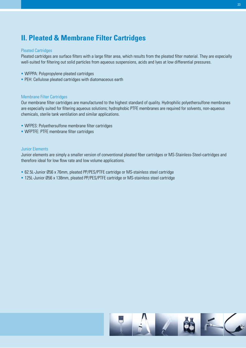
Pleated CartridgesPleated cartridges are surface filters with a large filter area, which results from the pleated filter material. They are especially well-suited for filtering out solid particles from aqueous suspensions, acids and lyes at low differential pressures.
WFPPA: Polypropylene pleated cartridgesPEH: Cellulose pleated cartridges with diatomaceous earth
Membrane Filter CartridgesOur membrane filter cartridges are manufactured to the highest standard of quality. Hydrophilic polyethersulfone membranes are especially suited for filtering aqueous solutions; hydrophobic PTFE membranes are required for solvents, non-aqueous chemicals, sterile tank ventilation and similar applications.
WFPES: Polyethersulfone membrane filter cartridgesWFPTFE: PTFE membrane filter cartridges
Junior Elements Junior elements are simply a smaller version of conventional pleated fiber cartridges or MS-Stainless-Steel-cartridges and therefore ideal for low flow rate and low volume applications. 62.5L-Junior Ø56 x 76mm, pleated PP/PES/PTFE cartridge or MS-stainless steel cartridge125L-Junior Ø56 x 138mm, pleated PP/PES/PTFE cartridge or MS-stainless steel cartridge
��
WFPPA Pleated cartridge, absolute
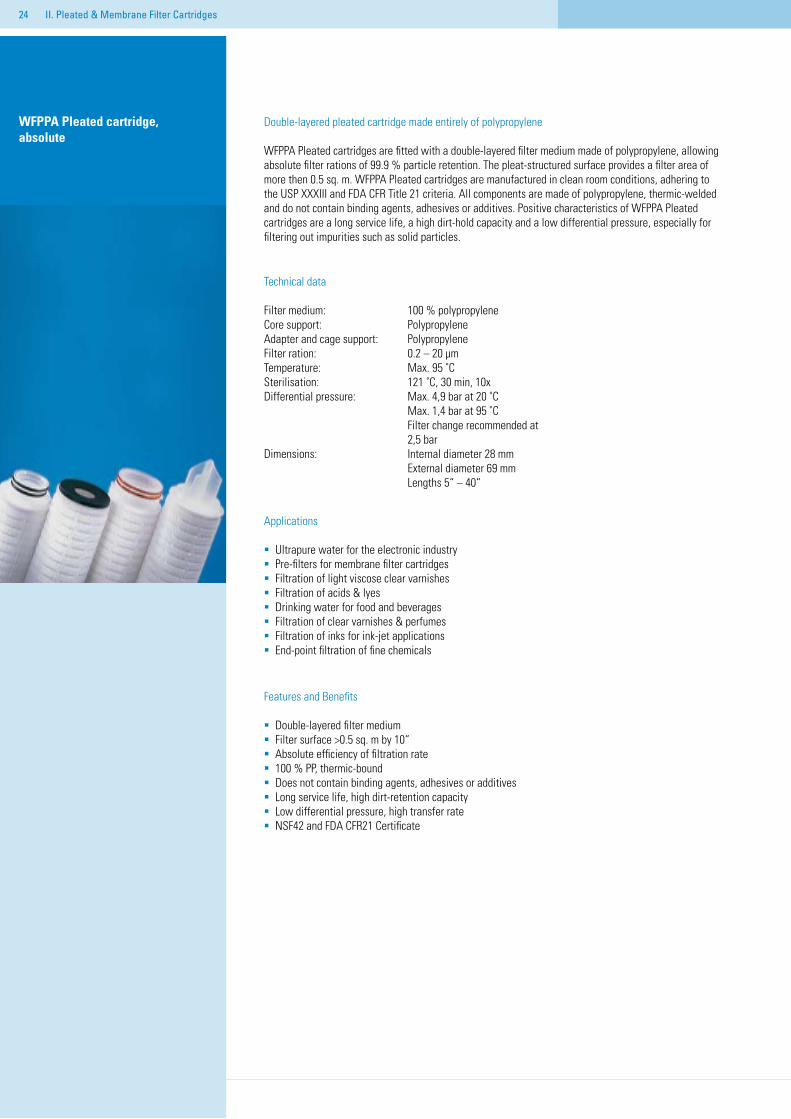
Double-layered pleated cartridge made entirely of polypropylene
WFPPA Pleated cartridges are fitted with a double-layered filter medium made of polypropylene, allowing absolute filter rations of 99.9 % particle retention. The pleat-structured surface provides a filter area of more then 0.5 sq. m. WFPPA Pleated cartridges are manufactured in clean room conditions, adhering to the USP XXXIII and FDA CFR Title 21 criteria. All components are made of polypropylene, thermic-welded and do not contain binding agents, adhesives or additives. Positive characteristics of WFPPA Pleated cartridges are a long service life, a high dirt-hold capacity and a low differential pressure, especially for filtering out impurities such as solid particles.
Technical data
Filter medium: 100 % polypropylene Core support: PolypropyleneAdapter and cage support: Polypropylene Filter ration: 0.2 – 20 μm Temperature: Max. 95 ˚CSterilisation: 121 ˚C, 30 min, 10xDifferential pressure: Max. 4,9 bar at 20 ˚C Max. 1,4 bar at 95 ˚C Filter change recommended at 2,5 barDimensions: Internal diameter 28 mm External diameter 69 mm Lengths 5“ – 40“
Applications
Ultrapure water for the electronic industryPre-filters for membrane filter cartridgesFiltration of light viscose clear varnishes Filtration of acids & lyesDrinking water for food and beveragesFiltration of clear varnishes & perfumes Filtration of inks for ink-jet applicationsEnd-point filtration of fine chemicals
Features and Benefits
Double-layered filter mediumFilter surface >0.5 sq. m by 10“Absolute efficiency of filtration rate100 % PP, thermic-boundDoes not contain binding agents, adhesives or additives Long service life, high dirt-retention capacityLow differential pressure, high transfer rateNSF42 and FDA CFR21 Certificate
II. Pleated & Membrane Filter Cartridges
��
226/
Fin
Code
7
222/
Fin
Code
5
DOE
Ada
pter
Con
figur
atio
ns
222/
Cap
Code
0
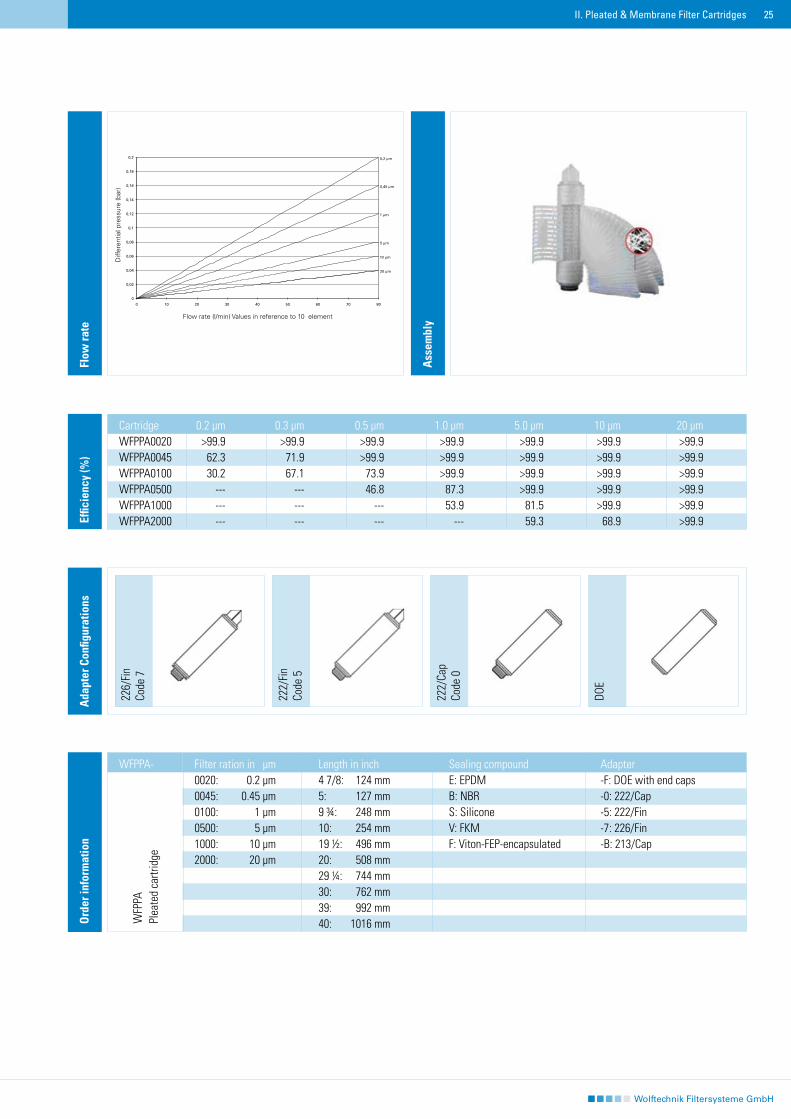
Cartridge 0.2 μm 0.3 μm 0.5 μm 1.0 μm 5.0 μm 10 μm 20 μmWFPPA0020 >99.9 >99.9 >99.9 >99.9 >99.9 >99.9 >99.9WFPPA0045 62.3 71.9 >99.9 >99.9 >99.9 >99.9 >99.9WFPPA0100 30.2 67.1 73.9 >99.9 >99.9 >99.9 >99.9WFPPA0500 --- --- 46.8 87.3 >99.9 >99.9 >99.9WFPPA1000 --- --- --- 53.9 81.5 >99.9 >99.9WFPPA2000 --- --- --- --- 59.3 68.9 >99.9Ef
ficie
ncy
(%)
Ass
embl
y
Flow
rate
Ord
er in
form
atio
nO
rder
info
rmat
ion
Filter ration in μm Length in inch Sealing compound Adapter0020: 0.2 μm 4 7/8: 124 mm E: EPDM -F: DOE with end caps0045: 0.45 μm 5: 127 mm B: NBR -0: 222/Cap0100: 1 μm 9 ¾: 248 mm S: Silicone -5: 222/Fin0500: 5 μm 10: 254 mm V: FKM -7: 226/Fin1000: 10 μm 19 ½: 496 mm F: Viton-FEP-encapsulated -B: 213/Cap2000: 20 μm 20: 508 mm 29 ¼: 744 mm 30: 762 mm 39: 992 mm 40: 1016 mm
II. Pleated & Membrane Filter Cartridges
WFPPA-
WFP
PAPl
eate
d ca
rtrid
ge
Diff
eren
tial p
ress
ure
(bar
)
Flow rate (l/min) Values in reference to 10″ element
��
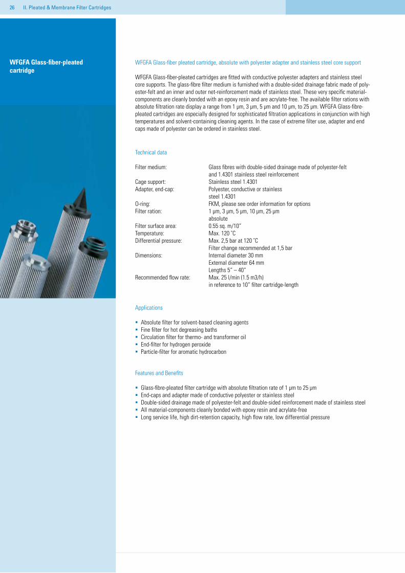
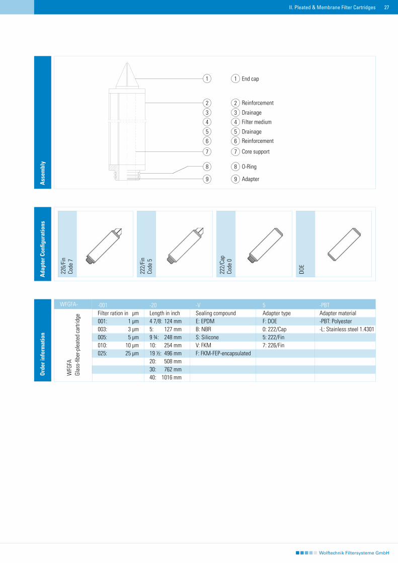
WFGFA Glass-fiber pleated cartridge, absolute with polyester adapter and stainless steel core support
WFGFA Glass-fiber-pleated cartridges are fitted with conductive polyester adapters and stainless steel core supports. The glass-fibre filter medium is furnished with a double-sided drainage fabric made of poly-ester-felt and an inner and outer net-reinforcement made of stainless steel. These very specific material-components are cleanly bonded with an epoxy resin and are acrylate-free. The available filter rations with absolute filtration rate display a range from 1 μm, 3 μm, 5 μm and 10 μm, to 25 μm. WFGFA Glass-fibre-pleated cartridges are especially designed for sophisticated filtration applications in conjunction with high temperatures and solvent-containing cleaning agents. In the case of extreme filter use, adapter and end caps made of polyester can be ordered in stainless steel.
Technical data
Filter medium: Glass fibres with double-sided drainage made of polyester-felt and 1.4301 stainless steel reinforcement Cage support: Stainless steel 1.4301Adapter, end-cap: Polyester, conductive or stainless steel 1.4301 O-ring: FKM, please see order information for optionsFilter ration: 1 μm, 3 μm, 5 μm, 10 μm, 25 μm absolute Filter surface area: 0.55 sq. m/10“Temperature: Max. 120 ˚CDifferential pressure: Max. 2,5 bar at 120 ˚C Filter change recommended at 1,5 barDimensions: Internal diameter 30 mm External diameter 64 mm Lengths 5“ – 40“Recommended flow rate: Max. 25 l/min (1.5 m3/h) in reference to 10“ filter cartridge-length
Applications
Absolute filter for solvent-based cleaning agentsFine filter for hot degreasing bathsCirculation filter for thermo- and transformer oilEnd-filter for hydrogen peroxide Particle-filter for aromatic hydrocarbon
Features and Benefits
Glass-fibre-pleated filter cartridge with absolute filtration rate of 1 μm to 25 μm End-caps and adapter made of conductive polyester or stainless steelDouble-sided drainage made of polyester-felt and double-sided reinforcement made of stainless steelAll material-components cleanly bonded with epoxy resin and acrylate-freeLong service life, high dirt-retention capacity, high flow rate, low differential pressure
WFGFA Glass-fiber-pleated cartridge
II. Pleated & Membrane Filter Cartridges
��II. Pleated & Membrane Filter Cartridges
226/
Fin
Code
7
222/
Fin
Code
5
DOE
Ada
pter
Con
figur
atio
ns
222/
Cap
Code
0
-001 -20 -V 5 -PBTFilter ration in μm Length in inch Sealing compound Adapter type Adapter material001: 1 μm 4 7/8: 124 mm E: EPDM F: DOE -PBT: Polyester 003: 3 μm 5: 127 mm B: NBR 0: 222/Cap -L: Stainless steel 1.4301005: 5 μm 9 ¾: 248 mm S: Silicone 5: 222/Fin 010: 10 μm 10: 254 mm V: FKM 7: 226/Fin 025: 25 μm 19 ½: 496 mm F: FKM-FEP-encapsulated 20: 508 mm 30: 762 mm 40: 1016 mm
WFGFA-
Ord
er in
form
atio
nA
ssem
bly
WFG
FA
Glas
s-fib
er-p
leat
ed c
artri
dge
1
2
3
4
5
6
7
8
9
End cap
Reinforcement
Drainage
Filter medium
Drainage
Reinforcement
Core support
O-Ring
Adapter
1
2
3
4
5
6
7
8
9
��
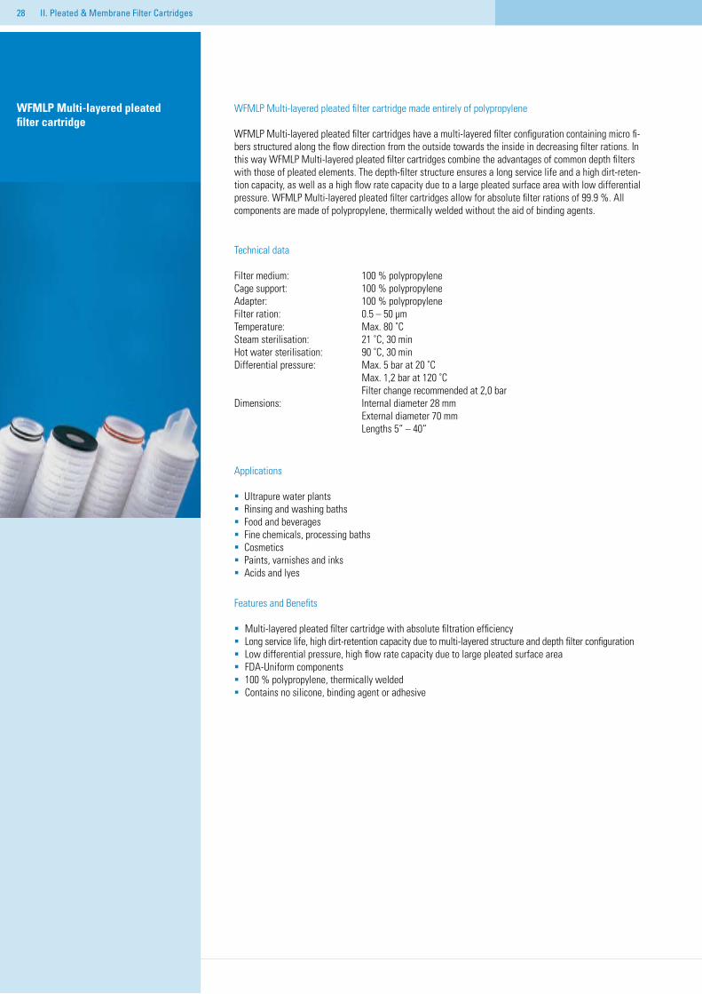
WFMLP Multi-layered pleated filter cartridge
II. Pleated & Membrane Filter Cartridges
WFMLP Multi-layered pleated filter cartridge made entirely of polypropylene
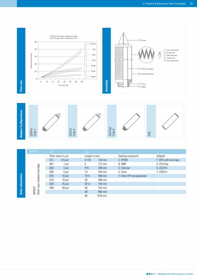
WFMLP Multi-layered pleated filter cartridges have a multi-layered filter configuration containing micro fi-bers structured along the flow direction from the outside towards the inside in decreasing filter rations. In this way WFMLP Multi-layered pleated filter cartridges combine the advantages of common depth filters with those of pleated elements. The depth-filter structure ensures a long service life and a high dirt-reten-tion capacity, as well as a high flow rate capacity due to a large pleated surface area with low differential pressure. WFMLP Multi-layered pleated filter cartridges allow for absolute filter rations of 99.9 %. All components are made of polypropylene, thermically welded without the aid of binding agents.
Technical data
Filter medium: 100 % polypropyleneCage support: 100 % polypropyleneAdapter: 100 % polypropylene Filter ration: 0.5 – 50 μm Temperature: Max. 80 ˚CSteam sterilisation: 21 ˚C, 30 minHot water sterilisation: 90 ˚C, 30 min Differential pressure: Max. 5 bar at 20 ˚C Max. 1,2 bar at 120 ˚C Filter change recommended at 2,0 barDimensions: Internal diameter 28 mm External diameter 70 mm Lengths 5“ – 40“
Applications
Ultrapure water plantsRinsing and washing bathsFood and beverages Fine chemicals, processing bathsCosmeticsPaints, varnishes and inksAcids and lyes
Features and Benefits
Multi-layered pleated filter cartridge with absolute filtration efficiency Long service life, high dirt-retention capacity due to multi-layered structure and depth filter configurationLow differential pressure, high flow rate capacity due to large pleated surface areaFDA-Uniform components 100 % polypropylene, thermically weldedContains no silicone, binding agent or adhesive
��II. Pleated & Membrane Filter Cartridges
Ass
embl
y
Flow
rate
001 -20 -V 5 Filter ration in μm Length in inch Sealing compound Adapter 0.5: 0.5 μm 4 7/8: 124 mm E: EPDM F: DOE with end caps 001: 1 μm 5: 127 mm B: NBR 0: 222/Cap 003: 3 μm 9 ¾: 248 mm S: Silicone 5: 222/Fin 005: 5 μm 10: 254 mm V: Viton 7: 226/Fin 010: 10 μm 19 ½: 496 mm F: Viton-FEP-encapsulated 010: 10 μm 20: 508 mm 025: 25 μm 29 ¼: 744 mm050: 50 μm 30: 762 mm 39: 992 mm 40: 1016 mm
WFMLP-
Ord
er in
form
atio
n
WFM
LPM
ulti-
laye
r ple
ated
car
tridg
e
226/
Fin
Code
7
222/
Fin
Code
5
DOE
Ada
pter
Con
figur
atio
ns
222/
Cap
Code
0
WFMLP Multi-layer pleated cartridgeFlow-through value in reference to 10“
Flow rate (l/min)
Diffe
rent
ial p
ress
ure
(bar
)
0,5
0,4
0,3
0,2
0,1
05 10 15 20 25 30 35 40
–– 0.5 μm
–– 1 μm
–– 3 μm
–– 5 μm
–– 10 μm
–– 25 μm
–– 50 μm
Outer reinforcement
Pre-filter layer
Centre filter layer
End-filter layer
Inner reinforcement
1
2
3
4
5
6
7
8
9
10
End cap
O-rings
Adapter
flow
Internal core support
External tube support
�0
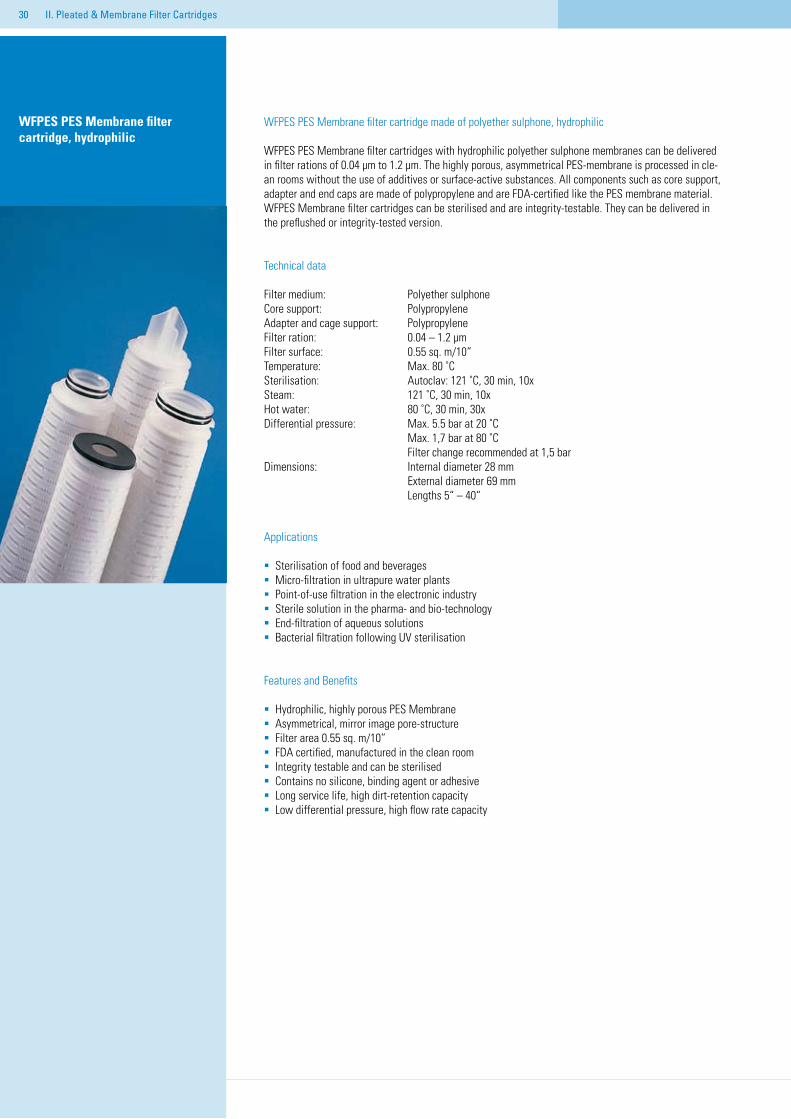
WFPES PES Membrane filter cartridge, hydrophilic
WFPES PES Membrane filter cartridge made of polyether sulphone, hydrophilic
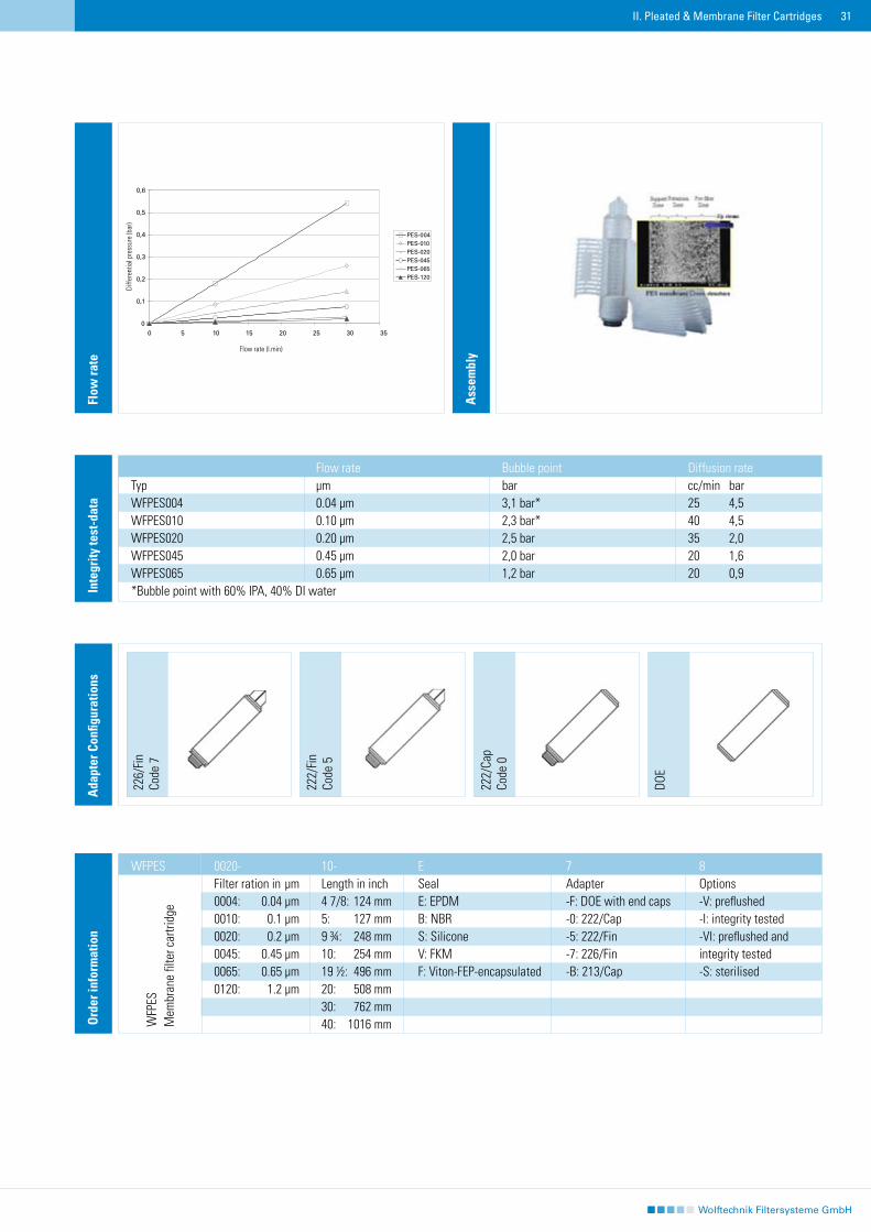
WFPES PES Membrane filter cartridges with hydrophilic polyether sulphone membranes can be delivered in filter rations of 0.04 μm to 1.2 μm. The highly porous, asymmetrical PES-membrane is processed in cle-an rooms without the use of additives or surface-active substances. All components such as core support, adapter and end caps are made of polypropylene and are FDA-certified like the PES membrane material.WFPES Membrane filter cartridges can be sterilised and are integrity-testable. They can be delivered in the preflushed or integrity-tested version.
Technical data
Filter medium: Polyether sulphoneCore support: PolypropyleneAdapter and cage support: Polypropylene Filter ration: 0.04 – 1.2 μm Filter surface: 0.55 sq. m/10“Temperature: Max. 80 ˚CSterilisation: Autoclav: 121 ˚C, 30 min, 10xSteam: 121 ˚C, 30 min, 10xHot water: 80 ˚C, 30 min, 30x Differential pressure: Max. 5.5 bar at 20 ˚C Max. 1,7 bar at 80 ˚C Filter change recommended at 1,5 barDimensions: Internal diameter 28 mm External diameter 69 mm Lengths 5“ – 40“
Applications
Sterilisation of food and beveragesMicro-filtration in ultrapure water plants Point-of-use filtration in the electronic industry Sterile solution in the pharma- and bio-technology End-filtration of aqueous solutionsBacterial filtration following UV sterilisation
Features and Benefits
Hydrophilic, highly porous PES MembraneAsymmetrical, mirror image pore-structureFilter area 0.55 sq. m/10“FDA certified, manufactured in the clean roomIntegrity testable and can be sterilisedContains no silicone, binding agent or adhesive Long service life, high dirt-retention capacity Low differential pressure, high flow rate capacity
II. Pleated & Membrane Filter Cartridges
��
226/
Fin
Code
7
222/
Fin
Code
5
DOE
Ada
pter
Con
figur
atio
ns
222/
Cap
Code
0
Inte
grity
test
-dat
a
Flow rate Bubble point Diffusion rateTyp μm bar cc/min barWFPES004 0.04 μm 3,1 bar* 25 4,5WFPES010 0.10 μm 2,3 bar* 40 4,5WFPES020 0.20 μm 2,5 bar 35 2,0WFPES045 0.45 μm 2,0 bar 20 1,6WFPES065 0.65 μm 1,2 bar 20 0,9*Bubble point with 60% IPA, 40% DI water
A
ssem
bly
Flow
rate
Ord
er in
form
atio
n
0020- 10- E 7 8Filter ration in μm Length in inch Seal Adapter Options0004: 0.04 μm 4 7/8: 124 mm E: EPDM -F: DOE with end caps -V: preflushed0010: 0.1 μm 5: 127 mm B: NBR -0: 222/Cap -I: integrity tested0020: 0.2 μm 9 ¾: 248 mm S: Silicone -5: 222/Fin -VI: preflushed and 0045: 0.45 μm 10: 254 mm V: FKM -7: 226/Fin integrity tested0065: 0.65 μm 19 ½: 496 mm F: Viton-FEP-encapsulated -B: 213/Cap -S: sterilised0120: 1.2 μm 20: 508 mm 30: 762 mm 40: 1016 mm
II. Pleated & Membrane Filter Cartridges
WFPES
WFP
ESM
embr
ane
filte
r car
tridg
e
Diffe
rent
ial p
ress
ure
(bar
)
Flow rate (l.min)
��
WFPTFE PTFE Membrane filter cartridge, hydrophobic
WFPTFE PTFE Membrane filter cartridge made of PTFE, hydrophobic
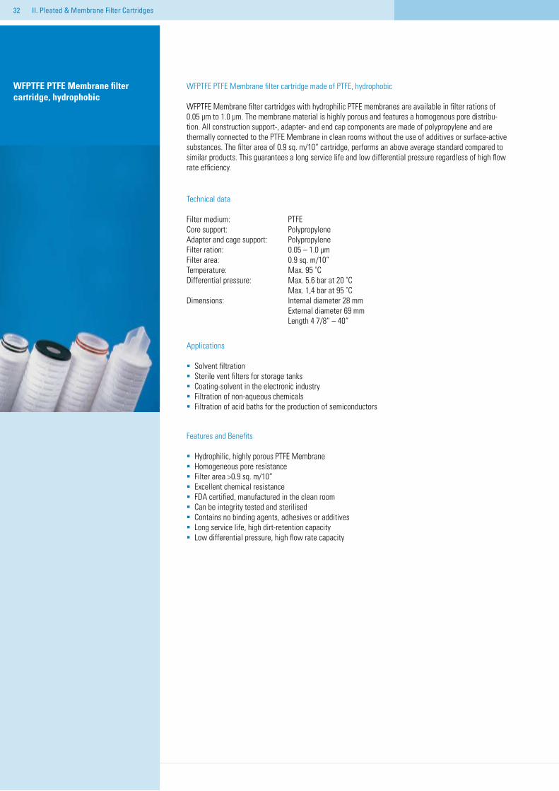
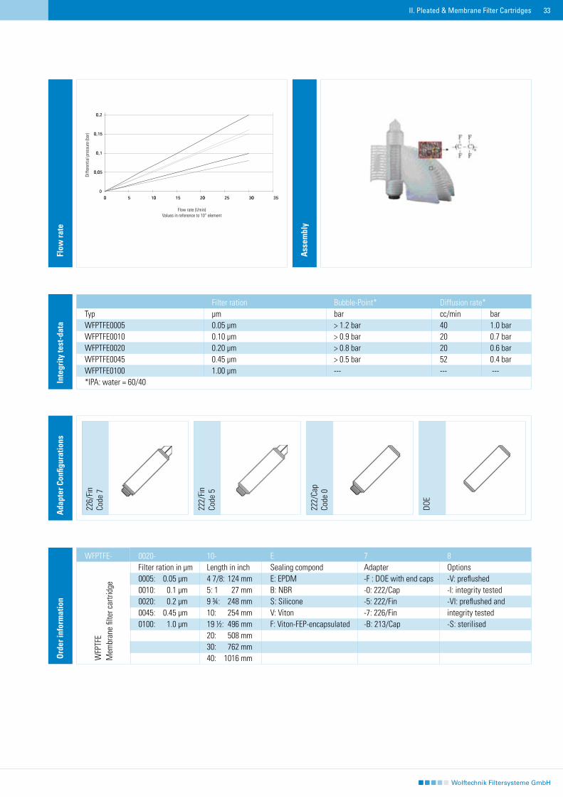
WFPTFE Membrane filter cartridges with hydrophilic PTFE membranes are available in filter rations of 0.05 μm to 1.0 μm. The membrane material is highly porous and features a homogenous pore distribu-tion. All construction support-, adapter- and end cap components are made of polypropylene and are thermally connected to the PTFE Membrane in clean rooms without the use of additives or surface-active substances. The filter area of 0.9 sq. m/10“ cartridge, performs an above average standard compared to similar products. This guarantees a long service life and low differential pressure regardless of high flow rate efficiency.
Technical data
Filter medium: PTFECore support: PolypropyleneAdapter and cage support: Polypropylene Filter ration: 0.05 – 1.0 μm Filter area: 0.9 sq. m/10“Temperature: Max. 95 ˚CDifferential pressure: Max. 5.6 bar at 20 ˚C Max. 1,4 bar at 95 ˚CDimensions: Internal diameter 28 mm External diameter 69 mm Length 4 7/8“ – 40“
Applications
Solvent filtrationSterile vent filters for storage tanksCoating-solvent in the electronic industryFiltration of non-aqueous chemicals Filtration of acid baths for the production of semiconductors
Features and Benefits
Hydrophilic, highly porous PTFE MembraneHomogeneous pore resistanceFilter area >0.9 sq. m/10“Excellent chemical resistance FDA certified, manufactured in the clean roomCan be integrity tested and sterilisedContains no binding agents, adhesives or additives Long service life, high dirt-retention capacity Low differential pressure, high flow rate capacity
II. Pleated & Membrane Filter Cartridges
��
226/
Fin
Code
7
222/
Fin
Code
5
DOE
Ada
pter
Con
figur
atio
ns
222/
Cap
Code
0
Ord
er in
form
atio
n
0020- 10- E 7 8Filter ration in μm Length in inch Sealing compond Adapter Options0005: 0.05 μm 4 7/8: 124 mm E: EPDM -F : DOE with end caps -V: preflushed0010: 0.1 μm 5: 1 27 mm B: NBR -0: 222/Cap -I: integrity tested0020: 0.2 μm 9 ¾: 248 mm S: Silicone -5: 222/Fin -VI: preflushed and 0045: 0.45 μm 10: 254 mm V: Viton -7: 226/Fin integrity tested0100: 1.0 μm 19 ½: 496 mm F: Viton-FEP-encapsulated -B: 213/Cap -S: sterilised 20: 508 mm 30: 762 mm 40: 1016 mm
II. Pleated & Membrane Filter Cartridges
Flow
rate
Ass
embl
y
WFPTFE-
WFP
TFE
Mem
bran
e fil
ter c
artri
dge
Diffe
rent
ial p
ress
ure
(bar
)
Flow rate (l/min) Values in reference to 10“ element
Inte
grity
test
-dat
a
Filter ration Bubble-Point* Diffusion rate*Typ μm bar cc/min barWFPTFE0005 0.05 μm > 1.2 bar 40 1.0 barWFPTFE0010 0.10 μm > 0.9 bar 20 0.7 barWFPTFE0020 0.20 μm > 0.8 bar 20 0.6 barWFPTFE0045 0.45 μm > 0.5 bar 52 0.4 barWFPTFE0100 1.00 μm --- --- ---*IPA: water = 60/40
��
Junior Pleated cartridges Junior Pleated cartridges
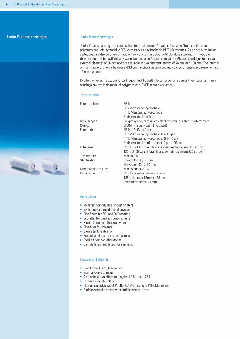
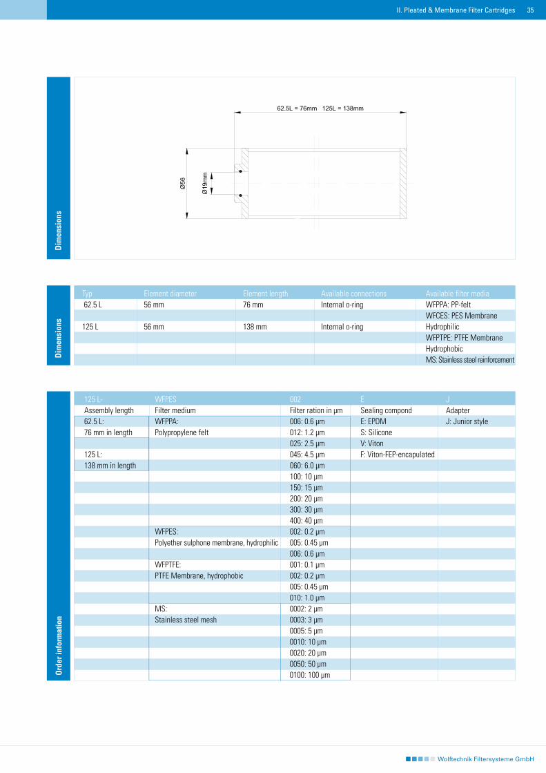
Junior Pleated cartridges are best suited for small-volume filtration. Available filter materials are polypropylene-felt, hydrophilic PES Membranes or hydrophobic PTFE Membranes. As a speciality Junior cartridges can also be offered made entirely of stainless steel with stainless steel mesh. These are then not pleated, but cylindrically wound around a perforated core. Junior Pleated cartridges feature an external diameter of 56 mm and are available in two different lengths of 76 mm and 138 mm. The internal o-ring is made of viton, silicon or EPDM and functions as a mount and seal on a housing protrusion with a 19 mm diameter.
Due to their overall size, Junior cartridges must be built into corresponding Junior filter housings. These housings are available made of polypropylene, PVDF or stainless steel.
Technical data
Filter medium: PP-felt PES Membrane, hydrophilic PTFE Membrane, hydrophobic Stainless steel meshCage support: Polypropylene, or stainless steel for stainless steel reinforcement O-ring: EPDM (silicon, viton, FEP-coated)Filter ration: PP-felt: 0.06 – 40 μm PES Membrane, hydrophilic: 0.2-0.6 μm PTFE Membrane, hydrophobic: 0.1-1.0 μm Stainless steel reinforcement: 2 μm -100 μm Filter area: 62.5 L: 1200 sq. cm (stainless steel reinforcement 110 sq. cm) 125 L: 2400 sq. cm (stainless steel reinforcement 220 sq. com)Temperature: Max. 80 ˚CSterilisation: Steam: 121 ˚C, 30 min Hot water: 90 ˚C, 30 minDifferential pressure: Max. 5 bar at 20 ˚CDimensions: 62.5 L diameter 56mm x 76 mm 125 L diameter 56mm x 138 mm Internal diameter: 19 mm
Applications
Ink filters for industrial ink-jet printersInk filters for barcode-label devicesFine filters for CD- and DVD coatingEnd-filter for graphic spray-systemsSterile filters for ultrapure waterFine-filter for solventsSterile tank ventilationProtective filters for vacuum pumpsSterile filters for laboratories Sample filters and filters for analysing
Features and Benefits
Small overall size, low volumeInternal o-ring to mountAvailable in two different lengths: 62.5 L and 125 LExternal diameter 56 mmPleated cartridge with PP-felt, PES Membrane or PTFE MembraneStainless steel element with stainless steel mesh
II. Pleated & Membrane Filter Cartridges
��
Dim
ensi
ons
Typ Element diameter Element length Available connections Available filter media 62.5 L 56 mm 76 mm Internal o-ring WFPPA: PP-felt WFCES: PES Membrane 125 L 56 mm 138 mm Internal o-ring Hydrophilic WFPTPE: PTFE Membrane Hydrophobic MS: Stainless steel reinforcement
II. Pleated & Membrane Filter Cartridges
Dim
ensi
ons
Ass
embl
y
Ord
er in
form
atio
n
125 L- WFPES 002 E JAssembly length Filter medium Filter ration in μm Sealing compond Adapter62.5 L: WFPPA: 006: 0.6 μm E: EPDM J: Junior style76 mm in length Polypropylene felt 012: 1.2 μm S: Silicone 025: 2.5 μm V: Viton125 L: 045: 4.5 μm F: Viton-FEP-encapulated138 mm in length 060: 6.0 μm 100: 10 μm 150: 15 μm 200: 20 μm 300: 30 μm 400: 40 μm WFPES: 002: 0.2 μm Polyether sulphone membrane, hydrophilic 005: 0.45 μm 006: 0.6 μm WFPTFE: 001: 0.1 μm PTFE Membrane, hydrophobic 002: 0.2 μm 005: 0.45 μm 010: 1.0 μm MS: 0002: 2 μm Stainless steel mesh 0003: 3 μm 0005: 5 μm 0010: 10 μm 0020: 20 μm 0050: 50 μm 0100: 100 μm
��
��
III. Activated Carbon Filters
Activated carbon absorbs a variety of impurities and can be used to reduce odor and taste substances, bacteria, VOCs, pesticides and general organic impurities, or to decolor fluids. There are two types: filters containing granulated carbon, and filters with porous activated carbon blocks extruded to form tubes. The maximum flow rates, contact times with the activated charcoal and thus the retention rates of these filters also depend on whether flow is axial or radial.
Activated Carbon Filters
GAC Granular Activated Carbon with 20 μm postfilter, axial flowRFC Granular Activated Carbon with 7 μm postfilter, radial flowCBC Activated Carbon Block, filter rating 0.5 μm, radial flowEP Activated Carbon Block, filter rating 5 μm, radial flow EPM Activated Carbon Block, filter rating 10 μm, radial flow
��
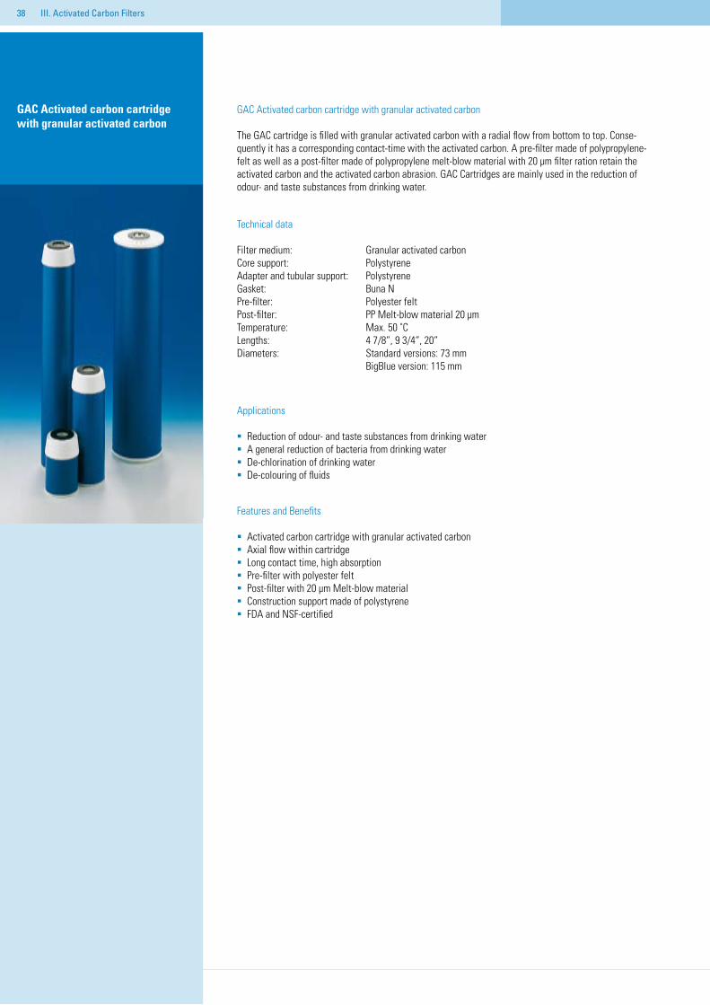
GAC Activated carbon cartridge with granular activated carbon
GAC Activated carbon cartridge with granular activated carbon
The GAC cartridge is filled with granular activated carbon with a radial flow from bottom to top. Conse-quently it has a corresponding contact-time with the activated carbon. A pre-filter made of polypropylene-felt as well as a post-filter made of polypropylene melt-blow material with 20 μm filter ration retain the activated carbon and the activated carbon abrasion. GAC Cartridges are mainly used in the reduction of odour- and taste substances from drinking water.
Technical data
Filter medium: Granular activated carbon Core support: PolystyreneAdapter and tubular support: Polystyrene Gasket: Buna N Pre-filter: Polyester felt Post-filter: PP Melt-blow material 20 μm Temperature: Max. 50 ˚CLengths: 4 7/8“, 9 3/4“, 20“Diameters: Standard versions: 73 mm BigBlue version: 115 mm
Applications
Reduction of odour- and taste substances from drinking waterA general reduction of bacteria from drinking waterDe-chlorination of drinking waterDe-colouring of fluids
Features and Benefits
Activated carbon cartridge with granular activated carbon Axial flow within cartridge Long contact time, high absorptionPre-filter with polyester feltPost-filter with 20 μm Melt-blow materialConstruction support made of polystyreneFDA and NSF-certified
III. Activated Carbon Filters
��
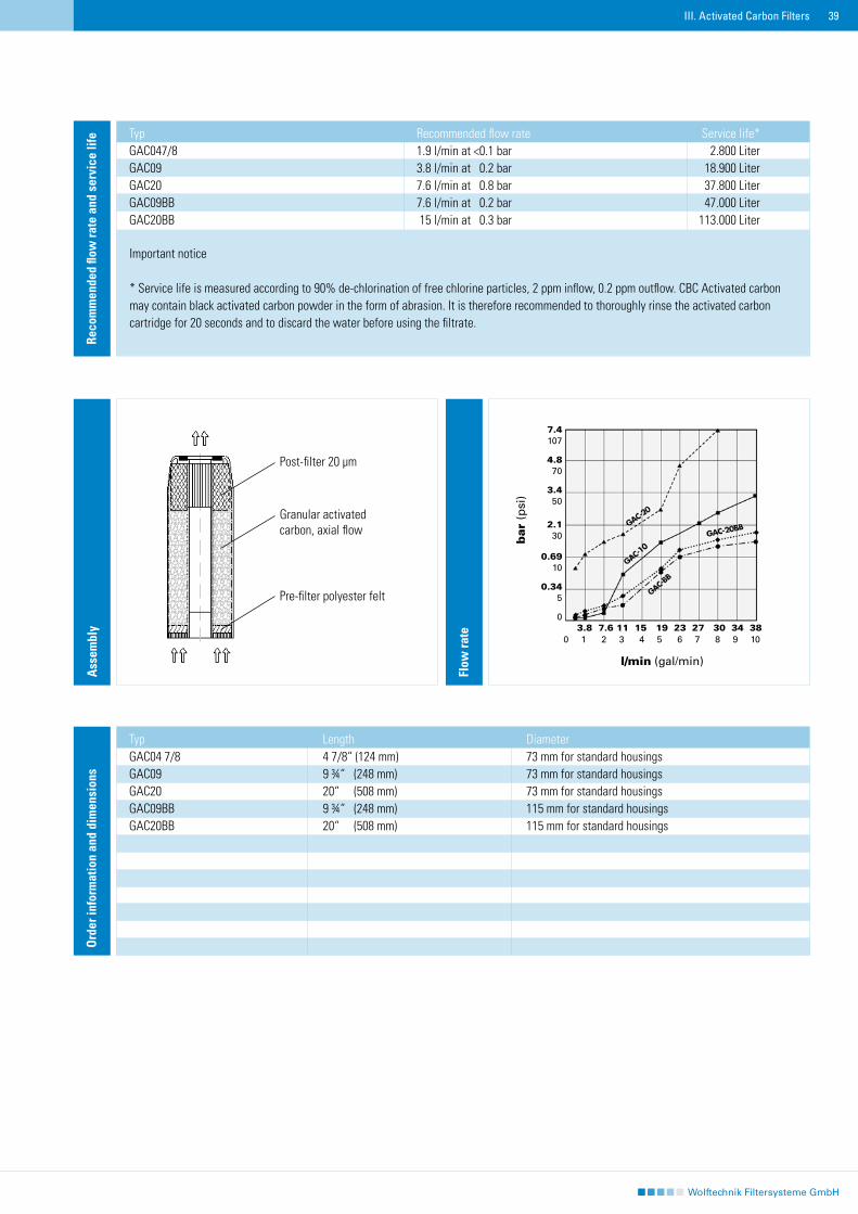
Reco
mm
ende
d flo
w ra
te a
nd s
ervi
ce li
fe Typ Recommended flow rate Service life*GAC047/8 1.9 l/min at <0.1 bar 2.800 LiterGAC09 3.8 l/min at 0.2 bar 18.900 LiterGAC20 7.6 l/min at 0.8 bar 37.800 LiterGAC09BB 7.6 l/min at 0.2 bar 47.000 LiterGAC20BB 15 l/min at 0.3 bar 113.000 Liter
Important notice
* Service life is measured according to 90% de-chlorination of free chlorine particles, 2 ppm inflow, 0.2 ppm outflow. CBC Activated carbon may contain black activated carbon powder in the form of abrasion. It is therefore recommended to thoroughly rinse the activated carbon cartridge for 20 seconds and to discard the water before using the filtrate.
Flow
rate
Ord
er in
form
atio
n an
d di
men
sion
s
III. Activated Carbon Filters
Typ Length DiameterGAC04 7/8 4 7/8“ (124 mm) 73 mm for standard housingsGAC09 9 ¾“ (248 mm) 73 mm for standard housingsGAC20 20“ (508 mm) 73 mm for standard housingsGAC09BB 9 ¾“ (248 mm) 115 mm for standard housingsGAC20BB 20“ (508 mm) 115 mm for standard housings......
Ass
embl
y
Post-filter 20 μm
Granular activated carbon, axial flow
Pre-filter polyester felt
�0
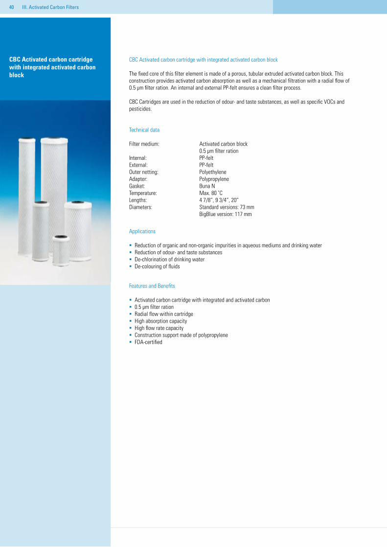
CBC Activated carbon cartridge with integrated activated carbon block
CBC Activated carbon cartridge with integrated activated carbon block
The fixed core of this filter element is made of a porous, tubular extruded activated carbon block. This construction provides activated carbon absorption as well as a mechanical filtration with a radial flow of 0.5 μm filter ration. An internal and external PP-felt ensures a clean filter process.
CBC Cartridges are used in the reduction of odour- and taste substances, as well as specific VOCs and pesticides.
Technical data
Filter medium: Activated carbon block 0.5 μm filter rationInternal: PP-feltExternal: PP-feltOuter netting: Polyethylene Adapter: Polypropylene Gasket: Buna NTemperature: Max. 80 ˚CLengths: 4 7/8“, 9 3/4“, 20“Diameters: Standard versions: 73 mm BigBlue version: 117 mm
Applications
Reduction of organic and non-organic impurities in aqueous mediums and drinking waterReduction of odour- and taste substancesDe-chlorination of drinking waterDe-colouring of fluids
Features and Benefits
Activated carbon cartridge with integrated and activated carbon 0.5 μm filter rationRadial flow within cartridge High absorption capacityHigh flow rate capacityConstruction support made of polypropyleneFDA-certified
III. Activated Carbon Filters
��
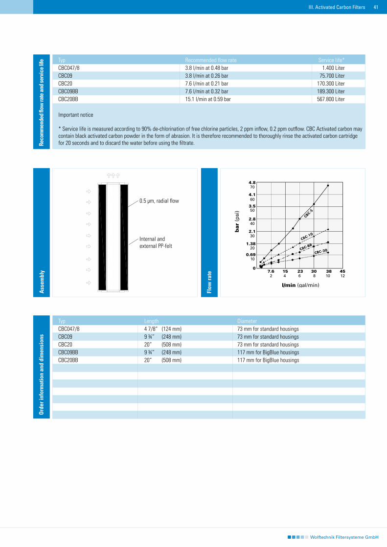
Reco
mm
ende
d flo
w ra
te a
nd se
rvic
e lif
e Typ Recommended flow rate Service life*CBC047/8 3.8 l/min at 0.48 bar 1.400 LiterCBC09 3.8 l/min at 0.26 bar 75.700 LiterCBC20 7.6 l/min at 0.21 bar 170.300 LiterCBC09BB 7.6 l/min at 0.32 bar 189.300 LiterCBC20BB 15.1 l/min at 0.59 bar 567.800 Liter
Important notice
* Service life is measured according to 90% de-chlorination of free chlorine particles, 2 ppm inflow, 0.2 ppm outflow. CBC Activated carbon may contain black activated carbon powder in the form of abrasion. It is therefore recommended to thoroughly rinse the activated carbon cartridge for 20 seconds and to discard the water before using the filtrate.
Flow
rate
Ord
er in
form
atio
n an
d di
men
sion
s
III. Activated Carbon Filters
Typ Length DiameterCBC047/8 4 7/8“ (124 mm) 73 mm for standard housingsCBC09 9 ¾“ (248 mm) 73 mm for standard housingsCBC20 20“ (508 mm) 73 mm for standard housingsCBC09BB 9 ¾“ (248 mm) 117 mm for BigBlue housingsCBC20BB 20“ (508 mm) 117 mm for BigBlue housings......
Ass
embl
y
0.5 μm, radial flow
Internal and external PP-felt
��
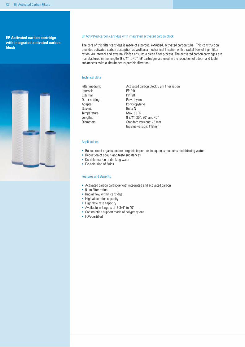
EP Activated carbon cartridge with integrated activated carbon block
EP Activated carbon cartridge with integrated activated carbon block
The core of this filter cartridge is made of a porous, extruded, activated carbon tube. This construction provides activated carbon absorption as well as a mechanical filtration with a radial flow of 5 μm filter ration. An internal and external PP-felt ensures a clean filter process. The activated carbon cartridges are manufactured in the lengths 9 3/4“ to 40“. EP Cartridges are used in the reduction of odour- and taste substances, with a simultaneous particle filtration.
Technical data
Filter medium: Activated carbon block 5 μm filter rationInternal: PP-feltExternal: PP-feltOuter netting: Polyethylene Adapter: Polypropylene Gasket: Buna NTemperature: Max. 80 ˚CLengths: 9 3/4“, 20“, 30“ and 40“Diameters: Standard versions: 73 mm BigBlue version: 118 mm
Applications
Reduction of organic and non-organic impurities in aqueous mediums and drinking waterReduction of odour- and taste substancesDe-chlorination of drinking waterDe-colouring of fluids
Features and Benefits
Activated carbon cartridge with integrated and activated carbon 5 μm filter rationRadial flow within cartridge High absorption capacityHigh flow rate capacityAvailable in lengths of 9 3/4“ to 40“Construction support made of polypropyleneFDA-certified
III. Activated Carbon Filters
��
Reco
mm
ende
d flo
w ra
te a
nd s
ervi
ce li
fe
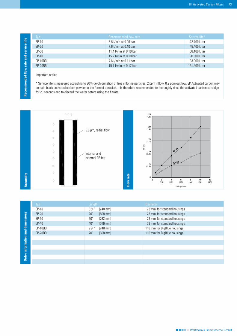
Typ Recommended flow rate Service life*EP-10 3.8 l/min at 0.09 bar 22.700 LiterEP-20 7.6 l/min at 0.10 bar 45.400 LiterEP-30 11.4 l/min at 0.10 bar 68.100 LiterEP-40 15.2 l/min at 0.10 bar 90.800 LiterEP-10BB 7.6 l/min at 0.11 bar 83.300 LiterEP-20BB 15.1 l/min at 0.17 bar 151.400 Liter
Important notice
* Service life is measured according to 90% de-chlorination of free chlorine particles, 2 ppm inflow, 0.2 ppm outflow. EP Activated carbon may contain black activated carbon powder in the form of abrasion. It is therefore recommended to thoroughly rinse the activated carbon cartridge for 20 seconds and to discard the water before using the filtrate.
III. Activated Carbon Filters
Flow
rate
Ord
er in
form
atio
n an
d di
men
sion
s
Typ Length DiameterEP-10 9 ¾“ (248 mm) 73 mm for standard housingsEP-20 20“ (508 mm) 73 mm for standard housingsEP-30 30“ (762 mm) 73 mm for standard housingsEP-40 40“ (1016 mm) 73 mm for standard housingsEP-10BB 9 ¾“ (248 mm) 118 mm for BigBlue housings EP-20BB 20“ (508 mm) 118 mm for BigBlue housings .
25(1.7)
20(1.4)
15(1.0)
10(0.7)
5(0.3)
00 2 4 6 8 10 12 (7.6) (15) (23) (30) (38) (45)
EP-10
EP-20
Ass
embl
y
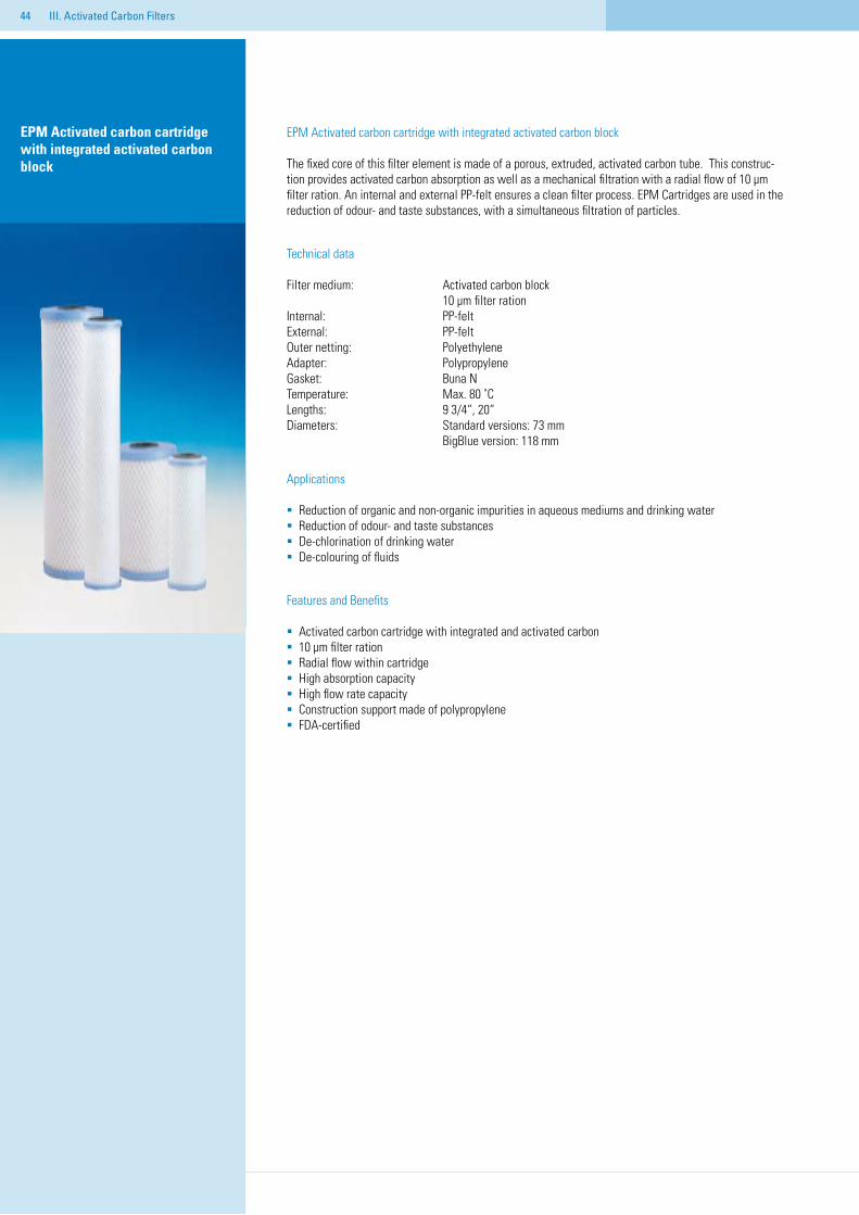
5.0 μm, radial flow
Internal and external PP-felt
l/min (gal/min)
bar (
psi)
��
EPM Activated carbon cartridge with integrated activated carbon block
EPM Activated carbon cartridge with integrated activated carbon block
The fixed core of this filter element is made of a porous, extruded, activated carbon tube. This construc-tion provides activated carbon absorption as well as a mechanical filtration with a radial flow of 10 μm filter ration. An internal and external PP-felt ensures a clean filter process. EPM Cartridges are used in the reduction of odour- and taste substances, with a simultaneous filtration of particles.
Technical data
Filter medium: Activated carbon block 10 μm filter rationInternal: PP-feltExternal: PP-feltOuter netting: Polyethylene Adapter: Polypropylene Gasket: Buna NTemperature: Max. 80 ˚CLengths: 9 3/4“, 20“Diameters: Standard versions: 73 mm BigBlue version: 118 mm
Applications
Reduction of organic and non-organic impurities in aqueous mediums and drinking waterReduction of odour- and taste substancesDe-chlorination of drinking waterDe-colouring of fluids
Features and Benefits
Activated carbon cartridge with integrated and activated carbon 10 μm filter rationRadial flow within cartridge High absorption capacityHigh flow rate capacityConstruction support made of polypropyleneFDA-certified
III. Activated Carbon Filters
��
Reco
mm
ende
d flo
w ra
te a
nd se
rvic
e lif
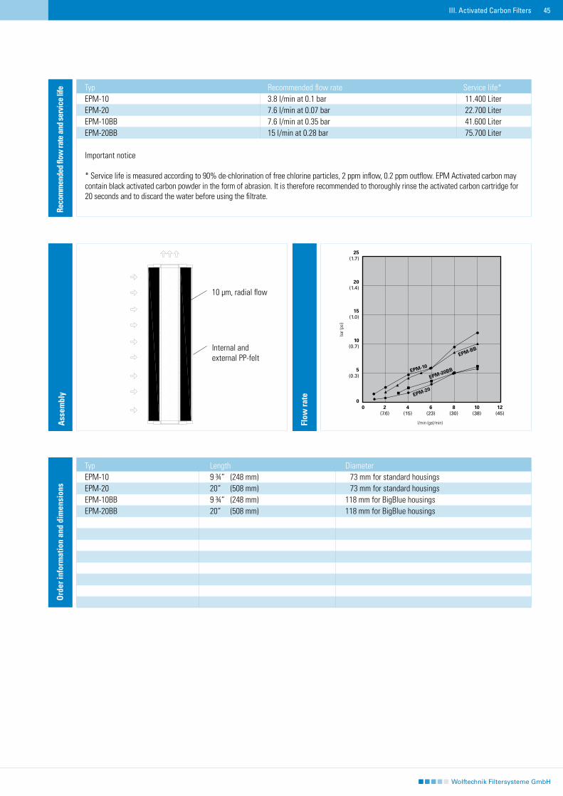
e Typ Recommended flow rate Service life*EPM-10 3.8 l/min at 0.1 bar 11.400 LiterEPM-20 7.6 l/min at 0.07 bar 22.700 LiterEPM-10BB 7.6 l/min at 0.35 bar 41.600 LiterEPM-20BB 15 l/min at 0.28 bar 75.700 Liter
Important notice
* Service life is measured according to 90% de-chlorination of free chlorine particles, 2 ppm inflow, 0.2 ppm outflow. EPM Activated carbon may contain black activated carbon powder in the form of abrasion. It is therefore recommended to thoroughly rinse the activated carbon cartridge for 20 seconds and to discard the water before using the filtrate.
Flow
rate
Ord
er in
form
atio
n an
d di
men
sion
s
Typ Length DiameterEPM-10 9 ¾“ (248 mm) 73 mm for standard housingsEPM-20 20“ (508 mm) 73 mm for standard housingsEPM-10BB 9 ¾“ (248 mm) 118 mm for BigBlue housings EPM-20BB 20“ (508 mm) 118 mm for BigBlue housings
III. Activated Carbon Filters
25(1.7)
20(1.4)
15(1.0)
10(0.7)
5(0.3)
00 2 4 6 8 10 12 (7.6) (15) (23) (30) (38) (45)
EPM-10
EPM-20BB
EPM-20
EPM-BB
Ass
embl
y
10 μm, radial flow
Internal and external PP-felt
l/min (gal/min)
bar (
psi)
46
47
IV. Sieve Filters, cleanable
Sieve filters are 100% surface filters and are suitable for separating solid particles from fluids. The cartridges only need to be taken out and rinsed to remove impurities retained on their surfaces. We therefore designate these as cleanable and reusab-le. The individual cartridges differ depending on the screen material and how it is processed.
Sieve Filters, cleanable
F40 sieve cartridges Nylon screen, cylindricalMS stainless steel Stainless steel screen, cylindrical screen cartridgesPD-MS stainless steel cartridges Stainless steel screen, pleatedSRF wedge wire cartridges Wedge wire element, cylindrical
48
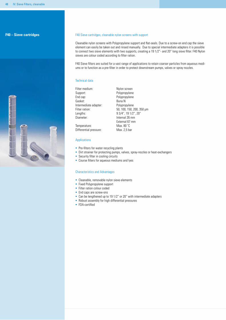
F40 Sieve cartridges, cleanable nylon screens with support
Cleanable nylon screens with Polypropylene support and flat-seals. Due to a screw-on end cap the sieve element can easily be taken out and rinsed manually. Due to special intermediate adapters it is possible to connect two sieve elements with two supports, creating a 19 1/2“- and 20“ long sieve filter. F40 Nylon sieves are colour coded according to filter ration.
F40 Sieve filters are suited for a vast range of applications to retain coarser particles from aqueous medi-ums or to function as a pre-filter in order to protect downstream pumps, valves or spray nozzles.
Technical data
Filter medium: Nylon screenSupport: Polypropylene End cap: PolypropyleneGasket: Buna NIntermediate adapter: PolypropyleneFilter ration: 50, 100, 150, 200, 350 µmLengths: 9 3/4“, 19 1/2“, 20“Diameter: Internal 26 mm External 67 mmTemperature: Max. 80 ˚CDifferential pressure: Max. 2,5 bar
Applications
Pre-filters for water recycling plantsDirt strainer for protecting pumps, valves, spray-nozzles or heat-exchangersSecurity filter in cooling circuitsCourse filters for aqueous mediums and lyes
Characteristics and Advantages
Cleanable, removable nylon sieve elementsFixed Polypropylene supportFilter ration colour codedEnd caps are screw-onsCan be lengthened up to 19 1/2“ or 20“ with intermediate adaptersRobust assembly for high differential pressuresFDA-certified
F40 – Sieve cartridges
IV. Sieve Filters, cleanable
49
Ord
er in
form
atio
n
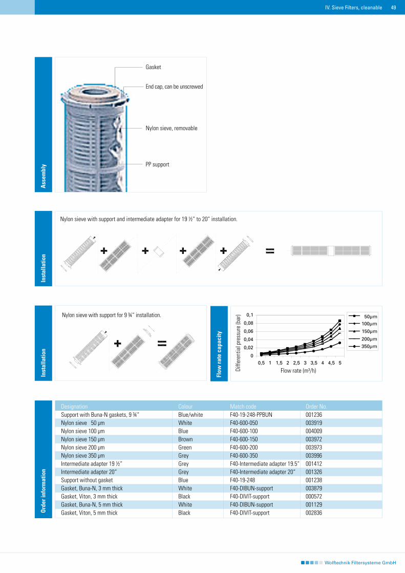
Designation Colour Match code Order No. Support with Buna-N gaskets, 9 ¾“ Blue/white F40-19-248-PPBUN 001236Nylon sieve 50 µm White F40-600-050 003919Nylon sieve 100 µm Blue F40-600-100 004009Nylon sieve 150 µm Brown F40-600-150 003972Nylon sieve 200 µm Green F40-600-200 003973Nylon sieve 350 µm Grey F40-600-350 003996Intermediate adapter 19 ½“ Grey F40-Intermediate adapter 19.5“ 001412Intermediate adapter 20“ Grey F40-Intermediate adapter 20“ 001326Support without gasket Blue F40-19-248 001238Gasket, Buna-N, 3 mm thick White F40-DIBUN-support 003879Gasket, Viton, 3 mm thick Black F40-DIVIT-support 000572Gasket, Buna-N, 5 mm thick White F40-DIBUN-support 001129Gasket, Viton, 5 mm thick Black F40-DIVIT-support 002836
Ass
embl
y
Gasket
End cap, can be unscrewed
Nylon sieve, removable
PP support
Inst
alla
tion
Inst
alla
tion
Nylon sieve with support and intermediate adapter for 19 ½“ to 20“ installation.
Nylon sieve with support for 9 ¾“ installation.
Flow
rate
cap
acity
IV. Sieve Filters, cleanable
Diffe
rent
ial p
ress
ure
(bar
)
Flow rate (m³/h)
50 IV. Sieve Filters, cleanable
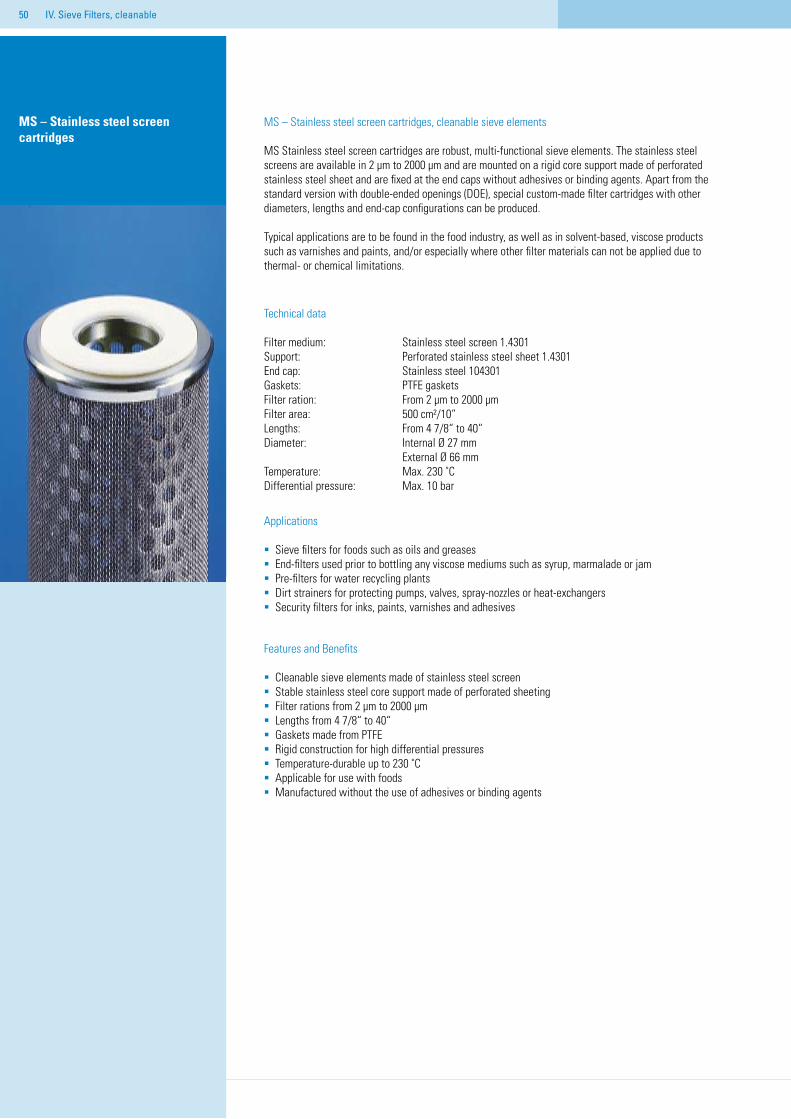
MS – Stainless steel screen cartridges, cleanable sieve elements
MS Stainless steel screen cartridges are robust, multi-functional sieve elements. The stainless steel screens are available in 2 µm to 2000 µm and are mounted on a rigid core support made of perforated stainless steel sheet and are fixed at the end caps without adhesives or binding agents. Apart from the standard version with double-ended openings (DOE), special custom-made filter cartridges with other diameters, lengths and end-cap configurations can be produced.
Typical applications are to be found in the food industry, as well as in solvent-based, viscose products such as varnishes and paints, and/or especially where other filter materials can not be applied due to thermal- or chemical limitations.
Technical data
Filter medium: Stainless steel screen 1.4301Support: Perforated stainless steel sheet 1.4301 End cap: Stainless steel 104301Gaskets: PTFE gasketsFilter ration: From 2 µm to 2000 µmFilter area: 500 cm²/10“Lengths: From 4 7/8“ to 40“Diameter: Internal Ø 27 mm External Ø 66 mmTemperature: Max. 230 ˚CDifferential pressure: Max. 10 bar
Applications
Sieve filters for foods such as oils and greasesEnd-filters used prior to bottling any viscose mediums such as syrup, marmalade or jamPre-filters for water recycling plantsDirt strainers for protecting pumps, valves, spray-nozzles or heat-exchangersSecurity filters for inks, paints, varnishes and adhesives
Features and Benefits
Cleanable sieve elements made of stainless steel screen Stable stainless steel core support made of perforated sheetingFilter rations from 2 µm to 2000 µmLengths from 4 7/8“ to 40“Gaskets made from PTFERigid construction for high differential pressuresTemperature-durable up to 230 ˚CApplicable for use with foodsManufactured without the use of adhesives or binding agents
MS – Stainless steel screen cartridges
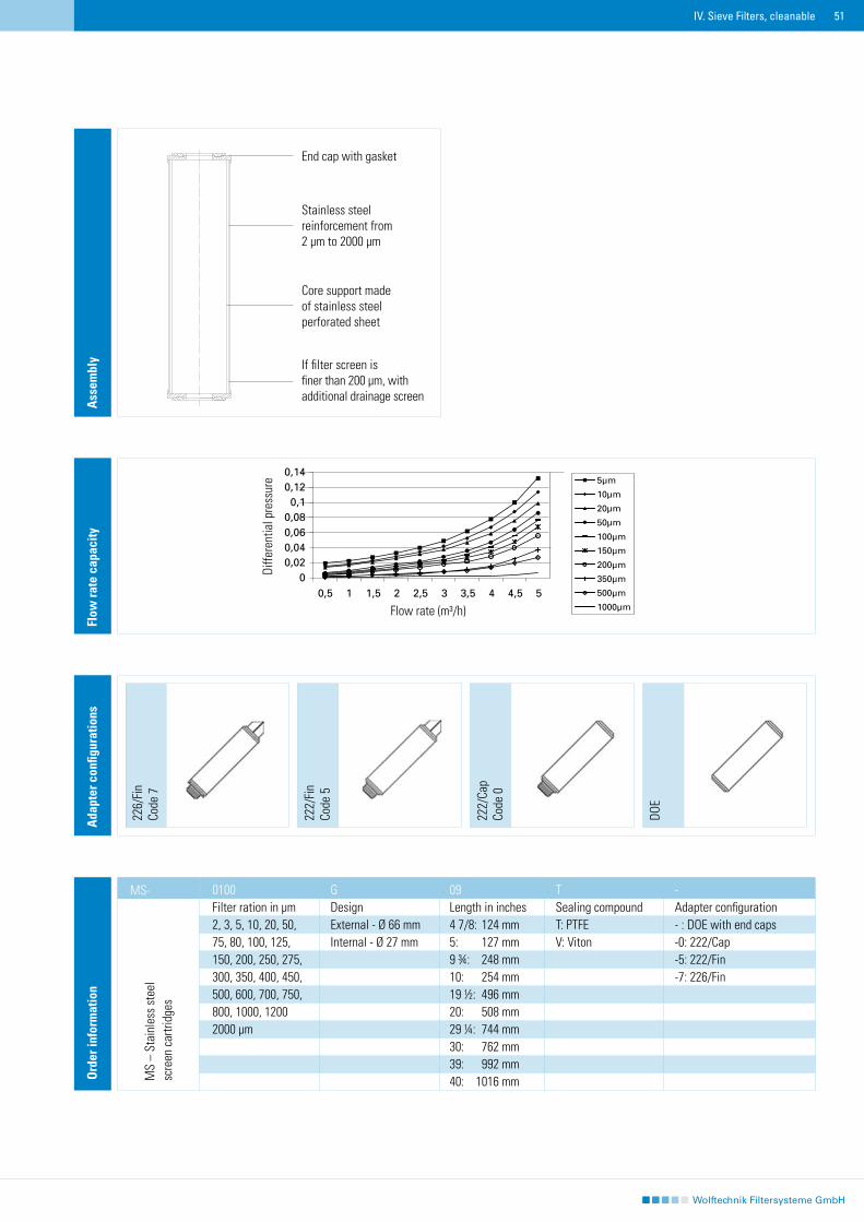
51IV. Sieve Filters, cleanable
Ass
embl
y
End cap with gasket
Stainless steel reinforcement from 2 µm to 2000 µm
Core support made of stainless steel perforated sheet
If filter screen is finer than 200 µm, with additional drainage screen
Ord
er in
form
atio
n
0100 G 09 T - Filter ration in µm Design Length in inches Sealing compound Adapter configuration 2, 3, 5, 10, 20, 50, External - Ø 66 mm 4 7/8: 124 mm T: PTFE - : DOE with end caps75, 80, 100, 125, Internal - Ø 27 mm 5: 127 mm V: Viton -0: 222/Cap150, 200, 250, 275, 9 ¾: 248 mm -5: 222/Fin300, 350, 400, 450, 10: 254 mm -7: 226/Fin 500, 600, 700, 750, 19 ½: 496 mm800, 1000, 1200 20: 508 mm2000 µm 29 ¼: 744 mm 30: 762 mm 39: 992 mm 40: 1016 mm
226/
Fin
Code
7
222/
Fin
Code
5
DOE
Ada
pter
con
figur
atio
ns
222/
Cap
Code
0
Flow
rate
cap
acity
MS-
MS
– St
ainl
ess
stee
l sc
reen
car
tridg
es
Diffe
rent
ial p
ress
ure
Flow rate (m³/h)
52 IV. Sieve Filters, cleanable
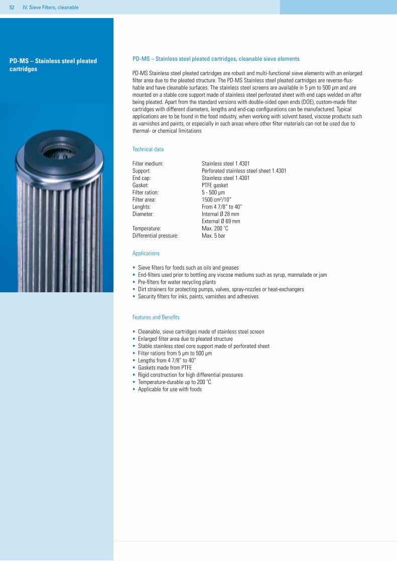
PD-MS – Stainless steel pleated cartridges, cleanable sieve elements
PD-MS Stainless steel pleated cartridges are robust and multi-functional sieve elements with an enlarged filter area due to the pleated structure. The PD-MS Stainless steel pleated cartridges are reverse-flus-hable and have cleanable surfaces. The stainless steel screens are available in 5 µm to 500 µm and are mounted on a stable core support made of stainless steel perforated sheet with end caps welded on after being pleated. Apart from the standard versions with double-sided open ends (DOE), custom-made filter cartridges with different diameters, lengths and end-cap configurations can be manufactured. Typical applications are to be found in the food industry, when working with solvent based, viscose products such as varnishes and paints, or especially in such areas where other filter materials can not be used due to thermal- or chemical limitations
Technical data
Filter medium: Stainless steel 1.4301Support: Perforated stainless steel sheet 1.4301 End cap: Stainless steel 1.4301Gasket: PTFE gasketFilter ration: 5 - 500 µm Filter area: 1500 cm²/10“Lenghts: From 4 7/8“ to 40“Diameter: Internal Ø 28 mm External Ø 69 mmTemperature: Max. 200 ˚CDifferential pressure: Max. 5 bar
Applications
Sieve filters for foods such as oils and greasesEnd-filters used prior to bottling any viscose mediums such as syrup, marmalade or jamPre-filters for water recycling plantsDirt strainers for protecting pumps, valves, spray-nozzles or heat-exchangersSecurity filters for inks, paints, varnishes and adhesives
Features and Benefits
Cleanable, sieve cartridges made of stainless steel screenEnlarged filter area due to pleated structureStable stainless steel core support made of perforated sheetFilter rations from 5 µm to 500 µmLengths from 4 7/8“ to 40“Gaskets made from PTFERigid construction for high differential pressuresTemperature-durable up to 200 ˚CApplicable for use with foods
PD-MS – Stainless steel pleated cartridges
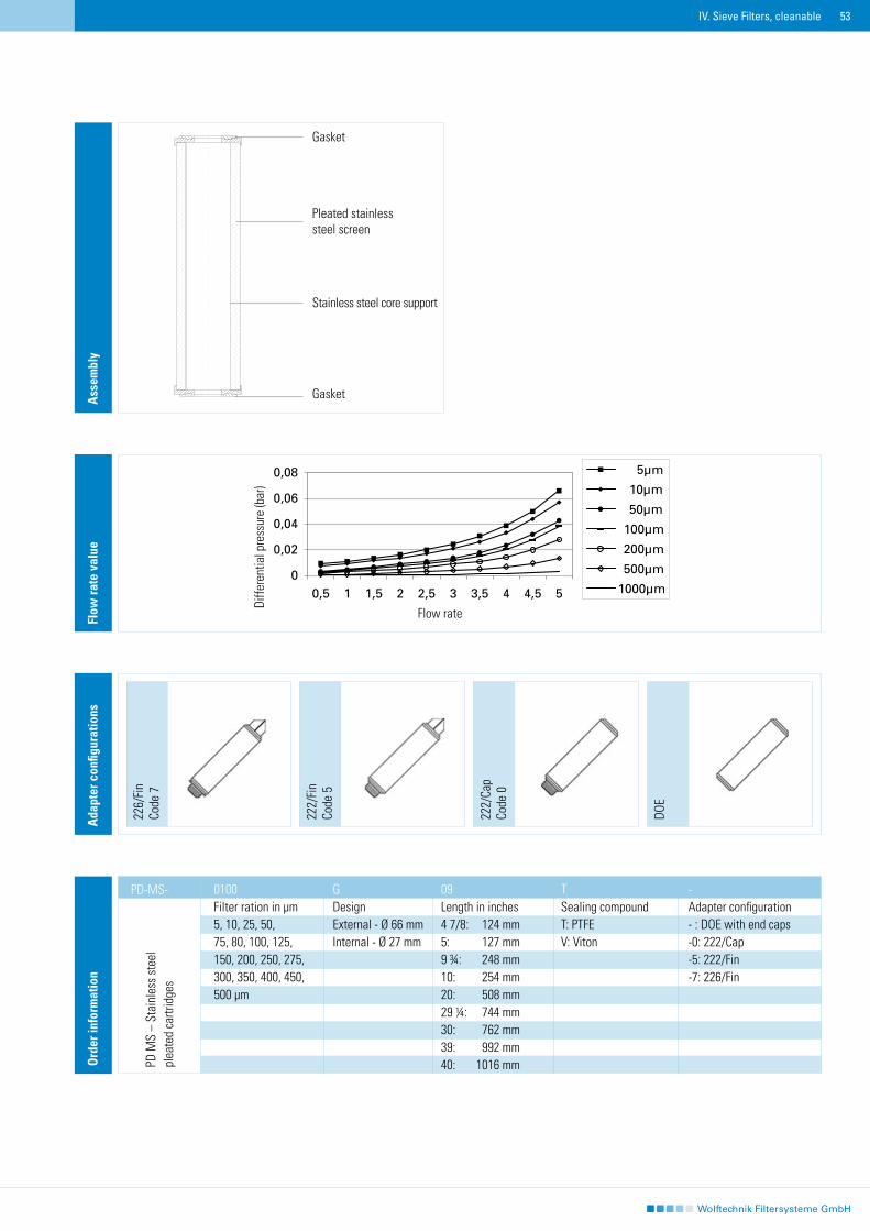
53IV. Sieve Filters, cleanable
Ass
embl
y
Gasket
Pleated stainless steel screen
Stainless steel core support
Gasket
Ord
er in
form
atio
n
0100 G 09 T - Filter ration in µm Design Length in inches Sealing compound Adapter configuration 5, 10, 25, 50, External - Ø 66 mm 4 7/8: 124 mm T: PTFE - : DOE with end caps75, 80, 100, 125, Internal - Ø 27 mm 5: 127 mm V: Viton -0: 222/Cap150, 200, 250, 275, 9 ¾: 248 mm -5: 222/Fin300, 350, 400, 450, 10: 254 mm -7: 226/Fin 500 µm 20: 508 mm 29 ¼: 744 mm 30: 762 mm 39: 992 mm 40: 1016 mm
226/
Fin
Code
7
222/
Fin
Code
5
DOE
Ada
pter
con
figur
atio
ns
222/
Cap
Code
0
Flow
rate
val
ue
PD-MS-
PD M
S –
Stai
nles
s st
eel
plea
ted
cartr
idge
s
Diffe
rent
ial p
ress
ure
(bar
)
Flow rate
54 IV. Sieve Filters, cleanable
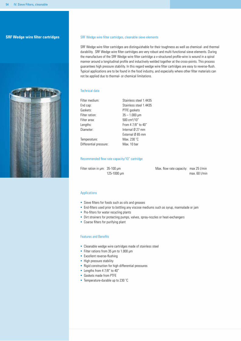
SRF Wedge wire filter cartridges, cleanable sieve elements
SRF Wedge wire filter cartridges are distinguishable for their toughness as well as chemical- and thermal durability. SRF Wedge wire filter cartridges are very robust and multi-functional sieve elements. During the manufacture of the SRF Wedge wire filter cartridge a v-structured profile-wire is wound in a spiral manner around a longitudinal profile and inductively welded together at the cross-points. This process guarantees high pressure stability. In this regard wedge wire filter cartridges are easy to reverse-flush. Typical applications are to be found in the food industry, and especially where other filter materials can not be applied due to thermal- or chemical limitations.
Technical data
Filter medium: Stainless steel 1.4435End cap: Stainless steel 1.4435Gaskets: PTFE gasketsFilter ration: 35 – 1.000 µm Filter area: 500 cm²/10“Lengths: From 4 7/8“ to 40“Diameter: Internal Ø 27 mm External Ø 65 mmTemperature: Max. 230 ˚CDifferential pressure: Max. 10 bar
Recommended flow rate capacity/10“ cartridge
Filter ration in µm: 35-100 µm Max. flow rate capacity: max 25 l/min 125-1000 µm max. 60 l/min
Applications
Sieve filters for foods such as oils and greasesEnd-filters used prior to bottling any viscose mediums such as syrup, marmalade or jamPre-filters for water recycling plantsDirt strainers for protecting pumps, valves, spray-nozzles or heat-exchangersCoarse filters for purifying plant
Features and Benefits
Cleanable wedge wire cartridges made of stainless steel Filter rations from 35 µm to 1.000 µmExcellent reverse-flushingHigh pressure stabilityRigid construction for high differential pressuresLengths from 4 7/8“ to 40“Gaskets made from PTFETemperature-durable up to 230 ˚C
SRF Wedge wire filter cartridges
55IV. Sieve Filters, cleanable
226/
Fin
Code
7
222/
Fin
Code
5
DOE
Ada
pter
con
figur
atio
ns
222/
Cap
Code
0
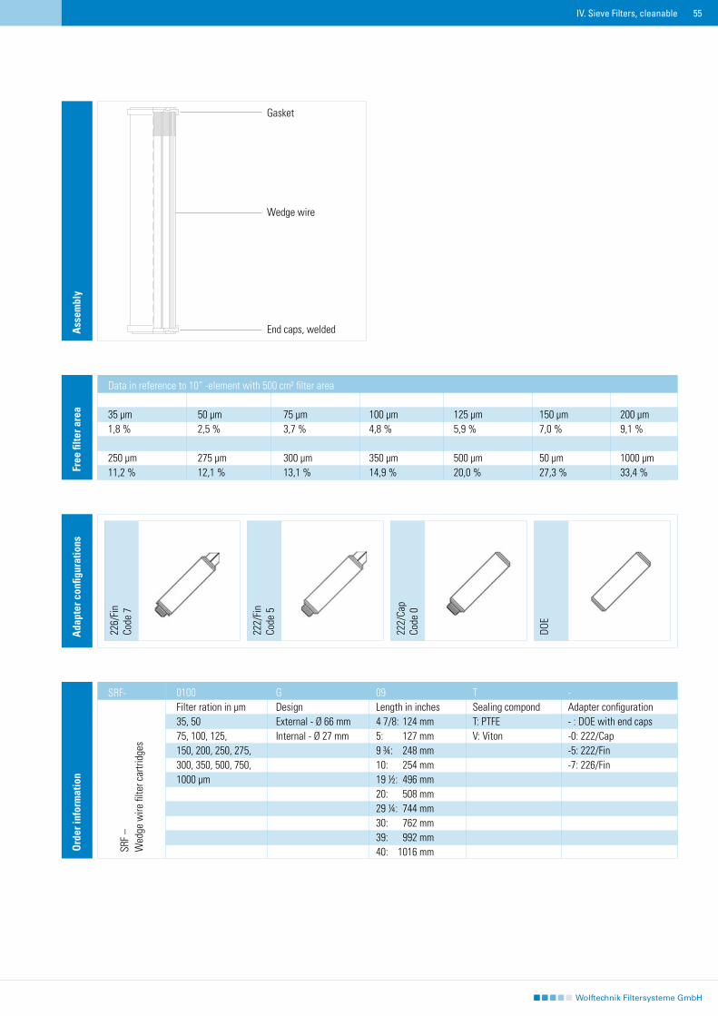
Ass
embl
y
Gasket
Wedge wire
End caps, welded
Free
filte
r are
a
Data in reference to 10“ -element with 500 cm² filter area 35 µm 50 µm 75 µm 100 µm 125 µm 150 µm 200 µm1,8 % 2,5 % 3,7 % 4,8 % 5,9 % 7,0 % 9,1 % 250 µm 275 µm 300 µm 350 µm 500 µm 50 µm 1000 µm 11,2 % 12,1 % 13,1 % 14,9 % 20,0 % 27,3 % 33,4 %
Ord
er in
form
atio
n
0100 G 09 T - Filter ration in µm Design Length in inches Sealing compond Adapter configuration 35, 50 External - Ø 66 mm 4 7/8: 124 mm T: PTFE - : DOE with end caps75, 100, 125, Internal - Ø 27 mm 5: 127 mm V: Viton -0: 222/Cap150, 200, 250, 275, 9 ¾: 248 mm -5: 222/Fin300, 350, 500, 750, 10: 254 mm -7: 226/Fin 1000 µm 19 ½: 496 mm 20: 508 mm 29 ¼: 744 mm 30: 762 mm 39: 992 mm 40: 1016 mm
SRF-
SRF
–W
edge
wire
filte
r car
tridg
es
56
57
V. Cartridge Filter Housings
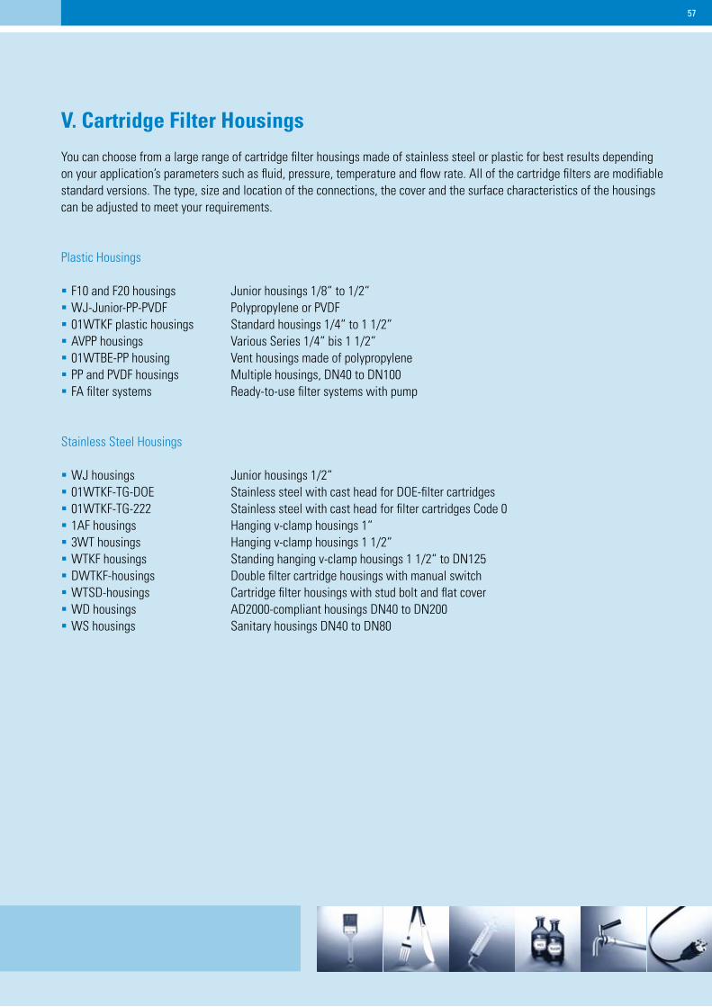
You can choose from a large range of cartridge filter housings made of stainless steel or plastic for best results depending on your application’s parameters such as fluid, pressure, temperature and flow rate. All of the cartridge filters are modifiable standard versions. The type, size and location of the connections, the cover and the surface characteristics of the housings can be adjusted to meet your requirements.
Plastic Housings
F10 and F20 housings Junior housings 1/8“ to 1/2“WJ-Junior-PP-PVDF Polypropylene or PVDF01WTKF plastic housings Standard housings 1/4“ to 1 1/2“AVPP housings Various Series 1/4“ bis 1 1/2“01WTBE-PP housing Vent housings made of polypropylene PP and PVDF housings Multiple housings, DN40 to DN100FA filter systems Ready-to-use filter systems with pump
Stainless Steel Housings
WJ housings Junior housings 1/2“01WTKF-TG-DOE Stainless steel with cast head for DOE-filter cartridges01WTKF-TG-222 Stainless steel with cast head for filter cartridges Code 0 1AF housings Hanging v-clamp housings 1“3WT housings Hanging v-clamp housings 1 1/2“WTKF housings Standing hanging v-clamp housings 1 1/2“ to DN125DWTKF-housings Double filter cartridge housings with manual switchWTSD-housings Cartridge filter housings with stud bolt and flat coverWD housings AD2000-compliant housings DN40 to DN200WS housings Sanitary housings DN40 to DN80
58 V. Cartridge Filter Housings
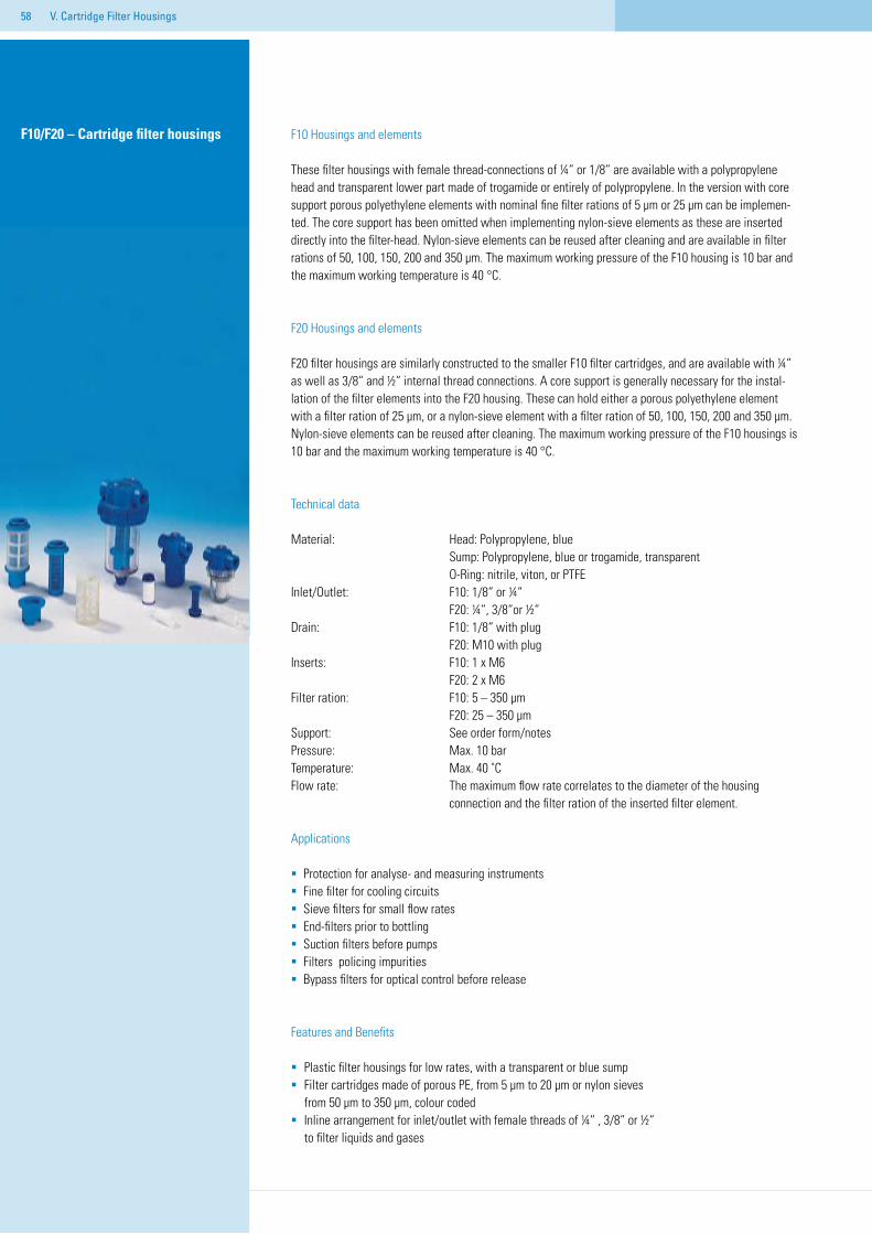
F10/F20 – Cartridge filter housings F10 Housings and elements
These filter housings with female thread-connections of ¼“ or 1/8“ are available with a polypropylene head and transparent lower part made of trogamide or entirely of polypropylene. In the version with core support porous polyethylene elements with nominal fine filter rations of 5 µm or 25 µm can be implemen-ted. The core support has been omitted when implementing nylon-sieve elements as these are inserted directly into the filter-head. Nylon-sieve elements can be reused after cleaning and are available in filter rations of 50, 100, 150, 200 and 350 µm. The maximum working pressure of the F10 housing is 10 bar and the maximum working temperature is 40 °C.
F20 Housings and elements
F20 filter housings are similarly constructed to the smaller F10 filter cartridges, and are available with ¼“ as well as 3/8“ and ½“ internal thread connections. A core support is generally necessary for the instal-lation of the filter elements into the F20 housing. These can hold either a porous polyethylene element with a filter ration of 25 µm, or a nylon-sieve element with a filter ration of 50, 100, 150, 200 and 350 µm. Nylon-sieve elements can be reused after cleaning. The maximum working pressure of the F10 housings is 10 bar and the maximum working temperature is 40 °C.
Technical data
Material: Head: Polypropylene, blue Sump: Polypropylene, blue or trogamide, transparent O-Ring: nitrile, viton, or PTFEInlet/Outlet: F10: 1/8“ or ¼“ F20: ¼“, 3/8“or ½“Drain: F10: 1/8“ with plug F20: M10 with plugInserts: F10: 1 x M6 F20: 2 x M6Filter ration: F10: 5 – 350 µm F20: 25 – 350 µm Support: See order form/notesPressure: Max. 10 barTemperature: Max. 40 ˚CFlow rate: The maximum flow rate correlates to the diameter of the housing connection and the filter ration of the inserted filter element.
Applications
Protection for analyse- and measuring instruments Fine filter for cooling circuits Sieve filters for small flow ratesEnd-filters prior to bottlingSuction filters before pumps Filters policing impurities Bypass filters for optical control before release
Features and Benefits
Plastic filter housings for low rates, with a transparent or blue sump Filter cartridges made of porous PE, from 5 µm to 20 µm or nylon sieves
from 50 µm to 350 µm, colour codedInline arrangement for inlet/outlet with female threads of ¼“ , 3/8“ or ½“
to filter liquids and gases
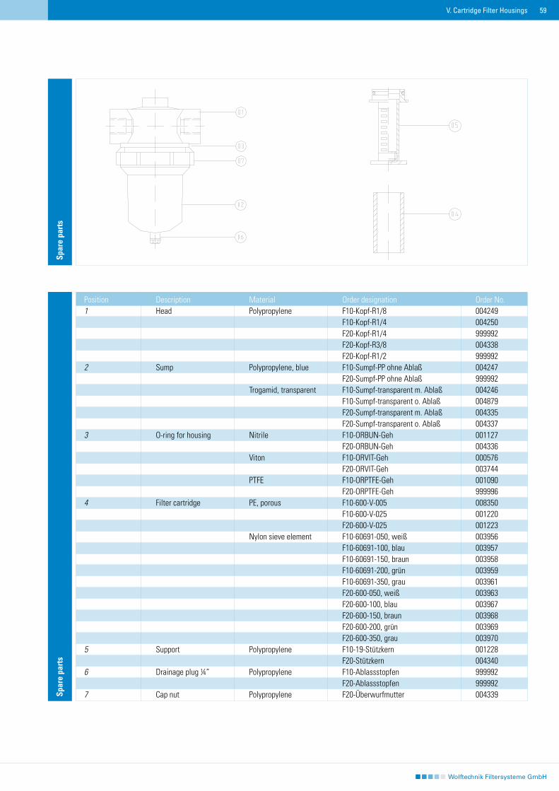
59V. Cartridge Filter Housings
Spar
e pa
rts
Position Description Material Order designation Order No.1 Head Polypropylene F10-Kopf-R1/8 004249 F10-Kopf-R1/4 004250 F20-Kopf-R1/4 999992 F20-Kopf-R3/8 004338 F20-Kopf-R1/2 9999922 Sump Polypropylene, blue F10-Sumpf-PP ohne Ablaß 004247 F20-Sumpf-PP ohne Ablaß 999992 Trogamid, transparent F10-Sumpf-transparent m. Ablaß 004246 F10-Sumpf-transparent o. Ablaß 004879 F20-Sumpf-transparent m. Ablaß 004335 F20-Sumpf-transparent o. Ablaß 0043373 O-ring for housing Nitrile F10-ORBUN-Geh 001127 F20-ORBUN-Geh 004336 Viton F10-ORVIT-Geh 000576 F20-ORVIT-Geh 003744 PTFE F10-ORPTFE-Geh 001090 F20-ORPTFE-Geh 9999964 Filter cartridge PE, porous F10-600-V-005 008350 F10-600-V-025 001220 F20-600-V-025 001223 Nylon sieve element F10-60691-050, weiß 003956 F10-60691-100, blau 003957 F10-60691-150, braun 003958 F10-60691-200, grün 003959 F10-60691-350, grau 003961 F20-600-050, weiß 003963 F20-600-100, blau 003967 F20-600-150, braun 003968 F20-600-200, grün 003969 F20-600-350, grau 0039705 Support Polypropylene F10-19-Stützkern 001228 F20-Stützkern 0043406 Drainage plug ¼“ Polypropylene F10-Ablassstopfen 999992 F20-Ablassstopfen 9999927 Cap nut Polypropylene F20-Überwurfmutter 004339
Spar
e pa
rts
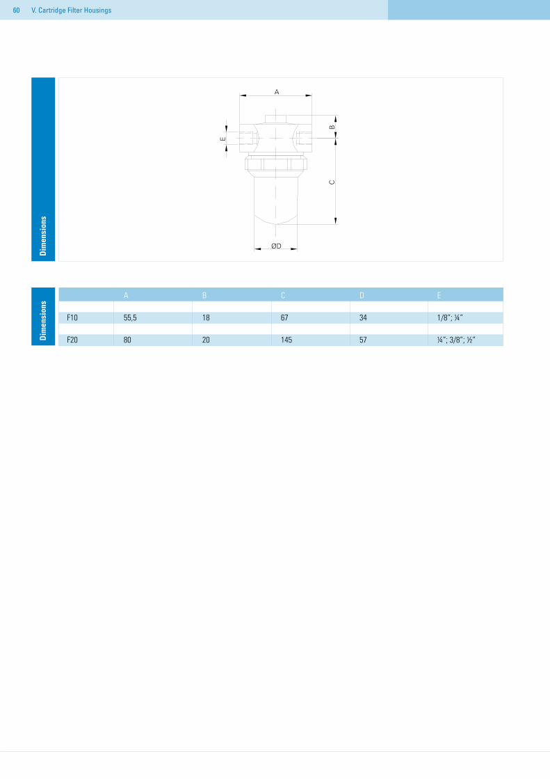
60
Dim
ensi
ons
V. Cartridge Filter Housings
A B C D E F10 55,5 18 67 34 1/8“; ¼“ F20 80 20 145 57 ¼“; 3/8“; ½“D
imen
sion
s
61V. Cartridge Filter Housings
Ord
er in
form
atio
n
Position Designation1 F10: Type series F10 F20: Type series F202 10: 1/8“ female thread (F10) 13: ¼“ female thread (F10/F20) 17: 3/8“ female thread (F20) 21: ½“ female thread (F20)3 B: Head with inserts4 950: Sump transp., without drain (F10) 951: Sump transp., with drain (F10) 990: Sump PP., without drain (F10) 960: Sump transp., without drain (F20) 961: Sump transp., with drain (F20) 990: Sump PP, without drain (F20) 991: Sump PP, with drain (F20)5 60.691: without support (F10) 10: with support (F10) 17: with support (F20)6 Filter ration in µm, nominal 5 µm PE-tubing (F10) 25 µm PE-tubing (F10/F20) 50 µm (white) nylon sieve (F10/F20) 100 µm (blue) nylon sieve (F10/F20) 150 µm (brown) nylon sieve (F10/F20) 200 µm (green) nylon sieve (F10/F20) 350 µm (grey) nylon sieve(F10/F20)
F10 10 B 990 /60.691 50 13 950 100 951 150 200 350F10 10 B 990 /10 5 13 950 25 951F20 13 B 960 /17 25 17 961 50 21 990 100 991 150 200 3501 2 3 4 5 6O
rder
exa
mpl
e
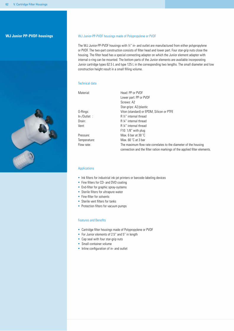
62
WJ Junior-PP-PVDF housings made of Polypropylene or PVDF
The WJ Junior-PP-PVDF housings with ½“ in- and outlet are manufactured from either polypropylene or PVDF. The two-part construction consists of filter head and lower part. Four star-grip nuts close the housing. The filter head has a special connecting adapter on which the Junior element adapter with internal o-ring can be mounted. The bottom parts of the Junior elements are available incorporating Junior cartridge types 62.5 L and type 125 L in the corresponding two lengths. The small diameter and low construction height result in a small filling volume.
Technical data
Material: Head: PP or PVDF Lower part: PP or PVDF Screws: A2 Star-grips: A2/plasticO-Rings: Viton (standard) or EPDM, Silicon or PTFEIn-/Outlet : R ½“ internal threadDrain: R ¼“ internal threadVent: R ¼“ internal thread F10: 1/8“ with plug Pressure: Max. 6 bar at 30 ˚CTemperature: Max. 60 ˚C at 3 barFlow rate: The maximum flow rate correlates to the diameter of the housing connection and the filter ration markings of the applied filter elements.
Applications
Ink filters for industrial ink-jet printers or barcode-labeling devicesFine filters for CD- and DVD coatingEnd-filter for graphic spray-systemsSterile filters for ultrapure waterFine-filter for solventsSterile vent filters for tanksProtection filters for vacuum pumps
Features and Benefits
Cartridge filter housings made of Polypropylene or PVDFFor Junior elements of 2.5“ and 5“ in lengthCap seal with four star-grip nuts Small container volumeInline configuration of in- and outlet
V. Cartridge Filter Housings
WJ Junior PP-PVDF-housings
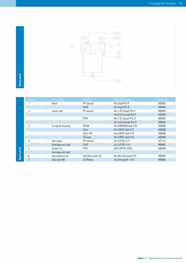
63V. Cartridge Filter Housings
Spar
e pa
rts
Position Description Material Order designation Order No.1 Head PP-natural WJ-Kopf-R½-P 999992 PVDF WJ-Kopf-R½-D 9999922 Lower part PP-natural WJ-125-Sumpf-R¼-P 999992 WJ-6.25-Sumpf-R¼-P 999992 PVDF WJ-125-Sumpf-R¼-D 999992 WJ-6.25-Sumpf-R¼-D 9999923 O-ring for housing EPDM WJ-OREPDM-Geh-P/D 999996 Viton WJ-ORVIT-Geh-P/D 999996 Viton-FEP WJ-ORFEP-Geh-P/D 999996 Silicone WJ-ORSIL-Geh-P/D 9999964 Vent plug PP-natural WJ-ESTOP-¼-P 007151 Drainage and vent PVDF WJ-ESTOP-¼-D 9999925 Gasket for PTFE 3WT-DIPTFE-ENTL 000364 drainage and vent6 Hex-head screw Stainless steel A2 WJ-6kt-Schraube-P/D 9999927 Star-grip M8 A2/Plastic WJ-Sterngriff—P/D 999992
Spar
e pa
rts
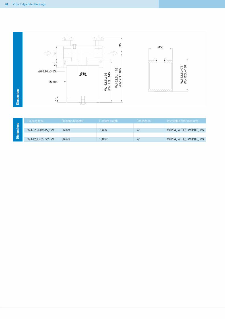
64
Housing type Element diameter Element length Connection Installable filter mediums WJ-62.5L-R½-PV/-VV 56 mm 76mm ½“ WFPPA, WFPES, WFPTFE, MS WJ-125L-R½-PV/ -VV 56 mm 138mm ½“ WFPPA, WFPES, WFPTFE, MSD
imen
sion
sD
imen
sion
s
V. Cartridge Filter Housings
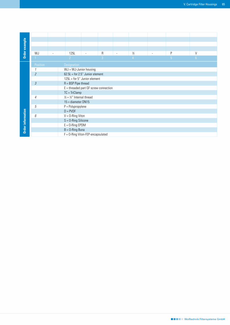
65
WJ - 125L - R - ½ - P V1 2 3 4 5 6
Ord
er in
form
atio
n
Position Designation1 WJ = WJ-Junior housing2 62.5L = for 2.5“ Junior element 125L = for 5“ Junior element3 R = BSP Pipe thread E = threaded part GF screw connection TC = TriClamp4 ½ = ½“ Internal thread 15 = diameter DN155 P = Polypropylene D = PVDF6 V = O-Ring Viton S = O-Ring Silicone E = O-Ring EPDM B = O-Ring Buna F = O-Ring Viton-FEP-encapsulated
Ord
er e
xam
ple
V. Cartridge Filter Housings
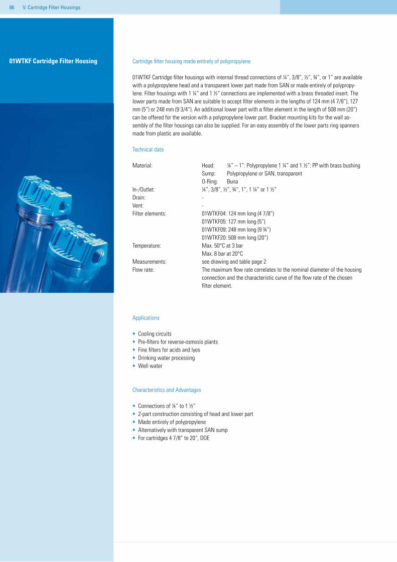
66 V. Cartridge Filter Housings
Cartridge filter housing made entirely of polypropylene
01WTKF Cartridge filter housings with internal thread connections of ¼“, 3/8“, ½“, ¾“, or 1“ are available with a polypropylene head and a transparent lower part made from SAN or made entirely of polypropy-lene. Filter housings with 1 ¼“ and 1 ½“ connections are implemented with a brass threaded insert. The lower parts made from SAN are suitable to accept filter elements in the lengths of 124 mm (4 7/8“), 127 mm (5“) or 248 mm (9 3/4“). An additional lower part with a filter element in the length of 508 mm (20“) can be offered for the version with a polypropylene lower part. Bracket mounting kits for the wall as-sembly of the filter housings can also be supplied. For an easy assembly of the lower parts ring spanners made from plastic are available.
Technical data
Material: Head: ¼” – 1”: Polypropylene 1 ¼” and 1 ½”: PP with brass bushing Sump: Polypropylene or SAN, transparent O-Ring: BunaIn-/Outlet: ¼”, 3/8”, ½“, ¾“, 1“, 1 ¼“ or 1 ½“Drain: -Vent: -Filter elements: 01WTKF04: 124 mm long (4 7/8”) 01WTKF05: 127 mm long (5”) 01WTKF09: 248 mm long (9 ¾”) 01WTKF20: 508 mm long (20“)Temperature: Max. 50°C at 3 bar Max. 8 bar at 20°CMeasurements: see drawing and table page 2Flow rate: The maximum flow rate correlates to the nominal diameter of the housing connection and the characteristic curve of the flow rate of the chosen filter element.
Applications
Cooling circuitsPre-filters for reverse-osmosis plantsFine filters for acids and lyesDrinking water processingWell water
Characteristics and Advantages
Connections of ¼“ to 1 ½“2-part construction consisting of head and lower part Made entirely of polypropyleneAlternatively with transparent SAN sump For cartridges 4 7/8“ to 20“, DOE
01WTKF Cartridge Filter Housing
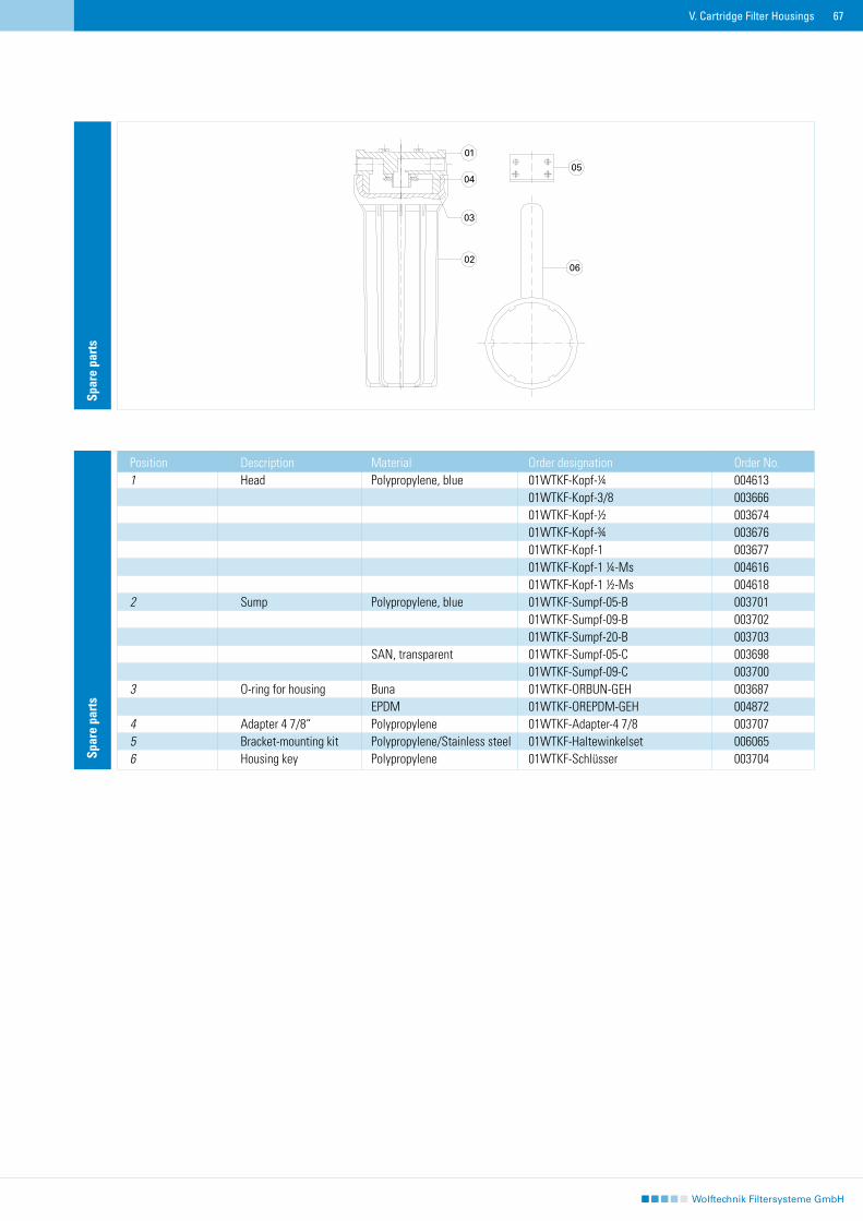
67V. Cartridge Filter Housings
Spar
e pa
rts
Position Description Material Order designation Order No.1 Head Polypropylene, blue 01WTKF-Kopf-¼ 004613 01WTKF-Kopf-3/8 003666 01WTKF-Kopf-½ 003674 01WTKF-Kopf-¾ 003676 01WTKF-Kopf-1 003677 01WTKF-Kopf-1 ¼-Ms 004616 01WTKF-Kopf-1 ½-Ms 0046182 Sump Polypropylene, blue 01WTKF-Sumpf-05-B 003701 01WTKF-Sumpf-09-B 003702 01WTKF-Sumpf-20-B 003703 SAN, transparent 01WTKF-Sumpf-05-C 003698 01WTKF-Sumpf-09-C 0037003 O-ring for housing Buna 01WTKF-ORBUN-GEH 003687 EPDM 01WTKF-OREPDM-GEH 0048724 Adapter 4 7/8“ Polypropylene 01WTKF-Adapter-4 7/8 0037075 Bracket-mounting kit Polypropylene/Stainless steel 01WTKF-Haltewinkelset 0060656 Housing key Polypropylene 01WTKF-Schlüsser 003704
Spar
e pa
rts
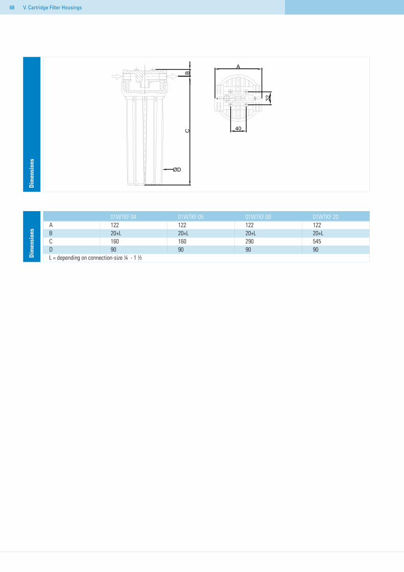
68 V. Cartridge Filter Housings
01WTKF 04 01WTKF 05 01WTKF 09 01WTKF 20A 122 122 122 122 B 20+L 20+L 20+L 20+LC 160 160 290 545D 90 90 90 90L = depending on connection-size ¼″ - 1 ½″
Dim
ensi
ons
Dim
ensi
ons
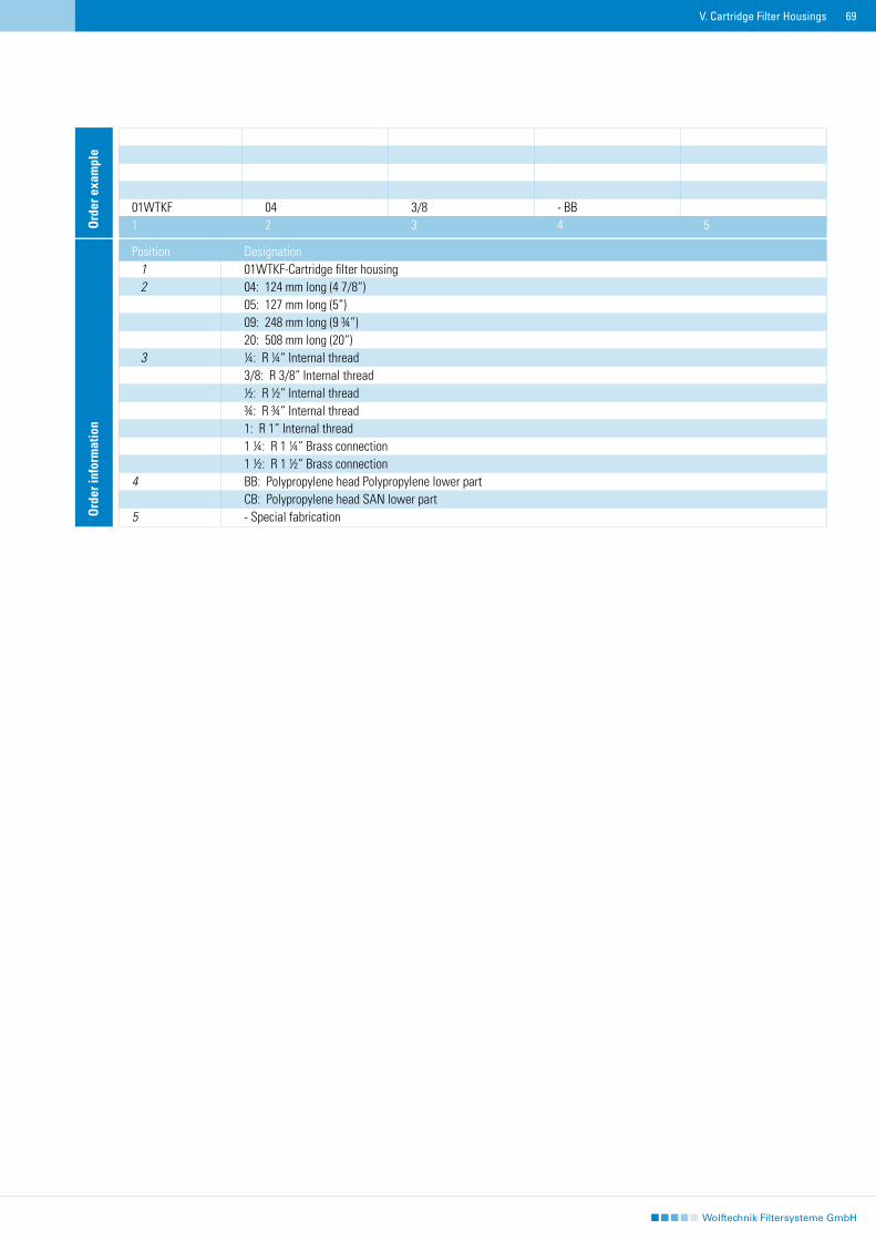
69V. Cartridge Filter Housings
01WTKF 04 3/8 - BB1 2 3 4 5O
rder
exa
mpl
eO
rder
info
rmat
ion
Position Designation 1 01WTKF-Cartridge filter housing 2 04: 124 mm long (4 7/8“) 05: 127 mm long (5“) 09: 248 mm long (9 ¾“) 20: 508 mm long (20“) 3 ¼: R ¼“ Internal thread 3/8: R 3/8“ Internal thread ½: R ½“ Internal thread ¾: R ¾“ Internal thread 1: R 1“ Internal thread 1 ¼: R 1 ¼“ Brass connection 1 ½: R 1 ½“ Brass connection 4 BB: Polypropylene head Polypropylene lower part CB: Polypropylene head SAN lower part5 - Special fabrication
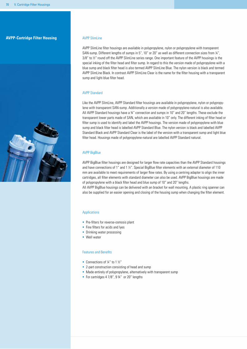
70 V. Cartridge Filter Housings
AVPP SlimLine
AVPP SlimLine filter housings are available in polypropylene, nylon or polypropylene with transparent SAN-sump. Different lengths of sumps in 5“, 10“ or 20“ as well as different connection sizes from ¼“, 3/8“ to ½“ round off the AVPP SlimLine series range. One important feature of the AVPP housings is the special inking of the filter head and filter sump. In regard to this the version made of polypropylene with a blue sump and black filter head is also termed AVPP SlimLine Blue. The nylon version is black and termed AVPP SlimLine Black. In contrast AVPP SlimLine Clear is the name for the filter housing with a transparent sump and light-blue filter head.
AVPP Standard
Like the AVPP SlimLine, AVPP Standard filter housings are available in polypropylene, nylon or polypropy-lene with transparent SAN-sump. Additionally a version made of polypropylene-natural is also available. All AVPP Standard housings have a ¾“ connection and sumps in 10“ and 20“ lengths. These exclude the transparent lower parts made of SAN, which are available in 10“ only. The different inking of filter head or filter sump is used to identify and label the AVPP housings. The version made of polypropylene with blue sump and black filter head is labelled AVPP Standard Blue. The nylon version is black and labelled AVPP Standard Black and AVPP Standard Clear is the label of the version with a transparent sump and light blue filter head. Housings made of polypropylene-natural are labelled AVPP Standard natural.
AVPP BigBlue
AVPP BigBlue filter housings are designed for larger flow rate capacities than the AVPP Standard housings and have connections of 1“ and 1 ½“. Special BigBlue filter elements with an external diameter of 110 mm are available to meet requirements of larger flow rates. By using a centring adapter to align the inner cartridges, all filter elements with standard diameter can also be used. AVPP BigBlue housings are made of polypropylene with a black filter head and blue sump of 10“ and 20“ lengths. All AVPP BigBlue housings can be delivered with an bracket for wall mounting. A plastic ring spanner can also be supplied for an easier opening and closing of the housing sump when changing the filter element.
Applications
Pre-filters for reverse-osmosis plantFine filters for acids and lyesDrinking water processingWell water
Features and Benefits
Connections of ¼“ to 1 ½“2-part construction consisting of head and sumpMade entirely of polypropylene, alternatively with transparent sumpFor cartridges 4 7/8“, 9 ¾“ or 20“ lengths
AVPP-Cartridge Filter Housing
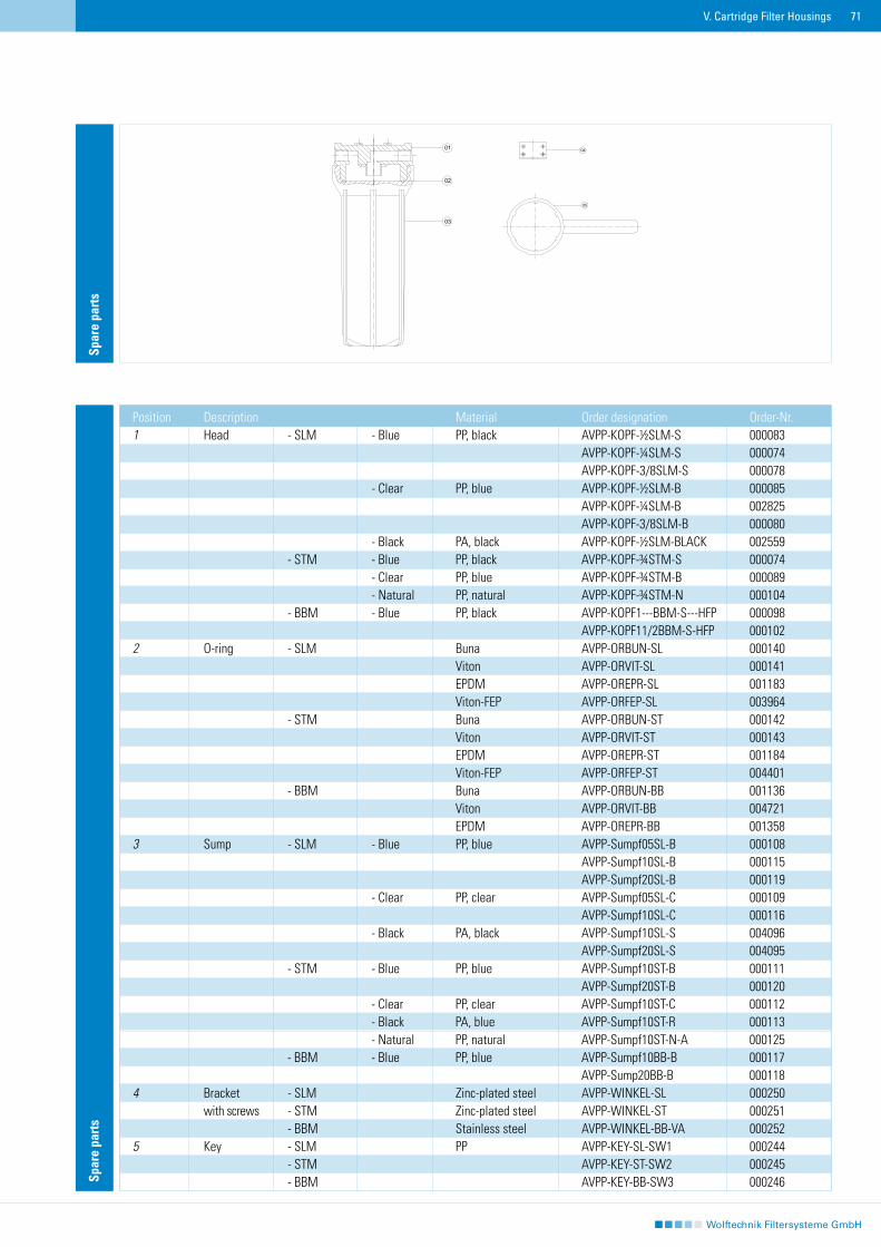
71V. Cartridge Filter Housings
Spar
e pa
rts
Position Description Material Order designation Order-Nr.1 Head - SLM - Blue PP, black AVPP-KOPF-½SLM-S 000083 AVPP-KOPF-¼SLM-S 000074 AVPP-KOPF-3/8SLM-S 000078 - Clear PP, blue AVPP-KOPF-½SLM-B 000085 AVPP-KOPF-¼SLM-B 002825 AVPP-KOPF-3/8SLM-B 000080 - Black PA, black AVPP-KOPF-½SLM-BLACK 002559 - STM - Blue PP, black AVPP-KOPF-¾STM-S 000074 - Clear PP, blue AVPP-KOPF-¾STM-B 000089 - Natural PP, natural AVPP-KOPF-¾STM-N 000104 - BBM - Blue PP, black AVPP-KOPF1---BBM-S---HFP 000098 AVPP-KOPF11/2BBM-S-HFP 0001022 O-ring - SLM Buna AVPP-ORBUN-SL 000140 Viton AVPP-ORVIT-SL 000141 EPDM AVPP-OREPR-SL 001183 Viton-FEP AVPP-ORFEP-SL 003964 - STM Buna AVPP-ORBUN-ST 000142 Viton AVPP-ORVIT-ST 000143 EPDM AVPP-OREPR-ST 001184 Viton-FEP AVPP-ORFEP-ST 004401 - BBM Buna AVPP-ORBUN-BB 001136 Viton AVPP-ORVIT-BB 004721 EPDM AVPP-OREPR-BB 0013583 Sump - SLM - Blue PP, blue AVPP-Sumpf05SL-B 000108 AVPP-Sumpf10SL-B 000115 AVPP-Sumpf20SL-B 000119 - Clear PP, clear AVPP-Sumpf05SL-C 000109 AVPP-Sumpf10SL-C 000116 - Black PA, black AVPP-Sumpf10SL-S 004096 AVPP-Sumpf20SL-S 004095 - STM - Blue PP, blue AVPP-Sumpf10ST-B 000111 AVPP-Sumpf20ST-B 000120 - Clear PP, clear AVPP-Sumpf10ST-C 000112 - Black PA, blue AVPP-Sumpf10ST-R 000113 - Natural PP, natural AVPP-Sumpf10ST-N-A 000125 - BBM - Blue PP, blue AVPP-Sumpf10BB-B 000117 AVPP-Sump20BB-B 0001184 Bracket - SLM Zinc-plated steel AVPP-WINKEL-SL 000250 with screws - STM Zinc-plated steel AVPP-WINKEL-ST 000251 - BBM Stainless steel AVPP-WINKEL-BB-VA 0002525 Key - SLM PP AVPP-KEY-SL-SW1 000244 - STM AVPP-KEY-ST-SW2 000245 - BBM AVPP-KEY-BB-SW3 000246
Spar
e pa
rts
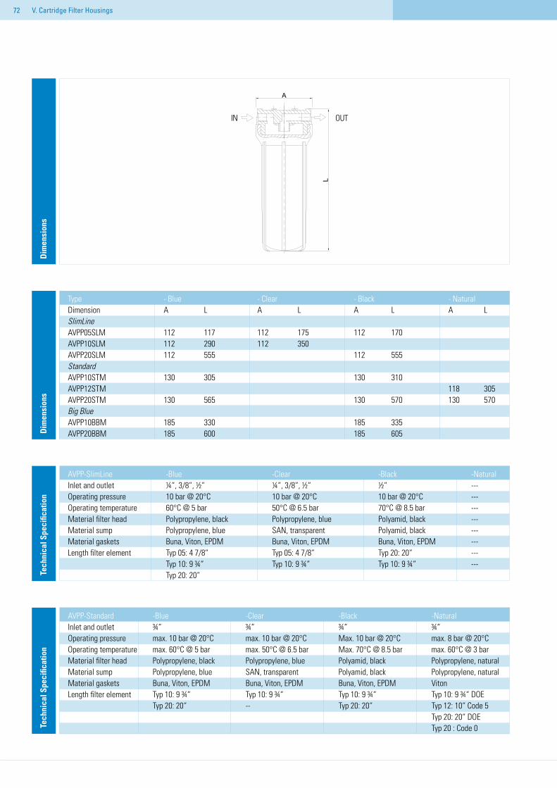
72 V. Cartridge Filter Housings
Type - Blue - Clear - Black - NaturalDimension A L A L A L A LSlimLineAVPP05SLM 112 117 112 175 112 170 AVPP10SLM 112 290 112 350 AVPP20SLM 112 555 112 555StandardAVPP10STM 130 305 130 310 AVPP12STM 118 305AVPP20STM 130 565 130 570 130 570Big BlueAVPP10BBM 185 330 185 335 AVPP20BBM 185 600 185 605D
imen
sion
sD
imen
sion
s
AVPP-SlimLine -Blue -Clear -Black -NaturalInlet and outlet ¼“, 3/8“, ½“ ¼“, 3/8“, ½“ ½“ ---Operating pressure 10 bar @ 20°C 10 bar @ 20°C 10 bar @ 20°C ---Operating temperature 60°C @ 5 bar 50°C @ 6.5 bar 70°C @ 8.5 bar ---Material filter head Polypropylene, black Polypropylene, blue Polyamid, black ---Material sump Polypropylene, blue SAN, transparent Polyamid, black ---Material gaskets Buna, Viton, EPDM Buna, Viton, EPDM Buna, Viton, EPDM ---Length filter element Typ 05: 4 7/8“ Typ 05: 4 7/8“ Typ 20: 20“ --- Typ 10: 9 ¾“ Typ 10: 9 ¾“ Typ 10: 9 ¾“ --- Typ 20: 20“ Te
chni
cal S
peci
ficat
ion
AVPP-Standard -Blue -Clear -Black -NaturalInlet and outlet ¾“ ¾“ ¾“ ¾“Operating pressure max. 10 bar @ 20°C max. 10 bar @ 20°C Max. 10 bar @ 20°C max. 8 bar @ 20°COperating temperature max. 60°C @ 5 bar max. 50°C @ 6.5 bar Max. 70°C @ 8.5 bar max. 60°C @ 3 barMaterial filter head Polypropylene, black Polypropylene, blue Polyamid, black Polypropylene, naturalMaterial sump Polypropylene, blue SAN, transparent Polyamid, black Polypropylene, naturalMaterial gaskets Buna, Viton, EPDM Buna, Viton, EPDM Buna, Viton, EPDM VitonLength filter element Typ 10: 9 ¾“ Typ 10: 9 ¾“ Typ 10: 9 ¾“ Typ 10: 9 ¾“ DOE Typ 20: 20“ -- Typ 20: 20“ Typ 12: 10“ Code 5 Typ 20: 20“ DOE Typ 20 : Code 0 Tech
nica
l Spe
cific
atio
n
IN OUT
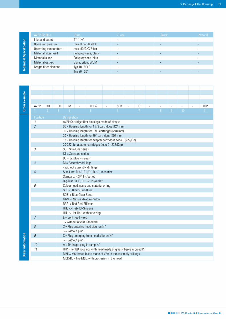
73V. Cartridge Filter Housings
Ord
er in
form
atio
n
Position Designation1 AVPP Cartridge filter housings made of plastic2 05 = Housing length for 4 7/8 cartridges (124 mm) 10 = Housing length for 9 ¾“ cartridges (248 mm) 20 = Housing length for 20“ cartridges (508 mm) 12 = Housing length for adapter cartridges code 5 (222/Fin) 20-222: for adapter cartridges Code 0 (222/Cap)3 SL = Slim Line series ST = Standard series BB = BigBlue – series4 M = Assembly drillings - without assembly drillings5 Slim Line: R ¼“, R 3/8“, R ½“, In-/outlet Standard: R 3/4 In-/outlet Big-Blue: R 1“, R 1 ½“ In-/outlet6 Colour head, sump and material o-ring SBB -> Black-Blue-Buna BCB -> Blue-Clear-Buna NNV -> Natural-Natural-Viton RRS -> Red-Red-Silicone HHS -> Hot-Hot-Silicone HH- -> Hot-Hot- without o-ring7 E = Vent head – red - = without a vent (Standard)8 S = Plug entering head side- on ¼“ - = without plug9 S = Plug emerging from head side-on ¼“ - = without plug10 A = Drainage plug in sump ¼“11 HFP = For BB housings with head made of glass-fiber-reinforced PP M6L = M6 thread insert made of V2A in the assembly drillings M6LVRL = like M6L, with protrusion in the head
AVPP 10 BB M - R 1 ½ - SBB - E - - - - - HFP1 2 3 4 5 6 7 8 9 10 11O
rder
exa
mpl
e
AVPP-BigBlue -Blue -Clear -Black -NaturalInlet and outlet 1“, 1 ½“ - - -Operating pressure max. 8 bar @ 20°C - - -Operating temperature max. 60°C @ 3 bar - - -Material filter head Polypropylene, black - - -Material sump Polypropylene, blue - - -Material gasket Buna, Viton, EPDM - - -Length filter element Typ 10: 9 ¾“ - - - Typ 20: 20“ - - - Te
chni
cal S
peci
ficat
ion
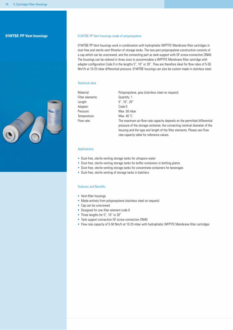
74 V. Cartridge Filter Housings
01WTBE-PP Vent housings made of polypropylene
01WTBE PP Vent housings work in combination with hydrophobic WFPTFE Membrane filter cartridges in dust-free and sterile vent filtration of storage tanks. The two-part polypropylene construction consists of a cap which can be unscrewed, and the connecting part as tank-support with GF screw-connection DN40. The housings can be ordered in three sizes to accommodate a WFPTFE Membrane filter cartridge with adapter configuration Code 0 in the lengths 5“, 10“ or 20“. They are therefore ideal for flow rates of 5-50 Nm³/h at 10-25 mbar differential pressure. 01WTBE housings can also be custom made in stainless steel.
Technical data
Material: Polypropylene, grey (stainless steel on request)Filter elements: Quantity: 1Length: 5“, 10“, 20“Adapter: Code 0Pressure: Max. 50 mbarTemperature: Max. 40 ˚C Flow rate: The maximum air-flow-rate capacity depends on the permitted differential pressure of the storage container, the connecting nominal diameter of the housing and the type and length of the filter elements. Please see Flow rate capacity table for reference values.
Applications
Dust-free, sterile venting storage tanks for ultrapure waterDust-free, sterile venting storage tanks for buffer containers in bottling plantsDust-free, sterile venting storage tanks for concentrate containers for beverages Dust-free, sterile venting of storage tanks in batchers
Features and Benefits
Vent-filter housingsMade entirely from polypropylene (stainless steel on request)Cap can be unscrewed Designed for one filter element code 0Three lengths for 5“, 10“ or 20“Tank support connection GF screw-connection DN40Flow rate capacity of 5-50 Nm/h at 10-25 mbar with hydrophobic WFPTFE Membrane filter cartridges
01WTBE-PP Vent housings
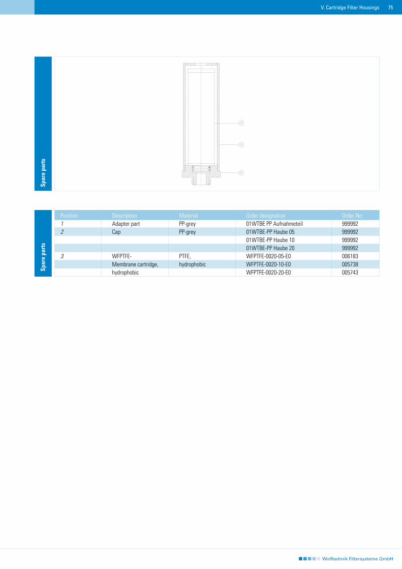
75V. Cartridge Filter Housings
Spar
e pa
rts
Position Description Material Order designation Order No.1 Adapter part PP-grey 01WTBE PP Aufnahmeteil 9999922 Cap PP-grey 01WTBE-PP Haube 05 999992 01WTBE-PP Haube 10 999992 01WTBE-PP Haube 20 9999923 WFPTFE- PTFE, WFPTFE-0020-05-E0 006183 Membrane cartridge, hydrophobic WFPTFE-0020-10-E0 005738 hydrophobic WFPTFE-0020-20-E0 005743
Spar
e pa
rts
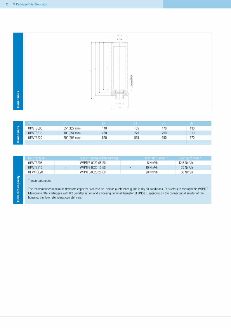
76
Dim
ensi
ons
Typ L1 L2 L3 L4 L5 01WTBE05 05“ (127 mm) 140 155 170 19001WTBE10 10“ (254 mm) 260 275 290 31001WTBE20 20“ (508 mm) 520 535 550 570
Dim
ensi
ons
Housing type Type of membrane filter cartridge Q for dp 10mbar * Q for dp 25mbar *01WTBE05 WFPTFE-0020-05-E0 5 Nm³/h 12.5 Nm³/h01WTBE10 + WFPTFE-0020-10-E0 = 10 Nm³/h 25 Nm³/h01 WTBE20 WFPTFE-0020-20-E0 20 Nm³/h 50 Nm³/h
* Important notice
The recommended maximum flow rate capacity is only to be used as a reference guide in dry air conditions. This refers to hydrophobic WFPTFE Membrane filter cartridges with 0.2 µm filter ration and a housing nominal diameter of DN50. Depending on the connecting diameter of the housing, the flow rate values can still vary.
Flow
rate
cap
acity
V. Cartridge Filter Housings
Fine
thre
ad N
B5x1
,5
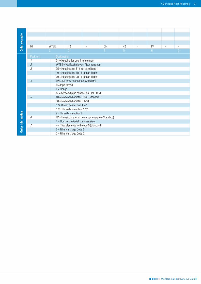
77
Position Designation1 01 = Housing for one filter element2 WTBE = Wolftechnik vent filter housings3 05 = Housings for 5“ filter cartridges 10 = Housings for 10“ filter cartridges 20 = Housings for 20“ filter cartridges4 DN = GF srew connection (Standard) R = Pipe thread F = Flange M = Screwed pipe connection DIN 118515 40 = Nominal diameter DN40 (Standard) 50 = Nominal diameter DN50 1 ¼ Thread connection 1 ¼“ 1 ½ =Thread connection 1 ½“ 2 = Thread connection 2“6 PP = Housing material polypropylene-grey (Standard) T = Housing material stainless steel7 - = Filter elements with code 0 (Standard) 5 = Filter cartridge Code 5 7 = Filter cartridge Code 7
01 WTBE 10 - DN 40 - PP - -1 2 3 4 5 6 7O
rder
exa
mpl
eO
rder
info
rmat
ion
V. Cartridge Filter Housings
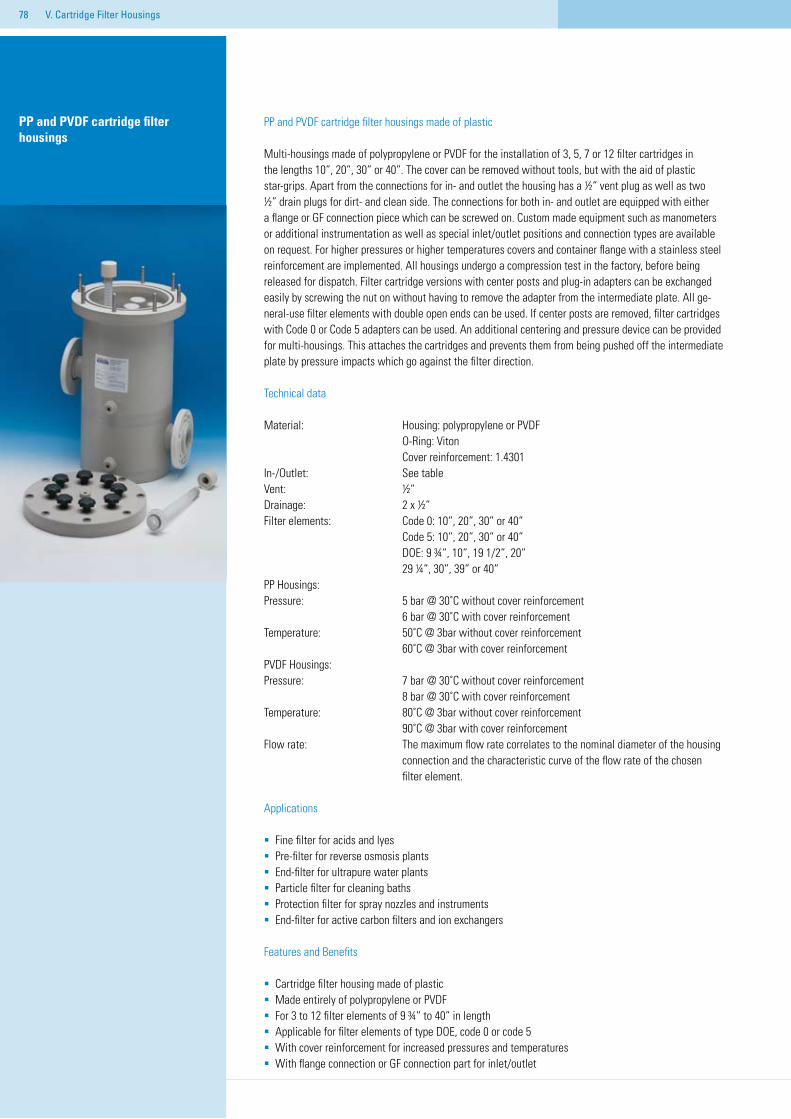
78 V. Cartridge Filter Housings
PP and PVDF cartridge filter housings
PP and PVDF cartridge filter housings made of plastic
Multi-housings made of polypropylene or PVDF for the installation of 3, 5, 7 or 12 filter cartridges in the lengths 10“, 20“, 30“ or 40“. The cover can be removed without tools, but with the aid of plastic star-grips. Apart from the connections for in- and outlet the housing has a ½“ vent plug as well as two ½“ drain plugs for dirt- and clean side. The connections for both in- and outlet are equipped with either a flange or GF connection piece which can be screwed on. Custom made equipment such as manometers or additional instrumentation as well as special inlet/outlet positions and connection types are available on request. For higher pressures or higher temperatures covers and container flange with a stainless steel reinforcement are implemented. All housings undergo a compression test in the factory, before being released for dispatch. Filter cartridge versions with center posts and plug-in adapters can be exchanged easily by screwing the nut on without having to remove the adapter from the intermediate plate. All ge-neral-use filter elements with double open ends can be used. If center posts are removed, filter cartridges with Code 0 or Code 5 adapters can be used. An additional centering and pressure device can be provided for multi-housings. This attaches the cartridges and prevents them from being pushed off the intermediate plate by pressure impacts which go against the filter direction.
Technical data
Material: Housing: polypropylene or PVDF O-Ring: Viton Cover reinforcement: 1.4301In-/Outlet: See tableVent: ½“Drainage: 2 x ½“ Filter elements: Code 0: 10“, 20“, 30“ or 40“ Code 5: 10“, 20“, 30“ or 40“ DOE: 9 ¾“, 10“, 19 1/2“, 20“ 29 ¼“, 30“, 39“ or 40“ PP Housings:Pressure: 5 bar @ 30˚C without cover reinforcement 6 bar @ 30˚C with cover reinforcement Temperature: 50˚C @ 3bar without cover reinforcement 60˚C @ 3bar with cover reinforcementPVDF Housings: Pressure: 7 bar @ 30˚C without cover reinforcement 8 bar @ 30˚C with cover reinforcementTemperature: 80˚C @ 3bar without cover reinforcement 90˚C @ 3bar with cover reinforcement Flow rate: The maximum flow rate correlates to the nominal diameter of the housing connection and the characteristic curve of the flow rate of the chosen filter element.
Applications
Fine filter for acids and lyesPre-filter for reverse osmosis plantsEnd-filter for ultrapure water plantsParticle filter for cleaning baths Protection filter for spray nozzles and instruments End-filter for active carbon filters and ion exchangers
Features and Benefits
Cartridge filter housing made of plasticMade entirely of polypropylene or PVDFFor 3 to 12 filter elements of 9 ¾“ to 40“ in length Applicable for filter elements of type DOE, code 0 or code 5With cover reinforcement for increased pressures and temperaturesWith flange connection or GF connection part for inlet/outlet
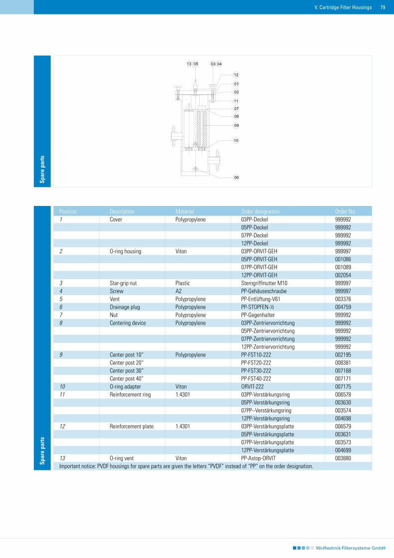
79V. Cartridge Filter Housings
Spar
e pa
rts
Position Description Material Order designation Order No.1 Cover Polypropylene 03PP-Deckel 999992 05PP-Deckel 999992 07PP-Deckel 999992 12PP-Deckel 9999922 O-ring housing Viton 03PP-ORVIT-GEH 999997 05PP-ORVIT-GEH 001086 07PP-ORVIT-GEH 001089 12PP-ORVIT-GEH 0020543 Star-grip nut Plastic Sterngriffmutter M10 9999974 Screw A2 PP-Gehäuseschraube 9999975 Vent Polypropylene PP-Entlüftung-V61 0033766 Drainage plug Polypropylene PP-STOPFEN-½ 0047597 Nut Polypropylene PP-Gegenhalter 9999928 Centering device Polypropylene 03PP-Zentriervorrichtung 999992 05PP-Zentriervorrichtung 999992 07PP-Zentriervorrichtung 999992 12PP-Zentriervorrichtung 9999929 Center post 10“ Polypropylene PP-FST10-222 002195 Center post 20“ PP-FST20-222 008381 Center post 30“ PP-FST30-222 007168 Center post 40“ PP-FST40-222 00717110 O-ring adapter Viton ORVIT-222 00717511 Reinforcement ring 1.4301 03PP-Verstärkungsring 006578 05PP-Verstärkungsring 003630 07PP--Verstärkungsring 003574 12PP-Verstärkungsring 00469812 Reinforcement plate 1.4301 03PP-Verstärkungsplatte 006579 05PP-Verstärkungsplatte 003631 07PP-Verstärkungsplatte 003573 12PP-Verstärkungsplatte 00469913 O-ring vent Viton PP-Astop-ORVIT 003880Important notice: PVDF housings for spare parts are given the letters “PVDF” instead of “PP” on the order designation.
Spar
e pa
rts
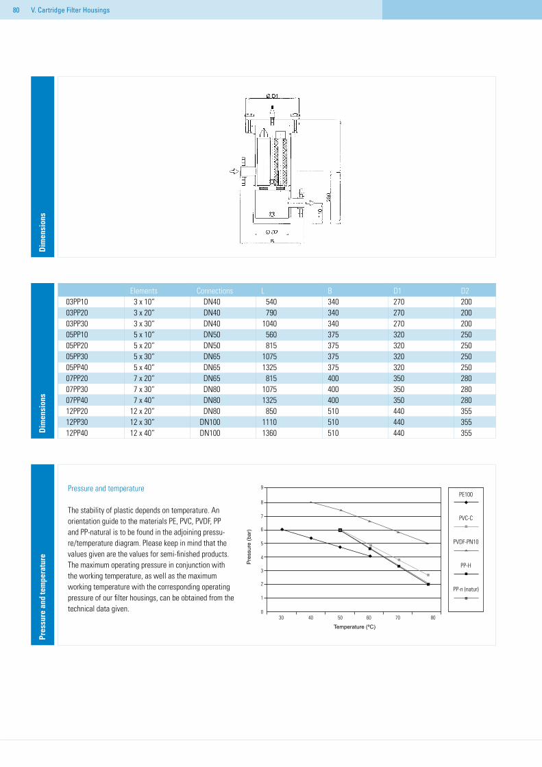
80 V. Cartridge Filter Housings
Dim
ensi
ons
Elements Connections L B D1 D203PP10 3 x 10“ DN40 540 340 270 20003PP20 3 x 20“ DN40 790 340 270 20003PP30 3 x 30“ DN40 1040 340 270 20005PP10 5 x 10“ DN50 560 375 320 25005PP20 5 x 20“ DN50 815 375 320 25005PP30 5 x 30“ DN65 1075 375 320 25005PP40 5 x 40“ DN65 1325 375 320 25007PP20 7 x 20“ DN65 815 400 350 28007PP30 7 x 30“ DN80 1075 400 350 28007PP40 7 x 40“ DN80 1325 400 350 28012PP20 12 x 20“ DN80 850 510 440 35512PP30 12 x 30“ DN100 1110 510 440 35512PP40 12 x 40“ DN100 1360 510 440 355D
imen
sion
sPr
essu
re a
nd te
mpe
ratu
re
Pressure and temperature
The stability of plastic depends on temperature. An orientation guide to the materials PE, PVC, PVDF, PP and PP-natural is to be found in the adjoining pressu-re/temperature diagram. Please keep in mind that the values given are the values for semi-finished products. The maximum operating pressure in conjunction with the working temperature, as well as the maximum working temperature with the corresponding operating pressure of our filter housings, can be obtained from the technical data given.
30 40 50 60 70 80
Temperatur (°C)
9
8
7
6
5
4
3
2
1
0
Druc
k (b
ar)
PE100
PVC-C
PVDF-PN10
PP-H
PP-n (natur)
Temperature (ºC)
Pre
ssur
e (b
ar)
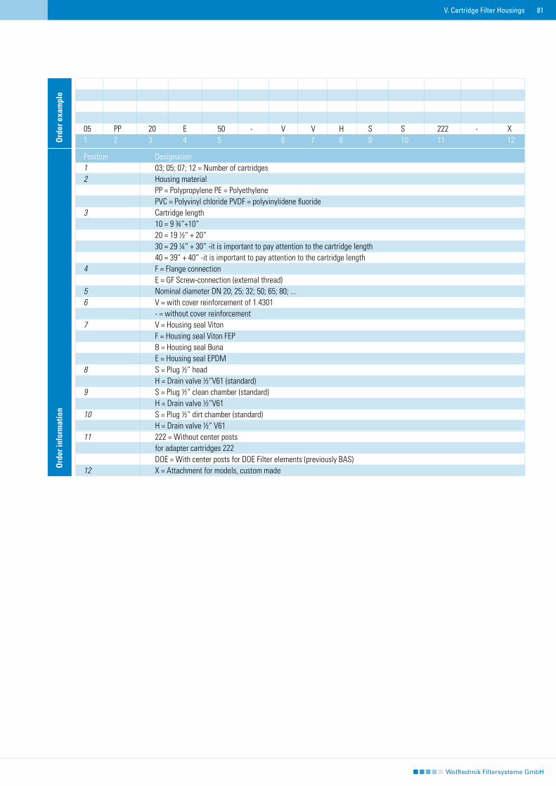
81V. Cartridge Filter Housings
Ord
er in
form
atio
n
Position Designation1 03; 05; 07; 12 = Number of cartridges2 Housing material PP = Polypropylene PE = Polyethylene PVC = Polyvinyl chloride PVDF = polyvinylidene fluoride3 Cartridge length 10 = 9 ¾“+10“ 20 = 19 ½“ + 20“ 30 = 29 ¼“ + 30“ -it is important to pay attention to the cartridge length 40 = 39“ + 40“ -it is important to pay attention to the cartridge length4 F = Flange connection E = GF Screw-connection (external thread)5 Nominal diameter DN 20; 25; 32; 50; 65; 80; ...6 V = with cover reinforcement of 1.4301 - = without cover reinforcement7 V = Housing seal Viton F = Housing seal Viton FEP B = Housing seal Buna E = Housing seal EPDM8 S = Plug ½“ head H = Drain valve ½“V61 (standard)9 S = Plug ½“ clean chamber (standard) H = Drain valve ½“V6110 S = Plug ½“ dirt chamber (standard) H = Drain valve ½“ V6111 222 = Without center posts for adapter cartridges 222 DOE = With center posts for DOE Filter elements (previously BAS)12 X = Attachment for models, custom made
05 PP 20 E 50 - V V H S S 222 - X1 2 3 4 5 6 7 8 9 10 11 12O
rder
exa
mpl
e
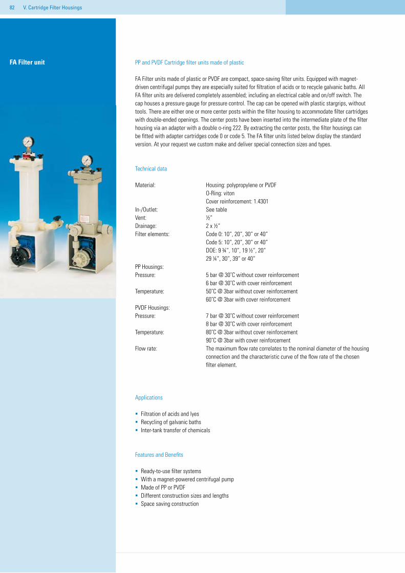
82 V. Cartridge Filter Housings
FA Filter unit PP and PVDF Cartridge filter units made of plastic
FA Filter units made of plastic or PVDF are compact, space-saving filter units. Equipped with magnet-driven centrifugal pumps they are especially suited for filtration of acids or to recycle galvanic baths. All FA filter units are delivered completely assembled; including an electrical cable and on/off switch. The cap houses a pressure gauge for pressure control. The cap can be opened with plastic stargrips, without tools. There are either one or more center posts within the filter housing to accommodate filter cartridges with double-ended openings. The center posts have been inserted into the intermediate plate of the filter housing via an adapter with a double o-ring 222. By extracting the center posts, the filter housings can be fitted with adapter cartridges code 0 or code 5. The FA filter units listed below display the standard version. At your request we custom make and deliver special connection sizes and types.
Technical data
Material: Housing: polypropylene or PVDF O-Ring: viton Cover reinforcement: 1.4301In-/Outlet: See tableVent: ½“Drainage: 2 x ½“Filter elements: Code 0: 10“, 20“, 30“ or 40“ Code 5: 10“, 20“, 30“ or 40“ DOE: 9 ¾“, 10“, 19 ½“, 20“ 29 ¼“, 30“, 39“ or 40“ PP Housings:Pressure: 5 bar @ 30˚C without cover reinforcement 6 bar @ 30˚C with cover reinforcement Temperature: 50˚C @ 3bar without cover reinforcement 60˚C @ 3bar with cover reinforcementPVDF Housings: Pressure: 7 bar @ 30˚C without cover reinforcement 8 bar @ 30˚C with cover reinforcementTemperature: 80˚C @ 3bar without cover reinforcement 90˚C @ 3bar with cover reinforcement Flow rate: The maximum flow rate correlates to the nominal diameter of the housing connection and the characteristic curve of the flow rate of the chosen filter element.
Applications
Filtration of acids and lyesRecycling of galvanic bathsInter-tank transfer of chemicals
Features and Benefits
Ready-to-use filter systemsWith a magnet-powered centrifugal pumpMade of PP or PVDFDifferent construction sizes and lengthsSpace saving construction
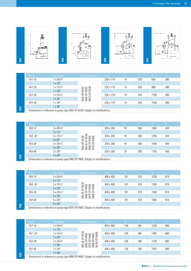
83V. Cartridge Filter Housings
FA1
Plant Cartridges Possible pumps L x B A C D E FA1-10 1 x 09 ¾“ 230 x 170 74 230 650 380 1 x 10“ FA1-20 1 x 19 ½“ 230 x 170 74 230 900 380 1 x 20“FA1-30 1 x 29 ¼“ 230 x 170 74 230 1150 380 1 x 30FA1-40 1 x 39“ 230 x 170 74 230 1400 380 1 x 40“Dimensions in reference to pump type M5E-EP-R230. Subject to modifications.
M4E
-EP-
R230
M5E
-EP-
R230
M5.
5-EP
-R23
0
FA3
Plant Cartridges Possible pumps L x B A C D E FA3-10 3 x 09 ¾“ 320 x 260 91 360 1005 450 3 x 10“FA3 -20 3 x 19 ½“ 320 x 260 91 360 1255 450 3x 20“ FA3-30 3 x 29 ¼“ 320 x 260 91 360 1505 450 3 x 30“ FA3-40 3 x 39“ 320 x 260 91 360 1755 450 3 x 40“Dimensions in reference to pump type M6E-EP-R400. Subject to modifications.
M5E
-EP-
R230
M5.
5E-E
P-R2
30M
6E-E
P-R4
00M
7E-E
P-R4
00
FA5
Plant Cartridges Possible pumps L x B A C D E FA5-10 5 x 09 ¾“ 400 x 400 101 370 1030 610 5 x 10“FA5 -20 5 x 19 ½“ 400 x 400 101 370 1285 610 5 x 20“FA5-30 5 x 29 ¼“ 400 x 400 101 370 1550 610 5 x 30“FA5-40 5 x 39“ 400 x 400 101 370 1805 610 5 x 40“Dimensions in reference to pump type M7E-EP-R400. Subject to modifications.
M5.
5E-E
P-R2
30M
6E-E
P-R4
00M
7E-E
P-R4
00M
8E-E
P-R4
00
FA7
Plant Cartridges Possible pumps L x B A C D E FA7-10 7 x 09 ¾“ 400 x 400 136 385 1220 680 7 x 10“ FA7 -20 7 x 19 ½“ 400 x 400 136 385 1465 680 7 x 20“ FA7-30 7 x 29 ¼“ 400 x 400 136 385 1720 680 7 x 30“ FA7-40 7 x 39“ 400 x 400 136 385 1975 680 7 x 40“Dimensions in reference to pump type M8E-EP-R400. Subject to modifications.
M5.
5E-E
P-R2
30M
6E-E
P-R4
00M
7E-E
P-R4
00M
8E-E
P-R4
00M
10E-
EP-R
400
FA1
FA7
FA3
FA5
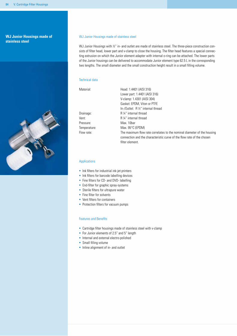
84 V. Cartridge Filter Housings
WJ Junior Housings made of stainless steel
WJ Junior Housings with ½“ in- and outlet are made of stainless steel. The three-piece construction con-sists of filter head, lower part and v-clamp to close the housing. The filter head features a special connec-ting extrusion on which the Junior element adapter with internal o-ring can be attached. The lower parts of the Junior housings can be delivered to accommodate Junior element type 62.5 L in the corresponding two lengths. The small diameter and the small construction height result in a small filling volume.
Technical data
Material: Head: 1.4401 (AISI 316) Lower part: 1.4401 (AISI 316) V-clamp: 1.4301 (AISI 304) Gasket: EPDM, Viton or PTFE In-/Outlet: R ½“ internal threadDrainage: R ¼“ internal threadVent: R ¼“ internal thread Pressure: Max. 10barTemperature: Max. 95°C (EPDM)Flow rate: The maximum flow rate correlates to the nominal diameter of the housing connection and the characteristic curve of the flow rate of the chosen filter element.
Applications
Ink filters for industrial ink-jet printersInk filters for barcode labelling devicesFine filters for CD- and DVD- labellingEnd-filter for graphic spray-systems Sterile filters for ultrapure waterFine filter for solventsVent filters for containersProtection filters for vacuum pumps
Features and Benefits
Cartridge filter housings made of stainless steel with v-clampFor Junior elements of 2.5“ and 5“ lengthInternal and external electro-polishedSmall filling volumeInline alignment of in- and outlet
WJ Junior Housings made of stainless steel
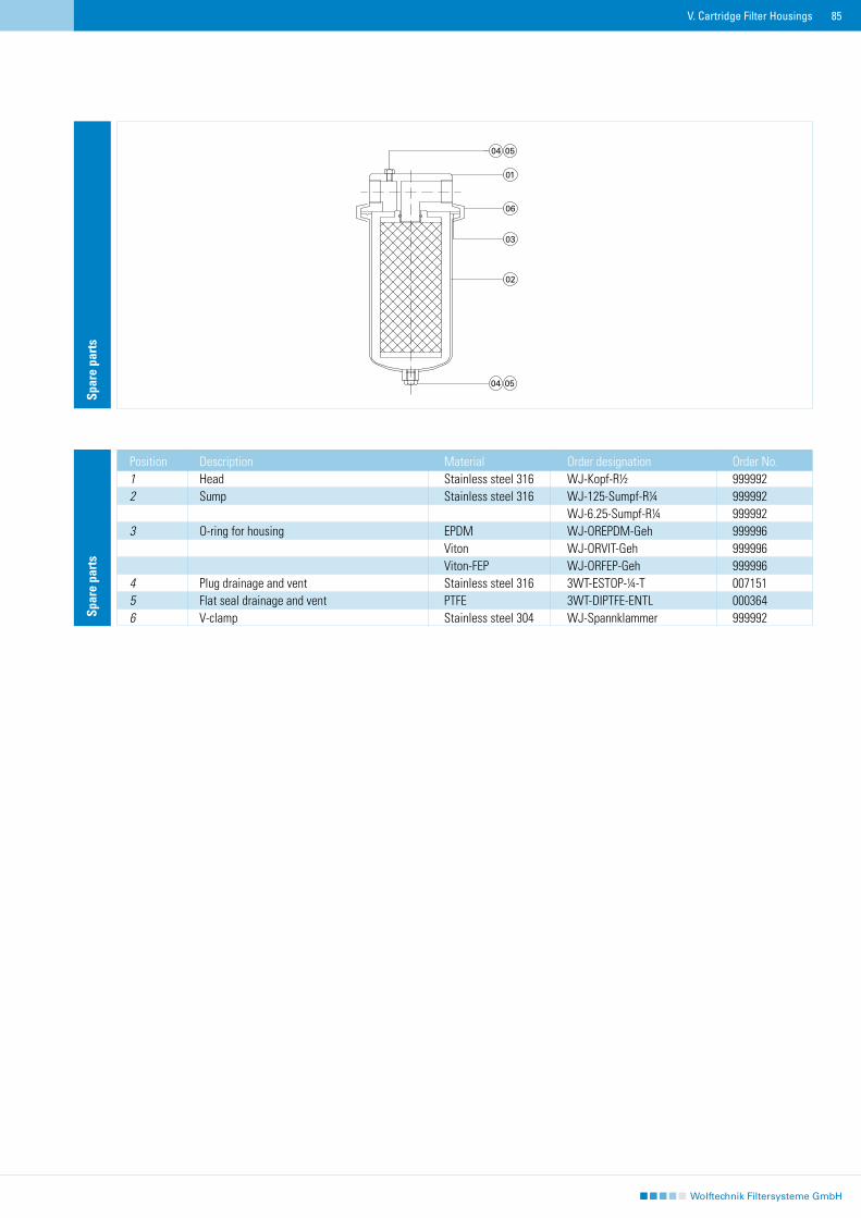
85V. Cartridge Filter Housings
Spar
e pa
rts
Position Description Material Order designation Order No.1 Head Stainless steel 316 WJ-Kopf-R½ 9999922 Sump Stainless steel 316 WJ-125-Sumpf-R¼ 999992 WJ-6.25-Sumpf-R¼ 9999923 O-ring for housing EPDM WJ-OREPDM-Geh 999996 Viton WJ-ORVIT-Geh 999996 Viton-FEP WJ-ORFEP-Geh 9999964 Plug drainage and vent Stainless steel 316 3WT-ESTOP-¼-T 007151 5 Flat seal drainage and vent PTFE 3WT-DIPTFE-ENTL 000364 6 V-clamp Stainless steel 304 WJ-Spannklammer 999992
Spar
e pa
rts
06
03
02
01
04 05
04 05
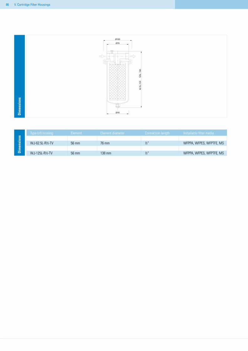
86 V. Cartridge Filter Housings
Dim
ensi
ons
Type (of) housing Element Element diameter Connection length Installable filter media WJ-62.5L-R½-TV 56 mm 76 mm ½“ WFPPA, WFPES, WFPTFE, MS WJ-125L-R½-TV 56 mm 138 mm ½“ WFPPA, WFPES, WFPTFE, MSD
imen
sion
s
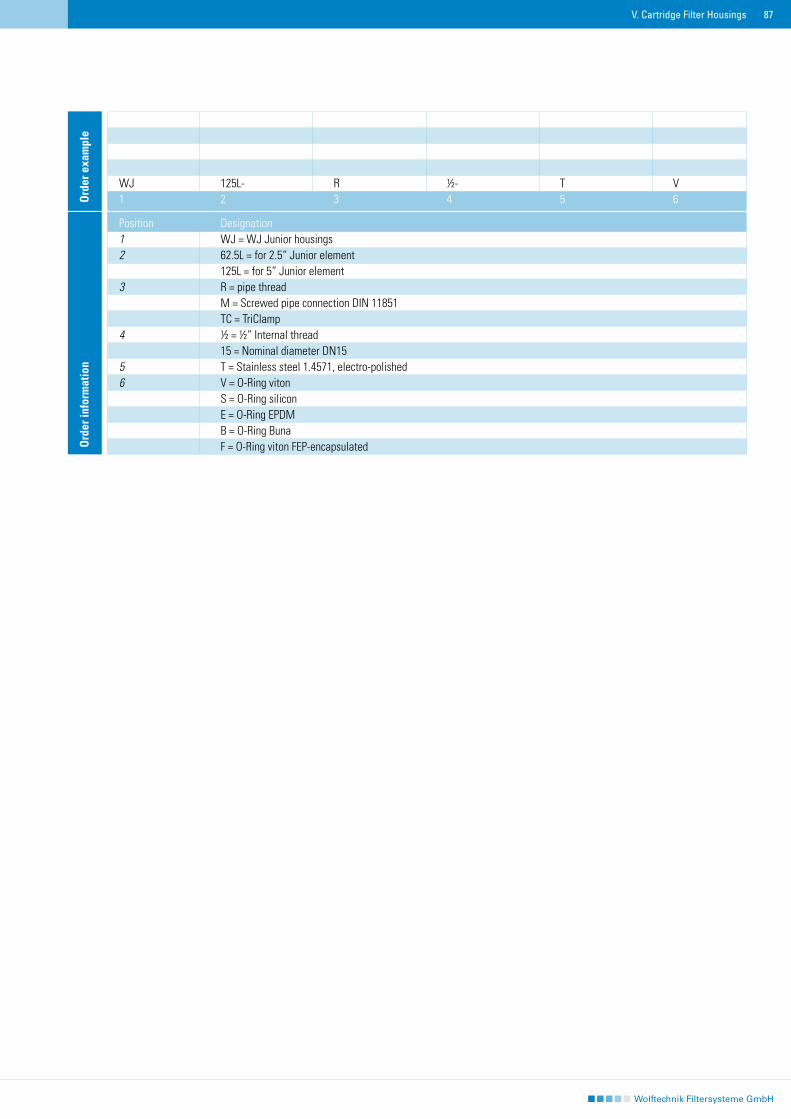
87V. Cartridge Filter Housings
Ord
er in
form
atio
n
Position Designation1 WJ = WJ Junior housings2 62.5L = for 2.5“ Junior element 125L = for 5“ Junior element3 R = pipe thread M = Screwed pipe connection DIN 11851 TC = TriClamp4 ½ = ½“ Internal thread 15 = Nominal diameter DN15 5 T = Stainless steel 1.4571, electro-polished6 V = O-Ring viton S = O-Ring silicon E = O-Ring EPDM B = O-Ring Buna F = O-Ring viton FEP-encapsulated
WJ 125L- R ½- T V1 2 3 4 5 6O
rder
exa
mpl
e
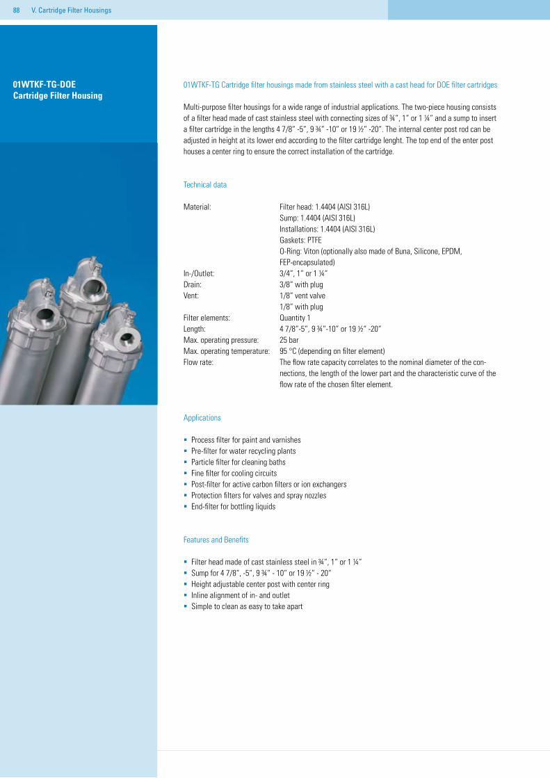
88
01WTKF-TG Cartridge filter housings made from stainless steel with a cast head for DOE filter cartridges
Multi-purpose filter housings for a wide range of industrial applications. The two-piece housing consists of a filter head made of cast stainless steel with connecting sizes of ¾“, 1“ or 1 ¼“ and a sump to insert a filter cartridge in the lengths 4 7/8“ -5“, 9 ¾“ -10“ or 19 ½“ -20“. The internal center post rod can be adjusted in height at its lower end according to the filter cartridge lenght. The top end of the enter post houses a center ring to ensure the correct installation of the cartridge.
Technical data
Material: Filter head: 1.4404 (AISI 316L) Sump: 1.4404 (AISI 316L) Installations: 1.4404 (AISI 316L) Gaskets: PTFE O-Ring: Viton (optionally also made of Buna, Silicone, EPDM, FEP-encapsulated)In-/Outlet: 3/4“, 1“ or 1 ¼“Drain: 3/8“ with plugVent: 1/8“ vent valve 1/8“ with plugFilter elements: Quantity 1Length: 4 7/8“-5“, 9 ¾“-10“ or 19 ½“ -20“Max. operating pressure: 25 barMax. operating temperature: 95 °C (depending on filter element)Flow rate: The flow rate capacity correlates to the nominal diameter of the con- nections, the length of the lower part and the characteristic curve of the flow rate of the chosen filter element.
Applications
Process filter for paint and varnishesPre-filter for water recycling plantsParticle filter for cleaning bathsFine filter for cooling circuitsPost-filter for active carbon filters or ion exchangersProtection filters for valves and spray nozzlesEnd-filter for bottling liquids
Features and Benefits
Filter head made of cast stainless steel in ¾“, 1“ or 1 ¼“ Sump for 4 7/8“, -5“, 9 ¾“ - 10“ or 19 ½“ - 20“Height adjustable center post with center ringInline alignment of in- and outletSimple to clean as easy to take apart
V. Cartridge Filter Housings
01WTKF-TG-DOE Cartridge Filter Housing
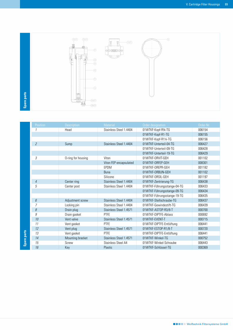
89V. Cartridge Filter Housings
Spar
e pa
rts
Position Description Material Order designation Order-Nr.1 Head Stainless Steel 1.4404 01WTKF-Kopf-R¾-TG 006154 01WTKF-Kopf-R1-TG 006155 01WTKF-Kopf-R1¼-TG 0061562 Sump Stainless Steel 1.4404 01WTKF-Unterteil-04-TG 006427 01WTKF-Unterteil-09-TG 006428 01WTKF-Unterteil-19-TG 0064293 O-ring for housing Viton 01WTKF-ORVIT-GEH 001102 Viton FEP-encapsulated 01WTKF-ORFEP-GEH 008301 EPDM 01WTKF-OREPR-GEH 001182 Buna 01WTKF-ORBUN-GEH 001102 Silicone 01WTKF-ORSIL-GEH 0011974 Center ring Stainless Steel 1.4404 01WTKF-Zentrierung-TG 0064385 Center post Stainless Steel 1.4404 01WTKF-Führungsstange-04-TG 006433 01WTKF-Führungsstange-09-TG 006434 01WTKF-Führungsstange-19-TG 0064356 Adjustment screw Stainless Steel 1.4404 01WTKF-Stellschraube-TG 0064377 Locking pin Stainless Steel 1.4404 01WTKF-Gewindestift-TG 0064398 Drain plug Stainless Steel 1.4571 01WTKF-ASTOP-R3/8-T 0007009 Drain gasket PTFE 01WTKF-DIPTFE-Ablass 00069210 Vent valve Stainless Steel 1.4571 01WTKF-EVENT-T 00071511 Vent gasket PTFE 01WTKF-DIPTFE-Entlüftung 00644112 Vent plug Stainless Steel 1.4571 01WTKF-ESTOP-R1/8-T 00072013 Vent gasket PTFE 01WTKF-DIPTFE-Entlüftung 00644114 Mounting bracket Stainless Steel 1.4571 01WTKF-Winkel-TG 00075215 Screw Stainless Steel A4 01WTKF-Winkel-Schraube 00644316 Key Plastic 01WTKF-Schlüssel-TG 000369
Spar
e pa
rts
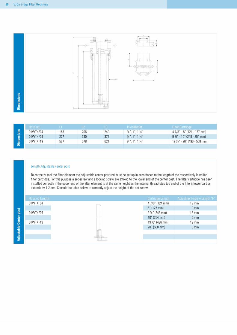
90 V. Cartridge Filter Housings
Dim
ensi
ons
Housing L1 L2 L3 Inlet/Outlet Filter Cartridge01WTKF04 153 206 249 ¾“, 1“, 1 ¼“ 4 7/8“ - 5“ (124 - 127 mm)01WTKF09 277 330 373 ¾“, 1“, 1 ¼“ 9 ¾“ - 10“ (248 - 254 mm)01WTKF19 527 578 621 ¾“, 1“, 1 ¼“ 19 ½“ - 20“ (496 - 508 mm)
Dim
ensi
ons
Housing Length Cartridge Length Adjustment-screw Length “H“01WTKF04 4 7/8“ (124 mm) 12 mm 5“ (127 mm) 9 mm01WTKF09 9 ¾“ (248 mm) 12 mm 10“ (254 mm) 6 mm01WTKF19 19 ½“ (496 mm) 12 mm 20“ (508 mm) 0 mm
Adj
usta
ble
Cent
er p
ost
Length Adjustable center post
To correctly seal the filter element the adjustable center post rod must be set up in accordance to the length of the respectively installed filter cartridge. For this purpose a set-screw and a locking screw are affixed to the lower end of the center post. The filter cartridge has been installed correctly if the upper end of the filter element is at the same height as the internal thread-step top end of the filter’s lower part or extends by 1-2 mm. Consult the table below to correctly adjust the height of the set-screw:
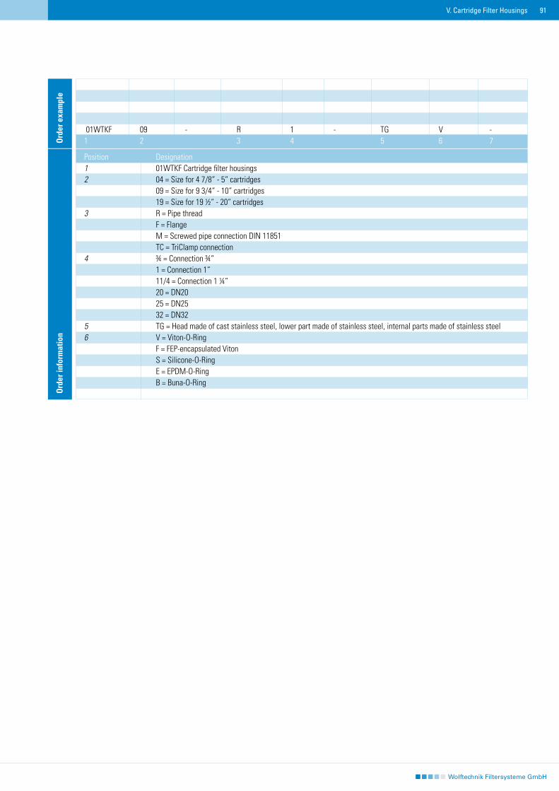
91V. Cartridge Filter Housings
Ord
er in
form
atio
n
Position Designation1 01WTKF Cartridge filter housings2 04 = Size for 4 7/8“ - 5“ cartridges 09 = Size for 9 3/4“ - 10“ cartridges 19 = Size for 19 ½“ - 20“ cartridges3 R = Pipe thread F = Flange M = Screwed pipe connection DIN 11851 TC = TriClamp connection4 ¾ = Connection ¾“ 1 = Connection 1“ 11/4 = Connection 1 ¼“ 20 = DN20 25 = DN25 32 = DN325 TG = Head made of cast stainless steel, lower part made of stainless steel, internal parts made of stainless steel6 V = Viton-O-Ring F = FEP-encapsulated Viton S = Silicone-O-Ring E = EPDM-O-Ring B = Buna-O-Ring
Ord
er e
xam
ple
01WTKF 09 - R 1 - TG V -1 2 3 4 5 6 7
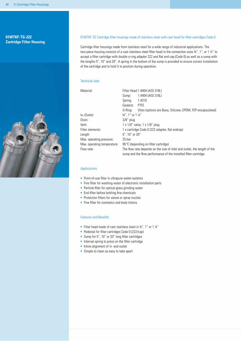
92
01WTKF-TG-222 Cartridge Filter Housing
01WTKF-TG Cartridge filter housings made of stainless steel with cast head for filter cartridges Code 0
Cartridge filter housings made from stainless steel for a wide range of industrial applications. The two-piece housing consists of a cast stainless steel filter head in the connection sizes ¾“, 1“, or 1 ¼“ to accept a filter cartridge with double o-ring adapter 222 and flat end cap (Code 0) as well as a sump with the lengths 5“, 10“ and 20“. A spring in the bottom of the sump is provided to ensure correct installation of the cartridge and to hold it in position during operation.
Technical data
Material: Filter Head: 1.4404 (AISI 316L) Sump: 1.4404 (AISI 316L) Spring: 1.4310 Gaskets: PTFE O-Ring: Viton (options are Buna, Silicone, EPDM, FEP-encapsulated)In-/Outlet: ¾“, 1“ or 1 ¼“Drain: 3/8“ plugVent: 1 x 1/8“ valve, 1 x 1/8“ plugFilter elements: 1 x cartridge Code 0 (222 adapter, flat endcap)Length 5“, 10“ or 20“Max. operating pressure: 25 barMax. operating temperature: 95°C (depending on filter cartridge)Flow rate: The flow rate depends on the size of inlet and outlet, the length of the sump and the flow performance of the installed filter cartridge.
Applications
Point-of-use filter in ultrapure water-systemsFine filter for washing water of electronic installation partsParticle filter for optical-glass grinding waterEnd-filter before bottling fine chemicals Protection filters for valves or spray nozzlesFine filter for cosmetics and body lotions
Features and Benefits
Filter head made of cast stainless steel in ¾“, 1“ or 1 ¼“Pedestal for filter cartridges Code 0 (222/cap)Sump for 5“, 10“ or 20“ long filter cartridges Internal spring to press on the filter cartridgeInline alignment of in- and outletSimple to clean as easy to take apart
V. Cartridge Filter Housings
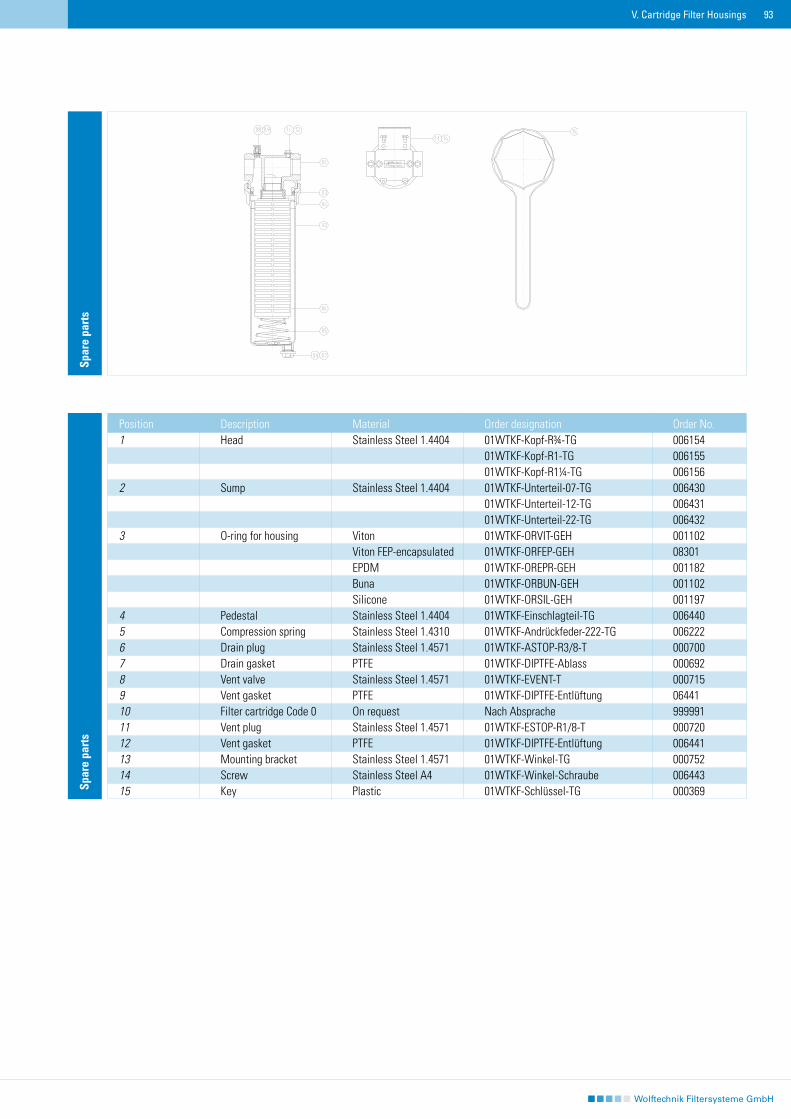
93
Position Description Material Order designation Order No.1 Head Stainless Steel 1.4404 01WTKF-Kopf-R¾-TG 006154 01WTKF-Kopf-R1-TG 006155 01WTKF-Kopf-R1¼-TG 0061562 Sump Stainless Steel 1.4404 01WTKF-Unterteil-07-TG 006430 01WTKF-Unterteil-12-TG 006431 01WTKF-Unterteil-22-TG 0064323 O-ring for housing Viton 01WTKF-ORVIT-GEH 001102 Viton FEP-encapsulated 01WTKF-ORFEP-GEH 08301 EPDM 01WTKF-OREPR-GEH 001182 Buna 01WTKF-ORBUN-GEH 001102 Silicone 01WTKF-ORSIL-GEH 0011974 Pedestal Stainless Steel 1.4404 01WTKF-Einschlagteil-TG 0064405 Compression spring Stainless Steel 1.4310 01WTKF-Andrückfeder-222-TG 0062226 Drain plug Stainless Steel 1.4571 01WTKF-ASTOP-R3/8-T 0007007 Drain gasket PTFE 01WTKF-DIPTFE-Ablass 0006928 Vent valve Stainless Steel 1.4571 01WTKF-EVENT-T 0007159 Vent gasket PTFE 01WTKF-DIPTFE-Entlüftung 0644110 Filter cartridge Code 0 On request Nach Absprache 99999111 Vent plug Stainless Steel 1.4571 01WTKF-ESTOP-R1/8-T 00072012 Vent gasket PTFE 01WTKF-DIPTFE-Entlüftung 00644113 Mounting bracket Stainless Steel 1.4571 01WTKF-Winkel-TG 00075214 Screw Stainless Steel A4 01WTKF-Winkel-Schraube 00644315 Key Plastic 01WTKF-Schlüssel-TG 000369Sp
are
part
sSp
are
part
s
V. Cartridge Filter Housings
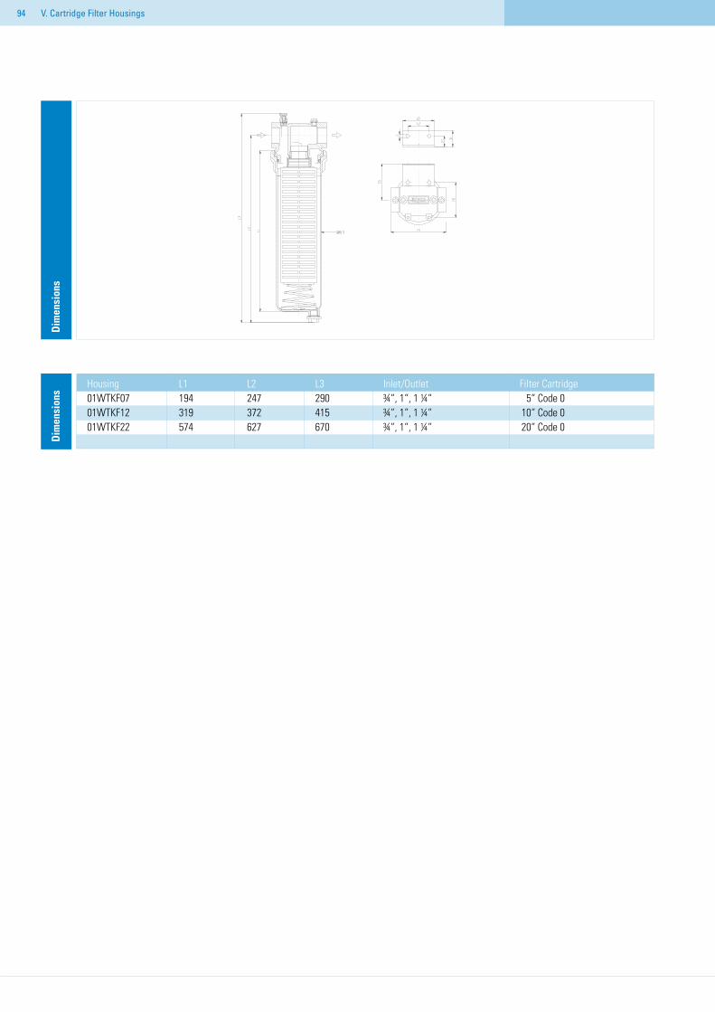
94 V. Cartridge Filter Housings
Dim
ensi
ons
Housing L1 L2 L3 Inlet/Outlet Filter Cartridge01WTKF07 194 247 290 ¾“, 1“, 1 ¼“ 5“ Code 001WTKF12 319 372 415 ¾“, 1“, 1 ¼“ 10“ Code 001WTKF22 574 627 670 ¾“, 1“, 1 ¼“ 20“ Code 0
Dim
ensi
ons
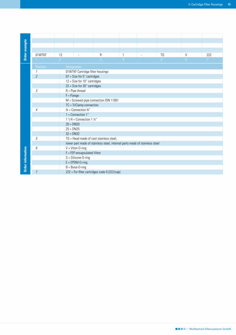
95
Ord
er in
form
atio
n
Position Designation1 01WTKF Cartridge filter housings2 07 = Size for 5“ cartridges 12 = Size for 10“ cartridges 22 = Size for 20“ cartridges3 R = Pipe thread F = Flange M = Screwed pipe connection DIN 11851 TC = TriClamp connection4 ¾ = Connection ¾“ 1 = Connection 1“ 1 1/4 = Connection 1 ¼“ 20 = DN20 25 = DN25 32 = DN325 TG = Head made of cast stainless steel, lower part made of stainless steel, internal parts made of stainless steel6 V = Viton-O-ring F = FEP-encapsulated Viton S = Silicone-O-ring E = EPDM-O-ring B = Buna-O-ring7 222 = For filter cartridges code 0 (222/cap)
01WTKF 12 - R 1 - TG V 2221 2 3 4 5 6 7O
rder
exa
mpl
e
V. Cartridge Filter Housings
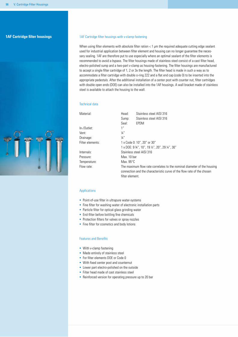
96 V. Cartridge Filter Housings
1AF Cartridge filter housings 1AF Cartridge filter housings with v-clamp fastening
When using filter elements with absolute filter ration < 1 µm the required adequate cutting edge sealant used for industrial application between filter element and housing can no longer guarantee the neces-sary sealing. 1AF are therefore put to use especially where an optimal sealant of the filter elements is recommended to avoid a bypass. The filter housings made of stainless steel consist of a cast filter head, electro-polished sump and a two-part v-clamp as housing-fastening. The filter housings are manufactured to accept a single filter cartridge of 1, 2 or 3x the length. The filter head is made in such a way as to accommodate a filter cartridge with double o-ring 222 and a flat end cap (code 0) to be inserted into the appropriate pedestals. After the additional installation of a center post with counter nut, filter cartridges with double open ends (DOE) can also be installed into the 1AF housings. A wall bracket made of stainless steel is available to attach the housing to the wall.
Technical data
Material: Head: Stainless steel AISI 316 Sump: Stainless steel AISI 316 Seal: EPDMIn-/Outlet: 1“ Vent: ¼“Drainage: ¼“Filter elements: 1 x Code 0: 10“, 20“ or 30“ 1 x DOE: 9 ¾“, 10“, 19 ½“, 20“, 29 ¼“, 30“Internals: Stainless steel AISI 316Pressure: Max. 10 barTemperature: Max. 95°C Flow rate: The maximum flow rate correlates to the nominal diameter of the housing connection and the characteristic curve of the flow rate of the chosen filter element.
Applications
Point-of-use filter in ultrapure water-systemsFine filter for washing water of electronic installation partsParticle filter for optical-glass grinding waterEnd-filter before bottling fine chemicals Protection filters for valves or spray nozzlesFine filter for cosmetics and body lotions
Features and Benefits
With v-clamp fasteningMade entirely of stainless steelFor filter elements DOE or Code 0With fixed center post and counternutLower part electro-polished on the outside Filter head made of cast stainless steelReinforced version for operating pressure up to 20 bar
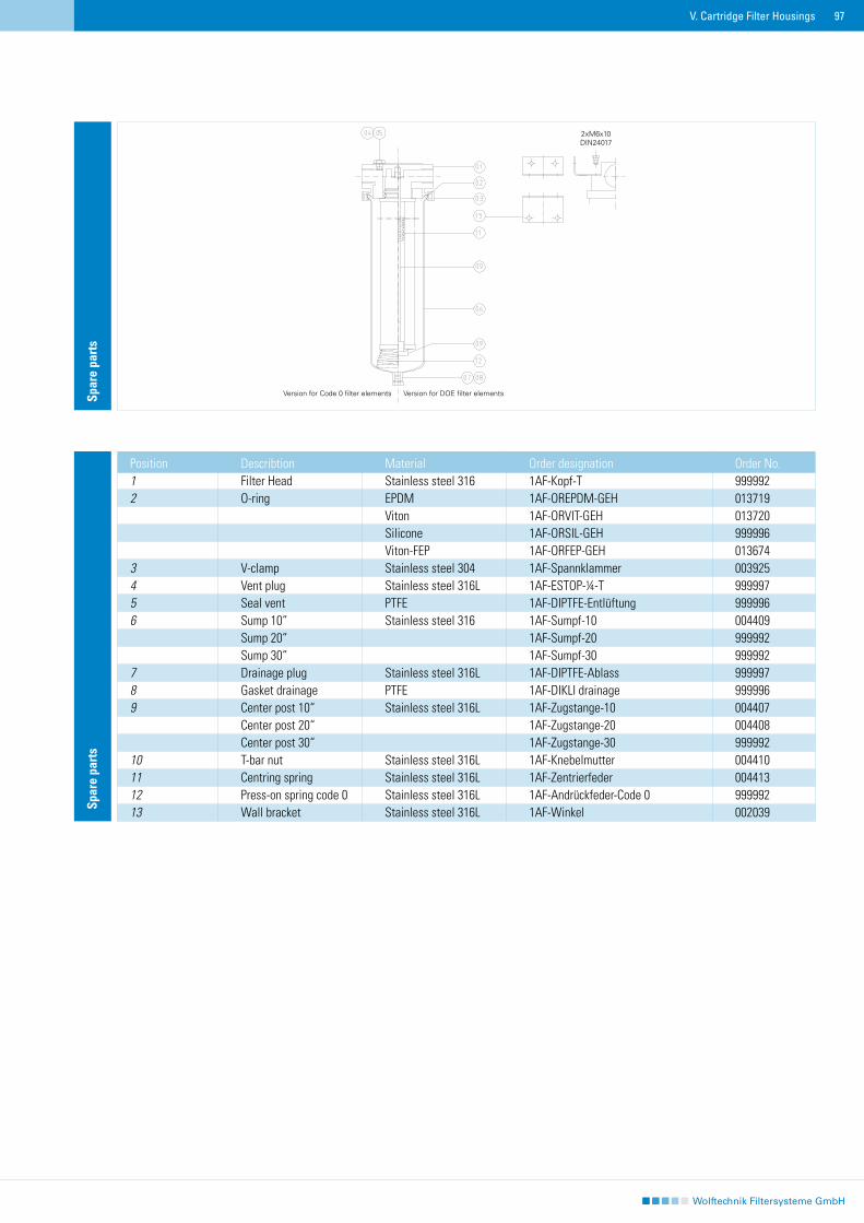
97V. Cartridge Filter Housings
Spar
e pa
rts
Position Describtion Material Order designation Order No.1 Filter Head Stainless steel 316 1AF-Kopf-T 9999922 O-ring EPDM 1AF-OREPDM-GEH 013719 Viton 1AF-ORVIT-GEH 013720 Silicone 1AF-ORSIL-GEH 999996 Viton-FEP 1AF-ORFEP-GEH 0136743 V-clamp Stainless steel 304 1AF-Spannklammer 0039254 Vent plug Stainless steel 316L 1AF-ESTOP-¼-T 9999975 Seal vent PTFE 1AF-DIPTFE-Entlüftung 9999966 Sump 10“ Stainless steel 316 1AF-Sumpf-10 004409 Sump 20“ 1AF-Sumpf-20 999992 Sump 30“ 1AF-Sumpf-30 9999927 Drainage plug Stainless steel 316L 1AF-DIPTFE-Ablass 9999978 Gasket drainage PTFE 1AF-DIKLI drainage 9999969 Center post 10“ Stainless steel 316L 1AF-Zugstange-10 004407 Center post 20“ 1AF-Zugstange-20 004408 Center post 30“ 1AF-Zugstange-30 99999210 T-bar nut Stainless steel 316L 1AF-Knebelmutter 00441011 Centring spring Stainless steel 316L 1AF-Zentrierfeder 00441312 Press-on spring code 0 Stainless steel 316L 1AF-Andrückfeder-Code 0 99999213 Wall bracket Stainless steel 316L 1AF-Winkel 002039
Spar
e pa
rts
Version for Code 0 filter elements Version for DOE filter elements
2xM6x10DIN24017

98 V. Cartridge Filter Housings
Dim
ensi
ons
A B C D 1AF 10 341 120 88,9 21,51AF 20 595 120 88,9 21,21AF 30 849 120 88,9 21,2 D
imen
sion
s
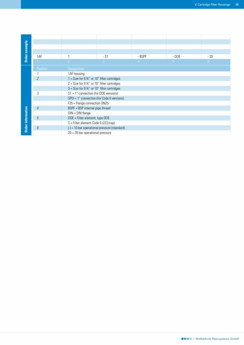
99V. Cartridge Filter Housings
Ord
er in
form
atio
n
Position Designation1 1AF housing 2 1 = Size for 9 ¾“ or 10“ filter cartridges 2 = Size for 9 ¾“ or 10“ filter cartridges 3 = Size for 9 ¾“ or 10“ filter cartridges 3 S1 = 1“ connection (for DOE versions) SPI3 = 1“ connection (for Code 0 versions) F25 = Flange connection DN254 BSPF = BSP internal pipe thread DIN = DIN flange 5 DOE = Filter element, type DOE 3 = Filter element Code 0 (222/cap)6 (-) = 10 bar operational pressure (standard) 20 = 20 bar operational pressure
1AF 1 - S1 - BSPF - DOE - 201 2 3 4 5 6O
rder
exa
mpl
e
100 V. Cartridge Filter Housings
3WT Cartridge filter housings 3WT Cartridge filter housings with v-clamp fastening
3WT Cartridge filter housings can be used to accept three filter elements. A main attribute of the 3WT housings is the special connection with two 90° elbows and 1 ½“ pipe connection for the in-/outlet of the filter head. A further characteristic is that the filter elements are installed hanging in an accumula-tive adapter. Center posts with counter nuts ensure a secure seal between housing and filter element. The accumulative adapter separates the inlet side from the dirt side and secures the center posts into position. The removable sump is fastened to the filter head via a v-clamp and can be delivered in two lengths. This enables three filter elements with double-open ends (DOE) with the lengths 9 ¾“, 10“, 19 ½“ or 20“ to be installed. 3WT housings are made entirely of stainless steel and are delivered in the standard version with viton seals. 3WT housings can be easily disassembled into their individual components and are therefore when handling easier to clean than other filters such as those for varnishes, paints and adhesives. 3WT housings are also suited to be used in filter applications for water, lyes and emulsions where especially the specific characteristics of a hanging housing in comparison to a standing container construction are an advantage.
Technical data
Material: Head: Stainless steel 104571 Sump: Stainless steel 1.4571 O-Ring: VitonInstallations: Stainless steel 1.4571 Tension clamp: 1.4571 In-/Outlet: 1 ½“ internal thread Vent: ¼“ internal threadDrainage: ½“ internal threadFilter elements: 3 x DOE: 9 ¾“, 10“, 19 ½“, 20“Pressure: Max. 10 barTemperature: Max. 95°C Flow rate: The maximum flow rate correlates to the nominal diameter of the housing connection and the characteristic curve of the flow rate of the chosen filter element.
Applications
Point-of-use filter in ultrapure water-systemsFine filter for washing water of electronic installation partsParticle filter for optical-glass-grinding waterEnd-filter before bottling fine chemicals Protection filters for valves of spray nozzlesFine filter for cosmetics and body lotionsProcess filters for varnishes, paints and adhesives
Features and Benefits
Hanging housing-construction With tension clamp fasteningInline – alignment of in- and outletCollective adapter with fixed guidance rodsFor filter elements 9 ¾“ or 10“ as well as 19 ½“ or 20“ in DOE applicationVery easy cleaning due to simple disassembling into individual componentsMade entirely of stainless steel
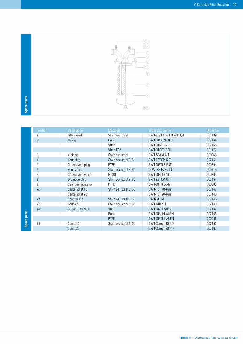
101V. Cartridge Filter Housings
Spar
e pa
rts
Spar
e pa
rts
Position Description Material Order designation Order No.1 Filter-head Stainless steel 3WT-Kopf 1 ½ T R ¼ R 1/4 0071392 O-ring Buna 3WT-ORBUN-GEH 007164 Viton 3WT-ORVIT-GEH 007165 Viton-FEP 3WT-ORFEP-GEH 0011773 V-clamp Stainless steel 3WT-SPAKLA-T 0003654 Vent plug Stainless steel 316L 3WT-ESTOP-¼-T 0071515 Gasket vent plug PTFE 3WT-DIPTFE-ENTL 0003646 Vent valve Stainless steel 316L 01WTKF-EVENT-T 0007157 Gasket vent valve HD300 3WT-DIKLI-ENTL 0003648 Drainage plug Stainless steel 316L 3WT-ESTOP-½-T 0071549 Seal drainage plug PTFE 3WT-DIPTFE-Abl 00036310 Center post 10“ Stainless steel 316L 3WT-FST 10-kurz 007147 Center post 20“ 3WT-FST 20-kurz 00714811 Counter nut Stainless steel 316L 3WT-GEH-T 00714512 Pedestal Stainless steel 316L 3WT-AUFN-T 00714013 Gasket pedestal Viton 3WT-DIVIT-AUFN 007167 Buna 3WT-DIBUN-AUFN 007166 PTFE 3WT-DIPTFE-AUFN 99999614 Sump 10“ Stainless steel 316L 3WT-Sumpf-10 R ½ 007162 Sump 20“ 3WT-Sumpf-20 R ½ 007163
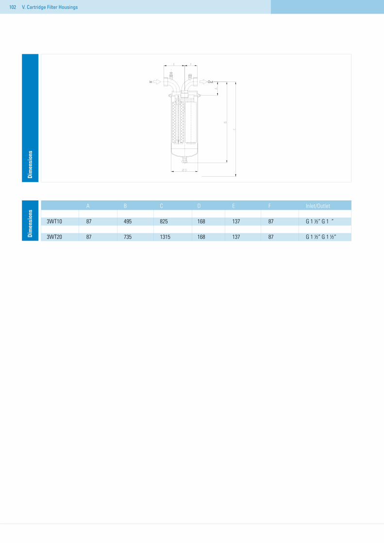
102 V. Cartridge Filter Housings
Dim
ensi
ons
A B C D E F Inlet/Outlet 3WT10 87 495 825 168 137 87 G 1 ½“ G 1 “ 3WT20 87 735 1315 168 137 87 G 1 ½“ G 1 ½“ D
imen
sion
s
In Out
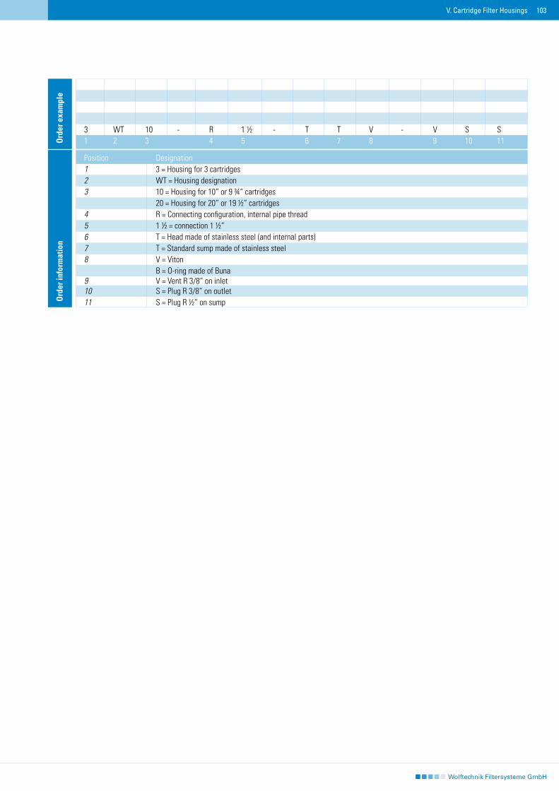
103V. Cartridge Filter Housings
Ord
er in
form
atio
n
Position Designation1 3 = Housing for 3 cartridges 2 WT = Housing designation 3 10 = Housing for 10“ or 9 ¾“ cartridges 20 = Housing for 20“ or 19 ½“ cartridges 4 R = Connecting configuration, internal pipe thread5 1 ½ = connection 1 ½“6 T = Head made of stainless steel (and internal parts)7 T = Standard sump made of stainless steel 8 V = Viton B = O-ring made of Buna9 V = Vent R 3/8“ on inlet10 S = Plug R 3/8“ on outlet11 S = Plug R ½“ on sump
3 WT 10 - R 1 ½ - T T V - V S S1 2 3 4 5 6 7 8 9 10 11O
rder
exa
mpl
e
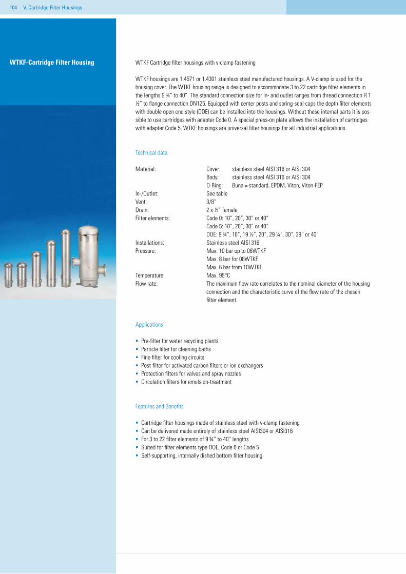
104
WTKF Cartridge filter housings with v-clamp fastening
WTKF housings are 1.4571 or 1.4301 stainless steel manufactured housings. A V-clamp is used for the housing cover. The WTKF housing range is designed to accommodate 3 to 22 cartridge filter elements in the lengths 9 ¾“ to 40“. The standard connection size for in- and outlet ranges from thread connection R 1 ½“ to flange connection DN125. Equipped with center posts and spring-seal-caps the depth filter elements with double open end style (DOE) can be installed into the housings. Without these internal parts it is pos-sible to use cartridges with adapter Code 0. A special press-on plate allows the installation of cartridges with adapter Code 5. WTKF housings are universal filter housings for all industrial applications.
Technical data
Material: Cover: stainless steel AISI 316 or AISI 304 Body: stainless steel AISI 316 or AISI 304 O-Ring: Buna = standard, EPDM, Viton, Viton-FEPIn-/Outlet: See tableVent: 3/8“Drain: 2 x ½“ femaleFilter elements: Code 0: 10“, 20“, 30“ or 40“ Code 5: 10“, 20“, 30“ or 40“ DOE: 9 ¾“, 10“, 19 ½“, 20“, 29 ¼“, 30“, 39“ or 40“Installations: Stainless steel AISI 316Pressure: Max. 10 bar up to 06WTKF Max. 8 bar for 08WTKF Max. 6 bar from 10WTKFTemperature: Max. 95°CFlow rate: The maximum flow rate correlates to the nominal diameter of the housing connection and the characteristic curve of the flow rate of the chosen filter element.
Applications
Pre-filter for water recycling plantsParticle filter for cleaning bathsFine filter for cooling circuitsPost-filter for activated carbon filters or ion exchangers Protection filters for valves and spray nozzlesCirculation filters for emulsion-treatment
Features and Benefits
Cartridge filter housings made of stainless steel with v-clamp fasteningCan be delivered made entirely of stainless steel AISI304 or AISI316 For 3 to 22 filter elements of 9 ¾“ to 40“ lengths Suited for filter elements type DOE, Code 0 or Code 5Self-supporting, internally dished bottom filter housing
WTKF-Cartridge Filter Housing
V. Cartridge Filter Housings
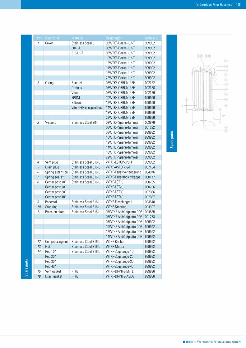
105
Spar
e pa
rts
Pos. Description Material Designation Order No.1 Cover Stainless Steel L 03WTKF-Deckel-L /-T 999992 304: -L 06WTKF-Deckel-L /-T 999992 316 L: -T 08WTKF-Deckel-L /-T 999992 10WTKF-Deckel-L /-T 999992 12WTKF-Deckel-L /-T 999992 14WTKF-Deckel-L /-T 999992 18WTKF-Deckel-L /-T 999992 22WTKF-Deckel-L /-T 9999922 O-ring Buna-N 03WTKF-ORBUN-GEH 002152 Options: 06WTKF-ORBUN-GEH 002158 Viton 08WTKF-ORBUN-GEH 002159 EPDM 10WTKF-ORBUN-GEH 999996 Silicone 12WTKF-ORBUN-GEH 999996 Viton-FEP-encapsulated 14WTKF-ORBUN-GEH 999996 18WTKF-ORBUN-GEH 999996 22WTKF-ORBUN-GEH 9999963 V-clamp Stainless Steel 304 03WTKF-Spannklammer 003876 06WTKF-Spannklammer 001322 08WTKF-Spannklammer 999992 10WTKF-Spannklammer 999992 12WTKF-Spannklammer 999992 14WTKF-Spannklammer 999992 18WTKF-Spannklammer 999992 22WTKF-Spannklammer 9999924 Vent plug Stainless Steel 316 L WTKF-ESTOP-3/8-T 9999925 Drain plug Stainless Steel 316 L WTKF-ASTOP-½-T 0071546 Spring extension Stainless Steel 316 L WTKF-Feder-Verlängerung 0040767 Spring seal kit Stainless Steel 316 L WTKF-Federabdichtkappe 0001778 Center post 10“ Stainless Steel 316 L WTKF-FST10 000795 Center post 20“ WTKF-FST20 000796 Center post 30“ WTKF-FST30 007086 Center post 40“ WTKF-FST40 0070879 Pedestal Stainless Steel 316 L WTKF-Einschlagteil 00364010 Stop ring Stainless Steel 316 L WTKF-Stopring 00439711 Press-on plate Stainless Steel 316 L 03WTKF-Andrückplatte-DOE 004885 06WTKF-Andrückplatte-DOE 001273 08WTKF-Andrückplatte-DOE 999992 10WTKF-Andrückplatte-DOE 999992 12WTKF-Andrückplatte-DOE 999992 14WTKF-Andrückplatte-DOE 99999212 Compressing nut Stainless Steel 316 L WTKF-Knebel 99999213 Nut Stainless Steel 316 L WTKF-Mutter 99999214 Rod 10“ Stainless Steel 316 L WTKF-Zugstange-10 999992 Rod 20“ WTKF-Zugstange-20 999992 Rod 30“ WTKF-Zugstange-30 999992 Rod 40“ WTKF-Zugstange-40 99999215 Vent gasket PTFE WTKF-DI-PTFE-ENTL 99999616 Drain gasket PTFE WTKF-DI-PTFE-ABLA 999996
V. Cartridge Filter Housings
Spar
e pa
rts
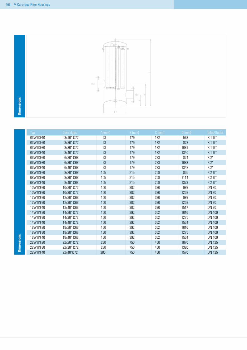
106
Typ Cartridges A (mm) B (mm) C (mm) D (mm) Inlet/Outlet03WTKF10 3x10“ Ø72 93 179 172 563 R 1 ½“03WTKF20 3x20“ Ø72 93 179 172 822 R 1 ½“03WTKF30 3x30“ Ø72 93 179 172 1081 R 1 ½“03WTKF40 3x40“ Ø72 93 179 172 1340 R 1 ½“06WTKF20 6x20“ Ø68 93 179 223 824 R 2“ 06WTKF30 6x30“ Ø68 93 179 223 1083 R 2“06WTKF40 6x40“ Ø68 93 179 223 1342 R 2“08WTKF20 8x20“ Ø68 105 215 258 855 R 2 ½“08WTKF30 8x30“ Ø68 105 215 258 1114 R 2 ½“08WTKF40 8x40“ Ø68 105 215 258 1373 R 2 ½“10WTKF20 10x20“ Ø72 160 382 330 999 DN 8010WTKF30 10x30“ Ø72 160 382 330 1258 DN 8012WTKF20 12x20“ Ø68 160 382 330 999 DN 8012WTKF30 12x30“ Ø68 160 382 330 1258 DN 8012WTKF40 12x40“ Ø68 160 382 330 1517 DN 8014WTKF20 14x20“ Ø72 160 392 362 1016 DN 10014WTKF30 14x30“ Ø72 160 392 362 1275 DN 10014WTKF40 14x40“ Ø72 160 392 362 1534 DN 10018WTKF20 18x20“ Ø68 160 392 362 1016 DN 10018WTKF30 18x30“ Ø68 160 392 362 1275 DN 10018WTKF40 18x40“ Ø68 160 392 362 1534 DN 10022WTKF20 22x20“ Ø72 280 750 450 1070 DN 12522WTKF30 22x30“ Ø72 280 750 450 1320 DN 12522WTKF40 22x40“Ø72 280 750 450 1570 DN 125D
imen
sion
sD
imen
sion
s
V. Cartridge Filter Housings
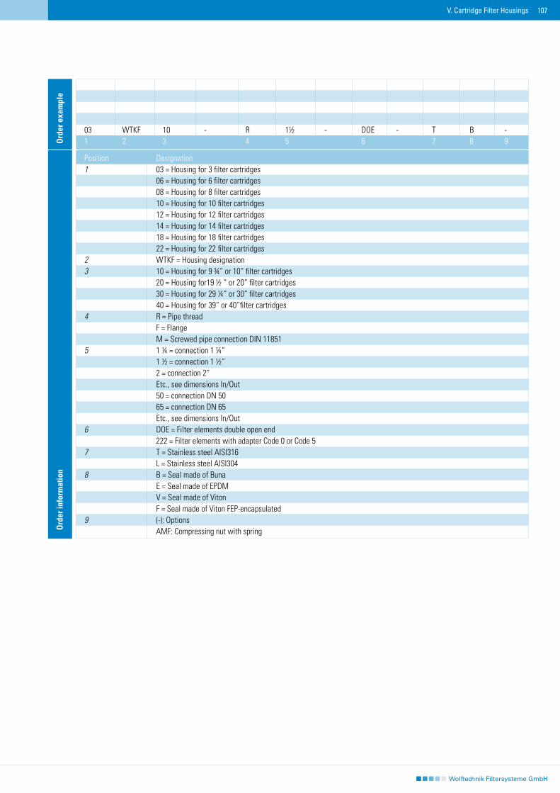
107
Ord
er in
form
atio
n
Position Designation1 03 = Housing for 3 filter cartridges 06 = Housing for 6 filter cartridges 08 = Housing for 8 filter cartridges 10 = Housing for 10 filter cartridges 12 = Housing for 12 filter cartridges 14 = Housing for 14 filter cartridges 18 = Housing for 18 filter cartridges 22 = Housing for 22 filter cartridges 2 WTKF = Housing designation3 10 = Housing for 9 ¾“ or 10“ filter cartridges 20 = Housing for19 ½ “ or 20“ filter cartridges 30 = Housing for 29 ¼“ or 30“ filter cartridges 40 = Housing for 39“ or 40“filter cartridges 4 R = Pipe thread F = Flange M = Screwed pipe connection DIN 118515 1 ¼ = connection 1 ¼“ 1 ½ = connection 1 ½“ 2 = connection 2“ Etc., see dimensions In/Out 50 = connection DN 50 65 = connection DN 65 Etc., see dimensions In/Out6 DOE = Filter elements double open end 222 = Filter elements with adapter Code 0 or Code 57 T = Stainless steel AISI316 L = Stainless steel AISI3048 B = Seal made of Buna E = Seal made of EPDM V = Seal made of Viton F = Seal made of Viton FEP-encapsulated9 (-): Options AMF: Compressing nut with spring
03 WTKF 10 - R 1½ - DOE - T B -1 2 3 4 5 6 7 8 9O
rder
exa
mpl
e
V. Cartridge Filter Housings

108 V. Cartridge Filter Housings
DWTKF Double cartridge filter housings with manual switch between the two
DWTKF Double cartridge filter housings made of stainless steel are equipped with a manual switch between the two for parallel or individual operational use. This enables a filter change without process-in-terruption and so ensures a continuous mode of operation. The double filter can be delivered with 2x3 pi-ece- or 2x6 piece filter elements in the lengths 9 ¾“ to 40“. According to the flow rate or medium different connections or connecting parts for inlet/and outlet can be delivered. For example flange, screwed pipe connection DIN 11851 or pipe thread. The versions with a central switch are equipped with 3-way ball valves. Deliverable accessories include vent valves, drains, manometers or complete vent-units. Special instruments such as differential pressure gauges or monitors are additional installable possibilities.
Technical data
Material: Housing: Stainless steel 1.4571 (V4A) or 1.4301 (V2A) Installations: Stainless steel 1.4571 O-Ring: Buna = standard (alternatively EPDM, Viton, Viton-FEP)In-/Outlet: See table Vent: 3/8“Drainage: 2 x ½“Filter elements: Code 0: 10“, 20“, 30“ or 40“ Code 5: 10“, 20“, 30“ or 40“ DOE: 9 ¾“, 10“, 19 ½“ 20“, 29 ¼“ , 30“ or 40“Pressure: Max. 10 bar to D06WTKFTemperature: Max. 95ºC Flow rate: The maximum flow rate correlates to the nominal diameter of the housing connection and the characteristic curve of the flow rate of the chosen filter element.
Applications
Fine filters for cooling circuits Particle filters for cleaning bathsPre-filters for reverse osmosis plantProtection filters for pumpsPre-filters for drinking water recycling Post-filters for activated carbon filters and ion exchangersSuspended particle filters for well-water Process filters for varnishes, paints and adhesives Coarse filters for delivery per refuelling vehicle
Features and Benefits
Double cartridge filter housings with manual switch between the twoParallel operation or individual operation possible Cap fastening with v-clamp Two assembly sizes with 2 x 3 piece or 2 x 6 piece filter elements Four lengths of 9 ¾“ to 40“ DOE or Code 0/Code 5Housing made of stainless steel AISI304 or AISI316Type and size of in- and outlet according to customer specificationCan be delivered optionally with automatic switch
DWTKF Double cartridge filter housings
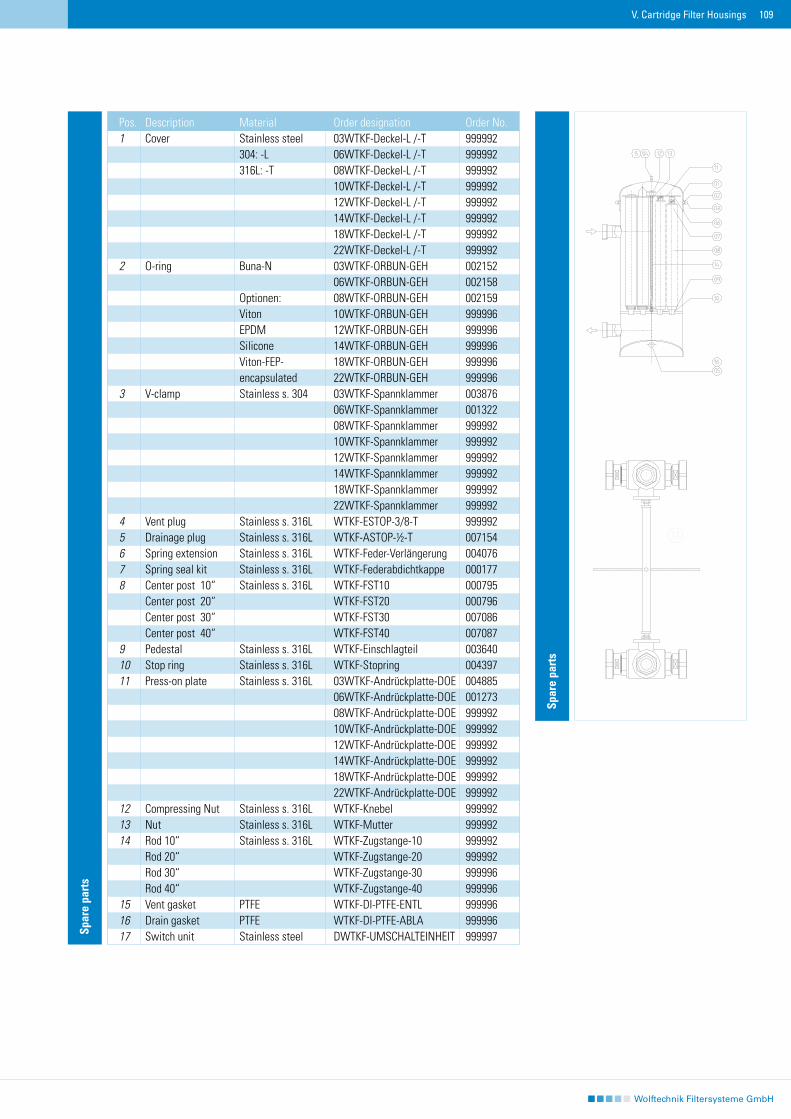
109V. Cartridge Filter Housings
Spar
e pa
rts
Pos. Description Material Order designation Order No.1 Cover Stainless steel 03WTKF-Deckel-L /-T 999992 304: -L 06WTKF-Deckel-L /-T 999992 316L: -T 08WTKF-Deckel-L /-T 999992 10WTKF-Deckel-L /-T 999992 12WTKF-Deckel-L /-T 999992 14WTKF-Deckel-L /-T 999992 18WTKF-Deckel-L /-T 999992 22WTKF-Deckel-L /-T 9999922 O-ring Buna-N 03WTKF-ORBUN-GEH 002152 06WTKF-ORBUN-GEH 002158 Optionen: 08WTKF-ORBUN-GEH 002159 Viton 10WTKF-ORBUN-GEH 999996 EPDM 12WTKF-ORBUN-GEH 999996 Silicone 14WTKF-ORBUN-GEH 999996 Viton-FEP- 18WTKF-ORBUN-GEH 999996 encapsulated 22WTKF-ORBUN-GEH 9999963 V-clamp Stainless s. 304 03WTKF-Spannklammer 003876 06WTKF-Spannklammer 001322 08WTKF-Spannklammer 999992 10WTKF-Spannklammer 999992 12WTKF-Spannklammer 999992 14WTKF-Spannklammer 999992 18WTKF-Spannklammer 999992 22WTKF-Spannklammer 9999924 Vent plug Stainless s. 316L WTKF-ESTOP-3/8-T 9999925 Drainage plug Stainless s. 316L WTKF-ASTOP-½-T 0071546 Spring extension Stainless s. 316L WTKF-Feder-Verlängerung 0040767 Spring seal kit Stainless s. 316L WTKF-Federabdichtkappe 0001778 Center post 10“ Stainless s. 316L WTKF-FST10 000795 Center post 20“ WTKF-FST20 000796 Center post 30“ WTKF-FST30 007086 Center post 40“ WTKF-FST40 0070879 Pedestal Stainless s. 316L WTKF-Einschlagteil 00364010 Stop ring Stainless s. 316L WTKF-Stopring 00439711 Press-on plate Stainless s. 316L 03WTKF-Andrückplatte-DOE 004885 06WTKF-Andrückplatte-DOE 001273 08WTKF-Andrückplatte-DOE 999992 10WTKF-Andrückplatte-DOE 999992 12WTKF-Andrückplatte-DOE 999992 14WTKF-Andrückplatte-DOE 999992 18WTKF-Andrückplatte-DOE 999992 22WTKF-Andrückplatte-DOE 99999212 Compressing Nut Stainless s. 316L WTKF-Knebel 99999213 Nut Stainless s. 316L WTKF-Mutter 99999214 Rod 10“ Stainless s. 316L WTKF-Zugstange-10 999992 Rod 20“ WTKF-Zugstange-20 999992 Rod 30“ WTKF-Zugstange-30 999996 Rod 40“ WTKF-Zugstange-40 99999615 Vent gasket PTFE WTKF-DI-PTFE-ENTL 99999616 Drain gasket PTFE WTKF-DI-PTFE-ABLA 99999617 Switch unit Stainless steel DWTKF-UMSCHALTEINHEIT 999997
Spar
e pa
rts
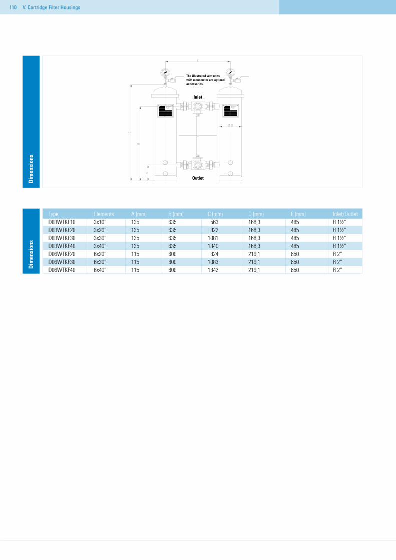
110 V. Cartridge Filter Housings
Type Elements A (mm) B (mm) C (mm) D (mm) E (mm) Inlet/OutletD03WTKF10 3x10“ 135 635 563 168,3 485 R 1½“D03WTKF20 3x20“ 135 635 822 168,3 485 R 1½“D03WTKF30 3x30“ 135 635 1081 168,3 485 R 1½“D03WTKF40 3x40“ 135 635 1340 168,3 485 R 1½“D06WTKF20 6x20“ 115 600 824 219,1 650 R 2“D06WTKF30 6x30“ 115 600 1083 219,1 650 R 2“D06WTKF40 6x40“ 115 600 1342 219,1 650 R 2“D
imen
sion
sD
imen
sion
s
The illustrated vent units with monometer are optional accessories.
Inlet
Outlet
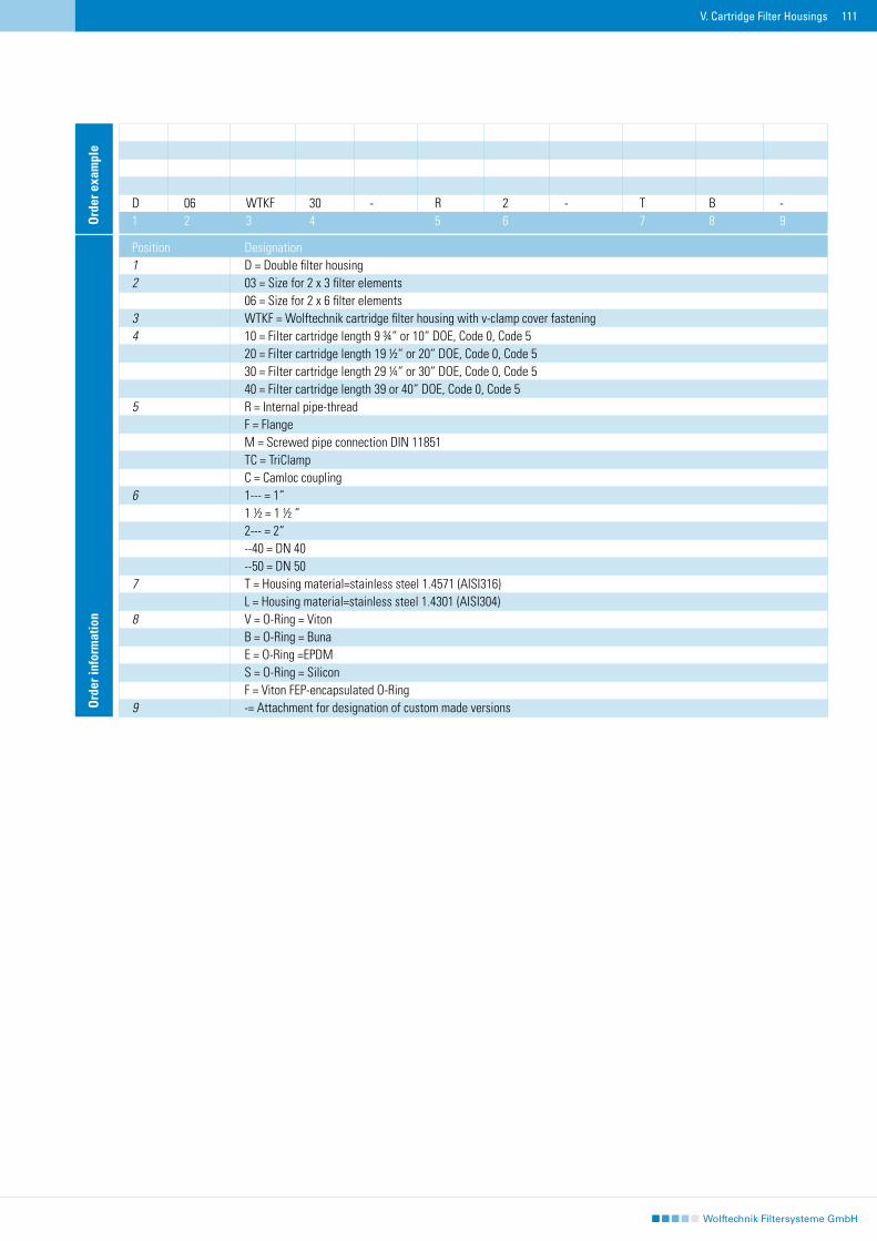
111V. Cartridge Filter Housings
Ord
er in
form
atio
n
Position Designation1 D = Double filter housing 2 03 = Size for 2 x 3 filter elements 06 = Size for 2 x 6 filter elements 3 WTKF = Wolftechnik cartridge filter housing with v-clamp cover fastening4 10 = Filter cartridge length 9 ¾“ or 10“ DOE, Code 0, Code 5 20 = Filter cartridge length 19 ½“ or 20“ DOE, Code 0, Code 5 30 = Filter cartridge length 29 ¼“ or 30“ DOE, Code 0, Code 5 40 = Filter cartridge length 39 or 40“ DOE, Code 0, Code 55 R = Internal pipe-thread F = Flange M = Screwed pipe connection DIN 11851 TC = TriClamp C = Camloc coupling 6 1--- = 1“ 1 ½ = 1 ½ “ 2--- = 2“ --40 = DN 40 --50 = DN 507 T = Housing material=stainless steel 1.4571 (AISI316) L = Housing material=stainless steel 1.4301 (AISI304)8 V = O-Ring = Viton B = O-Ring = Buna E = O-Ring =EPDM S = O-Ring = Silicon F = Viton FEP-encapsulated O-Ring9 -= Attachment for designation of custom made versions
D 06 WTKF 30 - R 2 - T B -1 2 3 4 5 6 7 8 9O
rder
exa
mpl
e
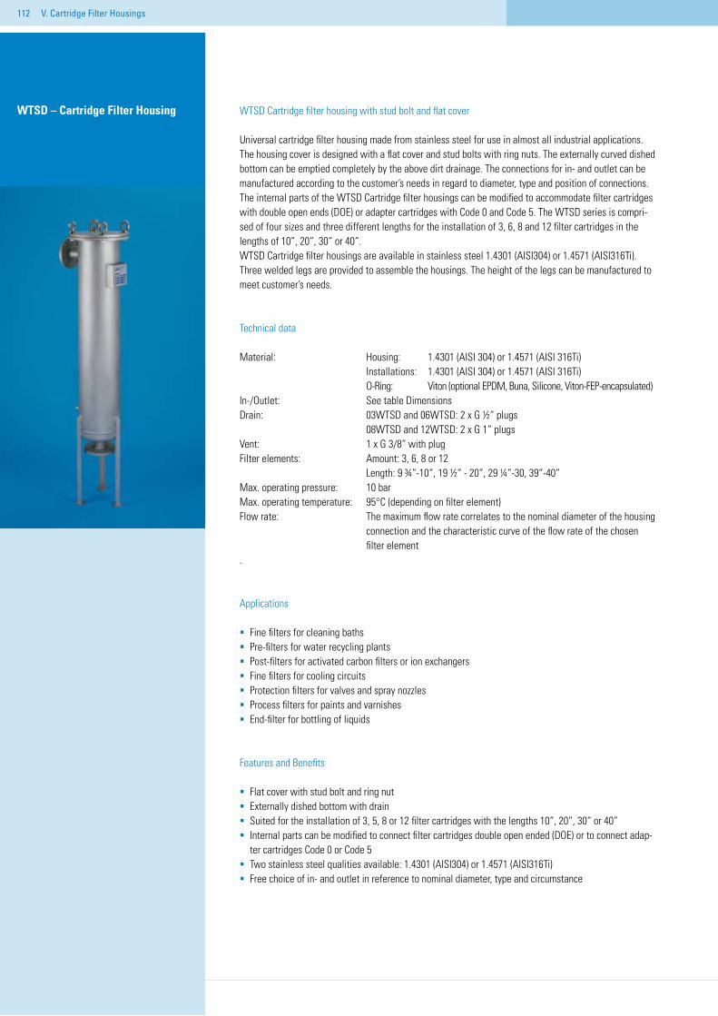
112
WTSD Cartridge filter housing with stud bolt and flat cover
Universal cartridge filter housing made from stainless steel for use in almost all industrial applications. The housing cover is designed with a flat cover and stud bolts with ring nuts. The externally curved dished bottom can be emptied completely by the above dirt drainage. The connections for in- and outlet can be manufactured according to the customer’s needs in regard to diameter, type and position of connections. The internal parts of the WTSD Cartridge filter housings can be modified to accommodate filter cartridges with double open ends (DOE) or adapter cartridges with Code 0 and Code 5. The WTSD series is compri-sed of four sizes and three different lengths for the installation of 3, 6, 8 and 12 filter cartridges in the lengths of 10“, 20“, 30“ or 40“.WTSD Cartridge filter housings are available in stainless steel 1.4301 (AISI304) or 1.4571 (AISI316Ti). Three welded legs are provided to assemble the housings. The height of the legs can be manufactured to meet customer’s needs.
Technical data
Material: Housing: 1.4301 (AISI 304) or 1.4571 (AISI 316Ti) Installations: 1.4301 (AISI 304) or 1.4571 (AISI 316Ti) O-Ring: Viton (optional EPDM, Buna, Silicone, Viton-FEP-encapsulated)In-/Outlet: See table DimensionsDrain: 03WTSD and 06WTSD: 2 x G ½“ plugs 08WTSD and 12WTSD: 2 x G 1“ plugsVent: 1 x G 3/8“ with plugFilter elements: Amount: 3, 6, 8 or 12 Length: 9 ¾“-10“, 19 ½“ - 20“, 29 ¼“-30, 39“-40“Max. operating pressure: 10 barMax. operating temperature: 95°C (depending on filter element)Flow rate: The maximum flow rate correlates to the nominal diameter of the housing connection and the characteristic curve of the flow rate of the chosen filter element.
Applications
Fine filters for cleaning bathsPre-filters for water recycling plantsPost-filters for activated carbon filters or ion exchangers Fine filters for cooling circuitsProtection filters for valves and spray nozzlesProcess filters for paints and varnishesEnd-filter for bottling of liquids
Features and Benefits
Flat cover with stud bolt and ring nutExternally dished bottom with drainSuited for the installation of 3, 5, 8 or 12 filter cartridges with the lengths 10“, 20“, 30“ or 40“Internal parts can be modified to connect filter cartridges double open ended (DOE) or to connect adap-
ter cartridges Code 0 or Code 5Two stainless steel qualities available: 1.4301 (AISI304) or 1.4571 (AISI316Ti)Free choice of in- and outlet in reference to nominal diameter, type and circumstance
WTSD – Cartridge Filter Housing
V. Cartridge Filter Housings
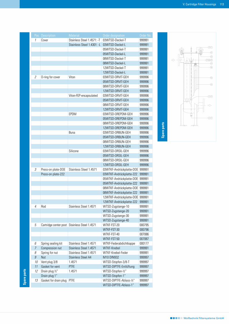
113
Spar
e pa
rts
Spar
e pa
rts
Pos. Description Material Order designation Order No.1 Cover Stainless Steel 1.4571: -T 03WTSD-Deckel-T 999991 Stainless Steel 1.4301: -L 03WTSD-Deckel-L 999991 05WTSD-Deckel-T 999991 05WTSD-Deckel-L 999991 08WTSD-Deckel-T 999991 08WTSD-Deckel-L 999991 12WTSD-Deckel-T 999991 12WTSD-Deckel-L 9999912 O-ring for cover Viton 03WTSD-ORVIT-GEH 999996 05WTSD-ORVIT-GEH 999996 08WTSD-ORVIT-GEH 999996 12WTSD-ORVIT-GEH 999996 Viton-FEP-encapsulated 03WTSD-ORVIT-GEH 999996 05WTSD-ORVIT-GEH 999996 08WTSD-ORVIT-GEH 999996 12WTSD-ORVIT-GEH 999996 EPDM 03WTSD-OREPDM-GEH 999996 05WTSD-OREPDM-GEH 999996 08WTSD-OREPDM-GEH 999996 12WTSD-OREPDM-GEH 999996 Buna 03WTSD-ORBUN-GEH 999996 05WTSD-ORBUN-GEH 999996 08WTSD-ORBUN-GEH 999996 12WTSD-ORBUN-GEH 999996 Silicone 03WTSD-ORSIL-GEH 999996 05WTSD-ORSIL-GEH 999996 08WTSD-ORSIL-GEH 999996 12WTSD-ORSIL-GEH 9999963 Press-on plate-DOE Stainless Steel 1.4571 03WTKF-Andrückplatte-DOE 999991 Press-on plate-222 03WTKF-Andrückplatte-222 999991 05WTKF-Andrückplatte-DOE 999991 05WTKF-Andrückplatte-222 999991 08WTKF-Andrückplatte-DOE 999991 08WTKF-Andrückplatte-222 999991 12WTKF-Andrückplatte-DOE 999991 12WTKF-Andrückplatte-222 9999914 Rod Stainless Steel 1.4571 WTSD-Zugstange-10 999991 WTSD-Zugstange-20 999991 WTSD-Zugstange-30 999991 WTSD-Zugstange-40 9999915 Cartridge center post Stainless Steel 1.4571 WTKF-FST-20 000795 WTKF-FST-30 000796 WTKF-FST-40 007086 WTKF-FST-50 0070876 Spring sealing kit Stainless Steel 1.4571 WTKF-Federabdichtkappe 0001777 Compression nut Stainless Steel 1.4571 WTKF-Knebel 9999918 Spring for nut Stainless Steel 1.4571 WTKF-Knebel-Feder 9999919 Nut Stainless Steel A4 M10 DIN932 99999710 Vent plug 3/8 1.4571 WTSD-Stopfen-3/8-T 99999711 Gasket for vent PTFE WTSD-DIPTFE-Entlüftung 99999712 Drain plug ½“ 1.4571 WTSD-Stopfen-½“ 999997 Drain plug 1“ WTSD-Stopfen-1“ 99999713 Gasket for drain plug PTFE WTSD-DIPTFE-Ablass-½“ 999997 WTSD-DIPTFE-Ablass-1“ 999997
V. Cartridge Filter Housings
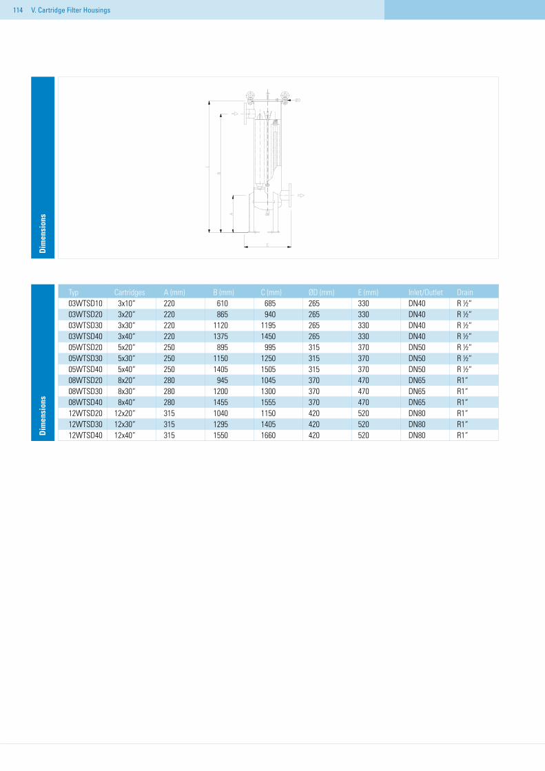
114 V. Cartridge Filter Housings
Dim
ensi
ons
Dim
ensi
ons
Typ Cartridges A (mm) B (mm) C (mm) ØD (mm) E (mm) Inlet/Outlet Drain03WTSD10 3x10“ 220 610 685 265 330 DN40 R ½“03WTSD20 3x20“ 220 865 940 265 330 DN40 R ½“03WTSD30 3x30“ 220 1120 1195 265 330 DN40 R ½“03WTSD40 3x40“ 220 1375 1450 265 330 DN40 R ½“05WTSD20 5x20“ 250 895 995 315 370 DN50 R ½“05WTSD30 5x30“ 250 1150 1250 315 370 DN50 R ½“05WTSD40 5x40“ 250 1405 1505 315 370 DN50 R ½“08WTSD20 8x20“ 280 945 1045 370 470 DN65 R1“08WTSD30 8x30“ 280 1200 1300 370 470 DN65 R1“08WTSD40 8x40“ 280 1455 1555 370 470 DN65 R1“12WTSD20 12x20“ 315 1040 1150 420 520 DN80 R1“12WTSD30 12x30“ 315 1295 1405 420 520 DN80 R1“12WTSD40 12x40“ 315 1550 1660 420 520 DN80 R1“
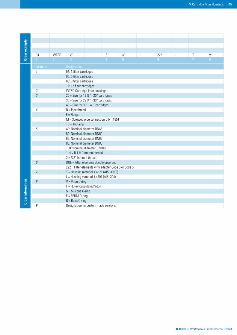
115V. Cartridge Filter Housings
03 WTSD 20 - F 40 - 222 - T V1 2 3 4 5 6 7 8O
rder
exa
mpl
eO
rder
info
rmat
ion
Position Designation1 03: 3 filter cartridges 05: 5 filter cartridges 08: 8 filter cartridges 12: 12 filter cartridges 2 WTSD Cartridge filter housings3 20 = Size for 19 ½“ - 20“ cartridges 30 = Size for 29 ¼“ - 30“ cartridges 40 = Size for 39“ - 40“ cartridges 4 R = Pipe thread F = Flange M = Screwed pipe connection DIN 11851 TC = TriClamp5 40: Nominal diameter DN65 50: Nominal diameter DN50 65: Nominal diameter DN65 80: Nominal diameter DN80 100: Nominal diameter DN100 1 ½ = R 1 ½“ Internal thread 2 = R 2“ Internal thread6 DOE = Filter elements double open end 222 = Filter elements with adapter Code 0 or Code 57 T = Housing material 1.4571 (AISI 316Ti) L = Housing material 1.4301 (AISI 304) 8 V = Viton o-ring F = FEP-encapsulated Viton S = Silicone O-ring E = EPDM O-ring B = Buna O-ring9 Designation for custom made versions
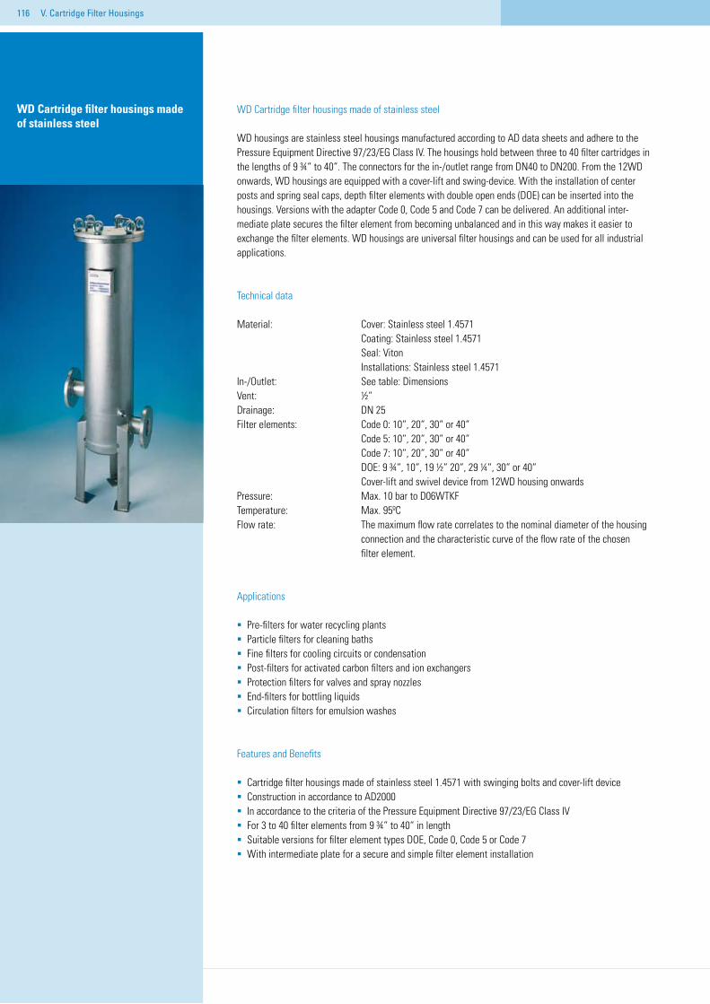
116 V. Cartridge Filter Housings
WD Cartridge filter housings made of stainless steel
WD housings are stainless steel housings manufactured according to AD data sheets and adhere to the Pressure Equipment Directive 97/23/EG Class IV. The housings hold between three to 40 filter cartridges in the lengths of 9 ¾“ to 40“. The connectors for the in-/outlet range from DN40 to DN200. From the 12WD onwards, WD housings are equipped with a cover-lift and swing-device. With the installation of center posts and spring seal caps, depth filter elements with double open ends (DOE) can be inserted into the housings. Versions with the adapter Code 0, Code 5 and Code 7 can be delivered. An additional inter-mediate plate secures the filter element from becoming unbalanced and in this way makes it easier to exchange the filter elements. WD housings are universal filter housings and can be used for all industrial applications.
Technical data
Material: Cover: Stainless steel 1.4571 Coating: Stainless steel 1.4571 Seal: Viton Installations: Stainless steel 1.4571In-/Outlet: See table: DimensionsVent: ½“Drainage: DN 25 Filter elements: Code 0: 10“, 20“, 30“ or 40“ Code 5: 10“, 20“, 30“ or 40“ Code 7: 10“, 20“, 30“ or 40“ DOE: 9 ¾“, 10“, 19 ½“ 20“, 29 ¼“, 30“ or 40“ Cover-lift and swivel device from 12WD housing onwards Pressure: Max. 10 bar to D06WTKFTemperature: Max. 95ºC Flow rate: The maximum flow rate correlates to the nominal diameter of the housing connection and the characteristic curve of the flow rate of the chosen filter element.
Applications
Pre-filters for water recycling plantsParticle filters for cleaning bathsFine filters for cooling circuits or condensationPost-filters for activated carbon filters and ion exchangersProtection filters for valves and spray nozzlesEnd-filters for bottling liquidsCirculation filters for emulsion washes
Features and Benefits
Cartridge filter housings made of stainless steel 1.4571 with swinging bolts and cover-lift deviceConstruction in accordance to AD2000In accordance to the criteria of the Pressure Equipment Directive 97/23/EG Class IVFor 3 to 40 filter elements from 9 ¾“ to 40“ in lengthSuitable versions for filter element types DOE, Code 0, Code 5 or Code 7With intermediate plate for a secure and simple filter element installation
WD Cartridge filter housings made of stainless steel
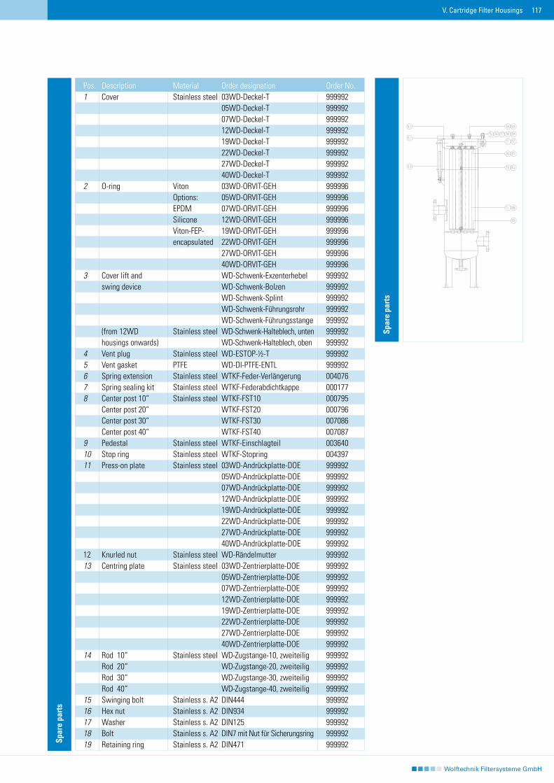
117V. Cartridge Filter Housings
Spar
e pa
rts
Pos. Description Material Order designation Order No.1 Cover Stainless steel 03WD-Deckel-T 999992 05WD-Deckel-T 999992 07WD-Deckel-T 999992 12WD-Deckel-T 999992 19WD-Deckel-T 999992 22WD-Deckel-T 999992 27WD-Deckel-T 999992 40WD-Deckel-T 9999922 O-ring Viton 03WD-ORVIT-GEH 999996 Options: 05WD-ORVIT-GEH 999996 EPDM 07WD-ORVIT-GEH 999996 Silicone 12WD-ORVIT-GEH 999996 Viton-FEP- 19WD-ORVIT-GEH 999996 encapsulated 22WD-ORVIT-GEH 999996 27WD-ORVIT-GEH 999996 40WD-ORVIT-GEH 9999963 Cover lift and WD-Schwenk-Exzenterhebel 999992 swing device WD-Schwenk-Bolzen 999992 WD-Schwenk-Splint 999992 WD-Schwenk-Führungsrohr 999992 WD-Schwenk-Führungsstange 999992 (from 12WD Stainless steel WD-Schwenk-Halteblech, unten 999992 housings onwards) WD-Schwenk-Halteblech, oben 9999924 Vent plug Stainless steel WD-ESTOP-½-T 9999925 Vent gasket PTFE WD-DI-PTFE-ENTL 9999926 Spring extension Stainless steel WTKF-Feder-Verlängerung 0040767 Spring sealing kit Stainless steel WTKF-Federabdichtkappe 0001778 Center post 10“ Stainless steel WTKF-FST10 000795 Center post 20“ WTKF-FST20 000796 Center post 30“ WTKF-FST30 007086 Center post 40“ WTKF-FST40 0070879 Pedestal Stainless steel WTKF-Einschlagteil 00364010 Stop ring Stainless steel WTKF-Stopring 00439711 Press-on plate Stainless steel 03WD-Andrückplatte-DOE 999992 05WD-Andrückplatte-DOE 999992 07WD-Andrückplatte-DOE 999992 12WD-Andrückplatte-DOE 999992 19WD-Andrückplatte-DOE 999992 22WD-Andrückplatte-DOE 999992 27WD-Andrückplatte-DOE 999992 40WD-Andrückplatte-DOE 99999212 Knurled nut Stainless steel WD-Rändelmutter 99999213 Centring plate Stainless steel 03WD-Zentrierplatte-DOE 999992 05WD-Zentrierplatte-DOE 999992 07WD-Zentrierplatte-DOE 999992 12WD-Zentrierplatte-DOE 999992 19WD-Zentrierplatte-DOE 999992 22WD-Zentrierplatte-DOE 999992 27WD-Zentrierplatte-DOE 999992 40WD-Zentrierplatte-DOE 99999214 Rod 10“ Stainless steel WD-Zugstange-10, zweiteilig 999992 Rod 20“ WD-Zugstange-20, zweiteilig 999992 Rod 30“ WD-Zugstange-30, zweiteilig 999992 Rod 40“ WD-Zugstange-40, zweiteilig 99999215 Swinging bolt Stainless s. A2 DIN444 99999216 Hex nut Stainless s. A2 DIN934 99999217 Washer Stainless s. A2 DIN125 99999218 Bolt Stainless s. A2 DIN7 mit Nut für Sicherungsring 99999219 Retaining ring Stainless s. A2 DIN471 999992
Spar
e pa
rts
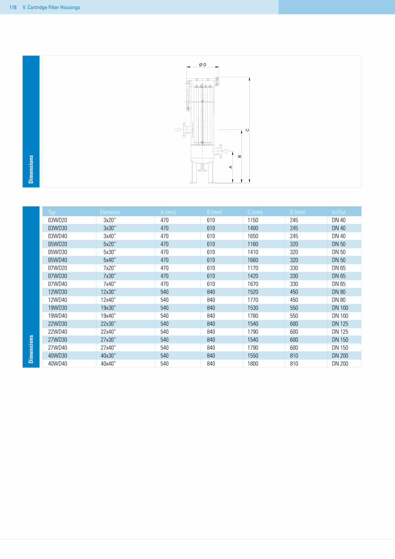
118 V. Cartridge Filter Housings
Typ Elements A (mm) B (mm) C (mm) D (mm) In/Out03WD20 3x20“ 470 610 1150 245 DN 4003WD30 3x30“ 470 610 1400 245 DN 4003WD40 3x40“ 470 610 1650 245 DN 4005WD20 5x20“ 470 610 1160 320 DN 5005WD30 5x30“ 470 610 1410 320 DN 5005WD40 5x40“ 470 610 1660 320 DN 5007WD20 7x20“ 470 610 1170 330 DN 6507WD30 7x30“ 470 610 1420 330 DN 6507WD40 7x40“ 470 610 1670 330 DN 6512WD30 12x30“ 540 840 1520 450 DN 8012WD40 12x40“ 540 840 1770 450 DN 8019WD30 19x30“ 540 840 1530 550 DN 10019WD40 19x40“ 540 840 1780 550 DN 10022WD30 22x30“ 540 840 1540 600 DN 12522WD40 22x40“ 540 840 1790 600 DN 12527WD30 27x30“ 540 840 1540 600 DN 15027WD40 27x40“ 540 840 1790 600 DN 15040WD30 40x30“ 540 840 1550 810 DN 20040WD40 40x40“ 540 840 1800 810 DN 200D
imen
sion
sD
imen
sion
s
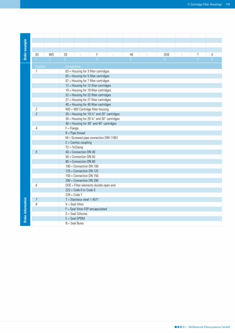
119V. Cartridge Filter Housings
Ord
er in
form
atio
n
Position Designation1 03 = Housing for 3 filter cartridges 05 = Housing for 5 filter cartridges 07 = Housing for 7 filter cartridges 12 = Housing for 12 filter cartridges 19 = Housing for 19 filter cartridges 22 = Housing for 22 filter cartridges 27 = Housing for 27 filter cartridges 40 = Housing for 40 filter cartridges 2 WD = WD Cartridge filter housing3 20 = Housing for 19 ½“ and 20“ cartridges 30 = Housing for 29 ¼“ and 30“ cartridges 40 = Housing for 39“ and 40“ cartridges4 F = Flange R = Pipe thread M = Screwed pipe connection DIN 11851 C = Camloc coupling TC = TriClamp5 40 = Connection DN 40 50 = Connection DN 50 80 = Connection DN 80 100 = Connection DN 100 125 = Connection DN 125 150 = Connection DN 150 200 = Connection DN 2006 DOE = Filter elements double open end 222 = Code 0 or Code 5 226 = Code 77 T = Stainless steel 1.45718 V = Seal Viton F = Seal Viton-FEP-encapsulated S = Seal Silicone E = Seal EPDM B = Seal Buna
03 WD 20 - F - 40 - DOE - T V1 2 3 4 5 6 7 8O
rder
exa
mpl
e
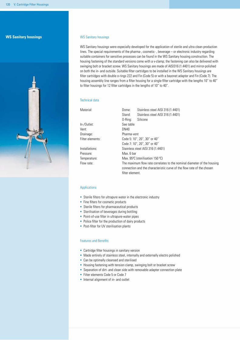
120
WS Sanitary housings
WS Sanitary housings were especially developed for the application of sterile and ultra clean production lines. The special requirements of the pharma-, cosmetic- , beverage – or electronic industry regarding suitable containers for sensitive processes can be found in the WS Sanitary housing construction. The housing fastening of the standard versions come with a v-clamp; the fastening can also be delivered with swinging bolt or bracket screw. WS Sanitary housings are made of AISI316 (1.4401) and mirror-polished on both the in- and outside. Suitable filter cartridges to be installed in the WS Sanitary housings are filter cartridges with double o-rings 222 and Fin (Code 5) or with a bayonet adapter and Fin (Code 7). The housing assembly line ranges from a filter housing for a single filter cartridge with the lengths 10“ to 40“ to filter housings for 12 filter cartridges in the lengths of 10“ to 40“.
Technical data
Material: Dome: Stainless steel AISI 316 (1.4401) Stand: Stainless steel AISI 316 (1.4401) O-Ring: SiliconeIn-/Outlet: See table Vent: DN40Drainage: Pharma-vent Filter elements: Code 5: 10“, 20“, 30“ or 40“ Code 7: 10“, 20“, 30“ or 40“Installations: Stainless steel AISI 316 (1.4401)Pressure: Max. 6 bar Temperature: Max. 95ºC (sterilisation 150 ºC) Flow rate: The maximum flow rate correlates to the nominal diameter of the housing connection and the characteristic curve of the flow rate of the chosen filter element.
Applications
Sterile filters for ultrapure water in the electronic industry Fine filters for cosmetic productsSterile filters for pharmaceutical productsSterilisation of beverages during bottlingPoint-of-use filter in ultrapure-water pipes Police filter for the production of dairy products Post-filter for UV sterilisation plants
Features and Benefits
Cartridge filter housings in sanitary versionMade entirely of stainless steel, internally and externally electro polishedCan be optimally cleansed and sterilised Housing fastening with tension clamp, swinging bolt or bracket screwSeparation of dirt- and clean side with removable adapter connection plateFilter elements Code 5 or Code 7Internal alignment of in- and outlet
WS Sanitary housings
V. Cartridge Filter Housings
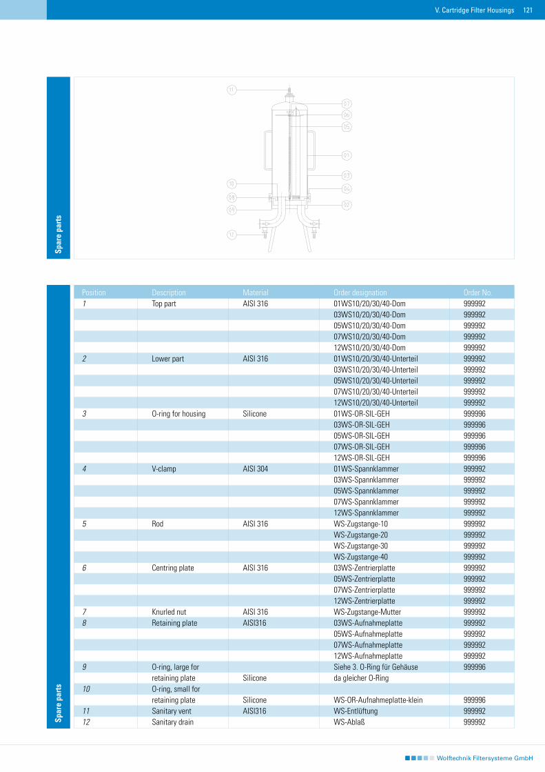
121
Spar
e pa
rts
Spar
e pa
rts
Position Description Material Order designation Order No.1 Top part AISI 316 01WS10/20/30/40-Dom 999992 03WS10/20/30/40-Dom 999992 05WS10/20/30/40-Dom 999992 07WS10/20/30/40-Dom 999992 12WS10/20/30/40-Dom 9999922 Lower part AISI 316 01WS10/20/30/40-Unterteil 999992 03WS10/20/30/40-Unterteil 999992 05WS10/20/30/40-Unterteil 999992 07WS10/20/30/40-Unterteil 999992 12WS10/20/30/40-Unterteil 9999923 O-ring for housing Silicone 01WS-OR-SIL-GEH 999996 03WS-OR-SIL-GEH 999996 05WS-OR-SIL-GEH 999996 07WS-OR-SIL-GEH 999996 12WS-OR-SIL-GEH 9999964 V-clamp AISI 304 01WS-Spannklammer 999992 03WS-Spannklammer 999992 05WS-Spannklammer 999992 07WS-Spannklammer 999992 12WS-Spannklammer 9999925 Rod AISI 316 WS-Zugstange-10 999992 WS-Zugstange-20 999992 WS-Zugstange-30 999992 WS-Zugstange-40 9999926 Centring plate AISI 316 03WS-Zentrierplatte 999992 05WS-Zentrierplatte 999992 07WS-Zentrierplatte 999992 12WS-Zentrierplatte 9999927 Knurled nut AISI 316 WS-Zugstange-Mutter 9999928 Retaining plate AISI316 03WS-Aufnahmeplatte 999992 05WS-Aufnahmeplatte 999992 07WS-Aufnahmeplatte 999992 12WS-Aufnahmeplatte 9999929 O-ring, large for Siehe 3. O-Ring für Gehäuse 999996 retaining plate Silicone da gleicher O-Ring10 O-ring, small for retaining plate Silicone WS-OR-Aufnahmeplatte-klein 99999611 Sanitary vent AISI316 WS-Entlüftung 99999212 Sanitary drain WS-Ablaß 999992
V. Cartridge Filter Housings
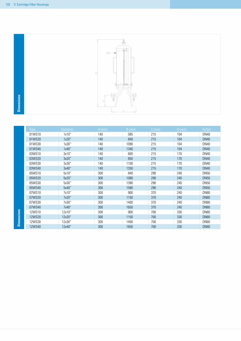
122
Type Elements A (mm) B (mm) C (mm) D (mm) In/Out01WS10 1x10“ 140 585 215 104 DN4001WS20 1x20“ 140 840 215 104 DN4001WS30 1x30“ 140 1090 215 104 DN4001WS40 1x40“ 140 1340 215 104 DN4003WS10 3x10“ 140 600 215 170 DN4003WS20 3x20“ 140 850 215 170 DN4003WS30 3x30“ 140 1100 215 170 DN4003WS40 3x40“ 140 1350 215 170 DN4005WS10 5x10“ 300 840 290 240 DN5005WS20 5x20“ 300 1090 290 240 DN5005WS30 5x30“ 300 1390 290 240 DN5005WS40 5x40“ 300 1590 290 240 DN5007WS10 7x10“ 300 900 370 240 DN8007WS20 7x20“ 300 1150 370 240 DN8007WS30 7x30“ 300 1400 370 240 DN8007WS40 7x40“ 300 1650 370 240 DN8012WS10 12x10“ 300 900 700 330 DN8012WS20 12x20“ 300 1150 700 330 DN8012WS30 12x30“ 300 1400 700 330 DN8012WS40 12x40“ 300 1650 700 330 DN80D
imen
sion
sD
imen
sion
s
V. Cartridge Filter Housings
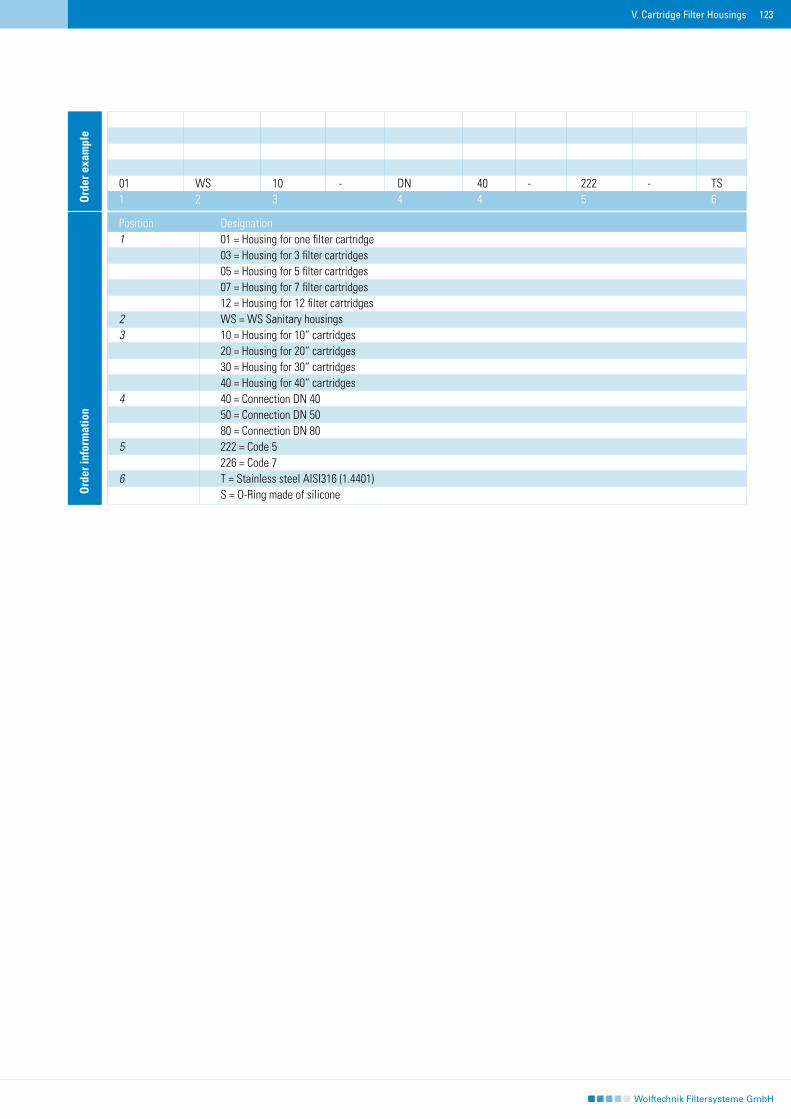
123
Ord
er in
form
atio
n
Position Designation1 01 = Housing for one filter cartridge 03 = Housing for 3 filter cartridges 05 = Housing for 5 filter cartridges 07 = Housing for 7 filter cartridges 12 = Housing for 12 filter cartridges 2 WS = WS Sanitary housings3 10 = Housing for 10“ cartridges 20 = Housing for 20“ cartridges 30 = Housing for 30“ cartridges 40 = Housing for 40“ cartridges 4 40 = Connection DN 40 50 = Connection DN 50 80 = Connection DN 805 222 = Code 5 226 = Code 76 T = Stainless steel AISI316 (1.4401) S = O-Ring made of silicone
01 WS 10 - DN 40 - 222 - TS1 2 3 4 4 5 6O
rder
exa
mpl
e
V. Cartridge Filter Housings
124
125
VI. Lenticular Cartridge Filters
CLC lenticular filter cartridges consist of cellulose with special polymer binders, and are made in 16-cell modules ranging in size from 12“ to 16“ in diameter. Filtration results from the combined effect of purely mechanical screening of the medium on the one hand and binding of turbidity-causing substances by the diatomaceous earth contained in the filter on the other. Because they are so effective for reducing turbidity, CLC lenticular cartridge filters are suited for a vast range of applications, either to remove colloi-dal impurities or as prefilters to protect and ease the load on downstream fine filter cartridges.WP housings for CLC lenticular cartridges are made of stainless steel 1.4571 or 1.4435. The sanitary versions are mirror polished on the inside and outside. WP housings are available to accommodate between one and four CLC lenticular cartridges 12“ or 16“ in diameter. These filters are so popular mainly because of their large surface area and depth filtration. The 12“ cartridges have a filter area of 1.8 sq.m and the 16“ cartridges of 3.6 sq.m. This makes it possible to install a filter area of 14.4 sq.m in a single 16WP4 housing.
Lenticular filter elements
CLC Lenticular filter cartridge Cellulose with special polymer binders
Lenticular filter housings
WP-housing Sanitary housing for CLC elements
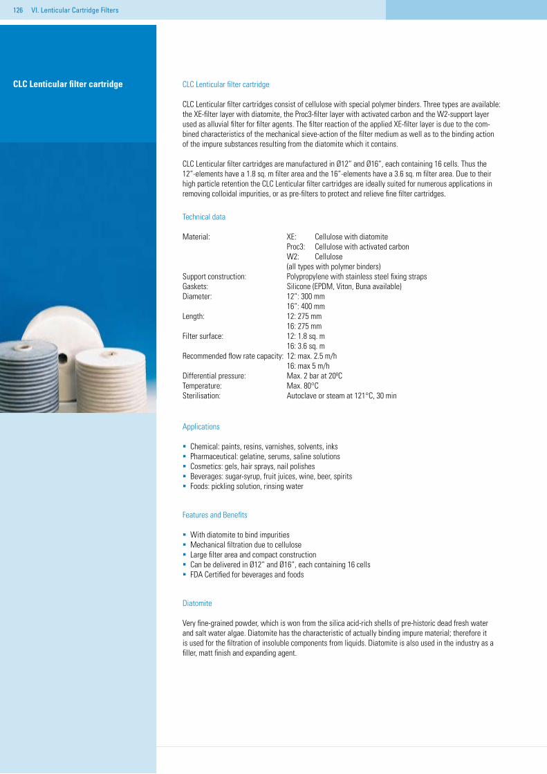
126
CLC Lenticular filter cartridge CLC Lenticular filter cartridge
CLC Lenticular filter cartridges consist of cellulose with special polymer binders. Three types are available: the XE-filter layer with diatomite, the Proc3-filter layer with activated carbon and the W2-support layer used as alluvial filter for filter agents. The filter reaction of the applied XE-filter layer is due to the com-bined characteristics of the mechanical sieve-action of the filter medium as well as to the binding action of the impure substances resulting from the diatomite which it contains.
CLC Lenticular filter cartridges are manufactured in Ø12“ and Ø16“, each containing 16 cells. Thus the 12“-elements have a 1.8 sq. m filter area and the 16“-elements have a 3.6 sq. m filter area. Due to their high particle retention the CLC Lenticular filter cartridges are ideally suited for numerous applications in removing colloidal impurities, or as pre-filters to protect and relieve fine filter cartridges.
Technical data
Material: XE: Cellulose with diatomite Proc3: Cellulose with activated carbon W2: Cellulose (all types with polymer binders)Support construction: Polypropylene with stainless steel fixing strapsGaskets: Silicone (EPDM, Viton, Buna available)Diameter: 12“: 300 mm 16“: 400 mmLength: 12: 275 mm 16: 275 mmFilter surface: 12: 1.8 sq. m 16: 3.6 sq. mRecommended flow rate capacity: 12: max. 2.5 m/h 16: max 5 m/hDifferential pressure: Max. 2 bar at 20ºC Temperature: Max. 80°C Sterilisation: Autoclave or steam at 121°C, 30 min
Applications
Chemical: paints, resins, varnishes, solvents, inksPharmaceutical: gelatine, serums, saline solutions Cosmetics: gels, hair sprays, nail polishesBeverages: sugar-syrup, fruit juices, wine, beer, spirits Foods: pickling solution, rinsing water
Features and Benefits
With diatomite to bind impuritiesMechanical filtration due to celluloseLarge filter area and compact constructionCan be delivered in Ø12“ and Ø16“, each containing 16 cellsFDA Certified for beverages and foods
Diatomite
Very fine-grained powder, which is won from the silica acid-rich shells of pre-historic dead fresh water and salt water algae. Diatomite has the characteristic of actually binding impure material; therefore it is used for the filtration of insoluble components from liquids. Diatomite is also used in the industry as a filler, matt finish and expanding agent.
VI. Lenticular Cartridge Filters
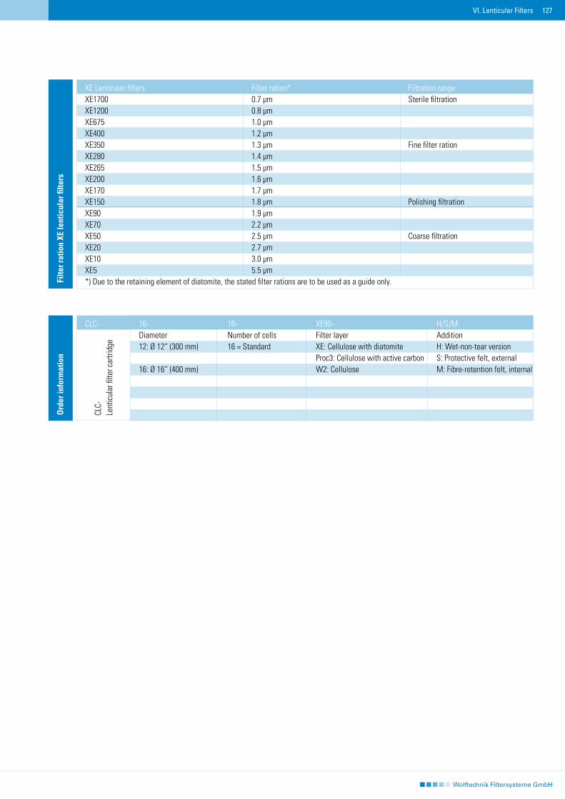
127
Filte
r rat
ion
XE le
ntic
ular
filte
rs
XE Lenticular filters Filter ration* Filtration range XE1700 0.7 µm Sterile filtrationXE1200 0.8 µm XE675 1.0 µm XE400 1.2 µm XE350 1.3 µm Fine filter rationXE280 1.4 µm XE265 1.5 µm XE200 1.6 µm XE170 1.7 µm XE150 1.8 µm Polishing filtrationXE90 1.9 µm XE70 2.2 µm XE50 2.5 µm Coarse filtrationXE20 2.7 µm XE10 3.0 µm XE5 5.5 µm*) Due to the retaining element of diatomite, the stated filter rations are to be used as a guide only.
Ord
er in
form
atio
n
16- 16- XE90- H/S/MDiameter Number of cells Filter layer Addition 12: Ø 12“ (300 mm) 16 = Standard XE: Cellulose with diatomite H: Wet-non-tear version Proc3: Cellulose with active carbon S: Protective felt, external16: Ø 16“ (400 mm) W2: Cellulose M: Fibre-retention felt, internal
CLC-
VI. Lenticular Filters
CLC-
Lent
icul
ar fi
lter c
artri
dge
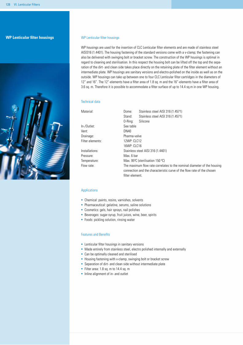
128
WP Lenticular filter housings
WP housings are used for the insertion of CLC Lenticular filter elements and are made of stainless steel AISI316 (1.4401). The housing fastening of the standard versions come with a v-clamp; the fastening can also be delivered with swinging bolt or bracket screw. The construction of the WP housings is optimal in regard to cleaning and sterilisation. In this respect the housing bolt can be lifted off the top and the sepa-ration of the dirt- and clean side takes place directly on the retaining plate of the filter element without an intermediate plate. WP housings are sanitary versions and electro-polished on the inside as well as on the outside. WP housings can take up between one to four CLC Lenticular filter cartridges in the diameters of 12“ and 16“. The 12“-elements have a filter area of 1.8 sq. m and the 16“-elements have a filter area of 3.6 sq. m. Therefore it is possible to accommodate a filter surface of up to 14.4 sq.m in one WP housing.
Technical data
Material: Dome: Stainless steel AISI 316 (1.4571) Stand: Stainless steel AISI 316 (1.4571) O-Ring: SiliconeIn-/Outlet: See table Vent: DN40Drainage: Pharma-valveFilter elements: 12WP: CLC12 16WP: CLC16Installations: Stainless steel AISI 316 (1.4401)Pressure: Max. 6 bar Temperature: Max. 95ºC (sterilisation 150 ºC) Flow rate: The maximum flow rate correlates to the nominal diameter of the housing connection and the characteristic curve of the flow rate of the chosen filter element.
Applications
Chemical: paints, resins, varnishes, solventsPharmaceutical: gelatine, serums, saline solutions Cosmetics: gels, hair sprays, nail polishesBeverages: sugar-syrup, fruit juices, wine, beer, spirits Foods: pickling solution, rinsing water
Features and Benefits
Lenticular filter housings in sanitary versionsMade entirely from stainless steel, electro polished internally and externally Can be optimally cleaned and sterilised Housing fastening with v-clamp, swinging bolt or bracket screwSeparation of dirt- and clean side without intermediate plate Filter area: 1.8 sq. m to 14.4 sq. mInline alignment of in- and outlet
WP Lenticular filter housings
VI. Lenticular Filters
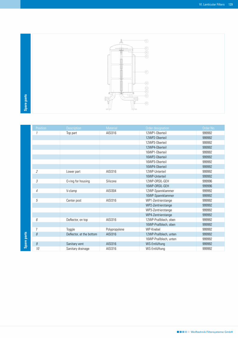
129
Spar
e pa
rts
Position Description Material Order designation Order No.1 Top part AISI316 12WP1-Oberteil 999992 12WP2-Oberteil 999992 12WP3-Oberteil 999992 12WP4-Oberteil 999992 16WP1-Oberteil 999992 16WP2-Oberteil 999992 16WP3-Oberteil 999992 16WP4-Oberteil 9999922 Lower part AISI316 12WP-Unterteil 999992 16WP-Unterteil 9999923 O-ring for housing Silicone 12WP-ORSIL-GEH 999996 16WP-ORSIL-GEH 9999964 V-clamp AISI304 12WP-Spannklammer 999992 16WP-Spannklammer 9999925 Center post AISI316 WP1-Zentrierstange 999992 WP2-Zentrierstange 999992 WP3-Zentrierstange 999992 WP4-Zentrierstange 9999926 Deflector, on top AISI316 12WP-Prallblech, oben 999992 16WP-Prallblech, oben 9999927 Toggle Polypropylene WP-Knebel 9999928 Deflector, at the bottom AISI316 12WP-Prallblech, unten 999992 16WP-Prallblech, unten 9999929 Sanitary vent AISI316 WS-Entlüftung 99999210 Sanitary drainage AISI316 WS-Entlüftung 999992
Spar
e pa
rts
VI. Lenticular Filters
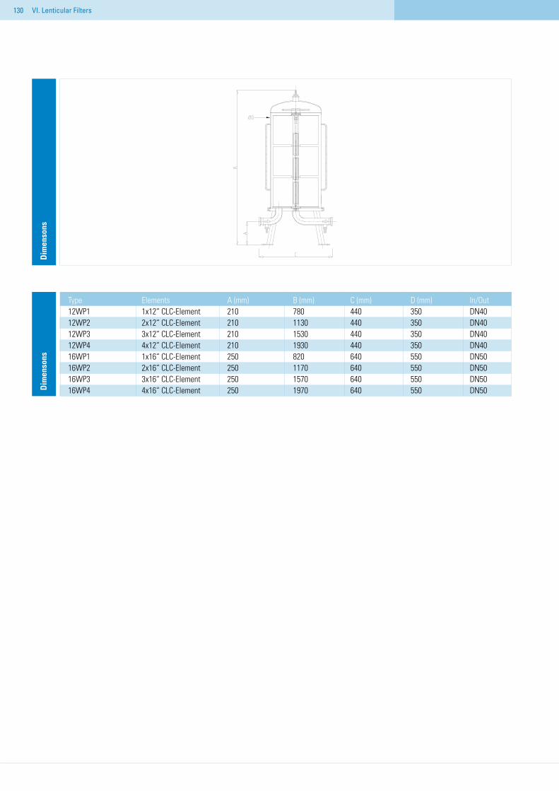
130
Type Elements A (mm) B (mm) C (mm) D (mm) In/Out12WP1 1x12“ CLC-Element 210 780 440 350 DN4012WP2 2x12“ CLC-Element 210 1130 440 350 DN4012WP3 3x12“ CLC-Element 210 1530 440 350 DN4012WP4 4x12“ CLC-Element 210 1930 440 350 DN4016WP1 1x16“ CLC-Element 250 820 640 550 DN5016WP2 2x16“ CLC-Element 250 1170 640 550 DN5016WP3 3x16“ CLC-Element 250 1570 640 550 DN5016WP4 4x16“ CLC-Element 250 1970 640 550 DN50D
imen
sons
Dim
enso
ns
VI. Lenticular Filters
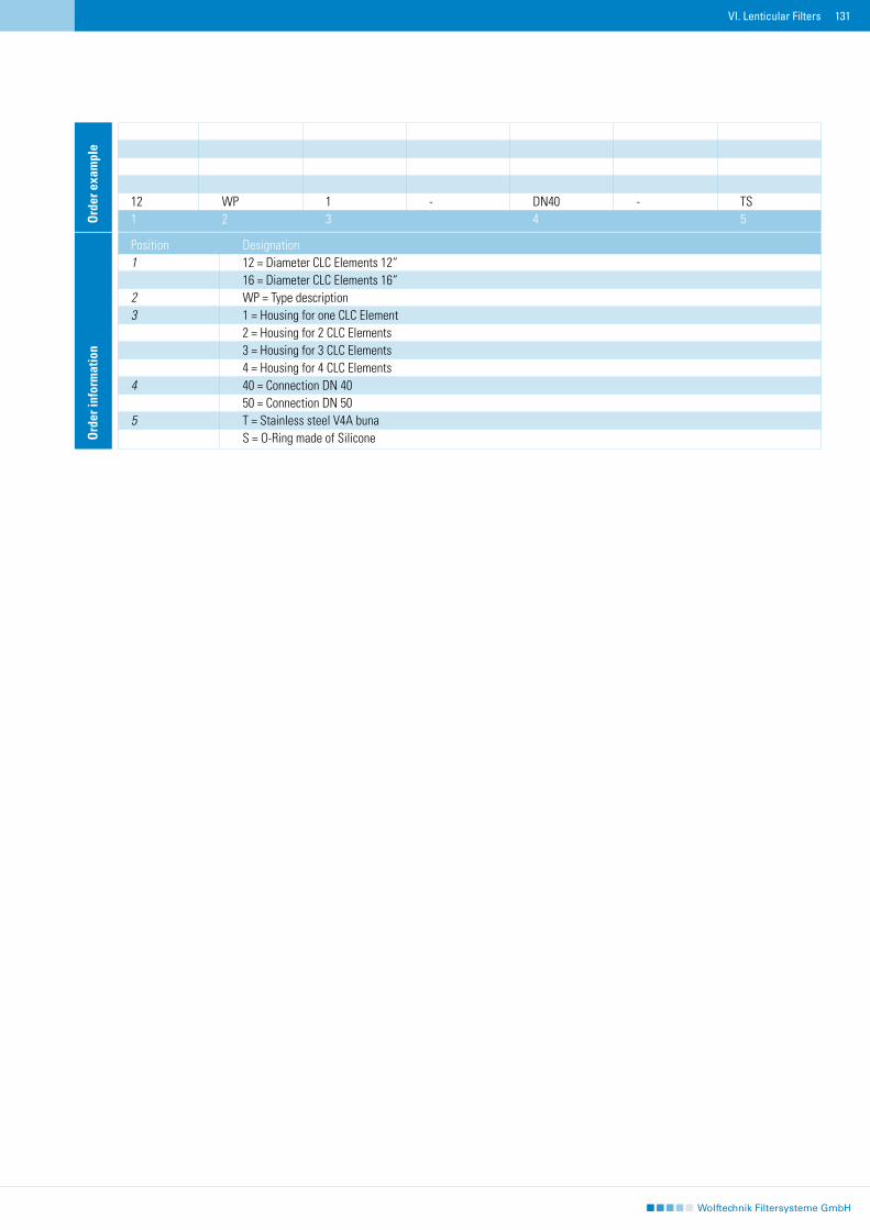
131
Ord
er in
form
atio
n
Position Designation1 12 = Diameter CLC Elements 12“ 16 = Diameter CLC Elements 16“2 WP = Type description3 1 = Housing for one CLC Element 2 = Housing for 2 CLC Elements 3 = Housing for 3 CLC Elements 4 = Housing for 4 CLC Elements4 40 = Connection DN 40 50 = Connection DN 505 T = Stainless steel V4A buna S = O-Ring made of Silicone
12 WP 1 - DN40 - TS1 2 3 4 5O
rder
exa
mpl
e
VI. Lenticular Filters
132
133
VII. Bag Filters and Strainer Baskets
Bag filters and strainers made of stainless steel and plastic with filter areas from 0.05 to 0.5 sq.m differ from one another in the type of cover used. The housings can take the form of single filters, switchable double filters, or multiple filters. All bag filters are modifiable standard versions. The type, size and location of the connections, the cover and surface characteristics of the housings can be adjusted to meet your requirements.
Stainless Steel HousingsWTBF20/35-KD With swinging bolts and hinged coverWTBF40/85-KD With swinging bolts and hinged coverWTBF-SB With stud bolt and removable coverWTBF-SK With v-clamp closureDWTBF Double-bag filter housing with switch between the two
Plastic HousingsPBH Inline housingWTBF-PP/-PVDF With stud bolt and removable cover
Filter Bags, Strainer Baskets, Magnet inserts, LUPUS®The filter bags or strainer baskets placed in the housings are available in various sizes, with different filter ratings and made of different materials. This allows you to select the right one for your application, depending on the flow rate and required re-sistance.
WFB Filter bag, nominal PO, PE, EPE, NMOWTBF Sieve baskets Stainless steel sieve mesh or perforated sheetingWTBF Magnet inserts Magnet inserts for ferrite particles LUPUS®-System Three piece installation kit for bag filter housings
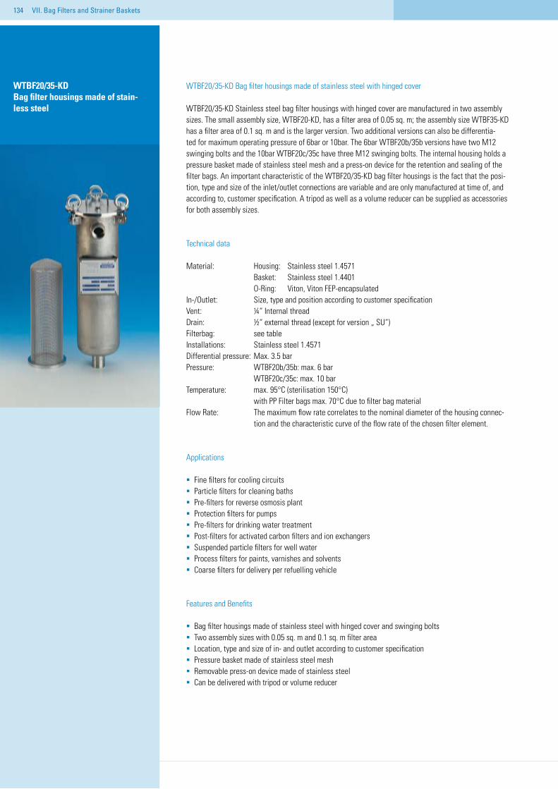
134 VII. Bag Filters and Strainer Baskets
WTBF20/35-KD Bag filter housings made of stainless steel with hinged cover
WTBF20/35-KD Stainless steel bag filter housings with hinged cover are manufactured in two assembly sizes. The small assembly size, WTBF20-KD, has a filter area of 0.05 sq. m; the assembly size WTBF35-KD has a filter area of 0.1 sq. m and is the larger version. Two additional versions can also be differentia-ted for maximum operating pressure of 6bar or 10bar. The 6bar WTBF20b/35b versions have two M12 swinging bolts and the 10bar WTBF20c/35c have three M12 swinging bolts. The internal housing holds a pressure basket made of stainless steel mesh and a press-on device for the retention and sealing of the filter bags. An important characteristic of the WTBF20/35-KD bag filter housings is the fact that the posi-tion, type and size of the inlet/outlet connections are variable and are only manufactured at time of, and according to, customer specification. A tripod as well as a volume reducer can be supplied as accessories for both assembly sizes.
Technical data
Material: Housing: Stainless steel 1.4571 Basket: Stainless steel 1.4401 O-Ring: Viton, Viton FEP-encapsulatedIn-/Outlet: Size, type and position according to customer specification Vent: ¼“ Internal threadDrain: ½“ external thread (except for version „ SU“)Filterbag: see tableInstallations: Stainless steel 1.4571Differential pressure: Max. 3.5 barPressure: WTBF20b/35b: max. 6 bar WTBF20c/35c: max. 10 barTemperature: max. 95°C (sterilisation 150°C) with PP Filter bags max. 70°C due to filter bag materialFlow Rate: The maximum flow rate correlates to the nominal diameter of the housing connec- tion and the characteristic curve of the flow rate of the chosen filter element.
Applications
Fine filters for cooling circuits Particle filters for cleaning bathsPre-filters for reverse osmosis plantProtection filters for pumpsPre-filters for drinking water treatmentPost-filters for activated carbon filters and ion exchangersSuspended particle filters for well water Process filters for paints, varnishes and solvents Coarse filters for delivery per refuelling vehicle
Features and Benefits
Bag filter housings made of stainless steel with hinged cover and swinging boltsTwo assembly sizes with 0.05 sq. m and 0.1 sq. m filter areaLocation, type and size of in- and outlet according to customer specificationPressure basket made of stainless steel meshRemovable press-on device made of stainless steelCan be delivered with tripod or volume reducer
WTBF20/35-KD Bag filter housings made of stain-less steel
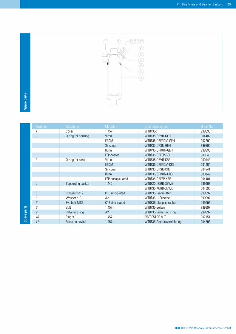
135VII. Bag Filters and Strainer Baskets
Spar
e pa
rts
Position Description Material Order designation Order No.1 Cover 1.4571 WTBF35c 9999932 O-ring for housing Viton WTBF35-ORVIT-GEH 004402 EPDM WTBF35-OREPDM-GEH 002299 Silicone WTBF35-ORSIL-GEH 999996 Buna WTBF35-ORBUN-GEH 999996 FEP-coated WTBF35-ORFEP-GEH 0039403 O-ring for basket Viton WTBF35-ORVIT-KRB 000143 EPDM WTBF35-OREPDM-KRB 001184 Silicone WTBF35-ORSIL-KRB 004241 Buna WTBF35-ORBUN-KRB 000142 FEP-encapsulated WTBF35-ORFEP-KRB 0044014 Supporting basket 1.4401 WTBF20-KORB-GEWE 999993 WTBF35-KORB-GEWE 0046955 Ring nut M12 C15 zinc-plated WTBF35-Ringmutter 9999976 Washer d13 A2 WTBF35-U-Scheibe 9999977 Eye bolt M12 C15 zinc-plated WTBF35-Klappschraube 9999978 Bolt 1.4571 WTBF35-Bolzen 9999979 Retaining ring A2 WTBF35-Sicherungsring 99999710 Plug ¼“ 1.4571 3WT-ESTOP-¼-T 00715111 Press-on device 1.4571 WTBF35-Andrückvorrichtung 004696
Spar
e pa
rts
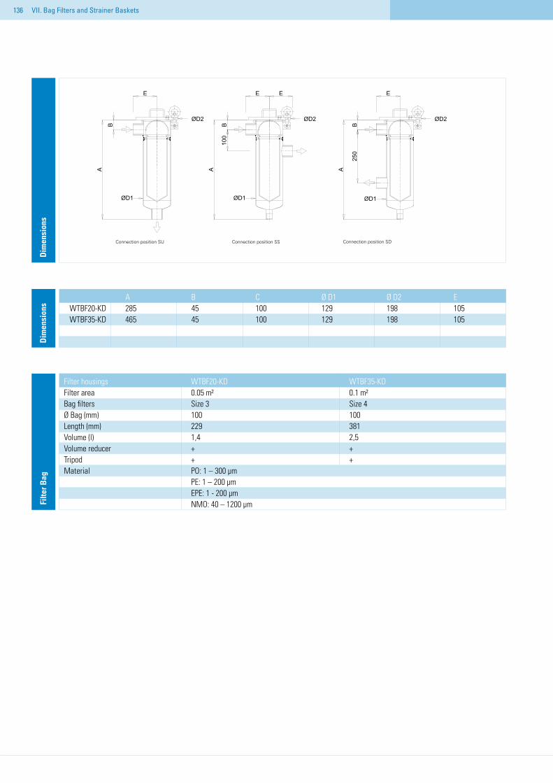
136
Dim
ensi
ons
Dim
ensi
ons
A B C Ø D1 Ø D2 EWTBF20-KD 285 45 100 129 198 105WTBF35-KD 465 45 100 129 198 105
Filte
r Bag
Filter housings WTBF20-KD WTBF35-KD Filter area 0.05 m² 0.1 m² Bag filters Size 3 Size 4 Ø Bag (mm) 100 100 Length (mm) 229 381 Volume (l) 1,4 2,5 Volume reducer + + Tripod + + Material PO: 1 – 300 µm PE: 1 – 200 µm EPE: 1 - 200 µm
NMO: 40 – 1200 µm
VII. Bag Filters and Strainer Baskets
Connection position SU Connection position SS Connection position SD
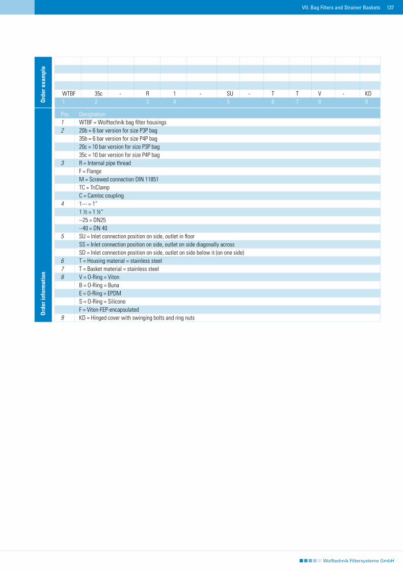
137VII. Bag Filters and Strainer Baskets
Ord
er e
xam
ple
WTBF 35c - R 1 - SU - T T V - KD1 2 3 4 5 6 7 8 9
Ord
er in
form
atio
n
Pos. Designation 1 WTBF = Wolftechnik bag filter housings 2 20b = 6 bar version for size P3P bag 35b = 6 bar version for size P4P bag 20c = 10 bar version for size P3P bag 35c = 10 bar version for size P4P bag 3 R = Internal pipe thread F = Flange M = Screwed connection DIN 11851 TC = TriClamp C = Camloc coupling 4 1--- = 1“ 1 ½ = 1 ½“ --25 = DN25 --40 = DN 40 5 SU = Inlet connection position on side, outlet in floor SS = Inlet connection position on side, outlet on side diagonally across SD = Inlet connection position on side, outlet on side below it (on one side) 6 T = Housing material = stainless steel 7 T = Basket material = stainless steel 8 V = O-Ring = Viton B = O-Ring = Buna E = O-Ring = EPDM S = O-Ring = Silicone F = Viton-FEP-encapsulated 9 KD = Hinged cover with swinging bolts and ring nuts
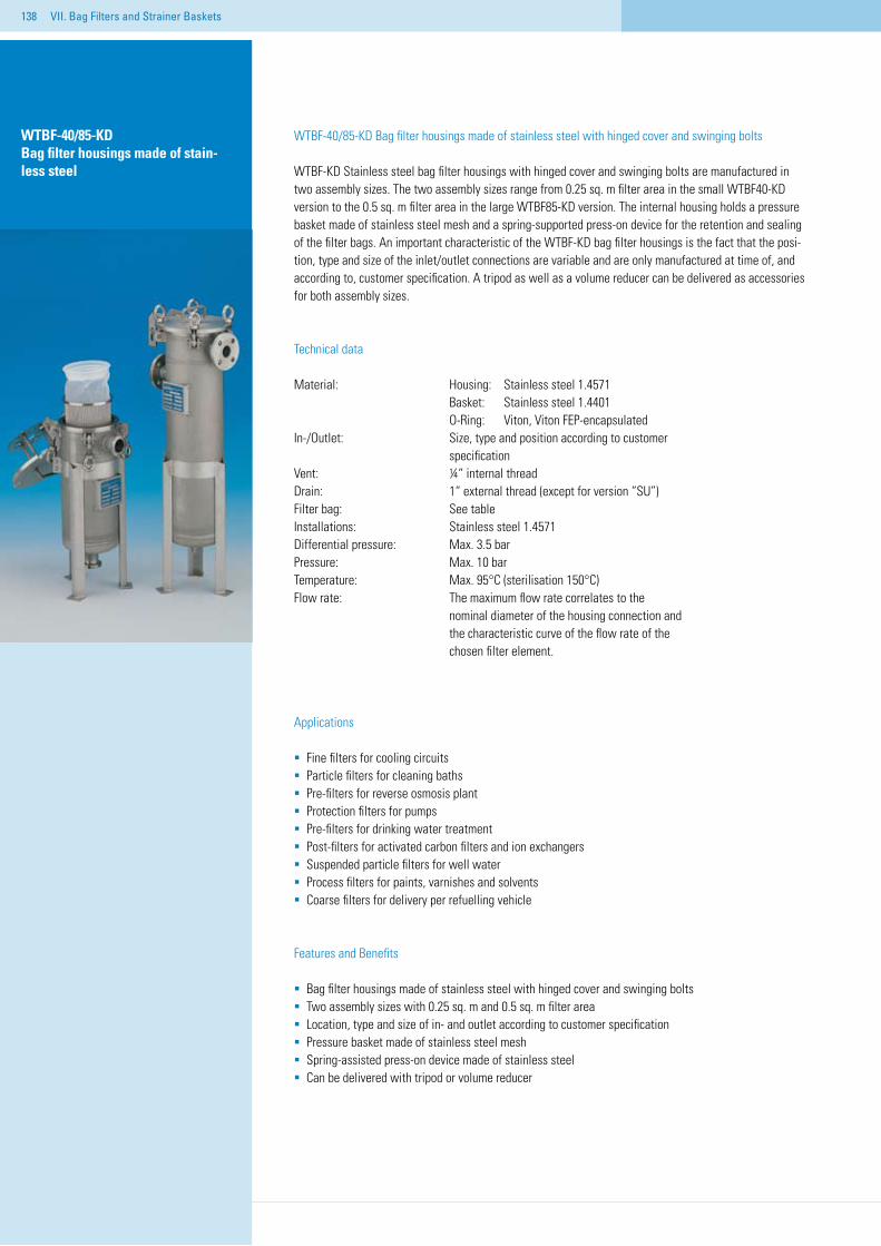
138
WTBF-40/85-KD Bag filter housings made of stain-less steel
WTBF-40/85-KD Bag filter housings made of stainless steel with hinged cover and swinging bolts
WTBF-KD Stainless steel bag filter housings with hinged cover and swinging bolts are manufactured in two assembly sizes. The two assembly sizes range from 0.25 sq. m filter area in the small WTBF40-KD version to the 0.5 sq. m filter area in the large WTBF85-KD version. The internal housing holds a pressure basket made of stainless steel mesh and a spring-supported press-on device for the retention and sealing of the filter bags. An important characteristic of the WTBF-KD bag filter housings is the fact that the posi-tion, type and size of the inlet/outlet connections are variable and are only manufactured at time of, and according to, customer specification. A tripod as well as a volume reducer can be delivered as accessories for both assembly sizes.
Technical data
Material: Housing: Stainless steel 1.4571 Basket: Stainless steel 1.4401 O-Ring: Viton, Viton FEP-encapsulated In-/Outlet: Size, type and position according to customer specification Vent: ¼“ internal threadDrain: 1“ external thread (except for version “SU”)Filter bag: See tableInstallations: Stainless steel 1.4571Differential pressure: Max. 3.5 barPressure: Max. 10 bar Temperature: Max. 95°C (sterilisation 150°C)Flow rate: The maximum flow rate correlates to the nominal diameter of the housing connection and the characteristic curve of the flow rate of the chosen filter element.
Applications
Fine filters for cooling circuits Particle filters for cleaning bathsPre-filters for reverse osmosis plantProtection filters for pumpsPre-filters for drinking water treatmentPost-filters for activated carbon filters and ion exchangersSuspended particle filters for well water Process filters for paints, varnishes and solvents Coarse filters for delivery per refuelling vehicle
Features and Benefits
Bag filter housings made of stainless steel with hinged cover and swinging boltsTwo assembly sizes with 0.25 sq. m and 0.5 sq. m filter areaLocation, type and size of in- and outlet according to customer specificationPressure basket made of stainless steel meshSpring-assisted press-on device made of stainless steelCan be delivered with tripod or volume reducer
VII. Bag Filters and Strainer Baskets
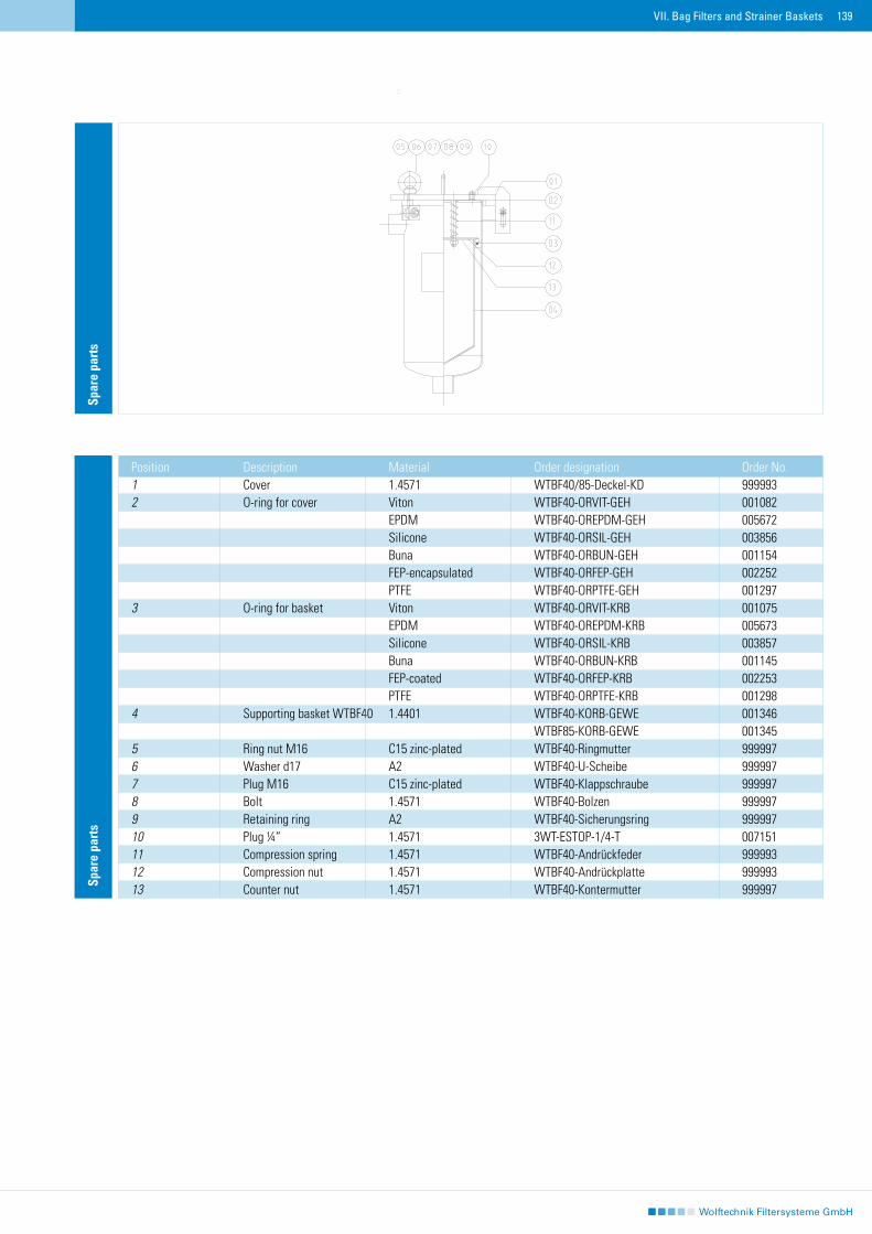
139
Spar
e pa
rts
Position Description Material Order designation Order No.1 Cover 1.4571 WTBF40/85-Deckel-KD 9999932 O-ring for cover Viton WTBF40-ORVIT-GEH 001082 EPDM WTBF40-OREPDM-GEH 005672 Silicone WTBF40-ORSIL-GEH 003856 Buna WTBF40-ORBUN-GEH 001154 FEP-encapsulated WTBF40-ORFEP-GEH 002252 PTFE WTBF40-ORPTFE-GEH 0012973 O-ring for basket Viton WTBF40-ORVIT-KRB 001075 EPDM WTBF40-OREPDM-KRB 005673 Silicone WTBF40-ORSIL-KRB 003857 Buna WTBF40-ORBUN-KRB 001145 FEP-coated WTBF40-ORFEP-KRB 002253 PTFE WTBF40-ORPTFE-KRB 0012984 Supporting basket WTBF40 1.4401 WTBF40-KORB-GEWE 001346 WTBF85-KORB-GEWE 0013455 Ring nut M16 C15 zinc-plated WTBF40-Ringmutter 9999976 Washer d17 A2 WTBF40-U-Scheibe 9999977 Plug M16 C15 zinc-plated WTBF40-Klappschraube 9999978 Bolt 1.4571 WTBF40-Bolzen 9999979 Retaining ring A2 WTBF40-Sicherungsring 99999710 Plug ¼“ 1.4571 3WT-ESTOP-1/4-T 00715111 Compression spring 1.4571 WTBF40-Andrückfeder 99999312 Compression nut 1.4571 WTBF40-Andrückplatte 99999313 Counter nut 1.4571 WTBF40-Kontermutter 999997
Spar
e pa
rts
VII. Bag Filters and Strainer Baskets
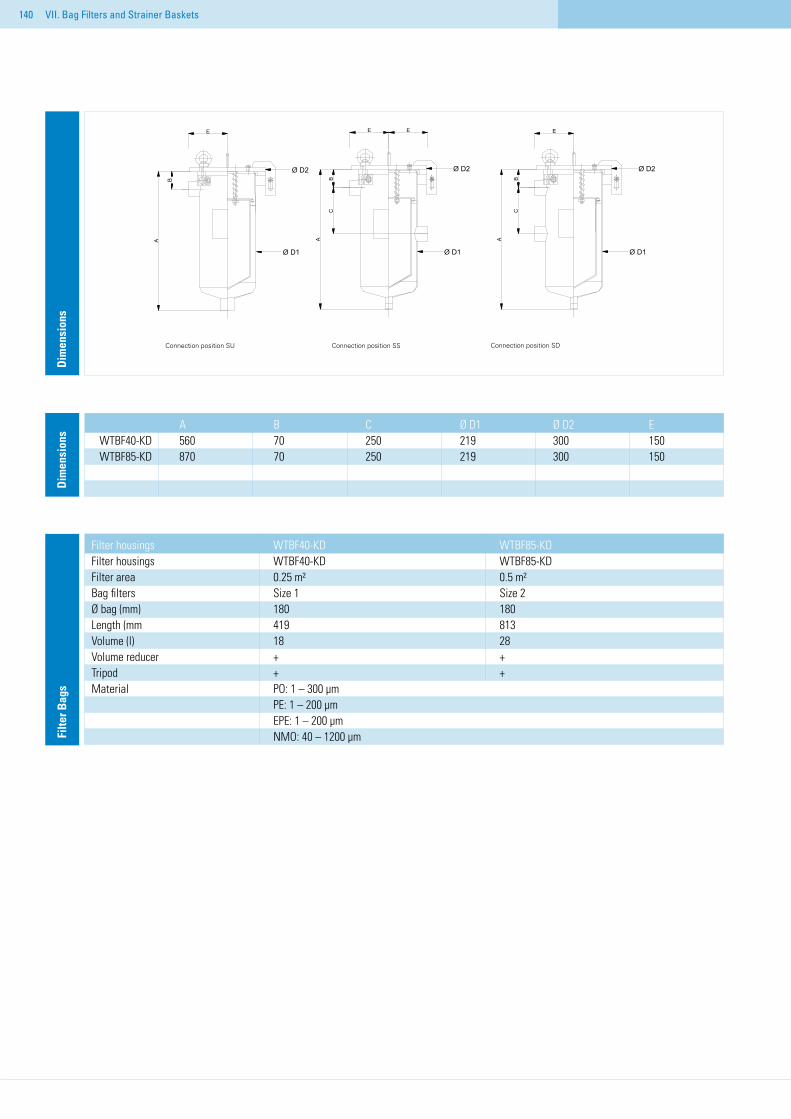
140
Dim
ensi
ons
Dim
ensi
ons
A B C Ø D1 Ø D2 EWTBF40-KD 560 70 250 219 300 150WTBF85-KD 870 70 250 219 300 150
Filte
r Bag
s
Filter housings WTBF40-KD WTBF85-KD Filter housings WTBF40-KD WTBF85-KD Filter area 0.25 m² 0.5 m² Bag filters Size 1 Size 2 Ø bag (mm) 180 180 Length (mm 419 813 Volume (l) 18 28 Volume reducer + + Tripod + + Material PO: 1 – 300 µm PE: 1 – 200 µm EPE: 1 – 200 µm NMO: 40 – 1200 µm
VII. Bag Filters and Strainer Baskets
A
CB
AA
B BC
Ø D2
Ø D1
Ø D2
Ø D1
Ø D2
Ø D1
E E EE
Stutzenstellung "SU"
Stutzenstellung "SS"
Stutzenstellung "SD"
Connection position SU Connection position SS Connection position SD
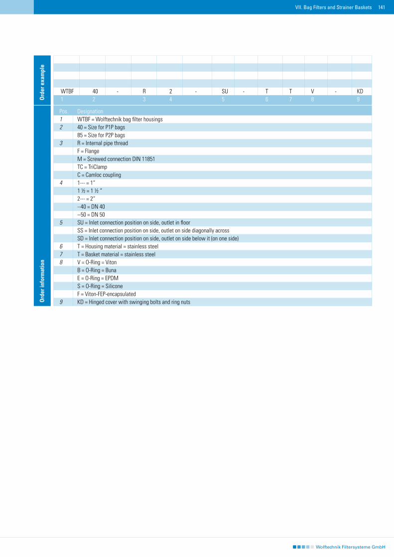
141
Ord
er e
xam
ple
WTBF 40 - R 2 - SU - T T V - KD1 2 3 4 5 6 7 8 9
Ord
er in
form
atio
n
Pos. Designation 1 WTBF = Wolftechnik bag filter housings 2 40 = Size for P1P bags 85 = Size for P2P bags 3 R = Internal pipe thread F = Flange M = Screwed connection DIN 11851 TC = TriClamp C = Camloc coupling 4 1--- = 1“ 1 ½ = 1 ½ “ 2--- = 2“ --40 = DN 40 --50 = DN 50 5 SU = Inlet connection position on side, outlet in floor SS = Inlet connection position on side, outlet on side diagonally across SD = Inlet connection position on side, outlet on side below it (on one side) 6 T = Housing material = stainless steel 7 T = Basket material = stainless steel 8 V = O-Ring = Viton B = O-Ring = Buna E = O-Ring = EPDM S = O-Ring = Silicone F = Viton-FEP-encapsulated 9 KD = Hinged cover with swinging bolts and ring nuts
VII. Bag Filters and Strainer Baskets
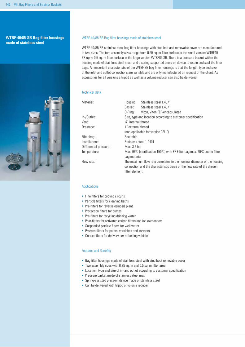
142
WTBF-40/85-SB Bag filter housings made of stainless steel
WTBF-40/85-SB stainless steel bag filter housings with stud bolt and removable cover are manufactured in two sizes. The two assembly sizes range from 0.25 sq. m filter surface in the small version WTBF40 SB up to 0.5 sq. m filter surface in the large version WTBF85 SB. There is a pressure basket within the housing made of stainless steel mesh and a spring-supported press-on device to retain and seal the filter bags. An important characteristic of the WTBF SB bag filter housings is that the length, type and size of the inlet and outlet connections are variable and are only manufactured on request of the client. As accessories for all versions a tripod as well as a volume reducer can also be delivered.
Technical data
Material: Housing: Stainless steel 1.4571 Basket: Stainless steel 1.4571 O-Ring: Viton, Viton FEP-encapsulatedIn-/Outlet: Size, type and location according to customer specification Vent: ¼“ internal threadDrainage: 1“ external thread (non-applicable for version “SU”)Filter bag: See tableInstallations: Stainless steel 1.4401Differential pressure: Max. 3.5 bar Temperature: Max. 95ºC (sterilisation 150ºC) with PP Filter bag max. 70ºC due to filter bag materialFlow rate: The maximum flow rate correlates to the nominal diameter of the housing connection and the characteristic curve of the flow rate of the chosen filter element.
Applications
Fine filters for cooling circuits Particle filters for cleaning bathsPre-filters for reverse osmosis plantProtection filters for pumpsPre-filters for recycling drinking water Post-filters for activated carbon filters and ion exchangersSuspended particle filters for well water Process filters for paints, varnishes and solvents Coarse filters for delivery per refuelling vehicle
Features and Benefits
Bag filter housings made of stainless steel with stud bodt removable coverTwo assembly sizes with 0.25 sq. m and 0.5 sq. m filter areaLocation, type and size of in- and outlet according to customer specificationPressure basket made of stainless steel meshSpring-assisted press-on device made of stainless steelCan be delivered with tripod or volume reducer
WTBF-40/85-SB Bag filter housings made of stainless steel
VII. Bag Filters and Strainer Baskets
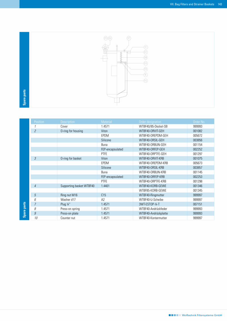
143
Spar
e pa
rts
Spar
e pa
rts
Position Description Material Order designation Order No.1 Cover 1.4571 WTBF40/85-Deckel-SB 9999932 O-ring for housing Viton WTBF40-ORVIT-GEH 001082 EPDM WTBF40-OREPDM-GEH 005672 Silicone WTBF40-ORSIL-GEH 003856 Buna WTBF40-ORBUN-GEH 001154 FEP-encapsulated WTBF40-ORFEP-GEH 002252 PTFE WTBF40-ORPTFE-GEH 0012973 O-ring for basket Viton WTBF40-ORVIT-KRB 001075 EPDM WTBF40-OREPDM-KRB 005673 Silicone WTBF40-ORSIL-KRB 003857 Buna WTBF40-ORBUN-KRB 001145 FEP-encapsulated WTBF40-ORFEP-KRB 002253 PTFE WTBF40-ORPTFE-KRB 0012984 Supporting basket WTBF40 1.4401 WTBF40-KORB-GEWE 001346 WTBF85-KORB-GEWE 0013455 Ring nut M16 C15 WTBF40-Ringmutter 9999976 Washer d17 A2 WTBF40-U-Scheibe 9999977 Plug ¼“″ 1.4571 3WT-ESTOP-¼-T 0071518 Press-on spring 1.4571 WTBF40-Andrückfeder 9999939 Press-on plate 1.4571 WTBF40-Andrückplatte 99999310 Counter nut 1.4571 WTBF40-Kontermutter 999997
VII. Bag Filters and Strainer Baskets
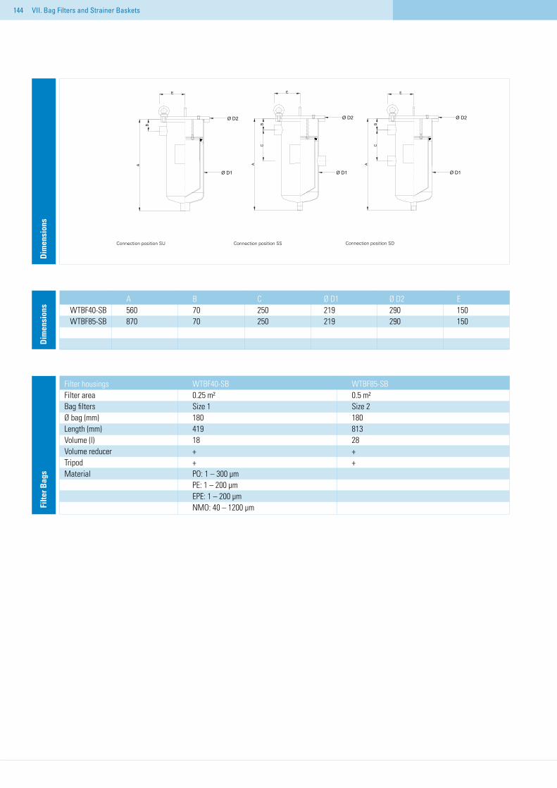
144
Dim
ensi
ons
Dim
ensi
ons
A B C Ø D1 Ø D2 EWTBF40-SB 560 70 250 219 290 150WTBF85-SB 870 70 250 219 290 150
Filter housings WTBF40-SB WTBF85-SB Filter area 0.25 m² 0.5 m² Bag filters Size 1 Size 2 Ø bag (mm) 180 180 Length (mm) 419 813 Volume (l) 18 28 Volume reducer + + Tripod + + Material PO: 1 – 300 µm PE: 1 – 200 µm EPE: 1 – 200 µm NMO: 40 – 1200 µm
VII. Bag Filters and Strainer Baskets
Filte
r Bag
s
Connection position SU Connection position SS Connection position SD
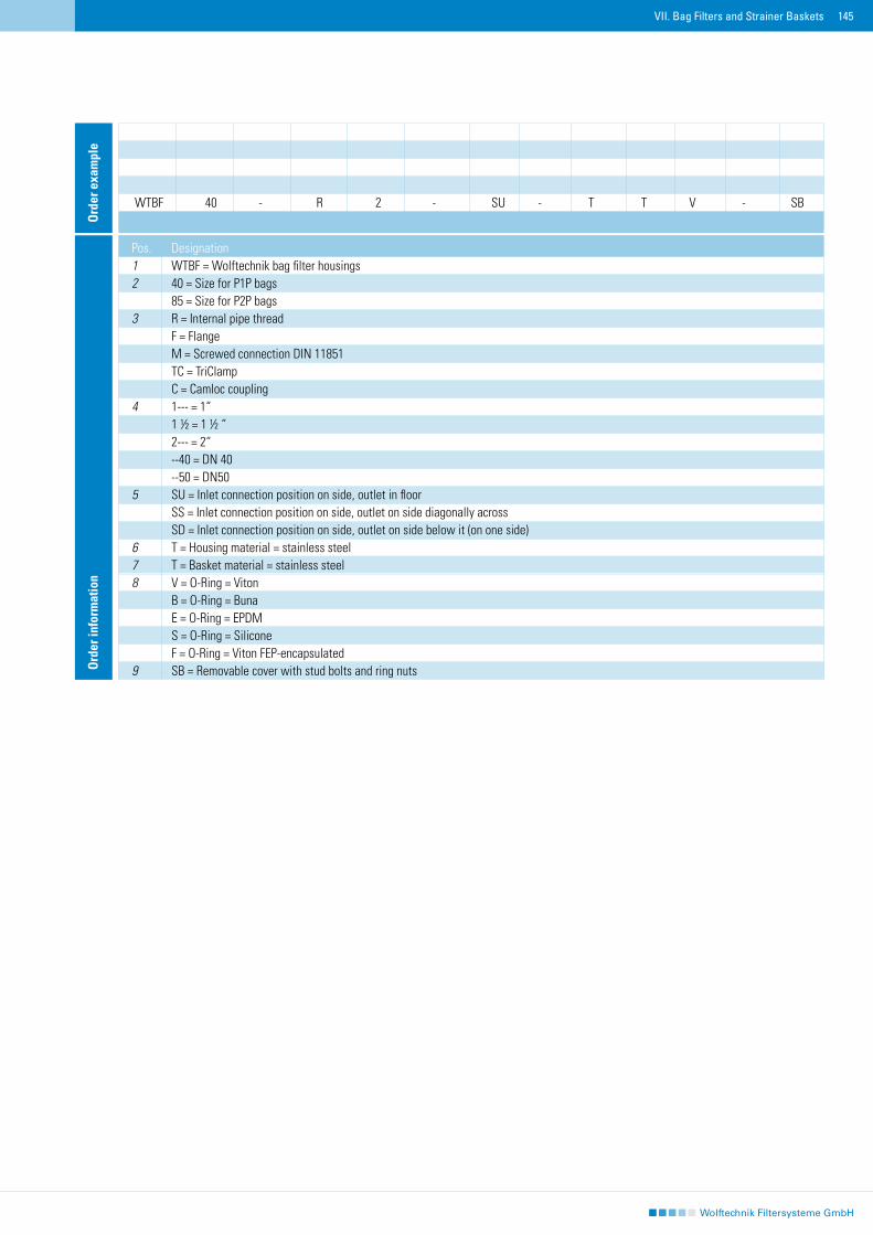
145
Ord
er e
xam
ple
WTBF 40 - R 2 - SU - T T V - SB
Ord
er in
form
atio
n
Pos. Designation 1 WTBF = Wolftechnik bag filter housings 2 40 = Size for P1P bags 85 = Size for P2P bags 3 R = Internal pipe thread F = Flange M = Screwed connection DIN 11851 TC = TriClamp C = Camloc coupling 4 1--- = 1“ 1 ½ = 1 ½ “ 2--- = 2“ --40 = DN 40 --50 = DN50x 5 SU = Inlet connection position on side, outlet in floor SS = Inlet connection position on side, outlet on side diagonally across SD = Inlet connection position on side, outlet on side below it (on one side) 6 T = Housing material = stainless steel 7 T = Basket material = stainless steel 8 V = O-Ring = Viton B = O-Ring = Buna E = O-Ring = EPDM S = O-Ring = Silicone F = O-Ring = Viton FEP-encapsulated 9 SB = Removable cover with stud bolts and ring nuts
VII. Bag Filters and Strainer Baskets
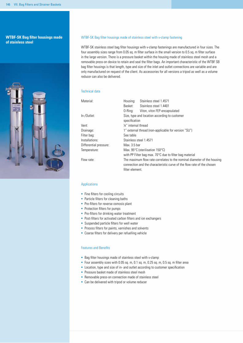
146 VII. Bag Filters and Strainer Baskets
WTBF-SK Bag filter housings made of stainless steel
WTBF-SK Bag filter housings made of stainless steel with v-clamp fastening
WTBF-SK stainless steel bag filter housings with v-clamp fastenings are manufactured in four sizes. The four assembly sizes range from 0.05 sq. m filter surface in the small version to 0.5 sq. m filter surface in the large version. There is a pressure basket within the housing made of stainless steel mesh and a removable press-on device to retain and seal the filter bags. An important characteristic of the WTBF SB bag filter housings is that length, type and size of the inlet and outlet connections are variable and are only manufactured on request of the client. As accessories for all versions a tripod as well as a volume reducer can also be delivered.
Technical data
Material: Housing: Stainless steel 1.4571 Basket: Stainless steel 1.4401 O-Ring: Viton, viton FEP-encapsulatedIn-/Outlet: Size, type and location according to customer specification Vent: ¼“ internal threadDrainage: 1“ external thread (non-applicable for version “SU”)Filter bag: See tableInstallations: Stainless steel 1.4571Differential pressure: Max. 3.5 bar Temperature: Max. 95°C (sterilisation 150°C) with PP Filter bag max. 70°C due to filter bag materialFlow rate: The maximum flow rate correlates to the nominal diameter of the housing connection and the characteristic curve of the flow rate of the chosen filter element.
Applications
Fine filters for cooling circuits Particle filters for cleaning bathsPre-filters for reverse osmosis plantProtection filters for pumpsPre-filters for drinking water treatmentPost-filters for activated carbon filters and ion exchangersSuspended particle filters for well water Process filters for paints, varnishes and solvents Coarse filters for delivery per refuelling vehicle
Features and Benefits
Bag filter housings made of stainless steel with v-clampFour assembly sizes with 0.05 sq. m, 0.1 sq. m, 0.25 sq. m, 0.5 sq. m filter areaLocation, type and size of in- and outlet according to customer specificationPressure basket made of stainless steel meshRemovable press-on connection made of stainless steelCan be delivered with tripod or volume reducer
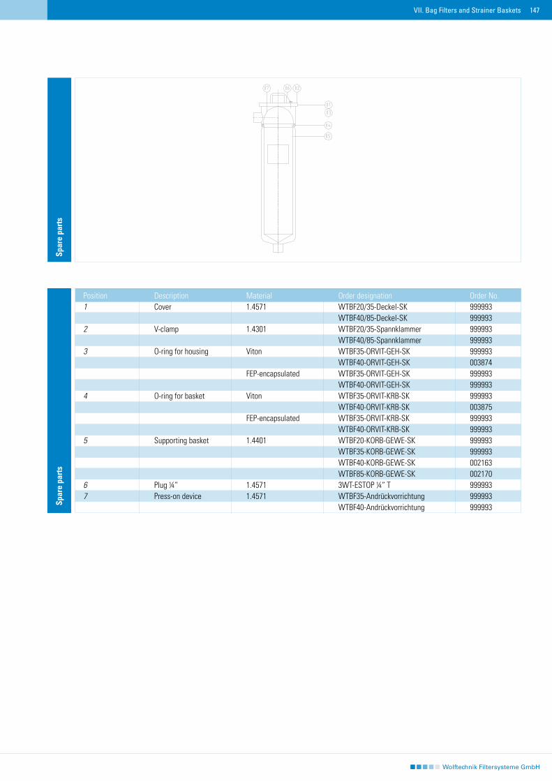
147VII. Bag Filters and Strainer Baskets
Spar
e pa
rts
Position Description Material Order designation Order No.1 Cover 1.4571 WTBF20/35-Deckel-SK 999993 WTBF40/85-Deckel-SK 9999932 V-clamp 1.4301 WTBF20/35-Spannklammer 999993 WTBF40/85-Spannklammer 9999933 O-ring for housing Viton WTBF35-ORVIT-GEH-SK 999993 WTBF40-ORVIT-GEH-SK 003874 FEP-encapsulated WTBF35-ORVIT-GEH-SK 999993 WTBF40-ORVIT-GEH-SK 9999934 O-ring for basket Viton WTBF35-ORVIT-KRB-SK 999993 WTBF40-ORVIT-KRB-SK 003875 FEP-encapsulated WTBF35-ORVIT-KRB-SK 999993 WTBF40-ORVIT-KRB-SK 9999935 Supporting basket 1.4401 WTBF20-KORB-GEWE-SK 999993 WTBF35-KORB-GEWE-SK 999993 WTBF40-KORB-GEWE-SK 002163 WTBF85-KORB-GEWE-SK 0021706 Plug ¼“ 1.4571 3WT-ESTOP ¼“ T 9999937 Press-on device 1.4571 WTBF35-Andrückvorrichtung 999993 WTBF40-Andrückvorrichtung 999993
Spar
e pa
rts
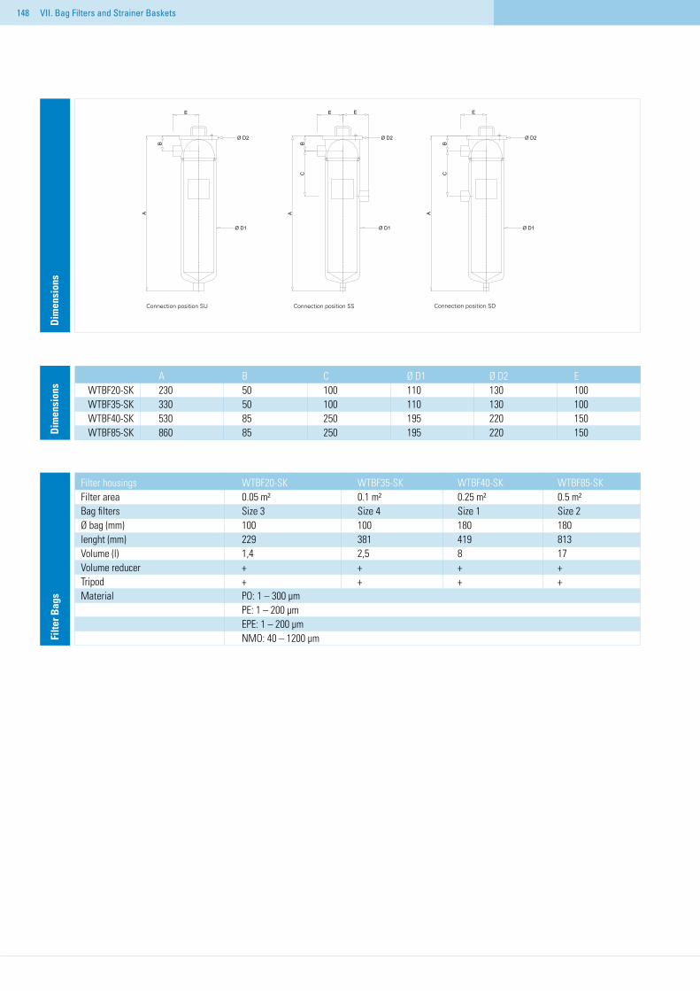
148 VII. Bag Filters and Strainer Baskets
Dim
ensi
ons
Dim
ensi
ons
A B C Ø D1 Ø D2 EWTBF20-SK 230 50 100 110 130 100WTBF35-SK 330 50 100 110 130 100WTBF40-SK 530 85 250 195 220 150WTBF85-SK 860 85 250 195 220 150
Filte
r Bag
s
Filter housings WTBF20-SK WTBF35-SK WTBF40-SK WTBF85-SK Filter area 0.05 m² 0.1 m² 0.25 m² 0.5 m² Bag filters Size 3 Size 4 Size 1 Size 2 Ø bag (mm) 100 100 180 180 lenght (mm) 229 381 419 813 Volume (l) 1,4 2,5 8 17 Volume reducer + + + + Tripod + + + + Material PO: 1 – 300 µm PE: 1 – 200 µm EPE: 1 – 200 µm NMO: 40 – 1200 µm
Connection position SU Connection position SS Connection position SD
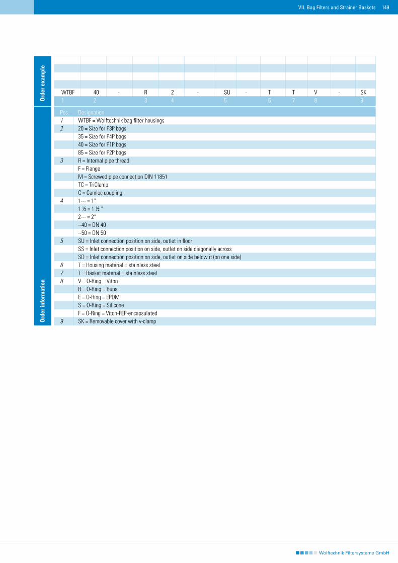
149VII. Bag Filters and Strainer Baskets
Ord
er e
xam
ple
WTBF 40 - R 2 - SU - T T V - SK1 2 3 4 5 6 7 8 9
Ord
er in
form
atio
n
Pos. Designation 1 WTBF = Wolftechnik bag filter housings 2 20 = Size for P3P bags 35 = Size for P4P bags 40 = Size for P1P bags 85 = Size for P2P bags 3 R = Internal pipe thread F = Flange M = Screwed pipe connection DIN 11851 TC = TriClamp C = Camloc coupling 4 1--- = 1“ 1 ½ = 1 ½ “ 2--- = 2“ --40 = DN 40 --50 = DN 50 5 SU = Inlet connection position on side, outlet in floor SS = Inlet connection position on side, outlet on side diagonally across SD = Inlet connection position on side, outlet on side below it (on one side) 6 T = Housing material = stainless steel 7 T = Basket material = stainless steel 8 V = O-Ring = Viton B = O-Ring = Buna E = O-Ring = EPDM S = O-Ring = Silicone F = O-Ring = Viton-FEP-encapsulated 9 SK = Removable cover with v-clamp
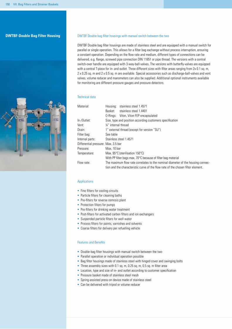
150 VII. Bag Filters and Strainer Baskets
DWTBF Double bag filter housings with manual switch between the two
DWTBF Double bag filter housings are made of stainless steel and are equipped with a manual switch for parallel or single operation. This allows for a filter bag exchange without process interruption, ensuring a constant operation. Depending on the flow rate and medium, different types of connections can be delivered, e.g. flange, screwed pipe connection DIN 11851 or pipe thread. The versions with a central switch-over handle are equipped with 3-way-ball-valves. The versions with butterfly-valves are equipped with a central T-piece for in- and outlet. Three different sizes with filter areas ranging from 2x 0.1 sq. m, 2 x 0.25 sq. m and 2 x 0.5 sq. m are available. Special accessories such as discharge-ball-valves and vent valves, volume reducer and manometers can also be supplied. Additional optional instruments available for monitoring are different pressure gauges and pressure detectors.
Technical data
Material: Housing: stainless steel 1.4571 Basket: stainless steel 1.4401 O-Rings: Viton, Viton FEP-encapsulatedIn-/Outlet: Size, type and position according customers specificationVent: ¼“ internal threadDrain: 1“ external thread (except for version “SU”)Filter bag: See tableInternal parts: Stainless steel 1.4571Differential pressure: Max. 3.5 barPressure: Max. 10 barTemperature: Max. 95°C (sterilisation 150°C) With PP filter bags max. 70°C because of filter bag materialFlow rate: The maximum flow rate correlates to the nominal diameter of the housing connec- tion and the characteristic curve of the flow rate of the chosen filter element.
Applications
Fine filters for cooling circuits Particle filters for cleaning bathsPre-filters for reverse osmosis plantProtection filters for pumpsPre-filters for drinking water treatmentPost-filters for activated carbon filters and ion exchangersSuspended particle filters for well water Process filters for paints, varnishes and solvents Coarse filters for delivery per refuelling vehicle
Features and Benefits
Double-bag filter housings with manual switch between the twoParallel operation or individual operation possible Bag filter housings made of stainless steel with hinged cover and swinging boltsThree assembly sizes with 0.1 sq. m, 0.25 sq. m, 0.5 sq. m filter areaLocation, type and size of in- and outlet according to customer specificationPressure basket made of stainless steel meshSpring-assisted press-on device made of stainless steelCan be delivered with tripod or volume reducer
DWTBF-Double Bag Filter Housing
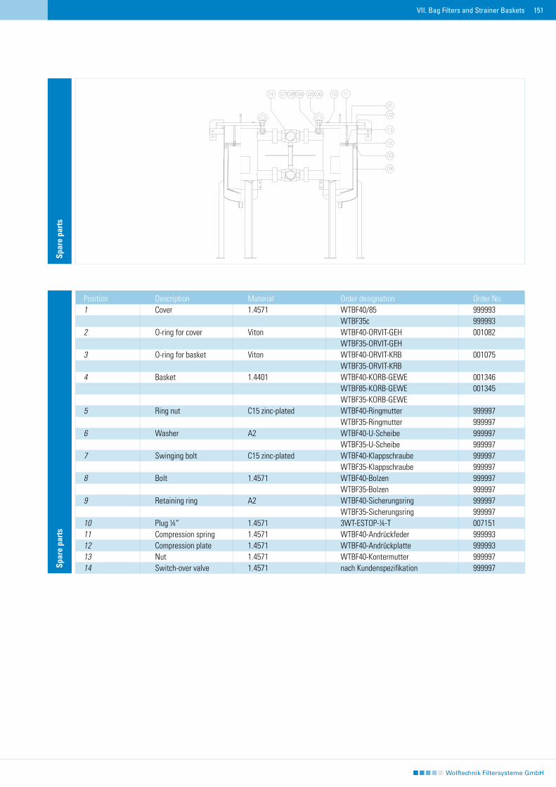
151VII. Bag Filters and Strainer Baskets
Spar
e pa
rts
Spar
e pa
rts
Position Description Material Order designation Order No.1 Cover 1.4571 WTBF40/85 999993 WTBF35c 9999932 O-ring for cover Viton WTBF40-ORVIT-GEH 001082 WTBF35-ORVIT-GEH 3 O-ring for basket Viton WTBF40-ORVIT-KRB 001075 WTBF35-ORVIT-KRB 4 Basket 1.4401 WTBF40-KORB-GEWE 001346 WTBF85-KORB-GEWE 001345 WTBF35-KORB-GEWE 5 Ring nut C15 zinc-plated WTBF40-Ringmutter 999997 WTBF35-Ringmutter 9999976 Washer A2 WTBF40-U-Scheibe 999997 WTBF35-U-Scheibe 9999977 Swinging bolt C15 zinc-plated WTBF40-Klappschraube 999997 WTBF35-Klappschraube 9999978 Bolt 1.4571 WTBF40-Bolzen 999997 WTBF35-Bolzen 9999979 Retaining ring A2 WTBF40-Sicherungsring 999997 WTBF35-Sicherungsring 99999710 Plug ¼“ 1.4571 3WT-ESTOP-¼-T 00715111 Compression spring 1.4571 WTBF40-Andrückfeder 99999312 Compression plate 1.4571 WTBF40-Andrückplatte 99999313 Nut 1.4571 WTBF40-Kontermutter 99999714 Switch-over valve 1.4571 nach Kundenspezifikation 999997
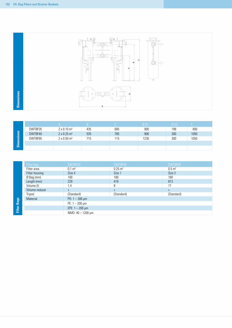
152 VII. Bag Filters and Strainer Baskets
Dim
ensi
ons
A B C Ø D1 Ø D2 EDWTBF35 2 x 0.10 m² 435 685 900 198 800 DWTBF40 2 x 0.25 m² 535 785 900 300 1050DWTBF85 2 x 0.50 m² 715 115 1230 300 1050
Filte
r Bag
s
Filter bag DWTBF35 DWTBF40 DWTBF85 Filter area 0.1 m² 0.25 m² 0.5 m² Filter housing Size 4 Size 1 Size 2 Ø Bag (mm) 100 180 180 Length (mm) 229 419 813 Volume (l) 1,4 8 17 Volume reducer + + + Tripod (Standard) (Standard) (Standard) Material PO: 1 – 300 µm PE: 1 – 200 µm EPE: 1 – 200 µm NMO: 40 – 1200 µm
Dim
ensi
ons
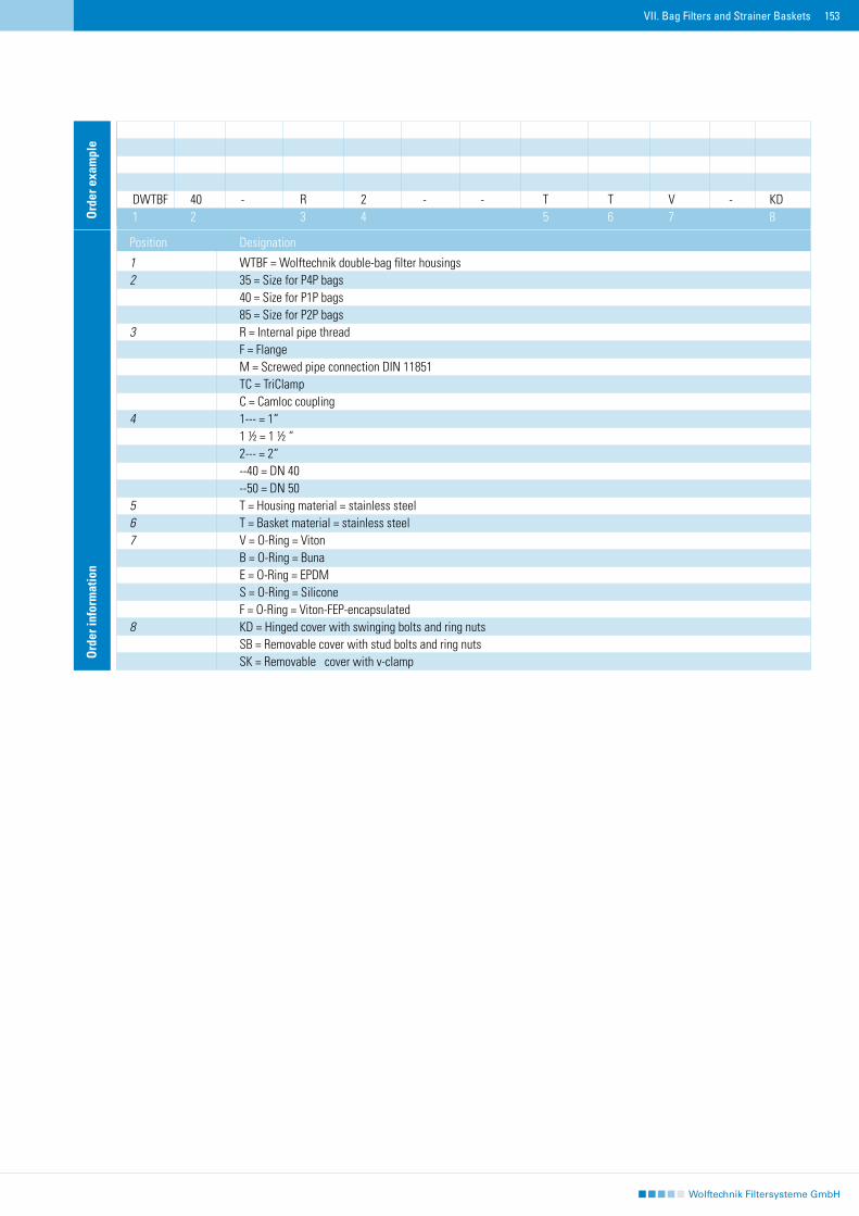
153VII. Bag Filters and Strainer Baskets
Ord
er e
xam
ple
DWTBF 40 - R 2 - - T T V - KD1 2 3 4 5 6 7 8
Ord
er in
form
atio
n
Position Designation
1 WTBF = Wolftechnik double-bag filter housings 2 35 = Size for P4P bags 40 = Size for P1P bags 85 = Size for P2P bags 3 R = Internal pipe thread F = Flange M = Screwed pipe connection DIN 11851 TC = TriClamp C = Camloc coupling 4 1--- = 1“ 1 ½ = 1 ½ “ 2--- = 2“ --40 = DN 40 --50 = DN 50 5 T = Housing material = stainless steel 6 T = Basket material = stainless steel 7 V = O-Ring = Viton B = O-Ring = Buna E = O-Ring = EPDM S = O-Ring = Silicone F = O-Ring = Viton-FEP-encapsulated 8 KD = Hinged cover with swinging bolts and ring nuts SB = Removable cover with stud bolts and ring nuts SK = Removable cover with v-clamp
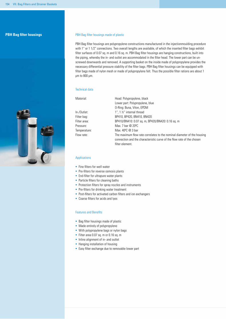
154 VII. Bag Filters and Strainer Baskets
PBH Bag filter housings made of plastic
PBH Bag filter housings are polypropylene constructions manufactured in the injectionmoulding procedure with 1“ or 1 1/2“ connections. Two overall lengths are available, of which the inserted filter bags exhibit filter surfaces of 0.07 sq. m and 0.16 sq. m. PBH Bag filter housings are hanging constructions, built into the piping, whereby the in- and outlet are accommodated in the filter head. The lower part can be un-screwed downwards and removed. A supporting basket on the inside made of polypropylene provides the necessary differential pressure stability of the filter bags. PBH Bag filter housings can be equipped with filter bags made of nylon mesh or made of polypropylene felt. Thus the possible filter rations are about 1 µm to 800 µm.
Technical data
Material: Head: Polypropylene, black Lower part: Polypropylene, blue O-Ring: Buna, Viton, EPDMIn-/Outlet: 1“, 1 ½“ internal thread Filter bag: BP410, BP420, BN410, BN420Filter area: BP410/BN410: 0.07 sq. m, BP420/BN420: 0.16 sq. mPressure: Max. 7 bar @ 20ºC Temperature: Max. 40ºC @ 3 barFlow rate: The maximum flow rate correlates to the nominal diameter of the housing connection and the characteristic curve of the flow rate of the chosen filter element.
Applications
Fine filters for well water Pre-filters for reverse osmosis plantsEnd-filter for ultrapure water plantsParticle filters for cleaning bathsProtection filters for spray nozzles and instrumentsPre-filters for drinking water treatmentPost-filters for activated carbon filters and ion exchangersCoarse filters for acids and lyes
Features and Benefits
Bag filter housings made of plasticMade entirely of polypropyleneWith polypropylene bags or nylon bagsFilter area 0.07 sq. m or 0.16 sq. mInline alignment of in- and outletHanging installation of housingEasy filter exchange due to removable lower part
PBH Bag filter housings
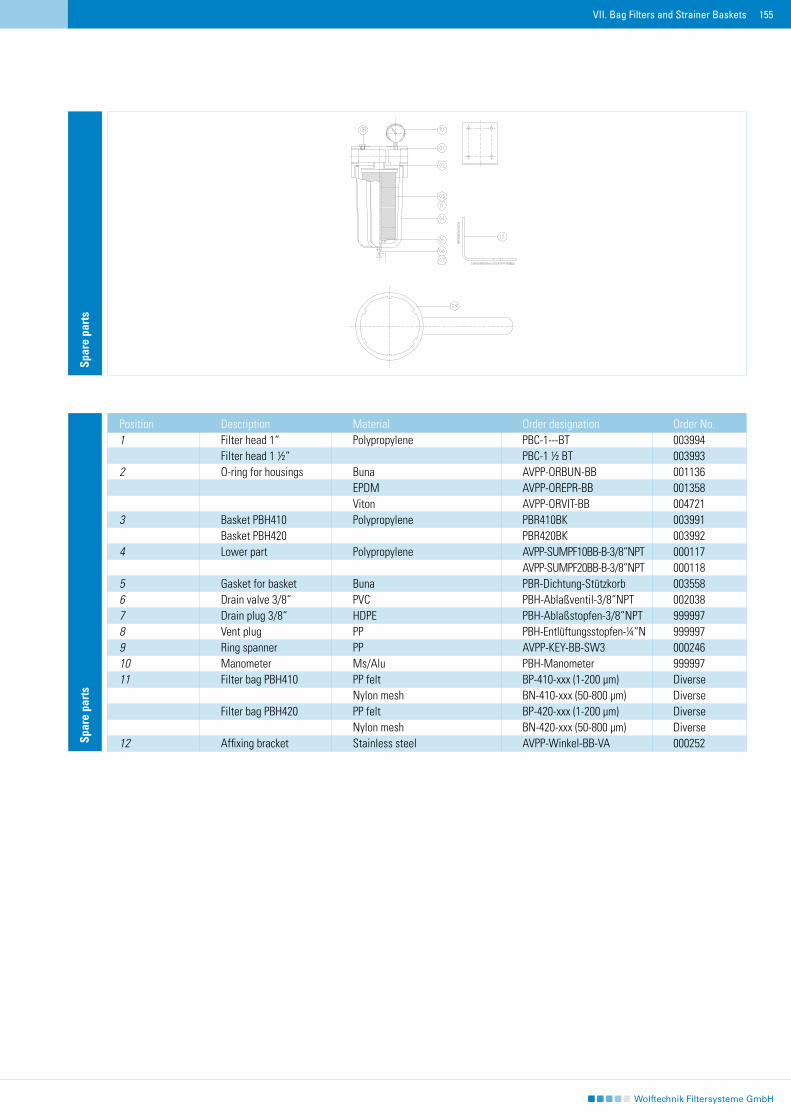
155VII. Bag Filters and Strainer Baskets
Spar
e pa
rts
Position Description Material Order designation Order No.1 Filter head 1“ Polypropylene PBC-1---BT 003994 Filter head 1 ½“ PBC-1 ½ BT 0039932 O-ring for housings Buna AVPP-ORBUN-BB 001136 EPDM AVPP-OREPR-BB 001358 Viton AVPP-ORVIT-BB 0047213 Basket PBH410 Polypropylene PBR410BK 003991 Basket PBH420 PBR420BK 0039924 Lower part Polypropylene AVPP-SUMPF10BB-B-3/8“NPT 000117 AVPP-SUMPF20BB-B-3/8“NPT 0001185 Gasket for basket Buna PBR-Dichtung-Stützkorb 0035586 Drain valve 3/8“ PVC PBH-Ablaßventil-3/8“NPT 0020387 Drain plug 3/8“ HDPE PBH-Ablaßstopfen-3/8“NPT 9999978 Vent plug PP PBH-Entlüftungsstopfen-¼“N 9999979 Ring spanner PP AVPP-KEY-BB-SW3 00024610 Manometer Ms/Alu PBH-Manometer 99999711 Filter bag PBH410 PP felt BP-410-xxx (1-200 µm) Diverse Nylon mesh BN-410-xxx (50-800 µm) Diverse Filter bag PBH420 PP felt BP-420-xxx (1-200 µm) Diverse Nylon mesh BN-420-xxx (50-800 µm) Diverse12 Affixing bracket Stainless steel AVPP-Winkel-BB-VA 000252
Spar
e pa
rts
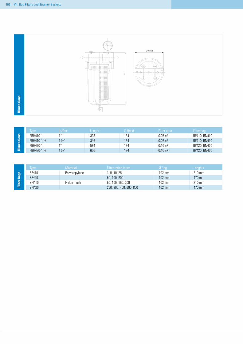
156 VII. Bag Filters and Strainer Baskets
Type In/Out Lenght Ø Head Filter area Filter bagPBH410-1 1“ 333 184 0.07 m² BP410, BN410PBH410-1 ½ 1 ½“ 346 184 0.07 m² BP410, BN410PBH420-1 1“ 594 184 0.16 m² BP420, BN420PBH420-1 ½ 1 ½“ 606 184 0.16 m² BP420, BN420D
imen
sion
s
Type Material Filter ration in µm Ø Bag LenghtsBP410 Polypropylene 1, 5, 10, 25, 102 mm 210 mmBP420 50, 100, 200 102 mm 470 mmBN410 Nylon mesh 50, 100, 150, 200 102 mm 210 mmBN420 250, 300, 400, 600, 800 102 mm 470 mmFi
lter b
ags
Dim
ensi
ons
Ø Head
L
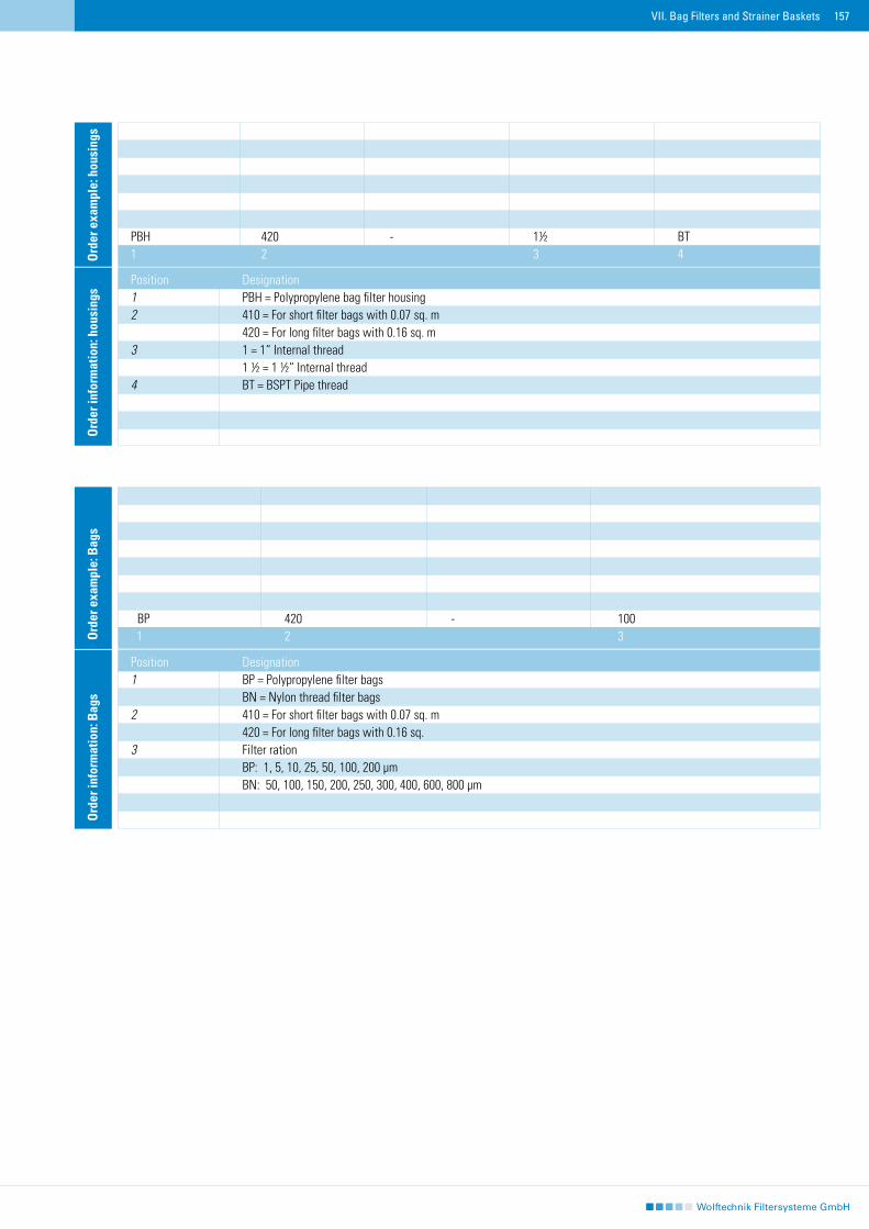
157VII. Bag Filters and Strainer Baskets
Ord
er in
form
atio
n: h
ousi
ngs
Position Designation1 PBH = Polypropylene bag filter housing 2 410 = For short filter bags with 0.07 sq. m 420 = For long filter bags with 0.16 sq. m3 1 = 1“ Internal thread 1 ½ = 1 ½“ Internal thread4 BT = BSPT Pipe thread
PBH 420 - 1½ BT1 2 3 4O
rder
exa
mpl
e: h
ousi
ngs
Ord
er in
form
atio
n: B
ags
Position Designation1 BP = Polypropylene filter bags BN = Nylon thread filter bags2 410 = For short filter bags with 0.07 sq. m 420 = For long filter bags with 0.16 sq. 3 Filter ration BP: 1, 5, 10, 25, 50, 100, 200 µm BN: 50, 100, 150, 200, 250, 300, 400, 600, 800 µm
BBP 420 - 100. 1 2 3O
rder
exa
mpl
e: B
ags
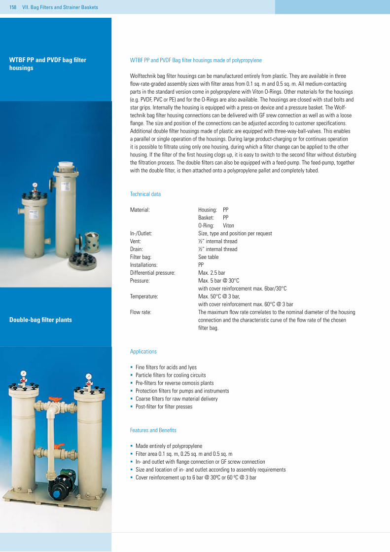
158
WTBF PP and PVDF Bag filter housings made of polypropylene
Wolftechnik bag filter housings can be manufactured entirely from plastic. They are available in three flow-rate-graded assembly sizes with filter areas from 0.1 sq. m and 0.5 sq. m. All medium-contacting parts in the standard version come in polypropylene with Viton O-Rings. Other materials for the housings (e.g. PVDF, PVC or PE) and for the O-Rings are also available. The housings are closed with stud bolts and star grips. Internally the housing is equipped with a press-on device and a pressure basket. The Wolf-technik bag filter housing connections can be delivered with GF srew connection as well as with a loose flange. The size and position of the connections can be adjusted according to customer specifications. Additional double filter housings made of plastic are equipped with three-way-ball-valves. This enables a parallel or single operation of the housings. During large product-charging or for continues operation it is possible to filtrate using only one housing, during which a filter change can be applied to the other housing. If the filter of the first housing clogs up, it is easy to switch to the second filter without disturbing the filtration process. The double filters can also be equipped with a feed-pump. The feed-pump, together with the double filter, is then attached onto a polypropylene pallet and completely tubed.
Technical data
Material: Housing: PP Basket: PP O-Ring: VitonIn-/Outlet: Size, type and position per request Vent: ½“″internal threadDrain: ½“ internal thread Filter bag: See tableInstallations: PPDifferential pressure: Max. 2.5 barPressure: Max. 5 bar @ 30°C with cover reinforcement max. 6bar/30°C Temperature: Max. 50°C @ 3 bar, with cover reinforcement max. 60°C @ 3 barFlow rate: The maximum flow rate correlates to the nominal diameter of the housing connection and the characteristic curve of the flow rate of the chosen filter bag.
Applications
Fine filters for acids and lyes Particle filters for cooling circuits Pre-filters for reverse osmosis plantsProtection filters for pumps and instrumentsCoarse filters for raw material deliveryPost-filter for filter presses
Features and Benefits
Made entirely of polypropyleneFilter area 0.1 sq. m, 0.25 sq. m and 0.5 sq. mIn- and outlet with flange connection or GF screw connectionSize and location of in- and outlet according to assembly requirements Cover reinforcement up to 6 bar @ 30ºC or 60 ºC @ 3 bar
WTBF PP and PVDF bag filter housings
VII. Bag Filters and Strainer Baskets
Double-bag filter plants
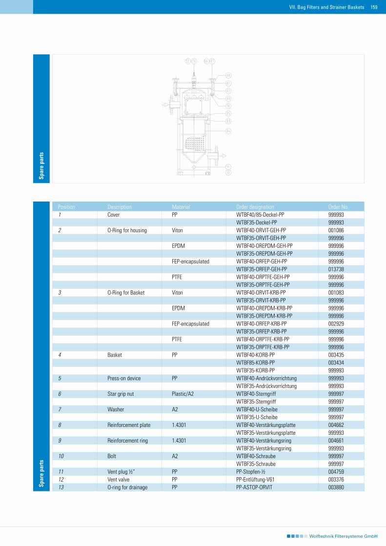
159
Spar
e pa
rts
Position Description Material Order designation Order No.1 Cover PP WTBF40/85-Deckel-PP 999993 WTBF35-Deckel-PP 9999932 O-Ring for housing Viton WTBF40-ORVIT-GEH-PP 001086 WTBF35-ORVIT-GEH-PP 999996 EPDM WTBF40-OREPDM-GEH-PP 999996 WTBF35-OREPDM-GEH-PP 999996 FEP-encapsulated WTBF40-ORFEP-GEH-PP 999996 WTBF35-ORFEP-GEH-PP 013738 PTFE WTBF40-ORPTFE-GEH-PP 999996 WTBF35-ORPTFE-GEH-PP 9999963 O-Ring for Basket Viton WTBF40-ORVIT-KRB-PP 001083 WTBF35-ORVIT-KRB-PP 999996 EPDM WTBF40-OREPDM-KRB-PP 999996 WTBF35-OREPDM-KRB-PP 999996 FEP-encapsulated WTBF40-ORFEP-KRB-PP 002929 WTBF35-ORFEP-KRB-PP 999996 PTFE WTBF40-ORPTFE-KRB-PP 999996 WTBF35-ORPTFE-KRB-PP 9999964 Basket PP WTBF40-KORB-PP 003435 WTBF85-KORB-PP 003434 WTBF35-KORB-PP 9999935 Press-on device PP WTBF40-Andrückvorrichtung 999993 WTBF35-Andrückvorrichtung 9999936 Star grip nut Plastic/A2 WTBF40-Sterngriff 999997 WTBF35-Sterngriff 9999977 Washer A2 WTBF40-U-Scheibe 999997 WTBF35-U-Scheibe 9999978 Reinforcement plate 1.4301 WTBF40-Verstärkungsplatte 004662 WTBF35-Verstärkungsplatte 9999939 Reinforcement ring 1.4301 WTBF40-Verstärkungsring 004661 WTBF35-Verstärkungsring 99999310 Bolt A2 WTBF40-Schraube 999997 WTBF35-Schraube 99999711 Vent plug ½“ PP PP-Stopfen-½ 00475912 Vent valve PP PP-Entlüftung-V61 00337613 O-ring for drainage PP PP-ASTOP-ORVIT 003880
Spar
e pa
rts
VII. Bag Filters and Strainer Baskets
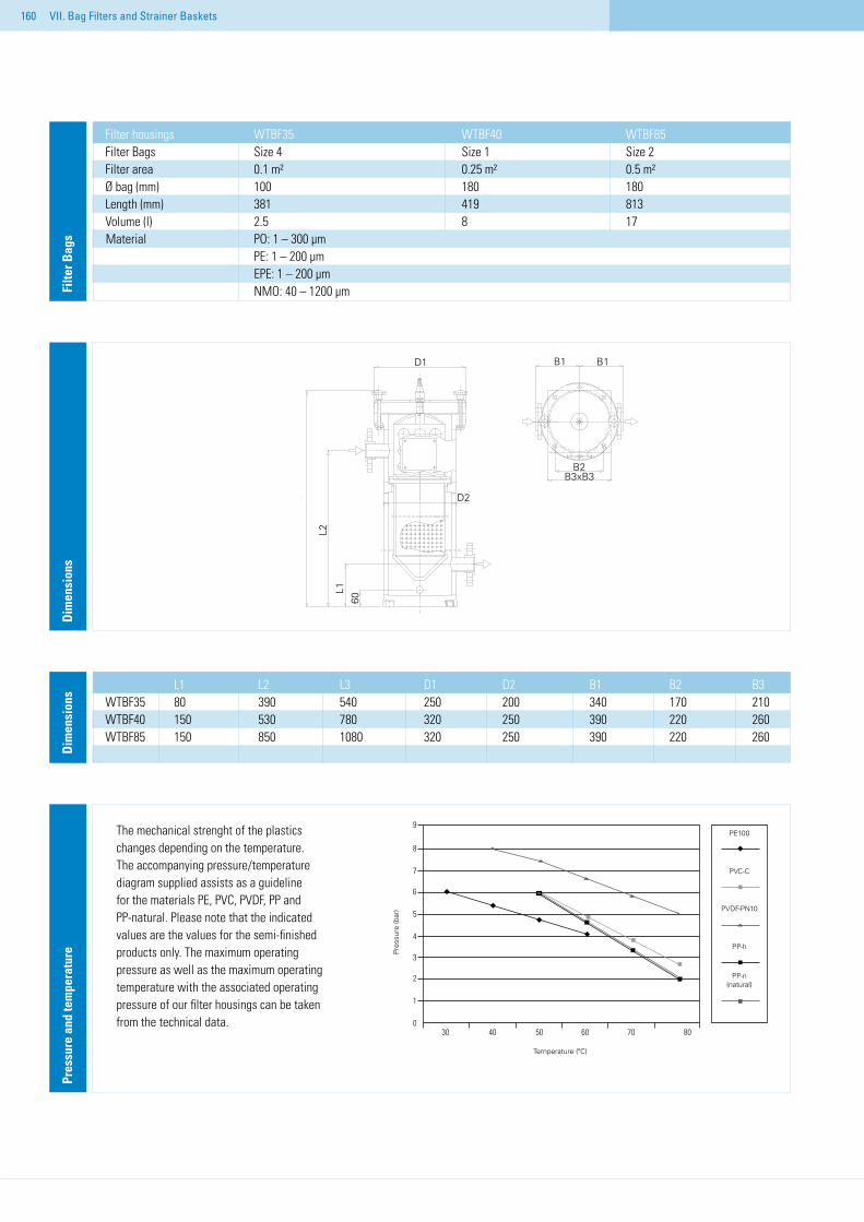
160
Dim
ensi
ons
L1 L2 L3 D1 D2 B1 B2 B3WTBF35 80 390 540 250 200 340 170 210WTBF40 150 530 780 320 250 390 220 260WTBF85 150 850 1080 320 250 390 220 260.D
imen
sion
s
Filter housings WTBF35 WTBF40 WTBF85Filter Bags Size 4 Size 1 Size 2Filter area 0.1 m² 0.25 m² 0.5 m²Ø bag (mm) 100 180 180Length (mm) 381 419 813Volume (l) 2.5 8 17
Material PO: 1 – 300 µm PE: 1 – 200 µm EPE: 1 – 200 µm NMO: 40 – 1200 µmFi
lter B
ags
Pres
sure
and
tem
pera
ture
The mechanical strenght of the plastics changes depending on the temperature. The accompanying pressure/temperature diagram supplied assists as a guideline for the materials PE, PVC, PVDF, PP and PP-natural. Please note that the indicated values are the values for the semi-finished products only. The maximum operating pressure as well as the maximum operating temperature with the associated operating pressure of our filter housings can be taken from the technical data.
VII. Bag Filters and Strainer Baskets
30 40 50 60 70 80
Temperatur (°C)
9
8
7
6
5
4
3
2
1
0
Druc
k (b
ar)
PE100
PVC-C
PVDF-PN10
PP-H
PP-n (natur)
Temperature (ºC)
Pres
sure
(bar
)
PP-n (natural)
PP-h
PVDF-PN10
PVC-C
PE100
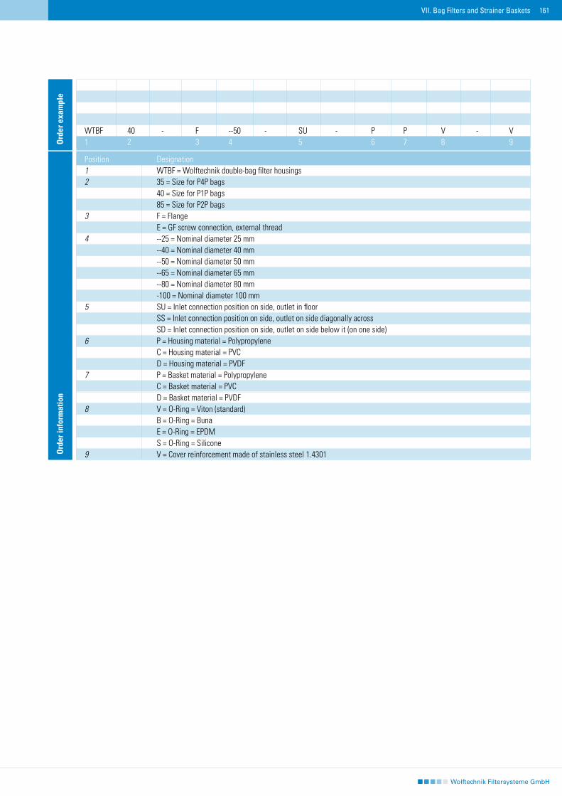
161
Ord
er in
form
atio
n
Position Designation1 WTBF = Wolftechnik double-bag filter housings 2 35 = Size for P4P bags 40 = Size for P1P bags 85 = Size for P2P bags3 F = Flange E = GF screw connection, external thread4 --25 = Nominal diameter 25 mm --40 = Nominal diameter 40 mm --50 = Nominal diameter 50 mm --65 = Nominal diameter 65 mm --80 = Nominal diameter 80 mm -100 = Nominal diameter 100 mm5 SU = Inlet connection position on side, outlet in floor SS = Inlet connection position on side, outlet on side diagonally across SD = Inlet connection position on side, outlet on side below it (on one side)6 P = Housing material = Polypropylene C = Housing material = PVC D = Housing material = PVDF7 P = Basket material = Polypropylene C = Basket material = PVC D = Basket material = PVDF8 V = O-Ring = Viton (standard) B = O-Ring = Buna E = O-Ring = EPDM S = O-Ring = Silicone 9 V = Cover reinforcement made of stainless steel 1.4301
WTBF 40 - F --50 - SU - P P V - V1 2 3 4 5 6 7 8 9O
rder
exa
mpl
e
VII. Bag Filters and Strainer Baskets
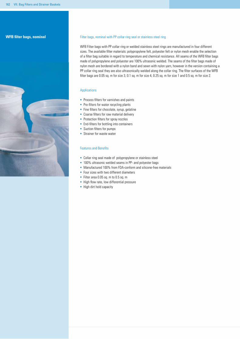
162 VII. Bag Filters and Strainer Baskets
Filter bags, nominal with PP collar ring seal or stainless steel ring
WFB Filter bags with PP collar ring or welded stainless steel rings are manufactured in four different sizes. The available filter materials: polypropylene felt, polyester felt or nylon mesh enable the selection of a filter bag suitable in regard to temperature and chemical resistance. All seams of the WFB filter bags made of polypropylene and polyester are 100% ultrasonic welded. The seams of the filter bags made of nylon mesh are bordered with a nylon band and sewn with nylon yarn, however in the version containing a PP collar ring seal they are also ultrasonically welded along the collar ring. The filter surfaces of the WFB filter bags are 0.05 sq. m for size 3, 0.1 sq. m for size 4, 0.25 sq. m for size 1 and 0.5 sq. m for size 2.
Applications
Process filters for varnishes and paintsPre-filters for water recycling plantsFine filters for chocolate, syrup, gelatineCoarse filters for raw material deliveryProtection filters for spray nozzlesEnd-filters for bottling into containersSuction filters for pumpsStrainer for waste water
Features and Benefits
Collar ring seal made of polypropylene or stainless steel100% ultrasonic welded seams in PP- and polyester bagsManufactured 100% from FDA-conform and silicone-free materialsFour sizes with two different diametersFilter area 0.05 sq. m to 0.5 sq. mHigh flow rate, low differential pressureHigh dirt hold capacity
WFB filter bags, nominal
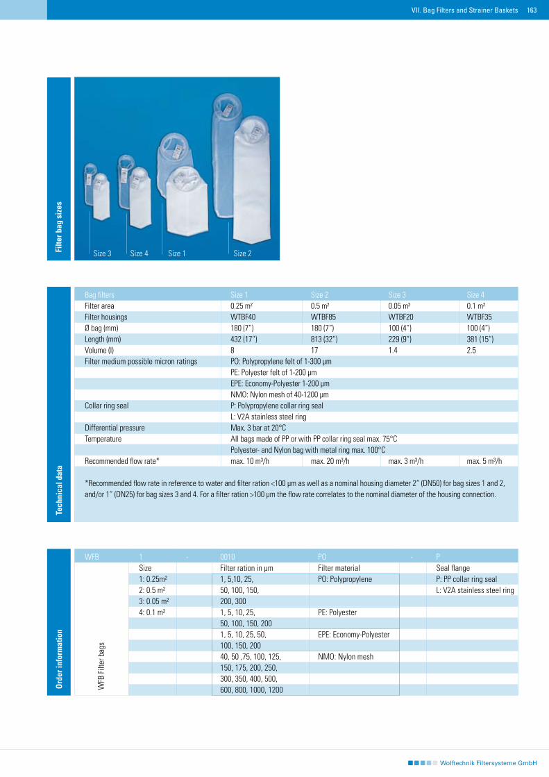
163VII. Bag Filters and Strainer Baskets
Tech
nica
l dat
a
Bag filters Size 1 Size 2 Size 3 Size 4Filter area 0.25 m² 0.5 m² 0.05 m² 0.1 m²Filter housings WTBF40 WTBF85 WTBF20 WTBF35Ø bag (mm) 180 (7“) 180 (7“) 100 (4“) 100 (4“) Length (mm) 432 (17“) 813 (32“) 229 (9“) 381 (15“)Volume (l) 8 17 1.4 2.5Filter medium possible micron ratings PO: Polypropylene felt of 1-300 µm PE: Polyester felt of 1-200 µm EPE: Economy-Polyester 1-200 µm NMO: Nylon mesh of 40-1200 µmCollar ring seal P: Polypropylene collar ring seal L: V2A stainless steel ringDifferential pressure Max. 3 bar at 20°CTemperature All bags made of PP or with PP collar ring seal max. 75°C Polyester- and Nylon bag with metal ring max. 100°CRecommended flow rate* max. 10 m³/h max. 20 m³/h max. 3 m³/h max. 5 m³/h
*Recommended flow rate in reference to water and filter ration <100 µm as well as a nominal housing diameter 2“ (DN50) for bag sizes 1 and 2, and/or 1“ (DN25) for bag sizes 3 and 4. For a filter ration >100 µm the flow rate correlates to the nominal diameter of the housing connection.
Filte
r bag
siz
es
Size 3 Size 4 Size 1 Size 2
Ord
er in
form
atio
n
1 - 0010 PO - PSize Filter ration in µm Filter material Seal flange1: 0.25m² 1, 5,10, 25, PO: Polypropylene P: PP collar ring seal2: 0.5 m² 50, 100, 150, L: V2A stainless steel ring3: 0.05 m² 200, 300 4: 0.1 m² 1, 5, 10, 25, PE: Polyester 50, 100, 150, 200 1, 5, 10, 25, 50, EPE: Economy-Polyester 100, 150, 200 40, 50 ,75, 100, 125, NMO: Nylon mesh 150, 175, 200, 250, 300, 350, 400, 500, 600, 800, 1000, 1200
WFB
WFB
Filt
er b
ags
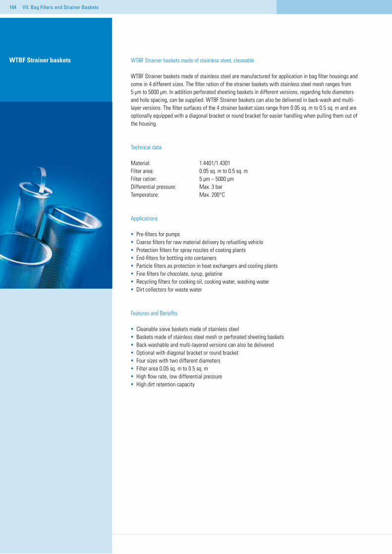
164 VII. Bag Filters and Strainer Baskets
WTBF Strainer baskets made of stainless steel, cleanable
WTBF Strainer baskets made of stainless steel are manufactured for application in bag filter housings and come in 4 different sizes. The filter ration of the strainer baskets with stainless steel mesh ranges from 5 µm to 5000 µm. In addition perforated sheeting baskets in different versions, regarding hole diameters and hole spacing, can be supplied. WTBF Strainer baskets can also be delivered in back-wash and multi-layer versions. The filter surfaces of the 4 strainer basket sizes range from 0.05 sq. m to 0.5 sq. m and are optionally equipped with a diagonal bracket or round bracket for easier handling when pulling them out of the housing.
Technical data
Material: 1.4401/1.4301Filter area: 0.05 sq. m to 0.5 sq. mFilter ration: 5 µm – 5000 µmDifferential pressure: Max. 3 barTemperature: Max. 200°C
Applications
Pre-filters for pumpsCoarse filters for raw material delivery by refuelling vehicleProtection filters for spray nozzles of coating plantsEnd-filters for bottling into containersParticle filters as protection in heat exchangers and cooling plantsFine filters for chocolate, syrup, gelatineRecycling filters for cooking oil, cooking water, washing waterDirt collectors for waste water
Features and Benefits
Cleanable sieve baskets made of stainless steelBaskets made of stainless steel mesh or perforated sheeting basketsBack-washable and multi-layered versions can also be deliveredOptional with diagonal bracket or round bracketFour sizes with two different diametersFilter area 0.05 sq. m to 0.5 sq. mHigh flow rate, low differential pressureHigh dirt retention capacity
WTBF Strainer baskets
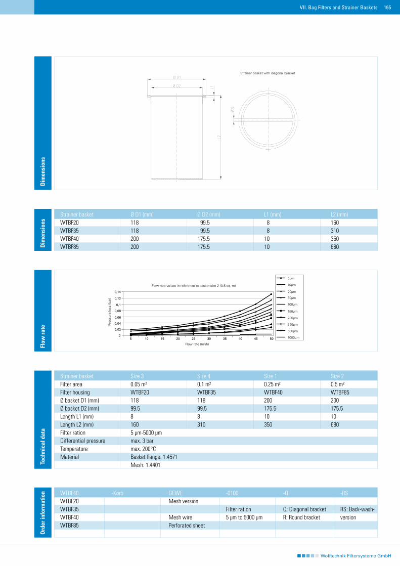
165VII. Bag Filters and Strainer Baskets
Dim
ensi
ons
Dim
ensi
ons
Strainer basket Ø D1 (mm) Ø D2 (mm) L1 (mm) L2 (mm)WTBF20 118 99.5 8 160 WTBF35 118 99.5 8 310 WTBF40 200 175.5 10 350 WTBF85 200 175.5 10 680
Tech
nica
l dat
a
Strainer basket Size 3 Size 4 Size 1 Size 2Filter area 0.05 m² 0.1 m² 0.25 m² 0.5 m²Filter housing WTBF20 WTBF35 WTBF40 WTBF85Ø basket D1 (mm) 118 118 200 200 Ø basket D2 (mm) 99.5 99.5 175.5 175.5Length L1 (mm) 8 8 10 10Length L2 (mm) 160 310 350 680Filter ration 5 µm-5000 µmDifferential pressure max. 3 barTemperature max. 200°CMaterial Basket flange: 1.4571 Mesh: 1.4401
Ord
er in
form
atio
n WTBF40 -Korb GEWE -0100 -Q -RSWTBF20 Mesh version WTBF35 Filter ration Q: Diagonal bracket RS: Back-wash-WTBF40 Mesh wire 5 µm to 5000 µm R: Round bracket versionWTBF85 Perforated sheet
Flow
rate
Strainer basket with diagonal bracket
Pres
sure
loss
(bar
)
Flow rate values in reference to basket size 2 (0.5 sq. m)
Flow rate (m³/h)
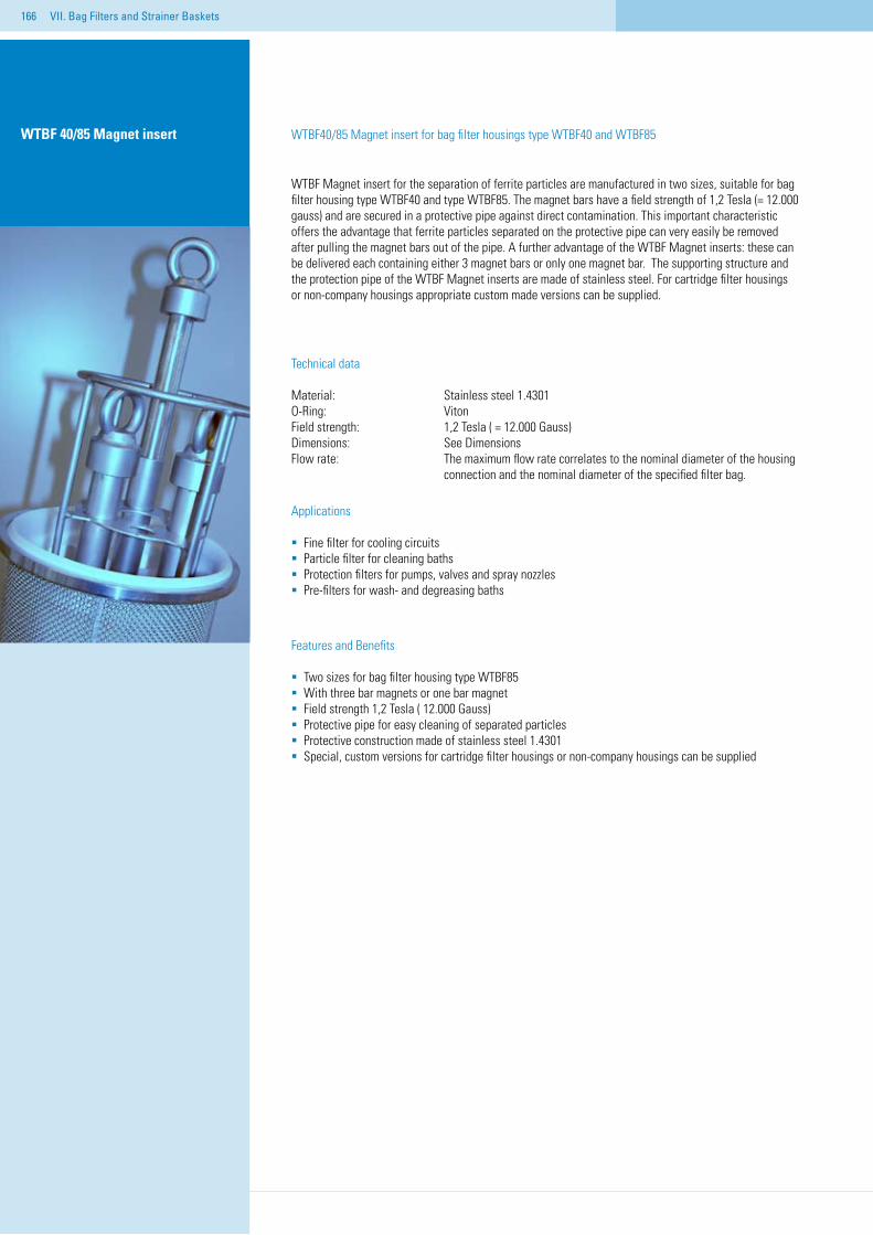
166
WTBF 40/85 Magnet insert WTBF40/85 Magnet insert for bag filter housings type WTBF40 and WTBF85
WTBF Magnet insert for the separation of ferrite particles are manufactured in two sizes, suitable for bag filter housing type WTBF40 and type WTBF85. The magnet bars have a field strength of 1,2 Tesla (= 12.000 gauss) and are secured in a protective pipe against direct contamination. This important characteristic offers the advantage that ferrite particles separated on the protective pipe can very easily be removed after pulling the magnet bars out of the pipe. A further advantage of the WTBF Magnet inserts: these can be delivered each containing either 3 magnet bars or only one magnet bar. The supporting structure and the protection pipe of the WTBF Magnet inserts are made of stainless steel. For cartridge filter housings or non-company housings appropriate custom made versions can be supplied.
Technical data
Material: Stainless steel 1.4301O-Ring: VitonField strength: 1,2 Tesla ( = 12.000 Gauss)Dimensions: See DimensionsFlow rate: The maximum flow rate correlates to the nominal diameter of the housing connection and the nominal diameter of the specified filter bag.
Applications
Fine filter for cooling circuits Particle filter for cleaning bathsProtection filters for pumps, valves and spray nozzlesPre-filters for wash- and degreasing baths
Features and Benefits
Two sizes for bag filter housing type WTBF85With three bar magnets or one bar magnetField strength 1,2 Tesla ( 12.000 Gauss)Protective pipe for easy cleaning of separated particlesProtective construction made of stainless steel 1.4301Special, custom versions for cartridge filter housings or non-company housings can be supplied
VII. Bag Filters and Strainer Baskets
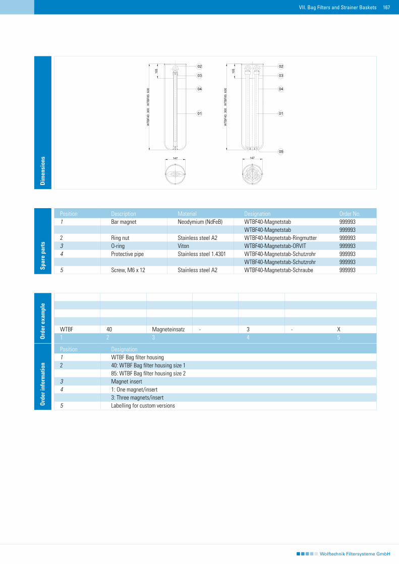
167
Dim
ensi
ons
Spar
e pa
rts
Position Description Material Designation Order No.1 Bar magnet Neodymium (NdFeB) WTBF40-Magnetstab 999993 WTBF40-Magnetstab 9999932 Ring nut Stainless steel A2 WTBF40-Magnetstab-Ringmutter 9999933 O-ring Viton WTBF40-Magnetstab-ORVIT 9999934 Protective pipe Stainless steel 1.4301 WTBF40-Magnetstab-Schutzrohr 999993 WTBF40-Magnetstab-Schutzrohr 9999935 Screw, M6 x 12 Stainless steel A2 WTBF40-Magnetstab-Schraube 999993
Ord
er in
form
atio
n
Position Designation1 WTBF Bag filter housing 2 40: WTBF Bag filter housing size 1 85: WTBF Bag filter housing size 23 Magnet insert4 1: One magnet/insert 3: Three magnets/insert5 Labelling for custom versions
WTBF 40 Magneteinsatz - 3 - X1 2 3 4 5O
rder
exa
mpl
e
02
04
01
05
0303
01
04
02
WTB
F40:
300
W
TBF8
5: 6
30
105
14710
5
WTB
F40:
300
W
TBF8
5: 6
30
147
VII. Bag Filters and Strainer Baskets
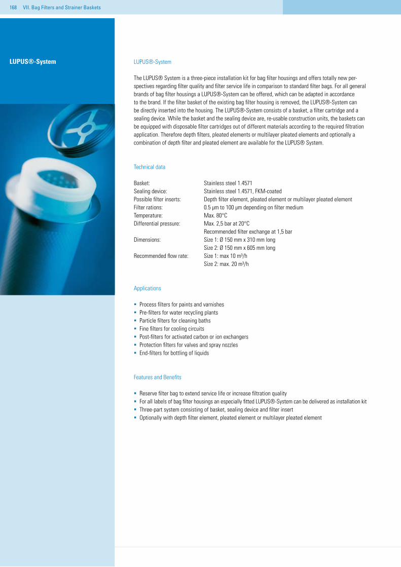
168
LUPUS®-System
The LUPUS® System is a three-piece installation kit for bag filter housings and offers totally new per-spectives regarding filter quality and filter service life in comparison to standard filter bags. For all general brands of bag filter housings a LUPUS®-System can be offered, which can be adapted in accordance to the brand. If the filter basket of the existing bag filter housing is removed, the LUPUS®-System can be directly inserted into the housing. The LUPUS®-System consists of a basket, a filter cartridge and a sealing device. While the basket and the sealing device are, re-usable construction units, the baskets can be equipped with disposable filter cartridges out of different materials according to the required filtration application. Therefore depth filters, pleated elements or multilayer pleated elements and optionally a combination of depth filter and pleated element are available for the LUPUS® System.
Technical data
Basket: Stainless steel 1.4571Sealing device: Stainless steel 1.4571, FKM-coatedPossible filter inserts: Depth filter element, pleated element or multilayer pleated element Filter rations: 0.5 µm to 100 µm depending on filter mediumTemperature: Max. 80°C Differential pressure: Max. 2,5 bar at 20°C Recommended filter exchange at 1,5 barDimensions: Size 1: Ø 150 mm x 310 mm long Size 2: Ø 150 mm x 605 mm longRecommended flow rate: Size 1: max 10 m³/h Size 2: max. 20 m³/h
Applications
Process filters for paints and varnishesPre-filters for water recycling plantsParticle filters for cleaning bathsFine filters for cooling circuits Post-filters for activated carbon or ion exchangersProtection filters for valves and spray nozzlesEnd-filters for bottling of liquids
Features and Benefits
Reserve filter bag to extend service life or increase filtration quality For all labels of bag filter housings an especially fitted LUPUS®-System can be delivered as installation kitThree-part system consisting of basket, sealing device and filter insertOptionally with depth filter element, pleated element or multilayer pleated element
LUPUS®-System
VII. Bag Filters and Strainer Baskets
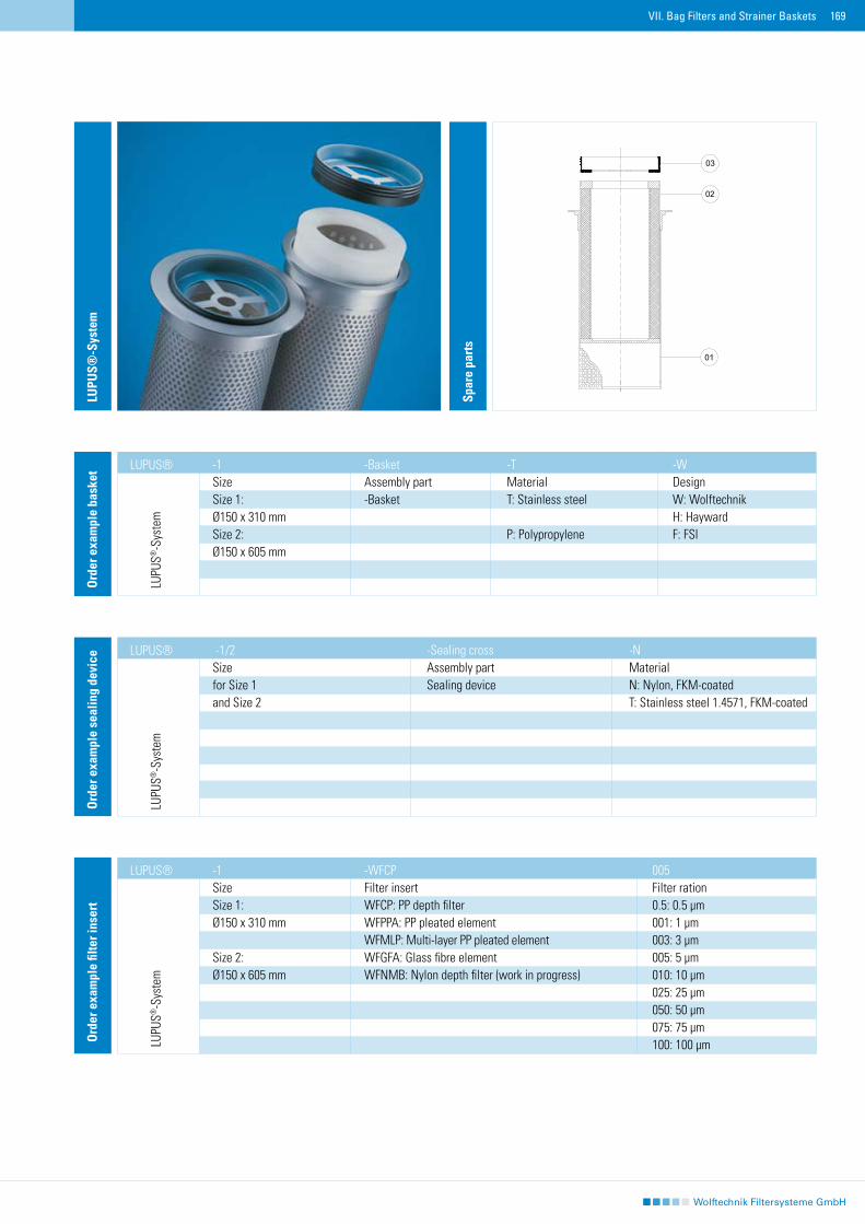
169
-1 -Basket -T -WSize Assembly part Material DesignSize 1: -Basket T: Stainless steel W: WolftechnikØ150 x 310 mm H: HaywardSize 2: P: Polypropylene F: FSIØ150 x 605 mm
Ord
er e
xam
ple
bask
et
LUPUS®
-1/2 -Sealing cross -N Size Assembly part Materialfor Size 1 Sealing device N: Nylon, FKM-coated and Size 2 T: Stainless steel 1.4571, FKM-coated
LUPUS®
Ord
er e
xam
ple
seal
ing
devi
ce
-1 -WFCP 005 Size Filter insert Filter rationSize 1: WFCP: PP depth filter 0.5: 0.5 µm Ø150 x 310 mm WFPPA: PP pleated element 001: 1 µm WFMLP: Multi-layer PP pleated element 003: 3 µmSize 2: WFGFA: Glass fibre element 005: 5 µmØ150 x 605 mm WFNMB: Nylon depth filter (work in progress) 010: 10 µm 025: 25 µm 050: 50 µm 075: 75 µm 100: 100 µm
LUPUS®
Ord
er e
xam
ple
filte
r ins
ert
LUPU
S®-S
yste
m
VII. Bag Filters and Strainer Baskets
LUPU
S®-S
yste
mLU
PUS®
-Sys
tem
LUPU
S®-S
yste
m
Spar
e pa
rts
01
03
02
170
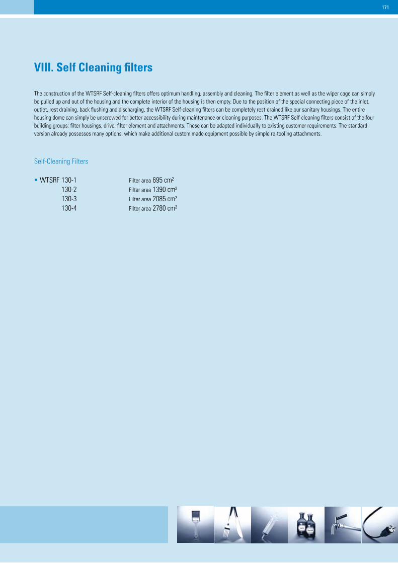
171
VIII. Self Cleaning filters
The construction of the WTSRF Self-cleaning filters offers optimum handling, assembly and cleaning. The filter element as well as the wiper cage can simply be pulled up and out of the housing and the complete interior of the housing is then empty. Due to the position of the special connecting piece of the inlet, outlet, rest draining, back flushing and discharging, the WTSRF Self-cleaning filters can be completely rest-drained like our sanitary housings. The entire housing dome can simply be unscrewed for better accessibility during maintenance or cleaning purposes. The WTSRF Self-cleaning filters consist of the four building groups: filter housings, drive, filter element and attachments. These can be adapted individually to existing customer requirements. The standard version already possesses many options, which make additional custom made equipment possible by simple re-tooling attachments.
Self-Cleaning Filters
WTSRF 130-1 Filter area 695 cm² 130-2 Filter area 1390 cm² 130-3 Filter area 2085 cm² 130-4 Filter area 2780 cm²
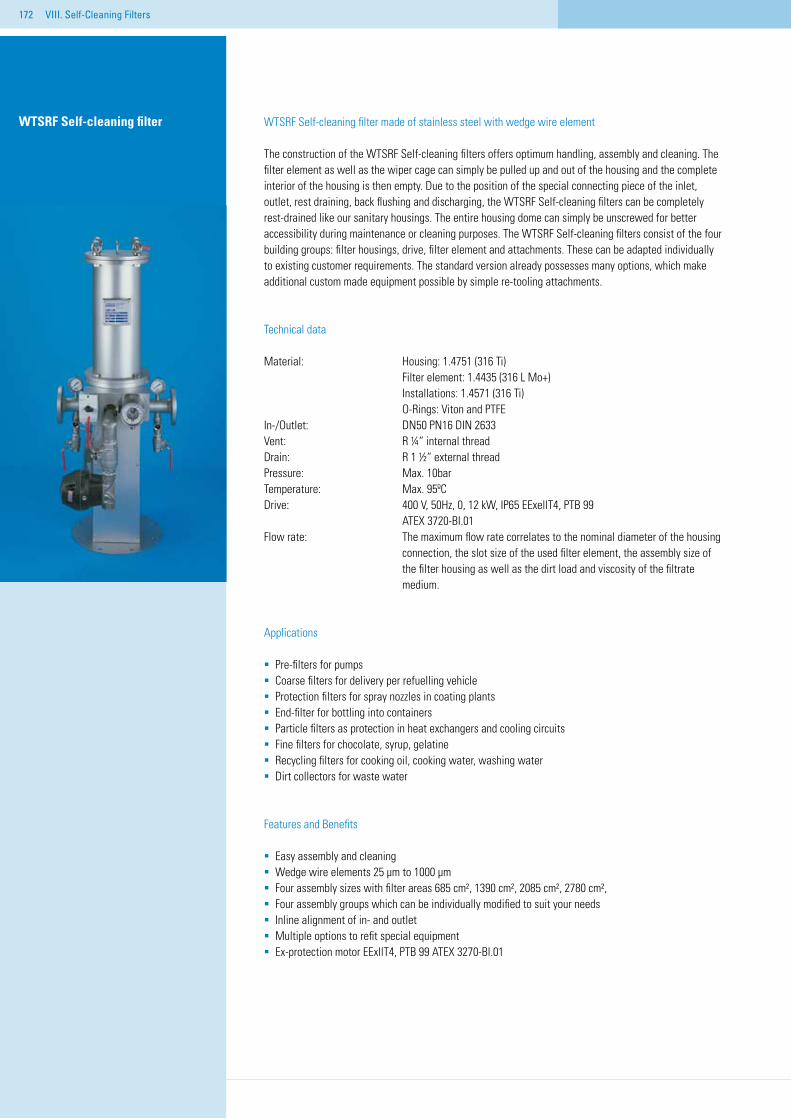
172 VIII. Self-Cleaning Filters
WTSRF Self-cleaning filter made of stainless steel with wedge wire element
The construction of the WTSRF Self-cleaning filters offers optimum handling, assembly and cleaning. The filter element as well as the wiper cage can simply be pulled up and out of the housing and the complete interior of the housing is then empty. Due to the position of the special connecting piece of the inlet, outlet, rest draining, back flushing and discharging, the WTSRF Self-cleaning filters can be completely rest-drained like our sanitary housings. The entire housing dome can simply be unscrewed for better accessibility during maintenance or cleaning purposes. The WTSRF Self-cleaning filters consist of the four building groups: filter housings, drive, filter element and attachments. These can be adapted individually to existing customer requirements. The standard version already possesses many options, which make additional custom made equipment possible by simple re-tooling attachments.
Technical data
Material: Housing: 1.4751 (316 Ti) Filter element: 1.4435 (316 L Mo+) Installations: 1.4571 (316 Ti) O-Rings: Viton and PTFEIn-/Outlet: DN50 PN16 DIN 2633Vent: R ¼“ internal threadDrain: R 1 ½“ external thread Pressure: Max. 10bar Temperature: Max. 95ºC Drive: 400 V, 50Hz, 0, 12 kW, IP65 EExellT4, PTB 99 ATEX 3720-BI.01Flow rate: The maximum flow rate correlates to the nominal diameter of the housing connection, the slot size of the used filter element, the assembly size of the filter housing as well as the dirt load and viscosity of the filtrate medium.
Applications
Pre-filters for pumpsCoarse filters for delivery per refuelling vehicle Protection filters for spray nozzles in coating plantsEnd-filter for bottling into containersParticle filters as protection in heat exchangers and cooling circuitsFine filters for chocolate, syrup, gelatine Recycling filters for cooking oil, cooking water, washing waterDirt collectors for waste water
Features and Benefits
Easy assembly and cleaningWedge wire elements 25 µm to 1000 µmFour assembly sizes with filter areas 685 cm², 1390 cm², 2085 cm², 2780 cm², Four assembly groups which can be individually modified to suit your needsInline alignment of in- and outletMultiple options to refit special equipmentEx-protection motor EExllT4, PTB 99 ATEX 3270-Bl.01
WTSRF Self-cleaning filter
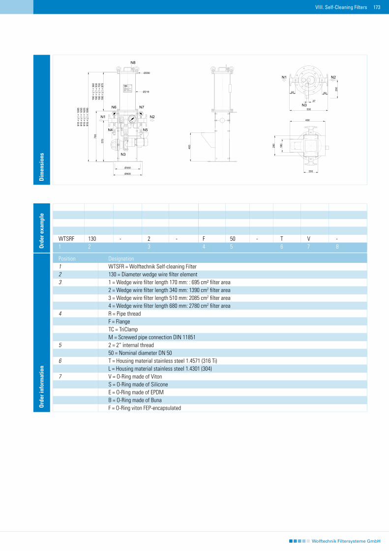
173VIII. Self-Cleaning Filters
Dim
ensi
ons
Ord
er in
form
atio
n
Position Designation1 WTSFR = Wolftechnik Self-cleaning Filter2 130 = Diameter wedge wire filter element3 1 = Wedge wire filter length 170 mm: : 695 cm² filter area 2 = Wedge wire filter length 340 mm: 1390 cm2 filter area 3 = Wedge wire filter length 510 mm: 2085 cm2 filter area 4 = Wedge wire filter length 680 mm: 2780 cm2 filter area4 R = Pipe thread F = Flange TC = TriClamp M = Screwed pipe connection DIN 118515 2 = 2“ internal thread 50 = Nominal diameter DN 506 T = Housing material stainless steel 1.4571 (316 Ti) L = Housing material stainless steel 1.4301 (304)7 V = O-Ring made of Viton S = O-Ring made of Silicone E = O-Ring made of EPDM B = O-Ring made of Buna F = O-Ring viton FEP-encapsulated
WTSRF 130 - 2 - F 50 - T V -1 2 3 4 5 6 7 8O
rder
exa
mpl
e
82 82
27
250
530
490
Ø219
Ø290
N2N1
N3
N5N4
N6 N7
N8
N1 N2
N3200
WTSRF130-2-F50-TV
max. Betriebstemperatur / max. working temperature
max. Betriebsdruck / max. working pressure
Inhalt / Volume
03/06
72014Hersteller / Produced by
Seriennummer / Serial number
Baujahr / Year made
2006
Typ / Modell
CE-
bar
400
280
180
95
10
22 l
C°
bar
Malmsheimer Straße 6771263 Weil der Stadt
Tel.: 07033 / 70 14 0Fax.: 07033 / 70 14 20
Germany
Wolftechnik Filtersysteme GmbH
570
Ø400
Ø350
915
+ L1
= 1
085
915
+ L1
= 1
255
915
+ L1
= 1
425
915
+ L1
= 1
595
190
+ L1
= 3
6019
0 +
L1 =
530
190
+ L1
= 7
0019
0 +
L1 =
870
700
bar
174
175
IX. Centrifugal Separators
To separate solid particles from aqueous mediums, Wolftechnik centrifugal separators take advantage of the differing specific weight of the two. The inside of the separator is specially shaped to make the medium circulate around inside of it. The resul-ting centrifugal forces act more strongly on the particles to be eliminated and enable efficient separation of them. Wolftechnik centrifugal separators are especially well-suited for removing hard, solid particles of sand, glass and metal.
Centrifugal Separators
WTEZA Compact, closed functional unit in five different sizes for flow rates of 2 sq. m/h to 40 sq. m/h.WTDZA The inlet chamber with flat cover and the dirt chamber with flanged dished bottom can be opened for inspection. There are three sizes to choose from, ranging from 5 sq. m/h to 40 sq.m/h.WTFZA The economical combination of WTEZA and WTDZA with flanged discharge pipe and tripod with hand-hole to inspect the dirt chamber. This assembly series is available in four sizes ranging from 65 sq. m/h to 150 sq. m/h.
Additional components
Automatic discharge device From ¾“ up to 2“ TBF Drop center paper band filter With automatic paper transport
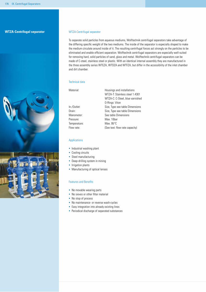
176 IX. Centrifugal Separators
WTZA-Centrifugal separator
To separate solid particles from aqueous mediums, Wolftechnik centrifugal separators take advantage of the differing specific weight of the two mediums. The inside of the separator is especially shaped to make the medium circulate around inside of it. The resulting centrifugal forces act strongly on the particles to be eliminated and enable efficient separation. Wolftechnik centrifugal separators are especially well-suited for removing hard, solid particles of sand, glass and metal. Wolftechnik centrifugal separators can be made of C-steel, stainless steel or plastic. With an identical internal assembly they are manufactured in the three assembly series WTEZA, WTDZA and WTFZA, but differ in the accessibility of the inlet chamber and dirt chamber.
Technical data
Material: Housings and installations WTZA-T: Stainless steel 1.4301 WTZA-C: C-Steel, blue varnished O-Rings: Viton In-/Outlet: Size, Type see table DimensionsDrain: Size, Type see table DimensionsManometer: See table DimensionsPressure: Max. 10bar Temperature: Max. 95°C Flow rate: (See text: flow rate capacity)
Applications
Industrial washing plantCooling circuitsSteel manufacturingDeep-drilling system in miningIrrigation plantsManufacturing of optical lenses
Features and Benefits
No movable wearing partsNo sieves or other filter materialNo stop of processNo maintenance- or reverse wash-cyclesEasy integration into already existing linesPeriodical discharge of separated substances
WTZA-Centrifugal separator
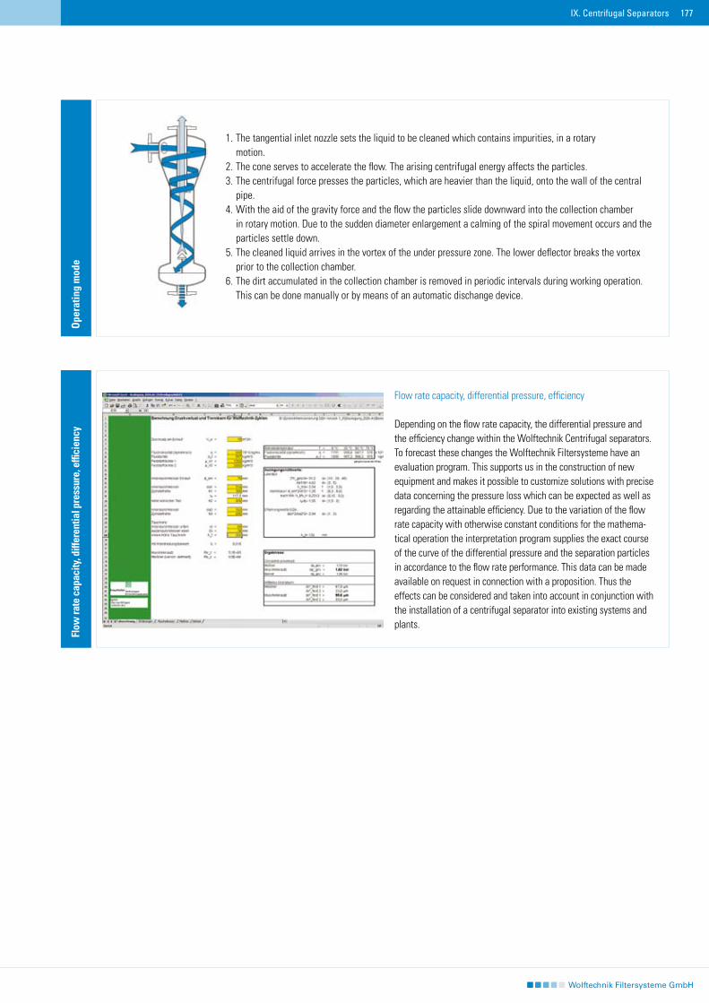
177IX. Centrifugal Separators
1. The tangential inlet nozzle sets the liquid to be cleaned which contains impurities, in a rotary motion.2. The cone serves to accelerate the flow. The arising centrifugal energy affects the particles.3. The centrifugal force presses the particles, which are heavier than the liquid, onto the wall of the central pipe.4. With the aid of the gravity force and the flow the particles slide downward into the collection chamber in rotary motion. Due to the sudden diameter enlargement a calming of the spiral movement occurs and the particles settle down.5. The cleaned liquid arrives in the vortex of the under pressure zone. The lower deflector breaks the vortex prior to the collection chamber.6. The dirt accumulated in the collection chamber is removed in periodic intervals during working operation. This can be done manually or by means of an automatic dischange device.
Ope
ratin
g m
ode
Flow rate capacity, differential pressure, efficiency
Depending on the flow rate capacity, the differential pressure and the efficiency change within the Wolftechnik Centrifugal separators. To forecast these changes the Wolftechnik Filtersysteme have an evaluation program. This supports us in the construction of new equipment and makes it possible to customize solutions with precise data concerning the pressure loss which can be expected as well as regarding the attainable efficiency. Due to the variation of the flow rate capacity with otherwise constant conditions for the mathema-tical operation the interpretation program supplies the exact course of the curve of the differential pressure and the separation particles in accordance to the flow rate performance. This data can be made available on request in connection with a proposition. Thus the effects can be considered and taken into account in conjunction with the installation of a centrifugal separator into existing systems and plants.
Flow
rate
cap
acity
, diff
eren
tial p
ress
ure,
effi
cien
cy
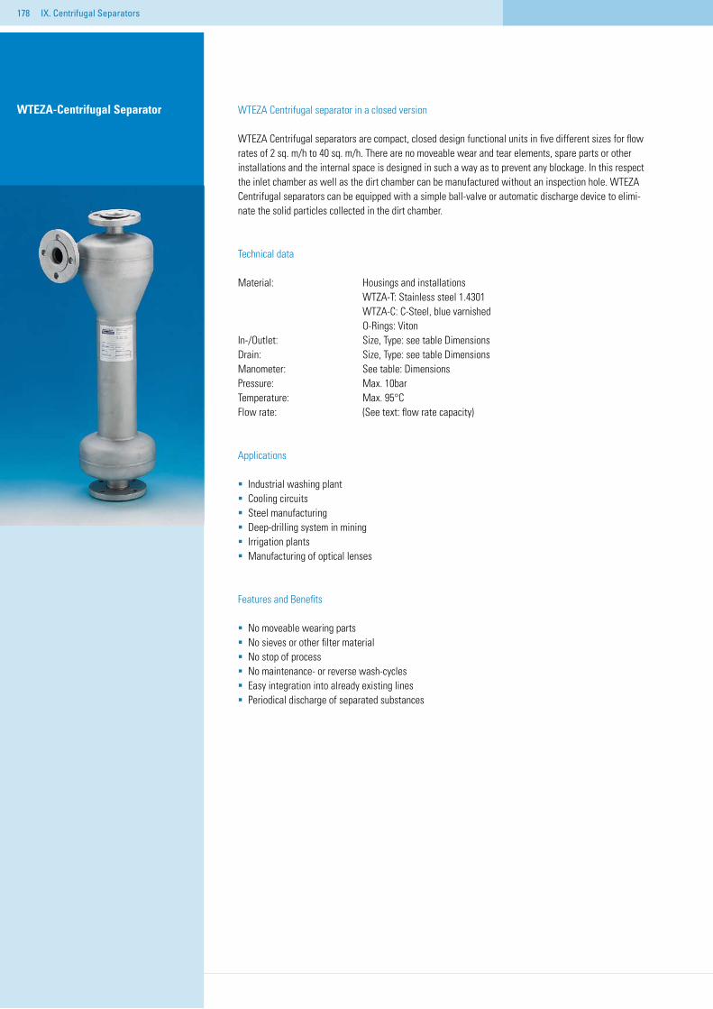
178 IX. Centrifugal Separators
WTEZA-Centrifugal Separator WTEZA Centrifugal separator in a closed version
WTEZA Centrifugal separators are compact, closed design functional units in five different sizes for flow rates of 2 sq. m/h to 40 sq. m/h. There are no moveable wear and tear elements, spare parts or other installations and the internal space is designed in such a way as to prevent any blockage. In this respect the inlet chamber as well as the dirt chamber can be manufactured without an inspection hole. WTEZA Centrifugal separators can be equipped with a simple ball-valve or automatic discharge device to elimi-nate the solid particles collected in the dirt chamber.
Technical data
Material: Housings and installations WTZA-T: Stainless steel 1.4301 WTZA-C: C-Steel, blue varnished O-Rings: Viton In-/Outlet: Size, Type: see table DimensionsDrain: Size, Type: see table DimensionsManometer: See table: DimensionsPressure: Max. 10bar Temperature: Max. 95°C Flow rate: (See text: flow rate capacity)
Applications
Industrial washing plantCooling circuitsSteel manufacturingDeep-drilling system in miningIrrigation plantsManufacturing of optical lenses
Features and Benefits
No moveable wearing partsNo sieves or other filter materialNo stop of processNo maintenance- or reverse wash-cyclesEasy integration into already existing linesPeriodical discharge of separated substances
Flow
rate
cap
acity
, Diff
eren
zial
druc
k, T
renn
-

179IX. Centrifugal Separators
Dim
ensi
ons
Model Flow (sq.m/h) dp (bar) p (bar) Inlet/Outlet Drain A B C D E FWTEZA002 2 1,2 10 ½“ AG ¾“ AG 387 475 45 114 142 48WTEZA005 5 1,2 10 ¾“ AG ¾“ AG 460 560 54 139 160 76WTEZA010 10 1,2 10 1 ¼“ AG ¾“ AG 500 635 67 168 250 89WTEZA025 25 1,2 10 2“ AG 1“ AG 730 895 110 273 372 114WTEZA040 40 1,2 10 DN 65 1“ AG 832 1050 104 273 400 140Material: Stainless steel 1.4301 stained and passivated or steel, varnished.
Dim
ensi
ons
Flow rate capacity, differential pressure, efficiency
Depending on the flow rate capacity, the differential pressure and the efficiency change within the Wolftechnik Centrifugal separators. To forecast these changes the Wolftechnik Filtersysteme have an evaluation program. This supports us in the construction of new equipment and makes it possible to customize solutions with precise data concerning the pressure loss which can be expected as well as regarding the attainable efficiency. Due to the variation of the flow rate capacity with otherwise constant conditions for the mathema-tical operation the interpretation program supplies the exact course of the curve of the differential pressure and the separation particles in accordance to the flow rate performance. This data can be made available on request in connection with a proposition. Thus the effects can be considered and taken into account in conjunction with the installation of a centrifugal separator into existing systems and plants.
Flow
rate
cap
acity
, diff
eren
tial p
ress
ure,
effi
cien
cy
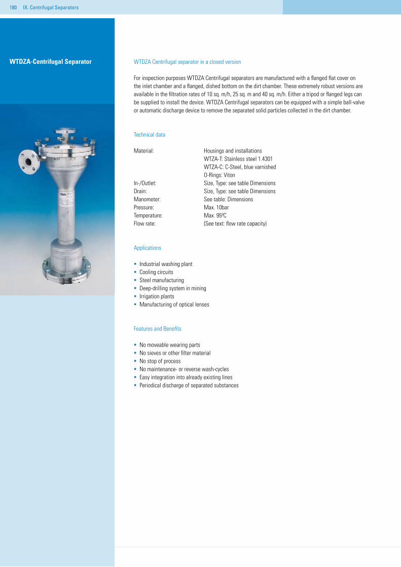
180 IX. Centrifugal Separators
WTDZA-Centrifugal Separator WTDZA Centrifugal separator in a closed version
For inspection purposes WTDZA Centrifugal separators are manufactured with a flanged flat cover on the inlet chamber and a flanged, dished bottom on the dirt chamber. These extremely robust versions are available in the filtration rates of 10 sq. m/h, 25 sq. m and 40 sq. m/h. Either a tripod or flanged legs can be supplied to install the device. WTDZA Centrifugal separators can be equipped with a simple ball-valve or automatic discharge device to remove the separated solid particles collected in the dirt chamber.
Technical data
Material: Housings and installations WTZA-T: Stainless steel 1.4301 WTZA-C: C-Steel, blue varnished O-Rings: Viton In-/Outlet: Size, Type: see table DimensionsDrain: Size, Type: see table DimensionsManometer: See table: DimensionsPressure: Max. 10bar Temperature: Max. 95ºC Flow rate: (See text: flow rate capacity)
Applications
Industrial washing plantCooling circuitsSteel manufacturingDeep-drilling system in miningIrrigation plantsManufacturing of optical lenses
Features and Benefits
No moveable wearing partsNo sieves or other filter materialNo stop of processNo maintenance- or reverse wash-cyclesEasy integration into already existing linesPeriodical discharge of separated substances
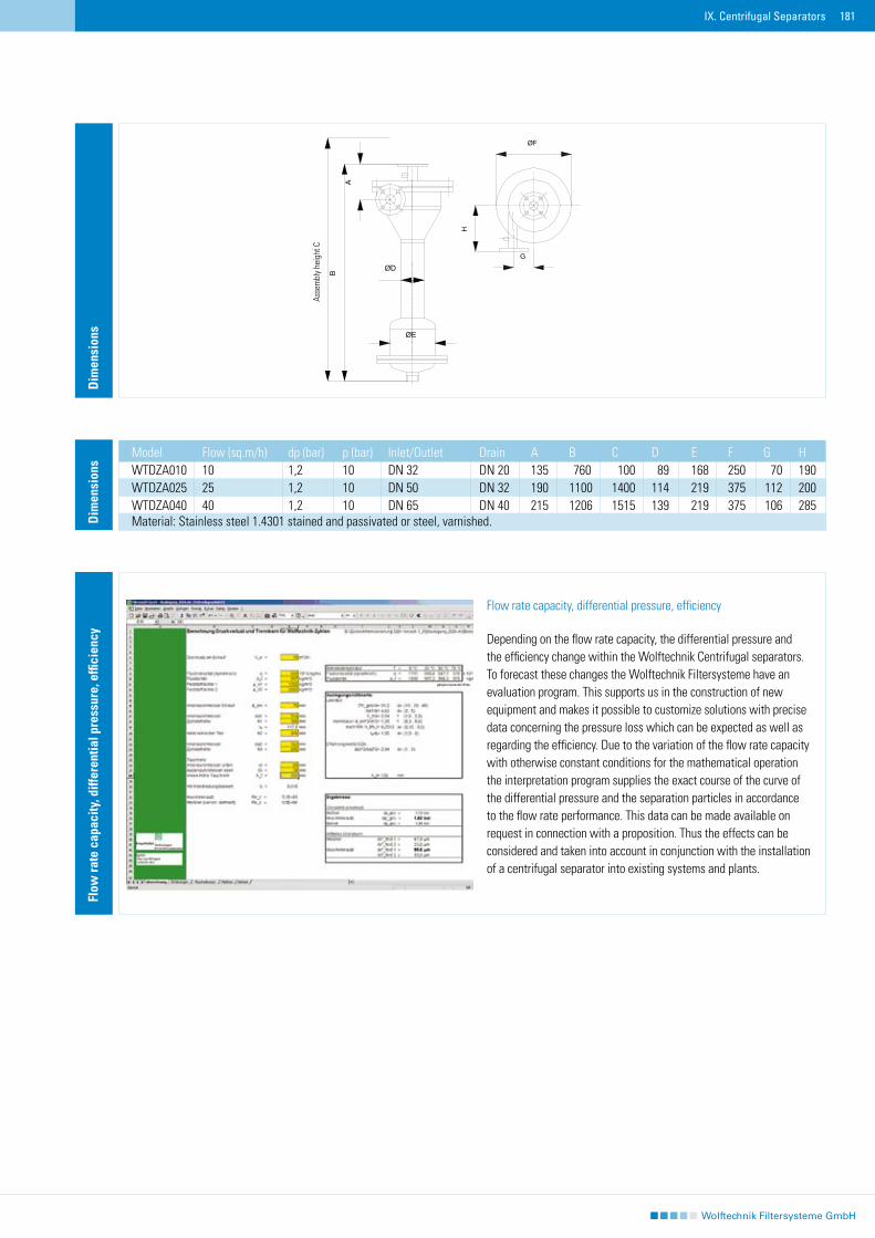
181IX. Centrifugal Separators
Dim
ensi
ons
Model Flow (sq.m/h) dp (bar) p (bar) Inlet/Outlet Drain A B C D E F G HWTDZA010 10 1,2 10 DN 32 DN 20 135 760 100 89 168 250 70 190WTDZA025 25 1,2 10 DN 50 DN 32 190 1100 1400 114 219 375 112 200WTDZA040 40 1,2 10 DN 65 DN 40 215 1206 1515 139 219 375 106 285Material: Stainless steel 1.4301 stained and passivated or steel, varnished.
Dim
ensi
ons
Flow rate capacity, differential pressure, efficiency
Depending on the flow rate capacity, the differential pressure and the efficiency change within the Wolftechnik Centrifugal separators. To forecast these changes the Wolftechnik Filtersysteme have an evaluation program. This supports us in the construction of new equipment and makes it possible to customize solutions with precise data concerning the pressure loss which can be expected as well as regarding the efficiency. Due to the variation of the flow rate capacity with otherwise constant conditions for the mathematical operation the interpretation program supplies the exact course of the curve of the differential pressure and the separation particles in accordance to the flow rate performance. This data can be made available on request in connection with a proposition. Thus the effects can be considered and taken into account in conjunction with the installation of a centrifugal separator into existing systems and plants.
Flow
rate
cap
acity
, diff
eren
tial p
ress
ure,
effi
cien
cy
Asse
mbl
y he
ight
C
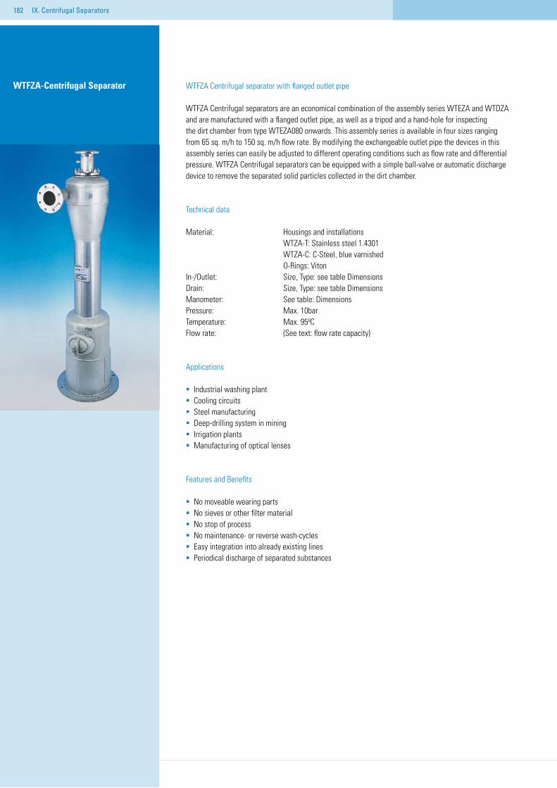
182 IX. Centrifugal Separators
WTFZA Centrifugal separator with flanged outlet pipe
WTFZA Centrifugal separators are an economical combination of the assembly series WTEZA and WTDZA and are manufactured with a flanged outlet pipe, as well as a tripod and a hand-hole for inspecting the dirt chamber from type WTEZA080 onwards. This assembly series is available in four sizes ranging from 65 sq. m/h to 150 sq. m/h flow rate. By modifying the exchangeable outlet pipe the devices in this assembly series can easily be adjusted to different operating conditions such as flow rate and differential pressure. WTFZA Centrifugal separators can be equipped with a simple ball-valve or automatic discharge device to remove the separated solid particles collected in the dirt chamber.
Technical data
Material: Housings and installations WTZA-T: Stainless steel 1.4301 WTZA-C: C-Steel, blue varnished O-Rings: Viton In-/Outlet: Size, Type: see table DimensionsDrain: Size, Type: see table DimensionsManometer: See table: DimensionsPressure: Max. 10bar Temperature: Max. 95ºC Flow rate: (See text: flow rate capacity)
Applications
Industrial washing plantCooling circuitsSteel manufacturingDeep-drilling system in miningIrrigation plantsManufacturing of optical lenses
Features and Benefits
No moveable wearing partsNo sieves or other filter materialNo stop of processNo maintenance- or reverse wash-cyclesEasy integration into already existing linesPeriodical discharge of separated substances
WTFZA-Centrifugal Separator
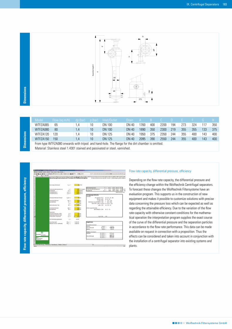
183IX. Centrifugal Separators
Dim
ensi
ons
Dim
ensi
ons
Model Flow (sq.m/h) dp (bar) p (bar) Inlet/Outlet Drain A B C D E F G HWTFZA065 65 1,4 10 DN 100 DN 40 1760 400 2200 194 273 324 117 350WTFZA080 80 1,4 10 DN 100 DN 40 1890 350 2300 219 355 355 133 375WTFZA120 120 1,4 10 DN 125 DN 40 1950 375 2350 244 355 400 143 400WTFZA150 150 1,4 10 DN 125 DN 40 2095 390 2550 244 355 400 143 400From type WTFZA080 onwards with tripod and hand-hole. The flange for the dirt chamber is omitted.Material: Stainless steel 1.4301 stained and passivated or steel, varnished.
Flow rate capacity, differential pressure, efficiency
Depending on the flow rate capacity, the differential pressure and the efficiency change within the Wolftechnik Centrifugal separators. To forecast these changes the Wolftechnik Filtersysteme have an evaluation program. This supports us in the construction of new equipment and makes it possible to customize solutions with precise data concerning the pressure loss which can be expected as well as regarding the attainable efficiency. Due to the variation of the flow rate capacity with otherwise constant conditions for the mathema-tical operation the interpretation program supplies the exact course of the curve of the differential pressure and the separation particles in accordance to the flow rate performance. This data can be made available on request in connection with a proposition. Thus the effects can be considered and taken into account in conjunction with the installation of a centrifugal separator into existing systems and plants.
Flow
rate
cap
acity
, diff
eren
tial p
ress
ure,
effi
cien
cy
Ass
embl
y he
ight
C
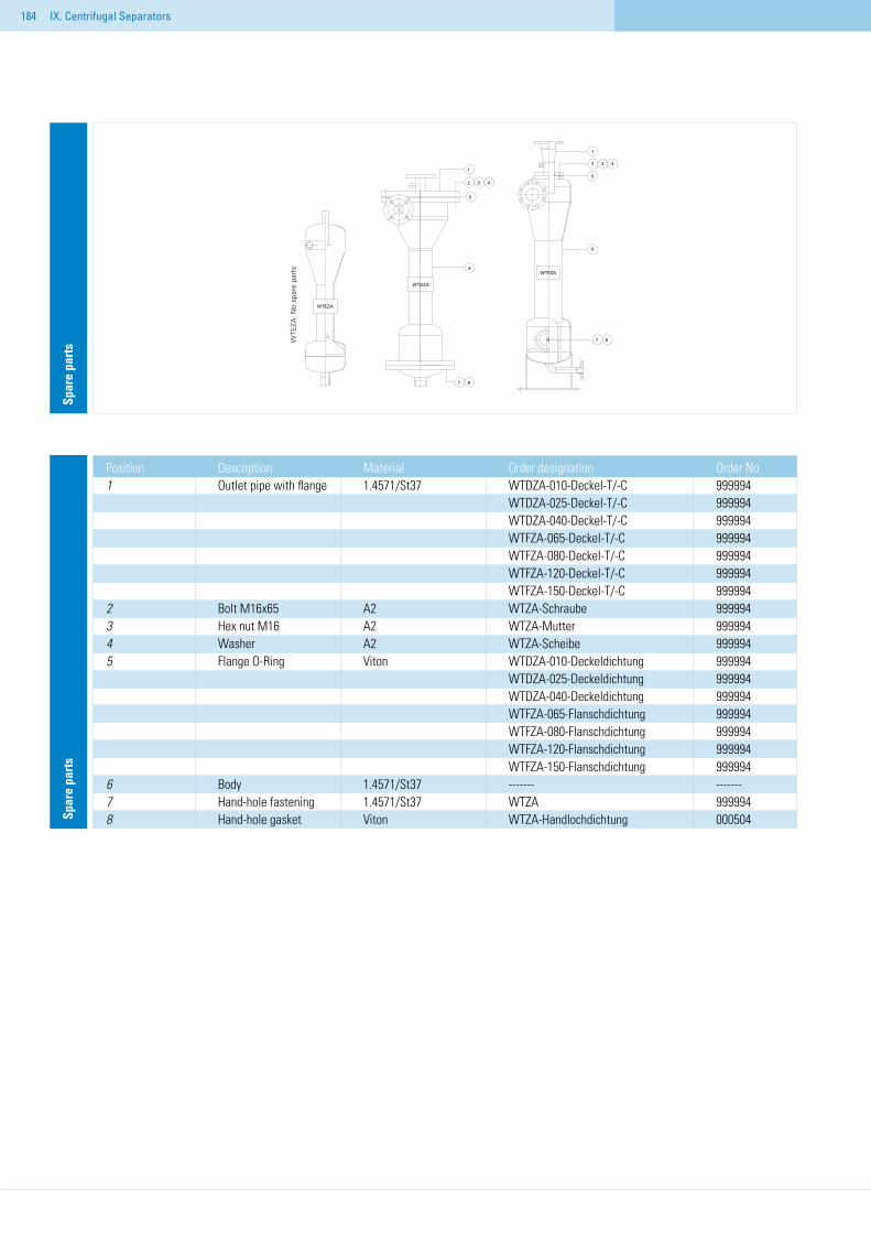
184
Spar
e pa
rts
Spar
e pa
rts
Position Description Material Order designation Order No.1 Outlet pipe with flange 1.4571/St37 WTDZA-010-Deckel-T/-C 999994 WTDZA-025-Deckel-T/-C 999994 WTDZA-040-Deckel-T/-C 999994 WTFZA-065-Deckel-T/-C 999994 WTFZA-080-Deckel-T/-C 999994 WTFZA-120-Deckel-T/-C 999994 WTFZA-150-Deckel-T/-C 9999942 Bolt M16x65 A2 WTZA-Schraube 9999943 Hex nut M16 A2 WTZA-Mutter 9999944 Washer A2 WTZA-Scheibe 9999945 Flange O-Ring Viton WTDZA-010-Deckeldichtung 999994 WTDZA-025-Deckeldichtung 999994 WTDZA-040-Deckeldichtung 999994 WTFZA-065-Flanschdichtung 999994 WTFZA-080-Flanschdichtung 999994 WTFZA-120-Flanschdichtung 999994 WTFZA-150-Flanschdichtung 9999946 Body 1.4571/St37 ------- -------7 Hand-hole fastening 1.4571/St37 WTZA 9999948 Hand-hole gasket Viton WTZA-Handlochdichtung 000504
IX. Centrifugal Separators
WTE
ZA: N
o sp
are
part
s
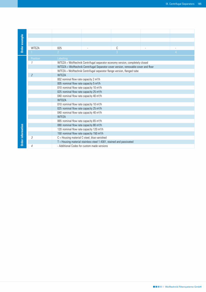
185IX. Centrifugal Separators
Ord
er in
form
atio
n
Position Labelling1 WTEZA = Wolftechnik Centrifugal separator economy version, completely closed WTDZA = Wolftechnik Centrifugal Separator cover version, removable cover and floor WTFZA = Wolftechnik Centrifugal separator flange version, flanged tube2 WTEZA 002 nominal flow rate capacity 2 m³/h 005 nominal flow rate capacity 5 m³/h 010 nominal flow rate capacity 10 m³/h 025 nominal flow rate capacity 25 m³/h 040 nominal flow rate capacity 40 m³/h WTDZA 010 nominal flow rate capacity 10 m³/h 025 nominal flow rate capacity 25 m³/h 040 nominal flow rate capacity 40 m³/h WTFZA 065 nominal flow rate capacity 65 m³/h 080 nominal flow rate capacity 80 m³/h 120 nominal flow rate capacity 120 m³/h 150 nominal flow rate capacity 150 m³/h3 C = Housing material C-steel, blue vanished T = Housing material stainless steel 1.4301, stained and passivated4 - Additional Codes for custom made versions
WTEZA 025 - C - -1 2 3 4O
rder
exa
mpl
e
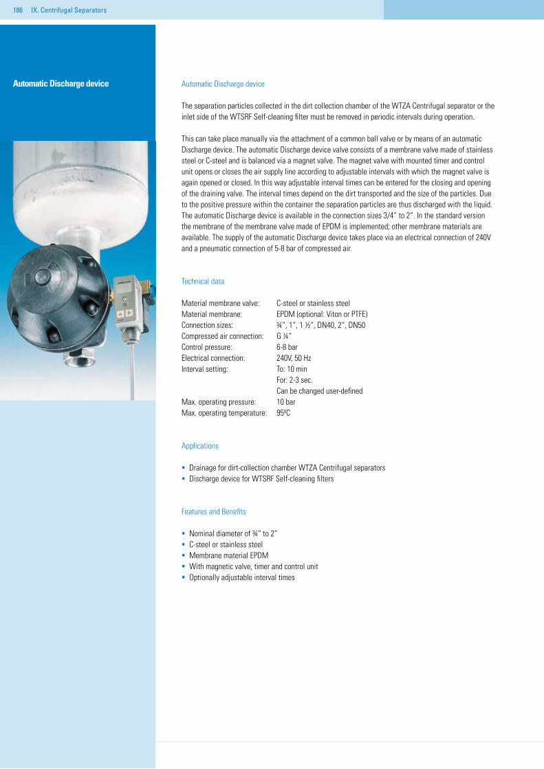
186
Automatic Discharge device
IX. Centrifugal Separators
Automatic Discharge device
The separation particles collected in the dirt collection chamber of the WTZA Centrifugal separator or the inlet side of the WTSRF Self-cleaning filter must be removed in periodic intervals during operation.
This can take place manually via the attachment of a common ball valve or by means of an automatic Discharge device. The automatic Discharge device valve consists of a membrane valve made of stainless steel or C-steel and is balanced via a magnet valve. The magnet valve with mounted timer and control unit opens or closes the air supply line according to adjustable intervals with which the magnet valve is again opened or closed. In this way adjustable interval times can be entered for the closing and opening of the draining valve. The interval times depend on the dirt transported and the size of the particles. Due to the positive pressure within the container the separation particles are thus discharged with the liquid. The automatic Discharge device is available in the connection sizes 3/4“ to 2“. In the standard version the membrane of the membrane valve made of EPDM is implemented; other membrane materials are available. The supply of the automatic Discharge device takes place via an electrical connection of 240V and a pneumatic connection of 5-8 bar of compressed air.
Technical data
Material membrane valve: C-steel or stainless steelMaterial membrane: EPDM (optional: Viton or PTFE)Connection sizes: ¾“, 1“, 1 ½“, DN40, 2“, DN50Compressed air connection: G ¼“Control pressure: 6-8 barElectrical connection: 240V, 50 HzInterval setting: To: 10 min For: 2-3 sec. Can be changed user-definedMax. operating pressure: 10 barMax. operating temperature: 95ºC
Applications
Drainage for dirt-collection chamber WTZA Centrifugal separatorsDischarge device for WTSRF Self-cleaning filters
Features and Benefits
Nominal diameter of ¾“ to 2“C-steel or stainless steelMembrane material EPDMWith magnetic valve, timer and control unitOptionally adjustable interval times
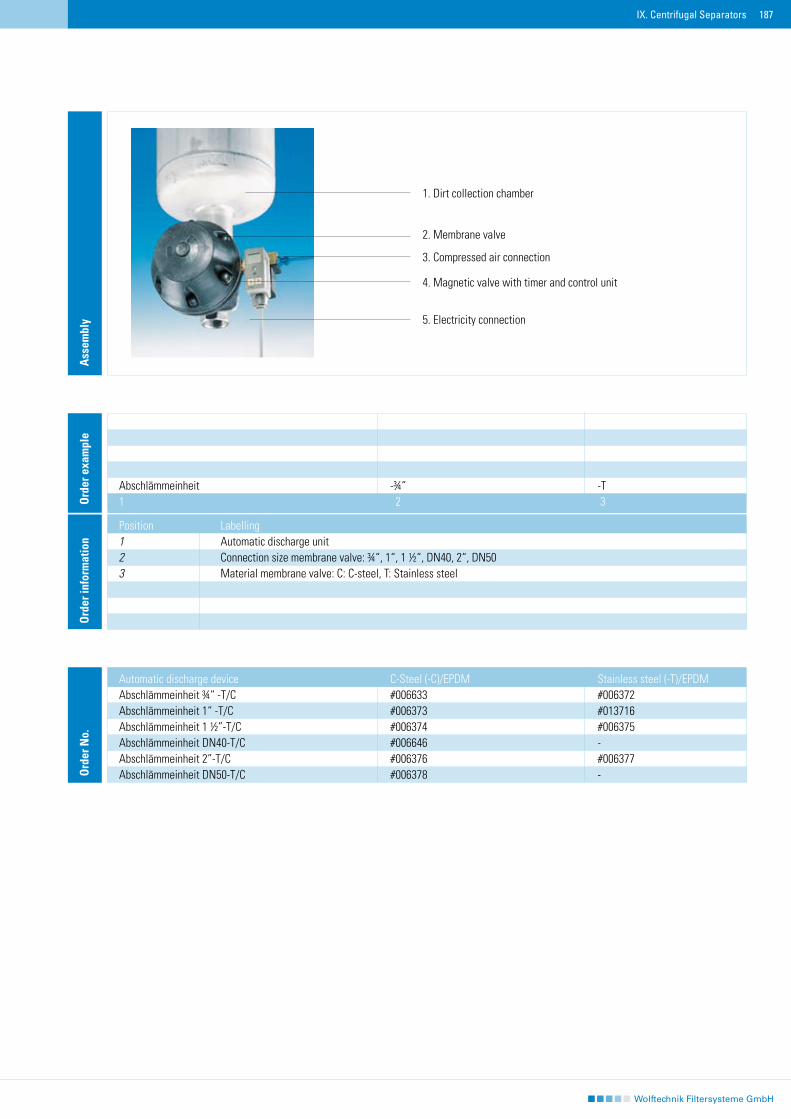
187IX. Centrifugal Separators
Automatic discharge device C-Steel (-C)/EPDM Stainless steel (-T)/EPDMAbschlämmeinheit ¾“ -T/C #006633 #006372Abschlämmeinheit 1“ -T/C #006373 #013716Abschlämmeinheit 1 ½”-T/C #006374 #006375Abschlämmeinheit DN40-T/C #006646 -Abschlämmeinheit 2”-T/C #006376 #006377Abschlämmeinheit DN50-T/C #006378 -
Position Labelling1 Automatic discharge unit2 Connection size membrane valve: ¾“, 1“, 1 ½“, DN40, 2“, DN503 Material membrane valve: C: C-steel, T: Stainless steel
Abschlämmeinheit -¾“ -T1 2 3O
rder
exa
mpl
eO
rder
info
rmat
ion
1. Dirt collection chamber
2. Membrane valve
3. Compressed air connection
4. Magnetic valve with timer and control unit
5. Electricity connection
Ass
embl
yO
rder
No.
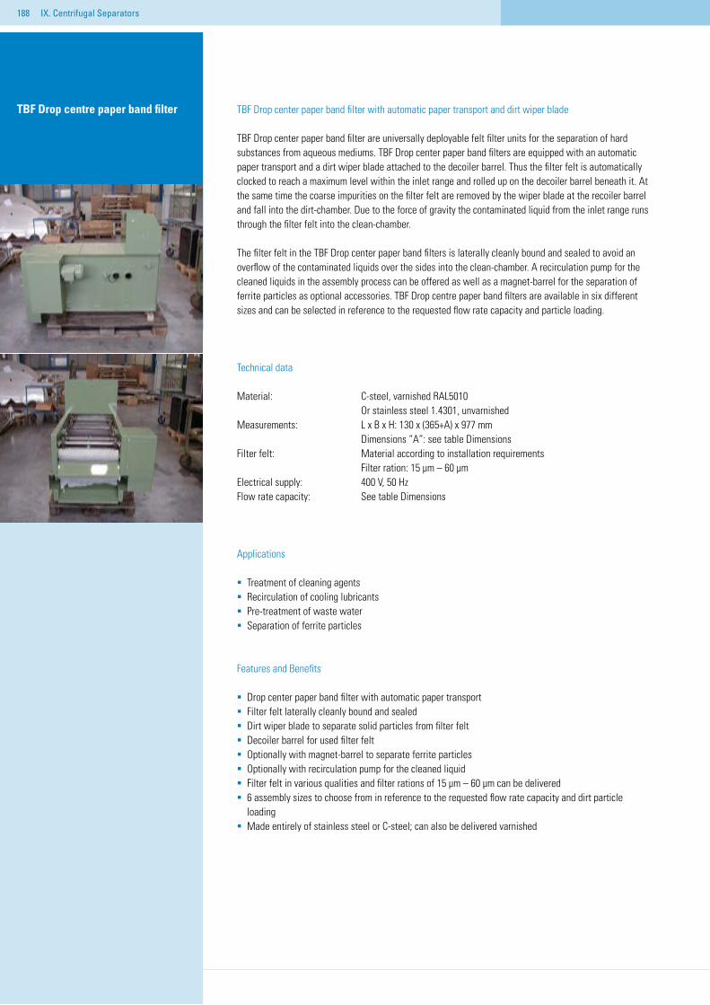
188
TBF Drop center paper band filter with automatic paper transport and dirt wiper blade
TBF Drop center paper band filter are universally deployable felt filter units for the separation of hard substances from aqueous mediums. TBF Drop center paper band filters are equipped with an automatic paper transport and a dirt wiper blade attached to the decoiler barrel. Thus the filter felt is automatically clocked to reach a maximum level within the inlet range and rolled up on the decoiler barrel beneath it. At the same time the coarse impurities on the filter felt are removed by the wiper blade at the recoiler barrel and fall into the dirt-chamber. Due to the force of gravity the contaminated liquid from the inlet range runs through the filter felt into the clean-chamber.
The filter felt in the TBF Drop center paper band filters is laterally cleanly bound and sealed to avoid an overflow of the contaminated liquids over the sides into the clean-chamber. A recirculation pump for the cleaned liquids in the assembly process can be offered as well as a magnet-barrel for the separation of ferrite particles as optional accessories. TBF Drop centre paper band filters are available in six different sizes and can be selected in reference to the requested flow rate capacity and particle loading.
Technical data
Material: C-steel, varnished RAL5010 Or stainless steel 1.4301, unvarnishedMeasurements: L x B x H: 130 x (365+A) x 977 mm Dimensions “A”: see table DimensionsFilter felt: Material according to installation requirements Filter ration: 15 µm – 60 µmElectrical supply: 400 V, 50 HzFlow rate capacity: See table Dimensions
Applications
Treatment of cleaning agentsRecirculation of cooling lubricants Pre-treatment of waste waterSeparation of ferrite particles
Features and Benefits
Drop center paper band filter with automatic paper transportFilter felt laterally cleanly bound and sealed Dirt wiper blade to separate solid particles from filter feltDecoiler barrel for used filter feltOptionally with magnet-barrel to separate ferrite particlesOptionally with recirculation pump for the cleaned liquidFilter felt in various qualities and filter rations of 15 µm – 60 µm can be delivered6 assembly sizes to choose from in reference to the requested flow rate capacity and dirt particle
loadingMade entirely of stainless steel or C-steel; can also be delivered varnished
TBF Drop centre paper band filter
IX. Centrifugal Separators
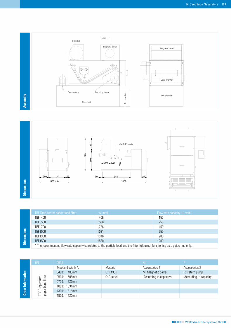
189
Ass
embl
yO
rder
info
rmat
ion
0500 L M R Type and width A Material Accessories 1 Accessories 2 0400: 406mm L: 1.4301 M: Magnetic barrel R: Return pump0500: 506mm C: C-steel (According to capacity) (According to capacity)0700: 726mm1000: 1031mm1300: 1316mm 1500: 1520mm
TBF
Dim
ensi
ons
380290 120
967
377
590
1350
15094060
365 + A
290 75"A"
Zulauf R 2" Nippel
380
290
120
967
377 590
1350
150
940
60
365
+ A
290
75"A
"
Zula
uf R
2" N
ippe
l
TBF Drop center paper band filter A (mm) Flow rate capacity* (L/min.) TBF 400 406 150 TBF 500 506 250 TBF 700 726 450 TBF 1000 1031 650TBF 1300 1316 900TBF 1500 1520 1200* The recommended flow rate capacity correlates to the particle load and the filter felt used, functioning as a guide line only.D
imen
sion
s
IX. Centrifugal Separators
TBF
Drop
cen
trepa
per b
and
filte
r Filter felt
Return pump
Clean tank
Inlet
Magnetic barrel
Decoiling device
Dirt
cha
mbe
r
Magnetic barrel
Used filter felt
Dirt chamber
Inlet R 2“ nipple
190
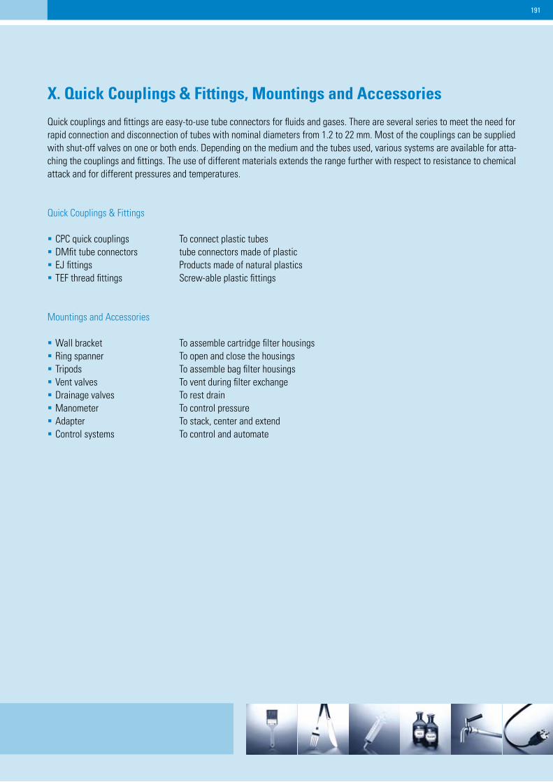
191
X. Quick Couplings & Fittings, Mountings and Accessories
Quick couplings and fittings are easy-to-use tube connectors for fluids and gases. There are several series to meet the need for rapid connection and disconnection of tubes with nominal diameters from 1.2 to 22 mm. Most of the couplings can be supplied with shut-off valves on one or both ends. Depending on the medium and the tubes used, various systems are available for atta-ching the couplings and fittings. The use of different materials extends the range further with respect to resistance to chemicalattack and for different pressures and temperatures.
Quick Couplings & Fittings
CPC quick couplings To connect plastic tubes DMfit tube connectors tube connectors made of plasticEJ fittings Products made of natural plasticsTEF thread fittings Screw-able plastic fittings
Mountings and Accessories
Wall bracket To assemble cartridge filter housings Ring spanner To open and close the housings Tripods To assemble bag filter housings Vent valves To vent during filter exchangeDrainage valves To rest drain Manometer To control pressureAdapter To stack, center and extend Control systems To control and automate
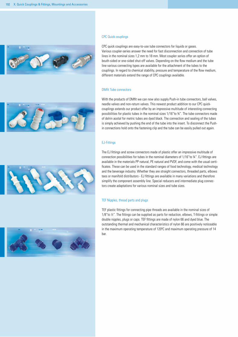
192 X. Quick Couplings & Fittings, Mountings and Accessories
CPC Quick couplings
CPC quick couplings are easy-to-use tube connectors for liquids or gases.Various coupler-series answer the need for fast disconnection and connection of tube lines in the nominal sizes 1,2 mm to 18 mm. Most coupler series offer an option of bouth-sided or one-sided shut-off valves. Depending on the flow medium and the tube line various connecting types are available for the attachment of the tubes to the couplings. In regard to chemical stability, pressure and temperature of the flow medium, different materials extend the range of CPC couplings available.
DMfit Tube connectors
With the products of DMfit we can now also supply Push-in tube connectors, ball valves, needle valves and non-return valves. This newest product addition to our CPC quick-couplings extends our product offer by an impressive multitude of interesting connecting possibilities for plastic tubes in the nominal sizes 1/16“to ¾“. The tube connectors made of delrin acetal for metric tubes are dyed black. The connection and sealing of the tubes is simply achieved by pushing the end of the tube into the insert. To disconnect the Push-in connections hold onto the fastening clip and the tube can be easily pulled out again.
EJ-Fittings
The EJ fittings and screw connectors made of plastic offer an impressive multitude of connection possibilities for tubes in the nominal diameters of 1/16“to ¾“. EJ fittings are available in the materials PP natural, PE natural and PVDF, and come with the usual certi-ficates. These can be used in the standard ranges of food technology, medical technology and the beverage industry. Whether they are straight connectors, threaded parts, elbows tees or manifold distributors - EJ fittings are available in many variations and therefore simplify the component assembly line. Special reducers and intermediate plug connec-tors create adaptations for various nominal sizes and tube sizes.
TEF Nipples, thread parts and plugs
TEF plastic fittings for connecting pipe threads are available in the nominal sizes of 1/8“to ½“. The fittings can be supplied as parts for reduction, elbows, T-fittings or simple double nipples, plugs or caps. TEF fittings are made of nylon 66 and dyed blue. The outstanding thermal and mechanical characteristics of nylon 66 are positively noticeable in the maximum operating temperature of 120ºC and maximum operating pressure of 14 bar.
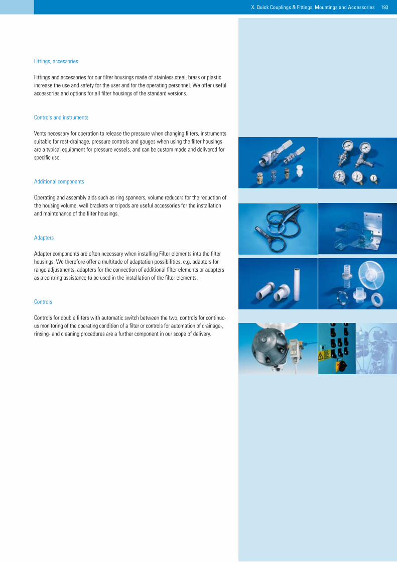
193X. Quick Couplings & Fittings, Mountings and Accessories
X. Schnellkupplungen & Fittings, Armaturen & Zubehör
Fittings, accessories
Fittings and accessories for our filter housings made of stainless steel, brass or plastic increase the use and safety for the user and for the operating personnel. We offer useful accessories and options for all filter housings of the standard versions.
Controls and instruments
Vents necessary for operation to release the pressure when changing filters, instruments suitable for rest-drainage, pressure controls and gauges when using the filter housings are a typical equipment for pressure vessels, and can be custom made and delivered for specific use.
Additional components
Operating and assembly aids such as ring spanners, volume reducers for the reduction of the housing volume, wall brackets or tripods are useful accessories for the installation and maintenance of the filter housings.
Adapters
Adapter components are often necessary when installing Filter elements into the filter housings. We therefore offer a multitude of adaptation possibilities, e.g. adapters for range adjustments, adapters for the connection of additional filter elements or adapters as a centring assistance to be used in the installation of the filter elements.
Controls
Controls for double filters with automatic switch between the two, controls for continuo-us monitoring of the operating condition of a filter or controls for automation of drainage-, rinsing- and cleaning procedures are a further component in our scope of delivery.
194
Are you interested in further information from Wolftechnik?
Every inquiry and every order requires a high measure of consultation and service by means of technical processing, offer generation and order execution. In order to always advise you well and comprehensively, we provide detailed documentation in the form of catalogues, data sheets and operating instructions. All information is continually made available under www.wolftechnik.de . This ensures that a fast, well-founded and optimal quality within the range of information can be delivered.
Wol
ftech
nik
New
slet
ter
Wol
ftech
nik
data
shee
ts
Wol
ftech
nik
oper
atin
g in
stru
ctio
ns
195
Publishing Information
Wolftechnik Filtersysteme GmbH
Malmsheimerstraße 6771263 Weil der Stadt
Phone +49 (0)7033-70 14-0Fax +49 (0)7033-70 14-20E-Mail: [email protected]
Managing directors:Bettina M.WolfClaudia BeckPeter KrauseHeinz Öhlschläger
Registered at:Leonberg District CourtReg. no.:HRB 1430VAT ID no.:DE 146 019 723
Responsible for contents:Peter Krause
Visual concept and implementation:Falkenstein Marketing & Kommunikationwww.hofgut-falkenstein.de
Photography:Martin Wolf Wagner BFFwww.martinwolfwagner.com
Fitti
ngs
and
quic
k co
uplin
gs
ww
w.w
olfte
chni
k.de
Wol
ftech
nik
imag
e br
ochu
re
Wol
ftech
nik
CD
Filtern ist unsere Sache
Ihr Partner für wirtschaftliche Filtration


Wolftechnik Filtersysteme GmbHMalmsheimerstraße 67D-71263 Weil der StadtPhone +49 (0)70 33-70 14-0Fax +49 (0)70 33-70 14-20
InternetE-Mail: [email protected]
B 295
Mal
msh
eim
erst
raße
Böblingen
Leonberg
Pforzheim
Calw
B 295
Heimsheim
Jose
f-Bey
erle
-Str.
Würm
Weil der Stadt
AUSFAHRT
HEIMSHEIM
HEI
LBR
ON
N
MÜNCHEN
CALW
WEIL DER STADT
SINDELFINGEN
BÖBLINGEN
LEONBERG
B 295
B 296
B 463
B 463
B 295
A8
A81
A8
A81
PFORZHEIM
STUTTGART
A 5KARLSRUHE


