Embed Size (px)
Citation preview
Proceedings of the 6th International Conference on Civil Structural and Transportation Engineering (ICCSTE'21)
Niagara Falls, Canada Virtual Conference – May 17-19, 2021
Paper No. 158
DOI: 10.11159/iccste21.158
158-1
Experimental Investigations of Eccentrically Loaded Circular Concrete-Filled Double Steel Tubular Short Columns
Junchang Ci1, Mizan Ahmed2, Shicai Chen1, Ahmed Hamoda3, Khaled Sennah4
1 Department of Civil Engineering, Beijing University of Technology, Beijing, P.R. China 2 Department of Civil Engineering, Monash University, Clayton, Melbourne, VIC, Australia
3 Department of Civil Engineering, Kafrelsheikh University, Kafrelsheikh, Egypt 4 Department of Civil Engineering, Ryerson University, Toronto, Canada
[email protected]; [email protected]; [email protected];
[email protected]; [email protected]
Abstract – Circular concrete-filled double steel tubular (CFDST) column offers improved strength and ductility compared to
conventional concrete-filled steel tubular (CFST) column. This paper reports an experimental program carried out on short CFDST
columns loaded either concentrically or eccentrically. The test parameters examine the influences of the eccentricity ratio and the
diameter-to-thickness ratio of the steel tubes. The eccentricity ratio varied from 0 to 1.64 while the diameter-to-thickness ratio of the
outer and inner steel tubes ranged between 43.8 to 54.75 and 32.57 to 45.6, respectively. It is observed that the tested columns failed in
a ductile manner, however, an increase of the eccentricity ratio reduces the ultimate loads of the columns remarkably.
Keywords: Concrete-filled double steel tubes; eccentric compression; stub columns; composite columns; ultimate
strength.
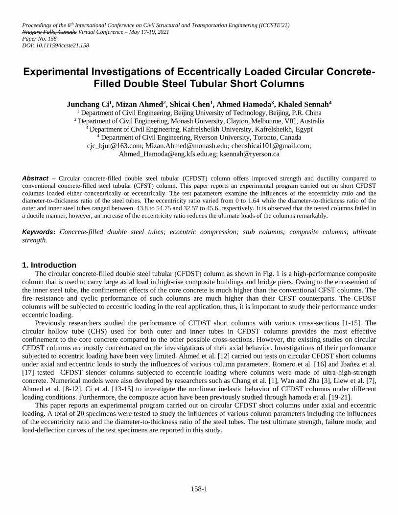
1. Introduction The circular concrete-filled double steel tubular (CFDST) column as shown in Fig. 1 is a high-performance composite
column that is used to carry large axial load in high-rise composite buildings and bridge piers. Owing to the encasement of
the inner steel tube, the confinement effects of the core concrete is much higher than the conventional CFST columns. The
fire resistance and cyclic performance of such columns are much higher than their CFST counterparts. The CFDST
columns will be subjected to eccentric loading in the real application, thus, it is important to study their performance under
eccentric loading.
Previously researchers studied the performance of CFDST short columns with various cross-sections [1-15]. The
circular hollow tube (CHS) used for both outer and inner tubes in CFDST columns provides the most effective
confinement to the core concrete compared to the other possible cross-sections. However, the existing studies on circular
CFDST columns are mostly concentrated on the investigations of their axial behavior. Investigations of their performance
subjected to eccentric loading have been very limited. Ahmed et al. [12] carried out tests on circular CFDST short columns
under axial and eccentric loads to study the influences of various column parameters. Romero et al. [16] and Ibañez et al.
[17] tested CFDST slender columns subjected to eccentric loading where columns were made of ultra-high-strength
concrete. Numerical models were also developed by researchers such as Chang et al. [1], Wan and Zha [3], Liew et al. [7],
Ahmed et al. [8-12], Ci et al. [13-15] to investigate the nonlinear inelastic behavior of CFDST columns under different
loading conditions. Furthermore, the composite action have been previously studied through hamoda et al. [19-21].
This paper reports an experimental program carried out on circular CFDST short columns under axial and eccentric
loading. A total of 20 specimens were tested to study the influences of various column parameters including the influences
of the eccentricity ratio and the diameter-to-thickness ratio of the steel tubes. The test ultimate strength, failure mode, and
load-deflection curves of the test specimens are reported in this study.
158-2
Fig. 1: Cross-section of a circular CFDST column.
2. Experiments on eccentrically loaded CFDST short columns 2.1. Specimens
A total of 20 columns including 16 CFDST columns loaded either concentrically or eccentrically as well as 2 CFST
columns and 2 DCFST columns were tested in this experimental program. The nominal diameter for the outer tube of the
tested columns was 219mm. The height of the test specimens was three times the diameter of the outer tube to avoid the
influence of the overall buckling of the columns. The geometric details of the test columns are given in Table 1. The
specimens are divided into four groups, namely G1, G2, G3, and G4. Group G1 consists of two CFST and DCFST
columns each makes a total number of 4. Out of these two columns, one is loaded concentrically whereas the other one is
under eccentric loading. In labeling the columns, taking CS-30-1 as an example, ‘CS’ indicates that the test specimen is
CFDST column (‘CF’-CFST column, ‘CD’-DCFST column), the number ‘30’ indicates the eccentric distance, (‘0’-axial
compressive test), and the last number indicates the group of test specimens. The CFDST columns were constructed by
placing the inner and outer hollow steel tubes concentrically and welded together with two steel bars to ensure their
concentricity and filled the hollow tubes with concrete. Furthermore, to prevent the column end effect, 8 stiffeners were
welded at the two ends of the column at an interval of 45° along the circumference of the outer tube before the concrete
pouring.
158-3
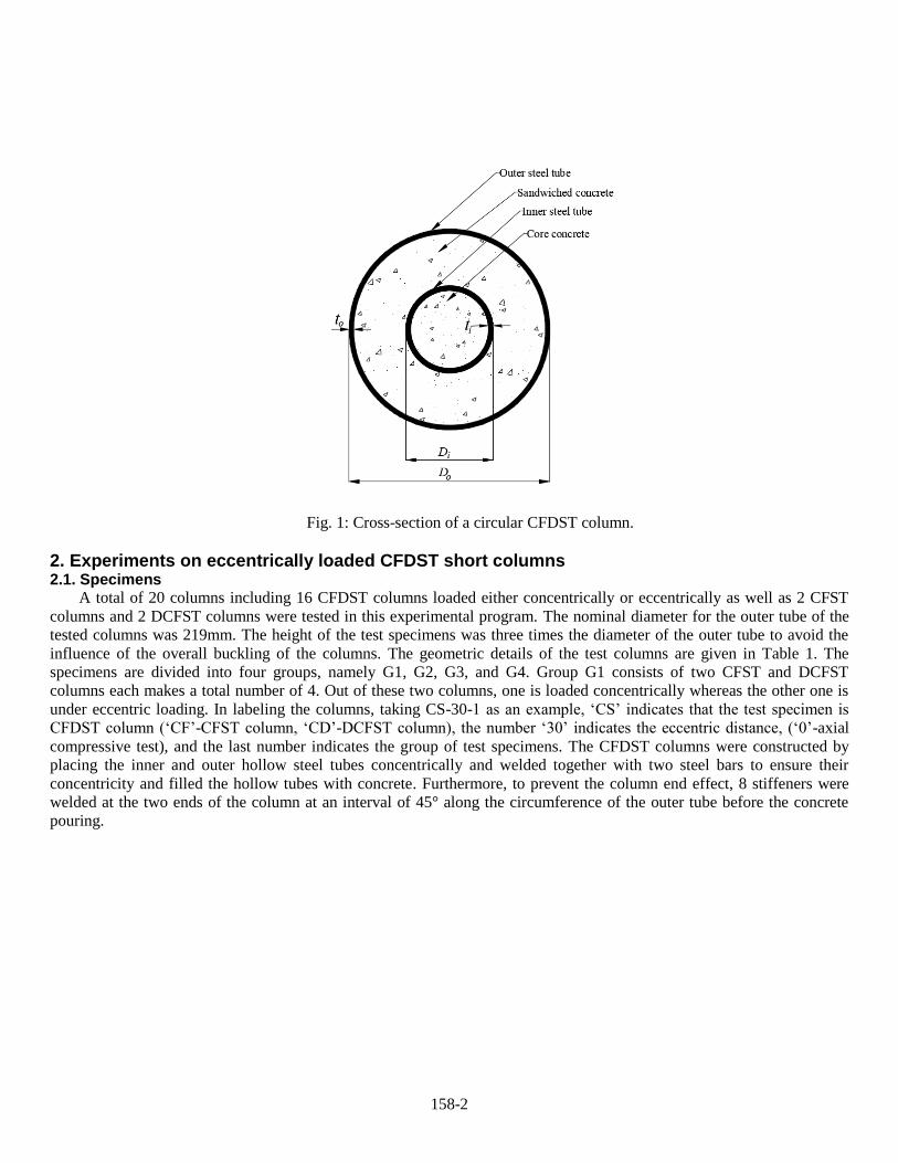
Table 1: Details of test specimens.
Grou
p
No
.
Column Outer tube Inner tube Ratio L
[mm] 𝑓𝑐𝑢′
[MPa]
Ecc.(𝑒/𝑟𝑐)
[mm]
𝑃𝑢,𝑒𝑥𝑝
(kN) 𝐷𝑜 [mm]
𝑡𝑜 [mm]
𝐷𝑖 [mm]
𝑡𝑖 [mm]
𝐷𝑜/𝑡𝑜 𝐷𝑖/𝑡𝑖
G1 1 CF-00-1 219 4 - - 54.75 - 660 47 0(0) 2704.3
7 2 CF-60-1 219 4 - - 54.75 - 660 47 60(0.55) 972.87
3 CD-00-
1
219 4 114 3.5 54.75 32.5
7
660 47 0(0) 2453.3
6 4 CD-60-
1
219 4 114 3.5 54.75 32.5
7
660 47 60(0.55) 1011.1
1 G2 5 CS-00-2 219 4 114 3.5 54.75 32.5
7
660 47 0(0) 3076.1
8 6 CS-00-
2#
219 4 114 3.5 54.75 32.5
7
660 47 0(0) 3014.6
2 7 CS-30-2 219 4 114 3.5 54.75 32.5
7
660 47 30(0.27) 1719.7
1 8 CS-60-2 219 4 114 3.5 54.75 32.5
7
660 47 60(0.55) 1171.1
7 9 CS-60-
2#
219 4 114 3.5 54.75 32.5
7
660 47 60(0.91) 1176.3
1 10 CS-140-
2
219 4 114 3.5 54.75 32.5
7
660 47 140(1.28) 626.47
11 CS-180-
2
219 4 114 3.5 54.75 32.5
7
660 47 180(1.64) 476.33
G3 12 CS-00-3 219 5 114 3.5 43.80 32.5
7
660 47 0(0) 3469.1
1 13 CS-00-
3#
219 5 114 3.5 43.80 32.5
7
660 47 0(0) 3484.2
5 14 CS-30-3 219 5 114 3.5 43.80 32.5
7
660 47 30(0.27) 1858.5
6 15 CS-60-3 219 5 114 3.5 43.80 32.5
7
660 47 60(0.91) 1066.1
7 16 CS-180-
3
219 5 114 3.5 43.80 32.5
7
660 47 180(1.64) 588.57
G4 17 CS-00-4 219 4 114 2.5 54.75 45.6
0
660 47 0(0) 2948.1
9 18 CS-00-
4#
219 4 114 2.5 54.75 45.6
0
660 47 0(0) 3118.1
2 19 CS-30-4 219 4 114 2.5 54.75 45.6
0
660 47 30(0.27) 1695.4
7 20 CS-180-
4
219 4 114 2.5 54.75 45.6
0
660 47 180(1.64) 456.63
Note:“#”indicates that it was a repeated test specimen.
2.2. Material properties of steel and concrete
The steel tube with the steel grade of Q235 was used to make the test specimens with the nominal yield strength of
235 N/mm2. Tensile coupon tests were performed according to the Chinese standard GB/T 228-2010 [18] to measure the
material properties of the steel tubes. Table 2 presents the measured average ± standard deviation of the material properties
of steel tubes obtained from tensile tests.
Table 2: Material properties of steel tubes obtained from tensile coupon tests.
Tube type No. Geometry of tube
D×t [mm] 𝑓𝑠𝑦(MPa) 𝐸𝑠(GPa) 𝑓𝑠𝑢
(MPa) 𝜀𝑢
Outer tube 1 219×4 301.3±5.6 202.5±4.8 387.7±1.9 0.19±0.01 2 219×5 331.7±6.9 416.9±2.6 0.15±0.01
Inner tube 3 114×2.5 314.4±5.2 198.1±6.3
375.3±2.5 0.19±0.01 4 114×3.5 328.8±10.0 415.5±6.5 0.15±0.01
Ready-mix concrete was used to fill the hollow tubes of test columns. Three concrete cube samples
(150mm×150mm×150mm) were cast and cured at the same conditions of test columns and used to measure the
compressive strength of concrete. The average cube strength was measured after 28 days was 47MPa.
158-4
2.3. Test setup
The columns were tested using a hydraulic testing machine with a capacity of 4000kN in the structural laboratory of
Beijing University of Technology, China. Two different loading scenarios were used to test the columns under concentric
and eccentric loading. Where the columns were subjected to axial load, the specimens were directly loaded to the testing
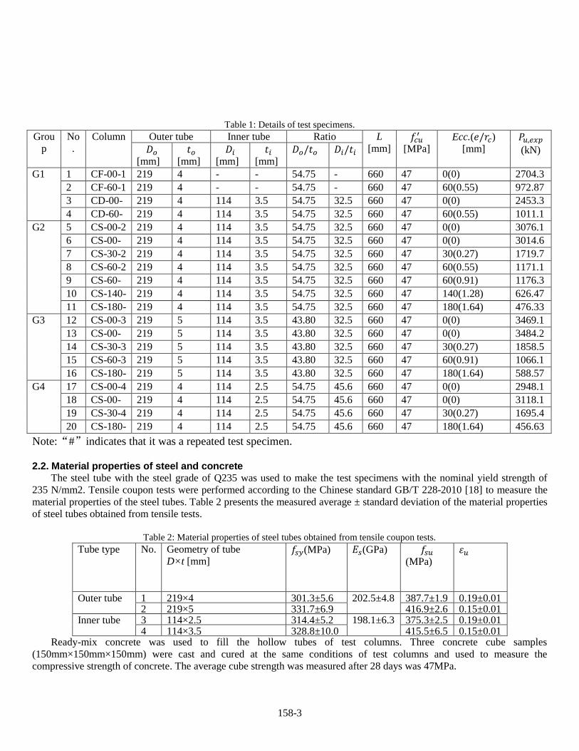
machine whereas the eccentric loading devices as illustrated in Fig. 2 composed of an adaptor plate and loading plate with
a spherical hinge were designed. The loading plates had grooved at different offsets to obtain the eccentric distances.
Figure 3 shows the test setup of columns under different loading conditions.
Fig. 2: Loading method.
(a)Under axial compression (b)Under small eccentric
loading (30mm and 60mm)
(c) Under large eccentric
loading (140mm and 180mm)
Fig. 3: Actual test configurations of the column specimen under axial and eccentric compression.
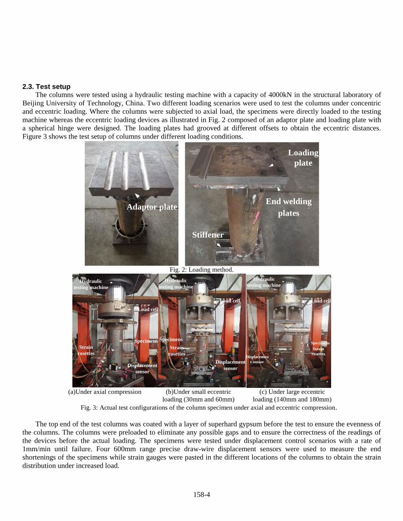
The top end of the test columns was coated with a layer of superhard gypsum before the test to ensure the evenness of
the columns. The columns were preloaded to eliminate any possible gaps and to ensure the correctness of the readings of
the devices before the actual loading. The specimens were tested under displacement control scenarios with a rate of
1mm/min until failure. Four 600mm range precise draw-wire displacement sensors were used to measure the end
shortenings of the specimens while strain gauges were pasted in the different locations of the columns to obtain the strain
distribution under increased load.
Adaptor plateEnd welding
plates
Loading
plate
Stiffener
Displacement
sensor
Specimens
Strain
rosettes
Load cell
Hydraulic
testing machine
Displacement
sensor
Specimens
Strain
rosettes
Load cell
Hydraulic
testing machine
Hydraulic
testing machine
Hydraulic
testing machine
Load cell
Specimens
Strain
rosettesDisplacemen
t sensor
158-5
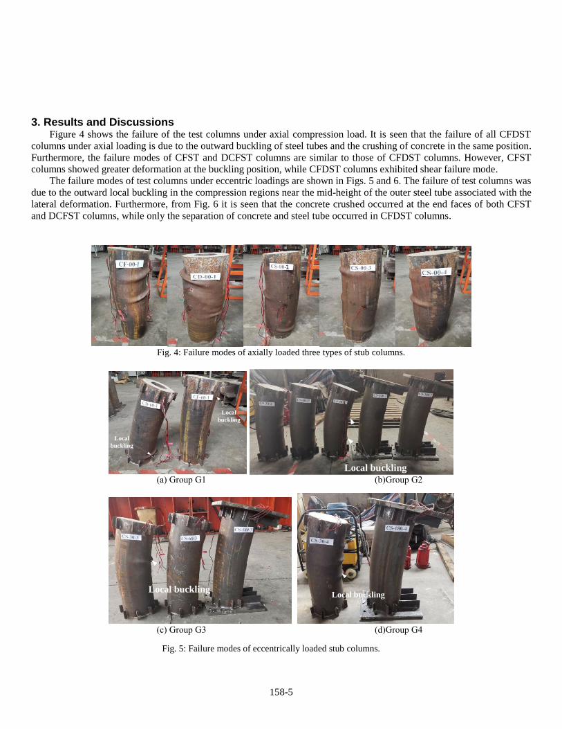
3. Results and Discussions Figure 4 shows the failure of the test columns under axial compression load. It is seen that the failure of all CFDST
columns under axial loading is due to the outward buckling of steel tubes and the crushing of concrete in the same position.
Furthermore, the failure modes of CFST and DCFST columns are similar to those of CFDST columns. However, CFST
columns showed greater deformation at the buckling position, while CFDST columns exhibited shear failure mode.
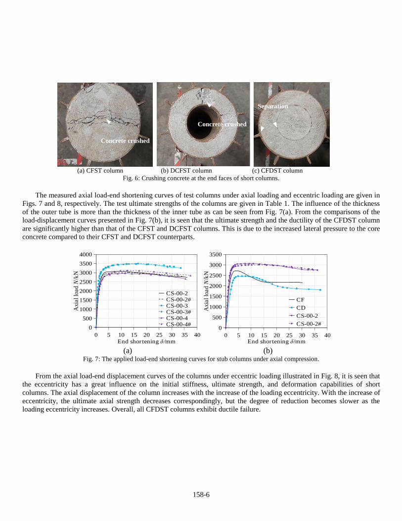
The failure modes of test columns under eccentric loadings are shown in Figs. 5 and 6. The failure of test columns was
due to the outward local buckling in the compression regions near the mid-height of the outer steel tube associated with the
lateral deformation. Furthermore, from Fig. 6 it is seen that the concrete crushed occurred at the end faces of both CFST
and DCFST columns, while only the separation of concrete and steel tube occurred in CFDST columns.
Fig. 4: Failure modes of axially loaded three types of stub columns.
(a) Group G1 (b)Group G2
(c) Group G3 (d)Group G4
Fig. 5: Failure modes of eccentrically loaded stub columns.
Local
buckling
Local
buckling
Local buckling
Local bucklingLocal buckling
158-6
(a) CFST column (b) DCFST column (c) CFDST column
Fig. 6: Crushing concrete at the end faces of short columns.
The measured axial load-end shortening curves of test columns under axial loading and eccentric loading are given in
Figs. 7 and 8, respectively. The test ultimate strengths of the columns are given in Table 1. The influence of the thickness
of the outer tube is more than the thickness of the inner tube as can be seen from Fig. 7(a). From the comparisons of the
load-displacement curves presented in Fig. 7(b), it is seen that the ultimate strength and the ductility of the CFDST column
are significantly higher than that of the CFST and DCFST columns. This is due to the increased lateral pressure to the core
concrete compared to their CFST and DCFST counterparts.
(a) (b)
Fig. 7: The applied load-end shortening curves for stub columns under axial compression.
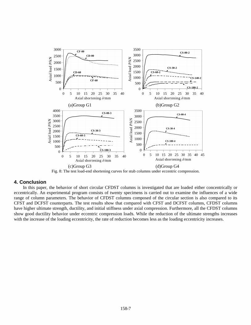
From the axial load-end displacement curves of the columns under eccentric loading illustrated in Fig. 8, it is seen that
the eccentricity has a great influence on the initial stiffness, ultimate strength, and deformation capabilities of short
columns. The axial displacement of the column increases with the increase of the loading eccentricity. With the increase of
eccentricity, the ultimate axial strength decreases correspondingly, but the degree of reduction becomes slower as the
loading eccentricity increases. Overall, all CFDST columns exhibit ductile failure.
Concrete crushed
Concrete crushed
Separation
0
500
1000
1500
2000
2500
3000
3500
4000
0 5 10 15 20 25 30 35 40
Axia
l lo
ad
N/k
N
End shor tening δ/mm
CS-00-2CS-00-2#CS-00-3CS-00-3#CS-00-4CS-00-4#
0
500
1000
1500
2000
2500
3000
3500
0 5 10 15 20 25 30 35 40
Axia
l lo
ad
N/k
N
End shor tening δ/mm
CF
CD
CS-00-2
CS-00-2#
158-7
(a)Group G1 (b)Group G2
(c)Group G3 (d)Group G4
Fig. 8: The test load-end shortening curves for stub columns under eccentric compression.
4. Conclusion In this paper, the behavior of short circular CFDST columns is investigated that are loaded either concentrically or
eccentrically. An experimental program consists of twenty specimens is carried out to examine the influences of a wide
range of column parameters. The behavior of CFDST columns composed of the circular section is also compared to its
CFST and DCFST counterparts. The test results show that compared with CFST and DCFST columns, CFDST columns
have higher ultimate strength, ductility, and initial stiffness under axial compression. Furthermore, all the CFDST columns
show good ductility behavior under eccentric compression loads. While the reduction of the ultimate strengths increases
with the increase of the loading eccentricity, the rate of reduction becomes less as the loading eccentricity increases.
0
500
1000
1500
2000
2500
3000
0 5 10 15 20 25 30 35 40
Axia
l lo
ad
P/k
N
Axial shor tening δ/mm
CF-00
CD-00
CD-60
CF-60
0
500
1000
1500
2000
2500
3000
3500
0 5 10 15 20 25 30 35 40
Ax
ial
load
P/k
N
Axial shor tening δ/mm
CS-00-2
CS-30-2
CS-60-2
CS-140-2
CS-180-2
0
500
1000
1500
2000
2500
3000
3500
4000
0 5 10 15 20 25 30 35 40
Ax
ial
load
P/k
N
Axial shor tening δ/mm
CS-00-3
CS-30-3
CS-60-3
CS-180-3 0
500
1000
1500
2000
2500
3000
3500
0 5 10 15 20 25 30 35 40 45
Ax
ial
load
P/k
N
Axial shor tening δ/mm
CS-00-4
CS-30-4
CS-180-4
158-8
References [1] Chang X, Ru ZL, Zhou W, Zhang YB. Study on concrete-filled stainless steel-carbon steel tubular(CFSCT) stub
columns under compression. Thin-Walled Struct 2013; 63: 125-133.
[2] Fang XD and Lin SJ (2014) Axial compressive test of columns with multi barrel tube-confined high performance
concrete. J Build Struc, 35(4): 236-45 (in Chinese).
[3] Wan CY and Zha XX (2016) Nonlinear analysis and design of concrete-filled dual steel tubular columns under axial
loading. Steel Compos Struct, 20(3): 571-97.
[4] Qian J, Li N, Ji X, Zhao Z. Experimental study on the seismic behavior of high strength concrete filled double-tube
columns. Earth. Eng. Eng. Vib. 2014; 13 (1): 47-57.
[5] Ekmekyapar T, AL-Eliwi BJM. Concrete filled double circular steel tube (CFDCST) stub columns. Eng Struct
2017;135: 68-80.
[6] Pei WJ. Research on mechanical performance of multibarrel tube-confined concrete columns. ME Thesis, Chang’an
University, Xi’an, China;2005. (in Chinese)
[7] Liew JR, Xiong M, Xiong D, Design of concrete filled tubular beam-columns with high strength steel and concrete,
Struct., 2016; 8:213-226.
[8] Ahmed M, Liang QQ, Patel VI, Hadi MNS. Nonlinear analysis of rectangular concrete-filled double steel tubular short
columns incorporating local buckling. Eng Struct 2018; 175:13-26.
[9] Ahmed M, Liang QQ, Patel VI, Hadi MNS. Experimental and numerical studies of square concrete-filled double steel
tubular short columns under eccentric loading. Eng Struct 2019; 197:109419.
[10] Ahmed M, Liang QQ, Patel VI, Hadi MNS. Numerical analysis of axially loaded circular high strength concrete-filled
double steel tubular short columns. Thin-Walled Struct 2019; 138:105-116.
[11] Ahmed M, Liang QQ, Patel VI, Hadi MNS. Experimental and numerical investigations of eccentrically loaded
rectangular concrete-filled double steel tubular columns. J Constr Steel Res 2020; 167: 105949.
[12] Ahmed M, Liang QQ, Patel VI, Hadi MNS. Behavior of eccentrically loaded double circular steel tubular short
columns filled with concrete. Eng Struct 2019; 201: 109790.
[13] Ci JC, Jia H, Chen SC, Yan WM, Song TY, Kim KS. Performance analysis and bearing capacity calculation on
circular concrete-filled double steel tubular stub columns under axial compression. Struct 2020; 25:554-565.
[14] Ci JC, Chen SC, Jia H, Yan WM, Song TY, Kim KS. Axial compression performance analysis and bearing capacity
calculation square concrete-filled double-tube short columns. Mar Struct 2020;72: 102775.
[15] Ci JC, Jia H, Ahmed M, Chen SC, Zhou D, Hou L.Experimental and numerical analysis of circular concrete-filled
double-steel tubular stub columns with inner square hollow section. Eng Struct 2021;227: 111400.
[16] Romero ML, Ibañez C, Espinós A, Portolés J, Hospitaler A. Influence of ultra-high strength concrete on circular
concrete-filled dual steel columns. Struct. 2017; 9: 13-20.
[17] Ibañez C, Romero ML, Espinós A, Portolés JM, Albero V. Ultra-high strength concrete on eccentrically loaded
slender circular concrete-filled dual steel columns. Struct. 2017; 12: 64-74.
[18] GB/T 228.1-2010. Metallic materials-Tensile testing-Part 1:Method of test at room temperature. 2010. (in Chinese)
[19]Hamoda, Ahmed, Fathi Abdelazeem, and Mohamed Emara. "Concentric compressive behavior of hybrid concrete–
Stainless Steel Double-Skin Tubular Columns incorporating High Performance Concretes." Thin-Walled
Structures 159 (2021): 107297.
[20] Hamoda, Ahmed, Mohamed Emara, and Walid Mansour. "Behavior of steel I-beam embedded in normal and steel
fiber reinforced concrete incorporating demountable bolted connectors." Composites Part B: Engineering 174 (2019):
106996.
[21] Hamoda, A., Hossain, K.M.A., Sennah, K., Shoukry, M. and Mahmoud, Z., 2017. Behaviour of composite high
performance concrete slab on steel I-beams subjected to static hogging moment. Engineering Structures, 140, pp.51-
65.


