Embed Size (px)
Citation preview
Field Visit
Zamrath M.N.M. 100618D
(This is submitted as partial fulfillment for module EN2902 Field Visit
Department of Electronic and Telecommunication)
1st May 2013
2 | P a g e
Introduction
Field visit is intended on familiarizing the students in their related industries. Field trip related to
“Field Visit” module was initially planned to go only to Piduruthalagala. But with additional one day
on our hand we could climb over the Kikiliyamana as well. Thus our visit was extended to two days‟
field trip to Piduruthalagala and followed by Kikiliyamana. Therefore this report will consider each
visit separately.
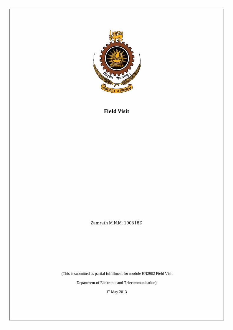
Piduruthalagala (in Nuwara Eliya) is the highest top of the country and it is obvious that the Airport
and Aviation (A&A) service (pvt) ltd considered it with the favor of unique geographical feature to
install the Sri Lanka‟s main radar system. The Piduruthalagala map is shown below.
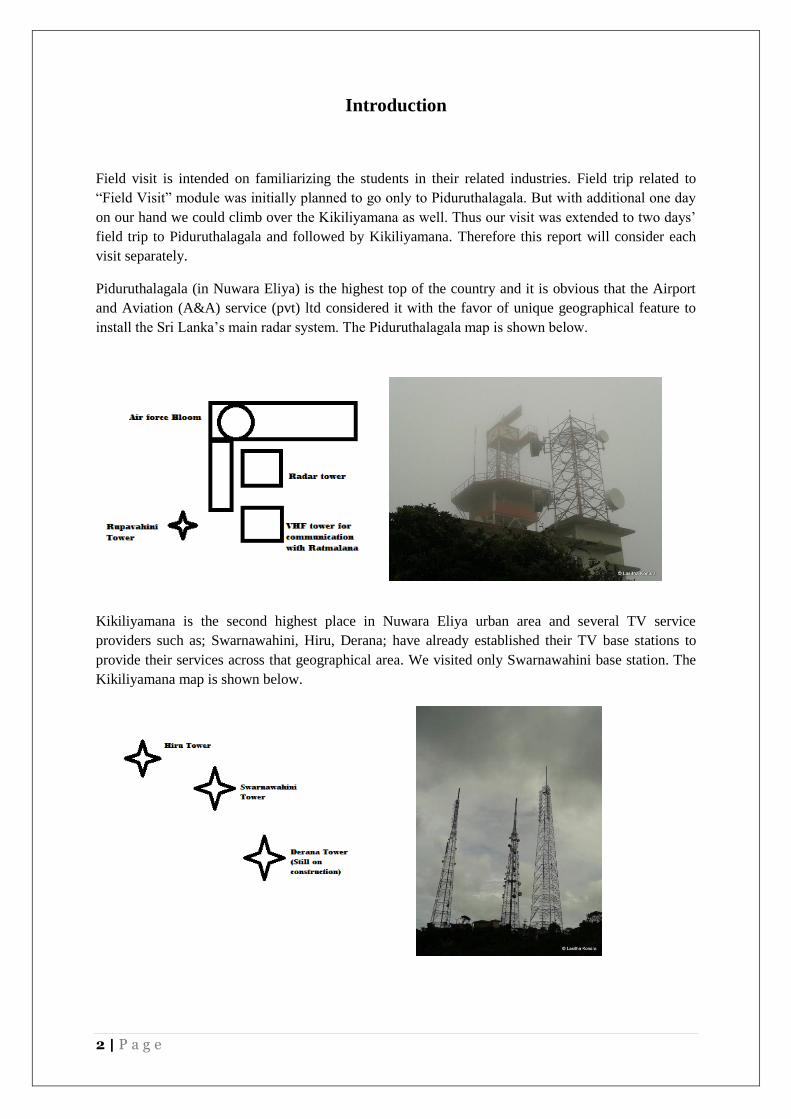
Kikiliyamana is the second highest place in Nuwara Eliya urban area and several TV service
providers such as; Swarnawahini, Hiru, Derana; have already established their TV base stations to
provide their services across that geographical area. We visited only Swarnawahini base station. The
Kikiliyamana map is shown below.
3 | P a g e
Field observations in Piduruthalagala
1. Radar system
Radar system in Piduruthalagala is responsible for the traffic control on tester of Sri Lanka while
ensuring a proper scheme for aircrafts to follow as well as for detect and produce the aircrafts to the
responsible authorities such as Sri Lanka Aircraft and Aviation ltd and sometimes Defense authorities.
For the detecting purposes there are two major types of Radars namely Primary and Secondary which
is separated under military and civil respectively.
An aircraft must include a piece of equipment called “Transponder” aboard the aircraft to let the radar
systems to convince that they are friendly. This mechanism automatically responds to the radar
system by providing all necessary details as required. This Radar is called Secondary Surveillance
Radar (S.S.R.). Even the Transponder is an imposed equipment for every aircraft, some aircraft
occasionally break this law and enter in to the zone without a transponder. This threat is common in
war times therefore the Primary radar (P.S.R.); which is capable of detecting enemy aircrafts or
unknown aircrafts which fail to render their identity; is used especially in war times by air force.
Piduruthalagala base station used this radar in war times to detect enemy aircrafts and to produce
those information to the defense.
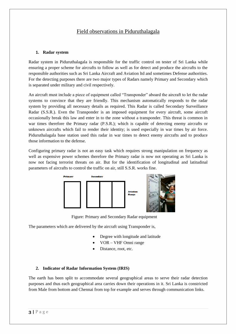
Configuring primary radar is not an easy task which requires strong manipulation on frequency as
well as expensive power schemes therefore the Primary radar is now not operating as Sri Lanka is
now not facing terrorist threats on air. But for the identification of longitudinal and latitudinal
parameters of aircrafts to control the traffic on air, still S.S.R. works fine.
Figure: Primary and Secondary Radar equipment
The parameters which are delivered by the aircraft using Transponder is,
Degree with longitude and latitude
VOR – VHF Omni range
Distance, root, etc.
2. Indicator of Radar Information System (IRIS)
The earth has been split to accommodate several geographical areas to serve their radar detection
purposes and thus each geographical area carries down their operations in it. Sri Lanka is constricted
from Male from bottom and Chennai from top for example and serves through communication links.
4 | P a g e
Figure: Communication links through several geographical areas
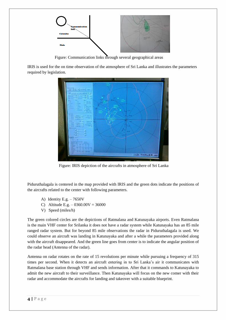
IRIS is used for the on time observation of the atmosphere of Sri Lanka and illustrates the parameters
required by legislation.
Figure: IRIS depiction of the aircrafts in atmosphere of Sri Lanka
Piduruthalagala is centered in the map provided with IRIS and the green dots indicate the positions of
the aircrafts related to the center with following parameters.
A) Identity E.g. – 7650V
C) Altitude E.g. – 0360.00V = 36000
V) Speed (miles/h)
The green colored circles are the depictions of Ratmalana and Katunayaka airports. Even Ratmalana
is the main VHF center for Srilanka it does not have a radar system while Katunayaka has an 85 mile
ranged radar system. But for beyond 85 mile observations the radar in Piduruthalagala is used. We
could observe an aircraft was landing in Katunayaka and after a while the parameters provided along
with the aircraft disappeared. And the green line goes from center is to indicate the angular position of
the radar head (Antenna of the radar).
Antenna on radar rotates on the rate of 15 revolutions per minute while pursuing a frequency of 315
times per second. When it detects an aircraft entering in to Sri Lanka‟s air it communicates with
Ratmalana base station through VHF and sends information. After that it commands to Katunayaka to
admit the new aircraft to their surveillance. Then Katunayaka will focus on the new comer with their
radar and accommodate the aircrafts for landing and takeover with a suitable blueprint.
5 | P a g e
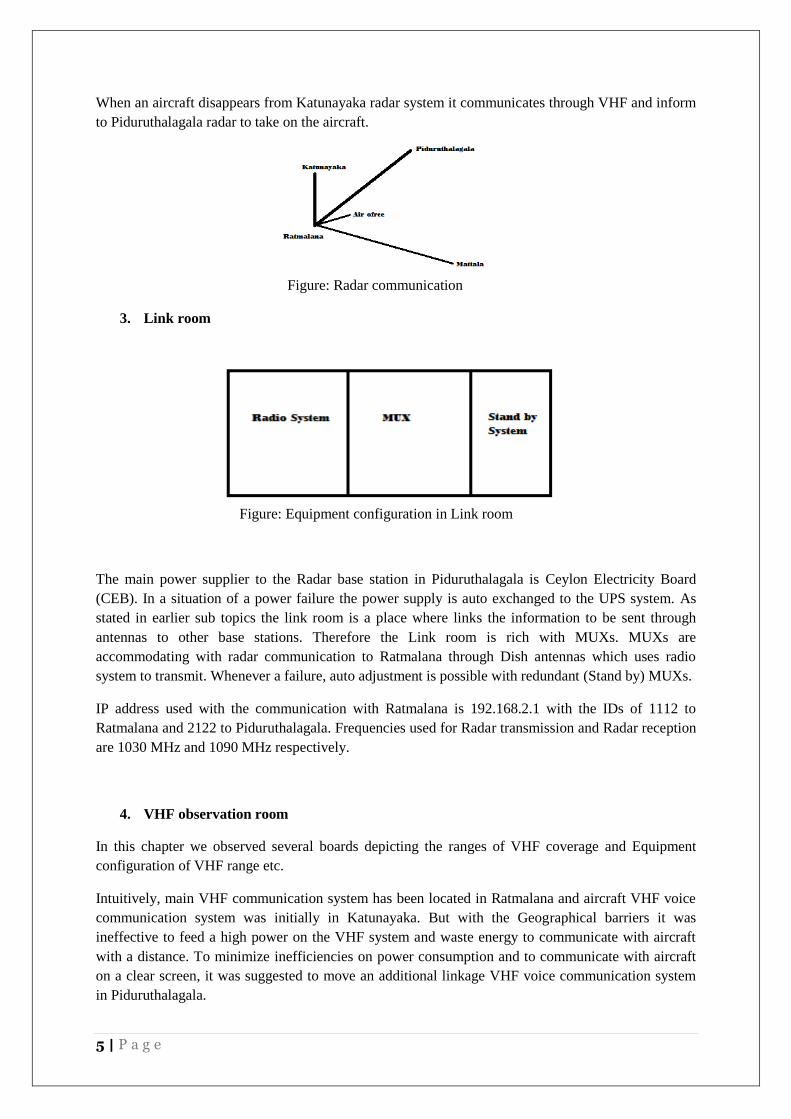
When an aircraft disappears from Katunayaka radar system it communicates through VHF and inform
to Piduruthalagala radar to take on the aircraft.
Figure: Radar communication
3. Link room
Figure: Equipment configuration in Link room
The main power supplier to the Radar base station in Piduruthalagala is Ceylon Electricity Board
(CEB). In a situation of a power failure the power supply is auto exchanged to the UPS system. As
stated in earlier sub topics the link room is a place where links the information to be sent through
antennas to other base stations. Therefore the Link room is rich with MUXs. MUXs are
accommodating with radar communication to Ratmalana through Dish antennas which uses radio
system to transmit. Whenever a failure, auto adjustment is possible with redundant (Stand by) MUXs.
IP address used with the communication with Ratmalana is 192.168.2.1 with the IDs of 1112 to
Ratmalana and 2122 to Piduruthalagala. Frequencies used for Radar transmission and Radar reception
are 1030 MHz and 1090 MHz respectively.
4. VHF observation room
In this chapter we observed several boards depicting the ranges of VHF coverage and Equipment
configuration of VHF range etc.
Intuitively, main VHF communication system has been located in Ratmalana and aircraft VHF voice
communication system was initially in Katunayaka. But with the Geographical barriers it was
ineffective to feed a high power on the VHF system and waste energy to communicate with aircraft
with a distance. To minimize inefficiencies on power consumption and to communicate with aircraft
on a clear screen, it was suggested to move an additional linkage VHF voice communication system
in Piduruthalagala.
6 | P a g e
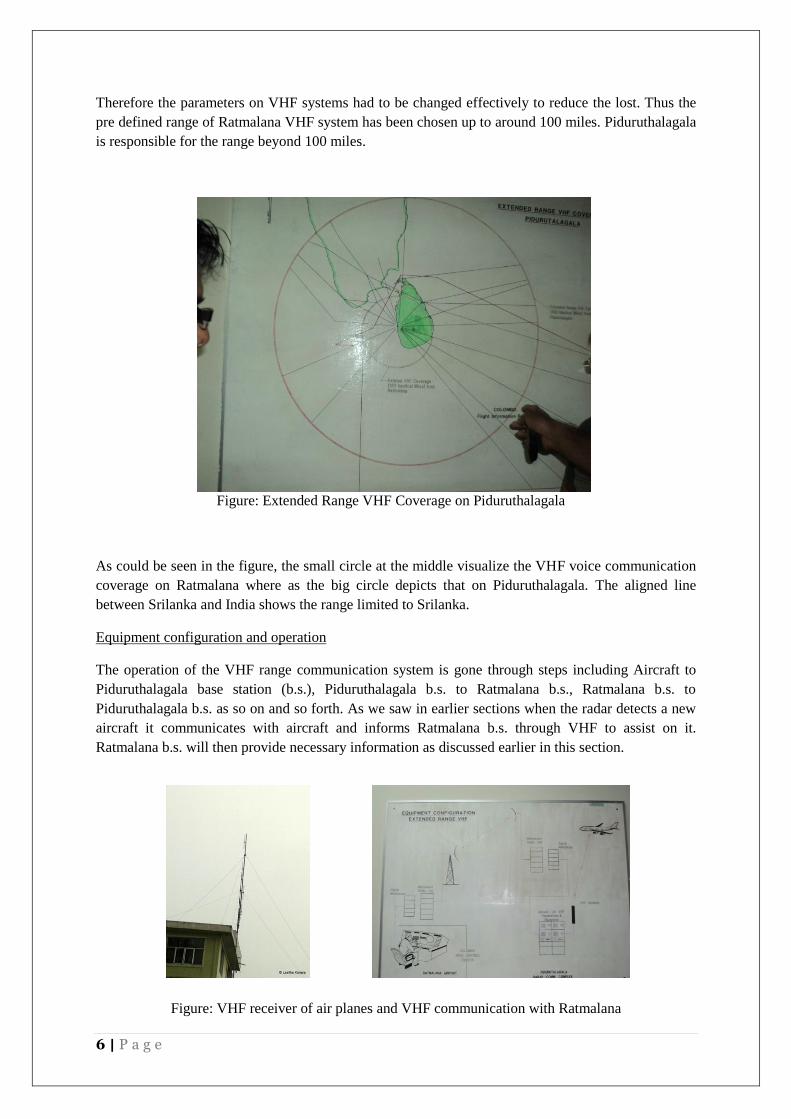
Therefore the parameters on VHF systems had to be changed effectively to reduce the lost. Thus the
pre defined range of Ratmalana VHF system has been chosen up to around 100 miles. Piduruthalagala
is responsible for the range beyond 100 miles.
Figure: Extended Range VHF Coverage on Piduruthalagala
As could be seen in the figure, the small circle at the middle visualize the VHF voice communication
coverage on Ratmalana where as the big circle depicts that on Piduruthalagala. The aligned line
between Srilanka and India shows the range limited to Srilanka.
Equipment configuration and operation
The operation of the VHF range communication system is gone through steps including Aircraft to
Piduruthalagala base station (b.s.), Piduruthalagala b.s. to Ratmalana b.s., Ratmalana b.s. to
Piduruthalagala b.s. as so on and so forth. As we saw in earlier sections when the radar detects a new
aircraft it communicates with aircraft and informs Ratmalana b.s. through VHF to assist on it.
Ratmalana b.s. will then provide necessary information as discussed earlier in this section.
Figure: VHF receiver of air planes and VHF communication with Ratmalana
7 | P a g e
Field observations in Kikiliyamana
“Swarnawahini” base station in Kikiliyamana is the second day field visit in our field trip. We have
been brought through TV transmission section as well as Radio transmission section in Swarnawahini
base station.
1. TV transmission
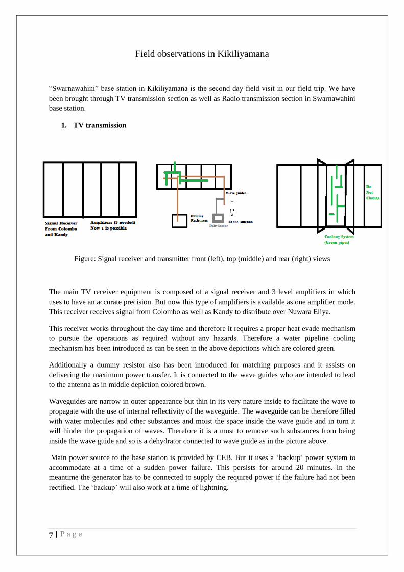
Figure: Signal receiver and transmitter front (left), top (middle) and rear (right) views
The main TV receiver equipment is composed of a signal receiver and 3 level amplifiers in which
uses to have an accurate precision. But now this type of amplifiers is available as one amplifier mode.
This receiver receives signal from Colombo as well as Kandy to distribute over Nuwara Eliya.
This receiver works throughout the day time and therefore it requires a proper heat evade mechanism
to pursue the operations as required without any hazards. Therefore a water pipeline cooling
mechanism has been introduced as can be seen in the above depictions which are colored green.
Additionally a dummy resistor also has been introduced for matching purposes and it assists on
delivering the maximum power transfer. It is connected to the wave guides who are intended to lead
to the antenna as in middle depiction colored brown.
Waveguides are narrow in outer appearance but thin in its very nature inside to facilitate the wave to
propagate with the use of internal reflectivity of the waveguide. The waveguide can be therefore filled
with water molecules and other substances and moist the space inside the wave guide and in turn it
will hinder the propagation of waves. Therefore it is a must to remove such substances from being
inside the wave guide and so is a dehydrator connected to wave guide as in the picture above.
Main power source to the base station is provided by CEB. But it uses a „backup‟ power system to
accommodate at a time of a sudden power failure. This persists for around 20 minutes. In the
meantime the generator has to be connected to supply the required power if the failure had not been
rectified. The „backup‟ will also work at a time of lightning.
8 | P a g e
2. FM transmission
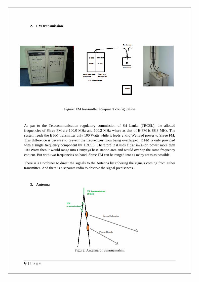
Figure: FM transmitter equipment configuration
As par to the Telecommunication regulatory commission of Sri Lanka (TRCSL), the allotted
frequencies of Shree FM are 100.0 MHz and 100.2 MHz where as that of E FM is 88.3 MHz. The
system feeds the E FM transmitter only 100 Watts while it feeds 2 kilo Watts of power to Shree FM.
This difference is because to prevent the frequencies from being overlapped. E FM is only provided
with a single frequency component by TRCSL. Therefore if it uses a transmission power more than
100 Watts then it would range into Deniyaya base station area and would overlap the same frequency
content. But with two frequencies on hand, Shree FM can be ranged into as many areas as possible.
There is a Combiner to direct the signals to the Antenna by cohering the signals coming from either
transmitter. And there is a separate radio to observe the signal preciseness.
3. Antenna
Figure: Antenna of Swarnawahini

9 | P a g e
Antenna consists two dishes to receive signals from Colombo as well as from Kandy. The reason
behind using two dishes is to guarantee the signal receiving from Colombo. The Line of Sight (LoS)
from Colombo is lied between two mountains in Kegalle and at a heavy rain condition the LoS will
tend to be faded. Therefore an additional root is introduced as Colombo to Kandy and in turn Kandy
to Nuwara Eliya.
Top of the antenna holds the TV transmitter (UHF) and therefore the position allows the tower to
transmit signals uniformly over the geographical area. FM transmitters are set up little below than TV
transmitter in a cross view.
10 | P a g e
Discussions and Recommendations (D&R)
D&R in Piduruthalagala visit
The world now we are living is very complex and the technology which grows along with that
requires a high insight on the new technological environment. The point to strike here is the
usage of the equipments in Piduruthalagala is aged a long way and it is required to replace or
modify because it is obvious that several countries have made aircrafts as well as unmanned
aircrafts which are not detectable by even a primary radar for an example.
It would be a better future investment if we can establish a proper satellite system linked to
Piduruthalagala base station.
D&R in Kikiliyamana visit
A problem has been highlighted in Kikiliyamana field visit is the LoS disruption and it can be
evaded by shifting the base station to Piduruthalagala. But it is not feasible due to many
reasons such as the cost which should be incurred in order to reinstall the base station,
legislation power of other governmental authorities to persist on Piduruthalagala, etc.
The frequency allotted to E FM is also a concern while others are having two frequencies; E
FM is having only one of them. If E FM has more than one frequency, it can be used to avoid
unnecessary expenses.
One of the problems we saw in Kikiliyamana site is utilization of old equipments which are
considered as power ineffective such as using three level amplifiers for the TV signal
transmissions. The unfavorable power failures could be avoided if they use new equipments
which are power effective.


