Embed Size (px)
Citation preview
3 4 4 5 6 0 3 8 4 5 3 6 5
-

1 , . . . . . . . . . . . ...... 2
ORNLTM-12757 Dist. Category UC-426
Fusion Energy Division
FEEDBACK CONTROL AND STABILIZATION EXPERIMENTS ON THE TEXAS
EXPERIMENTAL TOKAMAK (TEXT)
T. Uckan B. Richards* A. J. Wootton* R. D. Bengtson* R. Bravenec* B. A. Carreras G. X. Li*
P. D. Hurwitz* P. E. Phillips* W. L. Rowan* H. Y. w. TSUi*
J. R. Uglum* Y. Wen* D. Winslow*
Fusion Research Center, The University of Texas at Austin, Austin, TX 78712. *
This is a preprint of a paper presented at the 1 lth International Conference on Plasma Surface Interactions in Controlled Fusion Devices, May 23-27, 1994, Ibzaki-ken, Japan.
Date Published: June 1994
Prepared for the Office of Fusion Energy
Budget Activity No. AT 10
Prepared by OAK RIDGE NATIONAL LABORATORY
Oak Ridge, Tennessee 37831 managed by
MARTIN MARIETTA ENERGY SYSTEMS, INC. for the
U.S. DEPARTMENT OF ENERGY under contract DE-AC05-840R2 1400
3 4 4 5 6 0384536 5

CONTENTS
Page
ABSTRACT .................................................................................................................. 1 1 . INTRODUCTION ................................................................................................... 1
3 . EXPERIMENTAL OBSERVATIONS AND RESULTS ....................................... 4 4 . DISCUSSION ......................................................................................................... 11 ACKNOWLEDGMENTS ............................................................................................. 11 REFERENCES .............................................................................................................. 12
2 . FEEDBACK WAVE-LAUNCHING SYSTEM AND DIAGNOSTIC .................. 2
... 111

1
FEEDBACK CONTROL AND STABILIZATION EXPERIMENTS ON THE TEXAS EXPERIMENTAL TOKAMAK
(TEXT)
T. Uckan B. Richards A. J. Wootton R. D. Bengtson R. Bravenec B. A. Carreras G. X. Li
P. D. Hunvitz P. E. Phillips W. L. Rowan H. Y. W. Tsui J. R. Uglum Y. Wen D. Winslow
ABSTRACT
Plasma edge feedback experiments on the Texas Experimental Tokamak (TEXT) have been successful in controlling the edge plasma potential fluctuation level. The feedback wave-launcher, consisting of electrostatic probes located in the shadow of the limiter, is driven by the local edge potential fluctuations. In general, the edge potential fluctuations are modified in a broad frequency band. Moreover, it is observed that the potential fluctuations can be reduced (5100 kHz) without enhancing other modes, or excited (10 to 12 kHz), depending on the phase difference between the driver and the launcher signal, and gain of the system. This turbulence modification is achieved not only locally but also halfway around the torus and has about 2 cm of poloidal extent. Experiments on the characterization of the global plasma parameters with the edge feedback are discussed. Effects of the edge feedback on the estimated fluctuation-induced radial particle flux as well as on the local plasma parameters are presented.
1. INTRODUCTION
The edge plasma fluctuations in tokamaks play a significant role in the overall plasma confinement characteristics [ 13. Experiments on the Texas Experimental Tokamak (TEXT) indicate that electrostatic fluctuations in the edge plasma are responsible for most of the energy and particle transport [2]. Although the underlying basic mechanisms that drive the edge turbulence are still the subject of ongoing research in fusion devices, in this work, a possible control and influence of the edge plasma fluctuation level are investigated on TEXT. These exploratory experiments have been performed utilizing edge plasma feedback to study its effects on edge turbulence characteristics as well as on the global plasma parameters. The local edge potential fluctuations are used to drive the feedback wave-launcher located in the shadow of the limiter. A number of earlier feedback
2
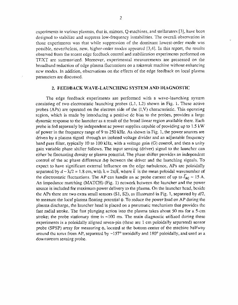
experiments in various plasmas, that is, mirrors, Q-machines, and stellarators [3], have been designed to stabilize and suppress low-frequency instabilities. The overall observation in those experiments was that while suppression of the dominant lowest-order mode was possible, nevertheless, new, higher-order modes appeared [3,4]. In this report, the results observed from the recent edge feedback control and stabilization experiments performed on TEXT are summarized. Moreover, experimental measurements are presented on the broadband reduction of edge plasma fluctuations on a tokamak machine without enhancing new modes. In addition, observations on the effects of the edge feedback on local plasma parameters are discussed.
2. FEEDBACK WAVE-LAUNCHING SYSTEM AND DIAGNOSTIC
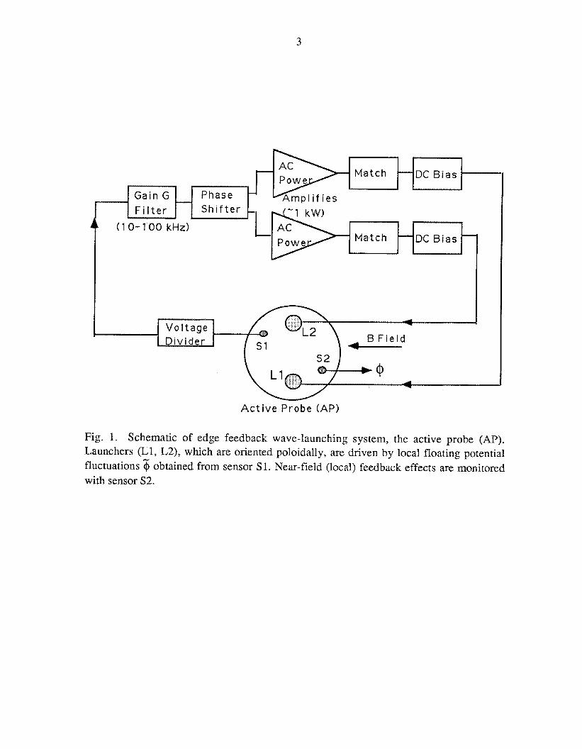
The edge feedback experiments are performed with a wave-launching system consisting of two electrostatic launching probes (L1, L2) shown in Fig. 1. These active probes (APs) are operated on the electron side of the (1,V) characteristic. This operating region, which is made by introducing a positive dc bias to the probes, provides a large dynamic response to the launcher as a result of the broad linear region available there. Each probe is fed separately by independent ac power supplies capable of providing up to 1.5 kW of power in the frequency range of 9 to 250 kHz. As shown in Fig. 1, the power sources are driven by a plasma signal through an isolated voltage divider and an adjustable frequency band pass filter, typically 10 to 100 kHz, with a voltage gain (G) control, and then a unity gain variable phase shifter follows. The input sensing (driver) signal to the launcher can either be fluctuating density or plasma potential. The phase shifter provides an independent control of the ac phase difference Acp between the driver and the launching signals. To expect to have significant external influence on the edge turbulence, APs are poloidally separated by d - h/2 = 1.8 cm, with h = 27t/E, where is the mean poloidal wavenumber of the electrostatic fluctuations. The AP can handle an ac probe current of up to G c - 15 A. An impedance matching (MATCH) (Fig. 1) network between the launcher and the power source is included for maximum power delivery to the plasma. On the launcher head, beside the APs there are two extra small sensors ( S l y S2), as illustrated in Fig. 1, separated by d/2, to measure the local plasma floating potential 9. To reduce the power load on AP during the plasma discharge, the launcher head is placed on a pneumatic mechanism that provides the fast radial stroke. The fast plunging action into the plasma takes about 50 ms for a 5-cm stroke; the probe stationary time is -100 ms. The main diagnostic utilized during these experiments is a poloidally aligned seven-pin (these are 1 cm poloidally separated) sensor probe (SPSP) array for measuring $, located at the bottom center of the machine halfway around the torus from AP, separated by -157' toroidally and 180' poloidally, and used as a downstream sensing probe.
3
M a t c h DC B i a s - -
G a i n G F i l t e r S h i f t e r -
DC B i a s 1 M a t c h -
A c t i v e P r o b e (AP)
Fig. 1. Schematic of edge feedback wave-launching system, the active probe (AP). Launchers (Ll, L2), which are oriented poloidally, are driven by local floating potential fluctuations 5 obtained from sensor S 1. Near-field (local) feedback effects are monitored with sensor S2.
4
3. EXPERIMENTAL OBSERVATIONS AND RESULTS
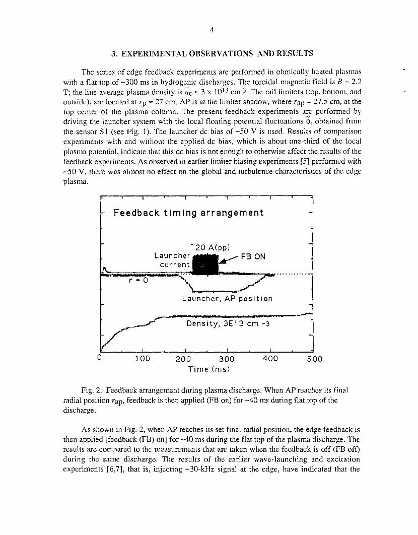
The series of edge feedback experiments are performed in ohmically heated plasmas with a flat top of -300 ins in hydrogenic discharges. The toroidal magnetic field is B - 2.2 T; the line average plasma density is ne = 3 x 1013 cm-3. The rail limiters (top, bottom, and outside), are located at rp = 27 cm; AP is at the limiter shadow, where rap = 27.5 cm, at the top center of the plasma column. The present feedback experiments are performed by driving the launcher system with the local floating potential fluctuations 6, obtained from the sensor S1 (see Fig. 1). The launcher dc bias of -50 V is used. Results of comparison experiments with and without the applied dc bias, which is about one-third of the local plasma potential, indicate that this dc bias is not enough to otherwise affect the results of the feedback experiments. As observed in earlier limiter biasing experiments [5] performed with -50 V, there was almost no effect on the global and turbulence characteristics of the edge plasma.
I t I I I I 1
Feedback t im ing arrangement I
1 .... . ..... . m
Launcher, AP p o s i t i o n
0 100 200 300 400 5 0 0 Time (ms)
Fig. 2. Feedback arrangement during plasma discharge. When AP reaches its final radial position rap, feedback is then applied (FB on) for -40 ms during flat top of the discharge.
As shown in Fig. 2, when AP reaches its set final radial position', the edge feedback is then applied [feedback (FB) on] for -40 ms during the flat top of the plasma discharge. The results are compared to the measurements that are taken when the feedback is off (FB off) during the same discharge. The results of the earlier wave-launching and excitation experiments [6,7], that is, injecting -3O-kHz signal at the edge, have indicated that the
5
propagation is taking place along the magnetic field line. Therefore, these feedback experiments are performed by locating AP, the wave-launcher, and the downstream sensing probe SPSP, which acts as a far-field sensor, on the same magnetic field line. This configuration is obtained from detailed calculations of the magnetics of TEXT, which is possible with a plasma current of Ip - 180 kA at r = 27.5 cm.
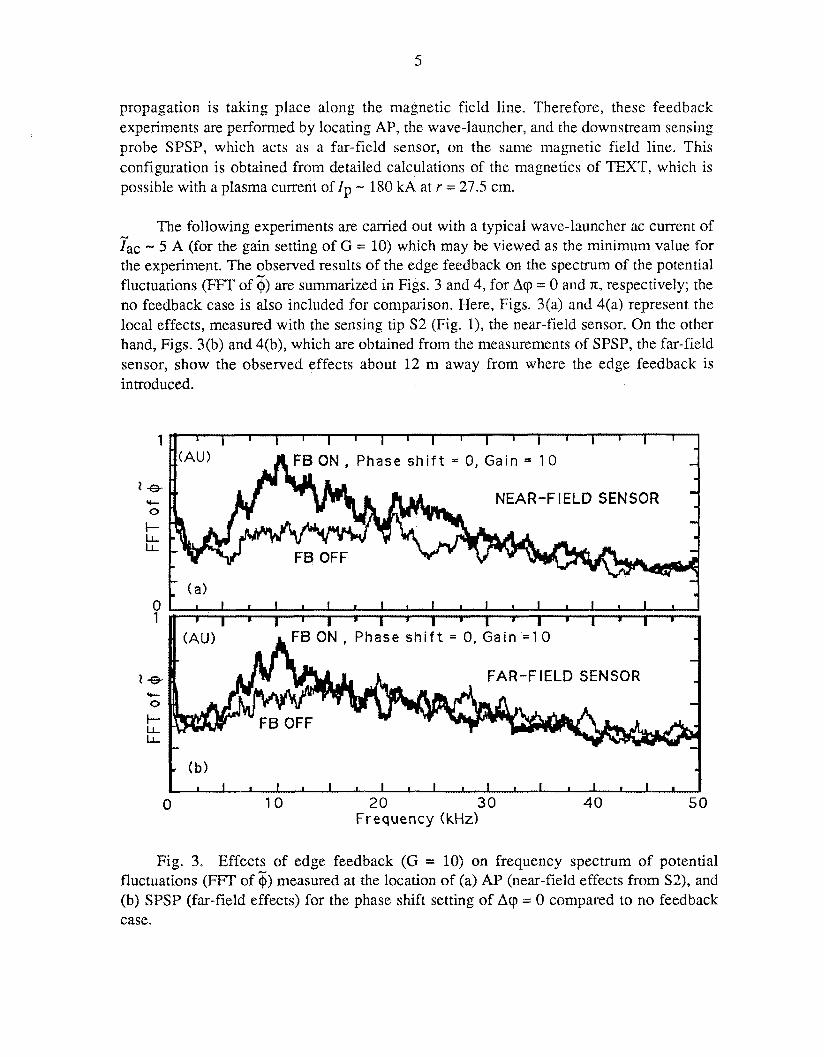
The following experiments are carried out with a typical wave-launcher ac current of fa, - 5 A (for the gain setting of G = 10) which may be viewed as the minimum value for the experiment. The observed results of the edge feedback on the spectrum of the potential fluctuations (FFT of $) are summarized in Figs. 3 and 4, for Arp = 0 and n, respectively; the no feedback case is also included for comparison. Here, Figs. 3(a) and 4(a) represent the local effects, measured with the sensing tip S2 (Fig. l), the near-field sensor. On the other hand, Figs. 3(b) and 4(b), which are obtained from the measurements of SPSP, the far-field sensor, show the observed effects about 12 m away from where the edge feedback is introduced.
1
le- 0
I- LL LL
v-
0 1
1 - Y- O
I- LL L L
NEAR-FIELD SENSOR
:AU) FB ON, Phase s h i f t = 0, Gain = 10
FB OFF
(a> I
I I I I 1 1 I I l l 1 1 I I I I I I 1
FAR-FIELD SENSOR
I c -. (b) I I I I I I I I t 1 1 I I 1 1 I l l
0 10 20 30 40 5 0 Frequency (kHz)
Fig. 3. Effects of edge feedback (G = 10) on frequency spectrum of potential fluctuations (FFT of $1 measured at the location of (a) AP (near-field effects from S2), and (b) SPSP (far-field effects) for the phase shift setting of Acp = 0 compared to no feedback case.
6
J
(b) I I I I I I 1 I I I I I I I I I 1 1 I
NEAR-FIELD SENSOR
FB ON, Phase s h i f t = IT, Gain = 10
I I I I I I I I
FAR-FIELD SENSOR
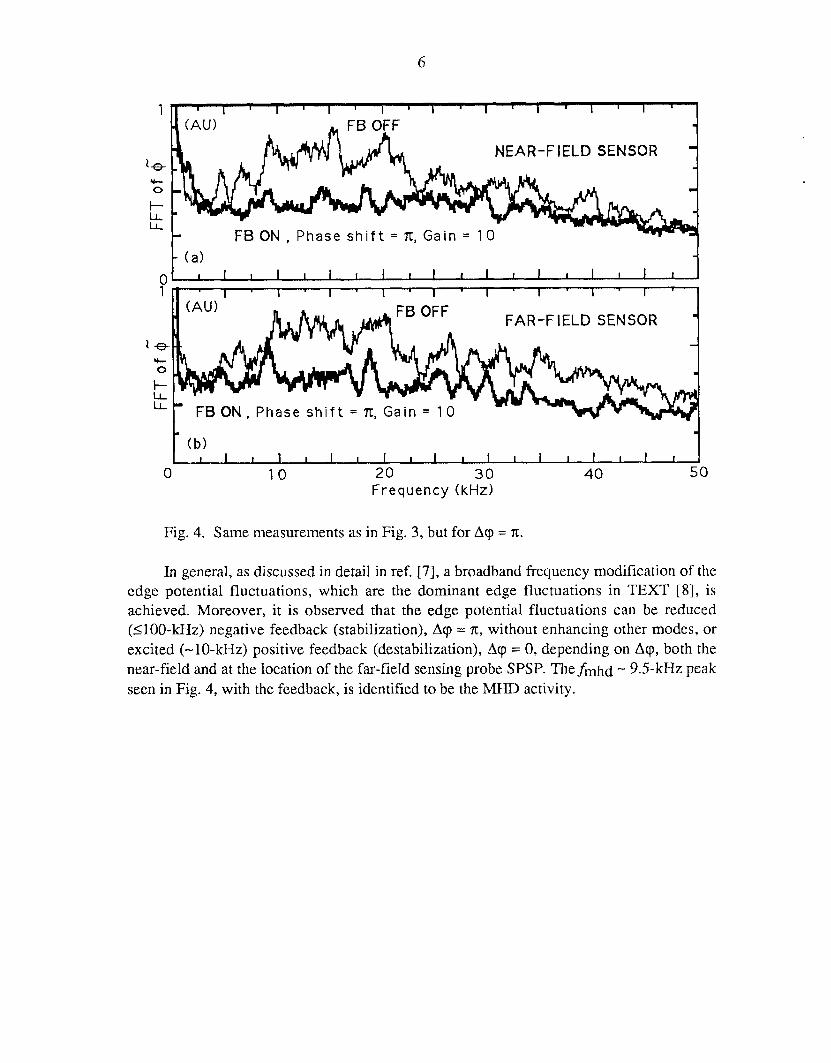
Fig. 4. Same measurements as in Fig. 3, but for Acp = n.
In general, as discussed in detail in ref. [7], a broadband frequency modification of the edge potential fluctuations, which are the dominant edge fluctuations in TEXT [8], is achieved. Moreover, it is observed that the edge potential fluctuations can be reduced (1100-kHz) negative feedback (stabilization), A 9 = n, without enhancing other modes, or excited (-10-kHz) positive feedback (destabilization), Acp = 0, depending on A q , both the near-field and at the location of the far-field sensing probe SPSP. Thefmhd - 9.5-kHz peak seen in Fig. 4, with the feedback, is identified to be the MHD activity.
7
1 r, I 1 I 1 I 1 I I I 1 I I I I i I I I
FFT o f db r / d t - -
FB ON, Phase s h i f t = E , Gain = 10 - I
- -
- 1.
- - - - - -
L .. I I I I I I I 1 I I 1 I I I I I I I I
0 10 20 30 40 5 0
Frequency (kHz1
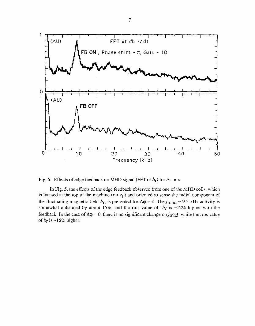
Fig. 5. Effects of edge feedback on MHD signal (FFT of &) for A q = n.
In Fig. 5, the effects of the edge feedback observed from one of the MHD coils, which is located at the top of the machine ( r > rp) and oriented to sense the radial component of
the fluctuating magnetic field &, is presented for Acp = x. Thefnlhd - 9.5-kHz activity is somewhat enhanced by about 15%, and the rms value of b, is -12% higher with the
feedback. In the case of Acp = 0, there is no significant change Onfmhd while the rms value of br is -15% higher.
8
1
FB ON, Phase s h i f t = 0 , G a i n = 20 1 %
Y-
FAR-FIELD SENSOR 0
LL LL
I-
0 0 Frequency (kHz)
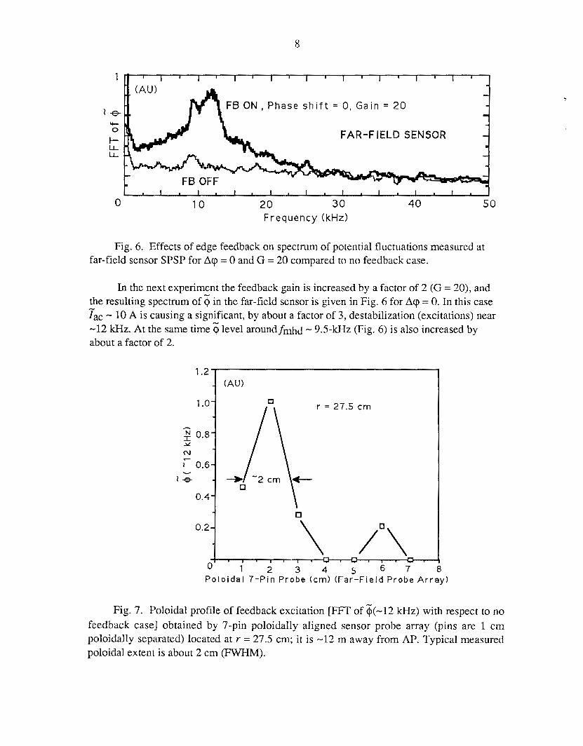
Fig. 6. Effects of edge feedback on spectrum of potential fluctuations measured at far-field sensor SPSP for A q = 0 and G = 20 compared to no feedback case.
In the next experiment the feedback gain is increased by a factor of 2 (G = 20), and the resulting spectrum of $ in the far-field sensor is given in Fig. 6 for A q = 0. In this case ?gc - 10 A is causing a significant, by about a factor of 3, destabilization (excitations) near -12 kHz. At the same time 5 level aroundfmhd - 9.5-kHz (Fig. 6) is also increased by about a factor of 2.
P o l o i d a l 7-Pin P r o b e (cm) ( F a r - F i e l d P r o b e A r r a y )
Fig. 7. Poloidal profile of feedback excitation [FFT of &-12 lcHz) with respect to no feedback case] obtained by 7-pin poloidally aligned sensor probe array (pins are 1 cm poloidally separated) located at r = 27.5 cm; it is -12 m away from AP. Typical measured poloidal extent is about 2 cm (FWHM).
9
In addition, the poloidal extent of the feedback excitations on $ is investigated. The measurements with SPSP give about 2 cm (FWHM) poloidal extent (Fig. 7) for the feedback excitation of $. These results indicate that the edge feedback can modify the amplitude of the potential fluctuations effectively not only locally but also halfway around the torus along a magnetic field line.
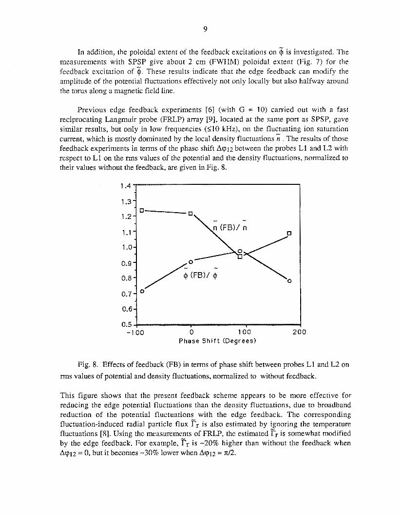
Previous edge feedback experiments [6] (with G = 10) carried out with a fast reciprocating Langmuir probe (FRLP) array [9], located at the same port as SPSP, gave similar results, but only in low frequencies (110 Hz), on the fluctuating ion saturation current, which is mostly dominated by the local density fluctuations s . The results of those feedback experiments in terms of the phase shift Aq12 between the probes L1 and L2 with respect to L1 on the rms values of the potential and the density fluctuations, normalized to their values without the feedback, are given in Fig. 8.
1.4
1.3
1.2
1.1
1 .o
0.9
0.8
0.7
0.6
0.5 - 1 00 0 100 200
Phase S h i f t (Degrees)
Fig. 8. Effects of feedback (FB) in terms of phase shift between probes L1 and L2 on
rms values of potential and density fluctuations, normalized to without feedback.
This figure shows that the present feedback scheme appears to be more effective for reducing the edge potential fluctuations than the density fluctuations, due to broadband reduction of the potential fluctuations with the edge feedback. The corresponding fluctuation-induced radial particle flux Fr is also estimated by ignoring the temperature fluctuations [SI. Using the measurements of FRLP, the estimated Fr is somewhat modified by the edge feedback. For example, Tr is -20% higher than without the feedback when A(p12 = 0, but it becomes -30% lower when Aq12 = 7~12.
10
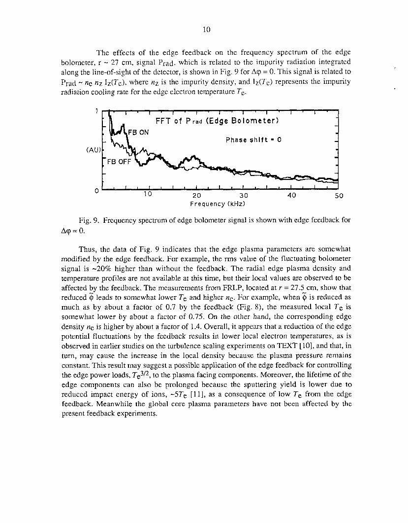
The effects of the edge feedback on the frequency spectrum of the edge bolometer, r - 27 cm, signal Prad, which is related to the impurity radiation integrated along the line-of-sight of the detector, is shown in Fig. 9 for A 9 = 0. This signal is related to Prad - ne n Z IZ(Te), where n~ is the impurity density, and IZ(Te) represents the impurity radiation cooling rate for the edge electron temperature Te.
1 FFT of P r a d (Edge Bolometer)
Phase shlft = 0 (AU)
10 20 30 40 50 0
Frequency (kHz1
Fig. 9. Frequency spectrum of edge bolometer signal is shown with edge feedback for Aq = 0.
Thus, the data of Fig. 9 indicates that the edge plasma parameters are somewhat modified by the edge feedback. For example, the rms value of the fluctuating bolometer signal is -20% higher than without the feedback. The radial edge plasma density and temperature profiles are not available at this time, but their local values are observed to be affected by the feedback. The measurements from FRLP, located at I = 27.5 cm, show that reduced $ leads to somewhat lower Te and higher ne. For example, when 6 is reduced as much as by about a factor of 0.7 by the feedback (Fig. S), the measured local Te is somewhat lower by about a factor of 0.75. On the other hand, the corresponding edge density ne is higher by about a factor of 1.4. Overall, it appears that a reduction of the edge potential fluctuations by the feedback results in lower local electron temperatures, as is observed in earlier studies on the turbulence scaling experiments on TEXT [IO], and that, in turn, may cause the increase in the local density because the plasma pressure remains constant. This result may suggest a possible application of the edge feedback for controlling the edge power loads, Te3/*, to the plasma facing components. Moreover, the lifetime of the edge components can also be prolonged because the sputtering yield is lower due to reduced impact energy of ions, -5Te [ 111, as a consequence of low Te from the edge feedback. Meanwhile the global core plasma parameters have not been affected by the present feedback experiments.
4. DISCUSSION
Plasma edge feedback experiments on TEXT have been successful in stabilizing the edge plasma potential fluctuation levels. Although the underlying physics issues have not been resolved from the present data, these experiments have demonstrated the feasibility of the edge feedback to influence, modify, and control the levels of the electrostatic edge fluctuations. Moreover, effects of the edge feedback on the local plasma parameters suggest the use of the feedback control to possibly influence the power levels on the edge components. Specifically, reduction of the electron temperature with the edge feedback lowers the erosion rate of the plasma facing components and, in turn, impurity production at the edge. On the basis of these observations, detailed experiments are planned with additional diagnostics at various feedback gain and phase shift settings for TEXT Upgrade, which has a divertor configuration. In addition, plans include measuring profiles with the optimized feedback schemes. These detailed experiments are needed for understanding the underlying mechanism of the edge feedback to design techniques for an effective control. More launchers will also be implemented to improve the poloidal flux coverage at the edge so that most impact on the global plasma characteristics can be achieved with the feedback.
ACKNOWLEDGMENTS
The authors thank the support of the TEXT group and operating staff. Special thanks are due to Dr. A. Sen, Columbia University, for his useful advice on the feedback experiments, and also to D. B. Crockett, K. W. Gentle, K. R. Carter, G. R. Dyer, and D. Patterson for their help in obtaining the hardware as well as in making the experiment possible. One of the authors (TU) thanks to J. N. Leboeuf, and P. K. Mioduszewski for valuable discussions and continuous encouragement.
12
REFERENCES
[ l ] A. J. Wootton et al., Plasma Physics and Controlled Fusion 34 (1992) 2023. [2] Ch. P. Ritz et al., Phys. Rev. Lett. 62 (1989) 1844. [3] T. K. Chu, and H. W. Hendel (Eds.), Feedback and Dynamic Control of Plasmas
(American Inst. of Physics, New York, N. Y. 1970), p. 114. [4] K. I. Thomassen et al., Nucl. Fusion 11 (1971) 175. [SI P. E. Phillips et al., J. Nucl. Mater. 145 & 147 (1987) 807. [6] T. Uckan, B. Richards, R. D. Bengtson et al., in h o c . of the 20th EPS
Conference on Controlled Fusion and Plasma Physics (1993) Vol. 17C, p. 635. [7] B. Richards, T. Uckan, A. J. Wootton et al,, Phys. Plasmas 1 (1994) 1606. [8] Ch. P. Ritz et al., Nucl. Fusion 27 (1987) 1125. [9] T. L. Rhodes et al., Rev. Sci. Instrum. 61 (1990) 3001. [ 101 T. L. Rhodes et al., Nucl. Fusion 33 (1993) 1147. [ 1 I] P. C. Stangeby and G. M. McCracken, Nucl. Fusion 30 (1990) 1225.
13
ORNLRM- 12757 Dist. Category UC-426
INTERNAL DISTRIBUTION
1. Director, Fusion Energy Division 23. J. F. Lyon 2. L.A.Berry 24. P. K. Mioduszewski
3-7. B. A. Cameras 25. M. Murakami 8. R.A.Dory 26. K. C. Shaing 9. T. E. Shannon 27-28. Laboratory Records Department
10-17. T.Uckan 29. Laboratory Records, ORNL-RC
34.
35. 36.
37.
38. 39. 40. 41. 42.
43.
44.
45. 46.
47.
48. 49.
50.
51. 52. 53.
18. L. A. Charlton 19. R. J. Colchin 20. J. H. Harris 21. R. C. Isler 22. J. N. Leboeuf
30. Central Research Library 31. Document Reference Section 32. Fusion Energy Division Library 33. ORNL Patent Section
EXTERNAL DISTRIBUTION
Office of the Assistant Manager for Energy Research and Development, U.S. Department of Energy, ORO, Oak Ridge, TN 37831 J. D. Callen, Department of Nuclear Engineering, University of Wisconsin, Madison, WI 53706- 1687 R. W. Conn, Department of Chemical, Nuclear, and Thermal Engineering, University of California, Los Angeles, CA 90024 N. A. Davies, Director, Office of Fusion Energy, Office of Energy Research, E%-50 Germantown, U.S. Department of Energy, Washington, DC 20545 S . 0. Dean, Fusion Power Associates, Inc., 2 Professional Drive, Suite 248, Gaithersburg, MD 20879 R. W. Gould, Department of Applied Physics, California Institute of Technology, Pasadena, CA 91 125 R. A. Gross, Plasma Research Laboratory, Columbia University, New York, NY 10027 D. M. Meade, Princeton Plasma Physics Laboratory, P.O. Box 451, Princeton, NJ 08543 M. Roberts, International Programs, Office of Fusion Energy, Office of Energy Research, ER-52 Germantown, U.S. Department of Energy, Washington, DC 20545 W. M. Stacey, School of Nuclear Engineering and Health Physics, Georgia Institute of Technology, Atlanta, GA 30332 D. Steiner, Nuclear Engineering Department, NES Building, Tibbetts Avenue, Rensselaer Polytechnic Institute, Troy, NY 12181 R. Varma, Physical Research Laboratory, Navrangpura, Ahmedabad 380009, India Bibliothek, Max-Planck Institut fur Plasrnaphysik, Boltzrnannsirasse 2, D-8046 Garching, Federal Republic of Germany Bibliothek, Institut fiir Plasmaphysik, KFA Julich GmbH, Postfach 1913, D-5 170 Julich, Federal Republic of Gertnany Bibliothek, KM Karlsruhe GmbH, Postfach 3640, D-7500 Karlsruhe 1, Federal Republic of Germany Bibliothbque, Centre de Recherches en Physique des Plasmas, &ole Polytechnique F6dkrale de Lausanne, 21 Avenue des Bains, CH-1007 Lausanne, Switzerland L. Laurent, CENKadarache, Departement de Recherches sur la Fusion Contr6l&, F-13108 Saint-Paul- lez-Durance Cedex, France Bibliothbque, CENKadarache, F-13 108 Saint-Paul-lez-Durance Cedex, France Library, &A Fusion, Culham Laboratory, Abingdon, Oxfordshire, OX14 3DB, England Library, JET Joint Undertaking, Abingdon, Oxfordshire OX14 3EA, England
14
54.
55. 56. 57. 58. 59.
60.
61. 62. 63.
64.
65. 66. 67. 68.
69.
70.
71. 72. 73. 74. 75.
76.
77.
78.
79.
80. 81.
82. 83.
84. 85. 86. 87. 88. 89. 90. 91. 92.
Library, FOM-Instituut voor Plasmafysica, Rijnhuizen, Edisonbaan 14,3439 hfN Nieuwegein, The Netherlands Library, National Institute for Fusion Science, Chikusa-ku, Nagoya 46.1-01, Japan Library, International Centre for Theoretical Physics, P.O. Box 586,1-34100 Trieste, Italy Library, Centro Ricerche Energia Frascati, C.P. 65,1-00024 Frascati (.Roma), Italy Library, Plasma Physics Laboratory, Kyoto University, Gokasho, Uji, Kyoto 61 1, Japan Plasma Research Laboratory, Australian National University, P.O. Box 4, Canberra, A.C.T. 2601, Australia Library, Japan Atomic Energy Research Institute, Naka Fusion Research Establishment, 801-1 Mukoyama, Naka-machi, Naka-gun, Ibaraki-ken, Japan G. A. Eliseev, I. V. Kurchatov Institute of Atomic Energy, P.O. Box 3402, 123 182 Moscow, Russia V. A. Glukhikh, Scientific-Research Institute of Electro-Physical Apparatus, 18863 1 Leningrad, Russia I. Shpigel, Institute of General Physics, U.S.S.R. Academy of Sciences, Ulitsa Vavilova 38, Moscow, Russia D. D. Ryutov, Institute of Nuclear Physics, Siberian Branch of the Academy of Sciences, Sovetskaya St. 5,630090 Novosibirsk, Russia 0. Pavlichenko, Kharkov Physical-Technical Institute, Academical St. 1 ,3 10108 Kharkov, Ukraine Deputy Director, Southwestern Institute of Physics, P.O. Box 15, Leshan, Sichuan, China (PRC) Director, The Institute of Plasma Physics, P.O. Box 26, Hefei, Anhui, China (PRC) R. A. Blanken, Experimental Plasma Physics Research Branch, Division of Applied Plasma Physics, Office of Energy Research, ER-542, Germantown, U.S. Department of Energy, Washington, DC 20545 R. A. E. Bolton, IREQ Hydro-Quebec Research Institute, 1800 Montk-Ste.-Julie, Varennes, P.Q. JOL 2P0, Canada D. H. Crandall, Experimental Plasma Physics Research Branch, Division of Applied Plasma Physics, Office of Energy Research, ER-542, Germantown, U.S. Department of Energy, Washington, DC 20545 R. L. Freeman, General Atomics, P.O. Box 85608, San Diego, CA 92138-5608 K. W. Gentle, RLM 11.222, Institute for Fusion Studies, University of Texas, Austin, TX 78712 R. J. Goldston, Princeton Plasma Physics Laboratory, P.O. Box 451, Princeton, NJ 08543 J. C. Hosea, Princeton Plasma Physics Laboratory, P.O. Box 451, Princeton, NJ 08543 D. Markevich, Division of Confinement Systems, Office of Energy Research, ER-55, Germantown, U.S. Department of Energy, Washington, DC 20545 R. H. McKnight, Experimental Plasma Physics Research Branch, Division of Applied Plasma Physics, Office of Energy Research, ER-542, Germantown, US. Department of Energy, Washington, DC 20545 E. Oktay, Division of Confinement Systems, Office of Energy Research, ER-55, Germantown, U.S. Department of Energy, Washington, DC 20545 W. L. Sadowski, Fusion Theory and Computer Services Branch, Division of Applied Plasma Physics, Office of Energy Research, ER-541, Germantown, U.S. Department of Energy, Washington, DC 20545 J. W. WiUis, Division of Confinement Systems, Office of Energy Research, ER-55, Germantown, U.S. Department of Energy, Washington, DC 20545 C. Alejaldre Division de Fusion, CIEMAT, Avenida Complutense 22, E-28040 Madrid, Spain Laboratory for Plasma and Fusion Studies, Department of Nuclear Engineering, Seoul National University, Shinrim-dong, Gwanak-ku, Seoul 151, Korea J. L. Johnson, Plasma Physics Laboratory, Princeton University, P.O. Box 451, Princeton, NJ 08543 L. M. Kovrizhnykh, Institute of General Physics, Russia Academy of Sciences, Ulitsa Vavilova 38, 11 7924 Moscow, Russia 0. Motojima, National Institute for Fusion Science, Chikusa-ku, Nagoya 464-01, Japan S . Okamura, Institute of Plasma Physics, Nagoya University, Chikusa-ku, Nagoya 464, Japan V. D. Shafranov, I. V. Kurchatov Institute of Atomic Energy, P.O. Box 3402, 123182 Moscow, Russia J. L. Shohet, Torsatron/Stellarator Laboratory, University of Wisconsin, Madison, WI 53706 H. Wobig, Max-Planck Institut fur Plasmaphysik, D-8046 Garching, Germany F. S. B. Anderson, University of Wisconsin, Madison, WI 53706 R. F. Gandy, Physics Department, Auburn University, Auburn, AL 36849-351 1 H. Kaneko, Plasma Physics Laboratory, Kyoto University, Gokasho, Uji, Japan G. H. Neilson, Princeton Plasma Physics Laboratory, P.O. Box 451, Princeton, NJ 08543
15
93. 94. 95. 96. 97. 98. 99.
100. 101. 102. 103. 104. 105. 106. 107. 108. 109.
110-1 11. 112-170.
S . Sudo, Plasma Physics Laboratory, Kyoto University, Gokasho, Uji, Japan H. Yamada, National Institute for Fusion Science, Chikusa-ku, Nagoya 464-01, Japan F. W. Perkins, Princeton Plasma Physics Laboratory, P.O. Box 451, Princeton, NJ 08533 T. Obiki, Plasma Physics Laboratory, Kyoto University, Gokasho, Uji, Kyoto, Japan A. Iiyoshi, National Institute for Fusion Studies, Chikusa-ku, Nagoya 464-01, Japan B. Richards, Fusion Research Center, University of Texas, Austin, TX 78712 R. D. Bengtson, Fusion Research Center, University of Texas, Austin, TX 78712 R. Bravenec, Fusion Research Center, University of Texas, Austin, TX 78712 G. X. Li, Fusion Research Center, University of Texas, Austin, TX 78712 P. D. Hurwitz, Fusion Research Center, University of Texas, Austin, TX 78712 P. E. Phillips, Fusion Research Center, University of Texas, Austin, TX 78712 W. L. Rowan, Fusion Research Center, University of Texas, Austin, TX 78712 H. Y . W. Tsui, Fusion Research Center, University of Texas, Austin, TX 78712 J. Uglum, Fusion Research Center, University of Texas, Austin, TX 78712 Y. Wen, Fusion Research Center, University of Texas, Austin, TX 78712 D. Winslow, Fusion Research Center, University of Texas, Austin, TX 78712 A. J. Wootton, Fusion Research Center, University of Texas, Austin, TX 78712 Office of Scientific and Technical Information, P.O. Box 62, Oak Ridge, TN 3783 1 Given distribution as shown in DOE/OSTI-4500, Magnetic Fusion Energy (Category Distribution UC-426, Experimental Plasma Physics)


