Embed Size (px)
Citation preview
1
E3306
11/04/21
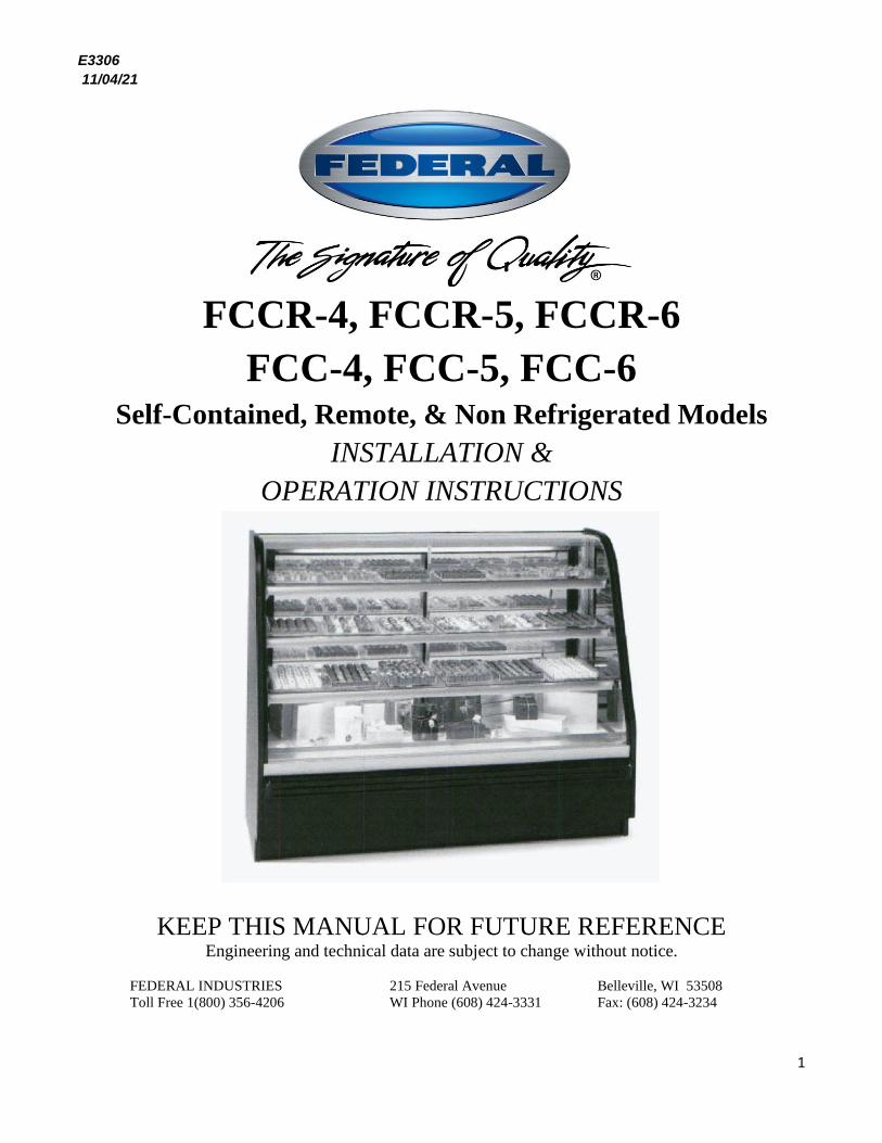
FCCR-4, FCCR-5, FCCR-6
FCC-4, FCC-5, FCC-6 Self-Contained, Remote, & Non Refrigerated Models
INSTALLATION &
OPERATION INSTRUCTIONS
KEEP THIS MANUAL FOR FUTURE REFERENCE Engineering and technical data are subject to change without notice.
FEDERAL INDUSTRIES 215 Federal Avenue Belleville, WI 53508
Toll Free 1(800) 356-4206 WI Phone (608) 424-3331 Fax: (608) 424-3234
2
CONTENTS
INTRODUCTION ....................................................................................................................................... 3
WARNING LABELS & SAFETY INSTRUCTIONS .............................................................................. 4
PRE-INSTALLATION PROCEDURES ................................................................................................... 5
Inspection For Shipping Damage ................................................................................................ 5
INSTALLATION INSTRUCTIONS ..................................................................................................... 5-7
Locating the Display Case ........................................................................................................... 5
Removing Case From Shipping Skid .......................................................................................... 5
Removing Packaging Material .................................................................................................... 5
Leveling the Case ........................................................................................................................ 6
Grill Removal .............................................................................................................................. 6
Front Panel................................................................................................................................... 6
Condensate Evaporator ................................................................................................................ 6
Shelving ....................................................................................................................................... 7
Lights ........................................................................................................................................... 7
Cleaning ....................................................................................................................................... 7
ELECTRICAL INFORMATION & GROUNDING ............................................................................... 8
OPERATING INSTRUCTIONS ......................................................................................................... 9-10
Initial Start-Up ............................................................................................................................. 9
Chocolate/Confectionary Display Conditions ............................................................................. 9
Controls ....................................................................................................................................... 9
Shelves ....................................................................................................................................... 10
Light Replacement ..................................................................................................................... 10
Tilt-Out Front Glass .................................................................................................................. 10
Doors ......................................................................................................................................... 10
Placing Product into Case .......................................................................................................... 10
Refrigerated Storage Area ......................................................................................................... 11
Periodic Maintenance ................................................................................................................ 11
CLEANING INSTRUCTIONS .......................................................................................................... 11-12
Daily Cleaning ........................................................................................................................... 11
Weekly Cleaning ....................................................................................................................... 11
Interior Cleaning ........................................................................................................................ 12
Exterior Cleaning ....................................................................................................................... 12
SERVICE INFORMATION ............................................................................................................... 13-15
Pre-Service Checklist ................................................................................................................ 14
Special Service Situations ......................................................................................................... 15
SALE & DISPOSAL ................................................................................................................................. 15
Owner Responsibility ................................................................................................................ 15
FCCR REFRIGERATION, ELECTRICAL DATA & EPLACEMENT PARTS ........................ 16-18
FCC ELECTRICAL DATA & REPLACEMENT PARTS ................................................................... 19
WIRING DIAGRAMS ........................................................................................................................ 20-26
3
INTRODUCTION
Thank you for purchasing a Federal Industries display case. This manual contains important
instructions for installing and servicing the Non-Refrigerated Curved Glass Hi-Style Display Case. A
repair parts list and wiring diagram are also included in the manual. Read all of these documents
carefully before installing or servicing your case.
NOTICE
Read this manual before installing your case. Keep this manual and refer to it before doing any service on the equipment. Failure to do so could result in personal injury or damage to the case.
NOTICE Installation and service of the electrical components in the case must be performed by a licensed electrician. The portions of this manual covering components contain technical instructions intended only for persons qualified to perform electrical work.
DANGER Improper or faulty hookup of electrical components in the case can result in severe injury or death. All electrical wiring hookups must be done in accordance with all applicable local, regional, or national standards.
SERIAL NUMBER
Record the model and serial numbers of the case for easy reference. Always refer to both model and
serial numbers in your correspondence regarding the case.
Case Model__________________________ Serial Number______________________
Condensing Unit Model________________ Serial Number______________________
We’re here to provide you with the best possible experience with your new product, however, we cannot cover
everything about your merchandiser in this manual, so if you have any additional questions or issues, please see
the SERVICE INFORMATION PAGE to find who you should contact.
4
WARNING LABELS & SAFETY
INSTRUCTIONS
This is the safety-alert symbol. When you see this symbol on your case or in the
manual, be alert to the potential for personal injury or damage to your equipment.
Be sure you understand all safety messages and always follow recommended precautions and safe
operating procedures.
NOTICE TO EMPLOYERS You must make sure that everyone who installs, uses, or services your case is thoroughly familiar with all safety information and procedures.
Important safety information is presented in this section and throughout the manual. The
Following signal words are used in the warning and safety messages:
DANGER: Severe injury or death will occur if you ignore the message.
WARNING: Severe injury or death can occur if you ignore the message.
CAUTION: Minor injury or damage to your case can occur if you ignore the message.
NOTICE: This is important installation, operation, or service information. If you ignore the
message, you may damage your case.
The warning and safety labels shown throughout this manual are placed on your Federal
Industries case at the factory. Follow all warning label instructions. If any warning or safety labels
become lost or damaged, call our customer service department at 1(800) 356-4206 for replacements.
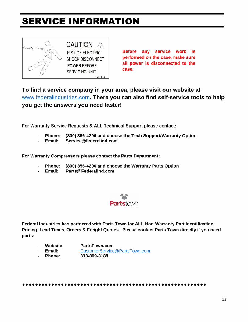
This label is located on the back of the display case.
CAUTION
POWER BEFORE
RISK OF ELECTRIC
SHOCK DISCONNECT
91-12340
SERVICING UNIT.
5
PRE-INSTALLATION PROCEDURES
Inspection for Shipping Damage You are responsible for filing all freight claims with the delivering truck line. Inspect all cartons
and crates for damage as soon as they arrive. If damage is noted to shipping crates, cartons, or if
a shortage is found, note this on the bill of lading (all copies) prior to signing.
If damage is discovered when the case is uncrated, immediately call the delivering truck line and
follow up the call with a written report indicating concealed damage to your shipment. Ask for
an immediate inspection of your concealed damage item. Crating material must be retained to
show the inspector from the truck line.
INSTALLATION INSTRUCTIONS Locating the Display Case
The case should be located where it is not subjected to the direct rays of the sun, heating ducts,
grills, radiator, or ceiling fans, nor should it be located near open doors or main door entrances.
Also, avoid locations where there are excessive air movement or air disturbances.
The condenser air inlet is located at the rear of the case. Do not block this inlet and do not locate
the air inlet near a source of heat.
Removing Case From Shipping Skid
CAUTION: Do not push against the curved glass, ends, doors or
door frames when removing the case from the skid or moving the case. Case
damage or glass breakage could result.
Move the case as near as possible to the final location before removing it from the shipping skid.
Remove the eight (8) bolts that secure the case to the shipping skid.
Removing the Packaging Material
Remove the shipping tags that secure the doors, and tilt-out front glass. If it is necessary to remove
tape residue from plastic material, use cleaning compounds recommended in the Cleaning section of
this manual.
6
Leveling the Case
The case must be level for proper drainage of defrost condensate to the condensate evaporator
reservoir.
The case must be level for the front glass to seal properly. The leveled case can be sealed to the floor
using a NSF Listed Sealant.
Grill Removal
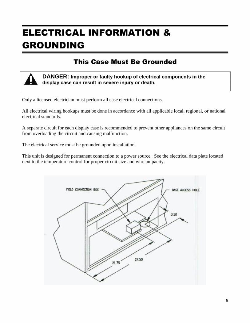
There is a removable slotted panel at the rear of the case. The panel allows access to the condensing
unit, the light ballast, the condensate pan, and the field wiring connection box. Remove this panel to
make field wiring connections. See electrical information and grounding section of this manual
before wiring case.
To remove the air grill, open the rear storage door and remove the two (2) screws along the right
edge of the grill. The left end is supported by two (2) pins attached to the case end. Pick up the grill
on either end and move it to the right to lift it off the locating pins.
Front Panel
The flat front panel attaches to the case using screws and brackets that fit into pockets on the base
front. To remove the panel, slide it upward to get the mounting brackets and screws out of the
pockets.
Removal of this panel allows access to the compressor service ports.
Condensate Evaporator
This case is furnished with an electrical condensate evaporator. Plumbing connections are not
required.
The condensate evaporator is located toward the front of the machine compartment and is accessible
from the rear of the case.
Make sure that the drain line has not been dislodged during shipment and that the drain trap is
located properly over the water reservoir of the condensate evaporator pan.
DANGER: Electric shock hazard. Do not operate unit with
panels removed.
7
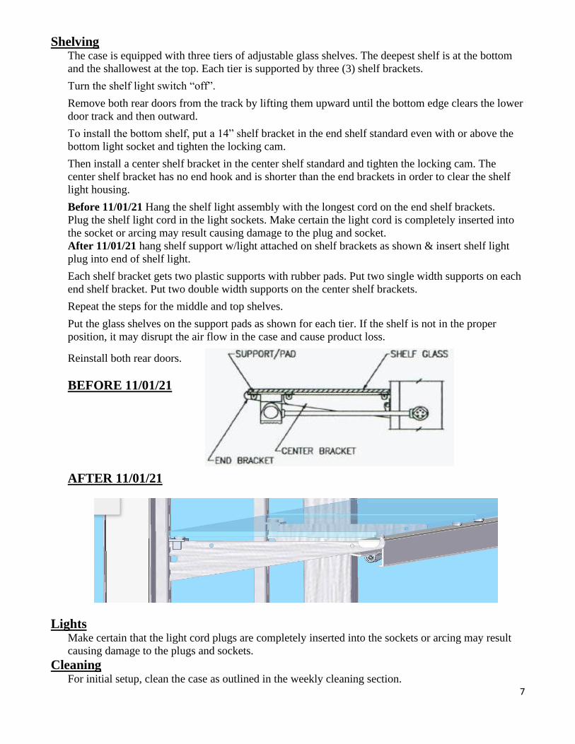
Shelving The case is equipped with three tiers of adjustable glass shelves. The deepest shelf is at the bottom
and the shallowest at the top. Each tier is supported by three (3) shelf brackets.
Turn the shelf light switch “off”.
Remove both rear doors from the track by lifting them upward until the bottom edge clears the lower
door track and then outward.
To install the bottom shelf, put a 14” shelf bracket in the end shelf standard even with or above the
bottom light socket and tighten the locking cam.
Then install a center shelf bracket in the center shelf standard and tighten the locking cam. The
center shelf bracket has no end hook and is shorter than the end brackets in order to clear the shelf
light housing.
Before 11/01/21 Hang the shelf light assembly with the longest cord on the end shelf brackets.
Plug the shelf light cord in the light sockets. Make certain the light cord is completely inserted into
the socket or arcing may result causing damage to the plug and socket.
After 11/01/21 hang shelf support w/light attached on shelf brackets as shown & insert shelf light
plug into end of shelf light.
Each shelf bracket gets two plastic supports with rubber pads. Put two single width supports on each
end shelf bracket. Put two double width supports on the center shelf brackets.
Repeat the steps for the middle and top shelves.
Put the glass shelves on the support pads as shown for each tier. If the shelf is not in the proper
position, it may disrupt the air flow in the case and cause product loss.
Reinstall both rear doors.
BEFORE 11/01/21
AFTER 11/01/21
Lights Make certain that the light cord plugs are completely inserted into the sockets or arcing may result
causing damage to the plugs and sockets.
Cleaning For initial setup, clean the case as outlined in the weekly cleaning section.
8
ELECTRICAL INFORMATION &
GROUNDING
This Case Must Be Grounded
DANGER: Improper or faulty hookup of electrical components in the
display case can result in severe injury or death.
Only a licensed electrician must perform all case electrical connections.
All electrical wiring hookups must be done in accordance with all applicable local, regional, or national
electrical standards.
A separate circuit for each display case is recommended to prevent other appliances on the same circuit
from overloading the circuit and causing malfunction.
The electrical service must be grounded upon installation.
This unit is designed for permanent connection to a power source. See the electrical data plate located
next to the temperature control for proper circuit size and wire ampacity.
9
OPERATING INSTRUCTIONS
Initial Start-Up After all the checks outlined in the installation section of this manual have been made, the case is
ready to be put into service. The service valves on the refrigeration system are back-seated when
the unit leaves the factory.
Chocolate/Confectionery Display Conditions Chocolate and confectionery display cases are designed to operate between 60F and 70F and
between 50% to 60% relative humidity. These display cases are not storage refrigerators capable
of holding product below these levels.
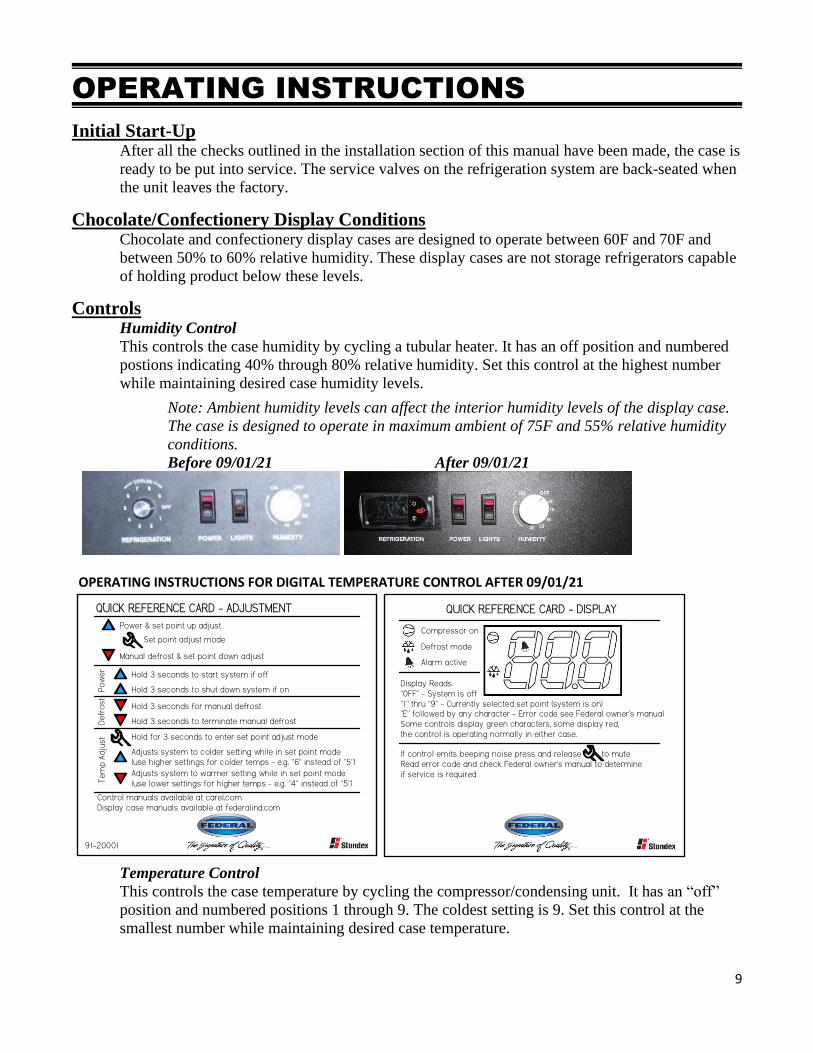
Controls Humidity Control
This controls the case humidity by cycling a tubular heater. It has an off position and numbered
postions indicating 40% through 80% relative humidity. Set this control at the highest number
while maintaining desired case humidity levels.
Note: Ambient humidity levels can affect the interior humidity levels of the display case.
The case is designed to operate in maximum ambient of 75F and 55% relative humidity
conditions.
Before 09/01/21 After 09/01/21
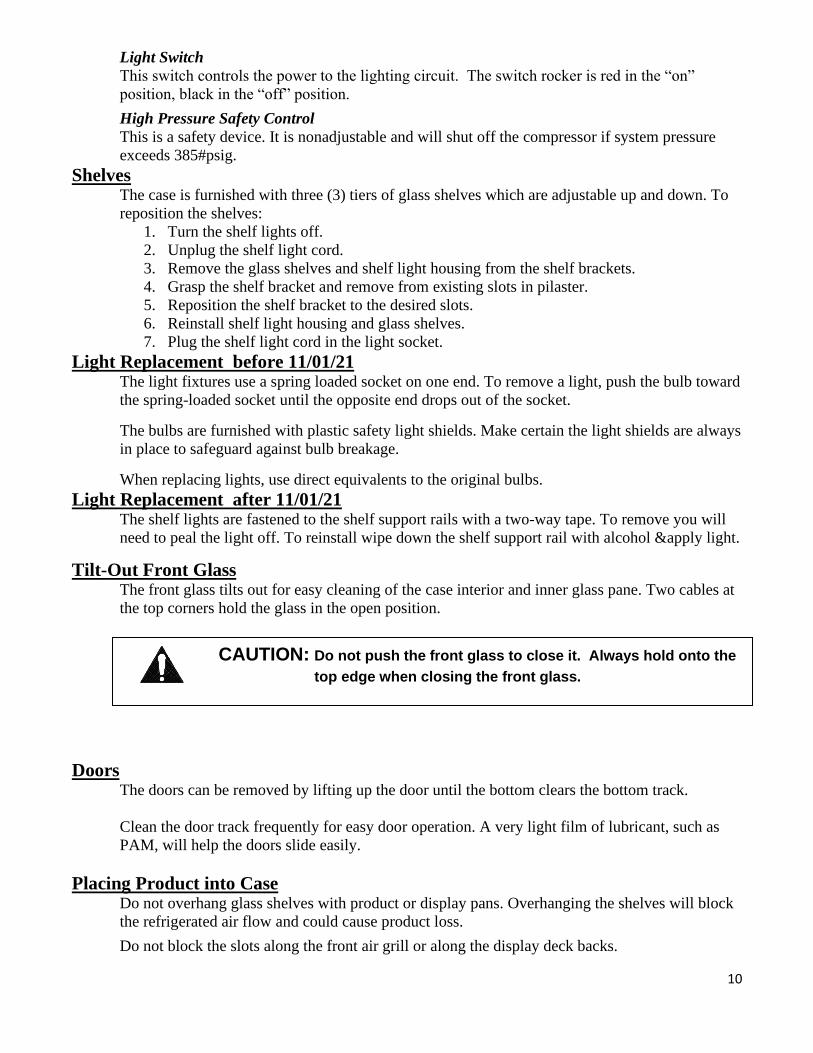
OPERATING INSTRUCTIONS FOR DIGITAL TEMPERATURE CONTROL AFTER 09/01/21
Power & set point up adjust
Manual defrost & set point down adjust
Set point adjust mode
QUICK REFERENCE CARD - ADJUSTMENT
Hold 3 seconds to start system if off
Hold 3 seconds to shut down system if on
Hold for 3 seconds to enter set point adjust mode
Hold 3 seconds for manual defrost
Hold 3 seconds to terminate manual defrost
Adjusts system to colder setting while in set point mode(use higher settings for colder temps - e.g. "6" instead of "5")
Adjusts system to warmer setting while in set point mode(use lower settings for higher temps - e.g. "4" instead of "5")
Po
wer
Defr
ost
Tem
p A
dju
st
91-20001
Control manuals available at carel.comDisplay case manuals available at federalind.com
QUICK REFERENCE CARD - DISPLAY
Compressor on
Defrost mode
Alarm active
Display Reads:"OFF" - System is off"1" thru "9" - Currently selected set point (system is on)"E" followed by any character - Error code see Federal owner's manualSome controls display green characters, some display red,the control is operating normally in either case.
If control emits beeping noise press and release to muteRead error code and check Federal owner's manual to determineif service is required
Temperature Control
This controls the case temperature by cycling the compressor/condensing unit. It has an “off”
position and numbered positions 1 through 9. The coldest setting is 9. Set this control at the
smallest number while maintaining desired case temperature.
10
Light Switch
This switch controls the power to the lighting circuit. The switch rocker is red in the “on”
position, black in the “off” position.
High Pressure Safety Control
This is a safety device. It is nonadjustable and will shut off the compressor if system pressure
exceeds 385#psig.
Shelves The case is furnished with three (3) tiers of glass shelves which are adjustable up and down. To
reposition the shelves:
1. Turn the shelf lights off.
2. Unplug the shelf light cord.
3. Remove the glass shelves and shelf light housing from the shelf brackets.
4. Grasp the shelf bracket and remove from existing slots in pilaster.
5. Reposition the shelf bracket to the desired slots.
6. Reinstall shelf light housing and glass shelves.
7. Plug the shelf light cord in the light socket.
Light Replacement before 11/01/21 The light fixtures use a spring loaded socket on one end. To remove a light, push the bulb toward
the spring-loaded socket until the opposite end drops out of the socket.
The bulbs are furnished with plastic safety light shields. Make certain the light shields are always
in place to safeguard against bulb breakage.
When replacing lights, use direct equivalents to the original bulbs.
Light Replacement after 11/01/21 The shelf lights are fastened to the shelf support rails with a two-way tape. To remove you will
need to peal the light off. To reinstall wipe down the shelf support rail with alcohol &apply light.
Tilt-Out Front Glass The front glass tilts out for easy cleaning of the case interior and inner glass pane. Two cables at
the top corners hold the glass in the open position.
Doors The doors can be removed by lifting up the door until the bottom clears the bottom track.
Clean the door track frequently for easy door operation. A very light film of lubricant, such as
PAM, will help the doors slide easily.
Placing Product into Case Do not overhang glass shelves with product or display pans. Overhanging the shelves will block
the refrigerated air flow and could cause product loss.
Do not block the slots along the front air grill or along the display deck backs.
CAUTION: Do not push the front glass to close it. Always hold onto the
top edge when closing the front glass.
11
Refrigerated Storage Area Looking at the back of the case, there is a lockable refrigerated storage compartment in the lower
right corner. The door swings down when opened. The storage door should always be closed
tightly to ensure proper operation of the display case.
Periodic Maintenance
Cleaning Condenser Coil Disconnect power to the unit.
Remove the rear grill and vacuum the front surface of the condenser coil. This should be done
every one to two months as necessary.
CLEANING INSTRUCTIONS
Daily Cleaning
The case should be cleaned thoroughly, as described in the weekly cleaning section, before it is
used for the first time.
NOTICE: Avoid splashing or soaking any electrical components with water to
prevent electrical damage to the case.
NOTICE: Shut off lights and power switches and remove all product from case.
Allow sufficient time for the unit to reach room temperature before
proceeding with cleaning.
Note: For major spills or foreign material buildup use complete weekly cleaning instructions.
1. Clean all foreign materials from the door opening.
2. Wipe complete interior of case using a damp cloth.
3. The glass can be cleaned with common window cleaner. The remaining exterior surface
should be wiped down using any ammoniated cleanser or soapy warm water.
NOTE: Detergents are not recommended.
CAUTION: Do not use alcohol based or solvent cleaners on the front or side glass.
Weekly Cleaning
This procedure is recommended on a weekly basis. It may need to be performed more often if
necessary to maintain a clean, sanitary case. The case should be cleaned to this procedure before
using the first time.
12
NOTICE: Avoid splashing or soaking any electrical components with water to prevent electrical damage to the case.
NOTICE: Shut off light and power switches and remove all product from case. Allow sufficient time for the unit to reach room temperature before proceeding with cleaning.
Interior Cleaning
1. Remove rear doors from track by lifting door upward until the bottom of the door clears the
lower door track and then outward. Remove the inner door in the same manner.
2. Remove all shelves from the case by sliding them rearward and through the door openings.
3. Unplug the shelf lights and lift one end then the other off the shelf brackets then through the door
opening.
4. Remove the shelf brackets from the shelf standards.
5. Open the tilt-out front glass.
6. Open the door for the rear storage area.
7. Clean the entire interior of the case using warm soapy water. Wipe off all soapy water with a
damp cloth and allow to dry.
NOTE: Depending on the amount of usage and spillage of foreign material, some fasteners may
have to be removed and parts disassembled to allow proper cleaning of the unit.
8. Clean all shelves, shelf brackets, and shelf light housings using warm soapy water and a brush.
Rinse thoroughly and allow to dry.
9. Clean all foreign material from inner and outer rear door tracks using warm soapy water and a
brush. Apply a light film of lubricant, such as PAM, to make the doors operate smoother.
10. Clean both sides of the doors, end glass, and interior of the front glass using any common
window cleaner.
CAUTION: Do not use alcohol based or solvent cleaners on the front or side glass.
11. Reassemble the case in reverse order starting with step 6.
Exterior Cleaning
1. Clean the front glass using any common window cleaner.
CAUTION: Do not use alcohol based or solvent cleaners on the front or side glass.
2. The exterior surfaces should be wiped down using any ammoniated cleansers or warm soapy
water.
13
SERVICE INFORMATION
Before any service work is
performed on the case, make sure
all power is disconnected to the
case.
To find a service company in your area, please visit our website at
www.federalindustries.com. There you can also find self-service tools to help
you get the answers you need faster!
For Warranty Service Requests & ALL Technical Support please contact:
- Phone: (800) 356-4206 and choose the Tech Support/Warranty Option - Email: [email protected]
For Warranty Compressors please contact the Parts Department:
- Phone: (800) 356-4206 and choose the Warranty Parts Option - Email: [email protected]
Federal Industries has partnered with Parts Town for ALL Non-Warranty Part Identification,
Pricing, Lead Times, Orders & Freight Quotes. Please contact Parts Town directly if you need
parts:
- Website: PartsTown.com - Email: [email protected] - Phone: 833-809-8188
…………………………………………………
14
Pre-Service Checklist You may avoid the cost and inconvenience of an unnecessary service call by first reviewing this
checklist of frequently encountered situations that can cause unsatisfactory case performance.
CAUTION: Before servicing case, turn off power at the main breaker of fuse box.
Case Does Not Operate
Check for disconnected power supply.
Check for tripped breaker or blown fuse.
Check that the thermostat is not “off”.
Lights Do Not Operate
Check that light switch is on.
Be sure light is properly seated in the sockets.
Case Temperature Too Warm
Check that the cold air inlet and outlet slots are not blocked.
Be sure front glass is closed tightly and back doors are closed.
Check for a blocked or dirty condenser coil.
Check interior airflow. Lack of adequate cold airflow could indicate a defective
evaporator fan or a blocked evaporator coil. Check that paper or foreign materials are not
blocking evaporator. If the evaporator coil is blocked due to excessive frost, turn the
thermostat knob to the “off” position for approximately one hour to defrost. Excessive
frost will build up if the case is operated with the rear doors open or the storage door ajar.
Glass Fogging
Check room ambient conditions – Case is designed to operate in an environment not to
exceed 75ºF and 55% relative humidity.
Check case temperature – Case is designed to operate between 60ºF and 70ºF.
15
Special Service Situations There are rare occasions when the refrigerant charge must be evacuated from a case to perform
service work. In those situations, Federal Industries recommends that the refrigerant charge be
evacuated into a recovery system to prevent the possibility of hydro-fluorocarbons (HFC’s) from
being released into the atmosphere. The release of HFC’s into the atmosphere is a potential
source of global warming.
If moisture or liquid is observed around or under a Federal Industries case, an immediate
investigation should be made by qualified personnel to determine the source of the moisture or
liquid. The investigation must determine if the case is malfunctioning or if there is a simple
housekeeping problem.
Moisture or liquid around or under a case is a potential slip/fall hazard for persons walking by or
working in the general area of the case. Any case malfunction or housekeeping problem that
creates a slip/fall hazard around or under a case should be corrected immediately.
SALE & DISPOSAL
Owner Responsibility
If you sell or give away your Federal Industries case, you must make sure that all safety labels
and the Installation-Service Manual are included with it. If you need replacement labels or
manuals, Federal Industries will provide them free of charge. Contact the customer service
department at Federal Industries at (800) 356-4206.
The customer service department at Federal Industries should be contacted at the time of sale or
disposal of your case so records may be kept of its new location.
If you sell or give away your Federal Industries case and you evacuate the refrigerant charge
before shipment, Federal Industries recommends that the charge be evacuated into a recovery
system to reduce the possibility of HCFC’s from being released into the atmosphere. The release
of HCFC’s into the atmosphere is a potential source of ozone depletion.
16
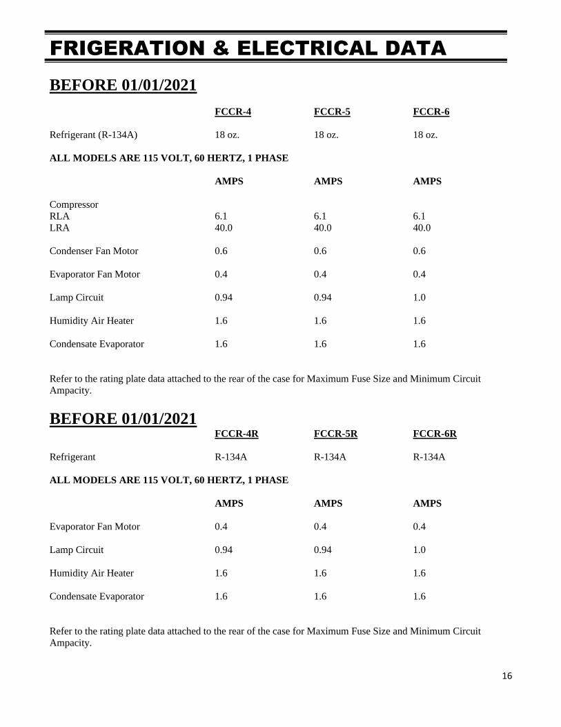
FRIGERATION & ELECTRICAL DATA
BEFORE 01/01/2021
FCCR-4 FCCR-5 FCCR-6
Refrigerant (R-134A) 18 oz. 18 oz. 18 oz.
ALL MODELS ARE 115 VOLT, 60 HERTZ, 1 PHASE
AMPS AMPS AMPS
Compressor
RLA 6.1 6.1 6.1
LRA 40.0 40.0 40.0
Condenser Fan Motor 0.6 0.6 0.6
Evaporator Fan Motor 0.4 0.4 0.4
Lamp Circuit 0.94 0.94 1.0
Humidity Air Heater 1.6 1.6 1.6
Condensate Evaporator 1.6 1.6 1.6
Refer to the rating plate data attached to the rear of the case for Maximum Fuse Size and Minimum Circuit
Ampacity.
BEFORE 01/01/2021 FCCR-4R FCCR-5R FCCR-6R
Refrigerant R-134A R-134A R-134A
ALL MODELS ARE 115 VOLT, 60 HERTZ, 1 PHASE
AMPS AMPS AMPS
Evaporator Fan Motor 0.4 0.4 0.4
Lamp Circuit 0.94 0.94 1.0
Humidity Air Heater 1.6 1.6 1.6
Condensate Evaporator 1.6 1.6 1.6
Refer to the rating plate data attached to the rear of the case for Maximum Fuse Size and Minimum Circuit
Ampacity.
17
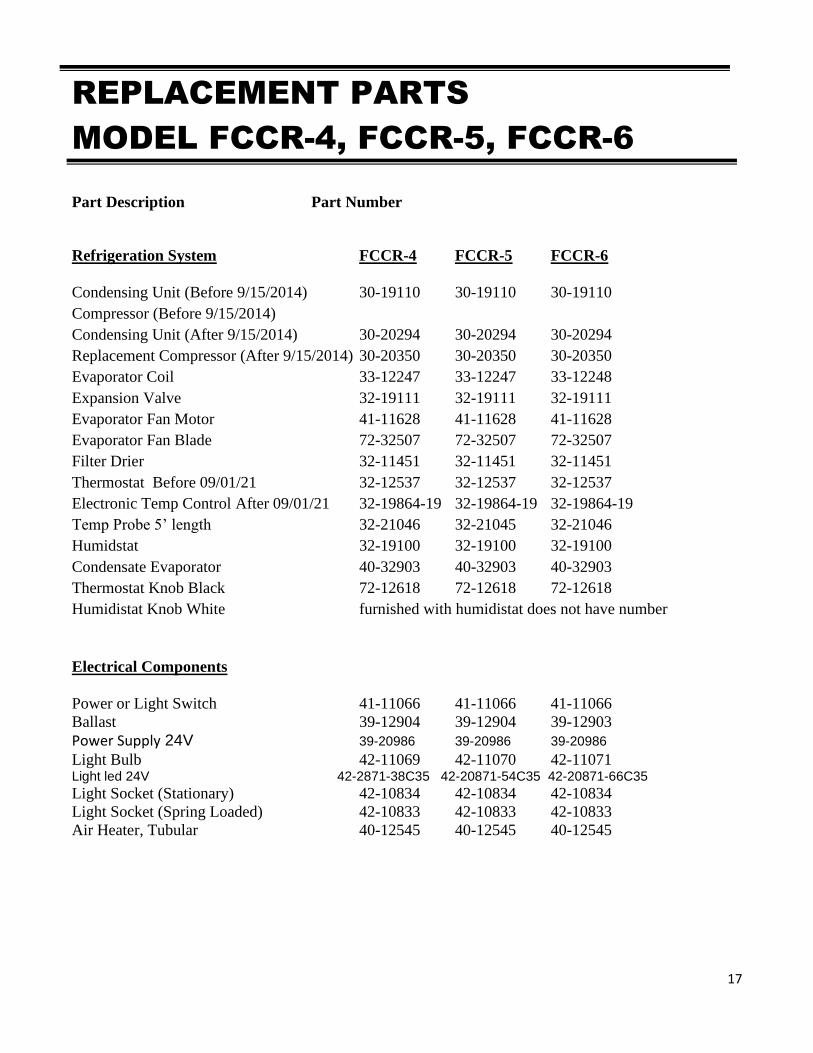
REPLACEMENT PARTS
MODEL FCCR-4, FCCR-5, FCCR-6
Part Description Part Number
Refrigeration System FCCR-4 FCCR-5 FCCR-6
Condensing Unit (Before 9/15/2014) 30-19110 30-19110 30-19110
Compressor (Before 9/15/2014)
Condensing Unit (After 9/15/2014) 30-20294 30-20294 30-20294
Replacement Compressor (After 9/15/2014) 30-20350 30-20350 30-20350
Evaporator Coil 33-12247 33-12247 33-12248
Expansion Valve 32-19111 32-19111 32-19111
Evaporator Fan Motor 41-11628 41-11628 41-11628
Evaporator Fan Blade 72-32507 72-32507 72-32507
Filter Drier 32-11451 32-11451 32-11451
Thermostat Before 09/01/21 32-12537 32-12537 32-12537
Electronic Temp Control After 09/01/21 32-19864-19 32-19864-19 32-19864-19
Temp Probe 5’ length 32-21046 32-21045 32-21046
Humidstat 32-19100 32-19100 32-19100
Condensate Evaporator 40-32903 40-32903 40-32903
Thermostat Knob Black 72-12618 72-12618 72-12618
Humidistat Knob White furnished with humidistat does not have number
Electrical Components
Power or Light Switch 41-11066 41-11066 41-11066
Ballast 39-12904 39-12904 39-12903
Power Supply 24V 39-20986 39-20986 39-20986
Light Bulb 42-11069 42-11070 42-11071 Light led 24V 42-2871-38C35 42-20871-54C35 42-20871-66C35
Light Socket (Stationary) 42-10834 42-10834 42-10834
Light Socket (Spring Loaded) 42-10833 42-10833 42-10833
Air Heater, Tubular 40-12545 40-12545 40-12545
18
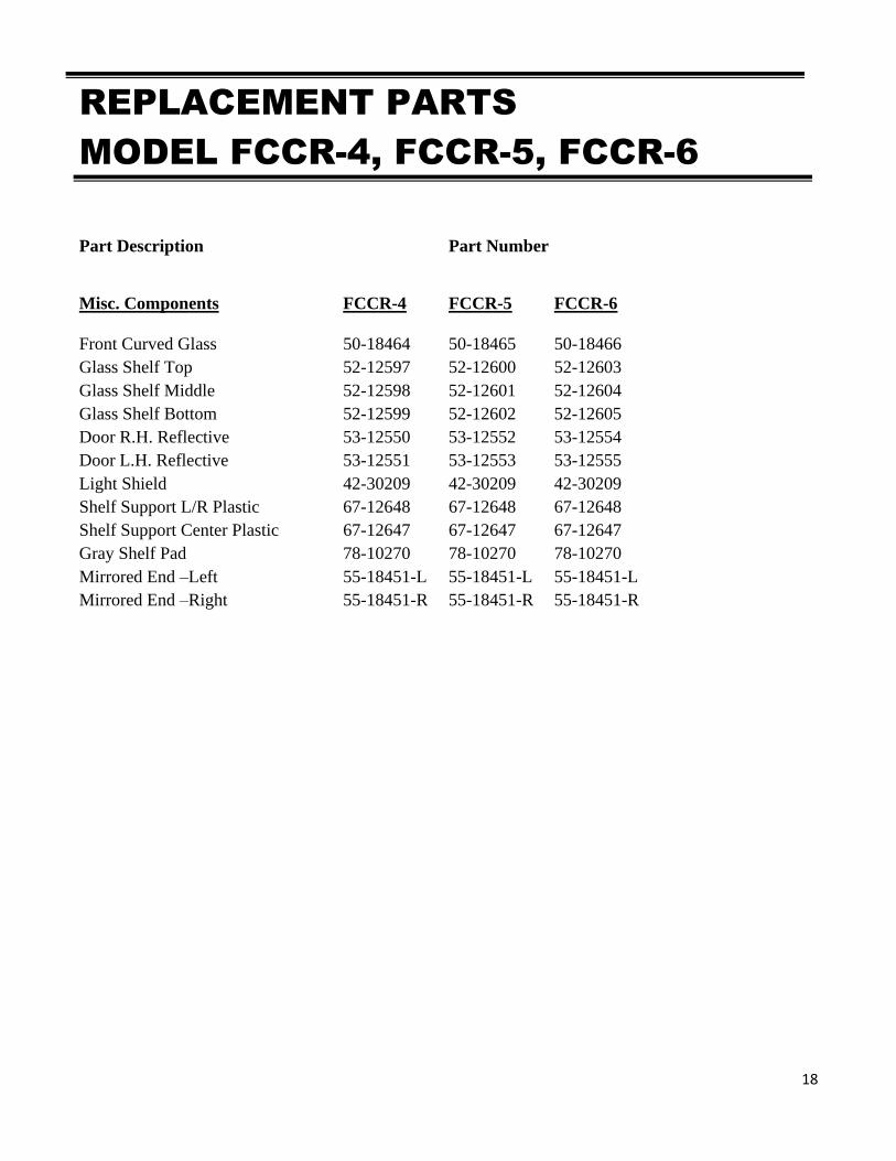
REPLACEMENT PARTS
MODEL FCCR-4, FCCR-5, FCCR-6
Part Description Part Number
Misc. Components FCCR-4 FCCR-5 FCCR-6
Front Curved Glass 50-18464 50-18465 50-18466
Glass Shelf Top 52-12597 52-12600 52-12603
Glass Shelf Middle 52-12598 52-12601 52-12604
Glass Shelf Bottom 52-12599 52-12602 52-12605
Door R.H. Reflective 53-12550 53-12552 53-12554
Door L.H. Reflective 53-12551 53-12553 53-12555
Light Shield 42-30209 42-30209 42-30209
Shelf Support L/R Plastic 67-12648 67-12648 67-12648
Shelf Support Center Plastic 67-12647 67-12647 67-12647
Gray Shelf Pad 78-10270 78-10270 78-10270
Mirrored End –Left 55-18451-L 55-18451-L 55-18451-L
Mirrored End –Right 55-18451-R 55-18451-R 55-18451-R
19
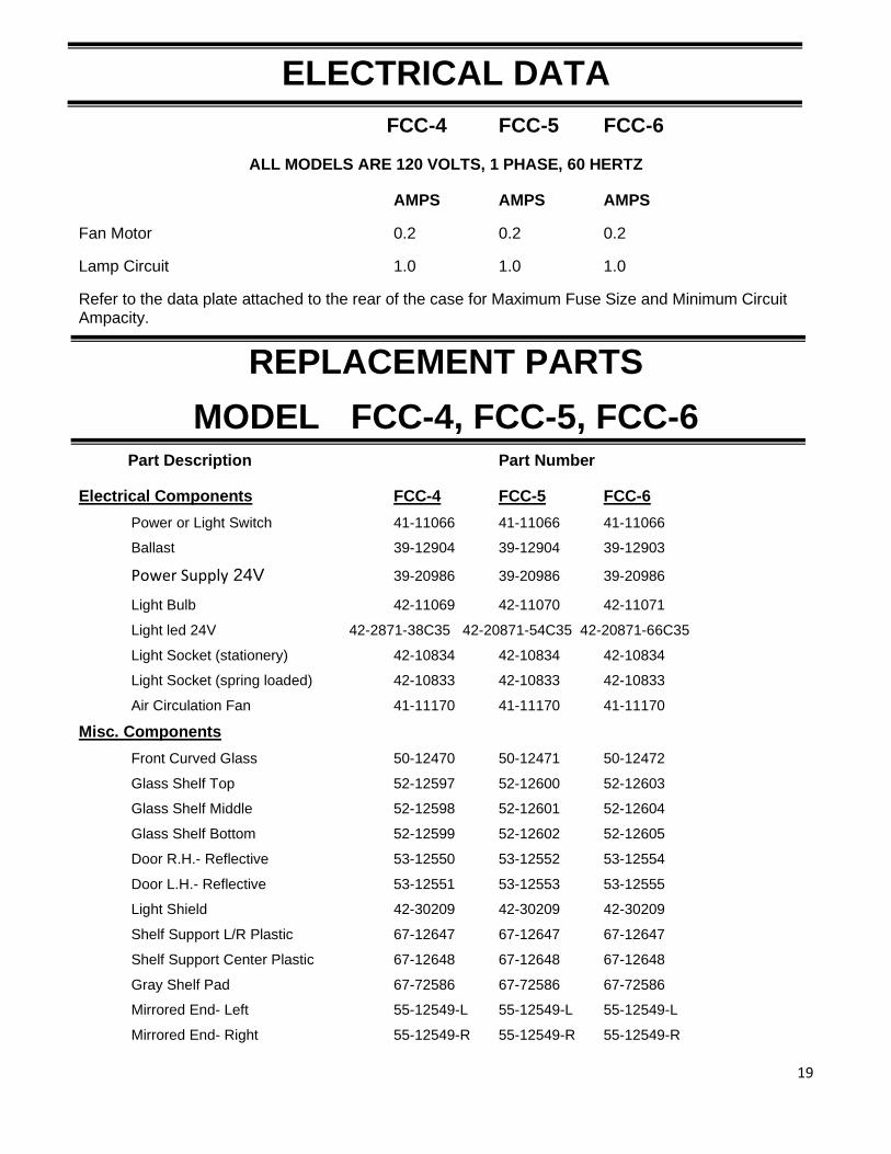
ELECTRICAL DATA
FCC-4 FCC-5 FCC-6
ALL MODELS ARE 120 VOLTS, 1 PHASE, 60 HERTZ
AMPS AMPS AMPS
Fan Motor 0.2 0.2 0.2
Lamp Circuit 1.0 1.0 1.0
Refer to the data plate attached to the rear of the case for Maximum Fuse Size and Minimum Circuit Ampacity.
REPLACEMENT PARTS
MODEL FCC-4, FCC-5, FCC-6 Part Description Part Number
Electrical Components FCC-4 FCC-5 FCC-6
Power or Light Switch 41-11066 41-11066 41-11066
Ballast 39-12904 39-12904 39-12903
Power Supply 24V 39-20986 39-20986 39-20986
Light Bulb 42-11069 42-11070 42-11071
Light led 24V 42-2871-38C35 42-20871-54C35 42-20871-66C35
Light Socket (stationery) 42-10834 42-10834 42-10834
Light Socket (spring loaded) 42-10833 42-10833 42-10833
Air Circulation Fan 41-11170 41-11170 41-11170
Misc. Components
Front Curved Glass 50-12470 50-12471 50-12472
Glass Shelf Top 52-12597 52-12600 52-12603
Glass Shelf Middle 52-12598 52-12601 52-12604
Glass Shelf Bottom 52-12599 52-12602 52-12605
Door R.H.- Reflective 53-12550 53-12552 53-12554
Door L.H.- Reflective 53-12551 53-12553 53-12555
Light Shield 42-30209 42-30209 42-30209
Shelf Support L/R Plastic 67-12647 67-12647 67-12647
Shelf Support Center Plastic 67-12648 67-12648 67-12648
Gray Shelf Pad 67-72586 67-72586 67-72586
Mirrored End- Left 55-12549-L 55-12549-L 55-12549-L
Mirrored End- Right 55-12549-R 55-12549-R 55-12549-R
20
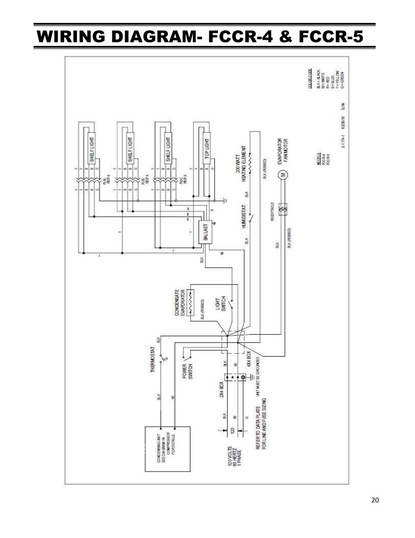
WIRING DIAGRAM- FCCR-4 & FCCR-5
21
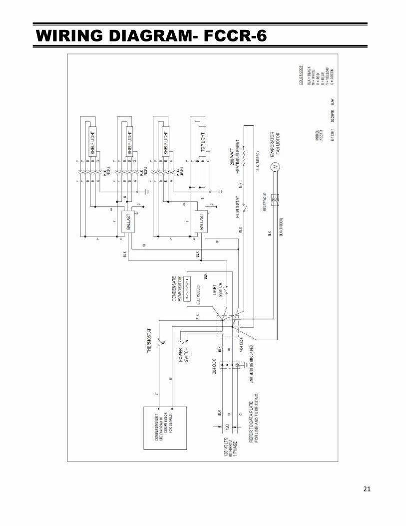
WIRING DIAGRAM- FCCR-6
22
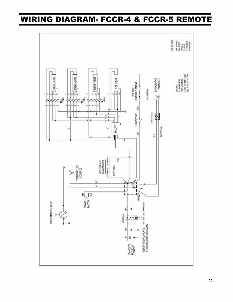
WIRING DIAGRAM- FCCR-4 & FCCR-5 REMOTE
23
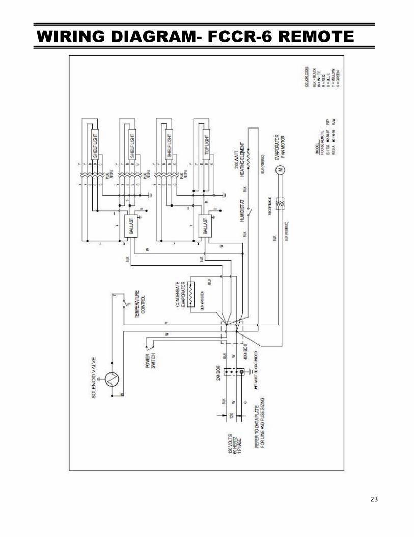
WIRING DIAGRAM- FCCR-6 REMOTE
24
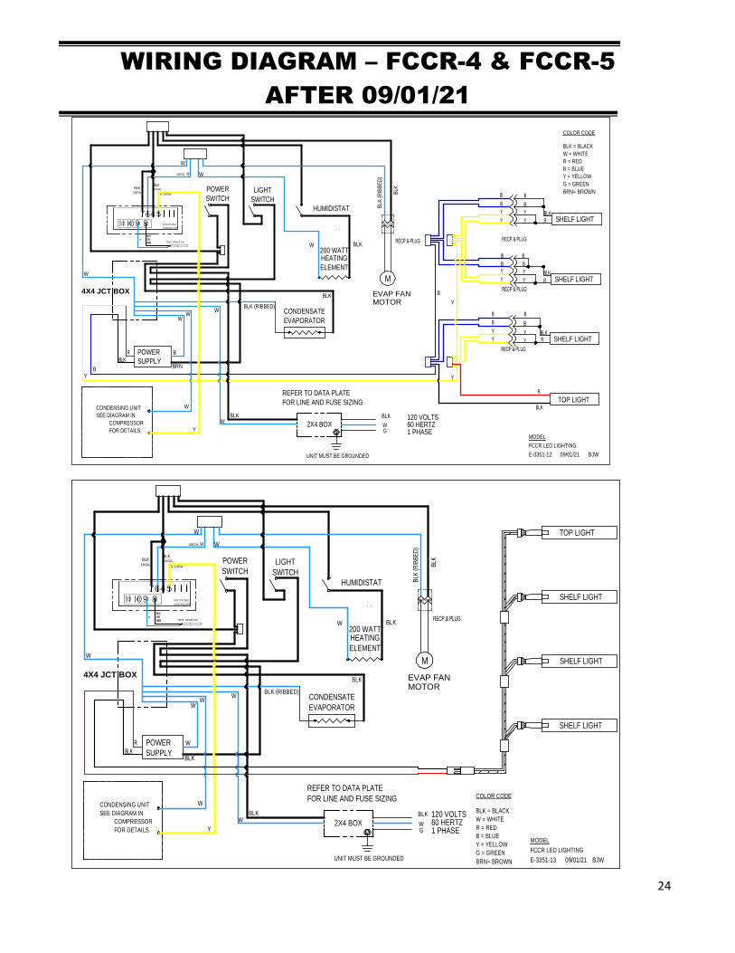
WIRING DIAGRAM – FCCR-4 & FCCR-5
AFTER 09/01/21
R
BLK
TOP LIGHT
RECP.& PLUG
B
B
Y
Y
RY
Y
Y
B
B
Y Y
B
Y SHELF LIGHT
SHELF LIGHTBLK
B
B
BLK
B
R
RECP.& PLUG
Y
B
B
Y Y
B
Y SHELF LIGHTBLK
B
R
BRN
POWER
SUPPLY
B
BLK
RRECP.& PLUG
200 WATTHEATING
ELEMENT
BLKW
HUMIDISTAT
TEMP. PROBE PBI
14GA.18GA.
W
BLKBLK
ELECTR ONIC
CONTROLLER11 109 8
76 54
BLK
OR
RED
BLK
OR
RED
14GA.
18GA. W
Y
FOR DETAILS.
COMPRESSOR
SEE DIAGRAM IN
CONDENSING UNIT
RECP.& PLUG
EVAP FANMOTOR
M
BLK
BLK
(RIB
BE
D)
LIGHT
SWITCH
POWER
SWITCH
CONDENSATE
EVAPORATOR
BLK
BLK (RIBBED)
4X4 JCT BOX
2X4 BOX
REFER TO DATA PLATE
FOR LINE AND FUSE SIZING
UNIT MUST BE GROUNDED
60 HERTZ1 PHASE
120 VOLTSBLK
WG
BLKW
B
B
W
W
WW
W
W
BJW09/01/21E-3351-12
FCCR LED LIGHTING
MODEL
COLOR CODE
BLK = BLACK
W = WHITE
R = RED
B = BLUE
Y = YELLOW
G = GREEN
BRN= BROWN
W
Y
Y Y
Y
TOP LIGHT
SHELF LIGHT
SHELF LIGHT
SHELF LIGHT
BLK
POWER
SUPPLY
W
BLK
R
200 WATTHEATING
ELEMENT
BLKW
HUMIDISTAT
TEMP. PROBE PBI
14GA.18GA.
W
BLKBLK
ELECTR ONIC
CONTROLLER11 109 8
76 54
BLK
OR
RED
BLK
OR
RED
14GA.
18GA. W
Y
FOR DETAILS.
COMPRESSOR
SEE DIAGRAM IN
CONDENSING UNIT
RECP.& PLUG
EVAP FANMOTOR
M
BLK
BLK
(RIB
BE
D)
LIGHT
SWITCH
POWER
SWITCH
CONDENSATE
EVAPORATOR
BLK
BLK (RIBBED)
4X4 JCT BOX
2X4 BOX
REFER TO DATA PLATE
FOR LINE AND FUSE SIZING
UNIT MUST BE GROUNDED
60 HERTZ1 PHASE
120 VOLTSBLK
WG
BLKW
W
W
WW
W
W
BJW09/01/21E-3351-13
FCCR LED LIGHTING
MODEL
W
Y
COLOR CODE
BLK = BLACK
W = WHITE
R = RED
B = BLUE
Y = YELLOW
G = GREEN
BRN= BROWN
25
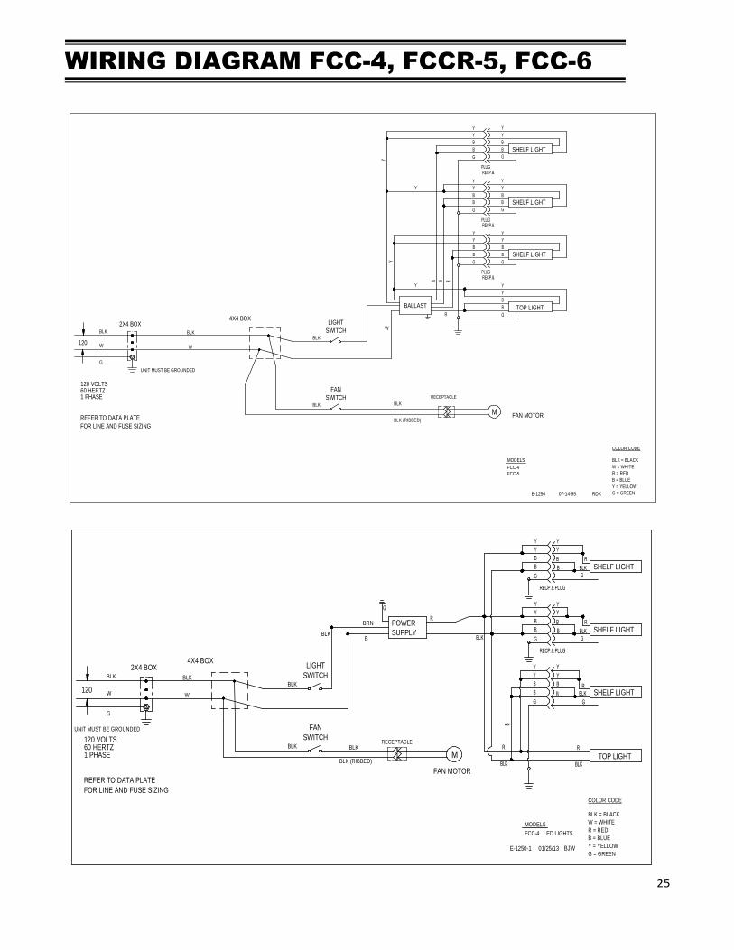
WIRING DIAGRAM FCC-4, FCCR-5, FCC-6
COLOR CODE
BLK = BLACK
W = WHITE
R = RED
B = BLUE
Y = YELLOW
G = GREENRDK07-14-95E-1250
UNIT MUST BE GROUNDED
MODELS
FCC-4
FAN MOTORM
RECEPTACLE
60 HERTZ1 PHASE
120 VOLTS
2X4 BOX
120
REFER TO DATA PLATE
FOR LINE AND FUSE SIZING
4X4 BOX
BLK
W
G
BLK
BLK (RIBBED)
W
FCC-5
Y Y
BALLAST
G
B
B
Y
TOP LIGHT
Y
B
Y
Y
PLUGRECP.&
RECP.&PLUG
B
B R
G
B
Y
Y
B
G
B
Y
Y
PLUGRECP.&
Y
B
G
B
Y
G
Y
B
G
B
Y
G
B
B
Y
Y
B
B
Y
Y
SHELF LIGHT
SHELF LIGHT
SHELF LIGHT
R
BLK
LIGHT
SWITCH
BLK
FAN
SWITCH
BLK
W
COLOR CODE
BLK = BLACK
W = WHITE
R = RED
B = BLUE
Y = YELLOW
G = GREENBJW01/25/13E-1250-1
UNIT MUST BE GROUNDED
MODELS
FCC-4 LED LIGHTS
FAN MOTOR
M
RECEPTACLE60 HERTZ1 PHASE
120 VOLTS
2X4 BOX
120
REFER TO DATA PLATE
FOR LINE AND FUSE SIZING
4X4 BOX
BLK
W
G
BLK
BLK (RIBBED)
BLK
LIGHT
SWITCH
BLK
FAN
SWITCH
BLK
W
R
BLK
TOP LIGHT
RECP.& PLUG
B
B
G
B
Y
Y
R
Y
Y
Y
B
G
B
Y
Y
G
B
Y
SHELF LIGHT
SHELF LIGHT
BRN POWER
SUPPLY
BLK
B
B
G
G
BLKB
R
R
BLK
B BLK
RECP.& PLUG
Y
B
G
B
Y
Y
G
B
Y
SHELF LIGHTBLKB
R
R
BLK
26
COLOR CODE
BLK = BLACK
W = WHITE
R = RED
B = BLUE
Y = YELLOW
G = GREENBJW01/25/13E-1250-2
UNIT MUST BE GROUNDED
MODELS
FCC-5 & 6 LED LIGHTS
FAN MOTOR
M
RECEPTACLE
60 HERTZ1 PHASE
120 VOLTS
2X4 BOX
120
REFER TO DATA PLATE
FOR LINE AND FUSE SIZING
4X4 BOX
BLK
W
G
BLK
BLK (RIBBED)
BLK
LIGHT
SWITCH
BLK
FAN
SWITCH
BLK
W
RPOWER
SUPPLYBLK
TOP LIGHT
RECP.& PLUG
B
B
G
B
Y
Y
R
Y
Y
Y
B
G
B
Y
Y
G
B
Y
SHELF LIGHT
SHELF LIGHT
BRN
B
BRN POWER
SUPPLY
BLK
B
B
G
G
G
BLKB
R
R
BLK
B BLK
RECP.& PLUG
Y
B
G
B
Y
Y
G
B
Y
SHELF LIGHTBLKB
R
R
COLOR CODE
BLK = BLACK
W = WHITE
R = RED
B = BLUE
Y = YELLOW
G = GREENBJW11/02/21E-1250-3
UNIT MUST BE GROUNDED
MODELS
FCC - LED LIGHTSFAN MOTOR
M
RECEPTACLE
60 HERTZ1 PHASE
120 VOLTS
2X4 BOX
120
REFER TO DATA PLATE
FOR LINE AND FUSE SIZING
4X4 BOX
BLK
W
G
BLK
BLK (RIBBED)
BLK
LIGHT
SWITCH
BLK
FAN
SWITCH
BLK
W
SHELF LIGHT
BLK POWER
SUPPLY
G
WBLK
BLK
R
SHELF LIGHT
TOP LIGHT
SHELF LIGHT
27
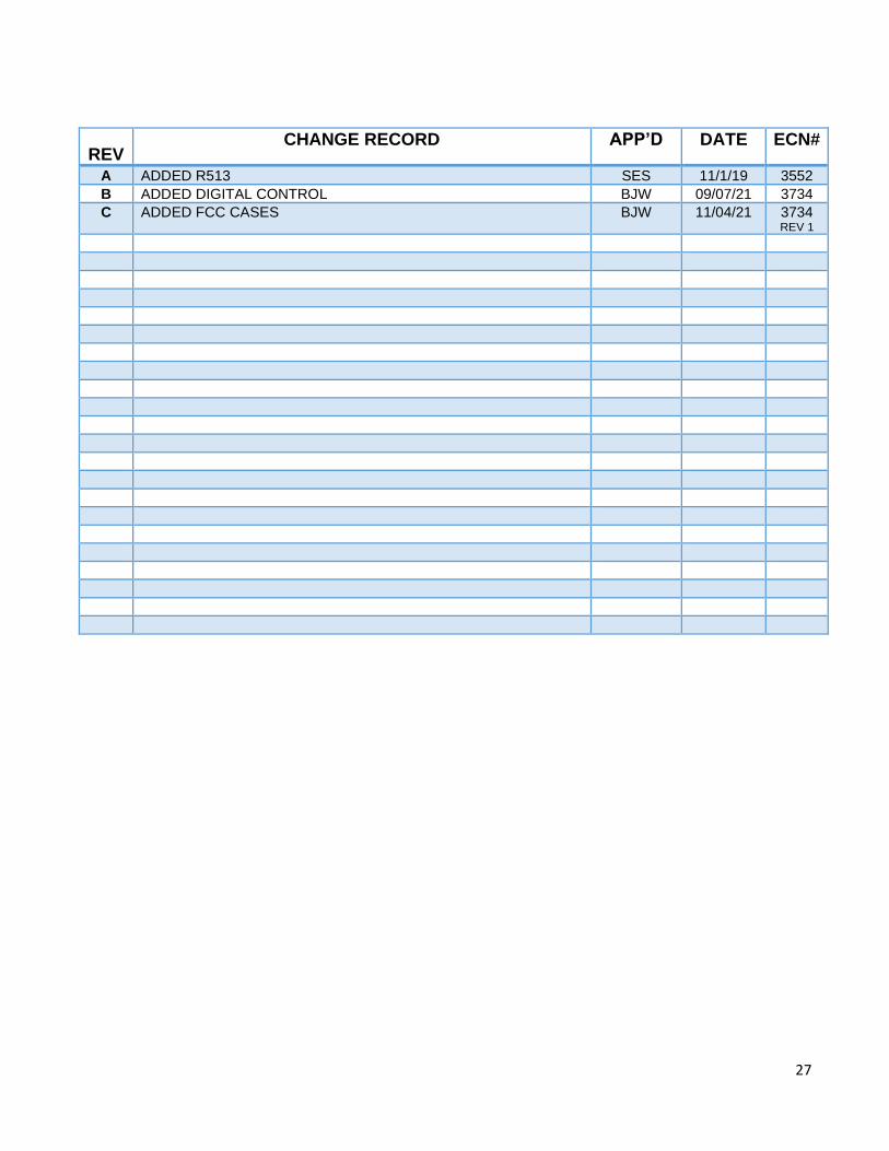
REV CHANGE RECORD APP’D DATE ECN#
A ADDED R513 SES 11/1/19 3552
B ADDED DIGITAL CONTROL BJW 09/07/21 3734
C ADDED FCC CASES BJW 11/04/21 3734 REV 1
![Preparation of [5 + 6]-, [6 + 6]-, and [6 + 7]-Bicyclic Guanidines fromC,C'-Bis(iminophosphoranes)](https://img.dokumen.tips/doc/110x75/6346fe92f88a53192c091c1a/preparation-of-5-6-6-6-and-6-7-bicyclic-guanidines-fromcc-bisiminophosphoranes.jpg)


