Embed Size (px)
Citation preview
This is a repository copy of Fault tolerant control in shape-changing internal robots.
White Rose Research Online URL for this paper:https://eprints.whiterose.ac.uk/160367/
Version: Accepted Version
Proceedings Paper:Balasubramanian, L., Wray, T. and Damian, D.D. orcid.org/0000-0002-0595-0182 (2020) Fault tolerant control in shape-changing internal robots. In: Proceedings of 2020 IEEE International Conference on Robotics and Automation (ICRA). 2020 IEEE International Conference on Robotics and Automation (ICRA), 31 May - 31 Aug 2020, Paris, France. IEEE , pp. 5502-5508. ISBN 9781728173962
https://doi.org/10.1109/ICRA40945.2020.9196989
© 2020 IEEE. Personal use of this material is permitted. Permission from IEEE must be obtained for all other users, including reprinting/ republishing this material for advertising orpromotional purposes, creating new collective works for resale or redistribution to servers or lists, or reuse of any copyrighted components of this work in other works. Reproduced in accordance with the publisher's self-archiving policy.
[email protected]://eprints.whiterose.ac.uk/
Reuse Items deposited in White Rose Research Online are protected by copyright, with all rights reserved unless indicated otherwise. They may be downloaded and/or printed for private study, or other acts as permitted by national copyright laws. The publisher or other rights holders may allow further reproduction and re-use of the full text version. This is indicated by the licence information on the White Rose Research Online record for the item.
Takedown If you consider content in White Rose Research Online to be in breach of UK law, please notify us by emailing [email protected] including the URL of the record and the reason for the withdrawal request.
Fault Tolerant Control in Shape-Changing Internal Robots
Lavanya Balasubramanian1, Tom Wray1, and Dana D. Damian1
Abstract— It is known that the interior of the human body isone of the most adverse environments for a foreign body, suchas an in-vivo robot, and vice-versa. As robots operating in-vivo
are increasingly recognized for their capabilities and potentialfor improved therapies, it is important to ensure their safety,especially for long term treatments when little supervisioncan be provided. We introduce an implantable robot that isflexible, extendable and symmetric, thus changing shape andsize. This design allows the implementation of an effective faulttolerant control, with features such as physical polling for faultdiagnosis, retraction and redundancy-based control switchingat fault. We demonstrate the fault-tolerant capabilities for animplantable robot that elongates tubular tissues by applyingtension to the tissue. In benchtop tests, we show a reduction ofthe fault risks by at least 83%. The study provides a valuablemethodology to enhance safety and efficacy of implantable andsurgical robots, and thus to accelerate their adoption.
I. INTRODUCTION
Tissue regeneration and growth are lengthy and physio-
logically demanding processes [1]. There are innumerable
cases in which the regenerative capability of the human
body cannot carry out these processes without assistance.
For instance, long-gap esophageal atresia (LGEA) (Fig. 1)
and short bowel syndrome (SBS) are congenital defects in
which up to two thirds of the organ (esophagus and bowel
respectively) are missing.
Current treatments suggest that mechanical stimulation
of the esophagus and bowel has the potential to lengthen
these organs [2], [3]. However further efforts are needed
in order to reduce the morbidity of these treatments, due
to the invasiveness of the underlying surgical intervention,
the ad hoc provision of mechanical stimulation, and the
necessary post-surgical treatment. It would be ideal to have
a robotic implant that resides inside the body, mounted on
the esophagus or bowel, and provides precise, localized and
effective mechanical stimulation until these tubular organs
are fully reconstructed.
Implantable technologies that can operate in the long
term inside the body and provide onboard clinical expertise
until the tissue heals can facilitate long-term therapies. Such
robotic implantable devices not only could complement a
surgeon’s capabilities but also deliver effective therapy at
all times during treatment through their ability to operate
autonomously [4], which is impossible in typical forms of
clinical practice. Robotic implantable technology also has
the potential to adjust and customize treatments, depending
on the target tissue and patient state. Lastly, treatment costs
1 Automatic Control and Systems Engineering Department, University ofSheffield, Mappin Street, S13JD, UK (e-mail: [email protected]).
This work was supported by The University of Sheffield and EPSRCR/150439.
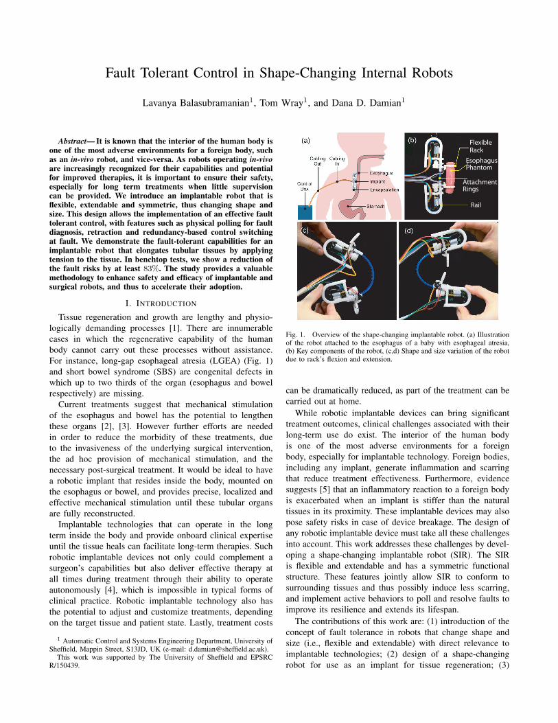
EsophagusPhantom
Flexible Rack
AttachmentRings
Rail
Fig. 1. Overview of the shape-changing implantable robot. (a) Illustrationof the robot attached to the esophagus of a baby with esophageal atresia,(b) Key components of the robot, (c,d) Shape and size variation of the robotdue to rack’s flexion and extension.
can be dramatically reduced, as part of the treatment can be
carried out at home.
While robotic implantable devices can bring significant
treatment outcomes, clinical challenges associated with their
long-term use do exist. The interior of the human body
is one of the most adverse environments for a foreign
body, especially for implantable technology. Foreign bodies,
including any implant, generate inflammation and scarring
that reduce treatment effectiveness. Furthermore, evidence
suggests [5] that an inflammatory reaction to a foreign body
is exacerbated when an implant is stiffer than the natural
tissues in its proximity. These implantable devices may also
pose safety risks in case of device breakage. The design of
any robotic implantable device must take all these challenges
into account. This work addresses these challenges by devel-
oping a shape-changing implantable robot (SIR). The SIR
is flexible and extendable and has a symmetric functional
structure. These features jointly allow SIR to conform to
surrounding tissues and thus possibly induce less scarring,
and implement active behaviors to poll and resolve faults to
improve its resilience and extends its lifespan.
The contributions of this work are: (1) introduction of the
concept of fault tolerance in robots that change shape and
size (i.e., flexible and extendable) with direct relevance to
implantable technologies; (2) design of a shape-changing
robot for use as an implant for tissue regeneration; (3)
introduction of active fault detection, retraction, recovery
and redundancy-based compensation strategies based on
the shape and structural reconfigurability of the robot; (4)
demonstration of the benefit of robot flexibility for fault
tolerance, such as disambiguation in fault identification.
II. RELATED WORK
In recent years, we have seen a recognition of the need for
and potential of flexible and soft technologies to be used in
safe and conformable medical devices. These developments
range from smart materials for stents to novel implantable
sensors and actuators. Stents made of nitinol exhibit self-
expansion due to mechanisms of shape memory and supere-
lasticity [6]. Xu et al. developed a soft membrane equipped
with arrays of multi-functional sensors and electronic and
optoelectronic components that can be placed around the
heart to acquire physiological information about the heart’s
function [7]. Roche et al. developed a soft sleeve to support
heart function by activating embedded pneumatic actuators
that can act as a bridge to transplant for patients with heart
failure [8]. A smart ingestible robot that can unfold in the
stomach can act as a therapeutic patch for peptic ulcers [9].
Our group has recently developed a robotic implant for
esophageal tissue growth with applications for LGEA [10],
[11]. The robot, attached to the tissue with two rings, mimics
the Foker technique by gently pulling on the tissue using
a direct current (DC) motor. We demonstrated in-vivo that
we can monitor and command these elongation forces and
induce cell proliferation in a swine model [12].
While the potential of in-vivo robots is recognized, clinical
acceptance is hindered by the susceptibility to failure of com-
plex medical devices. Therefore, safety is a key requirement
for any clinical translation of the robotic implant [13]. The
advancement of in-vivo robots will have to be aligned with
the development of fault-tolerant systems that will extend
their operational life in case of any fault occurrence [14].
Fault-tolerant mechanisms and control have been exten-
sively used in aeronautics; yet fault tolerance and long-term
operation have been of increased interest in robotics [15],
with researchers exploring robotic body-image [16], soft
encapsulation [17], and trial-and-error learning to increase
the resilience of robots to fault [18]. Fault-tolerant mech-
anisms and control have yet to be adopted for medical
robots. As in-vivo robots operate in inaccessible sites over
an extended period of time with limited supervision, a fault
tolerance strategy is necessary to detect and compensate for
any faults [19].
In this work, we advance our robotic implant technology
with shape-changing design features which we show to
enhance fault tolerant control.
III. IMPLANT REQUIREMENTS AND DESIGN
A. Requirements
Our in-vivo studies [12] have revealed unrecognized
challenges owing to the fixed design of the implant
operating over the long term in a harsh in-vivo environment.
Aside from the conventional requirements for implantable
technologies, such as biocompatibility, safety, additional
stringent requirements need to be met.
The physical requirements are as follows:
a) Implant flexibility: The robotic implant must be me-
chanically compliant (e.g., flexible) with the surrounding soft
tissue. We have ascertained in our previous work that tissue
fibrosis occurred at a notable level due to the contact forces
between the rigid implant and tissue [12]. A flexible robotic
implant should inflict minimum damage to the surrounding
organs and minimize fibrotic response [5].
b) Encapsulation: A soft, liquid-proof and airtight
cover for the implant to prevent damage to itself and its
surrounding organs.
c) Hardware redundancy: In order to reduce surgical
intervention, hardware redundancy would prove vital in case
of component failure.
The functional requirements are as follows:
d) Tissue tensioning and elongation: As a specific
requirement based on our previous work, the robotic implant
must be capable of applying a tension force to the tissue of
up to 2N. The robot also needs to provide sufficient tissue
displacement capability, approximately 100mm [2].
e) Implant fault tolerance: The robotic implant should
also be resilient to fault in order to guarantee its long-term
use, which can range from weeks to months of treatment.
From our experiments, the electronic parts were the com-
ponents that were most prone to failure. A mechanism and
control should be available for the robot to diagnose and
compensate for any faults, thus extending its operational
life and avoiding re-operative surgery. The focus of this
study is on the hardware redundancy and the implant fault
tolerance. The other requirements are detailed in a different
investigation of our group [20].
B. Implant Design
Based on the above design requirements, we advanced our
robotic implant [12] to a flexible, extendable and symmetric
design (Fig. 1 (b)(c)(d)), which provide enhanced fault toler-
ant control (FTC), as demonstrated in the following sections.
A flexible rack was used to ensure that the implant would
comply with the dynamics of the surrounding tissue to avoid
applying excessive stress to the organs in its proximity, as
well as reduce self-damage due to long-term shear stresses.
The width of the rack is 8mm, the total height is 3.8mm, the
width and height of the teeth is 3.8 and 1.8mm, respectively.
Two identical U-shaped rails, also referred to as the main
and mirror units, guide the rack displacement and house the
required electronics. The U-shape of the rail enables housing
an extra length of rack while reducing the overall length
of the robotic implant. The dimensions of the rail are as
follows: height = 67.35mm, width = 38.51mm, and depth =
15.30mm. The overall length of the robot is 135mm (when
the two rails are in contact), and the width is 35mm; these
dimensions are 35% and 16% larger than their respective
counterparts in [12]. The weight of this core prototype is
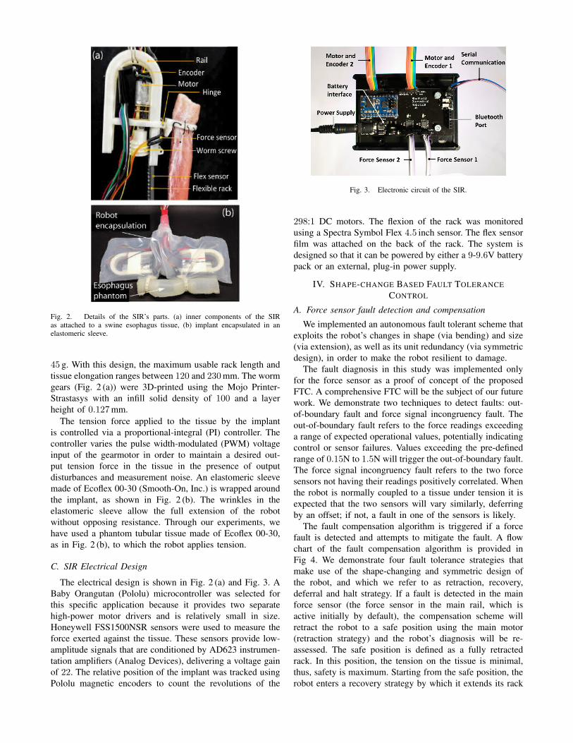
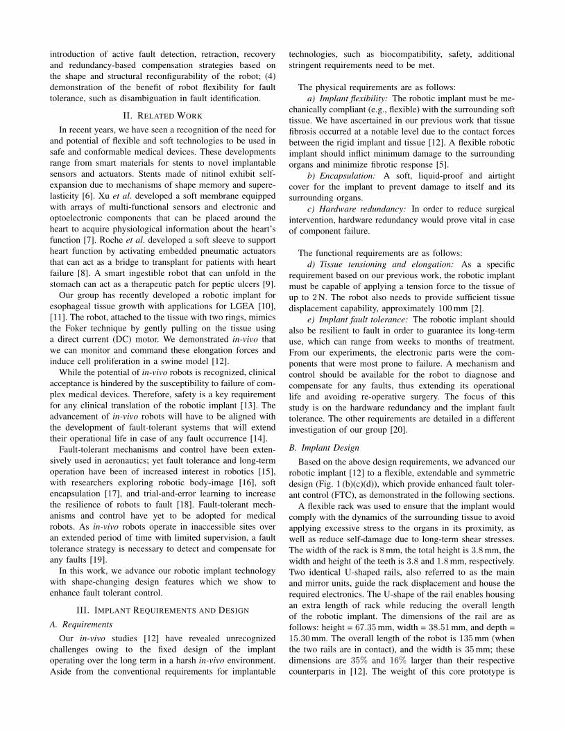
Fig. 2. Details of the SIR’s parts. (a) inner components of the SIRas attached to a swine esophagus tissue, (b) implant encapsulated in anelastomeric sleeve.
45 g. With this design, the maximum usable rack length and
tissue elongation ranges between 120 and 230mm. The worm
gears (Fig. 2 (a)) were 3D-printed using the Mojo Printer-
Strastasys with an infill solid density of 100 and a layer
height of 0.127mm.
The tension force applied to the tissue by the implant
is controlled via a proportional-integral (PI) controller. The
controller varies the pulse width-modulated (PWM) voltage
input of the gearmotor in order to maintain a desired out-
put tension force in the tissue in the presence of output
disturbances and measurement noise. An elastomeric sleeve
made of Ecoflex 00-30 (Smooth-On, Inc.) is wrapped around
the implant, as shown in Fig. 2 (b). The wrinkles in the
elastomeric sleeve allow the full extension of the robot
without opposing resistance. Through our experiments, we
have used a phantom tubular tissue made of Ecoflex 00-30,
as in Fig. 2 (b), to which the robot applies tension.
C. SIR Electrical Design
The electrical design is shown in Fig. 2 (a) and Fig. 3. A
Baby Orangutan (Pololu) microcontroller was selected for
this specific application because it provides two separate
high-power motor drivers and is relatively small in size.
Honeywell FSS1500NSR sensors were used to measure the
force exerted against the tissue. These sensors provide low-
amplitude signals that are conditioned by AD623 instrumen-
tation amplifiers (Analog Devices), delivering a voltage gain
of 22. The relative position of the implant was tracked using
Pololu magnetic encoders to count the revolutions of the
Fig. 3. Electronic circuit of the SIR.
298:1 DC motors. The flexion of the rack was monitored
using a Spectra Symbol Flex 4.5 inch sensor. The flex sensor
film was attached on the back of the rack. The system is
designed so that it can be powered by either a 9-9.6V battery
pack or an external, plug-in power supply.
IV. SHAPE-CHANGE BASED FAULT TOLERANCE
CONTROL
A. Force sensor fault detection and compensation
We implemented an autonomous fault tolerant scheme that
exploits the robot’s changes in shape (via bending) and size
(via extension), as well as its unit redundancy (via symmetric
design), in order to make the robot resilient to damage.
The fault diagnosis in this study was implemented only
for the force sensor as a proof of concept of the proposed
FTC. A comprehensive FTC will be the subject of our future
work. We demonstrate two techniques to detect faults: out-
of-boundary fault and force signal incongruency fault. The
out-of-boundary fault refers to the force readings exceeding
a range of expected operational values, potentially indicating
control or sensor failures. Values exceeding the pre-defined
range of 0.15N to 1.5N will trigger the out-of-boundary fault.
The force signal incongruency fault refers to the two force
sensors not having their readings positively correlated. When
the robot is normally coupled to a tissue under tension it is
expected that the two sensors will vary similarly, deferring
by an offset; if not, a fault in one of the sensors is likely.
The fault compensation algorithm is triggered if a force
fault is detected and attempts to mitigate the fault. A flow
chart of the fault compensation algorithm is provided in
Fig 4. We demonstrate four fault tolerance strategies that
make use of the shape-changing and symmetric design of
the robot, and which we refer to as retraction, recovery,
deferral and halt strategy. If a fault is detected in the main
force sensor (the force sensor in the main rail, which is
active initially by default), the compensation scheme will
retract the robot to a safe position using the main motor
(retraction strategy) and the robot’s diagnosis will be re-
assessed. The safe position is defined as a fully retracted
rack. In this position, the tension on the tissue is minimal,
thus, safety is maximum. Starting from the safe position, the
robot enters a recovery strategy by which it extends its rack
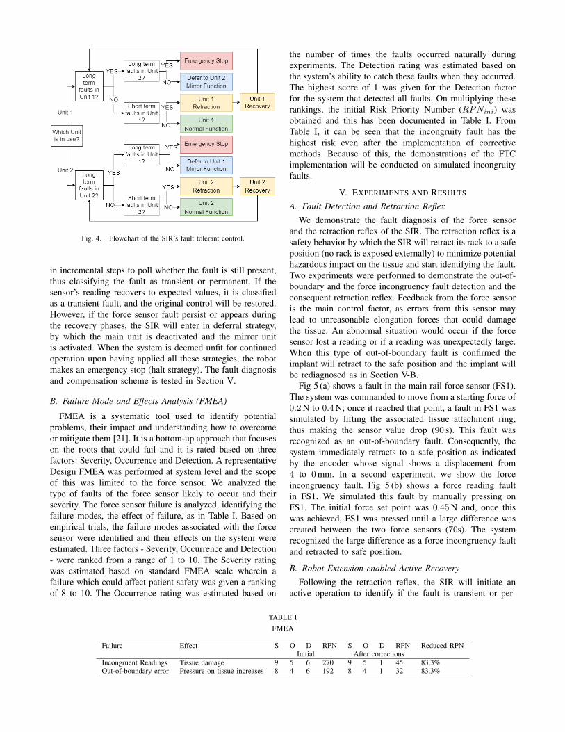
Fig. 4. Flowchart of the SIR’s fault tolerant control.
in incremental steps to poll whether the fault is still present,
thus classifying the fault as transient or permanent. If the
sensor’s reading recovers to expected values, it is classified
as a transient fault, and the original control will be restored.
However, if the force sensor fault persist or appears during
the recovery phases, the SIR will enter in deferral strategy,
by which the main unit is deactivated and the mirror unit
is activated. When the system is deemed unfit for continued
operation upon having applied all these strategies, the robot
makes an emergency stop (halt strategy). The fault diagnosis
and compensation scheme is tested in Section V.
B. Failure Mode and Effects Analysis (FMEA)
FMEA is a systematic tool used to identify potential
problems, their impact and understanding how to overcome
or mitigate them [21]. It is a bottom-up approach that focuses
on the roots that could fail and it is rated based on three
factors: Severity, Occurrence and Detection. A representative
Design FMEA was performed at system level and the scope
of this was limited to the force sensor. We analyzed the
type of faults of the force sensor likely to occur and their
severity. The force sensor failure is analyzed, identifying the
failure modes, the effect of failure, as in Table I. Based on
empirical trials, the failure modes associated with the force
sensor were identified and their effects on the system were
estimated. Three factors - Severity, Occurrence and Detection
- were ranked from a range of 1 to 10. The Severity rating
was estimated based on standard FMEA scale wherein a
failure which could affect patient safety was given a ranking
of 8 to 10. The Occurrence rating was estimated based on
the number of times the faults occurred naturally during
experiments. The Detection rating was estimated based on
the system’s ability to catch these faults when they occurred.
The highest score of 1 was given for the Detection factor
for the system that detected all faults. On multiplying these
rankings, the initial Risk Priority Number (RPNini) was
obtained and this has been documented in Table I. From
Table I, it can be seen that the incongruity fault has the
highest risk even after the implementation of corrective
methods. Because of this, the demonstrations of the FTC
implementation will be conducted on simulated incongruity
faults.
V. EXPERIMENTS AND RESULTS
A. Fault Detection and Retraction Reflex
We demonstrate the fault diagnosis of the force sensor
and the retraction reflex of the SIR. The retraction reflex is a
safety behavior by which the SIR will retract its rack to a safe
position (no rack is exposed externally) to minimize potential
hazardous impact on the tissue and start identifying the fault.
Two experiments were performed to demonstrate the out-of-
boundary and the force incongruency fault detection and the
consequent retraction reflex. Feedback from the force sensor
is the main control factor, as errors from this sensor may
lead to unreasonable elongation forces that could damage
the tissue. An abnormal situation would occur if the force
sensor lost a reading or if a reading was unexpectedly large.
When this type of out-of-boundary fault is confirmed the
implant will retract to the safe position and the implant will
be rediagnosed as in Section V-B.
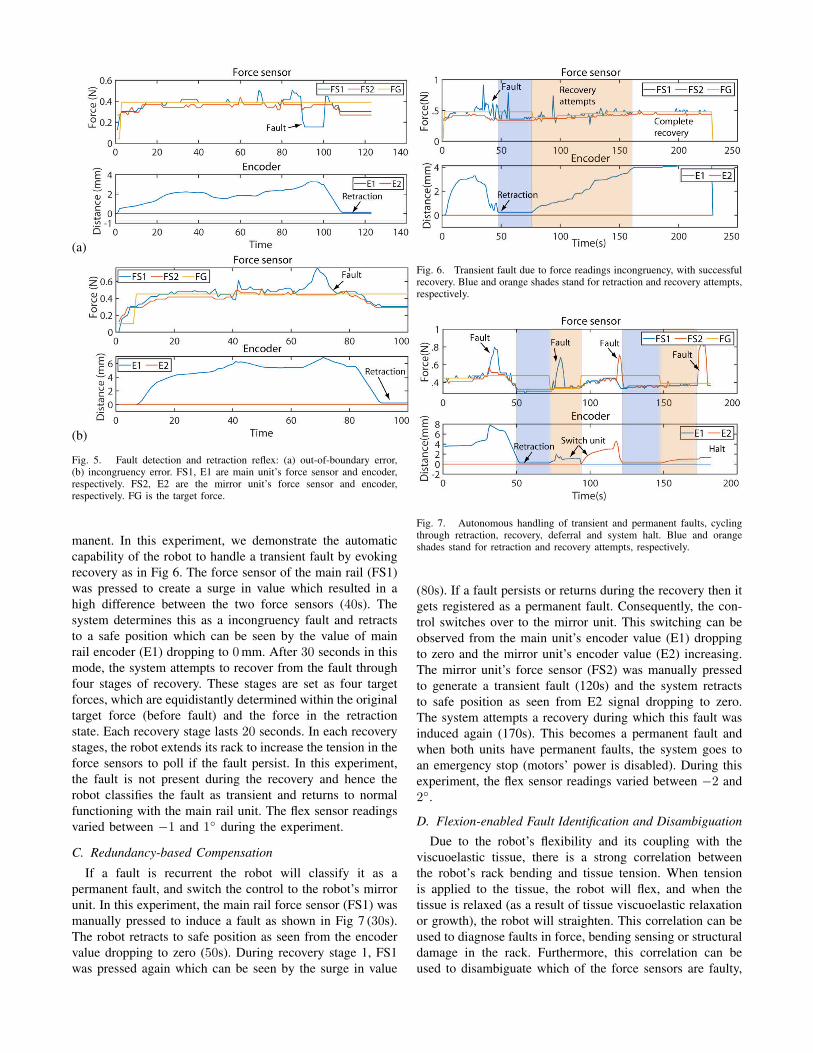
Fig 5 (a) shows a fault in the main rail force sensor (FS1).
The system was commanded to move from a starting force of
0.2N to 0.4N; once it reached that point, a fault in FS1 was
simulated by lifting the associated tissue attachment ring,
thus making the sensor value drop (90 s). This fault was
recognized as an out-of-boundary fault. Consequently, the
system immediately retracts to a safe position as indicated
by the encoder whose signal shows a displacement from
4 to 0mm. In a second experiment, we show the force
incongruency fault. Fig 5 (b) shows a force reading fault
in FS1. We simulated this fault by manually pressing on
FS1. The initial force set point was 0.45N and, once this
was achieved, FS1 was pressed until a large difference was
created between the two force sensors (70s). The system
recognized the large difference as a force incongruency fault
and retracted to safe position.
B. Robot Extension-enabled Active Recovery
Following the retraction reflex, the SIR will initiate an
active operation to identify if the fault is transient or per-
TABLE I
FMEA
Failure Effect S O D RPN S O D RPN Reduced RPNInitial After corrections
Incongruent Readings Tissue damage 9 5 6 270 9 5 1 45 83.3%Out-of-boundary error Pressure on tissue increases 8 4 6 192 8 4 1 32 83.3%
(a)
(b)
Fig. 5. Fault detection and retraction reflex: (a) out-of-boundary error,(b) incongruency error. FS1, E1 are main unit’s force sensor and encoder,respectively. FS2, E2 are the mirror unit’s force sensor and encoder,respectively. FG is the target force.
manent. In this experiment, we demonstrate the automatic
capability of the robot to handle a transient fault by evoking
recovery as in Fig 6. The force sensor of the main rail (FS1)
was pressed to create a surge in value which resulted in a
high difference between the two force sensors (40s). The
system determines this as a incongruency fault and retracts
to a safe position which can be seen by the value of main
rail encoder (E1) dropping to 0mm. After 30 seconds in this
mode, the system attempts to recover from the fault through
four stages of recovery. These stages are set as four target
forces, which are equidistantly determined within the original
target force (before fault) and the force in the retraction
state. Each recovery stage lasts 20 seconds. In each recovery
stages, the robot extends its rack to increase the tension in the
force sensors to poll if the fault persist. In this experiment,
the fault is not present during the recovery and hence the
robot classifies the fault as transient and returns to normal
functioning with the main rail unit. The flex sensor readings
varied between −1 and 1◦ during the experiment.
C. Redundancy-based Compensation
If a fault is recurrent the robot will classify it as a
permanent fault, and switch the control to the robot’s mirror
unit. In this experiment, the main rail force sensor (FS1) was
manually pressed to induce a fault as shown in Fig 7 (30s).
The robot retracts to safe position as seen from the encoder
value dropping to zero (50s). During recovery stage 1, FS1
was pressed again which can be seen by the surge in value
Fig. 6. Transient fault due to force readings incongruency, with successfulrecovery. Blue and orange shades stand for retraction and recovery attempts,respectively.
Fig. 7. Autonomous handling of transient and permanent faults, cyclingthrough retraction, recovery, deferral and system halt. Blue and orangeshades stand for retraction and recovery attempts, respectively.
(80s). If a fault persists or returns during the recovery then it
gets registered as a permanent fault. Consequently, the con-
trol switches over to the mirror unit. This switching can be
observed from the main unit’s encoder value (E1) dropping
to zero and the mirror unit’s encoder value (E2) increasing.
The mirror unit’s force sensor (FS2) was manually pressed
to generate a transient fault (120s) and the system retracts
to safe position as seen from E2 signal dropping to zero.
The system attempts a recovery during which this fault was
induced again (170s). This becomes a permanent fault and
when both units have permanent faults, the system goes to
an emergency stop (motors’ power is disabled). During this
experiment, the flex sensor readings varied between −2 and
2◦.
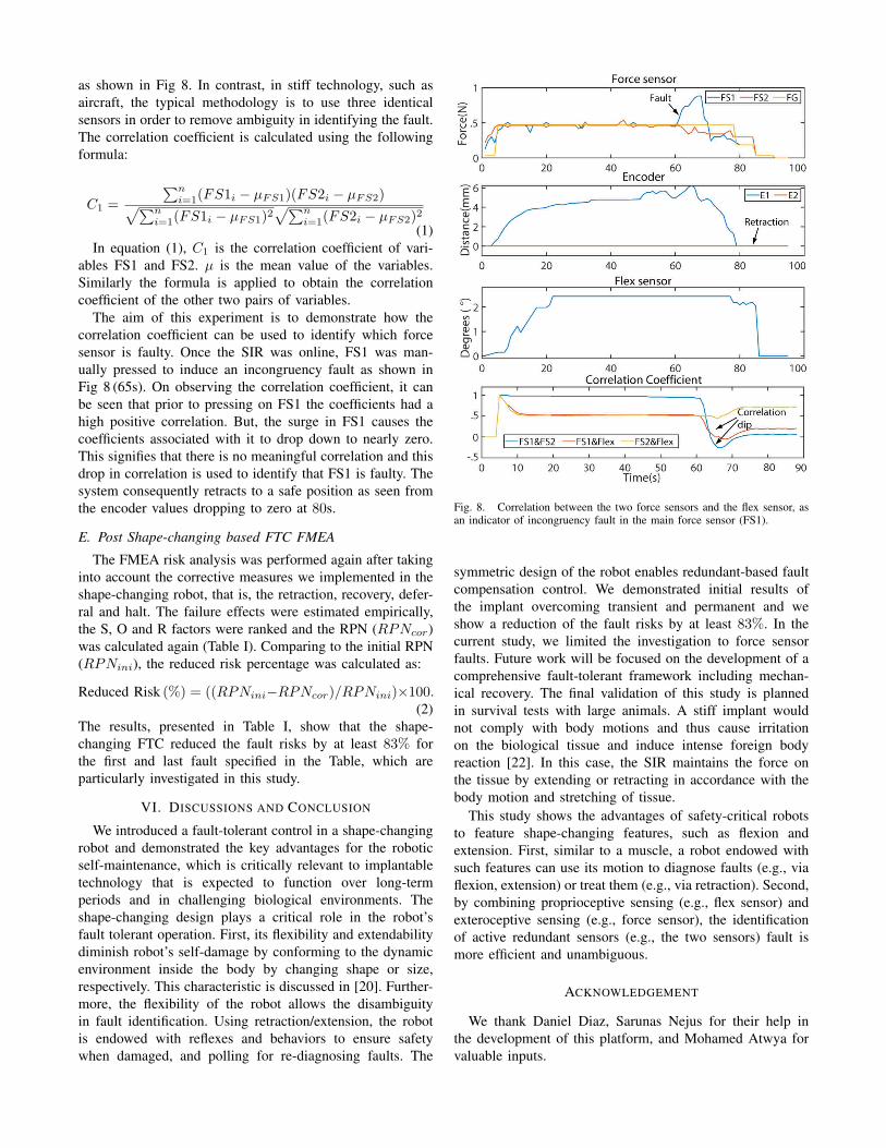
D. Flexion-enabled Fault Identification and Disambiguation
Due to the robot’s flexibility and its coupling with the
viscuoelastic tissue, there is a strong correlation between
the robot’s rack bending and tissue tension. When tension
is applied to the tissue, the robot will flex, and when the
tissue is relaxed (as a result of tissue viscuoelastic relaxation
or growth), the robot will straighten. This correlation can be
used to diagnose faults in force, bending sensing or structural
damage in the rack. Furthermore, this correlation can be
used to disambiguate which of the force sensors are faulty,
as shown in Fig 8. In contrast, in stiff technology, such as
aircraft, the typical methodology is to use three identical
sensors in order to remove ambiguity in identifying the fault.
The correlation coefficient is calculated using the following
formula:
C1 =
∑n
i=1(FS1i − µFS1)(FS2i − µFS2)
√
∑n
i=1(FS1i − µFS1)2
√
∑n
i=1(FS2i − µFS2)2
(1)
In equation (1), C1 is the correlation coefficient of vari-
ables FS1 and FS2. µ is the mean value of the variables.
Similarly the formula is applied to obtain the correlation
coefficient of the other two pairs of variables.
The aim of this experiment is to demonstrate how the
correlation coefficient can be used to identify which force
sensor is faulty. Once the SIR was online, FS1 was man-
ually pressed to induce an incongruency fault as shown in
Fig 8 (65s). On observing the correlation coefficient, it can
be seen that prior to pressing on FS1 the coefficients had a
high positive correlation. But, the surge in FS1 causes the
coefficients associated with it to drop down to nearly zero.
This signifies that there is no meaningful correlation and this
drop in correlation is used to identify that FS1 is faulty. The
system consequently retracts to a safe position as seen from
the encoder values dropping to zero at 80s.
E. Post Shape-changing based FTC FMEA
The FMEA risk analysis was performed again after taking
into account the corrective measures we implemented in the
shape-changing robot, that is, the retraction, recovery, defer-
ral and halt. The failure effects were estimated empirically,
the S, O and R factors were ranked and the RPN (RPNcor)
was calculated again (Table I). Comparing to the initial RPN
(RPNini), the reduced risk percentage was calculated as:
Reduced Risk (%) = ((RPNini−RPNcor)/RPNini)×100.(2)
The results, presented in Table I, show that the shape-
changing FTC reduced the fault risks by at least 83% for
the first and last fault specified in the Table, which are
particularly investigated in this study.
VI. DISCUSSIONS AND CONCLUSION
We introduced a fault-tolerant control in a shape-changing
robot and demonstrated the key advantages for the robotic
self-maintenance, which is critically relevant to implantable
technology that is expected to function over long-term
periods and in challenging biological environments. The
shape-changing design plays a critical role in the robot’s
fault tolerant operation. First, its flexibility and extendability
diminish robot’s self-damage by conforming to the dynamic
environment inside the body by changing shape or size,
respectively. This characteristic is discussed in [20]. Further-
more, the flexibility of the robot allows the disambiguity
in fault identification. Using retraction/extension, the robot
is endowed with reflexes and behaviors to ensure safety
when damaged, and polling for re-diagnosing faults. The
Fig. 8. Correlation between the two force sensors and the flex sensor, asan indicator of incongruency fault in the main force sensor (FS1).
symmetric design of the robot enables redundant-based fault
compensation control. We demonstrated initial results of
the implant overcoming transient and permanent and we
show a reduction of the fault risks by at least 83%. In the
current study, we limited the investigation to force sensor
faults. Future work will be focused on the development of a
comprehensive fault-tolerant framework including mechan-
ical recovery. The final validation of this study is planned
in survival tests with large animals. A stiff implant would
not comply with body motions and thus cause irritation
on the biological tissue and induce intense foreign body
reaction [22]. In this case, the SIR maintains the force on
the tissue by extending or retracting in accordance with the
body motion and stretching of tissue.
This study shows the advantages of safety-critical robots
to feature shape-changing features, such as flexion and
extension. First, similar to a muscle, a robot endowed with
such features can use its motion to diagnose faults (e.g., via
flexion, extension) or treat them (e.g., via retraction). Second,
by combining proprioceptive sensing (e.g., flex sensor) and
exteroceptive sensing (e.g., force sensor), the identification
of active redundant sensors (e.g., the two sensors) fault is
more efficient and unambiguous.
ACKNOWLEDGEMENT
We thank Daniel Diaz, Sarunas Nejus for their help in
the development of this platform, and Mohamed Atwya for
valuable inputs.
REFERENCES
[1] S. Eming, T. Wynn, and P. Martin, “Inflammation and metabolismin tissue repair and regeneration,” Science, vol. 356, pp. 1026–1030,2017.
[2] J. E. Foker, B. C. Linden, E. M. Boyle, and C. Marquardt, “Devel-opment of a true primary repair for the full spectrum of esophagealatresia.” Annals of surgery, vol. 226, no. 4, pp. 533–41; discussion541–3, oct 1997.
[3] A. U. Spencer, X. Sun, M. El-Sawaf, E. Q. Haxhija, D. Brei, J. Luntz,H. Yang, and D. H. Teitelbaum, “Enterogenesis in a clinically feasiblemodel of mechanical small-bowel lengthening,” Surgery, vol. 140,no. 2, pp. 212–220, 2006.
[4] C. Angeli and A. Chatzinikolaou, “On-line fault detection techniquesfor technical systems: A survey.” International Journal of Computer
Science and Applications, vol. 1, no. 1, pp. 12–30, 2004.
[5] P. Moshayedi, G. Ng, J. Kwok, G. Yeo, C. Bryant, J. Fawcett,K. Franze, and J. Guck, “The relationship between glial cellmechanosensitivity and foreign body reactions in the central nervoussystem.” Biomaterials, vol. 35, no. 13, pp. 3919–25, 2014.
[6] W. A. Gray, A. Feiring, M. Cioppi, R. Hibbard, B. Gray, Y. Khatib,D. Jessup, W. Bachinsky, E. Rivera, J. Tauth, R. Patarca, J. Massaro,H. P. Stoll, and M. R. Jaff, “S.M.A.R.T. self-expanding nitinol stent forthe treatment of atherosclerotic lesions in the superficial femoral artery(STROLL): 1-year outcomes,” Journal of Vascular and Interventional
Radiology, vol. 26, no. 1, pp. 21–28, 2015.
[7] L. Xu, S. R. Gutbrod, A. P. Bonifas, Y. Su, M. S. Sulkin, N. Lu,H.-J. Chung, K.-I. Jang, Z. Liu, M. Ying, C. Lu, R. C. Webb, J.-S.Kim, J. I. Laughner, H. Cheng, Y. Liu, A. Ameen, J.-W. Jeong, G.-T.Kim, Y. Huang, I. R. Efimov, and J. a. Rogers, “3D multifunctionalintegumentary membranes for spatiotemporal cardiac measurementsand stimulation across the entire epicardium.” Nature communications,vol. 5, p. 3329, 2014.
[8] E. T. Roche, M. A. Horvath, I. Wamala, A. Alazmani, S.-E. Song,W. Whyte, Z. Machaidze, C. J. Payne, J. C. Weaver, G. Fishbein,J. Kuebler, N. V. Vasilyev, D. J. Mooney, F. A. Pigula, and C. J. Walsh,“Soft robotic sleeve supports heart function.” Science Translational
Medicine, vol. 9, no. 373, pp. 1–12, 2017.
[9] S. Miyashita, S. Guitron, K. Yoshida, S. Li, D. D. Damian, and D. Rus,“Ingestible, controllable, and degradable origami robot for patchingstomach wounds,” Proceedings - IEEE International Conference on
Robotics and Automation, vol. 2016-June, no. 4, pp. 909–916, 2016.
[10] D. D. Damian, S. Arabagi, P. E. Dupont, A. Fabozzo, P. Ngo,R. Jennings, M. Manfredi, and P. E. Dupont, “Design of a Robotic
Implant for in-vivo Esophageal Tissue Growth,” Proceedings - IEEE
International Conference on Robotics and Automation, no. 1, pp. 73–74, 2014.
[11] E. R. Perez-Guagnelli, S. Nejus, J. Yu, S. Miyashita, Y. Liu, and D. D.Damian, “Axially and radially expandable modular helical soft actuatorfor robotic implantables,” in Proceedings of 2018 IEEE International
Conference on Robotics and Automation. IEEE, 2018, pp. 4297–4304.[12] D. D. Damian, K. Price, S. Arabagi, I. Berra, Z. Machaidze, S. Manjila,
S. Shimada, A. Fabozzo, G. Arnal, D. V. Story, J. D. Goldsmith, A. T.Agoston, C. Kim, R. W. Jennings, P. D. Ngo, M. Manfredi, and P. E.Dupont, “In vivo tissue regeneration with robotic implants.” Science
Robotics, vol. 3, no. 14, p. eaaq0018, 2018.[13] K. Cleary and C. Nguyen, “State of the art in surgical robotics: Clinical
applications and technology challenges,” Computer Aided Surgery,vol. 6, no. 6, pp. 312–328, 2001.
[14] N. J. Dowler, “Applying software dependability principles to medicalrobotics,” Computing Control Engineering Journal, vol. 6, no. 5, pp.222–225, Oct 1995.
[15] M.L.Visinsky, J.R.Cavallaro, and I.D.Walker, “Robotic fault detectionand fault tolerance: A survey,” Reliability Engineering & System
Safety, vol. 46, pp. 139–158, 1994.[16] J. Bongard, V. Zykov, and H. Lipson, “Resilient machines through
continuous self-modeling,” Science, vol. 314, pp. 1118–1121, 2006.[17] M. T. Tolley, R. F. Shepherd, B. Mosadegh, K. C. Galloway,
M. Wehner, M. Karpelson, R. J. Wood, and G. M. Whitesides, “Aresilient, untethered soft robot,” Soft Robotics, vol. 1, pp. 213–223,2014.
[18] A. Cully, J. Clune, D. Tarapore, and J.-B. Mouret, “Robots that canadapt like animals,” Nature, vol. 521, pp. 503–507, 2015.
[19] K.-J. Kim and S.-B. Cho, “Automated synthesis of multiple analogcircuits using evolutionary computation for redundancy-based fault-tolerance,” Applied Soft Computing, vol. 12, no. 4, pp. 1309–1321,2012.
[20] M. Atwya, C. Kavak, E. Alisse, Y. Liu, and D. D. Damian, “A flexibleand expandable robot for tissue-regenerative therapies,” 2020, (underreview).
[21] Y. Maddahi, A. Maddahi, S. Mohammad, and H. Monsef, “Designimprovement of wheeled mobile robots: Theory and experiment,”World Applied Sciences Journal, vol. 16, pp. 263–274, 01 2012.
[22] J. Subbaroyan, D. C. Martin, and D. R. Kipke, “A finite-elementmodel of the mechanical effects of implantable microelectrodes inthe cerebral cortex,” Journal of Neural Engineering, vol. 2, no. 4, p.103–113, Nov 2005.


