Embed Size (px)
Citation preview

Fast Area Estimation to Support Compiler Optimizations in FPGA-based Reconfigurable Systems
Dhananjay Kulkarni Walid A. Najjar University of California, Riverside
Dept. of Computer Science Riverside, CA 92521
{kulkarni, najjar}@cs.ucr.edu
Robert Rinker University of Idaho
Computer Science Dept. Moscow, ID 83844
Fadi J. Kurdahi University of California, Irvine
Dept. of Electrical and Computer Engineering
Irvine, CA 92717 [email protected]
ABSTRACT Several projects have developed compiler tools that translate high-level languages down to hardware description languages for mapping onto FPGA-based reconfigurable computers. These compiler tools can apply extensive transformations that exploit the parallelism inherent in the computations. However, the transformations can have a major impact on the chip area (number of logic blocks) used on the FPGA. It is imperative therefore that the compiler user be provided with feedback indicating how much space is being used. In this paper we present a fast compile-time area estimation technique to guide the compiler optimizations. Experimental results show that our technique achieves an accuracy within 2.5% for small image-processing operators, and within 5.0% for larger benchmarks, as compared to the usual post-compilation synthesis tool estimations. The estimation time is in the order of milliseconds as compared to several minutes for a synthesis tool.
1 1 INTRODUCTION One of the consequences of the increase in circuit densities and speed of VLSI systems over the past decade is the emerging viability of FPGA-based reconfigurable computing systems, or RCSs. These systems rely on the mapping of a program segment or function directly into fine-grained gate-level hardware. The density advantage of this form of computation can achieve speed-ups that are several orders of magnitude [1, 2] over sequential implementations. This technology is particularly beneficial to applications where the same computation is applied to a very large data set,
presenting ample opportunity for parallelism.
Examples include image and video processing, data compression etc. However, the main drawback of this form of computation is the semantic gap between the logic circuit model of FPGA programming, based on hardware description languages (such as VHDL
Figure 1 - Traditional compilation for FPGAs
HDL Code Generation (< 1 sec)
High Level Synthesis (seconds to minutes)
Ready for FPGA
Constraints met?
N
HLL Program
Compiler & Optimizations (msec to sec)
Y
Place & Route (minutes to
hours)

and Verilog), as used by circuit designers, and the algorithmic expression of the applications in a high level language such as C, as used by application programmers. Several projects have therefore developed compiler tools that transform high-level languages into HDLs for mapping onto FPGAs [3-7]. These tools not only allow application programmers to directly implement their algorithms into hardware, they also provide a tremendous opportunity for the compiler to perform extensive optimizations that can take advantage of the characteristics of FPGA technology. Some examples include: - Common subexpression elimination, which
reduces the required chip area by consolidating redundant values.
- Loop unrolling, which replicates the body of a loop so that several computations execute in parallel, thereby reducing the number of clock cycles required to complete the computations of the loop.
- Loop fusion, which allows computations in adjacent loops to be combined into a single cycle.
While some optimizations produce a “sure win” by improving (or at least not degrading) both execution speed and chip area, most optimizations trade off higher speed for increased circuit space. Compiler options control the application of this latter group of optimizations, thereby allowing the user to choose the most effective set. In most cases, the programmer continues to apply optimizations as long as the resulting circuit still fits on the FPGA. The interaction between optimizations is often very difficult to predict: the user must find the best combination by trial and error iterations of the compiler optimizations. Unfortunately, the process required for each design iteration can be quite time consuming. Figure 1 shows the normal design sequence, along with typical times required by each step. While the compiler executes on the order of seconds, even when optimizations are turned on, information on the exact amount of space required by the design is not determined until after the synthesis and place-and-route steps, which may take up to an hour or more. Although recent synthesis tools now provide reasonable estimates of space requirements,
obviating the need for the very long place-and-route step for estimation, even executing the synthesis step often adds several minutes to the design cycle. In this paper we report on a compile-time estimation technique that achieves reasonable accuracy and is fast enough to be used repeatedly within the compiler. Our technique is applied at the intermediate dataflow graph program representation. It makes space estimation information available to the compiler prior to the translation to a HDL. Experimental results show that our technique achieves a space estimation within 2.5% for small image-processing operators, and within 5.0% for larger benchmarks, when compared to the commercial synthesis tool estimations, and takes 5 to 6 orders of magnitude less time to compute. The objective of the estimation tool is to reduce development time by providing feedback to the compiler user about the amount of FPGA area that will be used by the code being generated (specifically, does the circuit fit on the FPGA?) Therefore, it is not necessary to achieve absolute accuracy in the estimation. In this work we have used the SA-C language and compiler tools [8]. The SA-C compiler translates the high-level SA-C code into dataflow graphs (DFGs), which can be viewed as abstract hardware circuits without timing information. The SA-C compiler applies aggressive optimizations that are reflected at the intermediate dataflow graph stage, before generating a VHDL hardware description, sometimes leading to a different structural design than that implied in the original SA-C source program. The hardware description is then synthesized and mapped using commercial tools. The use of a high level language as the starting point shortens the overall time required for implementing a design on the FPGA under the given constraints. However, the mapping, placement and routing are very complex and time-consuming phases and form the main bottleneck in the design process. Especially during early design iterations, these tools are used solely to estimate the circuit area of each design alternative; their primary functions of synthesis and mapping are only needed in the last iterations of the design process, when the final circuit is realized and tested.

The rest of the paper presents the compile-time estimation approach in section 2; experimental results are presented in section 3; and section 4 concludes and describes some future work.
2 ESTIMATION APPROACH 2.1 Compile-time Estimation In order to exploit the parallelism available on FPGAs, the SA-C compiler performs a large number of optimizations. As with a conventional language compiler, it is not always obvious what the effects of a particular optimization will be on the space required by the program. This uncertainty is especially problematic with FPGAs, where circuit space is usually the major limiting design constraint. As shown in Figure 2, we apply the estimation model on an intermediate format used by the SA-C compiler, and feed the space estimation results back to the user before the synthesis and mapping phase. Our purpose is to provide a quick and reasonably accurate resource usage estimation of a SA-C program. Rapid feedback about the size of the resulting design allows the user to try many variations of the design or the source program in the quest to find a fast and efficient design that can fit on the FPGA. In this context, resources are defined to be the number of look-up tables (LUTs) required by the design. Of course, the routing of signals between LUTs can itself consume some LUTs, and this can be determined only after place and route. However, these resources do not usually constitute a very large fraction of the overall resources. The intention is to allow the user (or the compiler in a fully automated system) to determine the extent of the optimizations it can “reasonably” do. For example, if after unrolling a loop body twice on the FPGA (that is having two identical and concurrent loop bodies in hardware) the total area utilization is 40%, then the user can determine that four concurrent loop bodies would probably fit safely on the FPGA. Because of fixed overhead in hardware, such as reading and writing memory, the area utilized on the FPGA does not grow linearly with unrolling the loop.
2.2 Estimation Methodology Since the DFG representation of a program does
not contain any low-level structural or timing information, our estimation tool does not incorporate scheduling, resource allocation or binding algorithms. Our method is to pre-compute a set of general resource consumption formulae for all DFG nodes. We then use these formulae to estimate the resource usage of the whole SA-C program, immediately following the main compilation step. The general formula and its coefficients for each resource node are stored in a data file called nodeparams. Input to the estimator is the SA-C DFG itself and the nodeparams file. Using the information in the nodeparams file, the estimator calculates the space usage of the dataflow graph in terms of LUTs. The complexity of
Figure 2: Compile-time estimation supports compiler optimizations
Time consuming
SA-C
DFG to VHDL Translator
Synthesis + placement + routing
Compile
DFG
FGPA configuration code
Optimizations
Estimation
VHDL
% area usage on FPGA

the estimation algorithm is O(n), where n is the number of nodes in the DFG.
2.3 Approximation Formulae A series of steps are involved in building the estimation model. DFG nodes are parameterized by the bit-widths of their inputs. For example, an 8-bit IADD node is the same as a 5-bit IADD node, except for the input widths. Some nodes are also parameterized by the number of inputs to the node. We first vary the generic parameters of each type of DFG node and create the corresponding VHDL instances. In the next step, we synthesize the VHDL files and record the estimations reported by Synplify1. We then do a regression analysis2 on the estimation values reported by the synthesis tool to generate a general formula for each DFG node. Depending on the number of function parameters, a single curve or a family of curves is used to characterize each type of DFG node. The general formulae are categorized as follows. Parameter y gives the estimated LUT usage, and is in general a function of bit-width (x) and the number (z) of inputs. C, p0, p1, p2, c0, c1 are the function coefficients that are recorded in the nodeparams file. • Constant: y = C
These nodes synthesize as signals and provide an interface with the memory and any other device outside the FPGA chip. They consume a fixed amount of resources on the FPGA. Examples include INPUT and OUTPUT nodes.
• Linear: y = p0 + p1 * x The LUT usage is a linear function of the bit-width x. Most of the arithmetic nodes belong to this category. Examples include unsigned addition and subtraction (UADD & USUB).
• Quadratic: y = p0 + p1 * (x – p2) 2 The LUT consumption of the nodes in this category is a quadratic function of bit-width. The multiplication operation belongs to this category (UMUL & IMUL).
1 Synplify is a widely used logic synthesis tool developed by Synplicity Inc. 2 Regression analysis is a general mathematical technique used to fit a curve to
the given data.
• BiProduct: y = (z-p0) * (x-p1) + p2 The LUT usage of nodes in this category depends on both the bit-width (x) and the number of inputs (z). Multi-input arithmetic nodes use the biproduct approximation. Examples include ISUM-MANY and USUM-MANY.
• MultiLinear2: y = c0 + (c1 * x/2) (z/2 – 1)
The LUT usage of these nodes also depends on the bit-width (x) and number of inpits (z). Multi-input logic operator nodes use the multilinear2 approximation; these include AND-MANY, OR-MANY.
2.4 Estimation Heuristics The implication of applying a formula to estimate the space required by individual nodes is that the final design is simply the concatenation of the circuits for each node. However, most synthesis tools also do timing and resource optimization, wherein they try to make the design as small (in terms of area) and as fast (in terms of timing) as possible by combining and merging circuits wherever possible. These tasks are very complex, because they entail solution of intractable problems. Our approach does not address the solution to such problems in general. However, an estimator that does not account for the more common logic optimizations would not be accurate enough to be useful. Hence we introduce a set of heuristics in our estimation, based on structural patterns, which are patterns that are frequently optimized during synthesis. In our compile-time estimation algorithm, we check for the existence of structural patterns in the DFG. If a pattern is found, we apply the estimation heuristics to the whole pattern, instead of to the individual nodes that form the pattern. Some examples follow: • Multiplication by a constant
When there is a multiplication operation performed in the SA-C source program, the compiler generates a UMUL node in the corresponding DFG. If the multiplication is by a constant that is power of 2, then the synthesis tool optimizes it as a shift operation. The estimator identifies this pattern in the DFG and replaces the estimation of a UMUL node with that of a shift.
• Comparison nodes In the DFG, a decision (“IF”) statement is implemented with a comparison node, such as IEQ (integer equal) or UGT (unsigned greater than), which produces a “true-false” signal, and a SELECTOR node, which routes one of two possible values to its output based on the compare result. Many comparison patterns can be optimized. For example, consider an addition operation in a SA-C program whose output is connected to a comparison node (for example, UGT) with the value 255 (11111111b), and then this result is used to select the appropiate value in the SELECTOR node. The most significant bit of the adder output of the adder is directly fed to the SELECTOR, eliminating the ULT node altogether.
3 EXPERIMENTAL RESULTS All benchmarks used in this paper are compiled for Annapolis MicroSystem Inc’s WildStar board [9]. This board uses the Xilinx Virtex (XCV1000) FPGAs [10, 11], each with 1 million equivalent system gates per chip. There are 27648 4-input LUTs in each FPGA. All the compile-time estimation results are compared with the estimation reported by Synplify.
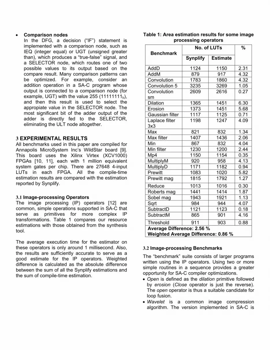
3.1 Image-processing Operators The image processing (IP) operators [12] are common, simple operations supported in SA-C that serve as primitives for more complex IP transformations. Table 1 compares our resource estimations with those obtained from the synthesis tool. The average execution time for the estimator on these operators is only around 1 millisecond. Also, the results are sufficiently accurate to serve as a good estimate for the IP operators. Weighted difference is calculated as the absolute difference between the sum of all the Synplify estimations and the sum of compile-time estimation.
Table 1: Area estimation results for some image processing operators
No. of LUTs Benchmark
Synplify Estimate
%
AddD 1124 1150 2.31 AddM 879 917 4.32 Convolution 1783 1860 4.32 Convolution 5 3235 3269 1.05 Convolution sm
2609 2616 0.27
Dilation 1365 1451 6.30 Erosion 1373 1451 5.68 Gaussian filter 1117 1125 0.71 Laplace filter 3x3
1198 1247 4.09
Max 821 832 1.34 Max filter 1407 1436 2.06 Min 867 832 4.04 Min filter 1230 1200 2.44 Mp4 1150 1154 0.35 MultiplyM 920 958 4.13 MultiplyD 1171 1182 0.94 Prewitt 1083 1020 5.82 Prewitt mag 1815 1792 1.27 Reduce 1013 1016 0.30 Roberts mag 1441 1414 1.87 Sobel mag 1943 1921 1.13 Sqrt 984 944 4.07 SubtractD 1121 1123 0.18 SubtractM 865 901 4.16 Threshold 911 903 0.88 Average Difference: 2.56 % Weighted Average Difference: 0.86 %
3.2 Image-processing Benchmarks The “benchmark” suite consists of larger programs written using the IP operators. Using two or more simple routines in a sequence provides a greater opportunity for SA-C compiler optimizations. • Open is defined as the dilation primitive followed
by erosion (Close operator is just the reverse). The open operator is thus a suitable candidate for loop fusion.
• Wavelet is a common image compression algorithm. The version implemented in SA-C is

based on the Cohen-Daubechies-Feauveau wavelet algorithm [13].
• The tridiagonal code solves the matrix equation [A]. [X] = [B]. The basic idea is to use the tridiagonal matrix A[8,8] and the vector X[8] as input, calculate B and then solve [A].[X] = [B] iteratively to obtain [X].
Table 2: Area estimation of larger image
processing codes No. of LUTs Code
Synplify Estimate
%
Open 4500 4780 6.22 Close 4500 4780 6.22 Wavelet 2172 2065 4.93 Tridiagonal 7476 7188 3.85 Average Difference: 5.30 % Weighted Average Difference: 0.88 %
Open is actually the combination of erosion + dilation, but when the two loops are fused, it runs 2 times faster than the individual routines, at the expense of more area. In wavelet and tridiagonal, the loops are fully unrolled to exploit more parallelism. The synthesis tool takes 6.2 minutes on average to do the synthesis and mapping. Our estimator takes only 1 millisec to do the estimation. Thus, our estimator takes 5 to 6 orders of magnitude less
time to compute than the commercial synthesis tools.
3.3 Comparing to Place and Route Area So far we have been comparing the results of our estimation tool to the area estimated by the synthesis tool. Because the synthesis tool performs the technology mapping, it has a much better handle on the estimated area. We have also compared the area returned by the place and route tool (Xilinx Foundation) for the four larger codes shown in Table 2. The results, in Table 3, show that the estimation tool is accurate enough even when compared to the place and route area. Table 3: Place and route actual area compared
to synthesis and estimation tool results Place
& Route
Synplify (%)
Estimate (%)
Open & Close
4300 4500 (4.65%)
4780 (11.6%)
Wavelet 2079 2172 (4.4%)
2065 (0.67%)
Tridiagonal 7036 7476 (6.25%)
7188 (2.16%)
4 Supporting SA-C Compiler Optimizations In this section we describe two examples that examine the effect of various SA-C compiler optimizations.
4.1 Example 1 Strip-mining is a parallelization technique that exploits the fact that the computation of elements of one loop iteration may also compute elements used in subsequent iterations; with stripmining, two (or more) iterations are replicated in parallel, with the common computations between iterations replicated only once. Performance gains are achieved because iterations are performed in parallel, at the expense of additional space required by the replicated circuits. However, the amount of space required by the replication of n iterations is less than that required of n times the replication of one iteration, due to a single replication of the common terms.
uint20 [:,:] main (uint8 image[:,:], uint8 kernel[:,:]) { uint20 res[:,:] =
// PRAGMA (strip-mine(4,3)) for window win[3,3] in image { uint20 val =
for elem1 in win dot elem2 in kernel return(sum((uint20)elem1*elem2));
} return(array(val)); } return (res);
Figure 3: Convolution

We use the convolution routine shown in Figure 3, which is a 3x3 convolution of an image with kernel. We do compile-time estimation of this SA-C code for the default case (no strip-mining) and then strip-mine the loop for windows of sizes [4,3] (i.e., two iterations in parallel), [5,3] (three iterations), [6,3], [7,3], [8,3] and [20,3], specified using a SA-C PRAGMA directive. Table 4: Area estimation of strip-mined convolution
No. of LUTs
strip- minin
g Synplify Est.
%
Diff
% LUT used on Virtex XCV 1000
None 1783 1949 9.3 7.04 (4,3) 2609 2794 7.09 9.43 5,3) 3458 3516 1.67 12.71
(6,3) 4269 4134 3.16 14.95
(7,3) 5122 4980 2.77 18.01 (8,3) 6709 5686 4.5 20.56 (20,3) 15883 14727 7.2 53.26 Average Difference: 5.09 % Weighted Average Difference: 5.26 %
Table 4 shows the results of strip-mining the convolution example. As with previous examples, the estimator determines the space required by the various designs with an average weighted difference of around 5%. Loop strip-mining when followed by full loop unrolling produces the effect of multidimensional partial loop unrolling, an optimization that can produce large performance gains but an exponential increase in size. The user can make use of the estimator to determine the maximum size of the window that can be used in strip-mining the inner loop body. 4.2 Example 2 In this example we present the effect of both, loop fusion and strip-mining on the prewitt + threshold.
We examine the estimation reported by our tool for three cases: a) independent loops b) loop fusion c) strip-mine and loop fusion, for the SA-C code shown in Figure 4. When no loop fusion is applied, there are two loops running on the reconfigurable board, one of them being activated multiple times. The performance of many systems is often limited by the time required to move data to the processing units. The fusion of producer-consumer loops is often helpful, since it reduces traffic and may eliminate intermediate data structures. Figure 5 shows the two loops after they are unrolled and fused. Here there is only one loop running on the reconfigurable board and the loop is activated once. Loop fusion sometimes does redundant computation. If FPGA space is plentiful, then this is not a problem since the computation is done in parallel. But if space is scarce, then other optimizations have to be applied to remove the redundancies.
// Prewitt int8 V[3,3] = { {-1, -1, -1}, { 0, 0, 0}, { 1, 1, 1} }; int8 H[3,3] = { {-1, 0, 1}, {-1, 0, 1}, {-1, 0, 1} }; uint8 R[:,:] = for window W[3,3] in Image {
int8 iph, int8 ipv = for h in H dot w in W dot v in V return(sum(h*w), sum(v*w));
uint8 mag = sqrt(iph*iph + ipv*ipv);
} return( array(mag) ); // Threshold uint8 T[:,:] = for pix in R{
uint8 t = pix>127 ?255 : 0; } return(array(t));
Figure 4: Prewitt + Threshold as two independent loops

Loop strip-mining when followed by full loop unrolling produces the effect of multidimensional partial loop unrolling. As shown in Figure 6, strip- mining the loop in Figure 5 wraps the loop inside a new loop with a 4x3 window generator. Strip-mining results in just one loop running on the reconfigurable board and with only half the iterations as before. Thus, new loops are created during optimization and the resource usage is affected depending on the window size used for strip-mining.
Note that the codes shown in Figures 5 and 6 are not written as such by a user but are equivalent to the codes resulting from the optimizations. Table 5: Area estimation of Prewitt+Threshold
Type of Optimization
on Prewitt +Threshold
Estimated LUT usage
% area on XCV1000
Independent Loops
1644 1.28
Loops fusion (default)
1063 0.83
Loop fusion + Strip-mine(4,3)
1280 1.00
Table 5 shows the estimation results. When the two loops exist independently, 1644 LUTs are used. Fusing the two loops (1063 LUTs) gives a better performance as well as reducing the LUT usage. If the compiler decides to strip-mine and fuse the first loop, it would cost 183 LUTs more than the default case. If the area is limited, then the default optimization is sufficient; otherwise the loop fusion and strip-mining case gives better performance at the cost of more area. This example is just a small piece of code that might appear in a larger application (e.g. tridiagonal algorithm), and in such cases compile-time estimations becomes more crucial. Large SA-C programs might contain hundreds of loops, and a number of combinations of optimizations can be performed on them. Depending on the availability of area on the target FPGA, the SA-C compiler can make a decision to apply the appropriate optimizations.
5 CONCLUSION In this paper we have presented the approach we used and the experimental results obtained for a compile-time estimator of circuit area for LUT-based FPGAs. The estimation model was developed to aid in evaluating the effects of compiler optimizations on the resource usage of a program written in HLL. Although we have used the SA-C language and its compiler in our examples, our technique can be applied to any compiler tool in which the intermediate representation is a data flow
// Loops fused uint8 T[:,:] = for window W[3,3] in Image
int8 iph = (W[0,2]+W[1,2]+W[2,2]) - (W[0,0]+W[1,0]+W[2,0]);
int8 ipv = (W[2,0]+W[2,1]+W[2,2]) - (W[0,0]+W[0,1]+W[0,2]);
uint8 mag = sqrt(iph*iph + ipv*ipv); uint8 t = mag>127 ? 255 : 0;
} return( array(t) ); Figure 5: Prewitt + Threshold, loops unrolled
and fused
// Loop strip-mining uint8 T[:,:] = for window W[4,3] in Image step(2,1) {
int8 iph1 = (W[0,2]+W[1,2]+W[2,2]) - (W[0,0]+W[1,0]+W[2,0]);
int8 ipv1 = (W[2,0]+W[2,1]+W[2,2]) - (W[0,0]+W[0,1]+W[0,2]);
uint8 mag1 = sqrt(iph1*iph1 + ipv1*ipv1); uint8 t1 = mag1>127 ? 255 : 0; int8 iph2 = (W[1,2]+W[2,2]+W[3,2]) -
(W[1,0]+W[2,0]+W[3,0]); int8 ipv2 = (W[3,0]+W[3,1]+W[3,2]) -
(W[1,0]+W[1,1]+W[1,2]); uint8 mag2 = sqrt(iph2*iph2 + ipv2*ipv2); uint8 t2 = mag2>127 ? 255 : 0; uint8 t[2,1] = {{t1},{t2}};
} return( tile(t) ); Figure 6: Prewitt + Threshold, loops fused
and strip-mined

graph. We have successfully demonstrated our estimation technique on a variety of individual benchmarks. Experimental results show that it provides usage estimates within 2.5% of those of the full place and route tools for small image-processing operators, and within 5.0% for larger benchmarks. Even for large program examples, the worst-case difference was only around 10%, which is still accurate enough to do meaningful space estimation during the early design stages. The time required to estimate even large programs is in the order of milliseconds, compared to several minutes for a synthesis tool. This allows the SA-C programmer to try numerous sets of optimizations in an attempt to find the highest performing design. Even though our tool is specific for the Xilinx Virtex (XCV1000) FPGA, the approach could be easily adapted for use with a variety of other FPGAs.
6 REFERENCES [1] A. DeHon, "The Density Advantage of
Reconfigurable Computing," IEEE Computer, vol. 33, pp. 41-49, 2000.
[2] W. H. Mangione-Smith, "Seeking Solutions in Configurable Computing," IEEE Computer, vol. 30, pp. 38 - 43, 1997.
[3] M. Gokhale, "The Streams-C Language", DARPA, www.darpa.mil/ito/psum19999/F282-0.html, 1999.
[4] S. C. Goldstein and M. Budiu, "The DIL Language and Compiler Manual," Carnegie Mellon University www.ece.cmu.edu/research/piperench/dil.ps, 1999.
[5] J. Hammes, R. Rinker, W. Böhm, and W. Najjar, "Compiling a High--level Language to Reconfigurable Systems," Compiler and Architecture Support for Embedded Systems (CASES'99), Washington DC,, 1999.
[6] J. P. Hammes and A. P. W. Böhm, "The SA-C Language", Colorado State University., www.cs.colostate.edu/cameron, 2001.
[7] Y. Li, T. Callahan, E. Darnell, R. Harr, U. Kurkure, and J. Stockwood, "Hardware-software co-design of embedded reconfigurable architectures," Design Automation Conf. (DAC), 1999.
[8] J. P. Hammes, A. P. W. Böhm, and M. Chawathe, "The SA-C Compiler", Colorado State University., www.cs.colostate.edu/cameron, 2001.
[9] "WildStar Reference Manual", Annapolis Micro Systems Inc., www.annapmicro.com, 2000.
[10] Xilinx, "Virtex 2.5 V Field Programmable Gate Array," in Product Specification, 2000.
[11] "Virtex 2.5 V Field Programmable Gate Array", Xilinx, Corp., http://www.xilinx.com/partinfo/ds003-2.pdf, 2000.
[12] A. P. W. Böhm, B. Draper, W. Najjar, J. Hammes, R. Rinker, M. Chawathe, and C. Ross, "One-Step Compilation of Image Processing Algorithms to FPGAs," IEEE Symposium on Field-Configurable Custom Machines (FCCM 2000), Rohnert Park, CA, 2001.
[13] A. Cohen, I. Daubechies, and J. C. Feauveau, "Biorthogonal Bases of Compactly Supported Wavelets," Comm. on Pure and Applied Mathematics, vol. XLV, pp. 485-560, 1992.


