Embed Size (px)
Citation preview

MAINTENANCE MANUAL
B-81725EN/05
MECHANICAL UNIT
< > F-200+B
• Original Instructions
Before using the Robot, be sure to read the "FANUC Robot Safety Manual (B-80687EN)" and understand the content. This manual can be used with controllers labeled R-30iA or R-J3iC. If you have a controller labeled R-J3iC, you should read R-30iA as R-J3iC throughout this manual.
• No part of this manual may be reproduced in any form. • All specifications and designs are subject to change without notice. The products in this manual are controlled based on Japan’s “Foreign Exchange and Foreign Trade Law”. The export from Japan may be subject to an export license by the government of Japan. Further, re-export to another country may be subject to the license of the government of the country from where the product is re-exported. Furthermore, the product may also be controlled by re-export regulations of the United States government. Should you wish to export or re-export these products, please contact FANUC for advice. In this manual we have tried as much as possible to describe all the various matters. However, we cannot describe all the matters which must not be done, or which cannot be done, because there are so many possibilities. Therefore, matters which are not especially described as possible in this manual should be regarded as ”impossible”.
B-81725EN/05 SAFETY PRECAUTIONS
s-1
SAFETY PRECAUTIONS Thank you for purchasing FANUC Robot. This chapter describes the precautions which must be observed to ensure the safe use of the robot. Before attempting to use the robot, be sure to read this chapter thoroughly. Before using the functions related to robot operation, read the relevant operator's manual to become familiar with those functions. If any description in this chapter differs from that in the other part of this manual, the description given in this chapter shall take precedence. For the safety of the operator and the system, follow all safety precautions when operating a robot and its peripheral devices installed in a work cell. In addition, refer to the “FANUC Robot SAFETY HANDBOOK (B-80687EN)”.
1 WORKING PERSON The personnel can be classified as follows.
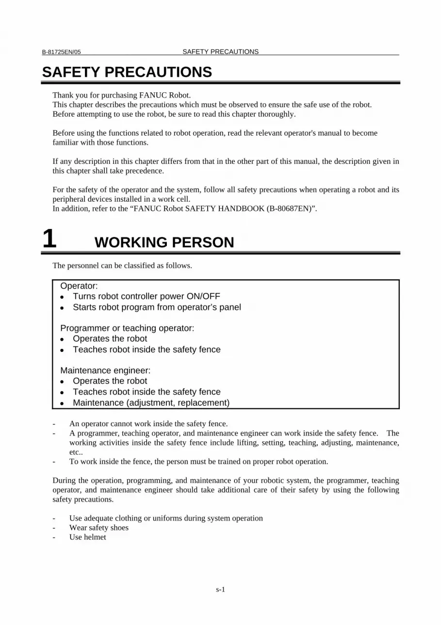
Operator: • Turns robot controller power ON/OFF • Starts robot program from operator’s panel Programmer or teaching operator: • Operates the robot • Teaches robot inside the safety fence Maintenance engineer: • Operates the robot • Teaches robot inside the safety fence • Maintenance (adjustment, replacement)
- An operator cannot work inside the safety fence. - A programmer, teaching operator, and maintenance engineer can work inside the safety fence. The
working activities inside the safety fence include lifting, setting, teaching, adjusting, maintenance, etc..
- To work inside the fence, the person must be trained on proper robot operation. During the operation, programming, and maintenance of your robotic system, the programmer, teaching operator, and maintenance engineer should take additional care of their safety by using the following safety precautions. - Use adequate clothing or uniforms during system operation - Wear safety shoes - Use helmet

SAFETY PRECAUTIONS B-81725EN/05
s-2
2 DEFINITION OF WARNING, CAUTION AND NOTE
To ensure the safety of user and prevent damage to the machine, this manual indicates each precaution on safety with "Warning" or "Caution" according to its severity. Supplementary information is indicated by "Note". Read the contents of each "Warning", "Caution" and "Note" before attempting to use the oscillator.
WARNING Applied when there is a danger of the user being injured or when there is a
danger of both the user being injured and the equipment being damaged if the approved procedure is not observed.
CAUTION Applied when there is a danger of the equipment being damaged, if the
approved procedure is not observed.
NOTE Notes are used to indicate supplementary information other than Warnings and
Cautions. • Read this manual carefully, and store it in a sales place.
3 WORKING PERSON SAFETY Working person safety is the primary safety consideration. Because it is very dangerous to enter the operating space of the robot during automatic operation, adequate safety precautions must be observed. The following lists the general safety precautions. Careful consideration must be made to ensure working person safety. (1) Have the robot system working persons attend the training courses held by FANUC. FANUC provides various training courses. Contact our sales office for details.
(2) Even when the robot is stationary, it is possible that the robot is still in a ready to move state, and is
waiting for a signal. In this state, the robot is regarded as still in motion. To ensure working person safety, provide the system with an alarm to indicate visually or aurally that the robot is in motion.
(3) Install a safety fence with a gate so that no working person can enter the work area without passing through the gate. Install an interlocking device, a safety plug, and so forth in the safety gate so that the robot is stopped as the safety gate is opened.
The controller is designed to receive this interlocking signal of the door switch. When the gate is opened and this signal received, the controller stops the robot (Please refer to "STOP TYPE OF ROBOT" in SAFETY PRECAUTIONS for detail of stop type). For connection, see Fig.2 (a) and Fig.2 (b).
(4) Provide the peripheral devices with appropriate grounding (Class A, Class B, Class C, and Class D).
B-81725EN/05 SAFETY PRECAUTIONS
s-3
(5) Try to install the peripheral devices outside the work area. (6) Draw an outline on the floor, clearly indicating the range of the robot motion, including the tools
such as a hand. (7) Install a mat switch or photoelectric switch on the floor with an interlock to a visual or aural alarm
that stops the robot when a working person enters the work area. (8) If necessary, install a safety lock so that no one except the working person in charge can turn on the
power of the robot. The circuit breaker installed in the controller is designed to disable anyone from turning it on when it is locked with a padlock.
(9) When adjusting each peripheral device independently, be sure to turn off the power of the robot (10) Operators should be ungloved while manipulating the operator’s panel or teach pendant. Operation
with gloved fingers could cause an operation error. (11) Programs, system variables, and other information can be saved on memory card or USB memories.
Be sure to save the data periodically in case the data is lost in an accident. (12) The robot should be transported and installed by accurately following the procedures recommended
by FANUC. Wrong transportation or installation may cause the robot to fall, resulting in severe injury to workers.
(13) In the first operation of the robot after installation, the operation should be restricted to low speeds. Then, the speed should be gradually increased to check the operation of the robot.
(14) Before the robot is started, it should be checked that no one is in the area of the safety fence. At the same time, a check must be made to ensure that there is no risk of hazardous situations. If detected, such a situation should be eliminated before the operation.
(15) When the robot is used, the following precautions should be taken. Otherwise, the robot and peripheral equipment can be adversely affected, or workers can be severely injured. - Avoid using the robot in a flammable environment. - Avoid using the robot in an explosive environment. - Avoid using the robot in an environment full of radiation. - Avoid using the robot under water or at high humidity. - Avoid using the robot to carry a person or animal. - Avoid using the robot as a stepladder. (Never climb up on or hang from the robot.)
(16) When connecting the peripheral devices related to stop(safety fence etc.) and each signal (external emergency , fence etc.) of robot. be sure to confirm the stop movement and do not take the wrong connection.
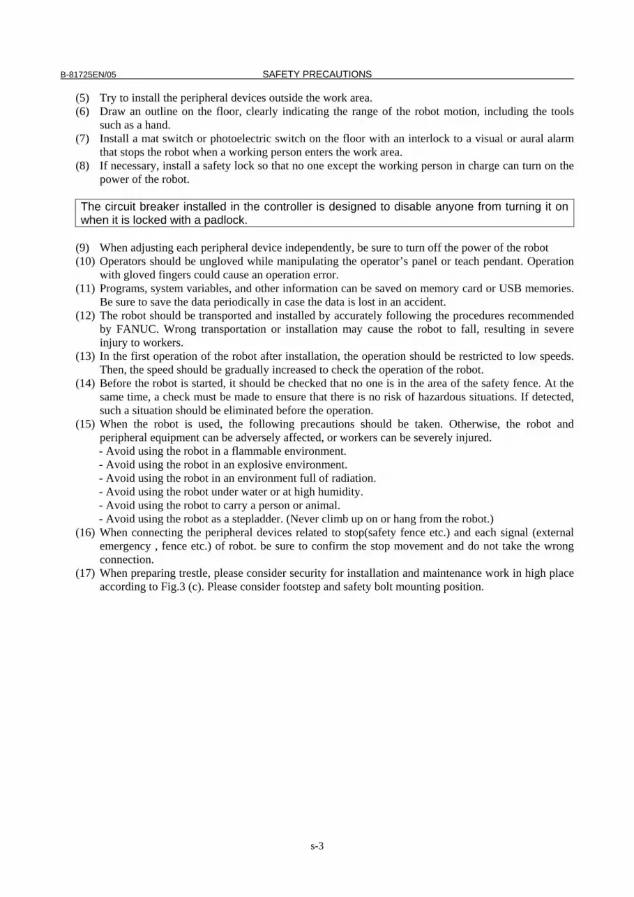
(17) When preparing trestle, please consider security for installation and maintenance work in high place according to Fig.3 (c). Please consider footstep and safety bolt mounting position.

SAFETY PRECAUTIONS B-81725EN/05
s-4
Interlocking device and safety plug that are activated if the gate is opened.
RM1Motor power,brake
RP1pulsecoder,RDI/RDO or RI/RO ,XHBK,XROT Earth
Safety fence
Fig. 3 (a) Safety fence and safety gate
Dual chain
Single chainPanel board
FENCE1
FENCE2
Panel board
EAS1
EAS11
EAS2
EAS21
(Note)
In case of R-30iATerminals EAS1,EAS11,EAS2,EAS21 or FENCE1,FENCE2are provided on the operation box or on the terminal blockof the printed circuit board.
In case of R-30iA MateTerminals EAS1,EAS11,EAS2,EAS21 are providedon the emergency stop board or connector panel.(in case of Open air type)
Termianls FENCE1,FENCE2 are providedon the emergency stop board.
Refer to controller maintenance manual for details.
Emergency stop boardor Panel board
(Note) In case of R-30iB Terminals EAS1,EAS11,EAS2,EAS21 are provided on the emergency stop board. In case R-30iA Terminals EAS1,EAS11,EAS2,EAS21 are provided on the emergency stop board or connector panel In case R-30iA Mate Terminals EAS1,EAS11,EAS2,EAS21 or FENCE1,FENCE2 are provided on the emergency stop board or in the connector panel of CRM65 (Open air type). Refer to the ELECTRICAL CONNCETIONS Chapter of CONNECTION of controller maintenance manual for details.
Fig. 3 (b) Limit switch circuit diagram of the safety fence
B-81725EN/05 SAFETY PRECAUTIONS
s-5
Steps
Safety belt
Fence
Trestle
Footstepfor maintenance
Fig.3 (c) Footstep for maintenance
3.1 OPERATOR SAFETY The operator is a person who operates the robot system. In this sense, a worker who operates the teach pendant is also an operator. However, this section does not apply to teach pendant operators. (1) If you do not have to operate the robot, turn off the power of the robot controller or press the
EMERGENCY STOP button, and then proceed with necessary work. (2) Operate the robot system at a location outside of the safety fence (3) Install a safety fence with a safety gate to prevent any worker other than the operator from entering
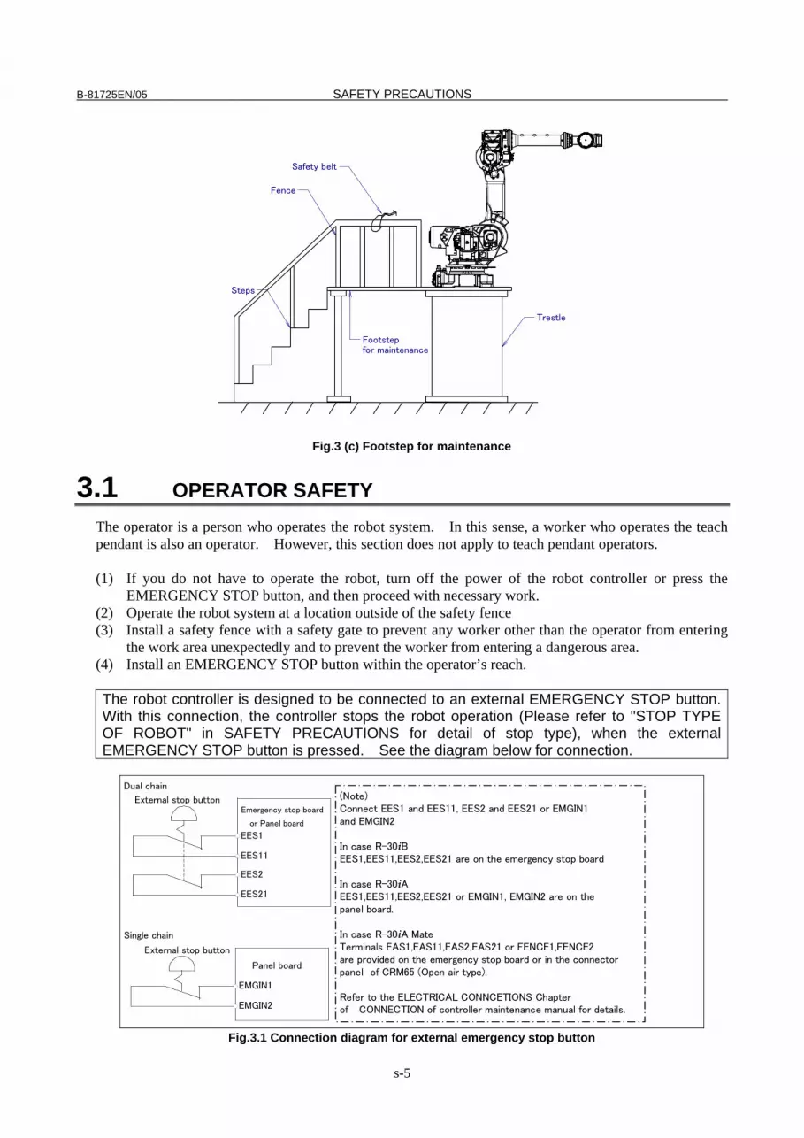
the work area unexpectedly and to prevent the worker from entering a dangerous area. (4) Install an EMERGENCY STOP button within the operator’s reach. The robot controller is designed to be connected to an external EMERGENCY STOP button. With this connection, the controller stops the robot operation (Please refer to "STOP TYPE OF ROBOT" in SAFETY PRECAUTIONS for detail of stop type), when the external EMERGENCY STOP button is pressed. See the diagram below for connection.
Dual chain
Single chain
(Note)Connect EES1and EES11,EES2 and EES21or EMGIN1and EMGIN2.
In case of R-30iAEES1,EES11,EES2,EES21 or EMGIN1,EMGIN2 are on the panel board.
In case of R-30iA MateEES1,EES11,EES2,EES21 are on the emergency stop boardor connector panel (in case of Open air type).EMGIN1,EMGIN2 are on the emergency stop board.
Refer to the maintenance manual of the controller for details.
External stop button
Panel board
EMGIN1
EMGIN2
Panel board
EES1
EES11
EES2
EES21
External stop button
(Note) Connect EES1 and EES11, EES2 and EES21 or EMGIN1 and EMGIN2 In case R-30iB EES1,EES11,EES2,EES21 are on the emergency stop board In case R-30iA EES1,EES11,EES2,EES21 or EMGIN1, EMGIN2 are on the panel board. In case R-30iA Mate Terminals EAS1,EAS11,EAS2,EAS21 or FENCE1,FENCE2 are provided on the emergency stop board or in the connector panel of CRM65 (Open air type). Refer to the ELECTRICAL CONNCETIONS Chapter of CONNECTION of controller maintenance manual for details.
Emergency stop board
or Panel board
Fig.3.1 Connection diagram for external emergency stop button

SAFETY PRECAUTIONS B-81725EN/05
s-6
3.2 SAFETY OF THE PROGRAMMER While teaching the robot, the operator must enter the work area of the robot. The operator must ensure the safety of the teach pendant operator especially. (1) Unless it is specifically necessary to enter the robot work area, carry out all tasks outside the area. (2) Before teaching the robot, check that the robot and its peripheral devices are all in the normal
operating condition. (3) If it is inevitable to enter the robot work area to teach the robot, check the locations, settings, and
other conditions of the safety devices (such as the EMERGENCY STOP button, the DEADMAN switch on the teach pendant) before entering the area.
(4) The programmer must be extremely careful not to let anyone else enter the robot work area. (5) Programming should be done outside the area of the safety fence as far as possible. If programming
needs to be done in the area of the safety fence, the programmer should take the following precautions: - Before entering the area of the safety fence, ensure that there is no risk of dangerous situations
in the area. - Be prepared to press the emergency stop button whenever necessary. - Robot motions should be made at low speeds. - Before starting programming, check the entire system status to ensure that no remote instruction
to the peripheral equipment or motion would be dangerous to the user. Our operator panel is provided with an emergency stop button and a key switch (mode switch) for selecting the automatic operation mode (AUTO) and the teach modes (T1 and T2). Before entering the inside of the safety fence for the purpose of teaching, set the switch to a teach mode, remove the key from the mode switch to prevent other people from changing the operation mode carelessly, then open the safety gate. If the safety gate is opened with the automatic operation mode set, the robot stops (Please refer to "STOP TYPE OF ROBOT" in SAFETY PRECAUTIONS for detail of stop type). After the switch is set to a teach mode, the safety gate is disabled. The programmer should understand that the safety gate is disabled and is responsible for keeping other people from entering the inside of the safety fence. (In case of R-30iA Mate Controller standard specification, there is no mode switch. The automatic operation mode and the teach mode is selected by teach pendant enable switch.)
Our teach pendant is provided with a DEADMAN switch as well as an emergency stop button. These button and switch function as follows: (1) Emergency stop button: Causes an emergency stop (Please refer to "STOP TYPE OF ROBOT" in SAFETY
PRECAUTIONS for detail of stop type) when pressed. (2) DEADMAN switch: Functions differently depending on the teach pendant enable/disable switch setting
status. (a) Disable: The DEADMAN switch is disabled. (b) Enable: Servo power is turned off when the operator releases the DEADMAN switch or when the
operator presses the switch strongly. Note) The DEADMAN switch is provided to stop the robot when the operator releases the teach pendant or
presses the pendant strongly in case of emergency. The R-30iB/R-30iA/ R-30iA Mate employs a 3-position DEADMAN switch, which allows the robot to operate when the 3-position DEADMAN switch is pressed to its intermediate point. When the operator releases the DEADMAN switch or presses the switch strongly, the robot stops immediately.
The operator’s intention of starting teaching is determined by the controller through the dual operation of setting the teach pendant enable/disable switch to the enable position and pressing the DEADMAN switch. The operator should make sure that the robot could operate in such conditions and be responsible in carrying out tasks safely.
The teach pendant, operator panel, and peripheral device interface send each robot start signal. However the validity of each signal changes as follows depending on the mode switch and the DEADMAN switch of the operator panel, the teach pendant enable switch and the remote condition on the software.

B-81725EN/05 SAFETY PRECAUTIONS
s-7
In case of R-30iB/R-30iA controller or CE or RIA specification of R-30iA Mate controller
Mode Teach pendant enable switch
Software remote
condition Teach pendant Operator panel Peripheral device
Local Not allowed Not allowed Not allowed On Remote Not allowed Not allowed Not allowed
Local Not allowed Allowed to start Not allowed AUTO mode
Off Remote Not allowed Not allowed Allowed to start
Local Allowed to start Not allowed Not allowed On
Remote Allowed to start Not allowed Not allowed Local Not allowed Not allowed Not allowed
T1, T2 mode
Off Remote Not allowed Not allowed Not allowed
T1,T2 mode: DEADMAN switch is effective.
In case of standard specification of R-30iA Mate controller Teach pendant enable switch Software remote condition Teach pendant Peripheral device
On Ignored Allowed to start Not allowed Local Not allowed Not allowed Off
Remote Not allowed Allowed to start (6) (Only when R-30iB/R-30iA controller or CE or RIA specification of R-30iA Mate controller is
selected.) To start the system using the operator’s panel, make certain that nobody is the robot work area and that there are no abnormal conditions in the robot work area.
(7) When a program is completed, be sure to carry out a test run according to the procedure below. (a) Run the program for at least one operation cycle in the single step mode at low speed. (b) Run the program for at least one operation cycle in the continuous operation mode at low
speed. (c) Run the program for one operation cycle in the continuous operation mode at the intermediate
speed and check that no abnormalities occur due to a delay in timing. (d) Run the program for one operation cycle in the continuous operation mode at the normal
operating speed and check that the system operates automatically without trouble. (e) After checking the completeness of the program through the test run above, execute it in the
automatic operation mode. (8) While operating the system in the automatic operation mode, the teach pendant operator should
leave the robot work area.
3.3 SAFETY OF THE MAINTENANCE ENGINEER For the safety of maintenance engineer personnel, pay utmost attention to the following. (1) During operation, never enter the robot work area. (2) A hazardous situation may arise when the robot or the system, are kept with their power-on during
maintenance operations. Therefore, for any maintenance operation, the robot and the system should be put into the power-off state. If necessary, a lock should be in place in order to prevent any other person from turning on the robot and/or the system. In case maintenance needs to be executed in the power-on state, the emergency stop button must be pressed.
(3) If it becomes necessary to enter the robot operation range while the power is on, press the emergency stop button on the operator panel, or the teach pendant before entering the range. The maintenance personnel must indicate that maintenance work is in progress and be careful not to allow other people to operate the robot carelessly.
(4) When entering the area enclosed by the safety fence, the maintenance worker must check the entire system in order to make sure no dangerous situations exist. In case the worker needs to enter the safety area whilst a dangerous situation exists, extreme care must be taken, and entire system status must be carefully monitored.
SAFETY PRECAUTIONS B-81725EN/05
s-8
(5) Before the maintenance of the pneumatic system is started, the supply pressure should be shut off and the pressure in the piping should be reduced to zero.
(6) Before the start of teaching, check that the robot and its peripheral devices are all in the normal operating condition.
(7) Do not operate the robot in the automatic mode while anybody is in the robot work area. (8) When you maintain the robot alongside a wall or instrument, or when multiple workers are working
nearby, make certain that their escape path is not obstructed. (9) When a tool is mounted on the robot, or when any moving device other than the robot is installed,
such as belt conveyor, pay careful attention to its motion. (10) If necessary, have a worker who is familiar with the robot system stand beside the operator panel
and observe the work being performed. If any danger arises, the worker should be ready to press the EMERGENCY STOP button at any time.
(11) When replacing a part, please contact FANUC service center. If a wrong procedure is followed, an accident may occur, causing damage to the robot and injury to the worker.
(12) When replacing or reinstalling components, take care to prevent foreign matter from entering the system.
(13) When handling each unit or printed circuit board in the controller during inspection, turn off the circuit breaker to protect against electric shock.
If there are two cabinets, turn off the both circuit breaker. (14) A part should be replaced with a part recommended by FANUC. If other parts are used, malfunction
or damage would occur. Especially, a fuse that is not recommended by FANUC should not be used. Such a fuse may cause a fire.
(15) When restarting the robot system after completing maintenance work, make sure in advance that there is no person in the work area and that the robot and the peripheral devices are not abnormal.
(16) When a motor or brake is removed, the robot arm should be supported with a crane or other equipment beforehand so that the arm would not fall during the removal.
(17) Whenever grease is spilled on the floor, it should be removed as quickly as possible to prevent dangerous falls.
(18) The following parts are heated. If a maintenance worker needs to touch such a part in the heated state, the worker should wear heat-resistant gloves or use other protective tools. - Servo motor - Inside the controller - Reducer - Gearbox - Wrist unit
(19) Maintenance should be done under suitable light. Care must be taken that the light would not cause any danger.
(20) When a motor, reducer, or other heavy load is handled, a crane or other equipment should be used to protect maintenance workers from excessive load. Otherwise, the maintenance workers would be severely injured.
(21) The robot should not be stepped on or climbed up during maintenance. If it is attempted, the robot would be adversely affected. In addition, a misstep can cause injury to the worker.
(22) When performing maintenance work in high place, secure a footstep and wear safety belt. (23) After the maintenance is completed, spilled oil or water and metal chips should be removed from the
floor around the robot and within the safety fence. (24) When a part is replaced, all bolts and other related components should put back into their original
places. A careful check must be given to ensure that no components are missing or left not mounted. (25) In case robot motion is required during maintenance, the following precautions should be taken :
- Foresee an escape route. And during the maintenance motion itself, monitor continuously the whole system so that your escape route will not become blocked by the robot, or by peripheral equipment. - Always pay attention to potentially dangerous situations, and be prepared to press the emergency stop button whenever necessary.
B-81725EN/05 SAFETY PRECAUTIONS
s-9
(26) The robot should be periodically inspected. (Refer to the robot mechanical manual and controller maintenance manual.) A failure to do the periodical inspection can adversely affect the performance or service life of the robot and may cause an accident
(27) After a part is replaced, a test execution should be given for the robot according to a predetermined method. (See TESTING section of “Controller operator’s manual”.) During the test execution, the maintenance staff should work outside the safety fence.
4 SAFETY OF THE TOOLS AND PERIPHERAL DEVICES
4.1 PRECAUTIONS IN PROGRAMMING (1) Use a limit switch or other sensor to detect a dangerous condition and, if necessary, design the
program to stop the robot when the sensor signal is received. (2) Design the program to stop the robot when an abnormal condition occurs in any other robots or
peripheral devices, even though the robot itself is normal. (3) For a system in which the robot and its peripheral devices are in synchronous motion, particular care
must be taken in programming so that they do not interfere with each other. (4) Provide a suitable interface between the robot and its peripheral devices so that the robot can detect
the states of all devices in the system and can be stopped according to the states.
4.2 PRECAUTIONS FOR MECHANISM (1) Keep the component cells of the robot system clean, and operate the robot in an environment free of
grease, water, and dust. (2) Don’t use unconfirmed liquid for cutting fluid and cleaning fluid. (3) Employ a limit switch or mechanical stopper to limit the robot motion so that the robot or cable does
not strike against its peripheral devices or tools. (4) Observe the following precautions about the mechanical unit cables. When theses attentions are not
kept, unexpected troubles might occur. • Use mechanical unit cable that have required user interface. • Don’t add user cable or hose to inside of mechanical unit. • Please do not obstruct the movement of the mechanical unit cable when cables are added to
outside of mechanical unit. • In the case of the model that a cable is exposed, Please do not perform remodeling (Adding a
protective cover and fix an outside cable more) obstructing the behavior of the outcrop of the cable.
• Please do not interfere with the other parts of mechanical unit when install equipments in the robot.
(5) The frequent power-off stop for the robot during operation causes the trouble of the robot. Please avoid the system construction that power-off stop would be operated routinely. (Refer to bad case example.) Please execute power-off stop after reducing the speed of the robot and stopping it by hold stop or cycle stop when it is not urgent. (Please refer to "STOP TYPE OF ROBOT" in SAFETY PRECAUTIONS for detail of stop type.) (Bad case example) • Whenever poor product is generated, a line stops by emergency stop. • When alteration was necessary, safety switch is operated by opening safety fence and
power-off stop is executed for the robot during operation. • An operator pushes the emergency stop button frequently, and a line stops.

SAFETY PRECAUTIONS B-81725EN/05
s-10
• An area sensor or a mat switch connected to safety signal operate routinely and power-off stop is executed for the robot.
(6) Robot stops urgently when collision detection alarm (SV050) etc. occurs. The frequent urgent stop by alarm causes the trouble of the robot, too. So remove the causes of the alarm.
5 SAFETY OF THE ROBOT MECHANISM
5.1 PRECAUTIONS IN OPERATION (1) When operating the robot in the jog mode, set it at an appropriate speed so that the operator can
manage the robot in any eventuality. (2) Before pressing the jog key, be sure you know in advance what motion the robot will perform in the
jog mode.
5.2 PRECAUTIONS IN PROGRAMMING (1) When the work areas of robots overlap, make certain that the motions of the robots do not interfere
with each other. (2) Be sure to specify the predetermined work origin in a motion program for the robot and program the
motion so that it starts from the origin and terminates at the origin. Make it possible for the operator to easily distinguish at a glance that the robot motion has
terminated.
5.3 PRECAUTIONS FOR MECHANISMS (1) Keep the work areas of the robot clean, and operate the robot in an environment free of grease, water,
and dust.
5.4 PROCEDURE TO MOVE ARM WITHOUT DRIVE POWER IN EMERGENCY OR ABNORMAL SITUATIONS
(1) For emergency or abnormal situations (e.g. persons trapped in or by the robot), brake release unit can be used to move the robot axes without drive power.
Please order following unit and cable.
Name Specification
Brake release unit
A05B-2450-J350 (Input Voltage AC100-115V single-phase) A05B-2450-J351 (Input Voltage AC200-240V single-phase)
Robot connection cable A05B-2450-J370 (5m) A05B-2450-J371 (10m)
Power cable
A05B-2525-J010 (5m) (AC100-115V Power plug) (*) A05B-2525-J011 (10m) (AC100-115V Power plug) (*) A05B-2450-J364 (5m) (No power plug) A05B-2450-J365 (10m) (No power plug)
(*) These do not support CE marking.
B-81725EN/05 SAFETY PRECAUTIONS
s-11
(2) Please make sure that adequate numbers of brake release units are available and readily accessible for robot system before installation.
(3) Regarding how to use brake release unit, please refer to Robot controller maintenance manual.
NOTE Robot systems installed without adequate number of brake release units or similar
means are not in compliance with EN ISO 10218-1 and the Machinery Directive and therefore cannot bear the CE marking.
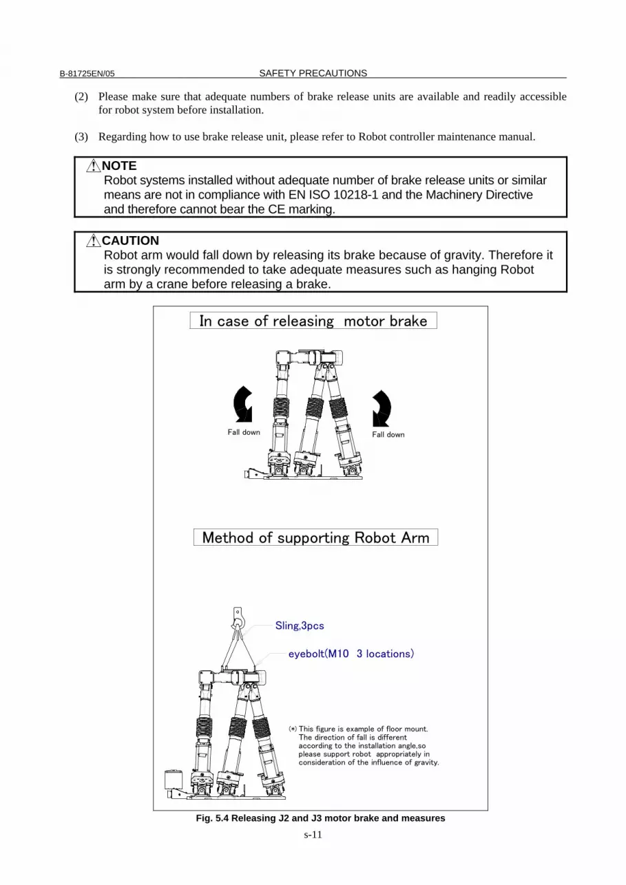
CAUTION Robot arm would fall down by releasing its brake because of gravity. Therefore it
is strongly recommended to take adequate measures such as hanging Robot arm by a crane before releasing a brake.
Fall down
eyebolt(M10 3 locations)
Sling,3pcs
Fall down
This figure is example of floor mount.The direction of fall is differentaccording to the installation angle,soplease support robot appropriately inconsideration of the influence of gravity.
(*)
Method of supporting Robot Arm
In case of releasing motor brake
Fig. 5.4 Releasing J2 and J3 motor brake and measures

SAFETY PRECAUTIONS B-81725EN/05
s-12
6 SAFETY OF THE END EFFECTOR
6.1 PRECAUTIONS IN PROGRAMMING (1) To control the pneumatic, hydraulic and electric actuators, carefully consider the necessary time
delay after issuing each control command up to actual motion and ensure safe control. (2) Provide the end effector with a limit switch, and control the robot system by monitoring the state of
the end effector.
7 STOP TYPE OF ROBOT The following three robot stop types exist:
Power-Off Stop (Category 0 following IEC 60204-1) Servo power is turned off and the robot stops immediately. Servo power is turned off when the robot is moving, and the motion path of the deceleration is uncontrolled. The following processing is performed at Power-Off stop. - An alarm is generated and servo power is turned off. - The robot operation is stopped immediately. Execution of the program is paused.
Controlled stop (Category 1 following IEC 60204-1) The robot is decelerated until it stops, and servo power is turned off. The following processing is performed at Controlled stop. - The alarm "SRVO-199 Controlled stop" occurs along with a decelerated stop. Execution of the
program is paused. - An alarm is generated and servo power is turned off.
Hold (Category 2 following IEC 60204-1) The robot is decelerated until it stops, and servo power remains on. The following processing is performed at Hold. - The robot operation is decelerated until it stops. Execution of the program is paused.
WARNING The stopping distance and stopping time of Controlled stop are longer than the
stopping distance and stopping time of Power-Off stop. A risk assessment for the whole robot system, which takes into consideration the increased stopping distance and stopping time, is necessary when Controlled stop is used.
When the emergency stop button is pressed or the FENCE is open, the stop type of robot is Power-Off stop or Controlled stop. The configuration of stop type for each situation is called stop pattern. The stop pattern is different according to the controller type or option configuration.

B-81725EN/05 SAFETY PRECAUTIONS
s-13
There are the following 3 Stop patterns.
Stop pattern Mode
Emergency stop
button
External Emergency
stop FENCE open SVOFF input Servo
disconnect
AUTO P-Stop P-Stop C-Stop C-Stop P-Stop A T1 P-Stop P-Stop - C-Stop P-Stop T2 P-Stop P-Stop - C-Stop P-Stop AUTO P-Stop P-Stop P-Stop P-Stop P-Stop
B T1 P-Stop P-Stop - P-Stop P-Stop T2 P-Stop P-Stop - P-Stop P-Stop AUTO C-Stop C-Stop C-Stop C-Stop C-Stop
C T1 P-Stop P-Stop - C-Stop P-Stop T2 P-Stop P-Stop - C-Stop P-Stop
P-Stop: Power-Off stop C-Stop: Controlled stop -: Disable The following table indicates the Stop pattern according to the controller type or option configuration.
Option R-30iB Standard A (*) Controlled stop by E-Stop (A05B-2600-J570) C (*) (*) R-30iB does not have servo disconnect.
R-30iA R-30iA Mate Option Standard
(Single) Standard
(Dual) RIA type
CE type Standard RIA
type CE
type Standard B (*) A A A A (**) A A Stop type set (Stop pattern C) (A05B-2500-J570)
N/A N/A C C N/A C C
(*) R-30iA standard (single) does not have servo disconnect. (**) R-30iA Mate Standard does not have servo disconnect, and the stop type of SVOFF input is
Power-Off stop. The stop pattern of the controller is displayed in "Stop pattern" line in software version screen. Please refer to "Software version" in operator's manual of controller for the detail of software version screen.
"Controlled stop by E-Stop" option When "Controlled stop by E-Stop" (A05B-2600-J570) option (In case of R-30iA/R-30iA Mate, it is Stop type set (Stop pattern C) (A05B-2500-J570)) is specified, the stop type of the following alarms becomes Controlled stop but only in AUTO mode. In T1 or T2 mode, the stop type is Power-Off stop which is the normal operation of the system.
Alarm Condition SRVO-001 Operator panel E-stop Operator panel emergency stop is pressed. SRVO-002 Teach pendant E-stop Teach pendant emergency stop is pressed. SRVO-007 External emergency stops External emergency stop input (EES1-EES11, EES2-EES21) is
open. (R-30iA/R-30iB controller) SRVO-194 Servo disconnect Servo disconnect input (SD4-SD41, SD5-SD51) is open.
(R-30iA controller) SRVO-218 Ext. E-stop/Servo Disconnect External emergency stop input (EES1-EES11, EES2-EES21) is
open. (R-30iA Mate/R-30iB controller) SRVO-408 DCS SSO Ext Emergency Stop In DCS Safe I/O connect function, SSO[3] is OFF. SRVO-409 DCS SSO Servo Disconnect In DCS Safe I/O connect function, SSO[4] is OFF.

SAFETY PRECAUTIONS B-81725EN/05
s-14
Controlled stop is different from Power-Off stop as follows: - In Controlled stop, the robot is stopped on the program path. This function is effective for a system
where the robot can interfere with other devices if it deviates from the program path. - In Controlled stop, physical impact is less than Power-Off stop. This function is effective for
systems where the physical impact to the mechanical unit or EOAT (End Of Arm Tool) should be minimized.
- The stopping distance and stopping time of Controlled stop is longer than the stopping distance and stopping time of Power-Off stop, depending on the robot model and axis. Please refer to the operator's manual of a particular robot model for the data of stopping distance and stopping time.
In case of R-30iA or R-30iA Mate, this function is available only in CE or RIA type hardware. When this option is loaded, this function cannot be disabled. The stop type of DCS Position and Speed Check functions is not affected by the loading of this option.
WARNING The stopping distance and stopping time of Controlled stop are longer than the
stopping distance and stopping time of Power-Off stop. A risk assessment for the whole robot system, which takes into consideration the increased stopping distance and stopping time, is necessary when this option is loaded.
8 WARNING LABEL (1) Greasing and degreasing label
1) 必ず排脂口を開けて給脂して下さい。
Open the grease outletat greasing.
必须在排脂口打开的状态下供脂。
2) 手動式ポンプを使用して給脂を行って下さい。
Use a hand pump atgreasing.
请使用手动式供脂泵进行供脂。
3) 必ず指定グリスを使用して下さい。
Use designated greaseat greasing.
必须使用指定的润滑脂。
Fig. 8 (a) Greasing and degreasing label
Description When greasing and degreasing, observe the instructions indicated on this label. 1) Open the grease outlet at greasing. 2) Use a hand pump at greasing. 3) Use designated grease at greasing.
NOTE See section I.3.2 ″ GREASE REPLACEMENT for explanations about specified
greases, the amount of grease to be supplied, and the locations of grease and degrease outlets for individual models.
B-81725EN/05 SAFETY PRECAUTIONS
s-15
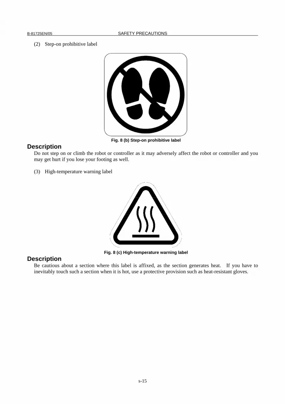
(2) Step-on prohibitive label
Fig. 8 (b) Step-on prohibitive label
Description Do not step on or climb the robot or controller as it may adversely affect the robot or controller and you may get hurt if you lose your footing as well. (3) High-temperature warning label
Fig. 8 (c) High-temperature warning label
Description Be cautious about a section where this label is affixed, as the section generates heat. If you have to inevitably touch such a section when it is hot, use a protective provision such as heat-resistant gloves.

SAFETY PRECAUTIONS B-81725EN/05
s-16
(4) Transportation label
>1000kg
>500kg X3
>150kg X3
>1000kg
<500kg X2
Fig. 8 (d) Transportation label
Description When transporting the robot, observe the instructions indicated on this label. 1) Using a crane
• Use a crane having a load capacity of 1000 kg or greater. • Use at least two slings each having a withstand load of
4900 N (500 kgf) or greater. • Use at least three eyebolts each having a withstand load of 1470 N (150 kgf) or greater.
2) Using a forklift • Use a forklift having a load capacity of 1,000 kg or greater. • Keep the total weight of the robot to be transported to within 1,000 kg because the withstand
load of the forklift bracket (option) is 4,900 N (500 kgf). NOTE See section II.3.1 TRANSPORTATION for explanations about the posture a
specific model should take when it is transported. (3) Range of motion and payload mark label
Below label is added when CE specification is specified.
1040
1022
1024
104
0
102
5
102
5
791
1237
869
744
747
791
829
MAX. PAYLOAD : 100kg
Kinematicsworkenvelope
最大动作范围
Fig.8 (e) Range of motion and payload mark label
B-81725EN/05 PREFACE
p-1
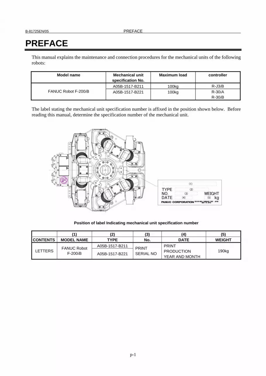
PREFACE This manual explains the maintenance and connection procedures for the mechanical units of the following robots:
Model name Mechanical unit specification No.
Maximum load controller
A05B-1517-B211 100kg R-J3iB FANUC Robot F-200iB A05B-1517-B221 100kg R-30iA
R-30iB The label stating the mechanical unit specification number is affixed in the position shown below. Before reading this manual, determine the specification number of the mechanical unit.
(1)
(3)
(4) (5)
(2)
kgWEIGHTNO.
DATE
TYPE
Position of label Indicating mechanical unit specification number
(1) (2) (3) (4) (5)
CONTENTS MODEL NAME TYPE No. DATE WEIGHT A05B-1517-B211
LETTERS FANUC Robot
F-200iB A05B-1517-B221 PRINT SERIAL NO
PRINT PRODUCTION YEAR AND MONTH
190kg
PREFACE B-81725EN/05
p-2
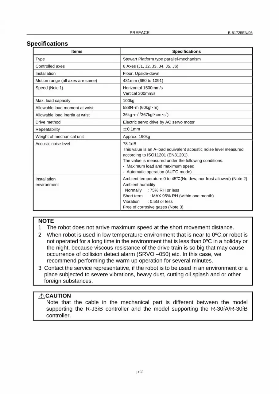
Specifications Items Specifications
Type Stewart Platform type parallel-mechanism
Controlled axes 6 Axes (J1, J2, J3, J4, J5, J6)
Installation Floor, Upside-down
Motion range (all axes are same) 431mm (660 to 1091)
Speed (Note 1) Horizontal 1500mm/s Vertical 300mm/s
Max. load capacity 100kg
Allowable load moment at wrist 588N・m (60kgf・m)
Allowable load inertia at wrist 36kg・m2 (367kgf・cm・s2)
Drive method Electric servo drive by AC servo motor
Repeatability ±0.1mm
Weight of mechanical unit Approx. 190kg
Acoustic noise level 78.1dB This value is an A-load equivalent acoustic noise level measured according to ISO11201 (EN31201). The value is measured under the following conditions. - Maximum load and maximum speed - Automatic operation (AUTO mode)
Installation environment
Ambient temperature 0 to 45℃(No dew, nor frost allowed) (Note 2) Ambient humidity Normally : 75% RH or less
Short term : MAX 95% RH (within one month) Vibration : 0.5G or less Free of corrosive gases (Note 3)
NOTE 1 The robot does not arrive maximum speed at the short movement distance. 2 When robot is used in low temperature environment that is near to 0ºC,or robot is
not operated for a long time in the environment that is less than 0ºC in a holiday or the night, because viscous resistance of the drive train is so big that may cause occurrence of collision detect alarm (SRVO –050) etc. In this case, we recommend performing the warm up operation for several minutes.
3 Contact the service representative, if the robot is to be used in an environment or a place subjected to severe vibrations, heavy dust, cutting oil splash and or other foreign substances.
CAUTION Note that the cable in the mechanical part is different between the model
supporting the R-J3iB controller and the model supporting the R-30iA/R-30iB controller.

B-81725EN/05 PREFACE
p-3
RELATED MANUALS For the FANUC Robot series, the following manuals are available: Safety handbook B-80687EN All persons who use the FANUC Robot and system designer must read and understand thoroughly this handbook
Intended readers : All persons who use FANUC Robot, system designer Topics : Safety items for robot system design, operation, maintenance
Setup and Operations manual SPOT TOOL B-81464EN-1 HANDLING TOOL B-81464EN-2 SEALING TOOL B-81464EN-4
Intended readers : Operator, programmer, maintenance person, system designer Topics : Robot functions, operations, programming, setup, interfaces, alarms Use : Robot operation, teaching, system design
R-J3iB controller
Maintenance manual B-81465EN B-81465EN-1 (For Europe)
Intended readers : Maintenance person, system designer Topics : Installation, connection to peripheral equipment, maintenance Use : Installation, start-up, connection, maintenance
Setup and Operations manual SPOT TOOL+ B-83124EN-1 HANDLING TOOL B-83124EN-2 DISPENSE TOOL B-83124EN-4 ALARM CODE LIST B-83124EN-6 SERVO GUN FUNCTION B-82634JA
Intended readers : Operator, programmer, maintenance person, system designer Topics : Robot functions, operations, programming, setup, interfaces, alarms Use : Robot operation, teaching, system design
R-30iA controller
Maintenance manual Standard: B-82595EN RIA: B-82595EN-2 CE: B-82595EN-1 (European specification)
Intended readers : Maintenance person, system designer Topics : Installation, connection to peripheral equipment, maintenance Use : Installation, start-up, connection, maintenance
PREFACE B-81725EN/05
p-4
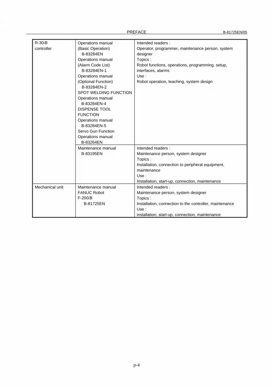
R-30iB controller
Operations manual (Basic Operation) B-83284EN Operations manual (Alarm Code List) B-83284EN-1 Operations manual (Optional Function) B-83284EN-2 SPOT WELDING FUNCTIONOperations manual B-83284EN-4 DISPENSE TOOL FUNCTION Operations manual B-83284EN-5 Servo Gun Function Operations manual B-83264EN
Intended readers : Operator, programmer, maintenance person, system designer Topics : Robot functions, operations, programming, setup, interfaces, alarms Use : Robot operation, teaching, system design
Maintenance manual B-83195EN
Intended readers : Maintenance person, system designer Topics : Installation, connection to peripheral equipment, maintenance Use : Installation, start-up, connection, maintenance
Mechanical unit Maintenance manual FANUC Robot F-200iB B-81725EN
Intended readers : Maintenance person, system designer Topics : Installation, connection to the controller, maintenance Use : installation, start-up, connection, maintenance

B-81725EN/05 TABLE OF CONTENTS
c - 1
TABLE OF CONTENTS SAFETY PRECAUTIONS............................................................................s-1 PREFACE....................................................................................................p-1
I. MAINTENANCE
1 CONFIGURATION ..................................................................................3 1.1 DRIVE MECHANISM (J1 to J6) ..................................................................... 4
2 PREVENTIVE MAINTENANCE...............................................................5 2.1 DAILY CHECKS ............................................................................................ 5 2.2 FIRST 1-MONTH (320 HOURS) CHECKS.................................................... 6 2.3 FIRST 3-MONTH CHECKS (960 HOURS).................................................... 7 2.4 3-MONTH (960 HOURS) CHECKS ............................................................. 11 2.5 6- MONTH CHECKS (1,920 HOURS) ......................................................... 11 2.6 1-YEAR CHECKS (3,840 HOURS).............................................................. 11 2.7 1.5-YEAR CHECKS (5,760 HOURS)........................................................... 11 2.8 3-YEAR CHECKS (11,520 HOURS)............................................................ 11 2.9 4-YEAR (15,360 HOURS) CHECKS............................................................ 11 2.10 MAINTENANCE TOOLS ............................................................................. 12
3 PERIODIC MAINTENANCE..................................................................13 3.1 REPLACING GREASE OF THE DRIVE MECHANISM ............................... 13 3.2 GREASING THE BALL SCREW.................................................................. 15 3.3 PROCEDURE FOR RELEASING THE GREASE REMAINING PRESSURE
..................................................................................................................... 16 3.4 REPLACING THE BATTERIES................................................................... 17
4 TROUBLE SHOOTING .........................................................................18 4.1 OVERVIEW ................................................................................................. 18 4.2 FAILURE AND CAUSE AND MEASURES .................................................. 18 4.3 BACKLASH.................................................................................................. 24
5 ADJUSTMENTS....................................................................................26 5.1 MASTERING ............................................................................................... 26
5.1.1 General ...................................................................................................................26 5.1.2 Resetting Alarms and Preparing for Mastering ......................................................27 5.1.3 Fixture Position Master ..........................................................................................27 5.1.4 Zero Position Master ..............................................................................................31

TABLE OF CONTENTS B-81725EN/05
c - 2
5.1.5 Quick Mastering .....................................................................................................33 5.1.6 Single Axis Mastering ............................................................................................35 5.1.7 Mastering Data Entry .............................................................................................37
5.2 CHECKING THE MASTERING ................................................................... 39
6 REPLACING PARTS ............................................................................41 6.1 NOTE FOR PART REPLACEMENT............................................................ 41 6.2 REPLACING MOTORS (FOR ALL AXES) .................................................. 41 6.3 REPLACING LEG UNITS (FOR ALL AXES) ............................................... 43 6.4 REPLACING THE WRIST UNIT .................................................................. 45 6.5 REPLACING THE FULL COVER (OPTION) ............................................... 47 6.6 REPLACING THE CABLE COVER (OPTION) ............................................ 48
7 PIPING AND WIRING ...........................................................................49 8 REPLACING CABLES..........................................................................51
8.1 CABLE FORMING....................................................................................... 51 8.2 CABLE REPLACEMENT ............................................................................. 53
II. CONNECTION
1 ROBOT INTERFERENCE AREA..........................................................59 2 MECHANICAL COUPLING TO THE ROBOT.......................................61
2.1 WRIST LOAD CONDITIONS....................................................................... 61 2.2 MECHANICAL COUPLING OF END EFFECTOR TO WRIST .................... 62 2.3 SETTING THE LOAD .................................................................................. 66 2.4 END EFFECTOR INTERFACE.................................................................... 67
3 TRANSPORTATION AND INSTALLATION .........................................70 3.1 TRANSPORTATION.................................................................................... 70 3.2 INSTALLATION ........................................................................................... 72 3.3 MAINTENANCE AREA................................................................................ 77 3.4 AIR CONTROL SET (OPTION) ................................................................... 78 3.5 INSTALLATION SPECIFICATIONS ............................................................ 79 3.6 STORAGE ................................................................................................... 79
APPENDIX A SPARE PARTS LISTS ..........................................................................83 B CONNECTION DIAGRAM.....................................................................85 C PERIODIC MAINTENANCE..................................................................90 D STRENGTH OF BOLT AND BOLT TORQUE LIST..............................92

I. MAINTENANCE


B-81725EN/05 MAINTENANCE 1.CONFIGURATION
- 3 -
1 CONFIGURATION The configuration of the mechanical unit is shown in Fig.1.
Connector panel
J1-axis motor
J1-axis LEG
J6-axis LEG
J2-axis LEG
J3-axis LEG
J4-axis LEG
J5-axis LEG
J3-axis motor
J4-axis motor
J6-axis motor
J5-axis motor
Top plate
Base
End effectormounting face
Fig.1 Mechanical unit configuration

1.CONFIGURATION MAINTENANCE B-81725EN/05
- 4 -
1.1 DRIVE MECHANISM (J1 to J6) Fig.1.1 shows the drive mechanism. The mechanical unit is structured as follows: The rotation of the motor drives gear 2 via gear 1, so that the ball screw coupled with gear 2 is rotated. By rotating the ball screw, the ball screw nut and the pipe coupled with the nut are driven in the axial direction.
Fig.1.1 Drive mechanism
NOTE All motors incorporate a brake that is applied when not energized. These brakes are active at power-off and emergency stop.
Motor
Pipe
Ball screw nut
Ball screw
Gear1 Gear2
B-81725EN/05 MAINTENANCE 2.PREVENTIVE MAINTENANCE
- 5 -
2 PREVENTIVE MAINTENANCE Optimum performance of the robot can be maintained for a long time by performing the periodic maintenance procedures presented in this chapter.
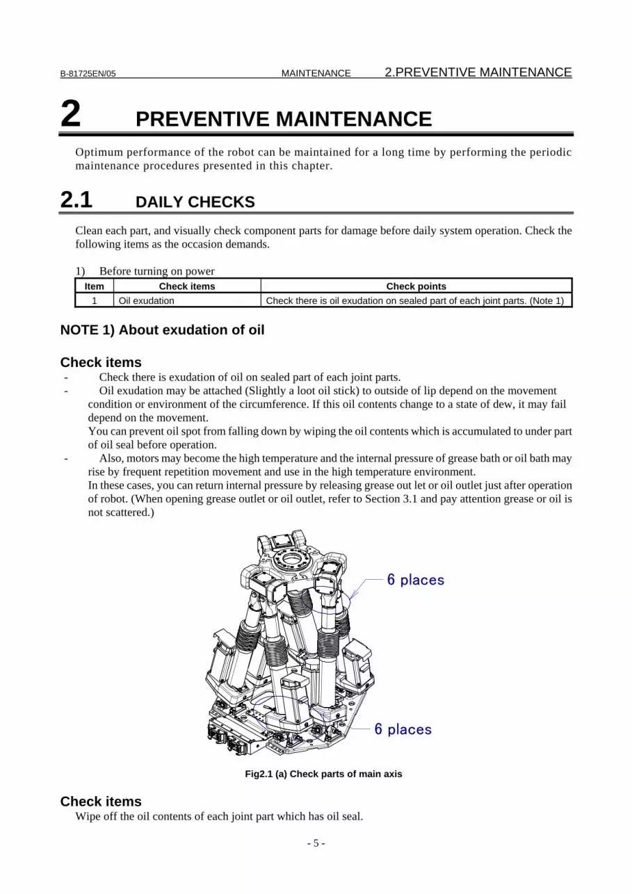
2.1 DAILY CHECKS Clean each part, and visually check component parts for damage before daily system operation. Check the following items as the occasion demands. 1) Before turning on power
Item Check items Check points 1 Oil exudation Check there is oil exudation on sealed part of each joint parts. (Note 1)
NOTE 1) About exudation of oil Check items - Check there is exudation of oil on sealed part of each joint parts. - Oil exudation may be attached (Slightly a loot oil stick) to outside of lip depend on the movement
condition or environment of the circumference. If this oil contents change to a state of dew, it may fail depend on the movement. You can prevent oil spot from falling down by wiping the oil contents which is accumulated to under part of oil seal before operation.
- Also, motors may become the high temperature and the internal pressure of grease bath or oil bath may rise by frequent repetition movement and use in the high temperature environment. In these cases, you can return internal pressure by releasing grease out let or oil outlet just after operation of robot. (When opening grease outlet or oil outlet, refer to Section 3.1 and pay attention grease or oil is not scattered.)
6 places
6 places
Fig2.1 (a) Check parts of main axis
Check items
Wipe off the oil contents of each joint part which has oil seal.

2.PREVENTIVE MAINTENANCE MAINTENANCE B-81725EN/05
- 6 -
Item Check items Check points 1 Air pressure Check air pressure using the pressure gauge on the air regulator as shown in
Fig.2.1 (b). If it does not meet the specified pressure of 0.49 to 0.69 MPa (5-7 kgf/cm2), adjust it using the regulator pressure setting handle.
2 Lubricator oil mist quantity Check the drop quantity during wrist or hand motion. If it does not meet the specified value (1 drop/10-20 sec), adjust it using the lubricator control knob. Under normal usage the lubricator becomes empty in about 10 to 20 days under normal operation.
3 Lubricator oil level Check to see that the lubricator level is within the specified level. 4 Leakage from hose Check the joints, tubes, etc. for leaks. Repair leaks, or replace parts, as
required. 5 Drain Check drain and release it. When quantity of the drain is remarkable,
examine the setting of the air dryer to the air supply side.
CAUTION If the robot operates with foreign material accumulated around the joint, a
malfunction or deformation may occur in the joint or leg unit. It is recommended that the full cover option and cable cover options be used in an
environment that suffers a large accumulation of foreign matters.
Adjusting knob Lubricator Oil inlet
Regulator pressure setting
Filter Pressure gauge
Lubricator
Lubricator mist amount check
Fig.2.1 (b) Air control set (option)
2) After automatic operation Item Check items Check points
1 Vibration, abnormal noises, and motor heating
Check whether the robot moves along and about the axes smoothly without unusual vibration or sounds. Also, check whether the temperature of the motors is excessively high.
2 Changing repeatability Check to see that the stop positions of the robot have not deviated from the previous stop positions.
3 Peripheral devices for proper operation
Check whether the peripheral devices operate properly according to commands from the robot.
4 Brakes for each axis Check that the end effector drops within 0.5 mm when the power is cut.
2.2 FIRST 1-MONTH (320 HOURS) CHECKS Check the following items once every one-month (320 hours). Additional inspection areas and times should be added to the table according to the robot’s working conditions, environment, etc. Then every 3 months thereafter. (See the Section 2.4.)
B-81725EN/05 MAINTENANCE 2.PREVENTIVE MAINTENANCE
- 7 -
Item Check items Check points 1 Ventilation portion of
controller If the ventilation portion of the controller is dusty, turn off power and clean the unit.
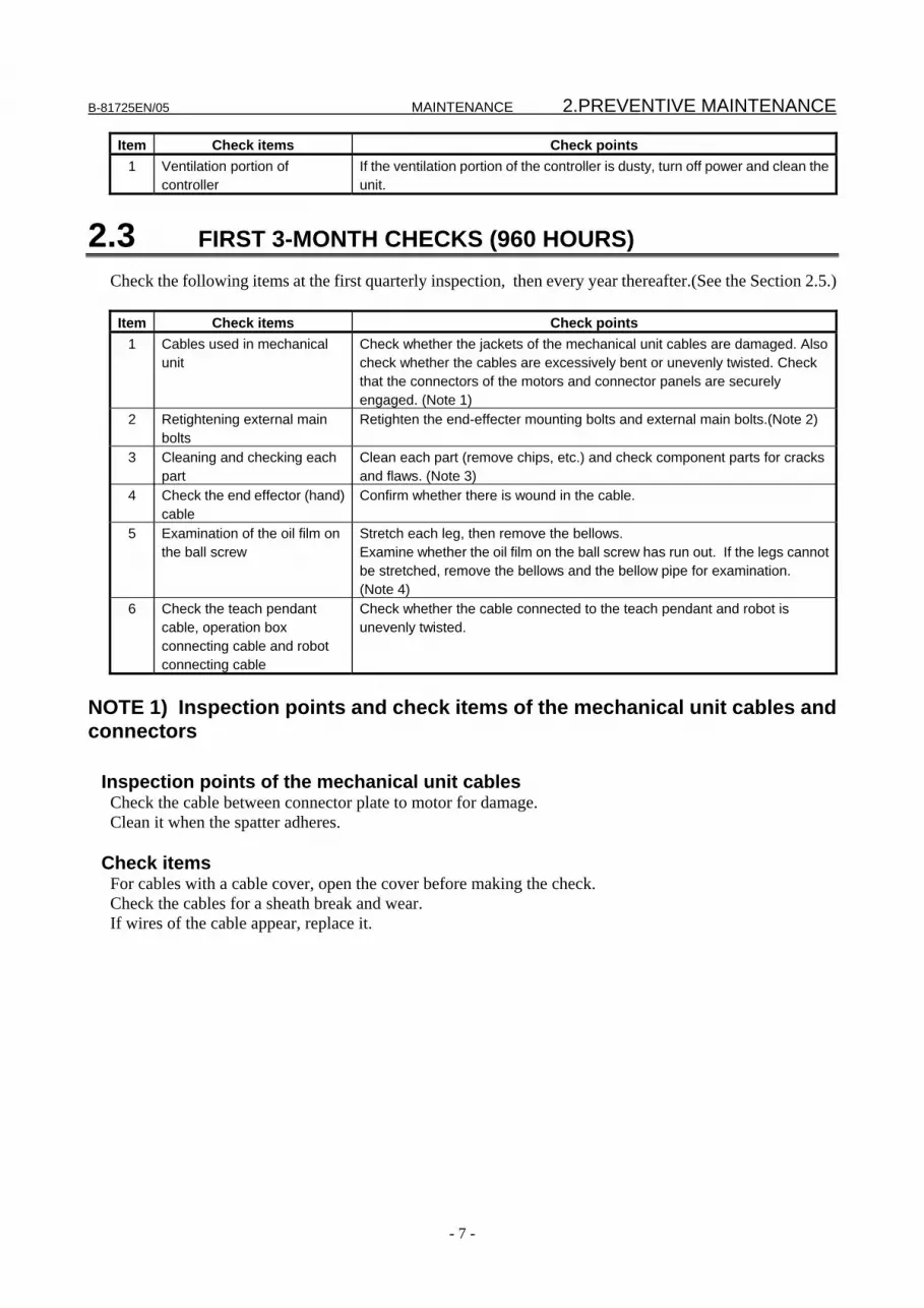
2.3 FIRST 3-MONTH CHECKS (960 HOURS) Check the following items at the first quarterly inspection, then every year thereafter.(See the Section 2.5.) Item Check items Check points
1 Cables used in mechanical unit
Check whether the jackets of the mechanical unit cables are damaged. Also check whether the cables are excessively bent or unevenly twisted. Check that the connectors of the motors and connector panels are securely engaged. (Note 1)
2 Retightening external main bolts
Retighten the end-effecter mounting bolts and external main bolts.(Note 2)
3 Cleaning and checking each part
Clean each part (remove chips, etc.) and check component parts for cracks and flaws. (Note 3)
4 Check the end effector (hand) cable
Confirm whether there is wound in the cable.
5 Examination of the oil film on the ball screw
Stretch each leg, then remove the bellows. Examine whether the oil film on the ball screw has run out. If the legs cannot be stretched, remove the bellows and the bellow pipe for examination. (Note 4)
6 Check the teach pendant cable, operation box connecting cable and robot connecting cable
Check whether the cable connected to the teach pendant and robot is unevenly twisted.
NOTE 1) Inspection points and check items of the mechanical unit cables and connectors
Inspection points of the mechanical unit cables Check the cable between connector plate to motor for damage. Clean it when the spatter adheres.
Check items For cables with a cable cover, open the cover before making the check. Check the cables for a sheath break and wear. If wires of the cable appear, replace it.

2.PREVENTIVE MAINTENANCE MAINTENANCE B-81725EN/05
- 8 -
Fig. 2.3 (a) Inspection points of the mechanical unit cables
Inspection points of the connectors
- Power/brake connectors of the motor exposed externally - Robot connection cables, earth terminal and user cables
Check items - Circular connector: Check the connector for looseness by turning it manually. - Square connector: Check the connector for disengagement of its lever. - Earth terminal: Check the connector for looseness.
6 places
Fig. 2.3 (b) Inspection points of connectors

B-81725EN/05 MAINTENANCE 2.PREVENTIVE MAINTENANCE
- 9 -
NOTE 2) Cleaning
- Check that there are not piling up of the spatter, peripheral equipment cable, and a big foreign body on the base. The leg unit runs aground when there is a foreign body on the base, and the ball screw might be damaged.
- Check if there is a trace of a collision around the gun or hand. - Check the grease bath (6 locations) for an oil leak. → If oil can be found a day after wiping oil, an oil leak may be caused.
6 places
6 places
Fig. 2.3 (c) Cleaning points
NOTE 3) Points to be retightened
- The end effecter mounting bolts, robot installation bolts, and bolts to be removed for inspection need to be retightened.
- The bolts exposed to the outside of the robot need to be retightened. For the tightening torque, see the recommended bolt tightening torque shown in the Appendix. A loose prevention agent (adhesive) is applied to some bolts. If the bolts are tightened with greater
than the recommended torque, the loose prevention agent may be removed. So, follow the recommended tightening torque when retightening them.
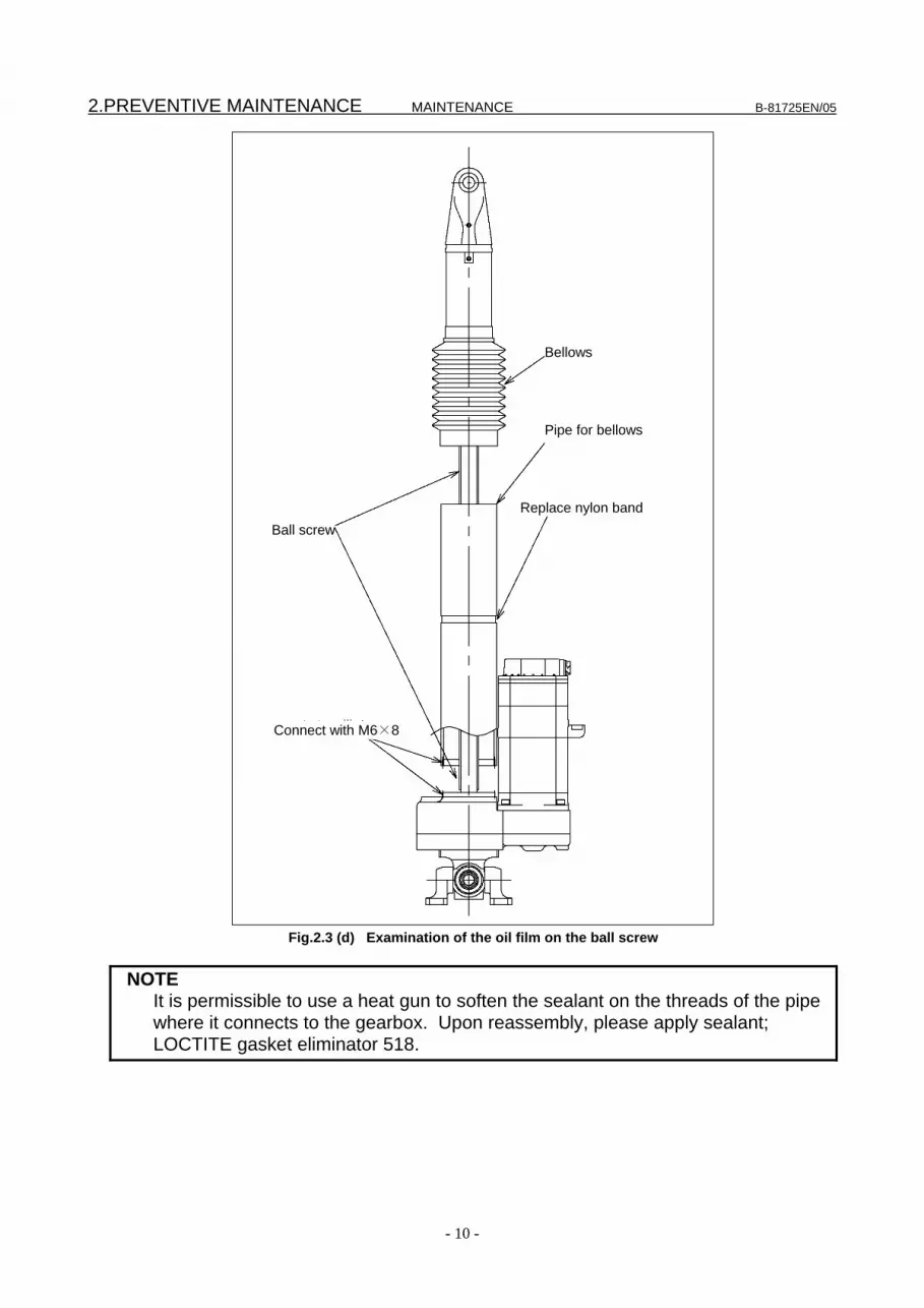
NOTE 4) Examination of the Oil Film on the Ball Screw
2.PREVENTIVE MAINTENANCE MAINTENANCE B-81725EN/05
- 10 -
Fig.2.3 (d) Examination of the oil film on the ball screw
NOTE It is permissible to use a heat gun to soften the sealant on the threads of the pipe
where it connects to the gearbox. Upon reassembly, please apply sealant; LOCTITE gasket eliminator 518.
Bellows
Pipe for bellows
Replace nylon band Ball screw
Connect with M6×8

B-81725EN/05 MAINTENANCE 2.PREVENTIVE MAINTENANCE
- 11 -
2.4 3-MONTH (960 HOURS) CHECKS Check the following item at the first one-months (320 hours), then every 3-month thereafter. (See the Subsection 2.2.)
Item Check items Check points 1 Ventilation portion of controller (See Section 2.2.)
2.5 6- MONTH CHECKS (1,920 HOURS) Check the following item once every six months. (or 1,920 hours operating)
Item Check items Check points 1 Greasing of the ball screw Grease the ball screw. (See Section 3.2.)
2.6 1-YEAR CHECKS (3,840 HOURS) Check the following items once every year (3,840 hours).
Item Check items Check points 1 Cables used in mechanical unit (See Section 2.3.) 2 Retightening external main bolts (See Section 2.3.) 3 Cleaning each parts and inspection (See Section 2.3.) 4 Check the end effector (hand) cable (See Section 2.3.) 5 Check the robot cable, teach pendant cable
and robot connecting cable (See Section 2.3.)
2.7 1.5-YEAR CHECKS (5,760 HOURS) Check the following item once every 1.5 year (5,760 hours).
Item Check items Check points 1 Battery Replace battery in the mechanical unit. (See Section 3.3)
2.8 3-YEAR CHECKS (11,520 HOURS) Check the following items once every 3 years (11,520 hours).
Item Check items Check points 1 Replacement of the grease in the gearbox Replace the grease in the gearbox. (See Section 3.1.)
2.9 4-YEAR (15,360 HOURS) CHECKS Check the following items once every 4 years (15,360 hours).
Item Check items Check points 1 Replace the mechanical unit cable Replace mechanical unit cable (See Chapter 8.)

2.PREVENTIVE MAINTENANCE MAINTENANCE B-81725EN/05
- 12 -
2.10 MAINTENANCE TOOLS The following tools and instruments are required for the maintenance procedures contained in this manual. 1) Measuring instruments
Instruments Accuracy/Capacity Applications Dial gauge accuracy 1/100 mm Measurement of positioning. Slide calipers 150 mm
2) Tools
Cross-point(+)screwdrivers ...........: Large, medium, and small sizes Conventional(-)screwdrivers .........: Large, medium, and small sizes Box screw driver ...........................: Dihedral width 2.5, 3, 5 Hex key set ....................................: Dihedral width 2.5, 3, 5, 6, 8, 10, 12, 14 Adjustable wrenches ...................: Large, Medium and small sizes Pliers Cutting pliers Cutting nippers Double hexagon offset wrench Torque wrench ...............................: M6 to M16 Grease gun Eyebolt ...........................................: M10 Rope................................................: allowable weight more than 1 ton LOCTITE 242 LOCTITE 262 LOCTITE .518 (Seal) Seal tape Gear puller Separator Flashlight

B-81725EN/05 MAINTENANCE 3.PERIODIC MAINTENANCE
- 13 -
3 PERIODIC MAINTENANCE
3.1 REPLACING GREASE OF THE DRIVE MECHANISM Replace the J1 to J6-axis gearbox grease in the cycle that is shorter among every three years and 11,520 hours by using the following procedures.
Table 3.1 Grease for 3-year periodical replacement
Supply position Grease name Quantity Gun tip pressure J1 to J6-axis gearbox Kyodo yushi
VIGOGREASE RE0 (Spec.: A98L-0040-0174#2KG)
Each 265 cm3 (230g) 0.1 MPa or less (Note 1)
Note 1 When using a hand pump, apply grease approximately once per two seconds.
Posture at greasing When replacing and replenishing grease, set the robot to a posture with about the same lengths on all axes.
Replacing procedure of grease 1 Remove the full cover (option) from the robot where applicable (see Section 6.5). 2 Turn off the controller power. 3 Remove the grease seal bolt. 4 Apply new grease from the grease inlet until it comes out from the grease outlet. 5 After applying grease, release the remaining pressure within the grease bath as described in the
procedure in Section 3.2. 6 Remount the seal bolt at the grease outlet. (For mounting the seal bolt, coil a new seal tape.) 7 Remount the full cover (option) to the robot where applicable (see Section 6.5).
CAUTION If greasing is performed incorrectly, the internal pressure of the grease bath may suddenly increase, possibly causing damage to the seal, which would in turn lead to grease leakage and abnormal operation. When performing greasing, therefore, observe the following cautions. 1 Before starting to grease, open the grease outlet (remove the bolt from the grease
outlet). 2 Supply grease slowly without applying excessive force, using a manual pump. 3 Whenever possible, avoid using a compressed-air pump, powered by the factory air
supply. Even when using a compressed-air pump unavoidably, set the gun tip pressure (see Table 3.1) to 0.1 MPa or less during application of grease.
4 Use grease only of the specified type. Grease of a type other than that specified may cause problems.
5 After applying grease, release the remaining pressure within the grease bath as described in the procedure in Section 3.3.
6 To prevent accidents caused by slipping, completely remove any excess grease from the floor or robot.

3.PERIODIC MAINTENANCE MAINTENANCE B-81725EN/05
- 14 -
Seal bolt (M6X8)for grease outlet
Grease nipple for grease inlet
Fig.3.1 (a) Replacing grease of gearbox (J1,J3,J4,J6-axis)
Grease nipple for grease inlet Seal bolt (M6X8)
for grease outlet
Fig.3.1 (b) Replacing grease of gearbox (J2,J5-axis)
When replacing or replenishing grease, posture the robot such that all axes are 668 mm or shorter. To replace or replenish grease when the robot is postured with the axes 668 mm or more long, remove the silencer (M5) and stuff the hole in advance.
B-81725EN/05 MAINTENANCE 3.PERIODIC MAINTENANCE
- 15 -
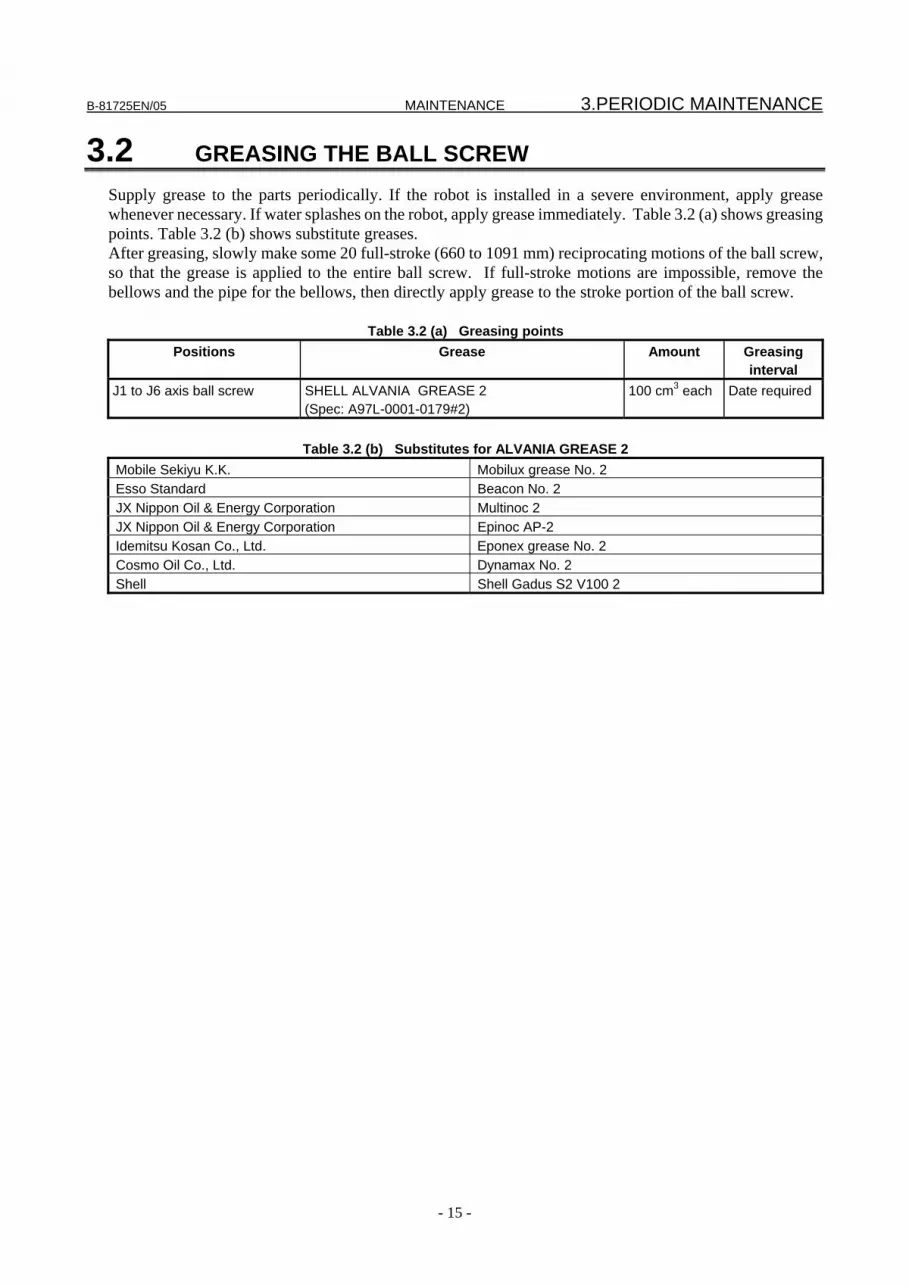
3.2 GREASING THE BALL SCREW Supply grease to the parts periodically. If the robot is installed in a severe environment, apply grease whenever necessary. If water splashes on the robot, apply grease immediately. Table 3.2 (a) shows greasing points. Table 3.2 (b) shows substitute greases. After greasing, slowly make some 20 full-stroke (660 to 1091 mm) reciprocating motions of the ball screw, so that the grease is applied to the entire ball screw. If full-stroke motions are impossible, remove the bellows and the pipe for the bellows, then directly apply grease to the stroke portion of the ball screw.
Table 3.2 (a) Greasing points Positions Grease Amount Greasing
interval J1 to J6 axis ball screw SHELL ALVANIA GREASE 2
(Spec: A97L-0001-0179#2) 100 cm3 each Date required
Table 3.2 (b) Substitutes for ALVANIA GREASE 2
Mobile Sekiyu K.K. Mobilux grease No. 2 Esso Standard Beacon No. 2 JX Nippon Oil & Energy Corporation Multinoc 2 JX Nippon Oil & Energy Corporation Epinoc AP-2 Idemitsu Kosan Co., Ltd. Eponex grease No. 2 Cosmo Oil Co., Ltd. Dynamax No. 2 Shell Shell Gadus S2 V100 2

3.PERIODIC MAINTENANCE MAINTENANCE B-81725EN/05
- 16 -
A
A
Grease bath
Bellows
Pipe for bellows
Grease nipple
To perform greasing when the robot is postured withthe axes 668 mm or more long, remove the silencer (M5) and stuff the hole in advance.
SECTION A-A
Fig.3.2 Greasing points
3.3 PROCEDURE FOR RELEASING THE GREASE REMAINING PRESSURE
After applying grease, operate the robot as instructed below with the seal bolt of the grease outlet uncapped to release the remaining pressure within the grease bath. Attach a recovery bag below the grease outlet to prevent output grease from splattering. Perform program operation for the time specified below with the grease outlet uncapped in order to release the remaining pressure. Perform program operation for ten minutes or more by setting a position to 300 mm in the Z-axis direction and a repetition operation of OVR 100%. When the above operation is impossible due to ambient conditions, perform the program operation for a time equivalent to the above. (When the maximum allowable movement distance is 150 mm, perform the
B-81725EN/05 MAINTENANCE 3.PERIODIC MAINTENANCE
- 17 -
operation for 20 minutes or more.) Upon completion of the above operation, attach the seal bolt to the grease outlet. When reusing the seal bolt, be sure to seal it with seal tape.
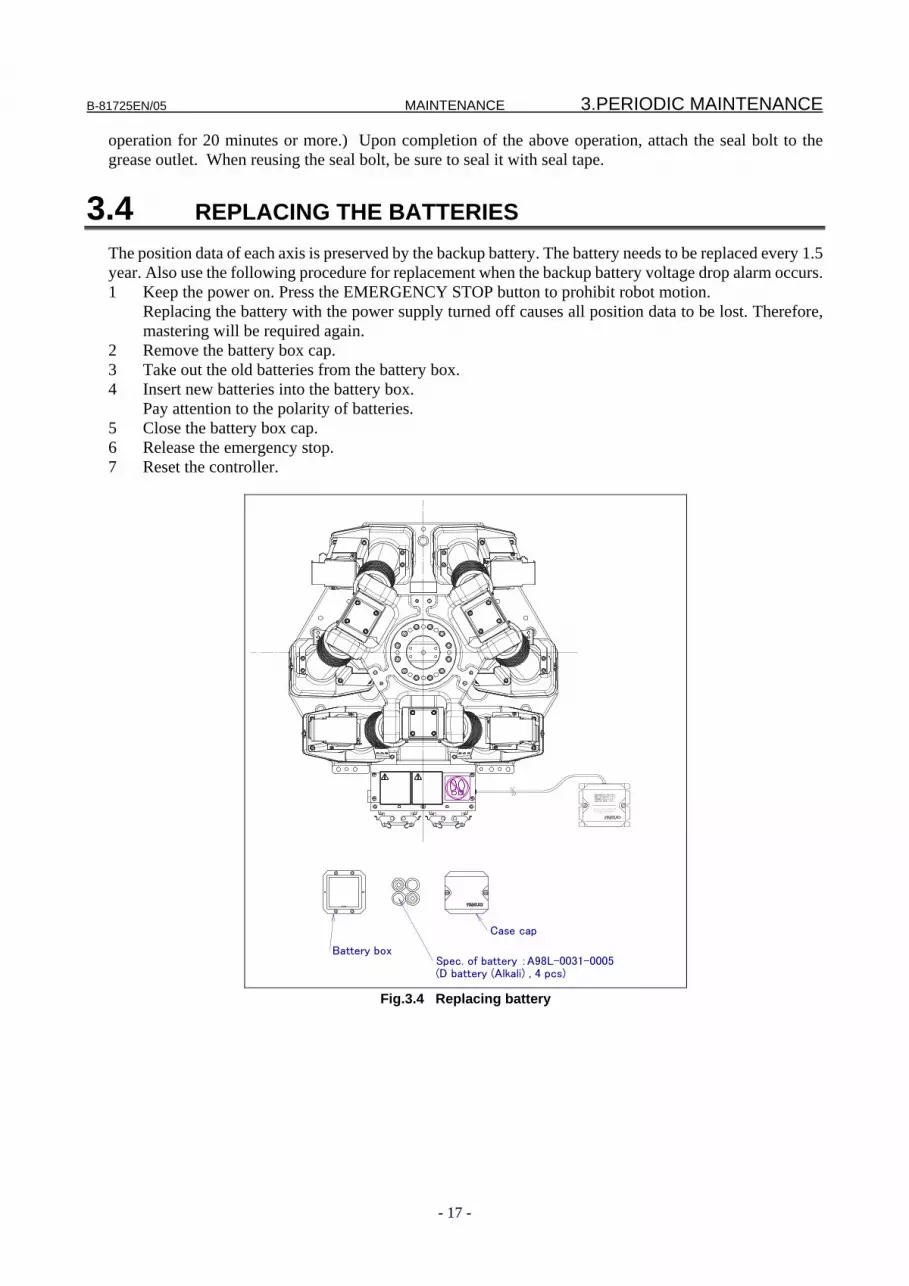
3.4 REPLACING THE BATTERIES The position data of each axis is preserved by the backup battery. The battery needs to be replaced every 1.5 year. Also use the following procedure for replacement when the backup battery voltage drop alarm occurs. 1 Keep the power on. Press the EMERGENCY STOP button to prohibit robot motion. Replacing the battery with the power supply turned off causes all position data to be lost. Therefore,
mastering will be required again. 2 Remove the battery box cap. 3 Take out the old batteries from the battery box. 4 Insert new batteries into the battery box. Pay attention to the polarity of batteries. 5 Close the battery box cap. 6 Release the emergency stop. 7 Reset the controller.
Battery box
Case cap
Spec. of battery :A98L-0031-0005(D battery (Alkali) , 4 pcs)
batteries(AM1) should be used.
Only the alkaline mangnese dioxide
be sure that the control power is on.
When replacing batteries(once a year)
乾電池(AM1)を使用して下さい.
交換用電池にはアルカリ-マンガン
電源を入れた状態で行なって下さい.
電池の交換(1年に1回)は,NCの
Fig.3.4 Replacing battery
4.TROUBLE SHOOTING MAINTENANCE B-81725EN/05
- 18 -
4 TROUBLE SHOOTING
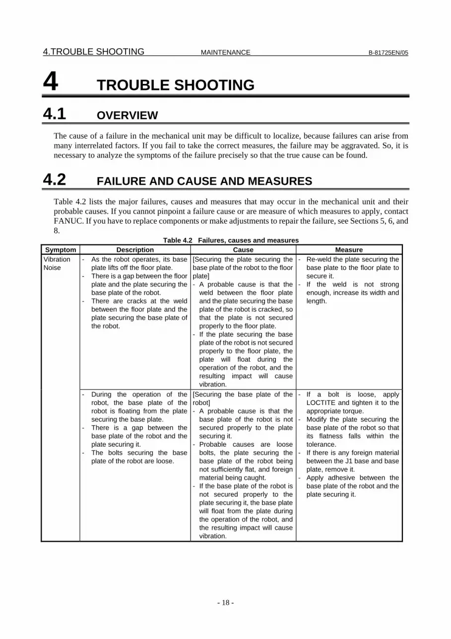
4.1 OVERVIEW The cause of a failure in the mechanical unit may be difficult to localize, because failures can arise from many interrelated factors. If you fail to take the correct measures, the failure may be aggravated. So, it is necessary to analyze the symptoms of the failure precisely so that the true cause can be found.
4.2 FAILURE AND CAUSE AND MEASURES Table 4.2 lists the major failures, causes and measures that may occur in the mechanical unit and their probable causes. If you cannot pinpoint a failure cause or are measure of which measures to apply, contact FANUC. If you have to replace components or make adjustments to repair the failure, see Sections 5, 6, and 8.
Table 4.2 Failures, causes and measures Symptom Description Cause Measure Vibration Noise
- As the robot operates, its base plate lifts off the floor plate.
- There is a gap between the floor plate and the plate securing the base plate of the robot.
- There are cracks at the weld between the floor plate and the plate securing the base plate of the robot.
[Securing the plate securing the base plate of the robot to the floor plate] - A probable cause is that the
weld between the floor plate and the plate securing the base plate of the robot is cracked, so that the plate is not secured properly to the floor plate.
- If the plate securing the base plate of the robot is not secured properly to the floor plate, the plate will float during the operation of the robot, and the resulting impact will cause vibration.
- Re-weld the plate securing the base plate to the floor plate to secure it.
- If the weld is not strong enough, increase its width and length.
- During the operation of the robot, the base plate of the robot is floating from the plate securing the base plate.
- There is a gap between the base plate of the robot and the plate securing it.
- The bolts securing the base plate of the robot are loose.
[Securing the base plate of the robot] - A probable cause is that the
base plate of the robot is not secured properly to the plate securing it.
- Probable causes are loose bolts, the plate securing the base plate of the robot being not sufficiently flat, and foreign material being caught.
- If the base plate of the robot is not secured properly to the plate securing it, the base plate will float from the plate during the operation of the robot, and the resulting impact will cause vibration.
- If a bolt is loose, apply LOCTITE and tighten it to the appropriate torque.
- Modify the plate securing the base plate of the robot so that its flatness falls within the tolerance.
- If there is any foreign material between the J1 base and base plate, remove it.
- Apply adhesive between the base plate of the robot and the plate securing it.
B-81725EN/05 MAINTENANCE 4.TROUBLE SHOOTING
- 19 -
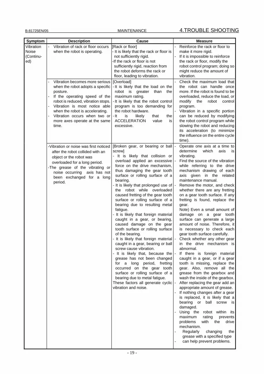
Symptom Description Cause Measure Vibration Noise (Continu- ed)
- Vibration of rack or floor occurs when the robot is operating.
[[Rack or floor] - It is likely that the rack or floor is not sufficiently rigid.
-If the rack or floor is not sufficiently rigid, reaction from the robot deforms the rack or floor, leading to vibration.
- Reinforce the rack or floor to make it more rigid.
- If it is impossible to reinforce the rack or floor, modify the robot control program; doing so might reduce the amount of vibration.
- Vibration becomes more serious when the robot adopts a specific posture.
- If the operating speed of the robot is reduced, vibration stops.
- Vibration is most notice able when the robot is accelerating.
- Vibration occurs when two or more axes operate at the same time.
[Overload] - It is likely that the load on the robot is greater than the maximum rating.
- It is likely that the robot control program is too demanding for the robot hardware.
- It is likely that the ACCELERATION value is excessive.
- Check the maximum load that the robot can handle once more. If the robot is found to be overloaded, reduce the load, or modify the robot control program.
- Vibration in a specific portion can be reduced by modifying the robot control program while slowing the robot and reducing its acceleration (to minimize the influence on the entire cycle time).
-Vibration or noise was first noticed after the robot collided with an object or the robot was overloaded for a long period.
-The grease of the vibrating or noise occurring axis has not been exchanged for a long period.
[Broken gear, or bearing or ball screw] - It is likely that collision or
overload applied an excessive force on the drive mechanism, thus damaging the gear tooth surface or rolling surface of a bearing.
- It is likely that prolonged use of the robot while overloaded caused fretting of the gear tooth surface or rolling surface of a bearing due to resulting metal fatigue.
- It is likely that foreign material caught in a gear, or bearing, caused damage on the gear tooth surface or rolling surface of the bearing.
- It is likely that foreign material caught in a gear, bearing or ball screw cause vibration.
- It is likely that, because the grease has not been changed for a long period, fretting occurred on the gear tooth surface or rolling surface of a bearing due to metal fatigue.
These factors all generate cyclic vibration and noise.
- Operate one axis at a time to determine which axis is vibrating.
- Find the source of the vibration while referring to the drive mechanism drawing of each axis given in the related maintenance manual.
- Remove the motor, and check whether there are any fretting on a gear tooth surface. If any fretting is found, replace the gear.
Note) Even a small amount of damage on a gear tooth surface can generate a large amount of noise. Therefore, it is necessary to check each gear tooth surface carefully.
- Check whether any other gear in the drive mechanism is abnormal.
- If there is foreign material caught in a gear, or if a gear tooth is missing, replace the gear. Also, remove all the grease from the gearbox andwash the inside of the gearbox.
- After replacing the gear add an appropriate amount of grease.
- If nothing changes after a gear is replaced, it is likely that a bearing or ball screw is damaged.
- Using the robot within its maximum rating prevents problems with the drive mechanism.
- Regularly changing the grease with a specified type
- can help prevent problems.

4.TROUBLE SHOOTING MAINTENANCE B-81725EN/05
- 20 -
Symptom Description Cause Measure Vibration Noise (Continu- ed)
- The cause of problem cannot be identified from examination of the floor, rack, or mechanical section.
[Controller, cable, and motor] - If a failure occurs in a controller
circuit, preventing control commands from being supplied to the motor normally, or preventing motor information from being sent to the controller normally, vibration might occur.
- If the Pulsecoder develops a fault, vibration might occur because information about the motor position cannot be transferred to the controller accurately.
- If the motor becomes defective, vibration might occur because the motor cannot deliver its rated performance.
- If a power line in a movable cable of the mechanical section has an intermittent break, vibration might occur because the motor cannot accurately respond to commands.
- If a Pulsecoder wire in a movable part of the mechanical section has an intermittent break, vibration might occur because commands cannot be sent to the motor accurately.
- If the controller is installed separately from the mechanical section, and a connection cable between them has an intermittent break, vibration might occur.
- If the power source voltage drops below the rating, vibration might occur.
- If a robot control parameter is set to an invalid value, vibration might occur.
- Refer to the Controller Maintenance Manual for troubleshooting related to the controller and amplifier.
- Replace the Pulsecoder for the motor of the axis that is vibrating, and check whether the vibration still occurs.
- Also, replace the motor of the axis that is vibrating, and check whether vibration still occurs.
- Check that the robot is supplied with the rated voltage.
- Check whether the sheath of the power cord is damaged. If so, replace the power cord, and check whether vibration still occurs.
- Check whether the sheath of the cable connecting the mechanical section and controller is damaged. If so, replace the connection cable, and check whether vibration still occurs.
- If vibration occurs only when the robot assumes a specific posture, it is likely that a cable in the mechanical unit is broken.
- Shake the movable part cable while the robot is at rest, and check whether an alarm occurs. If an alarm or any other abnormal condition occurs, replace the mechanical unit cable.
- Check that the robot control parameter is set to a valid value. If it is set to an invalid value, correct it. Contact FANUC for further information if necessary.
- There is some relationship between the vibration of the robot and the operation of a machine near the robot.
[Noise from a nearby machine] - If the robot is not grounded
properly, electrical noise is induced on the grounding wire, preventing commands from being transferred accurately, thus leading to vibration.
- If the robot is grounded at an unsuitable point, its grounding potential becomes unstable, and noise is likely to be induced on the grounding line, thus leading to vibration.
- Connect the grounding wire firmly to ensure a reliable ground potential and prevent extraneous electrical noise.
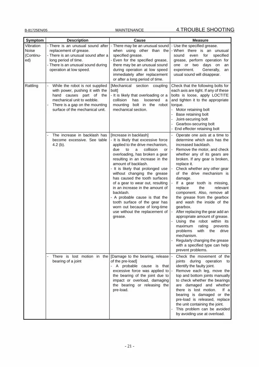
B-81725EN/05 MAINTENANCE 4.TROUBLE SHOOTING
- 21 -
Symptom Description Cause Measure Vibration Noise (Continu- ed)
- There is an unusual sound after replacement of grease.
- There is an unusual sound after a long period of time.
- There is an unusual sound during operation at low speed.
- There may be an unusual sound when using other than the specified grease.
- Even for the specified grease, there may be an unusual sound during operation at low speed immediately after replacement or after a long period of time.
- Use the specified grease. - When there is an unusual
sound even for specified grease, perform operation for one or two days on an experiment. Generally, an usual sound will disappear.
- While the robot is not supplied with power, pushing it with the hand causes part of the mechanical unit to wobble.
- There is a gap on the mounting surface of the mechanical unit.
[Mechanical section coupling bolt] - It is likely that overloading or a
collision has loosened a mounting bolt in the robot mechanical section.
Check that the following bolts for each axis are tight. If any of these bolts is loose, apply LOCTITE and tighten it to the appropriate torque. - Motor retaining bolt - Base retaining bolt - Joint-securing bolt - Gearbox-securing bolt - End effecter retaining bolt
- The increase in backlash has become excessive. See table 4.2 (b).
[Increase in backlash] - It is likely that excessive force
applied to the drive mechanism, due to a collision or overloading, has broken a gear resulting in an increase in the amount of backlash.
- It is likely that prolonged use without changing the grease has caused the tooth surfaces of a gear to wear out, resulting in an increase in the amount of backlash.
- A probable cause is that the tooth surface of the gear has worn out because of long-time use without the replacement of grease.
- Operate one axis at a time to determine which axis has the increased backlash.
- Remove the motor, and check whether any of its gears are broken. If any gear is broken, replace it.
- Check whether any other gear of the drive mechanism is damage.
- If a gear tooth is missing, replace the relevant component. Also, remove all the grease from the gearbox and wash the inside of the gearbox.
- After replacing the gear add an appropriate amount of grease.
- Using the robot within its maximum rating prevents problems with the drive mechanism.
- Regularly changing the grease with a specified type can help prevent problems.
Rattling
- There is lost motion in the bearing of a joint
[Damage to the bearing, release of the pre-load] - A probable cause is that
excessive force was applied to the bearing of the joint due to impact or overload, damaging the bearing or releasing the pre-load.
- Check the movement of the joints during operation to identify the faulty joint.
- Remove each leg, move the top and bottom joints manually to check whether the bearings are damaged and whether there is lost motion. If a bearing is damaged or the pre-load is released, replace the unit containing the joint.
- This problem can be avoided by avoiding use at overload.

4.TROUBLE SHOOTING MAINTENANCE B-81725EN/05
- 22 -
Symptom Description Cause Measure Motor overheat ing
- The ambient temperature of the installation location increases, causing the motor to overheat.
- After a cover was attached to the motor, the motor overheated.
- After the robot control program or the load was changed, the motor overheated.
[Ambient temperature] - It is likely that a rise in the
ambient temperature prevented the motor from releasing heat efficiently, thus leading to overheating.
[Operating condition] - It is likely that the robot was
operated with the maximum average current exceeded.
The teach pendant can be used to monitor the average current. Check the average current when the robot control program is running. The allowable average current is specified for the robot according to its ambient temperature. Contact FANUC for further information. - Relaxing the robot control
program and conditions can reduce the average current, thus preventing overheating.
- Reducing the ambient temperature is the most effective means of preventing overheating.
- Having the surroundings of the motor well ventilated enables the motor to release heat efficiently, thus preventing overheating. Using a fan to direct air at the motor is also effective.
- If there is a source of heat near the motor, it is advisable to install shielding to protect the motor from heat radiation.
- After a control parameter was changed, the motor overheated.
[Parameter] - If data input for a workpiece is
invalid, the robot cannot be accelerated or decelerated normally, so the average current increases, leading to overheating.
- Input an appropriate parameter as described in the manual.
- Symptom other than stated above
[Mechanical section problems] - It is likely that problems occurred
in the mechanical unit drive mechanism, thus placing an excessive load on the motor.
[Motor problems] - It is likely that a failure of the
motor brake resulted in the motor running with the brake applied, thus placing an excessive load on the motor.
- It is likely that a failure of the motor prevented it from delivering its rated performance, thus causing an excessive current to flow through the motor.
Repair the mechanical unit while referring to the above descriptions of vibration, noise, and rattling. - Check that, when the servo
system is energized, the brake is released.
- If the brake remains applied to the motor all the time, replace the motor.
- If the average current falls after the motor is replaced, it indicates that the first motorwas faulty.
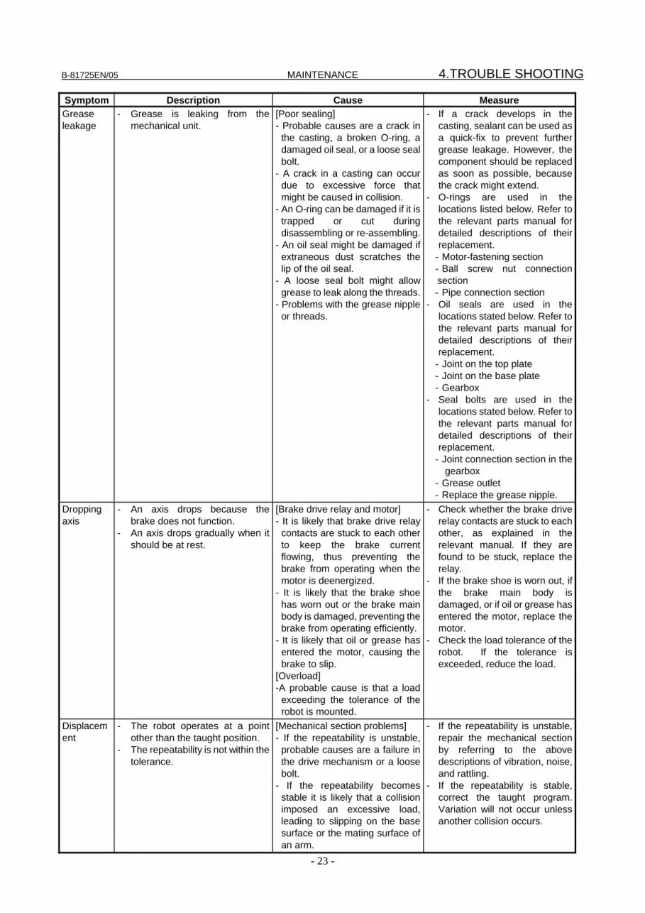
B-81725EN/05 MAINTENANCE 4.TROUBLE SHOOTING
- 23 -
Symptom Description Cause Measure Grease leakage
- Grease is leaking from the mechanical unit.
[Poor sealing] - Probable causes are a crack in
the casting, a broken O-ring, a damaged oil seal, or a loose seal bolt.
- A crack in a casting can occur due to excessive force that might be caused in collision.
- An O-ring can be damaged if it is trapped or cut during disassembling or re-assembling.
- An oil seal might be damaged if extraneous dust scratches the lip of the oil seal.
- A loose seal bolt might allow grease to leak along the threads.
- Problems with the grease nipple or threads.
- If a crack develops in the casting, sealant can be used as a quick-fix to prevent further grease leakage. However, the component should be replaced as soon as possible, because the crack might extend.
- O-rings are used in the locations listed below. Refer to the relevant parts manual for detailed descriptions of their replacement.
- Motor-fastening section - Ball screw nut connection section - Pipe connection section
- Oil seals are used in thelocations stated below. Refer to the relevant parts manual for detailed descriptions of their replacement.
- Joint on the top plate - Joint on the base plate - Gearbox
- Seal bolts are used in the locations stated below. Refer to the relevant parts manual for detailed descriptions of their replacement.
- Joint connection section in the gearbox
- Grease outlet - Replace the grease nipple.
Dropping axis
- An axis drops because the brake does not function.
- An axis drops gradually when it should be at rest.
[Brake drive relay and motor] - It is likely that brake drive relay
contacts are stuck to each other to keep the brake current flowing, thus preventing the brake from operating when the motor is deenergized.
- It is likely that the brake shoe has worn out or the brake main body is damaged, preventing the brake from operating efficiently.
- It is likely that oil or grease has entered the motor, causing the brake to slip.
[Overload] -A probable cause is that a load
exceeding the tolerance of the robot is mounted.
- Check whether the brake drive relay contacts are stuck to each other, as explained in the relevant manual. If they are found to be stuck, replace the relay.
- If the brake shoe is worn out, if the brake main body is damaged, or if oil or grease hasentered the motor, replace the motor.
- Check the load tolerance of the robot. If the tolerance is exceeded, reduce the load.
Displacement
- The robot operates at a point other than the taught position.
- The repeatability is not within the tolerance.
[Mechanical section problems] - If the repeatability is unstable,
probable causes are a failure in the drive mechanism or a loose bolt.
- If the repeatability becomes stable it is likely that a collision imposed an excessive load, leading to slipping on the base surface or the mating surface of an arm.
- If the repeatability is unstable, repair the mechanical section by referring to the above descriptions of vibration, noise, and rattling.
- If the repeatability is stable, correct the taught program. Variation will not occur unless another collision occurs.
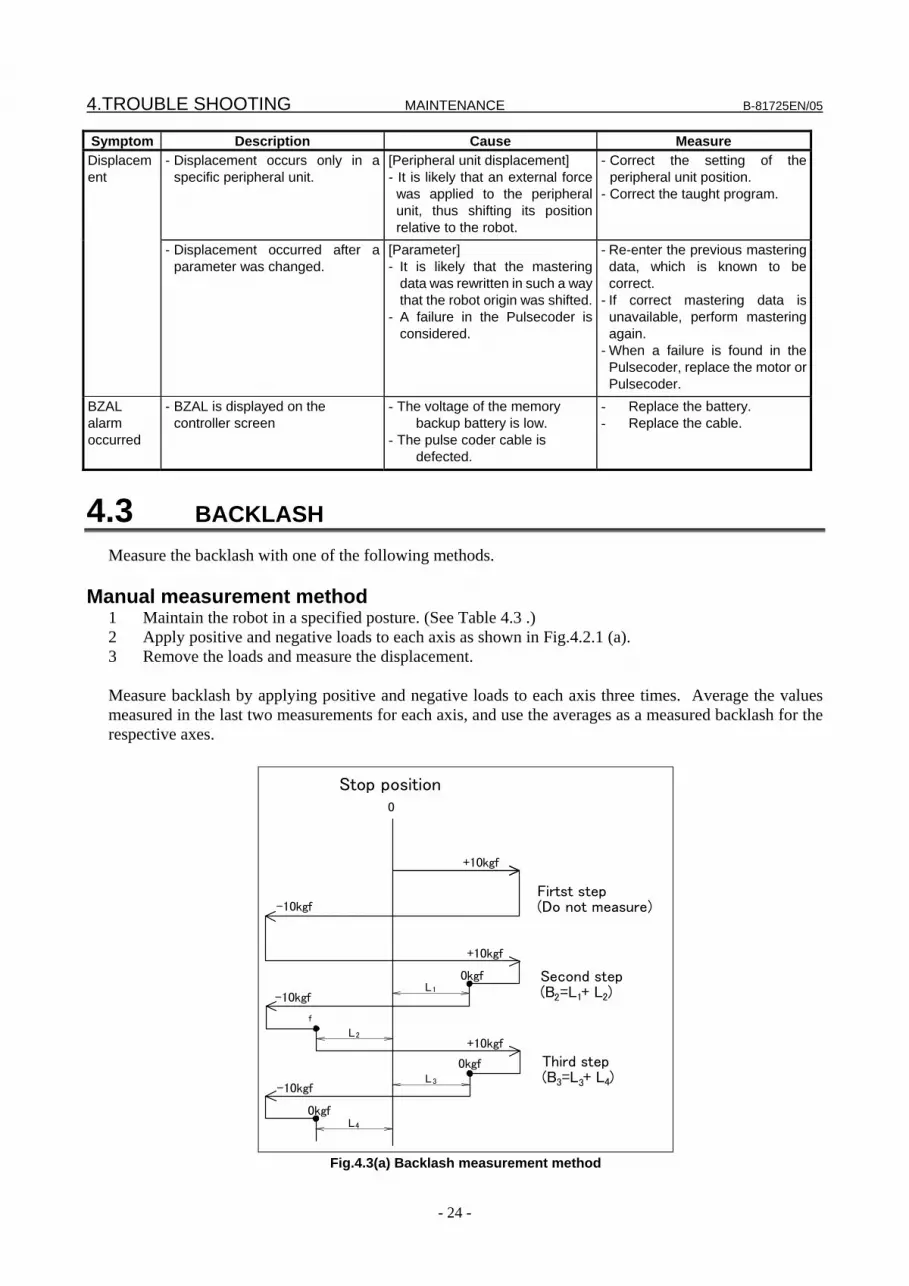
4.TROUBLE SHOOTING MAINTENANCE B-81725EN/05
- 24 -
Symptom Description Cause Measure - Displacement occurs only in a
specific peripheral unit. [Peripheral unit displacement] - It is likely that an external force
was applied to the peripheral unit, thus shifting its position relative to the robot.
- Correct the setting of the peripheral unit position.
- Correct the taught program.
Displacement
- Displacement occurred after a parameter was changed.
[Parameter] - It is likely that the mastering
data was rewritten in such a way that the robot origin was shifted.
- A failure in the Pulsecoder is considered.
- Re-enter the previous mastering data, which is known to be correct.
- If correct mastering data is unavailable, perform mastering again.
- When a failure is found in the Pulsecoder, replace the motor or Pulsecoder.
BZAL alarm occurred
- BZAL is displayed on the controller screen
- The voltage of the memory backup battery is low.
- The pulse coder cable is defected.
- Replace the battery. - Replace the cable.
4.3 BACKLASH Measure the backlash with one of the following methods.
Manual measurement method 1 Maintain the robot in a specified posture. (See Table 4.3 .) 2 Apply positive and negative loads to each axis as shown in Fig.4.2.1 (a). 3 Remove the loads and measure the displacement. Measure backlash by applying positive and negative loads to each axis three times. Average the values measured in the last two measurements for each axis, and use the averages as a measured backlash for the respective axes.
+10kgf
+10kgf
+10kgf
0
-10kgf
Stop position
-10kgf
-10kgf
L
L
L
L
Firtst step(Do not measure)
0kgf
0kgf
f
0kgf
Second step(B =L + L )2 21
Third step(B =L + L )3 43
1
2
3
4
Fig.4.3(a) Backlash measurement method

B-81725EN/05 MAINTENANCE 4.TROUBLE SHOOTING
- 25 -
Backlash B is calculated using the following expression: B=
2BB 32 +
Table 4.3 Measurement posture/Backlash permissible value Posture Direction Load
X Y Z W P R Permissible value (mm)
R ±10kg 200 200 1135 0 0 0 0.3
Automatic measurement method The reciprocating motion of the R-axis is performed with an angle of 0.3°or more and the difference between this position and the return position is measured. Measurement is made twice and their average is obtained as the measurement value.
Measurement position
Current positionadjustment measurement
0.3°or more 0.3°or more
Backlash
Backlash
Current positionadjustment measurement
Controller
Teach speed Each axis 25% Override 4%
800
Measurementposition±10kgf
200
200
Y
X
Fig. 4.3 (b) Measurement position (common to automatic measurement and manual measurement)
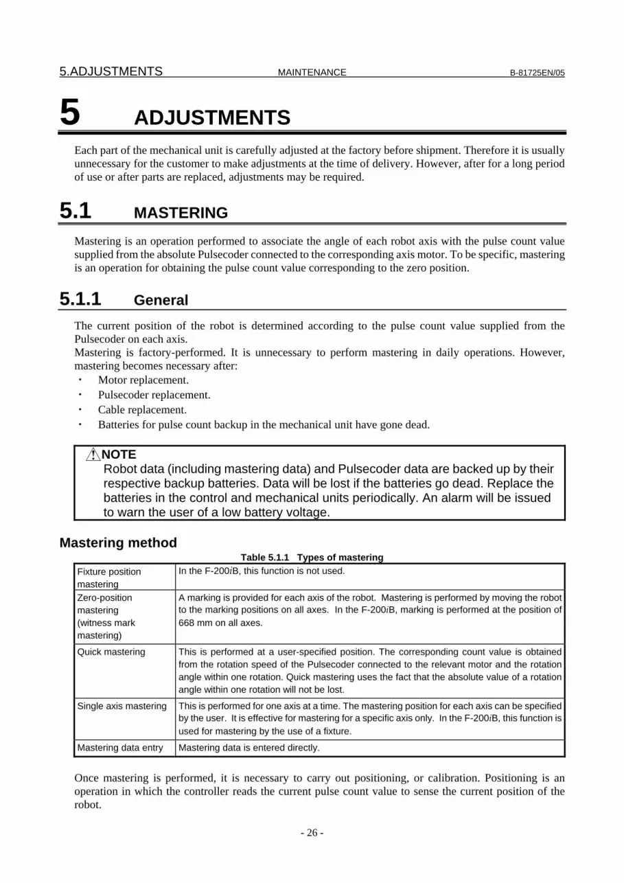
5.ADJUSTMENTS MAINTENANCE B-81725EN/05
- 26 -
5 ADJUSTMENTS Each part of the mechanical unit is carefully adjusted at the factory before shipment. Therefore it is usually unnecessary for the customer to make adjustments at the time of delivery. However, after for a long period of use or after parts are replaced, adjustments may be required.
5.1 MASTERING Mastering is an operation performed to associate the angle of each robot axis with the pulse count value supplied from the absolute Pulsecoder connected to the corresponding axis motor. To be specific, mastering is an operation for obtaining the pulse count value corresponding to the zero position.
5.1.1 General The current position of the robot is determined according to the pulse count value supplied from the Pulsecoder on each axis. Mastering is factory-performed. It is unnecessary to perform mastering in daily operations. However, mastering becomes necessary after: ・ Motor replacement. ・ Pulsecoder replacement. ・ Cable replacement. ・ Batteries for pulse count backup in the mechanical unit have gone dead.
NOTE Robot data (including mastering data) and Pulsecoder data are backed up by their
respective backup batteries. Data will be lost if the batteries go dead. Replace the batteries in the control and mechanical units periodically. An alarm will be issued to warn the user of a low battery voltage.
Mastering method
Table 5.1.1 Types of mastering Fixture position mastering
In the F-200iB, this function is not used.
Zero-position mastering (witness mark mastering)
A marking is provided for each axis of the robot. Mastering is performed by moving the robot to the marking positions on all axes. In the F-200iB, marking is performed at the position of 668 mm on all axes.
Quick mastering This is performed at a user-specified position. The corresponding count value is obtained from the rotation speed of the Pulsecoder connected to the relevant motor and the rotation angle within one rotation. Quick mastering uses the fact that the absolute value of a rotation angle within one rotation will not be lost.
Single axis mastering This is performed for one axis at a time. The mastering position for each axis can be specified by the user. It is effective for mastering for a specific axis only. In the F-200iB, this function is used for mastering by the use of a fixture.
Mastering data entry Mastering data is entered directly.
Once mastering is performed, it is necessary to carry out positioning, or calibration. Positioning is an operation in which the controller reads the current pulse count value to sense the current position of the robot.

B-81725EN/05 MAINTENANCE 5.ADJUSTMENTS
- 27 -
NOTE If mastering is performed incorrectly, the robot may behave unexpectedly. This is
very dangerous. So, the positioning screen is designed to appear only when the $MASTER_ENB system variable is 1 or 2. After performing positioning, press F5 [DONE] on the positioning screen. The $MASTER_ENB system variable is reset to 0 automatically, thus hiding the positioning screen.
5.1.2 Resetting Alarms and Preparing for Mastering Before performing mastering because a motor is replaced, it is necessary to release the relevant alarm and display the positioning menu.
Alarm displayed “Servo 062 BZAL” or “Servo 075 Pulse not established”
Procedure 1 Display the positioning menu by following steps 1 to 6.
1 Press the screen selection key. 2 Press [0 NEXT] and select [6 SYSTEM]. 3 Press F1 [TYPE], and select [SYSTEM Variable] from the menu. 4 Place the cursor on $MASTER_ENB, then key in “1” and press [ENTER]. 5 Press F1 [TYPE], and select[Master/Cal] from the menu. 6 Select the desired mastering type from the [Master/Cal] menu.
2 To reset the “Servo 062 BZAL” alarm, follow steps 1 to 5. 1 Press the screen selection key. 2 Press [0 NEXT] and select [6 SYSTEM]. 3 Press F1 [TYPE], and select [Master/Cal] from the menu. 4 Press the F3 RES_PCA, then press F4 [TRUE]. 5 Turn off the controller power and on again
3 To reset the “Servo 075 Pulse not established” alarm, follow steps 1 to 3. 1 When the controller power is turned on again, the message “Servo 075 Pulse not established”
appears again. 2 Move the axis for which the message mentioned above has appeared till alarm disappears when
press [FAULT RESET] in either direction.
5.1.3 Fixture Position Master Fixture position mastering is performed using a mastering fixture. This mastering is carried out in the predetermined fixture position. Fixture position mastering is accurate because a dedicated mastering fixture is used. Fixture position mastering is factory-performed. It is unnecessary to perform it in daily operations. In the F-200iB, fixture position mastering is performed with the operation for 1-axis mastering because it is performed for one axis at a time. "FIXTURE POSITION MASTER" on the Master/Cal menu is not used.
Operation for fixture position mastering 1 Remove the full cover (option) from the robot where applicable (see Section 6.5). 2 As shown in Fig. 5.1.3 (a), remove the nylon band securing the bellows unscrew the bellows pipe from
the gearbox and move the bellow pipe upward with using width across flat.
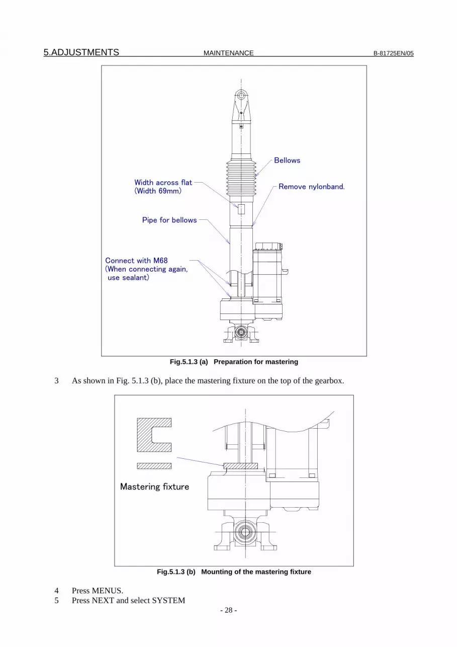
5.ADJUSTMENTS MAINTENANCE B-81725EN/05
- 28 -
Bellows
Remove nylonband.
Pipe for bellows
Width across flat(Width 69mm)
Connect with M68(When connecting again, use sealant)
Fig.5.1.3 (a) Preparation for mastering
3 As shown in Fig. 5.1.3 (b), place the mastering fixture on the top of the gearbox.
Mastering fixture
Fig.5.1.3 (b) Mounting of the mastering fixture
4 Press MENUS. 5 Press NEXT and select SYSTEM

B-81725EN/05 MAINTENANCE 5.ADJUSTMENTS
- 29 -
6 Press F1, [TYPE]. 7 Select Master/Cal.
SYSTEM Master/Cal JOINT 30%
1 FIXTURE POSITION MASTER 2 ZERO POSTIION MASTER 3 QUICK MASTER 4 SINGLE AXIS MASTER 5 SET QUICK MASTER REF 6 CALLIBRATE
Press ‘ ENTER ‘ or number key to select.
[ TYPE ] LOAD RES_PCA DONE
8 Select 4, Single Axis Master. You will see a screen similar to the following. For example of J1-axis
mastering.
SINGLE AXIS MASTER JOINT 30%
1/9 ACTUAL POS (MSTR POS) (SEL) [ST]
J1 700.000 (0.000) (0) [2] J2 700.000 (0.000) (0) [2] J3 700.000 (0.000) (0) [2] J4 700.000 (0.000) (0) [2] J5 700.000 (0.000) (0) [2] J6 700.000 (0.000) (0) [2] E1 0.000 (0.000) (0) [2] E2 0.000 (0.000) (0) [2] E3 0.000 (0.000) (0) [2] [ TYPE ] GROUP EXEC
9 Move the cursor to the SEL column for the unmastered axis and press the numeric key "1." Setting of
SEL is available per one axis or per plural axes.
JOINT 30%
5/9
(0.000) (0) [0]
(0.000) (0) [0]
SINGLE AXIS MASTER JOINT 30% 5/9 J1 700.000 (0.000) (1) [0] J2 700.000 (0.000) (0) [0]
GROUP EXEC 10 As shown in Fig. 5.1.3 (c), use Each axis to move the tool in the minus direction along the axis for
which mastering is to be performed, to bring the bottom face of the ball screw nut in contact with the top face of the mastering fixture. Release brake control.
NOTE Brake control can be released by setting the system variables as follows: $PARAM_GROUP. SSV_OFF _ALL :FALSE $PARAM GROUP. SSV OFF ENB[*]:FALSE (for all axes) After changing the system variables, turn off the controller power and on again.

5.ADJUSTMENTS MAINTENANCE B-81725EN/05
- 30 -
Mounting face
Mastering fixture
Ball screw nut
Fig.5.1.3 (c) Bringing the ball screw nut in contact
11 Input ‘668’ to axis data of mastering position.
SINGLE AXIS MASTER JOINT 30% 5/9 J1 700.000 (668.000) (1) [0] J2 700.000 (0.000) (1) [0]
GROUP EXEC 12 Press F5 [EXEC]. Mastering is performed. So, SEL is reset to 0, and ST is re-set to 2 or 1.
SINGLE AXIS MASTER JOINT 30%
1/9 ACTUAL POS (MSTR POS) (SEL) [ST]
J1 700.000 (668.000) (0) [2] J2 700.000 (0.000) (0) [2] J3 700.000 (0.000) (0) [2] J4 700.000 (0.000) (0) [2] J5 700.000 (0.000) (0) [2] J6 700.000 (0.000) (0) [2] E1 0.000 (0.000) (0) [2] E2 0.000 (0.000) (0) [2] E3 0.000 (0.000) (0) [2] [ TYPE ] GROUP EXEC
GROUP EXEC
13 When single axis mastering is completed, press the previous page key to resume the previous screen.

B-81725EN/05 MAINTENANCE 5.ADJUSTMENTS
- 31 -
BACK
SYSTEM Master/Cal JOINT 30%
1 FIXTURE POSITION MASTER 2 ZERO POSITION MASTER 3 QUICK MASTER 4 SINGLE AXIS MASTER 5 SET QUICK MASTER REF 6 CALIBRATE Press 'ENTER' or number key to select. [ TYPE ] DONE
14 Select [6 CALIBRATE], then press F4 [YES]. Positioning is performed. Alternatively, switch the
power off and on again. Positioning is performed. 15 Perform the operation described up to now for J1- to J6-axes. 16 After completion of positioning on all axes, press F5 "DONE."
DONE
17 Return brake control to original setting, and turn off the controller power and on again. 18 Apply a sealing compound to the M68 threads of the pipe for the bellows, then secure the pipe to the
gearbox. 19 Fasten the bellows to the groove of the bellows pipe with nylon bands. Care should be taken not to
give a twist in the bellows. 20 Remount the full cover (option) to the robot where applicable (see Section 6.5).
NOTE No check is made on the axis movable range during mastering. Be very careful
when running the robot. Continuing axis movement may result in the mechanical stopper being bumped.
5.1.4 Zero Position Master Zero position master refers to mastering performed at the position where a marking-off mark is located. The robot is moved to the marking-off positions (668 mm) on all axes to perform mastering. Marking-off mastering is visual adjustment and, therefore, may not be accurate. Use this mastering as an emergency measure.
Mastering 1 Press MENUS. 2 Press NEXT and select SYSTEM. 3 Press F1, [TYPE]. 4 Select Master/Cal.
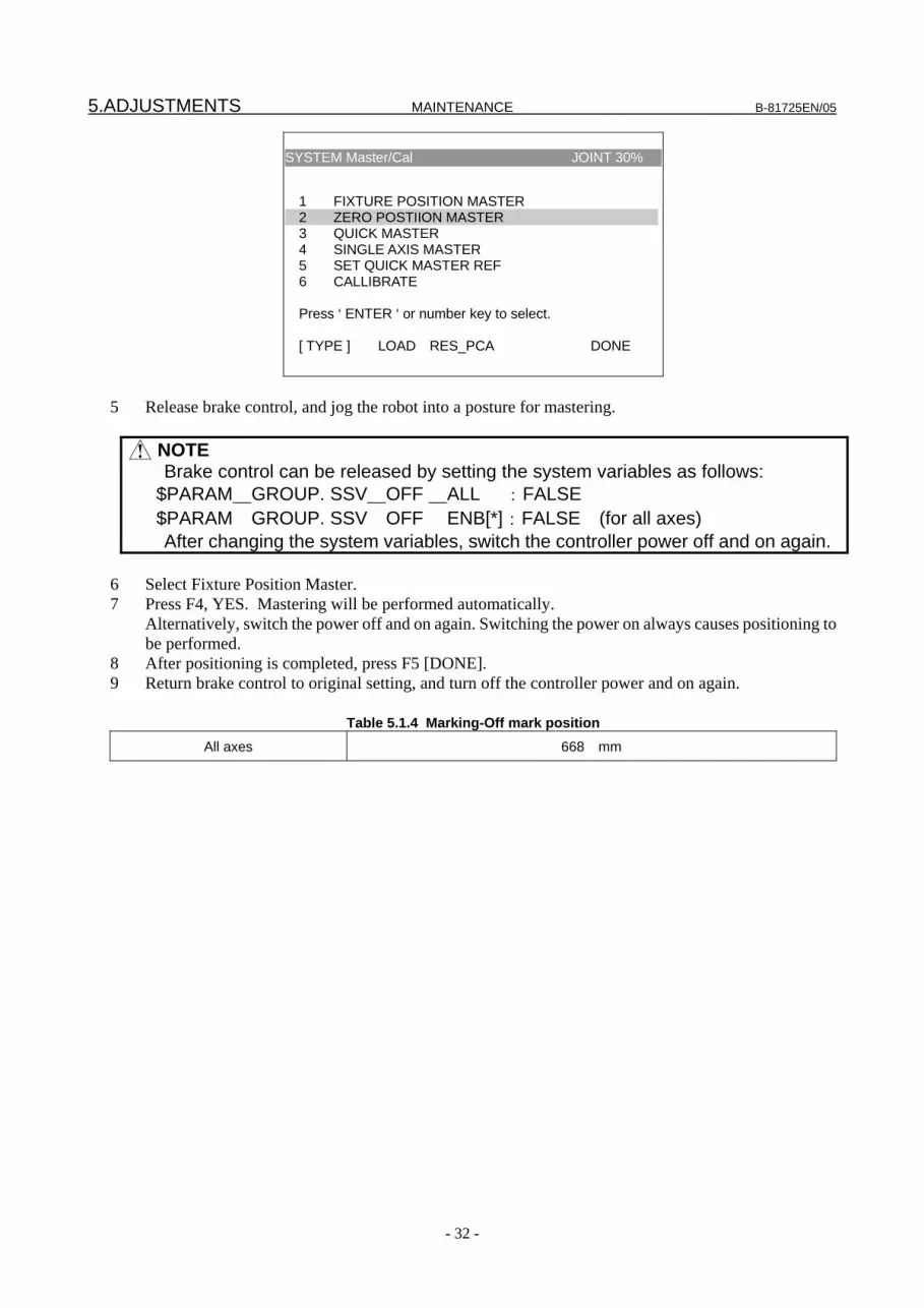
5.ADJUSTMENTS MAINTENANCE B-81725EN/05
- 32 -
SYSTEM Master/Cal JOINT 30%
1 FIXTURE POSITION MASTER 2 ZERO POSTIION MASTER 3 QUICK MASTER 4 SINGLE AXIS MASTER 5 SET QUICK MASTER REF 6 CALLIBRATE
Press ‘ ENTER ‘ or number key to select.
[ TYPE ] LOAD RES_PCA DONE
5 Release brake control, and jog the robot into a posture for mastering.
6 Select Fixture Position Master. 7 Press F4, YES. Mastering will be performed automatically. Alternatively, switch the power off and on again. Switching the power on always causes positioning to
be performed. 8 After positioning is completed, press F5 [DONE]. 9 Return brake control to original setting, and turn off the controller power and on again.
Table 5.1.4 Marking-Off mark position All axes 668 mm
NOTE Brake control can be released by setting the system variables as follows: $PARAM_GROUP. SSV_OFF _ALL :FALSE $PARAM GROUP. SSV OFF ENB[*]:FALSE (for all axes) After changing the system variables, switch the controller power off and on again.

B-81725EN/05 MAINTENANCE 5.ADJUSTMENTS
- 33 -
Fig.5.1.4 (a) Zero position mark position
(J1-, J3, J4, and J6-axes)
Fig.5.1.4 (b) Zero position mark position
(J2- and J5-axes)
5.1.5 Quick Mastering Quick mastering is performed at a user-specified position. The corresponding count value is obtained from the rotation speed of the Pulsecoder connected to the relevant motor and the rotation angle within one rotation. Quick mastering uses the fact that the absolute value of a rotation angle within one rotation will not be lost. Quick mastering is factory-performed at the position indicated in Table 5.1.4. Do not change the setting unless there is a problem. If it is impossible to set the robot at the position mentioned above, it is necessary to re-set the quick mastering reference position using the following method. (It would be convenient to set up a marker that can work in place of the witness mark.)
Pipe Pipe
Bellow pipe Bellow pipe
Marking-off is performed on the pipe side so that it matches the top face of the bellow pipe.
Marking-off is performed on the pipe side so that it matches the top face of the bellow pipe.

5.ADJUSTMENTS MAINTENANCE B-81725EN/05
- 34 -
NOTE 1 Quick mastering can be used, if the pulse count value is lost, for example,
because a low voltage has been detected on the backup battery for the pulse counter.
2 Quick mastering cannot be used, after the Pulsecoder is replaced or after the mastering data is lost from the robot controller.
Procedure Recording the Quick Master Reference Position
Step 1 Select SYSTEM. 2 Select Master/Cal.
SYSTEM Master/Cal JOINT 30%
1 FIXTURE POSITION MASTER 2 ZERO POSTIION MASTER 3 QUICK MASTER 4 SINGLE AXIS MASTER 5 SET QUICK MASTER REF 6 CALLIBRATE
Press ‘ ENTER ‘ or number key to select.
[ TYPE ] LOAD RES_PCA DONE
3 Release brake control, and jog the robot to the quick mastering reference position. 4 Move the cursor to SET QUICK MASTER REF and press ENTER. Press F4, YES.
NOTE If the robot has lost mastery due to mechanical disassembly or repair, you cannot perform this procedure. In this case, master to a fixture or master to zero degrees to restore robot mastery.
Procedure Quick Mastering
Step 1 Display the Master/Cal screen.
SYSTEM Master/Cal JOINT 30%
1 FIXTURE POSITION MASTER 2 ZERO POSTIION MASTER 3 QUICK MASTER 4 SINGLE AXIS MASTER 5 SET QUICK MASTER REF 6 CALLIBRATE
Press ‘ ENTER ‘ or number key to select.
[ TYPE ] LOAD RES_PCA DONE
2 Release brake control, and jog the robot to the quick mastering reference position.

B-81725EN/05 MAINTENANCE 5.ADJUSTMENTS
- 35 -
3 Move the cursor to QUICK MASTER and press ENTER. Press F4, YES. Quick mastering data is memorized.
4 Move the cursor to CALIBRATE and press ENTER. Calibration is executed. Calibration is executed by power on again.
5 After completing the calibration, press F5, DONE. DONE
6 Return brake control to original setting, and turn off the controller power and on again.
5.1.6 Single Axis Mastering Single axis mastering is performed for one axis at a time. The mastering position for each axis can be specified by the user. Single axis mastering can be used, if mastering data for a specific axis is lost, for example, because a low voltage has been detected on the pulse counter backup battery or because the Pulsecoder has been replaced. In the F-200iB, this function is also used for mastering by the use of a fixture.
SINGLE AXIS MASTER JOINT 30% 1/9
ACTUAL POS (MSTR POS) (SEL) [ST]J1 700.000 (0.000) (0) [2] J2 700.000 (0.000) (0) [2] J3 700.000 (0.000) (0) [2] J4 700.000 (0.000) (0) [2] J5 700.000 (0.000) (0) [2] J6 700.000 (0.000) (0) [2] E1 0.000 (0.000) (0) [2] E2 0.000 (0.000) (0) [2] E3 0.000 (0.000) (0) [2] GROUP EXEC
Table 5.1.6 Items set in single-axis mastering
Item Description Current position (ACTUAL POS)
The current position of the robot is displayed for each axis in degree units.
Mastering position (MSTR POS)
A mastering position is specified for an axis to be subjected to single axis mastering. It would be convenient to set to it to the 0° position.
SEL This item is set to 1 for an axis to be subjected to single axis mastering. Usually, it is 0.
ST
This item indicates whether single axis mastering has been completed for the corresponding axis. It cannot be changed directly by the user. The value of the item is reflected in $EACHMST_DON (1 to 9). 0: Mastering data has been lost. Single axis mastering is necessary. 1: Mastering data has been lost. (Mastering has been performed only for the other interactive axes.) Single axis mastering is necessary. 2: Mastering has been completed.
Procedure Mastering a Single Axis
Step 1 Select SYSTEM. 2 Select Master/Cal.

5.ADJUSTMENTS MAINTENANCE B-81725EN/05
- 36 -
SYSTEM Master/Cal JOINT 30%
1 FIXTURE POSITION MASTER 2 ZERO POSTIION MASTER 3 QUICK MASTER 4 SINGLE AXIS MASTER 5 SET QUICK MASTER REF 6 CALLIBRATE
Press ‘ ENTER ‘ or number key to select.
[ TYPE ] LOAD RES_PCA DONE
3 Select 4, Single Axis Master. You will see a screen similar to the following.
SINGLE AXIS MASTER JOINT 30% 1/9
ACTUAL POS (MSTR POS) (SEL) [ST]J1 700.000 (0.000) (0) [2] J2 700.000 (0.000) (0) [2] J3 700.000 (0.000) (0) [2] J4 700.000 (0.000) (0) [2] J5 700.000 (0.000) (0) [2] J6 700.000 (0.000) (0) [2] E1 0.000 (0.000) (0) [2] E2 0.000 (0.000) (0) [2] E3 0.000 (0.000) (0) [2] GROUP EXEC
4 Move the cursor to the SEL column for the unmastered axis and press the numeric key "1." Setting of
SEL is available per one axis or per plural axes.
JOINT 30%
5/9
(0.000) (0) [0]
(0.000) (0) [0]
SINGLE AXIS MASTER JOINT 30% 5/9 J1 700.000 (0.000) (1) [0] J2 700.000 (90.000) (0) [0]
GROUP EXEC
5 Turn off brake control as required, then jog the robot to the mastering position. 6 Enter axis data for the mastering position.
SINGLE AXIS MASTER JOINT 30% 5/9 J1 700.000 (668.000) (1) [0] J2 700.000 (0.000) (1) [0]
GROUP EXEC 7 Press F5 [EXEC]. Mastering is performed. So, SEL is reset to 0, and ST is re-set to 2 or 1.
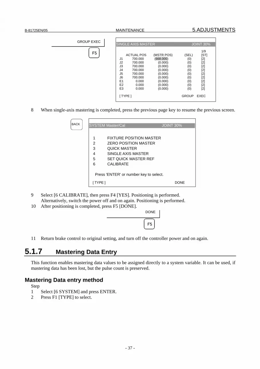
B-81725EN/05 MAINTENANCE 5.ADJUSTMENTS
- 37 -
SINGLE AXIS MASTER JOINT 30%
1/9 ACTUAL POS (MSTR POS) (SEL) [ST]
J1 700.000 (668.000) (0) [2] J2 700.000 (0.000) (0) [2] J3 700.000 (0.000) (0) [2] J4 700.000 (0.000) (0) [2] J5 700.000 (0.000) (0) [2] J6 700.000 (0.000) (0) [2] E1 0.000 (0.000) (0) [2] E2 0.000 (0.000) (0) [2] E3 0.000 (0.000) (0) [2] [ TYPE ] GROUP EXEC
GROUP EXEC
8 When single-axis mastering is completed, press the previous page key to resume the previous screen.
SYSTEM Master/Cal JOINT 30%
1 FIXTURE POSITION MASTER 2 ZERO POSITION MASTER 3 QUICK MASTER 4 SINGLE AXIS MASTER 5 SET QUICK MASTER REF 6 CALIBRATE Press 'ENTER' or number key to select. [ TYPE ] DONE
BACK
9 Select [6 CALIBRATE], then press F4 [YES]. Positioning is performed. Alternatively, switch the power off and on again. Positioning is performed. 10 After positioning is completed, press F5 [DONE].
DONE
11 Return brake control to original setting, and turn off the controller power and on again.
5.1.7 Mastering Data Entry This function enables mastering data values to be assigned directly to a system variable. It can be used, if mastering data has been lost, but the pulse count is preserved.
Mastering Data entry method Step 1 Select [6 SYSTEM] and press ENTER. 2 Press F1 [TYPE] to select.

5.ADJUSTMENTS MAINTENANCE B-81725EN/05
- 38 -
SYSTEM Variables JOINT 10%
1/98 1 $AP MAXAX 536870912 2 $AP PLUGGED 4 3 $AP TOTALAX 16777216 4 $AP USENUM [12] of Byte 5 $AUTOINIT 2 6 $BLT 19920216 [ TYPE ]
3 Change the mastering data. The mastering data is saved to the $DMR_GRP.$MASTER_COUN system variable.
SYSTEM Variables JOINT 10%
13 $DMR GRP DMR GRPT 14 $ENC STAT [2] of ENC STATT [ TYPE ]
4 Select $DMR_GRP.
JOINT 30% DMR GRPT
[2] of ENC STATT
SYSTEM Variables JOINT 10%
$DMR GRP 1/1
1 [1] DMR GRP T
SYSTEM Variables JOINT 10%
1/8 1 $MASTER DONE FALSE 2 $OT MINUS [9] of Boolean 3 $OT PLUS [9] of Boolean 4 $MASTER COUN [9] of Integer 5 $REF DONE FALSE 6 $REF POS [9] of Real 7 $REF COUNT [9] of Integer 8 $BCKLSH SIGN [9] of Boolean
[ TYPE ] TRUE FALSE
5 Select $MASTER_COUN, and enter the mastering data you have recorded.
JOINT30% FALSE [9] of Boolean [9] of Boolean [9] of Integer
SYSTEM Variables JOINT 10%
$DMR GRP [1].$MASTER COUN 1/9 1 [1] 95678329 2 [2] 10223045 3 [3] 3020442 4 [4] 304055030 5 [5] 20497709 6 [6] 2039490 7 [7] 0 8 [8] 0 9 [9] 0

B-81725EN/05 MAINTENANCE 5.ADJUSTMENTS
- 39 -
6 Press the previous page key. 7 Set $MASTER_DONE to TRUE
TRUE FALSE
F4
SYSTEM Variables JOINT 10%
$DMR GRP [1] 1/8 1 $MASTER DONE TRUE 2 $OT MINUS [9] of Boolean [ TYPE ] TRUE FALSE
8 Display the positioning screen, and select [6 CALIBRATE], then press F4 [YES]. 9 After completing positioning, press F5 [DONE].
DONE
5.2 CHECKING THE MASTERING 1 Checking whether mastering has been made correctly Usually, positioning is performed automatically at power-on. To check whether mastering has been
made correctly, note whether the displayed current position agrees with the actual robot position. Use the procedure described below:
(1) Reproduce a particular point in a program. Check whether the point agrees with the specified
position. (2) Set all axes of the robot to their 668mm positions. Check that the zero-degree position marks
indicated in Subsection 5.1.4 are aligned. There is no need to use any visual aid. (3) Using fixtures, set the robot to the mastering position in the same way as when performing
mastering. Check that the displayed current position agrees with the actual mastering position. If the displayed and actual positions do not match, the counter value for a Pulsecoder may have been
invalidated as a result of an alarm described below 2. Alternatively, the mastering data in system variable $DMR_GRP.$MASTER_COUN may have been overwritten as a result of an operation error or some other reason.
Compare the data with the values indicated on the supplied data sheet. This system variable is overwritten whenever mastering is performed. Whenever mastering is performed, record the value of the system variable on the data sheet.
2 Alarms that may be output during mastering and remedy for it
(1) BZAL alarm This alarm is output if the voltage of the Pulsecoder's backup battery falls to 0 V while the power
to the controller is disconnected. Also, if Pulsecoder connector is removed for replacing cables etc. this alarm is output because voltage becomes to 0. To clear the alarm, fit a new battery, execute the pulse reset (See Subsection 5.1.2.), then turn the power off then on again and confirm alarm is not output.
Battery might be weak if you can’t reset alarm, then replace battery to new one , perform pulse reset , turn off and on the controller power. Note that, if this alarm occurs, all data originally held by the Pulsecoder will have been lost. Mastering must be performed again.
(2) BLAL alarm
5.ADJUSTMENTS MAINTENANCE B-81725EN/05
- 40 -
This alarm is output if the voltage of the Pulsecoder's backup battery has fallen to a level where backup is no longer possible. If this alarm is output, fit a new battery immediately while keeping the power turned on. Check whether the current position data is valid, using the procedure described in 1.
(3) CKAL, RCAL, PHAL, CSAL, DTERR, CRCERR, STBERR, and SPHAL, alarms Contact the FANUC because the Pulsecoder may be defective.
B-81725EN/05 MAINTENANCE 6.REPLACING PARTS
- 41 -
6 REPLACING PARTS This section describes the replacement procedures for the major components of the mechanical section. When replacing mechanical components, be sure to follow the respective procedures. See Section 8 for how to replace the cables.
6.1 NOTE FOR PART REPLACEMENT Once motors are replaced, mastering becomes necessary. Perform mastering according to Section 5.1 after any of these components is replaced. Be very careful when carrying and assembling the heavy components listed below.
Table 6.1 Weight of the main parts Component Weight (approximate)
Servo motor (same motors used in M1 to M6) 6kg LEG unit. (See Fig. 6.3.) 19kg Wrist unit. (See Fig. 6.4.) 38kg
Controller (A cabinet) 120kg Controller (B cabinet) 180kg
In case of reusing seal bolts for F-200iB, observe following notes strictly. (If possible, change them to new seal bolts)
1) Apply LOCTITE 242 to female threads when the reusing seal bolts. 2) Notice the following 1 notes.
Remove excessive bits of sealant on the seal bolt.
NOTE When applying LOCTITE to the important bolt tightening points, make sure that it
is applied to the entire longitudinal portion in the engaging section of the female threads. If it is applied to the male threads, the bolts may be loosened because sufficient adhesion cannot be obtained. Remove the dust within the bolts and taps and wipe oil off the engaging section. Make sure that there is no solvent in the taps. Be sure to wipe the excess LOCTITE after tightening bolt.
NOTE 1 Description of [LT242] means LOCTITE 242. 2 Description of [LT262] means LOCTITE 262. 3 Description of [LT518] means LOCTITE 518. 4 Description of [LT7649] means LOCTITE 7649.
6.2 REPLACING MOTORS (FOR ALL AXES)
Remove 1 Remove the full cover (option) from the robot where applicable (see Section 6.5). 2 Set the robot to a posture with about the same lengths on all axes, and lift the top plate with a sling. 3 Set dial gauges at replacing axis, and prepare for single axis mastering after replacement. 4 Turn off the controller power. 5 Remove two connectors of the motor (1). 6 Remove four motor mounting bolts (2) and then remove the washer (3).
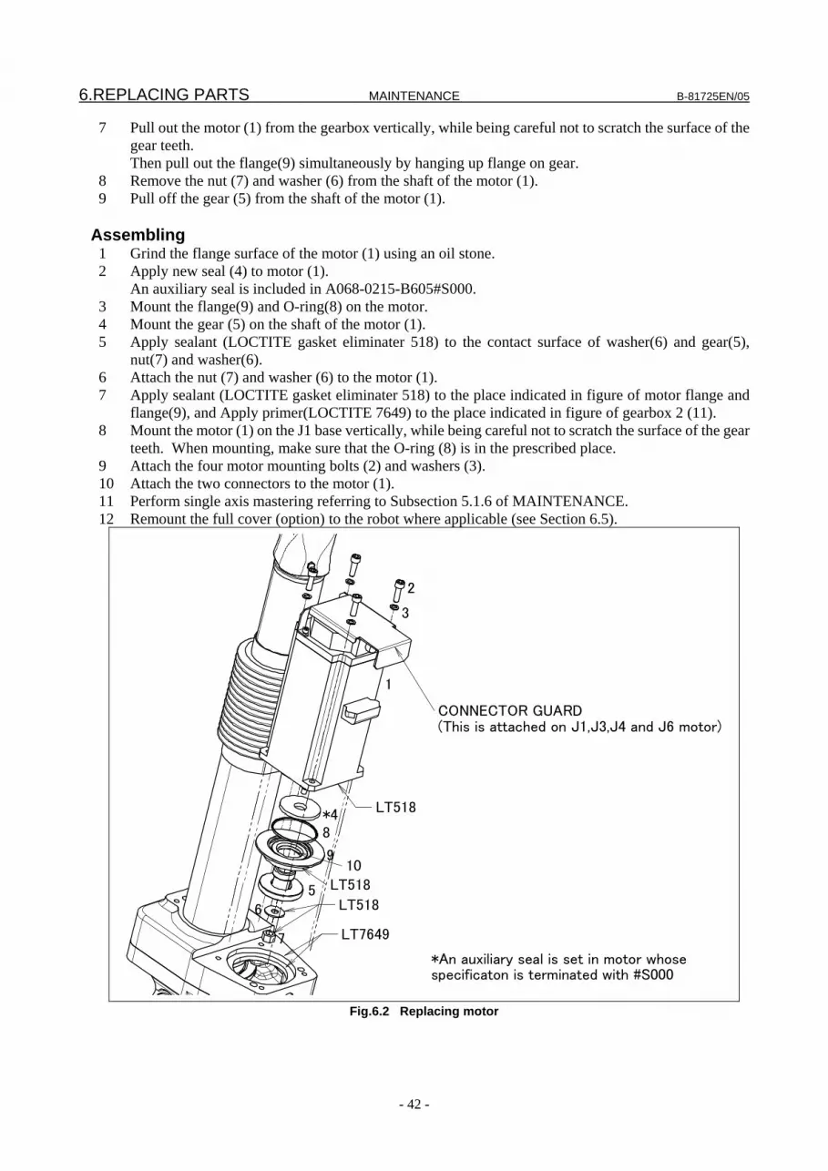
6.REPLACING PARTS MAINTENANCE B-81725EN/05
- 42 -
7 Pull out the motor (1) from the gearbox vertically, while being careful not to scratch the surface of the gear teeth.
Then pull out the flange(9) simultaneously by hanging up flange on gear. 8 Remove the nut (7) and washer (6) from the shaft of the motor (1). 9 Pull off the gear (5) from the shaft of the motor (1).
Assembling 1 Grind the flange surface of the motor (1) using an oil stone. 2 Apply new seal (4) to motor (1). An auxiliary seal is included in A068-0215-B605#S000. 3 Mount the flange(9) and O-ring(8) on the motor. 4 Mount the gear (5) on the shaft of the motor (1). 5 Apply sealant (LOCTITE gasket eliminater 518) to the contact surface of washer(6) and gear(5),
nut(7) and washer(6). 6 Attach the nut (7) and washer (6) to the motor (1). 7 Apply sealant (LOCTITE gasket eliminater 518) to the place indicated in figure of motor flange and
flange(9), and Apply primer(LOCTITE 7649) to the place indicated in figure of gearbox 2 (11). 8 Mount the motor (1) on the J1 base vertically, while being careful not to scratch the surface of the gear
teeth. When mounting, make sure that the O-ring (8) is in the prescribed place. 9 Attach the four motor mounting bolts (2) and washers (3). 10 Attach the two connectors to the motor (1). 11 Perform single axis mastering referring to Subsection 5.1.6 of MAINTENANCE. 12 Remount the full cover (option) to the robot where applicable (see Section 6.5).
1
2
3
*48
9
65
7
LT518
LT7649
LT518
10LT518
CONNECTOR GUARD(This is attached on J1,J3,J4 and J6 motor)
*An auxiliary seal is set in motor whosespecificaton is terminated with #S000
Fig.6.2 Replacing motor

B-81725EN/05 MAINTENANCE 6.REPLACING PARTS
- 43 -
Table 6.2 Replacing motor Name Specifications Q’ty LOCTITE Torque (N-m) 1 MOTOR A06B-0215-B605#S000 1 2 BOLT A6-BA-6X20 4 3 WASHER A97L-0001-0823#M6H 4 4 SEAL A98L-0004-0771#A25 1 5 GEAR 1 A290-7517-Y311 1 6 WASHER A290-7517-X321 1 LT518 7 NUT Contained in item 1. 1 LT242, LT518 7.4 8 O RING A98L-0001-0347#S50 1 9
FLANGE A290-7517-X320 1 LT518
10 OIL SEAL A98L-0040-0049#02504207 1 11 GEARBOX 2 A290-7517-X302 1 LT7649
6.3 REPLACING LEG UNITS (FOR ALL AXES)
Disassembly 1 Remove the full cover (option) from the robot where applicable (see Section 6.5). 2 Set the robot to a posture with an equal length of 820 mm or greater on all axes, and lift the total top
assembly (1) with a sling. 3 Set dial gauges at replacing axis, and prepare for single axis mastering after replacement. 4 Turn off the controller power. 5 Remove the two connectors of motor (2). 6 Cut off nylon band (3) on the pipe, and remove bellows (4). 7 Remove set screw (6) of pipe (5). 8 Remove pipe (5) from head (7). To do this, rotate pipe (5) while securing head (7) so that it is not
rotated. 9 Remove M10 bolt (8), M10 washer (9), M8 bolt (10), and M8 washer (11). Remove the leg unit
together with joint support 1 (12). Joint support 1 (12) faces the gearbox, and is opposite from the motor.
Assembly
1 Polish the joint support mounting surface of baseplate (13) with oil stone. 2 Insert joint pin (15) of a new LEG unit into joint support 1 (14). Tighten M10 bolt (8) and M10 washer
(9) with the specified torque. 3 Insert joint support 1 (12) and (14) into joint pin (15). Tack it with M10 bolt (16) and M10 washer (17),
then secure them to baseplate (13) with M8 bolts (10) and M8 washers (11). Finally, tighten M10 bolt (16) with the specified torque.
4 Mount pipe (5) to head (7). To do this, rotate pipe (5) while securing head (7) so that it is not rotated. 5 Mount set screw (6) of pipe (5). 6 Mount the two connectors to motor (2). 7 Perform single axis mastering referring to Subsection 5.1.6 of MAINTENANCE. 8 Secure bellows (4) to the pipe with nylon band (3). 9 Remount the full cover (option) to the robot where applicable (see Section 6.5).
NOTE When the pipe (5) is to be removed from and mounted to head (7), the width
across flat of the parallel portion of head (7) and the side of pipe (5) is used. Take great care so that impact and excessive force are not applied to the pipe (5) and head (7).
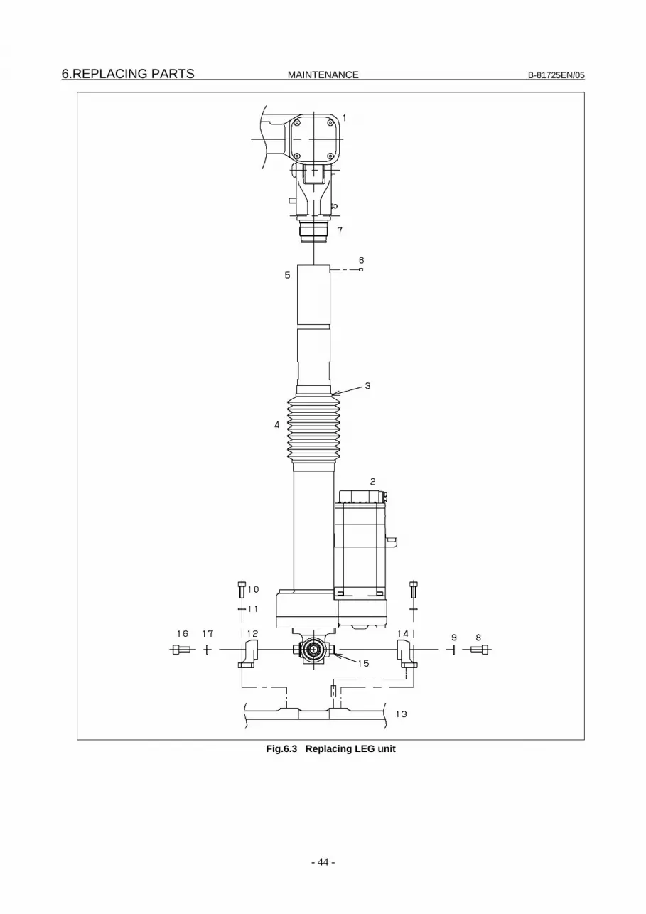
6.REPLACING PARTS MAINTENANCE B-81725EN/05
- 44 -
Fig.6.3 Replacing LEG unit

B-81725EN/05 MAINTENANCE 6.REPLACING PARTS
- 45 -
Table 6.3 Replacing LEG unit
Name Specifications Q’ty LOCTITE Torque (N-m)
1 TOTAL TOP ASSY A05B-1517-K501 1
2 MOTOR A06B-0215-B605#S000 1
3 NYLON BAND - 1
4 BELLOWS A290-7517-X316 1
5 PIPE A290-7517-X401 1
6 SET SCREW A6-SAKT-5X6 1
7 HEAD A290-7517-X402 1
8 BOLT A6-BA-10X20 1 LT262 76
9 WASHER A97L-0001-0823#M10H 1
10 BOLT A6-BA-8X20 4 LT262 37
11 WASHER A97L-0001-0823#M8H 4
12 JOINT SUPPORT 1 A290-7517-X303 1
13 BASE PLATE A290-7517-X201 1
14 JOINT SUPPORT 1 A290-7517-X303 1
15 JOINT PIN A290-7517-X306 1
16 BOLT A6-BA-10X20 1 LT262 76
17 WASHER A97L-0001-0823#M10H 1
6.4 REPLACING THE WRIST UNIT
Disassembly 1 Remove the full cover (option) from the robot where applicable (see Section 6.5). 2 Set the robot to a posture with an equal length of 820 mm or greater on all axes, and lift the total top
assembly (1) with a sling. 3 Set dial gauges at J1 to J6 axes, and prepare for single axis mastering after replacement. 4 Turn off the controller power. 5 Perform the following for each of the J1- to J6-axes.
1) Cut off nylon band (3) on the pipe, and remove bellows (4). 2) Remove set screw (6) of pipe (5). 3) Remove pipe (5) from head (7). To do this, rotate pipe (5) while securing head (7) so that it is not
rotated.
Assembly 1 Perform the following for each of the J1- to J6-axes.
1) Mount pipe (5) to head (7). To do this, rotate pipe (5) while securing head (7) so that it is not rotated.
2) Mount set screw (6) of pipe (5). 2 Perform single axis mastering referring to Subsection 5.1.6 of MAINTENANCE. 3 Secure bellows (4) on each axis to pipe (5) with nylon band (3). 4 Remount the full cover (option) to the robot where applicable (see Section 6.5).

6.REPLACING PARTS MAINTENANCE B-81725EN/05
- 46 -
NOTE 1 When pipe (5) is to be removed from and mounted to head (7), the width across
flat of the parallel portion of head (7) and the side of pipe (5) is used. Take great care so that impact and excessive force are not applied to pipe (5) and head (7).
2 After pipe (5) is removed from head (7), LEG unit (8) is slanted to keep the posture. At this time, take care so that no impact is applied to LEG unit (8).
Fig. 6.4 Replacing wrist unit
Table 6.4 Replacing wrist unit
Name Specifications Q’ty LOCTITE Torque (N-m) 1 TOTAL TOP ASSY A05B-1517-K501 1 2 MOTOR A06B-0215-B605#S000 6 3 NYLON BAND - 6 4 BELLOWS A290-7517-X316 6 5 PIPE A290-7517-X401 6 6 SET SCREW A6-SAKT-5X6 6 7 HEAD A290-7517-X402 6 8 WRIST - 6 9 TOTAL LEG ASSY A05B-1517-K311 6

B-81725EN/05 MAINTENANCE 6.REPLACING PARTS
- 47 -
6.5 REPLACING THE FULL COVER (OPTION)
Disassembly 1 Set the robot in a posture in such a way that its all axes are almost the same in length, and turn off the
power. 2 Remove the M8 screws (3), and then the plates (2). 3 Open Velcro fasteners C, B, and A in that order, and open the top plate Velcro fastener.
Assembly 1 Set the robot in a posture in such a way that its all axes are almost the same in length, and turn off the
power. 2 Put the jacket (1) on the robot so that Velcro fasteners A and B face to the connector panel. 3 Align their counterparts an the jacket (1) with the screw holes and top plate Velcro fastener, and fasten
the jacket with the M8 screws (3) and plates (2). 4 Close Velcro fasteners A and B in that order on the open/close part of the jacket (1). 5 Close Velcro fastener C on the support plate at the bottom of the robot.
Hole
Frame
C
1
2
3
AB
Magic tape part
Fig.6.5 Replacing full cover (option)
Table 6.5 Replacing full cover (option)
Name Specifications Q’ty LOCTITE Torque (N-m)
1 JACKET A290-7517-Y222 1
2 PLATE A290-7517-Y219 3
3 BOLT A6-BA-8X10 3 See the torque list in Appendix.
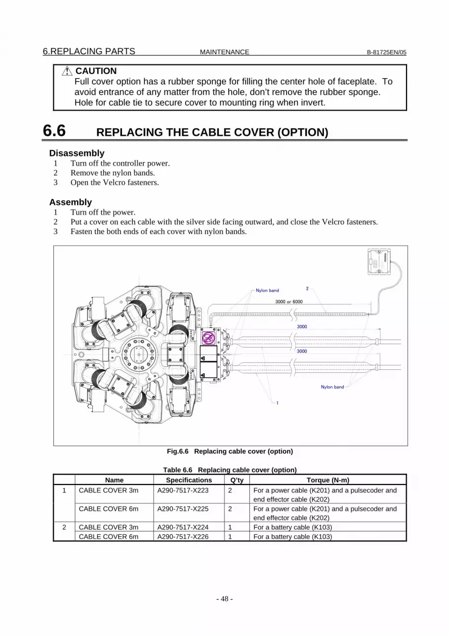
6.REPLACING PARTS MAINTENANCE B-81725EN/05
- 48 -
CAUTION Full cover option has a rubber sponge for filling the center hole of faceplate. To
avoid entrance of any matter from the hole, don’t remove the rubber sponge. Hole for cable tie to secure cover to mounting ring when invert.
6.6 REPLACING THE CABLE COVER (OPTION)
Disassembly 1 Turn off the controller power. 2 Remove the nylon bands. 3 Open the Velcro fasteners.
Assembly 1 Turn off the power. 2 Put a cover on each cable with the silver side facing outward, and close the Velcro fasteners. 3 Fasten the both ends of each cover with nylon bands.
‚‚�‚‚”‚”
‚…‚’‚
‰‚…
‚“(AM
1) ‚“
‚ˆ�‚‚
•‚Œ‚„
‚‚‚… ‚•
‚“‚…
‚„.O‚
Ž‚Œ
‚™ ‚”
‚‚̂…
�‚‚Œ‚‹
�‚‚Œ‚‰
‚Ž‚…
�‚�‚‚
Ž‚‡‚Ž
‚…‚“‚…
‚„‚‰
�‚‚˜‚‰
‚„‚…
‚‚‚… ‚“
‚•‚’‚…
‚”‚ˆ
�‚‚” ‚
”‚ˆ‚…
‚ƒ�‚‚
Ž‚”‚’
�‚‚Œ
�‚�‚‚
—‚…
‚’ ‚‰
‚“ �‚‚Ž.
W‚‚̂
…‚Ž
‚’‚…�‚‚Œ
�‚‚ƒ‚‰
‚Ž‚‡
‚‚�‚‚”‚”
‚…‚’‚
‰‚…
‚“(�‚‚
Ž‚ƒ‚…
�‚ ‚™
‚…�‚‚’)
Š£“d
’r(AM
1)‚ð
Žg—
p‚µ‚Ä
‰º‚³
‚¢.
ŒðŠ
·—p“
d’r‚É‚
̓Aƒ
‹ƒJƒ
Š-ƒ}ƒ
“ƒKƒ
““d
Œ¹‚ð
“ü‚ê‚
½�ó
‘Ô‚Å
�s‚È‚
Á‚ĉ
º‚³‚¢.
“d’r‚
ÌŒðŠ
·(1”N
‚É1‰
ñ)‚Í,
NC‚
Ì
3000
3000
3000 or 6000
Nylon band
Nylon band
1
2
Fig.6.6 Replacing cable cover (option)
Table 6.6 Replacing cable cover (option)
Name Specifications Q’ty Torque (N-m) CABLE COVER 3m A290-7517-X223 2 For a power cable (K201) and a pulsecoder and
end effector cable (K202) 1
CABLE COVER 6m A290-7517-X225 2 For a power cable (K201) and a pulsecoder and end effector cable (K202)
CABLE COVER 3m A290-7517-X224 1 For a battery cable (K103) 2 CABLE COVER 6m A290-7517-X226 1 For a battery cable (K103)
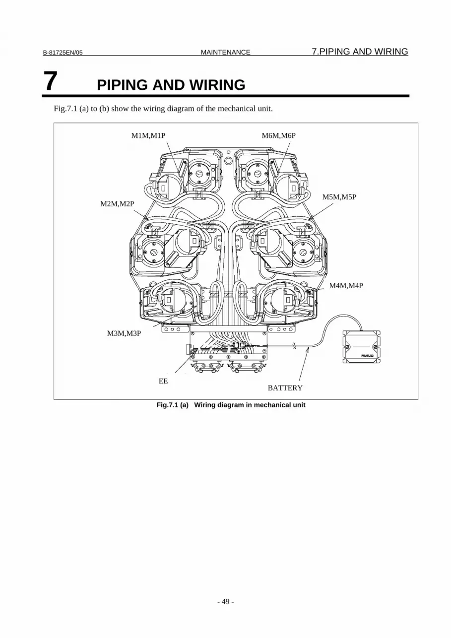
B-81725EN/05 MAINTENANCE 7.PIPING AND WIRING
- 49 -
7 PIPING AND WIRING Fig.7.1 (a) to (b) show the wiring diagram of the mechanical unit.
M2M,M2P
M3M,M3P
M1M,M1P M6M,M6P
M5M,M5P
M4M,M4P
EE BATTERY
Fig.7.1 (a) Wiring diagram in mechanical unit

7.PIPING AND WIRING MAINTENANCE B-81725EN/05
- 50 -
Fig.7.1 (b) Connector locations
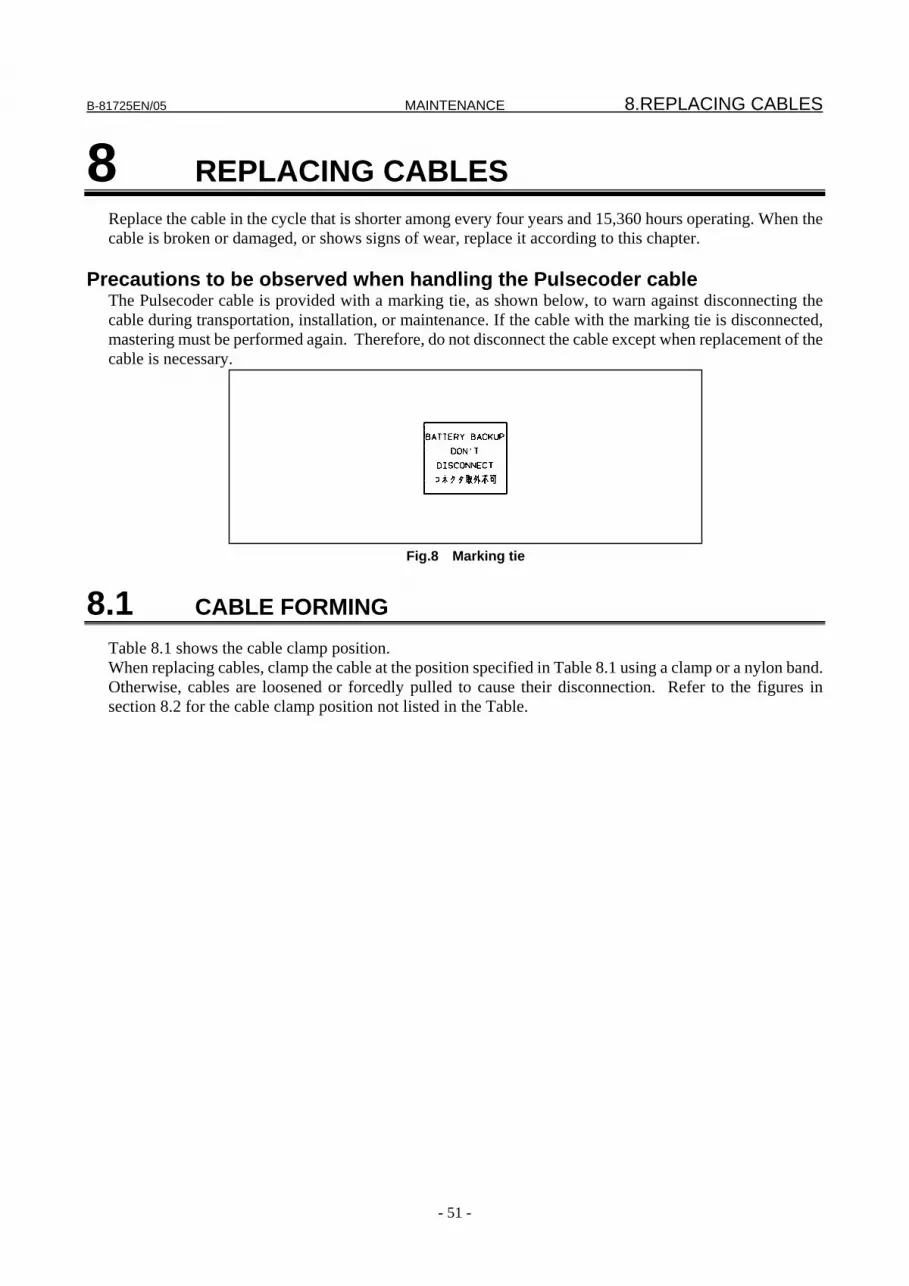
B-81725EN/05 MAINTENANCE 8.REPLACING CABLES
- 51 -
8 REPLACING CABLES Replace the cable in the cycle that is shorter among every four years and 15,360 hours operating. When the cable is broken or damaged, or shows signs of wear, replace it according to this chapter.
Precautions to be observed when handling the Pulsecoder cable The Pulsecoder cable is provided with a marking tie, as shown below, to warn against disconnecting the cable during transportation, installation, or maintenance. If the cable with the marking tie is disconnected, mastering must be performed again. Therefore, do not disconnect the cable except when replacement of the cable is necessary.
Fig.8 Marking tie
8.1 CABLE FORMING Table 8.1 shows the cable clamp position. When replacing cables, clamp the cable at the position specified in Table 8.1 using a clamp or a nylon band. Otherwise, cables are loosened or forcedly pulled to cause their disconnection. Refer to the figures in section 8.2 for the cable clamp position not listed in the Table.

8.REPLACING CABLES MAINTENANCE B-81725EN/05
- 52 -
Table 8.1 Cable clamp position
Cable clamp position Mark CableNo.
+
M1M
M2M
M3M
M4M
M5M
M6M
K103
RM1
K202(R-J3iB)orK302(R-30iA/R-30iB)
M1P
M2P
M3P
M4P
M5P
M6P
EE
RP1
-
+ -
K201
GB1A
EE K302
M1P K302
M2P K302
M4P K302
M3P K302
M5P K302
M6P K302 BATTERY BACKUP
DON'T
DISCONNECT
BATTERY BACKUP
DON'T
DISCONNECT
BATTERY BACKUP
DON'T
DISCONNECT
BATTERY BACKUP
DON'T
DISCONNECT
BATTERY BACKUP
DON'T
DISCONNECT
BATTERY BACKUP
DON'T
DISCONNECT
BATTERY BACKUP
DON'T
DISCONNECT
コネ クタ取外不可
-+
GB1 K103
D-3
32
1GB1
M1M K201
M2M K201
M3M K201
M4M K201
M5M K201
M6M K201
Each plate
Cable clamp 2Cable clamp 1
Neoprenesponge
Each plateCable clamp 2
Neoprenesponge
Cable clamp 1
Mark

B-81725EN/05 MAINTENANCE 8.REPLACING CABLES
- 53 -
8.2 CABLE REPLACEMENT This section describes a procedure for periodically replacing all the mechanical unit cables. If you need to replace a specific cable (because, for example, it is damaged), do so by referencing this section. See Section 7.1 for the configuration of the mechanical unit cables. Cable replacement makes it necessary to perform mastering. Before attempting replacement, therefore, see Section 5.1. The F-200iB has much wiring in its space. Before removing the cables, therefore, check how the cables run, with the robot at a posture with a length of 668 mm on all axes, by taking a picture or by other means.
Procedure for replacing cables K201, K202 and K302
Removal 1 Remove the full cover (option) from the robot where applicable (see Section 6.5). 2 Record the Quick Master Reference Position referring to Subsection 5.4.5 of MAINTENANCE. ( It is
set in 668mm for all axes when robot is shipped.) 3 Set the robot to a posture with a length of 668 mm on all axes and turn off the power to the controller. 4 Remove the controller cable from the connector panel located at the rear of the robot. 5 Remove the connectors from the motor. 6 Remove the nylon bands secured to the plates (plates 1, 2, and 3) of the gearbox for each axis. 7 Remove the nylon band secured to the plate (cable clamp 2) of the base plate. 8 Remove the nylon band secured to the plate (cable clamp 1) of the base plate. 9 Remove the connector panel cover, and remove the grounding cable and the housing from the
connector panel. For K202 and K302, also remove the EE connector and the battery connector.
Assembly 1 Mount new cables to the connector panel as shown in Fig. 8.2 (c). 2 Connect the cables as shown in Fig. 8.2 (a). Secure each cable to the corresponding plate of the base
plate at the marking position with a nylon band. Secure the cables for all axes to cable clamp 1 and the cables for the J1-, J2-, J5-, and J6-axes to cable clamp 2.
3 Secure each cable to the corresponding plate (plate 1, 2, or 3) of the gearbox for each axis at the marking position with a nylon band.
4 Mount the connectors to the motor. 5 Mount the controller cable to the connector panel. 6 Perform quick mastering. 7 Remount the full cover (option) to the robot where applicable (see Section 6.5).
NOTE Run each cable with great care so that its movable part does not come in contact
with the casting of the base plate and the gearbox. After connection, check the cables during operation because, even if the movable part does not come in contact while the robot is stationary, it may come in contact during operation depending on the operating posture.
In particular, the play portions on the J2- and J5-axes (See Fig. 8.2 (a)) must be formed upward so that they not come in contact with the base plate.
Procedure for replacing cable K103
Removal
1 Press the emergency stop button to perform the procedure while the power is on. Note that if the power is turned off, mastering is required.
2 Remove the battery box from the battery case.

8.REPLACING CABLES MAINTENANCE B-81725EN/05
- 54 -
3 Remove the +/- terminal and the nylon band secured to the battery box. 4 Remove the cable from the battery case, together with the rubber bushing located on the boundary
between the battery case and the outside. 5 Remove the connector panel cover. Remove the connector connected to K202 and the nylon band
secured to the connector panel. 6 Remove the cable from the connector panel, together with the rubber bushing located on the boundary
between the connector panel and the outside.
Assembly 1 Remove the +/- terminal rubber bushing from a new cable. 2 Run the +/- terminal from the inside of the connector panel through the K203-mounting hole. 3 Mount the connector rubber bushing to the connector panel and secure it to the connector panel with a
nylon band. 4 Connect the cable to the K202 (or K302) connector and secure it with a nylon band so that the
connector is not disconnected. 5 Mount the connector panel cover. 6 Mount the rubber bushing, removed in 1, to the cable again. 7 Run the +/- terminal from the outside of the battery case and mount the rubber bushing to the
K103-mounting hole of the battery case. 8 Mount the +/- terminal of the new cable to the battery box and secure it with a nylon band. 9 Secure the battery box to the battery case.
L L
F F
M4P
M5P
M6P
M3P
M2P
M1P
batteries(AM1) should be used.
Only the alkaline mangnese dioxide
be sure that the control power is on.
When replacing batteries(once a year)
乾電池(AM1)を使用して下さい.交換用電池にはアルカリ-マンガン電源を入れた状態で行なって下さい.電池の交換(1年に1回)は,NCの
I
I
J
J
E
E
GG
D
D
K
K
H
H
Battery box(Two countersunk 4X20 screws)
Battery case
Rubber bushing
Plate 1 Plate 2
Plate 1 Plate 2
Cable clamp 1
Plate 3
Plate 3
Rubber bushing
Connector panel cover(nine decorative M6X8)
Cable clamp 2
Must be formedupward so that is doesnot touch the base plate
Must be formedupward so that is doesnot touch the base plate
J
View J
Cable clamp 2
Fig.8.2 (a) Replacing the cable

B-81725EN/05 MAINTENANCE 8.REPLACING CABLES
- 55 -
Fig.8.2 (b) Replacing the cable
4M
4P6P
6M
5P
5M2M
2P
1M
1P
3M
3P
AA
Neopren sponge
Connector panelRM1 housing(four M4 X 10 screws)
RP1 housing(four M4 X 10 screws)
(Battery cable)(K103)
Earth cable(one M6X10 screw for each)
Rubber bushing
Must be secured with nylon bands.
Section AA
EE (four M3X5 screws)
Fig.8.2 (c) Replacing the cable
Sectional views


II. CONNECTION


B-81725EN/05 CONNECTION 1.ROBOT INTERFERENCE AREA
- 59 -
1 ROBOT INTERFERENCE AREA Fig.1 (a) shows the external dimensions of the robot. When installing peripheral devices, be careful to clear away any objects that are in the robot's motion path in normal operation. Fig.1 (b) shows the operation range of the robot.
325
609
700
800
650
Fig.1 (a) Mechanical unit operation area
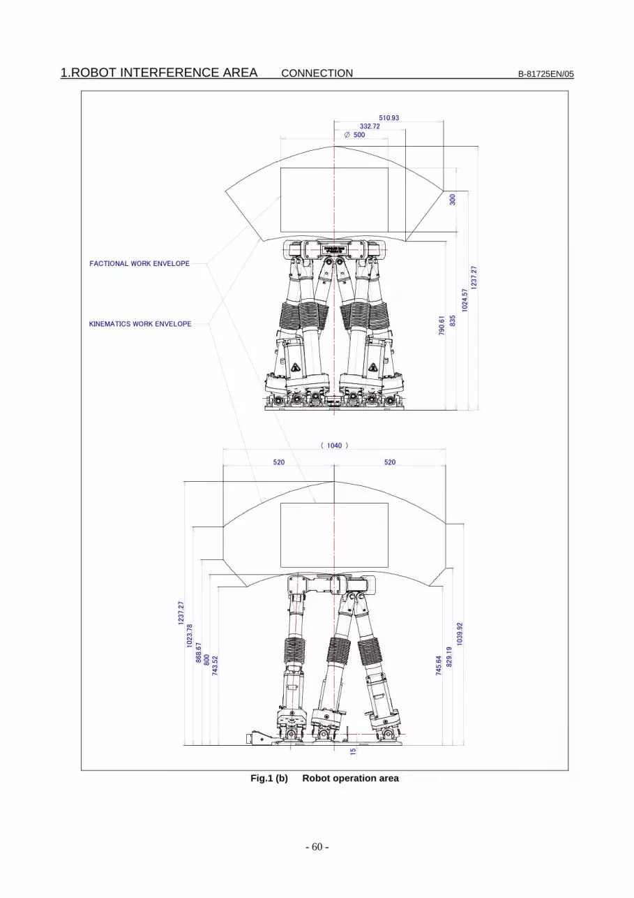
1.ROBOT INTERFERENCE AREA CONNECTION B-81725EN/05
- 60 -
1040( )
520 520
300
500O
790.
61
835
123
7.2
7
510.93332.72
1039
.92
829.1
9
745.6
4
743.5
2800
102
3.78
1237
.27
868.
67
15
1024
.57
FACTIONAL WORK ENVELOPE
KINEMATICS WORK ENVELOPE
Fig.1 (b) Robot operation area

B-81725EN/05 CONNECTION 2.MECHANICAL COUPLING TO THE ROBOT
- 61 -
2 MECHANICAL COUPLING TO THE ROBOT
2.1 WRIST LOAD CONDITIONS Fig.2.1 is diagram to limit loads applied to the wrist. Apply a load within the region indicated in the graph.
In:cm
X-Y permissible center of gravity position
+X
+Y
-40
-80 -60 -40 -20 80604020
-80
-60
-20
80
60
40
20
0
140kg
160kg
120kg100kg
80kg
60kg
100
100-100
-100
2 236kg・m (367kfg・cm・s )
-40≦Z≦40 (cm)
Z permissible center of gravity position
Allowable load inertia at wrist
+Y+Z
+X+Y+Z
+X
Fig.2.1 Wrist load diagram

2.MECHANICAL COUPLING TO THE ROBOT CONNECTION B-81725EN/05
- 62 -
2.2 MECHANICAL COUPLING OF END EFFECTOR TO WRIST Fig.2.2 (a) to (d) are the diagram for installing end effectors on the wrist. To fasten the end effector, first position it with two pin holes at C using fitting A or B, then lock it using six tapping screws at D. Select screws and positioning pins of a length that matches the depth of the tapped and pin holes.
O 90
(D) 6-M10 Depth 20 Equally spaced on circumference
90 ±0.05
(C) 2-O 10 depth 20 Equally spaced on circumference
AA'
+X
+Y
1100
-0.035(A) O
100O
70O
13
510
60+0.0350O
Section AA'
R2 C1C1
C1
l O 0.15 P
+0.015 0
P
Fig.2.2 (a) End effector mounting face (standard flange)
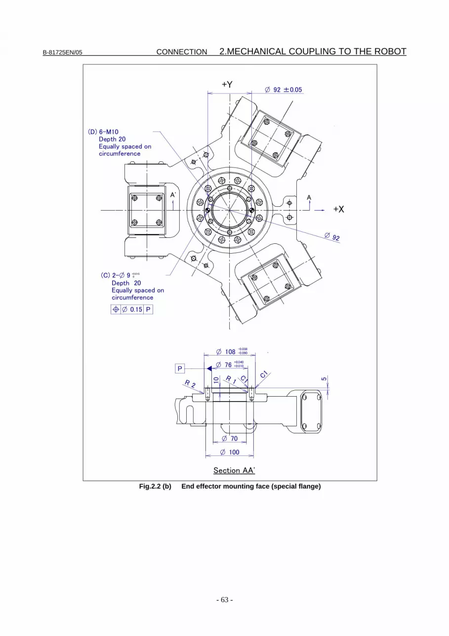
B-81725EN/05 CONNECTION 2.MECHANICAL COUPLING TO THE ROBOT
- 63 -
AA'
+X
+Y
Section AA'
l O 0.15 P
+0.015 0
O 92
100O
70O
5
108-0.038-0.090O
76+0.040+0.010O
10 C1
R 2
(D) 6-M10 Depth 20 Equally spaced on circumference
(C) 2-O 9 Depth 20 Equally spaced on circumference
C1R 1
P
92 ±0.05O
Fig.2.2 (b) End effector mounting face (special flange)

2.MECHANICAL COUPLING TO THE ROBOT CONNECTION B-81725EN/05
- 64 -
Y
AA'
+X
+Y
Section AA'
l O 0.15 P
+0.015 0
90O
100O
10 5
1600
-0.063O
80+0.0300O
10
C1 C1
P
(D) 6-M10 Depth 20 Equally spaced on circumference
(C) 2-O 10 Depth 20 Equally spaced on circumference
O 125
125 ±0.05O
Fig.2.2 (c) End effector mounting face (ISO flange-not insulated)

B-81725EN/05 CONNECTION 2.MECHANICAL COUPLING TO THE ROBOT
- 65 -
(D) 6-M10 Depth 20 Equally spaced on circumference
AA'
+X
+Y
Section AA'
l O 0.15 P
+0.015 0
90O
100O
10 10
5
O 125
(C) 2-O 10 Depth 20 Equally spaced on circumference
125 ±0.05O
1600
-0.063O
80+0.0300O
C1C1
Fig.2.2 (d) End effector mounting face (insulated ISO flange)

2.MECHANICAL COUPLING TO THE ROBOT CONNECTION B-81725EN/05
- 66 -
2.3 SETTING THE LOAD Enter the mass and the inertia of the hand mounted to the wrist, as described below: (1) Press MENUS to display the screen menu. (2) Press zero for next screen and select SYSTEM. (3) Press F1, TYPE, to display the screen switching menu and select variable. (4) Select item MOTION. The load setting number selection screen is displayed. Select the load
setting number used. (5) Press F3, DETAIL, to display the load setting screen. (6) Enter the load weight, the position of the center of gravity of the load, and the load inertia. The
load weight and the load inertia, as used here, refer to the X, Y, and Z coordinates and the inertia about the X-, Y-, and Z-axes in the absolute coordinate system with its origin at the center of the flange, with the robot being set to a posture with zero degrees.
MOTION/PAYLOAD SET JOINT 10% 1/8
Group 1
1 Schedule No [ 1]: [ ] 2 PAYLOAD [kg] 100.00
3 PAYLOAD CENTER X [cm] 60.00 4 PAYLOAD CENTER Y [cm] 0.00
5 PAYLOAD CENTER Z [cm] 0.00 6 PAYLOAD INERTIA X [kgfcms^2] 361.00
7 PAYLOAD INERTIA Y [kgfcms^2] 0.00 8 PAYLOAD INERTIA Z [kgfcms^2] 361.00
Fig.2.3 Setting load

B-81725EN/05 CONNECTION 2.MECHANICAL COUPLING TO THE ROBOT
- 67 -
2.4 END EFFECTOR INTERFACE
WARNING ・ Use mechanical unit cables that have required user interface. ・ Don’t add user cable or hose to inside of mechanical unit. ・ Please do not obstruct the movement of the mechanical unit cable when cables are
added to outside of mechanical unit. ・ Please do not perform remodeling (Adding a protective cover and fix an outside cable
more) obstructing the behavior of the outcrop of the cable. ・ Please do not interfere with the other parts of mechanical unit when equipment is
installed in the robot. ・ Cut unnecessary length of wire rod. Make insulation processing like winding acetate
tape. (See Fig.2.4 (a)) ・ If you can not prevent electrostatic charge of work and end effector, keep away an
end effector (a hand) cable from an end effector and a work as much as possible, when wiring it. When they come to close unavoidable, make insulation processing between them.
・ Be sure to seal connectors of hand side and robot side and terminal parts of cables, to prevent water from entering the mechanical unit. Also, attach cover to unused connector.
・ Check looseness of connector and wound of coating of cables routinely. When these attentions are not kept, unexpected troubles might occur.
Cut unnecessary length of unused wire rod Insulation processing
End effector (hand) cable
Fig.2.4 (a) Treatment method of end effector (hand) cable
Fig. 2.4 (b) shows the position of the optional cable interface. The end effector (RDI/RDO) or (RI/RO) is provided as standard.

2.MECHANICAL COUPLING TO THE ROBOT CONNECTION B-81725EN/05
- 68 -
EE
Detail A
A
EE
Fig.2.4 (b) Position of the EE interface
Fig. 2.4 (c) and (d) show the pin arrangement of the EE interface (RDI/RDO) or (RI/RO).
WARNING The RDO signal for the R-J3iB controller and the RO signal for the
R-30iA/R-30iB controller are incompatible with each other because different output formats are used. For details, refer to the Chapter 4 of CONNECTION of controller maintenance manuals.

B-81725EN/05 CONNECTION 2.MECHANICAL COUPLING TO THE ROBOT
- 69 -
4
RDO4
RDI3RDI8
Endeffector
EE interface (RDI/RDO) (Output)
Controller
W2524F(Fujikura.Ltd)
3 2 1RDO3 RDO2 RDO1
9RDI1
80V
7XHBK
6RDO6
5RDO5
15RDI5
14 13 12 11 10XPPABN RDI4 RDI2
2024VF(A4)
19 18 17 1624VF(A3) 24VF(A2) 24VF(A1) RDI6
24 23 22 21RDI7 RDO8 RDO7 Please prepare by user.
XHBK : Hand broken
XPPABN : Pneumatic pressure abnormal
Fig. 2.4 (c) Pin arrangement (R-J3iB) of the EE interface (RDI/RDO).
4RO4
RI3RI8
3 2 1RO3 RO2 RO1
9RI1
80V
7XHBK
6RO6
5RO5
15RI5
14 13 12 11 10XPPABN RI4 RI2
2024V
19 18 17 1624V 24V 24V RI6
24 23 22 21RI7 0V RO8 RO7
Controller
Please prepare by user.
EE interface (RI/RO) (Output)
XHBK : Hand broken
XPPABN : Pneumatic pressure abnormal
Endeffector
W2524F(Fujikura.Ltd)
Fig. 2.4 (d) Pin arrangement (R-30iA/R-30iB) of the EE interface (RI/RO).
Connector specifications
Table 2.4 (a) Connector specifications (Mechanical Unit) Cable name Output (connector panel) Maker/Dealer
RDI/RDO or RI/RO
JMR2524F Fujikura.Ltd
Table 2.4 (b) Connector specifications (User)
Cable name Output (connector panel) Maker/Dealer RDI/RDO or RI/RO
JMSP2524M straight plug (supplied) (FANUC spec.: A63L-0001-0234#S2524M) JMLP2524M angle plug
Fujikura.Ltd
NOTE For details of dimensions and for other information, refer to the catalog available
from the manufacturer or contact FANUC.
3.TRANSPORTATION AND INSTALLATION CONNECTION B-81725EN/05
- 70 -
3 TRANSPORTATION AND INSTALLATION
3.1 TRANSPORTATION 1) Transportation using a crane
The robot can be transported by lifting it. When transporting the robot, be sure to change the posture of the robot to that shown in Fig.3.1 (a) and lift by attaching sling to the three M10 eyebolts.
2) Transportation using a forklift
The robots can also be transported using a forklift (Refer to Fig.3.1 (b)). Transport materials are available as an option.
CAUTION For the F-200iB, the battery case is separate and, therefore, transport the robot
with the battery case secured to the connector panel together with the cable of about 7 m, as shown in Fig. 3.1 (a) and (b).
WARNING When tools or additional units are attached, the center of gravity of the robot
deviates, possibly causing instability during transportation. If the robot becomes unstable, remove the tools and take the transportation posture. This returns the center of gravity to the normal position. It is recommended that tools and additional units be transported separately from the robot.
The forklift transportation materials can be used only for transportation with a
forklift. Do not use the forklift transportation materials for other transportation means. Do not use the transportation materials to fix the robot.
Before transporting the robot with the transporting materials, check the fixing
bolts of the transportation materials and tighten the loose bolts. Do not lift using forklift or crane with base plate attached.

B-81725EN/05 CONNECTION 3.TRANSPORTATION AND INSTALLATION
- 71 -
Crane capacity min 1.0 tonSling capacity min 0.5 ton/sling
NOTE) 1.Machine weight is approximately 190kg 2.Eyebolts complied with JISB 1168. 3. Quantity eyebolt 4 sling 4 4.Do not ship with a tool exceeding the rated load attached. 5.Do not lift robot with a plate attached.
668 mm
J2 AXIS
J3 AXIS
J4 AXIS
J5 AXIS
J6 AXIS
Robot posture on transportation
J1 AXIS
668 mm
668 mm
668 mm
668 mm
668 mm
Battery case
742
M10 tap depth 20
650
800
Eyebolt(M10)
Fig.3.1 (a) Transportation using a crane

3.TRANSPORTATION AND INSTALLATION CONNECTION B-81725EN/05
- 72 -
743
200
100
137
200
100
137
800
(1140)570 570
Battery case
668 mm
J2 AXIS
J3 AXIS
J4 AXIS
J5 AXIS
J6 AXIS
Robot posture on transportation
J1 AXIS668 mm
668 mm
668 mm
668 mm
668 mm
NOTE) 1.Machine weight is approximately 190Kg. 2.Do not ship with heavy tooling 3. Do not lift robot with plate for fix.
Fork lift (Capacity: min 1.0 ton)
Fig.3.1 (b) Transportation using a forklift
3.2 INSTALLATION Fig.3.2 (a) shows the robot base dimensions. Fig.3.2 (b) shows actual examples of robot installation. In Fig.3.2 (b), the floor plate is imbedded in concrete and fastened with four M20 (strength classification 4.8) chemical anchors. Also fasten the block to the robot base using nine M16×35 bolts (strength classification 12.9). Next, position the robot, and weld the base plate to the floor plate. (Foot length is 10 to 15mm.) Use hexagon socket bolts as the M16×35 bolts and embed their heads in the counterbored holes without placing washers. It is recommended that the flatness of the block be 0.01 (Blocks are provided as options.)

B-81725EN/05 CONNECTION 3.TRANSPORTATION AND INSTALLATION
- 73 -
126.5
248
248
700
220
220
260
260
609
For robot positioning9-O18 throughtO28 C' BORE DP7
325
650
14277.5
177.5
177.5
189
284.073 u0.1 314.927
185u0
.1185u0
.1
80 44For robot positioning2-O8H8 through
162 103.5 313.5144
144
231.5
231.5 1
26.5
110
O8
H8+0.0220
Robot center (center of flange)
Front
82
82
Fig.3.2 (a) Dimensions of the robot base

3.TRANSPORTATION AND INSTALLATION CONNECTION B-81725EN/05
- 74 -
ロボット固定ボルト: 六角穴付きボルト M16x35(9 本) 強度区分:12.9 締付けトルク:310Nm(32kgfm) ワッシャを入れないこと
Fig.3.2 (b) Actual installation example
Pin for positioning robot
Welding position
Robot center (center of flange)
Block (plane0.01deg)
Base plate
Weld after positioning
Block (plane0.01deg)
Robot mounting bolt: Hexagon socket head cap screw M16×35 (9pcs) Strength classification: 12.9 Tightening torque:310Nm(32kgfm) Don’t insert washers
Chemical anchor : M20 (4pcs) Strength classification : 4.8Tightening torque : 19kgm
Base plate
Note) Bury the base plate in concrete.

B-81725EN/05 CONNECTION 3.TRANSPORTATION AND INSTALLATION
- 75 -
CAUTION 1 Parts to be provided by the customer:
- Robot mounting bolts : Hexagon socket head cap screw (Strength classification 12.9) 9pcs.
- Chemical anchors : M20 (strength classification 4.8) 4pcs.
- Block : thickness 32t 1pcs. - Floor plate : thickness 32t 1pcs. - Straight pin : φ8 2pcs.
2 Please use hexagon socket head cap screw for the robot mounting bolt, and bury the bolt head into the bore without washers.
3 Peripheral device parts, such as connection cables for devices, should not be place on the robot base. Don’t operate the robot with maintenance tools or any foreign objects on the robot. It will cause damage of mechanical unit by interference.
4 Daily cleaning of the robot base to be performed, especially the robot is placed in an environment that suffers a large accumulation of foreign matters. In such severe environment, full cover option is recommended to avoid interference trouble.
5 Installation work (welding, anchoring, etc.) is prepared by the customer.
Fig. 3.2 (d) and Table 3.2 (a) show the force and the moment that apply to the base plate at Power-Off stop time and at acceleration/deceleration time and at reset time. Table 3.2 (b) indicates the coasting time and distance until the robot stopping by Power-Off stop or by Controlled stop after input of the stop signal. Fig.3.2 (c) indicate the measurement condition.
Table 3.2 (a) Force and moment apply to the base plate
Vertical moment MV [kNm (kgfm)]
Force in vertical direction
FV [kN (kgf)]
Horizontal moment MH [kNm (kgfm)]
Force in horizontal direction
FH [kN (kgf)]
At Power-Off stop 2.25 (230) 70.6 (7200) 10.8 (1100) 44.1 (4500)
At acceleration/ deceleration
0.49 (50) 44.1 (4500) 1.27 (130) 27.4 (2800)
At reset 0.00 (0) 29.4 (3000) 1.08 (110) 18.6 (1900)
Table 3.2 (b) Stopping time and distance until the robot stopping by Power-Off stop
after input of stop signal Motion & Conditions Time
(msec) Distance
(mm) ΔW,ΔP,ΔR
(deg) (-519,0,1023,0,0,0) to (519,0,1023,0,0,0), Estop at X=0 150 189 0.245, 0.340, 0.269
(0,510,1025,0,0,0) to (0,-510,1025,0,0,0), Estop at Y=0 190 145 0.165, 1.178, 8.999
(0,0,835,0,0,40) to (0,0,835,0,0,-40), Estop at R=0 150 16 0.185,0.326,12.314
Table 3.2 (c) Stopping time and distance until the robot stopping by Controlled stop
after input of stop signal Motion & Conditions Time
(msec) Distance
(mm) (0,510,1025,0,0,0) to (0,-510,1025,0,0,0), Controlled stop at Y=150 500 636
(-519,0,1023,0,0,0) to (519,0,1023,0,0,0), Controlled stop at X=-160 540 672

3.TRANSPORTATION AND INSTALLATION CONNECTION B-81725EN/05
- 76 -
Measure point(Center of the flange)
+Y+Z
+X+Y+Z
+XWP
R
Center of the gravity of the work
Weight of work100kg
Center ofthe flange
Fig.3.2 (c) Measurement condition
F
HF
V
VM
HM
Fig.3.2 (d) Force and moment apply to the baseplate For the F-200iB, the battery case is tacked at the position identified in Fig. 3.1 (a) before delivery. The customer is responsible for securing the battery case to an outside, safe location. Fig 3.2 (d) shows the outline drawing of the battery case.

B-81725EN/05 CONNECTION 3.TRANSPORTATION AND INSTALLATION
- 77 -
Fig.3.2 (e) Battery case
3.3 MAINTENANCE AREA Fig. 3.3 shows the layout of the maintenance space.
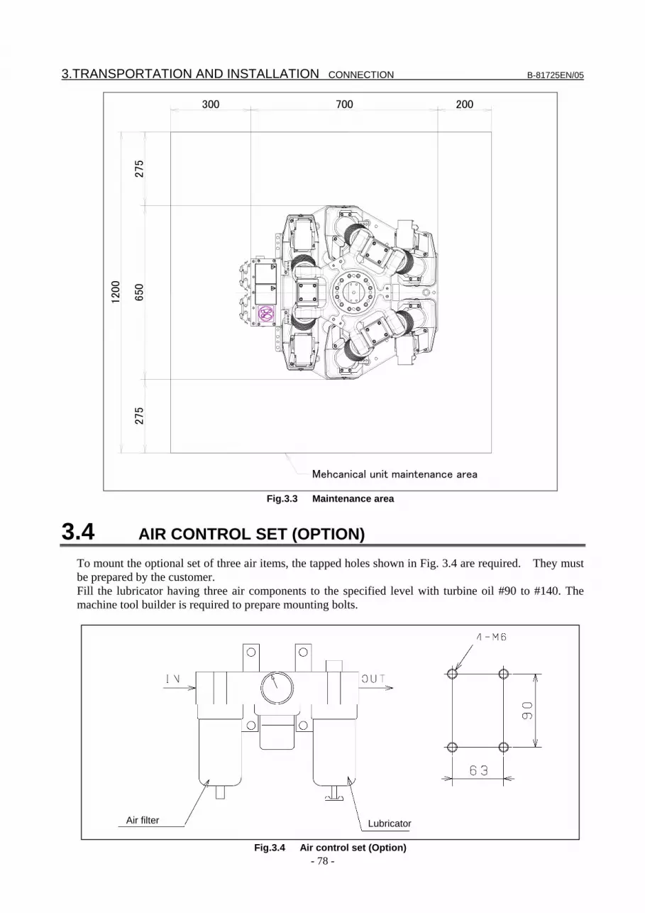
3.TRANSPORTATION AND INSTALLATION CONNECTION B-81725EN/05
- 78 -
120
0
275
650
275
700 200300
Mehcanical unit maintenance area
Fig.3.3 Maintenance area
3.4 AIR CONTROL SET (OPTION) To mount the optional set of three air items, the tapped holes shown in Fig. 3.4 are required. They must be prepared by the customer. Fill the lubricator having three air components to the specified level with turbine oil #90 to #140. The machine tool builder is required to prepare mounting bolts.
Fig.3.4 Air control set (Option)
Air filter Lubricator

B-81725EN/05 CONNECTION 3.TRANSPORTATION AND INSTALLATION
- 79 -
3.5 INSTALLATION SPECIFICATIONS Refer to specification of “PREFACE” about installation specifications.
3.6 STORAGE To store the robot, set it to the same posture as that used for transportation. (See II- 3.1)


APPENDIX


B-81725EN/05 APPENDIX A.SPARE PARTS LISTS
- 83 -
A SPARE PARTS LISTS Table A (a) Cables
(a) R-J3iB controller No. Specifications Function Remarks
K201 A660-8014-T495 J1 to J6 POWER K202 A660-8014-T496 J1 to J6 PULSECODER
+END EFFECTOR
K103 A05B-1517-D001 BATTERY (b) R-30iA/ R-30iB controller
No. Specifications Function Remarks K201 A660-8014-T495 J1 to J6 POWER K302 A660-8015-T880 J1 to J6 PULSECODER
+END EFFECTOR
K103 A05B-1517-D001 BATTERY
Table A (b) Motor Axis Specifications Remarks
J1 to J6 A06B-0215-B605#S000 (ModelαM4/5000i)
ModelαiS4/5000
NOTE: A motor whose specification number is terminated with #S000 has the built-in auxiliary seal. When ordering a motor, specify a motor whose specification number is terminated with #S000.
Table A (c) Battery grease
Name Specifications Remarks Battery A98L-0031-0005 1.5V, size D Grease A98L-0040-0174#2KG Kyodo Yushi
VIGOGREASE RE0 Grease A97L-0001-0179#2 Shell Alvania Grease S2
Table A (d) Total units
Name Specifications Remarks Total leg assembly A05B-1517-K311 Leg unit (T301 and motor) Total top assembly A05B-1517-K501 Top plate unit (T401 and T501)
Table A (e) Other parts
Name Specifications Remarks Bellows A290-7517-X316 Stopper A290-7517-X315 Top portion of the ball screw Flange A290-7517-X320
Table A (f) Units
Name Specifications Remarks Leg assembly A290-7517-T301 Pipe assembly A290-7517-T401
Top plate assembly A290-7517-T501
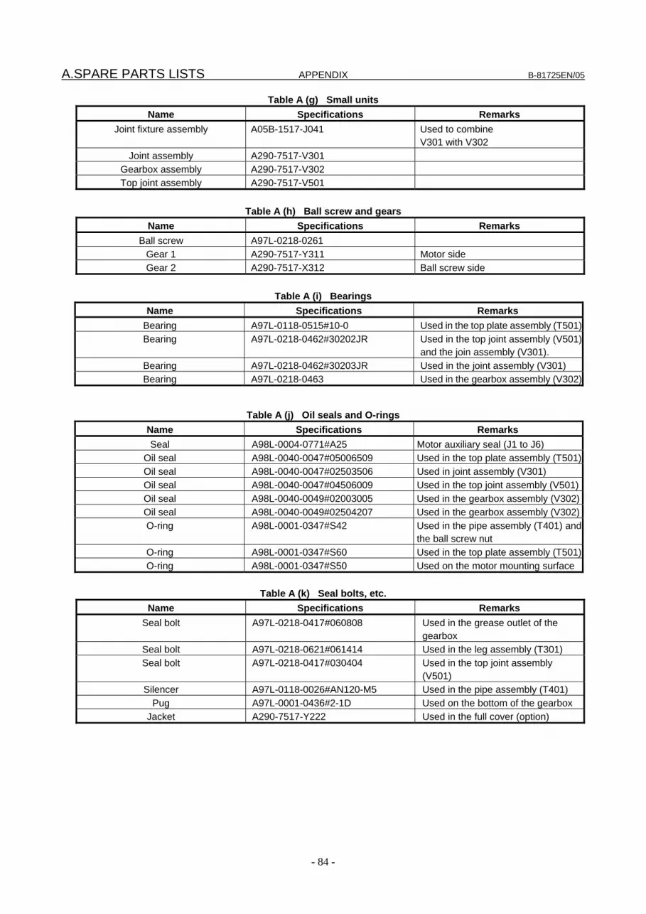
A.SPARE PARTS LISTS APPENDIX B-81725EN/05
- 84 -
Table A (g) Small units Name Specifications Remarks
Joint fixture assembly A05B-1517-J041 Used to combine V301 with V302
Joint assembly A290-7517-V301 Gearbox assembly A290-7517-V302 Top joint assembly A290-7517-V501
Table A (h) Ball screw and gears
Name Specifications Remarks Ball screw A97L-0218-0261
Gear 1 A290-7517-Y311 Motor side Gear 2 A290-7517-X312 Ball screw side
Table A (i) Bearings
Name Specifications Remarks Bearing A97L-0118-0515#10-0 Used in the top plate assembly (T501)Bearing A97L-0218-0462#30202JR Used in the top joint assembly (V501)
and the join assembly (V301). Bearing A97L-0218-0462#30203JR Used in the joint assembly (V301) Bearing A97L-0218-0463 Used in the gearbox assembly (V302)
Table A (j) Oil seals and O-rings Name Specifications Remarks Seal A98L-0004-0771#A25 Motor auxiliary seal (J1 to J6)
Oil seal A98L-0040-0047#05006509 Used in the top plate assembly (T501)Oil seal A98L-0040-0047#02503506 Used in joint assembly (V301) Oil seal A98L-0040-0047#04506009 Used in the top joint assembly (V501)Oil seal A98L-0040-0049#02003005 Used in the gearbox assembly (V302)Oil seal A98L-0040-0049#02504207 Used in the gearbox assembly (V302)O-ring A98L-0001-0347#S42 Used in the pipe assembly (T401) and
the ball screw nut O-ring A98L-0001-0347#S60 Used in the top plate assembly (T501)O-ring A98L-0001-0347#S50 Used on the motor mounting surface
Table A (k) Seal bolts, etc.
Name Specifications Remarks Seal bolt A97L-0218-0417#060808 Used in the grease outlet of the
gearbox Seal bolt A97L-0218-0621#061414 Used in the leg assembly (T301) Seal bolt A97L-0218-0417#030404 Used in the top joint assembly
(V501) Silencer A97L-0118-0026#AN120-M5 Used in the pipe assembly (T401)
Pug A97L-0001-0436#2-1D Used on the bottom of the gearbox Jacket A290-7517-Y222 Used in the full cover (option)

B-81725EN/05 APPENDIX B.CONNECTION DIAGRAM
- 85 -
B CONNECTION DIAGRAM

B.CONNECTION DIAGRAM APPENDIX B-81725EN/05
- 86 -
GB1A AMP 031KSFX
R2524F
4 3 2 19 8 7 6 5
15 14 13 12 11 1020 19 18 17 16
24 23 22 21
(0.5SQ 5A)φ9.6-φ15
0V(D1)
RDI7
RI9(XPPABN)
24VF(A3) 24VF(A2) 24VF(A1) RDI5
RDI1 RDO4 RDO3 RDO2 RDO1
RDO5 RDO6 RDI8 RDI4 RDI3 RDI2
RDO8 RDO7 RDI6
XHK
K201A660-8014-T495
K201A660-8014-T495
K201A660-8014-T495
K201A660-8014-T495
K201A660-8014-T495
K201A660-8014-T495
K202A660-8014-T496
K202A660-8014-T496
K202A660-8014-T496
K202A660-8014-T496
K202A660-8015-T496
K202A660-8015-T496
21 6V(BT7) 0V(BT7) 3
BASE-PLATE CONNECTOR PANEL
END EFFECTOR INTERFACE
J4G1 J4W1 J3V1
J1V1
RM1 Han 42DD(2.5SQ 10A)
M TYPE
J6G1 J6W1 J5G1 J5U1
J6V1 J6U1 BKC(J6) J5W1 J5V1
36
J2G1
424140
393837 J2W1
353433
323130
29158
J4V1
J2V1
282726
252423
22
J4U1
212019
181716
BKC(J5)
141312
11109
BK7 BK5
765
432
1 FGG
BK1
BK2
BK3 BK4
BKC(J1)
BKC(J2)
BKC(J3) BKC(J4)
J1U1
J3U1 J2U1
J3W1 J3G1
J1G1 J1W1
BATTERY
+
-
6V(BT1,BT2,BT3, BT4,BT5,BT6, BT7)
0V(BT1,BT2,BT3, BT4,BT5,BT6, BT7)
K103A05B-1517-D001
RDO4
RDI4
RP1 Han 42DD(2.5SQ 10A)
M TYPE
XPRQJ6
PRQJ6 XPRQJ5 PRQJ5
0V(C1,C2) 5V(C1,C2)
XPRQJ4
PRQJ4
XPRQJ3
PRQJ3
XPRQJ2
PRQJ2 0V(B1,B2) 0V(A1,A2)
36 24E(OT)
42
414039
3837 XROT
35
343332
313029158
0V(E1,E2)
XHBK
28
272625
242322
24VF(A1,A2,A3,A4)
21
201918
1716
5V(B1,B2)
14
131211
109
XPRQJ1
PRQJ1 5V(A1,A2)
7
654
321
FGG
RDI1 RDI7
RDO1 RDO7
RDI2 RDI8
RDO2 RDO8
RDI3
RDO3 XPPABN
RDO5 RDO6
RDI6 RDI5
Fig.B (a) Internal connection diagram ( R-J3iB controller)

B-81725EN/05 APPENDIX B.CONNECTION DIAGRAM
- 87 -
5V(A1) 123
4567
8910 0V(A1)
0V(BT1)
6V(BT1) XPRQJ1 PRQJ1
FG
M1M/M1BK
M1P 10SL1(0.3SQ 3A)
A63L-0001-0874
5V(A2) 123
4567
8910 0V(A2)
0V(BT2)
6V(BT2) XPRQJ2 PRQJ2
FG
M2M/M2BK
M2P 10SL1(0.3SQ 3A)
A63L-0001-0874
5V(B1) 123
4567
8910 0V(B1)
0V(BT3)
6V(BT3) XPRQJ3 PRQJ3
FG
M3M/M3BK
M3P 10SL1(0.3SQ 3A)
A63L-0001-0874
5V(B2) 123
4567
8910 0V(B2)
0V(BT4)
6V(BT4) XPRQJ4 PRQJ4
FG
M4M/M4BK
M4P 10SL1(0.3SQ 3A)
A63L-0001-0874
J1 MOTOR (αiS4/5000 with BRAKE)
J2 MOTOR (αiS4/5000 with BRAKE)
J3 MOTOR (αiS4/5000 with BRAKE)
J4 MOTOR (αiS4/5000 with BRAKE)
5V(C1) 123
4567
8910 0V(C1)
0V(BT5)
6V(BT5) XPRQJ5 PRQJ5
FG
M5M/M5BK
M5P 10SL1(0.3SQ 3A)
A63L-0001-0874
J5 MOTOR (αiS4/5000 with BRAKE)
5V(C2) 123
4567
8910 0V(C2)
0V(BT6)
6V(BT6) XPRQJ6 PRQJ6 FG
M6M/M6BK
M6P 10SL1(0.3SQ 3A)
A63L-0001-0874
J6 MOTOR (αiS4/5000 with BRAKE)
A63L-0001-0875#SC
A63L-0001-0875#SC
A63L-0001-0848#B10SL1 A63L-0001-0850
A63L-0001-0848#B10SL1 A63L-0001-0850
A63L-0001-0875#SC
A63L-0001-0848#B10SL1 A63L-0001-0850
A63L-0001-0875#SC
A63L-0001-0848#B10SL1 A63L-0001-0850
A63L-0001-0875#SC
A63L-0001-0848#B10SL1 A63L-0001-0850
A63L-0001-0875#SC
A63L-0001-0848#B10SL1 A63L-0001-0850
21 J1U1
J1V1
56
BK(J1) BKC(J1)
34
J1W1 J1G1
21 J2U1
J2V1
56
BK(J2) BKC(J2)
34
J2W1 J2G1
21 J3U1
J3V1
56
BK(J3) BKC(J3)
34
J3W1 J3G1
21 J4U1
J4V1
56
BK(J4) BKC(J4)
34
J4W1 J4G1
21 J5U1
J5V1
56
BK(J5) BKC(J5)
34
J5W1 J5G1
21 J6U1
J6V1
56
BK(J6) BKC(J6)
34
J6W1 J6G1

B.CONNECTION DIAGRAM APPENDIX B-81725EN/05
- 88 -
GB1A AMP 031KSFX
R2524F
4 3 2 19 8 7 6 5
15 14 13 12 11 1020 19 18 17 16
24 23 22 21
(0.5SQ 5A)φ9.6-φ15
0V(D1)
0V(D2)
RI9(XPPABN)
24VF(A3) 24VF(A2) 24VF(A1) RI5
RI1
RI7
RO4 RO3 RO2 RO1 RO5 RO6
RI8 RI4 RI3 RI2
RO8 RO7 RI6
XHK
K201A660-8014-T495
K201A660-8014-T495
K201A660-8014-T495
K201A660-8014-T495
K201A660-8014-T495
K201A660-8014-T495
K302A660-8015-T880
K302A660-8015-T880
K302A660-8015-T880
K302A660-8015-T880
K302A660-8015-T880
K302A660-8015-T880
21 6V(BT7) 0V(BT7) 3
BASE-PLATE CONNECTOR PANEL
END EFFECTOR INTERFACE
J4G1 J4W1 J3V1
J1V1
RM1 Han 42DD(2.5SQ 10A)
M TYPE
J6G1 J6W1 J5G1 J5U1
J6V1 J6U1 BKC(J6) J5W1 J5V1
36
J2G1
424140
393837 J2W1
353433
323130
29158
J4V1
J2V1
282726
252423
22
J4U1
212019
181716
BKC(J5)
141312
11109
BK7 BK5
765
432
1 FGG
BK1
BK2
BK3 BK4
BKC(J1)
BKC(J2)
BKC(J3) BKC(J4)
J1U1
J3U1 J2U1
J3W1 J3G1
J1G1 J1W1
BATTERY
+
-
6V(BT1,BT2,BT3, BT4,BT5,BT6, BT7)
0V(BT1,BT2,BT3, BT4,BT5,BT6, BT7)
K103A05B-1517-D001
RO4
RI4
RP1 Han 42DD(2.5SQ 10A)
M TYPE
XPRQJ6
PRQJ6 XPRQJ5 PRQJ5
0V(C1,C2) 5V(C1,C2)
XPRQJ4
PRQJ4
XPRQJ3
PRQJ3
XPRQJ2
PRQJ2 0V(B1,B2) 0V(A1,A2)
36 24E(OT)
42
414039
3837 XROT
35
343332
313029158
0V(E1,E2)
XHBK
28
272625
242322
24VF(A1,A2,A3,A4)
21
201918
1716
5V(B1,B2)
14
131211
109
XPRQJ1
PRQJ1 5V(A1,A2)
7
654
321
FGG
RI1 RI7
RO1 RO7
RI2 RI8
RO2 RO8
RI3
RO3 XPPABN
RO5 RO6
RI6 RI5
Fig.B (b) Internal connection diagram (R-30iA/ R-30iB controller)
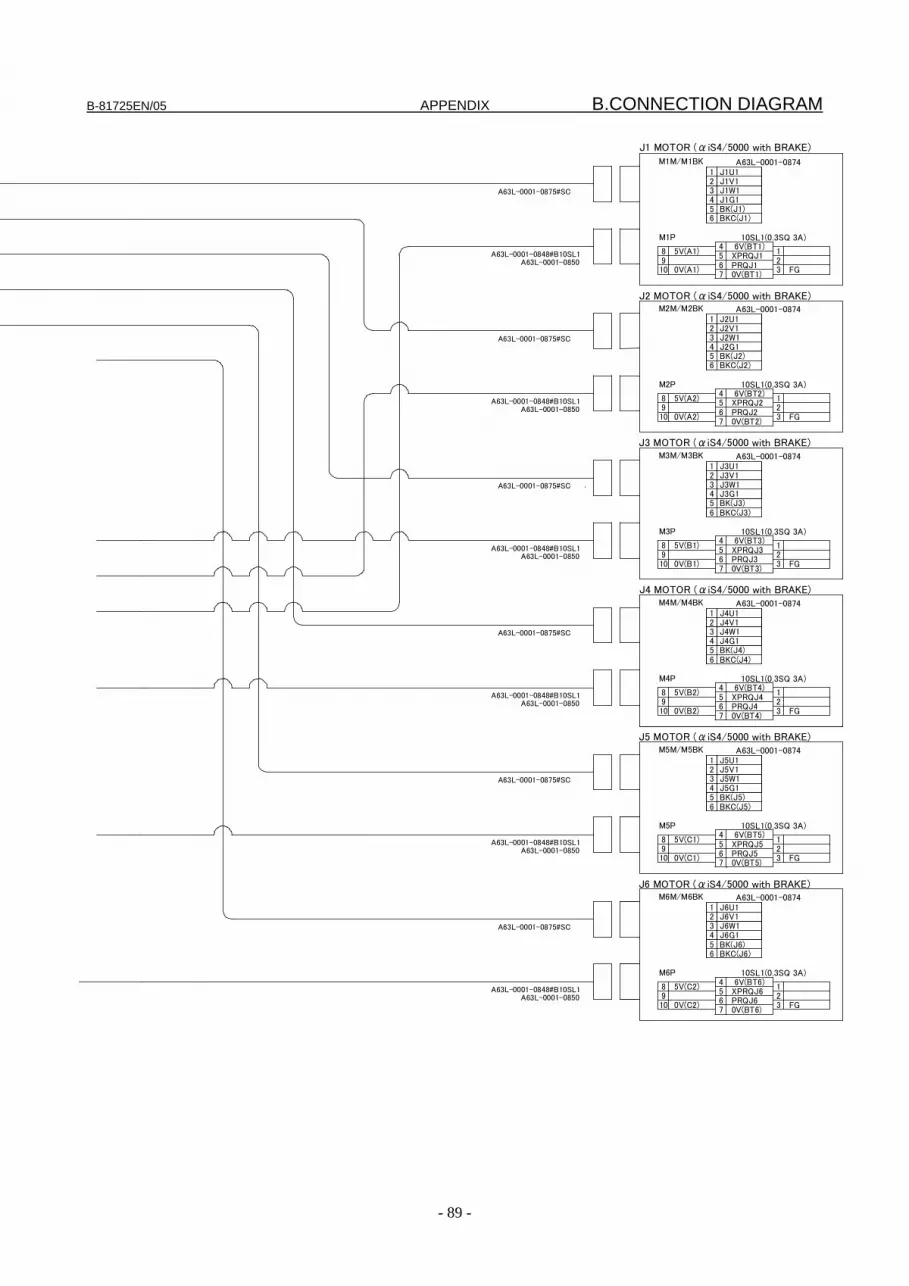
B-81725EN/05 APPENDIX B.CONNECTION DIAGRAM
- 89 -
5V(A1) 123
4567
8910 0V(A1)
0V(BT1)
6V(BT1) XPRQJ1 PRQJ1 FG
M1M/M1BK
M1P 10SL1(0.3SQ 3A)
A63L-0001-0874
5V(A2) 123
4567
8910 0V(A2)
0V(BT2)
6V(BT2) XPRQJ2 PRQJ2
FG
M2M/M2BK
M2P 10SL1(0.3SQ 3A)
A63L-0001-0874
5V(B1) 123
4567
8910 0V(B1)
0V(BT3)
6V(BT3) XPRQJ3 PRQJ3
FG
M3M/M3BK
M3P 10SL1(0.3SQ 3A)
A63L-0001-0874
5V(B2) 123
4567
8910 0V(B2)
0V(BT4)
6V(BT4) XPRQJ4 PRQJ4
FG
M4M/M4BK
M4P 10SL1(0.3SQ 3A)
A63L-0001-0874
J1 MOTOR (αiS4/5000 with BRAKE)
J2 MOTOR (αiS4/5000 with BRAKE)
J3 MOTOR (αiS4/5000 with BRAKE)
J4 MOTOR (αiS4/5000 with BRAKE)
5V(C1) 123
4567
8910 0V(C1)
0V(BT5)
6V(BT5) XPRQJ5 PRQJ5 FG
M5M/M5BK
M5P 10SL1(0.3SQ 3A)
A63L-0001-0874
J5 MOTOR (αiS4/5000 with BRAKE)
5V(C2) 123
4567
8910 0V(C2)
0V(BT6)
6V(BT6) XPRQJ6 PRQJ6
FG
M6M/M6BK
M6P 10SL1(0.3SQ 3A)
A63L-0001-0874
J6 MOTOR (αiS4/5000 with BRAKE)
A63L-0001-0875#SC
A63L-0001-0875#SC
A63L-0001-0848#B10SL1 A63L-0001-0850
A63L-0001-0848#B10SL1 A63L-0001-0850
A63L-0001-0875#SC
A63L-0001-0848#B10SL1 A63L-0001-0850
A63L-0001-0875#SC
A63L-0001-0848#B10SL1 A63L-0001-0850
A63L-0001-0875#SC
A63L-0001-0848#B10SL1 A63L-0001-0850
A63L-0001-0875#SC
A63L-0001-0848#B10SL1 A63L-0001-0850
21 J1U1
J1V1
56
BK(J1) BKC(J1)
34
J1W1 J1G1
21 J2U1
J2V1
56
BK(J2) BKC(J2)
34
J2W1 J2G1
21 J3U1
J3V1
56
BK(J3) BKC(J3)
34
J3W1 J3G1
21 J4U1
J4V1
56
BK(J4) BKC(J4)
34
J4W1 J4G1
21 J5U1
J5V1
56
BK(J5) BKC(J5)
34
J5W1 J5G1
21 J6U1
J6V1
56
BK(J6) BKC(J6)
34
J6W1 J6G1

C.PERIODIC MAINTENANCE APPENDIX B-81725EN/05
- 90 -
C PERIODIC MAINTENANCE
FANUC Robot F-200iB Periodic Maintenance Table
Working time (H)
Items Check time
Grease amount
First check320
3 month
960
6 month
1920
9 month
2880
1 years
3840 4800 5760 6720
2 years 7680 8640 9600 10560
1 Check the mechanical cable. (damaged or twisted) 0.2H ― ○ ○ ○
2 Check the motor connector. (loosening) 0.2H ― ○ ○ ○
3 Tighten the end effector bolt. 0.2H ― ○ ○ ○
4 Tighten the cover and main bolt. 2.0H ― ○ ○ ○
5 Remove spatter and dust etc. 1.0H ― ○ ○ ○
6 Check the end effector (hand) cable 0.1H ― ○ ○ ○
7 Replacing battery 0.1H ― ●
8 Greasing of J1 to J6-axis gearbox *1 0.5H 265ml
each
9
10
11
12
13
8
14
Position of grease nipple
Mec
hani
cal u
nit
14 Greasing to the ball screws *1 0.5H 100mleach ● ● ● ● ●
15 Replacing cable of mechanical
unit * 4.0H
16 Check the robot cable, teach pendant cable and robot connecting cable
0.2H ― ○ ○ ○
17 Cleaning the ventilator 0.2H ― ○ ○ ○ ○ ○ ○ ○ ○ ○ ○ ○ ○
Con
trolle
r
18 Replacing battery *2 0.1H ―
*1 Refer to this manual about greasing points. *2 Refer to chapter 7 of MAINTENANCE of controller maintenance manual *3 ●: requires order of parts
○: does not require order of parts

B-81725EN/05 APPENDIX C.PERIODIC MAINTENANCE
- 91 -
3 years 11520 12480 13440 14400
4 years 15360 16320 17280 18240
5 years 19200 20160 21120 22080
6 years23040 24000 24960 25920
7 years26880 27840 28800 29760
8 years30720 Items
○ ○ ○ ○ ○ 1
○ ○ ○ ○ ○ 2
○ ○ ○ ○ ○ 3
○ ○ ○ ○ ○ 4
○ ○ ○ ○ ○ 5
○ ○ ○ ○ ○ 6
● ● ● ● 7
● ● 8
9
10
11
12
13
● ● ● ● ● ● ● ● ● ● 14
● 15
○ ○ ○ ○ ○ 16
○ ○ ○ ○ ○ ○ ○ ○ ○ ○ ○ ○ ○ ○ ○ ○ ○ ○ ○ ○ 17
●
Ove
rhau
l
18
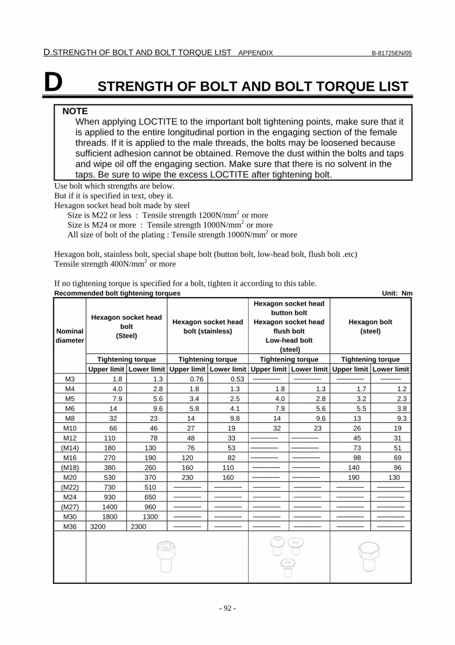
D.STRENGTH OF BOLT AND BOLT TORQUE LIST APPENDIX B-81725EN/05
- 92 -
D STRENGTH OF BOLT AND BOLT TORQUE LIST NOTE When applying LOCTITE to the important bolt tightening points, make sure that it
is applied to the entire longitudinal portion in the engaging section of the female threads. If it is applied to the male threads, the bolts may be loosened because sufficient adhesion cannot be obtained. Remove the dust within the bolts and taps and wipe oil off the engaging section. Make sure that there is no solvent in the taps. Be sure to wipe the excess LOCTITE after tightening bolt.
Use bolt which strengths are below. But if it is specified in text, obey it. Hexagon socket head bolt made by steel
Size is M22 or less : Tensile strength 1200N/mm2 or more Size is M24 or more : Tensile strength 1000N/mm2 or more All size of bolt of the plating : Tensile strength 1000N/mm2 or more
Hexagon bolt, stainless bolt, special shape bolt (button bolt, low-head bolt, flush bolt .etc) Tensile strength 400N/mm2 or more If no tightening torque is specified for a bolt, tighten it according to this table. Recommended bolt tightening torques Unit: Nm
Hexagon socket head bolt
(Steel)
Hexagon socket head bolt (stainless)
Hexagon socket head button bolt
Hexagon socket head flush bolt
Low-head bolt (steel)
Hexagon bolt (steel)
Tightening torque Tightening torque Tightening torque Tightening torque
Nominal diameter
Upper limit Lower limit Upper limit Lower limit Upper limit Lower limit Upper limit Lower limitM3 1.8 1.3 0.76 0.53 ―――― ―――― ―――― ――― M4 4.0 2.8 1.8 1.3 1.8 1.3 1.7 1.2M5 7.9 5.6 3.4 2.5 4.0 2.8 3.2 2.3M6 14 9.6 5.8 4.1 7.9 5.6 5.5 3.8M8 32 23 14 9.8 14 9.6 13 9.3M10 66 46 27 19 32 23 26 19 M12 110 78 48 33 ―――― ―――― 45 31
(M14) 180 130 76 53 ―――― ―――― 73 51 M16 270 190 120 82 ―――― ―――― 98 69
(M18) 380 260 160 110 ―――― ―――― 140 96 M20 530 370 230 160 ―――― ―――― 190 130
(M22) 730 510 ―――― ―――― ―――― ―――― ―――― ――――
M24 930 650 ―――― ―――― ―――― ―――― ―――― ――――
(M27) 1400 960 ―――― ―――― ―――― ―――― ―――― ――――
M30 1800 1300 ―――― ―――― ―――― ―――― ―――― ――――
M36 3200 2300 ―――― ―――― ―――― ―――― ―――― ――――

B-81725EN/05 INDEX
i-1
INDEX <Number>
1.5-YEAR CHECKS (5,760 HOURS) ............................11
1-YEAR CHECKS (3,840 HOURS) ...............................11
3-MONTH (960 HOURS) CHECKS ..............................11
3-YEAR CHECKS (11,520 HOURS) .............................11
4-YEAR (15,360 HOURS) CHECKS.............................11
6- MONTH CHECKS (1,920 HOURS) ..........................11
<A> ADJUSTMENTS ............................................................26
AIR CONTROL SET (OPTION)....................................78
<B> BACKLASH ...................................................................24
<C> CABLE FORMING ........................................................51
CABLE REPLACEMENT..............................................53
CHECKING THE MASTERING ...................................39
CONFIGURATION..........................................................3
CONNECTION DIAGRAM...........................................85
<D> DAILY CHECKS..............................................................5
DRIVE MECHANISM (J1 to J6)......................................4
<E> END EFFECTOR INTERFACE.....................................67
<F> FAILURE AND CAUSE AND MEASURES.................18
FIRST 1-MONTH (320 HOURS) CHECKS ....................6
FIRST 3-MONTH CHECKS (960 HOURS) ....................7
Fixture Position Master ...................................................27
<G> General ............................................................................26
GREASING THE BALL SCREW..................................15
<I> INSTALLATION............................................................72
INSTALLATION SPECIFICATIONS ...........................79
<M> MAINTENANCE AREA................................................77
MAINTENANCE TOOLS..............................................12
MASTERING ................................................................. 26
Mastering Data Entry ...................................................... 37
MECHANICAL COUPLING OF END EFFECTOR TO
WRIST ........................................................................ 62
MECHANICAL COUPLING TO THE ROBOT............ 61
<N> NOTE FOR PART REPLACEMENT ............................ 41
<O> OVERVIEW ................................................................... 18
<P> PERIODIC MAINTENANCE ................................... 13,90
PIPING AND WIRING .................................................. 49
PREFACE......................................................................p-1
PREVENTIVE MAINTENANCE .................................... 5
PROCEDURE FOR RELEASING THE GREASE
REMAINING PRESSURE.......................................... 16
<Q> Quick Mastering.............................................................. 33
<R> REPLACING CABLES.................................................. 51
REPLACING GREASE OF THE DRIVE
MECHANISM ............................................................ 13
REPLACING LEG UNITS (FOR ALL AXES).............. 43
REPLACING MOTORS (FOR ALL AXES) ................. 41
REPLACING PARTS..................................................... 41
REPLACING THE BATTERIES ................................... 17
REPLACING THE CABLE COVER (OPTION) ........... 48
REPLACING THE FULL COVER (OPTION) .............. 47
REPLACING THE WRIST UNIT.................................. 45
Resetting Alarms and Preparing for Mastering ............... 27
ROBOT INTERFERENCE AREA................................. 59
<S> SAFETY PRECAUTIONS ............................................ s-1
SETTING THE LOAD ................................................... 66
Single Axis Mastering..................................................... 35
SPARE PARTS LISTS ................................................... 83
STORAGE ...................................................................... 79
STRENGTH OF BOLT AND BOLT TORQUE LIST ... 92
INDEX B-81725EN/05
i-2
<T> TRANSPORTATION .....................................................70
TRANSPORTATION AND INSTALLATION..............70
TROUBLE SHOOTING .................................................18
<W> WRIST LOAD CONDITIONS .......................................61
<Z> Zero Position Master .......................................................31
B-81725EN/05 REVISION RECORD
r-1
REVISION RECORD Edition Date Contents
05 June, 2012
• Addition of R-30iB • Addition of note for low temperature • Addition of checks of oil exudation
• Correction of errors
04 Mar.,2011
• Addition of stop type of robot • Addition of stopping time and distance when controlled stop is executed • Addition note about end effector (hand) cable • Correction of errors
03 Jan, 2008 • Procedure to move arm without drive power in emergency or abnormal situations • Addition of Stopping time and distance when emergency stop • Correction of errors
02 July, 2006
• Addition of the panel board for the R-J3iC • Change of the recommended grease • Addition of a model supporting the R-J3iC • Change of part of the mastering method • Correction of troubleshooting • Correction of the spare part list
01 Mar, 2002

B-81725EN/05
* B - 8 1 7 2 5 E N / 0 5 *


