Embed Size (px)
Citation preview

F7904500
Technical Bulletin FTS 371 SMART Modbus Interface
Document Revision History Document
Version Modbus Map
Version Date Author Notes
0 1 1/4/17 CKR Document Created
A 1 7/11/17 JGG Footers and Part Number added

Technical Bulletin FTS 371 SMART Modbus Interface
F7904500 Rev A Uncontrolled if Printed
Page 2 of 12
FTS 371 Smart Controller Modbus RTU Over RS485
Addressing: The FTS 371 Smart AC and DC system controllers are configured to be a Modbus slave device. The controller
includes a rotary switch on the bottom right to accommodate multiple FTS 371 Smart Systems to be monitored through
Modbus. This rotary switch specifies the Modbus slave address with values 1 through 10 (Switch positions 1 to 9 address as
1 to 9 and Switch position 0 addresses as 10). When multiple FTS 371 controllers are used, they must be addressed and
monitored individually. Data is not collated from slaves to the master.
Baud Rate: The default baud rate upon booting is 9600 baud. The baud rate may be altered during runtime. See registers
#5[Tower Lighting Controller FW Baud Rate] and #401 [Boot Loader Baud Rate]. The bootloader interface is available at power. The
tower lighting controller Modbus interface on power up is available about 10 seconds later.
Station ID 1-10 Parity None
Baud Rate 9600 Stop Bits 1
Data Bits 8 Flow Control None
Register Access: Any span of registers can be read or written in one Modbus message with Modbus function code 03 (read)
and function code 16(write). Unmapped address space will return the values 65535 (0xFFFF). Access to restricted address
space outside the map areas will cause an error response. If writing multiple registers where there may be undefined or
reserved registers in the span between the desired registers to write, then the register data in the Modbus write message for
those undefined/reserved registers are simply ignored. For example, if writing register #30[LI Control] and register #44[LI Stage
Time] in 1 modbus write message the read only registers between should be written in the write message but the writes for
those registers is ignored. Only write capable registers process Modbus writes.
Modbus Error responses contain 3 bytes and 2 crc bytes. Those bytes are – Station ID, Function Code OR’d with 0x80 (to
indicate error), and the error code. The error codes are as follows:
(1) Unsupported Modbus Function Code - Only functions codes 3 (read) and 16 (write) are supported
(2) Unsupported Register Access - The register or register count exceed the valid map space
(3) Modbus Msg Size Error - The message size of a read function #3 must be 6 bytes + 2 crc bytes
(4) Unsupported Argument - The value written to a specified register is invalid
(6) FW Upgrade Not Ready - A FW upgrade was attempted before unlocking the upgrade process
FTS 371 Smart Controller Architecture Notes
The FTS 371 Smart Controller series is capable of firmware upgrade through USB on site and remotely through Modbus. To
accommodate this feature, the controller firmware is launched by a bootloader application. There are two tower lighting controller
firmware (TLCFW) programs, a primary and failsafe program. The failsafe firmware is non-writable / non-upgradable and will always
remain at the firmware revision that the controller originally ships with. The primary firmware may be upgraded through USB or
Modbus.
If at any time the primary firmware becomes unusable the failsafe firmware will run. Register #72 Controller Alarms / Indications Bit
11: Primary FW Alarm Indicates the primary firmware image has failed and the unit is running the failsafe TLCFW. For example, the
primary firmware may become unusable if a FW upgrade was in progress and was interrupted through power loss or communications
timeout. The primary TLCFW would be erased at the beginning of the upgrade and incompletely upgraded. There are safeguards in
place such that the primary TLCFW is not erased until 1) The firmware upgrade is unlocked with a special 2 register write sequence
with specific values and 2) the first upgrade packet received decodes properly as a valid TLCFW upgrade data.
For further information about remotely upgrading an FTS 371 Smart controller through Modbus refer to page 8.
Normal operation of the FTS 371 Smart Controller would be that on reset the bootloader would run for 10 seconds without finding
upgrade triggers and then launch the TLCFW. During the bootloader’s 10 seconds runtime the RS485 Modbus RTU map is restricted
to registers 400 through 661. Any other Modbus access such as access to the primary program’s Modbus tower monitoring map will
cause an error response until the TLCFW is launched. After the TLCFW is running the bootloader Modbus map space registers 400
through 661 are inaccessible and will cause an error response.
Also note that during the first 10 seconds of power up while the bootloader is running that the monitoring dry contacts will all be in an
un-energized alarm state. For example, the bcn, mkr, and PD alarm contacts Normally Closed terminal will be in an open state.

Technical Bulletin FTS 371 SMART Modbus Interface
F7904500 Rev A Uncontrolled if Printed
Page 3 of 12
FAA Compliant Monitoring of the FTS 371 Smart Controller with Modbus RTU Over RS485
This document section is intended as a guide only. Flash Technology and parent company SPX do not assume any responsibility or
liability of 3rd party Modbus host monitoring application programs. Please reference FAA Advisory Circular AC 70/7460-1 (Rev L at
the time of this document release) for definitive monitoring requirements. Please read the modbus map alarm register descriptions in
the FTS 371 Smart Tower Lighting Controller Modbus Map section prior to reviewing this guidance
It is recommended for the monitoring Modbus host to read the entire Modbus map space to poll the system for monitoring information
and diagnostic data. The Modbus host should examine the tower status register #70 to determine if a reportable event has occurred that
requires further examination. When a reportable event such as a beacon red night alarm, PD 19hour mode change alarm, marker
alarm, or other alarm occurs this register will increment from 0 to overflowing at 0xFFFF(65535d) back to 0. The host should
compare the previous tower status state register value to the newly received value.
If the value has changed then further examination of the alarm registers is required to determine the alarm source. NOTAM (Notice to
Airmen) worthy alarm points are as follows below.
Register #72 [Controller Alarms]
o Bit 6: GPS Sync Failure - Flashing devices out of sync on wind turbine site are grounds for issuing an FAA
NOTAM
o Bit 13: Input Flash Sync (Slave controllers only on linked multi controller systems). Slave controllers are required
receive operating mode (day or night) and flash sync from the master. Flashing devices out of sync on a tower are
grounds for issuing an FAA NOTAM
Register #78 [Beacon Red Night Alarms]
o Bit 0: Beacon Tier Red Night Alarm (On A1, A1+1 systems, or linked multi controller A2 and above systems).
Beacon Tier Red Night Alarms trigger on 4 missed flashes. Note that 4 good flash periods are required to restore
the alarm
Register #82 [Marker Alarms]
o Bit 0: Marker Tier Alarm NOTAM worthy only on A0 systems or A1 and above systems with flashing markers.
Marker Tier Alarms trigger on 4 bad marker periods. Note that 4 good marker periods are required to restore the
alarm
Register #301 [Auxiliary Interface Lights On / Off Command]
o If a radar system is controlling the FTS 371 Smart System, then upon reading register 301 it must be insured to be
the same command written to the that register. A failure of lights on represents a NOTAM event
FAA Advisory Circular AC 70/7460-1 Relevant Sections
Section 2.4 Light Failure Notification details the steps of when and how to file NOTAM issues and restorations with the
FAA.
Section 4.8 Monitoring Obstruction Lights details monitoring requirements
Section 13.5.3 Marking and Lighting Wind Turbines, Lighting Standards details light synchronization requirements
Section 14 Aircraft Detection Lighting systems details using a radar system through the FTS 371 Smart Auxiliary Modbus
or Dry Contact interfaces
Technical Bulletin FTS 371 SMART Modbus Interface
F7904500 Rev A Uncontrolled if Printed
Page 4 of 12
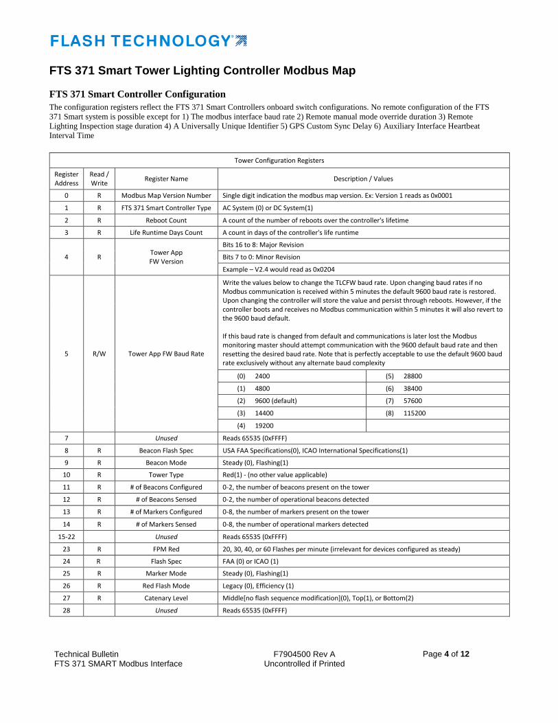
FTS 371 Smart Tower Lighting Controller Modbus Map
FTS 371 Smart Controller Configuration
The configuration registers reflect the FTS 371 Smart Controllers onboard switch configurations. No remote configuration of the FTS
371 Smart system is possible except for 1) The modbus interface baud rate 2) Remote manual mode override duration 3) Remote
Lighting Inspection stage duration 4) A Universally Unique Identifier 5) GPS Custom Sync Delay 6) Auxiliary Interface Heartbeat
Interval Time
Tower Configuration Registers
Register Address
Read / Write
Register Name Description / Values
0 R Modbus Map Version Number Single digit indication the modbus map version. Ex: Version 1 reads as 0x0001
1 R FTS 371 Smart Controller Type AC System (0) or DC System(1)
2 R Reboot Count A count of the number of reboots over the controller's lifetime
3 R Life Runtime Days Count A count in days of the controller's life runtime
4 R Tower App FW Version
Bits 16 to 8: Major Revision
Bits 7 to 0: Minor Revision
Example – V2.4 would read as 0x0204
5 R/W Tower App FW Baud Rate
Write the values below to change the TLCFW baud rate. Upon changing baud rates if no Modbus communication is received within 5 minutes the default 9600 baud rate is restored. Upon changing the controller will store the value and persist through reboots. However, if the controller boots and receives no Modbus communication within 5 minutes it will also revert to the 9600 baud default. If this baud rate is changed from default and communications is later lost the Modbus monitoring master should attempt communication with the 9600 default baud rate and then resetting the desired baud rate. Note that is perfectly acceptable to use the default 9600 baud rate exclusively without any alternate baud complexity
(0) 2400 (5) 28800
(1) 4800 (6) 38400
(2) 9600 (default) (7) 57600
(3) 14400 (8) 115200
(4) 19200
7 Unused Reads 65535 (0xFFFF)
8 R Beacon Flash Spec USA FAA Specifications(0), ICAO International Specifications(1)
9 R Beacon Mode Steady (0), Flashing(1)
10 R Tower Type Red(1) - (no other value applicable)
11 R # of Beacons Configured 0-2, the number of beacons present on the tower
12 R # of Beacons Sensed 0-2, the number of operational beacons detected
13 R # of Markers Configured 0-8, the number of markers present on the tower
14 R # of Markers Sensed 0-8, the number of operational markers detected
15-22 Unused Reads 65535 (0xFFFF)
23 R FPM Red 20, 30, 40, or 60 Flashes per minute (irrelevant for devices configured as steady)
24 R Flash Spec FAA (0) or ICAO (1)
25 R Marker Mode Steady (0), Flashing(1)
26 R Red Flash Mode Legacy (0), Efficiency (1)
27 R Catenary Level Middle[no flash sequence modification](0), Top(1), or Bottom(2)
28 Unused Reads 65535 (0xFFFF)
Technical Bulletin FTS 371 SMART Modbus Interface
F7904500 Rev A Uncontrolled if Printed
Page 5 of 12
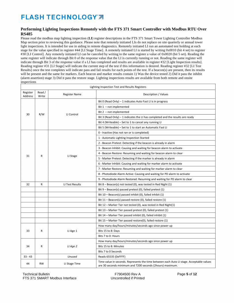
Performing Lighting Inspections Remotely with the FTS 371 Smart Controller with Modbus RTU Over
RS485 Please read the modbus map lighting inspection (LI) register descriptions in the FTS 371 Smart Tower Lighting Controller Modbus
Map section prior to reviewing this guidance. Please note that remotely initiated LIs do not replace on site quarterly or annual tower
light inspections. It is intended for use in aiding in remote diagnostics. Remotely initiated LI run an automated test holding at each
stage for the value specified in register #44 [LI Stage Time]. A remotely initiated LI is started by writing 0x0010 (bit 4 set) to register
#30 [LI Control]. Any remotely initiated LI can be canceled by writing to the same register a value of 0x0020 (bit 5 set). Reading the
same register will indicate through Bit 0 of the response value that the LI is currently running or not. Reading the same register will
indicate through Bit 3 of the response value if a LI has completed and results are available in register #32 [Light Inspection results].
Reading register #31 [LI Stage] will indicate the current step of the test if this information is desired. Reading register #32 [LI Test
Results] once the test completes will indicate pass and fail results for each points of the test. If a beacon(s) are present, then its results
will be present and the same for markers. Each beacon and marker results contain 1) Was the device tested 2) Did it pass the inhibit
(alarm assertion) stage 3) Did it pass the restore stage. Lighting inspections results are available from both remote and onsite
inspections
Lighting Inspection Test and Results Registers
Register Address
Read / Write
Register Name Description / Values
30 R/W LI Control
Bit 0 (Read Only) – 1 indicates Auto Fast LI is in progress
Bit 1 – not implemented
Bit 2 – not implemented
Bit 3 (Read Only) – 1 indicates the LI has completed and the results are ready
Bit 4 (Writeable) – Set to 1 to cancel any running LI
Bit 5 (Writeable) – Set to 1 to start an Automatic Fast LI
31 R LI Stage
0 - Inactive (Has not ran or is completed)
1 - Automatic Lighting Inspection Started
2 - Beacon Pretest: Detecting if the beacon is already in alarm
3 - Beacon Inhibit: Causing and waiting for beacon alarm to activate
4 - Beacon Restore: Resuming and waiting for beacon alarm to clear
5 - Marker Pretest: Detecting if the marker is already in alarm
6 - Marker Inhibit: Causing and waiting for marker alarm to activate
7 - Marker Restore: Resuming and waiting for marker alarm to clear
8 - Photodiode Alarm Active: Causing and waiting for PD alarm to activate
9 - Photodiode Alarm Restored: Resuming and waiting for PD alarm to clear
32 R LI Test Results Bit 8 – Beacon(s) not tested (0), was tested in Red Night (1)
Bit 9 – Beacon(s) passed pretest (0), failed pretest (1)
Bit 10 – Beacon(s) passed inhibit (0), failed inhibit (1)
Bit 11 – Beacon(s) passed restore (0), failed restore (1)
Bit 12 – Marker Tier not tested (0), was tested in Red Night(1)
Bit 13 – Marker Tier passed pretest (0), failed pretest (1)
Bit 14 – Marker Tier passed inhibit (0), failed inhibit (1)
Bit 15 – Marker Tier passed restore(0), failed restore (1)
33 R LI Age 1
How many day/hours/minutes/seconds ago since power up
Bits 15 to 8: Days
Bits 7 to 0: Hours
34 R LI Age 2
How many day/hours/minutes/seconds ago since power up
Bits 15 to 8: Minutes
Bits 7 to 0 Seconds
33 - 43 Unused Reads 65535 (0xFFFF)
44 RW LI Stage Time Time value in seconds. Represents the time between each Auto LI stage. Acceptable values are 30 seconds minimum and 7200 seconds (2hours) maximum.

Technical Bulletin FTS 371 SMART Modbus Interface
F7904500 Rev A Uncontrolled if Printed
Page 6 of 12
Performing Temporary Remote Mode Overrides with the FTS 371 Smart Controller with Modbus
RTU Over RS485
The FTS 371 Smart Controller’s operating mode can be remotely overridden. Register #60 [Mode Override Control] must be written
with the desired mode and register #61 [Mode Override Time] must be written with the desired minute count duration of the override.
Tower Override
Register Address
Read / Write
Register Name Description / Values
60 R/W Mode Override Control Read: Override Mode Off (0), Day (1), Red Night (3)
Write: Day (1), Red Night (3), Cancel Override Mode (4)
61 R/W Mode Override Time Valid range is 1-65535 Override Time in Minutes (1min to 45 days). Write sets the override time. Read retrieves the remaining amount of time of the override if the override is active. If override is not active a read retrieves the set override time
Technical Bulletin FTS 371 SMART Modbus Interface
F7904500 Rev A Uncontrolled if Printed
Page 7 of 12
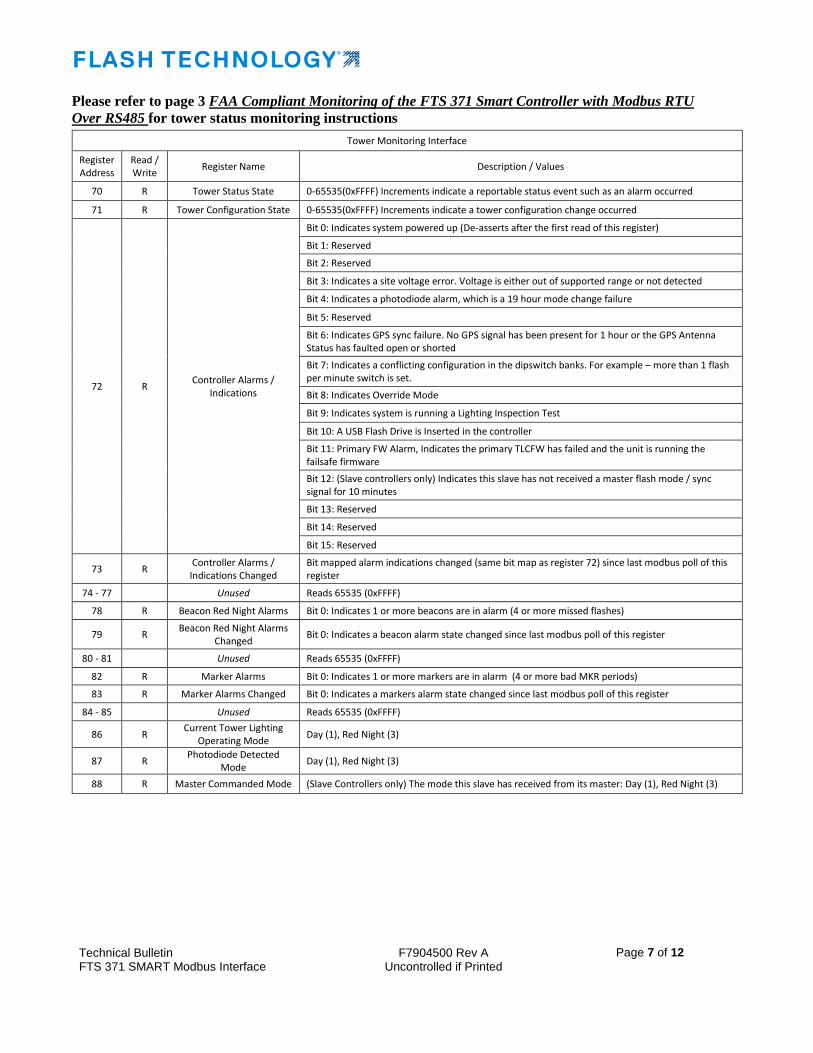
Please refer to page 3 FAA Compliant Monitoring of the FTS 371 Smart Controller with Modbus RTU
Over RS485 for tower status monitoring instructions
Tower Monitoring Interface
Register Address
Read / Write
Register Name Description / Values
70 R Tower Status State 0-65535(0xFFFF) Increments indicate a reportable status event such as an alarm occurred
71 R Tower Configuration State 0-65535(0xFFFF) Increments indicate a tower configuration change occurred
72 R Controller Alarms /
Indications
Bit 0: Indicates system powered up (De-asserts after the first read of this register)
Bit 1: Reserved
Bit 2: Reserved
Bit 3: Indicates a site voltage error. Voltage is either out of supported range or not detected
Bit 4: Indicates a photodiode alarm, which is a 19 hour mode change failure
Bit 5: Reserved
Bit 6: Indicates GPS sync failure. No GPS signal has been present for 1 hour or the GPS Antenna Status has faulted open or shorted
Bit 7: Indicates a conflicting configuration in the dipswitch banks. For example – more than 1 flash per minute switch is set.
Bit 8: Indicates Override Mode
Bit 9: Indicates system is running a Lighting Inspection Test
Bit 10: A USB Flash Drive is Inserted in the controller
Bit 11: Primary FW Alarm, Indicates the primary TLCFW has failed and the unit is running the failsafe firmware
Bit 12: (Slave controllers only) Indicates this slave has not received a master flash mode / sync signal for 10 minutes
Bit 13: Reserved
Bit 14: Reserved
Bit 15: Reserved
73 R Controller Alarms / Indications Changed
Bit mapped alarm indications changed (same bit map as register 72) since last modbus poll of this register
74 - 77 Unused Reads 65535 (0xFFFF)
78 R Beacon Red Night Alarms Bit 0: Indicates 1 or more beacons are in alarm (4 or more missed flashes)
79 R Beacon Red Night Alarms
Changed Bit 0: Indicates a beacon alarm state changed since last modbus poll of this register
80 - 81 Unused Reads 65535 (0xFFFF)
82 R Marker Alarms Bit 0: Indicates 1 or more markers are in alarm (4 or more bad MKR periods)
83 R Marker Alarms Changed Bit 0: Indicates a markers alarm state changed since last modbus poll of this register
84 - 85 Unused Reads 65535 (0xFFFF)
86 R Current Tower Lighting
Operating Mode Day (1), Red Night (3)
87 R Photodiode Detected
Mode Day (1), Red Night (3)
88 R Master Commanded Mode (Slave Controllers only) The mode this slave has received from its master: Day (1), Red Night (3)

Technical Bulletin FTS 371 SMART Modbus Interface
F7904500 Rev A Uncontrolled if Printed
Page 8 of 12
Diagnostic Data of the FTS 371 Smart Controller
The FTS 371 Smart Controller will indicate several diagnostic data points. Reboot count, Firmware build timestamp, and UUID
features are available for PCB and firmware tracking. The input AC voltage, DC supply voltage, and beacon current and power draw
are available to assist in troubleshooting. Voltage and current readings are taken during the flash on time. The calculated power draw
includes the flash off time for average power draw of the beacon.
Note that the beacon’s current and power draw will vary with the type of flash configured. The FH371IR flash head will output
different light levels for different flash types. For example, 60FPM Legacy FAA will draw about 25% more power than 20FPM
Legacy FAA during the flash on time. Power/Current draw efficiency is also affected by the site’s power supply voltage and ambient
temperature. For example, at 120VAC, 24C(75F) – with an FAA Efficiency flash selected average current draw per beacon is about
850mA. With an FAA Legacy 20FPM the flash draws about 475mA and at 60FPM 590mA.
FTS 371 Controller Board Diagnostics
Register Address
Read / Write
Register Name Description / Values
91 R/W Controller Reboot Any write value reboots this controller. Reading the register supplies the # of reboots of the system
92 – 122 R Controller Firmware
Build Timestamp ASCII string, null terminated. Indicates the Date and Time that this firmware was created. It should appear for example in this format: 371SM: SEP 2 2016 12:53:09
123 – 130 R/W Controller Board
Universally Unique Identifier
128 bit / 16 byte (8 register) Universally Unique Identification number. Factory Default is ASCII "0123456789ABCDEF" (0x30313233343536373839414243444545) and must be set by a Modbus master generating a UUID. Write 2 bytes per UUID register
130-138 - Unused Reads 65535 (0xFFFF)
139 R Controller Board Input
AC Power Voltage (FTS 371 Smart AC Controller only) The site power voltage in Volts AC RMS
140 R Controller Board DC
Power Voltage The FTS 371 Smart AC or DC board's DC power voltage in Volts DC
141 R FTS 371 Controller Photodiode Value
The amount of ambient light currently measured by the photodiode in Lux. Note the PD’s range is 0 to 740 Lux. Anything higher reads as 740 Lux
142 R Controller Up Time
Register 1
How many day/hours/minutes/seconds ago since power up
Bits 15 to 8: Days
Bits 7 to 0: Hours
143 R Controller Up Time
Register 2
How many day/hours/minutes/seconds ago since power up
Bits 15 to 8: Minutes
Bits 7 to 0 Seconds
144 R Beacon Current Draw Beacon Current Draw in AC milliamps RMS (or DC milliamps for a FTS 371 Smart DC Controller)
145 R Beacon Power Draw Beacon Power Draw in Watts RMS. Upper 8 bits is the whole number and lower 8 bits the 1st decimal digit. Ex: 9.4 Watts would read 0x0904. LSB Decimal digits will always be a 0 to 9 value
Technical Bulletin FTS 371 SMART Modbus Interface
F7904500 Rev A Uncontrolled if Printed
Page 9 of 12
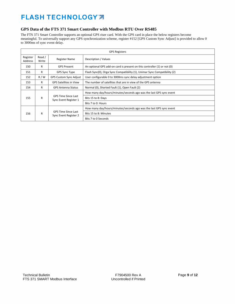
GPS Data of the FTS 371 Smart Controller with Modbus RTU Over RS485
The FTS 371 Smart Controller supports an optional GPS riser card. With the GPS card in place the below registers become
meaningful. To universally support any GPS synchronization scheme, register #152 [GPS Custom Sync Adjust] is provided to allow 0
to 3000ms of sync event delay.
GPS Registers
Register Address
Read / Write
Register Name Description / Values
150 R GPS Present An optional GPS add-on card is present on this controller (1) or not (0)
151 R GPS Sync Type Flash Sync(0), Orga Sync Compatibility (1), Unimar Sync Compatibility (2)
152 R / W GPS Custom Sync Adjust User configurable 0 to 3000ms sync delay adjustment option
153 R GPS Satellites in View The number of satellites that are in view of the GPS antenna
154 R GPS Antenna Status Normal (0), Shorted Fault (1), Open Fault (2)
155 R GPS Time Since Last
Sync Event Register 1
How many day/hours/minutes/seconds ago was the last GPS sync event
Bits 15 to 8: Days
Bits 7 to 0: Hours
156 R GPS Time Since Last
Sync Event Register 2
How many day/hours/minutes/seconds ago was the last GPS sync event
Bits 15 to 8: Minutes
Bits 7 to 0 Seconds
Technical Bulletin FTS 371 SMART Modbus Interface
F7904500 Rev A Uncontrolled if printed
Page 10 of 12
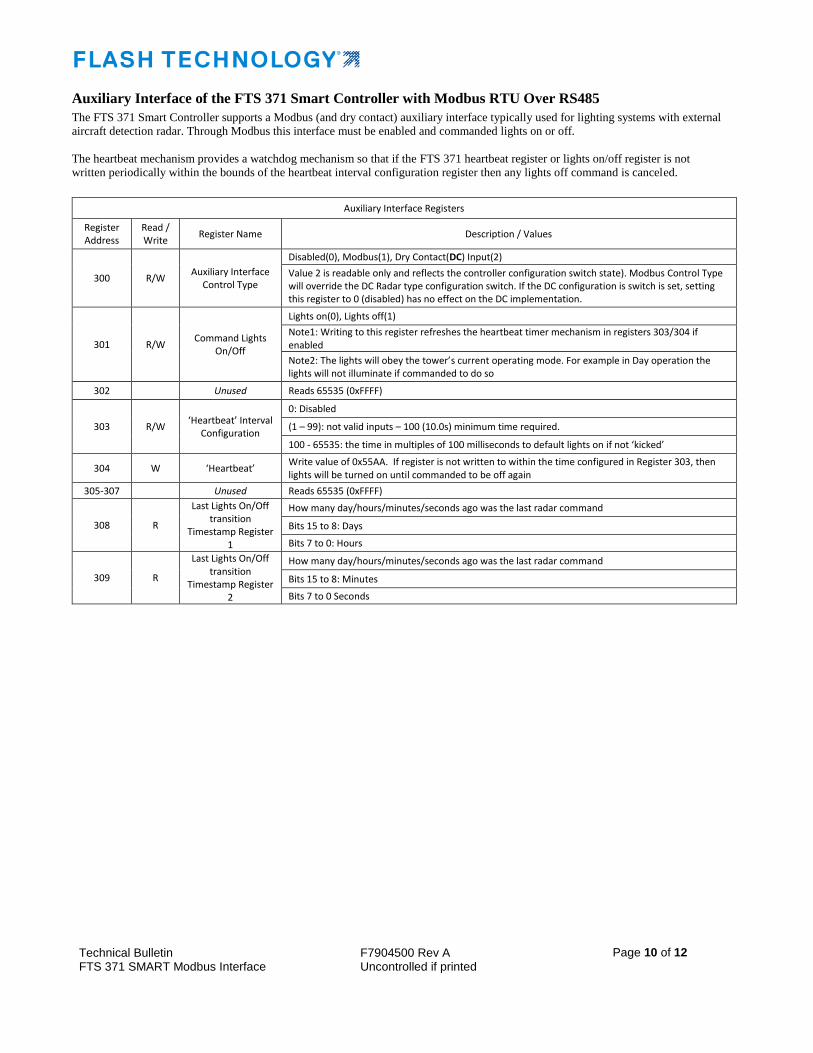
Auxiliary Interface of the FTS 371 Smart Controller with Modbus RTU Over RS485
The FTS 371 Smart Controller supports a Modbus (and dry contact) auxiliary interface typically used for lighting systems with external
aircraft detection radar. Through Modbus this interface must be enabled and commanded lights on or off.
The heartbeat mechanism provides a watchdog mechanism so that if the FTS 371 heartbeat register or lights on/off register is not
written periodically within the bounds of the heartbeat interval configuration register then any lights off command is canceled.
Auxiliary Interface Registers
Register Address
Read / Write
Register Name Description / Values
300 R/W Auxiliary Interface
Control Type
Disabled(0), Modbus(1), Dry Contact(DC) Input(2)
Value 2 is readable only and reflects the controller configuration switch state). Modbus Control Type will override the DC Radar type configuration switch. If the DC configuration is switch is set, setting this register to 0 (disabled) has no effect on the DC implementation.
301 R/W Command Lights
On/Off
Lights on(0), Lights off(1)
Note1: Writing to this register refreshes the heartbeat timer mechanism in registers 303/304 if enabled
Note2: The lights will obey the tower’s current operating mode. For example in Day operation the lights will not illuminate if commanded to do so
302 Unused Reads 65535 (0xFFFF)
303 R/W ‘Heartbeat’ Interval
Configuration
0: Disabled
(1 – 99): not valid inputs – 100 (10.0s) minimum time required.
100 - 65535: the time in multiples of 100 milliseconds to default lights on if not ‘kicked’
304 W ‘Heartbeat’ Write value of 0x55AA. If register is not written to within the time configured in Register 303, then lights will be turned on until commanded to be off again
305-307 Unused Reads 65535 (0xFFFF)
308 R
Last Lights On/Off transition
Timestamp Register 1
How many day/hours/minutes/seconds ago was the last radar command
Bits 15 to 8: Days
Bits 7 to 0: Hours
309 R
Last Lights On/Off transition
Timestamp Register 2
How many day/hours/minutes/seconds ago was the last radar command
Bits 15 to 8: Minutes
Bits 7 to 0 Seconds
Technical Bulletin FTS 371 SMART Modbus Interface
F7904500 Rev A Uncontrolled if printed
Page 11 of 12
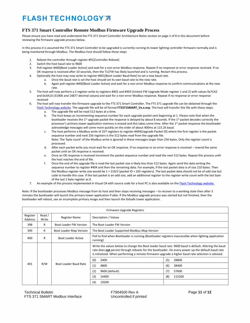
FTS 371 Smart Controller Remote Modbus Firmware Upgrade Process
Please ensure you have read and understand the FTS 371 Smart Controller Architecture Notes section on page 2 of 8 in this document before reviewing the firmware upgrade process below. In this process it is assumed the FTS 371 Smart Controller to be upgraded is currently running its tower lighting controller firmware normally and is being monitored through Modbus. The Modbus host should follow these steps
1. Reboot the controller through register #91[Controller Reboot] 2. Switch the host baud rate to 9600 3. Poll register #400[Boot Loader Active] and wait for a non-error Modbus response. Repeat if no response or error response received. If no
OK response is received after 10 seconds, then the TLCFW has likely launched and is running. Restart this process. 4. Optionally the host may now write to register #401[Boot Loader Baud Rate] to set a new baud rate.
a. Once the baud rate is set the host should set its own baud rate to the new rate. b. Again poll register #400[Boot Loader Active] and wait for a non-error Modbus response to confirm communications at the new
rate. 5. The host will now perform a 2 register write to registers #402 and #403 [Unlock FW Upgrade Mode register 1 and 2] with values 0x7CA2
and 0x3A1D (31906 and 14877 decimal values) and wait for a non-error Modbus response. Repeat if no response or error response received
6. The host will now transfer the firmware upgrade to the FTS 371 Smart Controller. The FTS 371 upgrade file can be obtained through the Flash Technology website. The upgrade file will be of format FTS371SMART_Vx.x.ecp. The host will transfer this file with these steps:
a. The upgrade file will be read 512 bytes at a time. b. The host keeps an incrementing sequence number for each upgrade packet sent beginning at 1. Please note that when the
bootloader receives the 1st upgrade packet the response is delayed by about 8 seconds. If the 1st packet decodes correctly the processor’s primary tower application memory is erased and this takes some time. After the 1st packet response the bootloader acknowledge messages will come more quickly on the order of about 400ms at 115.2k baud.
c. The host performs a Modbus write of 257 registers to register #404[Upgrade Packet ID] where the first register is the packet sequence number and next 256 registers is the 512 bytes read from the upgrade file. Note: The ‘byte count’ of the Modbus write is ignored in these messages larger than 256 bytes. Only the register count is processed.
d. After each packet write you must wait for an OK response. If no response or an error response is received – resend the same packet until an OK response is received.
e. Once an OK response is received increment the packet sequence number and read the next 512 bytes. Repeat this process until the host reaches the end of file.
f. Once the end of the upgrade file is read the last packet size is likely less than 512 bytes. Again send this data writing the sequence number to register #404 and then the remaining data. For example, if the last packet data is of size 210 bytes. Then the Modbus register write size would be 1 + 210/2 (packet ID + 105 registers). The last packet data should not be of odd size but code to handle this case. If the last packet is an odd size, add an additional register to the register write count with the last byte of the last 2 byte register as 0.
7. An example of this process implemented in Visual C# with source code for a host PC is also available on the Flash Technology website.
Note: If the bootloader processes Modbus message from its host and then stops receiving messages – to recover to a working state then after 3 minutes the bootloader will launch the primary tower application if able. If the Modbus upgrade process was started but not finished, then the bootloader will reboot, see an incomplete primary image and then launch the failsafe tower application.
Firmware Upgrade Registers
Register Address
Read / Write
Register Name Description / Values
398 R Boot Loader FW Version The Boot Loader FW Version
399 R Boot Loader Map Version The Boot Loader Supported Modbus Map Version
400 R Boot Loader Active Poll to find when Bootloader is running (Bootloader registers inaccessible when lighting application running)
401 R/W Boot Loader Baud Rate
Write the values below to change the Boot loader baud rate. 9600 baud is default. Altering the baud rate does not persist through reboots for the bootloader. On every power up the default baud rate is initialized. When performing a remote firmware upgrade a higher baud rate selection is advised.
(0) 2400 (5) 28800
(1) 4800 (6) 38400
(2) 9600 (default) (7) 57600
(3) 14400 (8) 115200
(4) 19200

Technical Bulletin FTS 371 SMART Modbus Interface
F7904500 Rev A Uncontrolled if printed
Page 12 of 12
402 W Unlock FW Upgrade
Mode Reg 1 Write registers #402 and #403 in 1 modbus message (2 registers, 4 bytes) the values 0x7CA2 and 0x3A1D respectively to unlock the upgrade mode
403 W Unlock FW Upgrade
Mode Reg 2
404 RW Upgrade Packet ID
Write register 404 with the packet sequence number together with the packet data registers 405 to 661. If the Modbus response to packet writes (packet ID + packet data) is an error, then read this register. It is possible the Modbus Host missed the controller’s packet successful acknowledgement and is repeating writes to a packet already committed. If the read packet ID # does not correspond to the Modbus host’s packet ID # write then skip the unnecessary repeat write and proceed to the next packet
405 to 661
W FW Upgrade Packet Data Parse the FW Upgrade file 512 bytes (256 registers) at a time and write to these registers in sequence


