Embed Size (px)
Citation preview
Experimental verification of the optimal tuningof a tunable vibration neutralizer for global
vibration control
Jedol Dayoua,*, M.J. Brennanb
aSchool of Science and Technology, University of Malaysia Sabah, Teluk Sepanggar,
88999 Kota Kinabalu, Sabah, MalaysiabInstitute of Sound and Vibration Research, University of Southampton, Southampton,
Hampshire, SO17 1BJ, UK
Received 11 April 2002; received in revised form 31 July 2002; accepted 1 August 2002
Abstract
A theoretical method has been previously proposed by the authors to optimize a tunablevibration neutralizer for global vibration control. However, experimental verification of thetuning method has yet to be presented. This paper aims to do this. It is shown that by using
the proposed optimization method, the tunable vibration neutralizer can be as effective as anactive control device in reducing global vibration of a structure. One particularly interestingfinding is that although the vibration neutralizer is a passive device which is incapable ofsupplying energy to a system, it appears to be as effective as active control in reducing the
global vibration of a structure, even in the frequency range where the control device isrequired to supply energy.# 2002 Elsevier Science Ltd. All rights reserved.
Keywords: Vibration; Absorbers; Neutralizers; Adaptive–passive control
1. Introduction
In the last decade, the tunable vibration neutralizer has been the subject of exten-sive research for the purpose of global vibration control. The aim has been to find analternative method to active control, for sound and vibration problems, and for pure
Applied Acoustics 64 (2003) 311–323
www.elsevier.com/locate/apacoust
0003-682X/02/$ - see front matter # 2002 Elsevier Science Ltd. All rights reserved.
PI I : S0003-682X(02 )00067 -1
* Corresponding author. Tel.: +60-088-320355; fax: +60-088-435324.
E-mail addresses: [email protected] (J. Dayou), [email protected] (M.J. Brennan).
academic interest. As a result, there has been quite a lot of theoretical work pub-lished on this subject [1–9].The most recent development on the theoretical work has been the determination
of the optimal tuning of a vibration neutralizer that minimizes the kinetic energy ofa host structure, which can be found in references [10–12]. The method on how todetermine the optimal tuning of the neutralizer has been called the active-passiveanalogy [13]. In another development, a procedure on how to apply multiple tunedtunable vibration neutralizers has been suggested by the authors in reference [14]. Inparallel with this, a method on how to tune a vibration neutralizer has been proposed[7]. Unfortunately, there have been no experimental results presented regarding theeffectiveness of an optimized vibration neutralizer.This paper is an extension of previous work [10], aimed at providing experimental
evidence supporting the suggested optimal tuning method for a single neutralizer. Itis found that the global reduction by the optimized vibration neutralizer is compar-able to that of active control. One interesting result is that although the vibrationneutralizer is incapable of supplying energy to a system, its effectiveness in reducingthe global vibration of a host structure in the frequency range where the controldevice is required to supply energy is very close to the reduction achieved by a fullyactive control device.This paper is arranged in 5 sections. Following this introduction there is a brief
review on the proposed optimal tuning method of a vibration neutralizer for globalvibration control in Section 2. The experimental method to verify the proposedtuning method is described in Section 3, and the experimental results are discussedin Section 4, which highlights several important findings. The paper is closed withsome conclusions in Section 5.
2. Review on the optimal tuning method of tunable vibration neutralizer for global
vibration control
2.1. Dynamic behavior of a structure with control devices attached
The dynamic behavior of a structure with a control device attached has beendescribed in many articles for example [4–6] and [10–15]. However, the theoreticalformulation is briefly described here for convenience.Consider a general structure which is excited by harmonic primary forces of arbi-
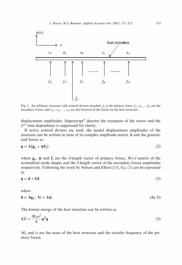
trary amplitude fp with J control devices fitted at x1, x2, . . ., xj,. . ., xJ as shown inFig. 1. The displacement of the host structure at any point can be written in terms ofa finite number of M modes as
w xð Þ ¼ U T xð Þq ð1Þ
where w(x) is the displacement of the structure at location x, U (x) is the M-lengthvector of the normalized mode shapes and q is the M-length vector of the modal
312 J. Dayou, M.J. Brennan /Applied Acoustics 64 (2003) 311–323
displacement amplitudes. SuperscriptT denotes the transpose of the vector and theej!t time dependence is suppressed for clarity.If active control devices are used, the modal displacement amplitudes of the
structure can be written in term of its complex amplitude matrix A and the general-ized forces as
q ¼ A gp þ fS� �
ð2Þ
where gp, and fs are the J-length vector of primary forces, M�J matrix of thenormalized mode shapes and the J-length vector of the secondary forces amplitudesrespectively. Following the work by Nelson and Elliott [15], Eq. (2) can be expressedas
q ¼ d þGfs ð3Þ
where
d ¼ Agp; G ¼ A ð4a; bÞ
The kinetic energy of the host structure can be written as
KE ¼Mh!
2
4qHq ð5Þ
Mh and ! are the mass of the host structure and the circular frequency of the pri-mary forces.
Fig. 1. An arbitrary structure with control devices attached. fp is the primary force, fs1, fs2,. . .,fsJ are the
secondary forces, and xs1, xs2,. . ., xsJ are the location of the forces on the host structure.
J. Dayou, M.J. Brennan /Applied Acoustics 64 (2003) 311–323 313
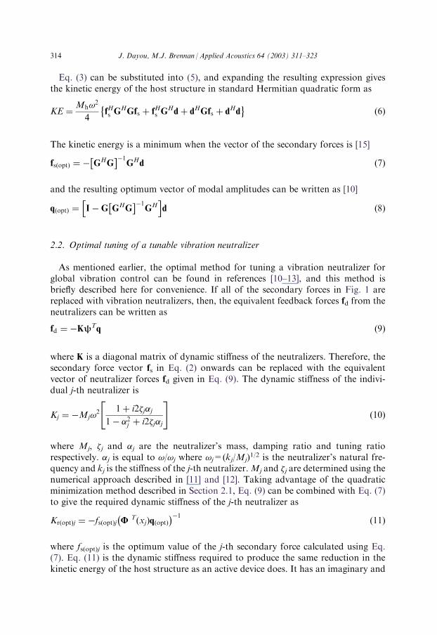
Eq. (3) can be substituted into (5), and expanding the resulting expression givesthe kinetic energy of the host structure in standard Hermitian quadratic form as
KE ¼Mh!
2
4fHs G
HGfs þ fHs GHdþ dHGfs þ dHd
� �ð6Þ
The kinetic energy is a minimum when the vector of the secondary forces is [15]
fsðoptÞ ¼ � GHG� ��1
GHd ð7Þ
and the resulting optimum vector of modal amplitudes can be written as [10]
qðoptÞ ¼ I �G GHG� ��1
GHh i
d ð8Þ
2.2. Optimal tuning of a tunable vibration neutralizer
As mentioned earlier, the optimal method for tuning a vibration neutralizer forglobal vibration control can be found in references [10–13], and this method isbriefly described here for convenience. If all of the secondary forces in Fig. 1 arereplaced with vibration neutralizers, then, the equivalent feedback forces fd from theneutralizers can be written as
fd ¼ �K Tq ð9Þ
where K is a diagonal matrix of dynamic stiffness of the neutralizers. Therefore, thesecondary force vector fs in Eq. (2) onwards can be replaced with the equivalentvector of neutralizer forces fd given in Eq. (9). The dynamic stiffness of the indivi-dual j-th neutralizer is
Kj ¼ �Mj!2 1þ i2�j�j
1� �2j þ i2�j�j
" #ð10Þ
where Mj, �j and �j are the neutralizer’s mass, damping ratio and tuning ratiorespectively. �j is equal to !/!j where !j=(kj/Mj)
1/2 is the neutralizer’s natural fre-quency and kj is the stiffness of the j-th neutralizer.Mj and �j are determined using thenumerical approach described in [11] and [12]. Taking advantage of the quadraticminimization method described in Section 2.1, Eq. (9) can be combined with Eq. (7)to give the required dynamic stiffness of the j-th neutralizer as
KrðoptÞj ¼ �fsðoptÞj UTðxjÞqðoptÞ
� ��1ð11Þ
where fs(opt)j is the optimum value of the j-th secondary force calculated using Eq.(7). Eq. (11) is the dynamic stiffness required to produce the same reduction in thekinetic energy of the host structure as an active device does. It has an imaginary and
314 J. Dayou, M.J. Brennan /Applied Acoustics 64 (2003) 311–323
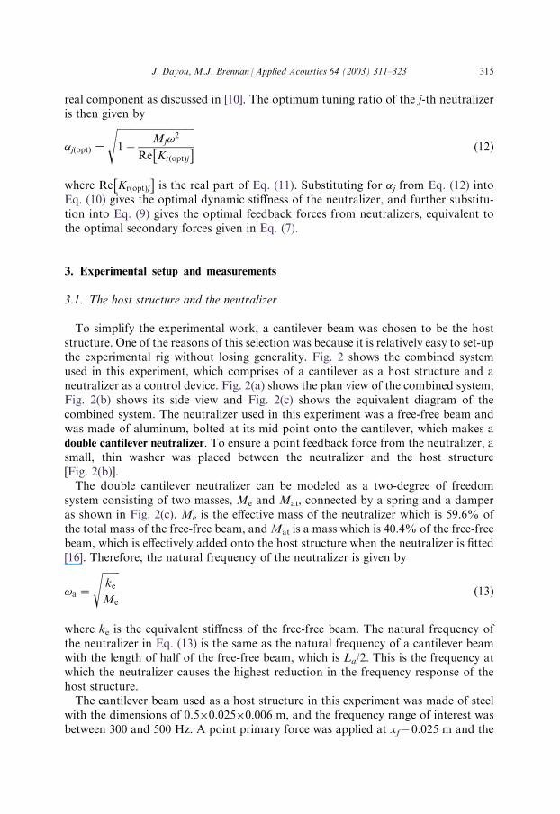
real component as discussed in [10]. The optimum tuning ratio of the j-th neutralizeris then given by
�jðoptÞ ¼
ffiffiffiffiffiffiffiffiffiffiffiffiffiffiffiffiffiffiffiffiffiffiffiffiffiffiffiffiffiffiffi1�
Mj!2
Re KrðoptÞj
� �s
ð12Þ
where Re KrðoptÞj
� �is the real part of Eq. (11). Substituting for �j from Eq. (12) into
Eq. (10) gives the optimal dynamic stiffness of the neutralizer, and further substitu-tion into Eq. (9) gives the optimal feedback forces from neutralizers, equivalent tothe optimal secondary forces given in Eq. (7).
3. Experimental setup and measurements
3.1. The host structure and the neutralizer
To simplify the experimental work, a cantilever beam was chosen to be the hoststructure. One of the reasons of this selection was because it is relatively easy to set-upthe experimental rig without losing generality. Fig. 2 shows the combined systemused in this experiment, which comprises of a cantilever as a host structure and aneutralizer as a control device. Fig. 2(a) shows the plan view of the combined system,Fig. 2(b) shows its side view and Fig. 2(c) shows the equivalent diagram of thecombined system. The neutralizer used in this experiment was a free-free beam andwas made of aluminum, bolted at its mid point onto the cantilever, which makes adouble cantilever neutralizer. To ensure a point feedback force from the neutralizer, asmall, thin washer was placed between the neutralizer and the host structure[Fig. 2(b)].The double cantilever neutralizer can be modeled as a two-degree of freedom
system consisting of two masses, Me and Mat, connected by a spring and a damperas shown in Fig. 2(c). Me is the effective mass of the neutralizer which is 59.6% ofthe total mass of the free-free beam, andMat is a mass which is 40.4% of the free-freebeam, which is effectively added onto the host structure when the neutralizer is fitted[16]. Therefore, the natural frequency of the neutralizer is given by
!a ¼
ffiffiffiffiffiffiffikeMe
sð13Þ
where ke is the equivalent stiffness of the free-free beam. The natural frequency ofthe neutralizer in Eq. (13) is the same as the natural frequency of a cantilever beamwith the length of half of the free-free beam, which is La/2. This is the frequency atwhich the neutralizer causes the highest reduction in the frequency response of thehost structure.The cantilever beam used as a host structure in this experiment was made of steel
with the dimensions of 0.5�0.025�0.006 m, and the frequency range of interest wasbetween 300 and 500 Hz. A point primary force was applied at xf=0.025 m and the
J. Dayou, M.J. Brennan /Applied Acoustics 64 (2003) 311–323 315
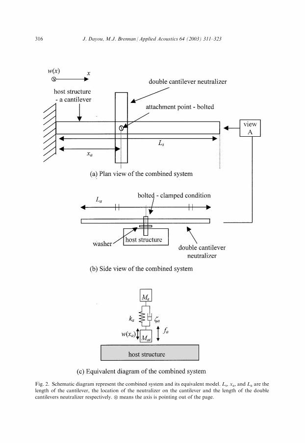
Fig. 2. Schematic diagram represent the combined system and its equivalent model. Ls, xa, and La are the
length of the cantilever, the location of the neutralizer on the cantilever and the length of the double
cantilevers neutralizer respectively. � means the axis is pointing out of the page.
316 J. Dayou, M.J. Brennan /Applied Acoustics 64 (2003) 311–323
modal damping ratio of the cantilever was set to be 0.05. This value was determinedby comparing the magnitude of the measured frequency response of the cantileverwith its theoretical prediction at its natural frequencies.
3.2. Physical properties of the neutralizers
The objective of this experiment was to show that a passive control device such asa neutralizer could be as effective as an active device in reducing the global responseof a structure when using the proposed optimal tuning method in Ref. [10]. In orderto achieve this, a simple approach was adopted by using six free-free beams as neu-tralizers to control the kinetic energy of the host structure at six different targetfrequencies within the specified range of interest. This was to simulate the result if asingle optimally detuned tunable vibration neutralizer was used. Three conditionswere investigated in this experiment [10].
a. When both real and imaginary parts of the required dynamic stiffness of Eq.(11) are positive, that is when the control device is required to be stiffness-likeand to absorb energy from the host structure.
b. When the real part is negative but the imaginary part of the required dynamicstiffness is positive, that is when the control device is required to be a mass-like and to absorb energy from the host structure.
c. When both real and imaginary parts of the required dynamic stiffness arenegative, that is when the control device is required to be a mass-like and tosupply energy to the host structure.
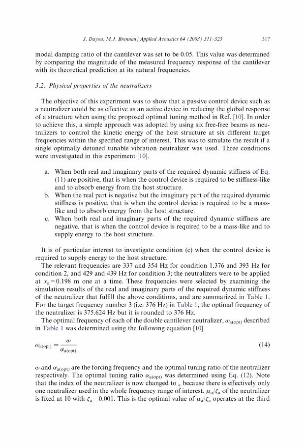
It is of particular interest to investigate condition (c) when the control device isrequired to supply energy to the host structure.The relevant frequencies are 337 and 354 Hz for condition 1,376 and 393 Hz for
condition 2, and 429 and 439 Hz for condition 3; the neutralizers were to be appliedat xa=0.198 m one at a time. These frequencies were selected by examining thesimulation results of the real and imaginary parts of the required dynamic stiffnessof the neutralizer that fulfill the above conditions, and are summarized in Table 1.For the target frequency number 3 (i.e. 376 Hz) in Table 1, the optimal frequency ofthe neutralizer is 375.624 Hz but it is rounded to 376 Hz.The optimal frequency of each of the double cantilever neutralizer, !a(opt) described
in Table 1 was determined using the following equation [10].
!aðoptÞ ¼!
�aðoptÞð14Þ
! and �a(opt) are the forcing frequency and the optimal tuning ratio of the neutralizerrespectively. The optimal tuning ratio �a(opt) was determined using Eq. (12). Notethat the index of the neutralizer is now changed to a because there is effectively onlyone neutralizer used in the whole frequency range of interest. �a/�a of the neutralizeris fixed at 10 with �a=0.001. This is the optimal value of �a/�a operates at the third
J. Dayou, M.J. Brennan /Applied Acoustics 64 (2003) 311–323 317
natural frequency of the host cantilever as determined using the numerical proce-dure described in [11,12]. The damping ratios of the neutralizers (�a) were deter-mined by comparing the measured frequency response of the neutralizer with thetheoretical prediction at its first resonance frequency, and the natural frequency ofthe neutralizer was determined by measuring the accelerance at the center of thedouble cantilevers neutralizer.The physical properties, the dimensions, the mass and the natural frequencies of
the neutralizers used in this experiment are summarized in Table 2. The naturalfrequency of the neutralizer is the first anti-resonance of the frequency responsefunction [2].Referring to Eq. (10), the optimal dynamic stiffness of the neutralizer can be
written as
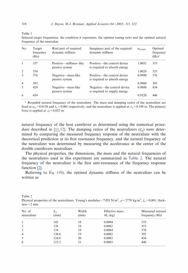
Table 1
Selected target frequencies, the condition it represents, the optimal tuning ratio and the optimal natural
frequency of the neutralize
No. Target
frequency
(Hz)
Real part of required
dynamic stiffness
Imaginary part of the required
dynamic stiffness
�a(opt) Optimal
frequency
(Hz)a
1 337 Positive—stiffness- like
passive system
Positive—the control device
is required to absorb energy
1.0051 335
2 354 1.0026 353
3 376 Negative—mass-like
passive system
Positive—the control device
is required to absorb energy
0.9990 376
4 393 0.9960 395
5 429 Negative—mass-like
passive system
Negative—the control device
is required to supply energy
0.9880 434
6 439 0.9520 446
a Rounded natural frequency of the neutralizer. The mass and damping ratios of the neutralizer are
fixed at �a=0.0138 and �a=0.001 respectively, and the neutralizer is applied at xa=0.198 m. The primary
force is applied at xf=0.025 m.
Table 2
Physical properties of the neutralizers. Young’s modulus=71E9 N/m2, �=2770 kg/m3, �a=0.001, thick-
ness=2 mm
No. of
neutralizer
La
(mm)
Width
(mm)
Effective mass,
Me (kg)
Measured natural
frequency (Hz)
1 142 18 0.0084 335
2 138 18 0.0082 353
3 134 19 0.0084 376
4 130.6 19 0.0082 395
5 124.8 20 0.0082 434
6 123.2 21 0.0085 446
318 J. Dayou, M.J. Brennan /Applied Acoustics 64 (2003) 311–323
KaðoptÞ ¼ �Me!2 1þ i2�a�aðoptÞ
1� �2aðoptÞ þ i2�a�aðoptÞ
" #ð15Þ
where �a is the damping ratio of the neutralizer, and �a(opt) is the optimal tuningratio between the forcing frequency ! to the natural frequency of the neutralizer[Eq. (14)], !a. Combining Eqs. (15), (9), (8) and (6) gives the kinetic energy of thecantilever. It should be noted that the effective added massMat onto the mass of thehost structure was ignored because it is very small (around 0.006 kg) compared tothe total mass of the cantilever, which is around 0.6 kg.
3.3. Measurements
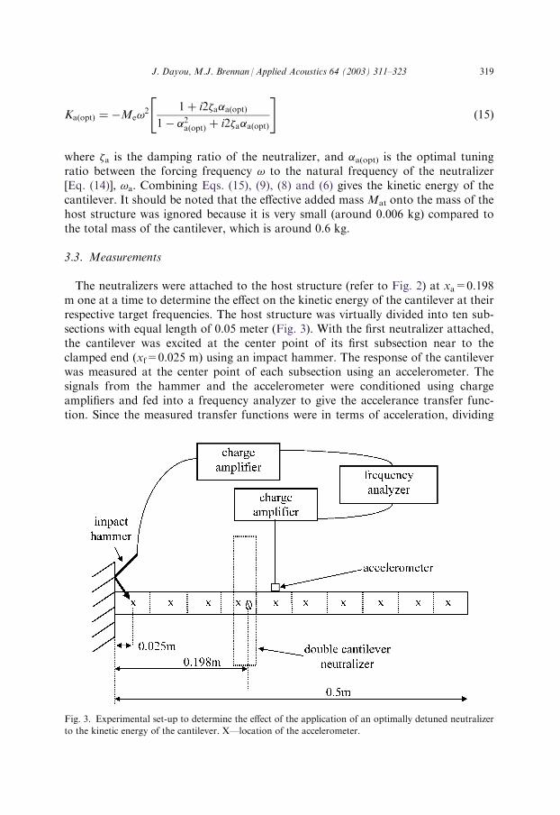
The neutralizers were attached to the host structure (refer to Fig. 2) at xa=0.198m one at a time to determine the effect on the kinetic energy of the cantilever at theirrespective target frequencies. The host structure was virtually divided into ten sub-sections with equal length of 0.05 meter (Fig. 3). With the first neutralizer attached,the cantilever was excited at the center point of its first subsection near to theclamped end (xf=0.025 m) using an impact hammer. The response of the cantileverwas measured at the center point of each subsection using an accelerometer. Thesignals from the hammer and the accelerometer were conditioned using chargeamplifiers and fed into a frequency analyzer to give the accelerance transfer func-tion. Since the measured transfer functions were in terms of acceleration, dividing
Fig. 3. Experimental set-up to determine the effect of the application of an optimally detuned neutralizer
to the kinetic energy of the cantilever. X—location of the accelerometer.
J. Dayou, M.J. Brennan /Applied Acoustics 64 (2003) 311–323 319
the measured transfer functions by i! gave the function in term of velocity. Inmathematical terms, if ej is the measured acceleration transfer function from the j-thsubsection in the modal domain, then the kinetic energy of the j-th subsection isgiven by
KEj ¼�whLs
40
eji!
2 ð16Þ
where KEj is the kinetic energy of the j-th subsection and �, w, h and Ls are thematerial density, the width, the thickness and the total length of the cantileverrespectively. Therefore, the total kinetic energy of the cantilever with 10 equal sub-sections is the summation of the kinetic energy of each subsection, which is
KE ¼XJ¼10
j¼1
KEj ð17Þ
The same procedure was followed for all of the neutralizers to determine their effectson the kinetic energy of the cantilever at their respective target frequency.
4. Results and discussion
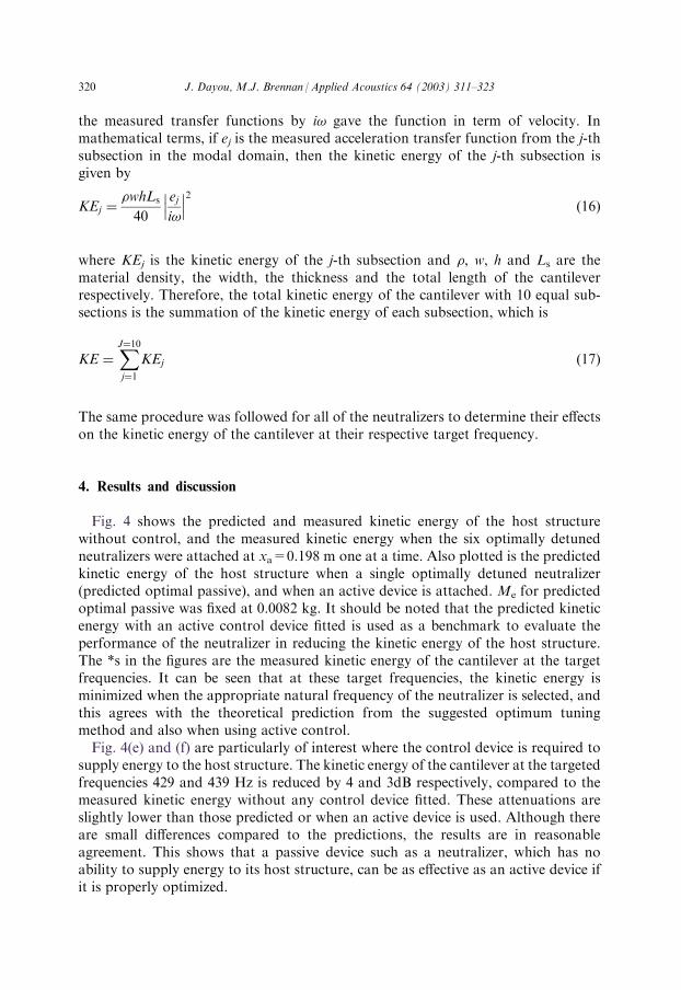
Fig. 4 shows the predicted and measured kinetic energy of the host structurewithout control, and the measured kinetic energy when the six optimally detunedneutralizers were attached at xa=0.198 m one at a time. Also plotted is the predictedkinetic energy of the host structure when a single optimally detuned neutralizer(predicted optimal passive), and when an active device is attached.Me for predictedoptimal passive was fixed at 0.0082 kg. It should be noted that the predicted kineticenergy with an active control device fitted is used as a benchmark to evaluate theperformance of the neutralizer in reducing the kinetic energy of the host structure.The *s in the figures are the measured kinetic energy of the cantilever at the targetfrequencies. It can be seen that at these target frequencies, the kinetic energy isminimized when the appropriate natural frequency of the neutralizer is selected, andthis agrees with the theoretical prediction from the suggested optimum tuningmethod and also when using active control.Fig. 4(e) and (f) are particularly of interest where the control device is required to
supply energy to the host structure. The kinetic energy of the cantilever at the targetedfrequencies 429 and 439 Hz is reduced by 4 and 3dB respectively, compared to themeasured kinetic energy without any control device fitted. These attenuations areslightly lower than those predicted or when an active device is used. Although thereare small differences compared to the predictions, the results are in reasonableagreement. This shows that a passive device such as a neutralizer, which has noability to supply energy to its host structure, can be as effective as an active device ifit is properly optimized.
320 J. Dayou, M.J. Brennan /Applied Acoustics 64 (2003) 311–323
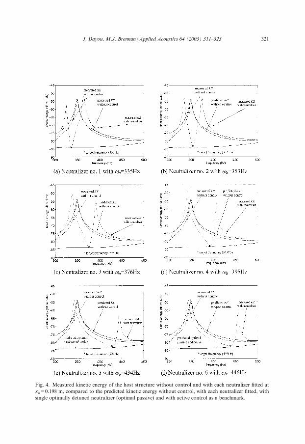
Fig. 4. Measured kinetic energy of the host structure without control and with each neutralizer fitted at
xa=0.198 m, compared to the predicted kinetic energy without control, with each neutralizer fitted, with
single optimally detuned neutralizer (optimal passive) and with active control as a benchmark.
J. Dayou, M.J. Brennan /Applied Acoustics 64 (2003) 311–323 321
Fig. 5 summarizes the results presented in Fig. 4; that is the kinetic energy of thecantilever at the target frequencies for all six optimally detuned neutralizers placedone at a time. This figure can be considered as the kinetic energy of the cantileverbeam when only one optimally detuned tunable vibration neutralizer is in used.Overall, the kinetic energy of the cantilever at the target frequencies when each ofthe neutralizers was applied is within �1 dB of the predicted kinetic energy wheneither a single optimally detuned neutralizer or an active device is used.
5. Conclusions
Experimental evidence to support the proposed optimal tuning of a vibrationneutralizer in reducing the global vibration of a continuous structure has been pre-sented in this paper. It has been shown that the effectiveness of the vibration neutralizeris comparable to that of active control as predicted by the authors [10].
References
[1] Bernhard RJ, Hall HR Jones JD. Adaptive-passive noise control; inter-noise 1992, 20–22 July 1992,
Toronto, Ontario, Canada.
[2] Brennan MJ. Vibration control using a tunable vibration neutralizer. Proc Instn Mech Engrs Part C.
Journal of Mechanical Engineering Science 1997;211:91–108.
[3] Brennan MJ. Control of flexural waves on a beam using a tunable vibration neutralizer. Journal of
Sound and Vibration 1998;222(3):389–407.
[4] Charette F, Fuller CR, Carneal JP. Control of sound radiation from plates using globally detuned
absorbers. Journal of Acoustical Society of America 1996;100(4):2781.
[5] Guigou, C, Maillard JP, Fuller CR. Study of globally detuned absorbers for controlling aircraft
interior noise. Fourth International Conference on Sound and Vibration, St. Petersburg, Russia, 24–
27 June 1996.
Fig. 5. Experimental results on the kinetic energy of the cantilever using neutralizer with optimal tuning
ratio at the targeted frequencies. The *s are the measured kinetic energy at the target frequencies of the
neutralizer with the optimal frequency attached.Me for predicted optimal passive is fixed at 0.0082 kg and
the result from active control is used as a benchmark.
322 J. Dayou, M.J. Brennan /Applied Acoustics 64 (2003) 311–323
[6] Huang YM, Fuller CR. Vibration and noise control of the fuselage via dynamic absorbers. Trans-
action of ASME: Journal of Vibration and Acoustics 1998;120:496–502.
[7] Kidner MRF. An active vibration neutralizer. PhD degree thesis, University of Southampton, 1999.
[8] Kitagawa Y, Midorikawa M. Seismic isolation and passive response-control buildings in Japan.
Smart Mater Struct 1998;7(5):581–7.
[9] Lang MA, Lorch DR, May DN, Simpson MA. MD-80 aircraft cabin noise control: a case history.
NASA/SAE/DLR 4th Aircraft Interior Noise Workshop 1992:13–33.
[10] Dayou J, Brennan MJ. Optimal tuning for tunable vibration neutralizer. Proc Instn Mech Engrs Part
C. Journal of Mechanical Engineering Science 2001;215:933–42.
[11] Brennan MJ, Dayou J. Global control of vibration using a tunable vibration neutralizer. Journal of
Sound and Vibration 2000;232(3):585–600.
[12] Brennan MJ, Dayou J. Global control of vibration using a tunable vibration neutralizer. Noise and
Vibration Worldwide 2001;32(5):16–23.
[13] Dayou J. Global control of flexural vibration of a one dimensional structure using tunable vibration
neutralizers. PhD degree thesis, University of Southampton, 1999.
[14] Dayou J, Brennan, MJ. Global control of structural vibration using multiple tuned tunable vibration
neutralizers. Journal of Sound and Vibration (in press).
[15] Nelson PA, Elliott SJ. Active control of sound. Academic Press; 1992.
[16] Kidner MRF, Brennan MJ. Improving the performance of a vibration neutralizer by actively
removing damping. Journal of Sound and Vibration 1999;221(4):587–606.
J. Dayou, M.J. Brennan /Applied Acoustics 64 (2003) 311–323 323


