Embed Size (px)
Citation preview
________________________________________
*Author for correspondence; E-mail: [email protected]
Int. J. Chem. Sci.: 14(4), 2016, 2645-2657 ISSN 0972-768X
www.sadgurupublications.com
EXPERIMENTAL STUDY ON PROCESS COST REDUCTION IN ELECTRO DEPOSITION PROCESS
K. SAKTHIVEL, V. MATHANRAJ* and G. MANIKANDARAJA
Department of Mechanical Engineering, SRM University, CHENNAI – 603203 (T.N.) INDIA
ABSTRACT
Recently, significant attention has been directed towards the use of energy analysis in the assessment of thermal and other industrial processes and their environmental impacts since energy analysis is an effective tool both for achieving efficient energy utilization with minimum (or zero) environmental impact and for understanding environmental issues. In this study, the new design and electrification of the hangar system for Electro Deposition (ED) coating system gives energy saving in process as well as reduction in material consumption. The same can be horizontality deployed in all automobile and auto components manufacturing industries in ED coating plant. The modified Hangars were tried in the production line and observed for the period of 52 days and found Current consumption reduction of 270 Amps/car body and material consumption reduction of 1.32 Kg/product.
Key words: Energy, Cost, Consumption, Quality & environment.
INTRODUCTION
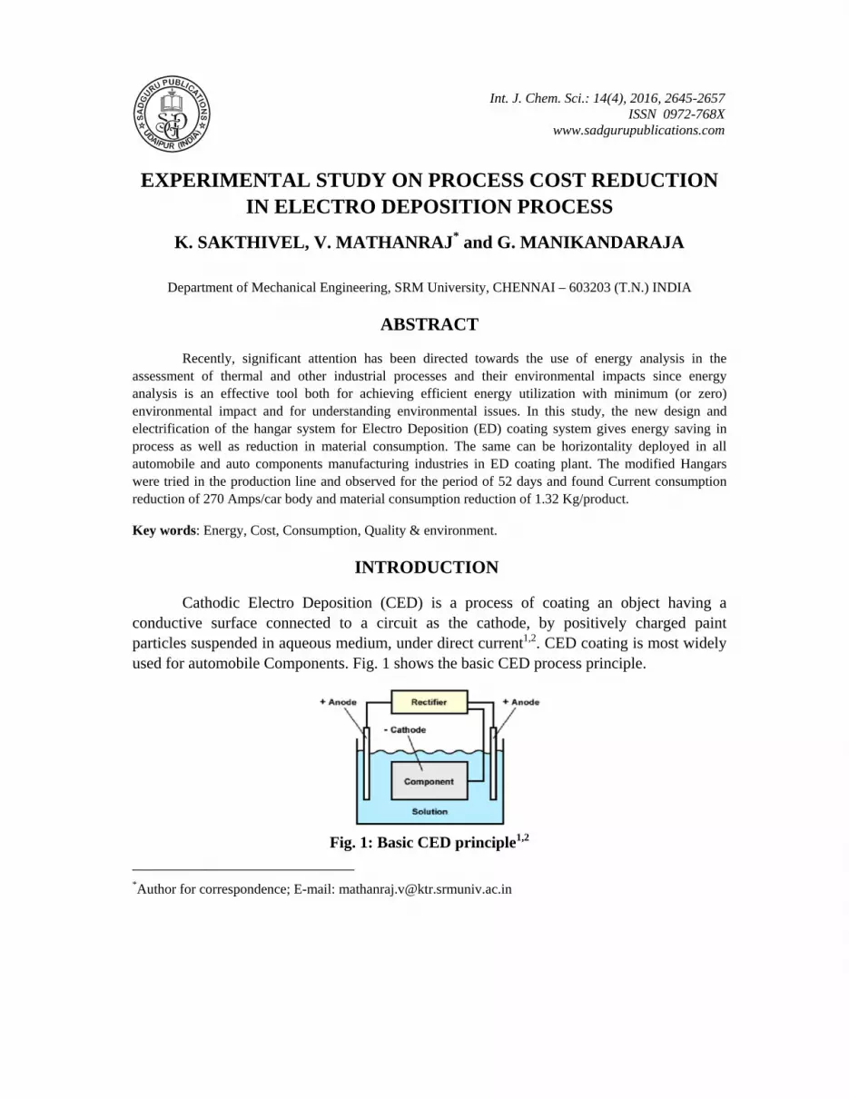
Cathodic Electro Deposition (CED) is a process of coating an object having a conductive surface connected to a circuit as the cathode, by positively charged paint particles suspended in aqueous medium, under direct current1,2. CED coating is most widely used for automobile Components. Fig. 1 shows the basic CED process principle.
Fig. 1: Basic CED principle1,2
K. Sakthivel et al.: Experimental Study on Process…. 2646
CED is most advanced and environment friendly water based coating to be done on metal components. A combination of dip and spray ensures reach of paint at every corner of component having intrinsic shape as well. CED is chemically resistant, mechanically durable, and pleasant in appearance having very good salt spray life and is sought for by all automobile users2. ED Coating is the first coating layer which gives the corrosion resistant and good adhesion property for the next coating layer. The ED coating will be maintained min of 20 micron thickness. ED process is done in the car bodies by having the facility to hold the product in a carrier/Hangar, with proper seating & locking arrangements. Here the study aims, to reduce the running cost of the process by reducing the energy consumption by implementing the small modification in the car body holding carrier/hangar.
Objectives
The cost reduction objectives includes:
1. Energy conservation in ED process
2. Raw material consumption reduction
Basic ED coating plant condition & facility details
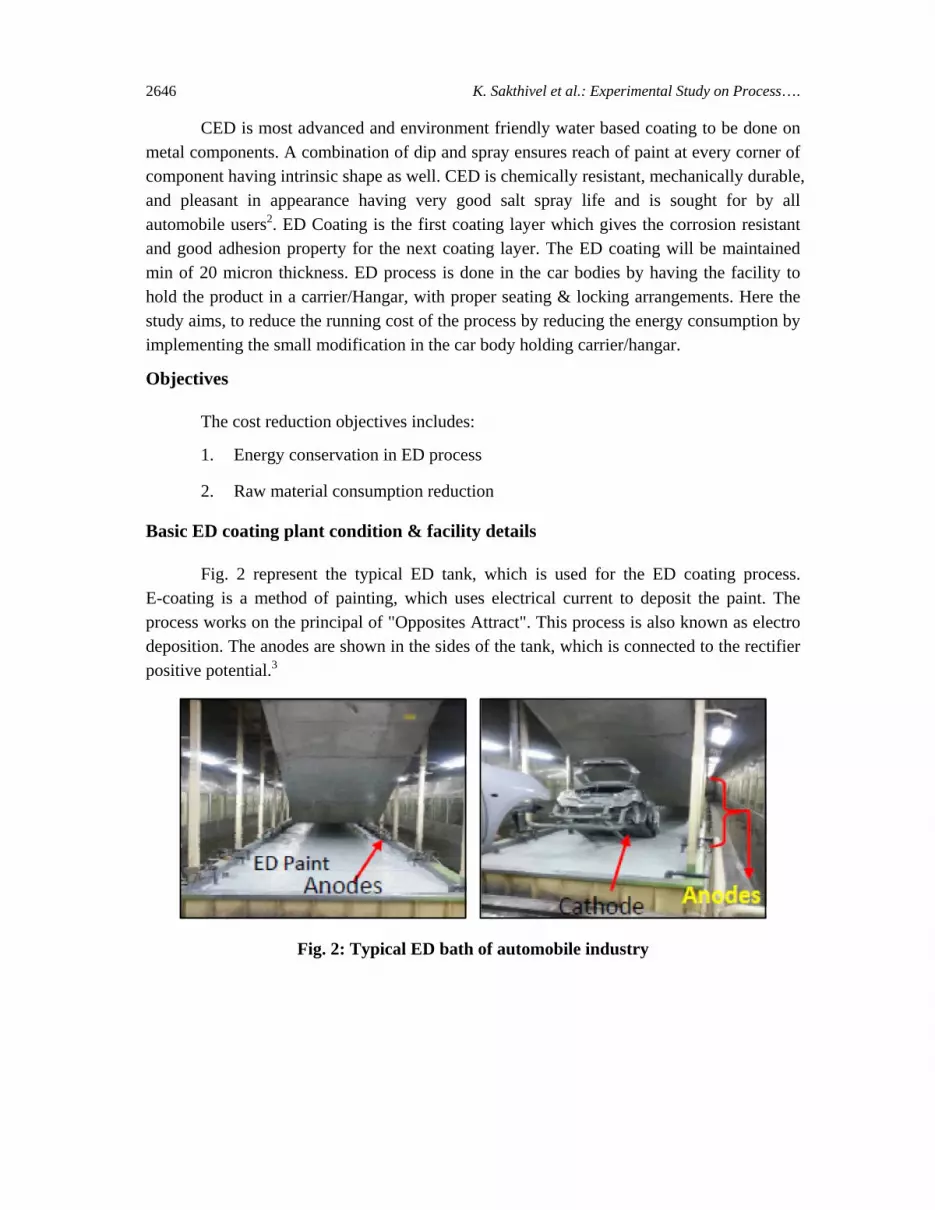
Fig. 2 represent the typical ED tank, which is used for the ED coating process. E-coating is a method of painting, which uses electrical current to deposit the paint. The process works on the principal of "Opposites Attract". This process is also known as electro deposition. The anodes are shown in the sides of the tank, which is connected to the rectifier positive potential.3
Fig. 2: Typical ED bath of automobile industry

Int. J. Chem. Sci.: 14(4), 2016 2647
Fig. 3 depicts the cable connection from carbon brush to hangar body seating point. The rectifier positive terminal is connected to the ED bath anodes and the negative terminal is connected to the bus bar.
Fig. 3: Cathode connection to hangar
E-coat offers a high corrosion resistance, normally in excess of 1000 hours salt spray resistance as well as an excellent aesthetic appearance4-6. This surface finish to provides a hard surface coupled with good chemical resistance giving excellent wear properties and is an excellent alternative to powder coating on many applications
The metal frame of a vehicle has an extremely complex shape, which makes it virtually impossible to coat many areas with conventional spray-applied paint. In order to achieve maximum corrosion resistance, the first coating layer in vehicle production is applied via electro deposition. This process is the most automatic, controllable, and efficient method for applying a corrosion inhibiting primer to a metallic work piece10-13.
Fig. 4: ED process flow4,5
K. Sakthivel et al.: Experimental Study on Process…. 2648
The metal body is electrically charged and immersed in a bath containing oppositely charged paint particles, which are attracted to the metal surface, and then baked into a tough film. Current practice favours making the vehicle body as the cathode in this process (this minimises corrosion of steel). Coatings used in this process are called cathodic electro coats7-9. Fig. 4, indicate the electro coating process sequence and process flow for the clear understanding.
Body seating arrangements - Hangars
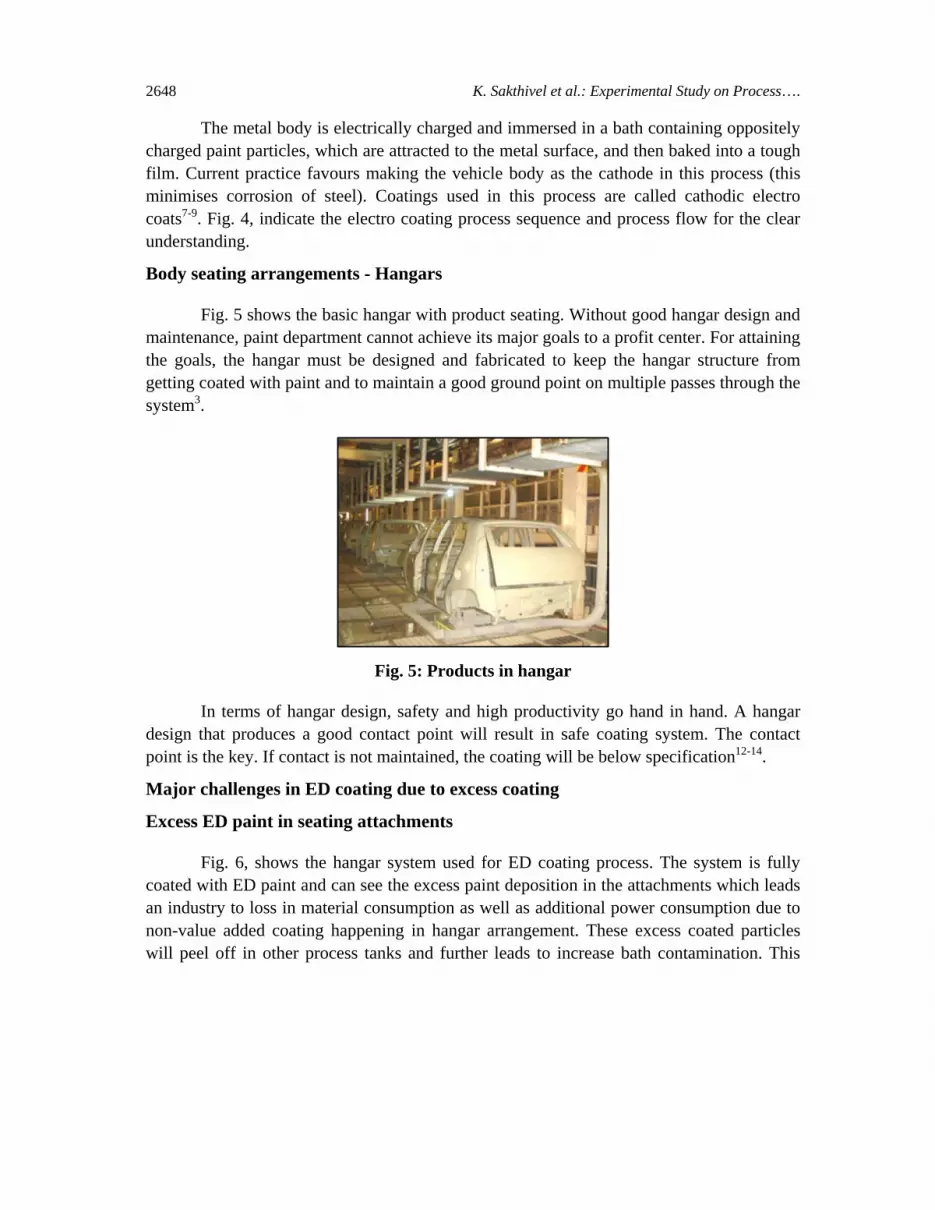
Fig. 5 shows the basic hangar with product seating. Without good hangar design and maintenance, paint department cannot achieve its major goals to a profit center. For attaining the goals, the hangar must be designed and fabricated to keep the hangar structure from getting coated with paint and to maintain a good ground point on multiple passes through the system3.
Fig. 5: Products in hangar
In terms of hangar design, safety and high productivity go hand in hand. A hangar design that produces a good contact point will result in safe coating system. The contact point is the key. If contact is not maintained, the coating will be below specification12-14.
Major challenges in ED coating due to excess coating
Excess ED paint in seating attachments
Fig. 6, shows the hangar system used for ED coating process. The system is fully coated with ED paint and can see the excess paint deposition in the attachments which leads an industry to loss in material consumption as well as additional power consumption due to non-value added coating happening in hangar arrangement. These excess coated particles will peel off in other process tanks and further leads to increase bath contamination. This

Int. J. Chem. Sci.: 14(4), 2016 2649
deposition in hangars will result in production loss due to major breakdown, failure in part locking mechanism.
Fig. 6: ED Coating in seating arrangements
Excess paint in the locking arrangements
Fig. 7 shows the excess paint deposition in the locking arrangements, which will fill in the clearance of shaft and barrel of locking unit. This deposition will make difficult to open and close the locking arrangement. This results in production loss due to equipment breakdown.
Fig. 7: Locking mechanism with paint deposition
Excess paint in all over the hanger surface
Fig. 8 illustrates the excess paint deposition in the hangar surface, because of full hangar is applied electrification for ED Coating process. This excess deposition happens due to repeated process and this excess paint coating will chip off in other process baths due to
K. Sakthivel et al.: Experimental Study on Process…. 2650
water and chemical turbulence and create the process bath contaminations, which will be results in defects/unit increase.
Fig. 8: Excess ED coating on hangar surface
Root cause analysis
The Root cause for these above mentioned problems is due to the excess paint deposition because of full hangar electrification.
Non insulated electrification cable
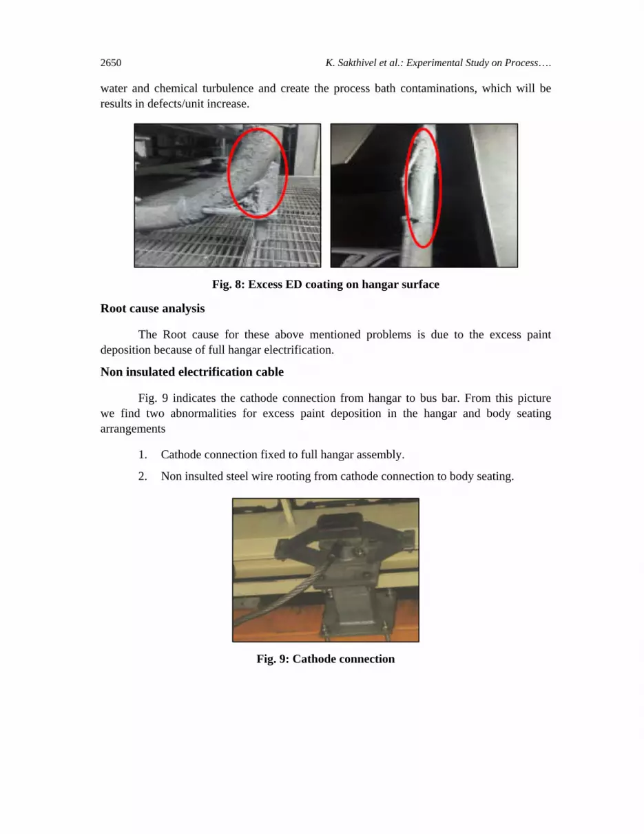
Fig. 9 indicates the cathode connection from hangar to bus bar. From this picture we find two abnormalities for excess paint deposition in the hangar and body seating arrangements
1. Cathode connection fixed to full hangar assembly.
2. Non insulted steel wire rooting from cathode connection to body seating.
Fig. 9: Cathode connection
Int. J. Chem. Sci.: 14(4), 2016 2651
Because of the cathode connection is connected to the full hangar assembly. The electrification passes to the whole hangar and CED takes place in all over the hangar results in excess paint deposition in hangar surface and body seating arrangements.
Proposals
There are two solutions available to eliminate the excess paint deposition in the hangar surface and body seating arrangements. This will avoid the excess paint deposition and reduce the paint sludge carry over to the other process baths.
So the contaminations due the paint sludge carry over and dry particles falling down in the process baths will reduce and the defects causes due to this will be eliminated,
The actions to be taken in part handling hangar are given below:
1. Insulator to be provide in between the Cathode connection & Hangar.
2. Insulated cable to be connected from hangar to body seating arrangement.
Experiment details
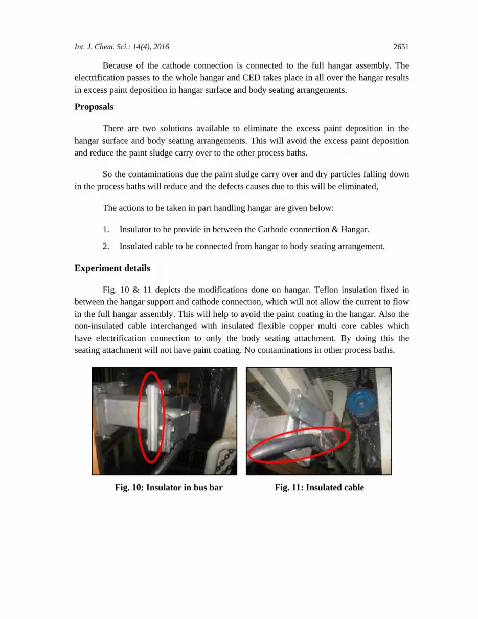
Fig. 10 & 11 depicts the modifications done on hangar. Teflon insulation fixed in between the hangar support and cathode connection, which will not allow the current to flow in the full hangar assembly. This will help to avoid the paint coating in the hangar. Also the non-insulated cable interchanged with insulated flexible copper multi core cables which have electrification connection to only the body seating attachment. By doing this the seating attachment will not have paint coating. No contaminations in other process baths.
Fig. 10: Insulator in bus bar Fig. 11: Insulated cable
K. Sakthivel et al.: Experimental Study on Process…. 2652
This results in reduction of ED process current consumption and raw material reduction.
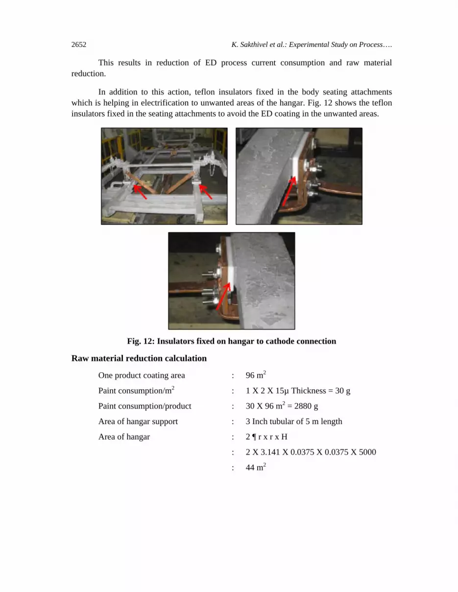
In addition to this action, teflon insulators fixed in the body seating attachments which is helping in electrification to unwanted areas of the hangar. Fig. 12 shows the teflon insulators fixed in the seating attachments to avoid the ED coating in the unwanted areas.
Fig. 12: Insulators fixed on hangar to cathode connection
Raw material reduction calculation
One product coating area : 96 m2
Paint consumption/m2 : 1 X 2 X 15µ Thickness = 30 g
Paint consumption/product : 30 X 96 m2 = 2880 g
Area of hangar support : 3 Inch tubular of 5 m length
Area of hangar : 2 ¶ r x r x H
: 2 X 3.141 X 0.0375 X 0.0375 X 5000
: 44 m2
Int. J. Chem. Sci.: 14(4), 2016 2653
Paint consumption of hangar : 30 gm x 44 = 1320 g savings
Cost/m2 coating : Rs : 10.74/-
Cost saving/product : 44 X 10.74 = Rs : 457.6/product
Current consumption reduction calculation
Current consumption/m2 : 6.07 Amps
Area of hangar support : 3 Inch tubular of 5 m length
Area of hangar : 2 ¶ r x r x H
: 2 X 3.141 X 0.0375 X 0.0375 X 5000
: 44 m2
Area of product : 96 m2
Total area for coating : 96 + 44 m2 = 140 m2
Current consumption : 850 Amps
Current consumption for hangar only : 44 X 6.07 = 267.14 Amps
Current consumption for product only : 96 X 6.07 = 582.72 Amps
One product body coating current : 850 Amps (Before modification)
One product body coating current : 580 Amps (After modification)
Current consumption reduction : 850-580 = 270 Amps
(kW) : Amp X Volt/1000
: 270 X 280/1000 = 75.6 kW Saving
This current consumption reduction is achieved because of eliminating the unwanted coating area in the hangar and body seating attachments. This reduction in current consumption gives the 75.6 kW savings/product. In addition to this, reduction in paint raw material consumption and defects per unit. So finally we are achieving cost reduction and quality improvement by reducing the Defects and other process like filter change frequency increase and hanger cleaning frequency increase.
Current consumption trend during trial
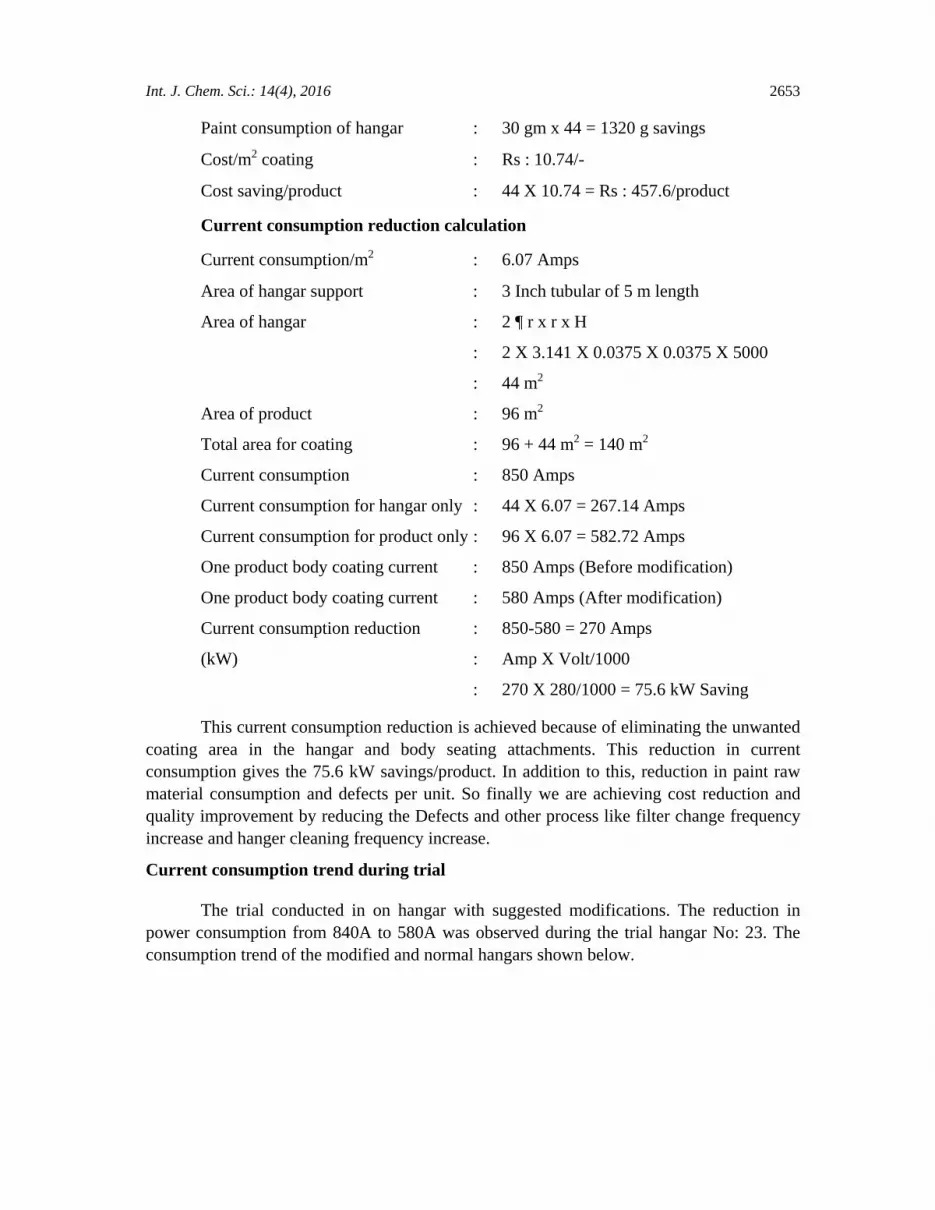
The trial conducted in on hangar with suggested modifications. The reduction in power consumption from 840A to 580A was observed during the trial hangar No: 23. The consumption trend of the modified and normal hangars shown below.
K. Sakthivel et al.: Experimental Study on Process…. 2654
1 2 3 4 5 6 7 8 9 10 11 12 13 14 15 16 17 18 19 20 21 22 23 24 25 26 27 28 29 30 31 32 33 34 35 36 37 38 39 40
1200
1000
800
600
400
200
0
Cur
rent
in A
mp
(I)
Hangar No
Fig. 13: Trial hangar no 23 – Current consumption
Fig. 13 shows the current consumption trend of hangar No 23 consuming less current compare to the other hangars which are not modified, the modified Hangar is consuming only 576 Amps were as the other hangars are averagely 850 Amps.
Present current consumption trend
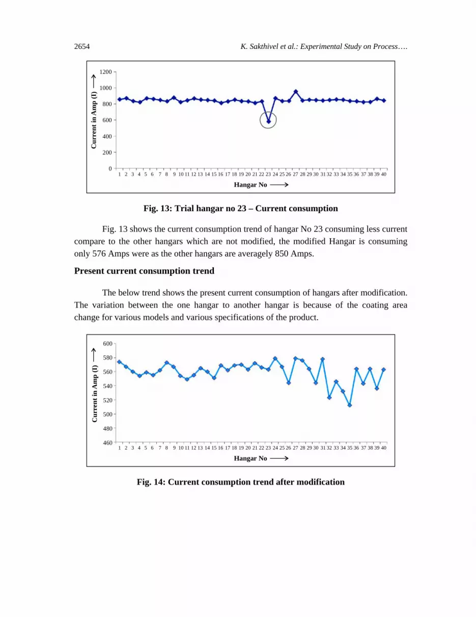
The below trend shows the present current consumption of hangars after modification. The variation between the one hangar to another hangar is because of the coating area change for various models and various specifications of the product.
1 2 3 4 5 6 7 8 9 10 11 12 13 14 15 16 17 18 19 20 21 22 23 24 25 26 27 28 29 30 31 32 33 34 35 36 37 38 39 40
600
580
560
540
520
500
480
460
Cur
rent
in A
mp
(I)
Hangar No
Fig. 14: Current consumption trend after modification
Int. J. Chem. Sci.: 14(4), 2016 2655
Fig. 14 shows the trend of present current consumption of hangars after modification. The variation between the one hangar to another hangar is because of the coating area change for various models and various specifications of the product. The current consumption of all hangars falls between 500 A to 580 A.
RESULTS AND DISCUSSION
(1) Current consumption reduction/Product : 270 Amps
(2) Power savings/hangar : 75.6 kW
(3) CED paint material consumption reduction : 1.32 Kg
(4) Material cost reduction/product : 457.6 INR
CONCLUSION
The hangars are expensive to make. However the single investment will improves huge savings in power consumption and paint material consumption. The hangar problems tend to have a creeping effect. The productivity changes cannot be noticed. If this is not corrected, suddenly a loss and breakdown are expected.3
To avoid this, continuous monitoring to be in place to notice what’s happening in the system, have a look on hangar and conveyor system for paint deposition. As discussed above, do the changes in the hangar, skids to have contacts only in the required area and isolate the unwanted part of the hangar and skids from electrification. This will give good result in energy conservation and material consumption.
(i) Frequent power consumption monitoring of hangars to be in place
(ii) Electrification to be applied only to the product
(iii) Less area of product seating supports to be planed
(iv) Proper isolating to be made for the seating supports
ACKNOWLEDGEMENT
The author would like to thank the management of M/S Renault Nissan for providing the facility to prove the hangar electrification, consumption reduction study, experimental trials & Implementations.
K. Sakthivel et al.: Experimental Study on Process…. 2656
REFERENCES
1. B. M. Quinn, C. Dekker and Serge G. Lemay, Electrode Position of Noble Metal Nanoparticles on Carbon Nanotubes, J. Am. Chem. Soc., 127(17), 6146-6147 (2005).
2. P. N. Shinde and M. S. Kumbhar, Interlock in Software in CED Paint Shop for Cost and Quality Improvement, Int. J. Engg. Res. Technol., 4(2), 719-725 (2015).
3. Sophie Peulon and Daniel Lincot, Mechanistic Study of Cathodic Electro deposition of Zinc Oxide and Zinc Hydroxychloride films from Oxygenated Aqueous Zinc Chloride Solutions, J. Electro Chem. Soc., 145(3), 864-874 (1998).
4. H. C. Shin, J. Dong and M. Liu, Nanoporous Structures Prepared by an Electrochemical Deposition Process, Adv. Mater., 15(19), 1610-1614 (2003).
5. Y. Liu, X. M. Yin, J. J. Zhang et al., A Electro-Deposition Process for Fabrication of Biomimetic Super-Hydrophobic Surface and its Corrosion Resistance on Magnesium Alloy, Electrochimica Acta, 125, 395-403 (2014).
6. Srisawat, Supsomboon, Process Improvement of Automotive Paint Shop, IJMMME, 1, 9 (2013).
7. T. S. N. Sankara Narayanan, Surface Pre-Treatment by Phosphate Conversion Coatings, Rev. Adv. Mater. Sci., 9, 130-177 (2005).
8. J. W. Gailen and E. J. Vaughan, Protective Coatings for Metals, Charles Griffin & Co. Ltd. (1979) p. 97.
9. F. L. La Que, In: Good Painting Practice, Ed. by John D. Keane, Vol. 1, 2nd Ed., Steel Structures Painting Council, Pittsburgh, Chap. 1.1 (1973) p. 3.
10. D. B. Freeman, Phosphating and Metal Pretreatment - A Guide to Modern Processes and Practice, Industrial Press Inc., New York (1986).
11. W. Mc Lead, D. V. Subrahmanyam and G. R. Hoey, Electrodep. Surf. Treat., 3, 335 (1975).
12. T. S. N. Sankara Narayanan and M. Subbaiyan, In: Surface Engineering- Fundamentals of Coatings, Ed. by P. K. Datta and J. S. Gray, Royal Society of Chemistry, London, 1, 132 (1993).
13. D. Rajenthirakumar, P. V. Mohanram and S. G. Harikarthik, Int. J. Lean Thinking, 2(1), 47 (2011).
Int. J. Chem. Sci.: 14(4), 2016 2657
14. T. S. N. Sankara Narayanan and M. Subbaiyan, Surf. Coat. Int. (JOCCA), 75(5), 184 (1992).
15. J. V. Laukonis, In: Interface Conversion for Polymer Coatings, Ed. by P. Weiss and G.D. Cheever, American Elsevier Publishing Company Inc., New York (1968) p. 182.
Revised : 02.10.2016 Accepted : 04.10.2016


