Embed Size (px)
Citation preview
Author's personal copy
Enhanced hydrogen and methane gas storage of silicon oxycarbide derived carbon
Cekdar Vakifahmetoglu a,1, Volker Presser b, Sun-Hwa Yeon b,2, Paolo Colombo a,3, Yury Gogotsi b,⇑a Dipartimento di Ingegneria Meccanica – Settore Materiali, University of Padova, 35131 Padova, Italyb Department of Materials Science and Engineering, A.J. Drexel Nanotechnology Institute, Drexel University, Philadelphia, PA 19104, USA
a r t i c l e i n f o
Article history:Received 24 January 2011Received in revised form 28 March 2011Accepted 28 March 2011Available online 1 April 2011
Keywords:Carbide derived carbonHydrogen storageMethane storagePolymer derived ceramics
a b s t r a c t
Two polysilsesquioxanes, with an empirical formula (RSiO1.5)n R = CH3 (PMS) and CH3–C6H5 (PMPS) werepyrolyzed at 1200 �C for 2 h to form SiOC ceramics of variable composition. Etching of polymer-derivedSiOC ceramics with chlorine gas at 1200 �C produced micro-/mesoporous carbon with a high specific sur-face area (SSA) reaching up to 2700 m2/g, hierarchical pore structure and showing very large pore vol-umes (up to 1.72 cc/g) without activation. Both, the SiOC precursors and the porous silicon oxycarbidederived carbons (SiOC-CDCs) were characterized in detail. Dissimilarities in the chemical compositionand free carbon content of the formed ceramics yielded different microstructures at the nanoscale. Thisfeature affected the final SSA and pore size distribution of the SiOC-CDC materials. The hydrogen andmethane storage capacity of the produced SiOC-CDC materials yielded maximum excess gravimetricuptake of 5.5 wt.% H2 at �196 �C and 21.5 wt.% CH4 at 25 �C and 60 bar. These values are higher thanfor other CDCs, nanotubes and activated carbons tested under the same conditions.
� 2011 Elsevier Inc. All rights reserved.
1. Introduction
Starting from early 1960s, polymeric precursors have been usedto produce advanced ceramics at significantly lower temperatures(T < 1500 �C) than the conventional powder sintering processing[1,2]. The interest in this approach has been increasing in the lastthree decades after the commercialization of preceramic polymers[3]. These precursors are organic–inorganic polymers with a back-bone usually containing Si atoms, which yield so called polymerderived ceramics (PDCs) via elimination of organic moieties. Thethermolysis of silicon-based polymeric precursors under con-trolled atmospheres has proven to be a very promising route forthe fabrication of advanced ceramic components, such as fibers,coatings, porous media, or complex-shaped structures. Manyexamples of polysilanes, polycarbosilanes, polysilazanes and poly-siloxanes have been used as precursors for the production of sili-con-based ceramics (SiC, Si3N4, SiOC, SiOCN, SiCN and Si(E)CN,where E = B, Al, Ti, etc.) in recent years [1]. PDCs form amorphousphases (e.g., SiOC or SiCN), in which nanocrystallites (such as SiC or
Si3N4) and free carbon (carbon not linked to Si atoms) can co-existand the structure evolution occurs with pyrolysis temperature [2].This complex nanostructure gives remarkable properties, such asgiant piezoresistivity, very low creep rate, high chemical resistanceand high thermal stability in comparison to conventional high-techceramics [4–6]. During pyrolysis (generally > 1200 �C) this com-plex amorphous phase separates into thermodynamically stablebinary compounds (e.g., SiC, Si3N4, SiO2, etc.) and multiphase cera-mic materials can be obtained. A comprehensive review on this to-pic can be found in Ref. [2].
Porous carbons having a wide variety of structures (micro-/mesoporous, amorphous/crystalline, etc.) find numerous applica-tions in gas storage, molecular sieves, absorbents, catalyst sup-ports, electrodes in batteries and supercapacitors, water/airfilters, and biomedical devices. They can be obtained using varioustechniques, such as activation or templating. Improved controlover the specific surface area, pore size and pore volume of porouscarbon has been reported for carbide derived carbon (CDC) [7,8].Chlorination of binary or ternary carbides has proven to yieldamorphous porous carbon with high SSA of up to 3100 m2/g andpore characteristics which are a function of synthesis temperatureand choice of carbide precursor [9,10]. Tuning of the pore size dis-tribution (PSD) with sub-Angström accuracy makes it possible tooptimize CDC for a specific application such as gas storage, tribol-ogy or electrochemistry [8,11,12]. Post-synthesis annealing is acommon way to further modify the properties of porous carbonto remove residual chlorine from the CDC synthesis and to improvesorption properties by obtaining a particular surface terminationor to increase the SSA up to 3300 m2/g [13,14].
1387-1811/$ - see front matter � 2011 Elsevier Inc. All rights reserved.doi:10.1016/j.micromeso.2011.03.042
⇑ Corresponding author. Tel.: +1 215 895 6446; fax: +1 215 895 1934.E-mail addresses: [email protected] (C. Vakifahmetoglu), vp344@drexel.
edu (V. Presser), [email protected] (S.-H. Yeon), [email protected] (P. Colombo),[email protected] (Y. Gogotsi).
1 Present address: Department of Materials Science and Engineering, Rutgers, TheState University of New Jersey, NJ 08854, USA.
2 Present address: Climate Change Technology Research Division, Korea Institute ofEnergy Research, Daejeon 305-343 Republic of Korea.
3 Also with: Department of Materials Science and Engineering, Pennsylvania StateUniversity, PA 16802, USA.
Microporous and Mesoporous Materials 144 (2011) 105–112
Contents lists available at ScienceDirect
Microporous and Mesoporous Materials
journal homepage: www.elsevier .com/locate /micromeso

Author's personal copy
Recently, we have shown that PDCs provide an additional de-gree of freedom for optimizing CDC porosity and performance bycontrolling the pyrolysis conditions (e.g., temperature). Pyrolysisof a commercial polysilazane precursor in the 600–1400 �C tem-perature range produced polymer-derived silicon carbonitride(SiCN) ceramics, which formed hierarchically porous (micro-/mesoporous) disordered/graphitic CDC materials with SSA in therange of 800–2400 m2/g after high temperature chlorination [15].High specific surface area of 3100 m2/g for activated PDC-CDCobtained from pyrolyzed electrospun polycarbosilane fibers wasreported by Rose et al. [9]. Although there have been reports onPDC-CDC derived from polycarbosilane and polysilazane precur-sors [9,15–18], no study has yet focused on SiOC ceramics. Studieson Si(O)C fibers reported CDC coatings, but no information on porestructure has been reported [19,20]. Albeit, it was shown that if aSiOC glass is etched for a long time (6 h) with a highly concentratedHF solution (�20%), the silica phase can be extracted leaving be-hind a highly porous oxycarbide-derived carbonaceous materialcontaining SiC crystallites and Si atoms bonded to carbon, withSSA values as high as 700 m2/g and high pore volume up to1.2 cm3/g [21,22]. It is important to note that this material canbe derived from commercially available, inexpensive, easy to han-dle and versatile precursors such as polysiloxanes.
The objectives of the present investigation were: (i) provide in-sights into phase evolution of SiOC ceramics derived from commer-cial silicon resins (polysiloxanes) at the nanoscale level, (ii) useSiOC ceramics to produce high SSA porous carbon with a hierarchi-cal pore structure referred to as SiOC-CDC (silicon oxycarbide de-rived carbon), and (iii) evaluate the potential of SiOC-CDCmaterials for gas storage applications.
2. Materials and methods
2.1. Materials
SiOC samples having two different carbon contents were pre-pared by using commercially available preceramic polymers. In or-der to produce SiOC ceramics with a low carbon content,polymethylsilsesquioxane ([(CH3SiO1.5)]n with n = 130–150, SilresMK, Wacker GmbH, Burghausen, Germany; total carbon after pyro-lysis: �13 wt.%) was used denoted as PMS in the remainder of thetext. For synthesis of SiOC with a higher carbon content, a poly-methylphenylsilsesquioxane ([(C6H5)0.62(CH3)0.31(OR)0.07SiO1.5]n
with n � 20, Silres H44, Wacker GmbH, Burghausen, Germany; to-tal carbon after pyrolysis: �33 wt.%) was used, denoted as PMPS inthe remainder of the text [23–25]. Both kinds of polymeric precur-sors were thermally cross-linked in air at 250 �C for 5 h and subse-quently pyrolyzed under N2 atmosphere (99.99%) at 1200 �C for2 h, with a 2 �C/min heating/cooling rate.
SiOC-CDC powders were produced by chlorination of preceram-ic polymer-derived SiOC powders crushed to 10–50 lm particlesize. The powder was placed in a horizontal tube furnace (diameter5 cm), purged in argon flow, heated to 1200 �C with the rate of2 �C/min and exposed to dry chlorine gas (10–15 cm3/min) for3 h. After chlorination, the samples were annealed at 600 �C for2 h under flowing hydrogen in order to remove residual chlorineand chlorides trapped in pores.
2.2. Characterization methods
2.2.1. Thermal and structural analysisThermogravimetric analysis (TGA) was performed using a SDT
2960 DTA–TGA from TA instruments and a Perkin Elmer TGA 7. Aminimal ambient air flow of 40 ml/min in the temperature rangebetween 25 and 800 �C was applied with a heating rate of 2 �C/
min. Raman spectra were recorded with a Renishaw 1000 micro-spectrometer using an argon-ion laser (514.5 nm, �1 lm lateralspot size). Analysis of the two main Raman active modes of disor-dered carbon (D-band at �1340 cm�1 and G-band at �1600 cm�1)was carried out by deconvolution using Voigtian peak profile func-tions. XRD analysis was conducted using a Rigaku diffractometerwith CuKa radiation (k = 1.5406 ÅA
0
) operated at 30 mA and 40 kV.XRD patterns were collected using step scans with a step of 0.01�2h and a count time of 2 s per step between 10� and 80�2h. Calcu-lation of the mean coherence length (�domain size) using the inte-gral breadth method was carried out on the raw, diffractograms byusing TOPAS4 (Bruker AXS) based on Rietveld refinement. The con-tribution from the instrument function was corrected following thefundamental parameter approach (FPA) [26] by measuring a refer-ence sample (corundum).
2.2.2. Microscopic investigationsScanning electron microscopy (SEM) was performed on samples
with no sputter coating using a Zeiss Supra 50VP scanning electronmicroscope operating at 10 kV equipped with an energy dispersiveX-ray spectrometer (EDS). All SEM samples were analyzed withoutthe application of any sputter coating. Transmission ElectronMicroscopy (TEM) samples were prepared by dispersing powdersin ethanol and placing the solution over a copper grid with a laceycarbon film. TEM measurements were performed using a JEOLJEM2100 microscope operating at 200 kV. In addition to imaging,the TEM was used to gather EDS spectra.
2.2.3. Gas sorption measurementPrior to all gas sorption measurements, all samples were de-
gassed at 300 �C in low vacuum (0.2 torr) for 24 h to remove ad-sorbed species. Gas adsorption analysis using N2 (at �196 �C) andCO2 (at 0 �C) as adsorbates was carried out with a Quadrasorb(Quantachrome Instruments). With the combined informationfrom N2 sorption (covering the range of �1–50 nm) and CO2 sorp-tion (0.35–1.5 nm) the PSD and SSA of micro- and mesoporositywere calculated. Assuming slit-shaped pores, we used the non-lo-cal density functional theory (NLDFT) for CO2 sorption and thequenched solid density functional theory (QSDFT) for N2 sorption,respectively [27,28]. For calculation of the SSA using multipointBET fitting, only the linear range between 0.05 and 0.3 P/P0 wasused.
2.2.4. CH4/H2 storageHydrogen and methane uptake was measured using a custom-
built volumetric Sieverts-type apparatus and a Modified-Benedict–Webb–Rubin (MBWR) [29] equation of state was usedfor analysis of the results [30]. The empty cell volume was measuredat room temperature whereas excess adsorption isotherms weredetermined by measuring the total adsorption up to 60 bar and thensubtracting the empty volume contribution using the calculatedvolume and known system volume. The gravimetric storagecapacity in wt.% is obtained from grams of gas per 100 g of carbon.Methane uptake measurements were carried out at room tempera-ture (25 �C) and hydrogen sorption was measured at �196 �C.
3. Results and discussion
3.1. Structure of PDC
Fig. 1(a) and (b) displays SEM images of the tested SiOC samplesproduced from PMS (low carbon polysiloxane) and PMPS (high car-bon polysiloxane), respectively. Both types of materials showedconchoidal fracture surfaces with no visible macroscopic porosityor flaws. EDS, given in the insets, shows only the presence of Si,
106 C. Vakifahmetoglu et al. / Microporous and Mesoporous Materials 144 (2011) 105–112

Author's personal copy
O and C, and PMPS derived SiOC contain a higher amount of carbonthan the PMS derived one. The pyrolyzed samples are labeled SiOC-1 (PMS derived, low carbon content) and SiOC-2 (PMPS derived,high carbon content) and SiOC-CDC-1 and SiOC-CDC-2 afterchlorination.
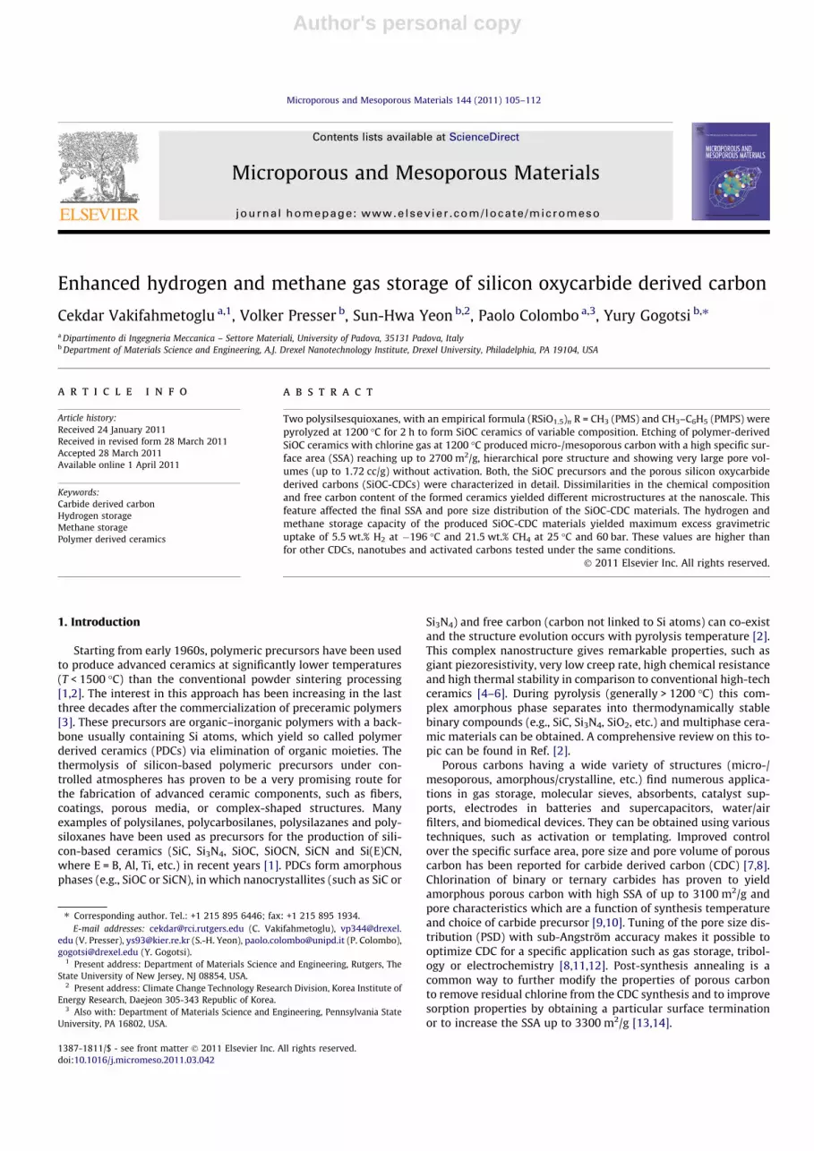
XRD patterns reported in Fig. 2(a) show a typical pattern (dif-fuse scattering) of an amorphous materials, with broad Braggreflections between 20� and 30�2h [5]. Compared to highly crystal-line materials, the peak profile is very broad, corresponding tonanocrystalline domains of �1 nm size. When we compare thetwo PDC materials, we see broader reflections for low carbon con-tent (PMS derived) SiOC-1 (graphite-(0 0 2): �0.4 nm; graphite-(1 0 1): �1.2 nm), whereas SiOC-2 (PMPS derived) shows narrowerpeaks (graphite-(0 0 2): �0.5 nm; graphite-(1 0 1): �1.3 nm) andthe presence of nanocrystalline cubic silicon carbide (domain size�1.0 nm). The presence of amorphous silica cannot be excludedand most likely the major peak of this phase was superimposedwith the broad reflections of disordered carbon in the given pat-terns. Both XRD patterns are in agreement with literature data re-ported for low and high carbon SiOC materials [22].
Raman spectroscopy (Fig. 2(b)) was used to acquire additionalinformation on the free carbon phase dispersed within the SiOCmatrix. For both samples, we see two in-plane modes: the charac-teristic disorder-induced D-mode at �1334–1338 cm�1 observedin carbon with finite crystallite size and the graphite G-mode near1600–1604 cm�1. SiOC-1 and SiOC-2 show both similar I(D)/I(G) ra-tios (1.2 and 1.1, respectively). The combined information aboutfull width at half maximum (FWHM), I(D)/I(G) ratio and mode posi-tion gives information on the carbon ordering and structure [31].For the planar domain size, we find for SiOC samples values of�4 nm [31]. In addition, values for the G band close to1600 cm�1 suggest the presence of disordered graphitic carbon[31,32]. For comparison with SiOC-CDC described in the next sec-tion, it is important to keep in mind that nanocrystalline carbonis already present in the PDC material.
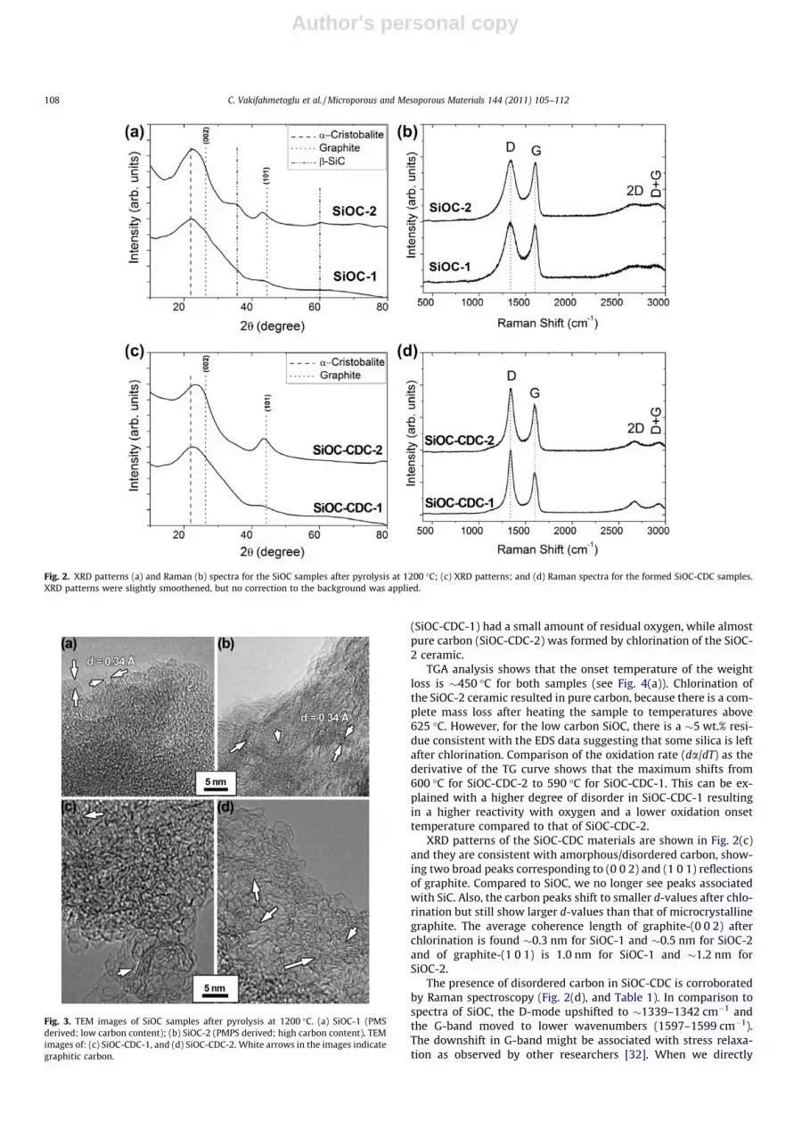
Fig. 3(a) and (b) depicts TEM images taken from the SiOC-1(PMS derived) and SiOC-2 (PMPS derived) samples showing thatthe amorphous matrix phase contains areas of nanocrystalline gra-phitic carbon (also indicated by Raman spectroscopy). When com-paring SiOCs with high and low carbon content, there is a cleartrend to increasing graphitic domains in SiOC-2 in agreement withXRD and Raman data. Values for the specific surface area (4–8 m2/g) were much higher than expected for micrometer sized particles(SSA of dense 10 lm particles is �0.2 m2/g). Larger and nanocrys-talline graphitic carbon regions in SiOC-2 show that the carboncontent of the preceramic precursor is a key parameter for control-ling the microstructure of SiOC after pyrolysis [33].
Polymer architecture, the functionality of side groups, and thedegree of cross-linking must be considered for complete under-standing of the PDC microstructure [34]. Accordingly, our XRD, Ra-man, and TEM investigations are consistent with an amorphousSiOC ceramic containing nanosized graphitic carbon and SiC. Thehigh C-content sample SiOC-2 has a higher content of nanocrystal-line graphitic carbon ribbons and crystalline SiC. Reported volu-metric amounts of SiC for SiOC ceramics derived from siloxanesof comparable composition, computed on the basis of measuredamount of C and Si, are�12 and�5 vol.%, respectively, for a methyland a methyl-phenyl-siloxane heat treated at 1200 �C in Ar and in agraphite furnace [5]. In our processing conditions, however, XRDsuggest a larger amount of crystalline SiC in high carbon-derivedsample at similar pyrolysis temperature.
3.2. Structure of SiOC-CDC
It is known that carbide to carbon conversion during chlorina-tion is a conformal process [7], that is, the initial shape and sizeof the carbide is largely preserved. As can be seen from Fig. 1(c)and (d), the shape of the SiOC particles did not change in theSiOC-CDC [9]. EDS analysis (shown in the insets in both figures)demonstrates that carbon derived from the SiOC-1 ceramic
Fig. 1. SEM images of (a) SiOC-1 (PMS derived, low carbon content); (b) SiOC-2 (PMPS derived, high carbon content); both samples are after 1200 �C pyrolysis and crushing;(c) SiOC-CDC-1 derived from SiOC-1; and (d) SiOC-CDC-2 derived from SiOC-2 chlorinations. Insets show EDS spectra.
C. Vakifahmetoglu et al. / Microporous and Mesoporous Materials 144 (2011) 105–112 107
Author's personal copy
(SiOC-CDC-1) had a small amount of residual oxygen, while almostpure carbon (SiOC-CDC-2) was formed by chlorination of the SiOC-2 ceramic.
TGA analysis shows that the onset temperature of the weightloss is �450 �C for both samples (see Fig. 4(a)). Chlorination ofthe SiOC-2 ceramic resulted in pure carbon, because there is a com-plete mass loss after heating the sample to temperatures above625 �C. However, for the low carbon SiOC, there is a �5 wt.% resi-due consistent with the EDS data suggesting that some silica is leftafter chlorination. Comparison of the oxidation rate (da/dT) as thederivative of the TG curve shows that the maximum shifts from600 �C for SiOC-CDC-2 to 590 �C for SiOC-CDC-1. This can be ex-plained with a higher degree of disorder in SiOC-CDC-1 resultingin a higher reactivity with oxygen and a lower oxidation onsettemperature compared to that of SiOC-CDC-2.
XRD patterns of the SiOC-CDC materials are shown in Fig. 2(c)and they are consistent with amorphous/disordered carbon, show-ing two broad peaks corresponding to (0 0 2) and (1 0 1) reflectionsof graphite. Compared to SiOC, we no longer see peaks associatedwith SiC. Also, the carbon peaks shift to smaller d-values after chlo-rination but still show larger d-values than that of microcrystallinegraphite. The average coherence length of graphite-(0 0 2) afterchlorination is found �0.3 nm for SiOC-1 and �0.5 nm for SiOC-2and of graphite-(1 0 1) is 1.0 nm for SiOC-1 and �1.2 nm forSiOC-2.
The presence of disordered carbon in SiOC-CDC is corroboratedby Raman spectroscopy (Fig. 2(d), and Table 1). In comparison tospectra of SiOC, the D-mode upshifted to �1339–1342 cm�1 andthe G-band moved to lower wavenumbers (1597–1599 cm�1).The downshift in G-band might be associated with stress relaxa-tion as observed by other researchers [32]. When we directly
Fig. 2. XRD patterns (a) and Raman (b) spectra for the SiOC samples after pyrolysis at 1200 �C; (c) XRD patterns; and (d) Raman spectra for the formed SiOC-CDC samples.XRD patterns were slightly smoothened, but no correction to the background was applied.
Fig. 3. TEM images of SiOC samples after pyrolysis at 1200 �C. (a) SiOC-1 (PMSderived; low carbon content); (b) SiOC-2 (PMPS derived; high carbon content). TEMimages of: (c) SiOC-CDC-1, and (d) SiOC-CDC-2. White arrows in the images indicategraphitic carbon.
108 C. Vakifahmetoglu et al. / Microporous and Mesoporous Materials 144 (2011) 105–112

Author's personal copy
compare the spectra from SiOC and SiOC-CDC, we see that the car-bon-related Raman peaks are much narrower after chlorinationindicating a higher ordering [31]. At the same time, we observedlarger I(D)/I(G) ratios after chlorination compared to the SiOC. InFig. 4(b), the I(D)/I(G) ratio is plotted as a function of the FWHM ofthe G-peak along with data for SiCN-CDC [15]. This trend is inagreement with the XRD results and consistent with a recent studyon SiCN-CDC [15] where we showed that the I(D)/I(G) ratio in-creases, whereas the G-mode bandwidth decreases as a functionof pyrolysis temperature, evolving towards values known for car-bon nanowalls (I(D)/I(G) �3.2 with FWHM G-band �40 cm�1) [35].
TEM images for both types of SiOC-CDC are shown in Fig. 3(c)and (d). After chlorination of SiOC, amorphous carbon and highlycurved single graphene sheets [36–38] were observed in bothSiOC-CDC materials. Also, ordered curved sheets of graphite withan interplanar spacing of 0.34 nm are identical to the carbon rib-bons in SiC-CDC produced at high etching temperature [36]. Theseordered ribbons shown by white arrows in both images were also
present in the SiOC ceramics. When directly comparing SiOC andSiOC-CDC, it’s clear that after chlorination, a more porous structureincluding thin carbon walls is formed [15,39].
Fig. 5 shows the nitrogen adsorption–desorption isotherms forSiOC-CDCs (Fig. 5(a)) and pore size distributions calculated fromCO2 and N2 sorption data using non-local density functional theory(NLDFT) and quenched solid density functional theory (QSDFT),respectively. SiOC-CDC-1 (derived from low-carbon SiOC) sampleexhibited a Type I isotherm (IUPAC classification), with no clearhysteresis loop. Type I isotherms are typical of microporous mate-rials, and in the present case the increasing uptake of nitrogen tillreaching a plateau and leveling off (P/P0 �0.4) with a negligiblehysteresis together with PSDs (ranging between 0.3 and 4 nm) gi-ven in Fig. 5(b) (see also Table 2 for mean pore size) demonstratesthat the sample contains mesopores which are close in size to therange of micropores. The isotherm for SiOC-CDC-2 has a pro-nounced hysteresis loop due to mesopores. Its shape is in accor-dance with a combination of micropores and small mesopores
Table 1Summary of the Raman data for all samples investigated.
Sample D-band G-band I(D) /I(G)
Position (cm�1) FWHM (cm�1) Position (cm�1) FWHM (cm�1)
SiOC-1 1334.0 156.3 1603.9 74.9 1.2SiOC-CDC-1 1339.0 68.2 1598.7 59.1 1.6SiOC-2 1337.5 149.4 1599.8 66.2 1.1SiOC-CDC-2 1341.8 83.6 1597.0 59.0 1.4
Fig. 4. TGA data for SiOC-CDC samples heated at 2 �C/min in air (a), and relationship between the peak intensity ratio of D band to G band (I(D)/I(G)) and the width of G band inthe Raman spectra of SiOC-CDC materials (b), including the data for CDC materials derived from SiCN (pyrolyzed at 1200 and 1400 �C).[15].
Fig. 5. N2 sorption isotherms for SiOC-CDCs where solid symbols correspond to adsorption and empty symbols to desorption of nitrogen (a); estimated pore size distributionsusing CO2 (NLDFT) and N2 (QSDFT) adsorption after chlorination (b).
C. Vakifahmetoglu et al. / Microporous and Mesoporous Materials 144 (2011) 105–112 109

Author's personal copy
having broad size distribution. In comparison, SiOC-CDC-2 pos-sesses a wider PSD in the mesoporous range, with a larger meanpore size (2.6 nm) compared to SiOC-CDC-1 (2.0 nm). WhileSiOC-CDC-2 has a lower SSA (2423 m2/g compared to that ofSiOC-CDC-1, which is 2726 m2/g), it has a larger total pore volume(1.720 cc/g compared to 1.403 cc/g of SiOC-CDC-1) because of thecontribution of mesopores.
As a rough estimate, Eq. (1) can be used to calculate the wallthickness separating the pores assuming a slit-pore model (carbonwall thickness, dw) [40].
dw ¼ 2=ðq � SBETÞ; ð1Þ
where q is the density of the carbon walls equal to the density ofpure graphite. From this, we see that for SiOC-CDC, the mean carbonwall thickness is in the range of 4.1–4.5 Å. In agreement with theTEM results, this shows that the pore walls are mainly built of singleor double graphene layers.
We found a discrepancy between SSA calculated from the N2
isotherm alone using multiple-point BET and the combined datafrom N2 and CO2 PSD (with the latter yielding larger values). Fromthe literature [41] this is expected to occur when a significant porevolume is comprised by pores smaller than 1 nm with nitrogensorption only yielding accurate data for pores larger than�0.6 nm. SiC-CDC synthesized at 1200 �C without activation yieldsa smaller SSA (�1500 m2/g), unimodal narrow PSD (0.97 nm),smaller total pore volume (0.5 cc/g) and smaller mesopore volume(�20%) compared to SiOC-CDCs (Table 2) [10,39,42]. It is expectedthat the SiOC samples would include a small amount of nanocrys-talline SiC (or Si–C rich clusters, especially in the case of SiOC-2, seeXRD data reported in Fig. 2(a)). Consistent with reports on SiC-CDC[39], the PSD of SiOC-CDC-2 shows a larger contribution of nar-rowly distributed subnanometer pores originating from SiCnanocrystals.
The hierarchic porosity with pores in the micro- and mesopor-ous range can be attributed to the removal of Si and O atoms fromthe silicon oxycarbide matrix, giving rise to an increased pore vol-ume in the range of pore size 1–4 nm, without a significant contri-bution to the subnanometer pores, as shown in Table 2. Incomparison, microporous CDC materials derived from crystallineSiC [39,43,44] or from SiC derived by the pyrolysis of polycarbosi-lane precursors at high temperatures [18], we observed higher SSAvalues, which are consistent with our previous findings [15] andalso with the data documented by Rose et al. [9], where a higherSSA was produced by chlorination of amorphous SiC-PDC.
Additional experiments preformed on amorphous silica etchedby chlorine gas under the same conditions did not result in anyporous structure (data not shown); silica remained completely in-tact after chlorine etching under the same experimental conditions(note that Gibbs energy minimization with FactSage™ for 1 mol ofnanocrystalline SiO2 in 10 mol of chlorine at 1200 �C yields only0.1 mol% SiCl4). Consequently, two types of etching reactions canbe postulated (Eqs. (2) and (3)), the extent of which depends onthe microstructure of the SiOC ceramics, which is in turn controlledby the preceramic polymer type.
SiO4�xCxðsÞ þ 2Cl2ðgÞ ! SiCl4ðgÞ þ4� x
3
� �COðgÞ
þ 4� x3
� �CO2ðgÞ þ
5x� 83
� �CðsÞ ð2Þ
0 6 x 6 4SiCðsÞ þ 2Cl2ðgÞ ! SiCl4ðgÞ þ CðsÞ ð3Þ
In SiOC, compared to vitreous silica, oxygen is partially substi-tuted by carbon. Therefore, the typical microstructure of SiOC ischaracterized by the presence of different Si-tetrahedra rangingfrom SiO4 via SiO3C and SiO2C2 to SiC4 (i.e. SiO4�xCx, 0 6 x 6 4), asshown by solid state 29Si NMR spectroscopy [32,45]. These mixedSiCxO4�x units are the part of a more complex nanostructure, albeitsome models have been proposed to describe it [46,47]. The do-main structure is highly stochastic, as clearly deducible from smallangle X-ray scattering (SAXS) data, and therefore, the convergenceof experimental and theoretical values may be coincidental [2].Thus, recent studies dealing with hydrofluoric acid (HF) etchingof interconnected silica-rich domains provide insights into thenanostructure of SiOC ceramics. For example, Pena-Alonso et al.[32] has shown that sol–gel derived SiOC pyrolyzed at 1200 �C pre-sented few interconnected silica clusters that could be etched byHF, producing a porous residue with a SSA of just 204 m2/g.Biasetto et al. [48] demonstrated that HF etching of sol–gel-derivedand PMS derived SiOC ceramics (pyrolyzed at 1200 �C) yielded dif-ferent SSA values. PMS derived SiOC showed SSA of 26.2 m2/g,while the SiOC obtained from sol–gel process had a SSA of194.4 m2/g. The authors explained this disparity by the differencesin the phase evolution [48]. PMS derived SiOC is supposed to havesmaller interconnected silica domains and/or more amorphous(less phase separated) structure. In this perspective, Dibandjoet al. [49] studied the effect of polymer architecture and showedthat HF etching of SiOC with a high carbon content did not yielda nanoporous structure, when the ceramic was pyrolyzed at1200 �C. This finding implied that the matrix was not yet phaseseparated, that means no interconnectivity between the silica-richdomains, most probably because of the free carbon phase, whichplays an important role in the stability of the amorphous phase[5,50]. The authors documented that modified linear or cyclic poly-siloxane derived ceramics are amorphous structures after pyrolysisat 1200 �C, in contrast to other sol–gel derived SiOC systems. Ourexperiments are in agreement with these findings in a way that:(i) both SiOC samples had amorphous structure after pyrolysis at1200 �C and PMS precursor (low-carbon) generated more intercon-nected silica-rich domains in the produced SiOC material com-pared to PMPS one causing a silica residue (�5 wt.%) afterchlorination, (ii) the size distribution of the SiCxO4�x (0 < x < 4)clusters in the SiOC microstructure is slightly larger for the SiOC-2 than for the SiOC-1, and (iii) higher content of crystalline SiCwas found in the SiOC-2 sample.
Accordingly, it seems that in the present study, microporescame from nanocrystalline SiC (in agreement with results on SiC-CDC) [39], while mesopores with a broader size distribution, camefrom carbon attached to the SiOC network. Interconnected
Table 2Calculated SSA, pore volume, and average pore size for both SiOC precursors and SiOC-CDC samples.
Sample Properties
BET (m2/g) SSA (m2/g)PSD (CO2: <1.0 nm)
SSA (m2/g)PSD (N2: >1.0 nm)
SSA (m2/g)PSD total
Pore volume (cm3/g)(<1.0 nm)
Total pore volume(cm3/g)
Average porewidth (nm)
SiOC-1 8 – 10 10 – – –SiOC-CDC-1 2593 1584 1141 2726 0.36 1.403 2.0SiOC-2 4 – 2 2 – – –SiOC-CDC-2 2364 1341 1082 2423 0.44 1.720 2.6
110 C. Vakifahmetoglu et al. / Microporous and Mesoporous Materials 144 (2011) 105–112

Author's personal copy
silica-domains, however, were not completely removed via chlori-nation as seen from TGA data (Fig. 4(a)). The chlorination behaviorof SiOC materials observed in the present study are well consistentwith the Brisebourg et al. [51] in which the authors showed thatmixed SiCxO4�x environments in silicon oxycarbide tend to desta-bilize the structure and enhance the Si-sites chlorination. In thatsense, the pore size in the residual C is probably related to theSiCxO4�x (0 < x < 4) domain size from which it originates. This find-ing is in agreement with the HF etching of SiOC [22,32,48] implyingthat while phase separation progresses differently in sol–gel orresin derived SiOC ceramics pyrolyzed at 1200 �C, the domainssurrounded by precipitated carbon have comparable size, whichis affected by the amount of carbon in the polymer and in theceramic, and also probably by the polymer architecture [52].
3.3. High pressure hydrogen and methane uptake
The results of high pressure hydrogen and methane sorptionmeasurements performed at �196 and 25 �C, respectively, are gi-ven in Fig. 6(a) and (b), respectively. Excess hydrogen uptake inSiOC-CDC-1 and SiOC-CDC-2 reaches 5.5 and 3.9 wt.%, respectively,at 60 bar and �196 �C. The difference in hydrogen sorption behav-ior of these two SiOC-CDC samples is explained by the comparisonof pore volumes and surface areas of very small pores (<0.6 nm) gi-ven in Table 2 and Fig. 5(b). While pore volumes of pores below1 nm were almost similar, the SSA of pores below 1 nm was largerin SiOC-CDC-1 (1584 m2/g) compared to 1341 m2/g for SiOC-CDC-2in agreement with reports by Yushin et al. [39] and Gogotsi et al.[53].
It is important to note that hydrogen sorption is not strictly afunction of SSA in general but a linear correlation exists with thevolume/SSA of pores smaller than 1 nm [39,53,54]. In particular,it was shown that while small pores (<1 nm) [54] are efficient forhydrogen sorption, pores above 1 nm contribute less to the storageof H2 at ambient pressure and liquid-nitrogen temperature. More-over, it was shown that hydrogen storage capacity increases line-arly with pore volume for pores less than 1 nm while no directcorrelation was found between hydrogen storage and volume ofpores greater than 1 nm [39]. The reported hydrogen uptake capac-ity of unactivated SiOC-CDC-1 is higher than the highest value ob-served to date for the CO2 activated TiC-CDCs (4.7 wt.% H2) andPDC derived SiC-CDC (ordered mesoporous and fiber shapedCDC), as well as SWCNTs, MWCNTs, and low-temperature metalhydrides [9,16–18,53]. The capacity of SiOC-CDC-1 with no furtherprocessing, is close to the DOE target of 6.0 wt.% by 2010 for hydro-gen storage on-board automobiles [55].
Excess methane uptake values were 21.5 and 16.4 wt.% at60 bar and 25 �C without saturation for SiOC-CDC-1 and SiOC-CDC-2, respectively. They are higher than in microporous CDC,
hexagonally ordered CDC produced from a replicated PDC-SiC,most MOFs, and activated carbon (KUA41751) [56,57], and compa-rable to cubic ordered mesostructured template CDCs [16]. Previ-ously, the largest CH4 excess uptake for CDC was reported to be�15 wt.% for bulk TiC-CDC and 18.5 wt.% for activated TiC-CDC at25 �C and 60 bar [14,58].
4. Conclusions
Amorphous SiOC materials with different carbon contents wereproduced by the pyrolysis of commercial polysiloxane resins at1200 �C. It was shown that the final SSA and PSD of the producedcarbon depended on the final characteristics of the formed SiOCceramics. The mean pore size slightly increased in CDC obtainedfrom SiOC with high carbon content. Low carbon SiOC derived por-ous carbon exhibited a very high SSA reaching �2700 m2/g, and alarge pore volume (1.72 cc/g). Testing of the produced CDC forgas storage without activation demonstrated its excellent perfor-mance with a maximum excess gravimetric uptake of 5.5 wt.% H2
at �196 �C and 21.5 wt.% CH4 (without saturation) at 25 �C and60 bar. The hydrogen storage capacity of the formed SiOC-CDCwas higher than that of other CDC materials, carbon nanotubesand activated carbons making it one of the most promising candi-dates for hydrogen storage so far. Likewise, CH4 uptake of SiOC-CDC exceeded that of other carbon materials.
Acknowledgements
V.P. gratefully acknowledges financial support by the Alexandervon Humboldt foundation. We are grateful to Dr. J.J. Niu and M.Heon (both Drexel University) for support with TEM and SEM,respectively, and Prof. J.E. Fischer (University of Pennsylvania) forproviding access to research instruments. We acknowledge theuse of instruments from the Centralized Research Facility (CRF)of Drexel University (XRD, Raman, SEM, and TEM) and the Univer-sity of Pennsylvania (TGA, Sieverts apparatus).
References
[1] R. Riedel, E. Ionescu, I.-W. Chen, in: R. Riedel, I.-W. Chen (Eds.), CeramicsScience and Technology, Volume 1: Structures, WILEY-VCH Verlag GmbH & Co.KGaA, Weinheim, 2008, pp. 3–38.
[2] P. Colombo, G. Mera, R. Riedel, G.D. Soraru, J. Am. Ceram. Soc. 93 (2010) 1805–1837.
[3] Y.D. Blum, K.B. Schwartz, R.M. Laine, J. Mater. Sci. 24 (1989) 1707–1718.[4] K. Terauds, P.E. Jimenez-Sanchez, R. Raj, C. Vakifahmetoglu, P. Colombo, J. Eur.
Ceram. Soc. 30 (2010) 2203–2207.[5] G.D. Soraru, S. Modena, E. Guadagnino, P. Colombo, J. Egan, C. Pantano, J. Am.
Ceram. Soc. 85 (2002) 1529–1536.[6] G. Thurn, J. Canel, J. Bill, F. Aldinger, J. Eur. Ceram. Soc. 19 (1999) 2317–2323.[7] Y. Gogotsi (Ed.), Carbon Nanomaterials, CRC Press, Boca Raton, Florida, 2006.[8] V. Presser, M. Heon, Y. Gogotsi, Adv. Funct. Mater. 21 (2011) 810–833.
Fig. 6. High pressure (a) hydrogen (at �196 �C), and (b) methane (at 25 �C) excess isotherms for SiOC-CDC materials.
C. Vakifahmetoglu et al. / Microporous and Mesoporous Materials 144 (2011) 105–112 111

Author's personal copy
[9] M. Rose, E. Kockrick, I. Senkovska, S. Kaskel, Carbon 48 (2010) 403–407.[10] Y. Gogotsi, A. Nikitin, H. Ye, W. Zhou, J.E. Fischer, B. Yi, H.C. Foley, M.W.
Barsoum, Nat. Mater. 2 (2003) 591–594.[11] J. Chmiola, G. Yushin, R. Dash, Y. Gogotsi, J. Power Sour. 158 (2006) 765–772.[12] D.A. Ersoy, M.J. McNallan, Y. Gogotsi, Mater. Res. Innovat. 5 (2001) 55–62.[13] S. Osswald, C. Portet, Y. Gogotsi, G. Laudisio, J.P. Singer, J.E. Fischer, V.V.
Sokolov, J.A. Kukushkina, A.E. Kravchik, J. Solid State Chem. 182 (2009) 1733–1741.
[14] S.-H. Yeon, S. Osswald, Y. Gogotsi, J.P. Singer, J.M. Simmons, J.E. Fischer, M.A.Lillo-Ródenas, Á. Linares-Solano, J. Power Sources 191 (2009) 560–567.
[15] S.-H. Yeon, P. Reddington, Y. Gogotsi, J.E. Fischer, C. Vakifahmetoglu, P.Colombo, Carbon 48 (2010) 201–210.
[16] M. Oschatz, E. Kockrick, M. Rose, L. Borchardt, N. Klein, I. Senkovska, T.Freudenberg, Y. Korenblit, G. Yushin, S. Kaskel, Carbon 48 (2010) 3987–3992.
[17] E. Kockrick, C. Schrage, L. Borchardt, N. Klein, M. Rose, I. Senkovska, S. Kaskel,Carbon 48 (2010) 1707–1717.
[18] P. Krawiec, E. Kockrick, L. Borchardt, D. Geiger, A. Corma, S. Kaskel, J. Phys.Chem. C 113 (2009) 7755–7761.
[19] L. Chen, G. Behlau, Y. Gogotsi, M.J. McNallan, Ceram. Eng. Sci. Proc. 24 (2003)57–62.
[20] Y.G. Gogotsi, S. Welz, J. Daghfal, M.J. McNallan, I.D. Jeon, K.G. Nickel, T. Kraft,Ceram. Eng. Sci. Proc. 19 (1998) 87–94.
[21] A.M. Wilson, G. Zank, K. Eguchi, W. Xing, B. Yates, J.R. Dahn, Chem. Mater. 9(1997) 2139–2144.
[22] R. Pena-Alonso, G.D. Soraru, R. Raj, J. Am. Ceram. Soc. 89 (2006) 2473–2480.[23] M. Scheffler, T. Gambaryan-Roisman, T. Takahashi, J. Kaschta, H. Muenstedt, P.
Buhler, P. Greil, Ceram. Trans. 115 (2000) 239–250.[24] P. Colombo, J. Hellmann, Mater. Res. Innovat. 6 (2002) 260–272.[25] C. Vakifahmetoglu, P. Colombo, Adv. Eng. Mater. 10 (2008) 256–259.[26] R.W. Cheary, A.A. Coelho, J.P. Cline, J. Res. Natl. Inst. Stan. 109 (2004) 1–25.[27] P.I. Ravikovitch, A.V. Neimark, Colloids Surf. A 187–188 (2001) 11–21.[28] P.I. Ravikovitch, A.V. Neimark, Langmuir 22 (2006) 11171–11179.[29] M. Benedict, G.B. Webb, L.C. Rubin, J. Chem. Phys. 10 (1942) 747–758.[30] NIST Standard Reference Database, 23: NIST Reference Fluid Thermodynamic
and Transport Properties Database.[31] A.C. Ferrari, J. Robertson, Phys. Rev. B: Condens. Matter 61 (2000) 14095.[32] R. Pena-Alonso, G. Mariotto, C. Gervais, F. Babonneau, G.D. Soraru, Chem.
Mater. 19 (2007) 5694–5702.[33] J. Cordelair, P. Greil, J. Eur. Ceram. Soc. 20 (2000) 1947–1957.[34] P. Dibandjo, S. Diré, F. Babonneau, G.D. Soraru, J. Non-Cryst. Solids 356 (2010)
132–140.
[35] S. Kurita, A. Yoshimura, H. Kawamoto, T. Uchida, K. Kojima, M. Tachibana, P.Molina-Morales, H. Nakai, J. Appl. Phys. 97 (2005) 104320–104325.
[36] S. Welz, M.J. McNallan, Y. Gogotsi, J. Mater. Process. Tech. 179 (2006) 11–22.[37] G.N. Yushin, E.N. Hoffman, A. Nikitin, H. Ye, M.W. Barsoum, Y. Gogotsi, Carbon
43 (2005) 2075–2082.[38] R.K. Dash, A. Nikitin, Y. Gogotsi, Microporous Mesoporous Mater. 72 (2004)
203–208.[39] G. Yushin, R. Dash, J. Jagiello, J. Fischer, Y. Gogotsi, Adv. Funct. Mater. 16 (2006)
2288–2293.[40] A. Janes, T. Thomberg, E. Lust, Carbon 45 (2007) 2717–2722.[41] J. Jagiello, M. Thommes, Carbon 42 (2004) 1227–1232.[42] R. Dash, J. Chmiola, G. Yushin, Y. Gogotsi, G. Laudisio, J. Singer, J. Fischer, S.
Kucheyev, Carbon 44 (2006) 2489–2497.[43] Y.G. Gogotsi, I.-D. Jeon, M.J. McNallan, J. Mater. Chem. 7 (1997) 1841–1848.[44] M.R. Bonilla, J.-S. Bae, T.X. Nguyen, S.K. Bhatia, J. Phys. Chem. C 114 (2010)
16562–16575.[45] C. Gervais, F. Babonneau, N. Dallabonna, G.D. Soraru, J. Am. Ceram. Soc. 84
(2001) 2160–2164.[46] A. Saha, R. Raj, D.L. Williamson, J. Am. Ceram. Soc. 89 (2006) 2188–2195.[47] G. Gregori, H.J. Kleebe, Y.D. Blum, F. Babonneau, Int. J. Mater. Res. 97 (2006)
710–720.[48] L. Biasetto, R. Peña-Alonso, G.D. Soraru, P. Colombo, Adv. Appl. Ceram. 107
(2008) 106–110.[49] P. Dibandjo, S. Dire, F. Babonneau, G.D. Soraru, Glass Technol.-Part A 49 (2008)
175–178.[50] H.-J. Kleebe, Y.D. Blum, J. Eur. Ceram. Soc. 28 (2008) 1037–1042.[51] M. Brisebourg, S. Mazerat, G. Puyoo, H. Plaisantin, P. Dibandjo, G.D. Soraru, G.
Chollon, Adv. Sci. Tech. 71 (2010) 86–91.[52] T. Takahashi, J. Kaschta, H. Münstedt, Rheol. Acta 40 (2001) 490–498.[53] Y. Gogotsi, C. Portet, S. Osswald, J.M. Simmons, T. Yildirim, G. Laudisio, J.E.
Fischer, Int. J. Hydrogen Energy 34 (2009) 6314–6319.[54] Y. Gogotsi, R.K. Dash, G. Yushin, T. Yildirim, G. Laudisio, J.E. Fischer, J. Am.
Chem. Soc. 127 (2005) 16006–16007.[55] R. Ströbel, J. Garche, P.T. Moseley, L. Jörissen, G. Wolf, J. Power Sour. 159 (2006)
781–801.[56] D. Lozano-Castell, J. Alcaniz-Monge, M.A. de la Casa-Lillo, D. Cazorla-Amor, A.
Linares-Solano, Fuel 81 (2002) 1777–1803.[57] G. Laudisio, R.K. Dash, J.P. Singer, G. Yushin, Y. Gogotsi, J.E. Fischer, Langmuir
22 (2006) 8945–8950.[58] S.-H. Yeon, I. Knoke, Y. Gogotsi, J.E. Fischer, Microporous Mesoporous Mater.
131 (2010) 423–428.
112 C. Vakifahmetoglu et al. / Microporous and Mesoporous Materials 144 (2011) 105–112


![Structure of silicon oxycarbide glasses derived from poly(methylsiloxane) and poly[methyl(phenyl)siloxane] precursors](https://img.dokumen.tips/doc/110x75/6325435b4643260de90da99a/structure-of-silicon-oxycarbide-glasses-derived-from-polymethylsiloxane-and-polymethylphenylsiloxane.jpg)