Embed Size (px)
Citation preview

DIGITAL NOTES
ENGINEERINGTHERMODYNAMICS
B.Tech II Year I Semester
DEPARTMENT OF MECHANICAL ENGINEERING
MALLA REDDY COLLEGE OF ENGINEERING & TECHNOLOGY
(An Autonomous Institution – UGC, Govt.of India) Recognizes under 2(f) and 12(B) of UGC ACT 1956
(Affiliated to JNTUH, Hyderabad, Approved by AICTE –Accredited by NBA & NAAC-“A” Grade-ISO 9001:2015 Certified)
DEPATMENT OF MECHANICAL ENGINEERING,MRCET

MALLA REDDY COLLEGE OF ENGINEERING & TECHNOLOGY
Vision * To establish a pedestal for the integral innovation, team spirit, originality and competence in the students, expose them to face the global challenges and become pioneers of Indian vision of modern society. Mission * To become a model institution in the fields of Engineering, Technology and Management. * To impart holistic education to the students to render them as industry ready engineers. * To ensure synchronization of institute ideologies with challenging demands of International Pioneering Organizations. QUALITY POLICY * To implement best practices in Teaching and Learning process for both UG and PG courses meticulously * To provide state of art infrastructure and expertise to impart quality education. * To groom the students to become intellectually creative and professionally competitive. * To channelize the activities and tune them in heights of commitment and sincerity, the requisites to claim the never-ending ladder of SUCCESS year after year.

ENGINEERING THERMODYNAMICS B.TECH II YEAR I SEM R20
Department of Mechanical Engineering,MRCET Page ii
MALLA REDDY COLLEGE OF ENGINEERING & TECHNOLOGY II Year B. Tech ME-I Sem
ENGINEERING THERMODYNAMICS
Course Objectives:
1. To understand the concepts of energy transformation, conversion of heat into work.
2. To acquire knowledge about the fundamentals of thermodynamic laws, the concept of
entropy, and principles.
3. To understand how the change of state results in a process.
4. To understand the various gas laws, psychrometric properties and chart.
5. To learn the importance of thermodynamic cycles, and the derivation of efficiency.
UNIT-I Basics of thermodynamics:
System - Types of Systems - Control Volume - Macroscopic and Microscopic viewpoints - Thermodynamic Equilibrium- State, Property, Process, Cycle – Reversibility – Quasi static Process, Irreversible Process, Causes of Irreversibility – Work and Heat, Point and Path functions. Zeroth Law of Thermodynamics – Principles of Thermometry –Constant Volume gas Thermometer – Scales of Temperature – PMM I - Joule’s Experiment – First law ofThermodynamics–Corollaries–FirstlawappliedtoaProcess–appliedtoaflowsystem – Steady Flow Energy Equation. UNIT-II Entropy Limitations of the First Law - Thermal Reservoir, Heat Engine, Heat pump, Parameters of performance, Second Law of Thermodynamics, Kelvin-Planck and Clausius Statements and their Equivalence / Corollaries, PMM of Second kind, Carnot’s principle, Carnot cycle and its specialties, Clausius Inequality, Entropy, Principle of Entropy Increase – Energy Equation, Availability and Irreversibility – Thermodynamic Potentials, Gibbs and Helmholtz Functions, Maxwell Relations – Elementary Treatment of the Third Law of Thermodynamics. UNIT-III Pure Substances: p-V-T- surfaces, T-S and h-s diagrams, Mollier Charts, Phase Transformations – Triple point at critical state properties during change of phase, Dryness Fraction – Mollier charts – Various Thermodynamic processes and energy Transfer – Steam Calorimetry. Perfect Gas Laws – Equation of State, specific and Universal Gas constants – Various Non-flow processes, properties, end states, Heat and Work Transfer, changes in Internal Energy – Throttling and Free Expansion Processes – Flow processes – Deviations from perfect Gas Model – Vander Waals Equation of State. UNIT-IV Mixtures of perfect Gases : Mole Fraction, Mass fraction Gravimetric and volumetric Analysis – Dalton’s Law of partial pressure, Amagat’s Law of additive volumes – Mole fraction , Volume fraction and partial pressure, Equivalent Gas constant, Enthalpy, sp. Heats and Entropy of Mixture of perfect Gases, Vapour, and Atmospheric air - Psychrometric Properties – Dry bulb Temperature, Wet Bulb Temperature, Dew point Temperature, Thermodynamic Wet Bulb Temperature, Specific Humidity, Relative Humidity, saturated Air, Vapour pressure, Degree of saturation – Adiabatic Saturation – Psychrometricchart.
L T/P/D C 3 0 3

ENGINEERING THERMODYNAMICS B.TECH II YEAR I SEM R20
Department of Mechanical Engineering,MRCET Page iii
UNI-V Power Cycles : Otto cycle, Diesel cycle, Dual Combustion cycle and Brayton cycle description and representation on P–V and T-S diagram, Thermal Efficiency, Mean Effective Pressures on Air standard basis – Comparison of Cycles. Basic Rankine cycle – Performance Evaluation.
TEXT BOOKS: 1. Engineering Thermodynamics, Special Edition. MRCET, McGrahillPublishers. 2. Engineering Thermodynamics / PK Nag /TMH, IIIEdition 3. Thermodynamics – J.P.Holman /McGrawHill
REFERENCE BOOKS: 1. Engineering Thermodynamics – Jones &Dugan 2. Thermodynamics – An Engineering Approach – YunusCengel& Boles/TMH 3. An introduction to Thermodynamics / YVC Rao / NewAge 4. Engineering Thermodynamics – K. Ramakrishna / AnuradhaPublisher
OUTCOMES:
1. Analyze the work and heat interactions associated with a prescribed process path and to
perform a analysis of a flow system.
2. Quantify the irreversibilites associated with each possibility and choose an optimal cycle.
3. Able to analyseMollier chart, and to find the quality of steam.
4. Able to analyze psychrometric chart, to estimate thermodynamic properties such as WBT,
DBT, RH, etc.
5. Analyze the thermodynamic cycles and evaluate performance parameters.

ENGINEERING THERMODYNAMICS B.TECH II YEAR I SEM R20
Department of Mechanical Engineering,MRCET Page iv
COURSE COVERAGE
S.NO NAME OF THE UNIT NAME OF THE TEXTBOOK CHAPTERS COVERED
1
Basic Concepts
Thermodynamics by P.K. Nag
Engineering Thermodynamics
– K. Ramakrishna
1,2,3
1,2
2 Limitations of the First Law
Thermodynamics by P.K. Nag 2,3,4
3
Pure Substances
Thermodynamics by P.K. Nag
Engineering Thermodynamics
– K. Ramakrishna
3,4,5,6
4,5,6
4 Mixtures of perfect Gases
Thermodynamics by P.K. Nag 3,4,5,6,7,8
5 Power Cycles
Thermodynamics by P.K. Nag 7,8,9,10

ENGINEERING THERMODYNAMICS B.TECH II YEAR I SEM R20
Department of Mechanical Engineering, MRCET Page 1
CONTENTS
S.No Name of the Unit Page No
1 Basic Concepts 2
2 Limitations of the First Law 18
3 Pure Substances 56
4 Mixtures of perfect Gases 73
5 Power Cycles 95
6 Question Bank 116
7 Case Study 123

ENGINEERING THERMODYNAMICS B.TECH II YEAR I SEM R20
DDEEPPAARRTTMMEENNTT OOFF MMEECCHHAANNIICCAALL,,M MRRCCEETT 11
POs for Mechanical Engineering
PO1 Engineering knowledge: Apply the knowledge of mathematics, science, engineering fundamentals, and an engineering specialization to the solution of complex engineering problems.
PO2
Problem analysis: Identify, formulate, review research literature, and analyzecomplexengineeringproblemsreachingsubstantiatedconclusions using first principles of mathematics, natural sciences, andengineering sciences.
PO3
Design/development of solutions: Design solutions for complex engineering problems and design system components of processes that meet the specified needs with appropriate consideration for the public
health and safety, and the cultural, societal, and environmental considerations.
PO4
Conduct investigations of complex problems: Use research-based knowledge and research methods including design of experiments, analysis and interpretation of data, and synthesis of the information to provide valid conclusions.
PO5
Modern tool usage: Create, select, and apply appropriate techniques, resources, and modern engineering and IT tools including prediction and modeling to complex engineering activities with an understanding of the limitations.
PO6
The engineer and society: Apply reasoning informed by the contextual knowledge to assess societal, health, safety, legal and cultural issues and
the consequent responsibilities relevant to the professional engineering practice.
PO7
Environment and sustainability: Understand the impact of the professional engineering solutions in societal and environmental contexts, anddemonstratetheknowledgeof,andneedforsustainabledevelopment.
PO8 Ethics: Apply ethical principles and commit to professional ethics and responsibilities and norms of the engineering practice.
PO9 Individual and team work: Function effectively as an individual, and as a member or leader in diverse teams, and in multidisciplinary settings.
PO10
Communication: Communicate effectively on complex engineering activities with the engineering community and with society at large, such as, being able to comprehend and write effective reports and design documentation, make effective presentations, and give and receive clear instructions.
PO11
Project management and finance: Demonstrate knowledge and understanding of the engineering and management principles and apply these to one’s own work, as a member and leader in a team, to manage projects and in multidisciplinary environments.
PO12 Life-longlearning:Recognizetheneedfor,andhavethepreparationand ability to engage in independent and life-long learning in the broadest context of technologicalchange

ENGINEERING THERMODYNAMICS B.TECH II YEAR I SEM R20
DDEEPPAARRTTMMEENNTT OOFF MMEECCHHAANNIICCAALL,,M MRRCCEETT 11
PSOs for Mechanical Engineering
PSO1 Ability to analyze, design and develop Mechanical systems to solve the Engineering
problems by integrating thermal, design and manufacturing domains.
PSO2 Ability to succeed in competitive examinations or to pursue higher studies or
research.
PSO3 Ability to apply the learned Mechanical Engineering knowledge for the development
of society and self.
PEOs for Mechanical Engineering
PEO1: PREPARATION
To provide sound foundation in mathematical, scientific and engineering fundamentals necessary to analyze, formulate and solve engineering problems.
The basic requirement for any student is to become asuccessful graduate is to have basic knowledge onfundamentals.
Therefore, the first andforemost the objective is defined as Preparation.
PEO2: CORE COMPETANCE
To provide thorough knowledge in Mechanical Engineering subjects including theoretical knowledge and practical training for preparing physical models pertaining to core field.
Providing services as per the Government & Industrial development plans andthrust areas.
Considering reports and projections of CII, ELIAP,AICTE, HRD etc., on industrial developmentsrequirements.
PEO3: INVENTION, INNOVATION AND CREATIVITY
To make the students to design,
Preparing students to solve complex engineeringproblems, which require idea about inventing, innovationand
experiment, analyze, interpret in the core field with the helpofother inter
disciplinary concepts wherever applicable.
creativity.
PEO4: CAREER DEVELOPMENT
To inculcate the habit of lifelonglearning for career development through successful completion ofadvanced
degrees, professional development courses, industrial training etc.
Preparing students to becomea successful person in his/her future.
PEO5: PROFESSIONALISM
To impart technical knowledge, ethical values for professional development of the student to solve complex problems and to work in multi-disciplinary ambience, whose solutions lead to significant societal benefits.
Preparing students to become a successful entrepreneur whocan meet the societalneeds.

ENGINEERING THERMODYNAMICS B.TECH II YEAR I SEM R20
DDEEPPAARRTTMMEENNTT OOFF MMEECCHHAANNIICCAALL,,M MRRCCEETT 11
Blooms Taxonomy:
Bloom’s Taxonomy is a classification of the different objectives and skills that
educators set for their students (learning objectives). The taxonomy was
proposed in 1956 by
BenjaminBloom,aneducationalpsychologistattheUniversityofChicago.Theterminol
ogy has been recently updated to include the following six levels of learning.
These 6 levels
canbeusedtostructurethelearningobjectives,lessons,andassessmentsofyourcours
e.
:
1. Remembering:Retrieving,recognizing,andrecallingrelevantknowledgefroml
ong‐ termmemory.
2. Understanding: Constructing meaning from oral, written, and graphic
messages
throughinterpreting,exemplifying,classifying,summarizing,inferring,compar
ing, andexplaining.
3. Applying: Carrying out or using a procedure for executing, orimplementing.
4. Analyzing: Breaking material into constituent parts, determining how the
parts
relatetooneanotherandtoanoverallstructureorpurposethroughdifferentiatin
g, organizing, andattributing.
5. Evaluating: Making judgments based on criteria and standards through
checking andcritiquing.
6. Creating: Putting elements together to form a coherent or functional
whole; reorganizing elements into a new pattern or structure through
generating, planning, orproducing.
Bloom'staxonomyisasetofthreehierarchicalmodelsusedtoclassifyeducationallearni
ng objectives into levels of complexity and specificity. The three lists cover the
learning
objectivesincognitive,affectiveandsensorydomains.Thecognitivedomainlisthasbee
n the primary focus of most traditional education and is frequently used to
structure curriculum learning objectives, assessments andactivities.

ENGINEERING THERMODYNAMICS B.TECH II YEAR I SEM R20
DDEEPPAARRTTMMEENNTT OOFF MMEECCHHAANNIICCAALL,,M MRRCCEETT 11
Mapping of Course Objectives
C111.1
Gain the knowledge on fluid mechanics fundamentals like fluid statics
and fluid kinematics
Engineering Thermodynamics (C111)
C111.2 HavebasicideaaboutthefundamentalequationsusedinFluidDynamics and are able to apply these concepts in real workingenvironment
C111.3 Study the fundamentals of turbo machinery and elements of hydroelectric power plant.
C111.4 Measure the performance of the different types of Hydraulic Turbines
C111.5 Calculate the performance of the different types of Hydraulic Pumps.

ENGINEERING THERMODYNAMICS B.TECH II YEAR I SEM R20
DDEEPPAARRTTMMEENNTT OOFF MMEECCHHAANNIICCAALL,,M MRRCCEETT 11
UNIT I
Basics of thermodynamics:
S.I. SYSTEM
Fundamental units of S.I system
Sr. No. Physical quantities Unit symbol
1 Length Metre m
2 Mass Kilogram Kg
3 Time Second S
4 Temperature Kelvin K
Supplementary units of S.I. system
Sr. No. Physical quantities
Unit symbol
1 Plane angle Radian Rad
Principal S.I. units
Sr. No.
Physical quantities Unit symbol
1 Force Newton N
2 Work Joule J, N.m
3 Power Watt W
4 Energy Joule J, N.m
5 Area Square metre m2
6 Volume Cubic metre m3
7 Pressure Pascal Pa
8 Velocity/speed metre per second m/s
9 Acceleration metre/second2 m/s2
10 Angular velocity radian/second rad/s
11 Angular acceleration radian/second2 rad/s2
12 Momentum kilogram metre/second
Kg.m/s
13 Torque Newton metre N.m
14 Density Kilogram/metre3 Kg/m3
15 Couple Newton.metre N.m
16 Moment Newton.metre N.m
S.I. Prefixes
Multiplication factor Prefix Symble
1012 Tera T
109 Giga G
106 Mega M
103 kilo k
102 hecto h
101 deca da
10-1 deci d
10-2 centi c
10-3 milli m

ENGINEERING THERMODYNAMICS B.TECH II YEAR I SEM R20
DDEEPPAARRTTMMEENNTT OOFF MMEECCHHAANNIICCAALL,,M MRRCCEETT 11
10-6 micro µ
10-9 nano n
10-12 pico p

ENGINEERING THERMODYNAMICS B.TECH II YEAR I SEM R20
DDEEPPAARRTTMMEENNTT OOFF MMEECCHHAANNIICCAALL,,M MRRCCEETT 11
Thermodynamics:
Thermodynamics is an axiomatic science which deals with the relations among heat, work and
properties of system which are in equilibrium. It describes state and changes in state of
physical systems.
System:
A thermodynamic system is defined as a quantity of matter or a region in space which is selected for the study.
Surroundings:
The mass or region outside the system is called surroundings.
Boundary:
The real or imaginary surfaces which separates the system and surroundings is called boundary. The real or imaginary surfaces which separates the system and surroundings is called boundary.
Types of thermodynamic system
On the basis of mass and energy transfer the thermodynamic system is divided into three
types.
1. Closed system
2. Opensystem
3. Isolatedsystem

ENGINEERING THERMODYNAMICS B.TECH II YEAR I SEM R20
DDEEPPAARRTTMMEENNTT OOFF MMEECCHHAANNIICCAALL,,M MRRCCEETT 11
Closed system: A system in which the transfer of energy but not mass can takes place across the boundary is called closed system. The mass inside the closed system remains constant.
For example: Boiling of water in a closed vessel. Since the water is boiled in closed vessel so
the mass of water cannot escapes out of the boundary of the system but heat energy
continuously entering and leaving the boundary of the vessel. It is an example of closed
system.
Open system: A system in which the transfer of both mass and energy takes place is called
an open system. This system is also known as control volume.
For example: Boiling of water in an open vessel is an example of open system because the
water and heat energy both enters and leaves the boundary of the vessel.
Isolated system: A system in which the transfer of mass and energy cannot takes place is
called an isolated system.
For example: Tea present in a thermos flask. In this the heat and the mass of the tea cannot
cross the boundary of the thermos flask. Hence the thermos flak is an isolated system.
Control Volume:
It’s a system of fixedvolume. This type of system is usually referred to as "open system” or a "controlvolume" Mass transfer can take place across a controlvolume. Energy transfer may also occur into or out of thesystem. Control Surface- It’s the boundary of a control volume across which the transfer of

ENGINEERING THERMODYNAMICS B.TECH II YEAR I SEM R20
DDEEPPAARRTTMMEENNTT OOFF MMEECCHHAANNIICCAALL,,M MRRCCEETT 11
both mass and energy takesplace. The mass of a control volume (open system) may or may not befixed. When the net influx of mass across the control surface equals zero then the mass of
the system is fixed andvice-versa. The identity of mass in a control volume always changes unlike the case for a control
mass system (closedsystem). Most of the engineering devices, in general, represent an open system orcontrol
volume.
Example:
Heat exchanger - Fluid enters and leaves the system continuously with the transfer of heat
across the system boundary.
Pump - A continuous flow of fluid takes place through the system with a transfer of mechanical
energy from the surroundings to the system.
Microscopic View or Study:
The approach considers that the system is made up of a very large number of
discrete particles known as molecules. These molecules have different velocities are
energies. The values of these energies are constantly changing with time. This
approach to thermodynamics, which is concerned directly with the structure of the
matter, is known as statistical thermodynamics.
The behavior of the system is found by using statistical methods, as the number of
molecules is very large. So advanced statistical and mathematical methods are
needed to explain the changes in thesystem.
The properties like velocity, momentum, impulse, kinetic energy and instruments
cannot easily measure force of impact etc. that describe themolecule.
Large numbers of variables are needed to describe a system. So the approach is
complicated.

ENGINEERING THERMODYNAMICS B.TECH II YEAR I SEM R20
DDEEPPAARRTTMMEENNTT OOFF MMEECCHHAANNIICCAALL,,M MRRCCEETT 11
Macroscopic View or Study:
In this approach a certain quantity of matter is considered without taking into
account the events occurring at molecular level. In other words this approach to
thermodynamics is concerned with gross or overall behavior. This is known as
classicalthermodynamics.
The analysis of macroscopic system requires simple mathematicalformula.
The value of the properties of the system are their average values. For examples
consider a sample of gas in a closed container. The pressure of the gas is the average
value of the pressure exerted by millions of individualmolecules.
In order to describe a system only a few properties areneeded.
S.No Macroscopic Approach Microscopic Approach
1
In this approach a certain quantity of
matter is considered without taking
into account the events occurring at
molecular level.
The matter is considered to be
comprised of a large number of tiny
particles known as molecules, which
moves randomly in chaotic fashion.
The effect of molecular motion is
considered.
2
Analysis is concerned with overall
behavior of the system.
The Knowledge of the structure of
matter is essential in analyzing the
behavior of the system.
3 This approach is used in the study of
classical thermodynamics.
This approach is used in the study of
statistical thermodynamics.
4 A few properties are required to
describe the system.
Large numbers of variables are
required to describe thesystem.
5
The properties like pressure,
temperature, etc. needed to describe
the system, can be easily measured.
The properties like velocity,
momentum, kinetic energy, etc.
needed to describe the system,
cannot be measured easily.
6 The properties of the system are their
average values.
The properties are defined for each
molecule individually.

ENGINEERING THERMODYNAMICS B.TECH II YEAR I SEM R20
DDEEPPAARRTTMMEENNTT OOFF MMEECCHHAANNIICCAALL,,M MRRCCEETT 11
7
This approach requires simple mathematical formulas for analyzing the system.
No. of molecules are very large so it requires advanced statistical and mathematical method to explain any change in thesystem.
Thermodynamic Equilibrium:
A thermodynamic system is said to exist in a state of thermodynamic equilibrium when no
change in any macroscopic property is registered if the system is isolated from its
surroundings.
An isolated system always reaches in the course of time a state of thermodynamic
equilibrium and can never depart from it spontaneously.
Therefore, there can be no spontaneous change in any macroscopic property if the system
exists in an equilibrium state. A thermodynamic system will be in a state of thermodynamic
equilibrium if the system is the state of Mechanical equilibrium, Chemical equilibrium and
Thermal equilibrium.
Mechanical equilibrium: The criteria for Mechanical equilibrium are the equality of
pressures.
Chemical equilibrium: The criteria for Chemical equilibrium are the equality of
chemicalpotentials.
Thermal equilibrium: The criterion for Thermal equilibrium is the equality of
temperatures.
State:
The thermodynamic state of a system is defined by specifying values of a set of measurable
properties sufficient to determine all other properties. For fluid systems, typical properties
are pressure, volume and temperature. More complex systems may require the
specification of more unusual properties. As an example, the state of an electric battery
requires the specification of the amount of electric charge itcontains.
Property:
Properties may be extensive or intensive.
Intensive properties: The properties which are independent of the mass of
thesystem. For example: Temperature, pressure and density are the intensive
properties.

ENGINEERING THERMODYNAMICS B.TECH II YEAR I SEM R20
DDEEPPAARRTTMMEENNTT OOFF MMEECCHHAANNIICCAALL,,M MRRCCEETT 11
Extensive properties: The properties which depend on the size or extent of the
system are called extensive properties.
For example: Total mass, total volume and total momentum.
Process:
When the system undergoes change from one thermodynamic state to final state due
change in properties like temperature, pressure, volume etc, the system is said to have
undergone thermodynamic process.
Various types of thermodynamic processes are: isothermal process, adiabatic process,
isochoric process, isobaric process and reversible process.
Cycle:
Thermodynamic cycle refers to any closed system that undergoes various changes due to
temperature, pressure, and volume, however, its final and initial state are equal. This cycle is
important as it allows for the continuous process of a moving piston seen in heat engines
and the expansion/compression of the working fluid in refrigerators, for example. Without
the cyclical process, a car wouldn't be able to continuously move when fuel is added, or a
refrigerator would not be able to staycold.Visually, any thermodynamic cycle will appear as
a closed loop on a pressure volume diagram.
Examples: Otto cycle, Diesel Cycle, Brayton Cycle etc.
Reversibility:
Reversibility, in thermodynamics, a characteristic of certain processes (changes of a system
from an initial state to a final state spontaneously or as a result of interactions with other
systems) that can be reversed, and the system restored to its initial state, without leaving
net effects in any of the systems involved.
An example of a reversible process would be a single swing of a frictionless pendulum from
one of its extreme positions to the other. The swing of a real pendulum is irreversible
because a small amount of the mechanical energy of the pendulum would be expended in
performing work against frictional forces, and restoration of the pendulum to its exact
starting position would require the supply of an equivalent amount of energy from a second
system, such as a compressed spring in which an irreversible change of state would occur.
Quasi static process:
When a process is processing in such a way that system will be remained infinitesimally
close with equilibrium state at each time, such process will be termed as quasi static process

ENGINEERING THERMODYNAMICS B.TECH II YEAR I SEM R20
DDEEPPAARRTTMMEENNTT OOFF MMEECCHHAANNIICCAALL,,M MRRCCEETT 11
or quasi equilibriumprocess.
In simple words, we can say that if system is going under a thermodynamic process through
succession of thermodynamic states and each state is equilibrium state then the process will
be termed as quasi static process.
We will see one example for understanding the quasi static process, but let us consider one
simple example for better understanding of quasi static process. If a person is coming down
from roof to ground floor with the help of ladder steps then it could be considered as quasi
static process. But if he jumps from roof to ground floor then it will not be a quasi static
process.
Weight placed over the piston is just balancing the force which is exerted in upward
direction by gas. If we remove the weight from the piston, system will have unbalanced
force and piston will move in upward direction due to force acting over the piston in upward
direction by thegas.
IrreversibleProcess:
The irreversible process is also called the natural process because all the processes occurring
in nature are irreversible processes. The natural process occurs due to the finite gradient
between the two states of the system. For instance, heat flow between two bodies occurs
due to the temperature gradient between the two bodies; this is in fact the natural flow of
heat. Similarly, water flows from high level to low level, current moves from high potential

ENGINEERING THERMODYNAMICS B.TECH II YEAR I SEM R20
DDEEPPAARRTTMMEENNTT OOFF MMEECCHHAANNIICCAALL,,M MRRCCEETT 11
to low potential,etc.
In the irreversible process the initial state of the system and surroundings cannot be
restored from the finalstate.
During the irreversible process the various states of the system on the path of
change from initial state to final state are not in equilibrium with eachother.
During the irreversible process the entropy of the system increases decisively and it
cannot be reduced back to its initialvalue.
The phenomenon of a system undergoing irreversible process is called as
irreversibility.
Causes of Irreversibility:
Friction: Friction is invariably present in real systems. It causes irreversibility in the process
as work done does not show an equivalent rise in the kinetic or potential energy of the
system. The fraction of energy wasted due to frictional effects leads to deviation from
reversiblestates.
Free expansion: Free expansion refers to the expansion of unresisted type such as expansion
in a vacuum. During this unresisted expansion the work interaction is zero, and without the
expense of any work, it is not possible to restore initial states. Thus, free expansion is
irreversible.
Heat transfer through a finite temperature difference: Heat transfer occurs only when there
exists temperature difference between bodies undergoing heat transfer. During heat
transfer, if heat addition is carried out in a finite number of steps then after every step the
new state shall be a non-equilibriumstate.
Nonequilibrium during the process:Irreversibilities are introduced due to lack of
thermodynamic equilibrium during the process. Non-equilibrium may be due to mechanical
inequilibrium, chemical inequilibrium, thermal inequilibrium, electrical inequilibrium, etc.
and irreversibility is called mechanical irreversibility, chemical irreversibility, thermal
irreversibility, electrical irreversibility respectively. Factors discussed above are also causing
non-equilibrium during the process and therefore make process irreversible.
Heat:
It is the energy in transition between the system and the surroundings by virtue of the
difference in temperature Heat is energy transferred from one system to another solely by
reason of a temperature difference between the systems. Heat exists only as it crosses the

ENGINEERING THERMODYNAMICS B.TECH II YEAR I SEM R20
DDEEPPAARRTTMMEENNTT OOFF MMEECCHHAANNIICCAALL,,M MRRCCEETT 11
boundary of a system and the direction of heat transfer is from higher temperature to lower
temperature. For thermodynamics sign convention, heat transferred to a system is positive;
Heat transferred from a system is negative.
Work:
Thermodynamic definition of work: Positive work is done by a system when the sole effect
external to the system could be reduced to the rise of a weight.
Work done by the system is positive and work done on the system is negative.
Types of work interaction:
Expansion and compression work (displacement work)
Work of a reversible chemicalcell
Work in stretching of a liquidsurface
Work done on elasticsolids
Work of polarization andmagnetization

ENGINEERING THERMODYNAMICS B.TECH II YEAR I SEM R20
DDEEPPAARRTTMMEENNTT OOFF MMEECCHHAANNIICCAALL,,M MRRCCEETT 11

ENGINEERING THERMODYNAMICS B.TECH II YEAR I SEM R20
DDEEPPAARRTTMMEENNTT OOFF MMEECCHHAANNIICCAALL,,M MRRCCEETT 11

ENGINEERING THERMODYNAMICS B.TECH II YEAR I SEM R20
DDEEPPAARRTTMMEENNTT OOFF MMEECCHHAANNIICCAALL,,M MRRCCEETT 11
Point and Path functions:
Point function does not depend on the history (or path) of the system. It only
depends on the state of thesystem.
Examples of point functions are: temperature, pressure, density, mass, volume,
enthalpy, entropy, internal energyetc.
Path function depends on history of the system (or path by which system arrived at a
givenstate).
Examples for path functions are work andheat.
Path functions are not properties of the system, while point functions are properties
of thesystem.
Change in point function can be obtained by from the initial and final values of the
function, whereas path has to defined in order to evaluate pathfunctions.
Zeroth Law of Thermodynamics:
The Thermodynamics Zeroth Law states that if two systems are at the same time in thermal

ENGINEERING THERMODYNAMICS B.TECH II YEAR I SEM R20
DDEEPPAARRTTMMEENNTT OOFF MMEECCHHAANNIICCAALL,,M MRRCCEETT 11
equilibrium with a third system, they are in equilibrium with each other.
If an object with a higher temperature comes in contact with an object of lower
temperature, it will transfer heat to the lower temperature object. The objects will approach
the same temperature and in the absence of loss to other objects, they will maintain a single
constant temperature. Therefore, thermal equilibrium is attained.
If objects ‘A’ and ‘C’ are in thermal equilibrium with ‘B’, then object ‘A’ is in thermal
equilibrium with object ‘C’. Practically this means all three objects are at the same
temperature and it forms the basis for comparison of temperatures.
If a=b; b=c then a=c
Principles of Thermometry:
Thermometry is the science and practice of temperature measurement. Any measurable
change in a thermometric probe (e.g. the dilatation of a liquid in a capillary tube, variation of
electrical resistance of a conductor, of refractive index of a transparent material, and so on)
can be used to mark temperature levels, that should later be calibrated against an
internationally agreed unit if the measure is to be related to other thermodynamic variables.

ENGINEERING THERMODYNAMICS B.TECH II YEAR I SEM R20
DDEEPPAARRTTMMEENNTT OOFF MMEECCHHAANNIICCAALL,,M MRRCCEETT 11
Thermometry is sometimes split in metrological studies in two subfields: contact
thermometry and noncontact thermometry. As there can never be complete thermal
uniformity at large, thermometry is always associated to a heat transfer problem with some
space-time coordinates of measurement, given rise to time-series plots and temperature
maps.

ENGINEERING THERMODYNAMICS B.TECH II YEAR I SEM R20
DDEEPPAARRTTMMEENNTT OOFF MMEECCHHAANNIICCAALL,,M MRRCCEETT 11
Scales of Temperature:
There are three temperature scales in use Fahrenheit, Celsius and Kelvin. Fahrenheit
temperature scale is a scale based on 32 for the freezing point of water and 212 for the
boiling point of water, the interval between the two being divided into 180 parts.
The conversion formula for a temperature that is expressed on the Celsius (C) scale to its
Fahrenheit (F) representation is: F = 9/5C + 32.
Celsius temperature scale also called centigrade temperature scale, is the scale based on 0
for the freezing point of water and 100 for the boiling point of water.
Kelvin temperature scale is the base unit of thermodynamic temperature measurement in
the International System (SI) of measurement. It is defined as 1/ 273.16 of the triple point
(equilibrium among the solid, liquid, and gaseous phases) of pure water.
Joule’s experiment:

ENGINEERING THERMODYNAMICS B.TECH II YEAR I SEM R20
DDEEPPAARRTTMMEENNTT OOFF MMEECCHHAANNIICCAALL,,M MRRCCEETT 11
James P. Joule carried out his famous experiment; he placed known amounts of water, oil,
and mercury in an insulated container and agitated the fluid with a rotating stirrer. The
amounts of work done on the fluid by the stirrer were accurately measured, and the
temperature changes of the fluid were carefully noted. He found for each fluid that a fixed
amount of work was required per unit mass for every degree of temperature rise caused by
the stirring, and that the original temperature of the fluid could be restored by the transfer
of heat through simple contact with a cooler object. In this experiment you can conclude
there is a relationship between heat and work or in other word heat is a form of energy.
Internal Energy
Through, Joule experiment what happen to energy between time it is added to water as
work, and time it is extracted to heat? Logic suggests that this energy contained in the water
in another form which called internal energy.
Internal energy refers to energy of molecules of substance which are ceaseless motion and
possess kinetics energy. The addition of heat to a substance increases this molecular
activity, and thus causes an increase in its internal energy. Work done on the substance can
have the same effect, as was shown by Joule. Internal energy cannot be directly measured;
there are no internal-energy meters. As a result, absolute values are unknown. However,
this is not a disadvantage in thermodynamic analysis, because only changes in internal
energy are required.
First Law of Thermodynamics:
During a thermodynamic cycle, a cyclic process the systems undergoes, the cyclic integral of
heat added is equal to integral of work done. The first law equation can also be written in
theform,
§(dQ – dW) = 0
Equation dU = dQ – dW is a corollary to the first law of thermodynamics. It shows that there
exists a property internal energy (U) of the system, such that a change in its value is equal to
the difference in heat entering and work leaving the system.
The First law of thermodynamics states that energy is neither created nor destroyed. Thus
the total energy of the universe is a constant. However, energy can certainly be transferred
from one form to another form.
The 1st law of thermodynamics can be mathematically stated as follows:
§dQ = §dW

ENGINEERING THERMODYNAMICS B.TECH II YEAR I SEM R20
DDEEPPAARRTTMMEENNTT OOFF MMEECCHHAANNIICCAALL,,M MRRCCEETT 11
Corollary 1:
There exists property of closed system; the change in value of this property during the process is given by the difference between heat supplied and work done.
dU = dQ - dW
Here E is property of system and is called as total energy that includes internal energy,
kinetic energy, potential energy, electrical energy, magnetic energy, chemical energy, etc.
Corollary 2:
For the isolated system, heat and work both interactions are absent (d Q = 0, d W = 0) and
E = constant. Energy can neither be created nor be destroyed; but, it can be converted from
one form toother.
Corollary 3:
A perpetual motion machine of first kind is almost impossible.
Perpetual Motion Machine of First Kind (PPM1):
A hypothetical machine which can produce useful work without any source or which can produce
more energy than consumed. It violates the first law of Thermodynamics. Perpetual Motion
Machine 1 (PMM1) is a machine that violates first law of thermodynamics. First law of
thermodynamics states that energy can be neither created or nor destroyed. A perpetual motion
machine 1 violates the law by creating energy. All processes in universe comply with first and
second law of thermodynamics. Therefore PPM1 does not and can never exist.
e.g.: An electric heater that consumes 1KW of electricity cannot produce more than 1KW heat.

ENGINEERING THERMODYNAMICS B.TECH II YEAR I SEM R20
DDEEPPAARRTTMMEENNTT OOFF MMEECCHHAANNIICCAALL,,M MRRCCEETT 11
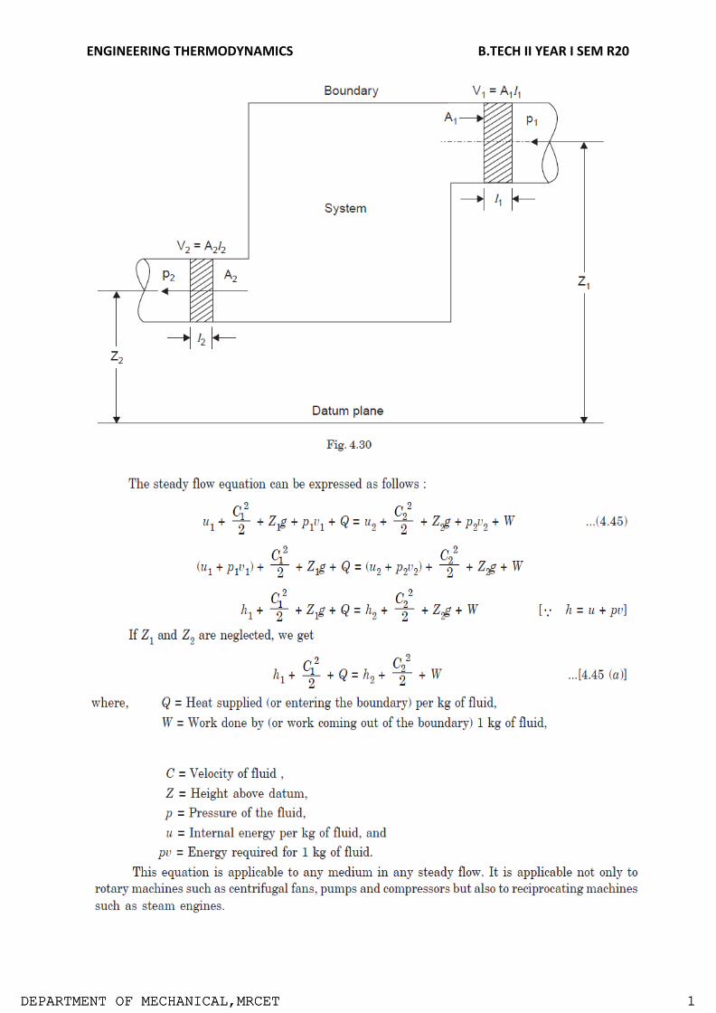
First law applied to a flow process
Steady flow energy equation:
Virtually all the practical systems involve flow of mass across the boundary separating the
system and the surroundings. Whether it be a steam turbine or a gas turbine or a
compressor or an automobile engine there exists flow of gases/gas mixtures into and out of
the system. So we must know how the first Law of thermodynamics can be applied to an
open system.
The fluid entering the system will have its own internal, kinetic and potential energies.
Let u1 be the specific internal energy of the fluid entering C1be the velocity of the fluid while
entering Z1 be the potential energy of the fluid while entering Similarly let u2, C2 and Z2 be
respective entities while leaving.
ENGINEERING THERMODYNAMICS B.TECH II YEAR I SEM R20
DDEEPPAARRTTMMEENNTT OOFF MMEECCHHAANNIICCAALL,,M MRRCCEETT 11

ENGINEERING THERMODYNAMICS B.TECH II YEAR I SEM R20
DDEEPPAARRTTMMEENNTT OOFF MMEECCHHAANNIICCAALL,,M MRRCCEETT 11

ENGINEERING THERMODYNAMICS B.TECH II YEAR I SEM R20
DDEEPPAARRTTMMEENNTT OOFF MMEECCHHAANNIICCAALL,,M MRRCCEETT 11

ENGINEERING THERMODYNAMICS B.TECH II YEAR I SEM R20
DDEEPPAARRTTMMEENNTT OOFF MMEECCHHAANNIICCAALL,,M MRRCCEETT 11

ENGINEERING THERMODYNAMICS B.TECH II YEAR I SEM R20
DDEEPPAARRTTMMEENNTT OOFF MMEECCHHAANNIICCAALL,,M MRRCCEETT 11

ENGINEERING THERMODYNAMICS B.TECH II YEAR I SEM R20
DDEEPPAARRTTMMEENNTT OOFF MMEECCHHAANNIICCAALL,,M MRRCCEETT 11

ENGINEERING THERMODYNAMICS B.TECH II YEAR I SEM R20
DDEEPPAARRTTMMEENNTT OOFF MMEECCHHAANNIICCAALL,,M MRRCCEETT 11

ENGINEERING THERMODYNAMICS B.TECH II YEAR I SEM R20
DDEEPPAARRTTMMEENNTT OOFF MMEECCHHAANNIICCAALL,,M MRRCCEETT 11

ENGINEERING THERMODYNAMICS B.TECH II YEAR I SEM R20
DDEEPPAARRTTMMEENNTT OOFF MMEECCHHAANNIICCAALL,,M MRRCCEETT 11

ENGINEERING THERMODYNAMICS B.TECH II YEAR I SEM R20
DDEEPPAARRTTMMEENNTT OOFF MMEECCHHAANNIICCAALL,,M MRRCCEETT 11

ENGINEERING THERMODYNAMICS B.TECH II YEAR I SEM R20
DDEEPPAARRTTMMEENNTT OOFF MMEECCHHAANNIICCAALL,,M MRRCCEETT 11
Industry applications
Automobile industries.
Refrigeration industries
Air craft applications
Defense industries
Thermal power plants
Chemical industries
Textile industries etc.
Assignment questions:
1. What is meant by thermodynamic equilibrium? Explain with the help of examples.
2. What is meant by SFEE and derive it and reduce it for the turbine.
3. Write about constant volume gas Thermometer? Why it is preferred over a
constant pressure gas Thermometer.
4. A blower handles 1kg/s of air at 200C and consuming a power of 15 kw. The inlet
and outlet velocities of air are 100 m/s and 150 m/s respectively. Find the exit air
temperature, assuming adiabatic conditions. Take Cp of air as 1.005 kJ/kgk.
5. Distinguish between macroscopic and microscopic point of view?
6. Discuss Quasi Static process, what are its characteristics?
7. Discuss First law of thermodynamics, explain Joule’s experiment.
Tutorial Questions
1. A piston cylinder device operates 1kg of fluid at 20atm pressure with initial volume
is 0.04m3. Fluid is allowed to expand reversibly following pV1.45=C. So that the volume
becomes double. The fluid is cooled at constant pressure until the piston comes back.
Determine the work done in each process?
2. When a stationary mass of gas was compressed without friction at constant pressure,
its initial state of 0.4m3 and 0.105MPa was found to change to final state of 0.20m3
and 0.105MPa. There was a transfer of 42.5kJ of heat from the gas during the
process. Determine the change in internal energy of the gas?

ENGINEERING THERMODYNAMICS B.TECH II YEAR I SEM R20
DDEEPPAARRTTMMEENNTT OOFF MMEECCHHAANNIICCAALL,,M MRRCCEETT 11
3. 0.44kg of air at 1800C, expands adiabatically to 3times its original volume and during
the process there is a fall in temperature to 150C. The work done during the process
is 52.5kJ. Calculate Cp and Cv ?
4. A new scale N of temperature is divided in such a way that the freezing point of ice is
1000N and the boiling point is 4000N. What is the temperature reading on this new
scale when the temperature is 1500C? At what temperature both the Celsius and the
new scale reading would be the same?
5. A piston-cylinder device operates 1 kg of fluid at 20 atm. Pressure. The initial volume
is 0.04 m3. The fluid is allowed to expand reversibly following a process pV1.4 =
constant so that the volume becomes double. The fluid is then cooled at a constant
pressure until the piston comes back to the original position. Keeping the piston
unaltered, heat is added reversibly to restore it to the initial pressure. Calculate the
work done in the cycle.
6.

ENGINEERING THERMODYNAMICS B.TECH II YEAR I SEM R20
DDEEPPAARRTTMMEENNTT OOFF MMEECCHHAANNIICCAALL,,M MRRCCEETT 11
UNIT-II
Enropy
Limitations of the First Law:
First law does not provide a clear idea about the direction of absorption or evolution of heat.
The first law of thermodynamics merely indicates that in any process there is a transformation
between the various forms of energy involved in the process but provides
noinformationregardingthefeasibilityofsuchtransformation.
Firstlawdoesnotprovideanyinformationregardingthedirectionprocesseswilltakewhether it is a
spontaneous or a non spontaneous process.
Thermal Reservoir:
A thermal reservoir is a large system (very high mass x specific heat value) from which a quantity of energy can be absorbed or added as heat without changing its temperature. The atmosphere and sea are examples of thermal reservoirs. Any physical body whose thermal energy capacity is large relative to the amount of energy it supplies or absorbs can be modelled as a thermal reservoir. A reservoir that supplies energy in the form of heat is called a source and one that absorbs energy in the form of heat is called asink.
Heat Engine:
It is a cyclically operating device which absorbs energy as heat from a high temperature reservoir, converts part of the energy into work and rejects the rest of the energy as heat to a thermal reservoir at low temperature. The working fluid is a substance, which absorbs energy as heat from a source, and rejects energy as heat to a sink.

ENGINEERING THERMODYNAMICS B.TECH II YEAR I SEM R20
DDEEPPAARRTTMMEENNTT OOFF MMEECCHHAANNIICCAALL,,M MRRCCEETT 11
Schematic representation of Heat Engine

ENGINEERING THERMODYNAMICS B.TECH II YEAR I SEM R20
Department of Mechanical Engineering, MRCET Page 40
Parameters of performance
The efficiency of Heat Engine
The efficiency ‘η’ of the heat engine is the ratio between its output of work to the heat supply of the heat engine. Let
us derive an expression for the efficiency of a heat engine.
η =W/Q1
where, W is the work done by the engine and Q1 is the heat absorbed from the source. After each cycle, the engine
returns to its original state so that it does not affect its internal energy.
ΔU = 0
W = Q1−Q2
Hence the engine efficiency is:
η =(Q1−Q2)/Q1
η = 1−Q2/Q1
So here efficiency will be 100% but in actual, this is not possible because there will be some loss of energy in the
system. Hence for every engine, there is a limit for its efficiency. Gasoline and diesel engines, jet engines, and steam
turbines that generate electricity are all examples of heat engines.
Heat pump:
A heat pump is a device that transfers heat energy from a source of heat to what is called a heat sink. Heat pumps move thermal energy in the opposite direction of spontaneous heat transfer, by absorbing heat from a cold space and releasing it to a warmer one. A heat pump uses a small amount of external power to accomplish the work of transferring energy from the heat source to the heat sink. The most common design of a heat pump involves four main components – a condenser, an expansion valve, an evaporator and a compressor. The heat transfer medium circulated through these components is called refrigerant.
Schematic representation of Heat Pump Coefficient of Performance

ENGINEERING THERMODYNAMICS B.TECH II YEAR I SEM R20
Department of Mechanical Engineering, MRCET Page 41
The coefficient of performance, COP, of a refrigerator is defined as the heat removed from the cold reservoir Qcold, (i.e. inside a refrigerator) divided by the work W done to remove the heat (i.e. the work done by the compressor).
COP - coefficient of performance - equation
As can be seen, the better (more efficient) the refrigerator is when more heat Qcold can be
removed from the inside of the refrigerator for a given amount of work. Since the first law of
thermodynamics must be valid also in this case (Qcold + W = Qhot), we can rewrite the
aboveequation:
The COP for heating and cooling are thus different, because the heat reservoir of interest is
different. When one is interested in how well a machine cools, the COP is the ratio of the heat
removed from the cold reservoir to input work. However, for heating, the COP is the ratio of the
heat removed from the cold reservoir plus the input work to the input work: medium to a high-
temperature is called heat pump.
Second Law of Thermodynamics
The second law of thermodynamics is a general principle which places constraints upon the direction of heat transfer and the attainable efficiencies of heat engines. In so doing, it goes beyond the limitations imposed by the first law of thermodynamics.
Kelvin-Planck Statement: It is impossible to devise a cyclically operating device, which produces no other effect than the

ENGINEERING THERMODYNAMICS B.TECH II YEAR I SEM R20
Department of Mechanical Engineering, MRCET Page 42
extraction of heat from a single thermal reservoir and delivers an equivalent amount of work.Heat engine with single thermal reservoir is not possible.
For a 1-T engine the thermal efficiency h=W/Q=1. No heat engine can have efficiency equal tounity.
Clausius statement
It is not possible for heat to flow from a colder body to a warmer body without any work having been
done to accomplish this flow. Energy will not flow spontaneously from a low temperature object to a
higher temperature object. This precludes a perfect refrigerator. The statements about refrigerators
apply to air conditioners and heat pumps, which embody the same principles.
This is the "second form" or Clausius statement of the second law.
OR
It is impossible to construct a device that operates in a cycle and produces no effect other than the
transfer of heat from a lower-temperature body to higher-temperature body.
Equivalence of Kelvin-Planck and Clausius Statements
To prove that violation of the Kelvin-Planck Statement leads to a violation of the Clausius Statement, let
us assume that Kelvin-Planck statement is incorrect.

ENGINEERING THERMODYNAMICS B.TECH II YEAR I SEM R20
Department of Mechanical Engineering, MRCET Page 43
Consider a cyclically working device 1, which absorbs energy Q1 as heat from a thermal reservoir at TH.
Equivalent amount of work W(W=Q1) is performed.
Consider another device 2 operating as a cycle, which absorbs energy QL as heat from a low
temperature thermal reservoir at TL and rejects energy QH (QH=QL+W). Such a device does not violate
Clausius statement. If the two devices are now combined, the combined device (enclosed by the dotted boundary) transfers
heat QL from the low temperature reservoir at TL to a high temperature reservoir at TH without
receiving any aid from an external agent, which is the violation of the Clausius statement.
Likewise let us assume that the Clausius statement is incorrect. So we have a device 1, cyclically
working transferring heat Q from a low temperature reservoir at TL to a high temperature thermal
reservoir at TH . Consider another device 2, which absorbs heat Q1 from a high temperature reservoir
at TH does work W and rejects energy Q as heat tot the low temperature reservoir at TL as shown in

ENGINEERING THERMODYNAMICS B.TECH II YEAR I SEM R20
Department of Mechanical Engineering, MRCET Page 44
figure.
If the two devices are combined (shown in figure by a dotted enclosure), then the combined device
receives energy (Q1-Q) as heat from a thermal reservoir and delivers equivalent work (W=Q1-Q) in
violation of the Kelvin-Planck statement.
Therefore violation of Clausius statement leads to the violation of the Kelvin-Planck statement. Hence,
these two statements are equivalent.

ENGINEERING THERMODYNAMICS B.TECH II YEAR I SEM R20
Department of Mechanical Engineering, MRCET Page 45

ENGINEERING THERMODYNAMICS B.TECH II YEAR I SEM R20
Department of Mechanical Engineering, MRCET Page 46

ENGINEERING THERMODYNAMICS B.TECH II YEAR I SEM R20
Department of Mechanical Engineering, MRCET Page 47

ENGINEERING THERMODYNAMICS B.TECH II YEAR I SEM R20
Department of Mechanical Engineering, MRCET Page 48

ENGINEERING THERMODYNAMICS B.TECH II YEAR I SEM R20
Department of Mechanical Engineering, MRCET Page 49

ENGINEERING THERMODYNAMICS B.TECH II YEAR I SEM R20
Department of Mechanical Engineering, MRCET Page 50

ENGINEERING THERMODYNAMICS B.TECH II YEAR I SEM R20
Department of Mechanical Engineering, MRCET Page 51

ENGINEERING THERMODYNAMICS B.TECH II YEAR I SEM R20
Department of Mechanical Engineering, MRCET Page 52

ENGINEERING THERMODYNAMICS B.TECH II YEAR I SEM R20
Department of Mechanical Engineering, MRCET Page 53

ENGINEERING THERMODYNAMICS B.TECH II YEAR I SEM R20
Department of Mechanical Engineering, MRCET Page 54

ENGINEERING THERMODYNAMICS B.TECH II YEAR I SEM R20
Department of Mechanical Engineering, MRCET Page 55

ENGINEERING THERMODYNAMICS B.TECH II YEAR I SEM R20
Department of Mechanical Engineering, MRCET Page 56

ENGINEERING THERMODYNAMICS B.TECH II YEAR I SEM R20
Department of Mechanical Engineering, MRCET Page 57

ENGINEERING THERMODYNAMICS B.TECH II YEAR I SEM R20
Department of Mechanical Engineering, MRCET Page 58

ENGINEERING THERMODYNAMICS B.TECH II YEAR I SEM R20
Department of Mechanical Engineering, MRCET Page 59

ENGINEERING THERMODYNAMICS B.TECH II YEAR I SEM R20
Department of Mechanical Engineering, MRCET Page 60

ENGINEERING THERMODYNAMICS B.TECH II YEAR I SEM R20
Department of Mechanical Engineering, MRCET Page 61
Principle of increase of entropy Let a system change from state 1 to state 2 by a reversible process A and return to state 1 by another reversible process B. Then 1A2B1 is a reversible cycle. Therefore, the Clausius inequality gives:
If the system is restored to the initial state from 1 to state 2 by an irreversible process C, then 1A2C1 is
an irreversible cycle. Then the Clausius inequality gives:

ENGINEERING THERMODYNAMICS B.TECH II YEAR I SEM R20
Department of Mechanical Engineering, MRCET Page 62
Subtracting the above equation from the first one,
Since the process 2B1 is reversible,
Where the equality sign holds good for a reversible process and the inequality sign holds good for an irreversible process. Now let us apply the above result to evaluate the entropy change of the universe when a system interacts with its surroundings and exchanges energy as heat with the surroundings. Let Tsur and Tsys be the temperatures of the surroundings and the system such that Tsur >Tsys. Let dQ represent the energy transfer as heat from t he surroundings to the system during the given irreversible process. dSsys = dQ/Tsys dSsur = -dQ/Tsur dSuni = dSsys + dSsur = (dQ/T)sys
(dQ/T)sur >0 DSuni >0 (since Tsur>Tsys) If the system is isolated, there is no change in the entropy of the surroundings and DS 0, for an isolated system Therefore the entropy of an isolated system either increases or, in the limit, remains constant.

ENGINEERING THERMODYNAMICS B.TECH II YEAR I SEM R20
Department of Mechanical Engineering, MRCET Page 63
The equality sign holds good when the process undergone by the system is reversible, the inequality sign holds good if there is any irreversibility present in the process. This statement is usually called the principle of entropy increase. Irreversible or spontaneous processes can occur only in that direction for which the
entropy of the universe or that of an isolated system, increases. These processes cannot
occur in the direction of decreasing entropy.
For an isolated system, DS > 0, for irreversible processes
DS = 0, for reversible processes
DS < 0, the process is impossible
Thermodynamic potentials
Thermodynamic potentials are state functions that, together with the corresponding equationsof state,
describe the equilibrium behavior of a system as a function of so-called”natural variables”. The natural
variables are a set of appropriate variables that allow tocompute other state functions by partial
differentiation of the thermodynamic potentials.

ENGINEERING THERMODYNAMICS B.TECH II YEAR I SEM R20
Department of Mechanical Engineering, MRCET Page 64

ENGINEERING THERMODYNAMICS B.TECH II YEAR I SEM R20
Department of Mechanical Engineering, MRCET Page 65

ENGINEERING THERMODYNAMICS B.TECH II YEAR I SEM R20
Department of Mechanical Engineering, MRCET Page 66

ENGINEERING THERMODYNAMICS B.TECH II YEAR I SEM R20
Department of Mechanical Engineering, MRCET Page 67

ENGINEERING THERMODYNAMICS B.TECH II YEAR I SEM R20
Department of Mechanical Engineering, MRCET Page 68

ENGINEERING THERMODYNAMICS B.TECH II YEAR I SEM R20
Department of Mechanical Engineering, MRCET Page 69

ENGINEERING THERMODYNAMICS B.TECH II YEAR I SEM R20
Department of Mechanical Engineering, MRCET Page 70

ENGINEERING THERMODYNAMICS B.TECH II YEAR I SEM R20
Department of Mechanical Engineering, MRCET Page 71
ENGINEERING THERMODYNAMICS B.TECH II YEAR I SEM R20
Department of Mechanical Engineering, MRCET Page 72

ENGINEERING THERMODYNAMICS B.TECH II YEAR I SEM R20
Department of Mechanical Engineering, MRCET Page 73

ENGINEERING THERMODYNAMICS B.TECH II YEAR I SEM R20
Department of Mechanical Engineering, MRCET Page 74

ENGINEERING THERMODYNAMICS B.TECH II YEAR I SEM R20
Department of Mechanical Engineering, MRCET Page 75

ENGINEERING THERMODYNAMICS B.TECH II YEAR I SEM R20
Department of Mechanical Engineering, MRCET Page 76

ENGINEERING THERMODYNAMICS B.TECH II YEAR I SEM R20
Department of Mechanical Engineering, MRCET Page 77
Industry applications
Automobile industries.
Refrigeration industries
Air craft applications
Defense industries
Thermal power plants etc.

ENGINEERING THERMODYNAMICS B.TECH II YEAR I SEM R20
Department of Mechanical Engineering, MRCET Page 78
Assignment questions
1. Describe briefly about the second law of thermodynamics with its corollaries.
2. State the limitations of first law of thermodynamics?State PMM 2?
3. Discuss briefly about Clausius inequality.
4. Discuss the significance of Third law of thermodynamics
5. A heat pump working on a reversed Carnot cycle takes in energy from a reservoir maintained at
30C and delivers it to another reservoir where temperature is 77C. The heat pump drives power
for its operation from a reversible engine operating within the higher and lower temperature
limits of 1077C and 77C. For 100 kJ/sec of energy supplied to the reservoir at 77C, estimate the
energy taken from the reservoir at 1077C.
6. Derive the expression for the efficiency of Carnot cycle with p-V and T-s diagrams.
7. Solve one T -dS equation by using Maxwell’s relations?

ENGINEERING THERMODYNAMICS B.TECH II YEAR I SEM R20
Department of Mechanical Engineering, MRCET Page 79
Tutorial questions
1. 0.5 kg of air executes a Carnot power cycle having a thermal efficiency of 50%. The heat transfer to
the air during isothermal expansion is 40 kJ. At the beginning of the isothermal expansion the
pressure is 7 bar and the volume is 0.12 m3. Determine the maximum and minimum temperatures
for the cycle in Kelvin, the volume at the end of isothermal expansion in m3 and the work, heat
transfer for each of the four processes in kJ. cp=1.008 kJ/kgK and cv=0.721 kJ/kgK for air.
2. Water is heated at a constant pressure of 0.7 MPa. The boiling point is 164.970C. The initial
temperature of water is 00C. The latent heat of evaporation is 2066.3 kJ/kg. Find the increase of
entropy of water if the final temperature is steam.
3. 1kg of ice at -50C expose to the atmosphere which, is at 200C. The ice melts and comes into
thermal equilibrium with the atmosphere. Determine the entropy increase of Universe. Cp for
ice is 2.039 kJ/kgK, and the enthalpy of fusion of ice is 333.3kJ/kg.
4. A heat engine is operating between two reservoirs 1000K and 300K is used to drive a heat
pump which extracts heat from the reservoir at 300K at arate twice that at which the engine
rejects the heat to it. If the efficiency of the engine is 40% of the maximum possible and COP
of heat pump is 50% of the maximum possible, then determine the temperature of the
reservoir to which the heat pump rejects heat. Also determine the rate of heat rejection from
the heat pump, if the rate of heat supply to the heat engine is 50kW?
5. A heat engine is operating between two reservoirs 1000K and 300K is used to drive a heat
pump which extracts heat from the reservoir at 300K at A heat engine is operating between
two reservoirs 1000K and 300K is used to drive a heat pump which extracts heat from the
reservoir at 300K. The efficiency of both the engines is equal. What is the value of
temperature T2.

ENGINEERING THERMODYNAMICS B.TECH II YEAR I SEM R20
Department of Mechanical Engineering, MRCET Page 80
UNIT -III Properties of pure substances
Pure substance
A substance that has a fixed chemical composition throughout the system is called a pure substance. Water, hydrogen, nitrogen, and carbon monoxide, for example, are all pure substance. A pure substance can also be a mixture of various chemical elements or compounds as long as the mixture is homogeneous. Air, a mixture of several compounds, is often considered to be a pure substance because it has a uniform chemical composition. “A mixture of two or more phases of a pure substance is still a pure substance as long as the chemical composition of all phases is the same. A mixture of ice and liquid water, for example, is a pure substance because both phases have the same chemical composition.”
PVT Surface
Pressure can be expressed as a function of temperature and specific volume: p = p(T, v). The plot of
p = p(T, v) is a surface called p-v-T surface. Figure 3.1 shows the p-v-T surface of a substance such as
water that expands onfreezing.
Figure 3.1 p-v-T surface and projections for a substance that expands on freezing.
(a) 3-D view (b) p-T diagram (c) p-vdiagram2.

ENGINEERING THERMODYNAMICS B.TECH II YEAR I SEM R20
Department of Mechanical Engineering, MRCET Page 81
The location of a point on the p-v-T surface gives the values of pressure, specific volume, and temperature at equilibrium. The regions on the p-v-T surface labeled solid, liquid, and vapor are single-phase regions. The state of a single phase is determined by any two of the properties: pressure, temperature, and specific volume. The two-phase regions where two phases exist in equilibrium separate the single-phase regions. The two-phase regions are: liquid-vapor, solid-liquid, and solid-vapor. Temperature and pressure are dependent within the two-phase regions. Once the temperature is specified, the pressure is determined and vice versa. The states within the two-phase regions can be fixed by specific volume and either temperature orpressure.
The projection of the p-v-T surface onto the p-T plane is known as the phase diagram as shown in Figure 3.1 (b). The two-phase regions of the p-v-T surface reduce to lines in the phase diagram. A point on any of these lines can represent any two-phase mixture at that particular temperature and pressure. The triple line of the p-v-T surface projects onto a point on the phase diagram called the triple point. Three phases coexist on the triple line or the triplepoint.
The constant temperature lines of the p-v diagram are called the isotherms. For any
specified temperature less than the critical temperature, the pressure remains constant within the two- phase region even though specific volume changes. In the single-phase liquid and vapor regions the pressure decreases at fixed temperature as specific volume increases. For temperature greater than or equal to the critical temperature, there is no passage across the two-phase liquid-vapor region.
Figure 3.1-2 T-v diagram for water (to scale).

ENGINEERING THERMODYNAMICS B.TECH II YEAR I SEM R20
Department of Mechanical Engineering, MRCET Page 82
Figure 3.1-2 is a T-v diagram for water. For pressure greater than or equal to the critical pressure, temperature increases continously at fixed pressure as the specific volume increases and there is no passage across the two-phase liquid-vapor region. The isobaric curve marked 50 MPa in Figure 3.1-2 shows this behavior. For pressure less than the critical value, there is a two-phase region where the temperature remains constant at a fixed pressure as the two- phase region is traversed. The isobaric curve with values of 20 MPa or less in Figure 3.1-2 shows the constant temperature during the phase change.
At 100oC, the saturated volumes of liquid and vapor water are 1.0434 cm3/g and 1,673.6 cm3/g, respectively. The quality of steam is the mass fraction of water vapor in a mixture of liquid and vapor water. The specific volume of 100oC steam with a quality of 0.65 is given by
v = (1 - 0.65)vL + 0.65 vV = (0.35)(1.0434) + (0.65)(1,673.6) = 1088.2 cm3/g
Phase Behavior:
We will consider a phase change of 1 kg of liquid water contained within a piston-cycinder assembly as shown in Figure 3.2-1a. The water is at 20oC and 1.014 bar (or 1 atm) as indicated by point (1) on Figure 3.2-2.
Figure 3.2-1 Phase change at constant pressure for water3
Figure 3.2-2 Sketch of T-v diagram for water
As the water is heated at constant pressure, the temperature increases
with a slight increase in specific volume until the system reaches point (f). This isthe

ENGINEERING THERMODYNAMICS B.TECH II YEAR I SEM R20
Department of Mechanical Engineering, MRCET Page 83
saturated liquid state corresponding to 1.014 bar. The saturation temperature for water at 1.014 bar is 100oC. The liquid states along the line segment 1-f are called subcooled or compressed liquid states. When the system is at the saturated liquid state (point f in Figure 3.2-2) any additional heat will cause the liquid to evaporate at constant pressure as shown in Figure 3.2-1b. When a mixture of liquid and vapor exists in equilibrium, the liquid phase is a saturated liquid and the vapor phase is a saturated vapor.
Liquid water continues to evaporate with additional heat until it becomes all saturated vapor at point (g). Any further heating will cause an increase in both temperature and specific volume and the saturated vapor becomes superheated vapor denoted by point (s) in Figure 3.2-2. For a two-phase liquid-vapor mixture, the quality x is defined as the mass fraction of vapor in the mixture
x = mvapor
mvapor +mliquid
When a substance exists as part liquid and part vapor at saturation conditions, its quality (x) is defined as the ratio of the mass of the vapor to the total mass of both vapor and liquid.
Enthalpy–Entropy Chart
An enthalpy–entropy chart, also known as the H–S chart or Mollier diagram, plots the total
heat against entropy, describing the enthalpy of a thermodynamic system. A typical chart
covers a pressure range of 0.01–1000 bar, and temperatures up to 800 degrees Celsius. It
shows enthalpy H in terms of internal energy U, pressure p and volume V using the
relationship H=U+pV or, in terms of specific enthalpy, specific entropy and specific volume.
On the diagram, lines of constant pressure, constant temperature and volume are plotted,
so in a two-phase region, the lines of constant pressure and temperature coincide. Thus,
coordinates on the diagram represent entropy andheat.
A vertical line in the h–s chart represents an isentropic process. The process 3–4 in a
Rankine cycle is isentropic when the steam turbine is said to be an ideal one. So the
expansion process in a turbine can be easily calculated using the h–s chart when the process
is considered to be ideal (which is the case normally when calculating enthalpies, entropies,
etc. Later the deviations from the ideal values and they can be calculated considering the
isentropic efficiency of the steam turbineused.

ENGINEERING THERMODYNAMICS B.TECH II YEAR I SEM R20
Department of Mechanical Engineering, MRCET Page 84

ENGINEERING THERMODYNAMICS B.TECH II YEAR I SEM R20
Department of Mechanical Engineering, MRCET Page 85
Lines of constant dryness fraction (x), sometimes called the quality, are drawn in the wet
region and lines of constant temperature are drawn in the superheated region. X gives
thefraction (by mass) of gaseous substance in the wet region, the remainder being colloidal
liquid droplets. Above the heavy line, the temperature is above the boiling point, and the
dry (superheated) substance is gasonly.
Characteristics of the critical point:
For saturated phase often its enthalpy is an importantproperty. Enthalpy-pressure charts are used for refrigeration cycleanalysis. Enthalpy-entropy charts for water are used for steam cycleanalysis. Note: Unlike pressure, volume and temperature which have specified numbers
associated with it, in the case of internal energy, enthalpy (and entropy) only changes are required. Consequently, a base (or datum) is defined -as you have seen in the case of water.

ENGINEERING THERMODYNAMICS B.TECH II YEAR I SEM R20
Department of Mechanical Engineering, MRCET Page 86
Let V be total volume of liquid vapour mixture of quality x, Vfthe volume of saturated liquid
and Vg the volume of saturated vapour, the corresponding masses being m, mf and mg
respectively.
Now, m = mf + mg
V = Vf+ Vg
m v= mfvf+ mgvg
Saturation States
When a liquid and its vapour are in equilibrium at certain pressure and temperature, only the pressure or the temperature i is s sufficient to identify the saturationstate. If pressure is given, the temperature of the mixture gets fixed, which is known as saturation temperature, or if the temperature is given, the saturation pressure getsfixed. Saturation liquid or saturated vapour has only on independent variable, i.e. only one property is required to b known to fix up the state.
Type of Steam
Wet steam:
Wet steam is defined as steam which is partly vapour and partly liquid suspended in it. It means that evaporation of water is not complete.
Dry saturated steam:
When the wet steam is further heated, and it does not contain any suspended particles of water, it is known as dry saturated steam.
Superheated steam: When the dry steam is further heated at constant pressure, thus raising its temperature, it is called superheated steam.
Measurement of Steam Quality:
The state of a pure substance gets fixed if two independent properties are given. A pure
substance is thus said to have two degrees of freedom. Of all thermodynamic properties, it
is easiest to measure the pressure and temperature of a substance. Therefore, whenever
pressure and temperature are independent properties, it is the practice to measure them to
determine that state of the substance.
Types of Calorimeters used for measurement of Steam Quality
BarrelCalorimeter SeparatingCalorimeter ThrottlingCalorimeter Combined Separating and Throttlingcalorimeter
Barrel Calorimeter Dryness fraction of steam can be found out very conveniently by barrel calorimeter as shown in figure. A vessel contains a measured quantity of water. Also water equivalent of

ENGINEERING THERMODYNAMICS B.TECH II YEAR I SEM R20
Department of Mechanical Engineering, MRCET Page 87
the vessel is determined experimentally and stamped platform of weighing machine. Sample of steam is passed through the sampling tube into fine exit holes for discharge of steam in the cold water.
The steam gets condensed and the temperature of water rises. The weighing machine gives
the steam condensed.
Basically, this calorimeter is used when we want to know the approximate dryness fraction of steam, or to have a rough idea about the dryness fraction. This calorimeter gives better results if the dryness fraction of steam is greater than 0.95.
ENGINEERING THERMODYNAMICS B.TECH II YEAR I SEM R20
Department of Mechanical Engineering, MRCET Page 88
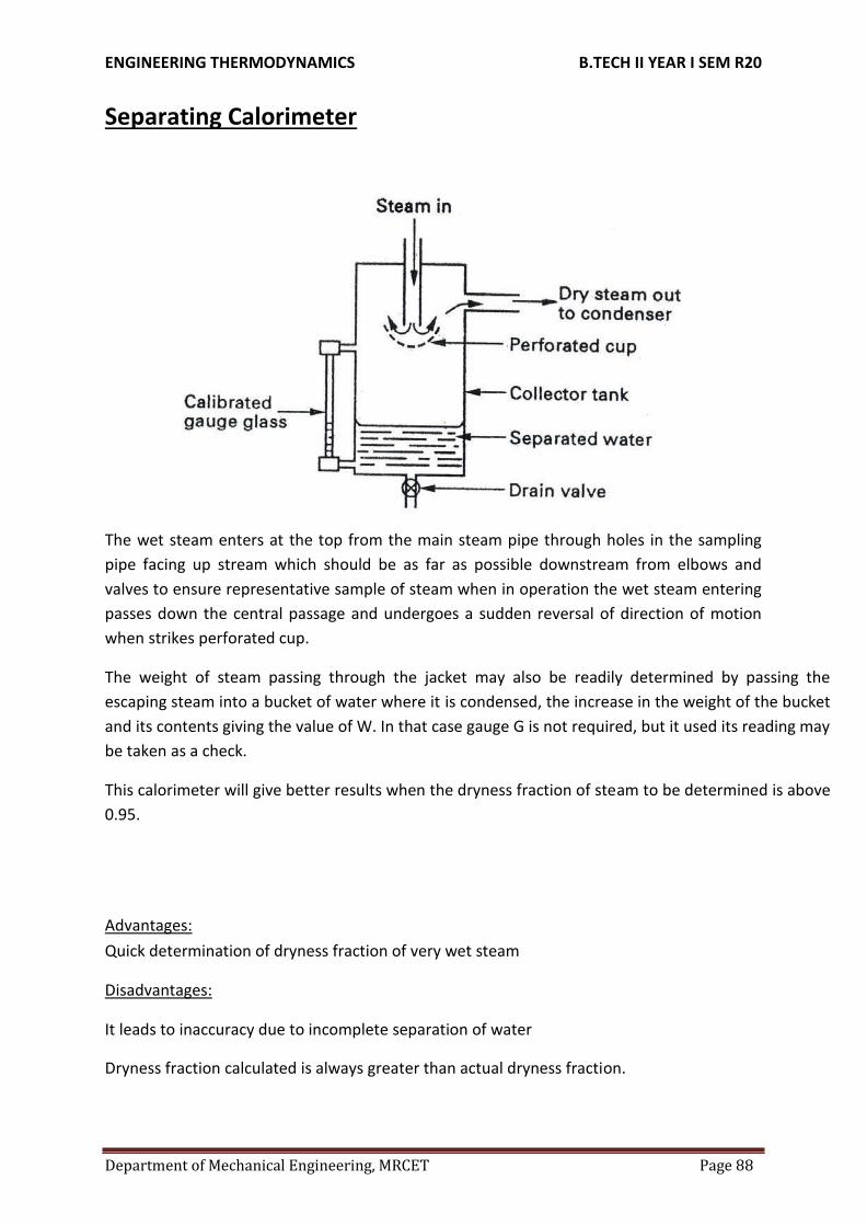
Separating Calorimeter
The wet steam enters at the top from the main steam pipe through holes in the sampling
pipe facing up stream which should be as far as possible downstream from elbows and
valves to ensure representative sample of steam when in operation the wet steam entering
passes down the central passage and undergoes a sudden reversal of direction of motion
when strikes perforated cup.
The weight of steam passing through the jacket may also be readily determined by passing the
escaping steam into a bucket of water where it is condensed, the increase in the weight of the bucket
and its contents giving the value of W. In that case gauge G is not required, but it used its reading may
be taken as a check.
This calorimeter will give better results when the dryness fraction of steam to be determined is above
0.95.
Advantages:
Quick determination of dryness fraction of very wet steam
Disadvantages:
It leads to inaccuracy due to incomplete separation of water
Dryness fraction calculated is always greater than actual dryness fraction.

ENGINEERING THERMODYNAMICS B.TECH II YEAR I SEM R20
Department of Mechanical Engineering, MRCET Page 89
Throttling Calorimeter
In the throttling calorimeter, a sample of wet steam of mass m and at pressure P1 is taken
from the steam main through a perforated sampling tube. Then it is throttled by the
partially-opened valve (or orifice) to a pressureP2measured by mercury manometer,
and temperature t2, so that after throttling the steam is in the superheatedregion.
The steady flow energy equation gives the enthalpy after throttling as equal to enthalpy
before throttling. The initial and final equilibrium states 1 and 2 are joined by a dotted line
since throttling is irreversible (adiabatic but not isentropic) and the intermediate states are
non-equilibrium states not describable by thermodynamic coordinates. The initial state
(wet) is given by P1and x1 and the final state by P2 andt2.
Advantages: Dryness fraction of very dry steam can be found out easily.
Disadvantages: It is not possible to find dryness fraction of very wet steam.
ENGINEERING THERMODYNAMICS B.TECH II YEAR I SEM R20
Department of Mechanical Engineering, MRCET Page 90
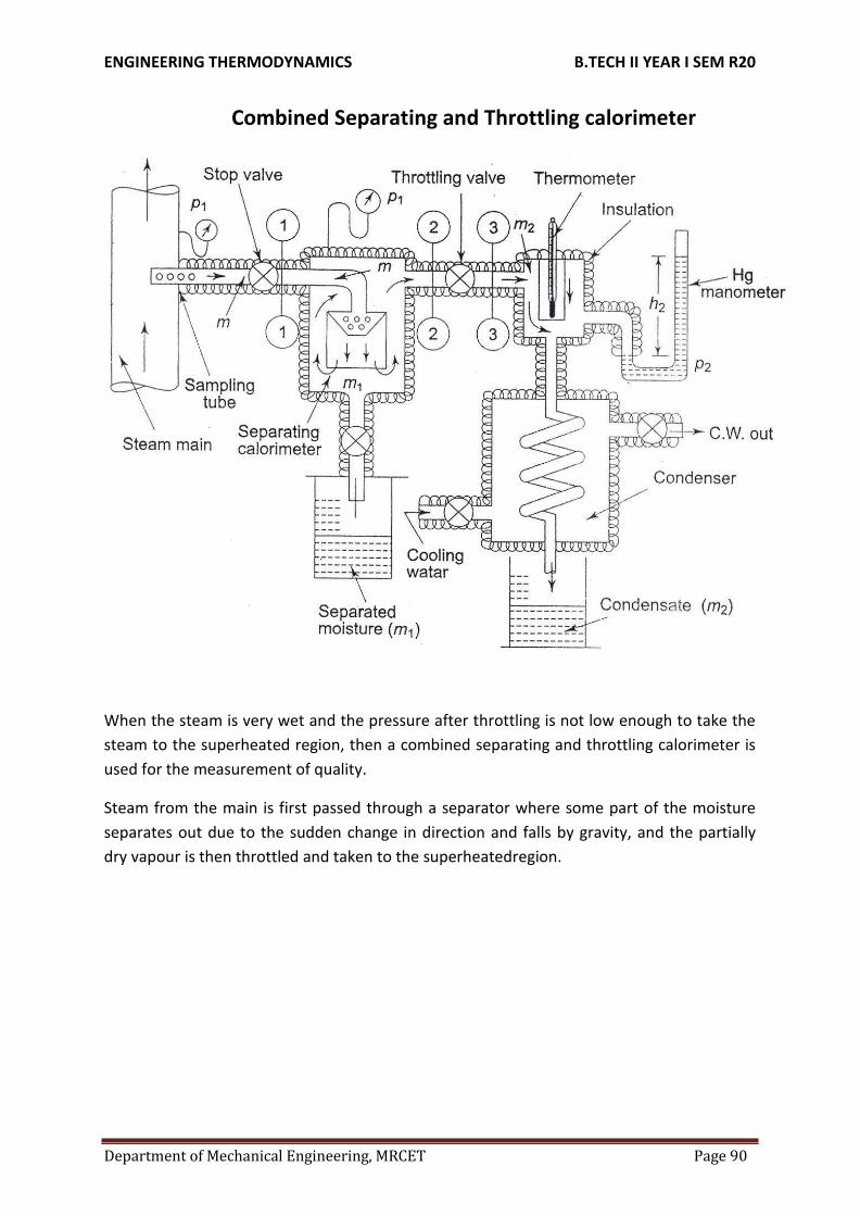
Combined Separating and Throttling calorimeter
When the steam is very wet and the pressure after throttling is not low enough to take the
steam to the superheated region, then a combined separating and throttling calorimeter is
used for the measurement of quality.
Steam from the main is first passed through a separator where some part of the moisture
separates out due to the sudden change in direction and falls by gravity, and the partially
dry vapour is then throttled and taken to the superheatedregion.

ENGINEERING THERMODYNAMICS B.TECH II YEAR I SEM R20
Department of Mechanical Engineering, MRCET Page 91
1. Calculate the dryness fraction of steam which has 1.5 kg of water in suspension with50 kg of steam.
Given
p1
x h 2 fg p1
h3 h2 hf
In Fig. process 1-2 represents the moisture separation from the wet sample of steam at
constant pressure P1 and process 2-3 represents throttling to pressure P2. With P2
and t3 being measured, h3 can be found out from the superheated steamtable.
Therefore x2, the quality of steam after partial moisture separation can be evaluated If m kg
of steam, is taken through the sampling tube in t s, m1 kg of it is separated, and m2 kg is
throttled and then condensed to water and collected, then m = m1 + m2 and at state 2, the
mass of dry vapour will be x2 m2. Therefore, the quality of the
sample of steam at state l, x1 is given by . .
m2
m1 m2
2 massof liquid vapourmixtureat state1 x 1
massof dry vapour state1 x

ENGINEERING THERMODYNAMICS B.TECH II YEAR I SEM R20
Department of Mechanical Engineering, MRCET Page 92
Heat added
Mass of water (mf) = 1.5 kg
Mass of steam (mg) = 50 kg
Required : Dryness fraction (x) Solution m
Dryness fraction (x) = ------- mg + mf
50
= --------------=0.971 ------- Ans
501.5 Eg. Steam is generated at 8 bar from water at 32oC. Determine the heat required to produce 1 kg of steam (a) when the dryness fraction is 0.85 (b) when steam is dry saturated and (c) when the steam is superheated to 305oC. The specific heat of superheated steam may be taken as 2.093kJ/kg-K.
Given:
Steampressure(p) = 8bar
Initial temperature of water (T1) = 32oC Mass ofsteam(m) = 1 kg
Required: Heat required when (a) x =
0.85 (b) x = 1 (c) Tsup = 305oC
Solution:(a)
SH LH
T 170.4
32oC
Heat required = Sensible heat addition + Latent
heat addition Sensible heat addition = m Cpw (ts – T1)
ts = saturation temperature = 170.4oC at 8bar
from steam table Cpw = Specific heat at constant
pressure = 4.186 kJ/kg (Taken)

ENGINEERING THERMODYNAMICS B.TECH II YEAR I SEM R20
Department of Mechanical Engineering, MRCET Page 93
Sensible Heat addition = 1 x 4.186 x (170.4 – 32)
= 79.34 kJ/kg
Latent heat addition / kg = x hfg
Latentheat(hfg) = 2046.5 kJ/kg from steam table at 8bar
Latent heat addition for ‘m’ kg = m xhfg
= 1 x 0.85 x (2046.5)
= 1739.525 kJ/kg
Totalheat required = 579.34 +1739.525
= 2318.865 kJ/kg --- Ans
(b) (b)
T 170.4
oC
Heat required = Sensible heat addition + Latent heat addition Latent heat addition / kg = x hfg
Latentheat(hfg) = 2046.5 kJ/kg from steam
table at 8 bar Latent heat addition for ‘m’ kg = mx
hfg
= 1 x 1 x (2046.5)
= 2046.5 kJ/kg
Totalheatrequired = 579.34 +2046.5
= 2625.84 kJ/kg ---Ans
Heat required = Sensible heat addition + Latent heat addition + Sensible
Heat addition Sensible heat addition to superheated steam
= m Cpv (Tsup – ts)
= 1 x 2.093 x (305 – 170.4)
= 281.72 kJ/kg
Latent heat addition / kg =hfg
SH LH

ENGINEERING THERMODYNAMICS B.TECH II YEAR I SEM R20
Department of Mechanical Engineering, MRCET Page 94
Latentheat(hfg) = 2046.5 kJ/kg from steam table at 8 bar
Totalheatrequired = 579.34 + 2046.5 +281.72
= 2907.56 kJ/kg --- Ans
Ideal Gas:
Perfect gas, also called ideal gas, a gas that conforms, in physical behaviour, to a particular, idealized relation between pressure, volume, and temperature called the general gas law.
Gas Laws:
Boyle’s Law
Boyle’s Law Pressure is inversely proportional to volume: p∞ 1/v Robert Boyle noticed that when the volume of a container holding an amount of gas is increased, pressure decreases, and vice versa (while the temperature is held constant). Note that this is not a linear relationship between p and V.
Charles’ Law:
Charles’ Law Volume is directly proportional to temperature: V = cT, where c > 0 is constant.
Scientist Jacque Charles noticed that if air in a balloon is heated, the balloon expands. For an
ideal gas, this relationship between V and T should be linear (as long as pressure is
constant).
Charles’ and Boyle’s Laws combined
Combine the two laws above: pV/T = K, where k is a constant, =
pV=mRTThe Individual Gas Constant - R
The Individual Gas Constant depends on the particular gas and is related to the molecular
weight of the gas. The value is independent of temperature. The induvidual gas constant, R,
for a gas can be calculated from the universal gas constant, Ru (given in several units
below), and the gas molecular weight,Mgas:
R = Ru/Mgas
In the SI system units are J/kgK.
The Universal Gas Constant -Ru
The Universal Gas Constant - Ru - appears in the ideal gas law and can be expressed as the
product between the Individual Gas Constant - R - for the particular gas - and the Molecular
Weight - Mgas - for the gas, and is the same for all ideal or perfect gases:
Ru = Mgas R, kJ/(kmol.K) : 8.3144598
The Molecular weight of a Gas Mixture

ENGINEERING THERMODYNAMICS B.TECH II YEAR I SEM R20
Department of Mechanical Engineering, MRCET Page 95
The average molecular weight of a gas mixture is equal to the sum of the mole fractions of
each gas multiplied by the molecular weight of that particular gas:
Mmixture = Σxi*Mi =(x1*M1+........ +xn*Mn)
where
xi = mole fractions of each gas
Mi = the molar mass of each gas
Throttling Process:
The porous plug experiment was designed to measure temperature changes when a fluid
flows steadily through a porous plug which is inserted in a thermally insulated, horizontal
pipe. The apparatus used by Joule and Thomson is shown in Figure
A gas at pressure and temperature flows continuously through a porous plug in a tube
and emerges into a space which is maintained at a constant pressure. The device is
thermally insulated and kept horizontal. Consider the dotted portion as controlvolume.
These results in
Therefore, whenever a fluid expands from a region of high pressure to a region of low pressure through a porous plug, partially opened valve or some obstruction, without exchanging any energy as heat and work with the surrounding (neglecting, the changes in PE and KE), the enthalpy of the fluid remains constant, and the fluid is said to have undergone a throttlingprocess.

ENGINEERING THERMODYNAMICS B.TECH II YEAR I SEM R20
Department of Mechanical Engineering, MRCET Page 96
Free expansion (or unresisted expansion) process. A free expansion occurs when a fluid is allowed to expand suddenly into a vaccum chamber through an orifice of large dimensions. In this process, no heat is supplied or rejected and no external work is done. Hence the total heat of the fluid remains constant. This type of expansion may also be called as constant total heat expansion. It is thus obvious, that in a free expansion process,
Q1-2 = 0, W1-2 = 0 and dU = 0.
van der Waals Equation of State:
The ideal gas law treats the molecules of a gas as point particles with perfectly elastic collisions. This works well for dilute gases in many experimental circumstances. But gas molecules are not point masses, and there are circumstances where the properties of the molecules have an experimentally measurable effect. A modification of the ideal gas law was proposed by Johannes D. van der Waals in 1873 to take into account molecular size and molecular interaction forces. It is usually referred to as the van der Waals equation ofstate.
The constants a and b have positive values and are characteristic of the individual gas.
The van der Waals equation of state approaches the ideal gas law PV=nRT as the values of
these constants approach zero. The constant a provides a correction for the intermolecular
forces. Constant b is a correction for finite molecular size and its value is the volume of one
mole of the atoms or molecules.
Since the constant b is an indication of molecular volume, it could be used to estimate the
radius of an atom or molecule, modeled as a sphere. Fishbane et al. give the value of b for
nitrogen gas as 39.4 x 10⁻⁶ m3/mol.

ENGINEERING THERMODYNAMICS B.TECH II YEAR I SEM R20
Department of Mechanical Engineering, MRCET Page 97
Assignment Questions
1. Draw the phase equilibrium diagram for a pure substance on T-s plot with relevant constant
property line?
2. 10 kg of feed water is heated in a boiler at a constant pressure of 1.5 MN/m2 from 40 C.
Calculate the enthalpy required and change of entropy when water is converted into following
qualities of steam in each case i) Wet steam at x=0.95and ii) Super heated steam at 300 C
3. Define dryness fraction of steam. Describe method of finding dryness fraction ofsteam using
separating and throttling calorimeter
4. A rigid close tank of volume 3m3 contains 5 kg of wet steam at a pressure of 200 kPa. The tank
is heated until the steam becomes dry saturated. Determine final pressure and heat transfer to
the tank.
5. Describe briefly about throttling and free expansion processes.
6. Describe briefly about “Mollier diagram”.
7. State Vander Waals equation, what is the importance of it?
Tutorial Questions
1. Determine the enthalpy and entropy of steam and the pressure is 2MPa and the specific volume
is 0.09m3/kg.
2. 10 kg of feed water is heated in a boiler at a constant pressure of 1.5 MN/m2 from 40 C.
Calculate the enthalpy required and change of entropy when water is converted into following
qualities of steam in each case i) Wet steam at x=0.95and ii) Super heated steam at 300 C
3. Air at 16oC and 1.2 bar occupies a volume of 0.03m3.the air is heated at constant volume until
the pressure is 4.3 bar and then cooled at constant pressure back to the original
temperature.Calculate the net heat flow to or from the airand the net entropychange.
4. 5 kg of steam with a dryness fraction of 0.9 expands adiabatically tothe Law PV1.13constant.
from a pressure of 8 bar to 1.5 bardetermine final dryness fractionii)heattransferred
iii)workdone
5. A vessel of 0.04 m2 Contains a mixture of saturated water and saturated steam at a temperature
of 250°C. The Mass liquid present is 9kg . Find pressure, the mass, the specific volume, the
enthalpy and entropy and the internal energy.

ENGINEERING THERMODYNAMICS B.TECH II YEAR I SEM R20
Department of Mechanical Engineering, MRCET Page 98
UNIT-IV
Mixtures of perfect Gases:
A mixture, consisting of several pure substances, is referred to as a solution. Examples of
pure substances are water, ethyl alcohol, nitrogen, ammonia, sodium chloride, and iron.
Examples of mixtures are air, consisting of nitrogen, oxygen and a number of other gases,
aqueous ammonia solutions, aqueous solutions of ethyl alcohol, various metal alloys. The
pure substances making up a mixture are called components or constituents.
Mixture of ideal gases
Basic assumption is that the gases in the mixture do not interact with each other.
Consider a mixture with components l = 1,2,3... with masses m1, m2, m3 ...miand with
number ofmoles.
The total mixture occupies a volume V, has a total pressure P and temperature T (which is also the temperature of each of the component species)
The total mass
(4.1)
Total number of mole N
(4.2)
Mass fraction of speciesi
Mole fraction of speciesi
The mass and number of moles of species iare related by
is the number of moles of speciesiand is the molar mass of speciesi
Also to be noted
(4.3)
(4.4)
(4.5)
and (4.6)
We can also define a molar mass of the mixture as

ENGINEERING THERMODYNAMICS B.TECH II YEAR I SEM R20
Department of Mechanical Engineering, MRCET Page 99
(4.7)
or,
or,
Dalton 's Law of partial pressure
Total pressure of an ideal gas mixture is equal to the sum of the partial pressures of the constituent components, That is
(4.9)
P is the total pressure of the mixture
Piis the partial pressure of species i
= pressure of the species if it existed alone in the given temperature T and volume V
(4.10)
is the universal gas constant = 8.314 kJ/k mol K
Amagat's Law:
Volume of an ideal gas mixture is equal to the sum of the partial volumes
(4.11)
V = total volume of the mixture
Vi= partial volume of the species i
= volume of the species if it existed alone in the given temperature T and pressure
For an ideal gas

ENGINEERING THERMODYNAMICS B.TECH II YEAR I SEM R20
Department of Mechanical Engineering, MRCET Page 100
Amagat's Law
Or
The volume fraction of species I
or,
Volume fraction = Mole fraction
Mass based analysis is known as gravimetric analysis
Mole based analysis is known as molar analysis
Mole Fraction:
(4.12)
(4.13)
(34.16)
The composition of a gas mixture can be described by the mole fractions of the gases
present. The mole fraction ( X ) of any component of a mixture is the ratio of the number of
moles of that component to the total number of moles of all the species present in the
mixture ( ntot ):
xA=moles of A/total moles
=na/ntot
=nA/(nA+nB+⋯)
The mole fraction is a dimensionless quantity between 0 and 1.

ENGINEERING THERMODYNAMICS B.TECH II YEAR I SEM R20
Department of Mechanical Engineering, MRCET Page 101
If xA=1.0 , then the sample is pure A , not a mixture.
If xA=0 , then no A is present in the mixture.
The sum of the mole fractions of all the components present must equal 1.
To see how mole fractions can help us understand the properties of gas mixtures, let’s evaluate the ratio of the pressure of a gas A to the total pressure of a gas mixture that contains A . We can use the ideal gas law to describe the pressures of both gas A and the mixture: PA=nART/V and Ptot=ntRT/V . The ratio of the two is thus
PA/Ptot= nA/ntot=xA
PA=XAPtot
Mass Fraction:
the mass fraction of a substance within a mixture is the ratio of the mass of that substance
to the total mass of the mixture.
Expressed as a formula, the mass fraction is
According to the conservation of mass, we have:

ENGINEERING THERMODYNAMICS B.TECH II YEAR I SEM R20
Department of Mechanical Engineering, MRCET Page 102

ENGINEERING THERMODYNAMICS B.TECH II YEAR I SEM R20
Department of Mechanical Engineering, MRCET Page 103

ENGINEERING THERMODYNAMICS B.TECH II YEAR I SEM R20
Department of Mechanical Engineering, MRCET Page 104

ENGINEERING THERMODYNAMICS B.TECH II YEAR I SEM R20
Department of Mechanical Engineering, MRCET Page 105

ENGINEERING THERMODYNAMICS B.TECH II YEAR I SEM R20
Department of Mechanical Engineering, MRCET Page 106

ENGINEERING THERMODYNAMICS B.TECH II YEAR I SEM R20
Department of Mechanical Engineering, MRCET Page 107

ENGINEERING THERMODYNAMICS B.TECH II YEAR I SEM R20
Department of Mechanical Engineering, MRCET Page 108

ENGINEERING THERMODYNAMICS B.TECH II YEAR I SEM R20
Department of Mechanical Engineering, MRCET Page 109
Atmospheric Air: Atmospheric air makes up the environment in almost every type of air conditioning system. Hence a thorough understanding of the properties of atmospheric air and the ability to analyze various processes involving air is fundamental to air conditioning design.
Psychrometry is the study of the properties of mixtures of air and water vapour.
Atmospheric air is a mixture of many gases plus water vapour and a number of pollutants The amount of water vapour and pollutants vary from place to place. The concentration of water vapour and pollutants decrease with altitude, and above an altitude of about 10 km, atmospheric air consists of only dry air. The pollutants have to be filtered out before processing the air. Hence, what we process is essentially a mixture of various gases that constitute air and water vapour. This mixture is known as moist air.
Psychrometric Properties:
Dry bulb temperature (DBT) is the temperature of the moist air as measured by a standard thermometer or other temperature measuring instruments.
Saturated vapour pressure (psat) is the saturated partial pressure of water vapour at the dry bulb temperature. This is readily available in thermodynamic tables and charts. ASHRAE suggests the following regression equation for saturated vapour pressure of water, which is valid for 0 to 100oC.
Relative humidity (Φ) is defined as the ratio of the mole fraction of water vapour in moist air to mole fraction of water vapour in saturated air at the same temperature and pressure. Using perfect gas equation we can show that:

ENGINEERING THERMODYNAMICS B.TECH II YEAR I SEM R20
Department of Mechanical Engineering, MRCET Page 110
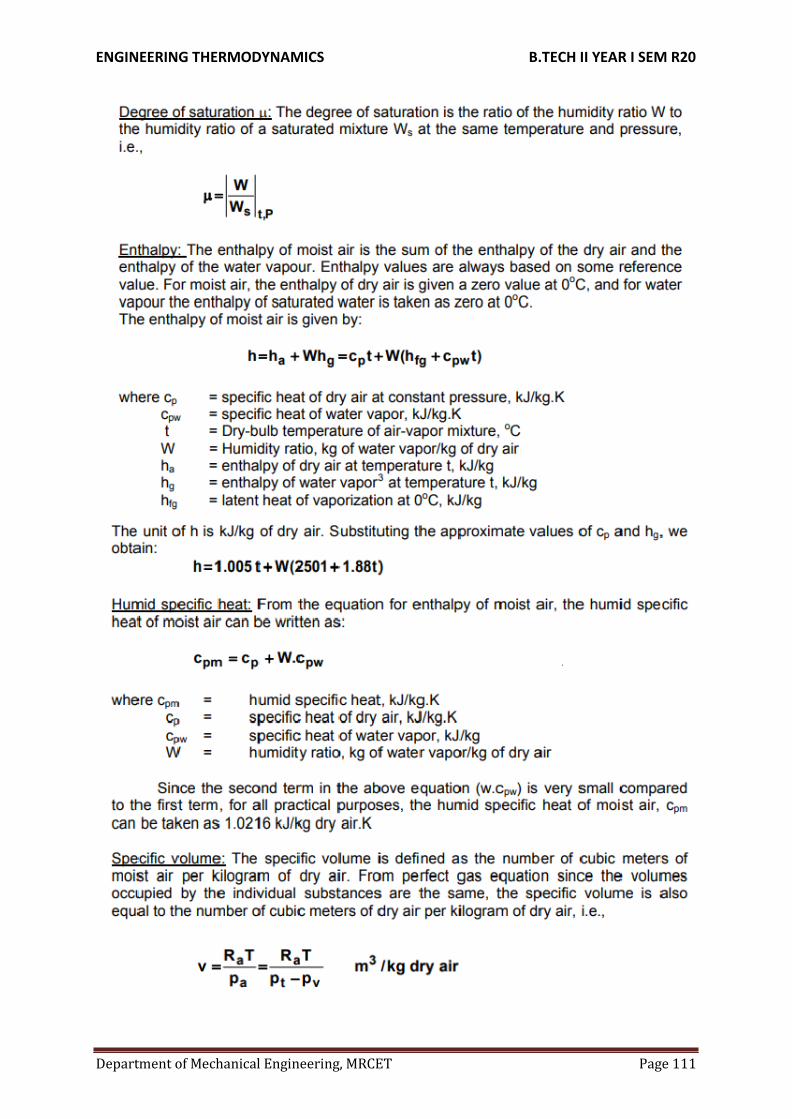
ENGINEERING THERMODYNAMICS B.TECH II YEAR I SEM R20
Department of Mechanical Engineering, MRCET Page 111

ENGINEERING THERMODYNAMICS B.TECH II YEAR I SEM R20
Department of Mechanical Engineering, MRCET Page 112

ENGINEERING THERMODYNAMICS B.TECH II YEAR I SEM R20
Department of Mechanical Engineering, MRCET Page 113

ENGINEERING THERMODYNAMICS B.TECH II YEAR I SEM R20
Department of Mechanical Engineering, MRCET Page 114

ENGINEERING THERMODYNAMICS B.TECH II YEAR I SEM R20
Department of Mechanical Engineering, MRCET Page 115

ENGINEERING THERMODYNAMICS B.TECH II YEAR I SEM R20
Department of Mechanical Engineering, MRCET Page 116

ENGINEERING THERMODYNAMICS B.TECH II YEAR I SEM R20
Department of Mechanical Engineering, MRCET Page 117

ENGINEERING THERMODYNAMICS B.TECH II YEAR I SEM R20
Department of Mechanical Engineering, MRCET Page 118

ENGINEERING THERMODYNAMICS B.TECH II YEAR I SEM R20
Department of Mechanical Engineering, MRCET Page 119

ENGINEERING THERMODYNAMICS B.TECH II YEAR I SEM R20
Department of Mechanical Engineering, MRCET Page 120
Industry applications
Automobile industries.
Refrigeration industries
Air craft applications
Defense industries
Thermal power plants etc.
Assignment Questions
1. Define mole fraction, and mass fraction. Explain about volumetric and gravimetric analysis?
2. Explain adiabatic saturation temperature?
3. Explain psychrometric charts while representing all the properties?
4. Locate i) sensible heating ii) sensible cooling iii) heating and humidification iv) heating and
dehumidification on psychrometric chart?
5. Compare degree of saturation and adiabatic saturation.
6. a) Define saturated air, wet bulb temperature, specific humidity and relativehumidity. b) State
and explain i) Dalton’s law of partial pressure ii) Avagadro’s law iii) Amagat’s law of additive
volumes.
7. The analysis by weight of a perfect gas mixture at 200C and 1.3bar is10%O2, 70%N2,15%CO2
and 5%CO. For a reference state of 00C and 1bar,determine partial pressure of the constituent
and gas constant of mixture.

ENGINEERING THERMODYNAMICS B.TECH II YEAR I SEM R20
Department of Mechanical Engineering, MRCET Page 121
Tutorial Questions
1. 1.8 kg of oxygen at 480 C is mixed with 6.2 kg of nitrogen at the same temperature. Both oxygen
and nitrogen are at the pressure of 102 k Pa before and after mixing. Find the increase in
entropy.
2. A mixture of ideal air and water vapour at a dbt of 220C and a total pressure of 730 mm Hg abs.
has a temperature of adiabatic saturation of 150C. Calculate: i. the speci_c humidity in gms per
kg of dry air. ii. the partial pressure of water vapour the relative humidity, and iv. enthalpy of the
mixture per kg of dry air.
3. Atmospheric air at 1.0132 bar has a DBT of 30°C and WBT of 24°C. Compute, (i) The partial
pressure of water vapour (ii) Specific humidity (iii) The dew point temperature (iv) Relative
humidity (v) Degree of saturation (vi) Density of air in the mixture (vii) Density of the vapour in
the mixture (viii) The enthalpy of the mixture.
4. A mixture of ideal gases consists of 3 kg of nitrogen and 6 kg of CO2 at a pressureof 250 kpa
and a temperature of 230C. Find(a) the mole fraction of each constituent(b) equivalent weight of
the mixture(c) equivalent gas constant of the mixture(d) partial pressures and partial volumes(e)
volume and density of mixture Cp and Cv of mixture. If the mixture is heated at constant volume
to 60C and the internal energy, enthalpy, and entropy of mixture. Find the changes in internal
energy, enthalpy, and entropy of mixture if the heating is done at constant pressure. Take γ for
CO2and N2 be 1.286 and 1.4.
5. Consider a mixture of ideal gases comprising 2kg of nitrogen and 3kg of carbon dioxide 250kPa
pressure and 300K temperature . Make calculations for i) Mole fraction, partial pressure and
partial volume of each constituent. ii) Molecular mass, gas constant, volume and density of the
mixture iii) Specific heats and adiabatic exponent for the mixture Take γ = 1.286 for CO2 and γ =
1.4 for nitrogen.

ENGINEERING THERMODYNAMICS B.TECH II YEAR I SEM R20
Department of Mechanical Engineering, MRCET Page 122
UNIT-V
Gas Power Cycles
Introduction
For the purpose of thermodynamic analysis of the internal combustion engines, the
following approximations are made:
The engine is assumed to operate on a closed cycle with a fixed mass of air which does not undergo any chemicalchange.
The combustion process is replaced by an equivalent energy addition process from an externalsource.
The exhaust process is replaced by an equivalent energy rejection process to external surroundings by means of which the working fluid is restored to the initial state.
The air is assumed to behave like an ideal gas with constant specific heat.These cycles are usually referred to as air standard cycle.
Otto Cycle
The Air Standard Otto cycle is named after its inventor Nikolaus A. Otto . Figures 5.1 (a), (b) and (c) illustrate the working principles of an Otto cycle. The Otto cycle consists of the following processes.
Figure 5.1
0-1: Constant pressure suction during which a mixture of fuel vapour and air is drawn into the cylinder as the piston executes an outward stroke.
1-2: The mixture is compressed isentropically due to the inward motion of the piston. Because of the isentropic compression , the temperature of the gas increases.

ENGINEERING THERMODYNAMICS B.TECH II YEAR I SEM R20
Department of Mechanical Engineering, MRCET Page 123
2-3: The hot fuel vapour-air mixture is ignited by means of an electric spark. Since the combustion is instantaneous, there is not enough time for the piston o move outward. This process is approximated as a constant volume energy addition process .
3-4: The hot combustion products undergo isentropic expansion and the piston executes an outward motion.
4-1: The exhaust port opens and the combustion products are exhausted into the atmosphere. The process is conveniently approximated as a constant-volume energy rejection process.
1-0: The remaining combustion products are exhausted by an inward motion of the piston at constant pressure.
Effectively there are four strokes in the cycle. These are suction, compression, expression, and exhaust strokes, respectively. From the P-V diagram it can be observed that the work done during the process 0-1 is exactly balanced by the work done during 1-0. Hence for the purpose of thermodynamic analysis we need to consider only the cycle 1-2-3-4, which is air- standard Otto Cycle.
(5.1)
Where and denote the energy absorbed and energy rejected in the form of heat. Application of the first law of thermodynamics to process 2-3 and 4-1gives:
(5.2)
(5.3)
Therefore,
(5.4)
1-2 and 3-4 are isentropic processesforwhich constant
Therefore,
(5.5)

ENGINEERING THERMODYNAMICS B.TECH II YEAR I SEM R20
Department of Mechanical Engineering, MRCET Page 124
and (5.7)
and
But
Hence
So,
(5.6)
(5.8)
or (5.9)
(5.10)
or
and
(5.12)
(5.13)
or (5.11)

ENGINEERING THERMODYNAMICS B.TECH II YEAR I SEM R20
Department of Mechanical Engineering, MRCET Page 125
Where
Compression ratio (5.14)
Since , the efficiency of the Otto cycle increases with increasing compression ratio. However,inanactualengine,thecompressionratiocannotbeincreasedindefinitelysince
higher compression ratios give higher values of and this leads tospontaneous and uncontrolled combustion of the gasoline-air mixture in the cylinder. Such a condition is usually calledknocking.
Figure 5.2
Performance of an engine is evaluated in terms of the efficiency (see Figure 5.2). However, sometime it is convenient to describe the performance in terms of mean effective pressure, an imaginary pressure obtained by equating the cycle work to the work evaluated by the following the relation
(5.15)
The mean effective pressure is defined as the net work divided by the displacement volume.
That is

ENGINEERING THERMODYNAMICS B.TECH II YEAR I SEM R20
Department of Mechanical Engineering, MRCET Page 126
DIESEL CYCLE
Figure 5.3 (a), (b) and (c)
The Diesel cycle was developed by Rudolf Diesel in Germany. Figures 5.3 (a), (b) and (c) explain the working principle of an Air Standard Diesel cycle. The following are the processes.
0-1: Constant pressure suction during which fresh air is drawn into the cylinder as the piston executes the outward motion.
1-2: The air is compressed isentropically. Usually the compression ratio in the Diesel cycle is much higher them that of Otto cycle. Because of the high compression ratio, the temperature of the gas at the end of isentropic compression is so high that when fuel is injected, it gets ignited immediately.
2-3: The fuel is injected into the hot compressed air at state 2 and the fuel undergoes a chemical reaction. The combustion of Diesel oil in air is not as spontaneous as the combustion of gasoline and the combustion is relatively slow. Hence the piston starts moving outward as combustion take place. The combustion processes is conveniently approximated as a constant pressure energy additionprocess.
3-4: The combustion products undergo isentropic expansion and the piston executes an outward motion.

ENGINEERING THERMODYNAMICS B.TECH II YEAR I SEM R20
Department of Mechanical Engineering, MRCET Page 127
4-1: The combustion products are exhausted at constant volume when the discharge port opens. This is replaced by a constant-volume energy rejection process.
1-0: The remaining combustion products are exhausted at constant pressure by the inward motion of the piston.
In the analysis of a Diesel cycle, two important parameters are: compression
ratio and the cut-off ratio . The cut-off ratio is defined as the ratio of the volume at the end of constant-pressure energy addition process to the volume at the beginning of the energy additionprocess.
(5.16)
(5.17) Energy added
Energy rejected (5.18)
(5.19)
or
(5.20)
1-2 is Isentropic:
4-1 is Constant volume:

ENGINEERING THERMODYNAMICS B.TECH II YEAR I SEM R20
Department of Mechanical Engineering, MRCET Page 128
But
Hence
Since 1−2 and 3−4 are isentropicprocesses
and
Hence
Also to be noted
(5.21)
(5.22)
(5.23)
The compression ratios normally in the Diesel engines vary between 14 and 17.
AIR STANDARD DUAL CYCLE
Figures 5.4 (a) and (b) shows the working principles of a Dual cycle. In the dual cycle, the energy addition is accomplished in two stages: Part of the energy is added at constant volume and part of the energy is added at constant pressure. The remaining processes are similar to those of the Otto cycle and the Diesel cycle. The efficiency of the cycle can be estimated in the following way

ENGINEERING THERMODYNAMICS B.TECH II YEAR I SEM R20
Department of Mechanical Engineering, MRCET Page 129
Figure 5.4.1 (a) and (b)
Energy added
Energy rejected
or
The efficiency of the cycle can be expressed in terms of the following ratios
(5.24)
(5.25)
(5.25)
(5.26)
Compression ratio, (5.27)
Cut-off ratio, (5.28)

ENGINEERING THERMODYNAMICS B.TECH II YEAR I SEM R20
Department of Mechanical Engineering, MRCET Page 130
Expansion ratio, (5.28)
Constant volume pressure ratio, (5.29)
(5.30)
If
If
Comparison of Otto, Diesel & Dual Cycles
For same compression ratio and heat rejection (Figures 5.5 (a) and (b))
Figure 5.5 (a) and (b)
1-6-4-5: Otto cycle

ENGINEERING THERMODYNAMICS B.TECH II YEAR I SEM R20
Department of Mechanical Engineering, MRCET Page 131
1-7-4-5: Diesel cycle
1-2-3-45 Dual cycle
For the same Q2 , the higher the Q1 , the higher is the cycle efficiency
For the same maximum pressure and temperature (Figures 5.6 (a) and (b))
Figure 5.6 (a) and (b)
1-6-4-5: Otto cycle
1-7-4-5: Diesel cycle
1-2-3-45 Dual cycle
Q1 is representedby:
Area under 6-4 for Otto cycle area under 7-4 for Diesel cycle
and areaunder 2-3-4 for Dual cycle and Q2 is same for all thecycles

ENGINEERING THERMODYNAMICS B.TECH II YEAR I SEM R20
Department of Mechanical Engineering, MRCET Page 132
The Brayton cycle
The Brayton cycle (or Joule cycle) represents the operation of a gas turbine engine. The cycle consists of four processes, as shown in Figure alongside a sketch of an engine: a - b Adiabatic, quasi-static (or reversible) compression in the inlet and compressor; b - c Constant pressure fuel combustion (idealized as constant pressure heat addition); c - d Adiabatic, quasi-static (or reversible) expansion in the turbine and exhaust nozzle, with which we take some work out of the air and use it to drive the compressor, andtake the remaining work out and use it to accelerate fluid for jet propulsion, or to turn a generator for electrical power generation; d - a Cool the air at constant pressure back to its initial condition.
The components of a Brayton cycle device for jet propulsion are shown in Figure 3.14. We will typically represent these components schematically, as in Figure 3.15. In practice, real Brayton cycles take one of two forms. Figure 3.16(a) shows an ``open'' cycle, where the working fluid enters and then exits the device. This is the way a jet propulsion cycle works. Figure 3.16(b) shows the alternative, a closed cycle, which recirculates the working fluid. Closed cycles are used, for example, in space power generation.

ENGINEERING THERMODYNAMICS B.TECH II YEAR I SEM R20
Department of Mechanical Engineering, MRCET Page 133
Schematics of typical military gas turbine engines.
Open cycle operation Closed cycle operation
Options for operating Brayton cycle gas turbine engines
Work and Efficiency

ENGINEERING THERMODYNAMICS B.TECH II YEAR I SEM R20
Department of Mechanical Engineering, MRCET Page 134
The objective now is to find the work done, the heat absorbed, and the thermal efficiency of
the cycle. Tracing the path shown around the cycle from - - - and back to , the first law gives (writing the equation in terms of a unit mass),
Here is zero because is a function of state, and any cycle returns the system to its
starting state3.2. The net work done is therefore
where , are defined as heat received by the system ( is negative). We thus need to
evaluate the heat transferred in processes - and - .
For a constant pressure, quasi-static process the heat exchange per unit mass is
We can see this by writing the first law in terms of enthalpy or by remembering the definition
of .
The heat exchange can be expressed in terms of enthalpy differences between the relevant states. Treating the working fluid as a perfect gas with constant specific heats, for the heat addition from the combustor,
The heat rejected is, similarly,
The net work per unit mass is given by
The thermal efficiency of the Brayton cycle can now be expressed in terms of the temperatures:

ENGINEERING THERMODYNAMICS B.TECH II YEAR I SEM R20
Department of Mechanical Engineering, MRCET Page 135
To proceed further, we need to examine the relationships between the different temperatures.
We know that points and are on a constant pressure process as are points and ,
and ; . The other two legs of the cycle are adiabatic and reversible, so
Therefore , or, finally, . Using this relation in the expression for thermal efficiency, Eq. (3.8) yields an expression for the thermal efficiency of a Brayton cycle
The temperature ratio across the compressor, . In terms of compressor temperature ratio, and using the relation for an adiabatic reversible process we can write the efficiency in terms of the compressor (and cycle) pressure ratio, which is the parameter commonly used:

ENGINEERING THERMODYNAMICS B.TECH II YEAR I SEM R20
Department of Mechanical Engineering, MRCET Page 136

ENGINEERING THERMODYNAMICS B.TECH II YEAR I SEM R20
Department of Mechanical Engineering, MRCET Page 137

ENGINEERING THERMODYNAMICS B.TECH II YEAR I SEM R20
Department of Mechanical Engineering, MRCET Page 138

ENGINEERING THERMODYNAMICS B.TECH II YEAR I SEM R20
Department of Mechanical Engineering, MRCET Page 139

ENGINEERING THERMODYNAMICS B.TECH II YEAR I SEM R20
Department of Mechanical Engineering, MRCET Page 110

ENGINEERING THERMODYNAMICS B.TECH II YEAR I SEM R20
Department of Mechanical Engineering, MRCET Page 111

ENGINEERING THERMODYNAMICS B.TECH II YEAR I SEM R20
Department of Mechanical Engineering, MRCET Page 112

ENGINEERING THERMODYNAMICS B.TECH II YEAR I SEM R20
Department of Mechanical Engineering, MRCET Page 113

ENGINEERING THERMODYNAMICS B.TECH II YEAR I SEM R20
Department of Mechanical Engineering, MRCET Page 114

ENGINEERING THERMODYNAMICS B.TECH II YEAR I SEM R20
Department of Mechanical Engineering, MRCET Page 115

ENGINEERING THERMODYNAMICS B.TECH II YEAR I SEM R20
Department of Mechanical Engineering, MRCET Page 116
Industry applications
Automobile industries.
Refrigeration industries
Air craft applications
Defense industries
Thermal power plants etc.
Assignment Questions
1. With p-V and T-s diagrams derive the efficiency of ottocycle.
2. With p-V and T-s diagrams derive the efficiency of Dieselcycle.
3. With p-V and T-s diagrams derive the efficiency of dual combustioncycle.
4. Differentiate between Otto cycle, diesel cycle and dual combustioncycle.
5. With p-V and T-s diagrams derive the efficiency of Rankinecycle.
6. An engine working on Otto cycle has a volume of 0.45 m3, pressure 1 bar and temperature 30°C at the beginning of compression stroke. At the end of compression stroke, the pressure is 11 bar. 210 kJ of heat is added at constant volume.Determine:
a. Pressures, temperatures and volumes at salient points in thecycle.
b. Percentageclearance.
c. Efficiency.
d. Mean effectivepressure.
7. In a Diesel cycle, air a 0.1 MPa and 300 K is compressed adiabatically until the pressure rises to 5 MPa. If 700 kJ/kg of energy in the form of heat is supplied at constant pressure, determine the compression ratio, cutoff ratio, thermal efficiency and mean effectivepressure.
8. An air-standard Diesel cycle has a compression ratio of 20, and the heat transferred to the working fluid per cycle is 1800 kJ/kg. At the beginning of the compression process, the pressure is 0.1 MPa and the temperature is 15°C. Consider ideal gas and constant specific heat model. Determine the pressure and temperature at each point in the cycle, The thermal efficiency, The mean effective pressure.

ENGINEERING THERMODYNAMICS B.TECH II YEAR I SEM R20
Department of Mechanical Engineering, MRCET Page 117
Tutorial Questions
1. An engine working on Otto cycle has a volume of 0.45 m3, pressure 1 bar and
temperature 30°C at the beginning of compression stroke. At the end of
compression stroke, the pressure is 11 bar. 210 kJ of heat is added at constant
volume.Determine:
a. Pressures, temperatures and volumes at salient points in thecycle.
b. Percentageclearance.
c. Efficiency.
d. Mean effectivepressure.
2. In a Diesel cycle, air a 0.1 MPa and 300 K is compressed adiabatically until the
pressure rises to 5 MPa. If 700 kJ/kg of energy in the form of heat is supplied at
constant pressure, determine the compression ratio, cutoff ratio, thermal efficiency
and mean effectivepressure.
3. An air-standard Diesel cycle has a compression ratio of 20, and the heat
transferred to the working fluid per cycle is 1800 kJ/kg. At the beginning of the
compression process, the pressure is 0.1 MPa and the temperature is 15°C.
Consider ideal gas and constant specific heat model. Determine the pressure and
temperature at each point in the cycle, The thermal efficiency, The mean effective
pressure.
4. An engine with 200mm cylinder diameter and 300mm stroke working on
theoretical diesel cycle. The initial pressure and temperature of air used are 1bar
and 270C. The cut of is 8% of the stroke. Determine air standard efficiency, mean
effective pressure and power of the engine if the working cycles per minute are
300? Assume the compression ratio is 15 and the working fluid is air.
5. An engine of 250mm bore and 375mm stroke works on Otto cycle. The clearance
volume is 0.00263m3. The initial pressure and temperature are 1bar and 500C.
The maximum pressure is limited to 25bar. Find the air standard efficiency and the
mean effective pressure of the cycle? Assume ideal conditions?

ENGINEERING THERMODYNAMICS B.TECH II YEAR I SEM R20
Department of Mechanical Engineering, MRCET Page 118
QUESTION BANK
UNIT-I
1. Explain briefly the following terms with diagram (wherevernecessary) a. Thermodynamic System, Surroundings &Boundary
b. Control Volume & ControlSurface
c. Intensive & ExtensiveProperty
d. Path Function & PointFunction
e. ThermodynamicEquilibrium 2. Describe the working principle of constant volume gas thermometer with a neat
sketch. 3. State and explain quasi- staticprocess. 4. List out the causes of irreversibility andexplain. 5. State and explain first law of thermodynamics with itscorollaries. 6. Prove that ‘Energy’ is a point function of a system undergoing change ofstate. 7. A stationary mass of gas is compressed without friction from an initial state of 0.35
m 3 and 0.11MPa to a final state of 0.25 m 3 at constant pressure. There is a transfer of 48.67 kJ of heat from the gas during the process. How much does the internal energy of the gaschange?
8. 0.2m3 of air at 3 bar and 1200C is contained in a system. A reversible adiabatic expansion takes place till the pressure falls to 1.5 bar. The gas is then heated at constant pressure till enthalpy increases by 75 kJ. Calculate the work done and the index of expansion, if the above processes are replaced by a single reversible polytropic process giving the same work between the same initial and finalstates.
UNIT-II
1. Write notes on the following a) Limitations of first law of thermodynamicsb)Thermal
energy reservoir c) Heat engine d) Heat pump e)COP
2. State and explain second law of thermodynamics with itscorollaries.
3. Explain Carnot cycle with p-V and T-s diagrams and derive the expression for
efficiency.
4. Describe briefly about Maxwell’sequations.
5. What is reversed Carnot heat engine? What are the limitations of Carnotcycle? 6. At the inlet to a certain nozzle the enthalpy of fluid passing is 2800 kJ/kg, and the
velocity is 50 m/s. At the discharge end the enthalpy is 2600 kJ/kg. The nozzle is horizontal and there is negligible heat loss fromit.
a. Find the velocity at exit of thenozzle. b. If the inlet area is 900 cm2 and the specific volume at inlet is 0.187 m3/kg,
find the mass flowrate. c. If the specific volume at the nozzle exit is 0.498 m3/kg, find the exit area of
nozzle. 7. A steam turbine operates under steady flow conditions receiving steam at the
followingstate:
a. pressure 15 bar, internal energy 2700 kJ/kg, specific volume 0.17m3/kg

ENGINEERING THERMODYNAMICS B.TECH II YEAR I SEM R20
Department of Mechanical Engineering, MRCET Page 119
and velocity 100 m/s. the exhaust of steam from the turbine is at 0.1
bar with internal energy 2175 kJ/kg, specific volume 0.15 m3/kg and velocity 300 m/s. The intake is 3 meters above the exhaust. The turbine develops 35 kW and heat loss over the surface of turbine is 20 kJ/kg. Determine the steam flow rate through theturbine.
8. A reversible engine receives heat from two thermal reservoirs maintained at
constant temperature of 750 K and 500 K. The engine develops 100 kW and
rejects 3600 kJ/min of heat to a heat sink at 250 K. Determine thermal efficiency
of the engine and heat supplied by each thermalreservoir.
UNIT-III
1. Explain the phase change of a pure substance on p-V-Tsurface.
2. Describe briefly about mollierchart.
3. Describe the working of combined separating and throttlingcalorimeter.
4. Explain briefly about the vanderwaals equation ofstate.
5. 2 kg. of gas at a temperature of 200 C undergoes a constant pressure process until the temperature is 1000 C. Find the heat transferred, ratio of specific heats, specific gas constant, work done, and change in entropy during the process. Take CV = 0.515 kJ/kg k, CP = 0.6448 kJ/kgk.
6. A container of 2 m3 capacity contains 10 kg of CO2 at 27°C. Estimate the pressure exerted by CO2 by using,a) Perfect gas equations and also using b) vanderwaals equation
7. Atmospheric air at 1.0132 bar has a DBT of 30°C and WBT of 24°C.Compute, (i) The partial pressure of watervapour
(ii) Specifichumidity
(iii) The dew pointtemperature
(iv) Relative humidity
(v) Degree ofsaturation
(vi) Density of air in themixture
(vii) Density of the vapour in themixture
8. A vessel of 0.04 m2 Contains a mixture of saturated water and saturated steam at a temperature of 250°C. The Mass liquid present is 9kg . Find pressure, the mass, the specific volume, the enthalpy and entropy and the internalenergy.
UNIT-IV
1. Write notes on the following terms a) Mole Fraction b) Mass fraction c) Gravimetric and d) volumetricAnalysis.
2. Write notes on the following terms a) Dry bulb Temperature b)Wet Bulb Temperature, c) Dew point Temperature d)Thermodynamic Wet BulbTemperature e) Specific Humidity f)Relative Humidity
3. Explain the various terms involved psychrometricchart. 4. 2 kg. of gas at a temperature of 20 0 C undergoes a constant pressure process until
the temperature is 100 0 C. Find the heat transferred, ratio of specific heats,specific

ENGINEERING THERMODYNAMICS B.TECH II YEAR I SEM R20
Department of Mechanical Engineering, MRCET Page 120
gas constant, work done, and change in entropy during the process. Take Cv = 0.515 kJ/kgk Cp = 0.6448 kJ/kg k.
5. a) Write the differences between gravimetric and volumetricanalysis. b) 1.8 kg of oxygen at 480 C is mixed with 6.2 kg of nitrogen at the same temperature. Both oxygen and nitrogen are at the pressure of 102 k Pa before and after mixing. Find the increase in entropy.
6. A mixture of ideal air and water vapour at a DBT of 22°C and a total pressure of 730 mm Hg abs has a temperature of adiabatic saturation of 15°C. Calculate, (i) The specific humidity in gms per kg of dry air. (ii) The partial pressure of water vapour. (iii) The relative humidity (iv) Enthalpy of the mixture per kg of dryair.
7. An air-water vapour mixture enters an adiabatic saturator at 30°C and leaves at 20°C, which is the adiabatic saturation temperature. The pressure remains constant at 100 kPa. Determine the relative humidity and the humidity ratio of the inlet mixture.
8. State and explain Daltons’ law of partial pressures and Amgot’s law of additive volumes.
UNIT-V
6. With p-V and T-s diagrams derive the efficiency of ottocycle.
7. With p-V and T-s diagrams derive the efficiency of Dieselcycle.
8. With p-V and T-s diagrams derive the efficiency of dual combustioncycle.
9. Differentiate between Otto cycle, diesel cycle and dual combustioncycle.
10. With p-V and T-s diagrams derive the efficiency of Rankinecycle.
11. An engine working on Otto cycle has a volume of 0.45 m3, pressure 1 bar and temperature 30°C at the beginning of compression stroke. At the end of compression stroke, the pressure is 11 bar. 210 kJ of heat is added at constant volume.Determine:
a. Pressures, temperatures and volumes at salient points in thecycle.
b. Percentageclearance.
c. Efficiency.
d. Mean effectivepressure.
12. In a Diesel cycle, air a 0.1 MPa and 300 K is compressed adiabatically until the pressure rises to 5 MPa. If 700 kJ/kg of energy in the form of heat is supplied at constant pressure, determine the compression ratio, cutoff ratio, thermal efficiency and mean effectivepressure.
13. An air-standard Diesel cycle has a compression ratio of 20, and the heat transferred to the working fluid per cycle is 1800 kJ/kg. At the beginning of the compression process, the pressure is 0.1 MPa and the temperature is 15°C. Consider ideal gas and constant specific heat model. Determine the pressure and temperature at each point in the cycle, The thermal efficiency, The mean effective pressure.

ENGINEERING THERMODYNAMICS B.TECH II YEAR I SEM R20
Department of Mechanical Engineering, MRCET Page 121
PROJECTS
1. Fabrication of Solar air conditioning Machine
2. A Project on Water cooler cum Water heater by using refrigerationSystem
3. Improving the performance of an engine block for various coolingfluids.
4. A Project on Fabrication of double reflection solarCooker
5. Experimental Investigation of Heat Recovery from R744 based RefrigerationSystem
6. Power Generation from RailwayTrack
7. Air poweredcars
8. Air PoweredBike
Video links
1. https://www.youtube.com/watch?v=qTYGloPSGec
2. https://www.youtube.com/watch?v=vJ_rsimoXV4
3. https://www.youtube.com/watch?v=JQLkiErH9x4&feature=youtu.be
4. https://www.youtube.com/watch?v=cdccGqpcNRw
5. https://www.youtube.com/watch?v=b5xR9rm6Zuc
6. https://www.youtube.com/watch?v=0VRD_ihjEBY
7. https://www.youtube.com/watch?v=uRpxhlX4Ga0
8. https://www.youtube.com/watch?v=UC3GtQjUpII


