Embed Size (px)
Citation preview
Engineering Manual
Revision Date: March 7, 2019
i
Ministry of Forests, Lands, Natural Resource Operations and Rural Development
Engineering Branch

PREFACE TO THE 2018 MFLNRO ENGINEERING MANUAL
The 2018 Engineering Manual (Manual) has been converted from a Word based PDF
document to the BC Government web platform with the intent to facilitate access and to
provide for ease of revision and updating. The Manual has also been updated to integrate
consideration of professional reliance and practice, including a new Chapter 8 –
Professional Responsibilities and Considerations. This update was accomplished
through a collaborative effort of regional operations, district, region, branch and BC
Timber Sales (including the Access Working Group) staff.
As with previous versions, the Manual is intended for internal use by Ministry of Forests,
Lands, Natural Resource Operations and Rural Development (MFLNRO). However, the
Manual is accessible to the public.
The Manual is a primary reference for MFLNRO operational engineering practices and
administration. The Manual can also be considered a training and succession tool. It
provides policy and guidance related to forest resource road and bridge administration,
design, construction, maintenance and deactivation activities funded by the Ministry, in
the form of:
policy direction on implementation of legislation and regulations;
mandatory procedures;
project checklists;
business practices for and administration of forest resource roads on behalf of
government;
best practice technical and professional practices throughout MFLNRO;
professional reliance;
recommended technical, professional and administrative applications; and
with a focus on safety.
For more comprehensive guidance on safety or other business or corporate related
protocols (such as contracts and procurement), staff must refer to specific applicable
procedures in addition to this manual.
As with any such policy, procedures and best practices, in exceptional situations where
the implementation of a policy, procedure or practice will not result in achieving the
expected result, the local decision maker could vary the practice for that specific
application. In such cases, the rationale for variation should be clearly documented and
placed on the project file.
The Engineering Manual is a “living document” and will be regularly reviewed and
continually improved. The responsibility for maintaining and updating the Manual rests
with the MFLNRO Chief Engineer.
Brian Chow, M.Eng., P.Eng., FEC
Chief Engineer
June 2018
TABLE OF CONTENTS CHAPTER 1 – ROAD ADMINISTRATION: 1.1 Mandatory Procedures & Best Practices 10 1.2 Types of Roads & Applicable Permits or Authorizations 13
1.2.1 Forest Service Roads 13 1.2.2 Road Permit Roads 17 1.2.3 Cutting Permit Roads 18 1.2.4 Special Use Permit Roads 18
1.3 Road Establishment 20
1.3.1 Road Status 20 1.3.2 Legal Access for FSRs 22 1.3.3 Right-of-Way Acquisition Compensation 23
1.4 Subdivisions Off Forest Service Roads 26 1.5 Signs on Forest Service Roads 27 1.6 Abandoned Vehicles on Forest Service Rights-of-Way 28 1.7 Temporary Closures of Forest Service Roads 29 1.8 Cancelling Road Permits 30 1.9 Cancelling Road Use Permits 31 1.10 Cancelling Works & Special Use Permits 32 1.11 Protocol Agreements Related to Roads 33 CHAPTER 2 – ROAD LAYOUT: 2.1 Mandatory Procedures & Best Practices 36 2.2 Road Layout Professional Responsibilities & Considerations 41 2.3 Pre-Field Investigation 43
2.3.1 Road Layout 43 2.3.2 Maps & Air Photos 43 2.3.3 Visual Impact 44 2.3.4 The Working Map 44 2.3.5 Land Alienations 45 2.3.6 Government Interests 46
2.4 Field Reconnaissance 47
2.4.1 Field Reconnaissance Procedures & Records 47 2.4.2 Specific Concerns 49 2.4.3 Drainage Structures 50 2.4.4 Harvesting Requirements 50 2.4.5 Use of Appropriate Professionals 50
2.5 Reconnaissance Report 52 2.6 Resources & Suggestions for Further Reading 54 2.7 Appendices 55
2.7.1 Project Tracking Checklist 55 CHAPTER 3 – ROAD SURVEY AND DESIGN: 3.1 Mandatory Procedures & Best Practices 59 3.2 Road Survey & Design Professional Responsibilities & Considerations 62
3.3 Road Location Survey 64
3.3.1 Types of Survey 64 3.3.2 Survey Levels 65
3.4 Survey Procedures 67
3.4.1 Survey Level 1 67 3.4.2 Survey Level 2 & 3 67 3.4.3 Survey Level 4 (For High-Order Survey Requirements) 69
3.5 Geometric Road Design 71
3.5.1 Design Planning Considerations 72 3.5.2 Road Design Criteria 72 3.5.3 Swell & Shrinkage of Materials 78 3.5.4 Example Correction Factors 79
3.6 Culvert Design 81
3.6.1 Log Culvert Design 86 3.6.2 Ford Design & Construction on Non-Fish Streams 93
3.7 Geometric Road Design Requirements 97 3.8 Survey & Design Outputs - Road Plans 99 3.9 Resources & Suggestions for Further Reading 101 3.10 Appendices
3.10.1 Drawing & Map Legends 102 3.10.2 Basic Drainage Site Report Requirements 102 3.10.3 Sample Survey & Design Contract 104 3.10.4 Project Tracking Checklist 104
CHAPTER 4 – DESIGN & CONSTRUCTION OF BRIDGES & MAJOR CULVERTS: 4.1 Mandatory Procedures and Best Practices 109 4.2 Structure Design & Construction Professional Responsibilities & Considerations 114
4.2.1 General 114 4.2.2 CRP Skill Sets for Crossings 115
4.3 Design Requirements for Retaining Structures 118
4.3.1 General Design Requirements 118 4.3.2 Factors to Consider in Selecting Facing Materials for MSE & GRS Retaining Structures 123 4.3.3 Geotechnical Report 124 4.3.4 Detailed Design Drawings & Specifications 125 4.3.5 Ministry Review of Externally Prepared Designs 126
4.4 Design Requirements for Crossings, Including Bridges & Major Culverts 127
4.4.1 Project & Design Responsibility & Considerations 127 4.4.2 Skill Set for CRP for Simple Crossings 132 4.4.3 Development & Use of Professional Engineer Forest Road General Arrangement 134
Bridge Design Aids 4.4.4 Typical Bridge Design Approach 135 4.4.5 Design Opening 137
4.5 Types of Bridge Structures 138
4.5.1 Bridge Superstructures 138 4.5.2 Bridge Substructures 139

4.6 Types of Major Culvert Structures 141
4.7 Site Data & Survey Requirements for Bridges & Major Culverts 142
4.8 Design Discharge Criteria 144
4.8.1 Factors Affecting Runoff 144 4.8.2 Methodologies to Estimate Design Flood Discharge 144 4.8.3 Comparing Discharges Using Hydrological Information 145
4.9 Agency Referrals 146
4.10 Construction Drawings & Specifications 147
4.10.1 General Bridge Arrangement Drawing Requirements 147 4.10.2 Bridge Superstructure Drawing Requirements 151 4.10.3 Bridge Substructure Drawing Requirements 151 4.10.4 Log Bridge Superstructure on Log Crib Drawing Requirements 152 4.10.5 Major Culvert Drawing Requirements 152 4.10.6 Portable Bridge Superstructures 153
4.11 Bridge & Major Culvert Materials Acquisition 154
4.12 Bridge & Major Culvert Materials Quality & Fabrication 165
4.12.1 In-Plant Inspection of Bridge Materials & Fabrication 167 4.12.2 Structural Field Welding 167 4.12.3 Structural Field Grouting 168
4.13 Major Culvert Construction 174
4.14 Use & Role of Environmental Monitors 175
4.15 Construction Documentation 177
4.16 Resources & Suggestions for Further Reading 178
4.17 Appendices 179
4.17.1 Project Tracking Checklist 179 4.17.2 Forest Service Bridge Design Checklist 179 4.17.3 Acceptance of Bridge & Major Culvert Drawings & Specifications 179 4.17.4 POR Construction Assurance Statement 179 4.17.5 Acceptance of Bridge & Major Culvert Drawings & Specifications 179
CHAPTER 5 – ROAD CONSTRUCTION: 5.1 Mandatory Procedures & Best Practices 183
5.2 Road Construction Professional Responsibilities & Considerations 190
5.2.1 Field Reviews 190 5.2.2 Changed Conditions 190 5.2.3 Modifications During Construction 191 5.2.4 Project Assurance 191
5.3 Road Corridor Preparation 192
5.3.1 Preparing the Site 192 5.3.2 Establishing Clearing Widths 192 5.3.3 Marking Clearing Widths 194 5.3.4 Establishing Pilot Trails 194 5.3.5 Felling & Yarding Within the Clearing Width 195
5.4 Grubbing & Stripping 197
5.5 Disposal of Debris 198
5.5.1 Piling & Burning 200 5.5.2 Scattering 201 5.5.3 Burying 202 5.5.4 Endhauling Debris for Disposal 205 5.5.5 Location of Disposal Sites for Debris 205
5.6 Subgrade Construction 206
5.6.1 Construction Near Licensed Waterworks 206 5.6.2 Construction in Riparian Management Areas 206 5.6.3 Fan Destabilization 206 5.6.4 Wildlife Measures & Features 207 5.6.5 Construction Surveys 207 5.6.6 Modifying the Road Layout & Design 207 5.6.7 Sidecast Construction 207 5.6.8 Full Bench & Partial Bench Construction 208 5.6.9 Endhauling Surplus Excavation Materials 209 5.6.10 Location of Disposal Sites for Excavation Spoil 209 5.6.11 Rock Excavation 210
5.7 Overlanding 211
5.7.1 Construction of Short-Term Roads 212 5.7.2 Winter Construction of Permanent Roads 212 5.7.3 Turnouts & Widenings 212 5.7.4 Location of Borrow Pits 213
5.8 Road Drainage Construction 214
5.8.1 Maintaining Surface Drainage Patterns 214 5.8.2 Drainage Practices & Water Quality 214 5.8.3 Ditch Construction Considerations 216 5.8.4 Cross-Drain Culvert Location 219 5.8.5 Cross-Drain Culvert Installation 219 5.8.6 Log Culvert Construction 220 5.8.7 Temporary Stream Crossings 220 5.8.8 Construction of Open & Closed Bottom Metal Culverts on Non-Fish Streams 221 5.8.9 Construction of Open & Closed Bottom Metal Culverts on Fish Streams 223 5.8.10 Fords on Non-Fish Streams 223
5.9 Stabilizing the Subgrade & Surfacing the Road 225
5.9.1 Ballasting 225 5.9.2 Surfacing 225 5.9.3 Surfacing Compaction 226 5.9.4 Protecting Erodible Fills Located Within Floodplains 226 5.9.5 Litter, Petroleum Products & Other Waste Materials 227
5.10 Construction & Use of Snow & One-Season Winter Roads 229
5.10.1 Snow Road Construction 229 5.10.2 One-Season Winter Road Construction 230 5.10.3 Road Use 231
5.11 Soil Erosion & Sediment Control 233
5.11.1 Soil Erosion Control Techniques 233 5.11.2 Sediment Control Techniques 234
5.12 Road Works Shutdown Indicators 235
5.12.1 Procedures for Shutting Down Operations 235 5.12.2 Limiting Road Use to Minimize Adverse Impacts 236 5.12.3 Emergency Road Maintenance 236
5.13 Resources & Suggestions for Further Reading 237 5.14 Appendices 239
5.14.1 Tables to Establish Clearing Width 239 5.14.2 Project Tracking Checklist 248
CHAPTER 6 – ROAD & STRUCTURE INSPECTION & MAINTENANCE: 6.1 Mandatory Procedures & Best Practices 252 6.2 Road & Structure Inspection & Maintenance Professional Responsibilities & Considerations 256
6.2.1 Road Maintenance Works 256 6.2.2 Maintenance Plan 256 6.2.3 Inspections of Roads 257 6.2.4 Engineered Structure Inspection & Maintenance 258 6.2.5 Project Assurance 258
6.3 Road & Structure Maintenance Levels 259 6.4 Road Maintenance Inspections 260
6.4.1 Road Risk Ratings & Maintenance Inspection Priorities 260 6.4.2 Road Inspection Frequencies 264 6.4.3 Road Maintenance Inspection Reports 265
6.5 Engineered Structure Inspections 268
6.5.1 Types of Inspections 268 6.5.2 Structural Deficiencies Noted in Inspections for FSR Structures 269 6.5.3 Clarification of GVW as Applicable to Bridge Load Rating 269 6.5.4 Engineered Structure Inspection Frequencies 274 6.5.5 Engineered Structure Inspection Reports 275 6.5.6 Engineered Structure Inspection Documentation 276
6.6 Maintenance Budgets 277 6.7 Scheduling Maintenance Works 278 6.8 Road User Safety Considerations During Maintenance Works Operations 279 6.9 Routine Types of Road Maintenance Works 280
6.9.1 Clearing Width Maintenance 280 6.9.2 Ditch & Culvert Maintenance 281 6.9.3 Road Prism Maintenance 283 6.9.4 Subgrade Maintenance 284 6.9.5 Road Surface Maintenance 285 6.9.6 Winter Operations: Snowplowing & Sanding 288 6.9.7 Spring Break-Up: Temporary Vehicle Weight Restrictions 290
6.10 Routine Types of Structure Maintenance Works: Bridges & Stream Culverts 291
6.10.1 Bridge Maintenance 291 6.10.2 Stream Culvert Maintenance 292 6.10.3 Bridge & Major Culvert Replacement 293
6.11 Other Maintenance Works Along Roads 294
6.11.1 Fords 294 6.11.2 Weirs 294 6.11.3 Fences 294 6.11.4 Cattleguards 294 6.11.5 Signs 294
6.12 Resources & Suggestions for Further Reading 296
6.13 Appendices 297 6.13.1 Example Qualitative Vulnerability Tables 297 6.13.2 Project Tracking Checklist 302 CHAPTER 7 – ROAD DEACTIVATION: 7.1 Mandatory Procedures & Best Practices 305 7.2 Road Deactivation Professional Responsibilities & Considerations 309
7.2.1 Involvement of Specialists in Road Deactivation 310 7.2.2 Professional Field Reviews 310 7.2.3 Project Assurance 311
7.3 Planning Road Deactivation 312 7.4 Deactivation Prescriptions 314
7.4.1 Prescription Requirements 314 7.4.2 Phases of Prescription Development 315 7.4.3 Modification of Prescriptions 319
7.5 Road Deactivation Works 320
7.5.1 Project Management 320 7.5.2 Cost Estimate of the Planned Works 320 7.5.3 Carrying Out the Works 320 7.5.4 Submission Requirements After Completing the Works 320 7.5.5 Inspections After Deactivation 321
7.6 Deactivation Hazard Warning Signs 322 7.7 Road Deactivation Objectives 323
7.7.1 Achieving Deactivation Objectives 323 7.8 Road Deactivation Techniques 325
7.8.1 Water Management Techniques 325 7.8.2 Road Fill Pullback Techniques 336 7.8.3 Revegetation Techniques 338
7.9 Resources & Suggestions for Further Reading 341 7.10 Appendices 342
7.10.1 Project Tracking Checklist 342 CHAPTER 8 – PROFESSIONAL RESPONSIBILITIES & CONSIDERATIONS: 8.1 Mandatory Procedures & Best Practices 346 Index of Appendices 348 Chapter 1: Road Administration Chapter 2: Road Layout Chapter 3: Road Survey & Design Chapter 4: Design & Construction of Bridges & Major Culverts Chapter 5: Road Construction Chapter 6: Road & Structure Inspection & Maintenance Chapter 7: Road Deactivation Chapter 8: Professional Responsibilities & Considerations
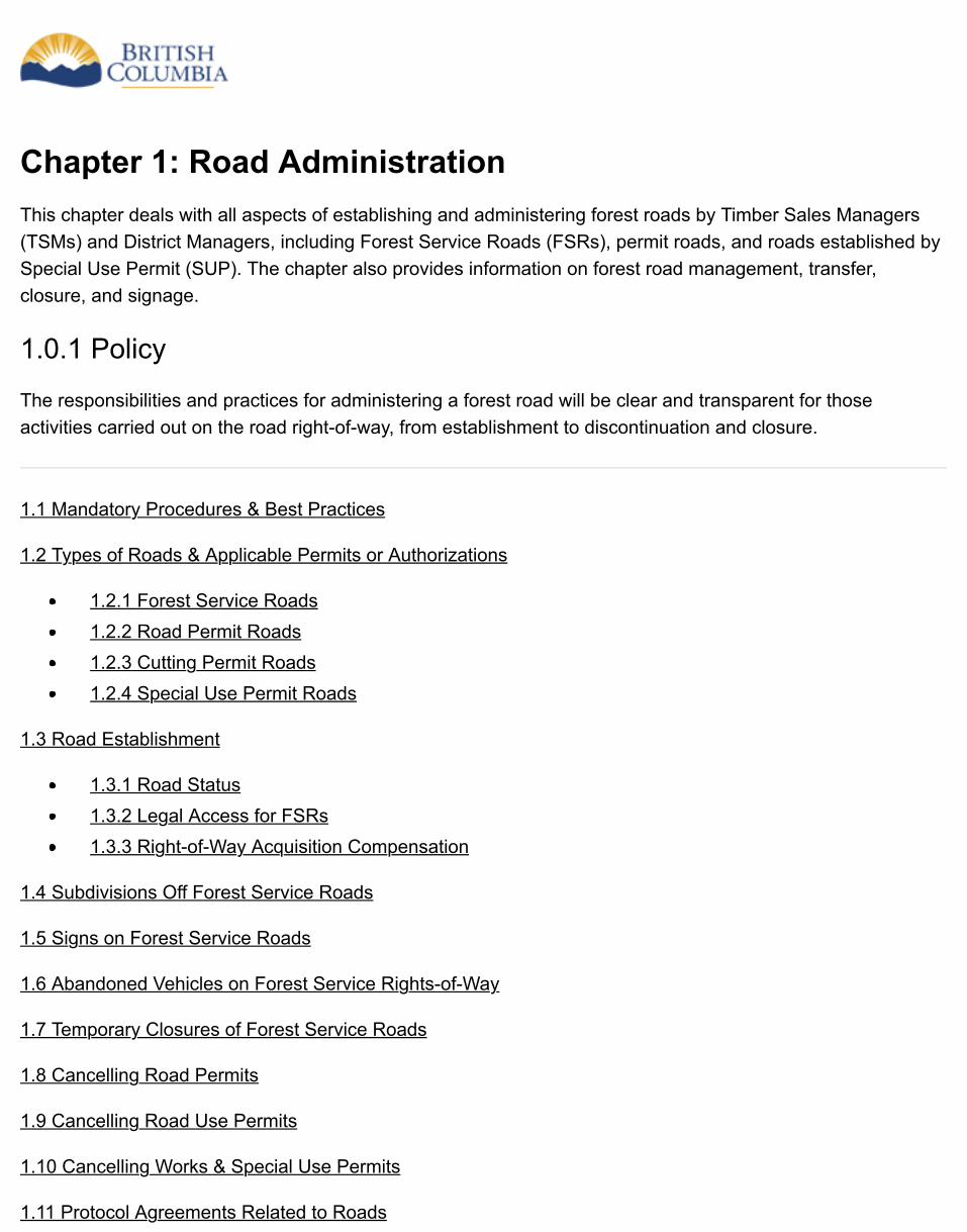
Chapter 1: Road AdministrationThis chapter deals with all aspects of establishing and administering forest roads by Timber Sales Managers(TSMs) and District Managers, including Forest Service Roads (FSRs), permit roads, and roads established bySpecial Use Permit (SUP). The chapter also provides information on forest road management, transfer,closure, and signage.
1.0.1 Policy
The responsibilities and practices for administering a forest road will be clear and transparent for thoseactivities carried out on the road right-of-way, from establishment to discontinuation and closure.
1.1 Mandatory Procedures & Best Practices
1.2 Types of Roads & Applicable Permits or Authorizations
1.2.1 Forest Service Roads1.2.2 Road Permit Roads1.2.3 Cutting Permit Roads1.2.4 Special Use Permit Roads
1.3 Road Establishment
1.3.1 Road Status1.3.2 Legal Access for FSRs1.3.3 Right-of-Way Acquisition Compensation
1.4 Subdivisions Off Forest Service Roads
1.5 Signs on Forest Service Roads
1.6 Abandoned Vehicles on Forest Service Rights-of-Way
1.7 Temporary Closures of Forest Service Roads
1.8 Cancelling Road Permits
1.9 Cancelling Road Use Permits
1.10 Cancelling Works & Special Use Permits
1.11 Protocol Agreements Related to Roads
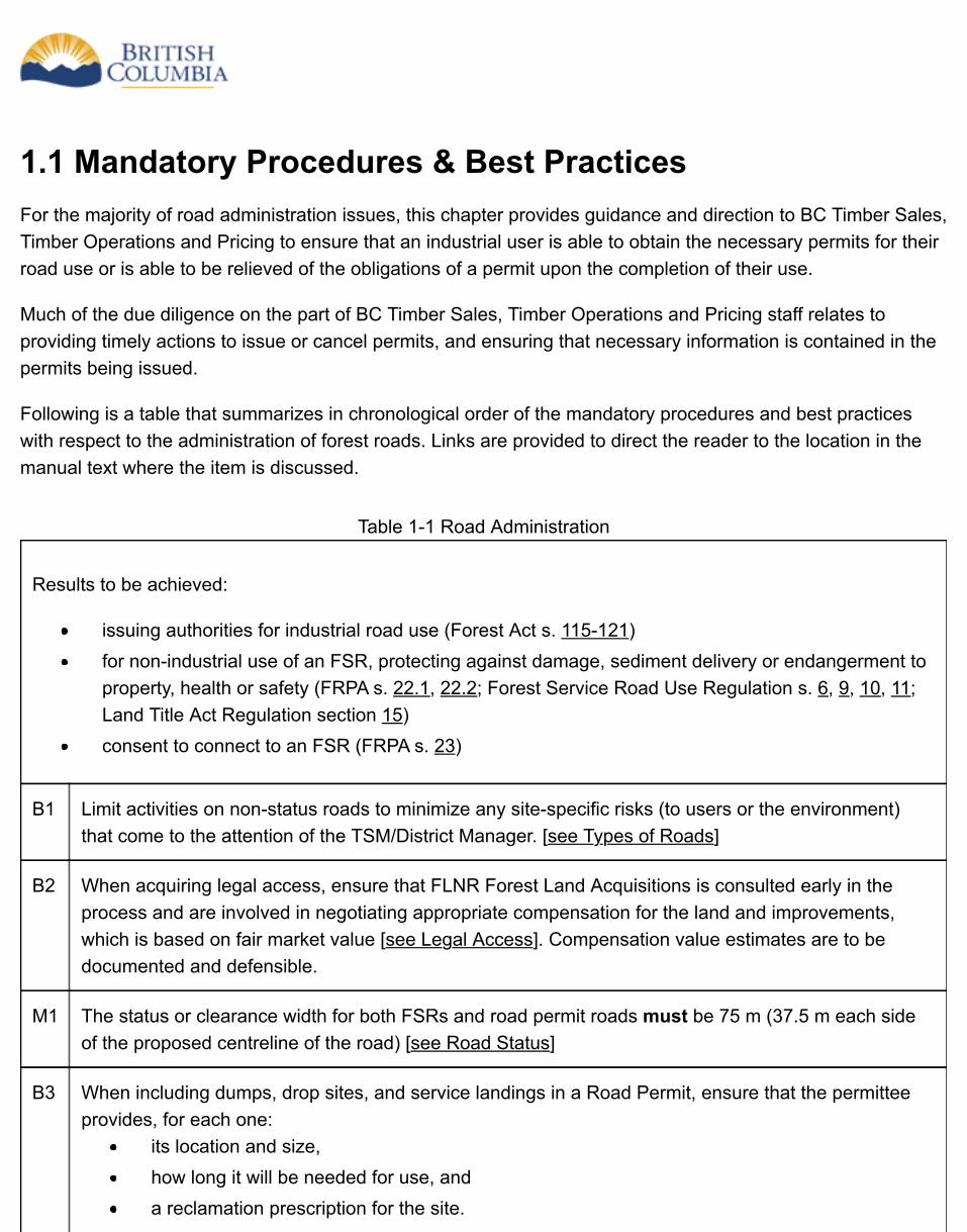
1.1 Mandatory Procedures & Best PracticesFor the majority of road administration issues, this chapter provides guidance and direction to BC Timber Sales,Timber Operations and Pricing to ensure that an industrial user is able to obtain the necessary permits for theirroad use or is able to be relieved of the obligations of a permit upon the completion of their use.
Much of the due diligence on the part of BC Timber Sales, Timber Operations and Pricing staff relates toproviding timely actions to issue or cancel permits, and ensuring that necessary information is contained in thepermits being issued.
Following is a table that summarizes in chronological order of the mandatory procedures and best practiceswith respect to the administration of forest roads. Links are provided to direct the reader to the location in themanual text where the item is discussed.
Table 1-1 Road Administration
Results to be achieved:
issuing authorities for industrial road use (Forest Act s. 115-121)for non-industrial use of an FSR, protecting against damage, sediment delivery or endangerment toproperty, health or safety (FRPA s. 22.1, 22.2; Forest Service Road Use Regulation s. 6, 9, 10, 11;Land Title Act Regulation section 15)consent to connect to an FSR (FRPA s. 23)
B1 Limit activities on non-status roads to minimize any site-specific risks (to users or the environment)that come to the attention of the TSM/District Manager. [see Types of Roads]
B2 When acquiring legal access, ensure that FLNR Forest Land Acquisitions is consulted early in theprocess and are involved in negotiating appropriate compensation for the land and improvements,which is based on fair market value [see Legal Access]. Compensation value estimates are to bedocumented and defensible.
M1 The status or clearance width for both FSRs and road permit roads must be 75 m (37.5 m each sideof the proposed centreline of the road) [see Road Status]
B3 When including dumps, drop sites, and service landings in a Road Permit, ensure that the permitteeprovides, for each one:
its location and size,how long it will be needed for use, anda reclamation prescription for the site.
[see Issuing Road Use Permits]
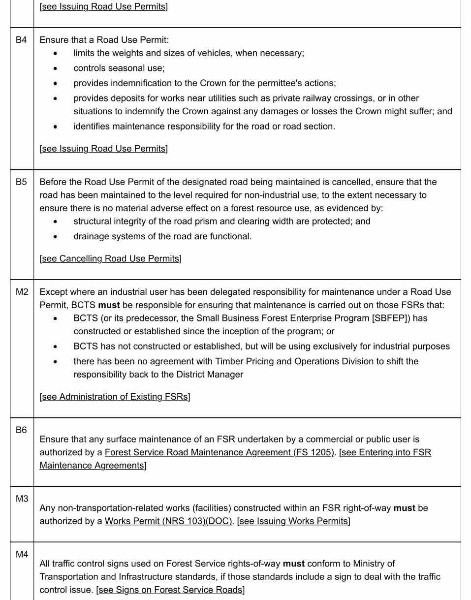
B4 Ensure that a Road Use Permit:limits the weights and sizes of vehicles, when necessary;controls seasonal use;provides indemnification to the Crown for the permittee's actions;provides deposits for works near utilities such as private railway crossings, or in othersituations to indemnify the Crown against any damages or losses the Crown might suffer; andidentifies maintenance responsibility for the road or road section.
[see Issuing Road Use Permits]
B5 Before the Road Use Permit of the designated road being maintained is cancelled, ensure that theroad has been maintained to the level required for non-industrial use, to the extent necessary toensure there is no material adverse effect on a forest resource use, as evidenced by:
structural integrity of the road prism and clearing width are protected; anddrainage systems of the road are functional.
[see Cancelling Road Use Permits]
M2 Except where an industrial user has been delegated responsibility for maintenance under a Road UsePermit, BCTS must be responsible for ensuring that maintenance is carried out on those FSRs that:
BCTS (or its predecessor, the Small Business Forest Enterprise Program [SBFEP]) hasconstructed or established since the inception of the program; orBCTS has not constructed or established, but will be using exclusively for industrial purposesthere has been no agreement with Timber Pricing and Operations Division to shift theresponsibility back to the District Manager
[see Administration of Existing FSRs]
B6Ensure that any surface maintenance of an FSR undertaken by a commercial or public user isauthorized by a Forest Service Road Maintenance Agreement (FS 1205). [see Entering into FSRMaintenance Agreements]
M3Any non-transportation-related works (facilities) constructed within an FSR right-of-way must beauthorized by a Works Permit (NRS 103)(DOC). [see Issuing Works Permits]
M4All traffic control signs used on Forest Service rights-of-way must conform to Ministry ofTransportation and Infrastructure standards, if those standards include a sign to deal with the trafficcontrol issue. [see Signs on Forest Service Roads]
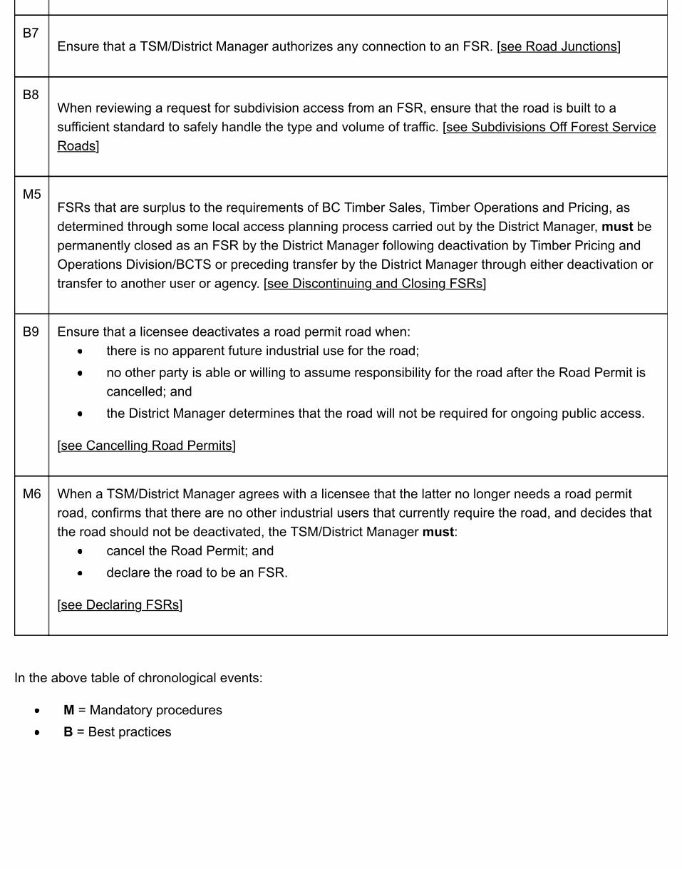
B7Ensure that a TSM/District Manager authorizes any connection to an FSR. [see Road Junctions]
B8When reviewing a request for subdivision access from an FSR, ensure that the road is built to asufficient standard to safely handle the type and volume of traffic. [see Subdivisions Off Forest ServiceRoads]
M5FSRs that are surplus to the requirements of BC Timber Sales, Timber Operations and Pricing, asdetermined through some local access planning process carried out by the District Manager, must bepermanently closed as an FSR by the District Manager following deactivation by Timber Pricing andOperations Division/BCTS or preceding transfer by the District Manager through either deactivation ortransfer to another user or agency. [see Discontinuing and Closing FSRs]
B9 Ensure that a licensee deactivates a road permit road when:there is no apparent future industrial use for the road;no other party is able or willing to assume responsibility for the road after the Road Permit iscancelled; andthe District Manager determines that the road will not be required for ongoing public access.
[see Cancelling Road Permits]
M6 When a TSM/District Manager agrees with a licensee that the latter no longer needs a road permitroad, confirms that there are no other industrial users that currently require the road, and decides thatthe road should not be deactivated, the TSM/District Manager must:
cancel the Road Permit; anddeclare the road to be an FSR.
[see Declaring FSRs]
In the above table of chronological events:
M = Mandatory proceduresB = Best practices
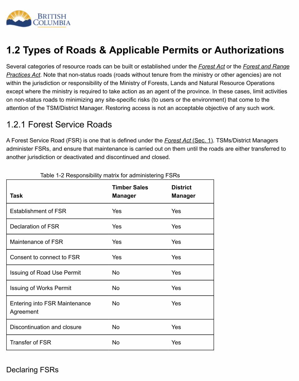
Table 1-2 Responsibility matrix for administering FSRs
TaskTimber SalesManager
DistrictManager
Establishment of FSR Yes Yes
Declaration of FSR Yes Yes
Maintenance of FSR Yes Yes
Consent to connect to FSR Yes Yes
Issuing of Road Use Permit No Yes
Issuing of Works Permit No Yes
Entering into FSR MaintenanceAgreement
No Yes
Discontinuation and closure No Yes
Transfer of FSR No Yes
1.2 Types of Roads & Applicable Permits or AuthorizationsSeveral categories of resource roads can be built or established under the Forest Act or the Forest and RangePractices Act. Note that non-status roads (roads without tenure from the ministry or other agencies) are notwithin the jurisdiction or responsibility of the Ministry of Forests, Lands and Natural Resource Operationsexcept where the ministry is required to take action as an agent of the province. In these cases, limit activitieson non-status roads to minimizing any site-specific risks (to users or the environment) that come to theattention of the TSM/District Manager. Restoring access is not an acceptable objective of any such work.
1.2.1 Forest Service Roads
A Forest Service Road (FSR) is one that is defined under the Forest Act (Sec. 1). TSMs/District Managersadminister FSRs, and ensure that maintenance is carried out on them until the roads are either transferred toanother jurisdiction or deactivated and discontinued and closed.
Declaring FSRs
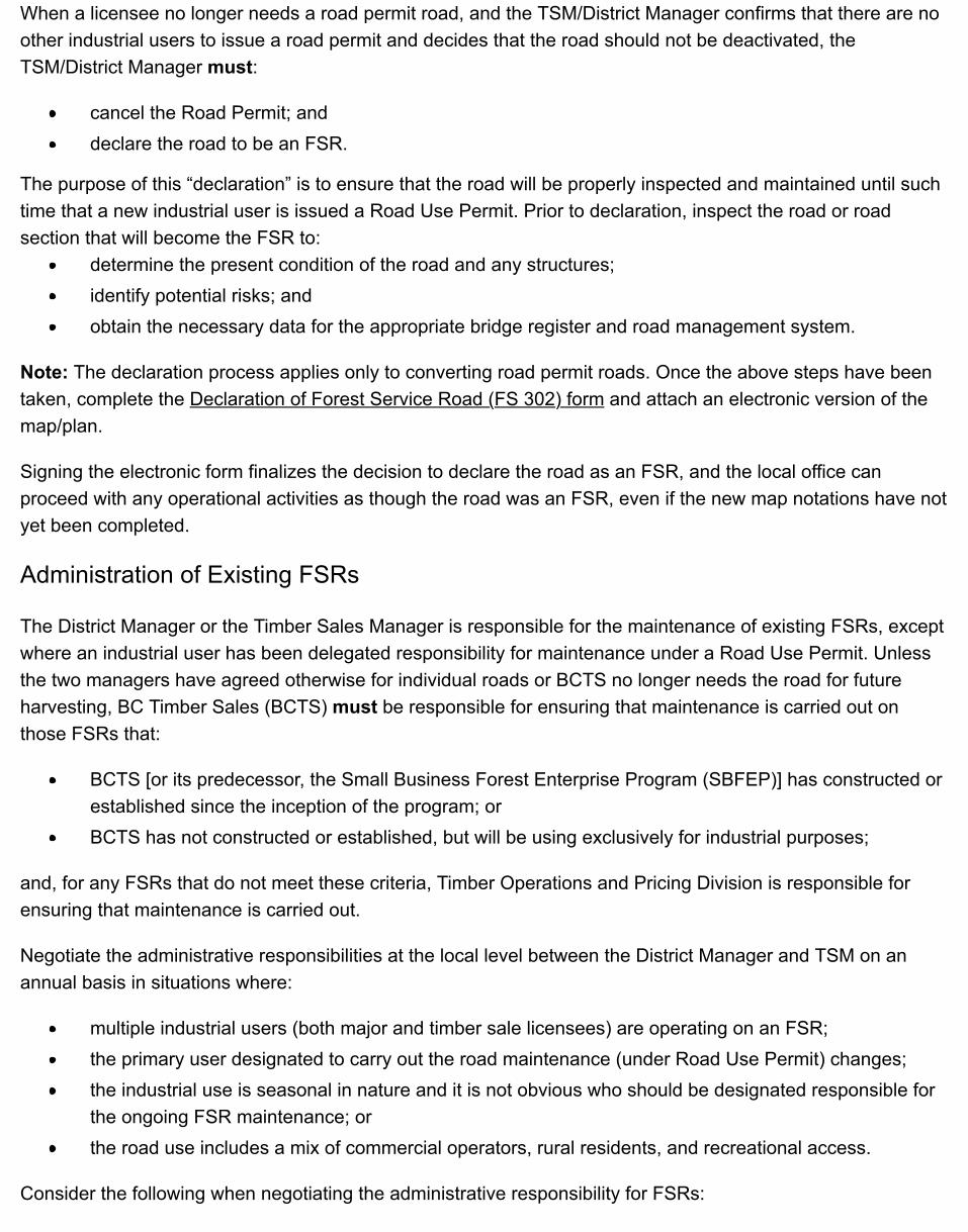
When a licensee no longer needs a road permit road, and the TSM/District Manager confirms that there are noother industrial users to issue a road permit and decides that the road should not be deactivated, theTSM/District Manager must:
cancel the Road Permit; anddeclare the road to be an FSR.
The purpose of this “declaration” is to ensure that the road will be properly inspected and maintained until suchtime that a new industrial user is issued a Road Use Permit. Prior to declaration, inspect the road or roadsection that will become the FSR to:
determine the present condition of the road and any structures;identify potential risks; andobtain the necessary data for the appropriate bridge register and road management system.
Note: The declaration process applies only to converting road permit roads. Once the above steps have beentaken, complete the Declaration of Forest Service Road (FS 302) form and attach an electronic version of themap/plan.
Signing the electronic form finalizes the decision to declare the road as an FSR, and the local office canproceed with any operational activities as though the road was an FSR, even if the new map notations have notyet been completed.
Administration of Existing FSRs
The District Manager or the Timber Sales Manager is responsible for the maintenance of existing FSRs, exceptwhere an industrial user has been delegated responsibility for maintenance under a Road Use Permit. Unlessthe two managers have agreed otherwise for individual roads or BCTS no longer needs the road for futureharvesting, BC Timber Sales (BCTS) must be responsible for ensuring that maintenance is carried out onthose FSRs that:
BCTS [or its predecessor, the Small Business Forest Enterprise Program (SBFEP)] has constructed orestablished since the inception of the program; orBCTS has not constructed or established, but will be using exclusively for industrial purposes;
and, for any FSRs that do not meet these criteria, Timber Operations and Pricing Division is responsible forensuring that maintenance is carried out.
Negotiate the administrative responsibilities at the local level between the District Manager and TSM on anannual basis in situations where:
multiple industrial users (both major and timber sale licensees) are operating on an FSR;the primary user designated to carry out the road maintenance (under Road Use Permit) changes;the industrial use is seasonal in nature and it is not obvious who should be designated responsible forthe ongoing FSR maintenance; orthe road use includes a mix of commercial operators, rural residents, and recreational access.
Consider the following when negotiating the administrative responsibility for FSRs:
whether the road in question provides access to communities (in this case, the long-term responsibilitywould be that of Timber Operations and Pricing Division);the future use of the area by BCTS or others;the current level and type of industrial use (including other non-forest related industrial users); andwhether the access is currently required to reach residences, cabins, commercial operations, parks orrecreation sites (in this case, the long-term responsibility would be that of Timber Operations andPricing Division).
Once the TSM has determined that BCTS will no longer need an FSR for future harvesting, report this to theDistrict Manager, for determining whether:
the road should be deactivated by BCTS; orthe responsibility for its administration should be shifted to Timber Operations and Pricing Division.
Also, small-scale salvage operations are not considered to be representative of operations that alone wouldgenerate future maintenance responsibilities for BCTS. These salvage operations are not tied to one program,but “piggy-back” on any regular harvesting operations.
Expand All | Collapse All
Issuing Road Use Permits
All industrial users on an FSR are required to obtain a Road Use Permit (FS 102)(DOC), unless anexemption is granted in accordance with section 22.1 (4) of FRPA. Road Use Permits, including thoseRoad Use Permits required by BCTS licensees, are issued by the District Manager. Ensure that theproposed use will not adversely affect other authorized users of the road, and that the permit:
limits the and sizes of vehicles, when necessary;controls seasonal use;provides indemnification to the Crown for the permittee’s actions;provides deposits for works near utilities such as private railway crossings, or in other situationsto indemnify the Crown against any damages or losses the Crown might suffer; andidentifies maintenance responsibility for the road use or road section.
Designate only one Road Use Permit holder to be responsible for carrying out all maintenance operations on a road or road section. However, other Road Use Permit holders are expected to contribute a reasonable amount to the expense of maintaining the road [Forest Planning and Practices Regulation(Sec. 79)].
Track the issuance and administration of Road Use Permits in a ledger (such as FRMA) and record:
the identity of the RUP holders;the identity of the maintainer;the termination of any RUPs and/or the conclusion of any maintenance responsibilities.
Ensure that the process for shared maintenance of an FSR described in the Shared Use RoadMaintenance Policy (PDF) is applied where the process in place on a given road is not suitable for one ormore of the parties expected to share the maintenance costs.
In addition, any disputes between road users for maintenance can be resolved by a third party or througha more formal process, such as the Commercial Arbitration Act. The District Manager is not responsiblefor resolving disputes, but may provide that service in any case if all parties agree.
Road maintenance includes any activity such as routine maintenance, road upgrading, or repair orreplacement of structures that is carried out until the FSR is deactivated. Refer to Chapter 6 of this manualfor details of road and structure inspection and maintenance.
Issuing Works Permits
Any non-transportation-related works (facilities) constructed within an FSR right- of-way must beauthorized by a Works Permit (NRS 103)(DOC). Examples include water, gas, hydro, or telephone lineworks. The Works Permit does not authorize road works or the harvesting of timber, nor does it conveytenure to any part of the right-of-way other than to permit the facilities to remain in place.
Entering into FSR Maintenance Agreements
For situations where the wilderness level of maintenance is not sufficient for a commercial or public user,that user may elect to undertake some or all of the surface maintenance of the FSR as authorized by theForest Service Road Maintenance Agreement (FS 1205) The agreement authorizes the end user to carryout incremental maintenance on FSRs at no cost to the ministry. The works envisioned under thisagreement are routine in nature. FSR Maintenance Agreements are issued by District Managers,including any proposed non-industrial maintenance proposed for FSRs that are administered by BCTS.
Discontinuing and closing FSRs
FSRs that are determined to be surplus to the requirements of the ministry, according to current budgetary requirements and as determined through some local access planning process carried out by the District Manager, must be discontinued and closed as an FSR by the District Manager following deactivation or preceding transfer by the District Manager (delegated to Director of Forest Tenures) to another user or agency, in keeping with the Forest Act [Sec. 121 (9)] and as delegated from the minister.
To declare an FSR discontinued and closed once it has been deactivated, or once it has been determined that another tenure will be established over the road, the District Manager must complete and sign an FSR Discontinue and Close Form (FS 301)(PDF), and attach the Exhibit A. Forward a copy of the completed FSR Discontinue and Close Form (FS 301) with attachments to the FLNR Forest Land Acquisitions Group, Forest Tenures Branch in Victoria to ensure FSR project history remains current.
In accordance with the Forest Act [Sec. 121 (9)], notification of FSR discontinuance and closures must occur and shall be at the discretion of the District Manager (as delegated from the minister), depending upon scale and location of the FSR as per the 2012 FLNR policy called Discontinue and Close Forest Service Roads Notification (PDF). In accordance with that policy, the methods and dates of notification must be recorded on the FSR Discontinue and Close Form (FS 301)(PDF).
Notification should be done a minimum of three (3) months prior to the FSR closure unless ecological,environmental or public safety circumstances dictate otherwise.
Once the District Manager signs the FSR Discontinue and Close Form (FS 301), proceed with anyadministrative activities, such as transfer to the BC Ministry of Transportation and Infrastructure (BCMoT)or to a tenure holder, as though the road is not an FSR any longer, even if new map notations have not yetbeen completed.
Transferring FSRs to BCMoT
For those instances where BCMoT wishes to take over administrative responsibility of an FSR as per theForest Act [Sec. 121 (9) (c)], the next step, after reaching agreement in principle with the local BCMoTmanager, is to involve the FLNR Forest Land Acquisitions Group, Forest Tenures Branch in Victoria toarrange for the delegated authority of each ministry to execute the assignment. Prior to the final executionof the assignment, the District Manager must declare the FSR discontinued and closed by completing andsigning an FSR Discontinue and Close Form (FS 301)(PDF).
Transferring public highways to FLNR
For those instances where FLNR wishes to take over administrative responsibility of a public highwaythere are currently two methods available, after reaching agreement in principle with the local BCMoTmanager and the District Manager:
Method 1 – transfer the public road as per the Land Act [Sec. 106] in consultation with ForestLand Acquisitions Group, Forest Tenures Branch.Method 2 – obtain the survey of the public road, or survey the public road, and contact FLNRForest Land Acquisitions Group, Forest Tenures Branch in Victoria to submit the necessary landtransfer in the provincial Land Title System. Authority has been delegated to the respectivedirectors at FLNR Forest Tenures Branch and BCMoT Properties and Land Management Branch.This may involve the payment of property transfer taxes.
District staff would then proceed with the FSR establishment process.
1.2.2 Road Permit Roads
Road permit roads are roads built, used, and maintained by timber licensees under a BCTS Road Permit (FS582)(DOC) or a Major Licensee Road Permit (FS 582)(DOC). Both of these permits are issued to a harvestinglicense holder [see Forest Act (Sec. 115 and Sec. 121)]. Such roads usually connect cutblocks and tieharvesting areas to FSRs, public highways or log dumps, but may also include on-block roads that are builtbefore a Cutting Permit is issued. Other industrial users are expected to contribute a reasonable amount to theexpense of maintaining the road [Forest and Range Practices Act [Sec. 22.3 (1) and (2)].
Optionally, grant an exemption for the use of the road in accordance with the Act (Forest Planning andPractices Regulation section 79.1).
A road is defined in the Forest Planning and Practices Regulation (Sec.1) as including landings. Therefore, inaddition to the usual temporary landings authorized for harvesting the right-of-way timber, it is acceptable for aroad permit to also authorize the upland portion of log dumps, helicopter drop sites, and helicopter servicelandings. However, when including such dumps, drop sites, and service landings in a Road Permit, ensure thatthe permittee provides, for each one:
its location and size;how long it will be needed for use; anda reclamation prescription for the site.
BCTS Road Permits
Within the BCTS Road Permit (FS 582)(DOC), the Schedule R provides for both:
roads constructed, maintained, and deactivated by the Timber Sale Licence holder; androads constructed and maintained by the Timber Sale Licence holder, but not deactivated by theholder.
Construction and maintenance specifications are included in Schedule R and form contractual requirements.Construction specifications are either:
General Construction Specifications – form fields on the schedule are filled in for such details asdesign vehicle load, road width, and road alignment; orDetailed Construction Specifications – road design drawings, such as plan profiles, are included aspart of the package.
Maintenance specifications are divided into two sets of requirements:
those concerning the maintenance of roads during operations – this maintenance is intended to protectthe road from damage (such as from erosion and from debris at culvert inlets); andthose concerning works and repairs once operations are complete – these works are intended to putthe roads in shape when the Timber Sale Licence expires.
1.2.3 Cutting Permit Roads
A cutting permit road is one authorized by a Cutting Permit (or by a license that does not have Cutting Permits).Such permits are only used on roads that are wholly contained within a cutblock. The one exception to thisrequirement is for roads constructed under a Woodlot Licence: all roads in that case can be authorized by aCutting Permit, including those outside a specific cutblock. Other industrial users are expected to contribute areasonable amount to the expense of maintaining the road [Forest and Range Practices Act, Sec. 22.3 (1) and(2)].
1.2.4 Special Use Permit Roads

Under the Provincial Forest Use Regulation, a Special Use Permit (FS 998A)(PDF) is issued by a DistrictManager for the construction and maintenance of a road for non-forest use, including construction andmaintenance of bridges and other drainage structures for non-forest use. Currently, these roads are normallyrestricted to mining operations outside a claim area, but other resource uses can be contemplated whereanother agency is not in a position to issue tenure over the road.
1.3 Road Establishment
1.3.1 Road Status
Preparing Road Status Requests
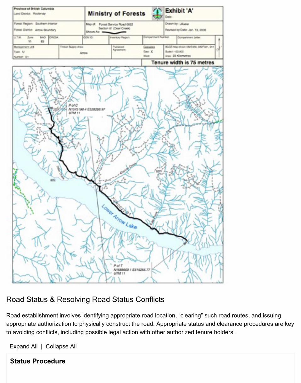
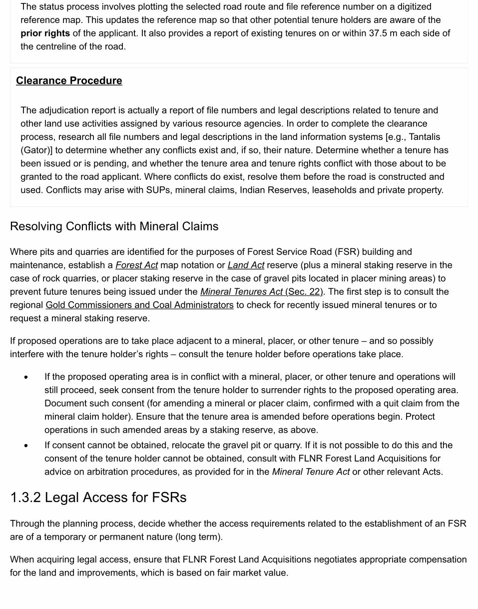
When a new FSR or road permit road is required, or when an existing non-status road is to be established asan FSR or road permit road, some basic information is needed to move the decision forward to implementation.To identify what interests or rights that may exist and to establish a registered interest over the land, carry out aroad status (adjudication report). The status or clearance width for both FSRs and road permit roads must be75 m (37.5 m each side of the proposed centreline of the road), which is also the width of the FSR right-of-wayand the width of the Road Permit. When preparing a status request, ensure that:
the proposed or actual road has been plotted on the area reference map and an Exhibit “A” sketchproduced;a status of the route shown on the Exhibit "A" sketch has been performed and all file or other referencenumbers recorded;each file or other reference number has been investigated to determine if any tenures have beenissued;copies of all tenure documents have been obtained and examined to determine if a conflict betweenthe tenure rights and the proposed road location exists; andnegotiations with tenure holders have been conducted and the agreement of the tenure holderobtained before road use or construction begins.
Figure 1-1 Exhibit "A" sketch
Road Status & Resolving Road Status Conflicts
Road establishment involves identifying appropriate road location, “clearing” such road routes, and issuingappropriate authorization to physically construct the road. Appropriate status and clearance procedures are keyto avoiding conflicts, including possible legal action with other authorized tenure holders.
Expand All | Collapse All
Status Procedure
The status process involves plotting the selected road route and file reference number on a digitizedreference map. This updates the reference map so that other potential tenure holders are aware of theprior rights of the applicant. It also provides a report of existing tenures on or within 37.5 m each side ofthe centreline of the road.
Clearance Procedure
The adjudication report is actually a report of file numbers and legal descriptions related to tenure andother land use activities assigned by various resource agencies. In order to complete the clearanceprocess, research all file numbers and legal descriptions in the land information systems [e.g., Tantalis(Gator)] to determine whether any conflicts exist and, if so, their nature. Determine whether a tenure hasbeen issued or is pending, and whether the tenure area and tenure rights conflict with those about to begranted to the road applicant. Where conflicts do exist, resolve them before the road is constructed andused. Conflicts may arise with SUPs, mineral claims, Indian Reserves, leaseholds and private property.
Resolving Conflicts with Mineral Claims
Where pits and quarries are identified for the purposes of Forest Service Road (FSR) building andmaintenance, establish a Forest Act map notation or Land Act reserve (plus a mineral staking reserve in thecase of rock quarries, or placer staking reserve in the case of gravel pits located in placer mining areas) toprevent future tenures being issued under the Mineral Tenures Act (Sec. 22). The first step is to consult theregional Gold Commissioners and Coal Administrators to check for recently issued mineral tenures or torequest a mineral staking reserve.
If proposed operations are to take place adjacent to a mineral, placer, or other tenure – and so possiblyinterfere with the tenure holder’s rights – consult the tenure holder before operations take place.
If the proposed operating area is in conflict with a mineral, placer, or other tenure and operations willstill proceed, seek consent from the tenure holder to surrender rights to the proposed operating area.Document such consent (for amending a mineral or placer claim, confirmed with a quit claim from themineral claim holder). Ensure that the tenure area is amended before operations begin. Protectoperations in such amended areas by a staking reserve, as above.If consent cannot be obtained, relocate the gravel pit or quarry. If it is not possible to do this and theconsent of the tenure holder cannot be obtained, consult with FLNR Forest Land Acquisitions foradvice on arbitration procedures, as provided for in the Mineral Tenure Act or other relevant Acts.
1.3.2 Legal Access for FSRs
Through the planning process, decide whether the access requirements related to the establishment of an FSRare of a temporary or permanent nature (long term).
When acquiring legal access, ensure that FLNR Forest Land Acquisitions negotiates appropriate compensationfor the land and improvements, which is based on fair market value.
To initiate the acquisition, complete a Right-of-Way Acquisition Request (FS 959A) form, and submit it using theShana forms (or by pdf) located on the ministry’s forms directory. Time is of the essence when requesting aright-of-way, as negotiating compensation and providing the legal survey can be time consuming.
Where access is required for a limited period of time, consider the use of a temporary statutory right-of-wayagreement (Guidelines for Legal Forest Access). Secure permanent or long-term access with a dedicated right-of-way involving a legal survey and purchase of right-of-way from the landowner.
Obtain a junction permit from the Ministry of Transportation and Infrastructure where an FSR joins a publichighway. Exercise care in choosing the best junction site possible – ideally, a T junction with ample sightdistance – since relocating highway junctions can be difficult and expensive, particularly where private propertyis involved.
1.3.3 Right-of-Way Acquisition Compensation
The framework of the Ministry’s compensation policy is based in the existing legislation. The Forest Act and theMinistry of Forests and Range Act (Section 5) provide the legislative authority to the Minister of Forests, Landsand Natural Resource Operations to acquire land for forestry purposes. The Expropriation Act and the FinancialAdministration Act both refer to the requirement of government to deal in terms of fair market value whenacquiring land and other assets.
Ultimately, the fair market value for land, combined with a value determined for depreciated roadimprovements, and certain damages represents the compensation due to a property owner. This value may becapitalized to represent an annual fee for a short-term agreement or paid in full for long-term or permanentacquisitions. Road use fees or charges based solely on the volume of timber or the amount of use are notreflective of fair market compensation and do not serve the equitable interests of the property owner and theProvince. However, volume and use charges may be applied to maintenance costs, provided they reflect theactual costs to maintain the road used.
Estimating the Value of Depreciated Road Improvements (DRIV)
Direct all matters regarding the acquisition of land and the application of the compensation policy to the SeniorLand Acquisition Officer, FLNR Forest Land Acquisitions, Forest Tenures Branch (FTB). Acting on the adviceand recommendations of Ministry forest land acquisitions staff, the Director, FTB, who is the only delegatedsigning authority for the Minister, reviews all land agreements to determine that the principles of fair marketvalue have been applied, and signs off on the agreement.
It is recommended to involve and consult with ministry Forest Lands Acquisitions staff early in the processwhen considering entering into an agreement for the purchase [dedication] or rental [statutory right-of-wayagreement] of land to become a forest service road. Forest Lands Acquisitions staff will assist in thedetermination of appropriate compensation.
Ministry engineering staff will be required to inspect or have inspected by individuals knowledgeable in roadconstruction and costing, the current road condition and provide an estimate for the value of the road andassociated improvements in its present condition. This value is referred to as the depreciated roadimprovement value [DRIV]. Forest Land Acquisition staff are not specialists in road cost estimating. A DRIV willneed to be provided by ministry engineering staff to the Forest Land Acquisition Project Manager working on
each forest service road project. The DRIV will be used in the compensation negotiations and if necessary,where a mutually satisfactory agreement cannot be reached, in expropriation. Any DRIV calculation should bedocumented and supported by background preparation guidelines/policy/direction for provincial consistency. Inthe case of expropriation, the compensation estimate (DRIV) and methodology is required to be shared with theland owner per section 20 (1) (e) of the Expropriation Compensation Act.
There are a number of ways that can be used to estimate the DRIV. One method is to estimate what the roadwould have cost to construct in the first place and subtracting the cost of repairs to bring it back to its originalcondition.
1. Inspect the road2. Determine how much it would cost to construct the road today. Possible approaches to estimating value of
the road and improvements include:
Detailed engineering cost estimate, Information from the appropriate appraisal manualUse of comparable, recent road construction contract resultsApplication of local knowledgeCurrent value per unit rate
3. Determine the costs of any road failures, required upgrades and repairs to bring the existingimprovements up to a new road standard [culverts, structures, ditching, surfacing, grading, brushing, etc.(some wooden bridges might have a negative value (require works to remove or other measures to makesafe)].
4. Reduce the cost of [1] by the cost of [3] and you have the DRIV.
Assistance in developing road construction cost estimates can be obtained through the Engineering Branch,Engineering Group for the respective region.
Acquiring Right-of-Way for Railway Crossings
Crossing a railway right-of-way is costly and requires ongoing maintenance obligations. The type of crossingand required safety features are dictated by the railway authority. In cases where railway crossings cannot beavoided, obtain tentative approval in principle from local railway authorities and prepare a plan. Key steps inthis process are:
submit a formal application for approval by railway and federal or provincial transport agencies,including the plan and the following information:
whether the proposed road right-of-way is junior or senior to trackage;who will pay for construction and crossing;what the projected daily traffic count will be for all vehicles (public and industrial);whether school buses will be using the crossing; and
allow eight months from the time of application to the time the crossing permit receives final approval.
Legal Access for Utility Right-of-Way Crossings
Obtain interim approvals for the location of the crossing from local utility (power, oil/gas, and communications)field offices. Special considerations are involved if the utility is situated within private property.
Legal Access for Road Permit Roads
Where the status/clearance process has identified conflicts with a proposed road permit route, licensees areexpected to resolve such conflicts themselves. If the permittee is unfamiliar with the steps necessary to resolvesuch conflicts, assistance can be obtained from the private sector. FLNR Forest Land Acquisitions can providea list of firms and individuals providing this service.
Legal Access for Cutting Permit Roads
Since proposed harvest areas are statused and cleared before Cutting Permits are issued, a separate statusand clearance procedure is not necessary for roads constructed within these areas. Because the permitteeneeds the flexibility to locate roads as best suits harvest operations, and as these roads are usually of atemporary low-order nature, their location is normally not specified in the Cutting Permit document itself.
Legal Access for Special Use Permit Roads
Under certain circumstances, roads within a provincial forest or wilderness area may be authorized by SUP, inkeeping with the Provincial Forest Use Regulation [Sec. 7 (1)(a)].
These types of roads are normally issued to holders of rights authorized by the Coal Act, GeothermalResources Act, or Mineral Tenure Act and may also be issued to Clean Energy Projects (CEP) proponents ifthey choose to apply for a road authorization under a SUP rather than under a Land Act Licence of Occupation,but in rare cases may be issued for other purposes.
SUP roads are normally mapped and statused in a process similar to that described for FSRs or road permitroads (described above). Like Road Permits, Special Use Permits authorize road construction and use only onunalienated Crown land. If tenure conflicts are identified during the status process, Special Use Permit holdersare expected to resolve such conflicts before road construction and use. If the Special Use Permit holder isunfamiliar with the resolution process, this service is available from the private sector. FLNR Forest LandAcquisitions should be consulted for further information on private sector firms or individuals providing thisservice.
Road Junctions
Ensure that a TSM/District Manager authorizes any connection to an FSR using a Road Junction RequirementsForm Letter (FS 1209)(DOC).
Note: A Road Permit, Cutting Permit and Timber Sale Licence incorporate an authorization for a junction of theroad permit road to the FSR.
Before approving an application to connect, ensure that the location, sight distances and drainage areacceptable (see Road Design Criteria). Ensure that requests from landowners for variance from the establishedalignment conditions are accompanied by a Professional Engineer’s recommendation.
1.4 Subdivisions Off Forest Service RoadsThe subdivision process involves the legal survey and creation of a number of separate smaller parcels of landfrom a larger parcel of privately owned or Crown land.
When reviewing a request for subdivision access from a Forest Service Road (FSR), ensure that theEngineering Group Leader confirms that the road is built to a sufficient standard to safely handle the type andvolume of traffic. The minimum requirements set out in the Land Title Act Regulation (Sec. 15) (BC Reg.334/79) concern the road width as it relates to the maximum width of vehicle allowed on the road.
Examine the width of the entire length of the FSR from the end of the nearest public road to the location of theproposed subdivision and determine whether or not the road width meets the requirement of the Regulation.
In addition, record all relevant factors (e.g., the general condition of the roads, expected traffic volumes,condition of structures, and safety features such as turnouts, widenings, and signage).
The process of subdivision normally requires the dedication and construction of public access roadsadministered by the Ministry of Transportation and Infrastructure, or a municipality if the subdivision falls withinan organized area. However, the use of other forms of access to subdivided areas is also considered, andSection 15 of the Land Titles Act Regulation deals with access by FSRs and prescribes the maximum allowedwidth of vehicles based on different minimum road widths. Minimum widths mean the width of the entire runningsurface from the nearest public road to the subdivision, other than for permitted exceptions that are spelled outin the Regulation.
Approving Officers consider a number of factors when deciding whether a particular subdivision applicationshould be approved. However, the Approving Officers cannot approve a subdivision application that relies onan FSR for access until the Engineering Group Leader certifies that the FSR in question meets the widthrequirements of the Regulation.

1.5 Signs on Forest Service RoadsSigns may not be erected on a Forest Service right-of-way without the approval of the District Manager. Ingeneral, commercial signs are not approved.
Standard informational and resource road radio communication signage has been developed for use on ForestService roads:
Forest Service Road Sign Standards
Other traffic control signage shall conform to Ministry of Transportation and Infrastructure (MOTI) standards:
Manual of Standard Traffic Signs & Pavement Markings - Chapter 2 (PDF, 5.3MB)
The Forest Service road sign must be placed at the start of an FSR system where there is a potential for publicor multiple industrial users. Determine:
whether name signs are necessary on a particular road;the size of the signs; andwhere the signs should be placed.
A primary justification for a traffic control sign is that the risk to users is greater than what a user would normallyencounter on an FSR such that the safety of the user may be dependent on the sign being in place.

1.6 Abandoned Vehicles on Forest Service Rights-of-WayOccasionally, ministry staff is faced with having to deal with abandoned vehicles or logging or road buildingequipment along Forest Service rights-of-way.
Consider the following when deciding whether or not to remove or dispose of such vehicles:
The vehicle or equipment may or may not have some residual value.The vehicle or equipment owner may or may not be identifiable if the licence plates or serial numbershave been removed.The cost of moving and disposing of the vehicle may be greater than the recoverable costs.The vehicle may be causing a danger to other road users or it may be a visible disturbance.
1.7 Temporary Closures of Forest Service RoadsWhere the District Manager determines that a road will be closed temporarily because of safety, sedimentdelivery, or property issues, place a “road closed” sign at the beginning of the road and install a physical barrierto keep vehicles off the road. Notify potential users of the closure through some form of local advertising.Closures of roads for environmental protection issues such as pressures on wildlife populations are carried outby Ministry of Environment staff through their legislation, and not through the powers provided to FLNR.
1.8 Cancelling Road PermitsCancel a licensee’s Road Permit at the request of the permittee where it is evident that the permittee will notneed the road any longer to harvest timber under a harvesting agreement.
Ensure that the permittee deactivates a road permit road when:
there is no apparent future industrial use for the road;no other party is able or willing to assume responsibility for the road after the Road Permit is cancelled;andthe District Manager determines that the road will not be required for ongoing public access.
Where a major licensee has deactivated a road according to regulations, it normally provides a declaration tothe District Manager that the licensee has met its deactivation obligations. The District Manager has up to 15months to approve the works after the licensee has provided the declaration. Once the works are approved, orthe 15 months passes without inspection, the District Manager will terminate the road permit.
For those road permit roads that a TSL holder deactivates, the TSM ensures that the road deactivation wascarried out properly and in accordance with the regulations, and then notifies the District Manager that the workhas been completed. The District Manager will normally rely upon the advice of the TSM but may carry out aninspection of the deactivated road to ensure that the work has been carried out satisfactorily.
For those road permit roads operated by a TSL holder where future use of the road by non-BCTS users maypreclude deactivating the road, the TSM notifies the District Manager accordingly, preferably well in advance ofthe completion of the TSL. Should the District Manager determine that the road should be deactivated in anyevent, he will so notify the TSM, again prior to completion of the TSL. If the District Manager determines thatthe road will not be deactivated, the District Manager may either issue a permit to another user or declare theroad to be an FSR under the administration of the District Manager.
Once the road has been deactivated, or the tenure has been shifted to another user, or the road has beendeclared to be an FSR, subject to the notifications and possible inspections as described in the precedingparagraphs, the TSM will terminate the existing road permit held by the timber sale licensee.
Do not create non-status roads by cancelling Road Permits for non-deactivated roads unless either transferringthe responsibility to another party or taking on a clear ministry administrative role by declaring the road an FSR.

1.9 Cancelling Road Use PermitsAn industrial user may apply to the District Manager to be relieved of its Road Use Permit on an FSR when thatroad will not be required for industrial purposes. Before the Road Use Permit of the designated maintainer iscancelled, ensure that the road has been maintained to the level required for non-industrial use, to the extentnecessary to ensure there is no material adverse effect on a forest resource, as evidenced by:
structural integrity of the road prism and clearing width are protected; anddrainage systems of the road are functional.
Otherwise, the permit will remain in force even while the user is idle for periods of time, and any designatedmaintenance obligations remain during those same periods.

1.10 Cancelling Works & Special Use PermitsWorks Permits and SUPs will either expire on a given date (as shown in the permit) or be cancelled when thepermittee advises the District Manager that the permit is no longer required for its intended purpose.
If a Works Permit has been issued for a Forest Service Road (FSR) that is about to be permanentlydiscontinued and closed or transferred, and the permittee intends to continue using the works, refer thepermittee to another agency to obtain a replacement tenure for these works.

1.11 Protocol Agreements Related to RoadsMinistry of Forests, Lands and Natural Resource Operations, Engineering Branch, Engineering and FLNRForest Land Acquisitions:
{{{{{{Protocol Agreements}}}}}} (only accessible to internal users, a login is required)
Chapter 2: Road LayoutAccess is a primary consideration in planning forest development. Although the principles for determining roadlocations apply to both main and secondary Forest Service Roads (FSRs), secondary roads are more site-specific to the harvesting system and the equipment used. Decisions made during access planning (defined aspreceding road layout and typically identifying route corridors, selecting life expectancies of various roadstypes, and establishing intended road users and vehicle types) and road layout may have significant effects onroad construction and maintenance costs, user safety, and other resources. Select and locate routes to meetthe objectives of higher-level plans within the constraints of any approved operational plans or permits. Roadlayout is a process of route selection and field marking based on pre-field investigation and fieldreconnaissance to determine a site-specific road location. The level of detail and the type of informationrequired for road layout depends on the required road design standards, the complexity of terrain, the size andcomplexity of stream crossings, and the need to consider other resource values.
This chapter presents the ministry’s mandatory procedures and best practices related to professionalresponsibility, pre-field and field investigation, and to the associated outputs. It is intended to provide the readerwith enough detail to be able to understand the processes and expected mandatory procedures, as well asensuring that the road meets the regulatory requirements related to safety and protection of other resources.
2.0.1 Policy
The location of a proposed Forest Service Road will be consistent with the outcomes of a Forest StewardshipPlan (FSP) or other applicable planning process, and will:
optimize operational needs;maximize safety;minimize cost; andminimize environmental impacts.
2.1 Mandatory Procedures & Best Practices
2.2 Road Layout Professional Responsibilities & Considerations
2.3 Pre-Field Investigation
2.3.1 Road Layout2.3.2 Maps & Air Photos2.3.3 Visual Impact2.3.4 The Working Map

2.3.5 Land Alienations2.3.6 Government Interests
2.4 Field Reconnaissance
2.4.1 Field Reconnaissance Procedures & Records2.4.2 Specific Concerns2.4.3 Drainage Structures2.4.4 Harvesting Requirements2.4.5 Use of Appropriate Professionals
2.5 Reconnaissance Report
2.6 Resources & Suggestions for Further Reading
2.7 Appendices
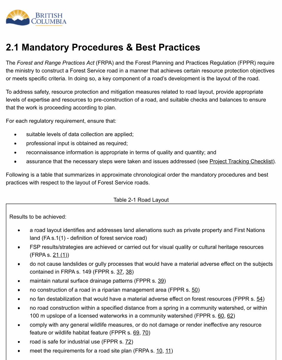
2.1 Mandatory Procedures & Best PracticesThe Forest and Range Practices Act (FRPA) and the Forest Planning and Practices Regulation (FPPR) requirethe ministry to construct a Forest Service road in a manner that achieves certain resource protection objectivesor meets specific criteria. In doing so, a key component of a road’s development is the layout of the road.
To address safety, resource protection and mitigation measures related to road layout, provide appropriatelevels of expertise and resources to pre-construction of a road, and suitable checks and balances to ensurethat the work is proceeding according to plan.
For each regulatory requirement, ensure that:
suitable levels of data collection are applied;professional input is obtained as required;reconnaissance information is appropriate in terms of quality and quantity; andassurance that the necessary steps were taken and issues addressed (see Project Tracking Checklist).
Following is a table that summarizes in approximate chronological order the mandatory procedures and bestpractices with respect to the layout of Forest Service roads.
Table 2-1 Road Layout
Results to be achieved:
a road layout identifies and addresses land alienations such as private property and First Nationsland (FA s.1(1) - definition of forest service road)FSP results/strategies are achieved or carried out for visual quality or cultural heritage resources(FRPA s. 21 (1))do not cause landslides or gully processes that would have a material adverse effect on the subjectscontained in FRPA s. 149 (FPPR s. 37, 38)maintain natural surface drainage patterns (FPPR s. 39)no construction of a road in a riparian management area (FPPR s. 50)no fan destabilization that would have a material adverse effect on forest resources (FPPR s. 54)no road construction within a specified distance from a spring in a community watershed, or within100 m upslope of a licensed waterworks in a community watershed (FPPR s. 60, 62)comply with any general wildlife measures, or do not damage or render ineffective any resourcefeature or wildlife habitat feature (FPPR s. 69, 70)road is safe for industrial use (FPPR s. 72)meet the requirements for a road site plan (FRPA s. 10, 11)
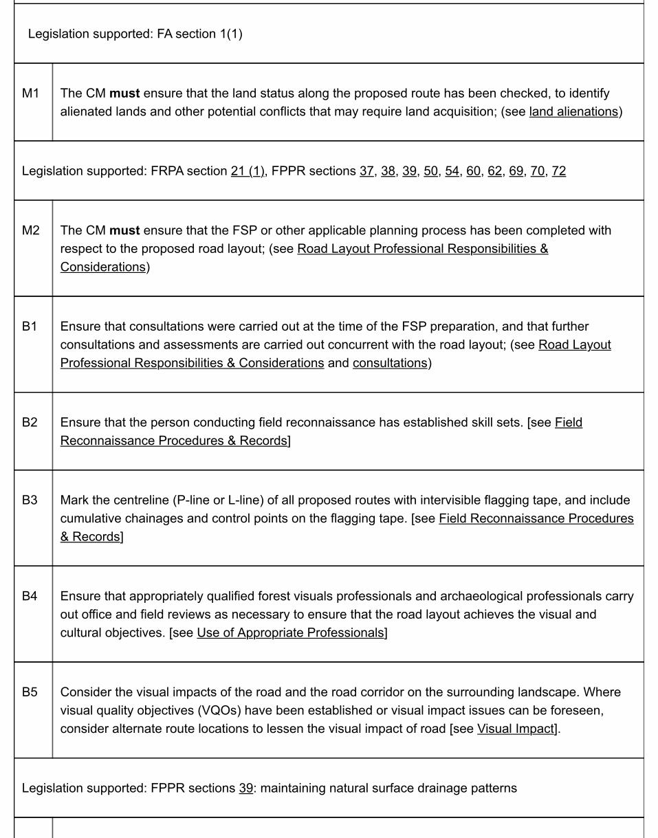
Legislation supported: FA section 1(1)
M1 The CM must ensure that the land status along the proposed route has been checked, to identifyalienated lands and other potential conflicts that may require land acquisition; (see land alienations)
Legislation supported: FRPA section 21 (1), FPPR sections 37, 38, 39, 50, 54, 60, 62, 69, 70, 72
M2 The CM must ensure that the FSP or other applicable planning process has been completed withrespect to the proposed road layout; (see Road Layout Professional Responsibilities &Considerations)
B1 Ensure that consultations were carried out at the time of the FSP preparation, and that furtherconsultations and assessments are carried out concurrent with the road layout; (see Road LayoutProfessional Responsibilities & Considerations and consultations)
B2 Ensure that the person conducting field reconnaissance has established skill sets. [see FieldReconnaissance Procedures & Records]
B3 Mark the centreline (P-line or L-line) of all proposed routes with intervisible flagging tape, and includecumulative chainages and control points on the flagging tape. [see Field Reconnaissance Procedures& Records]
B4 Ensure that appropriately qualified forest visuals professionals and archaeological professionals carryout office and field reviews as necessary to ensure that the road layout achieves the visual andcultural objectives. [see Use of Appropriate Professionals]
B5 Consider the visual impacts of the road and the road corridor on the surrounding landscape. Wherevisual quality objectives (VQOs) have been established or visual impact issues can be foreseen,consider alternate route locations to lessen the visual impact of road [see Visual Impact].
Legislation supported: FPPR sections 39: maintaining natural surface drainage patterns
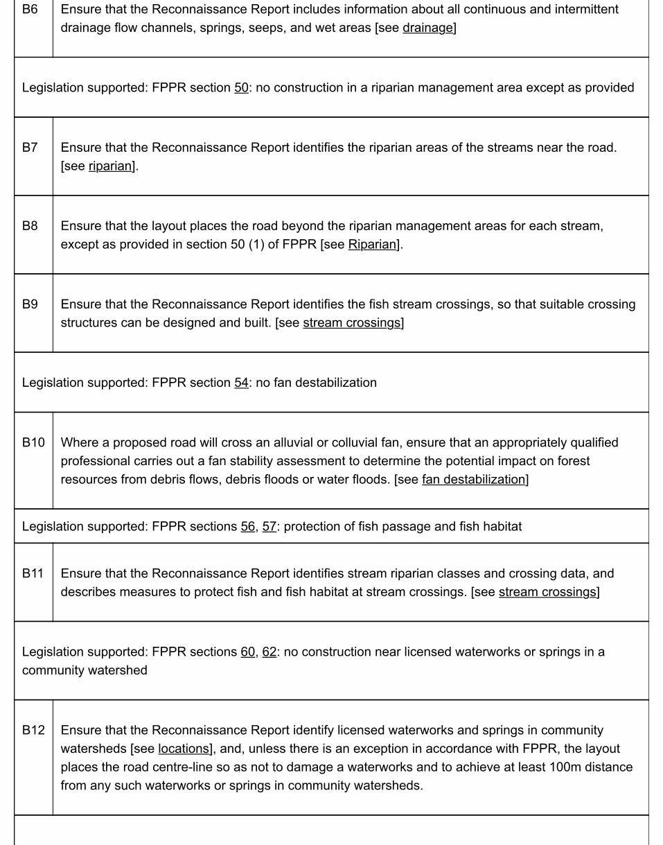
B6 Ensure that the Reconnaissance Report includes information about all continuous and intermittentdrainage flow channels, springs, seeps, and wet areas [see drainage]
Legislation supported: FPPR section 50: no construction in a riparian management area except as provided
B7 Ensure that the Reconnaissance Report identifies the riparian areas of the streams near the road.[see riparian].
B8 Ensure that the layout places the road beyond the riparian management areas for each stream,except as provided in section 50 (1) of FPPR [see Riparian].
B9 Ensure that the Reconnaissance Report identifies the fish stream crossings, so that suitable crossingstructures can be designed and built. [see stream crossings]
Legislation supported: FPPR section 54: no fan destabilization
B10 Where a proposed road will cross an alluvial or colluvial fan, ensure that an appropriately qualifiedprofessional carries out a fan stability assessment to determine the potential impact on forestresources from debris flows, debris floods or water floods. [see fan destabilization]
Legislation supported: FPPR sections 56, 57: protection of fish passage and fish habitat
B11 Ensure that the Reconnaissance Report identifies stream riparian classes and crossing data, anddescribes measures to protect fish and fish habitat at stream crossings. [see stream crossings]
Legislation supported: FPPR sections 60, 62: no construction near licensed waterworks or springs in acommunity watershed
B12 Ensure that the Reconnaissance Report identify licensed waterworks and springs in communitywatersheds [see locations], and, unless there is an exception in accordance with FPPR, the layoutplaces the road centre-line so as not to damage a waterworks and to achieve at least 100m distancefrom any such waterworks or springs in community watersheds.
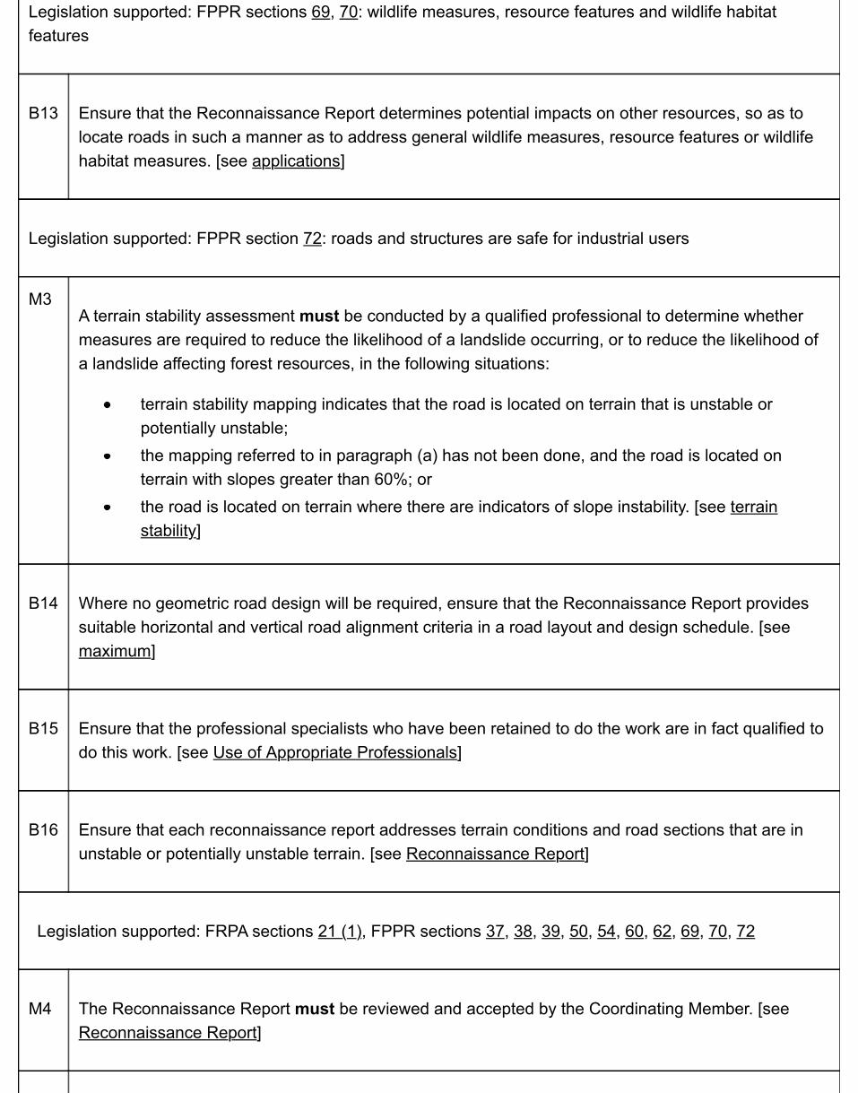
Legislation supported: FPPR sections 69, 70: wildlife measures, resource features and wildlife habitatfeatures
B13 Ensure that the Reconnaissance Report determines potential impacts on other resources, so as tolocate roads in such a manner as to address general wildlife measures, resource features or wildlifehabitat measures. [see applications]
Legislation supported: FPPR section 72: roads and structures are safe for industrial users
M3A terrain stability assessment must be conducted by a qualified professional to determine whethermeasures are required to reduce the likelihood of a landslide occurring, or to reduce the likelihood ofa landslide affecting forest resources, in the following situations:
terrain stability mapping indicates that the road is located on terrain that is unstable orpotentially unstable;the mapping referred to in paragraph (a) has not been done, and the road is located onterrain with slopes greater than 60%; orthe road is located on terrain where there are indicators of slope instability. [see terrainstability]
B14 Where no geometric road design will be required, ensure that the Reconnaissance Report providessuitable horizontal and vertical road alignment criteria in a road layout and design schedule. [seemaximum]
B15 Ensure that the professional specialists who have been retained to do the work are in fact qualified todo this work. [see Use of Appropriate Professionals]
B16 Ensure that each reconnaissance report addresses terrain conditions and road sections that are inunstable or potentially unstable terrain. [see Reconnaissance Report]
Legislation supported: FRPA sections 21 (1), FPPR sections 37, 38, 39, 50, 54, 60, 62, 69, 70, 72
M4 The Reconnaissance Report must be reviewed and accepted by the Coordinating Member. [seeReconnaissance Report]

M5 The Coordinating Member must sign (and seal as appropriate) the Road Project AssuranceStatement (PDF). [see Chapter 8: Professional Responsibilities & Considerations]
B17 Ensure that the necessary steps in the road layout process were undertaken and issues addressed[see Project Tracking Checklist]
Legislation supported: FRPA section 10, 11
B18 For BCTS projects, as the holders of a FSP, ensure that a Reconnaissance Report provides sufficientdetails to address the requirements of a road site plan. [see site plan]
In the above table of chronological events:
M = Mandatory proceduresB = Best practices
2.2 Road Layout Professional Responsibilities &ConsiderationsRoad layout includes pre-field and field reconnaissance works that address safety and resourceissues directly or lead to suitable applications at the survey, design and construction stages.Practices include:
review and confirmation of any FSP or other planning outcomes;field determination of any signs of landslide prone terrain;professional terrain and fan stability assessments;riparian classification of streams near the road;applying qualified personnel to the project;selecting the optimum route;preparing a Reconnaissance Report that addresses:
road survey instructions;seepage;locations of springs and licensed waterworks in community watersheds;resource features;wildlife habitat features; androad alignment controls where no geometric road design will take place;
flagging and traversing the proposed road centre-line; andfield checks of the proposed road location by professionals and FLNR staff, as necessarydue to project complexity or specific issues.
The CM is responsible for considering the composition and interaction of all the road layoutcomponents, as well as their relationships and impact on not only the users, but also on the roadcomponents and other resources. A key concept is continuity of professional oversight and outputreviews. The CM is charged with retaining a close familiarity with the progress of the project, andwith coordinating the various specialist inputs into the road layout and, as such, carries overallprofessional responsibility for the delivery of the layout.
The CM may need to update a road layout based on:
the results of consultations that have taken place after the road layout commenced; andthe field reconnaissance and recommendations made by other members, specialists or

road personnel.
Based on the foregoing, the CM must sign off (and may seal) the Road Project AssuranceStatement (PDF), approving the location of the road. For more information, see Chapter 8:Professional Responsibilities & Considerations.
2.3 Pre-Field Investigation
2.3.1 Road Layout
Allocate adequate time and resources to road layout. The road layout stage begins with thecollecting and analyzing of all available information for the development area, focusing on theroute corridor resulting from any approved access plan.
The first step in determining a road location is the pre-field investigation, which includes:
carrying out a thorough map and air photo review; andpreparing a working map of the area that shows study area boundaries, existing access,major drainages, land alienations, and other key planning elements.
2.3.2 Maps & Air Photos
Maps and air photos are a major source of information for examining terrain features andcollecting information about the study area. Use the following types of maps at 1:5,000 or1:10,000 scale for pre-field preparation, particularly for difficult or broken terrain:
contour maps;Terrain Resource Information Management (TRIM) maps;forest cover maps; andsoil and landform maps, terrain and stability maps, and ortho imagery.
Use the most recent series of air photos in conjunction with the available maps, to interpretphysical features, drainage, and forest cover. Photo scales at 1:15,000 and 1:20,000 enabledetail to be examined, although 1:60,000 photos are helpful for general landform orientation.
Complete an in-depth review of the maps and air photos to identify features and control pointsalong potential route (“recce”) locations, including:
stream crossings where location is critical;rock bluffs, benches, passes, saddles, and other dominant terrain features;potential switchback locations;harvesting systems and potential location of landings;
potential disposal sites for excavation spoil or debris;alienated lands, including powerline, gas pipeline, or railway crossings;current access to and junction with existing roads;log dumps, mill yards, or other destinations;avalanche chutes;talus slides;swamps and wet areas;forest cover and stand condition; andpotential environmentally sensitive areas.
2.3.3 Visual Impact
Consider the visual impacts of the road and the road corridor on the surrounding landscape.Where visual quality objectives (VQOs) have been established or visual impact issues can beforeseen, consider alternate route locations to lessen the visual impact of road. However,consider the impact of any increased costs to do so in evaluating the route alternatives. TheVisual Impact Assessment Guidebook provides details for consideration in the layout of forestroads.
2.3.4 The Working Map
The working map provides a visual summary of all information gathered during the pre-fieldinvestigation. Once assembled, it provides a picture of:
an outline of the study boundaries;the location, volume, and species of timber to be accessed;alienations that may apply to the access development, such as Indian Reserves or privateproperty and utilities;location of administrative, environmental, special interest, and land status concerns,including Visual Quality Objectives (VQOs); andspecifications that may affect the access itself, such as grade, alignment, haulrequirements, or the needs of other users.
In developing working maps, carry out the following steps:
Establish control points (including those to be used as photo ties) that may affect physicalaccess or define where the road recce needs to be.Establish a minimum of one photo tie per kilometer.Use the maps and air photos to locate the recce routes that most effectively andeconomically connect the control points and meet the general specifications for roadgrade and travel speed.
Mark the control points and proposed route locations on the air photos for verificationduring field reconnaissance.If 1:5,000 or 1:10,000 topographic mapping is available, check the grades along theproposed route options. Position roads away from water bodies and wetlands. Avoidareas of potential open-slope instability, potential surface soil erosion, and gully instability.Locate roads on benches, ridge tops, and flatter slopes to minimize erosion. Avoid erosionhazards such as:
heavy groundwater seepage;soft clay or sensitive silt soil strata;concave slopes;steeply dipping rock layers; andareas where there is a hazard of high mass wasting or erosion, includingdownslope sensitive areas.
Select stream crossings at locations where channel and bank disturbance will beminimized. Keep the number of stream crossings to a minimum.
2.3.5 Land Alienations
The CM must ensure that a proposed road is free of any potential land alienations. Check theland status of an area as a prerequisite for road layout, to identify alienated lands and otherpotential conflicts that may require right-of-way (R/W) acquisition.
Alienations and interests or conflicts that may require R/W acquisition generally fall into one ofthe following categories:
fee simple land;provincial government leasehold/tenure/interest;reserve by Ministerial Order/OIC; orfederal reserve.
Where applicable, notify land owners of the intent to enter. However, avoid any discussionconcerning possible land acquisition (and, in particular, expropriation). Limit discussions to thetopic of access being required for reconnaissance purposes only. Also, advise a landowner that,should the ministry require legal access across the property, then a Forest Land AcquisitionsProject Manager would contact the landowner to begin negotiations. If a landowner refusesministry staff entry onto the property, contact FLNR Forest Land Acquisitions for further advice onhow to proceed or how to negotiate the short-term access.
Do not assume that the occupant of a site is the landowner. Obtain information on the name ofcurrent landowners from the FLNR Forest Land Acquisitions in Victoria.

2.3.6 Government Interests
Based on potential conflicts that become evident during the road layout process, consider anyconcerns from the following government agencies, both provincial and federal, about the areaand information to be included in plans for development of access for the timber resource:
Ministry of Environment & Climate Change Strategy (provincial);Environment and Climate Change Canada (federal);Ministry of Transportation and Infrastructure (provincial)Transport Canada (federal; Navigation Protection Act);Ministry of Energy, Mines & Petroleum Resources (provincial; placer leases and miningclaims);BC Oil and Gas Commission (provincial); andMinistry of Agriculture (provincial; Agricultural Land Reserve).
2.4 Field ReconnaissanceThe process of field reconnaissance has three primary objectives:
1. investigate potential route corridors considering all of the elements, including reviews ofoptional locations and the constraints of the harvesting system that would contribute to thefinal location of the road;
2. gather information for subsequent use by the road survey and design contractor, and toaccess the need for any additional information or assessments; and
3. flag the reconnaissance line of the preferred road location using field traverse Survey Level 1standards as required. See Survey Level 1 for field traverse.
2.4.1 Field Reconnaissance Procedures & Records
Ensure that the person conducting field reconnaissance has established skill sets. Refer toEngineering Equipment and Services (EES) Directory.
Carry out the following reconnaissance steps:
1. Walk the proposed routes.2. Mark the centreline (P-line or L-line) of all proposed routes with intervisible flagging tape,
using hand instruments for direction and grade control. Maintain horizontal control with ahand-held compass and a hip chain; and maintain vertical control with clinometer readings.Handheld GPS units may be used to establish the centreline (P-line or L-line) where roadgrades are not an issue and the operator ensures that sufficient satellite coverage isavailable. Measure side slopes with a clinometer, and record average readings for consistenttopographic sections.
3. Note the grades between control points. Keep road gradients within specifications.4. Mark cumulative chainages and TP numbers on the flagging tape with felt pen. Mark curves
with flagging by approximating the best alignment.5. Mark control points used as photo ties on the ribbon line, noting the air photo tie number and
the air photo numbers.6. Where a location survey is not required for the project because of the easy terrain, reference
all control points and flag the right-of-way boundaries.7. Record side slopes between control points.8. Provide detailed notes on soils and topographic features, including:
stream crossings where channel and bank disturbances can be prevented or
mitigated, locations that require site plans, and data required for minor streamcrossings;forest cover (species composition, timber quality, and volume per hectare);recommended slash and debris disposal methods and additional clearing widthsrequired for the slash and debris disposal;soil types based on visual observations of exposed cuts, shallow hand-dug test holesand probing, and the location of these soils on maps or aerial photos;maximum road grades and minimum curve radii;location and extent of bedrock, if rippable, and the potential as ballast;location and extent of gravel sources and the potential for use as subgrade andsurfacing materials;endhaul sections and potential waste areas;recommended construction methods and potentially appropriate alternatives; andrecommended survey level or levels appropriate for the terrain. See Survey Levels.
9. Note harvest opportunities and access requirements. As part of any field reconnaissance,confirm or evaluate the need for any additional information or assessments, including:
terrain stability field assessments for roads;
A terrain stability assessment must be conducted by a qualified professional todetermine whether measures are required to reduce the likelihood of a landslideoccurring, or to reduce the likelihood of a landslide affecting forest resources, in thefollowing situations:
a. terrain stability mapping indicates that the road is located on terrain that isunstable or potentially unstable;
b. the mapping referred to in paragraph (a) has not been done, and the road islocated on terrain with slopes greater than 60%; or
c. the road is located on terrain where there are indicators of slope instability.
Ensure that the professional carries out the assessment in accordance with the EGBC Guidelines for Terrain Stability Assessments in the Forest Sector (PDF, 1.9MB).
riparian classification of streams, wetlands, and lakes;identification of fish streams;visual impact assessments;applications of general wildlife measures, and protection of resource featuresand wildlife habitat features;fan destabilization and a gully process (for coastal BC) (see fans and gully);archaeological impact assessments; and
soil erosion field assessments.
2.4.2 Specific Concerns
Consider the following items during reconnaissance:
1. Vertical alignment: The grades that result in the best combination of haul and constructioncosts should be selected. See Table 3-2: Summary of alignment controls for forest roads(PDF).
2. Horizontal alignment: The speed limits for various degrees of curvature are given in Table3-3: Curve Widenings.
3. Junctions: A high level of safety must be maintained in selecting a site for a junction. Thefollowing factors should be incorporated as much as possible:
adequate sight distance in both directions in accordance with the normal travel speed(up to 65km/h, 100m; and 65–80km/h, 150m);near-level ground conditions (2% plus or minus);right angle T-junctions rather than Y-junctions; andonly gradual change in horizontal or vertical alignment.
4. Soils: For locating roads, landforms can be excellent guides to desirable areas or to areas toavoid. Alluvial terrains, lacustrine deposits, water melt channels, colluvial deposits, alluvialfans eskers, and kames are strong indicators of the types of soils to be found below thesurface. Easily accessible gravels, found in alluvial fans or kames, are an economical sourceof surfacing material. Glacial moraines, which contain relatively unsorted material, are agood source of subgrade material. Other glacial deposits that can provide subgrade orsurfacing materials are basal tills and drumlins.
5. Riparian Management Areas: Ensure that riparian classifications are identified for streamsnear the road location, and that the road layout places the road beyond the riparianmanagement area for each stream, except as provided in section 50 (1) of FPPR.
Plan on obtaining any large fragmented rock required for road ballast or rip rap from rockoutcrops (quarries) or talus slopes. Avoid very fine-grained soils of lacustrine origin,particularly for sidehill construction.
Illustrations of the landforms mentioned here are found in Terrain Classification System forBritish Columbia (PDF, 8.21 MB).
2.4.3 Drainage Structures
Some of the most important control points reviewed during a field investigation are those used tolocate bridges and culverts.
Bridge Location
Locate a bridge site to provide an acceptable horizontal and vertical alignment for the road,considering:
stream width;upstream and downstream watercourse alignment;streambank stability;whether streambanks are fairly even in height on both sides;availability of local materials for construction;access to both sides of watercourse during construction phase;potential for ice and debris buildup; andpotential for streambank erosion.
Ideally, locate the crossing of a waterway at right angles to the centreline (P-line or L-line) of thewaterway and include approach tangents of a minimum 15m in length. Limit the maximum gradeon a bridge deck to 4%, but preferably less.
Major Culvert Location
In planning for major culverts, use much of the same location criteria as used for bridges. Referto the Fish-Stream Crossing Guidebook (PDF, 4.2MB).
2.4.4 Harvesting Requirements
As the field investigation proceeds, consider the harvesting systems that will affect on blockroads.. For detailed information on total chance plans and mainline roads, see FPInnovations(FERIC) Handbooks No. 4: Timber Development Planning for the British Columbia Interior: TheTotal Chance Concept (PDF, 4.19 MB), and No 9: Forest Harvesting and Renewal Planning forthe British Columbia Interior: An Extension of the Total Chance Concept, which cover planningconsiderations and logging methods for various types of terrain.
2.4.5 Use of Appropriate Professionals
To adequately manage and conserve forest resources, ensure that qualified professionalspecialists are consulted where appropriate. Site-specific conditions will dictate what the criticalimpacts and risks will be, but in general specialists might include those in the fields of terrainstability, stream morphology, structural engineering, aquatic and marine habitat, archeology,wildlife, botany, visual impacts, and forestry. Ensure that the professional specialists who havebeen retained to do the work are in fact qualified to do this work. See Engineering Equipment andServices (EES) Directory for those categories related to road engineering, and for theseparticular categories, consult with the ministry engineering professionals and have them:
assess a consultant's qualifications prior to retaining the consultant under a service

contract; andassist with service contract language.
2.5 Reconnaissance ReportRegardless of the complexity of the project, incorporate critical factors that will influence the final road locationin a reconnaissance report. The CM must review and accept this Report before the road project moves to thenext activity/phase, whether that be the survey and design, the road plan or the construction.
Depending on the site, prepare a reconnaissance report that ranges in size and detail from a map showingroute locations, a one-page summary and field notes to a multiple page document outlining in detail the variousoptions for route locations. The determining factor is the level of comfort with the quality of information, giventhe risks and potential impacts of the project. In general, ensure that each reconnaissance report includes amap showing route locations and addresses the following:
the need, if any, for any additional information or assessments to be carried our by the appropriateprofessionals;terrain conditions and road sections that are in unstable or potentially unstable terrain;road sections with side slopes over 60% or where slope instability indicators are found;control points and topographic features (e.g. rock bluffs, swamps, avalanche paths, landslides, anddebris slides), including those that may be used as photo ties;the sections of road that encroach on public utilities;the sections of road that are adjacent to or cross private property, Crown leases, or mineral and placerclaims or leases (where possible, alienated lands should be avoided);all continuous and intermittent drainage flow channels, springs, seeps, and wet areas;riparian areas;stream crossings where channel and bank disturbances can be prevented or mitigated;locations of springs and licensed waterworks in community watersheds;locations that require site plans;minor stream crossings;forest cover (species composition, timber quality, and volume per hectare);potential landing locations;soil type, based on visual observations of exposed cuts, shallow hand-dug test holes, and probing, andthe location of these soils on maps or aerial photos;maximum road grades and minimum curve radii;location and extent of bedrock, if rippable, and the potential as ballast;location and extent of gravel sources and the potential for use as subgrade and surfacing materials;endhaul sections and potential waste areas;recommended construction methods and potentially appropriate alternatives;recommended survey level or levels appropriate for the terrain; and

harvesting system requirements.
By addressing the foregoing, a Reconnaissance Report prepared by BCTS, for the purposes of FRPA section10 and 11, also addresses the requirements for a road site plan.
2.6 Resources & Suggestions for Further ReadingTechnical solutions to field problems or recommended processes can generally be found in the followingpublications as well as various other technical bulletins and handbooks commonly used by the forest industryand the BC Ministry of Forests, Lands and Natural Resource Operations.
BC Ministry of Forests. 1999. Mapping and Assessing Terrain Stability Guidebook. For. Prac. Br., B.C.Min. For. Victoria, B.C.___________. 1992. Forest inventory manual: forest classification, sampling and environmentallysensitive areas. Vol. 2. Inventory. Br., B.C. Min. For. Victoria, B.C. 161 p.BC Ministry of Sustainable Resource Management. 1996. Terrain Stability Mapping in BritishColumbia. For. Prac. Br., B.C. Min. For. Victoria, B.C.Braedon, R.E. 1990. Forest Harvesting and Renewal Planning for the British Columbia Interior: AnExtension of the Total-Chance Concept (PDF, 5.27 MB). FERIC handbook No.9. For. Eng. ResearchInst. Can. (FERIC). Vancouver, BC. 49 p.Braedon, R.E. 1983. Timber Development Planning for the British Columbia Interior: The Total-ChanceConcept (PDF, 4.19 MB). FERIC handbook No.4. For. Eng. Research Inst. Can. (FERIC). Vancouver,BC. 73 p.Chatwin, S.C., D.E. Howes, J.W. Schwab, and D.N. Swanston. 1994. A Guide for Management ofLandslide-Prone Terrain in the Pacific Northwest. 2nd ed. B.C. Min. For., Victoria, BC. Land Manage.Handb. No. 18. 220 p.Holmes, D.C.. 1989. Manual for Roads and Transportation. British Columbia Institute of Technology(BCIT). Burnaby, BC

2.7 Appendices
2.7.1 Project Tracking Checklist
Use this checklist to prepare a paper trail of key outputs prepared by consultants and sign-offs by the ministry.
Project Tracking Checklist (PDF)

Chapter 3: Road Survey & DesignRoute reconnaissance is usually the first on the ground location work used to define the generalposition of a road. Based on the reconnaissance and reconnaissance summary, furtherinvestigations and surveys may be required, including field traverses and surveys to anestablished standard or Survey Level. The level is determined primarily by the complexity of theterrain and end results required. Once the survey has been completed, the road design can becarried out.
Road design varies in complexity and can be as simple as providing basic road dimensions andgrades required to a more detailed design to establish excavation and fill volumes, grades andalignments. In most cases, road design is usually an office process utilizing computers and roaddesign software. Again, depending on the complexity and end results required, further roadsurvey work may be required to establish the road location.
This chapter presents the ministry's standards related to road location survey and road designpractices, and to the associated output. It is intended to provide the reader with enough detail tobe able to understand the mandatory procedures, as well as carrying out appropriate bestpractices to address the applicable regulatory requirements.
3.0.1 Policy
For any FSR, the road will be:
Surveyed with appropriate detail and accuracy for the terrain and complexity of the layout;andDesigned in a manner that:
Is commensurate with the level of survey and expected use, cost and potentialimpacts on other resources by the road construction; andIncorporates the results of any required assessments.
3.1 Mandatory Procedures & Best Practices
3.2 Road Survey & Design Professional Responsibilities & Considerations
3.3 Road Location Survey
3.3.1 Types of Survey3.3.2 Survey Levels
3.4 Survey Procedures
3.4.1 Survey Level 13.4.2 Survey Level 2 & 33.4.3 Survey Level 4 (For High-Order Survey Requirements)
3.5 Geometric Road Design
3.5.1 Design Planning Considerations3.5.2 Road Design Criteria3.5.3 Swell & Shrinkage of Materials3.5.4 Example Correction Factors
3.6 Culvert Design
3.6.1 Log Culvert Design3.6.2 Ford Design & Construction on Non-Fish Streams3.6.3 Design Considerations3.6.4 Cross Drain Culverts3.6.5 Culverts on Non-Fish-Bearing Streams3.6.6 Factors Affecting Runoff3.6.7 High Water Estimation Method for Stream Culverts3.6.8 Road Junctions3.6.9 Other Structures
3.7 Geometric Road Design Requirements
3.8 Survey & Design Outputs - Road Plans
3.9 Resources & Suggestions for Further Reading
3.10 Appendices
3.10.1 Drawing & Map Legends3.10.2 Basic Drainage Site Report Requirements3.10.3 Sample Survey & Design Contract3.10.4 Project Tracking Checklist


3.1 Mandatory Procedures & Best PracticesThe Forest Planning and Practices Regulation (FPPR) requires the government to construct a Forest Serviceroad in a manner that achieves certain resource protection objectives or meets specific criteria. Onecomponent of a road's development that addresses such objectives or criteria is its survey and design.
To address safety, and resource protection and mitigation measures related to road layout, it is necessary toprovide appropriate levels of expertise and resources to pre-construction of a road, and suitable checks andbalances to ensure that the work is proceeding according to plan.
Following is a table that summarizes in approximate chronological order the mandatory procedures and bestpractices with respect to the survey and design of Forest Service roads.
Table 3-1 Road Survey and Design
Results to be achieved:
Do not cause landslides or gully processes that would have a material adverse effect on forestresources (FPPR s. 37, 38)Maintain natural surface drainage patterns (FPPR s. 39)No construction of a road in a riparian management area (FPPR s. 50)No fan destabilization that would have a material adverse effect on forest resources (FPPR s. 54)Protection of fish passage (FPPR s. 56)No deposition or transport of deleterious materials into licensed waterworks drinking water (FPPR s.59)No road construction within a specified distance from a spring in a community watershed, or within100m upslope of a licensed water intake or spring in a community watershed (FPPR s. 60, 62)Road is safe for industrial use (FPPR s. 72)
Legislation supported: FPPR sections 37, 38, 57, 59, 69, 70, 72: do not cause landslides or gully processesthat will have a material adverse effect on forest resources
M1A geometric road design must be carried out for all roads that will cross areas with a moderate orhigh likelihood of landslides. [see Geometric Road Design Requirements]
B1 Ensure that at least a location survey level 3 is carried out for road crossing landslide prone terrain.
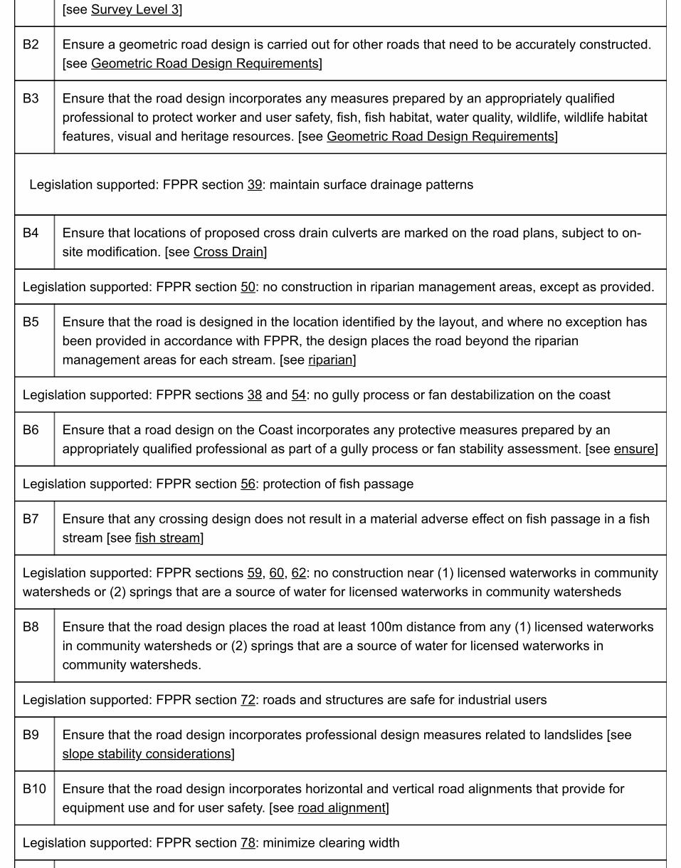
[see Survey Level 3]
B2 Ensure a geometric road design is carried out for other roads that need to be accurately constructed.[see Geometric Road Design Requirements]
B3 Ensure that the road design incorporates any measures prepared by an appropriately qualifiedprofessional to protect worker and user safety, fish, fish habitat, water quality, wildlife, wildlife habitatfeatures, visual and heritage resources. [see Geometric Road Design Requirements]
Legislation supported: FPPR section 39: maintain surface drainage patterns
B4 Ensure that locations of proposed cross drain culverts are marked on the road plans, subject to on-site modification. [see Cross Drain]
Legislation supported: FPPR section 50: no construction in riparian management areas, except as provided.
B5 Ensure that the road is designed in the location identified by the layout, and where no exception hasbeen provided in accordance with FPPR, the design places the road beyond the riparianmanagement areas for each stream. [see riparian]
Legislation supported: FPPR sections 38 and 54: no gully process or fan destabilization on the coast
B6 Ensure that a road design on the Coast incorporates any protective measures prepared by anappropriately qualified professional as part of a gully process or fan stability assessment. [see ensure]
Legislation supported: FPPR section 56: protection of fish passage
B7 Ensure that any crossing design does not result in a material adverse effect on fish passage in a fishstream [see fish stream]
Legislation supported: FPPR sections 59, 60, 62: no construction near (1) licensed waterworks in communitywatersheds or (2) springs that are a source of water for licensed waterworks in community watersheds
B8 Ensure that the road design places the road at least 100m distance from any (1) licensed waterworksin community watersheds or (2) springs that are a source of water for licensed waterworks incommunity watersheds.
Legislation supported: FPPR section 72: roads and structures are safe for industrial users
B9 Ensure that the road design incorporates professional design measures related to landslides [seeslope stability considerations]
B10 Ensure that the road design incorporates horizontal and vertical road alignments that provide forequipment use and for user safety. [see road alignment]
Legislation supported: FPPR section 78: minimize clearing width

B11 Ensure that clearing widths marked on the road plans provide for the minimum clearing widthconsidering operational requirements, safety, drainage, stability and topography [see clearing width]
Legislation supported: FPPR sections 37, 38, 39, 50, 54, 56, 57, 59, 60, 62, 69, 70, 72
M2 Road plans must be reviewed and accepted by the Coordinating Member [see Survey & DesignOutputs]
M3 The Coordinating Member must sign (and seal as appropriate) the Road Project AssuranceStatement (PDF). [see Chapter 8: Professional Responsibilities & Considerations]
B12 Ensure that the necessary steps in the road layout process were undertaken and issues addressed[see Project Tracking Checklist]
In the above table of chronological events:
M = Mandatory proceduresB = Best practices

3.2 Road Survey & Design Professional Responsibilities &ConsiderationsRoad survey and design includes applying the appropriate level of survey to achieve the required accuracy offield measurements, and preparing a geometric road design (including plans, profiles, cross-sections and massgraphs) based on the survey measurements, data and assessments, to tie the location of the road to the landbase. Practices include:
carrying out a location survey;incorporating professional assessments from the road site plan, including any strategies or objectivesthat are necessary;marking locations of cross drain culverts;locating roads outside of riparian management areas;consideration of sediment transport and deposition;locating roads appropriate distances from licensed waterworks in community watersheds; andproviding for suitable clearing widths to address topographic and operational needs; andpreparing a road plan that serves as or includes the road site plan under an FSP.
The CM is responsible for:
choosing the survey methods and instrumentation in accordance with the information contained in thisManual, based upon the accuracy and type of data required to facilitate the planning and design of thedetermining where a geometric road design is required;modifying the design and construction standard or adopting additional measures to protect workersduring construction, users and resource and habitat features.
To achieve the foregoing, the CM:
where the design is prepared using a computer application, must review the design to ensure that it isreasonable, correct, suitable for the ground conditions and constructible;may rely upon the geometric road design procedures contained in this manual; andmay use specialist input to revise locations, to incorporate special design measures, to specify specialconstruction techniques, or to develop specific measures that are to be employed during or followingconstruction to protect the environment or address worker or user safety. Examples include:
evaluating potential safety issues that are beyond the expertise of the CM, such as landslides,rockfalls, avalanches, karst features, danger trees;assessing terrain related concerns for road construction such as slope stability hazards,gullies, fans, floodplains, erosion or avalanches;identifying fish habitat and sensitivity;

identifying and addressing other forest and non-forest resources (e.g. archaeological sites);structural elements such as retaining walls;fords or fish stream culverts;bridges, including approach alignments;engineered fills or cut slope treatments;construction techniques such as overlanding or full bench excavation and endhaul;engineered rock cuts;measures to protect fan or floodplain stability;specialized erosion protection; andmeasures to protect resource and wildlife habitat features.
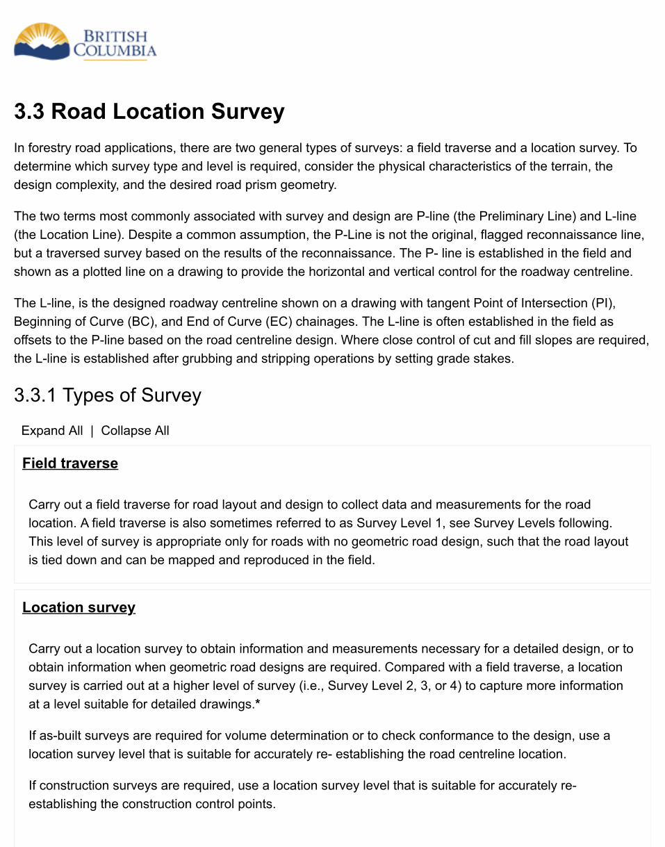
3.3 Road Location SurveyIn forestry road applications, there are two general types of surveys: a field traverse and a location survey. Todetermine which survey type and level is required, consider the physical characteristics of the terrain, thedesign complexity, and the desired road prism geometry.
The two terms most commonly associated with survey and design are P-line (the Preliminary Line) and L-line(the Location Line). Despite a common assumption, the P-Line is not the original, flagged reconnaissance line,but a traversed survey based on the results of the reconnaissance. The P- line is established in the field andshown as a plotted line on a drawing to provide the horizontal and vertical control for the roadway centreline.
The L-line, is the designed roadway centreline shown on a drawing with tangent Point of Intersection (PI),Beginning of Curve (BC), and End of Curve (EC) chainages. The L-line is often established in the field asoffsets to the P-line based on the road centreline design. Where close control of cut and fill slopes are required,the L-line is established after grubbing and stripping operations by setting grade stakes.
3.3.1 Types of Survey
Expand All | Collapse All
Field traverse
Carry out a field traverse for road layout and design to collect data and measurements for the roadlocation. A field traverse is also sometimes referred to as Survey Level 1, see Survey Levels following.This level of survey is appropriate only for roads with no geometric road design, such that the road layoutis tied down and can be mapped and reproduced in the field.
Location survey
Carry out a location survey to obtain information and measurements necessary for a detailed design, or toobtain information when geometric road designs are required. Compared with a field traverse, a locationsurvey is carried out at a higher level of survey (i.e., Survey Level 2, 3, or 4) to capture more informationat a level suitable for detailed drawings.*
If as-built surveys are required for volume determination or to check conformance to the design, use alocation survey level that is suitable for accurately re- establishing the road centreline location.
If construction surveys are required, use a location survey level that is suitable for accurately re-establishing the construction control points.
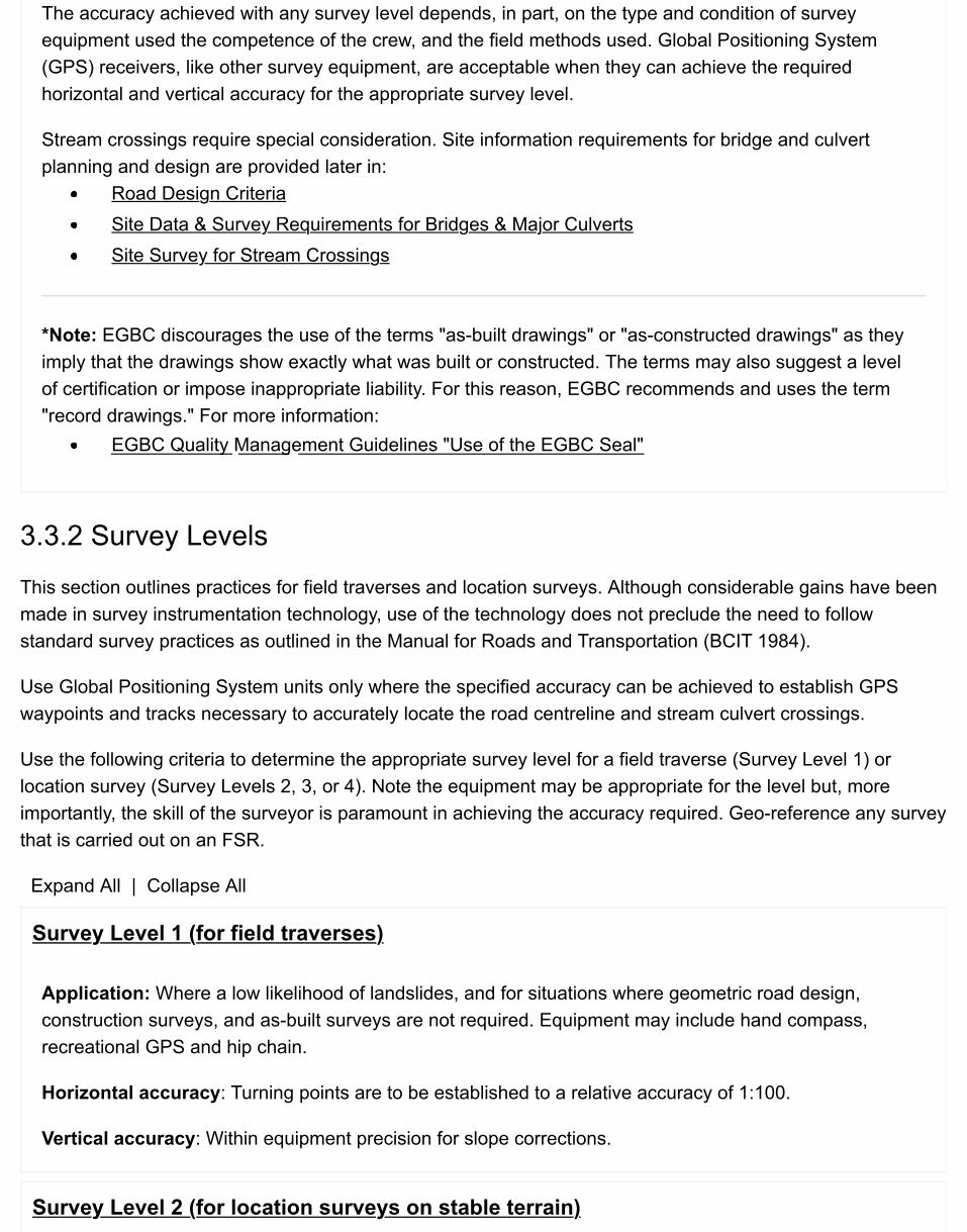
The accuracy achieved with any survey level depends, in part, on the type and condition of surveyequipment used the competence of the crew, and the field methods used. Global Positioning System(GPS) receivers, like other survey equipment, are acceptable when they can achieve the requiredhorizontal and vertical accuracy for the appropriate survey level.
Stream crossings require special consideration. Site information requirements for bridge and culvertplanning and design are provided later in:
Road Design CriteriaSite Data & Survey Requirements for Bridges & Major CulvertsSite Survey for Stream Crossings
*Note: EGBC discourages the use of the terms "as-built drawings" or "as-constructed drawings" as they imply that the drawings show exactly what was built or constructed. The terms may also suggest a level of certification or impose inappropriate liability. For this reason, EGBC recommends and uses the term "record drawings." For more information:
EGBC Quality Management Guidelines "Use of the EGBC Seal"
3.3.2 Survey Levels
This section outlines practices for field traverses and location surveys. Although considerable gains have beenmade in survey instrumentation technology, use of the technology does not preclude the need to followstandard survey practices as outlined in the Manual for Roads and Transportation (BCIT 1984).
Use Global Positioning System units only where the specified accuracy can be achieved to establish GPSwaypoints and tracks necessary to accurately locate the road centreline and stream culvert crossings.
Use the following criteria to determine the appropriate survey level for a field traverse (Survey Level 1) orlocation survey (Survey Levels 2, 3, or 4). Note the equipment may be appropriate for the level but, moreimportantly, the skill of the surveyor is paramount in achieving the accuracy required. Geo-reference any surveythat is carried out on an FSR.
Expand All | Collapse All
Survey Level 1 (for field traverses)
Application: Where a low likelihood of landslides, and for situations where geometric road design,construction surveys, and as-built surveys are not required. Equipment may include hand compass,recreational GPS and hip chain.
Horizontal accuracy: Turning points are to be established to a relative accuracy of 1:100.
Vertical accuracy: Within equipment precision for slope corrections.
Survey Level 2 (for location surveys on stable terrain)

Application: For location surveys on stable terrain with a low likelihood of landslides and for situationswhere a geometric road design, construction surveys, or as-built surveys are desired. Equipment mayinclude hand compass, clinometer and steel or fiberglass chain.
Horizontal accuracy: Turning points are to be established to a relative accuracy of 1:300.
Vertical accuracy: = 1.0* √total distance in kilometres, expressed in metres. For example, the verticalaccuracy for a 1km road is 1m. For a 2km road, the vertical accuracy is 1.41m.
Survey Level 3 (for location surveys within areas of moderate or high likelihood oflandslides)
Application: For location surveys, construction surveys, geometric road design, and as-built surveys inareas of moderate to high likelihood of landslides, as determined by a terrain stability field assessment.This is also the appropriate level of survey for material volume determination and detailed-engineeredestimates. May also be used for bridge and major culvert planning and design, but greater verticalaccuracy might be necessary. Equipment may include staff compass, rod and steel chain.
Horizontal accuracy: Turning points are to be established to a relative accuracy of 1:1,000.
Vertical accuracy: = 0.5 * √total distance in kilometres, expressed in metres. For example, the verticalaccuracy for a 1 km road is 0.5 m. For a 2 km road, the vertical accuracy is 0.71 m.
Survey Level 4 (for high-order survey requirements)
Application: A high-order survey for location surveys, construction surveys, construction contracting on acost-per-unit basis, check surveys, placement of permanent bridges, as-built surveys through Crownleases, mineral and placer claims, and leases, private property, and surveys to re-establish privateproperty lines. Equipment may include transits, rod and steel chain, or total station instruments.
Horizontal accuracy: Turning hubs are to be established to a relative accuracy of 1:5,000.
Vertical accuracy: = 0.3* √total distance in kilometres, expressed in metres. For example, the verticalaccuracy for a 1 km road is 0.3 m. For a 2 km road, the vertical accuracy is 0.42 m.

3.4 Survey Procedures
3.4.1 Survey Level 1
Where a geometric road design is not required (e.g., where a proposed road will not cross areas with amoderate or high likelihood of landslides as determined by a terrain stability field assessment), carry out thefollowing as part of a field traverse:
1. Clearly identify the beginning and end of the road.2. Clearly flag the proposed centreline of the road.3. Using an appropriate method (such as aluminum plaques and tree blazes), mark and record control
points, noting the control point number, station, bearing, and horizontal distance from the proposedcentreline.
4. Measure the bearing, slope gradient, and distance between the TPs and mark the cumulative changesand/or point number in the field.
5. Geo-reference the end points by double occupying the stations.6. Record notes describing forest cover, vegetative types, soil types, rock, groundwater seepage, streams,
and other related factors.
3.4.2 Survey Level 2 & 3
Carry out the following where a geometric road design is required:
1. Clearly identify the beginning and end of the road.2. Establish intervisible stations (called turning points [TPs] if done with a compass, or traverse hubs [THs] if
done with a transit) along the preliminary centreline (P-line). Use manufactured stakes or local material(blazed saplings) driven into the ground.
3. Measure the bearing, slope gradient, and distance between TPs and mark the cumulative chainagesand/or point number in the field. Take both foreshots and backshots to verify the readings and to protectagainst booking errors.
4. Measure the slope gradient and distance to additional grade breaks between TPs as intermediate foreshots to facilitate taking cross-sections at those locations.
5. Using an appropriate method (such as aluminum plaques and tree blazes), mark and record controlpoints, reference points, and benchmarks. Note the number, station, bearing, and horizontal distance fromthe P-line.
6. Geo-reference the end points by double occupying the stations.7. Record notes describing forest cover, vegetative types, soil types, rock, groundwater seepage, streams,
and other related factors that were not identified on the reconnaissance report.8. Obtain enough information to ensure that road junctions can be designed and constructed. This includes
capturing a minimum of 50 m of the existing road in the traverse (horizontal and vertical alignments and
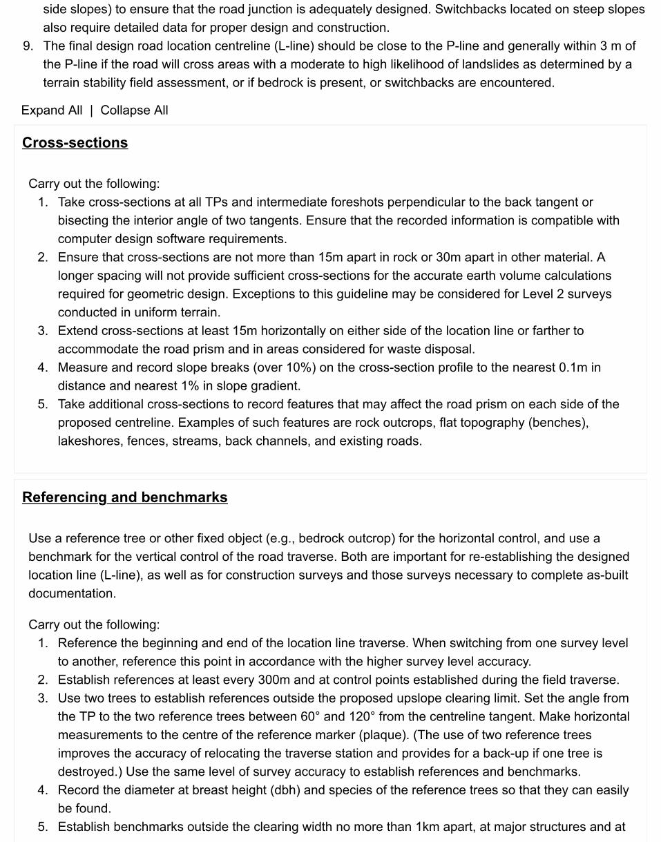
side slopes) to ensure that the road junction is adequately designed. Switchbacks located on steep slopesalso require detailed data for proper design and construction.
9. The final design road location centreline (L-line) should be close to the P-line and generally within 3 m ofthe P-line if the road will cross areas with a moderate to high likelihood of landslides as determined by aterrain stability field assessment, or if bedrock is present, or switchbacks are encountered.
Expand All | Collapse All
Cross-sections
Carry out the following:1. Take cross-sections at all TPs and intermediate foreshots perpendicular to the back tangent or
bisecting the interior angle of two tangents. Ensure that the recorded information is compatible withcomputer design software requirements.
2. Ensure that cross-sections are not more than 15m apart in rock or 30m apart in other material. Alonger spacing will not provide sufficient cross-sections for the accurate earth volume calculationsrequired for geometric design. Exceptions to this guideline may be considered for Level 2 surveysconducted in uniform terrain.
3. Extend cross-sections at least 15m horizontally on either side of the location line or farther toaccommodate the road prism and in areas considered for waste disposal.
4. Measure and record slope breaks (over 10%) on the cross-section profile to the nearest 0.1m indistance and nearest 1% in slope gradient.
5. Take additional cross-sections to record features that may affect the road prism on each side of theproposed centreline. Examples of such features are rock outcrops, flat topography (benches),lakeshores, fences, streams, back channels, and existing roads.
Referencing and benchmarks
Use a reference tree or other fixed object (e.g., bedrock outcrop) for the horizontal control, and use abenchmark for the vertical control of the road traverse. Both are important for re-establishing the designedlocation line (L-line), as well as for construction surveys and those surveys necessary to complete as-builtdocumentation.
Carry out the following:1. Reference the beginning and end of the location line traverse. When switching from one survey level
to another, reference this point in accordance with the higher survey level accuracy.2. Establish references at least every 300m and at control points established during the field traverse.3. Use two trees to establish references outside the proposed upslope clearing limit. Set the angle from
the TP to the two reference trees between 60° and 120° from the centreline tangent. Make horizontalmeasurements to the centre of the reference marker (plaque). (The use of two reference treesimproves the accuracy of relocating the traverse station and provides for a back-up if one tree isdestroyed.) Use the same level of survey accuracy to establish references and benchmarks.
4. Record the diameter at breast height (dbh) and species of the reference trees so that they can easilybe found.
5. Establish benchmarks outside the clearing width no more than 1km apart, at major structures and at
existing references for control points established during the field traverse.
Figure 3-1 Typical benchmarks and road survey reference information (source: Forest Road EngineeringGuidebook)
3.4.3 Survey Level 4 (For High-Order Survey Requirements)
As noted earlier, this high-order survey is also suitable for alienated lands such as private property (Note:coordinate this with FLNR Forest Land Acquisitions, Victoria).
Carry out the following:
1. Before starting work on alienated lands, contact the owners and explain the nature of the work. The ownermay be able to provide the location of corner pins and other useful information.
2. When working on alienated lands, keep the clearing (tree falling, line slashing, etc.) and marking of linesto a minimum.
3. Record the following information and tie it to the location line traverse:
all existing legal markers; improvements and utilities that may be affected by the right-of-way; fences and buildings; andparts of the existing road, if applicable, including the top of cut, toe of fill, grade, and ditchline.
4. If possible, close traverses onto at least two legal posts to ensure accuracy and to establish correctorientation of the survey with respect to the legal lot or lots.
5. Geo-reference the end points by double occupying the stations.
Expand All | Collapse All
Survey on private property, Crown leases, and mineral and placer claims and leases
For such road location surveys, carry out the following:Notify, in writing, owners of private property and holders of leases and claims before conducting

survey work.Carry out a P-line survey to a relative precision of 1:5,000 horizontally and a vertical accuracy of+0.3m per 1km of traverse.Keep the clearing and marking of lines to a minimum.Locate all existing legal markers and tie them into the traverse.Tie in to the P-line, including those for buildings, fences, and existing roads.
Ties to existing property boundaries
Traverse tie the location survey to existing property markers or other evidence of legal boundaries thatmay be near the location survey. Complete sufficient investigations to establish the location of the propertyline and determine whether the road right-of-way will encroach on the property line. If possible, relocatethe centreline and right-of-way if there is an encroachment.
Site survey for stream crossings
A sketch is generally sufficient for non-fish and non-major stream culverts, showing the culvert and thefoundation locations with enough detail so the locations can be accurately re-established in the field. BasicDrainage Site Report Requirements describes works and standards for data collection, site planning, andplan details.
To establish site survey specifications for all bridges and for the planned installation of any culvert2,000mm or greater in diameter, or with peak flow greater than 6 m3/s. (see Chapter 4: Design &Construction of Bridges & Major Culverts).
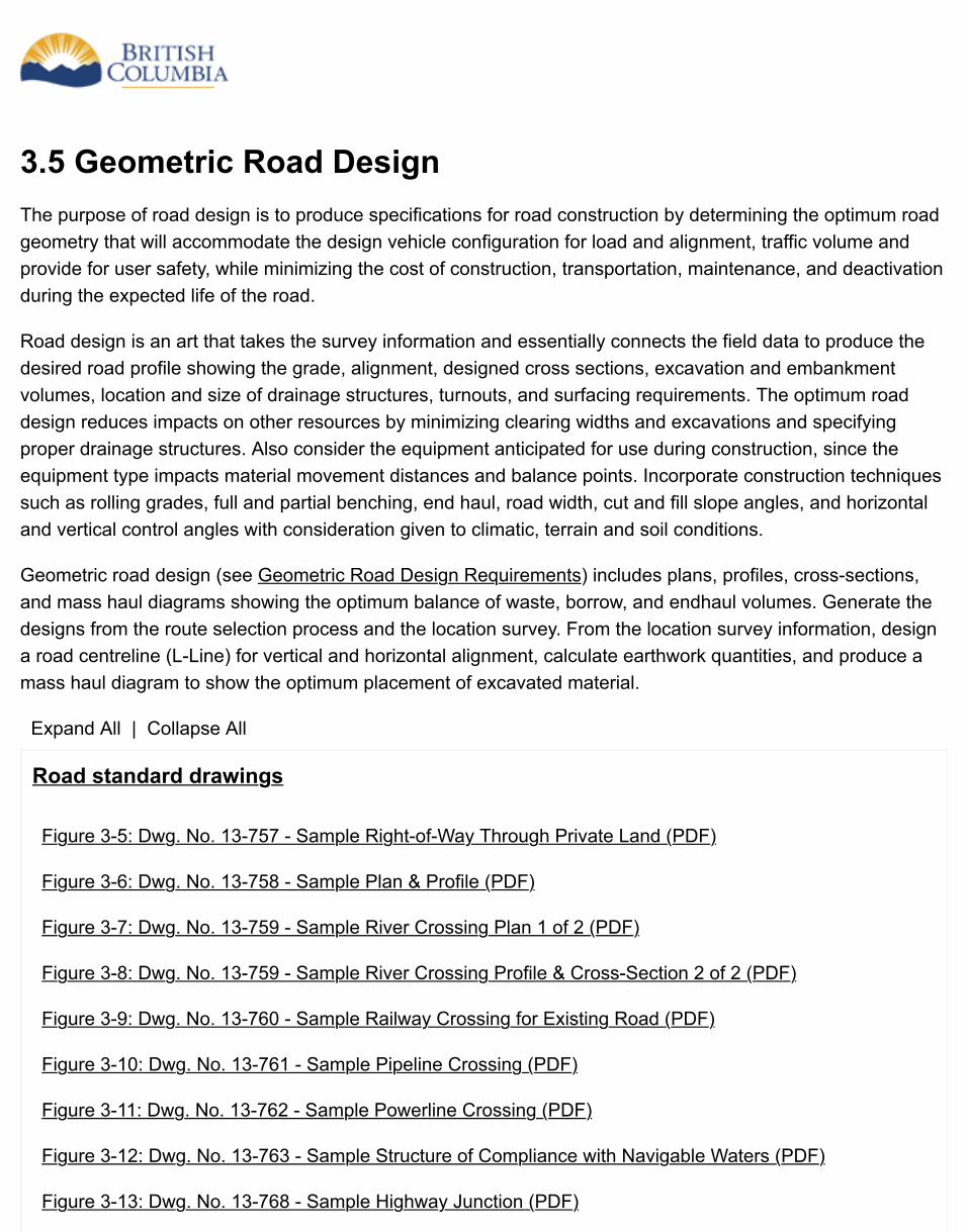
3.5 Geometric Road DesignThe purpose of road design is to produce specifications for road construction by determining the optimum roadgeometry that will accommodate the design vehicle configuration for load and alignment, traffic volume andprovide for user safety, while minimizing the cost of construction, transportation, maintenance, and deactivationduring the expected life of the road.
Road design is an art that takes the survey information and essentially connects the field data to produce thedesired road profile showing the grade, alignment, designed cross sections, excavation and embankmentvolumes, location and size of drainage structures, turnouts, and surfacing requirements. The optimum roaddesign reduces impacts on other resources by minimizing clearing widths and excavations and specifyingproper drainage structures. Also consider the equipment anticipated for use during construction, since theequipment type impacts material movement distances and balance points. Incorporate construction techniquessuch as rolling grades, full and partial benching, end haul, road width, cut and fill slope angles, and horizontaland vertical control angles with consideration given to climatic, terrain and soil conditions.
Geometric road design (see Geometric Road Design Requirements) includes plans, profiles, cross-sections,and mass haul diagrams showing the optimum balance of waste, borrow, and endhaul volumes. Generate thedesigns from the route selection process and the location survey. From the location survey information, designa road centreline (L-Line) for vertical and horizontal alignment, calculate earthwork quantities, and produce amass haul diagram to show the optimum placement of excavated material.
Expand All | Collapse All
Road standard drawings
Figure 3-5: Dwg. No. 13-757 - Sample Right-of-Way Through Private Land (PDF)
Figure 3-6: Dwg. No. 13-758 - Sample Plan & Profile (PDF)
Figure 3-7: Dwg. No. 13-759 - Sample River Crossing Plan 1 of 2 (PDF)
Figure 3-8: Dwg. No. 13-759 - Sample River Crossing Profile & Cross-Section 2 of 2 (PDF)
Figure 3-9: Dwg. No. 13-760 - Sample Railway Crossing for Existing Road (PDF)
Figure 3-10: Dwg. No. 13-761 - Sample Pipeline Crossing (PDF)
Figure 3-11: Dwg. No. 13-762 - Sample Powerline Crossing (PDF)
Figure 3-12: Dwg. No. 13-763 - Sample Structure of Compliance with Navigable Waters (PDF)
Figure 3-13: Dwg. No. 13-768 - Sample Highway Junction (PDF)
3.5.1 Design Planning Considerations
In order to meet the ever-increasing demand for access, be apprised of any multi- user needs: for example, oiland gas exploration, mining, power project, recreational, and public uses. These factors may influence thedesign widths, alignment, and grades beyond those required for forest access during harvesting. Use additionaland/or larger turnouts if heavy traffic is anticipated or there is potential for high recreational use of the road.Restrict utilities to only one side of the road to ensure that the road right-of-way has room to expand and beupgraded in the future.
Road maintenance can also be a significant factor to be recognized during road design. For example, access toretaining and catchment walls and spillways may be required once the road is built and, if the structures areinaccessible, this may increase the chance of being overlooked during inspections which may increase the costof maintenance.
Allow adequate room for equipment operation including snow removal and logging equipment. Largeequipment or operations often require additional road width and in the case of snow removal, for example, aplace to relocate snow and ice away from the roadway without damaging surrounding forest resources causedby trapping and diverting meltwater on sensitive slopes and not damaging signs, fences, and bridge guardrails.
When designing a road prism that includes excavation into side slopes or the placement of loads on the fillslopes, consider the nature of the soil and ground conditions, so that slope stability can be maintained. Inaddition to the immediate factors related to the slope, consider the road in the context of the overall area.
Ensure that the road is designed in the location identified by the layout and, where no exception has beenprovided in accordance with FPPR, the design places the road beyond the riparian management areas for eachstream.
Incorporate other information in the design, including prescriptions and assessments that relate to the roadlocation and design. These may include professional designs such as deep or steep excavations, retainingwalls, designs for stream crossings, bridge design and alignments, designs included in or based on terrainstability assessments, and specialized designs in rock cuts. For example, if a proposed road will cross areaswith a moderate or high likelihood of landslides as determined by a TSFA, incorporate measures to maintainslope stability into the geometric road design. Also, ensure that a road design on the Coast incorporates anyprotective measures prepared by an appropriately qualified professional as part of a gully process or fanstability assessment.
As a result, be aware of the intended use of the road, the timing of such use, construction techniques and othersurrounding design considerations as well as the following road design criteria.
3.5.2 Road Design Criteria
Consider the following factors in the road design:
Expand All | Collapse All
Clearing width
Keep the clearing widths as narrow as possible, to minimize impacts on other resources, but wide enoughto accommodate:
the road prism;user safety;decking of right-of-way timber;turnouts;subgrade drainage;subgrade stability;waste areas and endhaul areas;pits and quarries;landings;slash disposal;equipment operation;snow removal;fencing and other structures; andstanding timber root protection, especially on cut banks.
Move to a disposal site organic debris, rock, or other excess material that cannot be placed in the roadprism and within the clearing width because of terrain stability or other factors. Ensure such areas are ofsuitable size to accommodate the estimated volume of waste material and identify the areas in the roaddesign.
Calculate clearing widths on a station-by-station basis as part of a geometric road design. In situationswhere geometric road design is not required, use other methods as shown on page 179 in the ForestRoad Engineering Guidebook (PDF, 7.8MB).
Road alignment
Road design incorporates horizontal and vertical road alignments that provide for equipment use and foruser safety. This involves establishing:
appropriate travel speeds;appropriate maximum road grades;suitable stopping and sight distances;junctions with existing roads;road widths;turnouts; andappropriate traffic control devices.
Designed travel speeds often vary along forest roads due to terrain conditions or changing roadstandards. The cycle time or distance from the logging area to the dump or processing area may be animportant economic factor to consider in establishing an overall design speed. In other cases, topography
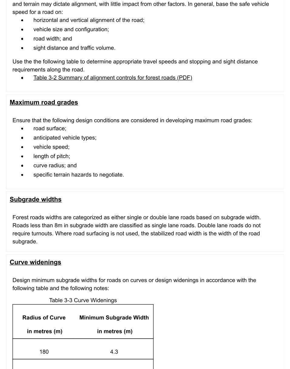
Table 3-3 Curve Widenings
Radius of Curve
in metres (m)
Minimum Subgrade Width
in metres (m)
180 4.3
and terrain may dictate alignment, with little impact from other factors. In general, base the safe vehiclespeed for a road on:
horizontal and vertical alignment of the road;vehicle size and configuration;road width; andsight distance and traffic volume.
Use the the following table to determine appropriate travel speeds and stopping and sight distancerequirements along the road.
Table 3-2 Summary of alignment controls for forest roads (PDF)
Maximum road grades
Ensure that the following design conditions are considered in developing maximum road grades:road surface;anticipated vehicle types;vehicle speed;length of pitch;curve radius; andspecific terrain hazards to negotiate.
Subgrade widths
Forest roads widths are categorized as either single or double lane roads based on subgrade width.Roads less than 8m in subgrade width are classified as single lane roads. Double lane roads do notrequire turnouts. Where road surfacing is not used, the stabilized road width is the width of the roadsubgrade.
Curve widenings
Design minimum subgrade widths for roads on curves or design widenings in accordance with thefollowing table and the following notes:
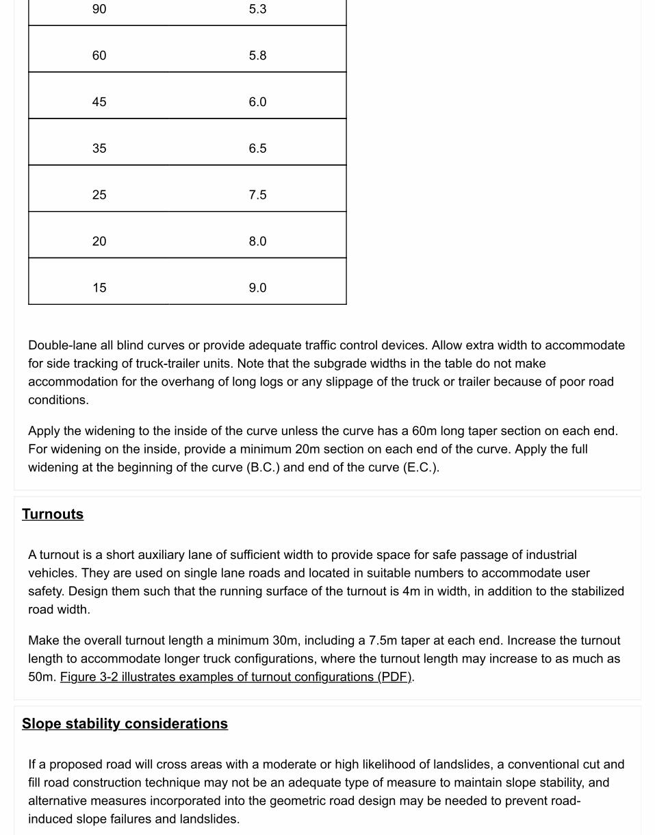
90 5.3
60 5.8
45 6.0
35 6.5
25 7.5
20 8.0
15 9.0
Double-lane all blind curves or provide adequate traffic control devices. Allow extra width to accommodatefor side tracking of truck-trailer units. Note that the subgrade widths in the table do not makeaccommodation for the overhang of long logs or any slippage of the truck or trailer because of poor roadconditions.
Apply the widening to the inside of the curve unless the curve has a 60m long taper section on each end.For widening on the inside, provide a minimum 20m section on each end of the curve. Apply the fullwidening at the beginning of the curve (B.C.) and end of the curve (E.C.).
Turnouts
A turnout is a short auxiliary lane of sufficient width to provide space for safe passage of industrialvehicles. They are used on single lane roads and located in suitable numbers to accommodate usersafety. Design them such that the running surface of the turnout is 4m in width, in addition to the stabilizedroad width.
Make the overall turnout length a minimum 30m, including a 7.5m taper at each end. Increase the turnoutlength to accommodate longer truck configurations, where the turnout length may increase to as much as50m. Figure 3-2 illustrates examples of turnout configurations (PDF).
Slope stability considerations
If a proposed road will cross areas with a moderate or high likelihood of landslides, a conventional cut andfill road construction technique may not be an adequate type of measure to maintain slope stability, andalternative measures incorporated into the geometric road design may be needed to prevent road-induced slope failures and landslides.
Examples of types of measures include:road relocation;site specific road construction techniques;methods to cross gullies and fish streamscut and fill slope angles;location and design of waste areas and endhaul areas;drainage control or installation of subsurface drainage; androad maintenance (including upgrading and modification), and deactivation strategies.
Examples of different road construction techniques that may be used in conjunction with appropriatedeactivation measures, include:
bench construction with no endhaul;oversteepened fills for single season use of the road;use of wood for fill support for short term roads;oversteepened cuts with modified drainage control to manage minor sloughing;bench construction with endhaul and replacement of finer material with coarse rock fill;full bench construction with 100% endhaul;retaining wall structures to support cut or fill slopes; andengineered fills that incorporate special requirements for compaction of the fill and reinforcementof the fill with geosynthetics.
Fill slope & cut slope angles
Design stable cut slopes, road fills, borrow pits, quarries, and waste areas in a manner that will notcontribute directly or indirectly to slope failures or landslides over the expected design life.
Table 3-4 General guidelines for cut and fill slope angles for use in forest road design (PDF)
Fill slopes
The stability of a fill slope depends on several variables, including the forces that tend to cause instability(gravitational and water pressure forces), and the forces that tend to oppose instability (e.g., shearstrength resistance of the soil or rock materials expressed as an internal friction angle or cohesion). Thestability of fill slope can be increased by incorporating various design and construction techniques.
Design fill slopes at or less than the “angle of repose.” The term “angle of repose” should be used in thecontext of loose, cohesionless soils only (e.g., non- plastic silt, sand, sand and gravel). Flatter side slopesin all types of soil will reduce the gravitational forces that tend to cause slope instability. For a fill slope incohesionless material, the angle of repose is about the same as the minimum value of that material’sangle of internal friction. Steeper fill slopes are more likely to cause a road-induced slope failure orlandslide than flatter fill slopes.
Compact the fill materials to increase the density and shearing resistance of the soil. The angle of internalfriction depends primarily on the relative density (loose versus dense), the particle shape (round versusangular), and the gradation (uniformly graded versus well graded). For relatively loose cohesionless soils,the minimum value of the angle of internal friction will range from about 27 degrees (2H : 1V) for roundeduniform soil grains to 37 degrees (1⅓H : 1V) for angular, well-graded soil grains. For relatively densecohesionless soils, the maximum value of the angle of internal friction will range from about 35 degrees(1.5H : 1V) for rounded uniform soil grains to 45 degrees (1H : 1V) for angular, well-graded soil grains.
Note: Fill slopes that are constructed at or less than the angle of repose (minimum angle of internalfriction) will not necessarily remain stable if partial or full saturation of the fill occurs. Such saturation canresult from surface and subsurface water flows during spring melt or after heavy periods of rainfall.
Expect that poorly drained fill materials will be prone to a greater likelihood of slope failure or sloughingthan well-drained fill materials. Additionally, the slopes of poorly drained fills at locations of significantzones of ground water seepage may experience larger and greater frequency of slope failures orsloughing problems. The significance of observed seepage zones might dictate the application of specialdrainage measures to reduce the likelihood of slope failure during construction and the intensity ofmaintenance activities over the operating life of the road. As a general rule, without special drainagemeasures, design the side slopes of poorly drained fills (e.g., fills composed of silty soils) at angles thatare flatter than the angle of repose to minimize the likelihood of slope failures.
Cut slopes
In the design of cut slopes, consider and address factors such as:the desired performance of the cut slopes;types of cut slope materials;overall terrain stability;engineering properties of soils;seepage conditions; andmaintenance.
In general, cut slopes will remain stable at slightly steeper angles than fill slopes constructed from like soilmaterials. The reason for this is the undisturbed soil materials in a cut are often in a denser state thansimilar type materials placed in a fill; and may contain sources of cohesive strength that further increasesthe shearing resistance of the soil.
Cut slopes designed at too flat an angle can be uneconomical in steep ground because of the largevolumes of excavation. Steeper cut slopes may be more economical to construct in terms of reducedvolumes of excavation. However, they can also be more costly from an operational standpoint becausethey require more maintenance due to sloughing and slumping.
For most forest roads, design cut slope angles to favour steeper angles to:reduce the length of cut slopes;minimize visible site disturbance; andreduce excavation costs;
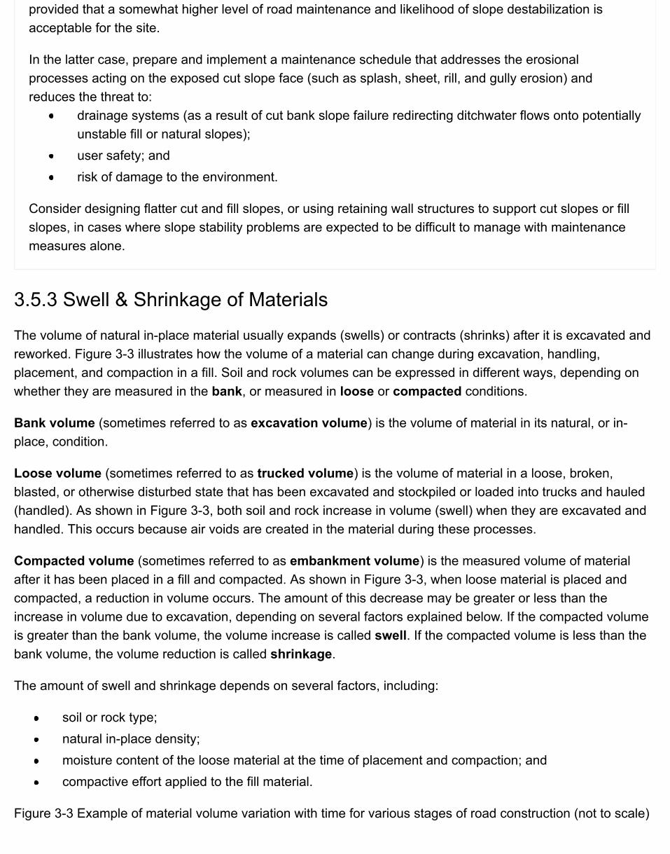
provided that a somewhat higher level of road maintenance and likelihood of slope destabilization isacceptable for the site.
In the latter case, prepare and implement a maintenance schedule that addresses the erosionalprocesses acting on the exposed cut slope face (such as splash, sheet, rill, and gully erosion) andreduces the threat to:
drainage systems (as a result of cut bank slope failure redirecting ditchwater flows onto potentiallyunstable fill or natural slopes);user safety; andrisk of damage to the environment.
Consider designing flatter cut and fill slopes, or using retaining wall structures to support cut slopes or fillslopes, in cases where slope stability problems are expected to be difficult to manage with maintenancemeasures alone.
3.5.3 Swell & Shrinkage of Materials
The volume of natural in-place material usually expands (swells) or contracts (shrinks) after it is excavated andreworked. Figure 3-3 illustrates how the volume of a material can change during excavation, handling,placement, and compaction in a fill. Soil and rock volumes can be expressed in different ways, depending onwhether they are measured in the bank, or measured in loose or compacted conditions.
Bank volume (sometimes referred to as excavation volume) is the volume of material in its natural, or in-place, condition.
Loose volume (sometimes referred to as trucked volume) is the volume of material in a loose, broken,blasted, or otherwise disturbed state that has been excavated and stockpiled or loaded into trucks and hauled(handled). As shown in Figure 3-3, both soil and rock increase in volume (swell) when they are excavated andhandled. This occurs because air voids are created in the material during these processes.
Compacted volume (sometimes referred to as embankment volume) is the measured volume of materialafter it has been placed in a fill and compacted. As shown in Figure 3-3, when loose material is placed andcompacted, a reduction in volume occurs. The amount of this decrease may be greater or less than theincrease in volume due to excavation, depending on several factors explained below. If the compacted volumeis greater than the bank volume, the volume increase is called swell. If the compacted volume is less than thebank volume, the volume reduction is called shrinkage.
The amount of swell and shrinkage depends on several factors, including:
soil or rock type;natural in-place density;moisture content of the loose material at the time of placement and compaction; andcompactive effort applied to the fill material.
Figure 3-3 Example of material volume variation with time for various stages of road construction (not to scale)
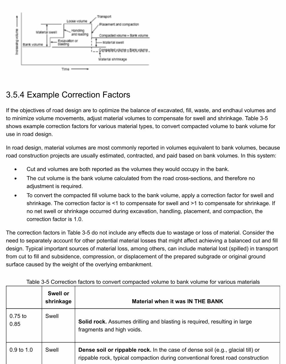
3.5.4 Example Correction Factors
If the objectives of road design are to optimize the balance of excavated, fill, waste, and endhaul volumes andto minimize volume movements, adjust material volumes to compensate for swell and shrinkage. Table 3-5shows example correction factors for various material types, to convert compacted volume to bank volume foruse in road design.
In road design, material volumes are most commonly reported in volumes equivalent to bank volumes, becauseroad construction projects are usually estimated, contracted, and paid based on bank volumes. In this system:
Cut and volumes are both reported as the volumes they would occupy in the bank.The cut volume is the bank volume calculated from the road cross-sections, and therefore noadjustment is required.To convert the compacted fill volume back to the bank volume, apply a correction factor for swell andshrinkage. The correction factor is <1 to compensate for swell and >1 to compensate for shrinkage. Ifno net swell or shrinkage occurred during excavation, handling, placement, and compaction, thecorrection factor is 1.0.
The correction factors in Table 3-5 do not include any effects due to wastage or loss of material. Consider theneed to separately account for other potential material losses that might affect achieving a balanced cut and filldesign. Typical important sources of material loss, among others, can include material lost (spilled) in transportfrom cut to fill and subsidence, compression, or displacement of the prepared subgrade or original groundsurface caused by the weight of the overlying embankment.
Table 3-5 Correction factors to convert compacted volume to bank volume for various materials
Swell or
shrinkage Material when it was IN THE BANK
0.75 to0.85
SwellSolid rock. Assumes drilling and blasting is required, resulting in largefragments and high voids.
0.9 to 1.0 Swell Dense soil or rippable rock. In the case of dense soil (e.g., glacial till) orrippable rock, typical compaction during conventional forest road construction
will result in swell.
1.0 to 1.15 ShrinkageCompact to loose soil. Lower correction factors are more appropriate forcoarse-grained soils (e.g., sand, sandy gravel, or mixtures of gravel, sand, silt,and clay). Higher correction factors are more appropriate for fine-grained soils(e.g., silt and clay). It is more possible to achieve shrinkage during conventionalforest road construction if the soil in the bank was in a loose condition.
For example, a correction factor of 1.0 (i.e., no shrinkage) may be appropriatefor compact sands and gravels, whereas a correction factor of 1.15 may beappropriate for very loose silts.
Notes Table 3-5:
1. The "example correction factors" are applicable to forest road design purposes only. They assumecompaction typically achieved during conventional forest road construction, and different correction factorscould apply for engineered fills, placed and compacted to achieve the highest material density possible.Because of the variability of natural materials and their conditions in the bank, the potential for materialloss during handling, and the range of road construction methods, correction factors are best determinedfrom experience and local knowledge.
2. The example correction factors are based on swell or shrinkage effects due to an increase or decrease inthe density of the soil or rock materials, and do not include any effects of potential wastage or loss ofmaterial from other sources.
Example
Bank volume = compacted volume x correction factor.
Example: If the compacted volume of shot rock is 12 m3 measured from drawings, how much bank volumeneeds to be drilled, blasted, and excavated to achieve this volume? Assume a correction factor of 0.75.
Solution: Bank volume = 12 m3 x 0.75 = 9 m3
Surfacing often depends on the material available within an economic haul distance and intended season ofuse. Rock ballast roads may require minimal surfacing material while other roads require extensive surfacingfor year round use. Consider the surfacing depth during the road design process. The depth of surfacing isdependent on the stabilization of the subgrade and the ability to carry design loads.
Table 3-6 Guidelines for maximum culvert spacing for forest roads
Erosion hazard Slight Moderate High
More than 50% bysoil type
Hardpan, rock,course gravels
Finegravels
Sands, silts,clays
Road gradient
3.6 Culvert DesignCulvert drainage design encompasses the selection of culvert materials, backfill requirements, scour protection,roadway alignment and adequate sizing to pass the expected flows. The information contained in this chapteris focused on design considerations, site selection, and design flows relevant to non-major stream crossingculverts.
Log culvert design and ford design are covered in the following sections:
3.6.1 Log Culvert Design3.6.2 Ford Design & Construction on Non-Fish Streams
If the site is a fish stream or a potential fish stream, consult the Fish-Stream Crossing Guidebook (PDF, 4.2MB)for site and design requirements.
3.6.3 Design Considerations
Design stream culverts to pass the highest peak flow of the stream that can be reasonably be expected basedon the anticipated length of time the culvert will remain on the site. For culverts anticipated to remain on siteless than three (3) years, design for a peak flow return period of 10 years and all others for the 100-year peakflow return period. Note that there is no consideration of replacing the structure after these periods.
Determine the culvert length (measured along the invert) from the distance between the toes of theembankment, plus 1m in gravelly soils or 2m in silty soils.
3.6.4 Cross Drain Culverts
Cross drain culverts are used to carry ditchwater from one side of the road to the other and spaced at intervalsnecessary to minimize erosion of the roadside ditchline.
Use the distances in Table 3-6 as a guide to the maximum spacing for cross-drain culverts between establishedwatercourses.
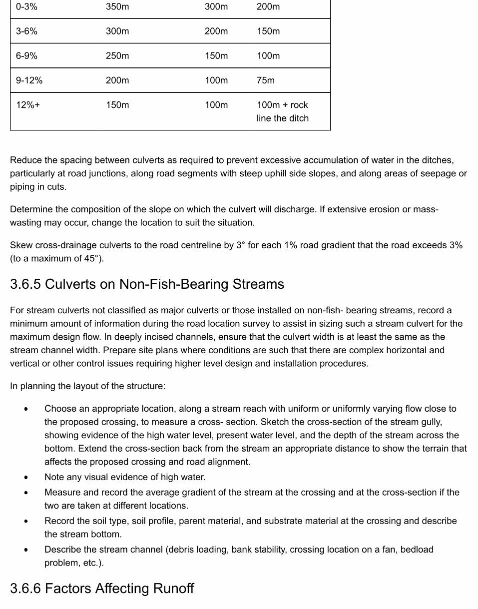
0-3% 350m 300m 200m
3-6% 300m 200m 150m
6-9% 250m 150m 100m
9-12% 200m 100m 75m
12%+ 150m 100m 100m + rockline the ditch
Reduce the spacing between culverts as required to prevent excessive accumulation of water in the ditches,particularly at road junctions, along road segments with steep uphill side slopes, and along areas of seepage orpiping in cuts.
Determine the composition of the slope on which the culvert will discharge. If extensive erosion or mass-wasting may occur, change the location to suit the situation.
Skew cross-drainage culverts to the road centreline by 3° for each 1% road gradient that the road exceeds 3%(to a maximum of 45°).
3.6.5 Culverts on Non-Fish-Bearing Streams
For stream culverts not classified as major culverts or those installed on non-fish- bearing streams, record aminimum amount of information during the road location survey to assist in sizing such a stream culvert for themaximum design flow. In deeply incised channels, ensure that the culvert width is at least the same as thestream channel width. Prepare site plans where conditions are such that there are complex horizontal andvertical or other control issues requiring higher level design and installation procedures.
In planning the layout of the structure:
Choose an appropriate location, along a stream reach with uniform or uniformly varying flow close tothe proposed crossing, to measure a cross- section. Sketch the cross-section of the stream gully,showing evidence of the high water level, present water level, and the depth of the stream across thebottom. Extend the cross-section back from the stream an appropriate distance to show the terrain thataffects the proposed crossing and road alignment.Note any visual evidence of high water.Measure and record the average gradient of the stream at the crossing and at the cross-section if thetwo are taken at different locations.Record the soil type, soil profile, parent material, and substrate material at the crossing and describethe stream bottom.Describe the stream channel (debris loading, bank stability, crossing location on a fan, bedloadproblem, etc.).
3.6.6 Factors Affecting Runoff
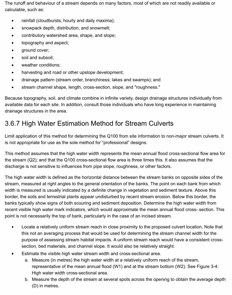
The runoff and behaviour of a stream depends on many factors, most of which are not readily available orcalculable, such as:
rainfall (cloudbursts; hourly and daily maxima);snowpack depth, distribution, and snowmelt;contributory watershed area, shape, and slope;topography and aspect;ground cover;soil and subsoil;weather conditions;harvesting and road or other upslope development;drainage pattern (stream order, branchiness; lakes and swamps); andstream channel shape, length, cross-section, slope, and "roughness."
Because topography, soil, and climate combine in infinite variety, design drainage structures individually fromavailable data for each site. In addition, consult those individuals who have long experience in maintainingdrainage structures in the area.
3.6.7 High Water Estimation Method for Stream Culverts
Limit application of this method for determining the Q100 from site information to non-major stream culverts. Itis not appropriate for use as the sole method for “professional” designs.
This method assumes that the high water width represents the mean annual flood cross-sectional flow area forthe stream (Q2); and that the Q100 cross-sectional flow area is three times this. It also assumes that thedischarge is not sensitive to influences from pipe slope, roughness, or other factors.
The high water width is defined as the horizontal distance between the stream banks on opposite sides of thestream, measured at right angles to the general orientation of the banks. The point on each bank from whichwidth is measured is usually indicated by a definite change in vegetation and sediment texture. Above thisborder, the soils and terrestrial plants appear undisturbed by recent stream erosion. Below this border, thebanks typically show signs of both scouring and sediment deposition. Determine the high water width fromrecent visible high water mark indicators, which would approximate the mean annual flood cross- section. Thispoint is not necessarily the top of bank, particularly in the case of an incised stream.
Locate a relatively uniform stream reach in close proximity to the proposed culvert location. Note thatthis not an averaging process that would be used for determining the stream channel width for thepurpose of assessing stream habitat impacts. A uniform stream reach would have a consistent cross-section, bed materials, and channel slope. It would also be relatively straight.Estimate the visible high water stream width and cross-sectional area.
a. Measure (in metres) the high water width at a relatively uniform reach of the stream,representative of the mean annual flood (W1) and at the stream bottom (W2). See Figure 3-4:High water width cross-sectional area.
b. Measure the depth of the stream at several spots across the opening to obtain the average depth(D) in metres.
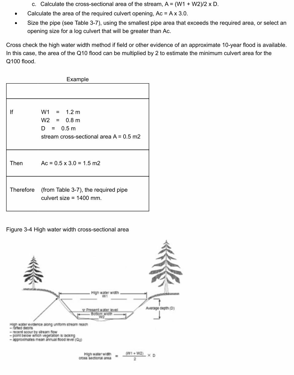
Example
If W1 = 1.2 mW2 = 0.8 mD = 0.5 mstream cross-sectional area A = 0.5 m2
Then Ac = 0.5 x 3.0 = 1.5 m2
Therefore (from Table 3-7), the required pipeculvert size = 1400 mm.
c. Calculate the cross-sectional area of the stream, A = (W1 + W2)/2 x D.Calculate the area of the required culvert opening, Ac = A x 3.0.Size the pipe (see Table 3-7), using the smallest pipe area that exceeds the required area, or select anopening size for a log culvert that will be greater than Ac.
Cross check the high water width method if field or other evidence of an approximate 10-year flood is available.In this case, the area of the Q10 flood can be multiplied by 2 to estimate the minimum culvert area for theQ100 flood.
Figure 3-4 High water width cross-sectional area
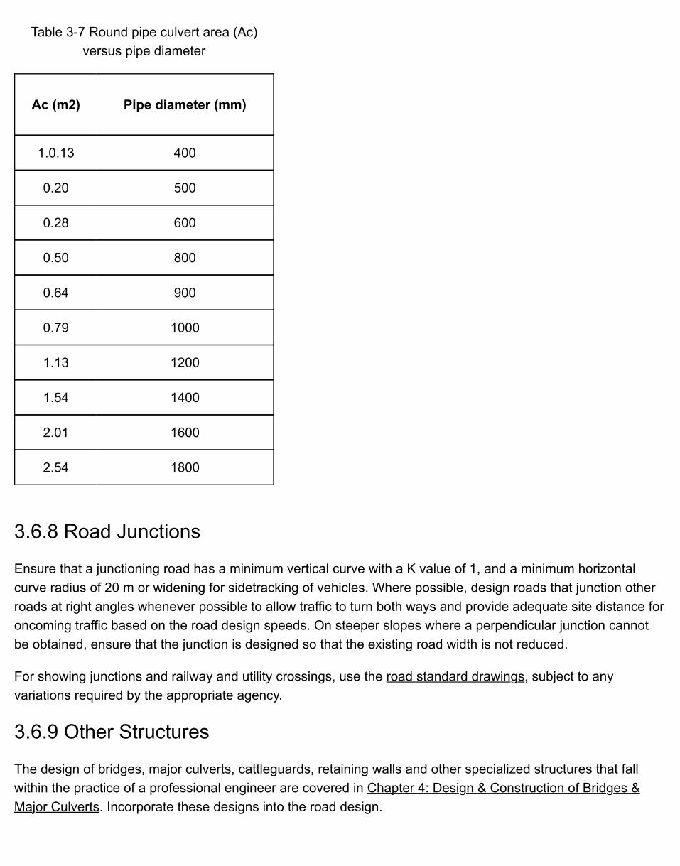
Table 3-7 Round pipe culvert area (Ac)versus pipe diameter
Ac (m2) Pipe diameter (mm)
1.0.13 400
0.20 500
0.28 600
0.50 800
0.64 900
0.79 1000
1.13 1200
1.54 1400
2.01 1600
2.54 1800
3.6.8 Road Junctions
Ensure that a junctioning road has a minimum vertical curve with a K value of 1, and a minimum horizontalcurve radius of 20 m or widening for sidetracking of vehicles. Where possible, design roads that junction otherroads at right angles whenever possible to allow traffic to turn both ways and provide adequate site distance foroncoming traffic based on the road design speeds. On steeper slopes where a perpendicular junction cannotbe obtained, ensure that the junction is designed so that the existing road width is not reduced.
For showing junctions and railway and utility crossings, use the road standard drawings, subject to anyvariations required by the appropriate agency.
3.6.9 Other Structures
The design of bridges, major culverts, cattleguards, retaining walls and other specialized structures that fallwithin the practice of a professional engineer are covered in Chapter 4: Design & Construction of Bridges &Major Culverts. Incorporate these designs into the road design.
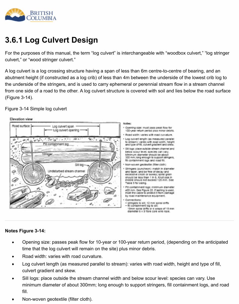
3.6.1 Log Culvert DesignFor the purposes of this manual, the term “log culvert” is interchangeable with “woodbox culvert,” “log stringerculvert,” or “wood stringer culvert.”
A log culvert is a log crossing structure having a span of less than 6m centre-to-centre of bearing, and anabutment height (if constructed as a log crib) of less than 4m between the underside of the lowest crib log tothe underside of the stringers, and is used to carry ephemeral or perennial stream flow in a stream channelfrom one side of a road to the other. A log culvert structure is covered with soil and lies below the road surface(Figure 3-14).
Figure 3-14 Simple log culvert
Notes Figure 3-14:
Opening size: passes peak flow for 10-year or 100-year return period, (depending on the anticipatedtime that the log culvert will remain on the site) plus minor debris.Road width: varies with road curvature.Log culvert length (as measured parallel to stream): varies with road width, height and type of fill,culvert gradient and skew.Sill logs: place outside the stream channel width and below scour level: species can vary. Useminimum diameter of about 300mm; long enough to support stringers, fill containment logs, and roadfill.Non-woven geotextile (filter cloth).

Table 3-8 Peak flows for various log culvert lifespans
Stringers (puncheon): match in diameter and taper, and be free of decay and excessive crook orsweep; spiral grain should be less than 1 in 8. Knot size in middle is less than 125mm. See Table 3-8for sizing.Fill containment logs: minimum diameter 400mm. See Figure 3-15. If lashing is used, inset the cable toprotect it from damage by road maintenance equipment.Connections:Stringers to sill; 12mm spiral driftsFill containment log to sill: 19mm spiral drifts or four wraps of 19mm diameter 6 x 9 fibre core wire ropeInlet control: place shot rock to protect against fill erosion below the design flood level.Outlet control: place rock as required to prevent outlet scouring and undermining of the sill logs.In the case of a skewed log culvert, measure the span of the stringers for design purposes frombearing to bearing along the stringers and not at right angles to the sill logs.
Consider log culverts for:
streams where other resource agencies require the culvert to be open bottomed; andsteep gradient streams.
Where the planned service life of the road is less than the life expectancy of the drainage structurecomponents, consider using log culverts:
as temporary structures on tote roads or pilot trails;on roads where ongoing minor debris problems are anticipated; andon permanent roads as temporary drainage structures at the clearing or subgrade construction stage,until the permanent drainage structures are installed.
Ensure that a log culvert design addresses the following:
opening size for design flow and debris management;culvert length and fill and surfacing requirements;superstructure design (stringer or puncheon sizing);substructure design (sills, mud sills, and foundation logs); andinlet and outlet protection requirements.
Expand All | Collapse All
Log culvert opening size
To meet current legislative requirements, design a log culvert to pass the highest peak flow of the streamthat can reasonably be expected within the following return periods specified below for the length of time itis anticipated that the log culvert will remain on site (see FPPR section 74). For methods to estimate thevalue of Q10 and Q100, design discharge of a creek see Figure 3-3: High water estimation method forstream culverts in this chapter and Chapter 4: Design Discharge Criteria.

Anticipated period that the log culvert will remain on the sitePeak flow return
period
For a log culvert that will remain on site for up to 3 years 10 years (i.e., Q10)
For a log culvert that will remain on site for over 3 years 100 years (i.e., Q100)
For a log culvert within a community watershed that will remain on site forover 3 years
100 years (i.e., Q100)
A log culvert is a type of open bottom structure, designed to span the stream channel width. This isparticularly important on fish-bearing streams to avoid impacts on fish habitat and fish passage - refer tothe section on “Open bottom culverts” in the Fish-Stream Crossing Guidebook (PDF, 4.2MB) page 6.
In addition to passing the required peak flow discharge, design log culverts to manage anticipated debris.Options may include, but are not limited to:
increasing the opening size (height and/or width);allowing debris to pass over the approaches;trapping debris with a specially fitted trash rack or other device; andcombining these and other options.
Inspect debris catchment devices frequently and clean them as required. The criteria for design of anydebris catchment device are site-specific and may incorporate professional input. Identify debris problemsfrom terrain hazard maps, air photo interpretations, field investigations, and reports for the area - see theGully Assessment Procedure Guidebook (PDF, 1.8MB).
The convention for specifying the opening size (inside measurements) of a log culvert is height (verticaldistance between the deepest point along the channel floor and the soffit of the stringers) followed by thewidth (horizontal distance measured at right angles between the inside face of the sill logs).
Log culvert length
Culvert length, as measured in the direction of the stream, is determined by the following:road width;depth of road fill over the log culvert, and fill slope angles;type of fill over the log culvert;inlet and outlet treatments;culvert gradient; andculvert skew.
Road width
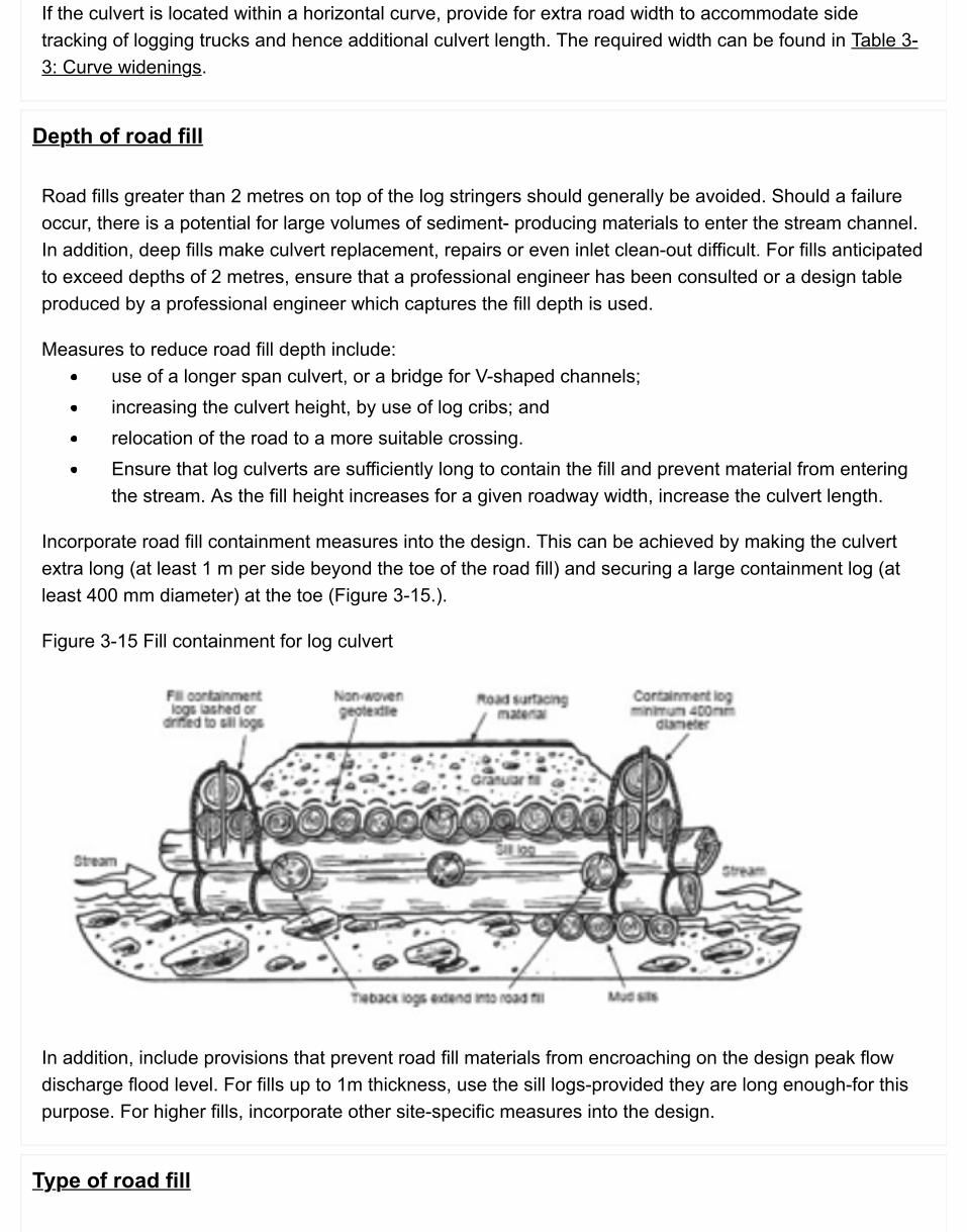
If the culvert is located within a horizontal curve, provide for extra road width to accommodate sidetracking of logging trucks and hence additional culvert length. The required width can be found in Table 3-3: Curve widenings.
Depth of road fill
Road fills greater than 2 metres on top of the log stringers should generally be avoided. Should a failureoccur, there is a potential for large volumes of sediment- producing materials to enter the stream channel.In addition, deep fills make culvert replacement, repairs or even inlet clean-out difficult. For fills anticipatedto exceed depths of 2 metres, ensure that a professional engineer has been consulted or a design tableproduced by a professional engineer which captures the fill depth is used.
Measures to reduce road fill depth include:use of a longer span culvert, or a bridge for V-shaped channels;increasing the culvert height, by use of log cribs; andrelocation of the road to a more suitable crossing.Ensure that log culverts are sufficiently long to contain the fill and prevent material from enteringthe stream. As the fill height increases for a given roadway width, increase the culvert length.
Incorporate road fill containment measures into the design. This can be achieved by making the culvertextra long (at least 1 m per side beyond the toe of the road fill) and securing a large containment log (atleast 400 mm diameter) at the toe (Figure 3-15.).
Figure 3-15 Fill containment for log culvert
In addition, include provisions that prevent road fill materials from encroaching on the design peak flowdischarge flood level. For fills up to 1m thickness, use the sill logs-provided they are long enough-for thispurpose. For higher fills, incorporate other site-specific measures into the design.
Type of road fill
To maximize fill slope angles and minimize culvert length, use shot rock or granular pit-run material for thefill material placed over a log culvert. Avoid the use of silty and clayey materials because these materialsrequire flatter fill slope angles (and therefore longer slope lengths) to maintain fill slope stability andincrease the potential for sedimentation.
Log culvert gradient
For stream gradients less than 10%, place the stringer soffit (culvert soffit) at 0% grade or at or near thesame gradient as the stream. Should the proposed culvert soffit gradient (not the stream channelgradient), exceed 10%, then apply other structural considerations.
Channel gradients
Channel gradients less than 10%: A cross-sectional sketch of the culvert, the fill, and a profile of thestream bed provide the best tools for determining log culvert length. Measure the required length directlyfrom a sketch drawn to scale.
Channel gradients greater than 10%: Measure the length directly from the cross-sectional sketch for thestream.
Inlet and outlet treatments
Incorporate headwalls or sill logs into log culvert design, allowing vertical end fills and therefore reducedculvert length.
Length for skewed culverts
Where a culvert crosses the roadway at other than a right angle to the road centreline, allow for theincreased culvert length caused by this skew.
Log culvert stringer selection
Stringer sizing involves selection of the appropriate log diameter and species to be used for the stringers.Table 3-9 (PDF) is an example of a log stringer sizing table developed by a professional engineer. Table 3-9 presents stringer sizing for log culverts, as a function of span (see Figure 3-15), total fill depth, loggingtruck axle loads (e.g., L75), and log species. In this professionally engineered table, the total fill depth isthe combined thickness of road surfacing and underlying road fill materials that extend down to the top ofthe stringers. The log diameters given in Table 3-9 are minimum mid-diameters, which are measured atmid-span under the bark. The total fill depth ranges from a minimum of 300mm to a maximum of 2m forthis table.
If the design discharge is 6 m3/sec or greater, or the road fill depth is greater than 2m, ensure that aprofessional engineer has been consulted or a design table produced by a professional engineer whichcaptures the fill depth is used.
Use oversize logs to account for unseen flaws, to give added strength for overloads and general heavyuse, and to extend the service life of the structure. For maximum service life, use sound western redcedar. Fill containment logs contain the fill or road surfacing and can be structural or non-structural. Firstly,place a geosynthetic over the stringers to prevent surfacing or fill material from migrating between thestringers and into the watercourse.
Log culvert substructure design
The substructure required depends on the bearing capacity of the foundation soils and the length anddiameter of the logs available. Choice of substructure is based on an estimate of the bearing strength ofthe soil at the site. From this, determine the diameter and length of the logs needed to support the designloads. Refer to FPInnovations’ Log Bridge Construction Handbook (1980) for a detailed explanation of thistopic.
Single sill logs
Use single sill logs as culvert foundations if the ground is firm and the sill log provides sufficient clearancefor the design flood and debris passage. Use a minimum diameter for sill logs of about 300mm. For shortservice-life culverts (planned for less than three years use), almost any species of wood will suffice for thesill logs, provided it is sound throughout. However, it is very important that the anticipated life-span of theroad be well thought-out. If there is a good chance that the life of the road will be extended, design andconstruct a culvert with a longer service-life.
The expected service life for sill logs is as follows (subject to site-specific soil and climatic conditions):Cedar (sound, with preservatives applied to cut surfaces): 20 years plus;Douglas-fir: 8-10 years;Spruce, hemlock and balsam: 4-6 years; andHardwood species: Variable but assume it is less than four (4) years.
Table 3-9 Log culvert stringer sizing table (PDF)
Mud sills
If the natural ground will not support the culvert loads on a single sill log, increase the load-bearing areawith the use of mud sills. These are short logs, 250mm (or larger) in diameter, and 1m to 6m in length,placed at right angles under the sill log for the entire length of the sill.
For crossings on soft ground, on non-fish bearing streams, another option is to extend the mudsillscompletely across the channel to and beneath the other sill log. This increases the stability of thestructure. It is important that the mudsills be placed below the scour level.

Log culvert inlet and outlet protection
Where the sill logs for log culverts are placed outside the stream channel and bedded below scour level,do not provide for additional inlet and outlet protection. If there is a concern about erosion around the inletor outlet, protect any erodible surfaces with rock to a level equivalent to the design flood. Provide at somesites an individually designed settling or debris catchment basin at the inlet.
Inlet protection for cross-drain log culverts: Inlet protection for cross-drain log culverts will normally beachieved with a ditch block to ensure that ditchwater is directed into the log culvert and not past it. In mostcases, use a catch basin to trap sediment and debris. For cross-drain culverts on a steep road grade,consider lining the ditch block, catchment basin, and the bottom of the channel with rock to minimizescouring.
Outlet protection for cross-drain log culverts: Do not consider placing log culverts on top of erodiblefills. Direct ditch flows onto erosion-resistant areas or onto outlet protection such as flumes or riprapaprons. Do not direct ditch water flows onto unprotected sidecast material unless it is composed of rock orother erosion-resistant materials. On steeper slopes, erosion control at the culvert outlet is a designchallenge. One option is to provide extensive outlet protection down the slope to an erosion-free area.

3.6.2 Ford Design & Construction on Non-Fish StreamsA ford is a dip in a road constructed to facilitate crossing a stream. The objective of a ford is to maintaindrainage and provide a safe, erosion-free, and storm-proof crossing that requires little or no maintenance. Inthe past, inappropriate location and design of fords, and uncontrolled use, has led to a number of negativeenvironmental impacts. These include increased sediment delivery, and degraded water quality downstream.
In isolated locations where maintenance equipment may not be available on a continuing basis, properlydesigned and constructed fords require little maintenance, and can be effective in reducing adverse impacts indrainage systems that are prone to debris flows or debris floods (Figure 3-16). Consider the use of fords forareas of low traffic and intermittent use. Consider them as alternatives to bridges or culverts only where thecrossings would not result in negative environmental impacts and where traffic use is confined to low-flowperiods. Do not consider using a ford if the crossing is expected to be subjected to extensive or year-roundtraffic.
Figure 3-16 Road profile (stream crossing)
Figure 3-17 Road cross-section (stream profile)

Ford Planning
Identify fords in the planning stage of road development to ensure that the required design and measuresinclude appropriate road grades leading into and out of the stream crossing.
Prior to planning a ford, evaluate the stream to ensure that it is not a fish stream. Refer to the Fish-StreamCrossing Guidebook (PDF, 4.2MB) for limitations on the use of fords on fish streams.
When planning a ford, and establishing design criteria, determine if any of the following possible user safetyrestrictions (or combination of restrictions) will apply to the stream crossing:
the design vehicle will only be able to cross the ford during certain months of the year;the design vehicle will not be able to cross the ford during periods of specific maximum stream flows;only certain types of vehicles will be able to cross the ford; andonly certain specific road uses will be considered for ford applications (such as industrial use).
Each proposed ford design is unique, but the objectives of any design are to:
pass the design peak flow;minimize downstream erosion of the stream;prevent sediment input into the stream from the approaches and associated ditches;provide a suitable road profile to accommodate safe passage of the design vehicle;ensure that the stream remains in its channel and cannot be diverted down the road or ditches; andensure that the ford will either pass channel debris-the preferable option-or trap it.
Ford Design
For a ford, the road profile dips into and out of the stream, creating a concave shape sufficient to ensure thatthe stream cannot be diverted away from its natural channel and down the road.
Ensure that the anticipated design vehicle can negotiate vertical and horizontal curves at the proposed ford.Where it is practical to do so, design the approaches to be at right angles to the stream.
Check the debris flow history of the stream channel:
on air photos;on terrain stability maps or terrain stability field assessments; andin the field and considering local knowledge.
For further information, refer to the Gully Assessment Procedures Guidebook (PDF, 1.8MB).
If there is a debris flow hazard, decide whether the ford should be designed to:
trap the debris, orallow the debris to pass over the ford (the preferred option).
The size and shape of the largest cobbles or boulders in the stream channel indicates the minimum size of rockrequired to resist movement when the stream is in flood, and thus provides a guide to the minimum size of rockto be used to construct the ford. The more angular the rock (such as shot rock), the more resistant it will be tomoving.
In some situations, the use of a ford may be restricted to low-flow periods when the flow is subsurface. Designa low-flow culvert to pass the anticipated low flow. With this design, peak flows and debris flow over the top ofthe ford, resulting in some increased annual maintenance. Use a sufficient size of running surface material toresist erosion.
Design methods are available for determining flow rates through voids in rock fills. Such voids may plug up withsediment and debris, so design the dip in the road profile to accommodate the peak flow discharge based onconsiderations similar to those applied to the design of a bridge or culvert.
Design Approval Requirements
Prepare sketches of the ford design, showing:
the road profile, extending at least 50 m at each end beyond the wetted perimeter at the design peakflow discharge;the width and depth of the wetted surface during;those months when use of the road is anticipated;design peak flow level and an estimate of debris volumes to be passed or trapped;annual low-flow level, or the flow levels for the periods of anticipated use;the range and average size of the material in the stream channel and its shape (angular, semi-angular,or rounded);the minimum width of the road running surface required to accommodate anticipated traffic;the requirements for any erosion-resistant materials for the road running surface, such as shot rockand concrete cross-ties, including use of any geosynthetics, to help separate different types andgradations of road fill materials;the rock source, size, and volume requirements;

the length, width, and depth of the upstream catchment basin if one is proposed;the type and dimensions of the low-flow culvert, if one is proposed; andthe length of apron to be surfaced with erosion resistant material.

3.7 Geometric Road Design Requirements
A geometric road design must be carried out for all roads that will cross areas with a moderate or highlikelihood of landslides. In those areas of potentially unstable terrain, incorporate measures to maintain slopestability into the geometric road design (including where necessary for protecting workers in excavationsgreater than 6m). These measures rarely allow for the most optimum balance of waste, borrow, and endhaulvolumes.
In addition to the above, carry out a geometric road design:
other than the foregoing situations, on side slopes greater than 50%, to facilitate construction andcontrol materials movements during construction, or to minimize impacts on alienated land and otherresources. It is recognized that when encountering short sections (i.e. <100 metres) of stable terrainalong a corridor where a geometric road design would not otherwise be required, it may be impracticalto mobilize a survey crew just for those short sections. In such situations, information from the fieldreconnaissance report would be utilized.on higher order roads or road sections where alignment constraints are particularly important toachieve, particularly for addressing the safety of road users.
In geometric road design, select specifications for road width, cut and fill slope angles, and horizontal andvertical control angles to match the required road standard. Design a road centreline location (L-Line) based oninformation from the location survey and reconnaissance report. Calculate earthwork volumes or quantities.
In addition to the design requirements previously mentioned, ensure that a geometric road design provides:
plans and profiles (see the road standard drawings for recommended content and layout);cross-sections with road prism templates;mass diagrams with balance lines;appropriate expansion and shrinkage factors for the material types;a schedule of quantities and units of measure for clearing, grubbing, excavating (other material androck), and graveling;planned movement and placement of materials (balancing of design);the location and size of required drainage structures such as culverts and bridges;the location and size of retaining walls or specialized roadway structures;clearing widths (generally tabular in variable widths);construction equipment considered in the design for material movements;estimated material costs;location survey alignment and designed centreline (L-Line) offsets, and clearing width offsets shown onthe site plan;

slope stake information (note that this information is only a guide and slope/grade stakes should becalculated and placed based on design or re- design cuts and fills at centreline);measures required for reducing potential impacts on other resource values;site-specific design and construction notes and prescriptions on, for example, the location of endhaulsections, borrow pits, waste and slash disposal areas, and full bench cut areas, and any otherinformation that the designer considers useful to the road builder;measures to maintain slope stability if the road will cross areas with a moderate or high likelihood oflandslides as determined by a TSFA; andinformation that the designer considers useful to the road builder or owner.
Whenever possible, allow for the use of waste or spoil material in ways that reduce endhauling requirements.For example, some material types may be used for the road subgrade, base course, turnouts, curve widenings,and embankment (fill). If these options are not available, or if the excess material consists of overburden anddebris, then identify spoil sites as close to the construction area as possible. Abandoned quarries, gravel pits,and roads are some possibilities for spoil sites. Alternatively, evaluate stable areas in gentle or benched terrainfor use as spoil sites.
3.8 Survey & Design Outputs - Road PlansThe output of survey and design is the road plan, which may include:
a list of documents that make up the road plan;a map showing the road location with key control points;project specific road design and construction standards or reference to an appropriate design andconstruction standard;any special conditions on use of certain road sections; for example, seasonal or weather limitationsbeyond normal operating conditions;assumed or documented ground conditions;cross-sections displaying road width, cut and fill slopes and surfacing depth;plan and profile views displaying:
vertical and horizontal alignmentlocation of field reference points (for example, private property boundaries)location, type and size of drainage structureslocations of special design sections (for example, retaining structures)locations and dimensions of turnoutslocations of landings, pits, quarries and spoil sitessites of specific concern for construction; for example, potentially unstable terrain, fishstreams, karst featureslocations of nonconventional construction sections such as endhaul sectionsclearing width
excavation and embankment volumes;probable material type (soil, rock, organic overburden etc);mass haul diagrams;surfacing requirements, where applicable;locations of signs, fences and roadside barriers;specialist assessments, recommendations or designs (e.g. TSAs, crossing designs and engineeredstructures);identification of required field reviews (e.g. confirmation of assumed ground conditions, reviews toensure conformance to specialist assessments, recommendations or designs);notification requirements required by others such as regulatory agencies or other parties;descriptions of any field surveys to be done before or during construction;communication of assumed ground conditions and protocol if unexpected groundconditions are encountered;

provisions for worker safety as required by applicable Occupational Health Safety Regulations or asrequired to mitigate other potential hazards;instructions for specific construction procedures required to implement any aspects of the design; forexample, traffic control measures and timing of the works;written procedures or references to SOPs that are intended to be followed during construction;locations of sensitive features and instructions for any special procedures around sensitive features,including construction methods, scheduling constraints and timing windows;instructions for creating access specifically for maintaining structures after construction is completed;andinstructions for future maintenance.
Design details for special design sections may be incorporated into the general design or may be provided asseparate documents. In either case, each Member must sign (and seal as appropriate) the work that he/she isresponsible for as required by the by-laws of his/her association.
Note that the road plan serves as the road site plan for BCTS roads built under FRPA.
The plotting data, plan profile information in Appendix 3, page 171 of the Forest Road Engineering Guidebook(PDF, 7.8MB) lists the basic information from a field survey and road design. Depending on the level of surveyand road design requirements, the information may vary somewhat. For example, with a geometric design,mass haul diagrams would be present. The road plan must be reviewed and accepted by the CoordinatingMember, usually the BCTS/District engineering technician. The intent is to ensure that a quality assurancereview for acceptance, by a qualified ministry staff person, is carried out as a mandatory procedure. The intentis to avoid receipt of deliverables on the sole basis of it being signed and sealed by a registered professional, toavoid the practice of "blind" reliance.
Field Reviews
Field reviews means field reviews conducted at the project site [and / or at fabrication location(s)] of theimplementation or construction of the engineering work by a Professional Engineer or his or her subordinateacting under his or her direct supervision, that the Professional Engineer in his or her professional discretionconsiders necessary to ascertain whether the implementation or construction of the work substantially compliesin all material respects with the engineering concepts or intent reflected in the engineering documents preparedfor the work.
3.9 Resources & Suggestions for Further ReadingBC Ministry of Forests. 2002. Fish-stream Crossing Guidebook (PDF, 4.3MB). For. Prac. Br.,B.C. Min. For. Victoria, B.C.
____________. 2002. Forest road engineering guidebook (PDF, 7.8MB). 2nd ed. For. Prac. Br.,B.C. Min. For. Victoria, B.C.
Holmes, D.C.. 1989. Manual for roads and transportation. British Columbia Institute ofTechnology (BCIT). Burnaby, BC
The Geometric Design Guide for Canadian Roads, 2007. published by the TransportationAssociation of Canada (TAC) provides design standards that can be used for forest roads.
3.10 Appendices
3.10.1 Drawing & Map Legends
As a general rule, primarily in the interest of time and money, pencil fair drawings are anacceptable presentation. However, there may occasions where inked final drawings are required.For that purpose, it will be noted that "template" information is shown.
Expand All | Collapse All
Symbols and markers
Drawing and map legends (PDF)
North arrow symbol
Compass readings will be accepted in areas where legal boundaries are not or cannot bedefined. The drawings prepared in such areas will show the North arrow as well as thedeclination arrow, amount of declination, and the year.
In all other areas where a firm tie has been made to a legal boundary, the commencementbearing is the boundary bearing, and only the true North arrow need be shown on the relateddrawings.
3.10.2 Basic Drainage Site Report Requirements
Expand All | Collapse All
Stream crossing data collection
Carry out the following:1. Take at least two cross-sections to measure flow. Divide the width of the stream into four
equal parts. Measure the flow velocity at each of the four sections.2. In planning the layout of the structure:
Choose an appropriate location, along a stream reach with uniform or uniformly

varying flow close to the proposed crossing, to measure a cross-section. Sketch thecross-section of the stream gully, showing evidence of the high-water level, presentwater level, and depth of the stream across the bottom. Extend the cross- sectionback from the stream an appropriate distance to show the terrain that affects theproposed crossing and road alignment.Note any visual evidence of high water.Measure and record the average gradient of the stream at the crossing and at thecross-section if the two are taken at different locations.Record the soil type, soil profile, parent material, and substrate material at thecrossing and describe the stream bottom.Describe the stream channel (debris loading, bank stability, crossing location on afan, bedload problem, etc.).If the site is a fish stream, consult the Fish-Stream Crossing Guidebook (PDF, 4.2MB)for site and design requirements.
1. For the flow measurement cross-sections, sketch a graph of surface velocity across thechannel and estimate average surface velocity (Vs) from the graph. Compute cross-sectional area (A), wetted perimeter (WP), and hydraulic radius (R) for each section.Average these values for two sections and use the slope of the reach between them toobtain discharge (Q) at present water level (PWL) and estimated high water level(HWL).
Centreline profiles
Take a centreline profile showing streambed, PWL, HWL (if possible), and top of bank(if well-defined), extending 50-100 m on each side of centreline.Tie in all cross-sections and profiles to a traverse.
Photographs
Take stereo pairs of photos looking upstream and downstream, with the centreline in theforeground. Note the sizes of any other culverts on the same stream or its tributaries, andrecord their past performances, if known.
Benchmarks and references
Establish a minimum of one benchmark and two reference points.
Additional information
Note the size, amount, and description of debris, and photograph debrisaccumulation.Make soil tests - at least one at the culvert site and one downstream where scour isexpected. Drive a bar into the bottom of each hole and note its behaviour.Note all topographic control features that may affect culvert design.Note possible sources of compaction-zone backfill, riprap, and road fill.
Plan Details
At a scale of 1:200, with 0.5 m contours, show the following:present waterline (give date) and estimated high waterline;boundaries and descriptions of rock, soil, and vegetation types;large boulders, beaver dams, or debris accumulations (describe);any use of private property that might be affected, with status and right-of-way lines(if known);flow pattern, by arrows with appropriate length and direction;soil test holes and their logs;stream cross-section locations or their direction and distance if they are off the plan;control traverse;declination;topography points;reference points and benchmark, including elevation datum; andthe key map.
3.10.3 Sample Survey & Design Contract
The following "sample" Survey & Design Contract are included in this appendix to illustrate thegeneral content of such a contract.
Sample Survey & Design Contract - title page and table of contents (PDF)Sample Survey & Design Contract - entire document (DOC)
The sample is for illustrative purposes only. Download the correct and current contract form(s)from the forms index as required.
3.10.4 Project Tracking Checklist
Use this checklist to prepare a paper trail of key outputs prepared by consultants and sign-offs bythe ministry.

Project Tracking Checklist (PDF)
Chapter 4: Design & Construction of Bridges & MajorCulvertsThis chapter describes key activities and practices related to addressing safety, environmental , structural andprofessional responsibility issues in the design and construction of bridges, major culverts and retainingstructures on Forest Service roads (FSRs). The topics covered include:
professional responsibilities and considerations;design requirements and considerations;types of structures;site data and survey requirements;estimating design discharge for streams;construction drawings and specifications;construction materials, quality assurance, and fabrication; andstatement of general conformance and construction documentation.
4.0.1 Definitions
Coordinating Registered Professional (CRP), Professional of Record (POR) and specialists aredefined in the Guidelines for Professional Services in the Forest Sector - Crossings V. 2Bridge means a temporary or permanent crossing structure carrying a road above a stream or otheropening and includes a log stringer/gravel deck structure with i) a span length equal to or greater than6 m or ii) an abutment height of 4m or greater.Major culvert means a culvert i) having a pipe diameter of 2,000 mm or greater; ii) a pipe arch with aspan greater than 2,130 mm; iii) an open bottom arch having a span greater than 2,130 mm, iv) has adesign discharge of 6 m3/sec or greater. or v) is a log stringer/gravel deck structure (log culvert) with aspan less than 6 m and a design discharge of 6 m3/s or greater.Retaining structure means any retaining structure greater than 1.5 m high.Portable bridge superstructure is a bridge superstructure that is designed and fabricated, inaccordance with the Forest Service Bridge Design and Construction Manual, for ease of movementand installation.Permanent materials: steel, concrete or treated wood.Temporary materials: untreated logs or untreated timbers.Permanent bridge is a bridge that has its stringers or girders and abutments comprised of permanentmaterials (even though it may have an untreated timber deck or untreated timber sills bearing on anabutment comprised of permanent materials). Rail car structures are an exception to the foregoing andwill be considered a temporary bridge regardless of the abutment type.Temporary bridge is a bridge that has its stringers or girders, or abutments, comprised of temporary

materials.
The Forest Service Bridge Design and Construction Manual (B.C. Ministry of Forests, 1999) provides furtherdiscussion on planning, design, and construction of forest road bridges.
Note: Log / wood box culverts, defined as those with gravel decks, spans less than 6m and abutment heightsless than 4m, are covered in Chapter 3: Road Survey & Design and Chapter 5: Road Construction of thismanual.
4.0.2 Policy
All bridges, major culverts and retaining structures on Forest Service roads will be designed and constructed to:
be safe for users;minimize the impacts on forest and other resources;be cost-effective; andbe appropriate for the site.
4.1 Mandatory Procedures and Best Practices
4.2 Structure Design & Construction Professional Responsibilities & Considerations
4.2.1 General4.2.2 CRP Skill Sets for Crossings
4.3 Design Requirements for Retaining Structures
4.3.1 General Design Requirements4.3.2 Factors to Consider in Selecting Facing Materials for MSE & GRS Retaining Structures4.3.3 Geotechnical Report4.3.4 Detailed Design Drawings & Specifications4.3.5 Ministry Review of Externally Prepared Designs
4.4 Design Requirements for Crossings, Including Bridges & Major Culverts
4.4.1 Project & Design Responsibility & Considerations4.4.2 Skill Set for CRP for Simple Crossings4.4.3 Development & Use of Professional Engineer Forest Road General Arrangement Bridge DesignAids4.4.4 Typical Bridge Design Approach4.4.5 Design Opening
4.5 Types of Bridge Structures
4.5.1 Bridge Superstructures4.5.2 Bridge Substructures
4.6 Types of Major Culvert Structures
4.7 Site Data & Survey Requirements for Bridges & Major Culverts
4.8 Design Discharge Criteria
4.8.1 Factors Affecting Runoff4.8.2 Methodologies to Estimate Design Flood Discharge4.8.3 Comparing Discharges Using Hydrological Information
4.9 Agency Referrals
4.10 Construction Drawings & Specifications
4.10.1 General Bridge Arrangement Drawing Requirements4.10.2 Bridge Superstructure Drawing Requirements4.10.3 Bridge Substructure Drawing Requirements4.10.4 Log Bridge Superstructure on Log Crib Drawing Requirements4.10.5 Major Culvert Drawing Requirements4.10.6 Portable Bridge Superstructures
4.11 Bridge & Major Culvert Materials Acquisition
4.12 Bridge & Major Culvert Materials Quality & Fabrication
4.12.1 In-Plant Inspection of Bridge Materials & Fabrication4.12.2 Structural Field Welding4.12.3 Structural Field Grouting
4.13 Major Culvert Construction
4.14 Use & Role of Environmental Monitors
4.15 Construction Documentation
4.16 Resources & Suggestions for Further Reading
4.17 Appendices
4.17.1 Project Tracking Checklist4.17.2 Forest Service Bridge Design Checklist4.17.3 Acceptance of Bridge & Major Culvert Drawings & Specifications

4.1 Mandatory Procedures & Best Practices
Table 4-1 Design & Construction of Bridges, Major Culverts & Retaining Structures
Results to be achieved:
bridges, major culverts and retaining structures safe for industrial user (FPPR s. 72)meet or exceed bridge design standards (FPPR s. 73)bridges and culverts designed to pass peak flow (FPPR s. 74)culvert materials standards (FPPR s. 76)retaining as-built information (FPPR s. 77)standards for FSR bridges built by licensees [FPPR s. 79(8)]
Note: All references to bridges, major culverts and retaining structures includes those bridges,major culverts and retaining structures built under Road Permit (BCTS) and designated in thatpermit to be an FS bridge to be used for harvesting after completion of the Timber SaleLicense. Insert the appropriate clauses in the Road Permit to achieve the results describedherein.
M1 A professional engineer registered with the Engineers and Geoscientists of British Columbia (EGBC) must prepare designs and take responsibility for retaining structures (associated with the road prism) that are greater than 1.5m high. [see Structure Design Responsibility]
M1a A professional engineer must prepare a geotechnical report for retaining structuresassociated with the road, and that it evaluates and addresses possible (1) foundationand construction difficulties, (2) effects on existing adjacent structures or slope stability,and (3) methods of overcoming any identified difficulties during the construction stage,or other requirements. [see Geotechnical Report]
M2
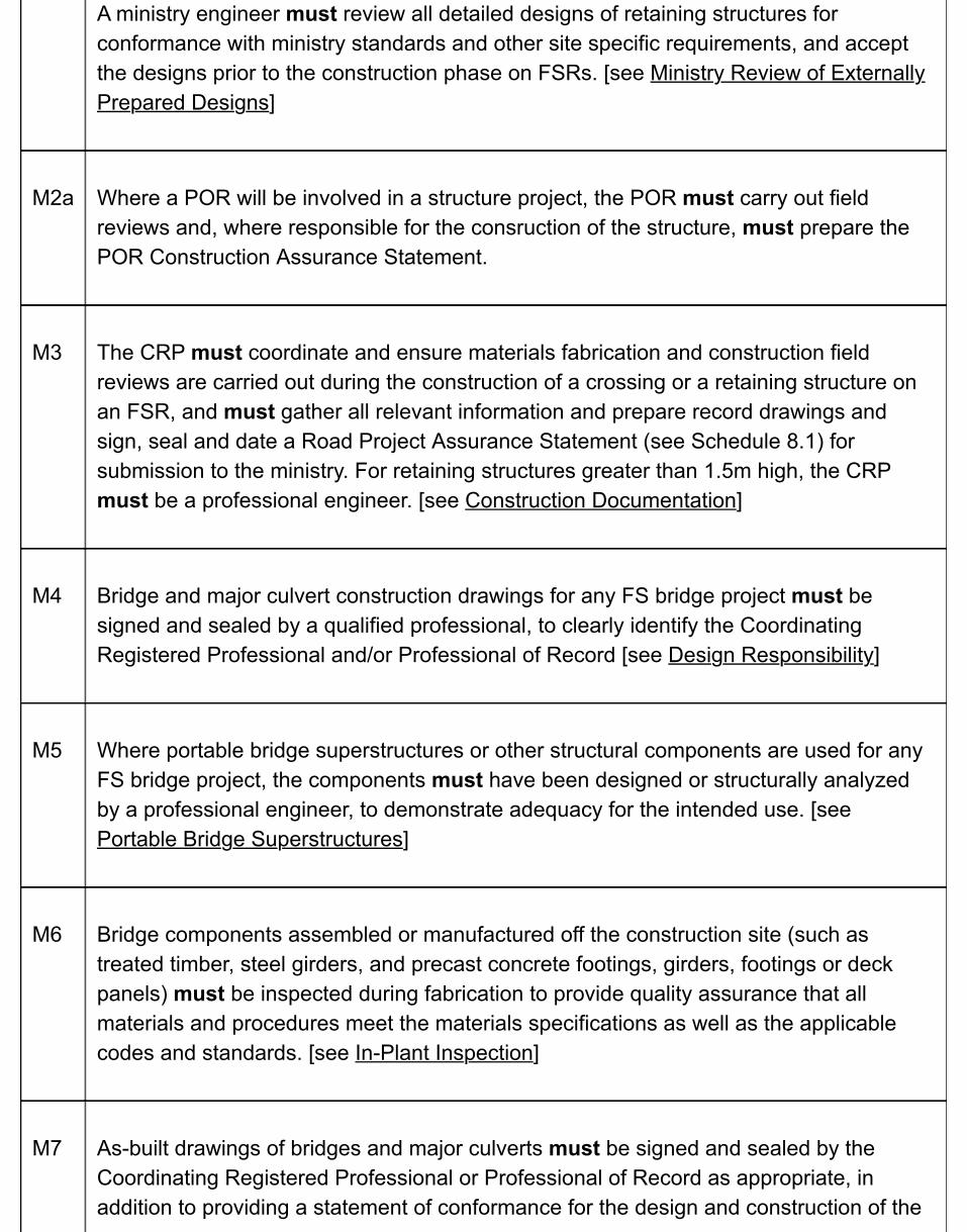
A ministry engineer must review all detailed designs of retaining structures forconformance with ministry standards and other site specific requirements, and acceptthe designs prior to the construction phase on FSRs. [see Ministry Review of ExternallyPrepared Designs]
M2a Where a POR will be involved in a structure project, the POR must carry out fieldreviews and, where responsible for the consruction of the structure, must prepare thePOR Construction Assurance Statement.
M3 The CRP must coordinate and ensure materials fabrication and construction fieldreviews are carried out during the construction of a crossing or a retaining structure onan FSR, and must gather all relevant information and prepare record drawings andsign, seal and date a Road Project Assurance Statement (see Schedule 8.1) forsubmission to the ministry. For retaining structures greater than 1.5m high, the CRPmust be a professional engineer. [see Construction Documentation]
M4 Bridge and major culvert construction drawings for any FS bridge project must besigned and sealed by a qualified professional, to clearly identify the CoordinatingRegistered Professional and/or Professional of Record [see Design Responsibility]
M5 Where portable bridge superstructures or other structural components are used for anyFS bridge project, the components must have been designed or structurally analyzedby a professional engineer, to demonstrate adequacy for the intended use. [seePortable Bridge Superstructures]
M6 Bridge components assembled or manufactured off the construction site (such astreated timber, steel girders, and precast concrete footings, girders, footings or deckpanels) must be inspected during fabrication to provide quality assurance that allmaterials and procedures meet the materials specifications as well as the applicablecodes and standards. [see In-Plant Inspection]
M7 As-built drawings of bridges and major culverts must be signed and sealed by theCoordinating Registered Professional or Professional of Record as appropriate, inaddition to providing a statement of conformance for the design and construction of the

bridge. [see Construction Documentation]
B1 During the conceptual design phase and well in advance of any detailed design work orprocurement of materials, ensure that a ministry engineer is given an opportunity toreview and comment on the suitability of a retaining structure proposed for constructionon an FSR by the ministry. [see Concept Review Phase]
B2 In consultation with the Ministry Engineer, determine the design parameters for a bridge,major culvert or retaining structure [see Design Implementation]
B3 Where the maintainer of an industrial use FSR will replace a bridge, major culvert orretaining structure on that road under a Road Use Permit, ensure that the conditions forthat crossing structure:
provide mandatory site specific design and construction requirements to themaintainer; anddirect the maintainer to submit the completed construction drawings for reviewand approval prior to commencing construction. [see Design Implementation andFS 1229 DM REQUIREMENTS – BUILDING OF FSR BRIDGES BY A ROADUSE PERMIT HOLDER (DOCX)]
B4 Ensure that practitioners in bridge, major culvert and retaining structure design for FSRshave established skill sets. Refer to the Engineering Equipment and Services (EES)Directory. [see Design Implementation]
B5 Ensure that a detailed site survey is carried out for bridge, major culvert and retainingstructure projects. [see Site Data]
B6 Ensure that general arrangement drawings clearly depict the proposed components andconfiguration of the bridge or major culvert in relation to the forest road, stream, andstreambanks. [see General Bridge Arrangement]
B7
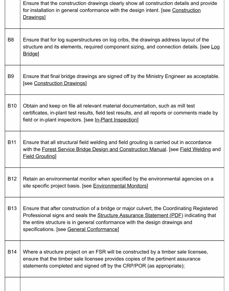
Ensure that the construction drawings clearly show all construction details and providefor installation in general conformance with the design intent. [see ConstructionDrawings]
B8 Ensure that for log superstructures on log cribs, the drawings address layout of thestructure and its elements, required component sizing, and connection details. [see LogBridge]
B9 Ensure that final bridge drawings are signed off by the Ministry Engineer as acceptable.[see Construction Drawings]
B10 Obtain and keep on file all relevant material documentation, such as mill testcertificates, in-plant test results, field test results, and all reports or comments made byfield or in-plant inspectors. [see In-Plant Inspection]
B11 Ensure that all structural field welding and field grouting is carried out in accordancewith the Forest Service Bridge Design and Construction Manual. [see Field Welding andField Grouting]
B12 Retain an environmental monitor when specified by the environmental agencies on asite specific project basis. [see Environmental Monitors]
B13 Ensure that after construction of a bridge or major culvert, the Coordinating RegisteredProfessional signs and seals the Structure Assurance Statement (PDF) indicating thatthe entire structure is in general conformance with the design drawings andspecifications. [see General Conformance]
B14 Where a structure project on an FSR will be constructed by a timber sale licensee,ensure that the timber sale licensee provides copies of the pertinent assurancestatements completed and signed off by the CRP/POR (as appropriate);

B15 Ensure that a BCTS/District engineering technician inspects the completed bridge foracceptability/assurance of the structure; and a Ministry Engineer reviews the as-builtinformation and field inspection note. [see see General Conformance]
B16 Ensure that the necessary steps in the bridge and major culvert design and constructionprocesses were undertaken and issues addressed [see Project Tracking Checklist]
In the above table of chronological events:
M = Mandatory proceduresB = Best practices
4.2 Structure Design & Construction ProfessionalResponsibilities & Considerations
4.2.1 General
The Guidelines for Professional Services in the Forest Sector - Crossings V. 2 (the Guidelines) are intended to establish standards of practice for forest road crossings that members should meet to fulfill professional obligations, including the duty to protect the safety, health and welfare of the public and the environment. Failure to meet the intent of these guidelines could be evidence of unprofessional conduct and may give rise to disciplinary proceedings by the ABCFP or the EGBC. Delivery of professional services for a crossing can involve the practice of professional forestry and professional engineering.
Consistent with the Guidelines, for any forest road crossings, a CRP must take responsibility for planning and coordinating all the professional services for the project, including the design, field reviews, as built/record drawings and Road Project Assurance Statement. As well , this manual applies the same rationale to determining professional practices and responsibilities for the design and construction of retaining structures greater than 1.5 m high. The CRP must direct those activities with sufficient oversight and supervision such that he/she can take overall responsibility and accountability for the crossing or retaining structure.
As to who can be a CRP or a POR for bridges:
for those bridges that meet the tests provided in the Guidelines for simple crossings, theCRP or POR may be either a forest professional or a professional engineer;for those bridges that meet the tests provided in the Guidelines for complex crossings, theCRP or POR must be a professional engineer.
A professional engineer or a forest professional in a structure project may be involved in some orall of the following:
project organization and assignment of responsibilities; planning and design; general considerations;hydrology and hydraulics; plans and supporting documents;
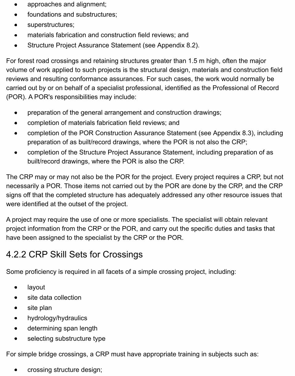
approaches and alignment;foundations and substructures; superstructures; materials fabrication and construction field reviews; andStructure Project Assurance Statement (see Appendix 8.2).
For forest road crossings and retaining structures greater than 1.5 m high, often the majorvolume of work applied to such projects is the structural design, materials and construction fieldreviews and resulting conformance assurances. For such cases, the work would normally becarried out by or on behalf of a specialist professional, identified as the Professional of Record(POR). A POR's responsibilities may include:
preparation of the general arrangement and construction drawings; completion of materials fabrication field reviews; andcompletion of the POR Construction Assurance Statement (see Appendix 8.3), includingpreparation of as built/record drawings, where the POR is not also the CRP;completion of the Structure Project Assurance Statement, including preparation of asbuilt/record drawings, where the POR is also the CRP.
The CRP may or may not also be the POR for the project. Every project requires a CRP, but notnecessarily a POR. Those items not carried out by the POR are done by the CRP, and the CRPsigns off that the completed structure has adequately addressed any other resource issues thatwere identified at the outset of the project.
A project may require the use of one or more specialists. The specialist will obtain relevantproject information from the CRP or the POR, and carry out the specific duties and tasks thathave been assigned to the specialist by the CRP or the POR.
4.2.2 CRP Skill Sets for Crossings
Some proficiency is required in all facets of a simple crossing project, including:
layoutsite data collectionsite planhydrology/hydraulicsdetermining span lengthselecting substructure type
For simple bridge crossings, a CRP must have appropriate training in subjects such as:
crossing structure design;

forest road design;terrain analysis;soil strength and other soil properties;stream flood hydrology and hydraulics; androute and site surveying.
For CRPs having limited university/technical school level academic equivalents for the abovesubjects, but having successfully completed applicable courses and seminars, ensure that theUnderstanding and Familiarity applies, and that the Experience is particularly applicable andcomplete.
A CRP needs to be generally familiar with guidebooks and professional guidelines applicable to:
fish stream identification;fish stream crossings;forest road engineering;terrain stability management and assessment;riparian management; andother relevant manuals.
A CRP also needs to be familiar with the following items on a region or area-specific basis:
methods of bridge construction;common road construction practices;factors affecting workability/stability/performance of fills and cut slopes;relevant regulatory requirements for bridge design and construction;assessing environmental impacts; andworker and bridge user safety.
A CRP should have sufficient bridge project experience, derived from several projects a yearspread over a period of at least three years, such that the experience would include:
working under the supervision or mentorship of a Professional Engineer seasoned in thisarea of practice; a range of ground conditions and design complexity; andtime spent with bridge foremen and machine operators carrying out bridge constructionand maintenance.
The CRP’s work experience and responsibilities during that period should be a combination of allof the following:

planning;field layout of bridges;bridge site data collection and site plan preparation;general bridge design, and coordination of specialist design components; bridge construction; andbridge use and maintenance.
4.3 Design Requirements for Retaining Structures
4.3.1 General Design Requirements
The FPPR requires BCTS and Timber Operations and Pricing Division to construct or maintain anFSR in a manner that ensures the road and the bridges, culverts, fords and other structuresassociated with the road are structurally sound and safe for use by industrial users.
Retaining structures associated with the road prism may be required at some locations tostabilize cut and fill slopes exceeding the natural angle of repose. They can be an importantcomponent of the road infrastructure to (1) optimize road layout and design and reduce overallconstruction costs, and (2) ensure slope stability and a stable road prism over the life of theroad. To address safety and resource protection, retaining structures installed on FSRs will besuitably planned in layout and design of a road, and properly designed and built to ensurestructural integrity, durability and serviceability.
This section describes the design requirements for conceptual and detailed design of retainingstructures greater than 1.5m high, installed within or adjacent to the road prism to stabilize roadcuts and fills or natural slopes. This section also describes the associated ministry acceptance /approval processes for such structures. Similar requirements and processes should beconsidered for retaining structures 1.5 m high and less.
The types of retaining structures captured by these design requirements include:
conventional retaining walls that do not incorporate geosynthetic reinforcement, such asinter locking concrete block walls, gabion walls, steel bin walls, log cribs, and cast-in-placeconcrete cantilever walls;reinforced soil retaining walls using mechanically stabilized earth (MSE)1 or geosyntheticreinforced soil (GRS) design methodologies;reinforced slope retention systems (no wall) using MSE or GRS design methodologies.
Expand All | Collapse All
Structure design responsibility
2

A professional engineer registered with the Engineers and Geoscientists of British Columbia (EGBC) must prepare designs for retaining structures that are greater than 1.5m high.
Conceptual design
During conceptual design and prior to detailed design, and based on a site visit, the designengineer will recommend a retaining structure type, and also facing materials for MSE andGRS retaining structures, to the ministry engineer for review. Selection of appropriateretaining structure type is typically based on an assessment of the design loading, depth toadequate foundation support, presence of deleterious environmental factors, physicalconstraints of the site, cross- sectional geometry of the road and natural slopes, foundationsettlement potential, desired aesthetics, constructability, maintenance, and cost.Recommended retaining structure types (including facing materials for MSE and GRSretaining structures) will meet the performance, durability, and serviceability requirementsestablished for the project by the ministry engineer.
MSE technology uses a tied-back approach to the design of the geosynthetics and typicallyuses a wider spacing of the geosynthetic reinforcement compared to GRS technology.
GRS technology consists of closely spaced layers of geosynthetic reinforcement andcompacted fill materials to produce a composite reinforced soil mass.
Detailed design
Analysis and design calculations of retaining structures will conform to best engineeringpractices as outlined below:
define project requirements, considerations, constraints, performance, durability andserviceability criteria; determine design methodology (analytical and designprocedures), and confirm design service life;define structure geometry, design loads, lateral earth and water pressures, andeffects of surcharge loads;assess external stability, and internal stability (if applicable), and facing materialstability (if applicable);check global stability;produce design and construction drawings to show road site and general layout,retaining structure profile, existing and finished grades, cross-sections and details,materials specifications, connection details, guardrails or barriers (if applicable),construction guidelines, maintenance requirements;make reference to any supporting documentation.
1
2
1
2

Design variations
Variations from the design requirements described herein may be acceptable in certainspecial situations. All such variations will be documented and require approval from theministry engineer prior to use.
Design service life
The design service life is potentially affected by the long-term effects of people, machinery,component material deterioration, seepage, flowing water, and other potentially deleteriousenvironmental factors. Design retaining structures for a service life based on consideration ofthe potential long-term effects of material deterioration on each of the material componentscomprising the structure. Design drawings will clearly specify (1) whether the structure ispermanent or temporary, and (2) the design service life of the structure.
Permanent retaining structures installed on roads to stabilize road cuts and fills ornatural slopes will have a minimum design service life of 45 years (same designservice life as permanent bridges for FSRs) or longer service life as otherwisespecified by the ministry engineer. Permanent retaining structures will be comprisedof durable materials, and will not incorporate any components having a lesser servicelife than the specified design requirement service life.Temporary retaining structures installed on roads to stabilize road cuts and fills ornatural slopes will have a minimum design service life of 15 years unless a lowerdesign requirement service life is specified by the ministry engineer afterconsideration of operational objectives and durability of material types contemplatedfor structure components. The installation of temporary retaining structures onpermanent term FSRs should only be permitted if sound justification (supported bycost effectiveness analysis) is provided and approval is given by the ministryengineer. The design of temporary retaining structures will not incorporate anycomponents having a lesser service life than the specified design requirement servicelife.
Design lateral forces
In addition to lateral earth pressures from level or sloping backfill, the design of retainingstructures will consider the effects of water pressure, surcharge loading (uniform area loads,point or line loads), compaction-induced pressures, frost-induced loads, and other forcesacting behind the structures as appropriate.

Minimum factors of safety for externalstability:
Minimum Factor of
Vehicle live load surcharge: As a minimum requirement, any in-service vehicle live loadsurcharge for engineering design of retaining structures will be based on a specific standardbridge design vehicle. See the Bridge Design & Construction Manual for Forest ServiceRoads.
Alternatively, to meet specific operational access needs, it may be required to design for avehicle live load surcharge that is possibly greater than a ministry standard bridge designvehicle to allow for safe passage of heavy equipment or non-standard vehicles (in a normaltransport configuration) that can reasonably be expected to regularly use the FSR, now or inthe future. In this case, obtain relevant manufacturers’ equipment / vehicle data for design.
Design methodology
Retaining structure systems installed steeper than 70 degrees will be designed as retainingwalls.
Unless otherwise specified herein or approved by the ministry engineer, the design engineerwill analyze the applied loads and induced stresses using the design methodologiesprovided in the reference documents below:
For both conventional retaining structure design (with no geosynthetic reinforcement) andMSE retaining structure design:
Canadian Foundation Engineering Manual, orAASHTO Standard Specifications for Highway Bridges, Seventeenth Edition 2002,Section 5 “Retaining Walls.”
For GRS retaining structure design:Canadian Foundation Engineering Manual (chapter sections as applicable), andChapter 4 of US Department of Transportation, Federal Highway Administration(FHWA), Publication No. FHWA-HRT-11-026 (Geosynthetic Reinforced SoilIntegrated Bridge System Interim Implementation Guide).http://www.fhwa.dot.gov/publications/research/infrastructure/structures/11026/11026.pdf (PDF, 8.68 MB)
Design factors of safety
Use the following minimum factors of safety for external stability calculations:
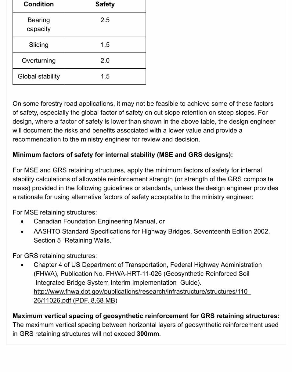
Condition Safety
Bearingcapacity
2.5
Sliding 1.5
Overturning 2.0
Global stability 1.5
On some forestry road applications, it may not be feasible to achieve some of these factorsof safety, especially the global factor of safety on cut slope retention on steep slopes. Fordesign, where a factor of safety is lower than shown in the above table, the design engineerwill document the risks and benefits associated with a lower value and provide arecommendation to the ministry engineer for review and decision.
Minimum factors of safety for internal stability (MSE and GRS designs):
For MSE and GRS retaining structures, apply the minimum factors of safety for internalstability calculations of allowable reinforcement strength (or strength of the GRS compositemass) provided in the following guidelines or standards, unless the design engineer providesa rationale for using alternative factors of safety acceptable to the ministry engineer:
For MSE retaining structures:Canadian Foundation Engineering Manual, orAASHTO Standard Specifications for Highway Bridges, Seventeenth Edition 2002,Section 5 “Retaining Walls.”
For GRS retaining structures:Chapter 4 of US Department of Transportation, Federal Highway Administration(FHWA), Publication No. FHWA-HRT-11-026 (Geosynthetic Reinforced Soil Integrated Bridge System Interim Implementation Guide).http://www.fhwa.dot.gov/publications/research/infrastructure/structures/110 26/11026.pdf (PDF, 8.68 MB)
Maximum vertical spacing of geosynthetic reinforcement for GRS retaining structures:The maximum vertical spacing between horizontal layers of geosynthetic reinforcement usedin GRS retaining structures will not exceed 300mm.
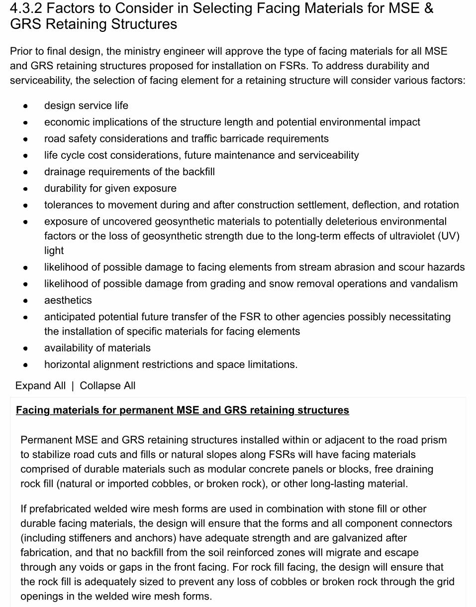
4.3.2 Factors to Consider in Selecting Facing Materials for MSE &GRS Retaining Structures
Prior to final design, the ministry engineer will approve the type of facing materials for all MSEand GRS retaining structures proposed for installation on FSRs. To address durability andserviceability, the selection of facing element for a retaining structure will consider various factors:
design service lifeeconomic implications of the structure length and potential environmental impactroad safety considerations and traffic barricade requirementslife cycle cost considerations, future maintenance and serviceabilitydrainage requirements of the backfilldurability for given exposuretolerances to movement during and after construction settlement, deflection, and rotationexposure of uncovered geosynthetic materials to potentially deleterious environmentalfactors or the loss of geosynthetic strength due to the long-term effects of ultraviolet (UV)lightlikelihood of possible damage to facing elements from stream abrasion and scour hazardslikelihood of possible damage from grading and snow removal operations and vandalismaestheticsanticipated potential future transfer of the FSR to other agencies possibly necessitatingthe installation of specific materials for facing elementsavailability of materialshorizontal alignment restrictions and space limitations.
Expand All | Collapse All
Facing materials for permanent MSE and GRS retaining structures
Permanent MSE and GRS retaining structures installed within or adjacent to the road prismto stabilize road cuts and fills or natural slopes along FSRs will have facing materialscomprised of durable materials such as modular concrete panels or blocks, free drainingrock fill (natural or imported cobbles, or broken rock), or other long-lasting material.
If prefabricated welded wire mesh forms are used in combination with stone fill or otherdurable facing materials, the design will ensure that the forms and all component connectors(including stiffeners and anchors) have adequate strength and are galvanized afterfabrication, and that no backfill from the soil reinforced zones will migrate and escapethrough any voids or gaps in the front facing. For rock fill facing, the design will ensure thatthe rock fill is adequately sized to prevent any loss of cobbles or broken rock through the gridopenings in the welded wire mesh forms.

The use of uncovered geotextile fabric at the front of galvanized welded wire mesh forms asa standalone facing material is not recommended for permanent GRS retaining structures onFSRs due to concerns for (1) loss of geosynthetic strength from long-term degradationeffects of weathering, UV light, abrasion and other environmental factors and (2) otherpossible sources of damage to the exposed fabric (e.g., vandalism or road maintenanceoperations) that may affect the functional service life of the facing.
Any variance to these criteria will be approved and documented by the ministry engineer.
Facing materials for temporary MSE and GRS retaining structures
Temporary MSE and GRS retaining structures installed within or adjacent to the road prismto stabilize road cuts and fills or natural slopes along FSRs should (preferably) have facingmaterials comprised of durable materials as specified above for permanent retainingstructures. Alternatively, the facing can be comprised of alternative materials provided thatthey do not have a lesser service life than the specified design requirement service life andtheir use is appropriate for the type of retaining structure.
The use of uncovered geotextile fabric at the front of galvanized welded wire mesh forms asa standalone facing material can be considered for temporary GRS retaining structures onFSRs after consideration of the various selection factors listed above and only afterconsultation with the ministry engineer. For this application, a double layer of geotextile fabricis recommended provided the design engineer has determined (after consideration of thesite specific UV potential) that this double layer system of geotextile fabric will providesuitable UV protection and address other factors listed above to meet project durability andserviceability requirements over the design requirement service life.
Furthermore, the geotextile fabric product will be treated using carbon black (a UV absorber)meeting the following minimum specification to make the geotextile fabric less sensitive toUV light: minimum 70 percent strength retained after 500 hrs of UV exposure according toASTM D4355-07 – “Standard Test Method for Deterioration of Geotextiles by Exposure toLight, Moisture and Heat in a Xenon Arc Type Apparatus.”
Any variance to these criteria will be approved and documented by the ministry engineer.
4.3.3 Geotechnical Report
A geotechnical report will be prepared to assess and address possible:
1. foundation and construction difficulties,2. effects on existing adjacent structures or slope stability, and3. methods of overcoming any identified difficulties during the construction stage, or other

requirements.
The report should include a recommendation of the preferred type of foundation, and methods ofscour protection (if applicable for the site).
4.3.4 Detailed Design Drawings & Specifications
The design engineer will prepare detailed design drawings prior to construction of any retainingstructures. The detailed design drawings will be signed, sealed, and dated by the designengineer taking responsibility for the design. Produce drawings at a scale and format that areusable in the construction process and include any explanatory notes, details, illustrations andspecifications for the materials and construction. This content may include, but is not limited to,the following:
site location, site plan, and general notes to specify:site location coordinates;name of FSR, forest district and region;whether the retaining structure is temporary or permanent, and design service lifeof the structure;design surcharge loading (uniform area loads, point or line loads), including thevehicle live load surcharge and the specific design vehicle or equipmentconfiguration and loads used in the structure design;design methodology and considerations, assumptions, constraints, anyperformance design criteria, and other project requirements;
longitudinal views and existing ground profile, cross-sections, site location coordinates,construction working points and elevations, finished ground profile and elevations (ifapplicable);specifications for soil / rock materials, erosion protection of backfills, adequate foundationpreparation, including scour protection (if applicable), and provisions for drainage ofbackfill materials and all soil reinforced zones (if applicable);material specifications for all components (including connection hardware), and includingspecification of corrosion protection of component materials to meet the design servicelife;facing material specifications and associated connection details, and geosynthetic layerlayout, spacing and length in the case of MSE and GRS retaining structures;preparation of foundation areas, installation and assemblage of structure components,sizing and extent of riprap (if applicable), and other important requirements to ensureproper construction of the retaining structure;reference to design aids, specific constraints dictated by the ministry, or works of otherswhich significantly impacted the resulting design.

All engineering reports and detailed design drawings and specifications, and engineered cost estimates related to the design of retaining structures (if applicable) will be signed, sealed, and dated by the design engineer.
It is the responsibility of the design engineer to ensure that appropriate quality assurance (QA) measures have been included in the design process. This may include engaging a qualified QA reviewer to check the design assumptions, calculations, notes and final design drawings consistent with the requirements of EGBC Bylaw 14(b) (PDF).
4.3.5 Ministry Review of Externally-Prepared Designs
Concept review phase: During the conceptual design phase and well in advance of any detailed design work or procurement of materials, ministry staff will ensure that a ministry engineer is given an opportunity to review and comment on the suitability of a retaining structure proposed for construction on an FSR by the ministry. Failure to do this could delay acceptance of the detailed design drawings and/or project.
Review and acceptance of detailed designs: Design engineers that prepare retaining structure designs for the ministry will consult with ministry professional engineering staff during the detailed design stage. A ministry engineer must review all detailed designs of retaining structures for conformance with ministry standards and other site specific requirements, and accept the designs prior to the construction phase on FSRs.
Accepted design drawings (for a retaining structure that will be constructed on an FSR) are to be stamped “For Construction.”

4.4 Design Requirements for Crossings, Including Bridges &Major Culverts
4.4.1 Project & Design Responsibility & Considerations
A “bridge” includes the superstructure, substructure, connections, approach road fills, and scourprotection works. A “major culvert” includes the culvert materials, compacted bedding andbackfill, embedment materials for embedded culverts, scour protection, and the roadway.
Where pertinent in the design of any bridge or major culvert, consider:
user safety;accommodation of pedestrian traffic where required;site selection, including assessment of stream geomorphology and geotechnical (globaland local) considerations;environmental integrity;fish habitat and fish passage;impact of the proposed structure on the stream during and after construction;site revegetation requirements;structure alignment and location (vertical and horizontal) relative to the road and streamchannel;complete structure combination (substructure, superstructure, connections, and scourprotection);suitability of selected foundations for the specific site;design flood development;navigation (Navigable Waters Protection Act), if applicable;debris potential and passage;scour protection;design vehicle configuration for load and alignment;design traffic frequency;design service life influence on selection of bridge type and composition;construction layout, methodology, and timing; andeconomics.

The design of bridges and major culverts encompasses more than just the design of structuralcomponents. Consider the composition and interaction of all the components, as well as theirrelationship and impact on not only the users, but also on the road and stream components andother resources.
A key concept in a successful project is continuity of professional oversight and output reviews.The professional that is charged with retaining a close familiarity with the progress of the project,and with coordinating the various specialist inputs, is known as the Coordinating RegisteredProfessional (CRP), who carries overall responsibility for the delivery of the professional aspectsof the project.
Guidelines for Professional Services in the Forest Sector - Crossings (PDF) describes the rolesand responsibilities of the CRP related to bridge planning as follows:
confirm that the necessary assessments for the project have been completed;utilize specialists in the planning;gather site information, including the site plan and other information;take overall responsibility for the conceptual plan and general arrangement drawings;address environmental considerations in the plan;coordinate activities relating to the crossing project in the context of the overalldevelopment;understand all generally accepted uncertainties inherent in the crossing project andassumptions made in relation to the project, including assumptions made by thespecialists;have an understanding of the roles and responsibilities of all the people involved in theplanning of the crossing project; andconsider information received from specialists and where appropriate incorporate theinformation into the plan.
To address these planning issues, the CRP ensures that a qualified professional has addressedthe need, if any, for specialist assessments for a new bridge or a bridge replacement, includingthose as part of a BCTS road site plan for new construction as described in FRPA, to provideresults and strategies to meet the objectives of the FSP. In practical terms for bridges and majorculverts, this means a map showing the proposed road location (and approximate crossinglocations) together with the results of any specialist assessments that may have been requiredalong or adjacent to the road, such as:
riparian;fisheries values;wildlife corridors;archaeological;
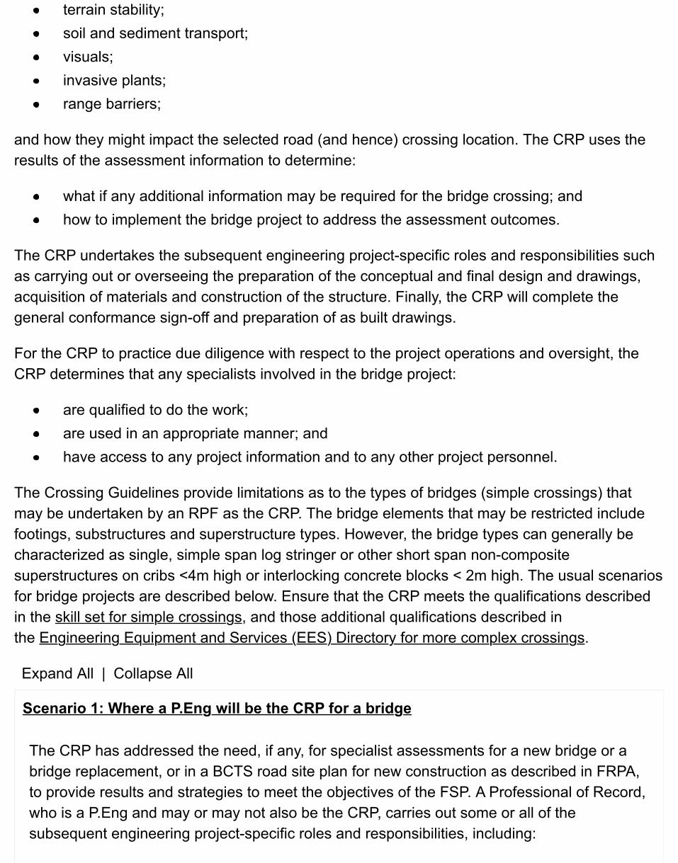
terrain stability;soil and sediment transport;visuals;invasive plants;range barriers;
and how they might impact the selected road (and hence) crossing location. The CRP uses theresults of the assessment information to determine:
what if any additional information may be required for the bridge crossing; andhow to implement the bridge project to address the assessment outcomes.
The CRP undertakes the subsequent engineering project-specific roles and responsibilities suchas carrying out or overseeing the preparation of the conceptual and final design and drawings,acquisition of materials and construction of the structure. Finally, the CRP will complete thegeneral conformance sign-off and preparation of as built drawings.
For the CRP to practice due diligence with respect to the project operations and oversight, theCRP determines that any specialists involved in the bridge project:
are qualified to do the work;are used in an appropriate manner; andhave access to any project information and to any other project personnel.
The Crossing Guidelines provide limitations as to the types of bridges (simple crossings) thatmay be undertaken by an RPF as the CRP. The bridge elements that may be restricted includefootings, substructures and superstructure types. However, the bridge types can generally becharacterized as single, simple span log stringer or other short span non-compositesuperstructures on cribs <4m high or interlocking concrete blocks < 2m high. The usual scenariosfor bridge projects are described below. Ensure that the CRP meets the qualifications describedin the skill set for simple crossings, and those additional qualifications described inthe Engineering Equipment and Services (EES) Directory for more complex crossings.
Expand All | Collapse All
Scenario 1: Where a P.Eng will be the CRP for a bridge
The CRP has addressed the need, if any, for specialist assessments for a new bridge or abridge replacement, or in a BCTS road site plan for new construction as described in FRPA,to provide results and strategies to meet the objectives of the FSP. A Professional of Record,who is a P.Eng and may or may not also be the CRP, carries out some or all of thesubsequent engineering project-specific roles and responsibilities, including:
the preparation of the conceptual design and general arrangement design drawings;quality assurance of materials fabrication;construction inspections;addressing required design revisions that become evident during construction;compiling materials and construction documentation; andpreparation and sign-off of as-built drawings and statement of constructionconformance.
Those items not carried out by the POR are done by the CRP, and the CRP signs off that thecompleted crossing structure has adequately addressed any other resource issues that wereidentified at the outset of the project.
Scenario 2: Where a forest professional will be the CRP for log stringer bridgesuperstructures
The CRP has addressed the need, if any, for specialist assessments for a new bridge or abridge replacement, or in a BCTS road site plan for new construction as described in FRPA,to provide results and strategies to meet the objectives of the FSP.
The CRP uses design aids as required for stringer arrangement and sizing, needle beamsizing where appropriate, lashing of stringers and connections to sills or caps, placement,arrangement and sizing of crib members or concrete block sills
The CRP is responsible for:the preparation of the conceptual design and general arrangement design drawings;construction inspections;addressing required design revisions that become evident during construction;compiling construction documentation; andpreparation and sign-off of as-built drawings and statement of constructionconformance.
Scenario 3: Where a forest professional will be the CRP for re-use of portablebridge superstructures
The CRP has addressed the need, if any, for specialist assessments for a new bridge or abridge replacement, or in a BCTS road site plan for new construction as described in FRPA,to provide results and strategies to meet the objectives of the FSP.

The CRP ensures that a professional engineer has carried out the design analysis to ensureadequacy for the intended use, and the structure has been inspected before re-use by aqualified inspector.
If any additional structural analysis is to be carried out by a professional engineer due to anypotential issues raised by the inspection prior to re-use, that engineer will generally be thePOR and as such will likely provide the necessary drawings, specifications, connectiondetails, etc. for any structure that requires remedial work prior to re-use.
The CRP uses design aids as required for placement, arrangement and sizing of cribmembers or concrete block sills.
CRP is responsible for:the preparation of the conceptual design and general arrangement design drawings;construction inspections;addressing required design revisions that become evident during construction;compiling construction documentation; andpreparation and sign-off of as-built drawings and statement of constructionconformance.
Scenario 4: Where a forest professional will be the CRP for other short span steelgirder bridge superstructures
The CRP has addressed the need, if any, for specialist assessments for a new bridge or abridge replacement, or in a BCTS road site plan for new construction as described in FRPA,to provide results and strategies to meet the objectives of the FSP
A POR who is a P.Eng carries out (under the project oversight of the CRP) the subsequentengineering project-specific roles and responsibilities, including:
the preparation of the conceptual design and general arrangement design drawings;quality assurance of materials fabrication;construction inspections;addressing required design revisions that become evident during construction;compiling materials and construction documentation; andpreparation and sign-off of as-built drawings and statement of constructionconformance.
Note that if the superstructure is composite, the POR or another professional engineer willnecessarily become the CRP, in accordance with the Crossing Guidelines.
The CRP signs off that the completed crossing structure has adequately addressed anyother resource issues that were identified at the outset of the project.
Bridge and major culvert construction drawings for any FS project (including those structures builtunder Road Permit (BCTS) and designated in that permit to be an FS structure to be used forharvesting after completion of the Timber Sale License) must be signed and sealed by one ormore professionals, to clearly identify the CRP and/or Professional/Professionals of Record(POR). The POR is usually the structural/design engineer, but in some complex projects with twoor more contributing engineers (such as geotechnical, river engineering, etc.), each of thoseparticipants can be designated as a POR. A POR can also be responsible for the overall generalarrangement drawings, as described in Scenario 4 above.
If the CRP has prepared the conceptual design and general arrangement drawings, the CRP willsign and seal those drawings. Where a designer working for the supply/erect contractor willprepare structural drawings, that engineer will be the POR for that work. In consultation with aMinistry Engineer, consider having the professional that will carry out the field review for generalconformance with the design and drawings complete and submit for review the proposedAssurance of Field Reviews FS 137 along with the construction drawings.
4.4.2 Skill Set for CRP for Simple Crossings
Expand All | Collapse All
Knowledge requirements
1. be members in good standing with ABCFP or EGBC;2. have appropriate education, training and experience within the discipline of forestry or
engineering that are congruent with CRP bridge design services;3. have considerable recognized specialization in the layout and conceptual design of
forest road bridges;4. be familiar with forest road and bridge planning, construction considerations and
techniques, design vehicle configurations and assessment, scour and scour protection, design flood hydrology determination, and bridge component properties and fabrication;
5. be thoroughly familiar with the Guidelines for Professional Services in the Forest Sector– Crossings (PDF) prepared by the Engineers and Geoscientists of British Columbia and the Association of BC Forest Professionals;
6. be thoroughly familiar with stream crossing requirements and procedures of the Department of Fisheries and Oceans Canada and the British Columbia Ministry of Environment;
7. have a working knowledge of related riparian and aquatic environmental issues (such as stream classification and fish passage requirements) and associated construction mitigation techniques;
8. have a working knowledge and understanding of the principles and best managementpractices related to stream crossings provided in the following publications:
Forest Practices Code of BC Forest Road Engineering Guidebook (June 2002)(PDF, 7.61 MB)Forest Practices Code of BC Fish-Stream Crossing Guidebook (PDF, 4.2MB)Forest Practices Code of BC Riparian Management Area GuidebookForest Practices Code of BC Fish-Stream Identification Guidebook (PDF)
Experience requirements
All CRPs require a minimum of 8 years of direct bridge experience in forestry or relatedindustries in British Columbia within the past 10 years, including at least three years ofprofessional experience at a level contemplated by the Crossing Guidelines. Such workexperience includes:1. Preparation of conceptual designs of forest road bridges, including analysis for log,
timber, and steel components.2. Development of general bridge arrangement drawings with consideration for:
design flood estimation;design flood and debris passage;bridge configuration alignment in relation to the road and stream;road approach and alignment considerations;crossing alignment to the stream;scour and scour protection;substructure and connection component alternatives including consideration forgeotechnical conditions and construction parameters;cost effectiveness of bridge options;construction equipment and practices in the forest sector.
1. Preparation of reports, drawings, specifications and cost estimates.2. Field reviews during construction of bridges to provide quality assurance and
confirmation of conformance to drawings and specifications, including:
field monitoring of construction activities during critical phases;assessing actual field conditions for consistency with design assumptions andrecognized “changed conditions”;assessing alternatives, and providing revisions to designs for “changedconditions”;preparing as-built drawings, and providing statements of constructionconformance.

4.4.3 Development & Use of Professional Engineer Forest Road General Arrangement Bridge Design Aids
Design aids may be utilized by qualified individuals producing general arrangement forest road bridge designs. The “Guidelines for Professional Services in the Forest Sector – Crossings”, Section 3.1, “Simple Crossings” requires where the Coordinating Registered Professional (CRP) is a Registered Professional Forester that - “plans must be prepared using structural details provided in drawings, tables, charts and other design aids that have been prepared by a Professional Engineer”.
These guidelines are applicable to: a CRP, an individual working in support of a CRP, a limited license holder with the Engineers and Geoscientists of BC, or anyone taking responsibility for a bridge general arrangement design and is utilizing design aids.
Expand All | Collapse All
Definition and content of a design aid
A design aid is a tool, produced by a professional engineer, which will provide anunambiguous result tied to clear parameters, and can be applied to a site-specific situation.An example of a design aid is a log stringer design table specifying log stringer diameters,subject to species and other identified limitations, for particular spans for specific designloads. A manual such as the FPINNOVATIONS Log Construction Handbook is notconsidered a design aid because a manual cannot be applied to a specific situation.However, individual stringer tables within that manual may be design aids.
When preparing design aids, a professional engineer should clearly state:the intended purpose, authorized users and application for the design aid;requirements and restrictions for those using the design aid (such as specific materialor site conditions, specific aspects requiring higher level oversight, materials orconnection requirements);assumptions made; codes referred to; and where applicable, Factors of Safety used in producing the design aid;limitations for application of the design aid;the name of the professional engineer having professional responsibility for thedesign aid; andexcept for those design aids in the public domain, the signature and seal of theprofessional engineer having professional responsibility for the design aid, the datethe design aid was signed, and a date when the design aid is not longer valid (asapplicable).

Use of design aids
A person should undertake the following best professional practices when using a design aidproduced by others:
are authorized by the “owner” of the design aid to use the design aid (note that sometables such as FPINNOVATIONS or Ministry log stringer tables are in the publicdomain; otherwise, the design aid is usually proprietary and often intended to be usedonly for client- specific applications);have discussed the design aid with the professional engineer that created the designaid to ensure that the individual using the design aid understands the limitations ofthe design aid and to ensure that they have the latest applicable version of thedesign aid;reference the specific design aid(s) in drawings and documentation when used forspecific projects;provide copies of the design aid(s) used (that are not in the public domain) with thedesign documentation provided to the client; andseek specialist assistance (usually from a professional bridge engineer) whenapplicability of the design aid is in question or unforeseen circumstances make thedesign aid not applicable or questionable.
4.4.4 Typical Bridge Design Approach
Bridge and major culvert designs and construction approaches for FSRs have evolved intoindustry standards. Typical details and arrangements are described in the Forest Service BridgeDesign and Construction Manual and in guidelines and requirements for ministry bridges. Themost common components have been structurally pre-engineered and are well known by bridgedesigners, fabricators, and erectors.
Ensure that practitioners in bridge and major culvert design for FSRs meet established skill sets.Refer to the skill set for simple crossings and the Engineering Equipment and Services (EES)Directory for more complex crossings.
Expand All | Collapse All
Forest Service Bridge Design & Construction Manual
The Forest Service Bridge Design and Construction Manual drawings include ministry-approved component configurations and details. Detailed designs for various components,such as concrete decks, slab girders, and various footing arrangements, are also provided in

the manual.
As well, the manual lists proprietary bridge components (consisting of conceptual drawingswith minimal details) that have been approved by the ministry. Proponents whose proprietarysystems have been accepted by the ministry have provided proof that their components willmeet the stringent requirements laid out in the manual for structural integrity, durability, andother relevant aspects pertaining to the product’s usage.
Design implementation process
Where the maintainer of an industrial use FSR will replace a bridge or major culvert on thatroad under a Road Use Permit, ensure that the District Manager, in the conditions for thatcrossing structure:
provides mandatory site specific design and construction requirements to themaintainer; anddirects the maintainer to submit the completed construction drawings for review andapproval prior to commencing construction.
For most other situations, utilize the following bridge or major culvert design implementationprocess:
in consultation with a Ministry Engineer, determine the design parameters for a bridgeor major culvert structure (see Appendix 4.3 DESIGN CHECKLIST) and determinewhether the conceptual designer will be the Ministry Engineer or a consultantprofessional engineer retained by BCTS/District; as described earlier, this person willnormally be the CRP;convey the design parameters and the performance requirements for the crossing tothe conceptual designer;have the conceptual designer conduct a site visit and make note of the physical siteparameters, including observations on design flood hydrology, foundation evaluation,vertical and horizontal alignment and crossing location opportunities, andconstruction limitations (such as equipment and materials access);have the conceptual designer evaluate the options for the crossing given theavailable information and make a recommendation for the development of a site planand oversee its completion (generally a detailed site plan for all but the simplestcrossings [see Site Data & Survey Requirements for Bridges & Major Culverts].
Note that in the above scenario, the Ministry Engineer may undertake the conceptual designand become the CRP for the project, should time and resources permit.
Conceptual design / general arrangement drawings

A conceptual design illustrates how the proposed crossing structure addresses the site-specific operational requirements. Typically, the general arrangement drawings consist ofone or more drawings showing the components and configuration of the proposed bridge ormajor culvert crossing, as well as construction details overlain on a site plan and profile [seeConstruction Drawings & Specifications], making reference to specific ministry standarddrawings and details laid out in the Forest Service Bridge Design and Construction Manual.
Ensure that the conceptual designer signs and seals the General Arrangement drawings.
Detailed structural design
For all but the most complex structures, a detailed structural design is typically notcompleted as part of the development of general arrangement designs. The finalsuperstructure arrangement is best left to the fabricator or erection contractor, who canprovide the most cost-effective and efficient design based on their materials availability anderection schemes. As part of the design/build process for the typical, simply supported forestroad bridge structures, the detailed structural design of the superstructure components arecompleted by the bridge fabricator or the contractor who is the successful bidder to constructthe bridge. In such cases, the contractor’s or fabricator’s engineer will normally be thestructural POR, and the professional that prepared the conceptual design will be theCoordinating Registered Professional (CRP) as described earlier in this chapter.
4.4.5 Design Opening
Base the design flood requirements for bridges and major culverts on the anticipated life of thestructures. Structures to be in place for a relatively short life pose reduced risks (compared withthose expected to have longer life), and thus reduced design flood concerns can be considered.
In addition to design flood passage, make allowances for anticipated debris. For bridges,incorporate freeboard above the design highwater to allow for passage of floating debris. In thecase of major culverts, also accommodate debris (floating or submerged) in the design process.
4.5 Types of Bridge Structures
4.5.1 Bridge Superstructures
Expand All | Collapse All
Unapproved superstructures or systems
Before an unproven system or product is implemented, bring it to the attention ofEngineering Branch for evaluation. If the branch determines that products or systemsprovide efficiencies and meet stringent performance requirements, those components areincorporated into the Forest Service Bridge Design and Construction Manual as acceptableministry standards.
Deviation from the requirements of the Forest Service Bridge Design and ConstructionManual and the associated standard drawings is not recommended. Where an unapprovedstructure or system is being considered for a project before the branch has completed itsreview and acceptance of such structures, contact the Ministry Engineer for input into theimplementation requirements.
Approved superstructures or systems
Approved ministry superstructure configurations, identified in the Forest Service BridgeDesign and Construction Manual, provide for numerous construction options such as:
timber decks on steel;precast concrete slabs;non-composite concrete decks on steel girders;composite concrete decks on steel girders;all steel portable bridges;Compo-Girders™; andsteel-free decks (precast concrete arch panel composite deck).
Generally, use the following “rules of thumb” to help guide estimating or evaluatingconceptual designs for typical single-lane, simply supported, permanent single-span bridges.Note that these rules of thumb are for completed in-place structures which consider both the
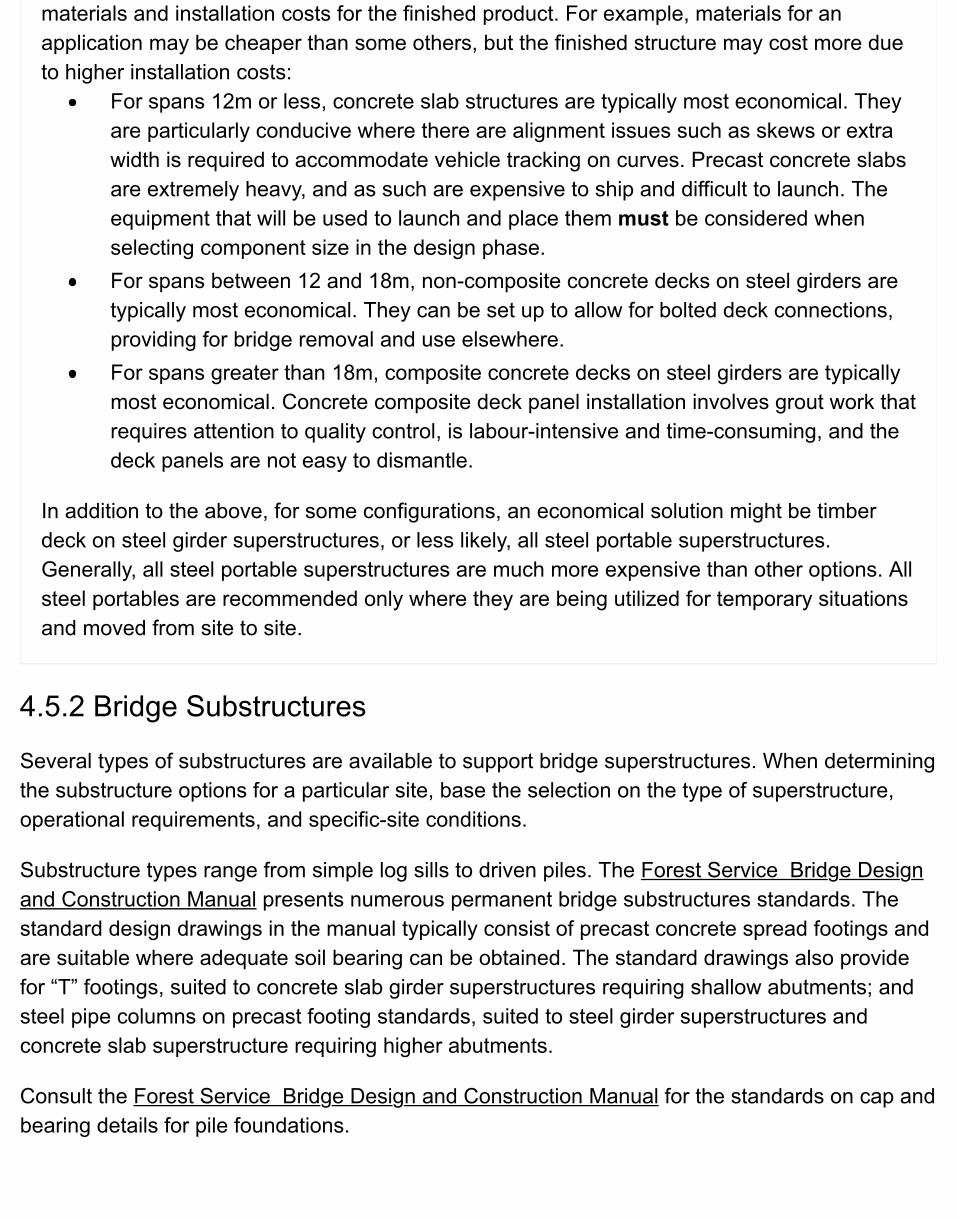
materials and installation costs for the finished product. For example, materials for anapplication may be cheaper than some others, but the finished structure may cost more dueto higher installation costs:
For spans 12m or less, concrete slab structures are typically most economical. Theyare particularly conducive where there are alignment issues such as skews or extrawidth is required to accommodate vehicle tracking on curves. Precast concrete slabsare extremely heavy, and as such are expensive to ship and difficult to launch. Theequipment that will be used to launch and place them must be considered whenselecting component size in the design phase.For spans between 12 and 18m, non-composite concrete decks on steel girders aretypically most economical. They can be set up to allow for bolted deck connections,providing for bridge removal and use elsewhere.For spans greater than 18m, composite concrete decks on steel girders are typicallymost economical. Concrete composite deck panel installation involves grout work thatrequires attention to quality control, is labour-intensive and time-consuming, and thedeck panels are not easy to dismantle.
In addition to the above, for some configurations, an economical solution might be timberdeck on steel girder superstructures, or less likely, all steel portable superstructures.Generally, all steel portable superstructures are much more expensive than other options. Allsteel portables are recommended only where they are being utilized for temporary situationsand moved from site to site.
4.5.2 Bridge Substructures
Several types of substructures are available to support bridge superstructures. When determiningthe substructure options for a particular site, base the selection on the type of superstructure,operational requirements, and specific-site conditions.
Substructure types range from simple log sills to driven piles. The Forest Service Bridge Designand Construction Manual presents numerous permanent bridge substructures standards. Thestandard design drawings in the manual typically consist of precast concrete spread footings andare suitable where adequate soil bearing can be obtained. The standard drawings also providefor “T” footings, suited to concrete slab girder superstructures requiring shallow abutments; andsteel pipe columns on precast footing standards, suited to steel girder superstructures andconcrete slab superstructure requiring higher abutments.
Consult the Forest Service Bridge Design and Construction Manual for the standards on cap andbearing details for pile foundations.

The following structures are examples of those not captured in standard design drawings in theForest Service Bridge Design and Construction Manual:
log cribs (suited to temporary usage);interlocking concrete block abutments (typically limited to three blocks high); andsteel binwalls (numerous steel binwalls exist, but few new ones are being installed).

4.6 Types of Major Culvert StructuresMajor culverts are often preferred structures in suitable situations. Their advantages over bridges may include:
economics – culverts are generally cheaper than bridges for typical sizes used;reduced maintenance when installed correctly; andgreater flexibility in terms of alignment options – culverts are suited to sites with horizontal and verticalcurves; they can be fit to suit the road alignment and approaches so as to minimize impacts; and theyenable maintenance of road widths and provide for road widenings more readily than bridges.
Steel and aluminum culverts are typically soil-metal structures. The soil and the metal work together to providethe structural integrity to support loads on the structure. The metal without the soil is insufficient to support thedesign loads and would collapse. Soil is compacted in lifts immediately adjacent to and in contact with theculvert bottom and sides, to combine with the metal to support the design loads. Uncompacted fill is notsufficiently dense to combine with the metal to support the design loads.
For most soil-metal culvert installations, the metal is galvanized steel. Some aluminum culverts exist, but theyare less common than galvanized steel. For a given installation, aluminum culverts are generally thicker butlighter than galvanized steel. However, the aluminum culverts tend to be more easily damaged duringinstallation.
Culverts come in a variety of shapes and sizes. The selection of appropriate size and shape should be afunction of the design parameters. Where floating debris is minimal and regular maintenance is anticipated,consider the use of debris catchers/traps. Where significant volume or size of floating or other debris isanticipated, a culvert may not be an option, and a bridge will be necessary to allow high water and debris topass.

4.7 Site Data & Survey Requirements for Bridges & MajorCulvertsEnsure that a detailed site survey (see Appendix E Bridge and Major Culvert Site Plan Specifications of theForest Service Bridge Design and Construction Manual) carried out for a bridge or major culvert project. Usethe survey information to produce site plan and profile drawings for planning, evaluating, and developing thecrossing design. Determine the type and extent of site survey to be completed, including the quality of siteinformation to be collected.
Typically, collect and note on a site plan the following information:
contours to 0.5 m interval accuracy (may vary depending on complexity of the site);the riparian class for streams or lake classification;the apparent high-water elevation of the stream, based on visible evidence of recent flooding;a description of the composition and size of stream bed materials;a description of streambank materials and stream stability;cross-sections and a profile of the stream: one cross-section should be along the proposed roadcentreline and extend beyond the stream channel width, normally to at least 50 m on each side;horizontal and vertical location of reference points established during the site survey, which can beused to establish (and re-establish) the structure location during construction;the stream flow velocity and direction, if the flow may influence the size or layout of the structure;a description of the soil profiles and foundation soil conditions, based on soil explorations appropriateto the level of risk;presence (or absence) of bedrock, and depth to bedrock;a description of any evidence of stream debris or slope instability that could affect the crossing, basedon upstream observations;any existing improvements or resource values in the vicinity that may influence the size or layout of thestructure;location and dimensions of any existing structure, including edge of roadway, abutment,superstructure, stream, edge of clearing information, profile of existing road to the limits of the survey,and location, general description, and extent of vegetation;the locations and dimensions of any upstream structures, and a note about whether there is anyevidence of damage or disturbance from any sources (erosion, debris damage, etc.);potential sources of rip rap, endfill material;any other pertinent information: Is the site currently accessible by road? Are there road or bridgerestrictions on load length or weight? If so, how can these be overcome? If test drilling seems likely,how much work is required to get a drilling truck (usually not all-wheel drive) to the site?if equipment fording or temporary bridge crossings will be necessary for construction, information

about possible ford and temporary bridge crossing locations and other considerations such as depth ofstream at that point, bottom material, and access gradients; andthe date of the survey and name of the surveyor.
If a fish stream is involved, consult chapter 3 of the Fish-stream Crossing Guidebook (PDF, 4.3MB) foradditional site information requirements.

4.8 Design Discharge CriteriaDetermine the design discharge for streams for a particular recurrence interval. Establishing a return periodprovides a benchmark of the relative risk to be attached to any particular design. The current regulationrequires peak flows to be determined in accordance with the anticipated life span of the structure at a site [seeFPPR section 74 (1)].
4.8.1 Factors Affecting Runoff
The runoff effect of a stream depends on many factors, most of which are not readily available or easy tocalculate, such as:
rainfall (e.g., occurrence of cloudbursts; hourly and daily maxima);snowpack depth and distribution, and snowmelt;contributory watershed area, shape, and slope;topography and aspect;forest and ground cover;soil and subsoil composition;weather conditions;harvesting and road or other upslope development or disturbance;drainage pattern (stream order, branchiness; lakes and swamps); andstream channel shape, length, cross-section, slope, and “roughness.”
Because topography, soil, and climate combine in infinite variety, design the drainage for specific sitesindividually from available data for each site. In addition, consult those who have long experience inmaintaining drainage structures in the area, as well as observing evidence of local activity/events.
4.8.2 Methodologies to Estimate Design Flood Discharge
There are too many analytical and empirical methods for estimating stream discharge to be discussed at anylength in this manual. Professional engineers, who in the course of carrying out their professional functions asdesigners of a bridge or a major culvert, are ultimately responsible for establishing the design discharge for astructure. Methodologies for determining design flood discharge include:
working from available evidence of flood flows in the stream in question;gathering evidence of flood flows in other streams, relating these to their drainage basincharacteristics, and then, from the characteristics of the basin under consideration, estimating a floodflow; andrelating meteorological data to stream basin characteristics and estimating flood flow through empirical

methods.
Obtain the necessary data for these methodologies from various sources:
Expand All | Collapse All
Site information
Use site-specific data at, and adjacent to, the proposed crossing to estimate the maximum flow. Recordsof culverts and bridges within the vicinity that have successfully withstood known flood events can provideuseful information in the estimation of flood flows.
Stream basin characteristics
Use stream basin characteristics such as length, slope, order, roughness, vegetative characteristics, andelevation band, combined with meteorological data, in empirical approaches to determine design floodflows.
Data from other streams
Use studies done on other streams in the vicinity, with similar characteristics, to provide information onrelationships and comparative values.
Hydrometric records
The Water Survey of Canada publishes Surface Water Data (annual reports of readings on hydrometricstations throughout the province), as well as Historical Stream Flow Summaries in which mean values andannual peaks are tabulated. Use these stream flow records to project design flood flows from theoreticalanalysis.
4.8.3 Comparing Discharges Using Hydrological Information
Determining design flood discharge usually involves applying several different methods and then usingjudgment to select an appropriate design value. In all stream flood discharge determinations, compare theproposed opening size with historically problem-free existing stream crossings serving similar drainages in thesame area.
Compare the flood discharge estimates derived from the site information with other data and theoreticalderivations. Base the final selection of design discharge and resulting bridge opening or major culvert size,taking into account these comparisons together with consideration of debris potential, ice jams, and any otherlocal factors that might influence the structure opening.
4.9 Agency ReferralsOnce the site plan and preliminary design are completed, decide if applications for permits to construct acrossing need to be made with relevant agencies such as the B.C. Ministry of Environment (MoE), Fisheriesand Oceans Canada (DFO), and Transport Canada (Navigation Protection Act).
Expand All | Collapse All
Ministry of Environment
MoE is concerned with protecting water, land and air quality, managing flood and erosion control, andprotecting the population and habitat of animals and resident fish species. The ministry administersvarious Acts that might be relevant to bridge or major culvert construction.
Fisheries & Oceans Canada
DFO is the lead federal government department responsible for protecting anadromous fish species andtheir habitat by administering the Fisheries Act and Regulations. Timing and methods of constructionmight be stipulated by either DFO or MoE agencies.
DFO Pacific Region has provided some commentary for small clear span bridges: Pacific RegionOperational Statement - Small Clear-Span Bridges.
Transport Canada
Transport Canada administers the Navigation Protection Act. Its mandate includes protection of the publicright of navigation in tidal waters. According to the division, approvals are required for every crossing.However, only refer and apply for crossings where the type and size of the structure or the nature of thestream have a potential for navigation problems.
Formal approvals issued by the Navigable Waters Protection Division require that the work be subjectedto an Environmental Assessment in accordance with the Canadian Environmental Assessment Act.
Local and regional governments
Where old structures are being removed as part of the new construction process, ensure that properapprovals from local government offices are received for any waste disposal needs, normally dealing withtreated wood and occasionally metal culverts.

4.10 Construction Drawings & SpecificationsA set of construction drawings consists of the general arrangement drawings supplemented with detailedsuperstructure and substructure drawings and other fabrication, material, and construction specifications.
It may be appropriate in some cases for the Ministry Engineer to take on the CRP role, given that engineer’sfamiliarity with the initial decisions for the project. However, the bridge engineer’s time constraints may precludethis option. If the Ministry Engineer is not the CRP, have the Ministry Engineer review the construction drawings(a combined package of general arrangement and structural drawings, including erection loads) and the FS137 Assurance of Field Reviews and approve them as meeting the ministry’s design and constructionrequirements.
Shop drawings are prepared by material fabricators to detail, and in many cases, complete the structuraldesign of bridge structure components. Ensure that these drawings are retained as part of the as-builtdocumentation. The complete construction drawing set provides comprehensive details on the location,composition, arrangement, design parameters, and fabrication, materials, and construction specifications forthe specific proposed structure.
On the construction drawings, clearly show all construction details and provide for installation in generalconformance with the design intent.
4.10.1 General Bridge Arrangement Drawing Requirements
Ensure that general arrangement drawings clearly depict the proposed components and configuration of thebridge or major culvert in relation to the forest road, stream, and streambanks. Also, use these drawings duringthe agency referral process (see the Forest Service Bridge Design and Construction Manual).
Ensure that the contents for bridge and major culvert general arrangement drawings include:
site location key map;designer’s name (and seal);name of the stream, road, and station (km) and adequate information to detail the location of thestructure;design vehicle configuration for load and alignment;design code references, specifically those from the most recent version of the CAN/CSA S6 –Canadian Highway Bridge Design Code and the Canadian Foundation Engineering Manual;expected life of the structure in place (temporary or permanent);design high-water elevation for bridges and design discharge;clearances between the design high-water level and soffit (low point of underside of superstructure) ofbridges;
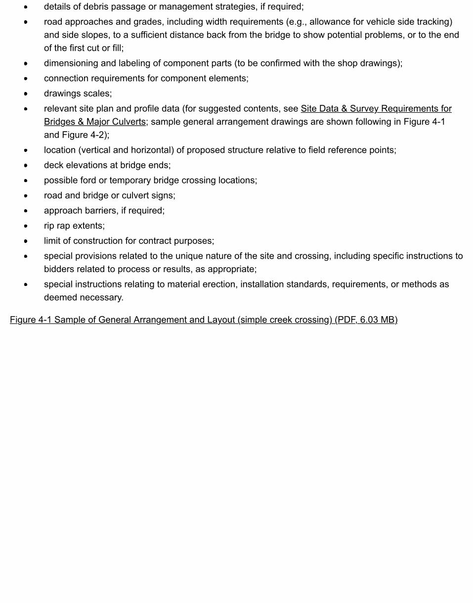
details of debris passage or management strategies, if required;road approaches and grades, including width requirements (e.g., allowance for vehicle side tracking)and side slopes, to a sufficient distance back from the bridge to show potential problems, or to the endof the first cut or fill;dimensioning and labeling of component parts (to be confirmed with the shop drawings);connection requirements for component elements;drawings scales;relevant site plan and profile data (for suggested contents, see Site Data & Survey Requirements forBridges & Major Culverts; sample general arrangement drawings are shown following in Figure 4-1and Figure 4-2);location (vertical and horizontal) of proposed structure relative to field reference points;deck elevations at bridge ends;possible ford or temporary bridge crossing locations;road and bridge or culvert signs;approach barriers, if required;rip rap extents;limit of construction for contract purposes;special provisions related to the unique nature of the site and crossing, including specific instructions tobidders related to process or results, as appropriate;special instructions relating to material erection, installation standards, requirements, or methods asdeemed necessary.
Figure 4-1 Sample of General Arrangement and Layout (simple creek crossing) (PDF, 6.03 MB)
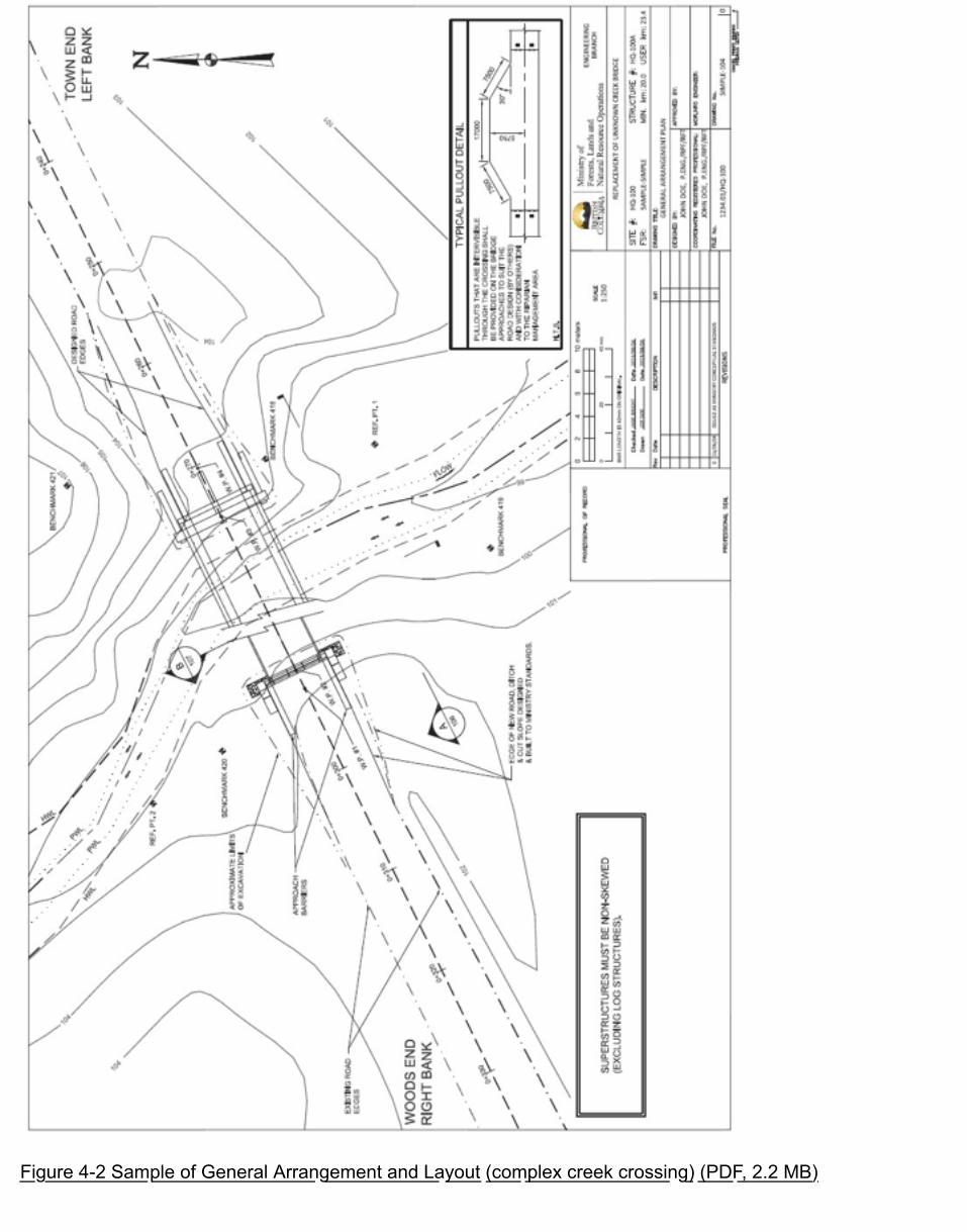
Figure 4-2 Sample of General Arrangement and Layout (complex creek crossing) (PDF, 2.2 MB)
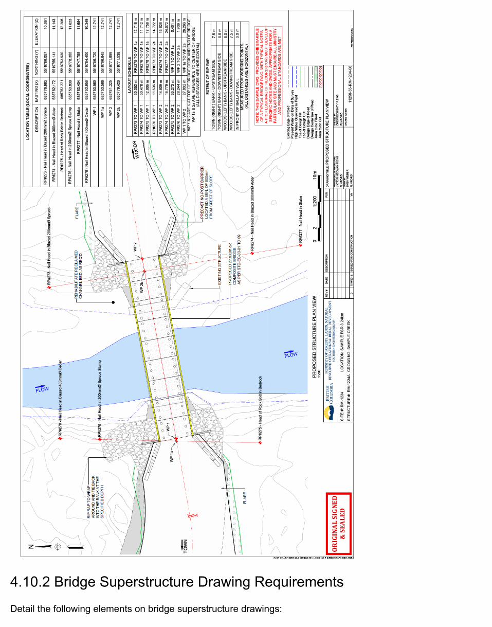
4.10.2 Bridge Superstructure Drawing Requirements
Detail the following elements on bridge superstructure drawings:

design code references, specifically those from the latest version of the CAN/CSA S6 – CanadianHighway Bridge Design Code and the Canadian Foundation Engineering Manual;individual member shapes, dimensions and connection details;materials specifications and CSA references, including but not limited to:
steel grades, impact category, finish;timber species, grades, preservative treatment;concrete strength, slump, and air entrainment;bearing materials and connections;superstructure elements, configuration, and connections;dimensions and sizes of components;girder or stringer arrangements and connections;span lengths;bridge and road width;curb and rail configuration, connections, and component elements;bridge label with structure number, date of manufacture, and load rating; andfield fabrication details.
Note that the superstructure drawings are normally supplemented by shop drawings prepared by the fabricator.
4.10.3 Bridge Substructure Drawing Requirements
Ensure that the following information on foundation requirements is detailed on the bridge substructuredrawings:
abutment elements, configuration, and connections;dimensions and sizes of components;critical elevations of substructure components;scour protection: dimensions, composition, extent of placement, design slope, design high water, andother considerations;piers;location and sizes of piles or posts;pile-driving specifications, minimum expected pile penetrations, set criteria, and required service levelcapacities;field welding requirements;bracing and sheathing configurations; andfoundation requirements, material types and depth, and compaction level.
The above requirements also apply to portable bridge superstructures.
4.10.4 Log Bridge Superstructure on Log Crib Drawing Requirements
Since log stringer and crib materials are variable in nature and finished dimensions are not uniform, log bridgedrawings are somewhat schematic. Ensure that the drawings address layout of the structure and its elements,required component sizing, and connection details.
Ensure that the following are indicated on the log bridge superstructure and log crib drawings:
schematic layout indicating width and span;reference source for stringer and needle beam sizing;minimum stringer, curb, and needle beam dimensions;stringer, curb, needle beam, and crib logs specifications, including species, quality characteristics ofacceptable logs, and seasoning;stringer-to-cap bearing details, including shim types and stringer and cap- bearing width and surfacepreparation;dap details at log connections;needle beam locations and connection details, if applicable;space to add stringer, curb, and needle beam sizes as part of the as-built record;deck layout, indicating tie sizes and spacing, plank thickness, and connections;other materials specifications, including sawn timber, hardware, and shims;excavated depth relative to scour line for mudsill or bottom bearing log;general layout and arrangement of front, wing wall, deadman, and tieback logs, and their connectionsto each other and to the bearing log or cap;description of crib fill material;layout and description of in-stream protection, if applicable; andrip rap protection layout and specifications (as required).
4.10.5 Major Culvert Drawing Requirements
Ensure that drawings and notes for major culverts portray and describe the following:
site plan (see Site Data & Survey Requirements for Bridges & Major Culverts)location of the culvert, such as a key map;design vehicle load;fill height, depth of cover, and maximum and minimum cover requirements;design slopes of fill and rip rap;culvert invert elevations at the inlet and outlet;culvert specifications and dimensions: opening dimensions, length, corrugation profile, gauge, materialtype, and inlet bevel specifications;site preparation requirements;embedment requirements, including a description of the substrate and any rock used to anchor the bedmaterial in the pipe;foundation details;backfill and installation specifications;installation camber;

culvert gradient;seepage barrier details if required;special attachments or modifications;inlet requirements (rip rap layout, stilling basin, etc.);outlet requirements (rip rap layout, stilling basin, backwater weir for fish passage);rip rap specifications, including dimensions and configuration;design high-water elevation and design discharge, inlet or outlet control;connection details for pipe sections; andany existing improvements and resource values in the vicinity of the culvert that would influence or beinfluenced by the structure.
Combine any of the above requirements may where appropriate. For example, drawings for a log stringerbridge on timber piles may include the details from Log Bridge Superstructure on Log Crib DrawingRequirements, plus those from Bridge Substructure Drawing Requirements.
Include any additional requirements for a fish stream culvert, as specified in the Fish-Stream CrossingGuidebook (PDF, 4.2MB).
4.10.6 Portable Bridge Superstructures
Where portable bridge superstructures or other structural components are used for any FS bridge project(including those bridges built under Road Permit (BCTS) and designated in that permit to be an FS bridge to beused for harvesting after completion of the Timber Sale License), the components must have been designed orstructurally analyzed by a professional engineer, to demonstrate adequacy for the intended use.
Record the ministry portable bridge superstructure number or, if there is no current superstructure number,contact the ministry engineer so that one can be assigned.
Once the components have been reviewed and approved by a professional engineer, re-use the components atnew sites without specific professional engineer review of the superstructure, provided that:
a qualified inspector has inspected the bridge at the new site before any use and does not detect anydamage or deterioration of the structure; see Chapter 6 Engineered Structured Inspections - Types ofInspections;the design loads to be carried are equal to or lower than the original design loads for thesuperstructure;the bridge is suitable and has been specifically designed or analyzed for the new site, and signed andsealed design drawings and specifications have been prepared; andthe superstructure has been fabricated and constructed in compliance with the appropriate legislation.

4.11 Bridge & Major Culvert Materials AcquisitionMaterials for FSR bridges and major culverts are acquired in two ways:
a requisition for materials through the Purchasing Commission and BC Bid; andthrough a works contract which includes supply and installation of bridges and major culverts.
In either case, all rules of government public tendering apply, and specifications and standards for bridge andculvert materials are the same.
Standard bridge materials templates for acquiring bridge materials have been developed for use and areavailable on the Engineering Branch website.
The ministry’s standard bridge material requisition templates are intended to be used primarily by MinistryEngineers and/or the professional engineer taking responsibility for a bridge structure design or installation.Bridge material requisitions need to be consistent with the design. Consult the Ministry Engineer when a bridgematerial requisition is being developed for a specific project.
Incorporate the language in the requisition templates into ministry contracts where bridge material supply isincluded in the contracted works. The design and quality assurance requirements for bridge material supplyunder direct requisition or through a design, supply, and construct contract are identical.

4.12 Bridge & Major Culvert Materials Quality & FabricationModern permanent structures have design lives that exceed 40 years. To achieve this longevity,ensure that the components are fabricated to detailed standards. Many important details (e.g.,rebar placement, concrete design, and welds) can only be inspected during the fabricationprocess.
Ensure that bridge and major culvert materials and fabrication meet minimum requirements, byrequiring materials and fabrication standards be met, including those of Canadian StandardsAssociation (CSA) and the American Society for Testing and Materials (ASTM). This provides ameans of ensuring the quality and consistency of materials, and provides equitable parametersfor competition for supply, fabrication, and erection. The requirements, as defined in thestandards, provide for a suitable blend of cost-effective and durable products. Ensure that thestandards for bridge and major culvert materials and fabrication are adhered to. In exceptionalcircumstances, there may be a reason to vary from the standards, but consult with a MinistryEngineer and Engineering Branch beforehand.
Ensure that all materials used for constructing bridges are new and conform to applicable CSA orASTM material standards in the Forest Service Bridge Design and Construction Manual. Inparticular:
Expand All | Collapse All
Concrete
Ensure that concrete is designed, mixed, transported, cast, and cured according to CSAStandard A23.1 – Concrete Materials and Methods of Concrete Construction and tested toCSA Standard A23.2 – Methods of Test for Concrete.
Precast concrete bridge elements conform to CSA Standard A23.4 – Concrete Materials andConstruction, which means fabrication by a CSA-certified precast concrete plant.
Unless otherwise required by the designer, precast concrete blocks are exempt and may besupplied by non-CSA-certified precast plants provided they meet the following specifications:
minimum 20 MPa concrete strength unless otherwise specified by a professionalengineer;single pour (must not have any cold joints); anda finish free of honeycombing.

For higher risk structures, those that consist of multiple levels of interlocking concrete blocks,or those with significant bearing pressures, ensure that quality requirements of precastconcrete blocks are more rigorous and are specified by the engineer taking responsibility forthe design.
Structural steel
Structural steel for permanent and portable bridges comply with CSA Standard CAN3-G40.21-M – Structural Quality Steels. Primary tension members of welded structures are oftype AT, grade 350 or better.
Weathering steel, type 350 AT, are not to be used for permanent bridges in marine or coastalareas or in areas where there is potential for road de-icing salts to come in contact with thebridge. Alternatively, specify galvanized or painted steel.
Steel fabrication is carried out by firms certified by the Canadian Welding Bureau (CWB) toDiv 1 or 2. A list of CWD companies can be found on the Canadian Welding Bureau (CWB)website.
Timber
Timber used for bridge construction is graded in accordance with the standard grading rulesof the Canadian Lumber Standards Administrative Board. Timber is grade-stamped, with theexception of unfinished or rough timber (in which case grading certificate may be requested),or local log stringers.
Structural timbers are Douglas-fir/larch #2 grade or better, except timber curbs may be anyspecies #2 grade or better. Note that the structure strength and other characteristics, such asdurability, make Douglas-fir/larch a superior product to other species.
Corrugated steel & hardware
Ensure that corrugated steel culverts are manufactured in accordance with CAN/CSA 3-G401 standard, Corrugated Steel Pipe Products. Steel culverts fabricated from steel sheetsneed to meet all requirements of ASTM A444, “Standard Specifications for Zinc Coated(Galvanized) Iron and Steel Sheets for Culverts and Underdrains.” Ensure that all hardwareconforms to applicable standards (that is, rivets are galvanized, and bolts and nuts areGrade C, galvanized, meeting the requirements of ASTM standard A563.
4.12.1 In-Plant Inspection of Bridge Materials & Fabrication
For any FS bridge project (including those bridges built under Road Permit (BCTS) anddesignated in that permit to be an FS bridge to be used for harvesting after completion of theTimber Sale License), bridge components assembled or manufactured off the construction site(such as treated timber, steel girders, and precast concrete footings, girders, footings or deckpanels) must be inspected during fabrication to provide quality assurance that all materials andprocedures meet the materials specifications as well as the applicable codes and standards.The costs associated with inspection are more than balanced off in terms of off- setting futureproblems with the fabricated components. The ministry engages a contractor to provide the in-plant inspection services at the various fabrication plants around the province. The in-plantquality assurance inspection contract is coordinated by the Engineering Branch.
Ensure that the fabricator producing the bridge materials provides copies of detailed shopdrawings to the in-plant inspector. The inspector confirms that the strength of materials anddetails of fabrication are consistent with the shop drawings and applicable specifications, asaccepted for the project, standards, and codes. Where discrepancies occur, the inspector notifiesthe appropriate Ministry Engineer for input on acceptability or required modifications.
For more detailed information regarding material and fabrication requirements, refer to the ForestService Bridge Design and Construction Manual.
The inspector completes an in-plant inspection report for each bridge and submits it to theMinistry Engineer.
Obtain and keep on file all relevant material documentation, such as mill test certificates, in-planttest results, field test results, and all reports or comments made by field or in-plant inspectors.
4.12.2 Structural Field Welding
Welding is a specialized field and the ministry requires minimum qualifications for companies andpersonnel involved in bridge construction.
Typically there are two types of structural welding on resource road bridges:
(a) shop fabrication of primary steel load bearing members and structural components, and
(b) field fabrication welding required for erection, assembly, and installation of bridgecomponents (e.g. connection of bearings to pipes and girders, steel braces anddiaphragms, and welded shear connectors for precast members).
Both types of structural welds are critical to the long term performance and integrity of thestructure. Structural welding on ministry bridge structures is required to conform to CanadianStandards Association (CSA) Standard W59, Welded Steel Construction (Metal Arc Welding).Firms carrying out welding on ministry structures are required to conform to CSA StandardW47.1, Certification of Companies for Fusion Welding of Steel Structures.

The Canadian Welding Bureau (CWB) is accredited by the Standards Council of Canada as aCertification Body for the administration of CSA Standards including W47.1, for :
Certification of companies involved in weldingCertification of Welding Inspection CompaniesCertification of Welding InspectorsCertification of Welding Electrodes
The CWB qualifies welders, welding procedures. The activity of the CWB contributes to the highlevel of competence enjoyed by industries employing welding and joining and the consistentprogress in welding technology, and the reliability of welded products.
All CWB certified companies are required to have certified welders and written weldingprocedures for each specific type of weld produced (Weld Data Sheets). A list of CWB certifiedcompanies is found on the Canadian Welding Bureau website.
The minimum welding certification requirements, for ministry bridge work, is CWB CertificationDivision 2 for shop fabrication and Div 3 for field welding. A Ministry Engineer or designer mayelect to specify a higher certification requirement for complex welding. Note that provincialwelding qualification is not adequate as it is different and not equivalent to CWB certification.CWB certification of the firms employing the welders, as well as conformance to CWBprocedures and standards, is required for all ministry bridge projects involving structural welding.
4.12.3 Structural Field Grouting
Structural field grout is a critical component to the safe performance and structural integrity ofministry bridges. Where structural field grouting is required, such as for composite concretedecks or shear connections for concrete slabs, mix and place the grout to attain the requiredbridge design compressive strength, and in accordance with manufacturer’s specifications. Theage of the grout should also be checked. Ideally grout should not be more than 6 months sincemanufacturer and absolutely not older than 12 months.
Manufacturer’s specifications provide for varying amounts of water which will significantly affectthe attainment of the design compressive strength within a specified time frame. Do not exceedmanufacture's maximum amount of water. It is recommended to have a vessel to measure thewater. When mixed properly, is usually somewhat fluid and is difficult to pour. Mixed grout shouldbe packed and can be vibrated into place. Where excessive water is used in mixing grout, thecure time, strength and durability of the grout are compromised. This is a serious problem wherethe grout is intended to be a structural connection, which is almost always the case for ministrybridge projects. Monitor grout mixing and placement procedures and ensure adherence tomanufacturer’s specifications. Utilize minimal amount of water in order to attain the requireddesign strengths.

It is also noted that other factors influence set time such as the ambient temperature over whichthere is limited ability to control. Additional precautions are required for mixing and placingconcrete or grout in cold or hot weather extremes. Placing of concrete products during extremecold or hot weather has the potential to affect both the long term strength and durability andprocedures should be reviewed by a Ministry Engineer.
Low temperatures during the placement and curing of grout can affect the ultimate strength anddurability of gout both temporarily and permanently. Grout cures slower in cold temperatures anddevelops ultimate strengths over longer periods of time. Exposure of fresh concrete totemperatures below freezing may actually stop the curing (hydration) process.
Hot weather can have a negative impact on both plastic and hardened state of concrete. Hotweather affects all of the major components of grout including water, cement and aggregates. Hotweather also has an impact on batching, mixing and placing of grout.
Precautions must be taken in advance of grouting operations that are anticipated to be effectedby cold or hot weather.
Expand All | Collapse All
Cold weather grout procedures
In “cold weather” conditions it is important to protect the concrete from freezing and tomaintain curing conditions to ensure sufficient strength and durability to satisfy intendedservice requirements. When temperatures drop or will potentially drop below 5 degreesCelsius, cold weather procedures should be implemented. Cold weather procedures mayextend beyond heating the water used to mix the grout and will need to address forecasttemperature conditions. Preheating and continued heating for the initial set period for theconcrete or grout may be required to ensure that the curing of concrete or grout is notaffected by cold temperatures and kept from freezing. If the concrete deck panels or slabsare not pre-heated, they will draw the heat out of the grout and will increase the possibility ofthe grout freezing in subzero temperatures. If the grout is not preheated, it will dramaticallyreduce the temperature of the heated water when mixed. The heat of hydration of the groutis not sufficient to keep the grout from freezing in subzero temperatures particularly if theconcrete deck panels or slabs are cold. If the grout freezes, it will most likely need to beextracted and redone which is a highly labour intensive and laborious process to be avoided.
Precautions may include some or all of the following:1. Pre-warm the dry mix grout and components being grouted to above 10 degrees
Celsius. The temperature during the initial 24 hours of cure time should be maintainedabove 10 degrees centigrade. The components’ temperature should be kept abovefreezing for a minimum of 72 hours subsequent to grout placement. Ensure compliancewith the manufacturer’s specifications in order to meet the specified compressive
strength within the required time frame.
Practices that have been typically implemented consist of wrapping the structure intarps and heating from beneath the structure using suitable heaters. Various types oftarps and covers have been used including: plastic sheeting, construction tarps, lumberwrap and even non-woven geotextile. The basic concept is using the wrapping tocontain the heat from a heat source such as a tiger torch or propane heater and towarm the components that are being grouted. The wrapping would cover the deck anddrape below the bridge to capture the rising heat. The dry mix grout can be placed onthe deck, under the wrap and be heated with the deck or slabs. For steel girderbridges, it may be sufficient to have a heat source between the girders to keep thedeck sufficiently warm through the grouting placement and initial setting. Exercisecaution to ensure that any heat source be directed away from any bridge componentsto avoid adversely warping steel components or cause cracking of concrete.
1. Use warm water (20 degrees centigrade) in mixing the grout.2. Provide sufficient labor to minimize the time required to place and finish the grouting
process, to minimize the handling time of the grout and resulting heat loss.
Hot weather grout procedures
Higher temperatures cause water to evaporate from the surface of grout at a much fasterrate and cement hydration occurs more quickly, causing the grout to stiffen earlier, lesseningworkability, increasing the chances of plastic cracking and reducing ultimate strength.
Precautions may include some or all of the following:1. Moisten precast components, steel reinforcement, and form work prior to grout
placement.2. Keep the grout cool prior to mixing, store in a cool location. Use cold water or ice, as a
part of the mixing water. Ice should be crushed, shaved or chipped form and must beconsidered as part of the mix design. Mixing should continue until all of the ice iscompletely melted.
3. Use a grout consistency that allows rapid placement and consolidation within acceptabletolerances to achieve the required design strength.
4. Provide sufficient labor to minimize the time required to place and finish the groutingprocess, as hot weather conditions substantially shorten the times to initial and final set.
5. Maintain moisture for the curing process by covering with damp burlap, and periodicallyrewetting, to maintain moisture as the grout sets, as soon as possible after the groutfinishing processes have been completed.
6. In extreme conditions consider adjusting the time of concrete placement to takeadvantage of cooler temperatures, such as early morning or night time placement.

Grout field sampling during field placement
Acquiring samples to allow for compressive testing of field placed structural grout is standardpractice for Ministry bridges. The Ministry procedure for grout sampling of in-situ placedstructural grout, used for composite precast concrete decks on steel girders and precastconcrete slab bridges with grouted shear connections, is in Appendix 4.5. The samplingprocedure is to be provided to and followed by the individuals tasked with taking the groutsamples in the field for each particular bridge project placing structural grout in the fieldduring construction. The grout sampling procedure may also be implemented for otherstructural grout applications as may be appropriate.
This Ministry procedure provides instructions on how to take representative samples of thegrout that has been placed in the field. The cured grout samples will provide the ability tolater test for compressive strength attained at appropriate times to assess the adequacy ofthe grout. This sampling and testing procedure is not fully consistent with various publishedCanadian or American standards for grout testing, but rather it is a hybrid of standards toaccommodate Ministry ’s particular needs. Various standards (e.g., ASTM, CSA) specify thatgrout would typically be tested using 50mm cubes. However, the cube molds are costly andwould not be readily distributed where required for our needs. The cylindrical molds areapplicable to our utilization and their shape allows them to be tested for compressivestrength in a laboratory. Local material testing laboratories will have the capability to test thesamples and the testing costs range from $20 – $30 per sample.
Taking grout samples
The initial set time for the sampled grout is a critical factor. Allowing the samples to cure in-situ, at minimum, overnight, will provide an approximate representation of the fieldconditions. These samples are not precise replicas of the grout in the field but should providea very good indication of quality and strength. Increasing the minimum number of requiredsamples or specifying longer field curing times shall be at the discretion of the MinistryEngineer.
Distributing grout sample molds
Suggested approach for distributing the cylinders – provide an envelope with an adequatenumber of cylinders, labels and one page instruction sheet included, to the party responsiblefor obtaining the samples. Would suggest discussing the procedure with the individual,identifying how the sample should be handled and placed subsequent to casting and whothe sample should be provided to subsequent to initial set.
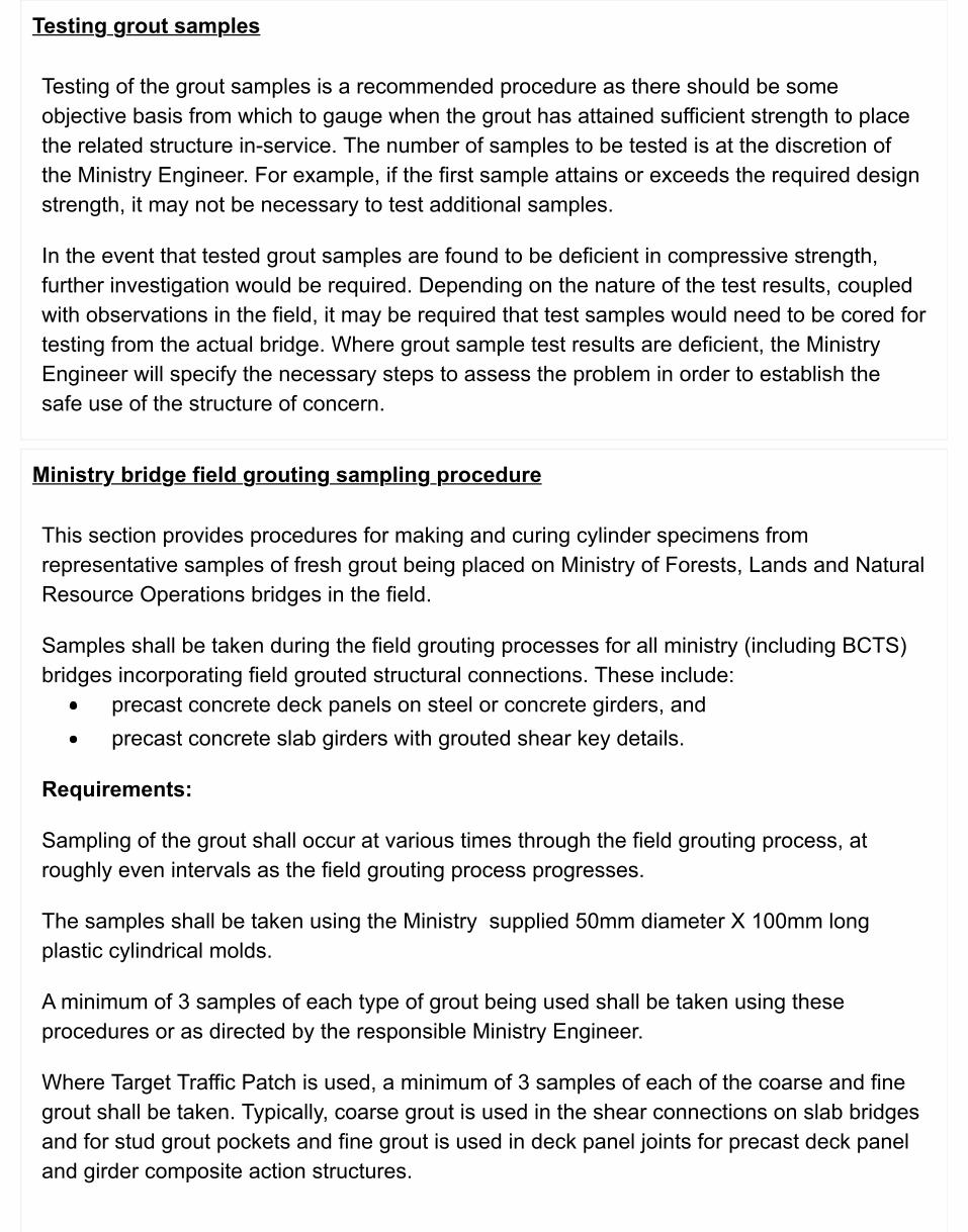
Testing grout samples
Testing of the grout samples is a recommended procedure as there should be someobjective basis from which to gauge when the grout has attained sufficient strength to placethe related structure in-service. The number of samples to be tested is at the discretion ofthe Ministry Engineer. For example, if the first sample attains or exceeds the required designstrength, it may not be necessary to test additional samples.
In the event that tested grout samples are found to be deficient in compressive strength,further investigation would be required. Depending on the nature of the test results, coupledwith observations in the field, it may be required that test samples would need to be cored fortesting from the actual bridge. Where grout sample test results are deficient, the MinistryEngineer will specify the necessary steps to assess the problem in order to establish thesafe use of the structure of concern.
Ministry bridge field grouting sampling procedure
This section provides procedures for making and curing cylinder specimens fromrepresentative samples of fresh grout being placed on Ministry of Forests, Lands and NaturalResource Operations bridges in the field.
Samples shall be taken during the field grouting processes for all ministry (including BCTS)bridges incorporating field grouted structural connections. These include:
precast concrete deck panels on steel or concrete girders, andprecast concrete slab girders with grouted shear key details.
Requirements:
Sampling of the grout shall occur at various times through the field grouting process, atroughly even intervals as the field grouting process progresses.
The samples shall be taken using the Ministry supplied 50mm diameter X 100mm longplastic cylindrical molds.
A minimum of 3 samples of each type of grout being used shall be taken using theseprocedures or as directed by the responsible Ministry Engineer.
Where Target Traffic Patch is used, a minimum of 3 samples of each of the coarse and finegrout shall be taken. Typically, coarse grout is used in the shear connections on slab bridgesand for stud grout pockets and fine grout is used in deck panel joints for precast deck paneland girder composite action structures.

Grout samples shall be provided to the Ministry Engineer or provided to the individualidentified in contract documents or specifications.
Procedure:1. A sample of representative fully mixed grout that is ready for placing shall be taken.2. Fill a cylindrical mold approximately halfway with grout.3. Using a blunt non absorbent rod, approximately 10mm in diameter and 250mm in length
(such as a spike head), uniformly over the cross section, rod the grout to the bottom ofthe mold 15 times.
4. Slightly overfill the mold with the second layer of grout and rod 15 times, evenlydistributing over the cross section, and approximately 13mm into the bottom layer.
5. Strike off the top surface of the mold with a flat edge trowel, or other suitablestraightedge, to remove excess grout and create a flat top surface.
6. Cover the mold with a damp cloth or paper towel and set the sample aside on site in asafe, flat location where the mold will not be disturbed for a minimum of 12 hours orovernight. The location should be representative of the conditions of the placed groutsuch as on the deck of the grouted surface or on the inside flange of a steel girder.Longer field curing times shall be at the discretion of the Ministry Engineer.
7. Ensure that a supplied, self adhesive, label is completed and placed on each groutsample.

4.13 Major Culvert ConstructionEnsure that major culvert installations receive compaction to obtain adequate structural integrity of theinstallation because culverts are generally soil-steel structures. The culvert itself will not support the designload without the soil-steel interaction. In order for the soil to work with the steel to support the design load, theculvert is adequately “bedded” and the soil appropriately compacted to be “structural.” The flexible steel isdesigned to distribute loads to the bedding and backfill surrounding it. Soil is most compactable when it iscomposed of select granular, free-draining material. Ensure that the backfill conforms to a specified sizegradation.
Typical backfill compaction is the minimum Standard Proctor Density of 95%. To achieve that level ofcompaction, use hand tools to work smaller areas (between corrugations); mechanical compactors such asplate and jumping jack tampers; or rollers and vibrating compactor equipment.
Typical construction practices include the following:
Provide adequate bedding before culverts are installed and backfilled. Where subgrade material isunsuitable, remove it and replace it with select granular, free-draining material compacted to supportthe culvert.Place and compact backfill in uniform layers, about 150–300 mm thick (compaction equipment andlayer thickness as specified by the designer) of select granular, free-draining material on each side ofthe culvert in a balanced and progressive manner, to avoid potential distortion or displacement of theculvert.Remove cobbles and boulders from the backfill, particularly where they could contact the culvert. Usehand tools to compact the material immediately adjacent to the culvert within the corrugations. Fullycompact each layer before the next layer is placed on top.Monitor compaction and complete compaction testing as specified by the designer.Avoid over-compaction of the backfill to prevent distorting the culvert. Continue backfill and compactionabove the culvert, as specified in the design. Establish minimum culvert cover before any equipmentloads are applied.

4.12 Bridge & Major Culvert Materials Quality & FabricationModern permanent structures have design lives that exceed 40 years. To achieve this longevity,ensure that the components are fabricated to detailed standards. Many important details (e.g.,rebar placement, concrete design, and welds) can only be inspected during the fabricationprocess.
Ensure that bridge and major culvert materials and fabrication meet minimum requirements, byrequiring materials and fabrication standards be met, including those of Canadian StandardsAssociation (CSA) and the American Society for Testing and Materials (ASTM). This provides ameans of ensuring the quality and consistency of materials, and provides equitable parametersfor competition for supply, fabrication, and erection. The requirements, as defined in thestandards, provide for a suitable blend of cost-effective and durable products. Ensure that thestandards for bridge and major culvert materials and fabrication are adhered to. In exceptionalcircumstances, there may be a reason to vary from the standards, but consult with a MinistryEngineer and Engineering Branch beforehand.
Ensure that all materials used for constructing bridges are new and conform to applicable CSA orASTM material standards in the Forest Service Bridge Design and Construction Manual. Inparticular:
Expand All | Collapse All
Concrete
Ensure that concrete is designed, mixed, transported, cast, and cured according to CSAStandard A23.1 – Concrete Materials and Methods of Concrete Construction and tested toCSA Standard A23.2 – Methods of Test for Concrete.
Precast concrete bridge elements conform to CSA Standard A23.4 – Concrete Materials andConstruction, which means fabrication by a CSA-certified precast concrete plant.
Unless otherwise required by the designer, precast concrete blocks are exempt and may besupplied by non-CSA-certified precast plants provided they meet the following specifications:
minimum 20 MPa concrete strength unless otherwise specified by a professionalengineer;single pour (must not have any cold joints); anda finish free of honeycombing.

For higher risk structures, those that consist of multiple levels of interlocking concrete blocks,or those with significant bearing pressures, ensure that quality requirements of precastconcrete blocks are more rigorous and are specified by the engineer taking responsibility forthe design.
Structural steel
Structural steel for permanent and portable bridges comply with CSA Standard CAN3-G40.21-M – Structural Quality Steels. Primary tension members of welded structures are oftype AT, grade 350 or better.
Weathering steel, type 350 AT, are not to be used for permanent bridges in marine or coastalareas or in areas where there is potential for road de-icing salts to come in contact with thebridge. Alternatively, specify galvanized or painted steel.
Steel fabrication is carried out by firms certified by the Canadian Welding Bureau (CWB) toDiv 1 or 2. A list of CWD companies can be found on the Canadian Welding Bureau (CWB)website.
Timber
Timber used for bridge construction is graded in accordance with the standard grading rulesof the Canadian Lumber Standards Administrative Board. Timber is grade-stamped, with theexception of unfinished or rough timber (in which case grading certificate may be requested),or local log stringers.
Structural timbers are Douglas-fir/larch #2 grade or better, except timber curbs may be anyspecies #2 grade or better. Note that the structure strength and other characteristics, such asdurability, make Douglas-fir/larch a superior product to other species.
Corrugated steel & hardware
Ensure that corrugated steel culverts are manufactured in accordance with CAN/CSA 3-G401 standard, Corrugated Steel Pipe Products. Steel culverts fabricated from steel sheetsneed to meet all requirements of ASTM A444, “Standard Specifications for Zinc Coated(Galvanized) Iron and Steel Sheets for Culverts and Underdrains.” Ensure that all hardwareconforms to applicable standards (that is, rivets are galvanized, and bolts and nuts areGrade C, galvanized, meeting the requirements of ASTM standard A563.
4.12.1 In-Plant Inspection of Bridge Materials & Fabrication

For any FS bridge project (including those bridges built under Road Permit (BCTS) anddesignated in that permit to be an FS bridge to be used for harvesting after completion of theTimber Sale License), bridge components assembled or manufactured off the construction site(such as treated timber, steel girders, and precast concrete footings, girders, footings or deckpanels) must be inspected during fabrication to provide quality assurance that all materials andprocedures meet the materials specifications as well as the applicable codes and standards.The costs associated with inspection are more than balanced off in terms of off- setting futureproblems with the fabricated components. The ministry engages a contractor to provide the in-plant inspection services at the various fabrication plants around the province. The in-plantquality assurance inspection contract is coordinated by the Engineering Branch.
Ensure that the fabricator producing the bridge materials provides copies of detailed shopdrawings to the in-plant inspector. The inspector confirms that the strength of materials anddetails of fabrication are consistent with the shop drawings and applicable specifications, asaccepted for the project, standards, and codes. Where discrepancies occur, the inspector notifiesthe appropriate Ministry Engineer for input on acceptability or required modifications.
For more detailed information regarding material and fabrication requirements, refer to the ForestService Bridge Design and Construction Manual.
The inspector completes an in-plant inspection report for each bridge and submits it to theMinistry Engineer.
Obtain and keep on file all relevant material documentation, such as mill test certificates, in-planttest results, field test results, and all reports or comments made by field or in-plant inspectors.
4.12.2 Structural Field Welding
Welding is a specialized field and the ministry requires minimum qualifications for companies andpersonnel involved in bridge construction.
Typically there are two types of structural welding on resource road bridges:
(a) shop fabrication of primary steel load bearing members and structural components, and
(b) field fabrication welding required for erection, assembly, and installation of bridgecomponents (e.g. connection of bearings to pipes and girders, steel braces anddiaphragms, and welded shear connectors for precast members).
Both types of structural welds are critical to the long term performance and integrity of thestructure. Structural welding on ministry bridge structures is required to conform to CanadianStandards Association (CSA) Standard W59, Welded Steel Construction (Metal Arc Welding).Firms carrying out welding on ministry structures are required to conform to CSA StandardW47.1, Certification of Companies for Fusion Welding of Steel Structures.

The Canadian Welding Bureau (CWB) is accredited by the Standards Council of Canada as aCertification Body for the administration of CSA Standards including W47.1, for :
Certification of companies involved in weldingCertification of Welding Inspection CompaniesCertification of Welding InspectorsCertification of Welding Electrodes
The CWB qualifies welders, welding procedures. The activity of the CWB contributes to the highlevel of competence enjoyed by industries employing welding and joining and the consistentprogress in welding technology, and the reliability of welded products.
All CWB certified companies are required to have certified welders and written weldingprocedures for each specific type of weld produced (Weld Data Sheets). A list of CWB certifiedcompanies is found on the Canadian Welding Bureau website.
The minimum welding certification requirements, for ministry bridge work, is CWB CertificationDivision 2 for shop fabrication and Div 3 for field welding. A Ministry Engineer or designer mayelect to specify a higher certification requirement for complex welding. Note that provincialwelding qualification is not adequate as it is different and not equivalent to CWB certification.CWB certification of the firms employing the welders, as well as conformance to CWBprocedures and standards, is required for all ministry bridge projects involving structural welding.
4.12.3 Structural Field Grouting
Structural field grout is a critical component to the safe performance and structural integrity ofministry bridges. Where structural field grouting is required, such as for composite concretedecks or shear connections for concrete slabs, mix and place the grout to attain the requiredbridge design compressive strength, and in accordance with manufacturer’s specifications. Theage of the grout should also be checked. Ideally grout should not be more than 6 months sincemanufacturer and absolutely not older than 12 months.
Manufacturer’s specifications provide for varying amounts of water which will significantly affectthe attainment of the design compressive strength within a specified time frame. Do not exceedmanufacture's maximum amount of water. It is recommended to have a vessel to measure thewater. When mixed properly, is usually somewhat fluid and is difficult to pour. Mixed grout shouldbe packed and can be vibrated into place. Where excessive water is used in mixing grout, thecure time, strength and durability of the grout are compromised. This is a serious problem wherethe grout is intended to be a structural connection, which is almost always the case for ministrybridge projects. Monitor grout mixing and placement procedures and ensure adherence tomanufacturer’s specifications. Utilize minimal amount of water in order to attain the requireddesign strengths.

It is also noted that other factors influence set time such as the ambient temperature over whichthere is limited ability to control. Additional precautions are required for mixing and placingconcrete or grout in cold or hot weather extremes. Placing of concrete products during extremecold or hot weather has the potential to affect both the long term strength and durability andprocedures should be reviewed by a Ministry Engineer.
Low temperatures during the placement and curing of grout can affect the ultimate strength anddurability of gout both temporarily and permanently. Grout cures slower in cold temperatures anddevelops ultimate strengths over longer periods of time. Exposure of fresh concrete totemperatures below freezing may actually stop the curing (hydration) process.
Hot weather can have a negative impact on both plastic and hardened state of concrete. Hotweather affects all of the major components of grout including water, cement and aggregates. Hotweather also has an impact on batching, mixing and placing of grout.
Precautions must be taken in advance of grouting operations that are anticipated to be effectedby cold or hot weather.
Expand All | Collapse All
Cold weather grout procedures
In “cold weather” conditions it is important to protect the concrete from freezing and tomaintain curing conditions to ensure sufficient strength and durability to satisfy intendedservice requirements. When temperatures drop or will potentially drop below 5 degreesCelsius, cold weather procedures should be implemented. Cold weather procedures mayextend beyond heating the water used to mix the grout and will need to address forecasttemperature conditions. Preheating and continued heating for the initial set period for theconcrete or grout may be required to ensure that the curing of concrete or grout is notaffected by cold temperatures and kept from freezing. If the concrete deck panels or slabsare not pre-heated, they will draw the heat out of the grout and will increase the possibility ofthe grout freezing in subzero temperatures. If the grout is not preheated, it will dramaticallyreduce the temperature of the heated water when mixed. The heat of hydration of the groutis not sufficient to keep the grout from freezing in subzero temperatures particularly if theconcrete deck panels or slabs are cold. If the grout freezes, it will most likely need to beextracted and redone which is a highly labour intensive and laborious process to be avoided.
Precautions may include some or all of the following:1. Pre-warm the dry mix grout and components being grouted to above 10 degrees
Celsius. The temperature during the initial 24 hours of cure time should be maintainedabove 10 degrees centigrade. The components’ temperature should be kept abovefreezing for a minimum of 72 hours subsequent to grout placement. Ensure compliancewith the manufacturer’s specifications in order to meet the specified compressive

strength within the required time frame.
Practices that have been typically implemented consist of wrapping the structure intarps and heating from beneath the structure using suitable heaters. Various types oftarps and covers have been used including: plastic sheeting, construction tarps, lumberwrap and even non-woven geotextile. The basic concept is using the wrapping tocontain the heat from a heat source such as a tiger torch or propane heater and towarm the components that are being grouted. The wrapping would cover the deck anddrape below the bridge to capture the rising heat. The dry mix grout can be placed onthe deck, under the wrap and be heated with the deck or slabs. For steel girderbridges, it may be sufficient to have a heat source between the girders to keep thedeck sufficiently warm through the grouting placement and initial setting. Exercisecaution to ensure that any heat source be directed away from any bridge componentsto avoid adversely warping steel components or cause cracking of concrete.
1. Use warm water (20 degrees centigrade) in mixing the grout.2. Provide sufficient labor to minimize the time required to place and finish the grouting
process, to minimize the handling time of the grout and resulting heat loss.
Hot weather grout procedures
Higher temperatures cause water to evaporate from the surface of grout at a much fasterrate and cement hydration occurs more quickly, causing the grout to stiffen earlier, lesseningworkability, increasing the chances of plastic cracking and reducing ultimate strength.
Precautions may include some or all of the following:1. Moisten precast components, steel reinforcement, and form work prior to grout
placement.2. Keep the grout cool prior to mixing, store in a cool location. Use cold water or ice, as a
part of the mixing water. Ice should be crushed, shaved or chipped form and must beconsidered as part of the mix design. Mixing should continue until all of the ice iscompletely melted.
3. Use a grout consistency that allows rapid placement and consolidation within acceptabletolerances to achieve the required design strength.
4. Provide sufficient labor to minimize the time required to place and finish the groutingprocess, as hot weather conditions substantially shorten the times to initial and final set.
5. Maintain moisture for the curing process by covering with damp burlap, and periodicallyrewetting, to maintain moisture as the grout sets, as soon as possible after the groutfinishing processes have been completed.
6. In extreme conditions consider adjusting the time of concrete placement to takeadvantage of cooler temperatures, such as early morning or night time placement.

Grout field sampling during field placement
Acquiring samples to allow for compressive testing of field placed structural grout is standardpractice for Ministry bridges. The Ministry procedure for grout sampling of in-situ placedstructural grout, used for composite precast concrete decks on steel girders and precastconcrete slab bridges with grouted shear connections, is in Appendix 4.5. The samplingprocedure is to be provided to and followed by the individuals tasked with taking the groutsamples in the field for each particular bridge project placing structural grout in the fieldduring construction. The grout sampling procedure may also be implemented for otherstructural grout applications as may be appropriate.
This Ministry procedure provides instructions on how to take representative samples of thegrout that has been placed in the field. The cured grout samples will provide the ability tolater test for compressive strength attained at appropriate times to assess the adequacy ofthe grout. This sampling and testing procedure is not fully consistent with various publishedCanadian or American standards for grout testing, but rather it is a hybrid of standards toaccommodate Ministry ’s particular needs. Various standards (e.g., ASTM, CSA) specify thatgrout would typically be tested using 50mm cubes. However, the cube molds are costly andwould not be readily distributed where required for our needs. The cylindrical molds areapplicable to our utilization and their shape allows them to be tested for compressivestrength in a laboratory. Local material testing laboratories will have the capability to test thesamples and the testing costs range from $20 – $30 per sample.
Taking grout samples
The initial set time for the sampled grout is a critical factor. Allowing the samples to cure in-situ, at minimum, overnight, will provide an approximate representation of the fieldconditions. These samples are not precise replicas of the grout in the field but should providea very good indication of quality and strength. Increasing the minimum number of requiredsamples or specifying longer field curing times shall be at the discretion of the MinistryEngineer.
Distributing grout sample molds
Suggested approach for distributing the cylinders – provide an envelope with an adequatenumber of cylinders, labels and one page instruction sheet included, to the party responsiblefor obtaining the samples. Would suggest discussing the procedure with the individual,identifying how the sample should be handled and placed subsequent to casting and whothe sample should be provided to subsequent to initial set.

Testing grout samples
Testing of the grout samples is a recommended procedure as there should be someobjective basis from which to gauge when the grout has attained sufficient strength to placethe related structure in-service. The number of samples to be tested is at the discretion ofthe Ministry Engineer. For example, if the first sample attains or exceeds the required designstrength, it may not be necessary to test additional samples.
In the event that tested grout samples are found to be deficient in compressive strength,further investigation would be required. Depending on the nature of the test results, coupledwith observations in the field, it may be required that test samples would need to be cored fortesting from the actual bridge. Where grout sample test results are deficient, the MinistryEngineer will specify the necessary steps to assess the problem in order to establish thesafe use of the structure of concern.
Ministry bridge field grouting sampling procedure
This section provides procedures for making and curing cylinder specimens fromrepresentative samples of fresh grout being placed on Ministry of Forests, Lands and NaturalResource Operations bridges in the field.
Samples shall be taken during the field grouting processes for all ministry (including BCTS)bridges incorporating field grouted structural connections. These include:
precast concrete deck panels on steel or concrete girders, andprecast concrete slab girders with grouted shear key details.
Requirements:
Sampling of the grout shall occur at various times through the field grouting process, atroughly even intervals as the field grouting process progresses.
The samples shall be taken using the Ministry supplied 50mm diameter X 100mm longplastic cylindrical molds.
A minimum of 3 samples of each type of grout being used shall be taken using theseprocedures or as directed by the responsible Ministry Engineer.
Where Target Traffic Patch is used, a minimum of 3 samples of each of the coarse and finegrout shall be taken. Typically, coarse grout is used in the shear connections on slab bridgesand for stud grout pockets and fine grout is used in deck panel joints for precast deck paneland girder composite action structures.

Grout samples shall be provided to the Ministry Engineer or provided to the individualidentified in contract documents or specifications.
Procedure:1. A sample of representative fully mixed grout that is ready for placing shall be taken.2. Fill a cylindrical mold approximately halfway with grout.3. Using a blunt non absorbent rod, approximately 10mm in diameter and 250mm in length
(such as a spike head), uniformly over the cross section, rod the grout to the bottom ofthe mold 15 times.
4. Slightly overfill the mold with the second layer of grout and rod 15 times, evenlydistributing over the cross section, and approximately 13mm into the bottom layer.
5. Strike off the top surface of the mold with a flat edge trowel, or other suitablestraightedge, to remove excess grout and create a flat top surface.
6. Cover the mold with a damp cloth or paper towel and set the sample aside on site in asafe, flat location where the mold will not be disturbed for a minimum of 12 hours orovernight. The location should be representative of the conditions of the placed groutsuch as on the deck of the grouted surface or on the inside flange of a steel girder.Longer field curing times shall be at the discretion of the Ministry Engineer.
7. Ensure that a supplied, self adhesive, label is completed and placed on each groutsample.

4.13 Major Culvert ConstructionEnsure that major culvert installations receive compaction to obtain adequate structural integrity of theinstallation because culverts are generally soil-steel structures. The culvert itself will not support the designload without the soil-steel interaction. In order for the soil to work with the steel to support the design load, theculvert is adequately “bedded” and the soil appropriately compacted to be “structural.” The flexible steel isdesigned to distribute loads to the bedding and backfill surrounding it. Soil is most compactable when it iscomposed of select granular, free-draining material. Ensure that the backfill conforms to a specified sizegradation.
Typical backfill compaction is the minimum Standard Proctor Density of 95%. To achieve that level ofcompaction, use hand tools to work smaller areas (between corrugations); mechanical compactors such asplate and jumping jack tampers; or rollers and vibrating compactor equipment.
Typical construction practices include the following:
Provide adequate bedding before culverts are installed and backfilled. Where subgrade material isunsuitable, remove it and replace it with select granular, free-draining material compacted to supportthe culvert.Place and compact backfill in uniform layers, about 150–300 mm thick (compaction equipment andlayer thickness as specified by the designer) of select granular, free-draining material on each side ofthe culvert in a balanced and progressive manner, to avoid potential distortion or displacement of theculvert.Remove cobbles and boulders from the backfill, particularly where they could contact the culvert. Usehand tools to compact the material immediately adjacent to the culvert within the corrugations. Fullycompact each layer before the next layer is placed on top.Monitor compaction and complete compaction testing as specified by the designer.Avoid over-compaction of the backfill to prevent distorting the culvert. Continue backfill and compactionabove the culvert, as specified in the design. Establish minimum culvert cover before any equipmentloads are applied.

4.14 Use & Role of Environmental MonitorsAn environmental monitor inspects site activities for:
conformance with construction work plans that incorporate measures to protect forest resources inaccordance with legislative requirements; orduring active development operations in sensitive habitats and ecosystems.
Retain an environmental monitor on a site specific project basis when specified in an environmentalmanagement plan or where required by an environmental agency (such as where bridge or major culvertconstruction occurs in critical or important fish habitats, or where instream work is approved outside of thefisheries timing window).
For appropriate qualifications for environmental monitors, see the Engineering Equipment and Services (EES)Directory under two categories:
[Professional Environmental Monitoring (RPBio)][Technical Environmental Monitoring]
Where an environmental monitor may be warranted, the scope of duties may include:
1. liaise with ministry staff or other regulatory agencies;2. observe, record, and photograph the baseline site conditions before work commences and identify any
significant (material adverse) changes in site conditions during and after work;3. attend the pre-work meeting and other project meetings as necessary, and provide assistance to the
Licensee/Permittee/Contractor or ministry to assess conformance with the construction contract workplans, contract conditions, and BCTS EMS requirements (e.g., EFPs; Hazardous Materials SpillPreparedness Responsibilities and Spill Action Steps; Landslide and Major Erosion Event Response andErosion Action Steps; and EMS documentation requirements);
4. conduct on-site field visits either continuously or periodically to observe active operations; the timing andduration of field visits will depend on the type and complexity of the work, and on the sensitivity of the siteand forest resource values at risk of damage or loss;
5. during field visits, evaluate the adequacy of erosion and sediment control techniques, including workprocedures for instream work, construction and diversions on watercourses, and observe, record, andphotograph site conditions and work procedures;
6. provide practical and appropriate options to protect or minimize harmful effects to fish and fish habitat ifchanges to the work occur due to unforeseen circumstances;
7. modify or stop operations if the following occurs:
site activities do not conform with approved construction contract work plans and contractconditions;work activities lead to harmful levels of sediment entering a stream;
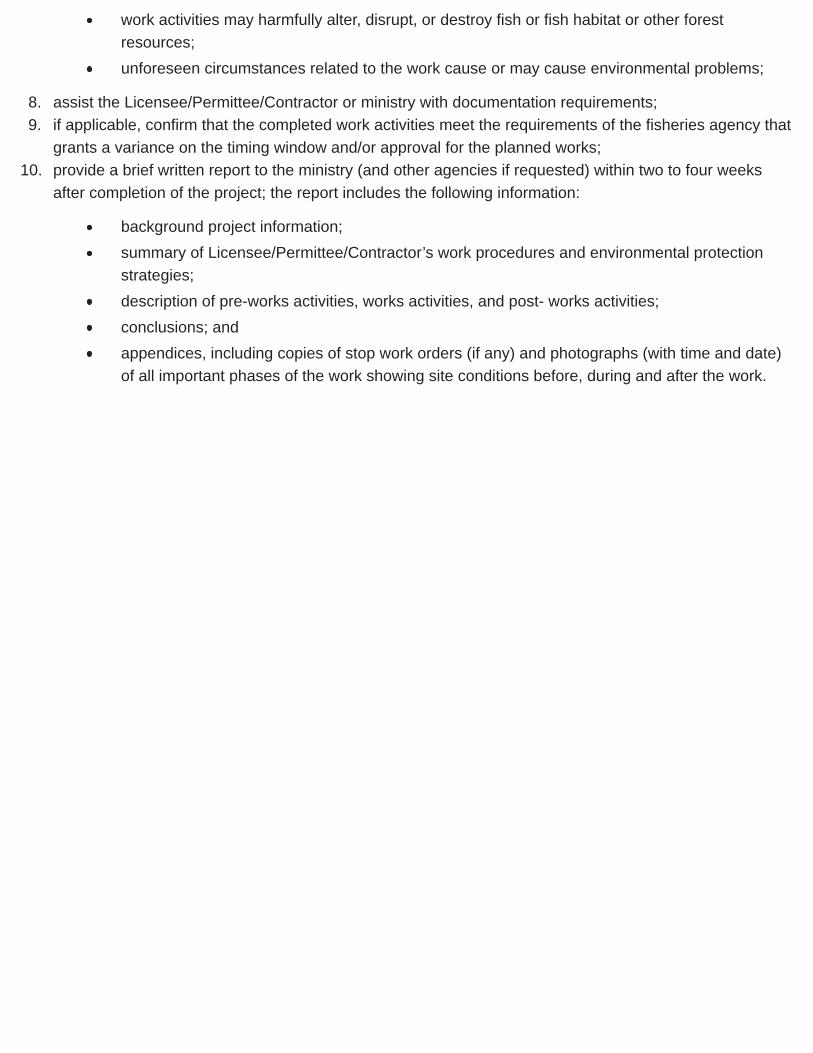
work activities may harmfully alter, disrupt, or destroy fish or fish habitat or other forestresources;unforeseen circumstances related to the work cause or may cause environmental problems;
8. assist the Licensee/Permittee/Contractor or ministry with documentation requirements;9. if applicable, confirm that the completed work activities meet the requirements of the fisheries agency that
grants a variance on the timing window and/or approval for the planned works;10. provide a brief written report to the ministry (and other agencies if requested) within two to four weeks
after completion of the project; the report includes the following information:
background project information;summary of Licensee/Permittee/Contractor’s work procedures and environmental protectionstrategies;description of pre-works activities, works activities, and post- works activities;conclusions; andappendices, including copies of stop work orders (if any) and photographs (with time and date)of all important phases of the work showing site conditions before, during and after the work.

4.15 Construction DocumentationAfter construction of a bridge or major culvert, ensure that the following as-built records are obtained and kepton file:
actual log stringer, curb, needle beam and crib log sizes (diameter and length for each member);pertinent construction data including, but not limited to, any pile driving records, hammer type,penetration, set criteria, and any critical dimensions;fabrication plant inspection reports, including mill test certificates and concrete test results;shop or as-built fabrication drawings;geosynthetic material identification;concrete and grout test results;field compaction results;confirmation of scour protection requirements;footing base elevation, deck elevation, and alignment location; andother pertinent fabrication, field, and construction data.
As-built drawings are normally the “approved for construction” drawings that are marked up to show allsignificant variations from the original design. Ensure that the as-built drawings see sample (PDF) are signedand sealed by the Coordinating Registered Professional. Where the original design has been modified, thesedrawings should have been amended accordingly by the designer before the as- built notes and details areinserted.
Ensure that a BCTS/District engineering technician inspects the completed bridge for acceptability/assuranceof the structure, often as part of the inspection for contract completion. Forward the package of statement ofconformance, as built drawings and field note from the engineering specialist to the Ministry Engineer forreview for completeness and acceptability.
Add all completed FS bridges to the appropriate BCTS/Timber Pricing and Operations Division file records androad and bridge data base.

4.16 Resources & Suggestions for Further ReadingHandbook of steel drainage and highway construction products, 2007 (PDF, 13.3MB). Can. ed. CorrugatedSteel Pipe Institute, Cambridge, Ontario.
BC Ministry of Forests. 1997. Forest service bridge design and construction manual. Victoria, BC.
__________________. 1981. Log bridge stringers and needle beam sizing - Metric Edition (PDF, 3.96 MB).Design Section, Engineering Branch. Victoria, BC.
Canadian Geotechnical Society. 1993. Canadian Foundation Engineering Manual. Richmond, BC
Canadian Standards Association. R2005. Canadian highway bridge design code (CAN/CSA S6-00).Mississauga, Ont.
Nagy, M.M., J.T. Trebett, G.V. Wellburn, and L.E. Gower. Second Edition. 1989. {{{{{{Log bridgeconstruction handbook}}}}}}. For. Eng. Research Inst. Can. (FERIC), Vancouver, BC.
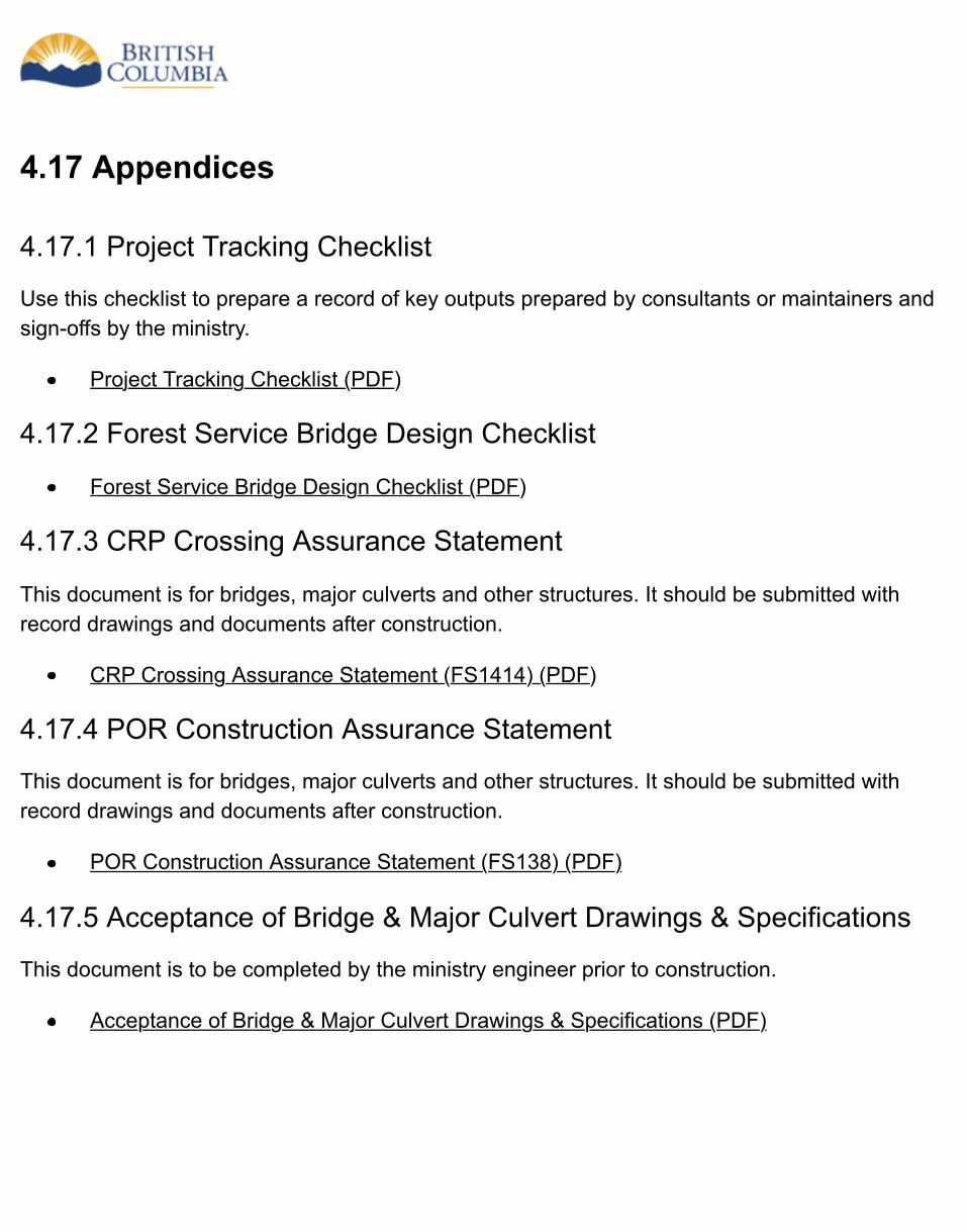
4.17 Appendices
4.17.1 Project Tracking Checklist
Use this checklist to prepare a record of key outputs prepared by consultants or maintainers andsign-offs by the ministry.
Project Tracking Checklist (PDF)
4.17.2 Forest Service Bridge Design Checklist
Forest Service Bridge Design Checklist (PDF)
4.17.3 CRP Crossing Assurance Statement
This document is for bridges, major culverts and other structures. It should be submitted withrecord drawings and documents after construction.
CRP Crossing Assurance Statement (FS1414) (PDF)
4.17.4 POR Construction Assurance Statement
This document is for bridges, major culverts and other structures. It should be submitted withrecord drawings and documents after construction.
POR Construction Assurance Statement (FS138) (PDF)
4.17.5 Acceptance of Bridge & Major Culvert Drawings & Specifications
This document is to be completed by the ministry engineer prior to construction.
Acceptance of Bridge & Major Culvert Drawings & Specifications (PDF)
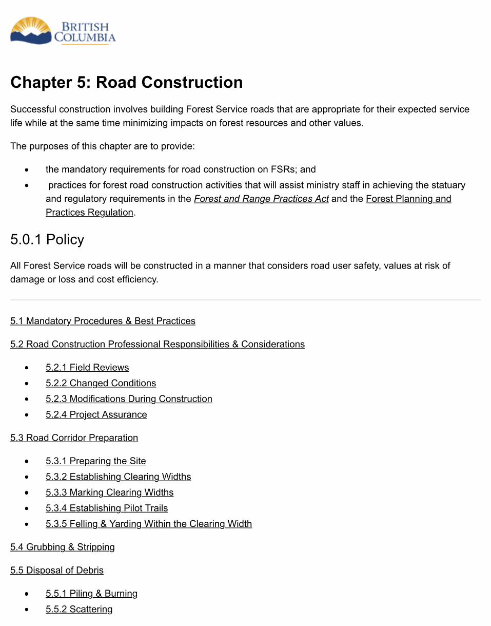
Chapter 5: Road ConstructionSuccessful construction involves building Forest Service roads that are appropriate for their expected servicelife while at the same time minimizing impacts on forest resources and other values.
The purposes of this chapter are to provide:
the mandatory requirements for road construction on FSRs; and practices for forest road construction activities that will assist ministry staff in achieving the statuaryand regulatory requirements in the Forest and Range Practices Act and the Forest Planning andPractices Regulation.
5.0.1 Policy
All Forest Service roads will be constructed in a manner that considers road user safety, values at risk ofdamage or loss and cost efficiency.
5.1 Mandatory Procedures & Best Practices
5.2 Road Construction Professional Responsibilities & Considerations
5.2.1 Field Reviews5.2.2 Changed Conditions5.2.3 Modifications During Construction5.2.4 Project Assurance
5.3 Road Corridor Preparation
5.3.1 Preparing the Site5.3.2 Establishing Clearing Widths5.3.3 Marking Clearing Widths5.3.4 Establishing Pilot Trails5.3.5 Felling & Yarding Within the Clearing Width
5.4 Grubbing & Stripping
5.5 Disposal of Debris
5.5.1 Piling & Burning5.5.2 Scattering
5.5.3 Burying5.5.4 Endhauling Debris for Disposal5.5.5 Location of Disposal Sites for Debris
5.6 Subgrade Construction
5.6.1 Construction Near Licensed Waterworks5.6.2 Construction in Riparian Management Areas5.6.3 Fan Destablilization5.6.4 Wildlife Measures & Features5.6.5 Construction Surveys5.6.6 Modifying the Road Layout & Design5.6.7 Sidecast Construction5.6.8 Full Bench & Partial Bench Construction5.6.9 Endhauling Surplus Excavation Materials5.6.10 Location of Disposal Sites for Excavation Spoil5.6.11 Rock Excavation
5.7 Overlanding
5.7.1 Construction of Short-Term Roads5.7.2 Winter Construction of Permanent Roads5.7.3 Turnouts & Widenings5.7.4 Location of Borrow Pits
5.8 Road Drainage Construction
5.8.1 Maintaining Surface Drainage Patterns5.8.2 Drainage Practices & Water Quality5.8.3 Ditch Construction Considerations5.8.4 Cross-Drain Culvert Location5.8.5 Cross-Drain Culvert Installation5.8.6 Log Culvert Construction5.8.7 Temporary Stream Crossings5.8.8 Construction of Open & Closed Bottom Metal Culverts on Non-Fish Streams5.8.9 Construction of Open & Closed Bottom Metal Culverts on Fish Streams5.8.10 Fords on Non-Fish Streams
5.9 Stabilizing the Subgrade & Surfacing the Road
5.9.1 Ballasting5.9.2 Surfacing5.9.3 Surfacing Compaction5.9.4 Protecting Erodible Fills Located Within Floodplains

5.9.5 Litter, Petroleum Products & Other Waste Materials
5.10 Construction & Use of Snow & One-Season Winter Roads
5.10.1 Snow Road Construction5.10.2 One-Season Winter Road Construction5.10.3 Road Use
5.11 Soil Erosion & Sediment Control
5.11.1 Soil Erosion Control Techniques5.11.2 Sediment Control Techniques
5.12 Road Works Shutdown Indicators
5.12.1 Procedures for Shutting Down Operations5.12.2 Limiting Road Use to Minimize Adverse Impacts5.12.3 Emergency Road Maintenance
5.13 Resources & Suggestions for Further Reading
5.14 Appendices
5.14.1 Tables to Establish Clearing Width5.14.2 Project Tracking Checklist
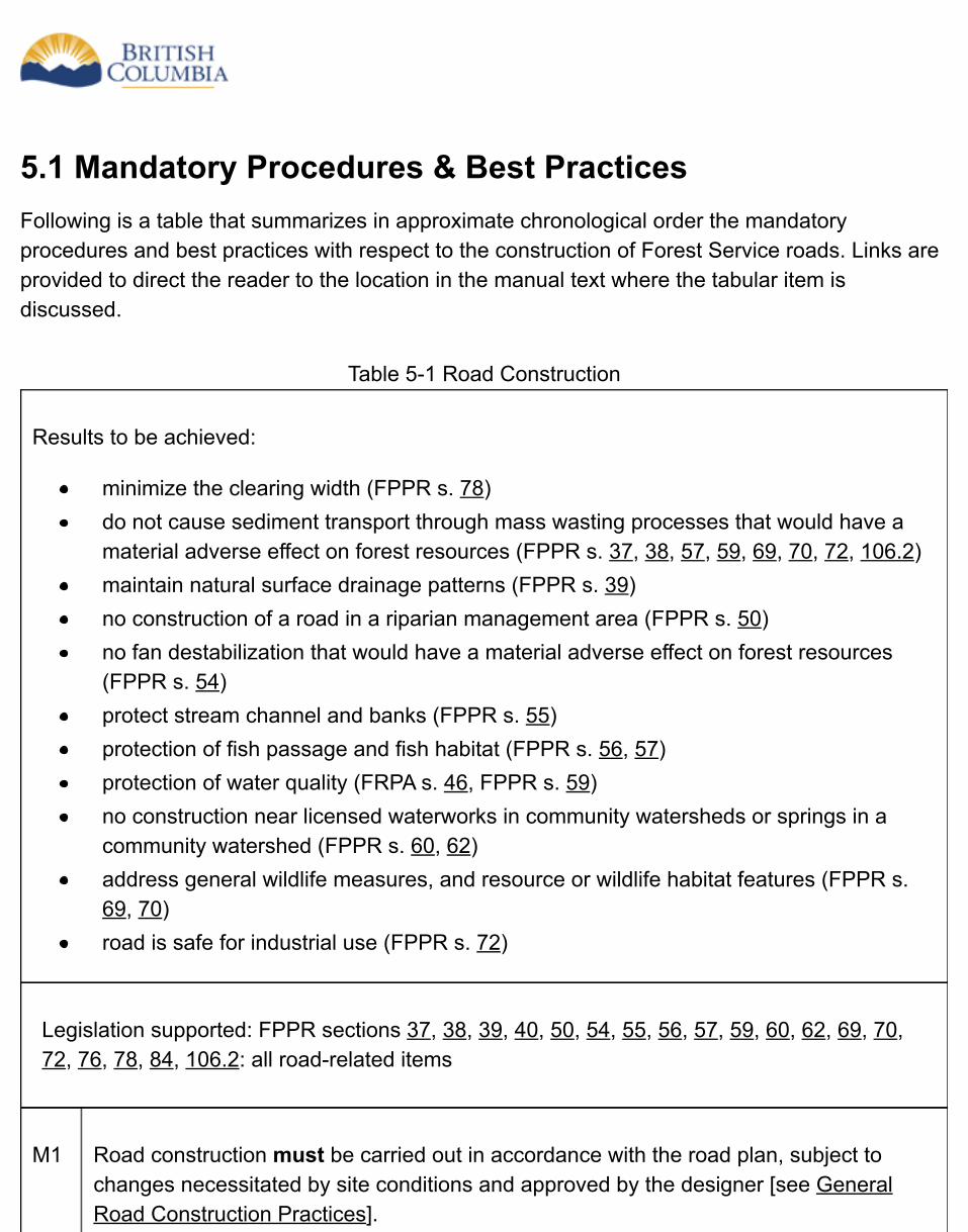
5.1 Mandatory Procedures & Best PracticesFollowing is a table that summarizes in approximate chronological order the mandatoryprocedures and best practices with respect to the construction of Forest Service roads. Links areprovided to direct the reader to the location in the manual text where the tabular item isdiscussed.
Table 5-1 Road Construction
Results to be achieved:
minimize the clearing width (FPPR s. 78)do not cause sediment transport through mass wasting processes that would have amaterial adverse effect on forest resources (FPPR s. 37, 38, 57, 59, 69, 70, 72, 106.2)maintain natural surface drainage patterns (FPPR s. 39)no construction of a road in a riparian management area (FPPR s. 50)no fan destabilization that would have a material adverse effect on forest resources(FPPR s. 54)protect stream channel and banks (FPPR s. 55)protection of fish passage and fish habitat (FPPR s. 56, 57)protection of water quality (FRPA s. 46, FPPR s. 59)no construction near licensed waterworks in community watersheds or springs in acommunity watershed (FPPR s. 60, 62)address general wildlife measures, and resource or wildlife habitat features (FPPR s.69, 70)road is safe for industrial use (FPPR s. 72)
Legislation supported: FPPR sections 37, 38, 39, 40, 50, 54, 55, 56, 57, 59, 60, 62, 69, 70,72, 76, 78, 84, 106.2: all road-related items
M1 Road construction must be carried out in accordance with the road plan, subject tochanges necessitated by site conditions and approved by the designer [see GeneralRoad Construction Practices].
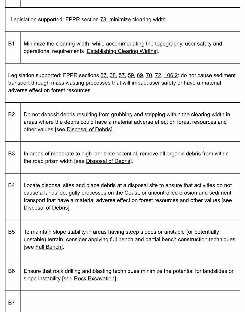
Legislation supported: FPPR section 78: minimize clearing width
B1 Minimize the clearing width, while accommodating the topography, user safety andoperational requirements [Establishing Clearing Widths].
Legislation supported: FPPR sections 37, 38, 57, 59, 69, 70, 72, 106.2: do not cause sedimenttransport through mass wasting processes that will impact user safety or have a materialadverse effect on forest resources
B2 Do not deposit debris resulting from grubbing and stripping within the clearing width inareas where the debris could have a material adverse effect on forest resources andother values [see Disposal of Debris].
B3 In areas of moderate to high landslide potential, remove all organic debris from withinthe road prism width [see Disposal of Debris].
B4 Locate disposal sites and place debris at a disposal site to ensure that activities do notcause a landslide, gully processes on the Coast, or uncontrolled erosion and sedimenttransport that have a material adverse effect on forest resources and other values [seeDisposal of Debris].
B5 To maintain slope stability in areas having steep slopes or unstable (or potentiallyunstable) terrain, consider applying full bench and partial bench construction techniques[see Full Bench].
B6 Ensure that rock drilling and blasting techniques minimize the potential for landslides orslope instability [see Rock Excavation].
B7
Shut down road construction work before slope stability is in question, or landslidesoccur [see Shutdown Indicators].
Legislation supported: FPPR section 39: maintain surface drainage patterns
B8 To maintain surface drainage patterns, keep water in its own drainage area, unlessmoving it to another area is necessary to avoid unstable or sensitive soils [seeMaintaining Surface Drainage Patterns].
Legislation supported: FPPR section 50: no construction in riparian management areas,except as provided
B9 B9. Do not locate borrow pits or disposal sites in a riparian management area [seeLocation of Disposal Sites].
B10 Ensure that there are no subgrade construction works within a riparian managementarea, unless otherwise exempted from this requirement by regulation [see Riparian].
Legislation supported: FPPR section 54: no fan destabilization on the Coast
B11 Ensure that road construction works do not cause fan destabilization on the Coast thatwill result in material and adverse effects on other resources [see Fan Destabilization].
Legislation supported: FPPR section 55: protect stream channel and banks
B12 Ensure that the disturbance to the stream channel and the stream bank at the crossingare mitigated to the extent that the original conditions are reasonably restored. Also,ensure that despite the works at the crossing, the stream banks above and below thecrossing are protected. Ensure that the disturbance to the stream channel and the
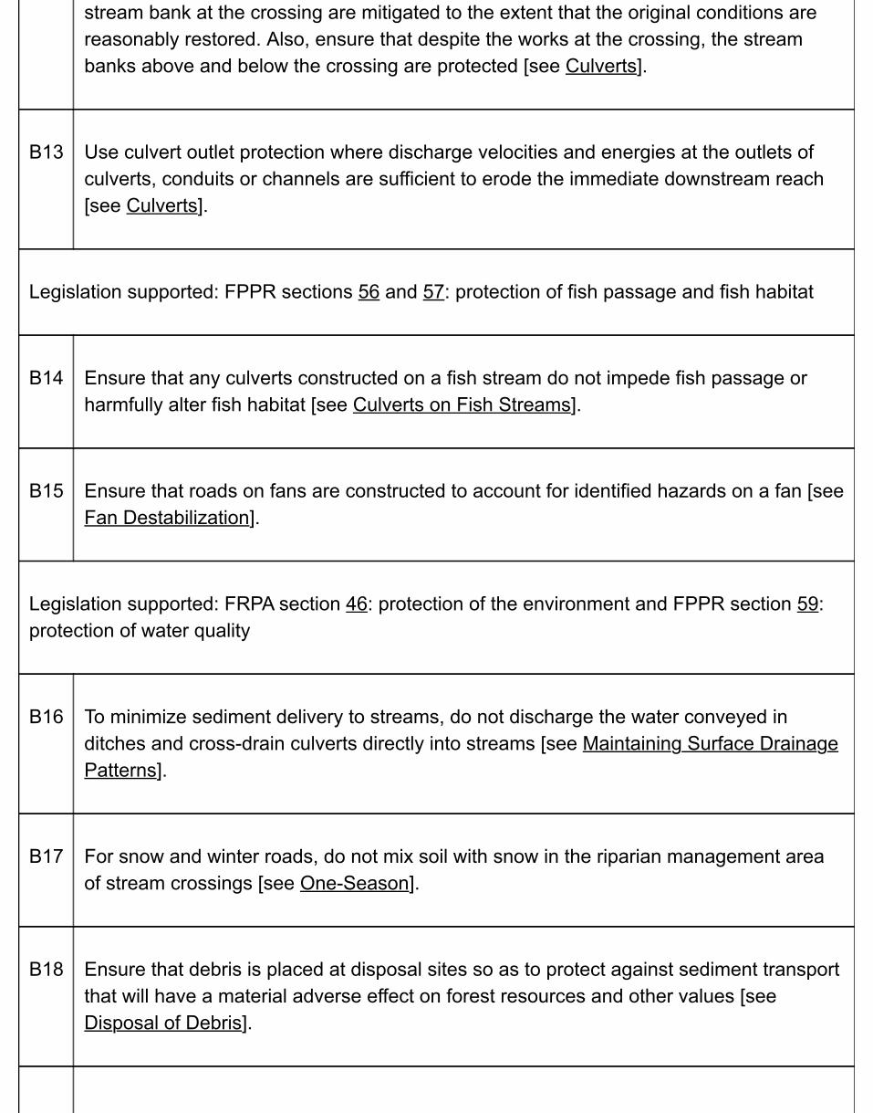
stream bank at the crossing are mitigated to the extent that the original conditions arereasonably restored. Also, ensure that despite the works at the crossing, the streambanks above and below the crossing are protected [see Culverts].
B13 Use culvert outlet protection where discharge velocities and energies at the outlets ofculverts, conduits or channels are sufficient to erode the immediate downstream reach[see Culverts].
Legislation supported: FPPR sections 56 and 57: protection of fish passage and fish habitat
B14 Ensure that any culverts constructed on a fish stream do not impede fish passage orharmfully alter fish habitat [see Culverts on Fish Streams].
B15 Ensure that roads on fans are constructed to account for identified hazards on a fan [seeFan Destabilization].
Legislation supported: FRPA section 46: protection of the environment and FPPR section 59:protection of water quality
B16 To minimize sediment delivery to streams, do not discharge the water conveyed inditches and cross-drain culverts directly into streams [see Maintaining Surface DrainagePatterns].
B17 For snow and winter roads, do not mix soil with snow in the riparian management areaof stream crossings [see One-Season].
B18 Ensure that debris is placed at disposal sites so as to protect against sediment transportthat will have a material adverse effect on forest resources and other values [seeDisposal of Debris].
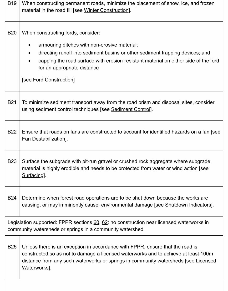
B19 When constructing permanent roads, minimize the placement of snow, ice, and frozenmaterial in the road fill [see Winter Construction].
B20 When constructing fords, consider:
armouring ditches with non-erosive material;directing runoff into sediment basins or other sediment trapping devices; andcapping the road surface with erosion-resistant material on either side of the fordfor an appropriate distance
[see Ford Construction]
B21 To minimize sediment transport away from the road prism and disposal sites, considerusing sediment control techniques [see Sediment Control].
B22 Ensure that roads on fans are constructed to account for identified hazards on a fan [seeFan Destabilization].
B23 Surface the subgrade with pit-run gravel or crushed rock aggregate where subgradematerial is highly erodible and needs to be protected from water or wind action [seeSurfacing].
B24 Determine when forest road operations are to be shut down because the works arecausing, or may imminently cause, environmental damage [see Shutdown Indicators].
Legislation supported: FPPR sections 60, 62: no construction near licensed waterworks incommunity watersheds or springs in a community watershed
B25 Unless there is an exception in accordance with FPPR, ensure that the road isconstructed so as not to damage a licensed waterworks and to achieve at least 100mdistance from any such waterworks or springs in community watersheds [see LicensedWaterworks].
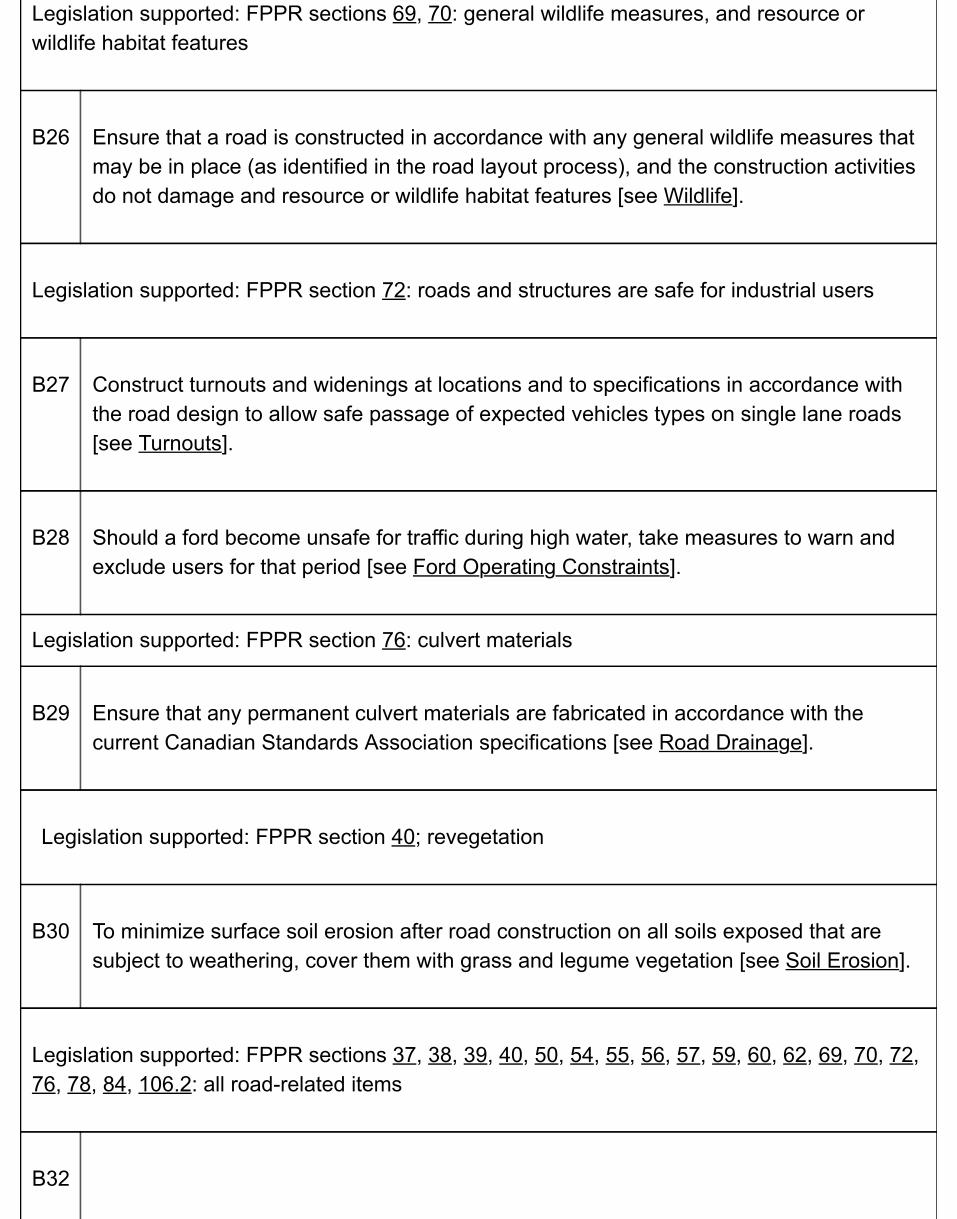
Legislation supported: FPPR sections 69, 70: general wildlife measures, and resource orwildlife habitat features
B26 Ensure that a road is constructed in accordance with any general wildlife measures thatmay be in place (as identified in the road layout process), and the construction activitiesdo not damage and resource or wildlife habitat features [see Wildlife].
Legislation supported: FPPR section 72: roads and structures are safe for industrial users
B27 Construct turnouts and widenings at locations and to specifications in accordance withthe road design to allow safe passage of expected vehicles types on single lane roads[see Turnouts].
B28 Should a ford become unsafe for traffic during high water, take measures to warn andexclude users for that period [see Ford Operating Constraints].
Legislation supported: FPPR section 76: culvert materials
B29 Ensure that any permanent culvert materials are fabricated in accordance with thecurrent Canadian Standards Association specifications [see Road Drainage].
Legislation supported: FPPR section 40; revegetation
B30 To minimize surface soil erosion after road construction on all soils exposed that aresubject to weathering, cover them with grass and legume vegetation [see Soil Erosion].
Legislation supported: FPPR sections 37, 38, 39, 40, 50, 54, 55, 56, 57, 59, 60, 62, 69, 70, 72,76, 78, 84, 106.2: all road-related items
B32
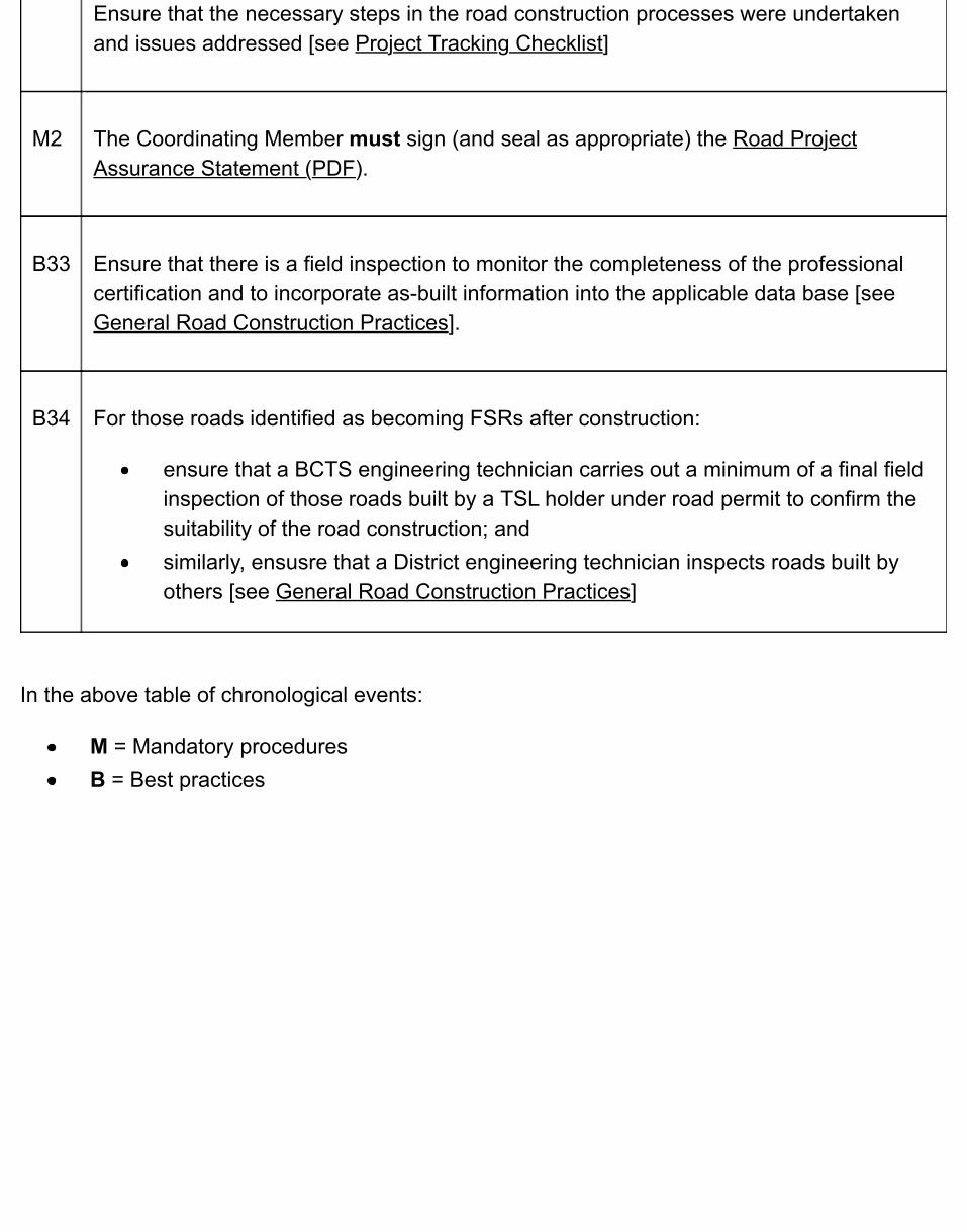
Ensure that the necessary steps in the road construction processes were undertakenand issues addressed [see Project Tracking Checklist]
M2 The Coordinating Member must sign (and seal as appropriate) the Road ProjectAssurance Statement (PDF).
B33 Ensure that there is a field inspection to monitor the completeness of the professionalcertification and to incorporate as-built information into the applicable data base [seeGeneral Road Construction Practices].
B34 For those roads identified as becoming FSRs after construction:
ensure that a BCTS engineering technician carries out a minimum of a final fieldinspection of those roads built by a TSL holder under road permit to confirm thesuitability of the road construction; andsimilarly, ensusre that a District engineering technician inspects roads built byothers [see General Road Construction Practices]
In the above table of chronological events:
M = Mandatory proceduresB = Best practices

5.2 Road Construction Professional Responsibilities &ConsiderationsAfter a road plan has been completed and signed off, it may then be appropriate to commence roadconstruction in accordance with that plan. Note that this phase of the road project does not include thoseengineered structures described in Chapter 4 of this manual. Those professionals taking part in the road construction works may include the CM, other Members or otherpersons working under supervision of the CM, and professional specialists where there may be terrain stabilityissues and corresponding design requirements. Other responsibilities related to road construction that may beundertaken by a Member are project management, quality control, quality assurance, contract administration orconstruction supervision. The CM must clarify the roles and responsibilities of each Member including the CM,and their reporting relationships, at the outset of the project. As with other road and structure phases, there must be a CM in place to provide oversight and undertakeprofessional responsibility for the construction of a forest road. Accordingly, a CM must:
ensure that the road plan has been signed off by a Member;exercise professional judgment to determine that there are no changed conditions that could affectsafety or the suitability of the road plan;identify and bring forward any special issues that may impact worker safety during construction;prescribe any field surveys (e.g., centre-line, slope staking) that may be required before and duringconstruction;determine the number and timing of field reviews during the construction process;carry out field reviews or delegate them to another person working under the CM's direct supervision;ensure that professional specialists and designers carry out field reviews of those portions of theproject for which specialist analysis or design was required;confirm that the completed road construction works are in general conformance with the road plan, andcomplete the Road Project Assurance Statement (PDF) for road construction.
5.2.1 Field Reviews
Identify what field reviews are required and what notification should be given to allow the field reviews to becarried out. If the road plan includes specialist designs or incorporates recommendations from a TSA, theremay also be a need for field reviews by terrain specialists or design specialists. The timing and extent of suchreviews are established by those specialists and confirmed by the CM.
5.2.2 Changed Conditions
If the CM becomes aware of changed conditions during construction, the CM for construction must either:
take responsibility for any changes needed to the road plan (this may involve obtaining input from otherMembers or specialists to re-assess the changed conditions); orcontact the CM who prepared the road plan, inform him/her of the changed conditions, and obtaininstructions on what changes may be needed to the road plan (in this case, the original CM would takeresponsibility for the changes, including preparing an updated road plan).
5.2.3 Modifications During Construction
Changed conditions or modifications may affect the road plan,and examples include:
changes in ground conditions (material characteristics or drainage) that require changes to the roaddesign;identification of sensitive features or resources at risk that were not previously known.
If modifications are made during construction, the CM for construction must document the changes, andindicate the reasons for the changes and their implications on:
the safety of road users;impacts to other resources;the planning objectives;intended use of the road; andcosts.
5.2.4 Project Assurance
The Road Project Assurance Statement must include or be accompanied by drawings that document thecompleted works. At the discretion and direction of the CM, these can vary from annotations or revisions shownon the original road plan documents through the completion of post construction surveys and preparation ofrecord drawings.
Upon completion of construction, ensure that there is a field inspection to monitor the completeness of theprofessional certification and to incorporate as-built information into the applicable data base.
For those roads that are built by TSL holders under road permit, and have been identified as becoming FSRsafter construction, it may be appropriate for a BCTS engineering technician to carry out a final inspection toconfirm the suitability of the works. Similarly, for those rare situations where other roads are to become FSRs,the district engineering technician should carry out the suitability inspection.
Suitability inspections may be carried out at key points in the construction, and at least at the completion of theworks. Refer any issues to the constructor, the constructor's CM and, where appropriate, to Compliance andEnforcement.
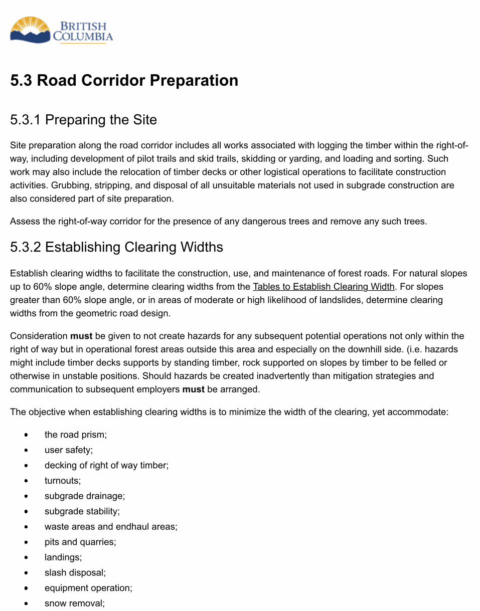
5.3 Road Corridor Preparation
5.3.1 Preparing the Site
Site preparation along the road corridor includes all works associated with logging the timber within the right-of-way, including development of pilot trails and skid trails, skidding or yarding, and loading and sorting. Suchwork may also include the relocation of timber decks or other logistical operations to facilitate constructionactivities. Grubbing, stripping, and disposal of all unsuitable materials not used in subgrade construction arealso considered part of site preparation.
Assess the right-of-way corridor for the presence of any dangerous trees and remove any such trees.
5.3.2 Establishing Clearing Widths
Establish clearing widths to facilitate the construction, use, and maintenance of forest roads. For natural slopesup to 60% slope angle, determine clearing widths from the Tables to Establish Clearing Width. For slopesgreater than 60% slope angle, or in areas of moderate or high likelihood of landslides, determine clearingwidths from the geometric road design.
Consideration must be given to not create hazards for any subsequent potential operations not only within theright of way but in operational forest areas outside this area and especially on the downhill side. (i.e. hazardsmight include timber decks supports by standing timber, rock supported on slopes by timber to be felled orotherwise in unstable positions. Should hazards be created inadvertently than mitigation strategies andcommunication to subsequent employers must be arranged.
The objective when establishing clearing widths is to minimize the width of the clearing, yet accommodate:
the road prism;user safety;decking of right of way timber;turnouts;subgrade drainage;subgrade stability;waste areas and endhaul areas;pits and quarries;landings;slash disposal;equipment operation;snow removal;
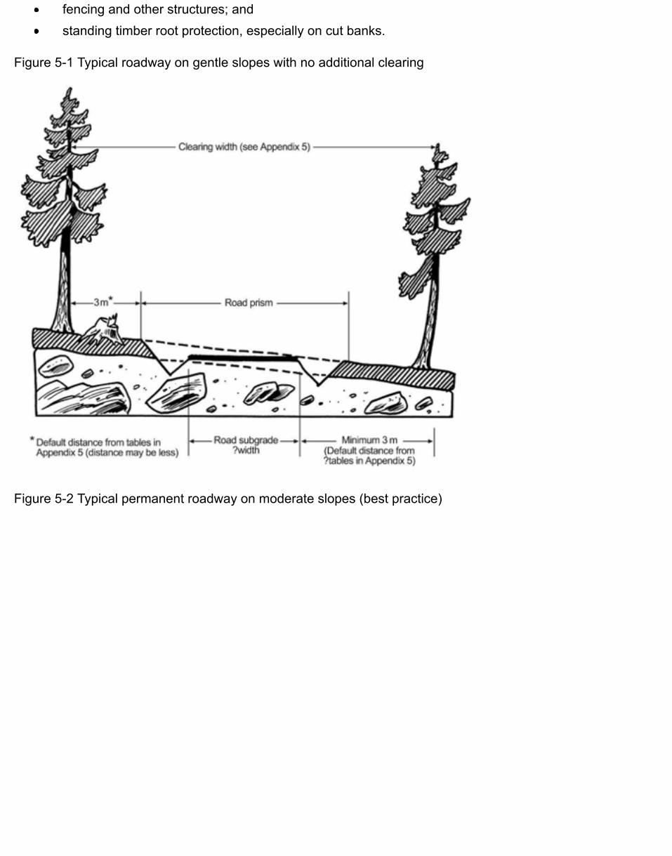
fencing and other structures; andstanding timber root protection, especially on cut banks.
Figure 5-1 Typical roadway on gentle slopes with no additional clearing
Figure 5-2 Typical permanent roadway on moderate slopes (best practice)
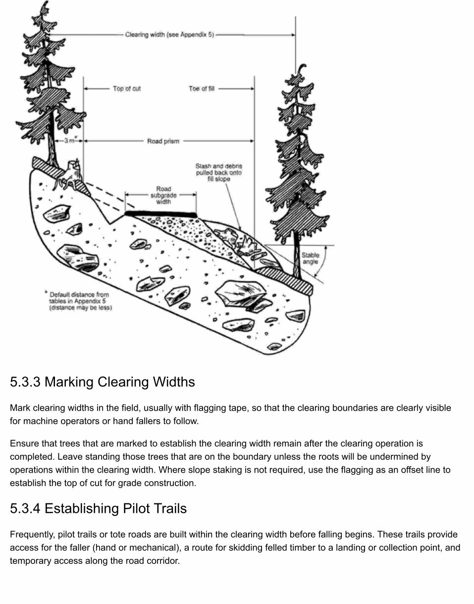
5.3.3 Marking Clearing Widths
Mark clearing widths in the field, usually with flagging tape, so that the clearing boundaries are clearly visiblefor machine operators or hand fallers to follow.
Ensure that trees that are marked to establish the clearing width remain after the clearing operation iscompleted. Leave standing those trees that are on the boundary unless the roots will be undermined byoperations within the clearing width. Where slope staking is not required, use the flagging as an offset line toestablish the top of cut for grade construction.
5.3.4 Establishing Pilot Trails
Frequently, pilot trails or tote roads are built within the clearing width before falling begins. These trails provideaccess for the faller (hand or mechanical), a route for skidding felled timber to a landing or collection point, andtemporary access along the road corridor.
Terrain and soil conditions govern the location of the pilot trail within the clearing width. Generally, construct thetrail below the flagged centreline on side hills, near the lower clearing width limits. This allows for easy accessto skid-fallen timber, and allows for the toe of the road fill to be keyed into the slope. Where drilling and blastingare required, build the trail above the road centreline, just below the upper clearing limit, to permit verticaldrilling of the rock cut.
Ensure that care is taken to remove debris from the downslope during the right-of-way logging phase unlessthe debris can reasonably be reached by equipment operating on the surface of the pilot trail or final roadsubgrade.
Install drainage structures concurrently with pilot trail construction, including temporary stream crossings thatmay be required during the road construction phase until the permanent crossing is constructed. For furtherdetails, see Road Drainage Construction.
5.3.5 Felling & Yarding Within the Clearing Width
Expand All | Collapse All
Felling methods
Several methods for falling trees within the clearing width are available depending on terrain, soilconditions, timber size, and total volume.
Fell all standing merchantable and non-merchantable timber along any section of road subgrade removethe timber before construction. Ensure that timber does not become buried under soil, rock, and debris,and the wood is accessible for future retrieval from the road subgrade.
Further information about falling is contained in the British Columbia Occupational Health and SafetyRegulation (Sec. 26.11 and 26.21 to 29.30) and the WorkSafeBC Guidelines (Part 26).
Landings
Locate landings within the clearing width so as not to interfere with other operations. Ideally, show landinglocations on the construction drawings and mark them in the field.
Protecting streambanks during felling operations
Before falling begins, ensure that streams and their associated riparian management areas and the“machine-free zones” identified on operational plans have their buffer zones flagged in the field. Useappropriate directional falling techniques to protect these areas. For further information, refer to theRiparian Management Area Guidebook.
Protecting streambanks during yarding operations

Yarding operations can result in streambank destabilization. Prevent this damage by yarding away fromstreams, not across them.
Removing debris from streams
Where debris is accidentally introduced into the stream, carry out clean-up concurrently with clearingoperations. Mitigate without delay any stream bank damage, outside of designated crossings.
Dangerous trees
Identify all dangerous trees outside the clearing width deemed hazardous to road workers or users and fellthem as part of the falling phase of site preparation. See Preparing the Site.
5.4 Grubbing & StrippingGrub and strip the road prism area of all topsoil and unsuitable mineral soils after all standing timber has beenfelled and removed, unless the following are applicable:
between the tops of cuts and adjacent standing timber (other than trees and stumps with exposedroots or roots that overhang the top of cut);between the toes of fills and adjacent standing timber; andwhere short-term roads – that is, one-season winter use roads or snow roads— are constructed orwhere overlanding techniques are applied.
“Grubbing” means the removal of stumps, roots, buried logs, and logging slash (downed logs, tree branchesand tops, and uprooted stumps, trees, and shrubs) and other debris left on the ground from clearing operations.“Stripping” means the removal of topsoil or other organic material, and mineral soils unsuitable for forming theroad subgrade.
Where grubbing operations have removed all organic soil, stripping is not required unless other unsuitable soilsare encountered.
5.5 Disposal of DebrisDisposal of debris consists of the disposal of material resulting from grubbing and strippingoperations within the clearing width. (For ease of reference, this material is simply called “debris”in this chapter.)
Accomplish disposal of debris by:
piling and burning;scattering;burying; orendhauling it to a suitable disposal site for debris.
Do not deposit debris resulting from grubbing and stripping within the clearing width in areaswhere the debris could have a material adverse effect on forest resources or create hazards forany subsequent operations and/or adversely affect other values. In addition to any other requiredmitigation actions to prevent damage, immediately remove any debris that is deposited in suchareas.
Ensure that the selected method of debris disposal:
meet objectives of higher level plans (such as those for smoke management, aesthetics,or pest management);are compatible with terrain conditions;consider the slash volume, loading, species, and piece sizes;do not alter natural drainage patterns; andare compatible with other resource values.
Figure 5-3 Debris placement for permanent road on terrain having a low likelihood of landslides(acceptable practice)
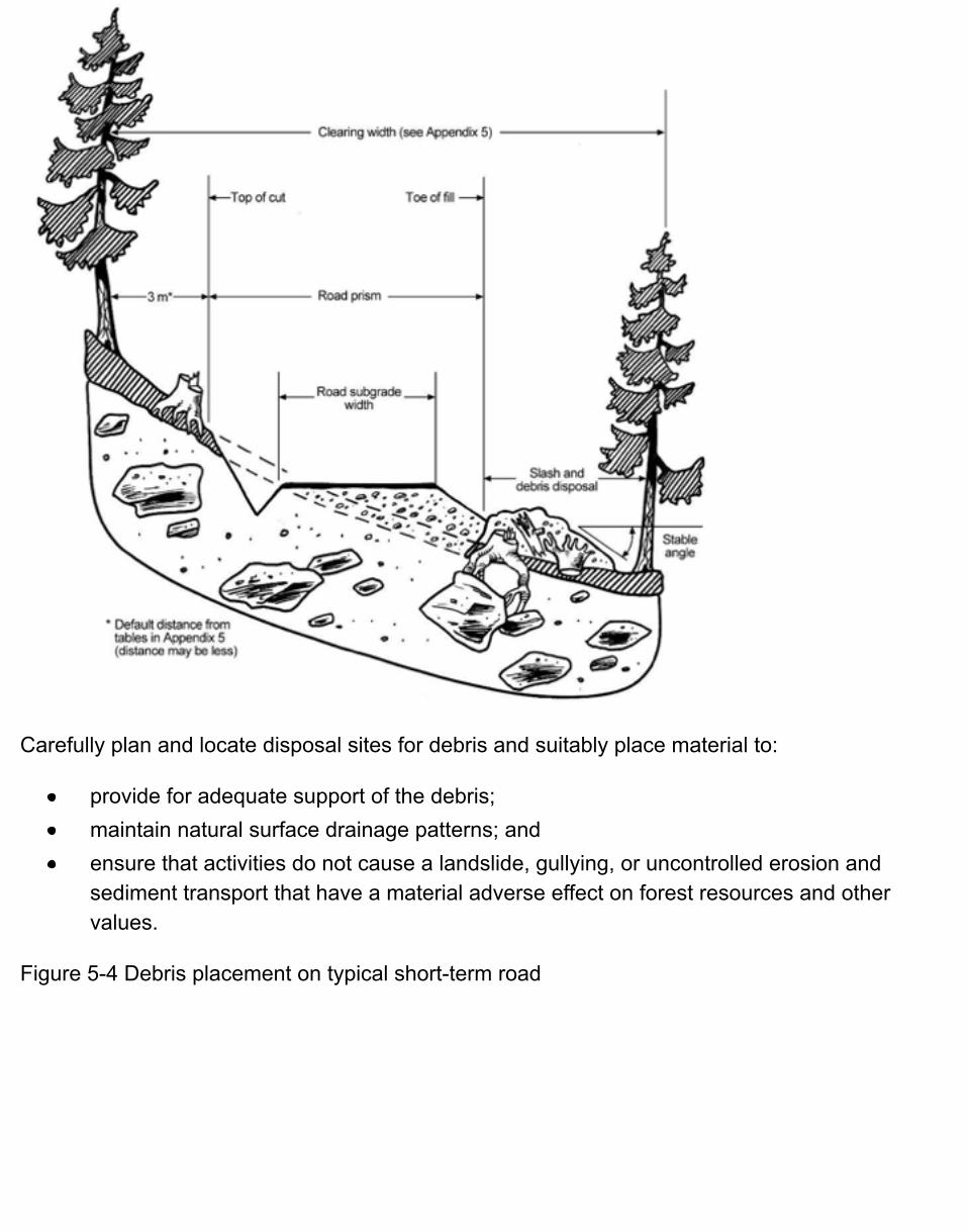
Carefully plan and locate disposal sites for debris and suitably place material to:
provide for adequate support of the debris;maintain natural surface drainage patterns; andensure that activities do not cause a landslide, gullying, or uncontrolled erosion andsediment transport that have a material adverse effect on forest resources and othervalues.
Figure 5-4 Debris placement on typical short-term road
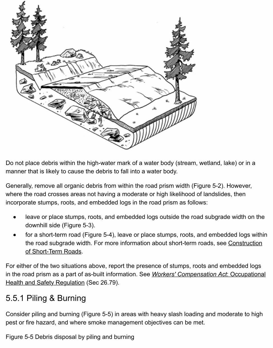
Do not place debris within the high-water mark of a water body (stream, wetland, lake) or in amanner that is likely to cause the debris to fall into a water body.
Generally, remove all organic debris from within the road prism width (Figure 5-2). However,where the road crosses areas not having a moderate or high likelihood of landslides, thenincorporate stumps, roots, and embedded logs in the road prism as follows:
leave or place stumps, roots, and embedded logs outside the road subgrade width on thedownhill side (Figure 5-3).for a short-term road (Figure 5-4), leave or place stumps, roots, and embedded logs withinthe road subgrade width. For more information about short-term roads, see Constructionof Short-Term Roads.
For either of the two situations above, report the presence of stumps, roots and embedded logsin the road prism as a part of as-built information. See Workers' Compensation Act: OccupationalHealth and Safety Regulation (Sec 26.79).
5.5.1 Piling & Burning
Consider piling and burning (Figure 5-5) in areas with heavy slash loading and moderate to highpest or fire hazard, and where smoke management objectives can be met.
Figure 5-5 Debris disposal by piling and burning
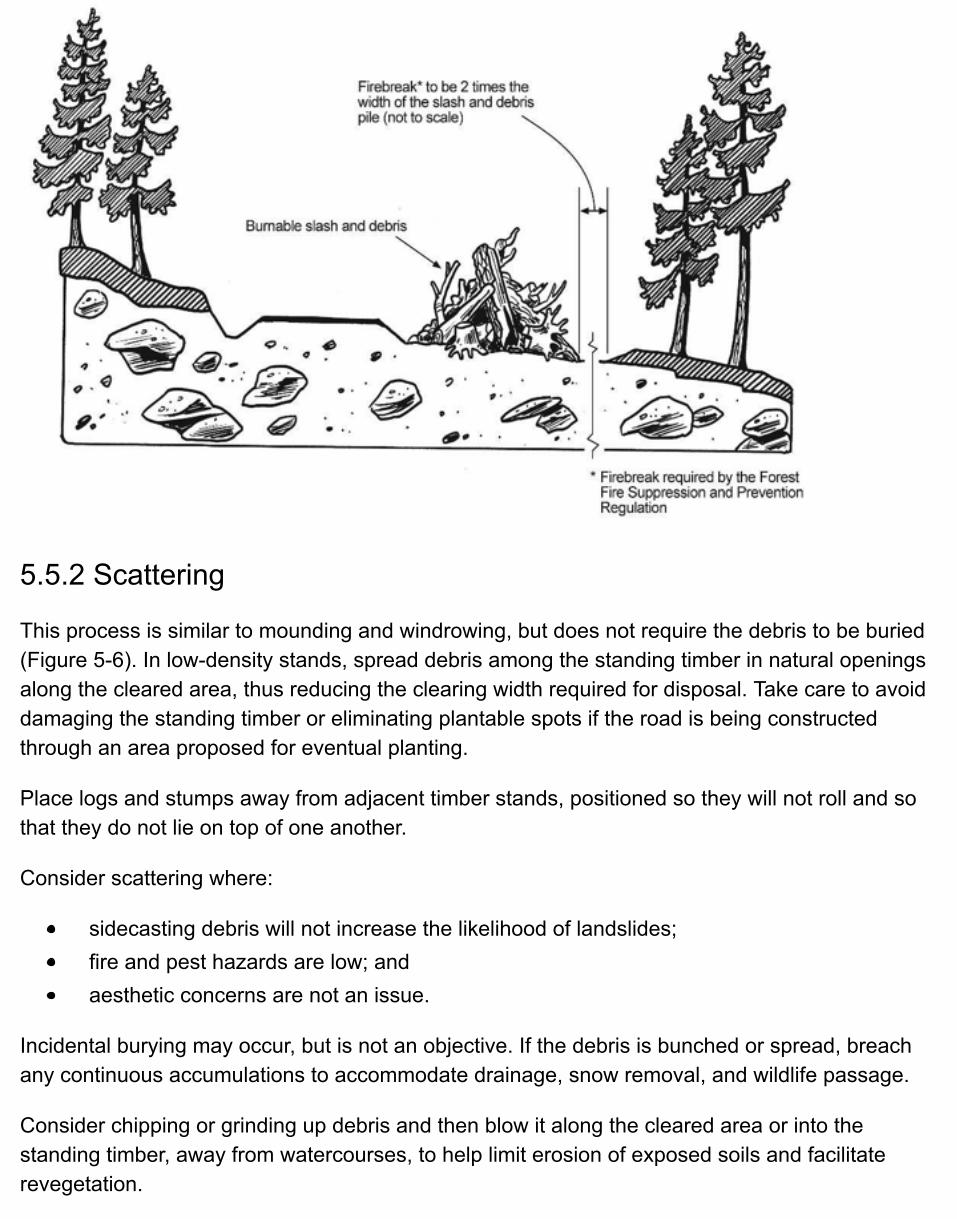
5.5.2 Scattering
This process is similar to mounding and windrowing, but does not require the debris to be buried(Figure 5-6). In low-density stands, spread debris among the standing timber in natural openingsalong the cleared area, thus reducing the clearing width required for disposal. Take care to avoiddamaging the standing timber or eliminating plantable spots if the road is being constructedthrough an area proposed for eventual planting.
Place logs and stumps away from adjacent timber stands, positioned so they will not roll and sothat they do not lie on top of one another.
Consider scattering where:
sidecasting debris will not increase the likelihood of landslides;fire and pest hazards are low; andaesthetic concerns are not an issue.
Incidental burying may occur, but is not an objective. If the debris is bunched or spread, breachany continuous accumulations to accommodate drainage, snow removal, and wildlife passage.
Consider chipping or grinding up debris and then blow it along the cleared area or into thestanding timber, away from watercourses, to help limit erosion of exposed soils and facilitaterevegetation.
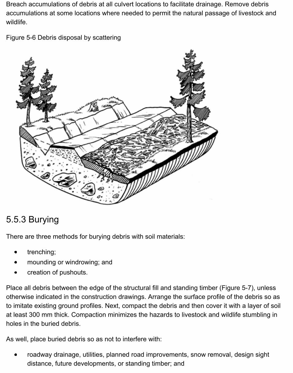
Breach accumulations of debris at all culvert locations to facilitate drainage. Remove debrisaccumulations at some locations where needed to permit the natural passage of livestock andwildlife.
Figure 5-6 Debris disposal by scattering
5.5.3 Burying
There are three methods for burying debris with soil materials:
trenching;mounding or windrowing; andcreation of pushouts.
Place all debris between the edge of the structural fill and standing timber (Figure 5-7), unlessotherwise indicated in the construction drawings. Arrange the surface profile of the debris so asto imitate existing ground profiles. Next, compact the debris and then cover it with a layer of soilat least 300 mm thick. Compaction minimizes the hazards to livestock and wildlife stumbling inholes in the buried debris.
As well, place buried debris so as not to interfere with:
roadway drainage, utilities, planned road improvements, snow removal, design sightdistance, future developments, or standing timber; and
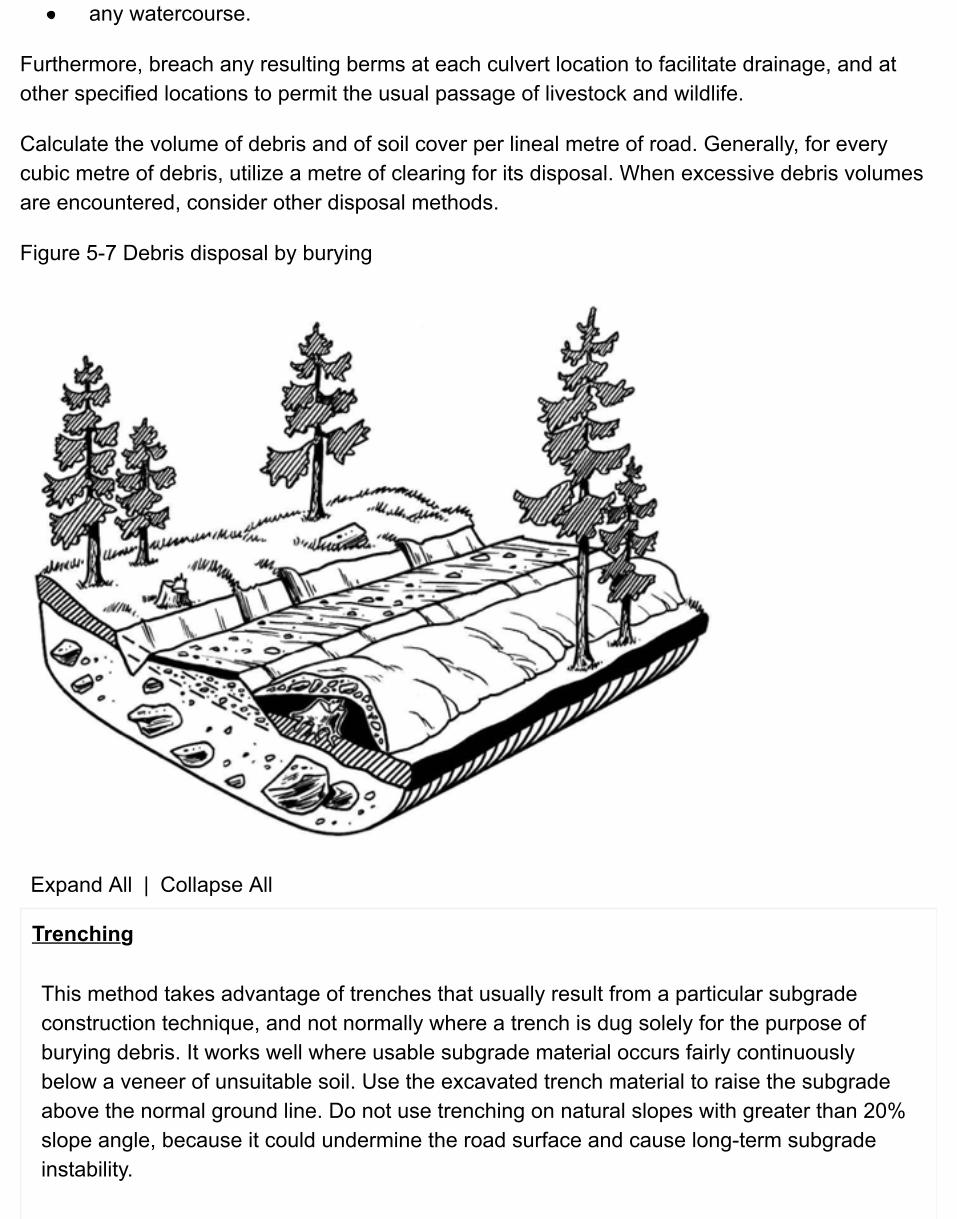
any watercourse.
Furthermore, breach any resulting berms at each culvert location to facilitate drainage, and atother specified locations to permit the usual passage of livestock and wildlife.
Calculate the volume of debris and of soil cover per lineal metre of road. Generally, for everycubic metre of debris, utilize a metre of clearing for its disposal. When excessive debris volumesare encountered, consider other disposal methods.
Figure 5-7 Debris disposal by burying
Expand All | Collapse All
Trenching
This method takes advantage of trenches that usually result from a particular subgradeconstruction technique, and not normally where a trench is dug solely for the purpose ofburying debris. It works well where usable subgrade material occurs fairly continuouslybelow a veneer of unsuitable soil. Use the excavated trench material to raise the subgradeabove the normal ground line. Do not use trenching on natural slopes with greater than 20%slope angle, because it could undermine the road surface and cause long-term subgradeinstability.
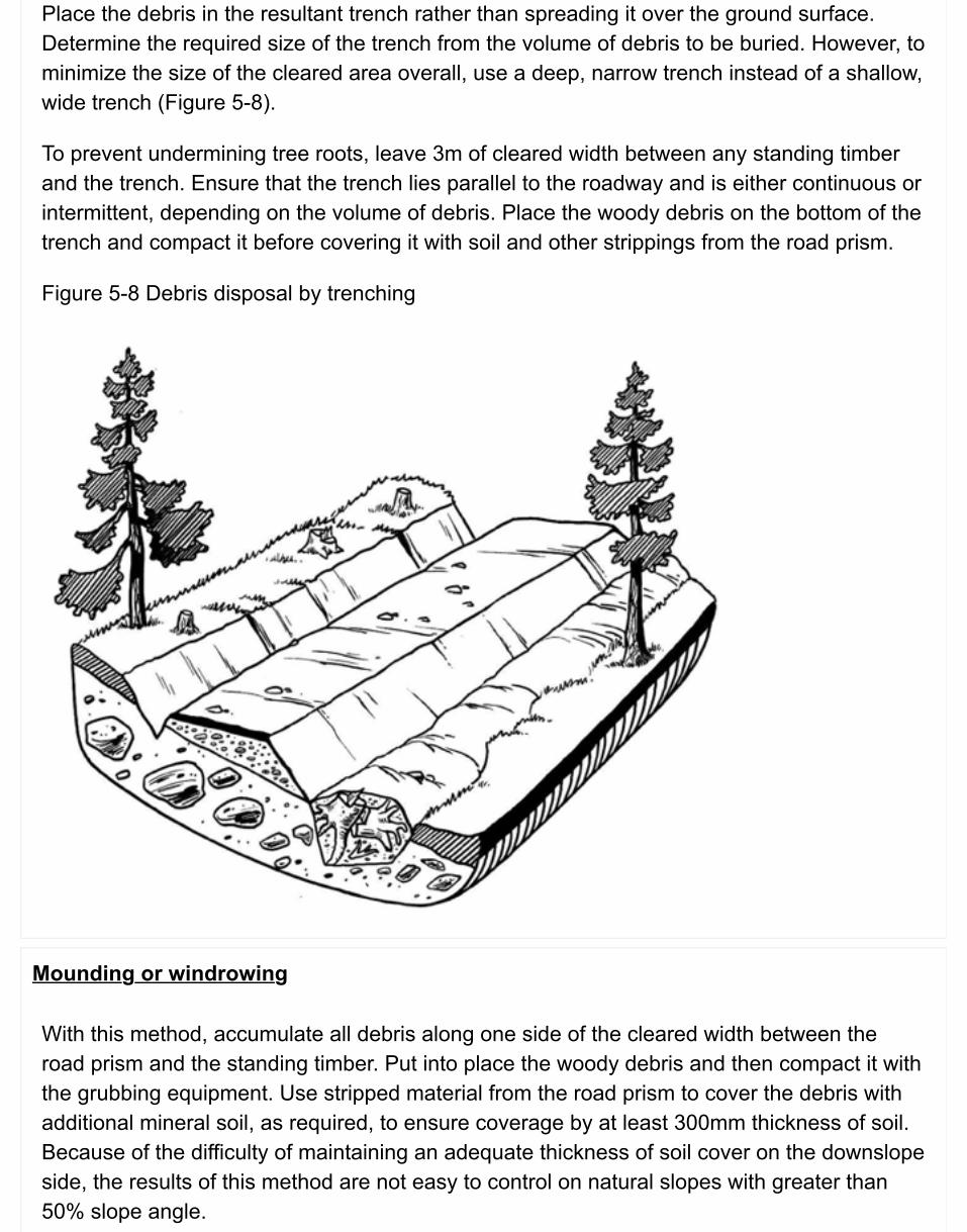
Place the debris in the resultant trench rather than spreading it over the ground surface.Determine the required size of the trench from the volume of debris to be buried. However, tominimize the size of the cleared area overall, use a deep, narrow trench instead of a shallow,wide trench (Figure 5-8).
To prevent undermining tree roots, leave 3m of cleared width between any standing timberand the trench. Ensure that the trench lies parallel to the roadway and is either continuous orintermittent, depending on the volume of debris. Place the woody debris on the bottom of thetrench and compact it before covering it with soil and other strippings from the road prism.
Figure 5-8 Debris disposal by trenching
Mounding or windrowing
With this method, accumulate all debris along one side of the cleared width between theroad prism and the standing timber. Put into place the woody debris and then compact it withthe grubbing equipment. Use stripped material from the road prism to cover the debris withadditional mineral soil, as required, to ensure coverage by at least 300mm thickness of soil.Because of the difficulty of maintaining an adequate thickness of soil cover on the downslopeside, the results of this method are not easy to control on natural slopes with greater than50% slope angle.
Creation of pushouts
Locate pushouts in natural openings along the cleared area and ensure that they areappropriate for the volume of material to be disposed. Do not push debris into standingtimber and properly groom the piles to be stable and visually acceptable.
5.5.4 Endhauling Debris for Disposal
Where debris or other unsuitable material cannot be disposed of outside of the road prism orwithin the clearing width, endhaul it (i.e., load and haul) to a suitable disposal site for debris.Endhaul debris from the road corridor in:
steep or unstable terrain where this material is removed to maintain slope stability; andareas with high recreational value where aesthetics may be an issue.
5.5.5 Location of Disposal Sites for Debris
Identify all disposal sites for debris before construction. Ensure that an approved disposal site fordebris is stable, well drained, and isolated from streams or wet sites; and does not have amaterial adverse effect on forest resources and other values. Sometimes, prepare and benchdisposal sites in advance to enable stable placement of the endhauled debris. Avoid overloadingof slopes. Where possible and practical, stockpile organic and fine-textured debris for placementover depleted borrow and gravel pits, quarries, and disposal sites for excavation spoil, as ameans of facilitating revegetation.
Dispose of the debris endhauled to an approved disposal site by piling and burning, scattering, orburying. Whichever disposal method is used, ensure that the top of any remaining debris materialis below the road surface (to allow for snowplowing and sight distance) and placed in a manner toallow surface water to drain away from the road.
Carefully place and pile debris to maintain slope stability at all times and take measures controlerosion and sediment transport.
5.6 Subgrade Construction
5.6.1 Construction Near Licensed Waterworks
Licensed waterworks have been identified as part of the road layout and road survey and designprocesses. Based on the information gathered through those processes, and for any otherlicensed waterworks discovered during construction of the road, unless there is an exception inaccordance with FPPR, ensure that the road is constructed so as not to damage a licensedwaterworks and to achieve at least 100m distance from any such waterworks or springs incommunity watersheds.
Additionally, ensure that at least 48 hours notice of impending construction work is provided towater licensees or water purveyors in community watersheds.
5.6.2 Construction in Riparian Management Areas
Ensure that a road is constructed in accordance with the layout and the design, such that thereare no subgrade construction works within a riparian management area, unless otherwiseexempted from this requirement under FPPR, section 50.
5.6.3 Fan Destabilization
Fans can be the runout zones for debris flows and can be influenced by over-bank flows duringdebris floods and floods. These events are not rare and can impact roads on fans. Conversely,roads can exacerbate the effects of these events.
FRPA recognizes fan destabilization on the Coast; province-wide, FRPA recognizes impacts tofish habitat and forest soils—impacts that can result from fan destabilization. There may be arange of causes of fan destabilization as a result of road construction, and a variety of potentialmitigative practices (see Land Management Handbook 57 Forest Management on FansHydrogeomorphic Hazards and General Prescriptions (PDF, 3.2MB). Ensure that the followingpractices are carried out when constructing roads on fan landforms that are identified along theproposed route:
explore each fan for evidence of debris flows, debris floods, and floods,build to account for the identified hazards with attention to the specific location of thecrossing on the fan, the need, if any, for climbing roads, drainage structure size and
configuration, and excavations into the stream channel or banks.
5.6.4 Wildlife Measures & Features
Ensure that a road is constructed in accordance with any general wildlife measures that may bein place (as identified in the road layout process), and the construction activities do not damageresource or wildlife habitat features.
5.6.5 Construction Surveys
Where the location and volumes of road building materials are critical, carry out constructionsurveys to re-establish the road centerline, to determine the limits of the cut and fill slopes, and toprovide grade control during construction.
Preferably, carry out construction surveys after clearing and grubbing operations, but beforeprimary excavation begins.
5.6.6 Modifying the Road Layout & Design
If the road design does not reflect the field conditions actually encountered after the clearingoperations, then modify the design to address those unforeseen conditions. Should aprofessional prescription not reflect actual field conditions, or if the layout and design revisionsaffect a prescription to maintain slope stability, then ensure that any design changes are reviewedand approved by a qualified registered professional before construction begins.
5.6.7 Sidecast Construction
Where terrain stability is not an issue, cut and fill (sidecast) is a common forest road buildingtechnique. During sidecast construction, excavated material from the uphill slope is placed on thedownhill slope (using crawler tractors or excavators) to form a fill to support the outside portionof the running surface of the road (Figure 5-2). If this fill material is not properly compacted,settlement will likely occur, leading to slumping at the shoulders and the creation of settlement ortension cracks in the road surface. Refer to the suggested cut and fill slope angles in Chapter 3,Table 3-4 General guidelines for cut and fill slope angles for use in forest road design (PDF).
Do not use topsoil and debris, and saturated and other unsuitable soils, as road fill. Rather,remove them, because they have a very low strength and can readily fail under vehicle loading.In areas having a low likelihood of landslides, however, consider placing stumps, roots, andembedded logs outside of the subgrade width (Figure 5-3).
Key in or notch the fill material into the slope, after all organic material and unsuitable soils havefirst been removed from the road prism. Ensure that the notch is sufficiently wide to allowequipment to work. Build up the fill in shallow lifts and compact it using the road-building
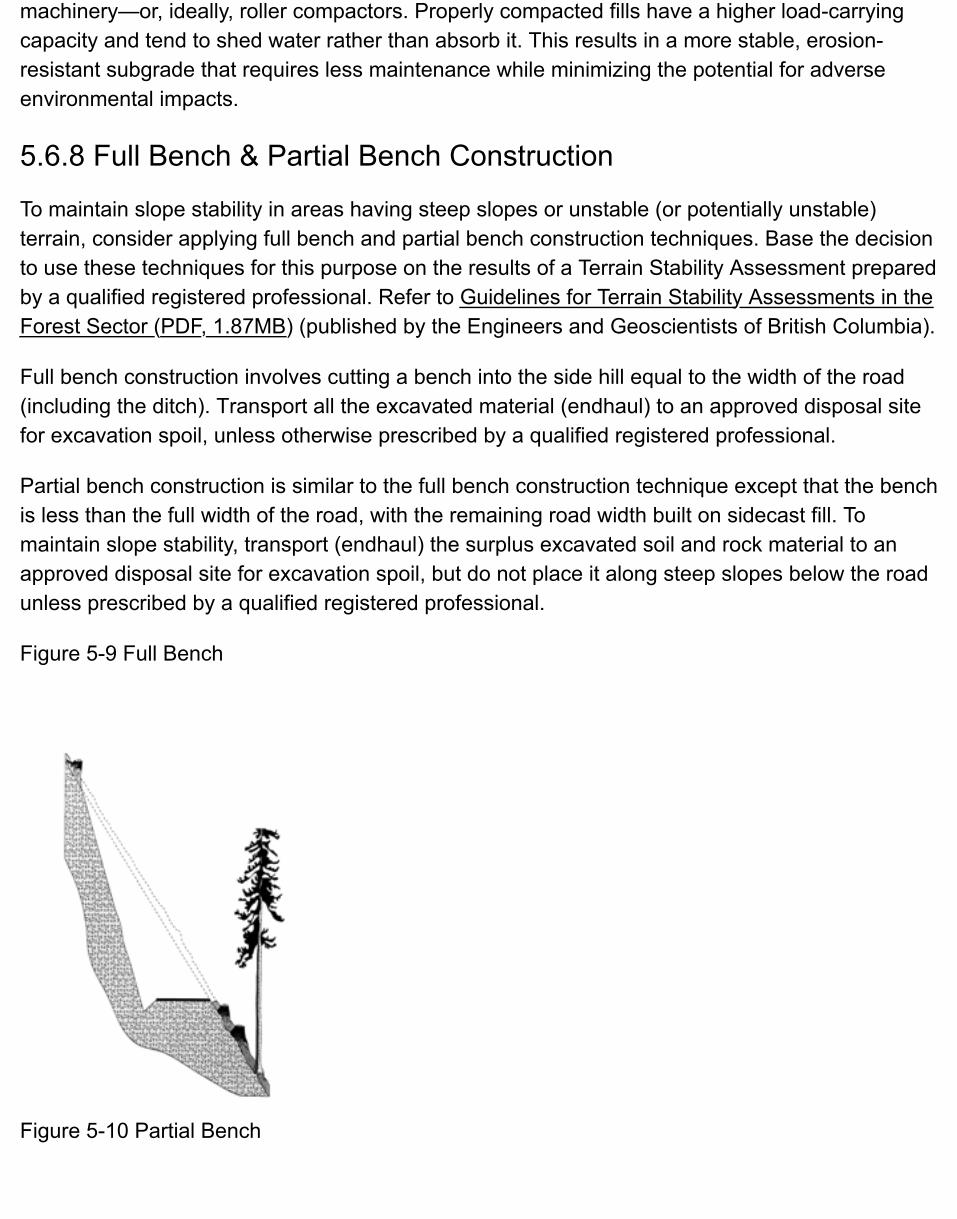
machinery—or, ideally, roller compactors. Properly compacted fills have a higher load-carrying capacity and tend to shed water rather than absorb it. This results in a more stable, erosion-resistant subgrade that requires less maintenance while minimizing the potential for adverse environmental impacts.
5.6.8 Full Bench & Partial Bench Construction
To maintain slope stability in areas having steep slopes or unstable (or potentially unstable) terrain, consider applying full bench and partial bench construction techniques. Base the decision to use these techniques for this purpose on the results of a Terrain Stability Assessment prepared by a qualified registered professional. Refer to Guidelines for Terrain Stability Assessments in the Forest Sector (PDF, 1.87MB) (published by the Engineers and Geoscientists of British Columbia).
Full bench construction involves cutting a bench into the side hill equal to the width of the road(including the ditch). Transport all the excavated material (endhaul) to an approved disposal site for excavation spoil, unless otherwise prescribed by a qualified registered professional.
Partial bench construction is similar to the full bench construction technique except that the bench is less than the full width of the road, with the remaining road width built on sidecast fill. To maintain slope stability, transport (endhaul) the surplus excavated soil and rock material to an approved disposal site for excavation spoil, but do not place it along steep slopes below the road unless prescribed by a qualified registered professional.
Figure 5-9 Full Bench
Figure 5-10 Partial Bench
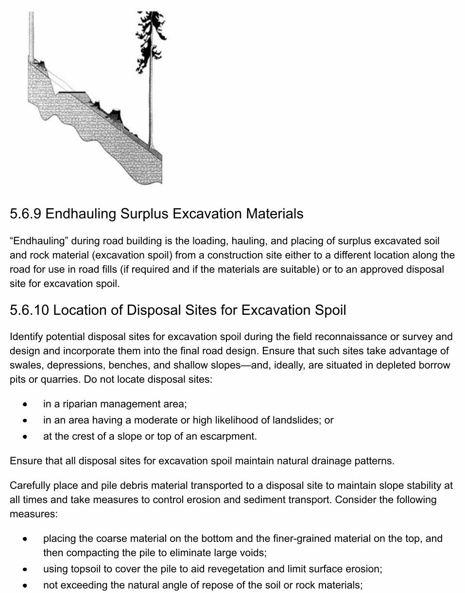
5.6.9 Endhauling Surplus Excavation Materials
“Endhauling” during road building is the loading, hauling, and placing of surplus excavated soiland rock material (excavation spoil) from a construction site either to a different location along theroad for use in road fills (if required and if the materials are suitable) or to an approved disposalsite for excavation spoil.
5.6.10 Location of Disposal Sites for Excavation Spoil
Identify potential disposal sites for excavation spoil during the field reconnaissance or survey anddesign and incorporate them into the final road design. Ensure that such sites take advantage ofswales, depressions, benches, and shallow slopes—and, ideally, are situated in depleted borrowpits or quarries. Do not locate disposal sites:
in a riparian management area;in an area having a moderate or high likelihood of landslides; orat the crest of a slope or top of an escarpment.
Ensure that all disposal sites for excavation spoil maintain natural drainage patterns.
Carefully place and pile debris material transported to a disposal site to maintain slope stability atall times and take measures to control erosion and sediment transport. Consider the followingmeasures:
placing the coarse material on the bottom and the finer-grained material on the top, andthen compacting the pile to eliminate large voids;using topsoil to cover the pile to aid revegetation and limit surface erosion;not exceeding the natural angle of repose of the soil or rock materials;
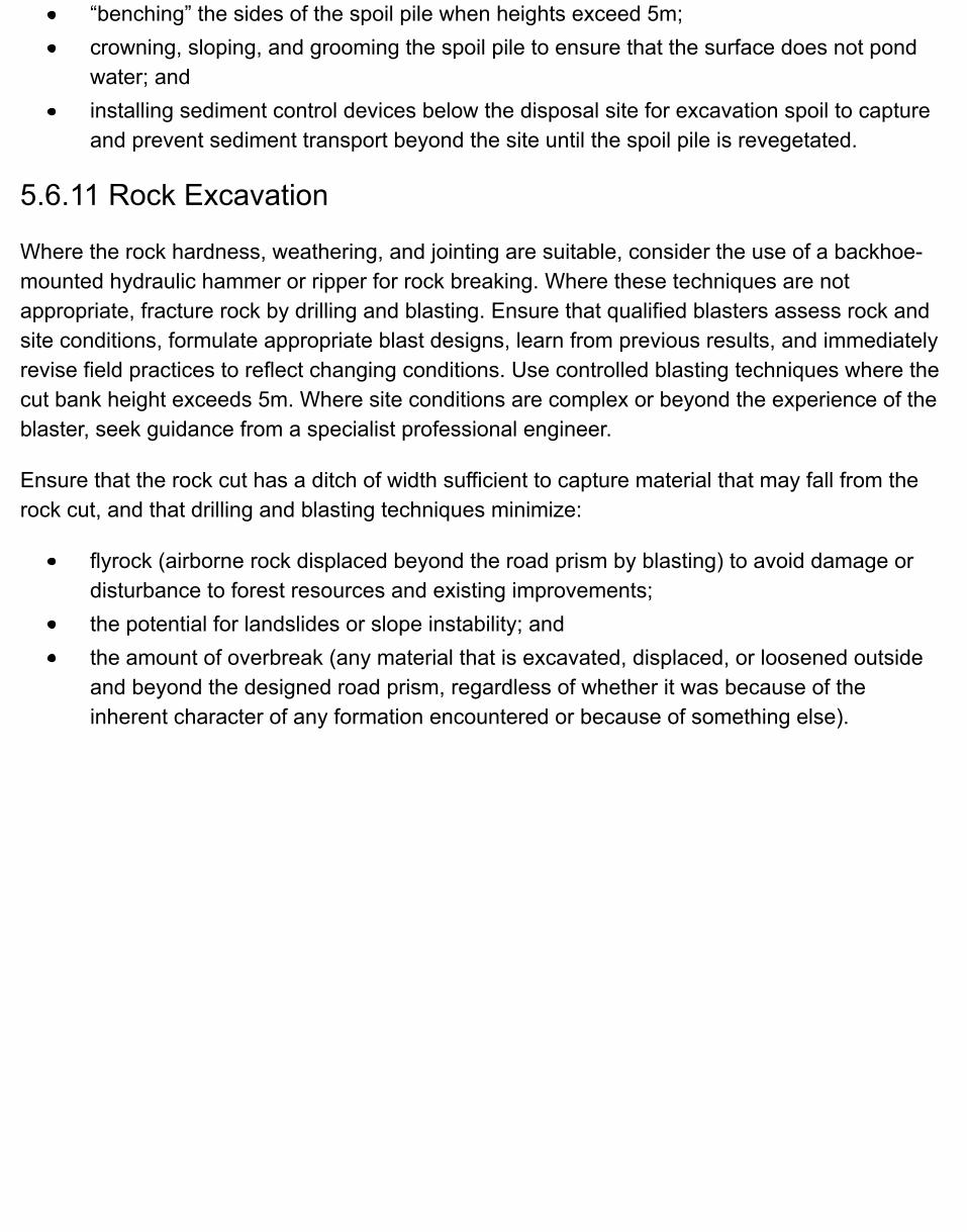
“benching” the sides of the spoil pile when heights exceed 5m;crowning, sloping, and grooming the spoil pile to ensure that the surface does not pondwater; andinstalling sediment control devices below the disposal site for excavation spoil to captureand prevent sediment transport beyond the site until the spoil pile is revegetated.
5.6.11 Rock Excavation
Where the rock hardness, weathering, and jointing are suitable, consider the use of a backhoe-mounted hydraulic hammer or ripper for rock breaking. Where these techniques are notappropriate, fracture rock by drilling and blasting. Ensure that qualified blasters assess rock andsite conditions, formulate appropriate blast designs, learn from previous results, and immediatelyrevise field practices to reflect changing conditions. Use controlled blasting techniques where thecut bank height exceeds 5m. Where site conditions are complex or beyond the experience of theblaster, seek guidance from a specialist professional engineer.
Ensure that the rock cut has a ditch of width sufficient to capture material that may fall from therock cut, and that drilling and blasting techniques minimize:
flyrock (airborne rock displaced beyond the road prism by blasting) to avoid damage ordisturbance to forest resources and existing improvements;the potential for landslides or slope instability; andthe amount of overbreak (any material that is excavated, displaced, or loosened outsideand beyond the designed road prism, regardless of whether it was because of theinherent character of any formation encountered or because of something else).
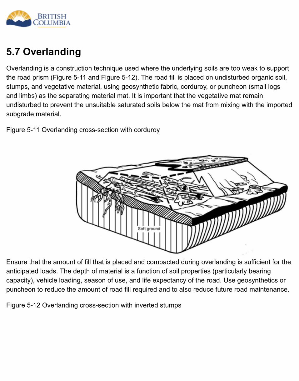
5.7 OverlandingOverlanding is a construction technique used where the underlying soils are too weak to supportthe road prism (Figure 5-11 and Figure 5-12). The road fill is placed on undisturbed organic soil,stumps, and vegetative material, using geosynthetic fabric, corduroy, or puncheon (small logsand limbs) as the separating material mat. It is important that the vegetative mat remainundisturbed to prevent the unsuitable saturated soils below the mat from mixing with the importedsubgrade material.
Figure 5-11 Overlanding cross-section with corduroy
Ensure that the amount of fill that is placed and compacted during overlanding is sufficient for theanticipated loads. The depth of material is a function of soil properties (particularly bearingcapacity), vehicle loading, season of use, and life expectancy of the road. Use geosynthetics orpuncheon to reduce the amount of road fill required and to also reduce future road maintenance.
Figure 5-12 Overlanding cross-section with inverted stumps
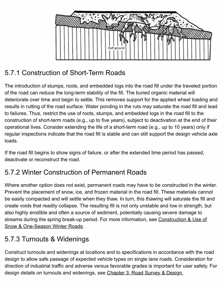
5.7.1 Construction of Short-Term Roads
The introduction of stumps, roots, and embedded logs into the road fill under the traveled portionof the road can reduce the long-term stability of the fill. The buried organic material willdeteriorate over time and begin to settle. This removes support for the applied wheel loading andresults in rutting of the road surface. Water ponding in the ruts may saturate the road fill and leadto failures. Thus, restrict the use of roots, stumps, and embedded logs in the road fill to theconstruction of short-term roads (e.g., up to five years), subject to deactivation at the end of theiroperational lives. Consider extending the life of a short-term road (e.g., up to 10 years) only ifregular inspections indicate that the road fill is stable and can still support the design vehicle axleloads.
If the road fill begins to show signs of failure, or after the extended time period has passed,deactivate or reconstruct the road.
5.7.2 Winter Construction of Permanent Roads
Where another option does not exist, permanent roads may have to be constructed in the winter.Prevent the placement of snow, ice, and frozen material in the road fill. These materials cannotbe easily compacted and will settle when they thaw. In turn, this thawing will saturate the fill andcreate voids that readily collapse. The resulting fill is not only unstable and low in strength, butalso highly erodible and often a source of sediment, potentially causing severe damage tostreams during the spring break-up period. For more information, see Construction & Use ofSnow & One-Season Winter Roads.
5.7.3 Turnouts & Widenings
Construct turnouts and widenings at locations and to specifications in accordance with the roaddesign to allow safe passage of expected vehicle types on single lane roads. Consideration fordirection of industrial traffic and adverse versus favorable grades is important for user safety. Fordesign details on turnouts and widenings, see Chapter 3: Road Survey & Design.

5.7.4 Location of Borrow Pits
Borrow pits are developed where additional material for subgrade construction or surfacing isrequired. Locate them outside of riparian management areas.
5.8 Road Drainage ConstructionIn this chapter, drainage consists of:
surface drainage works, including ditches and cross drain culverts as well as any ancillaryworks; andstream crossings, including metal culverts, log culverts and fords.
Ensure that any permanent culvert materials are fabricated in accordance with the currentCanadian Standards Association specifications.
5.8.1 Maintaining Surface Drainage Patterns
To maintain surface drainage patterns, keep water in its own drainage area, unless moving it toanother area is necessary to avoid unstable or sensitive soils.
Consider the potential for adverse upslope, downslope and downstream impacts before culvertlocations and outlet controls are determined. Measures to limit these impacts include:
installing flumes or riprap; orcarrying drainage flow farther along the ditchline to discharge it onto stable slopes.
Drainage systems are used to intercept and manage surface or subsurface drainage. If the soilsare easily erodible, consider changing the ditch gradient, alignment, or cross-section, or addingextra culverts, to reduce the distance over which water will have to be carried.
To minimize sediment delivery to streams, do not discharge the water conveyed in ditches andcross-drain culverts directly into streams. Allow these flows to settle out through the naturalvegetation on the forest floor before reaching any stream. Alternatively, filter these flows in otherways, such as through the use of settling basins or geosynthetics, until vegetation can be re-established. For more information about sediment control techniques, see Soil Erosion &Sediment Control.
5.8.2 Drainage Practices & Water Quality
Install drainage systems, whether permanent or temporary, concurrently with subgradeconstruction. Consider constructing temporary structures, such as cross- ditches, swales, oropen-topped culverts (e.g., cattleguards and similar structures), as appropriate, where water is
encountered, to accommodate the peak flows likely to be encountered during construction.Ensure that, if the site is left unattended and a storm takes place, the in-place drainage structurescan handle the runoff without damage resulting to the road or other resources. For a pilot trail ortote road, ensure that these can accommodate surface and subsurface drainage runoffthroughout the construction period. During road construction, remove any temporary drainagestructures that were previously installed to facilitate machine access and install permanentstructures in their place.
To ensure proper drainage during road construction:
stockpile an adequate supply of culverts, riprap, geotextiles, silt fencing, and grass seedon-site for immediate and future use, and to avoid construction delays;as water is encountered, establish adequate drainage to ensure flows are controlled andwater quality is maintained (where required) should a peak flow event occur;construct the final drainage structures as early in the construction process as ispracticable;construct silt traps, armoured ditch blocks, and aprons as construction progresses or assoon as soil conditions allow.
To protect water quality, utilize the following techniques, where applicable:
avoid working in areas of ponded water or saturated soils where this could result innegative impacts on resource values;construct stable cut and fill slopes;avoid in-stream work as much as possible. Where in-stream work is necessary, obtainappropriate agency approval before starting the work;ensure that machinery used in in-stream work is free of deleterious materials that mightbe deposited into the water; clean the machine undercarriage and tracks before doing in-stream work;install sufficient cross-drains and ditch blocks to keep ditchwater from eroding theditchline;install erosion-resistant aprons at the inlet and outlet of culverts;in ditches, use armouring, geotextile or silt fencing, blocks, or traps to minimize erosion;revegetate exposed erodible soils as soon as possible; andremove maintenance-intensive temporary construction measures such as silt fencing,straw or hay bales, and silt traps, when not required any longer.
5.8.3 Ditch Construction Considerations
Ensure that surface and subsurface flows do not cause excessive ditch or roadway erosion.Consider such factors as:
ditch soil conditions; gradient;alignment;cross-section;ancillary works;ditch stabilization; anddrainage alternatives where ditching is inappropriate.
Expand All | Collapse All
Ditch soil conditions
Ditch soil conditions influence erodibility. Finer textured, non-cohesive soils are more readilyeroded than coarser materials or cohesive soils.
Ditch gradient
The ditch gradient is largely dictated by the vertical alignment of the road. Ideally, constructthe gradient at a minimum of 2% to ensure that water will flow and not pond. Lower ditchgradients can still be effective, but may require a higher-than-routine level of inspection andmaintenance. Under certain conditions, ponded water can lead to a saturated subgrade. Thiscan contribute to severe roadway rutting, siltation, and possible failure of the roadway prism,as well as sediment deposition and plugging of cross-drain culverts. Such negative impactscan occur in both gentle and steep terrain.
However, keep ditch gradients in granular soils just steep enough to keep intercepted watermoving to cross-drain culverts without carrying excessive sediment. Steeper ditch gradientsin erodible soils generally increase the likelihood of erosion and sediment transport. Morefrequent culvert placement and armouring should be considered.
Ditch alignment
Avoid abrupt water flow changes. Sharp angles in the ditch alignment or flow obstructions inthe ditch (such as boulders or rock outcrops) can potentially deflect water into the subgradeor cutbanks and can result in erosion of the subgrade or undermining of the cutbank. Wherethere are impassable flow obstructions, consider installing additional cross-drain culverts.
Ditch cross-section
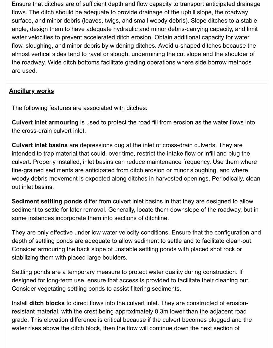
Ensure that ditches are of sufficient depth and flow capacity to transport anticipated drainageflows. The ditch should be adequate to provide drainage of the uphill slope, the roadwaysurface, and minor debris (leaves, twigs, and small woody debris). Slope ditches to a stableangle, design them to have adequate hydraulic and minor debris-carrying capacity, and limitwater velocities to prevent accelerated ditch erosion. Obtain additional capacity for waterflow, sloughing, and minor debris by widening ditches. Avoid u-shaped ditches because thealmost vertical sides tend to ravel or slough, undermining the cut slope and the shoulder ofthe roadway. Wide ditch bottoms facilitate grading operations where side borrow methodsare used.
Ancillary works
The following features are associated with ditches:
Culvert inlet armouring is used to protect the road fill from erosion as the water flows intothe cross-drain culvert inlet.
Culvert inlet basins are depressions dug at the inlet of cross-drain culverts. They areintended to trap material that could, over time, restrict the intake flow or infill and plug theculvert. Properly installed, inlet basins can reduce maintenance frequency. Use them wherefine-grained sediments are anticipated from ditch erosion or minor sloughing, and wherewoody debris movement is expected along ditches in harvested openings. Periodically, cleanout inlet basins.
Sediment settling ponds differ from culvert inlet basins in that they are designed to allowsediment to settle for later removal. Generally, locate them downslope of the roadway, but insome instances incorporate them into sections of ditchline.
They are only effective under low water velocity conditions. Ensure that the configuration anddepth of settling ponds are adequate to allow sediment to settle and to facilitate clean-out.Consider armouring the back slope of unstable settling ponds with placed shot rock orstabilizing them with placed large boulders.
Settling ponds are a temporary measure to protect water quality during construction. Ifdesigned for long-term use, ensure that access is provided to facilitate their cleaning out.Consider vegetating settling ponds to assist filtering sediments.
Install ditch blocks to direct flows into the culvert inlet. They are constructed of erosion-resistant material, with the crest being approximately 0.3m lower than the adjacent roadgrade. This elevation difference is critical because if the culvert becomes plugged and thewater rises above the ditch block, then the flow will continue down the next section of
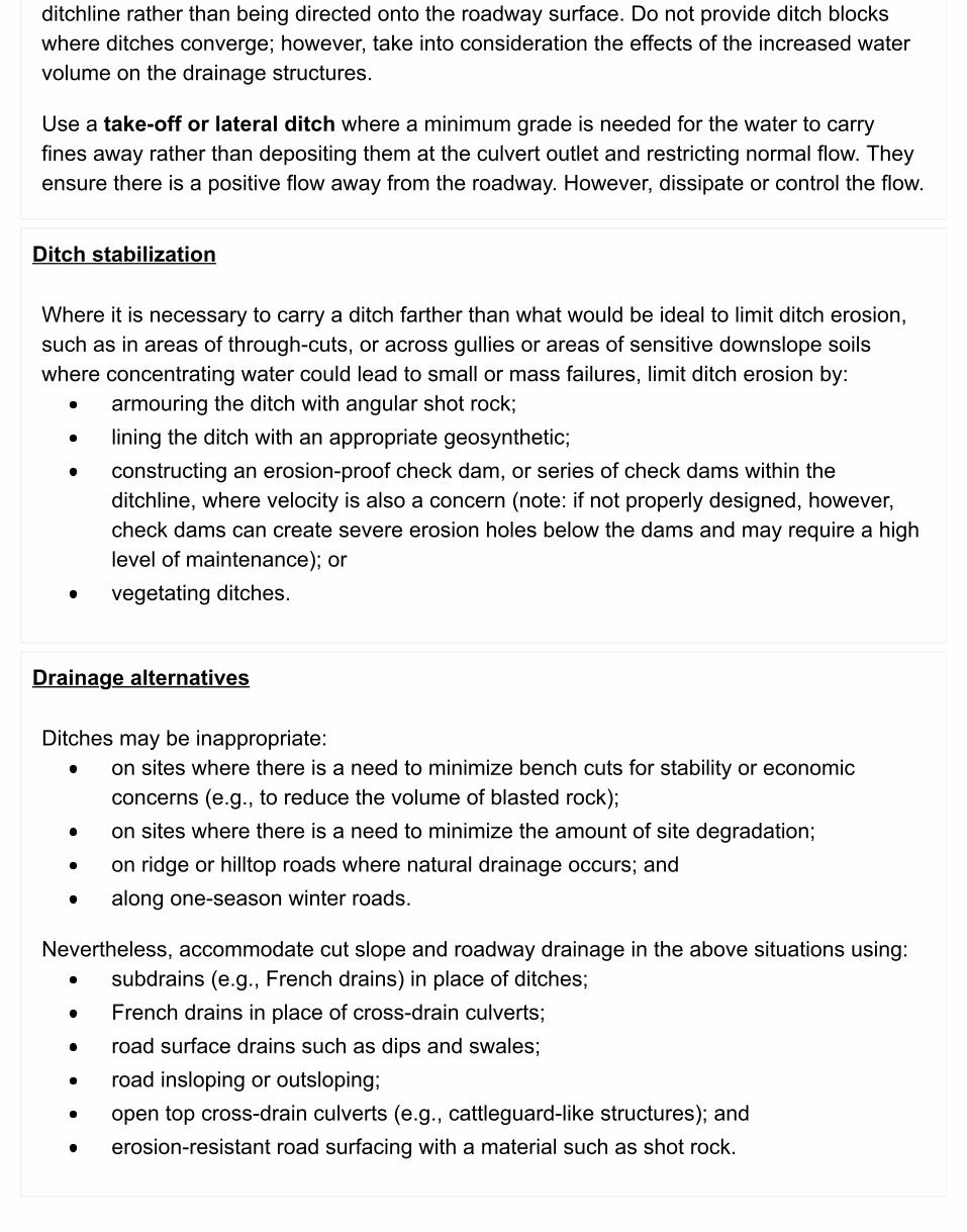
ditchline rather than being directed onto the roadway surface. Do not provide ditch blockswhere ditches converge; however, take into consideration the effects of the increased watervolume on the drainage structures.
Use a take-off or lateral ditch where a minimum grade is needed for the water to carryfines away rather than depositing them at the culvert outlet and restricting normal flow. Theyensure there is a positive flow away from the roadway. However, dissipate or control the flow.
Ditch stabilization
Where it is necessary to carry a ditch farther than what would be ideal to limit ditch erosion,such as in areas of through-cuts, or across gullies or areas of sensitive downslope soilswhere concentrating water could lead to small or mass failures, limit ditch erosion by:
armouring the ditch with angular shot rock;lining the ditch with an appropriate geosynthetic;constructing an erosion-proof check dam, or series of check dams within theditchline, where velocity is also a concern (note: if not properly designed, however,check dams can create severe erosion holes below the dams and may require a highlevel of maintenance); orvegetating ditches.
Drainage alternatives
Ditches may be inappropriate:on sites where there is a need to minimize bench cuts for stability or economicconcerns (e.g., to reduce the volume of blasted rock);on sites where there is a need to minimize the amount of site degradation;on ridge or hilltop roads where natural drainage occurs; andalong one-season winter roads.
Nevertheless, accommodate cut slope and roadway drainage in the above situations using:subdrains (e.g., French drains) in place of ditches;French drains in place of cross-drain culverts;road surface drains such as dips and swales;road insloping or outsloping;open top cross-drain culverts (e.g., cattleguard-like structures); anderosion-resistant road surfacing with a material such as shot rock.
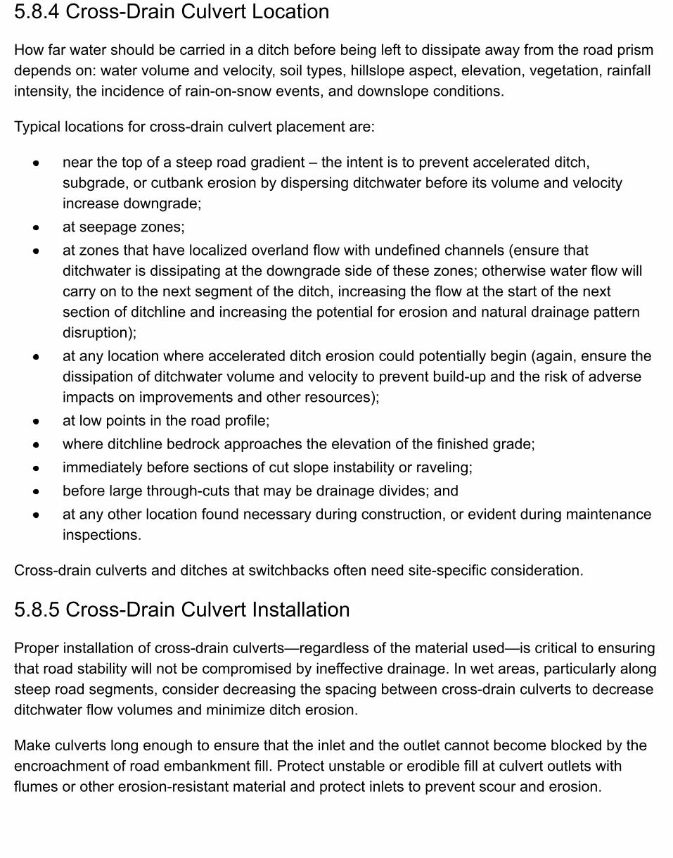
5.8.4 Cross-Drain Culvert Location
How far water should be carried in a ditch before being left to dissipate away from the road prismdepends on: water volume and velocity, soil types, hillslope aspect, elevation, vegetation, rainfallintensity, the incidence of rain-on-snow events, and downslope conditions.
Typical locations for cross-drain culvert placement are:
near the top of a steep road gradient – the intent is to prevent accelerated ditch,subgrade, or cutbank erosion by dispersing ditchwater before its volume and velocityincrease downgrade;at seepage zones;at zones that have localized overland flow with undefined channels (ensure thatditchwater is dissipating at the downgrade side of these zones; otherwise water flow willcarry on to the next segment of the ditch, increasing the flow at the start of the nextsection of ditchline and increasing the potential for erosion and natural drainage patterndisruption);at any location where accelerated ditch erosion could potentially begin (again, ensure thedissipation of ditchwater volume and velocity to prevent build-up and the risk of adverseimpacts on improvements and other resources);at low points in the road profile;where ditchline bedrock approaches the elevation of the finished grade;immediately before sections of cut slope instability or raveling;before large through-cuts that may be drainage divides; andat any other location found necessary during construction, or evident during maintenanceinspections.
Cross-drain culverts and ditches at switchbacks often need site-specific consideration.
5.8.5 Cross-Drain Culvert Installation
Proper installation of cross-drain culverts—regardless of the material used—is critical to ensuringthat road stability will not be compromised by ineffective drainage. In wet areas, particularly alongsteep road segments, consider decreasing the spacing between cross-drain culverts to decreaseditchwater flow volumes and minimize ditch erosion.
Make culverts long enough to ensure that the inlet and the outlet cannot become blocked by theencroachment of road embankment fill. Protect unstable or erodible fill at culvert outlets withflumes or other erosion-resistant material and protect inlets to prevent scour and erosion.
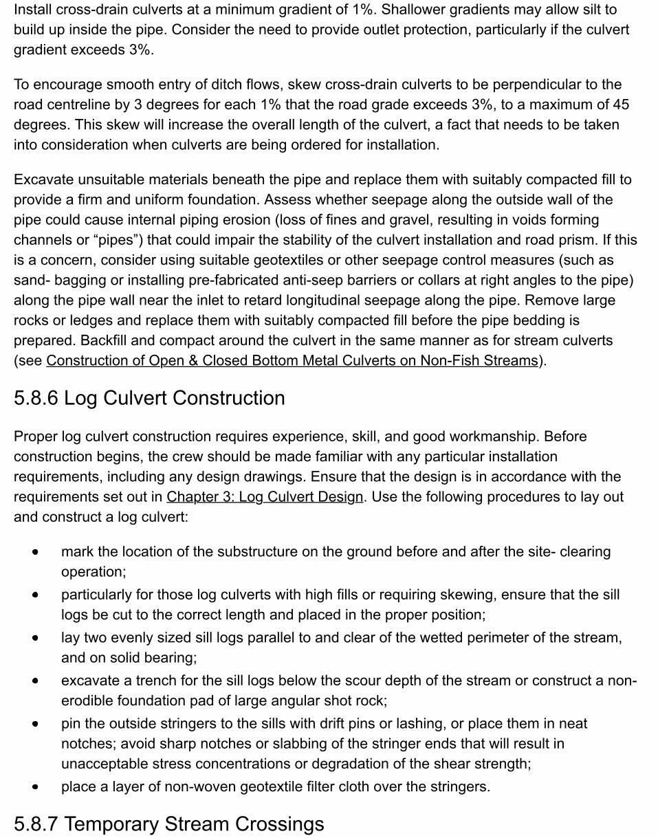
Install cross-drain culverts at a minimum gradient of 1%. Shallower gradients may allow silt tobuild up inside the pipe. Consider the need to provide outlet protection, particularly if the culvertgradient exceeds 3%.
To encourage smooth entry of ditch flows, skew cross-drain culverts to be perpendicular to theroad centreline by 3 degrees for each 1% that the road grade exceeds 3%, to a maximum of 45degrees. This skew will increase the overall length of the culvert, a fact that needs to be takeninto consideration when culverts are being ordered for installation.
Excavate unsuitable materials beneath the pipe and replace them with suitably compacted fill toprovide a firm and uniform foundation. Assess whether seepage along the outside wall of thepipe could cause internal piping erosion (loss of fines and gravel, resulting in voids formingchannels or “pipes”) that could impair the stability of the culvert installation and road prism. If thisis a concern, consider using suitable geotextiles or other seepage control measures (such assand- bagging or installing pre-fabricated anti-seep barriers or collars at right angles to the pipe)along the pipe wall near the inlet to retard longitudinal seepage along the pipe. Remove largerocks or ledges and replace them with suitably compacted fill before the pipe bedding isprepared. Backfill and compact around the culvert in the same manner as for stream culverts(see Construction of Open & Closed Bottom Metal Culverts on Non-Fish Streams).
5.8.6 Log Culvert Construction
Proper log culvert construction requires experience, skill, and good workmanship. Beforeconstruction begins, the crew should be made familiar with any particular installationrequirements, including any design drawings. Ensure that the design is in accordance with therequirements set out in Chapter 3: Log Culvert Design. Use the following procedures to lay outand construct a log culvert:
mark the location of the substructure on the ground before and after the site- clearingoperation;particularly for those log culverts with high fills or requiring skewing, ensure that the silllogs be cut to the correct length and placed in the proper position;lay two evenly sized sill logs parallel to and clear of the wetted perimeter of the stream,and on solid bearing;excavate a trench for the sill logs below the scour depth of the stream or construct a non-erodible foundation pad of large angular shot rock;pin the outside stringers to the sills with drift pins or lashing, or place them in neatnotches; avoid sharp notches or slabbing of the stringer ends that will result inunacceptable stress concentrations or degradation of the shear strength;place a layer of non-woven geotextile filter cloth over the stringers.
5.8.7 Temporary Stream Crossings
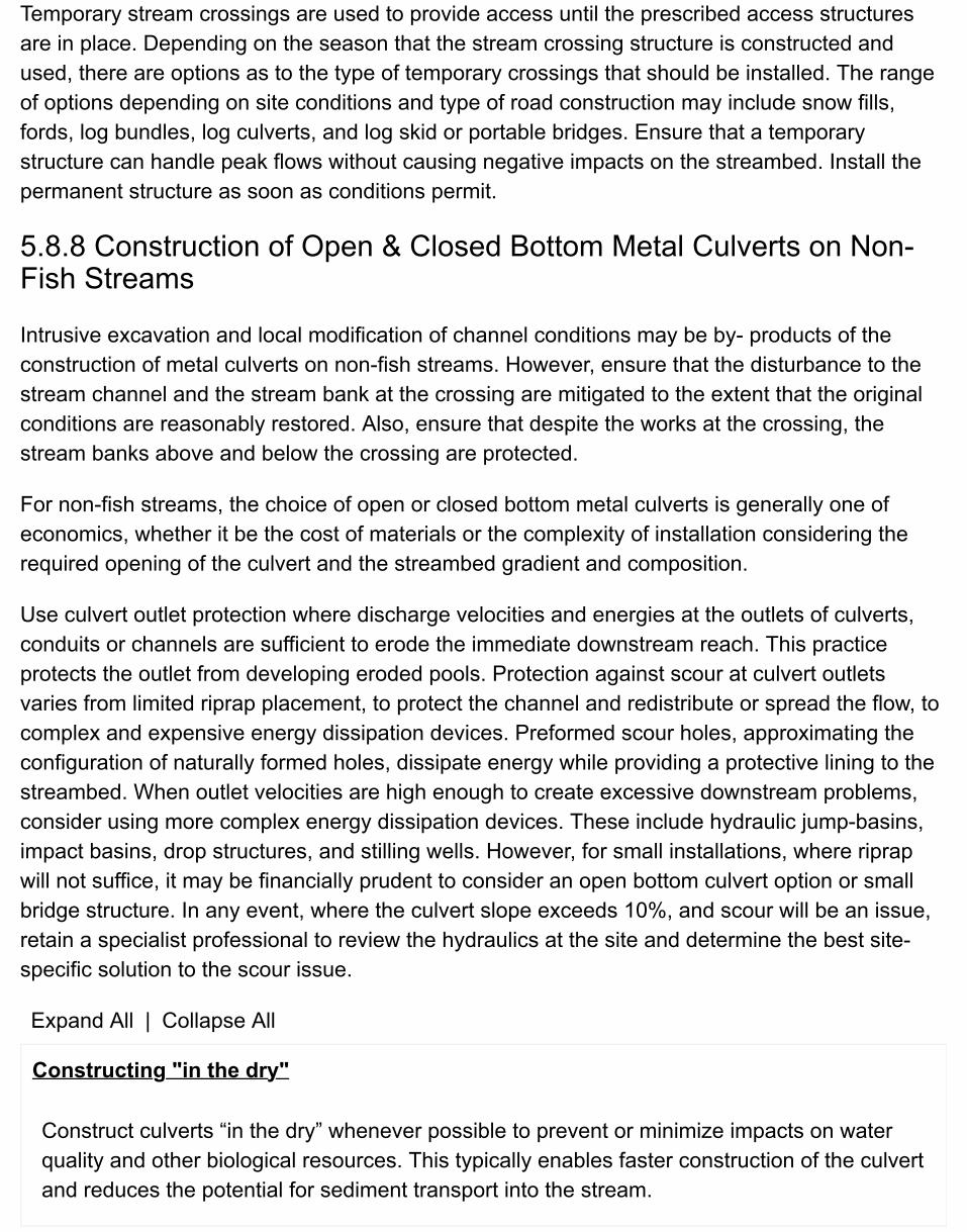
Temporary stream crossings are used to provide access until the prescribed access structuresare in place. Depending on the season that the stream crossing structure is constructed andused, there are options as to the type of temporary crossings that should be installed. The rangeof options depending on site conditions and type of road construction may include snow fills,fords, log bundles, log culverts, and log skid or portable bridges. Ensure that a temporarystructure can handle peak flows without causing negative impacts on the streambed. Install thepermanent structure as soon as conditions permit.
5.8.8 Construction of Open & Closed Bottom Metal Culverts on Non-Fish Streams
Intrusive excavation and local modification of channel conditions may be by- products of theconstruction of metal culverts on non-fish streams. However, ensure that the disturbance to thestream channel and the stream bank at the crossing are mitigated to the extent that the originalconditions are reasonably restored. Also, ensure that despite the works at the crossing, thestream banks above and below the crossing are protected.
For non-fish streams, the choice of open or closed bottom metal culverts is generally one ofeconomics, whether it be the cost of materials or the complexity of installation considering therequired opening of the culvert and the streambed gradient and composition.
Use culvert outlet protection where discharge velocities and energies at the outlets of culverts,conduits or channels are sufficient to erode the immediate downstream reach. This practiceprotects the outlet from developing eroded pools. Protection against scour at culvert outletsvaries from limited riprap placement, to protect the channel and redistribute or spread the flow, tocomplex and expensive energy dissipation devices. Preformed scour holes, approximating theconfiguration of naturally formed holes, dissipate energy while providing a protective lining to thestreambed. When outlet velocities are high enough to create excessive downstream problems,consider using more complex energy dissipation devices. These include hydraulic jump-basins,impact basins, drop structures, and stilling wells. However, for small installations, where riprapwill not suffice, it may be financially prudent to consider an open bottom culvert option or smallbridge structure. In any event, where the culvert slope exceeds 10%, and scour will be an issue,retain a specialist professional to review the hydraulics at the site and determine the best site-specific solution to the scour issue.
Expand All | Collapse All
Constructing "in the dry"
Construct culverts “in the dry” whenever possible to prevent or minimize impacts on waterquality and other biological resources. This typically enables faster construction of the culvertand reduces the potential for sediment transport into the stream.
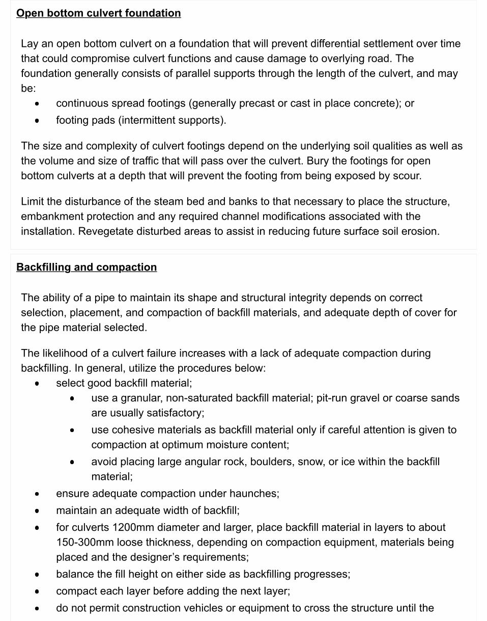
Open bottom culvert foundation
Lay an open bottom culvert on a foundation that will prevent differential settlement over timethat could compromise culvert functions and cause damage to overlying road. Thefoundation generally consists of parallel supports through the length of the culvert, and maybe:
continuous spread footings (generally precast or cast in place concrete); orfooting pads (intermittent supports).
The size and complexity of culvert footings depend on the underlying soil qualities as well asthe volume and size of traffic that will pass over the culvert. Bury the footings for openbottom culverts at a depth that will prevent the footing from being exposed by scour.
Limit the disturbance of the steam bed and banks to that necessary to place the structure,embankment protection and any required channel modifications associated with theinstallation. Revegetate disturbed areas to assist in reducing future surface soil erosion.
Backfilling and compaction
The ability of a pipe to maintain its shape and structural integrity depends on correctselection, placement, and compaction of backfill materials, and adequate depth of cover forthe pipe material selected.
The likelihood of a culvert failure increases with a lack of adequate compaction duringbackfilling. In general, utilize the procedures below:
select good backfill material;use a granular, non-saturated backfill material; pit-run gravel or coarse sandsare usually satisfactory;use cohesive materials as backfill material only if careful attention is given tocompaction at optimum moisture content;avoid placing large angular rock, boulders, snow, or ice within the backfillmaterial;
ensure adequate compaction under haunches;maintain an adequate width of backfill;for culverts 1200mm diameter and larger, place backfill material in layers to about150-300mm loose thickness, depending on compaction equipment, materials beingplaced and the designer’s requirements;balance the fill height on either side as backfilling progresses;compact each layer before adding the next layer;do not permit construction vehicles or equipment to cross the structure until the
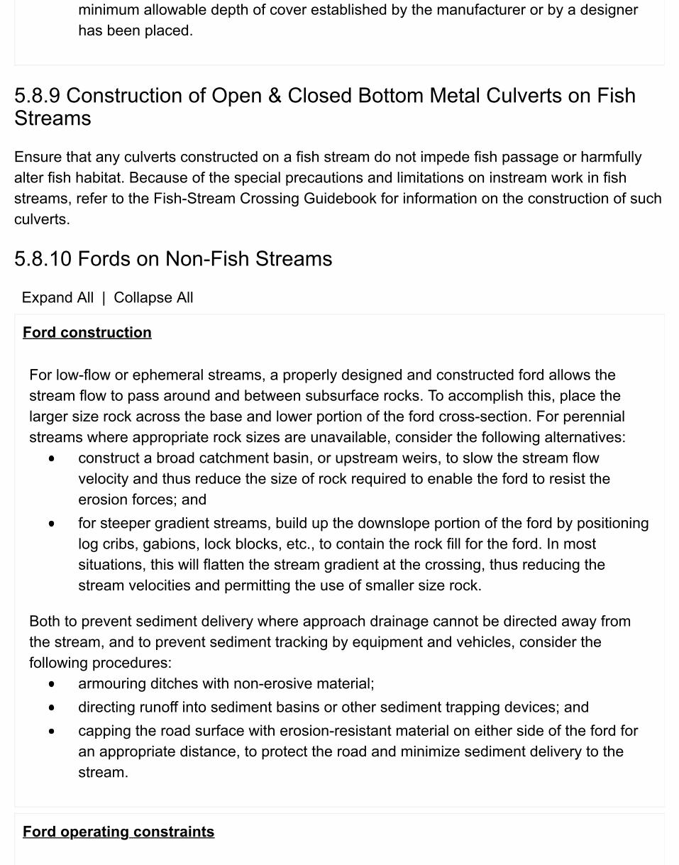
minimum allowable depth of cover established by the manufacturer or by a designerhas been placed.
5.8.9 Construction of Open & Closed Bottom Metal Culverts on FishStreams
Ensure that any culverts constructed on a fish stream do not impede fish passage or harmfullyalter fish habitat. Because of the special precautions and limitations on instream work in fishstreams, refer to the Fish-Stream Crossing Guidebook for information on the construction of suchculverts.
5.8.10 Fords on Non-Fish Streams
Expand All | Collapse All
Ford construction
For low-flow or ephemeral streams, a properly designed and constructed ford allows thestream flow to pass around and between subsurface rocks. To accomplish this, place thelarger size rock across the base and lower portion of the ford cross-section. For perennialstreams where appropriate rock sizes are unavailable, consider the following alternatives:
construct a broad catchment basin, or upstream weirs, to slow the stream flowvelocity and thus reduce the size of rock required to enable the ford to resist theerosion forces; andfor steeper gradient streams, build up the downslope portion of the ford by positioninglog cribs, gabions, lock blocks, etc., to contain the rock fill for the ford. In mostsituations, this will flatten the stream gradient at the crossing, thus reducing thestream velocities and permitting the use of smaller size rock.
Both to prevent sediment delivery where approach drainage cannot be directed away fromthe stream, and to prevent sediment tracking by equipment and vehicles, consider thefollowing procedures:
armouring ditches with non-erosive material;directing runoff into sediment basins or other sediment trapping devices; andcapping the road surface with erosion-resistant material on either side of the ford foran appropriate distance, to protect the road and minimize sediment delivery to thestream.
Ford operating constraints
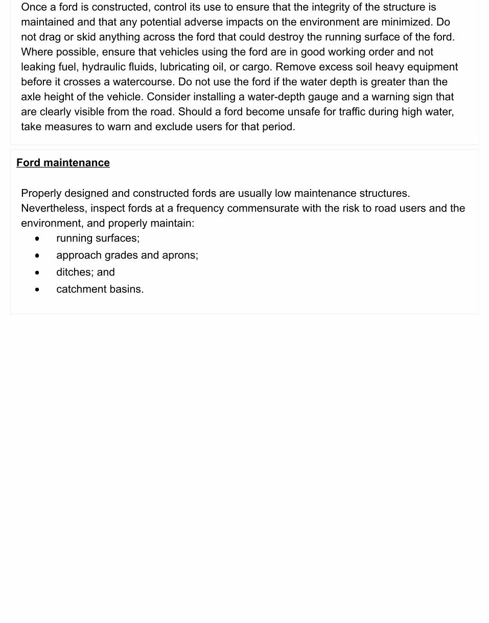
Once a ford is constructed, control its use to ensure that the integrity of the structure ismaintained and that any potential adverse impacts on the environment are minimized. Donot drag or skid anything across the ford that could destroy the running surface of the ford.Where possible, ensure that vehicles using the ford are in good working order and notleaking fuel, hydraulic fluids, lubricating oil, or cargo. Remove excess soil heavy equipmentbefore it crosses a watercourse. Do not use the ford if the water depth is greater than theaxle height of the vehicle. Consider installing a water-depth gauge and a warning sign thatare clearly visible from the road. Should a ford become unsafe for traffic during high water,take measures to warn and exclude users for that period.
Ford maintenance
Properly designed and constructed fords are usually low maintenance structures.Nevertheless, inspect fords at a frequency commensurate with the risk to road users and theenvironment, and properly maintain:
running surfaces;approach grades and aprons;ditches; andcatchment basins.
5.9 Stabilizing the Subgrade & Surfacing the Road
5.9.1 Ballasting
Ballasting is the use of rock to construct the road subgrade when other available material isincapable of supporting the design traffic load during the period of use.
Generally, ensure that suitable ballast material:
drains well;forms a structurally competent fill;compacts well; andresists erosion.
5.9.2 Surfacing
Surface the subgrade with pit-run gravel or crushed rock aggregate for one or more of thefollowing reasons:
where subgrade material is highly erodible and needs to be protected from water or windaction;where subgrade material will not support traffic loading during periods of use; andto form a driveable and gradeable surface.
Expand All | Collapse All
Surfacing material selection
Surfacing materials include crushed rock and pit-run gravel aggregates. Surfacing materialsconsist of inert, tough, durable particles that will not deteriorate when worked (handled,spread, or compacted) and combined with suitable fines, or when exposed to water andfreeze-thaw cycles. Ensure that aggregate particles are uniform in quality and free from anexcess of flat or elongated pieces.
Ensure that the aggregate is well graded (contains a mix of all particle sizes) for compactionand for a durable wearing surface. When the only source material is poorly graded, consider:
screening the material to remove the excessive particle sizes; or
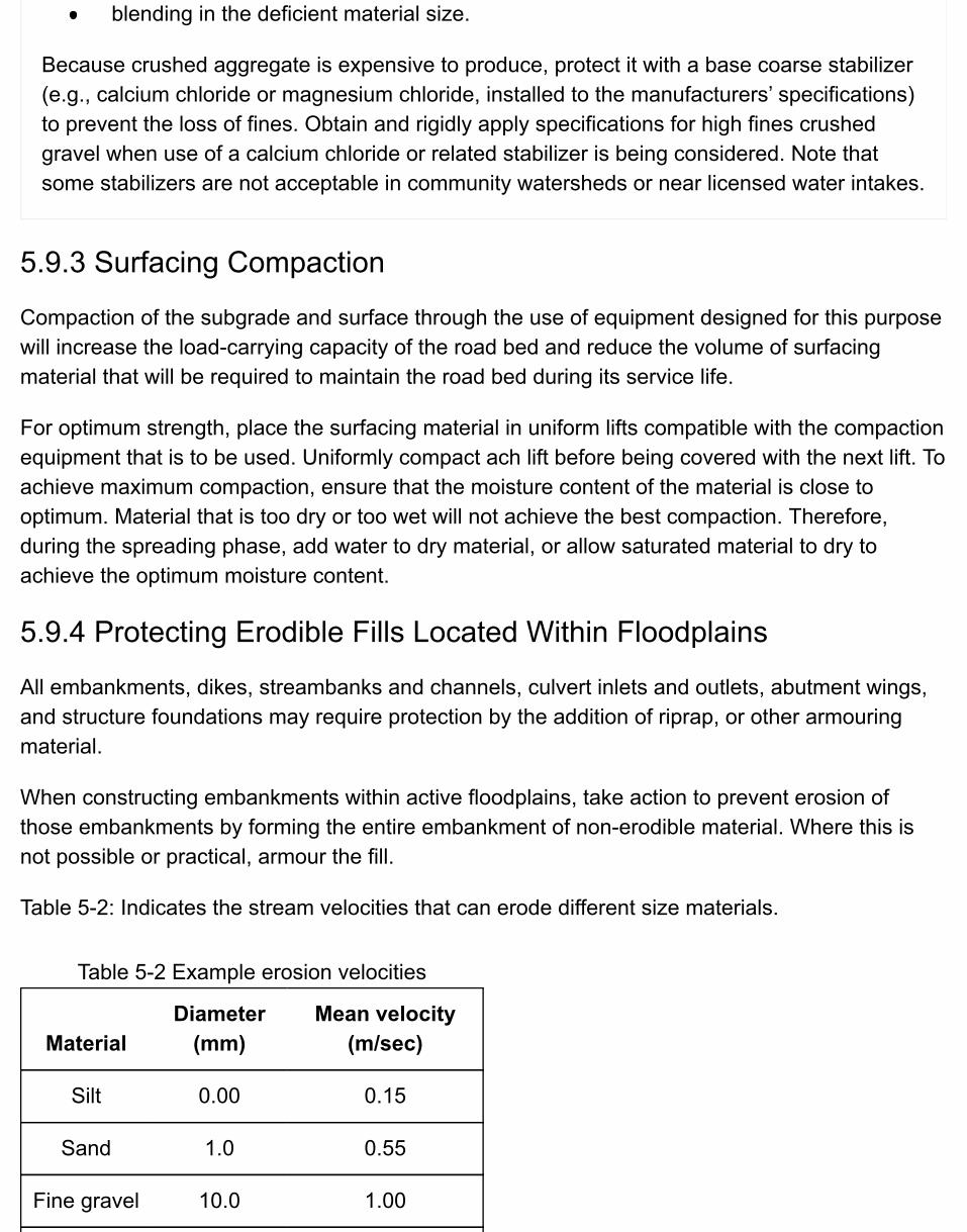
Table 5-2 Example erosion velocities
MaterialDiameter
(mm)Mean velocity
(m/sec)
Silt 0.00 0.15
Sand 1.0 0.55
Fine gravel 10.0 1.00
blending in the deficient material size.
Because crushed aggregate is expensive to produce, protect it with a base coarse stabilizer(e.g., calcium chloride or magnesium chloride, installed to the manufacturers’ specifications)to prevent the loss of fines. Obtain and rigidly apply specifications for high fines crushedgravel when use of a calcium chloride or related stabilizer is being considered. Note thatsome stabilizers are not acceptable in community watersheds or near licensed water intakes.
5.9.3 Surfacing Compaction
Compaction of the subgrade and surface through the use of equipment designed for this purposewill increase the load-carrying capacity of the road bed and reduce the volume of surfacingmaterial that will be required to maintain the road bed during its service life.
For optimum strength, place the surfacing material in uniform lifts compatible with the compactionequipment that is to be used. Uniformly compact ach lift before being covered with the next lift. Toachieve maximum compaction, ensure that the moisture content of the material is close tooptimum. Material that is too dry or too wet will not achieve the best compaction. Therefore,during the spreading phase, add water to dry material, or allow saturated material to dry toachieve the optimum moisture content.
5.9.4 Protecting Erodible Fills Located Within Floodplains
All embankments, dikes, streambanks and channels, culvert inlets and outlets, abutment wings,and structure foundations may require protection by the addition of riprap, or other armouringmaterial.
When constructing embankments within active floodplains, take action to prevent erosion ofthose embankments by forming the entire embankment of non-erodible material. Where this isnot possible or practical, armour the fill.
Table 5-2: Indicates the stream velocities that can erode different size materials.
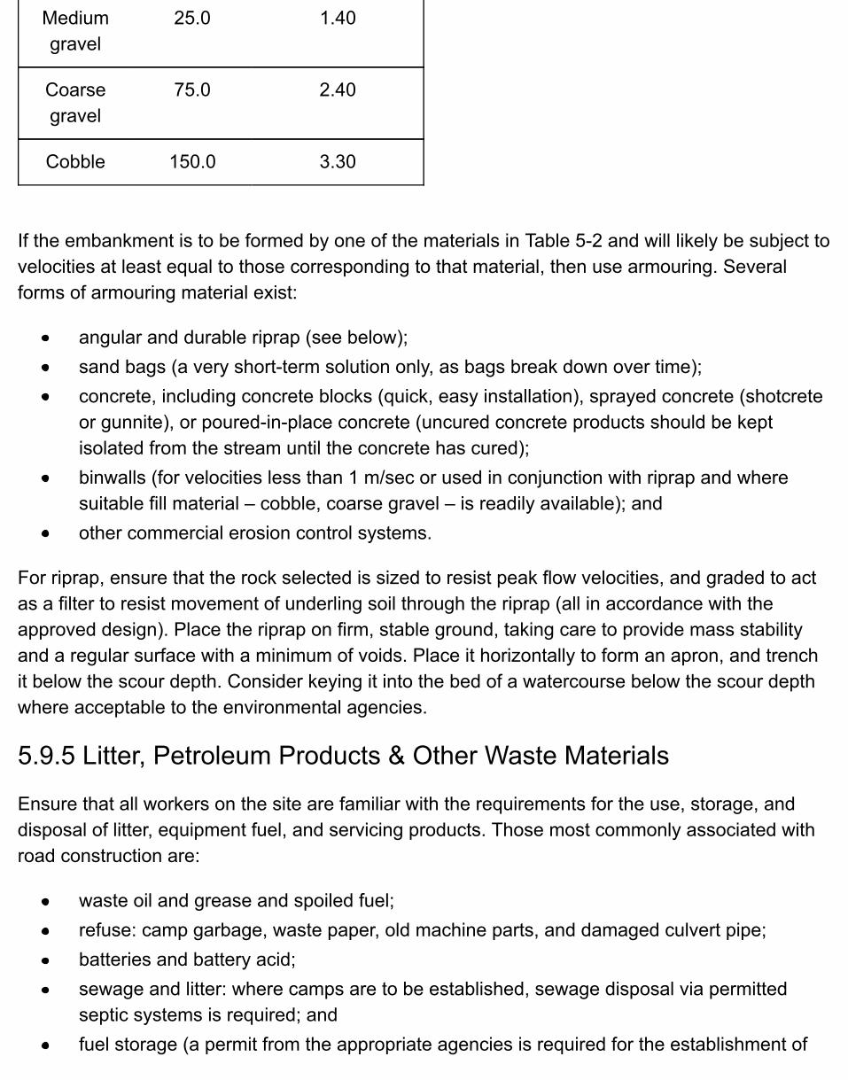
Mediumgravel
25.0 1.40
Coarsegravel
75.0 2.40
Cobble 150.0 3.30
If the embankment is to be formed by one of the materials in Table 5-2 and will likely be subject tovelocities at least equal to those corresponding to that material, then use armouring. Severalforms of armouring material exist:
angular and durable riprap (see below);sand bags (a very short-term solution only, as bags break down over time);concrete, including concrete blocks (quick, easy installation), sprayed concrete (shotcreteor gunnite), or poured-in-place concrete (uncured concrete products should be keptisolated from the stream until the concrete has cured);binwalls (for velocities less than 1 m/sec or used in conjunction with riprap and wheresuitable fill material – cobble, coarse gravel – is readily available); andother commercial erosion control systems.
For riprap, ensure that the rock selected is sized to resist peak flow velocities, and graded to actas a filter to resist movement of underling soil through the riprap (all in accordance with theapproved design). Place the riprap on firm, stable ground, taking care to provide mass stabilityand a regular surface with a minimum of voids. Place it horizontally to form an apron, and trenchit below the scour depth. Consider keying it into the bed of a watercourse below the scour depthwhere acceptable to the environmental agencies.
5.9.5 Litter, Petroleum Products & Other Waste Materials
Ensure that all workers on the site are familiar with the requirements for the use, storage, anddisposal of litter, equipment fuel, and servicing products. Those most commonly associated withroad construction are:
waste oil and grease and spoiled fuel;refuse: camp garbage, waste paper, old machine parts, and damaged culvert pipe;batteries and battery acid;sewage and litter: where camps are to be established, sewage disposal via permittedseptic systems is required; andfuel storage (a permit from the appropriate agencies is required for the establishment of
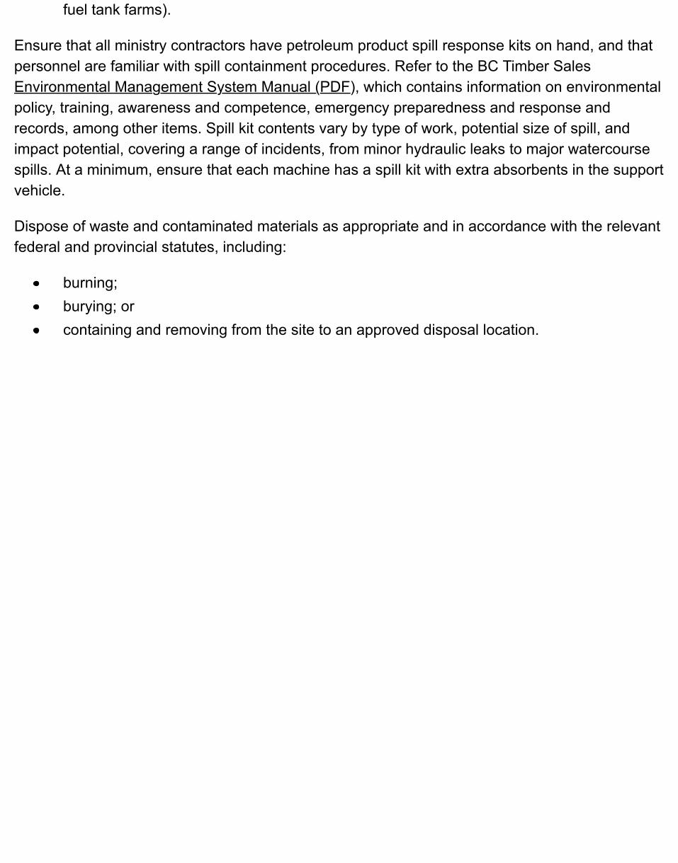
fuel tank farms).
Ensure that all ministry contractors have petroleum product spill response kits on hand, and thatpersonnel are familiar with spill containment procedures. Refer to the BC Timber SalesEnvironmental Management System Manual (PDF), which contains information on environmentalpolicy, training, awareness and competence, emergency preparedness and response andrecords, among other items. Spill kit contents vary by type of work, potential size of spill, andimpact potential, covering a range of incidents, from minor hydraulic leaks to major watercoursespills. At a minimum, ensure that each machine has a spill kit with extra absorbents in the supportvehicle.
Dispose of waste and contaminated materials as appropriate and in accordance with the relevantfederal and provincial statutes, including:
burning;burying; orcontaining and removing from the site to an approved disposal location.
5.10 Construction & Use of Snow & One-Season WinterRoadsThroughout much of British Columbia, forest operations are best conducted during the wintermonths. By using deep snow or frozen ground as the running surface, equipment working onsnow roads or one-season winter roads has a lower environmental impact than when working onall-weather roads. Fine- textured soils and muskeg ground conditions are especially vulnerable.Construct these seasonal roads during the early part of the winter, so that harvesting can becompleted before snowmelt and the break-up of frozen ground in the spring. If there is insufficientsnowpack, these road types cannot be constructed.
Snow roads and one-season winter roads use the strength of ice and snow to produce a stableroad bed that will support the design vehicle axle loads. In areas with heavy snowfall, the mainreliance is on the snow pack. In either case, weather is the essential and unpredictable factor inthe construction process, and logistics are key to constructing and using winter roads effectively.Where mid- winter thaws are common, construct short spur roads, and use and deactivate themin a matter of weeks.
Generally, watercourses are frozen for the life of the road, and in many cases drainage structuresmay not be required. Compact snow fills across small streams and gullies with the use of logbundles to allow the passage of any seepage that may occur or to reduce the volume of snowrequired. Where mid-winter thaws are common, install culverts in the snow fill to accommodatepossible flowing water.
Coordinate deactivation of these road types with operations and complete such work before thespring freshet. Restore all-natural drainage channels while road access is available. Do not leavelogs in stream channels, and breach snow fills to prevent the damming of watercourses. Thoughmid-winter thaws can disable even a well-built road, the high-risk period begins during springbreak-up. During that period, snowmelt can occur very quickly, resulting in rapid overland flows ofmeltwater, high flows in watercourses, and an extreme softness of soil materials that rendersthem highly susceptible to erosion. Any soils that have been mixed with snow become fluid andhighly susceptible to mass erosion. Debris or excavated spoil material piled on top of a snowlayer can become unstable on even gentle side slopes. For more information on roaddeactivation techniques, see Chapter 7: Road Deactivation.
5.10.1 Snow Road Construction
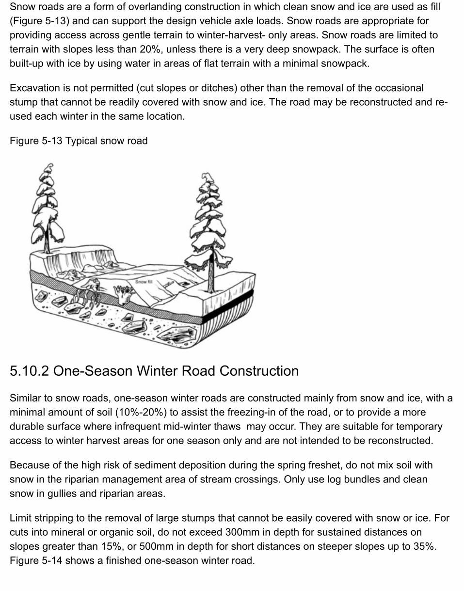
Snow roads are a form of overlanding construction in which clean snow and ice are used as fill(Figure 5-13) and can support the design vehicle axle loads. Snow roads are appropriate forproviding access across gentle terrain to winter-harvest- only areas. Snow roads are limited toterrain with slopes less than 20%, unless there is a very deep snowpack. The surface is oftenbuilt-up with ice by using water in areas of flat terrain with a minimal snowpack.
Excavation is not permitted (cut slopes or ditches) other than the removal of the occasionalstump that cannot be readily covered with snow and ice. The road may be reconstructed and re-used each winter in the same location.
Figure 5-13 Typical snow road
5.10.2 One-Season Winter Road Construction
Similar to snow roads, one-season winter roads are constructed mainly from snow and ice, with aminimal amount of soil (10%-20%) to assist the freezing-in of the road, or to provide a moredurable surface where infrequent mid-winter thaws may occur. They are suitable for temporaryaccess to winter harvest areas for one season only and are not intended to be reconstructed.
Because of the high risk of sediment deposition during the spring freshet, do not mix soil withsnow in the riparian management area of stream crossings. Only use log bundles and cleansnow in gullies and riparian areas.
Limit stripping to the removal of large stumps that cannot be easily covered with snow or ice. Forcuts into mineral or organic soil, do not exceed 300mm in depth for sustained distances onslopes greater than 15%, or 500mm in depth for short distances on steeper slopes up to 35%.Figure 5-14 shows a finished one-season winter road.
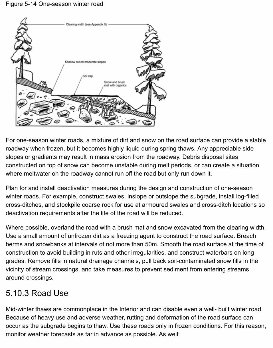
Figure 5-14 One-season winter road
For one-season winter roads, a mixture of dirt and snow on the road surface can provide a stableroadway when frozen, but it becomes highly liquid during spring thaws. Any appreciable sideslopes or gradients may result in mass erosion from the roadway. Debris disposal sitesconstructed on top of snow can become unstable during melt periods, or can create a situationwhere meltwater on the roadway cannot run off the road but only run down it.
Plan for and install deactivation measures during the design and construction of one-seasonwinter roads. For example, construct swales, inslope or outslope the subgrade, install log-filledcross-ditches, and stockpile coarse rock for use at armoured swales and cross-ditch locations sodeactivation requirements after the life of the road will be reduced.
Where possible, overland the road with a brush mat and snow excavated from the clearing width.Use a small amount of unfrozen dirt as a freezing agent to construct the road surface. Breachberms and snowbanks at intervals of not more than 50m. Smooth the road surface at the time ofconstruction to avoid building in ruts and other irregularities, and construct waterbars on longgrades. Remove fills in natural drainage channels, pull back soil-contaminated snow fills in thevicinity of stream crossings. and take measures to prevent sediment from entering streamsaround crossings.
5.10.3 Road Use
Mid-winter thaws are commonplace in the Interior and can disable even a well- built winter road.Because of heavy use and adverse weather, rutting and deformation of the road surface canoccur as the subgrade begins to thaw. Use these roads only in frozen conditions. For this reason,monitor weather forecasts as far in advance as possible. As well:

schedule night hauling when temperatures are expected to be above freezing during theday; andstrictly control all light traffic during unfrozen conditions.
5.11 Soil Erosion & Sediment ControlSoil disturbance is inevitable from most road construction activities. Control of soil erosion andthe subsequent transport of sediment during road construction are therefore important concernswhere there is direct or indirect connectivity to water. Erosion control addresses the source of soilerosion, whereas sediment control addresses the control and retention of sediment. As erosioncontrol has a generally higher level of effectiveness than sediment control, ensure that theprimary goals are, first, to minimize potentially damaging erosion of the disturbed sites; and,second, to limit the transport of sediment from these sites.
5.11.1 Soil Erosion Control Techniques
To minimize surface soil erosion after road construction, cover all exposed soils that are subjectto weathering (e.g., silty and sandy non-cohesive soils and clayey and other cohesive fine-grained soils) with grass and legume vegetation. A variety of erosion seed mixes are availablethat provide for rapid germination and long- term growth to create a solid sod layer. Take care toensure that the seed species selected are compatible with domestic livestock. Establish thisvegetative cover to protect and hold soil by:
decreasing the erosive effects of rain drop impact on soil particles;decreasing runoff velocity and volumes; andpromoting water infiltration into the soil.
Apply the cover as soon as slopes are completed, rather than after the entire road project iscomplete. Prompt revegetation by dry broadcast (by hand or spreader) or by hydroseeding notonly assists with erosion control; it also helps to prevent the spread of noxious weeds.
Other soil erosion control techniques include, but are not limited to, the following:
confinement of sensitive operations to periods of dry weather and selection of equipmentthat will create the least disturbance;compliance with local rainfall shutdown guidelines;temporary diversion or impoundment of stream flow using diversion ditches and berms toreduce the exposure of disturbed soil to flowing water during stream-crossing structureconstruction, or construction of rock-lined ditches or channels to provide a durableerosion-resistant surface; andinstallation of rock, straw bale, or sand bag check dams across a defined ditch or channel,
or placement of riprap on a slope, to reduce water velocity and scour potential.
For more detailed information on control of soil erosion and sediment transport, refer to theMinistry of Forests’ Best Management Practices Handbook: Hillslope Restoration in BritishColumbia.
5.11.2 Sediment Control Techniques
To minimize sediment transport away from the road prism and disposal sites, consider using thefollowing sediment control techniques:
install silt fencing to collect and detain runoff and retain sediment;install sediment retention berms (e.g., berm constructed of brush, rock, wood chips, orother material that may be wrapped in geotextile fabric);install sediment basins and traps to detain runoff and retain sediment;confine sensitive operations to periods of dry weather, minimize traffic through theseareas, and select equipment that will create the least disturbance (e.g., rubber-tired orrubber-tracked machinery);for stream culvert installations, use temporary diversion or impoundment of stream flow toreduce the exposure of disturbed soil to flowing water – being sure to obtain prior agencyapproval, if required.
For more detailed information on control of soil erosion and sediment transport, refer to theMinistry of Forests’ Best Management Practices Handbook: Hillslope Restoration in BritishColumbia.
5.12 Road Works Shutdown IndicatorsSeveral visible weather- and soil-related conditions can be used on site to help determine whenforest road operations are to be shut down because the works are causing, or may imminentlycause, environmental damage. Refer to the BC Timber Sales Environmental ManagementSystem Manual (PDF), which contains information on environmental policy, training, awarenessand competence, emergency preparedness and response and records, among other items.
Be prepared to shut down or alter construction activities during periods of adverse weather toavoid uncontrolled soil erosion and sediment transport. In general, work on earth materials inenvironmentally sensitive areas only during favourable soil moisture conditions. Considermaintaining a rain gauge at the work site and keeping a written record of rainfall levels.
The objective is to reduce potential adverse impacts on forest resources such as:
erosion of exposed soils;sediment transport to fish streams; andslope failure originating within the limits of the construction site or in the adjacent terrain.
When a qualified registered professional develops a prescription for a road-related activity inareas having a moderate or high likelihood of landslides, ensure that the prescription containssite-specific, weather-related shutdown indicators and start-up requirements.
In general, and where predictable, shut down work before the following happens:
sediment transport cannot be controlled;slope stability is in question, or landslides occur;windfall is happening around or near the site;the road surface deteriorates and vehicle traffic damages the road;activities damage adjacent stands and plantations;activities damage soils and inhibit future reforestation; andspills of fuel or explosives occur.
5.12.1 Procedures for Shutting Down Operations
1. Stop the activity. Cease works before soils are visibly soft or muddy and associated siltywaters or sediment are flowing toward streams, lakes, or marine-sensitive zones or where suchconditions are reasonably anticipated to develop. Equipment operators are usually in a position tofirst recognize signs of pending soil erosion on site. Emphasize the need for them tocommunicate their observations to the site supervisor during the project pre-work phase.
2. Take steps necessary to avoid impacts. Before shutdown, control drainage to ensure thatsubsequent damage does not occur. Carry out protective measures in the work area, primarily onsites where works are not at a completed and controlled stage. Consider the following generalpractices:
minimize sediment delivery from stockpiled erodible soils;ensure that drainage systems are functional;add water control measures (such as cross-ditches and waterbars) and other soil erosionand sediment control measures where appropriate.
3. Document and report the shutdown to the supervisor.
4. Account for all people working in the area before leaving the site.
5. Restarting the works. Establish and convey to the road crew the criteria for restarting works,including any further required mitigation measures.
5.12.2 Limiting Road Use to Minimize Adverse Impacts
Restrict traffic where works are shut down because of saturated soil conditions. Post temporarysigns warning of the danger, and advise the appropriate managers, agencies, and local residentsof the necessity to close/restrict the road to traffic.
5.12.3 Emergency Road Maintenance
Only in emergencies is it appropriate to carry out maintenance during high water flow orsaturated soil conditions because of the potential for creating an adverse impact. For example, ifa culvert is plugged or will imminently plug and wash out a road fill or drainage structure, thenrectify the problem immediately. Failure to carry out such works may result in the loss ofinfrastructure and unacceptable impacts to other resources. If adverse impacts indeed occurduring such maintenance work, notify the appropriate agencies at the earliest possible time.
5.13 Resources & Suggestions for Further ReadingAmerican Iron and Steel Institute. 1991. Handbook of steel drainage and highway construction products. Can. ed. W.P. Reyman Associates, Inc., New York.
Engineers and Geoscientists of British Columbia. 2003. Guidelines for terrain stability assessments in the forest sector. Vancouver,BC. 26 p.
Bennett, D.M. 2000. Forest road construction in mountainous terrain: evaluating endhauling operations. Case Study No.2. For. Eng. Research Inst. Can. (FERIC). Vol. 1, No. 3. Vancouver, BC. 12 p.
British Columbia Institute of Technology (BCIT). 1994. Road construction practices and procedures. RRET 3310/3311. Burnaby, BC.
___________________. 1995. Road construction course manual. RRET 310. Burnaby, BC.
BC Ministry of Forests. 1995. Riparian management area guidebook. Victoria, BC.
___________________. 1999. Forest Service bridge design and construction manual. Victoria, BC.
___________________. 2001. Gully assessment procedure guidebook. Victoria, BC.
___________________. 2002. Best management practices handbook: hillslope restoration in British Columbia. Victoria, BC.
___________________. 2002. Fish-stream crossing guidebook (PDF, 4.3MB). Victoria, BC.
B.C. Ministry of Transportation. 2002. Standard specifications for highway construction. Victoria, BC.
Chatwin, S.C., D.E. Howes, J.W. Schwab, and D.N. Swanston. 1994. A guide for management of landslide-prone terrain in the Pacific Northwest. 2nd ed. B.C. Min. For., Victoria, BC. Land Manage. Handb. No. 18. 220 p.
Dick, R.A., L.R. Fletcher, and D.V. D’Andrea. 1983. Explosives and blasting procedures manual. U.S. Dep. Int. Info. Circular 8925. 105 p.

Fannin, R.J. 2000. Basic geosynthetics: a guide to best practices (PDF). BiTech Publishers Ltd.,Richmond, BC.
Gustaffson, R. 1981. Blasting technique. Dynamit Nobel Wien, 327 pp.
Hemphill, G.B. 1981. Blasting operations. McGraw-Hill, New York. 258 p.
Hoek, E. and J. Bray. 1981. Rock slope engineering. Rev. 3rd ed. Inst. Mining and Metallurgy,London.
International Society of Explosives Engineers (ISEE). 1998. Blasters’ handbook. 17th ed.Cleveland, Ohio.
Nagy, M.M., J.T. Trebeth, G.V. Wellborn, and L.E. Gower. Second Edition. 1989. Log bridgeconstruction handbook. For. Eng. Research Inst. Can. (FERIC), Vancouver, BC.
5.14 Appendices
5.14.1 Tables to Establish Clearing Width
Expand All | Collapse All
Clearing width
The clearing width is shown in Table 5-3 and Table 5-4. Since clearing width calculations arestraightforward, but very tedious, Tables 5-3 to 5-9 and accompanying Table 5-10 and Table5-11 have been developed for convenience.
Note that the right-of-way width will not normally exceed 75m and the clearing widthwill not exceed the right-of-way width; any geometry in the tables in this Appendixthat indicates clearing widths that approach or exceed the 75m width should bereconsidered and perhaps other road construction alternatives used.
These tables provide slope distances (not the horizontal distances) for establishing suitableoffset distances from road centreline to facilitate easy field marking of the upper and lowerclearing width boundaries. Note that the offset slope distances in the tables depend onseveral factors:
unstabilized subgrade width;side slope angle of the natural ground surface; andangles of the fill and cut slopes.
On the tables in this appendix, the clearing width is the sum of the width determined fromthe tables and any additional width to account for special circumstances (see below,“Additions to Clearing Width”). The clearing width established from these tables may beexpressed as:
Clearing width = offset distance on cut side of centreline (from tables) + offset distance on fillside of centreline (from tables) + additional width (if necessary)
For a specific subgrade width, these tables assume:no horizontal or vertical adjustments at the road centreline;0.3m overburden thickness;3.0m clearing allowance above the top of the cut slope to standing timber;
selection of the appropriate cut and fill slope angles [Refer to the suggested cut andfill slope angles in Chapter 3, Table 3-4 General guidelines for cut and fill slopeangles for use in forest road design (PDF)];a ditch depth of 0.5m;sidecast road construction with little or no longitudinal movement of material; anda minimum 3.0m distance from the road shoulder to the lower side clearing widthboundary.
As well, it is assumed that where there is road fill, the toe of the fill slope demarcates thelower clearing width boundary. Therefore, to establish the clearing width when using thesetables, include additional width allowances as required (e.g., additional width will be requiredfor debris disposal on the lower side of the road below the toe of the fill slope).
Where the offset slope distance from the road centreline to the upper or lower clearing widthboundaries exceeds 50m, consider using alternative construction methods, such as retainingwalls, to reduce the clearing width requirements.
Determining clearing width from tables in this appendix
The following procedure is suggested:
Select the appropriate unstabilized subgrade width table (the tables have been developed forunstabilized subgrade widths of 4, 5, 6, 7, 8, 9, and 10 m). Do this after:
adjusting the road subgrade width to compensate for cuts or fills (see following:Adjustments to Road Subgrade Width in Tables to Compensate for Cuts and Fills atRoad Centreline); andadjusting the road subgrade width to compensate for road surfacing materials (seefollowing: Additions to Clearing Width).
Choose the appropriate natural side slope angle in the selected subgrade width table. Basedon the expected soil type to be encountered during road construction, choose theappropriate cut and fill slope angles for application in the tables. Details about selecting cutand fill slope angles for road design are given in Forest Road Engineering Guidebook(7.8MB) (Appendix 1: Field Identification of Soils).
To establish the upper clearing width boundary, read the offset slope distance from theappropriate cut slope angle column (the offset distance given in the cut slope angle columnis a slope distance between the road centreline and the upper clearing width boundary).
Use a two-step procedure to establish the lower clearing width boundary. First, read theoffset slope distance from the appropriate fill slope angle column (the offset distance given inthe fill slope angle column is a slope distance between the road centreline and the toe of any
fill slope). Second, include any additional width allowances (such as those for debris disposalon the lower side of the road below the toe of the fill, and to accommodate sight distance), asexplained following in Additions to Clearing Width).
Adjustments to road subgrade width to compensate for cuts and fills at roadcentreline
Limit the use of an adjusted road subgrade width in these tables for short sections ofanticipated cuts or fills at the road centreline to the obvious locations in the field, such aswhere cuts are required through small ridges or fills across linear slope depressions of lessthan 3.0m deep. For longer sections of road through areas with deep gullies or high ridges,complete a geometric road design and determine the clearing width from these drawings.
To compensate for a cut at the centreline, adjust the road subgrade width as follows: Add1.0m to the subgrade width for every 0.3m cut increment at centreline to determine the offsetslope distance on the cut side of centreline. Subtract 1.0m from the subgrade width for every0.3m cut increment at centreline to determine the offset slope distance on the fill side ofcentreline. For example, consider a 0.6m deep cut at centreline on a 6.0m wide unstabilizedsubgrade (assume surfacing material is not applied to the subgrade). Assume a natural sideslope angle of 35% above and below the road centreline, and fill and cut slope angles of1½H : 1V and 1H : 1V, respectively. In this case, adjust the unstabilized subgrade width by2.0m as follows:
choose the appropriate cut slope angle column from Table 5-7 (8.0 wide unstabilizedsubgrade) to determine the offset slope distance on the cut side of centreline; theoffset slope distance from this table is 12.0m;choose the appropriate fill slope angle column from Table 5-3 (4.0m wide unstabilizedsubgrade) to determine the offset slope distance on the fill side of centreline; theoffset slope distance from this table is 5.0m.
In this cut example, the clearing width (magnitude) is unchanged, but is shifted upslope withrespect to the road centreline.
If, because of shallow side slopes, the 0.6m cut resulted in a through-cut instead of a fillslope, use the appropriate cut slope angle column from Table 5-3 (4.0m wide unstabilizedsubgrade) to obtain the required offset slope distance from centreline to the lower clearingwidth boundary.
To adjust for fills at the centreline, reverse the above procedure. For example, to allow for a0.6m fill at centreline on a 6.0m wide road, adjust the unstabilized subgrade width by 2.0mas follows:
choose the appropriate cut slope angle column from Table 5-3 (4.0m wideunstabilized subgrade) to determine the offset slope distance on the cut side of
centreline;choose the appropriate fill slope angle column from Table 5-7 (8.0m wide unstabilizedsubgrade) to determine the offset slope distance on the fill side of centreline.
Additions to clearing width
Compensate for Surfacing or Ballasting Material
Before selecting the appropriate unstabilized subgrade width table, compensate for thethickness of surfacing or ballasting material anticipated to be placed over the unstabilizedsubgrade surface. For example, where surfacing material is needed to provide a finishedroad running surface, select a wider unstabilized subgrade width when determining theclearing width from Tables 5-3 to 5-9. For every 0.3m of surfacing depth, allow for anadditional 1.0m of unstabilized subgrade width.
For example, to obtain a 4.0m wide finished road running surface on subgrade soils that willrequire a 0.3m thickness of gravel, select Table 5-4 (5.0m wide unstabilized subgrade).
Compensate for Other Requirements
Calculate the extra width needed for turnouts, sight distance, snow removal, debris disposal,and similar needs on the fill side of road centreline. To determine the lower clearing widthboundary, add this extra width to the offset slope distance (fill side of centreline) given in thetables.
For example, if winter use of the road will require snowplowing, the standing timber shouldbe at least 4.0m or more away from the road shoulder. Since the tables will only provide for aminimum of 3.0m from the road shoulder to the lower clearing width boundary, simply addthe additional 1.0 or 2.0m to the offset slope distance. Where natural side slope angles aregreater than 20%, convert the extra width allowance to a slope distance, rounded up to thenearest metre, and then added to the offset slope distance determined from the tables.
Tables 5-3 to 5-9
Offset slope distances (m) from road centreline to upper (cut side) clearing width boundary andlower (fill side) clearing width boundary.
Table 5-3 Unstabilized Subgrade Width = 4m
Natural Side

Slope Angle Fill Slope Angle Cut Slope Angle
% 1H:
1V
1½H: 1V
2H : 1V ¼H:
1V
¾H:
1V
1H:
1V
1½H: 1V
2H : 1V
0-20 5 5 5 6 7 7 8 10
21-30 5 5 5 6 7 8 9 14
31-35 5 5 5 6 8 8 10 18
36-40 5 5 7 6 8 9 11 Use Table 5-11
41-45 5 5 Use Table 5-10 7 8 10 13
46-50 5 7 7 9 10 15
51-54 5 10 Use alternativeconstruction
methods
7 10 12 26 Use alternativeconstruction
methods55-57 5 13 7 10 12 34
58-60 5 19 7 10 13 48
Table 5-4 Unstabilized Subgrade Width = 5m
Natural SideSlope Angle Fill Slope Angle Cut Slope Angle
% 1H:
1V
1½H: 1V
2H : 1V ¼H:
1V
¾H:
1V
1H:
1V
1½H: 1V
2H : 1V
0-20 5 5 5 7 7 8 9 11
21-30 5 5 6 7 8 9 10 16
31-35 5 5 8 7 8 9 11 20
36-40 5 6 10 7 9 10 12 Use Table 5-11
41-45 5 7 Use Table 5-10 7 9 10 14
46-50 5 9 7 10 12 17

51-54 5 12 Use alternativeconstruction
methods
7 10 13 29 Use alternativeconstruction
methods55-57 5 16 7 11 14 37
58-60 6 23 8 11 15 54
Table 5-5 Unstabilized Subgrade Width = 6m
Natural SideSlope Angle Fill Slope Angle Cut Slope Angle
% 1H:
1V
1½H: 1V
2H : 1V ¼H:
1V
¾H:
1V
1H:
1V
1½H: 1V
2H : 1V
0-20 6 6 6 7 8 9 10 12
21-30 6 6 6 7 9 10 11 17
31-35 6 6 8 7 9 10 12 22
36-40 6 7 13 8 9 11 14 Use Table 5-11
41-45 6 9 Use Table 5-10 8 10 12 16
46-50 6 11 8 10 13 18
51-54 7 15 Use alternativeconstruction
methods
8 11 14 32 Use alternativeconstruction
methods55-57 7 19 8 12 15 41
58-60 8 29 8 12 16 60
Table 5-6 Unstabilized Subgrade Width = 7m
Natural SideSlope Angle Fill Slope Angle Cut Slope Angle
% 1H:
1V
1½H: 1V
2H : 1V ¼H:
1V
¾H:
1V
1H:
1V
1½H: 1V
2H : 1V
0-20 7 7 7 8 9 9 10 13
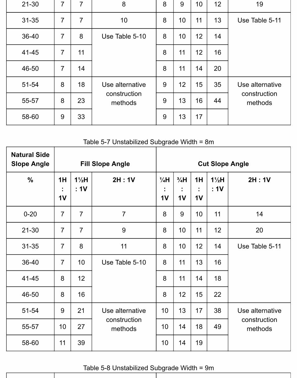
21-30 7 7 8 8 9 10 12 19
31-35 7 7 10 8 10 11 13 Use Table 5-11
36-40 7 8 Use Table 5-10 8 10 12 14
41-45 7 11 8 11 12 16
46-50 7 14 8 11 14 20
51-54 8 18 Use alternativeconstruction
methods
9 12 15 35 Use alternativeconstruction
methods55-57 8 23 9 13 16 44
58-60 9 33 9 13 17
Table 5-7 Unstabilized Subgrade Width = 8m
Natural SideSlope Angle Fill Slope Angle Cut Slope Angle
% 1H:
1V
1½H: 1V
2H : 1V ¼H:
1V
¾H:
1V
1H:
1V
1½H: 1V
2H : 1V
0-20 7 7 7 8 9 10 11 14
21-30 7 7 9 8 10 11 12 20
31-35 7 8 11 8 10 12 14 Use Table 5-11
36-40 7 10 Use Table 5-10 8 11 13 16
41-45 8 12 8 11 14 18
46-50 8 16 8 12 15 22
51-54 9 21 Use alternativeconstruction
methods
10 13 17 38 Use alternativeconstruction
methods55-57 10 27 10 14 18 49
58-60 11 39 10 14 19
Table 5-8 Unstabilized Subgrade Width = 9m
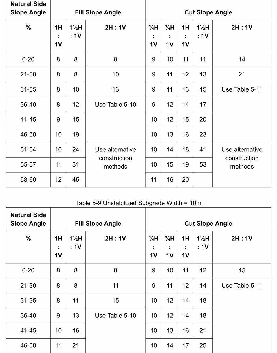
Natural SideSlope Angle Fill Slope Angle Cut Slope Angle
% 1H:
1V
1½H: 1V
2H : 1V ¼H:
1V
¾H:
1V
1H:
1V
1½H: 1V
2H : 1V
0-20 8 8 8 9 10 11 11 14
21-30 8 8 10 9 11 12 13 21
31-35 8 10 13 9 11 13 15 Use Table 5-11
36-40 8 12 Use Table 5-10 9 12 14 17
41-45 9 15 10 12 15 20
46-50 10 19 10 13 16 23
51-54 10 24 Use alternativeconstruction
methods
10 14 18 41 Use alternativeconstruction
methods55-57 11 31 10 15 19 53
58-60 12 45 11 16 20
Table 5-9 Unstabilized Subgrade Width = 10m
Natural SideSlope Angle Fill Slope Angle Cut Slope Angle
% 1H:
1V
1½H: 1V
2H : 1V ¼H:
1V
¾H:
1V
1H:
1V
1½H: 1V
2H : 1V
0-20 8 8 8 9 10 11 12 15
21-30 8 8 11 9 11 12 14 Use Table 5-11
31-35 8 11 15 10 12 14 18
36-40 9 13 Use Table 5-10 10 12 14 18
41-45 10 16 10 13 16 21
46-50 11 21 10 14 17 25

51-54 12 27 Use alternativeconstruction
methods
11 15 19 45 Use alternativeconstruction
methods55-57 13 36 11 16 21 58
58-60 14 50 11 17 22
Tables 5-10 & 5-11
The following two tables are referenced in Tables 5-3 to 5-9.
Table 5-10 Offset slope distance for 2H:1V fill slope angles
Natural Side Slope Angle Unstabilized Subgrade Width
% 4m 5m 6m 7m 8m 9m 10m
36-38 Use tables above 13 15 17 19
40 16 18 21 23
42 9 13 16 19 22 25 28
44 12 17 22 26 30 34 37
46 20 28 35 41 46 50
48 44 Use alternative construction methods
Table 5-11 Offset slope distance for 2H:1V cut slope angles
Natural Side Slope Angle Unstabilized Subgrade Width
% 4m 5m 6m 7m 8m 9m 10m
21-25 Use tables above Use tables above 17
26-28 20
30 22
32 20 21 23 24
34 22 24 25 27

36 19 21 23 25 27 29 31
38 22 24 27 29 32 34 36
40 26 29 32 35 38 41
42 32 36 39 43 47 50
44 42 52 Use alternative construction methods
5.14.2 Project Tracking Checklist
Use this checklist to prepare a paper trail of key outputs prepared by consultants and sign-offs bythe ministry.
Project Tracking Checklist (PDF)
Chapter 6: Road & Structure Inspection & MaintenanceRoad and structure inspection and maintenance are essential activities necessary to maintain theexpected safety considerations, service life, economic investment and environmental protectionon Forest Service roads.
This chapter describes the activities related to plans, assessments, works, and reports, includingthe following:
professional responsibilities and considerations;understanding the different required levels of maintenance, and vehicle access objectives;preparing a maintenance plan;road maintenance inspections;assigning road maintenance inspection priorities and frequency of inspections based onengineering risk analysis;allocating maintenance funding;road maintenance works as appropriate, including clearing width, ditch and culvert, roadprism, subgrade, road surface, and winter; andinspection and maintenance of structures, including bridges, major and other streamculverts, retaining walls, and other engineered structures.
This chapter presents the Ministry's mandatory requirements and best practices related to roadmaintenance inspections and the associated outputs. It is intended to provide the reader withenough detail to be able to understand the processes and mandatory procedures, as well ascarrying out appropriate best practices to address the applicable regulatory requirements.
Note that for extensive road maintenance works such as major repairs to, or modifying orrebuilding a section of road, many of the practices that are described in the appropriate sectionsof Chapter 5 Road Construction will be applicable.
6.0.1 Policy
Forest Service roads that are maintained by the ministry, and all FSR bridges, major culverts, andother engineered structures, will be inspected and maintained, taking into consideration theirlevel of use, strength and durability, and potential impacts on user safety and values at risk ofdamage or loss.
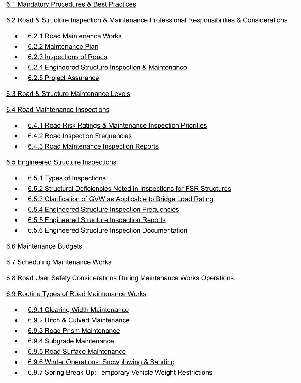
6.1 Mandatory Procedures & Best Practices
6.2 Road & Structure Inspection & Maintenance Professional Responsibilities & Considerations
6.2.1 Road Maintenance Works6.2.2 Maintenance Plan6.2.3 Inspections of Roads6.2.4 Engineered Structure Inspection & Maintenance6.2.5 Project Assurance
6.3 Road & Structure Maintenance Levels
6.4 Road Maintenance Inspections
6.4.1 Road Risk Ratings & Maintenance Inspection Priorities6.4.2 Road Inspection Frequencies6.4.3 Road Maintenance Inspection Reports
6.5 Engineered Structure Inspections
6.5.1 Types of Inspections6.5.2 Structural Deficiencies Noted in Inspections for FSR Structures6.5.3 Clarification of GVW as Applicable to Bridge Load Rating6.5.4 Engineered Structure Inspection Frequencies6.5.5 Engineered Structure Inspection Reports6.5.6 Engineered Structure Inspection Documentation
6.6 Maintenance Budgets
6.7 Scheduling Maintenance Works
6.8 Road User Safety Considerations During Maintenance Works Operations
6.9 Routine Types of Road Maintenance Works
6.9.1 Clearing Width Maintenance6.9.2 Ditch & Culvert Maintenance6.9.3 Road Prism Maintenance6.9.4 Subgrade Maintenance6.9.5 Road Surface Maintenance6.9.6 Winter Operations: Snowplowing & Sanding6.9.7 Spring Break-Up: Temporary Vehicle Weight Restrictions

6.10 Routine Types of Structure Maintenance Works: Bridges & Stream Culverts
6.10.1 Bridge Maintenance6.10.2 Stream Culvert Maintenance6.10.3 Bridge & Major Culvert Replacement
6.11 Other Maintenance Works Along Roads
6.11.1 Fords6.11.2 Weirs6.11.3 Fences6.11.4 Cattleguards6.11.5 Signs
6.12 Resources & Suggestions for Further Reading
6.13 Appendices
6.13.1 Example Qualitative Vulnerability Tables6.13.2 Project Tracking Checklist
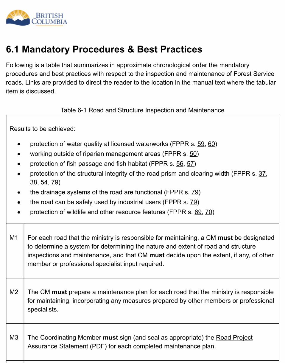
6.1 Mandatory Procedures & Best PracticesFollowing is a table that summarizes in approximate chronological order the mandatoryprocedures and best practices with respect to the inspection and maintenance of Forest Serviceroads. Links are provided to direct the reader to the location in the manual text where the tabularitem is discussed.
Table 6-1 Road and Structure Inspection and Maintenance
Results to be achieved:
protection of water quality at licensed waterworks (FPPR s. 59, 60)working outside of riparian management areas (FPPR s. 50)protection of fish passage and fish habitat (FPPR s. 56, 57)protection of the structural integrity of the road prism and clearing width (FPPR s. 37,38, 54, 79)the drainage systems of the road are functional (FPPR s. 79)the road can be safely used by industrial users (FPPR s. 79)protection of wildlife and other resource features (FPPR s. 69, 70)
M1 For each road that the ministry is responsible for maintaining, a CM must be designatedto determine a system for determining the nature and extent of road and structureinspections and maintenance, and that CM must decide upon the extent, if any, of othermember or professional specialist input required.
M2 The CM must prepare a maintenance plan for each road that the ministry is responsiblefor maintaining, incorporating any measures prepared by other members or professionalspecialists.
M3 The Coordinating Member must sign (and seal as appropriate) the Road ProjectAssurance Statement (PDF) for each completed maintenance plan.
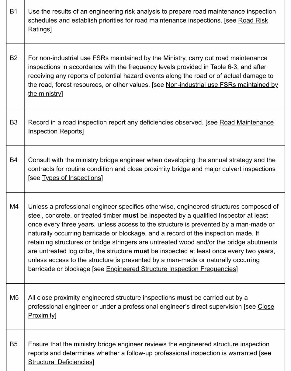
B1 Use the results of an engineering risk analysis to prepare road maintenance inspectionschedules and establish priorities for road maintenance inspections. [see Road RiskRatings]
B2 For non-industrial use FSRs maintained by the Ministry, carry out road maintenanceinspections in accordance with the frequency levels provided in Table 6-3, and afterreceiving any reports of potential hazard events along the road or of actual damage tothe road, forest resources, or other values. [see Non-industrial use FSRs maintained bythe ministry]
B3 Record in a road inspection report any deficiencies observed. [see Road MaintenanceInspection Reports]
B4 Consult with the ministry bridge engineer when developing the annual strategy and thecontracts for routine condition and close proximity bridge and major culvert inspections[see Types of Inspections]
M4 Unless a professional engineer specifies otherwise, engineered structures composed ofsteel, concrete, or treated timber must be inspected by a qualified Inspector at leastonce every three years, unless access to the structure is prevented by a man-made ornaturally occurring barricade or blockage, and a record of the inspection made. Ifretaining structures or bridge stringers are untreated wood and/or the bridge abutmentsare untreated log cribs, the structure must be inspected at least once every two years,unless access to the structure is prevented by a man-made or naturally occurringbarricade or blockage [see Engineered Structure Inspection Frequencies]
M5 All close proximity engineered structure inspections must be carried out by aprofessional engineer or under a professional engineer’s direct supervision [see CloseProximity]
B5 Ensure that the ministry bridge engineer reviews the engineered structure inspectionreports and determines whether a follow-up professional inspection is warranted [seeStructural Deficiencies]
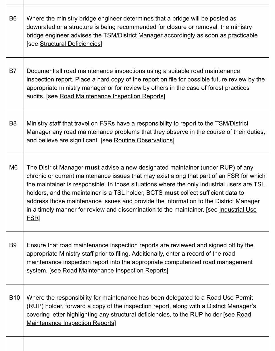
B6 Where the ministry bridge engineer determines that a bridge will be posted asdownrated or a structure is being recommended for closure or removal, the ministrybridge engineer advises the TSM/District Manager accordingly as soon as practicable[see Structural Deficiencies]
B7 Document all road maintenance inspections using a suitable road maintenanceinspection report. Place a hard copy of the report on file for possible future review by theappropriate ministry manager or for review by others in the case of forest practicesaudits. [see Road Maintenance Inspection Reports]
B8 Ministry staff that travel on FSRs have a responsibility to report to the TSM/DistrictManager any road maintenance problems that they observe in the course of their duties,and believe are significant. [see Routine Observations]
M6 The District Manager must advise a new designated maintainer (under RUP) of anychronic or current maintenance issues that may exist along that part of an FSR for whichthe maintainer is responsible. In those situations where the only industrial users are TSLholders, and the maintainer is a TSL holder, BCTS must collect sufficient data toaddress those maintenance issues and provide the information to the District Managerin a timely manner for review and dissemination to the maintainer. [see Industrial UseFSR]
B9 Ensure that road maintenance inspection reports are reviewed and signed off by theappropriate Ministry staff prior to filing. Additionally, enter a record of the roadmaintenance inspection report into the appropriate computerized road managementsystem. [see Road Maintenance Inspection Reports]
B10 Where the responsibility for maintenance has been delegated to a Road Use Permit(RUP) holder, forward a copy of the inspection report, along with a District Manager’scovering letter highlighting any structural deficiencies, to the RUP holder [see RoadMaintenance Inspection Reports]
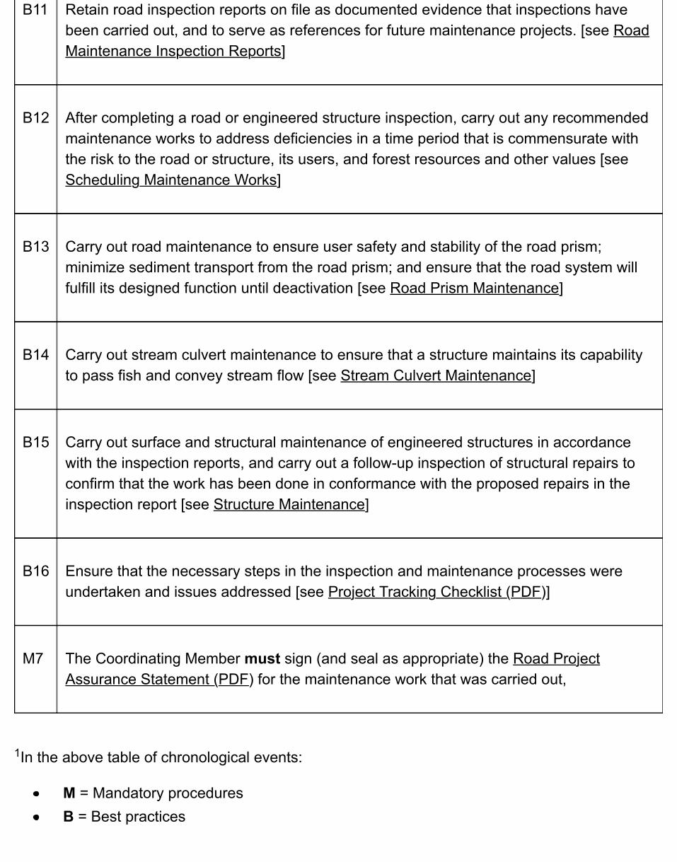
B11 Retain road inspection reports on file as documented evidence that inspections havebeen carried out, and to serve as references for future maintenance projects. [see RoadMaintenance Inspection Reports]
B12 After completing a road or engineered structure inspection, carry out any recommendedmaintenance works to address deficiencies in a time period that is commensurate withthe risk to the road or structure, its users, and forest resources and other values [seeScheduling Maintenance Works]
B13 Carry out road maintenance to ensure user safety and stability of the road prism;minimize sediment transport from the road prism; and ensure that the road system willfulfill its designed function until deactivation [see Road Prism Maintenance]
B14 Carry out stream culvert maintenance to ensure that a structure maintains its capabilityto pass fish and convey stream flow [see Stream Culvert Maintenance]
B15 Carry out surface and structural maintenance of engineered structures in accordancewith the inspection reports, and carry out a follow-up inspection of structural repairs toconfirm that the work has been done in conformance with the proposed repairs in theinspection report [see Structure Maintenance]
B16 Ensure that the necessary steps in the inspection and maintenance processes wereundertaken and issues addressed [see Project Tracking Checklist (PDF)]
M7 The Coordinating Member must sign (and seal as appropriate) the Road ProjectAssurance Statement (PDF) for the maintenance work that was carried out,
In the above table of chronological events:
M = Mandatory proceduresB = Best practices
1
6.2 Road & Structure Inspection & MaintenanceProfessional Responsibilities & Considerations
6.2.1 Road Maintenance Works
The information components for the Ministry's road maintenance works normally include:
an inventory of those roads for which the Ministry is responsible for maintaining;a risk-based maintenance plan that details inspection priorities and schedules;inspection reports of the roads and structures;maintenance plan descriptions of the remedial works that may be required based uponthe results of the inspections;a record of the proposed annual budget priorities and resulting allocations for the roadsand structures; anda record of the maintenance works actually carried out;
6.2.2 Maintenance Plan
Of the foregoing maintenance components, and as with other road activities in this manual, a CMmust be professionally responsible for the preparation of a maintenance plan as well as theoversight of the maintenance works themselves.
Where conditions are fairly benign or predictable, a maintenance plan prepared by a CM mayconsist of general guidelines such as those provided in this chapter. However, for all structuresand where there is a significant risk of detrimental effects on safety and adjacent resources, thereis a need for specific instructions for those structures and road sections.
A maintenance plan may incorporate specific maintenance considerations provided in road orstructure plans or construction documents or, because road use often changes over time and thepresent use may be different than the original road use contemplated in design, may requireupdated measures that address those changes. Accordingly, include in such a plan any originalor amended planning objectives, such as:
intended road use;existing road conditions; andsafety and environmental considerations.
The CM that prepares the maintenance plan must determine the level of detail required andensure that the plan:
incorporates maps of the roads to be included in the plan;identifies current or expected road use, both in terms of use types and volume;sets maintenance objectives for safety, structural integrity and potential hazards toadjacent resources;provides hazard and risk criteria for prioritizing inspection schedules and maintenancework;establishes the frequency and scope of inspection schedules;provides for implementation of remedial work on a priority basis determined frominspections; recognizes where other member or specialist input is required for site specific remedialwork, and incorporates the results of such input; where professional work is required, indicates the need for and timing of any field reviewsof remedial works and professional sign-off of the completed work; andsets conditions, if any, of road use.
Examples of works where there may be a need for professional specialist input to a roadmaintenance plan include:
stabilization of failing cut or fill slopes;repairs to or replacement of bridges, major culverts and engineered structures;replacement of drainage structures under high fills;road widening on steep slopes; and evaluating suitability of road grades or surface conditions, particularly in inclementweather, for specific vehicle configurations.
Where a CM for a road may not be comfortable with overseeing a structure maintenanceprogram as well, it may be reasonable to separate the maintenance responsibilities such that oneCM can oversee the road maintenance and another CM can be responsible for the structuremaintenance (and so note the assurance statements accordingly).
6.2.3 Inspections of Roads
Based upon the maintenance plan, the CM must develop a system for carrying out inspectionsfor those roads for which the Ministry is responsible for maintaining. This includes specifyingwhich roads or road sections require professional inspections (field reviews), and for such roads,inspection reports must be prepared by professional specialists or members as designated in the
maintenance plan, and signed off by those individuals. For those roads not requiring professionalinspections, a person determined by the CM to be suitably qualified to inspect the roads mustcarry out the inspections under the direction of the CM, and then sign off on the inspections.
A tabular summary for each road under consideration for inspection and maintenance isillustrated in the Sample Forest Service Road Maintenance Inspection Schedule (PDF).
6.2.4 Engineered Structure Inspection & Maintenance
A maintenance plan also includes engineered structures (bridges, major culverts and retainingstructures over 1.5m in height). These elements must be routinely inspected at least every two orthree years, depending upon site specific issues and the type of materials used in theconstruction of the structures (see Engineered Structure Inspection Frequencies). The CMresponsible for the road maintenance plan must:
incorporate into the maintenance plan the schedule and details of structure inspectionsconsistent with the requirements in the bridge register, and separately from the roadmaintenance issues;ensure that the structures are inspected by qualified individuals, including professionalspecialists where necessary, and the results are reviewed and accepted by the Ministrybridge engineer; andinclude in the maintenance plan any remedial measures for structures as specified byprofessional specialists.
6.2.5 Project Assurance
Once a maintenance plan is completed, a CM must complete the Road Project AssuranceStatement (PDF) for the plan.
In addition, a CM is responsible for overseeing the implementation of any remedial work andmust complete the Road Project Assurance Statement (PDF) for road and structuremaintenance.
6.3 Road & Structure Maintenance LevelsCurrent legislation requires:
1. at least a minimum level of road and structure maintenance on all forest roads, called a“wilderness road” level of maintenance; and
2. a high level of road and structure maintenance on all industrial use roads, called an“industrial use” level of maintenance.
These two road and structure maintenance levels are briefly defined as:
Wilderness road level of maintenance includes those road and structure maintenanceworks required for the protection of forest resources. It excludes vehicle access-relatedtypes of surface and structural maintenance, other than installing a barricade to preventaccess when the road is unsafe to use, unless such maintenance is necessary to mitigatea moderate to high risk of damage to forest resources and other values.Industrial use level of maintenance includes a wilderness road level of maintenance, plusother vehicle access‑related types of surface and structural maintenance to ensure thatthe structural integrity of the road prism and clearing width are protected, the drainagesystems of the road are functional, and the road can be used safely by industrial users.
In addition, Ministry Operations has the responsibility for providing for:
safe public access to “high value” forest recreation sites and trails or “important”recreational areas (as defined by Ministry of Tourism, Culture and the Arts); andsafe public access to year-round communities.
6.4 Road Maintenance InspectionsFocus road maintenance inspections on the structural integrity of the road prism and clearingwidth, the effectiveness of drainage systems, and the condition of the road surface. Also considerroad user safety, including signage and any values at risk. In addition, include in any roadmaintenance inspection a cursory examination of stream crossing structures to capture anyvisible signs of structural problems, abutment and pier scour, fish passage impediments orsediment deposition.
Before road maintenance inspections are carried out on FSRs, know and understand the level ofroad maintenance required on the road (e.g., wilderness road, industrial use, recreation access,community access) and the vehicle access objectives.
Prepare a road maintenance inspection schedule well in advance of the new fiscal year so thatinspection costs and necessary staff resources can be budgeted for. A road maintenanceinspection schedule includes the road names, the road use category (rural resident andrecreation use; environmentally maintained (wilderness road); industrial use), the road risk rating,the scheduled times for planned road maintenance inspections, plus any pertinent comments thatmay impact schedules and practices.
Sample forest service road maintenance inspection schedule (PDF)
Identify and prioritize required road maintenance works from field information documented duringroad maintenance inspections, and from information and incidents supplied by road users. Fromthis information, prepare a road maintenance works plan to schedule and budget for requiredmaintenance works to address the deficiencies.
Refer to the Fish-stream Crossing Guidebook (PDF, 4.3MB) when planning road maintenanceinspections and maintenance works at fish-stream crossings.
6.4.1 Road Risk Ratings & Maintenance Inspection Priorities
Use the results of an engineering risk analysis to prepare road maintenance inspection schedules(see Inspection Frequency Levels) and priorities for road maintenance inspections. Risk is thechance of injury or loss, defined as a measure of the probability (likelihood) and the consequenceof an adverse effect to health, property, the environment, or other things of value.
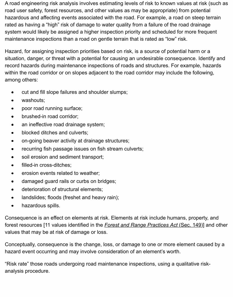
A road engineering risk analysis involves estimating levels of risk to known values at risk (such asroad user safety, forest resources, and other values as may be appropriate) from potentialhazardous and affecting events associated with the road. For example, a road on steep terrainrated as having a “high” risk of damage to water quality from a failure of the road drainagesystem would likely be assigned a higher inspection priority and scheduled for more frequentmaintenance inspections than a road on gentle terrain that is rated as “low” risk.
Hazard, for assigning inspection priorities based on risk, is a source of potential harm or asituation, danger, or threat with a potential for causing an undesirable consequence. Identify andrecord hazards during maintenance inspections of roads and structures. For example, hazardswithin the road corridor or on slopes adjacent to the road corridor may include the following,among others:
cut and fill slope failures and shoulder slumps;washouts;poor road running surface;brushed-in road corridor;an ineffective road drainage system;blocked ditches and culverts;on-going beaver activity at drainage structures;recurring fish passage issues on fish stream culverts;soil erosion and sediment transport;filled-in cross‑ditches;erosion events related to weather;damaged guard rails or curbs on bridges;deterioration of structural elements;landslides; floods (freshet and heavy rain);hazardous spills.
Consequence is an effect on elements at risk. Elements at risk include humans, property, andforest resources [11 values identified in the Forest and Range Practices Act (Sec. 149)] and othervalues that may be at risk of damage or loss.
Conceptually, consequence is the change, loss, or damage to one or more element caused by ahazard event occurring and may involve consideration of an element’s worth.
“Risk rate” those roads undergoing road maintenance inspections, using a qualitative risk-analysis procedure.
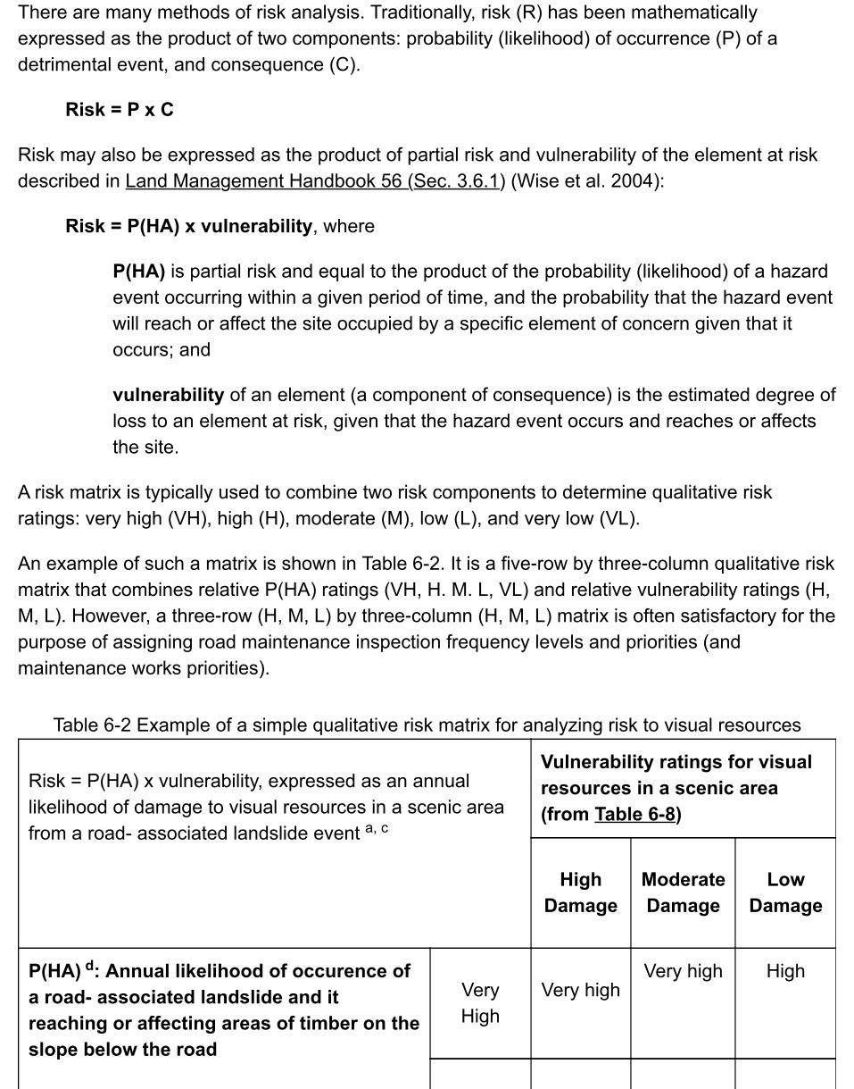
There are many methods of risk analysis. Traditionally, risk (R) has been mathematicallyexpressed as the product of two components: probability (likelihood) of occurrence (P) of adetrimental event, and consequence (C).
Risk = P x C
Risk may also be expressed as the product of partial risk and vulnerability of the element at riskdescribed in Land Management Handbook 56 (Sec. 3.6.1) (Wise et al. 2004):
Risk = P(HA) x vulnerability, where
P(HA) is partial risk and equal to the product of the probability (likelihood) of a hazardevent occurring within a given period of time, and the probability that the hazard eventwill reach or affect the site occupied by a specific element of concern given that itoccurs; and
vulnerability of an element (a component of consequence) is the estimated degree ofloss to an element at risk, given that the hazard event occurs and reaches or affectsthe site.
A risk matrix is typically used to combine two risk components to determine qualitative riskratings: very high (VH), high (H), moderate (M), low (L), and very low (VL).
An example of such a matrix is shown in Table 6-2. It is a five‑row by three‑column qualitative riskmatrix that combines relative P(HA) ratings (VH, H. M. L, VL) and relative vulnerability ratings (H,M, L). However, a three‑row (H, M, L) by three‑column (H, M, L) matrix is often satisfactory for thepurpose of assigning road maintenance inspection frequency levels and priorities (andmaintenance works priorities).
Table 6-2 Example of a simple qualitative risk matrix for analyzing risk to visual resources
Risk = P(HA) x vulnerability, expressed as an annuallikelihood of damage to visual resources in a scenic areafrom a road- associated landslide event
Vulnerability ratings for visualresources in a scenic area(from Table 6-8)
HighDamage
ModerateDamage
LowDamage
P(HA) : Annual likelihood of occurence ofa road- associated landslide and itreaching or affecting areas of timber on theslope below the road
VeryHigh
Very highVery high High
a, c
d
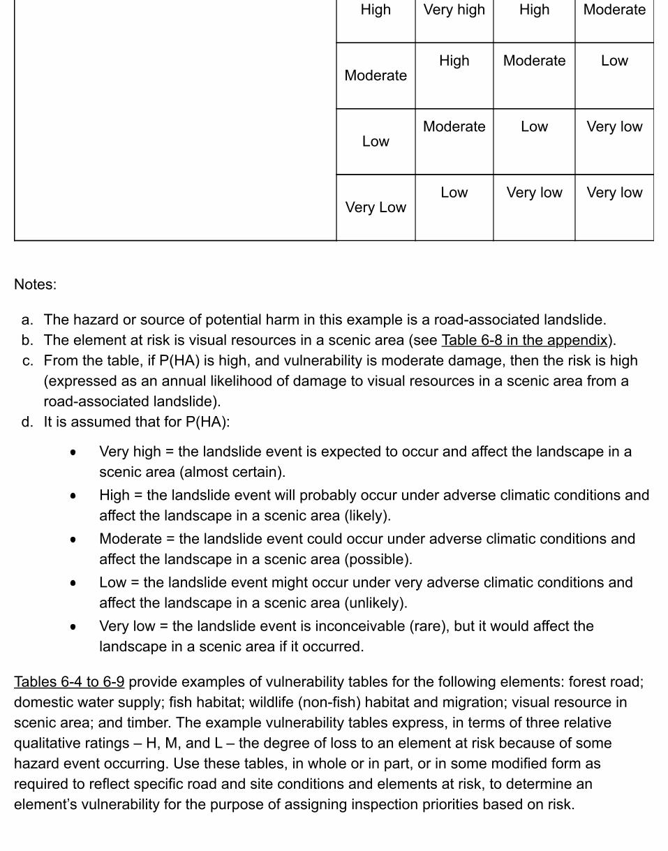
High Very high High Moderate
ModerateHigh Moderate Low
LowModerate Low Very low
Very LowLow Very low Very low
Notes:
a. The hazard or source of potential harm in this example is a road-associated landslide.b. The element at risk is visual resources in a scenic area (see Table 6-8 in the appendix).c. From the table, if P(HA) is high, and vulnerability is moderate damage, then the risk is high
(expressed as an annual likelihood of damage to visual resources in a scenic area from aroad-associated landslide).
d. It is assumed that for P(HA):
Very high = the landslide event is expected to occur and affect the landscape in ascenic area (almost certain).High = the landslide event will probably occur under adverse climatic conditions andaffect the landscape in a scenic area (likely).Moderate = the landslide event could occur under adverse climatic conditions andaffect the landscape in a scenic area (possible).Low = the landslide event might occur under very adverse climatic conditions andaffect the landscape in a scenic area (unlikely).Very low = the landslide event is inconceivable (rare), but it would affect thelandscape in a scenic area if it occurred.
Tables 6-4 to 6-9 provide examples of vulnerability tables for the following elements: forest road;domestic water supply; fish habitat; wildlife (non-fish) habitat and migration; visual resource inscenic area; and timber. The example vulnerability tables express, in terms of three relativequalitative ratings – H, M, and L – the degree of loss to an element at risk because of somehazard event occurring. Use these tables, in whole or in part, or in some modified form asrequired to reflect specific road and site conditions and elements at risk, to determine anelement’s vulnerability for the purpose of assigning inspection priorities based on risk.
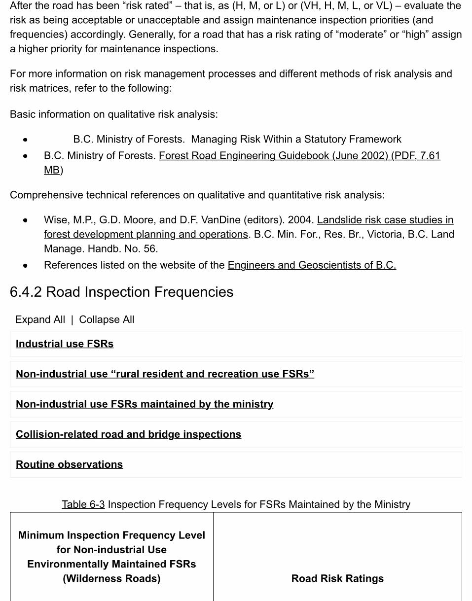
After the road has been “risk rated” – that is, as (H, M, or L) or (VH, H, M, L, or VL) – evaluate the risk as being acceptable or unacceptable and assign maintenance inspection priorities (and frequencies) accordingly. Generally, for a road that has a risk rating of “moderate” or “high” assign a higher priority for maintenance inspections.
For more information on risk management processes and different methods of risk analysis and risk matrices, refer to the following:
Basic information on qualitative risk analysis:
B.C. Ministry of Forests. Managing Risk Within a Statutory FrameworkB.C. Ministry of Forests. Forest Road Engineering Guidebook (June 2002) (PDF, 7.61MB)
Comprehensive technical references on qualitative and quantitative risk analysis:
Wise, M.P., G.D. Moore, and D.F. VanDine (editors). 2004. Landslide risk case studies inforest development planning and operations. B.C. Min. For., Res. Br., Victoria, B.C. LandManage. Handb. No. 56.References listed on the website of the Engineers and Geoscientists of B.C.
6.4.2 Road Inspection Frequencies
Expand All | Collapse All
Industrial use FSRs
Non-industrial use “rural resident and recreation use FSRs”
Non-industrial use FSRs maintained by the ministry
Collision-related road and bridge inspections
Routine observations
Table 6-3 Inspection Frequency Levels for FSRs Maintained by the Ministry
Minimum Inspection Frequency Levelfor Non-industrial Use
Environmentally Maintained FSRs(Wilderness Roads) Road Risk Ratings
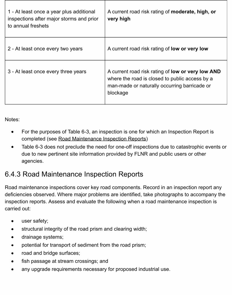
1 - At least once a year plus additionalinspections after major storms and priorto annual freshets
A current road risk rating of moderate, high, orvery high
2 - At least once every two years A current road risk rating of low or very low
3 - At least once every three years A current road risk rating of low or very low ANDwhere the road is closed to public access by aman-made or naturally occurring barricade orblockage
Notes:
For the purposes of Table 6-3, an inspection is one for which an Inspection Report iscompleted (see Road Maintenance Inspection Reports)Table 6-3 does not preclude the need for one-off inspections due to catastrophic events ordue to new pertinent site information provided by FLNR and public users or otheragencies.
6.4.3 Road Maintenance Inspection Reports
Road maintenance inspections cover key road components. Record in an inspection report anydeficiencies observed. Where major problems are identified, take photographs to accompany theinspection reports. Assess and evaluate the following when a road maintenance inspection iscarried out:
user safety;structural integrity of the road prism and clearing width;drainage systems;potential for transport of sediment from the road prism;road and bridge surfaces;fish passage at stream crossings; andany upgrade requirements necessary for proposed industrial use.
Document all road maintenance inspections using a suitable road maintenance inspection report.Place a hard copy of the report on file for possible future review by the appropriate ministrymanager or for review by others in the case of audits. The review of past reports can be helpfulfor identifying road segments or drainage structures that:
1. have recurrent problems and should receive a higher road risk rating, or2. should receive more frequent inspections or be scheduled earlier for maintenance works.
Ensure that road maintenance inspection reports are reviewed and signed off by the appropriateTimber Operations and Pricing Division/BCTS staff prior to filing. Additionally, enter a record ofthe road maintenance inspection report into the appropriate computerized road managementsystem.
Use the sample inspection report (or other equivalent report formats) to document maintenanceinspections of roads and minor drainage structures.
Sample forest service road maintenance inspection report (PDF)
Use the following documents along with the sample report:
Inspection codes for "problems noted" (PDF)Maintenance codes for “recommended maintenance works” (PDF)
Include in the road maintenance inspection reports:
the current and revised (if any) road risk rating;the date of the inspection (to establish a time frame for maintenance works, to have onhand for future reference, and to provide a better inspection history record);the name of the person doing the inspection (for accountability and for future reference);details about the weather conditions at the time of the inspection (to explain observedsurface runoff conditions that have occurred with prolonged or intense rainfall eventsbefore or during culvert inspections);the road name and project number (to identify where the inspection took place);the purpose of the inspection (scheduled, post-storm event, user complaint, other);the location of the inspection by geographic coordinates or station (e.g., “km 0.0 throughto km 6.35,” to identify the exact location of any concerns);the locations of individual problems by geographic coordinates or station, and all relevantdata for each issue;description of problems using Inspection Codes;good quality site photographs taken from a logical point of view or perspective;a recommended reasonable time frame for repairs to be completed, and a rationale forthat time frame (e.g. maintenance work should be carried out before fall rains to reduce

soil erosion and sediment transport); andany further description of the works required should be placed in the comments section foreach location.
As a result of the inspection, identify those works to be entered into either the current or thefuture maintenance works plan. When possible and commensurate with the priorities of TimberOperations and Pricing Division/BCTS, address deficiencies within an appropriate time frame.
Prepare a road maintenance works plan and prioritize maintenance works in accordance with therisks identified in the inspections. Retain the inspection reports on file as documented evidencethat inspections have been carried out, and to serve as references for future maintenanceprojects. Reviews of past reports and records can assist forest road managers in identifyingrecurrent problems and identifying those road sections to be assigned a higher risk rating.
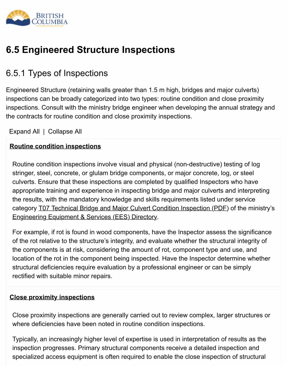
6.5 Engineered Structure Inspections
6.5.1 Types of Inspections
Engineered Structure (retaining walls greater than 1.5 m high, bridges and major culverts)inspections can be broadly categorized into two types: routine condition and close proximityinspections. Consult with the ministry bridge engineer when developing the annual strategy andthe contracts for routine condition and close proximity inspections.
Expand All | Collapse All
Routine condition inspections
Routine condition inspections involve visual and physical (non-destructive) testing of logstringer, steel, concrete, or glulam bridge components, or major concrete, log, or steelculverts. Ensure that these inspections are completed by qualified Inspectors who haveappropriate training and experience in inspecting bridge and major culverts and interpretingthe results, with the mandatory knowledge and skills requirements listed under servicecategory T07 Technical Bridge and Major Culvert Condition Inspection (PDF) of the ministry’sEngineering Equipment & Services (EES) Directory.
For example, if rot is found in wood components, have the Inspector assess the significanceof the rot relative to the structure’s integrity, and evaluate whether the structural integrity ofthe components is at risk, considering the amount of rot, component type and use, andlocation of the rot in the component being inspected. Have the Inspector determine whetherstructural deficiencies require evaluation by a professional engineer or can be simplyrectified with suitable minor repairs.
Close proximity inspections
Close proximity inspections are generally carried out to review complex, larger structures orwhere deficiencies have been noted in routine condition inspections.
Typically, an increasingly higher level of expertise is used in interpretation of results as theinspection progresses. Primary structural components receive a detailed inspection andspecialized access equipment is often required to enable the close inspection of structural
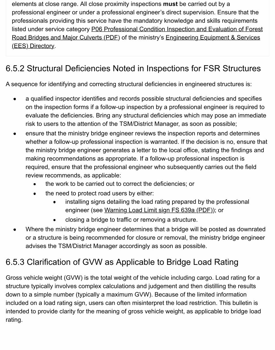
elements at close range. All close proximity inspections must be carried out by aprofessional engineer or under a professional engineer’s direct supervision. Ensure that theprofessionals providing this service have the mandatory knowledge and skills requirementslisted under service category P06 Professional Condition Inspection and Evaluation of ForestRoad Bridges and Major Culverts (PDF) of the ministry’s Engineering Equipment & Services(EES) Directory.
6.5.2 Structural Deficiencies Noted in Inspections for FSR Structures
A sequence for identifying and correcting structural deficiencies in engineered structures is:
a qualified inspector identifies and records possible structural deficiencies and specifieson the inspection forms if a follow-up inspection by a professional engineer is required toevaluate the deficiencies. Bring any structural deficiencies which may pose an immediaterisk to users to the attention of the TSM/District Manager, as soon as possible;ensure that the ministry bridge engineer reviews the inspection reports and determineswhether a follow-up professional inspection is warranted. If the decision is no, ensure thatthe ministry bridge engineer generates a letter to the local office, stating the findings andmaking recommendations as appropriate. If a follow-up professional inspection isrequired, ensure that the professional engineer who subsequently carries out the fieldreview recommends, as applicable:
the work to be carried out to correct the deficiencies; orthe need to protect road users by either:
installing signs detailing the load rating prepared by the professionalengineer (see Warning Load Limit sign FS 639a (PDF)); orclosing a bridge to traffic or removing a structure.
Where the ministry bridge engineer determines that a bridge will be posted as downratedor a structure is being recommended for closure or removal, the ministry bridge engineeradvises the TSM/District Manager accordingly as soon as possible.
6.5.3 Clarification of GVW as Applicable to Bridge Load Rating
Gross vehicle weight (GVW) is the total weight of the vehicle including cargo. Load rating for astructure typically involves complex calculations and judgement and then distilling the resultsdown to a simple number (typically a maximum GVW). Because of the limited informationincluded on a load rating sign, users can often misinterpret the load restriction. This bulletin isintended to provide clarity for the meaning of gross vehicle weight, as applicable to bridge loadrating.
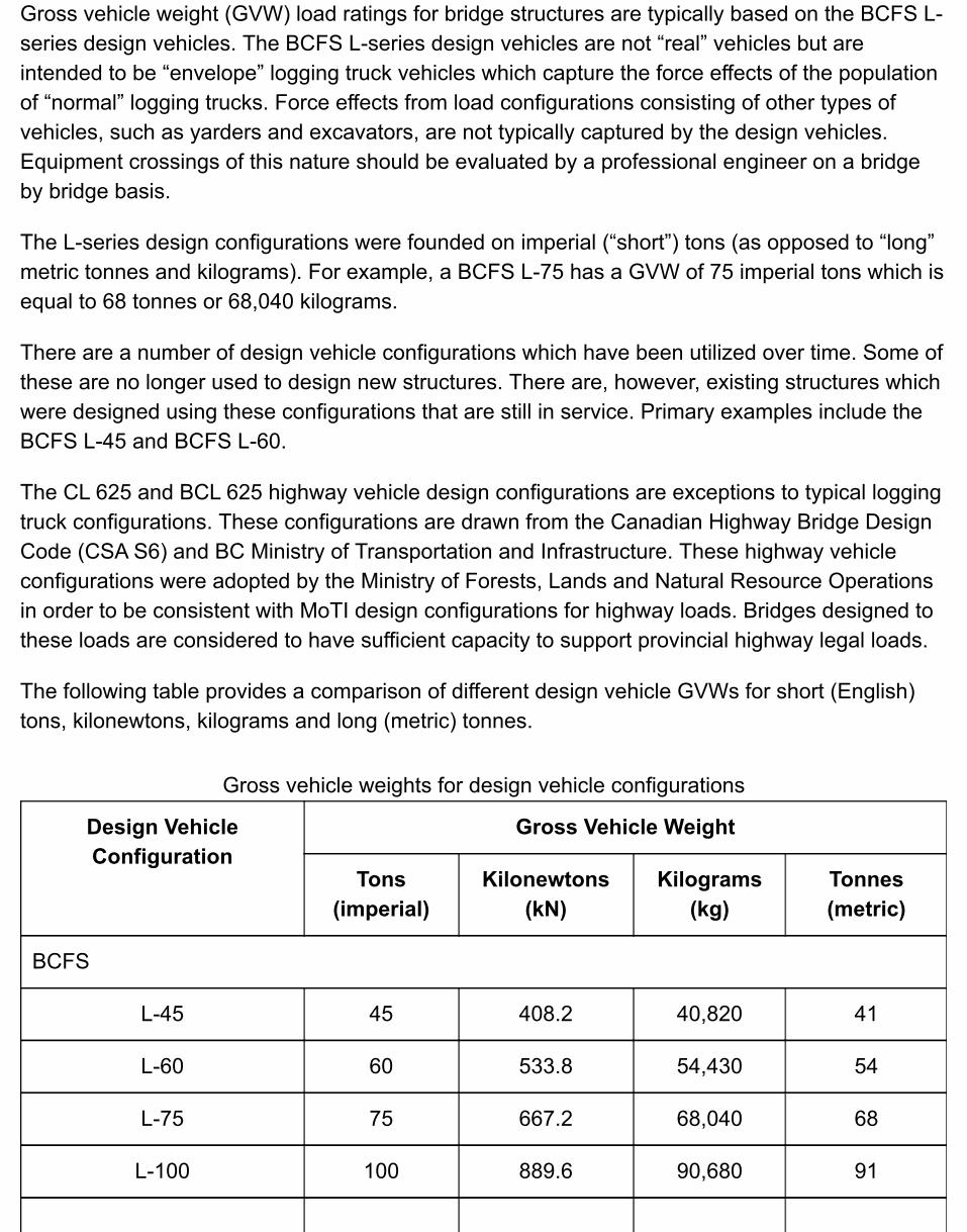
Gross vehicle weight (GVW) load ratings for bridge structures are typically based on the BCFS L-series design vehicles. The BCFS L-series design vehicles are not “real” vehicles but areintended to be “envelope” logging truck vehicles which capture the force effects of the populationof “normal” logging trucks. Force effects from load configurations consisting of other types ofvehicles, such as yarders and excavators, are not typically captured by the design vehicles.Equipment crossings of this nature should be evaluated by a professional engineer on a bridgeby bridge basis.
The L-series design configurations were founded on imperial (“short”) tons (as opposed to “long”metric tonnes and kilograms). For example, a BCFS L-75 has a GVW of 75 imperial tons which isequal to 68 tonnes or 68,040 kilograms.
There are a number of design vehicle configurations which have been utilized over time. Some ofthese are no longer used to design new structures. There are, however, existing structures whichwere designed using these configurations that are still in service. Primary examples include theBCFS L-45 and BCFS L-60.
The CL 625 and BCL 625 highway vehicle design configurations are exceptions to typical loggingtruck configurations. These configurations are drawn from the Canadian Highway Bridge DesignCode (CSA S6) and BC Ministry of Transportation and Infrastructure. These highway vehicleconfigurations were adopted by the Ministry of Forests, Lands and Natural Resource Operationsin order to be consistent with MoTI design configurations for highway loads. Bridges designed tothese loads are considered to have sufficient capacity to support provincial highway legal loads.
The following table provides a comparison of different design vehicle GVWs for short (English)tons, kilonewtons, kilograms and long (metric) tonnes.
Gross vehicle weights for design vehicle configurations
Design VehicleConfiguration
Gross Vehicle Weight
Tons(imperial)
Kilonewtons(kN)
Kilograms(kg)
Tonnes(metric)
BCFS
L-45 45 408.2 40,820 41
L-60 60 533.8 54,430 54
L-75 75 667.2 68,040 68
L-100 100 889.6 90,680 91
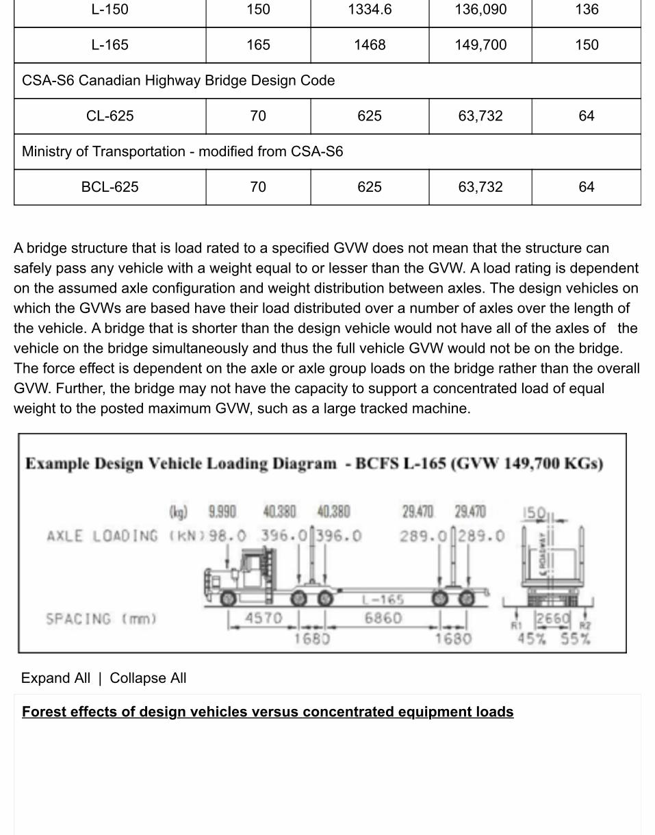
L-150 150 1334.6 136,090 136
L-165 165 1468 149,700 150
CSA-S6 Canadian Highway Bridge Design Code
CL-625 70 625 63,732 64
Ministry of Transportation - modified from CSA-S6
BCL-625 70 625 63,732 64
A bridge structure that is load rated to a specified GVW does not mean that the structure cansafely pass any vehicle with a weight equal to or lesser than the GVW. A load rating is dependenton the assumed axle configuration and weight distribution between axles. The design vehicles onwhich the GVWs are based have their load distributed over a number of axles over the length ofthe vehicle. A bridge that is shorter than the design vehicle would not have all of the axles of thevehicle on the bridge simultaneously and thus the full vehicle GVW would not be on the bridge.The force effect is dependent on the axle or axle group loads on the bridge rather than the overallGVW. Further, the bridge may not have the capacity to support a concentrated load of equalweight to the posted maximum GVW, such as a large tracked machine.
Expand All | Collapse All
Forest effects of design vehicles versus concentrated equipment loads
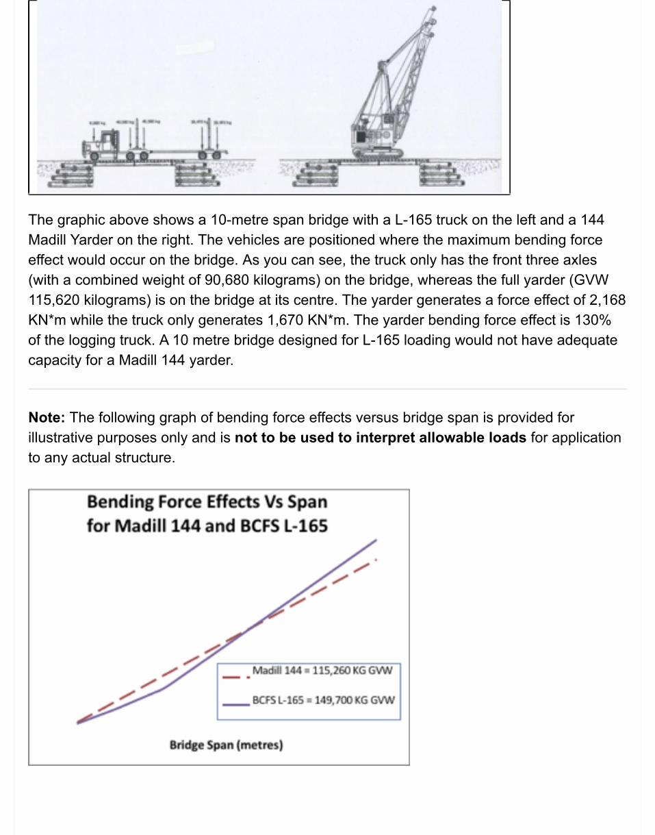
The graphic above shows a 10-metre span bridge with a L-165 truck on the left and a 144Madill Yarder on the right. The vehicles are positioned where the maximum bending forceeffect would occur on the bridge. As you can see, the truck only has the front three axles(with a combined weight of 90,680 kilograms) on the bridge, whereas the full yarder (GVW115,620 kilograms) is on the bridge at its centre. The yarder generates a force effect of 2,168KN*m while the truck only generates 1,670 KN*m. The yarder bending force effect is 130%of the logging truck. A 10 metre bridge designed for L-165 loading would not have adequatecapacity for a Madill 144 yarder.
Note: The following graph of bending force effects versus bridge span is provided forillustrative purposes only and is not to be used to interpret allowable loads for applicationto any actual structure.
The graph shows the bending force effects arising for a 144 Madill yarder with a GVW of115, 260 kilograms as compared to a BCFS L-165 logging truck configuration with a GVW of149,700 kilograms. Although the yarder has a significantly lower GVW, the resulting bendingforce effects are significantly greater than that of the heavier L-165 logging truck for shorterspan bridges. This result is due to the concentration of the weight of the yarder over ashorter length. In contrast, the logging truck does not have all of its axles on the shorter spanbridges. As the bridge length increases, more truck axles come into play on the bridge,resulting in the bending force effects of the logging truck surpassing those of the yarder.
Road network design vehicle load rating
Typically, road networks have a specified design vehicle load configuration identified. Allbridge structures would be designed for the specified design vehicle load. There have beenincidents where a bridge with a lower design load has been installed at the beginning of theroad network. This can effectively result in the lower design load restricting access on the fullroad network.
The design vehicle load configuration for Forest Service Roads would ideally be posted atthe commencement and other entrances to the road. Only bridges which were not capable ofmeeting that design vehicle load would be posted with a sign specifying an allowable safeGVW which has been determined by a Professional Engineer. New guidance is beingdeveloped for road signage and will be available in the foreseeable future.
Safe vehicle passage
Any concerns for safe capacity of bridge structures should be brought to the attention of aministry field engineer. Where it is uncertain whether a particular vehicle can safely cross abridge, a professional engineer should be consulted to assess the structure for the specificvehicle. For any structure that has been down rated, professional engineering advice iscritical to avoid errors in interpretation. Failure to assess the carrying capacity of a bridgecan have disastrous results as exemplified in the picture below.
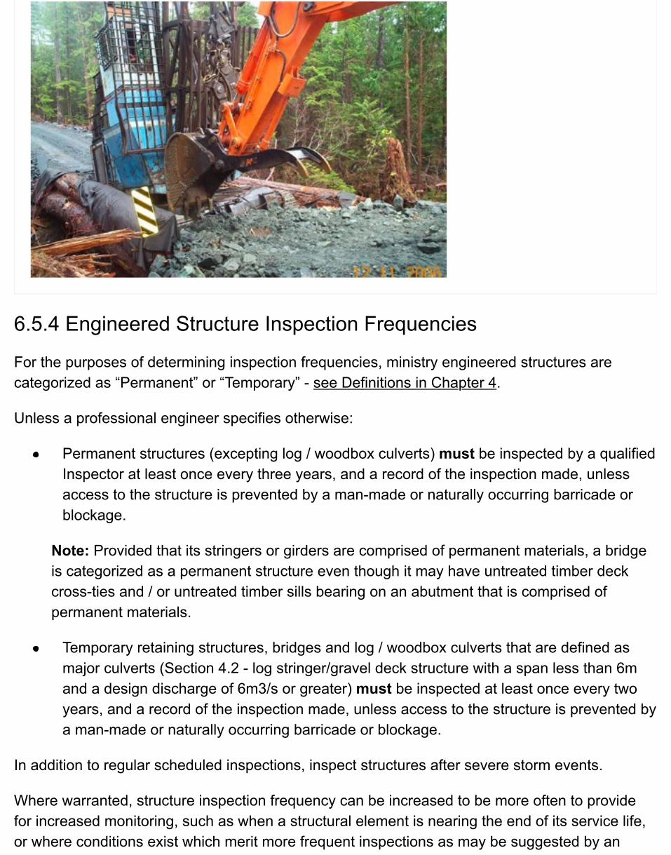
6.5.4 Engineered Structure Inspection Frequencies
For the purposes of determining inspection frequencies, ministry engineered structures arecategorized as “Permanent” or “Temporary” - see Definitions in Chapter 4.
Unless a professional engineer specifies otherwise:
Permanent structures (excepting log / woodbox culverts) must be inspected by a qualifiedInspector at least once every three years, and a record of the inspection made, unlessaccess to the structure is prevented by a man-made or naturally occurring barricade orblockage.
Note: Provided that its stringers or girders are comprised of permanent materials, a bridgeis categorized as a permanent structure even though it may have untreated timber deckcross-ties and / or untreated timber sills bearing on an abutment that is comprised ofpermanent materials.
Temporary retaining structures, bridges and log / woodbox culverts that are defined asmajor culverts (Section 4.2 - log stringer/gravel deck structure with a span less than 6mand a design discharge of 6m3/s or greater) must be inspected at least once every twoyears, and a record of the inspection made, unless access to the structure is prevented bya man-made or naturally occurring barricade or blockage.
In addition to regular scheduled inspections, inspect structures after severe storm events.
Where warranted, structure inspection frequency can be increased to be more often to providefor increased monitoring, such as when a structural element is nearing the end of its service life,or where conditions exist which merit more frequent inspections as may be suggested by an
inspector or determined by a professional engineer.
6.5.5 Engineered Structure Inspection Reports
Include the following in the inspection record of an engineered structure:
date of the inspection;a condition assessment of the components of the structure, including bridge approaches,and considering among other things the length of time a structure has been at its currentsite;a recommendation for any repairs that may be required and a schedule for those repairs;the date of the next scheduled inspection provided by the reviewing professionalengineer;inspector’s signature; andprofessional engineer’s signature and date.
The inspection records are used to identify current maintenance requirements as well as trackthe condition of the structure and required maintenance over time. Take illustrative photos duringthe inspection and provide a visual aid for the professional engineer evaluating the structurecondition. Photos of deficiencies or suspect problems are particularly useful. The photos alsoprovide an opportunity to track progression of condition of various structure components overtime (such as abutment erosion).
Retain inspection records for engineered structures for one year beyond the actual life of thestructure, or for portable bridge superstructures, the records should be retained with thesuperstructure records for one year beyond the actual life of the superstructure. Should astructure fail, these records will be useful in any subsequent investigation. Additionally, use theinspection records as a reference to determine the type of structures that are cost-effective andenvironmentally suitable for similar stream crossings.
Review the recommendations to ensure that the maintenance works comply with legislation.Ensure that the appropriate electronic bridge register is updated, that signed original inspectionreports are provided for the project files, and that the local FLNR manager is advised of anystructural issues that would impact ongoing use.
For bridge inspections, use the applicable ministry form available from the ministry form index:
FS1337A - Log Stringer or Timber Stringer Bridges (PDF, 1.3MB)FS1337B – Bridges Except for Log Stringer or Timber Stringer Bridges (PDF, 1.3MB)FS1337C - Culvert Inspection (PDF, 1.2MB)
Place copies of the completed inspections, signed by the inspector and professional engineer, onthe appropriate Operational Records Classification System (ORCS) files and/or entered into thebridge register.
Where the responsibility for maintenance has been delegated to a Road Use Permit (RUP)holder, forward a copy of the inspection report, along with a District Manager’s covering letterhighlighting any structural deficiencies, to the RUP holder. Where structural deficiencies are suchthat there is a risk to users, advise the RUP holder immediately, in the most expedient way, thatthere is a problem with the structure.
When structural repairs are completed, ensure that an inspection of the completed works iscarried out and a new inspection report generated for review by a ministry bridge engineer.Where time is not of the essence, consider carrying out the inspection of these works as part of afuture road inspection.
6.5.6 Engineered Structure Inspection Documentation
Place signed originals of final engineered structure inspection reports on the hardcopy projectfile. Also, place any follow-up documentation on the file.

6.6 Maintenance BudgetsRoad and structure maintenance plans and inspections:
provide a mechanism to help identify priorities for road and structure maintenance;ensure consistent and efficient allocation of ministry funding; andreduce the ministry’s liability by prioritizing and allocating funding for road and structure maintenancebased on the results of a documented maintenance inspection and engineering risk analysis of theroads and structures.
A ranking procedure for annual maintenance funding involves preparing a list of candidate road and structuremaintenance projects that will require funding, and then ranking the projects by priority according to establishedcriteria based on the estimated levels of risk to known values within and adjacent to the road right‑of‑way, andconsideration of vehicle access needs. The list is prepared by reviewing available road and structuremaintenance inspection reports on hard copy file or on a corporate database, and other relevant information,and considering the historical record of annual road and structure maintenance required on individual FSRs.
6.7 Scheduling Maintenance WorksAfter completing a road or engineered structure inspection, carry out any recommendedmaintenance works to address deficiencies in a time period that is commensurate with the risk tothe road or structure, its users, and forest resources and other values, as determined by theappropriate manager upon review of the inspection report.
Specify the time frames for road maintenance works in the inspection report (see MaintenanceInspection Report). It shows that the time frames may be expressed as “urgency ratings” (VH =within 1 week; H = within 30 days; M = preferably within current field season but before the nextfield season; L = reassess situation next inspection). “Reasonable time” to carry out maintenanceworks varies according to the specific site and problems identified. For example, waiting untilequipment is in the area is inappropriate if the road fill is already failing and washing into astream. However, waiting for equipment may be appropriate where a raveling cut slope is filling ina ditch that has a low likelihood of transporting sediment to a stream.
Ensure that the ministry bridge engineer describes the time frames for engineered structurerepair/remedial works in the comments section, to differentiate critical works from more routineworks.
Consider the guidelines for road works shutdown indicators when maintenance works are beingcarried out on FSRs. These indicators, and the procedures for shutting down operations, arepresented in Chapter 5: Road Construction.
6.8 Road User Safety Considerations During MaintenanceWorks OperationsWhere FSRs are open to traffic, post high-visibility, reflective “Crew and Equipment Working”signs or other applicable signs from the BC MoT Traffic Control Manual for Work onRoadways (specified as the standard reference by WorkSafeBC) at appropriate locationsalong the road to warn approaching traffic of any maintenance operations.
Place the signs in such a manner that they provide drivers with sufficient lead time to react –particularly when the road has many blind curves. Consider installing an additional warning sign at thebeginning of the road. Remove these signs whenever crews are not working.
Erect and maintain temporary signs and barricades, with lights or traffic cones if necessary, at the site of anyhazards and where any maintenance works are left uncompleted or unattended.
Advertise locally any maintenance projects that will require closing an FSR to traffic, both in advance of theproject starting and during the project term, in the form of newspaper advertisements or radio announcements.Provide the public with key information such as the exact location of the work, travel restrictions if any, start andcompletion dates, and the name of a ministry contact for further information.
If the local ministry office has a “road conditions” page on its public website, update the page to reflect thechanged conditions.
6.9 Routine Types of Road Maintenance Works
6.9.1 Clearing Width Maintenance
Clearing width maintenance includes brushing and vegetation control, and dangerous tree falling.
Expand All | Collapse All
Brushing and vegetation control
Carry out brushing when one of the following conditions occurs:The sight distance and/or the usable road width are dangerously impeded orreduced, such that the design speed of the road cannot be safely maintained.The useable road width is dangerously reduced to the point that vehicles cannotsafely pass each other at road widenings or turnouts or the road cannot be driven atthe design speed.Drainage systems are functioning below acceptable levels and roadside vegetation isa major contributing factor.The presence of roadside vegetation is impeding drying out of the road surface.Snow cannot be readily removed.
For example, potential hazards exist where brush limits visibility at the inside of a curve or atbridge approaches, or where heavy snow loads on roadside trees may cause the trees tobend over the road surface, restricting use of the road and creating a user safety hazard.
Manual methods for removing trees, brush, and other vegetation may include the use ofaxes, machetes, sandvik axes, chainsaws, or gasoline- or air-powered circular saws. Thesemethods are labour-intensive and require close supervision to ensure good production andworker safety.
Mechanical methods may include the use of crawler tractors, graders, hydro-axes,hydro‑mowers or attachments for graders, front-end loaders, and excavators. The highercost of operating mechanical equipment is usually offset by increased brushing productivityand user safety when compared to manual brushing and vegetation control methods. Betterclean-up and dressing of gentle cut and fill slopes during construction improves the likelihoodof being able to use mechanical methods of brushing after construction.
Use site chipping or mulching to minimize the fire hazard and increase the rate ofdecomposition. Leave mulch material in the ditchline, as it will usually flush out and throughcross‑ditch culverts.
Use of chemical defoliants and herbicides is tightly regulated under the province’s IntegratedPest Management Act. The user will possess a valid pesticide applicator’s licence and havea valid permit for the pesticide being used.
Be aware that brushing projects can create hazards, such as:Accumulated cut vegetation can plug culvert intakes and should be cleaned by handconcurrently with the brushing operation.Accumulated vegetation can plug ditchlines and should be either cleaned by hand orby a follow-up machine concurrent with brushing operations.Serious physical injury or equipment damage can occur when debris being cut by amachine shatters and flies in unpredictable directions. Appropriate roadway control(such as flaggers and warning signs) should be used during operations.
Dangerous tree falling
In addition to brushing and vegetation control, remove all snags and leaning or overhangingtrees that are a safety concern for road users or workers. This is usually accomplished byhand falling. Such trees are known as “dangerous trees” and are defined by the Workers’Compensation Board of BC (WorkSafeBC), in Occupational Health and Safety Regulation(Sec. 26.11).
6.9.2 Ditch & Culvert Maintenance
Probably the most critical aspect of any road maintenance project is maintenance of the drainagesystems. Implement the following types of maintenance works to minimize the likelihood ofclogged or damaged drainage systems which can potentially cause road washouts:
Clean and grade ditchesClean and repair culvert inlets, outlets, catch basins, trash racks, flumes, and transitionareas from the ditchline to catch basinsReplace or repair ditchblocks, small culverts, flumes and rip rap, head walls, andspillways, particularly during and after major storms and after yarding and loadingoperationsShape and grade off-take ditches to drain away from the road prism
Expand All | Collapse All
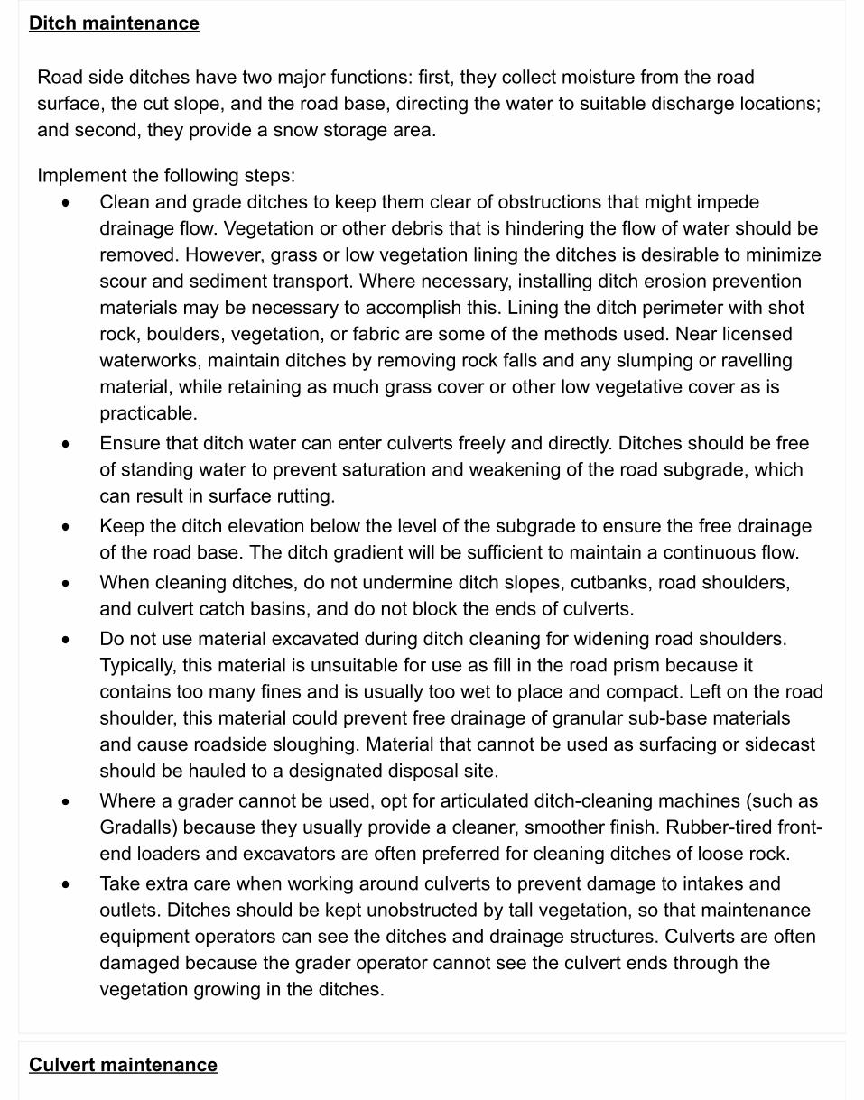
Ditch maintenance
Road side ditches have two major functions: first, they collect moisture from the roadsurface, the cut slope, and the road base, directing the water to suitable discharge locations;and second, they provide a snow storage area.
Implement the following steps:Clean and grade ditches to keep them clear of obstructions that might impededrainage flow. Vegetation or other debris that is hindering the flow of water should beremoved. However, grass or low vegetation lining the ditches is desirable to minimizescour and sediment transport. Where necessary, installing ditch erosion preventionmaterials may be necessary to accomplish this. Lining the ditch perimeter with shotrock, boulders, vegetation, or fabric are some of the methods used. Near licensedwaterworks, maintain ditches by removing rock falls and any slumping or ravellingmaterial, while retaining as much grass cover or other low vegetative cover as ispracticable.Ensure that ditch water can enter culverts freely and directly. Ditches should be freeof standing water to prevent saturation and weakening of the road subgrade, whichcan result in surface rutting.Keep the ditch elevation below the level of the subgrade to ensure the free drainageof the road base. The ditch gradient will be sufficient to maintain a continuous flow.When cleaning ditches, do not undermine ditch slopes, cutbanks, road shoulders,and culvert catch basins, and do not block the ends of culverts.Do not use material excavated during ditch cleaning for widening road shoulders.Typically, this material is unsuitable for use as fill in the road prism because itcontains too many fines and is usually too wet to place and compact. Left on the roadshoulder, this material could prevent free drainage of granular sub-base materialsand cause roadside sloughing. Material that cannot be used as surfacing or sidecastshould be hauled to a designated disposal site.Where a grader cannot be used, opt for articulated ditch-cleaning machines (such asGradalls) because they usually provide a cleaner, smoother finish. Rubber-tired front-end loaders and excavators are often preferred for cleaning ditches of loose rock.Take extra care when working around culverts to prevent damage to intakes andoutlets. Ditches should be kept unobstructed by tall vegetation, so that maintenanceequipment operators can see the ditches and drainage structures. Culverts are oftendamaged because the grader operator cannot see the culvert ends through thevegetation growing in the ditches.
Culvert maintenance
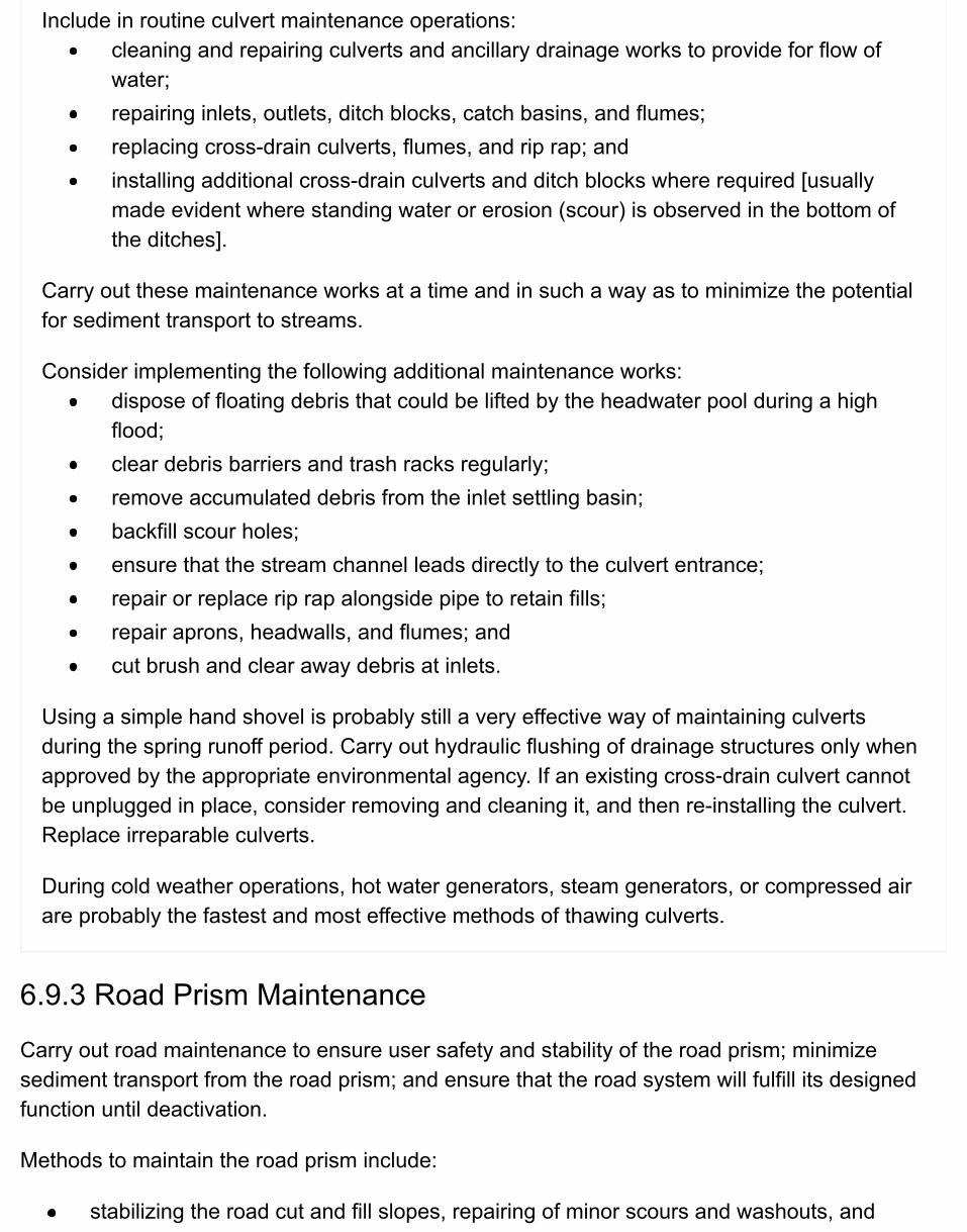
Include in routine culvert maintenance operations:cleaning and repairing culverts and ancillary drainage works to provide for flow ofwater;repairing inlets, outlets, ditch blocks, catch basins, and flumes;replacing cross-drain culverts, flumes, and rip rap; andinstalling additional cross-drain culverts and ditch blocks where required [usuallymade evident where standing water or erosion (scour) is observed in the bottom ofthe ditches].
Carry out these maintenance works at a time and in such a way as to minimize the potentialfor sediment transport to streams.
Consider implementing the following additional maintenance works:dispose of floating debris that could be lifted by the headwater pool during a highflood;clear debris barriers and trash racks regularly;remove accumulated debris from the inlet settling basin;backfill scour holes;ensure that the stream channel leads directly to the culvert entrance;repair or replace rip rap alongside pipe to retain fills;repair aprons, headwalls, and flumes; andcut brush and clear away debris at inlets.
Using a simple hand shovel is probably still a very effective way of maintaining culvertsduring the spring runoff period. Carry out hydraulic flushing of drainage structures only whenapproved by the appropriate environmental agency. If an existing cross‑drain culvert cannotbe unplugged in place, consider removing and cleaning it, and then re-installing the culvert.Replace irreparable culverts.
During cold weather operations, hot water generators, steam generators, or compressed airare probably the fastest and most effective methods of thawing culverts.
6.9.3 Road Prism Maintenance
Carry out road maintenance to ensure user safety and stability of the road prism; minimizesediment transport from the road prism; and ensure that the road system will fulfill its designedfunction until deactivation.
Methods to maintain the road prism include:
stabilizing the road cut and fill slopes, repairing of minor scours and washouts, and
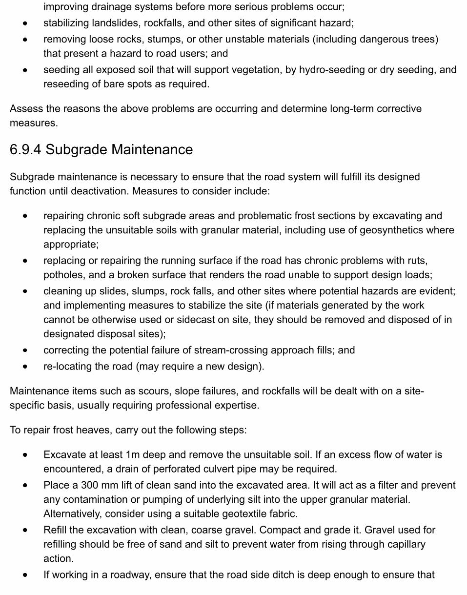
improving drainage systems before more serious problems occur;stabilizing landslides, rockfalls, and other sites of significant hazard;removing loose rocks, stumps, or other unstable materials (including dangerous trees)that present a hazard to road users; andseeding all exposed soil that will support vegetation, by hydro-seeding or dry seeding, andreseeding of bare spots as required.
Assess the reasons the above problems are occurring and determine long-term correctivemeasures.
6.9.4 Subgrade Maintenance
Subgrade maintenance is necessary to ensure that the road system will fulfill its designedfunction until deactivation. Measures to consider include:
repairing chronic soft subgrade areas and problematic frost sections by excavating andreplacing the unsuitable soils with granular material, including use of geosynthetics whereappropriate;replacing or repairing the running surface if the road has chronic problems with ruts,potholes, and a broken surface that renders the road unable to support design loads;cleaning up slides, slumps, rock falls, and other sites where potential hazards are evident;and implementing measures to stabilize the site (if materials generated by the workcannot be otherwise used or sidecast on site, they should be removed and disposed of indesignated disposal sites);correcting the potential failure of stream-crossing approach fills; andre-locating the road (may require a new design).
Maintenance items such as scours, slope failures, and rockfalls will be dealt with on a site-specific basis, usually requiring professional expertise.
To repair frost heaves, carry out the following steps:
Excavate at least 1m deep and remove the unsuitable soil. If an excess flow of water isencountered, a drain of perforated culvert pipe may be required.Place a 300 mm lift of clean sand into the excavated area. It will act as a filter and preventany contamination or pumping of underlying silt into the upper granular material.Alternatively, consider using a suitable geotextile fabric.Refill the excavation with clean, coarse gravel. Compact and grade it. Gravel used forrefilling should be free of sand and silt to prevent water from rising through capillaryaction.If working in a roadway, ensure that the road side ditch is deep enough to ensure that
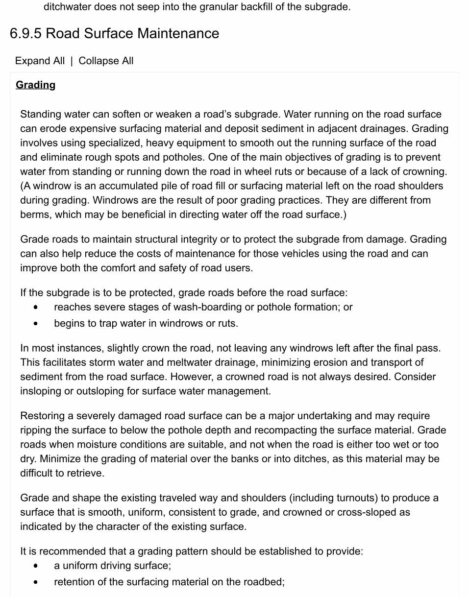
ditchwater does not seep into the granular backfill of the subgrade.
6.9.5 Road Surface Maintenance
Expand All | Collapse All
Grading
Standing water can soften or weaken a road’s subgrade. Water running on the road surfacecan erode expensive surfacing material and deposit sediment in adjacent drainages. Gradinginvolves using specialized, heavy equipment to smooth out the running surface of the roadand eliminate rough spots and potholes. One of the main objectives of grading is to preventwater from standing or running down the road in wheel ruts or because of a lack of crowning.(A windrow is an accumulated pile of road fill or surfacing material left on the road shouldersduring grading. Windrows are the result of poor grading practices. They are different fromberms, which may be beneficial in directing water off the road surface.)
Grade roads to maintain structural integrity or to protect the subgrade from damage. Gradingcan also help reduce the costs of maintenance for those vehicles using the road and canimprove both the comfort and safety of road users.
If the subgrade is to be protected, grade roads before the road surface:reaches severe stages of wash-boarding or pothole formation; orbegins to trap water in windrows or ruts.
In most instances, slightly crown the road, not leaving any windrows left after the final pass.This facilitates storm water and meltwater drainage, minimizing erosion and transport ofsediment from the road surface. However, a crowned road is not always desired. Considerinsloping or outsloping for surface water management.
Restoring a severely damaged road surface can be a major undertaking and may requireripping the surface to below the pothole depth and recompacting the surface material. Graderoads when moisture conditions are suitable, and not when the road is either too wet or toodry. Minimize the grading of material over the banks or into ditches, as this material may bedifficult to retrieve.
Grade and shape the existing traveled way and shoulders (including turnouts) to produce asurface that is smooth, uniform, consistent to grade, and crowned or cross-sloped asindicated by the character of the existing surface.
It is recommended that a grading pattern should be established to provide:a uniform driving surface;retention of the surfacing material on the roadbed;
a thorough mixing of the materials within the completed surface width; andno mixing of contaminated ditch material with any processed surfacing material.
Final grade such that no disturbed material such as gravel, cobbles, and boulders protrudemore than 50 mm above the road surface. If it does, remove the material and place it outsidethe running surface of the road so as not to obstruct drainage ways or structures. Scatter thismaterial off the roadbed if there is free drainage.Do not leave any windrows remaining after the final pass.
Material should roll freely across the blade of the grader. For best results, carry out gradingunder moist, but not saturated, road conditions. This provides optimum moisture content forcompaction, while eliminating dust and loss of fines.Under dry soil conditions, the road surface should be blade‑roughened to remove small rutsand depressions without disturbing the lower road surface.
For roads with pit run surfacing material, to eliminate potholes, cobbles, and washboard,scarify the entire rough section to a depth below the deepest pothole or surface imperfectionor largest cobble size over the full road width and then regrade, compact with a suitableroller, and, if feasible, apply a dust palliative. Also, use this procedure for regravelling a hard-packed surface.
Reshaping requires a cut deeper than normal grading to obtain the proper cross- section. Tiltthe blade back sufficiently to remove any washboard or other irregular conditions and takespecial care to “crown” the centre of the road.
Because reshaping requires cutting down into the grade, ensure that there is sufficientmoisture to:1. ensure the fines and binder material are not lost or blown away when brought to the
surface; and2. provide for sufficient compaction of the re-shaped gravel. In most areas this dictates that
reshaping should be scheduled for the spring and fall.
Leaving windrows is a bad grading practice. It keeps surface runoff on the road and leads towashouts. During dry conditions, when the hard road surface is difficult to grade, leave awindrow on the upper side of the road where there is no crown. Do not leave windrows onthe lower side of the road, because these can deflect water and eventually cause the road towash out.
Resurfacing
Resurface gravel roads when the existing surfacing material is no longer sufficient to supporttraffic loading or when there is not enough material available for grading purposes. Overtime, surfacing material can break down and is lost from the road surface. Spot-gravel roadswhere short sections of the road surface are failing or have a potential for failure, or wherepotholes that cannot be satisfactorily graded out are evident.
Surface with materials of sufficient strength, durability, and gradation so that at completion ofthe surfacing application, the surface will not rut when subjected to the loading exerted bythe rear axles of a fully loaded tandem truck on the completed surface. Suitable sources ofgravel materials include:
material from existing pits that have proven performance;gravels with 10%-15% fines; andmaterials that do not easily rut, washboard, or break down when wet.
Dust suppression
Dust from unpaved roads is not only a nuisance but can create a safety hazard by reducinga driver’s visibility. It may be necessary to apply a dust suppressant product to eliminate thedust problem by sealing the surface of the road. However, these products are not apermanent solution and their effectiveness decreases with time. Carry out furtherapplications of the products if dust suppression is to be maintained.
To properly select the appropriate product, it is important to understand the primary factorsthat generate dust, including:
vehicle speed;number of wheels per vehicle;number of vehicles;vehicle weight;particle size distribution (gradation) of the surface material;restraint of the surface fines (compaction, cohesiveness/bonding, durability); andsurface moisture (humidity, amount of precipitation, amount of evaporation).
In selecting the proper dust abatement program consider not only the above factors, but alsothe total long-term cost and environmental impacts of that program. Long-term costs includeroad improvement, road preparation, application of the dust suppressant in conjunction withthe number of times the product needs to be applied, and expected change in maintenancepractices.Environmental considerations typically include impacts to the water quality, aquatic habitat,and plant community.
A wide variety of dust suppressants are available on the market. They fall into seven basiccategories:
water;water-absorbing products;petroleum-based products;organic non-petroleum-based products;electrochemical products;polymer products; andclay additive products.
Regardless of the type used, the criteria for an acceptable dust suppressant product are thatthey must:
be environmentally compatible (i.e., without there being any adverse environmentaleffects);be easily applied with common road maintenance equipment;be workable and respond to surface or structural maintenance;provide reasonable retention and dust control;provide little loss of riding quality and be cost competitive; andbe approved by the Ministry of Transportation and Infrastructure.
6.9.6 Winter Operations: Snowplowing & Sanding
Expand All | Collapse All
General
Serrated grader blades will cut ice and snow much better than ordinary blades, and therough surface left by a serrated blade usually improves traction.
Restrict snow removal to the usable traveled way having roadbed support. Reshape over-width plowing as necessary to define the usable width.
Do not excavate into the gravel surface or remove surfacing materials along with the snow.
Breach snow berms frequently enough to allow road surface runoff from snowmelt to have asafe place to drain.
Before allowing snow removal from any road is allowed to take place, identify all road-relatedfixtures that might be at risk from snow removal operations (such as culvert markers, signs,bridge delineators, bridge guard logs, cattleguards, and fencing) and notify the snow removal
operators.
In an area of daylighted cuts, plow the road from the inside of the cut to the outside (in thedirection away from the cut slope) to avoid plugging culverts and ditches with snow.
Plow roads to a firm surface before sanding.
Fine crushed gravel as a sanding medium is superior to pit-run sand. The sharp angularmaterial provides better traction and breaks up an icy surface by rolling under vehicle tires.
Do not stop the spreading of sand in the middle of a curve, halfway up a hill, or at any otherpotential roadway hazard.
As a general rule, spread sand only along the centre of the road. Vehicle wheels will spreadthe sand full width. Use spinners or other power spreaders where available.
Snow removal at rail crossings
When conducting snowplowing operations at rail crossings, ensure that snow removal crewsthat are responsible for Forest Service road maintenance are aware of the following snowremoval guidelines:1. When snowplowing at rail crossings, the snowplow blade must be raised before going
over the crossing surface to ensure that the blades do not damage the rails.2. Windrows must not be left between the rails or within 8 metres of the track. Leaving
windrows can result in unsafe conditions with reduced sightlines at the crossing andincreased potential for trains or other rail vehicles impacting windrows and derailing orwhich could result in injuries to pedestrians and or damage to nearby motor vehiclescaused by thrown snow and ice.
3. Snow must not be piled up in close proximity or restrict sightlines at the crossing.
As road crossings are licensed by the rail companies, improper snow removal practices atrail crossings, or an accident at any rail crossing caused by improper snow removal practicesmay result in a crossing license being revoked and the crossing permanently closed.
Ensure that emergency contact information for the railway company is available in the eventof an incident involving snow removal or other reason at a rail crossing. Any incidentinvolving damage to signage, crossing surface or rails at a crossing should be called in to theemergency number immediately.
6.9.7 Spring Break-Up: Temporary Vehicle Weight Restrictions
Where it is necessary to impose vehicle weight restrictions to protect Forest Service Roads fromconsiderable damage during spring break-up, the restrictions may vary from 30% to 50% (ormore) of the legal axle loading. Restrictions normally extend from about mid-March to mid-May,depending on the weather conditions and the susceptibility of the subgrade to frost.
Certain indicators provide a guide to the timing of restrictions. These indicators are tied to thestages of spring break-up:
Incipient stage – the stage at which the surface starts to thaw and turn muddy; usuallymost of the ice and snow will be gone from the surface and along the road; andAdvanced stage – the stage at which the subgrade starts to thaw; most likely the surfacewill appear quite dry.
Impose the restrictions towards the end of the incipient stage. The road’s bearing strength issubstantially reduced when thawing of the subgrade occurs during the advanced stage. This isthe time the road is most susceptible to damage.
Since there are not any specific indicators or guides for when restrictions should be lifted, localknowledge is critical. Therefore, utilize the output of the local offices of the Ministry ofTransportation and Infrastructure, who determine when to impose and lift restrictions, and providecriteria for any exemptions. Central tire inflation research has been conducted by FERIC, adivision of FPInnovations, on {{{Tire Pressure Control Systems (PDF)}}} in conjunction with loghaulers and the Ministry of Transportation and Infrastructure which has implemented varioustrials allowing log haul on roads that would normally be shut down due to ‘breakup’.Consult with engineering branch staff prior to implementing a log haul program of this nature.
Publish notice of impending or imposed restrictions in local newspapers and/or announcerestrictions on local radio stations before they are imposed.
When temporary vehicle weight restrictions on roads are posted for FSRs, use the ministry’swarning load limit posters:
Poster - Warning Load Limit - Percentage Max Allow Weight (FS 639) (PDF)Poster - Warning Load Limit (FS 639a) (PDF)
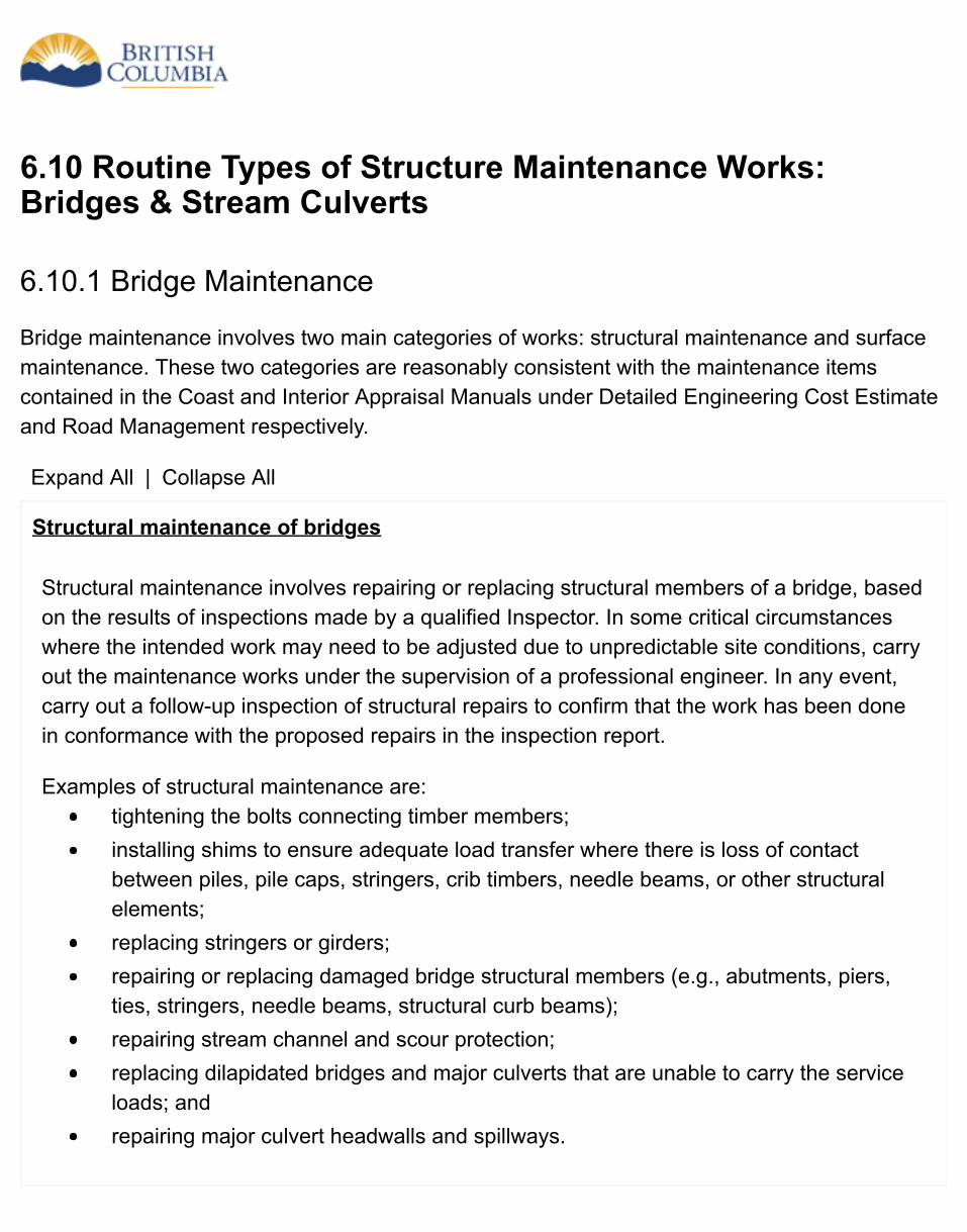
6.10 Routine Types of Structure Maintenance Works:Bridges & Stream Culverts
6.10.1 Bridge Maintenance
Bridge maintenance involves two main categories of works: structural maintenance and surfacemaintenance. These two categories are reasonably consistent with the maintenance itemscontained in the Coast and Interior Appraisal Manuals under Detailed Engineering Cost Estimateand Road Management respectively.
Expand All | Collapse All
Structural maintenance of bridges
Structural maintenance involves repairing or replacing structural members of a bridge, basedon the results of inspections made by a qualified Inspector. In some critical circumstanceswhere the intended work may need to be adjusted due to unpredictable site conditions, carryout the maintenance works under the supervision of a professional engineer. In any event,carry out a follow-up inspection of structural repairs to confirm that the work has been donein conformance with the proposed repairs in the inspection report.
Examples of structural maintenance are:tightening the bolts connecting timber members;installing shims to ensure adequate load transfer where there is loss of contactbetween piles, pile caps, stringers, crib timbers, needle beams, or other structuralelements;replacing stringers or girders;repairing or replacing damaged bridge structural members (e.g., abutments, piers,ties, stringers, needle beams, structural curb beams);repairing stream channel and scour protection;replacing dilapidated bridges and major culverts that are unable to carry the serviceloads; andrepairing major culvert headwalls and spillways.
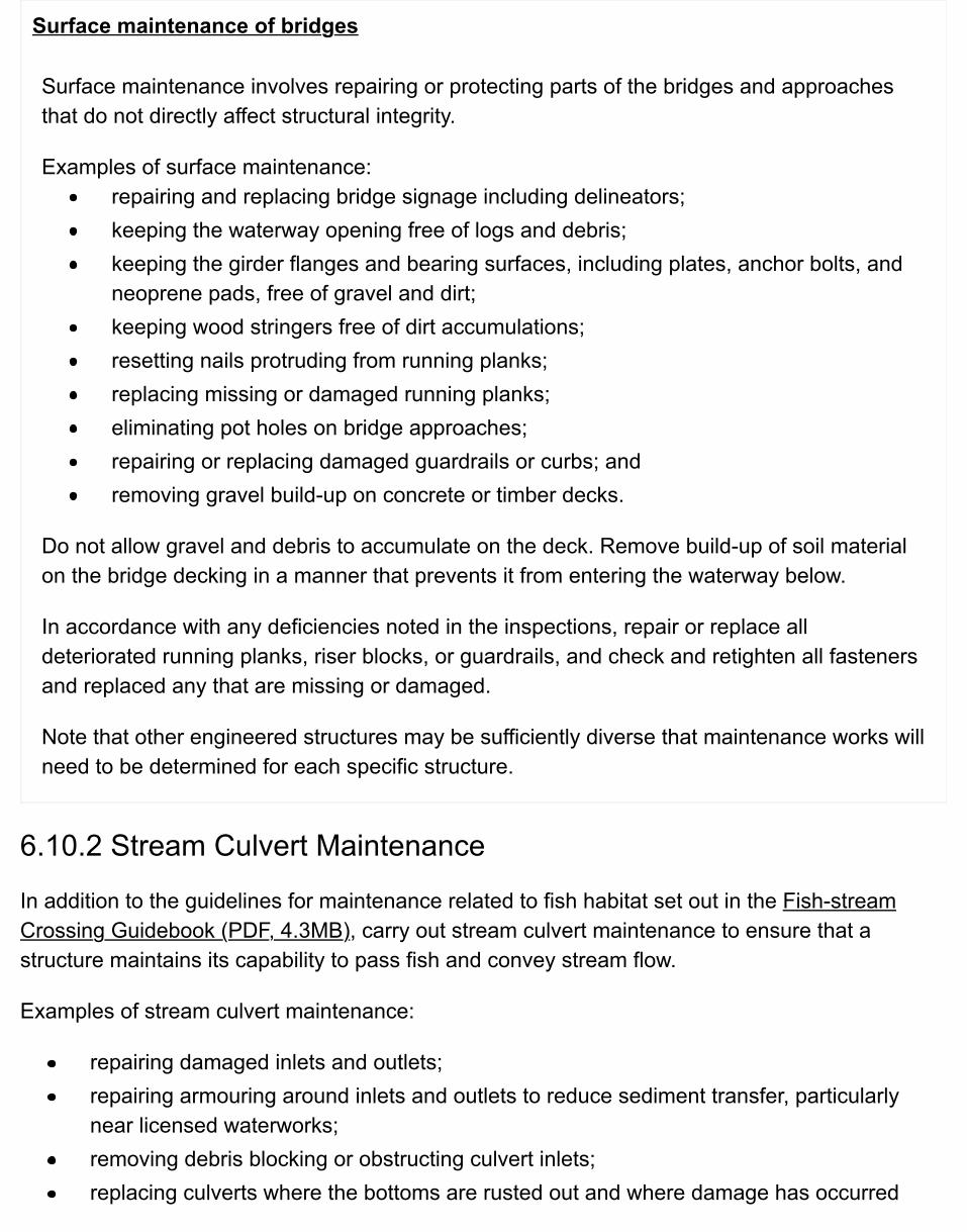
Surface maintenance of bridges
Surface maintenance involves repairing or protecting parts of the bridges and approachesthat do not directly affect structural integrity.
Examples of surface maintenance:repairing and replacing bridge signage including delineators;keeping the waterway opening free of logs and debris;keeping the girder flanges and bearing surfaces, including plates, anchor bolts, andneoprene pads, free of gravel and dirt;keeping wood stringers free of dirt accumulations;resetting nails protruding from running planks;replacing missing or damaged running planks;eliminating pot holes on bridge approaches;repairing or replacing damaged guardrails or curbs; andremoving gravel build-up on concrete or timber decks.
Do not allow gravel and debris to accumulate on the deck. Remove build-up of soil materialon the bridge decking in a manner that prevents it from entering the waterway below.
In accordance with any deficiencies noted in the inspections, repair or replace alldeteriorated running planks, riser blocks, or guardrails, and check and retighten all fastenersand replaced any that are missing or damaged.
Note that other engineered structures may be sufficiently diverse that maintenance works willneed to be determined for each specific structure.
6.10.2 Stream Culvert Maintenance
In addition to the guidelines for maintenance related to fish habitat set out in the Fish-streamCrossing Guidebook (PDF, 4.3MB), carry out stream culvert maintenance to ensure that astructure maintains its capability to pass fish and convey stream flow.
Examples of stream culvert maintenance:
repairing damaged inlets and outlets;repairing armouring around inlets and outlets to reduce sediment transfer, particularlynear licensed waterworks;removing debris blocking or obstructing culvert inlets;replacing culverts where the bottoms are rusted out and where damage has occurred
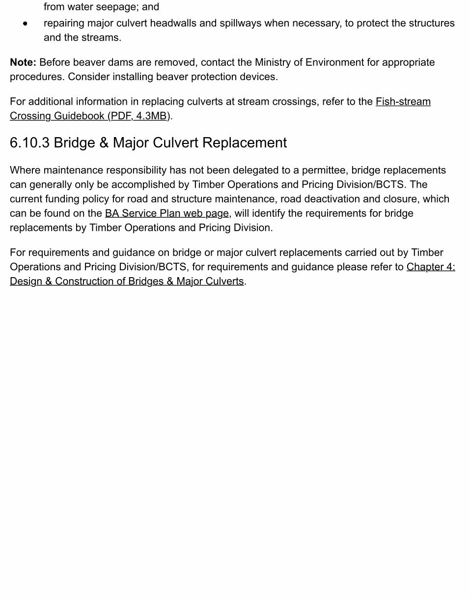
from water seepage; andrepairing major culvert headwalls and spillways when necessary, to protect the structuresand the streams.
Note: Before beaver dams are removed, contact the Ministry of Environment for appropriateprocedures. Consider installing beaver protection devices.
For additional information in replacing culverts at stream crossings, refer to the Fish-streamCrossing Guidebook (PDF, 4.3MB).
6.10.3 Bridge & Major Culvert Replacement
Where maintenance responsibility has not been delegated to a permittee, bridge replacementscan generally only be accomplished by Timber Operations and Pricing Division/BCTS. Thecurrent funding policy for road and structure maintenance, road deactivation and closure, whichcan be found on the BA Service Plan web page, will identify the requirements for bridgereplacements by Timber Operations and Pricing Division.
For requirements and guidance on bridge or major culvert replacements carried out by TimberOperations and Pricing Division/BCTS, for requirements and guidance please refer to Chapter 4:Design & Construction of Bridges & Major Culverts.
6.11 Other Maintenance Works Along Roads
6.11.1 Fords
Remove debris and sediment build-up on fords and approaches to minimize the impact ondownstream resources. Where a ford is exhibiting signs of failure, establish or restore those siteconditions that are vital for the successful operation of a ford. For additional information on fords,refer to Ford Design and Construction on Non-Fish Streams in Chapter 3.
6.11.2 Weirs
Where weirs are installed in a stream to maintain water levels for fish passage, inspect andmaintain them to ensure that the fish passage objectives are being met.
6.11.3 Fences
Repair or replace range fences that have been damaged as a result of activities on the road. TheRange Section in the local district office can advise on acceptable fence constructionspecifications and practices.
6.11.4 Cattleguards
Carry out the following steps:
Repair broken welds or tie rods promptly.Check and replace sills and foundations if any crushing has occurred.Keep rails, fences, posts, and gates in good condition to ensure that the cattleguard fulfilsits function.Clean the pit under the cattleguard periodically.Clean cattleguards in those situations where the Ministry has agreed with the landownerto do so, repair them, or replace them if repair is neither practical nor cost-effective.
6.11.5 Signs

Repair or replace damaged or vandalized signs and posts. Carry out sign maintenance, includingcleaning and regular hand brushing and snow removal around them, to ensure they can be seenin all conditions. Replace illegible signs at the earliest opportunity.
One of the ways that sign maintenance can be reduced is to install signs high enough so thatthey are difficult to reach. While this cannot be done in all instances (such as with bridgedelineators) it has been effective in reducing damage from spray paint or gunshots. This methodalso limits the impact that vegetation and accumulations of snow can have on sign visibility.

6.12 Resources & Suggestions for Further ReadingBritish Columbia Institute of Technology (BCIT). 1995. Surface maintenance: course manual. RRET 3328.Burnaby, B.C.
_______________. 2001. Bridge maintenance: course manual. RRET 3324. Burnaby, B.C.
_______________. 2001. Culvert maintenance: course manual. RRET 3322. Burnaby, B.C.
BC Ministry of Forests. 2002. Fish-stream Crossing Guidebook (PDF, 4.3MB). For. Prac. Br., B.C. Min. For.Victoria, B.C.
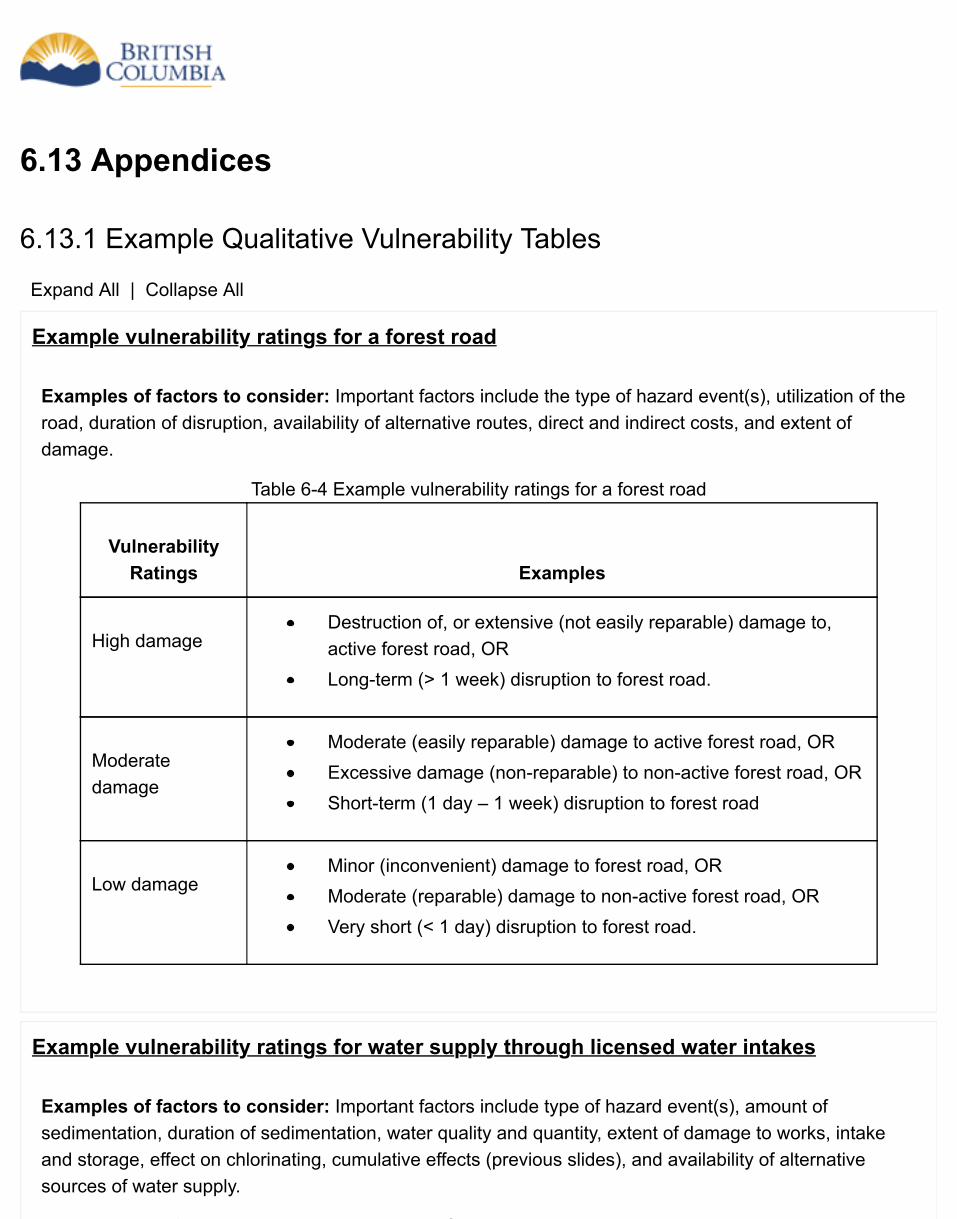
6.13 Appendices
6.13.1 Example Qualitative Vulnerability Tables
Expand All | Collapse All
Example vulnerability ratings for a forest road
Examples of factors to consider: Important factors include the type of hazard event(s), utilization of theroad, duration of disruption, availability of alternative routes, direct and indirect costs, and extent ofdamage.
Table 6-4 Example vulnerability ratings for a forest road
VulnerabilityRatings Examples
High damageDestruction of, or extensive (not easily reparable) damage to,active forest road, ORLong-term (> 1 week) disruption to forest road.
Moderatedamage
Moderate (easily reparable) damage to active forest road, ORExcessive damage (non-reparable) to non-active forest road, ORShort-term (1 day – 1 week) disruption to forest road
Low damageMinor (inconvenient) damage to forest road, ORModerate (reparable) damage to non-active forest road, ORVery short (< 1 day) disruption to forest road.
Example vulnerability ratings for water supply through licensed water intakes
Examples of factors to consider: Important factors include type of hazard event(s), amount ofsedimentation, duration of sedimentation, water quality and quantity, extent of damage to works, intakeand storage, effect on chlorinating, cumulative effects (previous slides), and availability of alternativesources of water supply.
Table 6-5 Example vulnerability ratings for water supply through licensed water intakes
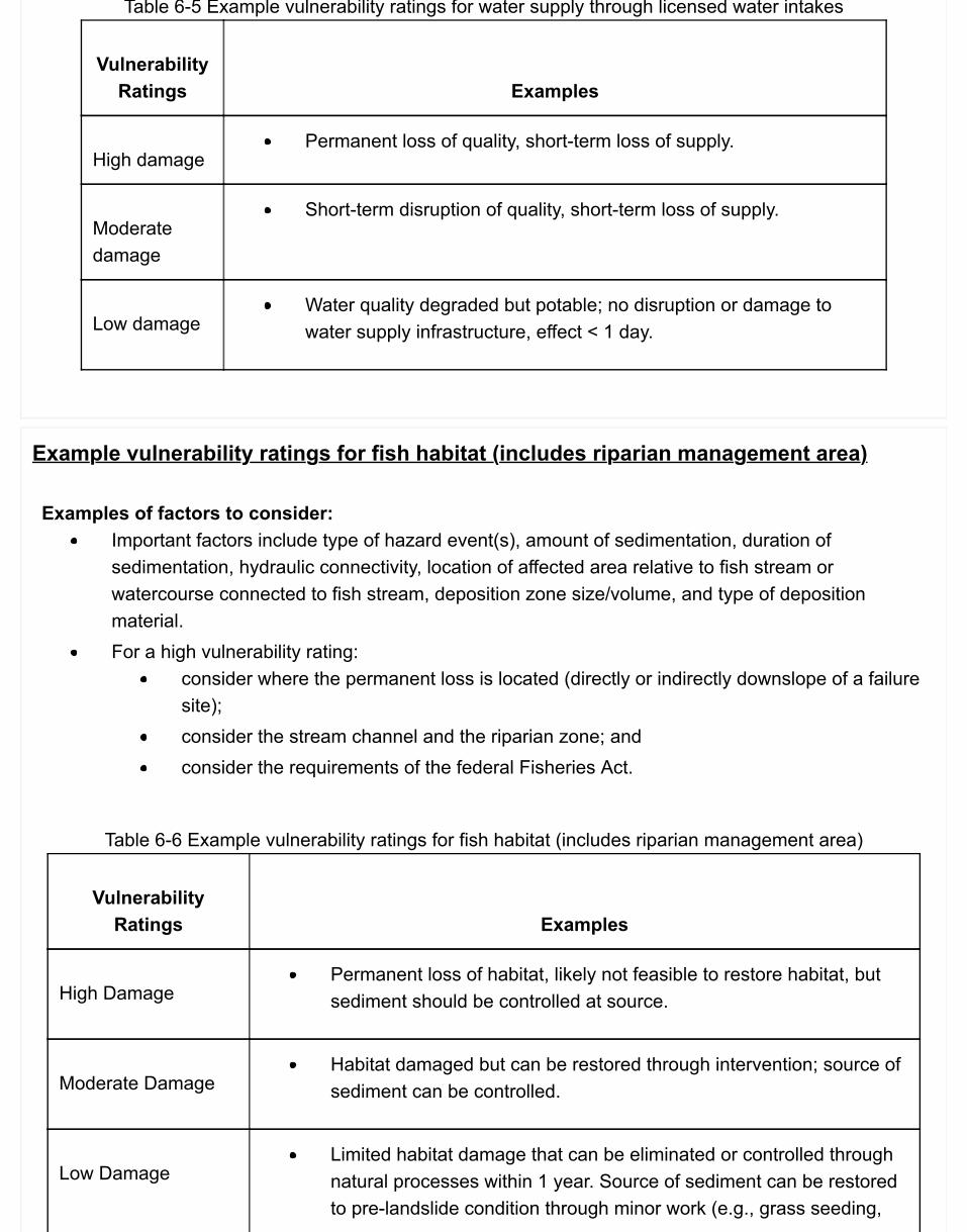
Table 6-5 Example vulnerability ratings for water supply through licensed water intakes
VulnerabilityRatings Examples
High damagePermanent loss of quality, short-term loss of supply.
Moderatedamage
Short-term disruption of quality, short-term loss of supply.
Low damageWater quality degraded but potable; no disruption or damage towater supply infrastructure, effect < 1 day.
Example vulnerability ratings for fish habitat (includes riparian management area)
Examples of factors to consider:Important factors include type of hazard event(s), amount of sedimentation, duration ofsedimentation, hydraulic connectivity, location of affected area relative to fish stream orwatercourse connected to fish stream, deposition zone size/volume, and type of depositionmaterial.For a high vulnerability rating:
consider where the permanent loss is located (directly or indirectly downslope of a failuresite);consider the stream channel and the riparian zone; andconsider the requirements of the federal Fisheries Act.
Table 6-6 Example vulnerability ratings for fish habitat (includes riparian management area)
VulnerabilityRatings Examples
High DamagePermanent loss of habitat, likely not feasible to restore habitat, butsediment should be controlled at source.
Moderate DamageHabitat damaged but can be restored through intervention; source ofsediment can be controlled.
Low DamageLimited habitat damage that can be eliminated or controlled throughnatural processes within 1 year. Source of sediment can be restoredto pre-landslide condition through minor work (e.g., grass seeding,
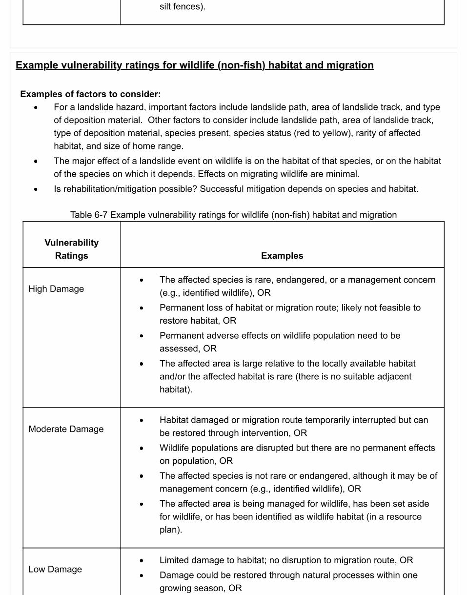
silt fences).
Example vulnerability ratings for wildlife (non-fish) habitat and migration
Examples of factors to consider:For a landslide hazard, important factors include landslide path, area of landslide track, and typeof deposition material. Other factors to consider include landslide path, area of landslide track,type of deposition material, species present, species status (red to yellow), rarity of affectedhabitat, and size of home range.The major effect of a landslide event on wildlife is on the habitat of that species, or on the habitatof the species on which it depends. Effects on migrating wildlife are minimal.Is rehabilitation/mitigation possible? Successful mitigation depends on species and habitat.
Table 6-7 Example vulnerability ratings for wildlife (non-fish) habitat and migration
VulnerabilityRatings Examples
High DamageThe affected species is rare, endangered, or a management concern(e.g., identified wildlife), ORPermanent loss of habitat or migration route; likely not feasible torestore habitat, ORPermanent adverse effects on wildlife population need to beassessed, ORThe affected area is large relative to the locally available habitatand/or the affected habitat is rare (there is no suitable adjacenthabitat).
Moderate DamageHabitat damaged or migration route temporarily interrupted but canbe restored through intervention, ORWildlife populations are disrupted but there are no permanent effectson population, ORThe affected species is not rare or endangered, although it may be ofmanagement concern (e.g., identified wildlife), ORThe affected area is being managed for wildlife, has been set asidefor wildlife, or has been identified as wildlife habitat (in a resourceplan).
Low DamageLimited damage to habitat; no disruption to migration route, ORDamage could be restored through natural processes within onegrowing season, OR
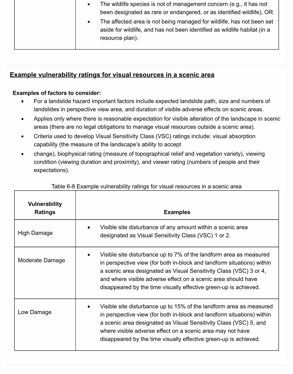
The wildlife species is not of management concern (e.g., it has notbeen designated as rare or endangered, or as identified wildlife), ORThe affected area is not being managed for wildlife, has not been setaside for wildlife, and has not been identified as wildlife habitat (in aresource plan).
Example vulnerability ratings for visual resources in a scenic area
Examples of factors to consider:For a landslide hazard important factors include expected landslide path, size and numbers oflandslides in perspective view area, and duration of visible adverse effects on scenic areas.Applies only where there is reasonable expectation for visible alteration of the landscape in scenicareas (there are no legal obligations to manage visual resources outside a scenic area).Criteria used to develop Visual Sensitivity Class (VSC) ratings include: visual absorptioncapability (the measure of the landscape’s ability to acceptchange), biophysical rating (measure of topographical relief and vegetation variety), viewingcondition (viewing duration and proximity), and viewer rating (numbers of people and theirexpectations).
Table 6-8 Example vulnerability ratings for visual resources in a scenic area
VulnerabilityRatings Examples
High DamageVisible site disturbance of any amount within a scenic areadesignated as Visual Sensitivity Class (VSC) 1 or 2.
Moderate DamageVisible site disturbance up to 7% of the landform area as measuredin perspective view (for both in-block and landform situations) withina scenic area designated as Visual Sensitivity Class (VSC) 3 or 4,and where visible adverse effect on a scenic area should havedisappeared by the time visually effective green-up is achieved.
Low DamageVisible site disturbance up to 15% of the landform area as measuredin perspective view (for both in-block and landform situations) withina scenic area designated as Visual Sensitivity Class (VSC) 5, andwhere visible adverse effect on a scenic area may not havedisappeared by the time visually effective green-up is achieved.
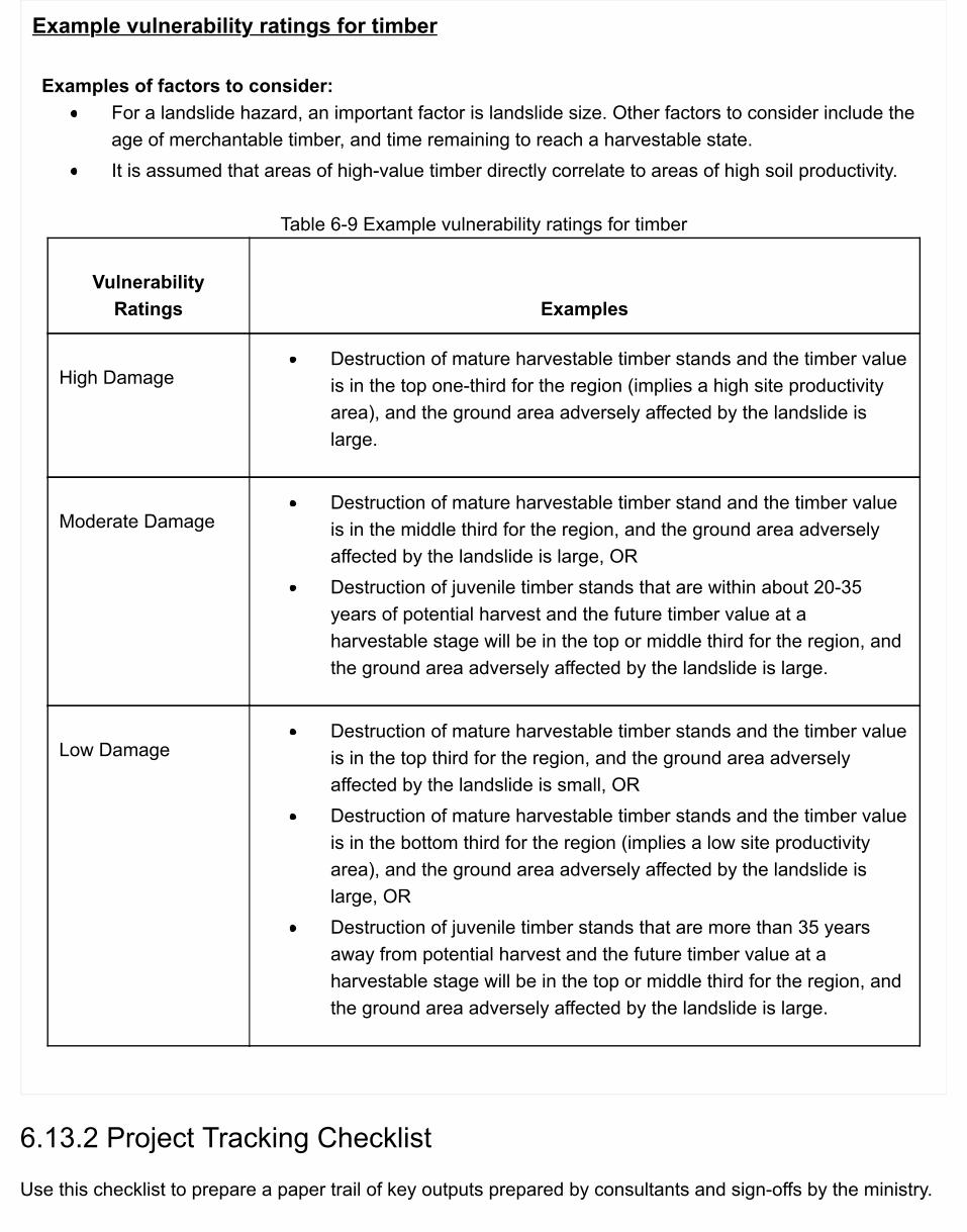
Example vulnerability ratings for timber
Examples of factors to consider:For a landslide hazard, an important factor is landslide size. Other factors to consider include theage of merchantable timber, and time remaining to reach a harvestable state.It is assumed that areas of high-value timber directly correlate to areas of high soil productivity.
Table 6-9 Example vulnerability ratings for timber
VulnerabilityRatings Examples
High DamageDestruction of mature harvestable timber stands and the timber valueis in the top one-third for the region (implies a high site productivityarea), and the ground area adversely affected by the landslide islarge.
Moderate DamageDestruction of mature harvestable timber stand and the timber valueis in the middle third for the region, and the ground area adverselyaffected by the landslide is large, ORDestruction of juvenile timber stands that are within about 20-35years of potential harvest and the future timber value at aharvestable stage will be in the top or middle third for the region, andthe ground area adversely affected by the landslide is large.
Low DamageDestruction of mature harvestable timber stands and the timber valueis in the top third for the region, and the ground area adverselyaffected by the landslide is small, ORDestruction of mature harvestable timber stands and the timber valueis in the bottom third for the region (implies a low site productivityarea), and the ground area adversely affected by the landslide islarge, ORDestruction of juvenile timber stands that are more than 35 yearsaway from potential harvest and the future timber value at aharvestable stage will be in the top or middle third for the region, andthe ground area adversely affected by the landslide is large.
6.13.2 Project Tracking Checklist
Use this checklist to prepare a paper trail of key outputs prepared by consultants and sign-offs by the ministry.

Project Tracking Checklist (PDF)
Chapter 7: Road DeactivationThe intent of road deactivation is to place a road in a self-maintaining state that will indefinitely protect adjacentresources. Road deactivation requirements typically include removing bridges and stream culverts, stabilizingthe road prism, and barricading the road surface width in a clearly visible manner to prevent access by motorvehicles (other than all-terrain vehicles).
This chapter describes the objectives of road deactivation, as well as professional responsibilities, mandatoryprocedures and best management practices for developing deactivation prescriptions and carrying out theworks. It also presents a number of road deactivation techniques that address the province-wide range ofterrain, soils, and climatic conditions, and assists ministry staff in achieving the statutory and regulatoryrequirements in the Forest and Range Practices Act and the Forest Planning and Practices Regulation.
7.0.1 Policy
When no longer required, Forest Service Roads (FSRs) that are the responsibility of either Timber Operationsand Pricing Division or BC Timber Sales (BCTS) will be deactivated in a planned manner that considers futureaccess needs, road user safety, cost efficiency, and values at risk of damage or loss.
7.1 Mandatory Procedures & Best Practices
7.2 Road Deactivation Professional Responsibilities & Considerations
7.2.1 Involvement of Specialists in Road Deactivation7.2.2 Professional Field Reviews7.2.3 Project Assurance
7.3 Planning Road Deactivation
7.4 Deactivation Prescriptions
7.4.1 Prescription Requirements7.4.2 Phases of Prescription Development7.4.3 Modification of Prescriptions
7.5 Road Deactivation Works
7.5.1 Project Management7.5.2 Cost Estimate of the Planned Works7.5.3 Carrying Out the Works

7.5.4 Submission Requirements After Completing the Works7.5.5 Inspections After Deactivation
7.6 Deactivation Hazard Warning Signs
7.7 Road Deactivation Objectives
7.7.1 Achieving Deactivation Objectives
7.8 Road Deactivation Techniques
7.8.1 Water Management Techniques7.8.2 Road Fill Pullback Techniques7.8.3 Revegetation Techniques
7.9 Resources & Suggestions for Further Reading
7.10 Appendices
7.10.1 Project Tracking Checklist
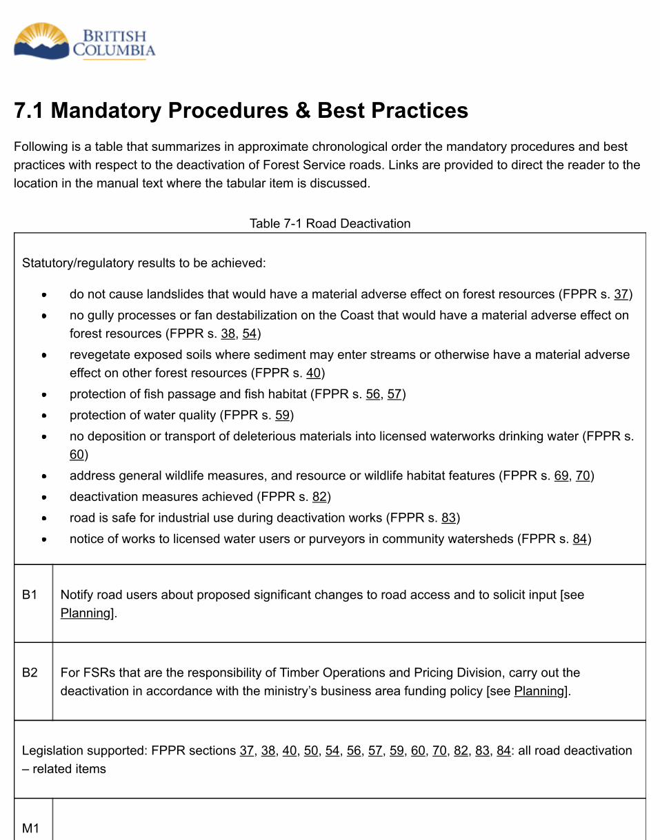
7.1 Mandatory Procedures & Best PracticesFollowing is a table that summarizes in approximate chronological order the mandatory procedures and bestpractices with respect to the deactivation of Forest Service roads. Links are provided to direct the reader to thelocation in the manual text where the tabular item is discussed.
Table 7-1 Road Deactivation
Statutory/regulatory results to be achieved:
do not cause landslides that would have a material adverse effect on forest resources (FPPR s. 37)no gully processes or fan destabilization on the Coast that would have a material adverse effect onforest resources (FPPR s. 38, 54)revegetate exposed soils where sediment may enter streams or otherwise have a material adverseeffect on other forest resources (FPPR s. 40)protection of fish passage and fish habitat (FPPR s. 56, 57)protection of water quality (FPPR s. 59)no deposition or transport of deleterious materials into licensed waterworks drinking water (FPPR s. 60)address general wildlife measures, and resource or wildlife habitat features (FPPR s. 69, 70)deactivation measures achieved (FPPR s. 82)road is safe for industrial use during deactivation works (FPPR s. 83)notice of works to licensed water users or purveyors in community watersheds (FPPR s. 84)
B1 Notify road users about proposed significant changes to road access and to solicit input [seePlanning].
B2 For FSRs that are the responsibility of Timber Operations and Pricing Division, carry out thedeactivation in accordance with the ministry’s business area funding policy [see Planning].
Legislation supported: FPPR sections 37, 38, 40, 50, 54, 56, 57, 59, 60, 70, 82, 83, 84: all road deactivation– related items
M1
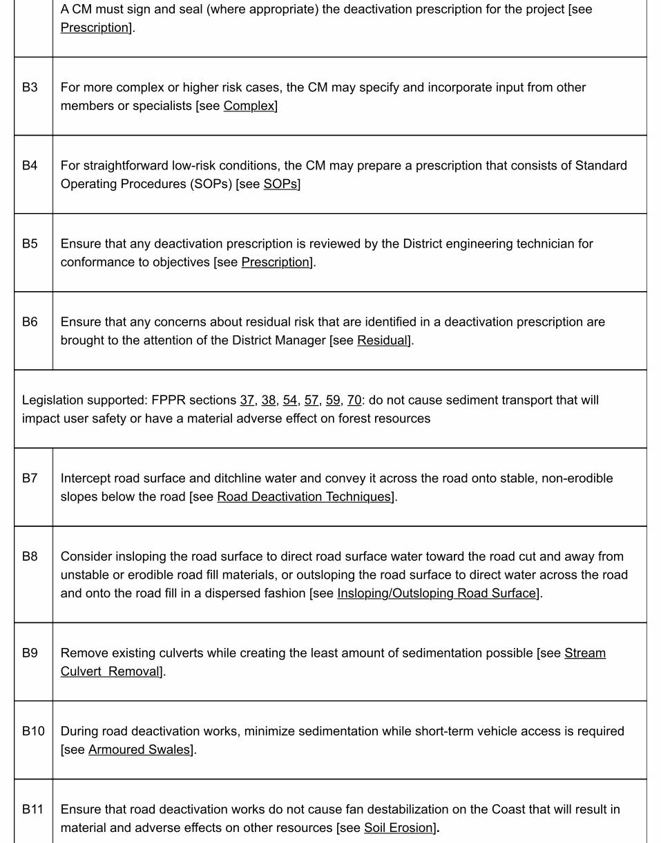
A CM must sign and seal (where appropriate) the deactivation prescription for the project [seePrescription].
B3 For more complex or higher risk cases, the CM may specify and incorporate input from othermembers or specialists [see Complex]
B4 For straightforward low-risk conditions, the CM may prepare a prescription that consists of StandardOperating Procedures (SOPs) [see SOPs]
B5 Ensure that any deactivation prescription is reviewed by the District engineering technician forconformance to objectives [see Prescription].
B6 Ensure that any concerns about residual risk that are identified in a deactivation prescription arebrought to the attention of the District Manager [see Residual].
Legislation supported: FPPR sections 37, 38, 54, 57, 59, 70: do not cause sediment transport that willimpact user safety or have a material adverse effect on forest resources
B7 Intercept road surface and ditchline water and convey it across the road onto stable, non-erodibleslopes below the road [see Road Deactivation Techniques].
B8 Consider insloping the road surface to direct road surface water toward the road cut and away fromunstable or erodible road fill materials, or outsloping the road surface to direct water across the roadand onto the road fill in a dispersed fashion [see Insloping/Outsloping Road Surface].
B9 Remove existing culverts while creating the least amount of sedimentation possible [see StreamCulvert Removal].
B10 During road deactivation works, minimize sedimentation while short-term vehicle access is required[see Armoured Swales].
B11 Ensure that road deactivation works do not cause fan destabilization on the Coast that will result inmaterial and adverse effects on other resources [see Soil Erosion].
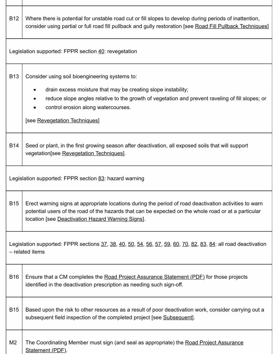
B12 Where there is potential for unstable road cut or fill slopes to develop during periods of inattention,consider using partial or full road fill pullback and gully restoration [see Road Fill Pullback Techniques]
Legislation supported: FPPR section 40: revegetation
B13 Consider using soil bioengineering systems to:
drain excess moisture that may be creating slope instability;reduce slope angles relative to the growth of vegetation and prevent raveling of fill slopes; orcontrol erosion along watercourses.
[see Revegetation Techniques]
B14 Seed or plant, in the first growing season after deactivation, all exposed soils that will supportvegetation[see Revegetation Techniques].
Legislation supported: FPPR section 83: hazard warning
B15 Erect warning signs at appropriate locations during the period of road deactivation activities to warnpotential users of the road of the hazards that can be expected on the whole road or at a particularlocation [see Deactivation Hazard Warning Signs].
Legislation supported: FPPR sections 37, 38, 40, 50, 54, 56, 57, 59, 60, 70, 82, 83, 84: all road deactivation– related items
B16 Ensure that a CM completes the Road Project Assurance Statement (PDF) for those projectsidentified in the deactivation prescription as needing such sign-off.
B15 Based upon the risk to other resources as a result of poor deactivation work, consider carrying out asubsequent field inspection of the completed project [see Subsequent].
M2 The Coordinating Member must sign (and seal as appropriate) the Road Project AssuranceStatement (PDF).

M3 The road must be barricaded after deactivation unless specifically exempted by the District Manager[see Barricade].
B16 Ensure that the necessary steps in the road deactivation processes were undertaken and issuesaddressed [see Project Tracking Checklist].
In the above table of chronological events:
M = Mandatory proceduresB = Best practices
7.2 Road Deactivation Professional Responsibilities &ConsiderationsA decision to deactivate a road may be an outcome from:
resource planning;a road plan; or an evaluation of risk.
A member may be involved in determining the need for deactivation, by analyzing items such as
risk;cost-benefit considerations; and silvicultural objectives.
As with other road elements, a CM takes professional responsibility for the development ofprescriptions and the field implementation of the prescriptions. As such, the CM must providedirection as to what deactivation measures are required, considering:
the level of hazard;the risk to downslope values; and the complexity of terrain and road conditions.
There may be a need for the CM to specify and incorporate input from other Members orSpecialists for more complex or higher risk cases. Examples of such deactivation works include:
removal of structures such as bridges, cribs or retaining structures; removal of drainage structures under large fills; removal of drainage structures where the work could have an impact on other resourcessuch as fish habitat or water quality for a community water supply; stabilizing fills on steep slopes; and road sections on or above steep slopes where drainage management is important forstability of slopes below the road.
Where, in the opinion of the CM, road deactivation is to be carried out in straightforward low-riskconditions, the CM may prepare a prescription that consists of Standard Operating Procedures(SOPs) that match practices to be followed with existing road conditions. Generally, for these
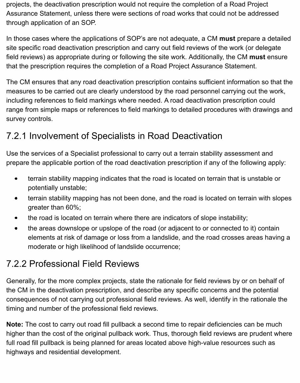
projects, the deactivation prescription would not require the completion of a Road ProjectAssurance Statement, unless there were sections of road works that could not be addressedthrough application of an SOP.
In those cases where the applications of SOP’s are not adequate, a CM must prepare a detailedsite specific road deactivation prescription and carry out field reviews of the work (or delegatefield reviews) as appropriate during or following the site work. Additionally, the CM must ensurethat the prescription requires the completion of a Road Project Assurance Statement.
The CM ensures that any road deactivation prescription contains sufficient information so that themeasures to be carried out are clearly understood by the road personnel carrying out the work,including references to field markings where needed. A road deactivation prescription couldrange from simple maps or references to field markings to detailed procedures with drawings andsurvey controls.
7.2.1 Involvement of Specialists in Road Deactivation
Use the services of a Specialist professional to carry out a terrain stability assessment andprepare the applicable portion of the road deactivation prescription if any of the following apply:
terrain stability mapping indicates that the road is located on terrain that is unstable orpotentially unstable;terrain stability mapping has not been done, and the road is located on terrain with slopesgreater than 60%;the road is located on terrain where there are indicators of slope instability;the areas downslope or upslope of the road (or adjacent to or connected to it) containelements at risk of damage or loss from a landslide, and the road crosses areas having amoderate or high likelihood of landslide occurrence;
7.2.2 Professional Field Reviews
Generally, for the more complex projects, state the rationale for field reviews by or on behalf ofthe CM in the deactivation prescription, and describe any specific concerns and the potentialconsequences of not carrying out professional field reviews. As well, identify in the rationale thetiming and number of the professional field reviews.
Note: The cost to carry out road fill pullback a second time to repair deficiencies can be muchhigher than the cost of the original pullback work. Thus, thorough field reviews are prudent wherefull road fill pullback is being planned for areas located above high-value resources such ashighways and residential development.

Unanticipated subsurface conditions may be encountered during deactivation works. In such anevent, and if potential material adverse impacts to adjacent resources are identified, ensure thatthe CM conducts a field review before the project continues.
7.2.3 Project Assurance
Based upon the risk to other resources as a result of poor deactivation work, consider carryingout a subsequent field inspection of any completed project.
For those projects identified in the deactivation prescription as needing sign-off of the RoadProject Assurance Statement (PDF), the CM must sign off the assurance statement, and mustensure that the statement includes or is accompanied by drawings that document the completedworks after completion of the works,.
7.3 Planning Road DeactivationConsider carrying out road deactivation projects on non-industrial use FSRs where a planningprocess identifies the roads as being candidates for road deactivation, or where the roads needto be closed to protect public safety and the cost of deactivating these roads is less than the costof carrying out maintenance to a wilderness road level of maintenance over the period ofexpected closure. Deactivation of FSRs is usually limited to in-block roads and cutblock accessroads, or to roads that provide duplicate access to areas. Ensure that for FSRs that are theresponsibility of Timber Operations and Pricing Division, deactivation is carried out in accordancewith the ministry’s business area funding policy.
Notify road users about proposed significant changes to road access and to solicit the public’sand First Nations’ input into road closure and related access issues. Ensure that the DistrictManager solicits and considers input from local stakeholders (e.g., licensees, public, FirstNations, miners) before making a decision on whether to deactivate an FSR.
Deactivation is typically carried out with the expectation that a road will receive no further fieldinspections or maintenance, and due to the inherent risk to vehicle users and to any deactivationstructures along the road, deactivation is expected to result in the elimination of motor vehicleaccess. This will be particularly applicable along road segments where unstable road fill is pulledback and where stream culverts and bridges are removed or deep cross-ditches are installedacross the road running width. However, for roads that cross flat or gentle terrain with no streamcrossings, little work may be necessary to deactivate the roads. In this case, motor vehicleaccess may be both possible and acceptable, provided that the District Manager approves thevariance from legislative requirements to barricade the road.
A deactivated FSR that has fulfilled all legal requirements reverts to the status of vacant Crownland or provincial forest. In other words, after the FSR is deactivated, it has no road status andthe responsibility for stability of the area shifts to the Crown, instead of FLNR as therepresentative of the Crown. Retaining the old road location (with expired tenure) on atlas mapsdoes no harm, as the former route may be useful in some emergency.
For FSRs that are the responsibility of Timber Operations and Pricing Division, deactivation mustbe carried out in accordance with the ministry’s {{{{{Policy for Operating Funds Road &Structure Maintenance and Road Closure}}}}}.

Did you find what you were looking for?
Yes No
7.4 Deactivation Prescriptions
7.4.1 Prescription Requirements
A CM must prepare and sign and seal the deactivation prescription for the project, and providethe results of any assessments in the letter or report that accompanies the deactivationprescriptions. Ensure that the deactivation prescription is reviewed by the District engineeringtechnician for conformance to objectives.
A deactivation prescription is a written document that clearly communicates the objectives andthe works to be performed, in accordance with the regulatory requirements in the Forest Planningand Practices Regulation (Sec. 82). Ensure that any deactivation prescription:
defines the objectives of the planned deactivation work, the vehicle access requirements(if an exemption under legislation has been granted to permit access by motor vehicles),and the techniques to be performed by station; andreports special requirements (e.g., worker safety and slope stability issues).
When a prescription is being prepared, ensure that the following are retained:
original field notes;final deactivation maps, tabular summary, and letter or report, as applicable; andany relevant correspondence.
Site specific information, detail and complexity of a deactivation prescription varies with siteconditions and the work required to achieve the deactivation goals. Such prescriptions may be assimple as providing directions to an operator with a basic map or may be as complex as having adetailed prescription of individual steps and site specific work requirements.
Use simple deactivation prescriptions where there are no perceived hazards from thedeactivation to worker safety and public infrastructure, or where the prescribed work is notexpected to create adverse environmental impacts. In these situations, provide StandardOperating Procedues (SOPs) in the form of basic directions to an operator with a signed andsealed map of the prescribed work area.
As the complexity of the site increases where there are fish streams, terrain stability hazardsalong or adjacent to the road system, or potential consequence to public infrastructure, provide agreater detailed and prescriptive signed and sealed report with definitions/sketches, as well asmaps/drawings referenced to stations in the field to assist an operator in completing the work. Insuch situations, the CM must carry out or delegate field reviews as the work progresses toconfirm site conditions and to provide quality assurance of the work.
A detailed road deactivation prescription may include:
a station by station description of conditions and mitigation measures prescribed; a map showing the locations of the measures prescribed; identification of site conditions that may be a concern for worker safety; identification of special concerns that affect the timing or conduct of the work; and recommendations for equipment or special work procedures necessary to complete thework.
Carry out all required referrals to other government agencies at appropriate stages duringdevelopment of prescriptions, and incorporate, where feasible, the requirements of thoseagencies. As well, obtain approvals for any works in and about a stream, as are required from theMinistry of Environment [Water Regulation (Part 7), under the Water Act (Sec. 9)] andDepartment of Fisheries and Oceans Canada (migratory fish). For information related todeactivation of crossings of fish streams, refer to the Fish-stream Crossing Guidebook (PDF,4.3MB).
7.4.2 Phases of Prescription Development
Base road deactivation prescriptions on suitable office review of available relevant informationand on field assessment. Prescriptions include a deactivation map, as well as otherdocumentation necessary to ensure that the works are successfully conducted and the objectivesof deactivation are achieved. These phases are discussed briefly below.
Expand All | Collapse All
Office review
Prior to field work, conduct an office-based review of existing information including localknowledge to help identify the potential resources at risk, terrain stability/landslide concerns(especially below the road corridor), sediment hazards, and consequences at and adjacentto the road.
Field assessment
Carry out a field assessment and prescribe deactivation techniques at specific locations.This task typically involves:
traversing the road corridor and identifying potential stability and drainage hazards;evaluating the risk to resources; andmarking prescription activities in the field.
When developing prescriptions, consider both the landslide hazard associated with the roadand the risk to downslope and downstream resources.
Before choosing a deactivation technique (or combination of techniques), evaluate thefollowing items:
if any access by motor vehicles is permitted, the type of vehicle access followingdeactivation;the stability of the road cuts and fills, the condition of culverts and bridges, theperformance of the existing road drainage system, existing sediment sources, andthe potential for further deterioration of road structures and prism;the stability of the terrain below (and, in some cases, above) the road corridor; andany existing access problems that may prevent or impede equipment access to theend of the road to start the deactivation work (e.g., locations where large landslideshave destroyed the road grade in gully areas, large cut slope landslides, existingdeactivation work, etc.).
Collect and record other useful site data that provides rationale for the prescriptions,including, for example:
surficial materials and geomorphologic processes;angles of natural and constructed slopes;length of fill slopes;height of cut slopes;road gradient;existing structures;streams, seepages, and road drainage controls.
Consider using a standard field data form to enhance the consistency and quality of datagathering.
Example Data Form for Deactivation Field Assessments (PDF)
Preparing maps, tabular summary, letter or report
Provide a deactivation map (or work plan) to scale to accompany a deactivation prescription,plus one or more of the following:
a summary (in table form) of prescribed techniques, by station; anda letter or report.
These requirements are more fully discussed below. Also, the following examples show thelinkage between various site and project conditions and the minimum content of a roaddeactivation prescription:
Examples: prescription content requirements (PDF)
Content of Deactivation Map (Work Plan)
Provide a map at 1:5000 scale or other suitable scale. Consider the following for illustrationon the map, as deemed appropriate to effectively communicate the design requirements toequipment operators and supervisory personnel:
proposed vehicle usage after deactivation (4-wheel drive (with no barricades), all-terrain vehicle, no access);topographic information;additional relevant planimetric information (e.g., streams, bodies of water, legalboundaries, landslides, utilities, highways);additional supporting information such as stream classifications, and timing windowsand measures for work in and around stream crossings (where applicable);special site access requirements;sites of potential concern for worker safety;requirements for terrain stability field reviews by a Specialist;special requirements for work carried out within a community watershed;location of all prescribed deactivation techniques by station (road chainage andprescription symbol), including the type and locations of hazards (e.g., record roadsegments that may be unstable before, during, or after road deactivation work);legend for prescription symbols;date of the assessment;name of the assessor; andscale bar and north arrow.
Note: Provide some of the items above in a tabular summary rather than on the 1:5000scale map if this would more clearly depict the work.
Content of Tabular Summary
Use a tabular summary where:more detail is given to communicate the requirements of the project to forestryoperations personnel;
the risk of damage to adjacent resources is moderate or high; orit may be necessary to re-establish the field markings.
In the tabular summary, provide:the measured chainage along the road;the associated recommended actions; anddetailed comments about such items as:
site conditions;worker safety issues;key reference points;rationale for road fill pullback; anddepth and width of cross-ditches.
Use the tabular summary as a tool to assess the results of the risk analysis, and to helpestimate the costs of road deactivation works.
Content of Letter or Report
Provide a report to accompany and complement deactivation maps and tabular summariesif:
there is a high risk to the environment;the project is large or complex; orthe road traverses areas of moderate to high likelihood of occurrence of landslides.
In the report, provide an estimate of the expected level of residual risk at the project site ifthe works are carried out in overall conformance with the prescriptions. Residual risk is theamount of risk remaining following the implementation of all hazard or risk control measuresspecified in the prescriptions, because it cannot practicably be further reduced. Ensure thatany concerns about residual risk are brought to the attention of the District Manager, whodetermines if and how the district may manage the residual risk after the road is deactivated.
Generally, for small projects, use a brief letter rather than a report. Provide in a letter orreport the following topics, as relevant:
geographical location information (watershed name and number, harvesting tenure);background information;description of deactivation objectives;prescription methodology;road reactivation considerations (such as road reconstruction, wet crossings, andsafety issues);site level information;

results and recommendations; andsite plans and illustrations.
7.4.3 Modification of Prescriptions
To address unforeseen site conditions, it may be necessary to modify the prescription. If there arereasonable grounds to believe that the changes to the prescription would not adversely impactforest resources or other values, the required changes can be made without further approval. Atthe start of the project, it is often useful to establish a protocol for the types of changes that canbe made on site. Where such changes are made, the CM must approve all changes to theprescription.
7.5 Road Deactivation Works
7.5.1 Project Management
Ensure that the person carrying out deactivation project management has the appropriate training andexperience to coordinate and manage projects, including carrying out the following activities:
making all required referrals to government agencies, obtaining all required approvals and permits, andproviding all required written notification at appropriate stages of the project;if applicable, retaining and coordinating the activities of the appropriate team of technical andprofessional consultants as required for the project;if applicable, preparing suitable contract documents for technical and professional services related toactivities such as prescription development, field reviews, and post-works inspections; and preparingsuitable contracts for works and supervision of the works;if applicable, coordinating purchase and delivery of required materials for the project;administering and retaining copies of all required documentation;coordinating and appropriately scheduling the timing of works; andundertaking other administrative and technical project duties as necessary.
7.5.2 Cost Estimate of the Planned Works
Include in the prescriptions for road deactivation a cost estimate for the works, with the appropriate extensionsof unit costs or phase lump sum costs.
7.5.3 Carrying Out the Works
All road deactivation works must be carried out in accordance with the requirements of a road deactivationprescription that has been accepted by the appropriate manager.
Ensure that suitable on-site inspection is provided as required during the deactivation works, and uponcompletion of the works.
7.5.4 Submission Requirements After Completing the Works
Upon completion of the works, place a hard copy of all as-built prescriptions on file, including the Road ProjectAssurance Statement, deactivation maps, tabular summaries of prescriptions, letters, and reports. In addition,incorporate as-built information into the applicable data base.

Note: If there are not any substantive changes to the prescriptions, mark the original prescriptions, maps,reports, etc., as the “as-built” information.
Ensure that the person who signs the Road Project Assurance Statement provides a letter to confirm or clarifywhere required:
the level of residual hazard or residual risk following completion of the deactivation work if it is differentfrom estimates provided in the prescriptions;the limitations of the works; orother site-specific explanatory information not covered in the Statement of Works Conformance form.
7.5.5 Inspections After Deactivation
The district can accept the recommendations of the TSM as to the adequacy and suitability of the works. Nofurther inspections are necessary. Proceed with close and discontinue after this point in time.

7.6 Deactivation Hazard Warning SignsBefore deactivation activities begin, erect warning signs at appropriate locations during the period of roaddeactivation activities to warn potential users of the road (either open or closed to traffic) of the hazards thatcan be expected on the whole road or at a particular location. Where an entire drainage or system of roads isbeing deactivated, post the signs at the earliest location to warn of the upcoming hazards. Repair or replacedamaged or missing signs as required during the period of the works. There is no legal requirement to leavesigns in place upon completion of deactivation works. Normally the deactivation works (barricading, waterbarring etc) can serve as sufficient warning to potential users that a road has been deactivated.
7.7 Road Deactivation ObjectivesFor elements at risk – including forest resources and social and economic values – within and adjacent to theroad location, ensure that deactivation minimizes the risk from hazards such as landslides, gully processes, fandestabilization, uncontrolled soil erosion, and sediment transport. Ensure that prescriptions and works for roaddeactivation consider a range of techniques (see Road Deactivation Techniques) to meet the followingobjectives:
place the road in a self-maintaining state that will protect indefinitely the elements at risk;stabilize the road prism and clearing width;maintain natural surface drainage patterns on the area within the road right-of- way and in adjacent orconnected areas affected by the works both during and after deactivation activities;minimize the impact of silt and sediment transport on other forest resources;prevent adversely impacting water quality in community watersheds or in streams diverted for humanconsumption by a licensed waterworks (also, ensure that at least 48 hours notice of impendingdeactivation work is provided to water licensees or water purveyors in community watersheds)for a fish stream, provide for safe fish passage and protection of fish habitat immediately upstream anddownstream, both in the timing and extent of the works;
7.7.1 Achieving Deactivation Objectives
The choice of water management, road fill pullback, and revegetation techniques to stabilize the road prism orclearing width depends on the terrain, slope gradient, soils, and climatic conditions of the area. Applydeactivation measures most aggressively where roads traverse areas of steep terrain or erodible soils,especially in geographical areas that receive high levels of precipitation.
Expand All | Collapse All
Water management
Maintain surface drainage patterns so that they are consistent with natural drainage patterns. Achieve thisby applying some or all of the following techniques:
Remove cross-drain culverts and replace them with cross-ditches to re- establish drainagepatterns, especially on steep road grades and side hills. If the likelihood of failure is minimal or theconsequences of a failure are low, consider leaving the cross-drain culvert intact, provided it isbacked up with a cross-ditch or armoured swale as necessary.Install cross-ditches or waterbars where there are steep grades, heavy groundwater seepages,switchbacks or road junctions, ditches prone to plugging, places where ponding may occur, andother potential drainage problem areas.Remove or breach windrows on the road surface.

Outslope or inslope the road surface as appropriate.Install trench drains, blanket drains, French drains, fords, and armoured swales.
Soil erosion and sediment control and road prism stabilization
Activities to minimize the impact of silt and sediment transport on forest resources include erosion controlmeasures (such as grass seeding, vegetation planting, soil bioengineering, and installation of erosioncontrol blankets) and sediment control measures (such as silt fence, catch basins, and check dams).See Chapter 5: Road Construction for examples of surface soil erosion and sediment control techniques,as well as for works shutdown indicators and procedures.
For roads that have been built on fans, ensure that care is taken to minimize erosion and sedimenttransport during the deactivation works; in particular, avoid any non-essential excavation of the streamchannel or banks.
Where the road prism is unstable, consider using partial or full road fill pullback and cut slope buttressingor other measure to suitably address the landslide hazard and risk of damage or loss to values. As well,take measures to remove organic material (stumps, roots, embedded logs, and topsoil) that mayreasonably be expected to fail and destabilize the road fill.
Take care in verifying indicators of slope instability. For example, tension cracks or minor slumps in theroad surface may indicate a failing road fill, rather than signaling unstable terrain. Consider using a partialpullback of the road fill to stabilize the road prism and protect users of the road and adjacent resources.However, if the slope instability indicators occur outside the road prism (e.g., a small slide) or theinstability within the road prism has the potential to affect adjacent resources (e.g., debris from a potentialfill slope failure could reach a fish stream), consider the area to be unstable.
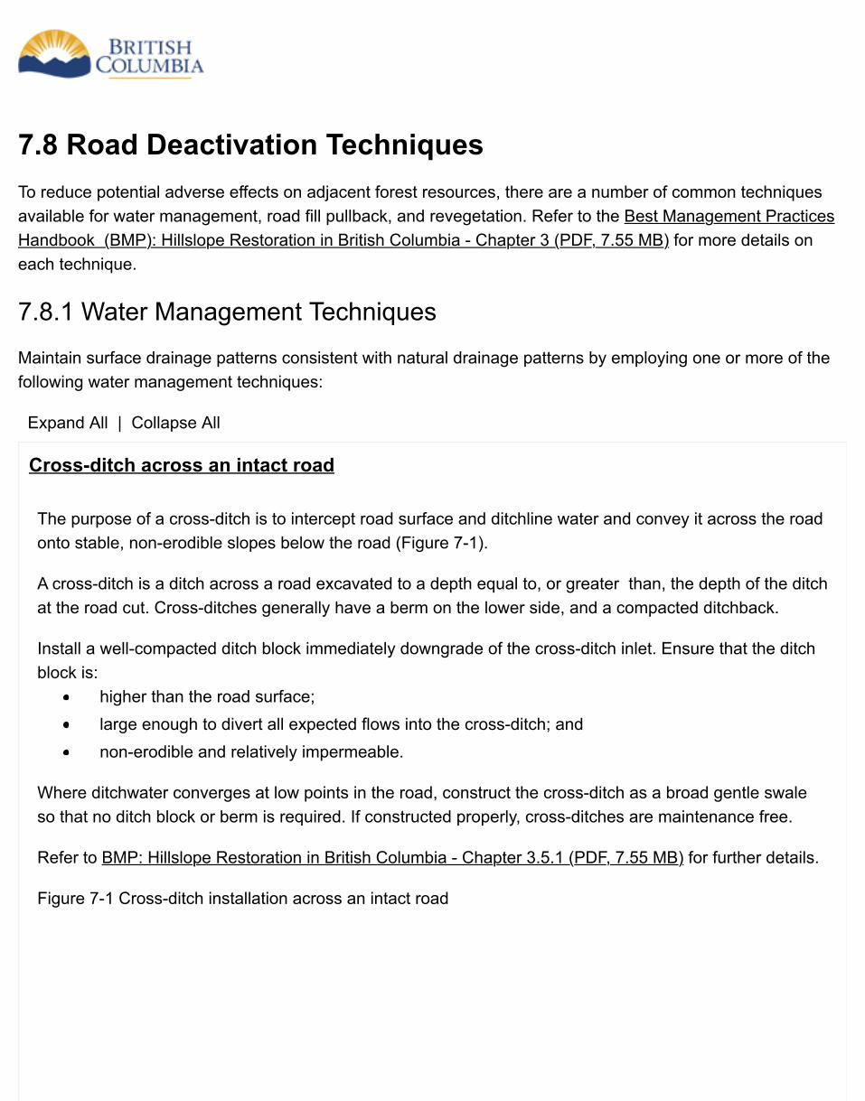
7.8 Road Deactivation TechniquesTo reduce potential adverse effects on adjacent forest resources, there are a number of common techniquesavailable for water management, road fill pullback, and revegetation. Refer to the Best Management PracticesHandbook (BMP): Hillslope Restoration in British Columbia - Chapter 3 (PDF, 7.55 MB) for more details oneach technique.
7.8.1 Water Management Techniques
Maintain surface drainage patterns consistent with natural drainage patterns by employing one or more of thefollowing water management techniques:
Expand All | Collapse All
Cross-ditch across an intact road
The purpose of a cross-ditch is to intercept road surface and ditchline water and convey it across the roadonto stable, non-erodible slopes below the road (Figure 7-1).
A cross-ditch is a ditch across a road excavated to a depth equal to, or greater than, the depth of the ditchat the road cut. Cross-ditches generally have a berm on the lower side, and a compacted ditchback.
Install a well-compacted ditch block immediately downgrade of the cross-ditch inlet. Ensure that the ditchblock is:
higher than the road surface;large enough to divert all expected flows into the cross-ditch; andnon-erodible and relatively impermeable.
Where ditchwater converges at low points in the road, construct the cross-ditch as a broad gentle swaleso that no ditch block or berm is required. If constructed properly, cross-ditches are maintenance free.
Refer to BMP: Hillslope Restoration in British Columbia - Chapter 3.5.1 (PDF, 7.55 MB) for further details.
Figure 7-1 Cross-ditch installation across an intact road
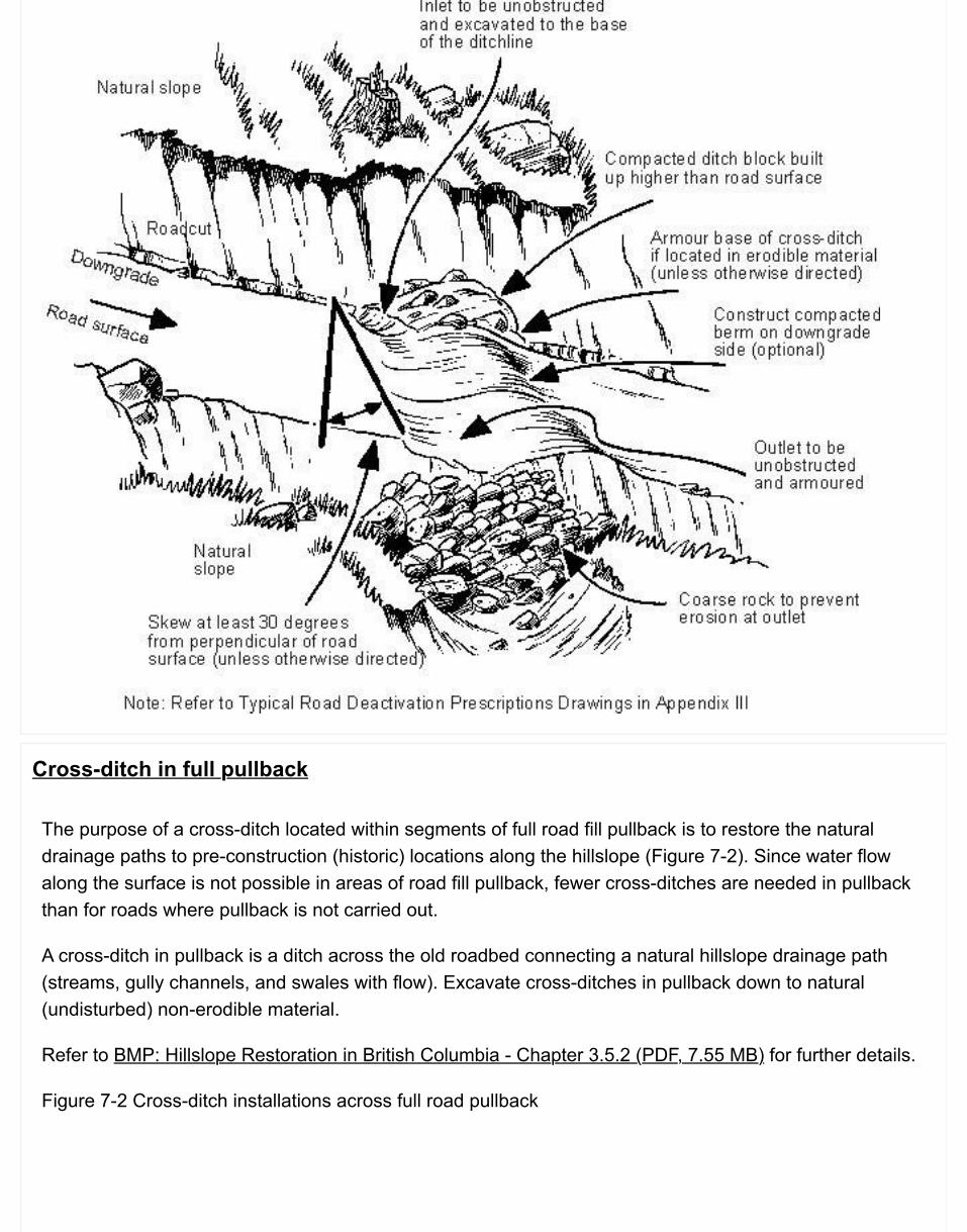
Cross-ditch in full pullback
The purpose of a cross-ditch located within segments of full road fill pullback is to restore the naturaldrainage paths to pre-construction (historic) locations along the hillslope (Figure 7-2). Since water flowalong the surface is not possible in areas of road fill pullback, fewer cross-ditches are needed in pullbackthan for roads where pullback is not carried out.
A cross-ditch in pullback is a ditch across the old roadbed connecting a natural hillslope drainage path(streams, gully channels, and swales with flow). Excavate cross-ditches in pullback down to natural(undisturbed) non-erodible material.
Refer to BMP: Hillslope Restoration in British Columbia - Chapter 3.5.2 (PDF, 7.55 MB) for further details.
Figure 7-2 Cross-ditch installations across full road pullback
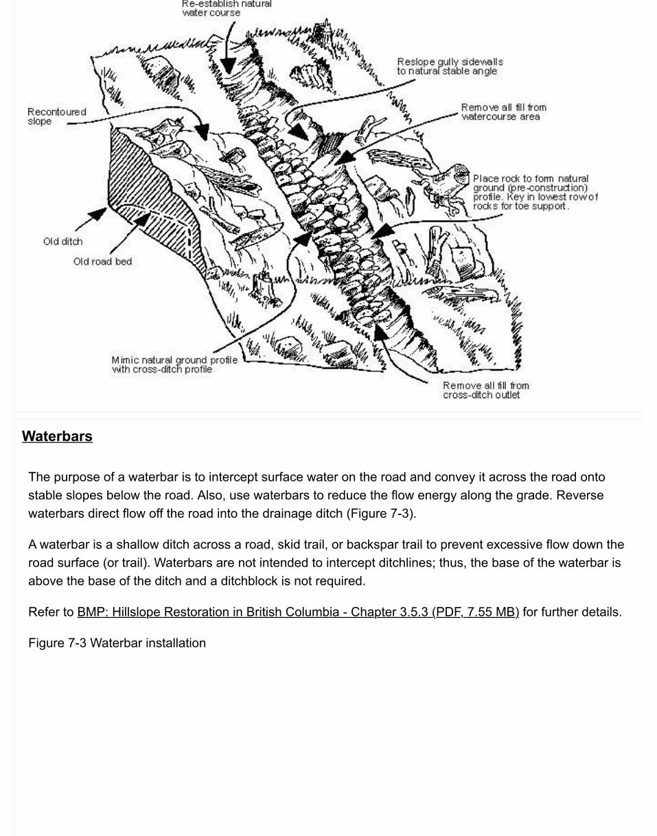
Waterbars
The purpose of a waterbar is to intercept surface water on the road and convey it across the road ontostable slopes below the road. Also, use waterbars to reduce the flow energy along the grade. Reversewaterbars direct flow off the road into the drainage ditch (Figure 7-3).
A waterbar is a shallow ditch across a road, skid trail, or backspar trail to prevent excessive flow down theroad surface (or trail). Waterbars are not intended to intercept ditchlines; thus, the base of the waterbar isabove the base of the ditch and a ditchblock is not required.
Refer to BMP: Hillslope Restoration in British Columbia - Chapter 3.5.3 (PDF, 7.55 MB) for further details.
Figure 7-3 Waterbar installation
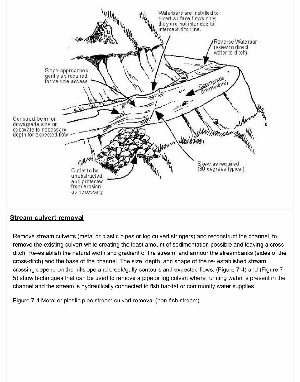
Stream culvert removal
Remove stream culverts (metal or plastic pipes or log culvert stringers) and reconstruct the channel, toremove the existing culvert while creating the least amount of sedimentation possible and leaving a cross-ditch. Re-establish the natural width and gradient of the stream, and armour the streambanks (sides of thecross-ditch) and the base of the channel. The size, depth, and shape of the re- established streamcrossing depend on the hillslope and creek/gully contours and expected flows. (Figure 7-4) and (Figure 7-5) show techniques that can be used to remove a pipe or log culvert where running water is present in thechannel and the stream is hydraulically connected to fish habitat or community water supplies.
Figure 7-4 Metal or plastic pipe stream culvert removal (non-fish stream)
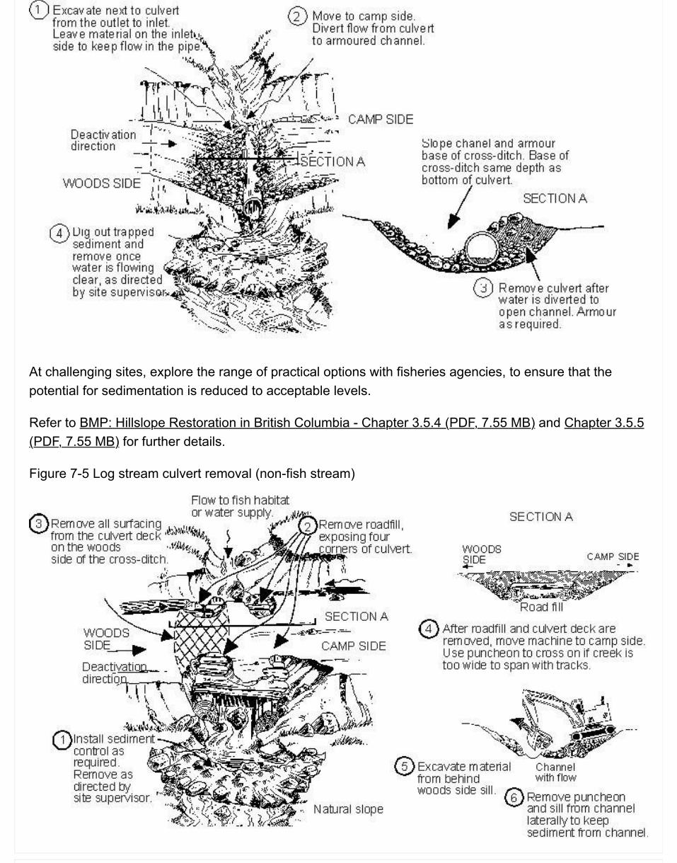
At challenging sites, explore the range of practical options with fisheries agencies, to ensure that thepotential for sedimentation is reduced to acceptable levels.
Refer to BMP: Hillslope Restoration in British Columbia - Chapter 3.5.4 (PDF, 7.55 MB) and Chapter 3.5.5(PDF, 7.55 MB) for further details.
Figure 7-5 Log stream culvert removal (non-fish stream)
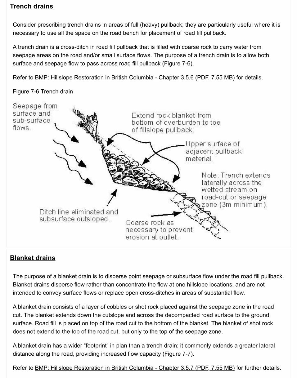
Trench drains
Consider prescribing trench drains in areas of full (heavy) pullback; they are particularly useful where it isnecessary to use all the space on the road bench for placement of road fill pullback.
A trench drain is a cross-ditch in road fill pullback that is filled with coarse rock to carry water fromseepage areas on the road and/or small surface flows. The purpose of a trench drain is to allow bothsurface and seepage flow to pass across road fill pullback (Figure 7-6).
Refer to BMP: Hillslope Restoration in British Columbia - Chapter 3.5.6 (PDF, 7.55 MB) for details.
Figure 7-6 Trench drain
Blanket drains
The purpose of a blanket drain is to disperse point seepage or subsurface flow under the road fill pullback.Blanket drains disperse flow rather than concentrate the flow at one hillslope locations, and are notintended to convey surface flows or replace open cross-ditches in areas of substantial flow.
A blanket drain consists of a layer of cobbles or shot rock placed against the seepage zone in the roadcut. The blanket extends down the cutslope and across the decompacted road surface to the groundsurface. Road fill is placed on top of the road cut to the bottom of the blanket. The blanket of shot rockdoes not extend to the top of the road cut, but only to the top of the seepage zone.
A blanket drain has a wider “footprint” in plan than a trench drain: it commonly extends a greater lateraldistance along the road, providing increased flow capacity (Figure 7-7).
Refer to BMP: Hillslope Restoration in British Columbia - Chapter 3.5.7 (PDF, 7.55 MB) for further details.
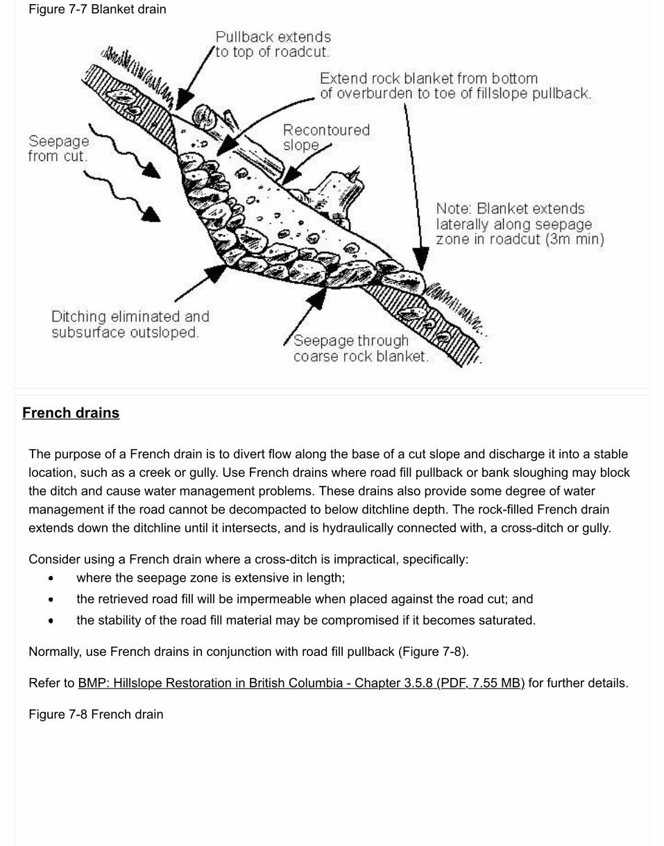
Figure 7-7 Blanket drain
French drains
The purpose of a French drain is to divert flow along the base of a cut slope and discharge it into a stablelocation, such as a creek or gully. Use French drains where road fill pullback or bank sloughing may blockthe ditch and cause water management problems. These drains also provide some degree of watermanagement if the road cannot be decompacted to below ditchline depth. The rock-filled French drainextends down the ditchline until it intersects, and is hydraulically connected with, a cross-ditch or gully.
Consider using a French drain where a cross-ditch is impractical, specifically:where the seepage zone is extensive in length;the retrieved road fill will be impermeable when placed against the road cut; andthe stability of the road fill material may be compromised if it becomes saturated.
Normally, use French drains in conjunction with road fill pullback (Figure 7-8).
Refer to BMP: Hillslope Restoration in British Columbia - Chapter 3.5.8 (PDF, 7.55 MB) for further details.
Figure 7-8 French drain

Fords and armoured swales
Fords and armoured swales provide erosion-resistant and storm-proof wet crossings for motor vehicles. Aford is used to cross a stream, whereas an armoured swale is constructed where a cross-ditch wouldnormally be used.
Fords
A ford is a dip in a road, constructed to cross a perennial or ephemeral stream, normally designed andbuilt as a permanent feature (Figure 7-9). Fords are a suitable road deactivation option where vehicleaccess is to be maintained. Fords are restricted to non-fish streams unless otherwise approved by thefisheries agencies. For deactivation, consider protecting the running surface of the ford using rock armourwhere the natural stream bottom will not support the intended vehicle loads.
Refer to BMP: Hillslope Restoration in British Columbia - Chapter 3.5.9 (PDF, 7.55 MB) for further details.
Figure 7-9 Example of a ford installed on a non-fish bearing stream
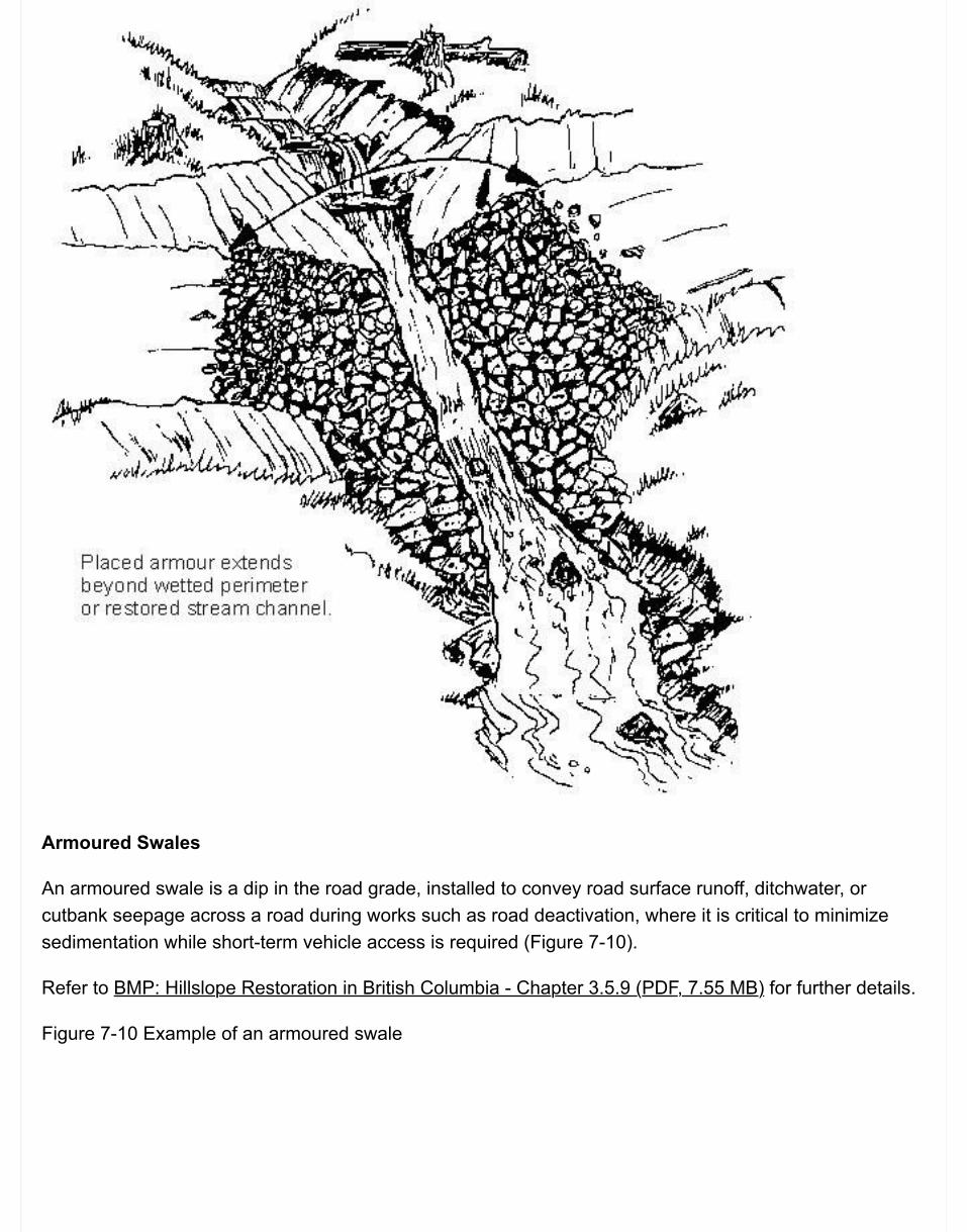
Armoured Swales
An armoured swale is a dip in the road grade, installed to convey road surface runoff, ditchwater, orcutbank seepage across a road during works such as road deactivation, where it is critical to minimizesedimentation while short-term vehicle access is required (Figure 7-10).
Refer to BMP: Hillslope Restoration in British Columbia - Chapter 3.5.9 (PDF, 7.55 MB) for further details.
Figure 7-10 Example of an armoured swale
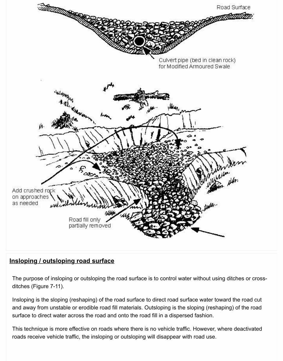
Insloping / outsloping road surface
The purpose of insloping or outsloping the road surface is to control water without using ditches or cross-ditches (Figure 7-11).
Insloping is the sloping (reshaping) of the road surface to direct road surface water toward the road cutand away from unstable or erodible road fill materials. Outsloping is the sloping (reshaping) of the roadsurface to direct water across the road and onto the road fill in a dispersed fashion.
This technique is more effective on roads where there is no vehicle traffic. However, where deactivatedroads receive vehicle traffic, the insloping or outsloping will disappear with road use.
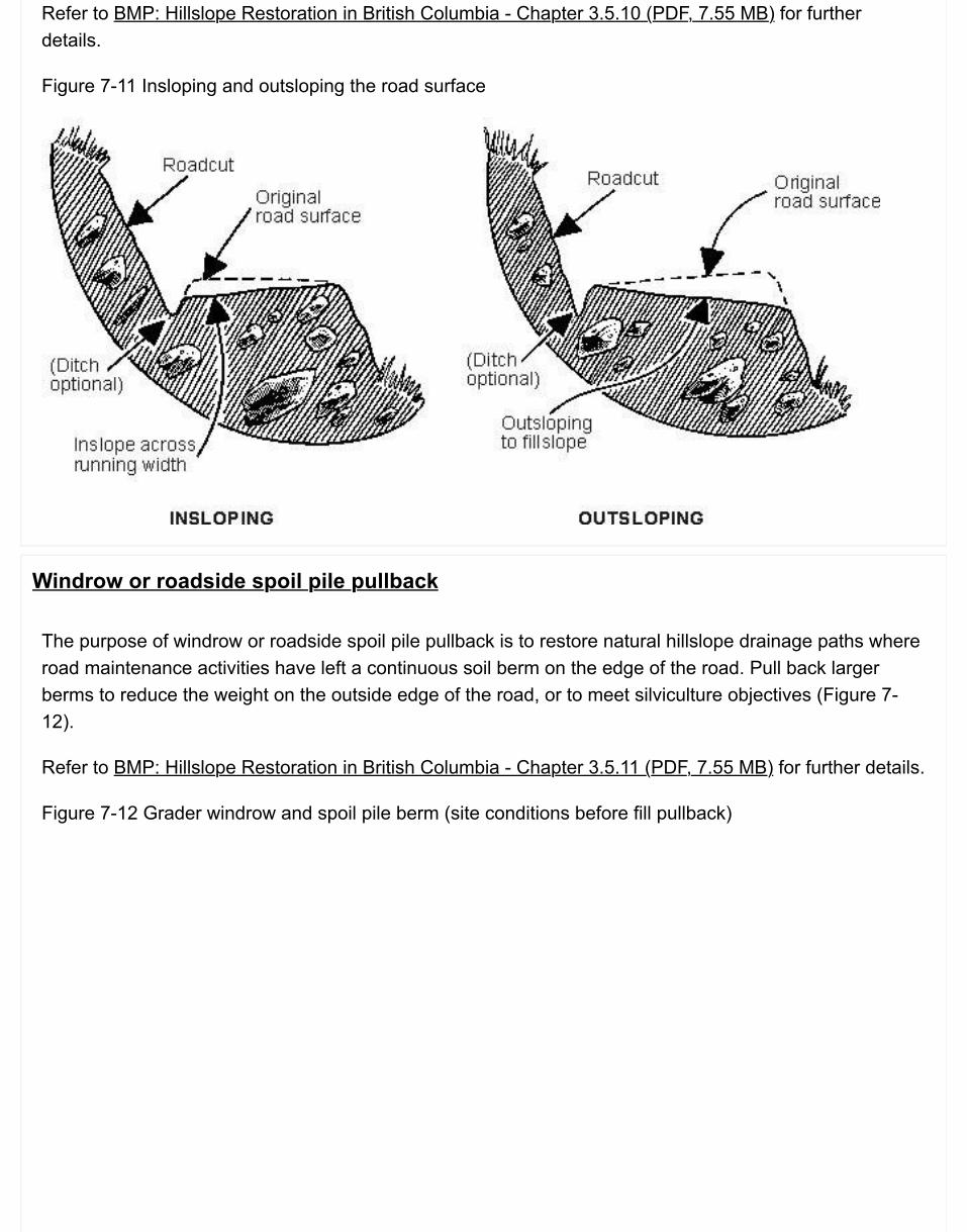
Refer to BMP: Hillslope Restoration in British Columbia - Chapter 3.5.10 (PDF, 7.55 MB) for furtherdetails.
Figure 7-11 Insloping and outsloping the road surface
Windrow or roadside spoil pile pullback
The purpose of windrow or roadside spoil pile pullback is to restore natural hillslope drainage paths whereroad maintenance activities have left a continuous soil berm on the edge of the road. Pull back largerberms to reduce the weight on the outside edge of the road, or to meet silviculture objectives (Figure 7-12).
Refer to BMP: Hillslope Restoration in British Columbia - Chapter 3.5.11 (PDF, 7.55 MB) for further details.
Figure 7-12 Grader windrow and spoil pile berm (site conditions before fill pullback)
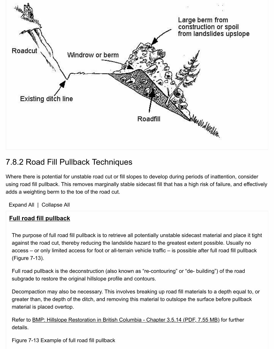
7.8.2 Road Fill Pullback Techniques
Where there is potential for unstable road cut or fill slopes to develop during periods of inattention, considerusing road fill pullback. This removes marginally stable sidecast fill that has a high risk of failure, and effectivelyadds a weighting berm to the toe of the road cut.
Expand All | Collapse All
Full road fill pullback
The purpose of full road fill pullback is to retrieve all potentially unstable sidecast material and place it tightagainst the road cut, thereby reducing the landslide hazard to the greatest extent possible. Usually noaccess – or only limited access for foot or all-terrain vehicle traffic – is possible after full road fill pullback(Figure 7-13).
Full road pullback is the deconstruction (also known as “re-contouring” or “de- building”) of the roadsubgrade to restore the original hillslope profile and contours.
Decompaction may also be necessary. This involves breaking up road fill materials to a depth equal to, orgreater than, the depth of the ditch, and removing this material to outslope the surface before pullbackmaterial is placed overtop.
Refer to BMP: Hillslope Restoration in British Columbia - Chapter 3.5.14 (PDF, 7.55 MB) for furtherdetails.
Figure 7-13 Example of full road fill pullback
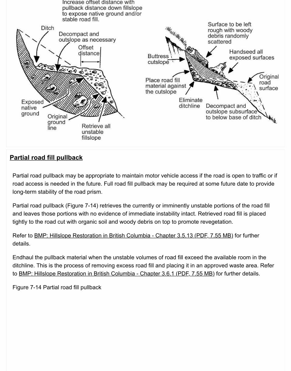
Partial road fill pullback
Partial road pullback may be appropriate to maintain motor vehicle access if the road is open to traffic or ifroad access is needed in the future. Full road fill pullback may be required at some future date to providelong-term stability of the road prism.
Partial road pullback (Figure 7-14) retrieves the currently or imminently unstable portions of the road filland leaves those portions with no evidence of immediate instability intact. Retrieved road fill is placedtightly to the road cut with organic soil and woody debris on top to promote revegetation.
Refer to BMP: Hillslope Restoration in British Columbia - Chapter 3.5.13 (PDF, 7.55 MB) for furtherdetails.
Endhaul the pullback material when the unstable volumes of road fill exceed the available room in theditchline. This is the process of removing excess road fill and placing it in an approved waste area. Referto BMP: Hillslope Restoration in British Columbia - Chapter 3.6.1 (PDF, 7.55 MB) for further details.
Figure 7-14 Partial road fill pullback
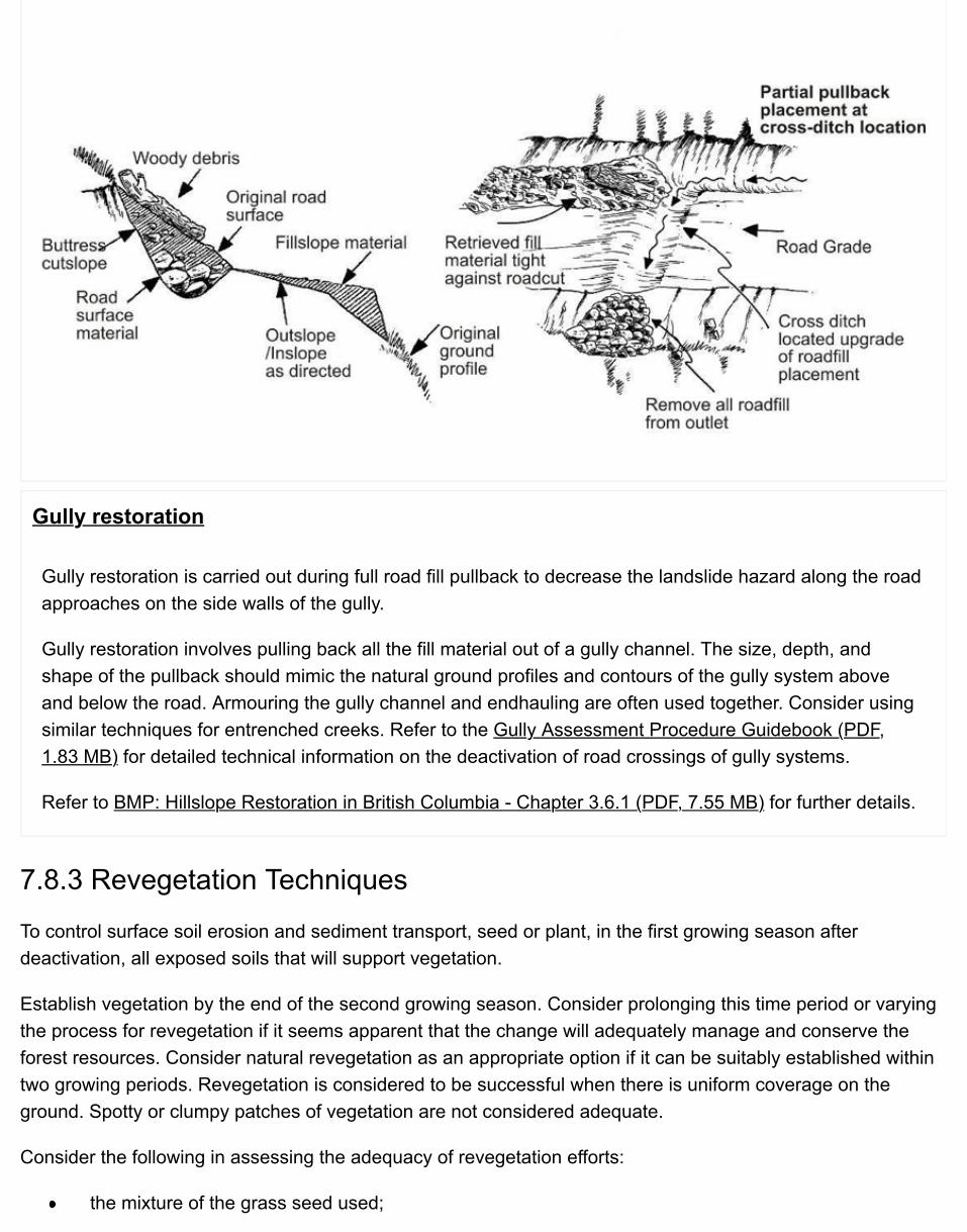
Gully restoration
Gully restoration is carried out during full road fill pullback to decrease the landslide hazard along the roadapproaches on the side walls of the gully.
Gully restoration involves pulling back all the fill material out of a gully channel. The size, depth, andshape of the pullback should mimic the natural ground profiles and contours of the gully system aboveand below the road. Armouring the gully channel and endhauling are often used together. Consider usingsimilar techniques for entrenched creeks. Refer to the Gully Assessment Procedure Guidebook (PDF,1.83 MB) for detailed technical information on the deactivation of road crossings of gully systems.
Refer to BMP: Hillslope Restoration in British Columbia - Chapter 3.6.1 (PDF, 7.55 MB) for further details.
7.8.3 Revegetation Techniques
To control surface soil erosion and sediment transport, seed or plant, in the first growing season afterdeactivation, all exposed soils that will support vegetation.
Establish vegetation by the end of the second growing season. Consider prolonging this time period or varyingthe process for revegetation if it seems apparent that the change will adequately manage and conserve theforest resources. Consider natural revegetation as an appropriate option if it can be suitably established withintwo growing periods. Revegetation is considered to be successful when there is uniform coverage on theground. Spotty or clumpy patches of vegetation are not considered adequate.
Consider the following in assessing the adequacy of revegetation efforts:
the mixture of the grass seed used;
the time and rate at which the seed was applied;the appropriateness of the fertilizer and mulch used; andthe number of attempts made to establish the vegetation.
Refer to BMP: Hillslope Restoration in British Columbia - Chapter 3.8 (PDF, 7.55 MB) for further details.
Expand All | Collapse All
Grass and legume seeding
Seeding is the most common and usually the most cost-effective means of treating deactivated roads toprevent erosion.
For further details, refer to Chapter 5: Soil Erosion & Sediment Control and BMP: Hillslope Restoration inBritish Columbia - Chapter 3.8.1 (PDF, 7.55 MB).
Scarification
To grow trees for soil erosion control purposes in areas that are not part of the net area to be reforested(but where trees can be reasonably expected to grow), it may be necessary to supplement grass seedingby scarifying the road surface, re-using local topsoils, or employing other similar measures.
Note: Scarification is for reforestation purposes, whereas decompaction during fill pullback activities is fordeactivation/water control purposes.
Scarification (also known as “silvicultural fluffing”) is designed to enhance revegetation. It involvesbreaking up the road surface to a minimum depth equal to about twice the length of the teeth on anexcavator bucket (about 400mm, or 16-20 inches).
Refer to BMP: Hillslope Restoration in British Columbia - Chapter 3.5.12 (PDF, 7.55 MB) for furtherdetails.
Woody species establishment
In addition to grass seeding of all deactivated roads where necessary, consider the localized re-use oftopsoil to grow trees for soil erosion control purposes.
Consider planting pioneering species such as alder, willow, and, in some cases, lodgepole pine andDouglas-fir on areas of full road fill pullback or on areas that have been scarified. These species areimportant early colonizers of disturbed sites, and prepare the site for later succession forest species suchas spruce, cedar, and hemlock. Before any planting activities on a permanently deactivated road areundertaken, consult with the professional forester responsible for silviculture activities in the area toensure that such planting is consistent with silviculture prescriptions prepared for the area.

Use topsoil and tree planting to achieve revegetation (outside the net area to be reforested) on apermanently deactivated road simply for controlling soil erosion. There is no requirement to reforest allpermanently deactivated roads, even where such reforesting is feasible. The choice to reforest rests withthe person required to deactivate the road.
Refer to BMP: Hillslope Restoration in British Columbia - Chapter 3.8.2 (PDF, 7.55 MB) for further details.
Soil bioengineering
Consider using soil bioengineering systems if the objective is to:drain excess moisture that may be creating slope instability (e.g., live pole drains, live silt fences,live bank protection, live gully breaks, and live staking);reduce slope angles relative to the growth of vegetation and prevent raveling of fill slopes (e.g.,wattle fences, modified brush layers, brush layers in a cut); orcontrol erosion along watercourses (e.g., live gravel bar staking, and live shade).
Soil bioengineering is a term that describes the use of living plant materials to build drains, slope breaks,low slope support walls and other similar living systems for water management and soil erosion control onsteep slopes. It may also be an effective technique for riparian restoration.
Refer to BMP: Hillslope Restoration in British Columbia - Chapter 6 (PDF, 7.55 MB) for further details.
Control of noxious weeds
During deactivation assessment, consider the presence of knapweed and other noxious weeds that arefound along many old logging roads. Consult with a forester, agrologist, or biologist to minimize thelikelihood of spreading these problem weeds through machine travel or seed disturbance, if schedulingdeactivation work outside the seed maturity time is not possible.
7.9 Resources & Suggestions for Further ReadingBC Ministry of Forests. 1997. Soil rehabilitation guidebook. Victoria, BC.
______________. 1999. Mapping and assessing terrain stability guidebook. Victoria, BC.
______________. 2001. Gully assessment procedure guidebook (PDF, 1.83 MB). Victoria, BC.
______________. 2002. Fish-stream crossing guidebook (PDF, 4.3MB). Victoria, BC.
BC Ministry of Forests and Range. 2004. Effectiveness evaluation of road deactivation techniques on the westcoast of Vancouver Island (PDF, 2.31 MB). Victoria, BC. For. Res. Ext. Note: EN-020.
Grainger, Bill. 2004. Terrain stability field assessments in “Gentle over Steep” terrain of the southern interior ofBritish Columbia (PDF). Grainger and Associates Consulting Ltd. Salmon Arm, BC.
Wise, M.P., G.D. Moore, and D.F. VanDine (editors). 2004. Landslide risk case studies in forest developmentplanning and operations. BC Min. For., Res. Br., Victoria, B.C. Land Manage. Handb. No. 56.
Vanbuskirk, C.D., R.J. Neden, J.W. Schwab, and F.R. Smith. 2005. Road and terrain attributes of road filllandslides in the Kalum Forest District. BC Min. For. and Range, Res. Br., Victoria, BC. Tech. Rep. 024.
Additional website resources:
Engineers & Geoscientists British Columbia: Division ResourcesRegion Research Sections listed for the BC Ministry of Forests, Lands and Natural ResourceOperations

7.10 Appendices
7.10.1 Project Tracking Checklist
Use this checklist to prepare a paper trail of key outputs prepared by consultants and sign-offs by BCTS/TimberPricing and Operations Division.
Project Tracking Checklist (PDF)

Chapter 8: Professional Responsibilities & ConsiderationsThis chapter describes the Ministry's mandatory procedures, best practices and applications of professional responsibility of members of the ABCFP and EGBC with respect to forest service roads. It is intended to provide enough detail on the processes and expected mandatory procedures, while ensuring that the road meets the regulatory requirements related to safety and protection of other resources.
Note that EGBC Members are required under their Association's by-laws to sign and seal all professional documents they prepare, and ABCFP Members may use their seal at their discretion.
Consistent with the joint guidelines prepared by the professional associations:
Guidelines for Professional Services in the Forest Sector - Forest Roads, June, 2012; andGuidelines for Professional Services in the Forest Sector - Crossings, 2014;
road activities will be carried out under the professional direction of a Coordinating Member (CM). Structuresthat form part of a road will be overseen by a Coordinating Registered Professional (CRP) or a Professional ofRecord (POR) depending upon the scope of the project and any necessary division of responsibilities.
Note that professional oversight for a forest road project may include responsibility for one or more of thefollowing activities:
road layout;road survey;road designpreparation of a road plan;design and fabrication of a structure (bridge, major culvert, retaining structure);construction of a road or structure;inspection and maintenance of an existing road; androad deactivation.
As such, this manual will refer to the scope of works as a project, whether the works encompasses severalactivities or not. For example, for an existing road that requires inspections and maintenance, and eventuallydeactivation, the project related to professional responsibilities may be limited to the activity taking place at thattime. As well, where a project may cover several activities, but the responsibilities may be shifted from oneagency to another, or from one professional to another, each project will be necessarily limited to only thoseactivities within the umbrella of each organization or professional.
Note that while the most common situation is where there is only one CM/CRP responsible for several phasesof a project, circumstances such as:

staff changes in the local office;shifts in priorities by management; andthe range of expertise provided by a CM
may dictate the need for one or more additional CM/CRP's for different job phases. However, there must be aclear division of responsibilities and understanding of each CM/CRP as to their scope of work and theirindividual professional responsibilities, as well as assurance that there is continuity in the professional oversightfor the project. Accordingly, for those projects that have been carried out since the implementation of theGuidelines for either forest roads or crossings, the responsibilities of a CM include reviewing any existingAssurance documents and confirming their project coverage and scope.
For some of its new road access, BCTS may elect to lay out, survey and design, and prepare a road plan for aroad, then shift the responsibility for construction to a TSL licensee, subject to the road becoming a forestservice road at some point after construction. As such, a professional working on behalf of the licensee mustundertake CM responsibilities for the road works after the transfer of responsibilities. The scope of that CM'sresponsibilities may include:
road layout;road survey;road design;preparation/amendment of the road plan;road construction; andpreparing the Ministry's Assurance Statement documents.
These responsibilities may be limited only to road construction, but if the licensee elects to relocate andredesign the road, there must be professional coverage on behalf of the licensee for those activities as well. ATSL road permit should include conditions that require the licensee to provide the professional oversight asrequired by the Acts and bylaws of the professional associations, and provide evidence of such in the form ofcompleted Assurance documents and drawings that document the completed works, in accordance with theform and format provided by the Ministry. Once the road becomes a forest service road subsequent toconstruction, the further professional responsibilities must be provided on behalf of the Ministry, suchresponsibilities to include review of those Assurance documents and confirmation of their project coverage andscope.
Generally, the professionals that are impacted by this chapter include the CM/CRP/POR and those Membersthat undertake the preparation of parts of the road or crossing project, as well as their interaction withSpecialists and Road Personnel during the life of the project. The CM/CRP/POR is responsible for consideringthe composition and interaction of all the road components, as well as their relationships and impact on theusers, the road itself and other resources. A key concept is continuity of professional oversight and outputreviews. The CM/CRP/POR is charged with retaining a close familiarity with the progress of the project, andwith coordinating the various Member and Specialist inputs into the road project and, as such, carries overallprofessional responsibility for the delivery of the project.
The CM/CRP/POR may be the only professional involved in a road project, or may be managing a team ofprofessionals. A team consists of a CM/CRP/POR who is qualified to oversee and take responsibility forprofessional practice associated with the forest road activities plus other Members and/or Specialists who are
required depending on the size and complexity of the project.
The CM/CRP/POR may need to draw upon other Members and Specialists for their expertise to assist with thedevelopment of some or all of a project, and for those situations, the CM/CRP/POR must establish a standardof care by:
identifying professional tasks;identifying considerations that need to be addressed; andidentifying outputs in the form of deliverables.
As the guidelines reflect, members need to exercise professional judgment when providing professionalservices associated with the design, construction, maintenance and deactivation of forest roads and crossings,and as such, the applications can vary depending on the circumstances.
There is a need for members to utilize a quality management plan to ensure that the work completed istechnically correct and complies with applicable codes, standards and regulatory requirements. The objectiveof this plan is for the professional to exercise due diligence by ensuring suitable applications of knowledge,completeness and correctness, and professional care. This may be accomplished through:
use of qualified specialists;documentation of supporting rationale for the professional's work;retention of project documentation; andwhere the Member so determines, an independent peer review of work that is especially complex orthat may particularly impact user safety.
Skills and knowledge of Members and CM/CRP/POR's should be consistent with the guidelines, as well asthose found in the Ministry's Engineering Equipment & Services (EES) system.
8.0.1 Policy
The planning, layout and design, construction, maintenance and deactivation of a Forest Service Road orcrossing on the road must be carried out or coordinated by a CM/CRP/POR who will be professionallyresponsible for the road outcomes.
8.1 Mandatory Procedures & Best Practices
Road Project Assurance StatementSample Road Project Assurance Statement (PDF)
Structure Assurance Statements are found in Chapter 4.
Mandatory Procedures & Best Practices8.1 Mandatory Procedures & Best Practices

8.1 Mandatory Procedures & Best PracticesProfessional practices related to Forest Service Roads must adhere to the Engineers and Geoscientists Act,R.S.B.C. 1996 c. 116 as amended, and the Foresters Act, R.S.B.C. 2003 c. 19. As well, the professionalresponsibilities and practices are intended to be consistent with the bylaws of the Associations and with the
Guidelines for Professional Services in the Forest Sector - Forest Roads (the Guideline), 2012; andGuidelines for Professional Services in the Forest Sector - Crossings V.2, 2014.
Table 8-1 Professional Services
Results to be achieved on a Forest Service Road project:
CM/CRP/POR's and Members who carry out professional work are qualified members of ABCFP who is authorized to practice professional forestry, or professional engineers, professional geoscientists, including limited licensees, licensed to practice by EGBC;overall professional responsibility for a project is clearly assigned, understood and continuous; the responsible professional must sign (and seal as appropriate) the output documents for the project, including the pertinent Assurance Statements;
M1 The CM/CRP/POR and Members must possess the necessary skills and knowledge to carry out theirprofessional responsibilities; (see skills)
M2 The CM/CRP/POR must sign off the pertinent Assurance Statements identifying him/her as the personwith overall professional responsibility for the project; (see Chapter 8 for roads; see Chapter 4 forstructures)
M3 where the CM/CRP/POR or Member is a professional engineer or professional geoscientist, theMember must seal all professional documents that he/she has prepared; (see use of seal)
M4 Where a road will be constructed by a timber sale licensee with the provision that, upon completion,the road will become an FSR, the Ministry must provide the form and format of any AssuranceStatements and drawings that document the completed works; (see TSL)
M5 Where a road project will be constructed by a timber sale licensee with the provision that, uponcompletion, the road will become an FSR, the timber sale licensee must provide copies of thepertinent Assurance Statements and as-built drawings completed and signed off by the CM/CRP/POR,as appropriate; (see assurance)
B1 There should be only one CM/CRP for a project, unless this becomes impracticable; in the event of

multiple CM/CRP's, the division of responsibilities and continuity of oversight are critical componentsthat need to be addressed by the subsequent CM/CRP; (see coordinating)
B2 Each project should have, for its professional work, an appropriate quality management plan,determined and overseen by the CM/CRP/POR; (see quality management)
B3 The CM/CRP/POR may adopt design and operational standards contained in this Manual, but isresponsible for determining the applicability of the these standards and modifying them as appropriateto address specific project requirements; (see judgement)
B4 Where the Member or CM/CRP/POR is a forest professional, he/she should seal professionaldocuments he/she has prepared; (see use of seal)
In the above table of chronological events:
M = Mandatory proceduresB = Best practices

Index of AppendicesChapter 1: Road AdministrationChapter 2: Road LayoutChapter 3: Road Survey & DesignChapter 4: Design & Construction of Bridges & Major CulvertsChapter 5: Road ConstructionChapter 6: Road & Structure Inspection & MaintenanceChapter 7: Road DeactivationChapter 8: Professional Responsibilities & Considerations