Embed Size (px)
Citation preview
Engineering xxx (2017) xxx–xxx
Contents lists available at ScienceDirect
Engineering
journal homepage: www.elsevier .com/ locate/eng
ResearchTunnel Engineering—Article
A Closer Look at the Design of Cutterheads for Hard Rock Tunnel-BoringMachines
https://doi.org/10.1016/j.eng.2017.12.0092095-8099/� 2017 THE AUTHORS. Published by Elsevier LTD on behalf of Chinese Academy of Engineering and Higher Education Press Limited Company.This is an open access article under the CC BY-NC-ND license (http://creativecommons.org/licenses/by-nc-nd/4.0/).
⇑ Corresponding author.E-mail address: [email protected] (J. Rostami).
Please cite this article in press as: Rostami J, Chang S-H. A Closer Look at the Design of Cutterheads for Hard Rock Tunnel-Boring Machines. Enghttps://doi.org/10.1016/j.eng.2017.12.009
Jamal Rostami a,⇑, Soo-Ho Chang b
a Excavation Engineering and Earth Mechanics Institute, Department of Mining Engineering, Colorado School of Mines, Golden, CO 80401, USAbGeotechnical Engineering Research Institute, Korea Institute of Civil Engineering and Building Technology, Goyang 10223, Korea
a r t i c l e i n f o a b s t r a c t
Article history:Received 2 May 2017Revised 15 August 2017Accepted 22 September 2017Available online xxxx
Keywords:TBM cutterhead designCutterhead layoutDisk cuttersCutting patternTBM efficiency
The success of a tunnel-boring machine (TBM) in a given project depends on the functionality of all com-ponents of the system, from the cutters to the backup system, and on the entire rolling stock. However,no part of the machine plays a more crucial role in the efficient operation of the machine than its cutter-head. The design of the cutterhead impacts the efficiency of cutting, the balance of the head, the life of thecutters, the maintenance of the main bearing/gearbox, and the effectiveness of the mucking along with itseffects on the wear of the face and gage cutters/muck buckets. Overall, cutterhead design heavily impactsthe rate of penetration (ROP), rate of machine utilization (U), and daily advance rate (AR). Although therehas been some discussion in commonly available publications regarding disk cutters, cutting forces, andsome design features of the head, there is limited literature on this subject because the design of cutter-heads is mainly handled by machine manufacturers. Most of the design process involves proprietary algo-rithms by the manufacturers, and despite recent attention on the subject, the design of rock TBMs hasbeen somewhat of a mystery to most end-users. This paper is an attempt to demystify the basic conceptsin design. Although it may not be sufficient for a full-fledged design by the readers, this paper allowsengineers and contractors to understand the thought process in the design steps, what to look for in aproper design, and the implications of the head design on machine operation and life cycle.
� 2017 THE AUTHORS. Published by Elsevier LTD on behalf of Chinese Academy of Engineering andHigher Education Press Limited Company. This is an open access article under the CC BY-NC-ND license
(http://creativecommons.org/licenses/by-nc-nd/4.0/).
1. Introduction
A tunnel-boring machine (TBM) is a ‘‘tunnel-production fac-tory”; as such, all parts of the production line should be functionalin order to make the final product, which is the next meter of exca-vated tunnel. TBMs have existed since the mid-19th century, bothin concept and in reality, and have been an integral part of the tun-neling industry since the 1950s. The continuous improvement ofTBMs and their capabilities since their introduction, especially inthe past two decades, has made them the method of choice inmany tunneling projects longer than �1.5 km. Of course, otherissues related to the tunnel application or ground conditions maychange this choice, and may require the use of competing systemssuch as drill and blast and/or the use of the sequential excavationmethod (SEM), also known as the new Austrian tunneling method(NATM), which primarily uses roadheaders.
Although the selection and choice of TBM specifications appearto be straightforward, this seemingly simple task has proven to bechallenging in several projects [1]. Problematic situations includedeep tunnels, where shield machines can be used but risk gettingtrapped, and mixed ground conditions, where the choice of open-type machines for higher cutting speed has resulted in dramaticsetbacks. In any case, the choice of machine type and specificationsovershadows the operation of the machine and its performanceduring tunnel construction. Thus, it is critical to understand theimplications of the choice of various machine types and relatedspecifications when estimating the potential performance of tun-neling machines. Although the choice of machine type is veryimportant to the success of an operation, the design of the cutter-head is the single most critical part of the TBM operation, irrespec-tive of the type of machine. This is because the TBM cutterhead isthe ‘‘business end” of the machine—the place where the cuttingtools meet the rock for the first time.
Designing the cutterhead involves the following factors: thechoice of the cutter type, spacing of the cutters for the given geol-ogy along the tunnel, cutterhead shape and profile, balance of the
(2017),
2 J. Rostami, S.-H. Chang / Engineering xxx (2017) xxx–xxx
head, efficient mucking, position and design of the muck buckets,access to the face and allotted space for letting miners reach theface, consideration for the structural joints and assembly of thehead, and cutting clearance for the cutters and the body of theTBM. Each of these design parameters has some implication forthe efficiency of the cutting process as well as the maintenanceof the cutters, cutterhead, and cutterhead support. Another issuewith the design of the head is the smooth operation and balanceof the head, which allows for better steering of the machine, espe-cially in mixed face conditions.
Despite the importance of the cutterhead design of a TBM, theamount of published literature on this subject is very limited [2].This is because cutterhead design is mainly performed by themachine manufacturers, and the end-users often do not getinvolved with this level of detail. There has been limited academicinterest on this topic due to a lack of opportunity to perform testsor follow normal procedures to validate hypotheses or obtainresults. As a result, it is difficult to design different cutterheadsand try them on an equal basis in order to assess their field perfor-mance or compare their design implications. Miniaturization of thehead to assess its performance is not very attractive because rockexcavation is widely viewed as not being scalable. On a large andfull scale, it is very rare for a project to allow significant changesor modifications to the cutterhead design, unless something drastichappens. This is because it is very expensive and time-consumingto change the cutterhead in the field, so alterations are often lim-ited to structural repairs and minor modifications of the muckingsystem.
Some activity on this topic has taken place in recent years, asthe TBM market seems to be growing in Asia. Research on thistopic has mainly taken place in the state key laboratories in China,and has also been done by researchers in Turkey and Korea [1,3–6].The focus of these activities has been to make the machines moreeffective, primarily to address the dire need and pressure toimprove the speed of tunneling and increase efficiency. However,some of the work in the past has focused on modeling without adiscussion of design steps [7,8], while other work has looked atthe design from a purely mechanical engineering point of view,without an in-depth discussion of rock behavior as it pertains tocutterhead design and machine operation [9]. This paper isintended to shed some light on the topic and to cover some basicprinciples of the cutterhead design procedure for hard rock TBMs.The content is not intended to be a discussion of a specific researchproject; rather, it is a reflection on the experiences of the primaryauthor in cutterhead design during the past two decades.
2. Cutterhead design in simple steps
This section offers an overview of cutterhead design in terms ofsimple steps to allow the reader to understand the process and beable to evaluate the critical design issues when dealing with theacquisition of a new rock TBM or the refurbishment of an existingmachine for a given tunnel geology.
2.1. Cutter selection
The first step in the process of cutterhead design and in theevaluation of a TBM for a project with a given geology is cutterselection. More information and a general guide on cutter selectionfor rock-cutting applications can be found in a paper by Rostami[10]. In addition, a discussion on various disk cutters and generaltrends in the application of disk cutters can be found in other pub-lications [11,12]. The trend in the industry has been to use 432 mm(17 in) diameter constant cross-section (CCS) disk cutters as thebase choice in various applications, especially on hard rock TBMs.
Please cite this article in press as: Rostami J, Chang S-H. A Closer Look at the Dhttps://doi.org/10.1016/j.eng.2017.12.009
An exception has been the use of larger 483 mm (19 in) disk cut-ters on TBMs working on very hard and abrasive rock, in order tominimize the need for cutter replacement. Another exception hasbeen the use of >500 mm (20 in) disk cutters on TBMs larger than10.5 m in diameter [12,13]. Smaller cutters, such as 150 mm, 300mm, and 365 mm cutters, are used for smaller cutterheads. Theimplications of the disk cutter size are as follows:
(1) Cutter load capacity. This determines the depth of penetra-tion. The typical load capacities of the 432 mm and 483 mm cuttersare 250 kN and 310 kN, respectively.
(2) Required cutting forces. These increase with the size of thecutter for the same rock type.
(3) Cutter velocity limit. This is imposed by the maximumallowed rotational speed of the bearings. The typical velocity limitsare 165 m�min�1 and 200 m�min�1 for 432 mm and 483 mm diskcutters, respectively.
Note that the cutterhead rotational speed (measured in revolu-tions per minute) on hard rock TBMs is a function of the disk cuttersize and velocity limit, and the diameter of the TBM, as follows:
VR ¼ VL=ðpDTBMÞ ð1Þwhere VR or RPM is the rotational speed of the cutterhead inr�min�1, VL is the velocity limit in m�min�1 (based on the cutterdiameter, as noted above), and DTBM is the machine diameter inm. Larger cutters typically have higher velocity limits and are suit-able for larger TBMs. A higher cutterhead rotational speed means ahigher rate of penetration (ROP), assuming that the machine poweris sufficient.
The cutter tip width, T, is another parameter to be selected; thiscontrols the cutting forces, F, in an almost linear fashion (F � T).The typical tip width varies from 12.5 mm to 25 mm. The higherthe capacity of the cutter and the higher the strength and abrasiv-ity of the rock, the higher tip width is needed.
2.2. Cut spacing
The second step in cutterhead design involves the selection ofthe cutting geometry, including the spacing and location of the cut-ters on the profile. Selection of the spacing and penetration is afunction of the cutting forces. Although the allowable cutter loadis the first parameter to check when selecting the cutting geome-try, it is necessary to keep in mind that an overall check of theTBM thrust, torque, and power may be needed in order to verifythe assumption of the penetration at the end of the design cycle.
Optimum spacing is a concept that has been discussed in the lit-erature; it refers to the spacing at which the required energy ofrock cutting/excavation is minimized for a given depth of penetra-tion [14]. The most common measure of optimization is the use ofspecific energy (SE), which is the amount of energy required toexcavate a unit volume of rock. SE is typically expressed inhp�h�cyd�1 (1 hp = 745.700 W), hp�h�ton�1, kW�h�m�3, or in similarunits that express energy per volume or weight of excavated rock.It has been proven that the magnitude of SE is minimized whenplotted against the spacing-to-penetration (S/P) ratio. The rangeof S/P ratios that require a minimum SE, or a so-called optimumS/P ratio for disk cutters, is typically within 10–20, although ithas been reported to be as low as 6 and as high as 40. The optimumrange of S/P ratio is a function of rock type; it increases with rockbrittleness and can change slightly with varying penetration. How-ever, for the most part and for practical design, an S/P ratio of 10–20 is often used in order to select the optimum spacing for a givenrange of penetration. For example, if the anticipated penetration isabout 5 mm�r�1, which is typical for granitic rock, the range ofoptimum spacing is between 50 mm and 100 mm. In general, how-ever, in order to avoid ridge buildup in high-strength and toughrocks, a spacing of 75–100 mm is selected for most cutterhead
esign of Cutterheads for Hard Rock Tunnel-Boring Machines. Eng (2017),
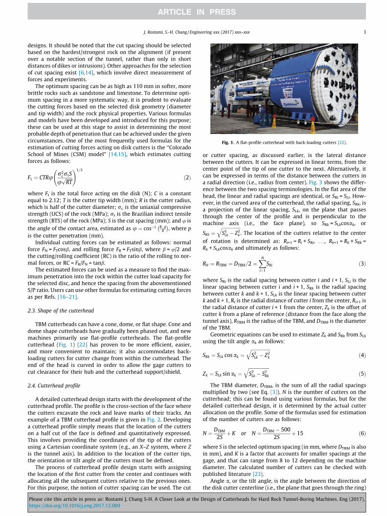
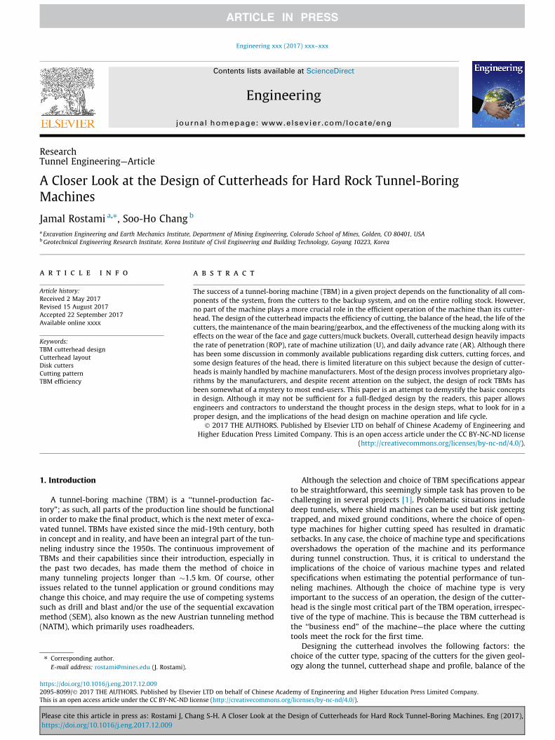
Fig. 1. A flat-profile cutterhead with back-loading cutters [22].
J. Rostami, S.-H. Chang / Engineering xxx (2017) xxx–xxx 3
designs. It should be noted that the cut spacing should be selectedbased on the hardest/strongest rock on the alignment (if presentover a notable section of the tunnel, rather than only in shortdistances of dikes or intrusions). Other approaches for the selectionof cut spacing exist [6,14], which involve direct measurement offorces and experiments.
The optimum spacing can be as high as 110 mm in softer, morebrittle rocks such as sandstone and limestone. To determine opti-mum spacing in a more systematic way, it is prudent to evaluatethe cutting forces based on the selected disk geometry (diameterand tip width) and the rock physical properties. Various formulasand models have been developed and introduced for this purpose;these can be used at this stage to assist in determining the mostprobable depth of penetration that can be achieved under the givencircumstances. One of the most frequently used formulas for theestimation of cutting forces acting on disk cutters is the ‘‘ColoradoSchool of Mines (CSM) model” [14,15], which estimates cuttingforces as follows:
Ft ¼ CTRur2
crtS
uffiffiffiffiffiffiRT
p !1=3
ð2Þ
where Ft is the total force acting on the disk (N); C is a constantequal to 2.12; T is the cutter tip width (mm); R is the cutter radius,which is half of the cutter diameter; rc is the uniaxial compressivestrength (UCS) of the rock (MPa); rt is the Brazilian indirect tensilestrength (BTS) of the rock (MPa); S is the cut spacing (mm); and u isthe angle of the contact area, estimated as u ¼ cos�1 R�p
R
� �, where p
is the cutter penetration (mm).Individual cutting forces can be estimated as follows: normal
force FN = FTcosb, and rolling force FR = FTsinb, where b = u/2 andthe cutting/rolling coefficient (RC) is the ratio of the rolling to nor-mal forces, or RC = FR/FN = tanb.
The estimated forces can be used as a measure to find the max-imum penetration into the rock within the cutter load capacity forthe selected disc, and hence the spacing from the abovementionedS/P ratio. Users can use other formulas for estimating cutting forcesas per Refs. [16–21].
2.3. Shape of the cutterhead
TBM cutterheads can have a cone, dome, or flat shape. Cone anddome shape cutterheads have gradually been phased out, and newmachines primarily use flat-profile cutterheads. The flat-profilecutterhead (Fig. 1) [22] has proven to be more efficient, easier,and more convenient to maintain; it also accommodates back-loading cutters for cutter change from within the cutterhead. Theend of the head is curved in order to allow the gage cutters tocut clearance for their hub and the cutterhead support/shield.
2.4. Cutterhead profile
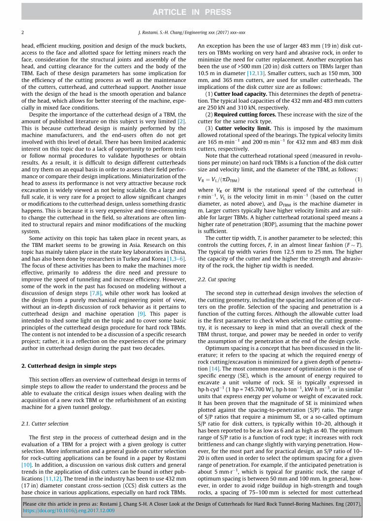
A detailed cutterhead design starts with the development of thecutterhead profile. The profile is the cross-section of the face wherethe cutters excavate the rock and leave marks of their tracks. Anexample of a TBM cutterhead profile is given in Fig. 2. Developinga cutterhead profile simply means that the location of the cutterson a half cut of the face is defined and quantitatively expressed.This involves providing the coordinates of the tip of the cuttersusing a Cartesian coordinate system (e.g., an X–Z system, where Zis the tunnel axis). In addition to the location of the cutter tips,the orientation or tilt angle of the cutters must be defined.
The process of cutterhead profile design starts with assigningthe location of the first cutter from the center and continues withallocating all the subsequent cutters relative to the previous ones.For this purpose, the notion of cutter spacing can be used. The cut
Please cite this article in press as: Rostami J, Chang S-H. A Closer Look at the Dhttps://doi.org/10.1016/j.eng.2017.12.009
or cutter spacing, as discussed earlier, is the lateral distancebetween the cutters. It can be expressed in linear terms, from thecenter point of the tip of one cutter to the next. Alternatively, itcan be expressed in terms of the distance between the cutters ina radial direction (i.e., radius from center). Fig. 3 shows the differ-ence between the two spacing terminologies. In the flat area of thehead, the linear and radial spacings are identical, or SRi = SLi. How-ever, in the curved area of the cutterhead, the radial spacing, SRk, isa projection of the linear spacing, SLk, on the plane that passesthrough the center of the profile and is perpendicular to themachine axis (i.e., the face plane), so SRk = SLkcosak, or
SRk ¼ffiffiffiffiffiffiffiffiffiffiffiffiffiffiffiffiffiS2Lk � Z2
k
q. The location of the cutters relative to the center
of rotation is determined as: Ri+1 = Ri + SRi, . . ., Rk+1 = Rk + SRk =Rk + SLkcosak and ultimately as follows:
RN ¼ RTBM ¼ DTBM=2 ¼XNi¼1
SRi ð3Þ
where SRi is the radial spacing between cutter i and i + 1, SLi is thelinear spacing between cutter i and i + 1, SRk is the radial spacingbetween cutter k and k + 1, SLk is the linear spacing between cutterk and k + 1, Ri is the radial distance of cutter i from the center, Ri+1 isthe radial distance of cutter i + 1 from the center, Zk is the offset ofcutter k from a plane of reference (distance from the face along thetunnel axis), RTBM is the radius of the TBM, and DTBM is the diameterof the TBM.
Geometric equations can be used to estimate Zk and SRk from SLkusing the tilt angle ak as follows:
SRk ¼ SLk cosak ¼ffiffiffiffiffiffiffiffiffiffiffiffiffiffiffiffiffiS2Lk � Z2
k
qð4Þ
Zk ¼ SLk sinak ¼ffiffiffiffiffiffiffiffiffiffiffiffiffiffiffiffiffiffiS2Lk � S2Rk
qð5Þ
The TBM diameter, DTBM, is the sum of all the radial spacingsmultiplied by two (see Eq. (3)). N is the number of cutters on thecutterhead; this can be found using various formulas, but for thedetailed cutterhead design, it is determined by the actual cutterallocation on the profile. Some of the formulas used for estimationof the number of cutters are as follows:
N ¼ DTBM
2Sþ K or N ¼ DTBM � 500
2Sþ 15 ð6Þ
where S is the selected optimum spacing (in mm, where DTBM is alsoin mm), and K is a factor that accounts for smaller spacings at thegage, and that can range from 8 to 12 depending on the machinediameter. The calculated number of cutters can be checked withpublished literature [23].
Angle a, or the tilt angle, is the angle between the direction ofthe disk cutter centerline (i.e., the plane that goes through the ring)
esign of Cutterheads for Hard Rock Tunnel-Boring Machines. Eng (2017),
Fig. 2. A typical cutterhead profile for a hard rock TBM with a flat profile (units: mm) (courtesy of The Robbins Company).
Fig. 3. Schematic drawing of the profile and definition of linear and radial spacing.
4 J. Rostami, S.-H. Chang / Engineering xxx (2017) xxx–xxx
and the tunnel axis. As such, a = 0� for the cutters that are perpen-dicular to the flat face (i.e., the plane that is normal to the tunnelaxis). This is typically the case for the cutters at the center of thecutterhead and the face. As the transition and gage cutters startand the profile enters a curvature, a typically increases to65�–70�. The purpose of the tilt angle is twofold:① For cutters thatare at the outer gage, the tilt angle cuts a clearance for the hub andcutter mounting assembly; and ② for the rest of the cutters in thegage area, the tilt angle ensures that the cutters are perpendicularto the face at the point of contact (within the curved section of theprofile in the gage area). The second requirement ensures theendurance of the cutters, since full-scale laboratory testing hasshown that the side force that is acting on the cutter is minimizedwhen the cutter is perpendicular to the face it is cutting at thepoint of contact, and increases when the cutter has an anglerelative to the surface that it cuts. This is shown in Fig. 4.
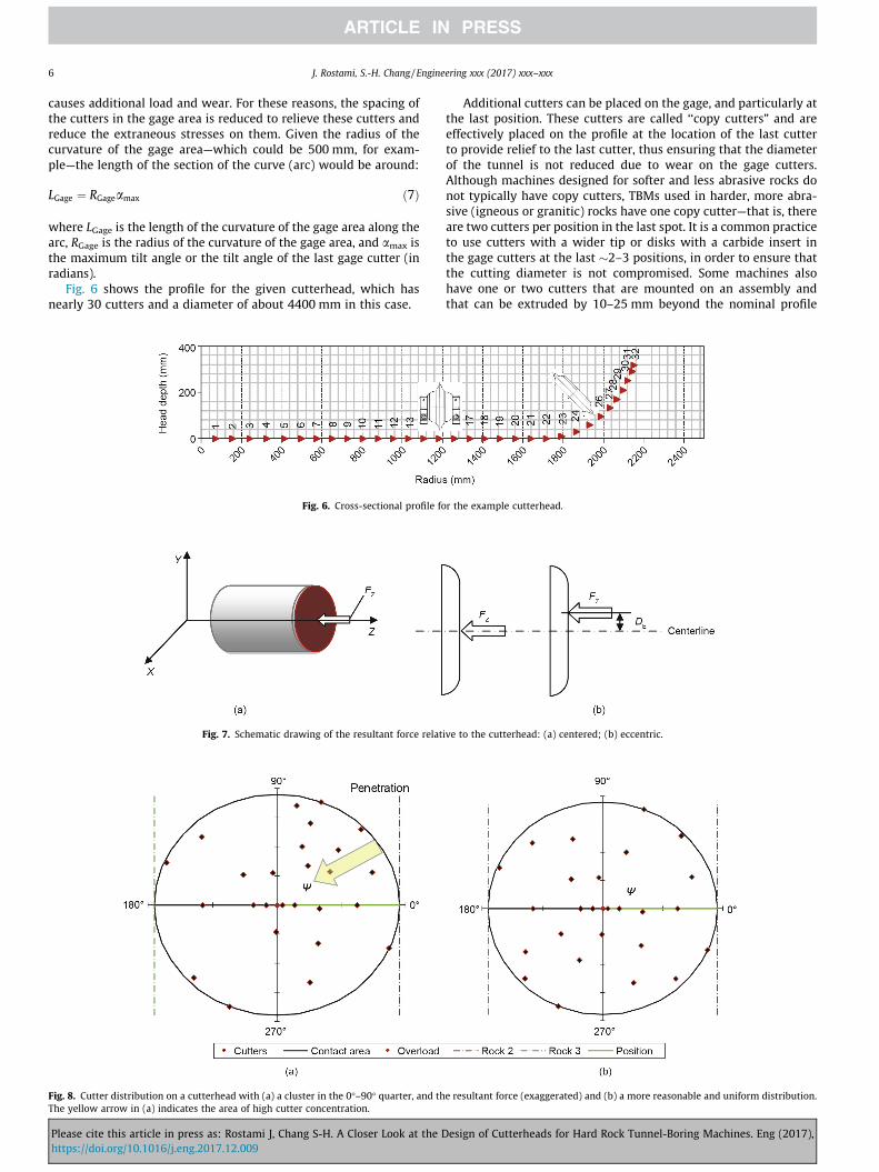
In practice, the first four disk cutters are combined in a setcalled the ‘‘center quad.” This is because of the lack of space atthe center, where there is no room for the installation of individualcutters, and because the mounting assembly (hub) for the cuttersdoes not allow the placement of the cutters in such a way thatthe desired spacing can be reached. Fig. 5 shows a picture of a cen-ter quad along with a schematic example of center quad position-ing in which reasonable spacing is achieved. The distance betweenthe blades in the quad set is typically fixed; by allocating one of theinner cutters at a certain distance from the center, the others willautomatically assume a spacing and thus radius from the center.For example, if the distance between the center quad disks is200 mm, when one of the inner blades is positioned at a radiusof 50 mm, the second blade automatically assumes a radius of150 mm from the center, which means a spacing of 100 mm fromthe first one. The third will be located at a distance of 250 mm from
Please cite this article in press as: Rostami J, Chang S-H. A Closer Look at the Dhttps://doi.org/10.1016/j.eng.2017.12.009
the center, which implies a spacing of 100 mm from the secondcutter track, and the fourth cutter will be located at a radius of350 mm from the center, which means a spacing of 100 mm fromthe third cutter track. This takes care of the first four cutters andthe first three spacings. Of course, for harder rock, the spacing ofthe cutters can be reduced by 10–15 mm in the center quad, whichwill reduce the spacing of the center cutters to 85–90 mm.
There are other arrangements for the center in which six cuttersare placed together; however, the overall arrangement is the sameas that of the quad, except that there are six cutters instead of four.Other cutters can be allocated along the line of the profile based onthe assigned (optimum) spacings. This means that when a quad isallocated, the fifth cutter can assume a radius of about 450 mm(assuming a 100 mm spacing between the fourth and fifth cutters).Given the clearances of the cutter housing, the cutter can be allo-cated to the area adjacent to the center quad without much inter-ference. The same applies for the sixth cutter and onward. Thus,these cutters in the so-called face area can be allocated to the pro-file without much of a problem, until they reach the transition andgage area. The cutter tilt angles start at the transition area, and theoffset from the face also increases (coordinate Z of the cutter tip).Some of the new flat-type heads have a very small transition area,meaning that only one or two cutters are present in the transition,and then the gage curve starts.
To allocate the cutters in the gage area, once the curvature ofthe head is established, cutters can be assigned to follow this cur-vature at an angle of about amax = 65�–70� (see the a angle inFig. 2). As noted before, the typical curvature radius of a flat cutter-head is 450–550 mm. This provides sufficient curvature to allowfor a gradual transition to gage cutters and to cut clearance forthe cutterhead and cutter mounting assemblies. The cutters inthe gage area are placed on the curvature at line spacings that
esign of Cutterheads for Hard Rock Tunnel-Boring Machines. Eng (2017),
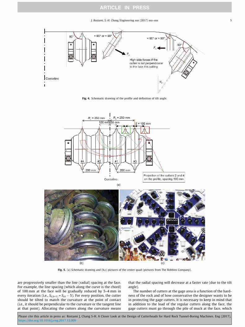
Fig. 4. Schematic drawing of the profile and definition of tilt angle.
Fig. 5. (a) Schematic drawing and (b,c) pictures of the center quad (pictures from The Robbins Company).
J. Rostami, S.-H. Chang / Engineering xxx (2017) xxx–xxx 5
are progressively smaller than the line (radial) spacing at the face.For example, the line spacing (which along the curve is the chord)of 100 mm at the face will be gradually reduced by 5–4 mm inevery iteration (i.e., SL(k+1) = SLk � 5). For every position, the cuttershould be tilted to match the curvature at the point of contact(i.e., it should be perpendicular to the curvature or the tangent lineat that point). Allocating the cutters along the curvature means
Please cite this article in press as: Rostami J, Chang S-H. A Closer Look at the Dhttps://doi.org/10.1016/j.eng.2017.12.009
that the radial spacing will decrease at a faster rate (due to the tiltangle).
The number of cutters at the gage area is a function of the hard-ness of the rock and of how conservative the designer wants to bein protecting the gage cutters. It is necessary to keep in mind thatin addition to the load of the regular cutters along the face, thegage cutters must go through the pile of muck at the face, which
esign of Cutterheads for Hard Rock Tunnel-Boring Machines. Eng (2017),
6 J. Rostami, S.-H. Chang / Engineering xxx (2017) xxx–xxx
causes additional load and wear. For these reasons, the spacing ofthe cutters in the gage area is reduced to relieve these cutters andreduce the extraneous stresses on them. Given the radius of thecurvature of the gage area—which could be 500 mm, for exam-ple—the length of the section of the curve (arc) would be around:
LGage ¼ RGageamax ð7Þ
where LGage is the length of the curvature of the gage area along thearc, RGage is the radius of the curvature of the gage area, and amax isthe maximum tilt angle or the tilt angle of the last gage cutter (inradians).
Fig. 6 shows the profile for the given cutterhead, which hasnearly 30 cutters and a diameter of about 4400 mm in this case.
Fig. 6. Cross-sectional profile fo
Fig. 7. Schematic drawing of the resultant force relat
Fig. 8. Cutter distribution on a cutterhead with (a) a cluster in the 0�–90� quarter, and thThe yellow arrow in (a) indicates the area of high cutter concentration.
Please cite this article in press as: Rostami J, Chang S-H. A Closer Look at the Dhttps://doi.org/10.1016/j.eng.2017.12.009
Additional cutters can be placed on the gage, and particularly atthe last position. These cutters are called ‘‘copy cutters” and areeffectively placed on the profile at the location of the last cutterto provide relief to the last cutter, thus ensuring that the diameterof the tunnel is not reduced due to wear on the gage cutters.Although machines designed for softer and less abrasive rocks donot typically have copy cutters, TBMs used in harder, more abra-sive (igneous or granitic) rocks have one copy cutter—that is, thereare two cutters per position in the last spot. It is a common practiceto use cutters with a wider tip or disks with a carbide insert inthe gage cutters at the last �2–3 positions, in order to ensure thatthe cutting diameter is not compromised. Some machines alsohave one or two cutters that are mounted on an assembly andthat can be extruded by 10–25 mm beyond the nominal profile
r the example cutterhead.
ive to the cutterhead: (a) centered; (b) eccentric.
e resultant force (exaggerated) and (b) a more reasonable and uniform distribution.
esign of Cutterheads for Hard Rock Tunnel-Boring Machines. Eng (2017),
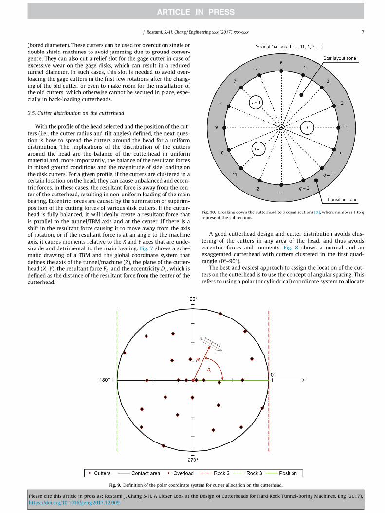
Fig. 10. Breaking down the cutterhead to q equal sections [9], where numbers 1 to qrepresent the subsections.
J. Rostami, S.-H. Chang / Engineering xxx (2017) xxx–xxx 7
(bored diameter). These cutters can be used for overcut on single ordouble shield machines to avoid jamming due to ground conver-gence. They can also cut a relief slot for the gage cutter in case ofexcessive wear on the gage disks, which can result in a reducedtunnel diameter. In such cases, this slot is needed to avoid over-loading the gage cutters in the first few rotations after the chang-ing of the old cutter, or even to make room for the installation ofthe old cutters, which otherwise cannot be secured in place, espe-cially in back-loading cutterheads.
2.5. Cutter distribution on the cutterhead
With the profile of the head selected and the position of the cut-ters (i.e., the cutter radius and tilt angles) defined, the next ques-tion is how to spread the cutters around the head for a uniformdistribution. The implications of the distribution of the cuttersaround the head are the balance of the cutterhead in uniformmaterial and, more importantly, the balance of the resultant forcesin mixed ground conditions and the magnitude of side loading onthe disk cutters. For a given profile, if the cutters are clustered in acertain location on the head, they can cause unbalanced and eccen-tric forces. In these cases, the resultant force is away from the cen-ter of the cutterhead, resulting in non-uniform loading of the mainbearing. Eccentric forces are caused by the summation or superim-position of the cutting forces of various disk cutters. If the cutter-head is fully balanced, it will ideally create a resultant force thatis parallel to the tunnel/TBM axis and at the center. If there is ashift in the resultant force causing it to move away from the axisof rotation, or if the resultant force is at an angle to the machineaxis, it causes moments relative to the X and Y axes that are unde-sirable and detrimental to the main bearing. Fig. 7 shows a sche-matic drawing of a TBM and the global coordinate system thatdefines the axis of the tunnel/machine (Z), the plane of the cutter-head (X–Y), the resultant force FZ, and the eccentricity DE, which isdefined as the distance of the resultant force from the center of thecutterhead.
Fig. 9. Definition of the polar coordinate syste
Please cite this article in press as: Rostami J, Chang S-H. A Closer Look at the Dhttps://doi.org/10.1016/j.eng.2017.12.009
A good cutterhead design and cutter distribution avoids clus-tering of the cutters in any area of the head, and thus avoidseccentric forces and moments. Fig. 8 shows a normal and anexaggerated cutterhead with cutters clustered in the first quad-rangle (0�–90�).
The best and easiest approach to assign the location of the cut-ters on the cutterhead is to use the concept of angular spacing. Thisrefers to using a polar (or cylindrical) coordinate system to allocate
m for cutter allocation on the cutterhead.
esign of Cutterheads for Hard Rock Tunnel-Boring Machines. Eng (2017),
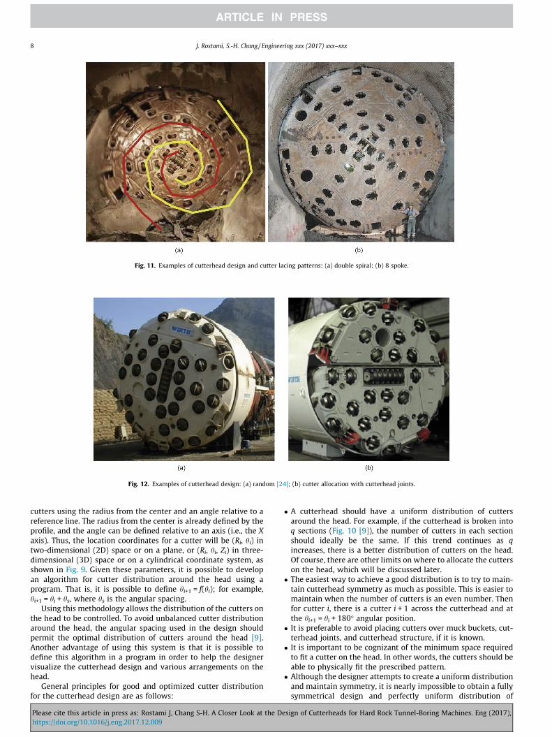
Fig. 11. Examples of cutterhead design and cutter lacing patterns: (a) double spiral; (b) 8 spoke.
Fig. 12. Examples of cutterhead design: (a) random [24]; (b) cutter allocation with cutterhead joints.
8 J. Rostami, S.-H. Chang / Engineering xxx (2017) xxx–xxx
cutters using the radius from the center and an angle relative to areference line. The radius from the center is already defined by theprofile, and the angle can be defined relative to an axis (i.e., the Xaxis). Thus, the location coordinates for a cutter will be (Ri, hi) intwo-dimensional (2D) space or on a plane, or (Ri, hi, Zi) in three-dimensional (3D) space or on a cylindrical coordinate system, asshown in Fig. 9. Given these parameters, it is possible to developan algorithm for cutter distribution around the head using aprogram. That is, it is possible to define hi+1 = f(hi); for example,hi+1 = hi + hs, where hs is the angular spacing.
Using this methodology allows the distribution of the cutters onthe head to be controlled. To avoid unbalanced cutter distributionaround the head, the angular spacing used in the design shouldpermit the optimal distribution of cutters around the head [9].Another advantage of using this system is that it is possible todefine this algorithm in a program in order to help the designervisualize the cutterhead design and various arrangements on thehead.
General principles for good and optimized cutter distributionfor the cutterhead design are as follows:
Please cite this article in press as: Rostami J, Chang S-H. A Closer Look at the Dhttps://doi.org/10.1016/j.eng.2017.12.009
� A cutterhead should have a uniform distribution of cuttersaround the head. For example, if the cutterhead is broken intoq sections (Fig. 10 [9]), the number of cutters in each sectionshould ideally be the same. If this trend continues as qincreases, there is a better distribution of cutters on the head.Of course, there are other limits on where to allocate the cutterson the head, which will be discussed later.
� The easiest way to achieve a good distribution is to try to main-tain cutterhead symmetry as much as possible. This is easier tomaintain when the number of cutters is an even number. Thenfor cutter i, there is a cutter i + 1 across the cutterhead and atthe hi+1 = hi + 180� angular position.
� It is preferable to avoid placing cutters over muck buckets, cut-terhead joints, and cutterhead structure, if it is known.
� It is important to be cognizant of the minimum space requiredto fit a cutter on the head. In other words, the cutters should beable to physically fit the prescribed pattern.
� Although the designer attempts to create a uniform distributionand maintain symmetry, it is nearly impossible to obtain a fullysymmetrical design and perfectly uniform distribution of
esign of Cutterheads for Hard Rock Tunnel-Boring Machines. Eng (2017),
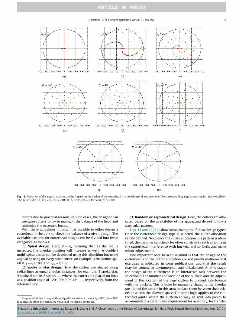
Fig. 13. Variation of the angular spacing and its impact on the design of the cutterhead in a double-spiral arrangement. The corresponding angular spacing is: (a) hs = 0�, (b) hs= 5�, (c) hs = 20�, (d) hs = 25�, (e) hs = 40�, (f) hs = 50�, (g) hs = 45�, and (h) hs = 60�.
J. Rostami, S.-H. Chang / Engineering xxx (2017) xxx–xxx 9
cutters due to practical reasons. In such cases, the designer canuse gage cutters to try to maintain the balance of the head andminimize the eccentric forces.With these guidelines in mind, it is possible to either design a
cutterhead or be able to check the balance of a given design. Theavailable patterns for cutterhead designs can be divided into threecategories as follows:
(1) Spiral design. Here, hi � Ri, meaning that as the radiusincreases, the angular position will increase as well.y A double-/multi-spiral design can be developed using this algorithm but usingangular spacing on every other cutter. An example is the double spi-ral hi+1 = hi + 180� and hi+2 = hi + hs.
(2) Spoke or star design. Here, the cutters are aligned alongradial lines at equal angular distances; for example: 3 spoke/star,4 spoke, 6 spoke, 8 spoke, . . ., where the cutters are placed on linesat a position angle of 120�, 90�, 60�, 45�, . . ., respectively, from thereference line.
y Keep in mind that in any of these algorithms, when hi+1 = hi + hs > 360�, then 360�is subtracted from the estimated value and the design continues.
Please cite this article in press as: Rostami J, Chang S-H. A Closer Look at the Dhttps://doi.org/10.1016/j.eng.2017.12.009
(3) Random or asymmetrical design. Here, the cutters are allo-cated based on the availability of the space, and do not follow aparticular pattern.
Figs. 11 and 12 [24] show some examples of these design types.Once the cutterhead design type is selected, the cutter allocationcan be defined. Next, once the cutter allocation in a pattern is iden-tified, the designer can check for other constraints such as joints inthe cutterhead, interference with buckets, and so forth, and makeminor adjustments.
One important note to keep in mind is that the design of thecutterhead and the cutter allocation are not purely mathematicalexercises as indicated in some publications, and that the resultmay be somewhat asymmetrical and unbalanced. At this stage,the design of the cutterhead is an interactive task between theselection of the number and location of the buckets and the adjust-ment of the location of the gage cutters to prevent interferencewith the buckets. This is done by manually changing the angularposition of the cutters in this area to place them between the buck-ets or within the allowed space. The same logic applies to the cut-terhead joints, where the cutterhead may be split into pieces toaccommodate a certain size requirement for assembly, for transfer
esign of Cutterheads for Hard Rock Tunnel-Boring Machines. Eng (2017),
10 J. Rostami, S.-H. Chang / Engineering xxx (2017) xxx–xxx
into the shaft or starter tunnel, or to contain the weight of the cut-terhead in larger sized machines (Fig. 12(b)).
2.6. Muck buckets
The selection of the number, size, and allocation of the bucketsis an integral part of the cutterhead design. The number and sizeof the buckets are proportional to the anticipated volume ofmaterial excavated, and increase with the expected ROP of theTBM in softer rocks. This is to accommodate efficient muckingand removal of the cut material from the face in order to avoiderosion of the face plate, wear of the cutters, and accumulationof muck and fines in the invert, the latter of which can causeexcessive load on the gage cutters and premature failure. Anotherissue is the size of the opening of the buckets, which is somewhatcontrolled by the expected sizing of the muck and is selected toallow certain size blocks into the muck chutes. The typical rangeof material that is allowed to enter the chute is about 100 mm �100 mm or 100 mm � 150 mm, as the upper limit of the size;blocks larger than this range are kept in the face to be brokenby the disks. This is done by the face plate or face shield holdingsuch blocks in the face.
Once the number of buckets is known, the buckets are system-atically and evenly spread around the head; thus, their angularposition will be determined as 360�/NBuckets. This is to make surethe volume of muck picked up from the invert is uniform. In addi-tion, there are some cases in which buckets of different lengthshave been used. In these cases, some longer buckets were placedin between regular buckets (i.e., every second or every thirdbucket). The most common number of buckets is four for small cut-terheads in very hard rock, six to eight for medium-sized machines,and more than 12 for machines larger than 9 m. The buckets aredesigned with respect to the softest formation along the tunnelin order to accommodate efficient mucking in the highest flow ofmaterial, whereas the cutter allocation and profile are selectedwith respect to the hardest formation along the alignment in orderto ensure that the spacing of the cuts is not excessive, which wouldcreate a ridge between the cuts.
Fig. 14. Graphical representation of the cutter
Please cite this article in press as: Rostami J, Chang S-H. A Closer Look at the Dhttps://doi.org/10.1016/j.eng.2017.12.009
3. Cutterhead modeling
Some examples of programs using an algorithm for cutter dis-tribution around the head are presented here. The basis for cutter-head modeling and for related spreadsheets is discussed elsewhere[7,8,25]. For this purpose, a 7.23 m diameter TBM that was studiedfor a project featuring 54 cutters is used to show the impact of var-ious values of hs on the design of a double-spiral layout. It is inter-esting to see that even though the design is for a double spiral, itcan be configured into a multi-star arrangement when reachingcertain values of hs. In this example, hs is varied from 0, whichinvolves theoretically lining up the cutters along the same line,to different values that will show the spread of the cutters aroundthe head. The first six cutters are arranged in a cluster (positionangles of 0� and 180�). The cutter angular position starts from cut-ter 7, which is set to sit at 90�, and cutter 8, which is set to beacross the center (180� apart), at 270�. The other cutters will beshifted by hs, as can be seen in Fig. 13. A closer examination ofthe angles shows a repeating pattern at certain values of hs.
An interesting setting is the distribution of the cutters at hs =30�, 45�, 60�, and 90�, which corresponds with a 12, 8, 6, and 4spoke cutterhead design pattern, respectively. Some examples ofangular spacing forming a spoke pattern for 45� and 60� are shownin Fig. 13(g) and (h). Similarly, it is interesting to observe that thepattern can be completely uniform and symmetrical, that is, if hs =40� or 50�, as shown in Fig. 13. The algorithm permits fine-tuningof the cutterhead design to achieve the best distribution. A quicklook at the design shows that in many patterns, buckets can beeasily allocated without interference with the cutters. This is oneof the advantages of using a fully symmetrical design. One of thespots close to the transition or near outer flanks of the face cutterscan be designated as the location of the access or manhole for entryto the cutterhead. The location of the manhole is not prescribed,since it can be literally anywhere that a 0.5–0.6 m radius holecan be placed.
The difference in the performance of TBMs using cutterheadswith different patterns in various conditions can be seen by cutter-head modeling, which will be discussed in the following section.
head in computer modeling (units: mm).
esign of Cutterheads for Hard Rock Tunnel-Boring Machines. Eng (2017),
J. Rostami, S.-H. Chang / Engineering xxx (2017) xxx–xxx 11
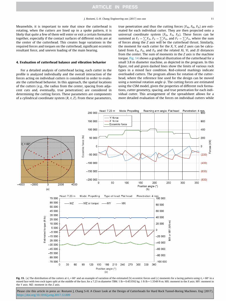
Meanwhile, it is important to note that since the cutterhead isrotating, when the cutters are lined up in a spoke pattern, it islikely that quite a few of them will enter or exit a certain formationtogether, especially if the contact surfaces of different rocks are atthe center of the cutterhead. This creates huge variations in therequired forces and torques on the cutterhead, significant eccentricresultant force, and uneven loading of the main bearing.
4. Evaluation of cutterhead balance and vibration behavior
For a detailed analysis of cutterhead lacing, each cutter in theprofile is analyzed individually and the overall interaction of theforces acting on individual cutters is considered in order to evalu-ate the cutterhead behavior. In this approach, the spatial locationsof the cutters (e.g., the radius from the center, spacing from adja-cent cuts and, eventually, true penetration) are considered indetermining the cutting forces. These parameters are componentsof a cylindrical coordinate system (R, h, Z). From these parameters,
Fig. 15. (a) The distribution of the cutters at hs = 60� and an example of variation of the emixed face with two rock types split at the middle of the face, for a 7.23 m diameter TBM.the Y axis; MZ: moment in the Z axis.
Please cite this article in press as: Rostami J, Chang S-H. A Closer Look at the Dhttps://doi.org/10.1016/j.eng.2017.12.009
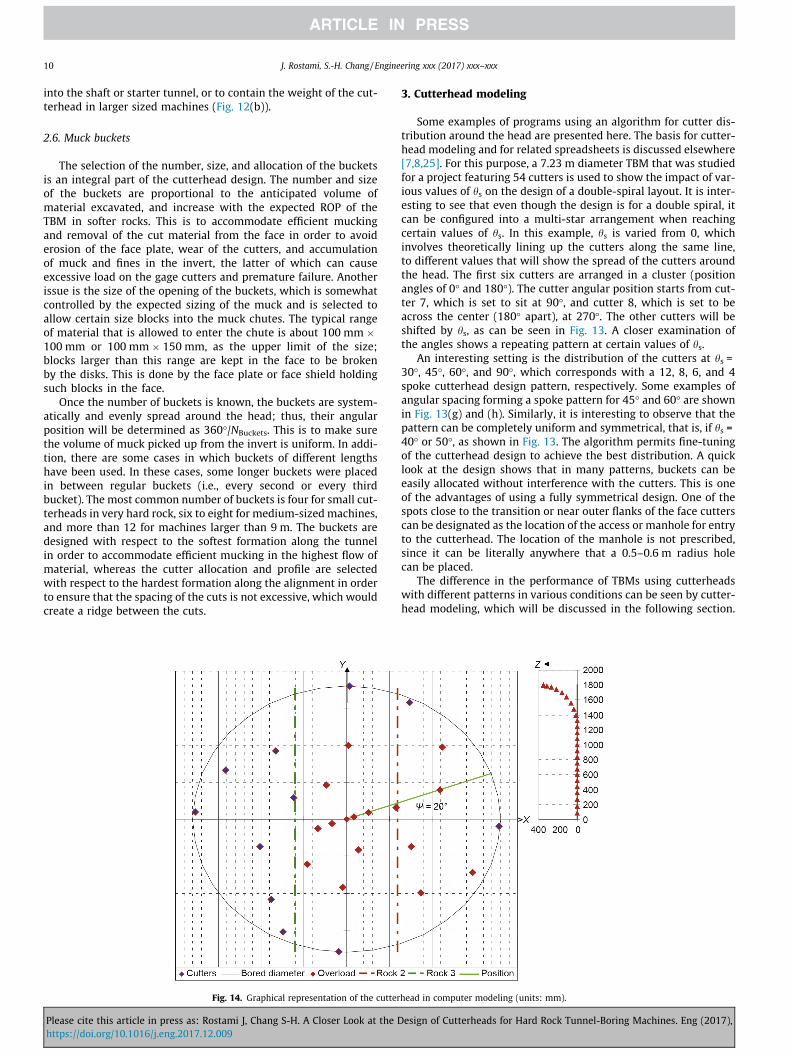
true penetration and thus the cutting forces (FNi, FRi, FSi) are esti-mated for each individual cutter. They are then projected onto auniversal coordinate system (FXi, FYi, FZi). These forces can besummed as FZ ¼P FZi, FX ¼P FXi, and FY ¼P FYi, where the sumof forces along the Z axis will be the cutterhead thrust. Similarly,the moment for each cutter for the X, Y, and Z axes can be calcu-lated from FXi, FYi, and FZi and the related Xi, Yi, and Zi distancesfrom the center. The sum of moments in the Z axis is the machinetorque. Fig. 14 shows a graphical illustration of the cutterhead for asmall 3.8 m diameter machine, as depicted in the program. In thisfigure, red and green dashed lines show the limits of various rocktypes in a mixed face condition. Red-colored markings indicateoverloaded cutters. The program allows for rotation of the cutter-head, where the reference line used for the design can be movedusing a nominal rotation angle w. The cutting forces are estimatedusing the CSM model, given the properties of different rock forma-tions, cutter geometry, spacing, and true penetration for each indi-vidual cutter. This arrangement of the spreadsheet allows for amore detailed evaluation of the forces on individual cutters while
stimated (b) eccentric forces and (c) moments for a lacing pattern using hs = 60� in a1 lb = 0.453592 kg; 1 ft�lb = 1.3549 N�m. MX: moment in the X axis; MY: moment in
esign of Cutterheads for Hard Rock Tunnel-Boring Machines. Eng (2017),
12 J. Rostami, S.-H. Chang / Engineering xxx (2017) xxx–xxx
providing the ability to change the cutterhead design and observethe effects of design issues on the force distribution across the face,total forces, and sum of moments.
The procedure permits the identification of potential problemareas where a cutter could be overloaded due to the lacing pattern,and can thus provide a warning. Overloading of a particular cuttercan happen despite the fact that the overall thrust and correspond-ing estimated average cutterloads are well within the thrust limitsand nominal capacity of the cutters, as set by the machine manu-facturer. In the model, the cutting forces are estimated, a full vectoranalysis of the forces is performed, and the amount of eccentricforces and moments can be determined. This modeling system alsoallows for full rotation of the head relative to a reference line in theface, and provides a powerful tool for cutterhead optimization. Themodel runs for full rotation of the head by changing the value of w,and records the estimated cutterhead thrust, torque, power, andeccentric forces and moments.
The ideal situation and best cutterhead design are when theamount of eccentric forces (FX and FY) are zero and the only resul-tant force and moment are in line with the Z or tunnel/machine
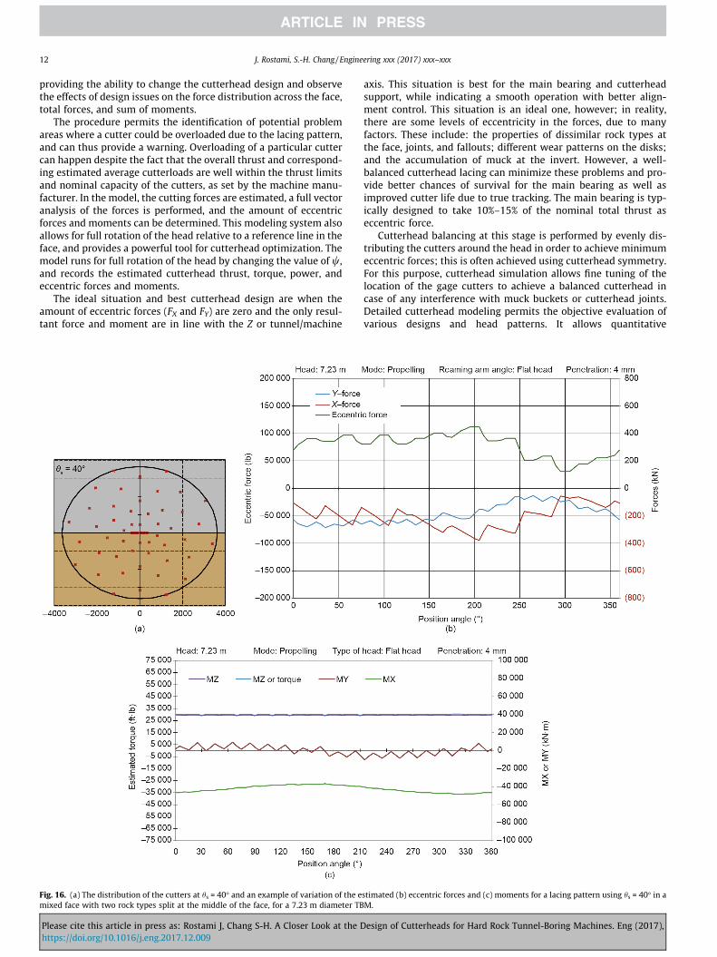
Fig. 16. (a) The distribution of the cutters at hs = 40� and an example of variation of the emixed face with two rock types split at the middle of the face, for a 7.23 m diameter TB
Please cite this article in press as: Rostami J, Chang S-H. A Closer Look at the Dhttps://doi.org/10.1016/j.eng.2017.12.009
axis. This situation is best for the main bearing and cutterheadsupport, while indicating a smooth operation with better align-ment control. This situation is an ideal one, however; in reality,there are some levels of eccentricity in the forces, due to manyfactors. These include: the properties of dissimilar rock types atthe face, joints, and fallouts; different wear patterns on the disks;and the accumulation of muck at the invert. However, a well-balanced cutterhead lacing can minimize these problems and pro-vide better chances of survival for the main bearing as well asimproved cutter life due to true tracking. The main bearing is typ-ically designed to take 10%–15% of the nominal total thrust aseccentric force.
Cutterhead balancing at this stage is performed by evenly dis-tributing the cutters around the head in order to achieve minimumeccentric forces; this is often achieved using cutterhead symmetry.For this purpose, cutterhead simulation allows fine tuning of thelocation of the gage cutters to achieve a balanced cutterhead incase of any interference with muck buckets or cutterhead joints.Detailed cutterhead modeling permits the objective evaluation ofvarious designs and head patterns. It allows quantitative
stimated (b) eccentric forces and (c) moments for a lacing pattern using hs = 40� in aM.
esign of Cutterheads for Hard Rock Tunnel-Boring Machines. Eng (2017),
J. Rostami, S.-H. Chang / Engineering xxx (2017) xxx–xxx 13
comparison between different designs in any given geological set-ting. Although the variation of forces for a well-balanced cutter-head in a uniform face is minimal, the variability of forces andmoments in mixed ground conditions could be significant. A majoradvantage of cutterhead modeling is its simulation of mixedground conditions, in which dissimilar materials (soft and hardrock or rock and fault gouge, etc.) are present at the face. Program-ming the individual cutters allows the cutting forces in each rocktype to be estimated, and thus provides the designer with actualforces in each section of the face. The highest contrast can beobserved when the face is split between two formations (withhighest differential strength) at the center. In this situation, thecomponents of the eccentric forces and moments are at their max-imum. An example of such a condition is given in Figs. 15 and 16.Accurate estimation and quantification of these parameters areessential to evaluate the potential of imbalanced forces on themain bearing, as these can inflict major damage on the main bear-ing and cutterhead.
A quick look at the figures shows that the lacing can impact themagnitude of the eccentric forces and moments, especially whendissimilar materials are cut at the face. In reality, it is very commonto have some dissimilarity in the material at the face due to differ-ent lithologies, different locations of a joint or a joint set, variabilityin the strength of the rock, directional properties, anisotropy, andso forth. A comparison of Figs. 15 and 16 shows the impact of aneven distribution of the cutters on the eccentric forces andmoments, even in a fully symmetrical cutterhead design. Lowerout-of-center forces and moments (in the X and Y directions) resultin better loading conditions on the cutterhead and main bearing.Thus, a comparison of the magnitude of the forces and momentspermits a quantitative evaluation of the performance of variousdesigns.
5. Conclusions
This paper is a summary of the principal concepts involved inthe design of cutterheads for hard rock TBMs. The generalapproach for developing an optimum design has been describedin a step-by-step manner. Some design patterns were presentedand their implications shown using various examples. It is neces-sary to keep in mind that the cutterhead will experience unbal-anced forces and moments irrespective of the head design;however, uniform distribution of the cutters will minimize thevariation of the eccentric forces and out-of-axis moments. Anoptimum design of the cutterhead will reduce the out-of-axisloading of the bearing, reduce the side forces on the cutters,and generally improve the performance of the machine; it willalso reduce the maintenance requirements of the cutters, cutter-head, and drive system. The importance of cutterhead balance isparamount, and design optimization can be done using computermodels that allow for variation of the design and evaluation ofthe forces and moments acting on the cutterhead. These modelspermit the simulation of various cutting scenarios and theirimpact on the forces, torque, power, and cutterloads. They canbe used to compare various cutterhead design patterns for appli-cation under certain working conditions, and to identify possiblemodifications. These models also allow the estimation of theanticipated forces acting on individual cutters as well as examina-tion of the forces and moments (including cutterhead torque) act-ing on the entire cutterhead or main bearing under variousconditions. The result of a well-designed cutterhead is improvedmachine performance through higher ROP, low cutter and cutter-head maintenance, and higher machine utilization.
Please cite this article in press as: Rostami J, Chang S-H. A Closer Look at the Dhttps://doi.org/10.1016/j.eng.2017.12.009
Compliance with ethics guidelines
Jamal Rostami and Soo-Ho Chang declare that they have no con-flict of interest or financial conflicts to disclose.
References
[1] Ates U, Bilgin N, Copur H. Estimating torque, thrust and other designparameters of different type TBMs with some criticism to TBMs used inTurkish tunneling projects. Tunn Undergr Space Technol 2014;40:46–63.
[2] Snyder LL. New design of hard rock TBMs. In: Proceedings of 1989 rapidexcavation and tunnelling conference. Littleton: Society for Mining,Metallurgy, and Exploration, Inc.; 1989. p. 756–67.
[3] Sun W, Ling J, Huo J, Guo L, Song X. Study of TBM cutterhead fatigue damagemechanisms based on a segmented comprehensive failure criterion. EngFailure Anal 2015;58(Pt 1):64–82.
[4] Genga Q, Wei Z, Menga H, Maciasb FJ. Mechanical performance of TBMcutterhead in mixed rock ground conditions. Tunn Undergr Space Technol2016;57:76–84.
[5] Lee SW, Chang SH, Park KH, Kim CY. TBM performance and development statein Korea. Procedia Eng 2011;14:3170–5.
[6] Cho JW, Jeon S, Yu SH, Chang SH. Optimum spacing of TBM disc cutters: Anumerical simulation using the three-dimensional dynamic fracturingmethod. Tunn Undergr Space Technol 2010;25(3):230–44.
[7] Rostami J, Ozdemir L. Computer modeling for cutterhead design and layout ofmechanical excavators. In: Proceedings of the 12th annual technical meetingof the institute of shaft drilling technology; 1993 May 3–5; Las Vegas, NV, USA.1993. p. 2–6.
[8] Rostami J. Hard rock TBM cutterhead modeling for design and performanceprediction. Geomech Tunn 2008;1(1):18–28.
[9] Huo J, Sun W, Chen J, Zhang X. Disc cutters plane layout design of the full-facerock tunnel boring machine (TBM) based on different layout patterns. ComputInd Eng 2011;61(4):1209–25.
[10] Rostami J. Rock cutting tools for mechanical mining. In: Proceedings of societyfor mining, metallurgy and exploration (SME) annualmeeting. Littleton: Society for Mining, Metallurgy, and Exploration, Inc.; 2001.
[11] Rostami J. Disc cutter technology for hard rock tunneling. Tunnels TunnellingInt 1998 Apr:42–4.
[12] Roby J, Sandell T, Kocab J, Lindbergh L. The current state of disc cutter designand development directions. Tunnel Undergr Constr 2009 Mar:36–45.
[13] The Niagara tunnel project [Internet]. Solon: The Robbins Company; [cited2017 Oct 26]. Available from: http://www.therobbinscompany.com/projects/niagara-tunnel-project/.
[14] Rostami J. Development of a force estimation model for rock fragmentationwith disc cutters through theoretical modeling and physical measurement ofcrushed zone pressure [dissertation]. Golden: Colorado School of Mines; 1997.
[15] Rostami J. Study of pressure distribution within the crushed zone in thecontact area between rock and disc cutters. Int J Rock Mech Min2013;57:172–86.
[16] Chang SH, Choi SW, Bae GJ, Jeon S. Performance prediction of TBM disc cuttingon granitic rock by the linear cutting test. Tunn Undergr Space Technol2006;21(3–4):271.
[17] Sanio HP. Prediction of the performance of disc cutters in anisotropic rock. Int JRock Mech Min 1985;22(3):153–61.
[18] Sato K, Gong F, Itakura K. Measurement of tool force and twist exerted on TBMdisc cutters. In: Proceedings of 2nd international symposium on minemechanization and automation. Rotterdam: A.A. Balkema; 1993. p. 271–8.
[19] Sato K, Gong F, Itakura K. Prediction of disc cutter performance using a circularrock cutting rig. In: Proceedings of 1st international symposium on minemechanization and automation. Golden: Colorado School of Mines; 1991. p.31–40.
[20] Gertsch R, Gertsch L, Rostami J. Disc cutting tests in Colorado Red Granite:Implications for TBM performance prediction. Int J Rock Mech Min 2007;44(2):238–46.
[21] Medel-Morales RC, Botello-Rionda S. Design and optimization of tunnel boringmachines by simulating the cutting rock process using the discrete elementmethod. Computación y Sistemas 2013;17(3):329–39.
[22] Willis D. Main beam TBM makes great time in Mumbai [Internet]. TunnelTalk;2014 Feb 25 [cited 2017 Nov 29]. Available from: http://www.tunneltalk.com/Mumbai-India-25Feb14-Robbins-main-beam-TBM-makes-great-time-in-Mumbai.php.
[23] Bruland A. Hard rock tunnel boring [dissertation]. Trondheim: NorwegianUniversity of Science and Technology; 1998.
[24] Alborz exploration tunnel [Internet]. Schruns: Jäger Bau GmbH; [cited 2017Nov 26]. Available from: http://www.jaegerbau.com/en/underground-construction/special-underground-projects/reference-projects/alborz-exploration-tunnel/.
[25] Cigla M, Ozdemir L. Computer modeling for improved production ofmechanical excavators. In: Proceedings of society for mining, metallurgy andexploration (SME) annual meeting. Littleton: Society for Mining, Metallurgy,and Exploration, Inc.; 2000.
esign of Cutterheads for Hard Rock Tunnel-Boring Machines. Eng (2017),


