Embed Size (px)
Citation preview
~ _, ENGINEERING AND DESIGN
1-1
GRAVITY DAM DESIGN I
••I
I I I
I
I r-------TAI 145 .U6 EM -~
I 1110-2-2200 1958
I 1

I
I
I This Engineer Manual contains copyrighted mn.terial by permission of the copyright pro
prietor, as indicated by a dagger (t) in the bibliography and in the vicinity of the copyrighted I material in the text. Reproduction in whole or in part is prohibited except by permission. Inquiry relative thereto should be directed to the Adjutant General, Department of the Army, Washington 25, D. C.
••I
I I I I I I
el· I
'
I MANUALS---.CORPS OF ENGINEERS
U.S. ARMY
lerA-. l'fS ENGINEERING AND DESIGN
GRAVITY DAM DESIGN,
TABLE OF CONTENTS
EM 1110--2-2200 25 Sep 58
'
-I ►
.,►
F
~ :1 f •
I
~ I ~
• ti t, f
• II
,U~ [.:iJ
i !_
: ; 'D -l -l-Z- a g i ,. • .
I qSF CHAPTER 1
INTRODUCTION Paragraph 1-01 PURPOSE AND SCOPE_ _________________________________________________ _ 1-02 REFERENCES ___________________________________________________________ _
a. Other Engineer Manuals and Guide Specifications __ ______ ___ _____ _____ __ _ b. Other Technical Publications _________________________________________ _
1-03 RESCISSION ____________________________________________________ ~- ______ _ 1-04 GENERAL ___________________________________________________________ ____ _ 1-05 DESIGN CONSIDERATIONS _______ ______________________________________ _
CHAPTER 2
LOADS 2- 01 FORCES AFFECTING THE DESIGN ____________________________________ _ 2-02 DEAD LO AD _______ ___ ____ ____ ________ ____ __ ____ __ ________________ __ ____ _ 2-03 EXTERNAL WATER PRESSURE ____________ _: _-~-~---- ____________ ______ _ 2- 04 INTERNAL WATER PRESSURE (UPLIFT) __________ ___ ____ _:_: - __________ _ 2-05 EARTH AND SILT PRESSURES ____ __ ___ ___ __ __ __ ~---------------- - - - - -- -2-06 EARTHQUAKE FORCES _________________________________________________ _ 2- 07 ICE PRESSURE ______ ___________________________ _______ '-_ - _ - _ - ___ - ______ _ 2-08 WIND PRESSURES ________ ___ ___________ ____ ~. ______ _____ ___________ _____ _ 2-09 SUBATMOSPHERIC PRESSURE ________ ________________________ _________ _ 2-1 o WA VE PRESSURE_ ___________________________________________ ~ __________ _ 2--11 REACTION OF FOUNDATIONS ___________ , ______________________________ _
CHAPTER 3
STABILITY 3-01 LOADING CONDITIONS __________ _____ -- - _____ -_ -___ -- - __________ ______ _ 3-02 STABILITY REQUIREMENTS _______ _____________ _______________________ _ 3- 03 OVERTURNING AND SLIDING CRITERIA _____________________________ _ 3-04 RESISTANCE TO SLIDING SHEAR-FRICTION FORMULA ______________ _ 3-05 DAM PROFILES ________________________________________ _________ ________ _
I
Page 1 1 1 1 1 1 2
3 3 3 3 4 4 5 5 6 6 6
7 7 7 8 8
EM 1110-2-2200 25 Sep 58
CHAPTER 4
STRESSES Paragraph Page 4-01 GENERAL___ _ _ _ _ _ _ _ _ _ _ _ _ _ _ _ _ _ _ _ _ _ _ _ _ _ _ _ _ _ _ _ _ _ _ _ _ _ _ _ _ _ _ _ _ _ _ _ _ _ _ _ _ _ _ _ _ _ _ _ _ _ 9 4-02 STRESS A.N .AL YSIS_ _ _ _ _ _ _ _ _ _ _ _ _ _ _ _ _ _ _ _ _ _ _ _ _ _ _ _ _ _ _ _ _ _ _ _ _ _ _ _ _ _ _ _ _ _ _ _ _ _ _ _ _ _ _ 9 4-03 STRESS CONCENTRATION A.T FOUNDATION___________________________ 10 4-04 STRESS CONCENTRATIONS A.ROUND OPENINGS_________________ _____ _ 10 4-05 REINFORCEMENT REQUIRED A.ROUND OPENINGS_____ _______________ 10
a. Compressive Reinforcement________ _______________________ ____________ 10 b. Tensile Reinforcement__________________________ _____________________ _ 10 c. Summary of Reinforcement Requfrements___ _ _ _ _ _ _ _ _ _ _ _ _ _ _ _ __ __ __ __ __ __ _ 11
4-06 MISCELLANEOUS STRESSES_________________________ ____________________ 11
CHAPTER 5
MISCELLANEOUS FEATURES
5-01 CONTRACTION A.ND CONSTRUCTION JOINTS__________________________ 13 5-02 INTERIOR DRA.INA.GE___ ______ ____ ___ ___________________________ ________ 13 5-03 SPILLWAY________________________________ _______________________________ 13 5-04 SPILLWAY BRIDGE______ ___ ______________________ ___________________ ____ 14 5-05 SPILLWAY PIERS_ ___ ______ __ ________________ ____________ ______ _________ _ 14 5-06 OUTLET WORKS________________________________ ________________________ _ 15 5-07 FOUNDATION GROUTING A.ND DRA.INA.GE____ _____ ______ _____________ 15 5-08 GALLERIES__________________ ______ __________ ____ ______________________ __ 15
a. Grouting Gallery_____ _____ ___________________ ____ __________________ __ 15 b. Gate Chambers and Access Galleries_____________ ______________________ 16
APPENDIX I
SELECTED BIBLIOGRAPHY
APPENDIX II
ILLUSTRATION
II
I e1
I I ·1 I . I .
I I .. I I I I I I
ell I
I 1e I I 1· 1·
I I I •• I
'
I I I I I le I
MANUALS-CORPS OF ENGINEERS U.S. ARMY
ENGINEERING AND DESIGN
GRAVITY DAM DESIGN
CHAPTER 1
INTRODUCTION
EM 1110-2-2200 25 Sep 58
1-01. PURPOSE AND SCOPE. This manual presents structural design criteria and discussions of various design considerations for the guidance of individuals and organizations within the Corps of Engineers engaged in planning and design of solid concrete gravity dams for Civil Works projects. Aspects of structural design for gravity dams discussed herein include design loading conditions, stability requirements, internal stresses, and miscellaneous structural features.
1-02. REFERENCES. a. Other Engineer Manuals and Guide Specifications. Reference is made in the text
to the following manuals in this series. The latest dates of publication and designations under the manual numbering system in use at the time of publication are shown in parenthesis:
EM 1110-2-1602 Hydraulic Design-Reservoir Outlet Structures (Feb. 1953- Part CXVI, Chapter 2).
EM 1110-2-1603 Hydraulic Design-Spillways (Mar. 1953-Part CXVI, Chapter 3). EM 1110-2-1608 Hydraulic Design-Waves and Wave Pressures (July 1952-Part
CXVI, Chapter 8). EM 1110-2-2000 Standard Practice for Concrete (Oct. 1953-Part CXX). EM 1110-2-2003 Requirements for Concrete in Areas of Hydraulic Structures Sub:
jected to High Velocity Discharges . EM 1110-2-2400 Structural Design of Spillways and Outlet Works (Oct. 1956-Part
CXXIV). EM 1110-2-2904 Design of Breakwaters and Jetties (Jan. 1957). EM 1110-2-3001 Hydroelectric Power Plants-General Architectural and Structural
Requirements (Mar. 1956-Part CXXX, Chapters 1, 2 and 3). EM 1110-2- 3501 Foundation Grouting-Planning (Apr. 1949-Part CXXXV, Chapter
1). EM 1110-2-3502 Foundation Grouting-Equipment (Apr. 1948-Part CXXXV,
Chapter 2). EM 1110-2-3503 Foundation Grouting-Field Technique and Inspection (Aug. 1950-
Part CXXXV, Chapter 3). Reference is also made to the following Civil Works Guide Specification:
CE-1305.01 F'Oundation Drilling and Grouting. b. Other Technical Publications. Appendix I consists of a selected bibliography of
literature pertaining to dam design. References in the manual text to items in the bibliography are indicated by numbers in an exponential position.
1-03. RESCISSION. Engineering Manual for Civil Works Construction, Part CXXIIGravity Dam Design, October 1952.
1-04. GENERAL. The solid gravity dam is the most commonly used type of concrete dam structure. Experience has indicated that this type of structure, constructed with careful attention being given to all factors which affect its durability, has an excellent record for safety and low maintenance cost .. An important feature of gravity dams is the relative simplicity in which a safe spillway and outlet works may be provided without the necessity of separate structures for these features. Factors favoring the use of gravity dams include the following:
(I) Shallow depth of overburden.
1
EM 1110-2-2200 25 Sep 58
(2) A firm rock foundation which is capable of supporting the resulting vertical and horizontal loads without progressive crushing, shearing, or settlement at the toe.
(3) An adequate source of acceptable fine and course aggregate for the required volume of concrete.
1-05. DESIGN CONSIDERATIONS. The design of a gravity dam is divided into two important phases: Stability analysis and the determination of stresses.
It is generally assumed in design that the dam is composed of individual transverse vertical elements each of which carries its load to the foundation without transfer of load from or to adjacent vertical elements and that the vertical stress varies linearly. The number of sections or elements to be so analyzed depends on the characteristics of the dam and the topography of the site. While such assumptions cannot be strictly true, the laborious and time consuming three dimensional analyses, as discussed in paragraph 4-06, are not considered necessary for dams of moderate height under ordinary conditions.
Complete data are not available to rationalize all phases of gravity dam design, and investigations are being continued by various agencies in an effort to remove remaining uncertainties. All of the criteria presented are not properly applicable under all conditions. Accordingly, the discussions accompanying the criteria should serve to determine the justification for deviating from those criteria.
2
I e1
-I
I
-~
·1 I • I
I I -~ I I
-I
I J
el: I
I.~ M I I 1·
1·
I I I {' I I I I I I
• I
*
THESE PAGES, 3, 4, 4a and 4b CONSTITUI'E CHANGE 2 TO EM 1110-2-2200, 25 S~P 58
(This change entirely supersedes Change 1) CHAPTER 2
LOADS
EM 1110-2-2200 . Change 2
23 Nov 60
2-01. FORCES AFFECTING THE DESIGN. Many of the forces which must be considered in the design of the gravity dam structure are of such a nature that an exact determination cannot be made. The intensity, direction, and location of these forces must be assumed by the designer after consideration of all available facts and, to a certain extent, must be based on judgment and experience. The following forces may be considered as affecting the design:
(I) Dead load. (2) External water pressure. (3) Internal water pressure (uplift). (4) Earth and silt pressure. (5) Earthquake forces. (6) Ice pressure. (7) Wind pressure. (8) Subatmospheric pressure.· (9) Wave pressure.
(10) Reaction of foundation.
2---02. DEAD LOAD. It is usually necessary to proceed with designs, at least in a preliminary manner, before a complete concrete analysis, including data on weights, is available. In such cases, the unit weight of concrete generally should be assumed to be 150 pounds per· cubic foot. In the determination of the dead load, relatively small voids, such as galleries, normally are not deducted e~cept in low dams, where such voids create an appreciable effect upon the stability of the structure. The dead loads considered should be the weights of concrete, superimposed backfill, and appurtenances such as gates and bridges.
2---03. EXTERNAL WATER PRESSURE. Although the weight of water varies slightly with temperature, the weight of fresh water should be taken at 62.5 pounds per cubic foot. Triangular distribution of the static water pressure acting normal to the face of the dam should suffice for the design of most dams. In special cases the dynamic effects of the velocity of approach to an overflow spillway become significant and should be considered. The dynamic effects of the headwater and tailwater streams are discussed in Vol. II of "Engineering for Dams." 3 Tailwater pressure, adjusted for retrogression, should be taken at full value for nonoverflow sections and at about 60 percent of full value for deep flow over the spillway, except that full value will be used in all cases for uplift assumptions. In some cases the jet of water on an overflow section will exert pressure on the structure; however, normally such forces may be neglected in the stability analysis.
2-04. INTERNAL WATER PRESSURE (UPLIFT) . Uplift exists within the body of a dam; at the contact plane between the dam and its foundation; and within the foundation below the contact plane. It is an active force which must be included in the design of dams to insure structural adequacy.
Effective downstream drainage, whether natural or artificial, will generally limit the uplift at the toe of the dam to tailwater pressure . Certain exception·s; as in the case of artesian pressures, are not within the scope of this portion of the manual.
The uplift pressure at any point under· the structure wi 11 be tai lwater pressure plus the pressure measured as an ordinate. from tailwater to the -hydraulic gradient between upper and lower pool. Uplift pressure will be considered as acting over 100% of the area upon which it i mpinges.
3
*
EM 1110-2-2200 Change 2 23 Nov 60
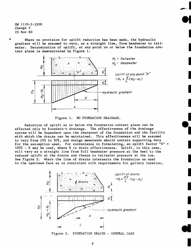
Where no provision for uplift reduction has been made, the hydraulic gradient will be assumed to vary, as a straight line, from headwater to tailwater. Determination of uplift, at any point on or below the foundation contact plane is demonstrated by Figure l.
L ____ ,__ ________ _,_,
H1 : Toi/water H2 = Headwater
Up/ill al any point "p"
:H, + {-(Hz-H,)
Figure 1. NO FOUNDATION DRAINAGE,
Reduction of uplift at or below the foundation contact plane can be effected only by foundati~n drainage. The effectiveness of the drainage system will be dependenD· upon the character of the foundation and the facility with which the dra1.ns can be maintained. This effect.iveness wi 11 be assumed to vary from 257. to 507., and design memoranda should contain supporting data for the assumption used. For convenience in formulating, an uplift factor "K" 100% - E may be used, where Eis drain effectiveness. Uplift, in this case, will vary as a straight line from full headwater pressure at the heel to the reduced uplift at the drains and thence to tailwater pressure at the toe. See Figure 2. Where the line of drains intersects the foundation as near to the upstream face as is consistent with requirements for gallery location,
' - L I -i
I
Upli ft at drains _ KX -H,+L (Hz-H1)
Figure 2 . FOUNDATION DRAINS - GENERAL CASE
4
---·-I el
I I ·1 ·1
I I I
•• = I
I I I I I
II I
I I 1·
I I I •• I I
I I I
• I
EM 1110-2-2200 Change 2
23 Nov 60
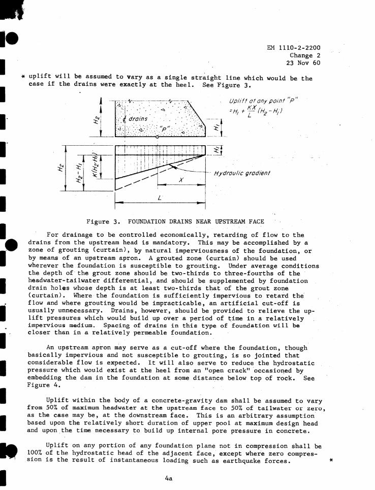
* uplift will be assumed to vary as a single str~ight line which would be the case if the drains were exactly at the heel. See Figure 3,
Uplift at any point "p"
=H +-KX(H -H) I L 2 I
Figure 3, FOUNDATION DRAINS NEAR UPSTREAM FACE
For drainage to be controlled economically, retarding of flow to the drains from the upstream head is mandatory. This may be accomplished by a zone of grouting (curtain), by natural imperviousness of the foundation, or by means of an upstream apron. A grouted zone (curtain) should be use·d wherever the foundation is susceptible to grouting. Under average conditions the depth of the grout zone should be two-thirds to three-fourths of the headwater-tai lwater differential, and should be supplemented by foundation drain noles whose depth is at least two-.thirds that of the grout zone {curtain). Where the foundation is suffi,ciently impervious to retard the flow and where grouting would be impracticable, an artificial cut-off is usually unnecessary. Drains, however, should be provided to relieve the uplift pressures which would build up over a period of ~ime in a relatively impervious medium. Spacing of drains in this type of foundation will be closer than in a relatively permeable foundation.
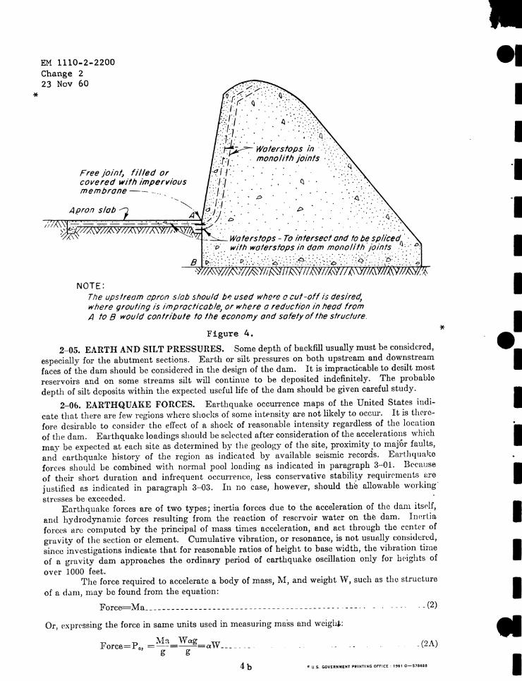
An upstream apron may serve as a cut-off where the foundation, though basically impervious and not susceptible to grouting, is so jointed that considerable flow is expected. It will also serve to reduce the hydrostatic pressure which would exist at the heel from an "open crack" ·occasio~ed by embedding the dam in the foundation at sqme distance below top of rock. See Figure 4.
Uplift within the body of a concrete-gravity dam shall be assumed to vary from 50% of maximum headwater at the upstream face to 50% of tailwater or. zero, as the case may be, at the downstream face. This is an arbitrary assumption based upon the relatively short duration of upper pool at maximum design head and upon . the time necessary to build up internal pore pressure in concrete.
Uplift on any portion of any foundation plane not in compression shall be 100% of the hydrostatic head of the adjacent face, except where zero compression is the result of instantaneous loading such as earthque.ke forces.
4a
*
*
EM 1110-2-2200 Change 2 23 Nov 60
Free joint, filled or covered with impervious membrane-- - -- ..
NOTE: Tfle upstream apron s lob should b,: used where C! cut-off is desired
where grouting is impracticable, or where a reduction in head fro/n
A to B would contribute to the economy and sofetyoflhe structure.
Figure 4.
2-05. EARTH AND SILT PRESSURES. Some depth of backfill usually must be considered,
especially for the abutment sections. Enrth or silt pressures on both upstream and downstream
faces of the dn.m should be considered in the design of the dam. It is impracticable to desilt most
reservoirs and on some streams silt will continue to be deposited indefinitely. The probable
depth of silt deposits within the expected useful life of the dam should be given careful study.
2-0b. EARTHQUAKE FORCES. Earthquake occun-ence maps of the United States indi
cate that there are few regions where sl1ot:ks of some inti>nsity are not likely to occur. It is there
fore desiraLle to consider the effect of a shock of reasonable intensity regardless of the location
of the dam. Earthquake loadings should be selected after consideration of the accelerations which
may be expected at each site as determined by the geology of the site, proximity .to majtr faults,
and earthquake history of the region as indicated by available seismic records. E arthquake
forCl'S should be combined with normal pool loading as indicated iu paragraph 3-01. Because
of their short duration and infrequent occurrrnce, less conservative stability requirrments ure
justified as indicated in paragraph 3-03. In no case, however, should th~ allowable working·
stresses be exceeded. Earthquake forces are of two types; inertia forces due to the acceleration of the dnm itsr lf,
and hydrodynamic forces resulting from the reaction of reservoir water on the dam. Inertia
forces nrc computed by the principal of mass times acceleration, and act through the center of
gruvity of the section or element. Cumulative vibration, or resonance, is not usmllly c:onsidcred,
since investigations indicate that for reasonable ratios of height to base width, the vihrntion time
of a gravity dam approaches the ordinary period of earthquake oscillation only for h<·ights of
over 1000 feet. The force required to accelerate a body of mass, 1-1, and weight vV, such ns the struct ure
of a d,1111, may be found from the equation:
Force=Nla __ . ___________ _________ ____ . ___ . _ .. ____ ___ . _ . __ _ . . _ . _ . . . . _ (2)
Or, Pxpressing the force in so.me units used in measuring mo.ss nnd weigh.:
Force=P., =:\,h= \Vag=aW __ _ g g
. (2A )
• U. S G0YUNJllll~Nt PJllHTING Of"F'ICE : IHI 0 -57940
*
I I ·1 ·1
I I
•• I I I I I I I
• I
I I I I I I I t I ,
I I
EM 1110---2-2200 25 Sep 58
The inertia of the reservoir water induces an increased pressure on the dam concurrently with masonry inertia forces. This force may be computed by [means of the Westergaard formula 14
using the parabolic approximation:
2 P e
2 = 3 CeaYfu-- - - - - - - - - - - - - - - - - - - - - - - - - - - - - - - - - - - - - - - - - - - -- - - - - - - - - - - - - (3)
Me=:5
Ceay2fu- - - - --- -- - - -- -- - - - --- -- - - - - - - - -- - - - - - - - - - - - - ---- - - - - - - -- - (4)
· In the above formulae-p e, = earthquake force due to acceleration of dam Pe, = additional total water pressure down to depth y Me= additional moment at depth y due to P •• a = ratio of earthquake acceleration, a to g g = acceleration of gravity = 32.2 ft. per. sec. a = earthquake acceleration = ag h = total height of dam C
0 = a factor depending principally on height of dam and the earthquake vibration
period, te, in seconds. W estergaard's approximate equation for C., which is sufficiently accurate for all usual conditions, in pound-second foot units is:
c. I_ h 2 -- - -- -- - - ------------------ - -- - - ------- ----------(5)
\f l-0.72 (1000 t) ·
51
An acceleration of 0.lg should be used in regions where moderate to severe shocks have been experienced or where other conditions are unfavorable- In more favorable regions this factor may be reduced to 0-05g. Period of vibration, te, is usually assumed as 1 second. Earthquake data may be obtained from the Coast and Geodetic Survey, Washington, D. C.
While an earthquake acceleration might take place in any direction, the most unfavorable direction with reservoir full is upstream, which causes the inertia forces to be directed downstream. Similarly, with reservoir empty, acceleration in the opposite direction would be .most unfavorable.
A vertical acceleration changes the weight of the masonry and the wate.r in the same ratio. Considering these elements alone, the resultant is not displaced from the position it would occupy if there were no earthquake. The increase in stresses is generally less than that resulting from an equal horizontal acceleration. Therefore, vertical acceleration may normally he neglected- Uplift is usually assumed unaffected by earthquake.
2-07. ICE PRESSURE. Ice pressure is of less importance in the design of a gravity da.m than in the design of gates and other appurtenances for the dam. Instances of ice damage to the gates are quite common while no instance is known of any serious ice damage occurring to the dam.
Experiments have indicated 2 that ice expands with rise in temperature and, being plastic, it flows under sustained pressure. Consequently, the yield strength of ice is far below its quickcrushing strength. The rate of rise of temperature and its probable duration are important factors in the determination of the pressure exerted on a structure. It is recommended that a unit pressure of not more than 5000 pounds per square foot be applied to the contact surface of the structure, based upon the expected ice thickness. For dams in this country the ice thickness normally will not exceed 2 feet. Ice pressure should be applied at_ the normal pool elevation.
2-08. WIND PRESSURES. Wind pressure of 30 pounds per square foot should be used in the stability investigation of a ditm for conditions as indicated in paragraph 3-01. SuperstructurE>s of
5
EM 1110-2-2200 25 Sep 58
dams carrying large crest gates should be investigated for wind loads of 30 pounds per square foot in any direction.
2-09. SUBATMOSPHERIC PRESSURE. The theoretical pressures along the downstream face of an ogee spillway crest approach atmospheric pressure at the head for which the crest profile is designed. For heads higher than the design head, subatmospheric pressures are obtained along the spillway. When spillway profiles are designed for heads appreciably less than the probable maximum that could be obtained, the magnitude of these pressures should be determined and considered in the stability analysis. M ethods and discussions covering the determination of these pressures are presented in EM 1110-2-1603.
2-10. WAVE PRESSURE. While wave pressures are of more importance in their effect upon gates and appurten:1.nces they may, in some instances, have an appreciable effect upon the dam proper. The height of waves is usually an important factor in the determination of the r equired freeboard of any dam.
Dimensions and force of waves depend on the extent of water surface, or fetch, the velocity of wind, and other factors. Information relating to waves and wave pressures are presented in EM 1110-2- 1608 and EM 1110-2- 2904.
2-11. REACTION OF FOUNDATIONS. The determination by statics of the reaction of the foundations of dams is covered in various t exts.3 In general, the resultant of all horizontal and vertical forces including uplift must be balanced by an equal and opposite reaction at the foundation consisting of the total vertical reaction and the total horizontal shear and friction. For the dam to be in static equilibrium the location of this force is such that the summation of moments are equal to zero. The distribution of the vertical reaction is assumed as trapezoidal for convenience only, with a knowledge that the elastic and plastic properties of both the foundation material and the concrete do affect the actual distribution.
The problem of determining the actual distribution is complicated by the horizontal reaction, internal stress relations, and other theoretical considerations. Moreover, variation of foundation materials with depth, cracks, and fissures which interrupt the tensile and shearing resistance of the foundation also make the problem more complex.
For overflow sections, the base width is generally determined by projecting the spillway s1ope to the foundation line and all concrete downstream from this line is disregarded. If a vertical longitudinal joint is not provided at this point, the mass of concrete downstream from the theor ectical toe must be investigated for inteinal stresses.
The assumed unit uplift pressure should be added to the computed unit foundation reaction to determine the maximum possible unit foundation pressure at any point.
Internal stresses and foundation pressures should be computed both with and without uplift to determine the maximum condition.
6
I I I I I I I
' I
I. 1:
-
\
CHAPTER 3
STABILITY
EM 1110-2-2200 . 25 Sep 58
3-01. LOADING CONDITIONS. The following loading conditions and requirements are suitable in general for gravity dams of moderate height. Loads which are not indicated, such as wave action, or any unusual loadings should be considered where applicable. Power intake sections should be investigated with emergency bulkheads closed and all water passages empty.
I. Construction Condition. Dam completed but no water in reservoir, no tailwater, wind load on downstream face.
IL Normal Operating Condition. Pool elevation at top of closed spillway gates, where spillway is gated; and at spillway crest, where spillway is ungated. Minimum tailwater elevation for gated and ungated spillways. Ice pressure, if applicable.
III. Induced Surcharge Condition. Pool elevation at top of partially opened gate. Tailwater pressure at full value for non-overflow section and 60 percent of full value for overflow section. Ice pressure if applicable.
IV. Flood Discharge Condition. Reservoir at maximum flood pool elevation. All gates open and tailwater at flood elevation. Tailwater pressure at full value for nonoverflow section and 60 percent of full value for overflow sections for all conditions of deep fl.ow over spillway, except that full value will be used in all cases for computation of the uplift. No ice pressure. ·
V. Construction Condition with Earthquake. Earthquake acceleration in a downstream direction. No water in reservoir. No wind load. No tailwater.
VI. Normal Operating Condition with Earthquake. Earthquake acceleration in an upstream direction. Reservoir at top of closed gate for gated spillways and at spillway crest for ungated spillways. Minimum tailwater. No ice pressure.
3-02. STABILITY REQUIREMENTS. The basic requirements for stability of a gravity dam for all conditions of loading are:
(1) That it be safe against overturning at any horizontal plane within the dam, at the base or at a plane below the base.
(2) That it be safe against sliding on any horizontal plane within the dam, on the foundation, or on any horizontal or nearly horizontal seam in the foundation.
(3) That allowable unit stresses in the concrete or in the foundation material shall not be exceeded.
3-03. OVERTURNING AND SLIDING CRITERIA. When the resultant of all forces acting above any horizontal plane through a dam intersects that plane outside of the middle third, tensile stresses are set up. Since the tensile strength of concrete is usually considered to be zero, it is generally required for all normal loading that the resultant intersect the plan'e within the middle third. However, because of the short duration of earthquake forces, as discussed in paragraph 2-06, it is considered justifiable to modify this requirement when these forces are included, as indicated in table 1.
. The horizontal forces acting on a dam tend to cause the structure to slide along horizontal planes. Resistance to sliding at or below the base is a function of the shearing strength of the foundation and at any plane above the base, the shearing strength of the concrete in the dam. Experience has shown that the shearing resistance of the foundation or concrete need not be investigated if the ratio of horizontal forces to vertical forces (1:H/~V) is such that a reasonable safety factor against sliding results. This will require that the ratio of :ZH/2:V be well below the coefficient of sliding friction of the material.
Table 1 indicates acceptable limits of the location of tptn~l!k~~~~~~~~~ sliding factor for all loading conditions as outlined in paragraph 3--JJL exceeds the values given, the shearing resistance should be investi ater". -~.=.::..:.!.~~--
7
: Bureau at R~clamation · - ''•n~ ~~rv,c:: Center
I
EM 1110-2-2200 25 Sep 58
TABLE 1
Loading Condition Resultant to Fall Within Following Central Percent of Base Width
Maximum Sliding
Factor "1:H/I.V
I 33½ IT ~½ Ill ~¼ IV 33½ V (For conditions V and VI, within base but allowable
0.65 o. 65 0.65
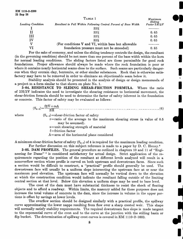
VI foundation pressure must not be exceeded) 0. 85 For the sake of economy, and unless the sliding tendency controls the design, the resultant
(in the governing condition) should be not more than one percent of the base width within the kern for normal loading conditions. The sliding factors listed are those permissible for good rock foundations. Proper allowance should always be made where the rock foundation is poor or where it contains nearly horizontal seams close to the surface. Such seams are particularly dangerous when they contain clay, bentonite, or other similar substances. Rock that is otherwise satisfactory may have to be removed in order to eliminate an objectionable seam below it.
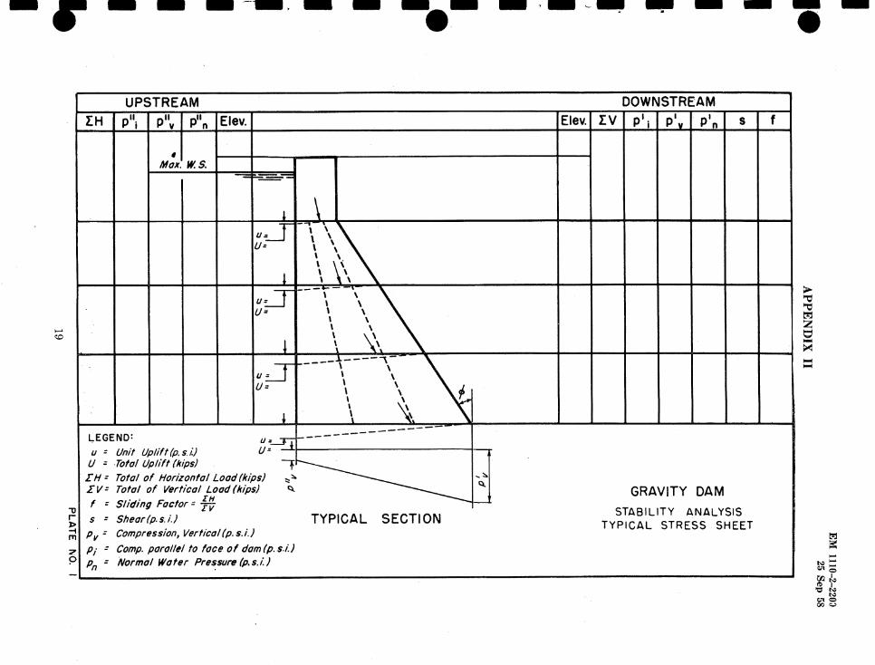
Stability analysis should be presented in the analysis of design or design memoranda of a project in a form similar to that shown on plate No. 1.
3-04. RESISTANCE TO SLIDING SHEAR.FRICTION FORMULA. Where the ratio of ~H/2:V indicates the need to investigate the shearing resistance to horizontal movement, the shear-friction formula should be used to determine the factor of safety inherent in the foundation or concrete. This factor of safety may be evaluated as follows:
where
(S.-i) = f2:'~t;sA ___________________________ ___ _______________ _ __ __________ (6)
(S.-r) =shear-friction factor of safety r=ratio of the average to the maximum shearing stress (a value of 0.5
may be assumed). s=unit shearing strength of material £= friction factor
A=area of the horizontal plane considered
A minimum shear-friction factor of safety (S._1) of 4 is required for the maximum loading condition. For further discussion on this subject reference is made to a paper by D. C. Henny.4
3-05. DAM PROFILES. The general procedure as outlined in chapters 10 and 11 of "Engineering for Dams" 3 is considered satisfactory for actual design. Strict application of the requirements regarding the position of the resultant at different levels analyzed will result in a nonoverflow section whose profile is curved on both upstream and downstream faces. Since such a section would be difficult to construct, a "practical" profile should generally be used. The downstream face will usually be a uniform slope intersecting the upstream face at or near the maximum pool elevation. The upstream face will normally be vertical down to the elevation at which the construction condition would indicate the resultant falling outside of the limiting central section at that level. Below this elevation a uniform slope may be used to base level.
The crest of the dam must have substantial thickness to resist the shock of floating objects and to afford a roadway. Within limits, the masonry added for these purposes does not increase the total volume of concrete in the dam, since the increase in volume in the upper portions is offset by savings at lower levels.
The overflow section should be designed similarly with a practical profile, the spillway curve approximating the lower nappe resulting from flow over a sharp crested weir. This shape will normally satisfy stability requirements. The required downstream face slope is made t angent to the exponential curve of the crest and to the curve at the junction with the stilling basin or flip bucket. The determination of spillway crest curves is covered in EM 1110-2-1603.
8
I
I I I
I
11 I
I' I
~ I
I
I 1e I I I I I I I {' I I I I I I le I
CHAPTER 4
STRESSES
EM 1110-2-2200 25 Sep 58
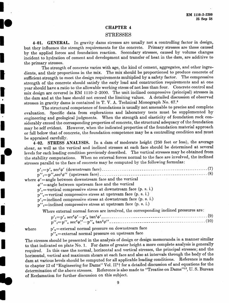
4-01. GENERAL. In gravity dams stresses are usually not a controlling factor in design, but they influence the strength requirements for the concrete. Primary stresses are those caused by the applied forces and foundation reaction. Secondary stresses, caused by volume changes incident to hydration of cement and development and transfer of heat in the dam, are additive to the primary stresses.
The strength of concrete varies with age, the kind of cement, aggregates, and other ingredients, and their proportions in the mix. The mix should be proportioned to produce concrete of sufficient strength to meet the design requirements multiplied by a safety factor. The compressive strength of the concrete should satisfy the early load and construction requirements and at one year should have a ratio to the allowable working stress of not less than four. Concrete control and mix design are covered in EM 1110-2-2000. The unit inclined compressive (principal) stresses in the dam and at the base should not exceed the limiting values. A detailed discussion of observed stresses in gravity dams is contained in T. V. A. Technical Monograph No. 67.8
The structural competence of foundations is usually not amenable to precise and complete evaluation. Specific data from explorations and laboratory tests must be supplemented by engineering and geological judgments. When the strength and elasticity of foundation rock considerably exceed the corresponding properties of concrete, the structural adequacy of the foundation may be self evident. However, when the indicated properties of the foundation material approach or fall below that of concrete, the foundation competence may be a controlling condition and ~ust be appraised carefully.
4-02. STRESS ANALYSIS. In a dam of moderate height (250 feet or less), the average shear, as well as the vertical and inclined stresses at each face should be determined at several levels for each loading condition previously described. The vertical stresses may be obtained from the stability computations. When no external forces normal to the face are involved, the inclined stresses parallel to the face of concrete may be computed by the following formulas:
p' 1=p' v sec2¢' (downstream face) _______ ______________ __ __________________________ (7)
p" 1= p" vsec2¢" (upstream face) _________________________ - _______ - - ____ - _ - - __ - _ - _ (8)
where ef>'=angle between downstream face and the vertical ¢"=angle between upstream face and the vertical p' v=vertical compressive stress at downstream face (p. s. i.) p" v=vertical compressive stress at upstream face (p. s. i.) p' ,=inclined compressive stress at downstream face (p. s. i.) p" ,=inclined compressive stress at upstream face (p. s. i.)
Where external normal forces are involved, the corresponding inclined pressures are:
p' 1=P'v sec2¢'-P'n tan2ef>'---- - - - --- - -- -------- - -- ------ - - - ----- -- -- ----- - _(9) p",=p"v sec2¢~'-p"n tan2,;li'' ________________________________________ ____ (10)
where p'n=external normal pressure on downstream face p" n = external normal pressure on upstream face
The stresses should be presented in the analysis of design or design memoranda in a manner similar to that indicated on plate No. I. For dams of greater height a more complete analysis is generally required. In this case the normal, horizontal and vertical stresses, the principal stresses; and the horizontal, vertical and maximum shears at each face and also at intervals through the body of the dam at various levels should be computed for all applicable loading conditions. Reference is made to chapter 12 of "Engineering for Dams" Vol. II3t for a detajled discussion of and equations for the determination of the above stresses. Reference is also made to "Treatise on Damsm2
, U. S. Bureau of Reclamation for further discussion on this subject.
9
EM 1110-2--2200 25 Sep 58
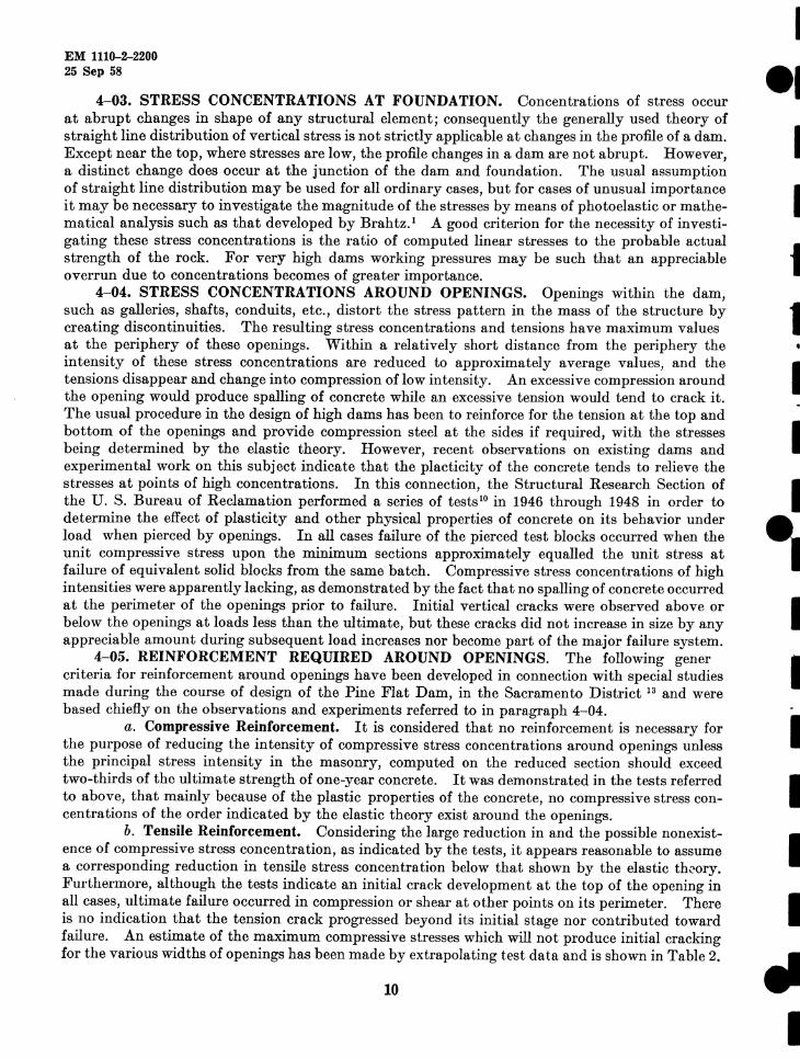
4-03. STRESS CONCENTRATIONS AT FOUNDATION. Concentrations of stress occur at abrupt changes in shape of any structural element; consequently the generally used theory of straight line distribution of vertical stress is not strictly applicable at changes in the profile of a dam. Except near the top, where stresses are low, the profile changes in a dam are not abrupt. However, a distinct change does occur at the junction of the dam and foundation. The usual assumption of straight line distribution may be used for all ordinary cases, but for cases of unusual importance it may be necessary to investigate the magnitude of the stresses by means of photoelastic or mathematical analysis such as that developed by Brahtz. 1 A good criterion for the necessity of investigating these stress concentrations is the ratio of computed linear stresses to the probable actual strength of the rock. For very high dams working pressures may be such that an appreciable overrun due to concentrations becomes of greater importance.
4-04. STRESS CONCENTRATIONS AROUND OPENINGS. Openings within the dam, such as galleries, shafts, conduits, etc., distort the stress pattern in the mass of the structure by creating discontinuities. The resulting stress concentrations and tensions have maximum values at the periphery of these openings. Within a relatively short distance from the periphery the intensity of these stress concentrations are reduced to approximately average values, and the tensions disappear and change into compression of low intensity. An excessive compression around the opening would produce spalling of concrete while an excessive tension would tend to crack it. The usual procedure in the design of high dams has been to reinforce for the tension at the top and bottom of the openings and provide compression steel at the sides if required, with the stresses being determined by the elastic theory. However, recent observations on existing dams and experimental work on this subject indicate that the placticity of the concrete tends to relieve the stresses at points of high concentrations. In this connection, the Structural Research Section of the U. S. Bureau of Reclamation performed a series of tests10 in 1946 through 1948 in order to determine the effect of plasticity and other physical properties of concrete on its behavior under load when pierced by openings. In all cases failure of the pierced test blocks occurred when the unit compressive stress upon the minimum sections approximately equalled the unit stress at failure of equivalent solid blocks from the same batch. Compressive stress concentrations of high intensities were apparently lacking, as demonstrated by the fact that no spalling of concrete occurred at the perimeter of the openings prior to failure. Initial vertical cracks were observed above or below the openings at loads less than the ultimate, but these cracks did not increase in size by any appreciable amount during subsequent load increases nor become part of the major failure system.
4-05. REINFORCEMENT REQUIRED AROUND OPENINGS. The following gener criteria for reinforcement around openings have been developed in connection with special studies made during the course of design of the Pine Flat Dam, in the Sacramento District 13 and were based chiefly on the observations and experiments referred to in paragraph 4-04.
a. Compressive Reinforcement. It is considered that no reinforcement is necessary for the purpose of reducing the intensity of compressive stress concentrations around openings unless the principal stress intensity in the masonry, computed on the reduced section should exceed two-thirds of the ultimate strength of one-year concrete. It was demonstrated in the tests referred to above, that mainly because of the plastic properties of the concrete, no compressive stress concentrations of the order indicated by the elastic theory exist around the openings.
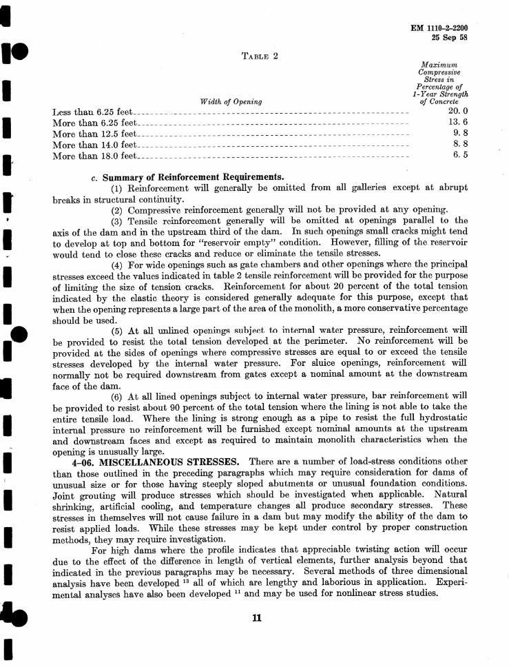
b. Tensile Reinforcement. Considering the large reduction in and the possible nonexistence of compressive stress concentration, as indicated by the tests, it appears reasonable to assume a corresponding reduction in tensile stress concentration below that shown by the elastic th-?ory. Furthermore, although the tests indicate an initial crack development at the top of the opening in all cases, ultimate failure occurred in compression or shear at other points on its perimeter. There is no indication that the tension crack progressed beyond its initial stage nor contributed toward failure. An estimate of the maximum compressive stresses which will not produce initial cracking for the various widths of openings has been made by extrapolating test data and is shown in Table 2.
10
I
I I t 1 I I I .. I I I I I I
" I
I
I I I I I I I i' I I I I I I le I
TABLE 2
Width of Opening Less than 6.25 feet_ _______ , ___________ - .. - __ - - - - - - - - - - ____ - - - - - - - - ___________ _ More than 6.25 feet ____________ _______ _____________________________________ _ More than 12.5 feet _______________ - - - - - -- __________________________________ _ More than 14.0 feet ________________________________________________________ _ More than 18.0 feet _________________________________ _______________ ___ _____ _
c. Summary of Reinforcement Requirements.
EM 1110-2-2200 25 Sep 58
Maximum Compressive
Stress in Percentage of
1-Year Strength of Concrete
20.0 13.6
9. 8 8. 8 6. 5
(1) Reinforcement will generally be omitted from all galleries except at abrupt breaks in structural continuity.
(2) Compressive reinforcement generally will not be provided at any opening. (3) Tensile reinforcement generally will be omitted at openings parallel to the
axis of the dam and in the upstream third of the dam. In such openings small cracks might tend to develop at top and bottom for "reservoir empty" condition. However, filling of the reservoir would tend to close these cracks and reduce or eliminate the tensile stresses.
(4) For wide openings such as gate chambers and other openings where the principal stresses exceed the values indicated in table 2 tensile reinforcement will be provided for the purpose of limiting the size of tension cracks. Reinforcement for about 20 percent of the total tension indicated by the elastic theory is considered generally adequate for this purpose, except that when the opening represents a large part of the area of the monolith, a more conservative percentage should be used.
(5) At all unlined openings subject to internal water pressure, reinforcement will be provided to resist the total tension developed at the perimeter. No reinforcement will be provided at the sides of openings where compressive stresses are equal to or exceed the tensile stresses developed by the internal water pressure. For sluice openings, reinforcement will normally not be required downstream from gates except a nominal amount at the downstream facf;.l of the dam.
(6) At all lined openings subject to internal water pressure, bar reinforcement will be provided to resist about 90 percent of the total tension where the lining is not able to take the entire tensile load. Where the lining is strong enough as a pipe to resist the full hydrostatic internal pressure no reinforcement will be furnished except nominal amounts at the upstream and downstream faces and except as required to maintain monolith characteristics when the opening is unusually large.
4-06. MISCELLANEOUS STRESSES. There are a number of load-stress conditions other than those outlined in the preceding paragraphs which may require consideration for dams of unusual size or for those having steeply sloped abutments or unusual foundation conditions. Joint grouting will produce stresses which should be investigated when applicable. Natural shrinking, artificial cooling, and temperature changes all produce secondary stresses. These stresses in themselves will not cause failure in a dam but may modify the ability of the dam to resist applied loads. While these stresses may be kept under control by proper construction methods, they may require investigation.
For high dams where the profile indicates that appreciable twisting action will occur due to the effect of the difference in length of vertical elements, further analysis beyond that indicated in the previous paragraphs may be necessary. Several methods of three dimensional analysis have been developed 13 all of which are lengthy and laborious in application. Experi~ mental analyses have also been developed 11 and may be used for nonlinear stress studies.
11

'
I
--1 I I I •
I I I
•• I I .
I I I 1:
,J I:
I
--1 I I I I I I i' I I I I I I le I
CHAPTER 5
MISCELLANEOUS FEATURES
EM 1110-2--2200 25 Sep 58
5-01. CONTRACTION AND CONSTRUCTION JOINTS. Transverse contraction joints will usually be spaced at not more than 50 feet. Where a powerhouse forms an integral part of a dam and the spacing of the units is in excess of this dimension, it will be necessary to increase the spacing of the joints in the intake block to match the spacing of the joints in the powerhouse. In the spillway section gate size and other requirements are factors in the determination of the spacing of contraction joints, but rarely will the 50 foot limitation need to be exceeded.
Horizontal, or nearly horizontal construction joints will be spaced to divide the structure into convenient working units and for control of construction procedure for the purpose of regulating temperature changes. The vertical spacing will usually not exceed 5 feet except that lift thicknesses of 7}~ feet will be permitted as provided in EM 1110-2-2000. Where necessary as a temperature control measure lift thicknesses may be limited to 2½ feet in certain parts of the dam.
A double line of waterstops should be provided near the upstream face at all contraction joints. A 6- to 8-inch diameter formed well will generally be provided between the two waterstops. This well should be capped at the top and terminated at the bottom at about the level of, and drained into, the gutter in the grouting gallery. The waterstops should be grouted about 6 inches into the foundation and should terminate near the top of the dam. For gated spillway sections the tops of the waterstops should terminate at the gate sills. A single line of waterstops should be placed around all galleries and other openings crossing monolith joints. A further discussion of joints and waterstops is presented in EM 1110--2-2000.
5-02. INTERIOR DRAINAGE. Usually a Hne of drainage holes about 8 inches in diameter and about 10 feet on centers will be provided within the body of the dam. These holes will be located near the upstream face of the dam and drain into the gutter of the grouting gallery. The holes should be parallel to the upstream face of the dam and may be formed with porous concrete pipe or a collapsible steel form. The function of these drains is to intercept the seepage through the concrete and convey it to the sump pump. This interception of the seepage will reduce con-· siderably the uplift effect within the body of the dam. The holes should extend to near the top of the section and should be straight in order that they may be drilled from the top in case of stoppage or plugging with concrete or deposits of lime. ·
5-03. SPILLWAY. The primary function of a spillway is to release surplus water from .. reservoirs in order to prevent overtopping and possible failure of the dam. An overflow or spillway
profile is governed in its upper portions by hydraulic considerations rather than by stability requirements. The term "ogee spillway" is generally used to describe the commonly used gravity dam spillways with crests shaped as indicated in paragraph 3-05.
The downstream face of the spillway section terminates either in a stilling basin apron or in a bucket type energy dissipator depending largely upon the nature of the site and upon the tailwater conditions.
Discharge over the spillway section must be confined by spray walls on either side, terminating in training walls extending along each side of the stilling basin. Height and length of training walls are usually determined by model tests or from previous tests of similar structures. Spray walls should be of sufficient height to contain the spillway design flow, with a moderate freeboard. Air entrainment will affect both the height and unit weight of the water. This condition should be considered in the design of the spray walls, with the maximum allowance for air entrainment being made at the stilling basin, decreasing uniformly to no allowance at the crest. Spray walls are usually designed as cantilevers projecting out of the monolith. Since the occurrence of the spillway design flood during the life of the structure is not very probable, design unit stresses for spray walls may be raised a maximum of 33¼ percent for that loading condition. A windload
13
EM 1110-2-2200 25 Sep 58
of 30 pounds per square foot or earthquake loading should be assumed for design of reinforcing in the outer face of the walls.
Hydraulic criteria for determining spillway and stilling basin design, including crest shapes, water pressure on the downstream face, water surface profiles, air entrainment, etc., are discussed in detail in EM 1110-2-1603. Structural criteria for the determination of the stilling basin design are covered in EM 1110-2-2400.
5-04. SPILLWAY BRIDGE. Bridges are provided across dam spillways to furnish a means of access for pedestrian and vehicular traffic between the nonoverflow sections; or to support operating machinery for the crest gates; or, usually, to serve both purposes. In the case of an uncontrolled spillway and in the absence of vehicular traffic, access between the nonoverflow sections may be provided by stair shafts and a gallery beneath the crest.
The design of a spillway bridge should be in accordance with good practice for any deck type, mult,iple span bridge. If the structure carries a State or County highway, the design should conform to the standards of the state or county as a minimum. Usually H20 or H20-S16 loading will be required. In addition, the special loadings required by reason of its function as an operating bridge should be taken into account, including provisions for any heavy concentrated loads.
Materials used in the design and construction of spillway bridges should be selected on the basis of function and economy. In most cases the floors, curbs, and parapets will be of reinforced concrete. The supporting beams and girders may be of structural steel, reinforced concrete, or prestressed concrete. Structural steel is often favored for comparative simplicity of erection. However, where lateral bracing between girders must be omitted as is the case when vertical-lift crest gates are used, the relatively small lateral stiffness of steel girders will impose some problems. The inertia inherent in reinforced concrete girders and beams, together with their increased stiffness in a horizontal direction, will sometimes favor their use. Advances, in recent years, in the technique of prestressed concrete make this type of construction an attractive possibility . Prestressed concrete can combine economy with comparative simplicity of erection, since it lends itself readily to precasting operations.
5-05. SPILLWAY PIERS. For uncontrolled spillways, the piers function as supports for the bridge. On controlled spillways, the piers will also contain the anchorage or slots for the crest gates and may support fixed hoists for the gates. The piers are generally located in the middle of the monolith, and the width of pier is usually determined by the size of the gates, with the average width being between 8 and 10 feet.
As the gates will be independently operated, various conditions of loading are possible. In general, the following critical conditions of loading should be investigated:
Case I. Both gates closed and water at the top of gates. Case II. One gate closed and the other gate wide open with water at the top of
the closed gate. Case I I I. One gate closed and the other open with bulkheads in place and water
at the top of the closed gate. Cases I and III result in maximum horizontal shear normal to the axis of the dam and the
largest overturning moment in the downstream direction. Case II results in lower horizontal shear and downstream overturning moment, but in
addition the pier will have a lateral bending moment due to the water flowing through the open gate and to the hoisting machinery starting the closed gate. A torsional shear in the horizontal plane will also be introduced by the reaction of the closed gate acting on one side of the pier.
When tainter gates with inclined end frames are used, cases II and III introduce the condition of the lateral component of the thrust on the trunion as a load on only one side of the pier in addition to the applicable loads indicated above. Because of the indeterminate nature of the stress distribution and of the importance of the piers to the structure, the working stresses should not be increased due to the infrequency of the loading considered for cases II and III.
14
I
--1 I I 1 I I I
•• I I I I I I
el I
I 1e I I
I I
I I I I I I -le I
EM 1110-2-2200 25 Sep 58
5-06. OUTLET WORKS. The outlet works for concrete dams are usually conduits or sluices through the masonry. All conduits may be at low level or some may be located at one or more higher levels to reduce the head on the gates, or to allow for future reservoir silting. In general, the location, size and shape of the outlet works are based on hydraulic, rather than structural considerations. Conduits may be provided for regulation of flows for flood control, navigation, irrigation, water supply or for multiple purposes. These openings are generally unlined except for short sections adjacent to the control gates. In conduits where velocities will be 40 feet per second or higher, precautions will be taken to insure that the concrete in the side walls and inverts will be of superior quality in accordance with the requirements of EM 1110-2-2003. If the dam includes a power intake section, penstocks will be provided except at low head plants with
·unlined spiral cases. The design considerations for penstocks are not within the scope of this chapter. Reinforcement around openings is discussed in paragraph 4-05.
Trash racks are provided for power plant intakes for the purpose of preventing debris from obstructing water passage or damaging the turbines. Normally trash racks are not provided for sluice conduits especially those of larger sizes. In general the necessity of trash racks depends upon the locat,ion of the dam with respect to reservoir areas that will produce floating debris, the size and location of the sluices within the dam, and other considerations bearing upon the possibility of damage and trouble due to the trash. An assumed head differential of 10 feet is usually used for the structural design of the racks.
The effect of project functions upon outlet works design and hydraulic design features, including trash rack types for sluice outlets, are discussed in EM 1110-2-1602. A discussion of the structural features of design for penstocks and trash racks for power plant intakes is included in EM 1110-2-3001.
5-07. FOUNDATION GROUTING AND DRAINAGE. It is customary to grout and drain the foundation rock of gravity dams. This is considered good practice not only in the case of those formations which are clearly defective but also in those which apparently are sound. A weH planned, well executed grouting program may disclose the presence of unsuspected weaknesses in the foundation and will improve any existing defects. Such a program, therefore, gives an added factor of safety and is cheap insurance against future trouble. The most common design
. consists of a single line of grout holes located near the heel, drilled at 5-foot centers and to a depth ranging from four-tenths to six-tenths of the ultimate hydrostatic head on the foundation. A corresponding line of drainage holes are drilled a few feet downstream from the grout curtain and to a depth roughly two-thirds to three-quarters that of the cutoff curtain. Detailed information on foundation grouting, planning and specification writing is contained in EM 1110-2-3501 and in Guide Specification for Civil Works Construction CE-1305.01.
5- 08. GALLERIES. A system of galleries, adits, chambers, and shafts is usually provided within the body of the dam to furnish means of access and space for drilling and grouting and for installation, operation, and maintenance of the accessories and the utilities in the dam. The primary considerations in the arrangement, of the required openings within the dam are their functional usefulness and efficiency and their location with respect to maintaining the structural integrity. ·
a. Grouting Gallery. A gallery for the grouting of the foundation cutoff will extend the full length of the dam. It will also serve as a collection main for the seepage from the foundation drainage holes and the interior drainage holes. The location of the gallery should be near the upstream face and as near the rock surface as possible. It has been standard practice to provide grouting galleries 5 feet wide by 7 feet high. Experience has indicated the desirability of increasing these dimensions to facilitate the drilling and grouting operations. Where practicable the width may be increased to 6 feet and the height to 8 feet. The floor of the gallery should slope about% inch per foot to a 12 inch by 12 inch gutter along the upstream side. The gallery is usually arranged as a series of horizontal runs and stair :flights. The stairs should be
15
EM 1110-2-2200 25 Sep 58
provided with safety treads or a nonslip aggregate finish. Metal treads are preferable where it is probable that equipment will be skidded up or down the steps since they provide protection against chipping of concrete. Where practicable, the width of tread and height of riser should be uniform throughout all flights of stairs and should never change in any one flight.
Details of drilling and grouting operations and equipment are covered in EM 11 I 0-2-3501, EM 1110-2-3502, and EM 1110-2-3503.
b. Gate Chambers and Access Galleries. Gate chambers are located directly over the service and emergency sluice gates. The size of these chambers is determined by the size of gates and hoists. Access galleries should be of sufficient size to permit passage of the largest component of the gates and hoists. Drainage gutters should be provided and the floor of the gallery sloped to the gutter with about ¾ inch per foot slope.
Fon THE CHIEF OF ENGINEERS:
16
W. P. LEBER, Colonel, Gorps of Engineers, Executive.
I e1
I I
I I I
•• I I I I I I
el I
APPENDIX I
SELECTED BIBLIOGRAPHY
EM 1110-2--2200 25 Sep 58
1. Brahtz, John H. A., "The Stress Function and Photo-Elasticity Applied to Dams," Trans., ASCE, Vol. 101, 1936, pp. 1240-1277.
2. Brown, E. and Clarke, G. C., "Ice Thrust in Connection with Hydroelectric Plant Design with Special Reference to Plant at Island Falls on Churchill River, Engineering Journal, (of Canada) Vol. 15, No. 1, January 1932, pp. 18-25, and No. 8, August 1932 pp. 393-7 (discussion).
t3. Creager, William P., J. D. Justin, and Julian Hinds, Engineering for Dams, John Wiley and Sons, New York, 1935.
4. Henny, D. C., "Stability of Straight Concrete Gravity Dams," Trans., ASCE, vol. 99, 1934, pp. 1041-1061.
5. Holmes, H. W., "Determination of Principal Stresses in Buttresses and Gravity Dams," Trans., ASCE, vol. 98, 1933, pp. 971-1038.
6. Molitor, David A., "Wave Pressures on Sea-Walls and Breakwaters," Trans., ASOE, vol. 100, 1935, pp. 984-1002.
7. Steele, Byram W., "Construction Joints," Trans., ASCE, vol. 106, 1941, pp. 1210-1245. 8. Tennessee Valley Authority, "Measurements of the Structural Behavior of Non-is and Hiwasse
Dams," Technical Monograph, No. 67, Knoxville, 1950. 9. Timoshenko, Stephen, Theory of Elasticity, McGraw-Hill Book Co., New York, 1951.
10. U. S. Bureau of Reclamation, "Investigation of the Influence of Openings in Concrete upon its Load-bearing Capacity," Structural Research Laboratory Report, SP 19, 1948.
11. U.S. Bureau of Reclamation, "Trial Load Method of Analyzing Arch Dams," Boulder Canyon Project, Final Reports, Part V, Bull. No. 1, 1938.
12. U. S. Bureau of Reclamation, "Treatise on Dams" Reclamation Manual, Volume X, Design and Construction, Part 2, Engineering Design, Design Supplement No. 2.
13. U. S. Corps of Engineers, Sacramento District, Pine Flat Project, Analysis of Design, Vol. 1, Sacramento, Calif.
14. Westergaard, H. M., "Water Pressures on Dams During Earthquakes," Trans., ASOE, vol. 98, 1933, pp. 418-433.
17

I
e1 I I ·I ·1
\
I I I
•• I I I I I I
- - - - - - -·-~- - - - -.. ~---. ---
"'D r )> -I CTI
z 9
UPSTREAM
:[H p'\ P11v P
11n Elev.
• Max. W. S.
= ------ ....
' \ /J =
I'~ \ \
U= \ \ \ \
\ \' 1 \ \
\ ' u:.J --
\\ \ I
U= \ \ I \
l I I
uJ ~----'"\-- \
\ \
I ' U= I \ \ \ \ ' I
~; L \ ---------
L,EGEND: II= !I -----
II : Unit Uplift {p, 5.i) U= u = Total Uplift (kip$)
1~ rH~ Total of Horizontal Load (kips) rv= Total of Vertical u,ad (kip5)
f = Sliding Factor= ;i $ ;: Shear(p. 5. i.) TYPICAL SECTION
Pv = Compression, Vertical (p. sJ)
P; = Comp. parallel to face of dom{p.s.i.) p = n Normal Wafer Pressure (p.sJ)
':,. ~
-
-DOWNSTREAM
Elev. rv P11 P
1v P
1n s f
--
GRAVITY DAM
STABILITY ANALYSIS TYPICAL STRESS SHEET

For sale by the Superintendent of Documents, U. S. Government Printing Office Washington 25, D. C, • Price 20 cents
I e1
I I ·I
·1 l
I I I
•• I I I I I I
el I


