Embed Size (px)
Citation preview
ENBRIDGE PIPELINES INC.
SOUTH EDMONTON TERMINAL EXPANSION PROJECT
HDD FEASIBILITY REPORT
PREPARED FOR
ENBRIDGE
PREPARED BY:
Edmonton Area Office Calgary Area Office 17806 - 118 Ave 9 - 214 Grande Blvd W. Edmonton, AB, T5S 2W3 Cochrane, AB, T4C 2G4 Phone: 780-784-1990 Phone: 403-932-0560
Document #: 816 - HDD FEASIBILITY- 05
Revision Dated Prepared Reviewed Approved
05 12/05/2014 JC BG BG
04 08/05/2014 JC BG BG
03 01/05/2014 JC BG BG
02 17/04/2014 JC BG BG
01 17/04/2014 JC BG BG
Enbridge Pipelines Inc. Edmonton Terminal (South) Expansion Project
Attachment 1 - HDD Feasibility Report - Revision 05 Condition 6 of Order XO-E101-017-2013
Page 1 of 22
SOUTH EDMONTON TERMINAL EXPANSION PROJECT HDD FEASIBILITY REPORT
5/12/2014 816-HDD Feasibility-05
Author: JC Dessertenne Page 2 of 22 Confidential
TABLE OF CONTENTS 1.0 INTRODUCTION ................................................................................................................... 3
2.0 HDD DESIGN PARAMETERS .............................................................................................. 4
3.0 BASELINE ROAD HDD ......................................................................................................... 5
3.1 Horizontal Directional Drill Alignment ......................................................................... 5
3.2 Laydown Area ............................................................................................................ 5
3.3 Design Summary ....................................................................................................... 5
3.4 Geotechnical Review ................................................................................................. 6
3.5 Construction Risks ..................................................................................................... 6
4.0 PIPELINE CORRIDOR HDD ................................................................................................. 9
4.1 Horizontal Directional Drill Alignment ......................................................................... 9
4.2 Laydown Area ............................................................................................................ 9
4.3 Design Summary ....................................................................................................... 9
4.4 Construction Risks ................................................................................................... 10
4.5 Construction Risks ................................................................................................... 10
5.0 RISK ASSESSMENTS ........................................................................................................ 11
6.0 HDD SCHEDULE FOR SET ................................................................................................ 11
7.0 DRILLING FLUID DISPOSAL .............................................................................................. 12
8.0 WATER SUPPLY ................................................................................................................ 13
9.0 RECOMMENDATIONS ....................................................................................................... 14
10.0 CONCLUSIONS ............................................................................................................ 14
Enbridge Pipelines Inc. Edmonton Terminal (South) Expansion Project
Attachment 1 - HDD Feasibility Report - Revision 05 Condition 6 of Order XO-E101-017-2013
Page 2 of 22
SOUTH EDMONTON TERMINAL EXPANSION PROJECT HDD FEASIBILITY REPORT
5/12/2014 816-HDD Feasibility-05
Author: JC Dessertenne Page 3 of 22 Confidential
1.0 INTRODUCTION Enbridge Pipelines Inc. (Enbridge) is proposing to construct two (2) 914.4 mm O.D. (NPS 36) pipelines. The pipelines will connect the North Edmonton Terminal (NET) to the South Edmonton Terminal (SET). The crossings are located approximately 600m west of the intersection of Baseline Road and Anthony Henday Drive near Edmonton, Alberta.
The pipelines will first cross the Baseline Road Right-of-Way (R/W) along a North-South alignment before turning west and then cross a Pipeline Corridor along an East-West alignment.
Four (4) pipeline sections have been approved by the National Energy Board (NEB) as part of the NEB Section 58 Order. All four (4) drills mentioned in the table below have been approved as part of the Edmonton Terminal (South) Expansion project’s NEB Order XO-E101-017-2013.
Proposed Drills Crossing LSD
Drill 2 - (220-S2N-1) Baseline Road N.E. 32-52-23 W4M
Drill 3 - (203-N2S-1) Baseline Road N.E. 32-52-23 W4M
Drill 2 - (220-S2N-1) Pipeline Corridor N.E. 32-52-23 W4M
Drill 3 - (203-N2S-1) Pipeline Corridor N.E. 32-52-23 W4M Table 1: Drills Summary
CCI has been retained by Stantec Inc. (Stantec) to complete the detailed engineering and design for the above mentioned trenchless crossings by the Horizontal Directional Drill (HDD) installation method. As a scope of work, CCI reviewed the survey and geotechnical investigation and completed a detailed engineering and design of the proposed HDD crossings and summarized this information with this design report.
This report is provided as a feasibility assessment of the site conditions incorporating the survey, geotechnical information, and a geometric review of the four (4) proposed HDD designs listed above. This report also states some of the challenges contractors will face and some mitigative strategies that may be implemented to minimize existing challenges on the project.
Enbridge Pipelines Inc. Edmonton Terminal (South) Expansion Project
Attachment 1 - HDD Feasibility Report - Revision 05 Condition 6 of Order XO-E101-017-2013
Page 3 of 22
SOUTH EDMONTON TERMINAL EXPANSION PROJECT HDD FEASIBILITY REPORT
5/12/2014 816-HDD Feasibility-05
Author: JC Dessertenne Page 4 of 22 Confidential
2.0 HDD DESIGN PARAMETERS The HDD crossings on this project are designed to incorporate the available geotechnical information, Pipeline Research Council Institute (PRCI) guidelines, above ground/buried facilities in the area, above ground/buried geometric parameters and space constraints.
The geotechnical conditions were considered in the designs of the HDD crossings so as to progress the drill through formations that are favourable for these trenchless installations. Typically, clay, clay till, silt, and sand formations will be encountered for these crossings which are considered favorable for the chosen methodology.
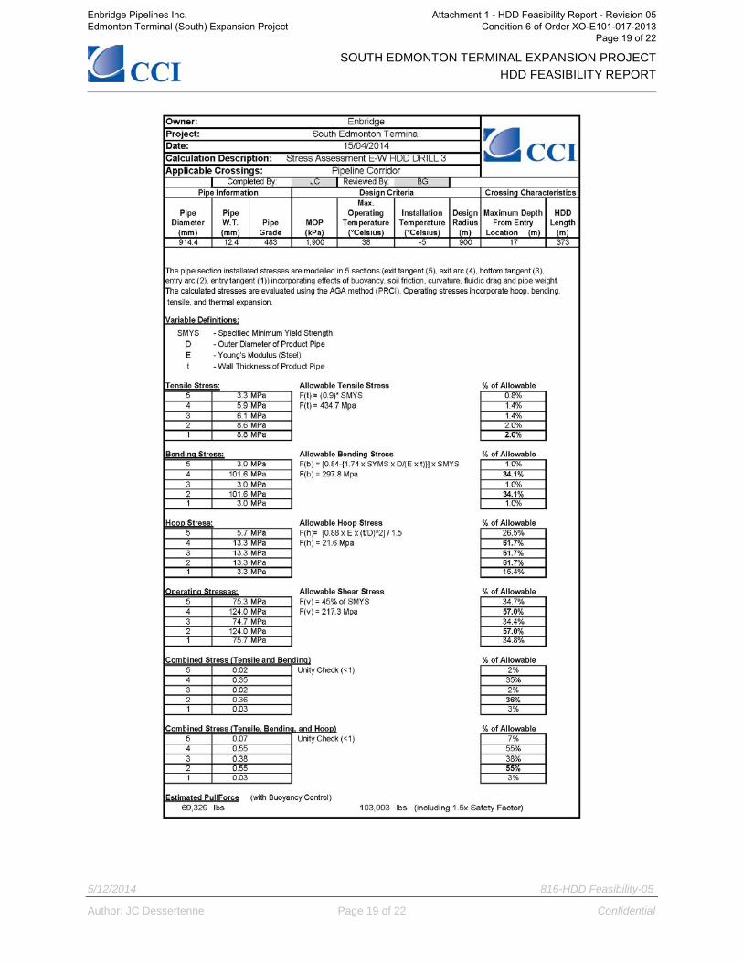
PRCI design guidelines, as suggested in CSA Z662, were utilized to model the bending, hoop, and tensile stresses for the installation, and operating conditions imposed during and after installation. The calculations considered the pipe diameter, wall thickness, grade, depth and geometric design of the crossing.
Space limitations associated with the R/W, Points-of-Inflection (PI) and achievable temporary workspace were also considered. In some cases, additional temporary workspace may be requested to ensure the required equipment can be set up on site to complete the work.
Enbridge Pipelines Inc. Edmonton Terminal (South) Expansion Project
Attachment 1 - HDD Feasibility Report - Revision 05 Condition 6 of Order XO-E101-017-2013
Page 4 of 22
SOUTH EDMONTON TERMINAL EXPANSION PROJECT HDD FEASIBILITY REPORT
5/12/2014 816-HDD Feasibility-05
Author: JC Dessertenne Page 5 of 22 Confidential
3.0 BASELINE ROAD HDD
3.1 Horizontal Directional Drill Alignment The proposed HDDs have a north to south alignment with the proposed entry points on the north side of Baseline Road and the exit points on the south side. The HDD Drawing numbers are:
- D-3.2-61416-0-10LFL (M629) - D-3.2-61417-0-10LFL (M630)
3.2 Laydown Area The pullback sections will be laid out along the R/W and 25m x 380m Temporary Workspace (TWS) located to the south of the exit points.
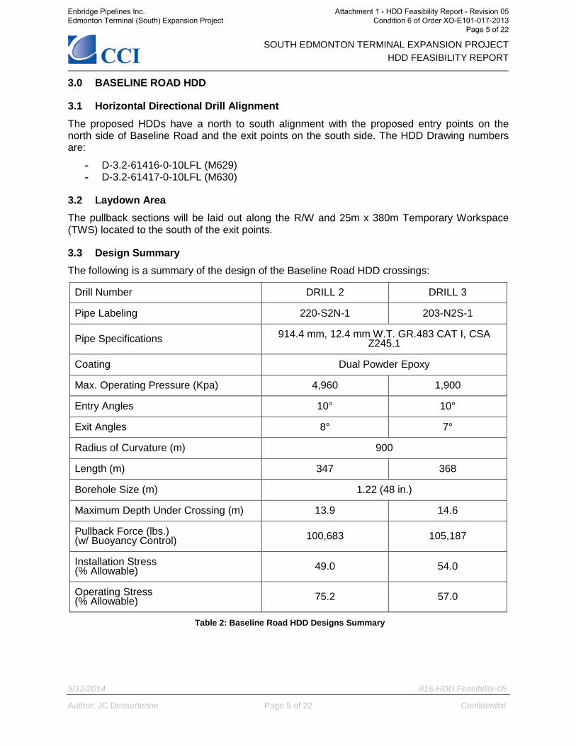
3.3 Design Summary The following is a summary of the design of the Baseline Road HDD crossings:
Drill Number DRILL 2 DRILL 3
Pipe Labeling 220-S2N-1 203-N2S-1
Pipe Specifications 914.4 mm, 12.4 mm W.T. GR.483 CAT I, CSA Z245.1
Coating Dual Powder Epoxy
Max. Operating Pressure (Kpa) 4,960 1,900
Entry Angles 10° 10°
Exit Angles 8° 7°
Radius of Curvature (m) 900
Length (m) 347 368
Borehole Size (m) 1.22 (48 in.)
Maximum Depth Under Crossing (m) 13.9 14.6
Pullback Force (lbs.) (w/ Buoyancy Control) 100,683 105,187
Installation Stress (% Allowable) 49.0 54.0
Operating Stress (% Allowable) 75.2 57.0
Table 2: Baseline Road HDD Designs Summary
Enbridge Pipelines Inc. Edmonton Terminal (South) Expansion Project
Attachment 1 - HDD Feasibility Report - Revision 05 Condition 6 of Order XO-E101-017-2013
Page 5 of 22
SOUTH EDMONTON TERMINAL EXPANSION PROJECT HDD FEASIBILITY REPORT
5/12/2014 816-HDD Feasibility-05
Author: JC Dessertenne Page 6 of 22 Confidential
3.4 Geotechnical Review A geotechnical investigation was recently carried out by AMEC Environment & Infrastructure (AMEC) for the proposed South Edmonton Terminal Phase 2 Expansion project (SET). The geotechnical investigation was completed on October 8th and 10th, 2013 and consisted of two (2) boreholes (BH13-01 and BH13-02). Both boreholes were located south of Baseline Road. The findings were used to complement existing geotechnical information and develop the assessment of these North-South HDD crossings. The report (EG10079), entitled “South Edmonton Terminal Pipeline Crossing Geotechnical Investigation, NE ¼ -Section 32, TWP 52, Range 23 W4M” is dated December 4, 2013.
Borehole BH07-32E was previously drilled in the vicinity and the findings have been used to supplement this report based on AMEC geotechnical investigation report number EG09540 entitled “Enbridge Edmonton North Terminal CWP1 Waupisoo Tanks – Tanks 32 and 35” and dated October 23rd, 2007.
A total of two (2) boreholes (BH13-02, and BH07-32E) were drilled in the Baseline Road area and were completed to a maximum depth of 16.5 meters below ground surface. The position of the boreholes on plan, and a representation of the soil conditions on a cross section along the proposed pipe alignment are provided on the drawings.
The proposed HDD crossings will primarily pass through a thick clay (till) layer (more than 10m), and possibly clay shale and sand layers. With the possibility of a rafted clay shale bedrock layer present along the drill path, a mud motor bit can be used as a Bottom Hole Assembly (BHA) for the first 50m before using a jetting assembly.
The clay till and silt layers materials are generally considered to be suitable for directional drilling and the HDD crossing of the Baseline Road is considered feasible. However, the geotechnical report states that some subsurface condition encountered in the boreholes in the vicinity could present risks to the HDD borehole stability and constructability.
3.5 Construction Risks The following are the main construction risks identified during the risk assessment conducted by CCI (Appendix B), the geotechnical investigation, and previous experience in the area. Also identified are the main mitigations strategies developed to minimize the challenges that may arise during construction. Zone 1: 0 - 30m Risk:
There is a risk of near surface sloughing at the entry location where near surface groundwater levels are present. This formation could cause some local borehole collapse and may impact schedule if the mitigation is not implemented. In addition, as mentioned in the geotechnical report, the sloughing sands encountered in borehole BH07-32E also present a risk of hydraulic fracturing.
Mitigation: Topsoil and clay (till) could be (if not already) removed from the entry location. In addition, casing could be installed to within the clay (till) layer to isolate the borehole from the formation and prevent near surface sloughing and/or hydraulic fracturing.
Enbridge Pipelines Inc. Edmonton Terminal (South) Expansion Project
Attachment 1 - HDD Feasibility Report - Revision 05 Condition 6 of Order XO-E101-017-2013
Page 6 of 22
SOUTH EDMONTON TERMINAL EXPANSION PROJECT HDD FEASIBILITY REPORT
5/12/2014 816-HDD Feasibility-05
Author: JC Dessertenne Page 7 of 22 Confidential
Risk: Based on the geotechnical report; a rafted clay shale layer has been identified 6m below ground surface near the entry side. This rafted shale layer could contain interstratified layers of weak clay shale and stronger siltstone. This could cause steering difficulties during pilot hole and borehole collapse during the reaming passes. In addition, as mentioned in the geotechnical report, “ice-rafted” blocks of clay shale bedrock could contain interbedded sequences of clayshale and coal. Drilling through the clay shale layer could present a potential risk of loss of drilling fluid if the coal deposits are encountered.
Mitigation: Proper size equipment should be used to help minimize deflection while drilling the pilot hole. In addition, drilling advancement rates and mud pressure should be closely monitored to ensure drilling fluid pressures do not lead to hydraulic fracturing.
Risk:
The clay shale layer may be high plastic and may result in the swelling of the borehole walls causing narrowing of the borehole, thickening of drilling fluid, and susceptible to development of mud rings during drilling.
Mitigation: The proper conditioning of the drilling fluid, and an Engineered Drilling Fluid Program (EDFP) that includes clay inhibitive products, and regular mechanical trips would maximize cuttings removal and aid in maintaining modelled annular pressure. In addition to mud properties, drilling equipment should be adequalty powered to deal with higher than expected drag forces.
Risk:
The HDDs have been designed with minimal cover. It is due to the R/W constrains with the location of the traps within the south tank farm and the 90 degree PI bend.
Mitigation: Since several constrains are present within the current designs, several recommendations from CCI are listed below: - An EDFP including an inhibitive polymer as well as a fluid loss additive to apply a filter cake. This will help maintaining the wellbore stabilization. - A grouting contingency plan should be supplied form the contractors in the event that undermining or over-excavating is observed. - The contractor should drill the pilot hole with a reduced flow rate drilling assembly (jetting assembly) as far as possible. This will also help maintaining the wellbore stabilization. - Two (2) additional trips early in the pilot hole are recommended to reduce the risk of hydraulic fracture. - The drilling contractor should provide onsite drilling fluid management. The measuring and controlling of the drilling fluid filtrate will indicate the fluids’ ability to stabilize the sand pockets that present risk for sloughing and washout. - A constant volumetric measurement of the cuttings removal from the bore is also recommended.
Enbridge Pipelines Inc. Edmonton Terminal (South) Expansion Project
Attachment 1 - HDD Feasibility Report - Revision 05 Condition 6 of Order XO-E101-017-2013
Page 7 of 22
SOUTH EDMONTON TERMINAL EXPANSION PROJECT HDD FEASIBILITY REPORT
5/12/2014 816-HDD Feasibility-05
Author: JC Dessertenne Page 8 of 22 Confidential
Zone 2: 30 - 300m Risk:
There is a potential of encountering cobbles and boulders in the clay till along the drill path. This may increase deviations within the pilot hole and potentially cause difficulties during reaming and pullback operations.
Mitigation: The pilot hole may need to be completed with the use of a mud motor and tri-cone bit. Proper size equipment should be used to help minimize deflection while drilling the pilot hole. A reamer with cutters designed for a rock formation is likely to be used to ensure any impact of cobbles or boulders is minimized. In addition, pulling back the drill stem and deviating the drill path could help minimize the risk.
Risk: The medium to high plastic clay layer may cause swelling of the shale and degradation of the borehole during directional drilling operations. This can cause higher than expected drag forces during pull through operations.
Mitigation: The hole should be adequatly conditioned prior to pull-through operations to reduce the drag forces. In addition, the drilling equipment should be adequately powered to deal with the higher drag forces.
Zone 3: 300 - 368m
Risk: With the exit point located close to the Pipeline Corridor Exit point; a risk of near surface sloughing is present at the exit location due to elevated groundwater levels.
Mitigation: The HDD contractor should be prepared in the situation where high groundwater conditions are present and sloughing soils are encountered. Additionally, drilling fluid should be carefully monitored to provide support to the borehole.
Enbridge Pipelines Inc. Edmonton Terminal (South) Expansion Project
Attachment 1 - HDD Feasibility Report - Revision 05 Condition 6 of Order XO-E101-017-2013
Page 8 of 22
SOUTH EDMONTON TERMINAL EXPANSION PROJECT HDD FEASIBILITY REPORT
5/12/2014 816-HDD Feasibility-05
Author: JC Dessertenne Page 9 of 22 Confidential
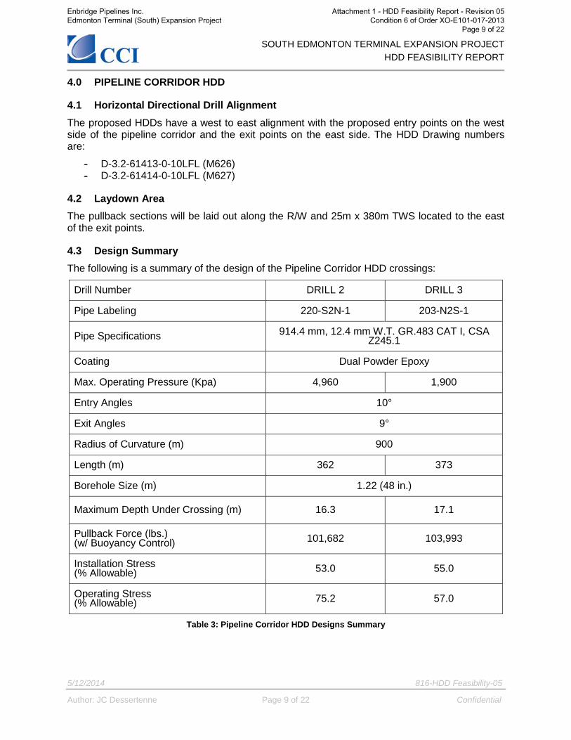
4.0 PIPELINE CORRIDOR HDD
4.1 Horizontal Directional Drill Alignment The proposed HDDs have a west to east alignment with the proposed entry points on the west side of the pipeline corridor and the exit points on the east side. The HDD Drawing numbers are:
- D-3.2-61413-0-10LFL (M626) - D-3.2-61414-0-10LFL (M627)
4.2 Laydown Area The pullback sections will be laid out along the R/W and 25m x 380m TWS located to the east of the exit points.
4.3 Design Summary The following is a summary of the design of the Pipeline Corridor HDD crossings:
Drill Number DRILL 2 DRILL 3
Pipe Labeling 220-S2N-1 203-N2S-1
Pipe Specifications 914.4 mm, 12.4 mm W.T. GR.483 CAT I, CSA Z245.1
Coating Dual Powder Epoxy
Max. Operating Pressure (Kpa) 4,960 1,900
Entry Angles 10°
Exit Angles 9°
Radius of Curvature (m) 900
Length (m) 362 373
Borehole Size (m) 1.22 (48 in.)
Maximum Depth Under Crossing (m) 16.3 17.1
Pullback Force (lbs.) (w/ Buoyancy Control) 101,682 103,993
Installation Stress (% Allowable) 53.0 55.0
Operating Stress (% Allowable) 75.2 57.0
Table 3: Pipeline Corridor HDD Designs Summary
Enbridge Pipelines Inc. Edmonton Terminal (South) Expansion Project
Attachment 1 - HDD Feasibility Report - Revision 05 Condition 6 of Order XO-E101-017-2013
Page 9 of 22
SOUTH EDMONTON TERMINAL EXPANSION PROJECT HDD FEASIBILITY REPORT
5/12/2014 816-HDD Feasibility-05
Author: JC Dessertenne Page 10 of 22 Confidential
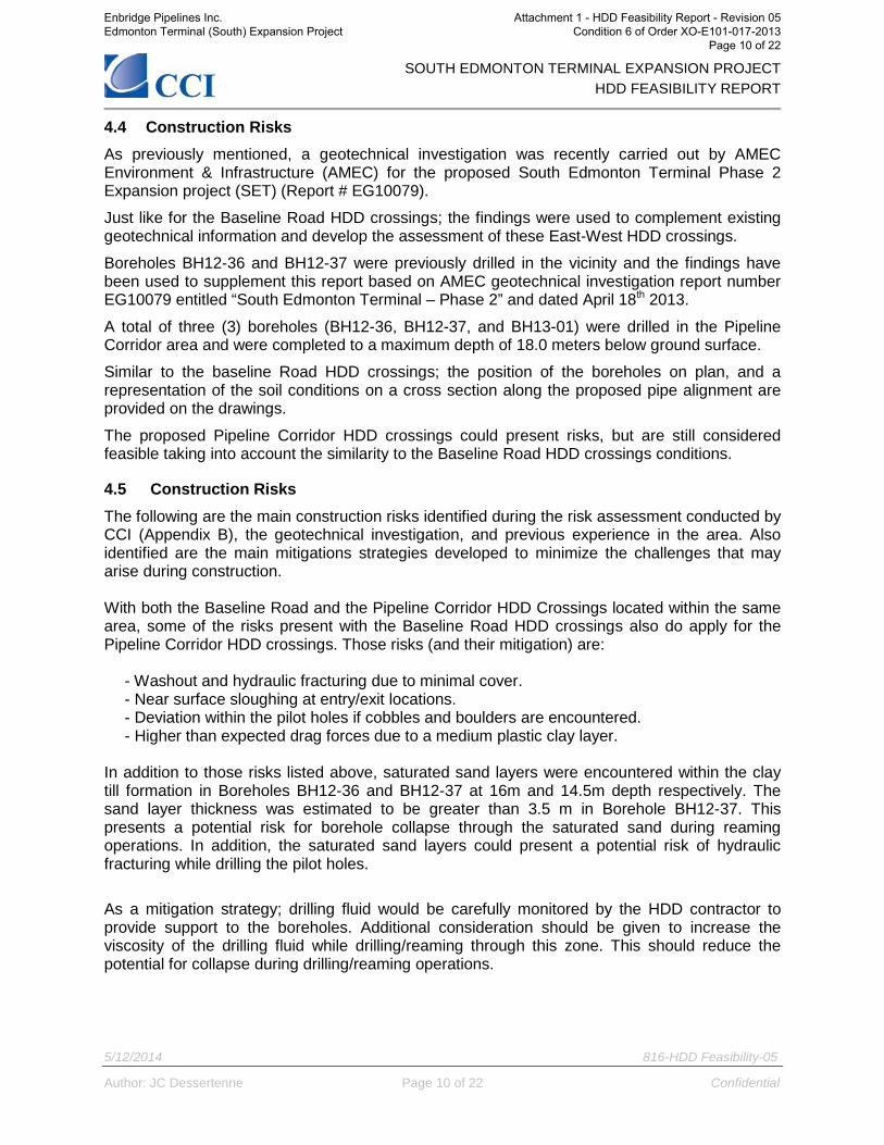
4.4 Construction Risks As previously mentioned, a geotechnical investigation was recently carried out by AMEC Environment & Infrastructure (AMEC) for the proposed South Edmonton Terminal Phase 2 Expansion project (SET) (Report # EG10079).
Just like for the Baseline Road HDD crossings; the findings were used to complement existing geotechnical information and develop the assessment of these East-West HDD crossings.
Boreholes BH12-36 and BH12-37 were previously drilled in the vicinity and the findings have been used to supplement this report based on AMEC geotechnical investigation report number EG10079 entitled “South Edmonton Terminal – Phase 2” and dated April 18th 2013.
A total of three (3) boreholes (BH12-36, BH12-37, and BH13-01) were drilled in the Pipeline Corridor area and were completed to a maximum depth of 18.0 meters below ground surface.
Similar to the baseline Road HDD crossings; the position of the boreholes on plan, and a representation of the soil conditions on a cross section along the proposed pipe alignment are provided on the drawings.
The proposed Pipeline Corridor HDD crossings could present risks, but are still considered feasible taking into account the similarity to the Baseline Road HDD crossings conditions.
4.5 Construction Risks The following are the main construction risks identified during the risk assessment conducted by CCI (Appendix B), the geotechnical investigation, and previous experience in the area. Also identified are the main mitigations strategies developed to minimize the challenges that may arise during construction. With both the Baseline Road and the Pipeline Corridor HDD Crossings located within the same area, some of the risks present with the Baseline Road HDD crossings also do apply for the Pipeline Corridor HDD crossings. Those risks (and their mitigation) are:
- Washout and hydraulic fracturing due to minimal cover. - Near surface sloughing at entry/exit locations. - Deviation within the pilot holes if cobbles and boulders are encountered. - Higher than expected drag forces due to a medium plastic clay layer.
In addition to those risks listed above, saturated sand layers were encountered within the clay till formation in Boreholes BH12-36 and BH12-37 at 16m and 14.5m depth respectively. The sand layer thickness was estimated to be greater than 3.5 m in Borehole BH12-37. This presents a potential risk for borehole collapse through the saturated sand during reaming operations. In addition, the saturated sand layers could present a potential risk of hydraulic fracturing while drilling the pilot holes.
As a mitigation strategy; drilling fluid would be carefully monitored by the HDD contractor to provide support to the boreholes. Additional consideration should be given to increase the viscosity of the drilling fluid while drilling/reaming through this zone. This should reduce the potential for collapse during drilling/reaming operations.
Enbridge Pipelines Inc. Edmonton Terminal (South) Expansion Project
Attachment 1 - HDD Feasibility Report - Revision 05 Condition 6 of Order XO-E101-017-2013
Page 10 of 22
SOUTH EDMONTON TERMINAL EXPANSION PROJECT HDD FEASIBILITY REPORT
5/12/2014 816-HDD Feasibility-05
Author: JC Dessertenne Page 11 of 22 Confidential
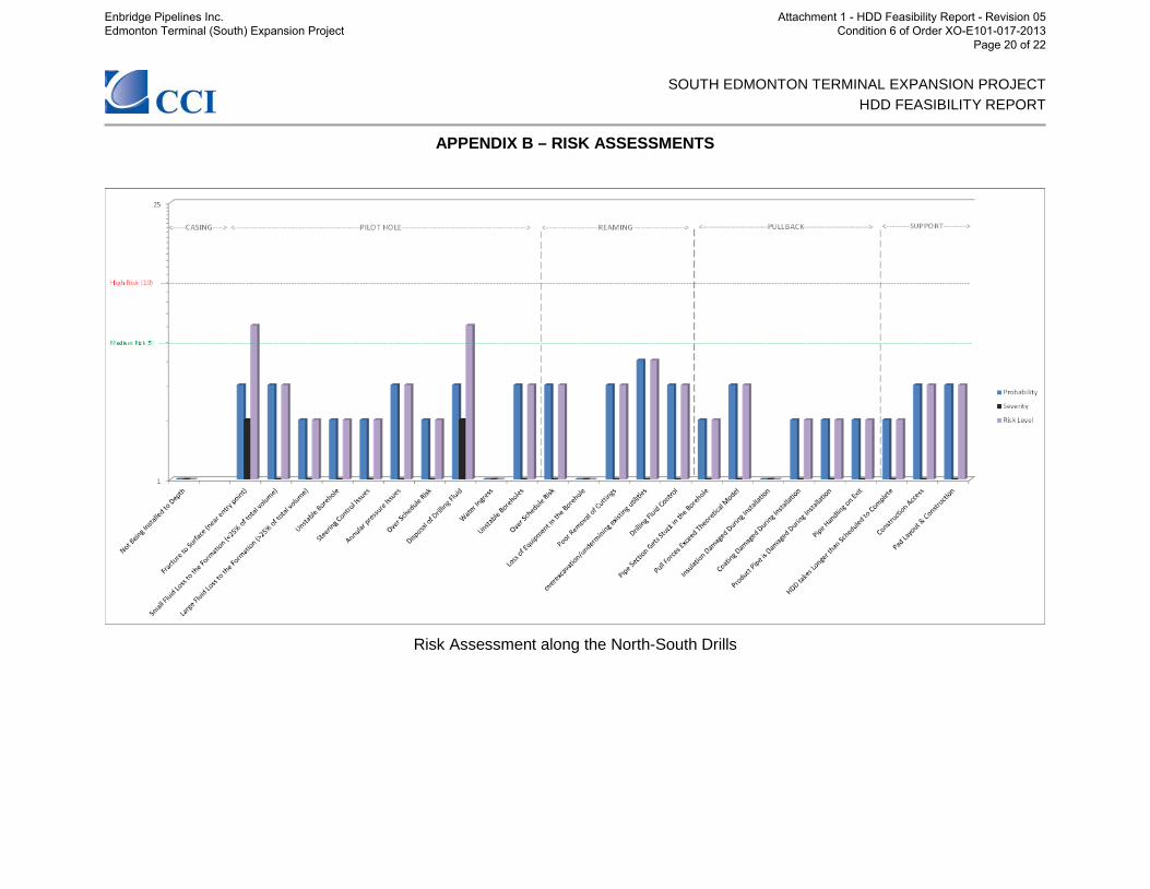
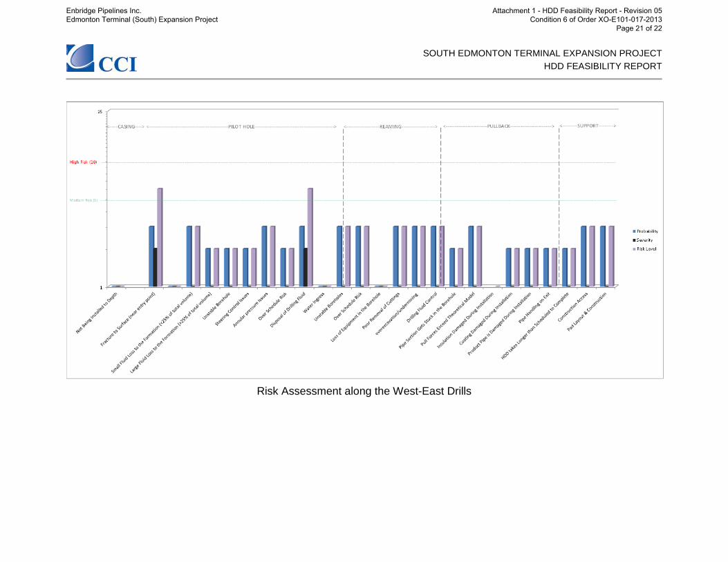
5.0 RISK ASSESSMENTS Appendix B shows the risk assessments for the North-South Drills and the East-West Drills.
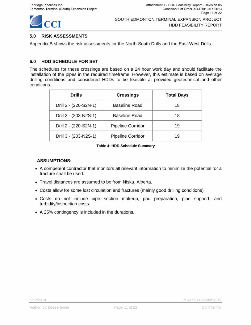
6.0 HDD SCHEDULE FOR SET The schedules for these crossings are based on a 24 hour work day and should facilitate the installation of the pipes in the required timeframe. However, this estimate is based on average drilling conditions and considered HDDs to be feasible at provided geotechnical and other conditions.
Drills Crossings Total Days
Drill 2 - (220-S2N-1) Baseline Road 18
Drill 3 - (203-N2S-1) Baseline Road 18
Drill 2 - (220-S2N-1) Pipeline Corridor 19
Drill 3 - (203-N2S-1) Pipeline Corridor 19
Table 4: HDD Schedule Summary
ASSUMPTIONS: • A competent contractor that monitors all relevant information to minimize the potential for a
fracture shall be used.
• Travel distances are assumed to be from Nisku, Alberta.
• Costs allow for some lost circulation and fractures (mainly good drilling conditions)
• Costs do not include pipe section makeup, pad preparation, pipe support, and turbidity/inspection costs.
• A 25% contingency is included in the durations.
Enbridge Pipelines Inc. Edmonton Terminal (South) Expansion Project
Attachment 1 - HDD Feasibility Report - Revision 05 Condition 6 of Order XO-E101-017-2013
Page 11 of 22
SOUTH EDMONTON TERMINAL EXPANSION PROJECT HDD FEASIBILITY REPORT
5/12/2014 816-HDD Feasibility-05
Author: JC Dessertenne Page 12 of 22 Confidential
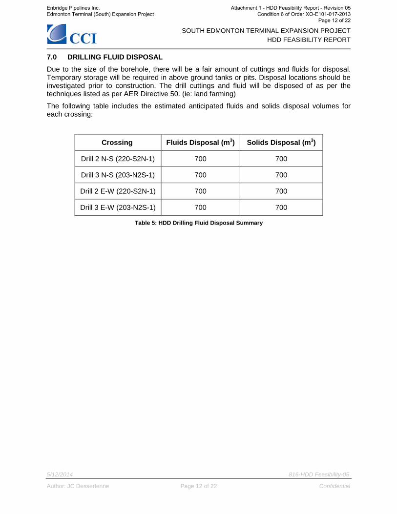
7.0 DRILLING FLUID DISPOSAL Due to the size of the borehole, there will be a fair amount of cuttings and fluids for disposal. Temporary storage will be required in above ground tanks or pits. Disposal locations should be investigated prior to construction. The drill cuttings and fluid will be disposed of as per the techniques listed as per AER Directive 50. (ie: land farming)
The following table includes the estimated anticipated fluids and solids disposal volumes for each crossing:
Crossing Fluids Disposal (m3) Solids Disposal (m3)
Drill 2 N-S (220-S2N-1) 700 700
Drill 3 N-S (203-N2S-1) 700 700
Drill 2 E-W (220-S2N-1) 700 700
Drill 3 E-W (203-N2S-1) 700 700
Table 5: HDD Drilling Fluid Disposal Summary
Enbridge Pipelines Inc. Edmonton Terminal (South) Expansion Project
Attachment 1 - HDD Feasibility Report - Revision 05 Condition 6 of Order XO-E101-017-2013
Page 12 of 22
SOUTH EDMONTON TERMINAL EXPANSION PROJECT HDD FEASIBILITY REPORT
5/12/2014 816-HDD Feasibility-05
Author: JC Dessertenne Page 13 of 22 Confidential
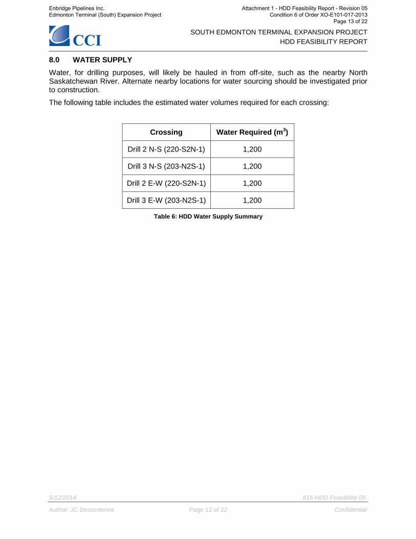
8.0 WATER SUPPLY Water, for drilling purposes, will likely be hauled in from off-site, such as the nearby North Saskatchewan River. Alternate nearby locations for water sourcing should be investigated prior to construction.
The following table includes the estimated water volumes required for each crossing:
Crossing Water Required (m3)
Drill 2 N-S (220-S2N-1) 1,200
Drill 3 N-S (203-N2S-1) 1,200
Drill 2 E-W (220-S2N-1) 1,200
Drill 3 E-W (203-N2S-1) 1,200
Table 6: HDD Water Supply Summary
Enbridge Pipelines Inc. Edmonton Terminal (South) Expansion Project
Attachment 1 - HDD Feasibility Report - Revision 05 Condition 6 of Order XO-E101-017-2013
Page 13 of 22
SOUTH EDMONTON TERMINAL EXPANSION PROJECT HDD FEASIBILITY REPORT
5/12/2014 816-HDD Feasibility-05
Author: JC Dessertenne Page 14 of 22 Confidential
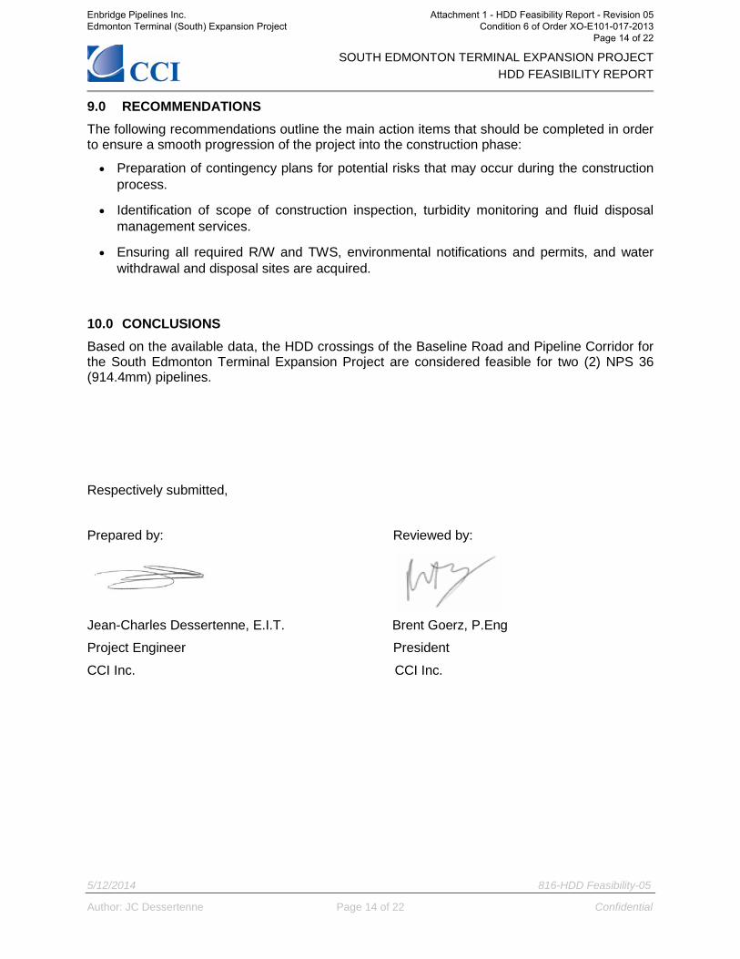
9.0 RECOMMENDATIONS The following recommendations outline the main action items that should be completed in order to ensure a smooth progression of the project into the construction phase:
• Preparation of contingency plans for potential risks that may occur during the construction process.
• Identification of scope of construction inspection, turbidity monitoring and fluid disposal management services.
• Ensuring all required R/W and TWS, environmental notifications and permits, and water withdrawal and disposal sites are acquired.
10.0 CONCLUSIONS Based on the available data, the HDD crossings of the Baseline Road and Pipeline Corridor for the South Edmonton Terminal Expansion Project are considered feasible for two (2) NPS 36 (914.4mm) pipelines.
Respectively submitted,
Prepared by: Reviewed by:
Jean-Charles Dessertenne, E.I.T. Brent Goerz, P.Eng
Project Engineer President
CCI Inc. CCI Inc.
Enbridge Pipelines Inc. Edmonton Terminal (South) Expansion Project
Attachment 1 - HDD Feasibility Report - Revision 05 Condition 6 of Order XO-E101-017-2013
Page 14 of 22
SOUTH EDMONTON TERMINAL EXPANSION PROJECT HDD FEASIBILITY REPORT
5/12/2014 816-HDD Feasibility-05
Author: JC Dessertenne Page 15 of 22 Confidential
APPENDIX A – STRESS CALCULATIONS
Enbridge Pipelines Inc. Edmonton Terminal (South) Expansion Project
Attachment 1 - HDD Feasibility Report - Revision 05 Condition 6 of Order XO-E101-017-2013
Page 15 of 22

SOUTH EDMONTON TERMINAL EXPANSION PROJECT HDD FEASIBILITY REPORT
5/12/2014 816-HDD Feasibility-05
Author: JC Dessertenne Page 16 of 22 Confidential
Enbridge Pipelines Inc. Edmonton Terminal (South) Expansion Project
Attachment 1 - HDD Feasibility Report - Revision 05 Condition 6 of Order XO-E101-017-2013
Page 16 of 22

SOUTH EDMONTON TERMINAL EXPANSION PROJECT HDD FEASIBILITY REPORT
5/12/2014 816-HDD Feasibility-05
Author: JC Dessertenne Page 17 of 22 Confidential
Enbridge Pipelines Inc. Edmonton Terminal (South) Expansion Project
Attachment 1 - HDD Feasibility Report - Revision 05 Condition 6 of Order XO-E101-017-2013
Page 17 of 22

SOUTH EDMONTON TERMINAL EXPANSION PROJECT HDD FEASIBILITY REPORT
5/12/2014 816-HDD Feasibility-05
Author: JC Dessertenne Page 18 of 22 Confidential
Enbridge Pipelines Inc. Edmonton Terminal (South) Expansion Project
Attachment 1 - HDD Feasibility Report - Revision 05 Condition 6 of Order XO-E101-017-2013
Page 18 of 22
SOUTH EDMONTON TERMINAL EXPANSION PROJECT HDD FEASIBILITY REPORT
5/12/2014 816-HDD Feasibility-05
Author: JC Dessertenne Page 19 of 22 Confidential
Enbridge Pipelines Inc. Edmonton Terminal (South) Expansion Project
Attachment 1 - HDD Feasibility Report - Revision 05 Condition 6 of Order XO-E101-017-2013
Page 19 of 22
SOUTH EDMONTON TERMINAL EXPANSION PROJECT HDD FEASIBILITY REPORT
APPENDIX B – RISK ASSESSMENTS
Risk Assessment along the North-South Drills
Enbridge Pipelines Inc. Edmonton Terminal (South) Expansion Project
Attachment 1 - HDD Feasibility Report - Revision 05 Condition 6 of Order XO-E101-017-2013
Page 20 of 22
SOUTH EDMONTON TERMINAL EXPANSION PROJECT HDD FEASIBILITY REPORT
Risk Assessment along the West-East Drills
Enbridge Pipelines Inc. Edmonton Terminal (South) Expansion Project
Attachment 1 - HDD Feasibility Report - Revision 05 Condition 6 of Order XO-E101-017-2013
Page 21 of 22
SOUTH EDMONTON TERMINAL EXPANSION PROJECT HDD FEASIBILITY REPORT
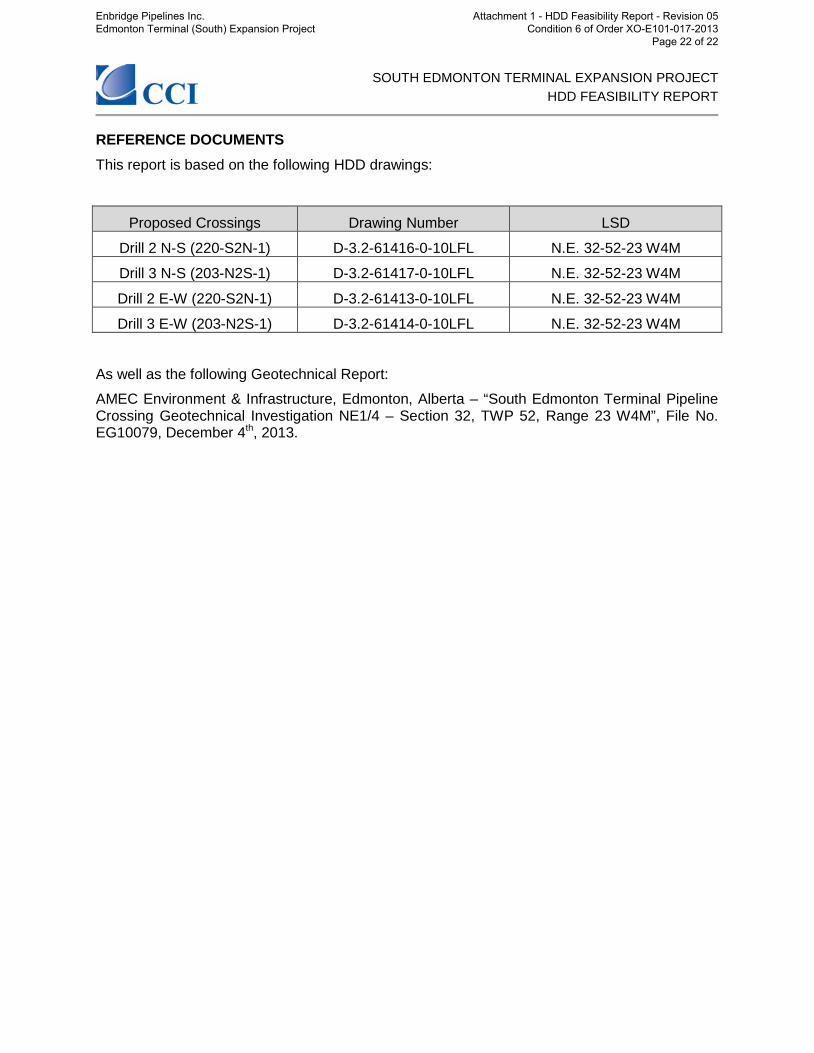
REFERENCE DOCUMENTS This report is based on the following HDD drawings:
Proposed Crossings Drawing Number LSD
Drill 2 N-S (220-S2N-1) D-3.2-61416-0-10LFL N.E. 32-52-23 W4M
Drill 3 N-S (203-N2S-1) D-3.2-61417-0-10LFL N.E. 32-52-23 W4M
Drill 2 E-W (220-S2N-1) D-3.2-61413-0-10LFL N.E. 32-52-23 W4M
Drill 3 E-W (203-N2S-1) D-3.2-61414-0-10LFL N.E. 32-52-23 W4M
As well as the following Geotechnical Report:
AMEC Environment & Infrastructure, Edmonton, Alberta – “South Edmonton Terminal Pipeline Crossing Geotechnical Investigation NE1/4 – Section 32, TWP 52, Range 23 W4M”, File No. EG10079, December 4th, 2013.
Enbridge Pipelines Inc. Edmonton Terminal (South) Expansion Project
Attachment 1 - HDD Feasibility Report - Revision 05 Condition 6 of Order XO-E101-017-2013
Page 22 of 22


