Embed Size (px)
Citation preview
ELECTRONICS FOR KIDSPLAY WITH SIMPLE CIRCUITS AND EXPERIMENT WITH
ELECTRICITY!
ØYVIND NYDAL DAHL
San Francisco

ELECTRONICS FOR KIDS. Copyright © 2016 by Øyvind Nydal Dahl.
All rights reserved. No part of this work may be reproduced or transmitted in any form or by any means, electronic or mechanical,including photocopying, recording, or by any information storage or retrieval system, without the prior written permission of the copyrightowner and the publisher.
Printed in Canada
First printing
20 19 18 17 16 1 2 3 4 5 6 7 8 9
ISBN-10: 1-59327-725-3ISBN-13: 978-1-59327-725-3
Publisher: William PollockProduction Editor: Riley HoffmanCover Illustration: Garry BoothInterior Design: Beth MiddleworthDevelopmental Editor: Jennifer Griffith-DelgadoTechnical Reviewer: John HewesCopyeditor: Julianne JigourCompositor: Riley HoffmanProofreader: Paula L. Fleming
For information on distribution, translations, or bulk sales, please contact No Starch Press, Inc. directly:No Starch Press, Inc.245 8th Street, San Francisco, CA 94103phone: 415.863.9900; [email protected]
Library of Congress Cataloging-in-Publication Data
Names: Nydal Dahl, Øyvind, author.Title: Electronics for kids : play with simple circuits and experiment with electricity! / by Øyvind Nydal Dahl.Description: San Francisco : No Starch Press, [2016] | Audience: Ages 10+ | Includes index.Identifiers: LCCN 2015048986 (print) | LCCN 2016005706 (ebook) | ISBN 9781593277253 (pbk.) | ISBN 1593277253 (pbk.) | ISBN 9781593277475 (epub) | ISBN 1593277474 (epub) | ISBN 9781593277482 (mobi) | ISBN 1593277482 (mobi)Subjects: LCSH: Electronics--Juvenile literature. | Electronic circuits--Juvenile literature.Classification: LCC TK7820 .N93 2016 (print) | LCC TK7820 (ebook) | DDC 621.381--dc23LC record available at http://lccn.loc.gov/2015048986
No Starch Press and the No Starch Press logo are registered trademarks of No Starch Press, Inc. Other product and company namesmentioned herein may be the trademarks of their respective owners. Rather than use a trademark symbol with every occurrence of atrademarked name, we are using the names only in an editorial fashion and to the benefit of the trademark owner, with no intention ofinfringement of the trademark.
The information in this book is distributed on an “As Is” basis, without warranty. While every precaution has been taken in thepreparation of this work, neither the author nor No Starch Press, Inc. shall have any liability to any person or entity with respect to anyloss or damage caused or alleged to be caused directly or indirectly by the information contained in it.

ABOUT THE AUTHOR
Øyvind Nydal Dahl has been an electronics enthusiast since he was a kid—he’s always lovedfiguring out how things worked so he could try to build them for himself. He studied electronics andcomputer science at the University of Oslo, where he received a master’s degree after building hisown microchip. He then co-founded the company Intelligent Agent to develop sensors that allowrobots to see through walls.
After a few years at Intelligent Agent, Øyvind set out on a mission to teach the world electronics.He gives workshops, develops courses, and writes about electronics and technology for a variety ofoutlets. He’s posted hundreds of articles, tutorials, and videos on his blog (http://www.build-electronic-circuits.com/) and maintains Ohmify (http://ohmify.com/), a membership site that makeslearning electronics fun and easy.

ABOUT THE TECHNICAL REVIEWERJohn Hewes began connecting electrical circuits at an early age, moving on to electronics projects asa teenager. He later earned a physics degree and continued to develop his interest in electronics,helping school students with their projects while working as a science technician.
John has taught electronics and physics up to an advanced level in the United Kingdom and ran aschool electronics club for children aged 11 to 18 years, setting up the websitehttp://www.electronicsclub.info/ to support the club. He believes that everyone can enjoy buildingelectronics projects, regardless of their age or ability.
BRIEF CONTENTS
Foreword by Joe Grand
Acknowledgments
Introduction
PART 1: PLAYING WITH ELECTRICITYChapter 1: What Is Electricity?
Chapter 2: Making Things Move with Electricity and Magnets
Chapter 3: How to Generate Electricity
PART 2: BUILDING CIRCUITSChapter 4: Creating Light with LEDs
Chapter 5: Blinking a Light for the First Time
Chapter 6: Let’s Solder!
Chapter 7: Controlling Things with Electricity
Chapter 8: Building a Musical Instrument
PART 3: THE DIGITAL WORLDChapter 9: How Circuits Understand Ones and Zeros
Chapter 10: Circuits That Make Choices
Chapter 11: Circuits That Remember Information
Chapter 12: Let’s Make a Game!
Handy Resources
Index
CONTENTS IN DETAIL
Foreword by Joe GrandAcknowledgments
INTRODUCTIONAbout This Book
Who Should Read This BookHow to Read This BookWhat’s in This Book?
Your Electronics LabUseful SuppliesSafety First!
PART 1: PLAYING WITH ELECTRICITY1WHAT IS ELECTRICITY?Project #1: Turn on a Light!
Shopping ListStep 1: Inspect the Light BulbStep 2: Connect the Light Bulb to the Battery
How Does Electricity Light a Bulb?What Is an Electron?Voltage Pushes ElectronsCurrent FlowsResistance Reduces CurrentLighting the Bulb
How Is a Circuit Like a Pipe System?Meet the SwitchProject #2: Intruder Alarm
Shopping ListToolsStep 1: Does the Buzzer Beep?Step 2: Prepare the AluminumStep 3: Foil Your DoorStep 4: Prepare a Trigger WireStep 5: Connect the Buzzer and Trigger Wire
Step 6: Mount the Buzzer and Trigger WireStep 7: Add a Power SourceStep 8: Stage an Intruder Alert!Step 9: What If the Intruder Alarm Doesn’t Work?
What’s Next?
2MAKING THINGS MOVE WITH ELECTRICITY AND MAGNETSHow Magnets Work
Try It Out: Find Some Magnetic Objects!Meet the ElectromagnetProject #3: Create Your Own Electromagnet
Shopping ListToolsStep 1: Check Your BoltStep 2: Remove Insulation from One End of the Coil WireStep 3: Wind the WireStep 4: Connect the Negative Battery Terminal to the CoilStep 5: Connect the SwitchStep 6: Test Your Super ElectromagnetStep 7: What If the Electromagnet Isn’t Working?
Meet the MotorProject #4: Create a Motor
Shopping ListToolsStep 1: Create the RotorStep 2: Build the Motor’s StructureStep 3: Place the MagnetsStep 4: Reinsulate Part of the CoilStep 5: Rev Up Your MotorStep 6: What If the Motor Doesn’t Work?
What’s Next?
3HOW TO GENERATE ELECTRICITYGenerating Electricity with Magnets
A Changing Magnetic Field Creates ElectricityHow Does a Generator Work?Creating Electricity from Water or Wind
Meet the MultimeterHow to Measure Voltage
What Are AC and DC?Project #5: Make a Shake Generator
Shopping ListToolsStep 1: Prepare Your TubeStep 2: Wind Your CoilStep 3: Connect the MultimeterStep 4: Shake That Thing!Step 5: What If There’s No Voltage?Try It Out: Using a Motor as a Generator
How Do Batteries Work?What’s Inside a Battery?The Chemistry Behind BatteriesWhat Determines a Battery’s Voltage?
Project #6: Turn On a Light with Lemon PowerMeet the LEDShopping ListToolsStep 1: Prepare Your WiresStep 2: Insert Electrodes into a LemonStep 3: Create Four Lemon BatteriesStep 4: Connect the Lemons in SeriesStep 5: Test Your Lemon BatteryTry It Out: More Food Batteries!Step 6: What If Your Lemon Light Doesn’t Work?
What’s Next?
PART 2: BUILDING CIRCUITS4CREATING LIGHT WITH LEDSMeet the Resistor
Resistor Color CodesHow to Write Large ValuesWhat Are Resistors Made Of?Resistors Control Current and Voltage
Introducing Ohm’s LawProject #7: Let’s Destroy an LED!
Shopping ListStep 1: Identify Which LED Leg Is Which
Step 2: Break That LED!Step 3: What If Nothing Happens to the LED?
How to Use an LED CorrectlyHow to Write Small ValuesProtecting Your LED with a ResistorCalculating the Resistance You Need
Project #8: Powering an LEDShopping ListStep 1: Twist the Resistor and LEDStep 2: Wire the Battery ClipStep 3: Let There Be Light!Step 4: What If the LED Doesn’t Work?
Building Circuits on a BreadboardHow to Connect Components and WiresWires to Use on a Breadboard
Project #9: Your First Breadboard CircuitShopping ListStep 1: Place the ResistorStep 2: Place the LEDStep 3: Place the Battery ClipStep 4: What If the LED Doesn’t Work?
What’s Next?
5BLINKING A LIGHT FOR THE FIRST TIMEMeet the Capacitor
How Capacitors WorkPolarized and Nonpolarized CapacitorsCapacitor Values
Project #10: Test a CapacitorShopping ListStep 1: Start with the LED CircuitStep 2: Add the CapacitorStep 3: Charge the CapacitorStep 4: Use the Capacitor to Light the LEDStep 5: What If the Circuit Doesn’t Work?
Describing Circuits with SymbolsMeet the Relay
Using the Relay to Blink a LightSlowing Down the Blinking
Project #11: Blink a Light!
Shopping ListStep 1: Identify the Relay PinsStep 2: Make the Relay Switch FastStep 3: Make the Relay Stay On LongerStep 4: Make the Relay Stay Off LongerStep 5: Add the LED and ResistorStep 6: What If the LED Won’t Blink?Try It Out: Make Your Intruder Alarm More Effective
What’s Next?
6LET’S SOLDER!How to Solder
Soldering Safety TipsHeat the Soldering IronClean the Soldering Iron TipTin the Soldering Iron TipHeat Both the Pin and the PadAdd SolderRemove the Soldering IronWatch Out for Bad Solder Joints!
Project #12: Solder Your First LED CircuitShopping ListToolsStep 1: Place the ComponentsStep 2: Bend the Component LegsHow to Read the Circuit Board IllustrationsStep 3: Heat and Clean the Soldering IronStep 4: Solder the Resistor and LEDStep 5: Trim the LegsStep 6: Solder the Battery ClipStep 7: Let There Be Light!Step 8: What If the Soldered LED Circuit Doesn’t Work?
Oops! How Do I Remove a Soldered Component?Project #13: Desolder the Battery Clip
Shopping ListToolsStep 1: Heat the Soldering IronStep 2: Place the Solder Wick on the Solder JointStep 3: Heat the Solder Joint and the Solder WickStep 4: Trim the Used Solder Wick
Step 5: Remove the Other Battery Clip WireTry It Out: Solder More Stuff!
What’s Next?
7CONTROLLING THINGS WITH ELECTRICITYMeet the Transistor
Why Use a Transistor?How the Transistor WorksControlling an LED with a Transistor
Project #14: Build a Circuit that Senses TouchShopping ListToolsStep 1: Place Components on the Prototyping BoardStep 2: Check Your Component PlacementStep 3: Solder the Components and Trim Excess LegsStep 4: Solder the Touch PadStep 5: Power It Up!Step 6: Test the SensorStep 7: What If the Touch Sensor Doesn’t Work?Try It Out: Can the Touch Sensor Detect Different Touches?
Resistors That Can Change ValueMeet the PotentiometerMeet the Photoresistor
Dividing a Voltage with ResistorsWhat Does a Voltage Divider Look Like?Calculating the Voltage from a Voltage DividerHow a Voltage Divider Can Help Measure Light
Project #15: Build a Sunrise Wake-Up AlarmShopping ListToolsStep 1: Place Components on the Prototyping BoardStep 2: Solder the Components and Trim the LegsStep 3: Add the Buzzer to the BoardStep 4: Make the Remaining Connections with WiresStep 5: Add the Battery Clip to the BoardStep 6: Set a Wake-Up CallStep 7: What If There’s No Sound?Try It Out: Temperature-Controlled Fan
What’s Next?
8BUILDING A MUSICAL INSTRUMENTMeet the Integrated CircuitICs and DatasheetsHow to Make Sound with ElectricitySounds That Humans Can HearMeet the 555 Timer
Powering an ICHow to Set the Output Speed of the 555 Timer
Project #16: Make Your Own Sound with the 555 TimerShopping ListStep 1: Place the 555 Timer on the BreadboardStep 2: Set the FrequencyStep 3: Connect the Speaker and Coupling CapacitorStep 4: Connect the Power and Reset PinsStep 5: Make Some Sound!Step 6: What If There’s No Sound?Checking Connections as a Team
Turning an Annoying Beep into MusicProject #17: An Instrument That Beeps and Boops
Shopping ListStep 1: Connect the 555 Timer and the CapacitorsStep 2: Connect Jumper WiresStep 3: Connect the Note Controller and ResistorStep 4: Add the “On” ButtonStep 5: Add the LoudspeakerStep 6: Play Some Music!Step 7: What If the Instrument Doesn’t Work?Try It Out: Make a Motion-Controlled Instrument
What’s Next?
PART 3: THE DIGITAL WORLD9HOW CIRCUITS UNDERSTAND ONES AND ZEROSOnes and Zeros as VoltagesMeet the Binary Number SystemProject #18: Convert from Binary to Decimal
ToolsStep 1: Write It Down on Paper
Step 2: Write the Position ValuesStep 3: Find the Value of Each DigitStep 4: Add the NumbersTry It Out: Transform More Binary Numbers
Bits and BytesNumbers Can Be AnythingProject #19: Color Guessing Game
Meet the RGB LEDShopping ListStep 1: Place the Color Chooser’s Push ButtonsStep 2: Connect the RGB LEDStep 3: Connect the Color Revealer ButtonStep 4: Test the ColorsStep 5: What If the Game Doesn’t Work?Try It Out: Solder the Color Guessing Game
How Binary Numbers Can Create WordsProject #20: The Secret Message Machine
Meet the DIP SwitchShopping ListStep 1: Connect the Push ButtonStep 2: Connect the DIP SwitchStep 3: Connect the LEDsStep 4: Send a Secret Message!Step 5: What If the Secret Message Machine Doesn’t Work?Why Computers Use Ones and Zeros
What’s Next?
10CIRCUITS THAT MAKE CHOICESIt’s Only LogicalMeet the Logic Gates
AND Gates Check for Two True InputsOR Gates Check for One True InputNOT Gates Flip InputsA Bigger AND Gate
How to Draw Logic Circuit DiagramsA Logic Equation for a Secret CodeConverting a Logic Equation into a Circuit DiagramTry It Out: Draw More Logical Statements as Circuits
Using Logic Gates in Real LifeMore About Current, Components, and Transistors
Project #21: A Secret Code CheckerShopping ListToolsHow to Use Other Voltages with a BreadboardMaking Circuits More ReliableStep 1: Place the Switches and ResistorsStep 2: Place the ICsStep 3: Place the Transistor and LEDStep 4: Build the Logic CircuitStep 5: Finish Wiring the TransistorProtecting Your ComponentsStep 6: Power and Test the Secret Code CheckerStep 7: What If the LED Doesn’t Light Up?Try It Out: Disarm Your Intruder Alarm
Negative Logic GatesNAND Looks for One False InputNOR Looks for Two False Inputs
What’s Next?
11CIRCUITS THAT REMEMBER INFORMATIONSaving One Bit at a TimeA Better Memory CircuitMemory That Changes Only at a Certain TimeAn Output That TogglesProject #22: An Electronic Coin Tosser
Shopping ListStep 1: Build the Oscillator CircuitStep 2: Add the Start ButtonStep 3: Build the Toggle CircuitStep 4: Add the Heads and Tails LEDsStep 5: Toss that “Coin”!Step 6: What If the Coin Tosser Doesn’t Work?
What’s Next?
12LET’S MAKE A GAME!Meet the Reaction Game Circuits
Meet the VCC and GND SymbolsWhy Is It Called VCC?A 555 Timer to Set the Light Speed
A Counter to Turn the LEDs OnA Latch to Start and Stop the Light
Project #23: An LED Reaction GameShopping ListToolsStep 1: Build the 555 Timer CircuitStep 2: Build the LED-Controlling CircuitStep 3: Build the Start and Stop CircuitStep 4: Practice Your Reaction Time!Step 5: What If the Game Isn’t Working?Try It Out: Change the Light’s Speed
Add a Buzzer to Your GameWhat’s Next? Go Make Cool Stuff!
HANDY RESOURCESComponent and Unit Value Cheat Sheets
Resistor Color CodesCapacitor CodesStandard Prefixes
A Quick Review of Ohm’s LawA Basic Voltage Divider CircuitOnline Electronics ShopsOnline Resources
INDEX
FOREWORDThere’s something special about bringing a project to life that you read about in a book or that startedas an idea in your head. And sometimes the simplest things are the most satisfying.
One of my favorite childhood projects was a mischievous little device made of a single resistorconnected between the tip and ring of a telephone line. I used a piece of one-sided copper circuitboard with rub-off symbols to lay out the design, and then I etched the unprotected copper away usingferric chloride in my basement. You could still use the phone normally to make outgoing calls, butanyone calling the house would receive a busy signal. This was the perfect way to make sure myparents didn’t receive any phone calls from my teachers during dinner!
A few years later, I modified a garage door opener to open any door of the same brand. In normaloperation, the passwords on the transmitter and receiver were manually set with a series of 10 DIPswitches. If the transmission signal matched what the receiver was expecting, then the garage doorwould open. I replaced the switches on my transmitter with a common 555 timer IC, to generate aclock signal, and a 10-stage binary counter, a type of digital logic device, to automatically try everysingle possible combination (that’s 210 or 1,024 attempts). Within a few minutes of holding down thebutton, the correct password would be transmitted and the garage door would open! I never used myuniversal “brute-force” garage door opener for malicious purposes, but it reinforced my hackermindset—solving problems with unconventional solutions, pushing the limits of technology, harmingno one, and learning through constant questioning and experimentation. I also thought it was prettycool to be able to modify an off-the-shelf device and make it do something the original designersprobably never anticipated.
When I was much younger, I somehow ended up with a 6 V lantern battery and a spring from anadjustable lamp. I wondered, “What would happen if I connected the spring between the batteryterminals?” So of course, I tried it. The spring got hotter and hotter until I freaked out, plucked it offthe terminals, and threw it into the bathroom sink. I had created a short circuit by connecting thepositive and negative terminals of the battery together, causing current to flow between them. I neverlooked at batteries and springs the same way again.
I remember trying to build my own alarm system for my bedroom door, sort of a low-tech versionof the one you’ll build in Chapter 1. I hung an old AM/FM radio from a hook on the back of my door,tuned it to static, turned the volume up to maximum, and “armed” it by connecting the sliding powerswitch to a wire I had attached to my wall. In theory, when the door opened, the wire would pull theswitch and turn on the radio, blasting white noise at the intruder. That didn’t happen. Instead, whenmy dad opened the door, the radio slid off the hook and crashed onto the floor. Back to the drawingboard on that one!
These stories are meant to do one thing: inspire you to explore the wonderful, wild world ofelectrons—and this book is the perfect launch pad! Øyvind breaks down complex electronicsfundamentals in an enjoyable, fun way. His passion for electronics and his love for teaching shine onevery page. Starting with the basics and building up from there, you’ll end up with the power tocreate bigger, better, faster, and more intelligent projects on your own. There’s no better way to learnthan by doing. So go ahead, turn the page and begin your adventure into all that electronics has tooffer!

Joe GrandProduct Designer, Hardware Hacker, and DaddyPortland, Oregon

ACKNOWLEDGMENTSFirst of all, thanks to my father for explaining how things work based on practice instead of theorywhen I was a kid. His great explanations got me started in the world of electronics. Also, many thanksto my mother, who had to endure all those technical discussions around the dinner table.
Thanks to Jennifer Griffith-Delgado, Riley Hoffman, Tyler Ortman, and the rest of the team at NoStarch Press—first of all for believing in me, but also for guiding me through the editorial process insuch a good way. You have been a dream to work with!
Thanks to my technical reviewer, John Hewes, for finding my errors, challenging me in someareas, and making me think through some parts of the book a few extra times.
Finally, a special thanks to Garry Booth for the cover illustration, to Beth Middleworth fordesigning the layout and background illustrations, and to Riley once more, for drawing the technicaldiagrams. Those three really made this book come alive.

INTRODUCTION
Welcome to Electronics for Kids! This book will teach you how to make cool things by puttingtogether the same parts that are inside televisions, electronic toys, radios, and all the other gadgets inthe world. You’ll build fun experiments, like a light powered by lemons, as well as useful (but stillfun) projects, like an intruder alarm and a musical instrument.
You’ll do more than just follow directions, however: you’ll also learn how every component in eachproject works.
My hope is that when you know how those components work, you’ll see how to create your owninventions by combining the components in different ways. Blinking a light is one of the first things Ilearned how to do with electronics. When I saw how that worked, a whole new world suddenlyopened up to me. Since then, I’ve built robots, music players, miniature computers, and even a devicethat lets you see through a wall! With practice, you can build those things, too—and this book willteach you the basic skills you need to start the journey.
ABOUT THIS BOOKWhen I was about 14 years old, I thought computers were cool, but I had no idea how they worked.They seemed magical, and I thought I’d never understand them or be able to build one. Luckily, mydad was an engineer, and he had a very good way of explaining things. When I asked questions, heshowed me not only how things worked but also how I could build something similar myself.
I wrote this as the book I would have loved to have had as a kid, and I hope you enjoy it!
Who Should Read This BookIf you’ve ever looked at an electronic gadget and thought, “How does that work?” or “How can Imake that?” as I did, then you’re in the right place. Whether you’re 8 or 100 years old, as long asyou’re curious and have a playful spirit, this book is for you.
How to Read This BookI recommend you read this book in order, because every chapter builds upon concepts and skillscovered in previous chapters.
Each chapter has at least one hands-on project. Build these projects! Electronics is a verypractical skill, and reading about how a component works or what a project should do is differentfrom experiencing it yourself. Just be sure to read a project in full before you dive into it so youunderstand the steps involved.
If you encounter problems as you build a project, don’t worry: that happens to everyone at somepoint when working with electronics—even me. Just keep at it, study your circuit, and rewire thewhole project if needed to get it working. When you’ve been battling to get a circuit working for acouple of hours, then suddenly find the error and your circuit works, you’ll feel amazing! If you get
stuck, grab a friend or family member and ask them to help out.If there are parts of the book you don’t understand right away, I recommend you keep on reading.
Don’t let details stop you. Come back to that particular topic later when you have some more projectsunder your belt.
What’s in This Book?As you work through this book, you’ll build your knowledge of electronics gradually, starting withbasic—but essential—information and simple circuits. After the basics, you’ll build more complexcircuits and meet components like resistors, capacitors, transistors, and integrated circuits. To seehow the components work and to understand electronics in a practical way, you’ll build fun projectsin every chapter.
At the end of the book, you’ll build one final, epic project: a game to play with your friends. Bythen, you’ll have enough experience and knowledge to modify the game or even build a totally newgame you invent yourself!
This book is divided into three parts. Part 1: Playing with Electricity is the foundation for therest of the book. It’s all about fundamental knowledge and how electricity actually works.
Chapter 1: What Is Electricity? introduces the science behind electricity and describes the basicrequirements for a circuit to turn something on.
Chapter 2: Making Things Move with Electricity and Magnets shows you how you can moveobjects with electricity. In this chapter, you’ll build a motor from scratch.
Chapter 3: How to Generate Electricity describes how batteries and power plugs in the wallprovide electricity. Of course, you’ll build your own electricity sources, too!
Part 2: Building Circuits is where you’ll really get your hands dirty. You’ll meet some of the mostimportant components in electronics, and you’ll learn how to build both permanent and temporarycircuits.
In Chapter 4: Creating Light with LEDs, you’ll build circuits on a breadboard for the first time tocreate a prototype, which is just a temporary circuit. You’ll learn about resistors, light-emittingdiodes (LEDs), and how to use those parts together.
Chapter 5: Blinking a Light for the First Time shows how two new components, capacitors andrelays, work. You’ll even combine these with an LED to create a circuit that blinks a light.
Chapter 6: Let’s Solder! teaches you how to solder. With soldering, you can transform a circuitfrom a prototype to a proper device that will last for years to come.
Chapter 7: Controlling Things with Electricity introduces the transistor, a component that lets acircuit control other circuits. You’ll learn how transistors work and how to use them to build atouch sensor and a simple alarm clock.
In Chapter 8: Building a Musical Instrument, you’ll learn what an integrated circuit is and howcircuits can make sound. You’ll combine this knowledge to build a musical instrument.
Part 3: The Digital World introduces digital electronics, which almost all modern technology is
based upon.
In Chapter 9: How Circuits Understand Ones and Zeros, you’ll learn about 1s and 0s, bits andbytes, and how to use them to communicate.
Chapter 10: Circuits That Make Choices teaches you how to build smart circuits that use logic tomake decisions. You’ll build a secret code checker and learn how you can combine it with yourintruder alarm.
Chapter 11: Circuits That Remember Information shows how you can use logic gates to createcircuits that remember information in a way similar to a computer. Then, you’ll use this to create anelectronic coin tosser.
Chapter 12: Let’s Make a Game! is dedicated to one large project. You’ll get to show off yournew skills by combining all the knowledge from the book to make a reaction speed game.
Finally, you’ll find a Handy Resources appendix at the back of the book, which includes cheatsheets for figuring out component values, doing some essential electronics calculations, and so on.You’ll learn about those concepts in detail throughout the book, but even electronics experts need aquick reference every now and then!
YOUR ELECTRONICS LABThe wonderful thing about electronics projects is that your “lab” can be anywhere you want—itdoesn’t have to be a garage or workshop. All you need is a flat surface to work on, with enough roomfor your tools and components. Just gather the supplies to build your latest invention, and you’re set.
Each project in this book includes a convenient list of the electronic components and tools neededto build it. Before you dig into a project, check its Shopping List to make sure you have all thematerials. I’ve also created a complete list of all the components and tools you’ll need for all theprojects in this book, which you can find linked from the book’s web page athttps://www.nostarch.com/electronicsforkids/. This list should always have the most up-to-date partnumbers and links to kits you can buy that contain all the necessary components.
Useful SuppliesWhether you’re building the projects in this book or other projects on your own, there are a fewsupplies that will always come in handy:
A digital multimeter (Jameco #2206061, Bitsbox #TL057, Rapid Electronics #55-6662) fortesting connections and making sure a project is working correctly.
A pair of wire cutters (Jameco #35482, Bitsbox #TL008)
A big spool of insulated wire (Jameco #36792, Bitsbox #W106BK)
Electrical tape to protect bare wires or fasten stuff.
9 V batteries—nearly every project in the book uses one!
A bunch of LEDs (Jameco #18041, Bitsbox #K033)
A bunch of resistors (Jameco #2217511, Bitsbox #K017)
Safety glasses to wear when snipping component leads, stripping wires, or soldering.
You can buy most of these from your local hardware store or from any online electronics retailer,like Jameco (http://www.jameco.com/), SparkFun (http://www.sparkfun.com/), or Bitsbox(http://www.bitsbox.co.uk/). Check out “Online Electronics Shops” on page 286 for more options.
You might also want to have a pair of scissors, some scrap paper, and pencils to take notes.
Safety First!All the circuits in this book use a low voltage, and they’re not dangerous to build and play with. Thatsaid, there are a few safety tips to keep in mind when using electronic components and tools:
Wear safety glasses when trimming components or soldering.
Use tools only for their intended purpose. Soldering irons are hot, and wire cutters are sharp—ifused improperly, they can hurt you. If you’re confused about how to use a tool, ask an adult forhelp.
An adult should supervise younger children when they’re working with small components, solder,tools, and so on to teach them how to use everything safely.
Keep electronic parts out of reach of babies and very young children.
Most projects in this book use batteries, but some do use power from a wall outlet. Follow theinstructions for those circuits carefully. Never plug components directly into a power outlet, or youwill get hurt.
Some projects do have steps you should take special care with, and I will clearly state that in theinstructions with a warning, like this:
WARNINGWhen you see this type of note, be careful with the step it talks about.
Electronics is a safe hobby, though, so you won’t see very many of these warnings. When you dosee one, don’t let it stop you from having fun. If you use common sense and follow the directions,you’ll have nothing to worry about.
Now let’s get started!

PART 1PLAYING WITH ELECTRICITY

1WHAT IS ELECTRICITY?
Push a button on a music player, and a song suddenly comes out of the speakers. Push a button on aTV’s remote control, and your favorite shows come to life instantly. These wonders happen thanks tothe magic of electricity, a type of energy that powers all the technology in your home. By the time youfinish this book, you’ll be an electronics wizard, and then you can try using your powers to build anyinvention you can imagine!
This book is all about understanding electricity and using it to make amazing things. In thischapter, we’ll explore how electricity works, and then you’ll build a complete electronics project: aburglar alarm that warns you if intruders have entered a room. Once you get the hang of usingelectricity, you can build all sorts of fun contraptions, like a musical instrument or a light-up game toplay with your friends. In fact, you’ll build these in this book.
PROJECT #1: TURN ON A LIGHT!When you flip the light switch in a room, the bulb brightens right away. Let’s look at how electricitymakes that bulb shine, starting with a little experiment.
Shopping ListFor this project, you’ll need the following parts:
A standard 9 V battery to power the circuit.
A small, incandescent light bulb rated for 9 to 12 V (DigiKey #CM394-ND, Bitsbox #OP037, or asimilar light bulb from a hardware store).
Step 1: Inspect the Light BulbLook closely at your light bulb; you should see a thin metal wire filament inside the glass. One end ofthis filament is connected to the metal side of the base, and the other end is connected to the metalcontact on the bottom.
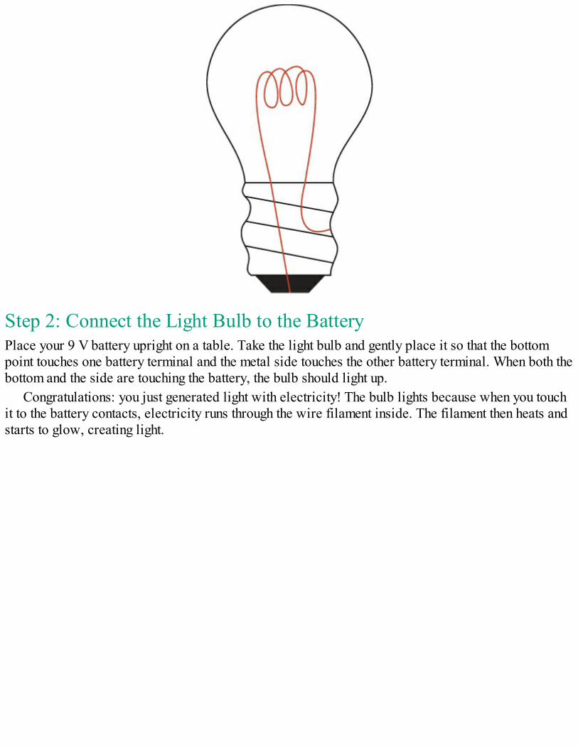
Step 2: Connect the Light Bulb to the BatteryPlace your 9 V battery upright on a table. Take the light bulb and gently place it so that the bottompoint touches one battery terminal and the metal side touches the other battery terminal. When both thebottom and the side are touching the battery, the bulb should light up.
Congratulations: you just generated light with electricity! The bulb lights because when you touchit to the battery contacts, electricity runs through the wire filament inside. The filament then heats andstarts to glow, creating light.
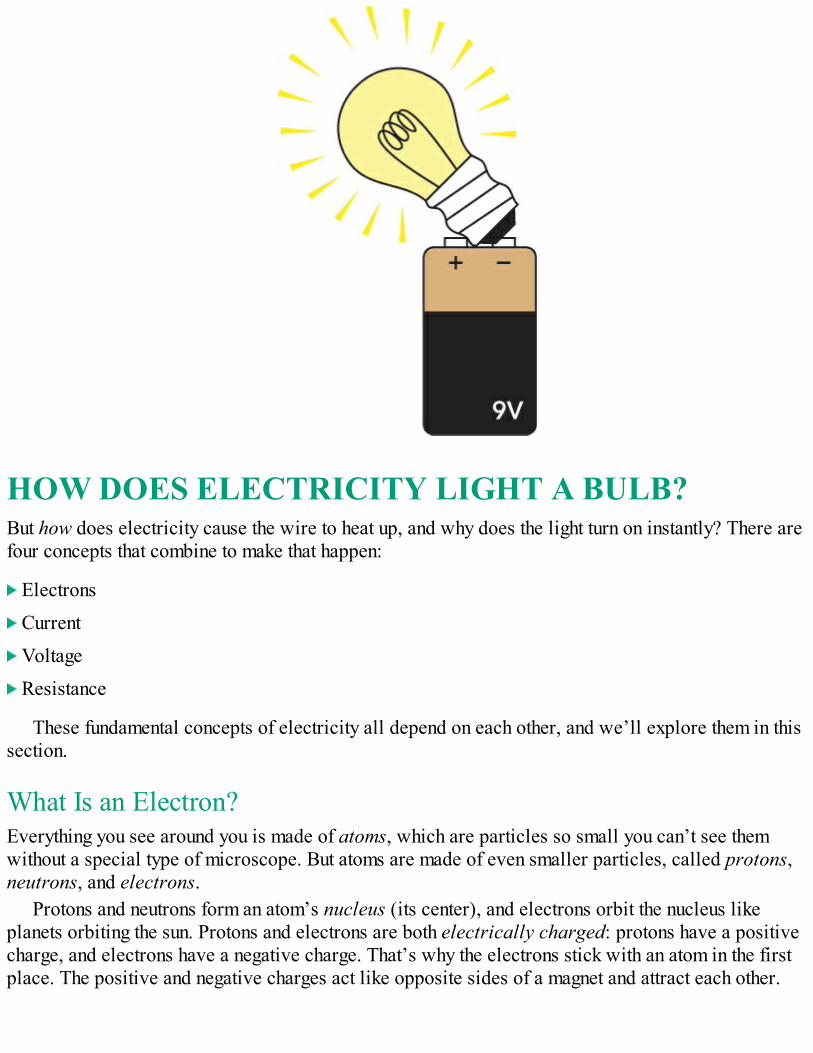
HOW DOES ELECTRICITY LIGHT A BULB?But how does electricity cause the wire to heat up, and why does the light turn on instantly? There arefour concepts that combine to make that happen:
Electrons
Current
Voltage
Resistance
These fundamental concepts of electricity all depend on each other, and we’ll explore them in thissection.
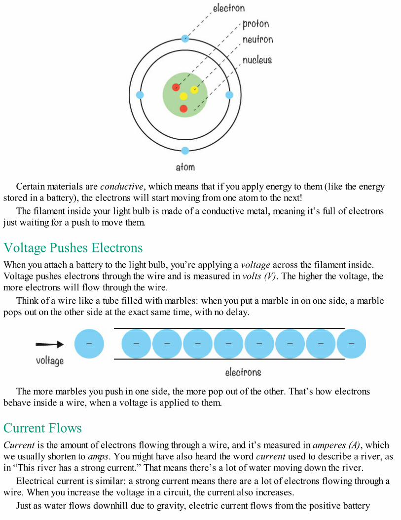
What Is an Electron?Everything you see around you is made of atoms, which are particles so small you can’t see themwithout a special type of microscope. But atoms are made of even smaller particles, called protons,neutrons, and electrons.
Protons and neutrons form an atom’s nucleus (its center), and electrons orbit the nucleus likeplanets orbiting the sun. Protons and electrons are both electrically charged: protons have a positivecharge, and electrons have a negative charge. That’s why the electrons stick with an atom in the firstplace. The positive and negative charges act like opposite sides of a magnet and attract each other.
Certain materials are conductive, which means that if you apply energy to them (like the energystored in a battery), the electrons will start moving from one atom to the next!
The filament inside your light bulb is made of a conductive metal, meaning it’s full of electronsjust waiting for a push to move them.
Voltage Pushes ElectronsWhen you attach a battery to the light bulb, you’re applying a voltage across the filament inside.Voltage pushes electrons through the wire and is measured in volts (V). The higher the voltage, themore electrons will flow through the wire.
Think of a wire like a tube filled with marbles: when you put a marble in on one side, a marblepops out on the other side at the exact same time, with no delay.
The more marbles you push in one side, the more pop out of the other. That’s how electronsbehave inside a wire, when a voltage is applied to them.
Current FlowsCurrent is the amount of electrons flowing through a wire, and it’s measured in amperes (A), whichwe usually shorten to amps. You might have also heard the word current used to describe a river, asin “This river has a strong current.” That means there’s a lot of water moving down the river.
Electrical current is similar: a strong current means there are a lot of electrons flowing through awire. When you increase the voltage in a circuit, the current also increases.
Just as water flows downhill due to gravity, electric current flows from the positive battery
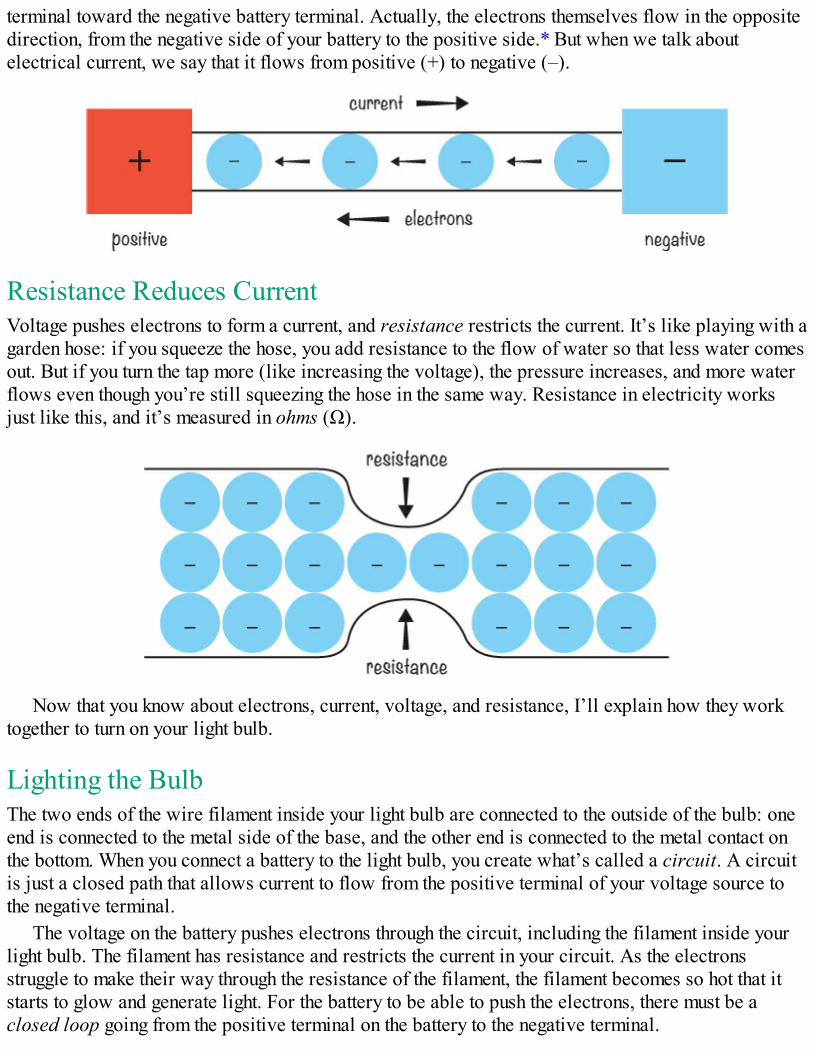
terminal toward the negative battery terminal. Actually, the electrons themselves flow in the oppositedirection, from the negative side of your battery to the positive side.* But when we talk aboutelectrical current, we say that it flows from positive (+) to negative (–).
Resistance Reduces CurrentVoltage pushes electrons to form a current, and resistance restricts the current. It’s like playing with agarden hose: if you squeeze the hose, you add resistance to the flow of water so that less water comesout. But if you turn the tap more (like increasing the voltage), the pressure increases, and more waterflows even though you’re still squeezing the hose in the same way. Resistance in electricity worksjust like this, and it’s measured in ohms (Ω).
Now that you know about electrons, current, voltage, and resistance, I’ll explain how they worktogether to turn on your light bulb.
Lighting the BulbThe two ends of the wire filament inside your light bulb are connected to the outside of the bulb: oneend is connected to the metal side of the base, and the other end is connected to the metal contact onthe bottom. When you connect a battery to the light bulb, you create what’s called a circuit. A circuitis just a closed path that allows current to flow from the positive terminal of your voltage source tothe negative terminal.
The voltage on the battery pushes electrons through the circuit, including the filament inside yourlight bulb. The filament has resistance and restricts the current in your circuit. As the electronsstruggle to make their way through the resistance of the filament, the filament becomes so hot that itstarts to glow and generate light. For the battery to be able to push the electrons, there must be aclosed loop going from the positive terminal on the battery to the negative terminal.
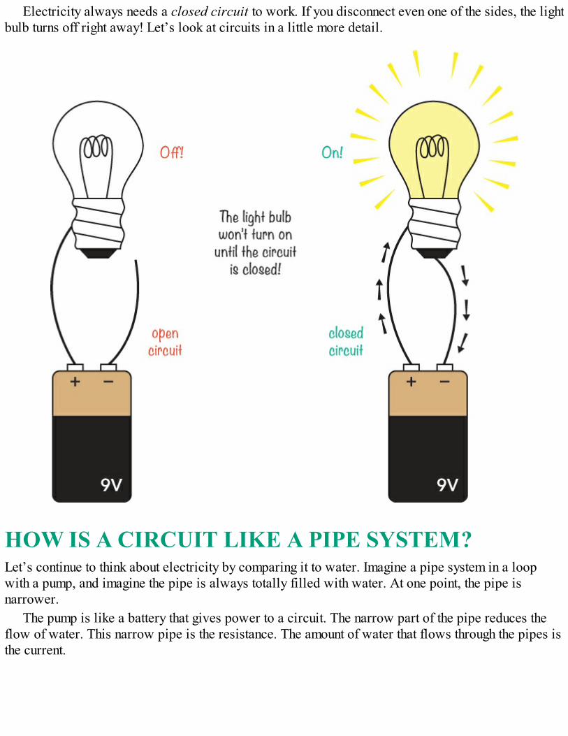
Electricity always needs a closed circuit to work. If you disconnect even one of the sides, the lightbulb turns off right away! Let’s look at circuits in a little more detail.
HOW IS A CIRCUIT LIKE A PIPE SYSTEM?Let’s continue to think about electricity by comparing it to water. Imagine a pipe system in a loopwith a pump, and imagine the pipe is always totally filled with water. At one point, the pipe isnarrower.
The pump is like a battery that gives power to a circuit. The narrow part of the pipe reduces theflow of water. This narrow pipe is the resistance. The amount of water that flows through the pipes isthe current.
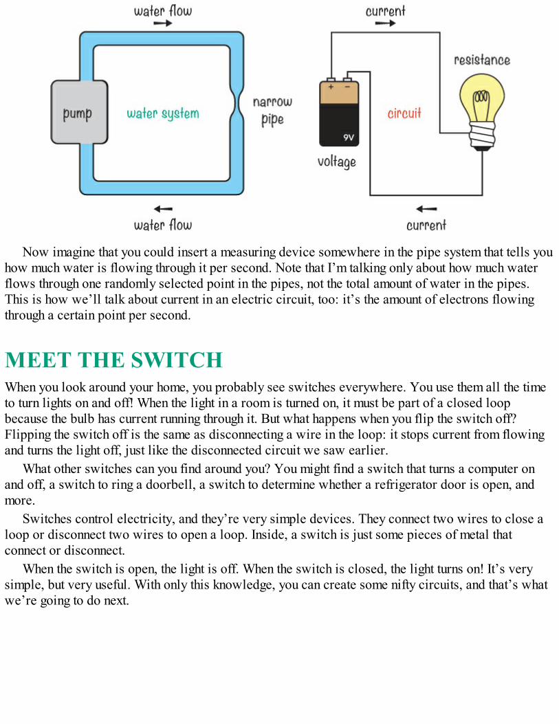
Now imagine that you could insert a measuring device somewhere in the pipe system that tells youhow much water is flowing through it per second. Note that I’m talking only about how much waterflows through one randomly selected point in the pipes, not the total amount of water in the pipes.This is how we’ll talk about current in an electric circuit, too: it’s the amount of electrons flowingthrough a certain point per second.
MEET THE SWITCHWhen you look around your home, you probably see switches everywhere. You use them all the timeto turn lights on and off! When the light in a room is turned on, it must be part of a closed loopbecause the bulb has current running through it. But what happens when you flip the switch off?Flipping the switch off is the same as disconnecting a wire in the loop: it stops current from flowingand turns the light off, just like the disconnected circuit we saw earlier.
What other switches can you find around you? You might find a switch that turns a computer onand off, a switch to ring a doorbell, a switch to determine whether a refrigerator door is open, andmore.
Switches control electricity, and they’re very simple devices. They connect two wires to close aloop or disconnect two wires to open a loop. Inside, a switch is just some pieces of metal thatconnect or disconnect.
When the switch is open, the light is off. When the switch is closed, the light turns on! It’s verysimple, but very useful. With only this knowledge, you can create some nifty circuits, and that’s whatwe’re going to do next.
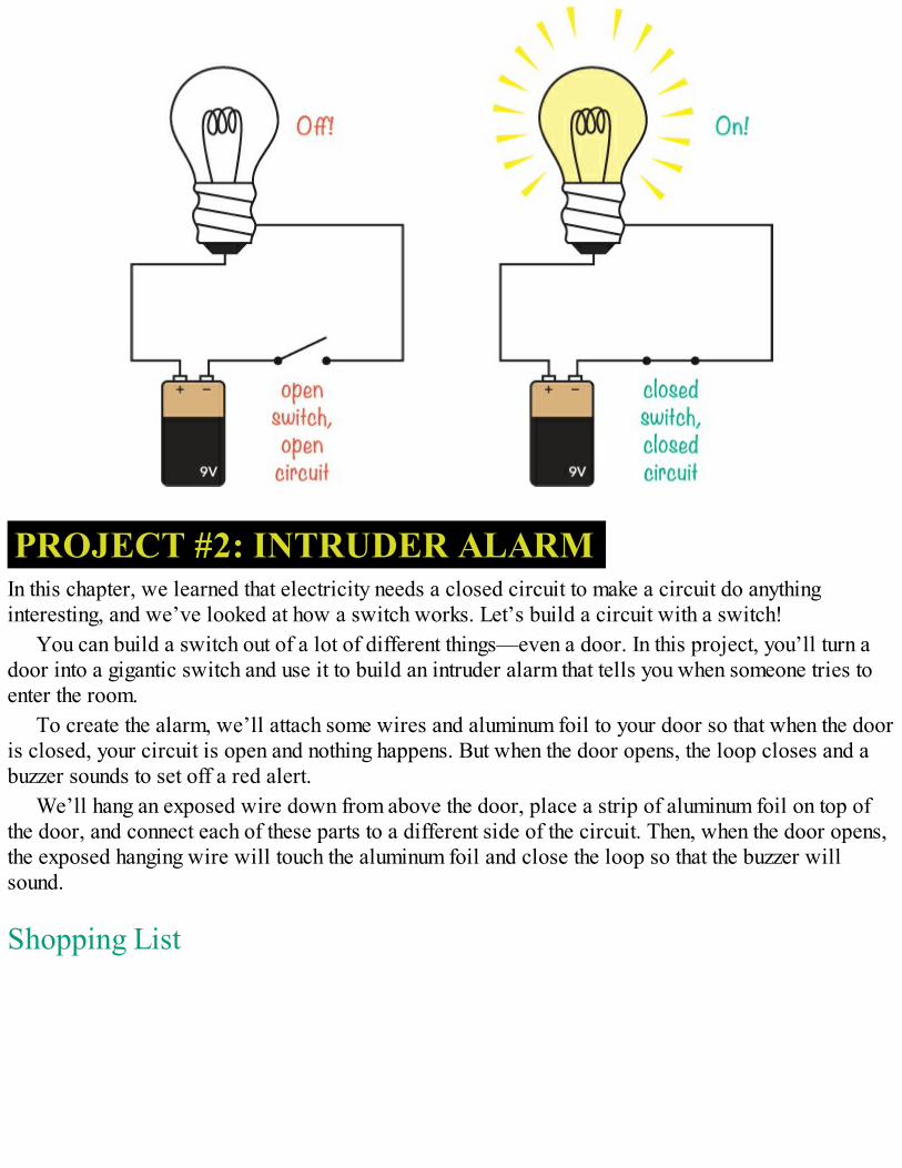
PROJECT #2: INTRUDER ALARMIn this chapter, we learned that electricity needs a closed circuit to make a circuit do anythinginteresting, and we’ve looked at how a switch works. Let’s build a circuit with a switch!
You can build a switch out of a lot of different things—even a door. In this project, you’ll turn adoor into a gigantic switch and use it to build an intruder alarm that tells you when someone tries toenter the room.
To create the alarm, we’ll attach some wires and aluminum foil to your door so that when the dooris closed, your circuit is open and nothing happens. But when the door opens, the loop closes and abuzzer sounds to set off a red alert.
We’ll hang an exposed wire down from above the door, place a strip of aluminum foil on top ofthe door, and connect each of these parts to a different side of the circuit. Then, when the door opens,the exposed hanging wire will touch the aluminum foil and close the loop so that the buzzer willsound.
Shopping List
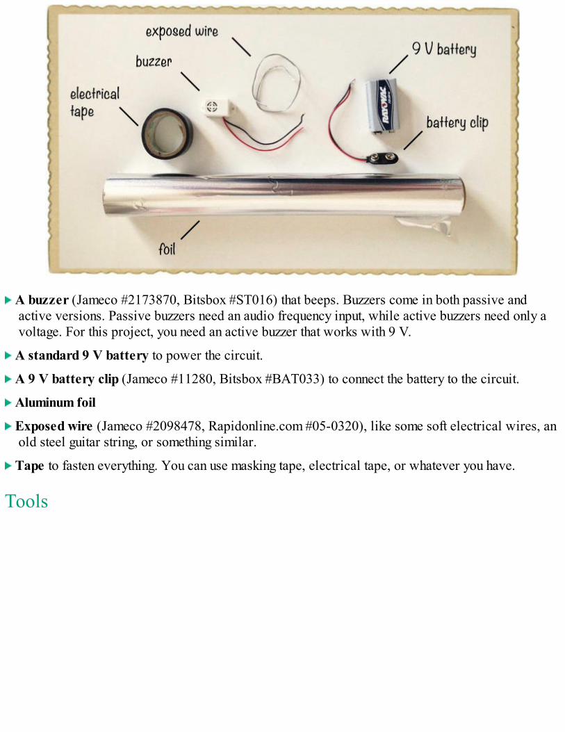
A buzzer (Jameco #2173870, Bitsbox #ST016) that beeps. Buzzers come in both passive andactive versions. Passive buzzers need an audio frequency input, while active buzzers need only avoltage. For this project, you need an active buzzer that works with 9 V.
A standard 9 V battery to power the circuit.
A 9 V battery clip (Jameco #11280, Bitsbox #BAT033) to connect the battery to the circuit.
Aluminum foil
Exposed wire (Jameco #2098478, Rapidonline.com #05-0320), like some soft electrical wires, anold steel guitar string, or something similar.
Tape to fasten everything. You can use masking tape, electrical tape, or whatever you have.
Tools
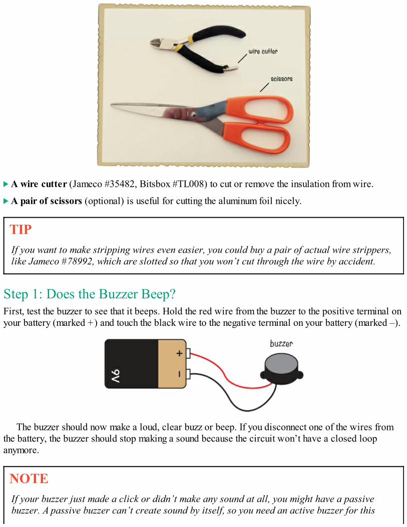
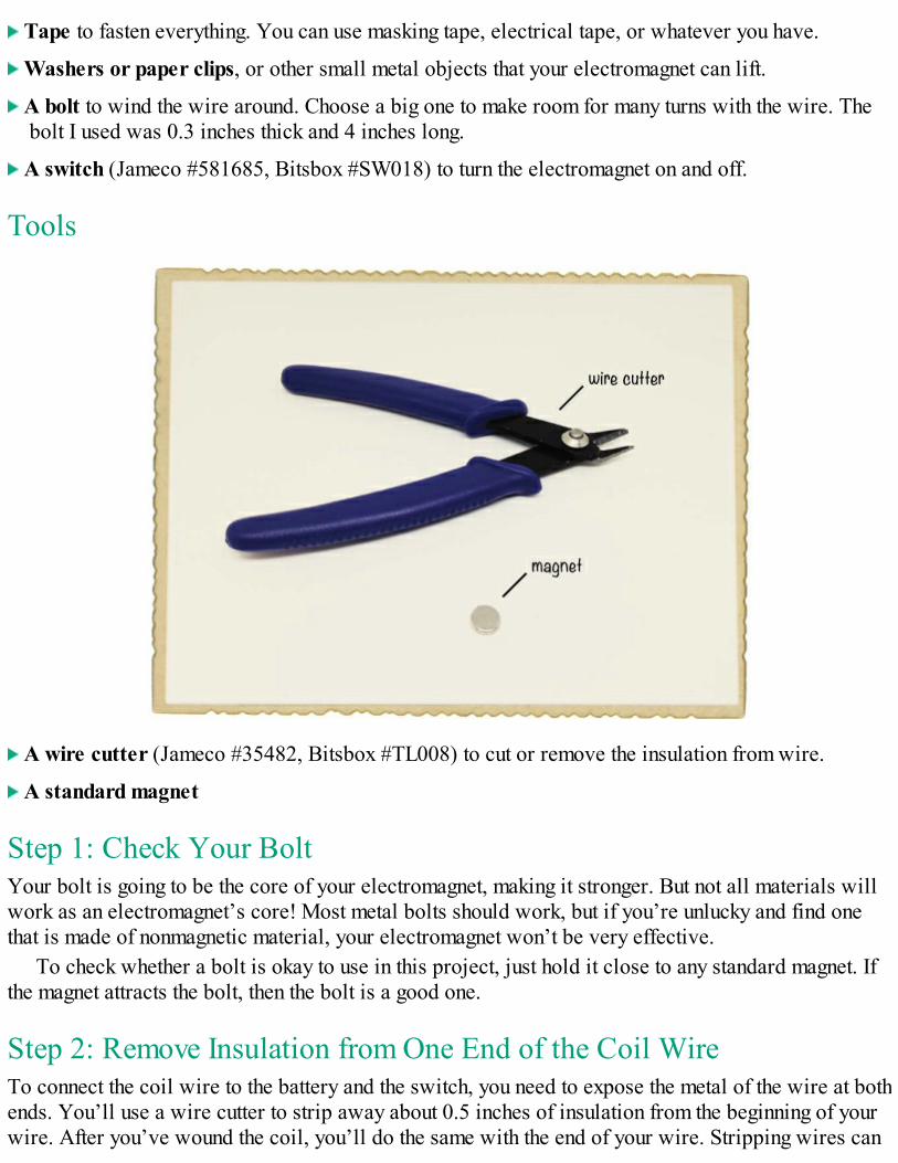
A wire cutter (Jameco #35482, Bitsbox #TL008) to cut or remove the insulation from wire.
A pair of scissors (optional) is useful for cutting the aluminum foil nicely.
TIPIf you want to make stripping wires even easier, you could buy a pair of actual wire strippers,like Jameco #78992, which are slotted so that you won’t cut through the wire by accident.
Step 1: Does the Buzzer Beep?First, test the buzzer to see that it beeps. Hold the red wire from the buzzer to the positive terminal onyour battery (marked +) and touch the black wire to the negative terminal on your battery (marked –).
The buzzer should now make a loud, clear buzz or beep. If you disconnect one of the wires fromthe battery, the buzzer should stop making a sound because the circuit won’t have a closed loopanymore.
NOTEIf your buzzer just made a click or didn’t make any sound at all, you might have a passivebuzzer. A passive buzzer can’t create sound by itself, so you need an active buzzer for this
project. The buzzer recommended in this project’s Shopping List (page 12) should do the trick.
Step 2: Prepare the AluminumUse a pair of scissors to cut a big, shiny strip of aluminum foil to go on the top of the door. Cut astraight piece of foil, about 1 inch wide and as long as the roll of aluminum foil is wide.
Step 3: Foil Your DoorFasten the strip of aluminum foil on the top of the door by using a piece of tape on each side of thestrip. The foil will act as a contact for the battery and buzzer wire.
Step 4: Prepare a Trigger WireGet a piece of exposed soft wire about 10 inches long. An exposed wire is a wire that doesn’t haveany plastic around it, as opposed to insulated wire, which is metal enclosed in plastic. Just find somewire that is already exposed, such as a steel string from a guitar, or use your wire cutters to snip apiece from the spool in the Shopping List (page 12). This is going to be your trigger wire.
NOTEYou could also use a wire cutter to remove, or strip, the plastic from insulated wires. If youwant to do that, ask an adult for help!
Step 5: Connect the Buzzer and Trigger WireConnect one side of the exposed trigger wire to the exposed metal end of the battery clip’s black wirewith some tape. Connecting two wires is easy. Here’s how you do it: Pick up the two wires you wantto connect and twist their ends together. Make sure the two pieces of metal are touching! Then wrapthem inside the tape together.
Following the same process, connect the red wire from the battery clip to the red wire on yourbuzzer.
Step 6: Mount the Buzzer and Trigger WireNow, let’s place the trigger wire and the buzzer above the door. First, tape the trigger wire onto thedoor frame above the door so that it’s hanging in front of the door when the door is closed and lyingon top of the door and the aluminum strip when the door is open.
Next, tape the buzzer to the door frame in such a way that the black wire can touch the aluminumfoil on top of the door. Tape the black wire onto the foil so that the exposed part of the wire touchesthe foil.
Step 7: Add a Power SourcePlace the battery on top of the door frame, close to the battery clip. Use some tape to hold it in placeif necessary. Then connect the battery clip to the battery.
Once the battery is connected, your finished intruder alarm should look something like this:
Step 8: Stage an Intruder Alert!Test the alarm by opening and closing the door. As the door opens, the exposed wire should hit thefoil, causing the buzzer to sound a loud alarm. For a more realistic test, invite someone else to open
the door instead!
Step 9: What If the Intruder Alarm Doesn’t Work?If the buzzer doesn’t go off, you might need to adjust the position of the trigger wire a bit, just to makesure the wire touches the strip of aluminum foil when the door opens. If the trigger wire touches thefoil just fine, try a different battery. If that doesn’t work, you might need to retape your battery leadsto their wires.
WHAT’S NEXT?Now you know the basics of electricity—a current of electrons flows through wires and makessomething happen, like lighting a light bulb or sounding an alarm. And you also know that to makethe electrons flow through the circuit, you need a voltage source, such as a battery, and a closedloop. That’s all you need to start tinkering with electronics!
What else can you think of to make with what you’ve learned? There are many other things thatcan be made into switches. For example, try making an alarm for your closet to keep nosy siblingsor friends away from your personal stuff. Or how about making a silent alarm? Just replace thebuzzer with a light bulb!
In the next two chapters, we’ll look at how electricity is generated and how we can useelectricity to make things move.

2MAKING THINGS MOVE WITHELECTRICITY AND MAGNETS
Big magnets attract small metal objects; small magnets stick to large metal objects. For example,refrigerator doors are usually big pieces of metal, so it’s easy cover them with tiny, decorativemagnets. You’ve probably seen magnets in cartoons, too: characters like to use giant horseshoe-shaped magnets to cause mischief. You can find magnets in nature or create them with electricity. Amagnet created with electricity is called an electromagnet.
You can use an electromagnet to make things move, and you don’t even have to be a superhero todo it! In fact, many things you see every day—like motors, loudspeakers, and the automatic doors inshops—work because electromagnets make something in them move.
An electromagnet is very easy to make, and in this chapter, you’ll build an electromagnet that youcan turn on and off with a switch. Then, you’ll use an electromagnet to build your very own motor!
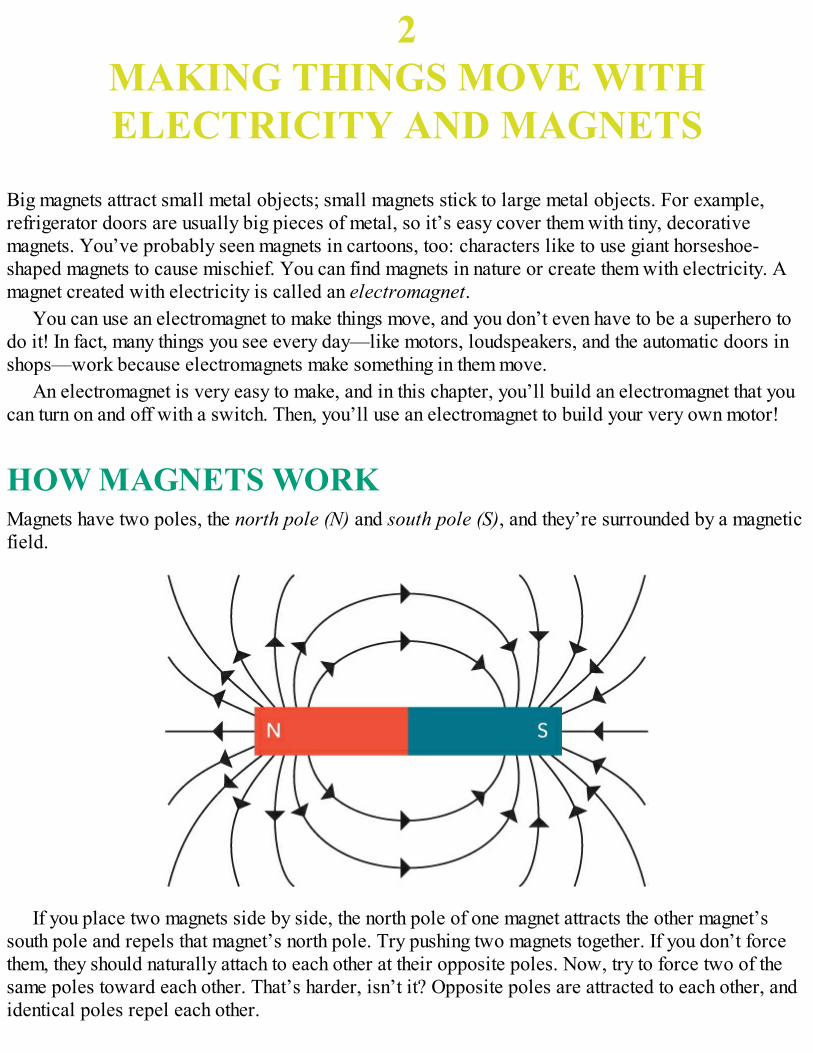
HOW MAGNETS WORKMagnets have two poles, the north pole (N) and south pole (S), and they’re surrounded by a magneticfield.
If you place two magnets side by side, the north pole of one magnet attracts the other magnet’ssouth pole and repels that magnet’s north pole. Try pushing two magnets together. If you don’t forcethem, they should naturally attach to each other at their opposite poles. Now, try to force two of thesame poles toward each other. That’s harder, isn’t it? Opposite poles are attracted to each other, andidentical poles repel each other.
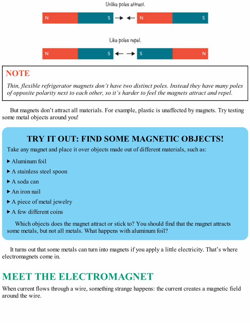
NOTEThin, flexible refrigerator magnets don’t have two distinct poles. Instead they have many polesof opposite polarity next to each other, so it’s harder to feel the magnets attract and repel.
But magnets don’t attract all materials. For example, plastic is unaffected by magnets. Try testingsome metal objects around you!
TRY IT OUT: FIND SOME MAGNETIC OBJECTS!Take any magnet and place it over objects made out of different materials, such as:
Aluminum foil
A stainless steel spoon
A soda can
An iron nail
A piece of metal jewelry
A few different coins
Which objects does the magnet attract or stick to? You should find that the magnet attractssome metals, but not all metals. What happens with aluminum foil?
It turns out that some metals can turn into magnets if you apply a little electricity. That’s whereelectromagnets come in.
MEET THE ELECTROMAGNETWhen current flows through a wire, something strange happens: the current creates a magnetic fieldaround the wire.
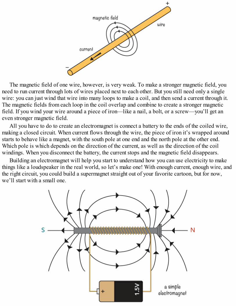
The magnetic field of one wire, however, is very weak. To make a stronger magnetic field, youneed to run current through lots of wires placed next to each other. But you still need only a singlewire: you can just wind that wire into many loops to make a coil, and then send a current through it.The magnetic fields from each loop in the coil overlap and combine to create a stronger magneticfield. If you wind your wire around a piece of iron—like a nail, a bolt, or a screw—you’ll get aneven stronger magnetic field.
All you have to do to create an electromagnet is connect a battery to the ends of the coiled wire,making a closed circuit. When current flows through the wire, the piece of iron it’s wrapped aroundstarts to behave like a magnet, with the south pole at one end and the north pole at the other end.Which pole is which depends on the direction of the current, as well as the direction of the coilwindings. When you disconnect the battery, the current stops and the magnetic field disappears.
Building an electromagnet will help you start to understand how you can use electricity to makethings like a loudspeaker in the real world, so let’s make one! With enough current, enough wire, andthe right circuit, you could build a supermagnet straight out of your favorite cartoon, but for now,we’ll start with a small one.
PROJECT #3: CREATE YOUR OWNELECTROMAGNETYou know the theory behind how to build your own electromagnet. But reading the theory isn’t thesame as making something in real life, so it’s time to have some fun!
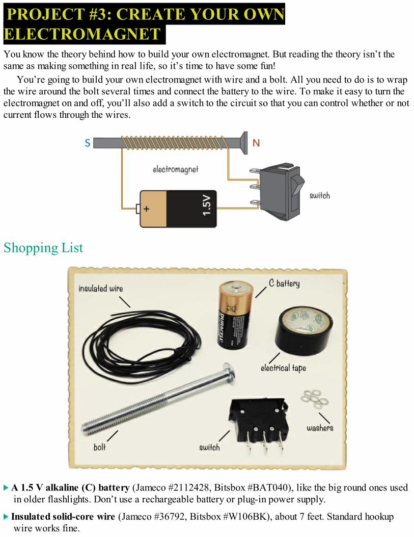
You’re going to build your own electromagnet with wire and a bolt. All you need to do is to wrapthe wire around the bolt several times and connect the battery to the wire. To make it easy to turn theelectromagnet on and off, you’ll also add a switch to the circuit so that you can control whether or notcurrent flows through the wires.
Shopping List
A 1.5 V alkaline (C) battery (Jameco #2112428, Bitsbox #BAT040), like the big round ones usedin older flashlights. Don’t use a rechargeable battery or plug-in power supply.
Insulated solid-core wire (Jameco #36792, Bitsbox #W106BK), about 7 feet. Standard hookupwire works fine.
Tape to fasten everything. You can use masking tape, electrical tape, or whatever you have.
Washers or paper clips, or other small metal objects that your electromagnet can lift.
A bolt to wind the wire around. Choose a big one to make room for many turns with the wire. Thebolt I used was 0.3 inches thick and 4 inches long.
A switch (Jameco #581685, Bitsbox #SW018) to turn the electromagnet on and off.
Tools
A wire cutter (Jameco #35482, Bitsbox #TL008) to cut or remove the insulation from wire.
A standard magnet
Step 1: Check Your BoltYour bolt is going to be the core of your electromagnet, making it stronger. But not all materials willwork as an electromagnet’s core! Most metal bolts should work, but if you’re unlucky and find onethat is made of nonmagnetic material, your electromagnet won’t be very effective.
To check whether a bolt is okay to use in this project, just hold it close to any standard magnet. Ifthe magnet attracts the bolt, then the bolt is a good one.
Step 2: Remove Insulation from One End of the Coil WireTo connect the coil wire to the battery and the switch, you need to expose the metal of the wire at bothends. You’ll use a wire cutter to strip away about 0.5 inches of insulation from the beginning of yourwire. After you’ve wound the coil, you’ll do the same with the end of your wire. Stripping wires can
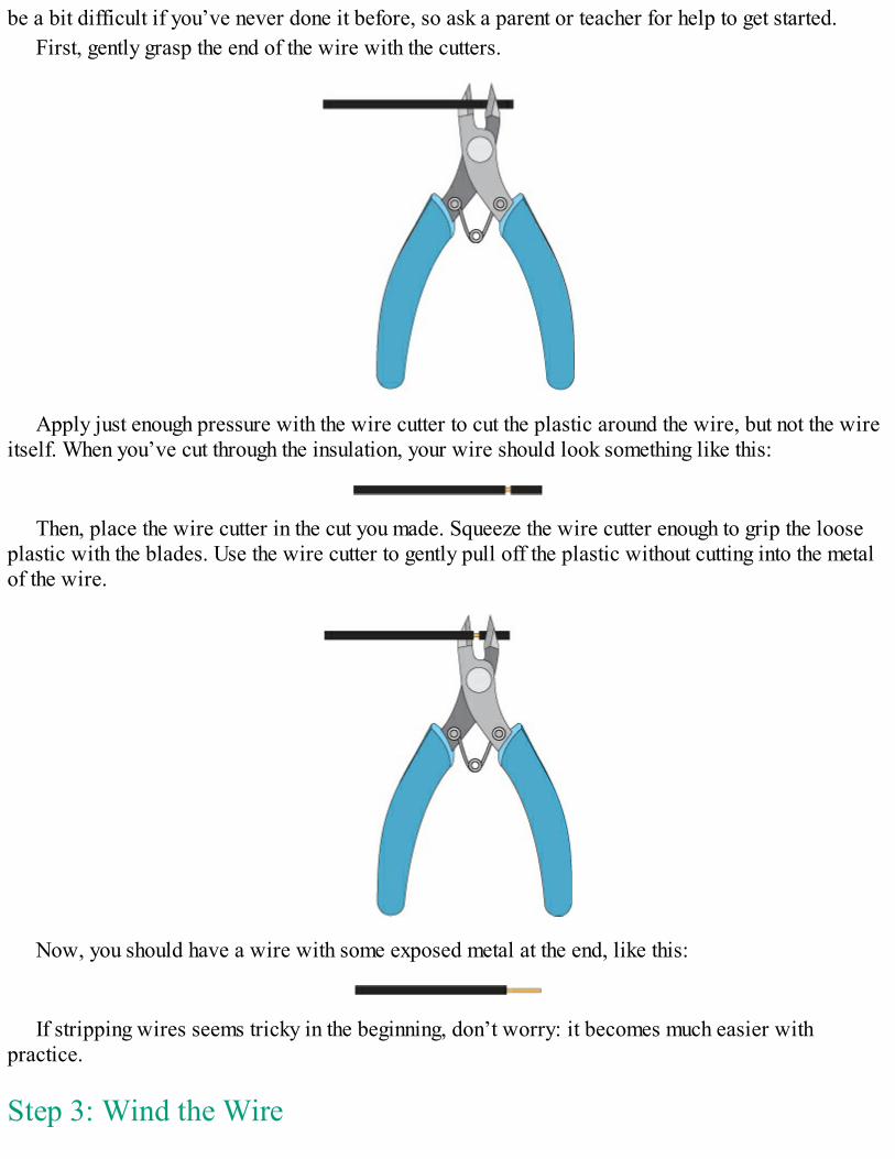
be a bit difficult if you’ve never done it before, so ask a parent or teacher for help to get started.First, gently grasp the end of the wire with the cutters.
Apply just enough pressure with the wire cutter to cut the plastic around the wire, but not the wireitself. When you’ve cut through the insulation, your wire should look something like this:
Then, place the wire cutter in the cut you made. Squeeze the wire cutter enough to grip the looseplastic with the blades. Use the wire cutter to gently pull off the plastic without cutting into the metalof the wire.
Now, you should have a wire with some exposed metal at the end, like this:
If stripping wires seems tricky in the beginning, don’t worry: it becomes much easier withpractice.
Step 3: Wind the Wire
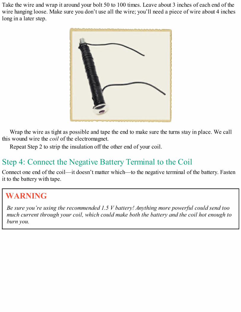
Take the wire and wrap it around your bolt 50 to 100 times. Leave about 3 inches of each end of thewire hanging loose. Make sure you don’t use all the wire; you’ll need a piece of wire about 4 incheslong in a later step.
Wrap the wire as tight as possible and tape the end to make sure the turns stay in place. We callthis wound wire the coil of the electromagnet.
Repeat Step 2 to strip the insulation off the other end of your coil.
Step 4: Connect the Negative Battery Terminal to the CoilConnect one end of the coil—it doesn’t matter which—to the negative terminal of the battery. Fastenit to the battery with tape.
WARNINGBe sure you’re using the recommended 1.5 V battery! Anything more powerful could send toomuch current through your coil, which could make both the battery and the coil hot enough toburn you.
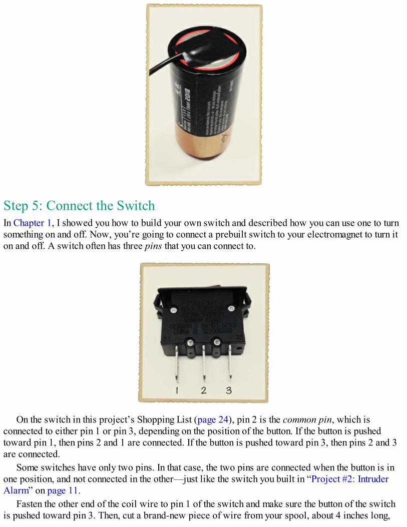
Step 5: Connect the SwitchIn Chapter 1, I showed you how to build your own switch and described how you can use one to turnsomething on and off. Now, you’re going to connect a prebuilt switch to your electromagnet to turn iton and off. A switch often has three pins that you can connect to.
On the switch in this project’s Shopping List (page 24), pin 2 is the common pin, which isconnected to either pin 1 or pin 3, depending on the position of the button. If the button is pushedtoward pin 1, then pins 2 and 1 are connected. If the button is pushed toward pin 3, then pins 2 and 3are connected.
Some switches have only two pins. In that case, the two pins are connected when the button is inone position, and not connected in the other—just like the switch you built in “Project #2: IntruderAlarm” on page 11.
Fasten the other end of the coil wire to pin 1 of the switch and make sure the button of the switchis pushed toward pin 3. Then, cut a brand-new piece of wire from your spool, about 4 inches long,
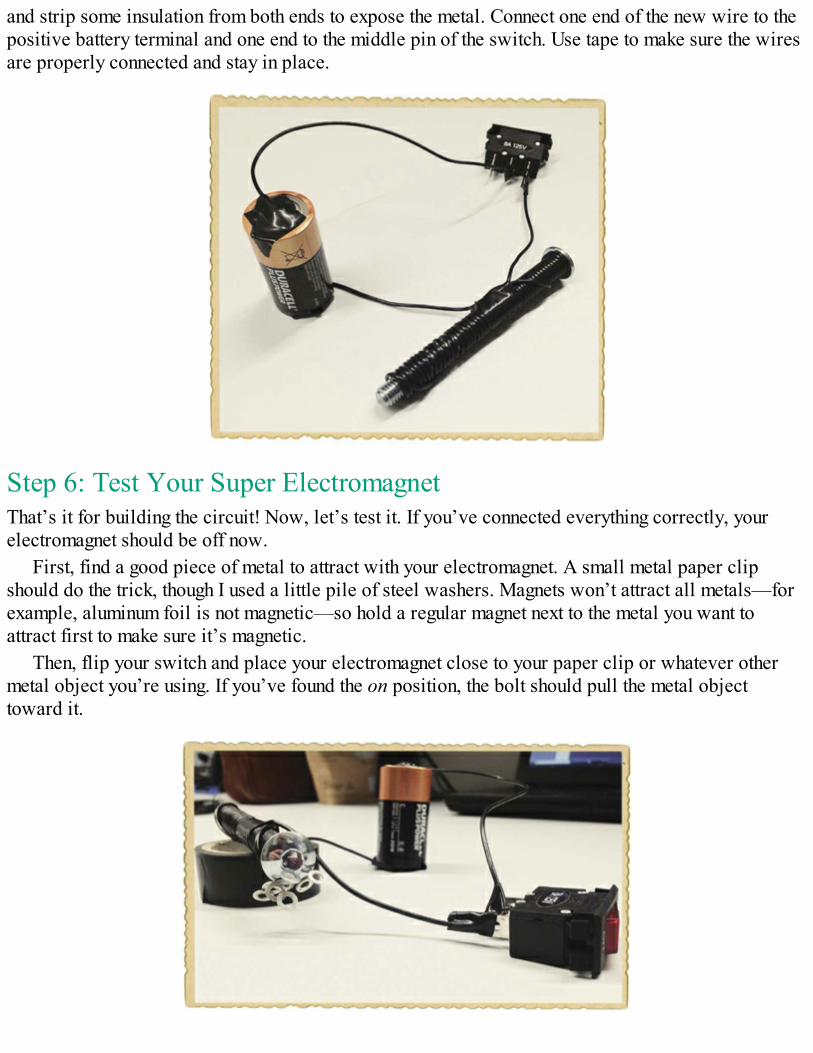
and strip some insulation from both ends to expose the metal. Connect one end of the new wire to thepositive battery terminal and one end to the middle pin of the switch. Use tape to make sure the wiresare properly connected and stay in place.
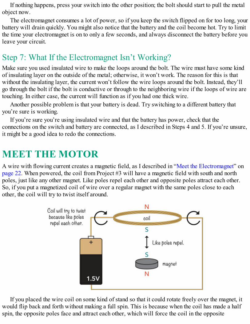
Step 6: Test Your Super ElectromagnetThat’s it for building the circuit! Now, let’s test it. If you’ve connected everything correctly, yourelectromagnet should be off now.
First, find a good piece of metal to attract with your electromagnet. A small metal paper clipshould do the trick, though I used a little pile of steel washers. Magnets won’t attract all metals—forexample, aluminum foil is not magnetic—so hold a regular magnet next to the metal you want toattract first to make sure it’s magnetic.
Then, flip your switch and place your electromagnet close to your paper clip or whatever othermetal object you’re using. If you’ve found the on position, the bolt should pull the metal objecttoward it.
If nothing happens, press your switch into the other position; the bolt should start to pull the metalobject now.
The electromagnet consumes a lot of power, so if you keep the switch flipped on for too long, yourbattery will drain quickly. You might also notice that the battery and the coil become hot. Try to limitthe time your electromagnet is on to only a few seconds, and always disconnect the battery before youleave your circuit.
Step 7: What If the Electromagnet Isn’t Working?Make sure you used insulated wire to make the loops around the bolt. The wire must have some kindof insulating layer on the outside of the metal; otherwise, it won’t work. The reason for this is thatwithout the insulating layer, the current won’t follow the wire loops around the bolt. Instead, they’llgo through the bolt if the bolt is conductive or through to the neighboring wire if the loops of wire aretouching. In either case, the current will function as if you had one thick wire.
Another possible problem is that your battery is dead. Try switching to a different battery thatyou’re sure is working.
If you’re sure you’re using insulated wire and that the battery has power, check that theconnections on the switch and battery are connected, as I described in Steps 4 and 5. If you’re unsure,it might be a good idea to redo the connections.
MEET THE MOTORA wire with flowing current creates a magnetic field, as I described in “Meet the Electromagnet” onpage 22. When powered, the coil from Project #3 will have a magnetic field with south and northpoles, just like any other magnet. Like poles repel each other and opposite poles attract each other.So, if you put a magnetized coil of wire over a regular magnet with the same poles close to eachother, the coil will try to twist itself around.
If you placed the wire coil on some kind of stand so that it could rotate freely over the magnet, itwould flip back and forth without making a full spin. This is because when the coil has made a halfspin, the opposite poles face and attract each other, which will force the coil in the opposite
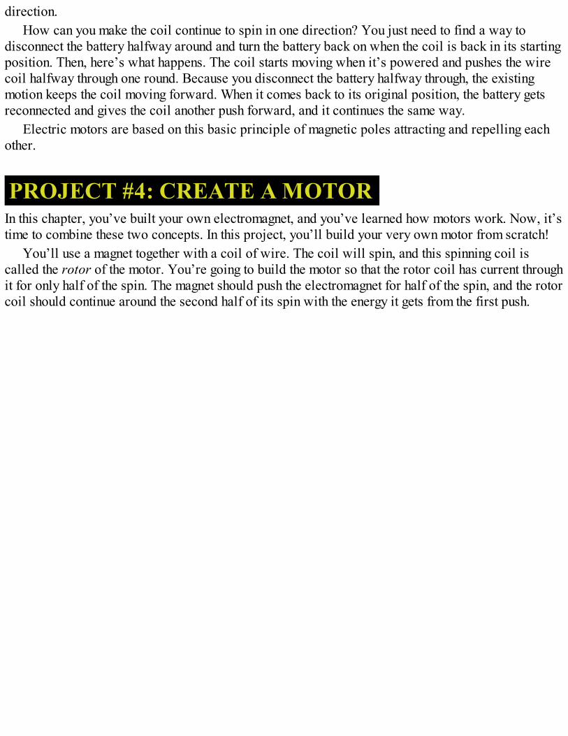
direction.How can you make the coil continue to spin in one direction? You just need to find a way to
disconnect the battery halfway around and turn the battery back on when the coil is back in its startingposition. Then, here’s what happens. The coil starts moving when it’s powered and pushes the wirecoil halfway through one round. Because you disconnect the battery halfway through, the existingmotion keeps the coil moving forward. When it comes back to its original position, the battery getsreconnected and gives the coil another push forward, and it continues the same way.
Electric motors are based on this basic principle of magnetic poles attracting and repelling eachother.
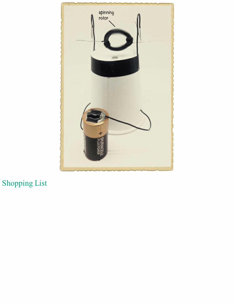
PROJECT #4: CREATE A MOTORIn this chapter, you’ve built your own electromagnet, and you’ve learned how motors work. Now, it’stime to combine these two concepts. In this project, you’ll build your very own motor from scratch!
You’ll use a magnet together with a coil of wire. The coil will spin, and this spinning coil iscalled the rotor of the motor. You’re going to build the motor so that the rotor coil has current throughit for only half of the spin. The magnet should push the electromagnet for half of the spin, and the rotorcoil should continue around the second half of its spin with the energy it gets from the first push.
Shopping List
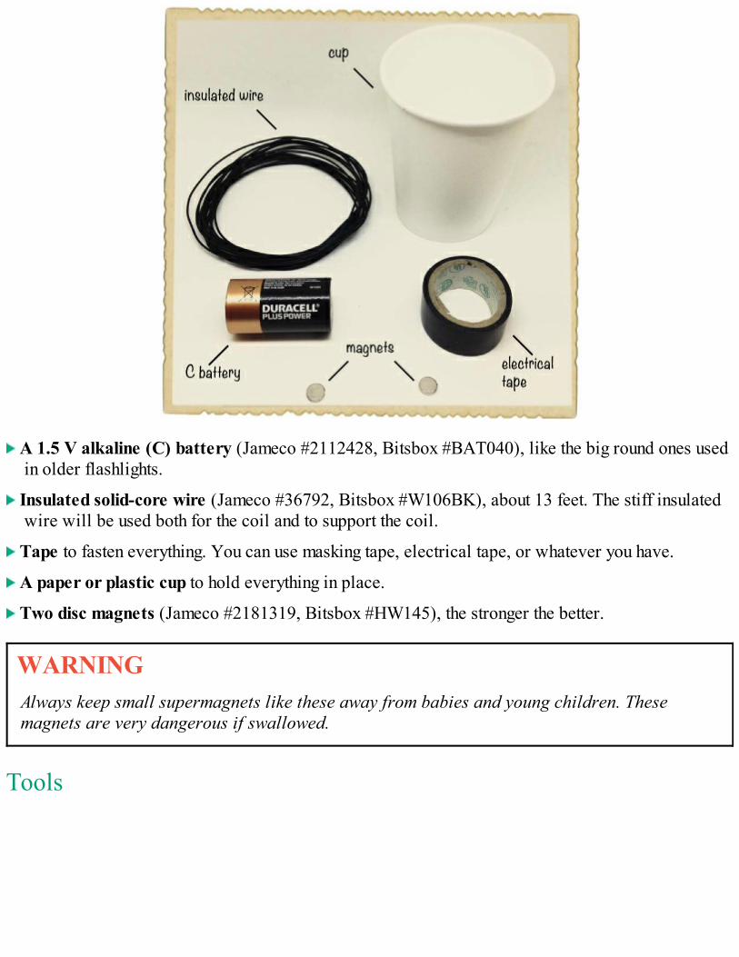
A 1.5 V alkaline (C) battery (Jameco #2112428, Bitsbox #BAT040), like the big round ones usedin older flashlights.
Insulated solid-core wire (Jameco #36792, Bitsbox #W106BK), about 13 feet. The stiff insulatedwire will be used both for the coil and to support the coil.
Tape to fasten everything. You can use masking tape, electrical tape, or whatever you have.
A paper or plastic cup to hold everything in place.
Two disc magnets (Jameco #2181319, Bitsbox #HW145), the stronger the better.
WARNINGAlways keep small supermagnets like these away from babies and young children. Thesemagnets are very dangerous if swallowed.
Tools
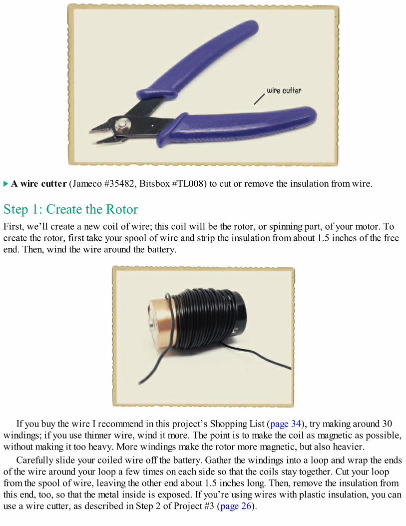
A wire cutter (Jameco #35482, Bitsbox #TL008) to cut or remove the insulation from wire.
Step 1: Create the RotorFirst, we’ll create a new coil of wire; this coil will be the rotor, or spinning part, of your motor. Tocreate the rotor, first take your spool of wire and strip the insulation from about 1.5 inches of the freeend. Then, wind the wire around the battery.
If you buy the wire I recommend in this project’s Shopping List (page 34), try making around 30windings; if you use thinner wire, wind it more. The point is to make the coil as magnetic as possible,without making it too heavy. More windings make the rotor more magnetic, but also heavier.
Carefully slide your coiled wire off the battery. Gather the windings into a loop and wrap the endsof the wire around your loop a few times on each side so that the coils stay together. Cut your loopfrom the spool of wire, leaving the other end about 1.5 inches long. Then, remove the insulation fromthis end, too, so that the metal inside is exposed. If you’re using wires with plastic insulation, you canuse a wire cutter, as described in Step 2 of Project #3 (page 26).
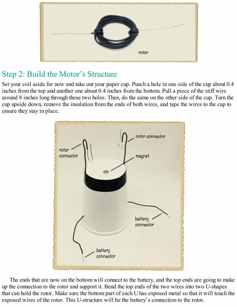
Step 2: Build the Motor’s StructureSet your coil aside for now and take out your paper cup. Punch a hole in one side of the cup about 0.4inches from the top and another one about 0.4 inches from the bottom. Pull a piece of the stiff wirearound 8 inches long through these two holes. Then, do the same on the other side of the cup. Turn thecup upside down, remove the insulation from the ends of both wires, and tape the wires to the cup toensure they stay in place.
The ends that are now on the bottom will connect to the battery, and the top ends are going to makeup the connection to the rotor and support it. Bend the top ends of the two wires into two U-shapesthat can hold the rotor. Make sure the bottom part of each U has exposed metal so that it will touch theexposed wires of the rotor. This U-structure will be the battery’s connection to the rotor.
Step 3: Place the MagnetsPlace one magnet on top of the cup. Then place one magnet inside the cup so that the two magnetsstick to each other through the cup. Place your rotor into the U-structure and adjust the position of themagnets to make sure they are at the center, just under the coil.
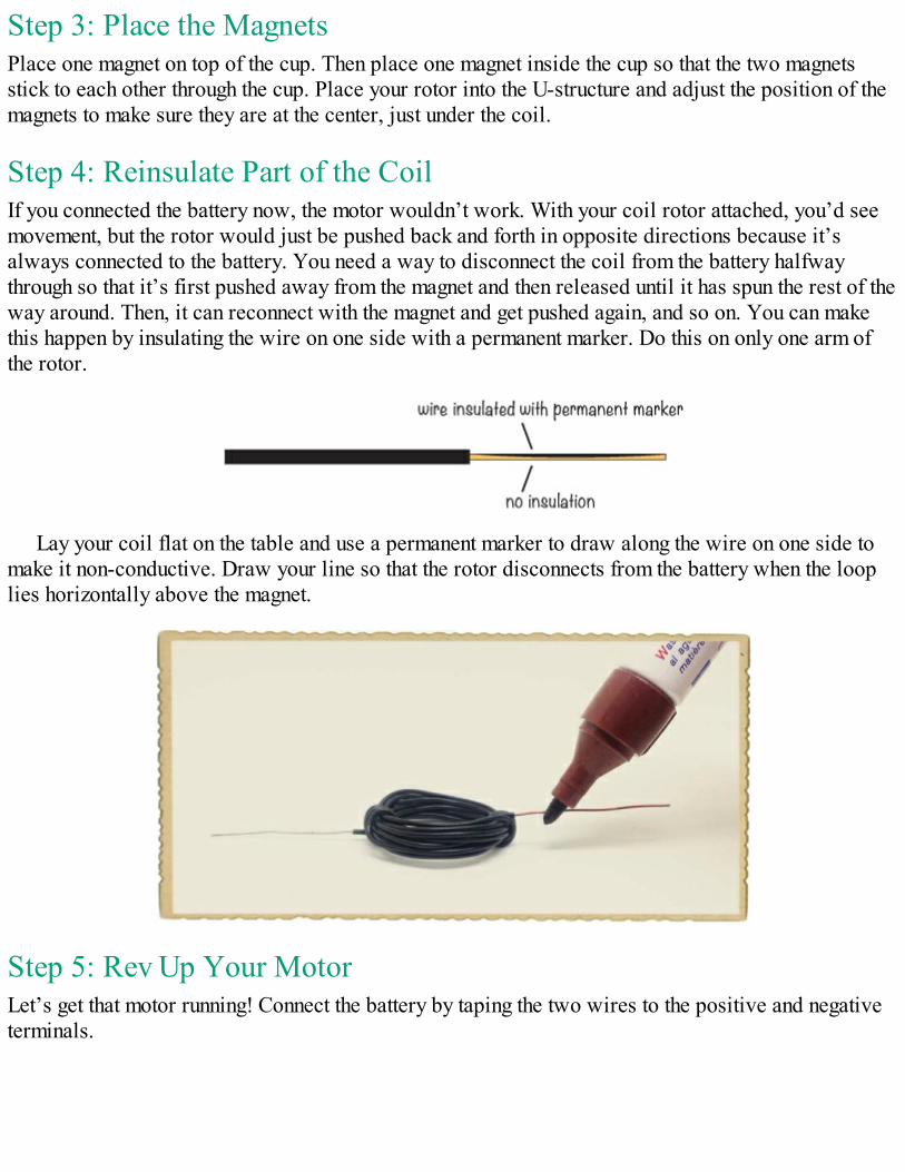
Step 4: Reinsulate Part of the CoilIf you connected the battery now, the motor wouldn’t work. With your coil rotor attached, you’d seemovement, but the rotor would just be pushed back and forth in opposite directions because it’salways connected to the battery. You need a way to disconnect the coil from the battery halfwaythrough so that it’s first pushed away from the magnet and then released until it has spun the rest of theway around. Then, it can reconnect with the magnet and get pushed again, and so on. You can makethis happen by insulating the wire on one side with a permanent marker. Do this on only one arm ofthe rotor.
Lay your coil flat on the table and use a permanent marker to draw along the wire on one side tomake it non-conductive. Draw your line so that the rotor disconnects from the battery when the looplies horizontally above the magnet.
Step 5: Rev Up Your MotorLet’s get that motor running! Connect the battery by taping the two wires to the positive and negativeterminals.
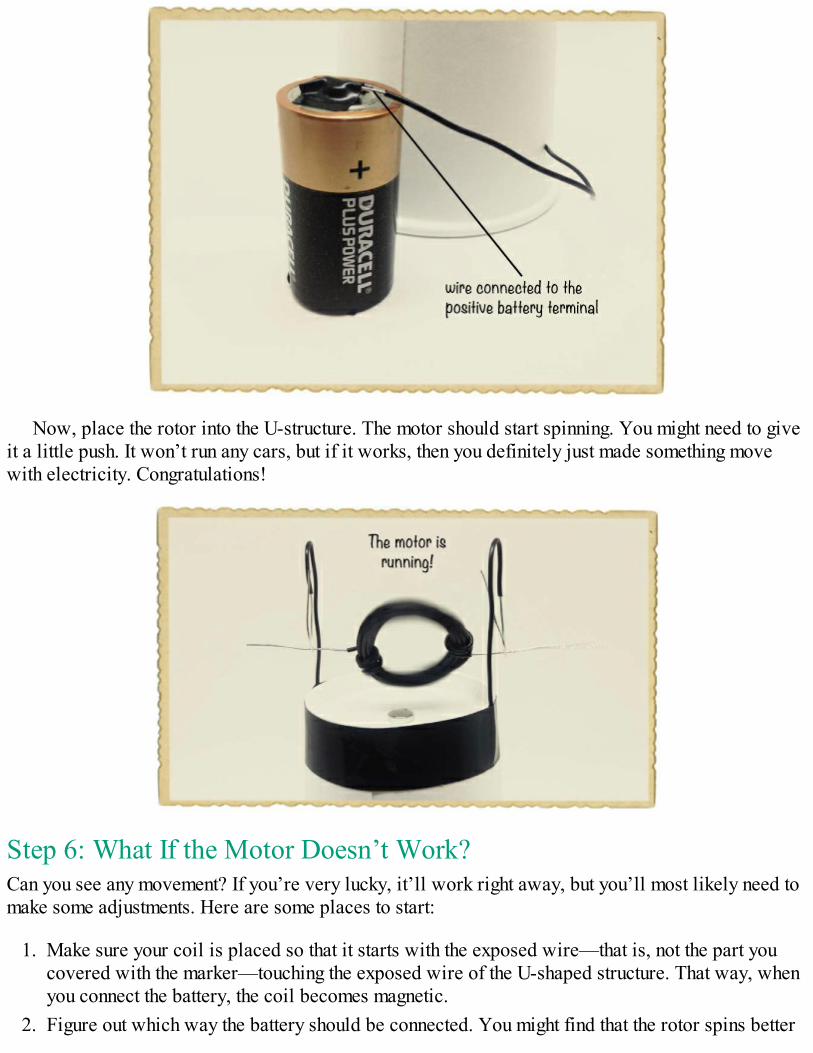
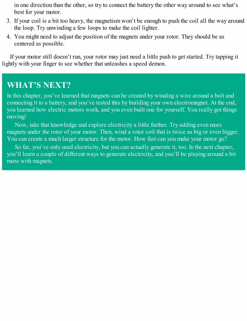
Now, place the rotor into the U-structure. The motor should start spinning. You might need to giveit a little push. It won’t run any cars, but if it works, then you definitely just made something movewith electricity. Congratulations!
Step 6: What If the Motor Doesn’t Work?Can you see any movement? If you’re very lucky, it’ll work right away, but you’ll most likely need tomake some adjustments. Here are some places to start:
1. Make sure your coil is placed so that it starts with the exposed wire—that is, not the part youcovered with the marker—touching the exposed wire of the U-shaped structure. That way, whenyou connect the battery, the coil becomes magnetic.
2. Figure out which way the battery should be connected. You might find that the rotor spins better
in one direction than the other, so try to connect the battery the other way around to see what’sbest for your motor.
3. If your coil is a bit too heavy, the magnetism won’t be enough to push the coil all the way aroundthe loop. Try unwinding a few loops to make the coil lighter.
4. You might need to adjust the position of the magnets under your rotor. They should be ascentered as possible.
If your motor still doesn’t run, your rotor may just need a little push to get started. Try tapping itlightly with your finger to see whether that unleashes a speed demon.
WHAT’S NEXT?In this chapter, you’ve learned that magnets can be created by winding a wire around a bolt andconnecting it to a battery, and you’ve tested this by building your own electromagnet. At the end,you learned how electric motors work, and you even built one for yourself. You really got thingsmoving!
Now, take that knowledge and explore electricity a little further. Try adding even moremagnets under the rotor of your motor. Then, wind a rotor coil that is twice as big or even bigger.You can create a much larger structure for the motor. How fast can you make your motor go?
So far, you’ve only used electricity, but you can actually generate it, too. In the next chapter,you’ll learn a couple of different ways to generate electricity, and you’ll be playing around a bitmore with magnets.

3HOW TO GENERATE ELECTRICITY
Chapter 1 described why you need a closed loop to get current flowing through a circuit, and Chapter2 showed you how to build your own electromagnet and motor. The projects in those chapters usedelectricity from a battery, but in this chapter, you’ll make your own electricity sources!
Specifically, you’ll learn how to build your own generator, which creates electricity frommovement, and your own battery, which creates electricity through chemical reactions. These are twoof the most common ways to obtain electricity.
GENERATING ELECTRICITY WITH MAGNETSWhen you run current through a wire, it creates a magnetic field around the wire, but there’s anotherconnection between electricity and magnetism. You can also create electricity using a wire and amagnet!
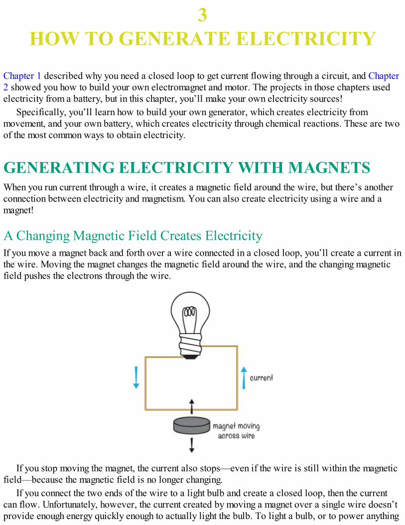
A Changing Magnetic Field Creates ElectricityIf you move a magnet back and forth over a wire connected in a closed loop, you’ll create a current inthe wire. Moving the magnet changes the magnetic field around the wire, and the changing magneticfield pushes the electrons through the wire.
If you stop moving the magnet, the current also stops—even if the wire is still within the magneticfield—because the magnetic field is no longer changing.
If you connect the two ends of the wire to a light bulb and create a closed loop, then the currentcan flow. Unfortunately, however, the current created by moving a magnet over a single wire doesn’tprovide enough energy quickly enough to actually light the bulb. To light a bulb, or to power anything
else, you need to find a way to generate more power, which is the amount of energy produced in acertain time.
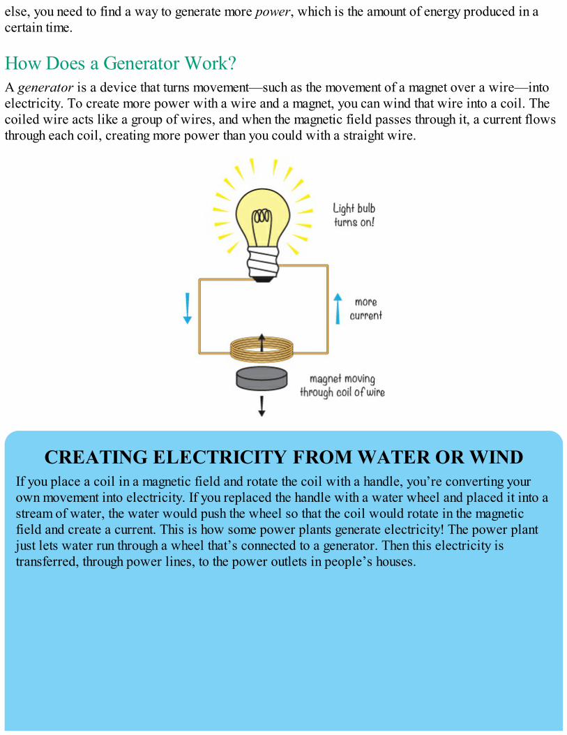
How Does a Generator Work?A generator is a device that turns movement—such as the movement of a magnet over a wire—intoelectricity. To create more power with a wire and a magnet, you can wind that wire into a coil. Thecoiled wire acts like a group of wires, and when the magnetic field passes through it, a current flowsthrough each coil, creating more power than you could with a straight wire.
CREATING ELECTRICITY FROM WATER OR WINDIf you place a coil in a magnetic field and rotate the coil with a handle, you’re converting yourown movement into electricity. If you replaced the handle with a water wheel and placed it into astream of water, the water would push the wheel so that the coil would rotate in the magneticfield and create a current. This is how some power plants generate electricity! The power plantjust lets water run through a wheel that’s connected to a generator. Then this electricity istransferred, through power lines, to the power outlets in people’s houses.
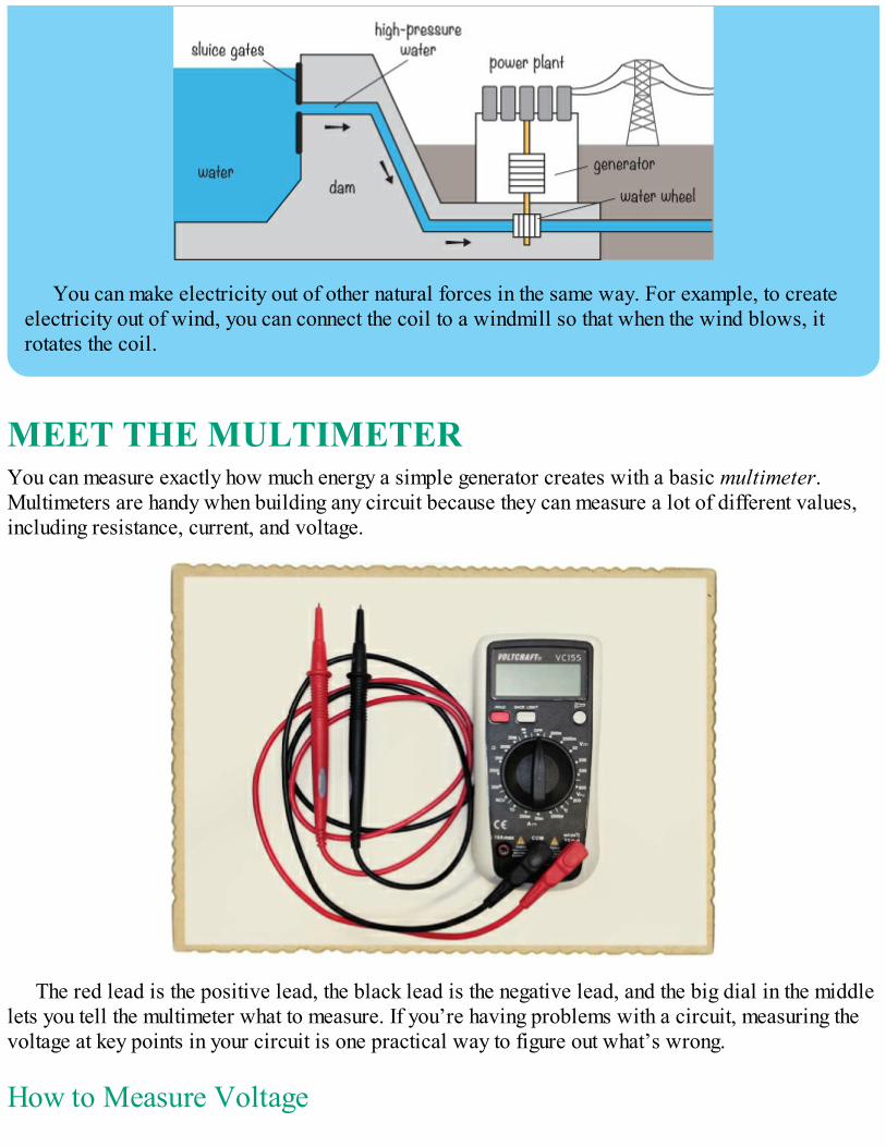
You can make electricity out of other natural forces in the same way. For example, to createelectricity out of wind, you can connect the coil to a windmill so that when the wind blows, itrotates the coil.
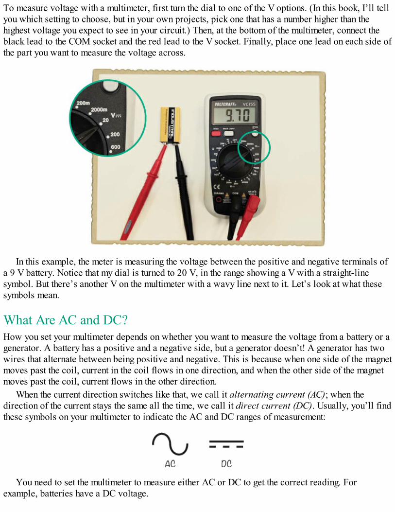
MEET THE MULTIMETERYou can measure exactly how much energy a simple generator creates with a basic multimeter.Multimeters are handy when building any circuit because they can measure a lot of different values,including resistance, current, and voltage.
The red lead is the positive lead, the black lead is the negative lead, and the big dial in the middlelets you tell the multimeter what to measure. If you’re having problems with a circuit, measuring thevoltage at key points in your circuit is one practical way to figure out what’s wrong.
How to Measure Voltage
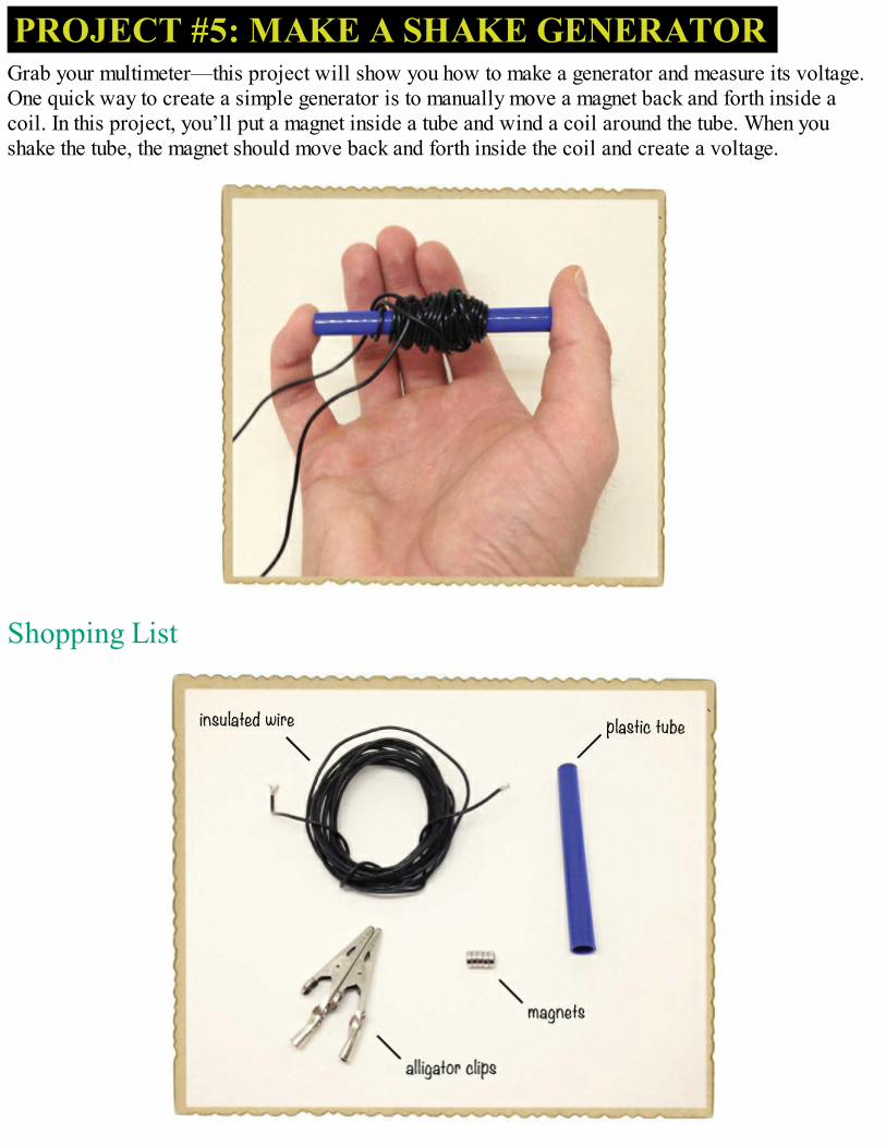
To measure voltage with a multimeter, first turn the dial to one of the V options. (In this book, I’ll tellyou which setting to choose, but in your own projects, pick one that has a number higher than thehighest voltage you expect to see in your circuit.) Then, at the bottom of the multimeter, connect theblack lead to the COM socket and the red lead to the V socket. Finally, place one lead on each side ofthe part you want to measure the voltage across.
In this example, the meter is measuring the voltage between the positive and negative terminals ofa 9 V battery. Notice that my dial is turned to 20 V, in the range showing a V with a straight-linesymbol. But there’s another V on the multimeter with a wavy line next to it. Let’s look at what thesesymbols mean.
What Are AC and DC?How you set your multimeter depends on whether you want to measure the voltage from a battery or agenerator. A battery has a positive and a negative side, but a generator doesn’t! A generator has twowires that alternate between being positive and negative. This is because when one side of the magnetmoves past the coil, current in the coil flows in one direction, and when the other side of the magnetmoves past the coil, current flows in the other direction.
When the current direction switches like that, we call it alternating current (AC); when thedirection of the current stays the same all the time, we call it direct current (DC). Usually, you’ll findthese symbols on your multimeter to indicate the AC and DC ranges of measurement:
You need to set the multimeter to measure either AC or DC to get the correct reading. Forexample, batteries have a DC voltage.
PROJECT #5: MAKE A SHAKE GENERATORGrab your multimeter—this project will show you how to make a generator and measure its voltage.One quick way to create a simple generator is to manually move a magnet back and forth inside acoil. In this project, you’ll put a magnet inside a tube and wind a coil around the tube. When youshake the tube, the magnet should move back and forth inside the coil and create a voltage.
Shopping List
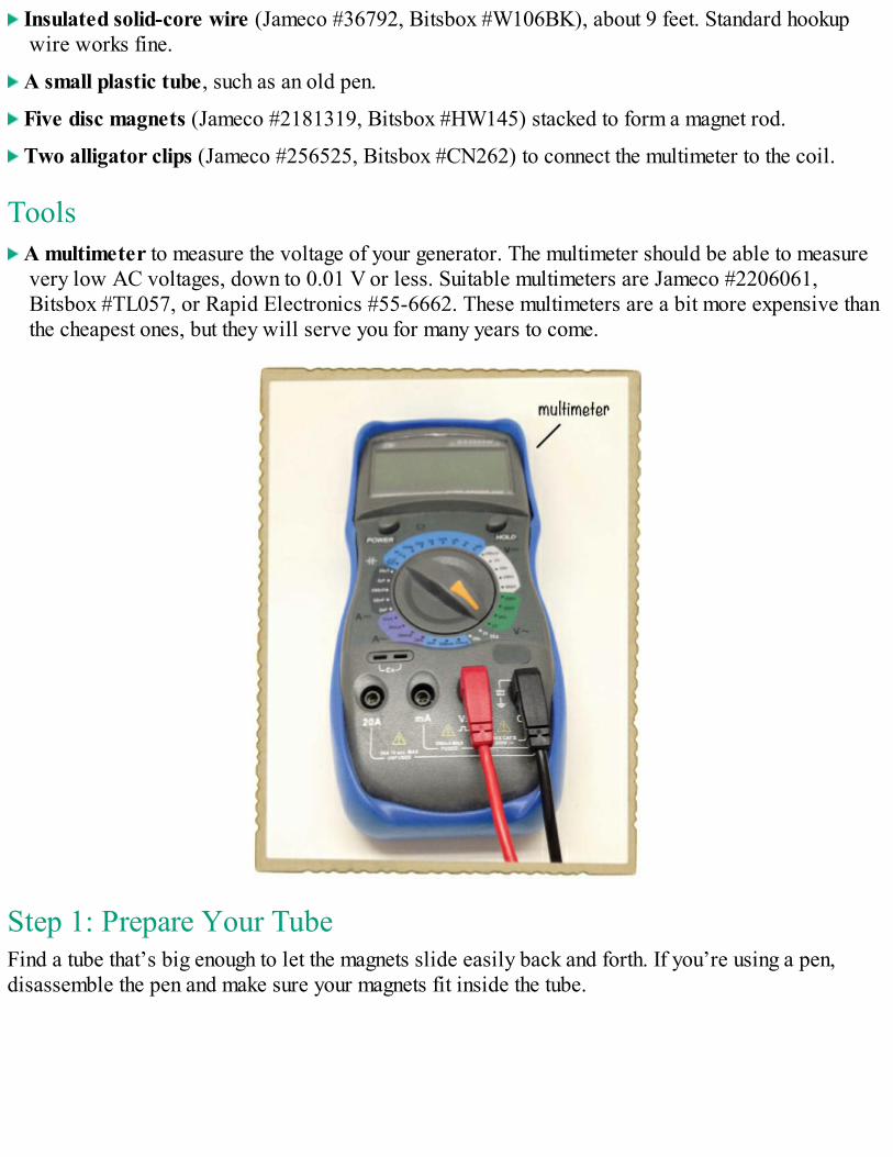
Insulated solid-core wire (Jameco #36792, Bitsbox #W106BK), about 9 feet. Standard hookupwire works fine.
A small plastic tube, such as an old pen.
Five disc magnets (Jameco #2181319, Bitsbox #HW145) stacked to form a magnet rod.
Two alligator clips (Jameco #256525, Bitsbox #CN262) to connect the multimeter to the coil.
Tools A multimeter to measure the voltage of your generator. The multimeter should be able to measure
very low AC voltages, down to 0.01 V or less. Suitable multimeters are Jameco #2206061,Bitsbox #TL057, or Rapid Electronics #55-6662. These multimeters are a bit more expensive thanthe cheapest ones, but they will serve you for many years to come.
Step 1: Prepare Your TubeFind a tube that’s big enough to let the magnets slide easily back and forth. If you’re using a pen,disassemble the pen and make sure your magnets fit inside the tube.
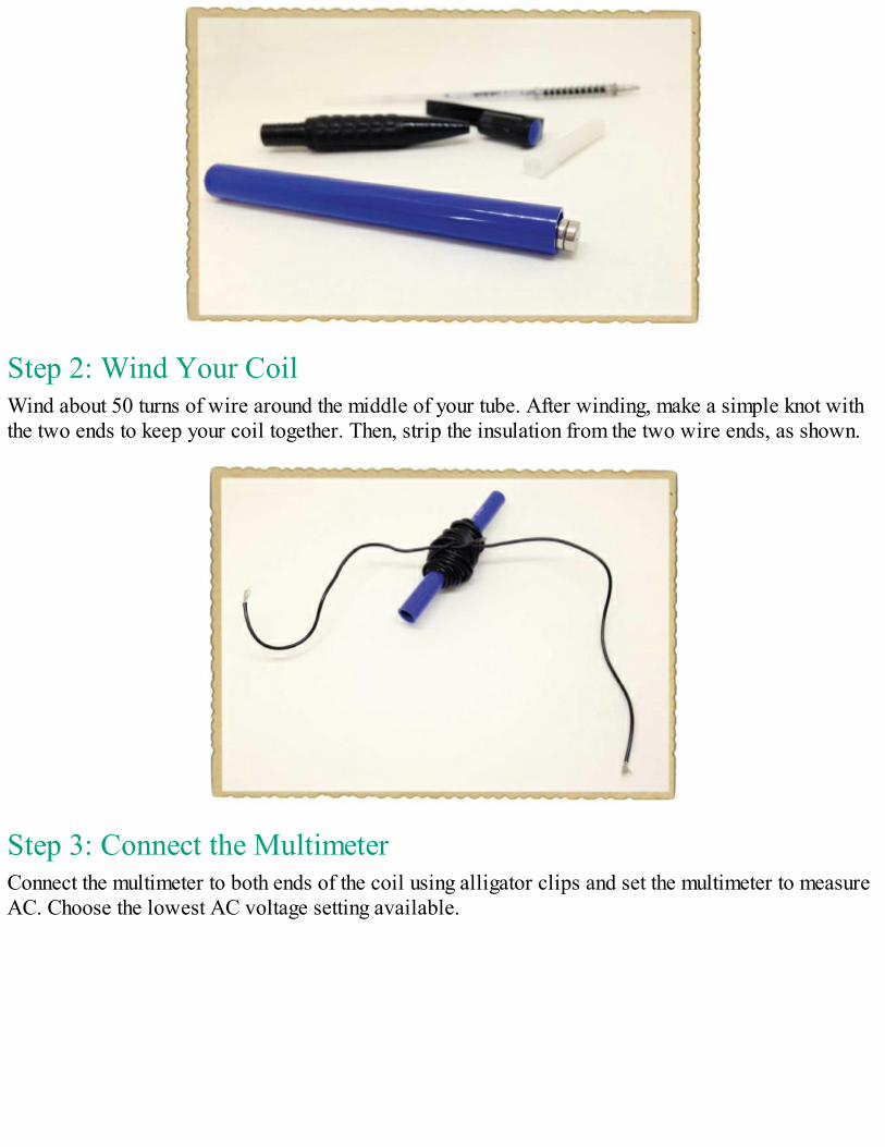
Step 2: Wind Your CoilWind about 50 turns of wire around the middle of your tube. After winding, make a simple knot withthe two ends to keep your coil together. Then, strip the insulation from the two wire ends, as shown.
Step 3: Connect the MultimeterConnect the multimeter to both ends of the coil using alligator clips and set the multimeter to measureAC. Choose the lowest AC voltage setting available.
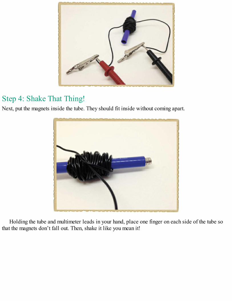
Step 4: Shake That Thing!Next, put the magnets inside the tube. They should fit inside without coming apart.
Holding the tube and multimeter leads in your hand, place one finger on each side of the tube sothat the magnets don’t fall out. Then, shake it like you mean it!
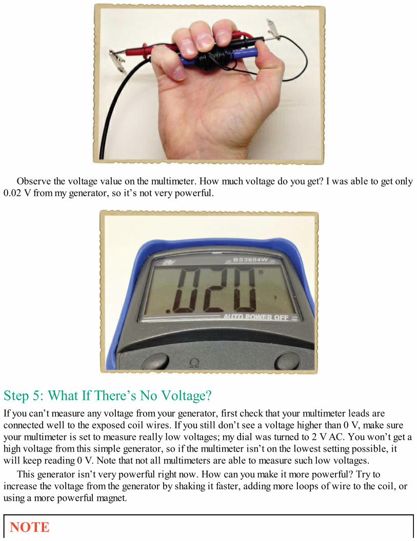
Observe the voltage value on the multimeter. How much voltage do you get? I was able to get only0.02 V from my generator, so it’s not very powerful.
Step 5: What If There’s No Voltage?If you can’t measure any voltage from your generator, first check that your multimeter leads areconnected well to the exposed coil wires. If you still don’t see a voltage higher than 0 V, make sureyour multimeter is set to measure really low voltages; my dial was turned to 2 V AC. You won’t get ahigh voltage from this simple generator, so if the multimeter isn’t on the lowest setting possible, itwill keep reading 0 V. Note that not all multimeters are able to measure such low voltages.
This generator isn’t very powerful right now. How can you make it more powerful? Try toincrease the voltage from the generator by shaking it faster, adding more loops of wire to the coil, orusing a more powerful magnet.
NOTE
Standard hookup wire is a bit bulky; even 50 turns take up a lot of space! If you want to get alot more turns, try using magnet wire instead. It’s really thin wire with a thin layer ofinsulating coating.
TRY IT OUT: USING A MOTOR AS A GENERATORA motor already has a magnet and a coil of wire that can rotate in the magnet’s magnetic field. Ifyou rotate the rotor with your hand, you can generate a voltage on the motor’s wires.
You could create a generator by reversing the motor you built in Chapter 2, but the poweryou’d get from it would be too small to measure. Instead, try to find an old motor from a computerfan or a radio-controlled toy car that you don’t want to play with anymore. Then, set yourmultimeter to a low-voltage DC range, such as 2 V DC. Attach the multimeter leads to the motorwires, just as you did with the shake generator, and turn the rotor with your fingers. Some motorshave internal circuits that control the motor, and those circuits can prevent the electricitygenerated inside the motor from going out to the wires. But if you’re lucky and find a motor thatdoesn’t have such circuits, you should see a reading on the multimeter. Try a low-voltage ACrange on your multimeter if you see nothing with DC.
HOW DO BATTERIES WORK?I’ve shown you how to generate electricity manually, but that doesn’t explain how you’ve poweredcircuits up to this point in the book. You’ve been using batteries, and in this section, we’ll look atwhat lets those batteries create electricity.
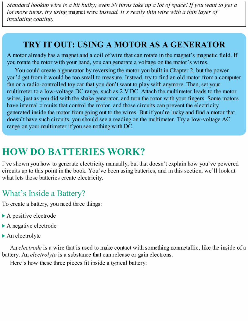
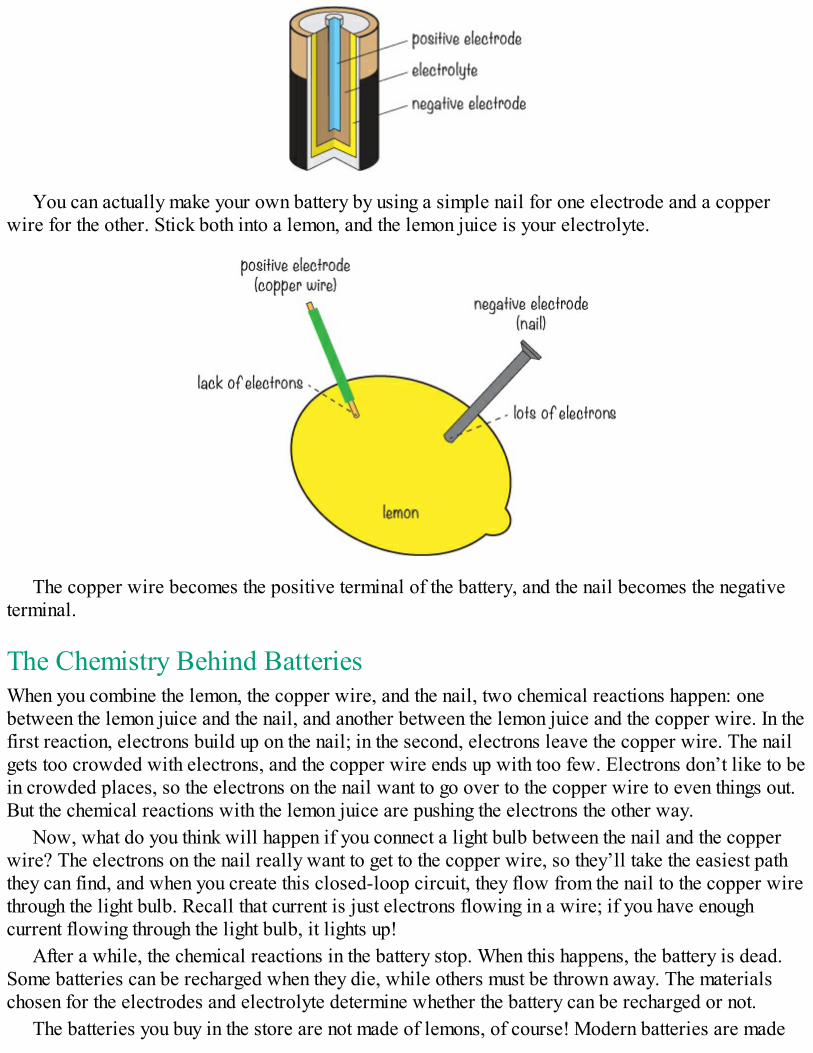
What’s Inside a Battery?To create a battery, you need three things:
A positive electrode
A negative electrode
An electrolyte
An electrode is a wire that is used to make contact with something nonmetallic, like the inside of abattery. An electrolyte is a substance that can release or gain electrons.
Here’s how these three pieces fit inside a typical battery:
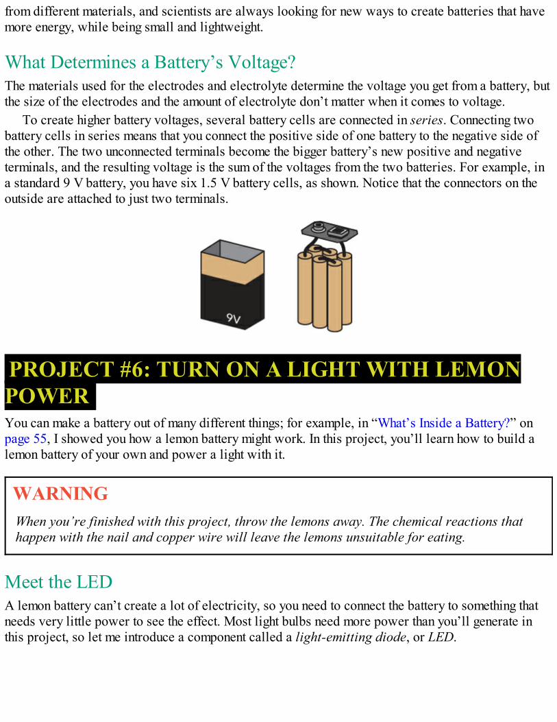
You can actually make your own battery by using a simple nail for one electrode and a copperwire for the other. Stick both into a lemon, and the lemon juice is your electrolyte.
The copper wire becomes the positive terminal of the battery, and the nail becomes the negativeterminal.
The Chemistry Behind BatteriesWhen you combine the lemon, the copper wire, and the nail, two chemical reactions happen: onebetween the lemon juice and the nail, and another between the lemon juice and the copper wire. In thefirst reaction, electrons build up on the nail; in the second, electrons leave the copper wire. The nailgets too crowded with electrons, and the copper wire ends up with too few. Electrons don’t like to bein crowded places, so the electrons on the nail want to go over to the copper wire to even things out.But the chemical reactions with the lemon juice are pushing the electrons the other way.
Now, what do you think will happen if you connect a light bulb between the nail and the copperwire? The electrons on the nail really want to get to the copper wire, so they’ll take the easiest paththey can find, and when you create this closed-loop circuit, they flow from the nail to the copper wirethrough the light bulb. Recall that current is just electrons flowing in a wire; if you have enoughcurrent flowing through the light bulb, it lights up!
After a while, the chemical reactions in the battery stop. When this happens, the battery is dead.Some batteries can be recharged when they die, while others must be thrown away. The materialschosen for the electrodes and electrolyte determine whether the battery can be recharged or not.
The batteries you buy in the store are not made of lemons, of course! Modern batteries are made
from different materials, and scientists are always looking for new ways to create batteries that havemore energy, while being small and lightweight.
What Determines a Battery’s Voltage?The materials used for the electrodes and electrolyte determine the voltage you get from a battery, butthe size of the electrodes and the amount of electrolyte don’t matter when it comes to voltage.
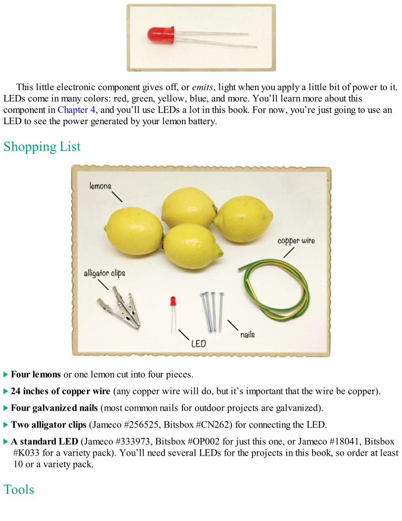
To create higher battery voltages, several battery cells are connected in series. Connecting twobattery cells in series means that you connect the positive side of one battery to the negative side ofthe other. The two unconnected terminals become the bigger battery’s new positive and negativeterminals, and the resulting voltage is the sum of the voltages from the two batteries. For example, ina standard 9 V battery, you have six 1.5 V battery cells, as shown. Notice that the connectors on theoutside are attached to just two terminals.
PROJECT #6: TURN ON A LIGHT WITH LEMONPOWERYou can make a battery out of many different things; for example, in “What’s Inside a Battery?” onpage 55, I showed you how a lemon battery might work. In this project, you’ll learn how to build alemon battery of your own and power a light with it.
WARNINGWhen you’re finished with this project, throw the lemons away. The chemical reactions thathappen with the nail and copper wire will leave the lemons unsuitable for eating.
Meet the LEDA lemon battery can’t create a lot of electricity, so you need to connect the battery to something thatneeds very little power to see the effect. Most light bulbs need more power than you’ll generate inthis project, so let me introduce a component called a light-emitting diode, or LED.
This little electronic component gives off, or emits, light when you apply a little bit of power to it.LEDs come in many colors: red, green, yellow, blue, and more. You’ll learn more about thiscomponent in Chapter 4, and you’ll use LEDs a lot in this book. For now, you’re just going to use anLED to see the power generated by your lemon battery.
Shopping List
Four lemons or one lemon cut into four pieces.
24 inches of copper wire (any copper wire will do, but it’s important that the wire be copper).
Four galvanized nails (most common nails for outdoor projects are galvanized).
Two alligator clips (Jameco #256525, Bitsbox #CN262) for connecting the LED.
A standard LED (Jameco #333973, Bitsbox #OP002 for just this one, or Jameco #18041, Bitsbox#K033 for a variety pack). You’ll need several LEDs for the projects in this book, so order at least10 or a variety pack.
Tools
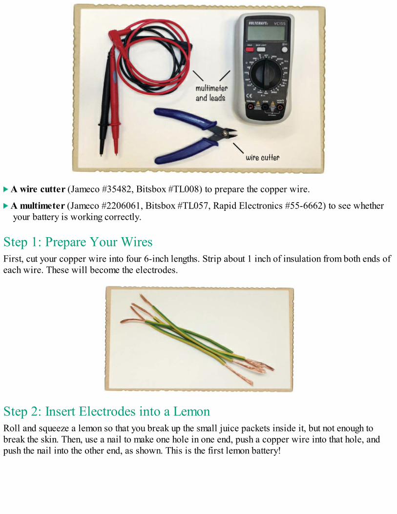
A wire cutter (Jameco #35482, Bitsbox #TL008) to prepare the copper wire.
A multimeter (Jameco #2206061, Bitsbox #TL057, Rapid Electronics #55-6662) to see whetheryour battery is working correctly.
Step 1: Prepare Your WiresFirst, cut your copper wire into four 6-inch lengths. Strip about 1 inch of insulation from both ends ofeach wire. These will become the electrodes.
Step 2: Insert Electrodes into a LemonRoll and squeeze a lemon so that you break up the small juice packets inside it, but not enough tobreak the skin. Then, use a nail to make one hole in one end, push a copper wire into that hole, andpush the nail into the other end, as shown. This is the first lemon battery!
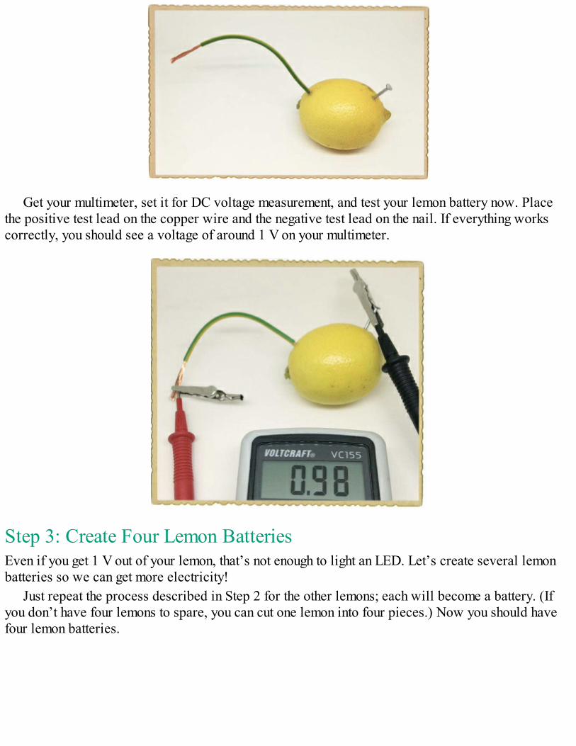
Get your multimeter, set it for DC voltage measurement, and test your lemon battery now. Placethe positive test lead on the copper wire and the negative test lead on the nail. If everything workscorrectly, you should see a voltage of around 1 V on your multimeter.
Step 3: Create Four Lemon BatteriesEven if you get 1 V out of your lemon, that’s not enough to light an LED. Let’s create several lemonbatteries so we can get more electricity!
Just repeat the process described in Step 2 for the other lemons; each will become a battery. (Ifyou don’t have four lemons to spare, you can cut one lemon into four pieces.) Now you should havefour lemon batteries.
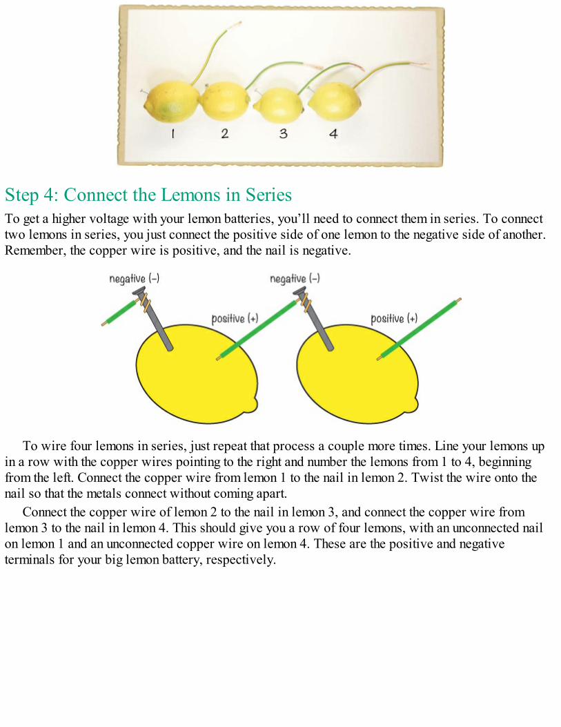
Step 4: Connect the Lemons in SeriesTo get a higher voltage with your lemon batteries, you’ll need to connect them in series. To connecttwo lemons in series, you just connect the positive side of one lemon to the negative side of another.Remember, the copper wire is positive, and the nail is negative.
To wire four lemons in series, just repeat that process a couple more times. Line your lemons upin a row with the copper wires pointing to the right and number the lemons from 1 to 4, beginningfrom the left. Connect the copper wire from lemon 1 to the nail in lemon 2. Twist the wire onto thenail so that the metals connect without coming apart.
Connect the copper wire of lemon 2 to the nail in lemon 3, and connect the copper wire fromlemon 3 to the nail in lemon 4. This should give you a row of four lemons, with an unconnected nailon lemon 1 and an unconnected copper wire on lemon 4. These are the positive and negativeterminals for your big lemon battery, respectively.
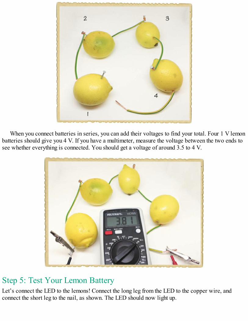
When you connect batteries in series, you can add their voltages to find your total. Four 1 V lemonbatteries should give you 4 V. If you have a multimeter, measure the voltage between the two ends tosee whether everything is connected. You should get a voltage of around 3.5 to 4 V.
Step 5: Test Your Lemon BatteryLet’s connect the LED to the lemons! Connect the long leg from the LED to the copper wire, andconnect the short leg to the nail, as shown. The LED should now light up.
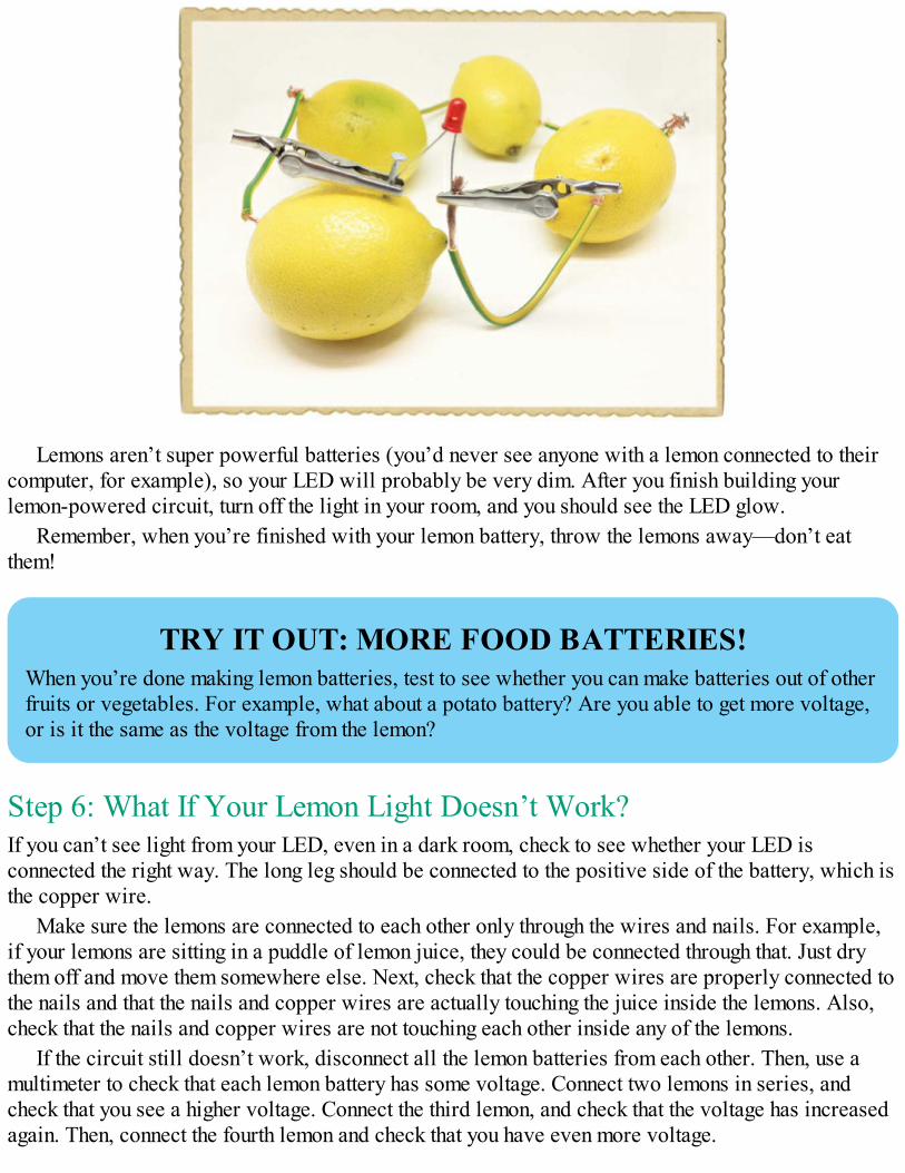
Lemons aren’t super powerful batteries (you’d never see anyone with a lemon connected to theircomputer, for example), so your LED will probably be very dim. After you finish building yourlemon-powered circuit, turn off the light in your room, and you should see the LED glow.
Remember, when you’re finished with your lemon battery, throw the lemons away—don’t eatthem!
TRY IT OUT: MORE FOOD BATTERIES!When you’re done making lemon batteries, test to see whether you can make batteries out of otherfruits or vegetables. For example, what about a potato battery? Are you able to get more voltage,or is it the same as the voltage from the lemon?
Step 6: What If Your Lemon Light Doesn’t Work?If you can’t see light from your LED, even in a dark room, check to see whether your LED isconnected the right way. The long leg should be connected to the positive side of the battery, which isthe copper wire.
Make sure the lemons are connected to each other only through the wires and nails. For example,if your lemons are sitting in a puddle of lemon juice, they could be connected through that. Just drythem off and move them somewhere else. Next, check that the copper wires are properly connected tothe nails and that the nails and copper wires are actually touching the juice inside the lemons. Also,check that the nails and copper wires are not touching each other inside any of the lemons.
If the circuit still doesn’t work, disconnect all the lemon batteries from each other. Then, use amultimeter to check that each lemon battery has some voltage. Connect two lemons in series, andcheck that you see a higher voltage. Connect the third lemon, and check that the voltage has increasedagain. Then, connect the fourth lemon and check that you have even more voltage.

If you see a voltage but the LED doesn’t light, then you probably just need some more power. Getanother lemon or two, create some more batteries, and connect them in series with the rest.
WHAT’S NEXT?In this chapter, you learned how to create your own electricity from magnetism and chemicalreactions. You made your own shake generator, and you built a lemon battery to power an LED.
If you want to explore generators even more, I suggest trying to find a dynamo from an oldbike. Unlike the generator you built in this chapter, a dynamo is a generator that gives you a DCvoltage, like a battery, and dynamos are commonly used to power headlights on bikes. Cut somewindmill blades out of some stiff cardboard or plastic, connect them to the dynamo, and seewhether you can harvest energy from the wind.
You’ve now met a few electronic components, including switches, LEDs, and motors. In thefollowing chapters, you’ll learn about even more components and graduate to building some realelectronic circuits, like lights that blink, a touch-sensitive switch, and even your own electronicmusical instrument!

PART 2BUILDING CIRCUITS

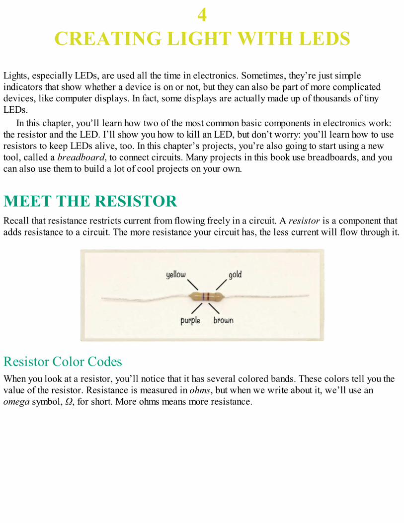
4CREATING LIGHT WITH LEDS
Lights, especially LEDs, are used all the time in electronics. Sometimes, they’re just simpleindicators that show whether a device is on or not, but they can also be part of more complicateddevices, like computer displays. In fact, some displays are actually made up of thousands of tinyLEDs.
In this chapter, you’ll learn how two of the most common basic components in electronics work:the resistor and the LED. I’ll show you how to kill an LED, but don’t worry: you’ll learn how to useresistors to keep LEDs alive, too. In this chapter’s projects, you’re also going to start using a newtool, called a breadboard, to connect circuits. Many projects in this book use breadboards, and youcan also use them to build a lot of cool projects on your own.
MEET THE RESISTORRecall that resistance restricts current from flowing freely in a circuit. A resistor is a component thatadds resistance to a circuit. The more resistance your circuit has, the less current will flow through it.
Resistor Color CodesWhen you look at a resistor, you’ll notice that it has several colored bands. These colors tell you thevalue of the resistor. Resistance is measured in ohms, but when we write about it, we’ll use anomega symbol, Ω, for short. More ohms means more resistance.
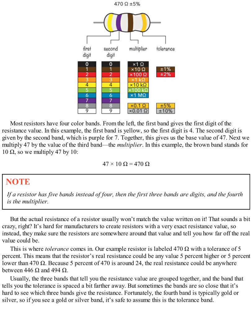
Most resistors have four color bands. From the left, the first band gives the first digit of theresistance value. In this example, the first band is yellow, so the first digit is 4. The second digit isgiven by the second band, which is purple for 7. Together, this gives us the base value of 47. Next wemultiply 47 by the value of the third band—the multiplier. In this example, the brown band stands for10 Ω, so we multiply 47 by 10:
47 × 10 Ω = 470 Ω
NOTEIf a resistor has five bands instead of four, then the first three bands are digits, and the fourthis the multiplier.
But the actual resistance of a resistor usually won’t match the value written on it! That sounds a bitcrazy, right? It’s hard for manufacturers to create resistors with a very exact resistance value, soinstead, they make sure the resistors are somewhere around that value and tell you how far off the realvalue could be.
This is where tolerance comes in. Our example resistor is labeled 470 Ω with a tolerance of 5percent. This means that the resistor’s real resistance could be any value 5 percent higher or 5 percentlower than 470 Ω. Because 5 percent of 470 is around 24, the real resistance could be anywherebetween 446 Ω and 494 Ω.
Usually, the three bands that tell you the resistance value are grouped together, and the band thattells you the tolerance is spaced a bit farther away. But sometimes the bands are so close that it’shard to see which three bands give the resistance. Fortunately, the fourth band is typically gold orsilver, so if you see a gold or silver band, it’s safe to assume this is the tolerance band.
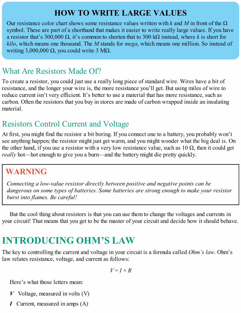
HOW TO WRITE LARGE VALUESOur resistance color chart shows some resistance values written with k and M in front of the Ωsymbol. These are part of a shorthand that makes it easier to write really large values. If you havea resistor that’s 300,000 Ω, it’s common to shorten that to 300 kΩ instead, where k is short forkilo, which means one thousand. The M stands for mega, which means one million. So instead ofwriting 3,000,000 Ω, you could write 3 MΩ.
What Are Resistors Made Of?To create a resistor, you could just use a really long piece of standard wire. Wires have a bit ofresistance, and the longer your wire is, the more resistance you’ll get. But using miles of wire toreduce current isn’t very efficient. It’s better to use a material that has more resistance, such ascarbon. Often the resistors that you buy in stores are made of carbon wrapped inside an insulatingmaterial.
Resistors Control Current and VoltageAt first, you might find the resistor a bit boring. If you connect one to a battery, you probably won’tsee anything happen; the resistor might just get warm, and you might wonder what the big deal is. Onthe other hand, if you use a resistor with a very low resistance value, such as 10 Ω, then it could getreally hot—hot enough to give you a burn—and the battery might die pretty quickly.
WARNINGConnecting a low-value resistor directly between positive and negative points can bedangerous on some types of batteries. Some batteries are strong enough to make your resistorburst into flames. Be careful!
But the cool thing about resistors is that you can use them to change the voltages and currents inyour circuit! That means that you get to be the master of your circuit and decide how it should behave.
INTRODUCING OHM’S LAWThe key to controlling the current and voltage in your circuit is a formula called Ohm’s law. Ohm’slaw relates resistance, voltage, and current as follows:
V = I × R
Here’s what those letters mean:
V Voltage, measured in volts (V)
I Current, measured in amps (A)
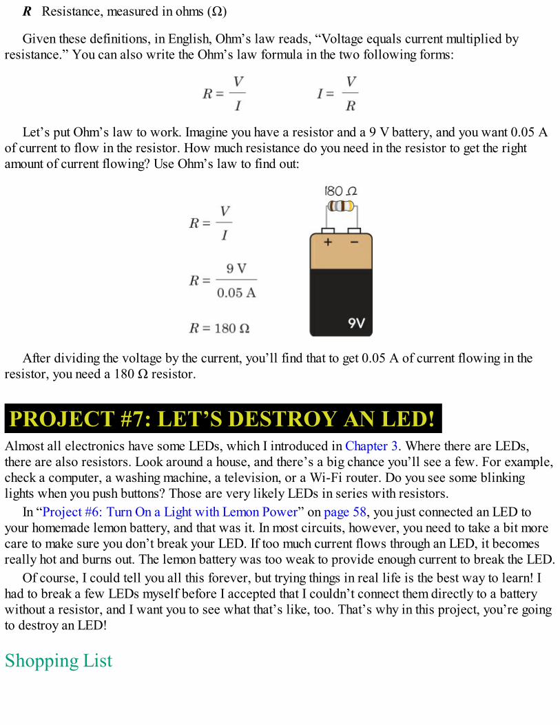
R Resistance, measured in ohms (Ω)
Given these definitions, in English, Ohm’s law reads, “Voltage equals current multiplied byresistance.” You can also write the Ohm’s law formula in the two following forms:
Let’s put Ohm’s law to work. Imagine you have a resistor and a 9 V battery, and you want 0.05 Aof current to flow in the resistor. How much resistance do you need in the resistor to get the rightamount of current flowing? Use Ohm’s law to find out:
After dividing the voltage by the current, you’ll find that to get 0.05 A of current flowing in theresistor, you need a 180 Ω resistor.
PROJECT #7: LET’S DESTROY AN LED!Almost all electronics have some LEDs, which I introduced in Chapter 3. Where there are LEDs,there are also resistors. Look around a house, and there’s a big chance you’ll see a few. For example,check a computer, a washing machine, a television, or a Wi-Fi router. Do you see some blinkinglights when you push buttons? Those are very likely LEDs in series with resistors.
In “Project #6: Turn On a Light with Lemon Power” on page 58, you just connected an LED toyour homemade lemon battery, and that was it. In most circuits, however, you need to take a bit morecare to make sure you don’t break your LED. If too much current flows through an LED, it becomesreally hot and burns out. The lemon battery was too weak to provide enough current to break the LED.
Of course, I could tell you all this forever, but trying things in real life is the best way to learn! Ihad to break a few LEDs myself before I accepted that I couldn’t connect them directly to a batterywithout a resistor, and I want you to see what that’s like, too. That’s why in this project, you’re goingto destroy an LED!
Shopping List
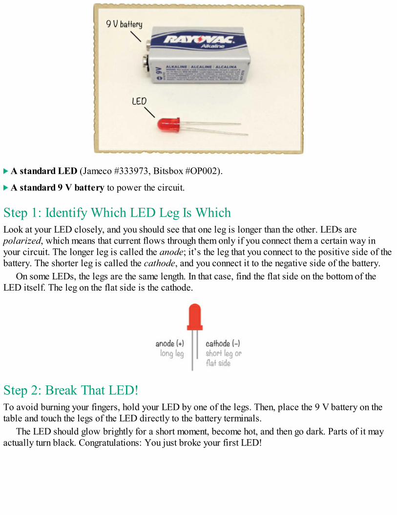
A standard LED (Jameco #333973, Bitsbox #OP002).
A standard 9 V battery to power the circuit.
Step 1: Identify Which LED Leg Is WhichLook at your LED closely, and you should see that one leg is longer than the other. LEDs arepolarized, which means that current flows through them only if you connect them a certain way inyour circuit. The longer leg is called the anode; it’s the leg that you connect to the positive side of thebattery. The shorter leg is called the cathode, and you connect it to the negative side of the battery.
On some LEDs, the legs are the same length. In that case, find the flat side on the bottom of theLED itself. The leg on the flat side is the cathode.
Step 2: Break That LED!To avoid burning your fingers, hold your LED by one of the legs. Then, place the 9 V battery on thetable and touch the legs of the LED directly to the battery terminals.
The LED should glow brightly for a short moment, become hot, and then go dark. Parts of it mayactually turn black. Congratulations: You just broke your first LED!
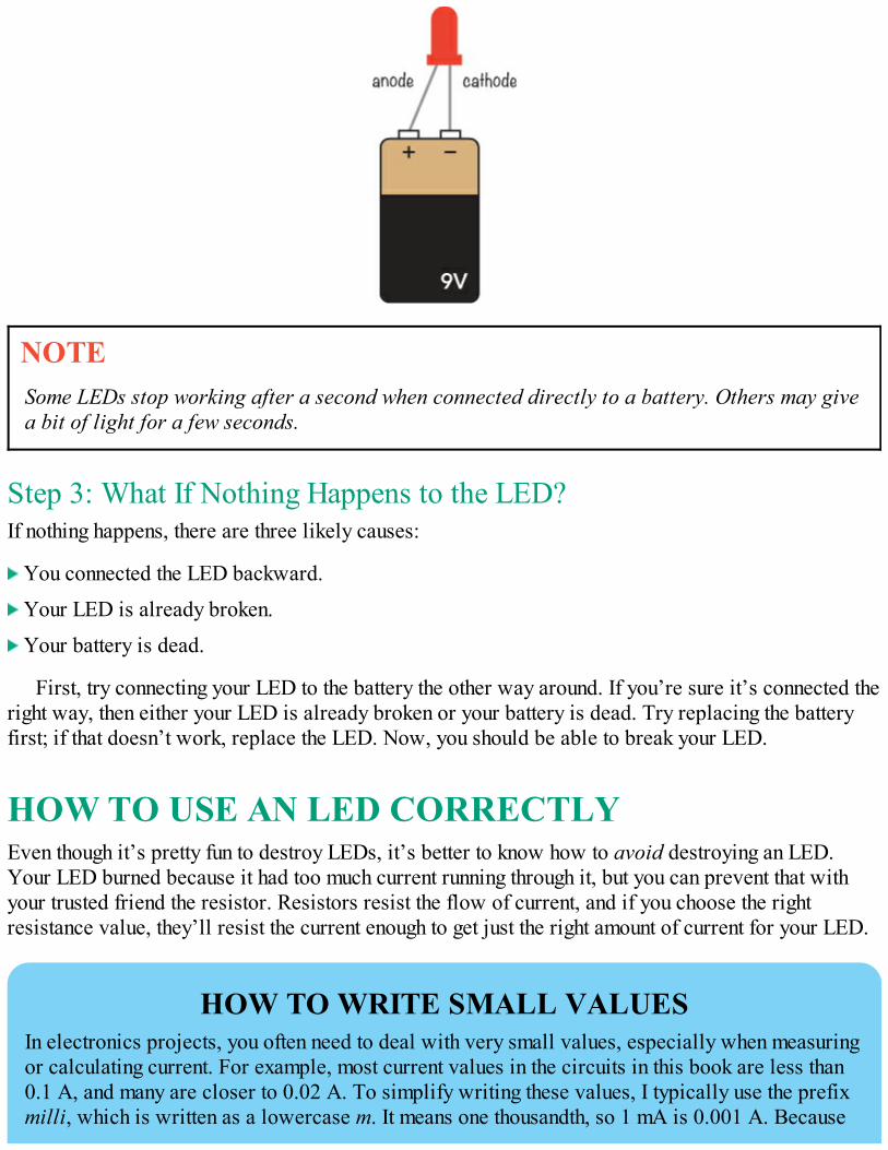
NOTESome LEDs stop working after a second when connected directly to a battery. Others may givea bit of light for a few seconds.
Step 3: What If Nothing Happens to the LED?If nothing happens, there are three likely causes:
You connected the LED backward.
Your LED is already broken.
Your battery is dead.
First, try connecting your LED to the battery the other way around. If you’re sure it’s connected theright way, then either your LED is already broken or your battery is dead. Try replacing the batteryfirst; if that doesn’t work, replace the LED. Now, you should be able to break your LED.
HOW TO USE AN LED CORRECTLYEven though it’s pretty fun to destroy LEDs, it’s better to know how to avoid destroying an LED.Your LED burned because it had too much current running through it, but you can prevent that withyour trusted friend the resistor. Resistors resist the flow of current, and if you choose the rightresistance value, they’ll resist the current enough to get just the right amount of current for your LED.
HOW TO WRITE SMALL VALUESIn electronics projects, you often need to deal with very small values, especially when measuringor calculating current. For example, most current values in the circuits in this book are less than0.1 A, and many are closer to 0.02 A. To simplify writing these values, I typically use the prefixmilli, which is written as a lowercase m. It means one thousandth, so 1 mA is 0.001 A. Because
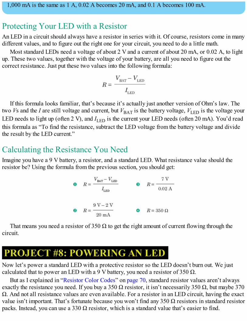
1,000 mA is the same as 1 A, 0.02 A becomes 20 mA, and 0.1 A becomes 100 mA.
Protecting Your LED with a ResistorAn LED in a circuit should always have a resistor in series with it. Of course, resistors come in manydifferent values, and to figure out the right one for your circuit, you need to do a little math.
Most standard LEDs need a voltage of about 2 V and a current of about 20 mA, or 0.02 A, to lightup. These two values, together with the voltage of your battery, are all you need to figure out thecorrect resistance. Just put these two values into the following formula:
If this formula looks familiar, that’s because it’s actually just another version of Ohm’s law. Thetwo Vs and the I are still voltage and current, but VBAT is the battery voltage, VLED is the voltage yourLED needs to light up (often 2 V), and ILED is the current your LED needs (often 20 mA). You’d readthis formula as “To find the resistance, subtract the LED voltage from the battery voltage and dividethe result by the LED current.”
Calculating the Resistance You NeedImagine you have a 9 V battery, a resistor, and a standard LED. What resistance value should theresistor be? Using the formula from the previous section, you should get:
That means you need a resistor of 350 Ω to get the right amount of current flowing through thecircuit.
PROJECT #8: POWERING AN LEDNow let’s power a standard LED with a protective resistor so the LED doesn’t burn out. We justcalculated that to power an LED with a 9 V battery, you need a resistor of 350 Ω.
But as I explained in “Resistor Color Codes” on page 70, standard resistor values aren’t alwaysexactly the resistance you need. If you buy a 350 Ω resistor, it isn’t necessarily 350 Ω, but maybe 370Ω. And not all resistance values are even available. For a resistor in an LED circuit, having the exactvalue isn’t important. That’s fortunate because you won’t find any 350 Ω resistors in standard resistorpacks. Instead, you can use a 330 Ω resistor, which is a standard value that’s easier to find.
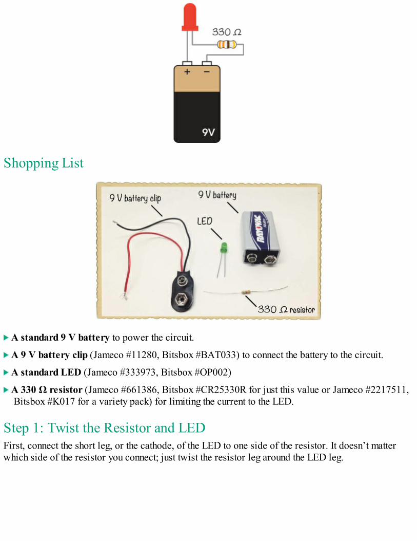
Shopping List
A standard 9 V battery to power the circuit.
A 9 V battery clip (Jameco #11280, Bitsbox #BAT033) to connect the battery to the circuit.
A standard LED (Jameco #333973, Bitsbox #OP002)
A 330 Ω resistor (Jameco #661386, Bitsbox #CR25330R for just this value or Jameco #2217511,Bitsbox #K017 for a variety pack) for limiting the current to the LED.
Step 1: Twist the Resistor and LEDFirst, connect the short leg, or the cathode, of the LED to one side of the resistor. It doesn’t matterwhich side of the resistor you connect; just twist the resistor leg around the LED leg.
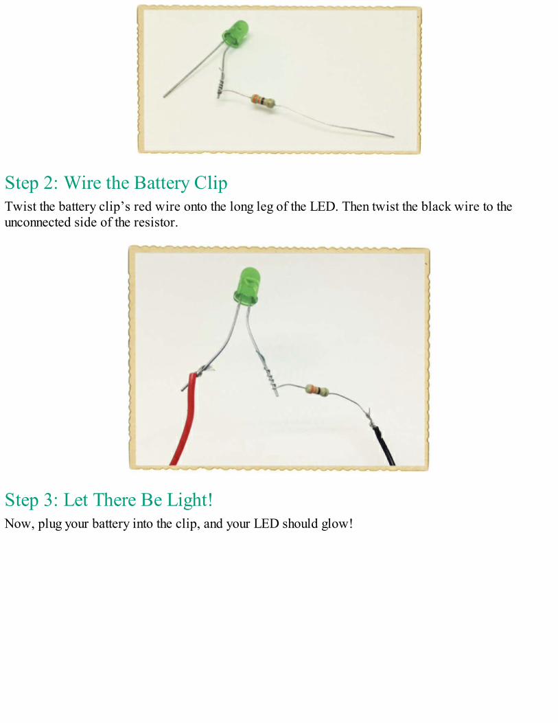
Step 2: Wire the Battery ClipTwist the battery clip’s red wire onto the long leg of the LED. Then twist the black wire to theunconnected side of the resistor.
Step 3: Let There Be Light!Now, plug your battery into the clip, and your LED should glow!
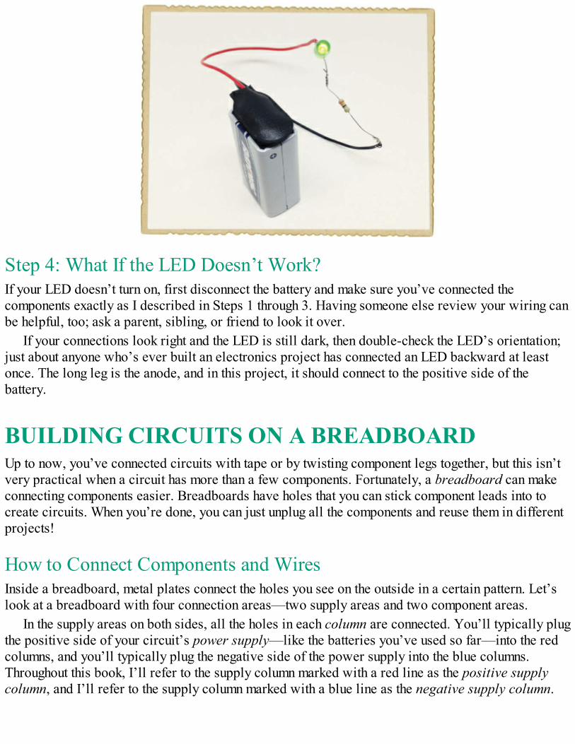
Step 4: What If the LED Doesn’t Work?If your LED doesn’t turn on, first disconnect the battery and make sure you’ve connected thecomponents exactly as I described in Steps 1 through 3. Having someone else review your wiring canbe helpful, too; ask a parent, sibling, or friend to look it over.
If your connections look right and the LED is still dark, then double-check the LED’s orientation;just about anyone who’s ever built an electronics project has connected an LED backward at leastonce. The long leg is the anode, and in this project, it should connect to the positive side of thebattery.
BUILDING CIRCUITS ON A BREADBOARDUp to now, you’ve connected circuits with tape or by twisting component legs together, but this isn’tvery practical when a circuit has more than a few components. Fortunately, a breadboard can makeconnecting components easier. Breadboards have holes that you can stick component leads into tocreate circuits. When you’re done, you can just unplug all the components and reuse them in differentprojects!
How to Connect Components and WiresInside a breadboard, metal plates connect the holes you see on the outside in a certain pattern. Let’slook at a breadboard with four connection areas—two supply areas and two component areas.
In the supply areas on both sides, all the holes in each column are connected. You’ll typically plugthe positive side of your circuit’s power supply—like the batteries you’ve used so far—into the redcolumns, and you’ll typically plug the negative side of the power supply into the blue columns.Throughout this book, I’ll refer to the supply column marked with a red line as the positive supplycolumn, and I’ll refer to the supply column marked with a blue line as the negative supply column.
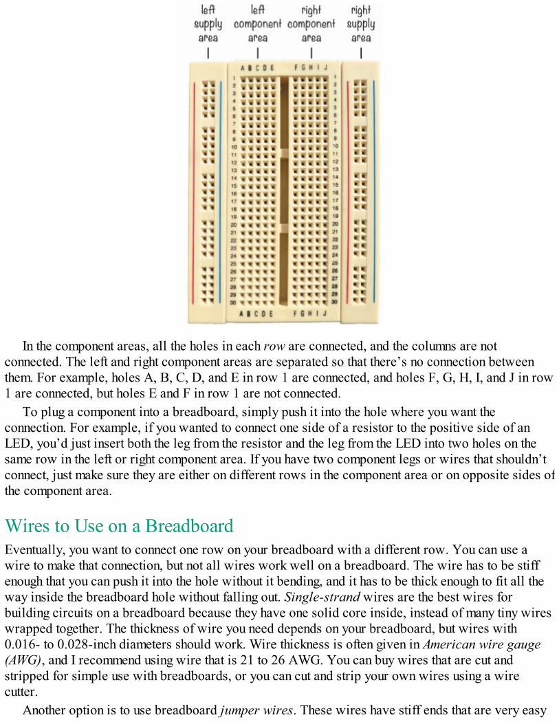
In the component areas, all the holes in each row are connected, and the columns are notconnected. The left and right component areas are separated so that there’s no connection betweenthem. For example, holes A, B, C, D, and E in row 1 are connected, and holes F, G, H, I, and J in row1 are connected, but holes E and F in row 1 are not connected.
To plug a component into a breadboard, simply push it into the hole where you want theconnection. For example, if you wanted to connect one side of a resistor to the positive side of anLED, you’d just insert both the leg from the resistor and the leg from the LED into two holes on thesame row in the left or right component area. If you have two component legs or wires that shouldn’tconnect, just make sure they are either on different rows in the component area or on opposite sides ofthe component area.
Wires to Use on a BreadboardEventually, you want to connect one row on your breadboard with a different row. You can use awire to make that connection, but not all wires work well on a breadboard. The wire has to be stiffenough that you can push it into the hole without it bending, and it has to be thick enough to fit all theway inside the breadboard hole without falling out. Single-strand wires are the best wires forbuilding circuits on a breadboard because they have one solid core inside, instead of many tiny wireswrapped together. The thickness of wire you need depends on your breadboard, but wires with0.016- to 0.028-inch diameters should work. Wire thickness is often given in American wire gauge(AWG), and I recommend using wire that is 21 to 26 AWG. You can buy wires that are cut andstripped for simple use with breadboards, or you can cut and strip your own wires using a wirecutter.
Another option is to use breadboard jumper wires. These wires have stiff ends that are very easy
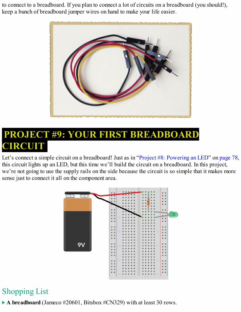
to connect to a breadboard. If you plan to connect a lot of circuits on a breadboard (you should!),keep a bunch of breadboard jumper wires on hand to make your life easier.
PROJECT #9: YOUR FIRST BREADBOARDCIRCUITLet’s connect a simple circuit on a breadboard! Just as in “Project #8: Powering an LED” on page 78,this circuit lights up an LED, but this time we’ll build the circuit on a breadboard. In this project,we’re not going to use the supply rails on the side because the circuit is so simple that it makes moresense just to connect it all on the component area.
Shopping List A breadboard (Jameco #20601, Bitsbox #CN329) with at least 30 rows.
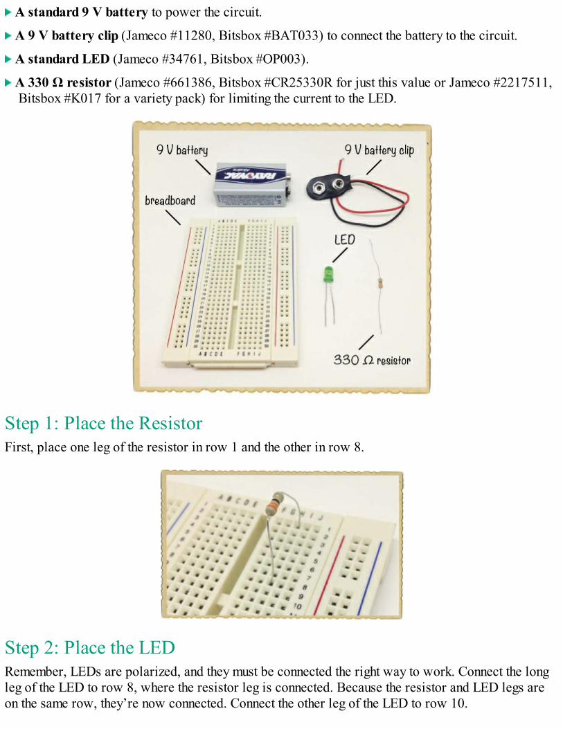
A standard 9 V battery to power the circuit.
A 9 V battery clip (Jameco #11280, Bitsbox #BAT033) to connect the battery to the circuit.
A standard LED (Jameco #34761, Bitsbox #OP003).
A 330 Ω resistor (Jameco #661386, Bitsbox #CR25330R for just this value or Jameco #2217511,Bitsbox #K017 for a variety pack) for limiting the current to the LED.
Step 1: Place the ResistorFirst, place one leg of the resistor in row 1 and the other in row 8.
Step 2: Place the LEDRemember, LEDs are polarized, and they must be connected the right way to work. Connect the longleg of the LED to row 8, where the resistor leg is connected. Because the resistor and LED legs areon the same row, they’re now connected. Connect the other leg of the LED to row 10.
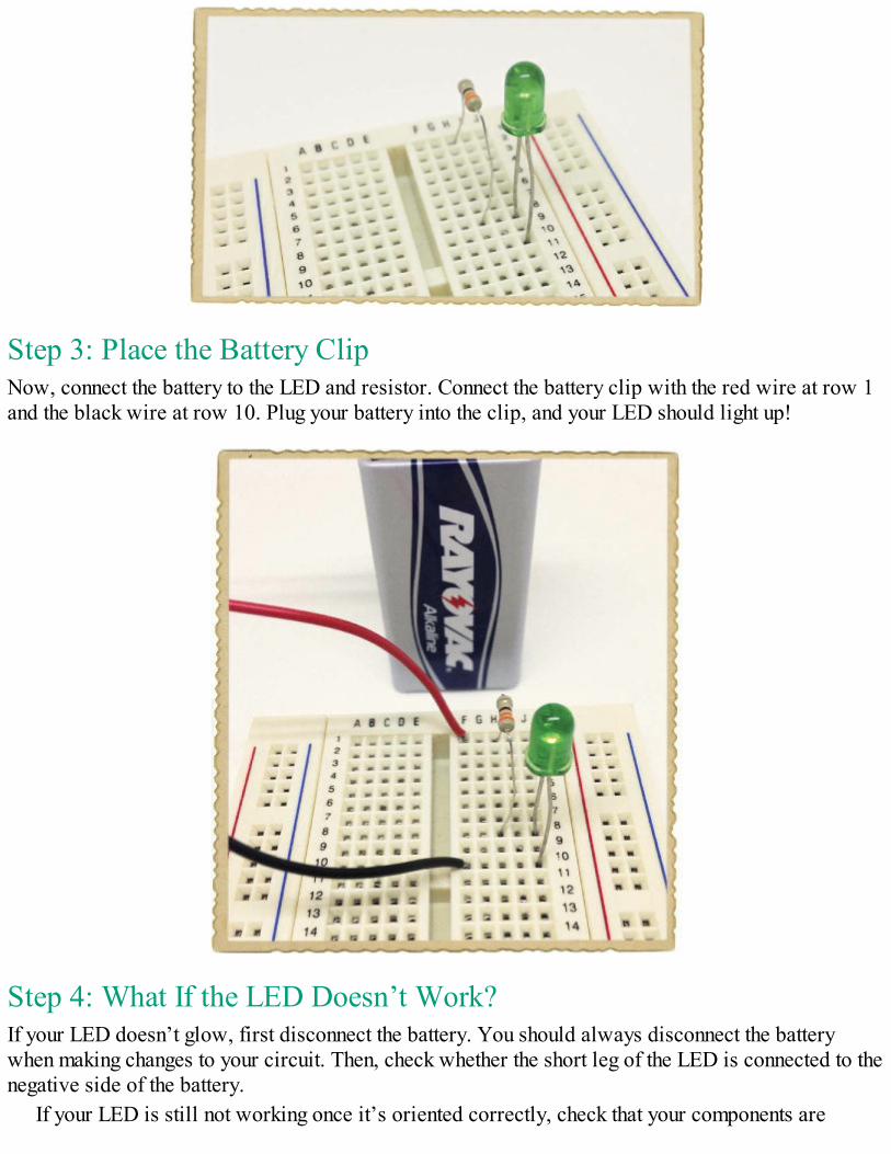
Step 3: Place the Battery ClipNow, connect the battery to the LED and resistor. Connect the battery clip with the red wire at row 1and the black wire at row 10. Plug your battery into the clip, and your LED should light up!
Step 4: What If the LED Doesn’t Work?If your LED doesn’t glow, first disconnect the battery. You should always disconnect the batterywhen making changes to your circuit. Then, check whether the short leg of the LED is connected to thenegative side of the battery.
If your LED is still not working once it’s oriented correctly, check that your components are
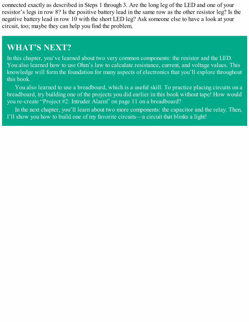
connected exactly as described in Steps 1 through 3. Are the long leg of the LED and one of yourresistor’s legs in row 8? Is the positive battery lead in the same row as the other resistor leg? Is thenegative battery lead in row 10 with the short LED leg? Ask someone else to have a look at yourcircuit, too; maybe they can help you find the problem.
WHAT’S NEXT?In this chapter, you’ve learned about two very common components: the resistor and the LED.You also learned how to use Ohm’s law to calculate resistance, current, and voltage values. Thisknowledge will form the foundation for many aspects of electronics that you’ll explore throughoutthis book.
You also learned to use a breadboard, which is a useful skill. To practice placing circuits on abreadboard, try building one of the projects you did earlier in this book without tape! How wouldyou re-create “Project #2: Intruder Alarm” on page 11 on a breadboard?
In the next chapter, you’ll learn about two more components: the capacitor and the relay. Then,I’ll show you how to build one of my favorite circuits—a circuit that blinks a light!

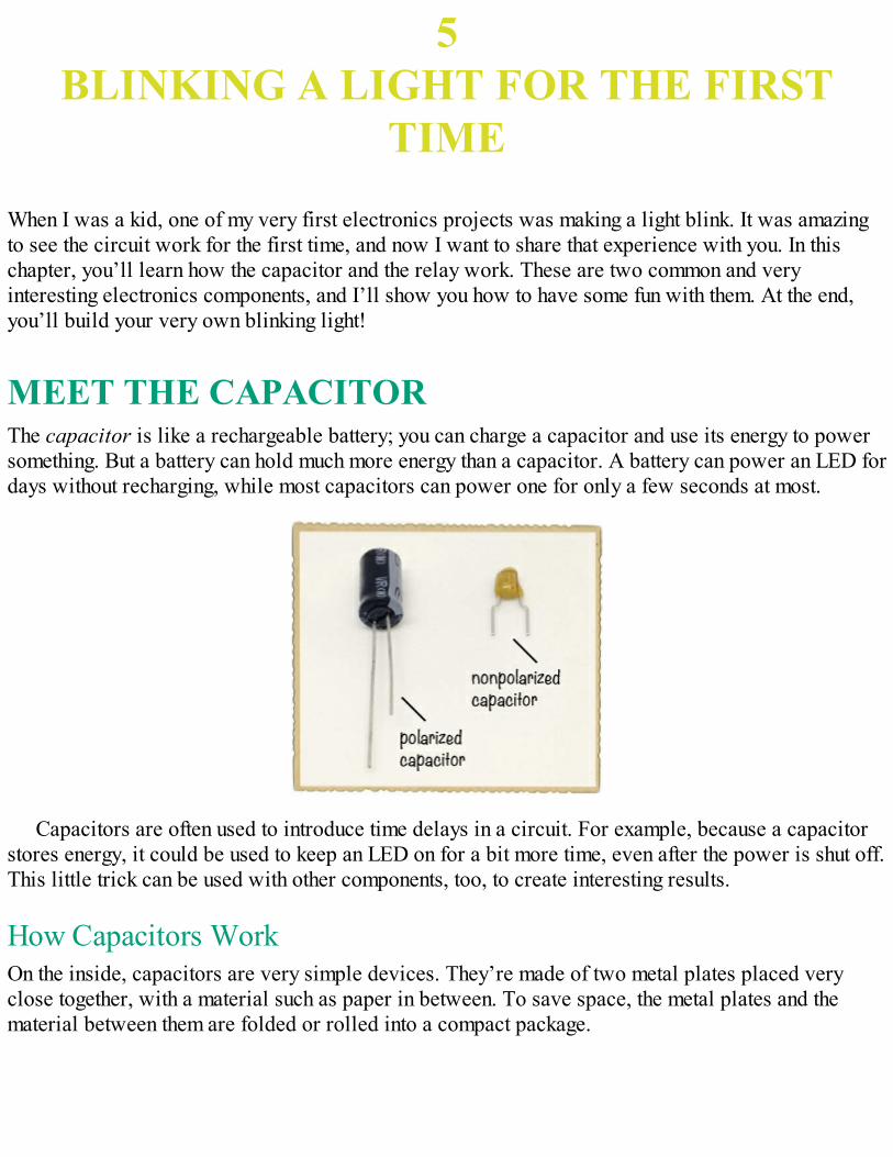
5BLINKING A LIGHT FOR THE FIRST
TIME
When I was a kid, one of my very first electronics projects was making a light blink. It was amazingto see the circuit work for the first time, and now I want to share that experience with you. In thischapter, you’ll learn how the capacitor and the relay work. These are two common and veryinteresting electronics components, and I’ll show you how to have some fun with them. At the end,you’ll build your very own blinking light!
MEET THE CAPACITORThe capacitor is like a rechargeable battery; you can charge a capacitor and use its energy to powersomething. But a battery can hold much more energy than a capacitor. A battery can power an LED fordays without recharging, while most capacitors can power one for only a few seconds at most.
Capacitors are often used to introduce time delays in a circuit. For example, because a capacitorstores energy, it could be used to keep an LED on for a bit more time, even after the power is shut off.This little trick can be used with other components, too, to create interesting results.
How Capacitors WorkOn the inside, capacitors are very simple devices. They’re made of two metal plates placed veryclose together, with a material such as paper in between. To save space, the metal plates and thematerial between them are folded or rolled into a compact package.
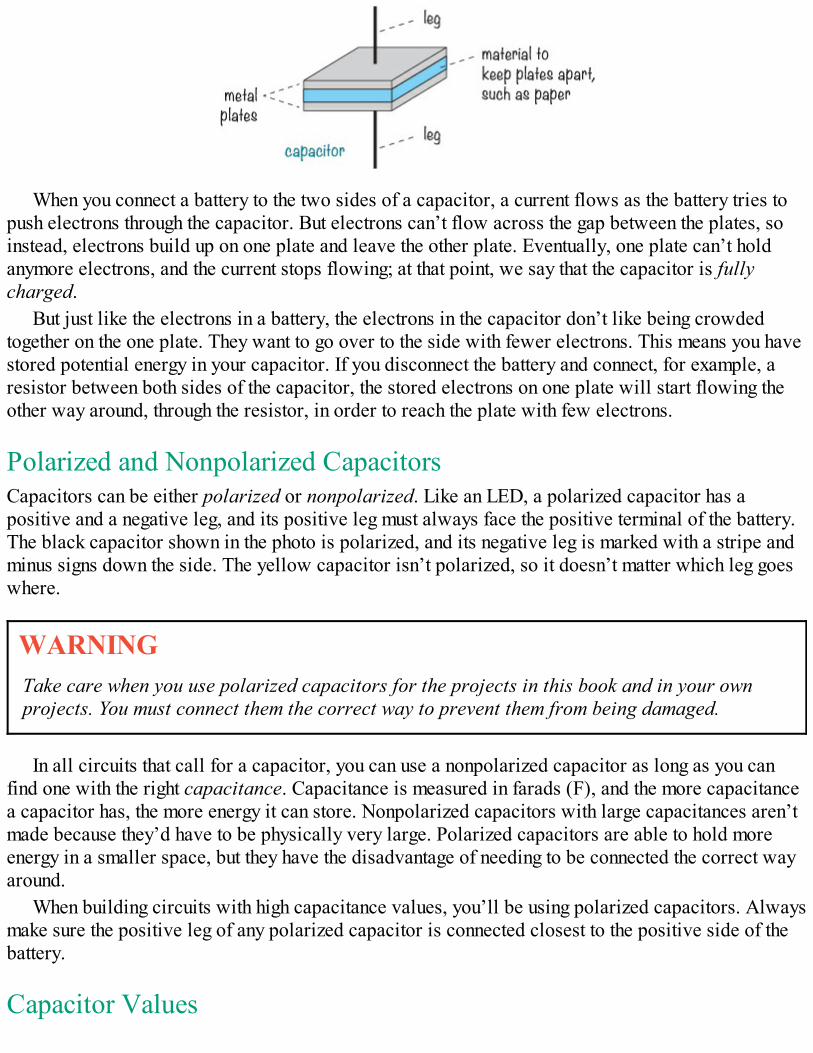
When you connect a battery to the two sides of a capacitor, a current flows as the battery tries topush electrons through the capacitor. But electrons can’t flow across the gap between the plates, soinstead, electrons build up on one plate and leave the other plate. Eventually, one plate can’t holdanymore electrons, and the current stops flowing; at that point, we say that the capacitor is fullycharged.
But just like the electrons in a battery, the electrons in the capacitor don’t like being crowdedtogether on the one plate. They want to go over to the side with fewer electrons. This means you havestored potential energy in your capacitor. If you disconnect the battery and connect, for example, aresistor between both sides of the capacitor, the stored electrons on one plate will start flowing theother way around, through the resistor, in order to reach the plate with few electrons.
Polarized and Nonpolarized CapacitorsCapacitors can be either polarized or nonpolarized. Like an LED, a polarized capacitor has apositive and a negative leg, and its positive leg must always face the positive terminal of the battery.The black capacitor shown in the photo is polarized, and its negative leg is marked with a stripe andminus signs down the side. The yellow capacitor isn’t polarized, so it doesn’t matter which leg goeswhere.
WARNINGTake care when you use polarized capacitors for the projects in this book and in your ownprojects. You must connect them the correct way to prevent them from being damaged.
In all circuits that call for a capacitor, you can use a nonpolarized capacitor as long as you canfind one with the right capacitance. Capacitance is measured in farads (F), and the more capacitancea capacitor has, the more energy it can store. Nonpolarized capacitors with large capacitances aren’tmade because they’d have to be physically very large. Polarized capacitors are able to hold moreenergy in a smaller space, but they have the disadvantage of needing to be connected the correct wayaround.
When building circuits with high capacitance values, you’ll be using polarized capacitors. Alwaysmake sure the positive leg of any polarized capacitor is connected closest to the positive side of thebattery.
Capacitor Values
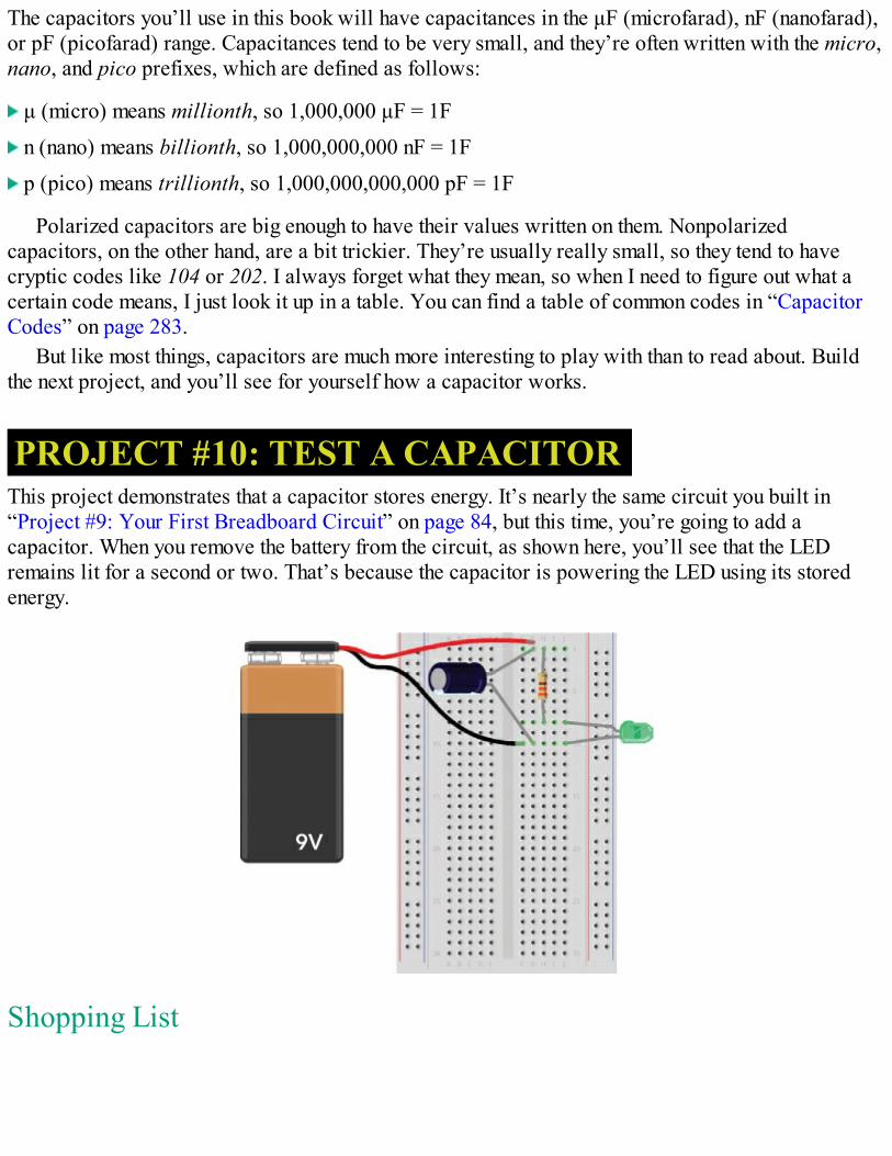
The capacitors you’ll use in this book will have capacitances in the μF (microfarad), nF (nanofarad),or pF (picofarad) range. Capacitances tend to be very small, and they’re often written with the micro,nano, and pico prefixes, which are defined as follows:
μ (micro) means millionth, so 1,000,000 μF = 1F
n (nano) means billionth, so 1,000,000,000 nF = 1F
p (pico) means trillionth, so 1,000,000,000,000 pF = 1F
Polarized capacitors are big enough to have their values written on them. Nonpolarizedcapacitors, on the other hand, are a bit trickier. They’re usually really small, so they tend to havecryptic codes like 104 or 202. I always forget what they mean, so when I need to figure out what acertain code means, I just look it up in a table. You can find a table of common codes in “CapacitorCodes” on page 283.
But like most things, capacitors are much more interesting to play with than to read about. Buildthe next project, and you’ll see for yourself how a capacitor works.
PROJECT #10: TEST A CAPACITORThis project demonstrates that a capacitor stores energy. It’s nearly the same circuit you built in“Project #9: Your First Breadboard Circuit” on page 84, but this time, you’re going to add acapacitor. When you remove the battery from the circuit, as shown here, you’ll see that the LEDremains lit for a second or two. That’s because the capacitor is powering the LED using its storedenergy.
Shopping List
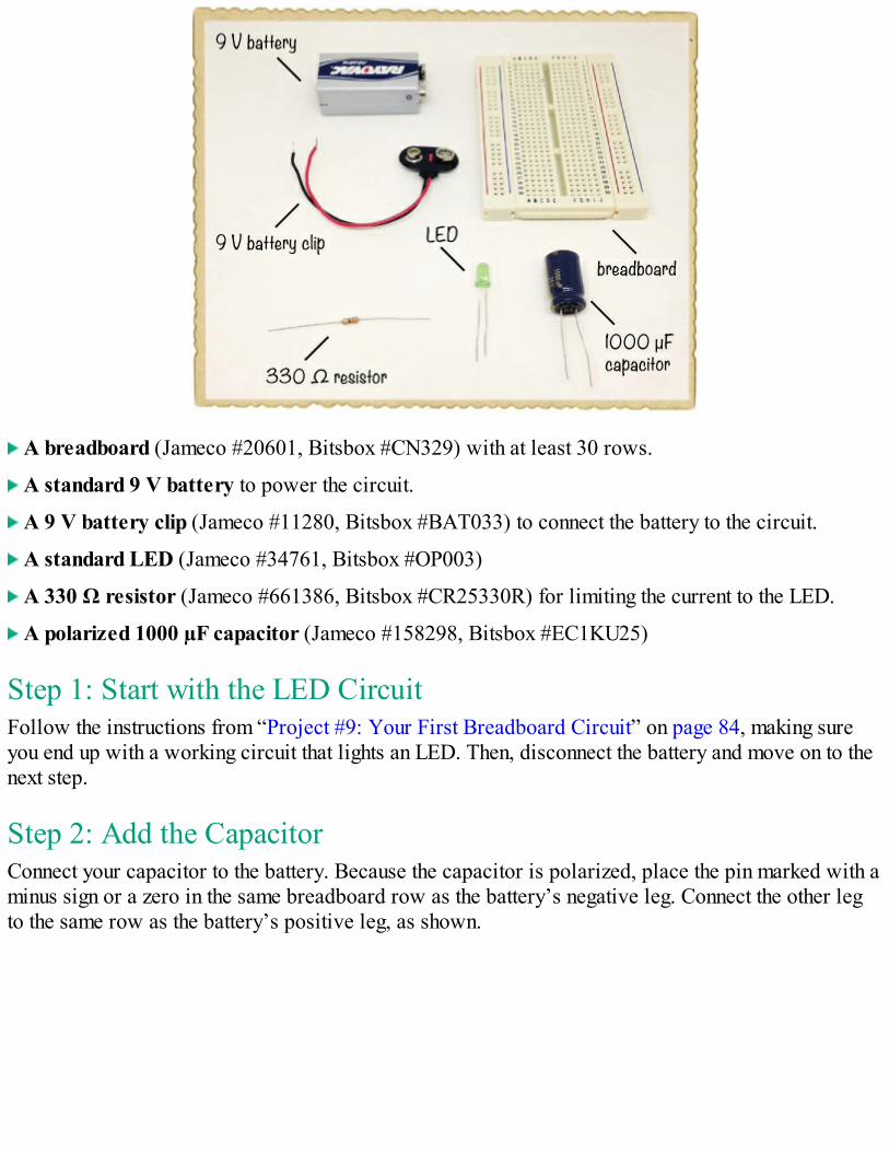
A breadboard (Jameco #20601, Bitsbox #CN329) with at least 30 rows.
A standard 9 V battery to power the circuit.
A 9 V battery clip (Jameco #11280, Bitsbox #BAT033) to connect the battery to the circuit.
A standard LED (Jameco #34761, Bitsbox #OP003)
A 330 Ω resistor (Jameco #661386, Bitsbox #CR25330R) for limiting the current to the LED.
A polarized 1000 µF capacitor (Jameco #158298, Bitsbox #EC1KU25)
Step 1: Start with the LED CircuitFollow the instructions from “Project #9: Your First Breadboard Circuit” on page 84, making sureyou end up with a working circuit that lights an LED. Then, disconnect the battery and move on to thenext step.
Step 2: Add the CapacitorConnect your capacitor to the battery. Because the capacitor is polarized, place the pin marked with aminus sign or a zero in the same breadboard row as the battery’s negative leg. Connect the other legto the same row as the battery’s positive leg, as shown.
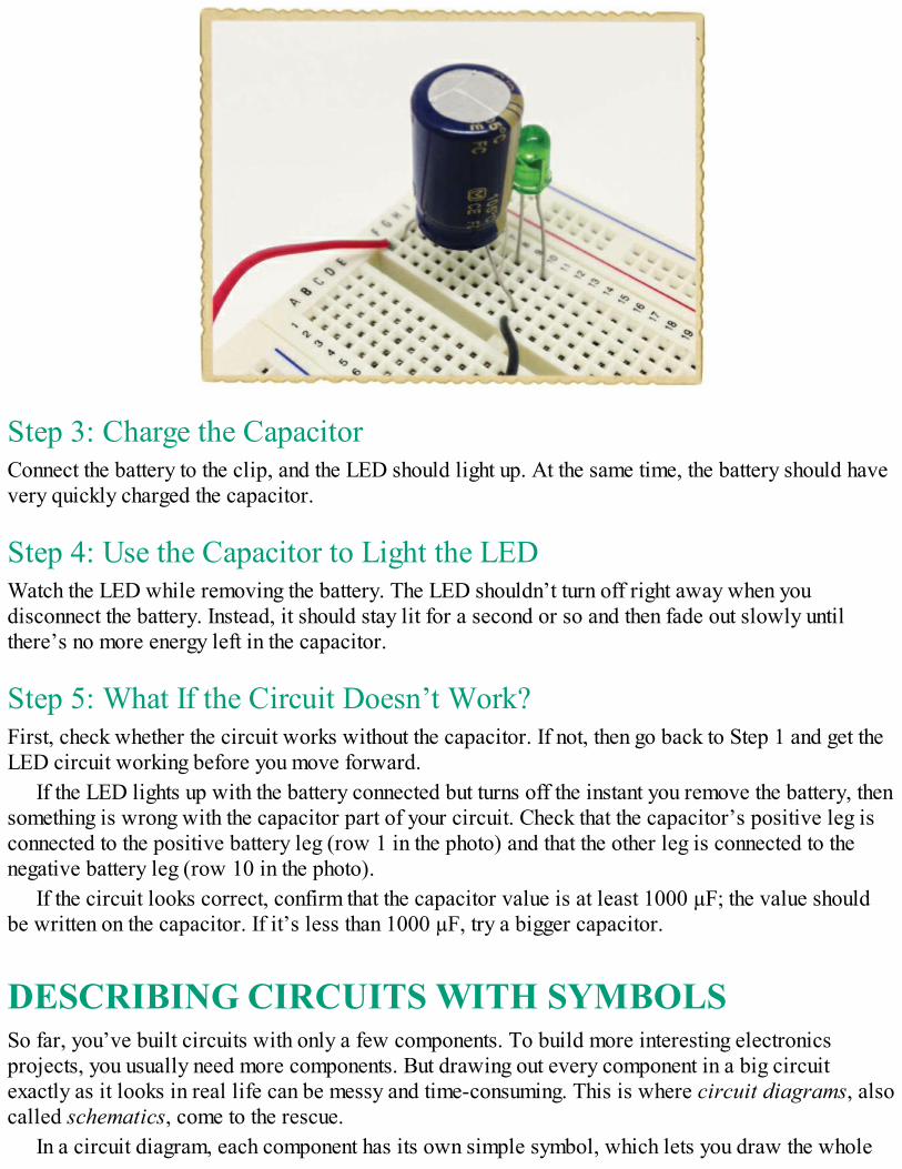
Step 3: Charge the CapacitorConnect the battery to the clip, and the LED should light up. At the same time, the battery should havevery quickly charged the capacitor.
Step 4: Use the Capacitor to Light the LEDWatch the LED while removing the battery. The LED shouldn’t turn off right away when youdisconnect the battery. Instead, it should stay lit for a second or so and then fade out slowly untilthere’s no more energy left in the capacitor.
Step 5: What If the Circuit Doesn’t Work?First, check whether the circuit works without the capacitor. If not, then go back to Step 1 and get theLED circuit working before you move forward.
If the LED lights up with the battery connected but turns off the instant you remove the battery, thensomething is wrong with the capacitor part of your circuit. Check that the capacitor’s positive leg isconnected to the positive battery leg (row 1 in the photo) and that the other leg is connected to thenegative battery leg (row 10 in the photo).
If the circuit looks correct, confirm that the capacitor value is at least 1000 µF; the value shouldbe written on the capacitor. If it’s less than 1000 µF, try a bigger capacitor.
DESCRIBING CIRCUITS WITH SYMBOLSSo far, you’ve built circuits with only a few components. To build more interesting electronicsprojects, you usually need more components. But drawing out every component in a big circuitexactly as it looks in real life can be messy and time-consuming. This is where circuit diagrams, alsocalled schematics, come to the rescue.
In a circuit diagram, each component has its own simple symbol, which lets you draw the whole
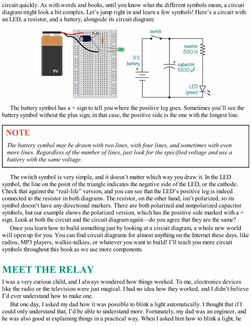
circuit quickly. As with words and books, until you know what the different symbols mean, a circuitdiagram might look a bit complex. Let’s jump right in and learn a few symbols! Here’s a circuit withan LED, a resistor, and a battery, alongside its circuit diagram:
The battery symbol has a + sign to tell you where the positive leg goes. Sometimes you’ll see thebattery symbol without the plus sign; in that case, the positive side is the one with the longest line.
NOTEThe battery symbol may be drawn with two lines, with four lines, and sometimes with evenmore lines. Regardless of the number of lines, just look for the specified voltage and use abattery with the same voltage.
The switch symbol is very simple, and it doesn’t matter which way you draw it. In the LEDsymbol, the line on the point of the triangle indicates the negative side of the LED, or the cathode.Check that against the “real-life” version, and you can see that the LED’s positive leg is indeedconnected to the resistor in both diagrams. The resistor, on the other hand, isn’t polarized, so itssymbol doesn’t have any directional markers. There are both polarized and nonpolarized capacitorsymbols, but our example shows the polarized version, which has the positive side marked with a +sign. Look at both the circuit and the circuit diagram again—do you agree that they are the same?
Once you learn how to build something just by looking at a circuit diagram, a whole new worldwill open up for you. You can find circuit diagrams for almost anything on the Internet these days, likeradios, MP3 players, walkie-talkies, or whatever you want to build! I’ll teach you more circuitsymbols throughout this book as we use more components.
MEET THE RELAYI was a very curious child, and I always wondered how things worked. To me, electronics deviceslike the radio or the television were just magical. I had no idea how they worked, and I didn’t believeI’d ever understand how to make one.
But one day, I asked my dad how it was possible to blink a light automatically. I thought that if Icould only understand that, I’d be able to understand more. Fortunately, my dad was an engineer, andhe was also good at explaining things in a practical way. When I asked him how to blink a light, he
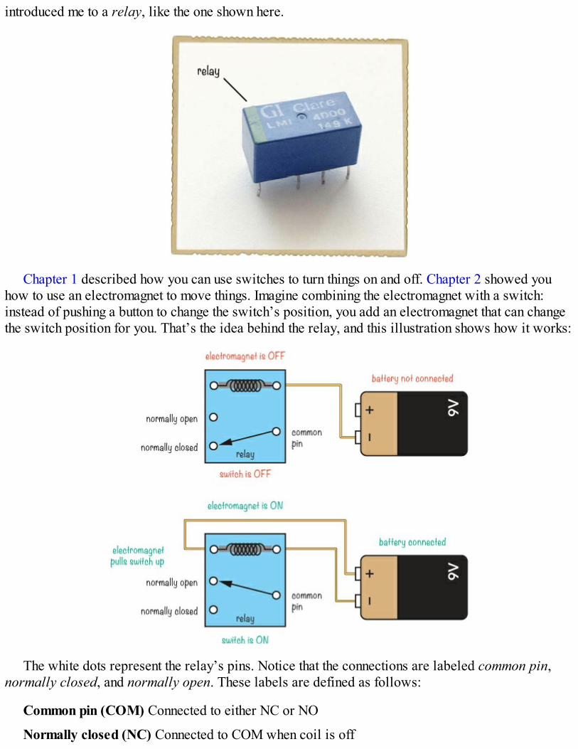
introduced me to a relay, like the one shown here.
Chapter 1 described how you can use switches to turn things on and off. Chapter 2 showed youhow to use an electromagnet to move things. Imagine combining the electromagnet with a switch:instead of pushing a button to change the switch’s position, you add an electromagnet that can changethe switch position for you. That’s the idea behind the relay, and this illustration shows how it works:
The white dots represent the relay’s pins. Notice that the connections are labeled common pin,normally closed, and normally open. These labels are defined as follows:
Common pin (COM) Connected to either NC or NO
Normally closed (NC) Connected to COM when coil is off
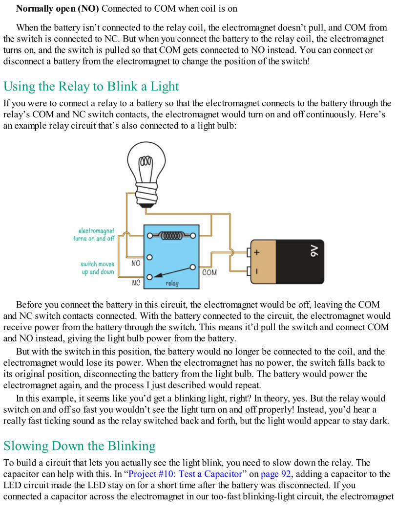
Normally open (NO) Connected to COM when coil is on
When the battery isn’t connected to the relay coil, the electromagnet doesn’t pull, and COM fromthe switch is connected to NC. But when you connect the battery to the relay coil, the electromagnetturns on, and the switch is pulled so that COM gets connected to NO instead. You can connect ordisconnect a battery from the electromagnet to change the position of the switch!
Using the Relay to Blink a LightIf you were to connect a relay to a battery so that the electromagnet connects to the battery through therelay’s COM and NC switch contacts, the electromagnet would turn on and off continuously. Here’san example relay circuit that’s also connected to a light bulb:
Before you connect the battery in this circuit, the electromagnet would be off, leaving the COMand NC switch contacts connected. With the battery connected to the circuit, the electromagnet wouldreceive power from the battery through the switch. This means it’d pull the switch and connect COMand NO instead, giving the light bulb power from the battery.
But with the switch in this position, the battery would no longer be connected to the coil, and theelectromagnet would lose its power. When the electromagnet has no power, the switch falls back toits original position, disconnecting the battery from the light bulb. The battery would power theelectromagnet again, and the process I just described would repeat.
In this example, it seems like you’d get a blinking light, right? In theory, yes. But the relay wouldswitch on and off so fast you wouldn’t see the light turn on and off properly! Instead, you’d hear areally fast ticking sound as the relay switched back and forth, but the light would appear to stay dark.
Slowing Down the BlinkingTo build a circuit that lets you actually see the light blink, you need to slow down the relay. Thecapacitor can help with this. In “Project #10: Test a Capacitor” on page 92, adding a capacitor to theLED circuit made the LED stay on for a short time after the battery was disconnected. If youconnected a capacitor across the electromagnet in our too-fast blinking-light circuit, the electromagnet
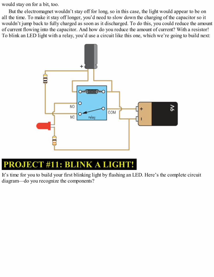
would stay on for a bit, too.But the electromagnet wouldn’t stay off for long, so in this case, the light would appear to be on
all the time. To make it stay off longer, you’d need to slow down the charging of the capacitor so itwouldn’t jump back to fully charged as soon as it discharged. To do this, you could reduce the amountof current flowing into the capacitor. And how do you reduce the amount of current? With a resistor!To blink an LED light with a relay, you’d use a circuit like this one, which we’re going to build next:
PROJECT #11: BLINK A LIGHT!It’s time for you to build your first blinking light by flashing an LED. Here’s the complete circuitdiagram—do you recognize the components?
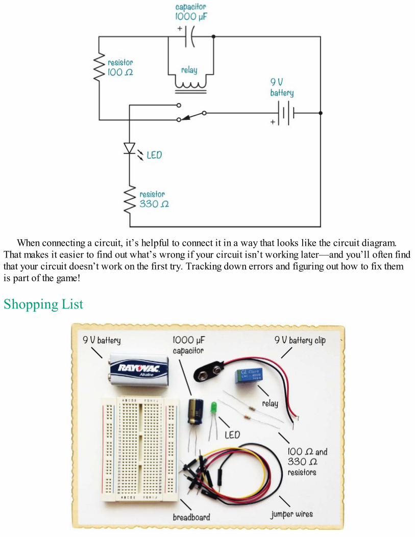
When connecting a circuit, it’s helpful to connect it in a way that looks like the circuit diagram.That makes it easier to find out what’s wrong if your circuit isn’t working later—and you’ll often findthat your circuit doesn’t work on the first try. Tracking down errors and figuring out how to fix themis part of the game!
Shopping List
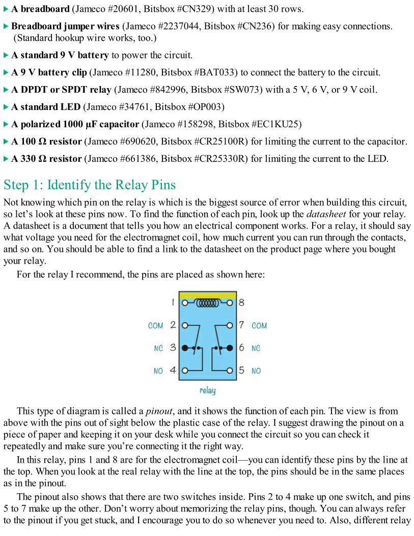
A breadboard (Jameco #20601, Bitsbox #CN329) with at least 30 rows.
Breadboard jumper wires (Jameco #2237044, Bitsbox #CN236) for making easy connections.(Standard hookup wire works, too.)
A standard 9 V battery to power the circuit.
A 9 V battery clip (Jameco #11280, Bitsbox #BAT033) to connect the battery to the circuit.
A DPDT or SPDT relay (Jameco #842996, Bitsbox #SW073) with a 5 V, 6 V, or 9 V coil.
A standard LED (Jameco #34761, Bitsbox #OP003)
A polarized 1000 µF capacitor (Jameco #158298, Bitsbox #EC1KU25)
A 100 Ω resistor (Jameco #690620, Bitsbox #CR25100R) for limiting the current to the capacitor.
A 330 Ω resistor (Jameco #661386, Bitsbox #CR25330R) for limiting the current to the LED.
Step 1: Identify the Relay PinsNot knowing which pin on the relay is which is the biggest source of error when building this circuit,so let’s look at these pins now. To find the function of each pin, look up the datasheet for your relay.A datasheet is a document that tells you how an electrical component works. For a relay, it should saywhat voltage you need for the electromagnet coil, how much current you can run through the contacts,and so on. You should be able to find a link to the datasheet on the product page where you boughtyour relay.
For the relay I recommend, the pins are placed as shown here:
This type of diagram is called a pinout, and it shows the function of each pin. The view is fromabove with the pins out of sight below the plastic case of the relay. I suggest drawing the pinout on apiece of paper and keeping it on your desk while you connect the circuit so you can check itrepeatedly and make sure you’re connecting it the right way.
In this relay, pins 1 and 8 are for the electromagnet coil—you can identify these pins by the line atthe top. When you look at the real relay with the line at the top, the pins should be in the same placesas in the pinout.
The pinout also shows that there are two switches inside. Pins 2 to 4 make up one switch, and pins5 to 7 make up the other. Don’t worry about memorizing the relay pins, though. You can always referto the pinout if you get stuck, and I encourage you to do so whenever you need to. Also, different relay
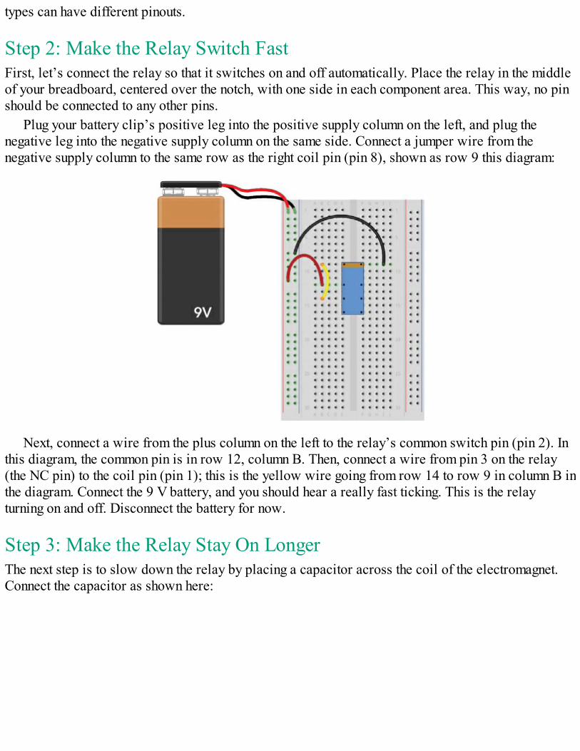
types can have different pinouts.
Step 2: Make the Relay Switch FastFirst, let’s connect the relay so that it switches on and off automatically. Place the relay in the middleof your breadboard, centered over the notch, with one side in each component area. This way, no pinshould be connected to any other pins.
Plug your battery clip’s positive leg into the positive supply column on the left, and plug thenegative leg into the negative supply column on the same side. Connect a jumper wire from thenegative supply column to the same row as the right coil pin (pin 8), shown as row 9 this diagram:
Next, connect a wire from the plus column on the left to the relay’s common switch pin (pin 2). Inthis diagram, the common pin is in row 12, column B. Then, connect a wire from pin 3 on the relay(the NC pin) to the coil pin (pin 1); this is the yellow wire going from row 14 to row 9 in column B inthe diagram. Connect the 9 V battery, and you should hear a really fast ticking. This is the relayturning on and off. Disconnect the battery for now.
Step 3: Make the Relay Stay On LongerThe next step is to slow down the relay by placing a capacitor across the coil of the electromagnet.Connect the capacitor as shown here:
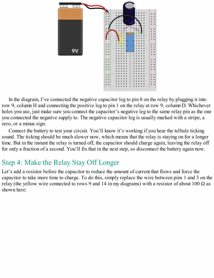
In the diagram, I’ve connected the negative capacitor leg to pin 8 on the relay by plugging it intorow 9, column H and connecting the positive leg to pin 1 on the relay at row 9, column D. Whicheverholes you use, just make sure you connect the capacitor’s negative leg to the same relay pin as the oneyou connected the negative supply to. The negative capacitor leg is usually marked with a stripe, azero, or a minus sign.
Connect the battery to test your circuit. You’ll know it’s working if you hear the telltale tickingsound. The ticking should be much slower now, which means that the relay is staying on for a longertime. But in the instant the relay is turned off, the capacitor should charge again, leaving the relay offfor only a fraction of a second. You’ll fix that in the next step, so disconnect the battery again now.
Step 4: Make the Relay Stay Off LongerLet’s add a resistor before the capacitor to reduce the amount of current that flows and force thecapacitor to take more time to charge. To do this, simply replace the wire between pins 1 and 3 on therelay (the yellow wire connected to rows 9 and 14 in my diagrams) with a resistor of about 100 Ω asshown here:
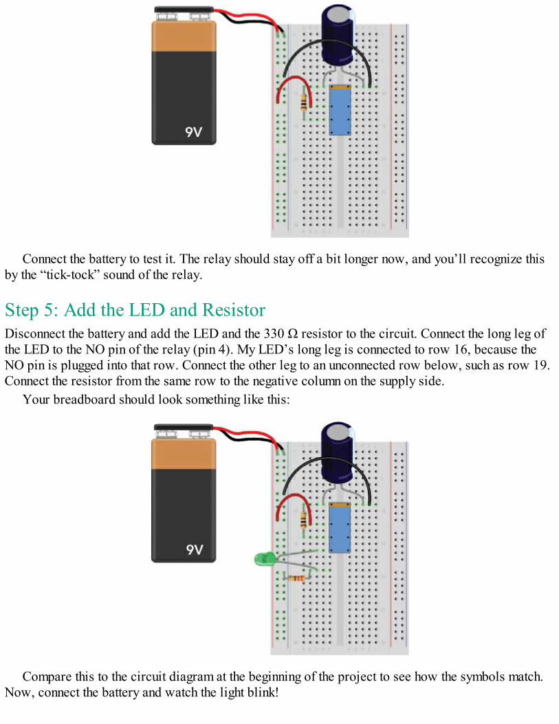
Connect the battery to test it. The relay should stay off a bit longer now, and you’ll recognize thisby the “tick-tock” sound of the relay.
Step 5: Add the LED and ResistorDisconnect the battery and add the LED and the 330 Ω resistor to the circuit. Connect the long leg ofthe LED to the NO pin of the relay (pin 4). My LED’s long leg is connected to row 16, because theNO pin is plugged into that row. Connect the other leg to an unconnected row below, such as row 19.Connect the resistor from the same row to the negative column on the supply side.
Your breadboard should look something like this:
Compare this to the circuit diagram at the beginning of the project to see how the symbols match.Now, connect the battery and watch the light blink!
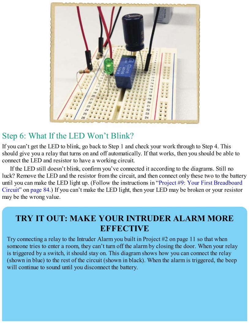
Step 6: What If the LED Won’t Blink?If you can’t get the LED to blink, go back to Step 1 and check your work through to Step 4. Thisshould give you a relay that turns on and off automatically. If that works, then you should be able toconnect the LED and resistor to have a working circuit.
If the LED still doesn’t blink, confirm you’ve connected it according to the diagrams. Still noluck? Remove the LED and the resistor from the circuit, and then connect only these two to the batteryuntil you can make the LED light up. (Follow the instructions in “Project #9: Your First BreadboardCircuit” on page 84.) If you can’t make the LED light, then your LED may be broken or your resistormay be the wrong value.
TRY IT OUT: MAKE YOUR INTRUDER ALARM MOREEFFECTIVE
Try connecting a relay to the Intruder Alarm you built in Project #2 on page 11 so that whensomeone tries to enter a room, they can’t turn off the alarm by closing the door. When your relayis triggered by a switch, it should stay on. This diagram shows how you can connect the relay(shown in blue) to the rest of the circuit (shown in black). When the alarm is triggered, the beepwill continue to sound until you disconnect the battery.
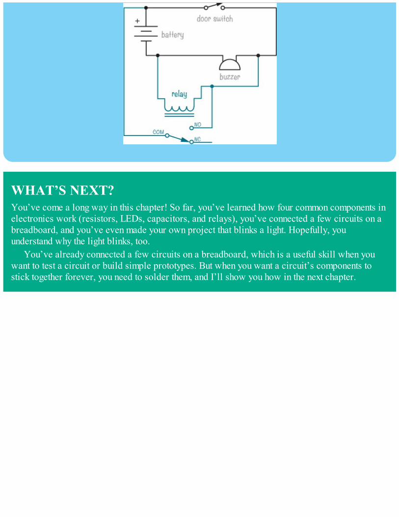
WHAT’S NEXT?You’ve come a long way in this chapter! So far, you’ve learned how four common components inelectronics work (resistors, LEDs, capacitors, and relays), you’ve connected a few circuits on abreadboard, and you’ve even made your own project that blinks a light. Hopefully, youunderstand why the light blinks, too.
You’ve already connected a few circuits on a breadboard, which is a useful skill when youwant to test a circuit or build simple prototypes. But when you want a circuit’s components tostick together forever, you need to solder them, and I’ll show you how in the next chapter.

6LET’S SOLDER!
In Chapter 5, you used a breadboard to build new circuits. A breadboard lets you quickly test newideas and experiment with different components to see the result, but it isn’t a permanent solution.Components can easily fall out, and there can be loose wires all over the breadboard. When you wantto use a circuit for a long time without changing it, it’s better to solder the circuit to a circuit board.Soldering is kind of like gluing: you melt a material called solder onto the component legs so thecomponents stick to the circuit board. A circuit board has holes like a breadboard, and when yousolder components to it, they become connected by plates of copper.
This chapter will teach you how to solder, starting with a simple LED circuit. This will give youthe foundation you need to solder your own circuits later. After you’ve practiced the basics in thischapter, you’ll continue soldering in Chapter 7 to build a touch-enabled switch and a circuit thatwakes you up when the sun rises in the morning.
HOW TO SOLDERTo solder a circuit, you need a few tools:
Solder
A soldering iron
A stand to hold the soldering iron
A damp sponge
Safety goggles
Solder is a mix of metals that can easily melt at high temperatures. The most commonly usedsolder melts at around 360 to 370 degrees Fahrenheit.
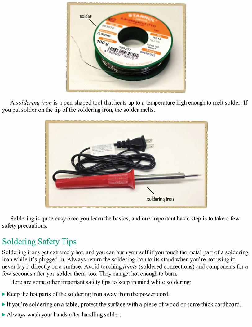
A soldering iron is a pen-shaped tool that heats up to a temperature high enough to melt solder. Ifyou put solder on the tip of the soldering iron, the solder melts.
Soldering is quite easy once you learn the basics, and one important basic step is to take a fewsafety precautions.
Soldering Safety TipsSoldering irons get extremely hot, and you can burn yourself if you touch the metal part of a solderingiron while it’s plugged in. Always return the soldering iron to its stand when you’re not using it;never lay it directly on a surface. Avoid touching joints (soldered connections) and components for afew seconds after you solder them, too. They can get hot enough to burn.
Here are some other important safety tips to keep in mind while soldering:
Keep the hot parts of the soldering iron away from the power cord.
If you’re soldering on a table, protect the surface with a piece of wood or some thick cardboard.
Always wash your hands after handling solder.
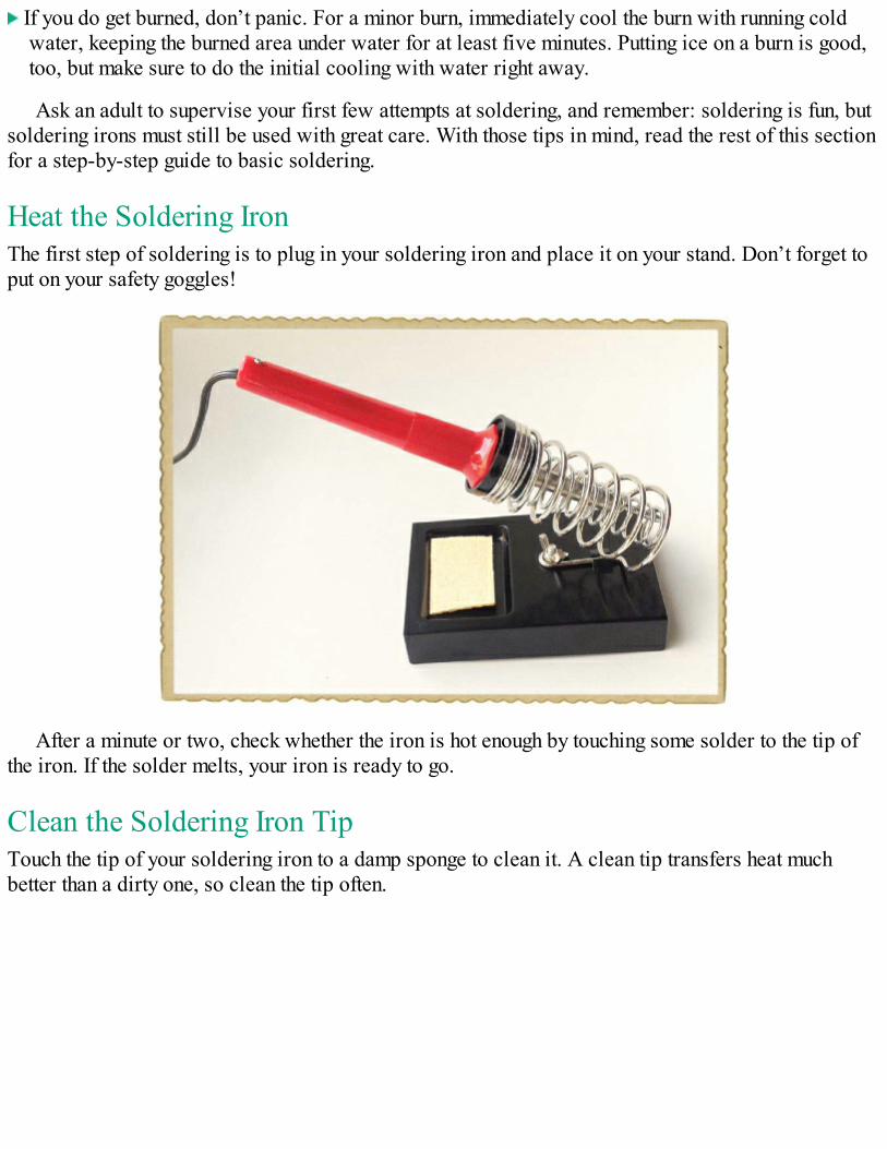
If you do get burned, don’t panic. For a minor burn, immediately cool the burn with running coldwater, keeping the burned area under water for at least five minutes. Putting ice on a burn is good,too, but make sure to do the initial cooling with water right away.
Ask an adult to supervise your first few attempts at soldering, and remember: soldering is fun, butsoldering irons must still be used with great care. With those tips in mind, read the rest of this sectionfor a step-by-step guide to basic soldering.
Heat the Soldering IronThe first step of soldering is to plug in your soldering iron and place it on your stand. Don’t forget toput on your safety goggles!
After a minute or two, check whether the iron is hot enough by touching some solder to the tip ofthe iron. If the solder melts, your iron is ready to go.
Clean the Soldering Iron TipTouch the tip of your soldering iron to a damp sponge to clean it. A clean tip transfers heat muchbetter than a dirty one, so clean the tip often.
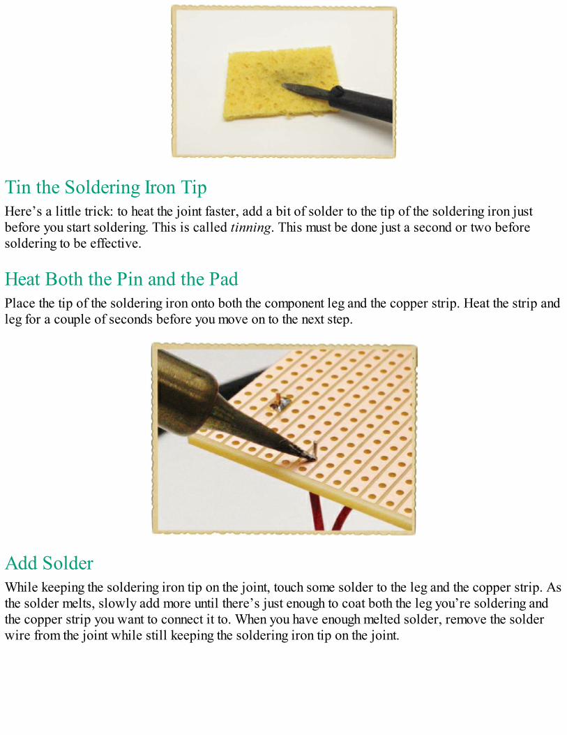
Tin the Soldering Iron TipHere’s a little trick: to heat the joint faster, add a bit of solder to the tip of the soldering iron justbefore you start soldering. This is called tinning. This must be done just a second or two beforesoldering to be effective.
Heat Both the Pin and the PadPlace the tip of the soldering iron onto both the component leg and the copper strip. Heat the strip andleg for a couple of seconds before you move on to the next step.
Add SolderWhile keeping the soldering iron tip on the joint, touch some solder to the leg and the copper strip. Asthe solder melts, slowly add more until there’s just enough to coat both the leg you’re soldering andthe copper strip you want to connect it to. When you have enough melted solder, remove the solderwire from the joint while still keeping the soldering iron tip on the joint.
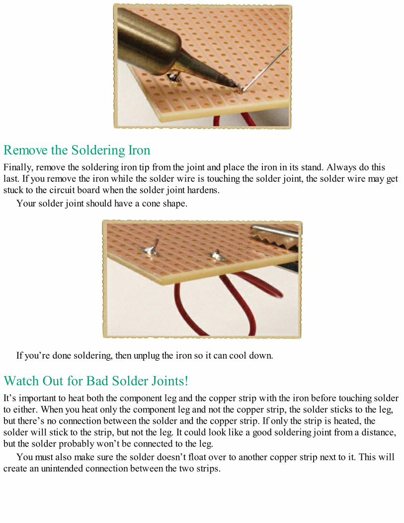
Remove the Soldering IronFinally, remove the soldering iron tip from the joint and place the iron in its stand. Always do thislast. If you remove the iron while the solder wire is touching the solder joint, the solder wire may getstuck to the circuit board when the solder joint hardens.
Your solder joint should have a cone shape.
If you’re done soldering, then unplug the iron so it can cool down.
Watch Out for Bad Solder Joints!It’s important to heat both the component leg and the copper strip with the iron before touching solderto either. When you heat only the component leg and not the copper strip, the solder sticks to the leg,but there’s no connection between the solder and the copper strip. If only the strip is heated, thesolder will stick to the strip, but not the leg. It could look like a good soldering joint from a distance,but the solder probably won’t be connected to the leg.
You must also make sure the solder doesn’t float over to another copper strip next to it. This willcreate an unintended connection between the two strips.
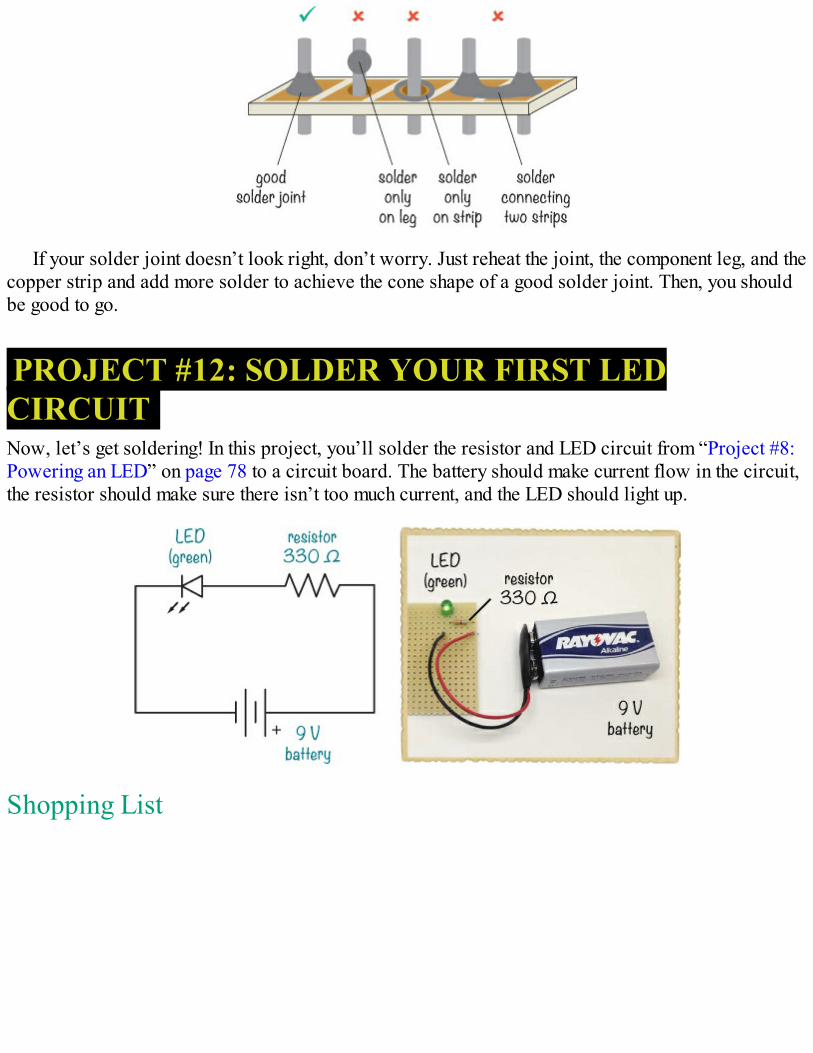
If your solder joint doesn’t look right, don’t worry. Just reheat the joint, the component leg, and thecopper strip and add more solder to achieve the cone shape of a good solder joint. Then, you shouldbe good to go.
PROJECT #12: SOLDER YOUR FIRST LEDCIRCUITNow, let’s get soldering! In this project, you’ll solder the resistor and LED circuit from “Project #8:Powering an LED” on page 78 to a circuit board. The battery should make current flow in the circuit,the resistor should make sure there isn’t too much current, and the LED should light up.
Shopping List
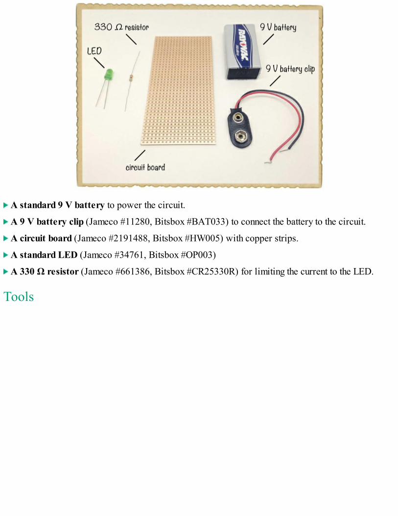
A standard 9 V battery to power the circuit.
A 9 V battery clip (Jameco #11280, Bitsbox #BAT033) to connect the battery to the circuit.
A circuit board (Jameco #2191488, Bitsbox #HW005) with copper strips.
A standard LED (Jameco #34761, Bitsbox #OP003)
A 330 Ω resistor (Jameco #661386, Bitsbox #CR25330R) for limiting the current to the LED.
Tools
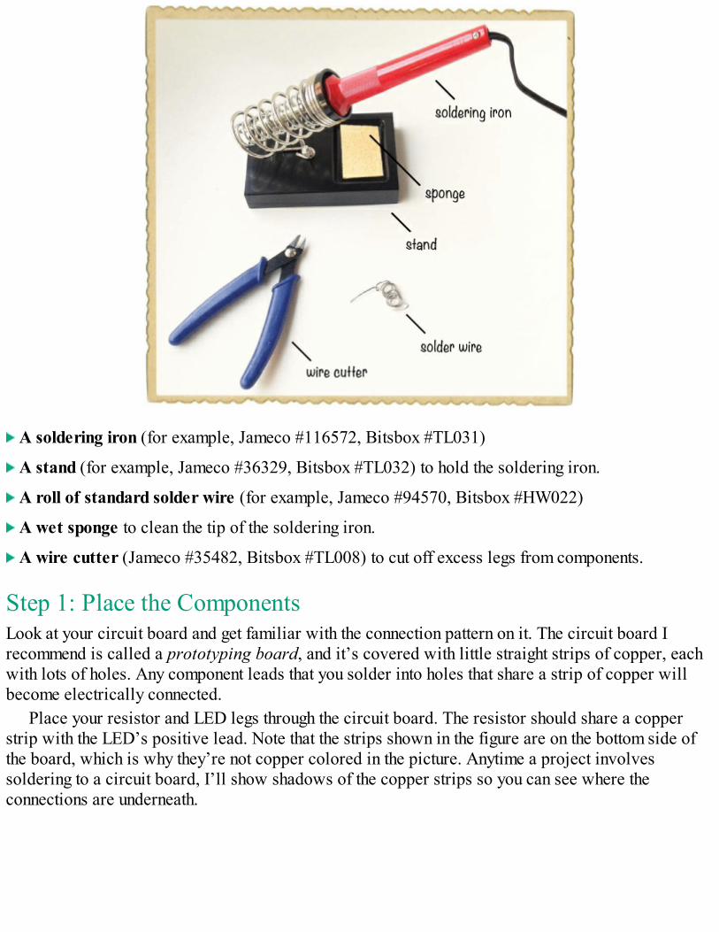
A soldering iron (for example, Jameco #116572, Bitsbox #TL031)
A stand (for example, Jameco #36329, Bitsbox #TL032) to hold the soldering iron.
A roll of standard solder wire (for example, Jameco #94570, Bitsbox #HW022)
A wet sponge to clean the tip of the soldering iron.
A wire cutter (Jameco #35482, Bitsbox #TL008) to cut off excess legs from components.
Step 1: Place the ComponentsLook at your circuit board and get familiar with the connection pattern on it. The circuit board Irecommend is called a prototyping board, and it’s covered with little straight strips of copper, eachwith lots of holes. Any component leads that you solder into holes that share a strip of copper willbecome electrically connected.
Place your resistor and LED legs through the circuit board. The resistor should share a copperstrip with the LED’s positive lead. Note that the strips shown in the figure are on the bottom side ofthe board, which is why they’re not copper colored in the picture. Anytime a project involvessoldering to a circuit board, I’ll show shadows of the copper strips so you can see where theconnections are underneath.
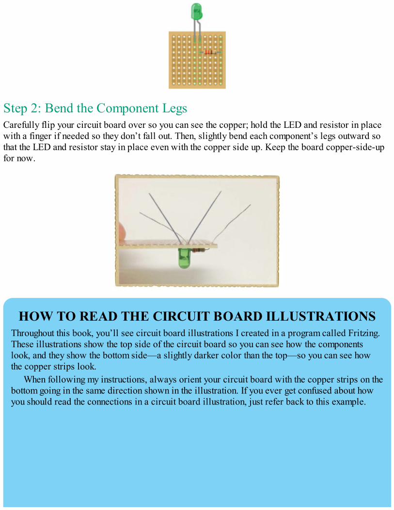
Step 2: Bend the Component LegsCarefully flip your circuit board over so you can see the copper; hold the LED and resistor in placewith a finger if needed so they don’t fall out. Then, slightly bend each component’s legs outward sothat the LED and resistor stay in place even with the copper side up. Keep the board copper-side-upfor now.
HOW TO READ THE CIRCUIT BOARD ILLUSTRATIONSThroughout this book, you’ll see circuit board illustrations I created in a program called Fritzing.These illustrations show the top side of the circuit board so you can see how the componentslook, and they show the bottom side—a slightly darker color than the top—so you can see howthe copper strips look.
When following my instructions, always orient your circuit board with the copper strips on thebottom going in the same direction shown in the illustration. If you ever get confused about howyou should read the connections in a circuit board illustration, just refer back to this example.

If you want to create your own circuit illustrations with Fritzing, you can download the free,open source software from http://www.fritzing.org/.
Step 3: Heat and Clean the Soldering IronYour components should be in place and ready to solder, so plug in and heat up the iron now. Thismay take a few minutes. As always, check to see whether the iron is hot enough by touching somesolder to the tip to see whether it melts.
Before you start soldering, clean the tip of the soldering iron, too. Wet your sponge just a little bitand wring out any excess water. Then, wipe the tip of the iron on the sponge to remove any oldsolder.
Step 4: Solder the Resistor and LEDWith the copper side of the circuit board facing up, solder each component leg to the board, asdescribed in “How to Solder” on page 112. Your board should look like this:
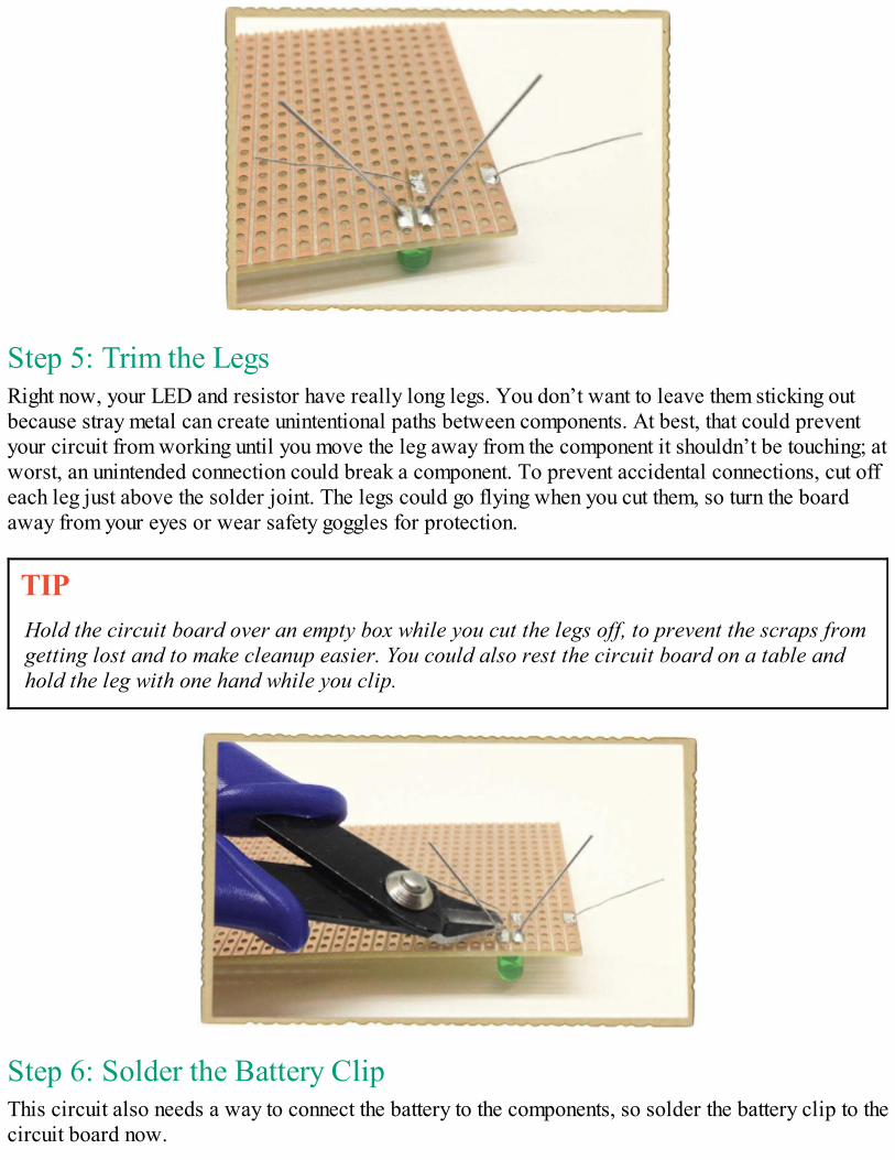
Step 5: Trim the LegsRight now, your LED and resistor have really long legs. You don’t want to leave them sticking outbecause stray metal can create unintentional paths between components. At best, that could preventyour circuit from working until you move the leg away from the component it shouldn’t be touching; atworst, an unintended connection could break a component. To prevent accidental connections, cut offeach leg just above the solder joint. The legs could go flying when you cut them, so turn the boardaway from your eyes or wear safety goggles for protection.
TIPHold the circuit board over an empty box while you cut the legs off, to prevent the scraps fromgetting lost and to make cleanup easier. You could also rest the circuit board on a table andhold the leg with one hand while you clip.
Step 6: Solder the Battery ClipThis circuit also needs a way to connect the battery to the components, so solder the battery clip to thecircuit board now.
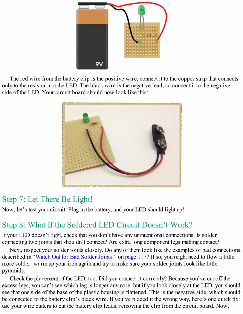
The red wire from the battery clip is the positive wire; connect it to the copper strip that connectsonly to the resistor, not the LED. The black wire is the negative lead, so connect it to the negativeside of the LED. Your circuit board should now look like this:
Step 7: Let There Be Light!Now, let’s test your circuit. Plug in the battery, and your LED should light up!
Step 8: What If the Soldered LED Circuit Doesn’t Work?If your LED doesn’t light, check that you don’t have any unintentional connections. Is solderconnecting two joints that shouldn’t connect? Are extra long component legs making contact?
Next, inspect your solder joints closely. Do any of them look like the examples of bad connectionsdescribed in “Watch Out for Bad Solder Joints!” on page 117? If so, you might need to flow a littlemore solder: warm up your iron again and try to make sure your solder joints look like littlepyramids.
Check the placement of the LED, too. Did you connect it correctly? Because you’ve cut off theexcess legs, you can’t see which leg is longer anymore, but if you look closely at the LED, you shouldsee that one side of the base of the plastic housing is flattened. This is the negative side, which shouldbe connected to the battery clip’s black wire. If you’ve placed it the wrong way, here’s one quick fix:use your wire cutters to cut the battery clip leads, removing the clip from the circuit board. Now,
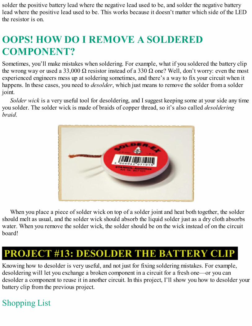
solder the positive battery lead where the negative lead used to be, and solder the negative batterylead where the positive lead used to be. This works because it doesn’t matter which side of the LEDthe resistor is on.
OOPS! HOW DO I REMOVE A SOLDEREDCOMPONENT?Sometimes, you’ll make mistakes when soldering. For example, what if you soldered the battery clipthe wrong way or used a 33,000 Ω resistor instead of a 330 Ω one? Well, don’t worry: even the mostexperienced engineers mess up at soldering sometimes, and there’s a way to fix your circuit when ithappens. In these cases, you need to desolder, which just means to remove the solder from a solderjoint.
Solder wick is a very useful tool for desoldering, and I suggest keeping some at your side any timeyou solder. The solder wick is made of braids of copper thread, so it’s also called desolderingbraid.
When you place a piece of solder wick on top of a solder joint and heat both together, the soldershould melt as usual, and the solder wick should absorb the liquid solder just as a dry cloth absorbswater. When you remove the solder wick, the solder should be on the wick instead of on the circuitboard!
PROJECT #13: DESOLDER THE BATTERY CLIPKnowing how to desolder is very useful, and not just for fixing soldering mistakes. For example,desoldering will let you exchange a broken component in a circuit for a fresh one—or you candesolder a component to reuse it in another circuit. In this project, I’ll show you how to desolder yourbattery clip from the previous project.
Shopping List
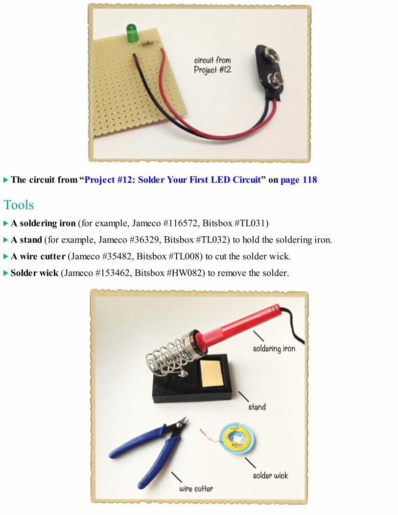
The circuit from “Project #12: Solder Your First LED Circuit” on page 118
Tools A soldering iron (for example, Jameco #116572, Bitsbox #TL031)
A stand (for example, Jameco #36329, Bitsbox #TL032) to hold the soldering iron.
A wire cutter (Jameco #35482, Bitsbox #TL008) to cut the solder wick.
Solder wick (Jameco #153462, Bitsbox #HW082) to remove the solder.
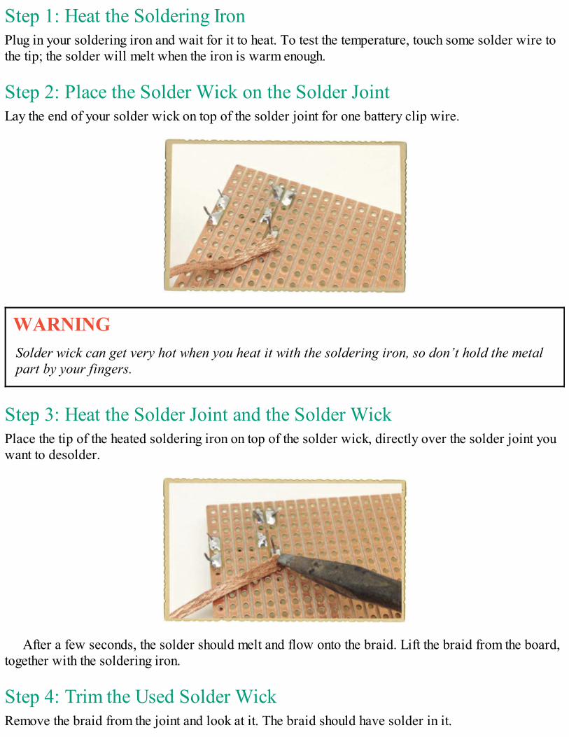
Step 1: Heat the Soldering IronPlug in your soldering iron and wait for it to heat. To test the temperature, touch some solder wire tothe tip; the solder will melt when the iron is warm enough.
Step 2: Place the Solder Wick on the Solder JointLay the end of your solder wick on top of the solder joint for one battery clip wire.
WARNINGSolder wick can get very hot when you heat it with the soldering iron, so don’t hold the metalpart by your fingers.
Step 3: Heat the Solder Joint and the Solder WickPlace the tip of the heated soldering iron on top of the solder wick, directly over the solder joint youwant to desolder.
After a few seconds, the solder should melt and flow onto the braid. Lift the braid from the board,together with the soldering iron.
Step 4: Trim the Used Solder WickRemove the braid from the joint and look at it. The braid should have solder in it.
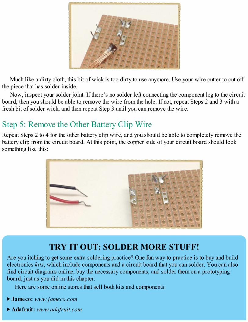
Much like a dirty cloth, this bit of wick is too dirty to use anymore. Use your wire cutter to cut offthe piece that has solder inside.
Now, inspect your solder joint. If there’s no solder left connecting the component leg to the circuitboard, then you should be able to remove the wire from the hole. If not, repeat Steps 2 and 3 with afresh bit of solder wick, and then repeat Step 3 until you can remove the wire.
Step 5: Remove the Other Battery Clip WireRepeat Steps 2 to 4 for the other battery clip wire, and you should be able to completely remove thebattery clip from the circuit board. At this point, the copper side of your circuit board should looksomething like this:
TRY IT OUT: SOLDER MORE STUFF!Are you itching to get some extra soldering practice? One fun way to practice is to buy and buildelectronics kits, which include components and a circuit board that you can solder. You can alsofind circuit diagrams online, buy the necessary components, and solder them on a prototypingboard, just as you did in this chapter.
Here are some online stores that sell both kits and components:
Jameco: www.jameco.com
Adafruit: www.adafruit.com

SparkFun: www.sparkfun.com
WHAT’S NEXT?In this chapter, you learned a very useful skill: soldering. This means you can make permanentcircuits for your projects without worrying that they’ll fall apart. And with a little practice atdesoldering, you can take projects apart on purpose, too.
In Chapter 7, I’ll introduce you to the transistor, the photoresistor, and the potentiometer.These are some really exciting components that you can use to make your circuit come alive andrespond to its surroundings. For example, I’ll show you how to create a circuit that tells you whenthe sun rises in the morning!

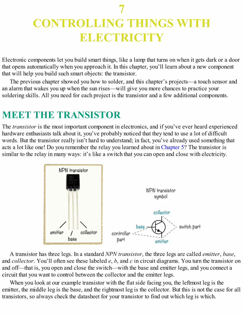
7CONTROLLING THINGS WITH
ELECTRICITY
Electronic components let you build smart things, like a lamp that turns on when it gets dark or a doorthat opens automatically when you approach it. In this chapter, you’ll learn about a new componentthat will help you build such smart objects: the transistor.
The previous chapter showed you how to solder, and this chapter’s projects—a touch sensor andan alarm that wakes you up when the sun rises—will give you more chances to practice yoursoldering skills. All you need for each project is the transistor and a few additional components.
MEET THE TRANSISTORThe transistor is the most important component in electronics, and if you’ve ever heard experiencedhardware enthusiasts talk about it, you’ve probably noticed that they tend to use a lot of difficultwords. But the transistor really isn’t hard to understand; in fact, you’ve already used something thatacts a lot like one! Do you remember the relay you learned about in Chapter 5? The transistor issimilar to the relay in many ways: it’s like a switch that you can open and close with electricity.
A transistor has three legs. In a standard NPN transistor, the three legs are called emitter, base,and collector. You’ll often see these labeled e, b, and c in circuit diagrams. You turn the transistor onand off—that is, you open and close the switch—with the base and emitter legs, and you connect acircuit that you want to control between the collector and the emitter legs.
When you look at our example transistor with the flat side facing you, the leftmost leg is theemitter, the middle leg is the base, and the rightmost leg is the collector. But this is not the case for alltransistors, so always check the datasheet for your transistor to find out which leg is which.
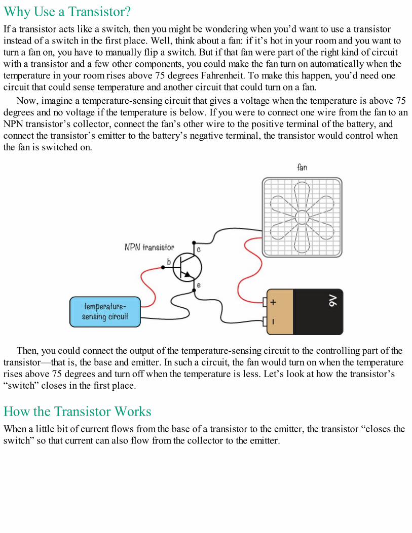
Why Use a Transistor?If a transistor acts like a switch, then you might be wondering when you’d want to use a transistorinstead of a switch in the first place. Well, think about a fan: if it’s hot in your room and you want toturn a fan on, you have to manually flip a switch. But if that fan were part of the right kind of circuitwith a transistor and a few other components, you could make the fan turn on automatically when thetemperature in your room rises above 75 degrees Fahrenheit. To make this happen, you’d need onecircuit that could sense temperature and another circuit that could turn on a fan.
Now, imagine a temperature-sensing circuit that gives a voltage when the temperature is above 75degrees and no voltage if the temperature is below. If you were to connect one wire from the fan to anNPN transistor’s collector, connect the fan’s other wire to the positive terminal of the battery, andconnect the transistor’s emitter to the battery’s negative terminal, the transistor would control whenthe fan is switched on.
Then, you could connect the output of the temperature-sensing circuit to the controlling part of thetransistor—that is, the base and emitter. In such a circuit, the fan would turn on when the temperaturerises above 75 degrees and turn off when the temperature is less. Let’s look at how the transistor’s“switch” closes in the first place.
How the Transistor WorksWhen a little bit of current flows from the base of a transistor to the emitter, the transistor “closes theswitch” so that current can also flow from the collector to the emitter.
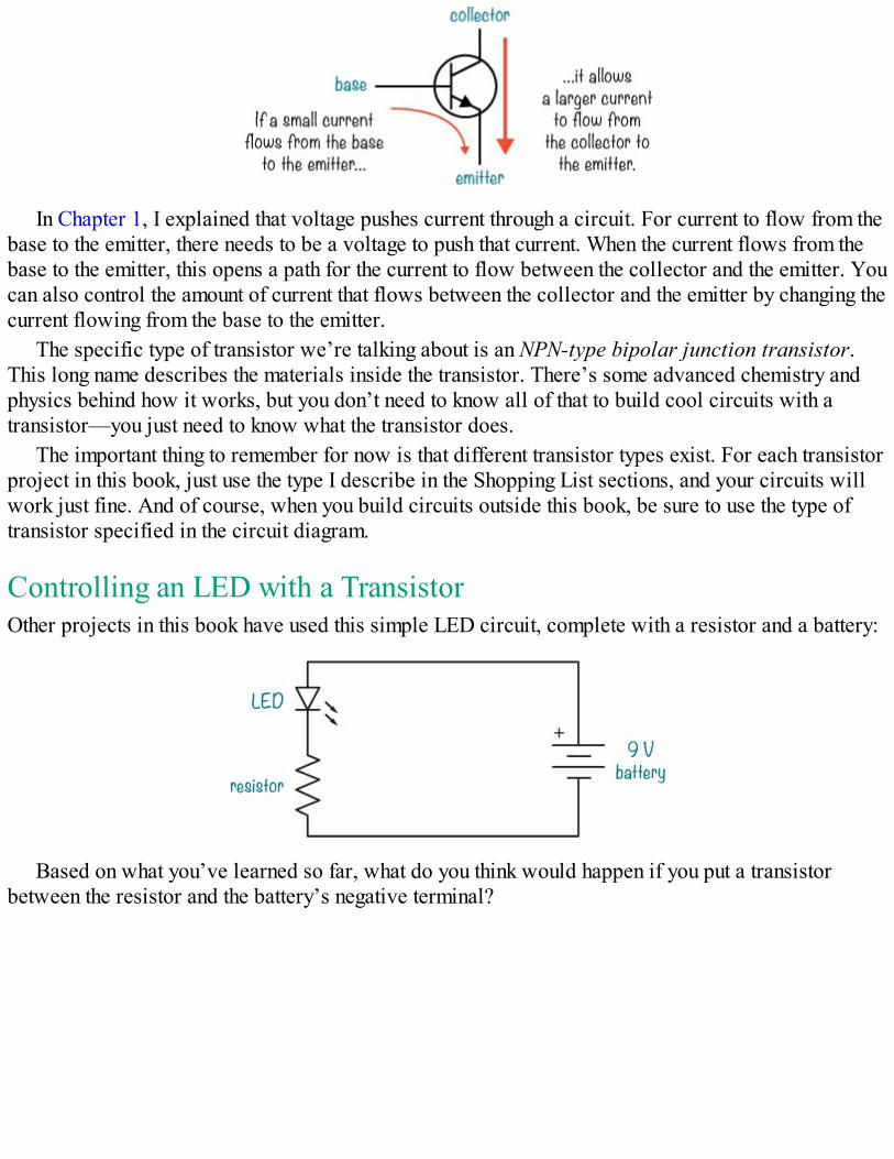
In Chapter 1, I explained that voltage pushes current through a circuit. For current to flow from thebase to the emitter, there needs to be a voltage to push that current. When the current flows from thebase to the emitter, this opens a path for the current to flow between the collector and the emitter. Youcan also control the amount of current that flows between the collector and the emitter by changing thecurrent flowing from the base to the emitter.
The specific type of transistor we’re talking about is an NPN-type bipolar junction transistor.This long name describes the materials inside the transistor. There’s some advanced chemistry andphysics behind how it works, but you don’t need to know all of that to build cool circuits with atransistor—you just need to know what the transistor does.
The important thing to remember for now is that different transistor types exist. For each transistorproject in this book, just use the type I describe in the Shopping List sections, and your circuits willwork just fine. And of course, when you build circuits outside this book, be sure to use the type oftransistor specified in the circuit diagram.
Controlling an LED with a TransistorOther projects in this book have used this simple LED circuit, complete with a resistor and a battery:
Based on what you’ve learned so far, what do you think would happen if you put a transistorbetween the resistor and the battery’s negative terminal?
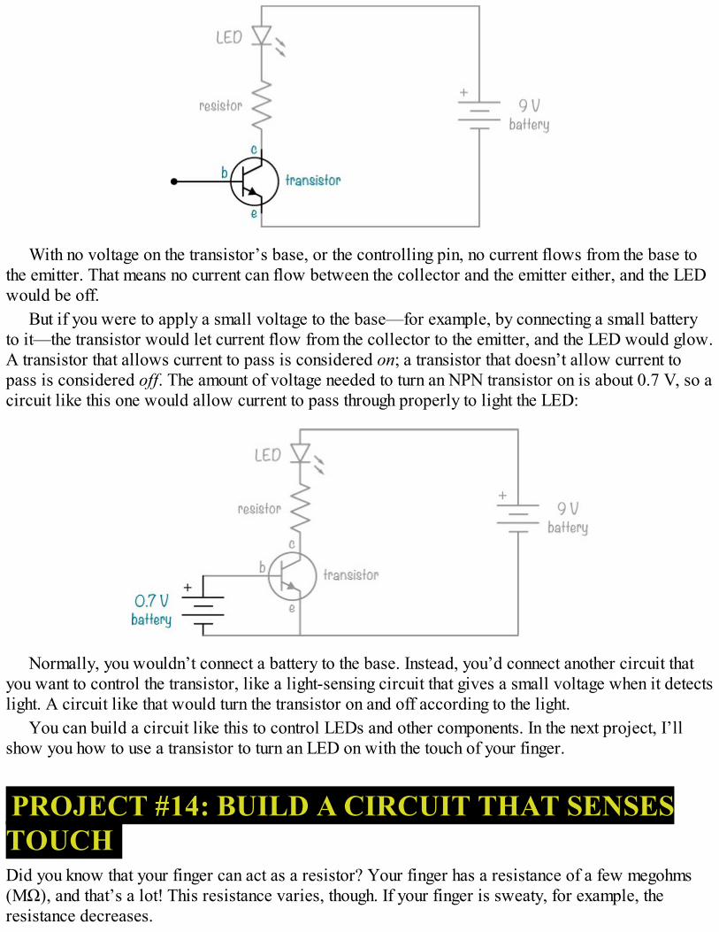
With no voltage on the transistor’s base, or the controlling pin, no current flows from the base tothe emitter. That means no current can flow between the collector and the emitter either, and the LEDwould be off.
But if you were to apply a small voltage to the base—for example, by connecting a small batteryto it—the transistor would let current flow from the collector to the emitter, and the LED would glow.A transistor that allows current to pass is considered on; a transistor that doesn’t allow current topass is considered off. The amount of voltage needed to turn an NPN transistor on is about 0.7 V, so acircuit like this one would allow current to pass through properly to light the LED:
Normally, you wouldn’t connect a battery to the base. Instead, you’d connect another circuit thatyou want to control the transistor, like a light-sensing circuit that gives a small voltage when it detectslight. A circuit like that would turn the transistor on and off according to the light.
You can build a circuit like this to control LEDs and other components. In the next project, I’llshow you how to use a transistor to turn an LED on with the touch of your finger.
PROJECT #14: BUILD A CIRCUIT THAT SENSESTOUCHDid you know that your finger can act as a resistor? Your finger has a resistance of a few megohms(MΩ), and that’s a lot! This resistance varies, though. If your finger is sweaty, for example, theresistance decreases.
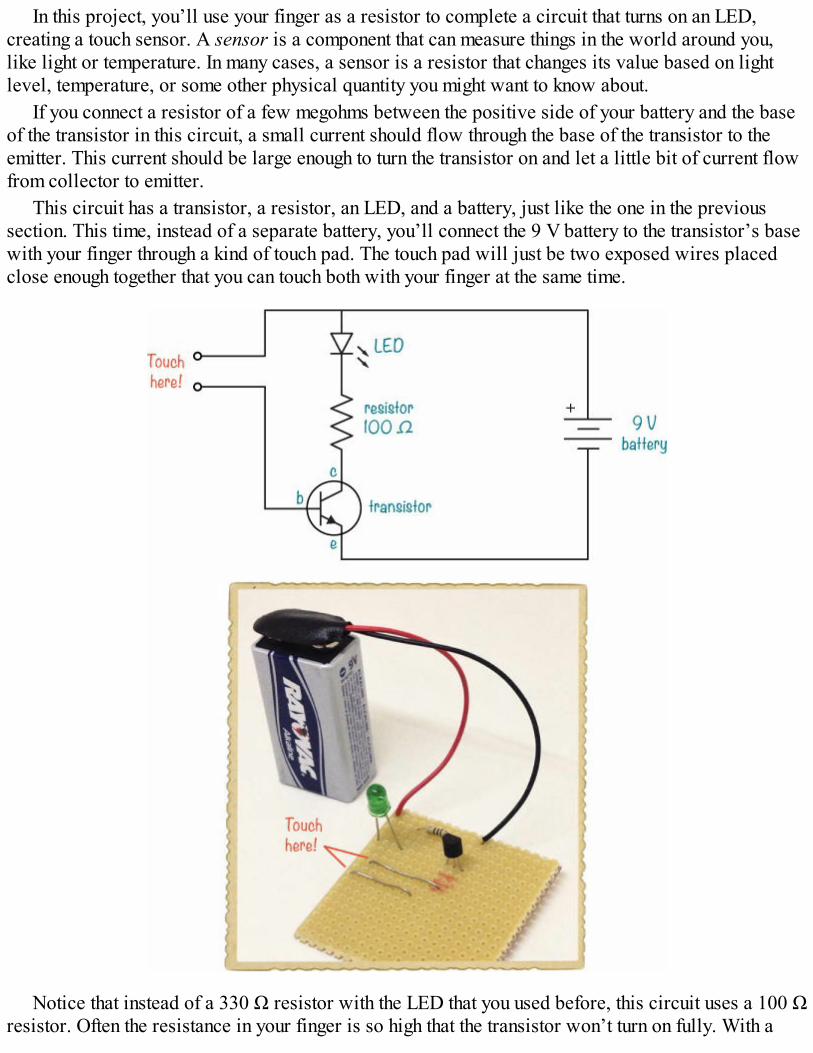
In this project, you’ll use your finger as a resistor to complete a circuit that turns on an LED,creating a touch sensor. A sensor is a component that can measure things in the world around you,like light or temperature. In many cases, a sensor is a resistor that changes its value based on lightlevel, temperature, or some other physical quantity you might want to know about.
If you connect a resistor of a few megohms between the positive side of your battery and the baseof the transistor in this circuit, a small current should flow through the base of the transistor to theemitter. This current should be large enough to turn the transistor on and let a little bit of current flowfrom collector to emitter.
This circuit has a transistor, a resistor, an LED, and a battery, just like the one in the previoussection. This time, instead of a separate battery, you’ll connect the 9 V battery to the transistor’s basewith your finger through a kind of touch pad. The touch pad will just be two exposed wires placedclose enough together that you can touch both with your finger at the same time.
Notice that instead of a 330 Ω resistor with the LED that you used before, this circuit uses a 100 Ωresistor. Often the resistance in your finger is so high that the transistor won’t turn on fully. With a
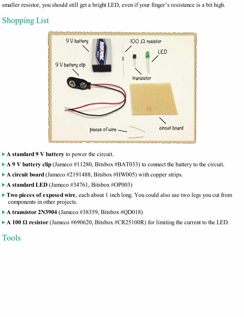
smaller resistor, you should still get a bright LED, even if your finger’s resistance is a bit high.
Shopping List
A standard 9 V battery to power the circuit.
A 9 V battery clip (Jameco #11280, Bitsbox #BAT033) to connect the battery to the circuit.
A circuit board (Jameco #2191488, Bitsbox #HW005) with copper strips.
A standard LED (Jameco #34761, Bitsbox #OP003)
Two pieces of exposed wire, each about 1 inch long. You could also use two legs you cut fromcomponents in other projects.
A transistor 2N3904 (Jameco #38359, Bitsbox #QD018)
A 100 Ω resistor (Jameco #690620, Bitsbox #CR25100R) for limiting the current to the LED.
Tools
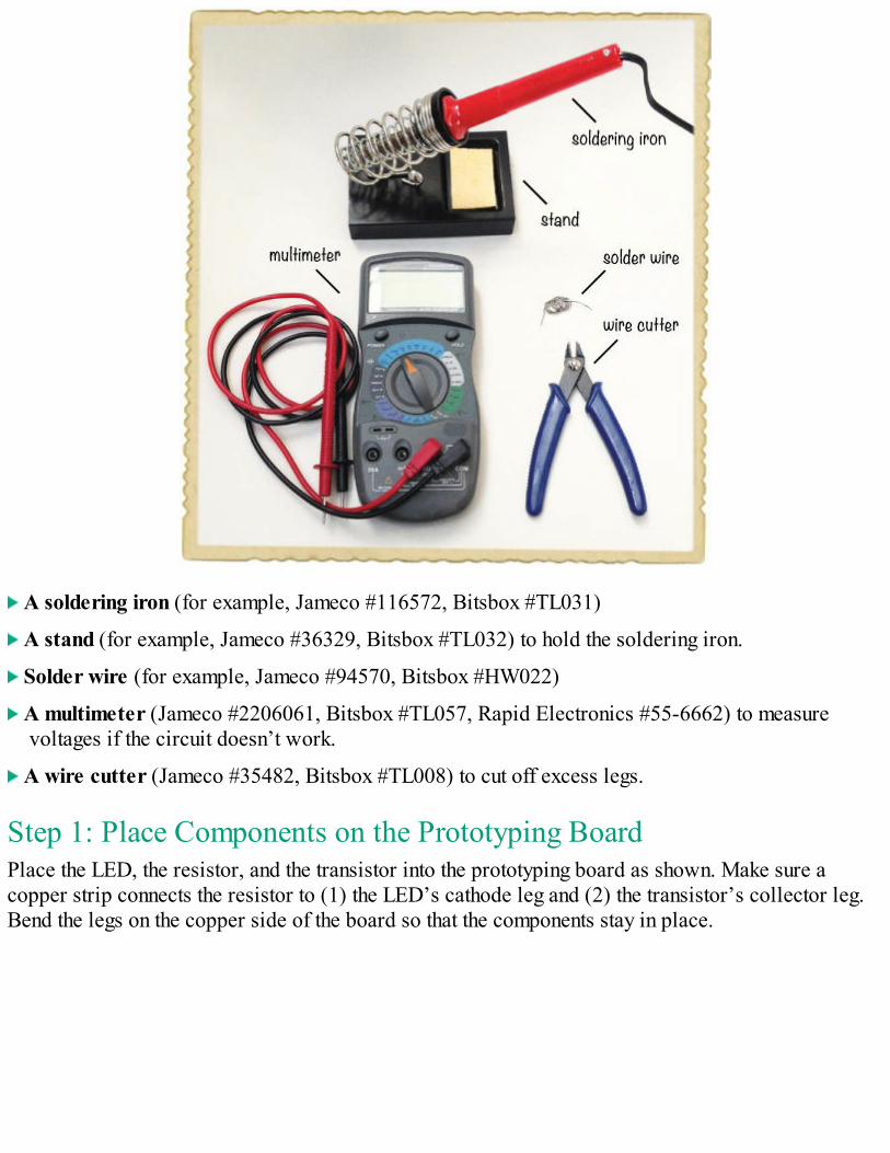
A soldering iron (for example, Jameco #116572, Bitsbox #TL031)
A stand (for example, Jameco #36329, Bitsbox #TL032) to hold the soldering iron.
Solder wire (for example, Jameco #94570, Bitsbox #HW022)
A multimeter (Jameco #2206061, Bitsbox #TL057, Rapid Electronics #55-6662) to measurevoltages if the circuit doesn’t work.
A wire cutter (Jameco #35482, Bitsbox #TL008) to cut off excess legs.
Step 1: Place Components on the Prototyping BoardPlace the LED, the resistor, and the transistor into the prototyping board as shown. Make sure acopper strip connects the resistor to (1) the LED’s cathode leg and (2) the transistor’s collector leg.Bend the legs on the copper side of the board so that the components stay in place.
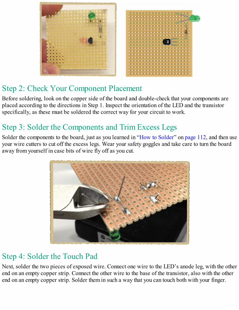
Step 2: Check Your Component PlacementBefore soldering, look on the copper side of the board and double-check that your components areplaced according to the directions in Step 1. Inspect the orientation of the LED and the transistorspecifically, as these must be soldered the correct way for your circuit to work.
Step 3: Solder the Components and Trim Excess LegsSolder the components to the board, just as you learned in “How to Solder” on page 112, and then useyour wire cutters to cut off the excess legs. Wear your safety goggles and take care to turn the boardaway from yourself in case bits of wire fly off as you cut.
Step 4: Solder the Touch PadNext, solder the two pieces of exposed wire. Connect one wire to the LED’s anode leg, with the otherend on an empty copper strip. Connect the other wire to the base of the transistor, also with the otherend on an empty copper strip. Solder them in such a way that you can touch both with your finger.
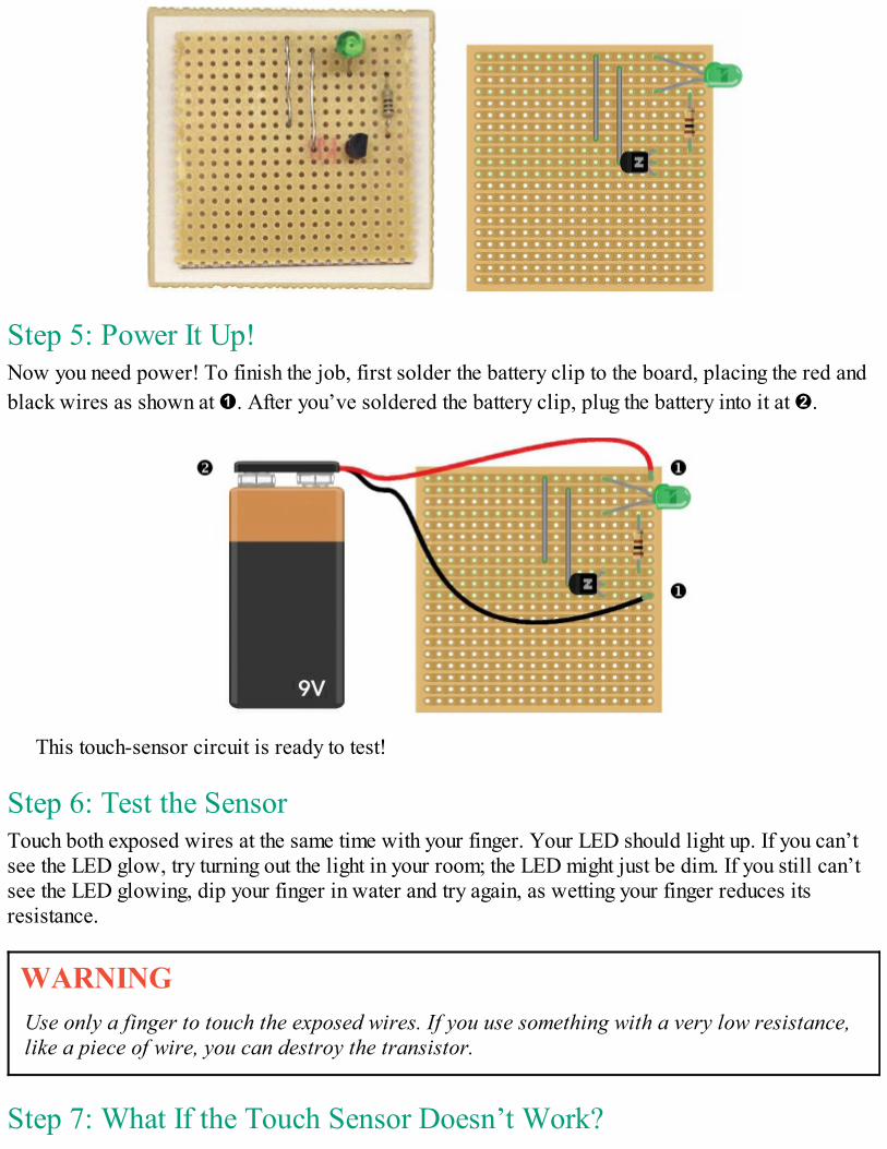
Step 5: Power It Up!Now you need power! To finish the job, first solder the battery clip to the board, placing the red andblack wires as shown at ➊. After you’ve soldered the battery clip, plug the battery into it at ➋.
This touch-sensor circuit is ready to test!
Step 6: Test the SensorTouch both exposed wires at the same time with your finger. Your LED should light up. If you can’tsee the LED glow, try turning out the light in your room; the LED might just be dim. If you still can’tsee the LED glowing, dip your finger in water and try again, as wetting your finger reduces itsresistance.
WARNINGUse only a finger to touch the exposed wires. If you use something with a very low resistance,like a piece of wire, you can destroy the transistor.
Step 7: What If the Touch Sensor Doesn’t Work?
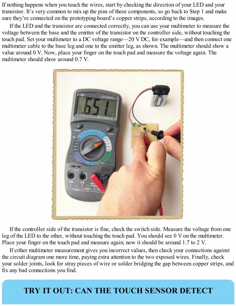
If nothing happens when you touch the wires, start by checking the direction of your LED and yourtransistor. It’s very common to mix up the pins of these components, so go back to Step 1 and makesure they’re connected on the prototyping board’s copper strips, according to the images.
If the LED and the transistor are connected correctly, you can use your multimeter to measure thevoltage between the base and the emitter of the transistor on the controller side, without touching thetouch pad. Set your multimeter to a DC voltage range—20 V DC, for example—and then connect onemultimeter cable to the base leg and one to the emitter leg, as shown. The multimeter should show avalue around 0 V. Now, place your finger on the touch pad and measure the voltage again. Themultimeter should show around 0.7 V.
If the controller side of the transistor is fine, check the switch side. Measure the voltage from oneleg of the LED to the other, without touching the touch pad. You should see 0 V on the multimeter.Place your finger on the touch pad and measure again; now it should be around 1.7 to 2 V.
If either multimeter measurement gives you incorrect values, then check your connections againstthe circuit diagram one more time, paying extra attention to the two exposed wires. Finally, checkyour solder joints, look for stray pieces of wire or solder bridging the gap between copper strips, andfix any bad connections you find.
TRY IT OUT: CAN THE TOUCH SENSOR DETECT
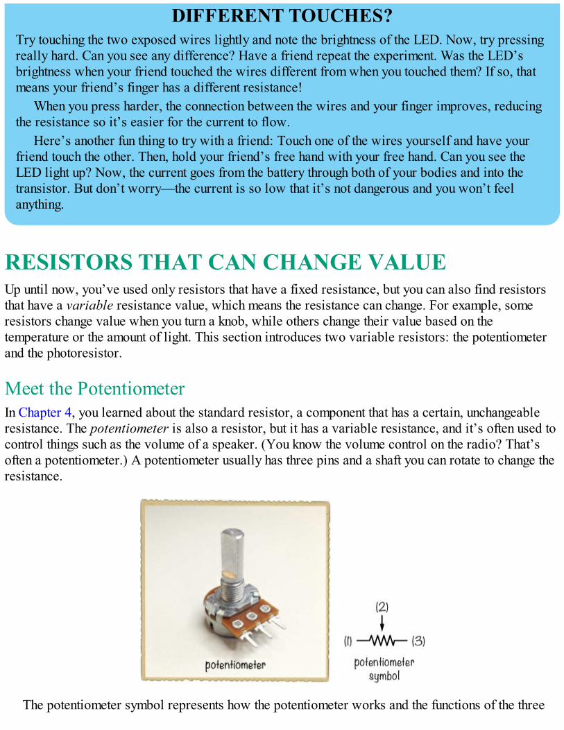
DIFFERENT TOUCHES?Try touching the two exposed wires lightly and note the brightness of the LED. Now, try pressingreally hard. Can you see any difference? Have a friend repeat the experiment. Was the LED’sbrightness when your friend touched the wires different from when you touched them? If so, thatmeans your friend’s finger has a different resistance!
When you press harder, the connection between the wires and your finger improves, reducingthe resistance so it’s easier for the current to flow.
Here’s another fun thing to try with a friend: Touch one of the wires yourself and have yourfriend touch the other. Then, hold your friend’s free hand with your free hand. Can you see theLED light up? Now, the current goes from the battery through both of your bodies and into thetransistor. But don’t worry—the current is so low that it’s not dangerous and you won’t feelanything.
RESISTORS THAT CAN CHANGE VALUEUp until now, you’ve used only resistors that have a fixed resistance, but you can also find resistorsthat have a variable resistance value, which means the resistance can change. For example, someresistors change value when you turn a knob, while others change their value based on thetemperature or the amount of light. This section introduces two variable resistors: the potentiometerand the photoresistor.
Meet the PotentiometerIn Chapter 4, you learned about the standard resistor, a component that has a certain, unchangeableresistance. The potentiometer is also a resistor, but it has a variable resistance, and it’s often used tocontrol things such as the volume of a speaker. (You know the volume control on the radio? That’soften a potentiometer.) A potentiometer usually has three pins and a shaft you can rotate to change theresistance.
The potentiometer symbol represents how the potentiometer works and the functions of the three
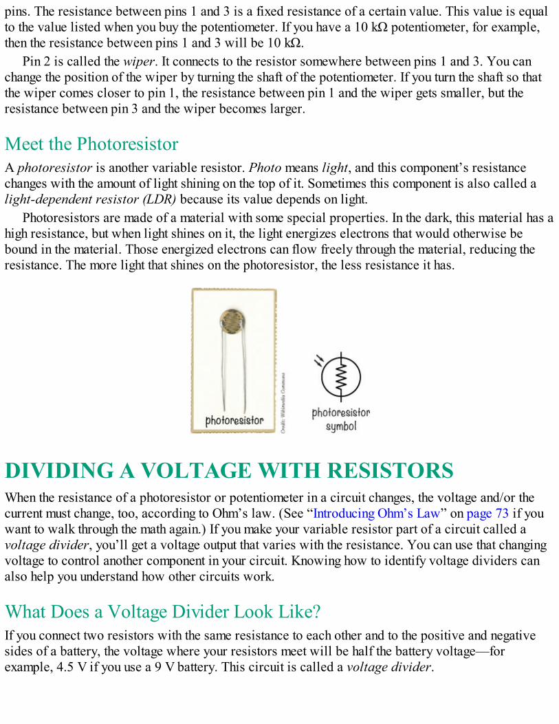
pins. The resistance between pins 1 and 3 is a fixed resistance of a certain value. This value is equalto the value listed when you buy the potentiometer. If you have a 10 kΩ potentiometer, for example,then the resistance between pins 1 and 3 will be 10 kΩ.
Pin 2 is called the wiper. It connects to the resistor somewhere between pins 1 and 3. You canchange the position of the wiper by turning the shaft of the potentiometer. If you turn the shaft so thatthe wiper comes closer to pin 1, the resistance between pin 1 and the wiper gets smaller, but theresistance between pin 3 and the wiper becomes larger.
Meet the PhotoresistorA photoresistor is another variable resistor. Photo means light, and this component’s resistancechanges with the amount of light shining on the top of it. Sometimes this component is also called alight-dependent resistor (LDR) because its value depends on light.
Photoresistors are made of a material with some special properties. In the dark, this material has ahigh resistance, but when light shines on it, the light energizes electrons that would otherwise bebound in the material. Those energized electrons can flow freely through the material, reducing theresistance. The more light that shines on the photoresistor, the less resistance it has.
DIVIDING A VOLTAGE WITH RESISTORSWhen the resistance of a photoresistor or potentiometer in a circuit changes, the voltage and/or thecurrent must change, too, according to Ohm’s law. (See “Introducing Ohm’s Law” on page 73 if youwant to walk through the math again.) If you make your variable resistor part of a circuit called avoltage divider, you’ll get a voltage output that varies with the resistance. You can use that changingvoltage to control another component in your circuit. Knowing how to identify voltage dividers canalso help you understand how other circuits work.
What Does a Voltage Divider Look Like?If you connect two resistors with the same resistance to each other and to the positive and negativesides of a battery, the voltage where your resistors meet will be half the battery voltage—forexample, 4.5 V if you use a 9 V battery. This circuit is called a voltage divider.
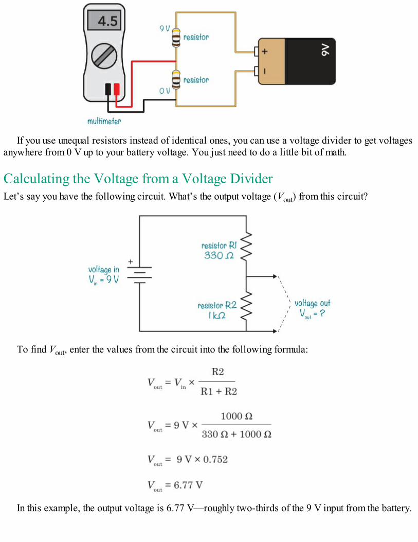
If you use unequal resistors instead of identical ones, you can use a voltage divider to get voltagesanywhere from 0 V up to your battery voltage. You just need to do a little bit of math.
Calculating the Voltage from a Voltage DividerLet’s say you have the following circuit. What’s the output voltage (Vout) from this circuit?
To find Vout, enter the values from the circuit into the following formula:
In this example, the output voltage is 6.77 V—roughly two-thirds of the 9 V input from the battery.
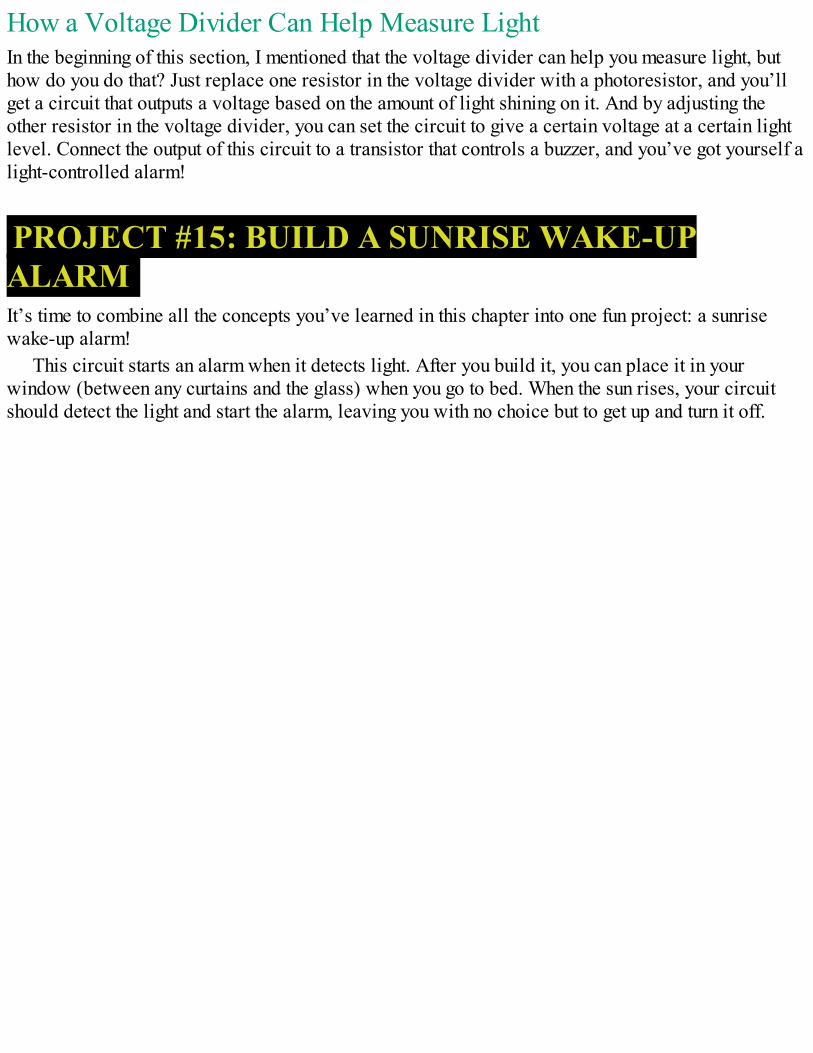
How a Voltage Divider Can Help Measure LightIn the beginning of this section, I mentioned that the voltage divider can help you measure light, buthow do you do that? Just replace one resistor in the voltage divider with a photoresistor, and you’llget a circuit that outputs a voltage based on the amount of light shining on it. And by adjusting theother resistor in the voltage divider, you can set the circuit to give a certain voltage at a certain lightlevel. Connect the output of this circuit to a transistor that controls a buzzer, and you’ve got yourself alight-controlled alarm!
PROJECT #15: BUILD A SUNRISE WAKE-UPALARMIt’s time to combine all the concepts you’ve learned in this chapter into one fun project: a sunrisewake-up alarm!
This circuit starts an alarm when it detects light. After you build it, you can place it in yourwindow (between any curtains and the glass) when you go to bed. When the sun rises, your circuitshould detect the light and start the alarm, leaving you with no choice but to get up and turn it off.
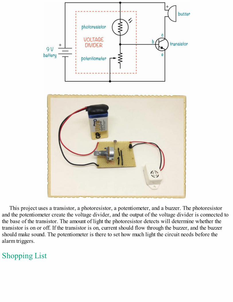
This project uses a transistor, a photoresistor, a potentiometer, and a buzzer. The photoresistorand the potentiometer create the voltage divider, and the output of the voltage divider is connected tothe base of the transistor. The amount of light the photoresistor detects will determine whether thetransistor is on or off. If the transistor is on, current should flow through the buzzer, and the buzzershould make sound. The potentiometer is there to set how much light the circuit needs before thealarm triggers.
Shopping List
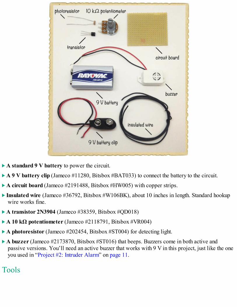
A standard 9 V battery to power the circuit.
A 9 V battery clip (Jameco #11280, Bitsbox #BAT033) to connect the battery to the circuit.
A circuit board (Jameco #2191488, Bitsbox #HW005) with copper strips.
Insulated wire (Jameco #36792, Bitsbox #W106BK), about 10 inches in length. Standard hookupwire works fine.
A transistor 2N3904 (Jameco #38359, Bitsbox #QD018)
A 10 kΩ potentiometer (Jameco #2118791, Bitsbox #VR004)
A photoresistor (Jameco #202454, Bitsbox #ST004) for detecting light.
A buzzer (Jameco #2173870, Bitsbox #ST016) that beeps. Buzzers come in both active andpassive versions. You’ll need an active buzzer that works with 9 V in this project, just like the oneyou used in “Project #2: Intruder Alarm” on page 11.
Tools
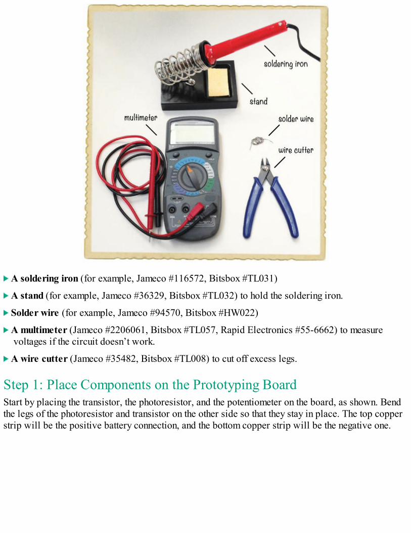
A soldering iron (for example, Jameco #116572, Bitsbox #TL031)
A stand (for example, Jameco #36329, Bitsbox #TL032) to hold the soldering iron.
Solder wire (for example, Jameco #94570, Bitsbox #HW022)
A multimeter (Jameco #2206061, Bitsbox #TL057, Rapid Electronics #55-6662) to measurevoltages if the circuit doesn’t work.
A wire cutter (Jameco #35482, Bitsbox #TL008) to cut off excess legs.
Step 1: Place Components on the Prototyping BoardStart by placing the transistor, the photoresistor, and the potentiometer on the board, as shown. Bendthe legs of the photoresistor and transistor on the other side so that they stay in place. The top copperstrip will be the positive battery connection, and the bottom copper strip will be the negative one.
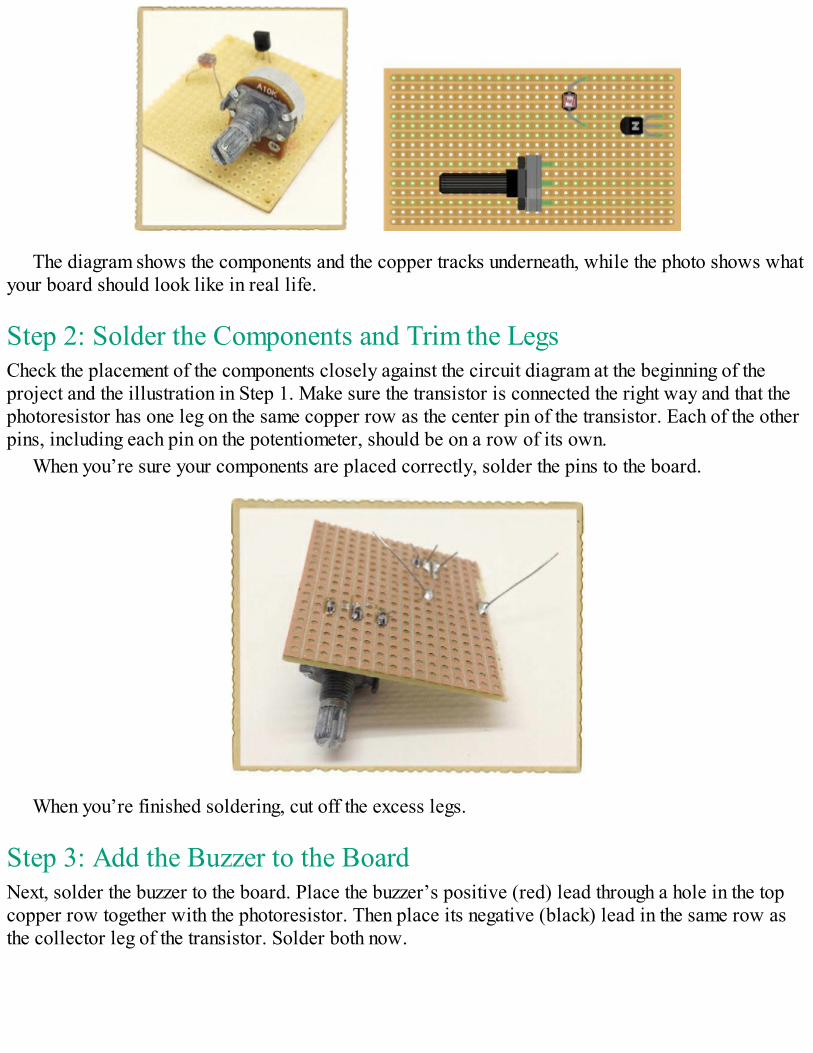
The diagram shows the components and the copper tracks underneath, while the photo shows whatyour board should look like in real life.
Step 2: Solder the Components and Trim the LegsCheck the placement of the components closely against the circuit diagram at the beginning of theproject and the illustration in Step 1. Make sure the transistor is connected the right way and that thephotoresistor has one leg on the same copper row as the center pin of the transistor. Each of the otherpins, including each pin on the potentiometer, should be on a row of its own.
When you’re sure your components are placed correctly, solder the pins to the board.
When you’re finished soldering, cut off the excess legs.
Step 3: Add the Buzzer to the BoardNext, solder the buzzer to the board. Place the buzzer’s positive (red) lead through a hole in the topcopper row together with the photoresistor. Then place its negative (black) lead in the same row asthe collector leg of the transistor. Solder both now.
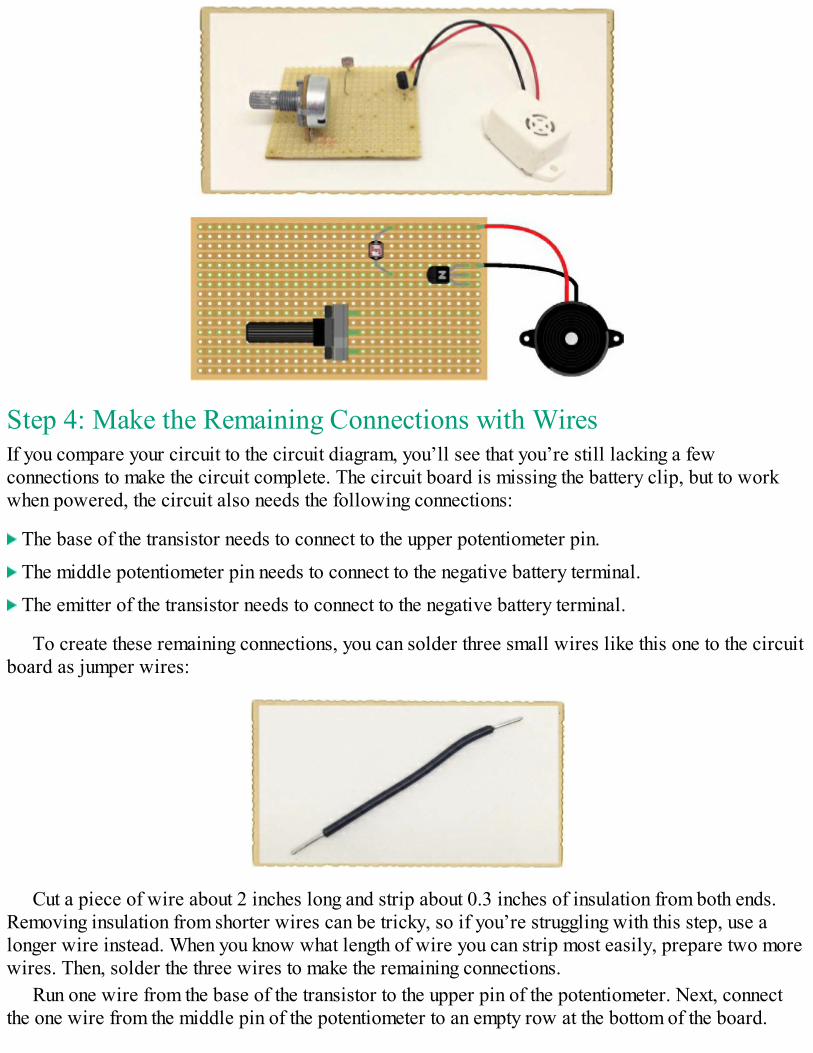
Step 4: Make the Remaining Connections with WiresIf you compare your circuit to the circuit diagram, you’ll see that you’re still lacking a fewconnections to make the circuit complete. The circuit board is missing the battery clip, but to workwhen powered, the circuit also needs the following connections:
The base of the transistor needs to connect to the upper potentiometer pin.
The middle potentiometer pin needs to connect to the negative battery terminal.
The emitter of the transistor needs to connect to the negative battery terminal.
To create these remaining connections, you can solder three small wires like this one to the circuitboard as jumper wires:
Cut a piece of wire about 2 inches long and strip about 0.3 inches of insulation from both ends.Removing insulation from shorter wires can be tricky, so if you’re struggling with this step, use alonger wire instead. When you know what length of wire you can strip most easily, prepare two morewires. Then, solder the three wires to make the remaining connections.
Run one wire from the base of the transistor to the upper pin of the potentiometer. Next, connectthe one wire from the middle pin of the potentiometer to an empty row at the bottom of the board.
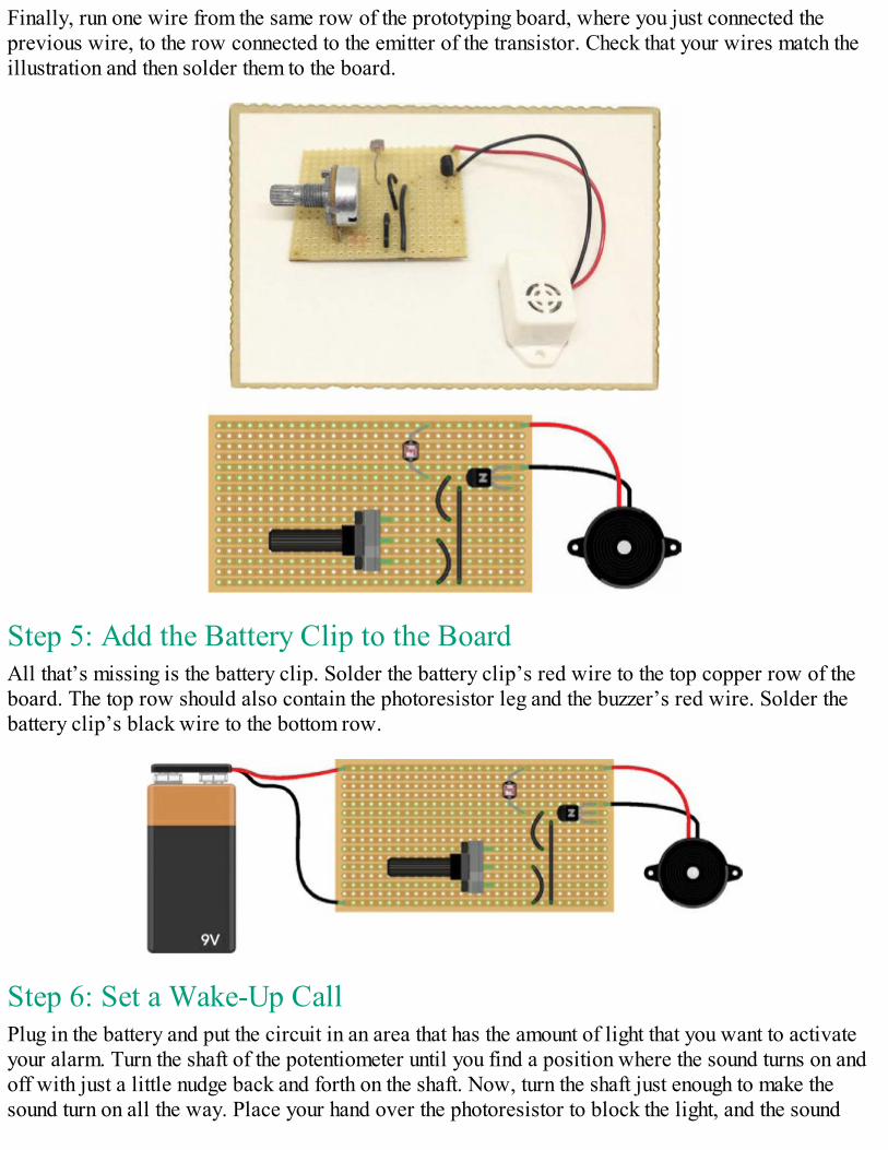
Finally, run one wire from the same row of the prototyping board, where you just connected theprevious wire, to the row connected to the emitter of the transistor. Check that your wires match theillustration and then solder them to the board.
Step 5: Add the Battery Clip to the BoardAll that’s missing is the battery clip. Solder the battery clip’s red wire to the top copper row of theboard. The top row should also contain the photoresistor leg and the buzzer’s red wire. Solder thebattery clip’s black wire to the bottom row.
Step 6: Set a Wake-Up CallPlug in the battery and put the circuit in an area that has the amount of light that you want to activateyour alarm. Turn the shaft of the potentiometer until you find a position where the sound turns on andoff with just a little nudge back and forth on the shaft. Now, turn the shaft just enough to make thesound turn on all the way. Place your hand over the photoresistor to block the light, and the sound

should stop. Remove your hand, and the sound should turn on again.Remove the battery from the circuit and wait until you’re about to go to bed. With the lights off,
place the circuit in your window, connect the battery, and go to sleep. When the sun rises and the lightoutside is as bright as the light you used to set your potentiometer, you’ll be awakened by your veryown sunrise alarm!
Step 7: What If There’s No Sound?Go through the circuit component by component, preferably with a friend. Check that your prototypingboard has every connection shown in the circuit diagram. Check that there are no short circuits, too.A short circuit is an unintentional connection between something in a circuit. For example, make suresolder joints that are close to each other aren’t actually touching.
If all looks good, use your multimeter to measure the voltage between the base and the emitter ofthe transistor. First, turn the shaft of your potentiometer all the way to one side, measure the voltage,and write it down. Then, turn the potentiometer all the way to the other side and measure the voltageagain. Your multimeter should show 0 V on one side and around 0.7 V on the other side. If it doesn’t,check your connections again.
If you’re still not sure what’s wrong, turn the potentiometer all the way to one side and measurethe voltage between the red and black buzzer wires. Then, turn the potentiometer all the way to theother side and measure again. You should get 0 V on one side and about 8 to 9 V on the other.
If all else fails, check your solder joints and redo any that look like the connections might not becomplete. And if you’ve built your circuit flawlessly, you may just have some broken components.Try breadboarding the project with new components, and if that works, solder those componentsinstead.
TRY IT OUT: TEMPERATURE-CONTROLLED FANYou can use the circuit you built in Project #15 for other things as well. For example, if youexchange the photoresistor for a thermistor, a resistor that changes resistance value based ontemperature, the circuit will respond to temperature instead of light.
You can also change what’s being controlled. Instead of an LED and resistor, try putting in afan. Now you have a temperature-controlled fan! The circuit diagram looks like this:
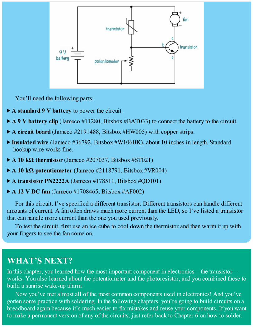
You’ll need the following parts:
A standard 9 V battery to power the circuit.
A 9 V battery clip (Jameco #11280, Bitsbox #BAT033) to connect the battery to the circuit.
A circuit board (Jameco #2191488, Bitsbox #HW005) with copper strips.
Insulated wire (Jameco #36792, Bitsbox #W106BK), about 10 inches in length. Standardhookup wire works fine.
A 10 kΩ thermistor (Jameco #207037, Bitsbox #ST021)
A 10 kΩ potentiometer (Jameco #2118791, Bitsbox #VR004)
A transistor PN2222A (Jameco #178511, Bitsbox #QD101)
A 12 V DC fan (Jameco #1708465, Bitsbox #AF002)
For this circuit, I’ve specified a different transistor. Different transistors can handle differentamounts of current. A fan often draws much more current than the LED, so I’ve listed a transistorthat can handle more current than the one you used previously.
To test the circuit, first use an ice cube to cool down the thermistor and then warm it up withyour fingers to see the fan come on.
WHAT’S NEXT?In this chapter, you learned how the most important component in electronics—the transistor—works. You also learned about the potentiometer and the photoresistor, and you combined these tobuild a sunrise wake-up alarm.
Now you’ve met almost all of the most common components used in electronics! And you’vegotten some practice with soldering. In the following chapters, you’re going to build circuits on abreadboard again because it’s much easier to fix mistakes and reuse your components. If you wantto make a permanent version of any of the circuits, just refer back to Chapter 6 on how to solder.

In Chapter 8, you’ll learn about integrated circuits. These are small components that containcircuits that have been shrunk down to fit on a tiny chip. These chips can be used to create themost amazing types of circuits. You’ll see what I mean when you build your very own electronicinstrument in Chapter 8!

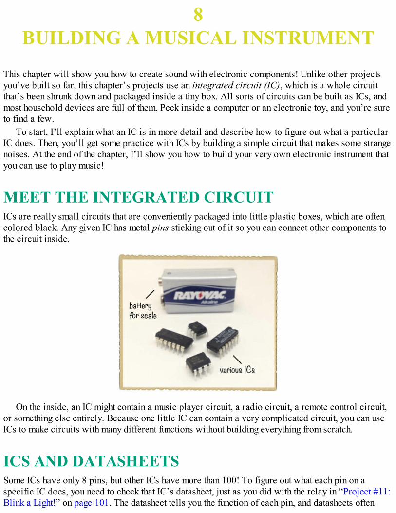
8BUILDING A MUSICAL INSTRUMENT
This chapter will show you how to create sound with electronic components! Unlike other projectsyou’ve built so far, this chapter’s projects use an integrated circuit (IC), which is a whole circuitthat’s been shrunk down and packaged inside a tiny box. All sorts of circuits can be built as ICs, andmost household devices are full of them. Peek inside a computer or an electronic toy, and you’re sureto find a few.
To start, I’ll explain what an IC is in more detail and describe how to figure out what a particularIC does. Then, you’ll get some practice with ICs by building a simple circuit that makes some strangenoises. At the end of the chapter, I’ll show you how to build your very own electronic instrument thatyou can use to play music!
MEET THE INTEGRATED CIRCUITICs are really small circuits that are conveniently packaged into little plastic boxes, which are oftencolored black. Any given IC has metal pins sticking out of it so you can connect other components tothe circuit inside.
On the inside, an IC might contain a music player circuit, a radio circuit, a remote control circuit,or something else entirely. Because one little IC can contain a very complicated circuit, you can useICs to make circuits with many different functions without building everything from scratch.
ICS AND DATASHEETSSome ICs have only 8 pins, but other ICs have more than 100! To figure out what each pin on aspecific IC does, you need to check that IC’s datasheet, just as you did with the relay in “Project #11:Blink a Light!” on page 101. The datasheet tells you the function of each pin, and datasheets often
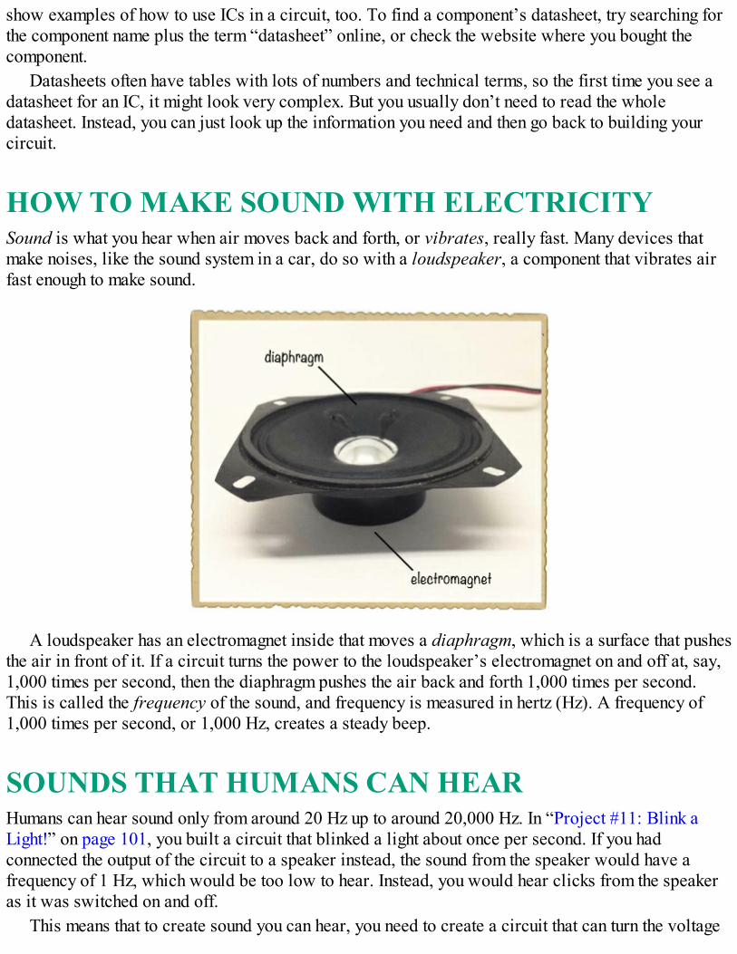
show examples of how to use ICs in a circuit, too. To find a component’s datasheet, try searching forthe component name plus the term “datasheet” online, or check the website where you bought thecomponent.
Datasheets often have tables with lots of numbers and technical terms, so the first time you see adatasheet for an IC, it might look very complex. But you usually don’t need to read the wholedatasheet. Instead, you can just look up the information you need and then go back to building yourcircuit.
HOW TO MAKE SOUND WITH ELECTRICITYSound is what you hear when air moves back and forth, or vibrates, really fast. Many devices thatmake noises, like the sound system in a car, do so with a loudspeaker, a component that vibrates airfast enough to make sound.
A loudspeaker has an electromagnet inside that moves a diaphragm, which is a surface that pushesthe air in front of it. If a circuit turns the power to the loudspeaker’s electromagnet on and off at, say,1,000 times per second, then the diaphragm pushes the air back and forth 1,000 times per second.This is called the frequency of the sound, and frequency is measured in hertz (Hz). A frequency of1,000 times per second, or 1,000 Hz, creates a steady beep.
SOUNDS THAT HUMANS CAN HEARHumans can hear sound only from around 20 Hz up to around 20,000 Hz. In “Project #11: Blink aLight!” on page 101, you built a circuit that blinked a light about once per second. If you hadconnected the output of the circuit to a speaker instead, the sound from the speaker would have afrequency of 1 Hz, which would be too low to hear. Instead, you would hear clicks from the speakeras it was switched on and off.
This means that to create sound you can hear, you need to create a circuit that can turn the voltage
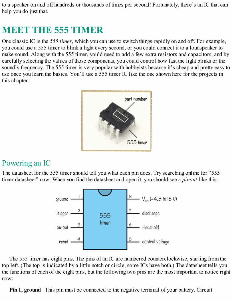
to a speaker on and off hundreds or thousands of times per second! Fortunately, there’s an IC that canhelp you do just that.
MEET THE 555 TIMEROne classic IC is the 555 timer, which you can use to switch things rapidly on and off. For example,you could use a 555 timer to blink a light every second, or you could connect it to a loudspeaker tomake sound. Along with the 555 timer, you’d need to add a few extra resistors and capacitors, and bycarefully selecting the values of those components, you could control how fast the light blinks or thesound’s frequency. The 555 timer is very popular with hobbyists because it’s cheap and pretty easy touse once you learn the basics. You’ll use a 555 timer IC like the one shown here for the projects inthis chapter.
Powering an ICThe datasheet for the 555 timer should tell you what each pin does. Try searching online for “555timer datasheet” now. When you find the datasheet and open it, you should see a pinout like this:
The 555 timer has eight pins. The pins of an IC are numbered counterclockwise, starting from thetop left. (The top is indicated by a little notch or circle; some ICs have both.) The datasheet tells youthe functions of each of the eight pins, but the following two pins are the most important to notice rightnow:
Pin 1, ground This pin must be connected to the negative terminal of your battery. Circuit
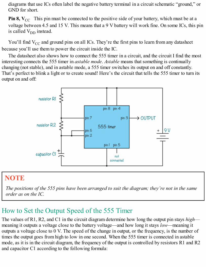
diagrams that use ICs often label the negative battery terminal in a circuit schematic “ground,” orGND for short.
Pin 8, VCC This pin must be connected to the positive side of your battery, which must be at avoltage between 4.5 and 15 V. This means that a 9 V battery will work fine. On some ICs, this pinis called VDD instead.
You’ll find VCC and ground pins on all ICs. They’re the first pins to learn from any datasheetbecause you’ll use them to power the circuit inside the IC.
The datasheet also shows how to connect the 555 timer in a circuit, and the circuit I find the mostinteresting connects the 555 timer in astable mode. Astable means that something is continuallychanging (not stable), and in astable mode, a 555 timer switches its output on and off constantly.That’s perfect to blink a light or to create sound! Here’s the circuit that tells the 555 timer to turn itsoutput on and off:
NOTEThe positions of the 555 pins have been arranged to suit the diagram; they’re not in the sameorder as on the IC.
How to Set the Output Speed of the 555 TimerThe values of R1, R2, and C1 in the circuit diagram determine how long the output pin stays high—meaning it outputs a voltage close to the battery voltage—and how long it stays low—meaning itoutputs a voltage close to 0 V. The speed of the change in output, or the frequency, is the number oftimes the output goes from high to low in one second. When the 555 timer is connected in astablemode, as it is in the circuit diagram, the frequency of the output is controlled by resistors R1 and R2and capacitor C1 according to the following formula:
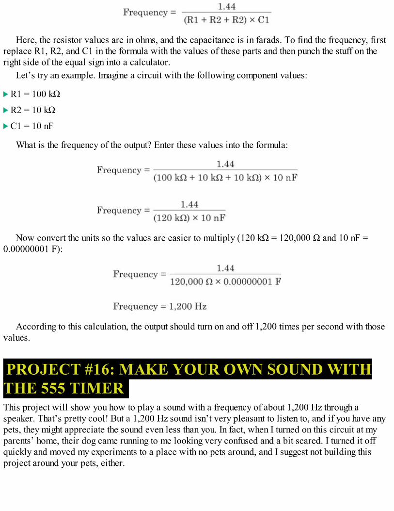
Here, the resistor values are in ohms, and the capacitance is in farads. To find the frequency, firstreplace R1, R2, and C1 in the formula with the values of these parts and then punch the stuff on theright side of the equal sign into a calculator.
Let’s try an example. Imagine a circuit with the following component values:
R1 = 100 kΩ
R2 = 10 kΩ
C1 = 10 nF
What is the frequency of the output? Enter these values into the formula:
Now convert the units so the values are easier to multiply (120 kΩ = 120,000 Ω and 10 nF =0.00000001 F):
According to this calculation, the output should turn on and off 1,200 times per second with thosevalues.
PROJECT #16: MAKE YOUR OWN SOUND WITHTHE 555 TIMERThis project will show you how to play a sound with a frequency of about 1,200 Hz through aspeaker. That’s pretty cool! But a 1,200 Hz sound isn’t very pleasant to listen to, and if you have anypets, they might appreciate the sound even less than you. In fact, when I turned on this circuit at myparents’ home, their dog came running to me looking very confused and a bit scared. I turned it offquickly and moved my experiments to a place with no pets around, and I suggest not building thisproject around your pets, either.
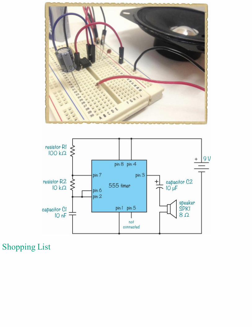
Shopping List
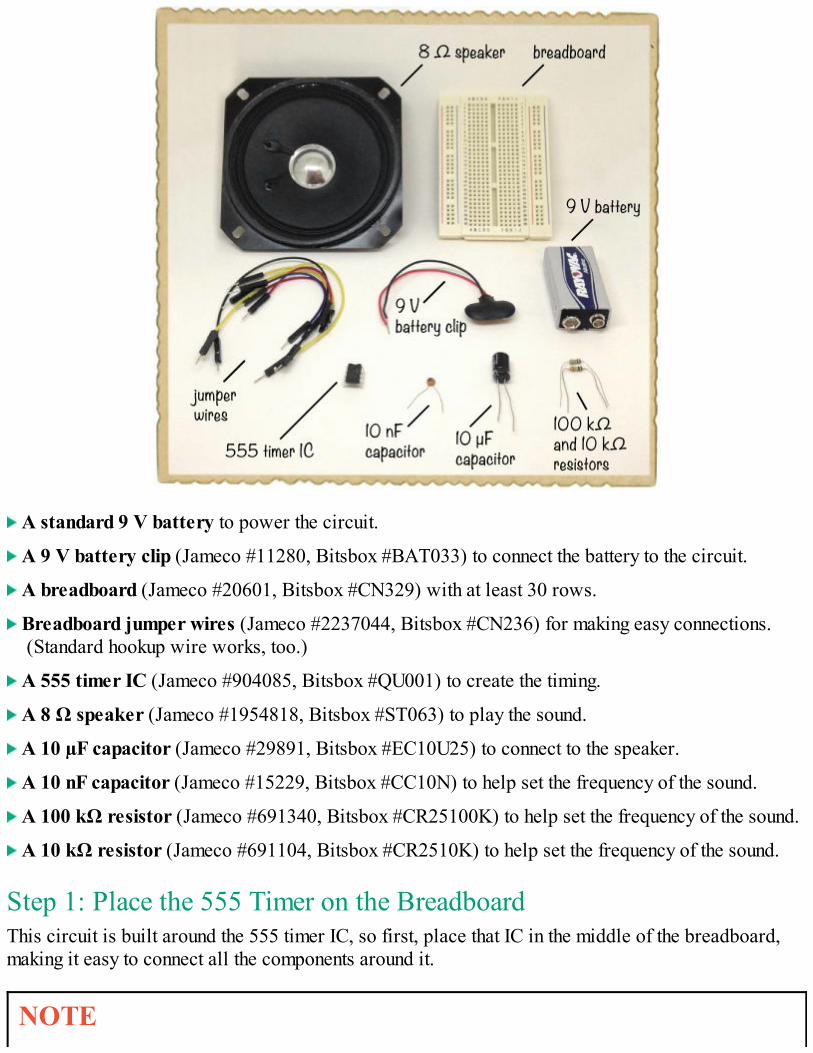
A standard 9 V battery to power the circuit.
A 9 V battery clip (Jameco #11280, Bitsbox #BAT033) to connect the battery to the circuit.
A breadboard (Jameco #20601, Bitsbox #CN329) with at least 30 rows.
Breadboard jumper wires (Jameco #2237044, Bitsbox #CN236) for making easy connections.(Standard hookup wire works, too.)
A 555 timer IC (Jameco #904085, Bitsbox #QU001) to create the timing.
A 8 Ω speaker (Jameco #1954818, Bitsbox #ST063) to play the sound.
A 10 µF capacitor (Jameco #29891, Bitsbox #EC10U25) to connect to the speaker.
A 10 nF capacitor (Jameco #15229, Bitsbox #CC10N) to help set the frequency of the sound.
A 100 kΩ resistor (Jameco #691340, Bitsbox #CR25100K) to help set the frequency of the sound.
A 10 kΩ resistor (Jameco #691104, Bitsbox #CR2510K) to help set the frequency of the sound.
Step 1: Place the 555 Timer on the BreadboardThis circuit is built around the 555 timer IC, so first, place that IC in the middle of the breadboard,making it easy to connect all the components around it.
NOTE
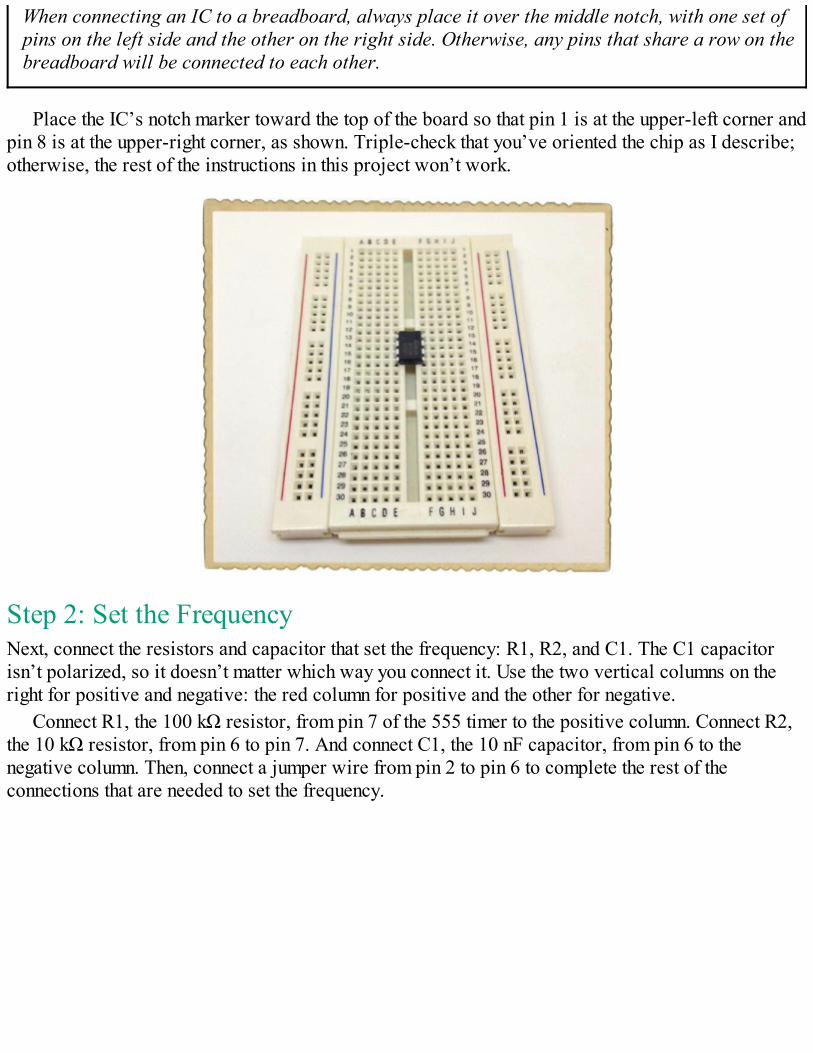
When connecting an IC to a breadboard, always place it over the middle notch, with one set ofpins on the left side and the other on the right side. Otherwise, any pins that share a row on thebreadboard will be connected to each other.
Place the IC’s notch marker toward the top of the board so that pin 1 is at the upper-left corner andpin 8 is at the upper-right corner, as shown. Triple-check that you’ve oriented the chip as I describe;otherwise, the rest of the instructions in this project won’t work.
Step 2: Set the FrequencyNext, connect the resistors and capacitor that set the frequency: R1, R2, and C1. The C1 capacitorisn’t polarized, so it doesn’t matter which way you connect it. Use the two vertical columns on theright for positive and negative: the red column for positive and the other for negative.
Connect R1, the 100 kΩ resistor, from pin 7 of the 555 timer to the positive column. Connect R2,the 10 kΩ resistor, from pin 6 to pin 7. And connect C1, the 10 nF capacitor, from pin 6 to thenegative column. Then, connect a jumper wire from pin 2 to pin 6 to complete the rest of theconnections that are needed to set the frequency.
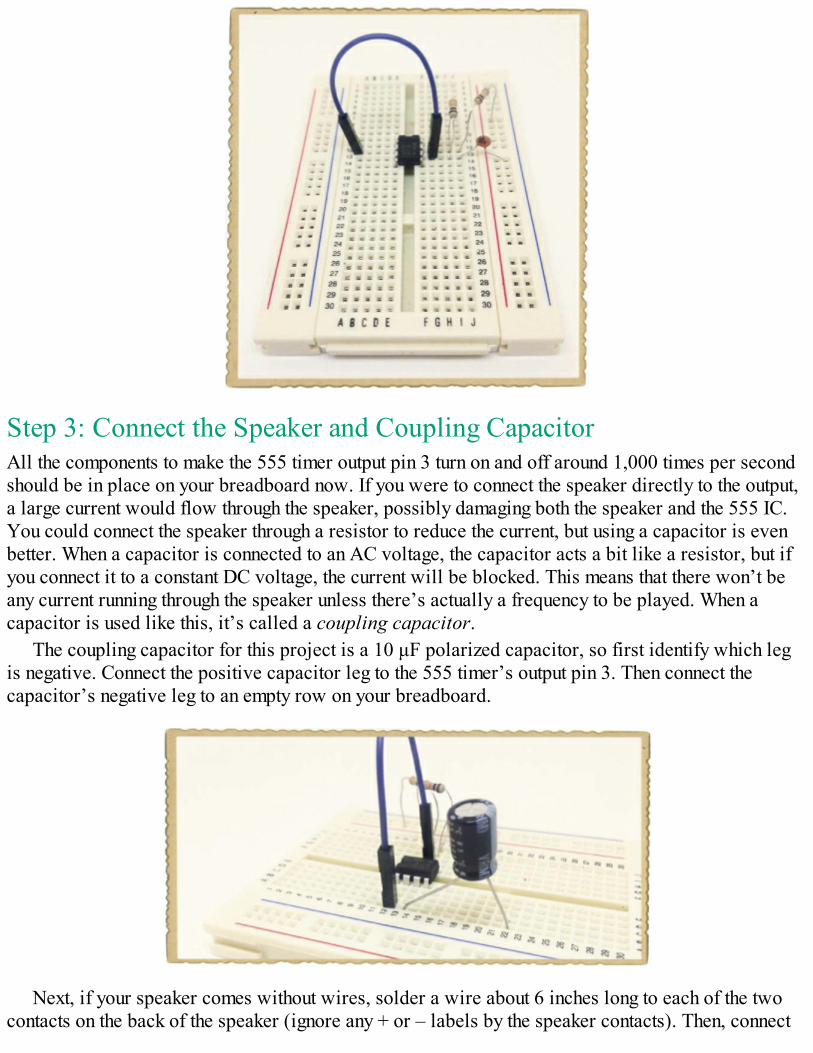
Step 3: Connect the Speaker and Coupling CapacitorAll the components to make the 555 timer output pin 3 turn on and off around 1,000 times per secondshould be in place on your breadboard now. If you were to connect the speaker directly to the output,a large current would flow through the speaker, possibly damaging both the speaker and the 555 IC.You could connect the speaker through a resistor to reduce the current, but using a capacitor is evenbetter. When a capacitor is connected to an AC voltage, the capacitor acts a bit like a resistor, but ifyou connect it to a constant DC voltage, the current will be blocked. This means that there won’t beany current running through the speaker unless there’s actually a frequency to be played. When acapacitor is used like this, it’s called a coupling capacitor.
The coupling capacitor for this project is a 10 μF polarized capacitor, so first identify which legis negative. Connect the positive capacitor leg to the 555 timer’s output pin 3. Then connect thecapacitor’s negative leg to an empty row on your breadboard.
Next, if your speaker comes without wires, solder a wire about 6 inches long to each of the twocontacts on the back of the speaker (ignore any + or – labels by the speaker contacts). Then, connect
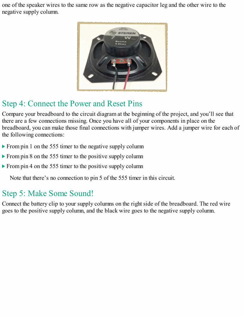
one of the speaker wires to the same row as the negative capacitor leg and the other wire to thenegative supply column.
Step 4: Connect the Power and Reset PinsCompare your breadboard to the circuit diagram at the beginning of the project, and you’ll see thatthere are a few connections missing. Once you have all of your components in place on thebreadboard, you can make those final connections with jumper wires. Add a jumper wire for each ofthe following connections:
From pin 1 on the 555 timer to the negative supply column
From pin 8 on the 555 timer to the positive supply column
From pin 4 on the 555 timer to the positive supply column
Note that there’s no connection to pin 5 of the 555 timer in this circuit.
Step 5: Make Some Sound!Connect the battery clip to your supply columns on the right side of the breadboard. The red wiregoes to the positive supply column, and the black wire goes to the negative supply column.
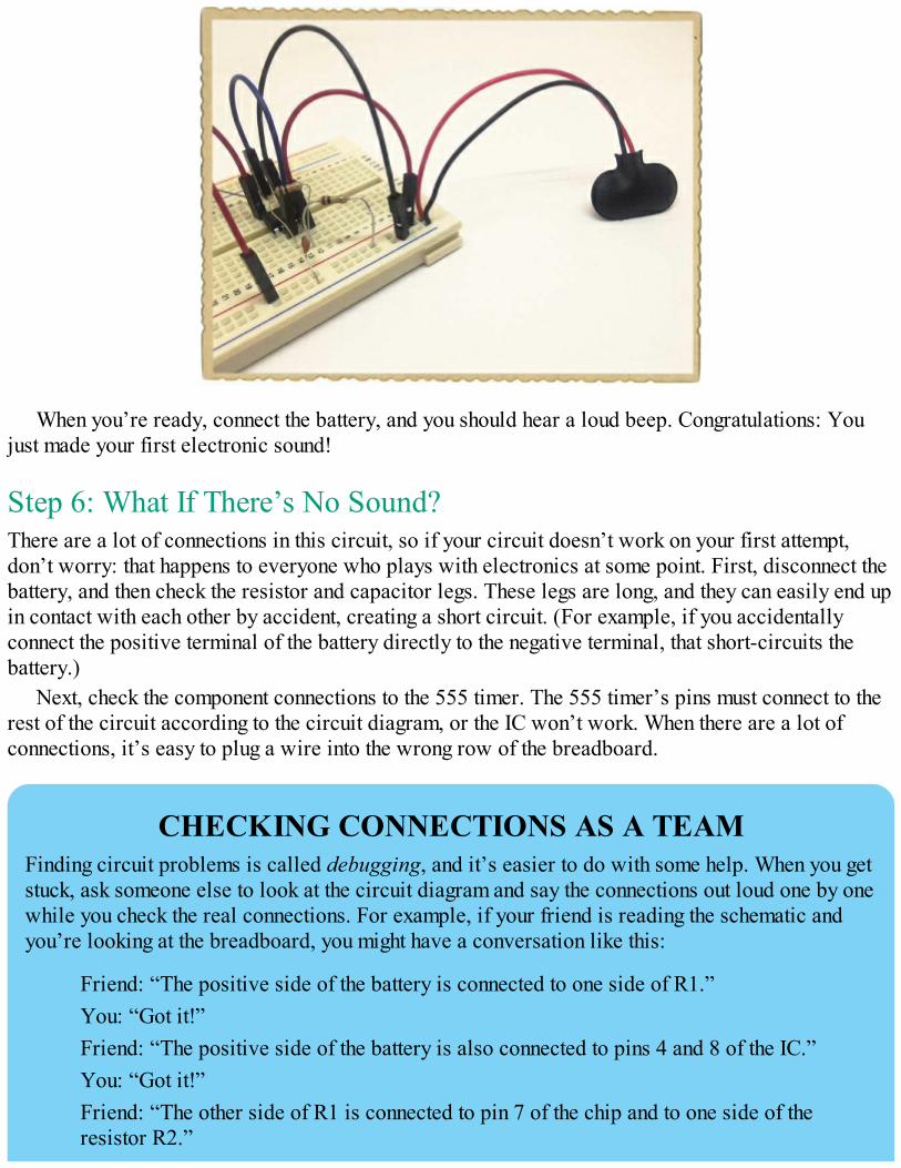
When you’re ready, connect the battery, and you should hear a loud beep. Congratulations: Youjust made your first electronic sound!
Step 6: What If There’s No Sound?There are a lot of connections in this circuit, so if your circuit doesn’t work on your first attempt,don’t worry: that happens to everyone who plays with electronics at some point. First, disconnect thebattery, and then check the resistor and capacitor legs. These legs are long, and they can easily end upin contact with each other by accident, creating a short circuit. (For example, if you accidentallyconnect the positive terminal of the battery directly to the negative terminal, that short-circuits thebattery.)
Next, check the component connections to the 555 timer. The 555 timer’s pins must connect to therest of the circuit according to the circuit diagram, or the IC won’t work. When there are a lot ofconnections, it’s easy to plug a wire into the wrong row of the breadboard.
CHECKING CONNECTIONS AS A TEAMFinding circuit problems is called debugging, and it’s easier to do with some help. When you getstuck, ask someone else to look at the circuit diagram and say the connections out loud one by onewhile you check the real connections. For example, if your friend is reading the schematic andyou’re looking at the breadboard, you might have a conversation like this:
Friend: “The positive side of the battery is connected to one side of R1.”You: “Got it!”Friend: “The positive side of the battery is also connected to pins 4 and 8 of the IC.”You: “Got it!”Friend: “The other side of R1 is connected to pin 7 of the chip and to one side of theresistor R2.”

You: “Oh, wait! I don’t have the connection to pin 7!”
And just like that, you’ll discover the problem.
If all your components appear to be oriented correctly and you see no short circuits, then check allyour breadboard connections to make sure components that should be connected share a row. Startwith the connection from the positive terminal of the battery on your circuit diagram. Is it connectedon the board just as the circuit diagram shows? If yes, then move on to the next connection; keep goinglike this until you’ve checked all the connections.
TURNING AN ANNOYING BEEP INTO MUSICThe sound you created in the previous project isn’t very pleasant. So how can you turn it into music?Musical notes are just sound waves that vibrate at specific frequencies, and that means it’s possibleto make an electronic instrument with the 555 timer. If you change the frequency of the signal that goesinto the speaker, then the tone of the sound will change. You just have to find a way to change the 555timer’s output frequency at will, without rebuilding the circuit every time.
Chapter 7 introduced two components that can change their resistance value: the potentiometer andthe photoresistor. If you use one of those components to control the frequency of the 555 timer’soutput signal, then when that component’s resistance changes, the sound will change, too. That’s howyou’ll make the instrument in the next project.
PROJECT #17: AN INSTRUMENT THAT BEEPSAND BOOPSThis project shows you how to combine what you’ve learned so far to build your very own electronicinstrument. Specifically, you’re going to build an instrument with a button to play sound and apotentiometer shaft to change the tone.
This instrument is like a very simple synthesizer that uses electricity to make sounds. Synthesizershave been used to add all kinds of bleeps, bloops, and glitchy sounds to songs since the beginning ofthe electronic music genre. This one is pretty basic, but it still makes plenty of fun noises. In fact, thecircuit for this project looks very similar to the circuit from “Project #16: Make Your Own Soundwith the 555 Timer” on page 167, but it has a few twists.
This circuit replaces the separate R1 and R2, which the circuits in Project #16 used, with apotentiometer (and a protective 1 kΩ resistor). The potentiometer acts like two resistors, meaning thatyou can effectively change the values of R1 and R2 whenever you want to change the tone you hear.
Notice that this circuit also has a switch connected to the positive battery terminal. This switch isa push button, and with a switch between power and your circuit, the instrument should make a soundonly when you push the button.
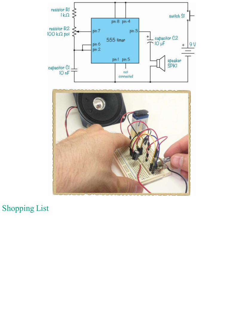
Shopping List
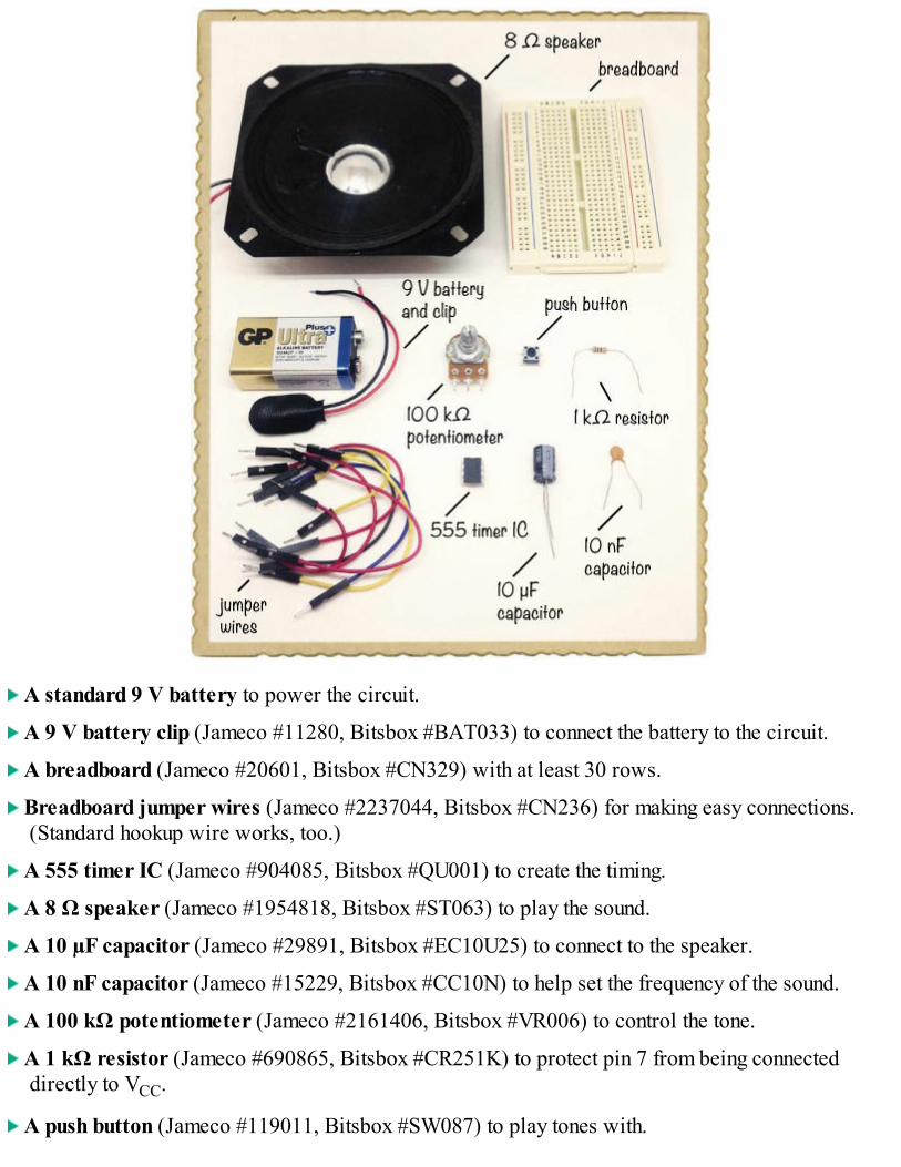
A standard 9 V battery to power the circuit.
A 9 V battery clip (Jameco #11280, Bitsbox #BAT033) to connect the battery to the circuit.
A breadboard (Jameco #20601, Bitsbox #CN329) with at least 30 rows.
Breadboard jumper wires (Jameco #2237044, Bitsbox #CN236) for making easy connections.(Standard hookup wire works, too.)
A 555 timer IC (Jameco #904085, Bitsbox #QU001) to create the timing.
A 8 Ω speaker (Jameco #1954818, Bitsbox #ST063) to play the sound.
A 10 µF capacitor (Jameco #29891, Bitsbox #EC10U25) to connect to the speaker.
A 10 nF capacitor (Jameco #15229, Bitsbox #CC10N) to help set the frequency of the sound.
A 100 kΩ potentiometer (Jameco #2161406, Bitsbox #VR006) to control the tone.
A 1 kΩ resistor (Jameco #690865, Bitsbox #CR251K) to protect pin 7 from being connecteddirectly to VCC.
A push button (Jameco #119011, Bitsbox #SW087) to play tones with.
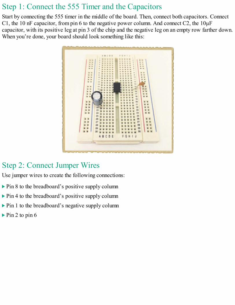
Step 1: Connect the 555 Timer and the CapacitorsStart by connecting the 555 timer in the middle of the board. Then, connect both capacitors. ConnectC1, the 10 nF capacitor, from pin 6 to the negative power column. And connect C2, the 10µFcapacitor, with its positive leg at pin 3 of the chip and the negative leg on an empty row farther down.When you’re done, your board should look something like this:
Step 2: Connect Jumper WiresUse jumper wires to create the following connections:
Pin 8 to the breadboard’s positive supply column
Pin 4 to the breadboard’s positive supply column
Pin 1 to the breadboard’s negative supply column
Pin 2 to pin 6
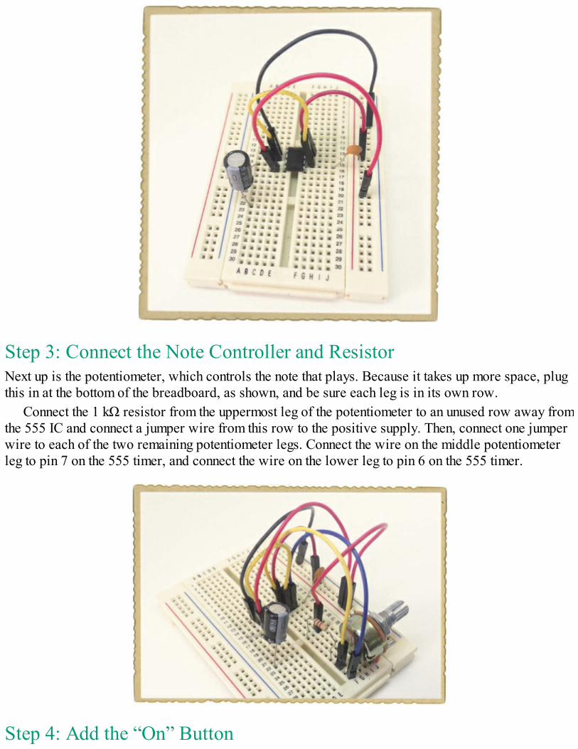
Step 3: Connect the Note Controller and ResistorNext up is the potentiometer, which controls the note that plays. Because it takes up more space, plugthis in at the bottom of the breadboard, as shown, and be sure each leg is in its own row.
Connect the 1 kΩ resistor from the uppermost leg of the potentiometer to an unused row away fromthe 555 IC and connect a jumper wire from this row to the positive supply. Then, connect one jumperwire to each of the two remaining potentiometer legs. Connect the wire on the middle potentiometerleg to pin 7 on the 555 timer, and connect the wire on the lower leg to pin 6 on the 555 timer.
Step 4: Add the “On” Button
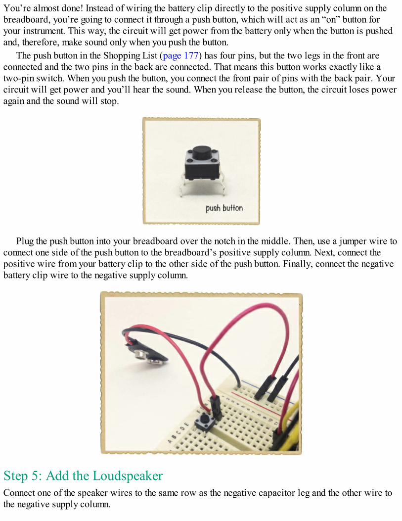
You’re almost done! Instead of wiring the battery clip directly to the positive supply column on thebreadboard, you’re going to connect it through a push button, which will act as an “on” button foryour instrument. This way, the circuit will get power from the battery only when the button is pushedand, therefore, make sound only when you push the button.
The push button in the Shopping List (page 177) has four pins, but the two legs in the front areconnected and the two pins in the back are connected. That means this button works exactly like atwo-pin switch. When you push the button, you connect the front pair of pins with the back pair. Yourcircuit will get power and you’ll hear the sound. When you release the button, the circuit loses poweragain and the sound will stop.
Plug the push button into your breadboard over the notch in the middle. Then, use a jumper wire toconnect one side of the push button to the breadboard’s positive supply column. Next, connect thepositive wire from your battery clip to the other side of the push button. Finally, connect the negativebattery clip wire to the negative supply column.
Step 5: Add the LoudspeakerConnect one of the speaker wires to the same row as the negative capacitor leg and the other wire tothe negative supply column.
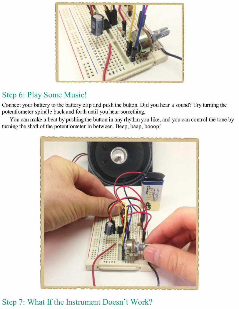
Step 6: Play Some Music!Connect your battery to the battery clip and push the button. Did you hear a sound? Try turning thepotentiometer spindle back and forth until you hear something.
You can make a beat by pushing the button in any rhythm you like, and you can control the tone byturning the shaft of the potentiometer in between. Beep, baap, booop!
Step 7: What If the Instrument Doesn’t Work?
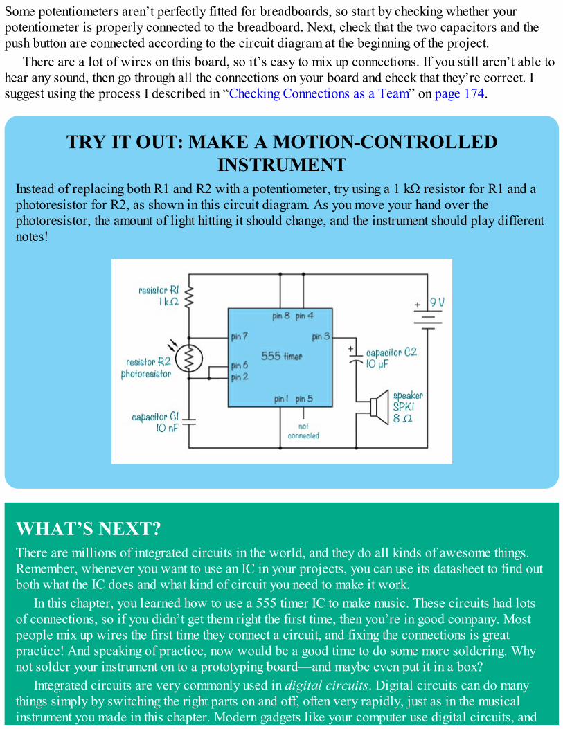
Some potentiometers aren’t perfectly fitted for breadboards, so start by checking whether yourpotentiometer is properly connected to the breadboard. Next, check that the two capacitors and thepush button are connected according to the circuit diagram at the beginning of the project.
There are a lot of wires on this board, so it’s easy to mix up connections. If you still aren’t able tohear any sound, then go through all the connections on your board and check that they’re correct. Isuggest using the process I described in “Checking Connections as a Team” on page 174.
TRY IT OUT: MAKE A MOTION-CONTROLLEDINSTRUMENT
Instead of replacing both R1 and R2 with a potentiometer, try using a 1 kΩ resistor for R1 and aphotoresistor for R2, as shown in this circuit diagram. As you move your hand over thephotoresistor, the amount of light hitting it should change, and the instrument should play differentnotes!
WHAT’S NEXT?There are millions of integrated circuits in the world, and they do all kinds of awesome things.Remember, whenever you want to use an IC in your projects, you can use its datasheet to find outboth what the IC does and what kind of circuit you need to make it work.
In this chapter, you learned how to use a 555 timer IC to make music. These circuits had lotsof connections, so if you didn’t get them right the first time, then you’re in good company. Mostpeople mix up wires the first time they connect a circuit, and fixing the connections is greatpractice! And speaking of practice, now would be a good time to do some more soldering. Whynot solder your instrument on to a prototyping board—and maybe even put it in a box?
Integrated circuits are very commonly used in digital circuits. Digital circuits can do manythings simply by switching the right parts on and off, often very rapidly, just as in the musicalinstrument you made in this chapter. Modern gadgets like your computer use digital circuits, and

you’ll learn more about digital electronics in the last few chapters of this book.

PART 3THE DIGITAL WORLD

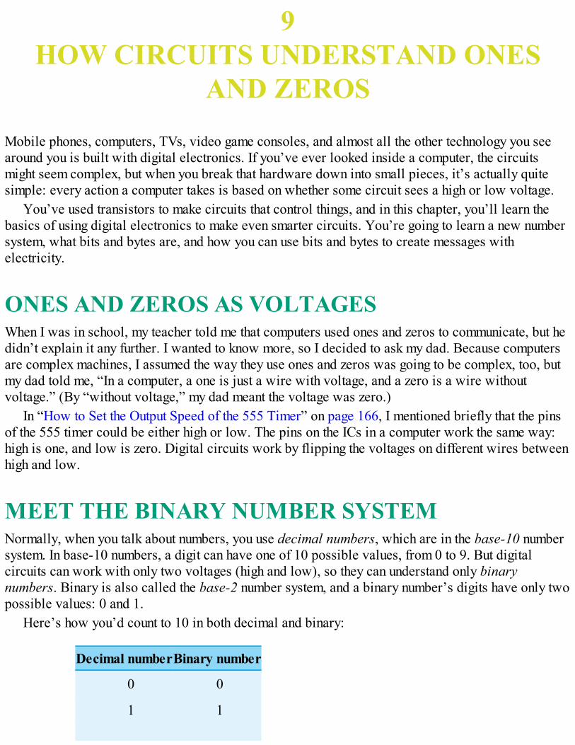
9HOW CIRCUITS UNDERSTAND ONES
AND ZEROS
Mobile phones, computers, TVs, video game consoles, and almost all the other technology you seearound you is built with digital electronics. If you’ve ever looked inside a computer, the circuitsmight seem complex, but when you break that hardware down into small pieces, it’s actually quitesimple: every action a computer takes is based on whether some circuit sees a high or low voltage.
You’ve used transistors to make circuits that control things, and in this chapter, you’ll learn thebasics of using digital electronics to make even smarter circuits. You’re going to learn a new numbersystem, what bits and bytes are, and how you can use bits and bytes to create messages withelectricity.
ONES AND ZEROS AS VOLTAGESWhen I was in school, my teacher told me that computers used ones and zeros to communicate, but hedidn’t explain it any further. I wanted to know more, so I decided to ask my dad. Because computersare complex machines, I assumed the way they use ones and zeros was going to be complex, too, butmy dad told me, “In a computer, a one is just a wire with voltage, and a zero is a wire withoutvoltage.” (By “without voltage,” my dad meant the voltage was zero.)
In “How to Set the Output Speed of the 555 Timer” on page 166, I mentioned briefly that the pinsof the 555 timer could be either high or low. The pins on the ICs in a computer work the same way:high is one, and low is zero. Digital circuits work by flipping the voltages on different wires betweenhigh and low.
MEET THE BINARY NUMBER SYSTEMNormally, when you talk about numbers, you use decimal numbers, which are in the base-10 numbersystem. In base-10 numbers, a digit can have one of 10 possible values, from 0 to 9. But digitalcircuits can work with only two voltages (high and low), so they can understand only binarynumbers. Binary is also called the base-2 number system, and a binary number’s digits have only twopossible values: 0 and 1.
Here’s how you’d count to 10 in both decimal and binary:
Decimal numberBinary number
0 0
1 1
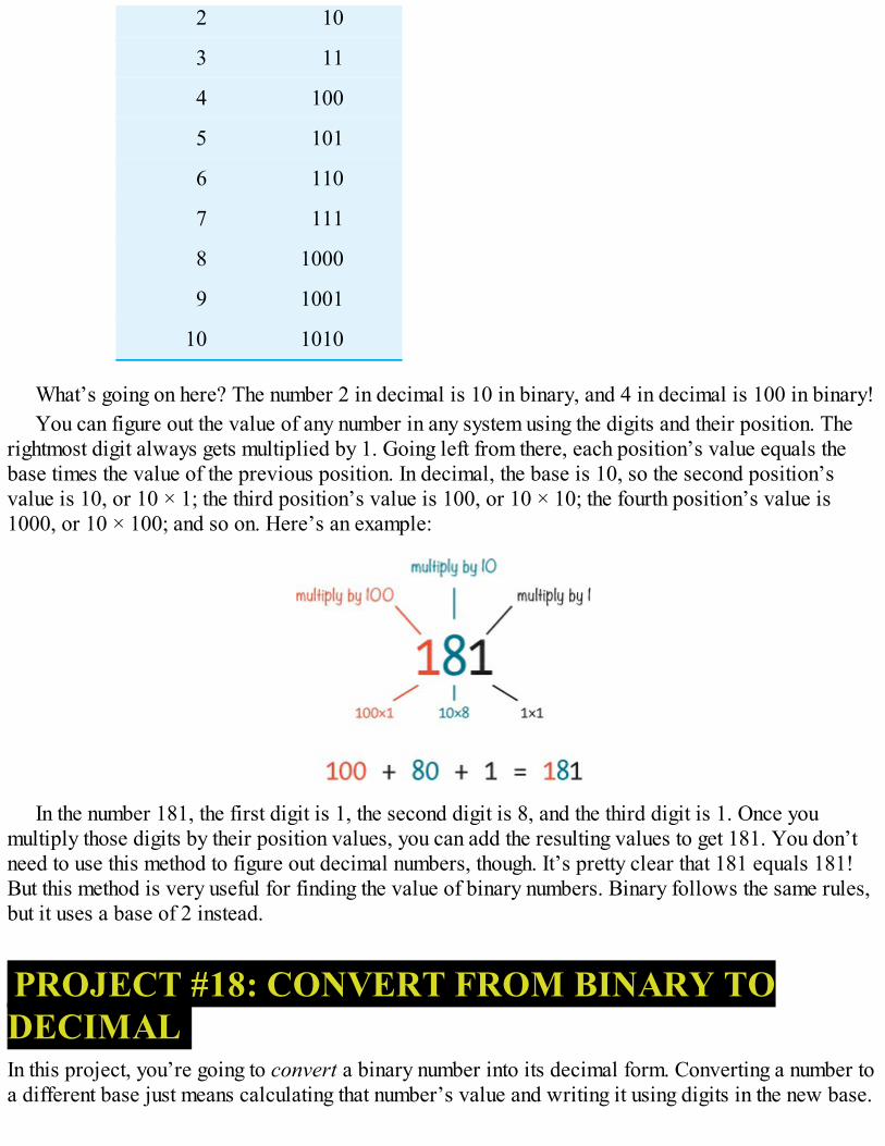
2 10
3 11
4 100
5 101
6 110
7 111
8 1000
9 1001
10 1010
What’s going on here? The number 2 in decimal is 10 in binary, and 4 in decimal is 100 in binary!You can figure out the value of any number in any system using the digits and their position. The
rightmost digit always gets multiplied by 1. Going left from there, each position’s value equals thebase times the value of the previous position. In decimal, the base is 10, so the second position’svalue is 10, or 10 × 1; the third position’s value is 100, or 10 × 10; the fourth position’s value is1000, or 10 × 100; and so on. Here’s an example:
In the number 181, the first digit is 1, the second digit is 8, and the third digit is 1. Once youmultiply those digits by their position values, you can add the resulting values to get 181. You don’tneed to use this method to figure out decimal numbers, though. It’s pretty clear that 181 equals 181!But this method is very useful for finding the value of binary numbers. Binary follows the same rules,but it uses a base of 2 instead.
PROJECT #18: CONVERT FROM BINARY TODECIMALIn this project, you’re going to convert a binary number into its decimal form. Converting a number toa different base just means calculating that number’s value and writing it using digits in the new base.
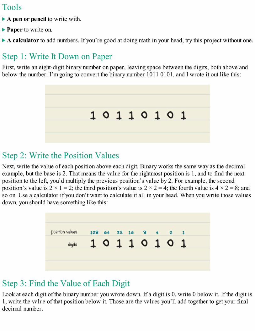
Tools A pen or pencil to write with.
Paper to write on.
A calculator to add numbers. If you’re good at doing math in your head, try this project without one.
Step 1: Write It Down on PaperFirst, write an eight-digit binary number on paper, leaving space between the digits, both above andbelow the number. I’m going to convert the binary number 1011 0101, and I wrote it out like this:
Step 2: Write the Position ValuesNext, write the value of each position above each digit. Binary works the same way as the decimalexample, but the base is 2. That means the value for the rightmost position is 1, and to find the nextposition to the left, you’d multiply the previous position’s value by 2. For example, the secondposition’s value is 2 × 1 = 2; the third position’s value is 2 × 2 = 4; the fourth value is 4 × 2 = 8; andso on. Use a calculator if you don’t want to calculate it all in your head. When you write those valuesdown, you should have something like this:
Step 3: Find the Value of Each DigitLook at each digit of the binary number you wrote down. If a digit is 0, write 0 below it. If the digit is1, write the value of that position below it. Those are the values you’ll add together to get your finaldecimal number.
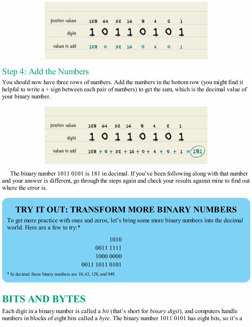
Step 4: Add the NumbersYou should now have three rows of numbers. Add the numbers in the bottom row (you might find ithelpful to write a + sign between each pair of numbers) to get the sum, which is the decimal value ofyour binary number.
The binary number 1011 0101 is 181 in decimal. If you’ve been following along with that numberand your answer is different, go through the steps again and check your results against mine to find outwhere the error is.
TRY IT OUT: TRANSFORM MORE BINARY NUMBERSTo get more practice with ones and zeros, let’s bring some more binary numbers into the decimalworld. Here are a few to try:*
10100011 11111000 0000
0011 1011 0101* In decimal, these binary numbers are 10, 63, 128, and 949.
BITS AND BYTESEach digit in a binary number is called a bit (that’s short for binary digit), and computers handlenumbers in blocks of eight bits called a byte. The binary number 1011 0101 has eight bits, so it’s a

byte. You can interact with a computer in many ways, but all your mouse clicks, key presses, webcamvideos, and so on need to be translated into bits and bytes before the computer can understand them.
In fact, when working with computers and other digital gadgets, you usually see much, much largernumbers than just 1 byte. All the files on a computer are collections of bytes, but if you tried todescribe their size in bytes alone, those numbers would be huge! That’s why files are usuallydescribed in larger units, like kilobytes* (kB), megabytes (MB), gigabytes (GB), terabytes (TB), andso on. Here’s what those units mean:
1 kB = 1,000 bytes
1 MB = 1,000 kB = 1,000,000 bytes
1 GB = 1,000 MB = 1,000,000 kB = 1,000,000,000 bytes
1 TB = 1,000 GB = 1,000,000 MB = 1,000,000,000 kB = 1,000,000,000,000 bytes
If a computer’s hard disk can hold 1 TB of data, then it can hold one trillion bytes, which is eighttrillion ones and zeros!
NUMBERS CAN BE ANYTHINGNow you might be thinking, “Why on Earth would I ever need eight trillion ones and zeros in mycomputer?” The fact is, whether you use a computer to write stories, draw pictures, talk to yourfriends, play video games, or anything else, you’re actually using those ones and zeros.
For example, how does a computer show an image on a screen? A computer screen is made of alot of small points called pixels, and each pixel can be set to a color that is a mix of red, green, andblue light. If you want a pixel to be the brightest yellow possible, you’d use numbers to tell thecomputer to turn that pixel’s red and green settings to full intensity and its blue setting to zero(because mixed red and green light looks like yellow). This way you can translate numbers into animage on the screen.
PROJECT #19: COLOR GUESSING GAMEIn this project, you’ll build a pixel-color guessing game using binary values. It’s a two-player gamewhere you and a friend take turns being “the computer” and “the user.”
The person who is the computer sets the color of the pixel by pushing a combination of threebuttons. When the computer is ready, the user must try to guess which color the pixel is. When theuser is ready to make the guess, they should say the chosen color out loud and then push the colorrevealer button to show the actual color. If the user guesses correctly, they get one point and get toguess again. If the guess is wrong, you switch roles. The first one to reach three points wins the round.
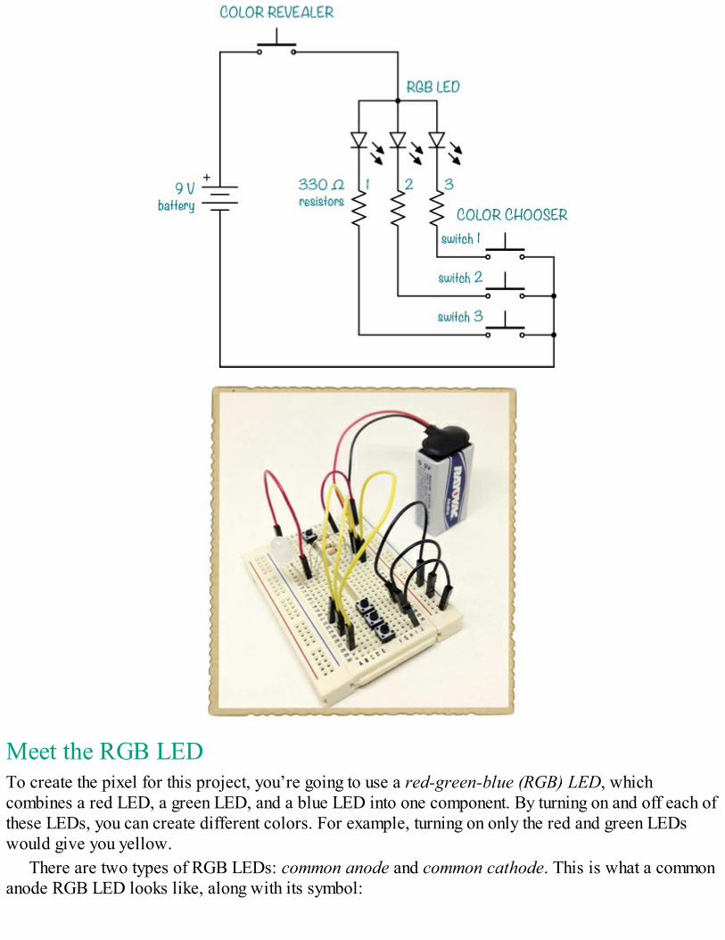
Meet the RGB LEDTo create the pixel for this project, you’re going to use a red-green-blue (RGB) LED, whichcombines a red LED, a green LED, and a blue LED into one component. By turning on and off each ofthese LEDs, you can create different colors. For example, turning on only the red and green LEDswould give you yellow.
There are two types of RGB LEDs: common anode and common cathode. This is what a commonanode RGB LED looks like, along with its symbol:
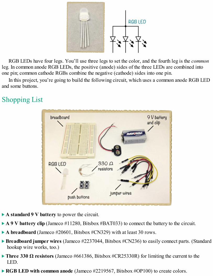
RGB LEDs have four legs. You’ll use three legs to set the color, and the fourth leg is the commonleg. In common anode RGB LEDs, the positive (anode) sides of the three LEDs are combined intoone pin; common cathode RGBs combine the negative (cathode) sides into one pin.
In this project, you’re going to build the following circuit, which uses a common anode RGB LEDand some buttons.
Shopping List
A standard 9 V battery to power the circuit.
A 9 V battery clip (Jameco #11280, Bitsbox #BAT033) to connect the battery to the circuit.
A breadboard (Jameco #20601, Bitsbox #CN329) with at least 30 rows.
Breadboard jumper wires (Jameco #2237044, Bitsbox #CN236) to easily connect parts. (Standardhookup wire works, too.)
Three 330 Ω resistors (Jameco #661386, Bitsbox #CR25330R) for limiting the current to theLED.
RGB LED with common anode (Jameco #2219567, Bitsbox #OP100) to create colors.
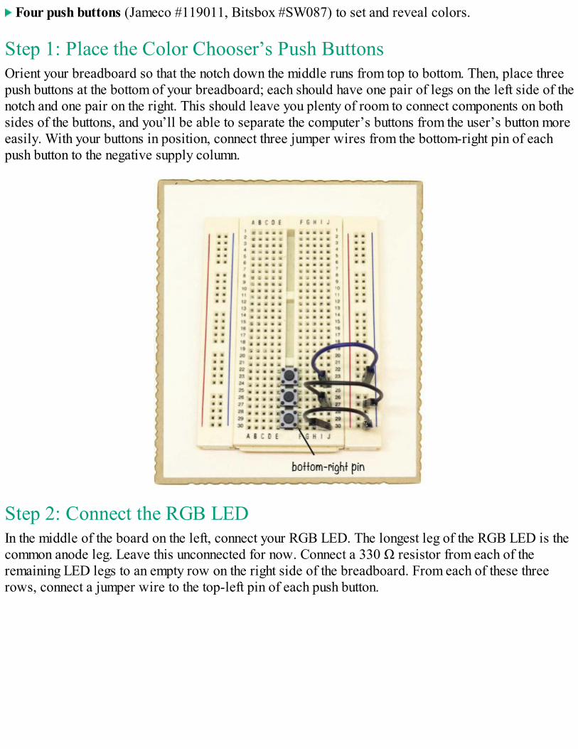
Four push buttons (Jameco #119011, Bitsbox #SW087) to set and reveal colors.
Step 1: Place the Color Chooser’s Push ButtonsOrient your breadboard so that the notch down the middle runs from top to bottom. Then, place threepush buttons at the bottom of your breadboard; each should have one pair of legs on the left side of thenotch and one pair on the right. This should leave you plenty of room to connect components on bothsides of the buttons, and you’ll be able to separate the computer’s buttons from the user’s button moreeasily. With your buttons in position, connect three jumper wires from the bottom-right pin of eachpush button to the negative supply column.
Step 2: Connect the RGB LEDIn the middle of the board on the left, connect your RGB LED. The longest leg of the RGB LED is thecommon anode leg. Leave this unconnected for now. Connect a 330 Ω resistor from each of theremaining LED legs to an empty row on the right side of the breadboard. From each of these threerows, connect a jumper wire to the top-left pin of each push button.
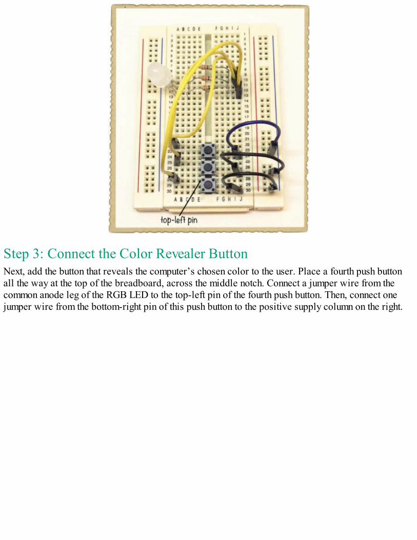
Step 3: Connect the Color Revealer ButtonNext, add the button that reveals the computer’s chosen color to the user. Place a fourth push buttonall the way at the top of the breadboard, across the middle notch. Connect a jumper wire from thecommon anode leg of the RGB LED to the top-left pin of the fourth push button. Then, connect onejumper wire from the bottom-right pin of this push button to the positive supply column on the right.
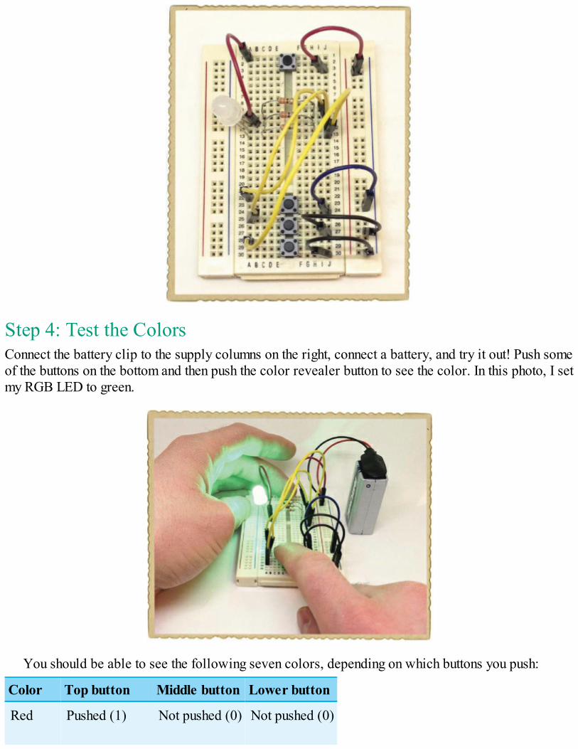
Step 4: Test the ColorsConnect the battery clip to the supply columns on the right, connect a battery, and try it out! Push someof the buttons on the bottom and then push the color revealer button to see the color. In this photo, I setmy RGB LED to green.
You should be able to see the following seven colors, depending on which buttons you push:
Color Top button Middle button Lower button
Red Pushed (1) Not pushed (0) Not pushed (0)
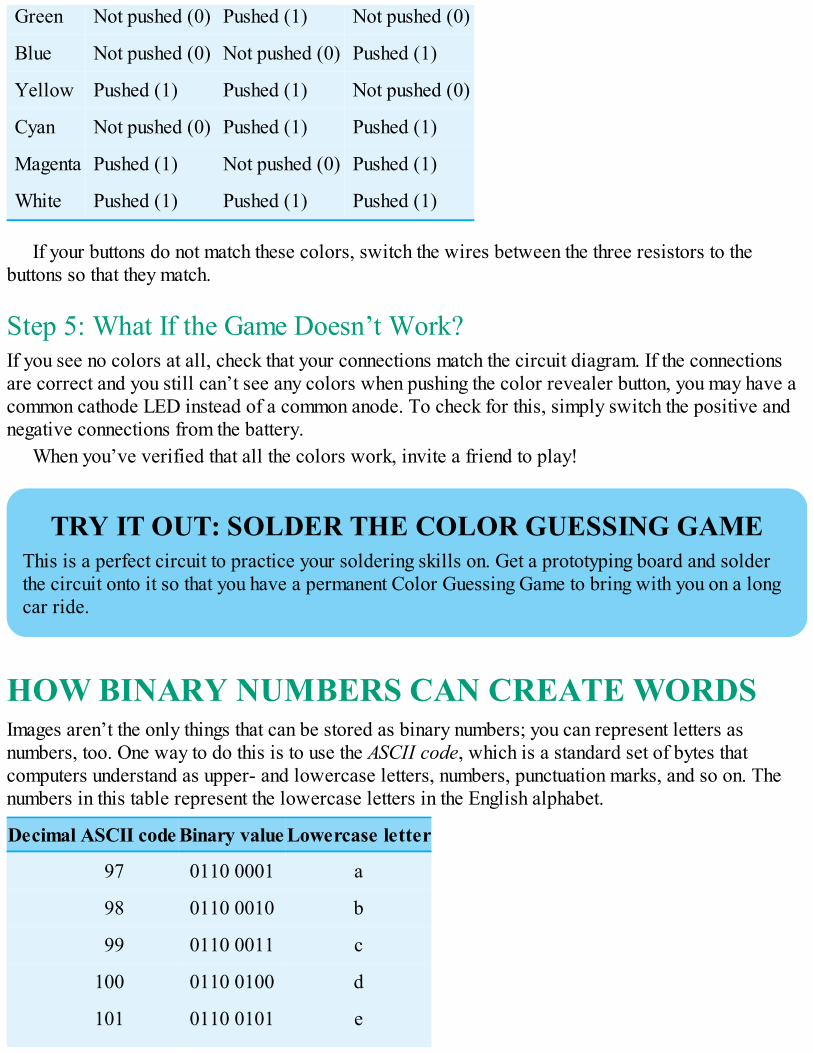
Green Not pushed (0) Pushed (1) Not pushed (0)
Blue Not pushed (0) Not pushed (0) Pushed (1)
Yellow Pushed (1) Pushed (1) Not pushed (0)
Cyan Not pushed (0) Pushed (1) Pushed (1)
Magenta Pushed (1) Not pushed (0) Pushed (1)
White Pushed (1) Pushed (1) Pushed (1)
If your buttons do not match these colors, switch the wires between the three resistors to thebuttons so that they match.
Step 5: What If the Game Doesn’t Work?If you see no colors at all, check that your connections match the circuit diagram. If the connectionsare correct and you still can’t see any colors when pushing the color revealer button, you may have acommon cathode LED instead of a common anode. To check for this, simply switch the positive andnegative connections from the battery.
When you’ve verified that all the colors work, invite a friend to play!
TRY IT OUT: SOLDER THE COLOR GUESSING GAMEThis is a perfect circuit to practice your soldering skills on. Get a prototyping board and solderthe circuit onto it so that you have a permanent Color Guessing Game to bring with you on a longcar ride.
HOW BINARY NUMBERS CAN CREATE WORDSImages aren’t the only things that can be stored as binary numbers; you can represent letters asnumbers, too. One way to do this is to use the ASCII code, which is a standard set of bytes thatcomputers understand as upper- and lowercase letters, numbers, punctuation marks, and so on. Thenumbers in this table represent the lowercase letters in the English alphabet.
Decimal ASCII code Binary value Lowercase letter
97 0110 0001 a
98 0110 0010 b
99 0110 0011 c
100 0110 0100 d
101 0110 0101 e
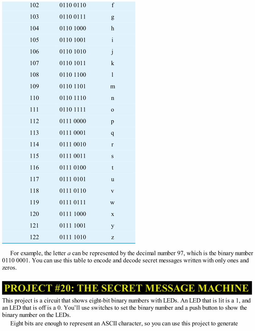
102 0110 0110 f
103 0110 0111 g
104 0110 1000 h
105 0110 1001 i
106 0110 1010 j
107 0110 1011 k
108 0110 1100 l
109 0110 1101 m
110 0110 1110 n
111 0110 1111 o
112 0111 0000 p
113 0111 0001 q
114 0111 0010 r
115 0111 0011 s
116 0111 0100 t
117 0111 0101 u
118 0111 0110 v
119 0111 0111 w
120 0111 1000 x
121 0111 1001 y
122 0111 1010 z
For example, the letter a can be represented by the decimal number 97, which is the binary number0110 0001. You can use this table to encode and decode secret messages written with only ones andzeros.
PROJECT #20: THE SECRET MESSAGE MACHINEThis project is a circuit that shows eight-bit binary numbers with LEDs. An LED that is lit is a 1, andan LED that is off is a 0. You’ll use switches to set the binary number and a push button to show thebinary number on the LEDs.
Eight bits are enough to represent an ASCII character, so you can use this project to generate
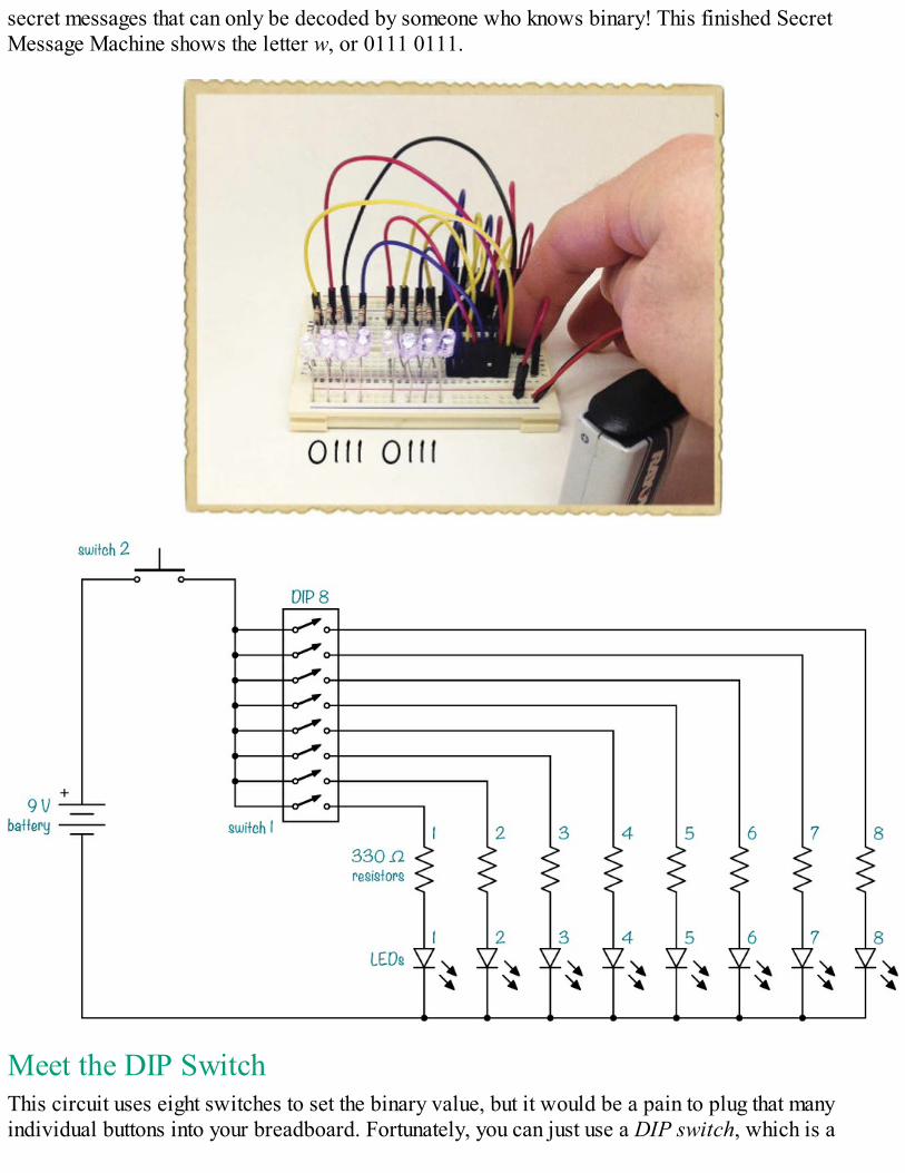
secret messages that can only be decoded by someone who knows binary! This finished SecretMessage Machine shows the letter w, or 0111 0111.
Meet the DIP SwitchThis circuit uses eight switches to set the binary value, but it would be a pain to plug that manyindividual buttons into your breadboard. Fortunately, you can just use a DIP switch, which is a
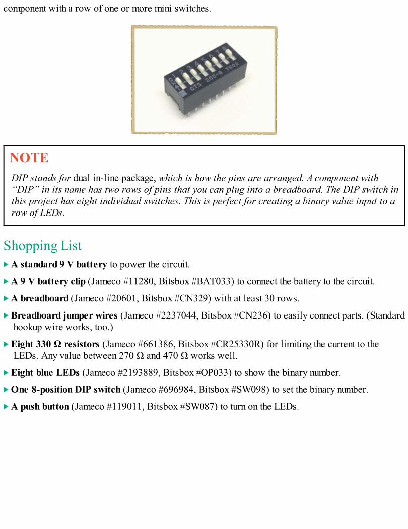
component with a row of one or more mini switches.
NOTEDIP stands for dual in-line package, which is how the pins are arranged. A component with“DIP” in its name has two rows of pins that you can plug into a breadboard. The DIP switch inthis project has eight individual switches. This is perfect for creating a binary value input to arow of LEDs.
Shopping List A standard 9 V battery to power the circuit.
A 9 V battery clip (Jameco #11280, Bitsbox #BAT033) to connect the battery to the circuit.
A breadboard (Jameco #20601, Bitsbox #CN329) with at least 30 rows.
Breadboard jumper wires (Jameco #2237044, Bitsbox #CN236) to easily connect parts. (Standardhookup wire works, too.)
Eight 330 Ω resistors (Jameco #661386, Bitsbox #CR25330R) for limiting the current to theLEDs. Any value between 270 Ω and 470 Ω works well.
Eight blue LEDs (Jameco #2193889, Bitsbox #OP033) to show the binary number.
One 8-position DIP switch (Jameco #696984, Bitsbox #SW098) to set the binary number.
A push button (Jameco #119011, Bitsbox #SW087) to turn on the LEDs.
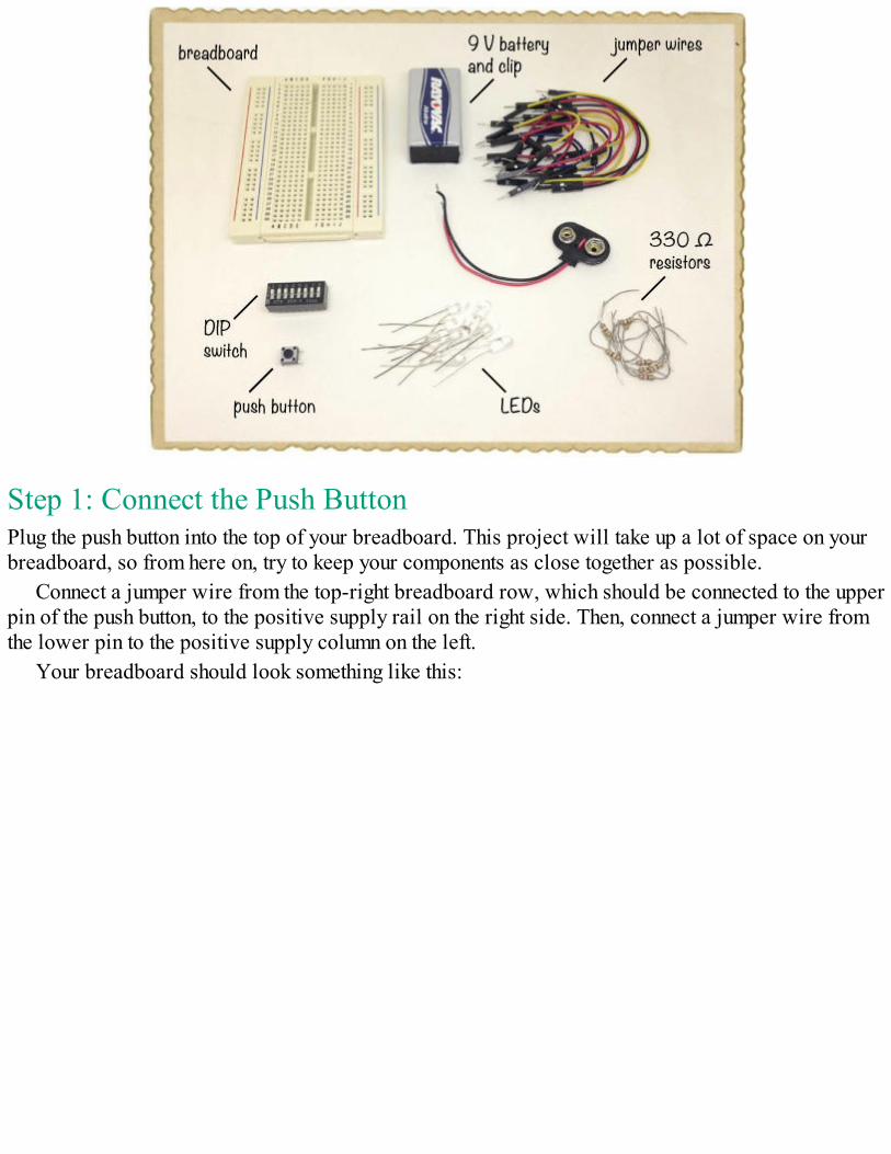
Step 1: Connect the Push ButtonPlug the push button into the top of your breadboard. This project will take up a lot of space on yourbreadboard, so from here on, try to keep your components as close together as possible.
Connect a jumper wire from the top-right breadboard row, which should be connected to the upperpin of the push button, to the positive supply rail on the right side. Then, connect a jumper wire fromthe lower pin to the positive supply column on the left.
Your breadboard should look something like this:
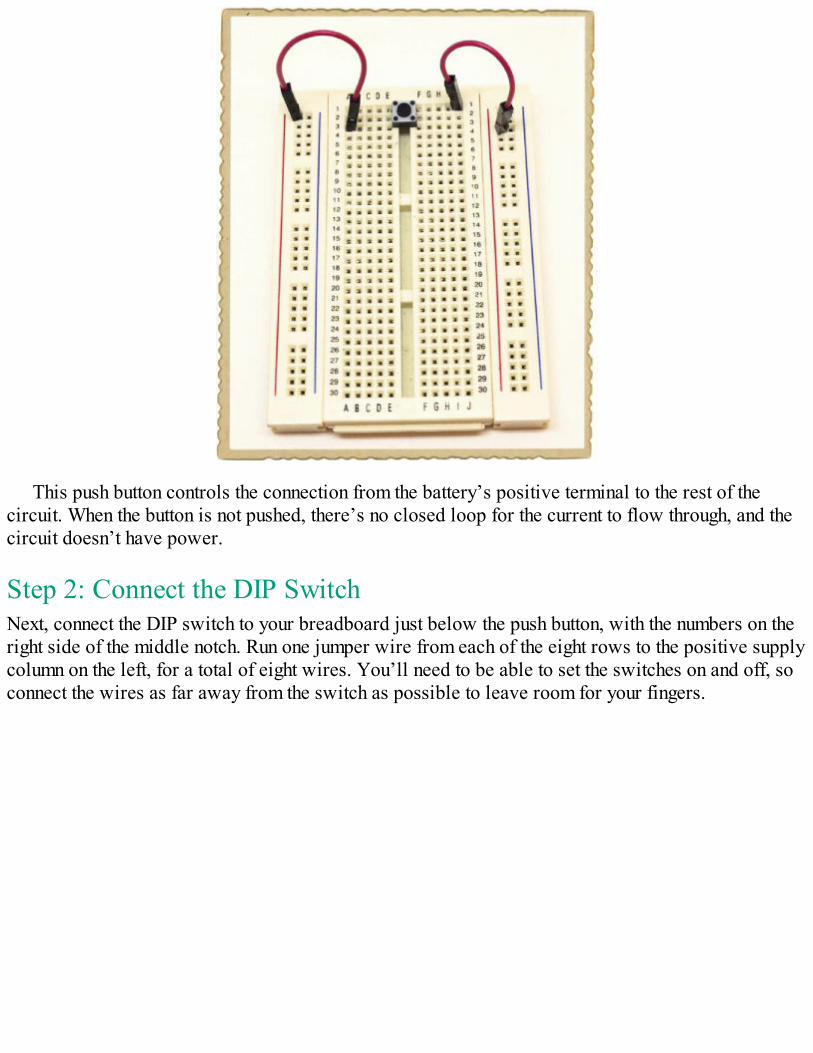
This push button controls the connection from the battery’s positive terminal to the rest of thecircuit. When the button is not pushed, there’s no closed loop for the current to flow through, and thecircuit doesn’t have power.
Step 2: Connect the DIP SwitchNext, connect the DIP switch to your breadboard just below the push button, with the numbers on theright side of the middle notch. Run one jumper wire from each of the eight rows to the positive supplycolumn on the left, for a total of eight wires. You’ll need to be able to set the switches on and off, soconnect the wires as far away from the switch as possible to leave room for your fingers.
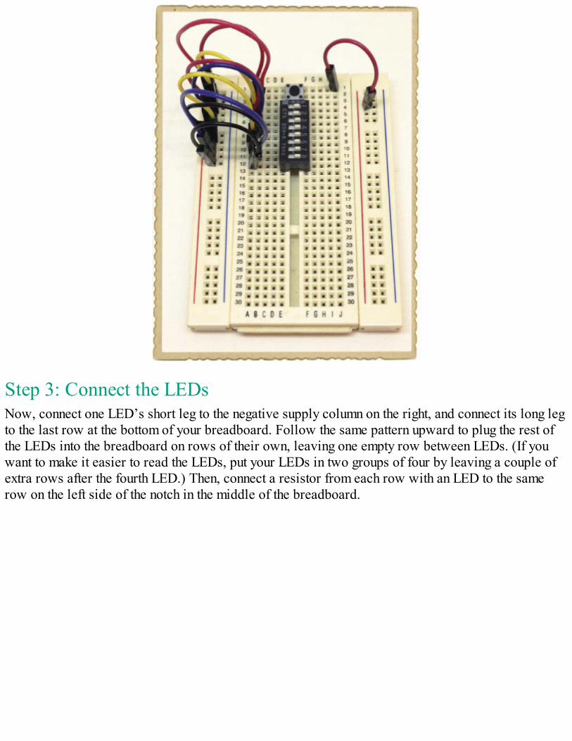
Step 3: Connect the LEDsNow, connect one LED’s short leg to the negative supply column on the right, and connect its long legto the last row at the bottom of your breadboard. Follow the same pattern upward to plug the rest ofthe LEDs into the breadboard on rows of their own, leaving one empty row between LEDs. (If youwant to make it easier to read the LEDs, put your LEDs in two groups of four by leaving a couple ofextra rows after the fourth LED.) Then, connect a resistor from each row with an LED to the samerow on the left side of the notch in the middle of the breadboard.
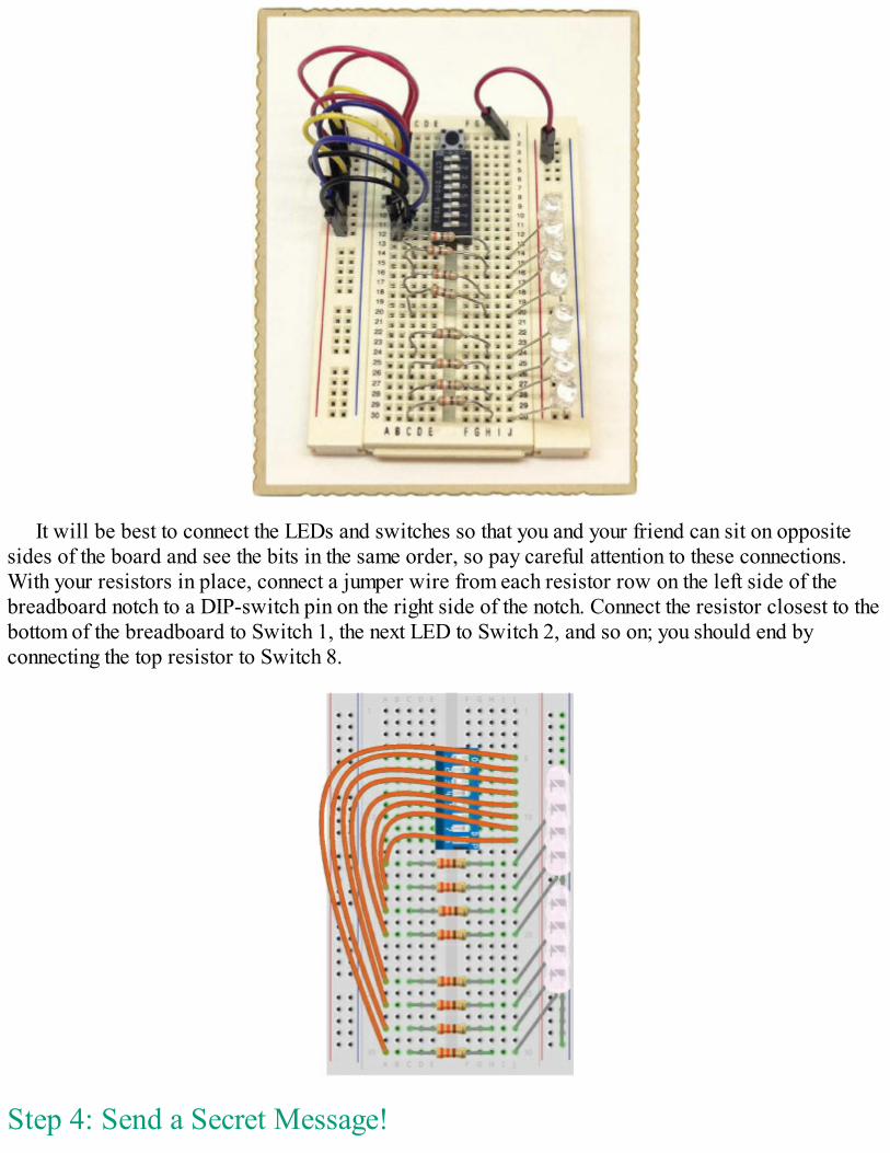
It will be best to connect the LEDs and switches so that you and your friend can sit on oppositesides of the board and see the bits in the same order, so pay careful attention to these connections.With your resistors in place, connect a jumper wire from each resistor row on the left side of thebreadboard notch to a DIP-switch pin on the right side of the notch. Connect the resistor closest to thebottom of the breadboard to Switch 1, the next LED to Switch 2, and so on; you should end byconnecting the top resistor to Switch 8.
Step 4: Send a Secret Message!
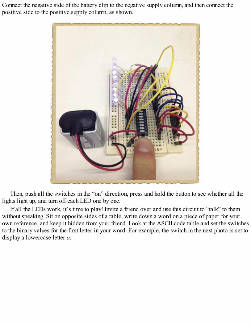
Connect the negative side of the battery clip to the negative supply column, and then connect thepositive side to the positive supply column, as shown.
Then, push all the switches in the “on” direction, press and hold the button to see whether all thelights light up, and turn off each LED one by one.
If all the LEDs work, it’s time to play! Invite a friend over and use this circuit to “talk” to themwithout speaking. Sit on opposite sides of a table, write down a word on a piece of paper for yourown reference, and keep it hidden from your friend. Look at the ASCII code table and set the switchesto the binary values for the first letter in your word. For example, the switch in the next photo is set todisplay a lowercase letter a.
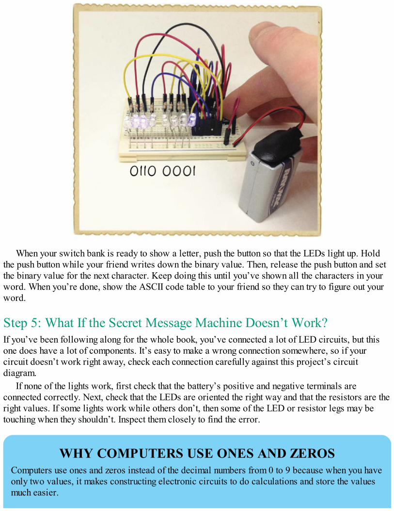
When your switch bank is ready to show a letter, push the button so that the LEDs light up. Holdthe push button while your friend writes down the binary value. Then, release the push button and setthe binary value for the next character. Keep doing this until you’ve shown all the characters in yourword. When you’re done, show the ASCII code table to your friend so they can try to figure out yourword.
Step 5: What If the Secret Message Machine Doesn’t Work?If you’ve been following along for the whole book, you’ve connected a lot of LED circuits, but thisone does have a lot of components. It’s easy to make a wrong connection somewhere, so if yourcircuit doesn’t work right away, check each connection carefully against this project’s circuitdiagram.
If none of the lights work, first check that the battery’s positive and negative terminals areconnected correctly. Next, check that the LEDs are oriented the right way and that the resistors are theright values. If some lights work while others don’t, then some of the LED or resistor legs may betouching when they shouldn’t. Inspect them closely to find the error.
WHY COMPUTERS USE ONES AND ZEROSComputers use ones and zeros instead of the decimal numbers from 0 to 9 because when you haveonly two values, it makes constructing electronic circuits to do calculations and store the valuesmuch easier.

For example, because each digit has only two possible values, one or zero, it’s easy to createa simple memory block to store binary numbers using switches, as you did with the DIP switch inProject #20.
It’s possible to save ones and zeros in many different ways, thereby creating memory. In theearly days of computing, it was common to save sets of ones and zeros as physical cards withholes in them. Today, many hard disks save ones and zeros on magnetic disks, or even viaelectrons stored inside an integrated circuit.
WHAT’S NEXT?In this chapter, you learned how binary numbers work. You’ve seen how ones and zeros can beused to show images on your computer screen and how to decode a bunch of seemingly randomones and zeros into readable text. To explore binary numbers a bit more, come up with your ownbinary codes for the letters in the alphabet. There are 26 letters from a to z. How many digits doyou need to represent all 26 letters? To figure this out, you can start by saying that the binarynumber 1 means a. The next binary number, 10, is b. Next, 11, is c. Write this down and keepincreasing until you reach z. Then, count the number of digits you needed for the z. This is theminimum number of digits you need.
Here’s another thing to try. Normally, if you count with your fingers, you can count to 10,right? If you don’t use your thumbs, you can only count to 8. But what if you count in binaryinstead? A straight finger is 1, and a bent finger is 0. How high can you count with eight fingersnow?
Digital values have another very important use: they allow you to create logic circuits, whichmake decisions based on whether certain wires see a high voltage or a low voltage. High istypically considered “true,” and low is typically “false.” If those wires are associated withsimple true-or-false questions and the voltages are the answers, then you can think of the outputfrom a logic circuit as a conclusion reached after asking a series of questions.
With logic, you can make circuits that do math, like adding two numbers, or circuits that dosomething only under a certain condition, like a door lock that opens only if you input the rightcombination of numbers. In Chapter 10, I’ll show you some of the building blocks of digital logicand how you can make smart circuits with them.

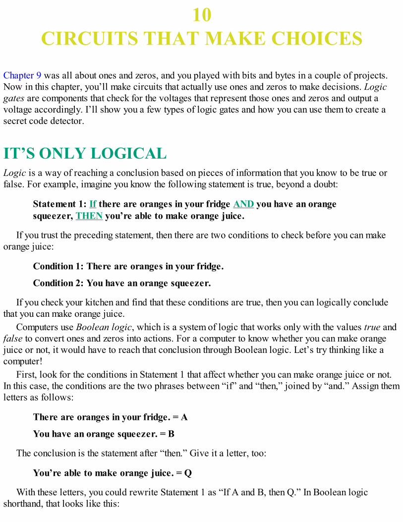
10CIRCUITS THAT MAKE CHOICES
Chapter 9 was all about ones and zeros, and you played with bits and bytes in a couple of projects.Now in this chapter, you’ll make circuits that actually use ones and zeros to make decisions. Logicgates are components that check for the voltages that represent those ones and zeros and output avoltage accordingly. I’ll show you a few types of logic gates and how you can use them to create asecret code detector.
IT’S ONLY LOGICALLogic is a way of reaching a conclusion based on pieces of information that you know to be true orfalse. For example, imagine you know the following statement is true, beyond a doubt:
Statement 1: If there are oranges in your fridge AND you have an orangesqueezer, THEN you’re able to make orange juice.
If you trust the preceding statement, then there are two conditions to check before you can makeorange juice:
Condition 1: There are oranges in your fridge.
Condition 2: You have an orange squeezer.
If you check your kitchen and find that these conditions are true, then you can logically concludethat you can make orange juice.
Computers use Boolean logic, which is a system of logic that works only with the values true andfalse to convert ones and zeros into actions. For a computer to know whether you can make orangejuice or not, it would have to reach that conclusion through Boolean logic. Let’s try thinking like acomputer!
First, look for the conditions in Statement 1 that affect whether you can make orange juice or not.In this case, the conditions are the two phrases between “if” and “then,” joined by “and.” Assign themletters as follows:
There are oranges in your fridge. = A
You have an orange squeezer. = B
The conclusion is the statement after “then.” Give it a letter, too:
You’re able to make orange juice. = Q
With these letters, you could rewrite Statement 1 as “If A and B, then Q.” In Boolean logicshorthand, that looks like this:
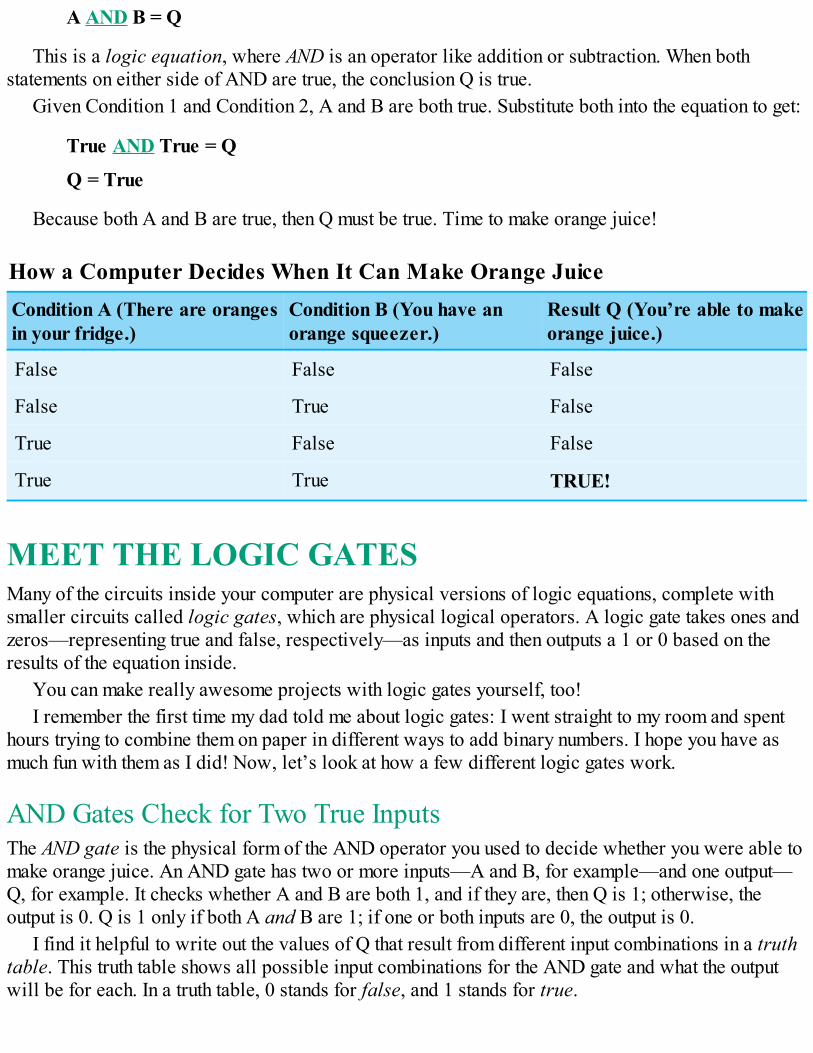
A AND B = Q
This is a logic equation, where AND is an operator like addition or subtraction. When bothstatements on either side of AND are true, the conclusion Q is true.
Given Condition 1 and Condition 2, A and B are both true. Substitute both into the equation to get:
True AND True = Q
Q = True
Because both A and B are true, then Q must be true. Time to make orange juice!
How a Computer Decides When It Can Make Orange JuiceCondition A (There are orangesin your fridge.)
Condition B (You have anorange squeezer.)
Result Q (You’re able to makeorange juice.)
False False False
False True False
True False False
True True TRUE!
MEET THE LOGIC GATESMany of the circuits inside your computer are physical versions of logic equations, complete withsmaller circuits called logic gates, which are physical logical operators. A logic gate takes ones andzeros—representing true and false, respectively—as inputs and then outputs a 1 or 0 based on theresults of the equation inside.
You can make really awesome projects with logic gates yourself, too!I remember the first time my dad told me about logic gates: I went straight to my room and spent
hours trying to combine them on paper in different ways to add binary numbers. I hope you have asmuch fun with them as I did! Now, let’s look at how a few different logic gates work.
AND Gates Check for Two True InputsThe AND gate is the physical form of the AND operator you used to decide whether you were able tomake orange juice. An AND gate has two or more inputs—A and B, for example—and one output—Q, for example. It checks whether A and B are both 1, and if they are, then Q is 1; otherwise, theoutput is 0. Q is 1 only if both A and B are 1; if one or both inputs are 0, the output is 0.
I find it helpful to write out the values of Q that result from different input combinations in a truthtable. This truth table shows all possible input combinations for the AND gate and what the outputwill be for each. In a truth table, 0 stands for false, and 1 stands for true.
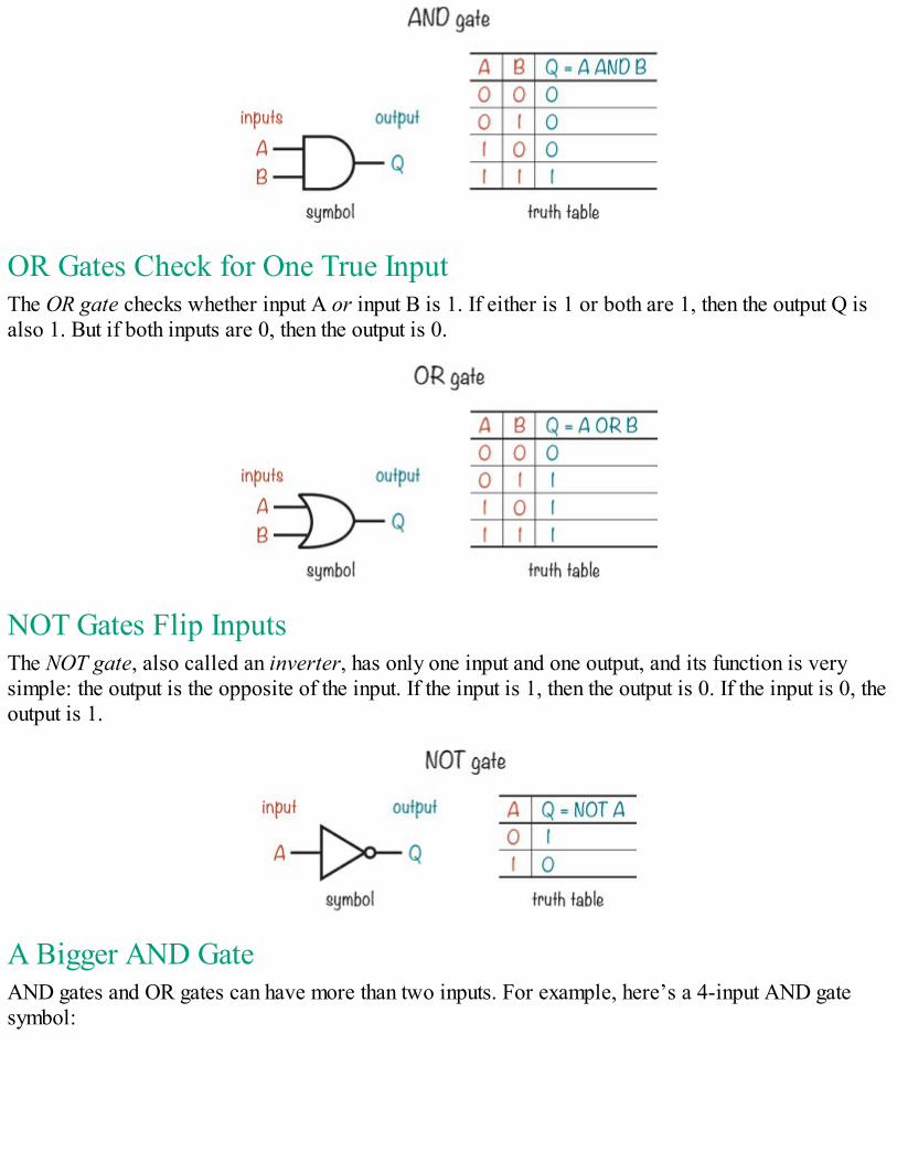
OR Gates Check for One True InputThe OR gate checks whether input A or input B is 1. If either is 1 or both are 1, then the output Q isalso 1. But if both inputs are 0, then the output is 0.
NOT Gates Flip InputsThe NOT gate, also called an inverter, has only one input and one output, and its function is verysimple: the output is the opposite of the input. If the input is 1, then the output is 0. If the input is 0, theoutput is 1.
A Bigger AND GateAND gates and OR gates can have more than two inputs. For example, here’s a 4-input AND gatesymbol:
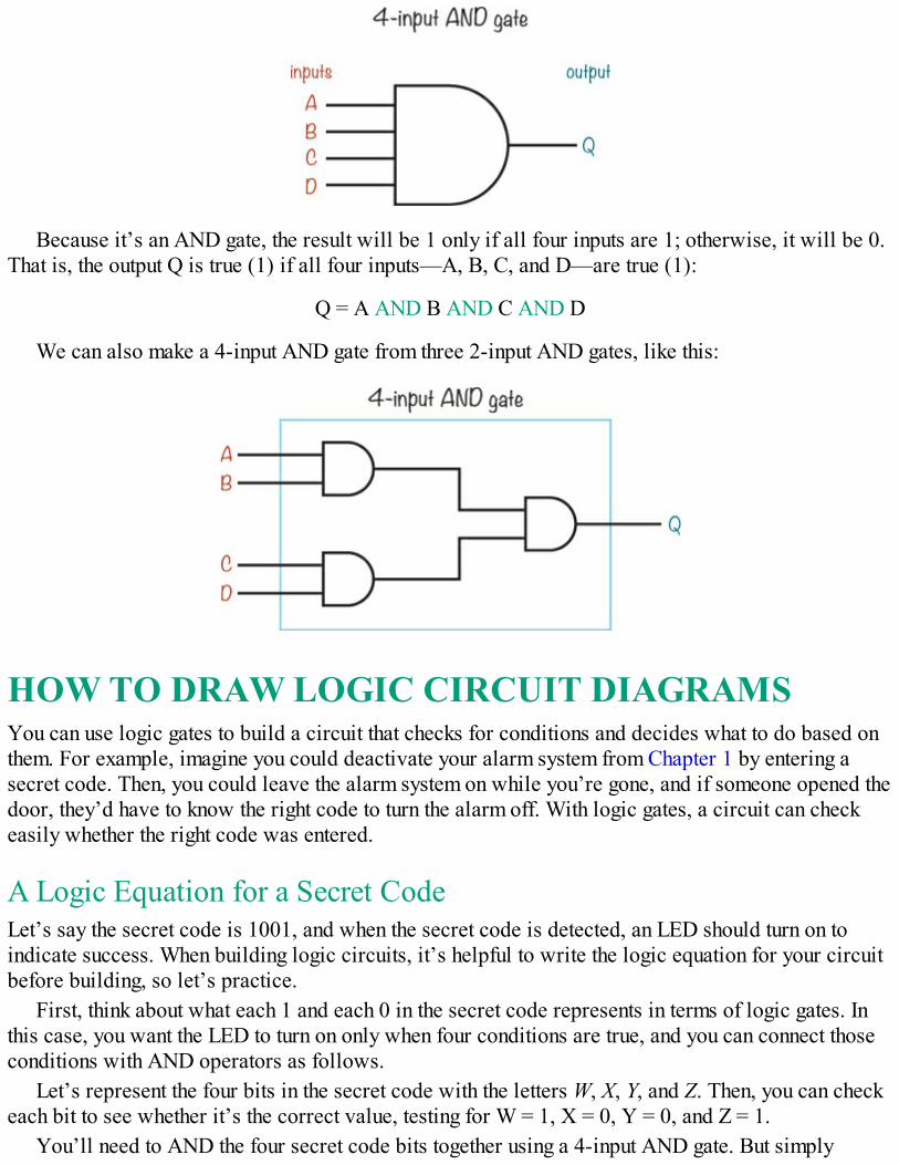
Because it’s an AND gate, the result will be 1 only if all four inputs are 1; otherwise, it will be 0.That is, the output Q is true (1) if all four inputs—A, B, C, and D—are true (1):
Q = A AND B AND C AND D
We can also make a 4-input AND gate from three 2-input AND gates, like this:
HOW TO DRAW LOGIC CIRCUIT DIAGRAMSYou can use logic gates to build a circuit that checks for conditions and decides what to do based onthem. For example, imagine you could deactivate your alarm system from Chapter 1 by entering asecret code. Then, you could leave the alarm system on while you’re gone, and if someone opened thedoor, they’d have to know the right code to turn the alarm off. With logic gates, a circuit can checkeasily whether the right code was entered.
A Logic Equation for a Secret CodeLet’s say the secret code is 1001, and when the secret code is detected, an LED should turn on toindicate success. When building logic circuits, it’s helpful to write the logic equation for your circuitbefore building, so let’s practice.
First, think about what each 1 and each 0 in the secret code represents in terms of logic gates. Inthis case, you want the LED to turn on only when four conditions are true, and you can connect thoseconditions with AND operators as follows.
Let’s represent the four bits in the secret code with the letters W, X, Y, and Z. Then, you can checkeach bit to see whether it’s the correct value, testing for W = 1, X = 0, Y = 0, and Z = 1.
You’ll need to AND the four secret code bits together using a 4-input AND gate. But simply
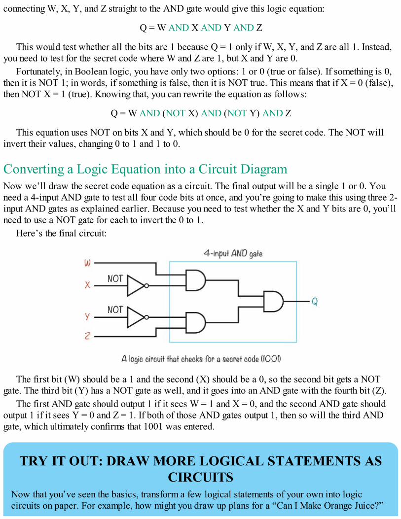
connecting W, X, Y, and Z straight to the AND gate would give this logic equation:
Q = W AND X AND Y AND Z
This would test whether all the bits are 1 because Q = 1 only if W, X, Y, and Z are all 1. Instead,you need to test for the secret code where W and Z are 1, but X and Y are 0.
Fortunately, in Boolean logic, you have only two options: 1 or 0 (true or false). If something is 0,then it is NOT 1; in words, if something is false, then it is NOT true. This means that if X = 0 (false),then NOT X = 1 (true). Knowing that, you can rewrite the equation as follows:
Q = W AND (NOT X) AND (NOT Y) AND Z
This equation uses NOT on bits X and Y, which should be 0 for the secret code. The NOT willinvert their values, changing 0 to 1 and 1 to 0.
Converting a Logic Equation into a Circuit DiagramNow we’ll draw the secret code equation as a circuit. The final output will be a single 1 or 0. Youneed a 4-input AND gate to test all four code bits at once, and you’re going to make this using three 2-input AND gates as explained earlier. Because you need to test whether the X and Y bits are 0, you’llneed to use a NOT gate for each to invert the 0 to 1.
Here’s the final circuit:
The first bit (W) should be a 1 and the second (X) should be a 0, so the second bit gets a NOTgate. The third bit (Y) has a NOT gate as well, and it goes into an AND gate with the fourth bit (Z).
The first AND gate should output 1 if it sees W = 1 and X = 0, and the second AND gate shouldoutput 1 if it sees Y = 0 and Z = 1. If both of those AND gates output 1, then so will the third ANDgate, which ultimately confirms that 1001 was entered.
TRY IT OUT: DRAW MORE LOGICAL STATEMENTS ASCIRCUITS
Now that you’ve seen the basics, transform a few logical statements of your own into logiccircuits on paper. For example, how might you draw up plans for a “Can I Make Orange Juice?”
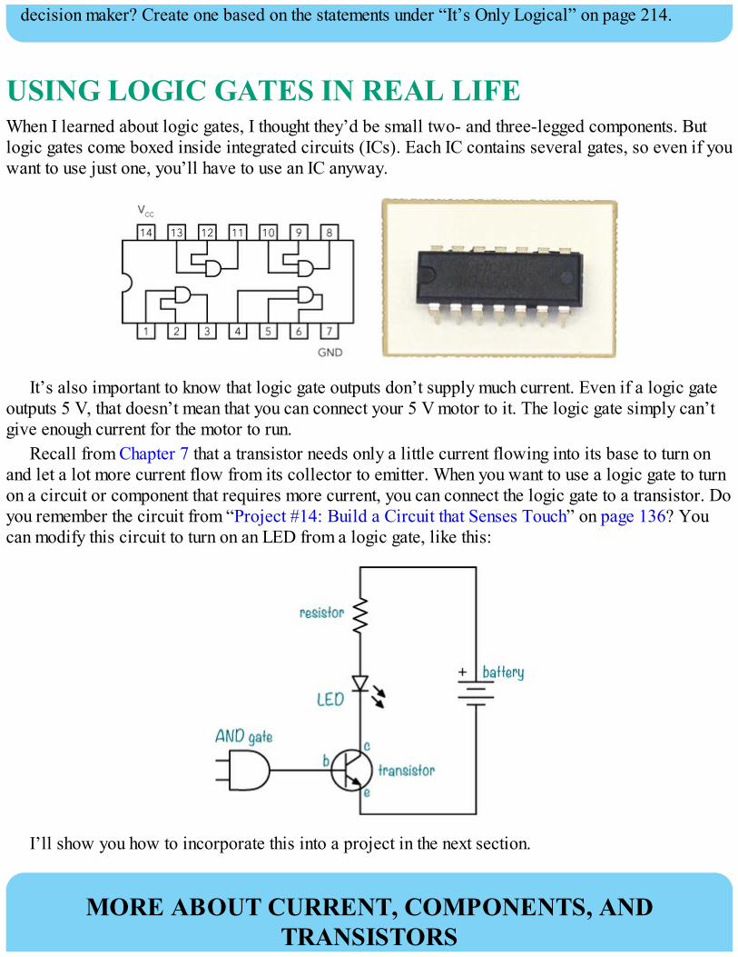
decision maker? Create one based on the statements under “It’s Only Logical” on page 214.
USING LOGIC GATES IN REAL LIFEWhen I learned about logic gates, I thought they’d be small two- and three-legged components. Butlogic gates come boxed inside integrated circuits (ICs). Each IC contains several gates, so even if youwant to use just one, you’ll have to use an IC anyway.
It’s also important to know that logic gate outputs don’t supply much current. Even if a logic gateoutputs 5 V, that doesn’t mean that you can connect your 5 V motor to it. The logic gate simply can’tgive enough current for the motor to run.
Recall from Chapter 7 that a transistor needs only a little current flowing into its base to turn onand let a lot more current flow from its collector to emitter. When you want to use a logic gate to turnon a circuit or component that requires more current, you can connect the logic gate to a transistor. Doyou remember the circuit from “Project #14: Build a Circuit that Senses Touch” on page 136? Youcan modify this circuit to turn on an LED from a logic gate, like this:
I’ll show you how to incorporate this into a project in the next section.
MORE ABOUT CURRENT, COMPONENTS, ANDTRANSISTORS
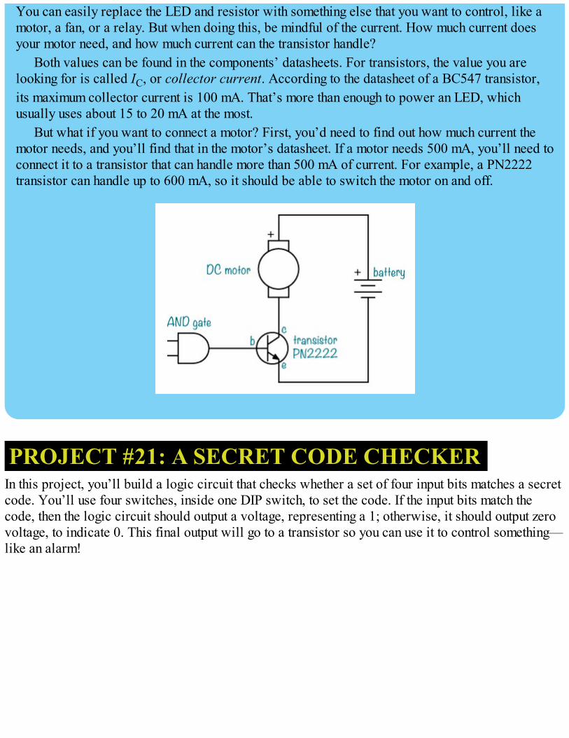
You can easily replace the LED and resistor with something else that you want to control, like amotor, a fan, or a relay. But when doing this, be mindful of the current. How much current doesyour motor need, and how much current can the transistor handle?
Both values can be found in the components’ datasheets. For transistors, the value you arelooking for is called IC, or collector current. According to the datasheet of a BC547 transistor,its maximum collector current is 100 mA. That’s more than enough to power an LED, whichusually uses about 15 to 20 mA at the most.
But what if you want to connect a motor? First, you’d need to find out how much current themotor needs, and you’ll find that in the motor’s datasheet. If a motor needs 500 mA, you’ll need toconnect it to a transistor that can handle more than 500 mA of current. For example, a PN2222transistor can handle up to 600 mA, so it should be able to switch the motor on and off.
PROJECT #21: A SECRET CODE CHECKERIn this project, you’ll build a logic circuit that checks whether a set of four input bits matches a secretcode. You’ll use four switches, inside one DIP switch, to set the code. If the input bits match thecode, then the logic circuit should output a voltage, representing a 1; otherwise, it should output zerovoltage, to indicate 0. This final output will go to a transistor so you can use it to control something—like an alarm!
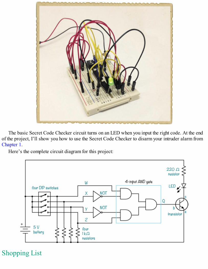
The basic Secret Code Checker circuit turns on an LED when you input the right code. At the endof the project, I’ll show you how to use the Secret Code Checker to disarm your intruder alarm fromChapter 1.
Here’s the complete circuit diagram for this project:
Shopping List
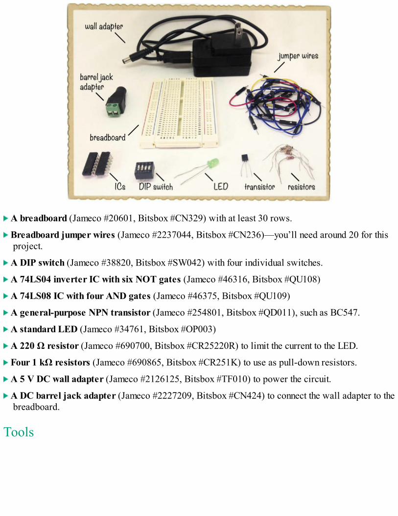
A breadboard (Jameco #20601, Bitsbox #CN329) with at least 30 rows.
Breadboard jumper wires (Jameco #2237044, Bitsbox #CN236)—you’ll need around 20 for thisproject.
A DIP switch (Jameco #38820, Bitsbox #SW042) with four individual switches.
A 74LS04 inverter IC with six NOT gates (Jameco #46316, Bitsbox #QU108)
A 74LS08 IC with four AND gates (Jameco #46375, Bitsbox #QU109)
A general-purpose NPN transistor (Jameco #254801, Bitsbox #QD011), such as BC547.
A standard LED (Jameco #34761, Bitsbox #OP003)
A 220 Ω resistor (Jameco #690700, Bitsbox #CR25220R) to limit the current to the LED.
Four 1 kΩ resistors (Jameco #690865, Bitsbox #CR251K) to use as pull-down resistors.
A 5 V DC wall adapter (Jameco #2126125, Bitsbox #TF010) to power the circuit.
A DC barrel jack adapter (Jameco #2227209, Bitsbox #CN424) to connect the wall adapter to thebreadboard.
Tools
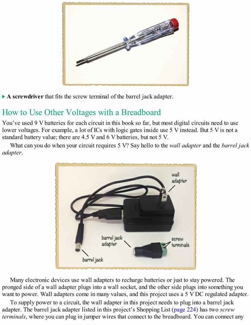
A screwdriver that fits the screw terminal of the barrel jack adapter.
How to Use Other Voltages with a BreadboardYou’ve used 9 V batteries for each circuit in this book so far, but most digital circuits need to uselower voltages. For example, a lot of ICs with logic gates inside use 5 V instead. But 5 V is not astandard battery value; there are 4.5 V and 6 V batteries, but not 5 V.
What can you do when your circuit requires 5 V? Say hello to the wall adapter and the barrel jackadapter.
Many electronic devices use wall adapters to recharge batteries or just to stay powered. Thepronged side of a wall adapter plugs into a wall socket, and the other side plugs into something youwant to power. Wall adapters come in many values, and this project uses a 5 V DC regulated adapter.
To supply power to a circuit, the wall adapter in this project needs to plug into a barrel jackadapter. The barrel jack adapter listed in this project’s Shopping List (page 224) has two screwterminals, where you can plug in jumper wires that connect to the breadboard. You can connect any
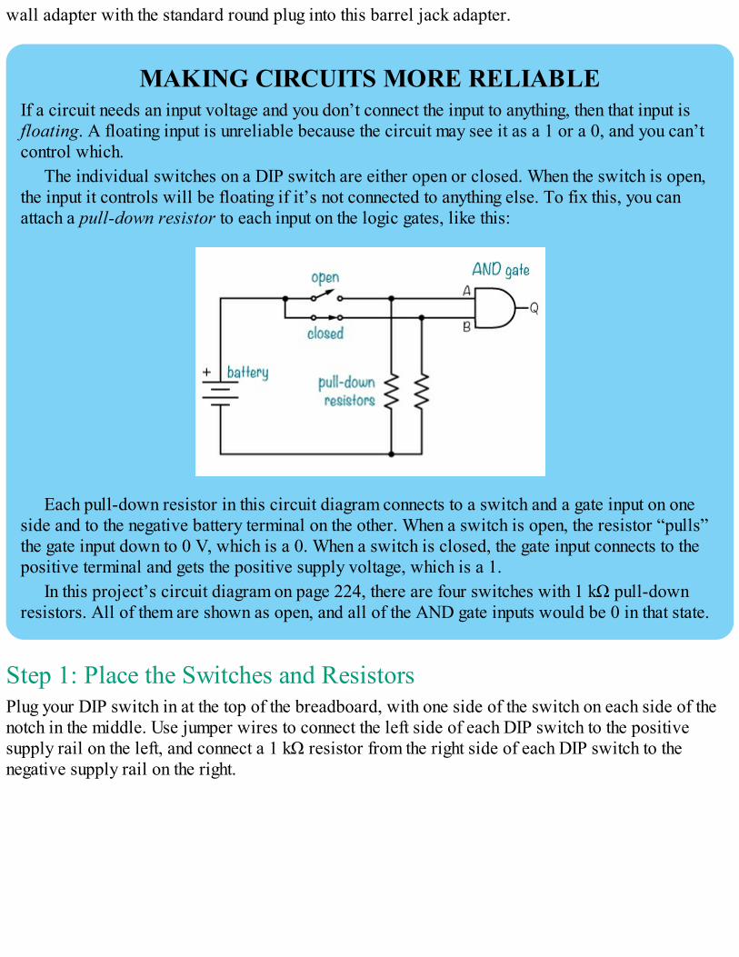
wall adapter with the standard round plug into this barrel jack adapter.
MAKING CIRCUITS MORE RELIABLEIf a circuit needs an input voltage and you don’t connect the input to anything, then that input isfloating. A floating input is unreliable because the circuit may see it as a 1 or a 0, and you can’tcontrol which.
The individual switches on a DIP switch are either open or closed. When the switch is open,the input it controls will be floating if it’s not connected to anything else. To fix this, you canattach a pull-down resistor to each input on the logic gates, like this:
Each pull-down resistor in this circuit diagram connects to a switch and a gate input on oneside and to the negative battery terminal on the other. When a switch is open, the resistor “pulls”the gate input down to 0 V, which is a 0. When a switch is closed, the gate input connects to thepositive terminal and gets the positive supply voltage, which is a 1.
In this project’s circuit diagram on page 224, there are four switches with 1 kΩ pull-downresistors. All of them are shown as open, and all of the AND gate inputs would be 0 in that state.
Step 1: Place the Switches and ResistorsPlug your DIP switch in at the top of the breadboard, with one side of the switch on each side of thenotch in the middle. Use jumper wires to connect the left side of each DIP switch to the positivesupply rail on the left, and connect a 1 kΩ resistor from the right side of each DIP switch to thenegative supply rail on the right.
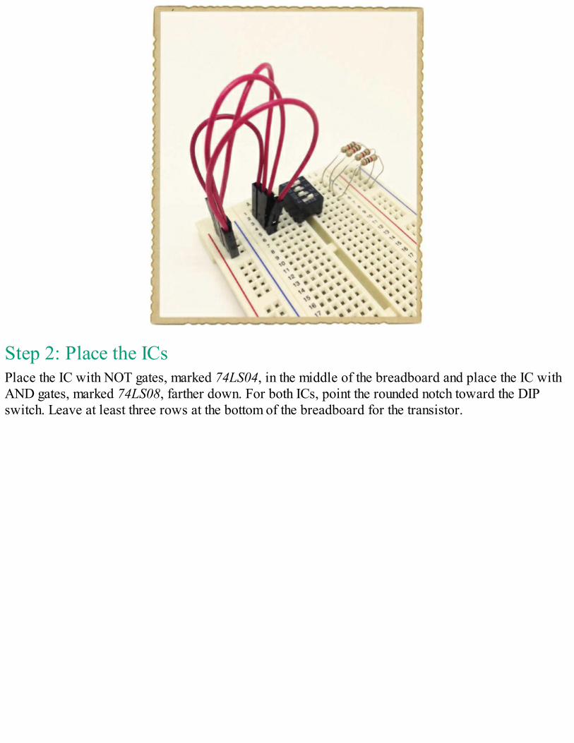
Step 2: Place the ICsPlace the IC with NOT gates, marked 74LS04, in the middle of the breadboard and place the IC withAND gates, marked 74LS08, farther down. For both ICs, point the rounded notch toward the DIPswitch. Leave at least three rows at the bottom of the breadboard for the transistor.
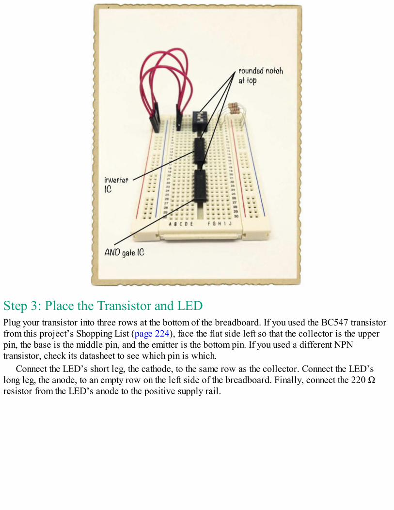
Step 3: Place the Transistor and LEDPlug your transistor into three rows at the bottom of the breadboard. If you used the BC547 transistorfrom this project’s Shopping List (page 224), face the flat side left so that the collector is the upperpin, the base is the middle pin, and the emitter is the bottom pin. If you used a different NPNtransistor, check its datasheet to see which pin is which.
Connect the LED’s short leg, the cathode, to the same row as the collector. Connect the LED’slong leg, the anode, to an empty row on the left side of the breadboard. Finally, connect the 220 Ωresistor from the LED’s anode to the positive supply rail.
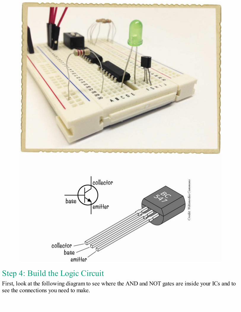
Step 4: Build the Logic CircuitFirst, look at the following diagram to see where the AND and NOT gates are inside your ICs and tosee the connections you need to make.
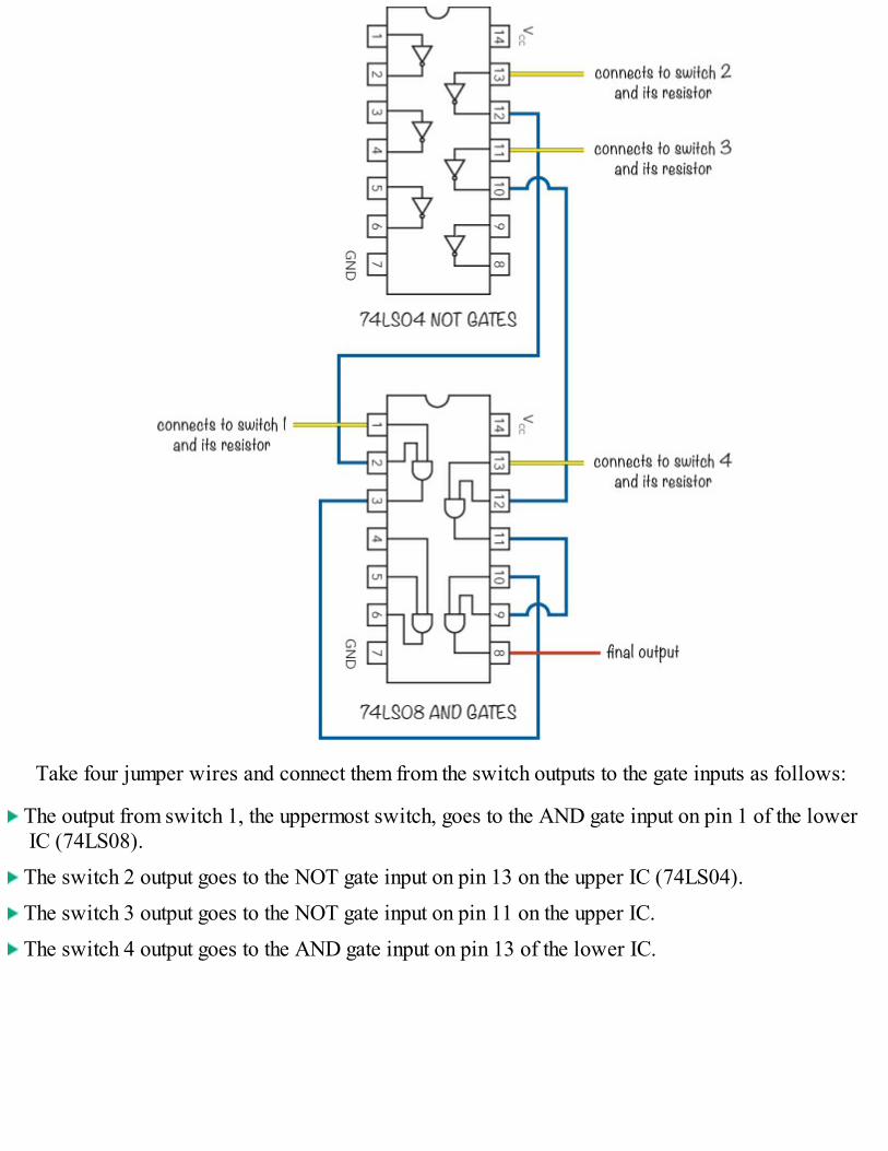
Take four jumper wires and connect them from the switch outputs to the gate inputs as follows:
The output from switch 1, the uppermost switch, goes to the AND gate input on pin 1 of the lowerIC (74LS08).
The switch 2 output goes to the NOT gate input on pin 13 on the upper IC (74LS04).
The switch 3 output goes to the NOT gate input on pin 11 on the upper IC.
The switch 4 output goes to the AND gate input on pin 13 of the lower IC.
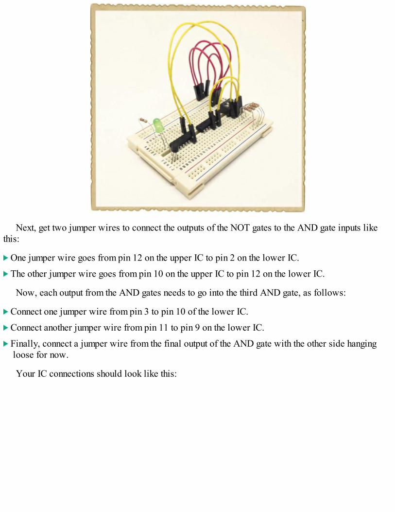
Next, get two jumper wires to connect the outputs of the NOT gates to the AND gate inputs likethis:
One jumper wire goes from pin 12 on the upper IC to pin 2 on the lower IC.
The other jumper wire goes from pin 10 on the upper IC to pin 12 on the lower IC.
Now, each output from the AND gates needs to go into the third AND gate, as follows:
Connect one jumper wire from pin 3 to pin 10 of the lower IC.
Connect another jumper wire from pin 11 to pin 9 on the lower IC.
Finally, connect a jumper wire from the final output of the AND gate with the other side hangingloose for now.
Your IC connections should look like this:
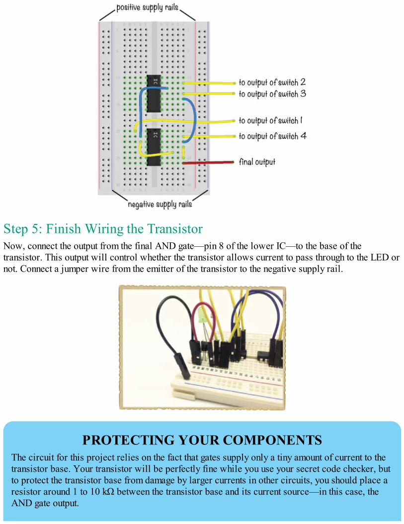
Step 5: Finish Wiring the TransistorNow, connect the output from the final AND gate—pin 8 of the lower IC—to the base of thetransistor. This output will control whether the transistor allows current to pass through to the LED ornot. Connect a jumper wire from the emitter of the transistor to the negative supply rail.
PROTECTING YOUR COMPONENTSThe circuit for this project relies on the fact that gates supply only a tiny amount of current to thetransistor base. Your transistor will be perfectly fine while you use your secret code checker, butto protect the transistor base from damage by larger currents in other circuits, you should place aresistor around 1 to 10 kΩ between the transistor base and its current source—in this case, theAND gate output.
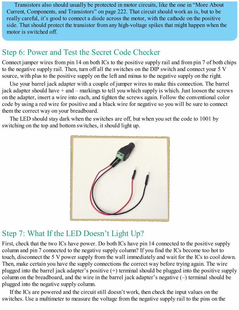
Transistors also should usually be protected in motor circuits, like the one in “More AboutCurrent, Components, and Transistors” on page 222. That circuit should work as is, but to bereally careful, it’s good to connect a diode across the motor, with the cathode on the positiveside. That should protect the transistor from any high-voltage spikes that might happen when themotor is switched off.
Step 6: Power and Test the Secret Code CheckerConnect jumper wires from pin 14 on both ICs to the positive supply rail and from pin 7 of both chipsto the negative supply rail. Then, turn off all the switches on the DIP switch and connect your 5 Vsource, with plus to the positive supply on the left and minus to the negative supply on the right.
Use your barrel jack adapter with a couple of jumper wires to make this connection. The barreljack adapter should have + and – markings to tell you which supply is which. Just loosen the screwson the adapter, insert a wire into each, and tighten the screws again. Follow the conventional colorcode by using a red wire for positive and a black wire for negative so you will be sure to connectthem the correct way on your breadboard.
The LED should stay dark when the switches are off, but when you set the code to 1001 byswitching on the top and bottom switches, it should light up.
Step 7: What If the LED Doesn’t Light Up?First, check that the two ICs have power. Do both ICs have pin 14 connected to the positive supplycolumn and pin 7 connected to the negative supply column? If you find the ICs become too hot totouch, disconnect the 5 V power supply from the wall immediately and wait for the ICs to cool down.Then, make certain you have the supply connections the correct way before trying again. The wireplugged into the barrel jack adapter’s positive (+) terminal should be plugged into the positive supplycolumn on the breadboard, and the wire in the barrel jack adapter’s negative (–) terminal should beplugged into the negative supply column.
If the ICs are powered and the circuit still doesn’t work, then check the input values on theswitches. Use a multimeter to measure the voltage from the negative supply rail to the pins on the
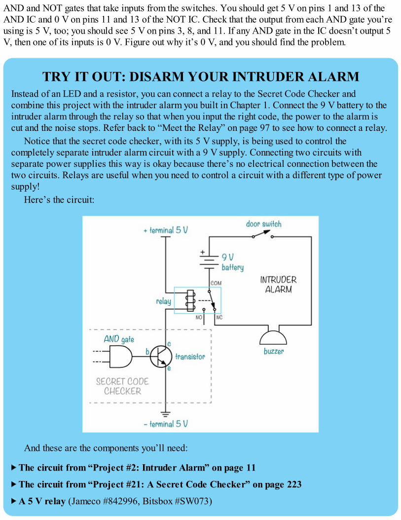
AND and NOT gates that take inputs from the switches. You should get 5 V on pins 1 and 13 of theAND IC and 0 V on pins 11 and 13 of the NOT IC. Check that the output from each AND gate you’reusing is 5 V, too; you should see 5 V on pins 3, 8, and 11. If any AND gate in the IC doesn’t output 5V, then one of its inputs is 0 V. Figure out why it’s 0 V, and you should find the problem.
TRY IT OUT: DISARM YOUR INTRUDER ALARMInstead of an LED and a resistor, you can connect a relay to the Secret Code Checker andcombine this project with the intruder alarm you built in Chapter 1. Connect the 9 V battery to theintruder alarm through the relay so that when you input the right code, the power to the alarm iscut and the noise stops. Refer back to “Meet the Relay” on page 97 to see how to connect a relay.
Notice that the secret code checker, with its 5 V supply, is being used to control thecompletely separate intruder alarm circuit with a 9 V supply. Connecting two circuits withseparate power supplies this way is okay because there’s no electrical connection between thetwo circuits. Relays are useful when you need to control a circuit with a different type of powersupply!
Here’s the circuit:
And these are the components you’ll need:
The circuit from “Project #2: Intruder Alarm” on page 11
The circuit from “Project #21: A Secret Code Checker” on page 223
A 5 V relay (Jameco #842996, Bitsbox #SW073)
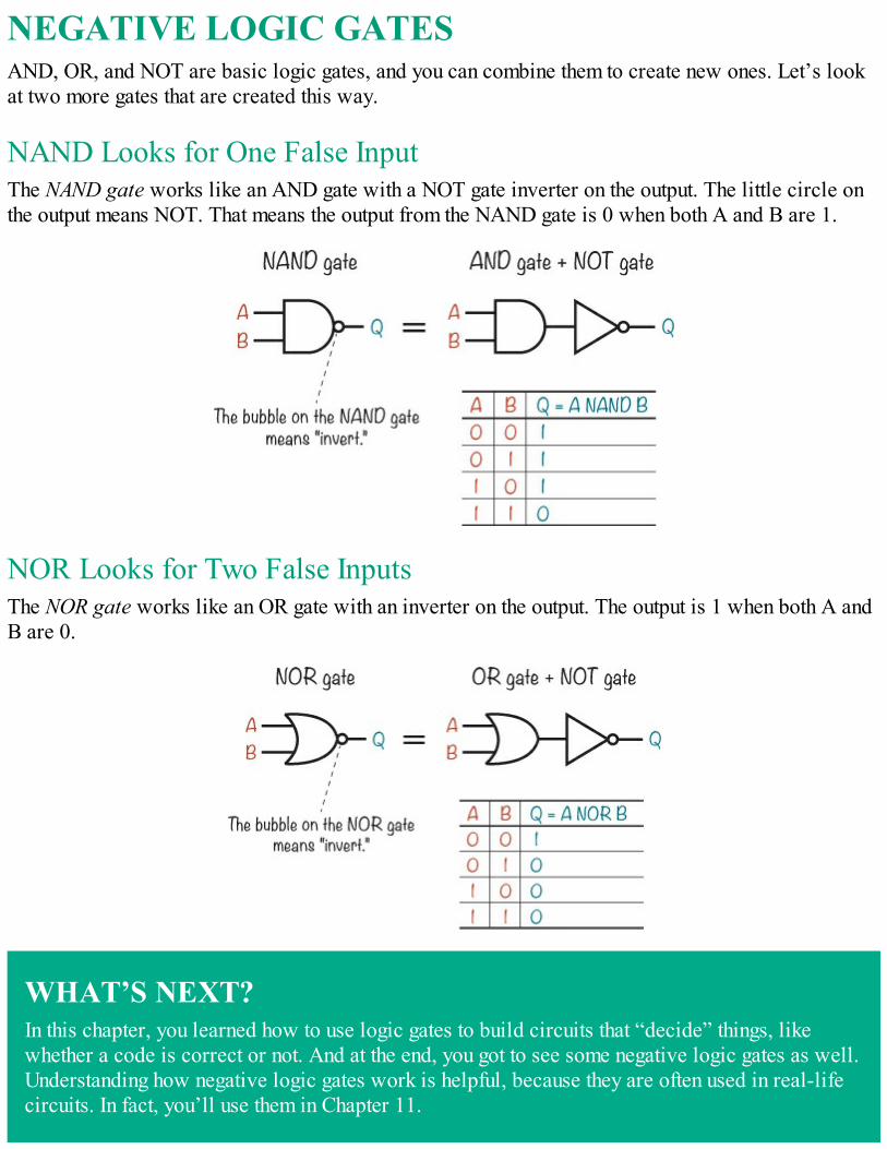
NEGATIVE LOGIC GATESAND, OR, and NOT are basic logic gates, and you can combine them to create new ones. Let’s lookat two more gates that are created this way.
NAND Looks for One False InputThe NAND gate works like an AND gate with a NOT gate inverter on the output. The little circle onthe output means NOT. That means the output from the NAND gate is 0 when both A and B are 1.
NOR Looks for Two False InputsThe NOR gate works like an OR gate with an inverter on the output. The output is 1 when both A andB are 0.
WHAT’S NEXT?In this chapter, you learned how to use logic gates to build circuits that “decide” things, likewhether a code is correct or not. And at the end, you got to see some negative logic gates as well.Understanding how negative logic gates work is helpful, because they are often used in real-lifecircuits. In fact, you’ll use them in Chapter 11.

If you want to explore gates a bit further, I suggest you try combining some logic gates you’velearned about on paper to create an XOR gate. An XOR gate gives out 1 only if the inputs aredifferent from each other.
By combining logic gates in different ways, you can create almost anything you can imagine.But that might be a bit hard to see right now, so in the next chapter, I’m going to show you somemore building blocks you can create with logic gates. You’ll learn how to build your ownmemory circuit, and then you’ll build your own electronic coin tosser!

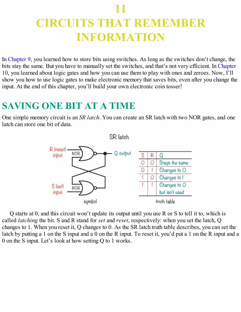
11CIRCUITS THAT REMEMBER
INFORMATION
In Chapter 9, you learned how to store bits using switches. As long as the switches don’t change, thebits stay the same. But you have to manually set the switches, and that’s not very efficient. In Chapter10, you learned about logic gates and how you can use them to play with ones and zeroes. Now, I’llshow you how to use logic gates to make electronic memory that saves bits, even after you change theinput. At the end of this chapter, you’ll build your own electronic coin tosser!
SAVING ONE BIT AT A TIMEOne simple memory circuit is an SR latch. You can create an SR latch with two NOR gates, and onelatch can store one bit of data.
Q starts at 0, and this circuit won’t update its output until you use R or S to tell it to, which iscalled latching the bit. S and R stand for set and reset, respectively: when you set the latch, Qchanges to 1. When you reset it, Q changes to 0. As the SR latch truth table describes, you can set thelatch by putting a 1 on the S input and a 0 on the R input. To reset it, you’d put a 1 on the R input and a0 on the S input. Let’s look at how setting Q to 1 works.
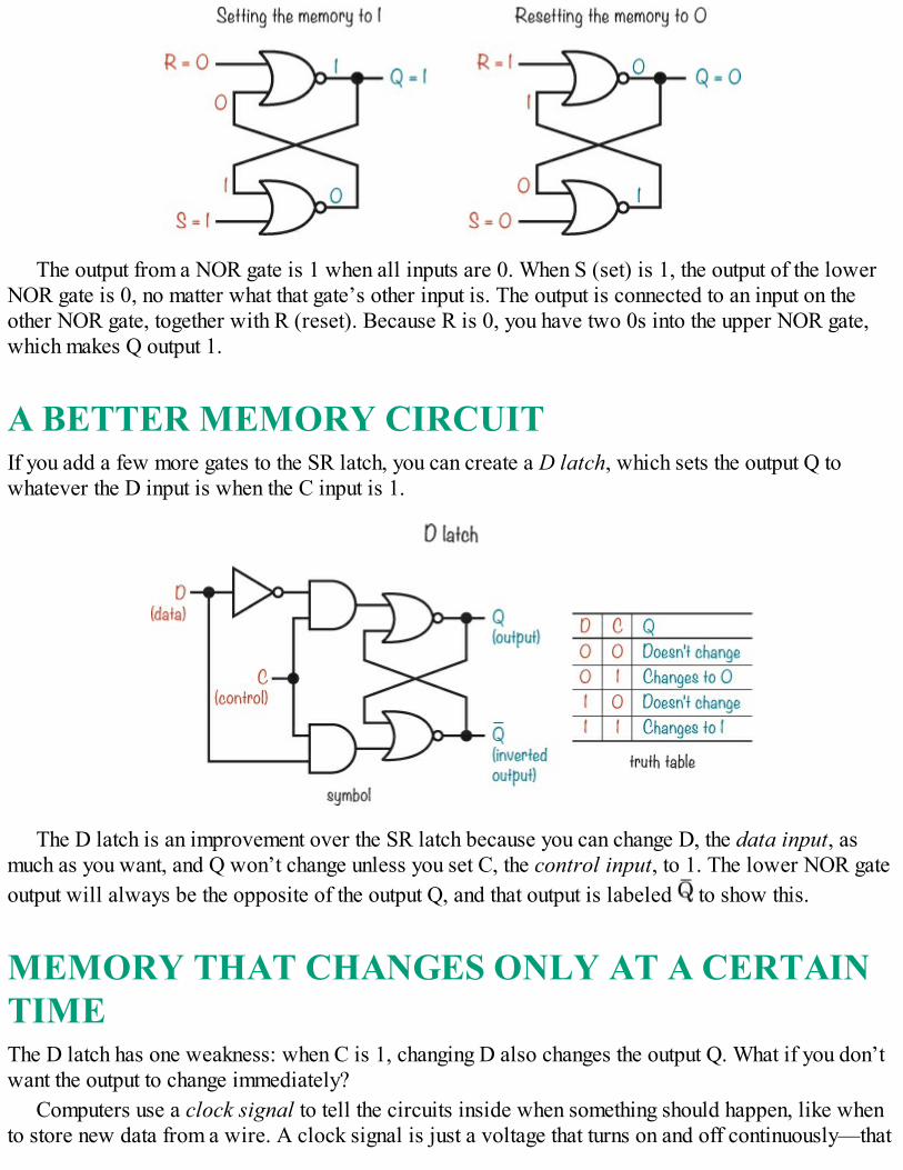
The output from a NOR gate is 1 when all inputs are 0. When S (set) is 1, the output of the lowerNOR gate is 0, no matter what that gate’s other input is. The output is connected to an input on theother NOR gate, together with R (reset). Because R is 0, you have two 0s into the upper NOR gate,which makes Q output 1.
A BETTER MEMORY CIRCUITIf you add a few more gates to the SR latch, you can create a D latch, which sets the output Q towhatever the D input is when the C input is 1.
The D latch is an improvement over the SR latch because you can change D, the data input, asmuch as you want, and Q won’t change unless you set C, the control input, to 1. The lower NOR gateoutput will always be the opposite of the output Q, and that output is labeled to show this.
MEMORY THAT CHANGES ONLY AT A CERTAINTIMEThe D latch has one weakness: when C is 1, changing D also changes the output Q. What if you don’twant the output to change immediately?
Computers use a clock signal to tell the circuits inside when something should happen, like whento store new data from a wire. A clock signal is just a voltage that turns on and off continuously—that
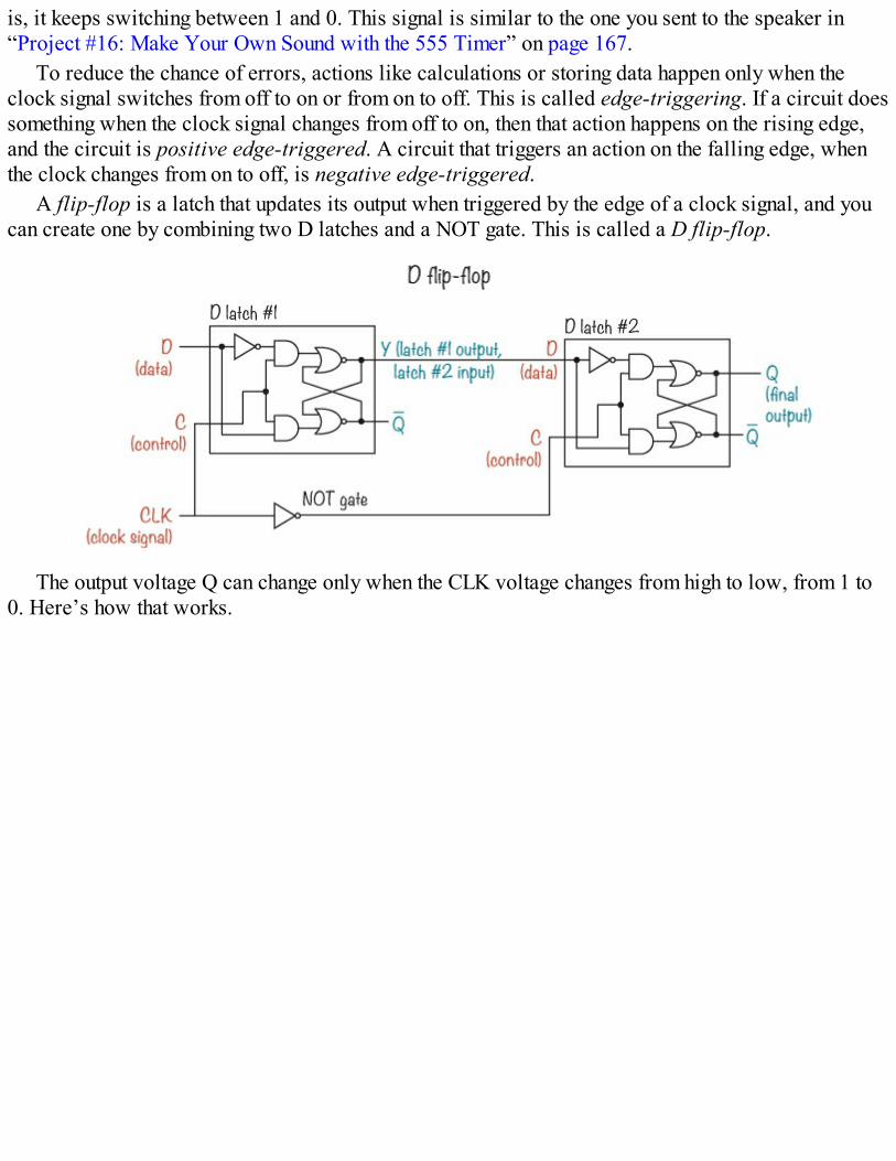
is, it keeps switching between 1 and 0. This signal is similar to the one you sent to the speaker in“Project #16: Make Your Own Sound with the 555 Timer” on page 167.
To reduce the chance of errors, actions like calculations or storing data happen only when theclock signal switches from off to on or from on to off. This is called edge-triggering. If a circuit doessomething when the clock signal changes from off to on, then that action happens on the rising edge,and the circuit is positive edge-triggered. A circuit that triggers an action on the falling edge, whenthe clock changes from on to off, is negative edge-triggered.
A flip-flop is a latch that updates its output when triggered by the edge of a clock signal, and youcan create one by combining two D latches and a NOT gate. This is called a D flip-flop.
The output voltage Q can change only when the CLK voltage changes from high to low, from 1 to0. Here’s how that works.
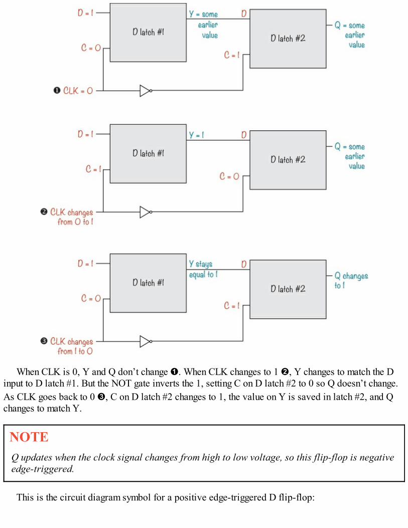
When CLK is 0, Y and Q don’t change ➊. When CLK changes to 1 ➋, Y changes to match the Dinput to D latch #1. But the NOT gate inverts the 1, setting C on D latch #2 to 0 so Q doesn’t change.As CLK goes back to 0 ➌, C on D latch #2 changes to 1, the value on Y is saved in latch #2, and Qchanges to match Y.
NOTEQ updates when the clock signal changes from high to low voltage, so this flip-flop is negativeedge-triggered.
This is the circuit diagram symbol for a positive edge-triggered D flip-flop:
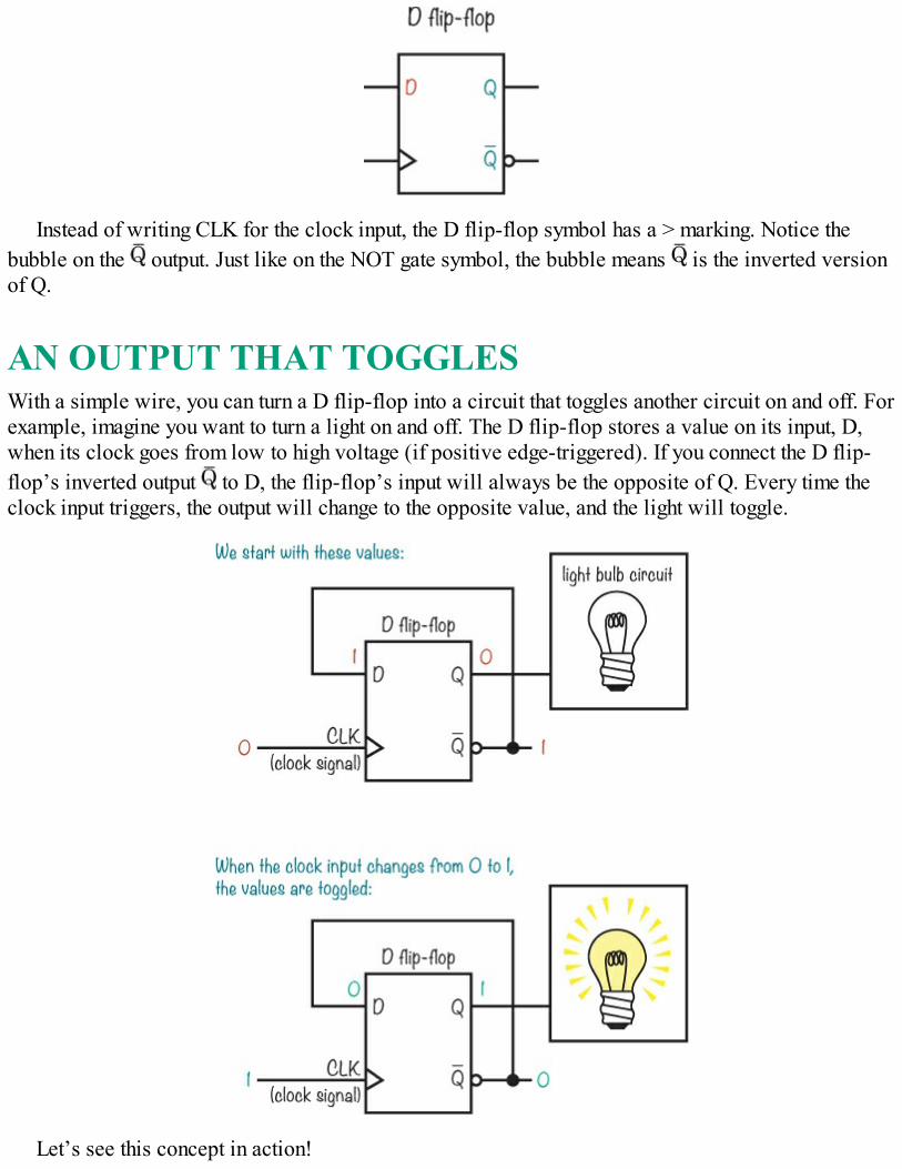
Instead of writing CLK for the clock input, the D flip-flop symbol has a > marking. Notice thebubble on the output. Just like on the NOT gate symbol, the bubble means is the inverted versionof Q.
AN OUTPUT THAT TOGGLESWith a simple wire, you can turn a D flip-flop into a circuit that toggles another circuit on and off. Forexample, imagine you want to turn a light on and off. The D flip-flop stores a value on its input, D,when its clock goes from low to high voltage (if positive edge-triggered). If you connect the D flip-flop’s inverted output to D, the flip-flop’s input will always be the opposite of Q. Every time theclock input triggers, the output will change to the opposite value, and the light will toggle.
Let’s see this concept in action!
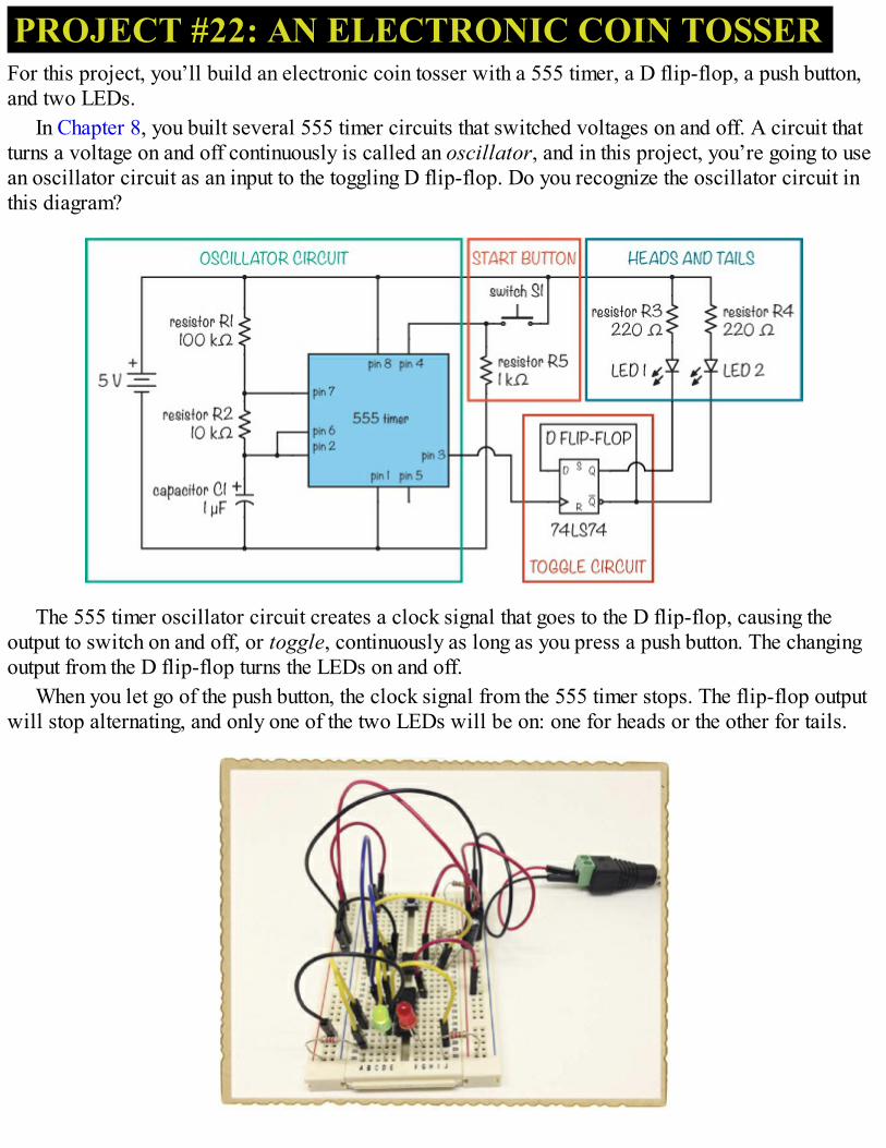
PROJECT #22: AN ELECTRONIC COIN TOSSERFor this project, you’ll build an electronic coin tosser with a 555 timer, a D flip-flop, a push button,and two LEDs.
In Chapter 8, you built several 555 timer circuits that switched voltages on and off. A circuit thatturns a voltage on and off continuously is called an oscillator, and in this project, you’re going to usean oscillator circuit as an input to the toggling D flip-flop. Do you recognize the oscillator circuit inthis diagram?
The 555 timer oscillator circuit creates a clock signal that goes to the D flip-flop, causing theoutput to switch on and off, or toggle, continuously as long as you press a push button. The changingoutput from the D flip-flop turns the LEDs on and off.
When you let go of the push button, the clock signal from the 555 timer stops. The flip-flop outputwill stop alternating, and only one of the two LEDs will be on: one for heads or the other for tails.
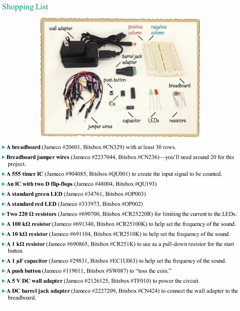
Shopping List
A breadboard (Jameco #20601, Bitsbox #CN329) with at least 30 rows.
Breadboard jumper wires (Jameco #2237044, Bitsbox #CN236)—you’ll need around 20 for thisproject.
A 555 timer IC (Jameco #904085, Bitsbox #QU001) to create the input signal to be counted.
An IC with two D flip-flops (Jameco #48004, Bitsbox #QU193)
A standard green LED (Jameco #34761, Bitsbox #OP003)
A standard red LED (Jameco #333973, Bitsbox #OP002)
Two 220 Ω resistors (Jameco #690700, Bitsbox #CR25220R) for limiting the current to the LEDs.
A 100 kΩ resistor (Jameco #691340, Bitsbox #CR25100K) to help set the frequency of the sound.
A 10 kΩ resistor (Jameco #691104, Bitsbox #CR2510K) to help set the frequency of the sound.
A 1 kΩ resistor (Jameco #690865, Bitsbox #CR251K) to use as a pull-down resistor for the startbutton.
A 1 µF capacitor (Jameco #29831, Bitsbox #EC1U063) to help set the frequency of the sound.
A push button (Jameco #119011, Bitsbox #SW087) to “toss the coin.”
A 5 V DC wall adapter (Jameco #2126125, Bitsbox #TF010) to power the circuit.
A DC barrel jack adapter (Jameco #2227209, Bitsbox #CN424) to connect the wall adapter to thebreadboard.
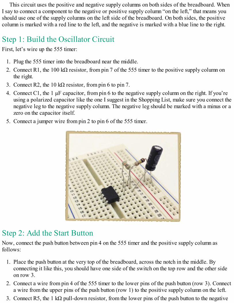
This circuit uses the positive and negative supply columns on both sides of the breadboard. WhenI say to connect a component to the negative or positive supply column “on the left,” that means youshould use one of the supply columns on the left side of the breadboard. On both sides, the positivecolumn is marked with a red line to the left, and the negative is marked with a blue line to the right.
Step 1: Build the Oscillator CircuitFirst, let’s wire up the 555 timer:
1. Plug the 555 timer into the breadboard near the middle.2. Connect R1, the 100 kΩ resistor, from pin 7 of the 555 timer to the positive supply column on
the right.3. Connect R2, the 10 kΩ resistor, from pin 6 to pin 7.4. Connect C1, the 1 µF capacitor, from pin 6 to the negative supply column on the right. If you’re
using a polarized capacitor like the one I suggest in the Shopping List, make sure you connect thenegative leg to the negative supply column. The negative leg should be marked with a minus or azero on the capacitor itself.
5. Connect a jumper wire from pin 2 to pin 6 of the 555 timer.
Step 2: Add the Start ButtonNow, connect the push button between pin 4 on the 555 timer and the positive supply column asfollows:
1. Place the push button at the very top of the breadboard, across the notch in the middle. Byconnecting it like this, you should have one side of the switch on the top row and the other sideon row 3.
2. Connect a wire from pin 4 of the 555 timer to the lower pins of the push button (row 3). Connecta wire from the upper pins of the push button (row 1) to the positive supply column on the left.
3. Connect R5, the 1 kΩ pull-down resistor, from the lower pins of the push button to the negative
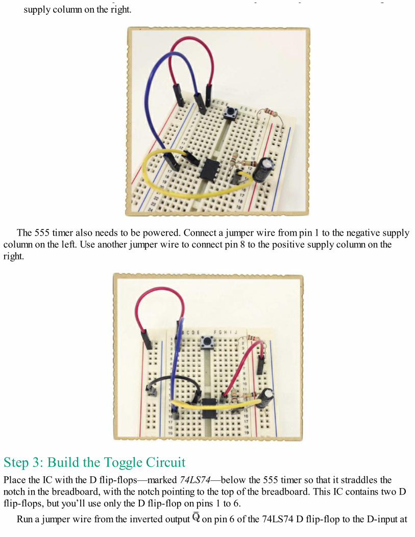
3. Connect R5, the 1 kΩ pull-down resistor, from the lower pins of the push button to the negativesupply column on the right.
The 555 timer also needs to be powered. Connect a jumper wire from pin 1 to the negative supplycolumn on the left. Use another jumper wire to connect pin 8 to the positive supply column on theright.
Step 3: Build the Toggle CircuitPlace the IC with the D flip-flops—marked 74LS74—below the 555 timer so that it straddles thenotch in the breadboard, with the notch pointing to the top of the breadboard. This IC contains two Dflip-flops, but you’ll use only the D flip-flop on pins 1 to 6.
Run a jumper wire from the inverted output on pin 6 of the 74LS74 D flip-flop to the D-input at
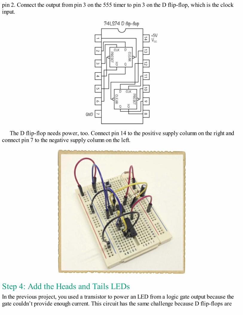
pin 2. Connect the output from pin 3 on the 555 timer to pin 3 on the D flip-flop, which is the clockinput.
The D flip-flop needs power, too. Connect pin 14 to the positive supply column on the right andconnect pin 7 to the negative supply column on the left.
Step 4: Add the Heads and Tails LEDsIn the previous project, you used a transistor to power an LED from a logic gate output because thegate couldn’t provide enough current. This circuit has the same challenge because D flip-flops are
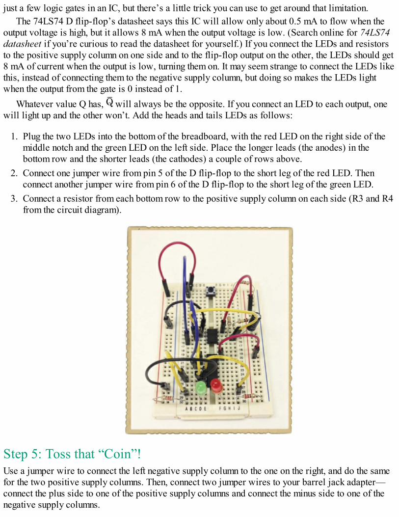
just a few logic gates in an IC, but there’s a little trick you can use to get around that limitation.The 74LS74 D flip-flop’s datasheet says this IC will allow only about 0.5 mA to flow when the
output voltage is high, but it allows 8 mA when the output voltage is low. (Search online for 74LS74datasheet if you’re curious to read the datasheet for yourself.) If you connect the LEDs and resistorsto the positive supply column on one side and to the flip-flop output on the other, the LEDs should get8 mA of current when the output is low, turning them on. It may seem strange to connect the LEDs likethis, instead of connecting them to the negative supply column, but doing so makes the LEDs lightwhen the output from the gate is 0 instead of 1.
Whatever value Q has, will always be the opposite. If you connect an LED to each output, onewill light up and the other won’t. Add the heads and tails LEDs as follows:
1. Plug the two LEDs into the bottom of the breadboard, with the red LED on the right side of themiddle notch and the green LED on the left side. Place the longer leads (the anodes) in thebottom row and the shorter leads (the cathodes) a couple of rows above.
2. Connect one jumper wire from pin 5 of the D flip-flop to the short leg of the red LED. Thenconnect another jumper wire from pin 6 of the D flip-flop to the short leg of the green LED.
3. Connect a resistor from each bottom row to the positive supply column on each side (R3 and R4from the circuit diagram).
Step 5: Toss that “Coin”!Use a jumper wire to connect the left negative supply column to the one on the right, and do the samefor the two positive supply columns. Then, connect two jumper wires to your barrel jack adapter—connect the plus side to one of the positive supply columns and connect the minus side to one of thenegative supply columns.
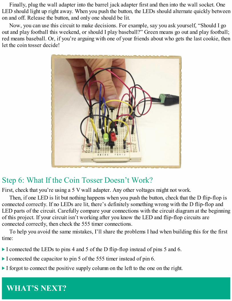
Finally, plug the wall adapter into the barrel jack adapter first and then into the wall socket. OneLED should light up right away. When you push the button, the LEDs should alternate quickly betweenon and off. Release the button, and only one should be lit.
Now, you can use this circuit to make decisions. For example, say you ask yourself, “Should I goout and play football this weekend, or should I play baseball?” Green means go out and play football;red means baseball. Or, if you’re arguing with one of your friends about who gets the last cookie, thenlet the coin tosser decide!
Step 6: What If the Coin Tosser Doesn’t Work?First, check that you’re using a 5 V wall adapter. Any other voltages might not work.
Then, if one LED is lit but nothing happens when you push the button, check that the D flip-flop isconnected correctly. If no LEDs are lit, there’s definitely something wrong with the D flip-flop andLED parts of the circuit. Carefully compare your connections with the circuit diagram at the beginningof this project. If your circuit isn’t working after you know the LED and flip-flop circuits areconnected correctly, then check the 555 timer connections.
To help you avoid the same mistakes, I’ll share the problems I had when building this for the firsttime:
I connected the LEDs to pins 4 and 5 of the D flip-flop instead of pins 5 and 6.
I connected the capacitor to pin 5 of the 555 timer instead of pin 6.
I forgot to connect the positive supply column on the left to the one on the right.
WHAT’S NEXT?

You’ve built a lot of different circuits in this book! At this point you have a solid foundation inelectronics, both in theory and practical experience. Now, the next step is to focus on what youthink is fun. Find a project you really want to build—and go make it!
The best way to continue learning is to build lots of circuits and read about anything you’recurious about. Follow tutorials online and find more books on different topics in electronics.
In Chapter 12, the final chapter, I’ll show you how to build one last project: a really coolgame where you have to test your reaction speed by “catching” a light. After that, I hope you’llcontinue exploring, playing, and having fun with electronics. There are so many great things youcan build!

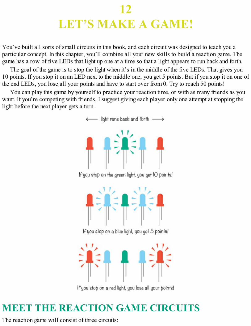
12LET’S MAKE A GAME!
You’ve built all sorts of small circuits in this book, and each circuit was designed to teach you aparticular concept. In this chapter, you’ll combine all your new skills to build a reaction game. Thegame has a row of five LEDs that light up one at a time so that a light appears to run back and forth.
The goal of the game is to stop the light when it’s in the middle of the five LEDs. That gives you10 points. If you stop it on an LED next to the middle one, you get 5 points. But if you stop it on one ofthe end LEDs, you lose all your points and have to start over from 0. Try to reach 50 points!
You can play this game by yourself to practice your reaction time, or with as many friends as youwant. If you’re competing with friends, I suggest giving each player only one attempt at stopping thelight before the next player gets a turn.
MEET THE REACTION GAME CIRCUITSThe reaction game will consist of three circuits:
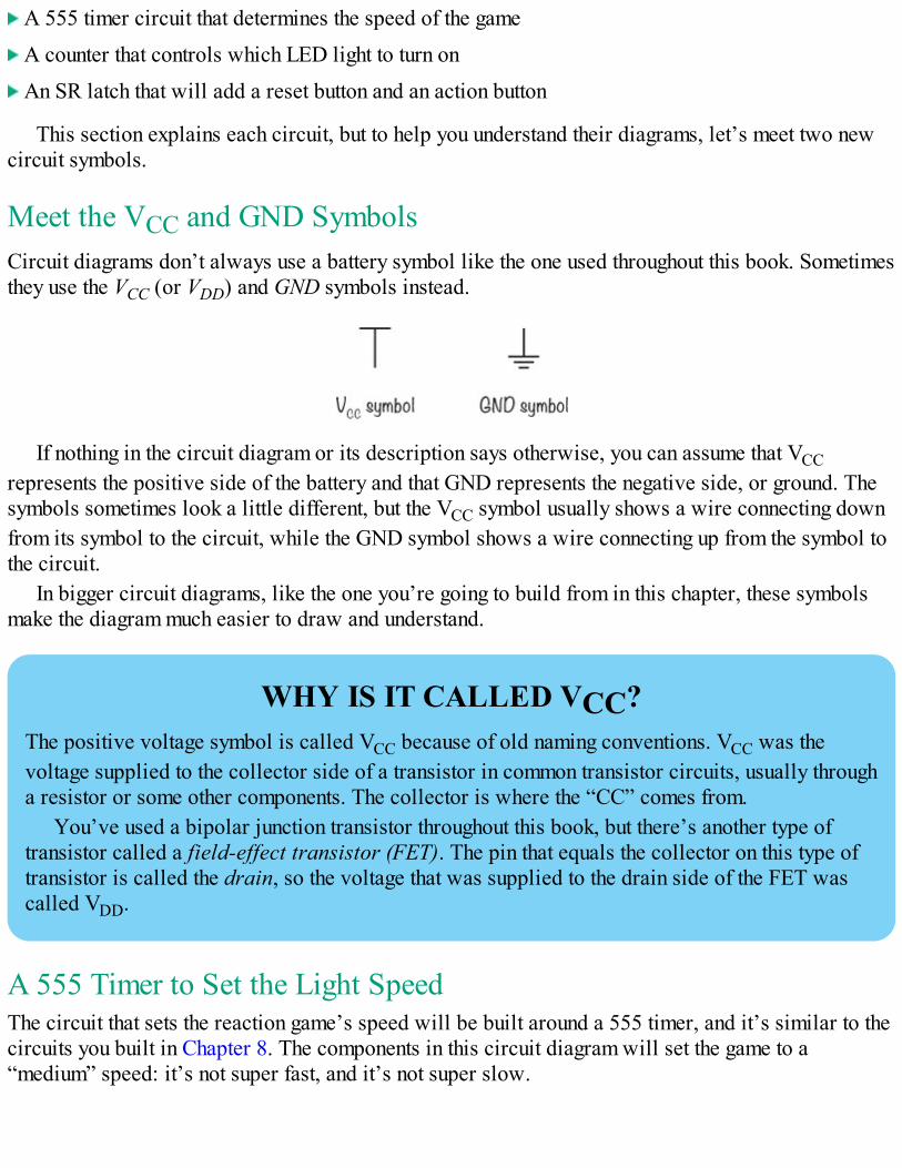
A 555 timer circuit that determines the speed of the game
A counter that controls which LED light to turn on
An SR latch that will add a reset button and an action button
This section explains each circuit, but to help you understand their diagrams, let’s meet two newcircuit symbols.
Meet the VCC and GND SymbolsCircuit diagrams don’t always use a battery symbol like the one used throughout this book. Sometimesthey use the VCC (or VDD) and GND symbols instead.
If nothing in the circuit diagram or its description says otherwise, you can assume that VCCrepresents the positive side of the battery and that GND represents the negative side, or ground. Thesymbols sometimes look a little different, but the VCC symbol usually shows a wire connecting downfrom its symbol to the circuit, while the GND symbol shows a wire connecting up from the symbol tothe circuit.
In bigger circuit diagrams, like the one you’re going to build from in this chapter, these symbolsmake the diagram much easier to draw and understand.
WHY IS IT CALLED VCC?The positive voltage symbol is called VCC because of old naming conventions. VCC was thevoltage supplied to the collector side of a transistor in common transistor circuits, usually througha resistor or some other components. The collector is where the “CC” comes from.
You’ve used a bipolar junction transistor throughout this book, but there’s another type oftransistor called a field-effect transistor (FET). The pin that equals the collector on this type oftransistor is called the drain, so the voltage that was supplied to the drain side of the FET wascalled VDD.
A 555 Timer to Set the Light SpeedThe circuit that sets the reaction game’s speed will be built around a 555 timer, and it’s similar to thecircuits you built in Chapter 8. The components in this circuit diagram will set the game to a“medium” speed: it’s not super fast, and it’s not super slow.
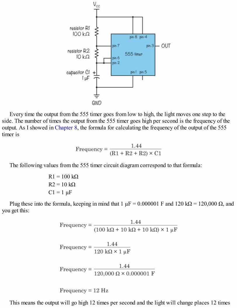
Every time the output from the 555 timer goes from low to high, the light moves one step to theside. The number of times the output from the 555 timer goes high per second is the frequency of theoutput. As I showed in Chapter 8, the formula for calculating the frequency of the output of the 555timer is
The following values from the 555 timer circuit diagram correspond to that formula:
R1 = 100 kΩR2 = 10 kΩC1 = 1 µF
Plug these into the formula, keeping in mind that 1 µF = 0.000001 F and 120 kΩ = 120,000 Ω, andyou get this:
This means the output will go high 12 times per second and the light will change places 12 times
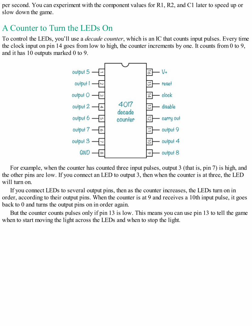
per second. You can experiment with the component values for R1, R2, and C1 later to speed up orslow down the game.
A Counter to Turn the LEDs OnTo control the LEDs, you’ll use a decade counter, which is an IC that counts input pulses. Every timethe clock input on pin 14 goes from low to high, the counter increments by one. It counts from 0 to 9,and it has 10 outputs marked 0 to 9.
For example, when the counter has counted three input pulses, output 3 (that is, pin 7) is high, andthe other pins are low. If you connect an LED to output 3, then when the counter is at three, the LEDwill turn on.
If you connect LEDs to several output pins, then as the counter increases, the LEDs turn on inorder, according to their output pins. When the counter is at 9 and receives a 10th input pulse, it goesback to 0 and turns the output pins on in order again.
But the counter counts pulses only if pin 13 is low. This means you can use pin 13 to tell the gamewhen to start moving the light across the LEDs and when to stop the light.
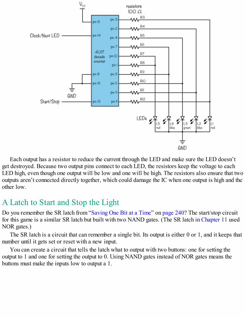
Each output has a resistor to reduce the current through the LED and make sure the LED doesn’tget destroyed. Because two output pins connect to each LED, the resistors keep the voltage to eachLED high, even though one output will be low and one will be high. The resistors also ensure that twooutputs aren’t connected directly together, which could damage the IC when one output is high and theother low.
A Latch to Start and Stop the LightDo you remember the SR latch from “Saving One Bit at a Time” on page 240? The start/stop circuitfor this game is a similar SR latch but built with two NAND gates. (The SR latch in Chapter 11 usedNOR gates.)
The SR latch is a circuit that can remember a single bit. Its output is either 0 or 1, and it keeps thatnumber until it gets set or reset with a new input.
You can create a circuit that tells the latch what to output with two buttons: one for setting theoutput to 1 and one for setting the output to 0. Using NAND gates instead of NOR gates means thebuttons must make the inputs low to output a 1.
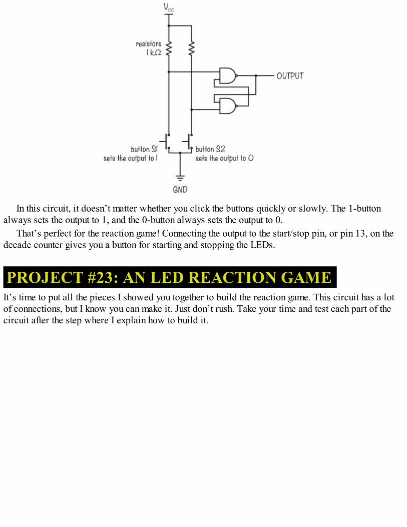
In this circuit, it doesn’t matter whether you click the buttons quickly or slowly. The 1-buttonalways sets the output to 1, and the 0-button always sets the output to 0.
That’s perfect for the reaction game! Connecting the output to the start/stop pin, or pin 13, on thedecade counter gives you a button for starting and stopping the LEDs.
PROJECT #23: AN LED REACTION GAMEIt’s time to put all the pieces I showed you together to build the reaction game. This circuit has a lotof connections, but I know you can make it. Just don’t rush. Take your time and test each part of thecircuit after the step where I explain how to build it.
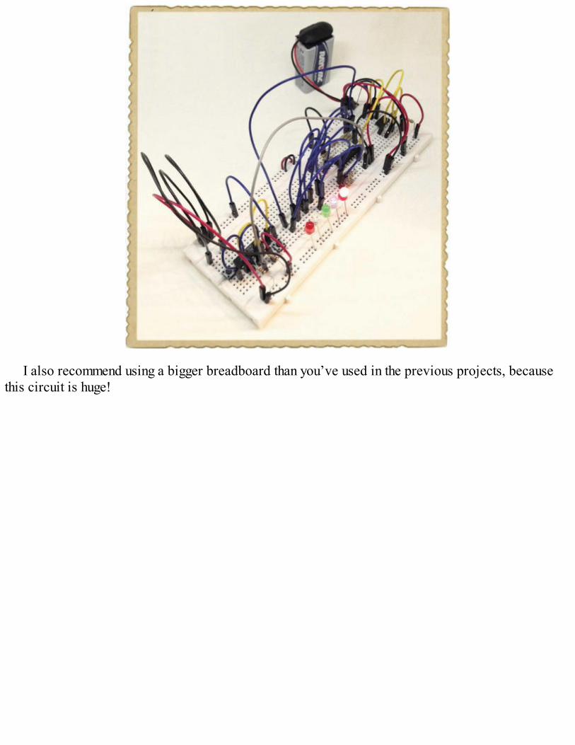
I also recommend using a bigger breadboard than you’ve used in the previous projects, becausethis circuit is huge!
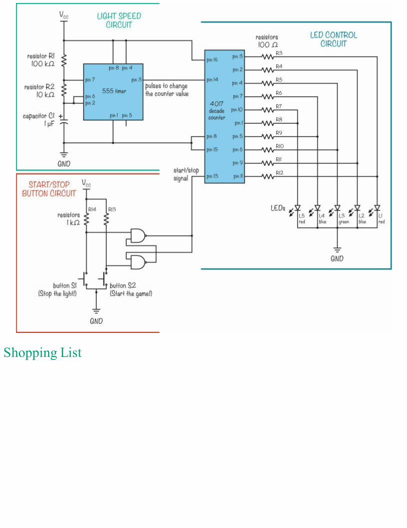
Shopping List
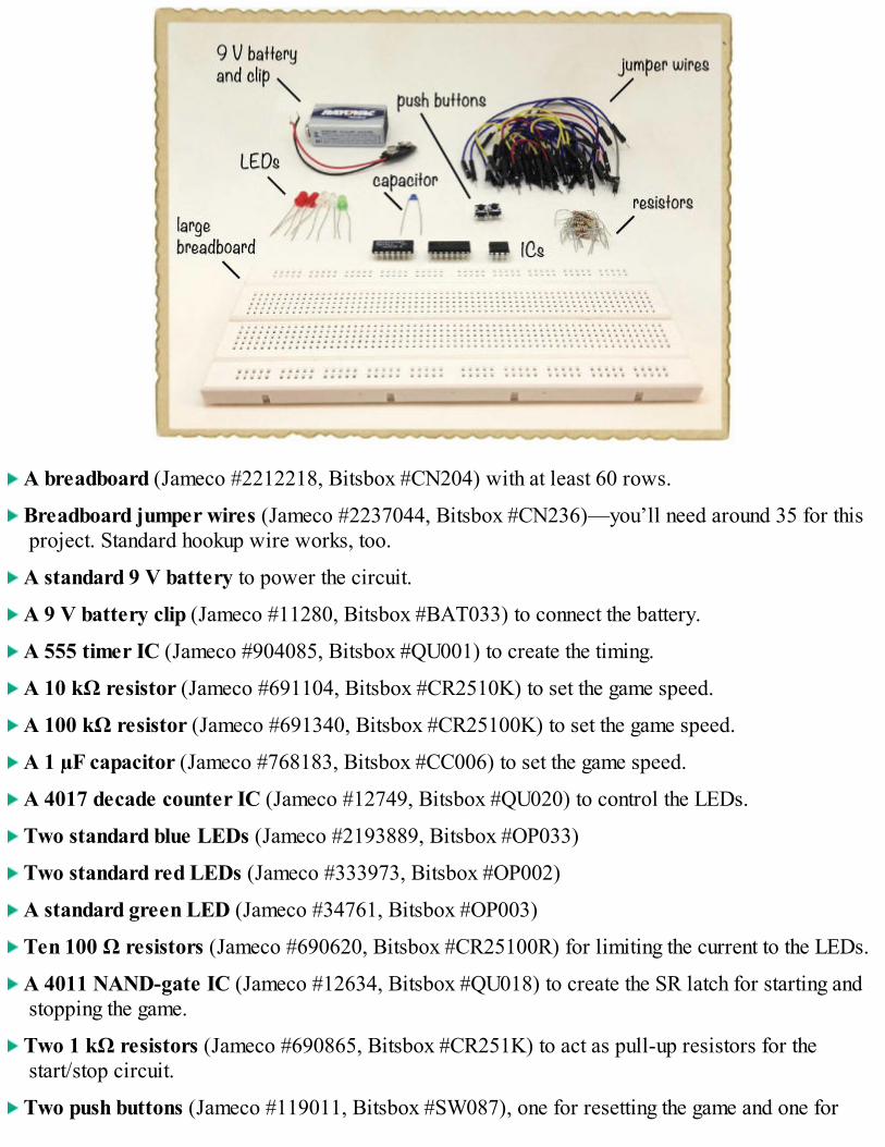
A breadboard (Jameco #2212218, Bitsbox #CN204) with at least 60 rows.
Breadboard jumper wires (Jameco #2237044, Bitsbox #CN236)—you’ll need around 35 for thisproject. Standard hookup wire works, too.
A standard 9 V battery to power the circuit.
A 9 V battery clip (Jameco #11280, Bitsbox #BAT033) to connect the battery.
A 555 timer IC (Jameco #904085, Bitsbox #QU001) to create the timing.
A 10 kΩ resistor (Jameco #691104, Bitsbox #CR2510K) to set the game speed.
A 100 kΩ resistor (Jameco #691340, Bitsbox #CR25100K) to set the game speed.
A 1 µF capacitor (Jameco #768183, Bitsbox #CC006) to set the game speed.
A 4017 decade counter IC (Jameco #12749, Bitsbox #QU020) to control the LEDs.
Two standard blue LEDs (Jameco #2193889, Bitsbox #OP033)
Two standard red LEDs (Jameco #333973, Bitsbox #OP002)
A standard green LED (Jameco #34761, Bitsbox #OP003)
Ten 100 Ω resistors (Jameco #690620, Bitsbox #CR25100R) for limiting the current to the LEDs.
A 4011 NAND-gate IC (Jameco #12634, Bitsbox #QU018) to create the SR latch for starting andstopping the game.
Two 1 kΩ resistors (Jameco #690865, Bitsbox #CR251K) to act as pull-up resistors for thestart/stop circuit.
Two push buttons (Jameco #119011, Bitsbox #SW087), one for resetting the game and one for
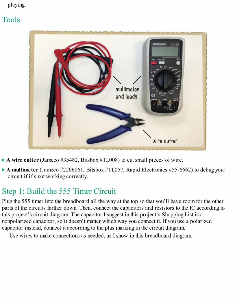
playing.
Tools
A wire cutter (Jameco #35482, Bitsbox #TL008) to cut small pieces of wire.
A multimeter (Jameco #2206061, Bitsbox #TL057, Rapid Electronics #55-6662) to debug yourcircuit if it’s not working correctly.
Step 1: Build the 555 Timer CircuitPlug the 555 timer into the breadboard all the way at the top so that you’ll have room for the otherparts of the circuits farther down. Then, connect the capacitors and resistors to the IC according tothis project’s circuit diagram. The capacitor I suggest in this project’s Shopping List is anonpolarized capacitor, so it doesn’t matter which way you connect it. If you use a polarizedcapacitor instead, connect it according to the plus marking in the circuit diagram.
Use wires to make connections as needed, as I show in this breadboard diagram.
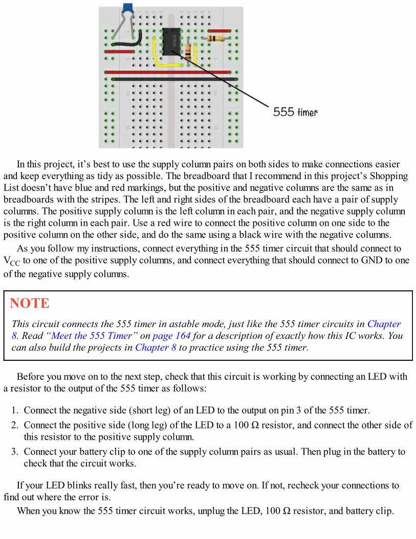
In this project, it’s best to use the supply column pairs on both sides to make connections easierand keep everything as tidy as possible. The breadboard that I recommend in this project’s ShoppingList doesn’t have blue and red markings, but the positive and negative columns are the same as inbreadboards with the stripes. The left and right sides of the breadboard each have a pair of supplycolumns. The positive supply column is the left column in each pair, and the negative supply columnis the right column in each pair. Use a red wire to connect the positive column on one side to thepositive column on the other side, and do the same using a black wire with the negative columns.
As you follow my instructions, connect everything in the 555 timer circuit that should connect toVCC to one of the positive supply columns, and connect everything that should connect to GND to oneof the negative supply columns.
NOTEThis circuit connects the 555 timer in astable mode, just like the 555 timer circuits in Chapter8. Read “Meet the 555 Timer” on page 164 for a description of exactly how this IC works. Youcan also build the projects in Chapter 8 to practice using the 555 timer.
Before you move on to the next step, check that this circuit is working by connecting an LED witha resistor to the output of the 555 timer as follows:
1. Connect the negative side (short leg) of an LED to the output on pin 3 of the 555 timer.2. Connect the positive side (long leg) of the LED to a 100 Ω resistor, and connect the other side of
this resistor to the positive supply column.3. Connect your battery clip to one of the supply column pairs as usual. Then plug in the battery to
check that the circuit works.
If your LED blinks really fast, then you’re ready to move on. If not, recheck your connections tofind out where the error is.
When you know the 555 timer circuit works, unplug the LED, 100 Ω resistor, and battery clip.
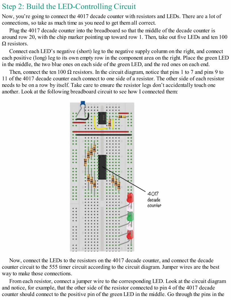
Step 2: Build the LED-Controlling CircuitNow, you’re going to connect the 4017 decade counter with resistors and LEDs. There are a lot ofconnections, so take as much time as you need to get them all correct.
Plug the 4017 decade counter into the breadboard so that the middle of the decade counter isaround row 20, with the chip marker pointing up toward row 1. Then, take out five LEDs and ten 100Ω resistors.
Connect each LED’s negative (short) leg to the negative supply column on the right, and connecteach positive (long) leg to its own empty row in the component area on the right. Place the green LEDin the middle, the two blue ones on each side of the green LED, and the red ones on each end.
Then, connect the ten 100 Ω resistors. In the circuit diagram, notice that pins 1 to 7 and pins 9 to11 of the 4017 decade counter each connect to one side of a resistor. The other side of each resistorneeds to be on a row by itself. Take care to ensure the resistor legs don’t accidentally touch oneanother. Look at the following breadboard circuit to see how I connected them:
Now, connect the LEDs to the resistors on the 4017 decade counter, and connect the decadecounter circuit to the 555 timer circuit according to the circuit diagram. Jumper wires are the bestway to make those connections.
From each resistor, connect a jumper wire to the corresponding LED. Look at the circuit diagramand notice, for example, that the other side of the resistor connected to pin 4 of the 4017 decadecounter should connect to the positive pin of the green LED in the middle. Go through the pins in the
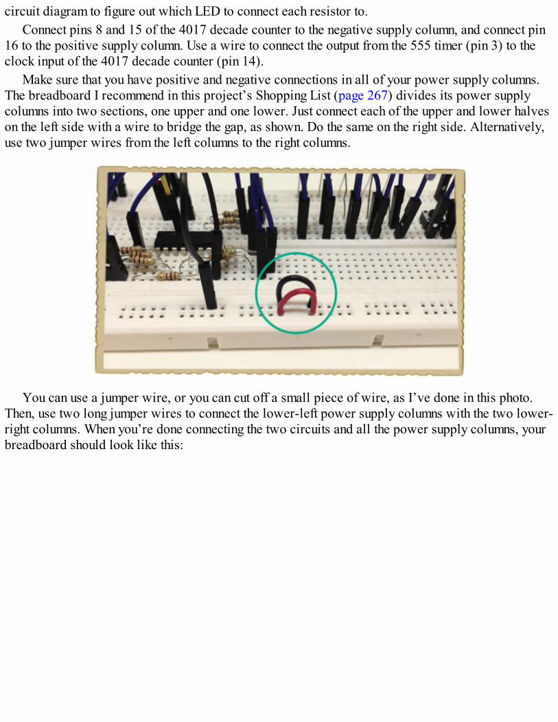
circuit diagram to figure out which LED to connect each resistor to.Connect pins 8 and 15 of the 4017 decade counter to the negative supply column, and connect pin
16 to the positive supply column. Use a wire to connect the output from the 555 timer (pin 3) to theclock input of the 4017 decade counter (pin 14).
Make sure that you have positive and negative connections in all of your power supply columns.The breadboard I recommend in this project’s Shopping List (page 267) divides its power supplycolumns into two sections, one upper and one lower. Just connect each of the upper and lower halveson the left side with a wire to bridge the gap, as shown. Do the same on the right side. Alternatively,use two jumper wires from the left columns to the right columns.
You can use a jumper wire, or you can cut off a small piece of wire, as I’ve done in this photo.Then, use two long jumper wires to connect the lower-left power supply columns with the two lower-right columns. When you’re done connecting the two circuits and all the power supply columns, yourbreadboard should look like this:
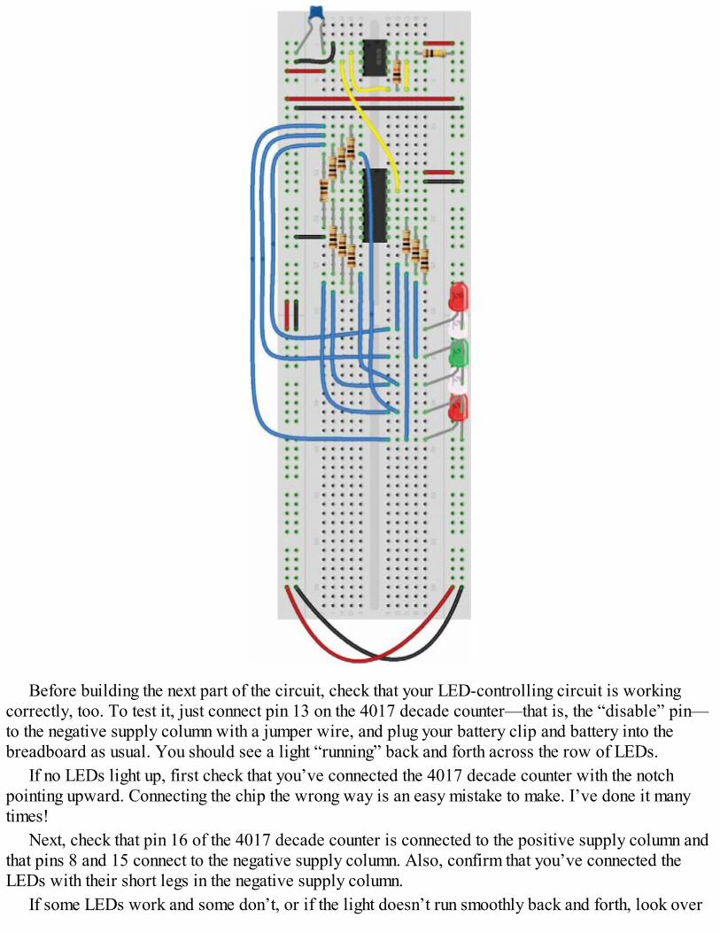
Before building the next part of the circuit, check that your LED-controlling circuit is workingcorrectly, too. To test it, just connect pin 13 on the 4017 decade counter—that is, the “disable” pin—to the negative supply column with a jumper wire, and plug your battery clip and battery into thebreadboard as usual. You should see a light “running” back and forth across the row of LEDs.
If no LEDs light up, first check that you’ve connected the 4017 decade counter with the notchpointing upward. Connecting the chip the wrong way is an easy mistake to make. I’ve done it manytimes!
Next, check that pin 16 of the 4017 decade counter is connected to the positive supply column andthat pins 8 and 15 connect to the negative supply column. Also, confirm that you’ve connected theLEDs with their short legs in the negative supply column.
If some LEDs work and some don’t, or if the light doesn’t run smoothly back and forth, look over
all the connections of resistors and jumper wires to find the fault.After verifying that your circuit works, remove the wire connecting pin 13 of the 4017 decade
counter to the negative supply column, and disconnect the battery from the breadboard.
Step 3: Build the Start and Stop CircuitThe last piece of this project is the button circuit that starts and stops the LEDs. Make theseconnections now:
1. Connect one push button at the bottom of the breadboard, across the notch in the middle. Plug the4011 NAND-gate IC into the breadboard, a couple of rows above the button. Make sure its chipmarking points toward row 1 on the breadboard.
2. Place the second button above the IC on the right component side so that it’s easy to reach it withyour finger.
3. Connect the two resistors, R13 and R14, as shown in the circuit diagram. Then, use jumperwires to make the remaining connections in the SR latch circuit, as shown in the followingbreadboard diagram. Connect the positive and negative supply columns to the NAND-gate IC(pins 14 and 7, respectively), and connect the wire from pin 11 of the NAND-gate IC to pin 13of the 4017 decade counter.
Compare your connections to the following image.
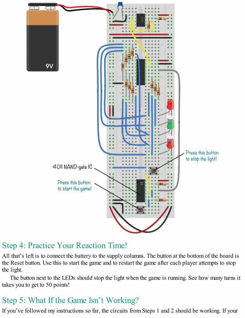
Step 4: Practice Your Reaction Time!All that’s left is to connect the battery to the supply columns. The button at the bottom of the board isthe Reset button. Use this to start the game and to restart the game after each player attempts to stopthe light.
The button next to the LEDs should stop the light when the game is running. See how many turns ittakes you to get to 50 points!
Step 5: What If the Game Isn’t Working?If you’ve followed my instructions so far, the circuits from Steps 1 and 2 should be working. If your
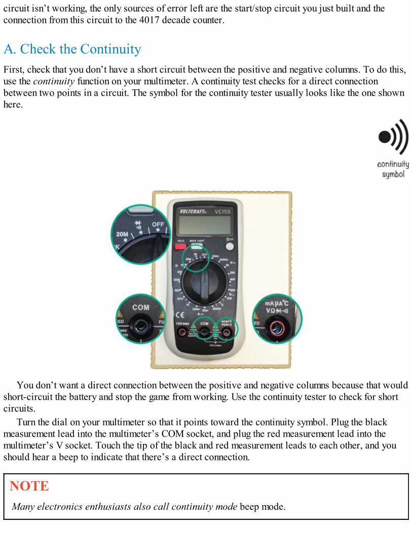
circuit isn’t working, the only sources of error left are the start/stop circuit you just built and theconnection from this circuit to the 4017 decade counter.
A. Check the ContinuityFirst, check that you don’t have a short circuit between the positive and negative columns. To do this,use the continuity function on your multimeter. A continuity test checks for a direct connectionbetween two points in a circuit. The symbol for the continuity tester usually looks like the one shownhere.
You don’t want a direct connection between the positive and negative columns because that wouldshort-circuit the battery and stop the game from working. Use the continuity tester to check for shortcircuits.
Turn the dial on your multimeter so that it points toward the continuity symbol. Plug the blackmeasurement lead into the multimeter’s COM socket, and plug the red measurement lead into themultimeter’s V socket. Touch the tip of the black and red measurement leads to each other, and youshould hear a beep to indicate that there’s a direct connection.
NOTEMany electronics enthusiasts also call continuity mode beep mode.
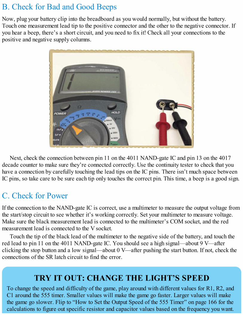
B. Check for Bad and Good BeepsNow, plug your battery clip into the breadboard as you would normally, but without the battery.Touch one measurement lead tip to the positive connector and the other to the negative connector. Ifyou hear a beep, there’s a short circuit, and you need to fix it! Check all your connections to thepositive and negative supply columns.
Next, check the connection between pin 11 on the 4011 NAND-gate IC and pin 13 on the 4017decade counter to make sure they’re connected correctly. Use the continuity tester to check that youhave a connection by carefully touching the lead tips on the IC pins. There isn’t much space betweenIC pins, so take care to be sure each tip only touches the correct pin. This time, a beep is a good sign.
C. Check for PowerIf the connection to the NAND-gate IC is correct, use a multimeter to measure the output voltage fromthe start/stop circuit to see whether it’s working correctly. Set your multimeter to measure voltage.Make sure the black measurement lead is connected to the multimeter’s COM socket, and the redmeasurement lead is connected to the V socket.
Touch the tip of the black lead of the multimeter to the negative side of the battery, and touch thered lead to pin 11 on the 4011 NAND-gate IC. You should see a high signal—about 9 V—afterclicking the stop button and a low signal—about 0 V—after pushing the start button. If not, check theconnections of the SR latch circuit to find the error.
TRY IT OUT: CHANGE THE LIGHT’S SPEEDTo change the speed and difficulty of the game, play around with different values for R1, R2, andC1 around the 555 timer. Smaller values will make the game go faster. Larger values will makethe game go slower. Flip to “How to Set the Output Speed of the 555 Timer” on page 166 for thecalculations to figure out specific resistor and capacitor values based on the frequency you want.
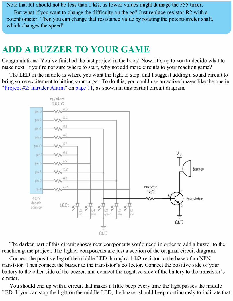
Note that R1 should not be less than 1 kΩ, as lower values might damage the 555 timer.But what if you want to change the difficulty on the go? Just replace resistor R2 with a
potentiometer. Then you can change that resistance value by rotating the potentiometer shaft,which changes the speed!
ADD A BUZZER TO YOUR GAMECongratulations: You’ve finished the last project in the book! Now, it’s up to you to decide what tomake next. If you’re not sure where to start, why not add more circuits to your reaction game?
The LED in the middle is where you want the light to stop, and I suggest adding a sound circuit tobring some excitement to hitting your target. To do this, you could use an active buzzer like the one in“Project #2: Intruder Alarm” on page 11, as shown in this partial circuit diagram.
The darker part of this circuit shows new components you’d need in order to add a buzzer to thereaction game project. The lighter components are just a section of the original circuit diagram.
Connect the positive leg of the middle LED through a 1 kΩ resistor to the base of an NPNtransistor. Then connect the buzzer to the transistor’s collector. Connect the positive side of yourbattery to the other side of the buzzer, and connect the negative side of the battery to the transistor’semitter.
You should end up with a circuit that makes a little beep every time the light passes the middleLED. If you can stop the light on the middle LED, the buzzer should beep continuously to indicate that

you’ve hit the main target.When you’ve customized the game to your liking, solder it onto a prototyping board. Maybe you’ll
even want to place it in a nice box to hide the electronics and show only the buttons and LEDs.
WHAT’S NEXT? GO MAKE COOL STUFF!I’m so happy you’ve read the book all the way to the end! I hope you’ve enjoyed the projects, andI hope you’ll continue building cool things with electronics. One way to practice is to find acircuit diagram for something exciting, buy the components, and build the circuit. You can findcircuit diagrams for almost anything online.
I’d also like to invite you to continue learning on my website, http://www.ohmify.com/. Youcan watch video courses, read lots of project tutorials, and visit a discussion forum where youcan ask questions and make friends with people from all over the world who also like to buildelectronics.
Just make sure to ask your parents’ permission to join the site, as it’s subscription based. Ifthey say yes, then use the following link for a special offer available only to the owners of thisbook: http://ohmify.com/e4k/.
Also be sure to check out the “Online Resources” on page 286—you’ll find loads of tutorialsand more circuits to build at those websites. Have fun!

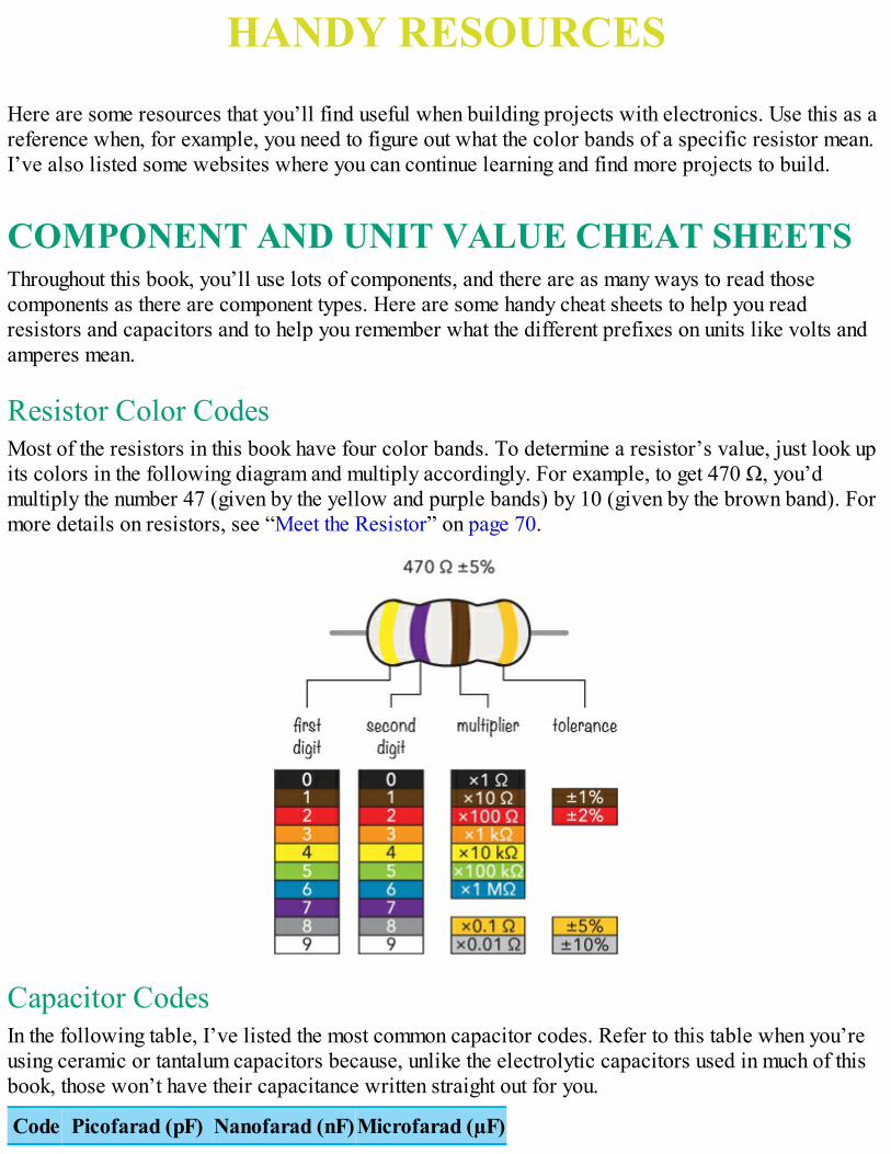
HANDY RESOURCES
Here are some resources that you’ll find useful when building projects with electronics. Use this as areference when, for example, you need to figure out what the color bands of a specific resistor mean.I’ve also listed some websites where you can continue learning and find more projects to build.
COMPONENT AND UNIT VALUE CHEAT SHEETSThroughout this book, you’ll use lots of components, and there are as many ways to read thosecomponents as there are component types. Here are some handy cheat sheets to help you readresistors and capacitors and to help you remember what the different prefixes on units like volts andamperes mean.
Resistor Color CodesMost of the resistors in this book have four color bands. To determine a resistor’s value, just look upits colors in the following diagram and multiply accordingly. For example, to get 470 Ω, you’dmultiply the number 47 (given by the yellow and purple bands) by 10 (given by the brown band). Formore details on resistors, see “Meet the Resistor” on page 70.
Capacitor CodesIn the following table, I’ve listed the most common capacitor codes. Refer to this table when you’reusing ceramic or tantalum capacitors because, unlike the electrolytic capacitors used in much of thisbook, those won’t have their capacitance written straight out for you.
Code Picofarad (pF) Nanofarad (nF)Microfarad (µF)
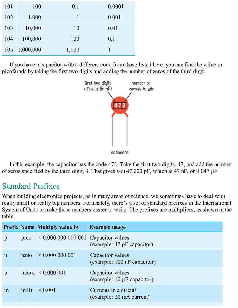
101 100 0.1 0.0001
102 1,000 1 0.001
103 10,000 10 0.01
104 100,000 100 0.1
105 1,000,000 1,000 1
If you have a capacitor with a different code from those listed here, you can find the value inpicofarads by taking the first two digits and adding the number of zeros of the third digit.
In this example, the capacitor has the code 473. Take the first two digits, 47, and add the numberof zeros specified by the third digit, 3. That gives you 47,000 pF, which is 47 nF, or 0.047 µF.
Standard PrefixesWhen building electronics projects, as in many areas of science, we sometimes have to deal withreally small or really big numbers. Fortunately, there’s a set of standard prefixes in the InternationalSystem of Units to make those numbers easier to write. The prefixes are multipliers, as shown in thetable.
Prefix Name Multiply value by Example usage
p pico × 0.000 000 000 001 Capacitor values(example: 47 pF capacitor)
n nano × 0.000 000 001 Capacitor values(example: 100 nF capacitor)
µ micro × 0.000 001 Capacitor values(example: 10 µF capacitor)
m milli × 0.001 Currents in a circuit(example: 20 mA current)
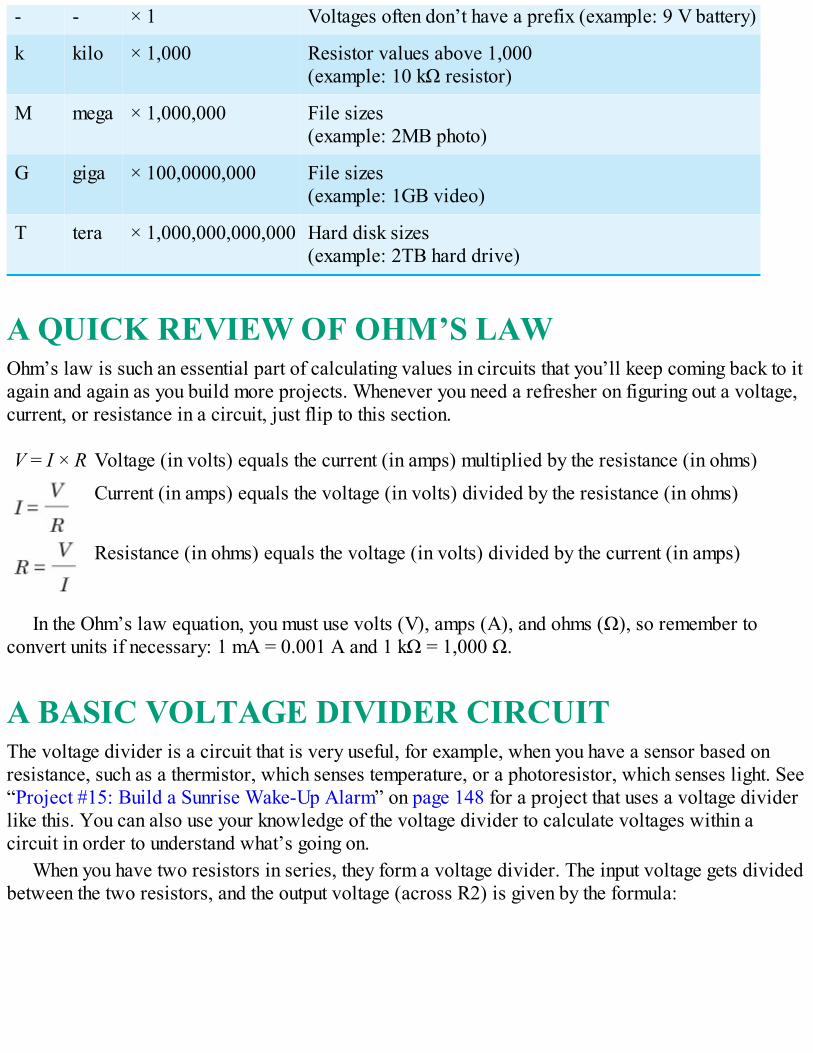
- - × 1 Voltages often don’t have a prefix (example: 9 V battery)
k kilo × 1,000 Resistor values above 1,000(example: 10 kΩ resistor)
M mega × 1,000,000 File sizes(example: 2MB photo)
G giga × 100,0000,000 File sizes(example: 1GB video)
T tera × 1,000,000,000,000 Hard disk sizes(example: 2TB hard drive)
A QUICK REVIEW OF OHM’S LAWOhm’s law is such an essential part of calculating values in circuits that you’ll keep coming back to itagain and again as you build more projects. Whenever you need a refresher on figuring out a voltage,current, or resistance in a circuit, just flip to this section.
V = I × R Voltage (in volts) equals the current (in amps) multiplied by the resistance (in ohms)
Current (in amps) equals the voltage (in volts) divided by the resistance (in ohms)
Resistance (in ohms) equals the voltage (in volts) divided by the current (in amps)
In the Ohm’s law equation, you must use volts (V), amps (A), and ohms (Ω), so remember toconvert units if necessary: 1 mA = 0.001 A and 1 kΩ = 1,000 Ω.
A BASIC VOLTAGE DIVIDER CIRCUITThe voltage divider is a circuit that is very useful, for example, when you have a sensor based onresistance, such as a thermistor, which senses temperature, or a photoresistor, which senses light. See“Project #15: Build a Sunrise Wake-Up Alarm” on page 148 for a project that uses a voltage dividerlike this. You can also use your knowledge of the voltage divider to calculate voltages within acircuit in order to understand what’s going on.
When you have two resistors in series, they form a voltage divider. The input voltage gets dividedbetween the two resistors, and the output voltage (across R2) is given by the formula:
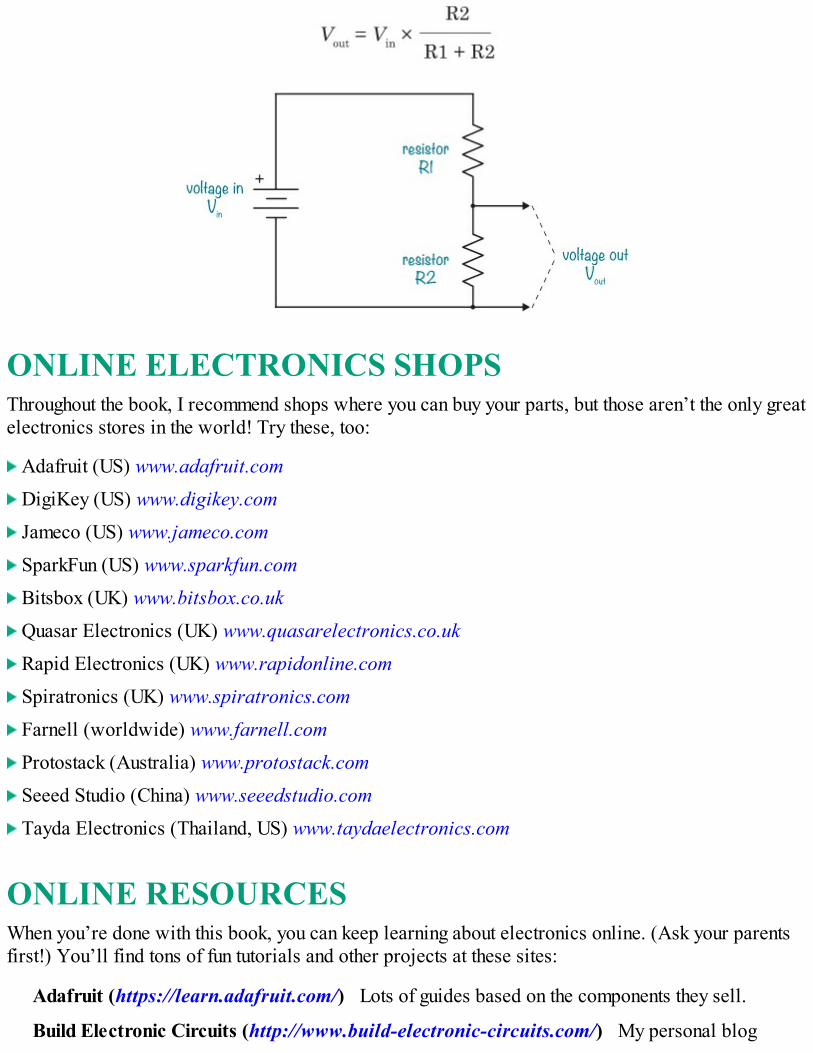
ONLINE ELECTRONICS SHOPSThroughout the book, I recommend shops where you can buy your parts, but those aren’t the only greatelectronics stores in the world! Try these, too:
Adafruit (US) www.adafruit.com DigiKey (US) www.digikey.com Jameco (US) www.jameco.com SparkFun (US) www.sparkfun.com Bitsbox (UK) www.bitsbox.co.uk Quasar Electronics (UK) www.quasarelectronics.co.uk Rapid Electronics (UK) www.rapidonline.com Spiratronics (UK) www.spiratronics.com Farnell (worldwide) www.farnell.com Protostack (Australia) www.protostack.com Seeed Studio (China) www.seeedstudio.com Tayda Electronics (Thailand, US) www.taydaelectronics.com
ONLINE RESOURCESWhen you’re done with this book, you can keep learning about electronics online. (Ask your parentsfirst!) You’ll find tons of fun tutorials and other projects at these sites:
Adafruit (https://learn.adafruit.com/) Lots of guides based on the components they sell.
Build Electronic Circuits (http://www.build-electronic-circuits.com/) My personal blog

where I post tutorials, videos, articles, and so on—all about electronics. I also have a freenewsletter with useful tips and tricks for your projects.
Electronics Club (http://www.electronicsclub.info/) A website for anyone wishing to learnabout electronics or build simple projects, created and maintained by John Hewes, the technicalreviewer of this book.
Ohmify (http://www.ohmify.com/) My online learning platform with courses, project tutorials,discussion forums, and more. Get cool step-by-step project tutorials, ask questions, make friends,and learn. Owners of this book get a special offer by going to http://www.ohmify.com/e4k/.
SparkFun (https://learn.sparkfun.com/) Lots of guides based on the components they sell.
You can also visit this book’s website at https://www.nostarch.com/electronicsforkids/ foradditional resources, updates, and more.

INDEX
NUMBERS AND SYMBOLS555 timer, 164–166
making sound using, 167–175setting output speed of, 166–167using for reaction game speed, 260–261
μF (microfarad), 92Ω (ohms), 7, 70
AA (amperes), 7AC (alternating current), 48–49adapters, 226alarm projects
intruder, 11–17, 108, 236–237sunrise, 148–157
alternating current (AC), 48–49American wire gauge (AWG), 83amperes (A), 7amps, 7AND gates, 216, 217AND operator, 215anode, 75ASCII code, 201–202astable mode, 165atoms, 6AWG (American wire gauge), 83
Bbarrel jack adapters, 226base, 132base-2 number system, 188base-10 number system, 188batteries
chemistry of, 56–58food, 65lemon, 58–66
what’s inside, 55–56beep mode, 277binary numbers, 188–190
converting to decimal, 190–192counting on fingers, 212why computers use, 211
bits, 193blinking lights
for reaction game, 265–278using a relay, 99–100, 101–108
Boolean logic, 214braid, desoldering, 125breadboards, 81–83, 84–87buzzer
adding to reaction game, 279–280in intruder alarm, 13–14in sunrise alarm, 153
bytes, 193
Ccapacitance, 91capacitors, 90–91
codes for, 283coupling, 171–172polarized and nonpolarized, 91–92testing, 92–95
cathode, 75charge, electric, 6cheat sheets, 282circuit boards, 111
illustrations of, 121circuits, 8–10
diagrams of, 95–97logic, 212making reliable, 227
clock signal, 242closed circuit, 8closed loop, 8codes
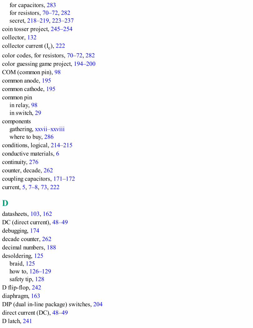
for capacitors, 283for resistors, 70–72, 282secret, 218–219, 223–237
coin tosser project, 245–254collector, 132collector current (Ic), 222color codes, for resistors, 70–72, 282color guessing game project, 194–200COM (common pin), 98common anode, 195common cathode, 195common pin
in relay, 98in switch, 29
componentsgathering, xxvii–xxviiiwhere to buy, 286
conditions, logical, 214–215conductive materials, 6continuity, 276counter, decade, 262coupling capacitors, 171–172current, 5, 7–8, 73, 222
Ddatasheets, 103, 162DC (direct current), 48–49debugging, 174decade counter, 262decimal numbers, 188desoldering, 125
braid, 125how to, 126–129safety tip, 128
D flip-flop, 242diaphragm, 163DIP (dual in-line package) switches, 204direct current (DC), 48–49D latch, 241
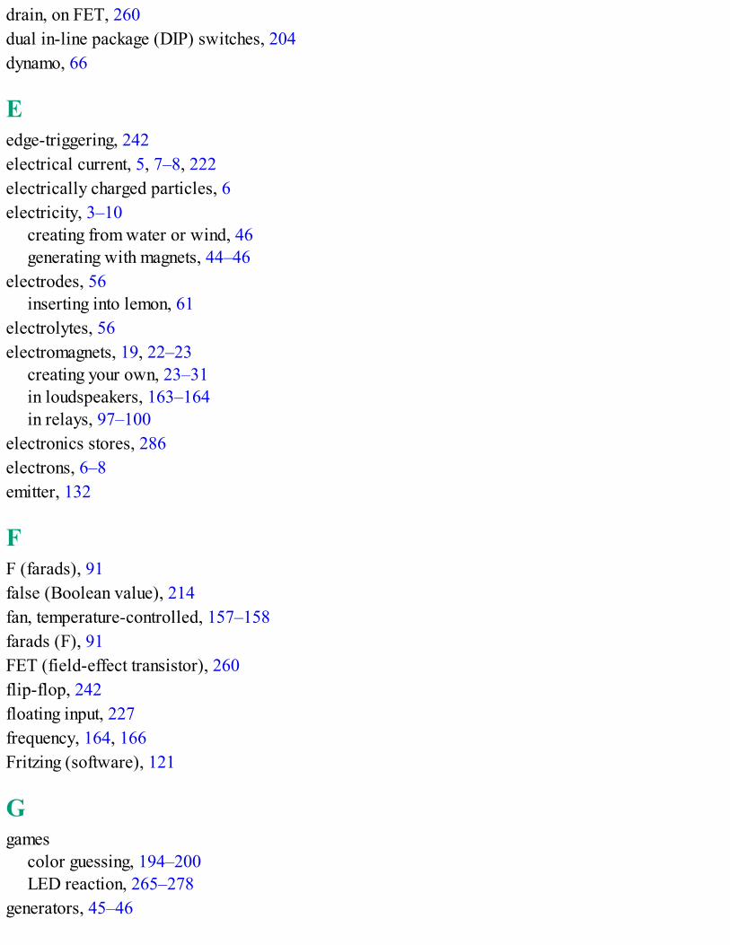
drain, on FET, 260dual in-line package (DIP) switches, 204dynamo, 66
Eedge-triggering, 242electrical current, 5, 7–8, 222electrically charged particles, 6electricity, 3–10
creating from water or wind, 46generating with magnets, 44–46
electrodes, 56inserting into lemon, 61
electrolytes, 56electromagnets, 19, 22–23
creating your own, 23–31in loudspeakers, 163–164in relays, 97–100
electronics stores, 286electrons, 6–8emitter, 132
FF (farads), 91false (Boolean value), 214fan, temperature-controlled, 157–158farads (F), 91FET (field-effect transistor), 260flip-flop, 242floating input, 227frequency, 164, 166Fritzing (software), 121
Ggames
color guessing, 194–200LED reaction, 265–278
generators, 45–46

creating your own, 49–54using motors as, 55
GND symbol, 259
HHz (hertz), 164
IIc (collector current), 222IC (integrated circuit), 161–163instrument, musical (project), 175–183insulation
adding to wire with marker, 38removing from wire, 26–27
integrated circuit (IC), 161–163International System of Units, 284intruder alarm project, 11–17, 108, 236–237inverter, 217
Jjoints, soldered, 113, 116, 117jumper wires, 83
Kkilo prefix (k), 72kits, electronics, 129
Llarge values, prefixes for, 72, 284latching, 240–241LDRs (light-dependent resistors), 146LEDs (light-emitting diodes), 58–59
blinking, 101–108, 265–278brightness of, varying with resistance, 144controlling with transistor, 135–136destroying, 74–76guessing color game, 194–200identifying legs, 75
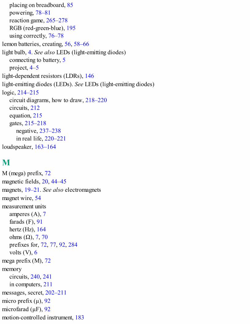
placing on breadboard, 85powering, 78–81reaction game, 265–278RGB (red-green-blue), 195using correctly, 76–78
lemon batteries, creating, 56, 58–66light bulb, 4. See also LEDs (light-emitting diodes)
connecting to battery, 5project, 4–5
light-dependent resistors (LDRs), 146light-emitting diodes (LEDs). See LEDs (light-emitting diodes)logic, 214–215
circuit diagrams, how to draw, 218–220circuits, 212equation, 215gates, 215–218
negative, 237–238in real life, 220–221
loudspeaker, 163–164
MM (mega) prefix, 72magnetic fields, 20, 44–45magnets, 19–21. See also electromagnetsmagnet wire, 54measurement units
amperes (A), 7farads (F), 91hertz (Hz), 164ohms (Ω), 7, 70prefixes for, 72, 77, 92, 284volts (V), 6
mega prefix (M), 72memory
circuits, 240, 241in computers, 211
messages, secret, 202–211micro prefix (μ), 92microfarad (μF), 92motion-controlled instrument, 183
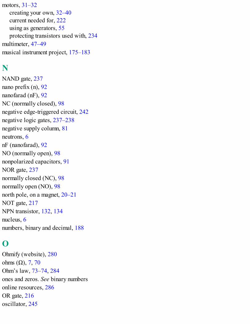
motors, 31–32creating your own, 32–40current needed for, 222using as generators, 55protecting transistors used with, 234
multimeter, 47–49musical instrument project, 175–183
NNAND gate, 237nano prefix (n), 92nanofarad (nF), 92NC (normally closed), 98negative edge-triggered circuit, 242negative logic gates, 237–238negative supply column, 81neutrons, 6nF (nanofarad), 92NO (normally open), 98nonpolarized capacitors, 91NOR gate, 237normally closed (NC), 98normally open (NO), 98north pole, on a magnet, 20–21NOT gate, 217NPN transistor, 132, 134nucleus, 6numbers, binary and decimal, 188
OOhmify (website), 280ohms (Ω), 7, 70Ohm’s law, 73–74, 284ones and zeros. See binary numbersonline resources, 286OR gate, 216oscillator, 245
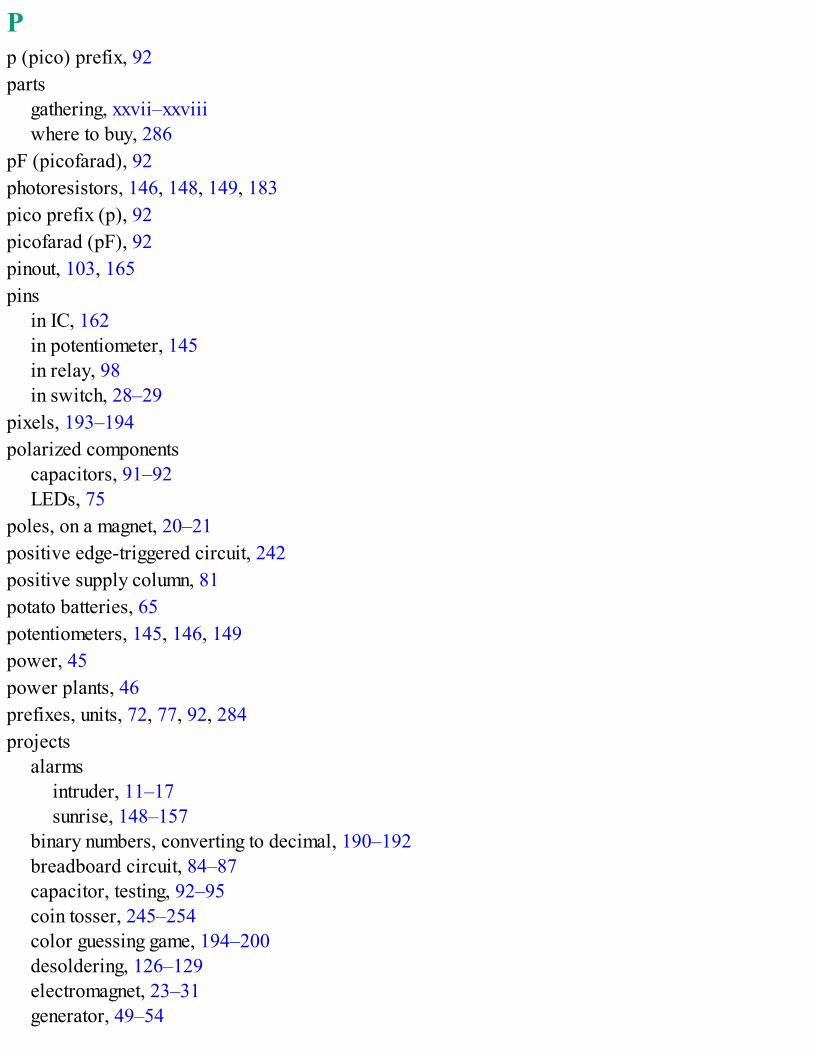
Pp (pico) prefix, 92parts
gathering, xxvii–xxviiiwhere to buy, 286
pF (picofarad), 92photoresistors, 146, 148, 149, 183pico prefix (p), 92picofarad (pF), 92pinout, 103, 165pins
in IC, 162in potentiometer, 145in relay, 98in switch, 28–29
pixels, 193–194polarized components
capacitors, 91–92LEDs, 75
poles, on a magnet, 20–21positive edge-triggered circuit, 242positive supply column, 81potato batteries, 65potentiometers, 145, 146, 149power, 45power plants, 46prefixes, units, 72, 77, 92, 284projects
alarmsintruder, 11–17sunrise, 148–157
binary numbers, converting to decimal, 190–192breadboard circuit, 84–87capacitor, testing, 92–95coin tosser, 245–254color guessing game, 194–200desoldering, 126–129electromagnet, 23–31generator, 49–54
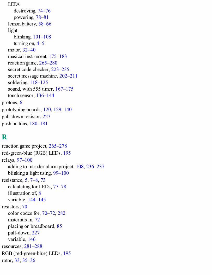
LEDsdestroying, 74–76powering, 78–81
lemon battery, 58–66light
blinking, 101–108turning on, 4–5
motor, 32–40musical instrument, 175–183reaction game, 265–280secret code checker, 223–235secret message machine, 202–211soldering, 118–125sound, with 555 timer, 167–175touch sensor, 136–144
protons, 6prototyping boards, 120, 129, 140pull-down resistor, 227push buttons, 180–181
Rreaction game project, 265–278red-green-blue (RGB) LEDs, 195relays, 97–100
adding to intruder alarm project, 108, 236–237blinking a light using, 99–100
resistance, 5, 7–8, 73calculating for LEDs, 77–78illustration of, 8variable, 144–145
resistors, 70color codes for, 70–72, 282materials in, 72placing on breadboard, 85pull-down, 227variable, 146
resources, 281–288RGB (red-green-blue) LEDs, 195rotor, 33, 35–36

Ssafety, xxviii–xxix
with battery lemons, 58soldering, 113–114, 128trimming wires, 122–123using resistors, 73using supermagnets, 34
schematics, 95–97screw terminals, 226secret code checker
adding to intruder alarm project, 236–237project, 223–235
secret message machine project, 202–211sensors, touch, 136, 144series, batteries connected in, 57–58shake generator project, 49–54short circuits, 156, 174single-strand wires, 83small values, prefixes for, 77, 284solder, 111–112
melting temperature, 112wick, 125
solderingavoiding bad joints, 117desoldering, 125–129how to, 112–117iron, 113
cleaning, 115stand, 114tinning, 115
safety tips, 113–114, 128supplies, 112
sound, 163–164555 timer project, 167–175creating with electricity, 163–164musical instrument project, 175–183
south pole, on a magnet, 20–21sponge (for cleaning soldering iron), 115SR latch, 240–241, 263–264
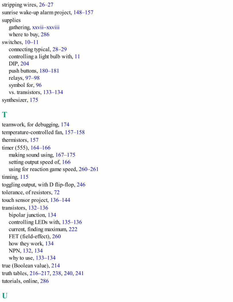
stripping wires, 26–27sunrise wake-up alarm project, 148–157supplies
gathering, xxvii–xxviiiwhere to buy, 286
switches, 10–11connecting typical, 28–29controlling a light bulb with, 11DIP, 204push buttons, 180–181relays, 97–98symbol for, 96vs. transistors, 133–134
synthesizer, 175
Tteamwork, for debugging, 174temperature-controlled fan, 157–158thermistors, 157timer (555), 164–166
making sound using, 167–175setting output speed of, 166using for reaction game speed, 260–261
tinning, 115toggling output, with D flip-flop, 246tolerance, of resistors, 72touch sensor project, 136–144transistors, 132–136
bipolar junction, 134controlling LEDs with, 135–136current, finding maximum, 222FET (field-effect), 260how they work, 134NPN, 132, 134why to use, 133–134
true (Boolean value), 214truth tables, 216–217, 238, 240, 241tutorials, online, 286
U
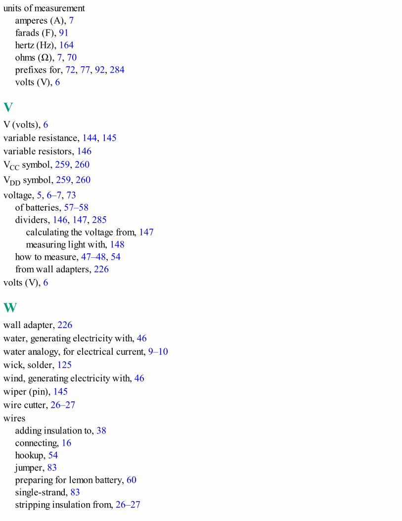
units of measurementamperes (A), 7farads (F), 91hertz (Hz), 164ohms (Ω), 7, 70prefixes for, 72, 77, 92, 284volts (V), 6
VV (volts), 6variable resistance, 144, 145variable resistors, 146VCC symbol, 259, 260VDD symbol, 259, 260voltage, 5, 6–7, 73
of batteries, 57–58dividers, 146, 147, 285
calculating the voltage from, 147measuring light with, 148
how to measure, 47–48, 54from wall adapters, 226
volts (V), 6
Wwall adapter, 226water, generating electricity with, 46water analogy, for electrical current, 9–10wick, solder, 125wind, generating electricity with, 46wiper (pin), 145wire cutter, 26–27wires
adding insulation to, 38connecting, 16hookup, 54jumper, 83preparing for lemon battery, 60single-strand, 83stripping insulation from, 26–27

XXOR gate, 238

Electronics for Kids is set in Century Schoolbook, Filmotype Candy, Housearama Kingpin,TheSansMono Condensed, and Billy the Flying Robot. The book was printed and bound by TCTranscontinental Printing in Beauceville, Québec, Canada. The paper is 70# Husky Offset, which iscertified by the Forest Stewardship Council (FSC).
The book uses an Otabind binding, in which the pages are bound together with a cold-set, flexibleglue, and the first and last pages of the resulting book block are attached to the cover. The cover is notactually glued to the book’s spine, and when open, the book lies flat and the spine doesn’t crack.

RESOURCESVisit https://www.nostarch.com/electronicsforkids/ for updates, errata, and more information.
MORE SMART BOOKS FOR CURIOUS KIDS!
ARDUINO PROJECT HANDBOOK25 Practical Projects to Get You Startedby MARK GEDDESJUNE 2016, 272 PP., $24.95ISBN 978-1-59327-690-4full color
JUNKYARD JAM BANDDIY Musical Instruments and Noisemakersby DAVID ERIK NELSONOCTOBER 2015, 408 PP., $24.95ISBN 978-1-59327-611-9

THE MAKER’S GUIDE TO THE ZOMBIE APOCALYPSEDefend Your Base with Simple Circuits, Arduino, and Raspberry Piby SIMON MONKOCTOBER 2015, 296 PP., $24.95ISBN 978-1-59327-667-6
THE LEGO® MINDSTORMS® EV3 DISCOVERY BOOKA Beginner’s Guide to Building and Programming Robotsby LAURENS VALKJUNE 2014, 396 PP., $34.95ISBN 978-1-59327-532-7full color
THE LEGO POWER FUNCTIONS IDEA BOOK, VOL. 1Machines and Mechanismsby YOSHIHITO ISOGAWAOCTOBER 2015, 324 PP., $24.95ISBN 978-1-59327-688-1full color

PYTHON FOR KIDSA Playful Introduction to Programmingby JASON R. BRIGGSDECEMBER 2012, 344 PP., $34.95ISBN 978-1-59327-407-8full color
800.420.7240 or 415.863.9900 | [email protected] | www.nostarch.com
REAL ELECTRONICS.REAL EASY.
Why do the lights in a house turn on when you flip a switch? How does a remote-controlled carmove? And what makes lights on TVs and microwaves blink? The technology around you may seemlike magic, but most of it wouldn’t run without electricity.
Electronics for Kids demystifies electricity with a collection of awesome hands-on projects. InPart 1, you’ll learn how current, voltage, and circuits work by making a battery out of a lemon, turninga metal bolt into an electromagnet, and transforming a paper cup and some magnets into a spinningmotor. In Part 2, you’ll make even more cool stuff as you:
• Solder a blinking LED circuit with resistors, capacitors, and relays
• Turn a circuit into a touch sensor using your finger as a resistor
• Build an alarm clock triggered by the sunrise
• Create a musical instrument that makes sci-fi sounds
Then, in Part 3, you’ll learn about digital electronics—things like logic gates and memory circuits—as you make a secret code checker and an electronic coin flipper. Finally, you’ll use everythingyou’ve learned to make the LED Reaction Game—test your reaction time as you try to catch ablinking light!
With its clear explanations and assortment of hands-on projects, Electronics for Kids will haveyou building your own circuits in no time.
ABOUT THE AUTHORØyvind Nydal Dahl built his first circuit at 14 and has been passionate about electronics ever since.He has a master’s degree in electronics from the University of Oslo, helps companies develop newproducts, and travels the world while teaching electronics workshops. He also writes beginner-friendly tutorials at http://www.build-electronic-circuits.com/.
THE FINEST IN GEEK ENTERTAINMENT™

Footnotes
Chapter 1: What Is Electricity?* The electron is a negative particle, but in some materials the current is made up of positive particles instead, and they flow in theopposite direction. So, at the atomic level, the particles can flow in either direction.
Chapter 9: How Circuits Understand Ones and Zeros* Sometimes kilobyte refers to 1024 bytes (2^10).