Embed Size (px)
Citation preview
FULLPAPER
www.afm-journal.de
2266
Electrochemically Tuned Properties for Electrolyte-FreeCarbon Nanotube Sheets
By Alexander A. Zakhidov, Dong-Seok Suh, Alexander A. Kuznetsov, Joseph
N. Barisci, Edgar Munoz, Alan B. Dalton, Steve Collins, Von H. Ebron,
Mei Zhang, John P. Ferraris, Anvar A. Zakhidov,* and Ray H. Baughman*
Injecting high electronic charge densities can profoundly change the optical,
electrical, and magnetic properties of materials. Such charge injection in bulk
materials has traditionally involved either dopant intercalation or the
maintained use of a contacting electrolyte. Tunable electrochemical charge
injection and charge retention, in which neither volumetric intercalation of
ions nor maintained electrolyte contact is needed, are demonstrated for
carbon nanotube sheets in the absence of an applied field. The tunability of
electrical conductivity and electron field emission in the subsequent material
is presented. Application of this material to supercapacitors may extend their
charge-storage times because they can retain charge after the removal of the
electrolyte.
1. Introduction
Injecting high electronic charge densities can profoundly changethe optical, electrical, and magnetic properties of materials.[1,2]
Three generic methods are available for electrically inducing largechanges in charge density: electrically gated charge injection indielectric-separated electrodes,[3] electrochemical charge injectionassociated with counter-ion intercalation, and electrochemicaldouble-layer (DL) charge injection. While dielectric-based chargeinjection, used in field-effect transistors (FETs), provides the basisfor today’s electronic technology, only the latter electrochemicalmethods (called Faradaic and non-Faradaic, respectively) havebeen successfully used so far to tune the bulk properties of
[*] Prof. A. A. Zakhidov, Prof. R. H. Baughman, Dr. D.-S. Suh,Dr. A. A. Kuznetsov, Dr. J. N. Barisci, Dr. E. Munoz, Dr. S. Collins,Dr. V. H. Ebron, Dr. M. Zhang, Prof. J. P. FerrarisNanoTech Institute, University of Texas at DallasRichardson, TX 75083-0688 (USA)E-mail: [email protected]; [email protected]
Dr. Al. A. ZakhidovCornell UniversityIthaca, NY 14850 (USA)
Dr. E. MunozInstituto de Carboquımica, CSICMiguel Luesma Castan, 4, 50018 Zaragoza (Spain)
Prof. A. B. DaltonDepartment of Physics and Surrey Materials InstituteUniversity of SurreyGuildford, Surrey GU2 7XH (U.K.)
DOI: 10.1002/adfm.200900253
� 2009 WILEY-VCH Verlag GmbH & Co. KGaA, Weinheim
materials. High electrochemical chargeinjection requires the close proximity ofoppositely charged ions and electronic car-riers (electrons or holes) in order to mitigaterepulsive Coulombic interactions. Faradaiccharge injection, used for doping conductingpolymers and graphite, achieves this proxi-mity and overall charge balance by thesimultaneous electrochemical insertion ofions andelectronic chargewithina solid.Thisinternal ion insertion dramatically changesstructure, introduces defects, and providesoppositely directed structural transforma-tions that are hysteretic and only partiallyreversible during ion de-insertion. In con-trast, in electrochemical non-Faradaic charge
injection, the counter-ions are electrostatically attracted to theinjected charge of aDLand reside on the electrode surface (withoutintercalation into the bulk). As a result, this process can be muchfaster, and large structural transformation of the electrodematerialcan be avoided. Thus, unlike Faradaic charge injection, non-Faradaic charge injection is highly reversible, which is essential formany applications. The separation between electrically injectedcharge carrierswithin the electrode andoppositely charged ionsonthe electrolyte side of the DL can be approximated by the Debyelength, LD, for the electrolyte if deviations from perfect chargescreening in the electrode are ignored. This Debye length is givenby
LD ¼ffiffiffiffiffiffiffiffiffiffiffiffiffiee0kT2z2e2n
r(1)
where e is the dielectric constant of the electrolyte, e0 is thepermittivity of free space, kT is the thermal energy, z is the ioncharge in numbers of electrons, e is the charge of an electron,and n is the concentration of the electrolyte. For a concentratedelectrolyte at room temperature, the Debye length is typically lessthan 1 nm, which is several orders of magnitude smaller than thecharge separation between the gate and channel of typical FETs.However, achieving large non-Faradaic charge injection in bulkmaterial requires a high surface-to-volume ratio for the charge-injected electrode, which for a macroscopic solid implies theexistence of nanoscale porosity. Supercapacitors based on DLcharge injection in nanotubes immersed in electrolytes achievespecific capacitances from tens to hundreds of Farads per gram ofnanotubes, depending on the nanotube type and the electrolyte.
Adv. Funct. Mater. 2009, 19, 2266–2272
FULLPAPER
www.afm-journal.de
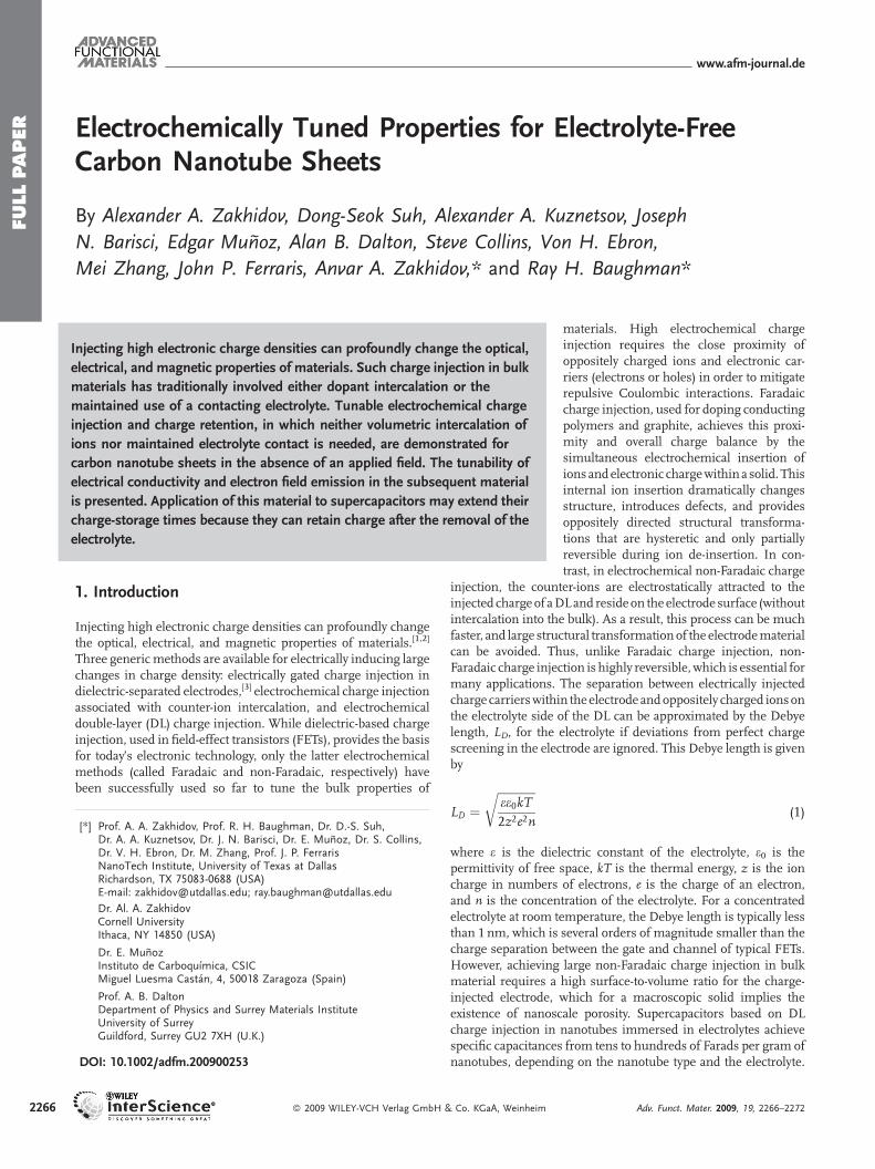
Figure 1. Typical cyclic voltammograms of a SWNT sheet electrode
(squares) and a MWNT sheet electrode (triangles) in 1 M NaCl aqueous
solution obtained at a scan rate of 25mV s�1. The current scales for SWNT
andMWNT electrodes are provided on the left and right sides of the graph,
respectively.
While the amount of injected DL charge may be as high as10�3–10�2 charge carriers per atom, changes in the electronicproperties of metal electrodes are small because changes in theelectronic charge density are masked by the initially largeelectronic charge densities of conventional metals. However,large changes in electronic and optical properties as a result ofDL charge injection can be achieved using electrodes having lowcharge densities, such as semiconductors or nanostructuredcarbons that are semimetallic and have low concentrations of freecharge carriers (�1019 cm�3). Due to their chemical inertness andpotentially high specific surface area, carbonnanotubes (CNTs) areideal materials for accumulating large amounts of injectedelectrical charge and demonstrating reversible tunability in theirphysical properties. Non-Faradaic electrochemical charge injec-tion inCNTshasbeen successfully used toprovide electrochemicalelectromechanical actuators[4] and liquid-ion-gated FETs.[5] DLcharge injection in nanotubes results in the bleaching of electronictransitions and corresponding changes in optical adsorption, aswell as pronounced changes in the intensity and frequency ofRaman lines.[6]
Potential application of the nanotube properties that have beentuned using electrochemical DL charge injection is limited by theneed to maintain contact between the electrode (including bothinternal andexternal surfaces) and the electrolyte. For example, thesurrounding electrolyte for the above-mentioned liquid-ion-gatedFETs limits their use in gaseous state sensing because gas mustfirst dissolve in the electrolyte before it can be detected.Consequently, device response rate and sensitivity are decreased,and detection capabilities are limited to only those gases that caneffectively dissolve in the electrolyte. In conventional DL-basednanotube supercapacitors, the contacting electrolyte that separatesthe electrodes provides mechanisms for self-discharge, so long-term energy storage in such a supercapacitor is not possible.
With the goal of eliminating these problems, we show that theDL charge that has been injected using liquid electrolytes, and itssubsequent effects, can be substantially maintained if themacroscopic CNT electrodes are removed from the electrolyte,washed, and dried. Retention of the injected charge in the driedCNTelectrodeswas indicatedby themaintenanceof the changes inphysical properties and by shifts in electrochemical potential,Fermi level position, and work function (WF). This chargeretention was used to tune CNT electrical conductivity and coldfield electron emission in electrolyte-free electrodes.
Pioneering studies by W. N. Hansen et al.[7,8] provide an earlyprecedent of this phenomenon; they reported the retention ofelectrolyte-based DL charge in noble metal electrodes thatwere removed from contact with the electrolyte. Use of planarelectrodes that were not nanostructured meant that onlythe properties of the surface layer changed and that the chargeinjected per unit of electrode weight was extremely low, so thetunability of bulk properties was not achieved and injectedcharge disappeared withinminutes upon air exposure.[7] Here, weinject charge into bulk CNT electrodes that have a very highgravimetric capacitance, and we show that the tunability ofbulk properties is retained even in the absence of a contactingelectrolyte. The injected charge does decay upon air exposure, dueto redox reactions with components of air; the charge decayhowever is much faster for injected electrons than for injectedholes.
Adv. Funct. Mater. 2009, 19, 2266–2272 � 2009 WILEY-VCH Verl
2. Results and Discussion
2.1. Voltammetry
It is well known that CNTs have high electrochemical stability andprovide non-Faradaic behavior in a variety of aqueous andnonaqueous electrolytes.[9,10] Figure 1 displays typical cyclicvoltammograms of single-wall CNT (SWNT) and multiwalledCNT (MWNT) sheets in 1 M NaCl aqueous solution. The cyclicvoltammograms indicate nearly ideal behavior for DL charging;this is especially true for the MWNT sheets, but minor Faradaicpeaks, which may be associated with oxygen-containing surfacefunctionalities on the CNTs or on carbonaceous impurities, arepresent.[9] The specific capacitance of the electrode, C, wascalculated as C¼ I/vm, where I is the current at the given scanrate (v) and m is the weight of the CNT electrode. Typical valuesfor specific capacitance were 25–30 F g�1 for SWNTsamples and6–10 F g�1 for MWNT sheets.
2.2. Retention of Potential
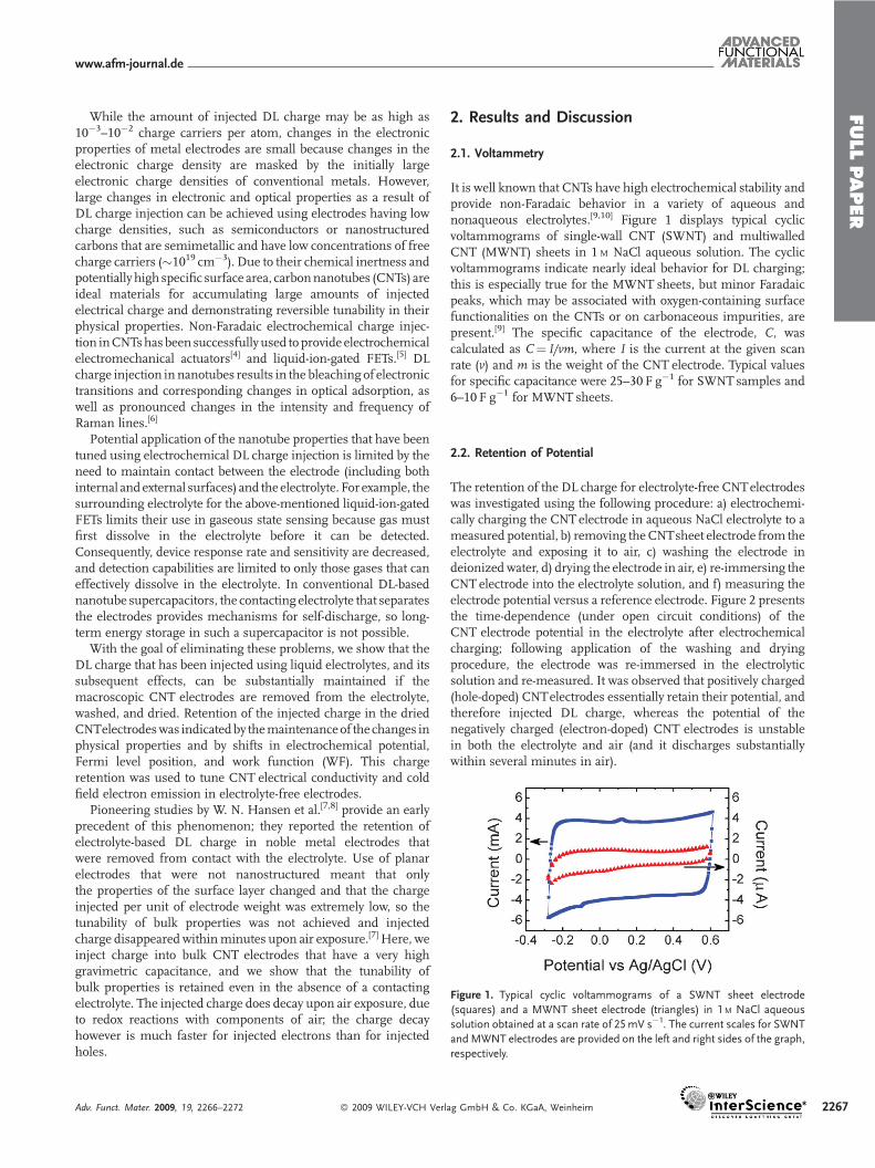
The retention of the DL charge for electrolyte-free CNTelectrodeswas investigated using the following procedure: a) electrochemi-cally charging the CNTelectrode in aqueous NaCl electrolyte to ameasured potential, b) removing theCNTsheet electrode from theelectrolyte and exposing it to air, c) washing the electrode indeionized water, d) drying the electrode in air, e) re-immersing theCNT electrode into the electrolyte solution, and f) measuring theelectrode potential versus a reference electrode. Figure 2 presentsthe time-dependence (under open circuit conditions) of theCNT electrode potential in the electrolyte after electrochemicalcharging; following application of the washing and dryingprocedure, the electrode was re-immersed in the electrolyticsolution and re-measured. It was observed that positively charged(hole-doped) CNTelectrodes essentially retain their potential, andtherefore injected DL charge, whereas the potential of thenegatively charged (electron-doped) CNT electrodes is unstablein both the electrolyte and air (and it discharges substantiallywithin several minutes in air).
ag GmbH & Co. KGaA, Weinheim 2267
FULLPAPER
www.afm-journal.de
Figure 2. Time-dependence of the potential of the electrode before and
after moving it from the 1M NaCl electrolyte to air and after subsequent
re-immersion in the electrolyte for A) SWNT and B) MWNT sheet elec-
trodes. The electrodes were measured under open circuit conditions from
time zero (after charging), so the potential changes in the electrolyte reflect
parasitic redox processes for this electrolyte. The measured electrode
potentials of both positive and negative electrode indicate that non-
Faradaically injected charge is partially retained even when the electrodes
are removed from the electrolyte and placed in air.
2268
The observed difference in behavior of the hole- and electron-doped CNT electrodes may be explained in terms of DL-inducedwork functionchanges.TheWFofaDL-chargedelectrodedependslinearly on the electrode potential, exhibiting a slope of 1, and isindependent of the electrode material.[7] Hole-doped (positivelycharged) CNTelectrodes have highWFs,whichmeans that they donot rapidly oxidize in the presence of oxygen. On the other hand,electron-doped (negatively charged) electrodes have substantiallylower WFs, so redox reactions can rapidly occur in air.
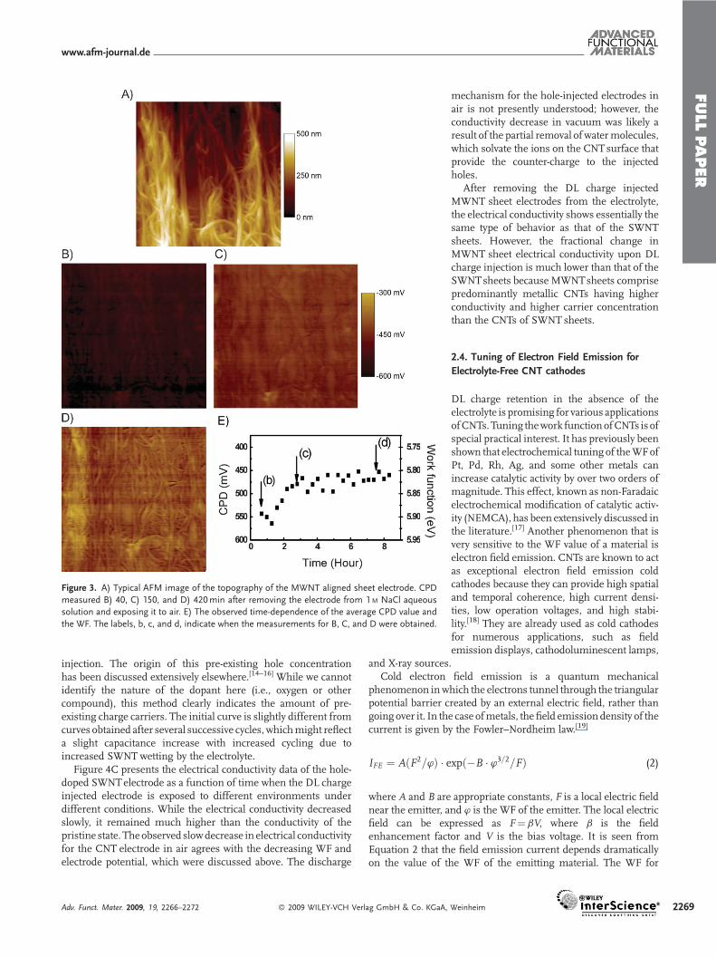
The degree of long-term charge retention, and the correspond-ing changes in WF, was demonstrated in air for a hole-dopedMWNTsheet electrode using Kelvin probe microscopy. A detaileddescription of Kelvin probemicroscopy, also referred to as electricforce microscopy, is provided elsewhere.[10] In brief, Kelvin probemicroscopy enables the mapping of the contact potentialdifference (CPD) between a conducting sample and a conductingprobe. Since theCPDequals the difference between theWFsof thesample and probe, thismethod allows spatialmapping of the workfunction of the conducting sample. Since the roughness of the
� 2009 WILEY-VCH Verlag GmbH &
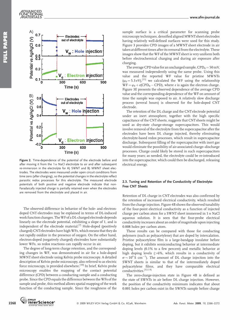
sample surface is a critical parameter for scanning probemicroscopy techniques, densified alignedMWNTsheet electrodeshaving relatively well-defined surfaces were used for this study.Figure 3 provides CPD images of a MWNT sheet electrode in airtakenat different times after its removal fromtheelectrolyte. Theseimages show that theWFof theMWNTsheet is very uniform bothbefore electrochemical charging and during air exposure aftercharging.
TheaverageCPDvalue foranunchargedsample,CPD0¼ 50mV,was measured independently using the same probe. Using thisvalue and the reported WF value for pristine MWNTs(w0¼ 5.3 eV),[11] we calculated the WF using the relationshipWF¼w0þ e(CPD0�CPD), where e is again the electron charge.Figure 3E presents the observed dependence of the average CPDvalue and the corresponding dependence of theWF on amount oftime the sample was exposed to air. A relatively slow dischargeprocess (several hours) is observed for the hole-doped CNTelectrode.
The retention of the DL charge and the CNTelectrode potentialunder an inert atmosphere, together with the high specificcapacitance of the CNTsheets, suggests that CNTsheets might beused as dry-state charge-storage supercapacitors. This wouldinvolve removal of the electrolyte from the supercapacitor after theelectrodes have been DL charge injected, thereby eliminatingelectrolyte-based redox processes, which result in supercapacitordischarge. Subsequent filling of the supercapacitor with inert gaswould eliminate the possibility of air-associated charge–dischargeprocesses. Charge could likely be stored in such supercapacitorsfor many years; as needed, the electrolyte could be re-introducedinto the supercapacitor, which could then be discharged, releasingelectrical energy.
2.3. Tuning and Retention of the Conductivity of Electrolyte-
Free CNT Sheets
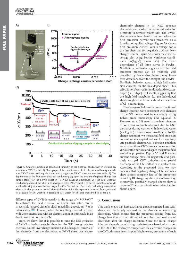
Retention of DL charge in CNT electrodes was also confirmed bythe retention of increased electrical conductivity, which resultedfrom the charge injection. Figure 4B shows the observed tunabilityof the four-point electrical conductivity as a function of injectedcharge per carbon atom for a SWNTsheet immersed in 1M NaClaqueous solution. It is seen that the four-probe electricalconductivity increases about an order ofmagnitudeupon injecting0.008 holes per carbon atom.
These results can be compared with those for conductingpolymers (such as polyacetylene) that are doped by intercalation.Pristine polyacetylene film is a large-bandgap insulator beforedoping, but it exhibits semiconducting behavior at intermediatedoping levels (0.1% to a few percent) and metallic behavior athigh doping levels (>6%, which results in a conductivity ofs� 104 S cm�1). The amount of DL charge injection into theSWNT sheets is similar to that of the intermediately dopedpolyacetylene films, and they have comparable electricalconductivities.[12,13]
The zero-charge-injection state in Figure 4B is defined asthe state of SWNTs in air before DL charge injection. However,the position of the conductivity minimum indicates that about0.001 holes per carbon exist in the SWNTs sample before charge
Co. KGaA, Weinheim Adv. Funct. Mater. 2009, 19, 2266–2272
FULLPAPER
www.afm-journal.de
Figure 3. A) Typical AFM image of the topography of the MWNT aligned sheet electrode. CPD
measured B) 40, C) 150, and D) 420min after removing the electrode from 1M NaCl aqueous
solution and exposing it to air. E) The observed time-dependence of the average CPD value and
the WF. The labels, b, c, and d, indicate when the measurements for B, C, and D were obtained.
injection. The origin of this pre-existing hole concentrationhas been discussed extensively elsewhere.[14–16] While we cannotidentify the nature of the dopant here (i.e., oxygen or othercompound), this method clearly indicates the amount of pre-existing charge carriers. The initial curve is slightly different fromcurves obtained after several successive cycles, whichmight reflecta slight capacitance increase with increased cycling due toincreased SWNT wetting by the electrolyte.
Figure 4C presents the electrical conductivity data of the hole-doped SWNTelectrode as a function of time when the DL chargeinjected electrode is exposed to different environments underdifferent conditions. While the electrical conductivity decreasedslowly, it remained much higher than the conductivity of thepristine state. The observed slowdecrease in electrical conductivityfor the CNT electrode in air agrees with the decreasing WF andelectrode potential, which were discussed above. The discharge
Adv. Funct. Mater. 2009, 19, 2266–2272 � 2009 WILEY-VCH Verlag GmbH & Co. KGaA,
mechanism for the hole-injected electrodes inair is not presently understood; however, theconductivity decrease in vacuum was likely aresult of the partial removal of watermolecules,which solvate the ions on the CNTsurface thatprovide the counter-charge to the injectedholes.
After removing the DL charge injectedMWNT sheet electrodes from the electrolyte,the electrical conductivity shows essentially thesame type of behavior as that of the SWNTsheets. However, the fractional change inMWNT sheet electrical conductivity upon DLcharge injection is much lower than that of theSWNTsheets because MWNTsheets comprisepredominantly metallic CNTs having higherconductivity and higher carrier concentrationthan the CNTs of SWNT sheets.
2.4. Tuning of Electron Field Emission for
Electrolyte-Free CNT cathodes
DL charge retention in the absence of theelectrolyte is promising for various applicationsofCNTs.Tuning thework functionofCNTs is ofspecial practical interest. It has previously beenshown that electrochemical tuning of theWFofPt, Pd, Rh, Ag, and some other metals canincrease catalytic activity by over two orders ofmagnitude. This effect, known as non-Faradaicelectrochemical modification of catalytic activ-ity (NEMCA), has been extensively discussed inthe literature.[17] Another phenomenon that isvery sensitive to the WF value of a material iselectron field emission. CNTs are known to actas exceptional electron field emission coldcathodes because they can provide high spatialand temporal coherence, high current densi-ties, low operation voltages, and high stabi-lity.[18] They are already used as cold cathodesfor numerous applications, such as fieldemission displays, cathodoluminescent lamps,
and X-ray sources.Cold electron field emission is a quantum mechanical
phenomenon inwhich the electrons tunnel through the triangularpotential barrier created by an external electric field, rather thangoing over it. In the case ofmetals, the field emission density of thecurrent is given by the Fowler–Nordheim law.[19]
IFE ¼ AðF2=’Þ � expð�B � ’3=2=FÞ (2)
where A and B are appropriate constants, F is a local electric fieldnear the emitter, and w is the WF of the emitter. The local electricfield can be expressed as F¼bV, where b is the fieldenhancement factor and V is the bias voltage. It is seen fromEquation 2 that the field emission current depends dramaticallyon the value of the WF of the emitting material. The WF for
Weinheim 2269
FULLPAPER
www.afm-journal.de
Figure 4. Charge injection and associated tunability of the electrical conductivity in wet and dry
states for a SWNT sheet. A) Photograph of the experimental electrochemical cell using a small-
area SWNT sheet working electrode and a large-area SWNT sheet counter electrode. B) The
dependence of the four-point electrical conductivity (s) upon the amount of injected charge (per
carbon atom) for the SWNT sheet in 1 M NaCl aqueous electrolyte. C) First run: Electrical
conductivity versus time when a DL charge-injected SWNT sheet is removed from the electrolyte
and held in air just above the electrolyte for 40 h. Second run: Electrical conductivity versus time
when a DL charge-injected SWNT sheet is dried in air for 8 h, exposed to vacuum for 4 h, exposed
to air again for 8 h, washed in deionized (DI) water for 8 h, and then dried in air for 6 h.
2270
different types of CNTs is usually in the range of 4.5–5.5 eV.[20]
To enhance the field emission of CNTs, this value can beirreversibly lowered either by alkali-metal film deposition[21] or byintercalation.[22] However, when the resulting material is coatedwith Cs or intercalated with an electron donor, it is unstable in airdue to oxidation of the CNTs.
Here, we show that it is possible to tune the field emissionof SWNT cathode sheets by changing the WF through electro-chemical double-layer charge injection and subsequent removal ofthe electrode from the electrolyte. A SWNT sheet was electro-
� 2009 WILEY-VCH Verlag GmbH & Co. KGaA, Weinheim
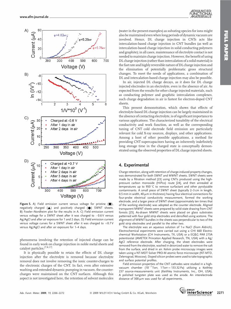
chemically charged in 1 M NaCl aqueouselectrolyte and washed in deionized water fora minute to remove excess salt. The SWNTelectrode was then placed in vacuumwhere thefield emission current was measured as afunction of applied voltage. Figure 5A showsfield emission current versus voltage for apristine sheet and for negatively and positivelycharged sheets. Figure 5B shows the current–voltage plot using Fowler–Nordheim coordi-nates (ln(IFE/V
2) versus 1/V). The lineardependence of all three curves in Fowler–Nordheim coordinates suggests that the fieldemission process can be relatively welldescribed by Fowler–Nordheim theory. How-ever, deviations from the straight-line Fowler–Nordheim behavior appear at high field emis-sion currents for the hole-doped sheet. Thiseffect is not observed for undoped and electron-doped (i.e., n-type) CNTsheets, suggesting thatthe high-field instability for the hole-dopedsheets might arise from field-induced ejectionof Cl� counter-ions.
Thechangesoffieldemissionas a functionofcharge injection were consistent with changesof the WF determined independently usingKelvin probe microscopy and Equation 2.However, up to 5% error in the determinationof WFs was routinely observed due to CNTdischarge during washes with deionized water(seeFig. 4C). Inorder to confirm theeffect ofDLcharge retention, we measured field emissioncurrent versus applied voltage for negativelyand positively charged CNTcathodes, and thenwe exposed these CNTsheet cathodes to air forvarious time periods and again measured fieldemission properties. Figure 5C and D showscurrent–voltage plots for negatively and posi-tively charged CNT cathodes after partialdischarge of the CNT cathodes in ambient air.According to the presented data, we mayconclude that negatively charged CNTcathodesshow almost complete loss of the propertiescaused byDL charge injection in less than a day;meanwhile, positively charged sheets show adegree ofDL charge retention in ambient air forabout 3 days.
3. Conclusions
This work shows that high DL charge densities injected into CNTsheets can be largely retained in the absence of contactingelectrolyte, which means that the properties arising from DLcharge injection can be utilized without the continued use ofelectrolyte after the charge injection. Since the initial chargeinjection depends upon having an electrolyte, where ionic chargesin the DL of the electrolyte compensate the electronic charges onthe CNTs, thismay seem impossible; however, precedents of such
Adv. Funct. Mater. 2009, 19, 2266–2272
FULLPAPER
www.afm-journal.de
Figure 5. A) Field emission current versus voltage for pristine (&),
negatively charged (~) and positively charged (�) SWNT sheets.
B) Fowler–Nordheim plot for the results in A. C) Field emission current
versus voltage for a SWNT sheet after it was charged to �0.6 V versus
Ag/AgCl and after air exposure for 1 and 2 days. D) Field emission current
versus voltage curves for a SWNT sheet after it was charged to þ0.7 V
versus Ag/AgCl and after air exposure for 1–4 days.
phenomena involving the retention of injected charge can befound in early work on charge injection in noble metal sheets andcatalyst particles.[7,8,17]
It is physically possible to retain the effects of DL chargeinjection after the electrolyte is removed because electrolyteremoval does not involve removing the ionic counter-charges tothe electronic charges of the CNT. In fact, even after extensivewashing and extended dynamic pumping in vacuum, the counter-charges were maintained on the CNT surfaces. Although thisaspect is not investigated here, the retention of solvent molecules
Adv. Funct. Mater. 2009, 19, 2266–2272 � 2009 WILEY-VCH Verl
(water in the present examples) as solvating species for ionsmightalsobemaintained evenwhen longperiodsofdynamic vacuumareinvolved. Hence, DL charge injection in CNTs acts likeintercalation-based charge injection in CNT bundles (as well asintercalation-based charge injection in solid conducting polymersand graphite); in all cases,maintenance of electrolyte contact is notneeded tomaintain charge injection.However, the benefit of usingDL charge injection (rather than intercalation of a solidmaterial) isthe fast rate andhighly reversible natureofDLcharge injection andthe elimination of potentially problematic gross structuralchanges. To meet the needs of applications, a combination ofDL and intercalation-based charge injection may also be possible.
In air, injected DL charge decays, as it does for DL chargeinjected electrodes in an electrolyte, even in the absence of air. Asexpected from the results for other charge injectedmaterials, suchas conducting polymer and graphitic intercalation complexes,such charge degradation in air is fastest for electron-doped CNTsheets.
This present demonstration, which shows that effects ofelectrolyte-based DL charge injection can be largely maintained intheabsenceof contacting electrolyte, is of significant importance tovarious applications. The characterized tunability of the electricalconductivity and work function, as well as the correspondingtuning of CNT cold electrode field emission are particularlyrelevant for cold X-ray sources, displays, and other applications.Among a host of other possible applications, a method forproviding CNT supercapacitors having an inherently indefinitelylong storage time in the charged state is conceptually demon-strated using the observed properties of DL charge injected sheets.
4. Experimental
Charge retention, along with retention of charge-induced property changes,was demonstrated for both SWNT and MWNT sheets. SWNT sheets weremade by a filtration method [23] using CNTs produced using the high-pressure carbon monoxide (HiPco) route [24], and then annealed attemperatures up to 950 8C to remove surfactant and other pyrolyzablecontaminants. A small piece of SWNT sheet (typically 2–3 cm in length,0.5mm in width, 40mm in thickness) having four electrical connections forfour-probe electrical conductivity measurement, formed the workingelectrode, and a larger piece of SWNT sheet (approximately ten times thatof the working electrode) was adopted as the counter electrode. Alignedtransparent MWNT sheets were prepared by solid-state drawing from CNTforests [25]. As-drawn MWNT sheets were placed on glass substratespatterned with four gold strip electrodes and densified using acetone. Thealignment of MWNT bundles in the sheets was perpendicular to two of thegold strip electrodes and parallel to the other two.
The electrolyte was an aqueous solution of 1 M NaCl (from Aldrich).Electrochemical experiments were carried out using a CHI 660 Electro-chemical Workstation (CH Instruments, TX, USA) or a EG&G PAR 273Apotentiostat (AMETEK Princeton Applied Research, TN, USA) with a Ag/AgCl reference electrode. After charging, the sheet electrodes wereremoved from the electrolyte, washed in deionized water to remove the saltfrom the surface, and dried in air. Kelvin probe microscopy images weretaken using a NT-MDT Solver PRO-M atomic force microscope (NT-MTD,Zelenograd,Moscow). Doped silicon probes were used to take topographicand surface potential profiles.
Field emission properties of the CNT cathodes were studied in a high-vacuum chamber (10�7 Torr, 1 Torr¼ 133.32 Pa) utilizing a Keithley237 source-measurements unit (Keithley Instruments, Inc., OH, USA).A polished tungsten plate was used as the anode. An interelectrodedistance of 300mm was used for all experiments.
ag GmbH & Co. KGaA, Weinheim 2271
FULLPAPER
www.afm-journal.de
2272
Acknowledgements
This work was supported by the National Science Foundation (NIRT awardDMI-0609115), the Robert A. Welch Foundation (Grant AT-0029), theStrategic Partnership for Research in Nanotechnology, and the AFOSRgrant on superconductivity. E. M. acknowledges funding from CSIC (Spain,Programa I3 2006 8 0I 060). We thank Kim Kangasniemi (NanotechAmerica Company) for contributions to the atomic force and Kelvin Probemicroscopy.
Received: February 11, 2009
Revised: March 23, 2009
Published online: May 22, 2009
[1] C. K. Chiang, C. R. Fincher, Jr., Y. W. Park, A. J. Heeger, H. Shirakawa,
E. J. Louis, S. C. Gau, A. G. MacDiarmid, Phys. Rev. Lett. 1977, 39, 1098.
[2] M. Imada, A. Fujimori, Y. Tokura, Rev. Mod. Phys. 1998, 70, 1039.
[3] C. H. Ahn, S. Gariglio, P. Paruch, T. Tybell, L. Antognazza, J.-M. Triscone,
Science 1999, 284, 1152.
[4] R. H. Baughman, C. Cui, A. A. Zakhidov, Z. Iqbal, J. N. Barisci, G. M. Spinks,
G. G. Wallace, A. Mazzoldi, D. De Rossi, A. G. Rinzler, O. Jaschinski,
S. Roth, M. Kertesz, Science 1999, 284, 1340.
[5] M. Kruger, M. R. Buitelaar, T. Nussbaumer, C. Schonenberger, L. Forro,
Appl. Phys. Lett. 2001, 78, 1291.
[6] L. Kavan, P. Rapta, L. Dunsch, M. J. Bronikowski, P. Willis, R. E. Smalley,
J. Phys. Chem. B 2001, 105, 10764.
[7] W. N. Hansen, D. M. Kolb, J. Electroanal. Chem. 1979, 100, 493.
[8] W. N. Hansen, J. Electroanal. Chem. 1983, 150, 133, and the references
therein.
[9] J. N. Barisci, G. G. Wallace, R. H. Baughman, J. Electroanal. Chem. 2000,
488, 92.
[10] J. N. Barisci, G. G. Wallace, R. H. Baughman, Electrochim. Acta 2000, 46,
509.
� 2009 WILEY-VCH Verlag GmbH &
[11] O. M. Kuttel, O. Groening, C. Emmenegger, L. Schlapbach, Appl. Phys. Lett.
1998, 73, 2113.
[12] A. J. Heeger, S. Kivelson, J. R. Schrieffer, W.-P. Su, Rev. Mod. Phys. 1988, 60,
781.
[13] D.-S. Suh, T. J. Kim, A. N. Aleshin, Y. W. Park, G. Piao, K. Akagi, H.
Shirakawa, J. S. Qualls, S. Y. Han, J. S. Brooks, J. Chem. Phys. 2001, 114,
7222.
[14] a) J. Appenzeller, J. Knoch, V. Derycke, R. Martel, S. Wind, P. Avouris, Phys.
Rev. Lett. 2002, 89, 126801. b) S. Heinze, J. Tersoff, R. Martel, V. Derycke,
J. Appenzeller, P. Avouris, Phys. Rev. Lett. 2002, 89, 106801.
[15] H. Ulbricht, G. Moos, T. Hertel, Phys. Rev B 2002, 66, 075404.
[16] T. Takenobu, T. Takano, M. Shiraishi, Y. Murakami, M. Ata, H. Kataura,
Y. Achiba, Y. Iwasa, Nat. Mater. 2003, 2, 683.
[17] D. Tsiplakides, C. G. Vayenas, J. Electrochem. Soc. 2001, 148, E189 and
references therein.
[18] R. H. Baughman, A. A. Zakhidov, W. A. de Heer, Science 2002, 297,
787.
[19] R. Gomer, Field Emission and Field Ionization, Harvard University Press,
Cambridge, MA 1961, Ch. 1–2.
[20] J. Zhao, J. Han, J. P. Lu, Phys. Rev. B 2002, 65, 193401.
[21] A. Wadhawan, R. E. Stallcup, II, J. M. Perez, Appl. Phys. Lett. 2001, 78,
108.
[22] M. Rao, P. C. Eklund, S. Bandow, A. Thess, R. E. Smalley, Nature 1997, 388,
257.
[23] A. G. Rinzler, J. Liu, H. Dai, P. Nikolaev, C. B. Huffman, F. J. Rodrıguez-
Macıas, P. J. Boul, A. H. Lu, D. Heymann, D. T. Colbert, R. S. Lee, J. E.
Fischer, A. M. Rao, P. C. Eklund, R. E. Smalley, Appl. Phys. A 1998, 67, 29.
[24] P. Nikolaev, M. J. Bronikowski, R. K. Bradley, F. Rohmund, D. T. Colbert, K.
A. Smith, R. E. Smalley, Chem. Phys. Lett. 1999, 313, 91, Elemental analysis
for purified HiPco SWNTs gives 86.77% C, 1.16% H, and 4.62% O from
Atlantic Microlab, Inc.
[25] M. Zhang, S. Fang, A. A. Zakhidov, S. B. Lee, A. E. Aliev, C. D. Williams, K. R.
Atkinson, R. H. Baughman, Science 2005, 309, 1215.
Co. KGaA, Weinheim Adv. Funct. Mater. 2009, 19, 2266–2272


