Embed Size (px)
Citation preview
Korean J. Chem. Eng., 25(5), 1145-1150 (2008)SHORT COMMUNICATION
1145
†To whom correspondence should be addressed.E-mail: [email protected]
Effects of magnetic field on calcium carbonate precipitation:Ionic and particle mechanisms
Nelson Saksono*, Misri Gozan*, Setijo Bismo*, Elsa Krisanti*, Roekmijati Widaningrum*, and Seung Koo Song**,†
*Department of Chemical Engineering, Faculty of Engineering, University of Indonesia, Kampus UI - Depok 16424, Indonesia**School of Chemical Engineering, Pusan National University, 30 Jangjeon-dong, Geumjeong-gu, Busan 609-735, Korea
(Received 2 March 2007 • accepted 27 January 2008)
Abstract−There are two most widely reported mechanisms to study the effect of magnetic fields on calcium car-bonate (CaCO3) precipitate, namely ionic and particle mechanisms. The effects are most debatable because they arecontrary to each other. This study explored the effects of both mechanisms in CaCO3 deposit and total CaCO3 pre-cipitation using ionic and particle methods. The ionic method showed reductions in CaCO3 deposit and total precipita-tion rate of CaCO3, whereas the particle method showed the opposite results. The particle number decreased and theaverage particle diameter of CaCO3 deposit increased in the ionic method. Meanwhile in the particle method, the particlenumber increased, average particle diameter decreased and particle aggregation of CaCO3 was observed. XRD meas-urement on all deposits showed that the crystal deposit was mostly of calcite and the traces of vaterite. However, theamount of the crystal in the particle method was observed to be less than that in the ionic method, indicating that CaCO3
deposit was more amorphous. Particle mechanism decreased the Ca2+ ion concentration in solution during magnetiza-tion, and ionic mechanism reduced scale (CaCO3) formation after magnetization and separation processes. This methodcould be applied for decreasing water hardness and prevent the formation of scaling.
Key words: Magnetic Treatment Mechanism, Calcium Carbonate Precipitation, CaCO3 Deposit Morphology
INTRODUCTION
Scale formation, such as on pipe walls and heat exchangers, is aserious problem encountered in almost all water processes. Typicalscale deposits are composed of minerals that become less solublewith increasing temperature. Calcium carbonate is the most com-mon deposit. Scale deposits usually form hard-to-remove-linings,which reduce water flow capacities. When they build up on the heatexchanger surfaces, heat transfer efficiency is reduced because oftheir low thermal conductivity. Anti-scale water treatment using chem-ical methods changes the solution chemistry and can be very ex-pensive. The chemical methods for water conditioning are econom-ically and ecologically visible especially under conditions of high cir-culation flow rates for large plants such as thermal power plants. Insome other areas, such as food and beverage industries or residen-tial areas, there are strict requirements for water quality. Thus, en-vironmental protection and economic considerations have becomestrong motivations for developing various types of physical anti-scale methods, among which are ultrasonic, ultraviolet radiation,electric, and magnetic treatments.
The anti-scale magnetic treatment (AMT) of hard waters has beenemployed for more than a half century. The first commercial devicefor the treatment was patented in Belgium in 1945 [1]. Powerfulelectromagnets have been used in hot water systems since the 1960sin the Soviet Union [2]. The application of AMT was first reportedin the United States in 1975 [2,3]. In many cases, the magnetic fieldwas delivered by permanent magnets in various geometrical con-figurations [4]. Several devices were based on alternating current
and pulsed fields [5]. According to the review paper of Baker andJudd [4], the efficiency of this treatment is still a controversial ques-tion and, as yet, there is no clear explanation of the phenomenon.At the same time, conclusions drawn based on laboratory work some-times are opposite to each other [4,6].
Two mechanisms have been developed to address magnetic fieldeffects on calcium carbonate precipitation: (1) a direct effect on dis-solved ions, and (2) a magnetic effect on particles [7]. The first mech-anism is known as the “ionic mechanism.” Examples of ionic re-sponse to a magnetic field have been reported by Higashitani et al.[8] who investigated the characteristics of calcium carbonate crys-tals. The crystals were formed by mixing of magnetically treated,quiescent-filtered solutions of calcium chloride and sodium carbon-ate. At a magnetic flux density greater than 3000 Gauss and expo-sure times longer than 10 min, it was found that the nucleation ofcalcium carbonate was suppressed, but the growth of particle sizewas accelerated and the portion of aragonite particles arose. Higash-itani attributes those results mainly to the magnetic exposure of thesodium carbonate solution prior to mixing. Chibowski et al. [9] ar-gued that the hydration energy of an anion CO3
2− is lower than acation Ca2+. By using spectrophotometer method, Barret and Parsons[10] and Chibowskia et al. [9] also found the absorbance reduction,indicating the presence of suppressed nucleation in magnetized solu-tion. Meanwhile, the observation of Kney and Parsons [7] did notnotice significant change on the absorbance value of the magneticsolution. Higashitani et al. [11] hypothesized that weak bonds ofwater molecules with the CO3
2− anion are quasi-stabilized and struc-tured by the magnetic exposure, so that they inhibit the precipita-tion rate of CaCO3 crystals.
We call the second mechanism, which involves the magnetic ef-fect on existing particles present in water, as the “particle mecha-
1146 N. Saksono et al.
September, 2008
nism.” Wang et al. [12], using turbidity measurements, observed afaster precipitation and smaller crystals of calcium carbonate in thepresence of a magnetic field of up to 8000 Gauss under quiescentcondition than in non-magnetic treatment. Lundager Madsen [13,14] has concluded that the field accelerates the nucleation of spar-ingly soluble diamagnetic salts of weak acids such as carbonates andphosphates. He suggested that the magnetic field is able to changethe orientation of the proton spin and to disturb dehydration phe-nomenon by hindering the transfer of a proton H+ from weak acid(HCO3
−) to a water molecule.Wang et al. [15], who considered the enhancement of coagulation
by a particle alignment, demonstrated the rate increase of aggrega-tion, as determined by weight measurement of sediment from a staticsolution treated by magnetic fields. Gabrielli et al. [16] have con-ducted comprehensive experiments in AMT using a calco-carbonicsolution in a circulated flowing system. They concluded that thefield strength, composition and flow velocity of the solution havesignificant effects on the scaling rate.
CaCO3 precipitation may occur in aqueous phase and on a sur-face phase (deposited). Total precipitation of CaCO3 has been widelydefined as the total mass of CaCO3 in both phases. In terms of themorphology, CaCO3 particles may be amorphous and polymorphousas crystals of calcite, aragonite and vaterite. Ahn et al. [17], Kobeet al. [18] and Knez et al. [19] using calco-carbonic solution for theinvestigation of CaCO3 morphology found that there is an increaseof aragonite crystals in aqueous phase under magnetic strength above10 kG. Similar work by Chibowski et al. [20] using solutions ofNa2CO3 and CaCl2 did not produce significant increase of arago-nite in aqueous phase. On the other hand, the morphology of CaCO3
deposit formed by precipitation of CaCO3 on a surface under theinfluence of magnetic field has not been established and needs tobe further investigated because the mechanism of the crystal for-mation on the surface and in aqueous solution is different [21].
The present study was designed to test and evaluate both mech-anisms by examining the amount of CaCO3 deposit formed and theamount of ions Ca2+ consumed in solution as a measure of total CaCO3
precipitation both in aqueous solution and on deposit. The morphol-ogy of CaCO3 deposit was examined by optical microscope. Theircrystal structures were identified by X-ray diffraction.
MATERIALS AND METHODS
1. Water and ElectrolytesElectrolytes CaCl2 and Na2CO3 of reagent-grade and deionized
water of the resistivity 18 MΩ, which was obtained from Milli-Qwater system, were utilized. Unfiltered CaCl2 and Na2CO3 0.01 Msolutions, respectively, were prepared by dissolving each electro-lyte into the deionized water, and then kept in airtight bottles at roomtemperature.2. Magnetic Field
A static magnetic field was produced by a pair of neodymiummagnets fixed to an aluminum frame with the N/S poles 15 mmapart. An average magnetic flux density (B) of 5,200 G was pro-duced, as measured at the center of the two poles with a Hall probe(Hirst GM 04). Each magnet was 100 mm (L)×15 mm (H)×20 mm(W). The distance of the magnetic poles was modified to producethe flux densities (magnetic induction) of 5,200, 4,000, and 2,000
Gauss.3. Experimental Procedure
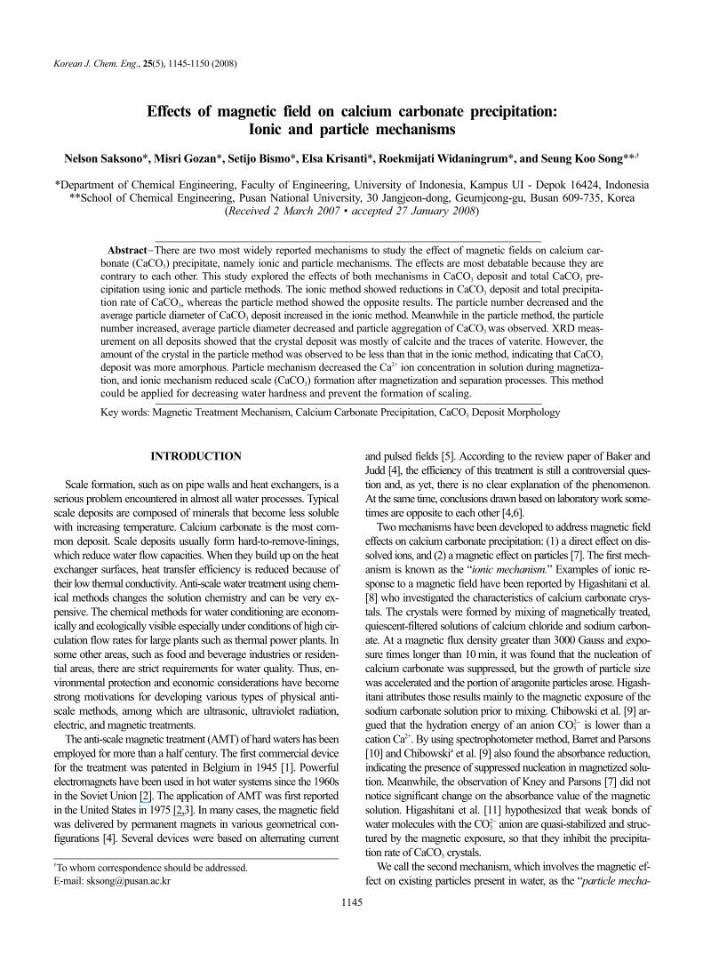
The experimental method is schematically illustrated in Fig. 1.The experiment consists of two parts. The first part of the experi-ment used the ionic method. In this method, for each run a mag-netic field of a given flux density for a given period of time wasexposed to Na2CO3 solution in a magnetization tube under the qui-escent condition. Most of the solutions, which contained 10 ml ofCaCl2 and Na2CO3 in 20 ml reactant, were put in precipitation glassreaction tubes (15 mm (OD)×150 mm (H)) right after the comple-tion of magnetic exposure. The wetted surface area on inner wallof glass reaction tube by 20 ml solutions was 5,978 mm2. The tem-perature of the solution was not controlled, and equal to the ambienttemperature of the surroundings (i.e., room temperature, 28-29 oC).
The second part of experiment used the particle method. In thismethod, treatment with a magnetic field was conducted during theprecipitating process of mixed reactants solution. The CaCO3 depositformed in the precipitation tube was acquired by removing the solu-tion. The deposit then was dissolved in 20 ml of 0.1 M HCl and itsCa2+ concentration was analyzed by EDTA complexometry (accu-racy≈0.05 mg as CaCO3). The Ca2+ concentration in the removedsolution of precipitation tube was also analyzed in the same way.CaCO3 was deposited on a thin-glass that would be used as a sam-ple. The thin-glass sample was vertically dipped into the solutionin 30 minutes and the sample object was magnified by microscopeoptics (Olympus HM 20) and recorded by a camera. The secondsample object, which was treated with longer dip (120 minutes),was used to identify the crystal structure of deposit CaCO3 by usingX-ray diffraction. The XRD patterns were obtained from PhilipsPW 1710 using Ni-filtered Cu Kα radiation (λ=0.154184 nm) at40 kV and 30 mA. The 2θ scanning range was 20-60o with a stepsize of 0.01o and time per step of 1.0 s.
RESULTS
1. Magnetization Effect on CaCO3 Deposit Formation
≅
Fig. 1. Experimental method.
Effects of magnetic field on calcium carbonate precipitation: Ionic and particle mechanisms 1147
Korean J. Chem. Eng.(Vol. 25, No. 5)
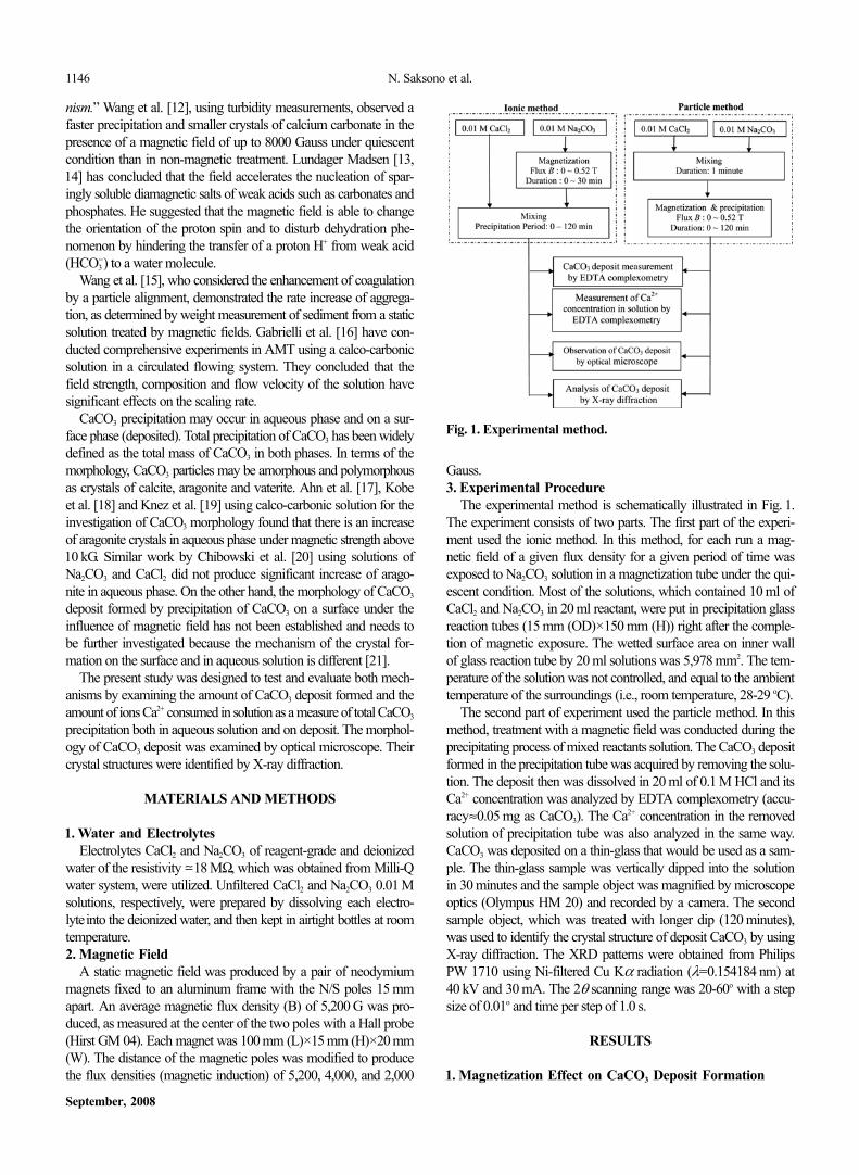
Fig. 2 and Fig. 3 show the characteristics of CaCO3 deposit formedon the surface (heterogeneous precipitations) under a magnetic field.The amount of CaCO3 deposit increased with the precipitationtime. Fig. 2 illustrates the decrease in the rate of CaCO3 depositformation in the first 30 minutes of precipitation along with the in-crease in magnetic flux density, and also with the magnetic dura-tion (Fig. 3). The rate of CaCO3 deposit formation after 30 minutesof precipitation of all treatments is approximately constant. Thisdenotes the substantial effect of magnetization occurring only in thefirst 30 minutes of precipitation. Higashitani et al. [8] found thatthe optimum magnetic flux and magnetic time in aqueous phasewere at 3,000 Gauss and 10 minutes, respectively. This means thatour experiments have not reached optimum magnetic flux and mag-netic time. This could be due to the difference in CaCO3 precipita-tion mechanism that occurred in homogeneous and heterogeneousprecipitations. With regard to this matter, Ben Amor et al. [22] foundthat CaCO3 heterogeneous precipitation was predominant comparedto CaCO3 homogeneous precipitation, particularly at low hardnesscondition. However, our study corroborated Higashitani hypothesis
that the existence of ion hydrate modification by magnetic field re-tained the nucleation rate.
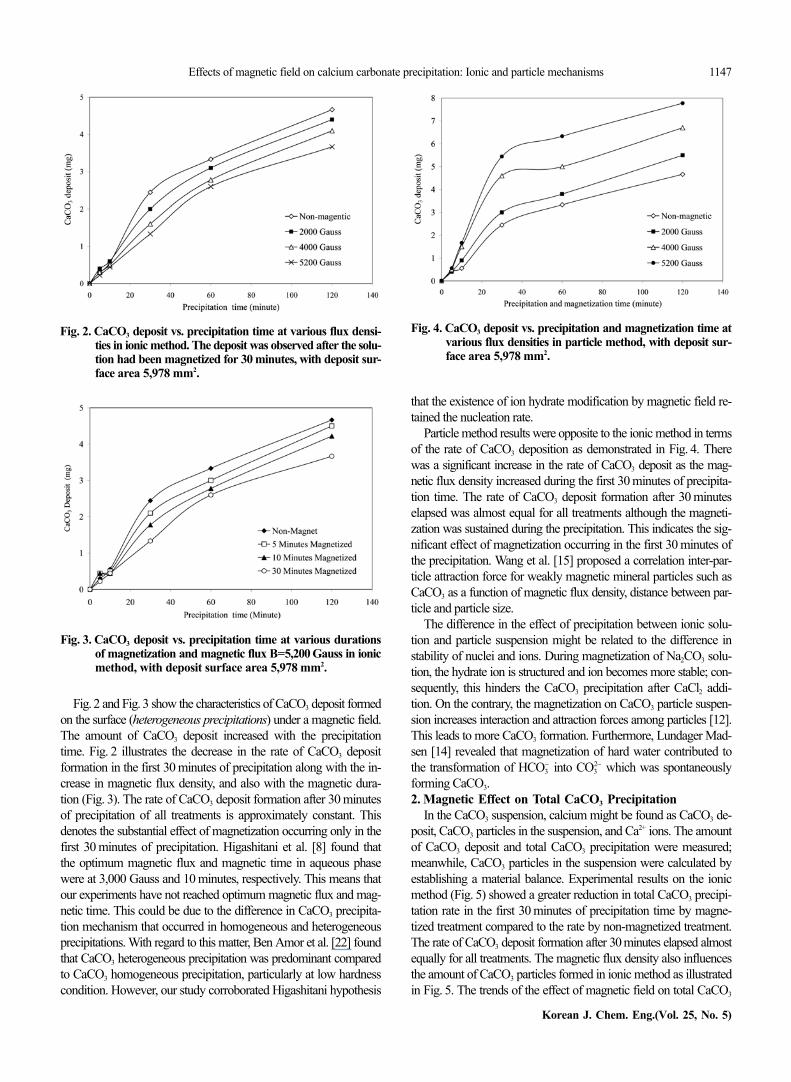
Particle method results were opposite to the ionic method in termsof the rate of CaCO3 deposition as demonstrated in Fig. 4. Therewas a significant increase in the rate of CaCO3 deposit as the mag-netic flux density increased during the first 30 minutes of precipita-tion time. The rate of CaCO3 deposit formation after 30 minuteselapsed was almost equal for all treatments although the magneti-zation was sustained during the precipitation. This indicates the sig-nificant effect of magnetization occurring in the first 30 minutes ofthe precipitation. Wang et al. [15] proposed a correlation inter-par-ticle attraction force for weakly magnetic mineral particles such asCaCO3 as a function of magnetic flux density, distance between par-ticle and particle size.
The difference in the effect of precipitation between ionic solu-tion and particle suspension might be related to the difference instability of nuclei and ions. During magnetization of Na2CO3 solu-tion, the hydrate ion is structured and ion becomes more stable; con-sequently, this hinders the CaCO3 precipitation after CaCl2 addi-tion. On the contrary, the magnetization on CaCO3 particle suspen-sion increases interaction and attraction forces among particles [12].This leads to more CaCO3 formation. Furthermore, Lundager Mad-sen [14] revealed that magnetization of hard water contributed tothe transformation of HCO3
− into CO32− which was spontaneously
forming CaCO3.2. Magnetic Effect on Total CaCO3 Precipitation
In the CaCO3 suspension, calcium might be found as CaCO3 de-posit, CaCO3 particles in the suspension, and Ca2+ ions. The amountof CaCO3 deposit and total CaCO3 precipitation were measured;meanwhile, CaCO3 particles in the suspension were calculated byestablishing a material balance. Experimental results on the ionicmethod (Fig. 5) showed a greater reduction in total CaCO3 precipi-tation rate in the first 30 minutes of precipitation time by magne-tized treatment compared to the rate by non-magnetized treatment.The rate of CaCO3 deposit formation after 30 minutes elapsed almostequally for all treatments. The magnetic flux density also influencesthe amount of CaCO3 particles formed in ionic method as illustratedin Fig. 5. The trends of the effect of magnetic field on total CaCO3
Fig. 2. CaCO3 deposit vs. precipitation time at various flux densi-ties in ionic method. The deposit was observed after the solu-tion had been magnetized for 30 minutes, with deposit sur-face area 5,978 mm2.
Fig. 4. CaCO3 deposit vs. precipitation and magnetization time atvarious flux densities in particle method, with deposit sur-face area 5,978 mm2.
Fig. 3. CaCO3 deposit vs. precipitation time at various durationsof magnetization and magnetic flux B=5,200 Gauss in ionicmethod, with deposit surface area 5,978 mm2.
1148 N. Saksono et al.
September, 2008
precipitation and CaCO3 deposit are similar as demonstrated in Fig.2 and Fig. 5.
Fig. 6 illustrates the result of the particle method, where the in-crease in total CaCO3 precipitation rate during the first 10 minutesof precipitation by magnetized treatment is higher than the rate bynon-magnetized treatment. The increase of magnetic flux densityleads to the increase of the amount of CaCO3 particles. In the samesolution model, Barret and Parson [10] also found that the maxi-mum CaCO3 precipitation occurred in the first 9 minutes of precip-itation. After 10 minutes of precipitation, the total CaCO3 precipitationrate was relatively constant for all curves. Comparison of the curvescorrelated between deposit of CaCO3 and total CaCO3 precipitationat different flux densities in ionic mechanism shows that there issimilar trend in which the amount of CaCO3 formed is lower asthe flux density is increased. Conversely, in the particle mechanismit was observed that the amount of CaCO3 formed was higher asthe flux density increased.
There was an interesting result of the particle method as shownin Fig. 7. The amount of CaCO3 particles in solution increased inthe first 10 minutes of precipitation time. The amount of CaCO3
particles was greater as the magnetic flux density was increased.
This result experimentally upholds the hypothesis given by Wanget al. [12] that a magnetic field enhances the nucleation and aggre-gation of the CaCO3 in liquid phase. The decreasing amount of par-ticles in solution after 10 minutes of precipitation showed the trans-formation of CaCO3 particles in liquid phase into the sediments anddeposit of CaCO3.3. Calcium Carbonate Morphology
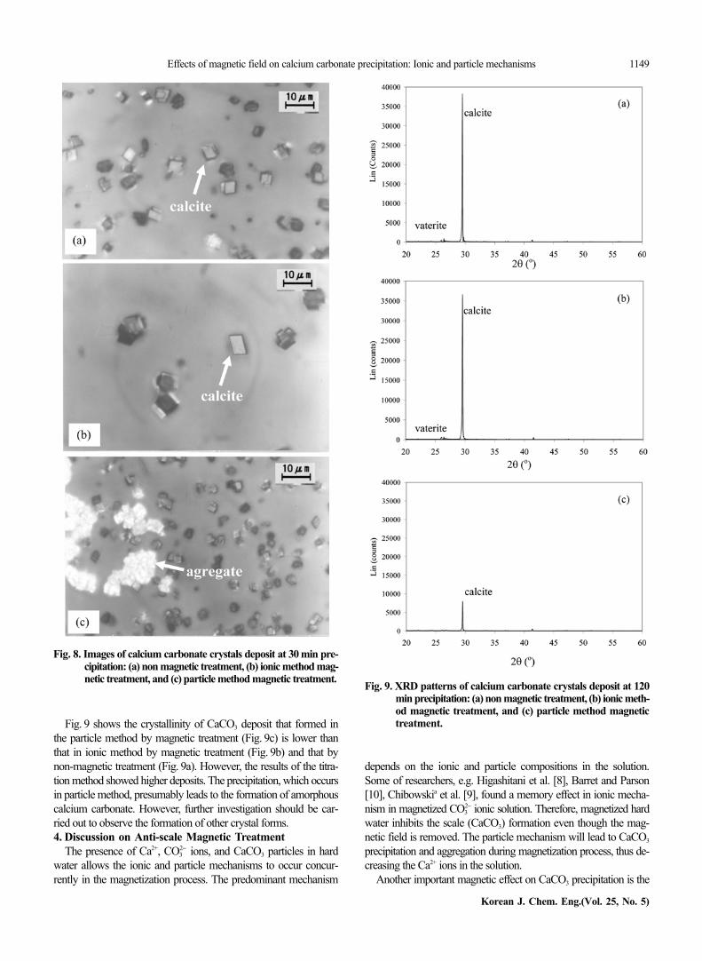
The morphology of calcium carbonate crystal deposit formedon the surface of the thin-glass sample dipped into the solution wasobserved with a microscope. It showed that the ionic method bymagnetic treatment produced a lower amount of CaCO3 particlescompared to the amount by non-magnetic treatment. The particlesize by using the ionic method can reach 10 mm. Higashitani et al.[8] found that the average diameter of the particles was greater asthe magnetic flux density was increased and as the magnetizationtime was longer.
On the other hand, the result of the particle method by magnetictreatment (Fig. 8c) showed that the amount of CaCO3 particles wasgreater compared to the amount by non-magnetic treatment, butthe particle size was smaller. Fig. 8c also shows that aggregation oc-curred in some particles. In general, Fig. 8 shows that some calcitecrystals appeared in cubic form.
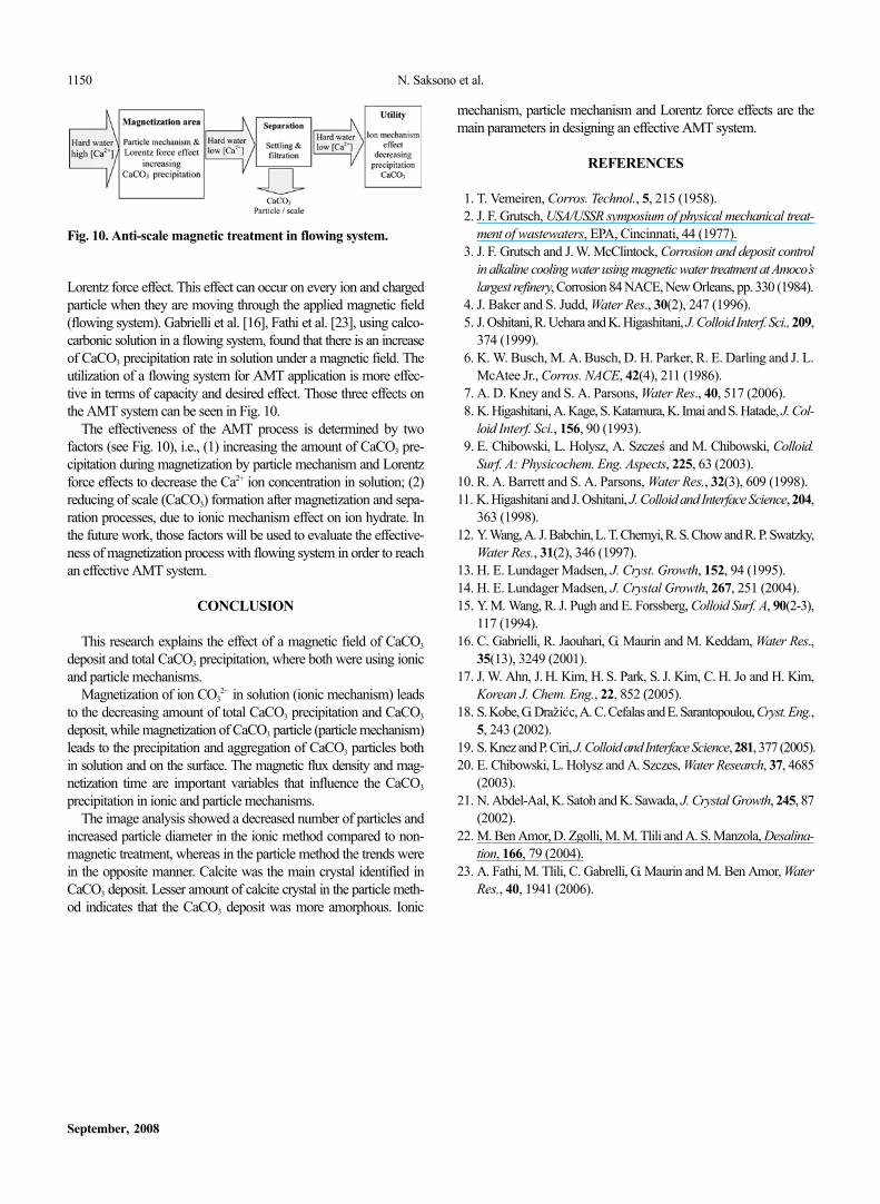
XRD test result on all the deposit samples as shown in Fig. 9 givesthat only one dominant peak appeared at 2θ=29,53o, which indi-cates that the crystal formed was of CaCO3 calcites. Some infini-tesimal peaks were observed at 2θ=26.41o, which indicates that thepeaks were of vaterite crystal. This result agrees with the observa-tion by Abdel-Aal et al. [21], who used scanning electron micros-copy on the same solution. His observation [21] suggested that thecalcite structure dominates the formation of CaCO3 surface crystal.On the other hand, vaterite crystal was not stable phase and wouldtransform to calcite crystal. Vaterite hardly grew on the surface dueto its geometric shape. Kobe at al. [18] suggest that the ground elec-tronic state of calcite is much lower than aragonite. Consequently,the Ca2+ and CO3
2− ions should have higher kinetic energies to over-come the repulsive forces of the potential barrier in order to formaragonite rather than calcite. Therefore, the formation of calcite isenergetically more in favor than that of aragonite.
Fig. 5. Total CaCO3 precipitation vs. precipitation time at variousflux densities in ionic method. The deposit was observedafter the solution had been magnetized for 30 minutes.
Fig. 6. Total CaCO3 precipitation vs. precipitation and magnetiza-tion time at various flux densities in particle method.
Fig. 7. Amount of CaCO3 particles in solution vs. precipitation andmagnetization time at various flux densities in particle meth-od.
Effects of magnetic field on calcium carbonate precipitation: Ionic and particle mechanisms 1149
Korean J. Chem. Eng.(Vol. 25, No. 5)
Fig. 9 shows the crystallinity of CaCO3 deposit that formed inthe particle method by magnetic treatment (Fig. 9c) is lower thanthat in ionic method by magnetic treatment (Fig. 9b) and that bynon-magnetic treatment (Fig. 9a). However, the results of the titra-tion method showed higher deposits. The precipitation, which occursin particle method, presumably leads to the formation of amorphouscalcium carbonate. However, further investigation should be car-ried out to observe the formation of other crystal forms.4. Discussion on Anti-scale Magnetic Treatment
The presence of Ca2+, CO32− ions, and CaCO3 particles in hard
water allows the ionic and particle mechanisms to occur concur-rently in the magnetization process. The predominant mechanism
depends on the ionic and particle compositions in the solution.Some of researchers, e.g. Higashitani et al. [8], Barret and Parson[10], Chibowskia et al. [9], found a memory effect in ionic mecha-nism in magnetized CO3
2− ionic solution. Therefore, magnetized hardwater inhibits the scale (CaCO3) formation even though the mag-netic field is removed. The particle mechanism will lead to CaCO3
precipitation and aggregation during magnetization process, thus de-creasing the Ca2+ ions in the solution.
Another important magnetic effect on CaCO3 precipitation is the
Fig. 8. Images of calcium carbonate crystals deposit at 30 min pre-cipitation: (a) non magnetic treatment, (b) ionic method mag-netic treatment, and (c) particle method magnetic treatment. Fig. 9. XRD patterns of calcium carbonate crystals deposit at 120
min precipitation: (a) non magnetic treatment, (b) ionic meth-od magnetic treatment, and (c) particle method magnetictreatment.
1150 N. Saksono et al.
September, 2008
Lorentz force effect. This effect can occur on every ion and chargedparticle when they are moving through the applied magnetic field(flowing system). Gabrielli et al. [16], Fathi et al. [23], using calco-carbonic solution in a flowing system, found that there is an increaseof CaCO3 precipitation rate in solution under a magnetic field. Theutilization of a flowing system for AMT application is more effec-tive in terms of capacity and desired effect. Those three effects onthe AMT system can be seen in Fig. 10.
The effectiveness of the AMT process is determined by twofactors (see Fig. 10), i.e., (1) increasing the amount of CaCO3 pre-cipitation during magnetization by particle mechanism and Lorentzforce effects to decrease the Ca2+ ion concentration in solution; (2)reducing of scale (CaCO3) formation after magnetization and sepa-ration processes, due to ionic mechanism effect on ion hydrate. Inthe future work, those factors will be used to evaluate the effective-ness of magnetization process with flowing system in order to reachan effective AMT system.
CONCLUSION
This research explains the effect of a magnetic field of CaCO3
deposit and total CaCO3 precipitation, where both were using ionicand particle mechanisms.
Magnetization of ion CO32− in solution (ionic mechanism) leads
to the decreasing amount of total CaCO3 precipitation and CaCO3
deposit, while magnetization of CaCO3 particle (particle mechanism)leads to the precipitation and aggregation of CaCO3 particles bothin solution and on the surface. The magnetic flux density and mag-netization time are important variables that influence the CaCO3
precipitation in ionic and particle mechanisms.The image analysis showed a decreased number of particles and
increased particle diameter in the ionic method compared to non-magnetic treatment, whereas in the particle method the trends werein the opposite manner. Calcite was the main crystal identified inCaCO3 deposit. Lesser amount of calcite crystal in the particle meth-od indicates that the CaCO3 deposit was more amorphous. Ionic
mechanism, particle mechanism and Lorentz force effects are themain parameters in designing an effective AMT system.
REFERENCES
1. T. Vemeiren, Corros. Technol., 5, 215 (1958).2. J. F. Grutsch, USA/USSR symposium of physical mechanical treat-
ment of wastewaters, EPA, Cincinnati, 44 (1977).3. J. F. Grutsch and J. W. McClintock, Corrosion and deposit control
in alkaline cooling water using magnetic water treatment at Amoco’slargest refinery, Corrosion 84 NACE, New Orleans, pp. 330 (1984).
4. J. Baker and S. Judd, Water Res., 30(2), 247 (1996).5. J. Oshitani, R. Uehara and K. Higashitani, J. Colloid Interf. Sci., 209,
374 (1999).6. K. W. Busch, M. A. Busch, D. H. Parker, R. E. Darling and J. L.
McAtee Jr., Corros. NACE, 42(4), 211 (1986).7. A. D. Kney and S. A. Parsons, Water Res., 40, 517 (2006).8. K. Higashitani, A. Kage, S. Katamura, K. Imai and S. Hatade, J. Col-
loid Interf. Sci., 156, 90 (1993).9. E. Chibowski, L. Holysz, A. Szcze and M. Chibowski, Colloid.
Surf. A: Physicochem. Eng. Aspects, 225, 63 (2003).10. R. A. Barrett and S. A. Parsons, Water Res., 32(3), 609 (1998).11. K. Higashitani and J. Oshitani, J. Colloid and Interface Science, 204,
363 (1998).12. Y. Wang, A. J. Babchin, L. T. Chernyi, R. S. Chow and R. P. Swatzky,
Water Res., 31(2), 346 (1997).13. H. E. Lundager Madsen, J. Cryst. Growth, 152, 94 (1995).14. H. E. Lundager Madsen, J. Crystal Growth, 267, 251 (2004).15. Y. M. Wang, R. J. Pugh and E. Forssberg, Colloid Surf. A, 90(2-3),
117 (1994).16. C. Gabrielli, R. Jaouhari, G. Maurin and M. Keddam, Water Res.,
35(13), 3249 (2001).17. J. W. Ahn, J. H. Kim, H. S. Park, S. J. Kim, C. H. Jo and H. Kim,
Korean J. Chem. Eng., 22, 852 (2005).18. S. Kobe, G. Dra i c, A. C. Cefalas and E. Sarantopoulou, Cryst. Eng.,
5, 243 (2002).19. S. Knez and P. Ciri, J. Colloid and Interface Science, 281, 377 (2005).20. E. Chibowski, L. Holysz and A. Szczes, Water Research, 37, 4685
(2003).21. N. Abdel-Aal, K. Satoh and K. Sawada, J. Crystal Growth, 245, 87
(2002).22. M. Ben Amor, D. Zgolli, M. M. Tlili and A. S. Manzola, Desalina-
tion, 166, 79 (2004).23. A. Fathi, M. Tlili, C. Gabrelli, G. Maurin and M. Ben Amor, Water
Res., 40, 1941 (2006).
ás
šz ác
Fig. 10. Anti-scale magnetic treatment in flowing system.


![Magnetic ionic plastic crystal: choline[FeCl4]](https://img.dokumen.tips/doc/110x75/6333cdfe7a687b71aa08630b/magnetic-ionic-plastic-crystal-cholinefecl4.jpg)


