Embed Size (px)
Citation preview
ORIGINAL ARTICLE
Effect of ultrasonic vibration of tool on electrical dischargemachining of cemented tungsten carbide (WC-Co)
Amir Abdullah & Mohammad R. Shabgard
Received: 7 August 2006 /Accepted: 17 July 2007 /Published online: 6 September 2007# Springer-Verlag London Limited 2007
Abstract This paper deals with the effect of copper toolvibration with ultrasonic (US) frequency on the electricaldischarge machining (EDM) characteristics of cementedtungsten carbide (WC-Co). It was found that ultrasonicvibration of the tool (USVT) was more effective inattaining a high material removal rate (MRR) whenworking under low discharge currents and low pulse times(finishing regimes). In general, the surface roughness andthe tool wear ratio (TWR) were increased when ultrasonicvibration was employed. It was observed that application ofultrasonic vibration significantly reduced arcing and opencircuit pulses, and the stability of the process had aremarkable improvement. This study showed that, therewere optimum conditions for ultrasonic assisted machiningof cemented tungsten carbide, although the conditions mayvary by giving other input parameters for those which hadbeen set constant in the present work.
Keywords Cemented tungsten carbide (WC-Co) .
Electrical discharge machining .Material removal rate .
Surface roughness . Tool wear ratio . Ultrasonic assistedEDM .Ultrasonic vibration of the tool
NomenclaturePEDM Pure electrical discharge machiningUS/EDM
Ultra-sonic assisted EDM
MRR Material removal rate (mm3/min)Vu Volumetric removal rate of workpiece with
ultrasonic (mm3/min)Vc Volumetric removal rate of workpiece without
ultrasonic (mm3/min)M1 Workpiece/tool weight before machining (g)M2 Workpiece/tool weight after machining (g)ρ Density (g/cm3)T Machining time (min)TWR Tool wear ratio (%)VT Volumetric removal rate of tool (mm3/min)VW Volumetric removal rate of workpiece (mm3/min)I Acousto-electric current (amp)μ Mobility of the charge carriers (m2/V.s)Pa Acoustic power (W)L Interaction length (m)ν Phase velocity (m/s)
1 Introduction
Cemented tungsten carbide (WC-Co) is a hard materialwith high mechanical strength. Due to these properties, it iswidely used in engineering industries especially in die andpunch manufacturing with expected growing application inthe future. However, these characteristics cause the ma-chining of cemented tungsten carbide to be very difficult(by mechanical forces) and expensive. To overcome thetechnical difficulties faced, special machining methods areemployed among which electrical-discharge machining(EDM) has been the most favorable.
EDM is an electro-thermal process in which material isremoved by successive electrical discharges occurringbetween an electrode and a workpiece immersed in adielectric fluid [1]. Every discharge ionizes a very restrictedarea between, the closest opposing peaks of roughness of
Int J Adv Manuf Technol (2008) 38:1137–1147DOI 10.1007/s00170-007-1168-8
A. Abdullah (*)Department of Mechanical Engineering,Amirkabir University of Technology,No 424, Hafez Ave.,Tehran, Irane-mail: [email protected]
M. R. ShabgardDepartment of Mechanical Engineering, University of Tabriz,Tabriz, Iran
the electrodes and generates a localized plasma channel,within a vapor bubble bridge, in which the temperature canbe as high as 8000–10000°C [2]. The plasma pressure hasbeen estimated to be up to several hundreds of bars. Thishot plasma may lead to melting and evaporation of bothelectrodes [3]. At the end of the pulse, when the dischargecurrent is stopped, the pressure suddenly falls, causing thesuperheated molten material on the surface of both elec-trodes to explode into the liquid dielectric, leaving a crateron the electrode surfaces and creating small solid and/orhollow debris [1, 3].
In the EDM process, there is no direct physical contactbetween the electrodes, and, therefore, no mechanicalstresses are exchanged between the workpiece and the tool(except the force of explosion of the small vapor bubbleand flushing forces). Therefore, the process has thecapability of machining cemented tungsten carbide (WC-Co)regardless of its high hardness. Several researchers haveinvestigated the EDM performance on cemented tungstencarbide [4–11]. Zolotykh and Korobva [4] studied thedependency of the machining rate, and the nature andmagnitude of damaged layer on the parameters of the pulseduration and pulse energy. They concluded that theoptimum operating condition would be the use of shortdischarge durations with low pulse energy at a highfrequency. Chetverikov and Foteev [5] have shown thatthe machining rate and average size of the side clearancebetween the workpiece and the tool electrode increases byseveral percents with increasing cobalt content. Gadallaand Tsai [6] have reported that the cutting rate of WC-Cocomposites, using wire EDM, increases with the cobaltcontent and with large WC grain size. Verkhoturov et al. [7]have pointed out that the structure of WC-Co promotes theselective removal of its low melting point phases, cobalt,
which leads to inter-granular fracture along the phaseboundaries. Lee and Li [8, 9] have investigated theinfluence of operating parameters of EDM of cementedtungsten carbide on the machining characteristics andsurface integrity of the workpiece. They have reported thatfor all values of discharge duration, the material removalrate increases with increase of discharge current andbecome constant at higher currents while there is a clearerdamaged layer on the EDMed surface. Yan et al. [10]pointed out that when machining micro-holes in carbidewith copper tool electrode, positive tool polarity must beused.
The carbon content of WC is high (6.13%wt). On theother hand, some hundredths percent of carbon is uncom-bined [11]. Meanwhile, in EDMing of WC-Co composites,a portion of WC can be dissociated into W2C and graphiteby the following equation [6, 11]:
2WC (¼) W2C þ Graphite ð1ÞFurthermore, the structure of WC-Co promotes selective
removal of its low melting point phase, cobalt, at thedischarge termination, when the plasma bubble collapseswith creation of succeeding shock wave dislodges, whichlead to loosening of WC grains [6]. These grains associatewith carbon, agglomerate and coagulate, resulting in largesize particles and will gather in the discharge gap (betweenthe tool and workpiece), and accumulate on the machinedsurface, thus making the discharge condition unstable andprone to arcing. All these result in a low material removalrate and a severely damaged surface layer. Consequently, itis necessary to develop a new technique for overcomingthese misbehaviors.
Several researchers have reported that ultrasonic assistedEDM of steel improves discharge characteristics [12–16].
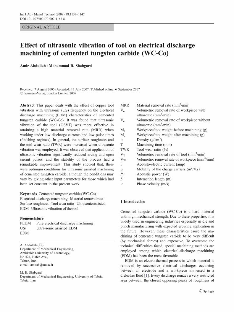
Fig. 1 Schematic set-up forexperiments
1138 Int J Adv Manuf Technol (2008) 38:1137–1147
Kremer [12] reported that ultrasonic vibrations can signifi-cantly improve the discharge efficiency, in EDM of alloysteel with a graphite tool. Murthy [13] showed that ultrasonicassisted EDM of steel significantly reduced inactive pulses.Zhixin et al. [14] reported that for machining of advancedceramics, the combination of ultrasonic machining and EDMmay provide a higher MRR. Lin and Yan [15] have pointedout that EDM of titanium alloy by using ultrasonic toolvibrations give higher MRR and eliminate the recast layer.
The present work is an empirical study on the effect ofultrasonic tool vibration on the electrical discharge machiningcharacteristics of cemented tungsten carbide (WC-Co). It wasobserved that application of ultrasonic vibration of the toolresulted in a drastically improved material removal rateespecially in finishing regimes, whilst it gave rise to highertool wear ratio and surface roughness under any condition. Inaddition, it was demonstrated that the ultrasonic vibration ofthe tool significantly reduced inactive pulses and improved thestability of the process.
2 Experimental setup and procedure
2.1 Experimental setup and equipment used
A series of experiments were carried out in butt modemachining on a die-sinking ED machine (DECKEL-DE20CENTER) with an iso-frequent pulse generator, having amaximum operating discharge current of 45 A and capable ofsetting open-circuit voltage at 120, 150, and 180 Volts withand without application of ultrasonic tool vibrations. Forultrasonic assisted tests, an ultrasonic head (LABSONIC-1000L) was attached to the ED machine head. The experi-mental set-up is shown schematically in Fig. 1.
The piezoelectric transducer has a power output range of0–200 W and operates at a frequency of about 25 KHz.
The current meter was connected in series with the sparkgap so that all sparking current was flowing through it tomeasure the average current. The voltmeter was connectedacross the gap between the tool and workpiece to measurethe average voltage. These two measurement devices andthe arc and short circuit (S.C.) stability LEDs as well as toolposition reading were serving as a tool for stabilitymonitoring. The oscilloscope (Hitachi VC-6524) wasemployed to capture and hold random frames of gapvoltage variations against time, which then were transferred
and stored on a PC hard disk through a serial cable and portconnection by using Matlab 6.5 software.
The tool and workpiece mass change were measured byusing a digital balance (CP224S-Surtorius) with a resolutionof 0.1 mgr. The surface roughness parameter Ra wasmeasured by using a surface roughness measuring instrument(Mahr-Perthomether M2).
2.2 Materials and variables of experiments
The workpiece material used for experiments was fine grainWC-Co composite ∅10 mm rod with 10%wt Co content(ISO K15-30). Table 1 gives some of the workpiecematerial properties. The electrode material was forgedcommercial pure copper.
The workpiece specimens were cut to circular tablets of6.5 mm thickness by wire EDM and ground to parallelfaces with a diamond-grain resin-bond grinding wheel.Copper tools were cut from 24 mm dia. rod and machinedto a cup shape (for assembling on the ultrasonic concentra-tor tip) by using a very accurate CNC lathe. The copperpieces were mounted on the concentrator tip using twospherical-tip grab screws while a Mylar washer wasbonding the concentrator tip to the copper cup. Otherexperimental conditions considered in the tests are given inTable 2. It is necessary to mention that the points on the
Table 1 Workpiece material properties
Nominal composition(by weight)
Grain size ISO range Hardness (HV) Density Kg/m3 TransverseStrength (MPa)
CompressiveStrength (MPa)
Modulus ofElasticity (GPa)
90%WC-10%Co Fine K15-K30 1300-1800 14600 3100 5170 620
Table 2 Experimental conditions and process variables
Condition and variables Description
Max. amplitude of ultrasonicvibration
5 μm (Approx.)
Frequency of ultrasonicvibration
≈25 KHz
Open circuit voltage 120 VGap average voltage 40 VWorkpiece Φ10 mm and 6.5 mm thickness tabletTool Φ24 mm O.D.& Φ14 mm I.D. Cup
with bottom thickness of 2.5 mmTool polarity PositiveDielectric Kerosene 85% & transformer oil 15%Pulse durations 1, 5, 10, 20 and 30 μsPulse off time 10 μs (constant)Discharge currents 11, 18, 25, 32 and 40 Amp.Type of flashing Normal submergedMachining mode Butt modeOutput power of transducer 200 W
Int J Adv Manuf Technol (2008) 38:1137–1147 1139
curves have been obtained by taking average from two tothree repeated tests results.
3 Test results
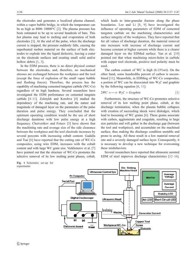
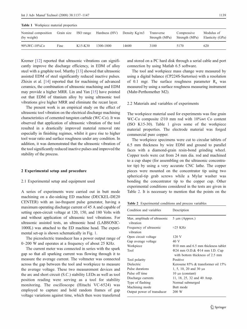
Figures 2, 3 and 4 show material removal rate againstpulse-on time with and without ultrasonic employment(US/EDM and PEDM (Pure EDM) respectively) fordifferent discharge current settings, and Figs. 5, 6, and 7
represent material removal rate against discharge currentwith and without ultrasonic vibration for different pulse-ontimes. The formula used to calculate the volumetric materialremoval rate is:
MRR Vu or Vcð Þ ¼ M 1 �M 2ð Þρ:t
� 103 ð2Þ
WhereMRR is the material removal rate (mm3/min), Vu isthe volumetric removal rate of workpiece with ultrasonic andVc is the volumetric removal rate of workpiece withoutultrasonic vibration of the tool, M1 and M2 are the workpiece
Fig. 2 Effect of tool vibration on MRR versus pulse-on time (Ti) forUS/EDM and pure EDM
Fig. 3 Effect of tool vibration on MRR versus pulse-on time (Ti) forUS/EDM and pure EDM
Fig. 4 Effect of tool vibration on MRR versus pulse-on time (Ti) forUS/EDM and pure EDM
Fig. 5 Effect of tool vibration on MRR versus discharge current (I)for US/EDM and pure EDM
1140 Int J Adv Manuf Technol (2008) 38:1137–1147
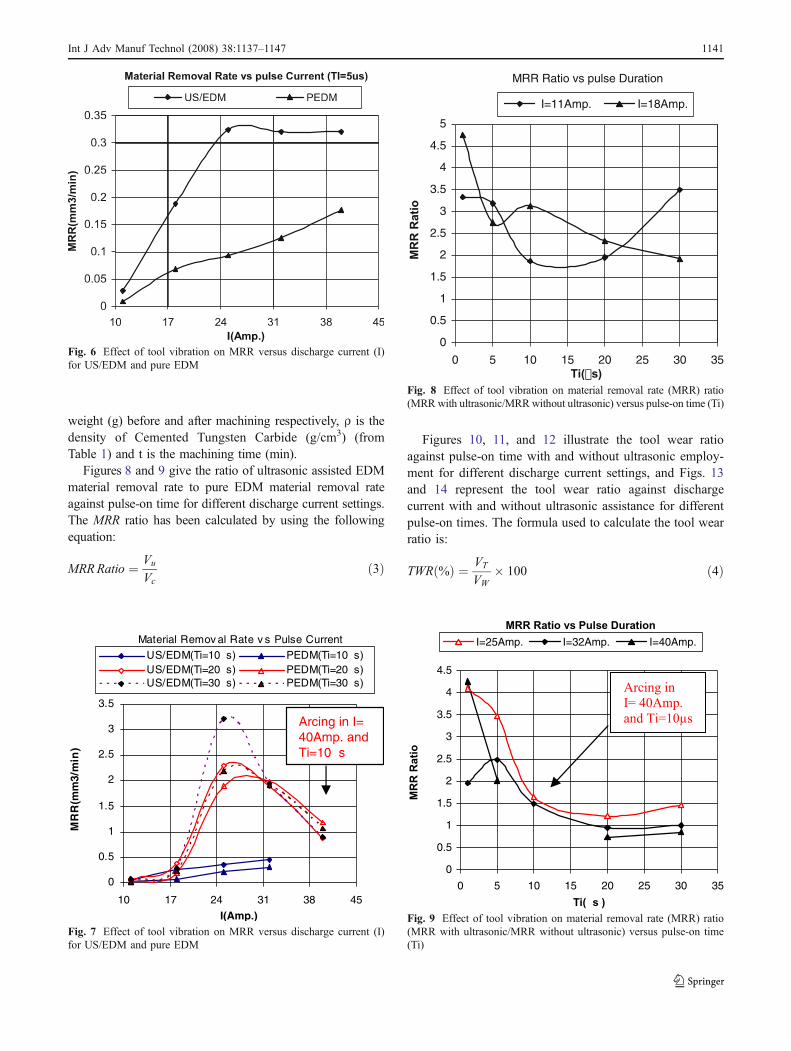
weight (g) before and after machining respectively, ρ is thedensity of Cemented Tungsten Carbide (g/cm3) (fromTable 1) and t is the machining time (min).
Figures 8 and 9 give the ratio of ultrasonic assisted EDMmaterial removal rate to pure EDM material removal rateagainst pulse-on time for different discharge current settings.The MRR ratio has been calculated by using the followingequation:
MRRRatio ¼ Vu
Vcð3Þ
Figures 10, 11, and 12 illustrate the tool wear ratioagainst pulse-on time with and without ultrasonic employ-ment for different discharge current settings, and Figs. 13and 14 represent the tool wear ratio against dischargecurrent with and without ultrasonic assistance for differentpulse-on times. The formula used to calculate the tool wearratio is:
TWR %ð Þ ¼ VT
VW� 100 ð4Þ
MRR Ratio vs Pulse Duration
0
0.5
1
1.5
2
2.5
3
3.5
4
4.5
0 5 10 15 20 25 30 35
Ti(µs )
MR
R R
atio
I=25Amp. I=32Amp. I=40Amp.
Arcing in
I= 40Amp.
and Ti=10µs
Fig. 9 Effect of tool vibration on material removal rate (MRR) ratio(MRR with ultrasonic/MRR without ultrasonic) versus pulse-on time(Ti)
MRR Ratio vs pulse Duration
0
0.5
1
1.5
2
2.5
3
3.5
4
4.5
5
0 5 10 15 20 25 30 35Ti(µs)
MR
R R
atio
I=11Amp. I=18Amp.
Fig. 8 Effect of tool vibration on material removal rate (MRR) ratio(MRRwith ultrasonic/MRRwithout ultrasonic) versus pulse-on time (Ti)
Material Remov al Rate v s Pulse Current
0
0.5
1
1.5
2
2.5
3
3.5
10 17 24 31 38 45
I(Amp.)
MR
R(m
m3/
min
)
US/EDM(Ti=10µs) PEDM(Ti=10µs)US/EDM(Ti=20µs) PEDM(Ti=20µs)US/EDM(Ti=30µs) PEDM(Ti=30µs)
Arcing in I= 40Amp. and Ti=10µs
Fig. 7 Effect of tool vibration on MRR versus discharge current (I)for US/EDM and pure EDM
Fig. 6 Effect of tool vibration on MRR versus discharge current (I)for US/EDM and pure EDM
Int J Adv Manuf Technol (2008) 38:1137–1147 1141
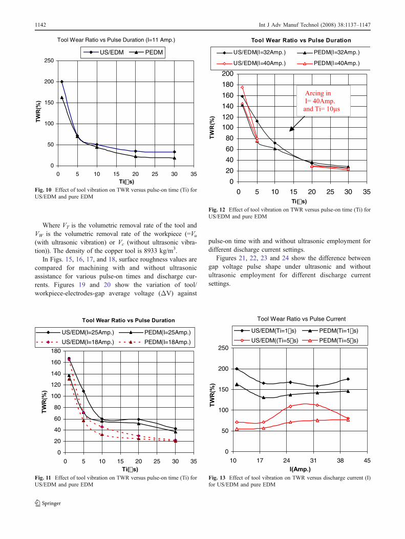
Where VT is the volumetric removal rate of the tool andVW is the volumetric removal rate of the workpiece (=Vu(with ultrasonic vibration) or Vc (without ultrasonic vibra-tion)). The density of the copper tool is 8933 kg/m3.
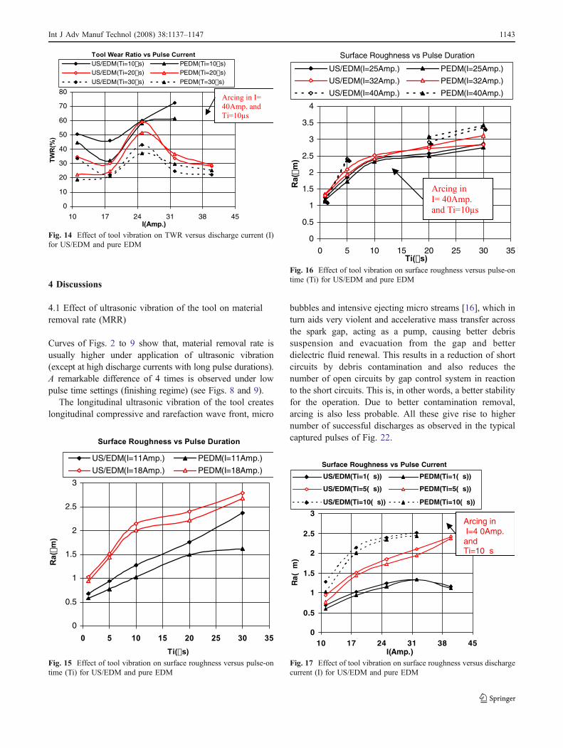
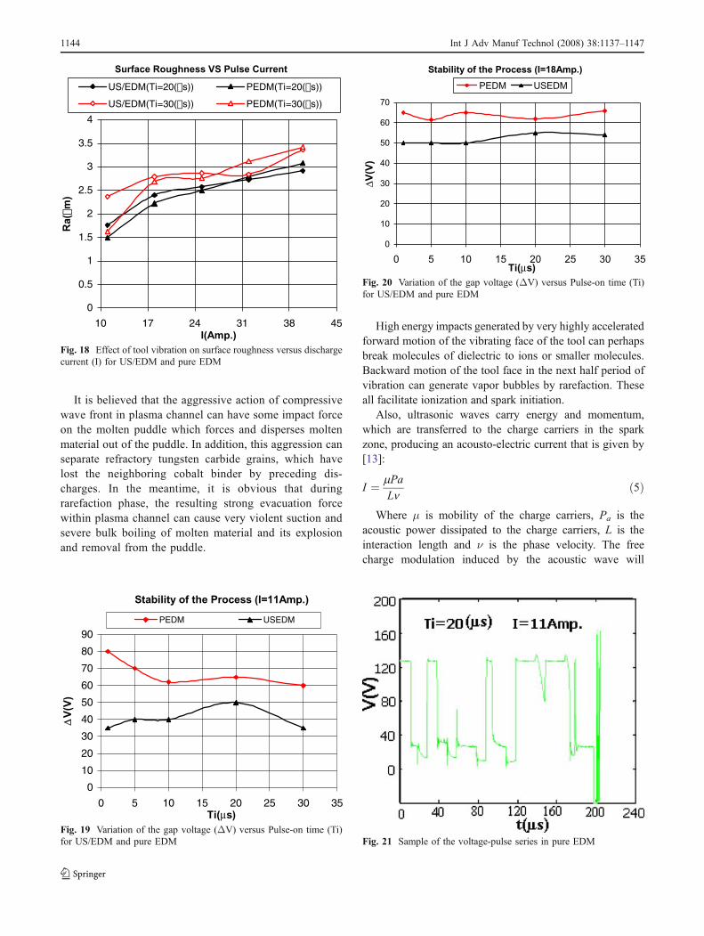
In Figs. 15, 16, 17, and 18, surface roughness values arecompared for machining with and without ultrasonicassistance for various pulse-on times and discharge cur-rents. Figures 19 and 20 show the variation of tool/workpiece-electrodes-gap average voltage (ΔV) against
pulse-on time with and without ultrasonic employment fordifferent discharge current settings.
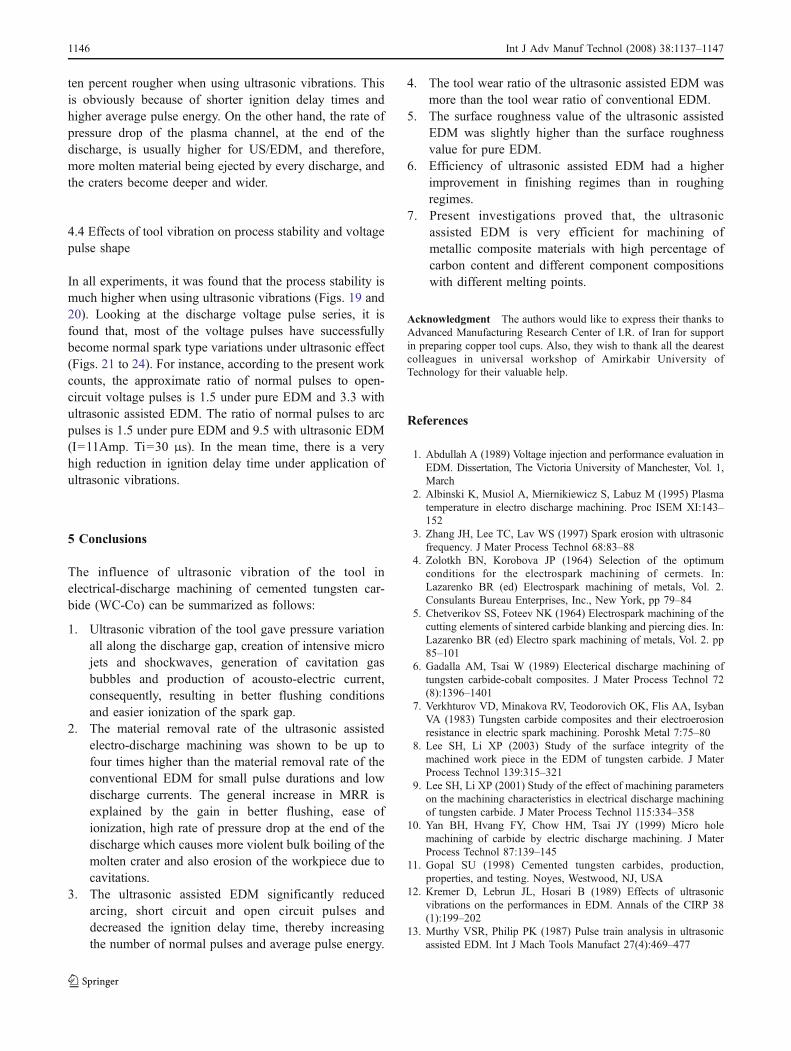
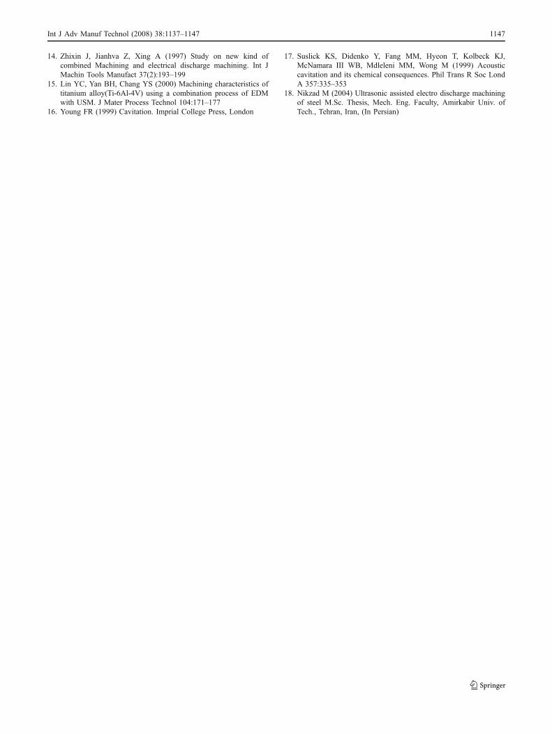
Figures 21, 22, 23 and 24 show the difference betweengap voltage pulse shape under ultrasonic and withoutultrasonic employment for different discharge currentsettings.
Tool Wear Ratio vs Pulse Current
0
50
100
150
200
250
10 17 24 31 38 45I(Amp.)
TW
R(%
)
US/EDM(Ti=1µs) PEDM(Ti=1µs)
US/EDM((Ti=5µs) PEDM(Ti=5µs)
Fig. 13 Effect of tool vibration on TWR versus discharge current (I)for US/EDM and pure EDM
Tool Wear Ratio vs Pulse Duration
0
20
40
60
80
100
120
140
160
180
200
0 5 10 15 20 25 30 35Ti(µs)
TW
R(%
)
US/EDM(I=32Amp.) PEDM(I=32Amp.)
US/EDM(I=40Amp.) PEDM(I=40Amp.)
Arcing in
I= 40Amp.
and Ti= 10µs
Fig. 12 Effect of tool vibration on TWR versus pulse-on time (Ti) forUS/EDM and pure EDM
Tool Wear Ratio vs Pulse Duration
0
20
40
60
80
100
120
140
160
180
0 5 10 15 20 25 30 35Ti(µs)
TW
R(%
)
US/EDM(I=25Amp.) PEDM(I=25Amp.)
US/EDM(I=18Amp.) PEDM(I=18Amp.)
Fig. 11 Effect of tool vibration on TWR versus pulse-on time (Ti) forUS/EDM and pure EDM
Tool Wear Ratio vs Pulse Duration (I=11 Amp.)
0
50
100
150
200
250
0 5 10 15 20 25 30 35Ti(µs)
TW
R(%
)
US/EDM PEDM
Fig. 10 Effect of tool vibration on TWR versus pulse-on time (Ti) forUS/EDM and pure EDM
1142 Int J Adv Manuf Technol (2008) 38:1137–1147
4 Discussions
4.1 Effect of ultrasonic vibration of the tool on materialremoval rate (MRR)
Curves of Figs. 2 to 9 show that, material removal rate isusually higher under application of ultrasonic vibration(except at high discharge currents with long pulse durations).A remarkable difference of 4 times is observed under lowpulse time settings (finishing regime) (see Figs. 8 and 9).
The longitudinal ultrasonic vibration of the tool createslongitudinal compressive and rarefaction wave front, micro
bubbles and intensive ejecting micro streams [16], which inturn aids very violent and accelerative mass transfer acrossthe spark gap, acting as a pump, causing better debrissuspension and evacuation from the gap and betterdielectric fluid renewal. This results in a reduction of shortcircuits by debris contamination and also reduces thenumber of open circuits by gap control system in reactionto the short circuits. This is, in other words, a better stabilityfor the operation. Due to better contamination removal,arcing is also less probable. All these give rise to highernumber of successful discharges as observed in the typicalcaptured pulses of Fig. 22.
Surface Roughness vs Pulse Current
0
0.5
1
1.5
2
2.5
3
10 17 24 31 38 45I(Amp.)
Ra
(µm
)
US/EDM(Ti=1(µs)) PEDM(Ti=1(µs))
US/EDM(Ti=5(µs)) PEDM(Ti=5(µs))
US/EDM(Ti=10(µs)) PEDM(Ti=10(µs))
Arcing inI=4 0Amp.
and Ti=10µs
Fig. 17 Effect of tool vibration on surface roughness versus dischargecurrent (I) for US/EDM and pure EDM
Surface Roughness vs Pulse Duration
0
0.5
1
1.5
2
2.5
3
3.5
4
0 5 10 15 20 25 30 35Ti(µs)
Ra(µ
m)
US/EDM(I=25Amp.) PEDM(I=25Amp.)
US/EDM(I=32Amp.) PEDM(I=32Amp.)
US/EDM(I=40Amp.) PEDM(I=40Amp.)
Arcing in
I= 40Amp.
and Ti=10µs
Fig. 16 Effect of tool vibration on surface roughness versus pulse-ontime (Ti) for US/EDM and pure EDM
Surface Roughness vs Pulse Duration
0
0.5
1
1.5
2
2.5
3
0 5 10 15 20 25 30 35
Ti(µs)
Ra(µ
m)
US/EDM(I=11Amp.) PEDM(I=11Amp.)
US/EDM(I=18Amp.) PEDM(I=18Amp.)
Fig. 15 Effect of tool vibration on surface roughness versus pulse-ontime (Ti) for US/EDM and pure EDM
Tool Wear Ratio vs Pulse Current
0
10
20
30
40
50
60
70
80
10 17 24 31 38 45I(Amp.)
TW
R(%
)
US/EDM(Ti=10µs) PEDM(Ti=10µs)US/EDM(Ti=20µs) PEDM(Ti=20µs)US/EDM(Ti=30µs) PEDM(T=30µs)
Arcing in I=
40Amp. and
Ti=10µs
Fig. 14 Effect of tool vibration on TWR versus discharge current (I)for US/EDM and pure EDM
Int J Adv Manuf Technol (2008) 38:1137–1147 1143
It is believed that the aggressive action of compressivewave front in plasma channel can have some impact forceon the molten puddle which forces and disperses moltenmaterial out of the puddle. In addition, this aggression canseparate refractory tungsten carbide grains, which havelost the neighboring cobalt binder by preceding dis-charges. In the meantime, it is obvious that duringrarefaction phase, the resulting strong evacuation forcewithin plasma channel can cause very violent suction andsevere bulk boiling of molten material and its explosionand removal from the puddle.
High energy impacts generated by very highly acceleratedforward motion of the vibrating face of the tool can perhapsbreak molecules of dielectric to ions or smaller molecules.Backward motion of the tool face in the next half period ofvibration can generate vapor bubbles by rarefaction. Theseall facilitate ionization and spark initiation.
Also, ultrasonic waves carry energy and momentum,which are transferred to the charge carriers in the sparkzone, producing an acousto-electric current that is given by[13]:
I ¼ mPaLn
ð5Þ
Where μ is mobility of the charge carriers, Pa is theacoustic power dissipated to the charge carriers, L is theinteraction length and ν is the phase velocity. The freecharge modulation induced by the acoustic wave will
Stability of the Process (I=11Amp.)
0
10
20
30
40
50
60
70
80
90
0 5 10 15 20 25 30 35Ti(µs)
∆V
(V)
PEDM USEDM
Fig. 19 Variation of the gap voltage (ΔV) versus Pulse-on time (Ti)for US/EDM and pure EDM
Surface Roughness VS Pulse Current
0
0.5
1
1.5
2
2.5
3
3.5
4
10 17 24 31 38 45I(Amp.)
Ra(µ
m)
US/EDM(Ti=20(µs)) PEDM(Ti=20(µs))
US/EDM(Ti=30(µs)) PEDM(Ti=30(µs))
Fig. 18 Effect of tool vibration on surface roughness versus dischargecurrent (I) for US/EDM and pure EDM
Stability of the Process (I=18Amp.)
0
10
20
30
40
50
60
70
0 5 10 15 20 25 30 35Ti(µs)
∆V(V
)
PEDM USEDM
Fig. 20 Variation of the gap voltage (ΔV) versus Pulse-on time (Ti)for US/EDM and pure EDM
Fig. 21 Sample of the voltage-pulse series in pure EDM
1144 Int J Adv Manuf Technol (2008) 38:1137–1147
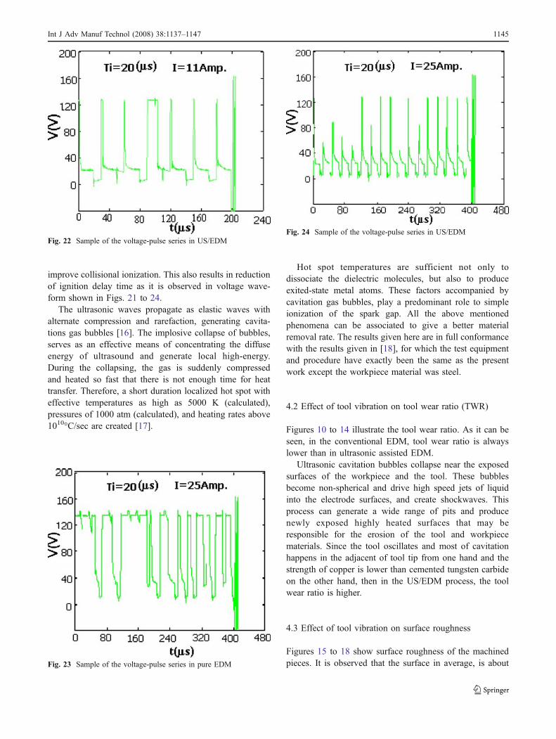
improve collisional ionization. This also results in reductionof ignition delay time as it is observed in voltage wave-form shown in Figs. 21 to 24.
The ultrasonic waves propagate as elastic waves withalternate compression and rarefaction, generating cavita-tions gas bubbles [16]. The implosive collapse of bubbles,serves as an effective means of concentrating the diffuseenergy of ultrasound and generate local high-energy.During the collapsing, the gas is suddenly compressedand heated so fast that there is not enough time for heattransfer. Therefore, a short duration localized hot spot witheffective temperatures as high as 5000 K (calculated),pressures of 1000 atm (calculated), and heating rates above1010°C/sec are created [17].
Hot spot temperatures are sufficient not only todissociate the dielectric molecules, but also to produceexited-state metal atoms. These factors accompanied bycavitation gas bubbles, play a predominant role to simpleionization of the spark gap. All the above mentionedphenomena can be associated to give a better materialremoval rate. The results given here are in full conformancewith the results given in [18], for which the test equipmentand procedure have exactly been the same as the presentwork except the workpiece material was steel.
4.2 Effect of tool vibration on tool wear ratio (TWR)
Figures 10 to 14 illustrate the tool wear ratio. As it can beseen, in the conventional EDM, tool wear ratio is alwayslower than in ultrasonic assisted EDM.
Ultrasonic cavitation bubbles collapse near the exposedsurfaces of the workpiece and the tool. These bubblesbecome non-spherical and drive high speed jets of liquidinto the electrode surfaces, and create shockwaves. Thisprocess can generate a wide range of pits and producenewly exposed highly heated surfaces that may beresponsible for the erosion of the tool and workpiecematerials. Since the tool oscillates and most of cavitationhappens in the adjacent of tool tip from one hand and thestrength of copper is lower than cemented tungsten carbideon the other hand, then in the US/EDM process, the toolwear ratio is higher.
4.3 Effect of tool vibration on surface roughness
Figures 15 to 18 show surface roughness of the machinedpieces. It is observed that the surface in average, is about
Fig. 22 Sample of the voltage-pulse series in US/EDM
Fig. 23 Sample of the voltage-pulse series in pure EDM
Fig. 24 Sample of the voltage-pulse series in US/EDM
Int J Adv Manuf Technol (2008) 38:1137–1147 1145
ten percent rougher when using ultrasonic vibrations. Thisis obviously because of shorter ignition delay times andhigher average pulse energy. On the other hand, the rate ofpressure drop of the plasma channel, at the end of thedischarge, is usually higher for US/EDM, and therefore,more molten material being ejected by every discharge, andthe craters become deeper and wider.
4.4 Effects of tool vibration on process stability and voltagepulse shape
In all experiments, it was found that the process stability ismuch higher when using ultrasonic vibrations (Figs. 19 and20). Looking at the discharge voltage pulse series, it isfound that, most of the voltage pulses have successfullybecome normal spark type variations under ultrasonic effect(Figs. 21 to 24). For instance, according to the present workcounts, the approximate ratio of normal pulses to open-circuit voltage pulses is 1.5 under pure EDM and 3.3 withultrasonic assisted EDM. The ratio of normal pulses to arcpulses is 1.5 under pure EDM and 9.5 with ultrasonic EDM(I=11Amp. Ti=30 μs). In the mean time, there is a veryhigh reduction in ignition delay time under application ofultrasonic vibrations.
5 Conclusions
The influence of ultrasonic vibration of the tool inelectrical-discharge machining of cemented tungsten car-bide (WC-Co) can be summarized as follows:
1. Ultrasonic vibration of the tool gave pressure variationall along the discharge gap, creation of intensive microjets and shockwaves, generation of cavitation gasbubbles and production of acousto-electric current,consequently, resulting in better flushing conditionsand easier ionization of the spark gap.
2. The material removal rate of the ultrasonic assistedelectro-discharge machining was shown to be up tofour times higher than the material removal rate of theconventional EDM for small pulse durations and lowdischarge currents. The general increase in MRR isexplained by the gain in better flushing, ease ofionization, high rate of pressure drop at the end of thedischarge which causes more violent bulk boiling of themolten crater and also erosion of the workpiece due tocavitations.
3. The ultrasonic assisted EDM significantly reducedarcing, short circuit and open circuit pulses anddecreased the ignition delay time, thereby increasingthe number of normal pulses and average pulse energy.
4. The tool wear ratio of the ultrasonic assisted EDM wasmore than the tool wear ratio of conventional EDM.
5. The surface roughness value of the ultrasonic assistedEDM was slightly higher than the surface roughnessvalue for pure EDM.
6. Efficiency of ultrasonic assisted EDM had a higherimprovement in finishing regimes than in roughingregimes.
7. Present investigations proved that, the ultrasonicassisted EDM is very efficient for machining ofmetallic composite materials with high percentage ofcarbon content and different component compositionswith different melting points.
Acknowledgment The authors would like to express their thanks toAdvanced Manufacturing Research Center of I.R. of Iran for supportin preparing copper tool cups. Also, they wish to thank all the dearestcolleagues in universal workshop of Amirkabir University ofTechnology for their valuable help.
References
1. Abdullah A (1989) Voltage injection and performance evaluation inEDM. Dissertation, The Victoria University of Manchester, Vol. 1,March
2. Albinski K, Musiol A, Miernikiewicz S, Labuz M (1995) Plasmatemperature in electro discharge machining. Proc ISEM XI:143–152
3. Zhang JH, Lee TC, Lav WS (1997) Spark erosion with ultrasonicfrequency. J Mater Process Technol 68:83–88
4. Zolotkh BN, Korobova JP (1964) Selection of the optimumconditions for the electrospark machining of cermets. In:Lazarenko BR (ed) Electrospark machining of metals, Vol. 2.Consulants Bureau Enterprises, Inc., New York, pp 79–84
5. Chetverikov SS, Foteev NK (1964) Electrospark machining of thecutting elements of sintered carbide blanking and piercing dies. In:Lazarenko BR (ed) Electro spark machining of metals, Vol. 2. pp85–101
6. Gadalla AM, Tsai W (1989) Electerical discharge machining oftungsten carbide-cobalt composites. J Mater Process Technol 72(8):1396–1401
7. Verkhturov VD, Minakova RV, Teodorovich OK, Flis AA, IsybanVA (1983) Tungsten carbide composites and their electroerosionresistance in electric spark machining. Poroshk Metal 7:75–80
8. Lee SH, Li XP (2003) Study of the surface integrity of themachined work piece in the EDM of tungsten carbide. J MaterProcess Technol 139:315–321
9. Lee SH, Li XP (2001) Study of the effect of machining parameterson the machining characteristics in electrical discharge machiningof tungsten carbide. J Mater Process Technol 115:334–358
10. Yan BH, Hvang FY, Chow HM, Tsai JY (1999) Micro holemachining of carbide by electric discharge machining. J MaterProcess Technol 87:139–145
11. Gopal SU (1998) Cemented tungsten carbides, production,properties, and testing. Noyes, Westwood, NJ, USA
12. Kremer D, Lebrun JL, Hosari B (1989) Effects of ultrasonicvibrations on the performances in EDM. Annals of the CIRP 38(1):199–202
13. Murthy VSR, Philip PK (1987) Pulse train analysis in ultrasonicassisted EDM. Int J Mach Tools Manufact 27(4):469–477
1146 Int J Adv Manuf Technol (2008) 38:1137–1147
14. Zhixin J, Jianhva Z, Xing A (1997) Study on new kind ofcombined Machining and electrical discharge machining. Int JMachin Tools Manufact 37(2):193–199
15. Lin YC, Yan BH, Chang YS (2000) Machining characteristics oftitanium alloy(Ti-6Al-4V) using a combination process of EDMwith USM. J Mater Process Technol 104:171–177
16. Young FR (1999) Cavitation. Imprial College Press, London
17. Suslick KS, Didenko Y, Fang MM, Hyeon T, Kolbeck KJ,McNamara III WB, Mdleleni MM, Wong M (1999) Acousticcavitation and its chemical consequences. Phil Trans R Soc LondA 357:335–353
18. Nikzad M (2004) Ultrasonic assisted electro discharge machiningof steel M.Sc. Thesis, Mech. Eng. Faculty, Amirkabir Univ. ofTech., Tehran, Iran, (In Persian)
Int J Adv Manuf Technol (2008) 38:1137–1147 1147


![F_ 9VcR]UVU ViZe Wc`^ 7]VVe DecVVe 6ZHHSLQJ](https://img.dokumen.tips/doc/110x75/6320f56bb71aaa142a0406ef/f-9vcruvu-vize-wc-7vve-decvve-6zhhslqj-.jpg)

