Embed Size (px)
Citation preview
Materials and Design 31 (2010) 2454–2463
Contents lists available at ScienceDirect
Materials and Design
journal homepage: www.elsevier .com/locate /matdes
Effect of process parameters on the strength of resistance spot welds in 6082-T6aluminium alloy
A.M. Pereira a,*, J.M. Ferreira b, A. Loureiro b, J.D.M. Costa b, P.J. Bártolo a
a CDRsp, Centre for Rapid and Sustainable Product Development, Polytechnic Institute of Leiria, Morro do Lena – Alto Vieiro, 2400-901 Leiria, Portugalb CEMUC, Centre of Mechanical Engineering of University of Coimbra, Rua Luís Reis dos Santos, Pólo II da Universidade de Coimbra, 3030-788 Coimbra, Portugal
a r t i c l e i n f o
Article history:Received 24 September 2009Accepted 21 November 2009Available online 26 November 2009
Keywords:Welding (D)Mechanical properties (E)Failure analysis (H)
0261-3069/$ - see front matter � 2009 Elsevier Ltd. Adoi:10.1016/j.matdes.2009.11.052
* Corresponding author. Tel.: +351 244820300; faxE-mail address: [email protected] (A.M. Pe
a b s t r a c t
In this study the microstructural and mechanical behaviour of resistance spot welds (RSW) done on alu-minium alloy 6082-T6 sheets, welded at different welding parameters, is examined. Microstructuralexaminations and hardness evaluations were carried out in order to determine the influence of weldingparameters on the quality of the welds. The welded joints were subjected to static tensile-shear tests inorder to determine their strength and failure mode. The increase in weld current and duration increasedthe nugget size and the weld strength. Beyond a critical nugget diameter the failure mode changed frominterfacial to pullout. Taking into consideration the sheet thickness and the mechanical properties of theweld, a simple model is proposed to predict the critical nugget diameter required to produce pull-out fail-ure mode in undermatched welds in heat-treatable aluminium alloys.
� 2009 Elsevier Ltd. All rights reserved.
1. Introduction
Resistance spot welding (RSW) is a process of joining metalcomponents through the fusion of discrete spots at the interfaceof the work pieces. It is one of the most useful and practical meth-ods for the manufacture of sheet metal assemblies [1]. This processis ideal for joining low carbon steel, stainless steel and nickel, alu-minium or titanium alloy components and is thus used extensively[2–5]. This welding method can be used for the bodies and chassisof automobiles, trucks, trailers, buses, and railroad passenger cars,cabinets, office furniture and many other products.
Increasing restrictions in terms of performance, pollution,safety and energy consumption have resulted in research into theuse of new materials and new processes aimed at weight reductionin the production of components and equipment. Improvementsare obtained through lighter materials, like aluminium alloys andbetter joining processes, such as resistance spot welding [6,7].
One of the major advantages of RSW is the easy automation(high speed and adaptability) in high-volume production. Despitethe obvious advantages of RSW this process has a major problemdue to the inconsistent quality from weld to weld. The complexityintroduced by many sources of variability complicates automation,reduces the quality of the weld and increases production costs [3].Therefore, it is necessary to identify and control the parametersaffecting the quality of the weld.
ll rights reserved.
: +351 244820310.reira).
During spot welding, important changes occur in the mechani-cal and metallurgical properties of the spot welded areas. Theinvestigation of these changes is very important for the safetyand quality of the welded joints [1]. Both the squeezing time andthe load applied on the electrodes prior to the transit of weldingcurrent have an important effect on mechanical properties due totheir influence on current flow. In fact they ensure that the fayingsurfaces will be in contact with each other during welding [8]. Alsothe welding current and weld time significantly influence theproperties of spot welds. In summary, the shear strength of singlelap spot welded joints is a complex phenomenon, which dependson several factors, namely, welding parameters and base materialproperties. These factors control the microstructure and size ofthe weld nugget, which determine the mechanical behaviour ofthe welds [5,9,10]. The nugget is the melted region located in theinterface between the abutting plates being welded.
In general an increase in weld current coarsens the microstruc-ture of the weld nugget and heat-affected zone and affects thehardness, though the weld hardness is also very influenced bythe base material’s composition and state of treatment [5,9,11].With austenitic stainless steel the increase in weld current doesnot produce any substantial change in the distribution of hardnesswithin the nugget because it cannot be hardened by heat-treat-ment [5,10]. However, in heat or mechanically treated aluminiumalloys, the increase in heat input during welding leads to a de-crease in microhardness and strength in the welds [12].
An increase in weld current and heat input increased the nuggetsize and improved the failure load of spot welds done on carbonand stainless steels, aluminium and magnesium alloys
1
180
Nugget
25
25
25
Alignment tabs
201
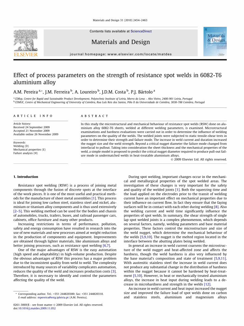
Fig. 1. Dimensions of tensile-shear test specimens (not to scale, dimensions in mm).
Wel
ding
for
ce
on
elec
trod
es
rren
t
A.M. Pereira et al. / Materials and Design 31 (2010) 2454–2463 2455
[1,5,9,11,13,14]. However, the tensile-peel strength and tensile-shear strength reach a maximum with the weld current and de-creases after this value [15]. This happens because the nuggetdiameter increases with current up to a specific value. After thatvalue, the nugget diameter decreases because of excessive meltingand splashing. This was observed by Vural et al. [16] for severalmaterial type combinations. The weld strength is also correlatedwith other process parameters, for example the applied load inwelds carried out on stainless steel sheets [17].
The main failure modes for static weld strength tests using lapshear or cross tension samples are interfacial and nugget pull-outfailure. Partial interfacial fracture is also observed [14,18]. In theinterfacial mode, failure occurs via crack propagation through thenugget fusion zone (FZ), while, in pullout mode failure occurs viacomplete nugget withdrawal from one sheet. Partial interfacialfracture combines both modes of fracture. Welds that fail in nuggetpullout mode provide higher peak loads and energy absorption lev-els than those which fail in interfacial failure mode. Because of this,process parameters should be adjusted so that pull-out failuremode is guaranteed [13,19], in order to ensure the reliability ofthe welds. In the early days of spot welding, the static strength ofspot welds in steel was considered to be only dependent on theweld nugget size. Several equations were proposed to predict theoptimum or the minimum nugget diameter to guarantee the pull-out failure mode of the welds. In Eq. (1), proposed by the AmericanWelding Society/American National Standard Institute/Society ofAutomotive Engineers [20] for welds in steel, the critical nugget sized is simply function of the sheet thickness t, both in mm.
d ¼ 4ffiffi
tp
ð1Þ
However, several authors claim this equation is not safe forsheet thicknesses beyond 1.0–1.5 mm [19,21] and the alterationsthat occur in the mechanical properties of the weld should be ta-ken into consideration. Eq. (2) was recommended by Pouranvariet al. [19] to predict the critical nugget diameter dcr, and besidesthe sheet thickness t it considers the hardness of the failure linematerial (H)FL and of the nugget (H)WN.
dcr ¼ 8tðHÞFL
ðHÞWNð2Þ
Those equations and others presented in the literature weremainly derived for welds in steels and few are mentioned for weldsin aluminium alloys. Eq. (3) was proposed by Sun et al. [22] forwelds in aluminium alloys 5182-O and 6111-T4, where no sub-stantial change in hardness was observed in the welds. Dcritical isthe critical size of the nugget required for pull-out failure, t thesheet thickness and f a porosity factor to consider influence of nug-get porosity on the weld strength.
Dcritical ¼3:2t
fð3Þ
Though the effect of the process parameters on the mechanicalbehaviour of resistance spot welds on carbon and stainless steels iswell documented results from aluminium alloys continue to bescarce. A better understanding of the effect of process parameterson the mechanical behaviour of spot welded joints in heat-treat-able aluminium alloys such as 6082-T6 is still required. The objec-tive of the current research is to investigate the effect of processparameters on shear strength and failure mode of spot weldedjoints in thin sheets of 6082-T6 aluminium alloy.
Squeeze
time
Forge
time
Cu
Weld time
Fig. 2. Typical spot welding cycle.
2. Experimental procedure
Aluminium alloy 6082-T6 sheets of 1 mm thick were used inthis study. The nominal chemical composition and basic
mechanical properties of this alloy are given in Table 1. Resis-tance spot welding lap joints were done on specimens of100 mm� 25 mm � 1 mm in size. Fig. 1 shows the geometryand dimensions of the welded specimens. Sheet surfaces wererandomly abraded with silicon carbide paper – P220 grade andafterwards cleaned with a dry air jet before resistance spotwelding.
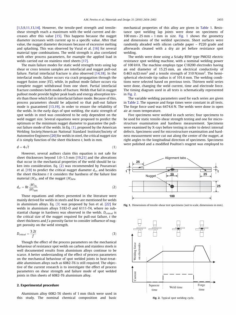
The welds were done using a Sciaky RSW type PMC02 electricresistance spot welding machine, with a nominal welding powerof 100 kVA. The machine employs type C18200 electrodes havingan end diameter of 15.25 mm, an electrical conductivity of0.463 m/X mm2 and a tensile strength of 310 N/mm2. The hemi-spherical electrode tip radius is of 101.6 mm. The welding condi-tions were selected based on previous tests. Thirteen weld serieswere done, changing the weld current, time and electrode force.The timing diagram used in all tests is schematically representedin Fig. 2.
The variable welding parameters used for each series are givenin Table 2. The squeeze and forge times were constant in all tests.The forge force used was 6474.6 N. The welds were done in openair at room temperature.
Five specimens were welded in each series; four specimens tobe used for static tensile-shear strength testing and one for micro-structure examination and hardness measurement. Specimenswere examined by X-rays before testing in order to detect internaldefects. Specimens used for microstructure examination and hard-ness measurement were cut out along the center of the nugget, atright angles to the longitudinal direction of specimens. Specimenswere polished and a modified Poulton’s reagent was employed to
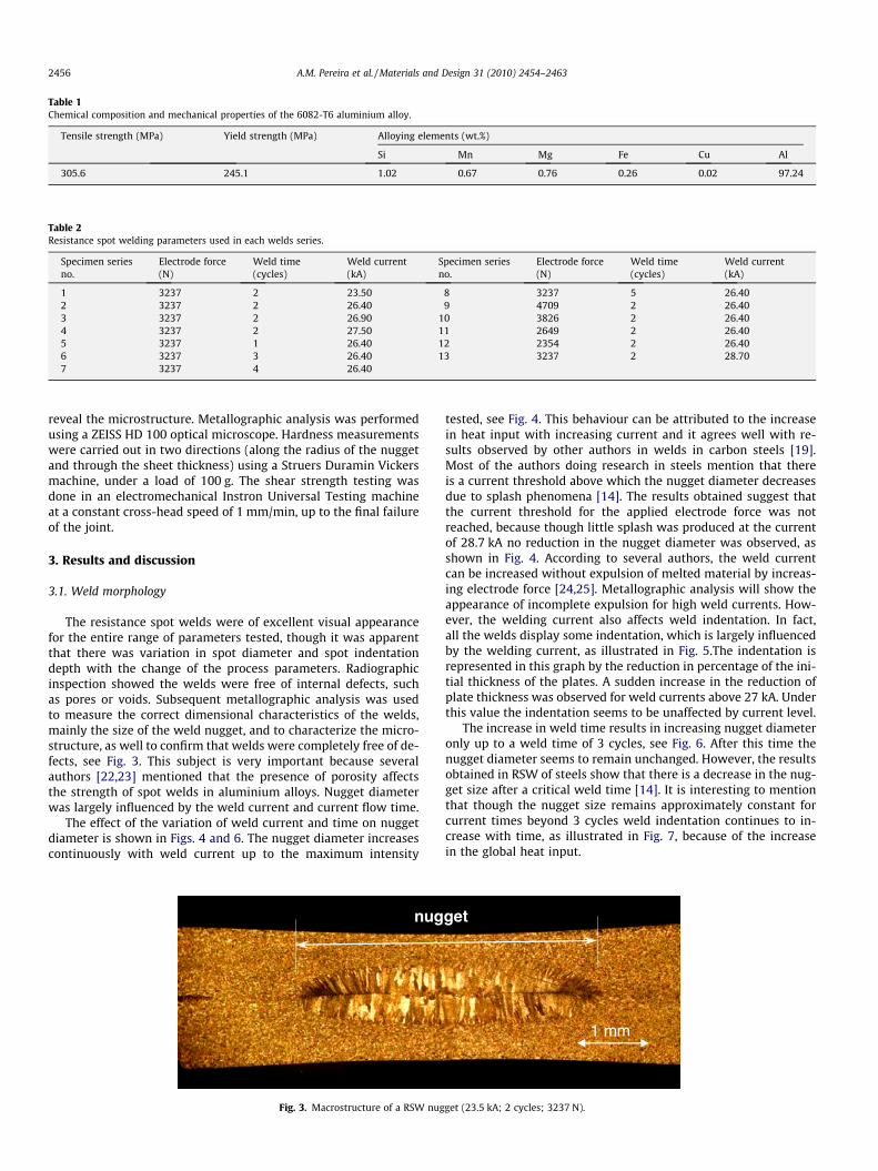
Table 1Chemical composition and mechanical properties of the 6082-T6 aluminium alloy.
Tensile strength (MPa) Yield strength (MPa) Alloying elements (wt.%)
Si Mn Mg Fe Cu Al
305.6 245.1 1.02 0.67 0.76 0.26 0.02 97.24
Table 2Resistance spot welding parameters used in each welds series.
Specimen seriesno.
Electrode force(N)
Weld time(cycles)
Weld current(kA)
Specimen seriesno.
Electrode force(N)
Weld time(cycles)
Weld current(kA)
1 3237 2 23.50 8 3237 5 26.402 3237 2 26.40 9 4709 2 26.403 3237 2 26.90 10 3826 2 26.404 3237 2 27.50 11 2649 2 26.405 3237 1 26.40 12 2354 2 26.406 3237 3 26.40 13 3237 2 28.707 3237 4 26.40
2456 A.M. Pereira et al. / Materials and Design 31 (2010) 2454–2463
reveal the microstructure. Metallographic analysis was performedusing a ZEISS HD 100 optical microscope. Hardness measurementswere carried out in two directions (along the radius of the nuggetand through the sheet thickness) using a Struers Duramin Vickersmachine, under a load of 100 g. The shear strength testing wasdone in an electromechanical Instron Universal Testing machineat a constant cross-head speed of 1 mm/min, up to the final failureof the joint.
3. Results and discussion
3.1. Weld morphology
The resistance spot welds were of excellent visual appearancefor the entire range of parameters tested, though it was apparentthat there was variation in spot diameter and spot indentationdepth with the change of the process parameters. Radiographicinspection showed the welds were free of internal defects, suchas pores or voids. Subsequent metallographic analysis was usedto measure the correct dimensional characteristics of the welds,mainly the size of the weld nugget, and to characterize the micro-structure, as well to confirm that welds were completely free of de-fects, see Fig. 3. This subject is very important because severalauthors [22,23] mentioned that the presence of porosity affectsthe strength of spot welds in aluminium alloys. Nugget diameterwas largely influenced by the weld current and current flow time.
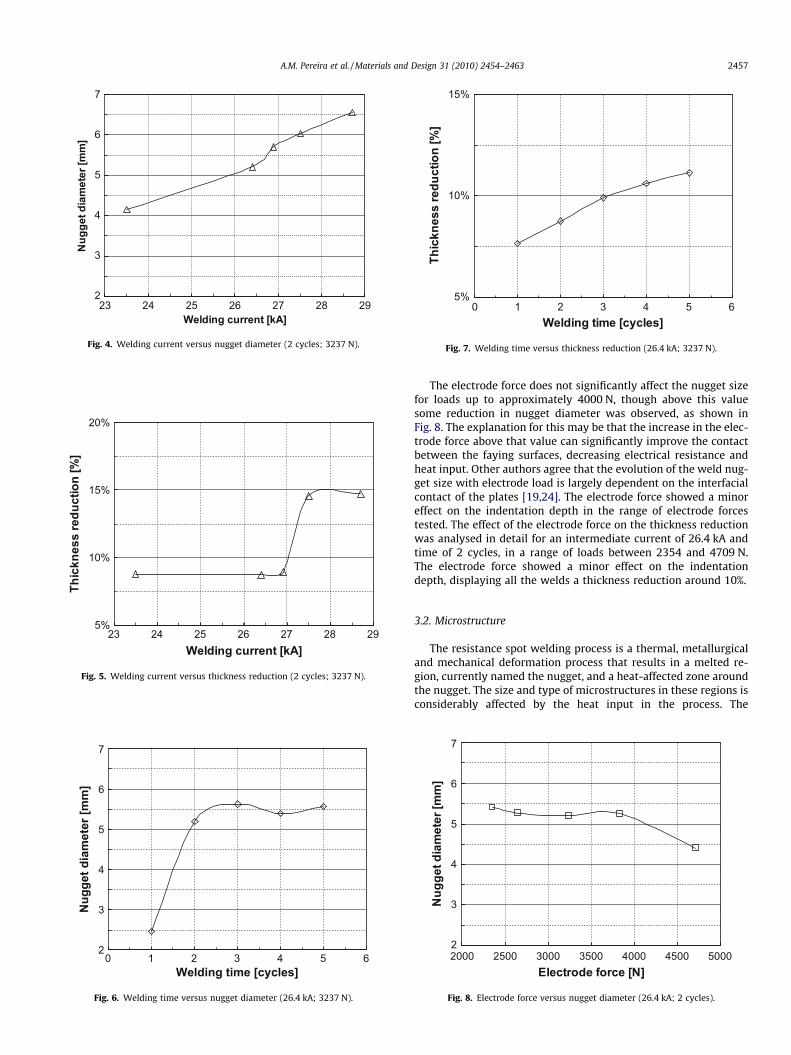
The effect of the variation of weld current and time on nuggetdiameter is shown in Figs. 4 and 6. The nugget diameter increasescontinuously with weld current up to the maximum intensity
nug
Fig. 3. Macrostructure of a RSW nug
tested, see Fig. 4. This behaviour can be attributed to the increasein heat input with increasing current and it agrees well with re-sults observed by other authors in welds in carbon steels [19].Most of the authors doing research in steels mention that thereis a current threshold above which the nugget diameter decreasesdue to splash phenomena [14]. The results obtained suggest thatthe current threshold for the applied electrode force was notreached, because though little splash was produced at the currentof 28.7 kA no reduction in the nugget diameter was observed, asshown in Fig. 4. According to several authors, the weld currentcan be increased without expulsion of melted material by increas-ing electrode force [24,25]. Metallographic analysis will show theappearance of incomplete expulsion for high weld currents. How-ever, the welding current also affects weld indentation. In fact,all the welds display some indentation, which is largely influencedby the welding current, as illustrated in Fig. 5.The indentation isrepresented in this graph by the reduction in percentage of the ini-tial thickness of the plates. A sudden increase in the reduction ofplate thickness was observed for weld currents above 27 kA. Underthis value the indentation seems to be unaffected by current level.
The increase in weld time results in increasing nugget diameteronly up to a weld time of 3 cycles, see Fig. 6. After this time thenugget diameter seems to remain unchanged. However, the resultsobtained in RSW of steels show that there is a decrease in the nug-get size after a critical weld time [14]. It is interesting to mentionthat though the nugget size remains approximately constant forcurrent times beyond 3 cycles weld indentation continues to in-crease with time, as illustrated in Fig. 7, because of the increasein the global heat input.
1 mm
get
get (23.5 kA; 2 cycles; 3237 N).
2
3
4
5
6
7
23 24 25 26 27 28 29Welding current [kA]
Nug
get d
iam
eter
[mm
]
Fig. 4. Welding current versus nugget diameter (2 cycles; 3237 N).
2
3
4
5
6
7
0 1 2 3 4 5 6Welding time [cycles]
Nug
get d
iam
eter
[mm
]
Fig. 6. Welding time versus nugget diameter (26.4 kA; 3237 N).
5%
10%
15%
20%
23 24 25 26 27 28 29Welding current [kA]
Thic
knes
s re
duct
ion
[%]
Fig. 5. Welding current versus thickness reduction (2 cycles; 3237 N).
5%
10%
15%
0 1 2 3 4 5 6Welding time [cycles]
Thic
knes
s re
duct
ion
[%]
Fig. 7. Welding time versus thickness reduction (26.4 kA; 3237 N).
A.M. Pereira et al. / Materials and Design 31 (2010) 2454–2463 2457
The electrode force does not significantly affect the nugget sizefor loads up to approximately 4000 N, though above this valuesome reduction in nugget diameter was observed, as shown inFig. 8. The explanation for this may be that the increase in the elec-trode force above that value can significantly improve the contactbetween the faying surfaces, decreasing electrical resistance andheat input. Other authors agree that the evolution of the weld nug-get size with electrode load is largely dependent on the interfacialcontact of the plates [19,24]. The electrode force showed a minoreffect on the indentation depth in the range of electrode forcestested. The effect of the electrode force on the thickness reductionwas analysed in detail for an intermediate current of 26.4 kA andtime of 2 cycles, in a range of loads between 2354 and 4709 N.The electrode force showed a minor effect on the indentationdepth, displaying all the welds a thickness reduction around 10%.
3.2. Microstructure
The resistance spot welding process is a thermal, metallurgicaland mechanical deformation process that results in a melted re-gion, currently named the nugget, and a heat-affected zone aroundthe nugget. The size and type of microstructures in these regions isconsiderably affected by the heat input in the process. The
2
3
4
5
6
7
2000 2500 3000 3500 4000 4500 5000Electrode force [N]
Nug
get d
iam
eter
[mm
]
Fig. 8. Electrode force versus nugget diameter (26.4 kA; 2 cycles).
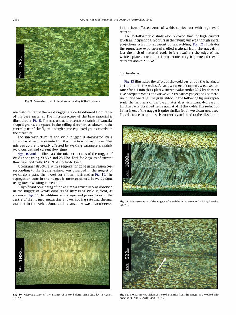
Fig. 9. Microstructure of the aluminium alloy 6082-T6 sheets.
Fig. 11. Microstructure of the nugget of a welded joint done at 28.7 kA; 2 cycles;3237 N.
2458 A.M. Pereira et al. / Materials and Design 31 (2010) 2454–2463
microstructures of the weld nugget are quite different from thoseof the base material. The microstructure of the base material isillustrated in Fig. 9. The microstructure consists mainly of pancakeshaped grains, elongated in the rolling direction, as shown in thecentral part of the figure, though some equiaxed grains coexist inthe structure.
The microstructure of the weld nugget is dominated by acolumnar structure oriented in the direction of heat flow. Thismicrostructure is greatly affected by welding parameters, mainlyweld current and current flow time.
Figs. 10 and 11 illustrate the microstructures of the nugget ofwelds done using 23.5 kA and 28.7 kA, both for 2 cycles of currentflow time and with 3237 N of electrode force.
A columnar structure, with a segregation zone in the region cor-responding to the faying surface, was observed in the nugget ofwelds done using the lowest current, as illustrated in Fig. 10. Thesegregation zone in the nugget is more enhanced in welds doneusing lower welding currents.
A significant coarsening of the columnar structure was observedin the nugget of welds done using increasing weld current, asshown in Fig. 11. In addition, some equiaxed grains form in thecentre of the nugget, suggesting a lower cooling rate and thermalgradient in the welds. Some grain coarsening was also observed
Fig. 10. Microstructure of the nugget of a weld done using 23.5 kA; 2 cycles;3237 N.
in the heat-affected zone of welds carried out with high weldcurrent.
The metallographic study also revealed that for high currentlevels an incipient flash occurs in the faying surfaces, though metalprojections were not apparent during welding. Fig. 12 illustratesthe premature expulsion of melted material from the nugget. Infact the melted material cools before reaching the edge of thewelded plates. These metal projections only happened for weldcurrents above 27.5 kA.
3.3. Hardness
Fig. 13 illustrates the effect of the weld current on the hardnessdistribution in the welds. A narrow range of currents was used be-cause for a 1 mm thick plate a current value under 23.5 kA does notgive adequate welds and above 28.7 kA causes projections of mate-rial during welding. The gray ribbon in the following figures repre-sents the hardness of the base material. A significant decrease inhardness was observed in the nugget of all the welds. The reductionin hardness of the nugget is quite similar for all weld currents used.This decrease in hardness is currently attributed to the dissolution
Fig. 12. Premature expulsion of melted material from the nugget of a welded jointdone at 28.7 kA, 2 cycles and 3237 N.
a40
6080
100
120
-6.0 -4.8 -3.6 -2.4 -1.2 0.0 1.2 2.4 3.6 4.8 6.0
Distance [mm]
Har
dene
ss H
V0,1
23.5kA - 2cycles - 3237N26.4kA - 2cycles - 3237N28.7kA - 2cycles - 3237N
b
4060
8010
012
0
-0.9 -0.6 -0.3 0.0 0.3 0.6 0.9Distance [mm]
Har
dnes
s H
V0,1
23.5kA - 2cycles - 3237N26.4kA - 2cycles - 3237N28.7kA - 2cycles - 3237N
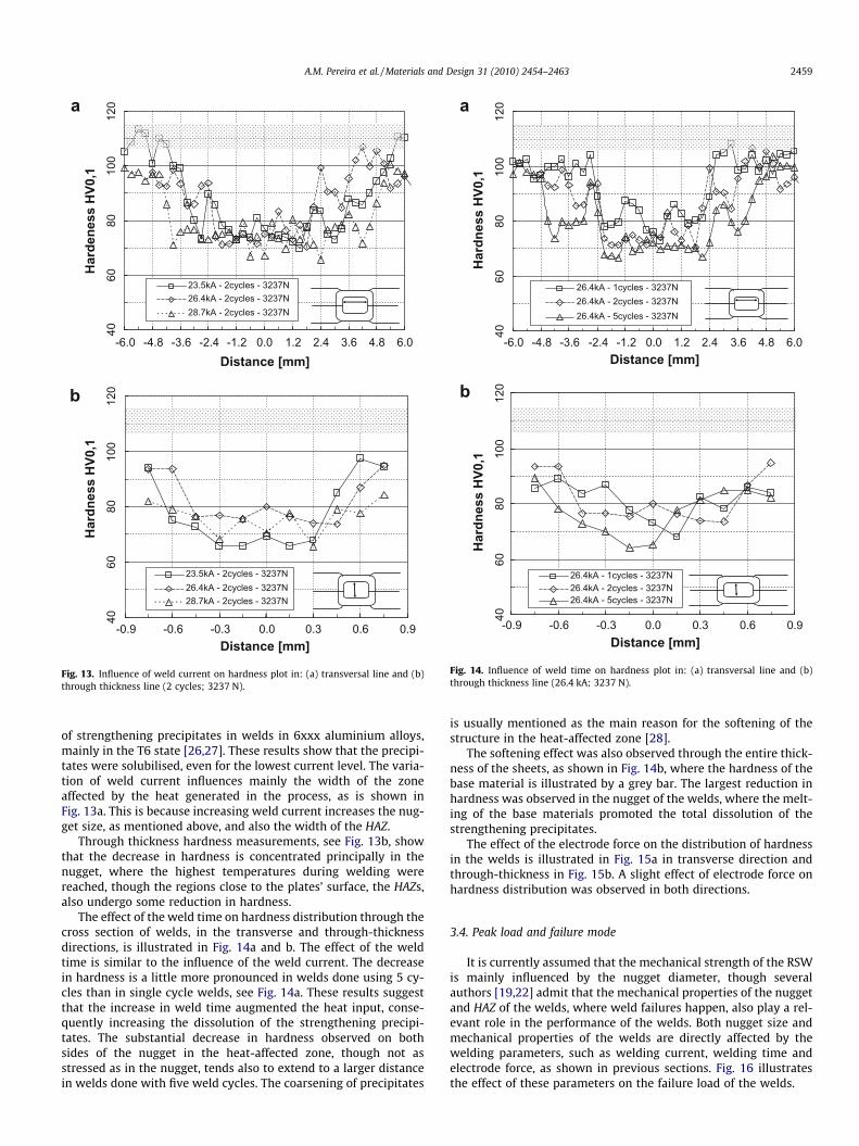
Fig. 13. Influence of weld current on hardness plot in: (a) transversal line and (b)through thickness line (2 cycles; 3237 N).
Distance [mm]
Har
dnes
s H
V0,1
26.4kA - 1cycles - 3237N26.4kA - 2cycles - 3237N26.4kA - 5cycles - 3237N
4060
8010
012
0
-6.0 -4.8 -3.6 -2.4 -1.2 0.0 1.2 2.4 3.6 4.8 6.0
4060
8010
012
0
-0.9 -0.6 -0.3 0.0 0.3 0.6 0.9Distance [mm]
Har
dnes
s H
V0,1
26.4kA - 1cycles - 3237N26.4kA - 2cycles - 3237N26.4kA - 5cycles - 3237N
a
b
Fig. 14. Influence of weld time on hardness plot in: (a) transversal line and (b)through thickness line (26.4 kA; 3237 N).
A.M. Pereira et al. / Materials and Design 31 (2010) 2454–2463 2459
of strengthening precipitates in welds in 6xxx aluminium alloys,mainly in the T6 state [26,27]. These results show that the precipi-tates were solubilised, even for the lowest current level. The varia-tion of weld current influences mainly the width of the zoneaffected by the heat generated in the process, as is shown inFig. 13a. This is because increasing weld current increases the nug-get size, as mentioned above, and also the width of the HAZ.
Through thickness hardness measurements, see Fig. 13b, showthat the decrease in hardness is concentrated principally in thenugget, where the highest temperatures during welding werereached, though the regions close to the plates’ surface, the HAZs,also undergo some reduction in hardness.
The effect of the weld time on hardness distribution through thecross section of welds, in the transverse and through-thicknessdirections, is illustrated in Fig. 14a and b. The effect of the weldtime is similar to the influence of the weld current. The decreasein hardness is a little more pronounced in welds done using 5 cy-cles than in single cycle welds, see Fig. 14a. These results suggestthat the increase in weld time augmented the heat input, conse-quently increasing the dissolution of the strengthening precipi-tates. The substantial decrease in hardness observed on bothsides of the nugget in the heat-affected zone, though not asstressed as in the nugget, tends also to extend to a larger distancein welds done with five weld cycles. The coarsening of precipitates
is usually mentioned as the main reason for the softening of thestructure in the heat-affected zone [28].
The softening effect was also observed through the entire thick-ness of the sheets, as shown in Fig. 14b, where the hardness of thebase material is illustrated by a grey bar. The largest reduction inhardness was observed in the nugget of the welds, where the melt-ing of the base materials promoted the total dissolution of thestrengthening precipitates.
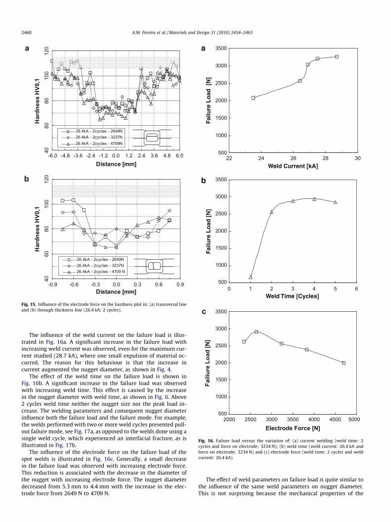
The effect of the electrode force on the distribution of hardnessin the welds is illustrated in Fig. 15a in transverse direction andthrough-thickness in Fig. 15b. A slight effect of electrode force onhardness distribution was observed in both directions.
3.4. Peak load and failure mode
It is currently assumed that the mechanical strength of the RSWis mainly influenced by the nugget diameter, though severalauthors [19,22] admit that the mechanical properties of the nuggetand HAZ of the welds, where weld failures happen, also play a rel-evant role in the performance of the welds. Both nugget size andmechanical properties of the welds are directly affected by thewelding parameters, such as welding current, welding time andelectrode force, as shown in previous sections. Fig. 16 illustratesthe effect of these parameters on the failure load of the welds.
a
Distance [mm]
Har
dnes
s H
V0,1
26.4kA - 2cycles - 2649N26.4kA - 2cycles - 3237N26.4kA - 2cycles - 4709N
b
4060
8010
012
0
-6.0 -4.8 -3.6 -2.4 -1.2 0.0 1.2 2.4 3.6 4.8 6.0
4060
8010
012
0
-0.9 -0.6 -0.3 0.0 0.3 0.6 0.9Distance [mm]
Har
dnes
s H
V0,1
26.4kA - 2cycles - 2649N26.4kA - 2cycles - 3237N26.4kA - 2cycles - 4709 N
Fig. 15. Influence of the electrode force on the hardness plot in: (a) transversal lineand (b) through thickness line (26.4 kA; 2 cycles).
a
500
1000
1500
2000
2500
3000
3500
22 24 26 28 30Weld Current [kA]
Failu
re L
oad
[N
]
b
500
1000
1500
2000
2500
3000
3500
0 1 2 3 4 5 6Weld Time [Cycles]
Failu
re L
oad
[N
]
c
500
1000
1500
2000
2500
3000
3500
2000 2500 3000 3500 4000 4500 5000
Electrode Force [N]
Faili
ure
Load
[N]
Fig. 16. Failure load versus the variation of: (a) current welding (weld time: 2cycles and force on electrode: 3234 N); (b) weld time (weld current: 26.4 kA andforce on electrode: 3234 N) and (c) electrode force (weld time: 2 cycles and weldcurrent: 26.4 kA).
2460 A.M. Pereira et al. / Materials and Design 31 (2010) 2454–2463
The influence of the weld current on the failure load is illus-trated in Fig. 16a. A significant increase in the failure load withincreasing weld current was observed, even for the maximum cur-rent studied (28.7 kA), where one small expulsion of material oc-curred. The reason for this behaviour is that the increase incurrent augmented the nugget diameter, as shown in Fig. 4.
The effect of the weld time on the failure load is shown inFig. 16b. A significant increase in the failure load was observedwith increasing weld time. This effect is caused by the increasein the nugget diameter with weld time, as shown in Fig. 6. Above2 cycles weld time neither the nugget size nor the peak load in-crease. The welding parameters and consequent nugget diameterinfluence both the failure load and the failure mode. For example,the welds performed with two or more weld cycles presented pull-out failure mode, see Fig. 17a, as opposed to the welds done using asingle weld cycle, which experienced an interfacial fracture, as isillustrated in Fig. 17b.
The influence of the electrode force on the failure load of thespot welds is illustrated in Fig. 16c. Generally, a small decreasein the failure load was observed with increasing electrode force.This reduction is associated with the decrease in the diameter ofthe nugget with increasing electrode force. The nugget diameterdecreased from 5.3 mm to 4.4 mm with the increase in the elec-trode force from 2649 N to 4709 N.
The effect of weld parameters on failure load is quite similar tothe influence of the same weld parameters on nugget diameter.This is not surprising because the mechanical properties of the
a
10mm
b
10mm
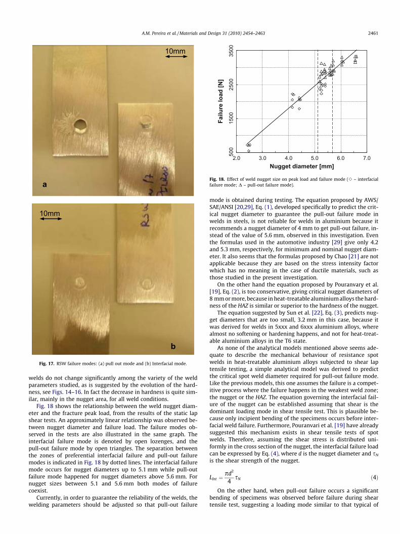
Fig. 17. RSW failure modes: (a) pull out mode and (b) Interfacial mode.
500
1500
2500
3500
2.0 3.0 4.0 5.0 6.0 7.0Nugget diameter [mm]
Failu
re lo
ad [N
]
Fig. 18. Effect of weld nugget size on peak load and failure mode (e – interfacialfailure mode; D – pull-out failure mode).
A.M. Pereira et al. / Materials and Design 31 (2010) 2454–2463 2461
welds do not change significantly among the variety of the weldparameters studied, as is suggested by the evolution of the hard-ness, see Figs. 14–16. In fact the decrease in hardness is quite sim-ilar, mainly in the nugget area, for all weld conditions.
Fig. 18 shows the relationship between the weld nugget diam-eter and the fracture peak load, from the results of the static lapshear tests. An approximately linear relationship was observed be-tween nugget diameter and failure load. The failure modes ob-served in the tests are also illustrated in the same graph. Theinterfacial failure mode is denoted by open lozenges, and thepull-out failure mode by open triangles. The separation betweenthe zones of preferential interfacial failure and pull-out failuremodes is indicated in Fig. 18 by dotted lines. The interfacial failuremode occurs for nugget diameters up to 5.1 mm while pull-outfailure mode happened for nugget diameters above 5.6 mm. Fornugget sizes between 5.1 and 5.6 mm both modes of failurecoexist.
Currently, in order to guarantee the reliability of the welds, thewelding parameters should be adjusted so that pull-out failure
mode is obtained during testing. The equation proposed by AWS/SAE/ANSI [20,29], Eq. (1), developed specifically to predict the crit-ical nugget diameter to guarantee the pull-out failure mode inwelds in steels, is not reliable for welds in aluminium because itrecommends a nugget diameter of 4 mm to get pull-out failure, in-stead of the value of 5.6 mm, observed in this investigation. Eventhe formulas used in the automotive industry [29] give only 4.2and 5.3 mm, respectively, for minimum and nominal nugget diam-eter. It also seems that the formulas proposed by Chao [21] are notapplicable because they are based on the stress intensity factorwhich has no meaning in the case of ductile materials, such asthose studied in the present investigation.
On the other hand the equation proposed by Pouranvary et al.[19], Eq. (2), is too conservative, giving critical nugget diameters of8 mm or more, because in heat-treatable aluminium alloys the hard-ness of the HAZ is similar or superior to the hardness of the nugget.
The equation suggested by Sun et al. [22], Eq. (3), predicts nug-get diameters that are too small, 3.2 mm in this case, because itwas derived for welds in 5xxx and 6xxx aluminium alloys, wherealmost no softening or hardening happens, and not for heat-treat-able aluminium alloys in the T6 state.
As none of the analytical models mentioned above seems ade-quate to describe the mechanical behaviour of resistance spotwelds in heat-treatable aluminium alloys subjected to shear laptensile testing, a simple analytical model was derived to predictthe critical spot weld diameter required for pull-out failure mode.Like the previous models, this one assumes the failure is a compet-itive process where the failure happens in the weakest weld zone;the nugget or the HAZ. The equation governing the interfacial fail-ure of the nugget can be established assuming that shear is thedominant loading mode in shear tensile test. This is plausible be-cause only incipient bending of the specimens occurs before inter-facial weld failure. Furthermore, Pouranvari et al. [19] have alreadysuggested this mechanism exists in shear tensile tests of spotwelds. Therefore, assuming the shear stress is distributed uni-formly in the cross section of the nugget, the interfacial failure loadcan be expressed by Eq. (4), where d is the nugget diameter and sN
is the shear strength of the nugget.
LInt ¼pd2
4sN ð4Þ
On the other hand, when pull-out failure occurs a significantbending of specimens was observed before failure during sheartensile test, suggesting a loading mode similar to that typical of
2462 A.M. Pereira et al. / Materials and Design 31 (2010) 2454–2463
cross tension tests. In this case several authors consider that thefailure mechanism is through-thickness shear in the HAZ [22,30].In this case Eq. (5) can be considered to be the governing law forpredicting pull-out failure load, LPO. The nugget diameter is desig-nated by d, the plate thickness by t and the shear strength of theHAZ by sHAZ.
LPO ¼ pdtsHAZ ð5Þ
Therefore, the critical nugget diameter required to obtain pull-out failure (dcr) is governed by Eq. (6), which results from the inter-section of Eqs. (4) and (5).
dcr ¼ 4tsHAZ
sNð6Þ
For spot welds with nugget diameters below dcr the interfacialfailure mode will be dominant while for diameters above this valuespot welds will exhibit pull-out failure mode. However, the evalu-ation of the shear strength of the nugget and HAZ of spot welds isdifficult, because those regions are narrow and present microstruc-tural gradients. Currently, the yield and tensile strength of materi-als are related to their hardness through empiric equationscharacterised by the generic Eq. (7), where HV and r representthe Vickers hardness and tensile strength of the material and K isapproximately constant, assuming the elastic properties areapproximately constant inside each family of materials [31,32].In addition, according to the Tresca criterion, both the shear andtensile strength of a metal are connected by a mathematical con-stant, shear strength is half of the tensile strength of the material.
HV ¼ Kr ð7Þ
Therefore, Eq. (6) can be rewritten as Eq. (8), where HVN andHVHAZ are the hardness of the nugget and HAZ.
dcr ¼ 4tHVHAZ
HVNð8Þ
Hardness is easier to evaluate than the tensile strength of thenugget or HAZ of the welds, though a difficulty remains. Whilethe hardness in the nugget is approximately constant and easy toaverage, the HAZ’ hardness exhibits a gradient between the nuggetand the non-affected base material, as shown in Figs. 14–16. Con-sequently dcr is function of the chosen hardness of the HAZ. To givean example; Fig. 18 shows that the minimum required diameter toget consistent pull-out failures is 5.6 mm. This corresponds towelds done using 26.4 kA, 2 cycles and 3237 N as welding param-eters. One example of the evolution of the hardness in those weldsis shown in Fig. 13. The average hardness in the nugget is HV75and in the HAZ it is approximately HV95. Introducing those valuesin Eq. (8), the critical nugget diameter to get pull-out failures is gi-ven as 5.1, which corresponds to the lower limit for which pull-outfailure can occur; though at that size interfacial failures can alsooccur, as shown in Fig. 18. As the definition of the average hardnessin the HAZ is difficult, because of the hardness gradient, a safe crit-ical diameter can be defined based on the hardness of the parentmaterial instead of the hardness of the HAZ. In this case the newformulation of Eq. (8) is indicated in Eq. (9), where HVBM is thehardness of the base material.
dcr ¼ 4tHVBM
HVNð9Þ
For a base material hardness of HV110 the critical diameter cal-culated by Eq. (9) is 5.9 mm, very close the experimental observa-tions. Eq. (9) allows us to define a safe boundary for obtaining pull-out failure, and has the advantage that the experimental values ofHVBM and HVN can be evaluated in a quick and easy way. This mod-el needs to be extended to RS welds in other aluminium sheetthicknesses. It was derived specifically for undermatched welds
in heat-treatable aluminium alloys. The matching grade of weldsis defined by the rate between the yield or tensile strength of theweld and the base material. According to whether this rate is equalto one, lower than one or higher than one the welds are consideredto be in the evenmatch, undermatch or overmatch condition,respectively. In the present model, when the grade of undermatchincreases, the critical nugget diameter increases too, in order toguarantee pull-out failure mode. For welds in mild steels, wherethe evenmatch condition is approximately observed, Eq. (9) giveshigher critical nugget diameters than Eq. (1), of the AmericanWelding Society et al. [20,29]. However Eq. (9) is not valid for over-match welds, typical of RSW in high strength steels, because itgives unsafe nugget diameters.
4. Conclusions
The influence of the weld parameters on the microstructure andtensile-shear strength of resistance spot welds on an aluminium al-loy 6082-T6 was studied. The conclusions obtained are summa-rised as follows:
– The increase in the weld current and time increased the nuggetdiameter and coarsened the microstructure; these transforma-tions were accompanied by a significant decrease in hardnessin the nugget and heat-affected zones of the welds.
– A significant increase in the failure load in static shear lap testswas observed in welds done with increasing weld current andtime, because of the augmentation of the nugget diameter;beyond a critical nugget diameter the failure changes frominterfacial mode to pullout mode.
– A simple analytical model was proposed to predict the criticalnugget size to obtain pull-out failures in undermatched weldsin heat-treatable aluminium alloys.
Acknowledgements
The authors thank the financial support of the Portuguese Foun-dation for Science and Technology (Grant SFRH/BD/37384/2007)and the assistance of the company OGMA-Indústria Aeronáuticade Portugal in the execution of the welds.
References
[1] Vural M, Akkus A. On the resistance spot weldability of galvanized interstitialfree steel sheets with austenitic stainless steel sheets. J Mater Process Technol2004;153–154:1–6.
[2] Kahraman N. The influence of welding parameters on the joint strength ofresistance spot-welded titanium sheets. Mater Des 2007;28:420–7.
[3] Jou M. Real time monitoring weld quality of resistance spot welding for thefabrication of sheet metal assemblies. J Mater Process Technol2003;132:102–13.
[4] Aslanlar S, Ogur A, Ozsarac U, Ilhan E, Demir Z. Effect of welding current onmechanical properties of galvanized chromized steel sheets in electricalresistance spot welding. Mater Des 2007;28:2–7.
[5] Özyürek D. An effect of weld current and weld atmosphere on the resistancespot weldability of 304L austenitic stainless steel. Mater Des 2008;29:503–97.
[6] Barnes TA, Pashby IR. Joining techniques for aluminium space frames used inautomobiles part II – adhesive bonding and mechanical fasteners. J MaterProcess Technol 2000;99:72–9.
[7] Pereira AM, Ferreira JM, Antunes FV, Bártolo PJ. Study on the fatigue strength ofAA 6082 – T6 adhesive lap joints. Int J Adhes Adhes 2009;29.
[8] Santos IO, Zang W, Gonçalves VM, Bay N, Martins PAF. Weld bonding ofstainless steel. Int J Mach Tools Manuf 2004;44:1431–9.
[9] Darwish SM, Al-Dekhial SD. Micro-hardness of spot welded (B.S. 1050)commercial aluminium as correlated with welding variables and strengthattributes. J Mater Process Technol 1999;91:43–51.
[10] Shamsul JB, Hisyam MM. Study of spot welding of austenitic stainless steeltype 304. J Appl Sci Res 2007;3(11):1494–9.
[11] Sun DQ, Lang B, Sun DX, Li JB. Microstructures and mechanical properties ofresistance spot welded magnesium alloy joints. Mater Sci Eng A 2007;460–461:494–8.
A.M. Pereira et al. / Materials and Design 31 (2010) 2454–2463 2463
[12] Leal RM, Loureiro A. Effect of overlapping friction stir welding passes in thequality of welds of aluminium alloys. Mater Des 2008;29:982–91.
[13] Marashi P, Pouranvari M, Amirabdollahian S, Abedi A, Goodarzi M.Microstructure and failure behavior of dissimilar resistance spot weldsbetween low carbon galvanized and austenitic stainless steels. Mater Sci EngA 2008;480:175–80.
[14] Goodarzi M, Marashib SPH, Pouranvari M. Dependence of overloadperformance on weld attributes for resistance spot welded galvanized lowcarbon steel. J Mater Process Technol 2009;209:4379–84.
[15] Aslanlar S. The effect of nucleus size on mechanical properties in electricalresistance spot welding of sheets used in automotive industry. Mater Des2006;27:125–31.
[16] Vural M, Akkus A, Eryürek B. Effect of welding nugget diameter on the fatiguestrength of the resistance spot welded joints of different steel sheets. J MaterProcess Technol 2006;176:127–32.
[17] Bouyousfi B, Sahraoui T, Guessasma S, Chaouch KT. Effect of processparameters on the physical characteristics of spot weld joints. Mater Des2007;28:414–9.
[18] Sun X, Stephens EV, Khaleel MA. Effects of fusion zone size and failure mode onpeak load and energy absorption of advanced high strength steel spot weldsunder lap shear loading conditions. Eng Fail Anal 2008;15:356–67.
[19] Pouranvari M, Asgari HR, Mosavizadeh SM, Marashi PH, Goodarzi M. Effect ofweld nugget size on overload failure mode of resistance spot welds. SciTechnol Weld Join 2007;12:217–25.
[20] Weld button criteria, recommended practices for test methods for evaluatingthe resistance spot welding behavior of automotive sheet steel metal,American National Standard. ANSI/AWS/SAE/D8.9-97. Section 5.7; 1997.
[21] Chao YJ. Failure mode of resistance spot welds: interfacial versus pullout. SciTechnol Weld Join 2003;8:133–7.
[22] Sun X, Stephens EV, Davies RW, Khaleel MA, Spinella DJ. Effects of fusion zonesize on failure modes and static strength o aluminum resistance spot welds.Weld J 2004;83(11):308s–18s.
[23] Chuco W, Gould J. Metallurgical interpretation of electrode life in resistancespot welding of aluminum sheet. In: Proceedings of joining of advanced andspecialty materials. St. Louis (Mo): ASM International; October 9–11 2000. p.114–21.
[24] Browne DJ, Chandler HW, Evans HW, Wen J. Computer simulation of resistancespot welding in aluminum: Part 1. Weld J 1995;74(10):339s–44s.
[25] Browne DJ, Chandler HW, Evans HW, Wen J, Newton CJ. Computer simulationof resistance spot welding in aluminum: Part 2. Weld J 1995;74(12):417s–22s.
[26] Starink MJ, Deschamps A, Wang SC. The strength of friction stir welded andfriction stir processed aluminium alloys. Scripta Mater 2008;58:377–82.
[27] Simar A, Bréchet Y, de Meester B, Denquin A, Pardoen T. Microstructure, localand global mechanical properties of friction stir welds in aluminium alloy6005A-T6. Mater Sci Eng A 2008;486:85–95.
[28] Heinz B, Skrotzki B. Characterization of a friction-stir-welded aluminium alloy6013. Metall Mater Trans B 2002;33B(June):489–98.
[29] Ewing KW, Cheresh M, Thompson R, Kukuchek P. ‘Static and impact strengthsof spot-welded HSLA and low carbon steel joints’ SAE 820281. Warrendale(PA): Society of Automotive Engineers; 1982.
[30] Lin SH, Pan J, Wu SR, Tyan T, Wung P. Failure loads of spot welds undercombined opening and shear static loading conditions. Int J Solids Struct2002:3919–39.
[31] Salazar-Guapuriche MA, Zhao YY, Pitman A, Greene A. Correlation of strengthwith hardness and electrical conductivity for aluminium alloy 7010. Mater SciForum 2006;519–521:853–8.
[32] Busby JT, Hash MC, Was GS. The relationship between hardness and yieldstress in irradiated austenitic and ferritic steels. J Nucl Mater2005;336:267–78.


![[SI 2012 2013]T6 Herramientas.Bussines Intelligence](https://img.dokumen.tips/doc/110x75/635ea871a0f1eac29f0ccb5f/si-2012-2013t6-herramientasbussines-intelligence.jpg)


