Embed Size (px)
Citation preview

http://jrp.sagepub.com/Journal of Reinforced Plastics and Composites
http://jrp.sagepub.com/content/31/12/845The online version of this article can be found at:
DOI: 10.1177/0731684412448103
2012 31: 845Journal of Reinforced Plastics and CompositesJ Jayaprakash, Emad Pournasiri and Fatimah De'nan
to corrosion activityEffect of bond strength on fiber reinforced polymer enveloped concrete cylinders with rebars exposed
Published by:
http://www.sagepublications.com
can be found at:Journal of Reinforced Plastics and CompositesAdditional services and information for
http://jrp.sagepub.com/cgi/alertsEmail Alerts:
http://jrp.sagepub.com/subscriptionsSubscriptions:
http://www.sagepub.com/journalsReprints.navReprints:
http://www.sagepub.com/journalsPermissions.navPermissions:
http://jrp.sagepub.com/content/31/12/845.refs.htmlCitations:
What is This?
- Jun 14, 2012Version of Record >>
at University of Nottingham on July 22, 2014jrp.sagepub.comDownloaded from at University of Nottingham on July 22, 2014jrp.sagepub.comDownloaded from

Article
Effect of bond strength on fiber reinforcedpolymer enveloped concrete cylinderswith rebars exposed to corrosion activity
J Jayaprakash, Emad Pournasiri and Fatimah De’nan
Abstract
This paper aims to investigate the effect of bond strength of corroded steel rebar embedded in concrete cylinders
enveloped externally using hybrid and non-hybrid fiber reinforced polymer (FRP) reinforcement. A series of 16 concrete
cylinders (i.e. 100 mm� 200 mm) embedded with steel rebar were prepared in the laboratory condition. The test
variables were types of fiber reinforced polymer wrapping (i.e. hybrid and non-hybrid fiber reinforced polymer reinforce-
ment), duration of corrosion activity, and percentage of mass loss in steel rebar. The specimens were immersed in
5% NaCl solution at a depth of 170 mm and anodic current was impressed through the rebar for accelerating the
corrosion activity. After the exposure period of 24 days, the embedded steel rebar in concrete cylinder was pulled out
monotonically to failure. The bond strength, percentage of mass loss in embedded steel rebar, and effect of different
periods of corrosion activity on concrete cylinders enveloped with hybrid and non-hybrid fiber reinforced polymer
reinforcement are addressed. Test results show that the observed bond strength of hybrid fiber reinforced polymer
confined specimens was the highest as compared to the non-hybrid CFRP and GFRP confined specimens. Moreover, the
bond strength performance of hybrid FRP confined specimens was slightly better than the non-hybrid CFRP confined
specimens.
Keywords
Carbon, glass, corrosion, concrete, cylinder, bond
Introduction
The corrosion of steel rebar is one of the predominantdegradation problems in reinforced concrete structures,which could seriously affect the serviceability and dur-ability of the existing structures. The RC massive struc-tures such as bridges, flyovers, skyscrapers, and marinestructures are very susceptible to corrosion attacks asthese structures have been exposed to different environ-mental conditions. The corrosion of steel rebarsembedded in concrete is mainly due to the ingress ofchloride ions and carbon-dioxide to the surface of steelrebars. When the corrosion is initiated in steel rebars,the corrosion products are deposited along the steelrebars which could increase the cross-sectional area ofthe steel rebars. The effect of expansion process in thesteel rebar initiates the internal stresses in concretewhich could eventually leads to spalling, delamination,and cracking of concrete around the steel rebar. The
cross-sectional area of steel rebar can be significantlyreduced, particularly during the later stage of corrosionpropagation. As a result, the reinforcement is exposedto direct environmental attacks and the corrosion pro-cess is rigorously accelerated. The direct exposure ofenvironmental attacks could cause unsound appearanceto the steel rebars and it also deteriorates the concreteto a high degree.1 Moreover, the degradation of bondbetween the steel and concrete could reduce the servicelife of RC structures.2 Haddad and Ashteyate3 havealso highlighted that the bond strength could be
School of Civil Engineering, Universiti Sains Malaysia, Malaysia
Corresponding author:
J. Jayaprakash, School of Civil Engineering, Universiti Sains Malaysia,
Malaysia
Email: [email protected]; [email protected]
Journal of Reinforced Plastics
and Composites
31(12) 845–854
! The Author(s) 2012
Reprints and permissions:
sagepub.co.uk/journalsPermissions.nav
DOI: 10.1177/0731684412448103
jrp.sagepub.com
at University of Nottingham on July 22, 2014jrp.sagepub.comDownloaded from
influenced by various factors such as size andembedded length of steel rebar, thickness of concretecover, and lateral confining pressure.
A number of experimental studies have investigatedthe effect of corrosion on the bond strength betweenembedded steel rebar and concrete.1,2,4–9 Almusallamet al.4 have examined the effect of crack width and deg-radation for various degrees of corrosion on the bondstrength of concrete. The results have shown that thebond strength was increased by 17% when the degreeof corrosion was increased up to 4%. Consequently, thebond strength was decreased dramatically by 35%owing to the cracking of concrete at 5% degree of cor-rosion of steel rebar. Fu and Chung6 have also foundthat the bond strength between steel rebar and concretewas initially increased due to the slight level of corro-sion, however, the bond strength was decreased atsevere rebar corrosion levels. Analogous to the previousinvestigations, the results of Lee et al.7 have shown thatincreasing the percentage of corrosion could decreasethe maximum bond strength and bond rigidity. Fromthis review, it can be seen that the investigations on theeffect of confinement on the bond behavior of corrodedsteel reinforcement has not extensively studied yet.
Fiber reinforced polymer (FRP) composites arebeing extensively used for upgrading and strengtheningof RC members such as beams, slabs, and columns.Substantial experimental investigations have provedthat the application of FRP reinforcement couldenhance the structural performance of RC mem-bers.10–14 However, a limited number of experimentalinvestigations have addressed the effect of bondstrength of corroded steel rebar in concrete cylindersconfined with FRP reinforcement.1,8 Gadva et al.1
have investigated the effect of corrosion of embeddedsteel rebar in FRP confined concrete cylinders. Theresults have shown that confining with glass fiber rein-forced polymer (GFRP) reinforcement dramaticallyreduced the rate of corrosion. Moreover, the GFRPreinforcement impeded the corrosion more thancarbon fiber reinforced polymer (CFRP) which wasprobably due to the electrical resistance of GFRPreinforcement. Papakonstantinou et al.8 have investi-gated the bond behavior of corroded reinforcing steelconfined with CFRP reinforcement. They have investi-gated the effect of different diameter of rebars, durationof corrosion activity, and number of FRP layers. Theexperimental results show that the percentage of bondstrength, as compared to the unconfined specimens,increased as the diameter and rib area of steel reinforce-ment increased. It was found from the review thatresearchers have used carbon and glass FRP reinforce-ment (i.e. non-hybrid FRP), however the effect ofhybrid FRP reinforcement has not received much atten-tion. The objective of this experimental investigation
was to study the effect of bond strength of corrodedsteel rebar embedded in concrete cylinders envelopedexternally using hybrid and non-hybrid FRPreinforcement.
Experimental program
Preparation and description of specimens
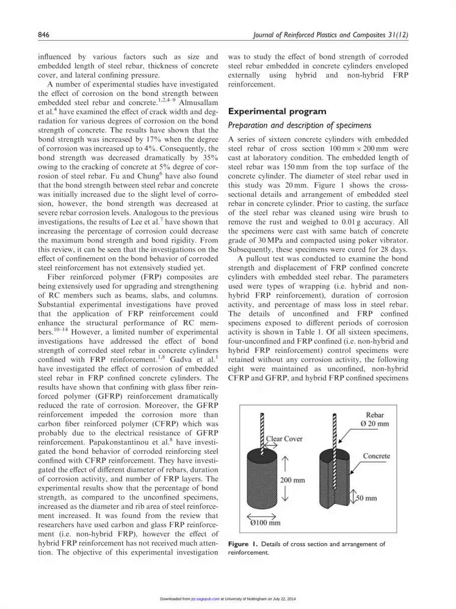
A series of sixteen concrete cylinders with embeddedsteel rebar of cross section 100mm� 200mm werecast at laboratory condition. The embedded length ofsteel rebar was 150mm from the top surface of theconcrete cylinder. The diameter of steel rebar used inthis study was 20mm. Figure 1 shows the cross-sectional details and arrangement of embedded steelrebar in concrete cylinder. Prior to casting, the surfaceof the steel rebar was cleaned using wire brush toremove the rust and weighed to 0.01 g accuracy. Allthe specimens were cast with same batch of concretegrade of 30MPa and compacted using poker vibrator.Subsequently, these specimens were cured for 28 days.
A pullout test was conducted to examine the bondstrength and displacement of FRP confined concretecylinders with embedded steel rebar. The parametersused were types of wrapping (i.e. hybrid and non-hybrid FRP reinforcement), duration of corrosionactivity, and percentage of mass loss in steel rebar.The details of unconfined and FRP confinedspecimens exposed to different periods of corrosionactivity is shown in Table 1. Of all sixteen specimens,four-unconfined and FRP confined (i.e. non-hybrid andhybrid FRP reinforcement) control specimens wereretained without any corrosion activity, the followingeight were maintained as unconfined, non-hybridCFRP and GFRP, and hybrid FRP confined specimens
Figure 1. Details of cross section and arrangement of
reinforcement.
846 Journal of Reinforced Plastics and Composites 31(12)
at University of Nottingham on July 22, 2014jrp.sagepub.comDownloaded from

with pre and post corrosion activities, and the remain-ing four-unconfined, non-hybrid CFRP and GFRPspecimens, and hybrid FRP confined specimens wereexposed to corrosion period of 24 days. The pre- andpost-corrosion periods were 6 and 12 days and 18 and12 days, respectively. Prior to the application of FRPreinforcement, the specimens were exposed to pre andpost corrosion activity. The CFRP reinforcement usedin this study had a tensile strength of 3,482MPa, thick-ness of 0.165mm, and modulus of elasticity of230,500MPa.15 Similarly, the GFRP reinforcementhad a tensile strength of 1,667MPa, thickness of0.353mm, and modulus of elasticity of 72,400MPa.15
Corrosion acceleration
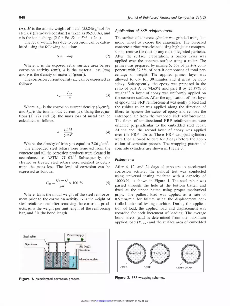
The process of corrosion was accelerated by impressingdirect current2,8,16 on the steel rebar embedded in con-crete cylinder using an integrated system of small rec-tifier and in-built ammeter to monitor the current and apotentiometer was used to control the intensity of cur-rent. The specimens were immersed in a tank of 5%NaCl solution for different periods of corrosion (i.e.6, 12, and 24 days). The aluminium plate was placed
at the bottom of the tank before pouring the preparedsalt solution. Subsequently, the specimens were placedover the aluminium plate. The level of salt solution wasmaintained at a depth of 40mm below the top surfaceof the concrete cylinder to avoid the pitting corrosionof rebar at the top surface of concrete. Prior to theapplication of current, the steel rebar was grinded toexpose the white metal to ensure good surface contact.The embedded steel rebar was connected to the positiveterminal of DC power supply and the aluminium platewas attached to the negative terminal. The DC regu-lated power supply used in the study was of 30V and3A. Figure 2 shows the schematic representation ofaccelerated corrosion activity. The relationship betweenthe corrosion current density and the weight of steelmass loss can be determined using Faraday’s law asfollows
�! ¼t:I:M
z:Fð1Þ
Where, �! is the metal weight loss due to corrosion,t is the duration of exposure (s), I is the average current
Table 1. Wrapping and corrosion activity detail of test specimens
Specimen Description and test program
UC No Corrosion activity Pullout test� (Unconfined�Control)
CHFC Wrapped with Carbon (1 ply) and GFRP (1 ply)� (2 plies) + Pullout test� (Confined�Control)
CCFC Wrapped with CFRP (2 plies) + Pullout test� (Confined�Control)
CGFC Wrapped with GFRP (2 plies) + Pullout test- (Confined�Control)
U6C Corrosion activity Corrosion activity (6 days) + Pullout test� (Confined�Control)
CHF6 Pre-corrosion activity (6 days) + Wrapped with Carbon (1 ply) and GFRP (1 ply)�
(2 plies) + Post-corrosion activity (18 days) + Pullout test
CCF6 Pre-corrosion activity (6 days) + Wrapped with CFRP (2 plies) + Post-corrosion activity
(18 days) + Pullout test
CGF6 Pre-corrosion activity (6 days) + Wrapped with GFRP (2 plies) + Post-corrosion activity
(18 days) + Pullout test
U12C Corrosion activity Corrosion activity (12 days) + Pullout test� (Unconfined�Control)
CHF12 Pre-corrosion activity (12 days) + Wrapped with Carbon (1 ply) and GFRP (1 ply)�
(2 plies) + Post-corrosion activity (12 days) + Pullout test
CCF12 Pre-corrosion activity (12 days) + Wrapped with CFRP (2 plies) + Post-corrosion activity
(12 days) + Pullout test
CGF12 Pre-corrosion activity (12 days) + Wrapped with GFRP (2 plies) + Post-corrosion activity
(12 days) + Pullout test
U24C Corrosion activity Corrosion activity (24 days) + Pullout test� (Unconfined�Control)
CHF24 Initially wrapped with Carbon (1 ply) and GFRP (1 ply)� (2 plies) + Corrosion activity
(24 days) + Pullout test
CCF24 Initially wrapped with CFRP (2 plies) + Corrosion activity (24 days) + Pullout test
CGF24 Initially wrapped with GFRP (2 plies) + Corrosion activity (24 days) + Pullout test
Jayaprakash et al. 847
at University of Nottingham on July 22, 2014jrp.sagepub.comDownloaded from
(A), M is the atomic weight of metal (55.846 g/mol forsteel), F (Faraday’s constant) is taken as 96,500 As, andz is the ionic charge (2 for Fe, Fe! Fe2þ þ 2e�).
The rebar weight loss due to corrosion can be calcu-lated using the following equation:
�w ¼ a�� ð2Þ
Where, a is the exposed rebar surface area beforecorrosion activity (cm2), � is the material loss (cm)and � is the density of material (g/cm3).
The corrosion current density icor can be expressed asfollows:
icor ¼Icora
ð3Þ
Where, icor is the corrosion current density (A/cm2),and Icor is the total anodic current (A). Using the equa-tions (1), (2) and (3), the mass loss of metal can becalculated as follows:
� ¼t:i:M
�:z:Fð4Þ
Where, the density of iron � is equal to 7.86 g/cm3.The embedded steel rebars were removed from the
concrete and all the corrosion products were cleaned inaccordance to ASTM G1-03.17 Subsequently, thecleaned or treated steel rebars were weighed to deter-mine the mass loss. The level of corrosion can beexpressed as follows:
CR ¼G0 � G
g0l� 100 % ð5Þ
Where, G0 is the initial weight of the steel reinforce-ment prior to the corrosion activity, G is the weight ofsteel reinforcement after removing the corrosion prod-ucts, g0 is the weight per unit length of the reinforcingbar, and l is the bond length.
Application of FRP reinforcement
The surface of concrete cylinder was grinded using dia-mond wheel to expose the aggregates. The preparedconcrete surface was cleaned using high-jet air compres-sor to remove the dust or any dust integrated particles.After the surface preparation, a primer layer wasapplied over the concrete surface using a roller. Theprimer was prepared by mixing 62.5% of part-A com-ponent with 37.5% of part-B component of total per-centage of weight. The applied primer layer wasallowed to dry for 30minutes and it must be non-sticky. Subsequently, the epoxy was prepared in theratio of part A by 74.63% and part B by 25.37% ofweight.15 A layer of epoxy was uniformly applied onthe concrete surface. After the application of first layerof epoxy, the FRP reinforcement was gently placed andthe rubber roller was applied along the direction offibers to squeeze the excess of epoxy and remove theentrapped air from the wrapped FRP reinforcement.The fibers of unidirectional FRP reinforcement wereoriented perpendicular to the embedded steel rebar.At the end, the second layer of epoxy was appliedover the FRP fabrics. These FRP wrapped cylinderswere then allowed to cure for 3 days before the appli-cation of corrosion process. The wrapping patterns ofconcrete cylinders are shown in Figure 3.
Pullout test
After 6, 12, and 24 days of exposure to acceleratedcorrosion activity, the pullout test was conductedusing universal testing machine with a capacity of1000 kN, as shown in Figure 4. The steel rebar waspassed through the hole at the bottom batten andfixed at the upper batten using proper mechanicalgrips. The pullout load was applied at a rate of0.5mm/min for failure using the displacement con-trolled universal testing machine. During the applica-tion of load, the applied load and displacement wasrecorded for each increment of loading. The averagebond stress (mave) is determined from the maximumapplied load (Pmax) and the surface area of embedded
Figure 2. Accelerated corrosion process.
CFRP+ GFRP
Hybrid
CFRP GFRP
Non-Hybrid Non-Hybrid
Figure 3. FRP wrapping schemes.
848 Journal of Reinforced Plastics and Composites 31(12)
at University of Nottingham on July 22, 2014jrp.sagepub.comDownloaded from

steel reinforcement. The average bond stress can becalculated using the equation below
�ave ¼Pmax
�:db:lð6Þ
Test results and discussion
General observation
In first two days of accelerated corrosion activity, finecracks were observed on the surface of the unconfinedconcrete cylinders (i.e. no FRP reinforcement). As the
duration of corrosion increased, the observed cracksbecame wider and corrosion products were leachedout from the top surface of the concrete cylinder. Theinitiation of crack indicates that the chloride ions weretransferred at faster rate and the resistivity of concretecylinders were also reduced as the rate of corrosionincreased. After 6 and 12 days of corrosion periods, itwas observed that the cracks were propagated parallelto the direction of embedded length of the steel rebarand deviated into different branches in circumferentialdirection at the end of embedded steel rebar. The crack-ing patterns of corroded specimens at 6 and 12 days areshown in Figure 5.
Figure 5. Cracking patterns of corroded specimens at (a) 6 days and (b) 12 days.
Figure 4. Experimental set-up of pullout test.
Jayaprakash et al. 849
at University of Nottingham on July 22, 2014jrp.sagepub.comDownloaded from
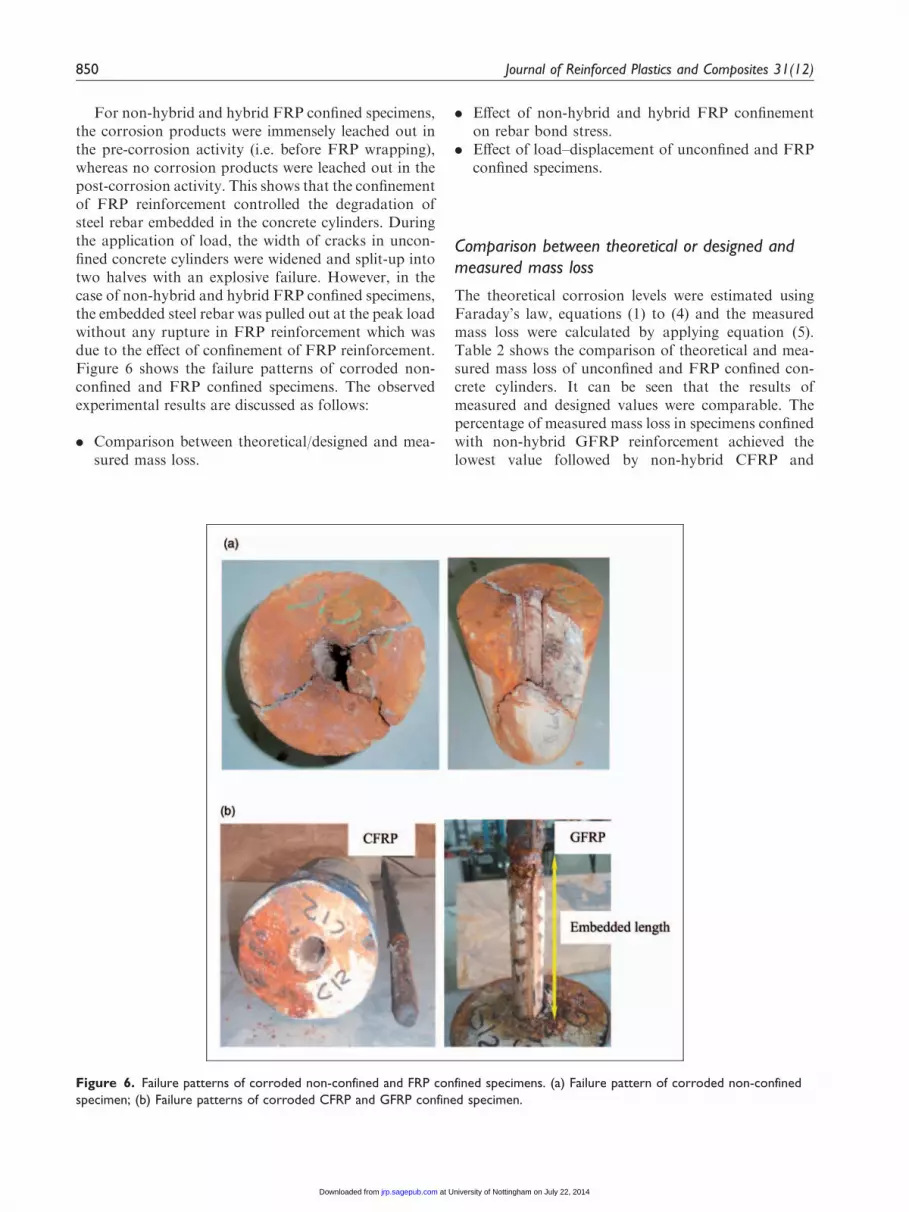
For non-hybrid and hybrid FRP confined specimens,the corrosion products were immensely leached out inthe pre-corrosion activity (i.e. before FRP wrapping),whereas no corrosion products were leached out in thepost-corrosion activity. This shows that the confinementof FRP reinforcement controlled the degradation ofsteel rebar embedded in the concrete cylinders. Duringthe application of load, the width of cracks in uncon-fined concrete cylinders were widened and split-up intotwo halves with an explosive failure. However, in thecase of non-hybrid and hybrid FRP confined specimens,the embedded steel rebar was pulled out at the peak loadwithout any rupture in FRP reinforcement which wasdue to the effect of confinement of FRP reinforcement.Figure 6 shows the failure patterns of corroded non-confined and FRP confined specimens. The observedexperimental results are discussed as follows:
. Comparison between theoretical/designed and mea-sured mass loss.
. Effect of non-hybrid and hybrid FRP confinementon rebar bond stress.
. Effect of load–displacement of unconfined and FRPconfined specimens.
Comparison between theoretical or designed andmeasured mass loss
The theoretical corrosion levels were estimated usingFaraday’s law, equations (1) to (4) and the measuredmass loss were calculated by applying equation (5).Table 2 shows the comparison of theoretical and mea-sured mass loss of unconfined and FRP confined con-crete cylinders. It can be seen that the results ofmeasured and designed values were comparable. Thepercentage of measured mass loss in specimens confinedwith non-hybrid GFRP reinforcement achieved thelowest value followed by non-hybrid CFRP and
Figure 6. Failure patterns of corroded non-confined and FRP confined specimens. (a) Failure pattern of corroded non-confined
specimen; (b) Failure patterns of corroded CFRP and GFRP confined specimen.
850 Journal of Reinforced Plastics and Composites 31(12)
at University of Nottingham on July 22, 2014jrp.sagepub.comDownloaded from

hybrid FRP (i.e. GFRP and CFRP) reinforcement.This was due to the higher electrical resistance offeredby GFRP1 than the hybrid FRP and non-hybrid CFRPreinforcement. From these results, it can be concludedthat the level of corrosion in embedded steel rebar wasinfluenced with the type of FRP reinforcement used.Moreover, an additional factor that affects the corro-sion was probably due to the heterogeneity of coarseaggregate within the specimens.2 Figure 7 shows thecomparison of theoretical and measured mass loss ofunconfined, non-hybrid CFRP and GFRP, and hybridFRP confined specimens.
Effect of hybrid and non-hybrid FRP confinementon rebar bond stress
The bond strength of non-hybrid CFRP and GFRPconfined specimens was decreased from 393.98% to80.98% and 343.65% to 56.24% as the corrosionlevel increased from 1.09% to 13.34% and 1.24% to9.34%, respectively. Similarly, in the case of hybridFRP confined specimens, the bond strength wasdecreased from 405.29% to 97.82% when the corro-sion level increased from 1.54% to 12.98%. Whencomparing the results of hybrid FRP and non-hybridGFRP confined specimens, the contribution on thebond strength performance of hybrid FRP confinedspecimens achieved a gain of 15.64% for 6 days,and 24.69% for 12 days over the non-hybridGFRP specimens. The effect of FRP confinement on
pre-corroded specimens was not only increased thebond strength but it also reduced the corrosion levelin embedded steel rebars. Moreover, the degradationon concrete envelope was also reduced due to theeffect of external FRP confinement. The bond strengthperformance of hybrid FRP confined specimens wasslightly better than the non-hybrid CFRP confinedspecimens. From these results, it can be seen thatthe observed bond strength of hybrid FRP confinedspecimens was the highest as compared to the non-hybrid CFRP and GFRP confined specimens. Thus,it can be concluded that the hybrid FRP could beeffectively used for repairing the corrosion-damagedconcrete members. To apply the hybrid FRP
Table 2. Summary of test results
Specimen Wrapping
Thickness
(mm)
Current duration (days)Maximum
pullout
load (kN)
Bond
strength
(MPa)
Enhancement
(%)
Displacement
(mm)
% Mass loss
Before
wrapping
After
wrapping Theoretical Measured
UC – – – – 79.125 8.40 – 4.79 – –
CHFC Hybrid 0.518 – – 113.50 12.04 43.44 8.29 – –
CCFC Non-hybrid CFRP 0.330 – – 111.84 11.87 41.35 9.76 – –
CGFC Non-hybrid GFRP 0.706 – – 101.43 10.76 35.77 7.43 – –
U6C – – 6 – 42.47 4.50 – 3.53 5.25 5.19
CHF6 Hybrid 0.518 6 18 81.78 8.68 92.55 7.07 7.35 7.67
CCF6 Non-hybrid CFRP 0.330 6 18 97.03 10.29 128.47 11.12 6.60 5.27
CGF6 Non-hybrid GFRP 0.706 6 18 70.72 7.50 66.52 7.10 4.24 3.54
U12C – – 12 – 37.66 3.93 – 3.02 9.75 11.35
CHF12 Hybrid 0.518 12 12 73.37 7.78 97.82 7.59 11.35 12.98
CCF12 Non-hybrid CFRP 0.330 12 12 68.16 7.23 80.98 9.31 10.76 13.34
CGF12 Non-hybrid GFRP 0.706 12 12 58.84 6.24 56.24 5.48 9.20 9.34
U24C – – 24 – 23.78 2.52 – 2.92 20.38 19.86
CHF24 Hybrid 0.518 24 – 120.16 12.75 405.29 8.46 2.27 1.54
CCF24 Non-hybrid CFRP 0.330 24 – 117.47 12.46 393.98 9.28 1.01 1.09
CGF24 Non-hybrid GFRP 0.706 24 – 105.50 11.19 343.65 7.86 1.05 1.24
Figure 7. Comparison between designed or theoretical and
measured mass loss.
Jayaprakash et al. 851
at University of Nottingham on July 22, 2014jrp.sagepub.comDownloaded from

reinforcement technique, the number of layers of FRPshould be two and above.
The relationship between bond strength and percent-age of mass loss (i.e. degree of corrosion) is presented inFigure 8. From the figure, it can be seen that the bondstrength of unconfined specimens was drasticallydecreased when the degree of corrosion increased.Similar trend was also observed in the case of corrosiondamaged FRP confined specimens, however the bondstrength of these corrosion damaged FRP confined spe-cimens was relatively greater over the corrosionexposed unconfined specimens. Moreover, it is remark-able to note that the bond strength of all initially
wrapped non-hybrid CFRP and GFRP and hybridFRP specimens with corrosion exposure was approxi-mately 5% greater over their respective non-corrodedconfined specimens. This trend was also observed instudies by Mangat and Elgarf16 and Fu and Chung18
due to the slight increase of corrosion level in theembedded steel rebar.
Effect of load–displacement relationship forunconfined and FRP confined specimens
Figures 9(a) through (c) portray load–displacementrelationship for different corrosion levels of non-hybrid CFRP and GFRP, and hybrid FRP confinedspecimens. From the Figure 9(a), it can be seen thatthe initial part of load–displacement profile of non-hybrid GFRP and CFRP and hybrid FRP confinedspecimens with 6 days of corrosion period achievedvery close to each other in the early stages of loading;however, for 12 days of corrosion period (Figure 9(b)),the trend of displacement profile was dissimilar whichwas due to the increase of percentage of corrosion insteel rebars. It can be seen from Figure 9(c), the stiffnessof initially wrapped non-hybrid GFRP and hybrid FRPspecimens exposed to 24 days of corrosion activity wasvery similar prior to the peak load as compared to thenon-hybrid CFRP confined specimen. It was also foundthat the stiffness of GFRP reinforcement was relativelybetter as compared to the CFRP reinforcement.
Figure 9. Load – displacement relationship for confined and unconfined specimens. (a) 6 days of corrosion period; (b) 12 days of
corrosion period; (c) 24 days of corrosion period.
Figure 8. Relationship between bond strength and percentage
of mass loss (i.e. degree of corrosion).
852 Journal of Reinforced Plastics and Composites 31(12)
at University of Nottingham on July 22, 2014jrp.sagepub.comDownloaded from

Figures 10(a) through (c) show the load–displacementprofile for FRP confined specimens with and withoutcorrosion activities. The control specimens CHFC orCCFC or CGFC were directly tested without any cor-rosion exposure. The specimens CHF24 or CCF24 orCGF24 were initially wrapped with FRP reinforcementbefore the application of corrosion process of 24 days.It can be seen that there was no significant differenceobserved in the displacement curves of these specimensup to the failure load. This shows that the effect ofcorrosion process did not affect the performance of ini-tially wrapped FRP specimens CHF24 or CCF24 orCGF24 since the permeability of chloride ions wasresisted due to the presence of FRP reinforcement.These figures also show that the amount of displace-ment at failure represents the ductility of the failurepattern of the non-hybrid CFRP and GFRP andhybrid FRP confined specimens. This larger displace-ment at failure could allow for redistribution of stressesand reduced the sudden brittle failure.8 It was alsofound that the ductility performance of the non-hybrid GFRP confined specimens was relatively signifi-cant than the non-hybrid CFRP and hybrid FRPconfined specimens.
Conclusions
Following conclusions can be deduced:
. The observed bond strength of hybrid FRP confinedspecimens was the highest as compared to thenon-hybrid CFRP and GFRP confined specimens.
Moreover, the bond strength performance ofhybrid FRP confined specimens was slightly betterthan the non-hybrid CFRP confined specimens.
. The bond strength of all initially wrapped non-hybrid CFRP and GFRP and hybrid FRP specimenswith corrosion exposure was approximately 5%greater over their respective non-corroded confinedcontrol specimens. This was due to the slightincrease of corrosion level in the embedded steelrebar.
. The percentage of measured mass loss in specimensconfined with non-hybrid GFRP reinforcementachieved the lowest value followed by non-hybridCFRP and hybrid FRP (Glass and Carbon FRP)reinforcement. This was due to the higher electricalresistance offered by GFRP than the hybrid FRPand non-hybrid CFRP reinforcement.
. The effect of FRP confinement on pre-corroded spe-cimens was not only increased the bond strength butit also reduced the corrosion level in embedded steelrebars.
. The ductility performance of the non-hybrid GFRPconfined specimens was relatively significant thanthe non-hybrid CFRP and hybrid FRP confinedspecimens.
Funding
The authors are grateful for the funding support provided byResearch University (RU) and Postgraduate Research Grant
Scheme (PRGS) (grants Ref. No. 811064 and 8043022) fromUniversiti Sains Malaysia, Malaysia.
Figure 10. Load–displacement relationship for FRP confined specimens with and without corrosion exposure.
Jayaprakash et al. 853
at University of Nottingham on July 22, 2014jrp.sagepub.comDownloaded from

References
1. Gadve S, Mukherjee A and Malhotra SN. Corrosion of
steel reinforcements embedded in FRP wrapped concrete.Construct Build Mater 2009; 23(1): 153–161.
2. Fang C, Lundgren K, Chen L, et al. Corrosion influenceon bond in reinforced concrete. Cem Concr Res 2004;
34(11): 2159–2167.3. Haddad RH and Ashteyate AM. Role of synthetic fibers
in delaying steel corrosion cracks and improving bond
with concrete. Can J Civil Eng 2001; 28(5): 787–793.4. Almusallam AA, Al-Gahtani AS, Aziz AR, et al. Effect
of reinforcement corrosion on bond strength. Construct
Build Mater 1996; 10(2): 123–129.5. Fang C, Lundgren K, Plos M, et al. Bond behaviour of
corroded reinforcing steel bars in concrete. Cem ConcrRes 2006; 36(10): 1931–1938.
6. Fu X and Chung DDL. Effect of corrosion on the bondbetween concrete and steel rebar. Cem Concr Res 1997;27(12): 1811–1815.
7. Lee HS, Noguchi T and Tomosawa F. Evaluation of thebond properties between concrete and reinforcement as afunction of the degree of reinforcement corrosion. Cem
Concr Res 2002; 32(8): 1313–1318.8. Papakonstantinou CG, Balaguru PN and Auyeung Y.
Influence of FRP confinement on bond behaviour of cor-
roded steel reinforcement. Cem Concr Compos 2011;33(5): 611–621.
9. Stanish K, Hooton RD and Pantazopoulou SJ.Corrosion effects on bond strength in reinforced con-
crete. ACI Struct J 1999; 96(6): 915–921.10. Lee S and Moy S. A method for predicting the flexural
strength of RC beams strengthened with carbon fiber
reinforced polymer. J Reinf Plast Compos 2007; 26(14):1383–1401.
11. Jayaprakash J, Abdul Samad AA and Abbasvoch AA.
Investigation on effects of variables on shear capacity ofprecracked RC T-beams with externally bonded bi-direc-tional CFRP discrete strips. J Compos Mater 2010; 44(2):
241–261.12. Ceroni F. Experimental performances of RC beams
strengthened with FRP materials. Construct BuildMater 2010; 24(9): 1547–1559.
13. Maaddawy TE. Behaviour of corrosion-damaged RCcolumns wrapped with FRP under combined flexuraland axial loading. Cem Concr Compos 2008; 30(6):
524–534.
14. Lee C, Bonacci JF, Thomas MDA, et al. Accelerated
corrosion and repair of reinforced concrete columns
using carbon fibre reinforced polymer sheets. Can J
Civil Eng 2000; 27(5): 941–948.15. BASF. BASF manufacturer’s manual, 2009.16. Mangat PS and Elgarf MS. Bond characteristics of cor-
roding reinforcement in concrete beams. Mater Struct
1999; 32: 89–97.17. ASTMG1-03. Standard practice for preparing, cleaning,
and evaluating corrosion test specimens. Philadelphia:
ASTM, 2003.
18. Fu X and Chung DDL. Effects of water-cement ratio,
curing age, silica fume, polymer admixtures, steel surface
treatments, and corrosion on bond between concrete and
steel reinforcing bars. ACI Mater J 1998; 95(6): 725–734.
Appendix
Notation
m atomic weight of metalI average currentt duration of exposure
�! metal weight loss due to corrosionZ ionic chargeF Faraday’s constant¼ 96,500 As
CR level of corrosionG weight of steel reinforcement after removing
the corrosion productsG0 initial weight of steel reinforcement prior to the
corrosion activityg0 weight per unit length of reinforcing bar
Pmax maximum applied load�ave average bond stressdb diameter of steel barl embedded length of steel reinforcement
Icor total anodic currenticor corrosion current densityd material loss of metala exposed rebar surface area before corrosion
activityg density of steel rebar
854 Journal of Reinforced Plastics and Composites 31(12)
at University of Nottingham on July 22, 2014jrp.sagepub.comDownloaded from


