Embed Size (px)
Citation preview
^"Tr
P 0 R T R E S U M
ED 015 271 08 VT 003 565INDUSTRIAL RADIOGRAPHY COURSE, INSTRUCTOR'S GUIDE, VOLUME 1.REPORT NUMBER ER5...0042...VOL.1 PUB DATE 67EDRS PRICE MF-41.50 HC- $16.16 402P.
DESCRIPTORS... *CURRICULUM GUIDES, *TEACHING GUIDES, *TRADE ANDINDUSTRIAL EDUCATION, *RADIOGRAPHERS,.*RADIATION1 TECHNICALEDUCATION,
THE PURPOSE OF THE GUIDE IS TO GIVE MAXIMUM ASSISTANCE'TO INSTRUCTORS IN PLANNING THE TRAINING OF LICENSEDINDUSTRIAL RADIOGRAPHERS. IT WAS DEVELOPED BY THE ENGINEERINGEXTENSION SERVICE, TEXAS AGRICULTURAL AND MECHANICALUNIVERSITY, COLLEGE STATION, TEXAS. THE 21 UNITS INCLUDE (1)INDUSTRIAL APPLICATIONS, (2) NONDESTRUCTIVE TESTING METHODS,(3) PROFESSIONAL ETHICS, (4) RADIATION DETECTION INSTRUMENTS!.(5) RELATED MATHEMATICS, (6) EFFECTS OF RADIATION! (7) IRONAND STEEL, (8) APPLICATIONS OF WELDING, (9) CONTAMINATIONTESTS, (10) FILM EXPOSURE FACTORS, (11) STANDARDS ANDLICENSES, (12) REQUIRED RECORDS AND REPORTS, (13) EQUIPMENT,(14) FILM, (15) MEASUREMENT OF RADIOGRAPHIC SENSITIVITY! AND(16) TRANSPORTATION OF RADIOACTIVE MATERIALS. THE 124 LESSONPLANS EACH GIVE SUBJECT, PURPOSE, TEACHING AIDS, REFERENCES,PREPARATION OF THE LEARNER, INSTRUCTIONAL TOPICS,APPLICATION, TEST, AND SUMMARY. STUDENTS SHOULD BE 18 YEARSOLD AND HIGH SCHOOL GRADUATES WHO, WHENEVER POSSIBLE, POSSESSPROFICIENCY IN MATHEMATICS, PHYSICS, AND CHEMISTRY. THEY MUSTNOT BE ACCIDENT PRONE, EMOTIONALLY UNSTABLE, OR HAVE ATENDENCY TO PANIC. TOTAL LESSON TIME REQUIRED IS 242 HOURS. ACOMPANION VOLUME (VT 003 503) CONTAINS 52 INFORMATION SHEETSRELATED TO THE LESSON PLANS, A GLOSSARY, AND A BIBLIOGRAPHYOf BOOKS AND FILMS. (EM)
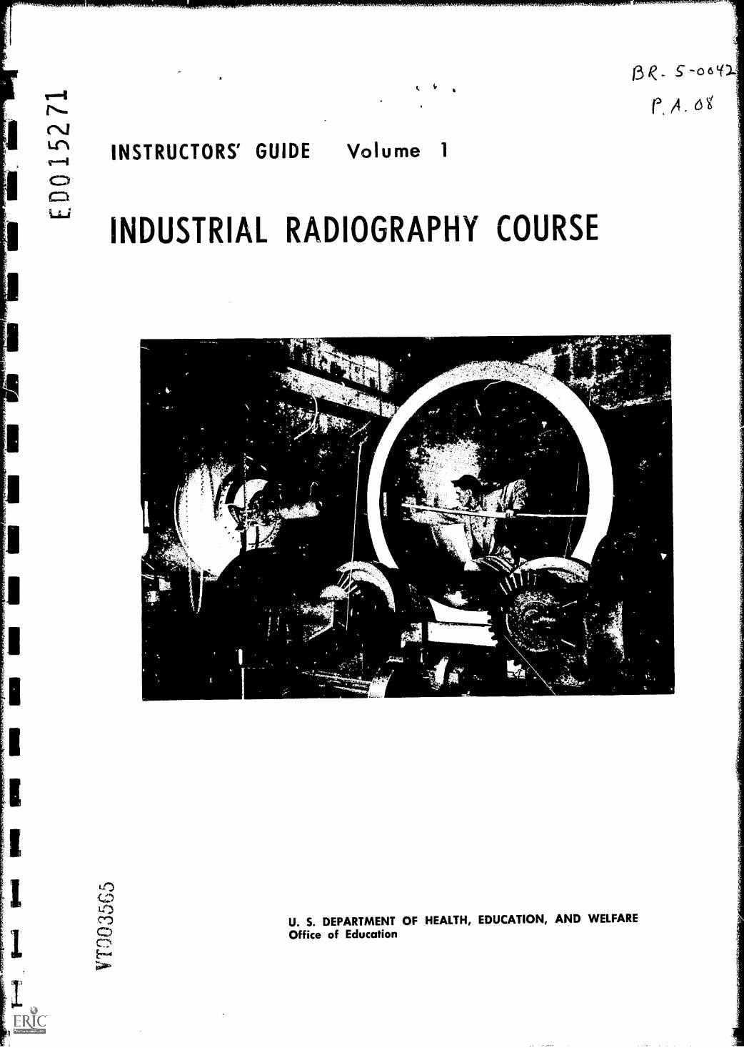
INSTRUCTORS' GUIDE Volume 1
INDUSTRIAL RADIOGRAPHY COURSE
ag_ E-oot(1
U. S. DEPARTMENT OF HEALTH, EDUCATION, AND WELFAREOffice of Education
U.S. DEPARTMENT OF HEALTH, EDUCATION & WELFARE
OFFICE OF EDUCATION
THIS DOCUMENT HAS BEEN REPRODUCED EXACTLY AS RECEIVED FROM THE
PERSON OR ORGANIZATION ORIGINATING IT. POINTS OF VIEW OR OPINIONS
STATED DO NOT NECESSARILY REPRESENT OFFICIAL OFFICE OF EDUCATION
POSITION OR POLICY.
INSTRUCTORS' GUIDE Volume 1
INDUSTRIAL RADIOGRAPHY COURSE
U. S. DEPARTMENT OF HEALTH, EDUCATION, AND WELFAREOffice of Education
Developed and publishedpursuant to a contract with theU. S. Department of Education
by
The Engineering Extension ServiceTexas A&M UniversityCollege Station, Texas
1967
INTRODUCTION
Anyone planning to teach the course outlined in this guide shouldbriefly review his objectives recognizing the fact that the field ofradiography has not been reduced to an exact science capable ofproviding repeatable, predictable and non-variable responses to testsand scientific exploration.
He must recognize as well the greater importance of interpretingthe findings of a test as compared to the more accurate pictorialrepresentation of the conditions being examined.
The basic objectives of the course previously referred to are simplythese:
To train adept individuals in the appropriate techniques of inspectingparts, materials and processes using for this purpose radioactivematerial or radiation prodT.cing equipment including all technical andpractical applications related thereto, that is, film exposure, filmprocessing, interpretation and evaluation.
To develop individual competency in the art or science of radiographyto a degree that the individual can meet all of the requirements for alicense that may be issued by an appropriate state licensing authorityor the U. S. Atomic Energy Commission.
In order to give maximum assistance to the instructor in meetingthe objectives of the course and in the accomplishment of his teachingas this instructors guide outlines in detail all information,helps, guides and suggestions that he may need in acquitting hisresponsibility.
The lesson plans contained herein provide the instructor withessential information relating to each topic together with other helpfulaids and ready references for his use.
These lessons are not intended as inflexible guides or stereotypedformats but should be used as suggested and when coupled with theskilled techniques and professional ability of the teacher can be. mosthelpful in allowing for each individuals own personal treatment of thesubject matter being careful, however, that a thorough course coverageis effected.
Topic arrangement has been planned and should be adhered to when-ever possible providing for the orderly development of proceduralknowledge and technical aptitude.
The instructor must take sufficient time to review each lesson planprior to its use giving himself the opportunity of procuring thesuggested teaching aids, films or whatever else is suggested therein.
Several films are listed as essential conveyors of information,however, the instructor should be aware of the need for schedulingthese well in advance of the anticipated date of showing to insureadequate time for delivery.
It might be stated merely as a refresher note that good instructorshave no difficulty in placing the proper emphasis on the use of films,visual aids and other teaching devices, never using them in place ofsound teaching techniques but rather to emphasize and stress variouselements of the program or as a device for effective summarization ofcourse material.
In addition to the aforementioned related technical information lessonplans, manipulative lesson plans, and experiment exercises are alsoincluded in this guide. These are used in conjunction with laboratoryexercises and planned practice sessions. Their use and application isquite similar to those previously discussed and will be found to bequite helpful in the operation of the training program.
Appropriate tests and examinations are also included for theinstructor's use and should be applied in their respective sequences orat such times when it is a reasonable certainty that all subject mattercovered by the test has been adequately presented.
The appendix of this instructors guide also contains a glossary ofterms, bibliography, film list, selected reference material,specifications, drawings and suggested instructional aids.
ENROLLEE QUALIFICATIONS
The basic or fundamental qualifications of a radiographic traineeare a minimnum age of 18 with a capability of rendering mature andsound judgements, making intelligent decisions and correctinterpretations. The individual must also possess good health andbe physically able to perform routine manually dextross operations.
The prospective student should have a high school education or itsequivalent. Whenever possible it is desirable that the trainee possessor develop proficiency in algebra, trigonometry, mechanical drawing,elementary physics and chemistry.
The individual should possess a reasonably neat appearance, havenormally good or properly corrected vision making him capable ofdetecting minute structural plans in poorly lighted areas.
There must be no record of accident proneness, emotionalinstability or tendency to panic.
He must be ready adaptable to any work situation, be reasonablyfacile, completely honest and dependable.
ti
11
TABLE OF CONTENTS -- Volume 1
INTRODUCTION
INSTRUCTORS LESSON PLANS
Unit 1
Lesson 1Lesson 2
Unit 2
Radiography as an Industrial ToolIndustrial Applications of Radioisotopes
Lesson 1 Ultrasonic Nondestructive TestingLesson 2 Magnetic Particle TestingLesson 3 Liquid Penetrant TestingLesson 4 Inspection of a Defective Part using the Liquid
Penetrant MethodLesson 5 Visiting Commercial Nondestructive Testing Laboratory
Unit 3
Leeson 1 Professional Ethics for the Industrial Radiographer
Unit 4
Lesson 1 Radiation Detection InstrumentsLesson 2 The Film BadgeLesson 3 Use of Pocket DosimetersLesson 4 How to use a Survey MeterLesson 5 Practical Procedures for MeasurementsLes son 6 Radiation
Unit 5
Lesson 1 Algebraic ExpressionsLesson 2 The Inverse Square LawLesson 3 The Square RootLesson 4 Geometric Principles of ExposureLesson 5 Logarithms
Unit 6
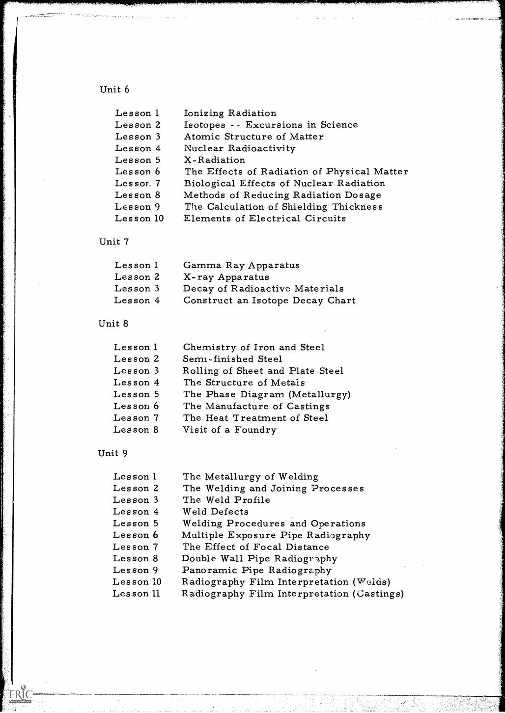
Lesson 1Lesson 2Les son 3Lesson 4Lesson 5Les son 6Lessor. 7Les son 8Lesson 9Lesson 10
Unit 7
Les son 1Les son 2Les son 3Lesson 4
Unit 8
Lesson 1Lesson 2Lesson 3Lesson 4Lesson 5Les son 6Les son 7Lesson 8
Unit 9
Les son 1Lesson 2Les son 3Les son 4Lesson 5Les son 6Lesson 7Les son 8Les son 9Lesson 10Les son 11
Ionizing RadiationIsotopes Excursions in ScienceAtomic Structure of MatterNuclear RadioactivityX-RadiationThe Effects of Radiation of Physical MatterBiological Effects of Nuclear RadiationMethods of Reducing Radiation DosageThe Calculation of Shielding ThicknessElements of Electrical Circuits
Gamma Ray ApparatusX-ray ApparatusDecay of Radioactive MaterialsConstruct an Isotope Decay Chart
Chemistry of Iron and SteelSemi finished SteelRolling of Sheet and Plate SteelThe Structure of MetalsThe Phase Diagram (Metallurgy)The Manufacture of CastingsThe Heat Treatment of SteelVisit of a Foundry
The Metallurgy of WeldingThe Welding and Joining ProcessesThe Weld ProfileWeld DefectsWelding Procedures and OperationsMultiple Exposure Pipe RadiographyThe Effect of Focal DistanceDouble Wall Pipe RadiographyPanoramic Pipe RadiographyRadiography Film Interpretation (Welds)Radiography Film Interpretation (Castings)
Unit 10
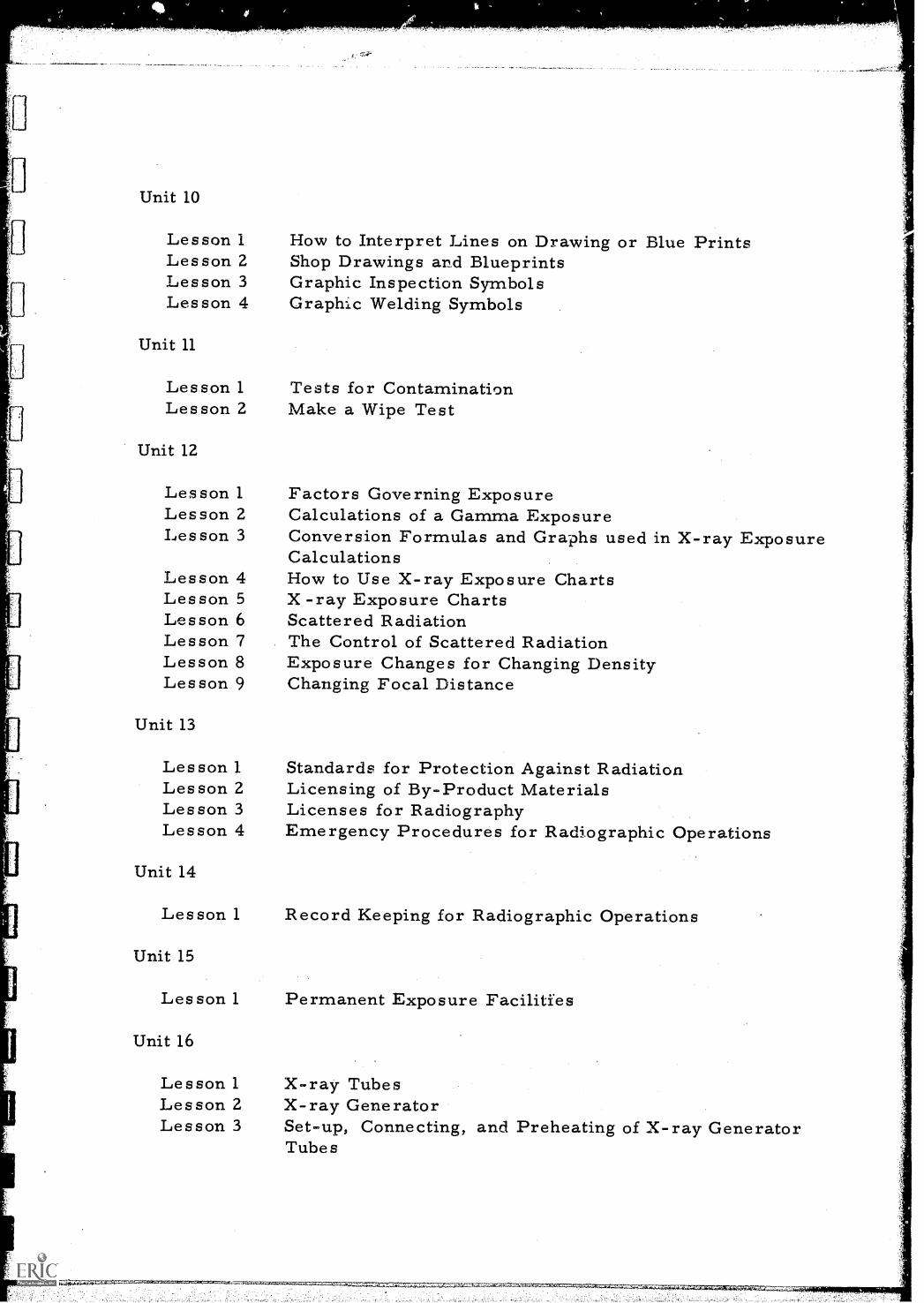
Lesson 1Lesson 2Lesson 3Lesson 4
Unit 11
Lesson 1Lesson 2
Unit 12
Lesson 1Lesson 2Les son 3
Lesson 4Lesson 5Les son 6Lesson 7Lesson 8Les son 9
Unit 13
Lesson 1Les son 2Les son 3Lesson 4
Unit 14
Lesson 1
Unit 15
Les son 1
Unit 16
Lesson 1Les son 2Lesson 3
How to Interpret Lines on Drawing or Blue PrintsShop Drawings and BlueprintsGraphic Inspection SymbolsGraphic Welding Symbols
Tests for ContaminationMake a Wipe Test
Factors Governing ExposureCalculations of a Gamma ExposureConversion Formulas and Graphs used in X-ray ExposureCalculationsHow to Use X-ray Exposure ChartsX -ray Exposure ChartsScattered RadiationThe Control of Scattered RadiationExposure Changes for Changing DensityChanging Focal Distance
Standards for Protection Against RadiationLicensing of By-Product MaterialsLicenses for RadiographyEmergency Procedures for Radiographic Operations
Record Keeping for Radiographic Operations
Permanent Exposure Facilities
X-ray TubesX-ray GeneratorSet-up, Connecting, and Preheating of X-ray GeneratorTubes

Lesson 4Lesson 5Lesson 6Lesson 7Lesson 8Lesson 9
Lesson 10Lesson 11Lesson 12Lesson 13
Unit 17
Lesson 1Lesson 2Lesson 3Lesson 4Lesson 5Lesson 6Les son 7Lesson 8
Unit 18
Auxiliary Equipment for Handling X-ray GeneratorsThe X-ray GeneratorMeasuring X-ray Tube Heel EffectDesign Characteristics of Gamma CameraGamma Ray Exposure DevicesPreparation of a Remote Controlled Gamma RayCamera for an ExposureRadiography with Unattached Gamma Ray SourcesChanging SourcesFocal Spot SizeVisit to a Pipeline or Process Construction Job
Film Manufacturing ProcessCharacteristics of Radiographic FilmRadiographic FilmLoading of Film CassettesThe Photographic ProcessFilm ArtifactsCare and Handling of Radiographic FilmMultiple Film Exposure
Lesson 1 DarkroomsLesson 2 Darkroom HousekeepingLesson 3 Insertion of Film on Processing HangersLesson 4 Use of Film Processing ReelsLesson 5 Film Processing ChemicalsLesson 6 Darkroom Film ProcessingLesson 7 Control of Chemical ProcessingLesson 8 Preparing for Film Radiography
Unit 19
Lesson 1Lesson 2
Unit 20
Lesson 1Lesson 2Lesson 3
Photographic DensityCalibration of a Transmission Densitometer
Measuring Radiographic SensitivityRadiographic Subject ContrastRadiographic Film Contrast
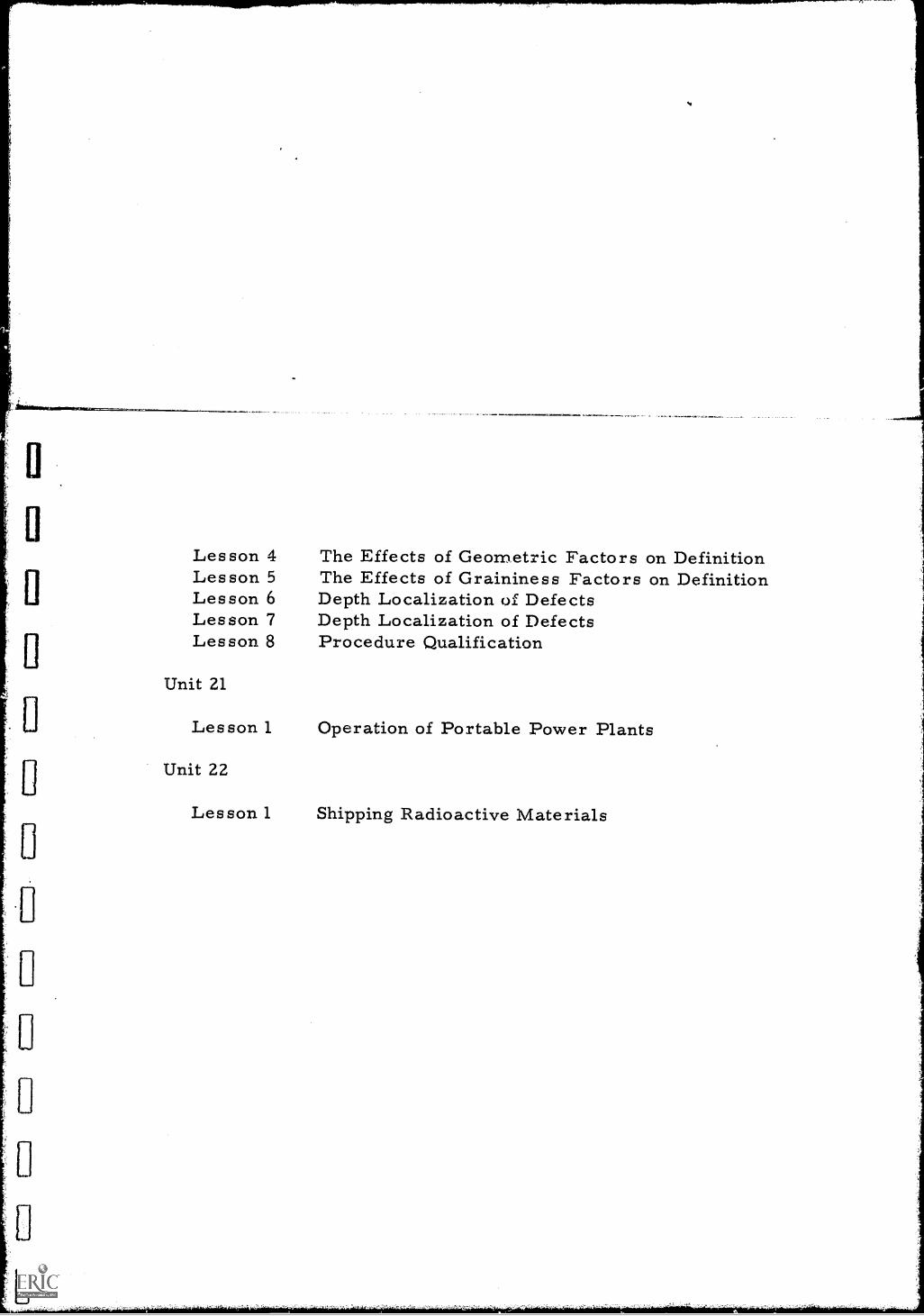
Lesson 4Lesson 5Lesson 6Lesson 7Lesson 8
Unit 21
Lesson 1
Unit 22
Lesson 1
4101110.1.
The Effects of Geometric Factors on DefinitionThe Effects of Graininess Factors on DefinitionDepth Localization of DefectsDepth Localization of DefectsProcedure Qualification
Operation of Portable Power Plants
Shipping Radioactive Materials
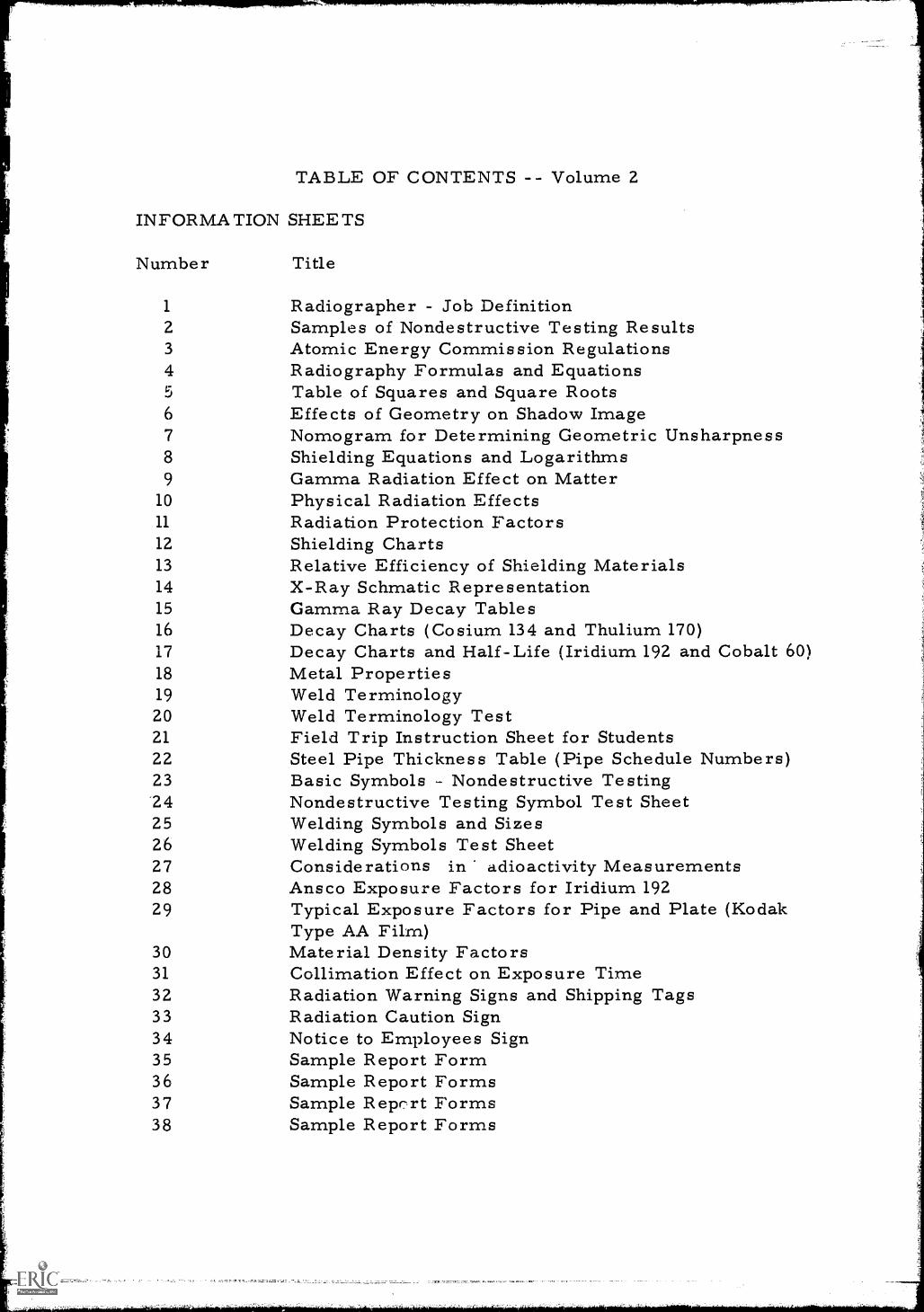
TABLE OF CONTENTS -- Volume 2
INFORMATION SHEETS
Number Title
1 Radiographer - Job Definition2 Samples of Nondestructive Testing Results3 Atomic Energy Commission Regulations4 Radiography Formulas and Equations5 Table of Squares and Square Roots6 Effects of Geometry on Shadow Image7 Nomogram for Determining Geometric Unsharpness8 Shielding Equations and Logarithms9 Gamma Radiation Effect on Matter
10 Physical Radiation Effects11 Radiation Protection Factors12 Shielding Charts13 Relative Efficiency of Shielding Materials14 X-Ray Schmatic Representation15 Gamma Ray Decay Tables16 Decay Charts (Cosium 134 and Thulium 170)17 Decay Charts and Half-Life (Iridium 192 and Cobalt 60)18 Metal Properties19 Weld Terminology20 Weld Terminology Test21 Field Trip Instruction Sheet for Students22 Steel Pipe Thickness Table (Pipe Schedule Numbers)23 Basic Symbols - Nondestructive Testing"24 Nondestructive Testing Symbol Test Sheet25 Welding Symbols and Sizes26 Welding Symbols Test Sheet27 Considerations in adioactivity Measurements28 Ansco Exposure Factors for Iridium 19229 Typical Exposure Factors for Pipe and Plate (Kodak
Type AA Film)30 Material Density Factors31 Collimation Effect on Exposure Time32 Radiation Warning Signs and Shipping Tags33 Radiation Caution Sign34 Notice to Employees Sign35 Sample Report Form36 Sample Report Forms37 Sample Report Forms38 Sample Report Forms
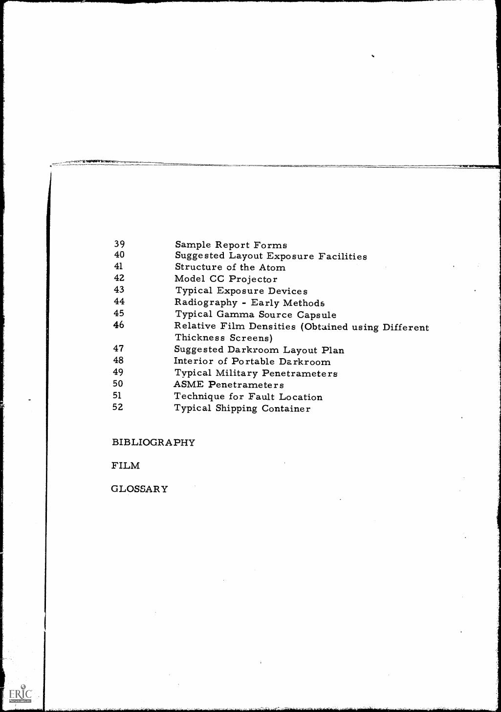
39 Sample Report Forms40 Suggested Layout Exposure Facilities41 Structure of the Atom42 Model CC Projector43 Typical Exposure Devices44 Radiography - Early Methods45 Typical Gamma Source Capsule46 Relative Film Densities (Obtained using Different
Thickness Screens)47 Suggested Darkroom Layout Plan48 Interior of Portable Darkroom49 Typical Military Penetrameters50 ASME Penetrameters51 Technique for Fault Location52 Typical Shipping Container
BIBLIOGRAPHY
FILM
GLOSSARY
1"
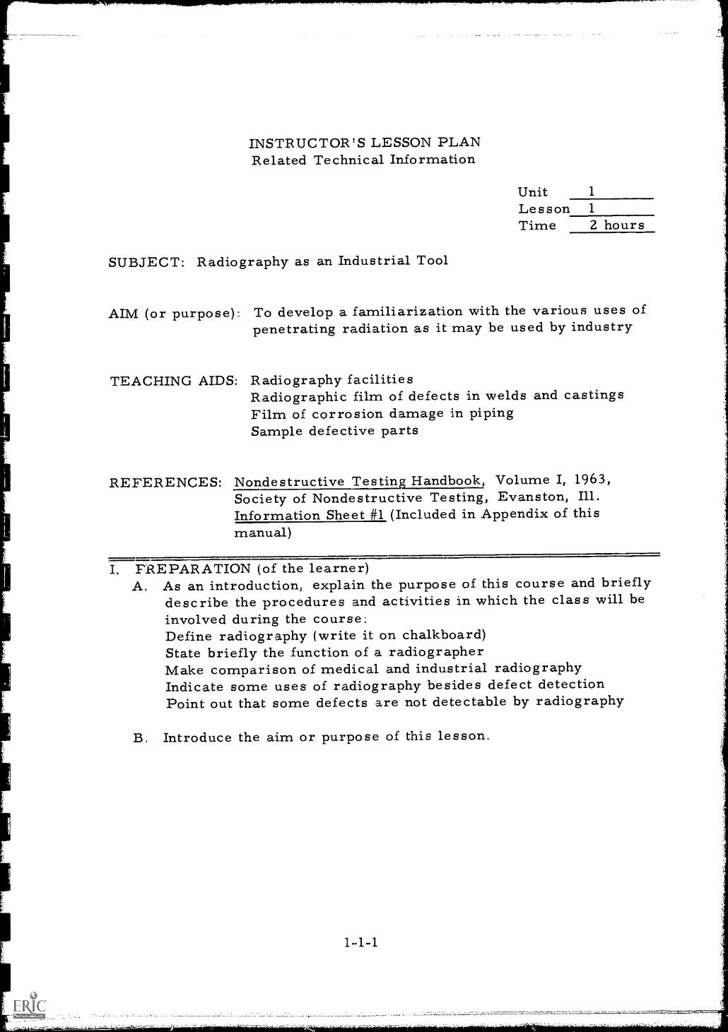
INSTRUCTOR'S LESSON PLANRelated Technical Information
Unit 1
Lesson 1
Time 2 hours
SUBJECT: Radiography as an Industrial Tool
AIM (or purpose) To develop a familiarization with the various uses ofpenetrating radiation as it may be used by industry
TEACHING AIDS: Radiography facilitiesRadiographic film of defects in welds and castingsFilm of corrosion damage in pipingSample defective parts
REFERENCES: Nondestructive Testing Handbook, Volume I, 1963,Society of Nondestructive Testing, Evanston, Ill.Information Sheet #1 (Included in Appendix of thismanual)
I. PREPARATION (of the learner)A. As an introduction, explain the purpose of this course and briefly
describe the procedures and activities in which the class will beinvolved during the course:Define radiography (write it on chalkboard)State briefly the function of a radiographerMake comparison of medical and industrial radiographyIndicate some uses of radiography besides defect detectionPoint out that some defects are not detectable by radiography
B. Introduce the aim or purpose of this lesson.
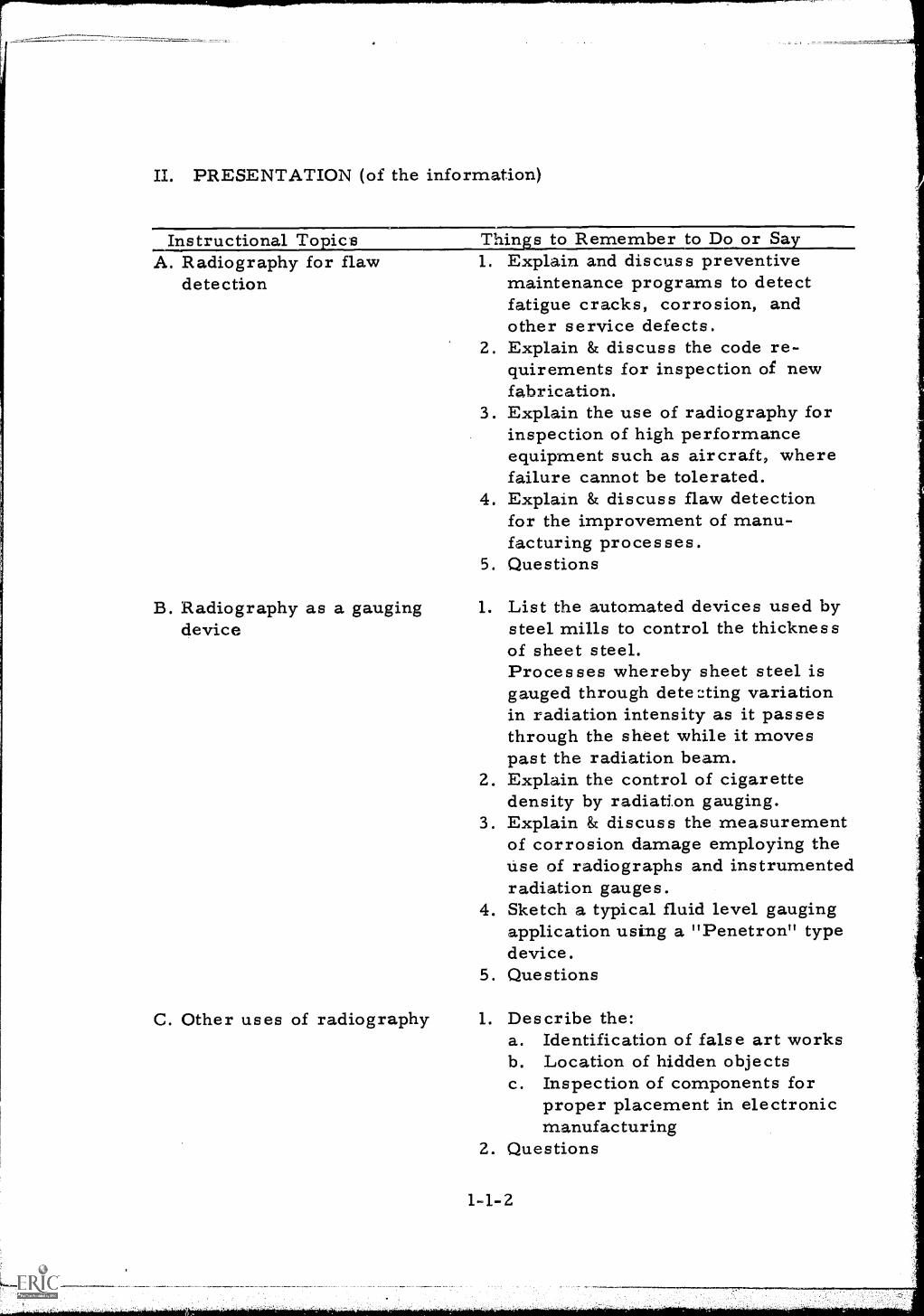
II. PRESENTATION (of the information)
Instructional Topics Things to Remember to Do or SayA. Radiography for flaw 1. Explain and discuss preventive
detection maintenance programs to detectfatigue cracks, corrosion, andother service defects.
2. Explain & discuss the code re-quirements for inspection of newfabrication.
3. Explain the use of radiography forinspection of high performanceequipment such as aircraft, wherefailure cannot be tolerated.
4. Explain & discuss flaw detectionfor the improvement of manu-facturing processes.
5. Questions
B. Radiography as a gaugingdevice
1. List the automated devices used bysteel mills to control the thicknessof sheet steel.Processes whereby sheet steel isgauged through deteL:ting variationin radiation intensity as it passesthrough the sheet while it movespast the radiation beam.
2. Explain the control of cigarettedensity by radiation gauging.
3. Explain & discuss the measurementof corrosion damage employing theuse of radiographs and instrumentedradiation gauges.
4. Sketch a typical fluid level gaugingapplication using a "Penetron" typedevice.
5. Questions
C. Other uses of radiography 1. Describe the:a. Identification of false art worksb. Location of hidden objectsc. Inspection of components for
proper placement in electronicmanufacturing
2. Questions
14-2
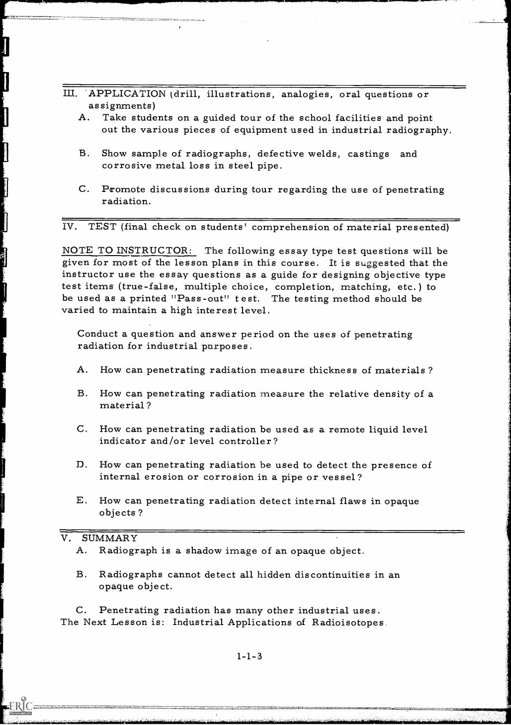
III. *APPLICATION (drill, illustrations, analogies, oral questions orassignments)
A. Take students on a guided tour of the school facilities and pointout the various pieces of equipment used in industrial radiography.
B. Show sample of radiographs, defective welds, castings andcorrosive metal loss in steel pipe.
C. Promote discussions during tour regarding the use of penetratingradiation.
IV. TEST (final check on students' comprehension of material presented)
NOTE TO INSTRUCTOR: The following essay type test questions will begiven for most of the lesson plans in this course. It is suggested that theinstructor use the essay questions as a guide for designing objective typetest items (true-false, multiple choice, completion, matching, etc.) tobe used as a printed "Pass-out" test. The testing method should bevaried to maintain a high interest level.
Conduct a question and answer period on the uses of penetratingradiation for industrial purposes.
A. How can penetrating radiation measure thickness of materials ?
B. How can penetrating radiation measure the relative density of amaterial?
C. How can penetrating radiation be used as a remote liquid levelindicator and level controller?
D. How can penetrating radiation be used to detect the presence ofinternal erosion or corrosion in a pipe or vessel?
E. How can penetrating radiation detect internal flaws in opaqueobjects?
V. SUMMARYA. Radiograph is a shadow image of an opaque object.
B. Radiographs cannot detect all hidden discontinuities in anopaque object.
C. Penetrating radiation has many other industrial uses.The Next Lesson is: Industrial Applications of Radioisotopes.
1-1-3
INSTRUCTOR'S LESSON PLANRelated Technical Information
Unit 1
Lesson 2
Time 2 hoursSUBJECT: Industrial Applications of Radioisotopes
AIM (or purpose): To develop an understanding of the many industrialuses of radioisotopes
TEACHING AIDS: Film: Industrial A lications of Radioisoto es (1960),57 mins. , 16 mm, sound, U. S. Atomic EnergyCommission
EQUIPMENT: Film projector and screen
I. PREPARATION (of the learner)Introduce the film - name, length, color, etc. stress lesson aim,A. The following points should be observed by the student when
viewing the film:1. The three fundamental divisions of industrial usage2. The various types of gauging devices and how they differ;
i. e. , the through - transmission, the backscatter, the betaand the gamma ray gauges
3. Methods of flow measurement using ladioisotopes4. Uses of flow gauges and fluid level indicators5. The various types of radiographic exposure devices shown in
the film
B. The above points will give a better understanding of the manyapplications of industrial radioisotopes.
C. After the film is shown a test will be given regarding the previouslydiscussed items.
II. PRESENTATION (of the information)
Instructional To ics"Industrial Applications oRadioisotopes"
Min s to Remember to Do or SaShow the film
III. APPLICATION (drill, illustrations, analogies, oral questions orassignments)
Discuss the film - with the students and emphasize the followingpoints:
A. The three fundamental classifications of industrial radioisotopeapplications:
1. Gauging2. Radiography3. Tracing
As each of these areas of work are discussed the subject shouldbe amplified and elaborated upon.
B. The principles and applications of:
1. Back scatter gauges2. Beta gauges3. Gamma gauges4. Through - transmission gauges5. Fluid densitometers6. Fluid level gauges
C. The different types of gamma exposure devices seen in the filmand the various applications of each,
D. Tracer applications
E. If certain points need additional clarifiCatiOn reshow the film orportions of it.
1-2-2
IV. TEST ( final check on students' comprehension of material presented)Note: Oral -Quiz
A. What are the three basic categories or classifications of industrialisotope applications?
B. Explain the difference between a back scatter and a throughtransmission thickness gauge.
C. What is the field of application of a beta gauge? Of a gammagauge?
D. Why is it necessary to have different types of gamma ray exposuredevices in radiographic applications? Why are different isotopesused?
E. How can a volume of fluid flow be measured using radioisotopes?
V. SUMMARY
A. Industrial applications of radioisotopes are being applied by manu-facturers of rubber, steel, plastics, paper, nylon, foods, cement,ships, oil and automobiles.
B. Tracer materials must be handled carefully and controlled becausethey are not usually recovered.
C. Beta emitters are used for penetrating thin materials having alow relative density.
D. Gamma emitters are used in radiography and in measuring thick,high density materials.
The Next Lesson is: Ultrasonic Nondestructive Testing
1-2-3
7777."777777!'"Ns
INSTRUCTOR'S LESSON PLANRelated Technical Information
SUBJECT: Untrasonic Nondestructive Testing
r
Unit . 2Lesson 1Time 1 hour
111,7M
AIM (or purpose): To develop understanding ()I nondestructive testingmethods outside the field of industrial radiography
TEACHING AIDS: Ultrasonic test equipmentUltrasonic test blocksSample defective partsTransducers
REFERENCES: Nondestructive Testing Handbook, Volume II, 1963, Societyfor Nondestructive Testing, Evanston, Ill.
PREPARATION (of the learner)Explain how this method of testing can be useful to the radiographer:A. As a supplement to radiography
B. Where radiography can not be effected
C. When a less expensive method of testing is needed
D. As a thickness test where only one side of the material is exposed
' i ,/f
2-1-1
x
II. PRESENTATION (of the information)
Instructional To icsA. Pulse echo testing
1. Transmission2. Reception3. Reflection
Thin s to Remember to Do or So
B. Ultrasonic 'transducers
1. Draw a chalkboard sketch toillustrate the introduction of soundinto a material, its reflection, andreception by the instrument.
2. Explain the pulsing of the soundto allow time for receiving thereflected signal.
3. Questions
1. Explain the piezoelectricphenomenon,Term means "Pressure Electric"Pressure applied to Quartzcrystal causes a potential differencebetween its opposite sides; ultra-sonic transducer contains such acrystal.Describe the construction oftransducers including the wear-plate, dampening materials, andelectrical connections.Display typical transducers.Questions
2.
3.4.
C. Wave propagation 1.
1. Longitudinal2. Shear 2.3. Surface4. Lamb 3.
D. Acoustic impedance 1.
2.
3.
4.
2-1-2
Illustrate and define on chalkboardthe various wave forms.Illustrate applications for each modeor wave form.Questions
Explain sonic reflections in termsof accoustical mismatch.Explain why some materials reflectpart and transmit part of the inci-dent beam.Explain the decay of the soundintensity as the beam travels fartheraway from the transmitter.Questions
II. PRESENTATION (continued)
Instructional TopicsE. Applications for sonic
testing1. Flaw detections2. Thickness measure-
ment
F. Limitations of ultrasonics1. Favorably oriented
defects2. Surface condition
Things to Remember to Do or Say1. Illustrate flaw detection on chalkboard.2. Illustrate on chalkboard the measure-
ment of pipe wall thickness.3. Questions
1. Compare favorable flaw orientationto radiography.
2. Define the minimum preparation re-quired of parts to be tested. Weldspatter on surface should be removedto ensure proper contact with probe.Small balloon filled with water can beplaced between probe and specimensurface to ensure proper contactover irregular surfaces. Oil orgrease sometimes used to improveprobe-specimen contact.
3. Questions
III. APPLICATION (drill, illustrations, analogies, oral questions oras signment)
Have students illustrate or explain the following:A. The three methods of pulse echo testing.
B. The detection of a defect by chalkboard sketches using thelongitudinal wave, the shear wave, and surface wave techniques.
C. The piezoelectric effect.
D. How discontinuities in a casting can be located by the acousticimpedance method.
E. The sonic method of flow detection; thickness measurement.
F. Advantages and disadvantages of the ultrasonic method of testing.
NOTE: A field trip to a commercial testing lab should be undertakenlater to give the students a better understanding of ultrasonicnon-destructive testing techniques.
2-1-3
IV. TEST (final check on students' comprehension of material presented)NOTE: Written Test
A. Define the piezoelectric effect.B. Draw a sketch of longitudinal wave, shear wave and surface wave
propagation modes.C. What is meant by pulse echo testing?D. What is acoustical impedance?E. What are the two major uses of ultrasonic testing?
Check papers and discuss
V. SUMMARY
A. Ultrasonic testing advantage over radiography is that operator canwork from only one side of specimen being examined.
B. Disadvantage is intimate contact with specimen requires smoothworking surfaces or angle inspections.
C. Area covered in a given time is usually greater than that covered byradiographic methods.
D. Lack of a permanent record, as in radiography, is a disadvantageE. Wave propagation method of testing is a visual method of inspection
employing the use of an oscilloscope.F. Acoustic impedance method of testing employs the use of sound waves.
The Next Lesson is: Magnetic Particle Testing
2-1-4
INSTRUCTOR'S LESSON PLANRelated Technical Information
Unit 2Lesson 2Time 2 hours
SUBJECT: Magnetic Particle Testing
AIM (or purpose): To develop an understanding of a testing technique otherthan radiography
TEACHING AIDS: Chalkboard, chalk, and eraserHorseshoe magnet and cracked specimen
MATERIALS: Oil for wet powder methodMagnetic powders
REFERENCES: Information Sheet #2Nondestructive Testing Handbook, Volume II, Societyfor Nondestructive Testing, 1963, Evanston, IllinoisNondestructive Testin -Ma netic Particle Testin PI-4-3,1964, General Dynamics-Convair, San Diego, California
I. PREPARATION (of the learner)A. Explain the advantages of the magnetic particle method
1. Very sensitive to surface defects2. Useful for detection of fine fatigue cracks3. Requires very lAtle training for most tasks
B. Show how the method can be used to aid the radiographer1. Help to identify film defect indications2. Can be used where radiography may not be effective3. May be less expensive test for the same quality of inspection
2-2-1
II. PRESENTATION (of the information)
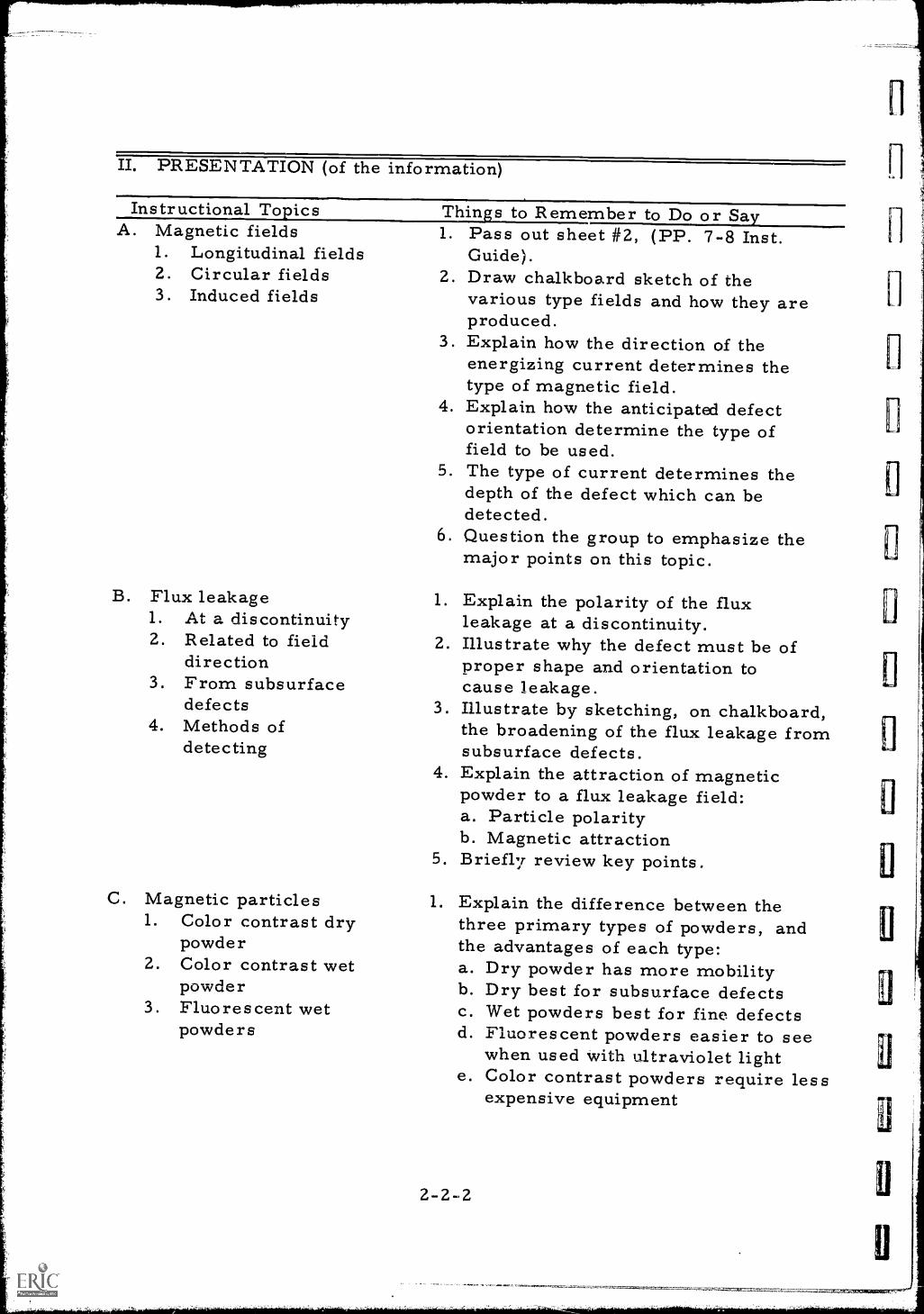
Instructional TopicsA. Magnetic fields
1. Longitudinal fieldsZ. Circular fields3. Induced fields
B. Flux leakage1. At a discontinuity2. Related to field
direction3. From subsurface
defects4. Methods of
detecting
Things to Remember to Do or Say
C. Magnetic particles1. Color contrast dry
powder2. Color contrast wet
powder3 . Fluo re s cent wet
powders
1. Pass out sheet #2, (PP. 7-8 Inst.Guide).
2. Draw chalkboard sketch of thevarious type fields and how they areproduced.
3. Explain how the direction of theenergizing current determines thetype of magnetic field.
4. Explain how the anticipated defectorientation determine the type offield to be used.
5. The type of current determines thedepth of the defect which can bedetected.
6. Question the group to emphasize themajor points on this topic.
1. Explain the polarity of the fluxleakage at a discontinuity.
2. Illustrate why the defect must be ofproper shape and orientation tocause leakage.
3. Illustrate by sketching, on chalkboard,the broadening of the flux leakage fromsubsurface defects.
4. Explain the attraction of magneticpowder to a flux leakage field:a. Particle polarityb. Magnetic attraction
5. Briefly review key points.
1. Explain the difference between thethree primary types of powders, andthe advantages of each type:a. Dry powder has more mobilityb. Dry best for subsurface defectsc. Wet powders best for fine defectsd. Fluorescent powders easier to see
when used with ultraviolet lighte. Color contrast powders require less
expensive equipment
2-2-2
a
El
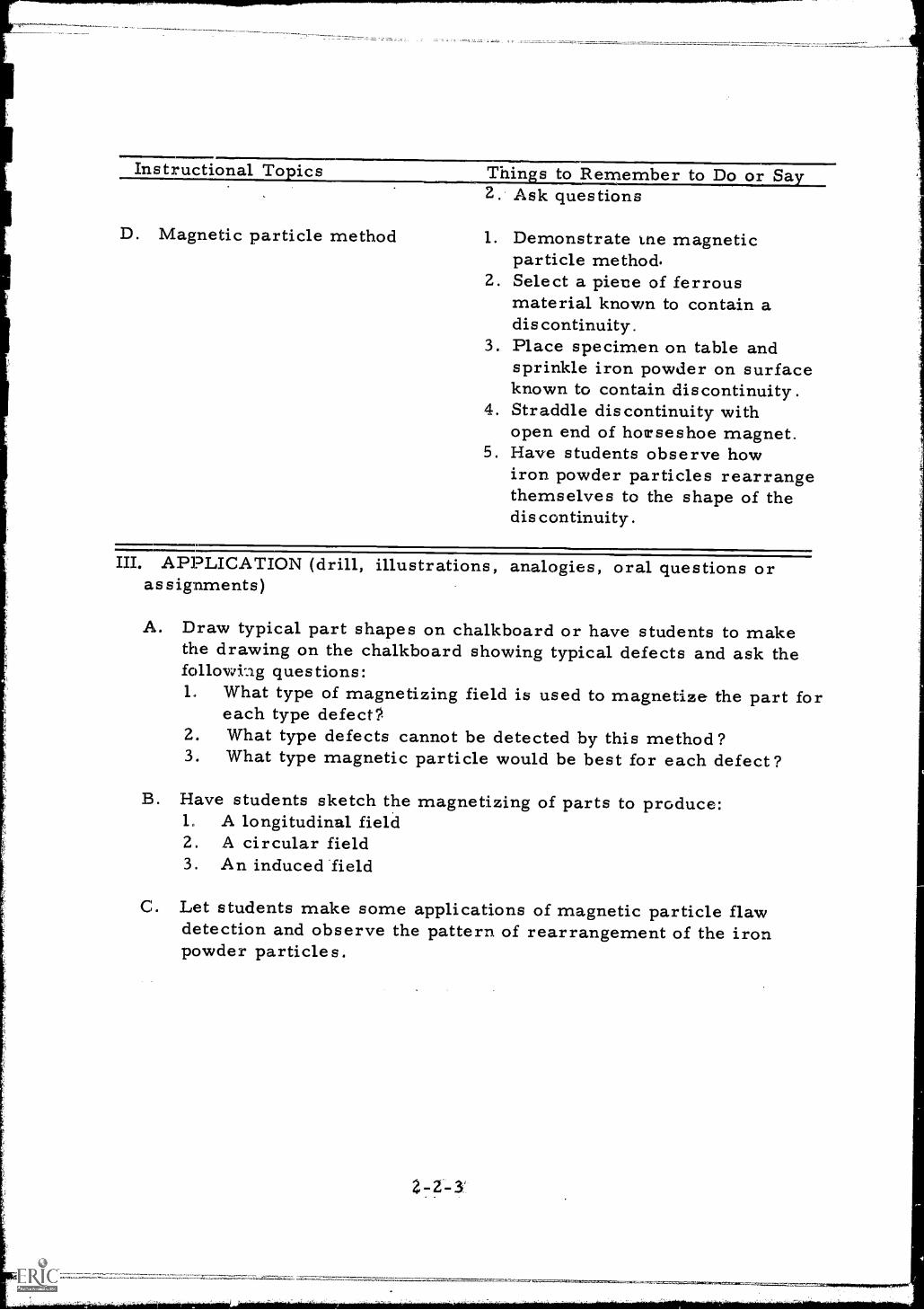
Instructional Topics Things to Remember to Do or Say
D. Magnetic particle method
2. Ask questions
1. Demonstrate tne magneticparticle method.
2. Select a piene of ferrousmaterial known to contain adiscontinuity.
3. Place specimen on table andsprinkle iron powder on surfaceknown to contain discontinuity.
4. Straddle discontinuity withopen end of horseshoe magnet.
5. Have students observe howiron powder particles rearrangethemselves to the shape of thediscontinuity.
III. APPLICATION (drill, illustrations, analogies, oral questions orassignments)
A. Draw typical part shapes on chalkboard or have students to makethe drawing on the chalkboard showing typical defects and ask thefollowi-ag questions:1. What type of magnetizing field is used to magnetize the part for
each type defect?.2. What type defects cannot be detected by this method?3. What type magnetic particle would be best for each defect?
B. Have students sketch the magnetizing of parts to produce:1. A longitudinal fieldZ. A circular field3. An induced field
C. Let students make some applications of magnetic particle flawdetection and observe the pattern of rearrangement of the ironpowder particles.
2 7Z-3
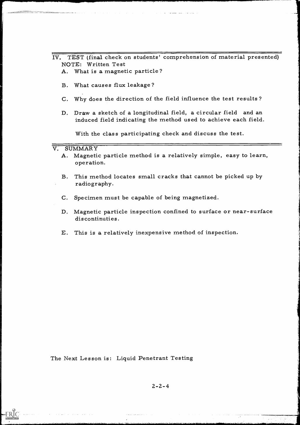
IV. TEST (final check on students' comprehension of material presented)NOTE: Written TestA. What is a magnetic particle?
B. What causes flux leakage?
C. Why does the direction of the field influence the test results?
D. Draw a sketch of a longitudinal field, a circular field and aninduced field indicating the method used to achieve each field.
With the class participating check and discuss the test.
V. SUMMARYA. Magnetic particle method is a relatively simple, easy to learn,
operation.
B. This method locates small cracks that cannot be picked up byradiography.
C. Specimen must be capable of being magnetized.
D. Magnetic particle inspection confined to surface or near-surfacediscontinuties.
E. This is a relatively inexpensive method of inspection.
The Next Lesson is: Liquid Penetrant Testing
2-2-4
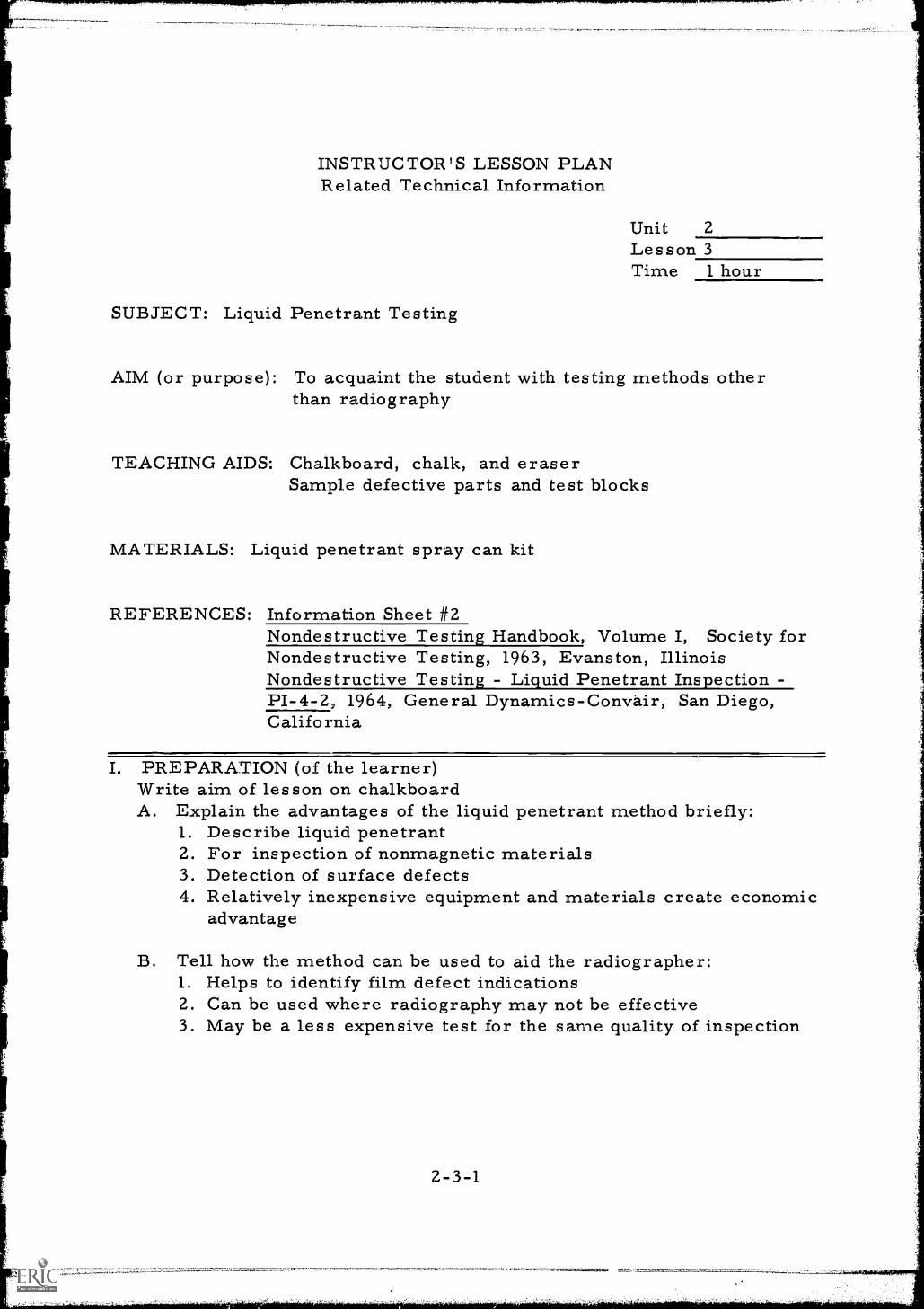
INSTRUCTOR'S LESSON PLANRelated Technical Information
Unit 2
Lesson 3Time 1 hour
SUBJECT: Liquid Penetrant Testing
AIM (or purpose): To acquaint the student with testing methods otherthan radiography
TEACHING AIDS: Chalkboard, chalk, and eraserSample defective parts and test blocks
MATERIALS: Liquid penetrant spray can kit
REFERENCES: Information Sheet #2Nondestructive Testing Handbook, Volume I, Society forNondestructive Testing, 1963, Evanston, IllinoisNondestructive Testing - Liquid Penetrant Inspection -P1-4-2, 1964, General Dynamics-Convair, San Diego,California
I. PREPARATION (of the learner)Write aim of lesson on chalkboardA. Explain the advantages of the liquid penetrant method briefly:
1. Describe liquid penetrant2. For inspection of nonmagnetic materials3. Detection of surface defects4. Relatively inexpensive equipment and materials create economic
advantage
B. Tell how the method can be used to aid the radiographer:1. Helps to identify film defect indications2. Can be used where radiography may not be effective3. May be a less expensive test for the same quality of inspection
II. PRESENTATION (of the information)
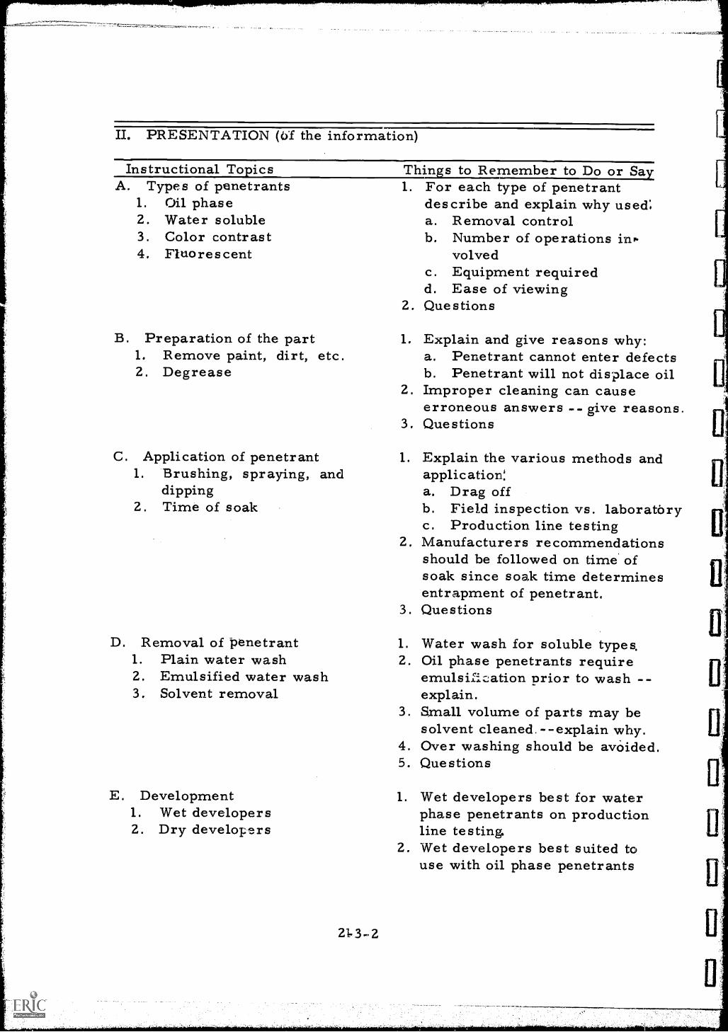
Instructional To icsA. Types of penetrants
1. Oil phase2. Water soluble3. Color contrast4. Fluorescent
B. Preparation of the part1. Remove paint, dirt, etc.2. Degrease
Thins to Remember to Do or SayFor each type of penetrantdescribe and explain why used:a. Removal controlb. Number of operations inr.
volvedc. Equipment requiredd. Ease of viewing
2. Questions
1.
1. Explain and give reasons why:a. Penetrant cannot enter defectsb. Penetrant will not displace oil
2. Improper cleaning can causeerroneous answers -- give reasons.Questions
C. Application of penetrant
3.
1.1. Brushing, spraying, and
dipping2. Time of soak
2.
3.
D. Removal of penetrant 1.1. Plain water wash 2.2. Emulsified water wash3. Solvent removal
3.
4.5.
E. Development 1.1. Wet developers2. Dry developers
2.
21.3-2
Explain the various methods andapplication:a. Drag offb. Field inspection vs. laboratoryc. Production line testingManufacturers recommendationsshould be followed on time ofsoak since soak time determinesentrapment of penetrant.Questions
Water wash for soluble types.Oil phase penetrants requireemulsification prior to wash --explain.Small volume of parts may besolvent cleaned. --explain why.Over washing should be avoided.Questions
Wet developers best for waterphase penetrants on productionline testing.Wet developers best suited touse with oil phase penetrants
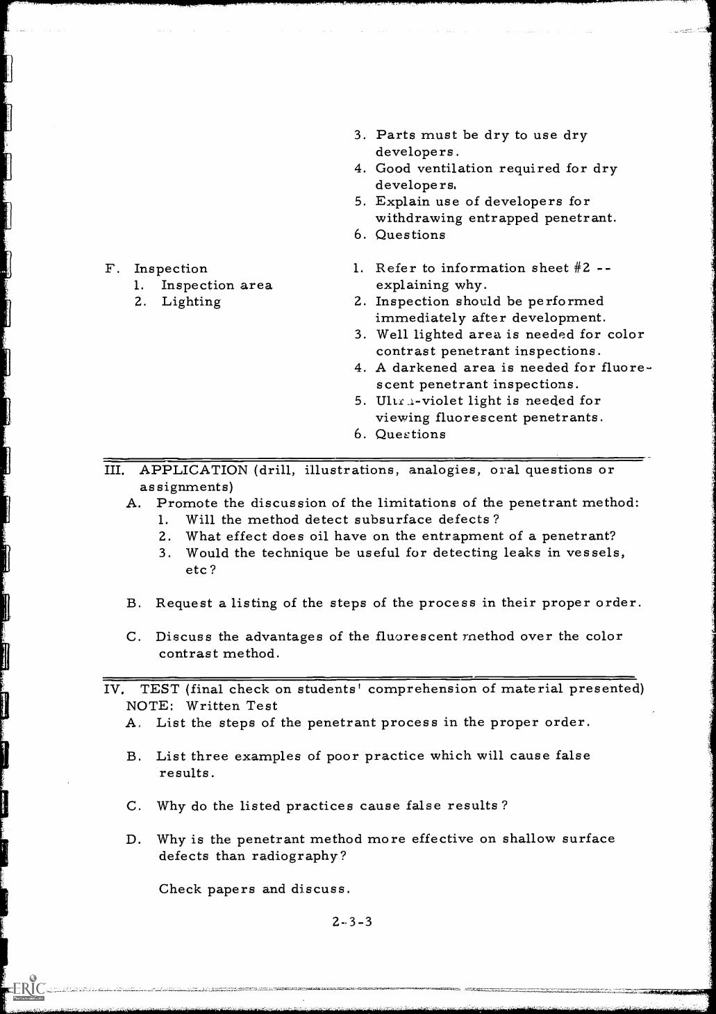
F. Inspection1. Inspection area2. Lighting
3. Parts must be dry to use drydevelopers.
4. Good ventilation required for drydevelope rs.
5. Explain use of developers forwithdrawing entrapped penetrant.
6. Questions
1. Refer to information sheet #2 --explaining why.
2. Inspection should be performedimmediately after development.
3. Well lighted area is needed for colorcontrast penetrant inspections.
4. A darkened area is needed for fluore-scent penetrant inspections.
5. U1ts..1-violet light is needed forviewing fluorescent penetrants.
6. Questions
III. APPLICATION (drill, illustrations, analogies, oral questions orassignments)
A. Promote the discussion of the limitations of the penetrant method:1. Will the method detect subsurface defects?2. What effect does oil have on the entrapment of a penetrant?3. Would the technique be useful for detecting leaks in vessels,
etc?
B. Request a listing of the steps of the process in their proper order.
C. Discuss the advantages of the fluorescent method over the colorcontrast method.
IV. TEST (final check on students' comprehension of material presented)NOTE: Written TestA, List the steps of the penetrant process in the proper order.
B. List three examples of poor practice which will cause falseresults.
C. Why do the listed practices cause false results?
D. Why is the penetrant method more effective on shallow surfacedefects than radiography?
Check papers and discuss.
2-.3-3
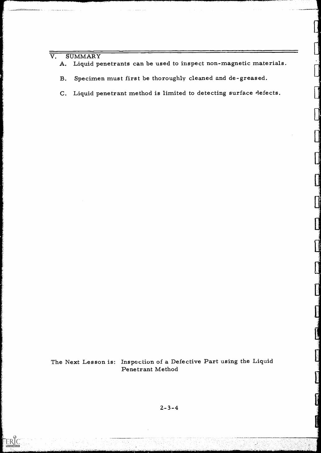
V. SUMMARYA. Liquid penetrants can be used to inspect non-magnetic materials.
B. Specimen must first be thoroughly cleaned and de-greased.
C. Liquid penetrant method is limited to detecting surface defects.
The Next Lesson is: Inspection of a Defective Part using the LiquidPenetrant Method
2-3-4

ri
ill
111,
INSTRUCTOR'S LESSON PLANManipulative Skills
Unit 2Lesson 4Time 2 hours
JOB (or operation): Inspect a defective part using the liquid penetrantmethod
AIM (or purpose): To develop skill in the technique of liquid penetrantinspection
MATERIALS: Paper TowelsLiquid Penetrant Kit
TEACHING AIDS: Chalkboard, chalk and eraserSample defective parts and test blocksManufacturers instruction sheets
REFERENCES: Nondestructive Testing Handbook, Volume I, Society forNondestructive Testing, 1963, Evanston, IllinoisNondestructive Testin - Li uid Penetrant InspectionPI-4-2, 1964, General Dynamics-Convair, San Diego,California
I. PREPARATION (of the learner)A. Write AIM of lesson on chalkboard.
B. Explain the importance of being able to perform a liquid penetrantinspection:1. A good technician has a basic knowledge of testing methods2. The test can be useful in the interpretation of radiographs3. The method may be more useful than radiography for certain
applications
2-4-1
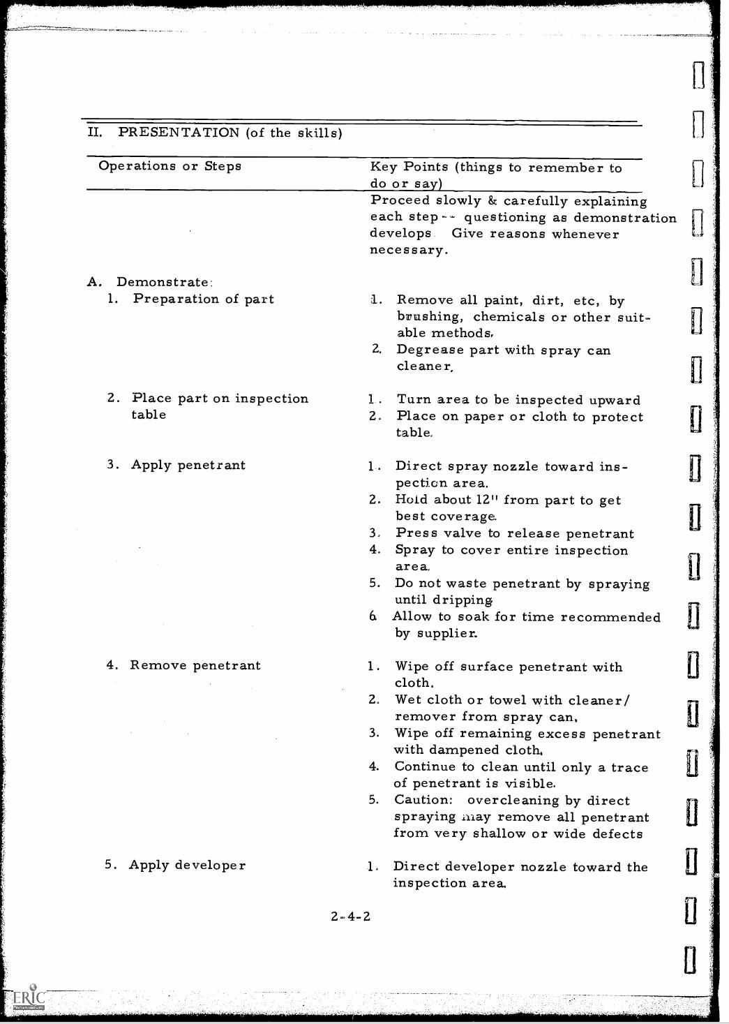
II. PRESENTATION (of the skills)
Operations or Steps Key Points (things to remember todo or say)
A. Demonstrate:1. Preparation of part
2. Place part on inspectiontable
3. Apply penetrant
4. Remove penetrant
Proceed slowly & carefully explainingeach step questioning as demonstrationdevelops. Give reasons whenevernecessary.
1. Remove all paint, dirt, etc, bybrushing, chemicals or other suit-able methods.
2. Degrease part with spray cancleane r,
Turn area to be inspected upward2. Place on paper or cloth to protect
table.
1. Direct spray nozzle toward ins-pection area.
2. Hold about 12" from part to getbest coverage.Press valve to release penetrant
4. Spray to cover entire inspectionarea.
5. Do not waste penetrant by sprayinguntil dripping
6 Allow to soak for time recommendedby supplier,
1. Wipe off surface penetrant withcloth.
2. Wet cloth or towel with cleaner/remover from spray can.
3. Wipe off remaining excess penetrantwith dampened cloth,
4. Continue to clean until only a traceof penetrant is visible.
5. Caution: overcleaning by directspraying .lay remove all penetrantfrom very shallow or wide defects
5. Apply developer Direct developer nozzle toward theinspection area,
2-4-2
11
6. Inspection
2. Hold nozzle 12" to 18" loom thepart to achieve best action ofdeveloper,
3. Spray lightly by pressing spraycan valve.
4. Inspection area should just bedamp while applying developer.
5. Caution: over wetting of theinspection surface will causerunning of the indications andhinder interpretation of results,
1, Allow adequate time for developerto stand. Check for recommendedtime.
2. Observe any indication of stainswhich indicate a defect.
NOTE: BEFORE GOING FURTHERMAKE SURE OF UNDERSTANDINGBY ASKING QUESTIONS
III. APPLICATION (practice by learner under close supervision)
A. Supervise groups of students in the performance of a liquidpenetrant inspection.
B. Discuss the factors which can cause poor results after student hasmade liquid penetrant inspection.
C. Instruct students to tell what they did and why.
IV. TEST (performance of skill to acceptable standards)
A. Assign students to perform a complete penetrant inspection.Give each student close supervision during test.
B. Discuss and comment on results observed.
V. SUMMARY
A. Preparation of test spe&men must be thorough to insure best results.B. Use of the penetrant materials in the proper sequence is mandatory.C. Each step must be timed according to manufacturers instructions.
The Next Lesson is: Visiting a Commercial Nondestructive Testing Laboratory.
2-4-3
INSTRUCTOR'S LESSON PLANManipulative Skills
NOTE TO INSTRUCTOR: All field trips must be carefully planned wellin advance to make sure students will be able toobserve the items given in Step I of this lesson.
Unit 2
Lesson 5
Time 6 hours(includes travel)
JOB (or operation): Visiting Commercial Nondestructive TestingLaboratory
AIM (or purpose): Develop a better understanding of the various inspectiontechniques employed by industry for control of materialquality
MATERIALS: Film badgesDosimetersSafety glassesHard hats
TEACHING AIDS: ChalkboardChalkEraser
I. PREPARATION (of the learner)A. Write aim on chalkboard.
B. Ask students to observe the following:1. The different types of inspection equipment and processes2. The internal quality control measures to insure reliable
inspection results3. The methods used t, identify the customers materials4. Preparation of materials prior to inspection5. Preparation of technique cards and work logs6. Marking of parts for disposition7. Preparation of reports and certifications8. Radiation safety devices9. A test will be given to check the results of this field trip
2-5-1
Ila.001,-.7,sposOqp,777C41,11111.
II. PRESENTATION (of the skills)
Operations or Steps Key Points (things to remember todo or say)
A. Stress safety procedures which 1. Select a commercial nondestructiveare to be followed in the labora- testing laboratory which offers atory a complete complement of testing
processes.B. Issue equipment, goggles, hard 2 Cover all aspects of safety.
hats, etc., before entering lab- 3. Point out the need for gentlemanlyoratory or as instructed by corn- behaviour and the fact that wepany officials are visitors.
III. APPLICATION (practice by learner under close supervision)
A. After returning from the trip, ask the students to discuss andexplain:
1. The different processes and techniques observed in use bythe laboratory
2. Established internal controls to insure a quality inspection3. Methods of maintaining records of techniques employed in
various tests4. Safety devices used in maintaining radiation survelliance
B. Discuss any unusual situations observed during the tour of thelaboratory.
IV. TEST (performance of skill to acceptable standards)
NOTE: WRITTEN TEST
A. Name the different types of nondestructive testing methods you observedin this laboratory.
B. Describe their safety equipment and procedures.
C. Describe some of the records that must be kept and alsofurnished the client.
D. What is meant by "Internal Controls" to insure a quality inspection?
Discuss results of test
2-5-2
L
Li
El
II
II
V. SUMMARYA. Safety precautions.
B. Various types of tests and inspections.
C. Need for records.
D. Conduct on tours and plant visitations.
The Next Lesson is: Professional Ethics for the Industrial Radiographer
2-5-3
INSTRUCTOR'S LESSON PLANRelated Technical Information
Unit 3
Lesson 1
Time 2 hours
SUBJECT: Professional Ethics for the Industrial Radiographer
AIM or purpose): To develop an appreciation of the responsibilities ofa Radiographer and situations which may arise in thespan of his career
NOTE TO TEACHER:Secure sufficient number of copies of AEC orState regulations in advance of this class to handout at this time
TEACHING AIDS: Chalkboard, chalk, and eraserCopy of AEC or State regulations
REFERENCES: Weldingaap.ection Manual D-1, D-46, Page 42,FOREWORD "Description of an Inspector" AmericanWelding Society 33 WEST 39th St. , New York, N. Y.
AEC or State regulations (Information Sheet #3)
I. PREPARATION (of the learner)
A. Write aim of lesson on chalkboard.
B. Ask the following questions:1. How can a radiographer augment his salary?2. What are the normal results of unethical business practices
and conduct?3. Express how you feel about such practices
PRESENT.ATION (of the information)
Instructional ToA. The inspector
1CS Thins to Remember to Do or Sa
B. The responsibility of theinspector-radiographer
C. Short cuts which lead toprofessional degradation
1. Explain that the radiographer maynot always be the inspector.
2. Explain also that the inspector isgenerally not the evaluator.
3. Define the job of the inspector as:The interpretation of the results ofan inspection of parts or an assemblyand the report of this inspection tothe controlling authority.
4. Questions
1. Explain to the prospective inspector-radiographer his role in:a. Ensuring product reliabilityb. Prevention of accidents and loss of
lifec. Securing a profit for the employerd. Maintenance of radiographer equip-
mente. Reporting deficiencies in equip-
ment and personnel under hissupervision
2. Questions
1. Point to the tendency to produceinferior quality as the working con-ditions worsen.
2. Explain the hazard and consequences ofthe following unethical practices:a. Incorrect penetrametersb. Wrong placement of penetrametersc. Incorrect film typesd. Incorrect film-focal distancee. Substitution of satisfactory film
for film from areas of inferiorquality
3. Explain the moral and legal problemscaused by irradiation of personsnot under a health control program.
3-1-2
D. The industrial spy
a. You and your company could besued
b. Your AEC License could berevoked
c. Criminal charges could be filedagainst you and your company
d. You have a moral responsibilityto protect those who are in yourwork area
4. Questions
1. Point out the tendency of some com-panies to employ means of gaininginformation from competitors.
2. Illustrate a number of job assignmentswhere a radiographer has access tocondfidential information:a. Defense plant workb. Research work on space programsc. Work on parts for which a patent
has been applied3. Warn the student of the hazard if
discussing his work with people out-side of his job responsibilities.
4. Questions
III. APPLICATION (drill, illustrations, analogies, oral questions orassignments)
A. Ask the students for an opinion of their responsibilities to anemployer observing unusual attitudes as this will indicateindividuals who may need closer supervision and guidance.
B. Invite students to explain or discuss the legal consequences foraccepting gratuities for the falsification of test records.
C. Suggest students explain and discuss the role of the inspector in:a. Making a profit for the companyb. Maintenance of equipmentc. Ensuring safety of company and customer personnel
D. .Assign students to discuss the job of an inspector.
3-1-3
IV. TEST (final check on students' comprehension of material presented)
NOTE: WRITTEN TEST
A. What are the possible consequences of accepting favors or money forfalsifying records?
B. What is the job of the inspector?
C. Name three hazards of using unethical radiographic short cuts.
D. What possible monetary loss or consequence could arise from theunnecessary exposure of others to radiation?
E. What is the best way to avoid revealing industrial secrets ?
Check and discuss
V. SUMMARY
A. Unethical reporting methods and practice can destroy the value ofproduct inspections.
B. Improper inspection practice can create and propogate hazardousworking conditions.
C. Poor inspection practices can be considered a form of sabotage.
D. How federal laws control the possession, use and handling ofradioisotopes in industry.
The Next Lesson is: Radiation detection instruments
3-1-4
INSTRUCTOR'S LESSON PLANRelated Technical Information
Unit 4Lesson 1
Time 2 hours
SUBJECT:- Radiation Detection Instruments
AIM (or purpose): To develop an understanding of the use of instrumentsfor detection and measuring ionizing radiation
TEACHING AIDS: Film Strip: Civil Defense Radiological Instruments, 35 mmOffice of Civil Defense, Department ofDefense, (Complete with lecture narrativefrom Radiological monitoring for Instructorscourse; RMI, or Exhibit-A of Appendix)
35mm film slide projector and screenDosimeters, dosimeter charge, and survey meters
REFERENCES: Maintenance manuals for instrumentsRadiation Safety in Industrial Radiography withRadioisotopes, P. M. Frazier, C. R. Buchanan, B. W.Morgan, Bulletin AECU 2967, U. S. Atomic EnergyCommission, Washington, D. C.
I. PREPARATION (of the learner)A. State the subject of this lesson and briefly explain why radiographers
must be familiar with radiation detection instruments.
B. Introduce the film and explain briefly the important items it coversincluding the following:1. Different types of instruments for detecting ionizing radiation2. Purpose of each type of detecting instrument3. Similarities in the ability, of each to detect ionizing radiation4. The limitations of each type of detecting instrument5. The basic difference between a dosimeter and a survey meter6. The comparison of total dose vs dose rate7. The definitions of the following: Roentgen, rad, and rem and
how they apply to radiation sa fety8. Abbreviations of certain often used terms
C. Advise group a test will be given.
4-1-1
II. PRESENTATION (of the information)
Instructional Topics Things to Remember to Do or SayA. Show the film strip in NOTE:
three parts Present the narrative in three (3) partsas furnished with the film strip.
Part I:
Part II:
Part III:
NOTE:Ask for questions or ask questionsduring the showing of each of the threeparts.
Part I: Dosimeters and dosimeter charges
Part II: Geiger Muller-type survey meters
Part III: Ionization chamber-type surveymeters
III. APPLICATION (drill, illustrations, analogies, oral questions orassignments)
A. Review the following points of information presented in the film:1. Similarity of the various types of radiation detection instruments2. Difference between a geiger counter and an ionization chamber3. Meanin g of dose rate4. Meaning of roentgen, rad, and rem5. Desirable characteristics of detection instruments6. Undesirable characteristics of different types of detecting
instruments7. Care and maintenance of detecting instruments
B. Call on individuals in the class to give the abbrevations forroentgens, roentgens per hour, milliroentgens per hour.
C. Point out the basic difference between a dosimeter and a surveymeter as was illustrated in the film strip.
4-1-2
IV. TEST (final check on students' comprehension of material presented)
A. Give a written test -- (The following questions are suggested)1. List four desirable characteristics of survey meters.2. What is the phenomenon on which the detection of radiation is
based in the construction of gamma ray detection and measuringinstruments ?
3. What are the two most popular types of enclosed gas volume rate-measuring instruments?
4. Define dose and dose rate.5. Explain the operation of an ionization chamber. Use a sketch if
necessary.6. Draw a sketch of the ionization chamber and electrometer suspension
of the pocket dosimeter. Label the parts.
B. After the class has completed the test, state the correct answers toeach question with the students assisting.
The Next Lesson is: The Film Badge
..=rtsazin.auct<V,
INSTRUCTOR'S LESSON PLANRelated Technical Information
Unit 4LessonTime 1 hour
SUBJECT: The Film Badge
AIM (or purpose): To thoroughly acquaint the student with the function andconstruction of an industrial film badge
TEACHING AIDS: Film badge holder and film badgeCut-away of film badge and holder
I. PREPARATION (of the learner)A. Write aim on chalkboard,
B. Explain the importance of the film badge.1. Give an account of an actual incident such as the following:
A filme badge processing service company wired a customerthat one of its film badges indicated an exposure to 5,000millirem of gamma ro x radiation. An investigation revealedthe employee had lost his film badge temporarily while makingradiographic exposures and the film badge was later found afew iiches from the exposure device. This indicated the filmbadge, but not the wearer, was exposed to 5,000 m/rem.
2. Indicate that it used to control the radiographers radiationexposure and will determine if the radiographer has exceededhis safe operating dosage.
3. Point out that control and monitoring of dosage is essential tothe continued health and safety of the radiographer.
PRESENTATION (of the information)
Instructional TopicsA. Purpose of film badge
::-.771
Things to Remember to Do or Sa1. Di Splay cut away badge and film
envelopes so that all may seeconstruction.
2. Explain how the badge is used tomeasure accumulative dosage.
4-2-1
II. PRESENTATION (continued)
Instructional Topics
B. Types of radiationdetected
C. Construction of filmbadges and film badgeholders
D. Wearing of film badges
E. Care of film badges
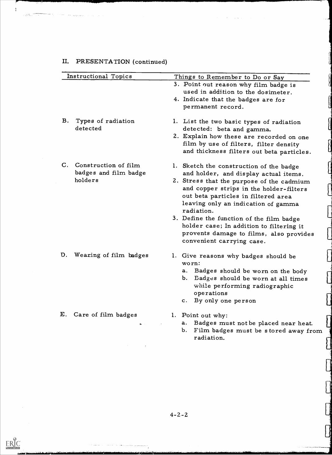
Things to Remember to Do or Say3. Point out reason why film badge is
used in addition to the dosimeter.4. Indicate that the badges are for
permanent record.
1. List the two basic types of radiationdetected: beta and gamma,
2. Explain how these are recorded on onefilm by use of filters, filter densityand thickness filters out beta particles.
1. Sketch the construction of the badgeand holder, and display actual items.
2. Stress that the purpose of the cadmiumand copper strips in the holder-filtersout beta particles in filtered arealeaving only an indication of gammaradiation.
3. Define the function of the film badgeholder case; In addition to filtering itprovents damage to films, also providesconvenient carrying case.
1. Give reasons why badges should beworn:a. Badges should be worn on the bodyb. Badges should be worn at all times
while performing radiographicoperations
c. By only one person
1. Point out why:a. Badges must not be placed near heat.b. Film badges must be s tored away from
radiation.
7.7
c. Badges must be in holder whenworn.
d. Badges must be kept dry.
F. Control badge 1. Explain purpose of control badge:a. During shipment to and from
customer and while radiographeris not using badge, all badges arestored with control badge.
b. If control badge indicates 50 m/remwhen checked, subtract sameamount from individual usersdose.
III. APPLICATION (drill, illustrations, analogies, oral questions orassignments)
A. Have all students sketch a cross section of the typical film badgeholder with filters.
B. Ask students to explain the purpose of the filters.
C. Ask students to list three actions which could damage the filmbadge.
D. Have students explain all the rules for wearing film badges.
IV. TEST (final check on students' comprehension of material presented)NOTE: Written TestA. What are three mandatory rules regarding the wearing of film
badges ?
B. Why does a film badge holder have metal strips attached inside?
C. Why is the film badge worn in addition to the dosimeter?
D. What are the three types of radiation recorded by the film badge?
E. Does the film badge record total dose or dose rate? Explain indetail?
Check and discuss when all tests are completed.
4-2-3
V. SUMMARY
A. 'Film badges advantage is that a permanent record of total accumulatedexposure is obt ained.
B. Badge can indirectly differentiate between beta and gamma radiation.
C. Film badge and dosimeter readings compliment each other.
The Next Lesson is: Use of Pocket Dosimeters
INSTRUCTOR'S LESSON PLANManipulative Skills
Unit 4Lesson 3Time 2 hours
JOB (or operation): Use of Pocket Dosimeters
AIM (or purpose): To develop skill in the use, and maintenance of pocketdosimeters and chargers
TEACHING AIDS: Pocket dosimetersDosimeter chargerSmall source of ionizing gamma radiation such as 5 meCo60 sources used in civil defense classes
REFERENCES: Manufacturers operation and maintenance manuals fordosimeter and charger
I. PREPARATION (of the learner)
A. Show the class a pocket dosimeter and explain its importance to aradiographer.
B. Point out advantages of the dosimeter over the film badge
C. Emphasize the importance of proper maintenance of pocket dosimeterand charger.
II. PRESENTATION (of the skills)
Operations or Steps Key Points (things to remember todo or say)
A. Reading the dosimeter Position students so they can seeand hear,1. (DEMONSTRATE) and point
out the various parts of adosimeter and charger.
2. Point out that the eyepieceshould be held about 1/2"from the eye,
4-3-1
B. Charging of dosimeters1. Place charger on table2. Connect dosimeter to charger3. Adjust the dosimeter
4-3-2
3. Call attention to the stronglight or use light on charger.
4. CAUTION not to press thedosimeter to charger positionwhen using charger as thiswould cause the reading to bealtered.
5. Emphasize that the zeromark should be to the leftof the field of vision.
6. Note that the dosimeter neednot be set to exactly zeroat the beginning of the exposureperiod.
7. Explain that the dosage isdetermined by subtracting thefirst reading from the lastreading in the exposure period.
Demonstrate and explain eachstep1. Place at convenient height
for ease of reading of dosimeter.Remove dust cover fromcharging receptacle.
2. Remove dust cover fromdosimeter . Insert contact intocharging receptacle.
3. Place eye about 1/2" from theeyepiece of the dosimeter.
4. Depress the dosimeter tothe bottogi of the receptacle.
5. Rotate the adjust knob onthe charger until the dosimeterreads near zero.
6. Release pressure on dosimeteruntil charger disengages.
7. Read dosimeter using internallight to ascertain if chargingis correct.
8. Emphasize importance ofreading scale in horizontalpositions.
II. PRESENTATION (continued)
Operations or Steps
C. Dosimeter chargeradjustments
Key Points (things to remember todo or say)Demonstrate and explain.1. If dosimeter will not zero:
a. Replace battery in chargerb. Polish battery contacts with
crocus cloth2. If replacement battery is not available,
try removing the light bulb insidecharger.
3. Explain why4. If bulb is burned out, replace with
the spare bulb located inside thecase.
III. APPLICATION (practice by learner under close supervision)A. Have students demonstrate ability to read and charge dosimeter.
B. Let students reset dosimeters to read exactly 100 mr. Ask studentsto turn dosimeter 180 degrees so that the reticle or scale isup-side-down, and have them read dosimeter in the inverted position.
Repeat readings obtained at 90 degrees and at 180 degrees fromhorizontal. Compare readings with horizontal reading.
IV. TEST (performance of skill to acceptable standards)A. Ask one or more students to charge dosimeters to near zero and
let other class members check for correct procedure.
B. Have students place their dosimeters on the rim of a 2 foot radiuscircle. Place a 5 MC cobalt 60 source in the exact center of thecircle and let each student calculate the period of time to producea dosage of from 100 to 150 mr. at the circle. Remove alldosimeters at the same time.
C. Have students read, record, and recharge his dosimeter.
D. Compare and discuss the results of each students efforts.
The Next Lesson is: How to Use a Survey
4-3-3
INSTRUCTOR'S LESSON PLANManipulative Skills
Unit 4Lesson 4Time 2 hours
JOB (or operation): How to use a Survey Meter
AIM (or purpose): To develop adeptness in the operation of beta-gamma survey meters
TOOLS AND EQUIPMENT: Several beta- gamma survey metersRadioactive gamma source
REFERENCES: Manufacturers operation and maintenance manuals
PREPARATION (of the learner)
A. Explain the importance of the proper use of survey meters. Pointingout that it is the most valuable piece of safety equipment in theradiographers posseision. It indicates the presence of a radiationfield and immediately indicates its intensity.
B. Indicate that in almost every case radiographic accidents couldhave been avoided if the survey meters had been used properly.
C. Relate story or personal experience along this line such as:A radiographer was making several exposures using a gammaexposure device as illustrated on the chalkboard. This deviceenabled the radiographer to crank the source capsule into aflexible tube. At the end of each exposure he was supposed tocrank the capsule back into the device and then check the surfaceof the device with his survey meter to make certain the capsulewas safely back in the storage device.
After making several routine exposures he stopped checking thedevice with his survey meter after each exposure.
At the completion of his assignment he noticed that the surveymeter indicated the source was not in the storage device. Aquick check with his survey meter located the capsule at thefar end of the flexible source tube.
4-4.4
For quite some time he had been cranking the source out whenhe should have been cranking it in. As a result he had beenexposing himself to a large amount of ionizing radiation and wasnot making any radiographs. A quick check with the survey meterbefore and after each exposure would have prevented this accident.
II. PRESENTATION (of the skills)
Opezations or Steps Key Points (things to rememberto do or say)
NOTE: Encourage students to askquestions during Demons-tration. Position studentsso they can see and hear.
A. Pick up survey meter
B. Turn instrument switch to onposition
C. Zero calibrate
D. Range selection
E . AEC range requirements
4-4-2
1. Grasp meter by handle,2. Point chamber end away
from body, explaining why.
1. Turn selector switch to zeroposition,
2. Allow the instrument to warmup at least two minutes, pointingout why.
1. Turn zero knob until needlereads zero on meter.
2. Observe needle for driftor erratic actions
3. Repeat zero step after waitinga short period if needle tendsto drift.
1. Check the zero reading oneach scale as the switch ismoved to each position.NOTE: The zero should notshift when the meter is notin a radiation field.
2. Turn selector switch to theposition for the requiredmeasurement of radiation.
Explain that meter must becapable of indicatingionizing radiation intensityfrom 2 mr/hr to 1 r /hr.
III. APPLICATION (practice by learner under close supervision)A. Request that each student perform the normal operation of zeroing
and checkout of the survey meter.
Draw meter readings and range switch position on chalkboard andhave students state dose rates indicated
C. Question group in the areas of what, how and why.
IV. TEST (performance of skill to acceptable standards)NOTE: Written Test
A. What is the purpose of the adjustable rheostat knob?
13. The survey meter
C. A survey does not measure
D. Survey meter ranges can behour as well as
and measures
dose.
to indicateper hour.
per
E. An AEC approved survey meter for use in radiography must havea range of mr/hr or lower to r /hr or higher.
V. SUMMARYA. Survey meters or rate meters give a quick indication of the
presence of a radiation field.
13. Rate meters also indicate the dose rate of a radiation field.
C. Rate meters cannot indicate the total accumulated dose unless theradiation field is constant.
The Next Lesson is: Practical Procedures for Measurement
4-.4-3
INSTRUCTOR'S LESSON PLANRelated Technical Information
Unit 4Lesson 5Time 2 hours
SUBJECT: "Practical Procedures for Measurement"
AIM (or purpose): To develop an understanding of the supporting theory ofradiation detection instruments used in industrialradiography
TEACHING AIDS: Film: PRACTICAL PROCEDURES FOR MEASUREMENT ,48 mins., 16 mm, sound, U.S. Atomic EnergyCommission
EQUIPMENT: Film projector and screen
I. PREPARATION (of the learner)
A. In order to achieve the maximum benefit from radiation detectingand measuring devices a radiographer must be familiar with theoperating characteristics of the equipment. A thorough knowledgeof the equipment in which the radiographer has entrusted his lifecan only be termed as good common sense.
B. LOOK FOR THE FOLLOWING POINTS IN THE FILM:The avalanche effect in a geiger tube.Fluorescent effect in a scintillator.Steady flow of current generated in an ionization chamber.The operating ranges of the three types of instruments and theirindividual characteristics.
II. PRESENTATION (of the information
Instructional To lesA. `Practical Procedures for
Measurement.° First part,Principles of RadiationDetection
4-5-1
Thin s to Remember to Do or Say1. Show film, rerun if necessary
stopping film to clarify pointsas needed.
III. APPLICATION (drill, illustrations, analogies, oral questions orassignments)
A. Request students to show by chalkboard sketches or with pencil andpaper the range of voltage operation of each of the three ,ype detectors.
B. Have them review and discuss the characteristics of the three types ofdetectors.
C. Discuss the formation of secondary ion pairs and the phenomenoncalled an "ion avalanche".
IV. TEST (final check on students' comprehension of material presented)NOTE: Written Test
A. List in increasing order of operating voltage the three types ofdetection instruments shown in the film.
B. Outline the operating charaateristics of each type instrument.
C. What happens in a detection chamber when a gamma ray passesthrough?
D. What are secondary ions ?
E. What is an ion avalanche ?
Check papers and discuss.
V. SUMMARYA. The need for radiation detection and measurements, the principles
and the use of various types of instrumentation.
B. Emphasis on the Geiger-Muller tube
C. Absolute and comparative activity measurements.
The Next Lesson is: Radiation
4-5-2
-1
V. SUMMARY
A. Safety Precautions
B. Various types of tests and inspections
C. Need for records
D. Conduct on tours and plant visitations
The Next Lesson is: Professional Ethics for the Industrial Radiographer
4-5-3
.1`
INSTRUCTOR'S LESSON PLANRelated Technical Information
Unit 4Les son 6Time 1 hovr
SUBJECT: Radiation
AIM (or purpose): To develop familiarization with the methods ofmonitoring and the control of penetrati2tg radiation.
TEACHING AIDS: Film: Living with Radiation, 2'8 mins. , 16mm, sound,U. S. Atomic Energy Commission
EQUIPMENT: Film, projector and screen
I. PREPARATION (of the learner)A. Introduce subject and aim of lesson - write it on chalkboard.
B. Look for the following points while viewing the film:1. Continuous employment of survey meters by the atomic workers
while conducting work with radioactive materials.2. Types of monitoring devices used at the facility in addition to
survey meters.3. Methods used in disposal of unwanted radioactive materials.4. Heavy shielded chambers used to make precision measurements
of weak source strengths.C. The points given above will assist the learner to better understand
the various methods of monitoring and controlling penetratingradiation.
D. Adirise group a test will be given.
II. PRESENTATION (of the information)
Instructional Topics"Living with Radiation"
4-6-1
Things to Remember to Do or SayShow film, rerun if necessarystopping film to clarify situationsas necessary.
M. APPLICATION (drill, illustrations, analogies, oral questions orassignments) Discuss the film - Emphasizing these points:
A. Use of safety devices and monitoring equipment used by the atomicworkers.
13. Monitoring devices used by atomic workers but seldom employedin industrial radiography.
C. The safety record of the facility shown in the film relating thisto the safety devices used by the facility.
D. Waste disposal procedures shown for the disposal of radiographicsources.
E. The purpose of the heavy shielding used in the construction of thecounting devices. Relate this to instruments used in wipe testing.
F. Rerun film again if necessary for understanding of certainsituations or of certain items that still may not be clear.
IV. TEST (final check on students' comprehension of material presented)NOTE: Oral QuizA. Name at least four different detection devices used by the atomic
workers in the film.
B. Why is it necessary to have controlled disposal methods forradioactive materials?
C. What is the purpose of the heavy shielding used with the countersshown in the film?
D. Why do the atomic workers always use the survey meter whenworking with radioactive materials ?
V, SUMMARYA. Separation-distance factor
13. Storage and/or disposal of radioactive wastes
C. Protection of populations, water, crops, and livestock by airand enviromental monitoring.
D. Protection of workers through use of film badges, radiation counters,shielding, remove-control devices, decontamination proceduresand biochemical studies.
4-6-2
t
'e
0
ft
II
"
A
II
E. The various types of detection instruments
The Next Lesson is: Algebriac Expressions
4-6-3
INSTRUCTOR'S LESSON PLANRelated Technical Information
Unit 5
Lesson 1
Time 1. 5 hours
SUBJECT: Algebraic Expressions
AIM (or purpose): To develop skill in the use of algebraic equations
REFERENCES: Brief College Algebra, W.L. Hart, 1947, D. C. Heath andCo.,, Boston, Mass.Industrial X-ray Handbook, Allan Ly...A, 1962, H. W.Sams, Indianapolis, Ind.Information Sheet #4
I. PREPARATION (of the learner)A. Using chalkboard list the subject of lesson explaining why it is
essential to have a working knowledge of algebraic expressions.
B. List several algebraic formulas on the board gauging theircomplexity to the contemplated proficiency level of the group inattendance.
C. Upon determining the lowest level of understanding present,proceed with the presentation, keeping before the group good andsufficient reason for wanting to know.
II. PRESENTATION (of the information)
Instructional TopicsA. The fundamental operations
a.b.c.d.
AdditionSubtractionMultiplicationDivision
Things to Remember to Do or SaDefine and illustrate on the chalkboard:1. Addition: Combining two or more
numbers so as to obtain a numbercalled a sum.
2. Subtraction: The act of taking onenumber or quantity from another.
3. Multiplication: The process of addinga given number or quantity a certainnumber of times by a briefercomputation.
5-1-.1
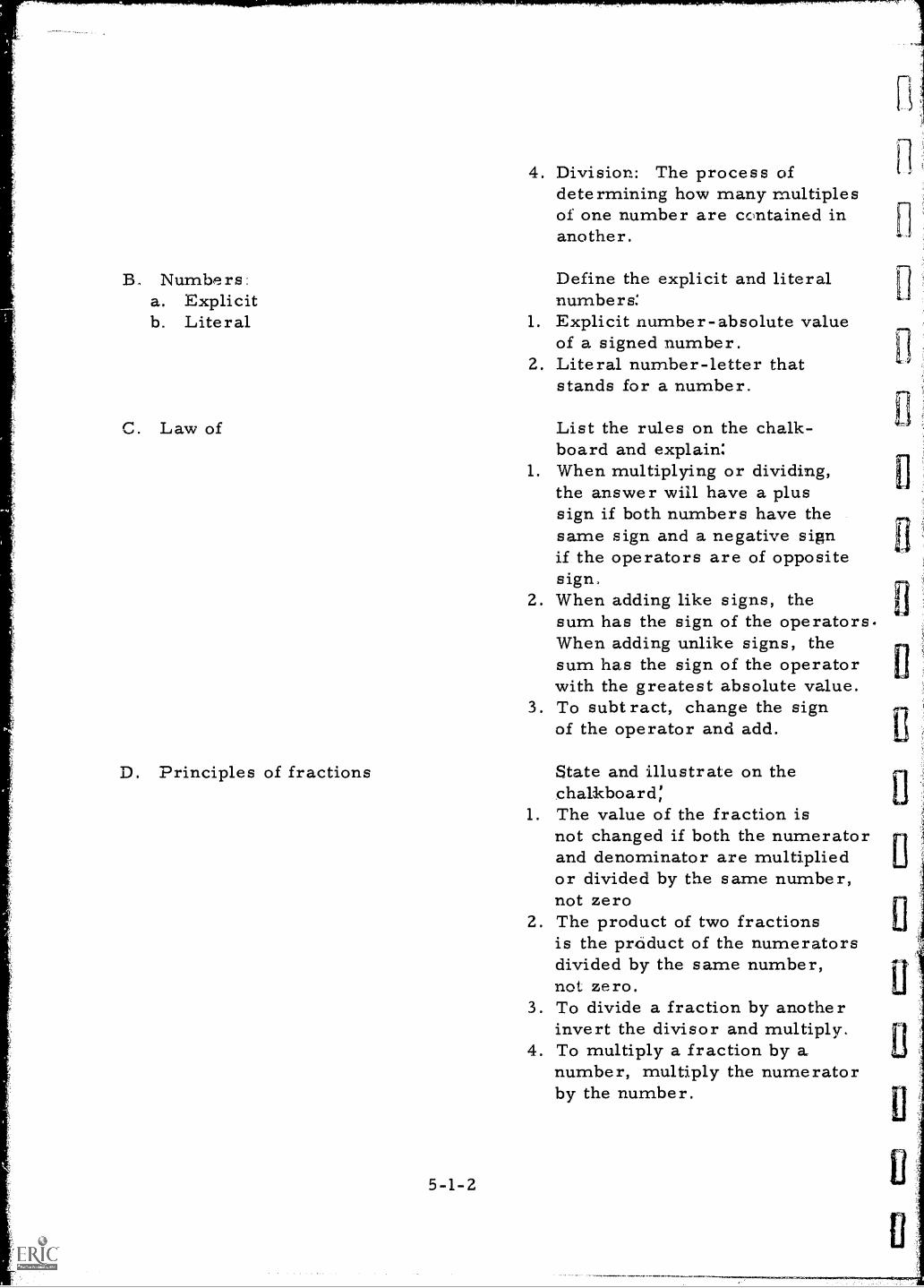
4. Division: The process ofdetermining how many multiplesof one number are contained inanother.
B. Numbers: Define the explicit and literala. Explicit numbers:b. Literal 1. Explicit number-absolute value
of a signed number.2. Literal number-letter that
stands for a number.
C. Law of
D. Principles of fractions
5-1-2
List the rules on the chalk-board and explain:
1. When multiplying or dividing,the answer will have a plussign if both numbers have thesame sign and a negative signif the operators are of oppositesign.
2. When adding like signs, thesum has the sign of the operators.When adding unlike signs, thesum has the sign of the operatorwith the greatest absolute value.
3. To subtract, change the signof the operator and add.
State and illustrate on thechalkboard:
1. The value of the fraction isnot changed if both the numeratorand denominator are multipliedor divided by the same number,not zero
2. The product of two fractionsis the product of the numeratorsdivided by the same number,not zero.
3. To divide a fraction by anotherinvert the divisor and multiply.
4. To multiply a fraction bynumber, multiply the numeratorby the number.
n
1
I I
11
I
I I
11
E. The equation
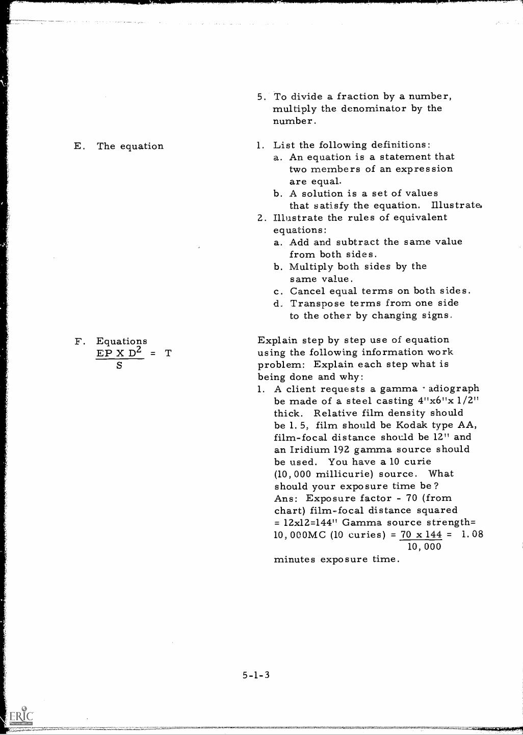
To divide a fraction by a number,multiply the denominator by thenumber.
1. List the following definitions:a. An equation is a statement that
two members of an expressionare equal.
b. A solution is a set of valuesthat satisfy the equation. Illustrate,
2. Illustrate the rules of equivalentequations:a. Add and subtract the same value
from both sides.b. Multiply both sides by the
same value.c. Cancel equal terms on both sides.d. Transpose terms from one side
to the other by changing signs,
F. Equations Explain step by step use of equationEP X D2 = T using the following information work
S problem: Explain each step what isbeing done and why:1. A client requests a gamma adiograph
be made of a steel casting 4"x6"x 1/2"thick. Relative film density shouldbe 1.5, film should be Kodak type AA,film-focal distance should be 12" andan Iridium 192 gamma source shouldbe used. You have a 10 curie(10, 000 millicurie) source. Whatshould your exposure time be?Ans: Exposure factor - 70 (fromchart) film-focal distance squared= 12x12=144" Gamma source strength=10, 000MC (10 curies) = 70 x 144 = 1.08
10, 000minutes exposure time.
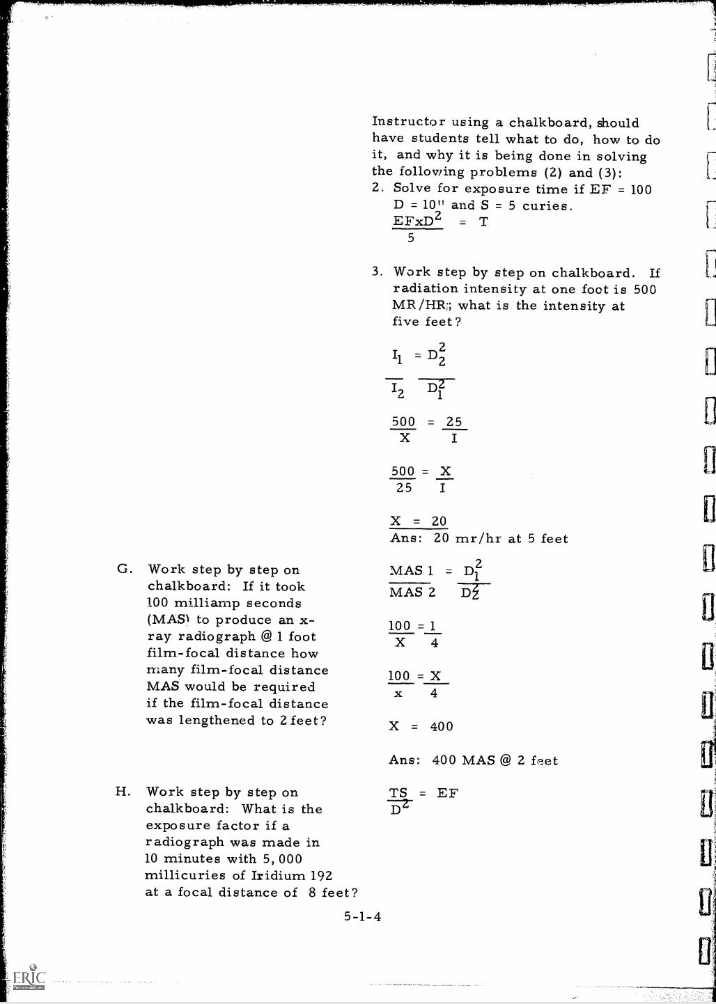
G. Work step by step onchalkboard: If it took100 milliamp seconds(MASI to produce an x-ray radiograph @ 1 footfilm-focal distance howmany film-focal distanceMAS would be requiredif the film-focal distancewas lengthened to 2 feet?
Instructor using a chalkboard, shouldhave students tell what to do, how to doit, and why it is being done in solvingthe following problems (2) and (3):2. Solve for exposure time if EF = 100
D = 10" and S = 5 curies.EFxD2 = T
5
3. Work step by step on chalkboard. Ifradiation intensity at one foot is 500MR /HR:; what is the intensity atfive feet?
2Il =D2
I2 1
1772
500 = 25X
500 = X25 I
X = 20Ans: 20 mr/hr at 5 feet
MAS 1 = D21
MAS 2
100 = 1X 4
100 = Xx 4
X = 400
Ans: 400 MAS @ 2 feet
H. Work step by step on TS = EFchalkboard: What is theexposure factor if aradiograph was made in10 minutes with 5,000millicuries of Iridium 192at a focal distance of 8 feet?
5-1-4
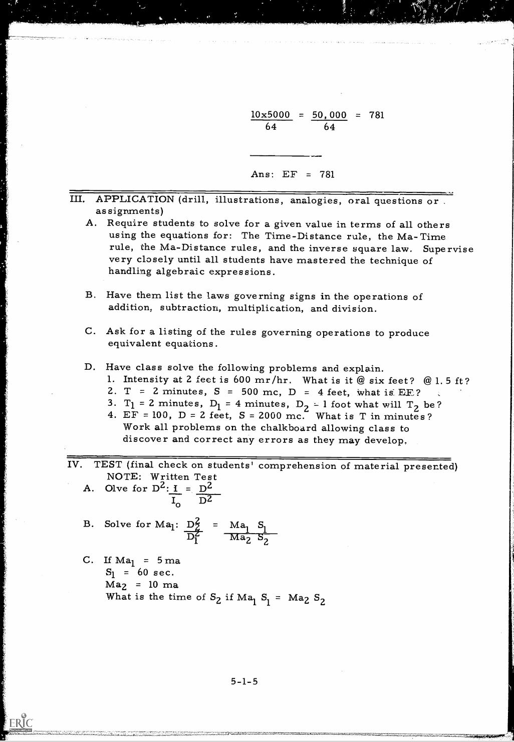
10x5000 = 50,000 = 78164 64
Ans: EF = 781
III. APPLICATION (drill, illustrations, analogies, oral questions oras sigranents)
A. Require students to solve for a given value in terms of all othersusing the equations for: The Time-Distance rule, the Ma-Timerule, the Ma-Distance rules, and the inverse square law. Supervisevery closely until all students have mastered the technique ofhandling algebraic expressions.
B. Have them list the laws governing signs in the operations ofaddition; subtraction, multiplication, and division.
C. Ask for a listing of the rules governing operations to produceequivalent equations.
D. Have class solve the following problems and explain.1. Intensity at 2 feet is 600 mr/hr. What is it @ six feet? @ 1. 5 ft?2. T = 2 minutes, S = 500 mc, D = 4 feet, what is:EE?3. Ti = 2 minutes, D1 = 4 minutes, D2 -- 1 foot what will T2 be?4. EF = 100, D = 2 feet, S = 2000 mc. What is T in minutes?
Work all problems on the chalkboard allowing class todiscover and correct any errors as they may develop.
IV. TEST (final check on students' comprehension of material presented)NOTE: Written Test
A. Olve for D2: i = D2I0 D2
B. Solve for Mai: D =1
Mai S1Ma2 S2
C. If Mai = 5maSl = 60 sec.Ma2 = 10 maWhat is the time of S2 if Mai Sl = Ma2 Sz
5-1-5
D. Solve for the new time if:T1 =10 sec.D11 = 24 inchesD2 = 48 inches
and
2T2 = D2
Ti =DCheck and discuss
V. SUMMARYA. An understanding of the use of algebraic expressions, formulas,
and equations is essential in radiography.
B. Mathematical law of signs must be understood.
C. Formulas and equations tend to speed up and simplify mostradiographic mathematical problems.
The Next Lesson is: The Inverse Square Law
5-1-6
INSTRUCSTOR'S LESSON PLANRelater technical Information
Unit 5
Lesson 2Time 1.5 hours
SUBJECT: The Inverse Square Law
AIM (or purpose): To develop an understanding of the meaning,manipulation, and use of the mathematicalrelationship as used in radiography calculations
REFERENCES: Radiography in Modern Industry, Eastman Kodak Co.,1958, Rochester, N. Y.Nondestructive Testing Handbook, Society for NondestructiveTesting, 1963, Evanston, IllinoisInformation Sheet #4 (see appendix)
I. PREPARATION (of the learner)A. Find out by oral questions what knowledge the class has about the
inverse square law.
B. Point out that all exposure calculations in radiography are basedon the inverse square law and that the radiographer will neverfully understand his trade until he has mastered its use in makingnecessary calculations.
C. Indicate that the inverse square law is used to calculate the distancerequired to be safe from harmful radiation.
IL PRESENTATION (of the information)
Instructional TopicsA. The inverse square law-
define and explain
Things to Remember to Do or Say1. The inverse square law is:
a. The basic mathematicslrelationship between intensity anddistance
b. The most frequently usedrelationship in industrialradiography
5-2-1

B. The mathematicalformula
C. Visual schematicillustration
D. Application of inversesquare law
c. The basis of all exposurecalculations
1. Write the inverse square law inmathematical terms on the chalkboard.
2. Explain the symbols in the inversesquare law equation.
3. Transpose the equation to all forms-distance, time, intensity.
Draw on chalkboard a geometricsketch of the inverse square lawrelationship and discuss with theclass.
Work the following problems onchalkboard step by step. Explaineach step encouraging students toask questions:a. Exposure time is 3 minutes at 1
foot. What is exposure time at3 feet?
b. Intensity at 1 foot is 500 mr/hr.What is intensity at 2 feet?
c. Intensity at 5 feet is 200 mr/hr.At what distance is intensity 2mr/hr?
III. APPLICATION (drill, illustrations, analogies, oral questions orassignments)
A. Ask the students to recite a word statement of the inverse squarelaw.
B. Ask the students to define the inverse square law by an example.
C. Place the inverse square law on the chalkboard in one form andask the students to transpose to all the other possible forms.
D. Give the students a set of conditions for each of the following cases:Calculate from the given data:1. A value of I02. A value of D93. A value of D4. A value of I
IV. TEST (final check on students' comprehension of material presented)
A. Write the inverse square law in any form.B. Transpose to all other forms. Show each step.C. Give three examples for use of the inverse square law.D. Given the following information, solve each problem:
Cobalt 60 yields 14, 500 mr/hr/curie at 1 footIridium 192 yields 5, 900 mr/hr/curie at 1 foot
1. What is the distance where the intensity of radiation from 5curies of Cobalt 60 is 20 mr/hr?
2. At 20 feet from a source of Iridium 192 the radiation intensity is250 mr/hr. How many curies of Iridium is present?
Check the answers with the class and discuss -- correcting allerrors.
The Next Lesson is: The Square Root
INSTRUCTOR'S LESSON PLANRelated Technical Information
Unit 5
Lesson 3
Time 2 hours
SUBJECT: The Square Root
AIM (or purpose): To develop skill and understanding in solving problemsinvolving square root as applied to radiography work
REFERENCES: Information Sheet #5
I. PREPARATION (of the learner)A. Explain briefly why it is important for a radiographer to be able
to figure square root.
B. Give practical situations where this type calculation is needed.For example: To solve problems involving safe working di stancesand distance shielding problems.
II. PRESENTATION (of the information)
Instructional TopicsA. The square root
Things to Remember to Do or SayUsing simple examples explain the meaningof square root.
B. The long division- 1. Illustrate on the chalkboard theestimate method of calculation of the square root of thedetermination number 2 using the following
procedure:a. Write the number as a non-
terminating decimal; i. e. , 2.000000,b. Group the digits to the right and
left of the decimal point in pairs;i. e., 02. 00 00 00.
c. Construct the square root sign overthe number and place the decimalpoint just above the decimal pointin the number.
5-3-1
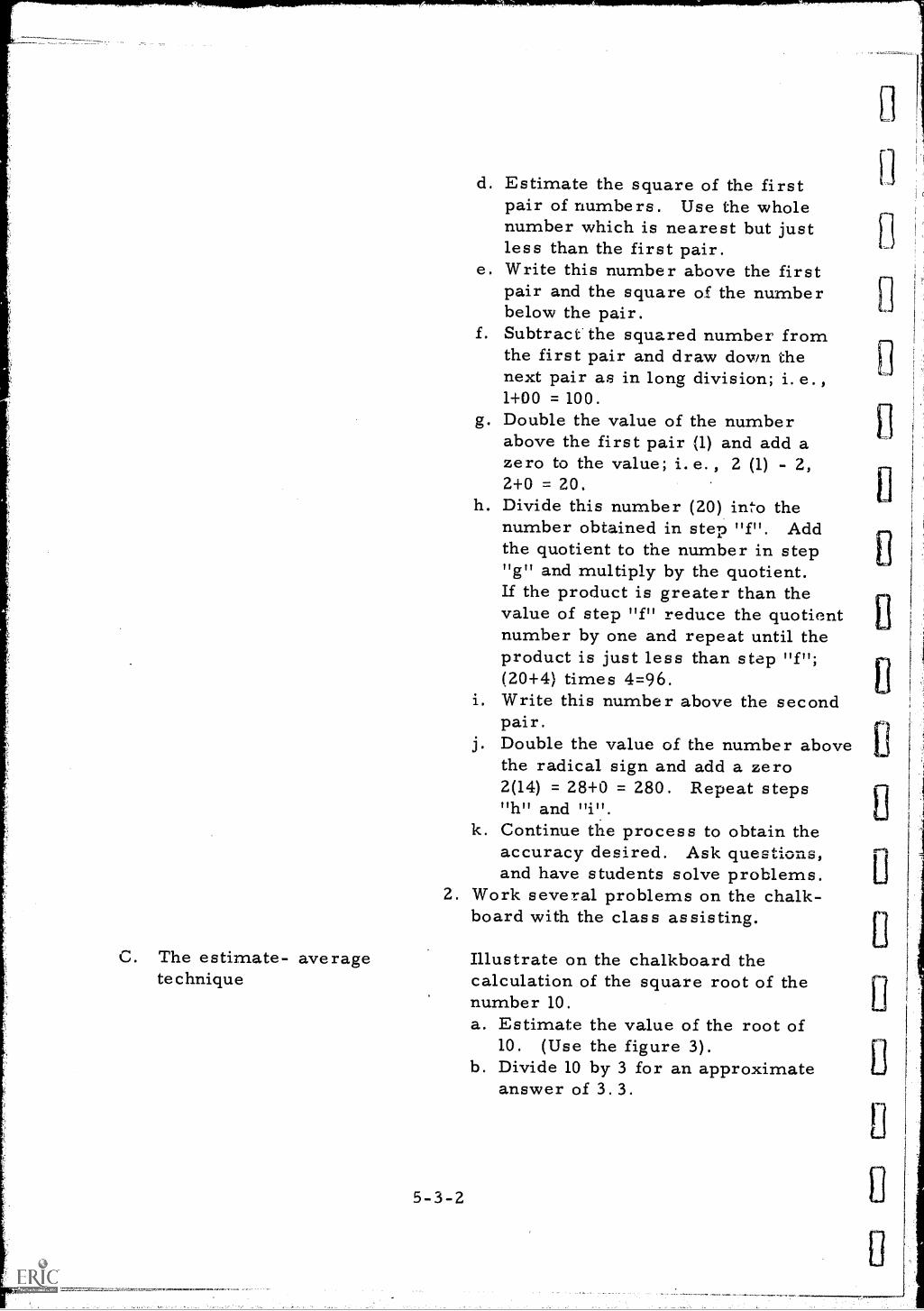
C. The estimate- averagetechnique
d. Estimate the square of the firstpair of numbers. Use the wholenumber which is nearest but justless than the first pair.
e. Write this number above the firstpair and the square of the numberbelow the pair.
f. Subtract the squared number fromthe first pair and draw down thenext pair as in long division; i.e.)1+00 = 100.
g. Double the value of the numberabove the first pair (1) and add azero to the value; i.e., 2 (1) - 2,2+0 = 20,
h. Divide this number (20) into thenumber obtained in step "f". Addthe quotient to the number in step"g" and multiply by the quotient.If the product is greater than thevalue of step "1" reduce the quotientnumber by one and repeat until theproduct is just less than step "f";(20+4) times 4=96.
i. Write this number above the secondpair.
j. Double the value of the number abovethe radical sign and add a zero2(14) = 28+0 = 280. Repeat steps"h" and "i".
k. Continue the process to obtain theaccuracy desired. Ask questions,and have students solve problems.
2. Work several problems on the chalk-board with the class assisting.
5-3-2
Illustrate on the chalkboard thecalculation of the square root of thenumber 10.a. Estimate the value of the root of
10. (Use the figure 3).b. Divide 10 by 3 for an approximate
answer of 3.3.
9
Li
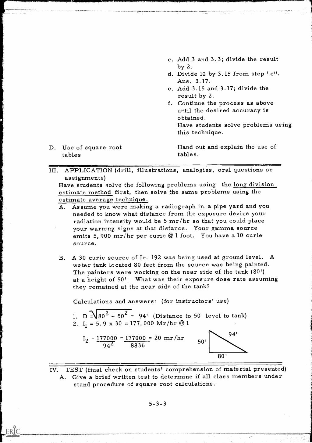
c. Add 3 and 3.3; divide the resultby 2.
d. Divide 10 by 3.15 from step "c".Ans . 3.17.
e. Add 3.15 and 3.17; divide theresult by 2.
f. Continue the process as aboveur.til the desired accuracy isobtained.Have students solve problems usingthis technique.
D. Use of square root Hand out and explain the use oftables tables.
III. APPLICATION (drill, illustrations, analogies, oral questions orassignments)
Have students solve the following problems using the long divisionestimate method first, then solve the same problems using theestimate ave rage techniqueA. Assume you were making a radiograph in. a pipe yard and you
needed to know what distance from the exposure device yourradiation intensity wo._41d be 5 mr/hr so that you could placeyour warning signs at that distance. Your gamma sourceemits 5,900 mr/hr per curie @ 1 foot. You have a 10 curiesource.
B. A 30 curie source of Ir. 192 was being used at ground level. Awater tank located 80 feet from the source was being painted.The painters were working on the near side of the tank (80')at a height of 50'. What was their exposure dose rate assumingthey remained at the near side of the tank?
Calculations and answers: (for instructors' use)
1. DN7302 + 502 = 94' (Distance to 50' level to tank)2. Il = 5.9 x 30 = 177,000 Mr/hr @ 1
Iz - 177000 = 177000 = 20 mr/hr8836
50'
80'
IV. TEST (final check on students' comprehension of material presented)A. Give a brief written test to determine if all class members under
stand procedure of square root calculations.
5-3-3
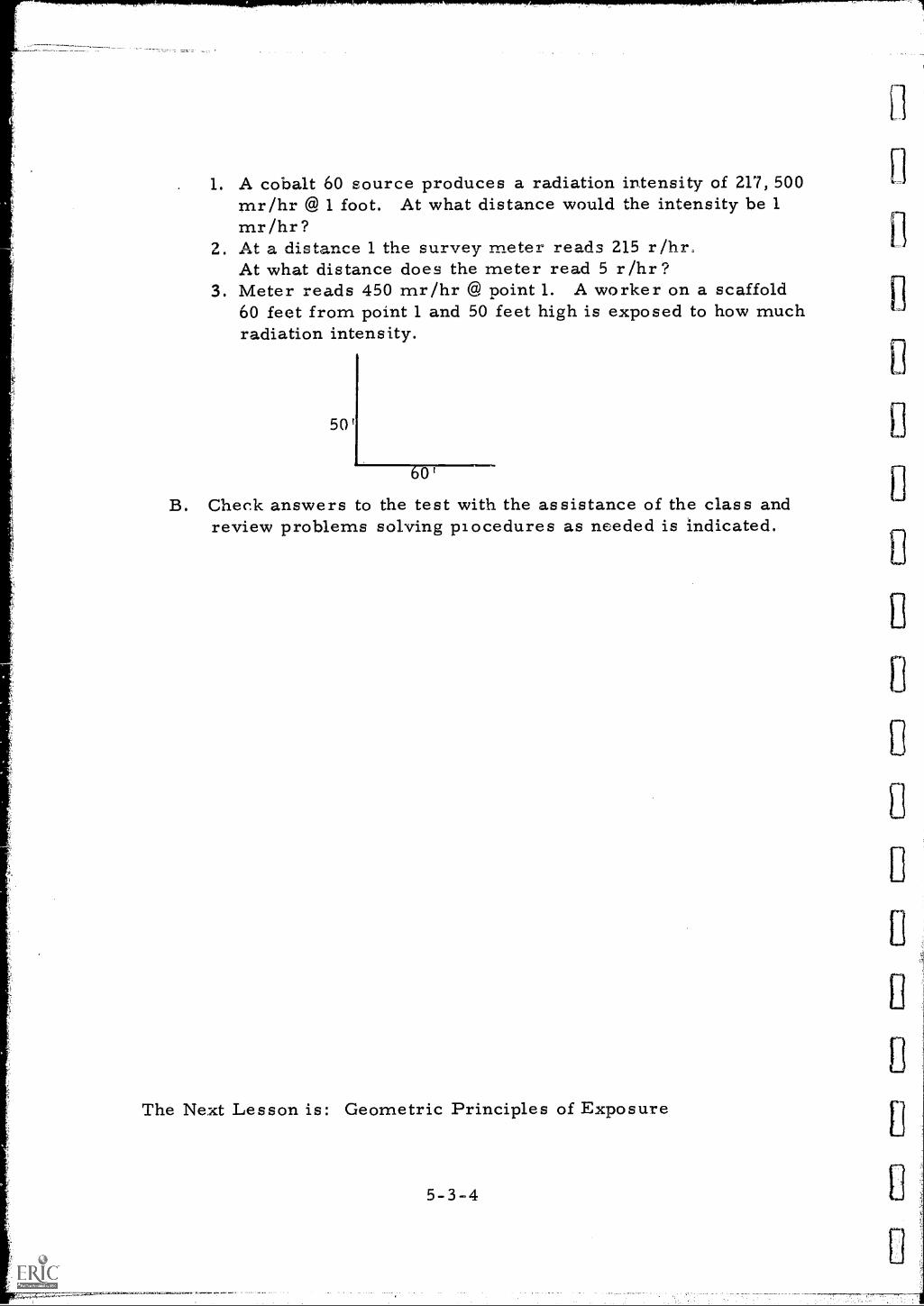
1. A cobalt 60 source produces a radiation intensity of 217, 500mr/hr @ 1 foot. At what distance would the intensity be 1mr/hr?Af .m A4 ofnw-se.c. the survey meter reads 215 r/hr.At what distance does the meter read 5 r/hr?
3. Meter reads 450 mr/hr @ point 1. A worker on a scaffold60 feet from point 1 and 50 feet high is exposed to how muchradiation intensity.
50'
0'
B. Check answers to the test with the assistance of the class andreview problems solving procedures as needed is indicated.
The Next Lesson is: Geometric Principles of Exposure
5-3-4
INSTRUCTOR'S LESSON PLANRelated Technical Information
Unit 5Les son 4Time 1. 5 hours
SUBJECT: :Geometric Principles of Exposure
AIM (or purpose): To teach the fundamentals of exposure as related to thegeometric arrangement of the exposure setup and developa thorough knowledge of the subject
TEACHING AIDS: Spot film viewerA round cardboard disc taped to the end of a stick orpointer
REFERENCES: InfonnatinclJaa,7_Nondestructive Testing Handbook, Volume T, 1963, Societyfor Nondestructive Testing, Evanston, Illinois
I. PREPARATION (of the learner)
Explain briefly that certain very simple and basic laws govern the art ofmaking good radiographs .
X-rays and gamma rays obey the same physical laws as light andformation of shadows or radiation may be better understood by knowledgeof these laws. The relationships of source, object and film will have aconsiderable bearing on the definition in the reproduced image. The skilldisplayed by the radiographer in image reproduction will depend a greatdeal on his knowledge of geometric principles and how these factorsgovern exposure patterns.
II. PRESENTATION (of the information)
Instructional To ics Things to Remember to Do or Say
A. Geometric _enlargement 1. Explain by chalkboard sketch theenlargement of the image when the filmis moved away from the object.
5-4-1
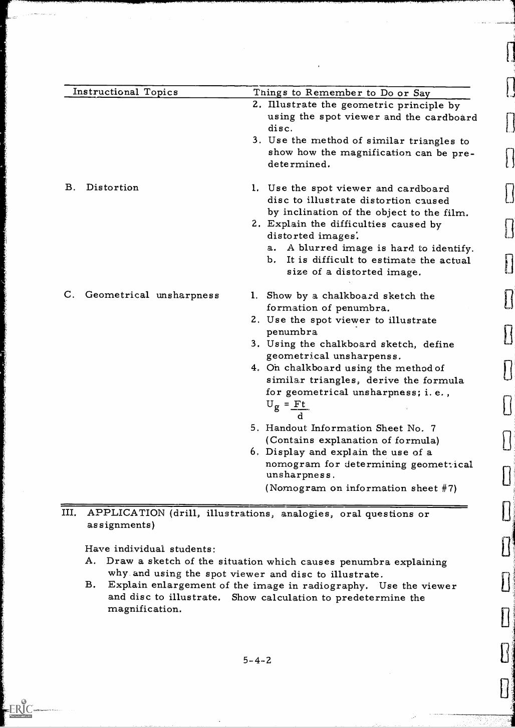
Instructional Topics Things to Remember to Do or Say
B. Distortion
C. Geometrical unsharpness
2. Illustrate the geometric principle byusing the spot viewer and the cardboarddisc.
3. Use the method of similar triangles toshow how the magnification can be pre-determined.
1. Use the spot viewer and cardboarddisc to illustrate distortion causedby inclination of the object to the film.
2. Explain the difficulties caused bydistorted images;a. A blurred image is hard to identify.b. It is difficult to estimate the actual
size of a distorted image.
1. Show by a chalkboard sketch theformation of penumbra.
2. Use the spot viewer to illustratepenumbra
3. Using the chalkboard sketch, definegeometrical unsharpenss.
4. Oh chalkboard using the method ofsimilar triangles, derive the formulafor geometrical unsharpness; i. e. ,
Ug =Ftd
5. Handout Information Sheet No. 7(Contains explanation of formula)
6, Display and explain the use of anomogram for determining geometricalunsharpness.(Nom.ogram on information sheet #7)
III. APPLICATION (drill, illustrations, analogies, oral questions orassignments)
Have individual students:A. Draw a sketch of the situation which causes penumbra explaining
why and using the spot viewer and disc to illustrate.B. Explain enlargement of the image in radiography. Use the viewer
and disc to illustrate. Show calculation to predetermine themagnification.
5-4-2
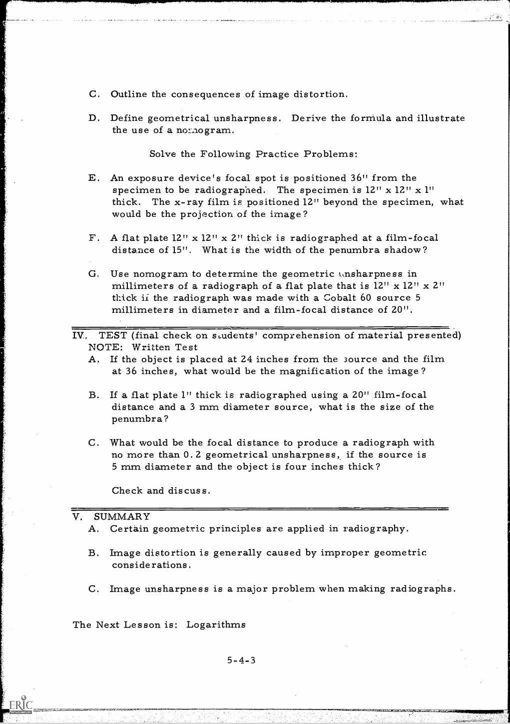
C. Outline the consequences of image distortion.
D. Define geometrical unsharpness. Derive the forrriula and illustratethe use of a nomogram.
Solve the Following Practice Problems:
E. An exposure device's focal spot is positioned 36" from thespecimen to be radiographed. The specimen is 12" x 12" x 1"thick. The x-ray film is positioned 12" beyond the specimen, whatwould be the projection of the image?
F. A flat plate 12" x 12" x 2" thick is radiographed at a film-focaldistance of 15". What is the width of the penumbra shadow?
CL Use nomogram to determine the geometric 1,nsharpness inmillimeters of a radiograph of a flat plate that is 12" x 12" x 2"thick ii the radiograph was made with a Cobalt 60 source 5millimeters in diameter and a film-focal distance of 20".
IV, TEST (final check on students' comprehension of material presented)NOTE: Written TestA. If the object is placed at 24 inches from the Source and the film
at 36 inches, what would be the magnification of the image?
B. If a flat plate 1" thick is radiographed using a 20" film-focaldistance and a 3 mm diameter source, what is the size of thepenumbra?
C. What would be the focal distance to produce a radiograph withno more than 0.2 geometrical unsharpness if the source is5 mm diameter and the object is four inches thick?
Check and discuss.
V. SUMMARYA. Certain geometric principles are applied in radiography.
B. Image distortion is generally caused by improper geometricconsiderations.
C. Image unsharpness is a major problem when making radiographs.
The Next Lesson is: Logarithms
5-4-3
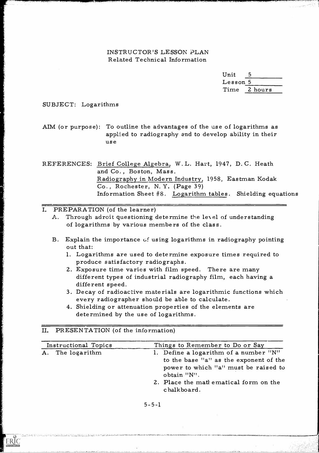
INSTRUCTOR'S LESSON PLANRelated Technical Information
Unit 5
Lesson 5Time 2 hours
SUBJECT: Logarithms
AIM (or purpose): To outline the advantages of the use of logarithms asapplied to radiography and to develop ability in theiruse
REFERENCES: I'Li.e.fcolkg3 2AlgeDra, W. L. Hart, 1947, D. C. Heathand Co., Boston, Mass.
1p21\2odernindustry 1958, Eastman KodakCo., Rochester, N. Y. (Page 39)Information Sheet #8. Logarithm tables. Shielding equations
I. PREPARATION (of the learner)A. Through adroit questioning determine the le\el of understanding
of logarithms by various members of the class.
B. Explain the importance of using logarithms in radiography pointingout that:1. Logarithms are used to determine exposure times required to
produce satisfactory radiographs.2. Exposure time varies with film speed. There are many
different types of industrial radiography film, each having adifferent speed.
3. Decay of radioactive materials are logarithmic functions whichevery radiographer should be able to calculate.
4. Shielding or attenuation properties of the elements aredetermined by the use of logarithms.
II. PRESENTATION (of the information)
Instructional TopicsA. The logarithm
;.4
Things to Remember to Do or Say1. Define a logarithm of a number "N"
to the base "a" as the exponent of thepower to which "a" must be raised toobtain "N",
2. Place the matt ematical form on thechalkboard.
5-51
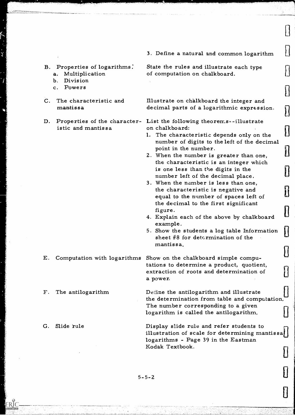
B. Properties of logarithms;a. Multiplicationb. Divisionc. Powers
C. The characteristic andmantissa
D. Properties of the character-istic and mantissa
E. Computation with logarithms
F. The antilogarithm
G. Slide rule
3. Define a natural and common logarithm
State the rules and illustrate each typeof computation on chalkboard.
Illustrate on chalkboard the integer anddecimal parts of a logarithmic expression.
List the following theorems -- illustrateon chalkboard:1. The characteristic depends only on the
number of digits to the left of the decimalpoint in the number.
2. When the number is greater than one,the characteristic is an integer whichis one less than the digits in thenumber left of the decimal place.
3. When the number is less than one,the characteristic is negative andequal to the number of spaces left ofthe decimal to the first significantfigure.
4. Explain each of the above by chalkboardexample.
5. Show the students a log table Informationsheet #8 for determination of themantissa.
Show on the chalkboard simple compu-tations to determine a product, quotient,extraction of roots and determination ofa power.
De.dne the antilogarithm and illustratethe determination from table and computation,The number corresponding to a givenlogarithm is called the antilogarithm,
Display slide rule and refer students toillustration of scale for determining mantissalogarithms - Page 39 in the EastmanKodak Textbook.
III. APPLICATION (drill, illustrations, analogies, oral questions orassignments)
A. List a group of numbers on the chalkboard and ask the students forthe characteristic and mantissa of each number. Show each on thechalkboard after students have given the answers.
B. Ask individual students to explain the rules for multiplication,division, and computation of powers by logarithms.
C. state simple problems on chalkboard for student exercise. Solveproblems on chalkboard after students have completed calculations.(Furnish mantissa values from log tables ).
D. Using equations on information sheet #8, work the following problem:Radiation intensity is 500 mr/hr. How many half-value layersare required to reduce the intensity to 100 mr/hr ?
E. How many tenth value layers are required to reduce radiation intensityfrom 500 mr/hr to 2 mr/hr ?
IV. TEST (final check on students' comprehension of material presented)NOTE: Written TestA. What is the characteristic and mantissa of the following logarithmic
expressions?a. 1. 4271b. 3. 9721c. 8. 473140d. 17.6541-20
B. What is the logarithm of the product of the logarithms: 3. 5001and 5. 4379 ?
C. What is the logarithm of log 5. 4970 divided by the log 4. 3660 ?
D. What is the logarithm of (27. 315)4 if the mantissa of 273 is . 4362.
E. What is the value of 27. 3154 if the antilogarithm of the mantissa. 7448 is 5556?
Check and Discuss
5-5-3
4.1
V; SUMMARYA. The whole number of a logarithm is called the characteristic.
B. The fraction of the number is called the mantissa.
C. The characteristic number contains one less digit than the numberit represents in log form.
D. The mantissa of a logarithm can be obtained from a log table suchas the one used in this lesson.
E. The mantissa can also be found by using a slide rule.
F. Problems of shielding can be solved quickly and accurately by theuse of logarithms.
G. Exposure time charts and the characteristic curve of x-ray filmare drawn on semi-log paper forms.
The Next Lesson is: Ionizing Radiation
5 -5 -4
INSTRUCTOR'S LESSON PLANRelv.ced Technical Information
Unit 6
Lesson 1
Time 1. 5 hours
SUBJECT: Ionizing Radiation
AIM (or purpose): To familiarize the student with the basic conceptsof radiation physics
TEACHING AIDS: Film: Invisible Bullets, Challenge Series, 45 mins. ,
16 mm. , sound, U. S. Atomic Energy Commission
EQUIPMENT: Film projector and screen
I. PREPARATION (of the learner)A. Caution group to look for the following points while viewing the film
and advise that a test will be given regarding some of these situationslater in the session.1. Ionization traces in the cloud chamber2. The relative energy of the different types of radiation3. The type of shielding necessary to stop different types of
radiation4. The explanation of various terms used in evaluation of biological
effects of radiation5. The effects of overdosage on the human body6. The geiger counter and the different windows used to detect
different types of radiation
B. Explain and stress the importance of these situations to theradiographer.
II. PRESENTATION (of the information)
Instructional To ics Thin s to Remember to Do or Sa"Invisible Bullets" Introduce Film
1. Title2. Length
6 -1 -1
=A-
III. APPLICATION (drill, illustrations, analogies, oral questions orassignments)
Discuss the film. Emphasize strong points in the discussion. Usequestions listed below to spark discussion.A. The spark chamber and the cloud chamber.
1. Methods of visually observing ionization from radiation2. The ionization path of the different forms of radiation3. The effect of radiation on the conductivity of gases
B. The geiger counter and the different window materials needed forthe different forms of radiation.
C. The relative penetrating power of different types of radiation.1. Lead shielding for gamma2. Glass for beta3. Paper for alpha
D. The units of measurement for biological radiation effects.1. The RAD2. The RBE
E. The effects of overdosage on the human body.1. Blood damage2. Bone marrow damage3. Nausea4. Lethal dose
F. Why are alpha and beta particles not usually considered hazardousin radiography?
G. When could they create a hazard?
H. Explain whether or not the human body can repair radiation damage.
I. Name three considerations in determining a lethal dose ofionizing radiation to a human being.
J. In what manner may the blood be damaged by ionizing r adiation?
K. What is meant by the relative biological effect?
L. How does a geiger counter measure radiation dose rate?
6-1-2
IV. TEST (final check on students' comprehension of material presented)NOTE: Written TestA. What is the effect of radiation on an air path through which it
passes?
B. Explain how this can be seen.
C. Which of the three types of radiation (alpha, beta, and gamma)has the greatest penetrating power? The least?
D. Which of these could be shielded by a piece of paper?
E. What is the rad and the rbe? What are they used to measure?
F. Do all forms of radiation have the same biological effects ?
G. What is the dosage level considered lethal?
Check and discuss
V. SUMMARYA. The meaning of radiation, its natural source, the various forms
it takes, and how it is used
B. The difference between alpha and beta particles and between gammarays and x-rays.
C. The extent of damage to living tissue by ionizing radiation dependson: type and intensity of the radiation; amount and parts of bodyexposed; duration of exposure.
D. Ionizing radiation can be observed in a cloud chamber instrument.
E. Time, distance, and shielding can reduce the hazards of ionizingradiation.
The Next Lesson is: Isotopes - Excursions in Science
64-3
INSTRUCTOR'S LESSON PLANRelated Technical Information
Unit 6
Lesson 2Time 1 hour
SUBJECT: Isotopes - Excursions in Science
AIM (or purpose): To acquaint class members with the basic conceptsof the nuclear sciences
TEACHING AIDS: Film: Isotope s - Excursions in Science, 20 mins. ,
16mm, sound, U. S. Atomic Energy Commission.
EQUIPMENT: Film projector and screen
PREPARATION (of the learner)A. Introduce the film by title giving a brief i'---:1111-4own on content
pointing out that in order to be able to employ use radio-isotopes in industry one must satisfy the Atomic Energ-;Commission and/or the State that one fully understands thebasic concepts of nuclear science,
B. Suggest that group watch for the following items when viewingthe film:1. The three rays (or particles) ejected by radioactive decay.2. The definition of half-life.3. The methods used to create artificial isotopes.4. The safety precautions used by companies and individuals
working with radioactive materials.5, The encapsulation of radioactive materials.
II. PRESENTATION (of the information
Instructional To ics Thins to Remember to Do or Say\\Isotopes - Excursions in Science Show the film
6-2-1
APPLICATION (drill, illustrations, analogies, oral questions orassignments)
Discuss the film, emphasizing these points in the discussion andquestioning as needed:
A. The rays and particles produced by radioactive decay1. Alpha2. Beta3. Gamma
B. Re-define and discuss decay half-life.
C. Production of artificial isotopes used for industrial radiography.
D. Safety equipment used by the workers in the film.
E. Encapsulation, particularly where related to radiography.
F. What is meant when one states that half-life is exponential?
G. Give an example: (If a radioactive isotope is said to have passedthrough three half-lives what percentage of its originalactivity remains?
H. Explain why all isotopes of elements are not radioactive.
I. Which of the three emitters has the greatest penetrating power,Alpha, Beta, or Gamma?
J. Which emitter is most suitable for radiography?
K. Alv?
L. What are the -4-hree basic methods of shielding against nuclearradiation?
M. Why is an isotope that is used-iv. radiography encapsulated?
N. Bow is the isotope encapsulated?
IV. TEST (final check on students' comprehension of material presented)NOTE: Oral QuizA. What are the three types of particles or rays emitted by radioactive
decay?
B. Define a half-life of a radioisotope.
6-2-2
CJ
nU
C. How are radioisotopes produced?
D. Why are isotopes used in radiography encapsulated?
V. SUMMARYA. Th:e- three types of radiation produced by radioactive decay.
B. Encapsulation usually eliminates alpha and beta radiation.
C. Half-life of a particular isotope of an element determines its use-ful life in an industrial application.
D. Safe handling procedures and rules must be understood and observedin order to use and handle radioactive materials.
The Next Lesson is: Atomic Structure of Matter
INSTRUCTOR'S LESSON PLANRelated Technical Information
Unit 6Lesson 3
Time 2 hours
SUBJECT: Atomic Structure of Matter
AIM (or purpose): To outline the basic nuclear science concepts andassist the student in developing a proper vocabularyregarding the subject
REFERENCES: Radiolo ical Monitorin for Instructors, Instructor's Guide,Lesson 2, Department of Defense, Office of Civil Defense,Training Division, Battle Creek, Mich.Information Sheet #41
I. PREPARATION (of the learner)A. Introduce topic developing interest by asking a few simple questions
regarding the structure of matter, supplying quick and informativeexplanations.
B. Stress the fact that the atomic theory as related to radiography isnot difficult to understand if you develop the theory a step at atime. Explain that the purpose of this lesson is to help tovisualize the atomic structure of matter and how it can bealtered to make gamma radiography possible.
II. PRESENTATION (of the information)
Instructional TopicsA, Matter
Things to Remember to Do or Say1. Anything which occupies space and
has mass or weight.2. That which can be classified according
to physical and chemical properties.3. Many different kinds of matter exist.4. Classification of matter is an
important part of nuclear science.
II. PRESENTATION (continued)
Instructional 'Ft: Epics Things to Remember to Do or SayB. Classification of Matter 1. Physical combination of two or more
1. Mixture substances characterized by nodefinite ratio. Each substancemaintaining its individual identity:Example: Cup of coffee.
2. Compound 2. Chemical combination of two or moresubstances characterized by definiteratio of the combining substances.Water contains two parts hydrogen toone part oxygen no matter where it isfound.
3. Element 3. Substance which cannot be separatedinto substances different from itselfby ordinary chemical means. Goldis one of the over 100 differentsubstances which contain only atomsof the same chemical property.Silver is another.
4. Molecule 4. Smallest part of a compound that canexist and still retain the chemiciproperties of the counpound. Amolecule contains two or more atoms.
5. Atom 5. Smallest conceivable part of anelement. Smallest portion of anelement that can enter into chemicalcombination.
C. Concept of the atom Information Sheet #411. The term "atom" means undividable.
It is from the Greek letter "a"meaning "not" and the word "tomos"meaning "cut".
2. The Greek concept proved to beerroneous, and it has been demonstrated,that an atom is dividable.
3. Iii about 190=0 scientists discovered theatom was not a uniform sphere.
4. It was also determined that it containeda strong positive charge in its centerwith a negative charge about it.
6-3-2
II. PRESENTATION (continued)
Instructional To ics Thin s to Remember to Do or Sa
D. Atomic structure
E. Isotopes of elements
5. The center dimension is smallcompared to the atom as a whole, about1 to 10,000 ratio and the negativecharges orbit around a nucleus.
6. If the nucleus of an atom was the sizeof a marble the entire atom wouldweight about 36 million tons andthe closest negative charge wouldorbit about 200 feet away.
1. An atom consists of protons, electrons,and neutrons.
2. Proton: is a subatomic particlefound in the nucleus of an atom. It ispositively charged.
3. Electron: a very light particle,negatively charged. Orbit s thenucleus. A proton is 1840 timesheaver than an electron.
4. Neutron: carries no electricalcharge. Weighs the same as a protonand is found in the nucleus.
5. Properties of each element are theperiod functions of the number ofprotons in its nucleus.
1. Different forms of the same element.2. Like brothers, they have the same
last name but different first names.3. Each element is assigned an atomic
number which is equal to the number ofprotons in the nucleus of its atom(Sometimes called "Z" number).
4. Each different form, or isotope, ofan element has a mass number(The "A" number) The "A" numberequals the total number of neutronsand protons in the nucleus of itsatoms.
5. Write on the chalkboard the correctsymbols for describing cobalt 60.
6-3-3
F. Ioniziation
6. Draw the structure of an atom otherthan the one shown on informationsheet and explain each step. Askfor student participation.
7. Some isotopes are not radioactive,(Stable)
8. Only unstable isotopes can be usedin radiography. Explain.
1. A process which results in theformation of electrically chargedparticles (ions) from neutral atomsor molecules.
2. Ionization is the process and positiveand negative ions are products ofthe process.
3. All three types of radiation, alpha,beta, and gamma. Cause ionizationas they interact with various matter.
4. On the chalkboard, demonstrate howradiation strikes orbital electronsand moves them out of orbit.
5. They actually disturb the organizedbalance of the atomic structuredisrupting the normal electricalbalance of the atom.
6. Ionization is also the process bywhich nuclear radiation loses itsenergy.
7. Ionization permits detection ofnuclear radiation, produces thebiological effects from nuclearradiation and provides a meansof shielding against nuclearradiation.
III. APPLICATION (drill, illustrations, analogies, oral question orassignments)
A. Suggest that students draw ari atomic structure without refering toinformation sheet.
B. Have them state the number of positive and neutral charges in thestructure.
C. Ask them to define the "z" number, "a" number.
6-3-4
(
IV. TEST (final check on students' comprehension of material presented)NOTE: Oral QuizA. Describe a compound, give an example.
B. A mixture, give an example
C. An isotope, give an example
D. Describe the structure of an atom, illustrate on chalkboard.
E. Define ionization.
F. Describe its (ionizations) safety value in radiography.
V. SUMMARYA. An atom is the smallest part of the elements hydrogen and oxygen.
If two atoms of hydrogen and atom of oxygen combine chemicallythey form one molecule of the compound water.
B. Concepts of the atom
C. Atomic structure
D. Isotopes
E. Ionization
The Next Lesson is: Nuclear Radioactivity
6-3-5
INSTRUCTOR'S LESSON PLANRelated Technical Information
Unit 6Lesson 4Time 2 hours
SUBJECT: Nuclear Radioactivity
AIM (or purpose): To assist the student in developing a basic understandingof the source of the energy emitted from radioactivematerials
REFERENCES: Information Sheet #41Nondestructive Testing Handbook, Volume I, Societyfor Nondestructive Testing, 1963, Evanston, Illinois
I. PREPARATION (of the learner)Explain the importance of understanding the radioactive decay processbecause:A. The information will aid the radiographer in selection of the
proper isotope material for each radiographic assignment.
B. The information is useful in the design of effective shielding.
II. PRESENTATION (of the information
Instructional TopicsA. The structure of an
atom
B. The atomic nucleus
Things to Remember to Do or SayDraw chalkboard sketch of a typicalatomic structure. Also use informationsheet #41 for this discussion.
1. Define:1. The proton a. Proton - positive parts of atom2. The neutron b. Neutron - neutral parts3. Atomic number c. Atomic weight - mass or weight of4. Atomic weight atom, total number of protons and
neutrons in an atomd. Atomic number - total number of
protons in an atom2. Show by sketches why the isotope has
the same atomic number but a differentatomic weight.
6 4 -1
C. Radiation emitters1. Natural emitters2. Neutron activated
jitters
D. Products of nuclear1. Alpha particles2. Beta particles3. Gamma rays
1. List on chalkboard some naturalemitters such as radium - uranium
2. Explain energy equilibrium andradioactive decay. Stable isotopesare in equilibrium - not radioactive.
3, Explain how elements can becomeradioactive by neutron bombardmentUnstable isotopes are not inequilibrium and decay back tostability. Neutrons upset stabilityby changing the atomic weight.
4. Illustrate the reaction of a neutronwith the element Cobalt 59 toillustrate the formation of Cobalt60.
radiation 1. Define the alpha particle - lightlypenetrating highly ionizing stream offast-moving helium nuclei
2. Explain why the alpha particle isstopped by a small amount of lightshielding material,
3. Define a beta particle,4. List the properties of beta particles
negative charged particle emittedfrom nucleus of atom. Mass andcharge equal to electron. Lowpenetrating power.
5. Explain the origin of the gammaray.Short wave length; electro-magnetic radiation of nuclearorigin, emitted from the nucleus,pure energy.
6. List the properties of gamma rays:a, Electromagnetic energyb. Discrete energy levelsc, Penetrating power relatively
high7. Discuss and contrast the electronic
and magnetic properties of the threetypes of radiation.
6-4-2
{1
it
III. APPLICATION (drill, illustrations, analogies, oral questions oras sigrunents)
A. Have students sketch a model of a typical atomic structure andlabel each component.
B. Ask students in turn to indicate and define the following:1. The proton2. The neutron3. The Electron4. Atomic weight5. Atomic number
C. Questions why an element becomes radioactive if an extra neutron isinjected into the nucleus.
D. Ask the students what materials are necessary to shield:1. Alpha particles2. Beta particles3. Gamma rays4. X-rays
IV. TEST (final check on students' comprehension of material presented)A. Give brief test:
1. List the three nuclear disintegration products.2. Indicate their penetrating power in increasing order.3. Explain the physical difference in the three types of radiation.4. Why are alpha and beta particles deflected by a magnetic field
when gamma rays are not.5. What is the difference between the gamma rays emitted from
different radioactive sources ?
B. Check answers and discuss with the class.
V. SUMMARYA. Gamma rays emitted from radioisotopes of elements have discrete
energy levels, therefore, the isotope and the element can beidentified.
B. Gamma energy is non-magnetic.
C. Beta particles can be deflected in a magnetic field.
D. Gamma rays are pure energy therefore they have no mass.
E. Beta particles have mass or weight.
6- 4- 3

F. Alpha particles are the least penetrating but are highly ionizing.
The Next Lesson is: X-radiation
INSTRUCTOR'S LESSON PLANRelated Technical Information
SUBJECT: X-radiation
Unit 6Lesson 5Time 2 hours
AIM (or purpose): To explain the theory of x-ray generation and todevelop a thorough understanding of the subject
TEACHING AIDS: Chart of the Electromagnetic Spectrum - Page 3-Radiography in Modern Industry
REFERENCES: Nondestructive Testing Handbook, Volume I, Societyfor Nondestructive Testing, 1963, Evanston, Illinois
I. PREPARATION (of the learner)Explain briefly why an industrial radiographer must have an under-standing of the principles of x-ray generation. Point out that a knowledgeof these principles is necessary to understand the calculations ofexposure.
II. PRESENTATION (of the information)
Instructional To icsA. The nature of radiation
1. Rays and/orparticles
2. Energy
B. X-ray generation1. Decelleration of
charged particles2. Source of
particles3. Target materials4. Voltage potential5. Radiation from
point of impact
Thin s to Remember to Do or Sa1. Define electromagnetic wave
energy.2. Explain gamma and x- radiation in
terms of rays of energy.3. Display and explain chart of the
electromagnetic spectrum.
1. Sketch on chalkboard an atomicstructure model and a pointrepresenting a source of chargedparticles.
2. Explain:a. The source of charged particlesb. Function of the targetc. Reason for the high voltage
6-5-1
6. Energy converted toheat
C. The continuous spectrum1. Short wave length
limit2. Effect of kilovoltage
D. The characteristicspectrum1. Critical voltage2. Definite wave
lengths
3. Illustrate on the sketch the reactionat the point of impact, showingelectron being displaced from orbit.
4. Indicate the efficiency of this system.
1. Sketch a typical intensity vs. wavelength graph en the chalkboard.
2. Define and point out the short wavelength limit.
3. Define and explain the effect ofdecelleration alone on the wave lengthof radiation.
4. Sketch in additional curves to showthe effect of changing kilovoltage.
1. Add a characteristic line to thechalkboard sketch.
2. Explain the origin of this line.3. Use chalkboard to define the critical
voltage.4, Explain the relation between the
characteristic wave length and theorbits of the atomic structure.
III. APPLICATION (drill, illustrations, analogies, oral questions orassignments)
A. Using a sketch of an atomic structure on the chalkboard or on apassout sheet have students identify the parts of the structureand indicate the source of charged particles.
B. Have students indicate the following:1. The reaction which produces the continuous spectrum.2. The reaction which produces the characteristic spectrum.3. The effect of increasing the kilovoltage by drawing a graph of
intensity vs. wave length,
IV. TEST (final check on students' comprehension of material presented)A. Suggested questions for written test:
1. Explain radiation in terms of rays of energy.2. What is the function of the target?3. What is produced at the target besides radiation?4. Why does decelleration produce white radiation?5. What is the effect of kilovoltage on the short wave length limit?
B. Revi, ew answers with the class allowing brief time for students tomake needed corrections.
The Next Lesson is: The Effects of Radiation on Physical Matter6-5-2
INSTRUCTOR'S LESSON PLANRelated Technical Information
Unit 6Lesson 6Time 2 hours
SUBJECT: The Effects of Radiation on Physical Matter
AIM (or purpose): To outline and thoroughly explain the reactions whichoccur within a material when it is subjected toradiation
REFERENCES: Nondestructive Testin Handbook, Volume 1, Society forNondestructive Testing, 1963, Evanston, IllinoisInformation Sheet #9, Scattering Effect
I. PREPARATION (of the learner)A Impress upon the students the need for developing a thorough
understanding of the subject and how this knowledge can affect thepersonal safety of the individual.
B. Help him to understand the damage that could be done to hisbody.
C. Attempt to develop a sense of responsibility in each student thatuntoward actions on his part may affect not only his but the safetyof others as well.
II. PRESENTATION (of the information)
Instructional To 3.cs Thins to Remember to Do or SaA. Scattering
1. Coherent energyscattering
2. The Compton effect3. Pair production4. Photoelectric effect
Pass out Information Sheet #91. Draw sketch of typical atomic
structure on chalkboard.2. Explain on the sketch:
a. The reaction in coherent scatteringb. The dual Compton reactionc. The formation of the particles in
pair productiond. The formation of the particle in
the photoelectric effecte. The fluorescence of certain materials
6-6-1
B. Ionization1. Photon2. Electron
C. Permanent effects
3. Compare and contrast the four commontypes of scattering.
1. Draw sketch on chalkboard of atomicstructure as an ion.
2. Define an ion.3. Explain how an ion can be created by
a photon of energy4. Indicate how the ejected electron can
create other ions.5. Point out useful utilization of the
ionizing effect.a. Sterilization of foodb. Radiation detection instruments
6. Explain metallic bonding and show whymetals are not permanently affected byirradiation.
Point out that:1. Irradiation does not leave the
material in a state of radioactivity,2. Most ionization is permanent.
III. APPLICATION (drill, illustrations, analogies, oral questions orassignments)
A. Give individual students one of the following problems to beillustrated on chalkboard:1. Coherent energy scattering2. The compton effect3. Pair production4. Photoelectric effect5. Creation of an ion by a photon of energy6. Creation of an ion pair by a photon and the ejected electron
B. Have each student explain his subject to the rest of the class askingthe group to offer comments or questions as the subject isdeveloped.
IV. TEST (final check on students' comprehension of material presented)NOTE: Written TestA. Why does radiation cause ionizaLion?
B. What is the difference between coherent and incoherent (Compton)scattering?
P.
[}
1.1
C. Does irradiation leave any residual radioactivity? (Explain)
D. Describe a use of ionizing radiation.
E. Contrast pair production with the Compton effect.
Check papers and discuss.
V. SUMMARY.A. Radioisotopes normally used in industrial radiography do not affect
the materials being radiographed.
B. Radioisotopes normally affect only living matter.
C. Ionization can damage or destroy living tissue.
D. Ionizing radiation can be created in several ways.
The Next Lesson is: Biological Effects of Nuclear Radiation
6-6-3
INSTRUCTOR'S LESSON PLANRelated Technical Information
Unit 6
Lesson 7Time 1. 5 hours
SUBJECT: Biological Effects of Nuclear Radiation
AIM (or purpose): To develop an awareness of the effects of nuclearradiation on the radiographers personal health
REFERENCES: Title 10, Federal Register, Part 20, U. S. AtomicEnergy Commission, Washington, D. C. RadiologicalHealth Handbook - U. S. Dept. of Health, Educationand Welfare - Public Health Service, Washington,D. C. Distributed by U. S. Dept. of Commerce - Officeof Technical Services.Information Sheet #1.0
I. PREPARATION (of the learner)A. Point out that this lesson will help to insure the future health
of the radiographer.
B. That it can also help to prevent serious injury to the radiographer.
C. Stress that it will help the radiographer to understand why hisemployer has certain safety rules which the radiographer mustobserve if he is to keep his job.
D. Explain that it will provide a thorough understanding of the biologicaleffects of ionizing radiation and precautionary measures thatmust be taken, if a person is to be licensed to use, possess, andhandle radioactive materials.
II. PRESENTATION (of the information)
Instructional To 'ics Thins to Remember to Do or SaA. Types of exposure
1. External radiation2. Inhalation and
ingestion3. Energy level of
radiation
Pass out Information Sheet #101. Explain the difference between:
a. External exposureb. Inhalation and ingestion
2. Emphasize the increased hazard ofinhalation particularly of bloodsoluble elements.
6-7-1
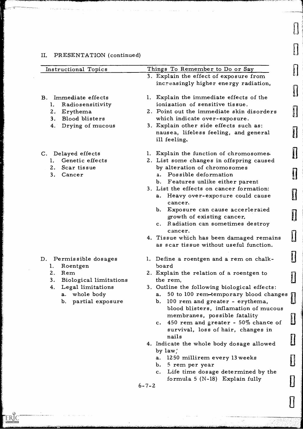
II. PRESENTATION (continued)
Instructional To i c s
B. Immediate effects1. Radiosensitivity2. Erythema3. Blood blisters4. Drying of mucous
C. Delayed effects1. Genetic effects2. Scar tissue3. Cancer
D. Permissible dosages1. Roentgen2. Rem3. Biological limitations4. Legal limitations
a. whole bodyb. partial exposure
las
Thin s To Remember to Do or Say3. Explain the effect of exposure from
increasingly higher energy radiation,
1. Explain the immediate effects of theionization of sensitive tissue.
2. Point out the immediate skin disorderswhich indicate over-exposure.
3. Explain other side effects such as:nausea, lifeless feeling, and generalill feeling,
1. Explain the function of chromosomes.2. List some changes in offspring caused
by alteration of chromosomesa. Possible deformationb. Features unlike either parent
3. List the effects on cancer formation:a. Heavy over-exposure could cause
cancer,b. Exposure can cause accerlerated
growth of existing cancer,c. Radiation can sometimes destroy
cancer.4. Tissue which has been damaged remains
as scar tissue without useful function.
1. Define a roentgen and a rem on chalk-board
2. Explain the relation of a roentgen tothe rem,
3. Outline the following biological effects:a. 50 to 100 remtemporary blood changesb. 100 rem and greater - erythema,
blood blisters, inflamation of mucousmembranes, possible fatality
c. 450 rem and greater - 50% chance ofsurvival, loss of hair, changes innails
4. Indicate the whole body dosage allowedby law:a. 12 50 millirem every 13 weeksb. 5 rem per yearc. Life time dosage determined by the
formula 5 (N-18) Explain fully6-7-2
5. Outline the partial exposure allowed bylaw for persons in restricted areas:a. Hands and forearms, feet and
ankles - 18 3/4 rems every 13weeks
b. Skin of whole body - 1/2 rems in13 weeks
6. Outline the whole body dosage allowedby law for person outside restrictedareas:a. Maximum of 1/2 rem in one yearb. No more than 100 millirem in seven
days
III. APPLICATION (drill, illustrations, analogies, oral questions orassignments)
A. Invite the students to discuss and list the biological effects of exposureto ionizing radiation.
B. Discuss the effects listed.
C. Have members of the class give the legal permissible dosages forwhole body exposure in restricted and unrestricted areas,
D. Ask for exact definitions of a roentgen and a rem.
E. Discuss the limits and effects of massive doses of radiation: -chances of survival and visible effects.
IV. TEST (final check on students comprehension of material presented)NOTE: Written TestA. List the permissible legal dosages for whole body exposure.
B. If a group of adults was exposed to a short term, whole body dose of450 rems of radiation what percentage would probably survive?
C. List five effects of excessive exposure of the human body tonuclear radiation.
D. Why does the higher energy radiation have a greater biologicaleffect?
E. From what dosage level of exposure would the average personcompletely recover from all ill effects?
Check papers and discuss
6- 7- 3
V. SUMMARYA. The total permissible accumulated radiation dove is determined by
a formula: 5 (N-18).
B. The permissible dose varies with individual parts of the body.
C. Detailed, current dose records of personal radiation exposure mustbe kept,
D. Ionizing radiation can destroy cancer cells but can also causegrowth of existing cancer cells.
E. Internal radiation exposure to alpha, beta, or gamma radiationcan be caused by inhalation or ingestion of contaminated air, food,or water.
The Next Lesson is: Methods of Reducing Radiation Dosage
6-7-4
INSTRUCTOR'S LESSON PLANRelated Technical Information
SUBJECT: Methods of Reducing Radiation Dosage
Unit 6
Lesson 8Time 2 hours
AIM (or purpose): To develop a working knowledge of the methods usedto reduce unwanted radiation intensities
TEACHING AIDS: Small source of radioactivitySamples of shielding materialsDosimeters
REFERENCES: Nondestructive Testing Handbook, Volume I, Societyfor Nondestructive Testing, 1963, Evanston, IllinoisInformation Sheet #11
1. PREPARATION (of the learner)A. Review the important points on effects of radiation cnuvered in the
two previous lessons.
B. Introduce the three essential ways of reducing or controllingradiation dosage when working with radioactive materials.
C. Explain why it is essential for a radiographer to understandmethods of reducing radiation dosage.
II. PRESENTATION (of the information)
Instructional TopicsA. Time of exposure
Thing ; to Remember to Do or SaPass out Information Sheet #11
1. Explain the concept of dose rate andtotal dosage.
2. Demonstrate:a. Place two dosimeters at a fixed
distance from a source ofradiation.
b. Remove one dosimeter after ashort period.
6-8-1
B. Distance from Source
C. Shielding of Source
c. Remove the second after twicethe time o'i the first.
d. Have students read and reportthe results of both dosimeters.
e. Discuss the results & why.
1. Review the inverse square law.2. Demonstrate:
a. Place one dosimeter a fixeddistance from the source and asecond at twice the distance.
b. Expose both for the same periodof time.
c. Have students read and report theresults of both dosimeters.
d. Discuss the results & why.
1. Explain absorption and attenuation ofradiation by shielding.
2. Demonstrate:a. Place two dosimeters at a fixed
distance from a source ofradiation.
b. Place shielding material betweensource and one dosimeter.
c. Remove both dosimeters at thesame time.
d. Have students read and report theresults of both dosimeters.
e. Discuss the results & why.f. Explain the "Half-Value and Tenth-
Value Layers"1. Amount of any shielding
materials required to reduceradiation intensity to one-half.
2. Amount required to reduceto one-tenth.
III. APPLICATION (drill, illstrations, analogies, oral questions orassignments)
A. Repeat the three preceding demonstrations.
B. For the "Time of Exposure" demonstration have students estimatethe dosage of the second dosimeter before reading.
6-8-2
C. For the "Distance from Exposure" demonstration have studentscalculate the dosage on the second dosimeter before reading,
D. For the "Shielding of Source" demonstration use several dosimetersand layers of shielding material to obtain data for the plotting ofa curve of dosage vs. thickness.Ask the students to estimate the thickness of the material toreduce the dosage to half of that without shielding.
IV. TEST (final check on students' comprehension of material presented)A. Ask class to write answers to the following questions:
1. Name the three factors in the control of dosage.2. If a radiographer receives a dose of mr/hr from a source by
standing 100 feet away for 5 minutes, how much will he receivein 12 minutes ?
3. If a radiographer receives a dose of 7 mr/hr from a source bystanding 100 feet away for 5 minutes, how much would he receivein 5 minutes at 75 feet away?
4. How thick is a Half-Value Layer? A tenth-value layer?
B. Check and discuss answers given. Make sure all class membersunderstand correct answers.
V. SUMMARYEmphasize the following major points:A. Time, distance and shielding are the three most important radiation
protection factors.
B. Radiation intensity is inversely proportional to the square of thedistance of source of radiation,
C. All materials having density and mass have some radiationshielding value.
D. Time spent in radiation field is proportional to the total exposuredose.
The Next Lesson is: The Calculation of Shielding Thickness
INSTRUCTOR'S LESSON PLANRelated Technical Information
Unit 6
Lesson 9Time 2 hours
SUBJECT: The Calculation of Shielding Thickness
AIM (or purpose): To develop understanding and ability in makingcalculations required for determining the thicknessof radiation shielding
REFERENCES: Radiation Safety in InduastxialRadiography wi.thRadioisotopes, P.M. Frazier, C.R. Buchanan, andG. W. Morgan, 1954, U. S. Dept. of Commerce,Washington, D. C.Information Sheets #8, #9, #12
PREPARATION (of the learnerA. Introduce the topic and briefly review the need for shielding
radioactive sources and radiographers from ionizing radiation.
B. Outline some of the subjects to be studied explaining why it isimportant to know the thickness of a half or tenth value layer,the location of shielding material, its properties and amountsneeded for varying source intensities.
II. PRESENTATION (of the information)
Instructional To ics Thins to Remember to Do or SaA. Absorption of gamma
radiation1. Compton effect2. Photoelectric effect3. Pair production
B. Geometry of Absorption1. Narrow beam2. Broad beam
Refer to information sheet #9and review mechanisms of attenu-ation of a photon beam as it passesthrough a material.
1. Define the two terminoligies andcontrast their meanings:a. Broad beam shielding includes
the effects of scattered radiationresulting from deflection of theprimary radiation as well asabsorption of the primaryradiation.
6- 94
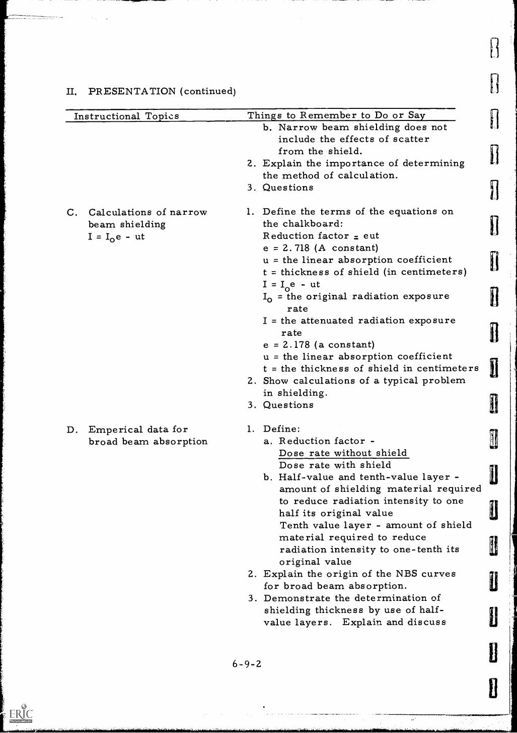
II. PRESENTATION (continued)
Instructional Topics
C. Calculations of narrowbeam shieldingI = Ioe - ut
D. Emperical data forbroad beam absorption
Things to Remember to Do or Sayb. Narrow beam shielding does not
include the effects of scatterfrom the shield.
2. Explain the importance of determiningthe method of calculation.
3. Questions
1. Define the terms of the equations onthe chalkboard:Reduction factor = eute = 2. 718 (A constant)u = the linear absorption coefficientt = thickness of shield (in centimeters)I = oe utIo = the original radiation exposure
rateI = the attenuated radiation exposure
ratee = 2.178 (a constant)u = the linear absorption coefficientt = the thickness of shield in centimeters
2. Show calculations of a typical problemin shielding.
3. Questions
1. Define:a. Reduction factor -
Dose rate without shieldDose rate with shield
b. Half-value and tenth-value layer -amount of shielding material requiredto reduce radiation intensity to onehalf its original valueTenth value layer - amount of shieldmaterial required to reduceradiation intensity to one-tenth itsoriginal value
2. Explain the origin of the NBS curvesfor broad beam absorption.
3. Demonstrate the determination ofshielding thickness by use of half-value layers. Explain and discuss
6-9-2
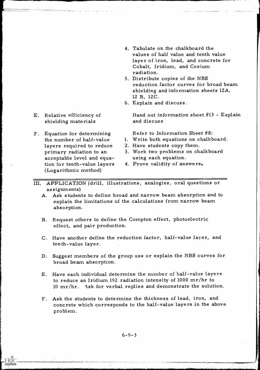
E. Relative efficiency ofshielding materials
F. Equation for determiningthe number of half-valuelayers required to reduceprimary radiation to anacceptable level and equa-tion for tenth-value layers(Logarithmic method)
4. Tabulate on the chalkboard thevalues of half value and tenth valuelayer of iron, lead, and concrete forCobalt, Iridium, and Cesiumradiation.
5. Distribute copies of the NBSreduction factor curves for broad beamshielding and information sheets 12A,12 B, 12C.
6. Explain and discuss.
Hand out information sheet #13 - Explainand discuss
Refer to Information Sheet #8:1. Write both equations on chalkboard.2. Have students copy them.3. Work two problems on chalkboard
using each equation.4. Prove validity of answers
III. APPLICATION (drill, illustrations, analogies, oral questions orassignments)
A. Ask students to define broad and narrow beam absorption and toexplain the limitations of the calculations from narrow beamabsorption.
B. Request others to define the Compton effect, photoelectriceffect, and pair production.
C. Have another define the reduction factor, half-value layer, andtenth-value layer.
D. Suggest members of the group use or explain the NBS curves forbroad beam absorption.
E. Have each individual determine the number of half value layersto reduce an Iridium 192 radiation intensity of 1000 mr/hr to10 mr/hr. es,sk for verbal replies and demonstrate the solution.
F. Ask the students to determine the thickness of lead, iron, andconcrete which corresponds to the half-value layers in the aboveproblem.
6-9-3
G. Invite all class members to work two shielding problems requiringthe use of the logarithmic method for solving the problems asexplained in step II. Discuss answers. Review the equationsif necessary.
IV. TEST (final check on students' comprehension of material. presented)NOTE: Written TestA. Define:
1. Half-value layer2. Tenth-value layer3. Reduction factor
B. How many half-value layers are needed to reduce a radiationintensity of 250 mr/hr to 2 mr/hr?
C. How much lead shielding is required to reduce the level ofCobalt 60 from 250 to 2 mr/hr?
D. What thickness of lead is required if the information is takenfrom the NBS absorption curves?
E. What is the difference between narrow beam and broad beamabsorption?
Check and discuss.
V. SUMMARYA. Shielding can be achieved with any relatively non- porous
material or anything that has mass or weight.
B. The required amount of shielding can be calculated by severalmethods.
C. Shielding from contamination is not as simple as shielding froma point source of radiation.
D. A mixture of several different types of material is sometimesused as shielding; i. e. , concrete, steel, sand, water, wood,etc.
The Next Lesson is: Elements of Electrical Circuits
6-9-4
EJ
ll
INSTRUCTOR'S LESSON PLANRelayed Technical Information
Unit 6Lesson 10Time 1.5 hours
SUBJECT: Elements of Electrical Circuits
AIM or purpose): To outline and acquaint the student with the fundamentalsof electronic circuitry
TEACHING AIDS Film: Elements of Electrical Circuits, 11 mins. , 16 mm,sound, Pennsylvania State University, UniversityPark, Pa.
EQUIPMENT: Film projector and screen
PREPARATION (of the learner)A. Point out that an understanding of the fundamentals of electronic
circuitry is necessary if the student is going to use and maintainx-ray generating, portable power generating, and nuclear radiationdetecting equipment properly and in a non-hazardous manner.
B. Invite special attention to the definitions of the following terms bythe student:1. Conductivity2. The amp3. The volt4. Resistance and the ohm5. Ohm's Law
C. Caution the group that a test will be given at the conclusion of thefilm showing.
II. PRESENTATION (of the information
Instructional To ics Thins to Remembqr to Do or SaElements of ElectricalCircuits4
74" '7XX.
Review film before showing to students.Make notes of key points and informstudents of these key points before showingthem the film.
6-10-1
1. N
II. PRESENTATION (continued)
m...uppriiRrirrnw.1..""Pr^". ,7"777',77,7
Instructional Topics Things to Remember to Do or SayHave film and projector set up beforestudents arrive.
III. APPLICATION (drill, illustrations, analogies, oral questions orassignments)
Discuss the film, emphasizing these points in the discussion;
A. The definition of the terms:1. Conductivity2. Insulators and conductors3. The volt, amp, and ohm
B. Ohm's Law and its application
C. The effects of heat on resistance
D. The effects of size and length of the conductor on resistance
IV. TEST (final check on students' comprehension of material presented)NOTE: Oral QuizA. If a six volt battery was connected across a 3 ohm resistor,
how many amps would flow?
B. Define:1. Resistance2. Amperage3. Voltage
C. What happens to the electrons in a conductor when a voltage isapplied? How is this related to the atomic bonding in metals ?
V. SUMMARYA. In order to understand the behavior of electric power one must
first learn to understand the basic laws pertaining to this subject.
B. The terms used in applying these laws must be interpreted properly.
C. Students must learn to use these circuits in a non-hazardousmanner.
The Next Lesson is: Gamma Ray Apparatus
6 -10 -2
...717110,141.777.7,
INSTRUCTOR'S LESSON PLANRelated Technical Information
Unit 7
Lesson 1
Time 1. 5 hours
SUBJECT: Gamma Ray Apparatus
AIM (or purpose): To provide knowledge and understanding of thecharacteristics of gamma ray exposure apparatus
TEACHING AIDS: Sample radiographsFilm viewer
REFERENCES: Nondestructive Testing Handbook, Volume I, Society forNondestructive Testing, 1963, Evanston, IllinoisRadiography in Modern Industry, Eastman Kodak Company,1958, Rochester, N. Y.
I. PREPARATION (of the learner)A. Introduce subject and explain the usefulness of the information to
be given in this lesson; point out that it will aid the radiographerin obtaining better radiographs making his job easier and safer.
B. Stress the fact that a thorough understanding of the equipment andits capabilities will result in improved techniques and economicadvantages.
II. PRESENTATION (of the information)
Instructional To ics Thin s to Remember to Do or SayList on the chalkboard and explain,A. Penetrating power o
gamma rays1.
the useful range of penetration forCobalt, Iridium, Cesium and Radium.
2. Explain the term KEV and MEV.List the KEV range or MEV range ofthe three synthetic isotopes - cobalt,iridium, and cesium.
4. Explain main energy spectrum ofCO 60, i.e., 1.1 MEV and 1.3 MEV.
7- 1-1
B. Quality of Radiation 1. Define radiation quality.2. Explain:
a. Why the radiation quality ofgamma radiation is fixed
b. The effect of the fixed. radiationquality on the latitude of thickness
c. The difficulties of sensitivitycontrol with isotope radiation
3. Show sample radiographes4. Questions
C. Safety 1. Point out the hazards of thecontinuously active source:a. Cannot be turned off while being
transportedb. During periods of storagec. Between exposuresd. In the event of capsule rupture
2. Explain the problems of shielding:a. Other workersb. Confined areasc. Scaffoldsd. Congested arease. Uncontrolled areas
3. Questions
D. Disadvantages uf gamma Discuss:radiation 1. The cost of source replacement
2. The expense of safety programs3. The limitations for inspection of
thin or light materials4. Questions
E. Advantages peculiar to Explain:gamma radiation 1. Equipment mobility
2. Self containment3. Unrestricted beam geometry4. Questions
III. APPLICATION (drill, illustrations, analogies, oral questions oras signments)
Discuss the following questions:A. What is the useful thickness range (in steel) of radiation from
Iridium 192 ? Cobalt 60 ? Cesium 137 ?
7-1-2
Ll
aj
B. What is the KEV range of Iridium 192 ? Cesium 137?
C. What is the MEV of the two Cobalt 60 gammas ?
D. What is the duty cycle of isotope radiation?
E. What is the greatest operational disadvantage of isotope radiation?
F. Why are the shielding requirements greater for Cobalt than Cesium?
G. Why is gamma radiation ineffective for inspection of light materialssuch as aluminum and magnesium?
IV. TEST (final check on students' comprehension of material presented)NOTE: Written TestA. Define KEV and MEV,
B. List the useful range of thickness for radiography with:1. Cobalt 602. Iridium 1923. Cesium 137
C. What effect on contrast would result from changing theradiographic technique of a 1/4" steel plate from the use ofIridium to Cobalt?
D. What is the greatest advantage of gamma radiation for radiographicuse?
Check and discuss
V. SUMMARYA. Gamma rays have relatively more penetrating power than portable
x-ray generators.
B. Gamma radiation cannot be shut off.
C. Gamma ray uses are more flexible than those of x-ray generators.
D. Gamma rays are unsuitable for radiographing thin, light metals andplastics.
E. Gamma ray intensity decays with time.
The Next Lesson is: X-ray Apparatus
7-1-3
INSTRUCTOR'S LESSON PLANRelated Technical Information
UnitLesson 2Time 1.5 hours
SUBJECT: X-ray Appartus
AIM (or purpose): To familiarize the student with the characteristicsof x-ray generators and x-ray apparatus
TEACHING AIDS: Sample radiographsFilm viewerX-ray generator and apparatus
REFERENCES: Nondestructive Testin Handbook, Volume I, Societyfor Nondestructive Testing, 1963, Evanston, IllinoisRadiography in Modern Industr Eastman Kodak Co. ,
1958, Rochester, N. Y.information Sheet #14
I. PREPARATION (of the learner)A. Arrange the class in good viewing position around the x-ray
apparatus and point out the essential parts and characteristicsof the equipment.
B. Give a brief review of the capabilities and uses of x-ray withspecial emphasis on industrial application.
C. Point out that each student will be given individual instruct4on onhow to use x-ray apparatus.
II. PRESENTATION (of the information)
Instructional To icsA. Penetrating power o
x-ray apparatus
Thins to Remember to Do or Say1. List on the chalkboard the range
of penetrating power for portablegenerators, fixed generators,and accelerations .Portable x-raygenerators range: about 1/8" to1 1/2" steel equivalent. Fixed type:
7-24
B. Quality of radiation
C. Safety
D. Disadvantages of x-rayapparatus
1/4" to 2 1/2"; accellerators up to12" or more.
2. Explain how penetration power canbe varied by changing kilovoltage.
3. Point out that as x- ray wave lengthdecreases, the penetrating powerincreases.
1. Define radiation quality. X-rayquality can be compared to the KVor wave length of the x-rays beinggene rated.
2. Explain:a. How radiation quality can be
varied on an x-ray generator bychanging KV setting
b. The effect of radiation qualityon thickness latitude
c. The ability to adjust sensitivityby changing the radiation quality
3. Show sample radiographs of the above.4. Hand out Information Sheet No. 14.
1. Point out the advantages of electricallygenerated radiation from 6.% safetystandpoint. Radiation can be turnedoff when not in use.
2. Explain why x-rays are easier toshield than higher energy gammaradiation. The higher the energythe more shielding necessary.
1. Define duty cycle and constantpotential. Explain the length oftime than an x-ray generator can beoperated without overheating tube iscalled duty cycle.
2. Explain why cooling is required in theoperation of x-ray generators. Coolingrequired to protect target and tube.
3. Point out the disadvantages of:a. Large size of x-ray tube headsb. Electrical power requirementsc. Restricted beam geometry of tank
unitsd. Restir duty cycle because of
7-2-2
excessive heat generated byelectrons striking target in x-raytube.
III. APPLICATION (drill, illustrations, analogies, oral questions oras signments)
Ask the class to assist in answering the following questions:A. What is the thickness range in steel of x-rays from a 200 KVP
x-ray generator?
B. How can penetrating power be adjusted on x-ray generators ?
C. What effect does radiation quality have on the latitude of thicknesswhich can be covered by a single exposure?
D. How does radiation quality effect sensitivity?
E. Why are x-rays from portable generators easier to shield thangamma rays ?
F. What is meant by an x-ray generators duty cycle?
G. How can the duty cycle be increased?
H. List four disadvantages of x-ray generators ?
IV. TEST (final check on students' comprehension of material presented)A. Suggested questions for oral or written test:
1. Define radiation quality.2. What happens to the wave length of the radiation when the KV
is increased?3. Define thickness latitude capability.4. List three safety features of x-ray generators.5. What is ;meant by a constant potential x-ray generator ?
B. Discuss correct answer for each question included in the testand clarify any additional questions class members may haveabout x-ray apparatus.
The Next Lesson is: Decay of Radioactive Materials
7-2-3
INSTRUCTOR'S LESSON PLANRelated Technical Information
SUBJECT: Decay of Radioactive Materials
(
UnitLesson 3
Time 1.5 hours
AIM (or purpose): To develop an understanding of radioactive decaymechanisms
REFERENCES: Nondestructive Testin- Handbook, Volume I, Societyfor Nondestructive Testing, 1963, Evanston, IllinoisInformation Sheets #15 and #16
PREPARATION (of the learner)A. Write aim of lesson on chalkboard explaining that the lesson is
calculated to help the radiographer in selecting the proper sourceof radiation for a particular assignment and should help himunderstand the safety requirements for each type of source.
B. Briefly review previously discussed material by holding a shortdiscussion, on alpha and beta particles, gamma photons and wherethese energy fcrms originate.
II. PRESENTATION (of the information
Instructional To icsA. Disintegration
mechanisms
Thin1.
s to Remember to Do o r SayList the four modes of disintegrationalpha particle emission, beta andpositron particle emission and "K"capture.
2. Define electron or "K" capture, i. e.electron capture from the "K"shell by the nucleus of the atom.
3. Define:a. Alpha particle - stream of fast
moving helium nuclei, highlyionizing, weakly penetrating
7-34
B. Disentegration scheme
b. Beta particle - negatively chargedparticle emitted from nucleus
c. Gamma photon - short wavelength, electromagnetic radiationof nuclear origin.
4. Questions
1. Draw chalkboard sketch of Cobalt 60decay scheme explaining:a. The intermediate gamma emissionb. The two beta disintegrationsc. The final two gamma emissionsd. The formation of stable Nickel
602. Questions
C. Decay half- life Refer to information sheets #15 and 161. Define half-life and decay rates on
chalkboard.2. List the half-life values for:
a. Cobalt 60 = 5.3 yearsb. Iridium 192 = 75 daysc. Cesium 137 = 27 years
3. Sketch a half-life decay curve on thechalkboard, explaining its use.
4. Questions
D. Decay tables 1. Explain the advantages of decay tables:a. Helps in figuring exposure time
accurately and quicklyb. Reduces calculation errorsc. Helps to project future needs of
replacement source capsules2. Work sample problems using decay
tables.
III. APPLICATION (drill, illustrations, analogies, oral questions oras signments)
A. Have the group list the four modes of disintegration.
B. Ask students to define each mode and discuss.
C. Request students draw the Cobalt 60 decay scheme and explain.
7-3-2
D. Ask the following questions and discuss each:1. What is meant by half-life?2. What is the half-life of Iridium 192 ? Cobalt 60?3. What is the value of the decay chart?
E. Have students work the following problem using a Cesium decaychart:1. 5 Curie Cesium 137 source was purchased in 1959. When will
its remaining activity be 30% of its original activity? What isits activity now ?
2. Using Cobalt tables (Information Sheet #15) what is the remainingactivity of a 2 curie Cobalt 60 source that was encapsulated inSeptember 1960?
IV. TEST (final check on students' comprehension of material presented)NOTE: Written TestA, Why are the two beta disintegrations of Cobalt 60 not used in
industrial radiography?
B. Does nuclear disintegration always produce a stable element:--Explain.
C. How long is a half-life?
D. What is the half-life of Cobalt 60? Iridium 192?
E. Define K capture?
F. What is the result of K capture?
G. How many half-lives has a cobalt 60 source had if it is 21.2 yearsold?
H. What percentage of its original activity does it still retain?
Check and discuss.
V. SUMMARYA. Time required for a radioactive isotope of an element to lose one-
half of its original energy or intensity is called half-life.
B. Long half-life is desirable in selecting a radioactive isotope foruse in radiography.
C. Only a. few radioisotopes are economically useful in industrialradiography.
7-3-3
D. Most radioactive isotopes are either too weak having a long wavelength or have an undesirable half-life, or a. combination ofboth.
The Next Lesson is: Construct an Isotope Decay Chart
7-3-4
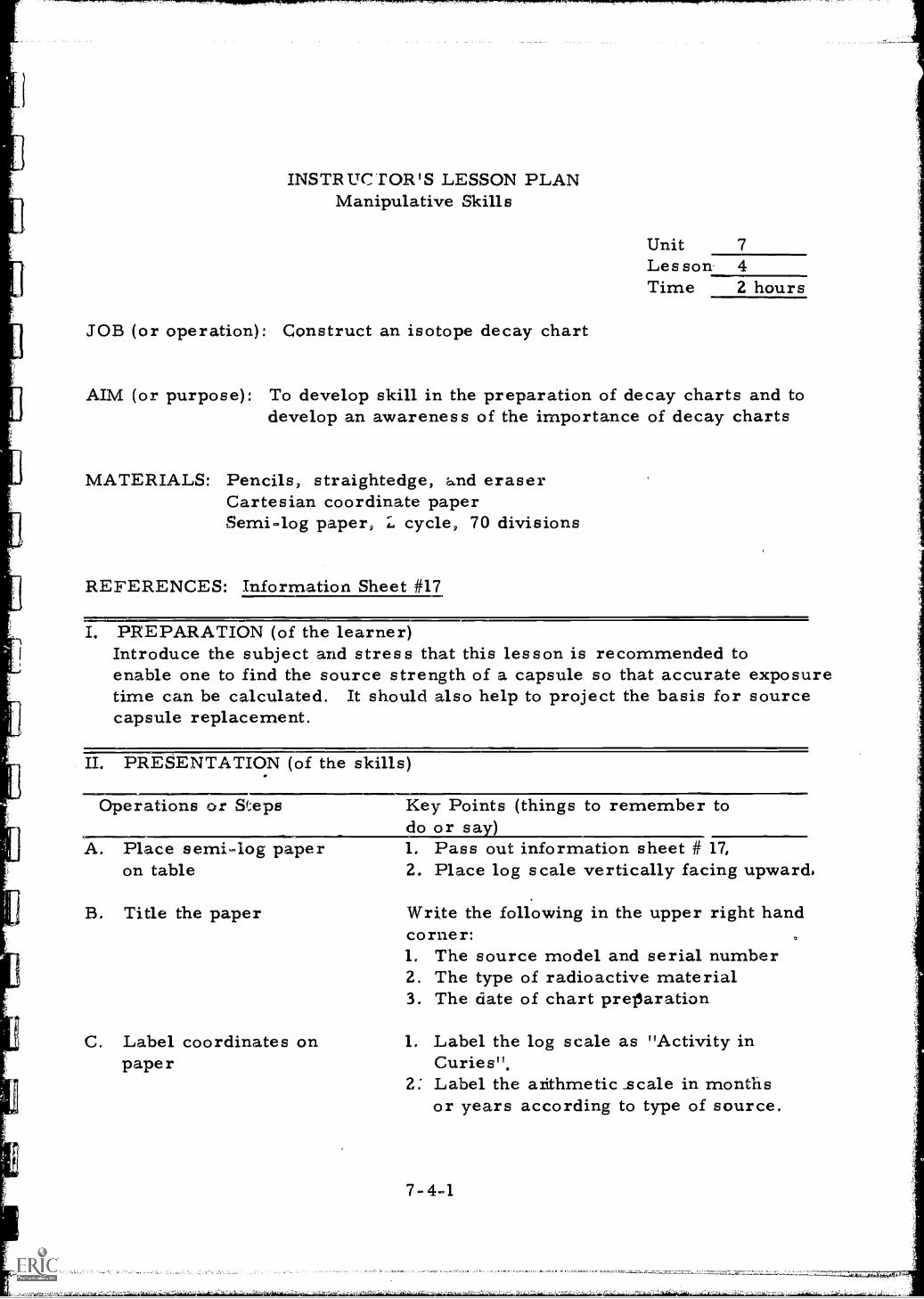
INSTRUC TOR'S LESSON PLANManipulative Skills
Unit 7Les son- 4Time 2 hours
JOB (or operation): Construct an isotope decay chart
AIM (or purpose): To develop skill in the preparation of decay charts and todevelop an awareness of the importance of decay charts
MATERIALS: Pencils, straightedge, and eraserCartesian coordinate paperSemi-log paper, 2, cycle, 70 divisions
REFERENCES: Information Sheet #17
PREPARATION (of the learner)Introduce the subject and stress that this lesson is recommended toenable one to find the source strength of a capsule so that accurate exposuretime can be calculated. It should also help to project the basis for sourcecapsule replacement.
II. PRESENTATION (of the skills)
Operations or Steps
A. Place semi-log paperon table
B. Title the paper
C. Label coordinates onpaper
Key Points (things to remember todo or sa )1, Pass out information sheet # 17,2. Place log scale vertically facing upward,
Write the following in the upper right handcorner:1. The source model and serial number2. The type of radioactive material3. The date of chart preparation
1. Label the log scale as "Activity inCuries".
2. Label the arithmetic _scale in monthsor years according to type of source.
7 -4 -1
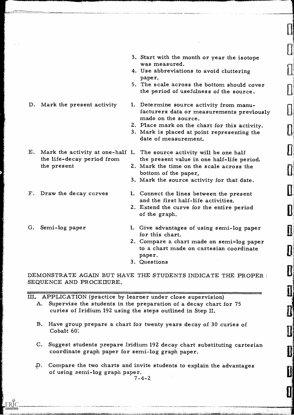
D. Mark the present activity
3. Start with the month or year the isotopewas measured.
4. Use abbreviations to avoid clutteringpaper,
5. The scale across the bottom should coverthe period of usefulness of the source.
1. Determine source activity from manu-facturers data or measurements previouslymade on the source.
2. Place mark on the chart for this activity.3. Mark is placed at point representing the
date of measurement.
E. Mark the activity at one-half 1. The source activity will be one halfthe life-decay period from the present value in one half-life period.the present 2. Mark the time on the scale across the
bottom of the paper,3. Mark the source activity for that date.
F. Draw the decay curves
G. Semi-log paper
1. Connect the lines between the presentand the first half-life activities.
2. Extend the curve for the entire periodof the graph.
1. Give advantages of using semi-log paperfor this chart.
2. Compare a chart made on semi,,log paperto a chart made on cartesian coordinatepaper.
3. Questions
DEMONSTRATE AGAIN BUT HAVE THE STUDENTS INDICATE THE PROPERSEQUENCE AND PROCEEEURE.
III. APPLICATION (practice by learner under close supervision)A. Supervise the students in the preparation of a decay chart for 75
curies of Iridium 192 using the steps outlined in Step II.
B. Have group prepare a chart for twenty years decay of 30 curies ofCobalt 601
C. Suggest students prepare Iridium 192 decay chart substituting cartesiancoordinate graph paper for semi-log graph paper.
D. Compare the two charts and invite students to explain the advantagesof using semi-log graph paper.
7-4-2
.-,,,n7r-ArrnarrrTIIR7PF7NITIMPIMPWr.
IV. TEST (performance of skill to acceptable standards)NOTE: Written TestA. Prepare a decay chart on 50 curies of Iridium 192.
B. Develop a decay chart on 20 curies of Cobalt 60.
C. Determine the strength of the Iridium source 60 days from now.6 months later.
D. Show the Cobalt source will have one-fourth the activity of the presenttime.
E. What is meant by a half-life of decay?Check and discuss.
V. SUMMARYA. Decay charts save time when making calculations for radiographic
exposures.
B. Semi-log paper condenses the size of charts necessary to plotdecay and straighten the curve.
C. Separate decay charts are necessary for each type of radioisotopebecause of differences in decay rates.
D. Decay charts are not used in x-ray exposure calculations.
The Next Lesson is: Chemistry of Iron and Steel
7-4-3
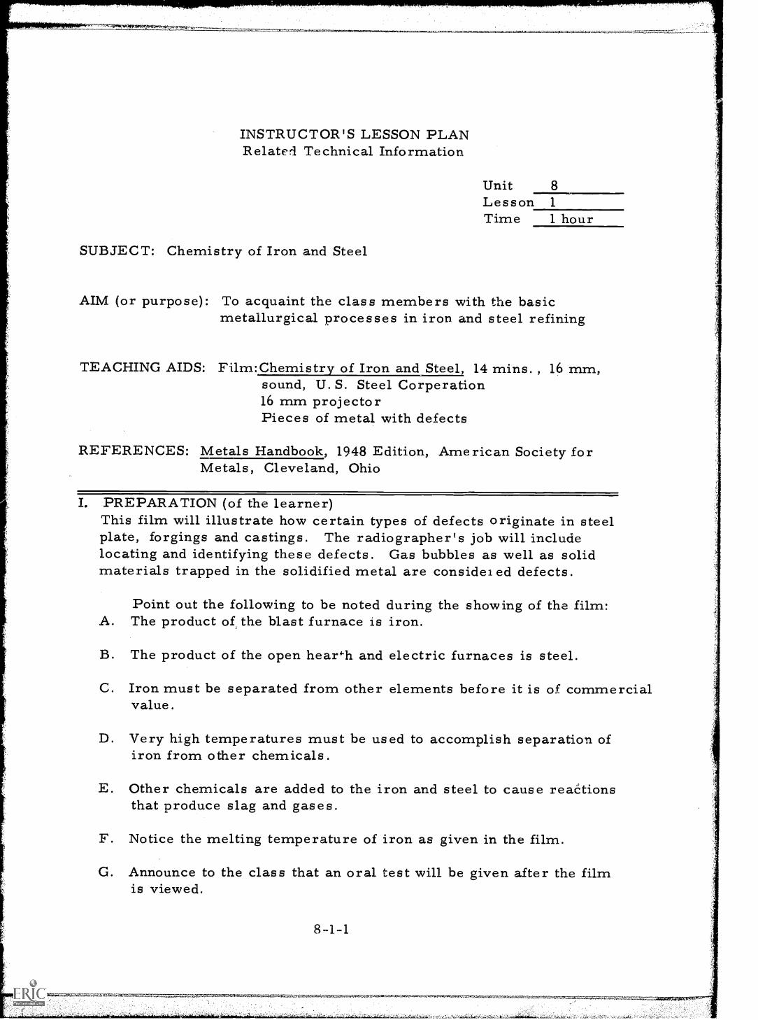
INSTRUCTOR'S LESSON PLANRelated Technical Information
SUBJECT: Chemistry of Iron and Steel
Unit 8Lesson 1
Time 1 hour
AIM (or purpose): To acquaint the class members with the basicmetallurgical processes in iron and steel refining
TEACHING AIDS: Film:Chemistry of Iron and Steel, 14 mins. , 16 mm,sound, U. S. Steel Corperation16 mm projectorPieces of metal with defects
REFERENCES: Metals Handbook, 1948 Edition, American Society forMetals, Cleveland, Ohio
I. PREPARATION (of the learner)This film will illustrate how certain types of defects originate in steelplate, forgings and castings. The radiographer's job will includelocating and identifying these defects. Gas bubbles as well as solidmaterials trapped in the solidified metal are consideied defects.
Point out the following to be noted during the showing of the film:A. The product of the blast furnace is iron.
B. The product of the open hear'-11 and electric furnaces is steel.
C. Iron must be separated from other elements before it is of commercialvalue.
D. Very high temperatures must be used to accomplish separation ofiron from other chemicals.
E. Other chemicals are added to the iron and steel to cause reactionsthat produce slag and gases.
F. Notice the melting temperature of iron as given in the film.
G. Announce to the class that an oral test will be given after the filmis viewed.
84-1
Vt=0,51. ATX.
II. PRESENTATION (of the information)
Instructional TopicsA. "The Chemistry of Iron
and Steel"
B. Causes of defects inmetals
Things to Remember to Do or SayShow the filmNOTE: The film should be viewed bythe instructor in advance to showing itto the class. Detailed notes should bemade by the instructor on importantinformation presented by the film foruse in class discussion after the filmshowing.
Review the basic causes of defects inmetals and relate to the informationpresented in the film. Explain howthese defects makes radiographynecessary.
III. APPLICATION (drill, illustrations, analogies, oral questions oras signrnents)
A. Discuss the film. Note the following points and invite comments fromthe students:1. The purpose of the blast furnace2. The purpose of the open hearth and electric furnaces.3. The materials which-are charged to each type furnace.4. The temperatures required for the making of iron and steel.
B. Show class examples of metal with defects and discuss what causedth' defects.
IV. TEST (final check on students' comprehension of material presented)Give verbal quiz. The following questions arc_ suggested:
A. What is the product of the blast furnace?
B. What is the product of the open hearth furnace?
C. What is the material charged to the blast furnace?
D. What is the temperature of the iron in the bottom of the blast furnace?
E. What are the bubbles that rise to the top of the metal in the openhearth furnace?
F. What are some typical defects in metal and what are their causes?
The Next Lesson is: Semi-finished Steel
8-1-2
INSTRUCTOR'S LESSON PLANRelated Technical Information
Unit 8Lesson 2Time 1 hour
SUBJECT: Semi-finished Steel
AIM (or purpose): To teach the basic metallurgical practices employedin steel making
TEACHING AIDS: Film: Semi-Finished Steel, 8 mins. , 16 mm, sound,United States Steel Corporation
EQUIPMENT: Film projector and screen
REFERENCES: Metals Handbook, 1948 Edition, American Society forMetals, Cleveland, OhioNondestructive Testin -Introduction PI-4-1, 1964,General Dynamics-Convair, San Diego, California
I. PREPARATION (of the learner)A. Introduce the film, pointing out some of the features to watch for:
1. The castings of the ingot2. Various types of ingot molds3. Addition of aluminum during pouring4. The squeezing of the metal as it passes through the rolling
mill
B. Stress that this information will help the radiographer to betterunderstand how some defects are removed while some remain inthe ingots.
II. PRESENTATION (of the information)
Instructional Topics Things to Remember to Do or Say'Semi- finished Steel/ Show the Film
8-2-1
III. APPLICATION (drill, illustrations, analogies, oral questions orassignments)
A. Have students discuss the practice of pouring the ingot:1. The use of the various types of ingot molds2., Hot topping molds3. Cropping of molds after solidification4. The source of future defects from improper cropping
B. Discuss the practice of deoxidation in the mold:1. The addition of aluminum and/or silicon to control gases in the
steel2. The source of future defects from improper deoxidation
C. Discuss the reason for reducing the steel in several passes insteadof one and the problem of internal rupture from excessive singlepass reduction.
D. Discuss the problem of laminations and the effect of gas bubbles whichdo not weld during rolling.
E. Invite questions from students for further discussion.
F. Re show film if all points or questions have not been cleared up.
IV. TEST (final check on students' comprehension of material presented)NOTE: Written TestA. What is the purpose of the hot top on an ingot mold?
B. Give reasons for the addition of aluminum during pouring.
C. What happens to the gas bubbles in the irgot when it passes throughthe rolling mill?
D. Why is the top of an ingot mold cut off and discarded?
E. What type of defect can be caused by poor stirring of the materialsadded for deoxidation, 1. e. , aluminum and silicon?
Discuss test results - give help where needed
8 -2-2
11
sl
V,. SUMMARYA. Casting of semi-finished steel requires many methods of removing
undesirable components and discontinuities from the ingot.
B. It is important that the correct amounts of each material be added tothe steel before the ingot is poured so that the ingot will meetrequired specifications.
The Next Lesson is: Rolling of Sheet and Piate Steel
8-2-3
S2,71,4,.....7
INSTRUCTOR'S LESSON PLANRelated Technical Information
Unit 8Lesson 3Time 1 hour
SUBJECT: Rolling of Sheet and Plate Steel
AIM (or purpose): To develop an understanding of the basic metallurgicalpractices in the making and finishing of steel
TEACHING AIDS: Film: Hot Rolling Steel Sheets, 8 mins. , 16 mm,sound, U. S. Steel Corporation
EQUIPMENT: Film projector and screen
REFERENCE-S-: Metals Handbook, 1948 Edition, American Society forMetals, Cleveland, OhioNondestructive Tes tin -Introduction - PI-4-1,- 1964,General Dynamics-Convair, San Diego, CaliforniaInformation Sheet #18
I. PREPARATION (of the learner)A. Introduce film and point out the following highlights to be noted
during the viewing of the film:1. The ragged ends of the plates and sheets as they are being rolled2. The removal of defects in the slab before final rolling3. The use of x-ray radiation to control the thickness of the sheet4. The control of the final temperature at the end of the rolling5. How some defects are removed at the mill and how some cannot
be removed because their presence and location is not known.6. The importance of temperature control if proper strength,
welding and impact properties are to be obt ained from thefinished product
B. Stress the importance of acquiring this related information andhow it will benefit the student in the pursuit of knowledge in thefield of radiography.
II. PRESENTATION (of the information)
Instructional Topics Things to Remember to Do or Say`Hot rolling steel sheets" Show the Film
III. APPLICATION (drill, illustrations, analogies, oral questions oras signments)
A. Have students discuss the control of end and edge defects;1. The cropping of the skelp to eliminate edge laminations2. The shearing of sheet strip before coiling
B. Discuss the removal of defects before final rolling.1. Defects may not be removed on thicker materials2. Areas of removal are leveled by subsequent rolling in thin sheet3. All defects may not be detected by the mill
C. Discuss the techniques of gauging thickness by radiation
D. Discuss the effect of poor finishing temperature on the steer.1. Wrong strength properties2. Poor welding properties3. Poor impact properties
E. Invite questions throughout discussion and resho.4 all or parts offilm if necessary.
F. Pass out information sheet # 18 and discuss,
IV. TEST (final check on students' comprehension of material presented)NOTE: Oral QuizA. Why is it necessary to crop the edges and ends of :rolled sheet and plate?
B. What is the result of improper control of the final rolling temperature?
C. Are all plates and sheets rolled from materials from which the defectshave been removed?
D. Can improper final rolling temperature cause defects to occur inlater fabrication?
Upon completion of test, discuss answers given, give help whereneeded
8-3-2
V:. SUMMARYA. Sheet and plate steel ends are cropped to remove laminations,
B. Grinders remove surface defects before final rolling,
C. Radiation emitting gauges are used to control the desired plate thicknessas plate is being rolled,
D. Steel must be soaked before rolling to insure uniform temperaturethroughout the plate before rolling,
E. Temperature control during rolling insures proper strength,and impact properties
The Next Lesson is: The Structure of Metals
8-3-3
INSTRUCTOR'S LESSON PLANRelated Technical Information
Unit 8Lesson 4Time 1. 5 hours
SUBJECT: The Structure of Metals
AIM (or purpose): To outline the basic structure of metals and developa thorough understanding of the subject
TEACHING AIDS: Prepared sketches on passout sheets showing thethree basic metallic structures
REFERENCES: Elements of Material Science, L. H. Van Vlack, 1961,Addison-Wesley Publishing Company, Reading, Mass.Physical Metallurgy for Engineers, D. S. Clark, andW.R. Varney, 1962, D. Van Nostrand Company, Princeton,N. J.
I. PREPARATION (of the learner)Explain why the knowledge of basic structure of metals is necessaryinformation for the radiographer.Point out that this information will be most helpful in interpretingx-ray films and in giving explanation of defects shown in the film.Review again some of the defects of metals that are evidenced byx-ray film.
II. PRESENT ATION (of the information)
Instructional To icsA. The metallic bond
Thin1.
s to Remember to Do or SaySketch a single plane view of ametallic structure.
2. Explain:a. The loosely held orbital electronsb. The electron cloudc. The forces holding the structure
together3. Relate the loosely held electron
forces to the high electrical andthermal conductivity of metals.
8-4-1
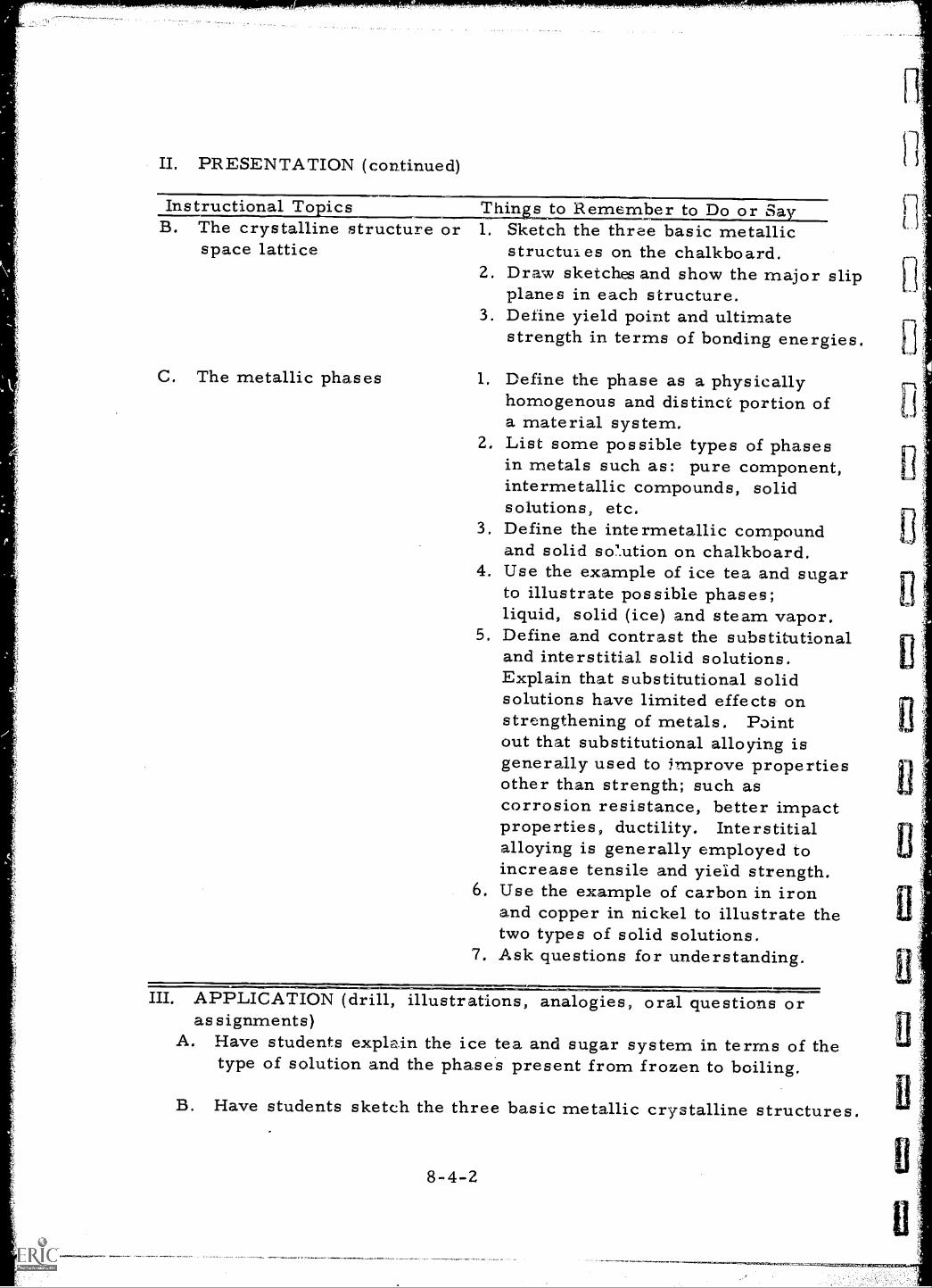
II. PRESENTATION (continued)
Instructional To ics Thin to Remember to Do or Sa rB. The crystalline structure or 1. Sketch the three basic metallic
space lattice structui es on the chalkboard.2. Draw sketches and show the major slip
planes in each structure.3. Define yield point and ultimate
strength in terms of bonding energies.
C. The metallic phases 1. Define the phase as a physicallyhomogenous and distinct portion ofa material system.
2. List some possible types of phasesin metals such as: pure component,intermetallic compounds, solidsolutions, etc.
3. Define the intermetallic compoundand solid so7.ution on chalkboard.
4. Use the example of ice tea and sugarto illustrate possible phases;liquid, solid (ice) and steam vapor.
5. Define and contrast the substitutionaland interstitial solid solutions.Explain that substitutional solidsolutions have limited effects onstrengthening of metals. Pointout that substitutional alloying isgenerally used to improve propertiesother than strength; such ascorrosion resistance, better impactproperties, ductility. Interstitialalloying is generally employed toincrease tensile and yield strength.
6. Use the example of carbon in ironand copper in nickel to illustrate thetwo types of solid solutions.
7. Ask questions for understanding.
III. APPLICATION (drill, illustrations, analogies, oral questions oras signments)
A. Have students explain the ice tea and sugar system in terms of thetype of solution and the phases present from frozen to boiling.
B. Have students sketch the three basic metallic crystalline structures.
8-4-2
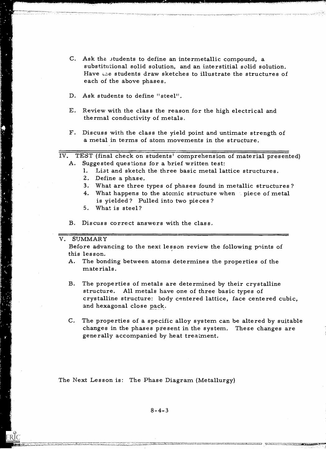
C. Ask the students to define an intermetallic compound, asubstitutional solid solution, and an interstitial solid solution.Have k,Lle students draw sketches to illustrate the structures ofeach of the above phases.
D. Ask students to define "steel".
E. Review with the class the reason for the high electrical andthermal conductivity of metals.
F. Discuss with the class the yield point and untimate strength ofa metal in terms of atom movements in the structure. 1
IV. TEST (final check on students' comprehension of material presented)A. Suggested questions for a brief written test:
1. List and sketch the three basic metal lattice structures.2. Define a phase.3. What are three types of phases found in metallic structures?4. What happens to the atomic structure when piece of metal
is yielded? Pulled into two pieces?5. What is steel?
B. Discuss correct answers with the class,.
V. SUMMARYBefore advancing to the next lesson review the following points ofthis lesson.A. The bonding between atoms determines the properties of the
materials.
B. The properties of metals are determined by their crystallinestructure. All metals have one of three basic types ofcrystalline structure: body centered lattice, face centered cubic,and hexagonal close pack,
The properties of a specific alloy system can be altered by suitablechanges in the phases present in the system. These changes aregenerally accompanied by heat treatment.
The Next Lesson is: The Phase Diagram (Metallurgy)
8-4-3
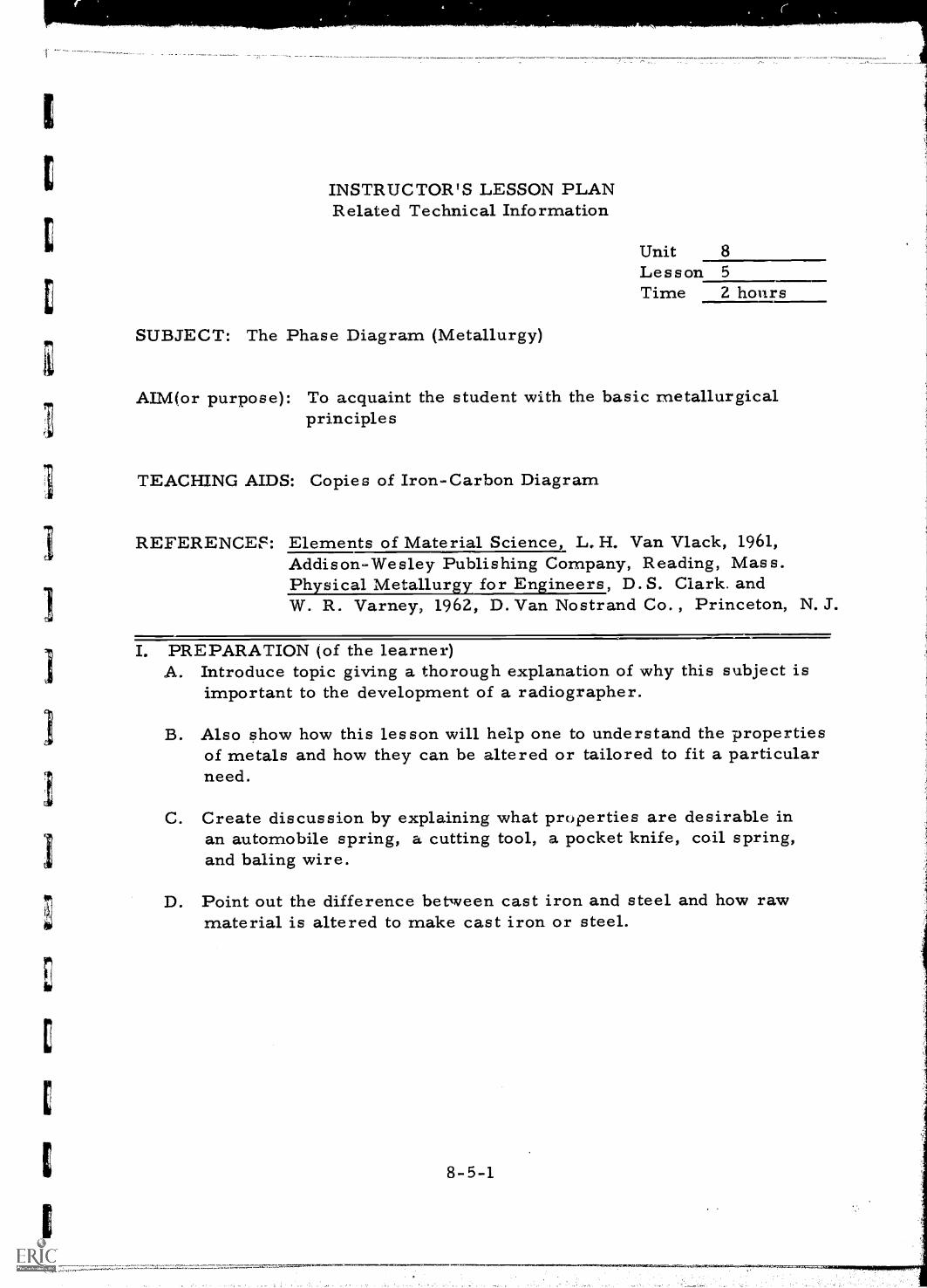
E
C
INSTRUCTOR'S LESSON PLANRelated Technical Information
Unit 8Lesson 5Time 2 hours
SUBJECT: The Phase Diagram (Metallurgy)
AIM(or purpose): To acquaint the student with the basic metallurgicalprinciples
TEACHING AIDS: Copies of Iron-Carbon Diagram
REFERENCEF: Elements of Material Science, L. H. Van Vlack, 1961,Addison-Wesley Publishing Company, Reading, Mass.Physical Metallurgy for Engineers, D. S. Clark. andW. R. Varney, 1962, D. Van Nostrand Co. , Princeton, N. J.
I. PREPARATION (of the learner)A. Introduce topic giving a thorough explanation of why this subject is
important to the development of a radiographer.
B. Also show how this lesson will help one to understand the propertiesof metals and how they can be altered or tailored to fit a particularneed.
C. Create discussion by explaining what properties are desirable inan automobile spring, a cutting tool, a pocket knife, coil spring,and baling wire.
D. Point out the difference between cast iron and steel and how rawmaterial is altered to make cast iron or steel.
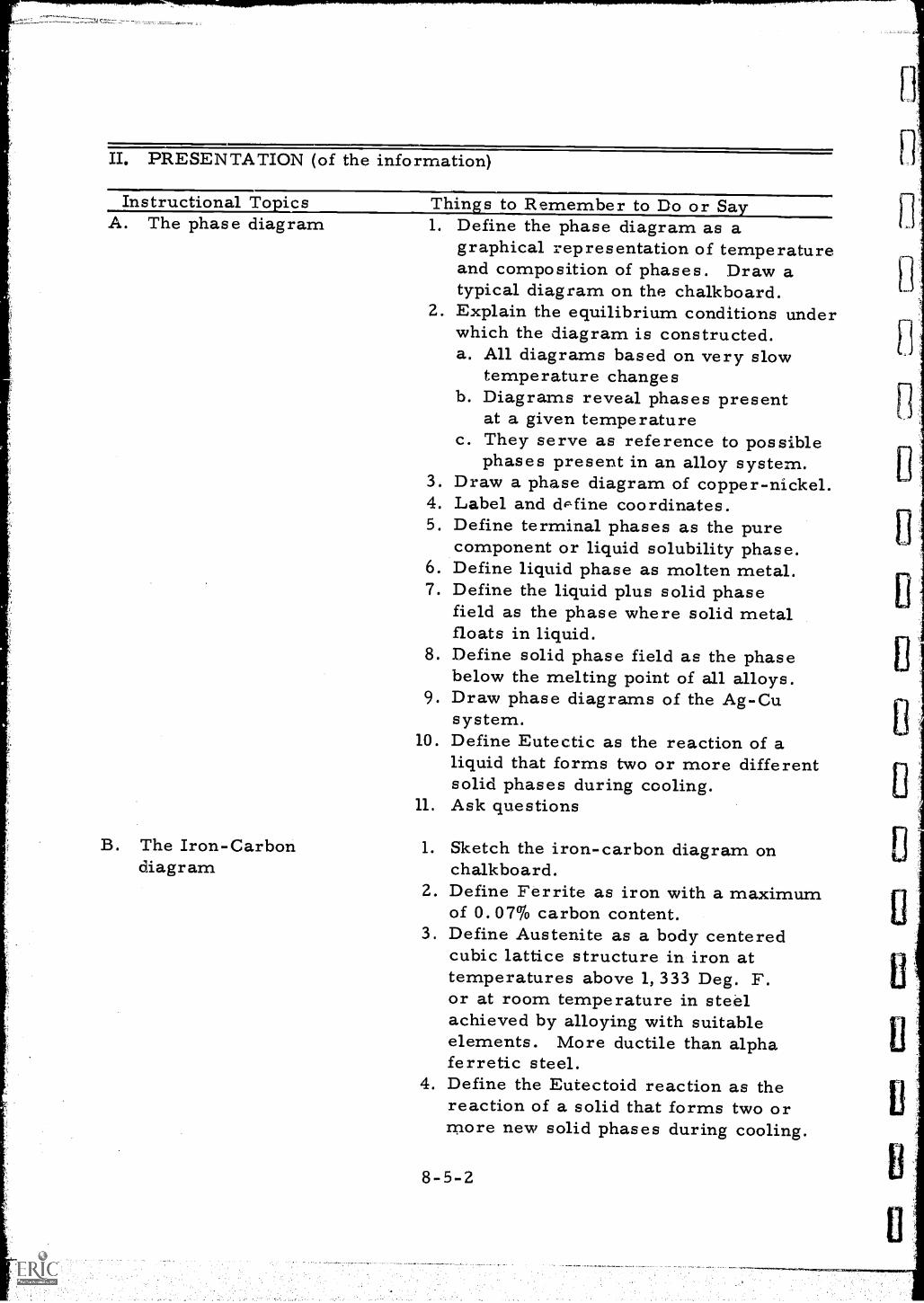
111111111111PIRIMPIP11.1111.1111111111.10*-
II. PRESENTATION (of the information)
Instructional To icsA. The phase diagram
Thins to Remember to Do or Sa
B. The Iron-Carbondiagram
1. Define the phase diagram as agraphical representation of temperatureand composition of phases. Draw atypical diagram on the chalkboard.
2. Explain the equilibrium conditions underwhich the diagram is constructed.a. All diagrams based on very slow
temperature changesb. Diagrams reveal phases present
at a given temperaturec. They serve as reference to possible
phases present in an alloy system.3. Draw a phase diagram of copper-nickel.4. Label and d'fine coordinates.5. Define terminal phases as the pure
component or liquid solubility phase.6. Define liquid phase as molten metal.7. Define the liquid plus solid phase
field as the phase where solid metalfloats in liquid.
8. Define solid phase field as the phasebelow the melting point of all alloys.
9. Draw phase diagrams of the Ag-Cusystem.
10. Define Eutectic as the reaction of aliquid that forms two or more differentsolid phases during cooling.
11. Ask questions
1. Sketch the iron-carbon diagram onchalkboard.
2. Define Ferrite as iron with a maximumof 0.07% carbon content.
3. Define Austenite as a body centeredcubic lattice structure in iron attemperatures above 1, 333 Deg. F.or at room temperature in steelachieved by alloying with suitableelements. More ductile than alphaferretic steel.
4. Define the Eutectoid reaction as thereaction of a solid that forms two ormore new solid phases during cooling.
8-5-2
1,
Il
As with Eutectic, the word Eutectoidcan also refer to an alloy compositionor structure associated with the reaction.
5. Carbide or Cementite is also callediron carbide; a normal constituent ofannealed steels and cast iron. Strengthenssteel but decreases ductility.
6. Explain the upper and lower criticaltemperatures between ferrite andaustenite fields.
7. Define limits of steel as between 0.07%and 1. 7% carbon content.
8. Define limits of cast iron as between1. 7% and 6. 6% carbon content.
9. Explain the lower melting point of theEutectic composition and explain itsimportance in casting practice. Theeutectic temperature can be achievedwith less expensive equipment becauseof the lower temperatures required.Eutectic composition contains 4. 3%carbon.
10. Indicate the temperature ranges ofmelting for cast steel. (about 2,800Degrees F.)
11. Ask questions
C. The phase transformation 1. Explain the transformation from onephase to another on heating or coolingthrough the transformation temperature:a. As temperature changes metal may
go through a change because thestructure at that temperature may be
ii
unstable.b. This phenomenon used to advantage
to change properties of an alloysystem.
c. Example: Steel heated to transformstructure to austenite; if quenchedin oil the phase produced results inmuch higher strength.
d. Alpha iron: The form of iron thatis stable below 1, 670 Deg. F., thetemperature at which a change inphase occurs.
8-5-3
e. Gamma iron: The form of ironthat is stable between 1, 670 Deg.F. and 2, 550 Deg. F.
2. Indicate the crystalline structure changein the transformation of austenite toferrite by explaining that austenite isthe high temperature body cubiccentered structure (sketch) and ferriteis the FCC structure (draw sketch).
3. Elaborate on the temperature rangeof transformation of steel compositionsabove and below as well as the eutectoidcomposition.a, Full transformation to austenite
below eutectoid compositionaccomplished at 1,650 Deg. F.
b. Above the eutectoid temperaturethe maximum required is 2, 065Deg. F. at a carbon content of 1. 7 %.
c. To achieve full hardness from heattreatment the temperature mustproduce a full austenitic structure.
4. Explain the martensite reaction on thechalkboard as the change from theaustenitic structure (face centeredcubic) at elevated temperature to theferrite structure (body centered cub.,r)at low temperatures.
5. Define the properties of martensite:a. strongb. hardc. toughAsk and invite questions
III. APPLICATION (drill, illustrations, analogies, oral questions orassignments)
A. Have a student sketch a simple phase diagram of a system ofcomponents which are completely soluble in one another.
B. Ask group to explain various parts of the diagram.
C. Have another student sketch the iron-carbon diagram.
D. Request group members to label each phase field by its metallurgicalname.
8-5-4
E . Have a discussion on the limits of the steel and iron ranges ofcomposition.
F. Ask for comments on the difference in melting points of steel andcast iron.
C.x. Have each member explain the advantages and methods of usingthe diagram.
H. Ask and invite questions throughout the drill.
IV. TEST (final check on students' comprehension of material presented)NOTE: Written TestA. Describe the composition of the following:
1. Ferrite or alpha iron2. Austenite or gamma iron3. Cementite or carbide
B. Outline the composition limits of irons arid steel.
C. Define a terminal phase.
D. What does the upper and lower critical temperature represent onthe phase diagram?
E . What is a eutectic composition?
F. Sketch the iron-carbon diagram.
Check and discuss.
V. SUMMARYA. The phase diagram is useful for determining changes in structure when
the temperature or composition of the alloy is altered.
B . The iron-carbon system is the most important engineering alloysystem.
C. The alteration of composition and temperature can produce amultitude of desirable properties.
D. The phase transformation is a result of changing the temperatureof the system. The martensite transformation is the most widelyused and most economical strengthening material used in engineeringalloys.
The Next Lesson is: The Manufacture of Castings
8-5-5
INSTRUCTOR'S LESSON PLANRelated Technical Information
Unit 8Lesson .6Time 2 hours
SUBJECT: The Manufacture of Castings
AIM (or purpose): To familiarize the student with the methods used toproduce castings and the defects which can result fromimproper casting procedures
TEACHING AIDS: Sample castings with and without defectsSmall cE.sting with riser, runner, and sprue attached
REFERENCES: Cast Metals Handbook, American Foun.dry-men's Society,1944, Chicago, IllinoisPhysical Metallurgy for Engineers, D. S. Clark and W. R.Varney, 1962, D. Van Nostrand Co., Princeton, N. J.
PREPARATION (of the learner)A. Introduce the subject and explain the importance of the information
contained in this lesson pointing out that a knowledge of the originof casting defects aids'in their interpretation as they may be shownon radiographs.
B. Explain further that a good inspector should be able to discussthe nature of a casting defect and the alleged origin of it inthe language of the foundryman.
II. PRESENTATION (of the information)
Instructional Topics Things to Remember to Do or SayA. The mold 1. Sketch a typical foundry mold and
label the drag, the cope, cores,risers, and downsprue.
2. Define the function of the variousparts of the mold.
3. Show the casting with all gates andrisers still in place.
8-6-1
B. The pattern
C. The molding materials
D. Pouring of the hot metal
4. Ask pertinent questions and invitediscusLion.
1. Explain the function of the patternand how it creates the shape of thecasting in the mold.
2. Explain why the pattern is alwayslarger than the final part:a. To allow for thermal expansionb. Allowing for surface defectremoval without altering size ofcasting..c. Ask questions
1. Define the composition of the sandused for molding.
2. Explain the difference between agreen and dry sand mold pointingout that green sand used wet is moreeconomical than dry sand. Steamgenerated from wet sand causes littletrouble on large castings. Scabsmay be formed but can be avoided byskin-drying mold with gas flame.
3. Describe the process of rammingas the packing of sand around thepattern in making a sand mold. Itis necessary to overcome theformation of voids, however,care must be exercised in the pro-cess to prevent the shifting of thepattern in the mold.
4. Ask questions
1. Define metal fluidity explaining thatit pertains to molten metal and itsability to flow as into a mold.
2. Explain why metals are poured 200to 700 degrees above their meltingtemperatures:a. To prevent cold lapsb. To allow thicker section ofcasting to form properly before metalsolidificationAsk questions.
8-6-2
E. Solidification
F. Casting defects
1. Explain the solidification in thin andthick sections of a mold stressing thatmetal must flow from thin to thicksection of mold or vice versa andmust not solidify prematurely,
2. Define "hot spots",3. Ask questions
1. Define and illustrate the origin of:a. Porosityb. Drossc. Shrinkage cavityd. Misrunse. Cold shutsf. Cracks
2. Show the sample castings and defectsdiscussing and explaining as each isshown.
III. APPLICATION (drill, illustrations, analogies, oral questions oras sign fonts)
A. Haveia, member of the group draw a cross section of a castingmold on the chalkboard.
B. Have another student draw in a simple pattern with all necessaryopenings.
C. Have still another label all the parts of the mold.
D. Ask participants to explain why the pattern cavity is larger thanthe final part.
E. Ask each individual student to explain the origin of the followingdefects: (Using a sketch for clarity if necessary)1. Porosity2, Dross3. Shrinkage cavity4. Mis runs5. Cold shuts6. Cracks
8-6-3
,'
IV. TEST (final check on students' comprehension of material presented)NOTE: Written TestA. Why is the pattern always larger than the final part ?
B. Do larger castings require higher pouring temperatures ? Why?
C. What type of defect could occur if the pouring temperature wasnot high enough?
D. What type of defects can develop from the contraction or shrinkageof the metal on cooling?
E. What is meant by ramming a mold?
What type defect would occur from improper ramming?
Check and Discuss
V. SUMMARYA. Proper design of mold can eliminate the formation of casting defects.
B. Pattern size allows for shrinkage that occurs whcen cas:ing coolsand solidifies.
1,
C. Some molding materials are porous to allow escape of hot vapors andgases through the walls of the mold.
D. Castings with a wide thickness latitude can contain shrint:.-age cracksdue to uneven cooling.
E. There are several types of casting defects, the more numk rousbeing porosity and shrinkage.
The Next Lesson is: The Heat Treatment of Steel
8-6-4
Wow
INSTRUCTOR'S LESSON PLANRelated Technical Information
Unit 8Lesson 7Time 2 hours
SUBJECT: The Heat Treatment of Steel
AIM (or purpose): To outline the operations which are employed instrengthening of steel
TEACHING AIDS: Sketch of iron-carbon diagram on pass out sheet (onefor each class member)Sample of normal, quenched and tempered steel stripsSamples of heat treat cracks in metal
REFERENCES: Elements of Material Science, L, H. Van Vlack, 1961,Addison-Wesley Publishing Company, Reading, Mass.Physical Metallurgy for Engineers, D. S. Clark andW.R. Varney, 1962, D. Van Nostrand Company,Princeton, N. J.
I. PREPARATION (of the learnerUse the following questions with explanation to introduce this lesson:
A. What happens when a piece of metal is heated to red hot andimmersed in water?
B. What process has been used on your pocket knife blade to give itproper temper?
C. Why is this process sometimes used on welds?
D. Why do some metals crack when subjected to this type treatment?
E. After heating and cooling, what would happen if the piece wasreheated to a lower temperature?
F. Explain that this information will assist the radiographer in under-standing the cause of equipment failure due to a lack of heat treat-ment or because of improper heat treatment.
8-7-1
.="
II. PRESENTATION (of the information)
Instructional To icsA. The iron-carbon
diagram
Thins to Remember to Do or Sa
B. The martensite reaction
1. Sketch the iron-carbon diagram onthe chalkboard.
2. Call to the students attention thatthis is an equilibrium diagram.
3. Review the phase change of coolingfrom the austenite phase to theferrite region.
4. Explain the formation of pearlite inslow cooling when cooled slowly fromcritical temperaturelit is a directtransformation product from Austenite.Pearlite is the eutectoid of iron andiron carbide and it resembles mother-of-pearl when viewed under a microscope.It consists of alternate layers oflamellae of iron and cementite andcontains 0. 33% carbon.
5. Explain the expansion of steel in thetransformation change due to thedifference in volume of the twophases.
1. Define the martensitic structure as abody centered tetragonaL Martensite isthe hardest of the transformationproducts of austenite. When carboncontent exceeds 0. 5% tetragonalityof the crystal structure is observed.Martensite is not an equilibrium pilase.
2. Explain the distortion of the ferriticstructure by the wedging action ofthe supersaturated carbon.
3. Describe how martensite is formed byrapid cooling to prevent the trans-formation to pearlite. Martensite inquenched steel has needle-like patterns.This structure in steel is obtained bydirect transformation from austenite,by rapid cooling to prevent uppertransformation products.
8-7-2
II. PRESENTATION (of the information)
Instructional Topics Things to Remember to Do or SayA. The iron-carbon
diagram
B. The martensite reaction
1. Sketch the iron-carbon diagram onthe chalkboard.
a. Call to the students attenton thatthis is an equilibrium diagram.
3. Review the phase change of coolingfrom the austenite phase to theferrite region.
4. Explain the formation of pearlite inslow cooling. When cooled slowly fromcritical temperature it is a direct'transformation produce fromAUSTENITE. Pear lite is the eutectoidof iron and iron carbide and itresembles mother-of-pearl whenviewed under a microscope. Itconsists of alternate layers oflamellae of iron and cementite andcontains 0.33% carbon.
5. Explain the expansion of steel in thetransformation change due to thedifference in volume of the two phases.
1. Define the martensitic structure as abody centered tetragonal. Martensiteis the hardest of the transformationproducts of austenite. When carboncontent exceeds 0. 5% tetragonrlityof the crystal. structure is observed.Martensite is not an equilibrium phase.
2. Explain the distortion of the ferriticstructure by the wedging action of thesupersaturated carbon.
3. Describe how martensite is formedby rapid cooling to prevent thetransformation, to pearlite.Martensite in quenched steel hasneedle-like patterns. This structurein steel is obtained by direct trans-formation from austenite, by rapidcooling to prevent upper transformationproducts.
8-7-3
C. The tempering process
D. Cracking caused byheat treatment
4. Define the martensite start and finishtemperatures.
5. Describe the properties of martensitebefore tempering. It has themaximum hardness and strength ofany decomposition product fromaustenite in steels.
1. Define the term "tempering" (some-times called "drawing") as a treat-ment below the lower critical temper-ature below the lower critical temperaturefollowed by any desired rate of cooling.Example: One percent carbon steelafter quenching in water from 1, 450degrees F. is extremely hard andbrittle. Tempering at between 200and 400 degrees F. results in slightloss of hardness and a great increasein toughness.
2. Explain the effect of tempering onthe structure of martensite, pointingout that quench cracking may beprevented and the steel is lesssusceptible to distortion.
3. List some desirable properties oftempered martensite.
Show samples containing heattreating cracks.
1. Discuss the stresses caused by themartensite reaction.
2. Explain the quench crack and itsformation -- show sample.
3. Draw a chalkboard sketch of thestress that develops in the trans-formation to martensite.Demonstrate:
1. Display three strips of steel about1/4" x 1/4" x 12" long. One shouldbe heated and quenched, one temperedand one without heat treatment.
2. Explain the properties of each steelstrip and how they differ.
8-7-4
U
III. APPLICATION (drill, illustrations, analogies, oral questions orassignments)
A. Have students explain by a chalkboard sketch the formation ofpearlite by the slow cooling of steel from the austenite to the ferriteregion.
B. Have students explain by a chalkboard sketch the formation ofmartensite by rapid cooling from the austenite region.
C. Ask students to elaborate on the transformation of martensite in termsof the volume change and stresses created. Have them contrast themartensite and pearlite transformation.
D. Ask the students to list the desirable properties of tempered martensite.
IV TEST (final check on students' comprehension of material presented)A. Explain the martensite reaction using a sketch of the iron-carbon
diagram.
B. What is the purpose of tempering the martensitic structure?
C. Explain how stresses are created by the martensitic reaction. Accountfor the stresses from both transformation and cooling.
D. Sketch the crystalline structure of steel in the austenite range andafter transformation to martensite.
E. List three desirable properties of tempered martensite.
Discussion of questions by the group after the test
V. SUMMARYA. Heat treatment of steel can both prevent and cause equipment failure.
B. Heat treatment can remove stresses that were formed in a weldmentduring the welding process.
C. Metal properties can be changed to fit their applications by heattreatment .
D. Some of these properties are: ductility, elasticity, malleability,toughness, and brittleness.
The Next Lesson is: Visit to a Foundry
8-7- 5
INSTRUCTOR'S LESSON PLANField Trip
Unit 8Les son 8Time 6 hours
SUBJECT: Visit to a Foundry
PURPOSE: To permit the students to observe the pouring, control andinspection of cast metals
MATERIALS: Film badges, dosimeters, safety hats, and safety glasses
I. PREPARATION (of the learner)A. Outline purpose of visit and stress need to observe all safety
precautions.
B. The students should also be coached to carefully observe and makenotes of the following:1. Preparation of the sand for molds2. Preparation of the molds (ramming)3. Placement of the chaplets and chills4. The flow paths of the molten metal5. Poi.ring of the molten metal6. The removal of the casting from the sand (shakeout)7. Inspection of the finished casting
II. PRESENTATION (of the information)A. Issue safety instructions to be followed while in the plant stressing
the need for gentlemanly behaviour.
B. Make the tour only under the guidance of a designated foundryemployee and the instructor.
III. APPLICATIONA. After completing the trip, ask the students to discuss:
1. Why the sand is given so much care and testing.2. Why the molds are larger than the final part.3. The purpose of chaplets and chills in mold preparation.4. Why the metal is allowed to flow back to the surface of the mold
during pouring.5. How defects can result from removing the casting from the sand
while the metal is still red hot.
8-8-1
6. The inspection techniques used by the foundry.
B. Invite questions and discuss unusual procedures noted.
IV. TESTNOTE: Written TestWrite a brief report on the observations made during the field trip coveringall aspects of foundry operation from preparation of molding materialsto the inspection of the finished product.
V. SUMMARYA. A casting is the result of many closely controlled processes and
steps.
B. Misalignment of molds can cause casting defects.
C. Extra metal is necessary when pouring a mold to allow for shrinkageduring the cooling process.
D. Final inspection of castings may include hardness tests and avariety of other types of nondestructive explorations.
E. A ladle analysis is generally made before castings are poured.
The Next Lesson is: The Metallurgy of Welding
8-8-2
INSTRUCTOR'S LESSON PLANRelated Technical Information
Unit 9
Lesson 1Time 2 hours
SUBJECT: The Metallurgy of Welding
AIM (or purpose): To provide information and develop an understandingof the reactions which occur during the welding processand their effect on the weld structure
TEACHING AIDS: Iron carbon diagram chart (pass out sheet for eachclass member)Sample electrodes with coatingsSectioned and etched welds
REFERENCES: Welding Metallurgy, G.H. Linnert, 1965, American WeldingSociety, New York, N. Y.Physical Metallurgy for Engineers, D. S. Clark and W. R.Varney, 1962; D. Van Nostrand, Princeton, N. J.
I. PREPARATION (of the learner)A. Introduce the lesson subject by asking selected basic questions to
start short discussions. The following questions should be used tohelp lead the class into a discussion of the lesson:1. Have any of you ever done any welding?2. What is welding?3. How many different types of welding processes do you know of?
B. Point out that a general knowledge of welding processes is necessaryto understand the cause of welding defects and a radiographer musthave this understanding in order to intelligently perform his work.
II. PRESENTATION (of the information)
Instructional To icsA. The structure of the
weld1. The weld deposit2. The fusion zone3. The heat affected zone4.. The parent metal
Things to Remember to Do or Say1. Review the metallurgy of cast steel.2. Draw a sketch of a typical weld and
label the different zones.3. Show samples of actual welds and
explain pertinent features.
9-1-1
B. The molten metalshield1. Inert gases2. Electrode coatings
a. Slagging coatingsb. Volatile coatings
3. Suberged arc flux
C. Cooling of the weldpuddle (solidification)
L Show sample electrodes and discuss:a. The degasification of the molted
metalb. Protection of the molten metal
from the atmospherec. Reduction of impurities in the
weld puddled. Addition of alloys to the weld
from slags and flux
1. Draw a sketch of a typical weld andan iron-carbon diagram on the chalk-board.
2. Associate the structure of the weldwith phases of the iron-carbon diagram.
3. Describe the effects of cooling onwarpage and residual stresses inwelds of steel.
III. APPLICATION (drill, illustrations, analogies, oral questions oras signments)
A. Ask students to sketch a typical weld profile on the chalkboard andlabel each metallurgical zone.
B. Have students plot the changes in volume and explain the stressesdeveloped in the solidification and cooling of welds.
C. Discuss with student participation the control of the final structureof welds in steel by proper heat control, i. e., preheat, postheat andinte rpas s temperature.
D. Have the students explain the purpose of electrode coatings, gasshielding and fluxes.
IV. TEST (final cheek on students' comprehension of material presented)A. Suggested questions for written test:
1. Outline the purpose of the coating on welding electrodes.2. Describe the source and action of the stresses developed in the
cooling of the weld deposit in a weld of carbon steel.3. Sketch a typical weld and label each distinct metallurgical zone.4. What is the purpose of preheat and postheat in the welding
process?5. How do the slag and flux shields differ from that produced by gases6. What are the advantages of the slagging shields ?
B. Check the test with the class, making sure each person has thecorrect answers.
9-1-2
V. SUMMARYThe structual soundness of a weldment depends upon: proper selectionof weld electrode, controlled metal temperature, proper joint preparation,removal of foreign materials from weld, prevention of oxidation of theweld, and joint, control of effects of expansion, contraction and warpage andenvironmental factors.
The Next Lesson is: The Welding and Joining Processes
.4.1111111111Willii"...11."11111111".11111111111111.111111.111111.11.111.11.1111111.1.11.14.111.1111.1.117"-
INSTRUCTOR'S LESSON PLAN.Related Technical Information
Unit 9Lesson 2Time 2 hours
SUBJECT: The Welding and Joining Processes
AIM (or purpose): To develop an acquaintance with the various approvedmethods and processes of joining metals
TEACHING AIDS: Posters and chartsSamples of various types of weldsSamples of soldering
REFERENCES: Welding Meta y, G. H. Linnert, 1965, AmericanWelding Society, New York, N. Y.
I. PREPARATION (of the learner)A. Introduce the topic and briefly describe the radiographer's interest
in the proposed subject.
B. To arouse attention and create interest discuss and outline thedifference between welding and soldering, also point out theadvantages of welding a structure instead of bolting it together,and whether the welding assembly is considered as soundstructurally as one that has been made by the forging process.
C. In addition, explain that the lesson should help the radiographerin the interpretation of radiographs. Radiographic interpretationof weldments depends to a significant degree upon the radiographersunderstanding of the welding or joining process. For this reason,the radiographer should be able to assure the welder that he (theradiographer) knows enough about the welding process to be ableto render sound judgements.
9-2-1
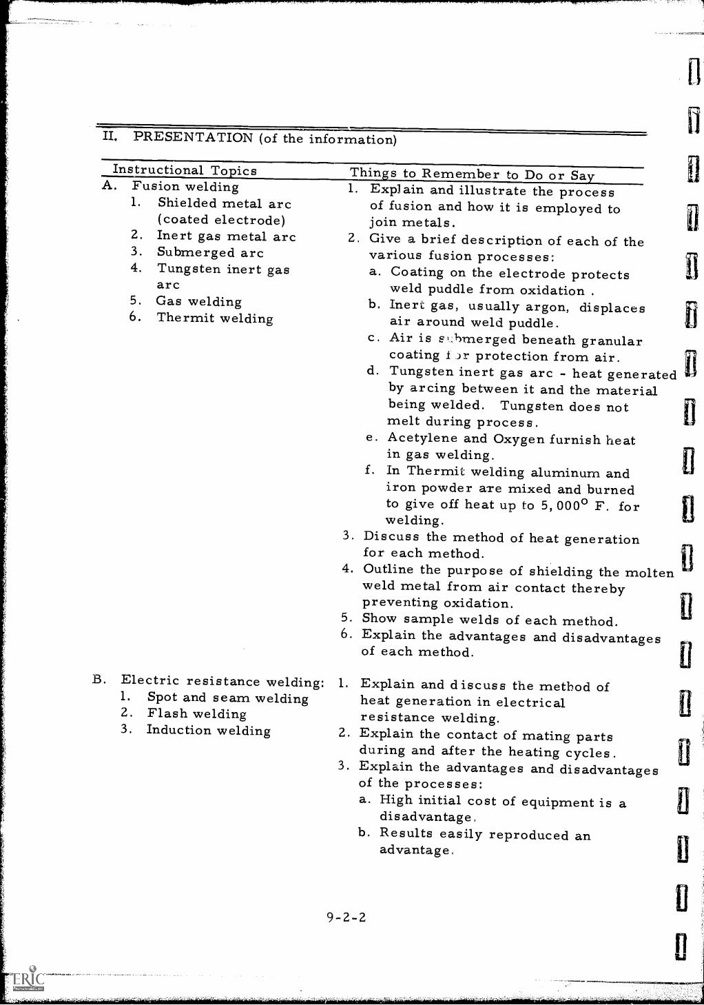
II. PRESENTATION (of the information)
Instructional To ics Thins to Remember to Do or SaA. Fusion welding
1. Shielded metal arc(coated electrode)
2. Inert gas metal arc3. Submerged arc4. Tungsten inert gas
arc5. Gas welding6. Thermit welding
1 Explain and illustrate the processof fusion and how it is employed tojoin metals.
2. Give a brief description of each of thevarious fusion processes:a. Coating on the electrode protects
weld puddle from oxidation .
b. Inert gas, usually argon, displacesair around weld puddle.
c. Air is si,hmerged beneath granularcoating Jr protection from air.
d. Tungsten inert gas arc - heat generatedby arcing between it and the materialbeing welded. Tungsten does notmelt during process.
e. Acetylene and Oxygen furnish heatin gas welding.
f. In Thermit welding aluminum andiron powder are mixed and burnedto give off heat up to 5, 000° F. forwelding.
Discuss the method of heat generationfor each method.Outline the purpose of shielding the moltenweld metal from air contact therebypreventing oxidation.Show sample welds of each method.Explain the advantages and disadvantagesof each method.
3.
4.
5.6.
B. Electric resistance welding: 1.1. Spot and seam welding2. Flash welding3. Induction welding 2.
3.
Explain and discuss the method ofheat generation in electricalresistance welding.Explain the contact of mating partsduring and after the heating cycles.Explain the advantages and disadvantagesof the processes:a. High initial cost of equipment is a
disadvantage,b. Results easily reproduced an
advantage,
9-2-2
1A ,
11
fl
11
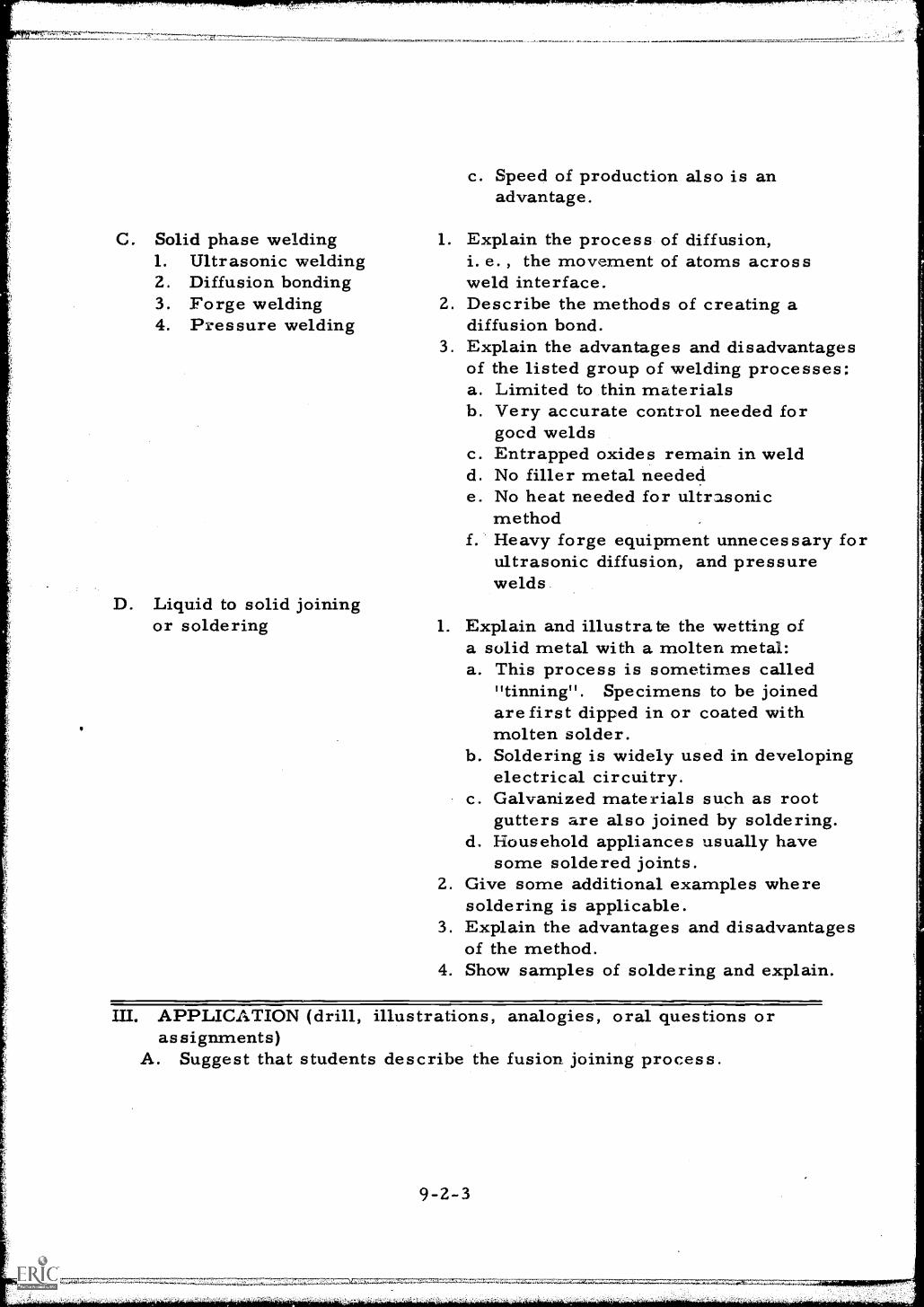
C. Solid phase welding1. Ultrasonic welding2. Diffusion bonding3. Forge welding4. Pressure welding
D. Liquid to solid joiningor soldering
c. Speed of production also is anadvantage.
1. Explain the process of diffusion,i. e. , the movement of atoms acrossweld interface.
2. Describe the methods of creating adiffusion bond.
3. Explain the advantages and disadvantagesof the listed group of welding processes;a. Limited to thin materialsb. Very accurate control needed for
good weldsc. Entrapped oxides remain in weldd. No filler metal needede. No heat needed for ultrasonic
methodHeavy forge equipment unnecessary forultrasonic diffusion, and pressurewelds.
1. Explain and illustrate the wetting ofa solid metal with a molten metal:a. This process is sometimes called
"tinning". Specimens to be joinedare first dipped in or coated withmolten solder.
b. Soldering is widely used in developingelectrical circuitry.
c. Galvanized materials such as rootgutters are also joined by soldering.
d, Household appliances usually havesome soldered joints.
2. Give some additional examples wheresoldering is applicable.
3. Explain the advantages and disadvantagesof the method.
4. Show samples of soldering and explain.
III. APPLICATION (drill, illustrations, analogies, oral questions orassignments)
A. Suggest that students describe the fusion joining process.
9-2-3
c.ltirikare
B. Have group explain the origin of the heat in the various arc weldingprocesses.
C. Request a thorough discussion and explanation of heat generationin the electrical resistance welding methods.
D. Ask class for examples of applications using the various methodsdiscussed. Have members justify their choice.
E. Have class identify the type of welding used to join each of thesamples exhibited in the classroom.
IV. TEST (final check on studentsNOTE: Written Test
A. What are the four major classifications of metal joining techniques
comprehension of material presented)
B. What is the purpose of the gas or slag shield of the molten weldpuddle?
C. What is the nature of the bond between the parent metal and solder inthe solder-type joint?
D. Compare the advantages and disadvantages of:a. The shielded metal arc weldb. The inert gas metal arc weld
E. Why are the electrical resistance methods used primarily for°production line work? Check and discuss.
V. SUMMARYA. Fusion methods of welding are the types that account for a major
part of industrial radiography work. They include shielded metalarc, inert gas metal arc, submerged arc, tungsten inert gasarc, acetyline gas, and Thermit welding processes.
B. Another widely used method is the electric resistance weldingmethod which includes spot and seam welding, flash welding andinduction welding.
C. Solid phase welding usually precludes the use of bonding metaland includes ultrasonic welding, diffusion bonding, forge welding,and pressure welding.
D. Liquid to solid joining is more commonly called soldering.
The Next Lesson is: The Weld Profile
9.Z -4
Bf
INSTRUCTOR'S LESSON PLANRelated Technical Information
Unit 9Lesson 3Time 1 hour
SUBJECT: The Weld Profile
AIM (or purpose): To develop knowledge and understanding of the componentparts of a weld and welding terminology in general
TEACHING AIDS: Sample weld sectionsSample steel plates prepared for welding
REFERENCES: Welding Metallurgy, G.H. Linnert, 1965, American WeldingSociety, New York, N. Y.Information Sheet #1 9Test
PREPARATION (of the learner)A. Explain the importance of the lesson and how it will help the
radiographer to properly interpret radiographs of weldments, theradiographer must know the structure of a weld, its componentsand correct welding terminology if he is to have the confidence ofhis associates.
B. The welder will naturally have greater respect for the radiographerwhen discussing detected weld defects if the radiographer canconverse in the language of the welder and make a professionaldiagnosis of the defects.
II. PRESENTATION (of the information)
Instructional Topics Things to Remember to Do or SayA. The fillet weld Use an overhead projector if
1. Width transparencies have been prepared.2. Throat If not, make chalkboard sketch as3. Toe follows:4. Root 1, Draw a sketch of a typical fillet5. Face weld on the chalkboard.
y7" -7r,'""7"7r,"7;..:7-Tr7,, 7.. ."
9 - 3 - 1.
B. The butt weld1. Groove2. Groove angle3. Root4. Face5. Root face6. Root opening7. Backing strips
C, Weld passes or layers1. Stringer or root
2. Hot pass
9-3-2
2. Label parts.3. Explain the method of measuring the
various dimensions.4. Draw sketches of dimensionally
correct and incorrect fillet welds.5. Ask questions.
1. Draw a sketch of a typical buttweld.
2. Describe and sketch the singleand double groove butt welds
3. Label the parts of the welds.4. Explain the methods of determining
the various dimensions of buttwelds.
5. Explain the purpose of the grooveangle, the root opening, and theroot face.
6. Sketch a backing strip in place ona single groove butt weld.
7. Explain the purpose of the backingstrip.
8. Review welds and terminologythroughout the discussion.Ask questions.
Refer to information sheet # 19and to the first illustration on thechalkboard The root pass is probably ,emost important and most troublesomepass.1. Complete penetration of this pass
is necessary.2. A root pass can contain: incomplete
penetration, burn through, icicles, inincomplete fusion, slag and cracks.Illustrate these on chalkboard duringdiscussion.
it
sj
ii
A hot pass follows the root pass.1. Some defects found in the root
pass can be eliminated with a hotpass.
2. Lack of fusion, slag and cracksare sometimes found in a hot pass.
3. Filler passes
4. Crown or reinforcementpass
Filler passes follow the hot pass.The crown is the top or final pass andsome crown defects include, undercut,and lack of form in that some areconcave or convex.
III. APPLICATION (drill, illustrations, analogies, oral questions orassignments)
A. Pass the sample plates and welds among the students for examination.
B. Ask a student to:1. Sketch a fillet weld on the chalkboard2. Label the various parts of the fillet weld3. Sketch a single groove butt weld on the chalkboard4. Label the parts of the butt weld
C. Ask for the definition and purpose of the following parts of thebut weld:1. The groove opening2. The root face3. The backing strip4. The root opening
D. Request discussion and definition of root, hot fillet, and crownpasses or layers.
E. Discuss possible flaws sometimes found in these passes andinvite questions.
IV. TEST (final check on students' comprehension of material presented)NOTE: Written TestA. Sketch a fillet weld and name the parts.
B. Sketch a single groove buttweld and name the parts.
C. Explain the purpose of:1. The root opening2. The root face3. Backing strips
D. Give test on Information Sheet #20
Check and discuss
9-3-3
V. SUMMARYA. An understanding of the weld profile is essential when radiographs
of weldments are being interpreted and discussed.
B. Fillet weldment description includes: toe, root, face, throat andwidth.
C. Butt weldments are described by: root, root opening, face, faceopening, groove, groove angle, backing strips.
D. Weld passes include: root, hot pass, filler passes and crown.
The Next Lesson is: Weld Defects
INSTRUCTOR'S LESSON PLANRelated Technical Information
Unit 9
Lesson 4Time 2 hours
SUBJECT: Weld Defects
AIM (or purpose): To assist the student in acquiring the ability torecognize the defects found in weldments and tobe aware of the capabilities of radiography todetect these defect
TEACHING AIDS: Samples of defective weldsFilm of defective weldsHigh intensity film viewer
REFERENCES: Nondestructive Testing Handbook, 1963, Society forNondestructive Testing, Evanston, IllinoisInformation Sheet #19
I. PREPARATION (of the learner)A. Introduce this lesson by discussing the following questions giving
the correct answers.1. Can radiographic techniques be used to find all defects in
Welds ? Why?2. What type of defects can be detected?3. Why is it important for the radiographer to know the limitations
of the technique?
B. Explain that the info- mation presented in this lesson will help tointerpret radiographs correctly. Point out that the interpretationshould indicate the type of defect shown in the radiograph assome defects are more serious than others. For example, a crackin a weld would be more important than a gas bubble.
II. PRESENTATION (of the information)
Instructional TopicsA. Profile defects
Things to Remember to Do or Say1. Use overhead projector or draw
a chalkboard sketch of fillet and
9-4-1
1. Undercutting2. Excessive reinforcement3. Lack of penetration4. Concavity
B. Structural defects1. Porosity2. Slag inclusions3. Incomplete fusion4. Cold lapping5. Cracking
a. Longitudinalb. Transversec. Craterd. Underbead
butt welds showing each typeof defect.
2. Refer to information sheet #19.3, Illustrate the origin of each type
defect.4. Compare the severity of each defect,5. Illustrate the appearance of the
defect image on radiographicfilm.
6. Show sample film,
1. Draw a chalkboard sketch of eachtype defect.
2. Illustrate the origin of each typedefect.
3. Compare the severity of thedefects.
4. Illustrate the appearance of thedefect indication on radiographicfilm.
5. Show sample film-explain anddiscuss.
6. Explain the limitation of radiographyin detecting certain types ofdefects.
III. APPLICATION (drill, illustrations, analogies, oral questions orassignments)
A. Have students sketch welds with the four types of cracks foundin welds.
B. Ask students to explain the origin of the cracks.
C. Ask the students to define the limits of radiography fordetection of weld defects.
D. Have the students identify defects on the sample film.
E. List the following defects in terms of their severity:1. Slag inclusions2. Porosity3. Concavity4. Cracking
9-4-2
IV. TEST (final check on students' comprehension of material presented)A. List three types of profile defects.
B. List three types of structural defects.
C. What is the cause of slag inclusions in a weld?
D. Show the four types of cracks found in welds by sketches.
E. State what conditions must exist for a weld defect to be found byradiography.
Check and discuss
V. SUMMARYA. Welding defects can be either structural or profile defects.
B. Profile defects are usually visible except if they are inside asmall diameter pipe.
C. Structural defects can be either visible or invisible, such ascracks in the weld or the base metal or extending into both.
The Next Lesson is: Field Trip to Observe Welding Procedures andOperations
9-4-3
INSTRUCTOR'S LESSON PLANRelated Technical Information
Field Trip
SUBJECT: Welding Procedures and Operations
Unit 9Les son 5
Time 6 hours
AIM (or purpose): To observe joint preparation, welding, andinspection of welded assemblies
MATERIALS: Film badges, dosimeters, safety glasses, hard hats
REFERENCES: Information Sheet #21
I. PREPARATION (of the learner)A. Introduce subject of trip and its purpose requesting students to
carefully observe the following procedures:1. Inspection of materials prior to fabrication2. The techniques of joint preparation3. The various types of welding processes4, Methods of marking for inspection identification5. Documentation of inspection and quality control
B. Read instructions to be followed while on field trip fromInformation Sheet #21, and invite any questions regarding thesubject trip.
II. PRESENTATION (of the information)
Instructional To ics Thins to Remember to Do or SayA. Tour a fabrication shop which Stress the need for gentlemanly
maintains its own inspection behaviour.department.
B. Students are to make notes asnecessary.
9-5-1
III. APPLICATION (drill, illustrations, analogies, oral questions orassignments)
A. After returning from the trip, ask the students to describe:1. Methods employed to inspect materials before beginning
fabrication2. The various types of welding joints used by the fabricator.3. All welding techniques and equipment employed by the manufacturer4. The observation of weldments at the final inspections5. The preparation of documents relative fabrication and inspection
B. Discuss any unusual observations made while touring the shop andinvite questions.
IV. TEST (final check on students' comprehension of material presented)NOTE: Written TestA. Name and briefly describe the various welding processes you observed
on the field trip.
B. How does the inspector know which welder or welders worked on aparticular weldment?
C. Why do two or more welders work simultaneously on the first passof a thick walled, large diameter pipe joint?
D. Describe briefly the joint preparation of a weldment.
E. Name some methods of quality control observed on this field trip.
Check and discuss
V. SUMMARYA. Joint preparation
B. Types of passes
C. Inspection procedures and aids
D. Documentation and quality control
The Next Lesson is: Multiple Exposure Pipe Radiography
9-5-2
it
iE
iB
Ar-
EXPERIMENT SHEETMultiple Exposure Pipe Radiography
Unit 9Les son 6Time 4 hours
SUBJECT:Inspection of a circumferential pipe weld using the multiple exposuretechnique
NOTE: Instructor performs all operations
INTRODUCTORY INFORMATION:Inspection of circumferential pipe welds may be accomplished usingseveral techniques of exposure. The double wall multiple exposuretechnique is used when access is not available to the inside surface,or the diameter to thickness ratio is too small to achieve satisfactorysensitivity. The length of weld which can be inspected on each exposureis limited by the change in metal thickness and change in film-focaldistance around the pipe. With proper procedures, satisfactoryradiographs can be obtained from one side.
MATERIALS AND EQUIPMENT:Gamma ray source and exposure facilitiesFilm cassettes and filmGamma ray survey meterPipe samplesPenetrameters, lead numbers, and shimsChart of diagnostic film lengthsDark room facilities
PROCEDURE:A. Single 16ad film cassettes with selected film and lead screens.
B. Transport film, gamma ray exposure device, and accessories toexposure site.
C. Determine the diagnostic length of each exposure.
D. Divide the pipe circumference into segments equal to the diagnosticlength.
9- 6 -1
E. Attach the exposure tube to the pipe opposite to the first segment tobe exposed.
FI Position the tube to the edge of the weld and directly opposite tothe center of the segment to be exposed.
G. Determine the extent of the weld reinforcement and select shimsof this added thickness.
H. Select a penetrameter which will indicate 2-2T sensitivity on thepipe wall if its equivalent 2T penetrameter could be placed on theinside.
I. Attach penetrameters on shims to the pipe at the center and theextreme end of the segment selected for exposure.
J. Attach lead numbers to the pipe segment to identify the exposure andto facilitate location of defects.
K. Mark the location of the lead numbers on the surface of the pipe.
L. Attach the film cassette to the outside of the pipe.
M. Position the film neatly over the segment to be inspected.
N. Secure the film tightly to the pipe with tape or elastic bands toinsure intimate contact of film and screens.
0. Attach a large letter "B" to the back side of the film cassetteswhere it will not interfere with the image of the weld line.
P. Calculate the exposure time required to produce a density not lessthan 1. 5 on the greatest thickness or more than 3. 3 on the leastthickness.
Q. Attach the source tube to the camera and extend the control cablesto a convenient location for operation.
R. Energize the survey meter, wait for warm up, and zero meter.
S. Extend source and expose for the required time.
T. Retract source into camera and survey camera to insure the safereturn of the source. Lock source in camera.
U. Remove film, move source tube to next segment of the pipe, andrepeat steps F through T until all segments have been exposed.
9-6-2
V. Develop all film for 5 minutes at 68°F. fix, wash, and dry.
W. View film for defects; prepare report of exposure and weld quality.
CONCLUSIONS:A. Penetrameters are required at two locations on the pipe because
the path is not of the same thickness and thedistance is different at these two locations.
B. The image of the letter "B" may appear on the radiograph dueto . This can be eliminated by
C. The sensitivity at the edge of the film isthe center of the film due to the effect ofradiation.
than
D. The density of the film at the edge of the film isthan in the center because of the difference in
distance.
The Next Lesson is: The Effect of Focal Distance
9-6-3
EXPERIMENT SHEETThe Effect of Focal Distance
Unit 9Les son 7Ti me 4 hours
SUBJECT:The effect of changing the film-focal distance on the distortionof the image and the sensitivity of the film.
NOTE: Instructor performs all operations
INTRODUCTORY INFORMATION:The degree of sharpness of an image depends on the size of the sourceand the distance between the source and the film. When the sourceis not a point, the case in all radiographic equipment, the image isdistorted because each point in the source forms its own image. Theoverlapping of these images form a halo around the central image whichis called penumbra. The penumbra distorts defects and the smallholes of the penetrameter resulting in loss of definition.. These
Fiects can be reduced by increasing the film-focal distance and makinguse a the basic laws of mathematics,
MATERIALS AND EQUIPMENT:Gamma ray (or x-ray) source and exposure facilities8" x 10" film cassettes and filmGamma ray survey meter6" x 8" steel plate, 1/2" to 3/4" thickPenetrameters and lead numbersDark room facilities
REFERENCES:Information Sheet #7 Nomogram of Geometrical Unshar ness
PROCEDURE:A. Single load 1m cassettes with selected film and lead screens.
B. Select penetrameters for 1/4" to 11/4" thickness in 1/8" steps.
C. Place the film on a lead sheet or exposure table.
9-7-1
D. Place the steel plate on the film and position in the center of thefilm.
E. Position the penetrameters on the plate in two neat rows in thecenter of the plate. Separate slightly and arrange in sequentialorder.
F. Attach lead number for identification. Avoid placing identificationwhere it will obstruct the image of the penetrameters or plate edge.
G. Aljgn source tube end directly over the center of the plate at afilm focal distance 5 times the thickness of the plate.
H. Calculate the exposure time required to produce a density of 1.8to 2. 2.
I. Attach the source tube to the camera and extend the control cables.
J. Energize the survey meter, wait for warmup, and zero meter.
K. Extend source and expose as required.
L. Retract source, survey, and lock source in camera.
M. Repeat steps C through L using 7, 10, 15 and 20 times the thicknessof the plate for a film focal distance.
N. Develop all film for 5 minutes at 68 F. Fix, wash and dry.
0. Examine film on viewer.
P. Record the minimum penetrameter sensitivity for each focal distance.
Q. Measure the geometric unsharpness of the plate dimensions andrecord for each focal distance.
R. Determine the expected geometrical unsharpness from thenomograms.
CONCLUSION:A. The minimum sensitivity attained at a D/T of 7 is
B. A 2-2T sensitivity was observed at a D/T of and above.
C. List the values obtained for geometrical unsharpness:
9-7-2
D/T
5
7
10
1520
Actual Measurement From Nomogram
D. The measured value of geometrical unsharpnesswith that taken from the nomogram.
E. To improve radiographic sensitivity the film focal distanceis .
The Next Lesson is: Double Pipe Radiography.
EXPERIMENT SHEETDouble Wall Pipe Radiography
Unit 9
Lesson 8Time 3 hours
SUBJECT:Inspection of welds in small diameter pipe using the double wall methodof exposure to produce an image of both walls.
NOTE: Instructor perform all operations.
INTRODUCTORY INFORMATION:When the outside diameter of a pipe is less than about four inches,inspection of welds can be accomplished by exposing both walls ofthe pipe to produce an elliptical image of the weld. Two exposuresare required to achieve 100% coverage using this technique.
MATERIALS AND EQUIPMENT:Gamma ray source and exposure facilitiesFilm cassettes and filmGamma ray survey metersPenetrameters, lead numbers, and shimsWelded pipe samples 4" or lessDark room facilities
REFERENCES:Information Sheet #22
PROCEDURE:A. Single load film cassettes with selected film and lead screens
B. Transport equipment to exposure site.
C. Determine the outside diameter of the pipe.
D. Position source tube to expose the weld.
E. Locate source tube to the side of the weld aim ut 30 degrees fromthe centerline of the weld.
9-8-1
F. The film to focal distance should be at least seven times theoutside diameter of the pipe.
G. Determine the extent of weld reinforcement and select a shim ofthis added thickness.
H. Select a penetrameter which will indicate 2-2T sensitivity on thetotal thickness of both walls.
I. Attach the penetrameter, on a shim, to the pipe on the source side.
J. Place penetrameter directly in line with the source tube end onthe opposite side of the weld from the 30 degree offset with thelong axis parallel to the pipe.
K. Attach a film cassette to the pipe.
L. Attach the film to the pipe opposite to the source tube. The filmshould not be wrapped to the pipe but should remain flat and tangentto the pipe, perpendicular to the centerline of the exposure.
M. Position film allowing for the throw of the shadow of the weld.About two inches overlap of the weld on the source offset sideis sufficient.
N. Attach lead numbers to the film for identification of the exposure.
O. Mark the point of tangency of the film to facilitate location ofdefects.
P. Calculate the exposure time required to produce a density notless than 1.5 nor more than 3.3.
Q. Attach the source tube to the camera and extend control cables.
R. Energize the survey meter, wait for warmup, and zero meter.
S. Extend source and expose the required time.
T. Retract the source into the camera, survey, and lock camera.
U. Repeat the entire operation to achieve a second exposure at 90degrees to the first exposure.
V. Develop film for 5 minutes at 68 F. Fix, wash and dry.
W. View film for defects, prepare reports.9-8-2
CONCLUSIONS:A. The equivalent single wall penetrameter sensitivity of this
radiographic tehcnique is
B. Two exposures are required for 100% coverage because
C. The source is offset from the weld to prevent the image of thetop from obscuring the image of the bottom
D. The pipe diameter is used as a basis for determining thedistance in order to obtain a
image.
The Next Lesson is: Panoramic Pipe Radiography
9-8-3
EXPERIMENT SHEETPanoramic Pipe Radiography
Unit 9Les son 9Time 4 hours
SUBJECT:Inspection of a circumferential pipe weld using the panoramicexposure technique
NOTE:Instructor performs all operations
INTRODUCTORY INFORMATION:Inspection of circumferential pipe welds may be performed usingseveral techniques of exposure. The panoramic technique producesrapid reliable results when access is available to the internal surfaceof the pipe and the diameter to thickness ratio is sufficient to permitthe necessary film focal distance. The advantages of the panoramictechnique are, exposure through a single wall, uniform film-focaldistance, and one exposure for an entire weld circumference.
MATERIALS AND EQUIPMENT:Gamma ray source and exposure facilitiesFilm cassettes and filmGamma ray survey meterPenetrameters, lead numbers, and shimsPipe s ample sDark room facilities
PROCEDURE:A. Single load film cassettes with selected film and lead screens .
B. Transport film, gamma ray exposure device, and accessories toexposure site.
C. Position exposure tube end at the exact inside center of thepipe in line with the weld.
D. Select a penetrameter which will indicate 2-2T sensitivity on thepipe wall if its equivalent 2T penetrameter were placed on theoutside.
9 -9 -i
E. Determine the extent of the weld reinforcement buildup.
F. Select a shim equivalent to the amount of weld reinforcement.
G. Place a penetrameter, on a shim, on the outside surface of thepipe adjacent to the weld with the long axis parallel to the pipeaxis.
H. Attach lead numbers to the outside circumference of the pipe on theopposite side of the weld from the penetrameter.
I. Place numbers in increasing sequential order every six inchesof circumference of the pipe.
J. Mark the location of the numbers in crayon on the exterior ofthe pipe.
K. Prepare and attach an identification code made from lead numbersand letters.
L. Attach the film cassettes to the exterior of the pipe.
M. Position the film neatly over the weld with approximately 11/2"overlap of film.
N. Secure film tightly to the pipe to insure intimate contact offilm and screen and a minimum distance between the pipe and cassette]
0. Calculate the exposure time required to produce a density not lessthan 1. 5 on the greatest thickness and no more than 3.3 on theleast thickness.
P. Connect exposure tube to the gamma ray camera.
Q. Extend control cables of gamma camera to a convenient locationfor operation.
R. Energize the survey meter, wait for warm up, and zero meter.
S. Ili-lock the gamma camera and extend source to exposure pOsition.Expose film for the required time.
T. Return source to camera, survey to insure safe return, and locksource in camera.
9-9-2 ll
U. Remove film from pipe, develop for 5 minutes at 68 F. fix,wash, and dry.
V. View film for defects. Prepare report of exposure and weldquality.
CONCLUSIONS:
A. Only one penetrameter is required to insure sensitivity becausethe is the same for all film.
B. The penetrameter will indicate 2% sensitivity of thethickness through a total metal path equal to thethickness.
C. The penetrameter size used for this exposure did not correspondto the measured plate thickness because the penetrameter was placedon a shim equal in thickness to the weld
D. Sequential numbering of the pipe surface is performed toenable the inspector to determine the exact ofdefects.
The Next Lesson is: Radiography Film Interpretation (Welds)
9-9-3
INSTRUCTOR'S LESSON PLANRelated Technical Information
Unit 9Lesson 10Time 2 hours
Note to Instructor : This is a practice lesson and time should be providedeach week for practice on this material
SUBJECT: Radiography Film Interpretation (Welds)
AIM (or purpose): To acquaint the student with the fundamentals ofweld film interpretation
TEACHING AIDS: Film viewerReference Radiographs of Steel Welds, ASTM E-99,American Society for Testing and Materials, Philadelphia,Pa.
MATERIALS: Sample weldsSample film
REFERENCES: Nondestructive Testing Handbook, Volume I, Society forNondestructive Testing, 1963, Evanston, Illinois
I. PREPARATION (of the learner)Explain that knowledge of the theory of image formation cannot besubstituted for experience in welding control. The radiographer mustbe able to explain each indication found on the film, and be able todifferentiate the nonrelevant indications from those of consequence.This lesson is calculated to help the student to more fully understandthe theoretical explanation of various defects and to assist him ingaining valuable experience in film interpretation.
II. PRESENTATION (of the information)
Instructional To icsA. Weld defects
1. Slag inclusions2. Lack of penetration
Thins to Remember to Do or Sa1. Sketch a cross section of a butt weld
containing slag inclusions.2. Sketch a density profile corresponding
9-10-1
3. Porosity4. Cracks5. Lack of fusion6. Surface discontinuities
a. Root and crownconcavity
b. Excess penetrationc. Excessive and
irregular crownd. Misalignment
(hi-lo)e. Undercutf. Backing rings
B. Viewing Screens
to the weld cross sections.3. Explain the source of the density
variations.4. Display sample weld sections.5. Show the sample film and explain.6. Repeat the procedure for each of the
other defects.
1. A high intensity film viewing screenis desirable for film interpretation.
2. A rheostat-type light intensifier isalso a desirable feature.
3. Viewing screen should be free ofartifacts.
4. Varying light intensity is an aid instudying shapes of defects.
III. APPLICATION (drill, illustrations, analogies, oral questions oras signments)
A. Ask the group to sketch each of the weld defects discussed in thepresentation and show the density profile for each type of defect.Allow one or more students to present each type.
B. Display the sample film on a viewer one at a time to the group.Have individual students identify each defect and its origin. Repeatuntil each student can identify every defect.
C. Display the film one at a time to the class for identification. Askthe group to identify each film on a sheet of paper to be handed tothe instructor. Examine the papers. Review the cause of thedefect, the density profile, and the film of each defect which thestudent fails to identify.
IV. TEST (final check on students' comprehension of material presented)Test the group on weld defect interpretation by displaying sample filmsto the group. Ask the students to identify each of the defects byplacing their answers on a piece of paper to be turnedin for. scoring.
9-10-2
V. SUMMARYA. To become skillful in weld defect interpretation the student should
be able to identify weld defects by name.
B. The location of a defect in the weld is often a clue to its identification.
C. Weld defects are also called discontinuities.
D. Some defects are more serious than others so they should becorrectly identified by their proper name.
The Next Lesson is: Radiograph Film Interpretation (Castings)
A-7:.A.,..-AAC-1:;40A.:*-.A.A.A.-. A...AA+ A ":""' 7:7-
9-10-3
7:77r 7'1-
INSTRUCTOR'S LESSON PLANRelated Technical Information
Unit 9Lesson 11Time 2 hours
Note to the Instructor: This is a practice lesson, time should be providedeach week for practice on this material.
SUBJECT: Radiography Film Interpretation (Castings)
AIM (or purpose): To teach the student the fundamentals of castinginspection, the appearance of casting defects on film,and the interpretation of serviceability of castings
TEACHING AIDS: Film viewerIndustrial Radiora hic Standards for Steel Castin sASTM E-71, American Society for Testing Materials,Philadelphia, Pa.
MATERIALS: Sample castingsSample film
REFERENCES: Defects and Failures in Pressure Vessels and Pi inHelmut Thielsch, 1965, Reihold Publishing Corp, NewYork, N. Y.
I. PREPARATION (of the learner)Stress that this lesson should help an individual to recognize castingdefects as the images appear on an x-ray film and should help thestudent to distinguish one type of defect from another. It should alsodevelop an understanding of the cause of many casting defectsrecognizing that castings often exhibit certain defects which are peculiarto the process. Film interpretation of castings can be explainedtheoretically; however, there is no substitute for practical experience.In this effort the student will have an opportunity to constantly comparethe film and theory in practice interpretations.
9-11-1
II. PRESENTATION (of the information)
Instructional Topics ThingsloRemember to Do or SayA. Casting defects 1. Make a chalkboard sketch of a
1. Gas and blow holes casting containing gas pockets.2. Sand spots 2. Sketch the density profile3. Inclusions corresponding to the casting.4. Internal shrinkage 3. Explain and discuss the source of5. Hot tears and cracking the density variations.6. Unfused chaplets 4. Display film showing the defect.7. Internal chills 5. Display sample casting with the defect.
6. Repeat the procedure for each of theother type defects.
B. Viewing Screens 1. A high intensity film viewing screenis desirable for film interpretation.
2. A rheostat-type light intensifieris also a desirable feature.
3. Viewing screen should be free ofartifacts.
4. Varying lights intensity is an aidin studying shapes of defects.
III. APPLICATION (drill, illustrations, analogies, oral questions oras signments)
A. Ask individuals from the group to explain the origin of each of thecasting defects, sketch a. cross section showing the defect, andsketch a density profile for the defective casting.
B. Display the sample film to the group one at a time on a film viewer.Have individual students identify each defect and outline its cause.Repeat until the students can identify each type of defect.
C. Show the film again one at a time on a film viewer. Ask the students toidentify and record the type of defect on a piece of paper to be tunedin. Review the papers. Analyze the cause, the density profile,and discuss the film of each defect type the students fail toidentify properly.
IV. TEST (final check on students' comprehension of material presented)Test the group on casting defect interpretation by displaying sampleradiographs on a viewer. Ask the students to identify each defect byplacing their answers on a piece of paper. Have students exchange testpapers. Review each radiograph on the screen and interpret. Checkresults.
9-11 -2
V. SUMMARYA. Casting defect interpretation requires practice.
C. Variable light intensity viewing screens are also a valuable trainingaid.
The Next Lesson is: How to Interpret Lines on Drawings or Blue Prints.
INSTRUCTOR'S LESSON PLANRelated Technical Information
Unit 10
Les son 1
Time 1. 5 hours
SUBJECT: How to Interpret Lines on Drawirg or Blue Prints
AIM (or purpose): To outline and explain the basic lines in drawings orblueprint
TEACHING AID: Chart showing lines with brief explanation identifyingeach type of line; chart with drawings fully dimensioned.Drawings or blueprints as used in radiography
MATERIALS: 8 1/2" x11" paper, pencils, and straightedge
I. PPt"=4RATION (of the learner)Point out that to do an effective job of reading one must be able tointerpret type, symbols, lines and the like, even in the simple taskof reading a road map. We interpret symbols, lihes and a varietyof characters.
In drawing and blueprint reading, it is also necessary to recognize andunderstand the various lines used to construct, measure, and show thedesign of a machine part or structure. This interpretation of linesand figures is known as blueprint reading and if the task is to be handledeffectively, considerable emphasis should be placed on the accuracy ofthe operations.
II. PRESENTATION (of the information)
Instructional To icsA. Object line
Thin s to Remember to Do or Sa
10-1-1
Pass out sample blueprints ordrawings as used in radiographic work.Illustrate on chalkboard and puint outon actual blueprints or drawings andexplain,1. Is a heavy solid line
Represents the real object on adrawing or blueprint
3.
4.
May be shown from several viewsor anglesAsk questions
B. Extension line 1. Is a light solid line2. Extends from object to indicate
points of measurement3. Seldom touches object (1/16" from
object point of measure)4. Ask questions
C. Dimension line 1. Is a light broken line2. Is broken for indicated dimensions
between points of measurement3. Has arrow on either end4. Arrows touch extension lines,
usually 1/4" distance from endaway from object
5. Ask questions
D. Hidden line 1. Is a heavy dashed line2. Represents hidden shapes of the
object that are obstructed by theexposed view
3. Ask questions
III. APPLICATION (drill, illustrations, analogies, oral questions oras signments)
Have students do the following on chalkboard or paper. Give closesupervision:A. Draw or sketch an object 3" long, 2" wide, and 1" thick
B. Add extension lines
C. Install dimension lines, showing dimensions
D. Show a step cut across the back corner of the object, using ahidden line
E. Ask students to locate on drawings or bleuprints the followinglines:1. Object lines2. Extension lines3. Dimension lines4. Hidden lines
10-1-2
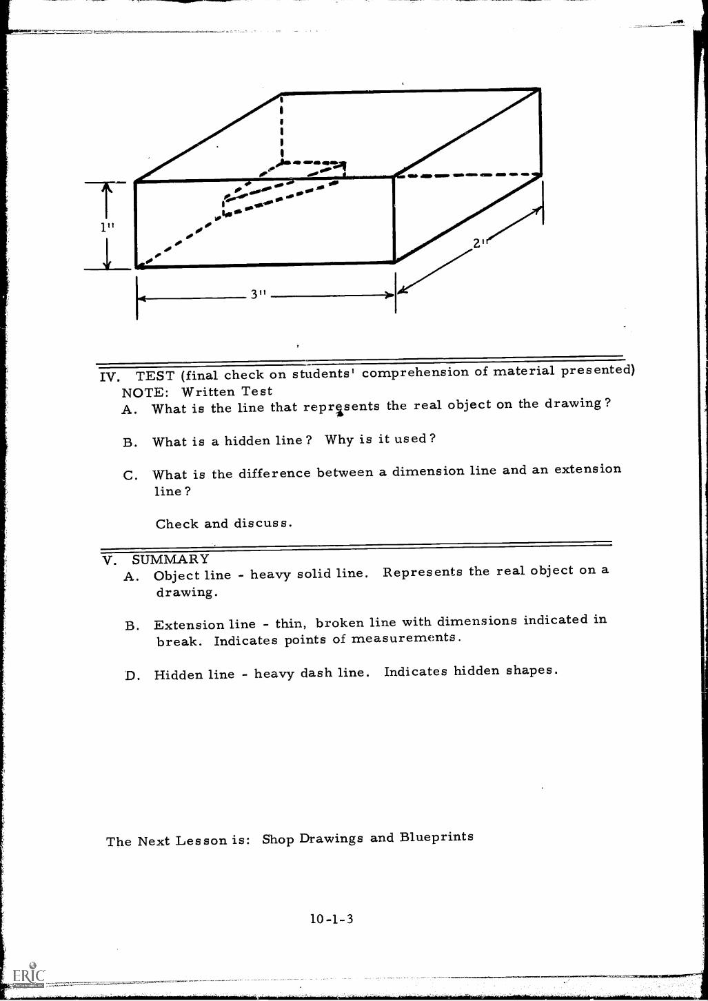
1"
311
IV. TEST (final check on students' comprehension of material presented)NOTE: Written TestA. What is the line that represents the real object on the drawing?
B. What is a hidden line? Why is it used?
C. What is the difference between a dimension line and an extensionline?
Check and discuss.
V. SUMMARYA. Object line - heavy solid line. Represents the real object on a
drawing.
B. Extension line - thin, broken line with dimensions indicated inbreak. Indicates points of measurements.
D. Hidden line - heavy dash line. Indicates hidden shapes.
The Next Lesson is: Shop Drawings and Blueprints
INSTRUCTOR'S LESSON PLANRelated Technical Information
SUBJECT: Shop Drawings and Blueprints
Unit 10
Les son 2
Time 2 hours
AIM (or purpose): To develop an understanding of the process of blue printproduction and to assist the student in the interpretationof blue prints
TEACHING AIDS: Film: Shop Drawings, 22 mins. , 16 mm, sound,Pennsylvania State University, UniversityPark, Pa.
EQUIPMENT: Film projector and screen
I. PREPARATION (of the learner)A. Introduce film, giving title and pointing out the following points
should be observed or noted while viewing the film:
1. The types of lines used to denote various parts and areas of theimage.
2. The number and placement of views necessary to clearly definethe part,
3. Methods used to reduce the size of the drawing and the placementof dimensions.
4. The methods of indicating internal sections.
B. Stress that this lesson should help the individual to locate componentparts on a drawing that are to be radiographed and should help theradiographer to make sketches indicating where radiographs areto be made or were made on a piece of equipment such as a refinerypressure vessel.
II. PRESENTATION (of the information)
Instructional To icsShop Drawings"
Thin s to Remember to Do or Sa
10-2-1
Show the film
III. APPLICATION (drill, illustrations, analogies, oral questions orassignments)
A. Discuss the film, emphasi?ing the following points in thediscussion:1. Types of lines used in drawings and what they denote.
a. Solid linesb. Dashed linesc. Center lines for axis of rotationd. Diagonal lines indicating sectioning
2. The number of views necessary to define a part.a. The plain viewb. The side viewc. The front viewd. Internal details
3. Methods of scalinga. Shortening of uniform sectionsb. Section rotations
B. Have members of the group prepare sketches on chalkboard orpaper using the various lines, views and details shown in thefilm.
C. Reshow the film in the event that any lack of understandingdevelops.
IV. TEST (final check on students' comprehension of material presented)NOTE: Written TestA. What type of lines are used for:
h. Outlining the part?2. To show a center of rotation?3. To indicate a section?
B. How many views should be shown of a part?
C. Should all details be shown in every view? Why?
D. What is meant by scale?
V. SUMMARYA. Radiographer sometimes works from a shop drawing.
B. It is important that you be able to identify the location ofradiographed parts from a drawing.
C. Sketches sometimes contain several different views of an object.
10-2-2
D. Sketches are not always drawn to scale.
E. Sketches and symbols should indicate what part of weld is tobe radiographed.
The Next Lesson is: Graphic Inspection Symbols
10-2-3
INSTRUCTOR'S LESSON PLANRelated Technical Information
Unit 10
Lesson 3
Time 2 hours
SUBJECT: Graphic Inspection Symbols
AIM (or purpose): To teach the student the standard symbols used ondrawings to indicate the place and type of inspection tobe employed
TEACHING AIDS: Information Sheet #24 (test)
REFERENCES: Information Sheet #23Nondestructive Testing Symbols, Military Standard 23A,August 1952, U. S. Department of Defense, Washington,D. C.
I. PREPARATION ( of the learner )This lesson is a continuation of the language of drawing symbols.The symbols discussed in this lesson are particularly useful to theinspectors. With a satisfactory blueprint or shop print the inspectorcan use these symbols to outline his inspection task without thenecessity of further instructions.
II. PRESENTATION (of the information)
Instructional TopicsA. The basic symbols
B. Elements of the testingsymbol:1. Reference line and
arrow
Things to Remember to Do or SayPass out Information Sheet #23
1. List the basic methods and theirsymbols on the chalkboard; i.e., R T,MT, PT, and UT.
2. Explain the meaning of the symbolsand answer questions.
1. Draw the reference line on the chalk-board and add the arrow.
2. Explain the purpose of the arrow andthe meaning of arrow and opposite side.
10-3-1
3. Point out that the arrow can point inany direction from either end of thereference line.
4. Invite questions.
2. Test-all-aroundsymbols
1. Add the symbol to the sketch.2. Explain its meaning.
3.. Extent of test 1. Sketch arrow to indicate a test fromboth sides - Explain.
2. Add information to sketch to indicatethe length of the part to be inspected.
3. Add information to show the numberto tests required for random testing.
4. Direction ofradiation
1. Sketch a symbol indicating the locationand distance of the radiation sourcefrom the area to be tested.Explain, and discuss.
5. Combination ofsymbols
1. Sketch a combination welding andtesting symbol.
2. Illustrate and explain the method ofcombining test symbols.
6. Specification 1. Add the tail to the reference line -Explain.
2. Show placement of specificationinformation in the tail of the arrow.Explain and discuss. Invite questions.
III. APPLICATION (drill, illustrations, analogies, oral questions orassignments)
A. Ask several members of the class to draw on the chalkboardsymbols to indicate types of tests indicated below:1. The symbol for a magnetic particle test of a pipe wel!I in
accordance with ASTM specifications.2. A symbol for radiographic inspection of a weld on a plate.
The film-focal distance should be indicated at 24" at aninclination of 15 degrees from the perpendicular.
3. A symbol for a combination ultrasonic test of a plate fromthe top side and a magnetic particle test from the back side.
4. A symbol combining the welding of a fillet weld in the fieldwith a magnetic particle inspection in accordance withASTM specifications.
10-3-2
il
5. A symbol for the panoramic X-ray of a large diameter pipeweld in accordance with Mil-Std-271.
B. Solicit the assistance of the entire class in checking the symbolsdrawn for accuracy and defining the meaning of each.
IV. TEST (final check on students' comprehension of material presented)A. Ask the group to draw the following symbols on a paper to be
turned in for checking:1. A symbol for radiographic inspection of a butt weld with a
film-focal distance of 12" and an inclination of the sourcefrom the perpendicular of 30 degrees.
2. A symbol for a radiographic inspection of a pipe weld inaccordance with ASME specifications.
3. A symbol for magnetic particle and ultrasonic inspection ofa weld.
4. A symbol for magnetic particle inspection of 20" of a powershaft which is six feet long.
B. Pass out the symbol test sheet #24 and ask the group to answer thefollowing questions, to be turned in for checking:1. How many different types of tests are indicated on the test
sheet?2. How many tests are required on the inside of the pipe?3. What type of tests are made on the inside of the pipe?4. How many welds are to be radiographed in whole or part.5. What is the extent of testing required on the welds of this
as sembly ?6. Where in the system are the welds located that require two
types of tests ?
The Next Lesson'is: Graphic Welding Symbols
10 -3 -3
INSTRUCTOR'S LESSON PLANRelated Technical Information
Unit 10Lesson 4Time 2 hours
SUBJECT: Graphic Welding Symbols
AIM (or purpose): To acquaint the student with an accurate and quickmethod of determining the welding procedures usedin fabrication and to improve an individual's abilityto read blueprints
TEACHING AIDS: Information Sheet #26 (test)
REFERENCES: Standard Welding Symbols, AWS 2.0, American WeldingSociety, New York, N. Y.Information Sheet #25
PREPARATION (of the learner)Explain, that a detailed drawing of each weld in an assembly might bepleasing to the eye; however, few draftsmen can achieve the artisticdetail of a professional artist. To convey the necessary information tothe craftsmen who must perform the work, engineers and draftsmenhave created a language of symbols which adequately tell the workmanwhat is to be done. A knowledge of the welding symbols will aidthe radiographer in establishing proper work procedures and helpa great deal in the interpretation of processed radiographic film.
II. PRESENTATION (of the information)
Instructional TopicsA. Welding symbols
Things to Remember to Do or Say1. Distribute information sheet #25
depicting standard arc weldingsymbols.
2. Explain the need for symbols as follows:a. Language understood by allb. Easy to learn and drawc. A lot of information in a small
space3. Invite discussion
10-4-1
7kLZ.-:,,77=a, V,..aeoc=eata.tag.,tt
B. The elements of the weldingsymbol
4. Explain the Use of these symbolsin blueprint preparation.
1. The reference line andarrow
1. Draw a reference line on the chalk-board and add an arrow.
2. Explain the purpose of the arrow andthe meaning of arrow side and oppositeside; indicates the side to weld.
3. The arrow can point in any directionfrom either end of the line.
4. Ask questions.
2. Field weld and weld-around symbol
1. Add the field weld symbol to thesketch.
2. Add the weld-all-around symbol.3. Explain their meaning.4. Point out the meaning of the symbol
without these elements.
3. Basic weld symbol 1. Add a basic weld or groove symbolto the chalkboard sketch.
2. Explain the meaning of the symbolplacement.
3. Show alternate placements.
4. Contour symbols 1. Add symbol to chalkboard sketch.2. Explain the symbols meaning.3. Show placement and meaning.
C. Supplementary information 1. Using the information sheet #25show the various other symbols forthe finish, length of weld, grooveangle, specification compliance, androot opening.
2. Give other illustrations on chalk-board as needed.
3. Illustrate the placement of informationto indicate the length and size of welds.
4. Ask and invite questions.
10-4-2
III. APPLICATION (drill, illustrations, analogies, oral questions oras signments)
Suggest one or more students portray on the chalkboard symbols toindicate the following types of welds and accessory information. Havegroup discuss each:
A. An intermittent chain fillet weld to be completed in the field witha pitch of 5 inches on 2 inch increments.
B. A double "V" groove field weld on a large pressure vessel shell._
C. An example of a shop weld on flat plate with a "U" groove whichrequires a single pass back weld.
D. The pressure containing field type weld used on piping with a single"V" groove.
E. A field fillet weld of a large slip-on flange welded inside and out.(Provide a sketch or a print of the slip-on flange)
IV. TEST (final check on students' comprehension of material presented)Pass out test sheet #26 showing different types of welds. Ask thestudents toA. Identify each type of weld profile shown on the drawing.
B. Indicate the number of shop welds and the number of field welds.
C. Enumerate the number of fillet welds.
D. Indicate the number of groove welds.
E. On a separate sheet of paper, have the students draw the symbol for1. A "V" groove field weld for pressure piping.2. The field fillet weld on a "T" joint with a fillet leg length of 1/2".
V. SUMMARYA. Welding symbols condense welding information.
B. Shop welds can be identified and separated from field welds.
C. Knowledge of welding symbols is helpful in writing inspectionspecifications.
D. Knowledge of welding symbols is helpful in cost estimating ofradiographic inspection services.
10-4-3
E. Welding symbols include i4entification of typos of joint preparationsrequired, as well as the lingth, type and contour of weld.
The Next Lesson is Testing for Contamination
10-4-4
[1;
INSTRUCTOR'S LESSON PLANRelated Technical Information
Unit 11
Les son 1
Time 2 hours
SUBJECT: Testing for Contamination
AIM (or purpose): To outline the correct methods and procedures used totest for leakage of radioactive source capsules.
TEACHING AIDS: Empty source capsulesDummy wipe test kits
REFERENCES: Information Sheet #27
I. PREPARATION (of the learner)A. Explain to students that early methods of encapsulation proved
inadequate and as a result many contamination incidents occurred.
B. Point out the possible hazards of handling source equipment that isleaking and explain why this is iital information for the radiographer.
C. Discuss the need for frequent leak testing of sources and generallyindicate the grave hazards that develop if carelese or contemptuousattitudes are formed regarding contamination.
II. PRESENTATION (of the information)
Instructional To icsA. The wipe test
Thin s to Remember to Do or Say1. Explain the purpose of the wipe
test and why it is so called.2. Point out that it is to detect and
measure radiation contamination.3. Show the students a typical wipe
test kit and explain the servicesavailable to the radiographer.Showing how an area being checkedis wiped with a damp swab or towel.
B. Counting instruments
C. Leaking sources andcontamination
4. Outline the requirements forauthorization to perform wipe testsand the equipment necessary toachieve successful testing.
5. Explain the methods employed towipe remote controlled equipmentand hand cameras.
6. Define the Curie, explaining thatit emits 37 billion disintegrationsor counts per second.
7. Illustrate on the chalkboard theconversion of counts per second(disintergrations/sec) to curies.
8. Pass out Information Sheet #27.
State the legal capabilities required ofthe instruments used for counting-ability to measure 0.005 microcuriesof ionizing radiation.
1. Outline the procedures for disposingof leaking sources and explain thata leaking, source should be reportedimmediately by wire or telephone.
2. State the requirements for reportinga leaking source to the regulatoryagencies.a. Place source and container inplastic bag to prevent spread ofcontamination.b. Place bag in locked permanentstorage room.c. Notify AEC or State authorities.d. Monitor area for possiblecontamination.e. Check self with monitoringdevice and remove contaminationas quickly as possible by usingshower.
NOTE: PLUG SHOWER DRAIN ANDHAVE WATER CHECKED FORCONTAMINATION.
III. APPLICATION (drill, illustrations, analogies, oral questions orassignments)
A. Ask students to explain the purpose of the wipe test and the procedurefor obtaining the sample.
B. Have the students calculate the leakage in curies of material froma given number of counts on a counting instrument.
C. Ask students to define the legal requirements for testing andhandling of sources which show leakage.
D. Show the students samples of capsules used in industrialradiography and ask for discussion on how leakage occurs.
IV. TEST (final check on students' comprehension of material presented)NOTE: Written TestA. What is the maximum limit of contamination allowed on a wipe test
of a radiographic source?
B. How often are wipe tests required by regulations?
C. What is the procedure when a source is found to be leaking?
D. How many microcuries of leakage has been detected by a wipe testif the counter indicates 50 disintegrations/sec?
E. Where is the wipe made on the testing of remote controlledequipment? On testing hand cameras ? On testing loose capsules ?
V. SUMMARYA. Inadequate methods of encapsulation led to wipe testing regulations.
B. Improved techniques still inadequa:.-,; in the event of an accidentwhile transporting radioactive materials.
C. A. E. C. or State regulatory body arranges for disposal ofcontaminated materials.
The Next Lesson is: Make a Wipe Test
11-1-3
INSTRUCTOR'S LESSON PLANManipulative Skills
Unit 11
Lesson 2Time 2 hours
JOB {or operation): Make a Wipe Test
AIM (or purpose): To develop skill in the use of the wipe test kit forcontamination testing
TOOLS AND EQUIPMENT: Remote control gamma ray exposure deviceGeiger-Muller and ion chamber type surveymetersBeta calibrating source
MATERIALS: Dummy wipe test kits (expendable)Shipping labels
REFERENCES: Manufacturer's illustrated instructions for use of wipetest kits
I. PREPARATION (of the learner)A. Explain the importance of the proper performance of the wipe test,
since improper testing could result in the use of leaking ordamaged sources and the contamination of the radiographer.
B. Remind students that ionizing radiation cannot be detected by man'ssenses and that contamination can be caused by very small amountsof radioactive material that cannot even be seen without the aid of amagnifying glass.
C. Explain that long half life gamma emitters are extremely hazardousin the form of contamination.
D. Compare this type of contamination with the effects of falloutfrom a nuclear detonation but explain that fallout would not be asconcentrated.
'''-',.304.....7=1=VE:',...,===.=.71=1",.."===e.,----7,
11-2-1
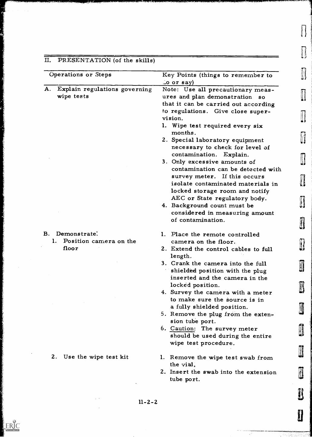
II. PRESENTATION (of the skills
Operations or Steps Key Points (things to remember to_go or saN )Note: Use all precautionary meas-ures and plan demonstration sothat it can be carried out accordingto regulations. Give close super-vision.1. Wipe test required every six
months.2. Special laboratory equipment
necessary to check for level ofcontamination. Explain.
3. Only excessive amounts ofcontamination can be detected withsurvey meter. If this occursisolate contaminated materials inlocked storage room and notifyAEC or State regulatory body.
4. Background count must beconsidered in measuring amountof contamination.
A. Explain regulations governingwipe tests
B. Demonstrate:1. Position camera on the
floor
2. Use the wipe test kit
11-2-2
1. Place the remote controlledcamera on the floor.
2. Extend the control cables to fulllength.
3. Crank the camera into the fullshielded position with the pluginserted and the camera in thelocked position.
4. Survey the camera with a meterto make sure the source is ina fully shielded position.
5. Remove the plug from the extent-sion tube port.
6. Caution: The survey metershould be used during the entirewipe test procedure.
1. Remove the wipe test swab fromthe via.
2. Insert the swab into the extensiontube port.
3
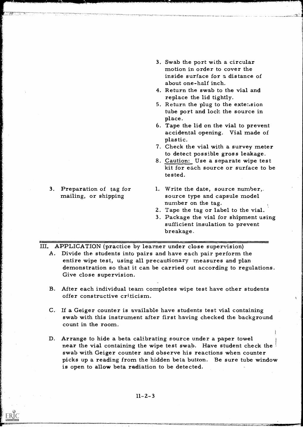
3. Preparation of tag formailing, or shipping
3. Swab the port with a circularmotion in order to cover theinside surface for a. distance ofabout one-half inch.
4. Return the swab to the vial andreplace the lid tightly.
5. Return the plug to the extensiontube port and lock the source inplace.
6. Tape the lid on the vial to preventaccidental opening. Vial made ofplastic.
7. Check the vial with a survey meterto detect possible gross leakage.
8. Caution: Use a separate wipe testkit for each source or surface to betested.
1. Write the date, source number,..source type and capsule modelnumber on the tag.
2. Tape the tag or label to the vial.3. Package the vial for shipment using
sufficient insulation to preventbreakage.
III. APPLICATION (practice by learner under close supervision)A. Divide the students into pairs and have each pair perform the
entire wipe test, using all precautionary measures and plandemonstration so that it can be carried out according to regulations.Give close supervision.
B. After each individual team completes wipe test have other studentsoffer constructive criticism.
C. If a Geiger counter is available have students test vial containingswab with this instrument after first having checked the backgroundcount in the room.
D. Arrange to hide a beta calibrating source under a paper towelnear the vial containing the wipe test swab. Have student check theswab with Geiger counter and observe his reactions when counterpicks up a reading from the hidden beta button. Be sure tube windowis open to allow beta radiation to be detected.
11-2-3
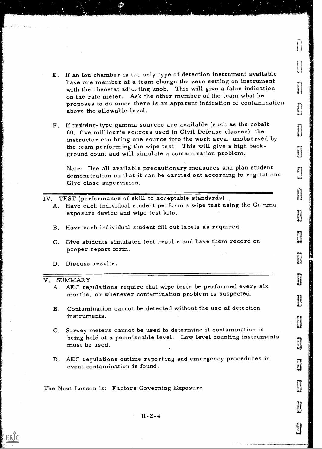
E. If an Ion chamber is ti- only type of detection instrument availablehave one member of a team change the zero setting on instrumentwith the rheostat adjusting knob. This will give a false indicationon the rate meter. Ask the other member of the team what heproposes to do since there is an apparent indication of contaminationabove the allowable level.
F. If training-type gamma sources are available (such as the cobalt60, five millicurie sources used in Civil Defense classes) theinstructor can bring one source into the work area, unobserved bythe team performing the wipe test. This will give a high back-ground count and will simulate a contamination problem.
Note: Use all available precautionary measures and plan studentdemonstration so that it can be carried out according to regulations.Give close supervision.
IV. TEST (performance of skill to acceptable standards)A. Have each individual student perform a wipe test using the Gs . nma
exposure device and wipe test kits.
B. Have each individual student fill out labels as required.
C. Give students simulated test results and have them record onproper report form.
D. Discuss results.
V. SUMMARYA. AEC regulations require that wipe tests be performed every six
months, or whenever contamination problem is suspected.
B. Contamination cannot be detected without the use of detectioninstruments.
C. Survey meters cannot be used to determine if contamination isbeing held at a permissable level.. Low level counting instrumentsmust be used.
D. AEC regulations outline reporting and emergency procedures inevent contamination is found.
The Next Lesson is: Factors Governing Exposure
11-2-4
INSTRUCTOR'S LESSON PLANRelated Technical Information
Unit 12Lesson 1
Time 1. 5 hours
SUBJECT: Factors Governing Exposure
AIM (or purpose): To teach the essential.factors which govern the timecalculation
TEACHING AIDS: Equivalence Factors P. 18 Eastman Kodak Testbook(table)
REFERENCES: Radiography in Modern Industry, 1958, Eastman Kodak Co.,Rochester, N. Y.
I. PREPARATION (of the learner)Explain the importance of this lesson by discussing and emphasizingthe following points:A. The calculation of exposure is the task in which the radiographer
has the most difficulty. Explain why.
B. A basic understanding of the methods of exposure calculation isnecessary for the student to .w3come a successful radiographer.Give reasons why this is true.
Note to Instructor: This lesson is an overview of all the factorsgoverning exposure. Individual factors will be covered byother lesson plans. The student should not be expected toretain all the information presented at this time.
II. PRESENTATION (of the information)
Instructional TopicsA. Factors governing
exposure1. Radiation source and
strength2. Film type3. Source to film
distance
Things to Remember to Do or Say1. Explain the effect of each factor
which alters the exposure setup:a. Source penetrating ability
determines its density andthickness applications.
WIMI=NNII
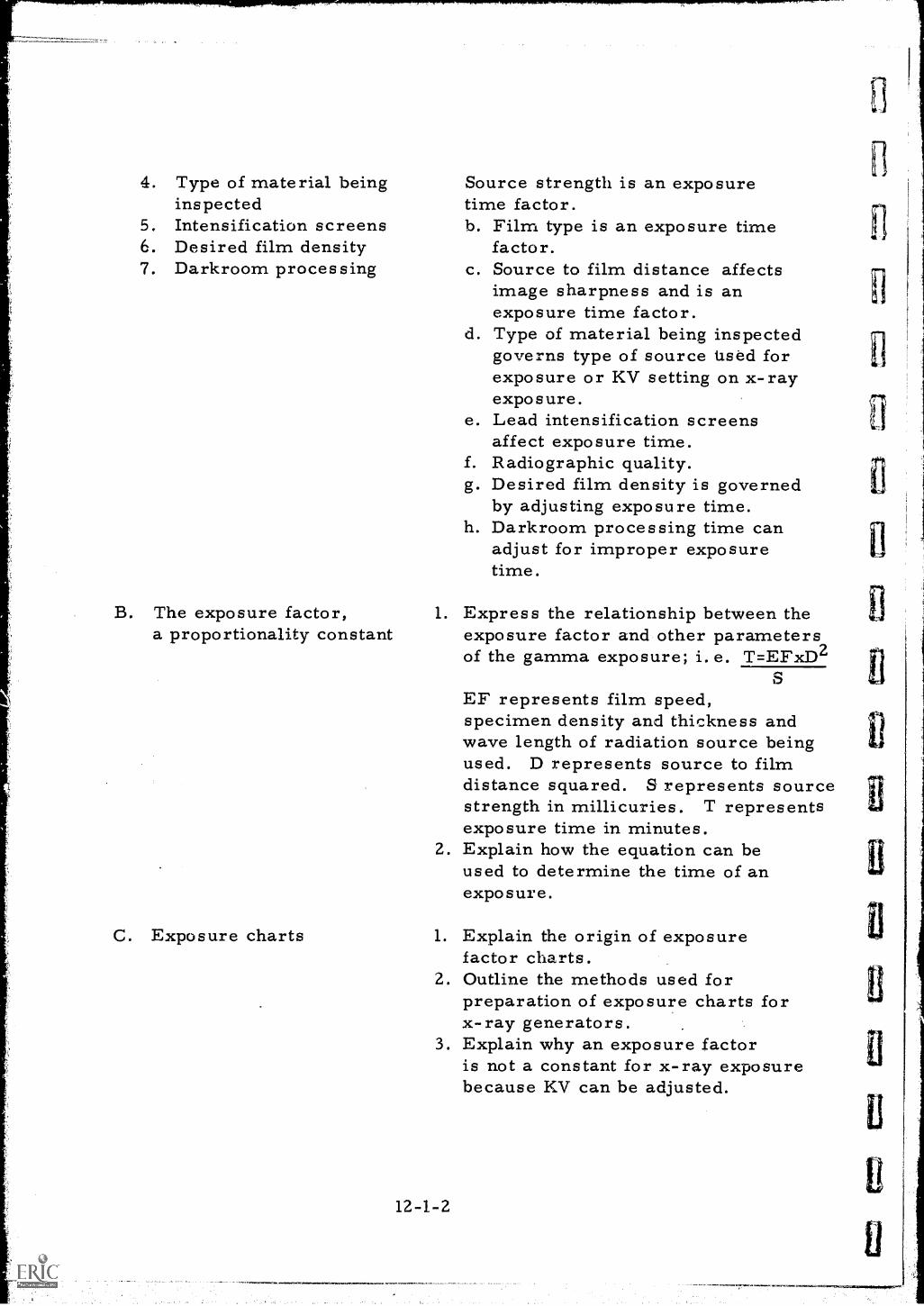
4. Type of material beinginspected
5. Intensification screens6. Desired film density7. Darkroom processing
B. The exposure factor,a proportionality constant
C. Exposure charts
Source strength is an exposuretime factor.b. Film type is an exposure time
factor.c. Source to film distance affects
image sharpness and is anexposure time factor.
d. Type of material being inspectedgoverns type of source tised forexposure or KV setting on x-rayexposure.
e. Lead intensification screensaffect exposure time.Radiographic quality.Desired film density is governedby adjusting exposure time.
h. Darkroom processing time canadjust for improper exposuretime.
f.g.
1. Express the relationship between theexposure factor and other parametersof the gamma exposure; i. e. T=EFxD2
SEF represents film speed,specimen density and thickness andwave length of radiation source beingused. D represents source to filmdistance squared. S represents sourcestrength in millicuries. T representsexposure time in minutes.
2. Explain how the equation can beused to determine the time of anexposure.
1. Explain the origin of exposurefactor charts.
2. Outline the methods used forpreparation of exposure charts forx-ray generators.
3. Explain why an exposure factoris not a constant for x-ray exposurebecause KV can be adjusted.
12-1-2
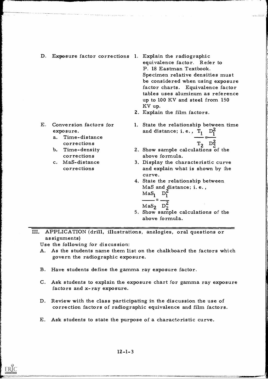
D.
E.
Exposure factor corrections
Conversion factorsexposure.a. Time-distance
correctionsb. Time-density
correctionsc. MaS-distance
corrections
for
1. Explain the radiographicequivalence factor. Refer toP. 18 Eastman Textbook.Specimen relative densities mustbe considered when using exposurefactor charts. Equivalence factortables uses aluminum as referenceup to 100 KV and steel from 150KV up.
2. Explain the film factors.
1. State the relationship between timeand distance; i. e. , Tl Dl
T D22 22. Show sample calculations of the
above formula.3. Display the characteristic curve
and explain what is shown by thecurve.
4. State the relationship betweenMaS and distance; i. e. ,
MaS1
D21
MaS2 Dz5. Show sample calculations of the
above formula.
III. APPLICATION (drill, illustrations, analogies, oral questions orassignments)
Use the following for discussion:A. As the students name them list on the chalkboard the factors which
govern the radiographic exposure.
B. Have students define the gamma ray exposure factor.
C. Ask students to explain the exposure chart for gamma ray exposurefactors and x-ray exposure.
D. Review with the class participating in the discussion the use ofcorrection factors of radiographic equivalence and film factors.
E. Ask students to state the purpose of a characteristic curve.
12-1-3
F. Using a gamma exposure factor chart, have students calculatethe time for a typical radiographic exposure.
IV. TEST (final check on students' comprehension of material presented)A. Suggested questions for a short written test:
1. List five factors which will alter the radiographic exposure.2. What is a gamma exposure factor?3. What is meant by radiographic equivalence?4. What is the purpose or the characteristic curve?5. What is meant by film factors?
B. With the class assisting check the answers to the test makingsure that all answers are corrected.
V. SUMMARYA. Many factors govern the selectior of proper exposure time.
(Check off list in A of Step II)
B. Exposure factor is a proportionality constant and differs witheach type film and gamma source.
C. Exposure charts simplify exposure computations.
D. Exposure factors are a combination of film speed, KV orMEV rating of radioactive source, daici specimen density andthickness .
E. Conversion factors are for time-distance, time-density, andMPS -distance adjustments.
The Next Lesson is: Calculation of a Gamma Exposure
12-1-411
INSTRUCTOR'S LESSON PLANRelated Technical Information
Unit 12
Lesson 2Time 2 hours
SUBJECT: Calculations of a Gamma Exposure
AIM (or purpose): To adequately outline the use of mathematicalexpressions used for exposure calculations
MATERIALS: Film suppliers exposure factor charts for eachstudent, Ansco C70d-31 Table of material or radiographicequivalence factors
REFERENCES: Radiography Modern Industry, 1958, Eastman Kodak Co.,Rochester, N. Y.Information Sheets #28, #29, and #30
I. PREPARATION (of the learner)A. It should be pointed out to the student body that radiography is not an
exact science, therefore, it will always be important to make useof all information that will help to improve the final product, theradiographer, and hold the element of variability to a minimum.This lesson is calculated to assist the radiographer in correctlycalculating the time it will take to make a radiographic exposureof the desired relative density. Inability to calculate exposuretime correctly may require that the specimen be re-radiographedone or more times.
B. An explanation should also be given regarding the methods ofdetermining the exposure necessary to produce an acceptableradiograph and how these methods can be applied to varioussituations.
II. PRESENTATION (of the information)
Instructional To icsA. The exposure factor
Thins to Remember to Do or Sa1. Define on the chalkboard the
exposure factor as a proportionalityfactor between thickness and time
12-2-1
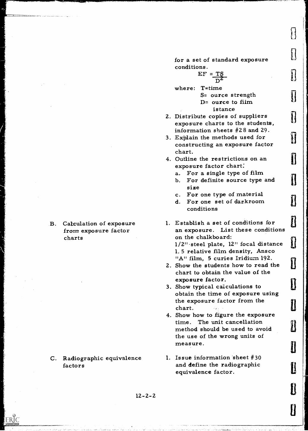
for a set of standard exposureconditions.
EF = TSD`
where: TmtimeS= ource strengthD= ource to film
istance2. Distribute copies of suppliers
exposure charts to the students,information sheets #2 8 and 29.
3. Explain the methods used forconstructing an exposure factorchart.
4. Outline the restrictions on anexposure factor chart:a. For a single type of filmb. For definite source type and
sizec. For one type of materiald. For one set of darkroom
conditions
B. Calculation of exposure 1. Establish a set of conditions forfrom exposure factor an exposure. List these conditionscharts on the chalkboard:
1/2"steel plate, 12" focal distance1. 5 relative film density, Ansco"A" film, 5 curies Iridium 192.
2. Show the students how to read thechart to obtain the value of theexposure factor.
3. Show typical calculations toobtain the time of exposure usingthe exposure factor from thechart. 1
4. Show how to figure the exposuretime. The unit cancellationmethod should be used to avoidthe use of the wrong units ofmeasure.
C. Radiographic equivalencefactors
12-2-2
1. Issue information sheet #30and define the radiographicequivalence factor.
fl
D. Problems
E. Expos ure factor tables
2. Show the procedure for obt ainingthe equivalent thickness of steelfrom the thickness of anothermaterial.
3. Explain and illustrate by workingproblem on chalkboard usinginformation listed on exposurechart.
1. Example problems2. Work problems3. Ask questions4. Determine that there is full
understanding.
1. Tables for frequently used pipeand plate sizes are time savers.
2. A separate exposure factor columnis necessary for each type film.
3. Outside pipe diameters do notvary with pipe wall thickness.
4. Use of tables cut down figuringtime.
5. Work sample problems on chalk-board using information sheet
6. Ask questions.
III. APPLICATION (drill, illustrations, analogies, oral questions oras signments)
A. Request students to illustrate to the class on the chalkboard, thecalculation of exposure time using a. different set of conditionsfor each student.
B. Have various individuals determine the time for an exposure usinga set of conditions listed on the chalkboard. Student shouldrestate these conditions on their individual papers.
C. Suggest that students calculate exposure times for the followingproblems using an exposure table:a. 1" steel plate 12" in diameter. Use 5 curies, Iridium 192b. 8" pipe, 3/8" wall thickness. Use 5c. IR. 192
D. Have group calculate exposure time for the following problemsusing an Ansco exposure chart:
12-2-3
a. 1" steel, focal distance 10", relative density 2.0, usingAnsco "A" film and a 1 curie source of Iridium 192.
b. 2" steel, focal distance 14" relative density 1.5 using Ansco"C" film and 10 curies of Iridium 192.
IV. TEST (final check on students' comprehension of material presented)NOTE: Written TestA. What is the time for exposure of a 1" thick steel plate at a film-
focal distance, of 24" for a density of 2.0 using Ansco A film and a20 curie source of Iridium 192?
B. What is the time for exposure of a 4" thick aluminum plate at afilm-focal distance of 36" for a density of 2.0 using Ansco B filmand a 15 curie source of Iridium 192?
C. a piece of Ansco A film was exposed through 1" of steel for2 minutes from a distance of 24" to produce a density of 2.0, whatis the strength of the Iridium 192 source needed to malcl theexposure?
Check and discuss.
V. SUMMARYA. Exposure factor represents the kind of gamma material and
type of film being used.
B. Charts and tables enable you to figure exposure times quicklyand accurately.
C. Exposure time considerations include:1. Specimen material2. Film-focal distance3. Relative density of film4. Film type5. Type of gamma source6. Source strength
The Next Lesson is: Conversion Formulas and Graphs used in X-rayExposure Calculations
INSTRUCTOR'S LESSON PLANRelated Technical Information
Unit 12
Lesson 3
Time 2 hours
SUBJECT: Conversion Formulas and Graphs used in X-ray ExposureCalculations
AIM (or purpose): To clarify and provide practice in the u 'e of themathematical expressions employed in exposurecalculations
REFERENCES: Radiography Industry, 1958, Eastman KodakCo., Rochester, N. Y., Pages 42 and 43.
PREPARATION (of the learner)A. Outline the topic and explain the purpose of this lesson. Pointing
out that although it is possible to make radiographs without makinguse of the characteristic curves for each type Film, an unnerstandingof the curves will eliminate a lot of guesswork in selecting themost appropriate film for a given assignment. These curves areespecially helpful in selecting the right film when radiographingcastings having a wide latitude of thickness. Operators who guessat the proper type of film to use are sometimes referred to as"picture takers" implying that their capabilities are limited toopening and closing a shutter. Therefore, take advantage of thesecharacteristic curves and eliminate the possibility of being socate gorized.
B. Stress the fact that a student must know the correct method ofdetermining the x-ray exposure times necessary to producesatisfactory or acceptable results if he is to succeed as a radiographer.
II. PRESENTATION (of the information)
Instructional TopicsA. Conversion formulas
Things to Remember to Do or Say1. Explain that a conversion formula
is used to adjust exposure time forfocal-film distance, film speed, andMa settings.
12-3-1
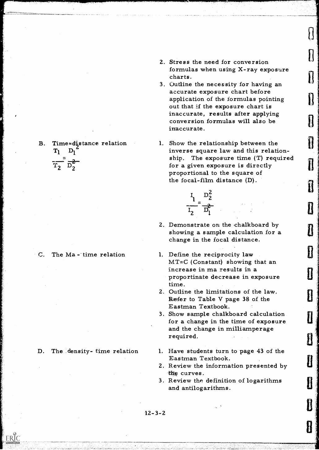
B. Time;.qstance relationT1 D1
T2 D2
C. The Ma -'time relation
D. The density- time relation
2. Stress the need for conversionformulas when using X-ray exposurecharts.
3. Outline the necessity for having anaccurate exposure chart beforeapplication of the formulas pointingout that if the exposure chart isinaccurate, results after applyingconversion formulas will also beinaccurate.
1. Show the relationship between theinverse square law and this relation-ship. The exposure time (T) requiredfor a given exposure is directlyproportional to the square ofthe focal-film distance (D).
I D21 2
12 Di
2. Demonstrate on the chalkboard byshowing a sample calculation for achange in the focal distance.
1.
2.
3.
Define the reciprocity lawMT=C (Constant) showing that anincrease in ma results in aproportinate decrease in exposuretime.Outline the limitations of the law.
tfer to Table V page 38 of theEastman Textbook.Show sample chalkboard calculationfor a change in the time of exposureand the change in milliamperagerequired.
1. Have students turn to page 43 of theEastman Textbook.
2. Review the information presented byth* curves.
3. Review the definition of logarithmsand antilogarithms.
12-3-2
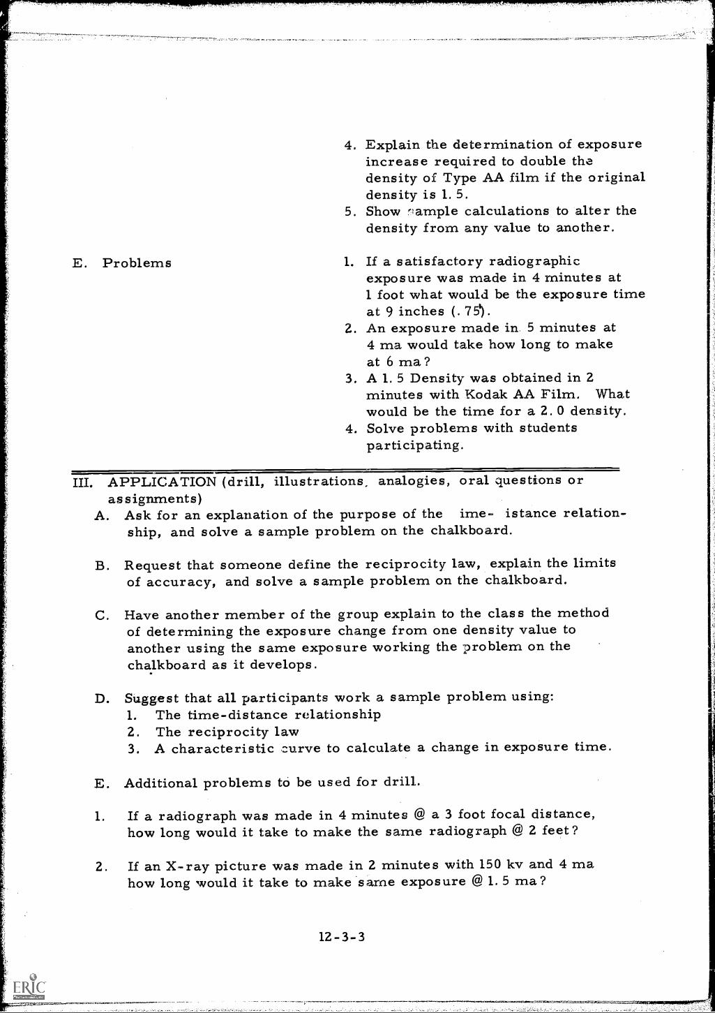
E. Problems
4. Explain the determination of exposureincrease required to double thedensity of Type AA film if the originaldensity is 1. 5.
5. Show rlample calculations to alter thedensity from any value to another.
1. If a satisfactory radiographicexposure was made in 4 minutes at1 foot what would be the exposure timeat 9 inches (.75').
Z. An exposure made in. 5 minutes at4 ma would take how long to makeat 6 ma?
3. A 1.5 Density was obtained in 2minutes with Kodak AA Film. Whatwould be the time for a 2.0 density.
4. Solve problems with studentsparticipating.
III. APPLICATION (drill, illustrations, analogies, oral questions orassignments)
A. Ask for an explanation of the purpose of the ime- istance relation-ship, and solve a sample problem on the chalkboard.
B. Request that someone define the reciprocity law, explain the limitsof accuracy, and solve a sample problem on the chalkboard.
C. Have another member of the group explain to the class the methodof determining the exposure change from one density value toanother using the same exposure working the problem on thechalkboard as it develops.
D. Suggest that all participants work a sample problem using:1. The time-distance relationship2. The reciprocity law3. A characteristic curve to calculate a change in exposure time.
E. Additional problems to be used for drill.
1. If a radiograph was made in 4 minutes @ a 3 foot focal distance,how long would it take to make the same radiograph @ 2 feet?
2. If an X-ray picture was made in 2 minutes with 150 kv and 4 mahow long would it take to make same exposure @ 1. 5 ma?
12-3-3
r
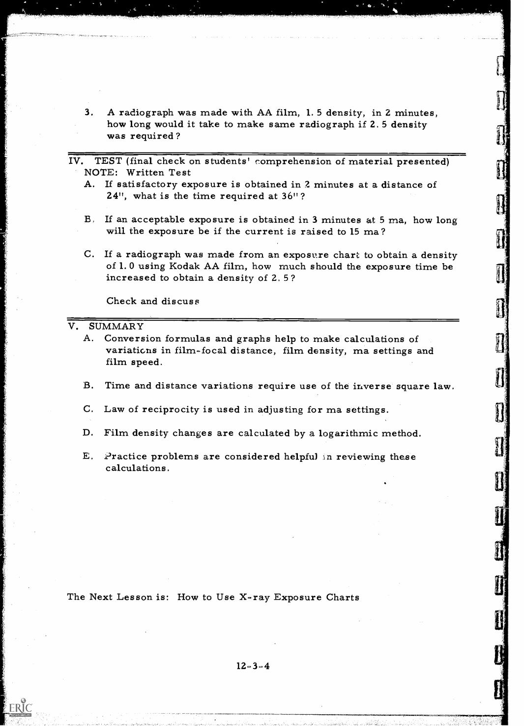
*Ai
3. A radiograph was made with AA film, 1. 5 density, in 2 minutes,how long would it take to make same radiograph if 2. 5 densitywas required?
IV. TEST (final check on students' comprehension of material presented)NOTE: Written TestA. If satisfactory exposure is obtained in 2 minutes at a distance of
24", what is the time required at 36" ?
B. If an acceptable exposure is obtained in 3 minutes at 5 ma, how longwill the exposure be if the current is raised to 15 ma?
C. If a radiograph was made from an exposure chart to obtain a densityof 1.0 using Kodak AA film, how much should the exposure time beincreased to obtain a density of 2, 5?
Check and discuss
V. SUMMARYA. Conversion formulas and graphs help to make calculations of
variations in film-focal distance, film density, ma settings andfilm speed.
B. Time and distance variations require use of the inverse square law.
C. Law of reciprocity is used in adjusting for ma settings.
D. Film density changes are calculated by a logarithmic method.
E. .L-Iractice problems are considered helpfu) in reviewing thesecalculations.
The Next Lesson is: How to Use X-ray Exposure Charts
12-3-4
INSTRUCTOR'S LESSON PLANRelated Technical Information
Unit 12Lesson 4Time 2 hours
SUBJECT: How to Use X-ray Exposure Charts
AIM (or purpose): To promote the use of x-ray exposure charts
R.7FERENCES: Radiography in Modern Industry, 1958, Eastman Kodak Co. ,
Rochester, N. Y. (Charts on pgs. 40 through 46)
I. PREPARATION (of the learner)A. Develop interest by pointing out that x-rays and gamma rays are
sometimes considered alike in every aspect except that theirorigins differ. Discuss the possibility that exposure timebe figured by one common method for x-rays and gamma raysexplaining to the class what the basic difference is, and its effecton time calculations.
B. Point out that this lesson will explain the various methods thatcan be used to figure x-ray exposure times. X-ray quality canbe altered by adjusting a knob on the x-ray console controlling thekv (kilovoltage). This means that with the x-rays you can selectthe radiation quality that should give the best results for aparticular application. This also means that exposure time willdiffer with each setting. An x-ray exposure chart is a graphshowing the relation between material thickness, kilovoltage, andexposure. Although exposure charts are available from manufacturersof x-ray equipment, corrections must be made for differentbrand generators. It is, therefore, considered desirable to preparean exposure chart for ones own x-ray generator.
II. PRESENTATION (of the information)
Instructional To ics Things to Remember to Do or SayA. The x -ray exposure
chart1. Refer students to pages 40 to 46
in the reference textbook explainingthe purpose of the exposure chart.
12-4-1
a. Exposure chart usually offersa choice of about four KVselections.
b. Exposure time is usually shownin milliampere seconds.
c. One or two film-focal distancesare usually listed.
d. One relative film density isused.
e. Conversion factors are availablefor changes in speed and filmdensity.
B. Figuring exposure from 1. Establish a set of conditions forthe x-ray exposure an exposure listing these conditionschart on the chalkboard.
2. Determine the kilovoltage for theexposure from the graphs ofrecommended voltage.
3. Illustrate the selection of the correctexposure from the chart.
4. If the exposure is given in milli-ampminutes, show how to obtain thetime in minutes. If one ma is beingused, read time directly; if two maare used divide by 2, etc.
El
n
C. Film factors for change of 1. Define film speed and film factor.film types Film speed is relative; coarse grain
film is faster than fine grain film. 11If one film has a relative speed of 1and another film has a relative speedof 2, then the exposure factor forfilm with relative speed of 2 is twiceas long as that for film with arelative speed of 1. NOTE: Anindustrial x-ray film is seldom describedas being coarse grained, it is usuallydescribed "less fine", "very fast".
2. Explain how this factor can be usedto obtain an equivalent exposure witha different type of film. Use filmspeed comparison between the twotype films and increase or decreasetime accordingly.
12-4-2
D. Film speed tables 1. Turn to page 55 of Eastman Textbook.Refer to the column on relative speed.Discuss differencies in film speedbetween Kodak AA and Kodak M film.(Ratio is 30:200 at 200 KV), Discusshow ratio changes with KV change.
III. APPLICATION (drill, illustrations, analogies, oral questions oras signments)
A. Suggest that students calculate the exposure for several sets ofconditions. Ask the students to explain their method of figuring tothe other students.
B. Have others in the group establish the time for exposure using aset of conditions listed on the chalkboard. Students should alsolist these conditions as a part of the solution to the problem.
C. Invite participating members to determine the new exposure timecaused by changing the film from that specified on the exposurechart to another type.
IV. TEST (final check on students' comprehension of material presented)NOTE: Written TestA. In radiographing a part made of 3/4" thick steel, what is the
exposure time to obtain a radiograph of 1.5 density on Kodak AAfilm using a film-focal distance of 40" using 200 kv and 2 ma?
B. What is the exposure time of the same set up if the film is Kodak M?
C. If the part is steel 1 1/4" thick, what is the exposure time toobtain a radiograph of 1.5 density on Kodak M film using a film-focal distance of 40" and 3 ma?
V. SUMMARYA. X-ray exposure charts are used to figure x-ray exposure times.
B. Resultant time can be given in milliampere minutes, or milli-ampere seconds.
C. Each line on the chart represents a different kilovoltage setting.
D. Times are shown for a 1 inilliampe rage setting. Settings higherthan 1 will reduce exposure time proportionally.
The Next Lesson is: X-ray Exposure Charts
12-4-3
EXPERIMENT SHEETX-ray Exposure Charts
Unit 12
Lesson 5Time 4 hours
SUBJECT:Construction of an exposure chart for an industrial x-ray generator
NOTE:Instructor performs all operations
INTRODUCTORY INFORMATION:Problems of exposure calculation have been presented in the classroom using an x-ray exposure chart. These charts are publishedand are generally furnished by the manufacturer; however, it isgenerally considered good practice to prepare a chart on eachgenerator because of their variations in output. It is the purpose ofthis experiment to develop an x-ray exposurr, chart for a particulargenerator.
MATERIALS AND EQUIPMENT:X-ray generator and exposure facilitiesFilm cassettes loaded with Kodak AA film and . 005" lead screensfront and backSteel step wedges, 1/4" to 1 1/2" in 1/4" stepsDensitometerLead sheet for masking wedgesDarkroom facilitiesSemi-log graph paper, two cycle, 70 divisionsClean rags
REFERENCES:Radiography de / Industry, 1958, Eastman Kodak Co. , Rochester,N. Y. , page 40
PROCEDURES:A. Clean and examine cassettes before loading film. Use lead screens
which have no visible defects.
B. Single load eight cassettes with Kodak AA film.12-5-1
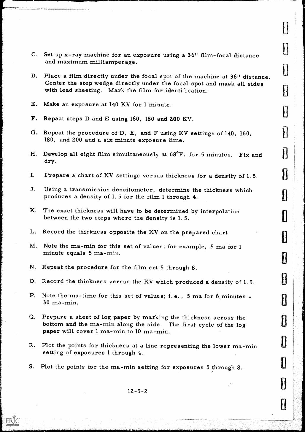
C. Set up x-ray machine for an exposure using a 36" film-focal distanceand maximum milliamper age.
D. Place a film directly under the focal spot of the machine at 36" distanceCenter the step wedge directly under the focal spot and mask all sideswith lead sheeting. Mark the film for identification.
E. Make an exposure at 140 KV for 1 minute.
F. Repeat steps D and E using 160, 180 and 200 KV.
G. Repeat the procedure of D, E, and F using KV settings of 140, 160,180, and 200 and a six minute exposure time.
H. Develop all eight film simultaneously at 68°F. for 5 minutes. Fix anddry.
I. Prepare a chart of KV settings versus thickness for a density of 1. 5,
J. Using a transmission densitometer, determine the thickness whichproduces a density of 1.5 for the film 1 through 4.
K. The exact thickness will have to be determined by interpolationbetween the two steps where the density is 1.5.
L. Record the thickness opposite the KV on the prepared chart.
M. Note the ma-min for this set of values; for example, 5 ma for 1minute equals 5 ma-min.
N. Repeat the procedure for the film set 5 through 8.
0. Record the thickness versus the KV which produced a density of 1.5.
P. Note the ma-time for this set of values; i.e. , 5 ma for 6 minutes =30 ma-min.
Q. Prepare a sheet of log paper by marking the thickness across thebottom and the ma-min along the side. The first cycle of the logpaper will cover 1 ma-min to 10 ma-min.
R. Plot the points for thickness at "J. line representing the lower ma-minsetting of exposures 1 through
S. Plot the points for the ma-min setting for exposures 5 through 8.
12-5-2
T. Connect the point for each KV setting by straight lines. Extendthese lines to the edge of the graph.
U. Label each KV line with the appropriate value.
CAUTION: Make sure only one thickness lead screens are usedfor this experiment.
CONCLUSIONS:A. The prepared chart is valid for a density of .
B. Type must be used when using this chant.
C. If an exposure was made of a 3/4" thick piece of steel using a 36"film-focal distance, 5 ma, and 160 KV, the time of exposure wouldbe
D. The purpose of the lead sheet masks is .
The Next Lesson is: Scattered Radiation
12- 5- 3
.
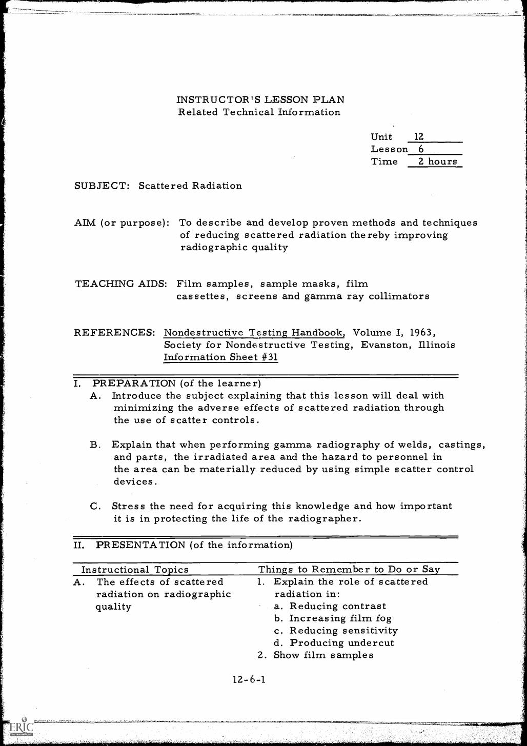
INSTRUCTOR'S LESSON PLANRelated Technical Information
Unit 12
Lesson 6Time 2 hours
SUBJECT: Scattered Radiation
AIM (or purpose): To describe and develop proven methods and techniquesof reducing scattered radiation thereby improvingradiographic quality
TEACHING AIDS: Film samples, sample masks, filmcassettes, screens and gamma ray collimators
REFERENCES: Nondestructive Testing Handbook, Volume I, 1963,Society for Nondestructive Testing, Evanston, IllinoisInformation Sheet #31
I. PREPARATION (of the learner)A. Introduce the subject explaining that this lesson will deal with
minimizing the adverse effects of scattered radiation throughthe use of scatter controls.
B. Explain that when performing gamma radiography of welds, castings,and parts, the irradiated area and the hazard to personnel inthe area can be materially reduced by using simple scatter controldevices.
C. Stress the need for acquiring this knowledge and how importantit is in protecting the life of the radiographer.
II. PRESENTATION (of the information)
Instructional To icsA. The effects of scattered
radiation on radiographicquality
Thins to Remember to Do or Sa1. Explain the role of scattered
radiation in:a. Reducing contrastb. Increasing film fogc. Reducing sensitivityd. Producing undercut
2. Show film samples
12-6 -1
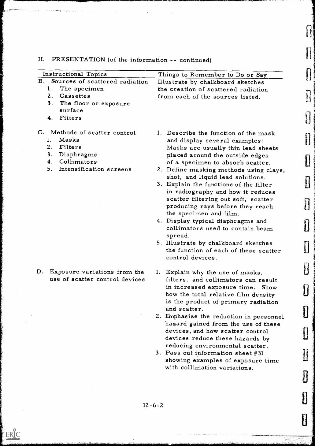
II. PRESENTATION (of the information -- continued)
Instructional To ics Thins to Remember to Do or Sa.B. Sources of scattered radiation
1. The specimen2. Cassettes3. The floor or exposure
surface4. Filters
C. Methods of scatter control1. Masks2 . Filters3. Diaphragms4. Collimators5. Intensification screens
Illustrate by chalkboard sketchesthe creation of scattered radiationfrom each of the sources listed.
1. Describe the function of the maskand display several examples:Masks are usually thin lead sheetsplaced around the outside edgesof a specimen to absorb scatter.
2. Define masking methods using clays,shot, and liquid lead solutions.
3. Explain the functions of the filterin radiography and how it reducesscatter filtering out soft, scatterproducing rays before they reachthe specimen and film.
4. Display typical diaphragms andcollimators used to contain beamSpread.
5. Illustrate by chalkboard sketchesthe function of each of these scattercontrol devices.
D. Exposure variations from the 1. Explain why the use of masks,use of scatter control devices filters, and collimators can result
in increased exposure time. Showhow the total relative film densityis the product of primary radiationand scatter.
2. Emphasize the reduction in personnelhazard gained from the use of thesedevices, and how scatter controldevices reduce these hazards byreducing environmental scatter.
3. Pass out information sheet #31showing examples of exposure timewith collimation variations.
12-6-2
sl
III. APPLICATION (drill, illustrations, analogies, oral questions orassignments)
A. Invite students to describe to the class the origin of scatteredradiation and its effect on the quality of the radiograph.
B. Ask members of the group to outline several sources of scatteredradiation and the methods of controlling the scatter.
C. Suggest that students draw a chalkboard sketch of a radiographicsetup using good scatter control techniques on a part of complicatedshape.
D. Have the group define the increased safety derived from the useof scatter control devices.
IV. TEST (final check on students' comprehension of material presented)NOTE: Written TestA. What are the advantages that ensue from the reduction of scattered
radiation?
B. Why does the reduction in scatter generally result in increased exposuretime?
C. List three scatter control devices and tell how they reduce scatter.
D. Describe at least three methods of masking to reduce scatter.
E. What function does the collimator serve besides the reduction ofscatter ?
Check and discuss,
V. SUMMARYA. Radiation scatter has a very detrimental effect on image quality.
B. Many factors contribute to creation of this adverse effect.
C. Several methods are used to minimize this adverse effect.
D. Elimination of scatter effect increases exposure time but alsoincreases image quality.
E. Personnel safety is increased by controlling environmentalscatter.
The Next Lesson is: The Control of Scattered Radiation
12-6-3
EXPERIMENT SHEETThe Control of Scattered Radiation
Unit 12
Les sonTime 3 hours
SUBJECT:Methods of reducing scattered radiation and improving radiographicquality
NOTE:Inthitructor performs all operations
INTRODUCTORY INFORMATION:Production of high quality radiographs reqvires the use of manytechniques. The use of good exposure techniques, proper selection offilm, and good dark room procedures will not always guarantee asatisfactory radiograph. Reduction of scattered radiation is also anessential necessity for the detection of very fine defects. Thisexperiment will show the difference in quality obtained from goodscatter control techniques.
MATERIALS AND EQUIPMENT:X-ray generator and exposure facilitiesFilm cassettes, 0> 005 and 0.010 lead screens, and film2" thick aluminum castingLead sheet, barium clay, and lead acetate solutionsPenetrametersFilm viewerLead numbersDark room facilities with equipment, timer, materials, etc.
PROCEDURE:A. Single load a film ca3sette with film and remove the intensifying
screens.
B. Set up the x-ray generator for an exposure of the aluminum castingusing 160 KV and the exposure chart constructed in a previousexperiment. Use radiographic equivalence factors to determine thethickness of steel to be used in the exposure determination.
12-7-1
C. Place a 1" thick piece of wood on a steel plate and position the filmon the wood block directly under the focal spot of the x-ray generator.Center the casting on the film. Mark the film for identification.Place a 2-2T penetrameter on the casting in the area of interest.
D. Expose the film to obtain a density of 2.0 in the area of interest.
E. Single load another cassette with the same film using a .005 front anda 0.010 back screen.
F. Place the film on a thick sheet of lead under the focal spot of thegenerator.
G. Position the part on the film using a good masking technique. Awater tight aluminum pan is required if liquid masking is used.CAUTION: Liquid lead solutions are poisonous and must be handledwith care.
H. Mark the film for identification and place a 2-2T penetrameter onthe casting.
I. Place a diaphragm on the tube port of the x-ray generator.
J. Expose the film using the same exposure as in the first film.
K. Develop both films simultaneously at 68°F. for 5 minutes. Fix anddr y
L. Place film on a viewer and compare the results.
CONCLUSIONS:A. The increased sensitivity of film number two is due to
B. The effect of the screens in the cassettes is to
C. The two filmarea of interest,
or of the same density in the
D. The purpose of the lead back up shee' in exposure number two wasto
The Next Lesson is: Exposure Changes for Changing Densities
12-7-2
EXPERIMENT SHEETExposure Changes for Changing Density
Unit .12Lesson 8Time 3 hours
SUBJECT:Changing the density of radiographs from one value to a seconddesired value
NOTE:Instructor performs all 'operations
INTRODUCTORY INFORMATION:The exposure charts for x-ray radiography are constructed for a fixeddensity. It is often necessary to change the density of a radiographto comply with specifications, increase contrast, or to improve thereadability of the film. The radiographer should be able to adjust thedensity of the film by adjustment of the exposure time given by theexposure chart.
MATERIALS AND EQUIPMENT:X-ray generator and exposure facilitiesFilm cassettes and Kodak AA filmSample part for inspectionDensitometerCharacteristic curves for type AA filmDarkroom facilities including equipment, materials, lead numbers, etc.Logarithm tables
PROCEDURE:A. Single load film cassettes with type AA film.
B. Set up the x-ray generator for an exposure of the sample part usingthe exposure chart constructed in a 'previous experiment.
C. Place a film directly under the focal spot of the machine andcenter, the sample part on the film. Mark the film f:or identification.
D. Make an exposure in accordance with the exposure chart.
12-8-1
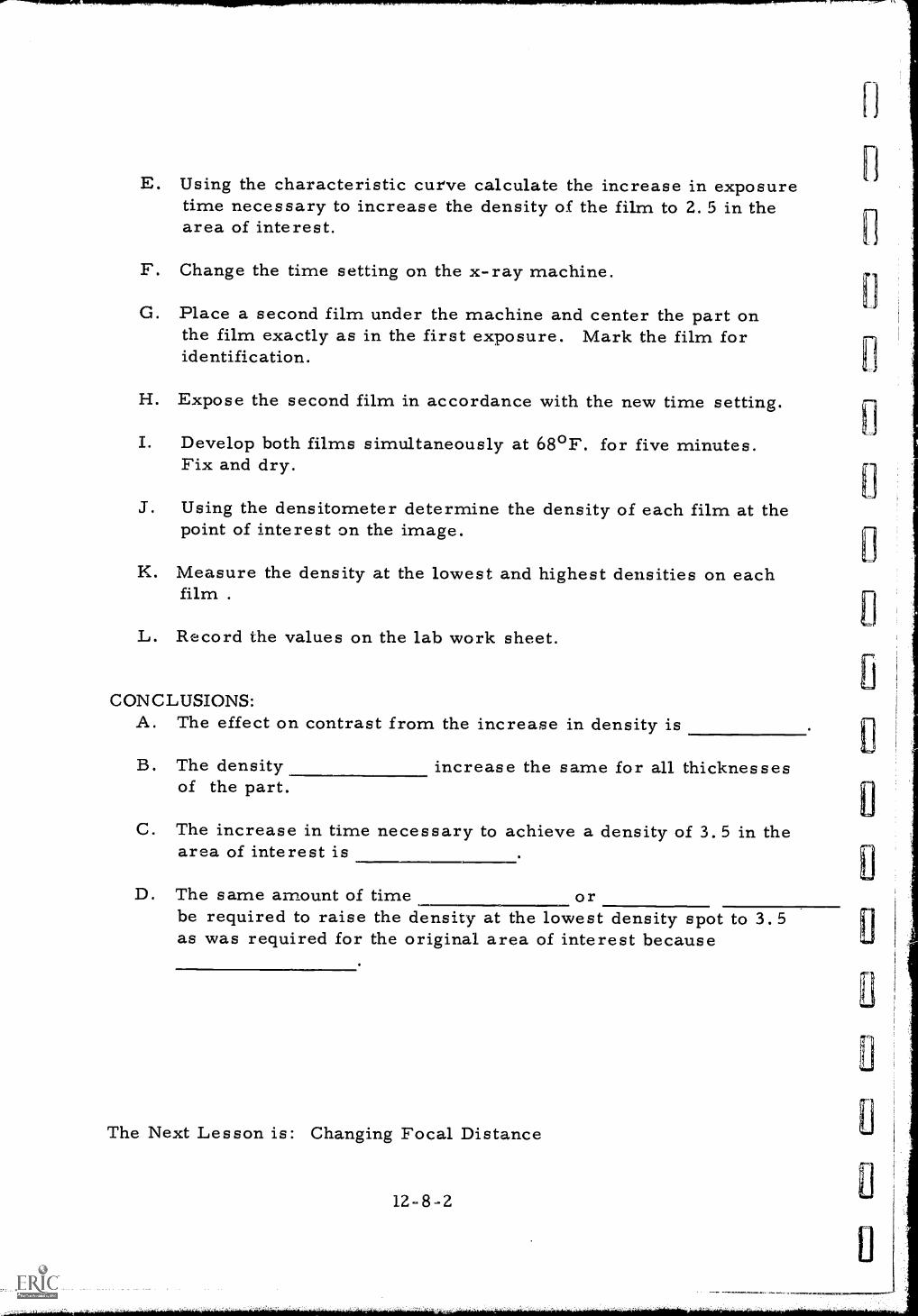
E. Using the characteristic curve calculate the increase in exposuretime necessary to increase the density of the film to 2. 5 in thearea of interest.
F. Change the time setting on the x-ray machine.
G. Place a second film under the machine and center the part onthe film exactly as in the first exposure. Mark the film foridentification.
H. Expose the second film in accordance with the new time setting.
I. Develop both films simultaneously at 68°F. for five minutes.Fix and dry.
J. Using the densitometer determine the density of each film at thepoint of interest on the image.
K. Measure the density at the lowest and highest densities on eachfilm
L. Record the values on the lab work sheet.
CONCLUSIONS:A. The effect on contrast from the increase in density is
B. The densityof the part.
increase the same for all thicknesses
C. The increase in time necessary to achieve a density of 3.5 in thearea of interest is
D. The same amount of time orbe required to raise the density at the lowest density spot to 3.5as was required for the original area of interest because
The Next Lesson is: Changing Focal Distance
12-8-2
EXPERIMENT SHEETChanging Focal Distance
Unit 12Lesson 9Time 3 hours
SUBJECT:Obt aining equivalent exposures when changing the focal distance.
NOTE: Instructor performs all operations
INTRODUCTORY INFORMATION:The exposure charts for x-ray radiography are constructed using afixed film-focal distance. It is often necessary to alter this distancebecause of the geometry of the part, obstructions in the radiationbeam path, or a desire to increase sensitivity and resolution. Theradiographer should be able to make the simple calculations required toachieve an exposure equivalent to that obtained at the standard focaldistance.
MATERIALS AND EQUIPMENT:X-ray generator and exposure facilitiesFilm cassettes and filmSample part for inspectionDensitometerDark room facilities, supplies and materialsLead numbersSix foot tape
PROCEDURE:A. Single load film cassettes with film selected for the experiment.
B. Setup x-ray generator for an exposure of the part selected ut. theexposure chart constructed in a previous experiment.
C. Place the film directly under the focal spot of the machine andcenter the sample part on the film. Mark the film for identification.
D. Make the exposure in accordance with the exposure chart.
12-9-1
E. Move the tube head of the machine from 36" to 24" focal distance.
F. Place a second film under the machine and center the part on thefilm exactly as on the first exposure. Mark the film for identification.
G. Calculate the change in time required by moving the tube head tothe new position.
H. Expose the new set up in accordance with the calculated time.
I. Develop both film simultaneously at 68°F. for 5 minutes. Fixand dry.
J. Using the densitometer, determine the density of each film at thesame point on the image of the part.
K. Record the values on the lab work sheet.
CONCLUSIONS:A. If the procedures are correctly followed, the density of the film
will be
B. When the film-f ocal distance is shortened, the intensity of theradiation beam is
C. When film-focal distance is shortened, the sharpness of the filmis
D. If the procedure did not produce the desired results, the difficultycould be caused by incorrectly the distance or anerror in
The Next Lesson is: Standards for Protection Against Radiation
12-9-2
it
INSTRUCTOR'S LESSON PLANRelated Technical Information
Unit 13Lesson 1
Time 2 hours
SUBJECT: Standards for Protection Against Radiation
AIM (or purpose): To outline the regulations imposed by the controllingagencies who issue licenses for use and possession ofradiation producing devices
REFERENCES: Information Sheet #3, #32, #33 and #34Copy of Title 10, Federal Register, Part 20, "Standardsfor Protection Against Radiation"
I. PREPARATION (of the learner)A. Introduce the topic and develop student interest by touching briefly
on the radiation banking concept and the minimum age of aradiographer. Explain what the maximum accumulated dosage is thata person may receive before he can no longer work as a radiographer,and how long a radiographer must be idle from work before he mayreturn to his duties after receiving the maximum allowable dosage.
B. Point out hcw this lesson will help the individual to better under-stand the safety rules and regulations that govern the handling, use,transfer, disposal, and possession of radioactive materials.
IL PRESENTATION (of the information)
Instructional To icsA. Definitions under Part 20
1. 20. 3-Byproduct materialCalendar quarterLicensed materialOccupational doseRadiationRadioactivematerial
Restr',,:ted areaUnrestricted area
Thins to Remember to Do or SayR_fer to Information Sheet #3and read the pertinent part ofeach definition to the class.
2. After reading each definitiontranslate the legal terminologyinto terms readily understood bythe students.
1.
13-1-1
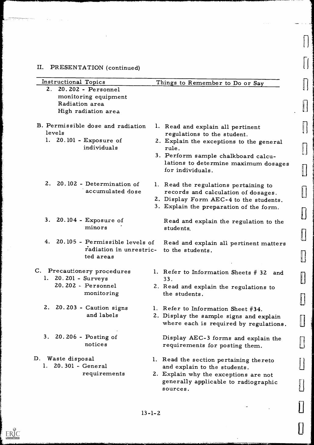
II. PRESENTATION (continued)
Instructional To ics2. 20. 202 - Personnel
monitoring equipmentRadiation areaHigh radiation area
Thins to Remember to Do or Sa
B. Permissible dose and radiationlevels1. 20.101 - Exposure of
individuals
2. 20.102 - Determination ofaccumulated dose
3. 20.104 - Exposure ofminors
1. Read and explain all pertinentregulations to the student.
2. Explain the exceptions to the generalrule.
3. Perform sample chalkboard calcu-lations to determine maximum dosagesfor individuals.
1. Read the regulations pertaining torecords and calculation of dosages.
2. Display Form AEC-4 to the students.3. Explain the preparation of the form.
4. 20.105 - Permissible levels ofradiation in unrestric-ted areas
C. Precaut!onery procedures1. 20. 201 - Surveys
20. 202 - Personnelmonitoring
2. 20.203 - Caution signsand labels
3. 20. 206 - Posting ofnotices
D. Waste disposal1. 20. 301 - General
requirements
Read and explain the regulation to thestudents.
Read and explain all pertinent mattersto the students.
1. Refer to Information Sheets # 32 and33.
L. Read and explain the regulations tothe students.
1. Refer to Information Sheet #34.2. Display the sample signs and explain
where each is required by regulations
Display AEC-3 forms and explain therequirements for posting them.
1. Read the section pertaining theretoand explain to the students.
2. Explain why the exceptions are notgenerally applicable to radiographicsources.
13-1-2
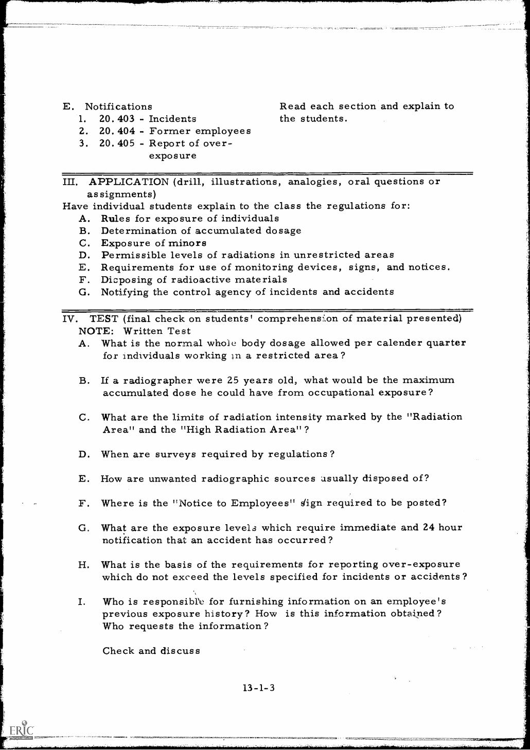
E. Notifications1. 20. 403 - Incidents2. 20. 404 - Former employees3. 20.405 - Report of over-
exposure
Read each section and explain tothe students.
III. APPLICATION (drill, illustrations, analogies, oral questions orassignments)
Have individual students explain to the class the regulations for:A. Rules for exposure of individualsB. Determination of accumulated dosageC. Exposure of minorsD. Permissible levels of radiations in unrestricted areasE. Requirements for use of monitoring devices, signs, and notices.F. Dicposing of radioactive materialsG. Notifying the control agency of incidents and accidents
IV. TEST (final check on students' comprehension of material presented)NOTE: Written TestA. What is the normal whole body dosage allowed per calender quarter
for individuals working )n a restricted area?
B. If a radiographer were 25 years old, what would be the maximumaccumulated dose he could have from occupational exposure?
C. What are the limits of radiation intensity marked by the "RadiationArea" and the "High Radiation Area"?
D. When are surveys required by regulations?
E. How are unwanted radiographic sources .asually disposed of?
F. Where is the "Notice to Employees" dign required to be posted?
G. What are the exposure levels which require immediate and 24 hournotification that an accident has occurred?
H. What is the basis of the requirements for reporting over-exposurewhich do not exceed the levels specified for incidents or accidents?
I. Who is responsible for furnishing information on an employee'sprevious exposure history? How is this information obtained?Who requests the information?
Check and discuss
13-1-3
V. SUMMARYA. A thorough understanding of the AEC standards for protection from
radiation are necessary in order to qualify for an AEC RadiographyLicense.
B. Permissible dose and radiation levels must be observed and currentrecords of dose levels must be maintained.
C. All precautionary procedures must be enforced.
D. Waste disposal procedures seldom apply to radiography licensees.
E. Notification time limits and procedures must be understood andmaintained.
The Next Lesson is: Licensing of Byproduct Materials
13-1-4
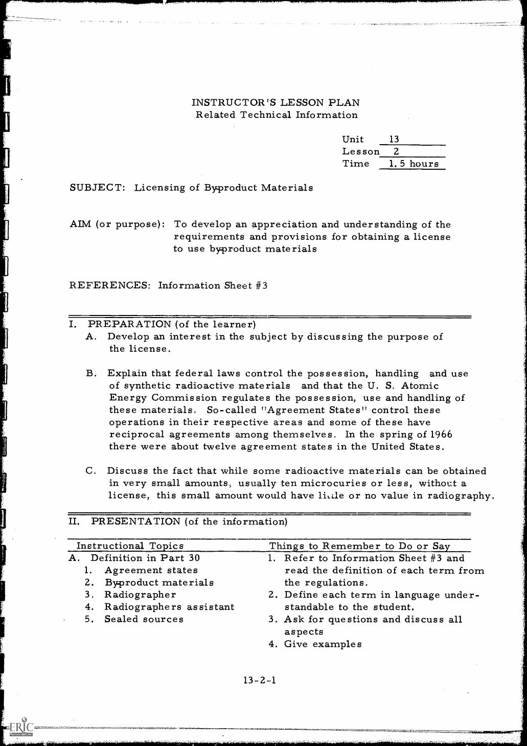
INSTRUCTOR'S LESSON PLANRelated Technical Information
Unit 13Les son 2Time 1. 5 hours
SUBJECT: Licensing of Byproduct Materials
AIM (or purpose): To develop an appreciation and understanding of therequirements and provisions for obtaining a licenseto use byproduct materials
REFERENCES: Information Sheet #3
PREPARATION (of the learner)A. Develop an interest in the subject by discussing the purpose of
the license.
B. Explain that federal laws control the possession, handling and useof synthetic radioactive materials and that the U. S. AtomicEnergy Commission regulates the possession, use and handling ofthese materials. So-called "Agreement States" control theseoperations in their respective areas and some of these havereciprocal agreements among themselves. In the spring of 1966there were about twelve agreement states in the United States.
C. Discuss the fact that while some radioactive materials can be obtainedin very small amounts, usually ten microcuries or less, without alicense, this small amount would have lit.de or no value in radiography.
II. PRESENTATION (of the information
Instructional To lesA. Definition in Part 30
1. Agreement states2. Byproduct materials3. Radiographer4. Radiographers as sistant5. Sealed sources
Thins to Remember to Do or Sa1. Refer to Information Sheet #3 and
read the definition of each term fromthe regulations.
2. Define each term in language under-standable to the student.
3. Ask for questions and discuss allaspects
4. Give examples
13-2-1
B. Exemptions 1. Read the pertinent part of each1. AEC contracts applicable section and explain to2.3.
CarriersWeak concentrations 2.
the students,Ask for questions and discuss.
4. Luminous dials 3. Give examples
C. Licenses 1. Read the applicable sections on1. Types - General and each of the listed topics.
Specific 2. Explain the regulations to the students,2. Applications 3. Ask for questions3. Requirements for issuance 4. Give examples4. Terms:
a. Transferralb. Limits of usec. Implied and written
5. Expiration, termination andrenewal
D. Enforcement1. Modification and
revocation2. Recall3. Violations
1. Read the pertinent part of eachsection and explain all subjectmatter to the student.
2. Ask questions3. Cite practical examples.
III. APPLICATION (drill, illustrations, analogies, oral questions orassignments)
Have individual students explain to the class the regulations for:A. Persons who are exempt from licensing for use and handling of
radioactive materials.
B. The types of licenses available and to whom they apply.
C. The terms of issuance, usage, and the transferral of licenses.
D. The legal measures available to the government for enforcementof the provision of a license.
IV. TEST (final check on students' comprehension of material presented)NOTE: Written TestA. What are the two types of licenses issued for use of byproduct
materials? What is the difference ?
B. Who is exempt from license requirements?
C. What is the difference between a radiographer and a radiographer's
13-2-2
11
assistant as defined by the regulations?
D. What is an agreement state? What authority does an agreement statehave over licensing?
E. What type of penalities can be imposed on persons who violate theterms of a license?
Check results and discuss.
V. SUMMARYA. The Atomic Energy Commission regulates the safe handling, use and
possession of synthetic radioactive isotopes,
B. The licensee must have a thorough understanding of these regulations.
C. These regulations include use, handling and possession of gammasources used in radiography.
D. Regulations also cover: enforcement of rules, types of licenses,requirements for issuance of licenses, definitions, agreementstates and exemptions.
The Next Lesson is: Licenses for Radiography
13-2-3
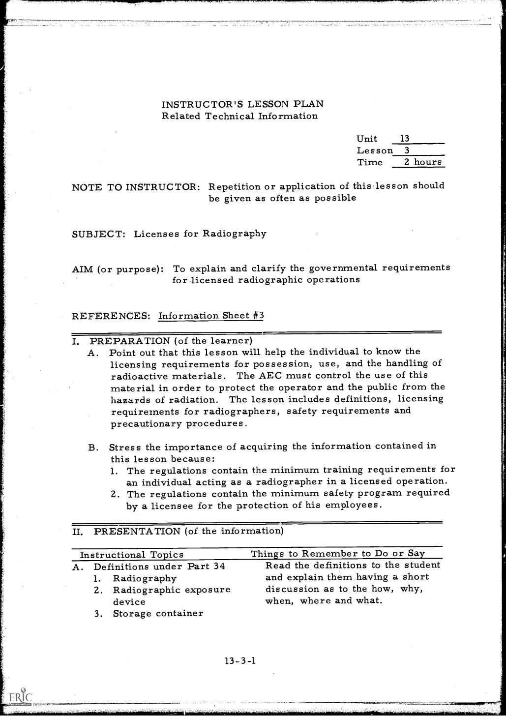
INSTRUCTOR'S LESSON PLANRelated Technical Information
Unit 13
Lesson 3
Time 2 hours
NOTE TO INSTRUCTOR: Repetition or application of this lesson shouldbe given as often as possible
SUBJECT: Licenses for Radiography
AIM (or purpose): To explain and clarify the governmental requirementsfor licensed radiographic operations
REFERENCES: Information Sheet #3
I. PREPARATION (of the learner)A. Point out that this lesson will help the individual to know the
licensing requirements for possession, use, and the handling ofradioactive materials. The AEC must control the use of thismaterial in order to protect the operator and the public from thehazards of radiation. The lesson includes definitions, licensingrequirements for radiographers, safety requirements andprecautionary procedures.
B. Stress the importance of acquiring the information contained inthis lesson because:1. The regulations contain the minimum training requirements for
an individual acting as a radiographer in a licensed operation.2. The regulations contain the minimum safety program required
by a licensee for the protection of his employees.
II. PRESENTATION (of the information)
Instructional TopicsA. Definitions under Part 34
1. Radiography2. Radiographic exposure
device3. Storage container
Things to Remember to Do or SayRead the definitions to the studentand explain them having a shortdiscussion as to the how, why,when, where and what.
13-3-1
B. Licensing requirements forradiography
1. Training program2. Written procedure
manual3. Internal inspection
program4. Organizational structure
for operational control
C. Safety requirements1. Radiation levels from
exposure devices2. Locks on exposure
devices.3. Storage areas4. Survey meters5. Wipe testing6. Inventories7. Emergency procedures8. Personnel monitoring
devices
1,
2.
3.
1.
2.
3.
D. Precautionary procedures1. Survellience of radiation areas2. Posting of signs3. Survey of radiation areas
Read the entire section on re-quirements and explain and discuss.Display an operational proceduremanual.Read Appendix A outlining theminimum training program.
Read and explain the applicablesections of the regulations anddiscuss them.Read the applicable sections of theprocedure manual dealing withthese topics and discuss themthoroughly.Explain the purpose of the pro-cedure manual, explaining allaspects of the manual,
Read, explain and discuss theapplicable sections of the regulations,inviting all questions as theydevelop.
III. APPLICATION (drill, illustrations, analogies, oral questions oras signments)
Have various students explain:A. The minimum requirements necessary to obtain a license for
radiographic operations
B. The maximum radiation intensity allowed to be emitted by a lockedexposure device
C. Requirements for locking of storage and exposure devices
D. The basic requirements for survey meters
E. The need for wipe testing
F. The necessity of logging of source usage
13-3-2
G. The procedure for conducting inventories.
H. The number and type of personnel monitoring devices required bylaw
I. The requirements for posting of notices.
J. The essential need for conducting radiation intensity surveys duringradiographic operations
IV. TEST (final check on students' comprehension of material presented)NOTE: Written TestA. How often must survey meters be calibrated?
B. How frequently should wipe tests be performed?
C. When must an inventory be made of exposure devices and sources?
D. What are the requirements for tagging of sources and marking ofstorage areas ?
E. When are exposure devices allowed to be unlocked?
F. What personnel monitoring devices must be worn by all radiographers ?
G. What is the purpose of the operating procedure manual?
H. When must physical radiation surveys be performed?
I. What is the operating range of a survey met er which conformsto governmental regulations?
Check and discuss.
V. SUMMARYA. Certain definitions must be studied and remembered if regulations
are to be understood.
B. Licensing requirements include formal training, written proceduresfor company operation, and organisational control structures.
C. Many specific safety regulations must be observed.
D. Precautionary procedures must be spelled out.
The Next Lesson is: Emergency Procedures for Radiographic Operations
13-3-3
INSTRUCTOR'S LESSON PLANRelated Technical Information
Unit 13Les son 4Time 2 hours
SUBJECT: Emergency Procedures for Radiographic Operations
AIM (or purpose): To stress the need for adhering to safe practicewhen emergencies occur in radiographic operations
REFERENCES: Copy of typical operating and administrative procedures
I. PREPARATION (of the learner)A. Introduce the subject and develop interest by pointing out that a
radiographer must be capable of coping with emergencies whichmay arise while operating or transporting exposure devices. Hemay also be required to handle other emergencies caused byfires in the area where the exposure device is stored, or is beingused, and in cases of suspected theft of radioactive materials.
B. The lesson will cover a variety of subjects and will help theindividual to understand the importance of a licensee'semergency and operating procedures. Point out that thesewritten procedures must be approved by the AEC.
II. PRESENTATION (of the information)
Instructionapics Things to Remember to Do or SayA. Accidents involving radio- 1. Explain that accidents can occur
active exposure devices regardless of the amount of careexercised.
2. Site examples of accidents: i.e. ,
fire in the exposure area, objectsfalling on the equipment, andauto accidents while transportingmaterials.
B. Problems involving mal-function or breakage ofexposure devices
13-4-1
1. Outline the procedures for postingsigns, barricading, and alertingproper officials.
2. Warn against attempts to repair
or recover devices when theradiographer is without experiencein these functional areas.
3. Inform the students of agencies andindividuals who should be contactedfor assistance.
4. Caution against leaving the areaunattended.
C. Problems involving stolen Instruct the students in the correctequipment procedures for notifying the local
regulatory officials of the theft.
D. Problems involving fire
E. Problems involving vehicleaccidents
1. Explain the importance of returningthe source to the locked positionin case of fire or a fire alarm.
2. Instruct in the removal of equipmentfrom the hazard area.
3. Explain the notification proceduresnecessary if sources are exposed inthe fire area.
4. Outline the assistance which mustbe rendered to fire fighters whensources are in the fire area.
1. Instruct the student in the importanceof removing injured personnel asa first action.
2. Explain why the area should beimmediately surveyed and madesecure.
3. Explain the importance of informinglaw enforcement officers of anyhazards.
4. Impress on the student thenecessity of keeping curiousityseekers from the area andnotifying the proper officials ofthe accident.
Vi
III. APPLICATION (drill, illustrations, analogies, oral questions oras signments)
Ask the students to explain:A. The procedures to follow in case of a malfunction or damage to
an exposure device.
B. The proper action to take when equipment is stolen, explaining why.
C. What to do in case of fire and the reasons for the action.
D. How to handle a vehicle accident in which radioactive materialsare involved.
IV. TEST (final check on students' comprehension of material presented)NOTE: Written TestA. What persons and officials are to be notified if equipment is
stolen?
B. If a fire breaks out in the area in which a radiographer is working,what is the first action to be taken?
C. What is the first concern of a radiographer involved in a vehicleaccident where people are injured and equipment is damaged?
D. Who can a radiographer always turn to for assistance if he cannotcontact his designated safety officer?
E. Under the circumstances should a radiographer leave a sourcewhich has been damaged?Check and discuss.
V. SUMMARYA. Accidents involving radioactive materials continue to happen despite
the strict exacting regulations that cover it uses and handling.
B. Many accidents occur because of negligence, apathy and contempton the part of the user of radioactive materials.
C. Stolen equipment must be reported to the AEC or the State immediatelyso that the danger created by the incident can be minimized bywarning the public of the potential hazard that exists.
D. Emergency operating procedures must cover the measures to betaken in case of fire involving radioactive materials.
13-4-3
E. Emergencies involving transportation of radioactive materialsmust also be covered in the Emergency Operating Procedures.
The Next Lesson is: Record Keeping for Radiographic Operations
13-4-4
INSTRUCTOR'S LESSON PLANRelated Technical Information
Unit 14Lesson 1
Time 2 hours
SUBJECT: Record Keeping for Radiographic Operations
AIM (or purpose): To outline the type records and reports requiredfor radiographic operations
REFERENCES: Information Sheets #3, #35, #36, #37, #38, and #39
I. PREPARATION (of the learner)A. Center a short discussion around record keeping that students know,
i. e. , (income tax, bank book, employment, etc.) stressingthe need for record keeping.
B. Point out that failure to keep adequate records is a legal violationof the license to possess radioactive materials and that failureto maintain record files can result in a citation for non-compliancewith the regulations and result in possible revocation of a license.
C. Explain the importance of this lesson and stress that it willhelp the individual to set up and keep current the records thatare required of the licensee and that the AEC requires that certainrecords pertaining to radiation safety be kept.
II. PRESENTATION (of the information)
Instructional Topics Things to Remember to Do or SayA. Wh'- records are 1. Explain the legal requirements
maintained for record keeping in that afederal law requires it and thatAEC inspectors check theserecords for discrepencies.
2. Explain the advantages ofadequate records to counteractand discourage employees claimsof malpractice.
3. Impress on the student that theprime objective of record keepingis to insure his own safety.
14-1-1
B. Daily record requirements 1. Distribute sample report forms.1. Daily dosimeter records 2. Explain the proper methods for2. Ultilization logs completing each form.3. Job survey records 3. Explain why each is required and4. Set-up sketches the extent of detail required.
4. Fill out each sample form whilediscussing procedures.
5. Invite questions.
C. Periodic records 1. Distribute sample report forms.1. Film badge summary and
records2. Explain the source of information
and the proper methods of2. Dosimeter summary completing the forms.3. Quarterly inventory 3. Illustrate techniques for summation4. Wipe /leak tests of exposure records.5. Survey meter calibration 4. Explain the nature and purpose of6. Unscheduled surveys an unscheduled survey.7. Container and exposure
device surveys
D. Historical records 1. Distribute sample forms.1. AEC-4 2. Show chalkboard calculations2. AEC-5 to determine allowable dosage.3. Transfer and disposal
records3. Explain the need for maintaining
transfer and disposal records;AEC keeps a careful awareness ofeach and every source of nuclearradiation under their control.
III. APPLICATION (drill, illustrations, analogies, oral questions orassignments)
A. Have individual students explain:1. The daily records required.2. The records required on a periodic basis and the time interval
of each,3. The historical records of employees and equipment.
B. Invite students to fill in practice forms supplying all necessaryinformation.
C. Create a variety of pseudo situations to fully cover the lessonin all its aspects, giving each student the opportunity for practiceand questions.
14-1-2
IV. TEST (final check on students' comprehension of material presented)NOTE: Written TestA. What records require preparation on a daily basis ?
B. What is the time interval for survey meter calibration? WipeTest? Source inventory?
C. What record is necessary before a prospective radiographer maywork for a new employer?
D. How often are dosimeter readings entered in the records?
E. What is the value of the sketch prepared of the exposure area?
Check and discuss.
V. SUMMARYA. A well, kept, current set of records is necessary if you are to
keep your AEC radiography license.
B. Some records require daily entrys.
C. Proper entry on each form is essential.
D. Records are inspected periodically by AEC representatives.
E. Legitimate records are most helpful in planning safetyimprovements.
The Next Lesson is: Permanent Exposure Facilities
14-1-3
INSTRUCTOR'S LESSON PLANRelated Technical Information
Unit 15Lesson 1
Time 3 hours
SUBJECT: Permanent Exposure Facilities
AIM (or purpose): To cover in detail the features and constructioncharacteristics of radiation exposure facilities
REFERENCES: Radiography in Modern Industry, 1958, Eastman KodakCo. , Rochester, N. Y.Radiation Safety in Industrial Radiography withRadioisotop es, AECU 2967, 1954, U. S. Atomic EnergyCommissionInformation Sheet #40
I. PREPARATION (of the learner)Explain. that the construction of exposure rooms is a very expensiveendeavor and that many rooms have been constructed which later provedinadequate or inconvenient because of poor planning. A familiarizationwith desirable features is mandatory if mistakes are to be avoided.Emphasize that every radiographer should be able to make some con-structive contribution to the design of a facility for exposure.
II. PRESENTATION (of the information
Instructional To ics Thin s to Remember to Do or SaA. Construction materials 1. Outline the use of lead and concrete
for x-ray and gamma ray radiationshielding. Wide lead sheet forfloor cover and wall cover is desirablebut quite fragile and expensive.
2. State the maximum energy levels forpractical use of each type shielding.
3. Compare construction costs forthe various types of construction.
4. Draw chalkboard sketches ofmethods of lead construction
15-1-1
B. Construction features
C. Openings
D. Monitoring devices
such as lapping and nail headcovering. Refer to page 114 ofthe Eastman textbook.
1. Draw a chalkboard sketch of atypical exposure room layout orrefer to Information Sheet #40.
2. Explain the desirability ofkeeping metallic members ofconstruction to a minimumthereby minimizing scatter.
3. Describe how vacant areas oridle work space can be used forshielding; Employing the distancefactor.
4. Define the limits of allowableintensity at the outside boundaryof the exposure room 2mr/hr.
5. Describe the construction ofpits and vaults for the storageof isotopes.
6. Describe the use of circuitbreakers and entry way interlocks;Line voltage to X-ray tube shouldbe interrupted when the door isopened while the unit is inoperation.
1. List the requirements for openingsin the exposure room walls orfloors; i.e., control cables,piping, ventilation, access doors,etc; Should be angled. Refer topage 114, of the Eastman textbook.
2. Describe the construction methodsof shielding around openings. SeeInformation 'sheet #40.
3. Draw a chalkboard sketch of ashielding maze at a major entryway. (Labyrinth)
1. Describe the console typ6 instru-ments for continuous radiationmonitoring. Automatic monitoralarms are activated when 2 mr/hr.
15-1-2
E. Auxiliary equipment
is exceeded.2. Explain why the survey meter must
be used in addition to the automaticdevices. Survey meters are port-able and do not rely on line voltagefor power. A survey meter iscarried into the exposure room.
3. Describe warning light systems.Red light when radiation fieldexists. Green light when radiationfield does not exist.
1. Explain the need for utilities, waterlights, power, and air conditioning.
2. Explain the need for hoists,cranes, and exposure tables. Tospeed up production less liftingand positioning of specimen andequipment.
3. Explain the desirability of keepingmetallic materials out of theexposure room to eliminate scatter.
4. Elaborate on the use of collimatorsfor gamma radiography to reducescatter.
III. APPLICATION (drill, illustrations, analogies, oral questions orassignments)
A. Have several students draw a sketch of an exposure room foruse with 20 curies of Cobalt 60 and 50 curies of Iridium 192.Show calculations for determining the thickness of the walls.Justify the use of construction materials.
B. Have other students;1. Add safety devices to the design.2. Describe auxiliary equipment needed,3. Indicate control devices needed for the design.
C. Invite questions and promote discussion.
IV. TEST (final check on students comprehension of material presented)NOTE: Written TestA. What type of material would be most economical for exposure room
construction if a 300 KV X-ray generator were the only source ofradiation? If Cobalt 60 is to be employed?
15-1-3
B. What techniques are used to shield openings in exposure roomwalls?
C. What type of safety devices are employed in construction ofexposure facilities to insure against accidental entry?
D. Why is metal construction material(other than lead) undesirablein the exposure room?Check and discuss.
V. SUMMARYA. Permanent exposure facilities are very desirable in radiographic
operations.
B. Selection of proper materials for exposure room will improve thequality of radiographs by minimizing the effects of scatterradiation.
C. Automatic interlock systemson all entrances to exposure roomare very desirable.
'D. Radiation monitoring devices are necessary for this type ofinstallation.
The Next Lesson is: X-ray Tubes
15 -1 4
INSTRUCTOR'S LESSON PLANRelated Technical Information
Unit 16Lesson 1
Time 2 hours
SUBJECT: X-ray Tubes
AIM (or purpose): To illustrate and describe the characteristics ofcommercial x-ray tubes
TEACHING AIDS: Defective x-ray tube to be used for demonstration
REFERENCES: Nondestructive Testing Handbcok, Volume I, Section14, 1963, Society for Nondestructive Testing, Evanston,Illinois
I. PREPARATION (of the learner)A. Write aim of lesson on the chalkboard and point out that this
lesson explains the characteristics of various types of x-raytubes and the uses of each type. Although some radiographersmay not have an opportunity to advise on new equipmentpurchases, they will find this information useful for a varietyof other purposes.
B. Identify the many different types of commercial x-ray generationsand describe their individual identifying features. Use thisopportunity to develop interest by relating some of theadvantages and disadvantages of each type.
II. PRESENTATION (of the informatioh)
Instructional TopicsA. Tube components
1. The anode2. The cathode3. The target4. The envelope5. The filament6. The window
Things to Remember to Do or Sa
164-1
1. Draw a chalkboard sketch of atypical hot cathode vacuum x-raytube.
2. Explain the function and constructionof each component, describing thematerials used.
3. Label the parts of the tube aspreviously listed in tube component.
4. Display sample tube.
B. X-ray tube targets1. Target materials2. Inclined targets3. 360 degree emission4. Rotating anodes5. Reduced focal
spot tubes
C. Efficienty and heatdissipation
D. Special constructionfeatures1. Focusing cuts2. Hooded anodes
1. Define the optimum characteristicsof target materials:a. High melting pointb. High atomic numberc. High to rural conductivityd. Low vapor pressure
2. Draw chalkboard sketches of thevarious geometric shapes of targets.
3. Explain the advantages of each typeof target design:a. 360° emission target for
circumferential shots.b. Rotating target for longer target
life4. Explain the advantages of the smaller
focal spot in that it reduces geometricunsharpness.
5. Define and explain "heel effect".
1. Define the eff ciency of the x-raytube for low and medium voltagesexplaining that as the voltage is loweredthe penetrating ability of the x-ray is alsolowered.
2. Explain the reason for the lack ofefficiency (x-rays result in less than 1%of energy created in tube)
3. Explain techniques for dissipation ofheat from the anode:a. Tungsten target surrounded by
copper heat dissipatorb. Oil and water circulated around the
anodec. Metal heat dissipating fins
4. Define the duty cycle outlining t:_epercentage of the total working daythat an x-ray generator can beoperated without overheating.
1. Draw chalkboard sketches of eachof the special features.
2. Explain the advantages of eachfeature:a. Focusing cups collimate the high
speed electrons toward tungsten
16-1-2
E. Beryllium windows
targetb. Hooded anode improves geometry of
the electrodes
Discuss the advantage of a berylliumwindow in an x-ray tube, explaining thatit provides maximum radiographiccontrast for thin or low densitymaterials.
III. APPLICATION (drill, illustrations, analogies, oral questions oras signments)
A. Have each student sketch on paper a typical inclined target hotcathode vacuum x-ray tube.
B. Ask individual students to:1. Sketch the x-ray tube on the chalkboard2. Explain the function of each part3. Discuss the target in detail and sketch other target designs4. Sketch and explain the purpose of special features which are used
to increase the performance of the tube5. Approximate the efficiency of x-ray tubes and tell how heat
is dissipate ..-om the anode.
IV. TEST (final check on students' comprehension of material presented)NOTE: Written TestA. Draw a sketch of a hot filament, inclined target, high vacuum x-ray
tube.
B. Label all of the parts of the tube.
C. Define the function of the filament, the anode, the target, and theenvelope.
D. Why is the efficiency of x-ray tubes very low?
E. Outline the advantage of a small focal spot size.
F. What is the purpose of an anode hood and the beryllium window?
Check and discuss.
16-1-3
V. SUMMARYA. X-ray generators consist of two main components, the control
console and the tube head.
B. The tube head contains the x-ray generating tube.
C. X-ray tube focal spot size is important. It should be as small aspossible.
D. The duty cycle of the tube is very important and depends upon thetube's ability to dissipate excessive heat generated while in use.
The Next Lesson is: X-ray Generator
16-1-4
11
INSTRUCTOR'S LESSON PLANRelated Technical Information
Unit 16Lesson 2Time 2 hours
SUBJECT: X-ray Generator
AIM (or purpose): To develop an understanding of the basic circuitry ofindustrial x-ray generators
TEACHING AIDS: An x-ray generator with top of control panel removed toexpose the internal wiring
MATERIALS: Colored pencils
REFERENCES: Nondestructive Testing Handbook. Volume I, Section 14,1963, Society for Nondestructive Testing, Evanston, Illinois
PREPARATION (of the learner)Introduce the subject and tell the group that the basic circuitry of x-raygenerators will be discussed in detail. Although generators varyslightly in design and placement of meters, fuses, and circuit breakers,all generators are basically the same. As shown in schematic drawings,all circuitry also seems to be of the same general nature. It shouldbe pointed out that knowledge of the basic circuitry is most useful whenthe radiographer by necessity must repair his own equipment.
IL PRESENTATION (of the information)
Instructional Topics Things to Remember to Do or Say1. Pass out Information Sheet #14. Sketch
a typical self-rectified x-ray generatorcircuit on the chalkboard.
A. The basic circuit1. Fuser2. Switcn3. Line voltage
compensator4. Voltmeter5. Timer6. Milliammeter
16-2-1
7. Filament transformer8. X-ray tube
2. Explain the function of each of thecomponents as previously listedunder A, the basic circuit.
3. Trace the current flow as it passesthrough the circuit.
B. Current characteristics 1.
1. Self-rectifying2. Valve tube half wave
rectification 2.3. Full wave valve
rectification3.
4.
C. Tank unit designs 1.
1. Grounded cathodes2. Grounded anodes3. Center ground systems 2.
3.
D. Separated unit machines 1.
2.
3.
4.
Draw chalkboard sketches of thevoltage wave form applied to thetube of a self-rectifying tube.Show the effect of self-rectification.Draw a simple bridge circuit andexplain how valve rectification isachieved.With chalkboard illustration explainthe advantages of the full wavevalve rectification.
Define a tan'.- unit and explain howit differs from externally fed high-voltage units.Draw sketches of each of the varioustank-type circuits.Explain the advantage of each onthe chalkboard.
Sketch the layout of this type machineby block diagrams.Explain the use of rod anodes byillustrating their ability to makeexposures in areas too small forconventional equipment.Explain why these units aregenerally limited to fixedinstallations (360° radiation patterncreates a hazardous condition out-side of the exposure room).Explain the unlimited duty cycleand the ability to use the x-raygenerator continuously without thedanger of overheating the tube.
III. APPLICATION (drill, illustrations, analogies, oral questions or. assignments)
A. Have several students make a chalkboard sketch of a self-rectifiedx-ray generator.
B. Suggest that others:1. Label all components.2. Explain the function of each component3. Draw a sketch of the applied and the rectified wave form of
this generator.4. Explain the advantage of full wave rectification
C. Ask other students to describe the various tank unit circuitrydesigns add explain their advantages to the group.
IV. TEST (final check on students' comprehension of material presented)NOTE: Written TestA. Draw a sketch of a self-rectifying x-ray generator circuit.
B. Label all essential parts.
C. Draw arrows to indicate current flow in the circuit.
D. Explain the advantages of the grounded anode and the groundedcathode tank units.
E. What are the advantages of separated unit construction? Whatare the disadvantages ?
V,. SUMMARYA. Self-rectified x-ray circuit is usually employed in a tank-type,
or self-contained, portable x-ray unit.
B. Self-rectified x-ray circuits have a relatively low milliamperageoutput.
C. Rod-anode type units are used where access to exposure area mustbe made through a relatively small opening.
D. Rod-anode units are capable of making a circumferential exposure.
E. Constant potential circuits are used to increase penetration,reduce exposure time, and produce longer tube life. These unitsare almost always stationary or fixed.
16-2-3
F. Rectified high-voltage circuits allow a more compact design plus highertube output.
The Next Lesson is: Set-up, Connecting, Preheating of X-ray Generator.and Tube.
16-2-4 [i
INSTRUCTOR'S LESSON PLANManipulative Skills
Unit 16Lesson 3
Time 1 hour
JOB (or operation): Set-up, ConnectiLg, and Preheating of X-rayGenerator and Tube
AIM (or purpose): To develop skill in conditioning x-ray tubes beforeapplying high voltages
TOOLS AND EQUIPMENT: X-ray exposure facilitiesX-ray generatorX-ray tubes - (new and used)
REFERENCES: Equipment manufacturers instruction manualNondestructive Testing Handbook, Volume I, 1963, Societyfor Nondestructive Testing, Evanston, Illinois
I. PREPARATION (of the learner)Point out that this lesson will provide instruction in the correctprocedure for operating the x-ray generator, stressing thatimproper procedures could result in damage to the x-ray tube,which is relatively expensive and not an easy item to install.
Explain that the tube must be warmed up slowly at the beginningof the working day otherwise the radiation output will fluctuate andlife of the tube may be materially shortened.
II. PRESENTATION (of the skills)
Operations or Steps Key Points (things to remember to door say)
A. Setup x-ray generator Place generator as if to makeexposure.
1. Rotate kv and ma controls to theminimum settings (Manufacturersrecommendations).
16-3-1
B. Preset controls 2. Set line voltage control to theproper value 220v or 110 v.
C. Connect cables
D. Turn on power switch
E. Set timer
1. Connect tube head to control panel.2. Connect to power line.3. Caution: Always connect ground
lead to proper ground.
1. Check indicator lights to insurethat generator is energized (Lightsshould be on).
2. Check kv and ma readings forminimum values (Check manu-facturers machine rating) Placetimer on maximum value (Checkrange of generator)
F. Turn on high voltage 1. Press the kv button to energize thehigh voltage.
2. Caution: Generator is now pro-ducing dangerous radiation. Donot stand or walk in front of tubehead. Increase kv slowly to one-half of the maximum rated value.Increase ma to one-half the ratedmaximum value.
G. Increase kilovoltage 1. To warmup generator wait oneminute after making initial adjust-ment.
2. Increase voltage 10 kv everyminute until maximum value isobtained.
3. Caution: X-ray generators whichhave been stored for long periodscf time should be "seasoned"
H. Increase milliamperage according to manufacturersrecommendations. To season,warm up slower and longer.
4. The warmup is performed slowlyI. Increase kv by steps to prevent tube damage and to give
constant radiation output -rather thana fluctuating output.
5. Examine sample tubes and explainand discuss parts that are easilydamaged.
16-3-2
IT... APPLICATION (practice by learner under close supervision)A. Supervise the students in performing the demonstrated x-ray
tube set up and preheat procedure.
B. Have all students discuss and explain why the warmup procedure isessential.
C. Suggest that points of caution be repeated by all to impress theseriousness of the subject.
IV. TEST (performance of skill to acceptable standards)NOTE: DemonstrationA. Have each student set up the x-ray generator from the beginning.
Test for use of proper safety precautions and proper sequence ofoperations.
B. Rotate the assignment of warming up the x-ray generator each day.
C. Post the warmup sequence on the lid of the x-ray control console.
V. SUMMARYA. The x-ray tube is the most expensive and one of the most fragile
parts of an x-ray generator.
B. Tubes cannot be replaced quickly and efficiently in the field.
C. An x-ray generator's behavior can vary between individual tubes.
D. A properly timed warmup period is essential.
E. Heat dissipation from x-ray tubes is a major problem on field units.
The Next Lesson is: Auxiliary Equipment for Handling X-ray Generators
16-3-3
, ^ ...,"1.,"""V40,4""1"-rr.2"71,
INSTRUCTOR'S LESSON PLANRelated Technical Information
Unit 16Lesson 4Time 1 hour
SUBJECT; Auxiliary Equipment for Handling X-ray Generators
AIM (or purpose): To acquaint students with the various devices employedto position and transport x-ray equipment
TEACHING AIDS: Photos of x-ray equipment and auxiliary handlingequipment
REFERENCES: Manufacturers literatureIndustrial X-ray Handbook, Allan Lytel, 1962, Howard W.Sams Co . . Inc .1Indianapolis , Indiana
I. PREFkRATION (of the learner)Develop student interest by relating the fact that when a commercialphotographer shoots certain pictures he is required to use necessaryor auxiliary equipment to make an effective shot.
The job of a radiographer would be most difficult, in fact, almostimpossible, if he were required to use an x-ray generator without thebenefit of supporting equipment. Various types of handling deviceshave been devised to lighten the physical labor of radiography and toincrease the production rate of routine jobs. Several of the more commondevices will be discussed in this lesson. For example, the matter ofmoving an x-ray generator through a long section of welded pipe orthe positioning of an x-ray tube for overhead exposures.
II. PRESENTATION (of the information)
Instructional TopicsA. Tube stands for portable
tank units
Things to Remember to Do or Say1. Display photographs of the several
types of tube stands or displaythe actual equipment.
2. Explain and discuss the limitsand uses of tube stands.
B. Positioners for fixedinstallations.
C. Special purpose devices1. Pipe line crawlers2. Vertical tank wall crawlers3. Pipe girth weld positioners
3. Display photos of portable cranesand mechanical positioners usedwith tube tank units. Discussimportance of these aids and giveexamples.
Display photos of overhead Tailsand boom cranes used to positionx-ray equipment. Explain theiruse, giving examples.
2. Show a photo of a productionexposure box expla;_ning itsimportance and purpose.
3. Discuss photos of precisionpositioning devices used to con-trol beam orientation outliningtheir use and the assistance theyrender.
4. Show photos of semi-fixed forklift and motorized equipment,explaining their advantages.
1. Display photos of these specialdevices.
2. Explain the operation of thesedevices.
3. Discuss how the devices are usedto speed production or to accomplishdifficult jobs.
III. APPLICATION (drill, illustrations, analogies, oral questions oras signments)
Have all students outline the procedures for:A. Positioning a portable x-ray machine to make a radiograph of
a 6" pipe 10 feet from the ground in a refinery.
B. Setting up the equipment to make a radiograph of a 36" pipe linegirth seam using both internal and external techniques.
C. Making an exposure of a section of a large oil storage tank ifthe weld is vertical and 15 feet from the ground.
D. Radiographing a rudder tab in place on the airplane.
16-4-2
fl
U
IV, TEST (final check on students' comprehension of material presented)NOTE: Oral QuizA. How can the expense of fabricating auxiliary equipment be justified?
B. If the radiographer were given a long production run of small partsto be inspected, what type of set up would probably be mosteconomical?
C. What is the advantage of a pipeline crawler over external exposuredevices?
V. SUMMARYA. Tube stands and jigs are available from x-ray equipment manufacturers.
B. Special types of auxiliary equipment such as "crawlers" have beenpatented and are used extensively in pipeline construction.
C. Vertical wall crawlers and centering devices are used on tanksand pressure vessels.
The Next Lesson is: The X-ray Generator
16-4-3
0 MraV=CIICI
INSTRUCTOR'S LESSON PLANRelated Technical Information
SUBJECT: The X-ray Generator
Unit 16Lesson 5
Time 2 hours
AIM (or purpose): To emphasize the need for exercising the propercare in the use and handling of x-ray generators
TEACHING AIDS: A defective or damaged x-ray tube
REFERENCES: Nondestructive Testing Handbook, Volume I, Section 14,1963, Society for Nondestructive Testing, Evanston,Illinois
I. PREPARATION (of the learner)A. Introduce the subject and invite consideration of the matters to
be discussed on the basis that the information is both essentialand quite interesting,
B. To insure satisfactory performance of x-ray generators, it isnecessary to have knowledge of the many factors which can causea malfunction. Following certain basic and accepted proceduresin the care and maintenance of the equipment will insure theradiographer that the x-ray will perform satisfactorily. X raygenerators that remain in a fixed positicn or location usuallyrequire less care and maintenance than the portable field unitsand frequently have a longer duty cycle in warmer climatesbecause the units can be kept cool by controlling tube headtemperature with circulating air, oil or water and by controllingexposure room temperature.
II. PRESENTATION (of the information)
Instructional Topics Things to Remember to Do or SaA. X-ray tube ratings 1. Explain the meaning of kvp, ma,
kvp-ma product, and duty cycleratings.
16 -5 -1

a. Kvp refers to kilovolt potentialof an x-ray generator
b. Ma refers to its milliamperagerange
c. X-ray exposure time is theproduct of kvp and-ma
d. Duty Cycle ratings refer tolength of time an x-ray generatorcan be used without overheatingand the length of time it mustremain off before being usedagain. This, of course, varieswith the heat-dissipating featuresof the generator.
2. Explain the function of the thermalcut-off switch and how thethermal cut-off temperature effectsthe duty cycle.a. The thermal cut-off switch
shuts off power to the tube headwhen the temperature in thehead reaches a predeterminedlimit.
b. Power remains 3ff until tubehead temperature returns tonormal, but will not automaticallyturn itself on as this couldcreate a safety hazard.
3. Explain the relation of the thermalcontrol parameters to tube life andhow overheating the tube head canshorten tube life.
1. Inform the students that x-raytubes are expected to produce severalthousand hours of satisfactoryservice if properly handled.
2. Explain the inability of the suppliersto determine abuse and how thisdetermines the guaranteed life.
Explain, discuss and illustrate asnecessary.
1. Mechanical failures caused bymechanical shock.
2. Ring fracture of glass caused by
internal stress ,-lue to poorannealing of glass.
3. Puncturing of glass caused byfaulty mounting and/or bubblesin glass.
4. Filament burn-out due to excessiveheating in which case filamentevaporates and burns out. Excessivefilament voltage can be caused bydefective connections.
5. Inverse filament burn otv: causedby backfiring in tubes fed withalternating current because ofover-loaded focal spot.
6. Melted focal spot caused by load,exceeding instantaneous ratings,the effect of poor control beingexercised by the user. It canalso be caused by timer failurein the ma circuit.
7. Melted anode caused by exceedingheat-storage capacity.
8. Gassy tube, the result of tube over-load or a poorly gassed tube.
D. Aids to longer tube life 1. Explain why x-ray tubes should be1. Preheating preheated before applying high2. Careful handling voltage.
2. Outline the procedure for storage,transportation, and handling ofx-ray tubes to minimize shock.
III. APPLICATION (drill, illustrations, analogies, oral questions oras signments)
A. Have individual students define:1. KVP2. KVP - MA product3. Duty cycle4. Thermal cut-off temperature
B. Suggest that students outline the various reasons for x-ray failures.
C. Have other students explain to the class the methods normallyused to avoid or delay tube failure.
16-5-3
D. Invite all students to discuss the procedures for preheating an x-raytube before using it for an exposure, being sure to always give thereasons why.
IV. TEST (final check on students' comprehension of material presented)NOTE: Written TestA. What are three possible consequences of thermal overloading of an
x-ray tube?
B. How do x-ray tubes become gassy in service?
C. Why should an x-ray tube be preheated before applying high kv?
D. What is the proper method of preheating an x-ray tube?
E. What is meant by a thermal cutoff temperature?
F. What are the consequences of adjusting the cutoff temperature togain a higher duty cycle than designed?
G. Approximately how long should a well-cared-for x-ray tube performsatisfactorily?
V. SUMMARYA. X-ray tube ratings include maximum milliamperage and kilovoltage
settings that may be controlled by automatic overload switches.
B. Thermal overload diaphragms and switches are also used.
C. Tube life usually depends upon the manner in which it was used andnot upon the total time of use.
D. Careful preheating of the x-ray tube, observance of the suggestedduty cycle and careful handling of the unit to prevent shock willprolong the life of the tube and other parts of the equipment.
The Next Lesson is: Measuring X-ray Tube Heel Effects
16-5-4
EXPERIMENT SHEETMeasuring X-ray Tube Heel Effect
Unit 16
Les son 6Time 3 hours
SUBJECT:Measuring the variation in x-ray tube intensity due to the Heel Effect
NOTE:Instructor performs all operations
INTRODUCTORY INFORMATION:The beam characteristics of x-ray tubes depend partially upon theangle of inclination of the target with respect to the axis of thecathode. The beam intensity diminishes toward the anode side of thetube and increases toward the cathode side. Knowledge of thecharacteristics of the machine can be used to advantage as well asprevent the production of inadequate film information.
MATERIALS AND EQUIPMENT:X-ray generator and exposure facilitiesFilm cassettes and filmDensitometerCharacteristic curves of the filmDark room facilities including all materials, lead numbers, etc.
PROCEDURE:A. single load two 14" x 17" film cassettes with film which displays
a near linear response to exposure from a density of 1.0 to 3. 5.(Kodak M or Ansco B)
B. Setup x-ray machine for an exposure.
C. Place the two film cassettes tightly end to end to form a plane14" x 34".
D. Pixsition the tube head over the film with the focal point exactly26 3/4" from the film.
16-6-1
E. Using a tube port pointer, align the focal spot directly over theabutting edges of the two film at the center of their 14" edges.
F. Mark the film with suitable identification in order to be able toidentify film position with the respective ends of the tube head.
G. Using approximately 15C 'cv, expose the film for a density of 3.0(If exposure factors are not known, make several trial exposureson small pieces of film in 5 x 7 cassettes before performing steps3 through 6).
H. Develop both film simultaneously at 68 °F for 5 minutes. Fix anddry,
I. With a crayon or pencil, draw a line 1/4" offset from the centerline of the film. Draw the line the fUll length of the 17" dimension.
J. Commencing at the edge which was directly under the tube port,determine the density every 1/2" until the opposite side has beenreached.
K. Prepare a table of distance in degrees for recording the densityvalues.
L. Label the center as "zero" degrees with negative distance towardthe anode side and positive distance toward the cathode. (Each1/2" equal one degree).
M. Opposite the distance on the chart, place the value determined by111densitometry.
N. Using the characteristic curves, determine the log of relativeexposure for each value of density.
0. Using the log of relative exposure of the center point, divideeach of the other values by this value and express as a percentage.
P. Enter this percentage value on the chart opposite the proper distance.
Q. Prepare a plot of emission angle vs. intensity using percentagevalues from the chart. (See NondestrUctive Testing Handbook,pgs. 14/30. ) Enter a value for every four degrees.
CONCLUSIONS:A. For near uniform exposure results, the object should not be
more than inches in diameter if this film-focaldistance is employed.
B. For near uniform exposure, the ratio of diameter to focal distanceshould be for this machine.
C. The heel effect be used to advantage whendistance must be kept to a minimum.
D. If density readings are made across the film plane, changesin density are also noted. The source of this difference is
E. The density decreases for all angles above the center line ofthe focal spots is explained by the law.
F. The electrode of the tube is nearest to theelectrical connection.
The Next Lesson is: Design Characteristics of Gamma Cameras.
16-6-3
INSTRUCTOR'S LESSON PLANRelated Technical Information
Unit 16Lesson 7
Time 1.5 hours
SUBJECT: Design Characteristics of Gamma Cameras
AIM (or purpose): To illustrate and stress the various design featuresof gamma ray exposure devices
TEACHING AIDS: All available gamma camera equipmentDummy source pigtail
REFERENCES: Nondestructive Testing Handbook, Volume I, Section 26,1963, Society for Nondestructive Testing, Evanston, IllinoisTitle 10, Federal Register, Part 34, Licenses for Radiographyand Radiation Safety Requirements for RadiographicOperationsInformation Sheets #42 and #43
I. PREPARATION (of the learner)Write aim of lesson on chalkboard, introducing the topic andexplaining that all gamma ray exposure devices are essentially of thesame basic design; however, each manufacturer has incorporatedindividual features which differentiate his equipment from that of hiscompetitors. The individual features of the different cameras mayresult in increased safety, reduced weight, or ease of operations;or they may act to produce the opposite results and for this reasonthe radiographer, should be familiar with the essential design featuresof available gamma exposure equipment.
II. PRESENTATION (of the information)
Instructional To ics Thin s to Remember to Do or SaA. Shielding materials
1. Lead2. Tungsten3. Depleted uranium
16-7-1
1. Define shielding equivalent.2. Draw a chalkboard sketch of
density vs. HVL (Half valuelayers) and indicate points forthe various shielding materials.
3. Distribute information sheets#42, and #43.
B. Locking devices
4.
1.1. Separate containers2. Locking plugs 2.3. Pinned shutters4. Pigtail locks
3.
C. Radiation leakage 1.1. At camera surface2. At surface of an outer
container2.
D. Extension and control cables 1.
2.
3.
Illustrate by chalkboard sketch ofa camera cross section showing theuse of various constructionmaterials.
Display available equipment withdifferent locking devices.List and explain other types oflocks by use of chalkboardsketches.Display source pigtail and explainhow locking mechanisms aredesigned to prevent removalduring cable disconnects.
Read the applicable section ofAEC Title 10, Part 34 concerninglimits of radiation levels forexposure defices.Explain the technique used bymanufacturers of enclosing theshield in a larger container tomeet the requirements of theregulations.
Display webbed metal and plasticsource extension tubes.Illustra.te by demonstration theeaive of damage to some types oftubes.List and explain the intendedpurpose of odometers and safetylights:a. Safety lights, red and green,
indicate whether source is out-side or inside the body of theexposure device.
b. Odometers indicate distancesource capsule has moved awayfrom the stored position insidethe body of the exposure device.
4. Explain the dangers of completereliance on these safety devices.
5. Outline the maintenance proceduresfor cranks and cables.
16-7-2
El
11
11
11
13
11
fi
11

E. Safety procedures
a. Prevent kinking of cables andhousing
b. Periodically check cableodometer zero setting
c. Remove cable from housingand clean both
d. Try to prevent stepping oncable housing.
Remind students that the AECrequires the use of an operatingsurvey meter to determineposition or location of sourcecapsule. There are no alternativesto this requirement.
III. APPLICATION (drill, illustrations, analogies, oral questions orassignments)
Use the following procedures to create discussion of the topic:A. Have each student detail and construct a chalkboard sketch of the
type of materials he would use and the safety features he wouldemploy in the construction of an "ideal" camera. Have studentsjustify each item as it is developed.
B. Invite other students to constructively criticize the constructiondesigns and demonstrate how they would improve them.
TEST (final check on students' comprehension of material presented)NOTE: Written TestA. List the common shielding materials in the increasing order
of their shielding ability per unit mass.
B. What is the prime disadvantage of reliance on devices which aredesigned to indicate the location of the source in remote handlingequipment?
C. What is the best device for determining if the source is extendedor shielded?
D. Describe the procedure for maintaining remote controlled devices.What is the most important item to consider in the inspection?
E. What are the possible consequences of worn locking devices ondetachable control cable exposure units ?
Check and discuss
16-7-3
V. SUMMARYA. Exposure device shielding materials are usually lead, tungsten, or
depleted uranium. Depleted uranium is the most efficient butis expensive.
B. All exposure devices have locking mechanisms. This is an AECrequirement.
C. All exposure device designs must be approved by the AEC. Thisis to assure that devices do not create a radiation hazard.
D. Webbed metal flexible tubes, plastic hoses and aluminum tubesare used to contain the drive cable and source capsule whileexposures are being made. These can all be damaged easilythus creating a radiation hazard.
E. Safety lights, flags, arrows, and odometers are helpful safetytools but are not foolproof. A properly operating survey metermust be used whenever the source is moved from its locked storageposition.
The Next Lesson is: Gamma Ray Exposure Devices
16-7-4
fl
INSTRUCTOR'S LESSON PLANRelated Technical Information
Unit 16Lesson 8Time 2 hours
SUBJECT: Gamma Ray Exposure Devices
AIM (or purpose): To further the understanding of the various types ofgamma r ay exposure devices available to the radiographer
TEACHING AIDS: Photographs of various devicesAll available gamma ray exposure equipment
REFERENCES: Manufacturers literatureIndustrial X-ray Handbook, Allan Lytel, 1962, Howard W.Sams Co. Inc., Indianapolis, IndianaInformation Sheets #42 and #43
I. PREPARATION (of the learner)Write aim of lesson on chalkboard and develop student interest bypointing out that certain design features have been adopted to bettersuit the gamma ray exposure device to a specific job. A particulartype of device may be many times more efficient in the performanceof a unique or specific task. The radiographer should be awareof the advantages and disadvantages, the limitations and attributes ofeach type of device.. There is no universally best type exposuredevice. Knowledge of the types that are available can be a valuableasset to the radiographer when selecting a particular type equipmentfor a specific type of job.
II. PRESENTATION (of the information)
Instructional To ics Thin s to Remember to Do or SayA. Remote controlled portable
units1. Crank extension2. Crank shutter'3. Pneumatic4. Snorkels
1. Issue information sheets #42, and#43 and display available types ofgamma ray equipment.
2. Demonstrate the operation of theequipment.
16-8-1
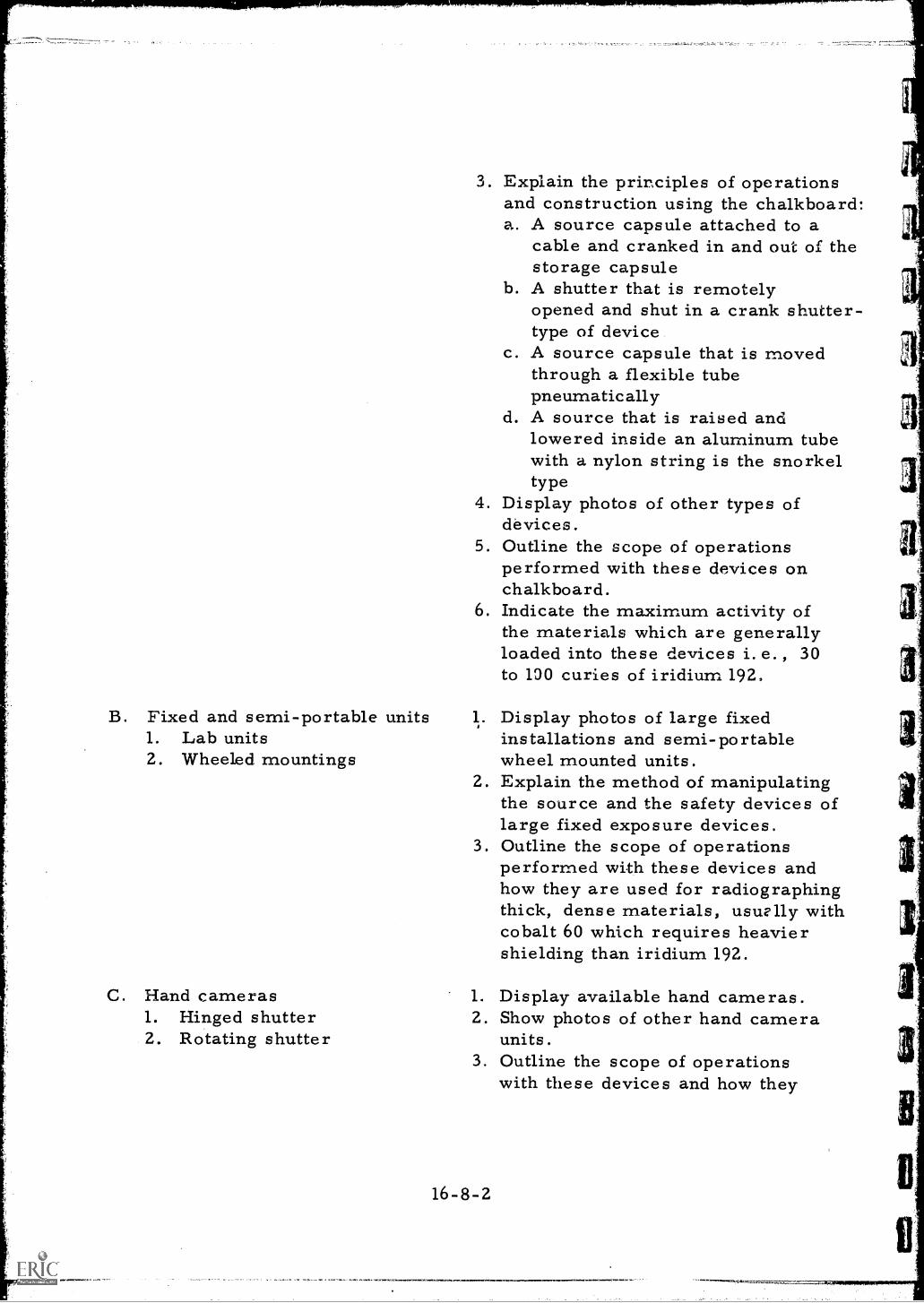
B. Fixed and semi-portable units1. Lab units2. Wheeled mountings
C. Hand cameras1. Hinged shutter2. Rotating shutter
3. Explain the principles of operationsand construction using the chalkboard:a. A source capsule attached to a
cable and cranked in and out of thestorage capsule
b. A shutter that is remotelyopened and shut in a crank shutter-type of device
c. A source capsule that is movedthrough a flexible tubepneumatically
d. A source that is raised andlowered inside an aluminum tubewith a nylon string is the snorkeltype
4. Display photos of other types ofdevices.
5. Outline the scope of operationsperformed with these devices onchalkboard.
6. Indicate the maximum activity ofthe materials which are generallyloaded into these devices i.e., 30to 190 curies of iridium 192.
1. Display photos of large fixedinstallations and semi-portablewheel mounted units.
2. Explain the method of manipulatingthe source and the safety devices oflarge fixed exposure devices.
3. Outline the scope of operationsperformed with these devices andhow they are used for radiographingthick, dense materials, usu'lly withcobalt 60 which requires heaviershielding than iridium 192.
1. Display available hand cameras.2. Show photos of other hand camera
units.3. Outline the scope of operations
with these devices and how they
16-8-2
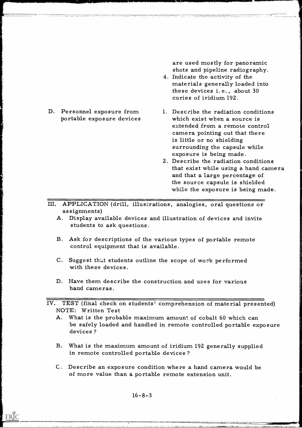
D. Personnel exposure fromportable exposure devices
are used mostly for panoramicshots and pipeline radiography.
4. Indicate the activity of thematerials generally loaded intothese devices i.e., about 30curies of iridium 192.
1. Describe the radiation conditionswhich exist when a source isextended from a remote controlcamera pointing out that thereis little or no shieldingsurrounding the capsule whileexposure is being made.
2. Describe the radiation conditionsthat exist while using a hand cameraand that a large percentage ofthe source capsule is shieldedwhile the exposure is being made.
III. APPLICATION (drill, illustrations, analogies, oral questions oras signrnents)
A. Display available devices and illustration of devices and invitestudents to ask questions.
B. Ask for descriptions of the various types of portable remotecontrol equipment that is available.
C. Suggest th:d.t students outline the scope of work performedwith these devices.
D. Have them describe the construction and uses for varioushand cameras.
IV. TEST (final check on students' comprehension of material presented)NOTE: Written TestA. What is the probable maximum amount of cobalt 60 which can
be safely loaded and handled in remote controlled portable exposuredevices ?
B. What is the maximum amount of iridium 192 generally suppliedin remote controlled portable devices ?
C. Describe an exposure condition where a hand camera would beof more value than a portable remote extension unit.
16-8-3
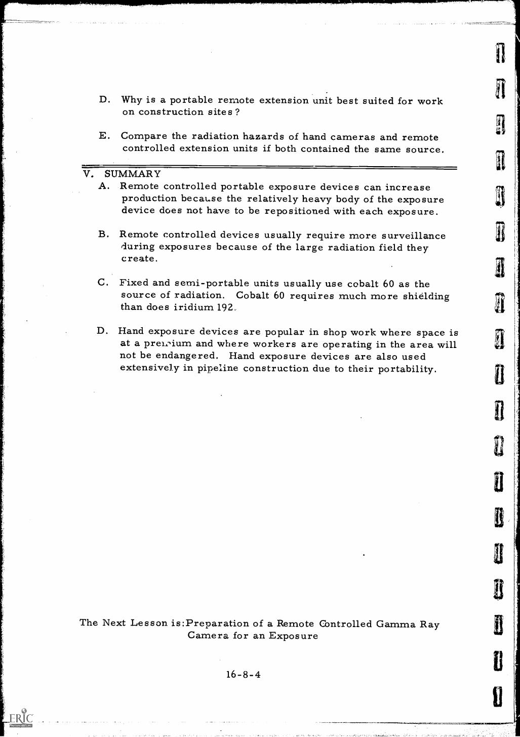
D. Why is a portable remote extension unit best suited for workon construction sites?
E. Compare the radiation hazards of hand cameras and remotecontrolled extension units if both contained the same source.
V. SUMMARYA. Remote controlled portable exposure devices can increase
production because the relatively heavy body of the exposuredevice does not have to be repositioned with each exposure.
B. Remote controlled devices usually require more surveillanceduring exposures because of the large radiation field theycreate.
C. Fixed and semi-portable units usually use cobalt 60 as thesource of radiation. Cobalt 60 requires much more shieldingthan does iridium 192,
D. Hand exposure devices are popular in shop work where space isat a prei,:qum and where workers are operating in the area willnot be endangered. Hand exposure devices are also usedextensively in pipeline construction due to their portability.
The Next Lesson is:Preparation of a Remote Controlled Gamma RayCamera for an Exposure
16-8-4
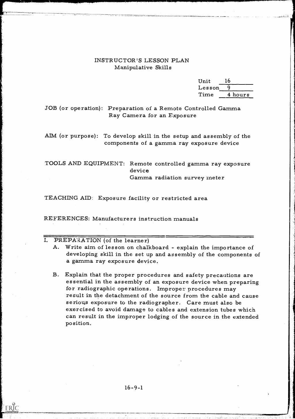
INSTRUCTOR'S LESSON PLANManipulative Skills
Unit 16Lesson 9
Time 4 hours
JOB (or operation): Preparation of a Remote Controlled GammaRay Camera for an Exposure
AIM (or purpose): To develop skill in the setup and assembly of thecomponents of a gamma ray exposure device
TOOLS AND EQUIPMENT: Remote controlled gamma ray exposuredeviceGamma radiation survey meter
TEACHING AID: Exposure facility or restricted area
REFERENCES: Manufacturers instruction manuals
I. PREPARATION (of the learner)A. Write aim of lesson on chalkboard - explain the importance of
developing skill in the set up and assembly of the components ofa gamma ray exposure device.
B. Explain that the proper procedures and safety precautions areessential in the assembly of an exposure device when preparingfor radiographic operations. Imprope7 procedures mayresult in the detachment of the source from the cable and causeserious exposure to the radiographer. Care must also beexercised to avoid damage to cables and extension tubes whichcan result in the improper lodging of the source in the extendedposition.
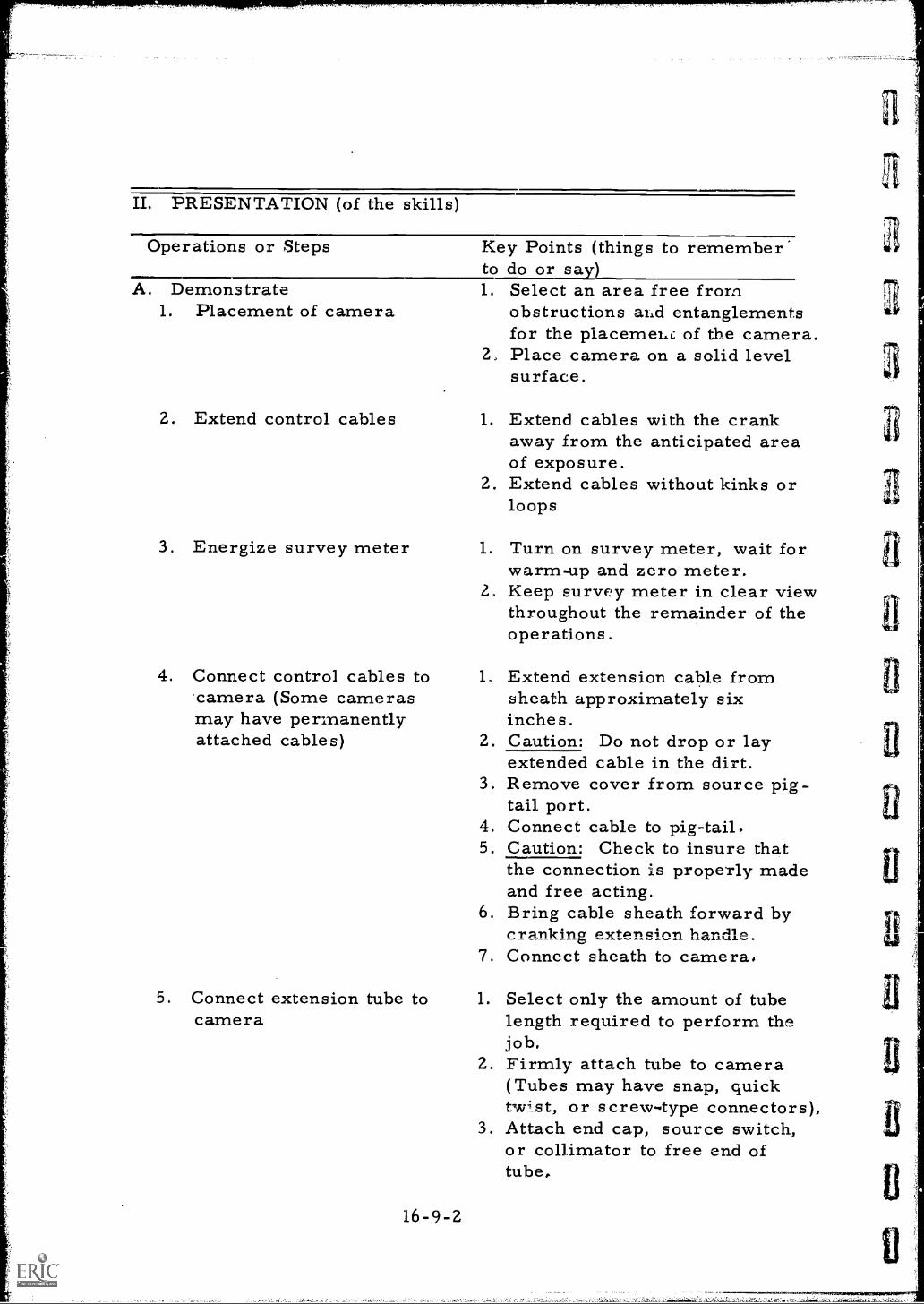
IL PRESENTATION (of the skills)
Operations or Steps
A. Demonstrate1. Placement of camera
2. Extend control cables
3. Energize survey meter
4. Connect control cables tocamera (Some camerasmay have permanentlyattached cables)
5. Connect extension tube tocamera
Key Points (things to remember'to do or say)1. Select an area free from
obstructions alid entanglementsfor the placemeht. of the camera.Place camera on a solid levelsurface.
1. Extend cables with the crankaway from the anticipated areaof exposure.
2. Extend cables without kinks orloops
1. Turn on survey meter, wait forwarm-up and zero meter.
2, Keep survey meter in clear viewthroughout the remainder of theoperations.
1. Extend extension cable fromsheath approximately sixinches.
2. Caution: Do not drop or layextended cable in the dirt.
3. Remove cover from source pig-tail port.
4. Connect cable to pig-tail.5. Caution: Check to insure that
the connection is properly madeand free acting.
6. Bring cable sheath forward bycranking extension handle.
7. Connect sheath to camera.
1. Select only the amount of tubelength required to perform thejob.
2. Firmly attach tube to camera(Tubes may have snap, quicktw-;st, or screw-type connectors),
3. Attach end cap, source switch,or collimator to free end oftube,
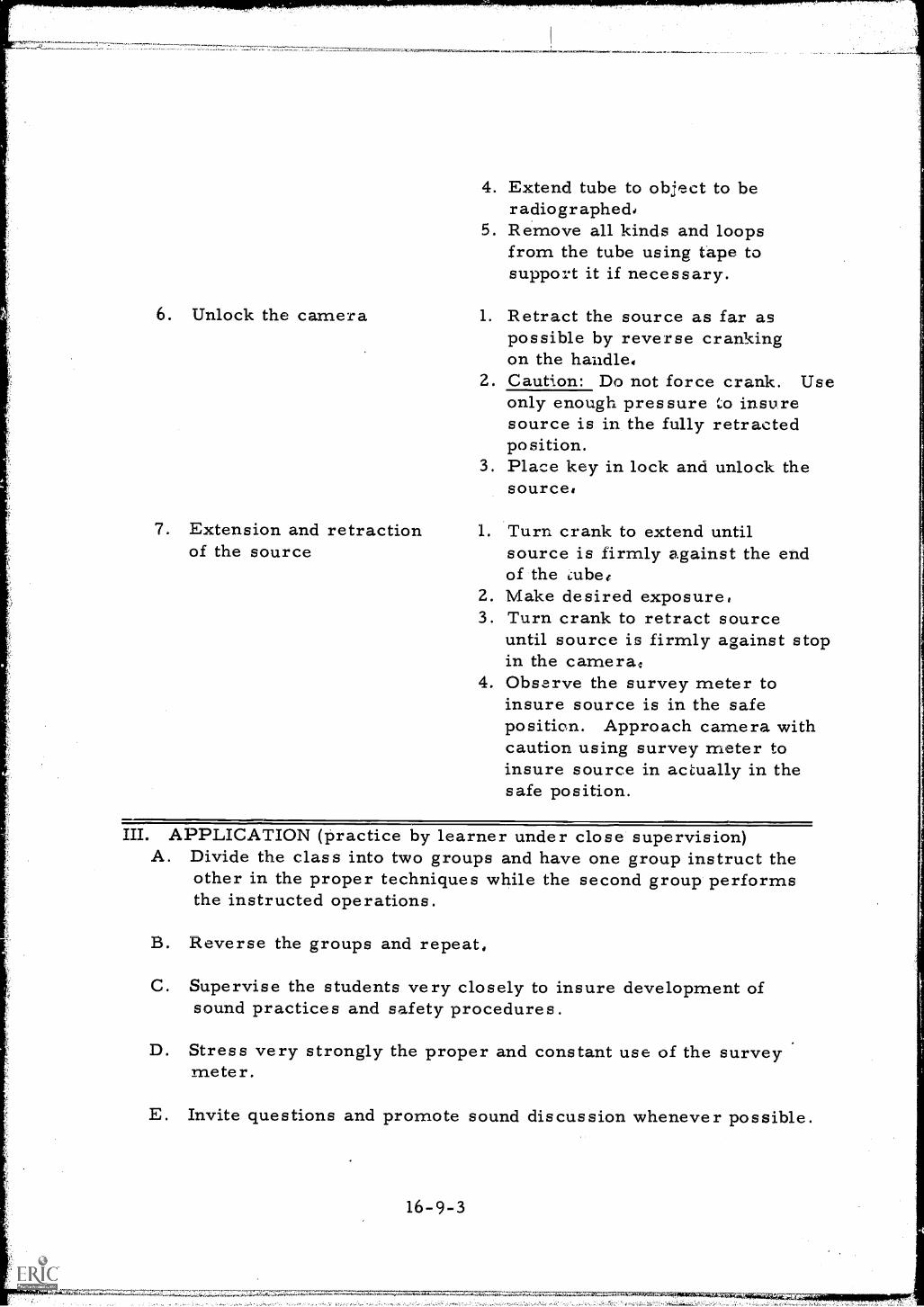
6. Unlock the camera
7. Extension and retractionof the source
4. Extend tube to object to beradiographed,
5. Remove all kinds and loopsfrom the tube using tape tosupport it if necessary.
1. Retract the source as far aspossible by reverse crankingon the handle,
2. Caution: Do not force crank. Useonly enough pressure insuresource is in the fully retractedposition.
3. Place key in lock and unlock thesource,
1. Turn crank to extend untilsource is firmly against the endof the cube(
2. Make desired exposure,3. Turn crank to retract source
until source is firmly against stopin the cameral,
4. Observe the survey meter toinsure source is in the safeposition. Approach camera withcaution using survey meter toinsure source in actually in thesafe position.
III. APPLICATION (practice by learner under close supervision)A. Divide the class into two groups and have one group instruct the
other in the proper techniques while the second group performsthe instructed operations.
B. Reverse the groups and repeat,
C. Supervise the students very closely to insure development ofsound practices and safety procedures.
D. Stress very strongly the proper and constant use of the surveymeter.
E. Invite questions and promote sound discussion whenever possible.
16-9-3
11,4;74 41 .3 4 4.4 .^ 4.4., .4 44 On-4 y
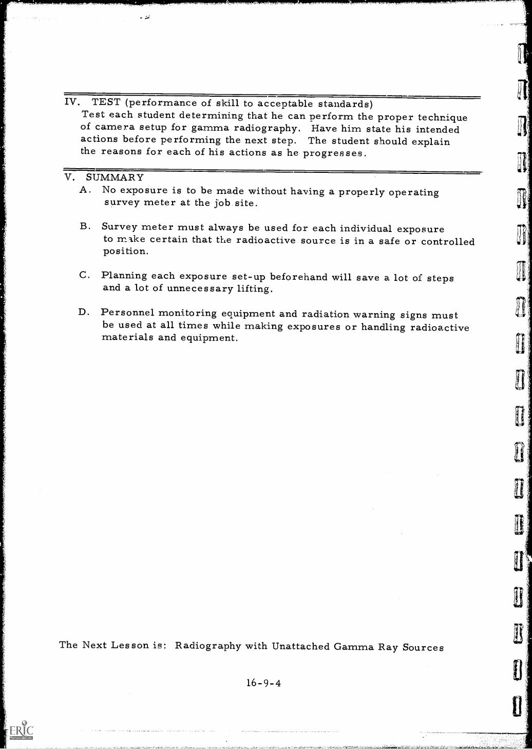
IV. TEST (performance of skill to acceptable standards)Test each student determining that he can perform the proper techniqueof camera setup for gamma radiography. Have him state his intendedactions before performing the next step. The student should explainthe reasons for each of his actions as he progresses.
V. SUMMARYA. No exposure is to be made without having a properly operating
survey meter at the Sob site.
B. Survey meter must always be used for each individual exposureto rni.ke certain that the radioactive source is in a safe or controlledposition.
C. Planning each exposure set-up beforehand will save a lot of stepsand a lot of unnecessary lifting.
D. Personnel monitoring equipment and radiation warning signs mustbe used at all times while making exposures or handling radioactivematerials and equipment.
The Next Lesson is: Radiography with Unattached Gamma Ray Sources
16-9-4
".i-
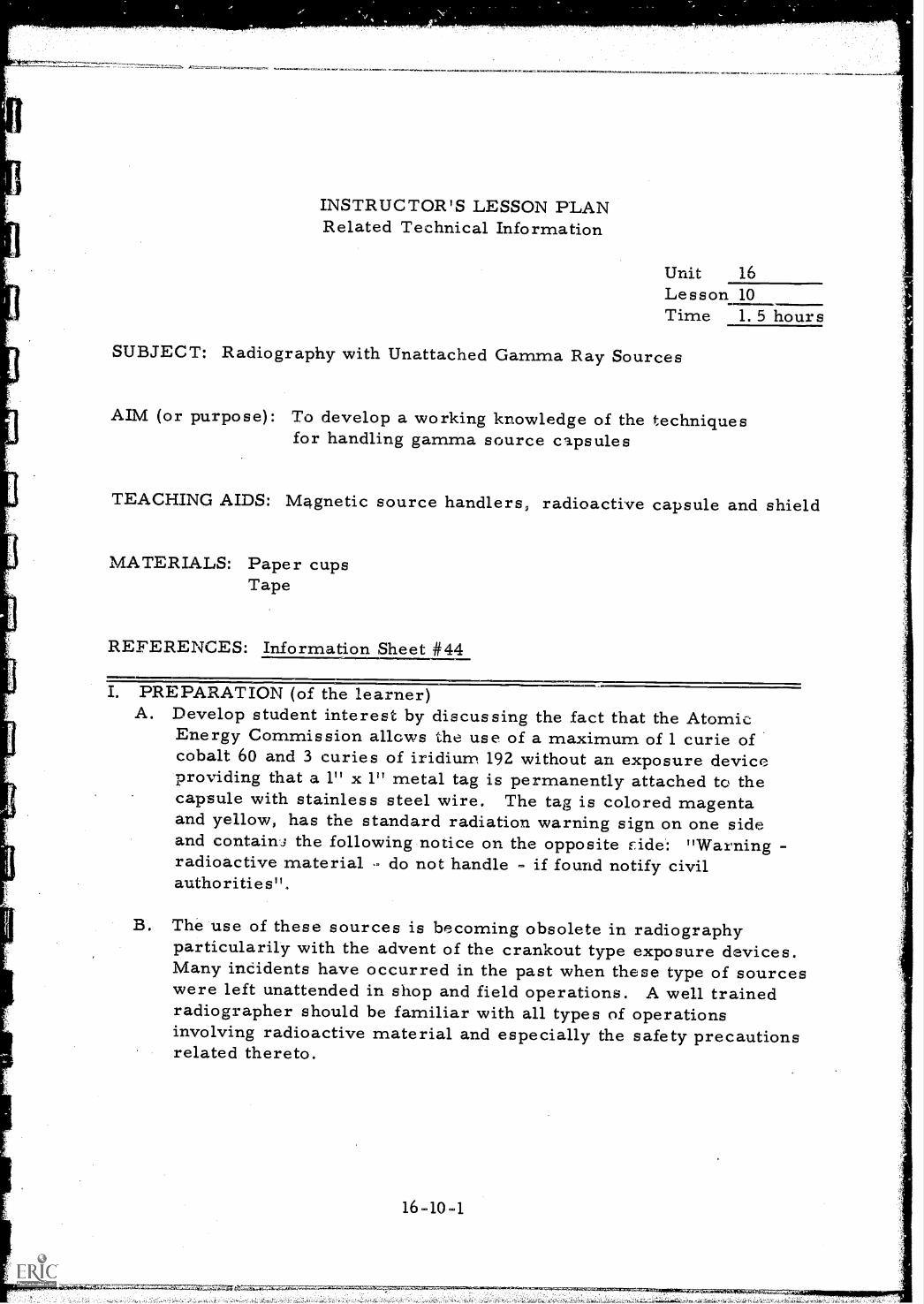
INSTRUCTOR'S LESSON PLANRelated Technical Information
Unit 16Lesson 10Time 1. 5 hours
SUBJECT: Radiography with Unattached Gamma Ray Sources
AIM (or purpose): To develop a working knowledge of the techniquesfor handling gamma source capsules
TEACHING AIDS: Magnetic source handlers, radioactive capsule and shield
MATERIALS: Paper cupsTape
REFERENCES: Information Sheet #44
PREPARATION (of the learner)A. Develop student interest by discussing the fact that the Atomic
Energy Commission allows the use of a maximum of 1 curie ofcobalt 60 and 3 curies of iridium 192 without an exposure deviceproviding that a 1" x 1" metal tag is permanently attached to thecapsule with stainless steel wire. The tag is colored magentaand yellow, has the standard radiation warning sign on one sideand contain': the following notice on the opposite F id e : "Warningradioactive material - do not handled if found notify civilauthorities ".
B. The use of these sources is becoming obsolete in radiographyparticularily with the advent of the crankout type exposure devices.Many incidents have occurred in the past when these type of sourceswere left unattended in shop and field operations. A well trainedradiographer should be familiar with all types of operationsinvolving radioactive material and especially the safety precautionsrelated thereto.
16 -10 -1
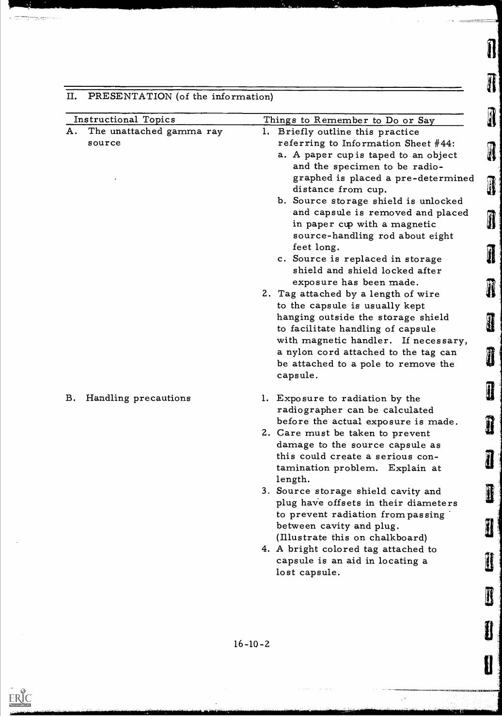
II. PRESENTATION (of the information)
Instructional Topics Things to Remember to Do or SayA. The unattached gamma ray 1. Briefly outline this practice
source referring to Information Sheet #44:a. A paper cup is taped to an object
and the specimen to be radio-graphed is placed a pre-determineddistance from cup.
b. Source storage shield is unlockedand capsule is removed and placedin paper cup with a magneticsource-handling rod about eightfeet long.
c. Source is replaced in storageshield and shield locked afterexposure has been made.
2. Tag attached by a length of wireto the capsule is usually kepthanging outside the storage shieldto facilitate handling of capsulewith magnetic handler. If necessary,a nylon cord attached to the tag canbe attached to a pole to remove thecapsule.
B. Handling precautions 1. Exposure to radiation by theradiographer can be calculatedbefore the actual exposure is made.
2. Care must be taken to preventdamage to the source capsule asthis could create a serious con-tamination problem. Explain atlength.
3. Source storage shield cavity andplug haVe offsets in their diametersto prevent radiation from passingbetween cavity and plug.(Illustrate this on chalkboard)
4. A bright colored tag attached tocapsule is an aid in locating alost capsule.
16-10-2
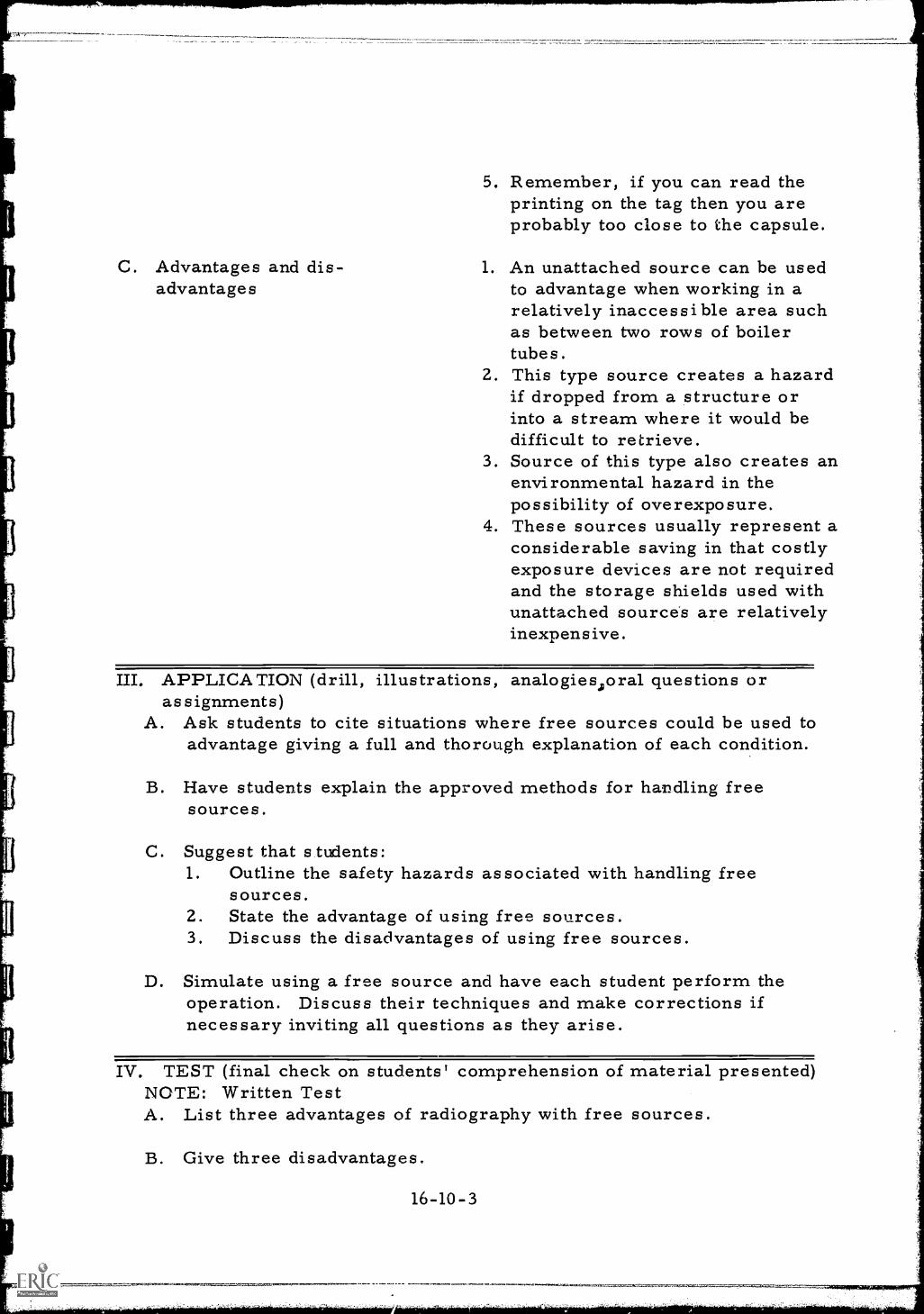
C. Advantages and dis-advantages
5. Remember, if you can read theprinting on the tag then you areprobably too close to the capsule.
1. An unattached source can be usedto advantage when working in arelatively inaccessible area suchas between two rows of boilertubes.
2. This type source creates a hazardif dropped from a structure orinto a stream where it would bedifficult to retrieve.
3. Source of this type also creates anenvironmental hazard in thepossibility of overexposure.
4. These sources usually represent aconsiderable saving in that costlyexposure devices are not requiredand the storage shields used withunattached sources are relativelyinexpensive.
III. APPLICATION (drill, illustrations, analogies ;oral questions orassignments)
A. Ask students to cite situations where free sources could be used toadvantage giving a full and thorough explanation of each condition.
B. Have students explain the approved methods for handling freesources.
C. Suggest that students:1. Outline the safety hazards associated with handling free
sources.2. State the advantage of using free sources.3. Discuss the disadvantages of using free sources.
D. Simulate using a free source and have each student perform theoperation. Discuss their techniques and make corrections ifnecessary inviting all questions as they arise.
IV. TEST (final check on students' comprehension of material presented)NOTE: Written TestA. List three advantages of radiography with free sources.
B. Give three disadvantages.
16-10-3
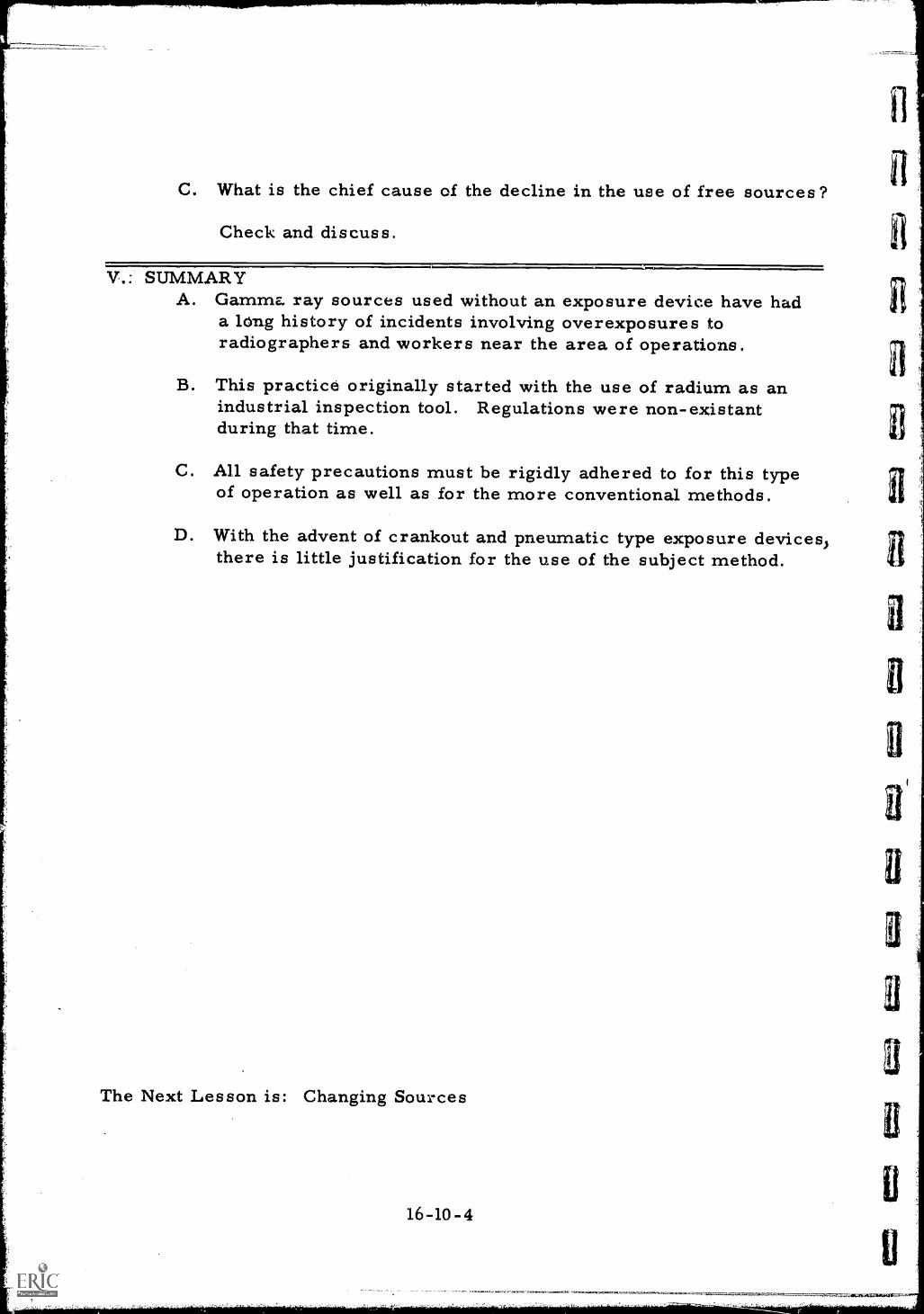
C. What is the chief cause of the decline in the use of free sources?
Check and discuss.
V.: SUMMARYA. Gamma ray sources used without an exposure device have had
a long history of incidents involving overexposures toradiographers and workers near the area of operations.
B. This practice originally started with the use of radium as anindustrial inspection tool. Regulations were non-existantduring that time.
C. All safety precautions must be rigidly adhered to for this typeof operation as well as for the more conventional methods.
D. With the advent of crankout and pneumatic type exposure devices,there is little justification for the use of the subject method.
The Next Lesson is: Changing Sources
16-10-4
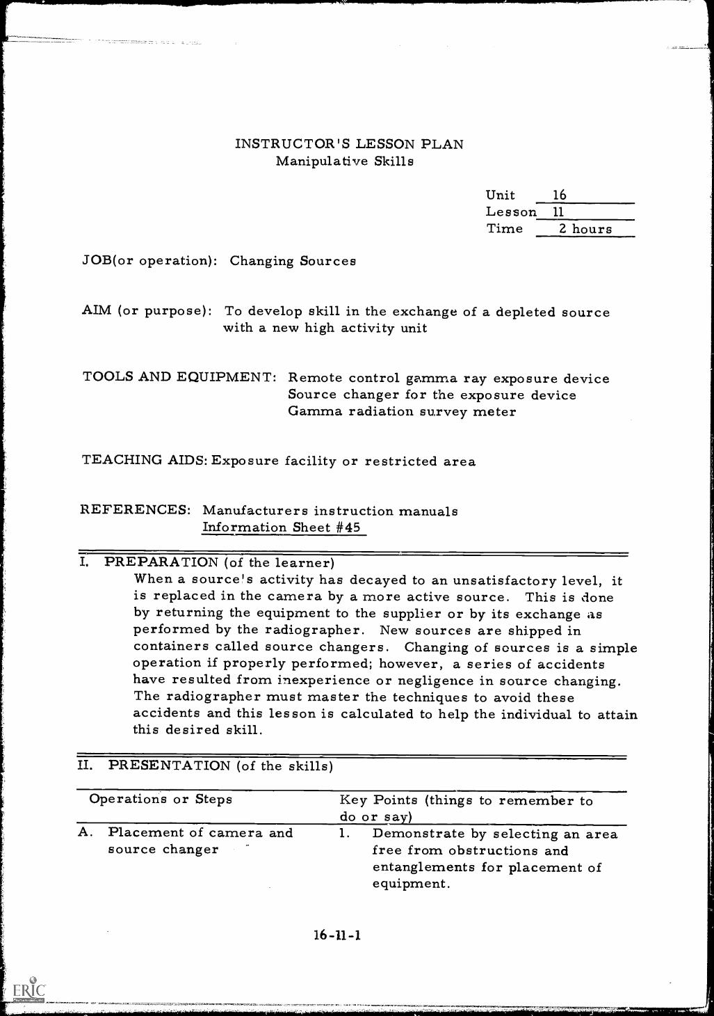
INSTRUCTOR'S LESSON PLANManipulative Skills
Unit 16Lesson 11
Time 2 hours
JOB(or operation): Changing Sources
AIM (or purpose): To develop skill in the exchange of a depleted sourcewith a new high activity unit
TOOLS AND EQUIPMENT: Remote control gamma ray exposure deviceSource changer for the exposure deviceGamma radiation survey meter
TEACHING AIDS: Exposure facility or restricted area
REFERENCES: Manufacturers instruction manualsInformation Sheet #45
PREPARATION (of the learner)When a source's activity has decayed to an unsatisfactory level, itis replaced in the camera by a more active source. This is doneby returning the equipment to the supplier or by its exchange asperformed by the radiographer. New sources are shipped incontainers called source changers. Changing of sources is a simpleoperation if properly performed; however, a series of accidentshave resulted from inexperience or negligence in source changing.The radiographer must master the techniques to avoid theseaccidents and this lesson is calculated to help the individual to attainthis desired skill.
II. PRESENTATION (of the skills)
Operations or Steps
A. Placement of camera andsource changer
Key Points (things to remember todo or say )1. Demonstrate by selecting an area
free from obstructions andentanglements for placement ofequipment.
16-11-1
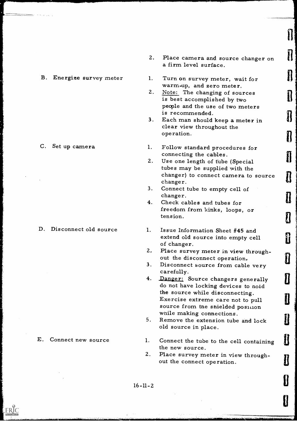
B. Energize survey meter
C. Set up camera
D. Disconnect old source
E. Connect new source
2. Place camera and source changer ona firm level surface.
1. Turn on survey meter, wait forwarm-up, and zero meter.
2. Note: The changing of sourcesis best accomplished by twopeople and the use of two metersis recommended.
3. Each man should keep a meter inclear view throughout theoperation.
1. Follow standard procedures forconnecting the cables.
2. Use one length of tube (Specialtubes may be supplied with thechanger) to connect camera to sourcechanger.
3. Connect tube to empty cell ofchanger.
4. Check cables and tubes forfreedom from kinks, loops, ortension.
1. Issue Information Sheet #45 andextend old source into empty cellof changer.
2. Place survey meter in view through-out the disconnect operation,
3. Disconnect source from cable verycarefully.
4. Danger: Source changers generallydo not have locking devices to noldthe source while disconnecting.Exercise extreme care not to pullsource from the shielded positionwhile making connections.
5. Remove the extension tube and lockold source in place.
1. Connect the tube to the cell containingthe new source.
2. Place survey meter in view through-out the connect operation.
16-11-2
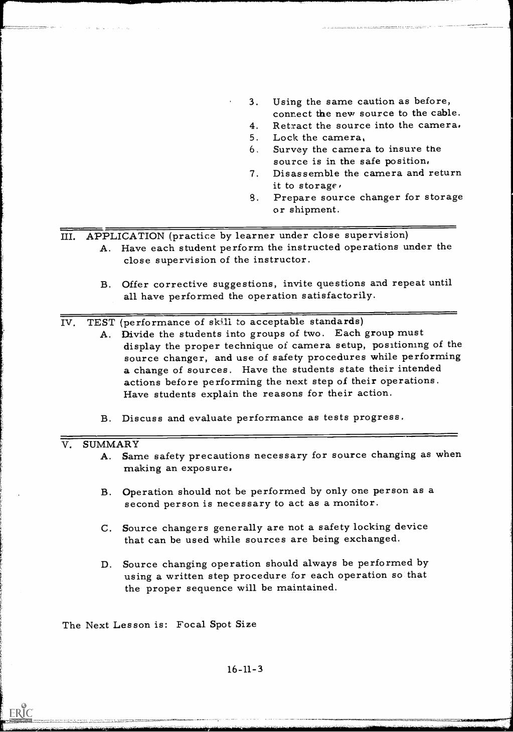
3. Using the same caution as before,connect the new source to the cable.
4. Ret:cact the source into the camera.5. Lock the camera,6 Survey the camera to insure the
source is in the safe position,7. Disassemble the camera and return
it to storage,8. Prepare source changer for storage
or shipment.
III. APPLICATION (practice by learner under close supervision)A. Have each student perform the instructed operations under the
close supervision of the instructor.
B. Offer corrective suggestions, invite questions and repeat untilall have performed the operation satisfactorily.
Iv. TEST (performance of skill to acceptable standards)A. Divide the students into groups of two. Each group must
display the proper technique of camera setup, positioning of thesource changer, and use of safety procedures while performinga change of sources. Have the students state their intendedactions before performing the next step of their operations.Have students explain the reasons for their action.
B. Discuss and evaluate performance as tests progress.
V. SUMMARYA. Same safety precautions necessary for source changing as when
making an exposure,
B. Operation should not be performed by only one person as asecond person is necessary to act as a monitor.
C. Source changers generally are not a safety locking devicethat can be used while sources are being exchanged.
D. Source changing operation should always be performed byusing a written step procedure for each operation so thatthe proper sequence will be maintained.
The Next Lesson is: Focal Spot Size
16-11-3
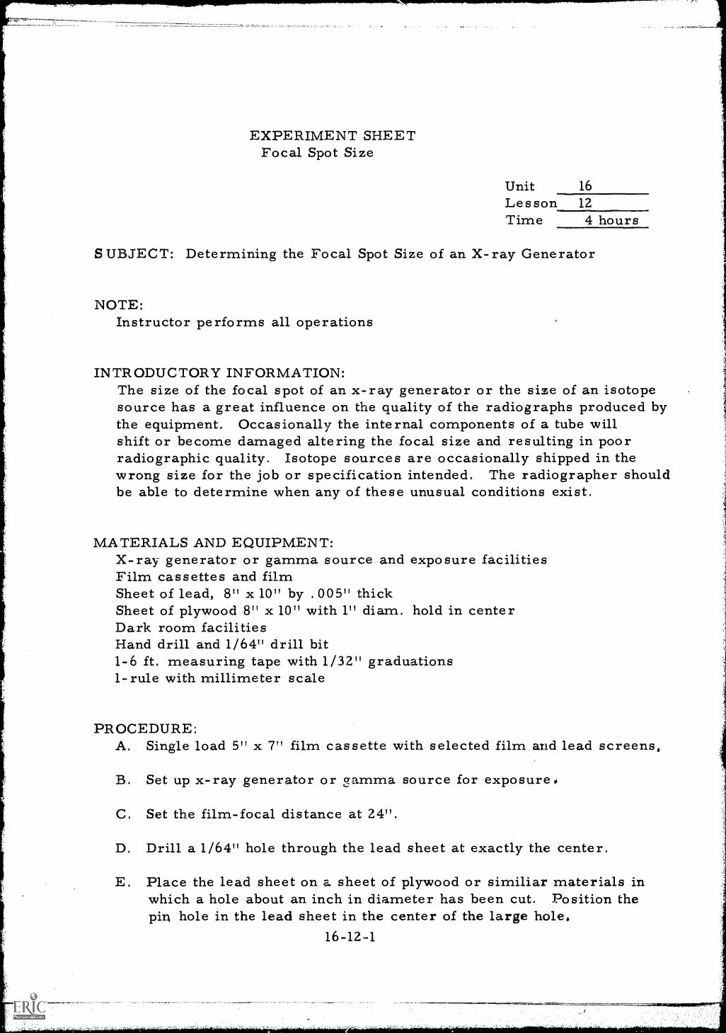
EXPERIMENT SHEETFocal Spot Size
Unit 16
Les son 12Time 4 hours
SUBJECT: Determining the Focal Spot Size of an X-ray Generator
NOTE:Instructor performs all operations
INTRODUCTORY INFORMATION:The size of the focal spot of an x-ray generator or the size of an isotopesource has a great influence on the quality of the radiographs produced bythe equipment. Occasionally the internal components of a tube willshift or become damaged altering the focal size and resulting in poorradiographic quality. Isotope sources are occasionally shipped in thewrong size for the job or specification intended. The radiographer shouldbe able to determine when any of these unusual conditions exist.
MATERIALS AND EQUIPMENT:X-ray generator or gamma source and exposure facilitiesFilm cassettes and filmSheet of lead, 8" x 10" by . 005" thickSheet of plywood 8" x 10" with 1" diam. hold in centerDark room facilitiesHand drill and 1/64" drill bit1-6 ft. measuring tape with 1/32" graduations1-rule with millimeter scale
PROCEDURE:A. Single load 5" x 7" film cassette with selected film and lead screens,
B. Set up x-ray generator or gamma source for exposure.
C. Set the film-focal distance at 24".
D. Drill a 1/64" hole through the lead sheet at exactly the center.
E. Place the lead sheet on a sheet of plywood or similiar materials inwhich a hole about an inch in diameter has been cut. Position thepin hole in the lead sheet in the center of the large hole.
16-12-1
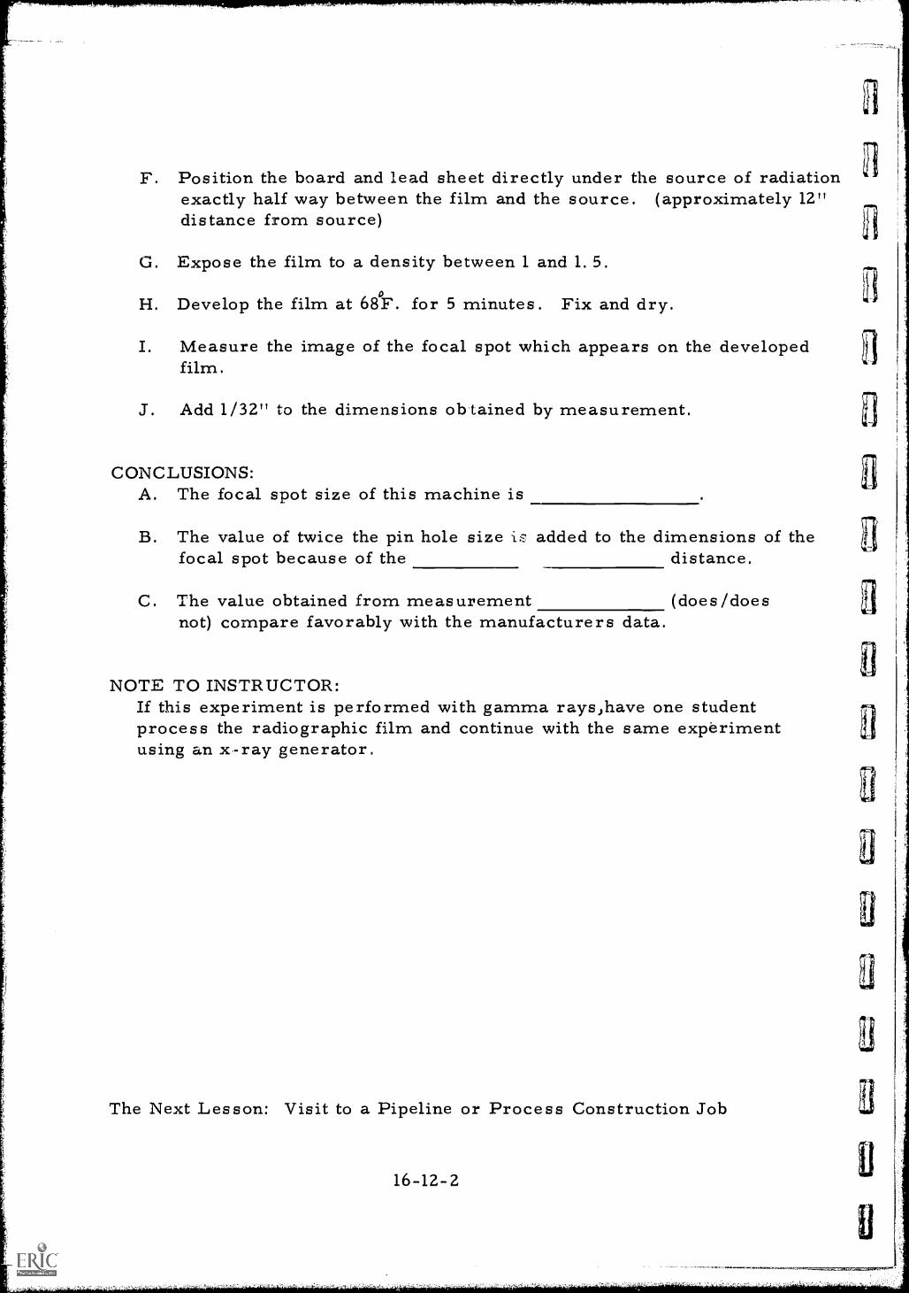
1
F. Position the board and lead sheet directly under the source of radiationexactly half way between the film and the source. (approximately 12"distance from source)
G. Expose the film to a density between 1 and 1.5.
H. Develop the film at 68°F. for 5 minutes. Fix and dry.
I. Measure the image of the focal spot which appears on the developedfilm.
J. Add 1/32" to the dimensions obtained by measurement.
CONCLUSIONS:A. The focal spot size of this machine is
B. The value of twice the pin hole size is added to the dimensions of thefocal spot because of the distance.
C. The value obtained from measurement (does/doesnot) compare favorably with the manufacturers data.
NOTE TO INSTRUCTOR:If this experiment is performed with gamma rays,have one studentprocess the radiographic film and continue with the same experimentusing an x-ray generator.
The Next Lesson: Visit to a Pipeline or Process Construction Job
16-12-2
L
LE1
3
INSTRUCTOR'S LESSON PLANRelated Technical Information
Unit 16Lesson 13Time 6 hours
(1 day)
SUBJECT: Visit to a Pipeline or Process Construction Job
AIM (or purpose): To permit the student to observe the construction andinspection of pipe, and to experience the hazards andrigors of pipe construction
MATERIALS: Film badgesthsimetersSafety glassesHard hats
I. PREPARATION (of the learner)A. Before leaving for the field tripithe student should be instructed
as to the reasons for the trip, its objectives, and the need for carefullyobserving the following operations:1. The hazards of the construction, particularly the overhead
handling of pipe, overhead welding, movement of heavyequipment, and the work at elevated positions
Z. The welding of pipe in all positions,3. The care (or mishandling) of welding electrodes4. The types of welding equipment employed5. Methods of pipe alignment6. Preheating and stress relieving practices7. Weld bead preparation and cleaning practices8. The types of inspections employed after completion of welding
B. Issue safety instructions to be followed while at the job site,particularly caution against watching the welders at work. Issuesafety glasses, hard hats, and any other items that will be needed.Remind all students to behave as guests of the company and,-emain in the group under the guidance of the supervisor.
16-13-1
II. PRESENTATION (of the information)
Instructional Topics Things to Remember to Do or SayObservations in the visited Be sure that students are made awarefacility that a test will be given on what
was observed.
III. APPLICATION (drill, illustrations, analogies, oral questions oras signments)
After returning from the trip, ask the students to discuss:A. Their opinion of pipe construction work
B. The possible source of defects in welded pipe
C. The method of handling welding electrodes and how this can affectthe weld quality
D. How the pipe ends were aligned and how this could affect the x-rayfilm image
E. How the weld cleaning practices affect quality and possible improvedmethods of weld cleaning
F. The methods used for inspection
G. The special handling tools used by the inspectors
IV. TEST (final check on students' comprehension of material presented)A. Instruct each student to prepare a detailed written report on the
observations made during the plant tour. Suggest that he coverin detail all observations that will in any way affect the radiographersfunction either in the field of manufacture, fabrication, inspection,handling or testing.
B. Have them list any suggestions they may have for future field tripsand how these trips may be made more fruitful or benificial to them.
C. Check each report and discuss the results with the group.
The Next Lesson is: Film Manufacturing Process
16-13-2
INSTRUCTOR'S LESSON PLANRelated Technical Information
SUBJECT: Film Manufacturing Process
Unit 17Lesson 1
Time 1 hour
AIM (or purpose): To emphasize the methods and controls used in themaking of radiographic film
TEACHING AIDS: Film: The Inside Story, 32 mills. , 16 mm, sound,Eastman Kodak Company, Rochester, N. Y.
Film projector and screen
PREPARATION (of the learner)A. Introduce the film giving its name, length and type. Ask the students
to carefully observe the following:1. The layers of different materials which comprise the structure
of radiographic film2. The functions of each layer of the radiographic film.3. The chemcals used to produce a sensitized emulsion.4. The care used to insure uniformity of the finished product.5. The care used in handling of radiographic film.6. The fact that most x-ray film consists of seven layers of materials.
B. Advise the students that a test will be given after the film isshown and suggest that it be closely observed with this in mind.
II. PRESENTATION (of the learner)
Instructional To icsA. The Inside Story
Thin s to Remember to Do or SaShow the film.
III. APPLICATION (drill, illustrations, analogies, oral questions oras signments)
A. Review the film emphasizing these points in the discussion:1. The structural make up of radiographic film-
a. The film baseb. The emulsionc. The surface gelation layer
17-1-1
2. The treatment of silver nitrate and potassium bromide to producethe sensitive silver bromide crystals
3. The extreme care exercised in making of film to insure freedomfrom defects in the finished product
4. The quality control checks used to insure uniformity of thefinished product
B. In addition to reviewing the actual film content,some reference canbe made regarding the need for continued careful handling ofthe product after it is received for use by the radiographer and theneed for his being aware of expiration dates and film storage conditions.
IV. TEST (final check on students' comprehension of material presented)NOTE: Written TestA. What is the purpose of the plastic layer between the two emulsion
layers of radiographic film?
B. What is the composition of the gelation layer in radiographic film?
C. What part does the emulsion perform in the exposure of a radiographicfilm?
D. Why is the radiographic film subjected to the various inspection bythe manufacturer during the manufacture of the film?
E. What would be the consequences to the radiographic operator if thefilm did not react uniformly on exposure?
V. SUMMARYA. Parts of this instructional movie were made under simulated
conditions because the film cannot be exposed to white light.
B. It is possible for the resultant film speed to vary slightly fromone batch of raw material used in the manufacture of the film toanother.
C. When opening a new box of film,cut off a strip of the top or bottomsheet, or both, and develop without exposing it to check for filmfog,
D. Always observe the manufacturing date on the box before acceptingfilm.
The Next Lesson is: Characteristics of Radiographic Film
-",411.1epargrai....-....-..
a
INSTRUCTOR'S LESSON PLANRelated Technical Information
Unit 17Lesson 2Time 2 hours
SUBJECT: Characteristics of Radiographic Film
AIM (or purpose): To develop background information regarding theproperties of industrial film and how these propertif,:saffect radiographic quality
TEACHING AIDS: Samples of coarse and fine grain filmIdentical radiographs using different films
REFERENCES: Ra.clic)n.a. itplertiIndt 1958, EastmanKodak Co., Rochester, N. Y.Kodak Photographic Films and Plates for Scientificand Technical Use, Publication P-9, Eastman KodakCo., Rochester, N. Y. (1960)Characteristic curves of various films - EastmanKodak Co.
I. PREPARATION (of the learner)A. State the subject and relate its aim or purpose outlining briefly
why film characteristics are so vitally important to the radio-grapher.
B. Explain that the lesson will prove to be an interesting andinformative one, imparting some fundamental and basicinformation that will be of considerable help to all.
II. PRESENTATION (of the information)
Instructional TopicsA. The characteristic curve
17-2-1
Things to Remember to Do or Say__1. Refer to curves shown in text.2. Explain by chalkboard sketches:
a. The method of constructinga characteristic curve
b. The coordinates of the curvec. The relationship between
density and exposure
3. Outline the differences incharacteristic curves of differentfilm, i.e., the differences inchemistry and processing.
4. Display typical characteristiccurves.
1. Define granularity on chalkboardas minute silver particles having atendency to group together inrelatively large masses. This isreferred to as clumping. Coarsegrain film exhibit this graininessmore than fine grain film. Thex-ray image is composed ofcountless minute silver grains.
2. Explain:a. The relationship of granularity
to film speedb. The effect of increased
radiation energy on graininessc. The granularity from
fluorescent screensd. The relationship of development
time to graininess3. Compare a fine grain film with a
coarse grain film on chalkboard.
1. Define and explain resolving power.2. Explain the dependence of resolving
power on the character of theemulsion.
1. Explain film turbidity and itsrelation to exposure.
2. Define as muddled or stirred up.
1. Differentiate between inherent filmcontrast and subject contrast.
2. Film contrast is:a. The range of inherent grain
sizesb. Its relation to density
3. Subject contrast is the ratio ofradiation intensities passing throughtwo selected portions of aspecimen.
F. Sharpness (Acutance)
G. Factors affecting sensitivity
4. Show the method of determiningthe contrast exaggeration from theslope of the characteristic curve.
1 Define film sharpness as detailof image not blurred. Refer toFigure 20, Page 27 EastmanTextbook.
2. Explain:a. The dependence of sharpness
on the emulsionb. Why weak developer reduces
sharpness3. Explain why sharpness is more
important than resolving powerin radiography.
4. Sharpness also depends uponintimate film and screen contact.
Have students turn to Page 48,Eastman Textbook and explain thefactors listed in Table VI.
III. APPLICATION (drill, illustrations, analogies, oral questions orassignments)
Have all students:A. Explain the construction of a characteristic curve,
B. Point out the information which can be derived from the curve.Have the student concentrate on speed and density gradient.
C. Explain film contrast and how to determine the density range whichproduces the maximum contrast.
D. Define granularity and how it is produced. Explain the techniquesfor minimizing "graininessTM.
E. Give a definition of sharpness.
IV. TEST (final check on students' comprehension of material presented)NOTE: Written TestA. From the characteristic curves which have been discussed,
determine the film with the maximum speed. (Curves arein textbook)
17-2-3
B. Above what approximate value of density will contrast exaggerationoccur in Kodak AA film?
C. What range of density will give the: best contrast using Kodak Mfilm with lead screens?
D. What is graininess? What factors can be' controlled to minimizegraininess ?
E. Define image sharpness. How does the character of the emulsioneffect sharpness?
F. Have students work a problem involving the use of logarithm tablesin figuring a change in film exposure time for a particular filmby increasing the required relative density from 1. 5 to 2.0.
Check and discuss.
V. SUMMARYA. The characteristic curve is most important in selecting film to
be used for any particular assignment.
B. Film grain size increases with film speed. Relatively smallgrain size is desirable.
C. Film resolving power depends upon the character of the filmemulsion.
D. Film contrast is inherent. Subject contrast depends upon theshape or thickness variation of the specimen and on its densityvariation.
E. Spent developer causes a reduction in image sharpness.
F. When using intensifying screens, good contact with film is necessaryfor maximum sharpness.
The Next Lesson is: Radiographic Screens
17-2-4
El
ti
INSTRUCTOR'S LESSON PLANRelated Technical Information
SUBJECT: Radiographic Screens
Unit 17Lesson 3
Time 2 hou rs
AIM (or purpose): To define the purpose, and mechanisms ofintensification and the advantages and disadvantagesof radiographic intensification screens
TEACHING AIDS: Lead and fluorescent screens
REFERENCES: Radiography in Modern Industry, 1958, EastmanKodak Co., Rochester, N. Y.Information Sheet #46
I. PREPARATION (of the learner)A. After introducing the subject, make the following statement to create
interest and discussion: The use of lead screens with radiographicfilm will decrease the required exposure time and reduce the adverseeffects of scattered radiation on the film and lead screens can alsoimprove image quality. Calcium tungstate screens reduceexposure time and the amount of the x-ray radiation beam absorbedby the film is less than 1% of the total. This means that morethan 99% of the available energy is performing no useful purpose.Therefore, any means of increasing the amount of energy utilizedfor creating the image will increase the efficiency of the operation.Radiographic screens are used for this purpose,
B. Explain that it is not expected that these statements will either beunderstood or accepted as such but are being made to demonstratethe depth and scope of this particular lesson and what exactly isbeing proposed for coverage.
17-3-1
II. PRESENTATION (of the information)
Instructional Topics Things to Remember to Do or SayA. The purpose of screens 1. Outline on the chalkboard the
1. Intensification possible reductions in exposure2. Reduction of scattering time which result from the use3. Preferential intensification of lead or fluorescent screens.
2. Explain the reduction in scatteringwhen lead screens are employed andthe problems of scattering whenfluorescent screens are used.Lead screens filter out or absorbsoft primary radiation andsecondary scattered radiationwhile fluorescent screens cause filmblurring and fogging, particularilyif intimate contact is not madeand maintained with the film.
3. Define on chalkboard the conditionswhich may result in longerexposure times when lead screensare used.
4. Explain the preferential intensificatipof lead to the primary beam andfiltering of scattered radiation.
B. Mechanisms ofintensification
C. Disadvantages of screens1. Film contact2. False indications
17-3-2
1. Issue Information Sheet #46 andexplain the action of lead screensin producing electron emissionand secondary radiation pointingout that a lead screens' reaction toradiation is in the form ofelectron emission while secondaryradiation is absorbed by the lead.
2. Explain the light emission offluorescent screens in that certainchemicals fluoresse and asthey absorb x-rays or gamma raysthey immediately emit light. Thelight intensity depending uponradi,ation intensity.
1. Explain the effects of non-uniformcontact between film and screensresulting in blurring and fogging.
3. Static electricity marks 2.4. Afterglow5. Graininess6. Cleanliness requirements 3
4.
5.
Show how to determine if screenscontact is uniform. Tape cassettetightly but do not damage film.Explain how false indications aregenerated by scratches on thescreens. See illustration page 24figure 19, Eastman Textbook.Discuss the generation of staticelectricity and the marks itproduces. Static marks are starshaped and usually occur in dryclimates when cassette is thrown onwork bench and if operator is wearingrubber soled shoes.Outline the effect of afterglow fromfluorescent screens. Afterglow in fluorescent screens blursfilm,
6. Explain why fluorescent screenscause graininess and whygraininess from fluorescent screensis independent of film grain size.
7 Demonstrate the necessity of keepingscreens free from dirt, lint,and trash. (images of dirt willappear on radiograph and willtend to scratch the film.It will also contaminate developingchemicals.)
III. APPLICATION (drill, illustrations, analogies, oral questions orassignments)
Have students:A. Explain the effects of using lead screens on the speed of exposure
when employing 160 kv or more.
B. Explain the effects of lead screens on the definition of theradiograph.
C. List and explain the undesirable effects of intensifying screenusage.
D. Explain the phenomenon which results in intensification whenusing lead screens.
17-3-3
E. Explain why lead screens are not used at lower kv settings.
F. Explain Why calcium tungstate screens are not used with gamma rays.
G. Place a calcium tungstate screen near a source of gamma radiationand have students observe the greenish glow emitted by the screen.Darken the room before exposing the screen. Observe all requiredsafety precautions when conducting this demonstration. Ask studentsto explain the demonstration.
IV. TEST (final check on students' comprehension of material presented)NOTE: Written TestA. What happens when radiation passes through a thin sheet of lead
placed in contact with a film in its exposure holder?
B. What is the most objectionable characteristic of fluorescentscreen intensification?
C. What is afterglow and why is it objectionable?
D. Scratches, dirt, and lint between the film and the screen causeundesirable effects. Elaborate.
E. What is the effect of poor film to screen contact? How can thedegree of contact be determined?
Check and discuss.
V. SUMMARYA. Lead intensifying screens are usually used at radiation intensities
above 125 kv.
B. Calcium tungstate screens are for x-ray use only.
C. Lead screens speed exposure time by electron emission.
The Next Lesson is: Load-i.ng of Film Cassettes
17-3-4
INSTRUCTOR'S LESSON PLANManipulative Skills
Unit 17Lesson _4Time 1 hour
JOB (or operation): Loading of Film Cassettes
AIM (or purpose): To assist the student in the development of skillsand the proper techniques of handling film, screensand cassettes
MATERIALS: FilmTrichloroethyleneCheese clothVery fine steel wool
TEACHING AIDS: Film cassettesIntensifying screens
REFERENCES: Radiography in Modern Industry, 1958, Eastman KodakCo. , Rochester, N.Y.
I. PREPARATION (of the learner)Write aim of lesson on chalkboard and stress the need for this effortin that proper handling, loading, and care of film cassettes and screensis essential to production of high quality radiographic film. Use ofproper handling procedures and high quality work are characteristics ofcompetent radiographers and an individual will prosper and succeed indirect proportion to how well he can perform the total task. Makinga first class exposure is not enough if the film is damaged ordestroyed through improper handling.
II. PRESENTATION (of the skills)
Operations or Steps Key Points (things to remember todo or say)
A. Demonstrate in lighted room 1. Clean work bench space of allpreparation of loading area objects in the area particularily
where film is to be loaded
17-44
B. Collect materials
C. Examine cassettes andscreens
D. Assembl' components
17-4-2
2 Wipe top of work bench withdamp cloth to remove all dirtand lint.
3. Dry bench top with dry cloth4. Rub top of bench with palm of
hand to insure freedom fromgrit and dirt.
1. Select cassettes, screens, andfilm to be used in loading.
2. Place each component in convenientposition for assembly.
3. Stand film box upright againstbackboard behind work area.
1. Open cassettes and inspect forlint or dirt. If necessaryclean them with a damp clothand dry thoroughly.
2. Examine screens for lint, dirt,excessive oxidation, scratches,or creases.
3. If necessary clean oxide fromlead screens with cloth wettedin trichloroethylene, Drythoroughly. Heavy concen-trations of dirt and oxidation maybe removed by light rubbingwith very fine steel wool.
4. Caution: Use only recommendedsolvents and never use an abrasiveon fluorescent screens.
5. Discard screens with creases.6. Examine screens to insure that
intimate contact can be madeover the full surface.
1. Place screens in cassetteswith cassettes flat and open onthe bench.
2. If a thicker screen is to beused on one side, be sure that thescreen is on the back side ofthe cassettes.
E. Load film 1. Remove film from the boxone at a time.
2. Remove interleave from film.3 Hold film by the edge and lay
on screen opposite the flapof the cassettes.
4. Caution: Avoid crimping,sliding, fingerprinting orscratching the film.
5. Lay other screen on filmwithout sliding.
6. Close cover, tape or lock.
III. APPLICATION (practice by learner under close supervision)A. Have all students practice film loading while room is
lighted, using old developed film.
B. Have all students practice film loading in dark room with onlysafe light illumination still using old developed film.
C. Give close supervision throughout, inviting all questions andrepeating any procedure that is the least doubtful.
IV. TEST (performance of skill to acceptable standards)NOTE: Performance TestA. Collect cassettes, screens and undeveloped film on the work
bench. Have each student load one cassette in total darknessfrom the disassembled layout.
b. Check results and discuss repeating operation where unsatisfactoryresults were obtained.
V. SUMMARYA. Good Housekeeping in film loading room is absolutely necessary
to prevent film artifacts.
B. Preliminary steps can be taken before white lights areextinguished.
C. Cassettes should be marked top and bottom so that properthickness screen is on the proper side.
D. Screens are sometimes used on one side only.
The Next Lesson is: The Photographic Process
17-4-3
INSTRUCTOR'S LESSON PLANRelated Technical Information
Unit 17Lesson 5
Time 1.5 hours
SUBJECT: The Photographic Process
AIM (or purpose): To acquaint the students with the chemical reactionswhich occur in the process of producing a radiograph
REFERENCES: College Chemist Sinko and Plain, 1966, McGraw-HillBook Co., New York, N. Y.Negative Making - with Kodak, Blank and White SheetFilms, Kodak Publication No. F-5-1962, EastmanKodak Co. , Rochester, N. Y.
I. PREPARATION (of the learner)A. Develop student interest in the proposed subject by pointing out
that the sole purpose of the lesson is to assist the radiographerin doing quality work.
B. While a knowledge of the chemical processes of film exposure anddevelopment is not absolutely essential to the production ofdarkened film, this knowledge is essential if the radiographerdesires to maintain the highest possible level of quality workmanship.
IL PRESENTATION (of the information)
Instructional To ics Thins to Remember to Do or SaA. The emulsion
1.2.3.
GelatinChemical compositionSensitive collodialsuspension
4. Grain size
17-5-1
1. Explain the purpose of the gelatin:a. Acts as a vehicle which
silver bromide crystals aredistributed.
b. Crystal distribution must beuniform for dependable radiographs
c. It has properties whichincrease silver bromide (AgBr)sensitivity to radiant energy
B. Exposure and the latentimage
C. Developing
17-5-2
2. Outline on the chalkboard theproces5 of mixing chemicals toform the sensitive collodialsuspension:a. Start with a flexible cellulose
derivitive base coated withan adhesive sub-coat whichbinds emulsion firmly tobase.
b. Film coated on both sides toincrease speed
c. Film consists of seven layers;cellulose base, adhesive onboth sides, emulsion on bothsides, protective coating onboth sides
3. Write the chemical equationfor the reaction on the chalk-board, i. e. ,
AgNo3 + KBr = AgBr + KNO34. Explain the light-sensitive
characteristics of silver bromide.5. Explain the relationship between
grain size and holding time of thesuspension.
1. Explain the tendency of AgBr todecompose to free metallic silverwhen exposed to radiation.
2. Relate the amount of decompositionto the amount of exposure.
3. Ask questions.
1. Explain the reduction of AgBrby the developer to form blackmetallic silver.
2. Relate the film density to theextent of decomposition onexposure and the amount of AgBrconverted on developing.
3. Define the time dependence ofthe developing process.
D. Fixing
E. Washing and drying
4. Caution against over develop-ment and the reduction of allsilver to the metallic form.
1. Explain the presence of unaffectedAgBr left in the film after developingand its sensitivity to radiation andlight.
2. Outline the reaction between thefixer (sodium thiosulfate) andthe unexposed AgBr to form watersoluble silver thiosulfate ions.
3. Explain and discuss the timedependence of the fixing reaction.
4. Define the action of hardeners.
1. Explain the necessity of washingto remove the soluble silver ionsfrom the film.
2. Stipulate the time and temperaturerequirements of washing foradequate removal of the silverions.
3. Explain and discuss the dryingprocess necessary to put the filmin condition for handling andstorage:a. Remove excess moisture from
filmb. Vent drying cabinetc. Do not overheat filmd. Clean, warm, dry air necessary
17-5-3
III. APPLICATION (drill, illustrations, analogies, oral questions orassignments)
A. Have individual students explain and illustrate when possible:1. The composition of the emulsion2. The exposure process and the chemical reactions that occur3. The chemical process of development4. The chemical process of fixation
B. Question to promote discussion:1. What is the result of prolonged over-development?2. What happens to the unaffected silver bromide crystals if film
is exposed to light before fixation?3. How are solvable ions removed from film? Why?4. Why is film washed before drying?5. What effect does humidity have on film drying? How can it
be reduced?
IV. TEST (final check on students' comprehension of mztterial presented)NOTE: Written TestA. Define the sensitive chemical compound in film emulsions.B. What occurs when radiation strikes the emulsion?C. Describe what takes place in the developing of film.D. What happens to the film if it is left in the developer for an amount
of time longer than necessary to develop the latent image?E. Define the element that forms the black image on the film?F. What occurs when the film is fixed?G. Why is it necessary to wash the film after fixing?
Check and discuss.V. SUMMARY
A. Radiographic film normally consists of seven layers of materials;three layers on each side of the base material.
B. Silver bromide crystals are light sensitive and are sensitive toradiation.
C. The latent image of a specimen is formed by the decomposition ofsilver bromide to free metallic silver.
D. Fixation and hardening are necessary for the removal of undevelopedsilver salts and the hardening of the gelatin so it will withstand dry'ngwith warm air.
E. Washing diffuses and washes off the fixer.
The Next Lesson is: Film Artifacts
17-5-4
INSTRUCTOR'S LESSON PLANRelated Technical Information
Unit 17Lesson 6Time 2 hours
SUBJECT: Film Artifacts
AIM (or purpose): To develop an understanding of the various unsatis-factory conditions which occur in radiography, thecauses of these conditions, and how they areeliminated
TEACHING AIDS: An assortment of damaged film
REFERENCES: Radiography in Modern Industry, 1958, Eastman KodakCompany, Rochester, N. Y.
I. PREPARATION (of the learner)A. After introducing the subject of the lesson, point out that nothing
reflects more on the abilities of a radiographer than theproduction of poor quality film, even though the poor quality may bethe result of a variety of causes and many circumstances otherthan poor workmanship. Conditions quite often arise which changethe quality level of the film and the radiographer must learn torecognize these conditions in order to be able to correct thecause and bring the level of quality back to normal.
B. This lesson will deal with the abnormal qualities that canaffect the quality of film adversely and its importance isrelatively self evident.
II. PRESENTATION (of the information)
Instructional Topics Thins to Remember to Do or SaA. Incorrect density 1. Explain the conditions which
1. Over or under-exposure can result from incorrect2. Over or under-development exposure.3. Depleted developer 2. Describe the latitude in density
which can result from developingprocedures. Explain how changes
17-6-1
a.=
3.
B. Incorrect contrast 1.1. Radiation quality2. Over or under-development
2.
3.
C. Poor sensitivity 1.1. Geometric factors2. Film factors
2.
3.
4.
5.
D. Fog 1.1. Light leaks2. Radiation leaks3. Improper safe lights 2.4. Heat, humidity, and
vapors5. Improper darkroom
procedures 3.
4.
5.
E. Streaks and stains 1
1. Film hangers2. Poor chemical agitation 2.3. Elimination of stop
bath4. Elimination of wetting
agents3.
5. Spent chemicals4.
17-6-2
in development can be beneficialas well as harmful.Display sample film.
Outline the effects of improperpenetration characteristics onfilm contrast.Describe the effects ofdevelopment procedures oncontrast.Display sample film.
Outline the methods of adjustingexposure dimensions to improvedefinition.Review the effects of a largefocal spot on film sensitivity.Review the problems in the useof radiographic screens.Examine the choice of film forthe job being performed.Display sample film.
Describe the effect on film whenexposed to light or radiationleaks.State the desired characteristicsof a safe light and detail theconsequences of improper handlingof film under safe light condition.Explain the effects of atmosphericconditions on film fogging.Describe the dark room procedureswhich result in fogging.Display sample film.
Explain why dirty film hangers causestreaks.Describe the effects of improperagitation of developer, stop bath,and fixer on stains and streaking.Explain why the elimination ofstop bath and wetting agentscause streaking.Describe the staining of film fromthe use of depleted chemicals.
F. Mechanical film defects1. Damage to emulsion
a. Looseningb. Scratching
2. Crimp marks3. Static marks4. Air bells5. Dirt in cassettes
D Display sample film.
1. Describe the conditions whichcause each of the listed defects.
2. Explain how these conditions areeliminated.
3. Display sample film.
III. APPLICATION (drill, illustrations, analogies, oral questions orassignments)
A. Have all students separate the sample film into groupsrepresenting:1. Improper techniques2. Improper darkroom practices3. Mechanical handling defects
B. Suggest that they identify the source of the defects in eachcategory.
C. Have them explain how each defect can be eliminated.
IV. TEST (final check on students' comprehension of material presented)NOTE: Written TestA. What is the cause of light and dark streaks on film which has
been developed using hangers?
B. What causes streaks at the top corners of film which has beenprocessed while suspended on film hangers?
C. How can a radiographer determine if a crimp mark was madebefore or after exposure?
D. How is a static mark identified? Eliminated?
E. What happens to film that is washed for prolonged periods inwarm water? Why?
F. Describe the effect of fogging on sensitivity? Why?
G. How can a radiographer determine when the darkroomchemicals need replenishing or replacing?
17 -6 -3
H. What causes air bells? How can they be eliminated?
Check and discuss.
V. SUMMARYA. Correct optimum film density is seldom achieved.
B. Film contrast can be improved with correct developingprocedures.
C. Good film sensitivity depends upon proper geometry ofexposure set-up, proper film screens and the proper film.
D. Film fog is caused by age of film, heat, light leak, over-developing, improper safe lights, humidity, vapors, etc.
E. Other film or artifacts are streaks, stains.
F. Mechanical defects include damaged emulsion, static marks,dirt in cassettes, etc.
The Next L,,sson is: Care and Handling of Radiographic Film
17-6-4
INSTRUCTOR'S LESSON PLANRelated Technical Information
Unit 17Lesson 7Time 1. 5 hours
SUBJECT: Care and Handling of Radiographic Film
AIM (or purpose): To teach the correct techniques for care and handlingof radiographic film
TEACHING AIDS: Film boxesFilm with interleavesFilm storage envelope
REFERENCES: Radiography in Modern Industry, 1958, Eastman Kodak Co. ,
Rochester, N. Y.
PREPARATION (of the l earner)Since radiographic film is highly sensitive and easily damaged. It isnecessary to consider the subject of care and handling film. Radiographicfilm is sensitive to light, heat, moisture, some gases, radiation andphysical strain. The best radiographic techniques can be renderedworthless if the film is damaged before, during, or after processing.To avoid this waste in time, energy, and money, a knowledge of filmhandling practices is most essential and in some instances mandatory.
II. PRESENTATION (of the information)
Instructional Topics Things to Remember to Do or. SayA. Opening of film boxes
B. Loading and handlingcassettes
1. Demonstrate the operation.2. Explain the function of the inner pack
or seal (keeps out moisture)3. Caution against rapid withdrawal of
film from the box and explain staticmarks.
4. Recommend removal of the film inthe interleave to avoid scratching.
1. Recommend the loading of film in theinterleave when screens are notemployed.
17-7-1
C. Storage of film
D. Dark room handling
2. Explain why the film cannot be loadedin the interleave when using screens;Interleaf image appears on radiograph.
3. Caution against abrasion of film inloading.
4. Describe the strain damage to filmcaused by excessive bending or pressureon the cassette or exposure holder.
1. Explain the ideal storage facility,such as the film storage cabinet inthe darkroom.
2. Explain the desire for:a. Controlled temperature and humidityb. Controlled environmentc. Light tightnessd. Radiation shielding to prevent fogging
3. Recommend a film supply equal only torequirements..
4. Explain the desirability of maintaining astock rotation plan.
1. Use oldest film first.2. Explain and display film damage from:
a. Improper attachment of film tohangers
b. Overloading tanks3. Explain why the temperature of the
drying process must be controlled.4. Excessive humidity and heat affects
film quality and film drying time.5. Explain the necessity of corner
removal on processed filmtbecause itremoves corner clip holes and sharpedges that scratch other film.
6. Recommend the utilization of inter-leaving for storage of processed filmas it prevents film abrasion.
7. Display the recommended edge sealenvelope for processed film storage.
III. APPLICATION (drill, illustrations, analogies, oral questions orassignments)
Have all students:
17-7-2
. Explain the procedures, precautions and whys for opening andhandling of boxed film.
B. Outline the techniques for loading film cassettes, employing paperinterleaving, and the avoidance of strain damage.
C. Describe the ideal film storage area and explain the reasoningbehind the design.
D. List three operations in the darkroom where film may be damaged.
E. Describe the procedure for the storage of exposed film.
IV. TEST (final check on students' comprehension of material presented)NOTE: Written TestA. What is the purpose of the paper interleave found in new film packages ?
How can it be used to advantage after the box is opened for use?
B. What type of film defect can result from very rapid withdrawal offilm from the package?
C. List four operations of film handling where emulsion strain islikely to occur.
D. Why is it best to keep only a limited amount of film in storage?
E. What is the purpose of corner cutting after the drying of film?
Check and discuss.
V. SUMMARYA. Care must be taken when removing unexposed film from container to
prevent static marks on film and to keep sharp corners of filmfrom damaging other film.
B. Interleaving paper prevents abrasion and can be left on film ifscreens are not being used in cassettes.
C. Film storage includes proper inventory to prevent ageing of film;protection from x-ray and gamma radiation and protection fromexcessive heat.
D. Interleaves should be used in storing processed film.
The Next Lesson is: Multiple Film Exposure
17-7-3
EXPERIMENT SHEETMultiple Film Exposure
Unit 17Lesson 8Time 4 hours
SUBJECT:The radiographic inspection of parts or materials with high subjectcontrast due to shape of the part
NOTE:Instructor performs all operations
INTRODUCTORY INFORMATION:When a part must be inspected which has two or more areas of varyingthickness, selection of the proper film involves a critical analysis todetermine the density at the thickest and thinnest areas of the part.If the density of the film in these areas cannot be maintained within thelimits desired for a single film, multiple exposures are required toachieve the desired results. To avoid the time consumption ofmultiple exposure, techniques may be used to achieve the desiredresults in a single exposure. Developing skill in the use of thesetechniques is the purpose of this experiment.
MATERIALS AND EQUIPMENT:Gamma ray or x-ray source and exposure facilitiesFilm cassettes and filmSurvey meterDens itomete rPenetrameters, lead numbers, and shimsCharacteristic curves of filmSample partsDarkroom facilities
PROCEDURE:A. Measure the thickness of the part at the maximum and minimum
areas. Determine the ratio of the thicknesses.
B. Examine film types to determine if a suitable film is availablefor a single film inspection.
17-8-1
C. Use characteristic curves to determine the difference in the relativeexposure to maintain the density limits between 1. 5 and 3, 0.
D. If a single sheet film cannot be used, select a slow speed film forthe thin section of the part. The film should be selected to begiven an exposure for a density of 2.0.
E. Examine the characteristics of other film to determine whichpossesses a speed, at a density of 2. 0, relative to the firstequivalent to the ratio of the thicknesses from the maximum andminimum areas.
F. Load suitable film cassettes with one film of each type andappropriate screens. Use only two screens placing one screenon each side of the film sandwich.
G. Transport the equipment to the exposure site.
H. Select desired exposure conditions and erect equipment.
I. Setup film for exposure using 2-2T penetrameters for each thicknessto be examined. Place penetrameters on shims of equal thicknessif placement cannot be made directly on the part.
J. Mark the film with appropriate numbers for identification.
K. Calculate the exposure time to produce a density of 2.0 on theslower film and the thinnest section. Check the density which willresult from exposure of the faster film in the thicker section.The density should be between 1 5 and 3. 3.
L. Energize survey meter, wait for warmup, and zero meter.
M. Perform exposure, survey equipment, and secure in safetycondition.
N. Develop film for 5 minuted at 68°F., fix, wash and dry,
0. View each film individually in the areas of the part where thedensity and sensitivity meet the required limits.
P. Measure the density of each film in the areas of interest.
17-8-2
CONCLUSIONS:A. The maximum thickness ratio which could be tolerated under
these limitations if Kodak AA and M film were used is
B. This technique , or be used withonly one type film even though the density could not be maintainedwithin limits on a single sheet of film. Explain.
C. The density of each filmexposure calculations.
The Next Lesson is: Darkrooms
17-8-3
or the value expected from the
INSTRUCTOR'S LESSON PLANRelated Technical Information
Unit 18
Lesson 1
Time 2 hours
SUBJECT: Darkrooms
AIM (or purpose): To acquaint the student with construction features ofportable and stationary darkrooms
REFERENCES: Nondestructive Testing Handbook, Volume I, 1963,Society for Nondestructive Testing, Evanston, IllinoisInformation Sheet #47 and #48
1. PREPARATION (of the learner)A. Explain that it is sometimes necessary to improvise a temporary
field darkroom, and a knowledge of the basic requirement of sucha facility would be most helpful. It would be beneficial to knowwhat problems occur when operating from portable darkroomsthat generally do not occur in stationary facilities.
B. This lesson will also provide a thorough study and considerationof all construction features whether they are used in portableor fixed installations.
II. PRESENTATION (of the information)
Instructional To icsA. Stationary darkrooms
1. Layout
Thins to Remember to Do or Sa1.
3.
4.
18-1-1
Issue information sheets #47 and48.Describe the area requirements bythe planned volume of work to beperformed.Explain the desirability of separateloading and processing rooms for largework loads.Discuss and expl ain the necessityfor keeping the wet functionsseparate from the dry as it preventsdamaging of the film.
2. Construction
3. Processing tanks
4. Dryers
1. Explain the desirability of usingchemical resistant paints onsmooth finished walls sincephotographic chemicals attackordinary house paint.
2. Elaborate on the necessity for tile,stainless steel or plastic coveringsaround the processing tank area --to combat corrosive chemicals.
3. Describe suitable floor coverings againstressing chemical resistantmaterials.
4. Draw chalkboard sketches of maze typeentrance and light lock.
5. Explain the necessity for stainlesssteel or plastic plumbing-tocombat corrosive effect caused bychemicals. Give examples.
6. Explain the function of water linecheck valves which are installed inautomatic cooling lines preventingreverse flow contamination.
1. List the desirable tank constructionmaterials--some types of stainlesssteel, plastics, hard rubber orfiberglass.
2. Define the ideal water temperaturecontrol system. Controls at68° - 720.
3. Outline the desirable capacity ratiofor developer, stop bath, fixer, andwash tanks. No less than 5 gallonseach and 10 gallon for wash.
1. Explain the necessity for adequatecapacity so film won't touch andstick.
2. Describe the desirable features; i.e.timer, heat and fan controls, drippans, etc.
18-1-2
5. Illumination
B. Portable Darkrooms
1. Outline the requirements forillumination.
2. List the restrictions on brightness:a. Filtered light fixtures positioned
so film will be handled at least4' away
b. 15 watt bulbs and Wratten filtersexcept for extremely lightsensitive film use 7 1/2 watts.
3. Describe the method of checkingto determine if the room is over-illuminated:a. Cut piece of film in twob. Develop one piecec. Check densityd. Place other piece on table top
for an houre. Develop second filmf. Check densityg. Compare the two films
1. Describe a typical portable darkroomin terms of size and method ofconstruction, see information sheet#46 (both sides).
2. Explain the necessity for additionalcare when working in the restrictedspace of a portable darkroom:a. Danger of damaging developed,
unexposed filmb. Film must be protected if gamma
exposure device is stored indarkroom
3. Discuss and explain the problems ofentrances, cleanliness, sealing oftanks, maintenance of chemicaltemperature, drying of film, tankcapacity,environmental temperaturecontrol, water supply, power supply,etc.
III. APPLICATION (drill, illustrations, analogies, oral questions oras signments)
Have students:A. Describe the layout and facilities for the processing of several
hundred hangers of film per day.
B. Outline the requirements and restrictions of darkroom illumination.
C. Discuss the available construction materials for processing tanks.
D. Describe the materials for protection of floors and walls ofdarkrooms.
E. Compare portable field darkrooms with stationary installationsand discuss the additional problems of working from portabledarkrooms.
IV. TEST (final check on students' comprehension of material presented)NOTE: Written TestA. Draw sketches of two types of entrance ways for stationary darkrooms.
B. Why are processing tanks usually made from stainless steel?
C. Why are check valves on processing tanks and water lines desirableand required by many city regulations ?
D. List three problems of field darkroom construction which arenot found in stationary facilities. Explain how these are overcomein field installations.
E. What is the safe distance from exposed film for a 15 watt bulbwhen used in an acceptable safelight holder with a filter?
Check and discuss.
V. SUMMARYA. Portable field darkrooms are usually not as desirable as fixed
installation. This is due mainly to an inadequate wash watersupply and the problem of maintaining temperature control ofthe chemi.dals.
B. Darkrooms should be planned to provide a "dry" side for filmloading and unloading and a "wet" side for film processing.
18-1-4
iy
C. Film processing chemicals are corrosive and precautions mustbe taken to counteract this problem when designing darkroomfacilities.
D. Portable facilities have much greater inherent problems in combatingt he effects of corrosion by film-developing chemicals.
The Next Lesson is: Darkroom Housekeeping
18-1-5
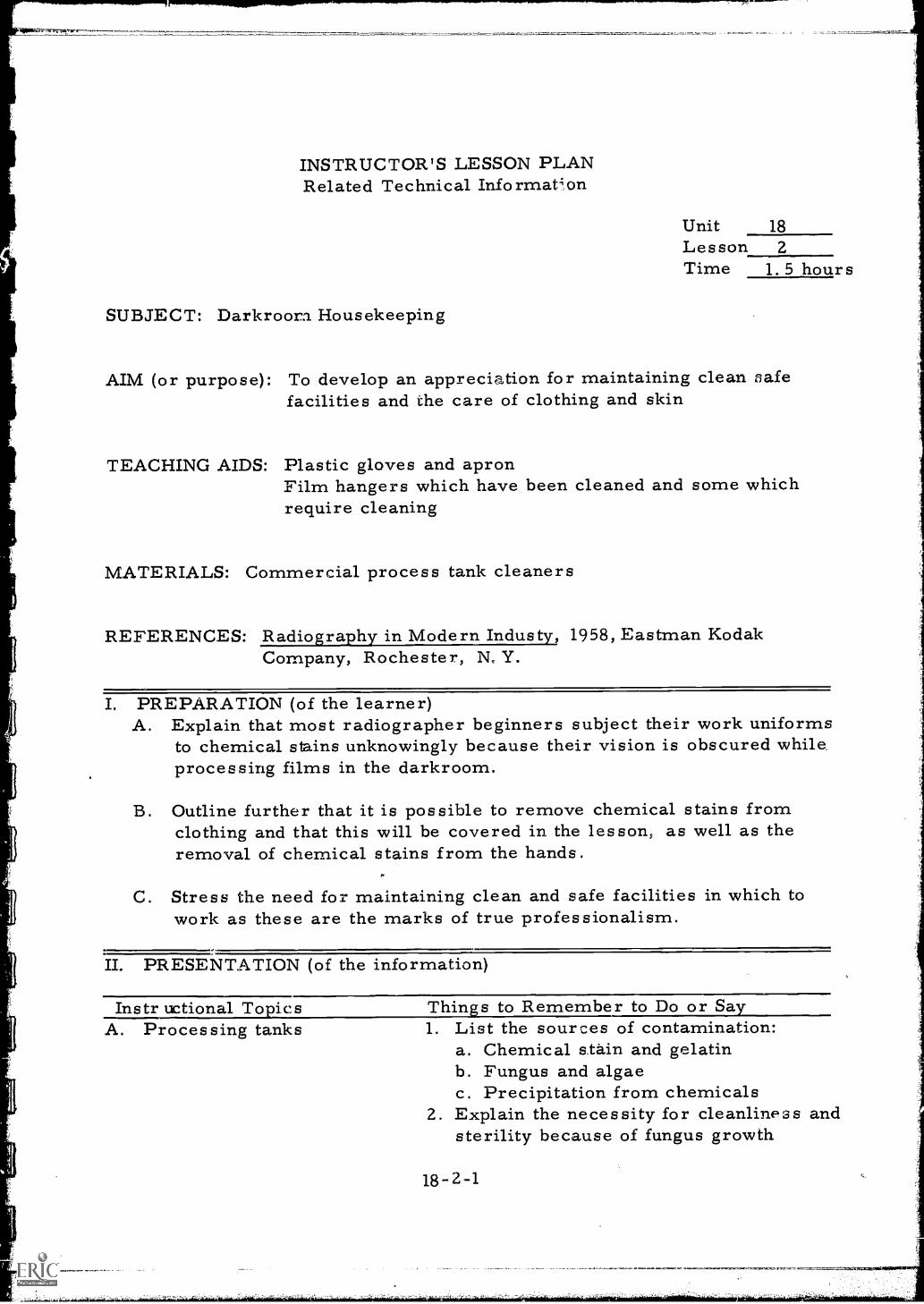
INSTRUCTOR'S LESSON PLANRelated Technical Informat4on
Unit 18Lesson 2Time 1. 5 hours
SUBJECT: Darkroom Housekeeping
AIM (or purpose): To develop an appreciation for maintaining clean nafefacilities and the care of clothing and skin
TEACHING AIDS: Plastic gloves and apronFilm hangers which have been cleaned and some whichrequire cleaning
MATERIALS: Commercial process tank cleaners
REFERENCES: Radiography in Modern Industy, 1958, Eastman KodakCompany, Rochester, N. Y.
I. PREPARATION (of the learner)A. Explain that most radiographer beginners subject their work uniforms
to chemical stains unknowingly because their vision is obscured while,processing films in the darkroom.
B. Outline further that it is possible to remove chemical stains fromclothing and that this will be covered in the lesson, as well as theremoval of chemical stains from the hands.
C. Stress the need for maintaining clean and safe facilities in which towork as these are the marks of true professionalism.
II. PRESENTATION (of the information)
Instr uctional To icsA. Processing tanks
Thins to Remember to Do or Sa1. List the sources of contamination:
a. Chemical stain and gelatinb. Fungus and algaec. Precipitation from chemicals
2. Explain the necessity for cleanliness andsterility because of fungus growth
18-2-1
B. Processing hangers
C. Stains on clothing
that can occur in chemical tanks.3. Describe and display commercial
cleaners for the removal of contamination.4. List the chemical formulas on the chalk-
board for use in removal of variouscontaminating agents.
5. Outline precautions to be employed inhandling chemicals:a. Do not let chemicals remain in
contact with the skin.b. Avoid splashing liquid or chemicals
in the eyes.
1. Describe and explain the similarity ofhanger contamination to tank contaminationsince hangers come in contact with tankwalls and with chemicals in the tanks.
2. List chemical formulas of solutions forremoval of contamination on the chalk-board.
3. Detail the use of nitric acid solutionsfor very difficult clip stains explainingthe process of soaking hanger clips innitric acid water solution a few minutes.Tben rinse with tap water. NOTE:Always add acid to water (water in thetank first)
4. Display dirty and properly cleanedhangers.
1. Explain that the best method of controlof clothing stains is the careful handlingof materials to avoid spillage.
2. Display rubber or plastic apron used tokeep chemicals from clothing.Demonstrate use.
3. Describe the chemicals and methods used toremove stains from clothing. Moisten withspot remover and rinse with water.Chemical spot and stain removerssupplied by film manufacturers.
4. List the chemical formulas for stainremovers on the chalkboard.
5. Caution against the use of solutions oncolored fabrics and synthetic fiberssince some spot removers will bleach
18-2-2
D. Care of hands
out color of garment.
1. Caution against over exposure of handsto processing chemicals because theycan cause skin discoloration and rash.
2. Recommend the use of gloves and dis-posable towels.
3. List on the chalkboard the formula forpotassium permanganate solutions usedto remove skin stains.
4. Describe the method of skin stainremoval.
5. Demonstrate the preferred method.
III. APPLICATION (drill, illustrations, analogies, oral questions orassignments)
A. Explain the necessity for periodic cleaning of processing tanks andpromote discussion.
B. Explain the consequences of dirty hanger clips and how to removecontamination asking questions as explanation progresses.
C. Describe the method of removing stains from hands and clothingdemonstrate and have students participate in the examples used.
IV. TEST (final check on students' comprehension of materials presented)NOTE: Written TestA. What is the source of contamination found in chemical processing
tanks ?
B. What effect does contamination have on film processing quality?Describe.
C. How can stains be removed from clothing? Give examples.
D. What measures can be employed to prevent skin irritation fromchemicals?
Check and discuss.
V. SUMMARYA. Dirty film hangers are a major cause of film artifacts.
B. Quality work cannot be maintained without a constant program ofdarkroom housekeeping.
C. Fresh chemicals offer no advantage if chemical tanks are not keptclean.
D. Stains on worker's hands and clothing reflect poorly on the abilityof the worker.
The Next Lesson is: Insertion of Film on Processing Hangers
18-2-4
INSTRUCTOR'S LESSON PLANManipulative Skills
Unit 18Lesson 3
Time 1. 5 hours
JOB (or operation): Insertion of Film on Processing Hangers
AIM (or purpose): To develop skill in the insertion of film into processinghangers
TOOLS AND EQUIPMENT: Darkroom facilities
MATERIALS: Clean rags
TEACHING AIDS: Sheets of 14" x 17" film (defective or outdated)14" x 17" processing hangers14" x1.7" film cassettes or exposure holdersBrush
I. PREPARATION (of the learner)A. Introduce the subject and elaborate on how the best radiograph
can be damaged by improper insertion into processing hangers.Explain that faulty insertion can result in film becoming detachedin the chemicals or dryer with subsequent damage to one or moreof the other film,
B. Outline that processing camera cut film sheets is very similar toprocessing x-ray film and if anyone has such experience it willstand him in good stead when studying the material about to bepresented,
II. PRESENTATION (of the skills)
Operations or Steps
A. Assemble equipment
Key Points (things to remember to door say)1. Gather hangers to be loaded.
Collect exposure holders or cassettescontaining exposed film. (Useoutdated or damaged film.)
18-3-1
B. Inspect hangers
C. Position equipment
D. Remove film fromcassette (Simulatedarkroom procedurewhile demonstratingin white light)
E. Pick up processinghanger (hangers arestacked upside down.Directions apply tohandling in the posi-tion in which theyare stacked)
F. Clip film to hanger
1. Examine hangers for contamination.2. Inspect clips for bits of film left from
previous processing.3. Clean hangers if necessary before
proceeding using brushes)solventsand rags.
1. Turn hangers upside down and lean themagainst back board of work bench.
2. Clear area to stack hangers after loadingthem (hang from hanger storage racksif convenient).
3. Stack cassettes near the hangersallowing room for opening andstacking of unloaded cassettes.
1. Unlatch exposure holder,2. Remove film from holder by grasping
the upper left hand corner of the 17"length between the thumb and forefingerof the left hand.
1. Pick up the hanger with the right hand.2. Grasp the clip in the upper left corner
between the thumb and forefinger.3. Steady the hanger with the other three
fingers of the right hand,
1. Open clip in the right hand bysqueezing.
2. Insert the corner of the film held in theleft hand into the clip.
3. Caution: Do not pin it too close to theedge or force it too deeply into clip.The pin should pierce the film about3/8" from each edge of the film.
4. Reverse hands and pin the other topcorner,
5. Caution: Pin both top corners insuch manner that the film hangs straightin the hanger.
6. Holding the hanger upside down in theright hand, grasp the bottom left edgeof the film by the thumb and forefinger
18-3-Z
4,4
G. Repeat steps. D,E, and Fwith white lights extin-guished and after ad-justing to darkened room
of the left hand with the bar of thehanger in the web of the thumb and theback of the hand toward the body.
7. Turn the hanger ovf;r.8. Clip the corner held in the left hand,9. Grasp the upper right corner with
the thumb and forefinger of theright hand,
10 Clip the corner with the left hand.11. Stack or hang the loaded hangers to
avoid damage until film is loaded intoprocessing tanks,
Repeat the procedure outlined above,
III. APPLICATION (practice by learner under close supervision)A. Have each student simultaneously perform the task of inserting a
film into a processing hanger several times under supervision ofthe teacher. Do this in a lighted room.
B. Inspect work and discuss.
C. Repeat process several times in darkened room under closestpossible supervision.
IV. TEST (performance of skill to acceptable standards)NOTE: Performance TestHave each student insert a film in a hanger in total darkness. Repeatuntil all students can load film without damage and without the aidof safe lights.
Check and discuss.
V. SUMMARYA. All preliminary steps must be planned in advance so that student
will be oriented as to equipment and material location beforeroom is darkened.
B. Hands must be washed and dried before handling film to preventartifacts.
18-3-3
C. Hangers must be inspected for cleanliness before lights areextinguished.
D. Film must hang squarely in hanger to prevent bulging and subequentlytouching adjoining film while in the chemical processing tanks.
The Next Lesson is: Use of Film Processing Reels
18-3-4
INSTRUCTOR'S LESSON PLANManipulative Skills
Unit 18Lesson 4Time 1. 5 hours
JOB (or operation): Use of Film Processing Reels
AIM (or purpose): To familiarize the student with the correct use offilm processing reels
TOOLS AND EQUIPMENT: Dark room facilitiesFilm cassettesReelsPlastic or stainless steel "tee" sticks
MATERIALS: Clean ragsScrub brush
TEACHING AIDS: 70 mm film (used or outdated)
I. PREPARATION (of the learner)A. Outline that many radiographic applications require the use of film
over 17" long requiring for its processing a different type of filmhandler. A reel is usually substituted for the hanger in situationsof this sort. Show students typical reels. There are severaltypes on the market. Also show the students the "Tee" shapedstainless steel wire through which reels are threaded prior toimmersion into chemicals.
B. Explain that the process is quite similar to that used in processingregular 35 mm film and if any of those present have experiencein the processing of this size film,this exposure will be mosthelpful in acquiring the new skills.
18-4-1
,==;:liklIFORIEMPAUP, ,
II. PRESENTATION (of the skills)
Operations or Steps
A. Preparation of 70 mmfilm
B. Inserting film in reel
C. Demonstrate usingpreviously developedfilm, in light
D. Placing reels inchemicals
Key Points (things to remember to door say)._Illustrate and explain on the chalkboardthat one end of the film should be trimmedwith a paper cutter or scissors removingcorners. This will facilitate starting thefilm into the grooved guides of the reels.
1. The film is wound into the grooves inthe reel or in the space between thewire that the reel is made of. (Showboth types) The grooves act asspacers that allow the chemicalsolution to contact the film betweeneach circumferential warp of the filmGrooves are spaced so that properlyinserted film surfaces will not comein contact with each other.
1. Hold the reel in one hand.2. Place the end of the film in the clip
located on the axle of the reel. Somereels have a sharp end of a nail thatis forced through the end of the film.
3. Holding the side edges of the film withthe other hand, between the thumb andindex finger, apply slight, but steadypressure to the film to reduce :itswidth until it is equal to the widthbetween the reel grooves.
4. While maintaining this slight pressureon the film, start rotating the reel withthe other hand,thereby feeding the filminto the reel grooves.
5. After the film has been placed on the reelcheck to see if any film surfaces aretoucning. If they are, unwind the filmto the point of film contact and rewind.
1. String each completed reel of film ona "Tee" stick by threading the stickthrough the hollow axle of the reel.
18-4-2
11
E. Removing developed filmfrom reel
F. Reel housekeeping
2. To develop film immerse the reels andstick in the chemicals.Remove the film from the reels bygrasping the very edge of the filmwith one hand and reel with the otherhand and unwind it.
1. Developed film can be dried by hangingthe film on an improvised clothes linemade of nylon string and using plasticclothes pins.
2. If the film is dried outdoors avoid strongsunlight and dusty areas.
3. A large percentage of field radiographsare dried in this manner especiallyon pipeline construction jobs.
Reels must be scrubbed the same asfilm hangers to remove contaminants
III. APPLICATION (practice by learner under close supervision)A. Pass out reels to each student
B. Review film inserting sequence and technique by threading an 18" x70 mm film on reel.
C. Pass out strips of film to each student.
D. Ask them to prepare film for threading as demonstrated in Step II.
E. Have each student thread film on reel.
F. Time this operation.
G. Examine each threaded reel for kinked film and for film surfacecontact.
H. Practice as many times as necessary,
I. Repeat E above, using exposed, undeveloped film with whitelights out in dark room.
J.. Process films.
K. Examine and discuss results,
18-4-3
IV. TEST (performance of skill to acceptable standards)NOTE: Performance TestA. Have students place films in film cassettes in dark room with
white lights out.
B. Have students remove films from cassettes and thread film onreels.
C. Turn on lights, examine and discuss results.
D. Turn out white lights and distribute some previously exposed filmthat has not been developed. (Film should be in cassettes).
E. Have students remove film from cassettes, place on reels anddevelop.
. After film have been processed)inspeci each person's film onviewing screen and point out results of improper reel techniques.(Kinks, finger prints, etc.)
Remind students that film artifacts can sometimes be mistakenfor specimen defects.
V. SUMMARYA. Film preparation for aid in inserting film in reel groove.
B. Grooves separate layers of film.
C. Creases and kinks in film will cause film surface contact duringprocessing and show up as artifacts on finished radiograph.
D. Film reels must be kept clean, especially groove surfaces.
The Next Lesson is: Film Processing Chemicals
18-4-4
I
it
INSTRUCTOR'S LESSON PLANRelated Technical Information
Unit 18
Lesson 5
Tme 2 hours
SUBJECT: Film Processing Chemicals
AIM (or purpose): To provide knowledge and information regarding theuse of various chemicals in the processing of industrialradiographic film
MATERIALS: Bottles and packages of processing chemicals
REFERENCES: Radiography in Modern Industry, 1958, Eastman KodakCompany, Rochester, N. Y
PREPARATION (of the learner)Much of the students time to date has been devoted to developing aclear understanding of the principles of exposure or the taking of agood radiograph, The care exercised in the exposure must befollowed by painstaking perfection in the darkroom if the fundamentalslearned to date are to be fully utilized. Everyone produces betterwork when he understands the reasons for his actions. The principlesof chemical processing will be reviewed and expanded in this lessonto help improve the procedures and processes employed in thedarkroom.
II. PRESENTATION (of the information)
Instructional To icsA. Developer
flings to Remember to Do or Say1. This subject was discussed previously
in the lesson plan entitled "ThePhotographic Process" and thereforeit should be reviewed briefly.
2. Show the types of prepared chemicalsavailable for radiographic use.
3. Explain the mixing of chemicals,especially the precautions that shouldbe taken in mixing dry chemicals.
4. Describe the ideal storage environmentfor radiographic chemicals:
18-5-1
B. Stop bath
C. Fixer
D. Wetting agents
E. Replenishers
a. Dry, cool room,b. Chemicals must not be exposed
to bright sunshine,
1. Define the purpose of the stop bathand explain that it stops thealkaline developing process with anacid neutralizer.
2. Relate the acidity of the stop bath tothe alkalinity of the developer.
3. Describe commercial stop baths andthe use of acetic acid.
4. Caution: Use care in mixing strongacids demonstrating the propermethod.
1. Review the purpose of the fixer out-lining that it removes all the undevelopedsilver.
2. Explain the use of ammonium orsodium thiosulfate for fixing.
3 2escribe the added benefits from useof commercially prepared chemicalscontaining agents to control the rateof reaction.
4. Outline the purpose of the hardenerexplaining that it conditions thegelatin so film can withstand dryingwith warm air.
1, Describe the purpose of wetting agents:a. Wetting agents remove film
water marks,b. Accelerates drying time.
2. Explain that household liquiddetergents are sometimes used forthis purpose.
1. Define the purpose of replenishing.2. Tabulate the results in increased
chemical usage from replenishing.3. Explain the effect of replenishment
on fixing and how it reduces fixing time.See Table XYYT,P. 75,Eastman Text-book.
18-5-2
F. Supplemental 1. Describe the process of filmintensification:a. Under developed film can be
darkened by immersing it inhardener solution for 5 minutes.
b. Film can be washed for 5 minutesthen immersed in an intensifiersolution for up tr 10 minutes.
2. Caution students on the safe handlingof strong chemicals used in theseprocesses.
III. APPLICATION (drill, illustrations, analogies, oral questions orassignments)
A. Suggest that students describe the entire and complete chemicalprocessing of film.
B. Have individual students describe and elaborate on each step inthe process.
C. Have students describe the controls employed for the reaction.
D. Ask for a description of the use of chemicals other than prepackagedthat can be used in the processing of film.
E. Have one student develop a small radiograph in a set of chemicalspreviously prepared in jars. Reverse the sequence of the developerand the fixer, inviting a prediction of the results (Film will beclear).
IV. TEST (final check on studentsNOTE: Written TestA. What is the purpose of the stop bath?
comprehension of material presented)
B. What type of film artifacts result from elimination of the stopbath or from continued use of weak baths?
C. What happens to the fixer if the stop bath is depleted or is tooweak to perform its intended task?
D. What is the purpose of replenishing?
E. What is the purpose of the post-wash wetting agents?
Check and discuss.
18-5-3
V. SUMMARYA. Developer sh( ald be mixed thoroughly, kept in a temperature con-
trolled environment end not exposed to sunlight.
B. The stop bath neutralizes the alkaline action of the developer.
C. The fixer removes all undeveloped silver. Also hardens orconditions gelatin for drying in warm air.
D. Wetting agents remove water marks and accelerate drying time.
The Next Lesson is: Darkroom Film Processing
18-5-4
INSTRUCTOR'S LESSON PLANManipulative Skills
JOB (or operation): Darkroom Film Processing
Unit 18Lesson 6Time 2 hours
AIM (or purpose): To assist students in acquiring the necessary skilland the proper techniques in darkroom procedure andthe chemical processing of film
TOOLS AND EQUIPMENT: Film hangersProcessing tanksDevelopment time indicator chartDarkroom facilityTimerThermometer
MATERIALS: Processing chemicals
TEACHING AIDS: Exposed or outdated film
REFERENCES: Radiography .odern Industry, 1958, Eastman KodakCompany, Rochester, N. Y.Nondestructive Testing Handbook, Volume I, 1963,Society for Nondestructive Testing, Evanston, Illinois
PREPARATION (of the learner)Explain that the exposure of a film is only one part of the process ofproducing a radiograph. The proper chemical processing of thefilm is equally as important as the exposure. Processing techniquesdo not change appreciably once the fundamentals have been masteredand repetition and practice does the rest, until ultimately the proceduresbecome automatic reactions. It is therefore easy to see the importanceof establishing good work habits from the beginning.
18-6-1
-J
II. PRESENTATION (of the skills)
Operations or Steps
A. Prepare processingtanks
B. Load hangers
C. Set timer
D. Developing
Key Points (things to remember todo or say)1. Have all chemicals and materials
ready to use in dark room. Establishproper temperature and prepare todemonstrate.
2. Remove lids from the tanks and storeout of way.
3. Energize temperature control device,4. Use plastic or rubber paddles to
stir chemicals.5. Replenish chemical to proper height
in tanks,
Since hanger loading is covered byanother lesson, review briefly.
1. Check the temperature of thechemicals,
2. Use a process time indicator or chartto determine the optimum processtime.
3. Set timer for the indicated time.
1. Pick up hangers containing film bythe cross bar,
2. Caution: If more than one film ishandled at a time, separate hangerswith fingers. Do not attempt to handlemore than three hangers at a time.
3. Lower film into tank slowly, keepinghangers vertical and separated.
4. Energize timer,5. Agitate each film to remove air
bubbles from the surface by raisinghanger about 1/2" and tapping sharplyon the top of the tank.
6. Agitate each film every 30 secondsby moving from side to side and upand down in tank. Better results canbe obtained by lifting film clear oftank and draining from the corner.
7. Remove film from the tank and placein clear water when proper time hasbeen reached.
18-6-2
11
11
11
11
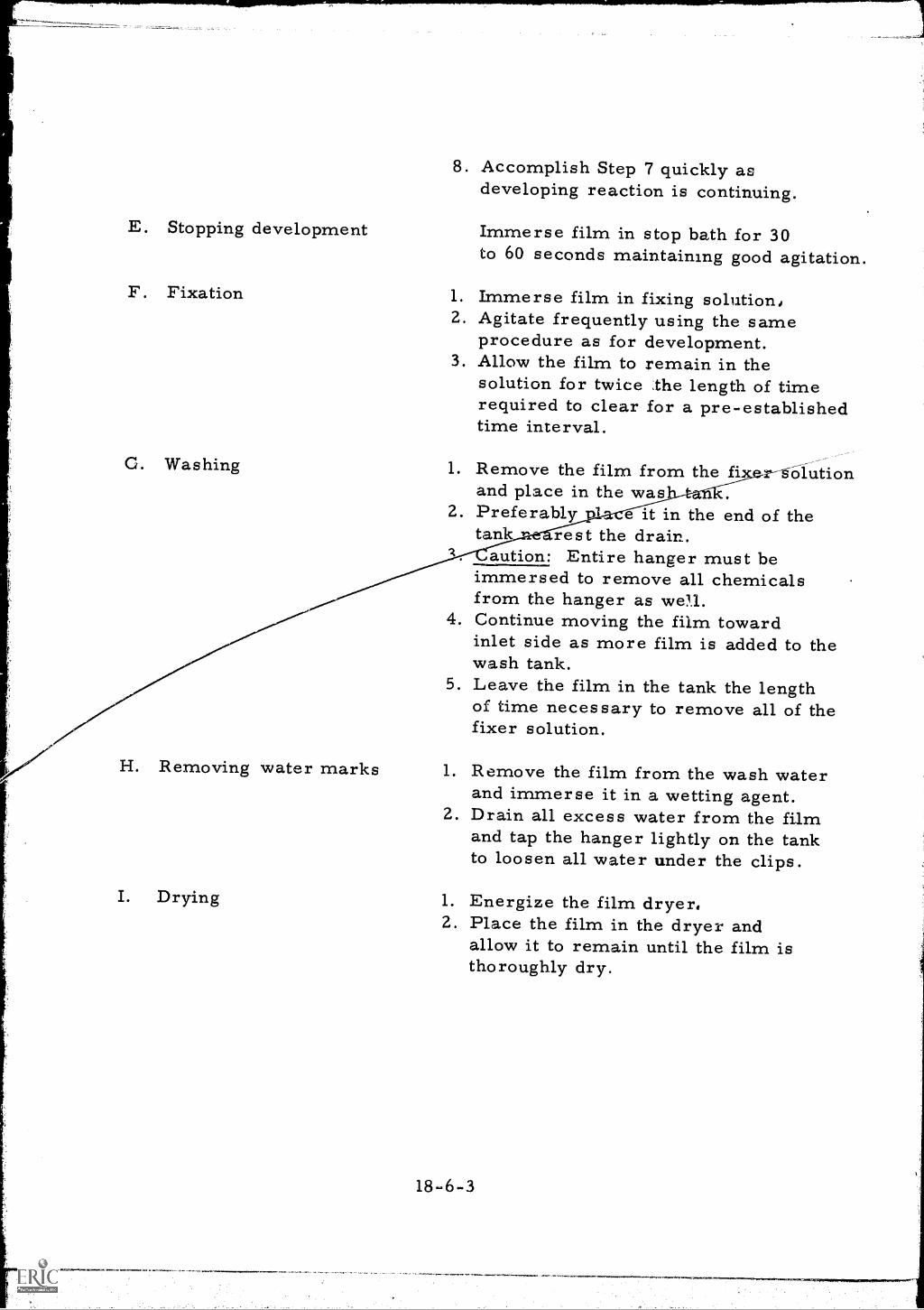
8. Accomplish Step 7 quickly asdeveloping reaction is continuing.
E. Stopping development Immerse film in stop bath for 30to 60 seconds maintaining good agitation.
F. Fixation
G. Washing
H. Removing water marks
I. Drying
1. Immerse film in fixing solution,2. Agitate frequently using the same
procedure as for development.3. Allow the film to remain in the
solution for twice the length of timerequired to clear for a pre-establishedtime interval.
1. Remove the film from the fiand place in the was
2. Preferably 1 e it in the end of thetank rest the drain.
aution: Entire hanger must beimmersed to remove all chemicalsfrom the hanger as well.
4. Continue moving the film towardinlet side as more film is added to thewash tank.
5. Leave the film in the tank the lengthof time necessary to remove all of thefixer solution.
--r-golution
1. Remove the film from the wash waterand immerse it in a wetting agent.
2. Drain all excess water from the filmand tap the hanger lightly on the tankto loosen all water under the clips.
1. Energize the film dryer.2. Place the film in the dryer and
allow it to remain until the film isthoroughly dry.
18-6-3
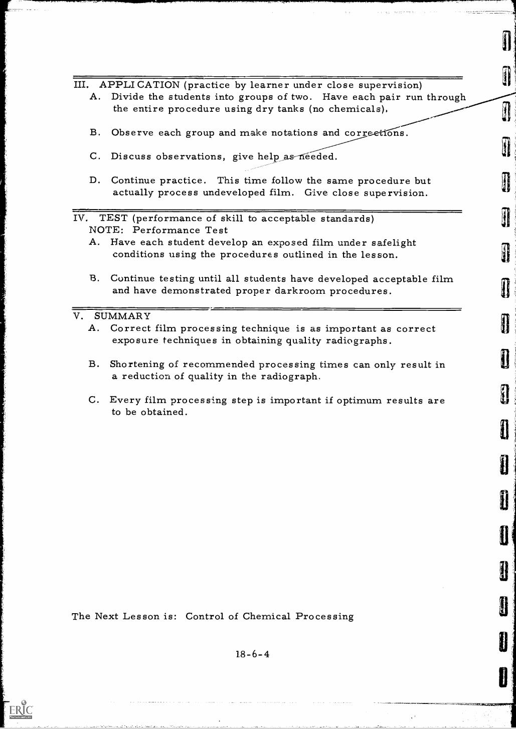
III. APPLICATION (practice by learner under close supervision)A. Divide the students into groups of two. Have each pair run through
the entire procedure using dry tanks (no chemicals),
B. Observe each group and make notations and core 'tons.
C. Discuss observations, give help_as--ffeeded.__D. Continue practice. This time follow the same procedure but
actually process undeveloped film. Give close supervision.
IV. TEST (performance of skill to acceptable standards)NOTE: Performance TestA. Have each student develop an exposed film under safelight
conditions using the procedures outlined in the lesson.
B. Continue testing until all students have developed acceptable filmand have demonstrated proper darkroom procedures.
V. SUMMARYA. Correct film processing technique is as important as correct
exposure techniques in obtaining quality radiographs.
B. Shortening of recommended processing times can only result ina reduction of quality in the radiograph.
C. Every film processing step is important if optimum results areto be obtained.
The Next Lesson is: Control of Chemical Processing
18-6-4
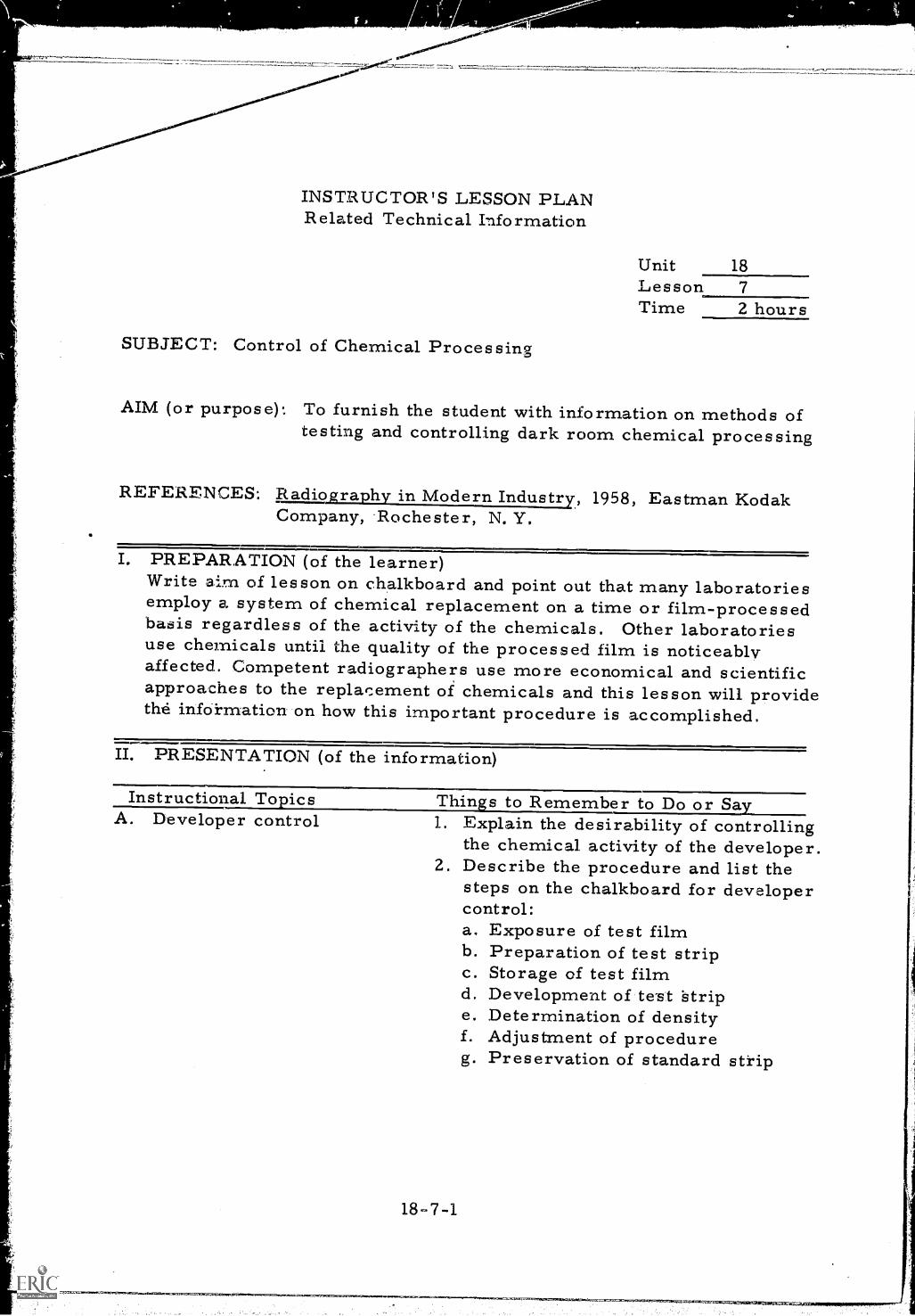
INSTRUCTOR'S LESSON PLANRelated Technical Information
SUBJECT: Control of Chemical Processing
Unit 18LessonTime 2 hours
AIM (or purpose): To furnish the student with information on methods ofto and controlling dark room chemical processing
REFERENCES: Radiography in Modern Industry, 1958, Eastman KodakCompany, Rochester, N. Y.
I. PREPARATION (of the learner)Write aim of lesson on chalkboard and point out that many laboratoriesemploy a system of chemical replacement on a time or film-processedbasis regardless of the activity of the chemicals. Other laboratoriesuse chemicals until the quality of the processed film is noticeablyaffected. Competent radiographers use more economical and scientificapproaches to the replacement of chemicals and this lesson will providethe infokmation on how this important procedure is accomplished.
II. PRESENTATION (of the information)
Instructional To ics Thins to Remember to Do or SaA. Developer control 1. Explain the desirability of controlling
the chemical activity of the developer.2. Describe the procedure and list the
steps on the chalkboard for developercontrol:a. Exposure of test filmb. Preparation of test stripc. Storage of test filmd. Development of test Stripe. Determination of densityf. Adjustment of procedureg. Preservation of standard strip
18-7-1
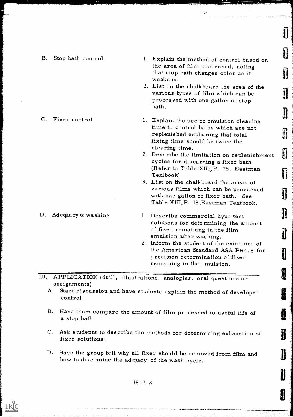
B. Stop bath control
C. Fixer control
D. Adequacy of washing
1. Explain the method of control based onthe area of film processed, notingthat stop bath changes color as itweakens.
2. List on the chalkboard the area of thevarious types of film which .can beprocessed with one gallon of stopbath.
1. Explain the use of emulsion clearingtime to control baths which are notreplenished explaining that totalfixing time should be twice theclearing time.
2. Describe the limitation on replenishmentcycles for discarding a fixer bath(Refer to Table XIII,P. 75, EastmanTextbook)
3. List on the chalkboard the areas ofvarious films which can be processedwith one gallon of fixer bath. SeeTable XIII,P. 18,Eastman Textbook.
1, Describe commercial hypo testsolutions for determining the amountof fixer remaining in the filmemulsion after washing.
2. Inform the student of the existence ofthe American Standard ASA P- H4. forprecision determination of fixerremaining in the emulsion.
III. APPLICATIONassignments)
A. Start discussion and have students explain the method of developercontrol.
(drill, illustrations, analogies, oral questions or
B. Have them compare the amount of film processed to useful life ofa stop bath.
C. Ask students to describe the methods for determining exhaustion offixer solutions.
D. Have the group tell why all fixer should be removed from film andhow to determine the adequacy of the wash cycle.
18-7-2
IV. TEST (final check on students' comprehension of material presented)NOTE: Written TestA Why is a check system desirable for control of chemical solution
activity in film processing?
13. What method is used to correct the activity of a developer if thefilm test strip has too high a density?
C. What is the common practice used to control fixer activity?
D. What undesirable effects restrict the repeated replenishmentof fixer solutions ?
Check and discuss.
V. SUMMARYA. While recommended developing and fixing times vary,they are all
based on Fresh, full strength chemicals used at or near 680 F.
B. Some developer stop baths indicate a need for replacement by a changein color,
C. Developer is seldom contaminated because it is used first butliquid level must be maintained in addition to replacing spentdeveloper with a replenishing agent
D. Adequate cycle with a constant replacement of wash water is verydesirable.
The Next Lesson is: Preparing for Field Radiography
18-7-3
INSTRUCTOR'S LESSON PLANManipulative Skills
Unit 18Lesson 8Time 6 hours
JOB (or operation): Preparing for Field Radiography
AIM (or purpose): To develop skill in the procedures and precautionsrequired to move radiographic equipment and portabledarkrooms to a field location
TOOLS AND EQUIPMENT: Portable darkroomMotor vehicleGamma ray camera and controlsSurvey meter, Dosimeter charger,Film badges
MATERIALS: All film and accessories necessary to perform theradiographic functions
REFERENCES: Title 10, Federal Register, Parts 20 and 34, Ru..es andRegulations, U. S. Atomic Energy Commission,Washington, D. C.Information Sheet #3
I. PREPARATION (of the learner)Much of the success achieved in any field operation depends inlarge measure on careful planning before leaving for the jobsite.A professional radiographer should form the habit of checking allequipment before leaving and be able to select the darkroom locationwhich is most convenient to the work on the site. With practice andstudy these good work habits can be acquired and retained. Writeaim on chalkboard.
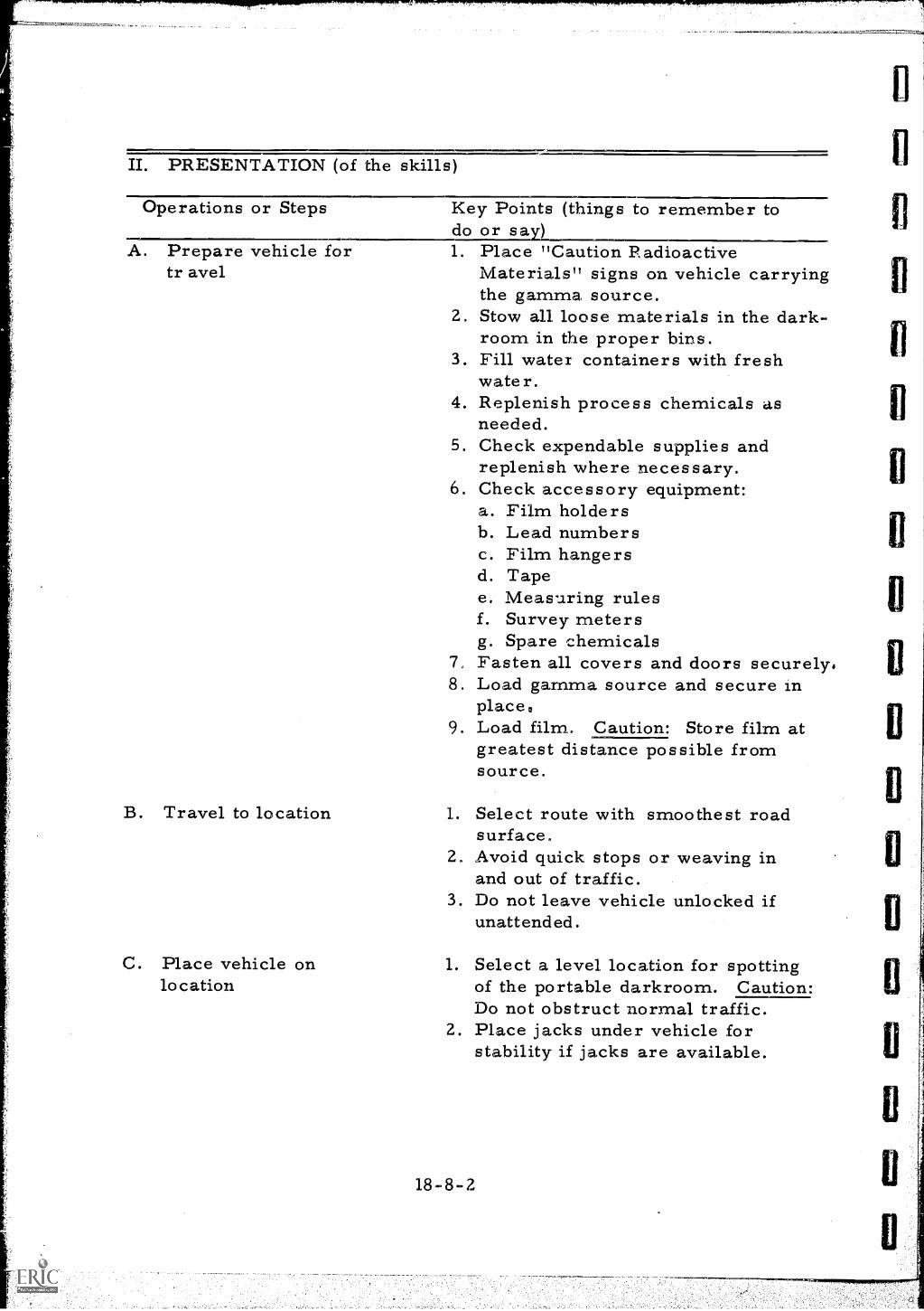
D. Preparation of job site 1. Examine the work area for presenceof other workmen or for instrumentswhich might be damaged by radiation.For example: Many processing plantsuse control instruments that respondto a fixed amount of radiation. Ifanother radiation field is creatednear this instruments it will sta:et togive false signals that can upsetthe operation of the processing unit.
2. Erect rope barricades and radiationsigns. Note: Do not obstruct normaloperations with barricades unless aradiation hazard does actually exist.Do not omit the barricades fromareas where radiation hazards existjust because it may hinder otheroperations.
3. Examine area again for presence ofworkmen.
4. Unload the equipment to be used.
III. APPLICATION (practice by learner und.er close supervision)A. Divide the class into small groups. Have each group prepare the
vehicle for movement, move to a job site, and setup for performance.Have the group return the vehicle to the laboratory and place theequipment in its original condition. Supervise the preparation andmovements.
B. Repeat the operations having the students tell what they are doingand why they are doing it, correct any faulty concepts or operations.
IV. TEST (performance of skill to acceptable standardsNOTE: Performance TestA. Grade each student on the preparation of equipment and vehicles
conduct of driving, and selection of location on each trip madewith the portable darkroom.
B. After each tripldiscuss the conduct of the trip with the students.Indicate areas of needed improvement.
V. SUMMARYA. It is important to use a check list when preparing for a field
as signrn.ent.
B. Gamma exposure devices must be locked at all times when not inuse and especially when being transported to and from fieldassignments.
C. Vehicle transporting gamma exposure device must have radiationwarning signs prominently displayed.
D. It is desirable to pick the smoothest route to and from fieldlocation because:a. Chemicals can spill out of tankb. Survey meters can be damagedc. Exposure device can be damaged
E. Constant surveillance is necessary when using gamma and x-rayequipment outside a controlled area.
The Next Lesson is: Photographic Density
18-8-4
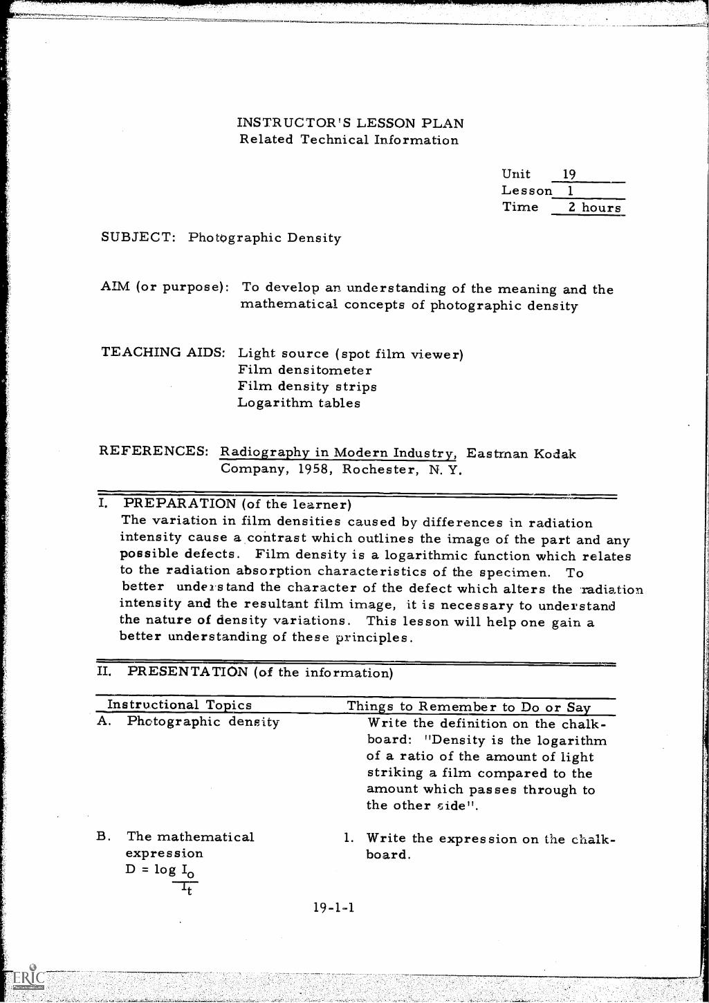
INSTRUCTOR'S LESSON PLANRelated Technical Information
SUBJECT: Photographic Density
Unit 19Lesson 1
Time 2 hours
AIM (or purpose): To develop an understanding of the meaning and themathematical concepts of photographic density
TEACHING AIDS: Light source (spot film viewer)Film densitometerFilm density stripsLogarithm tables
REFERENCES: Radiography in Modern Industry, Eastman KodakCompany, 1958, Rochester, N. Y.
en,I. PREPARATION (of the learner)The variation in film densities caused by differences in radiationintensity cause a.contrast which outlines the image of the part and anypossible defects. Film density is a logarithmic function which relatesto the radiation absorption characteristics of the specimen. Tobetter understand the character of the defect which alters the radiationintensity and the resultant film image, it is necessary to understandthe nature of density variations. This lesson will help one gain abetter understanding of these principles.
II. PRESENTATION (of the information)
Instructional To sicsA. Photographic density
B. The mathematicalexpressionD = log IoIt
Thin. s to Remember to Do or SaWrite the definition on the chalk-board: "Density is the logarithmof a ratio of the amount of lightstriking a film compared to theamount which passes through tothe other
1. Write the expression on the chalk-board.
19-1-1
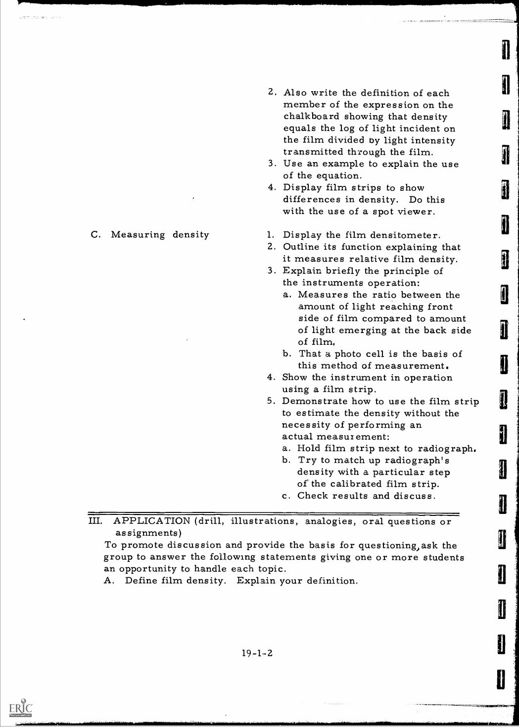
C. Measuring density
2. Also write the definition of eachmember of the expression on thechalkboard showing that densityequals the log of light incident onthe film divided by light intensitytransmitted through the film.
3. Use an example to explain the useof the equation.
4. Display film strips to showdifferences in density. Do thiswith the use of a spot viewer.
1. Display the film densitometer.2. Outline its function explaining that
it measures relative film density.3. Explain briefly the principle of
the instruments operation:a. Measures the ratio between the
amount of light reaching frontside of film compared to amountof light emerging at the back sideof filmy
b. That a photo cell is the basis ofthis method of measurement.
4. Show the instrument in operationusing a film strip.
5. Demonstrate how to use the film stripto estimate the density without thenecessity of performing anactual measurement:a. Hold film strip next to radiograph.b. Try to match up radiograph's
density with a particular stepof the calibrated film strip.
c. Check results and discuss.
III. APPLICATION (drill, illustrations, analogies, oral questions orassignments)
To promote discussion and provide the basis for questioning.,ask thegroup to answer the following statements giving one or more studentsan opportunity to handle each topic.A. Define film density. Explain your definition.
19-1-2
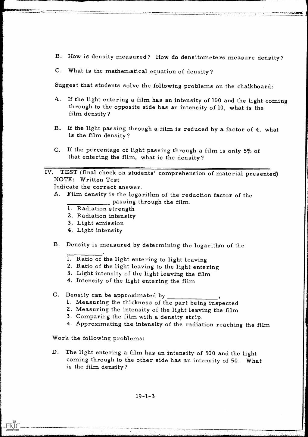
B. How is density measured? How do densitometers measure density?
C. What is the mathematical equation of density?
Suggest that students solve the following problems on the chalkboard:
A. If the light entering a film has an intensity of 100 and the light comingthrough to the opposite side has an intensity of 10, what is thefilm density?
B. If the light passing through a film is reduced by a factor of 4, whatis the film density?
C. If the percentage of light passing through a film is only 5% ofthat entering the film, what is the density?
IV. TEST (final check on students' comprehension of material presented)NOTE: Written TestIndicate the correct answer.A. Film density is the logarithm of the reduction factor of the
passing through the film.1. Radiation strength2. Radiation intensity3. Light emission4. Light intensity
B. Density is measured by determining the logarithm of the
1. Ratio of the light entering to light leaving2. Ratio of the light leaving to the light entering3. Light intensity of the light leaving the film4. Intensity of the light entering the film
C. Density can be approximated by1. Measuring the thickness of the part being inspected2. Measuring the intensity of the light leaving the film3. Comparirg the film with a density strip.4. Approximating the intensity of the radiation reaching the film
Work the following problems:
D. The light entering a film has an intensity of 500 and the lightcoming through to the other side has an intensity of 50. Whatis the film density?
19-1-3
iV
E. If the light passing through a film is reduced by a factor of 25, whatis the film density?
F. If the density of a film is 2.0 and a light enters the film with anintensity of 100, what is the intensity of the light at the exit side?
V. SUMMARYA. Radiographic relative film density is the log of the ratio of light
incident on a film compared to the light emerging through thefilm.
B. Film densities cannot be estimated accurately on a visual basis,therefore, a densitometer should be used.
C. The radiographic film density range is important for quality work.
The Next Lesson is: Calibration of a Transmission Densitometer
19-1-4
3
3
3
INSTRUCTOR'S LESSON PLANManipulative Skills
Unit 19Lesson 2Time 2hours
JOB (or operation): Calibration of a Transmission Densitometer
AIM (or purpose): To develop skill in calibrating and using a filmdensitometer
TOOLS AND EQUIPMENT: Photovolt transmission densitometerVarious types of measuring meters
TEACHING AIDS: Film density stripsSample radiographsVarious types of measuring meters
REFERENCES: Manufacturers operating instruction manual
I. PREPARATION (of the learner)Introduce this lesson by having students visually estimate threedifferent relative densities on a radiograph of a steel step wedge.Record individual estimates on the chalkboard and follow up bychecking the relative densities on the photovolt type densitometer.The results should be something less than accurate and this willdemonstrate the importance of using a densitometer in measuringrelative film density. Compare a densitometer to other type metersstudents should be familiar with. A densitometer is an instrumentfor measuring relative film density. Densitometers are of two types,visual and photo dectric. Great accuracy is generally not requiredin film density measurements, however, some specifications requirea definite range of density for all film delivered to specification.It is necessary for the radiographer to know how to obtain the densityof a film if the work is performed according to these specifications.
II. PRESENTATION (of the skills)
II. PRESENTATION (continued)
Operations or Steps
A. Set up
B. Zero and warmup
C. Calibrate photometer
19-2-2
Key Points (things to remember todo or say)1. Place densitometer on a table of
convenient height.2. Turn off main switch and power
switch on the density unit.3. Connect control panel to
density unit.4. Connect instrument to proper
power source.
1. Check mechanical zero on indicatingmeter. Adjust if necessary.
2. Turn range switch to the lowestsensitivity setting.
3. Turn selector switch to warmupposition.
4. Turn lamp control knobs ondensity unit full counter clockwiseand energize power switch on thedensity unit.
5. Allow ten minutes for warmup.
1. Set the pointer to the index on thehigh density side of the meter byelectrical zero control adjustment.
2. Turn sensitivity switch to maximumand check above operation. Readjustif necessary.
3. Return sensitivity to minimum position.4. Depress arm of density unit firmly
to the aperture without a negative inposition.
5. Open shutter by depressing plungeron end of arm.
6. Turn fine lamp control to midwayposition.
7. Make an approximate meter zerowith the coarse lamp control.
8. Make final zero adjustment withfine control.
9. Release shutter and check indexon high end of scale. Recalibrateif necessary.
D. Measuring density 1.. Place negative on density unittable with the .area to be measuredover the aperture.
2. Depress the arm and open theshutter.
3. Read the density direct from themeter.
4. For density above 1. 3 movesensitivity switch to properposition and add a density valueequal to the number on theselector switch opposite theindex mark.
III. APPLICATION (practice by learner under close supervision)Divide the students into small groups. Under close supervisionhave each student in each group repeat the following demonstration:A. Set up.
B. Zero and warm up.
C. Calibrate photometer.
D. Measure density of film.
IV. TEST (performance of skill to acceptable standards)NOTE: Performance TestA. Request that each student calibrate the instrument.
B. Have them read and record the density of each increment ofa test strip made of a step wedge.
E. Compare their results with yours.
Check and discuss.
V. SUMMARYA. A densitometer is a valuable aid in improving the quality of
radiographs.
B. The densitometer eliminates guesswork when checking resultsof exposure time calculations.
C. A densitometer is often used to estimate percentage of metalloss occurring in piping subject to corrosive attack.
The Next Lesson is: Measuring Radiographic Sensitivity
19-2-3
INSTRUCTOR'S LESSON PLAN:(elated Technical Information
Unit 20Lesson 1
Time 2 hours
SUBJECT: Measuring Radiographic Sensitivity
AIM (or purpose): To outline the purpose and methods of usingimage quality indicators
TEACHING AIDS: Assorted penetrametersFilm viewerSample film showing penetrameters
REFERENCES: Standard for Welding of Reactor Coolant andAssociated S stems and Com onents for NuclearPower Plants, Nay-Ships, 250-1500-1, Nov. 1960,U. S. Navy Bureau of ShipsRadiography in Modern Industry, Eastman Kodak Co. ,1958, Rochester, N. Y,Information Sheets #49 and #50
I. PREPARATION (of the learner)Write aim On chalkboard explaining that much of the success of theradiographic operation depends on the ability of the radiographer toachieve the required sensitivity in his work. To insure that hehas met the desired requirements, the radiographer must have sometype of image quality indicator. The purpose of this lesson is todevelop a better understanding of the various types of indicators,describe their use, and impart a thorough knowledge of the limi-tations of their use.
II. PRESENTATION (of the information)
Instructional To icsA. Penetrameter
sensitivity
Thins to Remember to DO or Sa1.
20-1-1
Write the following definition onthe chalkboard: "An indication ofthe ability of the radiographicprocedure is to indicate a certaindifference in specimen thickness':
r.
B. Penetrameterconstruction
2. Elaborate on the above definition:a. Penetrameter sensitivity does
not guarantee the ability todetect a defect,
b. The sharp edges of a penetra-meter are more easily seenthan natural defects.
c. Only indicates ability to detecta thickness changes
3. Describe the generally acceptedsensitivity levels of Americanspecification (2% of the specimenthickness)
1. Draw a chalkboard sketch of thevarious types of penetrametersincluding the European types.
2. Distribute a specification sheet ona typical American penetrameter.Information sheets #49 and #50
3. Explain the function of the holesand slots outlining that hole diametersare usually one, two and fourtimes the penetrameter thickness.One or more holes should beperceptible in the radiographicimage.
4. Display all available penetrametertypes for student examination.
5. Explain why penetrameters shouldbe made of similar material to thatbeing inspected as they usuallyrepresent a 2% increase in subjectthickness on the radiograph.
C. Radiographic quality 1. Explain radiographic quality levellevel in terms of shim thickness and hole
size.2. Standard quality level is generally
designated as 2-2T.3. To indicate 2-2T quality the 2T
hole is a 2% shim must be clearlyvisible.
20-1-2
I
D. Placement ofpenetrameters
E. Film quality
1. Explain that penetrameters areplaced on the source side of thespecimen because image qualityindication should represent thefarthest specimen-film distance.
2, Explain that shim blocks are requiredto achieve proper thickness sinceshim blocks make up difference inweld thickness and plate thickness.(Penetrameter is placed on theplate.)
3. Describe and illustrate with achalkboard sketch the techniquefor determining the properpenetrameter when the penetra-meter can not be placed on thesource side.
1. Caution students against acceptanceof film quality on penetrameter imagealone.
2. Outline other means of determiningfilm quality such as:a. Freedom from light leaksb. Elimination of processing defects
such as streaks, air bells, andwater marks
c. Cleanliness of film and freedomfrom dirt and scratches
d. Absence of pressure marks andcrimps
e. Indication of poor screen contact
III. APPLICATION (drill, illustrations, analogies, oral questions orassignments)
A. Refer to specification sheet for construction of penetrameters andask individual students to explain the various dimensions andhow they are obtained.
B. To stimulate discussion ask the group the following questions, giveone or more students an opportunity to answer. In the event thatno answer or an incorrect one is offered,hasten to supply thecorrect information and give all supporting data freely. Becareful not to request answers on subject not fully coveredin previous presentations:
20-1-3
1. What is meant by penetrameter sensitivity?2. What is the generally accepted penetrameter sensitivity?3. What is meant by radiographic quality level?4. What is the generally accepted value of radiographic quality
level?5. Why is the penetrameter placed on the source side of the
specimen?6. What does a penetrameter measure?7. What are other factors which indicate film quality?
C. Have the students view the sample film and identify the penetrametersensivity and the radiographic quality level of each film.
IV. TEST (final check on students' comprehension of material presented)NOTE: Written TestEach statement below contains a missing word or words, therefore,the missing information should be supplied.A. Penetrameter sensitivity is an indication of the ability of a
radiographic procedure to indicate a difference in specimen
B. The generally accepted radiographic quality level iswhich means the procedure has the ability to resolve a
hole in a thick shim.
C. Shim blocks are used under penetrameter in weld inspection toincrease the of the metal to the same as the weldreinforcement.
D. Penetrameters are placed on the source side of the specimenbecause their image is greatest by this placement.
E. Penetrameters should be constructed of materials having similarradiation properties as the specimen to be inspected.
V. SUMMARYA. A penetrameter is an image quality indicator.
B. An image quality indicator is used to detect a thickness change.
C. There are several shapes and sizes of penetrameters.
D. Penetrameters are placed between the source of penetrating radiationand the specimen being radiographed when feasible.
20-1- 4
E. There are other means of determining film quality besides thepenetrameter image.
The Next Lesson is: Radiographic Subject Contrast
20-1-5
777:777,
INSTRUCTOR'S LESSON PLANRelated Technical Information
Unit 20Lesson 2Time 2 hours
SUBJECT: Radiographic Subject Contrast
AIM (or purpose): To furnish the student with a basic understanding ofthe factors controlling radiographic sensitivity
TEACHING AIDS: Film viewerX-ray exposure chartsSample radiographic film
REFERENCES: Radiography in Modern Industry, Eastman Kodak Co.,1958, Rochester, N. Y.
I. PREPARATION (of the learner)Since the primary purpose of most radiographic inspections is todetect defects and disamtinuities in materials, a knowledge of thefactors affecting the sensitivity of the procedure is quite important.The thickness of the various portions of the specimen influences theradiation reaching the film, therefore, the ratio of the intensitiesfrom different thicknesses is called the subject contrast. Tostudy the effect of subject contrast on film sensitivity is the purposeof this lesson and its relative importance is self evident.
II. PRESENTATION (of the information)
Instructional To icsA. Subject contrast
Thins to Remember to Do or Say1. Write the definition of subject
contrast on the chalkboard: "Theratio of radiation intensitiestransmitted by different portionsof the specimen;'
2. Explain the definition and illustratewith a chalkboard sketch such asFig. 10 in Radiography j.,/11A.ocj
20-2-1
B. Factors affecting subjectcontrast1. Thickness difference
in specimen
Z. Radiographic quality
3. Radiation scattering
3. Explain the independence of subjectcontrast from time, milliamperage,distance, and film type, pointing outthat subject contrast depends ba,-inallyupon specimen thickness and densityvariations.
1. Using an exposure chart, illustrate bya chalkboard sketch the range ofintensities which can be produced froma specimen with a thickness differenceof 2 to 1. See page 49 of Radiography inMoclersiri:
Z. Display sample film showing the subjectcontrast obtainable from differentthicknesses.
1. Define radiographic quality and writethe chalkboard: "The relationship
between the specimen geometry andthe penetrating qualities of the radiation;'
Z. Using an exposure chart, illustrate onthe chalkboard the ratio of intensitiesfrom a specimen with a 2 to 1 thicknessratio when different kv's are used.
3. Display film showing the change insubject contrast from severaldifferent kv's.
1. Review the effects of scattered radiationon the overall density of the film.
2. Explain why scattering reduces contrast.3. Explain the benefits from the use of
masks and diaphragms:a. Scatter fogs film, undercuts thin
parts of specimen, reduces overallcontrast.
b. Tends to cause a fog or haze overimage.
c. Masks and diaphragms absorbscatter.
d. Filters absorb soft radiation thatcauses scatter.
20-2 - 2
4. Describe the action of filters inthe radiation beam.
5. Review the actions of intensifyingscreens:a. Reduce exposure time at high kvp,b. Improve radiographic quality at low
kv,c. Reduce scatter in both cases,
6. Display sample radiographs which showproper and improper control ofscattered radiation.
III. APPLICATION (drill, illustrations, analogies, oral questions oras signments)
To promote discussion, invite the group to consider variousquestions. Give one or more individuals opportunity to answer, however,in the event an improper or incorrect answer is given the instructormust hasten to correct the matter and avoid such questions as reflectsunexplored subject matter.A. What are the factors which affect subject contrast?
B. What is subject contrast?
C. What is radiation quality?
D. How does scattered radiation affect subject contrast?
E. What effect does a difference in section thickness within a specimenhave on subject contrast?
F. What are some of the methods of reducing radiation scattering?
IV. TEST (final check on students' comprehension of material presented)NOTE: Written TestIndicate the correct answer by writing in one of the four suggested answers.A. Subject contrast is the ratio of the transmitted by
different portions of the specimen.1. Gamma rays2. X-rays3. Radiation intensities4. Density levels
20-2-3
B. When the subject contrast increases, the film will respond by
1. Fogging2. Increasing contrast3. Decreasing contrast4. Decreasing exposure time
C. If two radiographs are made of the same test piece using differentkilovoltages, the radiation intensity ratio from area of differentthicknesses will be for the higher kilovoltage.1. Higher2. The same3. Lower
D. Radiographic quality is the relationship between the specimengeometry and1. The gamma ray source strength2. The intensity of the radiation3. The exposure factor4. The penetrating qualities of the radiation
E. Scattered radiation reduces subject contrast by1. Reducing exposure time2. Producing a coherent uniform radiation3. Intensification of the primary radiation4. Creating a haze or fog over the image
V. SUMMARYA. Subject contrast is the ratio of radiation intensities transmitted by
different portions of the specimen.
B. The factors affecting subject contrast are: Thickness variationin specimen, radiation quality, and radiation scattering.
C. Radiation scattering effects can be reduced with filters, diaphragmsand masks.
The Next Lesson is: Radiographic Film Contrast
20-2-4
B
11
13
11
11
INSTRUCTOR'S LESSON PLANRelated Technical Information
Unit 20Lesson 3Time 2 hours
SUBJECT: Radiographic Film Contrast
AIM (or purpose): To develop a basic understanding of the factorscontrolling radiographic sensitivity
TEACHING AIDS: Film viewerCharacteristic curves of various filmSample radiographs
REFERENCES: Radiography in Modern Industry, Eastman Kodak Co. ,
1958, Rochester, N.Y.
I. PREPARATION (of the learner)The purpose of the radiographic inspection is generally speaking thedetection of small discontinuities in a material. The radiographer ishired to perform the necessary functions to detect these smallirregularities and this lesson is to help him understand the factorswhich affect the sensitivity of the procedure, and his ability to achievethe desired results.
II. PRESENTATION (of the information)
Instructional To ics Thin s to Remember to Do or SaA. Film contrast 1. Write the definition of film contrast
on the chalkboard: "The slope ofthe characteristic curve; i.e., theratio of density to the relative exposureof the film':
2. Explain the definition and illustratewith a chalkboard sketch of the curve.
3. Outline the independence of filmcontrast from the quality of theradiation. Film contrast is aninherent part of each type film
20-3-1
B. Factors affecting filmcontrast1. Explsure time2. Temperature3. Agitation4. Developer activity
C. Density
1. Explain the zlecessity of controllingthe development time to achieve fulldevelopment.
2. Display films developed at varioustimes at the same temperatures.Discuss the differences.
3. Caution against over development toachieve greater speed. Overdevelopment:auses fog.
4. Remind the student of the relationshipbetween time and temperature indeveloping. As developer temperaturerises, development time decreases.
5. Recommend the control of temperatureor adjustment of time to achieve uniformresults, by controlling darkroomtemperature or developer chemicaltemperature.
6. Display sample film developed at thesame time but at various temperatures.Discuss.
7. Explain the need for maintaining freshchemicals and compare the effects ofdepleted chemicals to insufficientdeveloping time. Fresh chemicalsincrease production and quality.
8. Invite questions.
1. Review the relationship between theslope of the characteristic curve andthe difference in film density forvarious exposures. A linear relation-ship exists only between the heel andthe toe of the characteristic curve.
Z. Show by a chalkboard sketch, themethod of calculating a densitygradient.
3. Explain by use of the chalkboard thedifference in densities obtained foran equivalent exposure of a part inan area of the curve with a low anda high density gradient. (See Fig. 75of Radiography ii11\4(ylei)rmIndus try)Heel and toe areas of a characteristiccurve offer wider density ranges.
20-3-2
3
4. Discuss the slope of the curve anddensity of film contrast.a. Compare and discuss slopes of
three or four different typesof film
b. Measure the range of linearrelationship for each type
III. APPLICATION (drill, illustrations, analogies, oral questions orassignments)
Oral questions following the same procedures as outline in Step III ofthe preceeding two lesson plans.A. What is meant by film contrast?
Ans. The slope of the characteristic curve
B. What are the factors affecting film contrast?Ans. Processing practices and density
C. List the processing practices which affect film contrastAns. Time, temperature, agitation, and developer activity
D. Why should the developing time be controlled?Ans. Full development produces maximum film contrast, while
over development reduces contrast and promotes fogging
E. Why is agitation important to control of film contrast?Ans. Improper agitation retards development and produces
streaks which obsecure the true image contrast
F. What is meant by a density gradient?Ans. Density gradient is the instantaneous slope of a point on
the characteristic curve
G. Whr..t value is a knowledge of the density gradient?Ans. Density gradient is useful in determining the film density
and contrast produced by different radiation intensities.
IV. TEST (final check on students' comprehension of material presented)NOTE: Written TestEach statement below contains a missing word or words. Supply themissing information.A. Film contrast is the ratio of the to the relative
exposure of the film.
20-3-3
B. Film contrast is independent of
C. Over development of film can result in reduction of density andthe production of an overall
D. Time of development is directly related to the ofdevelopment.
E. Lack of agitation reduces film contrast by reducing chemicalactivity at the surface of the film and by producingon the film.
F. The density gradient is the of the curve at aparticular point on the characteristic curve.
G. Image contrast between two portions of a specimen is increasedwhen the exposure is made in a region of the curve with a high
V. SUMMARYA. Film contrast is defined as the slope of the characteristic curve
or the ratio of the density to the relative exposure of the film.
B. Radiographic contrast is the product of subject contrast and filmcontrast.
C. Processing factors affect radiographic contrast.
D. Film contrast varies with each type of film.
The Next Lesson is: The Effects of Geometric Factors on Definition
20-3-4
INSTRUCTOR'S LESSON PLANRelated Technical Information
Unit 20Lesson 4Time 2 hours
SUBJECT: The Effects of Geometric Factors on Definition
AIM (or purpose): To outline the factors controlling radiographicsensitivity
TEACHING AIDS: Film viewerSamples of radiographic film
REFERENCES: Radiography in Modern Industry, Eastman Kodak Co.,1958, Rochester, N.Y.
I. PREPARATION (of the learner)The sensitivity of a film is a function of radiographic contrast andimage definition. Radiographic contrast has been treated withdiscussions on subject and film contrast. However, image definitionis a function of geometric and graininess factors. This lesson willdeal with the first of these, the geometric factors and demonstratehow they can be controlled to improve the overall film sensitivity.
II. PRESENTATION (of the information)
Instructional Topics Things to Remember to Do or SaA. Geometric factor
B. Geometric factors affectingsensitivity1. Focal spot size
Define the geometric factor affectingdef:ilition as any factor which possessesdimensional measurements.
Illustrate and explain the effects ofchanging the focal spot size onsensitivity by using a chalkboardillustration and a light source witha diaphragm closure. (See Fig. 10of Radiography in Modern Industry)
20-4-1
2. Film-focal distance 1. Illustrate and explain the effects offilm-focal distance by chalkboardsketch and light source.
2. Display sample film for studentexamination.
3. Invite questions.
3. Specimen-filmdistance
1. Illustrate and explain by chalkboardsketch and light source demonstration.
2. Display sample film for studentexamination.
3. Discuss results of film examination.
4. Abruptness ofthickness change
1. Display sample radiographs with"defects" having rounded and sharpedges.
2. Explain why sharp edges are easierto detect than rounded edges. Usethe density gradient for explanation.
5. Screen to film contact 1. Display sample film made with goodand poor screen contact.
2. Explain the image distortion causedby poor screen contact. Usechalkboard sketch.
3. Invite questions.
III. APPLICATION (drill, illustrations, analogies, oral questions orassignments)
A. Promote discussion and questions by asking the group to describethe following geometric factors and explain how they affectsensitivity. Allow one or more students to treat each factor beingready to correct any misconceptions and incorrect responses. Becareful not to request information on subject matter not coveredin previous work.1. The focal spot or gamma source size2. The film to focal spot distance3. The film to specimen distance4. Abruptness of thickness change5. Intensifying screen to film contact
B. Ask individual students to demonstrate the first three factors usinga visible light source.
20-4-2
C. Using the sample film, ask the students to elaborate on the possiblecauses of poor sensitivity on each film.
IV. TEST (final check on students' comprehension of material presented)NOTE: Written TestEach statement below contains a missing word or words. Supply themissing information.A. The specimen image will have greater as the
focal spot size is decreased.
B. The specimen image is in size as the specimen tofilm distance is increased.
C. The image will also have poorer as the specimen tofilm distance is increased.
D. As the change in section thickness becomes more abrupt, thespecimen image will become
E. When the screen fails to make good contact with the film, theimage is blurred because the emanation fromthe point where it was generated.
V. SUMMARYA. Any factor which has dimensional measurements is called a
geometric factor.
B. Focal -film distance is the distance between the source ofpenetrating radiation and the film that is to be exposed.
C. Distance between the near side of the specimen being radiographedand the film is called the specimen-film distance.
D. Use of density gradient explains why sharp edged defects are easierto detect than rounded defects.
E. Screen must be in intimate contact with film for optimum results.
The Next Lesson is: The Effect of Graininess Factors on Definitions
20-4-3
INSTRUCTOR'S LESSON PLANRelated Technical Information
Unit 20Lesson 5
Time 2 hours
SUBJECT: The Effect of Graininess Factors on Definition
AIM (or purpose): To develop a basic understanding of the factorsthat control radiographic sensitivity
TEACHING AIDS: Film viewerSample radiographic film
REFERENCES: E2. )y.iD i in Modern Industm Eastman Kodak Co. ,
1958, Rochester, N. Y.
I. PREPARATION (of the learner)Throughout the career of a radiographer, he is confronted with onemajor problem. He must show the part to be inspected in sufficientdetail to permit evaluation of its serviceability. This lesson and thepreceeding three lessons cover the major factors that control sensitivityand are a complete outline of the problem. An understanding of eachfactor and its relationship to the others will help to eliminate many ofthe problems of maintaining a satisfactory sensitivity level in thefinished product.
II. PRESENTATION (of the information)
Instructional To icsA. Graininess factors
Thins to Remember to Do or Sa1. Define a graininess factor as any
influence which tends to produce a"graininess" in the image of thespecimen.
2. Define graininess as the clumpingof silver grains in the film toproduce a visually discernableparticle in the emulsion.
3. Draw a chalkboard sketch to illustrategraininess and show how it reducesfilm sensitivity.
20-5-1
B. Graininess factorsaffecting definition1. Type of film
2. Types of intensifyingscreens
1. Explain the presence of grains in allfilm, all x- ray film is grainy and thefaster the film the grainer.
2. Relate the speed of a film to itsgraininess, explaining that film speedincreases with grain size.
3. Explain the desirability of using finegrain film for detecting small defects.Fine grain gives better images detailso is better for detecting smalldefects.
4. Display sample film. Allow studentsto compare grain size of variousfilms.
5. Ask questions.
1. Describe the construction offluorescent screens and explain howthe grains in the screens causegraininess in the film image. Calciumtungstate and barium lead sulfatefinely powered and mixed with abinder and coated as a thin layer ona cardboard support.
2. Compare lead and fluorescent screensand their effect on graininess. Leadscreens cause no graininess whenintimate contact is made with film.Calcium tungstate screens are notused with gamma rays because theycause graininess.
3. Explain the relationship between thestrength of the radiation and graininesswhen fluorescent screens areemployed. As radiation penetrationincreases, graininess increases whenusing calcium tungstate screens.
4. Display sample film for studentexamination to illustrate the effectsof different type., of screens.
5. Ask questions.
20-5-2
ri
0
3. Radiation quality
4. Development
1. Explain the effect of radiation strengthin producing graininess. Aspenetration of radiation increases,graininess also increases.
2. Explain the rate of reaction ofdifferent types of film to highstrength radiation. Graininess isincreased when development time islengthened to increase film speed.
3. Describe the use of inherent finegrain film for high energy radiationpointing out why.
1. Explain the relation betweendeveloping time and the growth of"Clumps". A developing speed whichgives a decrease in graininess willalso give an appreciable loss infilm speed.
2. Describe the adverse effects whichaccompany the practice of increasingdeveloping time to gain film speed.Overdevelopment can cause fog anddecrease contrast.
III. APPLICATION (drill, illustrations, analogies, oral questions oras signments)
To promote discussion invite the group to answer the following questions,giving one or more students an opportunity to answer each question.The instructor should be careful to quickly supply the correctanswer in the event of misunderstanding or lack of knowledge. Noquestions should be asked if there is doubt that the subject wasadequately covered or if the information is new or beyond theknowledge of the student:A. Define the graininess factor and its effect on sensitivity.
B. What is graininess?
C. Explain why some films have more graininess than others.
D. Explain why fluorescent screens cause graininess.
E. Define radiation quality.
20-5-3
F. How does radiation quality affect graininess ?
G. How do film developing practices affect graininess ?
H. Select a film to be used in detecting fine casting cracks andexplain why you picked that particular film.
I. Explain why you would not use a fluorescent screen with gammarays.
IV. TEST (final check on students' comprehension of material presented)NOTE: Written TestIndicate the correct word or words to complete the following statements.A. The speed and graininess of the film are increased by
1. Increasing the time of development2. Decreasing the time of development3. Using a lower kilovoltage4. Increasing the ma and decreasing the time
B. Graininess decreases the sensitivity of a film by1. Creating a fog on the film2. Decreasing the film contrast3. Accentuating large defects4. Obscuring small defects
C. Graininess is increased by1. Lower energy radiation2. Using lead intensifying screens3. Shorter developing times4. Using higher energy radiation
D. Inherent graininess is a characteristic of1. Fast speed film2. Slow speed film3. High Contrast film4. Low contrast film
E. The intensifying screen has little effect ongraininess.1. Calcuim tungstate2. Bariun lead sulphate3. Zinc sulfide4. Lead
20-5-4
. SUMMARYA. Any factor which tends to produce graininess in the specimen image
is referred to as a graininess factor.
B. Graininess is the combining of individual silver grains in the filmto produce a visible particle in the film emulsion.
C. Graininess varies with:1. Type of film2. Type of screens3. Radiation quality4. Film development techniques
The Next Lesson is: Depth Localization of Defects
20-5-5
INSTRUCTOR'S LESSON PLANRelated Technical Information
Unit 20Lesson 6Time 2 hours
SUBJECT: Depth Localization of Defects
AIM (or purpose): To develop ability to locate flaws detected throughthe inspection of materials
TEACHING AIDS: Film viewerSample film
REFERENCES: Radiography ,n Modern Industry, Eastman Kodak Co. ,
1958, Rochester, N. Y.Information Sheet #51
I. PREPARATION (of the learner)Often a defective part will be found which can be salvaged in themachining process if the defect is in an area where metal is tobe or can be removed. The machinist will want assurance that thedefect can or will be removed before commencing operations. Thislesson will cover a method of determining where a defect is located.
II. PRESENTATION (d the information)
Instructional TopicsA. Parallax
B. The parallax method
Things to Remember to Do or Say1. Place the definition of the chalkboard:
"The apparent displacement of anobject as seen from two differentpoints;'
2. Explain the definition.3. Issue information sheet #51.4. Invite questions.
1. Draw a chalkboard sketch of the set-up as shown on the information sheet,for making a flaw depth determination.Indicate on the sketch:
20-6-1
C. Depth calculations
a. The position of the markersb. The position of the sourcec. The important distancesd. The position of the film
2. Indicate on the chalkboard whathappens to the flaw image when thetwo exposures are made.
3. Display for student examination asample film from a depth determination.Explain all aspects.
1. Illustrate and explain the method ofdistance measurement on the chalk-board and with the sample film.
2. Discuss the mathematical calculationson the information sheet.
3. Explain the method of determiningthe approximate location of the defectwithout making calculations.
III. APPLICATION (drill, illustrations, analogies, oral questions oras signments)
A. Promote discussion with the use of the following oral questions,being careful to observe the admonitions outlined In previous'lesson plans.1. What is the purpose of the markers on the test piece?
Ans. A reference point for measurement of parallax.2. What is parallax?
Ans. The apparent displacement of an object as seen from twodifferent points.
3. Why is the source shifted for the second exposure?Ans. To furnish a second point from which to observe thedefect.
B. Give finite dimensions to the shift in image, the film-focal distance,and the focal spot shift on a chalkboard sketch. Ask each studentto calculate the location of the defect.
IV. TEST (final check on students' comprehension of material.t. presented)NOTE: Written TestA. What is parallax?
B. What dimensions must be known to be able to calculate a flaw depthby the parallax method?
20-6-2
C. If the shift iu flaw location was less than one half of the topmarker shift, where is the flaw located?
D. If the film-focal distance of a parallax exposure was 36 ' and theflaw moved 1/2" when the focal spot was moved 5 1/2", what is thedistance from the bottom surface of the flaw to the bottom surfaceof the specimen?
V. SUMMARYA. Initially a radiograph does not necessarily indicate the depth of a
flaw or discontinuity.
B. Parallax is the apparent displacement of an object (flaw) as seen fromtwo different points.
C. Depth of a flaw can be determined by the parallax method.
D. Approximate depth of a flaw can be determined without makingcalculations.
The Next Lesson is: Depth Localization of Defects
20-6-3
EXPERIMENT SHEETDepth Localization of Defects
Unit 20Lesson 7Time 4 hours
SUBJECT:Determination of the location of an internal defect in a metal part
NOTE:Instructor performs all operations
INTRODUCTORY INFORMATION:It is often desirable to know how far below the surface a defect in apart is located. The defect may be of little significance if located inan area of low stress or it may be desirable to remove or repair thedefective area. The parallax method is a useful technique forlocalization of the defect position.
MATERIALS AND EQUIPMENT:Gamma or x-ray source and exposure facilitiesFilm cassettes and filmGamma ray survey meterSample part with known defect. (A casting about three inches thickwith the defect near the center is preferable)Lead numbersDarkroom facilities
PROCEDURE:A. Single load a film cassette with the selected film and screens.
B. Place lead numbers on the back of the part to be inspected nearthe outer edges and in a straight line which includes the defect.
C. Place a lead number on the top of the part about half the distancefrom: the defect and the more distant edge in line with the numberson the bottom.
D. Place the part on the film and position the source of radiation ata film-focal distance of 24 inches. Center the source over thepart at a point which is displaced from the center line of the
20-7-1
defect by two to four inches. Note: The distance the source isoffset from the defect is not important and the amount is generallydictated by the size of the part; however, once the distance isestablished it must be measured with the best possible accuracyand recorded.
47.'4. Energize the survey meter, wait for warmup, and zero the meter.
F. Determine the exposure time required to produce a density ofapproximately 1. 5.
G. Expose the film for the indicated length of time.
H. Return the equipment to the safe position.
I. Move the source of radiation two to four inches on the oppsite sideof the defect maintaining the alignment with the lead markers.
J. Expose for the additional time to achieve the total density of 2.5.
K. Return the equipment to the safe position.
L. Develop the film for 5 minutes at 68.F. fix, wash, and dry.
M. Examine the film on a film viewer. Note: If the Lniage is netsatisfactory for measurement of the defect position shift withthe single exposure, the procedure must be repeated using twofilm; i. e., one for each exposure. The films then can besuperimposed for viewing.
N. Record the amount of image shift in the defect image and recordthe results as dimension "b".
0. Record the image shift on the top marker and record and dimensionI II'm .
P. Add the exact amount of the source shift from the center of thedefect for each exposure and record as dimension "a".
Q. The film-focal distance should be recorded as dimension "t".
R. Calculate the distance "d" of the defect from the bottom surfaceof the part.
S. Determine if the image shift is more or less than one half of thetop marker shift.
20-7-2
CONCLUSIONS:A. The defect is closer to the surface
of the pant because the defect shift is than half themarker shift.
B. The depth of the defect from the top surface of the part is
C. A film-focal distance of 48" would befor this technique if the specimen is only 1/2" thick becauseof the shift in the position of thedefect on the radiograph.
The Next Lesson is: Procedure Qualification
20-7-3
EXPERIMENT SHEETProcedure Qualification
Unit - 20Lesson 8Time 3 hours
SUBJECT:Qualification of the techniques for double wall pipe exposure withsubsequent single wall viewing.
NOTE:Instructor performs all operations
INTRODUCTORY INFORMATION:Most specifications for radiography require the penetrameter tobe placed on the source side of the part. This procedure may notby possible when making a double' wall multiple exposure of pipeto be viewed as single wall or under other circumstances whichpreclude placing the penetrameter on the source side. To qualifya procedure with penetrameters on the film side, a test exposureis generally required on a sample of equal thickness. This exposureis to demonstrate the capability of achieving the desired sensitivityand to establish the equivalent penetrameter to be used to indicatethe desired sensitivity.
MATERIALS AND EQUIPMENT:Gamma ray (or x-ray) source and exposure facilitiesFilm cassettes and filmGamma ray survey meterSample pipePenetrameters and lead numbersDark room facilities
PROCEDURE:A. Single load film cassettes with selected film and lead screens.
B. Determine the pipe wall thickness.
C. Select a penetrameter for 2-2T sensitivity on the full wallthickness and a series of penetrameters ranging in thicknessdown to one fourth the wall thickness.
20-8-1
..111.M.1-17.=17,.....,171..
D. Place the film on a lead sheet or exposure table and tape all thepenetrameters except the 2-2T to the film in a straight line nearthe center of the film. Align the penetrameters end to end insequential order of thickness.
E. Align the pipe sample over the penetrameters. The penetrametersshould be in line at the point of tangency of the pipe.
F. Place the full wall 2-2T penetrameter inside the pipe with thelong axis parallel to the pipe. Position in order not to interferewith the image of the other penetrameters.
G. Attach lead numbers and letters to the film for the purpose ofidentifying the exposure.
H. Align the source tube directly over the pipe at a film-focal distancenot less than seven times the pipe wall thickness.
I. Calculate the exposure time required to produce a density notless than 1.5 nor more than 3.3.
J. Attach the source tube to the camera and extend the control cables.
K. Energize the survey meter, wait for warmup, and zero meter.
L. Extend source and expose for required time.
M. Retract source, survey, and lock source in camera.
N. Remove and develop film for 5 minutes at 680F. fix, wash, and dry.
0. Examine film on viewer.
P. If the penetrameter on the source side indicates proper sensitivity,determine the thinnest penetrameter on the film side which has a2T hole clearly visible.
CONCLUSIONS:A. For this exposure the penetrameter will indicate
a 2-2T sensitivity when used on the film side.
B. The exposure calculation was made using a thickness ofto produce a film which is viewed as a thickness of
20-8-2
C. The sensitivity of this film will indicate 2-2T sensitivity on athickness of
D. This qualification procedure is necessary because it issometimes impossible to place the on the
side.
The Next Lesson is: Operation of Portable Power Plants
20-8-3
INSTRUCTOR'S LESSON PLANManipulative Skills
Unit 21Lesson 1
Time 2 hours
JOB (or operation): Operation of Portable Power Plants
AIM (or purpose): To assist students in acquiring skill in the care,maintenance, and operation of powerplants used infield radiographic operations
TOOLS AND EQUIPMENT: Portable powerplant
MATERIALS: FuelOilLubricants
REFERENCES: Manufacturers operating manual.
I. PREPARATION (of the learner)Many field radiographic operations rely on portable power plants tofurnish power for x-ray generators and the operation of the darkroom.The success of the entire operation is dependent an the properfunctioning of the power plant, therefore, the radiographer mustknow.how to care for and operate these portable power plants tobest advantage. This lesson will help to provide some basic andfundamental facts, however, it is recommended that a thoroughstudy be made of the manufacturer's operating manual and itsprocedures be followed as closely as possible.
II. PRESENTATION (of the skills)
Operations or Steps Key Points (things to remember todo or say)
A. Preparation
21-1-1
Place students in proper positionto see and hear.
1. Check and fill crankcase with properor recommended motor oil.
2. Check and fill oil bath air cleaner ifso equipped.
B. Starting
C. Apply load
D. Stopping
21-1-2
3. Fill fuel tank with the correct gradeof fuel.
4. Lubricate bearings which requireperiodic service.
5. Remove all covers from intakesand exhausts.
6. Disconnect all eleccrical loadsfrom power plant.
1. Open fuel tank valve.2. Close choke lever. (Some units
may have automatic chokes)3. Wind starter rope around pulley
(Some units may have electricalstarters and do not require handcranking)
4. Remove ground or energize startingswitch.
5. Pull starter rope with steady evenmotion. Repeat if engine doesnot start.
6. When engine starts, return choketo open position.
7. If engine is electrically cranked,return starting switch to "Run!-I_position after engine starts.
1. Turn off switches on all apparatusto be connected to power plant.
2. Engage power lines to powerplant aft er engine has beenwarmed.
3. Pickup load on each apparatus asneeded.
4. Caution: Do not apply loadgreater than the capar'ty of th?.power plant,
1. Remove load from power plant.2. Connect ground or push stop button
to short circuit ignition of engine.3. Turn off fuel line valve.4. Allow engine to cool then replace
covers on intake and exhaust.
E. Precautions 1. Never fuel engine while running.2. Keep guards on flywheels and
moving parts.3. Do not restrict passage of cooling
air to engine.4. Do not overload power plant.5. Have spare spark plugs available.6. Caution: An x-ray generator
cannot function properly with afluctuating power supply.
III. APPLICATION (practice by learner under close supervision)A. Have one student instruct another in the proper starting procedure
under close supervision of teacher.
B. Alternate student and learner positions until all students haveperformed the operations.
C. Have each student tell what he is going to do, how he will do itand why he is doing it.
IV. TEST (performance of skill to acceptable standards)NOTE: Written and performance testA. Have each student outline in written form the procedure for
st,a.r-ing a portable power plant.
B. Have each student start the engine, apply a load, stop andprepare engine for shut down.
V. SUMMARYA. Power plants perform two separate functions in that they furnish
power for the x-ray generator and for the portable darkroom.
B. Fluctuation of power to the x-ray generator will reduce qualityof the resultant radiograph.
C. Maintaining a power plant in accordance with the manufacturer'srecommendations should be adequate for outdoor operations.
The Next Lesson is: Shipping Radioactive Materials
21-1-3
INSTRUCTOR'S LESSON PLANManipulative Skills
Unit 22Lesson 1
Time 2 hours
JOB (or operation): Shipping Radioactive Materials
AIM (or purpose): To develop skill in the preparation of radioactivematerials for shipment
TOOLS AND EQUIPMENT: Gamma ray source (simulate)Screw driver, pliers, adjustable wrenchShipping containers
MATERIALS: Labels (poison)Straps, nails, tape, ef:rews, etc.
REFERENCES: Transportation of Radioactive Materials, 1965, U. S.Atomic Energy Commisssion, Washington, D. C.Information Sheet #52
I. PREPARATION (of the learner)The shipment of radioactive materials is controlled by strictlegal procedures for the purpose of avoiding injury and damage toother people. These procedures are very simple requiring only anadequate exposure to the fundamental requirements to learn them.The pur- --)se of this lesson is to assist the individual in thedevelopment of skill in handling radioactive materials in accordancewitti prescribed regulations.
II. PRESENTATION (of the skills)
Operations or Steps Key Points (things to remember todo or say)
Pass out information sheet #52and place students so all can see andhear.
1. Enter date of shipment in sourcelocation and source inventoryrecords.
A. Preparation of recordsand shipping documents
22-1-1
B. Prepare gamma source
C. Label shippingcontainer
D. Notify recipient
E. Receipt of sources
22-1-2
2. Prepare packing slip indication:a. Source typeb. Source serial numberc. Strength of source on shipment
date3. Enclose copy of decay chart if
source is not being shipped fordisposal.
4. Prepare class D label (poison)
1. Transfer to shipping container2. Secure and survey container3. Crate or package in shipping
container4. Survey the surface of shipping
container with gamma surveymeter.
5. Secure all closures on shippingcontniner
1. Place radiation signs on outsideof container
2. Fill in the surface radiation levelblock of the class D label(poison)
3. Attach the label to the container4. Attach the packing slip to the
container
1. Telephone, wire, or send letterto addressee informing of theshipment indicating carrier andexact route if available
2. Notify the transportation companyto pick up container.
1. Reverse the procedure of survey,removal from container, and entryinto records.
2. Notify the shipper of receipt.3. Store source in approved vault.
III. APPLICATION (practice by learner under close supervision)A. Separate the students into small groups. Have each group
prepare a simulated shipping container for shipment. The groupshould show the necessary record entries and prepare alldocuments. Supervise the activity very closely.
B. Have the groups exchange containers. Ask the students to nowtake the necessary receiving actions. Observe all proce..dures forexact conformity to regulations, invite questions and superviseclosely.
IV. TEST (performance of skill to acceptable standards)NOTE: Performance TestHave the students prepare an actual source for shipment, makeentry in the record book, attach all labels, and prepare notifications.If conditions permit, have students actually ship container.
V. SUMMARYA. Federal laws govern the transport of radioactive materials.
B. Shipping containers must be properly labeled and addressed.
C. All containers must be monitored for excessive leakage ofradiation.
D. Containers must be made of an acceptable material..
E. Shipping containers must be locked.
F. Incoming shipments must be checked for leakage, quantity ofmaterial and for contamination.
22-1-3
Any appendices, addenda orreferences called for in this
volume are included in volumeII of the same title.