Embed Size (px)
Citation preview
Form No. 3414-381 Rev A
E-Z Vac™ Complete Twin BaggerTimeCutter® HD Riding MowerModel No. 79345—Serial No. 400000000 and Up
Register at www.Toro.com.Original Instructions (EN) *3414-381* A

WARNINGCALIFORNIA
Proposition 65 WarningThis product contains a chemical or chemicalsknown to the State of California to cause cancer,
birth defects, or reproductive harm.
IntroductionRead this information carefully to learn how to operate andmaintain your product properly and to avoid injury andproduct damage. You are responsible for operating theproduct properly and safely.
You may contact Toro directly at www.Toro.com for productand accessory information, help finding a dealer, or to registeryour product.
Whenever you need service, genuine Toro parts, or additionalinformation, contact an Authorized Service Dealer or ToroCustomer Service and have the model and serial numbers ofyour product ready. Figure 1 identifies the location of themodel and serial numbers on the product. Write the numbersin the space provided.
g005673
Figure 1
1. Model and serial number location
Model No.
Serial No.
This manual identifies potential hazards and has safetymessages identified by the safety-alert symbol (Figure 2),which signals a hazard that may cause serious injury or deathif you do not follow the recommended precautions.
g000502
Figure 2
1. Safety-alert symbol
This manual uses 2 words to highlight information.Important calls attention to special mechanical informationand Note emphasizes general information worthy of specialattention.
ContentsSafety ........................................................................... 3
Towing Safety ......................................................... 3Safety and Instructional Decals ................................. 4
Setup ............................................................................ 51 Preparing the Machine........................................... 62 Installing the Weight.............................................. 63 Removing the Grass Deflector and BeltCover ................................................................. 7
4 Installing the Baffle and Blower Support................... 85 Installing the Pulley Assembly, Belt Cover, andShoulder Bolt .....................................................10
6 Installing the AttachmentMount............................107 Installing the Latch Rod ........................................128 Assembling the Bagger Top...................................129 Installing the Bagger Top ......................................1310 Installing the Blower Assembly.............................1411 Installing the Blower Belt and Powered BaggerCover ................................................................15
12 Installing the Discharge Tubes .............................16Operation ....................................................................19
Emptying the Grass Bags.........................................19Clearing Obstructions from the BaggerSystem ..............................................................19
Removing the Bagger..............................................20Operating Tips ......................................................21
Maintenance .................................................................22RecommendedMaintenance Schedule(s) ......................22Preparing for Maintenance.......................................22Cleaning the Hood Screen .......................................22Cleaning the Bagger and Bags...................................23Inspecting the Blower Belt .......................................23Replacing the Blower Belt ........................................23Inspecting the Bagger .............................................24Inspecting the Mower Blades ...................................24
Storage ........................................................................24Storing the Bagger Attachment.................................24
Troubleshooting ...........................................................25
© 2017—The Toro® Company8111 Lyndale Avenue SouthBloomington, MN 55420 2
Contact us at www.Toro.com.Printed in the USAAll Rights Reserved

SafetyWARNING
When the bagger is in operation, the blower isrotating and can cut off or injure hands and fingers.
• Before adjusting, cleaning, repairing, andinspecting the blower, and before uncloggingthe chute, shut off the engine and wait for allmoving parts to stop. Remove the key.
• Use a stick, not your hands, to remove anobstruction from the blower and tube.
• Keep hands and feet away from moving parts.Do not make adjustments with the enginerunning.
WARNINGDebris, such as leaves, grass, or brush can catchfire. A fire in the engine area can cause personalinjury and property damage.
• Keep the engine and muffler area free of debrisaccumulation.
• Take care when opening the bagger cover tokeep debris from falling onto the engine andmuffler area.
• Allow the machine to cool before storing it.
The following list contains safety information specific to Toroproducts and other safety information you must know.
• Become familiar with the safe operation of the equipment,with the operator controls, and safety signs.
• Use extra care with grass catchers or other attachments.These can change the operating characteristics and thestability of the machine.
• Follow the recommendations for adding or removingweights as described in the Operator’s Manual for themachine.
• Do not use a grass catcher on steep slopes. A heavygrass catcher could cause loss of control or overturn themachine.
• Slow down and use extra care on hillsides. Mow slopesside to side. Turf conditions can affect the stability ofthe machine. Use extreme caution while operating neardrop-offs.
• Keep all movement on slopes slow and gradual. Do notmake sudden changes in speed, directions, or turning.
• The grass catcher can obstruct the view to the rear. Useextra care when operating the machine in reverse.
• Use care when loading or unloading the machine into atruck or trailer.
• Do not use the mower deck without the dischargedeflector or grass catcher.
• Park the machine on a level surface, disengage the drives,engage the parking brake, and shut off the engine beforeleaving the operator's position for any reason includingunclogging or emptying the grass catcher.
• If you remove the grass catcher, install any dischargedeflector or guard that was removed to install the grasscatcher. Do not operate the machine without either theentire grass catcher or the grass deflector in place.
• Do not leave grass in the grass catcher for extendedperiods of time.
• Grass catcher components are subject to wear, damage,and deterioration, which could expose moving parts orallow objects to be thrown. Frequently check componentsand replace them with manufacturer's recommendedparts when necessary.
Towing Safety• Do not attach towed equipment except at the hitch point.
• Follow the attachment manufacturer's recommendationfor weight limits for towed equipment and towing onslopes.
• Never allow children or others in or on towed equipment.
• On slopes, the weight of the towed equipment may causeloss of traction and loss of control. Reduce towed weightand slow down.
• Stopping distance increases with the weight of the towedload. Travel slowly and allow extra distance to stop.
• Make wide turns to keep the attachment clear of themachine.
• Do not tow a load that weighs more than the towingmachine.
3
Safety and Instructional Decals
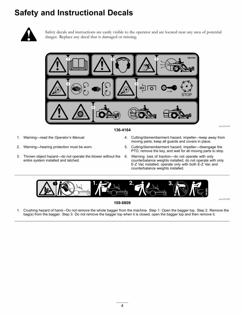
Safety decals and instructions are easily visible to the operator and are located near any area of potentialdanger. Replace any decal that is damaged or missing.
decal136-4164
136-4164
1. Warning—read the Operator’s Manual. 4. Cutting/dismemberment hazard, impeller—keep away frommoving parts; keep all guards and covers in place.
2. Warning—hearing protection must be worn. 5. Cutting/dismemberment hazard, impeller—disengage thePTO, remove the key, and wait for all moving parts to stop.
3. Thrown object hazard—do not operate the blower without theentire system installed and latched.
6. Warning; loss of traction—do not operate with onlycounterbalance weights installed; do not operate with onlyE-Z Vac installed; operate only with both E-Z Vac andcounterbalance weights installed.
decal109-6809
109-6809
1. Crushing hazard of hand—Do not remove the whole bagger from the machine. Step 1: Open the bagger top. Step 2: Remove thebag(s) from the bagger. Step 3: Do not remove the bagger top when it is closed; open the bagger top and then remove it.
4

SetupLoose PartsUse the chart below to verify that all parts have been shipped.
Procedure Description Qty. Use
1 No parts required – Prepare the machine.
Weight tray 1Left weight-tray mount 1Right weight-tray mount 1Suitcase weight—16 kg (35 lb) 1Retaining rod 1Bolt (3/8 x 1-1/4 inches) 2Flange nut (3/8 inch) 4Carriage bolt (3/8 x 1 inch) 2
2
Self-tapping bolt (5/16 x 3/4 inch) 2
Install the weight.
3 No parts required – Remove the grass deflector and beltcover.
Blower support 1Hex washer-head screw (3/8 x 3/4 inch) 2Baffle 1Carriage bolt (5/16 x 3/4 inch) 4
4Flange nut (5/16 inch) 4
Install the baffle and blower support.
Pulley assembly 15 Belt cover 1Install the pulley assembly and beltcover.
Stabilizer bracket 1Carriage bolt (5/16 x 3/4 inch) 2Locknut (5/16 inch) 4Self-tapping screw (5/16 x 3/4 inch) 2Bolt (5/16 x 1 inch) 2Pivot frame 1Hairpin cotter 2Rod 2
6
Washer 2
Install the attachment mount.
Latch rod 17 Hairpin cotter 1 Install the latch rod.
Bagger top 1Bagger screen 18Hairpin cotter 2
Assemble the bagger top.
9 Grass Bag 2 Install the bagger top.
10 Blower assembly 1 Install the blower assembly.
Powered bagger cover 111 Blower belt 1Install the blower belt and poweredbagger cover.
Upper tube 1Screw (1/4 x 3/4 inches) 2Washer (1/4 inch) 2Locknut (1/4 inch) 2
12Lower tube 1
Install the discharge tubes.
5
Determine the left and right sides of the machine from the normal operating position.
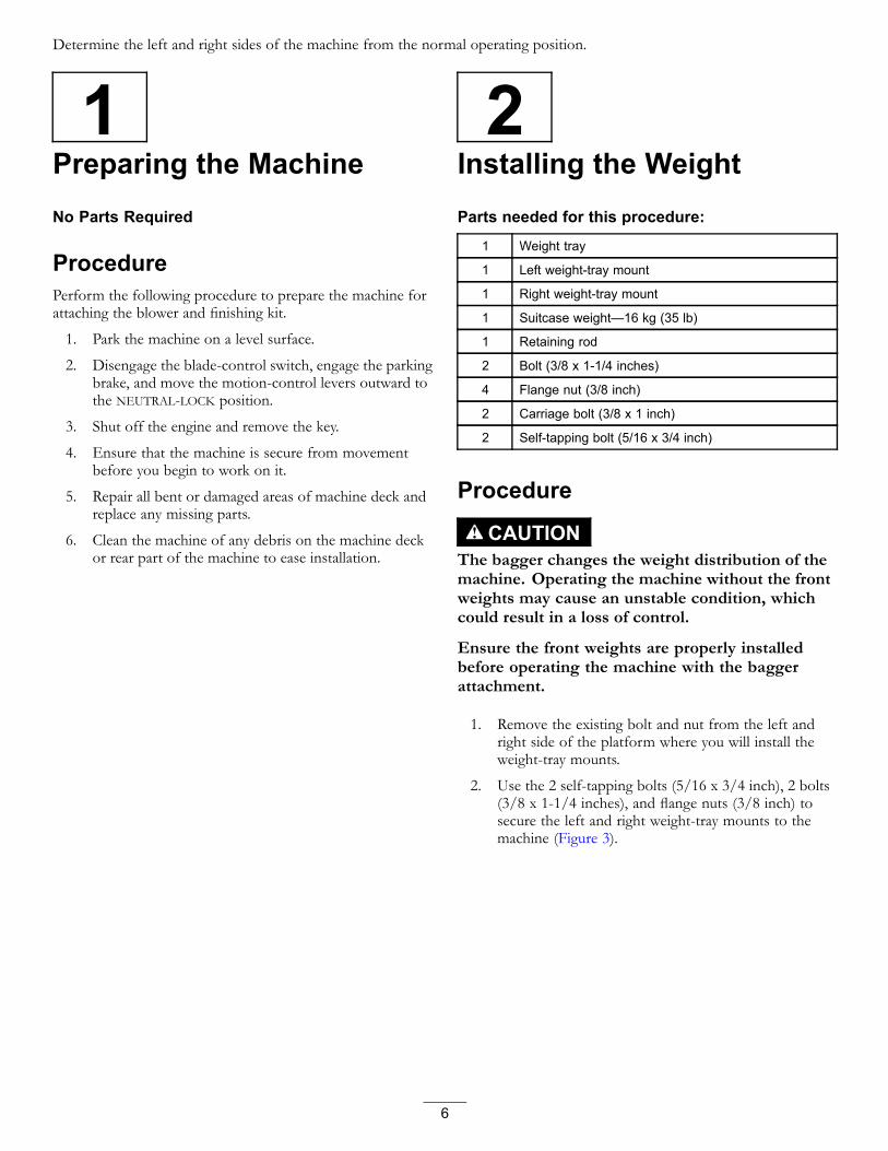
1Preparing the MachineNo Parts Required
ProcedurePerform the following procedure to prepare the machine forattaching the blower and finishing kit.
1. Park the machine on a level surface.
2. Disengage the blade-control switch, engage the parkingbrake, and move the motion-control levers outward tothe NEUTRAL-LOCK position.
3. Shut off the engine and remove the key.
4. Ensure that the machine is secure from movementbefore you begin to work on it.
5. Repair all bent or damaged areas of machine deck andreplace any missing parts.
6. Clean the machine of any debris on the machine deckor rear part of the machine to ease installation.
2Installing the WeightParts needed for this procedure:
1 Weight tray
1 Left weight-tray mount
1 Right weight-tray mount
1 Suitcase weight—16 kg (35 lb)
1 Retaining rod
2 Bolt (3/8 x 1-1/4 inches)
4 Flange nut (3/8 inch)
2 Carriage bolt (3/8 x 1 inch)
2 Self-tapping bolt (5/16 x 3/4 inch)
Procedure
CAUTIONThe bagger changes the weight distribution of themachine. Operating the machine without the frontweights may cause an unstable condition, whichcould result in a loss of control.
Ensure the front weights are properly installedbefore operating the machine with the baggerattachment.
1. Remove the existing bolt and nut from the left andright side of the platform where you will install theweight-tray mounts.
2. Use the 2 self-tapping bolts (5/16 x 3/4 inch), 2 bolts(3/8 x 1-1/4 inches), and flange nuts (3/8 inch) tosecure the left and right weight-tray mounts to themachine (Figure 3).
6
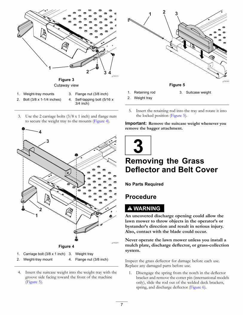
g196533
Figure 3Cutaway view
1. Weight-tray mounts 3. Flange nut (3/8 inch)2. Bolt (3/8 x 1-1/4 inches) 4. Self-tapping bolt (5/16 x
3/4 inch)
3. Use the 2 carriage bolts (3/8 x 1 inch) and flange nutsto secure the weight tray to the mounts (Figure 4).
g196549
Figure 4
1. Carriage bolt (3/8 x 1 inch) 3. Weight tray2. Weight-tray mount 4. Flange nut (3/8 inch)
4. Insert the suitcase weight into the weight tray with thegroove side facing toward the front of the machine(Figure 5).
g196560
Figure 5
1. Retaining rod 3. Suitcase weight2. Weight tray
5. Insert the retaining rod into the tray and rotate it intothe locked position (Figure 5).
Important: Remove the suitcase weight whenever youremove the bagger attachment.
3Removing the GrassDeflector and Belt CoverNo Parts Required
Procedure
WARNINGAn uncovered discharge opening could allow thelawn mower to throw objects in the operator’s orbystander’s direction and result in serious injury.Also, contact with the blade could occur.
Never operate the lawn mower unless you install amulch plate, discharge deflector, or grass-collectionsystem.
Inspect the grass deflector for damage before each use.Replace any damaged parts before use.
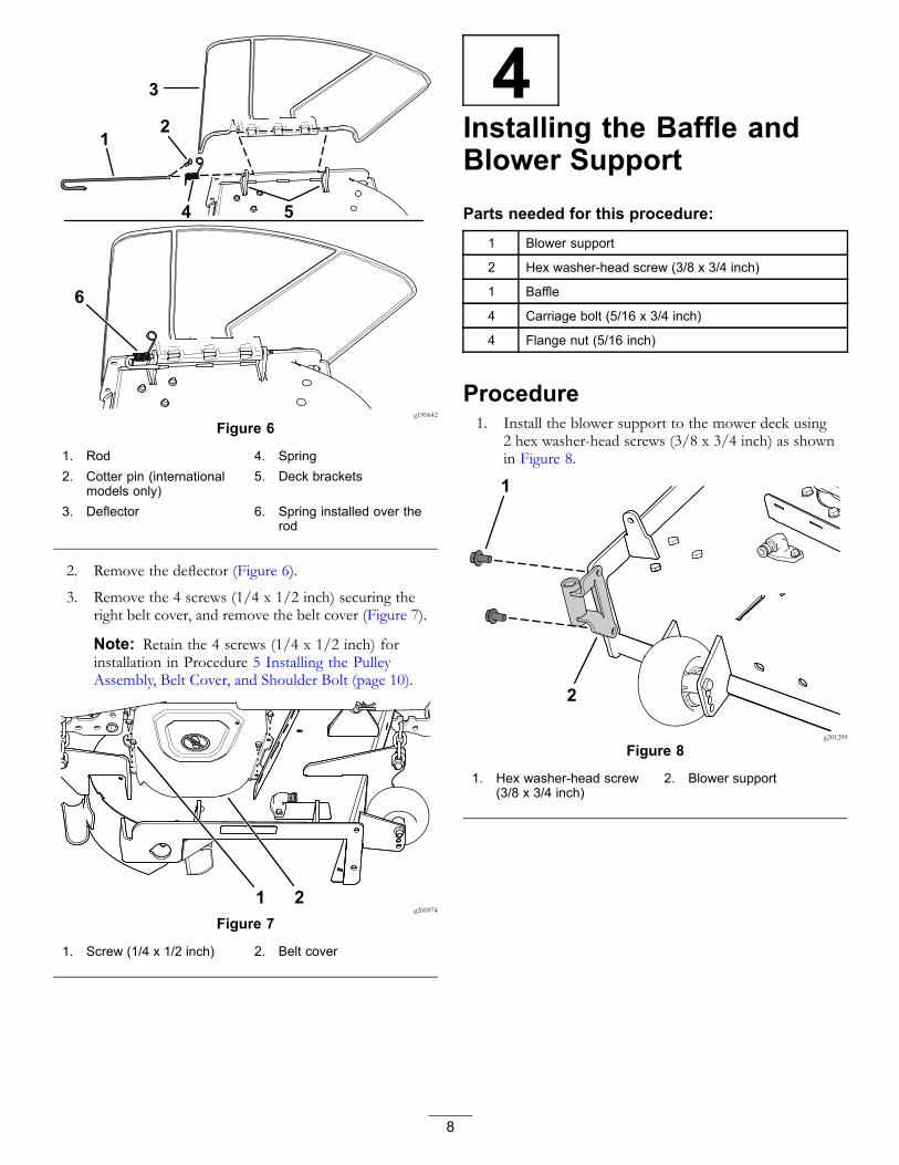
1. Disengage the spring from the notch in the deflectorbracket and remove the cotter pin (international modelsonly), slide the rod out of the welded deck brackets,spring, and discharge deflector (Figure 6).
7
g190642
Figure 6
1. Rod 4. Spring2. Cotter pin (international
models only)5. Deck brackets
3. Deflector 6. Spring installed over therod
2. Remove the deflector (Figure 6).
3. Remove the 4 screws (1/4 x 1/2 inch) securing theright belt cover, and remove the belt cover (Figure 7).
Note: Retain the 4 screws (1/4 x 1/2 inch) forinstallation in Procedure 5 Installing the PulleyAssembly, Belt Cover, and Shoulder Bolt (page 10).
g200974
Figure 7
1. Screw (1/4 x 1/2 inch) 2. Belt cover
4Installing the Baffle andBlower SupportParts needed for this procedure:
1 Blower support
2 Hex washer-head screw (3/8 x 3/4 inch)
1 Baffle
4 Carriage bolt (5/16 x 3/4 inch)
4 Flange nut (5/16 inch)
Procedure1. Install the blower support to the mower deck using
2 hex washer-head screws (3/8 x 3/4 inch) as shownin Figure 8.
g201299
Figure 8
1. Hex washer-head screw(3/8 x 3/4 inch)
2. Blower support
8

2. Remove the existing bolt and nut from the mower deck(Figure 9).
Important: For 48-inch and 60-inch mower decks,there is only one bolt and nut that you can remove.For 54-inch mower deck, remove the bolt and nutas shown in Figure 9.
g206498
Figure 9
1. Existing bolt 2. Existing nut
3. Install the left side of the baffle using a carriage bolt(5/16 x 3/4 inch) and flange nut (5/16 inch) as shownin Figure 10.
4. Loosen the 2 carriage bolts (5/16 x 3/4 inch) in thebaffle slots, and slide the baffle until the hole alignswith the hole in the mower deck (Figure 10).
5. Install baffle as shown in Figure 10.
Important: Ensure that you use the correct holefor the baffle; refer to Figure 10.
6. Tighten the 2 carriage bolts (5/16 x 3/4 inch) in thebaffle slots (Figure 10).
g206496
Figure 1054-inch mower deck shown
1. Inner baffle 6. Install this carriage bolt(5/16 x 3/4 inch) andflange nut (5/16 inch) aftersliding the baffle.
2. Hole for 48-inch and60-inch mower deckinstallation.
7. Slots in the baffle
3. Hole for 54-inch mowerdeck installation.
8. Loosen these 2 carriagebolts (5/16 x 3/4 inch) and2 flange nut (5/16 inch).
4. Right blade 9. Install this carriage bolt(5/16 x 3/4 inch) andflange nut (5/16 inch) first.
5. Outer baffle
9
5Installing the PulleyAssembly, Belt Cover,and Shoulder BoltParts needed for this procedure:
1 Pulley assembly
1 Belt cover
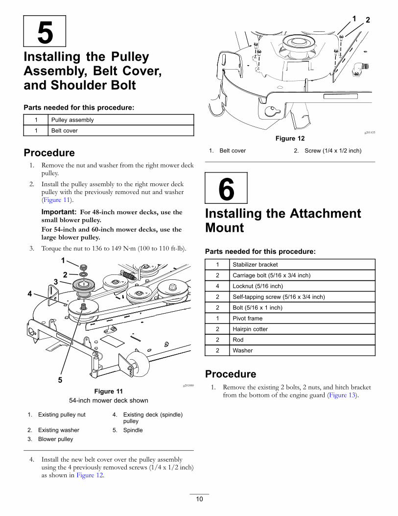
Procedure1. Remove the nut and washer from the right mower deck
pulley.
2. Install the pulley assembly to the right mower deckpulley with the previously removed nut and washer(Figure 11).
Important: For 48-inch mower decks, use thesmall blower pulley.For 54-inch and 60-inch mower decks, use thelarge blower pulley.
3. Torque the nut to 136 to 149 N∙m (100 to 110 ft-lb).
g201880
Figure 1154-inch mower deck shown
1. Existing pulley nut 4. Existing deck (spindle)pulley
2. Existing washer 5. Spindle3. Blower pulley
4. Install the new belt cover over the pulley assemblyusing the 4 previously removed screws (1/4 x 1/2 inch)as shown in Figure 12.
g201435
Figure 12
1. Belt cover 2. Screw (1/4 x 1/2 inch)
6Installing the AttachmentMountParts needed for this procedure:
1 Stabilizer bracket
2 Carriage bolt (5/16 x 3/4 inch)
4 Locknut (5/16 inch)
2 Self-tapping screw (5/16 x 3/4 inch)
2 Bolt (5/16 x 1 inch)
1 Pivot frame
2 Hairpin cotter
2 Rod
2 Washer
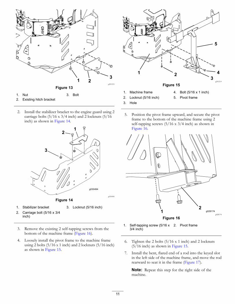
Procedure1. Remove the existing 2 bolts, 2 nuts, and hitch bracket
from the bottom of the engine guard (Figure 13).
10
g201215
Figure 13
1. Nut 3. Bolt2. Existing hitch bracket
2. Install the stabilizer bracket to the engine guard using 2carriage bolts (5/16 x 3/4 inch) and 2 locknuts (5/16inch) as shown in Figure 14.
g030494
g030494
Figure 14
1. Stabilizer bracket 3. Locknut (5/16 inch)2. Carriage bolt (5/16 x 3/4
inch)
3. Remove the existing 2 self-tapping screws from thebottom of the machine frame (Figure 16).
4. Loosely install the pivot frame to the machine frameusing 2 bolts (5/16 x 1 inch) and 2 locknuts (5/16 inch)as shown in Figure 15.
g201214
Figure 15
1. Machine frame 4. Bolt (5/16 x 1 inch)2. Locknut (5/16 inch) 5. Pivot frame3. Hole
5. Position the pivot frame upward, and secure the pivotframe to the bottom of the machine frame using 2self-tapping screws (5/16 x 3/4 inch) as shown inFigure 16.
g028174
Figure 16
1. Self-tapping screw (5/16 x3/4 inch)
2. Pivot frame
6. Tighten the 2 bolts (5/16 x 1 inch) and 2 locknuts(5/16 inch) as shown in Figure 15.
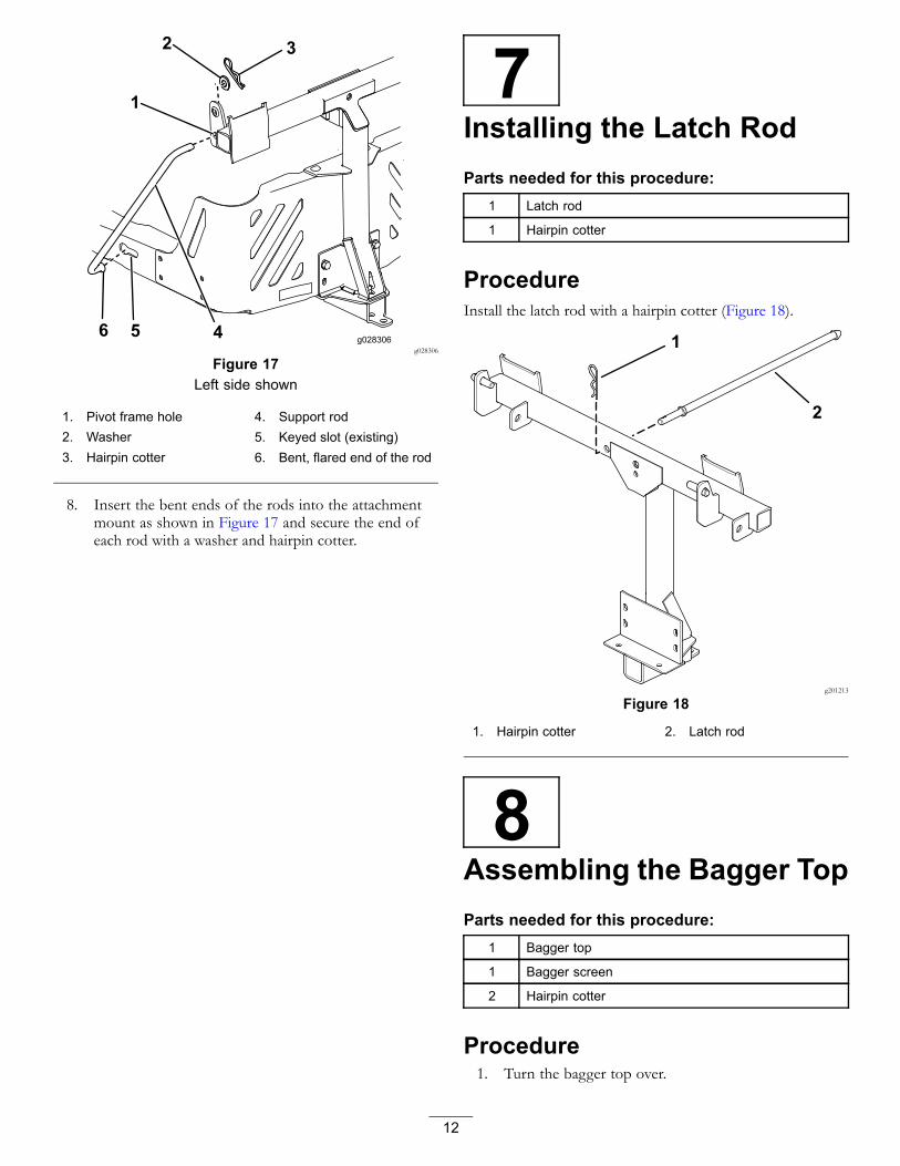
7. Install the bent, flared end of a rod into the keyed slotin the left side of the machine frame, and move the rodrearward to seat it in the frame (Figure 17).
Note: Repeat this step for the right side of themachine.
11
g028306
Figure 17Left side shown
1. Pivot frame hole 4. Support rod2. Washer 5. Keyed slot (existing)3. Hairpin cotter 6. Bent, flared end of the rod
8. Insert the bent ends of the rods into the attachmentmount as shown in Figure 17 and secure the end ofeach rod with a washer and hairpin cotter.
7Installing the Latch RodParts needed for this procedure:
1 Latch rod
1 Hairpin cotter
ProcedureInstall the latch rod with a hairpin cotter (Figure 18).
g201213
Figure 18
1. Hairpin cotter 2. Latch rod
8Assembling the Bagger TopParts needed for this procedure:
1 Bagger top
1 Bagger screen
2 Hairpin cotter
Procedure1. Turn the bagger top over.
12
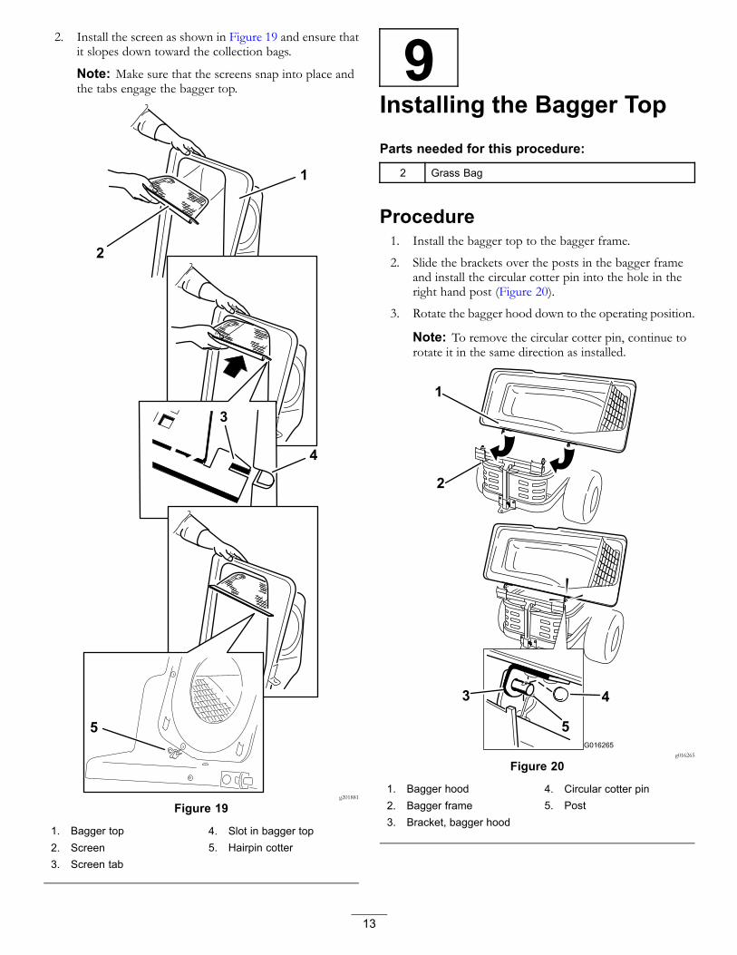
2. Install the screen as shown in Figure 19 and ensure thatit slopes down toward the collection bags.
Note: Make sure that the screens snap into place andthe tabs engage the bagger top.
g201881
Figure 19
1. Bagger top 4. Slot in bagger top2. Screen 5. Hairpin cotter3. Screen tab
9Installing the Bagger TopParts needed for this procedure:
2 Grass Bag
Procedure1. Install the bagger top to the bagger frame.
2. Slide the brackets over the posts in the bagger frameand install the circular cotter pin into the hole in theright hand post (Figure 20).
3. Rotate the bagger hood down to the operating position.
Note: To remove the circular cotter pin, continue torotate it in the same direction as installed.
G016265g016265
Figure 20
1. Bagger hood 4. Circular cotter pin2. Bagger frame 5. Post3. Bracket, bagger hood
13
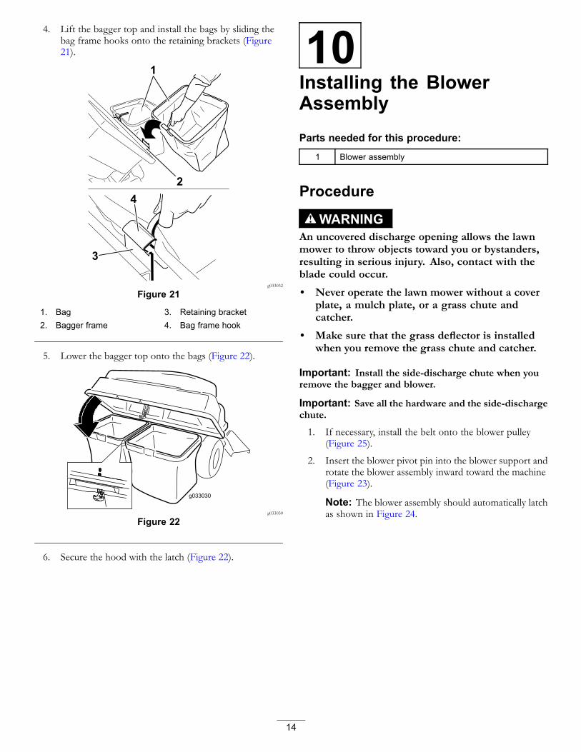
4. Lift the bagger top and install the bags by sliding thebag frame hooks onto the retaining brackets (Figure21).
1
2
3
4
g033032
Figure 21
1. Bag 3. Retaining bracket2. Bagger frame 4. Bag frame hook
5. Lower the bagger top onto the bags (Figure 22).
g033030
Figure 22
6. Secure the hood with the latch (Figure 22).
10Installing the BlowerAssemblyParts needed for this procedure:
1 Blower assembly
Procedure
WARNINGAn uncovered discharge opening allows the lawnmower to throw objects toward you or bystanders,resulting in serious injury. Also, contact with theblade could occur.
• Never operate the lawn mower without a coverplate, a mulch plate, or a grass chute andcatcher.
• Make sure that the grass deflector is installedwhen you remove the grass chute and catcher.
Important: Install the side-discharge chute when youremove the bagger and blower.
Important: Save all the hardware and the side-dischargechute.
1. If necessary, install the belt onto the blower pulley(Figure 25).
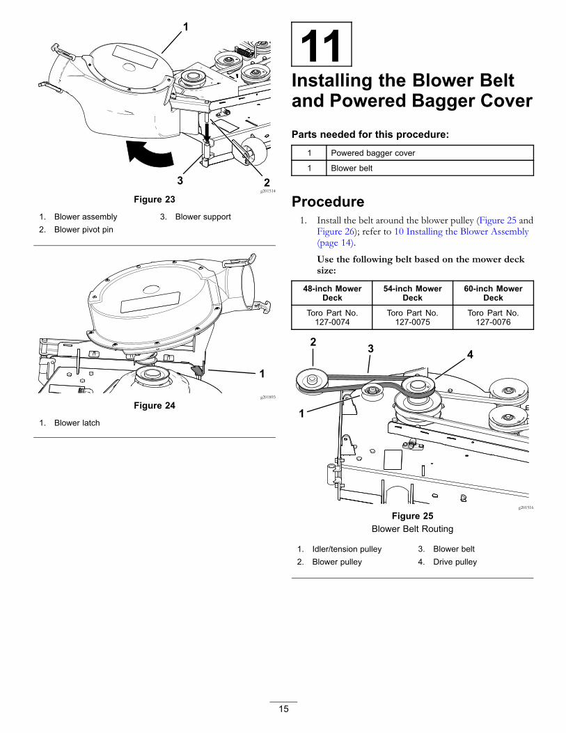
2. Insert the blower pivot pin into the blower support androtate the blower assembly inward toward the machine(Figure 23).
Note: The blower assembly should automatically latchas shown in Figure 24.
14
g201514
Figure 23
1. Blower assembly 3. Blower support2. Blower pivot pin
g201893
Figure 24
1. Blower latch
11Installing the Blower Beltand Powered Bagger CoverParts needed for this procedure:
1 Powered bagger cover
1 Blower belt
Procedure1. Install the belt around the blower pulley (Figure 25 and
Figure 26); refer to 10 Installing the Blower Assembly(page 14).
Use the following belt based on the mower decksize:
48-inch MowerDeck
54-inch MowerDeck
60-inch MowerDeck
Toro Part No.127-0074
Toro Part No.127-0075
Toro Part No.127-0076
g201516
Figure 25Blower Belt Routing
1. Idler/tension pulley 3. Blower belt2. Blower pulley 4. Drive pulley
15

g201513
Figure 26
1. Blower pulley 5. Idler arm2. Blower in position (housing
portion removed forillustrative purposes)
6. Drive pulley
3. Spring 7. Idler/tension pulley4. Idler-pulley post 8. Blower belt
2. Ensure that the belt remains aligneld to the blowerpulley while you are installing the blower assembly.
3. Pull the spring loaded idler pulley away from the fixedspring post, and route the belt around the mower deckpulley (Figure 26).
Note: Ensure that the belt is routed around the blowerpulley correctly.
4. Route the belt around the drive pulley as illustrated inFigure 25 and Figure 26.
5. Install the powered bagger cover over the belt cover,and secure it by tightening the knob (Figure 27).
g201515
Figure 27
1. Knob 3. Belt cover2. Powered bagger cover
12Installing the DischargeTubesParts needed for this procedure:
1 Upper tube
2 Screw (1/4 x 3/4 inches)
2 Washer (1/4 inch)
2 Locknut (1/4 inch)
1 Lower tube
ProcedureImportant: Make sure that the mower deck is in thelowest height-of-cut position before installing thedischarge tubes.
Note: Remember to install the grass deflector when youremove the bagger from the mower.
1. Disengage the PTO and engage the parking brake.
2. Shut off the engine and remove the key.
3. Lower the mower deck to the lowest height-of-cutposition.
4. Remove the bags for viewing the tube under the hood.
5. Lower and latch the hood.
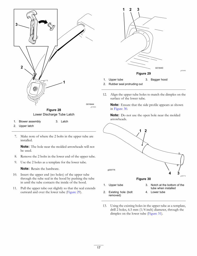
6. Use both latches to attach the lower tube to the blowerassembly (Figure 28).
Note: Ensure the notch in the lower tube is at thebottom when installed (Figure 30).
16
3
G018444
1
2
g018444
Figure 28Lower Discharge Tube Latch
1. Blower assembly 3. Latch2. Upper latch
7. Make note of where the 2 bolts in the upper tube areinstalled.
Note: The hole near the molded arrowheads will notbe used.
8. Remove the 2 bolts in the lower end of the upper tube.
9. Use the 2 holes as a template for the lower tube.
Note: Retain the hardware.10. Insert the upper end (no holes) of the upper tube
through the tube seal in the hood by pushing the tubein until the tube contacts the inside of the hood.
11. Pull the upper tube out slightly so that the seal extendsoutward and over the lower tube (Figure 29).
G018440
1 2 3
g018440
Figure 29
1. Upper tube 3. Bagger hood2. Rubber seal protruding out
12. Align the upper tube holes to match the dimples on thesurface of the lower tube.
Note: Ensure that the side profile appears as shownin Figure 30.
Note: Do not use the open hole near the moldedarrowheads.
g020776
1 2
4 3g020776
Figure 30
1. Upper tube 3. Notch at the bottom of thetube when installed
2. Existing hole (boltremoved)
4. Lower tube
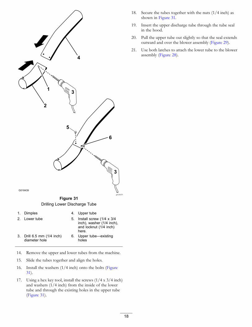
13. Using the existing holes in the upper tube as a template,drill 2 holes, 6.5 mm (1/4 inch) diameter, through thedimples on the lower tube (Figure 31).
17
G018439
4
2
3
3
1
6
5
g018439
Figure 31Drilling Lower Discharge Tube
1. Dimples 4. Upper tube2. Lower tube 5. Install screw (1/4 x 3/4
inch), washer (1/4 inch),and locknut (1/4 inch)here.
3. Drill 6.5 mm (1/4 inch)diameter hole
6. Upper tube—existingholes
14. Remove the upper and lower tubes from the machine.
15. Slide the tubes together and align the holes.
16. Install the washers (1/4 inch) onto the bolts (Figure31).
17. Using a hex key tool, install the screws (1/4 x 3/4 inch)and washers (1/4 inch) from the inside of the lowertube and through the existing holes in the upper tube(Figure 31).
18. Secure the tubes together with the nuts (1/4 inch) asshown in Figure 31.
19. Insert the upper discharge tube through the tube sealin the hood.
20. Pull the upper tube out slightly so that the seal extendsoutward and over the blower assembly (Figure 29).
21. Use both latches to attach the lower tube to the blowerassembly (Figure 28).
18
OperationNote: Determine the left and right sides of the machinefrom the normal operating position.
WARNINGTo avoid personal injury, follow these procedures:
• Become familiar with all operating and safetyinstructions in the Operator's Manual for themower before using this attachment.
• Never remove the discharge tube, bags, baggerhood, or the chute while the engine is running.
• Always shut the engine off and wait for allmoving parts to stop before clearing anobstruction from the bagging system.
• Never perform maintenance or repairs while theengine is running.
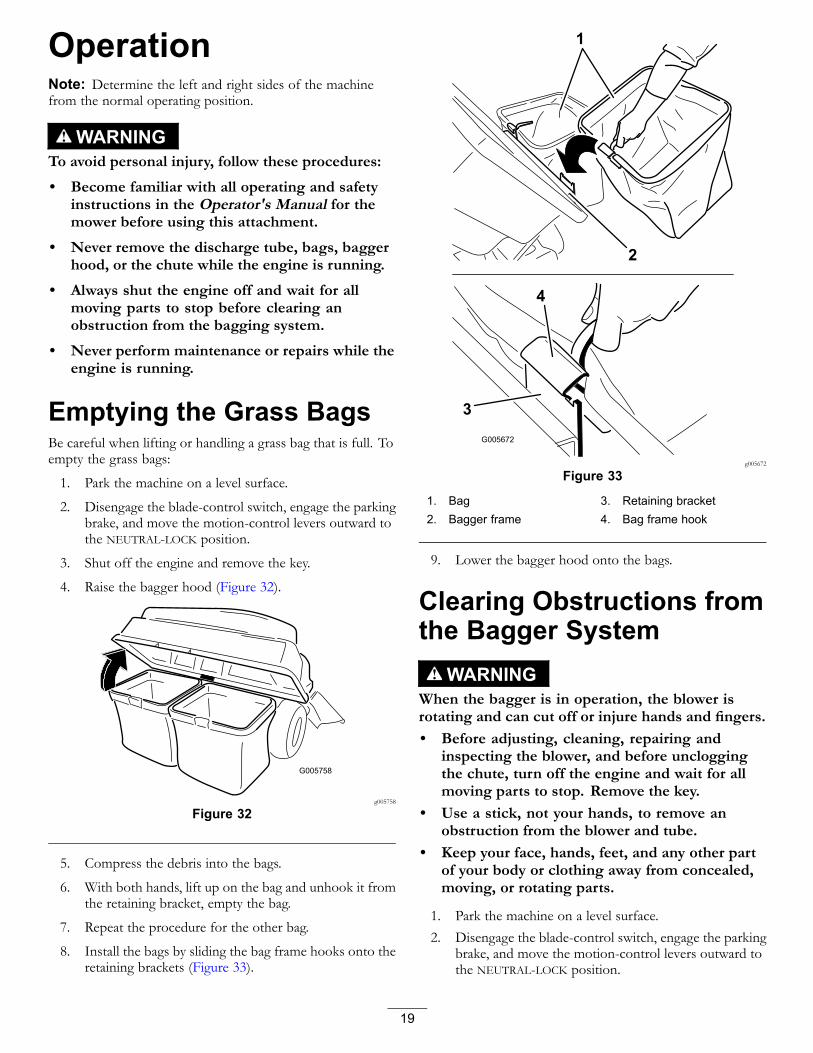
Emptying the Grass BagsBe careful when lifting or handling a grass bag that is full. Toempty the grass bags:
1. Park the machine on a level surface.
2. Disengage the blade-control switch, engage the parkingbrake, and move the motion-control levers outward tothe NEUTRAL-LOCK position.
3. Shut off the engine and remove the key.
4. Raise the bagger hood (Figure 32).
G005758
g005758
Figure 32
5. Compress the debris into the bags.
6. With both hands, lift up on the bag and unhook it fromthe retaining bracket, empty the bag.
7. Repeat the procedure for the other bag.
8. Install the bags by sliding the bag frame hooks onto theretaining brackets (Figure 33).
G005672
1
2
3
4
g005672
Figure 33
1. Bag 3. Retaining bracket2. Bagger frame 4. Bag frame hook
9. Lower the bagger hood onto the bags.
Clearing Obstructions fromthe Bagger System
WARNINGWhen the bagger is in operation, the blower isrotating and can cut off or injure hands and fingers.• Before adjusting, cleaning, repairing and
inspecting the blower, and before uncloggingthe chute, turn off the engine and wait for allmoving parts to stop. Remove the key.
• Use a stick, not your hands, to remove anobstruction from the blower and tube.
• Keep your face, hands, feet, and any other partof your body or clothing away from concealed,moving, or rotating parts.
1. Park the machine on a level surface.2. Disengage the blade-control switch, engage the parking
brake, and move the motion-control levers outward tothe NEUTRAL-LOCK position.
19
3. Shut off the engine and remove the key.
4. Empty the bags.
5. Unlatch the lower tube.
6. Remove the tubes from the bagger.
7. Use a stick or similar object, not your hands, to removeand clear the obstruction from the tube assembly.
Note: In most cases, you can shake the debris out ofthe tubes.
8. If the blower assembly is plugged, remove the plasticbelt cover, unlatch the bagger blower assembly, removethe belt, and swing it open.
9. Use a stick or similar object, not your hands, to removeand clear the obstruction from the blower assembly.
10. After you remove the obstruction, install the completebagger system and resume operation.
Removing the BaggerWARNING
Components around the engine will be hot ifthe machine has been running. Touching hotcomponents can cause burns.
• Do not touch engine components when hot.
• Allow engine to cool before removing the bagger.
CAUTIONFailing to remove the front bagger weightsand operating the machine without the baggerattachment may cause an unstable condition whichcould result in a loss of control.
Always remove the front weights when removingthe bagger attachment.
Remove the bagger by repeating the setup sections from theInstallation Instructions and Operator’s Manual in reverse order.Always remove the front baffles and front weights whenremoving the bagger attachments.
Important: Install the side-discharge chute when youremove the bagger and blower.
Note: It is only necessary to remove the cutoff baffle wheninstalling a mulching kit.
20

Operating TipsTips for Bagging
Remembering the Size of theMachine with the AttachmentRemember that the machine is longer and wider with thisattachment installed. By turning too sharply in confinedplaces you may damage the attachment.
TrimmingAlways trim with the left side of the mower. Do not trim withthe right side of the mower because you could damage thebagger chute and discharge tube.
Cutting HeightDo not set the mower cutting height too low because longgrass surrounding the mower can prevent air from gettingunder the mower and entering the bagging system. If enoughair does not get under the mower, the bagging system willplug.
Cutting FrequencyCut the grass often, especially when it grows rapidly. You willneed to cut your grass twice if it gets excessively long.
Cutting TechniqueFor best lawn appearance, be sure to slightly overlap themower into the previously cut area. This helps reduce theload on the engine and reduces the chance of plugging thechute and discharge tube.
Bagging SpeedMost often you will bag with the mower throttle in the FASTposition and drive at a normal ground speed. However,in extremely dry and dusty grass, you may want to slightlyreduce the throttle speed and increase the ground speed ofthe mower. The bagging system may plug if you drive toofast and the engine speed gets too slow. On hills, it maybe necessary to slow the mower ground speed. This helpsmaintain the engine speed and bagging efficiency. Mowdownhill whenever possible.
CAUTIONAs the bagger fills, extra weight is added to the backof the machine. If you stop and start suddenly onhills, you may lose steering control or the machinemay tip.
• Do not start or stop suddenly when going uphillor downhill. Avoid uphill starts.
• If you do stop the machine when going uphill,disengage the blade control. Then back downthe hill using a slow speed.
• Avoid sudden turns or rapid speed changes onslopes.
• Never operate the machine without the baggerattachment and the front weights still installed.
Bagging Long GrassExcessively long grass is heavy and may not be propelledcompletely into the grass bags. If this happens, the dischargetube and chute may plug. To avoid plugging the baggingsystem, mow the grass at a high height of cut, then lower themower to your normal cutting height and repeat the baggingprocess.
Bagging Wet GrassAlways try to cut grass when it is dry because your lawn willhave a neat appearance. If you must cut wet grass, use theconventional side discharge feature of the mower. Severalhours later, when the clippings are dry, install the completebagger attachment and vacuum up the grass clippings.
Signs of PluggingAs you are bagging, a small amount of grass clippingsnormally blow out the front of the mower. An excessiveamount of clippings blowing out indicates that the bags arefull or the system is plugged.
21

MaintenanceNote: Determine the left and right sides of the machine from the normal operating position.
Recommended Maintenance Schedule(s)Maintenance Service
Interval Maintenance Procedure
After the first 8 hours • Inspect the blower belt.• Inspect the bagger.
After each use • Clean the hood screen.• Clean the bagger.
Every 25 hours • Inspect the blower belt.
Every 100 hours • Inspect the bagger.
WARNINGIf you leave the key in the key switch, someone could accidently start the engine and seriously injureyou or other bystanders.
Remove the key and disconnect the wire from the spark plug before you do any maintenance. Set the wireaside so that it does not accidentally contact the spark plug.
WARNINGEngines can become hot when they are operating. Severe burns can occur from contacting hot surfaces.
Allow engines, especially the muffler, to cool before touching.
WARNINGDebris, such as leaves, grass, or brush can catch fire. A fire in the engine area can cause personal injuryand property damage.
• Keep the engine and muffler area free of debris accumulation.
• Take care when opening the bagger cover to keep debris from falling onto the engine and muffler area.
• Allow the machine to cool before storing it.
Preparing for MaintenanceDo the following steps before preforming maintenance onthe machine:
1. Park the machine on a level surface.
2. Disengage the PTO, move the motion control levers tothe NEUTRAL-LOCK position, and engage the parkingbrake.
3. Shut off the engine and remove the key.
4. Clean the mower of any debris on the deck or rear partof the mower to ease maintenance.
Cleaning the Hood ScreenService Interval: After each use
1. Open the bagger hood.
2. Clean the debris from the screen.
3. Close the bagger hood.
22

Cleaning the Bagger andBagsService Interval: After each use
1. Wash the inside and outside of the bagger hood, bags,tube, and the underside of the mower.
Note: Use a mild automotive detergent to remove dirt.2. Make sure that you remove matted grass from all parts.
3. After washing all parts, let them dry thoroughly.
Note: With all parts installed, start and run the machine fora minute to assist in drying.
Inspecting the Blower BeltService Interval: After the first 8 hours
Every 25 hours
Check belts for cracks, frayed edges, burn marks or any otherdamage. Replace damaged belts.
Replacing the Blower Belt1. Remove the plastic belt cover.
2. Pull back on the spring-loaded idler pulley to relievethe belt tension (Figure 34).
g202246
Figure 34
1. Blower pulley 4. Mower deck2. Blower in position (housing
portion removed forillustrative purposes)
5. Idler/tension pulley
3. Drive pulley 6. Blower belt
3. Remove the existing bagger belt from the mower-deckpulley.
4. Remove the blower from the mower deck.
5. Remove the existing bagger belt from the blowerpulleys.
6. Install the new belt around the blower pulleys (Figure34).
7. Install the blower onto the blower support.
8. Install the new belt around the mower-deck pulley(Figure 34).
9. Pull back on the spring loaded idler pulley and installthe belt onto the spring-loaded idler pulley (Figure 34).
23

Inspecting the BaggerService Interval: Every 100 hours
After the first 8 hours
1. Check the upper tube, lower tube, bagger hood, andthe blower assembly.
Note: Replace these parts if they are cracked orbroken.
2. Check the bags, bagger frame, and screen.
Note: Replace any parts that are cracked or broken.3. Tighten all nuts bolts and screws.
Inspecting the MowerBlades1. Inspect the mower blades regularly and whenever a
blade strikes a foreign object.
2. If blades are badly worn or damaged, install new blades;refer to your machine Operator's Manual for completeblade maintenance.
StorageStoring the BaggerAttachment1. Clean the bagger attachment; refer to Cleaning the
Bagger Attachment.
2. Inspect the bagger attachment for damage; refer toInspecting the Bagger Attachment.
3. Ensure that the grass bags are empty and thoroughlydry.
4. Store the bagger in a clean, dry place, out of directsunlight. This protects the plastic parts and extends thelife of the bagger. If you must store the bagger outside,cover it with a weatherproof cover.
24

TroubleshootingProblem Possible Cause Corrective Action
1. The cutting blade(s) are bent orunbalanced.
1. Install new cutting blade(s).
2. The blade-mounting bolt is loose. 2. Tighten the blade-mounting bolt.3. There is a loose blower pulley or pulley
assembly.3. Tighten the appropriate pulley.
4. The bagger belt is worn. 4. Replace the belt.
There is abnormal vibration.
5. The blower fan blade(s) are bent orunbalanced.
5. Contact an Authorized Service Dealer.
1. The engine speed is too low. 1. Always operate the engine at fullthrottle.
2. The screen in the bagger hood isplugged.
2. Remove debris, leaves, or grassclippings from the screen.
3. The bagger belt is loose. 3. Replace the bagger belt.4. There is a plugged tube or blower. 4. Locate and remove the plugged debris.
Reduced bagging performance
5. The bags are full. 5. Empty the hopper.
1. The bags are too full. 1. Dump more frequently.
2. The engine speed is too low. 2. Always operate the engine at fullthrottle.
3. The grass is too wet. 3. Cut grass when it is dry.4. The grass is too long. 4. Cut no more than 51 to 76 mm (2 to
3 inches) or 1/3 of the grass height,whichever is less.
5. The screen in the bagger hood isplugged.
5. Remove debris, leaves, or grassclippings from the screen.
6. The ground speed is too fast. 6. Drive slower at full throttle.
The blower and tubes plug too frequently.
7. The bagger belt is worn. 7. Replace the belt.
1. The bags are too full. 1. Dump more frequently.
2. The ground speed is too fast. 2. Drive the machine at slow groundspeed while operating the engine atfull throttle.
Debris blowout
3. The mower deck is not leveled. 3. See the machine Operator's Manualfor leveling the mower deck.
1. The blower is plugged. 1. Remove debris, leaves, or grassclippings from the blower impeller.
The blower impeller does not spin freely.
2. The impeller is not aligned. 2. Contact an Authorized Service Dealer.
25

Notes:

European Privacy NoticeThe Information Toro CollectsToro Warranty Company (Toro) respects your privacy. In order to process your warranty claim and contact you in the event of a product recall, we ask youto share certain personal information with us, either directly or through your local Toro company or dealer.
The Toro warranty system is hosted on servers located within the United States where privacy law may not provide the same protection as appliesin your country.
BY SHARING YOUR PERSONAL INFORMATION WITH US, YOU ARE CONSENTING TO THE PROCESSING OF YOUR PERSONAL INFORMATIONAS DESCRIBED IN THIS PRIVACY NOTICE.
The Way Toro Uses InformationToro may use your personal information to process warranty claims, to contact you in the event of a product recall and for any other purpose which we tellyou about. Toro may share your information with Toro's affiliates, dealers or other business partners in connection with any of these activities. We will notsell your personal information to any other company. We reserve the right to disclose personal information in order to comply with applicable laws andwith requests by the appropriate authorities, to operate our systems properly or for our own protection or that of other users.
Retention of your Personal InformationWe will keep your personal information as long as we need it for the purposes for which it was originally collected or for other legitimate purposes(such as regulatory compliance), or as required by applicable law.
Toro's Commitment to Security of Your Personal InformationWe take reasonable precautions in order to protect the security of your personal information. We also take steps to maintain the accuracy and currentstatus of personal information.
Access and Correction of your Personal InformationIf you would like to review or correct your personal information, please contact us by email at [email protected].
Australian Consumer LawAustralian customers will find details relating to the Australian Consumer Law either inside the box or at your local Toro Dealer.
374-0282 Rev C
The Toro Warranty Residential Products
andThe Toro GTS Starting Guarantee
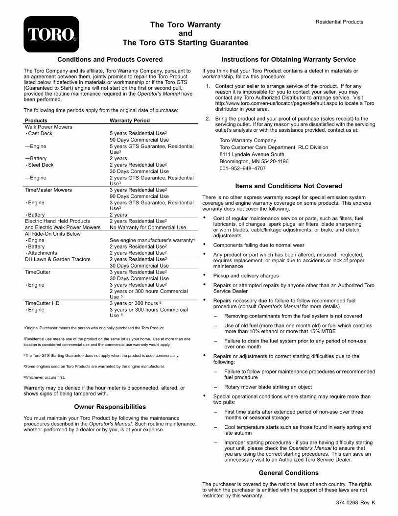
Conditions and Products CoveredThe Toro Company and its affiliate, Toro Warranty Company, pursuant toan agreement between them, jointly promise to repair the Toro Productlisted below if defective in materials or workmanship or if the Toro GTS(Guaranteed to Start) engine will not start on the first or second pull,provided the routine maintenance required in the Operator's Manual havebeen performed.
The following time periods apply from the original date of purchase:
Products Warranty PeriodWalk Power Mowers•Cast Deck 5 years Residential Use2
90 Days Commercial Use—Engine 5 years GTS Guarantee, Residential
Use3—Battery 2 years•Steel Deck 2 years Residential Use2
30 Days Commercial Use—Engine 2 years GTS Guarantee, Residential
Use3TimeMaster Mowers 3 years Residential Use2
90 Days Commercial Use•Engine 3 years GTS Guarantee, Residential
Use3•Battery 2 yearsElectric Hand Held Products 2 years Residential Use2and Electric Walk Power Mowers No Warranty for Commercial UseAll Ride-On Units Below•Engine See engine manufacturer's warranty4•Battery 2 years Residential Use2•Attachments 2 years Residential Use2DH Lawn & Garden Tractors 2 years Residential Use2
30 Days Commercial UseTimeCutter 3 years Residential Use2
30 Days Commercial Use•Engine 3 years Residential Use2
2 years or 300 hours CommercialUse 5
TimeCutter HD 3 years or 300 hours 5
•Engine 3 years or 300 hours CommercialUse 5
1Original Purchaser means the person who originally purchased the Toro Product.
2Residential use means use of the product on the same lot as your home. Use at more than onelocation is considered commercial use and the commercial use warranty would apply.
3The Toro GTS Starting Guarantee does not apply when the product is used commercially.
4Some engines used on Toro Products are warranted by the engine manufacturer.
5Whichever occurs first.
Warranty may be denied if the hour meter is disconnected, altered, orshows signs of being tampered with.
Owner ResponsibilitiesYou must maintain your Toro Product by following the maintenanceprocedures described in the Operator's Manual. Such routine maintenance,whether performed by a dealer or by you, is at your expense.
Instructions for Obtaining Warranty ServiceIf you think that your Toro Product contains a defect in materials orworkmanship, follow this procedure:
1. Contact your seller to arrange service of the product. If for anyreason it is impossible for you to contact your seller, you maycontact any Toro Authorized Distributor to arrange service. Visithttp://www.toro.com/en-us/locator/pages/default.aspx to locate a Torodistributor in your area.
2. Bring the product and your proof of purchase (sales receipt) to theservicing outlet. If for any reason you are dissatisfied with the servicingoutlet’s analysis or with the assistance provided, contact us at:
Toro Warranty CompanyToro Customer Care Department, RLC Division8111 Lyndale Avenue SouthBloomington, MN 55420-1196001–952–948–4707
Items and Conditions Not CoveredThere is no other express warranty except for special emission systemcoverage and engine warranty coverage on some products. This expresswarranty does not cover the following:
• Cost of regular maintenance service or parts, such as filters, fuel,lubricants, oil changes, spark plugs, air filters, blade sharpeningor worn blades, cable/linkage adjustments, or brake and clutchadjustments
• Components failing due to normal wear
• Any product or part which has been altered, misused, neglected,requires replacement, or repair due to accidents or lack of propermaintenance
• Pickup and delivery charges
• Repairs or attempted repairs by anyone other than an Authorized ToroService Dealer
• Repairs necessary due to failure to follow recommended fuelprocedure (consult Operator's Manual for more details)
– Removing contaminants from the fuel system is not covered
– Use of old fuel (more than one month old) or fuel which containsmore than 10% ethanol or more that 15% MTBE
– Failure to drain the fuel system prior to any period of non-useover one month
• Repairs or adjustments to correct starting difficulties due to thefollowing:
– Failure to follow proper maintenance procedures or recommendedfuel procedure
– Rotary mower blade striking an object
• Special operational conditions where starting may require more thantwo pulls:
– First time starts after extended period of non-use over threemonths or seasonal storage
– Cool temperature starts such as those found in early spring andlate autumn
– Improper starting procedures - if you are having difficulty startingyour unit, please check the Operator's Manual to ensure thatyou are using the correct starting procedures. This can save anunnecessary visit to an Authorized Toro Service Dealer.
General ConditionsThe purchaser is covered by the national laws of each country. The rightsto which the purchaser is entitled with the support of these laws are notrestricted by this warranty.
374-0268 Rev K


