Embed Size (px)
Citation preview
DySCO: a DYnamic Spectrum and COntentionControl Framework for Enhanced Broadcast
Communication in Vehicular Networks
Marco Di Felice, Luca Bedogni, Luciano Bononi
Abstract
Recently, the IEEE 1609.4 protocol has been defined to enable multi-channeloperations in a vehicular environment, and to guarantee interference-free co-existenceof safety-related and non-safety related applications in the same network. To meetthese goals, the protocol assumes strict time synchronization among vehicles, andtime/frequency separation in the Dedicated Short Range Communication (DSRC)band. However, recent studies have demonstrated that this approach might notbe suitable for safety-related broadcast applications with strict Quality-of-Service(QoS) requirements. In this paper, we investigate the potentials of Cognitive Radio(CR) technology to enhance the delivery ratio of safety-related broadcast applica-tions in a multi-channel vehicular scenario. In this research field, we propose threenovel contributions: (i) we introduce an analytical model to study the delivery ra-tio of broadcast applications in IEEE 802.11p/1609.4 multi-channel vehicular net-works, and the impact of MAC and PHY parameters on the system performance;(ii) we propose a framework to jointly decide the optimal values of the ContentionWindow size (CW) at the MAC layer and of the Control CHannel (CCH) band-width at PHY layer, so that each vehicle is able to transmit all its safety data duringthe CCH interval with a minimum MAC collision probability, and (iii) we discussthe framework implementation in a realistic vehicular scenario. Our on-demandbandwidth allocation algorithm utilizes vacant frequencies in the DSRC band toincrease the bandwidth of the CCH, leveraging the spectrum agile capabilities of-fered by the CR technology. Simulation results confirm the effectiveness of ourproposal in enhancing the delivery rate of broadcast applications under varyingnetwork scenarios and load conditions.
1 IntroductionNowadays, safety-oriented services constitute one of the main applications of VehicularAd Hoc NETworks (VANETs), due to the promises to reduce cars’ accidents, optimizefuel consumption and provide real-time information assistance to the drivers. In mostcases, these services rely on the ability to disseminate periodic information amongthe vehicles of the network, by guaranteeing high delivery ratio and reduced latencyof the communication [1][2]. This is the case, for instance, of collision warning sys-tems, adaptive cruise control and cooperative driver-assistance applications, proposed
1
among others by [1][2]. The implementation of these systems is made possible by theconcurrent definition of a reference protocol stack for Vehicle-to-Vehicle (V2V) andVehicle-to-Infrastructure (V2I) communication, generically referred as ”Wireless Ac-cess Vehicular Environment” (WAVE) stack. One of the most interesting characteristicof the WAVE stack is the utilization of specific frequencies for vehicular communica-tion in the Dedicated Short Range Communication (DSRC) band. Moreover, the co-existence of safety-related and non-safety applications is achieved by allocating eachapplication class on a different DSRC channel, and by enforcing synchronous channelswitches to enable multi-channel operations on single-radio devices, based on the IEEE1609.4 protocol [3]. According to this standard, each node of the vehicular networkmust synchronously switch between a Control CHannel (CCH) interval, during whichit is tuned to a common control channel and exchanges safety-related information, anda Service CHannel interval (SCH), during which it is tuned to one of six service chan-nels and can transmit non-safety information (e.g. infotainment). The duration of eachCCH/SCH interval is fixed, and equal to 50ms [3]. Despite the clear advantages pro-vided by the utilization of multi-channel technology on the capacity of the vehicularnetwork, there are important concerns on the impact of the time/frequency division en-forced by the IEEE 1609.4 protocol on the delivery ratio of safety-related applications.Recent studies [4][5][6][7][8] highlight the existence of two main problems affectingthe performance of broadcast applications in IEEE 1609.4/802.11p vehicular networks:
• Synchronous Collisions Problem. Packet losses might originate at the start ofeach CCH interval because of the synchronization of backoff processes amongdifferent vehicles.
• Bandwidth Shortage Problem. In a congested scenario, a vehicle might not beable to transmit all its safety data before the end of the CCH interval. At the sametime, even in congested scenarios, the DSRC band might be highly underutilized,since (i) each channel is used only half of the time, and (ii) while transmittingon the control channel, all the remaining frequencies of SCH channels are notutilized.
Most of the existing studies address just one problem in isolation, e.g. reducing theoccurrence of MAC collisions [6]. In this paper, we show that the previous issuesare closely related, and need to be jointly considered for best supporting the require-ments of safety-related broadcast applications. To this aim, we propose a cross-layerframework (called DYSCO) for enhancing the performance of safety-related applica-tions in vehicular networks, and we provide three novel contributions in this paper: (i)we propose an analytical model to investigate the performance of safety-related broad-cast applications in IEEE 802.11p/WAVE multi-channel VANETs; (ii) we characterizethe impact of different MAC/PHY parameters on the Packet-Delivery-Ratio (PDR) ofsafety-related broadcast applications and (iii) we introduce a method to determine asuitable configuration of MAC/PHY parameters that allows to satisfy the QoS require-ments of the vehicular applications, and we discuss its implementation aspects in arealistic scenario. The parameter decision process used by DySCO works on two-step.First, it determines the optimal size of the Contention Window (CW) at MAC layerin order to keep the MAC collision probability below a pre-defined Quality-of-Service
2
(QoS) threshold. Then, it estimates the minimum PHY bandwidth of the control chan-nel that is required to transmit all the safety packets before the end of the CCH interval.To this aim, we propose to increase the control channel bandwidth by using the band-width of service channels (around 60 Mhz) since these frequencies are left unusedduring the CCH interval, and do not pose problems of opportunistic spectrum accessand licensed user protection. We rely on CR technology [9] to implement spectrum re-configurability at the PHY layer, and on the presence of a fixed Road Side Unit (RSU)to detect the current channel load conditions. The simulation results confirm the ef-fectiveness of our framework in enhancing the performance of safety-related broadcastapplications, and in dynamically adapting to varying network and load conditions.The rest of the paper is organized as follows. In Section 2, we review the existingworks on multi-channel and CR-based vehicular networks. In Section 3 we introducethe system model used in this paper. In Section 4, we present an analytical model to in-vestigate the performance of broadcast applications in IEEE 802.11p/1609.4 networks,and we characterize the impact of MAC/PHY parameters on system performance. InSection 5 we describe in detail the DySCO framework, that is extensively evaluatedin Section 6 through simulations. Section 7 concludes the work and discusses futureextensions.
2 Related WorksIn this Section, we describe the related works in the field of multi-channel vehicularnetworks. To this aim, we first provide a quick overview of the IEEE 802.11p/WAVEstandard (in Section 2.1), and then we briefly discuss some protocols’ enhancementsproposed in the literature (in Section 2.2), mainly focusing on CR-based approaches.
2.1 The IEEE WAVE stackRecently, a complete protocol stack for Wireless Access in a Vehicular Environment(WAVE) has been proposed for standardization by IEEE. At the PHY layer, the WAVEstack utilizes the DSRC frequencies that have been reserved for vehicle-to-vehicle(V2V) and vehicle-to-infrastructure (V2I) communication in both US and Europe. TheDSRC band is then divided into one Control CHannel (CCH) and six Service Channels(SCH), 10-MhZ wide each. At the MAC layer, the wireless transmissions of unicastand broadcast frames on each DSRC channel are regulated by the IEEE 802.11p stan-dard [10], that also includes Enhanced Differentiated Channel Access (EDCA) mech-anisms (from previous IEEE 802.11e standard) to support QoS traffic differentiationamong different Traffic Classes (TCs). On top of the MAC layer, the IEEE 1609.4protocol [3] supports multi-channel operations on a single radio transceiver, by assum-ing strict synchronization among vehicles, and slotted time division between ControlChannel (CCH) intervals and Service Channel (SCH) intervals. During the CCH in-terval, vehicles tune their radio to the CCH channel and transmit control and safety-related data. During the SCH interval, vehicles can tune their radio to any of the sixservice channels of the DSRC band, and transmit non-safety related information. De-fault length of CCH and SCH intervals is 50 ms each, and a Guard Interval (GI) is
3
introduced between each SCH/CCH interval to allow synchronization and radio fre-quencies reconfiguration.
2.2 IEEE 802.11p/1609.4 EnhancementsSeveral recent studies have investigated the performance of IEEE 802.11p/1609.4 multi-channel VANETs, and have highlighted the problems caused by the channel switchingoperations on the performance of safety-related broadcast applications, mainly in termsof additional packet losses at the start and at the end of each CCH interval [4][5][6][7].To solve these issues, some works have proposed enhanced contention control mech-anisms at the MAC layer that attempt to reduce the problem of synchronous channelaccesses from different vehicles. For instance, the authors of [4] have proposed to in-troduce random delays in the backoff process in order to distribute the transmissionsover all the CCH interval. Similar, in [5] we have described a distributed scheme thatenables each vehicle to adjust its Contention Window (CW) size at the MAC layerbased on the actual traffic load on the CCH. However, while increasing the CW sizeat MAC layer can be considered an effective solution to reduce the probability of syn-chronous collisions, it might also increase the channel access delay in high load net-work scenarios, so that some packets might be discarded because of the end of the CCHinterval. The problem of CCH channel saturation has been recently tackled with twoapproaches. One approach, proposed among others by [7] and [8], consists in adjustingthe CCH/SCH interval lengths in a dynamic manner. However, this solution does notsolve the problem of suboptimal utilization of DSRC spectrum resources, and also in-volves precise synchronization among the vehicles. A more effective approach is to useCR technology [9] to scale the CCH bandwidth to the current channel load. Althoughresearch on CR-VANETs is still at a preliminary stage [11], some interesting resultshave been achieved on spectrum sensing and access technologies from moving vehi-cles, as reported in [12][13]. For our scope, the most similar works are [14][15], wherethe authors propose a centralized optimization framework for a CR-based vehicularenvironment, and [16], where the authors describe a fuzzy-logic based optimizationframework to dynamically extend the CCH bandwidth in congested scenarios by usingvacant TV-band frequencies.Compared to existing studies on multi-channel and CR-based vehicular networks, ourpaper introduces these novelties: (i) it address the performance issues of safety-relatedbroadcast applications by considering at the same time MAC and PHY issues, in orderto mitigate the occurrence of MAC collisions while providing adequate bandwidth totransmit all packets on the same CCH interval, (ii) it investigates the utilization of CRtechnology in the DSRC frequencies, thus avoiding the issues of opportunistic spec-trum access that occur in the licensed bands (e.g. TV frequency), (iii) it relies on ananalytical framework to enhance the performance of safety-related broadcast applica-tions.
4
5.8
50
5.9
20
5.8
90
5.8
50
5.8
90
5.9
20
5.8
50
5.8
90
5.9
20
RSU RSU RSU
Frequencies
DSRC
BCCH=30 Mhz BCCH=20 MhzBCCH=10 Mhz
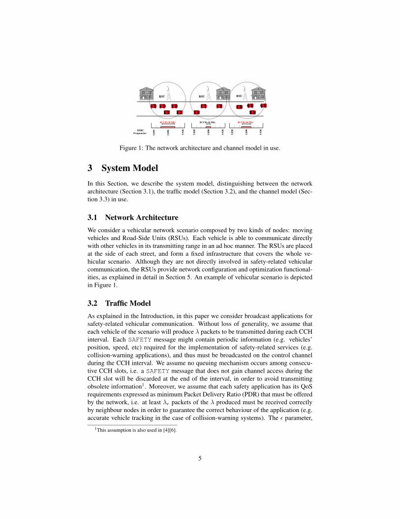
Figure 1: The network architecture and channel model in use.
3 System ModelIn this Section, we describe the system model, distinguishing between the networkarchitecture (Section 3.1), the traffic model (Section 3.2), and the channel model (Sec-tion 3.3) in use.
3.1 Network ArchitectureWe consider a vehicular network scenario composed by two kinds of nodes: movingvehicles and Road-Side Units (RSUs). Each vehicle is able to communicate directlywith other vehicles in its transmitting range in an ad hoc manner. The RSUs are placedat the side of each street, and form a fixed infrastructure that covers the whole ve-hicular scenario. Although they are not directly involved in safety-related vehicularcommunication, the RSUs provide network configuration and optimization functional-ities, as explained in detail in Section 5. An example of vehicular scenario is depictedin Figure 1.
3.2 Traffic ModelAs explained in the Introduction, in this paper we consider broadcast applications forsafety-related vehicular communication. Without loss of generality, we assume thateach vehicle of the scenario will produce λ packets to be transmitted during each CCHinterval. Each SAFETY message might contain periodic information (e.g. vehicles’position, speed, etc) required for the implementation of safety-related services (e.g.collision-warning applications), and thus must be broadcasted on the control channelduring the CCH interval. We assume no queuing mechanism occurs among consecu-tive CCH slots, i.e. a SAFETY message that does not gain channel access during theCCH slot will be discarded at the end of the interval, in order to avoid transmittingobsolete information1. Moreover, we assume that each safety application has its QoSrequirements expressed as minimum Packet Delivery Ratio (PDR) that must be offeredby the network, i.e. at least λr packets of the λ produced must be received correctlyby neighbour nodes in order to guarantee the correct behaviour of the application (e.g.accurate vehicle tracking in the case of collision-warning systems). The ε parameter,
1This assumption is also used in [4][6].
5
defined as:ε = 1− λr
λ(1)
defines the maximum packet loss probability tolerated by the vehicular application.Both λ and λr are assumed fixed and known to the vehicles and to the RSUs of thescenario.
3.3 Channel ModelWe assume that each vehicle of the scenario is equipped with a Software Defined Radio(SDR) transceiver. Each SDR device implements the full IEEE 802.11p/WAVE stack,and also provides Cognitive Radio (CR) functionalities for dynamic spectrum accessand management. At the upper layers, we assume that the channel operations are regu-lated by the standard IEEE 1609.4 scheme [3]. Moreover, the broadcast transmissionson the control channel are regulated by the IEEE MAC 802.11p protocol [10]. How-ever, we introduce two important difference to the IEEE 802.11 protocol. First, weassume that each vehicle can adjust the MAC Contention Window (CW) size to trans-mit broadcast SAFETY messages on the CCH, based on the actual channel contentionconditions. Second, we assume that the bandwidth of the CCH can be dynamicallyexpanded at the PHY layer over the 10 Mhz foreseen by the IEEE 802.11p [10], byusing additional DSRC frequencies allocated for the service channels, as depicted inFigure 1. The opportunistic usage of SCH frequencies during the CCH interval canbe practically enabled by the utilization of spectrum-agile SDR platforms [9], and canbe further justified considering that: (i) SCH channels are not used during the CCHslot, since all vehicles must be tuned on the control channel according to the 1609.4standard, (ii) the IEEE 802.11p standard already foresees the possibility to increase theCCH bandwidth to 20 Mhz, by aggregating orthogonal carriers from other channels.Based on the current value of the CCH bandwidth (i.e. BCCH ), the transmitting rateon the CCH (RCCH ) is then determined using the Shannon’s low:
RCCH = BCCH · log(1 +
PtNf
)(2)
where Pt is the transmitting power (assumed constant for all the vehicles), and Nf isthe value of the noise floor.
4 Analytical Results and MotivationsIn this Section, we investigate the performance of safety broadcast applications inVANETs through analytical and simulation results. To this aim, we use the systemmodel described in Section 3, and we introduce new assumptions (detailed in Sec-tion 4.1) to make the analysis tractable Through the analytical model described be-low, we then characterize the impact of MAC/PHY parameters on the performance ofsafety-related broadcast applications (Section 4.2), and we derive important consider-ations that are used in the proposal of our DySCO framework (Section 5).
6
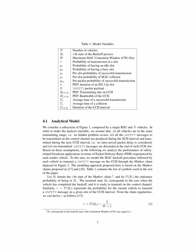
Table 1: Model Variables
N Number of vehiclesBi i-th state of the Backoff processW Maximum MAC Contention Window (CW) Sizeτ Probability of transmission in a slotpi Probability of having an idle slotpb Probability of having a busy slotps Per-slot probability of successful transmissionpc Per-slot probability of MAC collisionpps Per-packet probability of successful transmissionσ PHY duration of an 802.11p slotS SAFETY packet payloadRCCH PHY Transmitting rate on CCHBCCH PHY Bandwdith of the CCHTs Average time of a successful transmissionTc Average time of a collisionTCCH Duration of the CCH interval
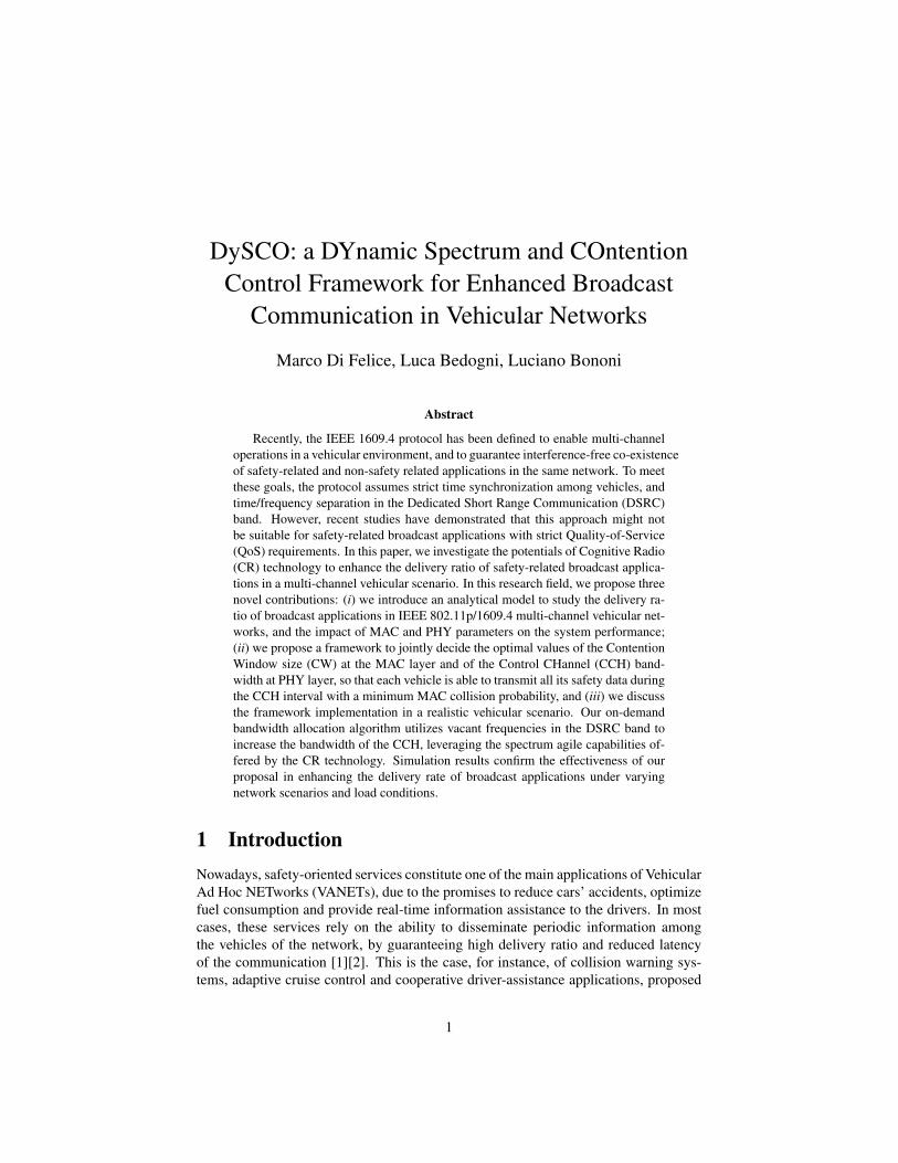
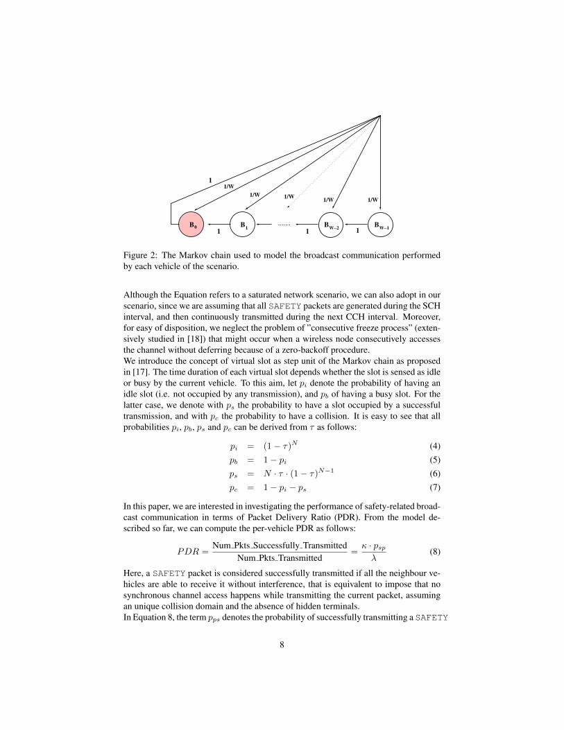
4.1 Analytical ModelWe consider a subsystem of Figure 1, composed by a single RSU and N vehicles. Inorder to make the analysis tractable, we assume that: (i) all vehicles are in the sametransmitting range, i.e. no hidden problem occurs, (ii) all the SAFETY messages tobe transmitted on the control channel are produced during the SCH interval and trans-mitted during the next CCH interval, i.e. no inter-arrival packet delay is considered,and (iii) un-transmitted SAFETY messages are discarded at the end of each CCH slot.Based on these assumptions, in the following we analyze the performance of safety-related broadcast applications in terms of Packet Delivery Ratio (PDR) experienced byeach sender vehicle. To this aim, we model the MAC backoff procedure followed byeach vehicle to transmit a SAFETY message on the CCH through the Markov chaindepicted in Figure 2. The modeling approach proposed here is based on the Markovchains proposed in [17] and [18]. Table 1 contains the list of symbols used in the restof the paper.
Let Bi denote the i-th state of the Markov chain 2, and let P (Bi) the stationaryprobability of being in Bi. The terminal state B0 corresponds to the case when thevehicle has completed the backoff, and it is ready to transmit on the control channel.Similarly, τ = P (B0) represents the probability for the current vehicle to transmita SAFETY message on a given slot of the CCH interval. From the chain regularities,we can derive τ as follows [17]:
τ = P (B0) =2
W + 1(3)
2Bi corresponds to the backoff state with Contention Window (CW) size equal to i.
7
B B BW−1
BW−210
1 1 1
1/W
1/W 1/W1/W 1/W
1
.......
Figure 2: The Markov chain used to model the broadcast communication performedby each vehicle of the scenario.
Although the Equation refers to a saturated network scenario, we can also adopt in ourscenario, since we are assuming that all SAFETY packets are generated during the SCHinterval, and then continuously transmitted during the next CCH interval. Moreover,for easy of disposition, we neglect the problem of ”consecutive freeze process” (exten-sively studied in [18]) that might occur when a wireless node consecutively accessesthe channel without deferring because of a zero-backoff procedure.We introduce the concept of virtual slot as step unit of the Markov chain as proposedin [17]. The time duration of each virtual slot depends whether the slot is sensed as idleor busy by the current vehicle. To this aim, let pi denote the probability of having anidle slot (i.e. not occupied by any transmission), and pb of having a busy slot. For thelatter case, we denote with ps the probability to have a slot occupied by a successfultransmission, and with pc the probability to have a collision. It is easy to see that allprobabilities pi, pb, ps and pc can be derived from τ as follows:
pi = (1− τ)N (4)pb = 1− pi (5)ps = N · τ · (1− τ)N−1 (6)pc = 1− pi − ps (7)
In this paper, we are interested in investigating the performance of safety-related broad-cast communication in terms of Packet Delivery Ratio (PDR). From the model de-scribed so far, we can compute the per-vehicle PDR as follows:
PDR =Num Pkts Successfully Transmitted
Num Pkts Transmitted=κ · pspλ
(8)
Here, a SAFETY packet is considered successfully transmitted if all the neighbour ve-hicles are able to receive it without interference, that is equivalent to impose that nosynchronous channel access happens while transmitting the current packet, assumingan unique collision domain and the absence of hidden terminals.In Equation 8, the term pps denotes the probability of successfully transmitting a SAFETY
8
message. Assuming the independence among consecutive transmission attempts, theprobability pps can be derived from the probability of having a successful transmissionin a virtual slot, knowing that the slot is busy, i.e.:
pps =pspb
=N · τ · (1− τ)N−1
1− ((1− τ)N )(9)
The other term κ of Equation 8 represents the average number of SAFETY packets thatare transmitted during the CCH slot, accounting for the average MAC access delayrequired to transmit each packet (E[Taccess] in the following), and the length of theCCH interval (TCCH ), defined by the IEEE 1609.4 standard [3]. Again, assumingthe independence among consecutive transmissions, we can reasonably estimate κ asfollows:
κ = min
(λ,E[Taccess]
Tcch
)(10)
Equation 10 reflects the intuition that the maximum number of CCH accesses for eachvehicle depends on the time duration of each access compared to TCCH , and in anycase it cannot exceed the traffic request λ.In the following, we derive the equation for E[Taccess], i.e. of the MAC access delaydefined as the time that elapses from when the SAFETY packet is available on top of theMAC queue to when it is effectively transmitted on the control channel, including MACbackoff delay and PHY transmitting delay3. We express E[Taccess] as a function of theaverage duration of the backoff delay (i.e. E[BF ]), of the duration of each transmission(Ts) and of the average duration of a virtual slot (i.e. E[Tslot]), as follows [19]:
E[Taccess] = E[BF ] · E[Tslot] + Ts =W
2· E[Tslot] + Ts (11)
The average duration of the virtual slot depends on whether the slot is idle, or occupiedby a transmission or by a collision, i.e.:
E[Tslot] = pi · σ + Ts · ps + Tc · pc (12)
where σ is the duration of an empty slot according to the MAC 802.11p [10]. Tsuccessis the time required for a successful transmission and Tcoll is the average time of acollision event. Based on the packet size (S), the transmission time of the preamble(TPRE) and the data-rate used (RCCH ) on the control channel, and excluding the casesof consecutive transmissions in the same logic slot due to the assumption of a single(synchronous) collision domain, the exact values of Ts and Tc can be derived as:
Ts = DIFS + σ +S
RCCH+ TPRE (13)
Tc = EIFS + σ +S
RCCH+ TPRE (14)
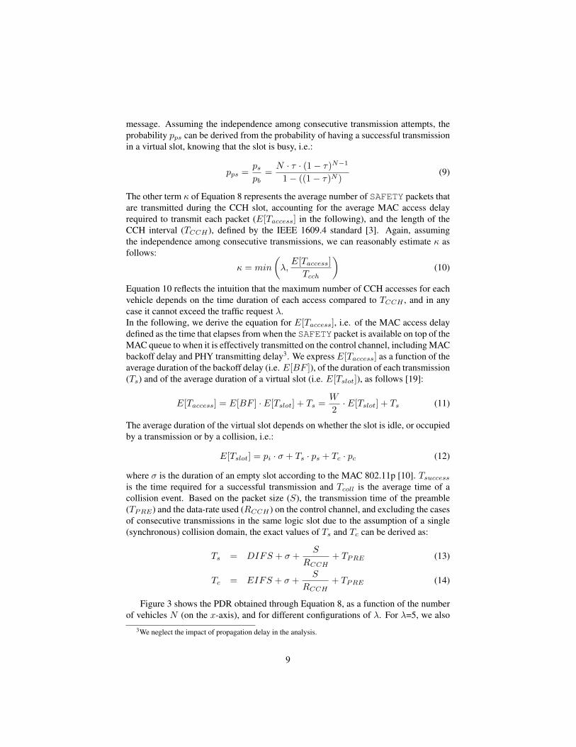
Figure 3 shows the PDR obtained through Equation 8, as a function of the numberof vehicles N (on the x-axis), and for different configurations of λ. For λ=5, we also
3We neglect the impact of propagation delay in the analysis.
9
0
0.1
0.2
0.3
0.4
0.5
0.6
0.7
0.8
0.9
1
0 5 10 15 20 25 30 35 40 45 50
Pac
ket
Del
iver
y R
atio
(P
DR
)
Number of vehicles
λ=5 pkts (Analytical)λ=5 pkts (Simulation)
λ=20 pkts (Analytical)λ=30 pkts (Analytical)
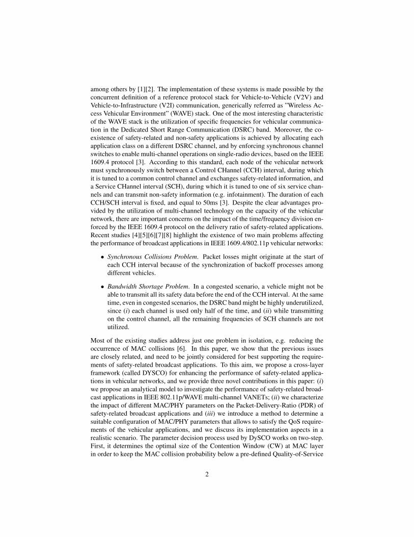
Figure 3: The PDR index as a function of the number of vehicles, and for differentvalues of λ.
0
0.1
0.2
0.3
0.4
0.5
0.6
0.7
0.8
0.9
1
16 64 128 256 512 1024
Pack
et
Deli
very
Rati
o (
PD
R)
MAC Contention Window (CW) size
N=10 vehiclesN=20 vehiclesN=30 vehicles
(a)
0
0.1
0.2
0.3
0.4
0.5
0.6
0.7
0.8
0.9
16 64 128 256 512 1024
0.2
0.4
0.6
0.8
MA
C C
oll
isio
n P
rob
ab
ilit
y
Pack
et
Un
tran
smit
ted
Rati
o
MAC Contention Window (CW) size
N=10, Collision ProbabilityN=10, Untransmitted RatioN=30, Collision ProbabilityN=30, Untransmitted Ratio
(b)
0.5
0.55
0.6
0.65
0.7
0.75
0.8
0.85
0.9
0.95
1
16 64 128 256 512 1024
Pack
et
Deli
very
Rati
o (
PD
R)
MAC Contention Window (CW) size
R=3 Mb/sR=6 Mb/s
R=12 Mb/s
(c)
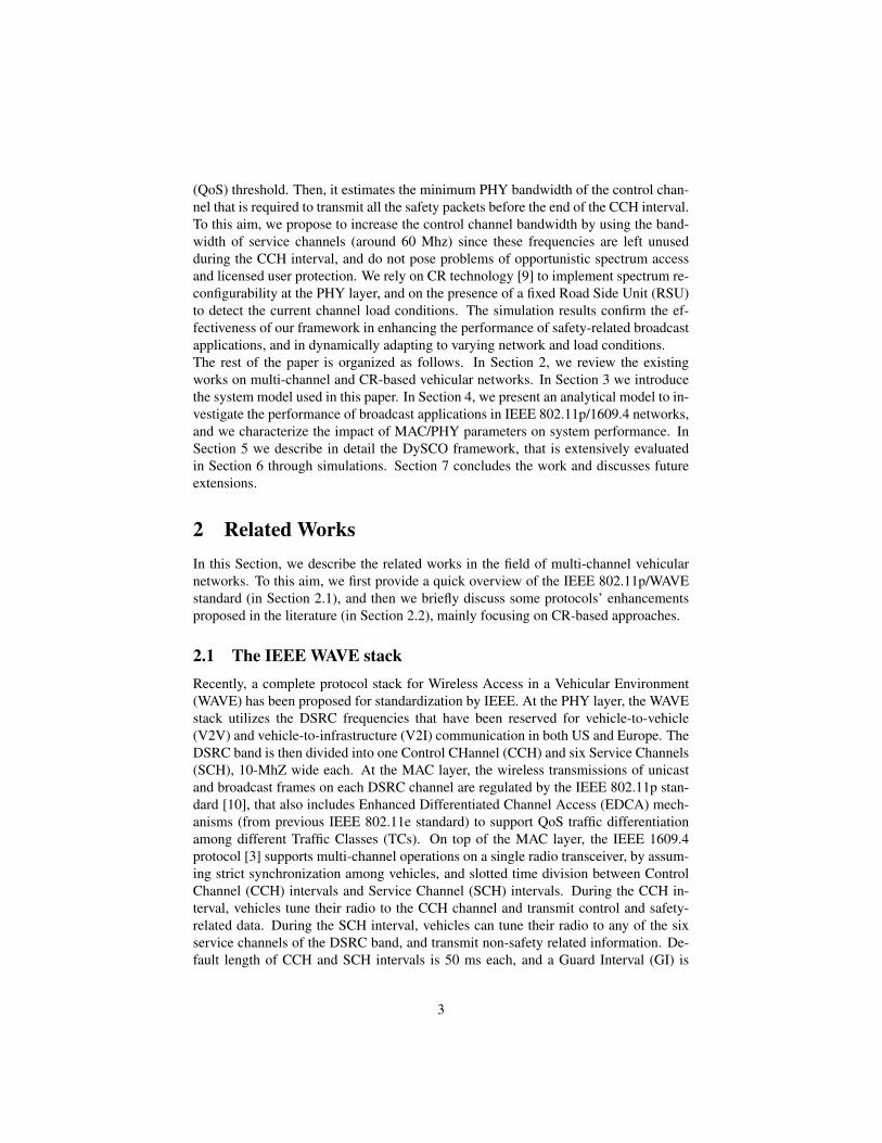
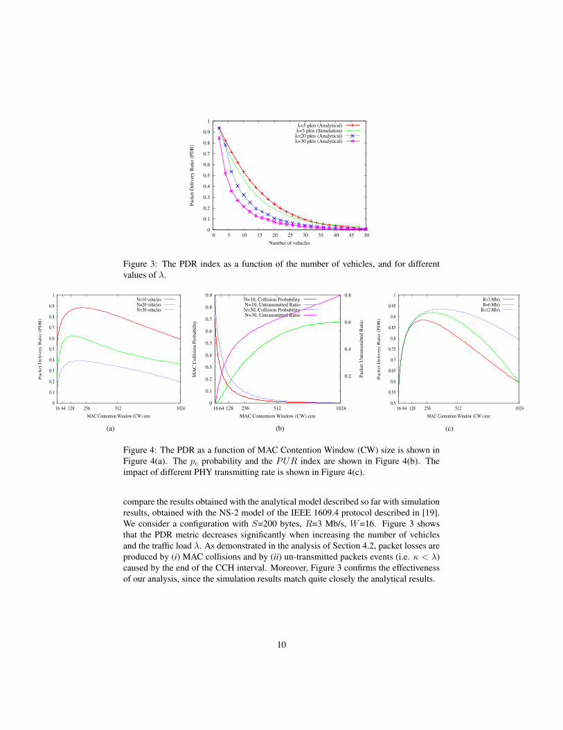
Figure 4: The PDR as a function of MAC Contention Window (CW) size is shown inFigure 4(a). The pc probability and the PUR index are shown in Figure 4(b). Theimpact of different PHY transmitting rate is shown in Figure 4(c).
compare the results obtained with the analytical model described so far with simulationresults, obtained with the NS-2 model of the IEEE 1609.4 protocol described in [19].We consider a configuration with S=200 bytes, R=3 Mb/s, W=16. Figure 3 showsthat the PDR metric decreases significantly when increasing the number of vehiclesand the traffic load λ. As demonstrated in the analysis of Section 4.2, packet losses areproduced by (i) MAC collisions and by (ii) un-transmitted packets events (i.e. κ < λ)caused by the end of the CCH interval. Moreover, Figure 3 confirms the effectivenessof our analysis, since the simulation results match quite closely the analytical results.
10
4.2 Parameter CharacterizationIn Figure 4(a), we show the PDR for different values of the MAC Contention Window(CW), comprised between a minimum (equal to 16), and a maximum value (equal to1024). Moreover, in the same Figure we show three curves for different configurationsof N , i.e. the number of vehicles in the network. For each value of N , Figure 4(a) con-firms the existence of an optimal value ofCW maximizing the per-vehicle PDR metric.This is in accordance with previous results on the performance of MAC 802.11 pro-tocol. However, Figure 4(a) reveals also the existence of a performance trade-off thatis intrinsically related to the operations of IEEE 1609.4-based multi-channel VANETs.If the CW size is below the optimal value, then synchronous MAC collisions mightoccur among vehicles selecting the same slot, thus causing a performance loss in termsof per-vehicle PDR. On the opposite, if the CW size exceeds the optimal value, thenpacket losses might occur at the end of the CCH interval, since some of the λ pack-ets might not have chance to be transmitted before the expiration of the CCH interval.This intuition is confirmed by Figure 4(b), where we depict the MAC Collision risk onthe x1y1 axes (computed through Equation 4), as a function of the CW size, while inthe x1y2 axis we show the Packet Untransmitted Ratio (PUR), defined as the ratio ofpacket discarded at the end of the CCH interval as follows:
PUR = 1− κ
λ(15)
We consider two configurations of N , for the same traffic load λ=5. As expected,the MAC Collision Risk decreases when increasing the CW size. However, this inturn increases the average MAC access delay (defined by Equation 11), thus producinghigher values of the PUR index. Finally, Figure 4(c) shows the PDR as a function of theCW size, for different configurations of the PHY transmitting rate, i.e. RCCH . Again,we consider a configuration with N=10 and λ=5. Figure 4(c) shows that increasing thePHY transmitting rate can mitigate the performance loss caused by the un-transmittedpackets at end of the CCH slot, since each vehicle experiences a lower average MACaccess delay (e.g. E[Taccess]) to transmit each SAFETY packet. To summarize, twoimportant considerations can be drawn from previous results: (i) the PDR of broadcastapplications is mainly determined by an appropriate selection of the CW size at theMAC layer, and of the transmitting rate at the PHY layer and (i) given the joint impactof these parameters on the delivery rate, cross-layer design should be considered forperformance optimizations.
5 The DySCO FrameworkBased on the previous considerations, we present here our DYnamic Spectrum andContention COntrol (DYSCO) framework to decide the optimal configurations of MAC/PHYtransmitting parameters in order to enhance the performance of safety-related broad-cast applications. Considering the network architecture of Section 3, we assume thatthe DYSCO framework is implemented at each RSU, that in turns propagates the resultof the decision process (i.e. the MAC/PHY configuration) to the moving vehicles in its
11
range. Although we are aware of the drawbacks of a centralized architecture (e.g. sin-gle point of failure, low scalability, etc), we rely on the presence of a centralized nodeto be able to exploit the memory effects of the RSU, and to ensure that all vehicles ofthe scenario will use the same radio settings during the CCH interval. We will considerthe extension to a distributed architecture as future work. In the following, we providean overview of the DYSCO framework implemented by each RSU. The details of theparameter decision algorithm are described in Section 5.2, while the implementationaspects are discussed in Section 5.3.
Algorithm 1: RSU operationsAt each CCH interval:Sense the CCH channel and compute pb through Equation 24.Update the estimation of N through Equation 26.
At each Tf interval:Determine W with Equation 19.Determine RCCH with Equation 22 and BCCH with Equation 2.Bound W value to the range [WDEF : WMAX ]Bound BCCH value to the range [BDEF : BMAX ]Compute PDRnew(W,BCCH) through Equation 8if (PDRnew(W,BCCH) > PDRold) then
Create a NETCONF=< W,BCCH , Tf > packetTransmit it on next SCH interval
end if
5.1 OverviewEvery CCH interval, each RSU senses the CCH, and determines the current channelcontention conditions through the approach defined in Section 5.3. Then, every Tftime units, the RSU executes Algorithm 1 to determine the most suitable values ofthe MAC Contention Window (CW) size and of the PHY channel bandwidth to beused by each vehicle of the scenario. Through these values, the RSU computes thecurrent PDR metric (i.e. PDRnew) with Equation 8 and compares it with the pre-vious stored value of the PDR, i.e. PDRold. This check is required to avoid thecase in which an excessive increase of the CW size would determine an intolerablenumber of un-transmitted packets, so that the performance of the application becomeworse. In case PDRnew < PDRold, no parameter optimization is performed by theDySCO framework. In case PDRnew > PDRold, then the information about the newMAC/PHY configuration to be used by each vehicle of the scenario are encapsulatedon a NETCONF packet, that is periodically transmitted by the RSU on each servicechannels during the SCH interval 4. The NETCONF packet has the following struc-ture:
< W,BCCH , Tstamp > (16)
4The NETCONF are periodically transmitted during SCH interval on each service channel in order toavoid interference with SAFETY packets transmitted on the CCH
12
Here, W and BCCH represent respectively the values of the MAC CW size and of thePHY bandwidth of the CCH (computed through the method detailed in Section 5.2),while Tstamp is the temporal validity of the parameters’ setting (equal to Tf in our ex-periments). On receiving the SAFETY message, each vehicle: (i) adjusts the value ofits MAC CW size toW , and (ii) computesRCCH through Equation 2, and reconfiguresits radio accordingly.
5.2 Decision AlgorithmHere, we detail how the W and BCCH values are determined by the RSU in order tomeet the QoS requirements of safety-related vehicular applications. We recall fromSection 3 that in our scenario the QoS is expressed in terms of PDR threshold, i.e weassume that the packet loss rate cannot exceed the ε factor of Equation 1. Both the εthreshold and the traffic request λ are assumed to be fixed and known by the RSU. Astraightforward approach to solve the problem would be to determine (numerically) thecombination of < W,RCCH > parameters that maximizes Equation 8. However, thisapproach might involve considerable computation efforts from the RSU, and mightalso lead to excessive spectrum resource utilization from the vehicular network. Forthis reason, we propose here a two-step decision process that has the main advantageto be practically implementable by RSUs, although at the cost of potentially incurringin suboptimal solutions. The proposed solution works as follows:
• Step 1. The RSU determines the optimal MAC CW size (W ) in order to mitigatethe risk of packet losses caused by synchronous channel access by vehicles thathave selected the same MAC slot for their transmission attempts.
• Step 2. Based on the value of W , the RSU computes the minimum rate RCCHrequired in order to ensure that each vehicle is able to transmit all its λ packetsduring the CCH interval.
For Step1, we impose that the probability of successful MAC transmission must behigher that the QoS threshold 1− ε, i.e.:
pps > 1− ε (17)
where pps is given by Equation 9. Recalling that (1 − τ)N ∼ (1 − τ ·N) if τ << 1,then we get:
(N − 1) · τ > ε (18)
from which we can derive (substituting τ with Equation 4.1) the following upper boundon W :
W >2 · (N − 1)
ε(19)
For Step 2, we attempt to determine the minimum value of rate RCCH such that eachvehicle is able to transmit all its λ packets during the CCH slot, i.e.:
TCCHE[Taccess]
≥ λ (20)
13
where E[Taccess] represents the average access time according to Equation 11, andTCCH is the default CCH interval duration (fixed to 50 ms). If we consider that Tc ∼Ts, and that pb=1− pi=ps + pc, we can rewrite Equation 11 as follows:
E[Taccess] =W
2· σ · (1− pb) + Ts ·
(1 + pb ·
W
2
)(21)
Using Equation 21 in 20, and considering that Ts is mainly dominated by the transmit-ting delay (i.e. Ts ∼ S/RCCH ), we can derive RCCH as follows:
RCCH ≥S · λ · β
TCCH − α · λ(22)
where α = W2 · σ · (1 − pb) and β = 1 + pb · W2 . The term α represents the average
idle time associated to each transmission. Thus, a suitable assignment of RCCH existsonly if the total number of empty slots does not exceed the TCCH interval. Otherwise,we set R to the maximum transmitting rate RMAX . From the transmitting rate RCCH ,the RSU can then determine the value of the BCCH through Equation 2.
In the Algorithm 1, we replaced Equations 19 and 22 with equalities, so that theminimum value of RCCH that satisfies Equation 22 is selected in order to minimizethe overall spectrum resources utilization. Thus, the final W and RCCH transmitted inthe NETCONF packet are as follows:{
W = 2·(N−1)ε
RCCH = S·λ·βTCCH−α·λ
(23)
Moreover, in Algorithm 1, we introduced upper and lower bounds for the values ofW and BCCH , i.e. we adjust the value of W to be in range [WREF : WMAX ] andBCCH in the range [BREF : BMAX ]. The upper bound is used to limit the utilizationof spectrum resources, and to avoid undetermined backoff process durations.From the description provided so far, it is easy to verify that the DySCO frameworkis highly adaptive to the current CCH contention conditions. In fact, in a scenariowith heavy CCH load utilization produced by a high number of N (e.g. peak hoursof traffic), the W value is increased to avoid MAC collisions, and consequently theBCCH value is expanded to reduce the MAC access delay of each transmission attempt.Conversely, as soon as N decreases (e.g. vehicular traffic density is reduced), the Wvalue is reduced accordingly, and thus less DSRC bandwidth is requested.
5.3 Channel Load EstimationIn order to be able to determine the current value of W and BCCH using Equation 23,the RSU must know the current value of N and pb. Generally speaking, these valuesare hard to be determined in practice, also considering that the RSU does not main-tain a list of authorized stations in the vehicular network. However, assuming smoothvariations of vehicular traffic conditions, the load conditions of the control channel canbe derived by means of the Slot Utilization (SU) metric proposed in [20]. At the start
14
of each CCH, the RSU counts the number of transmission attempts it observes on thechannel (Num Busy Slots) and then divides this number by the total duration of theobservation window, i.e. W . The result is a lower bound on the contention level ofCCH:
SU =Num Busy Slots
W(24)
It is easy to see that SU provides a punctual approximation of the channel load thatwill converge to pb for an enough long period of observations. For this reason, at eachCCH interval the RSU updates the current estimation of SU as follows:
SU = SUnew · α+ SUold · (1− α) (25)
Here, SUnew is the value computed through Equation 24 during the current CCH inter-val, SUold is the previous stored value of the SU metric, and α is a parameter that de-cides the relevance of history in the current decision. Using Equation 5 with SU = pb,and the approximation (1− τ)N ∼ (1− τ ·N), the RSU can estimate the value of Nas follows:
N = SU · W + 1
2(26)
In the section below, we show that this approximation works reasonably well also undervarying traffic conditions.
6 Performance EvaluationIn this Section, we evaluate the performance of the DYSCO framework under differentnetwork and load conditions. To this aim, we consider an highway scenario with 4lanes, and vehicles uniformly distributed over them. Following the same approachused in Sections 4 and 5, we consider a subset of the network architecture with Nvehicle and 1 RSU in the same scenario. We use the Ns-2 tool for the simulationanalysis, with the extension described in [19] to model IEEE 1609.4-based vehicularnetworks. Unless specified otherwise, we use the simulation parameters of Table 2 inthe evaluation. In the following, we compare the performance of:
• MAC 802.11p. This is the reference IEEE MAC 802.11p, with the default con-figurations of MAC/PHY parameters as foreseen by the standard [10]. Eachvehicle transmits SAFETY packets with a default CW size W equal to 16 5 anda constant rate RDEF equal to 3 Mb/s.
• DySCO-CW. This is a sub-configuration of the DySCO framework, in whichonly the CW size optimization is performed at the MAC layer through Equa-tion 19. As before, each vehicle transmits SAFETY packets at a default rateRDEF equal to 3 Mb/s, by following the MAC 802.11p backoff scheme forchannel access.
5We assume all packets belong to the same TC. We will model EDCA traffic differentiation as futurework.
15
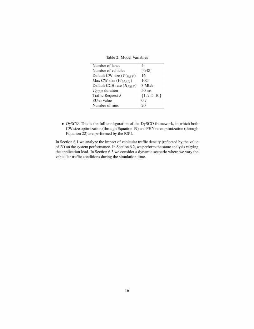
Table 2: Model Variables
Number of lanes 4Number of vehicles [4:48]Default CW size (WREF ) 16Max CW size (WMAX ) 1024Default CCH rate (RREF ) 3 Mb/sTCCH duration 50 msTraffic Request λ {1, 2, 5, 10}SU-α value 0.7Number of runs 20
• DySCO. This is the full configuration of the DySCO framework, in which bothCW size optimization (through Equation 19) and PHY rate optimization (throughEquation 22) are performed by the RSU.
In Section 6.1 we analyze the impact of vehicular traffic density (reflected by the valueofN ) on the system performance. In Section 6.2, we perform the same analysis varyingthe application load. In Section 6.3 we consider a dynamic scenario where we vary thevehicular traffic conditions during the simulation time.
16
0
0.1
0.2
0.3
0.4
0.5
0.6
0.7
0.8
0.9
1
0 5 10 15 20 25 30 35 40 45 50
Pac
ket
Del
iver
y R
atio
(P
DR
)
Number of vehicles
IEEE MAC 802.11p SchemeDySCO-CW Framework
DYSCO Framework
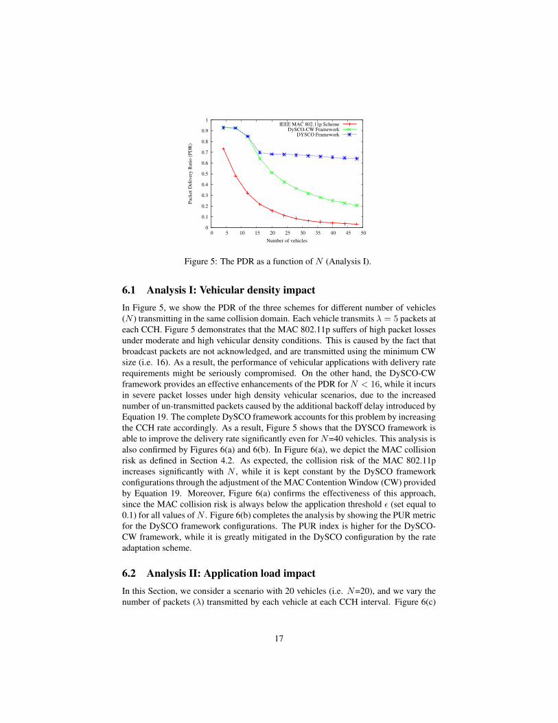
Figure 5: The PDR as a function of N (Analysis I).
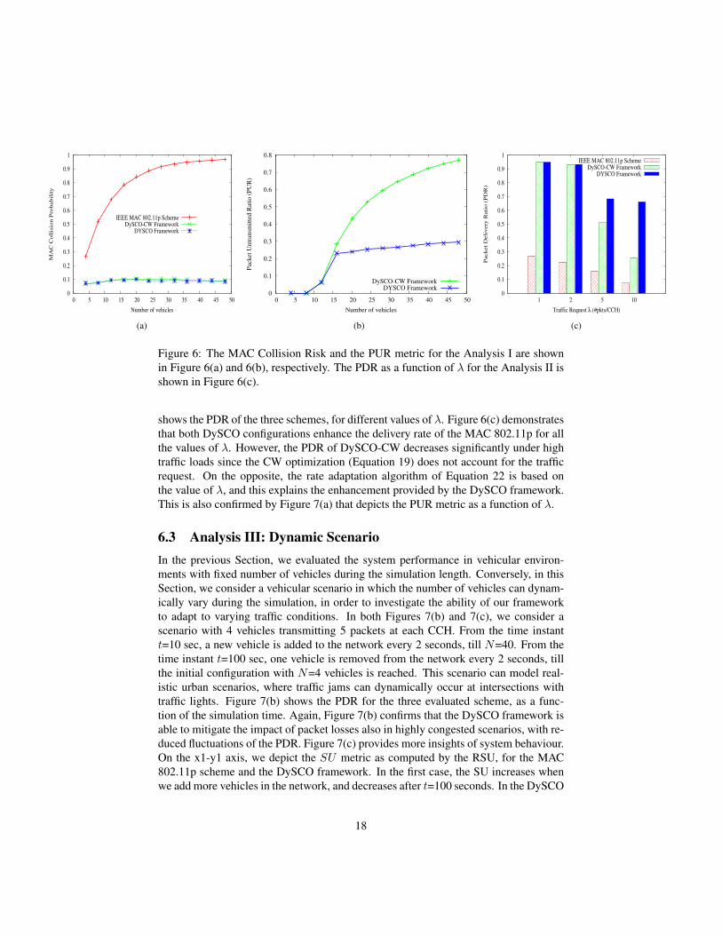
6.1 Analysis I: Vehicular density impactIn Figure 5, we show the PDR of the three schemes for different number of vehicles(N ) transmitting in the same collision domain. Each vehicle transmits λ = 5 packets ateach CCH. Figure 5 demonstrates that the MAC 802.11p suffers of high packet lossesunder moderate and high vehicular density conditions. This is caused by the fact thatbroadcast packets are not acknowledged, and are transmitted using the minimum CWsize (i.e. 16). As a result, the performance of vehicular applications with delivery raterequirements might be seriously compromised. On the other hand, the DySCO-CWframework provides an effective enhancements of the PDR for N < 16, while it incursin severe packet losses under high density vehicular scenarios, due to the increasednumber of un-transmitted packets caused by the additional backoff delay introduced byEquation 19. The complete DySCO framework accounts for this problem by increasingthe CCH rate accordingly. As a result, Figure 5 shows that the DYSCO framework isable to improve the delivery rate significantly even for N=40 vehicles. This analysis isalso confirmed by Figures 6(a) and 6(b). In Figure 6(a), we depict the MAC collisionrisk as defined in Section 4.2. As expected, the collision risk of the MAC 802.11pincreases significantly with N , while it is kept constant by the DySCO frameworkconfigurations through the adjustment of the MAC Contention Window (CW) providedby Equation 19. Moreover, Figure 6(a) confirms the effectiveness of this approach,since the MAC collision risk is always below the application threshold ε (set equal to0.1) for all values ofN . Figure 6(b) completes the analysis by showing the PUR metricfor the DySCO framework configurations. The PUR index is higher for the DySCO-CW framework, while it is greatly mitigated in the DySCO configuration by the rateadaptation scheme.
6.2 Analysis II: Application load impactIn this Section, we consider a scenario with 20 vehicles (i.e. N=20), and we vary thenumber of packets (λ) transmitted by each vehicle at each CCH interval. Figure 6(c)
17
0
0.1
0.2
0.3
0.4
0.5
0.6
0.7
0.8
0.9
1
0 5 10 15 20 25 30 35 40 45 50
MA
C C
oll
isio
n P
rob
ab
ilit
y
Number of vehicles
IEEE MAC 802.11p SchemeDySCO-CW Framework
DYSCO Framework
(a)
0
0.1
0.2
0.3
0.4
0.5
0.6
0.7
0.8
0 5 10 15 20 25 30 35 40 45 50
Pack
et
Un
tran
smit
ted
Rati
o (
PU
R)
Number of vehicles
DySCO-CW FrameworkDYSCO Framework
(b)
0
0.1
0.2
0.3
0.4
0.5
0.6
0.7
0.8
0.9
1
1 2 5 10
Pack
et
Deli
very
Rati
o (
PD
R)
Traffic Request λ (#pkts/CCH)
IEEE MAC 802.11p SchemeDySCO-CW Framework
DYSCO Framework
(c)
Figure 6: The MAC Collision Risk and the PUR metric for the Analysis I are shownin Figure 6(a) and 6(b), respectively. The PDR as a function of λ for the Analysis II isshown in Figure 6(c).
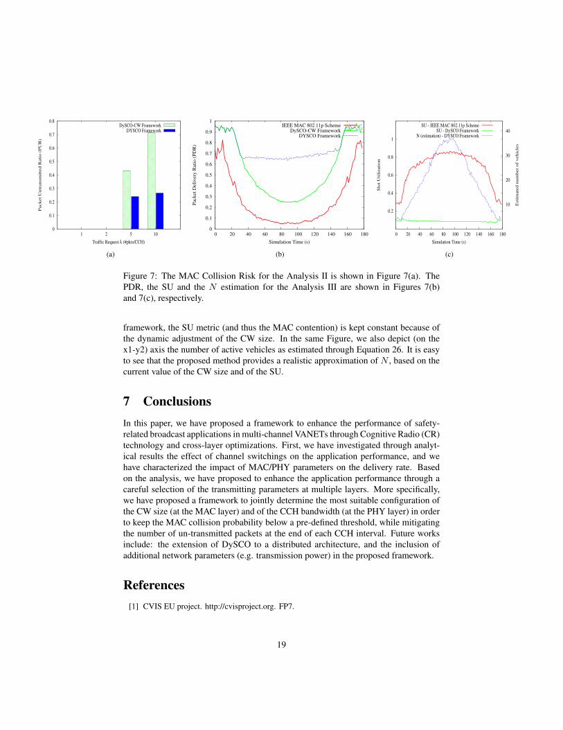
shows the PDR of the three schemes, for different values of λ. Figure 6(c) demonstratesthat both DySCO configurations enhance the delivery rate of the MAC 802.11p for allthe values of λ. However, the PDR of DySCO-CW decreases significantly under hightraffic loads since the CW optimization (Equation 19) does not account for the trafficrequest. On the opposite, the rate adaptation algorithm of Equation 22 is based onthe value of λ, and this explains the enhancement provided by the DySCO framework.This is also confirmed by Figure 7(a) that depicts the PUR metric as a function of λ.
6.3 Analysis III: Dynamic ScenarioIn the previous Section, we evaluated the system performance in vehicular environ-ments with fixed number of vehicles during the simulation length. Conversely, in thisSection, we consider a vehicular scenario in which the number of vehicles can dynam-ically vary during the simulation, in order to investigate the ability of our frameworkto adapt to varying traffic conditions. In both Figures 7(b) and 7(c), we consider ascenario with 4 vehicles transmitting 5 packets at each CCH. From the time instantt=10 sec, a new vehicle is added to the network every 2 seconds, till N=40. From thetime instant t=100 sec, one vehicle is removed from the network every 2 seconds, tillthe initial configuration with N=4 vehicles is reached. This scenario can model real-istic urban scenarios, where traffic jams can dynamically occur at intersections withtraffic lights. Figure 7(b) shows the PDR for the three evaluated scheme, as a func-tion of the simulation time. Again, Figure 7(b) confirms that the DySCO framework isable to mitigate the impact of packet losses also in highly congested scenarios, with re-duced fluctuations of the PDR. Figure 7(c) provides more insights of system behaviour.On the x1-y1 axis, we depict the SU metric as computed by the RSU, for the MAC802.11p scheme and the DySCO framework. In the first case, the SU increases whenwe add more vehicles in the network, and decreases after t=100 seconds. In the DySCO
18
0
0.1
0.2
0.3
0.4
0.5
0.6
0.7
0.8
1 2 5 10
Pack
et
Un
tran
sm
itte
d R
ati
o (
PU
R)
Traffic Request λ (#pkts/CCH)
DySCO-CW FrameworkDYSCO Framework
(a)
0
0.1
0.2
0.3
0.4
0.5
0.6
0.7
0.8
0.9
1
0 20 40 60 80 100 120 140 160 180
Pack
et
Deli
very
Rati
o (
PD
R)
Simulation Time (s)
IEEE MAC 802.11p SchemeDySCO-CW Framework
DYSCO Framework
(b)
0.2
0.4
0.6
0.8
1
0 20 40 60 80 100 120 140 160 180
10
20
30
40
Slo
t U
tili
zati
on
Esti
mate
d n
um
ber
of
veh
icle
s
Simulation Time (s)
SU - IEEE MAC 802.11p SchemeSU - DySCO Framework
N (estimation) - DYSCO Framework
(c)
Figure 7: The MAC Collision Risk for the Analysis II is shown in Figure 7(a). ThePDR, the SU and the N estimation for the Analysis III are shown in Figures 7(b)and 7(c), respectively.
framework, the SU metric (and thus the MAC contention) is kept constant because ofthe dynamic adjustment of the CW size. In the same Figure, we also depict (on thex1-y2) axis the number of active vehicles as estimated through Equation 26. It is easyto see that the proposed method provides a realistic approximation of N , based on thecurrent value of the CW size and of the SU.
7 ConclusionsIn this paper, we have proposed a framework to enhance the performance of safety-related broadcast applications in multi-channel VANETs through Cognitive Radio (CR)technology and cross-layer optimizations. First, we have investigated through analyt-ical results the effect of channel switchings on the application performance, and wehave characterized the impact of MAC/PHY parameters on the delivery rate. Basedon the analysis, we have proposed to enhance the application performance through acareful selection of the transmitting parameters at multiple layers. More specifically,we have proposed a framework to jointly determine the most suitable configuration ofthe CW size (at the MAC layer) and of the CCH bandwidth (at the PHY layer) in orderto keep the MAC collision probability below a pre-defined threshold, while mitigatingthe number of un-transmitted packets at the end of each CCH interval. Future worksinclude: the extension of DySCO to a distributed architecture, and the inclusion ofadditional network parameters (e.g. transmission power) in the proposed framework.
References[1] CVIS EU project. http://cvisproject.org. FP7.
19
[2] EuroFOT EU project. http://www.eurofot-ip.eu. FP7.
[3] IEEE Trial-Use Standard for Wireless Access in Vehicular Environments (WAVE) - Multi-Channel Operation. IEEE Std 1609.4-2006, 2006.
[4] C. Campolo, A. Molinaro and A. V. Vinel. Understanding the performance of short-livedcontrol broadcast packets in 802.11p/WAVE Vehicular networks. In Proc. of IEEE VNC,Amsterdam, pp. 102-108, 2011.
[5] M. Di Felice, A. J. Ghandour, H. Artail and L. Bononi. On the Impact of Multi-channelTechnology on Safety-Message Delivery in IEEE 802.11p/1609.4 Vehicular Networks. Toappear in Proc. of IEEE ICCCN, Munich, 2012.
[6] D. Jiang and L. Delgrossi. IEEE 1609.4 DSRC Multi-Channel Operations and Its Im-plications on Vehicle Safety Communications. in Proc. of IEEE VNC, Tokyio, pp. 1-8,2009.
[7] J. Misic, G. Badawy and V. Misic. Performance Characterization for IEEE 802.11p Net-work with Single Channel Devices. IEEE Transactions on Vehicular Technology, 68(4),pp. 1775-1789, 2011.
[8] Q. Wang, S. Leng, H. Fu and Y. Zhang. An IEEE 802.11p-based Multichannel MACScheme with Channel Coordination for Vehicular Ad Hoc Networks. IEEE Transactionson Intelligent Transportation Systems, 99(1), pp. 1-10, 2011.
[9] I. F. Akyildiz, W. Y. Lee, M. C. Vuran, and S. Mohanty. NeXt Generation/Dynamic Spec-trum Access/Cognitive Radio Wireless Networks: A Survey. Computer Networks Journal,50(1), pp. 2127-2159, 2006.
[10] Wireless LAN Medium Access Control (MAC) and Physical Layer (PHY) Specifications:Wireless Access in Vehicular Environment IEEE Std 802.11p/D7.0, 2009.
[11] M. Di Felice, R. Doost-Mohammady, K. Chowdhury and L. Bononi. Smart Radios forSmart Vehicles. In IEEE Vehicular Technology Magazine, 7(2), pp. 26-33, 2012.
[12] M. Di Felice, K. Chowdhury and L. Bononi. Cooperative Spectrum Management inCognitive Vehicular Ad Hoc Networks. In Proc. of IEEE VNC, Amsterdam, 2011.
[13] S. Pagadarai, A. M. Wyglinski and R. Vuyyuru. Characterization of Vacant UHF TVChannels for Vehicular Dynamic Spectrum Access. In Proc. of IEEE VNC, Tokyo, 2009.
[14] X. Wang and P-H. Ho. A Novel Sensing Coordination Framework for CR-Vanets. IEEETransactions on Vehicular Technology, 59(4), pp. 1936-1948, 2010.
[15] D. Niyato, E. Hossain, and P. Wang. Optimal Channel Access Management with QoSSupport for Cognitive Vehicular Networks. IEEE Transactions on Mobile Computing,10(4), pp. 573-591, 2011.
[16] A. J. Ghandour, K. Fawaz and H. Artail. Data Delivery Guarantees in Congested Vehicularad Hoc Networks using Cognitive Networks. In Proc. of IEEE IWCMC, 2011.
[17] G. Bianchi. Performance analysis of the IEEE 802.11 distributed coordination function. inIEEE Journal on Selected Areas in Communications, 18(3), pp. 535-547, 2000.
20
[18] X. Ma and X. Chen. Performance Analysis of IEEE 802.11 Broadcast Scheme in Ad HocWireless LANs. in IEEE Transactions on Vehicular Technology, 57(6), pp. 3757-3768,2008.
[19] A. J. Ghandour, M. Di Felice, H. Artail and L. Bononi. Modeling and Simulation of WAVE1609.4-based Multi-channel Vehicular Ad Hoc Networks. In Proc. of ICST SimuTools,Desenzano, 2012.
[20] L.Bononi, M.Conti and L.Donatiello. Design and Performance Evaluation of a DistributedContention Control (DCC) Mechanism for IEEE 802.11 Wireless Local Area Networks.Journal of Parallel and Distributed Computing, 60(4), pp. 407-430, 2000.
21