Embed Size (px)
Citation preview
U. S. Dept. of Agriculture S o i l Conservation Service Engineering Divis ion Design Branch
August 19, 1969
DESIGN NOTE NO. 8 * Subject: Entrance Head Losses i n Drop I n l e t Spillways
During the past severa l years, hydraulic model tests of drop i n l e t spillways have been i n progress a t St . Anthony F a l l s , Minnesota, and S t i l lwa te r , Oklahoma. New elbows and t r a n s i t i o n s have been t e s t e d a t St. Anthony F a l l s , and i n l e t s with t r a s h racks and simulated t r a s h have been t e s ted on large-scale models a t S t i l lwa te r . Although t h e t e s t s have not been completed and repor t s a r e not yet ava i l ab le , considerable information on entrance losses has been obtained which can be used i n design.
Table I i s a summary of entrance head loss coef f i c ien t s compiled from a recent review of a l l ava i l ab le data. The coef f i c ien t s rnarked with a s t e r i s k s were estimated from test data. The others are measured values. A l l a r e considered r e l i a b l e fo r design purposes.
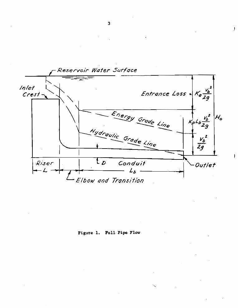
The nomenclature i n t h i s design note is the same as i n Technical Release No. 29. The entrance head loss coef f i c ien t , K,, multipl ied by the ve loc i ty head i n the conduit (ba r re l ) gives the t o t a l entrance head loss from the rese rvo i r t o the conduit, including elbow and t r a n s i t i o n losses a t the conduit entrance. For f u l l pipe flow, as shown i n TR 29,
where H, = t o t a l head on the spil lway v, = mean ve loc i ty of flow i n the conduit & = entrance head loss coef f i c ien t K, = f r i c t i o n loss c o e f f i c i e n t f o r the conduit (see ES-42) & = length of the conduit
Figure 1 i l l u s t r a t e s how the quan t i t i e s i n Equation (1) are re la ted . The hydraulic grade l i n e usual ly is considered t o i n t e r s e c t the plane of the conduit o u t l e t 0.5D a b w e t h e inver t of the conduit o r a t the t a i lwa te r surface , whichever is higher. % is equal t o t h e d i f ference i n e levat ion between the HGL a t t h i s point and the rese rvo i r water surf ace.
*by A. S. Payne, Ass is tant Chief, Design Branch
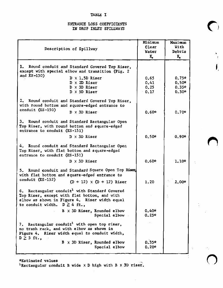
ENTRANCE LOSS COEFFICIENTS IN DROP I U T SPILLWAYS
I Descript ion of Spillway
r - - - - I '1. Round conduit and Standard Covered Top Riser , except with s p e c i a l elbow and t r a n s i t i o n (Fig. 2 and ES -150) D x 1.5D Riser
D x 2D Riser D x 3D Riser D X 5D Riser
2. Round conduit and Standard Covered Top Riser , with round bottom and square-edged entrance t o conduit (ES -150) D x 3D Riser
3. Round conduit and Standard Rectangular Open Top Riser , with round bottom and square-edged entrance t o conduit (ES -15 1)
D x 3D Riser
4. Round conduit and Standard Rectangular Open Top Riser , with f l a t bottom and s quare-edged entrance t o conduit (ES -15 1)
D x 3D Riser
5. Round conduit and Standard Square Open Top with f l a t bottom and square-edged entrance t o conduit (ES -152) (D + 12) X (D + 12) Riser I 6. Rectangular conduit1 with Standard Covered Top Riser , except with f l a t bottom, and with elbow as shown i n Figure 4. Riser width equal t o conduit width. D 2 4 f t . ,
B X 3D Riser , Rounded elbow Specia l elbow
7. Rectangular conduit1 with open top riser, no t r a s h rack, and with elbow a s shown i n Figure 4. Riser width equal t o conduit width, D 5 5 f t . ,
B x 3 D Riser , Rounded elbow Specia l elbow
Minimum Clear Water
%
*Estimated values ' ~ e c t a n ~ u l a r conduit B wide X D high with B X 3D r i s e r .
Maximum With
Debris S
J
Conduit
L b -
Figure 1. Pull Pipe Flow
Special Elbow and Transition
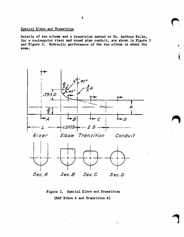
Details of two elbows and a transition tested at St. Anthony Falls, for a rectangular r i ser and round pipe conduit, are shown in Figure 2 and Figure 3. Hydraulic performance of the two elbows is about the same.
Riser
Figure 2. Special Elbow and Transition
(SAF Elbow 6 and Transition A)
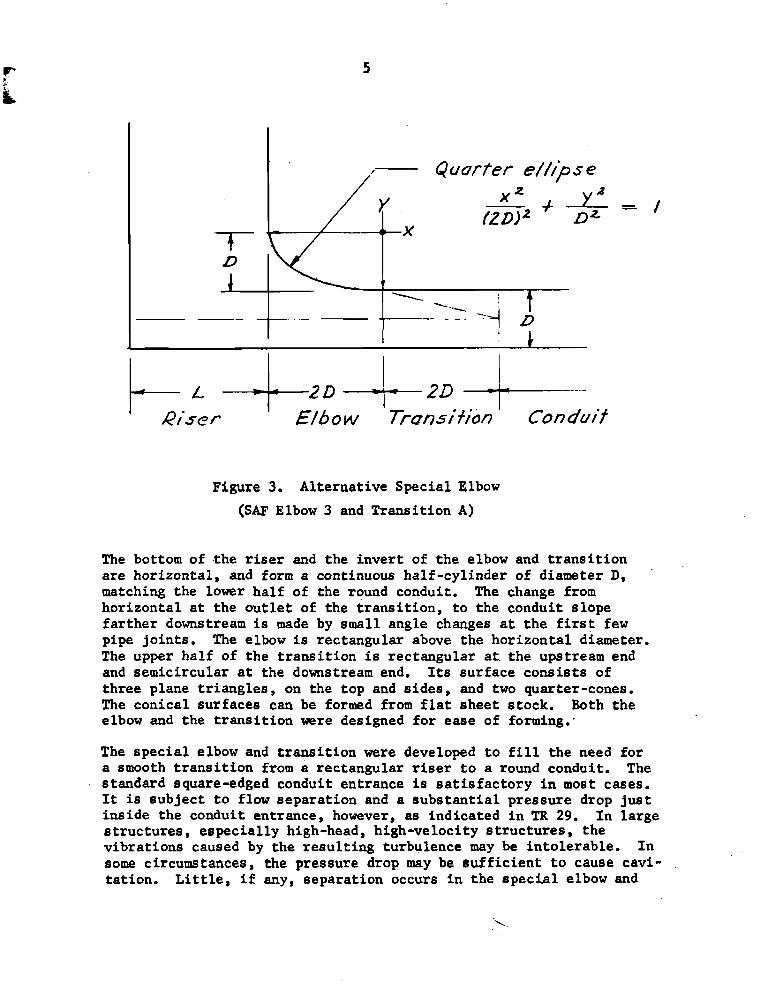
Figure 3. Al ternat ive Special Elbow
(SAF Elbow 3 and Transi t ion A)
The bottom of t h e riser and the i n v e r t of the elbow and t r a n s i t i o n a r e hor izonta l , and form a continuous hal f -cyl inder of diameter D, matching the lower ha l f of the round conduit. The change from hor izonta l a t the o u t l e t of the t r a n s i t i o n , t o t h e conduit s lope f a r t h e r downstream is made by small angle changes a t t h e f i r s t few pipe jo in ts . The elbow is rectangular a b w e t h e hor izon ta l diameter. The upper ha l f of the t r a n s i t i o n is rec tangular a t the upstream end and semicircular a t the downstream end. Its surface cons i s t s of th ree plane t r i ang les , on the top and s ides , and two quarter-cones. The conical surfaces can be formed from f l a t sheet stock. Both t h e elbow and the t r a n s i t i o n were designed f o r ease of forming:
The s p e c i a l elbow and t r a n s i t i o n were developed t o f i l l t h e need f o r a smooth t r a n s i t i o n from a rectangular riser t o a round conduit. The standard square-edged conduit entrance is s a t i s f a c t o r y i n most cases. It i s sub jec t t o flow separa t ion and a s u b s t a n t i a l pressure drop j u s t ins ide the conduit entrance, however, as indica ted i n TR 29. I n large s t r u c t u r e s , e spec ia l ly high-head, high-velocity s t r u c t u r e s , the v ib ra t ions caused by the r e s u l t i n g turbulence may be in to le rab le . I n some circumstances, the pressure drop may be s u f f i c i e n t t o cause cavi- ta t ion . L i t t l e , i f any, separa t ion occurs i n the s p e c i a l elbow and
t r a n s i t i o n , and t h e l o c a l pressure drop is e s s e n t i a l l y eliminated. An added advantage is t h a t the energy l o s s is much less than i n t h e square-edged entrance; enough t o make a d i f fe rence of severa l f e e t i n the t o t a l head required f o r a given discharge i n some cases.
Entrance Loss Coeff ic ients
The "minimum, c l e a r water1' values of IC, i n Table I represent t h e condition where minimum losses occur i n the t r a s h racks. The "maximum with debris" values a r e f o r t r a s h racks p a r t i a l l y blocked by debris. The s u s c e p t i b i l i t y of the various types of i n l e t s t o clogging with debr is was considered i n est imating the coef f i c ien t s .
Minimum coef f i c ien t s w i l l give the h ighes t discharges and ve loc i t i e s . They should be used i n appraising the downstream e f f e c t s of maximum discharge and i n determining t h e requirements f o r energy diss ipat ion. Maximum coef f i c ien t s should be used f o r e s tab l i sh ing rese rvo i r s torage volume requirements and computing drawdown t i m e . The re la t ionsh ip between f r i c t i o n loss i n the conduit and l o c a l pressure deviat ions w i l l ind ica te whether maximum o r minimum v e l o c i t i e s a r e more c r i t i c a l fo r cav i t a t ion p ~ t e n t i a l .
Table I gives new values of % f o r the Standard Cwered Top Riser. I n TR 29, a t e s t value of 0.687 i s quoted and K, = 1.0 is r e c o m n d e d f o r design. The tests were made with a f l a t bottom riser, however, while the standard r i s e r has a round bottom. Losses a t t h e conduit entrance probably a r e lower with t h e round bottom riser. Subsequent t e s t s of the s p e c i a l elbow with a round bottom riser have given f u r t h e r support t o lower values of &. The values i n Table I (0.60 and 0.70), therefore, a r e believed t o be the bes t est imates on t h e bas i s of da ta avai lable thus fa r .
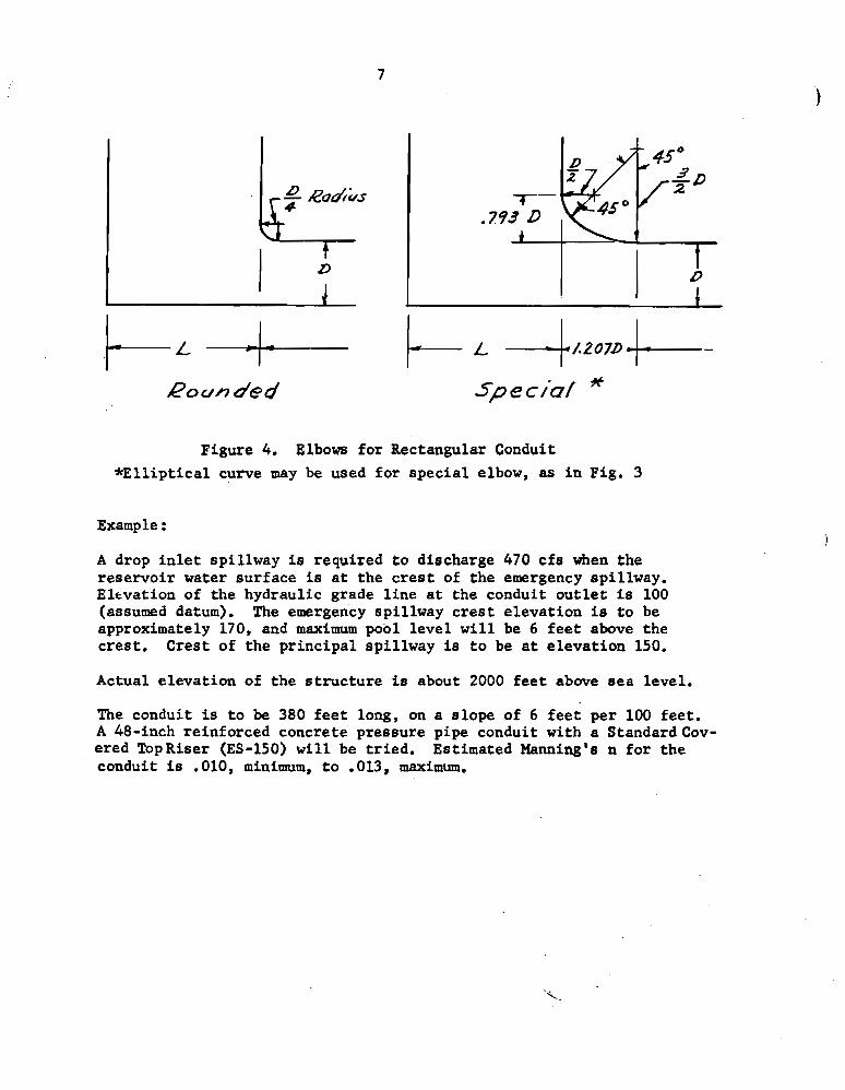
The coef f i c ien t s fo r rec tangular conduits a r e appl icable t o conduits not less than 4 f e e t deep having r i s e r s with t h e standard covered top and t r a s h rack (ES-150), and t o conduits not less than 5 f e e t deep having open top risers with no t r a s h racks. Spillways of t h i s s i z e , de ta i l ed as indica ted , are capable of pa8sing:most debr is without danger 'of clogging. Hence, only "c lear water'' coe f f i c ien t s a r e applicable. The "rounded" and l lspecial l l elbows f o r which coef f i c ien t s a r e given a r e i l l u s t r a t e d i n Figure 4.
Rounded
Figure 4. Elbows f o r Rectangular Conduit
* E l l i p t i c a l curve may be used f o r spec ia l elbow, as i n Fig. 3
Example :
A drop i n l e t spi l lway is required t o discharge 470 c f s when t h e rese rvo i r water surface is a t the c r e s t of the emergency spillway. Elevation of the hydraulic grade l i n e a t the conduit o u t l e t is 100 (assumed datum). The emergency spil lway c r e s t e levat ion is t o be approximately 170, and maximum pool l e v e l w i l l be 6 f e e t above the cres t . Crest of the p r inc ipa l spi l lway is t o be at e leva t ion 150.
Actual e levat ion of the s t r u c t u r e is about 2000 f e e t a b w e s e a level .
The conduit is t o be 380 f e e t long, on a s lope of 6 f e e t per 100 fee t . A 48-inch reinforced concrete pressure pipe conduit with a StandardCov- ered TopRiser (ES-150) w i l l be t r i ed . Estimated Manning's n f o r the conduit is .010, minimum, t o .013, maximum.
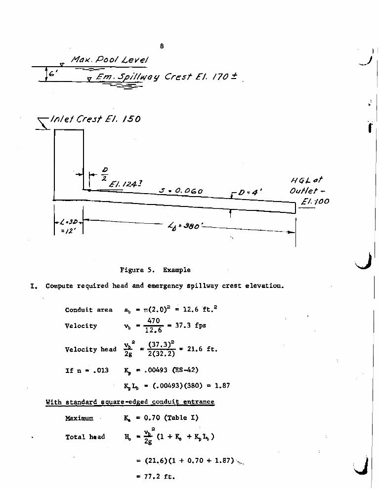
Figure 5. Example
I. Compute required head and emergency spil lway crest elevation.
Conduit a rea a, = n(2.0)' = 12.6 ft.'
47 0 Veloci ty vb - 37.3 fps
12.6
2
Velocity head = (37*3)2 = 21.6 f t . 2g 2(32.2)
I f n - .013 I$ = .00493 @S-42)
1 154 = (. 00493) (380) - 1.87
With standard square-edged conduit entrance
Maximum K, = 0.70 (Table I) 2
Tota l hr ad
= (21.6)(1 + 0.70 + 1.87).\_
= 77.2 f t .
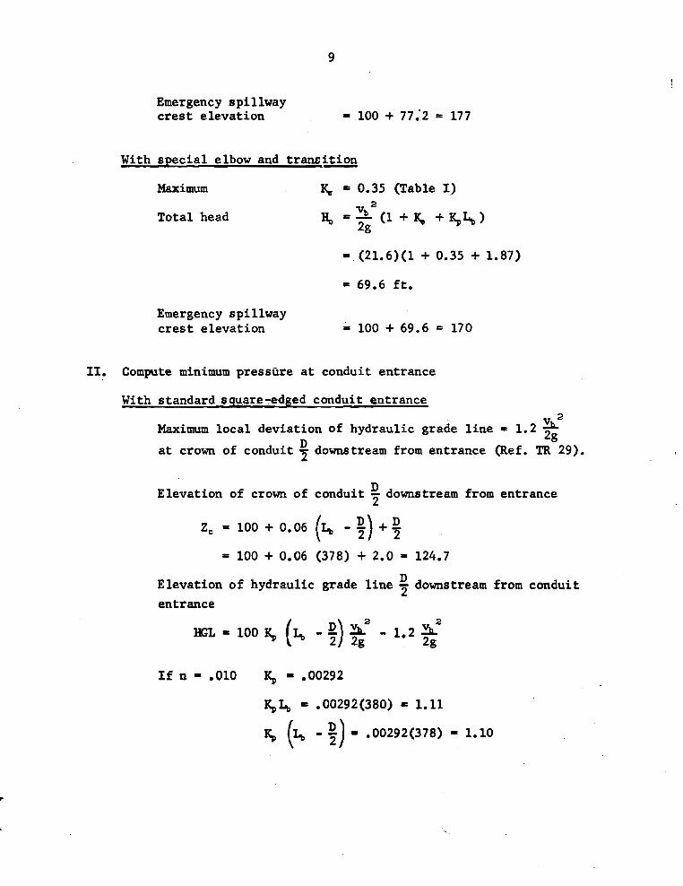
Emergency spil lway c r e s t e levat ion = 100 + 77.'2 = 177
With s p e c i a l elbow and t r a n s i t i o n
Maximum & = 0.35 (Table I )
Tota l head
= 69.6 f t .
Emergency spil lway c r e s t e l eva t ion A 100 + 69.6 = 170
11. Compute minimum pressure a t conduit entrance
With standard square-edged conduit entrance 2
Maxi- l o c a l deviat ion of hydraulic grade l i n e = 1.2 D 2g
a t crown of conduit 7 downstream from entrance (Ref. TR 29).
Elevation of crown of conduit downstream from entrance 7
D Elevation of hydraulic grade l i n e 7 downstream from conduit
entrance
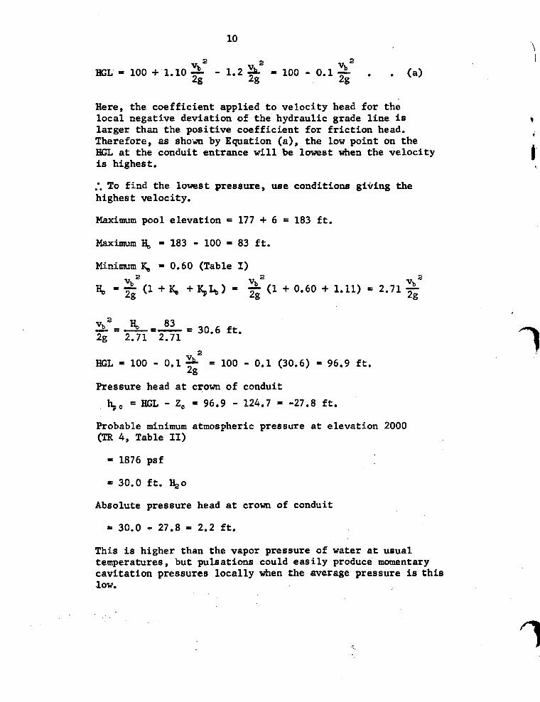
Here, the coefficient applied to velocity head for the local negative deviation of the hydraulic grade line is larger than the positive coefficient for friction head. Therefore, as shown by Equation (a), the low point on the EGL at the conduit entrance will be lowest when the velocity is highest.
.', To find the lowest pressure, w e conditions giving the highest velocity.
Maximum pool elevation = 177 + 6 = 183 ft.
Maximum )b = 183 - 100 = 83 ft.
Minimum % = 0.60 (Table I)
2
HGL = 100 - 0.1 = 100 - 0.1 (30.6) = 96.9 ft. 2g
Pressure head at crown of conduit
t$, = HGL - Z, = 96.9 - 124.7 = -27.8 ft.
Robable minimum atmospheric pressure at elevation 2000 (TR 4, Table 11)
= 1876 psf
= 30.0 ft. %o
Absolute pressure head at crown of conduit
= 30.0 - 27.8 = 2.2 ft.
This is higher than the vapor pressure of water at usual temperatures, but pulsations could easily produce momentary cavitation pressures locally when the average pressure is this low.
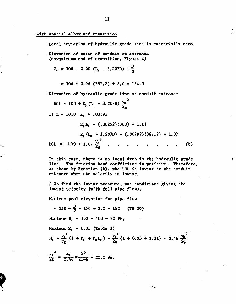
With s p e c i a l elbow and t r a n s i t i o n
Local devia t ion of hydraulic grade l i n e is e s s e n t i a l l y zero.
Elevation of crown of conduit a t entrance (downstream end of t r a n s i t i o n , Figure 2)
D Ze 100 + 0.06 (I, - 3.2070) + 5
Elevation of hydraulic grade l i n e at conduit entrance
In t h i s case, the re i s no l o c a l drop i n t h e hydraulic grade l ine . The f r i c t i o n head c o e f f i c i e n t is posi t ive . Therefore, as shown by Equation (b) , t h e H a is lowest a t the conduit entrance when t h e v e l o c i t y is lowest.
.*. To f ind t h e lowest pressure, use condit ions giving t h e lowest v e l o c i t y (with f u l l pipe flow).
Minimum pool e leva t ion f o r pipe flow - 150 + = S O + 2.0 152 (TR 29)
Minimum = 152 - 100 = 52 f t .
Maximum & = 0.35 (Table I)
vb2 H, 52 6 = === = 21.1 ft.
2
HGL = 100 + 1.07 = 100 + 1.07 (21.1) = 122.6 2g
Pressure head at crown of conduit
$, m HGL - 2, = 122.6 - 124.0 = - 1.4 f t .
Absolute pressure head at crown of conduit (see page 30)
= 30.0 - 1.4 = 28.6 f t .


