Embed Size (px)
Citation preview
DRAFT FINAL UNIFORM FEDERAL POLICY
QUALITY ASSURANCE PROJECT PLAN
REMEDIAL INVESTIGATION – PROJECT 09 FORMER CHARLESTOWN NAVAL AUXILIARY LANDING FIELD
CHARLESTOWN, RHODE ISLAND (UNCLASSIFIED)
Contract Number: W912DR-18-D-0006 Task Order: W912DR19F0626 Project ID No.: D01RI0008-09
DCN: CONHTRW-041921-AAAW
U.S. ARMY CORPS OF ENGINEERS
NEW ENGLAND DISTRICT 696 Virginia Road
Concord, MA 01742
and
U.S. ARMY CORPS OF ENGINEERS BALTIMORE DISTRICT
2 Hopkins Plaza Baltimore, MD 21201
April 2021

(This page intentionally left blank)
DRAFT FINAL UNIFORM FEDERAL POLICY
QUALITY ASSURANCE PROJECT PLAN
REMEDIAL INVESTIGATION – PROJECT 09 FORMER CHARLESTOWN NAVAL AUXILIARY LANDING FIELD
CHARLESTOWN, RHODE ISLAND (UNCLASSIFIED)
Contract Number: W912DR-18-D-0006 Task Order: W912DR19F0626 Project ID No.: D01RI0008-09
DCN: CONHTRW-041921-AAAW
Prepared for:
U.S. ARMY CORPS OF ENGINEERS
NEW ENGLAND DISTRICT 696 Virginia Road
Concord, MA 01742
Under contract through:
U.S. ARMY CORPS OF ENGINEERS BALTIMORE DISTRICT
2 Hopkins Plaza Baltimore, MD 21201
Prepared by:
WESTON SOLUTIONS, INC. 43 North Main Street Concord, NH 03301
April 2021

(This page intentionally left blank)
UFP-QAPP Remedial Investigation – Project 09
Former Charlestown Naval Auxiliary Landing Field
Contract No.W912DR-18-D-0006 Draft Final Project No.03886.553.006 Page 3 of 420 \\nascnh1\CNH_Data\Data\PROJECTS\03886553 (CNALF)\006\03-Planning\3.1-Work-Plan\Project 09 WP\Draft_Final\CNALF_Proj09_DF_UFP_QAPP_clean_041821.docx
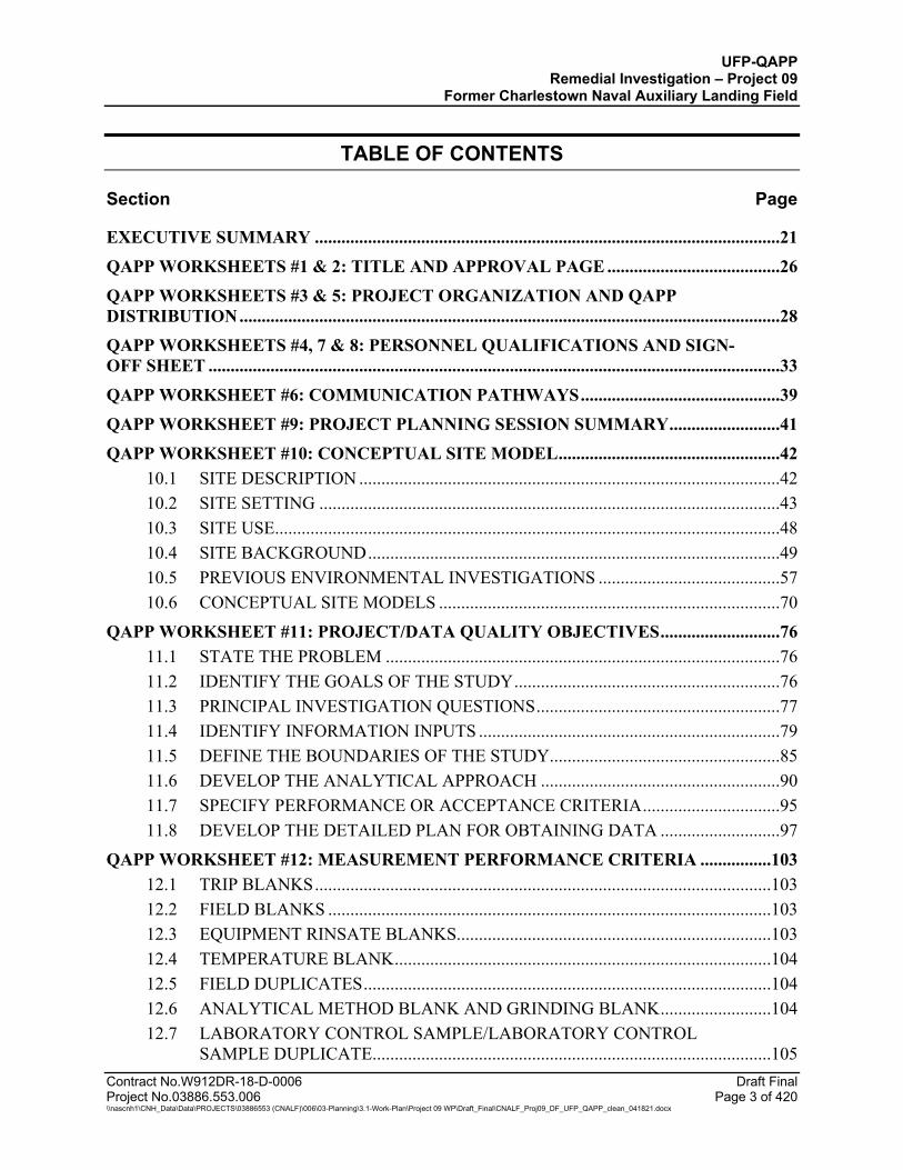
TABLE OF CONTENTS
Section Page
EXECUTIVE SUMMARY .........................................................................................................21 QAPP WORKSHEETS #1 & 2: TITLE AND APPROVAL PAGE .......................................26 QAPP WORKSHEETS #3 & 5: PROJECT ORGANIZATION AND QAPP DISTRIBUTION ..........................................................................................................................28 QAPP WORKSHEETS #4, 7 & 8: PERSONNEL QUALIFICATIONS AND SIGN-OFF SHEET .................................................................................................................................33 QAPP WORKSHEET #6: COMMUNICATION PATHWAYS .............................................39 QAPP WORKSHEET #9: PROJECT PLANNING SESSION SUMMARY .........................41 QAPP WORKSHEET #10: CONCEPTUAL SITE MODEL ..................................................42
10.1 SITE DESCRIPTION ...............................................................................................42 10.2 SITE SETTING ........................................................................................................43 10.3 SITE USE..................................................................................................................48 10.4 SITE BACKGROUND .............................................................................................49 10.5 PREVIOUS ENVIRONMENTAL INVESTIGATIONS .........................................57 10.6 CONCEPTUAL SITE MODELS .............................................................................70
QAPP WORKSHEET #11: PROJECT/DATA QUALITY OBJECTIVES ...........................76 11.1 STATE THE PROBLEM .........................................................................................76 11.2 IDENTIFY THE GOALS OF THE STUDY ............................................................76 11.3 PRINCIPAL INVESTIGATION QUESTIONS .......................................................77 11.4 IDENTIFY INFORMATION INPUTS ....................................................................79 11.5 DEFINE THE BOUNDARIES OF THE STUDY....................................................85 11.6 DEVELOP THE ANALYTICAL APPROACH ......................................................90 11.7 SPECIFY PERFORMANCE OR ACCEPTANCE CRITERIA ...............................95 11.8 DEVELOP THE DETAILED PLAN FOR OBTAINING DATA ...........................97
QAPP WORKSHEET #12: MEASUREMENT PERFORMANCE CRITERIA ................103 12.1 TRIP BLANKS .......................................................................................................103 12.2 FIELD BLANKS ....................................................................................................103 12.3 EQUIPMENT RINSATE BLANKS.......................................................................103 12.4 TEMPERATURE BLANK .....................................................................................104 12.5 FIELD DUPLICATES ............................................................................................104 12.6 ANALYTICAL METHOD BLANK AND GRINDING BLANK .........................104 12.7 LABORATORY CONTROL SAMPLE/LABORATORY CONTROL
SAMPLE DUPLICATE..........................................................................................105
UFP-QAPP Remedial Investigation – Project 09
Former Charlestown Naval Auxiliary Landing Field
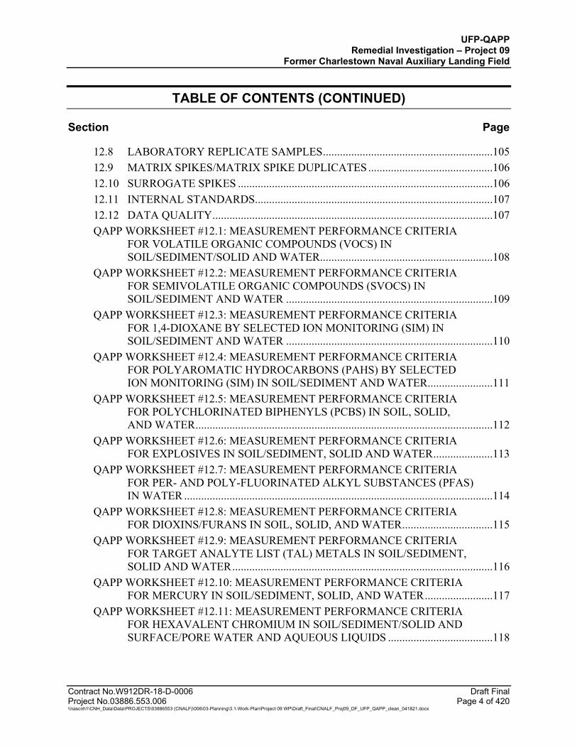
TABLE OF CONTENTS (CONTINUED)
Section Page
Contract No.W912DR-18-D-0006 Draft Final Project No.03886.553.006 Page 4 of 420 \\nascnh1\CNH_Data\Data\PROJECTS\03886553 (CNALF)\006\03-Planning\3.1-Work-Plan\Project 09 WP\Draft_Final\CNALF_Proj09_DF_UFP_QAPP_clean_041821.docx
12.8 LABORATORY REPLICATE SAMPLES ............................................................105 12.9 MATRIX SPIKES/MATRIX SPIKE DUPLICATES ............................................106 12.10 SURROGATE SPIKES ..........................................................................................106 12.11 INTERNAL STANDARDS....................................................................................107 12.12 DATA QUALITY ...................................................................................................107 QAPP WORKSHEET #12.1: MEASUREMENT PERFORMANCE CRITERIA
FOR VOLATILE ORGANIC COMPOUNDS (VOCS) IN SOIL/SEDIMENT/SOLID AND WATER .............................................................108
QAPP WORKSHEET #12.2: MEASUREMENT PERFORMANCE CRITERIA FOR SEMIVOLATILE ORGANIC COMPOUNDS (SVOCS) IN SOIL/SEDIMENT AND WATER .........................................................................109
QAPP WORKSHEET #12.3: MEASUREMENT PERFORMANCE CRITERIA FOR 1,4-DIOXANE BY SELECTED ION MONITORING (SIM) IN SOIL/SEDIMENT AND WATER .........................................................................110
QAPP WORKSHEET #12.4: MEASUREMENT PERFORMANCE CRITERIA FOR POLYAROMATIC HYDROCARBONS (PAHS) BY SELECTED ION MONITORING (SIM) IN SOIL/SEDIMENT AND WATER .......................111
QAPP WORKSHEET #12.5: MEASUREMENT PERFORMANCE CRITERIA FOR POLYCHLORINATED BIPHENYLS (PCBS) IN SOIL, SOLID, AND WATER .........................................................................................................112
QAPP WORKSHEET #12.6: MEASUREMENT PERFORMANCE CRITERIA FOR EXPLOSIVES IN SOIL/SEDIMENT, SOLID AND WATER .....................113
QAPP WORKSHEET #12.7: MEASUREMENT PERFORMANCE CRITERIA FOR PER- AND POLY-FLUORINATED ALKYL SUBSTANCES (PFAS) IN WATER .............................................................................................................114
QAPP WORKSHEET #12.8: MEASUREMENT PERFORMANCE CRITERIA FOR DIOXINS/FURANS IN SOIL, SOLID, AND WATER ................................115
QAPP WORKSHEET #12.9: MEASUREMENT PERFORMANCE CRITERIA FOR TARGET ANALYTE LIST (TAL) METALS IN SOIL/SEDIMENT, SOLID AND WATER ............................................................................................116
QAPP WORKSHEET #12.10: MEASUREMENT PERFORMANCE CRITERIA FOR MERCURY IN SOIL/SEDIMENT, SOLID, AND WATER ........................117
QAPP WORKSHEET #12.11: MEASUREMENT PERFORMANCE CRITERIA FOR HEXAVALENT CHROMIUM IN SOIL/SEDIMENT/SOLID AND SURFACE/PORE WATER AND AQUEOUS LIQUIDS .....................................118

UFP-QAPP Remedial Investigation – Project 09
Former Charlestown Naval Auxiliary Landing Field
TABLE OF CONTENTS (CONTINUED)
Section Page
Contract No.W912DR-18-D-0006 Draft Final Project No.03886.553.006 Page 5 of 420 \\nascnh1\CNH_Data\Data\PROJECTS\03886553 (CNALF)\006\03-Planning\3.1-Work-Plan\Project 09 WP\Draft_Final\CNALF_Proj09_DF_UFP_QAPP_clean_041821.docx
QAPP WORKSHEET #12.12: MEASUREMENT PERFORMANCE CRITERIA FOR HEXAVALENT CHROMIUM IN GROUNDWATER AND TAP WATER ..................................................................................................................119
QAPP WORKSHEET #12.13: MEASUREMENT PERFORMANCE CRITERIA FOR FERROUS IRON IN SOIL ............................................................................120
QAPP WORKSHEET #12.14: MEASUREMENT PERFORMANCE CRITERIA FOR PERCHLORATE IN SOIL/SEDIMENT, SOLID AND WATER ................121
QAPP WORKSHEET #12.15: MEASUREMENT PERFORMANCE CRITERIA FOR TOTAL SULFIDE IN SOIL/SEDIMENT .....................................................122
QAPP WORKSHEET #12.16: MEASUREMENT PERFORMANCE CRITERIA FOR TOTAL ORGANIC CARBON (TOC) IN SOIL/SEDIMENT ......................123
QAPP WORKSHEET #12.17: MEASUREMENT PERFORMANCE CRITERIA FOR CORROSIVITY (PH) IN SOIL/SEDIMENT AND IDW .............................124
QAPP WORKSHEET #12.18: MEASUREMENT PERFORMANCE CRITERIA FOR ASBESTOS IN SOIL .....................................................................................125
QAPP WORKSHEET #12.19: MEASUREMENT PERFORMANCE CRITERIA FOR TOXICITY CHARACTERISTIC LEACHING PROCEDURE (TCLP) VOLATILE ORGANIC COMPOUNDS (VOCS) .................................................126
QAPP WORKSHEET #12.20: MEASUREMENT PERFORMANCE CRITERIA FOR TOXICITY CHARACTERISTIC LEACHING PROCEDURE (TCLP) SEMIVOLATILE ORGANIC COMPOUNDS (SVOCS) .....................................127
QAPP WORKSHEET #12.21: MEASUREMENT PERFORMANCE CRITERIA FOR TOXICITY CHARACTERISTIC LEACHING PROCEDURE (TCLP) METALS AND MERCURY ..................................................................................128
QAPP WORKSHEET #12.22: MEASUREMENT PERFORMANCE CRITERIA FOR VOLATILE ORGANIC COMPOUNDS (VOCS) IN IDW WATER ...........129
QAPP WORKSHEET #12.23: MEASUREMENT PERFORMANCE CRITERIA FOR SEMIVOLATILE ORGANIC COMPOUNDS (SVOCS) IN IDW WATER ..................................................................................................................130
QAPP WORKSHEET #12.24: MEASUREMENT PERFORMANCE CRITERIA FOR RESOURCE CONSERVATION AND RECOVERY ACT (RCRA) METALS INCLUDING MERCURY IN IDW WATER .......................................131
QAPP WORKSHEET #12.25: MEASUREMENT PERFORMANCE CRITERIA FOR IGNITABILITY IN SOIL (IDW) AND FLASHPOINT IN WATER (IDW) ......................................................................................................................132
QAPP WORKSHEET #12.26: MEASUREMENT PERFORMANCE CRITERIA FOR REACTIVITY (CYANIDE AND SULFIDE) IN IDW .................................133

UFP-QAPP Remedial Investigation – Project 09
Former Charlestown Naval Auxiliary Landing Field
TABLE OF CONTENTS (CONTINUED)
Section Page
Contract No.W912DR-18-D-0006 Draft Final Project No.03886.553.006 Page 6 of 420 \\nascnh1\CNH_Data\Data\PROJECTS\03886553 (CNALF)\006\03-Planning\3.1-Work-Plan\Project 09 WP\Draft_Final\CNALF_Proj09_DF_UFP_QAPP_clean_041821.docx
QAPP WORKSHEET #12.27: MEASUREMENT PERFORMANCE CRITERIA FOR POLYCHLORINATED BIPHENYLS (PCBS) IN IDW ..............................134
QAPP WORKSHEET #12.28: MEASUREMENT PERFORMANCE CRITERIA FOR GASOLINE RANGE ORGANICS (GRO) IN IDW .....................................135
QAPP WORKSHEET #12.29: MEASUREMENT PERFORMANCE CRITERIA FOR DIESEL RANGE ORGANICS (DRO) AND OIL RANGE ORGANICS (ORO) IN IDW ..................................................................................136
QAPP WORKSHEET #12.30: MEASUREMENT PERFORMANCE CRITERIA FOR ASBESTOS IN AIR .......................................................................................137
QAPP WORKSHEET #12.31: MEASUREMENT PERFORMANCE CRITERIA FOR GEOPHYSICAL SURVEYS .........................................................................138
QAPP WORKSHEET #13: SECONDARY DATA USES AND LIMITATIONS ...............139 QAPP WORKSHEETS #14 & 16: PROJECT TASKS & SCHEDULE ..............................144 QAPP WORKSHEET #15: PROJECT ACTION LIMITS AND LABORATORY-SPECIFIC DETECTION/QUANTITATION LIMITS ..........................................................146 QAPP WORKSHEET #17: SAMPLING DESIGN AND RATIONALE .............................147
17.1 MOBILIZATION ...................................................................................................147 17.2 WETLAND DELINEATION .................................................................................147 17.3 VEGETATIVE COVER SURVEY ........................................................................147 17.4 SITE PREPARATION............................................................................................148 17.5 GEOPHYSICAL INVESTIGATION .....................................................................149 17.6 SURFACE AND SUBSURFACE SOIL SAMPLING ...........................................159 17.7 MONITORING WELL INSTALLATION.............................................................167 17.8 GROUNDWATER SAMPLING AND WATER SUPPLY WELL
SAMPLING ............................................................................................................172 17.9 ISM SEDIMENT SAMPLING ...............................................................................181 17.10 INVESTIGATIVE SURFACE WATER AND PORE WATER SAMPLING
AND BACKGROUND SURFACE WATER SAMPLING ...................................184 17.11 TEST PIT EXCAVATION AND SOIL SAMPLING ............................................186 17.12 INSPECTION, MANAGEMENT, AND DISPOSAL OF MDAS .........................193 17.13 RISK ASSESSMENTS ...........................................................................................194 17.14 INVESTIGATION-DERIVED WASTE MANAGEMENT ..................................195 17.15 POTENTIAL FUTURE ACTIVITIES IN THE CERCLA PROCESS ..................196 17.16 EQUIPMENT DECONTAMINATION PROCEDURES ......................................196

UFP-QAPP Remedial Investigation – Project 09
Former Charlestown Naval Auxiliary Landing Field
TABLE OF CONTENTS (CONTINUED)
Section Page
Contract No.W912DR-18-D-0006 Draft Final Project No.03886.553.006 Page 7 of 420 \\nascnh1\CNH_Data\Data\PROJECTS\03886553 (CNALF)\006\03-Planning\3.1-Work-Plan\Project 09 WP\Draft_Final\CNALF_Proj09_DF_UFP_QAPP_clean_041821.docx
17.17 POST-REMEDIAL INVESTIGATION SITE RESTORATION PLAN ...............198 17.18 DAMAGE TO SITE STRUCTURES .....................................................................198 17.19 EROSION AND SEDIMENT CONTROL PLAN .................................................198 17.20 STORMWATER MANAGEMENT PLAN ...........................................................199 17.21 ENVIRONMENTAL PROTECTION PLAN (EPP) ..............................................199 17.22 CONTINGENCY PLAN AND SITE SECURITY .................................................201 17.23 QUALITY CONTROL PLAN ...............................................................................202
QAPP WORKSHEET #18: SAMPLING LOCATIONS AND METHODS ........................210 QAPP WORKSHEETS #19 & 30: SAMPLE CONTAINERS, PRESERVATION, AND HOLD TIMES ..................................................................................................................242 QAPP WORKSHEET #20: FIELD AND LABORATORY QC SUMMARY .....................253 QAPP WORKSHEET #21: FIELD SOPS ...............................................................................265 QAPP WORKSHEET #22: FIELD EQUIPMENT CALIBRATION, MAINTENANCE, TESTING, AND INSPECTION...............................................................269 QAPP WORKSHEET #23: ANALYTICAL SOPS ................................................................273 QAPP WORKSHEET #24: ANALYTICAL INSTRUMENT CALIBRATION .................285 QAPP WORKSHEET #25: ANALYTICAL INSTRUMENT AND EQUIPMENT MAINTENANCE, TESTING, AND INSPECTION...............................................................329 QAPP WORKSHEETS #26 & 27: SAMPLE HANDLING, CUSTODY, AND DISPOSAL..................................................................................................................................338 QAPP WORKSHEET #28: LABORATORY QUALITY CONTROL AND CORRECTIVE ACTION .........................................................................................................341
QAPP WORKSHEET #28.1: VOLATILE ORGANIC COMPOUNDS (VOCS) BY GAS CHROMATOGRAPHY/MASS SPECTROMETRY (GC/MS) ...................341
QAPP WORKSHEET #28.2: SEMIVOLATILE ORGANIC COMPOUNDS (SVOCS) BY GAS CHROMATOGRAPHY/MASS SPECTROMETRY (GC/MS) .................................................................................................................344
QAPP WORKSHEET #28.3: 1,4-DIOXANE BY SELECTED ION MONITORING BY GAS CHROMATOGRAPHY/MASS SPECTROMETRY (GC/MS) .............348
QAPP WORKSHEET #28.4: POLYAROMATIC HYDROCARBONS (PAHS) BY GAS CHROMATOGRAPHY/MASS SPECTROMETRY (GC/MS) SIM ...........351
QAPP WORKSHEET #28.5: POLYCHLORINATED BIPHENYLS (PCBS) BY GC/ECD ..................................................................................................................355
UFP-QAPP Remedial Investigation – Project 09
Former Charlestown Naval Auxiliary Landing Field
TABLE OF CONTENTS (CONTINUED)
Section Page
Contract No.W912DR-18-D-0006 Draft Final Project No.03886.553.006 Page 8 of 420 \\nascnh1\CNH_Data\Data\PROJECTS\03886553 (CNALF)\006\03-Planning\3.1-Work-Plan\Project 09 WP\Draft_Final\CNALF_Proj09_DF_UFP_QAPP_clean_041821.docx
QAPP WORKSHEET #28.6: EXPLOSIVES BY HIGH-PERFORMANCE LIQUID CHROMATOGRAPHY (HPLC) .............................................................358
QAPP WORKSHEET #28.7: PER- AND POLYFLUOROALKYL SUBSTANCES (PFAS) BY LC/MS/MS ..........................................................................................361
QAPP WORKSHEET #28.8: DIOXINS AND FURANS BY HIGH-RESOLUTION MASS SPECTROMETRY (HRMS) ......................................................................365
QAPP WORKSHEET #28.9: TARGET ANALYTE LIST (TAL) METALS BY ICP-MS ...................................................................................................................367
QAPP WORKSHEET #28.10: MERCURY BY COLD VAPOR ATOMIC ABSORPTION (CVAA) ........................................................................................370
QAPP WORKSHEET #28.11: HEXAVALENT CHROMIUM BY ION CHROMATOGRAPHY .........................................................................................372
QAPP WORKSHEET #28.12: TRACE HEXAVALENT CHROMIUM BY ION CHROMATOGRAPHY .........................................................................................374
QAPP WORKSHEET #28.13: FERROUS IRON BY SPECTROPHOTOMETER ..........376 QAPP WORKSHEET #28.14: PERCHLORATE BY LC/MS/MS ...................................377 QAPP WORKSHEET #28.15: TOTAL SULFIDE BY TITRATION ...............................380 QAPP WORKSHEET #28.16: TOTAL ORGANIC CARBON (TOC) BY TOC
ANALYZER ...........................................................................................................381 QAPP WORKSHEET #28.17: CORROSIVITY AND PH BY PH METER .....................382 QAPP WORKSHEET #28.18: SVOC AND TCLP SVOCS BY GAS
CHROMATOGRAPHY/MASS SPECTROMETRY (GC/MS) ............................383 QAPP WORKSHEET #28.19: TOTAL AND TCLP METALS BY ICP-AES .................385 QAPP WORKSHEET #28.20: TOTAL MERCURY AND TCLP MERCURY BY
CVAA .....................................................................................................................386 QAPP WORKSHEET #28.21: IGNITABILITY/FLASHPOINT ......................................387 QAPP WORKSHEET #28.22: REACTIVE CYANIDE AND REACTIVE
SULFIDE BY FLOW INJECTION ANALYZER AND TITRATION .................388 QAPP WORKSHEET #28.23: GASOLINE RANGE ORGANICS (GRO) BY GAS
CHROMATOGRAPHY .........................................................................................389 QAPP WORKSHEET #28.24: DIESEL RANGE ORGANICS (DRO) AND OIL
RANGE ORGANICS (ORO) BY GAS CHROMATOGRAPHY .........................392 QAPP WORKSHEET #28.25: ASBESTOS IN SOIL .......................................................395 QAPP WORKSHEET #28.26: ASBESTOS IN AIR .........................................................396
QAPP WORKSHEET #29: PROJECT DOCUMENTS AND RECORDS ..........................397
UFP-QAPP Remedial Investigation – Project 09
Former Charlestown Naval Auxiliary Landing Field
TABLE OF CONTENTS (CONTINUED)
Section Page
Contract No.W912DR-18-D-0006 Draft Final Project No.03886.553.006 Page 9 of 420 \\nascnh1\CNH_Data\Data\PROJECTS\03886553 (CNALF)\006\03-Planning\3.1-Work-Plan\Project 09 WP\Draft_Final\CNALF_Proj09_DF_UFP_QAPP_clean_041821.docx
QAPP WORKSHEETS #31, 32 & 33: ASSESSMENTS AND CORRECTIVE ACTION......................................................................................................................................400 QAPP WORKSHEET #34: DATA VERIFICATION AND VALIDATION INPUTS .......401 QAPP WORKSHEET #35: DATA VERIFICATION PROCEDURES ...............................403 QAPP WORKSHEET #36: DATA VALIDATION PROCEDURES ...................................405 QAPP WORKSHEET #37: DATA USABILITY ASSESSMENT ........................................414 REFERENCES ...........................................................................................................................416

UFP-QAPP Remedial Investigation – Project 09
Former Charlestown Naval Auxiliary Landing Field
Contract No.W912DR-18-D-0006 Draft Final Project No.03886.553.006 Page 10 of 420 \\nascnh1\CNH_Data\Data\PROJECTS\03886553 (CNALF)\006\03-Planning\3.1-Work-Plan\Project 09 WP\Draft_Final\CNALF_Proj09_DF_UFP_QAPP_clean_041821.docx
LIST OF TABLES
Table Page
Table 10-1 Project 09 HTRW/Munitions Response Sites ........................................................43
Table 10-2 CNALF Water Supply Wells .................................................................................46
Table 10-3 Charlestown Landfill Investigation Activity Timeline ..........................................50
Table 10-4 Eastern Area Landfill Investigation Activity Timeline .........................................52
Table 10-5 Ninigret Wildlife Refuge Landfill Investigation Activity Timeline ......................54
Table 10-6 Burn Pit Area Investigation Activity Timeline ......................................................56
Table 11-1 Analytical Sample Summary .................................................................................99
Table 17-1 Laboratory Processing Flow Chart for CNALF Project 09 ISM and Composite Samples ..............................................................................................162
Table 17-2 Action Levels for Direct-Reading Air Monitoring Instruments ..........................190
Table 17-3 MEC/MPPEH Notification Roster .......................................................................202
Table 17-4 QC Reporting Logs and Records .........................................................................207
Table 21-1 List of Applicable SOPs.......................................................................................265
Table 21-2 List of Applicable Field Forms ............................................................................268
UFP-QAPP Remedial Investigation – Project 09
Former Charlestown Naval Auxiliary Landing Field
Contract No.W912DR-18-D-0006 Draft Final Project No.03886.553.006 Page 11 of 420 \\nascnh1\CNH_Data\Data\PROJECTS\03886553 (CNALF)\006\03-Planning\3.1-Work-Plan\Project 09 WP\Draft_Final\CNALF_Proj09_DF_UFP_QAPP_clean_041821.docx
LIST OF FIGURES
Figure
Figure 1 Site Location
Figure 2 Project 09 Site Layouts Figure 3 Site Surface Topography Figure 4 Current Ninigret Park Features
Figure 5 Bedrock Surface Contours
Figure 6 1992 Groundwater Contours and Flow Direction
Figure 7 1974 Groundwater Contours and Flow Direction
Figure 8 Well Protection Areas and Groundwater Classification
Figure 9 Wetlands and Cover Types
Figure 10 Westerly State Airport Wind Rose Diagram
Figure 11 Previous Environmental Investigations at Charlestown Landfill – MRS 4 Dump Site
Figure 12 Previous Environmental Investigations at Eastern Area Landfill – MRS 3 Hunter Island Dump Site
Figure 13 Previous Environmental Investigations at Ninigret Wildlife Refuge Landfill – MRS 2 Inland Toxic Waste Dump
Figure 14 Previous Environmental Investigations at Burn Pit Area Figure 14a Burn Pit Area – 1962 Aerial View Figure 14b Burn Pit Area – 2016 Aerial View Figure 15 1996 URS Geophysical Investigation Results at Charlestown Landfill Figure 16 1996 URS Geophysical Investigation Results at Eastern Area Landfill Figure 17 1996 URS Geophysical Investigation Results at Ninigret Wildlife Refuge Landfill Figure 18 1996 URS Geophysical Investigation Results at Burn Pit Area Figure 19 Project 09 Charlestown Landfill Conceptual Site Model Figure 20 Project 09 Eastern Area Landfill Conceptual Site Model Figure 21 Project 09 Ninigret Wildlife Refuge Landfill Conceptual Site Model Figure 22 Project 09 Burn Pit Area Conceptual Site Model Figure 23 Charlestown Landfill – MRS 4 Dump Site Proposed Geophysical Investigation Figure 24 Eastern Area Landfill – MRS 3 Hunter Island Dump Site, Proposed Geophysical
Investigation
UFP-QAPP Remedial Investigation – Project 09
Former Charlestown Naval Auxiliary Landing Field
LIST OF FIGURES (CONTINUED)
Figure
Contract No.W912DR-18-D-0006 Draft Final Project No.03886.553.006 Page 12 of 420 \\nascnh1\CNH_Data\Data\PROJECTS\03886553 (CNALF)\006\03-Planning\3.1-Work-Plan\Project 09 WP\Draft_Final\CNALF_Proj09_DF_UFP_QAPP_clean_041821.docx
Figure 25 Ninigret Wildlife Refuge Landfill – MRS 2 Inland Toxic Waste Dump, Proposed Geophysical Investigation
Figure 26 Charlestown Landfill – MRS 4 Dump Site, Proposed Surface Soil Samples Figure 27 Eastern Area Landfill – MRS 3 Hunter Island Dump Site, Proposed Surface Soil
Samples Figure 28 Ninigret Wildlife Refuge Landfill – MRS 2 Inland Toxic Waste Dump, Proposed
Surface Soil and Wetland Sediment Samples Figure 29 Burn Pit Area Surface and Subsurface Soil Samples Figure 30 Background Soil Sample Locations Figure 30a Background Soil Sample Locations, Aerial Imagery 1945 Figure 30b Background Soil Sample Locations, Aerial Imagery 1954 Figure 30c Background Soil Sample Locations, Aerial Imagery 1963 Figure 30d Background Soil Sample Locations, Aerial Imagery 1988 Figure 30e Background Soil Sample Locations, Aerial Imagery 1994 Figure 30f Background Soil Sample Locations, Aerial Imagery 2016 Figure 31 Soil Parent Types Figure 32 Charlestown Landfill New and Existing Monitoring Wells
Figure 33 Eastern Area Landfill New and Existing Monitoring Wells
Figure 34 Ninigret Wildlife Refuge Landfill New and Existing Monitoring Wells
Figure 35 Burn Pit Area New and Existing Monitoring Wells
Figure 36 Site Parcel Map
Figure 37 Proposed Tidal Shoreline and Tidal Wetland Sediment and SurfaceWater/Porewater Locations
Figure 38 Proposed Freshwater Sediment and Surface/Pore Water Sample Locations
UFP-QAPP Remedial Investigation – Project 09
Former Charlestown Naval Auxiliary Landing Field
Contract No.W912DR-18-D-0006 Draft Final Project No.03886.553.006 Page 13 of 420 \\nascnh1\CNH_Data\Data\PROJECTS\03886553 (CNALF)\006\03-Planning\3.1-Work-Plan\Project 09 WP\Draft_Final\CNALF_Proj09_DF_UFP_QAPP_clean_041821.docx
LIST OF ATTACHMENTS
Attachment A Accident Prevention Plan (APP)/Site-Specific Safety and Health Plan (SSHP) (Submitted under Separate Cover)
Attachment B Drinking Water Well Information in Vicinity of the Former Charlestown Naval Air Landing Facility
Attachment C Laboratory Analytical Data Tables for Project 09 from “Technical Memorandum – Historical Review for Project 08 and Project 09, Former Naval Auxiliary Landing Field, Charlestown, Rhode Island. JCO. 2018.”
Attachment D Risk Assessment Work Plan
Attachment E Project Schedule
Attachment F Field SOPs
Attachment G Field Forms
Attachment H Laboratory Certifications
Attachment I Laboratory SOPs
Attachment J Worksheet #15 Tables
Attachment K Probability Assessment for Determining the Probability of Encountering MEC During Site Activities at Naval Auxiliary Landing Field, Charlestown, RI
UFP-QAPP Remedial Investigation – Project 09
Former Charlestown Naval Auxiliary Landing Field
Contract No.W912DR-18-D-0006 Draft Final Project No.03886.553.006 Page 14 of 420 \\nascnh1\CNH_Data\Data\PROJECTS\03886553 (CNALF)\006\03-Planning\3.1-Work-Plan\Project 09 WP\Draft_Final\CNALF_Proj09_DF_UFP_QAPP_clean_041821.docx
LIST OF ACRONYMS
°C degrees Celsius
ADR Automated Data Review
AES Atomic Emission Spectroscopy
AFFF aqueous film-forming foam
AGC U.S. Army Geospatial Center
Alion Alion Science and Technology
APP Accident Prevention Plan
ARARs Applicable or Relevant and Appropriate Requirements
ASTM ASTM International
BEHP bis(2-ethylhexyl)phthalate
bgs below ground surface
CA corrective action
CAR Corrective Action Request
CCV continuing calibration verification
CENAB U.S. Army Corps of Engineers Baltimore District
CENAE U.S. Army Corps of Engineers New England District
CERCLA Comprehensive Environmental Response, Compensation, and Liability Act
CHIP Charlestown School High Incentive Program
CHMM Certified Hazardous Materials Manager
CIH Certified Industrial Hygienist
CNALF Former Naval Auxiliary Landing Field
COC chain of custody
COPC contaminant of potential concern
COPEC contaminant of potential environmental concern
Cr+6 hexavalent chromium
CSM Conceptual Site Model
CSP Certified Safety Professional
CVAAS Cold Vapor Atomic Absorption Spectrophotometer
DCA dichloroethane
DDD dichlorodiphenyldichloroethane
DDE dichlorodiphenyldichloroethylene
DDESB DoD Explosives Safety Board
DDT dichlorodiphenyltrichloroethane
DERP Department of Defense Environmental Restoration Program
UFP-QAPP Remedial Investigation – Project 09
Former Charlestown Naval Auxiliary Landing Field
LIST OF ACRONYMS (CONTINUED)
Contract No.W912DR-18-D-0006 Draft Final Project No.03886.553.006 Page 15 of 420 \\nascnh1\CNH_Data\Data\PROJECTS\03886553 (CNALF)\006\03-Planning\3.1-Work-Plan\Project 09 WP\Draft_Final\CNALF_Proj09_DF_UFP_QAPP_clean_041821.docx
DESR Defense Explosives Safety Regulation
DFW definable feature of work
DGM digital geophysical mapping
DGPS Differential Global Positioning System
DNT dinitrotoluene
DO dissolved oxygen
DoD Department of Defense
DoDI Department of Defense Instruction
DOE U.S. Department of Energy
DQI data quality indicator
DQO data quality objective
DU Decision Unit
E&E Ecology and Environment, Inc.
ECD electron capture detector
EM electromagnetic induction metal detection
EM31 Frequency Electromagnetic Induction Metal Detection
EM61 Time Domain Electromagnetic Induction Metal Detection
EPC exposure point concentration
EPP Environmental Protection Plan
eQAPP electronic Quality Assurance Project Plan
ESL Ecological Screening Level
ESV Ecological Screening Value
FOSA perfluorooctane sulfonamide
FRB Field Reagent Blank
FS Feasibility Study
ft feet
FUDS Formerly Used Defense Site
g Gram
GC gas chromatography
GC/ECD Gas Chromatography-Electron Capture Detector
GC/MS gas chromatograph-mass spectrometry
GIS Geographic Information System
GPR ground penetrating radar

UFP-QAPP Remedial Investigation – Project 09
Former Charlestown Naval Auxiliary Landing Field
LIST OF ACRONYMS (CONTINUED)
Contract No.W912DR-18-D-0006 Draft Final Project No.03886.553.006 Page 16 of 420 \\nascnh1\CNH_Data\Data\PROJECTS\03886553 (CNALF)\006\03-Planning\3.1-Work-Plan\Project 09 WP\Draft_Final\CNALF_Proj09_DF_UFP_QAPP_clean_041821.docx
GPS Global Positioning System
GSA General Services Administration Region I
GSSI Geophysical Survey Systems, Inc.
GSV geophysical system verification
HCl hydrochloric acid
HDPE high-density polyethylene
HHC Human Health Criteria
HHRA Human Health Risk Assessment
HNO3 nitric acid
HPLC high performance liquid chromatography
HQ hazard quotient
HRGC/HRMS high resolution gas chromatography/high resolution mass spectrometry
HRGS Hager-Richter Geoscience, Inc.
HTRW hazardous, toxic, and radioactive waste
ICAL initial calibration
ICP inductively coupled plasma
ICP-MS inductively coupled plasma/mass spectrometer
ICS interference check sample
ICV initial calibration verification
IDW Investigation-Derived Waste
ISM Incremental Sampling Methodology
ISO industry standard object
ITC IT Corporation
ITRC Interstate Technology & Regulatory Council
IVS instrument verification strip
JCO The Johnson Company, Inc.
L liter
lb pound
LC liquid chromatography
LCS laboratory control sample
LCSD laboratory control sample duplicate
LOD limit of detection
LOQ limit of quantitation
UFP-QAPP Remedial Investigation – Project 09
Former Charlestown Naval Auxiliary Landing Field
LIST OF ACRONYMS (CONTINUED)
Contract No.W912DR-18-D-0006 Draft Final Project No.03886.553.006 Page 17 of 420 \\nascnh1\CNH_Data\Data\PROJECTS\03886553 (CNALF)\006\03-Planning\3.1-Work-Plan\Project 09 WP\Draft_Final\CNALF_Proj09_DF_UFP_QAPP_clean_041821.docx
MC munitions constituents
MCL Maximum Contaminant Level
MD munition debris
MEC munitions and explosives of concern
MeOH methanol
mg/kg milligrams per kilogram
mg/L milligrams per liter
MHz megahertz
mL milliliter
MMRP Military Munitions Response Program
MPA Measurement Performance Activity
MPC Measurement Performance Criteria
MQO measurement quality objective
MRS Munitions Response Site
MS matrix spike
mS/m milliSiemens per meter
MSD matrix spike duplicate
NALF Naval Auxiliary Landing Field
NCP National Contingency Plan
NEPCO New England Power Company
NMEA National Marine Electronics Association
NMRD non-munitions debris items
NRWQC National Recommended Water Quality Criteria
NTU Nephelometric turbidity unit
NWR Ninigret Wildlife Refuge
OE ordnance and explosives
ORP oxidation-reduction potential
P.G. Professional Geologist
PAH polycyclic aromatic hydrocarbon
PAL Project Action Level
PAM personal air monitoring
PCB polychlorinated biphenyl
PCDD/PCDF polychlorinated dibenzo-p-dioxin and polychlorinated dibenzofuran
UFP-QAPP Remedial Investigation – Project 09
Former Charlestown Naval Auxiliary Landing Field
LIST OF ACRONYMS (CONTINUED)
Contract No.W912DR-18-D-0006 Draft Final Project No.03886.553.006 Page 18 of 420 \\nascnh1\CNH_Data\Data\PROJECTS\03886553 (CNALF)\006\03-Planning\3.1-Work-Plan\Project 09 WP\Draft_Final\CNALF_Proj09_DF_UFP_QAPP_clean_041821.docx
PDF Portable Document Format
PETN pentaerythritol tetranitrate
PFAS per- and polyfluoroalkyl substances
PFBA perfluorobutanoic acid
PFBS perfluorobutanesulfonic acid
PFDA perfluorodecanoic acid
PFDoA perfluorododecanoic acid
PFDS perfluorodecanesulfonic acid
PFHpA perfluoroheptanoic acid
PFHpS perfluoroheptanesulfonic acid
PFHxA perfluorohexanoic acid
PFHxS perfluorohexanesulfonic acid
PFNA perfluorononanoic acid
PFNS perfluorononanesulfonic acid
PFOA perfluorooctanoic acid
PFOS perfluorooctane sulfonate
PFOS perfluorooctanesulfonic acid
PFPeA perfluoropentanoic
PFPeA perfluoropentanoic acid
PFPeS perfluoropentanesulfonic acid
PFTeA perfluorotetradecanoic acid
PFTriA perfluorotridecanoic acid
PFTriA perfluorotridecanoic acid
PFUnA perfluoroundecanoic acid
PFUnA perfluoroundecanoic acid
pH pH units
PID photoionization detector
PM Project Manager
PPE personal protective equipment
PUL precision utility location
PVC polyvinyl chloride
QA quality assurance
QAPP Quality Assurance Project Plan
UFP-QAPP Remedial Investigation – Project 09
Former Charlestown Naval Auxiliary Landing Field
LIST OF ACRONYMS (CONTINUED)
Contract No.W912DR-18-D-0006 Draft Final Project No.03886.553.006 Page 19 of 420 \\nascnh1\CNH_Data\Data\PROJECTS\03886553 (CNALF)\006\03-Planning\3.1-Work-Plan\Project 09 WP\Draft_Final\CNALF_Proj09_DF_UFP_QAPP_clean_041821.docx
QC quality control
QSM Quality Systems Manual
RAO Remedial Action Objective
RCA root-cause analysis
RCRA Resource Conservation and Recovery Act
RI remedial investigation
RICRMC Rhode Island Coastal Resources Management Council
RIDEM Rhode Island Department of Environmental Management
RIDOH Rhode Island Department of Health
RIHPC Rhode Island Historical Preservation Commission
RL reporting limit
ROE right of entry
RPD relative percent difference
RRT relative retention time
RSL Regional Screening Level
RTK real-time kinematic
SDG sample delivery group
SEDD staged electronic data deliverable
SHPO State Historic Preservation Office
SHSO Site Health and Safety Officer
SI site investigation
SIM Selected Ion Monitoring
SLERA Screening Level Ecological Risk Assessment
SO Safety Officer
SOP standard operating procedure
SRM Standard Reference Material
SSHP Site Safety and Health Plan
SSL Soil Screening Level
SU sampling unit
SUAS small unmanned aircraft systems
SVOC semivolatile organic compound
TCLP Toxicity Characteristic Leaching Procedure
TBD to be determined
UFP-QAPP Remedial Investigation – Project 09
Former Charlestown Naval Auxiliary Landing Field
LIST OF ACRONYMS (CONTINUED)
Contract No.W912DR-18-D-0006 Draft Final Project No.03886.553.006 Page 20 of 420 \\nascnh1\CNH_Data\Data\PROJECTS\03886553 (CNALF)\006\03-Planning\3.1-Work-Plan\Project 09 WP\Draft_Final\CNALF_Proj09_DF_UFP_QAPP_clean_041821.docx
TEM Transmission Electron Microscopy
TOC total organic carbon
TP Technical Paper
TPH total petroleum hydrocarbons
UFP-QAPP Uniform Federal Policy Quality Assurance Project Plan
URS URS Consultants, Inc.
USACE U.S. Army Corps of Engineers
USEPA U.S. Environmental Protection Agency
USFWS U.S. Fish and Wildlife Service
USGS U.S. Geological Survey
UTM Universal Transverse Mercator
UXO TIII UXO Technician III
UXO unexploded ordnance
VISL vapor intrusion screening level
VOC volatile organic compound
WESTON® Weston Solutions, Inc.
ZHE zero headspace extraction
UFP-QAPP Remedial Investigation – Project 09
Former Charlestown Naval Auxiliary Landing Field
Contract No.W912DR-18-D-0006 Draft Final Project No.03886.553.006 Page 21 of 420 \\nascnh1\CNH_Data\Data\PROJECTS\03886553 (CNALF)\006\03-Planning\3.1-Work-Plan\Project 09 WP\Draft_Final\CNALF_Proj09_DF_UFP_QAPP_clean_041821.docx
EXECUTIVE SUMMARY
This Uniform Federal Policy Quality Assurance Project Plan (UFP-QAPP) was prepared by Weston Solutions, Inc. (WESTON®) for the U.S. Army Corps of Engineers (USACE) New England District (CENAE) under Contract Number W912DR-18-D-0006, Task Order W912DR19F0626 with USACE Baltimore District (CENAB). This UFP-QAPP presents planned remedial investigation (RI) activities at the Former Naval Auxiliary Landing Field (CNALF) in Charlestown, Rhode Island (Figure 1). CNALF is a Formerly Used Defense Site (FUDS) under the U.S. Department of Defense (DoD) Environmental Restoration Program (DERP). USACE has been designated by the DoD and Department of the Army as the Lead Agency responsible for the execution of the FUDS Program.
This UFP-QAPP addresses the four Project 09 sites at CNALF included on Figure 2 and described as follows based on the site historical data review report and the Draft Final QAPP for the Project 09 sites prepared by The Johnson Company, Inc. (JCO) (2018 and 2019):
Charlestown Landfill – MRS 4 Dump Site
Approximately 13-acre landfill area with fill extending 7-12 feet (ft) deep.
Contains military debris, including airplane and vehicle parts, scrap metal, and inert practice bombs, household debris, and crushed and intact or partially intact drums.
Reported to contain munitions debris (MD) associated with inert practice bombs, but no history or evidence of MEC.
Eastern Area Landfill – MRS 3 Hunter Island Dump Site
Approximately 6-acre landfill area with fill extending 3.5-6.5 ft deep.
Formerly an island on Ninigret Pond that was transformed into a peninsula through the placement of fill by the U.S. Navy. Access is obtained via a current walking path and footbridge.
Contains aircraft parts, including those from airplanes previously used for fire training, and construction debris, including concrete, bricks, and metal parts.
Reported to contain MD (20 millimeter (mm) munition belts, but no history or evidence of MEC at the MRS.
Ninigret Wildlife Refuge Landfill – MRS 2 Inland Toxic Waste Dump
Approximately 4-acre landfill area with fill extending 2-4 ft deep.
UFP-QAPP Remedial Investigation – Project 09
Former Charlestown Naval Auxiliary Landing Field
Contract No.W912DR-18-D-0006 Draft Final Project No.03886.553.006 Page 22 of 420 \\nascnh1\CNH_Data\Data\PROJECTS\03886553 (CNALF)\006\03-Planning\3.1-Work-Plan\Project 09 WP\Draft_Final\CNALF_Proj09_DF_UFP_QAPP_clean_041821.docx
Contains trash, small to medium caliber ammunition, airplane parts, at least one airplane hulk previously used for fire training, construction debris, scrap metal, appliances, tires, cans, bottles, and drums
Reported occurrences of MD, but no history or evidence of MEC
Burn Pit Area
Approximately 3-acre area Used for fire and rescue training
The Project 09 sites will be investigated in accordance with the requirements of the Comprehensive Environmental Response, Compensation, and Liability Act (CERCLA). Portions of the three Project 09 landfill sites are also considered low probability Munitions Response Sites (MRSs) as summarized in the Probability Assessment in Attachment K. Project 09 MRSs are shown on Figure 2. As part of the RI, these MRS areas are being investigated for the presence or absence of munitions and explosives of concern (MEC) under the Military Munitions Response Program (MMRP). The DERP, including response actions under MMRP, also typically follow the requirements of CERCLA.
CNALF was formerly used as a pilot and flight crew training facility during World War II and later as a support facility to Quonset Point Naval Air Station. The approximately 630-acre facility was closed in the early 1970s and by 1982 was transferred to two entities: the U.S. Department of Interior Fish and Wildlife Service (USFWS) and the Town of Charlestown. Between 1987 and 2018, USACE, the U.S. Environmental Protection Agency (USEPA), and Rhode Island Department of Environmental Management (RIDEM) performed several environmental investigations at the CNALF Project 09 sites that included limited investigations of potential environmental impacts and potential presence of MEC. Data and observations from the following investigations provide the basis for determining data gaps and the proposed tasks included in the RI listed as follows:
Data Source
Ecology and Environment, Inc. (E&E). 1987. Engineering Report on Contamination Evaluation at the Former Naval Auxiliary Landing Field, Charlestown, Rhode Island. Prepared for U.S. Army Corps of Engineers Huntsville Division, Huntsville, Alabama. March 1987.
Rhode Island Department of Environmental Management (RIDEM). 1993. Preliminary Assessment of Ninigret Park, Charlestown, R.I., RID987480910. September 1993.
IT Corporation (ITC). 1993. Phase I Remedial Investigation Report: Former Naval Auxiliary Landing Field, Charlestown, Rhode Island. Prepared for U.S. Army Corps of Engineers, Omaha District, Omaha, Nebraska. October 1993.
Geophysical Applications, Inc. (Geophysical Applications). 1994. EM Terrain Conductivity and Magnetic Surveys, Naval Auxiliary Landing Field Site, Charlestown, Rhode Island. Prepared for URS Consultants, Inc. October 1994.
URS Consultants, Inc. (URS). 1996. Phase II Remedial Investigation Report: Former Naval Auxiliary Landing Field, Charlestown, Rhode Island. Prepared for United States Army Corps of Engineers, Omaha District, Omaha, Nebraska. September 1996.
UFP-QAPP Remedial Investigation – Project 09
Former Charlestown Naval Auxiliary Landing Field
Contract No.W912DR-18-D-0006 Draft Final Project No.03886.553.006 Page 23 of 420 \\nascnh1\CNH_Data\Data\PROJECTS\03886553 (CNALF)\006\03-Planning\3.1-Work-Plan\Project 09 WP\Draft_Final\CNALF_Proj09_DF_UFP_QAPP_clean_041821.docx
Data Source
URS. 1997. Secondary Report – Final, Former Naval Auxiliary Landing Field, Charlestown, Rhode Island. Prepared for U.S. Army Corps of Engineers Omaha District. January 1997.
U.S. Army Corps of Engineers, Rock Island District (USACE). 1999. Ordnance and Explosives Archives Search Report for the former Naval Auxiliary Landing Field, Charlestown, Rhode Island. April 1999.
Roy F. Weston, Inc. (WESTON). 2000. Final Site Inspection Report for Ninigret Park, Charlestown, Rhode Island. Prepared for U.S. Environmental Protection Agency, Region I, Office of Site Remediation and Restoration, 1 Congress Street, Suite 1100, Boston, MA. April 13, 2000.
WESTON. 2001. Supplemental Phase II Remedial Investigation (Phase II Study) of Sites 2, 4, and 6 at the Former Naval Auxiliary Landing Field (NALF), Charlestown, Rhode Island. Prepared for U.S. Army Corps of Engineers New England District, 696 Virginia Road, Concord, Massachusetts. January 2001.
Alion Science and Technology (Alion). 2008. Final Site Inspection Report for Naval Auxiliary Landing Field. Prepared for U.S. Army Engineers and Support Center, Huntsville and U.S. Army Corps of Engineers, Baltimore District. August 2008.
U.S. Army Geospatial Center (AGC). 2018. Final Historical Environmental Photographic Analysis, Charlestown Naval Auxiliary Landing Field, RI. August 2018.
The Johnson Company, Inc. (JCO). 2018. Technical Memorandum: Historical Review for Project 08 and Project 09 Former Naval Auxiliary Landing Field, Charlestown, Rhode Island. Prepared for U.S. Army Corps of Engineers, New England District, 696 Virginia Road, Concord, Massachusetts. November 2018.
JCO. 2019. Draft Final UFP-Quality Assurance Project Plan, Remedial Investigation - Project 09, Former Naval Auxiliary Landing Field, Charlestown, Rhode Island. Prepared for U.S. Army Corps of Engineers, New England District, 696 Virginia Road, Concord, Massachusetts. October 2019.
These investigations were limited in scope for the size and heterogeneity of the Project 09 sites. Existing historical data are insufficient to support a complete RI including risk assessments. Although these investigations found no indication of gross contamination; or high concentrations of constituents in soil, groundwater, surface water or sediment; or evidence of MEC at the Project 09 sites, significant data gaps exist that need to be addressed in order to complete the RI and risk assessments.
The technical approach presented in this UFP-QAPP is based on detailed findings presented in the previous investigations listed above and summarized in the November 2018 Historical Review Technical Memorandum (JCO, 2018). The technical approach was generated based on communications and meetings between USACE, the contractor, and stakeholders.
The objectives of this RI are to:
1. Define the nature and extent of waste areas at the landfill sites;
2. Determine nature and extent of site-related contaminants in soil, sediment, groundwater, pore water and surface water, as well as, fate and transport of hazardous contaminants, MEC and MC associated with DoD-related activities at each of the Landfill/MRS areas;
3. Determine whether per- and polyfluoroalkyl substances (PFAS) are present above current health advisories in drinking water sources in Ninigret Park and off-site residential areas;

UFP-QAPP Remedial Investigation – Project 09
Former Charlestown Naval Auxiliary Landing Field
Contract No.W912DR-18-D-0006 Draft Final Project No.03886.553.006 Page 24 of 420 \\nascnh1\CNH_Data\Data\PROJECTS\03886553 (CNALF)\006\03-Planning\3.1-Work-Plan\Project 09 WP\Draft_Final\CNALF_Proj09_DF_UFP_QAPP_clean_041821.docx
4. Obtain data of sufficient quality and quantity to support evaluating potential human health and ecological risks posed by hazardous chemicals and MC;
5. Obtain data of sufficient quality and quantity to determine whether explosives hazards associated with MEC exist at the Landfill Sites and MRSs;
The following activities will be implemented as part of this RI:
Charlestown Landfill, Eastern Area Landfill, and Ninigret Wildlife Refuge Landfill
Wetland delineation to document the various wetland habitats at each site, support the location of samples and minimize impacts to wetland areas during site activities;
Quantitative baseline vegetative cover survey to document current conditions, and assess the presence and extent of invasive species prior to clearing vegetation;
Vegetative clearing to facilitate safe worker access, for surface geophysics data collection, test pit excavation and drill rig/equipment access;
Surface geophysical survey across the landfill/MRS areas;
Collection and analysis of surface soil samples using Incremental Sampling Methodology (ISM);
Overburden and bedrock monitoring well installation and collection and analysis of groundwater samples upgradient and downgradient of the site’s groundwater and, development and sampling of existing monitoring wells;
Collection and analysis of investigative sediment samples using ISM in the adjacent freshwater ponds/wetlands, tidal wetlands, and Ninigret Pond shorelines;
Collection and analysis of discrete surface water and pore water samples in the adjacent freshwater ponds/wetlands, tidal wetlands and Ninigret Pond; and
Test pit excavation and collection and analysis of subsurface soil samples in the landfills including radioactivity survey of debris and sampling and analysis of asbestos in soil and air.
Burn Pit Area
Quantitative baseline vegetative cover survey to document current conditions, and assess the presence and extent of invasive species prior to clearing vegetation;
Vegetative clearing to facilitate drill rig access;
Collection and analysis of surface and subsurface soil samples using ISM;
UFP-QAPP Remedial Investigation – Project 09
Former Charlestown Naval Auxiliary Landing Field
Contract No.W912DR-18-D-0006 Draft Final Project No.03886.553.006 Page 25 of 420 \\nascnh1\CNH_Data\Data\PROJECTS\03886553 (CNALF)\006\03-Planning\3.1-Work-Plan\Project 09 WP\Draft_Final\CNALF_Proj09_DF_UFP_QAPP_clean_041821.docx
Overburden and bedrock monitoring well installation and collection and analysis of groundwater upgradient and downgradient of the sites including development and sampling of an existing monitoring well.
Sitewide
Background media sampling and analysis of constituents in surface soil, freshwater pond/wetland surface water and sediment; tidal wetland surface water and sediment; and Ninigret Pond and Foster Cove shoreline surface water and sediment.
Sampling of existing potable water supply wells both within Ninigret Park and off-site local residential drinking water wells northeast and of CNALF for analysis of PFAS. If detected, the scope of potential response actions and additional investigations to determine source of detected PFAS will be evaluated based on the Remedial Investigation drinking water results and will be addressed under a UFP-QAPP addendum.
This document is a stand-alone UFP-QAPP that serves as the primary work plan document for the RI and provides the sampling rationale, design, quality assurance (QA), and quality control (QC) procedures to be followed for Project 09. This UFP-QAPP will provide the field team, analytical laboratory, and data validators with the information necessary to comply with the project objectives, as well as to provide guidance to correct any non-conformance.
UFP-QAPP Remedial Investigation – Project 09
Former Charlestown Naval Auxiliary Landing Field
Contract No.W912DR-18-D-0006 Draft Final Project No.03886.553.006 Page 26 of 420 \\nascnh1\CNH_Data\Data\PROJECTS\03886553 (CNALF)\006\03-Planning\3.1-Work-Plan\Project 09 WP\Draft_Final\CNALF_Proj09_DF_UFP_QAPP_clean_041821.docx
QAPP WORKSHEETS #1 & 2: TITLE AND APPROVAL PAGE
1. Project Identifying Information
a. Site name: Former Naval Auxiliary Landing Field b. Site location: Charlestown, Rhode Island c. Contract/Work assignment number: W912DR-18-D-0006, T.O. W912DR19F0626
2. Lead Organization
a. Lead Organization Project Manager: Carol Ann Charette, PMP – United States Army Corps of Engineers (USACE) New England District (CENAE) and Todd T. Beckwith – USACE Baltimore District (CENAB) (name/title/signature/date):
Carol Ann Charette, PMP Date Project Manager USACE - CENAE
Todd T. Beckwith Date Project Manager USACE - CENAB
b. Preparer – Prime Contractor and Team Subcontractors (name/title/signature/date):
Chris Kane, PMP Date Project Manager Weston Solutions, Inc.
Stacie Popp-Young, P.E., CQM-C, LEED AP Date Quality Assurance (QA) Officer Weston Solutions, Inc.
Gretchen Fodor Date Project Chemist Weston Solutions, Inc.
UFP-QAPP Remedial Investigation – Project 09
Former Charlestown Naval Auxiliary Landing Field
Contract No.W912DR-18-D-0006 Draft Final Project No.03886.553.006 Page 27 of 420 \\nascnh1\CNH_Data\Data\PROJECTS\03886553 (CNALF)\006\03-Planning\3.1-Work-Plan\Project 09 WP\Draft_Final\CNALF_Proj09_DF_UFP_QAPP_clean_041821.docx
3. Lead Federal Agency
USACE
4. State Regulatory Agency
Rhode Island Department of Environmental Management (RIDEM) Supervisor: Richard Gottlieb Project Manager: Shawn Lowry
5. Other Stakeholders
Landowner – U.S. Fish and Wildlife Service (USFWS) Point of Contact: Charles Vandemoer
Landowner – Town of Charlestown Public Works Director: Alan Arsenault Town Administrator: Mark Stankiewicz Parks and Recreation Director: Vicky Hilton
6. Associated Documents
Plans and reports from previous investigations relevant to the project are summarized in QAPP Worksheet #10.
7. Guidance
This document was prepared in accordance with the requirements of the Uniform Federal Policy for Quality Assurance Project Plans, U.S. Environmental Protection Agency (USEPA), 2005, and the Uniform Federal Policy for Quality Assurance Project Plans Optimized UFP-QAPP Worksheets, USEPA, 2012.
8. Regulatory Program(s)
The applicable regulatory program for these remedial investigation activities is the Comprehensive Environmental Response, Compensation, and Liability Act (CERCLA).
9. Scope
This document is a project-specific UFP-QAPP.
10. Planning Sessions
Scoping session dates are listed in QAPP Worksheet #9.
UFP-QAPP Remedial Investigation – Project 09
Former Charlestown Naval Auxiliary Landing Field
Contract No.W912DR-18-D-0006 Draft Final Project No.03886.553.006 Page 28 of 420 \\nascnh1\CNH_Data\Data\PROJECTS\03886553 (CNALF)\006\03-Planning\3.1-Work-Plan\Project 09 WP\Draft_Final\CNALF_Proj09_DF_UFP_QAPP_clean_041821.docx
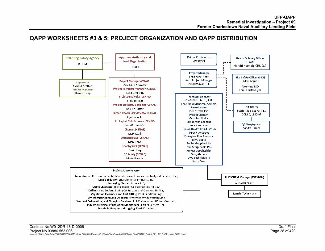
QAPP WORKSHEETS #3 & 5: PROJECT ORGANIZATION AND QAPP DISTRIBUTION
UFP-QAPP Remedial Investigation – Project 09
Former Charlestown Naval Auxiliary Landing Field
QAPP WORKSHEETS #3 & 5: PROJECT ORGANIZATION AND QAPP DISTRIBUTION (CONTINUED)
Contract No.W912DR-18-D-0006 Draft Final Project No.03886.553.006 Page 29 of 420 \\nascnh1\CNH_Data\Data\PROJECTS\03886553 (CNALF)\006\03-Planning\3.1-Work-Plan\Project 09 WP\Draft_Final\CNALF_Proj09_DF_UFP_QAPP_clean_041821.docx
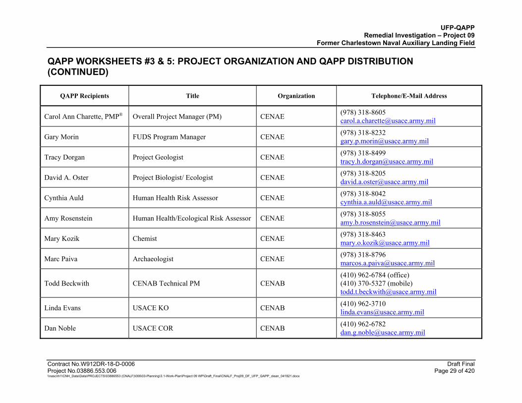
QAPP Recipients Title Organization Telephone/E-Mail Address
Carol Ann Charette, PMP® Overall Project Manager (PM) CENAE (978) 318-8605 [email protected]
Gary Morin FUDS Program Manager CENAE (978) 318-8232 [email protected]
Tracy Dorgan Project Geologist CENAE (978) 318-8499 [email protected]
David A. Oster Project Biologist/ Ecologist CENAE (978) 318-8205 [email protected]
Cynthia Auld Human Health Risk Assessor CENAE (978) 318-8042 [email protected]
Amy Rosenstein Human Health/Ecological Risk Assessor CENAE (978) 318-8055 [email protected]
Mary Kozik Chemist CENAE (978) 318-8463 [email protected]
Marc Paiva Archaeologist CENAE (978) 318-8796 [email protected]
Todd Beckwith CENAB Technical PM CENAB (410) 962-6784 (office) (410) 370-5327 (mobile) [email protected]
Linda Evans USACE KO CENAB (410) 962-3710 [email protected]
Dan Noble USACE COR CENAB (410) 962-6782 [email protected]
UFP-QAPP Remedial Investigation – Project 09
Former Charlestown Naval Auxiliary Landing Field
QAPP WORKSHEETS #3 & 5: PROJECT ORGANIZATION AND QAPP DISTRIBUTION (CONTINUED)
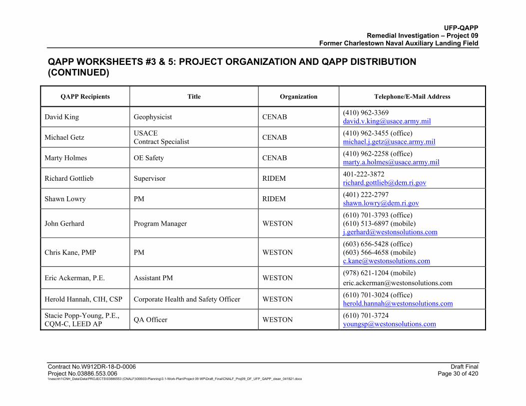
Contract No.W912DR-18-D-0006 Draft Final Project No.03886.553.006 Page 30 of 420 \\nascnh1\CNH_Data\Data\PROJECTS\03886553 (CNALF)\006\03-Planning\3.1-Work-Plan\Project 09 WP\Draft_Final\CNALF_Proj09_DF_UFP_QAPP_clean_041821.docx
QAPP Recipients Title Organization Telephone/E-Mail Address
David King Geophysicist CENAB (410) 962-3369 [email protected]
Michael Getz USACE Contract Specialist CENAB (410) 962-3455 (office)
Marty Holmes OE Safety CENAB (410) 962-2258 (office) [email protected]
Richard Gottlieb Supervisor RIDEM 401-222-3872 [email protected]
Shawn Lowry PM RIDEM (401) 222-2797 [email protected]
John Gerhard Program Manager WESTON (610) 701-3793 (office) (610) 513-6897 (mobile) [email protected]
Chris Kane, PMP PM WESTON (603) 656-5428 (office) (603) 566-4658 (mobile) [email protected]
Eric Ackerman, P.E. Assistant PM WESTON (978) 621-1204 (mobile) [email protected]
Herold Hannah, CIH, CSP Corporate Health and Safety Officer WESTON (610) 701-3024 (office) [email protected]
Stacie Popp-Young, P.E., CQM-C, LEED AP QA Officer WESTON (610) 701-3724

UFP-QAPP Remedial Investigation – Project 09
Former Charlestown Naval Auxiliary Landing Field
QAPP WORKSHEETS #3 & 5: PROJECT ORGANIZATION AND QAPP DISTRIBUTION (CONTINUED)
Contract No.W912DR-18-D-0006 Draft Final Project No.03886.553.006 Page 31 of 420 \\nascnh1\CNH_Data\Data\PROJECTS\03886553 (CNALF)\006\03-Planning\3.1-Work-Plan\Project 09 WP\Draft_Final\CNALF_Proj09_DF_UFP_QAPP_clean_041821.docx
QAPP Recipients Title Organization Telephone/E-Mail Address
Vincent Dello Russo, P.G. Technical Manager WESTON (517) 381-5949 (office) (603) 361-9496 (mobile) [email protected]
Mike Argue Site Safety Officer WESTON (603) 656-5403 (office) (413) 281-9572 (mobile) [email protected]
Louise Kritzberger Alternate Site Safety Officer WESTON (610) 701-3618 (office) (484) 5721-9441 (mobile) [email protected]
Josh Frizzell, P.G. Lead Field Manager and Sample Team Leader WESTON (470) 277-4600 (cell)
Michael Kanarek, P.G. Alternate Field Manager and Sample Team Leader WESTON (603) 656-5450
Bruce Moe Unexploded Ordnance (UXO) Technician III (TIII) WESTON (920) 636-6494 (mobile)
Ryan Steigerwalt, P.G. Senior Project Geophysicist WESTON (267) 258-2672 (mobile) [email protected]
Sandra Takata QC Geophysicist WESTON (610) 701-3119 (office) (865) 382-5365 (mobile) [email protected]
Greg Abrams Field Geophysicist WESTON (703) 599-2840 [email protected]
Terry Bosko Ecological Risk Assessor WESTON (847)-918-4000 (office) [email protected]

UFP-QAPP Remedial Investigation – Project 09
Former Charlestown Naval Auxiliary Landing Field
QAPP WORKSHEETS #3 & 5: PROJECT ORGANIZATION AND QAPP DISTRIBUTION (CONTINUED)
Contract No.W912DR-18-D-0006 Draft Final Project No.03886.553.006 Page 32 of 420 \\nascnh1\CNH_Data\Data\PROJECTS\03886553 (CNALF)\006\03-Planning\3.1-Work-Plan\Project 09 WP\Draft_Final\CNALF_Proj09_DF_UFP_QAPP_clean_041821.docx
QAPP Recipients Title Organization Telephone/E-Mail Address
Teresa Verstraet Human Health Risk Assessor WESTON (480)-213-5139 (office) [email protected]
Gretchen Fodor Chemist WESTON (703) 724-0544 (office) [email protected]
Kent Alexander Supporting Chemist WESTON (720) 474-4500 [email protected]
Charles Vandemoer National Wildlife Refuge Manager USFWS (401) 364-9124
Alan Arsenault Public Works Director Town of Charlestown (401) 364-1200
Mark Stankiewicz Town Administrator Town of Charlestown (401) 364-1200
Vicky Hilton Parks and Recreation Director Town of Charlestown (401) 364-1222
Susan Scherer Analytical Laboratory Subcontractor Laboratory PM ALS Middletown (717) 702 2245
Fiona Adamsky Analytical Laboratory Subcontractor Backup Laboratory PM ALS Middletown (717) 514-0564
Aimee Cormier Laboratory Director ProScience Analytical Services, Inc.
(718) 935-3212 [email protected]
Evin McKinney Data Validation Subcontractor Senior Data Validation Scientist
Environmental Synectics, Inc.
(916) 737-4023 [email protected]
Notes: A hard copy of the UFP-QAPP will also be made available to the field team during field activities.
UFP-QAPP Remedial Investigation – Project 09
Former Charlestown Naval Auxiliary Landing Field
Contract No.W912DR-18-D-0006 Draft Final Project No.03886.553.006 Page 33 of 420 \\nascnh1\CNH_Data\Data\PROJECTS\03886553 (CNALF)\006\03-Planning\3.1-Work-Plan\Project 09 WP\Draft_Final\CNALF_Proj09_DF_UFP_QAPP_clean_041821.docx
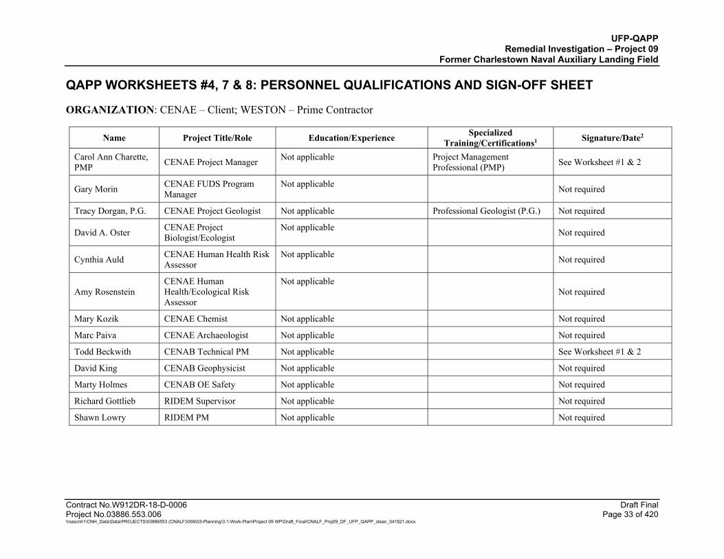
QAPP WORKSHEETS #4, 7 & 8: PERSONNEL QUALIFICATIONS AND SIGN-OFF SHEET
ORGANIZATION: CENAE – Client; WESTON – Prime Contractor
Name Project Title/Role Education/Experience Specialized Training/Certifications1 Signature/Date2
Carol Ann Charette, PMP CENAE Project Manager Not applicable Project Management
Professional (PMP) See Worksheet #1 & 2
Gary Morin CENAE FUDS Program Manager
Not applicable Not required
Tracy Dorgan, P.G. CENAE Project Geologist Not applicable Professional Geologist (P.G.) Not required
David A. Oster CENAE Project Biologist/Ecologist
Not applicable Not required
Cynthia Auld CENAE Human Health Risk Assessor
Not applicable Not required
Amy Rosenstein CENAE Human Health/Ecological Risk Assessor
Not applicable Not required
Mary Kozik CENAE Chemist Not applicable Not required
Marc Paiva CENAE Archaeologist Not applicable Not required
Todd Beckwith CENAB Technical PM Not applicable See Worksheet #1 & 2
David King CENAB Geophysicist Not applicable Not required
Marty Holmes CENAB OE Safety Not applicable Not required
Richard Gottlieb RIDEM Supervisor Not applicable Not required
Shawn Lowry RIDEM PM Not applicable Not required
UFP-QAPP Remedial Investigation – Project 09
Former Charlestown Naval Auxiliary Landing Field
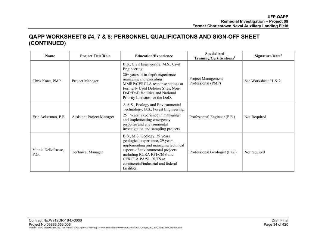
QAPP WORKSHEETS #4, 7 & 8: PERSONNEL QUALIFICATIONS AND SIGN-OFF SHEET (CONTINUED)
Contract No.W912DR-18-D-0006 Draft Final Project No.03886.553.006 Page 34 of 420 \\nascnh1\CNH_Data\Data\PROJECTS\03886553 (CNALF)\006\03-Planning\3.1-Work-Plan\Project 09 WP\Draft_Final\CNALF_Proj09_DF_UFP_QAPP_clean_041821.docx
Name Project Title/Role Education/Experience Specialized Training/Certifications1 Signature/Date2
Chris Kane, PMP Project Manager
B.S., Civil Engineering; M.S., Civil Engineering. 20+ years of in-depth experience managing and executing MMRP/CERCLA response actions at Formerly Used Defense Sites, Non-DoD/DoD facilities and National Priority List sites for the DoD.
Project Management Professional (PMP) See Worksheet #1 & 2
Eric Ackerman, P.E. Assistant Project Manager
A.A.S., Ecology and Environmental Technology; B.S., Forest Engineering. 25+ years’ experience in managing and implementing emergency response and environmental investigation and sampling projects.
Professional Engineer (P.E.) Not Required
Vinnie DelloRusso, P.G. Technical Manager
B.S., M.S. Geology, 39 years geological experience, 29 years implementing and managing technical aspects of environmental projects including RCRA RFI/CMS and CERCLA PA/SI, RI/FS at commercial/industrial and federal facilities.
Professional Geologist (P.G.) Not required
UFP-QAPP Remedial Investigation – Project 09
Former Charlestown Naval Auxiliary Landing Field
QAPP WORKSHEETS #4, 7 & 8: PERSONNEL QUALIFICATIONS AND SIGN-OFF SHEET (CONTINUED)
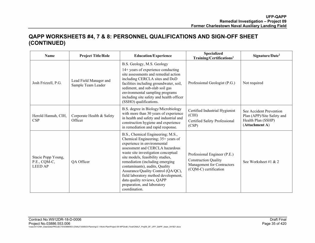
Contract No.W912DR-18-D-0006 Draft Final Project No.03886.553.006 Page 35 of 420 \\nascnh1\CNH_Data\Data\PROJECTS\03886553 (CNALF)\006\03-Planning\3.1-Work-Plan\Project 09 WP\Draft_Final\CNALF_Proj09_DF_UFP_QAPP_clean_041821.docx
Name Project Title/Role Education/Experience Specialized Training/Certifications1 Signature/Date2
Josh Frizzell, P.G. Lead Field Manager and Sample Team Leader
B.S. Geology, M.S. Geology 14+ years of experience conducting site assessments and remedial action including CERCLA sites and DoD facilities including groundwater, soil, sediment, and sub-slab soil gas environmental sampling programs including site safety and health officer (SSHO) qualifications.
Professional Geologist (P.G.) Not required
Herold Hannah, CIH, CSP
Corporate Health & Safety Officer
B.S. degree in Biology/Microbiology with more than 30 years of experience in health and safety and industrial and construction hygiene and experience in remediation and rapid response.
Certified Industrial Hygienist (CIH) Certified Safety Professional (CSP)
See Accident Prevention Plan (APP)/Site Safety and Health Plan (SSHP) (Attachment A)
Stacie Popp Young, P.E., CQM-C, LEED AP
QA Officer
B.S., Chemical Engineering; M.S., Chemical Engineering; 35+ years of experience in environmental assessment and CERCLA hazardous waste site investigation conceptual site models, feasibility studies, remediation (including emerging contaminants), audits, Quality Assurance/Quality Control (QA/QC), field laboratory method development, data quality reviews, QAPP preparation, and laboratory coordination.
Professional Engineer (P.E.) Construction Quality Management for Contractors (CQM-C) certification
See Worksheet #1 & 2
UFP-QAPP Remedial Investigation – Project 09
Former Charlestown Naval Auxiliary Landing Field
QAPP WORKSHEETS #4, 7 & 8: PERSONNEL QUALIFICATIONS AND SIGN-OFF SHEET (CONTINUED)
Contract No.W912DR-18-D-0006 Draft Final Project No.03886.553.006 Page 36 of 420 \\nascnh1\CNH_Data\Data\PROJECTS\03886553 (CNALF)\006\03-Planning\3.1-Work-Plan\Project 09 WP\Draft_Final\CNALF_Proj09_DF_UFP_QAPP_clean_041821.docx
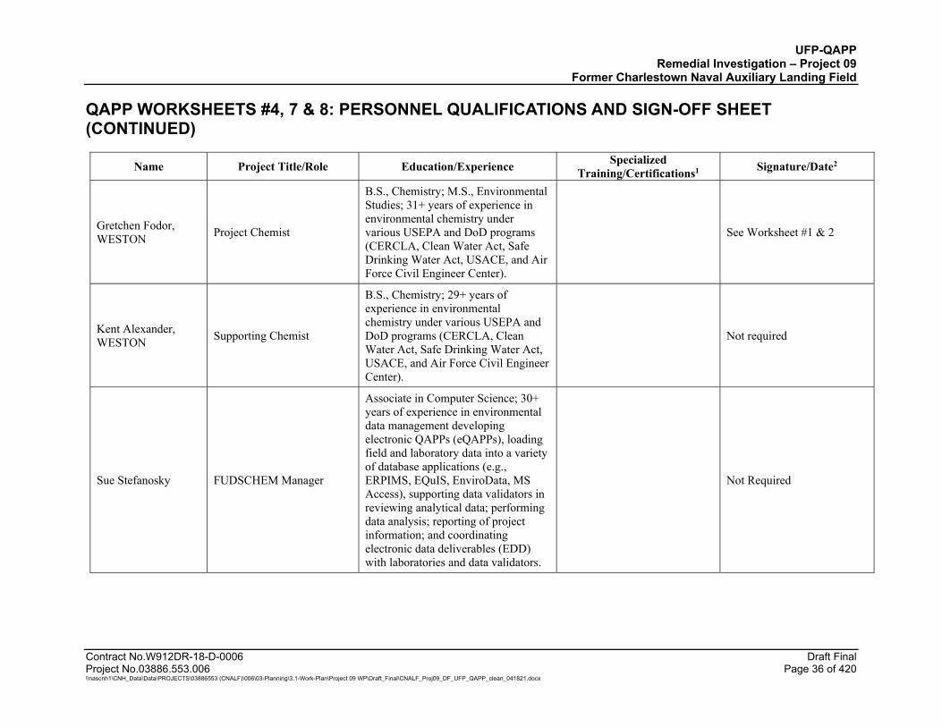
Name Project Title/Role Education/Experience Specialized Training/Certifications1 Signature/Date2
Gretchen Fodor, WESTON Project Chemist
B.S., Chemistry; M.S., Environmental Studies; 31+ years of experience in environmental chemistry under various USEPA and DoD programs (CERCLA, Clean Water Act, Safe Drinking Water Act, USACE, and Air Force Civil Engineer Center).
See Worksheet #1 & 2
Kent Alexander, WESTON Supporting Chemist
B.S., Chemistry; 29+ years of experience in environmental chemistry under various USEPA and DoD programs (CERCLA, Clean Water Act, Safe Drinking Water Act, USACE, and Air Force Civil Engineer Center).
Not required
Sue Stefanosky FUDSCHEM Manager
Associate in Computer Science; 30+ years of experience in environmental data management developing electronic QAPPs (eQAPPs), loading field and laboratory data into a variety of database applications (e.g., ERPIMS, EQuIS, EnviroData, MS Access), supporting data validators in reviewing analytical data; performing data analysis; reporting of project information; and coordinating electronic data deliverables (EDD) with laboratories and data validators.
Not Required
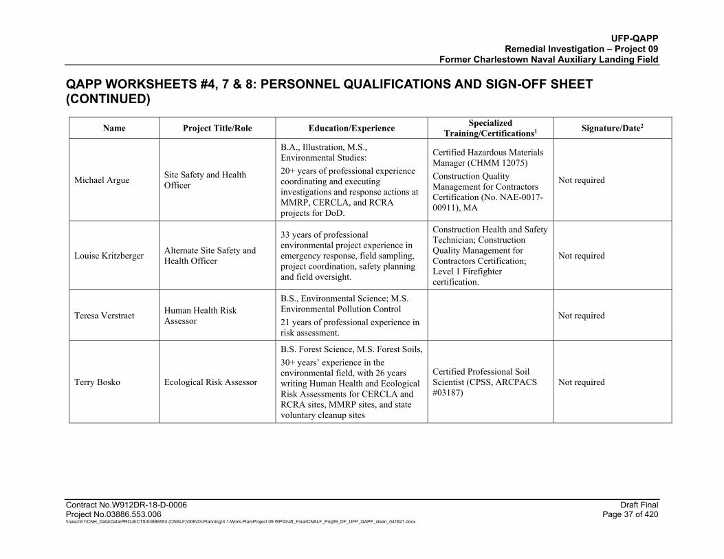
UFP-QAPP Remedial Investigation – Project 09
Former Charlestown Naval Auxiliary Landing Field
QAPP WORKSHEETS #4, 7 & 8: PERSONNEL QUALIFICATIONS AND SIGN-OFF SHEET (CONTINUED)
Contract No.W912DR-18-D-0006 Draft Final Project No.03886.553.006 Page 37 of 420 \\nascnh1\CNH_Data\Data\PROJECTS\03886553 (CNALF)\006\03-Planning\3.1-Work-Plan\Project 09 WP\Draft_Final\CNALF_Proj09_DF_UFP_QAPP_clean_041821.docx
Name Project Title/Role Education/Experience Specialized Training/Certifications1 Signature/Date2
Michael Argue Site Safety and Health Officer
B.A., Illustration, M.S., Environmental Studies: 20+ years of professional experience coordinating and executing investigations and response actions at MMRP, CERCLA, and RCRA projects for DoD.
Certified Hazardous Materials Manager (CHMM 12075) Construction Quality Management for Contractors Certification (No. NAE-0017-00911), MA
Not required
Louise Kritzberger Alternate Site Safety and Health Officer
33 years of professional environmental project experience in emergency response, field sampling, project coordination, safety planning and field oversight.
Construction Health and Safety Technician; Construction Quality Management for Contractors Certification; Level 1 Firefighter certification.
Not required
Teresa Verstraet Human Health Risk Assessor
B.S., Environmental Science; M.S. Environmental Pollution Control 21 years of professional experience in risk assessment.
Not required
Terry Bosko Ecological Risk Assessor
B.S. Forest Science, M.S. Forest Soils, 30+ years’ experience in the environmental field, with 26 years writing Human Health and Ecological Risk Assessments for CERCLA and RCRA sites, MMRP sites, and state voluntary cleanup sites
Certified Professional Soil Scientist (CPSS, ARCPACS #03187)
Not required
UFP-QAPP Remedial Investigation – Project 09
Former Charlestown Naval Auxiliary Landing Field
QAPP WORKSHEETS #4, 7 & 8: PERSONNEL QUALIFICATIONS AND SIGN-OFF SHEET (CONTINUED)
Contract No.W912DR-18-D-0006 Draft Final Project No.03886.553.006 Page 38 of 420 \\nascnh1\CNH_Data\Data\PROJECTS\03886553 (CNALF)\006\03-Planning\3.1-Work-Plan\Project 09 WP\Draft_Final\CNALF_Proj09_DF_UFP_QAPP_clean_041821.docx
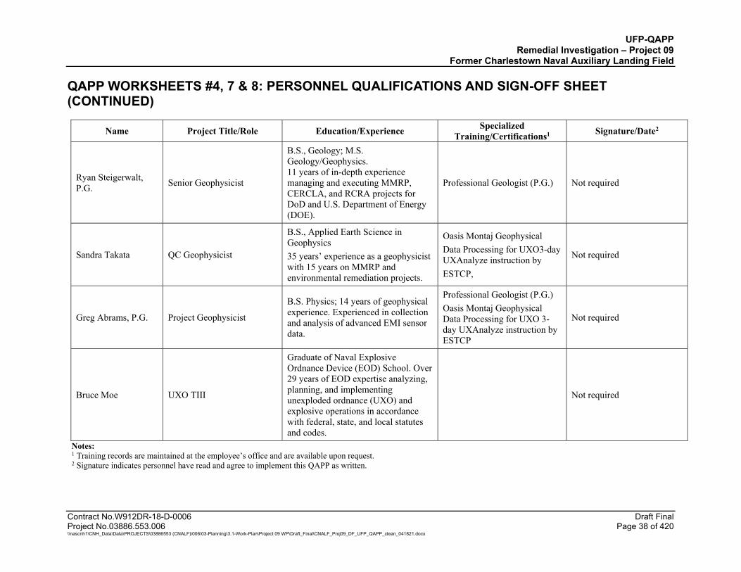
Name Project Title/Role Education/Experience Specialized Training/Certifications1 Signature/Date2
Ryan Steigerwalt, P.G. Senior Geophysicist
B.S., Geology; M.S. Geology/Geophysics. 11 years of in-depth experience managing and executing MMRP, CERCLA, and RCRA projects for DoD and U.S. Department of Energy (DOE).
Professional Geologist (P.G.) Not required
Sandra Takata QC Geophysicist
B.S., Applied Earth Science in Geophysics 35 years’ experience as a geophysicist with 15 years on MMRP and environmental remediation projects.
Oasis Montaj Geophysical Data Processing for UXO3-day UXAnalyze instruction by ESTCP,
Not required
Greg Abrams, P.G. Project Geophysicist
B.S. Physics; 14 years of geophysical experience. Experienced in collection and analysis of advanced EMI sensor data.
Professional Geologist (P.G.) Oasis Montaj Geophysical Data Processing for UXO 3-day UXAnalyze instruction by ESTCP
Not required
Bruce Moe UXO TIII
Graduate of Naval Explosive Ordnance Device (EOD) School. Over 29 years of EOD expertise analyzing, planning, and implementing unexploded ordnance (UXO) and explosive operations in accordance with federal, state, and local statutes and codes.
Not required
Notes: 1 Training records are maintained at the employee’s office and are available upon request. 2 Signature indicates personnel have read and agree to implement this QAPP as written.
UFP-QAPP Remedial Investigation – Project 09
Former Charlestown Naval Auxiliary Landing Field
Contract No.W912DR-18-D-0006 Draft Final Project No.03886.553.006 Page 39 of 420 \\nascnh1\CNH_Data\Data\PROJECTS\03886553 (CNALF)\006\03-Planning\3.1-Work-Plan\Project 09 WP\Draft_Final\CNALF_Proj09_DF_UFP_QAPP_clean_041821.docx
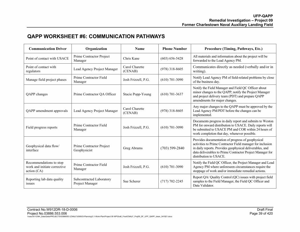
QAPP WORKSHEET #6: COMMUNICATION PATHWAYS
Communication Driver Organization Name Phone Number Procedure (Timing, Pathways, Etc.)
Point of contact with USACE Prime Contractor Project Manager Chris Kane (603) 656-5428 All materials and information about the project will be
forwarded to the Lead Agency PM.
Point of contact with regulators Lead Agency Project Manager Carol Charette
(CENAB) (978) 318-8605 Communicates directly as needed (verbally and/or in writing).
Manage field project phases Prime Contractor Field Manager Josh Frizzell, P.G. (610) 701-3090 Notify Lead Agency PM of field-related problems by close
of the business day.
QAPP changes Prime Contractor QA Officer Stacie Popp-Young (610) 701-3637
Notify the Field Manager and Field QC Officer about minor changes to the QAPP; notify the Project Manager and project delivery team (PDT) and prepare QAPP amendments for major changes.
QAPP amendment approvals Lead Agency Project Manager Carol Charette (CENAB) (978) 318-8605
Any major changes to the QAPP must be approved by the Lead Agency PM/PDT before the changes can be implemented.
Field progress reports Prime Contractor Field Manager Josh Frizzell, P.G. (610) 701-3090
Documents progress in daily report and submits to Weston PM for onward distribution to USACE. Daily reports will be submitted to USACE PM and COR within 24 hours of work completion that day, whenever possible.
Geophysical data flow/ interface
Prime Contractor Project Geophysicist Greg Abrams (703) 599-2840
Provides documentation of progress of geophysical activities to Prime Contractor Field manager for inclusion in daily reports. Provides geophysical deliverables, and data deliverables to Prime Contractor Project Manager for distribution to USACE.
Recommendations to stop work and initiate corrective action (CA)
Prime Contractor Field Manager Josh Frizzell, P.G. (610) 701-3090
Notify the Field QC Officer, the Project Manager and Lead Agency PM where unforeseen circumstances require the stoppage of work and/or immediate remedial actions.
Reporting lab data quality issues
Subcontracted Laboratory Project Manager Sue Scherer (717) 702-2245
Report QA/ Quality Control (QC) issues with project field samples to the Field Manager, the Field QC Officer and Data Validator.
UFP-QAPP Remedial Investigation – Project 09
Former Charlestown Naval Auxiliary Landing Field
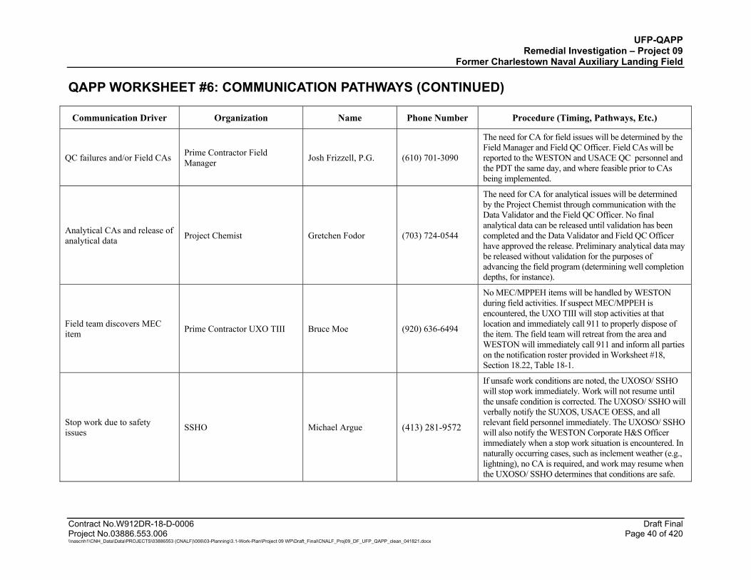
QAPP WORKSHEET #6: COMMUNICATION PATHWAYS (CONTINUED)
Contract No.W912DR-18-D-0006 Draft Final Project No.03886.553.006 Page 40 of 420 \\nascnh1\CNH_Data\Data\PROJECTS\03886553 (CNALF)\006\03-Planning\3.1-Work-Plan\Project 09 WP\Draft_Final\CNALF_Proj09_DF_UFP_QAPP_clean_041821.docx
Communication Driver Organization Name Phone Number Procedure (Timing, Pathways, Etc.)
QC failures and/or Field CAs Prime Contractor Field Manager Josh Frizzell, P.G. (610) 701-3090
The need for CA for field issues will be determined by the Field Manager and Field QC Officer. Field CAs will be reported to the WESTON and USACE QC personnel and the PDT the same day, and where feasible prior to CAs being implemented.
Analytical CAs and release of analytical data Project Chemist Gretchen Fodor (703) 724-0544
The need for CA for analytical issues will be determined by the Project Chemist through communication with the Data Validator and the Field QC Officer. No final analytical data can be released until validation has been completed and the Data Validator and Field QC Officer have approved the release. Preliminary analytical data may be released without validation for the purposes of advancing the field program (determining well completion depths, for instance).
Field team discovers MEC item Prime Contractor UXO TIII Bruce Moe (920) 636-6494
No MEC/MPPEH items will be handled by WESTON during field activities. If suspect MEC/MPPEH is encountered, the UXO TIII will stop activities at that location and immediately call 911 to properly dispose of the item. The field team will retreat from the area and WESTON will immediately call 911 and inform all parties on the notification roster provided in Worksheet #18, Section 18.22, Table 18-1.
Stop work due to safety issues SSHO Michael Argue (413) 281-9572
If unsafe work conditions are noted, the UXOSO/ SSHO will stop work immediately. Work will not resume until the unsafe condition is corrected. The UXOSO/ SSHO will verbally notify the SUXOS, USACE OESS, and all relevant field personnel immediately. The UXOSO/ SSHO will also notify the WESTON Corporate H&S Officer immediately when a stop work situation is encountered. In naturally occurring cases, such as inclement weather (e.g., lightning), no CA is required, and work may resume when the UXOSO/ SSHO determines that conditions are safe.
UFP-QAPP Remedial Investigation – Project 09
Former Charlestown Naval Auxiliary Landing Field
Contract No.W912DR-18-D-0006 Draft Final Project No.03886.553.006 Page 41 of 420 \\nascnh1\CNH_Data\Data\PROJECTS\03886553 (CNALF)\006\03-Planning\3.1-Work-Plan\Project 09 WP\Draft_Final\CNALF_Proj09_DF_UFP_QAPP_clean_041821.docx
QAPP WORKSHEET #9: PROJECT PLANNING SESSION SUMMARY
The scope of work was initially developed jointly by USACE and The Johnson Company, Inc. (JCO) with input from stakeholders in a February 7, 2019 Historical Review Meeting held in Charlestown, Rhode Island. This UFP-QAPP addresses the four Project 09 sites at CNALF included on Figure 2 based on the site historical data review report and the Draft Final QAPP for the Project 09 sites prepared by JCO in October 2019 (JCO, 2018 and 2019). In addition, bimonthly project planning teleconference meetings were conducted jointly by USACE, USACE CX, and WESTON between October 2019 and April 2020 to refine the investigation approach. Bimonthly Project team conference calls were held on 10/3/2019, 10/28/2019, 11/12/2019, 11/26/2019, 12/10/2019, 12/20/2019, 1/7/2020, 1/9/2020, 1/21/2020, 2/5/2020, 2/13/2020, 2/27/2020 (with USACE CX), 3/5/2020 (with USACE CX), and continued on a biweekly basis since March 2020 with USACE. Project team conference calls were expanded and continue as weekly meetings since January 2021. A Technical Project Planning Meeting is scheduled for 30 April 2021 with stakeholders.
UFP-QAPP Remedial Investigation – Project 09
Former Charlestown Naval Auxiliary Landing Field
Contract No.W912DR-18-D-0006 Draft Final Project No.03886.553.006 Page 42 of 420 \\nascnh1\CNH_Data\Data\PROJECTS\03886553 (CNALF)\006\03-Planning\3.1-Work-Plan\Project 09 WP\Draft_Final\CNALF_Proj09_DF_UFP_QAPP_clean_041821.docx
QAPP WORKSHEET #10: CONCEPTUAL SITE MODEL
This worksheet presents the Conceptual Site Models (CSMs) for each of the Project 09 sites. The CSM identifies the potential sources of contaminants, the likely release mechanisms from those sources, migration pathways, and potentially exposed receptors. This compilation of background information and review of historical information was completed by JCO in the Historical Data Review Report and the Draft Final QAPP for the Project 09 documents in 2018 and 2019 (JCO, 2018 and 2019). Reference to “current” screening levels in these sections refers to screening levels at the time the 2018 Historical Data Review Report was completed. The background information provided in the following sections presents the available information used for developing the CSMs for each site.
10.1 SITE DESCRIPTION
The Former Charlestown Naval Auxiliary Landing Field (CNALF) is a Formerly Used Defense Site (FUDS) under the U.S. Department of Defense (DoD) Environmental Restoration Program (DERP). The U.S. Army Corps of Engineers (USACE) has been designated by the DoD and Department of the Army as the Lead Agency responsible for the execution of the FUDS Program.
The property was acquired between 1940 and 1942 by the U.S. Navy and encompasses approximately 630 acres on Foster Cove and Ninigret Pond in Charlestown, Rhode Island. It was used as a pilot and flight crew training facility during World War II and later as a support facility to Quonset Point Naval Air Station. The facility was closed in the early 1970s (USACE, 1999; RIHPC, 1975; CHIP, 1982).
By 1982 the property was transferred to two entities: the USFWS and the Town of Charlestown. The USFWS portion of CNALF encompasses approximately 400 acres and is known as the Ninigret Wildlife Refuge (NWR); this property is listed as USEPA CERCLIS RI9143530260. The Town of Charlestown portion of CNALF encompasses approximately 230 acres and is known as Ninigret Park; this property is listed as USEPA CERCLIS RID987480910 (Graham, 2017; URS, 1996).
In 2017, USACE reorganized the prior authorized DERP-FUDS property Hazardous Toxic and Radioactive Waste (HTRW) Project 01 into two separate projects, Project 08 and Project 09. The purpose of these new reorganized projects was to break up the work into individual projects to allow for more effective management and execution. The four Project 09 sites that will be addressed in the remedial investigation (RI) field activities are listed in Table 10-1. The three landfills of Project 09 are also being investigated for munitions under the Military Munitions Response Program (MMRP). Their associated Munitions Response Site (MRS) names are included in Table 10-1; however, further discussion of the sites in this document will address the sites by their HTRW names. The project area sizes listed in Table 10-1 are based on the known historic usage and visible disturbances observed through historic aerial imagery review.
UFP-QAPP Remedial Investigation – Project 09
Former Charlestown Naval Auxiliary Landing Field
Contract No.W912DR-18-D-0006 Draft Final Project No.03886.553.006 Page 43 of 420 \\nascnh1\CNH_Data\Data\PROJECTS\03886553 (CNALF)\006\03-Planning\3.1-Work-Plan\Project 09 WP\Draft_Final\CNALF_Proj09_DF_UFP_QAPP_clean_041821.docx
Table 10-1 Project 09 HTRW/Munitions Response Sites
HTRW Project Name MMRP MRS Name Acreage
Project 09 Charlestown Landfill MRS 4 Dump Site 13.0 acres
Project 09 Eastern Area Landfill MRS 3 Hunter Island Dump Site 6.0 acres
Project 09 Ninigret Wildlife Refuge Landfill MRS 2 Inland Toxic Waste Dump 4.0 acres
Project 09 Burn Pit Area Not applicable 3.0 acres
10.2 SITE SETTING
10.2.1 Topography and Surface Features
The land surface of CNALF was formed by glacial sedimentation and modified by coastal processes. The land slopes gradually from the north at approximately 40 feet (ft) above mean sea level to the south/southeast at sea level where it consists of wetlands and Ninigret Pond, a coastal saltwater lagoon. The ground surface is generally flat, with the exception of the landfills, which are uneven. The CNALF topography is shown in Figure 3 (ITC, 1993; URS, 1996).
Most of CNALF is covered by grass or shrubs. The Ninigret Park portion of CNALF has been modified for recreational purposes and includes buildings and facilities, a swimming area in Little Nini Pond, sports courts and fields, and a bike track and trails, as shown in Figure 4. The NWR portion of CNALF has generally remained unaltered since the CNALF facility was closed, with the exception of removal of approximately 70 acres of asphalt runways, taxiways, and parking areas, which was evaluated in 1995 (Herbert, 1995) and performed prior to 2001 based on aerial photos (Freeman, 2018; Google Earth Pro, 2001).
10.2.2 Surface Water Hydrology
Natural surface overland flow is minimal due to the high permeability of the surficial sands and gravel, and the gently sloping topography (Figure 3). Most of the surface water runoff is from asphalt-covered areas and is diverted to drainage areas or ponds (including Little Nini Pond [freshwater]) through a limited stormwater management conveyance system. In addition, there are several permanent and seasonal small freshwater ponds in wetland areas of CNALF that do not have inlets or outlets and their water levels are controlled by the groundwater table. Ninigret Pond, the coastal saltwater lagoon adjacent to CNALF, is connected to Block Island Sound by the Charlestown Breachway and is subject to tidal variation of approximately 2 ft (ITC, 1993; URS, 1996).
10.2.3 Geology
The overburden geology reportedly consists of Quaternary glacial deposits of the Charlestown moraine and outwash plain, comprised of well-stratified fine to coarse sand and gravel, and ranges from 25 to 75-ft thick. Based on reported observations from onsite borings on depths to bedrock and current surface topography, the overburden is not likely greater than 50 ft thick. In the north-
UFP-QAPP Remedial Investigation – Project 09
Former Charlestown Naval Auxiliary Landing Field
Contract No.W912DR-18-D-0006 Draft Final Project No.03886.553.006 Page 44 of 420 \\nascnh1\CNH_Data\Data\PROJECTS\03886553 (CNALF)\006\03-Planning\3.1-Work-Plan\Project 09 WP\Draft_Final\CNALF_Proj09_DF_UFP_QAPP_clean_041821.docx
central portion of CNALF, coarser deposits are underlain by dense glacial till, comprised of well graded sand, silt, clay, and gravel, reaching up to 41 ft in thickness. In the southern portion of CNALF, where tidal marshes exist, the surficial soil consists of a peat-like organic layer. Bedrock is highly fractured and consists of granitic and gneissic rocks of Pennsylvanian age. The top of bedrock ranges in elevation from 5 to 50 ft below mean sea level. Figure 5 shows bedrock surface contours drawn by others from data collected during the 1974-1977 New England Power Company (NEPCO) site investigations and from borings advanced in 1992 (ITC, 1993; URS, 1996).
10.2.4 Hydrogeology
The water table aquifer is unconfined and located in the sand and gravel units of the glacial outwash plain. Based on borings drilled by IT Corporation (ITC), the overburden in the northernmost portion of CNALF is unsaturated. Groundwater flow at CNALF is generally to the south and southeast; however, Little Nini Pond, which was constructed by the Navy as a source for fire suppression water, received surface water runoff and has no outlet (except for the overflow invert on the south end). As a result, Little Nini Pond seasonally serves as a local groundwater recharge area, causing a locally elevated water table and radial groundwater flow away from the pond to the west, east and south. However, during drought conditions, local flow is likely toward the southeast. Groundwater contours presented in the Phase II RI Report from data collected in December 1992 are depicted in Figure 6 (URS, 1996). These contours are like those presented in the NEPCO Environmental Report from data obtained from 25 piezometers in a 1974 site investigation, which are depicted in Figure 7 (RIDEM, 1993). Subsequent information obtained from localized 1994 water elevation data, which incorporates more wells, indicated that in the areas of the Charlestown Landfill and Eastern Area Landfill the groundwater flow direction is to the east/southeast toward Ninigret Pond.
Horizontal hydraulic gradients at CNALF ranged from 0.001 to 0.006 ft/ft as measured by NEPCO in 1977 and ITC in 1992. The ITC report stated that the highest horizontal flow gradients (0.003 to 0.006 ft/ft) are south of Runway 30 (ITC, 1993).
Field test results have shown a wide range in hydraulic conductivity – from 1 to 755 ft/day which URS Consultants, Inc. (URS) attributed to the variability in the type of tests conducted, well diameters, and volumes of the aquifer being subjected to water level changes. Hydraulic conductivity of the water table aquifer calculated from an eight-hour step drawdown pumping test by NEPCO in 1977 indicated the upper value of 755 ft/day. Slug tests at the landfill areas by Ecology and Environment, Inc. (E&E) in 1977 were inconclusive due to extremely rapid rates of infiltration. Slug tests in the Charlestown Landfill and Eastern Area Landfill by URS in 1994 indicated values between 1.34 and 66.01 ft/day in the sand and gravel unit (URS, 1996).
Annual groundwater fluctuations at CNALF average 3.98 ft with a maximum reported range of 8.86 ft, based on monthly observations from October 1946 to October 2020 in a U.S. Geological Survey (USGS) observation well CHW-18. This well is an overburden well, constructed in sand and clay to a depth of 32 ft below ground surface. As reported by NEPCO, the highest water levels were in April, while the lowest water levels generally occurred during the months of October, November, and December. Based on measurements from the 25 piezometers installed in 1974 and reported by NEPCO, groundwater fluctuations in the northern part of CNALF are similar to those

UFP-QAPP Remedial Investigation – Project 09
Former Charlestown Naval Auxiliary Landing Field
Contract No.W912DR-18-D-0006 Draft Final Project No.03886.553.006 Page 45 of 420 \\nascnh1\CNH_Data\Data\PROJECTS\03886553 (CNALF)\006\03-Planning\3.1-Work-Plan\Project 09 WP\Draft_Final\CNALF_Proj09_DF_UFP_QAPP_clean_041821.docx
observed at the USGS well; in the central part of CNALF the magnitude of the fluctuations is estimated to be 30% less than those in the USGS well; and in the southern part of CNALF groundwater fluctuations are minimal (ITC, 1993; URS, 1996).
Groundwater in wells located within approximately 100 ft of Ninigret Pond show tidal fluctuations of approximately 0.1 to 0.3 ft (URS, 1996).
CNALF is within an area of RIDEM groundwater classification GA, and the majority of the CNALF is designated as a non-community wellhead protection area as shown on Figure 8. Groundwater resources classified as GA are known or presumed to be suitable for drinking water use without treatment (RIDEM, 2009). There is no public water supply available in the Town of Charlestown. All residential, recreational, and commercial water supplies are provided by local wells. A drinking water well inventory was prepared from the existing State of Rhode Island database for drinking water wells. A list of the available well information and a well location map is provided in Attachment B for drinking water wells in the vicinity of CNALF.
A residential area abuts the east/northeast boundary of the Ninigret Park portion of the former CNALF property. This area includes Colony Road, Hunters Harbor Road, Dudley Lane, and South Arnolda Road and is not connected to a public water supply. The homes in this area reportedly rely on private wells for water supply. The total depths of the known private residential wells range from 12 to 600 ft below ground surface, where depth of groundwater ranges from 3 to 69 ft below ground surface (Town of Charlestown, 2018). The southeastern-most portion of this residential area near Ninigret Pond is potentially downgradient from the CNALF property.
There are potentially seven active water supply wells identified at CNALF, RW-1 through RW-7, as shown in Figure 6 and Figure 7. There are an additional two unidentified PVC pipes near the dog park that could potentially be used as water supply wells, as well as, one former Navy well, Pump House No. 4 Well No. 12, that is a potential water supply well that is not currently in use. Information for these wells is summarized in Table 10-2 below (ITC, 1993).
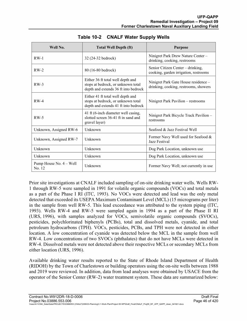
UFP-QAPP Remedial Investigation – Project 09
Former Charlestown Naval Auxiliary Landing Field
Contract No.W912DR-18-D-0006 Draft Final Project No.03886.553.006 Page 46 of 420 \\nascnh1\CNH_Data\Data\PROJECTS\03886553 (CNALF)\006\03-Planning\3.1-Work-Plan\Project 09 WP\Draft_Final\CNALF_Proj09_DF_UFP_QAPP_clean_041821.docx
Table 10-2 CNALF Water Supply Wells
Well No. Total Well Depth (ft) Purpose
RW-1 32 (24-32 bedrock) Ninigret Park Drew Nature Center – drinking, cooking, restrooms
RW-2 80 (16-80 bedrock) Senior Citizen Center – drinking, cooking, garden irrigation, restrooms
RW-3 Either 36 ft total well depth and stops at bedrock, or unknown total depth and extends 36 ft into bedrock
Ninigret Park Gate House residence – drinking, cooking, restrooms, showers
RW-4 Either 41 ft total well depth and stops at bedrock, or unknown total depth and extends 41 ft into bedrock
Ninigret Park Pavilion – restrooms
RW-5 41 ft (6-inch diameter well casing, slotted screen 36-41 ft in sand and gravel layer)
Ninigret Park Bicycle Track Pavilion – restrooms
Unknown, Assigned RW-6 Unknown Seafood & Jazz Festival Well
Unknown, Assigned RW-7 Unknown Former Navy Well used for Seafood & Jazz Festival
Unknown Unknown Dog Park Location, unknown use
Unknown Unknown Dog Park Location, unknown use
Pump House No. 4 – Well No. 12 Unknown Former Navy Well; not currently in use
Prior site investigations at CNALF included sampling of on-site drinking water wells. Wells RW-1 through RW-5 were sampled in 1991 for volatile organic compounds (VOCs) and total metals as a part of the Phase I RI (ITC, 1993). No VOCs were detected and lead was the only metal detected that exceeded its USEPA Maximum Contaminant Level (MCL) (15 micrograms per liter) in the sample from well RW-5. This lead exceedance was attributed to the system piping (ITC, 1993). Wells RW-4 and RW-5 were sampled again in 1994 as a part of the Phase II RI (URS, 1996), with samples analyzed for VOCs, semivolatile organic compounds (SVOCs), pesticides, polychlorinated biphenyls (PCBs), total and dissolved metals, cyanide, and total petroleum hydrocarbons (TPH). VOCs, pesticides, PCBs, and TPH were not detected in either location. A low concentration of cyanide was detected below the MCL in the sample from well RW-4. Low concentrations of two SVOCs (phthalates) that do not have MCLs were detected in RW-4. Dissolved metals were not detected above their respective MCLs or secondary MCLs from either location (URS, 1996).
Available drinking water results reported to the State of Rhode Island Department of Health (RIDOH) by the Town of Charlestown or building operators using the on-site wells between 1988 and 2019 were reviewed. In addition, data from lead analyses were obtained by USACE from the operator of the Senior Center (RW-2) water treatment system. These data are summarized below:
UFP-QAPP Remedial Investigation – Project 09
Former Charlestown Naval Auxiliary Landing Field
Contract No.W912DR-18-D-0006 Draft Final Project No.03886.553.006 Page 47 of 420 \\nascnh1\CNH_Data\Data\PROJECTS\03886553 (CNALF)\006\03-Planning\3.1-Work-Plan\Project 09 WP\Draft_Final\CNALF_Proj09_DF_UFP_QAPP_clean_041821.docx
According to the RIDOH database, well RW-2 (Senior Center) was analyzed eight times between 1988 and 2019, including analysis of VOCs, SVOCs, cyanide, pesticides, and PCBs that have not been detected. Metals were also analyzed, and none were detected above current MCLs.
Additional lead data provided to USACE by the operator of the treatment system at the Senior Center included data from 10 sampling events between 1993 and 2010 from 5 sample locations within the building for each event. Prior to 2006, lead was detected above the MCL in at least one location during each sampling event. In 1993, all 5 locations detected lead above the MCL. The water treatment system was installed in 1998 due to the low pH of the water that was thought to be leaching lead from system fittings. The system provides acid neutralization and softening. The well pump was found to have bronze fittings that can leach lead and was replaced in 2004 with a pump with lead-free fittings. Since the pump was replaced, results from the 5 annual sampling events through 2010 detected low lead concentrations below the MCL.
VOCs, SVOCs, pesticides, and PCBs were analyzed in samples from wells RW-1 (Nature Center), RW-4 (Pond Pavilion), and RW-5 (Bike Pavilion), and none were detected. Metals were not analyzed.
10.2.5 Ecology
Land cover types and wetlands were mapped in 1993 by ITC and confirmed in 1996 by URS. Based on the most current Rhode Island Geographic Information System (GIS) data (2011) and the USFWS National Wetland Inventory (2006), these cover types and wetland areas have not changed significantly since 1996. The most current information is shown in Figure 9.
Approximately half of the CNALF land area is coastal brushland/shrub. The coastal brushlands comprise an ecologically important and rare upland habitat. From observations during the 10 July 2018 site visit by JCO, this type of habitat is dominated by stands of bayberry in the understory, with cherry-red cedar associations as the main canopy. Other canopy vegetation observed in this habitat include primarily scrub oak and birch. Much of the understory is overtaken by various non-native, invasive vegetation, including oriental bittersweet, Japanese honeysuckle, and multiflora rose (ITC, 1993; URS, 1996; JCO, 2018).
Other cover types in CNALF include: developed areas (for recreation, residential, or institutional), forest, and wetlands (marine, estuarine, and freshwater). From observations during the July 10, 2018, JCO site visit, forested areas at CNALF are generally representative of coastal forest, dominated by a mix of deciduous broadleaf tree species (oaks, cherries, etc.). There are both freshwater and saltwater wetlands at CNALF. Freshwater wetlands are generally palustrine forested wetlands dominated by an overstory consisting of oak and red maple, with an understory comprised of pepperbush, highbush blueberry, swamp azalea, and other shrub and small tree species. As the CNALF property is bordered by Ninigret Pond and Foster Cove which are large coastal salt ponds, Spartina salt marsh is present along the shoreline (generally only along the Eastern Area Landfill and NWR areas) (ITC, 1993; URS, 1996; JCO, 2018).
UFP-QAPP Remedial Investigation – Project 09
Former Charlestown Naval Auxiliary Landing Field
Contract No.W912DR-18-D-0006 Draft Final Project No.03886.553.006 Page 48 of 420 \\nascnh1\CNH_Data\Data\PROJECTS\03886553 (CNALF)\006\03-Planning\3.1-Work-Plan\Project 09 WP\Draft_Final\CNALF_Proj09_DF_UFP_QAPP_clean_041821.docx
Three federally-listed threatened or endangered species may occur on NWR. These species include the northern long eared bat (Myotis septentrionalis), red knot (Calidris canatus rufa), and the roseate tern (Sterna dougallii dougallii) (USFWS, 2018). There are 47 migratory bird species potentially occurring in the project area as well during different times of the year (USFWS, 2019). Piping plover (Charadrius melodus) may also occur here. The 1996 URS report also documented a number of other avian species such as northern harrier (Circus hudsonius), yellow breasted chat (Icteria virens), and the American bittern (Botaurus lentiginosus).
10.2.6 Archeology
Archeological investigations of CNALF were conducted in 1974 and 1992. Archeological sensitivity areas are areas with a high probability for prehistoric or historic resources to be present. The archeological sensitivity areas identified during the 1974 investigation and archeological sensitivity zones identified during the 1992 investigations are shown in Figure 2. Zone 1/Area A has been placed on the National Register of Historic Places as a late Woodland Indian campsite and one of the few known ceramic yielding sites in southern Rhode Island. During investigations, Zone 2/Area D, Area B, Area C, and Area E yielded quartz chipping debris, signifying the possible presence of stone tools. Zone 3 is considered an archeological sensitivity zone because there are intact burials known to exist under the runway. Portions of the landfill locations are located within the archeological sensitivity areas shown in Figure 2. USACE will coordinate work activities with USFWS, and the State Historic Preservation Office (SHPO) (ITC, 1993; RIHPC, 1975).
10.2.7 Climate
Based on climate data gathered at the Automated Surface Observing System (ASOS) installed at nearby Westerly State Airport, Rhode Island, average temperatures for the site vicinity range from 30 degrees Fahrenheit (°F) in winter to 70 °F in the summer. The average amount of precipitation for this region is 22 inches, approximately 45 percent of which occurs during the months of April through September in the form of rain showers. In winter, the ground is frequently, but not continuously, covered with snow. Seasonal snowfall averages 36 inches.
Rhode Island is strongly influenced by prevailing westerly winds and the moderating effects of the Atlantic Ocean. ASOS Westerly State Airport climate data in the site vicinity indicate the predominant average wind direction in Charlestown varies throughout the year, with winds predominantly from the southwest. An all-year windrose diagram based on data collected by Iowa Environmental Mesonet (IEM) from 31 July 1999 to 13 October 2019 is provided as Figure 10.
10.3 SITE USE
The following information regarding Ninigret Park and the NWR use and potential human receptors is based on information gathered during a 10 July 2018 site visit and interviews with Charlestown Parks and Recreation employees by JCO and CENAE. The majority of the Project 09 investigation activities will be conducted on the USFWS NWR property, with access to the NWR through Ninigret Park. The Charlestown Landfill site overlaps with the property boundary between Ninigret Park and the NWR.

UFP-QAPP Remedial Investigation – Project 09
Former Charlestown Naval Auxiliary Landing Field
Contract No.W912DR-18-D-0006 Draft Final Project No.03886.553.006 Page 49 of 420 \\nascnh1\CNH_Data\Data\PROJECTS\03886553 (CNALF)\006\03-Planning\3.1-Work-Plan\Project 09 WP\Draft_Final\CNALF_Proj09_DF_UFP_QAPP_clean_041821.docx
Ninigret Park and the NWR is visited year-round for recreational activities such as biking, birding, walking, jogging, sports games, picnicking, swimming, and boating by an estimated 20,000 people each year, according to the Charlestown Parks and Recreation Department. Ninigret Park hosts multi-day biking events and festivals, children’s summer camp programs, and other programs at the Frosty Drew Nature Center and Senior Center (recreational). Ninigret Park is maintained by Department of Public Works staff although the Frosty Drew Nature Center is not a Town facility it is operated and managed by a separate non-profit organization. The Town and Park facilities are staffed seasonally; and the Senior Center (including independent offices on the second floor) has approximately eight full-time year-round staff. The annual summer festivals typically draw approximately 20,000 attendees to Ninigret Park. The NWR is also used for deer and turkey hunting and is managed by USFWS staff. Seven active water supply wells within Ninigret Park are used to varying degrees for drinking, cooking, and restrooms. Ninigret Park and the NWR are used as a water access point for recreational activities, including swimming and boating, as well as fishing within Ninigret Pond. Ninigret Pond is frequently used for small boat and commercial boat fishing for fin-fish and shell fish. There are no shellfish closure restrictions along the shoreline of the project area (Figure 4). There are numerous commercial shell-fish beds within Ninigret Pond surrounding the former airfield.
Ninigret Park includes one year-round residence located at the Ninigret Park Gate House. This building has an active water supply well (RW-3 on Figure 6 and Figure 7) that is used for residential purposes.
10.4 SITE BACKGROUND
10.4.1 Charlestown Landfill Background
The Charlestown Landfill encompasses an area of approximately 13 acres and is located in both Ninigret Park and NWR on the east end of CNALF (see Figure 2). Fill thicknesses in the central portion of the landfill are approximately 7 – 12 ft below ground surface and may have included filling to depths below the water table. This landfill was reportedly used for disposal of military debris, including airplane and vehicle parts, scrap metals, and inert practice bombs. Reportedly, aircraft fuselages previously used in firefighting training were buried in the landfill and are not in-place aircraft crash sites. The Charlestown Landfill is located adjacent to and east of the former CNALF sewage treatment system sand filters and south of the sewage disposal area. In 1973 and 1977, the landfill was partially excavated in search of airplane parts. Parts from nine separate aircraft were uncovered during these excavations. Coal clinkers from the coal furnaces at the site were also encountered during excavation. Excavations encountered refuse that included household debris, practice bombs, and crushed, intact or partially intact drums in the landfilled area. Some of the drums were reportedly associated with a strong chemical odor and observed to be leaking. Some of the drums were intact and reportedly contained unknown liquids at that time. These excavations were backfilled, and local fill/soils was used to re-grade the area. No identifiable markings were noted on the drums and containers observed at the time of these prior excavations. In approximately 1987, the Town of Charlestown reportedly used the area along the northwest boundary of the landfill for disposal of road debris, asphalt, and soil. Sometime after April 1985, the Town of Charlestown also used the former sand filter area, west of the landfill, for disposal of crushed asphalt, subsoil gravel, concrete and light brush removed during construction of Ninigret
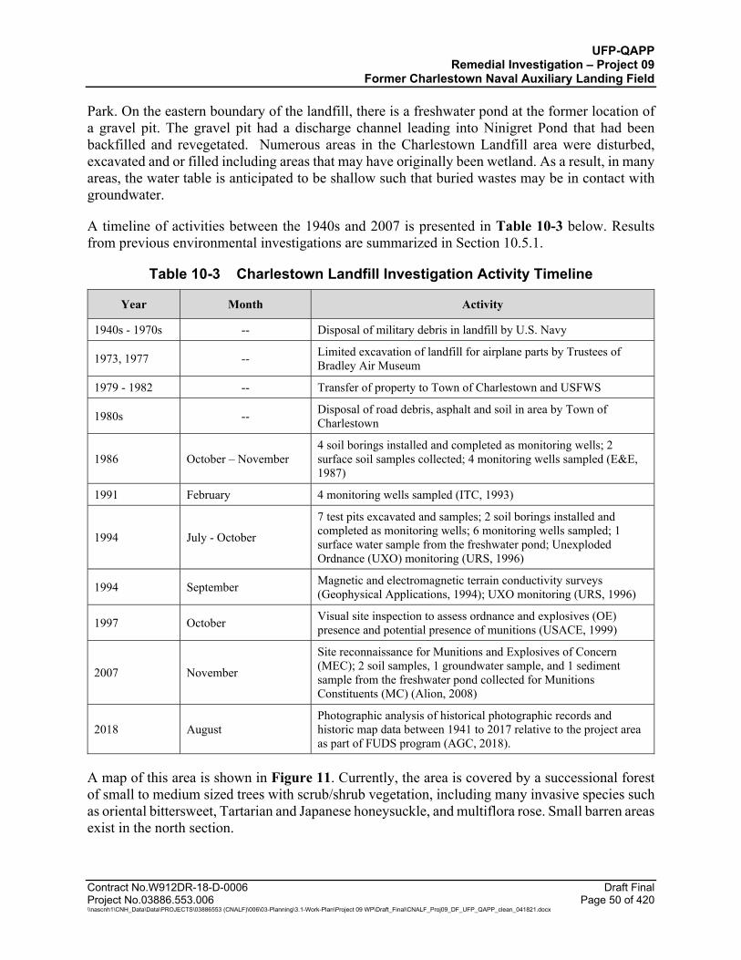
UFP-QAPP Remedial Investigation – Project 09
Former Charlestown Naval Auxiliary Landing Field
Contract No.W912DR-18-D-0006 Draft Final Project No.03886.553.006 Page 50 of 420 \\nascnh1\CNH_Data\Data\PROJECTS\03886553 (CNALF)\006\03-Planning\3.1-Work-Plan\Project 09 WP\Draft_Final\CNALF_Proj09_DF_UFP_QAPP_clean_041821.docx
Park. On the eastern boundary of the landfill, there is a freshwater pond at the former location of a gravel pit. The gravel pit had a discharge channel leading into Ninigret Pond that had been backfilled and revegetated. Numerous areas in the Charlestown Landfill area were disturbed, excavated and or filled including areas that may have originally been wetland. As a result, in many areas, the water table is anticipated to be shallow such that buried wastes may be in contact with groundwater.
A timeline of activities between the 1940s and 2007 is presented in Table 10-3 below. Results from previous environmental investigations are summarized in Section 10.5.1.
Table 10-3 Charlestown Landfill Investigation Activity Timeline
Year Month Activity
1940s - 1970s -- Disposal of military debris in landfill by U.S. Navy
1973, 1977 -- Limited excavation of landfill for airplane parts by Trustees of Bradley Air Museum
1979 - 1982 -- Transfer of property to Town of Charlestown and USFWS
1980s -- Disposal of road debris, asphalt and soil in area by Town of Charlestown
1986 October – November 4 soil borings installed and completed as monitoring wells; 2 surface soil samples collected; 4 monitoring wells sampled (E&E, 1987)
1991 February 4 monitoring wells sampled (ITC, 1993)
1994 July - October
7 test pits excavated and samples; 2 soil borings installed and completed as monitoring wells; 6 monitoring wells sampled; 1 surface water sample from the freshwater pond; Unexploded Ordnance (UXO) monitoring (URS, 1996)
1994 September Magnetic and electromagnetic terrain conductivity surveys (Geophysical Applications, 1994); UXO monitoring (URS, 1996)
1997 October Visual site inspection to assess ordnance and explosives (OE) presence and potential presence of munitions (USACE, 1999)
2007 November
Site reconnaissance for Munitions and Explosives of Concern (MEC); 2 soil samples, 1 groundwater sample, and 1 sediment sample from the freshwater pond collected for Munitions Constituents (MC) (Alion, 2008)
2018 August Photographic analysis of historical photographic records and historic map data between 1941 to 2017 relative to the project area as part of FUDS program (AGC, 2018).
A map of this area is shown in Figure 11. Currently, the area is covered by a successional forest of small to medium sized trees with scrub/shrub vegetation, including many invasive species such as oriental bittersweet, Tartarian and Japanese honeysuckle, and multiflora rose. Small barren areas exist in the north section.
UFP-QAPP Remedial Investigation – Project 09
Former Charlestown Naval Auxiliary Landing Field
Contract No.W912DR-18-D-0006 Draft Final Project No.03886.553.006 Page 51 of 420 \\nascnh1\CNH_Data\Data\PROJECTS\03886553 (CNALF)\006\03-Planning\3.1-Work-Plan\Project 09 WP\Draft_Final\CNALF_Proj09_DF_UFP_QAPP_clean_041821.docx
The overburden material within the central part of the Charlestown Landfill is composed of fill and well-stratified fine to coarse sand and gravel glacial outwash deposits. The satellite areas to the north and northeast have not been previously investigated so the subsurface conditions are unknown. Surface topography for the site ranges from approximately 20 ft amsl in the northwest corner of the site to sea level at the Ninigret Pond shoreline along the eastern boundary of the site. Historic landfill and excavation activities have adjusted the natural surface topography, creating steep slopes in areas with most disturbance (Figure 11). Based on historical observations from monitoring wells, groundwater is present at approximately 7.5 ft to 13 ft below ground surface (bgs) in the overburden at this landfill. Tidal influence on groundwater in this area is negligible (approximately 0.03 ft). Historical investigation reports indicate groundwater flow is to the east/southeast (URS, 1996). Bedrock is assumed at 24-30 ft bgs based on refusal depths reported in soil boring logs (E&E, 1987). A residential area abutting the east/northeast boundary of the Ninigret Park and the NWR portions of CNALF is potentially downgradient from the Charlestown Landfill. Contaminants in the fill and debris, if present, have the potential to impact the surrounding environment by volatilizing into the air, run off via erosion in surface water (and potentially depositing in sediment or other surface soil), and leaching to groundwater via infiltrated surface water or direct groundwater contact with waste below the season-high water table, as well as groundwater to surface water migration.
The areas of investigation proposed for this RI have expanded upon those investigated previously by ITC (1993) and URS (1996), based on the disturbances observed in historic aerial imagery taken of the Charlestown Landfill region (AGC, 2018). The historic photograph assessment identified additional excavation and manually disturbed areas to the north and northeast of the known Charlestown Landfill boundaries that could be associated with military landfill operations in the late 1940s through the 1960s. The depths of these impacted of areas are unknown. An April 1954 historic aerial (Figure 30b) showed evidence of water being present in one of the excavation pits to the north of the landfill (AGC, 2018), suggesting that the excavation depths touched the groundwater table or overland water flowed into the pit after a recent precipitation event. These areas were not previously assessed during geophysical assessments in the 1990s. Most of these areas have since been revegetated; however, there are mounded materials (i.e. concrete piles, asphalt piles, debris) and steep slopes in these areas presently that could impact efforts to properly complete geophysical surveys.
The fill material encountered during test pit activities in the landfill was characterized as a heterogeneous mixture of sand and gravel mixed with landfill materials, including bomb shell casings, piping, metallic debris, cinders, slag, asbestos shingles, and glass in addition to the aircraft and fire training aircraft components as well as drums/containers. At most locations the debris is covered with variable thickness of soil, but there is no engineered cap and the cover thickness is unknown across the landfill. The Town of Charlestown stockpile/landfill area is located along the northwest edge of the landfill and contains asphalt and road debris at the surface and is not covered with soil.
10.4.2 Eastern Area Landfill Background
The Eastern Area Landfill is approximately 60 acres and is located in NWR at the end of Runway 30 on the east end of CNALF, between the Charlestown Landfill and Ninigret Pond (see Figure 2).
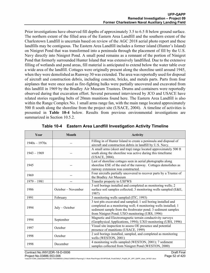
UFP-QAPP Remedial Investigation – Project 09
Former Charlestown Naval Auxiliary Landing Field
Contract No.W912DR-18-D-0006 Draft Final Project No.03886.553.006 Page 52 of 420 \\nascnh1\CNH_Data\Data\PROJECTS\03886553 (CNALF)\006\03-Planning\3.1-Work-Plan\Project 09 WP\Draft_Final\CNALF_Proj09_DF_UFP_QAPP_clean_041821.docx
Prior investigations have observed fill depths of approximately 3.5 to 6.5 ft below ground surface. The northern extent of the filled area of the Eastern Area Landfill and the southern extent of the Charlestown Landfill is uncertain based on review of the AGC 2018 aerial photo report and these landfills may be contiguous. The Eastern Area Landfill includes a former island (Hunter’s Island) on Ninigret Pond that was transformed into a peninsula through the placement of fill by the U.S. Navy directly into Ninigret Pond. A small pond remains as a remnant of the portion of Ninigret Pond that formerly surrounded Hunter Island that was extensively landfilled. Due to the extensive filling of wetlands and pond areas, fill material is anticipated to extend below the water table over a wide area of the landfill. Cottages were originally present along the shoreline until around 1945, when they were demolished as Runway 30 was extended. The area was reportedly used for disposal of aircraft and construction debris, including concrete, bricks, and metals parts. Parts from four airplanes that were once used as fire-fighting hulks were partially uncovered and excavated from this landfill in 1969 by the Bradley Air Museum Trustees. Drums and containers were reportedly observed during that excavation effort. Several personnel interviewed by JCO and USACE have related stories regarding belts of 20mm munitions found here. The Eastern Area Landfill is also within the Range Complex No. 1 small arms range fan, with the main range located approximately 500 ft south along the shoreline from the project site (USACE, 2004). A timeline of activities is presented in Table 10-4 below. Results from previous environmental investigations are summarized in Section 10.5.2.
Table 10-4 Eastern Area Landfill Investigation Activity Timeline
Year Month Activity
1940s – 1970s -- Filling in of Hunter Island to create a peninsula and disposal of aircraft and construction debris in landfill by U.S. Navy.
1943 – 1969 -- A small arms (skeet and trap) range located approximately 500 ft south along the shoreline was active during this timeframe (USACE, 2004).
1945 -- Last of shoreline cottages seen in aerial photographs along shoreline ESE of the end of the runway. Cottages demolishes as runway extension was constructed.
1969 -- Four aircrafts partially uncovered to recover parts by a Trustee of the Bradley Air Museum
1979 – 1981 -- Transfer property to USFWS
1986 October – November 3 soil borings installed and completed as monitoring wells; 2 surface soil samples collected; 3 monitoring wells sampled (E&E, 1987)
1991 February 3 monitoring wells sampled (ITC, 1993)
1994 July – October
3 test pits excavated and sampled; 1 soil boring installed and completed as a monitoring well; 4 monitoring wells installed; 1 sediment sample from the freshwater pond; 3 sediment samples from Ninigret Pond; UXO monitoring (URS, 1996)
1994 September Magnetic and Electromagnetic terrain conductivity surveys (Geophysical Applications, 1994); UXO monitoring (URS, 1996)
1997 October Visual site inspection to assess OE presence and potential presence of munitions (USACE, 1999)
1998 October 2 soil borings installed, sampled, and completed as monitoring wells (WESTON, 2001)
1998 December 4 monitoring wells sampled (WESTON, 2001); 7 sediment samples collected from Ninigret Pond (WESTON, 2000)

UFP-QAPP Remedial Investigation – Project 09
Former Charlestown Naval Auxiliary Landing Field
Table 10-4 Eastern Area Landfill Investigation Activity Timeline (Continued)
Contract No.W912DR-18-D-0006 Draft Final Project No.03886.553.006 Page 53 of 420 \\nascnh1\CNH_Data\Data\PROJECTS\03886553 (CNALF)\006\03-Planning\3.1-Work-Plan\Project 09 WP\Draft_Final\CNALF_Proj09_DF_UFP_QAPP_clean_041821.docx
Year Month Activity
2007 November Site reconnaissance for MEC; 2 soil samples, 1 groundwater sample, and 1 sediment sample from the freshwater pond collected for MC analysis (Alion, 2008)
2018 -- Photographic analysis of historical photographic records and historic map data between 1941 to 2017 relative to the project area as part of FUDS program (AGC, 2018).
A map of this area is shown in Figure 12. The areas of investigation proposed for this RI have expanded upon those investigated previously by ITC (1993) and URS (1996), based on the disturbances observed in historic aerial imagery of the Eastern Area Landfill (AGC, 2018). The historic photograph assessment identified additional disturbed areas to the north of the known Eastern Landfill boundary and east/southeast of the end of Runway 30 that could be associated with military landfill or airfield expansions operations in the late 1940s through the 1970s. These activities included filling in the original shoreline and creating the causeway to Hunter Island. The depths of these impacted areas and materials used as fill are unknown. These areas were not previously assessed during geophysical assessments in the 1990s. Some of these excavation/fill activities generated steep slopes near the water’s edge which is indicative of filled wetland or pond areas.
Currently, the area is densely vegetated with shrubs, vines, and small trees, including many invasive species, such as stands of Phragmites in the interior and along the shores of the small freshwater pond, oriental bittersweet, Tartarian and Japanese honeysuckle, and multiflora rose.
The overburden material at this landfill is composed of fill overlying well-stratified fine to coarse sand and gravel glacial outwash deposits. The surface topography ranges across the site from approximately 11 ft amsl in the northeast corner of the landfill to sea level along the shorelines in the south toward the small pond (designated wetland) and east toward Ninigret Pond. Groundwater was encountered at 4 to 6.8 ft bgs in the overburden in this area. Tidal influence on groundwater in this area is up to 0.2 ft. Historical investigation reports indicate groundwater flow is to the east/southeast (URS, 1996). Confirmed bedrock is at 17.6 ft bgs at CN-08 based on a borehole core; bedrock is deeper than 20 ft bgs at CN-06 and 22 ft bgs at CN-07 since it was not encountered in the soil borings (E&E, 1987).
The fill material encountered during test pit activities was characterized as a heterogeneous mixture of sand and gravel with some silt and clay mixed with landfilled materials, including construction and demolition debris, scrap metal, plastic, cinders, ash, lumber, burned aircraft components, drums and containers and steel practice (inert) bombs. At most locations, the landfill debris is covered by surficial soil fill of variable thickness, but there is no engineered cap across the landfill (URS, 1996). Due to the unknown depth of the landfill in this area, it is possible the landfill soils are in contact with the groundwater table.
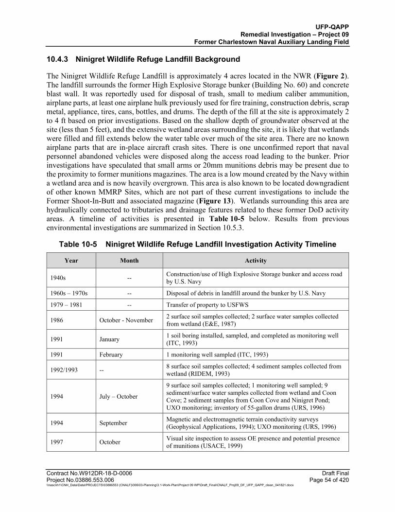
UFP-QAPP Remedial Investigation – Project 09
Former Charlestown Naval Auxiliary Landing Field
Contract No.W912DR-18-D-0006 Draft Final Project No.03886.553.006 Page 54 of 420 \\nascnh1\CNH_Data\Data\PROJECTS\03886553 (CNALF)\006\03-Planning\3.1-Work-Plan\Project 09 WP\Draft_Final\CNALF_Proj09_DF_UFP_QAPP_clean_041821.docx
10.4.3 Ninigret Wildlife Refuge Landfill Background
The Ninigret Wildlife Refuge Landfill is approximately 4 acres located in the NWR (Figure 2). The landfill surrounds the former High Explosive Storage bunker (Building No. 60) and concrete blast wall. It was reportedly used for disposal of trash, small to medium caliber ammunition, airplane parts, at least one airplane hulk previously used for fire training, construction debris, scrap metal, appliance, tires, cans, bottles, and drums. The depth of the fill at the site is approximately 2 to 4 ft based on prior investigations. Based on the shallow depth of groundwater observed at the site (less than 5 feet), and the extensive wetland areas surrounding the site, it is likely that wetlands were filled and fill extends below the water table over much of the site area. There are no known airplane parts that are in-place aircraft crash sites. There is one unconfirmed report that naval personnel abandoned vehicles were disposed along the access road leading to the bunker. Prior investigations have speculated that small arms or 20mm munitions debris may be present due to the proximity to former munitions magazines. The area is a low mound created by the Navy within a wetland area and is now heavily overgrown. This area is also known to be located downgradient of other known MMRP Sites, which are not part of these current investigations to include the Former Shoot-In-Butt and associated magazine (Figure 13). Wetlands surrounding this area are hydraulically connected to tributaries and drainage features related to these former DoD activity areas. A timeline of activities is presented in Table 10-5 below. Results from previous environmental investigations are summarized in Section 10.5.3.
Table 10-5 Ninigret Wildlife Refuge Landfill Investigation Activity Timeline
Year Month Activity
1940s -- Construction/use of High Explosive Storage bunker and access road by U.S. Navy
1960s – 1970s -- Disposal of debris in landfill around the bunker by U.S. Navy
1979 – 1981 -- Transfer of property to USFWS
1986 October - November 2 surface soil samples collected; 2 surface water samples collected from wetland (E&E, 1987)
1991 January 1 soil boring installed, sampled, and completed as monitoring well (ITC, 1993)
1991 February 1 monitoring well sampled (ITC, 1993)
1992/1993 -- 8 surface soil samples collected; 4 sediment samples collected from wetland (RIDEM, 1993)
1994 July – October
9 surface soil samples collected; 1 monitoring well sampled; 9 sediment/surface water samples collected from wetland and Coon Cove; 2 sediment samples from Coon Cove and Ninigret Pond; UXO monitoring; inventory of 55-gallon drums (URS, 1996)
1994 September Magnetic and electromagnetic terrain conductivity surveys (Geophysical Applications, 1994); UXO monitoring (URS, 1996)
1997 October Visual site inspection to assess OE presence and potential presence of munitions (USACE, 1999)
UFP-QAPP Remedial Investigation – Project 09
Former Charlestown Naval Auxiliary Landing Field
Table 10-5 Ninigret Wildlife Refuge Landfill Investigation Activity Timeline (Continued)
Contract No.W912DR-18-D-0006 Draft Final Project No.03886.553.006 Page 55 of 420 \\nascnh1\CNH_Data\Data\PROJECTS\03886553 (CNALF)\006\03-Planning\3.1-Work-Plan\Project 09 WP\Draft_Final\CNALF_Proj09_DF_UFP_QAPP_clean_041821.docx
Year Month Activity
1998 October 2 soil borings installed, sampled, and completed as monitoring wells (WESTON, 2001)
1998 December 3 monitoring wells sampled (WESTON, 2001)
2007 November Site reconnaissance for MEC; 2 soil samples, 1 groundwater sample, and 1 sediment sample from wetland collected for MC analysis (Alion, 2008)
2018 -- Photographic analysis of historical photographic records and historic map data between 1941 to 2017 relative to the project area as part of FUDS program (AGC, 2018).
A map of the area is shown in Figure 13. The Ninigret Wildlife Refuge Landfill footprint area to be investigation for this RI is similar to that investigated previously by ITC (1993) and URS (1996), and consistent with the disturbed areas observed in historic aerial imagery of the Ninigret Wildlife Refuge Landfill area (AGC, 2018). Currently the area is covered by large shrubs and small to medium sized trees characteristic of early to mid-successional coastal forest, including invasive species such as oriental bittersweet, Tartarian and Japanese honeysuckle, and multiflora rose.
The surface topography ranges across the site from 3 to 19 ft amsl. The highest elevation is in the immediate vicinity of the vegetated-covered former Building No. 60 in the middle of the site. The ground elevation drops to 3 ft amsl within 50 feet from the top of the bunker, resulting in steep slopes (Figure 13) overlying the bunker. Beyond the former structure, the surface topography is gently sloped as it meets sea level approximately 750 ft to the south. The central bunker area is surrounded by wetlands to the south, west, and east.
The overburden material at this landfill is composed of fill overlying well-stratified fine to coarse sand and gravel glacial outwash deposits. Groundwater was encountered at 4.5 to 5 ft bgs in the overburden at this location. This area has not been evaluated to determine tidal influence on groundwater. Historical investigation reports indicate groundwater flow is to the south/southeast toward Coon Cove and Ninigret Pond. The top of bedrock is assumed to be deeper than 30 ft bgs.
No test pit activities have been reported. The fill material encountered in soil borings and surface soil samples was described as silty sand fill. Debris observed on the surface of the landfill included trash, small arms or 20mm munitions debris, construction debris, scrap metal, appliance, tires, cans, bottles, burned aircraft components and empty drums (including those labeled toluene, acetone, and chloromethane). Due to the unknown depth of the landfill in this area, it is possible the landfill soils are in contact with the groundwater table.
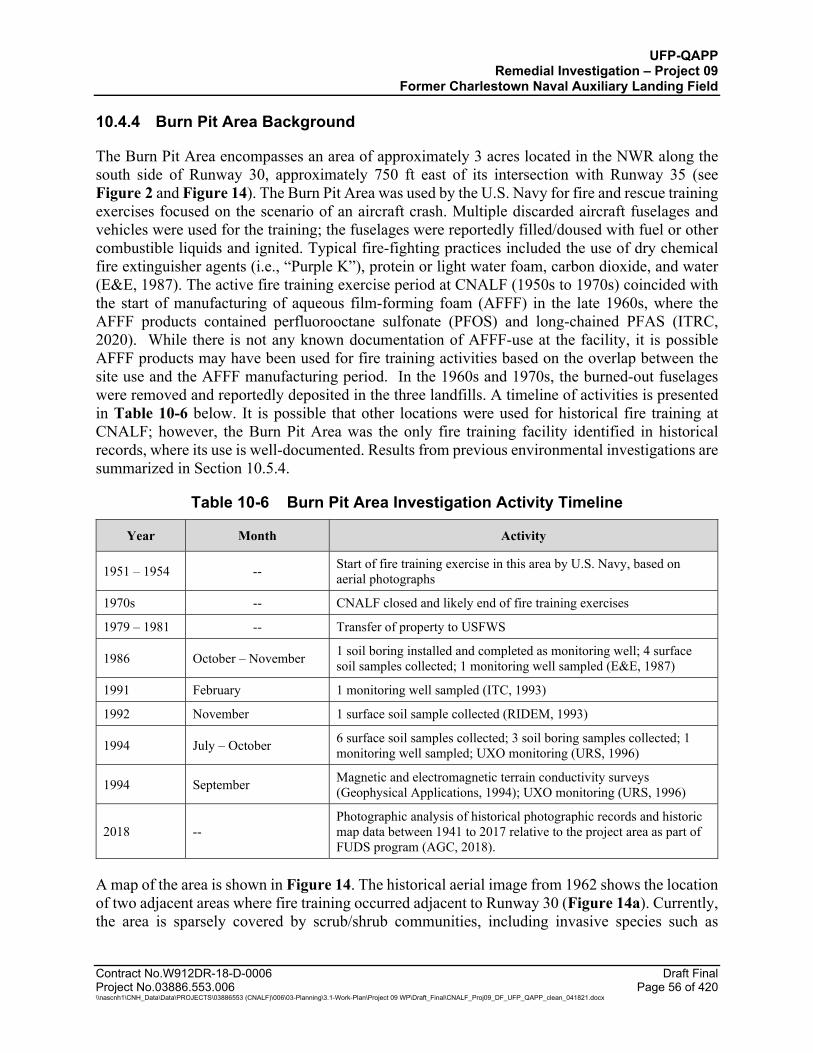
UFP-QAPP Remedial Investigation – Project 09
Former Charlestown Naval Auxiliary Landing Field
Contract No.W912DR-18-D-0006 Draft Final Project No.03886.553.006 Page 56 of 420 \\nascnh1\CNH_Data\Data\PROJECTS\03886553 (CNALF)\006\03-Planning\3.1-Work-Plan\Project 09 WP\Draft_Final\CNALF_Proj09_DF_UFP_QAPP_clean_041821.docx
10.4.4 Burn Pit Area Background
The Burn Pit Area encompasses an area of approximately 3 acres located in the NWR along the south side of Runway 30, approximately 750 ft east of its intersection with Runway 35 (see Figure 2 and Figure 14). The Burn Pit Area was used by the U.S. Navy for fire and rescue training exercises focused on the scenario of an aircraft crash. Multiple discarded aircraft fuselages and vehicles were used for the training; the fuselages were reportedly filled/doused with fuel or other combustible liquids and ignited. Typical fire-fighting practices included the use of dry chemical fire extinguisher agents (i.e., “Purple K”), protein or light water foam, carbon dioxide, and water (E&E, 1987). The active fire training exercise period at CNALF (1950s to 1970s) coincided with the start of manufacturing of aqueous film-forming foam (AFFF) in the late 1960s, where the AFFF products contained perfluorooctane sulfonate (PFOS) and long-chained PFAS (ITRC, 2020). While there is not any known documentation of AFFF-use at the facility, it is possible AFFF products may have been used for fire training activities based on the overlap between the site use and the AFFF manufacturing period. In the 1960s and 1970s, the burned-out fuselages were removed and reportedly deposited in the three landfills. A timeline of activities is presented in Table 10-6 below. It is possible that other locations were used for historical fire training at CNALF; however, the Burn Pit Area was the only fire training facility identified in historical records, where its use is well-documented. Results from previous environmental investigations are summarized in Section 10.5.4.
Table 10-6 Burn Pit Area Investigation Activity Timeline
Year Month Activity
1951 – 1954 -- Start of fire training exercise in this area by U.S. Navy, based on aerial photographs
1970s -- CNALF closed and likely end of fire training exercises
1979 – 1981 -- Transfer of property to USFWS
1986 October – November 1 soil boring installed and completed as monitoring well; 4 surface soil samples collected; 1 monitoring well sampled (E&E, 1987)
1991 February 1 monitoring well sampled (ITC, 1993)
1992 November 1 surface soil sample collected (RIDEM, 1993)
1994 July – October 6 surface soil samples collected; 3 soil boring samples collected; 1 monitoring well sampled; UXO monitoring (URS, 1996)
1994 September Magnetic and electromagnetic terrain conductivity surveys (Geophysical Applications, 1994); UXO monitoring (URS, 1996)
2018 -- Photographic analysis of historical photographic records and historic map data between 1941 to 2017 relative to the project area as part of FUDS program (AGC, 2018).
A map of the area is shown in Figure 14. The historical aerial image from 1962 shows the location of two adjacent areas where fire training occurred adjacent to Runway 30 (Figure 14a). Currently, the area is sparsely covered by scrub/shrub communities, including invasive species such as
UFP-QAPP Remedial Investigation – Project 09
Former Charlestown Naval Auxiliary Landing Field
Contract No.W912DR-18-D-0006 Draft Final Project No.03886.553.006 Page 57 of 420 \\nascnh1\CNH_Data\Data\PROJECTS\03886553 (CNALF)\006\03-Planning\3.1-Work-Plan\Project 09 WP\Draft_Final\CNALF_Proj09_DF_UFP_QAPP_clean_041821.docx
oriental bittersweet, Tartarian and Japanese honeysuckle, and multiflora rose, with many barren areas of stone, gravel, hardened soil, and crumbled asphalt (Figure 14b).
The surface topography in this area is flat with an elevation of approximately 11 ft amsl, with a gentle southward slope. The former asphalt surface of the adjacent runway was removed, and the area is now sparsely vegetated.
The overburden material in this area is composed of fill overlying well-stratified fine to coarse sand and gravel glacial outwash deposits. Groundwater was encountered at 8 – 10.5 ft bgs in the overburden at this location. This area has not been evaluated to determine tidal influence on groundwater. Historical investigation reports indicate groundwater flow in this area is to the south/southeast toward Ninigret Pond. Bedrock is assumed deeper than 23 ft bgs and estimated to be approximately 30 to 40 ft amsl, based on bedrock surface contours from investigations in the 1970s.
The surface material encountered at the Burn Pit Area during previous investigations was a black, sandy silt/silty sand mixture with burned metallic debris, ash, and degrading asphalt and extends approximately 6-inch bgs.
10.5 PREVIOUS ENVIRONMENTAL INVESTIGATIONS
The following summary reviews the extent of environmental investigation at CNALF after the facility closure in approximately 1974. The General Services Administration prepared an Environmental Impact Statement in approximately 1979 which was based primarily upon reviews of existing data (GSA, 1979). In 1976, NEPCO filed an application to build a nuclear power plant at CNALF and initiated site investigations to characterize the physical and hydrogeologic features of CNALF. The application was not approved, and the power plant was not constructed (URS, 1996). The first environmental contamination assessment was conducted by E&E in 1987. This was a preliminary determination phase that was initiated under the Defense Environmental Restoration Account by the Huntsville Division of USACE because of concerns that environmental contamination may have resulted from DoD activities (E&E, 1987). This investigation was followed by a Phase I RI by ITC (1993), and a Phase II RI by URS (1996) under DERP for the Omaha District of USACE. The Phase II RI included a baseline human-health (HHRA) and screening level ecological risk assessments (SLERA). In 1993, RIDEM performed a Preliminary Assessment under a multi-site cooperative agreement between RIDEM and USEPA (RIDEM, 1993). In 2000, WESTON performed a Site Investigation (SI) for USEPA under the Superfund Technical Assessment and Response Team contract (WESTON, 2000). In 2001, WESTON performed a Supplemental Phase II RI under DERP-FUDS for CENAE (WESTON, 2001).
Laboratory analytical data obtained from these previous investigations was tabulated in the JCO Technical Memorandum, Historical Review for Project 08 and Project 09. Data tables from this document that are pertinent to Project 09 are included in Attachment C.
UFP-QAPP Remedial Investigation – Project 09
Former Charlestown Naval Auxiliary Landing Field
Contract No.W912DR-18-D-0006 Draft Final Project No.03886.553.006 Page 58 of 420 \\nascnh1\CNH_Data\Data\PROJECTS\03886553 (CNALF)\006\03-Planning\3.1-Work-Plan\Project 09 WP\Draft_Final\CNALF_Proj09_DF_UFP_QAPP_clean_041821.docx
10.5.1 Risk Assessments
URS conducted a baseline HHRA and a SLERA of the three landfills and the Burn Pit Area in 1996 as part of their Phase II RI. URS only included the validated results from their Phase II RI (which included VOCs, SVOCs, metals, PCBs, and pesticides) in their risk assessments because there was uncertainty of how the data review from previous environmental investigations was performed. The media of potential concern and potential receptors evaluated in the HHRA for each site included:
Charlestown Landfill:
Media of potential concern: surface soil, surface water, and sediment Potential receptors: park visitors (child and adult), park workers
Eastern Area Landfill:
Media of potential concern: sediment (Ninigret Pond), surface water, shellfish Potential receptors: shellfish harvesters, refuge visitors, (child and adult) USFWS
personnel
Burn Pit Area:
Media of potential concern: surface soil, subsurface soil Potential receptors: refuge visitors (child and adult), USFWS personnel, future
construction workers
Ninigret Wildlife Refuge Landfill:
Media of potential concern: surface soil, surface water, sediment (Coon Cove and Ninigret Pond), shellfish
Potential receptors: USFWS personnel, shellfish harvesters
The HHRA assessment indicated that under the current and projected future use scenarios evaluated as a part of the HHRA, noncarcinogenic and carcinogenic chemicals posed no unacceptable thread to the potentially exposed populations. The total sitewide hazard indices were less than 1.0 and the total sitewide carcinogenic risk were below or within the acceptable National Contingency Plan (NCP) range of 10-6 to 10-4. The HHRA concluded that the onsite contaminants did not pose significant or unacceptable risks to human health (URS, 1996).
The SLERA included an evaluation of habitats and food chain modeling for four different indicator species present at the four sites: white-footed mouse, muskrat, raccoon, and common crow. The main potential exposure route evaluated was ingestion of contaminated food or prey. Results of the SLERA indicated:
Charlestown Landfill:
Computed hazard index risk indicator animal: white-footed mouse Primary risk-driving contaminant(s): barium

UFP-QAPP Remedial Investigation – Project 09
Former Charlestown Naval Auxiliary Landing Field
Contract No.W912DR-18-D-0006 Draft Final Project No.03886.553.006 Page 59 of 420 \\nascnh1\CNH_Data\Data\PROJECTS\03886553 (CNALF)\006\03-Planning\3.1-Work-Plan\Project 09 WP\Draft_Final\CNALF_Proj09_DF_UFP_QAPP_clean_041821.docx
Eastern Area Landfill:
Computed hazard index risk indicator animal: white-footed mouse Primary risk-driving contaminant(s): barium, lead
Burn Pit Area:
Computed hazard index risk indicator animal: none identified Primary risk-driving contaminant(s): barium
Ninigret Wildlife Refuge Landfill:
Computed hazard index risk indicator animal: white-footed mouse, muskrat Primary risk-driving contaminant(s): barium, 4,4-DDT, lead
The critical effect for barium was uncertain other than that it is acutely toxic at higher concentrations. The contaminant 4,4-DDT at the Ninigret Wildlife Refuge Landfill had a single sample that resulted in a HQ of 74. Concentrations of lead also caused the HQ to exceed the acceptable value of 1 with a HQ value of 10. Risk for the white-footed mouse is related to increased risk posed to animals with a combination of a relatively small home range and a relatively high metabolic rate. Other species at risk for possible effects due to contamination would include voles, other mice, and moles. Risk for the muskrat is related to consumption of wetland vegetation and shellfish. Animals with wider home ranges and migratory habits were not found to be at risk to potential effects (URS, 1996).
10.5.2 Charlestown Landfill Previous Environmental Investigations
Prior investigations at the Charlestown Landfill included geophysical surveys, analytical sampling of soil, sediment, surface water, groundwater and sediment, excavation of test pits, inspection for munitions and baseline risk assessments. Results of these investigations are summarized below.
10.5.2.1 Geophysical Survey
Geophysical Applications conducted magnetic and electromagnetic terrain conductivity surveys in September 1994. The survey was done in areas based on the then-assumed landfill extent. After clearing the transect lines, reconnaissance-level geophysical data (total field magnetics and terrain conductivity electromagnetic induction) for this area were acquired on widely spaced transects (nominally 50 ft) using fixed endpoints and a compass. The data is limited by the wide transect spacing, and the accuracy of any individual data point could vary by as much as 20 ft. Results from the geophysical investigation are shown in Figure 15. Magnetic anomalies were observed, indicating a large volume of ferromagnetic objects and materials. Cinders and slag observed near the southeastern corner of the survey region contributed greatly to the observed anomalies (Geophysical Applications, 1994). Anomalies were identified up to the boundaries of the then-assumed landfill extent. These anomalies likely extend beyond the landfill limit as understood in 1996 in some areas (URS, 1996). Prior surveys did not include areas of surface water. Proposed investigation areas extend beyond the limits of the prior investigations and include outlying areas identified during aerial photo review completed in 2018 by the U.S. Army Geospatial Center (AGC, 2018) and the small pond in this area.

UFP-QAPP Remedial Investigation – Project 09
Former Charlestown Naval Auxiliary Landing Field
Contract No.W912DR-18-D-0006 Draft Final Project No.03886.553.006 Page 60 of 420 \\nascnh1\CNH_Data\Data\PROJECTS\03886553 (CNALF)\006\03-Planning\3.1-Work-Plan\Project 09 WP\Draft_Final\CNALF_Proj09_DF_UFP_QAPP_clean_041821.docx
10.5.2.2 Surface Soil Sampling (0-2 ft bgs)
Surface soil results from samples collected in 1986 (E&E, 1987) and 1994 (URS, 1996) showed no detectable VOCs, PCBs, or SVOCs, except for one estimated low-level detection of benzo(a)pyrene and chloroform. Dichlorodiphenyltrichloroethane (DDT), dichlorodiphenyldichloroethylene (DDE), and dichlorodiphenyldichloroethane (DDD) were present at low levels above current USEPA Soil Screening Level (SSL) and USEPA ecological screening levels; and total petroleum hydrocarbons (TPH) ranged from non-detect to 3,300 milligrams per kilogram (mg/kg). Concentrations of one metal (cadmium) exceeded average elemental concentrations of eastern U.S. surficial soils described in Shacklette and Boerngen (1984) or the concentrations in background surface soil samples collected from the CNALF property in 2007. Concentrations of several metals (aluminum, arsenic, barium, cadmium, chromium, cobalt, copper, iron, lead, manganese, nickel, selenium, vanadium, and zinc) exceeded USEPA SSL and USEPA ecological screening levels current at that time; and three metals (arsenic, chromium, and iron) exceeded USEPA Regional Screening Levels (RSL) for residential direct contact. Sample results from a 2007 investigation of MC in soil (Alion, 2008) showed no detections of MC in surface soil.
10.5.2.3 Subsurface Soil Sampling
Subsurface soil fill and debris material sample results collected by URS in 1994 (URS, 1996) showed the following VOC and SVOC compounds at low and estimated levels, but above current USEPA SSL screening levels; 2-methylnaphthalene, benzene, toluene, ethylbenzene, xylene, and chloro/dichlorobenzene. Polycyclic aromatic hydrocarbons (PAHs) were also present in two samples at low and estimated levels, but above current USEPA SSL and USEPA RSL for residential direct contact. DDT and its metabolites were present at low levels above current USEPA SSL and USEPA ecological screening levels, although soil below 1 ft bgs is below the ecological exposure zone. Reported TPH concentrations ranged from 26 – 621 mg/kg. Concentrations of three metals (barium, cadmium, and zinc) exceeded average elemental concentrations of eastern U.S. surficial soils described in Shacklette and Boerngen (1984) or the concentrations in background surface soil samples collected from the CNALF property in 2007. Concentrations of several metals (aluminum, arsenic, barium, cadmium, chromium, cobalt, copper, iron, lead, manganese, nickel, selenium, vanadium, and zinc) exceeded USEPA SSL and USEPA ecological screening levels; and five metals (arsenic, chromium, cobalt, iron, and manganese) exceeded USEPA RSL for residential direct contact.
Results for subsurface soil samples collected in 1994 located within or below the fill and debris material (URS, 1996) showed no detectable VOCs, and only one SVOC at an estimated concentration (benzo(a)anthracene) above the current USEPA SSL. DDT and its metabolites were present at low levels above current USEPA SSL and USEPA ecological screening levels (although soil below 1 ft bgs is below the ecological exposure zone). Estimated concentrations of two PCB Aroclors were reported above current USEPA SSL. Concentrations of two metals (cadmium and zinc) exceeded average elemental concentrations of eastern U.S. surficial soils described in Shacklette and Boerngen (1984) or the concentrations in background surface soil samples collected from the CNALF property in 2007. Concentrations of several metals (arsenic, barium, cadmium, chromium, cobalt, copper, iron, lead, manganese, nickel, vanadium, and zinc) exceeded USEPA
UFP-QAPP Remedial Investigation – Project 09
Former Charlestown Naval Auxiliary Landing Field
Contract No.W912DR-18-D-0006 Draft Final Project No.03886.553.006 Page 61 of 420 \\nascnh1\CNH_Data\Data\PROJECTS\03886553 (CNALF)\006\03-Planning\3.1-Work-Plan\Project 09 WP\Draft_Final\CNALF_Proj09_DF_UFP_QAPP_clean_041821.docx
SSL and USEPA ecological screening levels; and two metals (chromium and iron) exceeded USEPA RSL for residential direct contact.
10.5.2.4 Groundwater Sampling
Groundwater sample results from 1986 (E&E, 1987) showed no detectable concentrations of PCBs, pesticides, SVOCs, or VOCs and TPH concentrations of 36 milligrams per liter (mg/L) and lower. Three dissolved metals were detected above screening levels, including mercury, nickel, and zinc (zinc was also detected in a blank sample). Several total metals also exceeded screening levels, but these results may be biased as a result of sample turbidity due to the use of bailers to collect the samples.
Groundwater sample results from 1991 (ITC, 1993) showed no detections of any compounds analyzed (VOCs, TPH, or 8 dissolved metals).
Groundwater sample results from 1994 (URS, 1996) showed the following compounds above current screening levels: 1,2-dichloroethane (DCA), 2,4-dinitrotoluene (DNT), 2,6-DNT, DDT/DDE/DDD, and one dissolved metal (manganese). Several total metals also exceeded current screening levels, but these results may be biased as a result of the sampling methodology.
Groundwater sample results from 2007 (Alion, 2008) showed no detections of MC. These samples were not analyzed for other constituents.
10.5.2.5 Surface Water Sampling
In 1994, a surface water sample was collected from the freshwater pond adjacent to the Charlestown Landfill (URS, 1996). Results showed no detection of VOCs, SVOCs, pesticides, PCBs, or TPH. Metals were below current screening levels except for magnesium and manganese. The elevated dissolved magnesium concentration may be associated with saltwater intrusion.
10.5.2.6 Sediment Sampling
In 2007, sediment sample results from the adjacent freshwater pond (Alion, 2008) showed no detections of MC. This sample was not analyzed for other constituents.
10.5.2.7 Munitions Inspection and MC Sampling
Historically, there is no evidence of MEC and there are no records of munitions disposal; however, munition debris (MD) was identified during previous investigations (bomb shell casings and multiple 100-pound (lb) and 1,000-lb inert practice bombs). The 2007 SI found no MEC, but identified MD consisting of 1,000-lb practice bombs.
In 2008, as part of the SI, Alion conducted a qualitative munitions risk evaluation. MEC was determined to pose a low to moderate risk based on the MD found. No MC were identified as Contaminants of Potential Ecological Concern (COPECs) or Contaminants of Potential Concern (COPCs) based on the SLERA and HHRA performed during the SI. An RI/Feasibility Study (FS)
UFP-QAPP Remedial Investigation – Project 09
Former Charlestown Naval Auxiliary Landing Field
Contract No.W912DR-18-D-0006 Draft Final Project No.03886.553.006 Page 62 of 420 \\nascnh1\CNH_Data\Data\PROJECTS\03886553 (CNALF)\006\03-Planning\3.1-Work-Plan\Project 09 WP\Draft_Final\CNALF_Proj09_DF_UFP_QAPP_clean_041821.docx
for munitions was recommended since there is the potential for MEC to be present in the subsurface based on past practices or disposing of MD in this landfill (Alion, 2008).
A Probability Assessment for Determining the Probability of Encountering MEC During Site Activities was finalized in February 2021 (Attachment K) that addressed the three landfill MRS sites. The assessment determined there was a low probability of encountering MEC per the guidance Defense Explosives Safety Regulation (DESR) 6055.09 Edition 1 and Engineering Manual 385-1-97.
10.5.3 Eastern Area Landfill Previous Environmental Investigations
Prior investigations at the Eastern Area Landfill included geophysical surveys, analytical sampling of soil, sediment, groundwater and sediment, excavation of test pits, inspection for munitions and baseline risk assessments. No surface water samples were collected. Results of these investigations are summarized below.
10.5.3.1 Geophysical Survey
Geophysical Applications conducted magnetic and electromagnetic terrain conductivity surveys in September 1994. The survey was done in areas based on the then-assumed landfill extent. After clearing the transect lines, reconnaissance-level geophysical data (total field magnetics and terrain conductivity electromagnetic induction) for this area were acquired on widely spaced transects (nominally 50 ft) using fixed endpoints and a compass. The data is limited by the wide transect spacing, and the accuracy of any individual data point could vary by as much as 20 ft. Results from the geophysical investigation are shown in Figure 16. The survey found that most ferrous materials at this site are located northwest, north, and northeast of the pond. Ferrous demolition debris was visible at the ground surface near many of the magnetic anomalies (Geophysical Applications, 1994). Anomalies were identified up to the boundaries of the then-assumed landfill extent. These anomalies likely extend beyond the landfill limit as understood in 1996 in some areas (URS, 1996). Prior surveys did not include areas of surface water. Proposed investigation areas extend beyond the limits of the prior investigations and include areas identified during aerial photo review completed in 2018 by the U.S. Army Geospatial Center (AGC, 2018) and the small pond in this area.
10.5.3.2 Surface Soil Sampling (0-2 ft bgs)
In 1986, surface soil samples were analyzed (E&E, 1987) and showed no VOCs above current screening levels, only one SVOC (benzidine) exceeded current screening levels in a single sample, and there were no detectable PCBs or TPH. DDT/DDE were present at low levels above current USEPA SSL and USEPA ecological screening levels. Metals concentrations did not exceed average elemental concentrations of eastern U.S. surficial soils described in Shacklette and Boerngen (1984) or the concentrations in background surface soil samples collected from the CNALF property in 2007. Concentrations of several metals (arsenic, chromium, copper, lead, nickel, and zinc) exceeded current USEPA SSL and USEPA ecological screening levels; and arsenic and chromium exceeded current USEPA RSL for residential direct contact.
In 2007, surface soil sample results (Alion, 2008) showed no detections of MC.

UFP-QAPP Remedial Investigation – Project 09
Former Charlestown Naval Auxiliary Landing Field
Contract No.W912DR-18-D-0006 Draft Final Project No.03886.553.006 Page 63 of 420 \\nascnh1\CNH_Data\Data\PROJECTS\03886553 (CNALF)\006\03-Planning\3.1-Work-Plan\Project 09 WP\Draft_Final\CNALF_Proj09_DF_UFP_QAPP_clean_041821.docx
10.5.3.3 Subsurface Soil Sampling
Subsurface soil samples collected below the fill and debris material in 1994 (URS, 1996) showed no detectable VOCs or PCBs. SVOCs were detected at estimated levels below the laboratory quantitation limit with benzo(a)anthracene, benzo(a)pyrene, dibenzofuran, and naphthalene above the current USEPA SSL or USEPA RSL for residential direct contact. TPH concentrations were below current RIDEM criteria and ranged from non-detectable levels to 209 mg/kg. DDT and its metabolites and endrin aldehyde were present at low levels above current USEPA SSL and USEPA ecological screening levels. Metals concentrations did not exceed average elemental concentrations of eastern U.S. surficial soils described in Shacklette and Boerngen (1984) or the concentrations in background surface soil samples collected from the CNALF property in 2007. Concentrations of several metals (aluminum, arsenic, barium, chromium, cobalt, copper, iron, lead, manganese, nickel, selenium, thallium, vanadium, and zinc) exceeded current USEPA SSL and USEPA ecological screening levels; and six metals (aluminum, arsenic, chromium, cobalt, iron, and thallium) exceeded current USEPA RSL for residential direct contact.
Subsurface soil samples collected below the fill and debris material in 1998 (WESTON, 2001) showed no detectable VOCs or SVOCs. Three metals (barium, cadmium, and lead) exceeded average elemental concentrations of eastern U.S. surficial soils described in Shacklette and Boerngen (1984) or the concentrations in background surface soil samples collected from the CNALF property in 2007. Concentrations of several metals (arsenic, barium, cadmium, chromium, lead, mercury, and selenium) exceeded current USEPA SSL and USEPA ecological screening levels (although soil below 1 ft bgs is below the ecological exposure zone); and two metals (arsenic and chromium) exceeded current USEPA RSL for residential direct contact.
10.5.3.4 Groundwater Sampling
Groundwater sample results from 1986 (E&E, 1987) showed no detectable concentrations of PCBs, pesticides, SVOCs, or VOCs. TPH concentrations were at or below detection limits; and one dissolved metal (zinc) exceeded current screening levels, but zinc was detected in a blank sample analysis. Several total metals also exceeded current screening levels, but these results may be biased as a result of the use of bailers.
Groundwater sample results from 1991 (ITC, 1993) showed no detections of VOCs, SVOCs, PCBs, pesticides, or TPH; however, several dissolved metals were above current screening levels, including antimony, cadmium, chromium, lead, nickel, and silver.
Groundwater sample results from 1994 (URS, 1996) showed no detections of VOCs and SVOCs, except an estimated concentration of 1,2-DCA and naphthalene in one sample. PCBs, pesticides, and TPH were not detected in the groundwater samples. Several dissolved metals concentrations were reported above current screening levels, including antimony, arsenic, beryllium, chromium, cobalt, iron, manganese, and vanadium. Several total metals also exceeded current screening levels, but these results may be the result of the sampling methodology.
Groundwater sample results from 1998 (WESTON, 2001) showed no detection of VOCs or SVOCs. The metals chromium and total lead exceeded current screening levels.
UFP-QAPP Remedial Investigation – Project 09
Former Charlestown Naval Auxiliary Landing Field
Contract No.W912DR-18-D-0006 Draft Final Project No.03886.553.006 Page 64 of 420 \\nascnh1\CNH_Data\Data\PROJECTS\03886553 (CNALF)\006\03-Planning\3.1-Work-Plan\Project 09 WP\Draft_Final\CNALF_Proj09_DF_UFP_QAPP_clean_041821.docx
A 2007 groundwater sample was analyzed for MC and none were detected (Alion, 2008).
10.5.3.5 Sediment Sampling
A 1994 sediment sample was collected from the submerged fill material in the freshwater pond (URS, 1996). Results showed no detected VOCs or PCBs. Several PAHs exceeded current screening criteria in that sample. DDT and its metabolites were present at low levels above current USEPA ecological screening levels. Several metals exceeded current sediment screening levels (aluminum, arsenic, cadmium, chromium, cobalt, iron, lead, manganese, sodium, and zinc). Sodium exceedances interpreted to be associated with saltwater intrusion in this pond.
A 2007 sediment sample collected from the freshwater pond (Alion, 2008) showed no detections of MC, except for an estimated concentration of 2,4-DNT in only the duplicate, but not the primary sample. This sample was not analyzed for any other constituents.
10.5.3.6 Munitions Inspection and MC Sampling
Historically, there is no evidence of MEC and there are no records of munitions disposal; however, MD was identified during previous investigations (steel practice bombs) and there were unconfirmed reports of 20mm munitions belts being found in this area. There were no MEC or MD findings during the 2007 SI.
In 2008, as part of their SI, Alion conducted a qualitative munitions risk evaluation. MEC was determined to pose a low to moderate risk based on the MD found. No MC were identified as COPCs during the HHRA. However, 2,4-DNT and 2,6-DNT were identified as COPECs during the SLERA, which require further evaluation. An RI/FS was recommended since there is the potential for MEC to be present in the subsurface based on past practices of disposing of MD in this landfill (Alion, 2008).
A Probability Assessment for Determining the Probability of Encountering MEC During Site Activities was finalized in February 2021 (Attachment K) that addressed the three landfill MRS sites. The assessment determined there was a low probability of encountering MEC per the guidance Defense Explosives Safety Regulation (DESR) 6055.09 Edition 1 and Engineering Manual 385-1-97.
10.5.4 Ninigret Wildlife Refuge Landfill Previous Environmental Investigations
Prior investigations at the Ninigret Wildlife Refuge Landfill included geophysical surveys, analytical sampling of soil, sediment, surface water, groundwater and sediment, inspection for munitions and baseline risk assessments. No test pits were investigated at the Ninigret Wildlife Refuge Landfill. Results of these investigations are summarized below.
10.5.4.1 Geophysical Survey
Geophysical Applications conducted magnetic and electromagnetic terrain conductivity surveys in September 1994. The survey was done in areas based on the then-assumed landfill extent. After clearing the transect lines, reconnaissance-level geophysical data (total field magnetics and terrain
UFP-QAPP Remedial Investigation – Project 09
Former Charlestown Naval Auxiliary Landing Field
Contract No.W912DR-18-D-0006 Draft Final Project No.03886.553.006 Page 65 of 420 \\nascnh1\CNH_Data\Data\PROJECTS\03886553 (CNALF)\006\03-Planning\3.1-Work-Plan\Project 09 WP\Draft_Final\CNALF_Proj09_DF_UFP_QAPP_clean_041821.docx
conductivity electromagnetic induction) for this area were acquired along radial transects extending from the bunker structure using fixed endpoints and a compass. The data is limited by the wide transect spacing, and the accuracy of any individual data point could vary by as much as 20 ft. Results from the geophysical investigation are shown in Figure 17. Landfill materials were identified in eight locations along the survey traverses (Geophysical Applications, 1994). Anomalies were identified up to the boundaries of the then-assumed landfill extent. These anomalies likely extend beyond the landfill limit as understood in 1996 in some areas (URS, 1996). Proposed investigation areas extend beyond the limits of the prior investigations and include areas identified during aerial photo review completed in 2018 by the U.S. Army Geospatial Center (AGC, 2018).
10.5.4.2 Surface Soil Sampling (0-2 ft bgs)
Results from surface soil samples collected in 1986 (E&E, 1987) showed no detectable VOCs, PCBs, or TPH. PAHs were detected in one sample with concentrations that exceeded current USEPA human health screening levels. DDT was present at low levels above current USEPA SSL and USEPA ecological screening levels. Concentrations of one metal (cadmium) exceeded average elemental concentrations of eastern U.S. surficial soils described in Shacklette and Boerngen (1984) or the concentrations in background surface soil samples collected from the CNALF property in 2007. Concentrations of several metals (cadmium, chromium, copper, lead, nickel, and zinc) exceeded current USEPA SSL and USEPA ecological screening levels; and only chromium exceeded current USEPA RSL for residential direct contact.
Results from surface soil samples collected in 1991 (ITC, 1993) showed no detectable VOCs.
Results from surface soil samples collected in 1992 and 1993 (RIDEM, 1993) showed 7 VOCs (1,1,1-trichloroethane, ethylbenzene, tetrachloroethene, toluene, trichloroethene, xylenes, and methylene chloride) at concentrations that exceeded the current USEPA SSL for human health, and 12 SVOCs, primarily PAHs, at concentrations above current screening levels. Concentrations for four metals (cadmium, lead, nickel, and zinc) exceeded average elemental concentrations of eastern U.S. surficial soils described in Shacklette and Boerngen (1984) or the concentrations in background surface soil samples collected from the CNALF property in 2007. Concentrations of several metals (cadmium, chromium, copper, lead, nickel, and zinc) exceeded current USEPA SSL and USEPA ecological screening levels; and lead exceeded current USEPA RSL for residential direct contact.
Results from surface soil samples collected in 1994 (URS, 1996) showed one VOC at estimated concentrations above current screening levels (chloroform) and SVOCs at estimated or detected concentrations above current screening levels including 2-methylnaphthalene, several PAHs, and dibenzofuran. No PCBs were detected. TPH levels ranged from non-detect to 1610 mg/kg. DDT/DDE/DDD were present at levels higher than detected elsewhere at CNALF, and were above current USEPA SSL, USEPA ecological screening levels, and USEPA residential RSLs. Concentrations of six metals (antimony, barium, cadmium, copper, lead, and zinc) exceeded average elemental concentrations of eastern U.S. surficial soils described in Shacklette and Boerngen (1984) or the concentrations in background surface soil samples collected from the CNALF property in 2007. All metals for which a standard is established exceeded current USEPA

UFP-QAPP Remedial Investigation – Project 09
Former Charlestown Naval Auxiliary Landing Field
Contract No.W912DR-18-D-0006 Draft Final Project No.03886.553.006 Page 66 of 420 \\nascnh1\CNH_Data\Data\PROJECTS\03886553 (CNALF)\006\03-Planning\3.1-Work-Plan\Project 09 WP\Draft_Final\CNALF_Proj09_DF_UFP_QAPP_clean_041821.docx
SSL and USEPA ecological screening levels for certain samples; and several metals exceeded USEPA residential RSL.
Results from 2007 (Alion, 2008) showed no detections of MC in surface soil.
10.5.4.3 Subsurface Soil Sampling
Results from subsurface soil samples collected in 1991 (ITC, 1993) showed no detectable VOCs, SVOC, PCBs, pesticides, or TPH. Concentrations of one metal (barium) exceeded average elemental concentrations of eastern U.S. surficial soils described in Shacklette and Boerngen (1984) or the concentrations in background surface soil samples collected from the CNALF property in 2007. Concentrations of several metals (arsenic, barium, chromium, copper, lead, nickel, and zinc) exceeded current USEPA SSL and USEPA ecological screening levels (although soil below 1 ft bgs is below the ecological exposure zone); and arsenic and chromium exceeded current USEPA RSL for residential direct contact. No test pits or subsurface soil sampling from test pits was performed at the Ninigret Wildlife Refuge Landfill.
Results from subsurface soil samples collected in 1998 from soil below the fill and debris material (WESTON, 2001) showed no detectable VOCs or SVOCs. No metals exceeded the range of average elemental concentrations of eastern U.S. surficial soils described in Shacklette and Boerngen (1984) or the concentrations in background surface soil samples collected from the CNALF property in 2007. Concentrations of three metals (barium, chromium, and lead) exceeded current USEPA SSL and USEPA ecological screening levels (although soil below 1 ft bgs is below the ecological exposure zone); and chromium exceeded current USEPA residential RSL.
10.5.4.4 Groundwater Sampling
Groundwater sample results from 1991, 1994 and 1998 (ITC, 1993; URS, 1996; WESTON, 2001) showed no detectable VOCs, SVOCs, TPH, PCBs, or pesticides. Dissolved iron and manganese exceeded current screening levels. Two total metals also exceeded current screening levels, but these results may be the biased as result of the sampling methodology.
A 2007 groundwater sample (Alion, 2008) showed no detections of MC.
10.5.4.5 Surface Water Sampling
Results from surface water samples collected in 1986 from the adjacent wetlands (E&E, 1987) showed no detectable VOCs, SVOCs, TPH, PCBs, or pesticides. Several metals exceeded current screening levels (total arsenic, cadmium, chromium, copper, lead, mercury; dissolved lead, mercury, and zinc).
Results from surface water samples collected in 1994 from the adjacent wetlands and Coon Cove (URS, 1996) showed no detectable VOCs, except for carbon disulfide in 2 samples and toluene in 1 sample above current screening levels. No SVOCs, TPH, or PCBs were detected. Six of the seven samples showed no detectable pesticides except for estimated concentrations of lindane and DDE above current screening levels. One sample contained several pesticides at concentrations or estimated concentrations above current screening levels (alpha-BHC, endosulfan I, endrin,
UFP-QAPP Remedial Investigation – Project 09
Former Charlestown Naval Auxiliary Landing Field
Contract No.W912DR-18-D-0006 Draft Final Project No.03886.553.006 Page 67 of 420 \\nascnh1\CNH_Data\Data\PROJECTS\03886553 (CNALF)\006\03-Planning\3.1-Work-Plan\Project 09 WP\Draft_Final\CNALF_Proj09_DF_UFP_QAPP_clean_041821.docx
lindane, heptachlor, and methoxychlor). All metals for which a current standard screening level is established exceeded those screening levels, except for nickel and cobalt.
10.5.4.6 Sediment Sampling
Sediment samples collected in 1993 from the adjacent wetlands (RIDEM, 1993) showed no detectable VOCs. PAH concentrations exceeded current screening levels in one sample; no other SVOCs were detected. Several metals exceeded current sediment screening levels, including cadmium, chromium, copper, lead, nickel, and zinc.
Sediment samples collected in 1994 from the adjacent wetlands and Coon Cove approximately 500 ft southeast of the landfill (URS, 1996) showed no detectable VOCs (except for estimated concentrations of carbon disulfide), SVOCs, PCBs, or pesticides (except for two estimated concentrations of DDE/DDD above current screening levels). TPH levels ranged from 159 mg/kg to an estimated concentration of 615 mg/kg. Several metals exceeded current sediment screening levels, including aluminum, arsenic, beryllium, cadmium, chromium, cobalt, iron, lead, sodium, vanadium, and zinc. Sodium exceedances may be associated with the presence of saltwater in the wetland.
A 2007 sediment sample from the adjacent wetland showed no detections of MC. This sample was not analyzed for other constituents.
10.5.4.7 Munitions Inspection and MC Sampling
Historically, there is no evidence of MEC and there are no records of munitions disposal. There were no MEC or MD identified during the 2007 SI. Test pits were not excavated in the Ninigret Wildlife Refuge Landfill. Additionally, due to the proximity of the former munitions’ magazines, there may be discarded small arms or 20mm munitions debris in this area.
As part of the SI, Alion conducted a qualitative munitions risk assessment. MEC was determined to pose a low risk based on the MD found. No MC was identified as COPECs or COPCs based on the SLERA and HHRA performed during the SI. An RI/FS for munitions was recommended since there is the potential for MEC to be present in the subsurface based on past practices of disposing of MD in this landfill (Alion, 2018).
A Probability Assessment for Determining the Probability of Encountering MEC During Site Activities was finalized in February 2021 (Attachment K) that addressed the three landfill MRS sites. The assessment determined there was a low probability of encountering MEC per the guidance Defense Explosives Safety Regulation (DESR) 6055.09 Edition 1 and Engineering Manual 385-1-97.
10.5.5 Burn Pit Area Previous Environmental Investigations
Prior investigations at the Burn Pit Area included geophysical surveys, analytical sampling of soil, groundwater and baseline risk assessments. No test pits were investigated at the Burn Pit Area. Results of these investigations are summarized below.

UFP-QAPP Remedial Investigation – Project 09
Former Charlestown Naval Auxiliary Landing Field
Contract No.W912DR-18-D-0006 Draft Final Project No.03886.553.006 Page 68 of 420 \\nascnh1\CNH_Data\Data\PROJECTS\03886553 (CNALF)\006\03-Planning\3.1-Work-Plan\Project 09 WP\Draft_Final\CNALF_Proj09_DF_UFP_QAPP_clean_041821.docx
10.5.5.1 Geophysical Survey
Geophysical Applications conducted magnetic and electromagnetic terrain conductivity surveys in September 1994 that investigated the then-assumed burn pit boundaries. After clearing the transect lines, reconnaissance-level geophysical data (total field magnetics and terrain conductivity electromagnetic induction) for only the eastern portion of this area were acquired on widely spaced transects (nominally 50 ft) using fixed endpoints and a compass. The data is limited by the wide transect spacing, and the accuracy of any individual data point could vary by as much as 20 ft. Results from the geophysical investigation are shown in Figure 18. The magnetic survey indicated a general absence of ferrous objects. The electromagnetic survey exhibited a small anomaly at a 30 by 50 foot area within the presumed former Burn Pit Area (Geophysical Applications, 1994). Anomalies were identified up to the boundaries of the then-assumed burn pit extent. These anomalies likely extend beyond the burn pit limit as understood in 1996 in some areas (URS, 1996). Proposed investigation areas extend beyond the limits of the prior investigations and include outlying areas identified during aerial photo review completed in 2018 by the U.S. Army Geospatial Center (AGC, 2018).
10.5.5.2 Surface Soil Sampling (0-2 ft bgs)
Surface soil samples collected in 1986 (E&E, 1987), likely collected from outside the area with black ash, showed no detectable VOCs, PCBs, or pesticides; and no SVOCs above current screening levels. TPH concentrations ranged from 150 – 7,900 mg/kg. Concentrations of three metals (cadmium, copper, and lead) exceeded average elemental concentrations of eastern U.S. surficial soils described in Shacklette and Boerngen (1984) or the concentrations in background surface soil samples collected from the CNALF property in 2007. Concentrations of several metals (arsenic, cadmium, chromium, copper, lead, nickel, and zinc) exceeded current USEPA SSL and USEPA ecological screening levels; and arsenic and chromium exceeded current USEPA RSL for residential direct contact.
Surface soil sample results from samples collected in 1992 (RIDEM, 1993) and 1994 (URS, 1996) from surficial black ash material and surface soil outside of the black ash material showed similar results. No VOCs were reported above current screening levels, and three SVOCs were reported at estimated concentrations above current screening levels (PAH compounds: naphthalene, chrysene, and benzo(a)anthracene). No PCBs were detected. TPH concentrations ranged from 282 to 3,150 mg/kg. Pesticides DDT and DDD were present at low levels above current USEPA SSL and USEPA ecological screening levels; and dieldrin was present at a low level above current USEPA SSL. Concentrations of one metal (copper) exceeded average elemental concentrations of eastern U.S. surficial soils described in Shacklette and Boerngen (1984) or the concentrations in background surface soil samples collected from the CNALF property in 2007. Concentrations of most metals for which a current screening level is established exceeded USEPA SSL and USEPA ecological screening levels; and several metals exceeded current USEPA residential RSLs.
10.5.5.3 Subsurface Soil Sampling
Subsurface soil sample results from samples collected in 1994 below the black ash material (URS, 1996) showed no VOCs or SVOCs above current screening levels, no detectable PCBs, and
UFP-QAPP Remedial Investigation – Project 09
Former Charlestown Naval Auxiliary Landing Field
Contract No.W912DR-18-D-0006 Draft Final Project No.03886.553.006 Page 69 of 420 \\nascnh1\CNH_Data\Data\PROJECTS\03886553 (CNALF)\006\03-Planning\3.1-Work-Plan\Project 09 WP\Draft_Final\CNALF_Proj09_DF_UFP_QAPP_clean_041821.docx
an estimated concentration of one pesticide above screening levels (heptachlor epoxide). TPH concentrations ranged from non-detectable levels to 348 mg/kg. Concentrations of one metal (barium) exceeded average elemental concentrations of eastern U.S. surficial soils described in Shacklette and Boerngen (1984) or the concentrations in background surface soil samples collected from the CNALF property in 2007. Concentrations of most metals for which a screening level is established exceeded current USEPA SSL and USEPA ecological screening levels (although soil below 1 ft bgs is below the ecological exposure zone); and arsenic and chromium exceeded current USEPA residential RSL.
10.5.5.4 Groundwater Sampling
Groundwater sample results from 1986 (E&E, 1987), 1991 (ITC, 1993), and 1994 (URS, 1996) showed no detectable VOCs, SVOCs, PCBs, or pesticides. TPH was detected only in 1986 at a concentration of 3 mg/L and was not detected in subsequent samples. Several dissolved metals exceeded current screening levels, including cobalt, iron, lead, and manganese. Several total metals also exceeded screening levels, but these results may be biased due to the sampling methodology.
10.5.6 Water Supply Wells Previous Environmental Investigations
Five of the seven active water supply wells at Ninigret Park (RW-1 through RW-5) were sampled during the 1991 Phase I RI and again during the 1994 Phase II RI.
February 1991 (ITC, 1993): The five wells were sampled for VOCs and total metals. VOCs were not detected. Lead was the only metal detected that exceeded its USEPA Maximum Contaminant Level (MCL) (15 micrograms per liter) in the sample from well RW-5. The lead exceedance was attributed to the system piping.
October 1994 (URS, 1996): Wells RW-4 and RW-5 were sampled for VOCs, semivolatile organic compounds (SVOCs), pesticides, polychlorinated biphenyls (PCBs), total and dissolved metals, cyanide, and total petroleum hydrocarbons (TPH). VOCs, pesticides, PCBs, and TPH were not detected in either location. A low concentration of cyanide was detected below the MCL in the sample from well RW-4. Low concentrations of two SVOCs (phthalates) that do not have MCLs were detected in RW-4. Dissolved metals were not detected above their respective MCLs or secondary MCLs from either location (URS, 1996).
Available drinking water results reported to the RIDOH by the Town of Charlestown or building operators using the on-site wells between 1988 and 2019 were reviewed and included the following:
Well RW-2 (Senior Center) was analyzed eight times between 1988 and 2019, including analysis of VOCs, SVOCs, cyanide, pesticides, and PCBs that have not been detected. Metals were also analyzed, and none were detected above current MCLs.
UFP-QAPP Remedial Investigation – Project 09
Former Charlestown Naval Auxiliary Landing Field
Contract No.W912DR-18-D-0006 Draft Final Project No.03886.553.006 Page 70 of 420 \\nascnh1\CNH_Data\Data\PROJECTS\03886553 (CNALF)\006\03-Planning\3.1-Work-Plan\Project 09 WP\Draft_Final\CNALF_Proj09_DF_UFP_QAPP_clean_041821.docx
VOCs, SVOCs, pesticides, and PCBs were analyzed in samples from wells RW-1 (Nature Center), RW-4 (Pond Pavilion), and RW-5 (Bike Pavilion), and none were detected. Metals were not analyzed.
Additional lead data provided to USACE by the operator of the treatment system at the Senior Center included data from 10 sampling events between 1993 and 2010 from 5 sample locations within the building for each event. Prior to 2006, lead was detected above the MCL in at least one location during each sampling event. In 1993, all 5 locations detected lead above the MCL. The water treatment system was installed in 1998 due to the low pH of the water that was thought to be leaching lead from system fittings. The system provides acid neutralization and softening. The well pump was found to have bronze fittings that can leach lead and was replaced in 2004 with a pump with lead-free fittings. Since the pump was replaced, results from the 5 annual sampling events through 2010 detected low lead concentrations below the MCL.
10.6 CONCEPTUAL SITE MODELS
10.6.1 Charlestown Landfill Conceptual Site Model
A pictorial representation of the preliminary CSM is shown in Figure 19. A discussion of the land use, receptors potential contaminant migration pathways are discussed in detail in the Risk Assessment Work Plan (Attachment D, Tables 3-2 and 4-1). The Charlestown Landfill and surrounding area was used for disposal of military waste and debris is comprised of one main landfill area and several peripheral areas of suspected disposal pits. The main landfill contains bomb shell casings, piping, metallic debris, cinders, slag, asbestos shingles, and glass. There are also reportedly crushed, intact or partially intact drums present in the landfill that may contain unknown liquids. The fill and debris in the main landfill footprint are present at the surface in some areas and extend to a depth of approximately 12 ft bgs, which is intermittently below the water table. Contaminants in the fill and debris, if present, have the potential to impact the surrounding environment by volatilizing into the air, run off via erosion in surface water (and potentially depositing in sediment or other surface soil), and leaching to groundwater via infiltrated surface water or direct groundwater contact with waste below the season-high water table, as well as groundwater to surface water migration. Overburden groundwater may potentially impact bedrock groundwater by direct recharge. The distribution of contaminants in the landfill material is expected to be heterogeneous due to the variety of waste materials deposited and the broad timeframe over which landfilling occurred. This is supported by test pit observations from previous investigations (URS, 1996).
Historical investigation results did not document evidence of gross contamination associated with the landfill. Concentrations of organic constituents were low and exceeded screening levels at some sampling locations. Organic contaminants in soil detected above screening levels included SVOCs (primarily consisting of a few PAHs) at about half the sampling locations, and isolated petroleum hydrocarbons co-located with petroleum VOCs. Several metals were detected in soil above screening levels. A background soil and sediment study will be conducted as a part of the RI that will help determine if these metals are contaminants of potential concern associated with

UFP-QAPP Remedial Investigation – Project 09
Former Charlestown Naval Auxiliary Landing Field
Contract No.W912DR-18-D-0006 Draft Final Project No.03886.553.006 Page 71 of 420 \\nascnh1\CNH_Data\Data\PROJECTS\03886553 (CNALF)\006\03-Planning\3.1-Work-Plan\Project 09 WP\Draft_Final\CNALF_Proj09_DF_UFP_QAPP_clean_041821.docx
the landfill (see Section 17.6). Similarly, DDT and its metabolites were detected above screening levels in soil at the Charlestown Landfill. The presence of these pesticides is likely common across the CNALF property and interpreted to be consistent with historical surface application of pesticides when the airfield was in use. Unless field observations indicate a release of pesticides and/or herbicides in the landfill, it is assumed that the detected low concentrations of pesticides and/or herbicides are consistent with intentional widespread application of pesticides and/or herbicides across the CNALF property, as legally applied following manufacturer’s instructions. Pesticide and/or herbicide contamination will not be eligible for remedial action under FUDS unless a release has been or is documented.
The general groundwater flow direction through the site is to the east-southeast towards Ninigret Pond, based on the historic groundwater elevation data (Figures 6 and 7) and the general site topography (Figure 3). Groundwater was sampled at 6 locations, five of which are in the southern portion of the landfill area. The samples were largely free of organic contaminants, except for the isolated detection of 1,2-DCA, 2,4-DNT, 2,6-DNT, and DDT and its metabolites above screening levels. Several metals in groundwater exceeded screening levels; the extent to which those exceedances are attributable to naturally-occurring or background levels of metals is not known. Groundwater impacts, where they may be present beneath or downgradient of the landfill, likely originate from contaminants in the fill and debris leaching to the groundwater via rainwater infiltration or direct contact with the seasonally-high water table.
Surface water in the adjacent freshwater pond was sampled once in 1994 for VOCs, SVOCs, pesticides, total and dissolved metals, total recoverable petroleum hydrocarbons, cyanide, and total suspended solids as a part of the Phase II RI. Organic contaminants were not detected. Magnesium and manganese concentrations in the surface water sample exceeded screening levels; these may represent background levels of those metals. Sediment in the pond was sampled for MC only; none were detected.
Although historical investigation results indicate contamination associated with the Charlestown Landfill is limited, the scope of previous investigations is not sufficient to characterize its potential nature and extent. The number of sampling locations and the distribution of those samples leave a portion of the landfill uncharacterized. In addition, the laboratory reporting limits for many analytes in the historical data set are higher than current screening levels; this is particularly true for the ecological risk-based screening levels.
10.6.2 Eastern Area Landfill Conceptual Site Model
A pictorial representation of the preliminary CSM is shown in Figure 20. The Eastern Area Landfill site includes a former island in Ninigret Pond that was transformed into a peninsula through the placement of fill by the U.S. Navy. The area was also used for disposal of fire training hulk aircraft and construction debris. It contains steel practice bombs, at least four aircraft, concrete, bricks, scrap metal, plastic, cinders, ash, and lumber. The fill and debris are present at the surface in some areas and extend to approximately 6.5 ft bgs, below the water table. Based on aerial photo image review (AGC, 2018) extensive areas of Ninigret Pond have been filled historically, indicating that wide areas of fill existing below the water table at the site. Contaminants in the fill and debris, if present, have the potential to impact the surrounding
UFP-QAPP Remedial Investigation – Project 09
Former Charlestown Naval Auxiliary Landing Field
Contract No.W912DR-18-D-0006 Draft Final Project No.03886.553.006 Page 72 of 420 \\nascnh1\CNH_Data\Data\PROJECTS\03886553 (CNALF)\006\03-Planning\3.1-Work-Plan\Project 09 WP\Draft_Final\CNALF_Proj09_DF_UFP_QAPP_clean_041821.docx
environment by volatilizing into the air; by overland flow into surface water and sediment; by direct contact with surface soil; and by leaching to groundwater via infiltrated surface water or direct groundwater contact with waste below the seasonally-high water table. Overburden groundwater may potentially impact bedrock groundwater by direct recharge. The distribution of contaminants in the landfill material is expected to be heterogeneous due to the variety of waste materials deposited and the broad timeframe over which landfilling occurred. This is supported by test pit observations from previous investigations (URS, 1996).
Historical investigation results did not document evidence of gross contamination associated with the landfill. Organic constituents were either not detected or were present at concentrations below current screening levels in most samples. Organic contaminants detected in soil above screening levels were limited to estimated concentrations of PAHs in 2 samples. Several metals were detected in soil above screening levels. A background soil and sediment study will be conducted as a part of the RI that will help determine if these metals are contaminants of concern associated with the landfill (see Section 17.6). Similarly, DDT and its metabolites were detected above screening levels in soil at the Eastern Area Landfill. The presence of these pesticides is likely common across the CNALF property and interpreted to be consistent with historical surface application of pesticides when the airfield was in use. Unless field observations indicate a release of pesticides and/or herbicides in the landfill, it is assumed that the detected low concentrations of pesticides and/or herbicides are consistent with intentional widespread application of pesticides and/or herbicides across the CNALF property, as legally applied following manufacturer’s instructions. Pesticide and/or herbicide contamination will not be eligible for remedial action under FUDS unless a release has been documented.
The general groundwater flow direction through the site is to the east-southeast towards Ninigret Pond, based on the historic groundwater elevation data (Figures 6 and 7) and the general site topography (Figure 3). Groundwater was sampled at 5 locations and found to be free of organic contaminants, except for one estimated concentration of 1,2-dichloroethane above screening levels, low concentrations of TPH below screening levels, and a few detections of common lab contaminants. Several metals in groundwater exceeded screening levels; the extent to which those exceedances are attributable to naturally-occurring or background levels of metals is not known. Groundwater impacts, where they may be present, likely originate from contaminants in the fill and debris leaching to the groundwater via rainwater infiltration or direct groundwater contact with the seasonally-high water table.
Sediment in the freshwater pond was sampled once for MC and other constituents. Results exceeded current screening criteria for PAHs and TPH. Surface water in the pond has not been sampled.
The historical investigation results indicate contamination associated with the landfill is limited; however, the scope of previous investigations is not sufficient to characterize its potential nature and extent. The number of sampling locations and the distribution of those samples leaves portions of the landfill uncharacterized. In addition, the laboratory reporting limits for several analytes in the historical data set are above current screening levels; this is particularly true for the ecological risk-based screening levels.

UFP-QAPP Remedial Investigation – Project 09
Former Charlestown Naval Auxiliary Landing Field
Contract No.W912DR-18-D-0006 Draft Final Project No.03886.553.006 Page 73 of 420 \\nascnh1\CNH_Data\Data\PROJECTS\03886553 (CNALF)\006\03-Planning\3.1-Work-Plan\Project 09 WP\Draft_Final\CNALF_Proj09_DF_UFP_QAPP_clean_041821.docx
10.6.3 Ninigret Wildlife Refuge Landfill Conceptual Site Model
A pictorial representation of the preliminary CSM is shown in Figure 21. The Ninigret Wildlife Refuge Landfill was the location of a high explosive storage bunker. The area surrounding the bunker was used for disposal of trash and construction debris. The landfill contains trash, small arms or 20mm munitions debris, airplane parts, construction debris, scrap metal, appliances, tires, cans, bottles, and drums. Based on observations from surface inspection and soil borings, debris is present at the surface with fill and debris extending to 4 ft bgs, which may be intermittently below the water table. It is possible that the fill depth could be deeper than what has been observed, allowing for more contact with saturated subsurface conditions. The land to the west, south, and east is low-lying estuarine and marine wetland. Contaminants in the fill and debris, if present, have the potential to impact the surrounding environment by volatilizing into the air; by overland flow to surface water and sediment; and by leaching to groundwater via infiltrated rainfall or direct groundwater contact below the seasonally-high water table. Overburden groundwater can potentially impact bedrock groundwater by direct recharge. The distribution of contaminants in the landfill material is expected to be heterogeneous due to the variety of waste materials deposited and the broad timeframe over which landfilling occurred.
Historical investigation results did not document evidence of gross contamination associated with the landfill. Concentrations of organic constituents exceeded screening levels at some sampling locations. Organic contaminants in surface soil detected above screening levels included pesticides, VOCs, SVOCs (a few PAHs) and petroleum hydrocarbons. Several metals were detected in soil above screening levels. A background soil and sediment study will be conducted as a part of the RI that will help determine if these metals are contaminants of concern associated with the landfill (see Section 17.6). Similarly, DDT and its metabolites were detected above screening levels in soil at the Ninigret Wildlife Refuge Landfill. Subsurface samples were limited but did not show organic constituent concentrations above screening levels. The presence of these pesticides is likely common across the CNALF property and interpreted to be consistent with historical surface application of pesticides when the airfield was in use. Unless field observations indicate a release of pesticides and/or herbicides in the landfill, it is assumed that the detected low concentrations of pesticides and/or herbicides are consistent with intentional widespread application of pesticides and/or herbicides across the CNALF property, as legally applied following manufacturer’s instructions. Pesticide and/or herbicide contamination will not be eligible for remedial action under FUDS unless a release has been documented.
The general groundwater flow direction through the site is to the south-southeast towards surrounding wetlands, Ninigret Pond, based on the historic groundwater elevation data (Figure 7) and the general site topography (Figure 3). Groundwater sampled from three monitoring wells at the site did not contain organic contaminants. Two metals in groundwater (iron and manganese) exceeded screening levels in groundwater; the extent to which these exceedances are attributable to naturally-occurring or background levels of metals is not known. Groundwater impacts, where they may be present, likely originate from contaminants in the fill and debris leaching to the groundwater via rainwater infiltration or direct groundwater contact with the seasonally-high water table.
UFP-QAPP Remedial Investigation – Project 09
Former Charlestown Naval Auxiliary Landing Field
Contract No.W912DR-18-D-0006 Draft Final Project No.03886.553.006 Page 74 of 420 \\nascnh1\CNH_Data\Data\PROJECTS\03886553 (CNALF)\006\03-Planning\3.1-Work-Plan\Project 09 WP\Draft_Final\CNALF_Proj09_DF_UFP_QAPP_clean_041821.docx
Surface water in the adjacent wetlands and nearby Coon Cove of Ninigret Pond was sampled at 9 locations. The surface water samples were free of organic contaminants, except for low levels of three compounds above screening levels: pesticides in one sample, toluene in one sample, and carbon disulfide in four samples. Carbon disulfide, however, is a common naturally occurring contaminant in anoxic wetlands. Concentrations of several metals exceeded screening levels; these may represent background levels of those metals. Sediment in the wetlands surrounding the landfill and Coon Cove contained PAHs above screening levels in one sample and TPH above screening levels in another sample. DDT and its metabolites were detected in 2 out of 12 samples at concentrations above screening levels.
Although the historical investigation results indicate contamination associated with the landfill is limited, the scope of previous investigations is not sufficient to characterize its potential nature and extent. The number of sampling locations is low relative to the approximately 4-acre area of landfill. The distribution of the previous samples leaves a portion of the landfill uncharacterized, and the lateral extent of landfill on the north, east, and south sides of the landfill is poorly defined. In addition, the laboratory reporting limits for several analytes in the historical data set are above current screening levels; this is particularly true for the ecological risk-based screening levels.
10.6.4 Burn Pit Area Conceptual Site Model
A pictorial representation of the preliminary CSM is shown in Figure 22. The Burn Pit Area was used for simulated crashed aircraft fire training. Airplane fuselages were filled/doused with combustible liquids and ignited, then the fires were put out using dry chemical fire extinguishers (“Purple K”), protein and/or light water foam, carbon dioxide, and water. There is no documentation of AFFF being used at CNALF, but it is possible it was used due to the overlap of CNALF fire training with the AFFF containing PFAS being manufactured in the 1960s and 1970s. The burn area surface material includes burned metallic debris, ash, and degrading asphalt and extends to approximately 6-inch bgs. Contaminants in the leaded-fuel and fire-fighting materials (potentially including PFAS in firefighting foam) could have impacted the surrounding environment by volatizing into the air, overland flow migration to surface soil, sediment and surface water and leaching to groundwater via infiltration. Contaminants in the residual ash and underlying soil, if present, can impact the surrounding environment by volatizing into the air, spread by overland flow during precipitation events, and leaching to groundwater via infiltration of precipitation. The closest drinking water well to the Burn Pit Area is the RW-1 well located at the Frosty Drew Nature Center, approximately 400 ft north and upgradient of the site. RW-1 is believed to be screened within the overburden aquifer and has a total well depth of 40 ft. It is unlikely that RW-1 would intercept groundwater from the Burn Pit Area due to its likely low withdrawal volume, upgradient location and distance away from the site boundaries.
Historical investigation results show surface soil contained TPH at several locations and a few PAH compounds at isolated locations above screening levels. The lateral extent of these surface soil impacts has not been delineated. TPH and PAHs were not detected above screening levels in subsurface soil as shallow as 2 to 4 ft bgs; therefore, the vertical extent of contamination appears to be limited to surface soil, consistent with historical use of the area for fire training.
UFP-QAPP Remedial Investigation – Project 09
Former Charlestown Naval Auxiliary Landing Field
Contract No.W912DR-18-D-0006 Draft Final Project No.03886.553.006 Page 75 of 420 \\nascnh1\CNH_Data\Data\PROJECTS\03886553 (CNALF)\006\03-Planning\3.1-Work-Plan\Project 09 WP\Draft_Final\CNALF_Proj09_DF_UFP_QAPP_clean_041821.docx
A second potential fire training area, located approximately 100 ft west from the historical soil and groundwater investigation area, was identified from a 1962 aerial photograph in the AGC photo analysis (AGC, 2018). One surface soil sample was collected from that area in 1994; estimated concentrations of two PAHs in that sample exceed current screening levels.
Several metals are present in soil above screening levels. A background soil study will be conducted as a part of the RI that will help determine if these metals are contaminants of potential concern associated with the burn pit area (see Section 17.6). Similarly, DDT and its metabolites were detected above screening levels in soil at the Burn Pit Area. The presence of these pesticides is likely common across the CNALF property and interpreted to be consistent with historical surface application of pesticides when the airfield was in use. Unless field observations indicate a release of pesticides and/or herbicides in the landfill, it is assumed that the detected low concentrations of pesticides and/or herbicides are consistent with intentional widespread application of pesticides and/or herbicides across the CNALF property, as legally applied following manufacturer’s instructions. Pesticide and/or herbicide contamination will not be eligible for remedial action under FUDS unless a release has been or is documented.
The general groundwater flow direction through the site is to the south-southeast, based on the historic groundwater elevation data (Figures 6 and 7) and the general site topography (Figure 3). Groundwater samples collected from a single monitoring well within the area of surficial soil TPH exceedances and surficial black ash material did not exceed screening levels for VOCs, SVOCs, PCBs, or pesticides. Consistent with the subsurface soil results, these historical groundwater data indicate contaminants associated with the former Burn Pit Area activities are isolated to shallow soil and do not extend downward to the water table. Several metals in groundwater did exceed screening levels; the extent to which those exceedances are attributable to naturally-occurring or background levels of metals is not known.
Previous investigation results show petroleum hydrocarbons and PAHs, and metals are constituents of concern for additional characterization in surface soil. No previous investigations have been performed to address potential PFAS contamination.
UFP-QAPP Remedial Investigation – Project 09
Former Charlestown Naval Auxiliary Landing Field
Contract No.W912DR-18-D-0006 Draft Final Project No.03886.553.006 Page 76 of 420 \\nascnh1\CNH_Data\Data\PROJECTS\03886553 (CNALF)\006\03-Planning\3.1-Work-Plan\Project 09 WP\Draft_Final\CNALF_Proj09_DF_UFP_QAPP_clean_041821.docx
QAPP WORKSHEET #11: PROJECT/DATA QUALITY OBJECTIVES
11.1 STATE THE PROBLEM
CNALF was formerly used as a pilot and flight crew training facility during World War II and later as a support facility to Quonset Point Naval Air Station. This investigation addresses the four Project 09 locations at CNALF which include three landfills (Charlestown Landfill, Eastern Area Landfill, and Ninigret Wildlife Refuge Landfill) used for disposal of a variety of items including military debris, construction debris, trash, and munitions debris; and includes the Burn Pit Area that was used for fire and rescue training exercises. The activities conducted on the property at these four sites, could potentially have caused the release of multiple contaminants of potential concern into the environment.
Several environmental and military munitions investigations have been performed since the facility was closed in the early 1970s. These investigations found no indication of gross contamination; or high concentrations of constituents in soil, groundwater, surface water or sediment; or evidence of MEC at the Project 09 sites. However, these investigations were relatively limited in scope for the size and heterogeneity of the Project 09 sites. These historical data are insufficient to support a complete remedial investigation including risk assessments. Therefore, the problem is that multiple data gaps exist and need to be addressed to complete the RI including: Determine the nature and extent of wastes present at each site; assess the nature and extent of contamination attributable to potential sources within the landfills and the Burn Pit Area; determine whether MEC and associated MC are present; evaluate the potential human health and ecological hazard /risk associated with these sites based on current and foreseeable future uses. Proposed RI activities are intended to fill these data gaps and provide the basis for evaluating the need for additional response actions including remediation.
11.2 IDENTIFY THE GOALS OF THE STUDY
The primary goals of the study are to obtain sufficient and quality data to: 1) define the nature and extent of waste areas associated with the landfills; 2) assess the nature and extent of site-related hazardous contaminants; 3) confirm whether MEC is present and assess the extent of potential MC impacts; 4) complete a background study of surface soil, sediments, groundwater and surface water at CNALF to establish background concentrations to compare to the RI sample results from the project 09 sites; 5) conduct a baseline HHRA and SLERA to evaluate the potential human health and ecological risk posed by hazardous substances including MC present at the Project 09 sites; 6) conduct a hazard assessment for MEC; and, 7) assess whether unacceptable risks and/or MEC hazards exist that require remedial actions. Based on the results of the RI and the hazard/risk assessments, an FS may be completed, if needed, to develop remedial alternatives for contamination linked only to DoD-related activities. To achieve the project goals, the field investigation is designed to perform the following actions:
1. Define the nature and extent of waste areas at the landfill sites;
2. Determine nature and extent, as well as fate and transport, of hazardous contaminants, MEC and MC associated with DoD-related activities at each of the Project 09 sites;

UFP-QAPP Remedial Investigation – Project 09
Former Charlestown Naval Auxiliary Landing Field
Contract No.W912DR-18-D-0006 Draft Final Project No.03886.553.006 Page 77 of 420 \\nascnh1\CNH_Data\Data\PROJECTS\03886553 (CNALF)\006\03-Planning\3.1-Work-Plan\Project 09 WP\Draft_Final\CNALF_Proj09_DF_UFP_QAPP_clean_041821.docx
3. Determine CNALF-specific background concentrations for soil, sediment, groundwater and surface water that can be compared to the RI sample results to identify contaminants of potential concern, and whether they pose potential risk;
4. Determine whether on-site and off-site drinking water wells are impacted by site-related contaminants above USEPA RSLs, MCLs or Hazard Advisory Levels (HALs);
5. Obtain data of sufficient quality and quantity to support evaluating potential human health and ecological risks posed by hazardous chemicals and MC associated with the Project 09 sites;
6. Obtain data of sufficient quality and quantity to determine whether explosives hazards associated with MEC exist at the landfills; and
7. Obtain data of sufficient quality and quantity to evaluate options for potential remedial actions necessary to mitigate unacceptable risks in accordance with federal regulations and, to the extent applicable, state regulations, if needed.
11.3 PRINCIPAL INVESTIGATION QUESTIONS
Principal investigation questions support efficient collection of data needed to resolve the investigation problem. Decision-making questions (decision questions) will lead to the development of decision statements.
Decision Question 1: Are concentrations of constituents in site media related to historical DoD activities at the Project 09 sites?
Outcome: Determine whether constituent concentrations in site soil, groundwater, surface water, and sediment are statistically greater than constituent concentrations in soil, groundwater, surface water, and sediment collected from background locations (and thus reflect site-related contaminants), or are consistent with background concentrations measured during the background sampling study. If constituent concentrations indicate site-related contamination, risk assessments will be performed to assess potential human health and ecological impacts (see Decision Question 4). If site-related constituents do not exceed background concentrations, no action will be recommended.
Decision Question 2: Are site-related contaminant sources present within the landfills and the Burn Pit Area, where are they located, and have contaminants migrated from the site to other media?
UFP-QAPP Remedial Investigation – Project 09
Former Charlestown Naval Auxiliary Landing Field
Contract No.W912DR-18-D-0006 Draft Final Project No.03886.553.006 Page 78 of 420 \\nascnh1\CNH_Data\Data\PROJECTS\03886553 (CNALF)\006\03-Planning\3.1-Work-Plan\Project 09 WP\Draft_Final\CNALF_Proj09_DF_UFP_QAPP_clean_041821.docx
Outcome: Determine if there are COPCs associated with site soil, buried wastes groundwater, sediment, surface water, and pore water that exceed background concentrations and also exceed risk-based screening concentrations; and define the lateral and vertical limits of waste areas, impacted groundwater and soils at each site. If site-related contamination sources are identified, these data will be used in conjunction with the results of risk assessments to support an evaluation of potential remedial alternatives.
Decision Question 3: Are concentrations of site-related contaminants present in tapwater from water supply wells at Ninigret Park; and are PFAS compounds or VOCs present in tapwater from water supply wells at nearby off-site residential properties exceeding the USEPA regional screening levels (RSLs), Maximum Contaminant Levels (MCLs), or Hazard Advisory Levels (HALs)?
Outcome: Determine concentrations of potential site-related contaminants in drinking water sources for comparison to applicable regulatory criteria and site data to determine the extent of potential site-related impacts. If regulatory exceedances are detected, mitigation options will be evaluated.
Decision Question 4: Are concentrations of contaminants associated with DoD-related activities present in site media, and if so, do they pose any potential unacceptable risk to human and/or ecological receptors based on the current and anticipated future use of these properties?
Outcome: Determine if site-related concentrations of contaminants in soil, sediment, surface water, pore water and groundwater exceed the site-specific background concentrations established from the background sampling study (see Decision Question 1) or any appliable screening levels; if so, perform a baseline HHRA and SLERA to identify the contaminants, media and locations that pose an unacceptable risk to human and/or ecological receptors. If concentrations of detected contaminants present an unacceptable human health or ecological risk remedial alternatives will be evaluated in an FS. If concentrations of contaminants do not indicate a risk, no action will be recommended.
Decision Question 5: Are munitions present at the landfills that may pose an explosive hazard?
Outcome: Determine the presence or absence of MEC and the associated explosive hazard, and the nature (type) and extent (distribution) of MD in the landfills. If MEC is found during the landfill investigations, then an evaluation of risks associated with explosive hazards will be performed to determine the appropriate mitigation response (see Worksheet #17). If no MEC is found and no explosive hazards are present in an MRS, then No Action for MEC is required at that MRS.
Decision Question 6: Are MC metals or explosives present at the landfills due to the presence of damaged or leaking munitions items that may pose an unacceptable risk to human health and/or ecological receptors?
UFP-QAPP Remedial Investigation – Project 09
Former Charlestown Naval Auxiliary Landing Field
Contract No.W912DR-18-D-0006 Draft Final Project No.03886.553.006 Page 79 of 420 \\nascnh1\CNH_Data\Data\PROJECTS\03886553 (CNALF)\006\03-Planning\3.1-Work-Plan\Project 09 WP\Draft_Final\CNALF_Proj09_DF_UFP_QAPP_clean_041821.docx
Outcome: Determine whether damaged or leaking munitions items are present at the landfills by biased sampling only to determine the presence/absence of a release. If damaged or leaking munitions items are observed or if significant staining is observed in soil proximal to any munitions items, characterize MC metals and explosives concentrations in landfill soils using biased sampling. Characterize MC metals and explosives concentrations in groundwater whether or not munitions items are observed. If MC metals and/or explosives are present, these constituents will be included in the characterization of the nature and extent of site-related contamination as a potential contaminant source (Described in Decision Questions 2 and 4). Surface water, porewater and sediment data for MC and explosives compounds will only be collected if a release of MC or explosives is detected in surface soil or test pit soil. Data from biased MC sampling will not be used in the risk assessments. See Section 11.6.1.
11.4 IDENTIFY INFORMATION INPUTS
11.4.1 Review of Previous Laboratory Data Usability
A technical review of historical analytical data was performed by JCO (2018) to evaluate available documentation related to sample locations, sample depths, and sampling methods. Data quality concerns and limitations to the usability of some of the historical data identified by JCO (2018) are listed below.
1986 soil and groundwater analytical data (E&E, 1987)
Non-detect results for acids (phenolic compounds) are unreliable due to very low surrogate recoveries. These results may contain false negatives or may be biased low.
Acetone results can’t be reliably verified without knowing the dilution factors. Lower concentrations could be carryover in the instrument from previously analyzed samples with higher concentrations. Low concentrations of acetone could also result from laboratory contamination.
Methylene chloride could be a laboratory contaminant.
Di-n-butyl phthalate and bis(2-ethylhexyl)phthalate (BEHP) are likely laboratory contaminants.
1986, 1991, and 1994 groundwater samples (E&E, 1987; ITC, 1993; URS, 1996) were collected using bailers which increases sample turbidity and aeration (possibly resulting in loss of volatile compounds, and increase in SVOCs, total metals, pesticides and PCBs which may be adsorbed to suspended solids) and may not be representative of the water in the formation.
UFP-QAPP Remedial Investigation – Project 09
Former Charlestown Naval Auxiliary Landing Field
Contract No.W912DR-18-D-0006 Draft Final Project No.03886.553.006 Page 80 of 420 \\nascnh1\CNH_Data\Data\PROJECTS\03886553 (CNALF)\006\03-Planning\3.1-Work-Plan\Project 09 WP\Draft_Final\CNALF_Proj09_DF_UFP_QAPP_clean_041821.docx
1991 soil VOC samples (ITC, 1993) were collected in unpreserved VOA vials which may have resulted in loss of volatile compounds and is no longer an acceptable collection/preservation method.
Reporting limits for many compounds exceed screening levels.
1998 (WESTON, 2001) laboratory results generally had a low bias to matrix spike/matrix spike duplicate (MS/MSD) recoveries so sample results may be biased low. The 3,3-dichlorobenzidine aqueous sample results should be rejected due to 0% recovery in the LCS.
Aqueous 2-chloroethyl vinyl ether results are not reliable. This analyte degrades in acid environments, and VOA samples are preserved upon collection to pH<2.
Low concentrations of common laboratory contaminants may not be true sample components; these include MEK, MIBK, acetone, methylene chloride, and phthalates.
11.4.2 Summary of Historical Data and Data Gaps
Data usability results were considered while reviewing compiled historical data to identify remaining data inputs (data gaps) needed to answer the decision questions identified in Section 11.4.1.
Decision Question 1: Are concentrations of constituents in site media related to historical DoD activities at the Project 09 sites?
Previous investigations have included collecting soil, groundwater, surface water, and sediment samples from the three landfills, soil and groundwater samples from the Burn Pit Area, and soil and sediment samples from background locations. However, the following data gaps have been identified:
Historic air photo analysis provide evidence that the project sites were larger in area and in a different geometric shape than it was understood during previous environmental and geophysical investigations (AGC, 2018);
Groundwater has not been fully characterized downgradient of the three landfill areas and the Burn Pit Area;
Groundwater monitoring wells do not fully penetrate the saturated overburden and no wells are installed in bedrock and groundwater flow conditions in the overburden and bedrock has not been characterized;
Surface water and sediment have not been characterized in the freshwater ponds adjacent to the Charlestown and Eastern Area Landfills, in Ninigret Pond, or wetlands surrounding the Ninigret Wildlife Refuge Landfill;
Data are not available for hexavalent chromium;
UFP-QAPP Remedial Investigation – Project 09
Former Charlestown Naval Auxiliary Landing Field
Contract No.W912DR-18-D-0006 Draft Final Project No.03886.553.006 Page 81 of 420 \\nascnh1\CNH_Data\Data\PROJECTS\03886553 (CNALF)\006\03-Planning\3.1-Work-Plan\Project 09 WP\Draft_Final\CNALF_Proj09_DF_UFP_QAPP_clean_041821.docx
MC at the surface or in the fill and debris material is not fully characterized;
Polychlorinated dibenzo-p-dioxins and polychlorinated dibenzofurans (Dioxins/furans) and PFAS have not been evaluated in the Burn Pit Area;
Reporting limits for many analytes exceed the current screening levels, limiting the ability to compare to results to screening levels; and
The available background data is very limited for soil and sediment and non-existent in groundwater and surface water.
Decision Question 2: Are site-related contaminant sources present within the landfills and the Burn Pit Area, where are they located, and have contaminants migrated from the site to other media?
Previous investigations have included geophysical surveys, test pitting (except Ninigret Wildlife Refuge Landfill and Burn Pit Area), and soil sampling in the four study areas. However, the following data gaps have been identified:
For all areas, an insufficient quantity/distribution of samples has been collected in each of the landfills as the full extent of landfill coverage is unknown;
The extent and contents of the northern and northwestern portions of the Charlestown Landfill, identified in the historic air photo analysis (AGC, 2018), is not well-understood;
Reported buried aircraft locations near the northern limit of the Eastern Area Landfill are located outside the previous geophysical survey area used by URS (1996) to delineate the landfill extent and have not been characterized;
The Ninigret Wildlife Refuge Landfill has not been evaluated through test pits to identify the vertical extent and nature of fill and debris, and geophysical data has limited spatial coverage;
The extent of impacted surface soil in the Burn Pit Area has not been fully delineated; delineation was limited to the black ash area;
The western half of the Burn Pit Area, identified as a possible fire training area in the Historical Air Photo Analysis (AGC, 2018), has not been fully evaluated; and
The geophysical data in the four study areas should be considered reconnaissance-level and the accuracy and completeness could be significantly improved with current equipment and Global Positioning System (GPS) technology.

UFP-QAPP Remedial Investigation – Project 09
Former Charlestown Naval Auxiliary Landing Field
Contract No.W912DR-18-D-0006 Draft Final Project No.03886.553.006 Page 82 of 420 \\nascnh1\CNH_Data\Data\PROJECTS\03886553 (CNALF)\006\03-Planning\3.1-Work-Plan\Project 09 WP\Draft_Final\CNALF_Proj09_DF_UFP_QAPP_clean_041821.docx
Decision Question 3: Are concentrations of site-related contaminants present in tapwater from water supply wells at Ninigret Park; and are PFAS compounds or VOCs present in tapwater from water supply wells at nearby off-site residential properties exceeding the USEPA RSLs, MCLs or HALs?
Previous investigations have included collecting samples from water supply wells RW-1 through RW-5. These samples were analyzed for VOCs, SVOCs, metals, TPH, pesticides, and PCBs. However, the following data gaps have been identified:
The available well construction information is limited and unclear;
These wells were not sampled for PFAS;
Not all identified potential water supply wells have been sampled;
Groundwater has not been fully characterized in the area downgradient from the Charlestown Landfill which may intersect residential wells; and
Groundwater quality and flow direction have not been fully characterized at the Charlestown Landfill in the east/northeast corner of the Ninigret Wildlife Refuge Landfill near the abutting residential area.
Decision Question 4: Are concentrations of contaminants associated with DoD-related activities present in site media, and if so, do they pose any potential unacceptable risk to human and/or ecological receptors based on the current and anticipated future use of these properties?
Previous investigations have included baseline ecological and human health risk assessments based on soil, surface water, sediment, and groundwater data. However, the following data gaps have been identified:
The ecological and human health risk assessments are based on limited and outdated data.
Decision Question 5: Are munitions present at the landfills that may pose an explosive hazard?
Previous investigations have included observations of MD. However, the following data gaps have been identified:
Prior geophysical surveys were at a reconnaissance level, with limited test pit investigation.
Historic air photo analysis (AGC, 2018) provides evidence that the areas of disturbances at each of the sites is larger than previously known, and that the prior geophysical surveys only assessed areas within the then-understood landfill extents.
UFP-QAPP Remedial Investigation – Project 09
Former Charlestown Naval Auxiliary Landing Field
Contract No.W912DR-18-D-0006 Draft Final Project No.03886.553.006 Page 83 of 420 \\nascnh1\CNH_Data\Data\PROJECTS\03886553 (CNALF)\006\03-Planning\3.1-Work-Plan\Project 09 WP\Draft_Final\CNALF_Proj09_DF_UFP_QAPP_clean_041821.docx
Decision Question 6: Are MC metals or explosives present at the landfills due to the presence of damaged or leaking munitions items that may pose an unacceptable risk to human health and/or ecological receptors?
Previous investigations have included limited observations of munitions debris at some areas of CNALF, however, only limited explosives sampling was performed at the landfills.
11.4.3 Data to Be Collected in the Current Investigation
The specific types of new data needed to address the identified data gaps and answer the decision questions are summarized below.
Decision Question 1: Are concentrations of constituents in site media related to historical DoD activities at the Project 09 sites?
Contaminant concentrations in groundwater will be obtained from laboratory analysis of groundwater samples collected from newly-installed and pre-existing monitoring wells downgradient and upgradient of the source areas screened in the overburden and bedrock.
Contaminant concentrations in soil will be obtained from laboratory analysis of surficial soil samples collected from the four sites and background locations.
Contaminant concentrations in subsurface soil will be obtained from laboratory analysis of soil samples collected from test pits dug in the three landfills and from soil borings at the Burn Pit Area.
Contaminant concentrations in sediment, surface water, and pore water will be obtained from laboratory analysis of sediment, surface water, and pore water samples collected from areas downgradient of the four sites and from background locations (except pore water samples).
Analytical results from environmental samples will be used in comparison to background results and screening levels to determine the appropriate COPCs for the investigative samples downgradient of each site.
Decision Question 2: Are site-related contaminant sources present within the landfills and the Burn Pit Area, where are they located, and have contaminants migrated from the site to other media?
Data on horizontal extent of impacted materials will be obtained from laboratory analysis of surface soil, test pit soil and groundwater samples collected from the four sites; visual surveys of surficial material and test pits; and geophysical surveys of the landfills.
UFP-QAPP Remedial Investigation – Project 09
Former Charlestown Naval Auxiliary Landing Field
Contract No.W912DR-18-D-0006 Draft Final Project No.03886.553.006 Page 84 of 420 \\nascnh1\CNH_Data\Data\PROJECTS\03886553 (CNALF)\006\03-Planning\3.1-Work-Plan\Project 09 WP\Draft_Final\CNALF_Proj09_DF_UFP_QAPP_clean_041821.docx
Data on vertical extent and contents of landfills will be obtained from laboratory analysis of subsurface soil samples collected from the test pits, visual observations and soil logging during test pit and geophysical surveys of subsurface material.
Water level data and hydraulic conductivity test results from monitoring wells will be used to support the CSM for contaminant fate and transport.
Decision Question 3: Are concentrations of site-related contaminants present in tapwater from water supply wells at Ninigret Park; and are PFAS compounds or VOCs present in tapwater from water supply wells at nearby off-site residential properties exceeding the USEPA RSLs, MCLs or HALs?
Data on concentrations of contaminants in water supply wells will be obtained from laboratory analysis of untreated water samples collected from seven water supply wells identified at Ninigret Park (PFAS and comprehensive list of additional parameters) and from a limited number of off-site residential wells (PFAS and VOCs only). If filtration and or treatment systems are present, then post-treatment/filtration samples will also be collected for comparison with untreated sample results during the first sampling event.
Data on groundwater flow directions at the sites will be obtained from water level data collected using synoptic water level rounds.
Information will be collected on well specifications; treatment/filtration system specification and maintenance frequency; and piping and plumbing fixture characteristics that may affect sample results.
Decision Question 4: Are concentrations of contaminants associated with DoD-related activities present in site media, and if so, do they pose a potential unacceptable risk to human and/or ecological receptors based on the current and anticipated future use of these properties?
Data on concentrations of contaminants in soil, groundwater, surface water, pore water, and sediment will be obtained from laboratory analysis of samples of these media as described for Decision Questions #1 and #3.
Data distinguishing wetland areas will be obtained from a wetland delineation survey at each site.
Data on potential ecological receptors will be obtained from a vegetative cover survey.
Decision Question 5: Are munitions present at the landfills that may pose an explosive hazard?
UFP-QAPP Remedial Investigation – Project 09
Former Charlestown Naval Auxiliary Landing Field
Contract No.W912DR-18-D-0006 Draft Final Project No.03886.553.006 Page 85 of 420 \\nascnh1\CNH_Data\Data\PROJECTS\03886553 (CNALF)\006\03-Planning\3.1-Work-Plan\Project 09 WP\Draft_Final\CNALF_Proj09_DF_UFP_QAPP_clean_041821.docx
Geophysical surveys of the landfills will be conducted to identify subsurface anomalies.
Test pits will be excavated to investigate some anomalies to catalogue MEC and/or MD observed and sample associated soil, as necessary.
Decision Question 6: Are MC metals or explosives present at the landfills due to the presence of damaged or leaking munitions items that may pose an unacceptable risk to human health and/or ecological receptors?
If damaged or leaking munitions items are observed or if significant staining is observed in soil proximal to any munitions items, data from surface soil and test pit soil will be collected. Groundwater data for MC and explosives compounds will be collected regardless of whether MEC or MD is observed at the landfills for use along with soil data collected for in completing the HHRA and SLERA. Surface water, porewater and sediment data for MC and explosives compounds will only be collected if a release of MC or explosives is detected in surface soil or test pit soil.
11.5 DEFINE THE BOUNDARIES OF THE STUDY
The boundaries of the investigation are delineated by combining the target population (population of interest) with the spatial and temporal boundaries. Defining the boundaries of the study helps provide data representative of the population. For MEC, the target population includes any MM discarded at the MRSs, including UXO and DMM. The target population also includes MD, which serves as an indicator of potential MEC hazards and potential MC contamination. The target population for hazardous chemicals and MC is the set of all possible samples that may be collected from the 4 sites. Hazardous chemicals and MC (where applicable) will be quantified by sampling and analysis of the COPCs in soil, test pits, groundwater, sediment, surface water and pore water.
11.5.1 Spatial Boundaries
Spatial boundaries for the Project 09 sites, the three landfills and the Burn Pit Area, are defined by previous investigation results and the results of the Historical Air Photo Analysis (AGC, 2018), and will be modified during the RI based on field observations. The spatial boundaries for the investigation of each medium within and near each location are detailed below.
For surface soil, the horizontal extents of investigation are the horizontal extents of each site, as defined by the previous investigation results and the results of the Historical Air Photo Analysis (AGC, 2018), and modified during the RI based on field observations. For example, surface soil sample Decision Unit (DU) locations, as discussed in Section 11.5.3 below, will be modified or added based on visual observations of exposed solid waste and debris to include test pits near anomalies and expand the sampling area as necessary to characterize the extent of impact. Subsurface test pit excavation and soil sample locations will be similarly modified based on the results of the geophysical survey.
UFP-QAPP Remedial Investigation – Project 09
Former Charlestown Naval Auxiliary Landing Field
Contract No.W912DR-18-D-0006 Draft Final Project No.03886.553.006 Page 86 of 420 \\nascnh1\CNH_Data\Data\PROJECTS\03886553 (CNALF)\006\03-Planning\3.1-Work-Plan\Project 09 WP\Draft_Final\CNALF_Proj09_DF_UFP_QAPP_clean_041821.docx
The vertical extent of the surface soil samples is 0 to 1 ft bgs. At the landfills, the vertical extent of the subsurface test pit soil sampling is the depth of fill (approximately 4 to 12 ft bgs), based on visual observations and the results of the geophysical survey. At the Burn Pit Area, the vertical extent of the subsurface soil samples is 1 to 8 ft bgs, based on the depth of the seasonally high water table.
For groundwater, the horizontal extent of investigation are the areas within, upgradient and downgradient of each site as defined by previous investigation results and the results of the Historical Air Photo Analysis (AGC, 2018), and as modified during the RI based on field observations. The vertical extent of groundwater characterization is from the water table (approximately 4-13 ft bgs) to the top of bedrock for overburden groundwater, and to 100 ft bgs in bedrock. PID screening results will be considered when selecting the vertical placement of well screens.
For sediment, surface water, and pore water, the horizontal extents of investigation are the areas identified as the freshwater pond adjacent to the Charlestown Landfill, the freshwater pond at the Eastern Area Landfill, tidal wetlands adjacent to the Ninigret Wildlife Refuge Landfill, and Ninigret Pond downgradient of each landfill. The vertical extent of the sediment samples and pore water samples is 0-0.5 ft below sediment surface. The vertical extent of the surface water samples is the mid-point of the surface water column.
Spatial boundaries for the background surface soil study are, horizontally, areas within the NWR property with no known or suspected contamination and expected to contain naturally occurring compounds, or compounds from anthropogenic aerial depositions ubiquitous to CNALF. The vertical extent of the surface soil samples is 0 to 1 ft bgs.
Spatial boundaries for the Ninigret Pond study are, horizontally, the extents of Ninigret Pond within the intertidal zone along the shore adjacent to the Charlestown Landfill, Eastern Area Landfill, and Ninigret Wildlife Refuge Landfill. The vertical extent of the sediment samples and pore water samples is 0 to 0.5 ft below sediment surface. The vertical extent of the surface water samples is the mid-point of the surface water column.
Spatial boundaries for the tidal sediment and surface water background study are, horizontally, the extents of Ninigret Pond within the intertidal zone along the edge of the pond northeast, south, and southwest of CNALF; within Foster Cove; and tidal wetlands near the Ninigret Pond margin that are expected to contain naturally occurring compounds and compounds from anthropogenic activities ubiquitous to Ninigret Pond. The vertical extent of the sediment samples and pore water samples is 0-0.5 ft below sediment surface. The vertical extent of the surface water samples is the mid-point of the surface water column.
Spatial boundaries for the freshwater sediment and surface water background study are, horizontally, the extents of freshwater wetlands located northwest of Ninigret Wildlife Refuge Landfill and northeast of Foster Cove on the NWR property that are expected to contain naturally occurring compounds and compounds from anthropogenic activities ubiquitous to freshwater ponds in the CNALF vicinity. The vertical extent of the sediment samples is 0-0.5 ft below
UFP-QAPP Remedial Investigation – Project 09
Former Charlestown Naval Auxiliary Landing Field
Contract No.W912DR-18-D-0006 Draft Final Project No.03886.553.006 Page 87 of 420 \\nascnh1\CNH_Data\Data\PROJECTS\03886553 (CNALF)\006\03-Planning\3.1-Work-Plan\Project 09 WP\Draft_Final\CNALF_Proj09_DF_UFP_QAPP_clean_041821.docx
sediment surface. The vertical extent of the surface water samples is the mid-point of the surface water column.
Spatial boundaries for the Project 09 water supply well investigation are horizontally and vertically limited to the locations and construction of the seven known existing water supply wells located within Ninigret Park on the Town of Charlestown property. If additional water supply wells are identified within Ninigret Park or the NWR during field activities that may be used as water supply wells, they will be evaluated for addition to the investigation.
Spatial boundaries for the off-site residential well investigation include the nearest residences abutting CNALF in the neighborhood located east and northeast of CNALF, (cross-gradient and potentially downgradient of the Charlestown Landfill) and bedrock wells located off-site to the west and north of CNALF. The vertical extent of investigation is limited to the construction of the existing residential wells, which is unknown at this time.
11.5.2 Temporal Boundaries
The period of the RI work will include preliminary logistics through demobilization activities. The project schedule is provided in Attachment E. Samples will be collected over an extended initial mobilization period of several months to collect samples from the various sites and media continuously during the field investigation. Initial sample results from investigative groundwater, surface soil, test pit soil samples, sediment, surface water, pore water, background media samples and drinking water supply well samples will be evaluated to determine COPCs at each site to determine additional sampling to define the nature and extent of contamination. For example, initial results from groundwater samples will be compared to upgradient background sample results prior to a second mobilization to complete a second round of groundwater samples and potential step-out locations for additional installation of monitoring wells and sampling of the other media as necessary to define the extent of impact. Water supply well sampling will be conducted concurrently with the initial site investigations to assess potential drinking water impacts and the potential need for immediate mitigation. Evaluation of analytical results and supporting non-analytical data must take into account the uncertainty of the timing of releases that may have occurred over a period of up to 75 years since CNALF was developed. In addition, taking into account human activities that have altered site conditions since the CNALF facility was closed, such as the excavation of aircraft in the landfills; the removal of pavement from the runways; and installation and use of on-site drinking water wells. The timing of natural environmental factors relative to the sampling activities will also be considered including periods of extreme drought or flooding that affect groundwater and surface water levels, and major storm events that can alter shoreline sediment conditions.
11.5.3 Incremental Sampling Methodology (ISM) Decision Units (DUs) and Sampling Units (SUs)
Investigation and background samples for surface soil, subsurface soil (at the Burn Pit Area only) and sediment that will be used to assess nature and extent, as well as potential human and ecological risks at each site will be collected using Incremental Sampling Methodology (ISM). This approach will generate statistically representative data for these media. Decision Units (DUs)

UFP-QAPP Remedial Investigation – Project 09
Former Charlestown Naval Auxiliary Landing Field
Contract No.W912DR-18-D-0006 Draft Final Project No.03886.553.006 Page 88 of 420 \\nascnh1\CNH_Data\Data\PROJECTS\03886553 (CNALF)\006\03-Planning\3.1-Work-Plan\Project 09 WP\Draft_Final\CNALF_Proj09_DF_UFP_QAPP_clean_041821.docx
are user-defined areas for which decisions regarding potential exposure risk, and the potential need for additional response action and/or remedial action will be made at each site. Sampling units (SUs) are user-defined subset areas of a DU for which samples are collected to evaluate a representative concentration for that area. DUs may be subdivided into multiple SUs to evaluate contaminant distribution within a DU, but decisions regarding potential risk and whether or not additional response actions are necessary will be made at the scale of each DU.
The investigative DUs for this RI include soil and sediment, as applicable, within and near each Project 09 location (the three landfills and the Burn Pit Area). Background DUs include surficial soil and sediment from areas with no known or suspected contamination to represent background as described in Section 11.5.1 for comparison with investigative DU sample results.
For the risk assessments, each Project 09 site (the three landfills and the Burn Pit Area) will be evaluated separately as a distinct Site. Within each site, individual exposure areas for evaluating surface soil will be defined by 1-acre investigative DUs that will be subdivided into 3 investigative SUs per DU. Each ISM sample from a surface soil SU will consist of 30 increments, for a total of 90 increments per surface soil investigative DU. Similarly, subsurface soil at the Burn Pit Area will be evaluated using 1-acre investigative DU areas and a depth interval of 1 to 8 ft bgs. Each subsurface investigative DU will be subdivided into 3 SUs with 10 borings and 3 increments per boring for a total of 30 increment per SU sample with a total of 90 increments per subsurface soil DU. Sediment DUs will be defined by 400 to 600 ft long by 5 ft wide linear investigative DUs and similarly subdivided into 3 investigative SUs per DU. Each ISM sample for a sediment SU will consist of 30 increments for a total of 90 increments per sediment DU. Surface water and pore water samples will be collected as discrete samples; three surface water and three pore water samples will be collected from each sediment DU. Data from each investigative SU within a DU will be combined to develop an exposure point concentration as described in Attachment D (Risk Assessment Work Plan) to estimate the mean contaminant concentration in each DU. Background SUs will have the same area or length as the investigative DUs but will not be subdivided; background SUs for soil and sediment will be combined for comparison to applicable investigative DU results. Groundwater and drinking water samples will be collected as discrete samples from individual monitoring wells or drinking water supply wells over a minimum of 2 sampling events per well. Each individual well will be considered as its own exposure point (DU) and data will be evaluated for potential risk as described in Attachment D (Risk Assessment Approach).
Investigative ISM SU soil samples will be collected by combining an equal volume of soil from a systematically random location within each of the 30 increment cells for processing and analysis by the laboratory as a single sample. The process is repeated to generate 3 SU samples per DU for processing and analysis by the laboratory. Background soil samples will be collected by combining an equal volume of soil from a systematically random location within each of 90 equal area increment cell over the 1 acre background SU for processing and analysis by the laboratory as a single sample. Exposure point concentrations will be derived from sample data within each DU for the initial assessment. As appropriate, data from several DU areas may be combined for some receptors, such as birds, that may have a range larger than 1 acre and range freely across the site. In addition, data from individual investigative SUs will be used to assess contaminant distribution with each site, but individual investigative SU data will not be used to make decisions or inferences

UFP-QAPP Remedial Investigation – Project 09
Former Charlestown Naval Auxiliary Landing Field
Contract No.W912DR-18-D-0006 Draft Final Project No.03886.553.006 Page 89 of 420 \\nascnh1\CNH_Data\Data\PROJECTS\03886553 (CNALF)\006\03-Planning\3.1-Work-Plan\Project 09 WP\Draft_Final\CNALF_Proj09_DF_UFP_QAPP_clean_041821.docx
regarding potential risk. Individual investigative SU data will be used to guide additional follow-on sampling that may be necessary, based on evaluation of the investigative DU data.
Investigative sediment DUs will consist of 400 to 600 ft long by 5 ft wide areas subdivided into 90 equal area increment cells. Each investigative sediment DU will be subdivided into 3 equal area investigative SUs having 30 equal area cells per SU. Each SU transect will consist of 2 cells wide by 15 cells long. Investigative SU samples will be collected by combining an equal volume of sediment from a systematically random location within each of the 30 increment cells for processing and analysis by the laboratory as a single sample. The process is repeated to generate 3 SU samples per DU for processing and analysis by the laboratory.
Like the investigative DUs, the background sediment SUs will consist of 400 to 600 ft long by 5 ft wide areas subdivided into 90 equal area increment cells. There will be three background sediment SUs per DU, each of equal area having 30 equal area cells per SU. Each background sediment SU transect will consist of two cells wide and 45 cells long. Background sediment ISM samples will be collected by combining an equal volume of sediment from a systematically random location within each of 90 equal area increment cells over the SU for processing and analysis by the laboratory as a single sample.
Exposure point concentrations will be derived from sample data within each DU for the initial assessment. As appropriate, data from several DU areas may be combined for some receptors, such as birds, that may have a range larger than a single DU and range freely across the site. In addition, data from individual investigative sediment SUs will be used to assess contaminant distribution with each site, but individual investigative SU data will not be used to make decisions or inferences regarding potential risk. Individual investigative SU data will be used to guide additional follow-on sampling that may be necessary, based on evaluation of the investigative DU data.
11.5.3.1 Discrete and Composite Sample Decision Units
Groundwater and drinking water samples will be collected as discrete samples from individual monitoring wells or drinking water supply wells over a minimum of 2 sampling events per well. The water supply DUs include individual on-site water supply wells and individual off-site water supply wells. Groundwater DUs consist of individual monitoring wells at each site. Upgradient groundwater monitoring wells will be used represent background groundwater. Each individual well will be considered as its own exposure point (DU) and data will be evaluated for potential risk as described in Attachment D (Risk Assessment Approach). Surface water and pore water samples will be collected as discrete samples within each sediment DU. Background surface water will be collected from background sediment DUs from areas with no known or suspected contamination to represent background as described in Section 11.5.1 for comparison with investigative DU sample results. No background pore water samples will be collected. Surface water and pore water data will be evaluated for potential risk as described in Attachment D (Risk Assessment Approach).
Subsurface test pit soil samples at the landfills will be collected as biased composite samples with 3 soil aliquots per excavator bucket and 20 to 30 aliquots per test pit sample. The samples will be processed similarly to ISM samples by the laboratory for analysis. Due to the biased nature of the

UFP-QAPP Remedial Investigation – Project 09
Former Charlestown Naval Auxiliary Landing Field
Contract No.W912DR-18-D-0006 Draft Final Project No.03886.553.006 Page 90 of 420 \\nascnh1\CNH_Data\Data\PROJECTS\03886553 (CNALF)\006\03-Planning\3.1-Work-Plan\Project 09 WP\Draft_Final\CNALF_Proj09_DF_UFP_QAPP_clean_041821.docx
test pit locations and aliquot selection, test pit soil data will be used only to assess whether a relationship exists between landfill soil and downgradient groundwater, sediment, surface water, and pore water sample results and to assess the distribution of contaminants in the landfills. The test pit data will not be evaluated in the risk assessment, as described below in Section 11.6.1.
11.6 DEVELOP THE ANALYTICAL APPROACH
This section defines the analytical or evaluation approach that will be used to answer the principal investigation questions and what screening values or standards will be used.
11.6.1 Decision Parameters
This section details the parameters that will be used to draw conclusions or make inferences about the data set and to compare the results to the action levels defined in the following section.
Decision Question 1: Are concentrations of constituents at the site related to DoD site activities?
Parameter: Laboratory analytical data obtained from source area ISM investigative DU samples for soil and sediment and discrete surface water DU samples will be statistically compared to data collected from background SUs. If concentrations in the background locations are not statistically different from concentrations in the site media, the contaminant may be considered non-site related and thus, not a COPC. For drinking water samples from on-site and off-site water supply wells, individual well sample results will be compared to drinking water screening levels to determine if contaminants may be site-related. For groundwater samples, downgradient monitoring well results will be compared to upgradient monitoring wells results to determine whether a contaminant is a site-related COPC.
Sediment, surface water and pore water samples from investigative DUs will be collected and analyzed concurrently with soil and groundwater sampling. Results from sediment, surface water and pore water samples may be considered site-related for the purpose of evaluating potential risks only if they exceed background sediment and surface water concentrations. The landfill test pit soil sample results will be used to determine whether a relationship exists between potential source areas in the landfills and COPCs that are identified in downgradient groundwater, surface water, and pore water data. The water results (i.e., groundwater, surface water, and pore water) will be compared to test pit soil results to evaluate a relationship of potential water contaminant to source materials in the landfills. Non-statistical methods (i.e., lines of evidence) will be used to evaluate if there is a link between the detected contaminants and water results, such as detection of the same analyte in both media and highly elevated concentrations in these media. Direct contact exposure with the waste/soil within the landfill test pits and landfill subsurface soil is not considered to be a complete exposure pathway based on limited future use as a recreational/wildlife refuge area, so the test pit results will not be evaluated in the risk assessment. Comparison of test pit soil to screening levels is not proposed as a means for evaluating risk, but to assess the landfill as a potential source of contaminants in groundwater.
UFP-QAPP Remedial Investigation – Project 09
Former Charlestown Naval Auxiliary Landing Field
Contract No.W912DR-18-D-0006 Draft Final Project No.03886.553.006 Page 91 of 420 \\nascnh1\CNH_Data\Data\PROJECTS\03886553 (CNALF)\006\03-Planning\3.1-Work-Plan\Project 09 WP\Draft_Final\CNALF_Proj09_DF_UFP_QAPP_clean_041821.docx
The following steps will be taken to evaluate COPCs for analysis in sediment, surface water and pore water:
If chemical is detected in test pit but not in surface soil and not in groundwater, landfilled chemical is considered immobile (i.e., not potentially impacting other media). If chemical is detected in test pit and is measured in surface soil and/or groundwater, chemical is considered to potentially impact other media and is considered to a preliminary COPC. Concentrations in groundwater and soil are evaluated further, as described below.
If concentrations in downgradient groundwater do not exceed upgradient groundwater concentrations, the chemical is considered to be discharging to surface water at ambient levels and non-site related. If concentrations in downgradient groundwater exceed surface water actions levels (discussed in Section 11.6.2 and presented in Worksheet #15), the chemical is considered to be a COPC for sediment, surface water and pore water.
If concentrations in soil do not exceed background, chemical runoff to sediment is considered to be at ambient levels and non-site related. If concentrations in soil exceed soil and sediment actions levels (discussed in Section 11.6.2 and presented in Worksheet #15), the chemical is considered to be a COPC for sediment, surface water and pore water.
Decision Question 2: Are site-related contaminant sources present within the landfills and the Burn Pit Area, where are they located, and have contaminants migrated from the site to other media?
Parameter: Laboratory analytical data obtained from surface and subsurface soil samples; geophysical data collected from geophysical surveys; visual observations of surficial material; and visual observations and soil logging and screening obtained from test pits; and during ISM soil sampling will be analyzed to delineate the nature and extent of contaminants in the landfills and at the Burn Pit Area and to characterize the contents of the landfills. In addition, results from upgradient and downgradient monitoring wells and data from drinking water supply wells will be used to assess the extent of site-related groundwater impacts.
Decision Question 3: Are concentrations of site-related contaminants present in tapwater from water supply wells at Ninigret Park; and are PFAS compounds or VOCs present in tapwater from water supply wells at nearby off-site residential properties exceeding the USEPA RSLs, MCLs or HALs?
Parameter: Laboratory analytical data obtained from drinking water samples from water supply wells will be compared to the USEPA RSLs, MCLs or HALs. If contaminant concentrations attributable to historical activities at CNALF are detected in the water supply wells and exceed regulatory drinking water standards or action levels, appropriate response actions to address the contaminant will be evaluated and implemented by USACE; otherwise, it will be concluded that no immediate response actions are necessary. Contaminant concentrations above screening levels but below
UFP-QAPP Remedial Investigation – Project 09
Former Charlestown Naval Auxiliary Landing Field
Contract No.W912DR-18-D-0006 Draft Final Project No.03886.553.006 Page 92 of 420 \\nascnh1\CNH_Data\Data\PROJECTS\03886553 (CNALF)\006\03-Planning\3.1-Work-Plan\Project 09 WP\Draft_Final\CNALF_Proj09_DF_UFP_QAPP_clean_041821.docx
drinking water standards and action levels will be evaluated in the risk assessment. Results from pre-treatment and post-treatment samples for well locations that have existing treatment or filtration systems will be compared to assess the effectiveness of the treatment on contaminant concentrations and potential human health exposure risk.
Decision Question 4: Are concentrations of contaminants associated with DoD-related activities present in site media, and if so, do they pose any potential unacceptable risk to human and/or ecological receptors based on the current and anticipated future use of these properties?
Parameter: Laboratory analytical data obtained from soil, sediment, surface water, pore water, and groundwater samples will be compared with human health and/or ecological screening levels, where appropriate, as described in Attachment D (Risk Assessment Work Plan). If an analyte concentration exceeds the background concentration and exceeds applicable screening levels, then that analyte will initially be considered a COPC for evaluation in the risk assessment.
Risk assessments will be conducted for both human and ecological receptors using measured concentrations to derive exposure point concentrations (EPCs) as described in Attachment D (Risk Assessment Work Plan). ISM gives a confident estimate of the true mean concentration within a DU (i.e., 95% UCL). For ISM samples, the 95UCL on the mean will be calculated for the SU samples within each DU. For discrete samples, the 95UCL of the mean concentration of the dataset will be calculated if more than eight data points are available. Initially, this assessment will be conducted separately for each DU within a project area. The SLERA may also combine DUs, to assess exposure of wide-ranging and migratory higher-level organisms that may be exposed throughout a project area or the site as a whole. Non-statistical methods will be used to develop the EPCs for water samples. These EPCs will be combined with appropriate exposure parameters and toxicity values to calculate risk estimates to determine if concentrations could pose an unacceptable risk to human and/or ecological receptors. Further details pertaining to the scope of the risk assessments is provided in Section 17.13.
If the risk assessments conclude that one or more contaminants could pose an unacceptable risk, appropriate response actions to address these risks will be evaluated in a FS; otherwise it will be concluded that no response actions are necessary to address risks.
Decision Question 5: Are munitions present at the landfills that may pose an explosive hazard?
Parameter: Geophysical data collected from geophysical surveys; visual observations of surficial material during transect survey and test pits. This data will be used to determine the presence or absence of MEC, whether a potential explosive hazard exists, and the nature (type) and extent (distribution) of MD in the landfills. If the MEC investigation determines that explosive hazards are present in an MRS, then a hazard assessment will be performed. If no explosive hazards are present in an MRS, then No Action for MEC is required at the landfill MRSs.
UFP-QAPP Remedial Investigation – Project 09
Former Charlestown Naval Auxiliary Landing Field
Contract No.W912DR-18-D-0006 Draft Final Project No.03886.553.006 Page 93 of 420 \\nascnh1\CNH_Data\Data\PROJECTS\03886553 (CNALF)\006\03-Planning\3.1-Work-Plan\Project 09 WP\Draft_Final\CNALF_Proj09_DF_UFP_QAPP_clean_041821.docx
Decision Question 6: Are explosives present at the landfills due to the presence of damaged or leaking munitions items that may pose an unacceptable risk to human health and/or ecological receptors?
Parameter: Data from surface soil, test pit soil and groundwater samples at the landfills. If transect geophysical survey observations and/or visual inspection of test pits indicate the presence of munitions, explosives compounds will be included in laboratory analysis of landfill surface soil and/or test pit soil samples. Groundwater samples will be analyzed for explosives based on historic observations of munitions debris at CNALF Surface water, porewater and sediment data for MC and explosives compounds will only be collected if a release of MC or explosives is detected in surface soil or test pit soil.MC explosives will be included in the risk assessments (Described in Decision Question 4).
11.6.2 Project Action Levels
The human health screening levels and ecological screening values used to select the project action levels (PALs) are provided in Worksheet #15. Project action levels are established in the UFP-QAPP to ensure the selected analytical laboratory and method can provide accurate data to achieve the reference limits (e.g., regulatory limits or risk-based limits) on which action limits are based. The following project risk-based limits and screening levels will be used to evaluate nature and extent of contamination and to identify COPCs for evaluation in the risk assessments in conjunction with background concentrations established as part of this RI. The lowest value of human health and ecological screening levels will be used as the project action level for laboratory analysis. However, the risk assessment will only use the applicable screening levels (i.e., human health or ecological). For compounds that don’t have screening levels, a project quantitation goal of 5 times the LOQ was used as the laboratory project action level.
Soil
Human Health
o USEPA RSLs (November 2019 or most recent) for residential soil, target cancer risk of 1E-06 and target HQ of 0.1
Ecological (hierarchy of sources)
o USEPA Ecological Soil Screening Levels (Eco-SSLs) (various publications available at: https://www.epa.gov/risk/ecological-soil-screening-level-eco-ssl-guidance-and-documents).
o USEPA Region 4 Ecological Screening Values (ESVs) for Soil (2018) (https://www.epa.gov/sites/production/files/2018-03/documents/era_regional_supplemental_guidance_report-march-2018_update.pdf)
o LANL 2017. EcoRisk Database, Version 4.1, minimum no effect level for soil
o USEPA Region 5 Resource Conservation and Recovery Act (RCRA) Ecological Screening Levels (ESLs) for Soil
UFP-QAPP Remedial Investigation – Project 09
Former Charlestown Naval Auxiliary Landing Field
Contract No.W912DR-18-D-0006 Draft Final Project No.03886.553.006 Page 94 of 420 \\nascnh1\CNH_Data\Data\PROJECTS\03886553 (CNALF)\006\03-Planning\3.1-Work-Plan\Project 09 WP\Draft_Final\CNALF_Proj09_DF_UFP_QAPP_clean_041821.docx
Sediment
Human Health
o USEPA RSLs for residential soil, target cancer risk of 1E-06 and target HQ of 0.1
Ecological (hierarchy of sources)
o USEPA, Region 4, 2018. Region 4 Freshwater and Marine/Estuarine Sediment Screening Values for Hazardous Waste Sites, March 2018 Update
o USEPA Region 3, 2006. Freshwater and Marine Sediment Screening Benchmarks
o LANL. September 2017. ECORISK Database (Release 4.1), LA-UR-17-26376, Los Alamos National Laboratory, Los Alamos, New Mexico. Minimum no effect level for sediment aquatic organisms
o USEPA Region 5, 2003. Ecological Screening Levels for sediment
o NJDEP, 2009. Ecological Screening Criteria (http://www.nj.gov/dep/srp/guidance/ecoscreening/)
Surface Water and Pore Water
Human Health
o USEPA National Recommended Water Quality Criteria (NRWQC) Human Health Criteria (HHC) Consumption of Water and Organisms
o USEPA NRWQC HHC Consumption of Organisms Only
Ecological (hierarchy of sources)
o USEPA, 2009. National Recommended Water Quality Criteria for freshwater and saltwater (chronic). Office of Water, Washington, D.C.
o USEPA, Region 4, 2018. Region 4 Freshwater and Saltwater Surface Water Screening Values for Hazardous Waste Sites, March 2018 Update (chronic values)
o USEPA Region 3, 2006, Freshwater and Marine Screening Benchmarks
Groundwater (human health only)
Human Health
o USEPA RSLs for Tapwater, target cancer risk of 1E-06 and target HQ of 0.1
o USEPA Drinking Water Standards MCLs
o USEPA RSLs and HAL
o If volatile compounds are detected in groundwater near or below buildings, data may also be evaluated with USEPA vapor intrusion screening levels (VISLs), though VISLs are not included in Worksheet #15.
UFP-QAPP Remedial Investigation – Project 09
Former Charlestown Naval Auxiliary Landing Field
Contract No.W912DR-18-D-0006 Draft Final Project No.03886.553.006 Page 95 of 420 \\nascnh1\CNH_Data\Data\PROJECTS\03886553 (CNALF)\006\03-Planning\3.1-Work-Plan\Project 09 WP\Draft_Final\CNALF_Proj09_DF_UFP_QAPP_clean_041821.docx
11.7 SPECIFY PERFORMANCE OR ACCEPTANCE CRITERIA
11.7.1 Physical Data
The physical and non-analytical data collected will be of the quantity and quality necessary to provide technically sound assessments of the contents and extent of the four sites and support assessments of potential risks and hazards to human health and the environment.
Physical and non-analytical data that will be collected include the following:
Synoptic water level monitoring (SOP-13)
Soil boring data (boring logs, location coordinates, lithologic descriptions, PID field screenings, beginning and ending depths) (SOP-1 and -02)
Rock core descriptions (visual descriptions, beginning and ending depths, fracture depths, rock quality designations) (ASTM International [ASTM] D5434-12 and D6032-08)
Well yield tests for bedrock wells (water level readings, field yield calculations) (SOP-23)
Location and elevation surveying of wells and samples locations (SOP-11)
Monitoring well development logs (stabilized water quality field parameters; depth to water/drawdown measurements; volumes of water) (SOP-23)
Test pit logs (soil visual descriptions, PID screening readings, photos of test pits, debris observations, test pit dimensions and depths) (SOP-20)
Radiation field screening measurements to detect radiation levels exceeding action levels (alpha, beta, gamma) and radiation exposure rate measurements will be performed according to instrument manufacturer manuals and radiation monitoring subcontractor procedures
Surface geophysical surveys (GEO SOPs-1,2,5,7 and MR-SOPs-1,3,4)
Slug test results (SOP--04)
Field parameters for groundwater, pore water and surface water (water level readings, water quality measurements) (SOPs-14,16,19)
Vegetation survey and wetland delineation (habitat type, amount/type of invasive plants, threatened or endangered plants, varieties of vegetation) (See Section 17.3)
Physical data will be collected in the field following the SOPs listed in Worksheet #21 and provided in Attachment F, documenting the information in the appropriate field forms (Attachment G) and project logbooks (Attachment F, SOP-05). Soil logging during monitoring
UFP-QAPP Remedial Investigation – Project 09
Former Charlestown Naval Auxiliary Landing Field
Contract No.W912DR-18-D-0006 Draft Final Project No.03886.553.006 Page 96 of 420 \\nascnh1\CNH_Data\Data\PROJECTS\03886553 (CNALF)\006\03-Planning\3.1-Work-Plan\Project 09 WP\Draft_Final\CNALF_Proj09_DF_UFP_QAPP_clean_041821.docx
well installation and subsurface sampling tasks will be performed by a geoscientist. The geophysical surveys will be performed by a geophysicist.
Field equipment will be calibrated as specified in Worksheet #22 to meet acceptance specified in the attached standard operating procedures (SOPs) (Attachment F) and the manufacturer’s operating manuals.
As field events are completed, the physical data from field activities be uploaded as inputs or electronic files into the project’s FUDSCHEM database as described in Worksheet #36.
11.7.2 Chemical Data
Laboratory analytical data will be generated by ALS Middletown and four other in-network supporting environmental laboratories which hold DoD Environmental Laboratory Accreditation Program (ELAP) and National Environmental Laboratory Accreditation Conference (NELAC) certifications, using USEPA test methods. ALS laboratory certifications are provided in Attachment H. Laboratory SOPs are summarized in Worksheet #23 and are included in Attachment I.
Air and soil samples will be collected for asbestos analysis which will be conducted by ProScience Analytical Services, Inc. which holds American Industrial Hygiene Association (AIHA) and Rhode Island Department of Health (RI DOH) certifications for asbestos analysis. Laboratory certifications are provided in Attachment H. Laboratory SOPs are summarized in Worksheet #23 and are included in Attachment I.
The data will be of the quantity and quality necessary to provide technically sound and defensible assessments of potential risks and hazards to human health and the environment by meeting the precision, accuracy, representativeness, comparability, completeness, and sensitivity requirements as described in Worksheet #37 and as evaluated during the data validation process in Worksheet #36. The project criteria are provided in Worksheets #12, #15 (Attachment J), #19, #24, and #28, which are based upon the DoD Quality Systems Manual (QSM) and cited EPA SW-846 and EPA drinking water methodology. Data will be compared to the screening levels provided in Worksheet #15 (Attachment J). ALS Middletown will upload Staged Electronic Data Deliverables (SEDDs) with the most recently published specifications (e.g., specification 5.2). These results will be validated by an independent third-party subcontractor, Environmental Synectics Inc. (see Worksheet #36). The validated results will be input into the project’s FUDSCHEM database once the final data validation reports are available (see Worksheet #36 for more details). Asbestos data will not require the SEDD deliverable and upload.

UFP-QAPP Remedial Investigation – Project 09
Former Charlestown Naval Auxiliary Landing Field
Contract No.W912DR-18-D-0006 Draft Final Project No.03886.553.006 Page 97 of 420 \\nascnh1\CNH_Data\Data\PROJECTS\03886553 (CNALF)\006\03-Planning\3.1-Work-Plan\Project 09 WP\Draft_Final\CNALF_Proj09_DF_UFP_QAPP_clean_041821.docx
11.8 DEVELOP THE DETAILED PLAN FOR OBTAINING DATA
The RI fieldwork includes investigation of multiple media across the four project sites. Data from geophysical surveys, test pits, and sampling and laboratory analysis will be used to assess potential sources within the landfills. Sampling and analysis and visual inspection will be used to assess potential impacts to the surficial soils at the landfills and Burn Pit Area; subsurface soils at the Burn Pit Area; sediment, surface water, and pore water in water bodies adjacent to the landfills; and the groundwater at the four Project 09 sites. Geophysical surveys and test pit investigation will be used to determine if MEC is present at the landfills.
Worksheet #17 identifies the technical approach for the Project 09 RI. The data obtained from the RI will be used to determine the nature and extent of contamination, as well as fate and transport of COPCs associated with each of the Project 09 sites. Geophysical surveys and test pit investigation will be used to determine if MEC is present at the landfills. The data obtained from the RI will also be used to support site-specific human health and ecological risk assessments and, if needed, a FS. The risk assessment work plan for this RI is included as Attachment D. The exposure scenarios for the HHRA are summarized in Attachment D, Table 3-2, while the exposure scenarios for the ecological risk assessment are summarized in Attachment D, Table 4-1. If MEC is encountered, data will be used to perform a hazard assessment to determine what response actions are needed.
The numbers of samples per site by media to support the risk assessment for each exposure scenario is included in Table 11-1.

UFP-QAPP Remedial Investigation – Project 09
Former Charlestown Naval Auxiliary Landing Field
Contract No.W912DR-18-D-0006 Draft Final Project No.03886.553.006 Page 98 of 420 \\nascnh1\CNH_Data\Data\PROJECTS\03886553 (CNALF)\006\03-Planning\3.1-Work-Plan\Project 09 WP\Draft_Final\CNALF_Proj09_DF_UFP_QAPP_clean_041821.docx
(This page intentionally left blank)

UFP-QAPP Remedial Investigation – Project 09
Former Charlestown Naval Auxiliary Landing Field
Contract No.W912DR-18-D-0006 Draft Final Project No.03886.553.006 Page 99 of 420 \\nascnh1\CNH_Data\Data\PROJECTS\03886553 (CNALF)\006\03-Planning\3.1-Work-Plan\Project 09 WP\Draft_Final\CNALF_Proj09_DF_UFP_QAPP_clean_041821.docx
Table 11-1 Analytical Sample Summary
Sample Identification Number of Samples Matrix/Type Analytical Group Purpose Exposure Scenario
Charlestown Landfill Surface Soil Sampling CL-SS-01A, B, C through CL-SS-08A, B, C and CL-SS-09A CL-SS-10A, B, C through CL-SS-12A, B, C
25 9 contingent step-out samples
Surface Soils – ISM (0 to 1 ft bgs)
SVOCs, Low-level (8270D), 1,4-Dioxane (8270D-SIM), PAHs (8270D-SIM); PCBs (8082A), TAL metals (6020A) including mercury (7471B), Cr+6 (7199) with ancillary parameters pH (9045D), TOC (Lloyd Kahn), Total Sulfide (9034) and Ferrous iron (SM3500-Fe B), and explosives (8330B), TOC (Lloyd Kahn) & pH (9045D) (TOC and pH will analyze one sample per DU). MC metals are included in the TAL metal list.
Nature & Extent; Risk Assessment
Park Worker Recreational
Terrestrial Organisms
Eastern Area Landfill Surface Soil Sampling EAL-SS-01A, B, C through EAL-SS-04A, B, C EAL-SS-05A, B, C through EAL-SS-06A, B, C
12 6 contingent step-out samples
Surface Soils – ISM (0 to 1 ft bgs)
SVOCs, Low-level (8270D), 1,4-Dioxane (8270D-SIM), PAHs (8270D-SIM); PCBs (8082A), TAL metals (6020A) including mercury (7471B), Cr+6 (7199) with ancillary parameters pH (9045D), TOC (Lloyd Kahn), Total Sulfide (9034) and Ferrous iron (SM3500-Fe B), and explosives (8330B), TOC (Lloyd Kahn) & pH (9045D) (TOC and pH will analyze one sample per DU). MC metals are included in the TAL metal list.
Nature & Extent; Risk Assessment
Park Worker Recreational
Terrestrial Organisms
Ninigret Wildlife Refuge Landfill Surface Soil Sampling NWL-SS-01A, B, C through NWL-SS-04A, B, C NWR-SS-05A, B, C NWR-SS-06A, B, C
12 6 contingent step-out samples
Surface Soils – ISM (0 to 1 ft bgs)
SVOCs Low-level (8270D), 1,4-Dioxane (8270D-SIM), PAHs (8270D-SIM); PCBs (8082A), TAL metals (6020A) including mercury (7471B), Cr+6 (7199) with ancillary parameters pH (9045D), TOC (Lloyd Kahn), Total Sulfide (9034) and Ferrous iron (SM3500-Fe B), and explosives (8330B), perchlorate (6850), TOC (Lloyd Kahn) & pH (9045D) (TOC and pH will analyze 1 sample per DU). MC metals are included in the TAL metal list.
Nature & Extent; Risk Assessment
Park Worker; Construction Worker
Recreational Terrestrial Organisms
Burn Pit Area Surface Soil Sampling BPA-SS-01A, B, C through BPA-SS-03A, B, C BPA-SS-04A, B, C ; BPA-SS-05A, B, C
9 6 contingent step-out samples
Surface Soils – ISM (0 to 1 ft bgs)
Dioxins/furans (8290A), PAHs (8270D-SIM), PCBs (8082A) (1 DU), TAL metals (6020A) including mercury (7471B), Cr+6 (7199) with ancillary parameters pH (9045D), TOC (Lloyd Kahn), Total Sulfide (9034) and Ferrous iron (SM3500-Fe B), TOC (Lloyd Kahn) & pH (9045D) (TOC and pH will analyze 1 sample per DU)
Nature & Extent; Risk Assessment
Park Worker; Construction Worker
Recreational Terrestrial Organisms
Burn Pit Area Subsurface Soil Sampling BPA-SBS-01A, B, C through BPA-SBS-03A, B, C BPA-SBS-04A, B, C; BPA-SBS-05A, B, C
9 6 contingent step-out samples
Subsurface Soils – ISM (0 to 8 ft bgs)
Dioxins/furans (8290A), PAHs (8270D-SIM), TAL metals (6020A) including mercury (7471B), Cr+6 (7199) with ancillary parameters pH (9045D), TOC (Lloyd Kahn), Total Sulfide (9034) and Ferrous iron (SM3500-Fe B),. TOC (Lloyd Kahn) & pH (9045D) (TOC and pH will analyze 1 sample per DU)
Nature & Extent; Risk Assessment Construction Worker
Background Surface Soil Sampling BG9-SS-01 through BG9-SS-08 8 Surface Soils – ISM
(0 to 1 ft bgs)
PAHs (8270D-SIM), TAL metals (6020A) including mercury (7471B), Cr+6 (7199) with ancillary parameters pH (9045D), TOC (Lloyd Kahn), Total Sulfide (9034) and Ferrous iron (SM3500-Fe B),. MC metals are included in the TAL metal list. TOC (Lloyd Kahn) & pH (9045D) (TOC and pH will analyze 3 SU samples)
Nature & Extent; Risk Assessment; selection of site-related chemicals
Not applicable
Charlestown Landfill Groundwater Sampling - 2 Rounds CL-CN-01 through CL-CN-04-mmddyy, CL-CN-14, CL-CN-15; CL-MW-01A through CL-MW-13A; CL-MW-01B through CL-MW-13B; CL-MW-01C, CL-MW-03C, CL-MW-05C, CL-MW-06C, CL-MW-08C, CL-MW-09C, CL-MW-11C-mmddyy
78 Groundwater: Shallow & Deep Overburden Groundwater: Bedrock
VOCs (8260C), SVOCs Low-level (8270D), 1,4-dioxane (8270D-SIM), PAHs, (8270D-SIM), TAL metals (6020A), including mercury (7470A), Cr+6 (218.6) and explosives (8330B). PCBs (8082A) may be added pending Round 1 surface soil and test pit soil results.
Nature & Extent Not applicable
Eastern Area Landfill Groundwater Sampling - 2 Rounds EAL-CN-06 through EAL-CN-08, EAL-CN-16, EAL-LF201, EAL-MW-01A through EAL-MW-11A, EAL-MW-01B through EAL-MW-11B, EAL-MW-01C, EAL-MW-04C, EAL-MW-05C, EAL-MW-08C, EAL-MW-11C-mmddyy
72 Groundwater: Shallow & Deep Overburden Groundwater: Bedrock
VOCs (8260C), SVOCs Low-level (8270D), 1,4-dioxane (8270D-SIM), PAHs, (8270D-SIM), TAL metals (6020A) including, mercury (7470A), Cr+6 (218.6), and explosives (8330B). PCBs (8082A) may be added pending Round 1 surface soil and test pit soil results.
Nature & Extent Not applicable
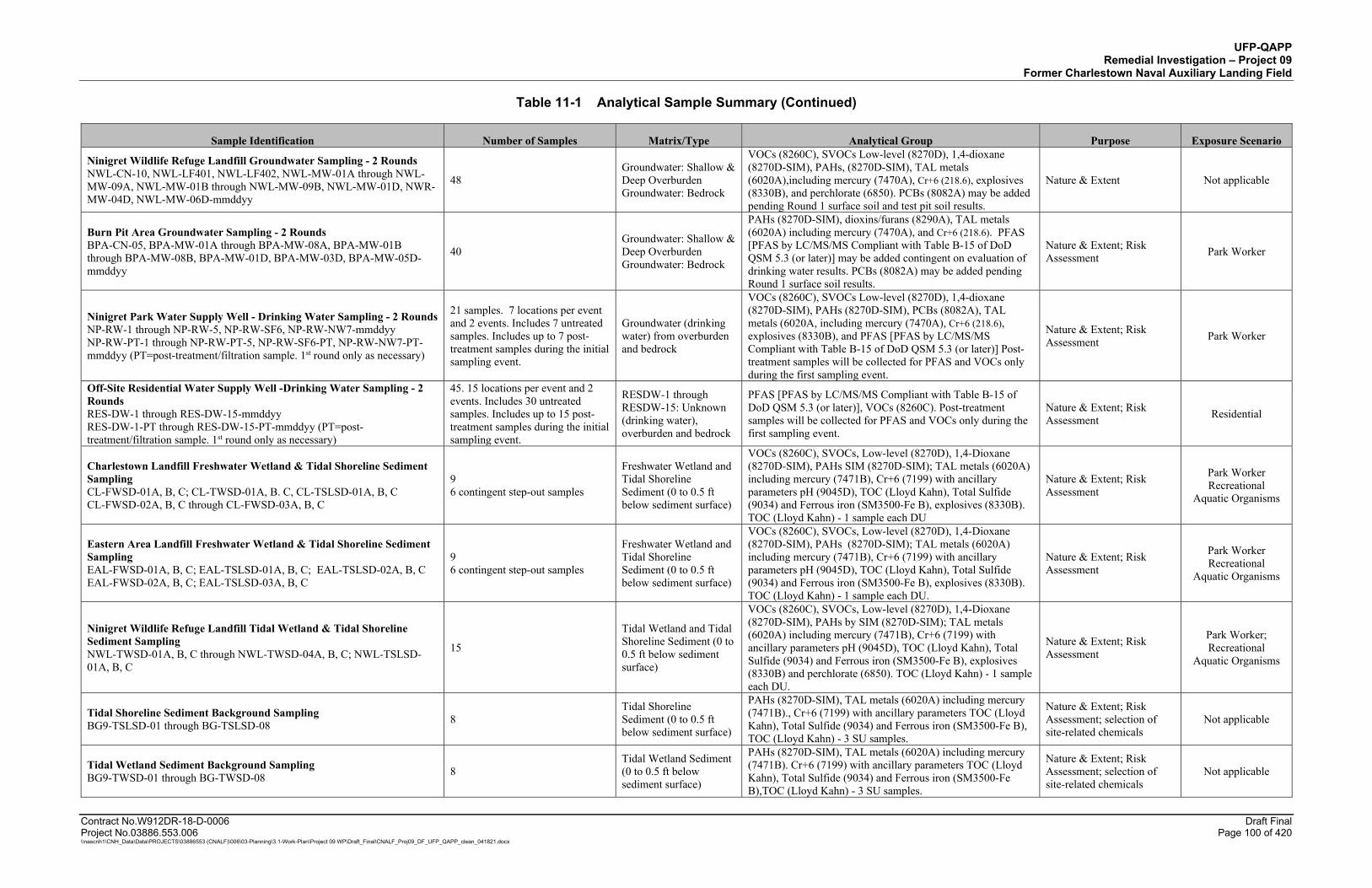
UFP-QAPP Remedial Investigation – Project 09
Former Charlestown Naval Auxiliary Landing Field
Table 11-1 Analytical Sample Summary (Continued)
Contract No.W912DR-18-D-0006 Draft Final Project No.03886.553.006 Page 100 of 420 \\nascnh1\CNH_Data\Data\PROJECTS\03886553 (CNALF)\006\03-Planning\3.1-Work-Plan\Project 09 WP\Draft_Final\CNALF_Proj09_DF_UFP_QAPP_clean_041821.docx
Sample Identification Number of Samples Matrix/Type Analytical Group Purpose Exposure Scenario
Ninigret Wildlife Refuge Landfill Groundwater Sampling - 2 Rounds NWL-CN-10, NWL-LF401, NWL-LF402, NWL-MW-01A through NWL-MW-09A, NWL-MW-01B through NWL-MW-09B, NWL-MW-01D, NWR-MW-04D, NWL-MW-06D-mmddyy
48 Groundwater: Shallow & Deep Overburden Groundwater: Bedrock
VOCs (8260C), SVOCs Low-level (8270D), 1,4-dioxane (8270D-SIM), PAHs, (8270D-SIM), TAL metals (6020A),including mercury (7470A), Cr+6 (218.6), explosives (8330B), and perchlorate (6850). PCBs (8082A) may be added pending Round 1 surface soil and test pit soil results.
Nature & Extent Not applicable
Burn Pit Area Groundwater Sampling - 2 Rounds BPA-CN-05, BPA-MW-01A through BPA-MW-08A, BPA-MW-01B through BPA-MW-08B, BPA-MW-01D, BPA-MW-03D, BPA-MW-05D-mmddyy
40 Groundwater: Shallow & Deep Overburden Groundwater: Bedrock
PAHs (8270D-SIM), dioxins/furans (8290A), TAL metals (6020A) including mercury (7470A), and Cr+6 (218.6). PFAS [PFAS by LC/MS/MS Compliant with Table B-15 of DoD QSM 5.3 (or later)] may be added contingent on evaluation of drinking water results. PCBs (8082A) may be added pending Round 1 surface soil results.
Nature & Extent; Risk Assessment Park Worker
Ninigret Park Water Supply Well - Drinking Water Sampling - 2 Rounds NP-RW-1 through NP-RW-5, NP-RW-SF6, NP-RW-NW7-mmddyy NP-RW-PT-1 through NP-RW-PT-5, NP-RW-SF6-PT, NP-RW-NW7-PT-mmddyy (PT=post-treatment/filtration sample. 1st round only as necessary)
21 samples. 7 locations per event and 2 events. Includes 7 untreated samples. Includes up to 7 post-treatment samples during the initial sampling event.
Groundwater (drinking water) from overburden and bedrock
VOCs (8260C), SVOCs Low-level (8270D), 1,4-dioxane (8270D-SIM), PAHs (8270D-SIM), PCBs (8082A), TAL metals (6020A, including mercury (7470A), Cr+6 (218.6), explosives (8330B), and PFAS [PFAS by LC/MS/MS Compliant with Table B-15 of DoD QSM 5.3 (or later)] Post-treatment samples will be collected for PFAS and VOCs only during the first sampling event.
Nature & Extent; Risk Assessment Park Worker
Off-Site Residential Water Supply Well -Drinking Water Sampling - 2 Rounds RES-DW-1 through RES-DW-15-mmddyy RES-DW-1-PT through RES-DW-15-PT-mmddyy (PT=post-treatment/filtration sample. 1st round only as necessary)
45. 15 locations per event and 2 events. Includes 30 untreated samples. Includes up to 15 post-treatment samples during the initial sampling event.
RESDW-1 through RESDW-15: Unknown (drinking water), overburden and bedrock
PFAS [PFAS by LC/MS/MS Compliant with Table B-15 of DoD QSM 5.3 (or later)], VOCs (8260C). Post-treatment samples will be collected for PFAS and VOCs only during the first sampling event.
Nature & Extent; Risk Assessment Residential
Charlestown Landfill Freshwater Wetland & Tidal Shoreline Sediment Sampling CL-FWSD-01A, B, C; CL-TWSD-01A, B. C, CL-TSLSD-01A, B, C CL-FWSD-02A, B, C through CL-FWSD-03A, B, C
9 6 contingent step-out samples
Freshwater Wetland and Tidal Shoreline Sediment (0 to 0.5 ft below sediment surface)
VOCs (8260C), SVOCs, Low-level (8270D), 1,4-Dioxane (8270D-SIM), PAHs SIM (8270D-SIM); TAL metals (6020A) including mercury (7471B), Cr+6 (7199) with ancillary parameters pH (9045D), TOC (Lloyd Kahn), Total Sulfide (9034) and Ferrous iron (SM3500-Fe B), explosives (8330B). TOC (Lloyd Kahn) - 1 sample each DU
Nature & Extent; Risk Assessment
Park Worker Recreational
Aquatic Organisms
Eastern Area Landfill Freshwater Wetland & Tidal Shoreline Sediment Sampling EAL-FWSD-01A, B, C; EAL-TSLSD-01A, B, C; EAL-TSLSD-02A, B, C EAL-FWSD-02A, B, C; EAL-TSLSD-03A, B, C
9 6 contingent step-out samples
Freshwater Wetland and Tidal Shoreline Sediment (0 to 0.5 ft below sediment surface)
VOCs (8260C), SVOCs, Low-level (8270D), 1,4-Dioxane (8270D-SIM), PAHs (8270D-SIM); TAL metals (6020A) including mercury (7471B), Cr+6 (7199) with ancillary parameters pH (9045D), TOC (Lloyd Kahn), Total Sulfide (9034) and Ferrous iron (SM3500-Fe B), explosives (8330B). TOC (Lloyd Kahn) - 1 sample each DU.
Nature & Extent; Risk Assessment
Park Worker Recreational
Aquatic Organisms
Ninigret Wildlife Refuge Landfill Tidal Wetland & Tidal Shoreline Sediment Sampling NWL-TWSD-01A, B, C through NWL-TWSD-04A, B, C; NWL-TSLSD-01A, B, C
15
Tidal Wetland and Tidal Shoreline Sediment (0 to 0.5 ft below sediment surface)
VOCs (8260C), SVOCs, Low-level (8270D), 1,4-Dioxane (8270D-SIM), PAHs by SIM (8270D-SIM); TAL metals (6020A) including mercury (7471B), Cr+6 (7199) with ancillary parameters pH (9045D), TOC (Lloyd Kahn), Total Sulfide (9034) and Ferrous iron (SM3500-Fe B), explosives (8330B) and perchlorate (6850). TOC (Lloyd Kahn) - 1 sample each DU.
Nature & Extent; Risk Assessment
Park Worker; Recreational
Aquatic Organisms
Tidal Shoreline Sediment Background Sampling BG9-TSLSD-01 through BG-TSLSD-08 8
Tidal Shoreline Sediment (0 to 0.5 ft below sediment surface)
PAHs (8270D-SIM), TAL metals (6020A) including mercury (7471B)., Cr+6 (7199) with ancillary parameters TOC (Lloyd Kahn), Total Sulfide (9034) and Ferrous iron (SM3500-Fe B), TOC (Lloyd Kahn) - 3 SU samples.
Nature & Extent; Risk Assessment; selection of site-related chemicals
Not applicable
Tidal Wetland Sediment Background Sampling BG9-TWSD-01 through BG-TWSD-08 8
Tidal Wetland Sediment (0 to 0.5 ft below sediment surface)
PAHs (8270D-SIM), TAL metals (6020A) including mercury (7471B). Cr+6 (7199) with ancillary parameters TOC (Lloyd Kahn), Total Sulfide (9034) and Ferrous iron (SM3500-Fe B),TOC (Lloyd Kahn) - 3 SU samples.
Nature & Extent; Risk Assessment; selection of site-related chemicals
Not applicable

UFP-QAPP Remedial Investigation – Project 09
Former Charlestown Naval Auxiliary Landing Field
Table 11-1 Analytical Sample Summary (Continued)
Contract No.W912DR-18-D-0006 Draft Final Project No.03886.553.006 Page 101 of 420 \\nascnh1\CNH_Data\Data\PROJECTS\03886553 (CNALF)\006\03-Planning\3.1-Work-Plan\Project 09 WP\Draft_Final\CNALF_Proj09_DF_UFP_QAPP_clean_041821.docx
Sample Identification Number of Samples Matrix/Type Analytical Group Purpose Exposure Scenario
Freshwater Wetland Sediment Background Sampling BG9-FWSD-01 through BG-FWSD-08 8
Freshwater Wetland Sediment (0 to 0.5 ft below sediment surface)
PAHs (8270D-SIM), TAL metals (6020A) including mercury (7471B)., Cr+6 (7199) with ancillary parameters TOC (Lloyd Kahn), Total Sulfide (9034) and Ferrous iron (SM3500-Fe B), TOC (Lloyd Kahn) - 3 SU samples.
Nature & Extent; Risk Assessment; selection of site-related chemicals
Not applicable
Charlestown Landfill Fresh Water Wetland & Tidal Shoreline Surface/Pore Water Sampling CL-FWSW-01A, B, C; CL-TWPW-01A, B, C; CL-TSLSW-01A, B, C; CL-FWPW-01A, B, C; CL-TWPW-01A, B, C; CL-TSLPW-01A, B. C CL-FWSW-02A, B, C; CL-FSW-03A, B, C; CL-FWPW-02A, B, C; CL-FWPW-03A, B, C
18 (9SW/9PW) 12 contingent step-out samples
Freshwater Wetland and Tidal Shoreline Surface Water (middle of water column) & Pore Water (0 to 0.5 ft below sediment surface)
VOCs (8260C), SVOCs Low-level (8270D), 1,4-Dioxane (8270D-SIM), PAHs (8270D-SIM), dissolved TAL metals (6020A) including mercury (7470A), Cr+6 (7199) and explosives (8330B), and hardness by calculation (SM 2540B).
Nature & Extent; Risk Assessment
Park Worker Recreational
Aquatic Organisms
Eastern Area Landfill Freshwater Wetland & Tidal Shoreline Surface/Pore Water Sampling EAL-FWSW-01A, B, C ; EAL-TSLSW-01A, B, C; EAL-TSLSW-02A, B, C; EAL-FWPW-01A, B, C; EAL-TSLPW-01A, B. C; EAL-TSLPW-02A, B, C, EAL-FWSW-02A, B, C; EAL-TSLSW-03A, B, C; EAL-FWPW-02A, B, C; EAL-TSLPW-03A, B, C
18 (9SW/9PW) 12 contingent step-out samples
Freshwater Wetland and Tidal Shoreline Surface Water (middle of water column) & Pore Water (0 to 0.5 ft below sediment surface)
VOCs (8260C), SVOCs Low-level (8270D), 1,4-Dioxane (8270D-SIM), PAHs (8270D-SIM), dissolved TAL metals (6020A) including mercury (7470A), Cr+6 (7199) explosives (8330B), and hardness by calculation (SM 2540B).
Nature & Extent; Risk Assessment
Park Worker Recreational
Aquatic Organisms
Ninigret Wildlife Refuge Landfill Tidal Wetland & Tidal Shoreline Surface/Pore Water Sampling NWL-TWSW-01A, B, C through NWL-TWSW-04A, B, C; NWL-TSLSW-01A, B, C; NWL-TWPW-01A, B, C through NWL-TWPW-04A, B, C; NWL-TSLPW-01A, B, C
30 (15 SW/15PW)
Tidal Wetland and Tidal Shoreline Surface Water (middle of water column) & Pore Water (0 to 0.5 ft below sediment surface)
VOCs (8260C), SVOCs Low-level (8270D), 1,4-Dioxane (8270D-SIM), PAHs (8270D-SIM), dissolved TAL metals (6020A) including mercury (7470A), Cr+6 (7199), explosives (8330B), hardness by calculation (SM2540B), and perchlorate (6850). Explosives are contingent upon detecting explosives in background samples.
Nature & Extent; Risk Assessment
Park Worker Recreational
Aquatic Organisms
Tidal Shoreline Background Surface Water Sampling BG9-TSLSW-01 through BG9-TSLSW-08 8
Tidal Shoreline Surface Water (middle of water column)
PAHs (8270D-SIM), dissolved TAL metals (6020A) including mercury (7470A), Cr+6 (7199),hardness by calculation (SM2540B).
Nature & Extent; Risk Assessment; selection of site-related chemicals
Not applicable
Tidal Wetland Background Surface Water Sampling BG9-TWSW-01 through BG9-TWSW-08 8
Tidal Wetland Surface Water (middle of water column; midpoint of SU)
PAHs (8270D-SIM), dissolved TAL metals (6020A) including mercury (7470A), Cr+6 (7199), hardness by calculation (SM2540B).
Nature & Extent; Risk Assessment; selection of site-related chemicals
Not applicable
Freshwater Wetland Background Surface Water Sampling BG9-FWSW-01 through BG9-FWSW-08 8
Freshwater Wetland Surface Water (middle of water column; midpoint of SU)
PAHs (8270D-SIM), dissolved TAL metals (6020A) including mercury (7470A), Cr+6 (7199), hardness by calculation (SM2540B).
Nature & Extent; Risk Assessment; selection of site-related chemicals
Not applicable
Charlestown Landfill Test Pit Soil Sampling CL-TPSO-01 through CL-TPSO-21 CL-TPSO-22 through CL-TPSO-23
21 (VOCs 63) 2 contingent step-out samples (VOCs 6)
Subsurface Soil (One composite sample will be collected from each test pit, with 3 aliquots of soil collected from each excavator bucket. VOCs will be collected as 3 discrete samples per test pit.)
VOCs (8260C), SVOCs, Low-level (8270D), 1,4-Dioxane (8270D-SIM), PAHs (8270D-SIM); PCBs (8082A), ), TAL metals (6020A) including mercury (7471B), Cr+6 (7199) with ancillary parameters pH (9045D), TOC (Lloyd Kahn), Total Sulfide (9034) and Ferrous iron (SM3500-Fe B), Asbestos (USEPA Region 1), and explosives (8330B).
Nature & Extent Not applicable
Eastern Area Landfill Test Pit Soil Sampling EAL-TPSO-01 though EAL-TPSO-13 EAL-TPSO-14 through EAL-TPSO-16
13 (VOC 39) 3 contingent step-out samples (VOC 9)
Subsurface Soil (One composite sample will be collected from each test pit, with 3 aliquots of soil collected from each excavator bucket. VOCs will be collected as 3 discrete samples per test pit.)
VOCs (8260C), SVOCs, Low-level (8270D), 1,4-Dioxane (8270D-SIM), PAHs (8270D-SIM); PCBs (8082A), ), TAL metals (6020A) including mercury (7471B), Cr+6 (7199) with ancillary parameters pH (9045D), TOC (Lloyd Kahn), Total Sulfide (9034) and Ferrous iron (SM3500-Fe B), Asbestos (USEPA Region 1), and explosives (8330B).
Nature & Extent Not applicable
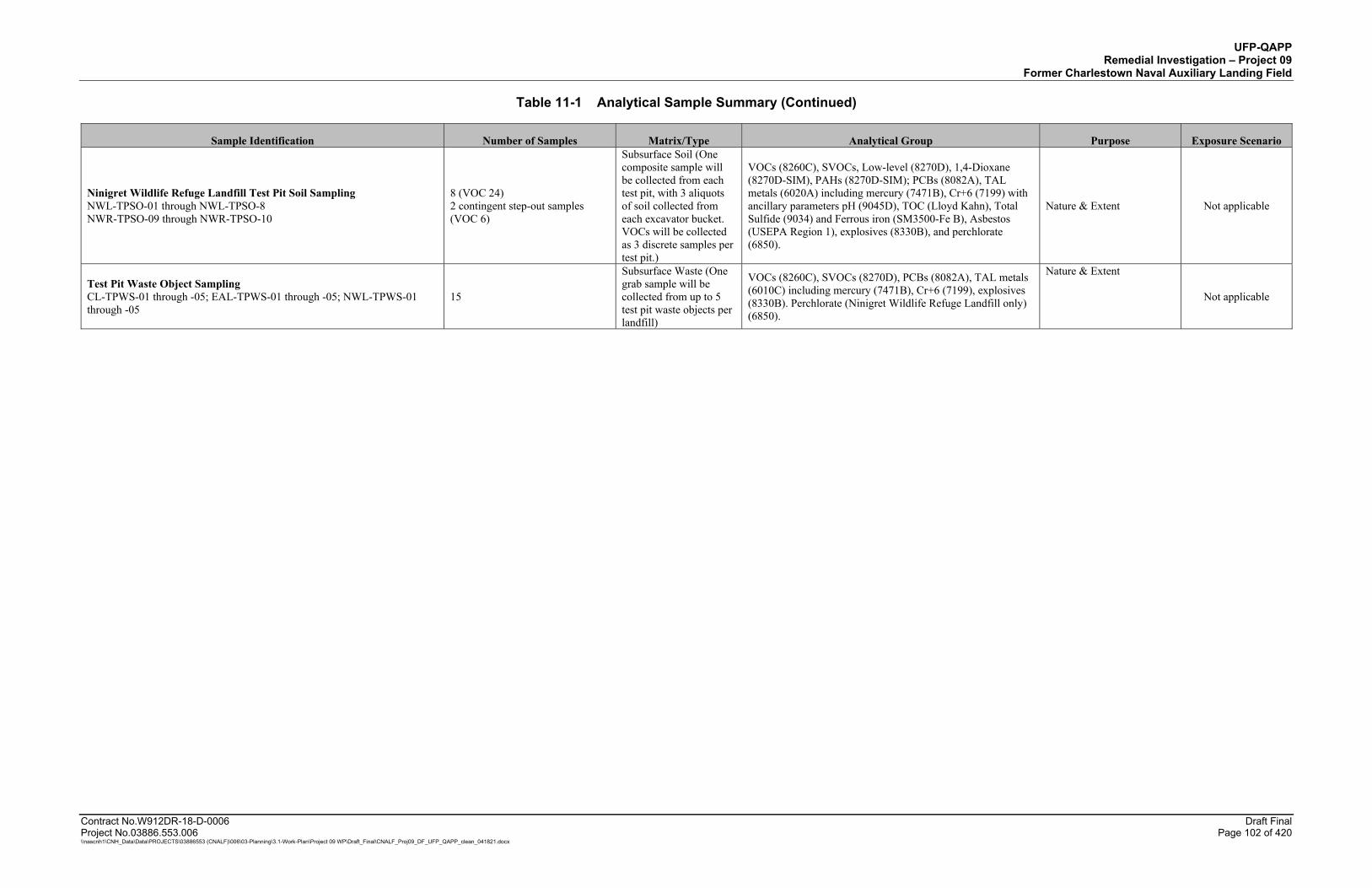
UFP-QAPP Remedial Investigation – Project 09
Former Charlestown Naval Auxiliary Landing Field
Table 11-1 Analytical Sample Summary (Continued)
Contract No.W912DR-18-D-0006 Draft Final Project No.03886.553.006 Page 102 of 420 \\nascnh1\CNH_Data\Data\PROJECTS\03886553 (CNALF)\006\03-Planning\3.1-Work-Plan\Project 09 WP\Draft_Final\CNALF_Proj09_DF_UFP_QAPP_clean_041821.docx
Sample Identification Number of Samples Matrix/Type Analytical Group Purpose Exposure Scenario
Ninigret Wildlife Refuge Landfill Test Pit Soil Sampling NWL-TPSO-01 through NWL-TPSO-8 NWR-TPSO-09 through NWR-TPSO-10
8 (VOC 24) 2 contingent step-out samples (VOC 6)
Subsurface Soil (One composite sample will be collected from each test pit, with 3 aliquots of soil collected from each excavator bucket. VOCs will be collected as 3 discrete samples per test pit.)
VOCs (8260C), SVOCs, Low-level (8270D), 1,4-Dioxane (8270D-SIM), PAHs (8270D-SIM); PCBs (8082A), TAL metals (6020A) including mercury (7471B), Cr+6 (7199) with ancillary parameters pH (9045D), TOC (Lloyd Kahn), Total Sulfide (9034) and Ferrous iron (SM3500-Fe B), Asbestos (USEPA Region 1), explosives (8330B), and perchlorate (6850).
Nature & Extent Not applicable
Test Pit Waste Object Sampling CL-TPWS-01 through -05; EAL-TPWS-01 through -05; NWL-TPWS-01 through -05
15
Subsurface Waste (One grab sample will be collected from up to 5 test pit waste objects per landfill)
VOCs (8260C), SVOCs (8270D), PCBs (8082A), TAL metals (6010C) including mercury (7471B), Cr+6 (7199), explosives (8330B). Perchlorate (Ninigret Wildlife Refuge Landfill only) (6850).
Nature & Extent
Not applicable
UFP-QAPP Remedial Investigation – Project 09
Former Charlestown Naval Auxiliary Landing Field
Contract No.W912DR-18-D-0006 Draft Final Project No.03886.553.006 Page 103 of 420 \\nascnh1\CNH_Data\Data\PROJECTS\03886553 (CNALF)\006\03-Planning\3.1-Work-Plan\Project 09 WP\Draft_Final\CNALF_Proj09_DF_UFP_QAPP_clean_041821.docx
QAPP WORKSHEET #12: MEASUREMENT PERFORMANCE CRITERIA
Measurement performance criteria (MPC) for field sample and QC sample results are used to evaluate project Data Quality Indicators (DQIs) for overall and laboratory accuracy/bias, accuracy/bias (contamination), and overall and laboratory precision (see Worksheet #37). This UFP-QAPP summarizes MPCs for various QC samples including laboratory and field blanks that will be used as QC measures to evaluate the DQIs. Field QC samples and the MPC that will be used during the sampling at the CNALF Project 09 site are summarized in Worksheets #12.1 through #12.31.
12.1 TRIP BLANKS
A trip blank will be prepared in the laboratory, accompany bottleware to the field, and accompany samples to the laboratory. The laboratory will analyze trip blanks for only volatile parameters (i.e., VOCs and GRO). The primary purpose of a trip blank is to identify volatile contamination that may be introduced into field samples during transportation and storage.
12.2 FIELD BLANKS
A field blank is used to provide information about contaminants that may be introduced during sample collection, storage, and transport. A field blank is a sample prepared in the field to evaluate the potential for contamination of a sample by site contaminants from a source not associated with the sample collected. Typically, field blanks are collected during sampling events where contaminants are present in the atmosphere and originate from a source other than the source being sampled. For this project, Field Reagent Blanks (FRBs) will be collected during PFAS sample collection. PFAS-free water will be supplied by the laboratory along with the empty sample containers. During field sampling, the PFAS-free water will be poured into the empty bottles, the containers will be sealed and then shipped to the laboratory for PFAS analysis. FRBs will be collected at a frequency of 1 per 20 or one per day of sampling, whichever is more frequent.
12.3 EQUIPMENT RINSATE BLANKS
Equipment rinsate blanks will be collected from non-dedicated sampling equipment to assess the adequacy of the decontamination process and whether contaminants may have been introduced during the sample collection process. An equipment rinsate blank (i.e., decontamination rinsate or equipment rinsate) consists of a sample of deionized water poured over or through decontaminated field sampling equipment that is considered ready to collect or process an additional sample.
To collect an equipment rinsate blank sample, deionized water will be pumped or poured over and/or through the decontaminated sampling equipment. The runoff water from the decontaminated equipment will be collected into the sample containers directly. The deionized water may be pumped by use of an electric or hand submersible pump, or poured by tipping the jug of water upside down or by use of a stopcock and gravity.
At a minimum, equipment rinsate blank samples will be collected at a rate of 1 per 20 samples per matrix per sampling equipment type (or 1 per sampling event per matrix per equipment type). The
UFP-QAPP Remedial Investigation – Project 09
Former Charlestown Naval Auxiliary Landing Field
Contract No.W912DR-18-D-0006 Draft Final Project No.03886.553.006 Page 104 of 420 \\nascnh1\CNH_Data\Data\PROJECTS\03886553 (CNALF)\006\03-Planning\3.1-Work-Plan\Project 09 WP\Draft_Final\CNALF_Proj09_DF_UFP_QAPP_clean_041821.docx
equipment rinsate blank samples will be analyzed for the same parameters as the field samples that were collected using that piece of equipment. Equipment blanks should not contain concentrations greater than one-half the LOQ for analytes of interest.
When disposable or dedicated sampling equipment is used, equipment rinsate blank samples do not need to be collected.
12.4 TEMPERATURE BLANK
A temperature blank is a container of tap water that is packed and shipped to the laboratory with field samples requiring preservation by cooling to less than or equal to 6 degrees Celsius (°C) without reaching the freezing point. Upon arrival of the samples, the laboratory measures and records the temperature of the blank. The temperature reading is used to document that field samples were maintained in a cooled state during shipment to the laboratory. The information is used by both the laboratory and the data validator. If the temperature blank exceeds the criterion of freezing or greater than 6°C, then the laboratory must notify the Technical Manager or Project Chemist immediately for guidance on whether the samples should be analyzed.
12.5 FIELD DUPLICATES
A field duplicate is a generic term for two field samples collected at the same time in the same location. Field duplicates are intended to represent the same population and progress through the steps of the analytical preparation and analysis process in an identical manner to provide precision information concerning the sampling process. Field duplicate samples will be assigned different sample identifiers.
For this project, duplicate samples will be collected at a rate of 1 sample per 20 routine samples.
12.6 ANALYTICAL METHOD BLANK AND GRINDING BLANK
The analytical method blank is an analyte-free matrix to which reagents are added in the same volumes or proportions as used in sample processing, and the method blank sample is carried through the complete sample preparation and analytical process. The purpose of the method blank is to document contamination resulting from the sample preparation and analytical process. A method blank shall be included in every analytical batch. For most methods, an analytical batch is defined as 20 samples.
Analytes detected in a method blank must not exceed one-half the LOQ or one-tenth the amount measured in the associated field samples in the same batch or 1/10th the regulatory limit, whichever is greater. Method blank corrective actions (CAs) shall be performed in accordance with Worksheet #28. If necessary and feasible and, if sufficient sample remains for re-extraction or reanalysis, the laboratory will reanalyze the samples with a compliant method blank.
For samples that must be ground in a ring-and-puck mill (puck mill), the laboratory cleans the puck mill between grinding of field samples. To document that the puck mill has been cleaned, the laboratory then grinds a clean sand matrix using the puck mill at the frequency stipulated by DoD
UFP-QAPP Remedial Investigation – Project 09
Former Charlestown Naval Auxiliary Landing Field
Contract No.W912DR-18-D-0006 Draft Final Project No.03886.553.006 Page 105 of 420 \\nascnh1\CNH_Data\Data\PROJECTS\03886553 (CNALF)\006\03-Planning\3.1-Work-Plan\Project 09 WP\Draft_Final\CNALF_Proj09_DF_UFP_QAPP_clean_041821.docx
QSM 5.3. The ground clean sand is designated as the “grinding blank” which the laboratory can subsequently use as the analytical batch method blank or else report the grinding blank separately from the method blank. For this project, a grinding blank will be required for ISM and Composite soil samples and ISM sediment samples which are processed using the ISM sample preparation process; this laboratory process is described in detail in section 17.6.1. For project samples, a grinding blank will only be required for explosives, PCBs, perchlorate, and dioxins/furans. Grinding blank results should not exceed one-half the LOQ.
12.7 LABORATORY CONTROL SAMPLE/LABORATORY CONTROL SAMPLE DUPLICATE
Laboratory control samples (LCSs) and laboratory control sample duplicates (LCSDs) are analyte-free water (for aqueous analyses) or clean sand or solid matrices (for soil/sediment analysis) that are spiked with the target analytes for each analyte. The LCS and LCSD are analyzed to assess overall method performance through the laboratory’s ability to recover analytes from a clean matrix. The spiking level must be greater than the lowest concentration standard used for calibration and less than or equal to the midpoint of the linear range calibrated. The LCS/LCSD results are evaluated in conjunction with other related QC information to determine the acceptability of field sample data.
The LCS/LCSD shall be carried through the complete sample preparation and analysis process. One LCS/LCSD shall be included in every analytical batch. The performance of the LCS and LCSD are evaluated against the QC acceptance limits provided in the DoD Quality Systems Manual (QSM) for Environmental Laboratories, Version 5.3, May 2019 (DoD, 2019). Whenever an analyte in an LCS/LCSD is outside the acceptance limit, CA needs to be performed. After the system problems have been resolved and system control has been reestablished, the samples in the analytical batch shall be reanalyzed for only the out-of-control analytes, if feasible. When an analyte in an LCS/LCSD exceeds the upper or lower control limit and no CA is performed or the CA was ineffective or not required, the appropriate validation qualifier will be applied to the affected results.
12.8 LABORATORY REPLICATE SAMPLES
Laboratory replicates are quality control samples prepared by the laboratory to monitor laboratory precision. The laboratory extracts/digests and analyzes replicate aliquots from the same sample container (for soil and sediments) the parent sample was collected from. Laboratory replicates include laboratory duplicates and laboratory triplicates. Laboratory duplicates are frequently run and reported for inorganic analyses, but also may be analyzed for organic analyses if there is insufficient sample volume available. Laboratory duplicates may be prepared by the laboratory to evaluate precision in a sample matrix in the event that insufficient sample is available for preparation of MS and MSD samples.
A laboratory duplicate is a repeated independent determination of the same sample, by the same analyst, at essentially the same time, and under the same conditions as the parent sample. Laboratory duplicate samples are obtained by preparing two aliquots of a field sample and performing separate analysis on each aliquot. The analysis of laboratory duplicate samples
UFP-QAPP Remedial Investigation – Project 09
Former Charlestown Naval Auxiliary Landing Field
Contract No.W912DR-18-D-0006 Draft Final Project No.03886.553.006 Page 106 of 420 \\nascnh1\CNH_Data\Data\PROJECTS\03886553 (CNALF)\006\03-Planning\3.1-Work-Plan\Project 09 WP\Draft_Final\CNALF_Proj09_DF_UFP_QAPP_clean_041821.docx
monitors precision; however, it may be affected by sample inhomogeneity, particularly in the case of nonaqueous samples. The relative percent difference (RPD) is a mathematical value used to assess precision between a parent sample and its laboratory duplicate.
A laboratory triplicate is a third aliquot obtained from the same sample container as the parent sample and laboratory duplicate sample which is prepared and analyzed along with the parent sample and laboratory duplicate. rate analyses on the aliquots. When a laboratory triplicate is prepared, the relative standard deviation (RSD) is a mathematical value used to assess precision between the parent sample, its laboratory duplicate, and its laboratory triplicate.
For ISM and Composite soil and sediment samples, one laboratory duplicate and one laboratory triplicate will be prepared and analyzed for every 20 (or fewer) field samples. Laboratory replicates should be prepared from samples suspected of containing elevated concentrations of target analytes.
12.9 MATRIX SPIKES/MATRIX SPIKE DUPLICATES
MS/MSDs are used to assess the performance of the method as applied to a particular matrix. MS/MSDs are aliquots of field samples spiked with known concentrations of target analytes. The spiking occurs in the laboratory during the sample preparation process and prior to analysis. The spiking level must be greater than the lowest concentration standard used for calibration and less than or equal to the midpoint of the linear range calibration.
A minimum of one MS sample and one MSD sample will be collected per 20 site samples per matrix collected. Sampling locations selected for the purpose of assigning an MS/MSD should be an area anticipated to be free from contamination or with low concentrations of target analytes. During the collection of soil MS/MSD samples, field personnel will avoid areas that are stained or known to have elevated levels of contamination.
Site-specific samples shall be selected for spiking, and the sample to be used for MS/MSD will be designated on the chain-of-custody. The MS/MSD data are used to assess analytical bias for the method in the sample matrix. The acceptance criteria used for the MS and MSD will be the DoD QSM 5.3 LCS control limits (where available) and statistically-derived laboratory control limits if no LCS control limits have been published in the DoD QSM 5.3 Appendix C tables. If the LCS analyses are acceptable and the MS/MSD sample recoveries are out of control limits, the outliers are attributed to the sample matrix. The MS/MSD sample results are not used to control the analytical process.
12.10 SURROGATE SPIKES
Surrogates are organic compounds similar in structure and chemical behavior to the target analytes, but are not normally detected in environmental samples. The surrogate results are used to evaluate accuracy, method performance, and extraction efficiency. The surrogate compounds are spiked in environmental samples, control samples, and blank samples in accordance with the method requirements. The surrogate should be spiked at a concentration less than or equal to the midpoint
UFP-QAPP Remedial Investigation – Project 09
Former Charlestown Naval Auxiliary Landing Field
Contract No.W912DR-18-D-0006 Draft Final Project No.03886.553.006 Page 107 of 420 \\nascnh1\CNH_Data\Data\PROJECTS\03886553 (CNALF)\006\03-Planning\3.1-Work-Plan\Project 09 WP\Draft_Final\CNALF_Proj09_DF_UFP_QAPP_clean_041821.docx
of the calibration range. For PFAS, the laboratory uses extracted isotopically-labeled standards as surrogates.
When the acceptance criterion of a surrogate recovery is not met, CA must be performed. After the system problems have been resolved and system control has been reestablished, the sample is re-prepared and reanalyzed. If CAs are not performed, infeasible, or ineffective, the appropriate validation qualifier shall be applied to the sample results.
12.11 INTERNAL STANDARDS
Internal Standards (ISs) are known amounts of specific compounds added after preparation of a sample extract. IS recoveries may be affected by column injection losses, purging losses, or viscosity effects. ISs will be added to environmental and QC samples in accordance with the method requirements.
When IS results are outside the acceptance limits, CAs will be performed. After the system problems have been resolved and system control has been reestablished, the samples analyzed while the system was malfunctioning shall be reanalyzed or re-extracted and reanalyzed. If CAs are not performed or are ineffective, then the appropriate validation qualifier shall be applied to the sample results.
12.12 DATA QUALITY
QC procedures are employed during chemical analysis to support and document the attainment of established method quality objectives. Whether these QC procedures support an assessment of general batch control or matrix-specific application, documentation includes calculating DQIs to verify data usability and contract compliance. DQIs (also referred to as parameters of precision, accuracy, representativeness, comparability, completeness, and sensitivity [PARCCS]) are developed during site-specific scoping sessions during the DQO development process. See Worksheet #37 for the approach that will be employed to assess PARCCS.
Worksheet 12 References
DoD (Department of Defense). 2019. Quality Systems Manual (QSM) for Environmental Laboratories, Version 5.3. May 2019.
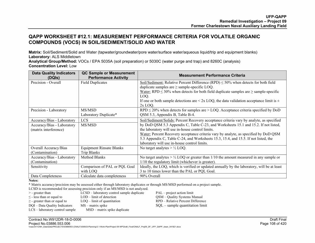
UFP-QAPP Remedial Investigation – Project 09
Former Charlestown Naval Auxiliary Landing Field
Contract No.W912DR-18-D-0006 Draft Final Project No.03886.553.006 Page 108 of 420 \\nascnh1\CNH_Data\Data\PROJECTS\03886553 (CNALF)\006\03-Planning\3.1-Work-Plan\Project 09 WP\Draft_Final\CNALF_Proj09_DF_UFP_QAPP_clean_041821.docx
QAPP WORKSHEET #12.1: MEASUREMENT PERFORMANCE CRITERIA FOR VOLATILE ORGANIC COMPOUNDS (VOCS) IN SOIL/SEDIMENT/SOLID AND WATER
Matrix: Soil/Sediment/Solid and Water (tapwater/groundwater/pore water/surface water/aqueous liquid/trip and equipment blanks) Laboratory: ALS Middletown Analytical Group/Method: VOCs / EPA 5035A (soil preparation) or 5030C (water purge and trap) and 8260C (analysis) Concentration Level: Low
Data Quality Indicators (DQIs)
QC Sample or Measurement Performance Activity Measurement Performance Criteria
Precision - Overall Field Duplicates Soil/Sediment: Relative Percent Difference (RPD) ≤ 50% when detects for both field duplicate samples are ≥ sample-specific LOQ. Water: RPD ≤ 30% when detects for both field duplicate samples are ≥ sample-specific LOQ. If one or both sample detections are < 2x LOQ, the data validation acceptance limit is ± 2x LOQ.
Precision - Laboratory MS/MSD Laboratory Duplicate*
RPD ≤ 20% when detects for samples are > LOQ. Acceptance criteria specified by DoD QSM 5.3, Appendix B, Table B-4.
Accuracy/Bias - Laboratory LCS Soil/Sediment/Solids: Percent Recovery acceptance criteria vary by analyte, as specified by DoD QSM 5.3 Appendix C, Table C-23, and Worksheets 15.1 and 15.2. If not listed, the laboratory will use in-house control limits. Water: Percent Recovery acceptance criteria vary by analyte, as specified by DoD QSM 5.3 Appendix C, Table C-24, and Worksheets 15.3, 15.4, and 15.5. If not listed, the laboratory will use in-house control limits.
Accuracy/Bias - Laboratory (matrix interference)
MS/MSD
Overall Accuracy/Bias (Contamination)
Equipment Rinsate Blanks Trip Blanks
No target analytes > ½ LOQ.
Accuracy/Bias - Laboratory (Contamination)
Method Blanks
No target analytes > ½ LOQ or greater than 1/10 the amount measured in any sample or 1/10 the regulatory limit (whichever is greater).
Sensitivity Comparison of PAL or PQL Goal with LOQ
Ideally, the LOQ, which is verified or updated annually by the laboratory, will be at least 3 to 10 times lower than the PAL or PQL Goal.
Data Completeness Calculate data completeness 90% Overall Notes: * Matrix accuracy/precision may be assessed either through laboratory duplicates or through MS/MSD performed on a project sample. LCSD is recommended for assessing precision only if an MS/MSD is not analyzed. > - greater than LCSD – laboratory control sample duplicate PAL – project action limit ≤ - less than or equal to LOD – limit of detection QSM – Quality Systems Manual ≥ - greater than or equal to LOQ – limit of quantitation RPD – Relative Percent Difference DQI – Data Quality Indicators MS – matrix spike SQL – sample quantitation limit LCS – laboratory control sample MSD – matrix spike duplicate
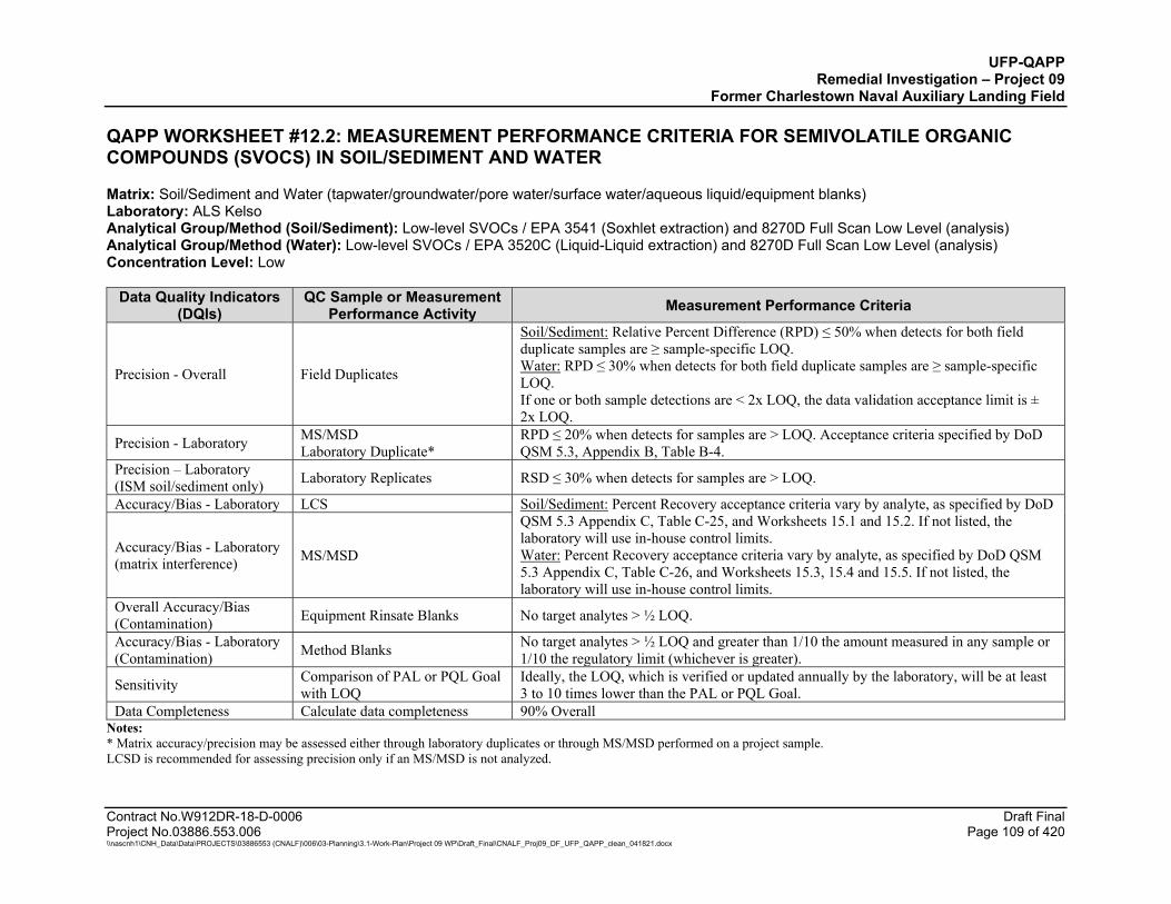
UFP-QAPP Remedial Investigation – Project 09
Former Charlestown Naval Auxiliary Landing Field
Contract No.W912DR-18-D-0006 Draft Final Project No.03886.553.006 Page 109 of 420 \\nascnh1\CNH_Data\Data\PROJECTS\03886553 (CNALF)\006\03-Planning\3.1-Work-Plan\Project 09 WP\Draft_Final\CNALF_Proj09_DF_UFP_QAPP_clean_041821.docx
QAPP WORKSHEET #12.2: MEASUREMENT PERFORMANCE CRITERIA FOR SEMIVOLATILE ORGANIC COMPOUNDS (SVOCS) IN SOIL/SEDIMENT AND WATER
Matrix: Soil/Sediment and Water (tapwater/groundwater/pore water/surface water/aqueous liquid/equipment blanks) Laboratory: ALS Kelso Analytical Group/Method (Soil/Sediment): Low-level SVOCs / EPA 3541 (Soxhlet extraction) and 8270D Full Scan Low Level (analysis) Analytical Group/Method (Water): Low-level SVOCs / EPA 3520C (Liquid-Liquid extraction) and 8270D Full Scan Low Level (analysis) Concentration Level: Low
Data Quality Indicators (DQIs)
QC Sample or Measurement Performance Activity Measurement Performance Criteria
Precision - Overall Field Duplicates
Soil/Sediment: Relative Percent Difference (RPD) ≤ 50% when detects for both field duplicate samples are ≥ sample-specific LOQ. Water: RPD ≤ 30% when detects for both field duplicate samples are ≥ sample-specific LOQ. If one or both sample detections are < 2x LOQ, the data validation acceptance limit is ± 2x LOQ.
Precision - Laboratory MS/MSD Laboratory Duplicate*
RPD ≤ 20% when detects for samples are > LOQ. Acceptance criteria specified by DoD QSM 5.3, Appendix B, Table B-4.
Precision – Laboratory (ISM soil/sediment only) Laboratory Replicates RSD ≤ 30% when detects for samples are > LOQ.
Accuracy/Bias - Laboratory LCS Soil/Sediment: Percent Recovery acceptance criteria vary by analyte, as specified by DoD QSM 5.3 Appendix C, Table C-25, and Worksheets 15.1 and 15.2. If not listed, the laboratory will use in-house control limits. Water: Percent Recovery acceptance criteria vary by analyte, as specified by DoD QSM 5.3 Appendix C, Table C-26, and Worksheets 15.3, 15.4 and 15.5. If not listed, the laboratory will use in-house control limits.
Accuracy/Bias - Laboratory (matrix interference) MS/MSD
Overall Accuracy/Bias (Contamination) Equipment Rinsate Blanks No target analytes > ½ LOQ.
Accuracy/Bias - Laboratory (Contamination) Method Blanks No target analytes > ½ LOQ and greater than 1/10 the amount measured in any sample or
1/10 the regulatory limit (whichever is greater).
Sensitivity Comparison of PAL or PQL Goal with LOQ
Ideally, the LOQ, which is verified or updated annually by the laboratory, will be at least 3 to 10 times lower than the PAL or PQL Goal.
Data Completeness Calculate data completeness 90% Overall Notes: * Matrix accuracy/precision may be assessed either through laboratory duplicates or through MS/MSD performed on a project sample. LCSD is recommended for assessing precision only if an MS/MSD is not analyzed.
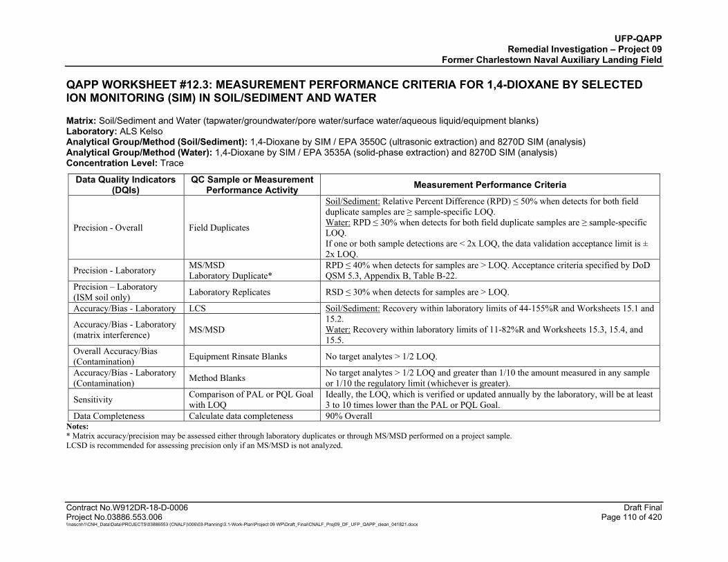
UFP-QAPP Remedial Investigation – Project 09
Former Charlestown Naval Auxiliary Landing Field
Contract No.W912DR-18-D-0006 Draft Final Project No.03886.553.006 Page 110 of 420 \\nascnh1\CNH_Data\Data\PROJECTS\03886553 (CNALF)\006\03-Planning\3.1-Work-Plan\Project 09 WP\Draft_Final\CNALF_Proj09_DF_UFP_QAPP_clean_041821.docx
QAPP WORKSHEET #12.3: MEASUREMENT PERFORMANCE CRITERIA FOR 1,4-DIOXANE BY SELECTED ION MONITORING (SIM) IN SOIL/SEDIMENT AND WATER
Matrix: Soil/Sediment and Water (tapwater/groundwater/pore water/surface water/aqueous liquid/equipment blanks) Laboratory: ALS Kelso Analytical Group/Method (Soil/Sediment): 1,4-Dioxane by SIM / EPA 3550C (ultrasonic extraction) and 8270D SIM (analysis) Analytical Group/Method (Water): 1,4-Dioxane by SIM / EPA 3535A (solid-phase extraction) and 8270D SIM (analysis) Concentration Level: Trace
Data Quality Indicators (DQIs)
QC Sample or Measurement Performance Activity Measurement Performance Criteria
Precision - Overall Field Duplicates
Soil/Sediment: Relative Percent Difference (RPD) ≤ 50% when detects for both field duplicate samples are ≥ sample-specific LOQ. Water: RPD ≤ 30% when detects for both field duplicate samples are ≥ sample-specific LOQ. If one or both sample detections are < 2x LOQ, the data validation acceptance limit is ± 2x LOQ.
Precision - Laboratory MS/MSD Laboratory Duplicate*
RPD ≤ 40% when detects for samples are > LOQ. Acceptance criteria specified by DoD QSM 5.3, Appendix B, Table B-22.
Precision – Laboratory (ISM soil only) Laboratory Replicates RSD ≤ 30% when detects for samples are > LOQ.
Accuracy/Bias - Laboratory LCS Soil/Sediment: Recovery within laboratory limits of 44-155%R and Worksheets 15.1 and 15.2. Water: Recovery within laboratory limits of 11-82%R and Worksheets 15.3, 15.4, and 15.5.
Accuracy/Bias - Laboratory (matrix interference) MS/MSD
Overall Accuracy/Bias (Contamination) Equipment Rinsate Blanks No target analytes > 1/2 LOQ.
Accuracy/Bias - Laboratory (Contamination) Method Blanks No target analytes > 1/2 LOQ and greater than 1/10 the amount measured in any sample
or 1/10 the regulatory limit (whichever is greater).
Sensitivity Comparison of PAL or PQL Goal with LOQ
Ideally, the LOQ, which is verified or updated annually by the laboratory, will be at least 3 to 10 times lower than the PAL or PQL Goal.
Data Completeness Calculate data completeness 90% Overall Notes: * Matrix accuracy/precision may be assessed either through laboratory duplicates or through MS/MSD performed on a project sample. LCSD is recommended for assessing precision only if an MS/MSD is not analyzed.
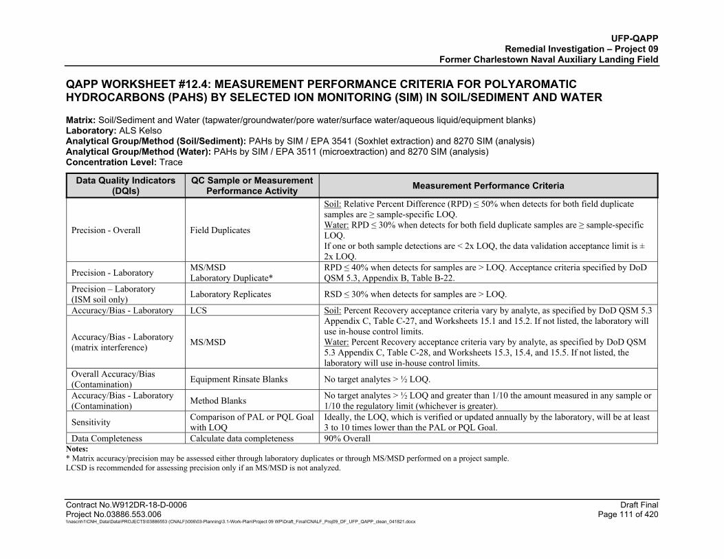
UFP-QAPP Remedial Investigation – Project 09
Former Charlestown Naval Auxiliary Landing Field
Contract No.W912DR-18-D-0006 Draft Final Project No.03886.553.006 Page 111 of 420 \\nascnh1\CNH_Data\Data\PROJECTS\03886553 (CNALF)\006\03-Planning\3.1-Work-Plan\Project 09 WP\Draft_Final\CNALF_Proj09_DF_UFP_QAPP_clean_041821.docx
QAPP WORKSHEET #12.4: MEASUREMENT PERFORMANCE CRITERIA FOR POLYAROMATIC HYDROCARBONS (PAHS) BY SELECTED ION MONITORING (SIM) IN SOIL/SEDIMENT AND WATER
Matrix: Soil/Sediment and Water (tapwater/groundwater/pore water/surface water/aqueous liquid/equipment blanks) Laboratory: ALS Kelso Analytical Group/Method (Soil/Sediment): PAHs by SIM / EPA 3541 (Soxhlet extraction) and 8270 SIM (analysis) Analytical Group/Method (Water): PAHs by SIM / EPA 3511 (microextraction) and 8270 SIM (analysis) Concentration Level: Trace
Data Quality Indicators (DQIs)
QC Sample or Measurement Performance Activity Measurement Performance Criteria
Precision - Overall Field Duplicates
Soil: Relative Percent Difference (RPD) ≤ 50% when detects for both field duplicate samples are ≥ sample-specific LOQ. Water: RPD ≤ 30% when detects for both field duplicate samples are ≥ sample-specific LOQ. If one or both sample detections are < 2x LOQ, the data validation acceptance limit is ± 2x LOQ.
Precision - Laboratory MS/MSD Laboratory Duplicate*
RPD ≤ 40% when detects for samples are > LOQ. Acceptance criteria specified by DoD QSM 5.3, Appendix B, Table B-22.
Precision – Laboratory (ISM soil only) Laboratory Replicates RSD ≤ 30% when detects for samples are > LOQ.
Accuracy/Bias - Laboratory LCS Soil: Percent Recovery acceptance criteria vary by analyte, as specified by DoD QSM 5.3 Appendix C, Table C-27, and Worksheets 15.1 and 15.2. If not listed, the laboratory will use in-house control limits. Water: Percent Recovery acceptance criteria vary by analyte, as specified by DoD QSM 5.3 Appendix C, Table C-28, and Worksheets 15.3, 15.4, and 15.5. If not listed, the laboratory will use in-house control limits.
Accuracy/Bias - Laboratory (matrix interference) MS/MSD
Overall Accuracy/Bias (Contamination) Equipment Rinsate Blanks No target analytes > ½ LOQ.
Accuracy/Bias - Laboratory (Contamination) Method Blanks No target analytes > ½ LOQ and greater than 1/10 the amount measured in any sample or
1/10 the regulatory limit (whichever is greater).
Sensitivity Comparison of PAL or PQL Goal with LOQ
Ideally, the LOQ, which is verified or updated annually by the laboratory, will be at least 3 to 10 times lower than the PAL or PQL Goal.
Data Completeness Calculate data completeness 90% Overall Notes: * Matrix accuracy/precision may be assessed either through laboratory duplicates or through MS/MSD performed on a project sample. LCSD is recommended for assessing precision only if an MS/MSD is not analyzed.
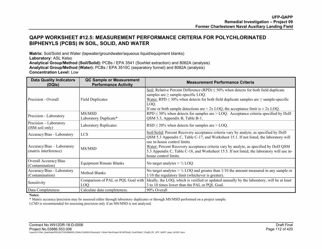
UFP-QAPP Remedial Investigation – Project 09
Former Charlestown Naval Auxiliary Landing Field
Contract No.W912DR-18-D-0006 Draft Final Project No.03886.553.006 Page 112 of 420 \\nascnh1\CNH_Data\Data\PROJECTS\03886553 (CNALF)\006\03-Planning\3.1-Work-Plan\Project 09 WP\Draft_Final\CNALF_Proj09_DF_UFP_QAPP_clean_041821.docx
QAPP WORKSHEET #12.5: MEASUREMENT PERFORMANCE CRITERIA FOR POLYCHLORINATED BIPHENYLS (PCBS) IN SOIL, SOLID, AND WATER
Matrix: Soil/Solid and Water (tapwater/groundwater/aqueous liquid/equipment blanks) Laboratory: ASL Kelso Analytical Group/Method (Soil/Solid): PCBs / EPA 3541 (Soxhlet extraction) and 8082A (analysis) Analytical Group/Method (Water): PCBs / EPA 3510C (separatory funnel) and 8082A (analysis) Concentration Level: Low Data Quality Indicators
(DQIs) QC Sample or Measurement
Performance Activity Measurement Performance Criteria
Precision - Overall Field Duplicates
Soil: Relative Percent Difference (RPD) ≤ 50% when detects for both field duplicate samples are ≥ sample-specific LOQ. Water: RPD ≤ 30% when detects for both field duplicate samples are ≥ sample-specific LOQ. If one or both sample detections are < 2x LOQ, the acceptance limit is ± 2x LOQ.
Precision - Laboratory MS/MSD Laboratory Duplicate*
RPD ≤ 30% when detects for samples are > LOQ. Acceptance criteria specified by DoD QSM 5.3, Appendix B, Table B-1.
Precision – Laboratory (ISM soil only) Laboratory Replicates RSD ≤ 20% when detects for samples are > LOQ.
Accuracy/Bias - Laboratory LCS Soil/Solid: Percent Recovery acceptance criteria vary by analyte, as specified by DoD QSM 5.3 Appendix C, Table C-17, and Worksheet 15.1. If not listed, the laboratory will use in-house control limits. Water: Percent Recovery acceptance criteria vary by analyte, as specified by DoD QSM 5.3 Appendix C, Table C-18, and Worksheet 15.5. If not listed, the laboratory will use in-house control limits.
Accuracy/Bias – Laboratory (matrix interference) MS/MSD
Overall Accuracy/Bias (Contamination) Equipment Rinsate Blanks No target analytes > ½ LOQ.
Accuracy/Bias - Laboratory (Contamination) Method Blanks No target analytes > ½ LOQ and greater than 1/10 the amount measured in any sample or
1/10 the regulatory limit (whichever is greater).
Sensitivity Comparison of PAL or PQL Goal with LOQ
Ideally, the LOQ, which is verified or updated annually by the laboratory, will be at least 3 to 10 times lower than the PAL or PQL Goal.
Data Completeness Calculate data completeness. 90% Overall Notes: * Matrix accuracy/precision may be assessed either through laboratory duplicates or through MS/MSD performed on a project sample. LCSD is recommended for assessing precision only if an MS/MSD is not analyzed.
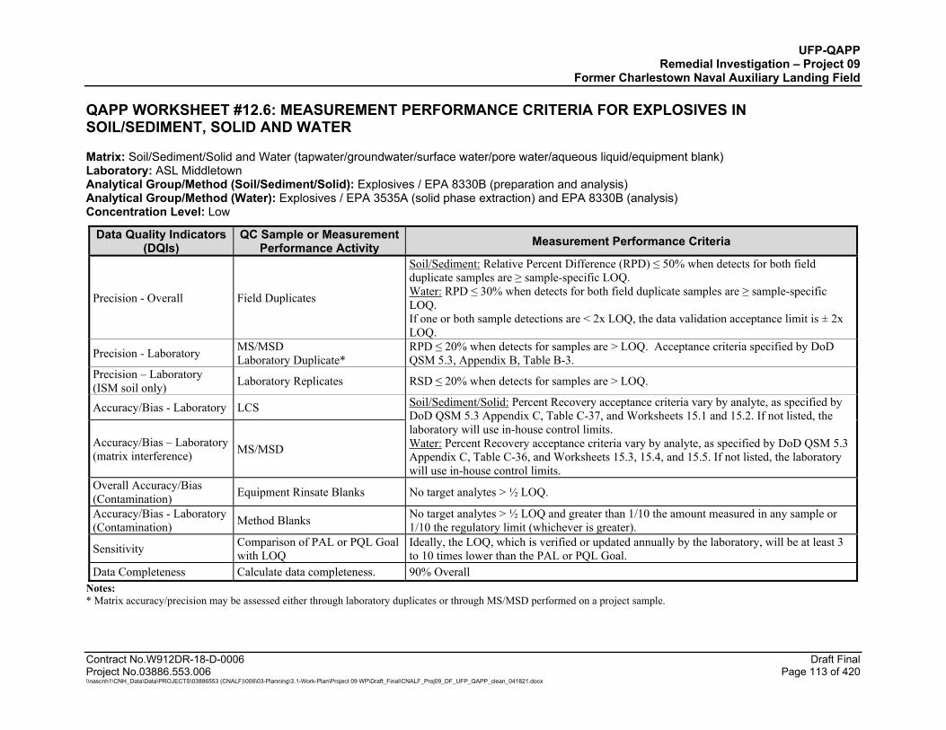
UFP-QAPP Remedial Investigation – Project 09
Former Charlestown Naval Auxiliary Landing Field
Contract No.W912DR-18-D-0006 Draft Final Project No.03886.553.006 Page 113 of 420 \\nascnh1\CNH_Data\Data\PROJECTS\03886553 (CNALF)\006\03-Planning\3.1-Work-Plan\Project 09 WP\Draft_Final\CNALF_Proj09_DF_UFP_QAPP_clean_041821.docx
QAPP WORKSHEET #12.6: MEASUREMENT PERFORMANCE CRITERIA FOR EXPLOSIVES IN SOIL/SEDIMENT, SOLID AND WATER
Matrix: Soil/Sediment/Solid and Water (tapwater/groundwater/surface water/pore water/aqueous liquid/equipment blank) Laboratory: ASL Middletown Analytical Group/Method (Soil/Sediment/Solid): Explosives / EPA 8330B (preparation and analysis) Analytical Group/Method (Water): Explosives / EPA 3535A (solid phase extraction) and EPA 8330B (analysis) Concentration Level: Low
Data Quality Indicators (DQIs)
QC Sample or Measurement Performance Activity Measurement Performance Criteria
Precision - Overall Field Duplicates
Soil/Sediment: Relative Percent Difference (RPD) ≤ 50% when detects for both field duplicate samples are ≥ sample-specific LOQ. Water: RPD ≤ 30% when detects for both field duplicate samples are ≥ sample-specific LOQ. If one or both sample detections are < 2x LOQ, the data validation acceptance limit is ± 2x LOQ.
Precision - Laboratory MS/MSD Laboratory Duplicate*
RPD ≤ 20% when detects for samples are > LOQ. Acceptance criteria specified by DoD QSM 5.3, Appendix B, Table B-3.
Precision – Laboratory (ISM soil only) Laboratory Replicates RSD ≤ 20% when detects for samples are > LOQ.
Accuracy/Bias - Laboratory LCS Soil/Sediment/Solid: Percent Recovery acceptance criteria vary by analyte, as specified by DoD QSM 5.3 Appendix C, Table C-37, and Worksheets 15.1 and 15.2. If not listed, the laboratory will use in-house control limits. Water: Percent Recovery acceptance criteria vary by analyte, as specified by DoD QSM 5.3 Appendix C, Table C-36, and Worksheets 15.3, 15.4, and 15.5. If not listed, the laboratory will use in-house control limits.
Accuracy/Bias – Laboratory (matrix interference) MS/MSD
Overall Accuracy/Bias (Contamination) Equipment Rinsate Blanks No target analytes > ½ LOQ.
Accuracy/Bias - Laboratory (Contamination) Method Blanks No target analytes > ½ LOQ and greater than 1/10 the amount measured in any sample or
1/10 the regulatory limit (whichever is greater).
Sensitivity Comparison of PAL or PQL Goal with LOQ
Ideally, the LOQ, which is verified or updated annually by the laboratory, will be at least 3 to 10 times lower than the PAL or PQL Goal.
Data Completeness Calculate data completeness. 90% Overall Notes: * Matrix accuracy/precision may be assessed either through laboratory duplicates or through MS/MSD performed on a project sample.
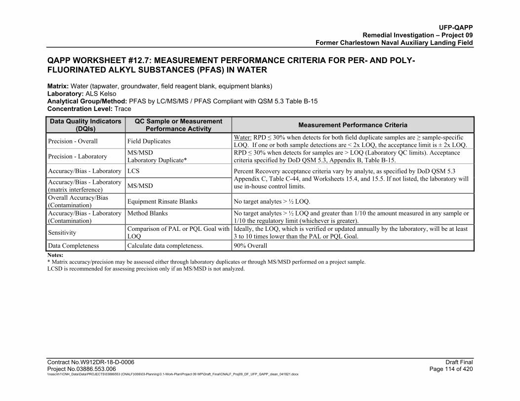
UFP-QAPP Remedial Investigation – Project 09
Former Charlestown Naval Auxiliary Landing Field
Contract No.W912DR-18-D-0006 Draft Final Project No.03886.553.006 Page 114 of 420 \\nascnh1\CNH_Data\Data\PROJECTS\03886553 (CNALF)\006\03-Planning\3.1-Work-Plan\Project 09 WP\Draft_Final\CNALF_Proj09_DF_UFP_QAPP_clean_041821.docx
QAPP WORKSHEET #12.7: MEASUREMENT PERFORMANCE CRITERIA FOR PER- AND POLY-FLUORINATED ALKYL SUBSTANCES (PFAS) IN WATER
Matrix: Water (tapwater, groundwater, field reagent blank, equipment blanks) Laboratory: ALS Kelso Analytical Group/Method: PFAS by LC/MS/MS / PFAS Compliant with QSM 5.3 Table B-15 Concentration Level: Trace
Data Quality Indicators (DQIs)
QC Sample or Measurement Performance Activity Measurement Performance Criteria
Precision - Overall Field Duplicates Water: RPD ≤ 30% when detects for both field duplicate samples are ≥ sample-specific LOQ. If one or both sample detections are < 2x LOQ, the acceptance limit is ± 2x LOQ.
Precision - Laboratory MS/MSD Laboratory Duplicate*
RPD ≤ 30% when detects for samples are > LOQ (Laboratory QC limits). Acceptance criteria specified by DoD QSM 5.3, Appendix B, Table B-15.
Accuracy/Bias - Laboratory LCS Percent Recovery acceptance criteria vary by analyte, as specified by DoD QSM 5.3 Appendix C, Table C-44, and Worksheets 15.4, and 15.5. If not listed, the laboratory will use in-house control limits. Accuracy/Bias - Laboratory
(matrix interference) MS/MSD
Overall Accuracy/Bias (Contamination) Equipment Rinsate Blanks No target analytes > ½ LOQ.
Accuracy/Bias - Laboratory (Contamination)
Method Blanks
No target analytes > ½ LOQ and greater than 1/10 the amount measured in any sample or 1/10 the regulatory limit (whichever is greater).
Sensitivity Comparison of PAL or PQL Goal with LOQ
Ideally, the LOQ, which is verified or updated annually by the laboratory, will be at least 3 to 10 times lower than the PAL or PQL Goal.
Data Completeness Calculate data completeness. 90% Overall Notes: * Matrix accuracy/precision may be assessed either through laboratory duplicates or through MS/MSD performed on a project sample. LCSD is recommended for assessing precision only if an MS/MSD is not analyzed.
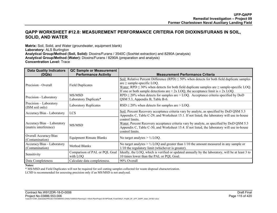
UFP-QAPP Remedial Investigation – Project 09
Former Charlestown Naval Auxiliary Landing Field
Contract No.W912DR-18-D-0006 Draft Final Project No.03886.553.006 Page 115 of 420 \\nascnh1\CNH_Data\Data\PROJECTS\03886553 (CNALF)\006\03-Planning\3.1-Work-Plan\Project 09 WP\Draft_Final\CNALF_Proj09_DF_UFP_QAPP_clean_041821.docx
QAPP WORKSHEET #12.8: MEASUREMENT PERFORMANCE CRITERIA FOR DIOXINS/FURANS IN SOIL, SOLID, AND WATER
Matrix: Soil, Solid, and Water (groundwater, equipment blank) Laboratory: ALS Burlington Analytical Group/Method (Soil, Solid): Dioxins/Furans / 3540C (Soxhlet extraction) and 8290A (analysis) Analytical Group/Method (Water): Dioxins/Furans / 8290A (preparation and analysis) Concentration Level: Trace
Data Quality Indicators (DQIs)
QC Sample or Measurement Performance Activity Measurement Performance Criteria
Precision - Overall Field Duplicates
Soil: Relative Percent Difference (RPD) ≤ 50% when detects for both field duplicate samples are ≥ sample-specific LOQ. Water: RPD ≤ 30% when detects for both field duplicate samples are ≥ sample-specific LOQ. If one or both sample detections are < 2x LOQ, the acceptance limit is ± 2x LOQ.
Precision - Laboratory MS/MSD Laboratory Duplicate*
RPD ≤ 20% when detects for samples are > LOQ. Acceptance criteria specified by DoD QSM 5.3, Appendix B, Table B-6.
Precision – Laboratory (ISM soil only) Laboratory Replicates RSD ≤ 20% when detects for samples are > LOQ.
Accuracy/Bias - Laboratory LCS Soil: Percent Recovery acceptance criteria vary by analyte, as specified by DoD QSM 5.3 Appendix C, Table C-29, and Worksheet 15.1. If not listed, the laboratory will use in-house control limits. Water: Percent Recovery acceptance criteria vary by analyte, as specified by DoD QSM 5.3 Appendix C, Table C-30, and Worksheet 15.4. If not listed, the laboratory will use in-house control limits.
Accuracy/Bias – Laboratory (matrix interference) MS/MSD
Overall Accuracy/Bias (Contamination) Equipment Rinsate Blanks No target analytes > ½ LOQ.
Accuracy/Bias - Laboratory (Contamination) Method Blanks No target analytes > ½ LOQ and greater than 1/10 the amount measured in any sample or
1/10 the regulatory limit (whichever is greater).
Sensitivity Comparison of PAL or PQL Goal with LOQ
Ideally, the LOQ, which is verified or updated annually by the laboratory, will be at least 3 to 10 times lower than the PAL or PQL Goal.
Data Completeness Calculate data completeness. 90% Overall Notes: * MS/MSD and Field Duplicates will not be required for soil cutting samples collected for waste disposal characterization. LCSD is recommended for assessing precision only if an MS/MSD is not analyzed.

UFP-QAPP Remedial Investigation – Project 09
Former Charlestown Naval Auxiliary Landing Field
Contract No.W912DR-18-D-0006 Draft Final Project No.03886.553.006 Page 116 of 420 \\nascnh1\CNH_Data\Data\PROJECTS\03886553 (CNALF)\006\03-Planning\3.1-Work-Plan\Project 09 WP\Draft_Final\CNALF_Proj09_DF_UFP_QAPP_clean_041821.docx
QAPP WORKSHEET #12.9: MEASUREMENT PERFORMANCE CRITERIA FOR TARGET ANALYTE LIST (TAL) METALS IN SOIL/SEDIMENT, SOLID AND WATER
Matrix: Soil/Sediment, Solid, and Water (tapwater, groundwater, surface water, pore water, equipment blank) Laboratory: ALS Middletown Analytical Group/Method (Soil/Sediment/Solids): Metals / EPA 3050B (acid digestion) and 6020A (analysis) Analytical Group/Method (Water): Metals / EPA 3015A (microwave digestion) and 6020A (analysis) Concentration Level: Trace
Data Quality Indicators (DQIs)
QC Sample or Measurement Performance Activity Measurement Performance Criteria
Precision - Overall Field Duplicates
Soil/Sediment: Relative Percent Difference (RPD) ≤ 50% when detects for both field duplicate samples are ≥ sample-specific LOQ. Water: RPD ≤ 30% when detects for both field duplicate samples are ≥ sample-specific LOQ. If one or both sample detections are < 2x LOQ, the data validation acceptance limit is ± 2x LOQ.
Precision - Laboratory MS/MSD Laboratory Duplicate*
RPD ≤ 20% when detects for samples are > LOQ. Acceptance criteria specified by DoD QSM 5.3, Appendix B, Table B-9.
Precision – Laboratory (ISM soil only) Laboratory Replicates RSD ≤ 20% when detects for samples are > LOQ.
Accuracy/Bias - Laboratory LCS Soil/Sediment/Solid: Percent Recovery acceptance criteria vary by analyte, as specified by DoD QSM 5.3 Appendix C, Table C-5, and Worksheets 15.1 and 15.2. If not listed, the laboratory will use in-house control limits. Water: Percent Recovery acceptance criteria vary by analyte, as specified by DoD QSM 5.3 Appendix C, Table C-6, and Worksheets 15.3, 15.4, and 15.5. If not listed, the laboratory will use in-house control limits.
Accuracy/Bias – Laboratory (matrix interference) MS/MSD
Overall Accuracy/Bias (Contamination) Equipment Rinsate Blanks No target analytes > ½ LOQ.
Accuracy/Bias - Laboratory (Contamination) Method Blanks No target analytes > ½ LOQ and greater than 1/10 the amount measured in any sample or
1/10 the regulatory limit (whichever is greater).
Sensitivity Comparison of PAL or PQL Goal with LOQ
Ideally, the LOQ, which is verified or updated annually by the laboratory, will be at least 3 to 10 times lower than the PAL or PQL Goal.
Data Completeness Calculate data completeness. 90% Overall Notes: * Matrix accuracy/precision may be assessed either through laboratory duplicates or through MS/MSD performed on a project sample. LCSD is recommended for assessing precision only if an MS/MSD is not analyzed.

UFP-QAPP Remedial Investigation – Project 09
Former Charlestown Naval Auxiliary Landing Field
Contract No.W912DR-18-D-0006 Draft Final Project No.03886.553.006 Page 117 of 420 \\nascnh1\CNH_Data\Data\PROJECTS\03886553 (CNALF)\006\03-Planning\3.1-Work-Plan\Project 09 WP\Draft_Final\CNALF_Proj09_DF_UFP_QAPP_clean_041821.docx
QAPP WORKSHEET #12.10: MEASUREMENT PERFORMANCE CRITERIA FOR MERCURY IN SOIL/SEDIMENT, SOLID, AND WATER
Matrix: Soil/Sediment/Solid and Water (tapwater, groundwater, surface water, pore water, aqueous IDW, equipment blanks) Laboratory: ALS Middletown Analytical Group/Method: Mercury / EPA 7471B (soil/sediment preparation and analysis) and EPA 7470A (water preparation and analysis) Concentration Level: Low
Data Quality Indicators (DQIs)
QC Sample or Measurement
Performance Activity Measurement Performance Criteria
Precision - Overall Field Duplicates
Soil/Sediment: Relative Percent Difference (RPD) ≤ 50% when detects for both field duplicate samples are ≥ sample-specific LOQ. Water: RPD ≤ 30% when detects for both field duplicate samples are ≥ sample-specific LOQ. If one or both sample detections are < 2x LOQ, the acceptance limit is ± 2x LOQ.
Precision - Laboratory MS/MSD Laboratory Duplicate*
RPD ≤ 20% when detects for samples are > LOQ (Laboratory QC limits). Acceptance criteria specified by DoD QSM 5.3 Appendix B Table B-7.
Precision – Laboratory (ISM soil only) Laboratory Replicates RSD ≤ 20% when detects for samples are > LOQ.
Accuracy/Bias - Laboratory LCS Soil/Sediment/Solid: Recovery within 80-124%R as specified by DoD QSM 5.3 Appendix C, Table C-11 and Worksheets 15.1 and 15.2. Water: Recovery within 82-119%R as specified by DoD QSM 5.3, Appendix C, Table C-12 and Worksheets 15.3, 15.4, and 15.5.
Accuracy/Bias - Laboratory (matrix interference) MS/MSD
Overall Accuracy/Bias (Contamination) Equipment Rinsate Blanks No target analytes > ½ LOQ.
Accuracy/Bias - Laboratory (Contamination) Method Blanks No target analytes > ½ LOQ and greater than 1/10 the amount measured in any sample or 1/10
the regulatory limit (whichever is greater).
Sensitivity Comparison of PAL or PQL Goal with LOQ
Ideally, the LOQ, which is verified or updated annually by the laboratory, will be at least 3 to 10 times lower than the PAL or PQL Goal.
Data Completeness Calculate data completeness. 90% Overall Notes: * Matrix accuracy/precision may be assessed either through laboratory duplicates or through MS/MSD performed on a project sample. LCSD is recommended for assessing precision only if an MS/MSD is not analyzed.
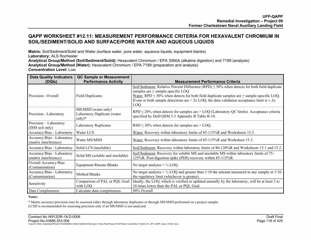
UFP-QAPP Remedial Investigation – Project 09
Former Charlestown Naval Auxiliary Landing Field
Contract No.W912DR-18-D-0006 Draft Final Project No.03886.553.006 Page 118 of 420 \\nascnh1\CNH_Data\Data\PROJECTS\03886553 (CNALF)\006\03-Planning\3.1-Work-Plan\Project 09 WP\Draft_Final\CNALF_Proj09_DF_UFP_QAPP_clean_041821.docx
QAPP WORKSHEET #12.11: MEASUREMENT PERFORMANCE CRITERIA FOR HEXAVALENT CHROMIUM IN SOIL/SEDIMENT/SOLID AND SURFACE/PORE WATER AND AQUEOUS LIQUIDS
Matrix: Soil/Sediment/Solid and Water (surface water, pore water, aqueous liquids, equipment blanks) Laboratory: ALS Rochester Analytical Group/Method (Soil/Sediment/Solid): Hexavalent Chromium / EPA 3060A (alkaline digestion) and 7199 (analysis) Analytical Group/Method (Water): Hexavalent Chromium / EPA 7199 (preparation and analysis) Concentration Level: Low
Data Quality Indicators (DQIs)
QC Sample or Measurement Performance Activity Measurement Performance Criteria
Precision - Overall Field Duplicates
Soil/Sediment: Relative Percent Difference (RPD) ≤ 50% when detects for both field duplicate samples are ≥ sample-specific LOQ. Water: RPD ≤ 30% when detects for both field duplicate samples are ≥ sample-specific LOQ. If one or both sample detections are < 2x LOQ, the data validation acceptance limit is ± 2x LOQ.
Precision - Laboratory MS/MSD (water only) Laboratory Duplicate (water only)*
RPD ≤ 20% when detects for samples are > LOQ (Laboratory QC limits). Acceptance criteria specified by DoD QSM 5.3 Appendix B Table B-10.
Precision – Laboratory (ISM soil only) Laboratory Replicates RSD ≤ 30% when detects for samples are > LOQ.
Accuracy/Bias - Laboratory Water LCS Water: Recovery within laboratory limits of 85-115%R and Worksheets 15.3. Accuracy/Bias - Laboratory (matrix interference) Water MS/MSD Water: Recovery within laboratory limits of 85-115%R and Worksheet 15.3.
Accuracy/Bias - Laboratory Solid LCS (insoluble) Soil/Sediment: Recovery within laboratory limits of 80-120%R and Worksheets 15.1 and 15.2. Accuracy/Bias - Laboratory (matrix interference) Solid MS (soluble and insoluble) Soil/Sediment: Recovery for soluble MS and insoluble MS within laboratory limits of 75-
125%R. Post-digestion spike (PDS) recovery within 85-115%R. Overall Accuracy/Bias (Contamination) Equipment Rinsate Blanks No target analytes > ½ LOQ.
Accuracy/Bias - Laboratory (Contamination) Method Blanks No target analytes > ½ LOQ and greater than 1/10 the amount measured in any sample or 1/10
the regulatory limit (whichever is greater).
Sensitivity Comparison of PAL or PQL Goal with LOQ
Ideally, the LOQ, which is verified or updated annually by the laboratory, will be at least 3 to 10 times lower than the PAL or PQL Goal.
Data Completeness Calculate data completeness. 90% Overall Notes: * Matrix accuracy/precision may be assessed either through laboratory duplicates or through MS/MSD performed on a project sample. LCSD is recommended for assessing precision only if an MS/MSD is not analyzed.
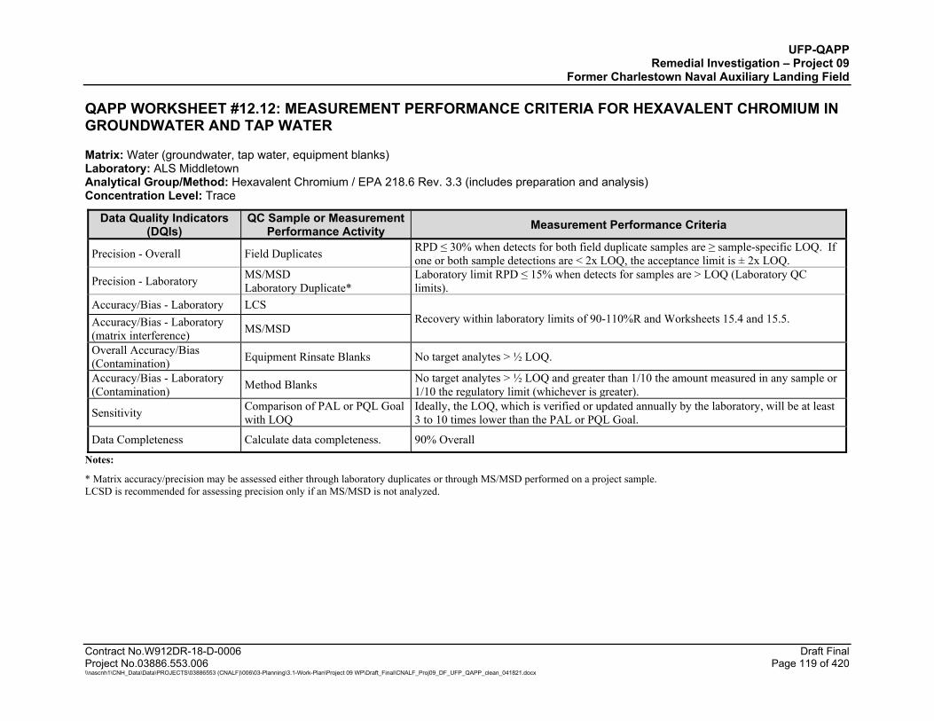
UFP-QAPP Remedial Investigation – Project 09
Former Charlestown Naval Auxiliary Landing Field
Contract No.W912DR-18-D-0006 Draft Final Project No.03886.553.006 Page 119 of 420 \\nascnh1\CNH_Data\Data\PROJECTS\03886553 (CNALF)\006\03-Planning\3.1-Work-Plan\Project 09 WP\Draft_Final\CNALF_Proj09_DF_UFP_QAPP_clean_041821.docx
QAPP WORKSHEET #12.12: MEASUREMENT PERFORMANCE CRITERIA FOR HEXAVALENT CHROMIUM IN GROUNDWATER AND TAP WATER
Matrix: Water (groundwater, tap water, equipment blanks) Laboratory: ALS Middletown Analytical Group/Method: Hexavalent Chromium / EPA 218.6 Rev. 3.3 (includes preparation and analysis) Concentration Level: Trace
Data Quality Indicators (DQIs)
QC Sample or Measurement Performance Activity Measurement Performance Criteria
Precision - Overall Field Duplicates RPD ≤ 30% when detects for both field duplicate samples are ≥ sample-specific LOQ. If one or both sample detections are < 2x LOQ, the acceptance limit is ± 2x LOQ.
Precision - Laboratory MS/MSD Laboratory Duplicate*
Laboratory limit RPD ≤ 15% when detects for samples are > LOQ (Laboratory QC limits).
Accuracy/Bias - Laboratory LCS Recovery within laboratory limits of 90-110%R and Worksheets 15.4 and 15.5. Accuracy/Bias - Laboratory
(matrix interference) MS/MSD
Overall Accuracy/Bias (Contamination) Equipment Rinsate Blanks No target analytes > ½ LOQ.
Accuracy/Bias - Laboratory (Contamination) Method Blanks No target analytes > ½ LOQ and greater than 1/10 the amount measured in any sample or
1/10 the regulatory limit (whichever is greater).
Sensitivity Comparison of PAL or PQL Goal with LOQ
Ideally, the LOQ, which is verified or updated annually by the laboratory, will be at least 3 to 10 times lower than the PAL or PQL Goal.
Data Completeness Calculate data completeness. 90% Overall
Notes:
* Matrix accuracy/precision may be assessed either through laboratory duplicates or through MS/MSD performed on a project sample. LCSD is recommended for assessing precision only if an MS/MSD is not analyzed.

UFP-QAPP Remedial Investigation – Project 09
Former Charlestown Naval Auxiliary Landing Field
Contract No.W912DR-18-D-0006 Draft Final Project No.03886.553.006 Page 120 of 420 \\nascnh1\CNH_Data\Data\PROJECTS\03886553 (CNALF)\006\03-Planning\3.1-Work-Plan\Project 09 WP\Draft_Final\CNALF_Proj09_DF_UFP_QAPP_clean_041821.docx
QAPP WORKSHEET #12.13: MEASUREMENT PERFORMANCE CRITERIA FOR FERROUS IRON IN SOIL
Matrix: Soil/Sediment Leachate (only for the Soil/Sediment sample selected for the Hexavalent Chromium Matrix Spike) Laboratory: ALS Middletown Analytical Group/Method: Ferrous Iron / ASTM D3987-06 (shake extraction with water) and Standard Methods SM3500-Fe B (analysis) Concentration Level: Low
Data Quality Indicators (DQIs)
QC Sample or Measurement Performance Activity Measurement Performance Criteria
Precision - Overall Field Duplicates Field duplicates will not be analyzed.
Precision - Laboratory MS/MSD Laboratory Duplicate*
No MS/MSD will be performed on project samples for this test parameter. Laboratory Duplicate RPD ≤ 20% when detects for samples are > LOQ (Laboratory QC limits).
Accuracy/Bias - Laboratory LCS No MS/MSD will be performed on project samples for this test parameter. LCS Recovery within laboratory limits of 90-110%R and Worksheets 15.1 and 15.2. Accuracy/Bias - Laboratory
(matrix interference) MS/MSD
Overall Accuracy/Bias (Contamination) Equipment Rinsate Blanks Equipment blanks will not be analyzed.
Accuracy/Bias - Laboratory (Contamination) Method Blanks No target analytes > ½ LOQ and greater than 1/10 the amount measured in any sample or
1/10 the regulatory limit (whichever is greater).
Sensitivity Comparison of PAL or PQL Goal with LOQ
Ideally, the LOQ, which is verified or updated annually by the laboratory, will be at least 3 to 10 times lower than the PAL or PQL Goal.
Data Completeness Calculate data completeness. 90% Overall
Notes: * Matrix accuracy/precision may be assessed either through laboratory duplicates or through MS/MSD performed on a project sample. LCSD is recommended for assessing precision only if an MS/MSD is not analyzed.

UFP-QAPP Remedial Investigation – Project 09
Former Charlestown Naval Auxiliary Landing Field
Contract No.W912DR-18-D-0006 Draft Final Project No.03886.553.006 Page 121 of 420 \\nascnh1\CNH_Data\Data\PROJECTS\03886553 (CNALF)\006\03-Planning\3.1-Work-Plan\Project 09 WP\Draft_Final\CNALF_Proj09_DF_UFP_QAPP_clean_041821.docx
QAPP WORKSHEET #12.14: MEASUREMENT PERFORMANCE CRITERIA FOR PERCHLORATE IN SOIL/SEDIMENT, SOLID AND WATER
Matrix: Soil/Sediment/Solid and Water (groundwater, surface water, pore water, aqueous waste, equipment blanks) Laboratory: ALS Houston Analytical Group/Method: Perchlorate EPA 6850 (preparation and analysis) Concentration Level: Low
Data Quality Indicators (DQIs)
QC Sample or Measurement Performance Activity Measurement Performance Criteria
Precision - Overall Field Duplicates
Soil: Relative Percent Difference (RPD) ≤ 50% when detects for both field duplicate samples are ≥ sample-specific LOQ. Water: RPD ≤ 30% when detects for both field duplicate samples are ≥ sample-specific LOQ. If one or both sample detections are < 2x LOQ, the data validation acceptance limit is ± 2x LOQ.
Precision - Laboratory MS/MSD Laboratory Duplicate*
RPD ≤ 15% when detects for samples are > LOQ (Laboratory QC limits). Acceptance criteria specified by DoD QSM 5.3 Appendix B Table B-13.
Precision – Laboratory (ISM soil only) Laboratory Replicates RSD ≤ 20% when detects for samples are > LOQ.
Accuracy/Bias - Laboratory LCS Soil/Sediment/Solid: Recovery within 84-121%R as specified by DoD QSM 5.3 Appendix C, Table C-7 and Worksheets 15.1 and 15.2. Water: Recovery within 84-119%R as specified by DoD QSM 5.3, Appendix C, Table C-8 and Worksheets 15.3 and 15.4.
Accuracy/Bias - Laboratory (matrix interference) MS/MSD
Overall Accuracy/Bias (Contamination) Equipment Rinsate Blanks No target analytes > ½ LOQ.
Accuracy/Bias - Laboratory (Contamination) Method Blanks No target analytes > ½ LOQ and greater than 1/10 the amount measured in any sample or
1/10 the regulatory limit (whichever is greater).
Sensitivity Comparison of PAL or PQL Goal with LOQ
Ideally, the LOQ, which is verified or updated annually by the laboratory, will be at least 3 to 10 times lower than the PAL or PQL Goal.
Data Completeness Calculate data completeness. 90% Overall Notes:
* Matrix accuracy/precision may be assessed either through laboratory duplicates or through MS/MSD performed on a project sample. LCSD is recommended for assessing precision only if an MS/MSD is not analyzed.
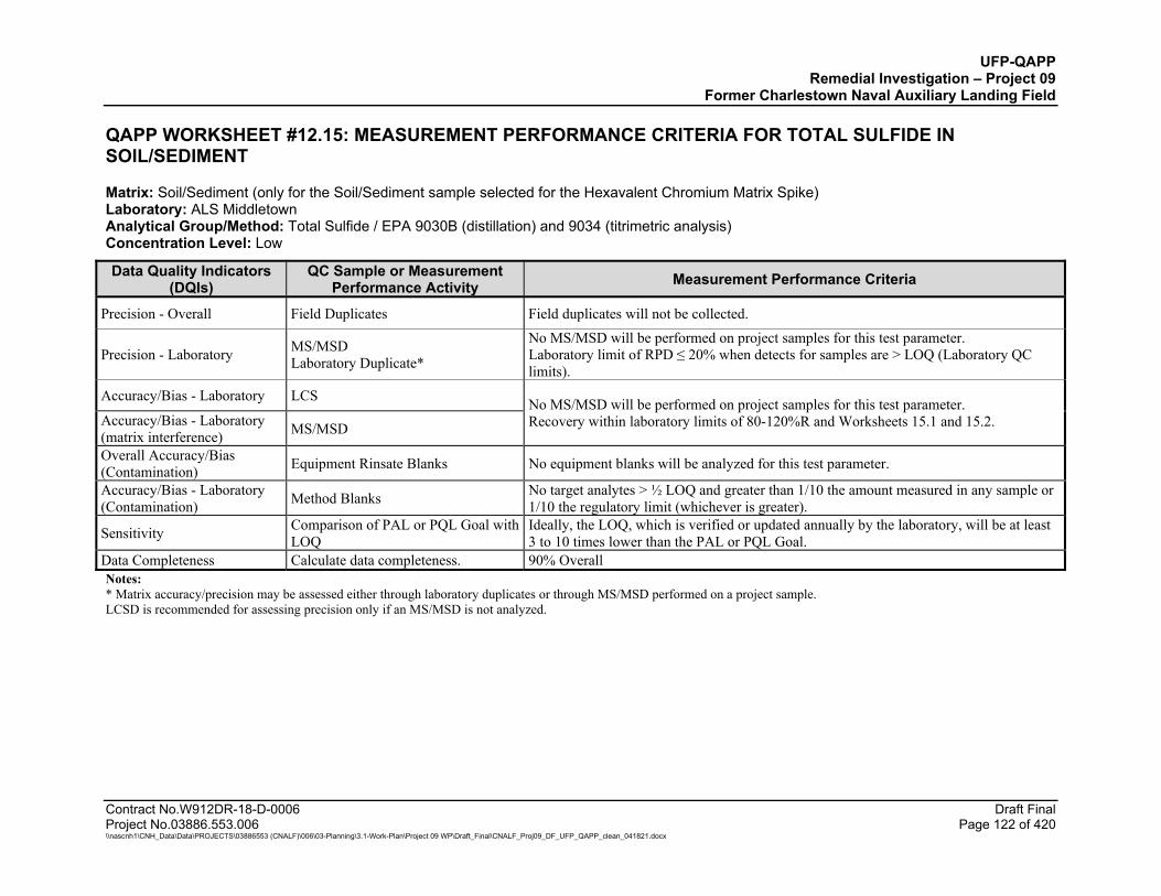
UFP-QAPP Remedial Investigation – Project 09
Former Charlestown Naval Auxiliary Landing Field
Contract No.W912DR-18-D-0006 Draft Final Project No.03886.553.006 Page 122 of 420 \\nascnh1\CNH_Data\Data\PROJECTS\03886553 (CNALF)\006\03-Planning\3.1-Work-Plan\Project 09 WP\Draft_Final\CNALF_Proj09_DF_UFP_QAPP_clean_041821.docx
QAPP WORKSHEET #12.15: MEASUREMENT PERFORMANCE CRITERIA FOR TOTAL SULFIDE IN SOIL/SEDIMENT
Matrix: Soil/Sediment (only for the Soil/Sediment sample selected for the Hexavalent Chromium Matrix Spike) Laboratory: ALS Middletown Analytical Group/Method: Total Sulfide / EPA 9030B (distillation) and 9034 (titrimetric analysis) Concentration Level: Low
Data Quality Indicators (DQIs)
QC Sample or Measurement Performance Activity Measurement Performance Criteria
Precision - Overall Field Duplicates Field duplicates will not be collected.
Precision - Laboratory MS/MSD Laboratory Duplicate*
No MS/MSD will be performed on project samples for this test parameter. Laboratory limit of RPD ≤ 20% when detects for samples are > LOQ (Laboratory QC limits).
Accuracy/Bias - Laboratory LCS No MS/MSD will be performed on project samples for this test parameter. Recovery within laboratory limits of 80-120%R and Worksheets 15.1 and 15.2. Accuracy/Bias - Laboratory
(matrix interference) MS/MSD
Overall Accuracy/Bias (Contamination) Equipment Rinsate Blanks No equipment blanks will be analyzed for this test parameter.
Accuracy/Bias - Laboratory (Contamination) Method Blanks No target analytes > ½ LOQ and greater than 1/10 the amount measured in any sample or
1/10 the regulatory limit (whichever is greater).
Sensitivity Comparison of PAL or PQL Goal with LOQ
Ideally, the LOQ, which is verified or updated annually by the laboratory, will be at least 3 to 10 times lower than the PAL or PQL Goal.
Data Completeness Calculate data completeness. 90% Overall Notes: * Matrix accuracy/precision may be assessed either through laboratory duplicates or through MS/MSD performed on a project sample. LCSD is recommended for assessing precision only if an MS/MSD is not analyzed.
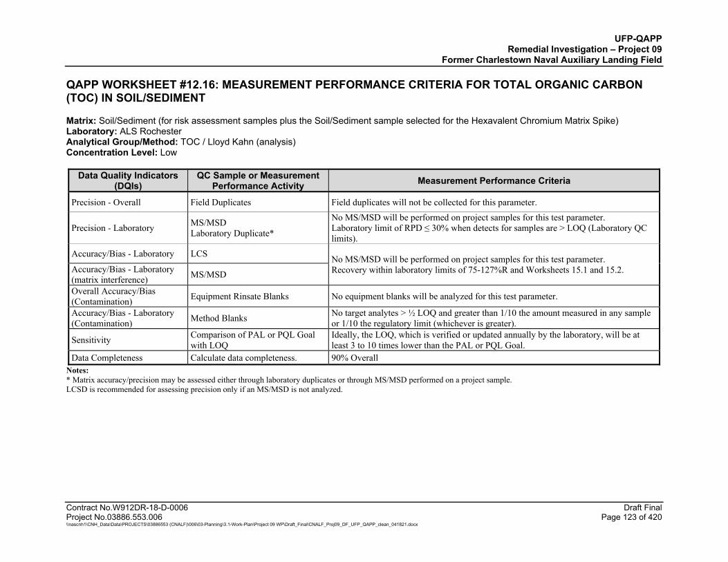
UFP-QAPP Remedial Investigation – Project 09
Former Charlestown Naval Auxiliary Landing Field
Contract No.W912DR-18-D-0006 Draft Final Project No.03886.553.006 Page 123 of 420 \\nascnh1\CNH_Data\Data\PROJECTS\03886553 (CNALF)\006\03-Planning\3.1-Work-Plan\Project 09 WP\Draft_Final\CNALF_Proj09_DF_UFP_QAPP_clean_041821.docx
QAPP WORKSHEET #12.16: MEASUREMENT PERFORMANCE CRITERIA FOR TOTAL ORGANIC CARBON (TOC) IN SOIL/SEDIMENT
Matrix: Soil/Sediment (for risk assessment samples plus the Soil/Sediment sample selected for the Hexavalent Chromium Matrix Spike) Laboratory: ALS Rochester Analytical Group/Method: TOC / Lloyd Kahn (analysis) Concentration Level: Low
Data Quality Indicators (DQIs)
QC Sample or Measurement Performance Activity Measurement Performance Criteria
Precision - Overall Field Duplicates Field duplicates will not be collected for this parameter.
Precision - Laboratory MS/MSD Laboratory Duplicate*
No MS/MSD will be performed on project samples for this test parameter. Laboratory limit of RPD ≤ 30% when detects for samples are > LOQ (Laboratory QC limits).
Accuracy/Bias - Laboratory LCS No MS/MSD will be performed on project samples for this test parameter. Recovery within laboratory limits of 75-127%R and Worksheets 15.1 and 15.2. Accuracy/Bias - Laboratory
(matrix interference) MS/MSD
Overall Accuracy/Bias (Contamination) Equipment Rinsate Blanks No equipment blanks will be analyzed for this test parameter.
Accuracy/Bias - Laboratory (Contamination) Method Blanks No target analytes > ½ LOQ and greater than 1/10 the amount measured in any sample
or 1/10 the regulatory limit (whichever is greater).
Sensitivity Comparison of PAL or PQL Goal with LOQ
Ideally, the LOQ, which is verified or updated annually by the laboratory, will be at least 3 to 10 times lower than the PAL or PQL Goal.
Data Completeness Calculate data completeness. 90% Overall Notes: * Matrix accuracy/precision may be assessed either through laboratory duplicates or through MS/MSD performed on a project sample. LCSD is recommended for assessing precision only if an MS/MSD is not analyzed.

UFP-QAPP Remedial Investigation – Project 09
Former Charlestown Naval Auxiliary Landing Field
Contract No.W912DR-18-D-0006 Draft Final Project No.03886.553.006 Page 124 of 420 \\nascnh1\CNH_Data\Data\PROJECTS\03886553 (CNALF)\006\03-Planning\3.1-Work-Plan\Project 09 WP\Draft_Final\CNALF_Proj09_DF_UFP_QAPP_clean_041821.docx
QAPP WORKSHEET #12.17: MEASUREMENT PERFORMANCE CRITERIA FOR CORROSIVITY (PH) IN SOIL/SEDIMENT AND IDW
Matrix: Soil/Sediment, Soil (IDW) and Water (IDW) Laboratory: Soil/Sediment – ALS Rochester Laboratory: Soil/Solid (IDW) and Water (IDW) - ALS Middletown Analytical Group/Method: Corrosivity (pH) / EPA 9045D (soil or soil IDW analysis) or 9040C (water IDW analysis) Concentration Level: not applicable
Data Quality Indicators (DQIs)
QC Sample or Measurement Performance Activity Measurement Performance Criteria
Precision - Overall Field Duplicates* Field duplicates will not be collected.
Precision - Laboratory Laboratory Duplicate (each sample pH is measured twice)
Within ± 0.1 pH units.
Accuracy/Bias - Laboratory LCS Not applicable.
Accuracy/Bias - Laboratory (matrix interference) MS and MSD Not applicable.
Overall Accuracy/Bias (Contamination) Equipment Rinsate Blanks Not applicable.
Accuracy/Bias - Laboratory (Contamination) Method Blanks Not applicable.
Sensitivity Comparison to TSDF acceptance limits
Sample results will be provided to the Treatment, Storage, and Disposal Facility (TSDF) to determine how soil IDW and water IDW will be profiled and disposed. A pH > 2 and a pH < 12.5 is considered non-corrosive waste.
Data Completeness Calculate data completeness. 90% Overall Notes:
* Project-specific Laboratory Duplicates and field duplicates will not be required for soil samples collected for waste disposal characterization. Sensitivity does not apply to this method, however, the soil pH will be compared to TSDF acceptance criteria to properly dispose of soil cuttings. pH – hydrogen ion concentration
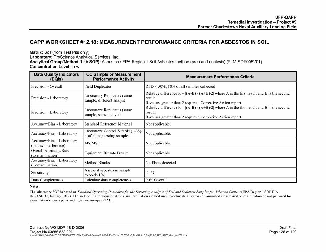
UFP-QAPP Remedial Investigation – Project 09
Former Charlestown Naval Auxiliary Landing Field
Contract No.W912DR-18-D-0006 Draft Final Project No.03886.553.006 Page 125 of 420 \\nascnh1\CNH_Data\Data\PROJECTS\03886553 (CNALF)\006\03-Planning\3.1-Work-Plan\Project 09 WP\Draft_Final\CNALF_Proj09_DF_UFP_QAPP_clean_041821.docx
QAPP WORKSHEET #12.18: MEASUREMENT PERFORMANCE CRITERIA FOR ASBESTOS IN SOIL
Matrix: Soil (from Test Pits only) Laboratory: ProScience Analytical Services, Inc. Analytical Group/Method (Lab SOP): Asbestos / EPA Region 1 Soil Asbestos method (prep and analysis) (PLM-SOP005V01) Concentration Level: Low
Data Quality Indicators (DQIs)
QC Sample or Measurement Performance Activity Measurement Performance Criteria
Precision - Overall Field Duplicates RPD < 50%; 10% of all samples collected
Precision - Laboratory Laboratory Replicates (same sample, different analyst)
Relative difference R = |(A-B) / (A+B)/2| where A is the first result and B is the second result. R-values greater than 2 require a Corrective Action report
Precision - Laboratory Laboratory Replicates (same sample, same analyst)
Relative difference R = |(A-B) / (A+B)/2| where A is the first result and B is the second result. R-values greater than 2 require a Corrective Action report
Accuracy/Bias - Laboratory Standard Reference Material Not applicable.
Accuracy/Bias - Laboratory Laboratory Control Sample (LCS)- proficiency testing samples Not applicable.
Accuracy/Bias - Laboratory (matrix interference) MS/MSD Not applicable.
Overall Accuracy/Bias (Contamination) Equipment Rinsate Blanks Not applicable.
Accuracy/Bias - Laboratory (Contamination) Method Blanks No fibers detected
Sensitivity Assess if asbestos in sample exceeds 1%. < 1%
Data Completeness Calculate data completeness. 90% Overall Notes: The laboratory SOP is based on Standard Operating Procedure for the Screening Analysis of Soil and Sediment Samples for Asbestos Content (EPA Region I SOP EIA-INGASED2, January 1999). The method is a semiquantitative visual estimation method used to delineate asbestos contaminated areas based on examination of soil prepared for examination under a polarized light microscope (PLM).

UFP-QAPP Remedial Investigation – Project 09
Former Charlestown Naval Auxiliary Landing Field
Contract No.W912DR-18-D-0006 Draft Final Project No.03886.553.006 Page 126 of 420 \\nascnh1\CNH_Data\Data\PROJECTS\03886553 (CNALF)\006\03-Planning\3.1-Work-Plan\Project 09 WP\Draft_Final\CNALF_Proj09_DF_UFP_QAPP_clean_041821.docx
QAPP WORKSHEET #12.19: MEASUREMENT PERFORMANCE CRITERIA FOR TOXICITY CHARACTERISTIC LEACHING PROCEDURE (TCLP) VOLATILE ORGANIC COMPOUNDS (VOCS)
Matrix: TCLP Leachate prepared from Soil (IDW) Laboratory: ALS Middletown Analytical Group/Method: TCLP VOCs / EPA 1311 (TCLP extraction), 5030C (purge and trap), and 8260C (analysis) Concentration Level: Low
Data Quality Indicators (DQIs)
QC Sample or Measurement Performance Activity Measurement Performance Criteria
Precision - Overall Field Duplicates* Not required for Soil IDW.
Precision - Laboratory MS/MSD* Laboratory Duplicate RPD within statistically derived in-house recovery limits.
Accuracy/Bias - Laboratory LCS Laboratory limits for Percent Recovery acceptance criteria vary by analyte, as specified in Worksheets 15.6.
Accuracy/Bias - Laboratory (matrix interference) MS and MSD* Not required for Soil IDW.
Overall Accuracy/Bias (Contamination) Equipment Rinsate Blanks Not required for Soil IDW.
Accuracy/Bias - Laboratory (Contamination) TCLP fluid (Method Blank) No target analytes > ½ LOQ and greater than 1/10 the amount measured in any sample or
1/10 the regulatory limit (whichever is greater).
Sensitivity Comparison to TCLP regulatory limit The concentration of non-detected analytes < TCLP regulatory limits.
Data Completeness Calculate data completeness. 90% Overall Notes:
* MS/MSD and Field Duplicates will not be required for soil samples collected for waste disposal characterization. LCSD is recommended for assessing precision only if an MS/MSD is not analyzed.
DoD QSM 5.3 does not specify LCS recovery limits for TCLP analytes; laboratory in-house recovery limits will be used. TCLP – Toxicity Characteristic Leaching Procedure VOC – volatile organic compounds
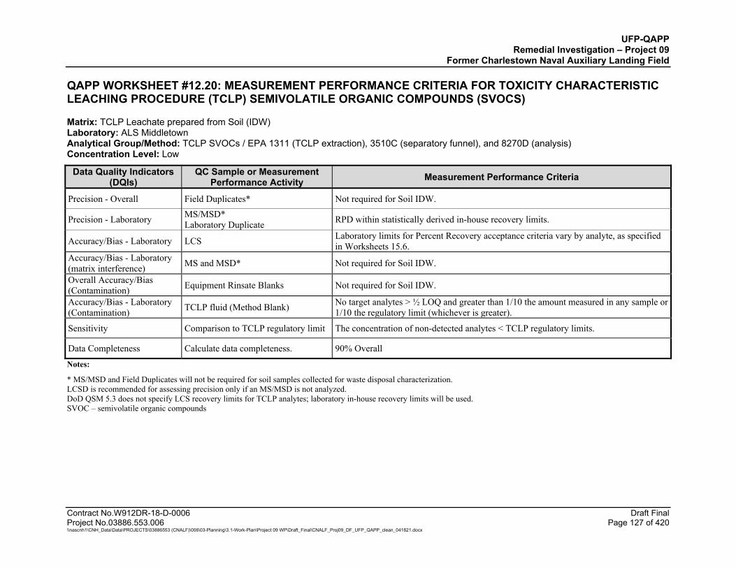
UFP-QAPP Remedial Investigation – Project 09
Former Charlestown Naval Auxiliary Landing Field
Contract No.W912DR-18-D-0006 Draft Final Project No.03886.553.006 Page 127 of 420 \\nascnh1\CNH_Data\Data\PROJECTS\03886553 (CNALF)\006\03-Planning\3.1-Work-Plan\Project 09 WP\Draft_Final\CNALF_Proj09_DF_UFP_QAPP_clean_041821.docx
QAPP WORKSHEET #12.20: MEASUREMENT PERFORMANCE CRITERIA FOR TOXICITY CHARACTERISTIC LEACHING PROCEDURE (TCLP) SEMIVOLATILE ORGANIC COMPOUNDS (SVOCS)
Matrix: TCLP Leachate prepared from Soil (IDW) Laboratory: ALS Middletown Analytical Group/Method: TCLP SVOCs / EPA 1311 (TCLP extraction), 3510C (separatory funnel), and 8270D (analysis) Concentration Level: Low
Data Quality Indicators (DQIs)
QC Sample or Measurement Performance Activity Measurement Performance Criteria
Precision - Overall Field Duplicates* Not required for Soil IDW.
Precision - Laboratory MS/MSD* Laboratory Duplicate RPD within statistically derived in-house recovery limits.
Accuracy/Bias - Laboratory LCS Laboratory limits for Percent Recovery acceptance criteria vary by analyte, as specified in Worksheets 15.6.
Accuracy/Bias - Laboratory (matrix interference) MS and MSD* Not required for Soil IDW.
Overall Accuracy/Bias (Contamination) Equipment Rinsate Blanks Not required for Soil IDW.
Accuracy/Bias - Laboratory (Contamination) TCLP fluid (Method Blank) No target analytes > ½ LOQ and greater than 1/10 the amount measured in any sample or
1/10 the regulatory limit (whichever is greater).
Sensitivity Comparison to TCLP regulatory limit The concentration of non-detected analytes < TCLP regulatory limits.
Data Completeness Calculate data completeness. 90% Overall
Notes:
* MS/MSD and Field Duplicates will not be required for soil samples collected for waste disposal characterization. LCSD is recommended for assessing precision only if an MS/MSD is not analyzed. DoD QSM 5.3 does not specify LCS recovery limits for TCLP analytes; laboratory in-house recovery limits will be used. SVOC – semivolatile organic compounds

UFP-QAPP Remedial Investigation – Project 09
Former Charlestown Naval Auxiliary Landing Field
Contract No.W912DR-18-D-0006 Draft Final Project No.03886.553.006 Page 128 of 420 \\nascnh1\CNH_Data\Data\PROJECTS\03886553 (CNALF)\006\03-Planning\3.1-Work-Plan\Project 09 WP\Draft_Final\CNALF_Proj09_DF_UFP_QAPP_clean_041821.docx
QAPP WORKSHEET #12.21: MEASUREMENT PERFORMANCE CRITERIA FOR TOXICITY CHARACTERISTIC LEACHING PROCEDURE (TCLP) METALS AND MERCURY
Matrix: TCLP Leachate prepared from Soil (IDW) Analytical Group/Method: TCLP Metals / EPA 1311 (TCLP extraction), 3015A (microwave digestion), 6010C (ICP-AES analysis), or 7470A (CVAA analysis) Concentration Level: Low
Data Quality Indicators (DQIs)
QC Sample or Measurement Performance Activity Measurement Performance Criteria
Precision - Overall Field Duplicates* Not required for Soil IDW.
Precision - Laboratory MS/MSD* Laboratory Duplicate* RPD within statistically derived in-house recovery limits.
Accuracy/Bias - Laboratory LCS Laboratory limits for Percent Recovery acceptance criteria vary by analyte, as specified in Worksheets 15.6.
Accuracy/Bias - Laboratory (matrix interference)
MS and MSD* Not required for Soil IDW.
Overall Accuracy/Bias (Contamination)
Equipment Rinsate Blanks Not required for Soil IDW.
Accuracy/Bias - Laboratory (Contamination)
TCLP fluid (Method Blank)
No target analytes > ½ LOQ and greater than 1/10 the amount measured in any sample or 1/10 the regulatory limit (whichever is greater).
Sensitivity Comparison to TCLP regulatory limit The concentration of non-detected analytes < TCLP regulatory limits.
Data Completeness Calculate data completeness. 90% Overall Notes: * MS/MSD and Field Duplicates will not be required for soil samples collected for waste disposal characterization. If the laboratory selects a project sample for a laboratory duplicate, then the QC limits noted in the table above will apply. LCSD is recommended for assessing precision only if an MS/MSD is not analyzed. DoD QSM 5.3 does not specify LCS recovery limits for TCLP analytes; laboratory in-house recovery limits will be used.

UFP-QAPP Remedial Investigation – Project 09
Former Charlestown Naval Auxiliary Landing Field
Contract No.W912DR-18-D-0006 Draft Final Project No.03886.553.006 Page 129 of 420 \\nascnh1\CNH_Data\Data\PROJECTS\03886553 (CNALF)\006\03-Planning\3.1-Work-Plan\Project 09 WP\Draft_Final\CNALF_Proj09_DF_UFP_QAPP_clean_041821.docx
QAPP WORKSHEET #12.22: MEASUREMENT PERFORMANCE CRITERIA FOR VOLATILE ORGANIC COMPOUNDS (VOCS) IN IDW WATER
Matrix: Water (IDW) Laboratory: ALS Middletown Analytical Group/Method: VOCs / EPA 5030C (purge and trap) and 8260C (analysis) Concentration Level: Low
Data Quality Indicators (DQIs)
QC Sample or Measurement Performance Activity Measurement Performance Criteria
Precision - Overall Field Duplicates Not required for water IDW.
Precision - Laboratory MS/MSD Laboratory Duplicate*
MS/MSD not required for water IDW. Laboratory Duplicate: RPD ≤ 20% when detects for samples are > LOQ. Acceptance criteria specified by DoD QSM 5.3, Appendix B, Table B-4.
Accuracy/Bias - Laboratory LCS Percent Recovery acceptance criteria vary by analyte, as specified by DoD QSM 5.3 Appendix C, Table C-24, and Worksheet 15.7. If not listed, the laboratory will use in-house control limits.
Accuracy/Bias - Laboratory (matrix interference)
MS/MSD Not required for water IDW.
Overall Accuracy/Bias (Contamination)
Equipment Rinsate Blanks Trip Blanks
Equipment Blanks not required for water IDW. Trip Blank concentration < LOQ for all analytes.
Accuracy/Bias - Laboratory (Contamination)
Method Blanks No target analytes > ½ LOQ and greater than 1/10 the amount measured in any sample or 1/10 the regulatory limit (whichever is greater).
Sensitivity Comparison to TCLP regulatory limit The concentration of non-detected analytes < TCLP regulatory limits.
Data Completeness Calculate data completeness. 90% Overall Notes: * Matrix precision may be assessed by analysis of a laboratory duplicate. Field duplicates are not required for water IDW. If the laboratory selects a project sample for a laboratory duplicate, then the QC limits noted in the table above will apply. LCSD is recommended for assessing precision only if an MS/MSD is not analyzed.
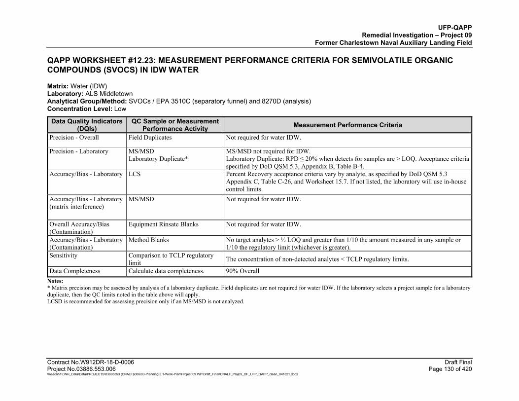
UFP-QAPP Remedial Investigation – Project 09
Former Charlestown Naval Auxiliary Landing Field
Contract No.W912DR-18-D-0006 Draft Final Project No.03886.553.006 Page 130 of 420 \\nascnh1\CNH_Data\Data\PROJECTS\03886553 (CNALF)\006\03-Planning\3.1-Work-Plan\Project 09 WP\Draft_Final\CNALF_Proj09_DF_UFP_QAPP_clean_041821.docx
QAPP WORKSHEET #12.23: MEASUREMENT PERFORMANCE CRITERIA FOR SEMIVOLATILE ORGANIC COMPOUNDS (SVOCS) IN IDW WATER
Matrix: Water (IDW) Laboratory: ALS Middletown Analytical Group/Method: SVOCs / EPA 3510C (separatory funnel) and 8270D (analysis) Concentration Level: Low
Data Quality Indicators (DQIs)
QC Sample or Measurement Performance Activity Measurement Performance Criteria
Precision - Overall Field Duplicates Not required for water IDW.
Precision - Laboratory MS/MSD Laboratory Duplicate*
MS/MSD not required for IDW. Laboratory Duplicate: RPD ≤ 20% when detects for samples are > LOQ. Acceptance criteria specified by DoD QSM 5.3, Appendix B, Table B-4.
Accuracy/Bias - Laboratory LCS Percent Recovery acceptance criteria vary by analyte, as specified by DoD QSM 5.3 Appendix C, Table C-26, and Worksheet 15.7. If not listed, the laboratory will use in-house control limits.
Accuracy/Bias - Laboratory (matrix interference)
MS/MSD Not required for water IDW.
Overall Accuracy/Bias (Contamination)
Equipment Rinsate Blanks Not required for water IDW.
Accuracy/Bias - Laboratory (Contamination)
Method Blanks No target analytes > ½ LOQ and greater than 1/10 the amount measured in any sample or 1/10 the regulatory limit (whichever is greater).
Sensitivity Comparison to TCLP regulatory limit The concentration of non-detected analytes < TCLP regulatory limits.
Data Completeness Calculate data completeness. 90% Overall Notes: * Matrix precision may be assessed by analysis of a laboratory duplicate. Field duplicates are not required for water IDW. If the laboratory selects a project sample for a laboratory duplicate, then the QC limits noted in the table above will apply. LCSD is recommended for assessing precision only if an MS/MSD is not analyzed.

UFP-QAPP Remedial Investigation – Project 09
Former Charlestown Naval Auxiliary Landing Field
Contract No.W912DR-18-D-0006 Draft Final Project No.03886.553.006 Page 131 of 420 \\nascnh1\CNH_Data\Data\PROJECTS\03886553 (CNALF)\006\03-Planning\3.1-Work-Plan\Project 09 WP\Draft_Final\CNALF_Proj09_DF_UFP_QAPP_clean_041821.docx
QAPP WORKSHEET #12.24: MEASUREMENT PERFORMANCE CRITERIA FOR RESOURCE CONSERVATION AND RECOVERY ACT (RCRA) METALS INCLUDING MERCURY IN IDW WATER
Matrix: Water (IDW) Laboratory: ALS Middletown Analytical Group/Method: Metals / EPA 3015A (microwave digestion) and 6010C (ICP-AES analysis) or 7470A (CVAA analysis) Concentration Level: Low
Data Quality Indicators (DQIs)
QC Sample or Measurement Performance Activity Measurement Performance Criteria
Precision - Overall Field Duplicates Not required for water IDW.
Precision - Laboratory MS/MSD* Laboratory Duplicate
MS/MSD not required for IDW. RPD ≤ 20% when detects for samples are > LOQ. Acceptance criteria specified by DoD QSM 5.3, Appendix B, Table B-8.
Accuracy/Bias - Laboratory LCS Percent Recovery acceptance criteria vary by analyte, as specified by DoD QSM 5.3 Appendix C, Table C-4, and Worksheet 15.7. If not listed, the laboratory will use in-house control limits.
Accuracy/Bias – Laboratory (matrix interference)
MS/MSD * Not required for water IDW.
Overall Accuracy/Bias (Contamination) Equipment Rinsate Blanks Not required for water IDW.
Accuracy/Bias - Laboratory (Contamination) Method Blanks No target analytes > ½ LOQ and greater than 1/10 the amount measured in any sample or
1/10 the regulatory limit (whichever is greater).
Sensitivity Comparison to TCLP regulatory limit The concentration of non-detected analytes < TCLP regulatory limits.
Data Completeness Calculate data completeness. 90% Overall Notes: * Matrix accuracy/precision may be assessed either through laboratory duplicates or through MS/MSD performed on a project sample. If the laboratory selects a project sample for a laboratory duplicate, then the QC limits noted in the table above will apply. LCSD is recommended for assessing precision only if an MS/MSD is not analyzed.
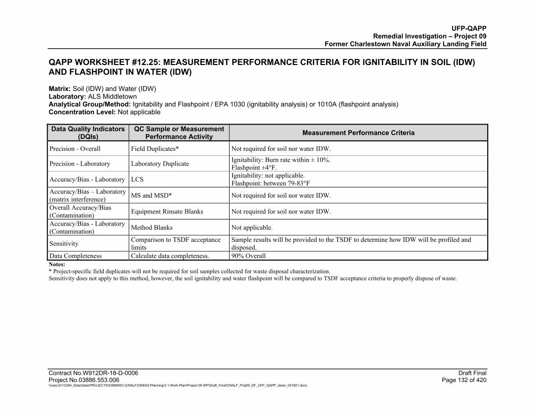
UFP-QAPP Remedial Investigation – Project 09
Former Charlestown Naval Auxiliary Landing Field
Contract No.W912DR-18-D-0006 Draft Final Project No.03886.553.006 Page 132 of 420 \\nascnh1\CNH_Data\Data\PROJECTS\03886553 (CNALF)\006\03-Planning\3.1-Work-Plan\Project 09 WP\Draft_Final\CNALF_Proj09_DF_UFP_QAPP_clean_041821.docx
QAPP WORKSHEET #12.25: MEASUREMENT PERFORMANCE CRITERIA FOR IGNITABILITY IN SOIL (IDW) AND FLASHPOINT IN WATER (IDW)
Matrix: Soil (IDW) and Water (IDW) Laboratory: ALS Middletown Analytical Group/Method: Ignitability and Flashpoint / EPA 1030 (ignitability analysis) or 1010A (flashpoint analysis) Concentration Level: Not applicable
Data Quality Indicators (DQIs)
QC Sample or Measurement Performance Activity Measurement Performance Criteria
Precision - Overall Field Duplicates* Not required for soil nor water IDW.
Precision - Laboratory Laboratory Duplicate Ignitability: Burn rate within ± 10%. Flashpoint ±4°F.
Accuracy/Bias - Laboratory LCS Ignitability: not applicable. Flashpoint: between 79-83°F
Accuracy/Bias – Laboratory (matrix interference) MS and MSD* Not required for soil nor water IDW.
Overall Accuracy/Bias (Contamination) Equipment Rinsate Blanks Not required for soil nor water IDW.
Accuracy/Bias - Laboratory (Contamination) Method Blanks Not applicable.
Sensitivity Comparison to TSDF acceptance limits
Sample results will be provided to the TSDF to determine how IDW will be profiled and disposed.
Data Completeness Calculate data completeness. 90% Overall Notes: * Project-specific field duplicates will not be required for soil samples collected for waste disposal characterization. Sensitivity does not apply to this method, however, the soil ignitability and water flashpoint will be compared to TSDF acceptance criteria to properly dispose of waste.

UFP-QAPP Remedial Investigation – Project 09
Former Charlestown Naval Auxiliary Landing Field
Contract No.W912DR-18-D-0006 Draft Final Project No.03886.553.006 Page 133 of 420 \\nascnh1\CNH_Data\Data\PROJECTS\03886553 (CNALF)\006\03-Planning\3.1-Work-Plan\Project 09 WP\Draft_Final\CNALF_Proj09_DF_UFP_QAPP_clean_041821.docx
QAPP WORKSHEET #12.26: MEASUREMENT PERFORMANCE CRITERIA FOR REACTIVITY (CYANIDE AND SULFIDE) IN IDW
Matrix: Soil (IDW) and Water (IDW) Laboratory: ALS Middletown Analytical Group/Method: Reactive Cyanide / SW-846 Chapter 7.3.3.2 with analysis based on EPA 9012B Analytical Group/Method: Reactive Sulfide / SW-846 Chapter 7.3.4.2 with analysis based on EPA 9034 (soil IDW) or SM 4500-S2- F (water IDW) Concentration Level: Not applicable
Data Quality Indicators (DQIs)
QC Sample or Measurement Performance Activity Measurement Performance Criteria
Precision - Overall Field Duplicates* Not required for soil nor water IDW.
Precision - Laboratory Laboratory Duplicate Reactive Cyanide: RPD ≤ 20% Reactive Sulfide: RPD ≤ 20%
Accuracy/Bias - Laboratory LCS Reactive Cyanide: 0-90%R Reactive Sulfide: 49-148%R
Accuracy/Bias – Laboratory (matrix interference) MS and MSD* Not required for soil nor water IDW.
Overall Accuracy/Bias (Contamination) Equipment Rinsate Blanks Not required for soil nor water IDW.
Accuracy/Bias - Laboratory (Contamination) Method Blanks Reactive Cyanide: < LOD of 10 mg/kg
Reactive Sulfide: < LOD of 6.25 mg/kg
Sensitivity Comparison to TSDF acceptance limits
Sample results will be provided to the TSDF to determine how soil IDW will be profiled and disposed.
Data Completeness Calculate data completeness. 90% Overall Notes: * Field duplicates and laboratory duplicates will not be required for IDW soil samples. If the laboratory selects a project sample for Laboratory QC, the acceptance criteria are noted in the table above. LCSD is recommended for assessing precision only if an MS/MSD is not analyzed.

UFP-QAPP Remedial Investigation – Project 09
Former Charlestown Naval Auxiliary Landing Field
Contract No.W912DR-18-D-0006 Draft Final Project No.03886.553.006 Page 134 of 420 \\nascnh1\CNH_Data\Data\PROJECTS\03886553 (CNALF)\006\03-Planning\3.1-Work-Plan\Project 09 WP\Draft_Final\CNALF_Proj09_DF_UFP_QAPP_clean_041821.docx
QAPP WORKSHEET #12.27: MEASUREMENT PERFORMANCE CRITERIA FOR POLYCHLORINATED BIPHENYLS (PCBS) IN IDW
Matrix: Soil (IDW) and Water (IDW) Laboratory: ASL Kelso Analytical Group/Method: Metals / EPA 3541 (Soxhlet extraction) or 3510 (separatory funnel) and 8082A (analysis) Concentration Level: Low
Data Quality Indicators (DQIs)
QC Sample or Measurement Performance Activity Measurement Performance Criteria
Precision - Overall Field Duplicates Not required for soil nor water IDW.
Precision - Laboratory MS/MSD Laboratory Duplicate*
RPD ≤ 30% when detects for samples are > LOQ. Acceptance criteria specified by DoD QSM 5.3, Appendix B, Table B-1.
Accuracy/Bias - Laboratory LCS Soil: Percent Recovery acceptance criteria vary by analyte, as specified by DoD QSM 5.3 Appendix C, Table C-17, and Worksheet 15.6. If not listed, the laboratory will use in-house control limits. Water: Percent Recovery acceptance criteria vary by analyte, as specified by DoD QSM 5.3 Appendix C, Table C-18, and Worksheet 15.7. If not listed, the laboratory will use in-house control limits.
Accuracy/Bias – Laboratory (matrix interference)
MS/MSD Not required for soil nor water IDW.
Overall Accuracy/Bias (Contamination)
Equipment Rinsate Blanks Not required for soil nor water IDW.
Accuracy/Bias - Laboratory (Contamination)
Method Blanks
No target analytes > ½ LOQ and greater than 1/10 the amount measured in any sample or 1/10 the regulatory limit (whichever is greater).
Sensitivity Comparison to TSDF acceptance limits
Sample results will be provided to the TSDF to determine how IDW will be profiled and disposed.
Data Completeness Calculate data completeness. 90% Overall Notes: * Matrix accuracy/precision may be assessed either through laboratory duplicates or through MS/MSD performed on a project sample. LCSD is recommended for assessing precision only if an MS/MSD is not analyzed.

UFP-QAPP Remedial Investigation – Project 09
Former Charlestown Naval Auxiliary Landing Field
Contract No.W912DR-18-D-0006 Draft Final Project No.03886.553.006 Page 135 of 420 \\nascnh1\CNH_Data\Data\PROJECTS\03886553 (CNALF)\006\03-Planning\3.1-Work-Plan\Project 09 WP\Draft_Final\CNALF_Proj09_DF_UFP_QAPP_clean_041821.docx
QAPP WORKSHEET #12.28: MEASUREMENT PERFORMANCE CRITERIA FOR GASOLINE RANGE ORGANICS (GRO) IN IDW
Matrix: Soil (IDW) and Water (IDW) Laboratory: ALS Middletown Analytical Group/Method: GRO / EPA 5035A (soil solid-phase extraction) or 5030C (water purge and trap) and 8015D (analysis) Concentration Level: Low
Data Quality Indicators (DQIs)
QC Sample or Measurement Performance Activity Measurement Performance Criteria
Precision - Overall Field Duplicates Not required for soil or water IDW.
Precision - Laboratory MS/MSD Laboratory Duplicate*
MS/MSD not required for soil or water IDW. Laboratory Duplicate: RPD ≤ 30% when detects for samples are > LOQ (Laboratory QC limits). Acceptance criteria specified by DoD QSM 5.3, Appendix B, Table B-1.
Accuracy/Bias - Laboratory LCS
Soil: Recovery within 79-122 %R, as specified by DoD QSM 5.3 Appendix C, Table C-13, and Worksheet 15.6. Water: Recovery within 78-122 %R, as specified by DoD QSM 5.3 Appendix C, Table C-14, and Worksheet 15.7.
Accuracy/Bias - Laboratory (matrix interference) MS/MSD Not required for soil or water IDW.
Overall Accuracy/Bias (Contamination)
Equipment Rinsate Blanks Trip Blank
Equipment Blanks: Not required for soil or water IDW. Trip Blanks: No target analytes > LOQ
Accuracy/Bias - Laboratory (Contamination) Method Blanks No target analytes > ½ LOQ and greater than 1/10 the amount measured in any sample or
1/10 the regulatory limit (whichever is greater).
Sensitivity Comparison to TSDF acceptance limits
Sample results will be provided to the TSDF to determine how soil IDW will be profiled and disposed.
Data Completeness Calculate data completeness. 90% Overall Notes: * Matrix accuracy/precision may be assessed either through laboratory duplicates or through MS/MSD performed on a project sample. LCSD is recommended for assessing precision only if an MS/MSD is not analyzed. %R – percent recovery GRO – gasoline range organics
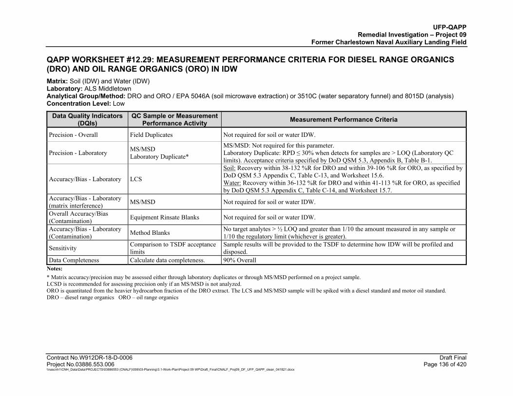
UFP-QAPP Remedial Investigation – Project 09
Former Charlestown Naval Auxiliary Landing Field
Contract No.W912DR-18-D-0006 Draft Final Project No.03886.553.006 Page 136 of 420 \\nascnh1\CNH_Data\Data\PROJECTS\03886553 (CNALF)\006\03-Planning\3.1-Work-Plan\Project 09 WP\Draft_Final\CNALF_Proj09_DF_UFP_QAPP_clean_041821.docx
QAPP WORKSHEET #12.29: MEASUREMENT PERFORMANCE CRITERIA FOR DIESEL RANGE ORGANICS (DRO) AND OIL RANGE ORGANICS (ORO) IN IDW Matrix: Soil (IDW) and Water (IDW) Laboratory: ALS Middletown Analytical Group/Method: DRO and ORO / EPA 5046A (soil microwave extraction) or 3510C (water separatory funnel) and 8015D (analysis) Concentration Level: Low
Data Quality Indicators (DQIs)
QC Sample or Measurement Performance Activity Measurement Performance Criteria
Precision - Overall Field Duplicates Not required for soil or water IDW.
Precision - Laboratory MS/MSD Laboratory Duplicate*
MS/MSD: Not required for this parameter. Laboratory Duplicate: RPD ≤ 30% when detects for samples are > LOQ (Laboratory QC limits). Acceptance criteria specified by DoD QSM 5.3, Appendix B, Table B-1.
Accuracy/Bias - Laboratory LCS
Soil: Recovery within 38-132 %R for DRO and within 39-106 %R for ORO, as specified by DoD QSM 5.3 Appendix C, Table C-13, and Worksheet 15.6. Water: Recovery within 36-132 %R for DRO and within 41-113 %R for ORO, as specified by DoD QSM 5.3 Appendix C, Table C-14, and Worksheet 15.7.
Accuracy/Bias - Laboratory (matrix interference) MS/MSD Not required for soil or water IDW.
Overall Accuracy/Bias (Contamination) Equipment Rinsate Blanks Not required for soil or water IDW.
Accuracy/Bias - Laboratory (Contamination) Method Blanks No target analytes > ½ LOQ and greater than 1/10 the amount measured in any sample or
1/10 the regulatory limit (whichever is greater).
Sensitivity Comparison to TSDF acceptance limits
Sample results will be provided to the TSDF to determine how IDW will be profiled and disposed.
Data Completeness Calculate data completeness. 90% Overall Notes: * Matrix accuracy/precision may be assessed either through laboratory duplicates or through MS/MSD performed on a project sample. LCSD is recommended for assessing precision only if an MS/MSD is not analyzed. ORO is quantitated from the heavier hydrocarbon fraction of the DRO extract. The LCS and MS/MSD sample will be spiked with a diesel standard and motor oil standard. DRO – diesel range organics ORO – oil range organics
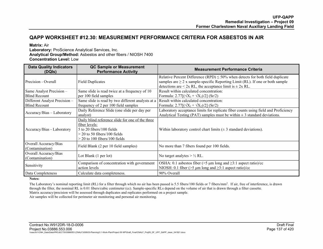
UFP-QAPP Remedial Investigation – Project 09
Former Charlestown Naval Auxiliary Landing Field
Contract No.W912DR-18-D-0006 Draft Final Project No.03886.553.006 Page 137 of 420 \\nascnh1\CNH_Data\Data\PROJECTS\03886553 (CNALF)\006\03-Planning\3.1-Work-Plan\Project 09 WP\Draft_Final\CNALF_Proj09_DF_UFP_QAPP_clean_041821.docx
QAPP WORKSHEET #12.30: MEASUREMENT PERFORMANCE CRITERIA FOR ASBESTOS IN AIR Matrix: Air Laboratory: ProScience Analytical Services, Inc. Analytical Group/Method: Asbestos and other fibers / NIOSH 7400 Concentration Level: Low
Data Quality Indicators (DQIs)
QC Sample or Measurement Performance Activity Measurement Performance Criteria
Precision - Overall Field Duplicates Relative Percent Difference (RPD) ≤ 50% when detects for both field duplicate samples are ≥ 2 x sample-specific Reporting Limit (RL). If one or both sample detections are < 2x RL, the acceptance limit is ± 2x RL.
Same Analyst Precision – Blind Recount
Same slide is read twice at a frequency of 10 per 100 field samples
Result within calculated concentration: Formula: 2.77[(√X1 + √X2)/2] (Sr/2)
Different Analyst Precision – Blind Recount
Same slide is read by two different analysts at a frequency of 2 per 100 field samples
Result within calculated concentration: Formula: 2.77[(√X1 + √X2)/2] (Sr/2)
Accuracy/Bias – Laboratory Daily Reference Slide (one slide per day per analyst)
Laboratory acceptance limits for replicate fiber counts using field and Proficiency Analytical Testing (PAT) samples must be within ± 3 standard deviations.
Accuracy/Bias - Laboratory
Daily blind reference slide for one of the three fiber levels: 5 to 20 fibers/100 fields > 20 to 50 fibers/100 fields > 20 to 100 fibers/100 fields
Within laboratory control chart limits (± 3 standard deviations).
Overall Accuracy/Bias (Contamination) Field Blank (2 per 10 field samples) No more than 7 fibers found per 100 fields.
Overall Accuracy/Bias (Contamination) Lot Blank (1 per lot) No target analytes > ½ RL.
Sensitivity Comparison of concentration with government action levels
OSHA: 0.1 asbestos fiber (>5 μm long and ≥3:1 aspect ratio)/cc NIOSH: 0.1 fiber (>5 μm long and ≥3:1 aspect ratio)/cc
Data Completeness Calculate data completeness. 90% Overall Notes: The Laboratory’s nominal reporting limit (RL) for a filter through which no air has been passed is 5.5 fibers/100 fields or 7 fibers/mm2. If air, free of interference, is drawn through the filter, the nominal RL is 0.01 fibers/cubic centimeter (cc). Sample-specific RLs depend on the volume of air that is drawn through a filter cassette. Matrix accuracy/precision will be assessed through duplicates and replicates performed on a project sample. Air samples will be collected for perimeter air monitoring and personal air monitoring.
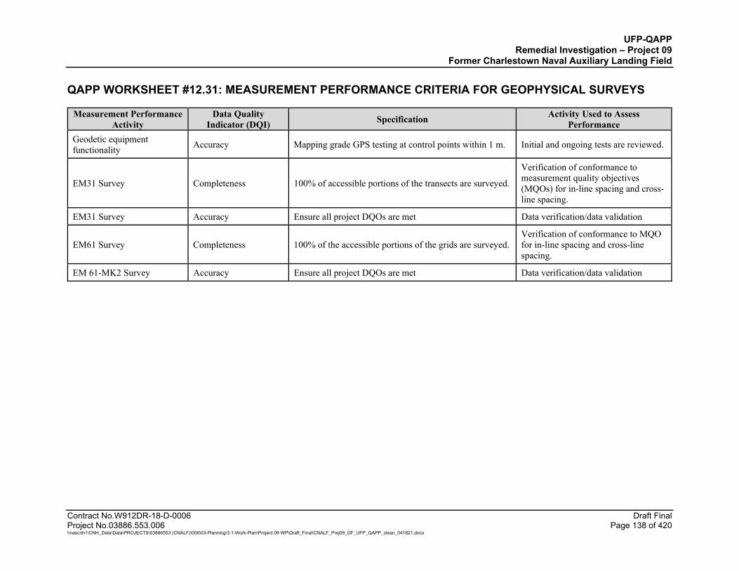
UFP-QAPP Remedial Investigation – Project 09
Former Charlestown Naval Auxiliary Landing Field
Contract No.W912DR-18-D-0006 Draft Final Project No.03886.553.006 Page 138 of 420 \\nascnh1\CNH_Data\Data\PROJECTS\03886553 (CNALF)\006\03-Planning\3.1-Work-Plan\Project 09 WP\Draft_Final\CNALF_Proj09_DF_UFP_QAPP_clean_041821.docx
QAPP WORKSHEET #12.31: MEASUREMENT PERFORMANCE CRITERIA FOR GEOPHYSICAL SURVEYS
Measurement Performance Activity
Data Quality Indicator (DQI) Specification Activity Used to Assess
Performance Geodetic equipment functionality Accuracy Mapping grade GPS testing at control points within 1 m. Initial and ongoing tests are reviewed.
EM31 Survey Completeness 100% of accessible portions of the transects are surveyed.
Verification of conformance to measurement quality objectives (MQOs) for in-line spacing and cross-line spacing.
EM31 Survey Accuracy Ensure all project DQOs are met Data verification/data validation
EM61 Survey Completeness 100% of the accessible portions of the grids are surveyed. Verification of conformance to MQO for in-line spacing and cross-line spacing.
EM 61-MK2 Survey Accuracy Ensure all project DQOs are met Data verification/data validation
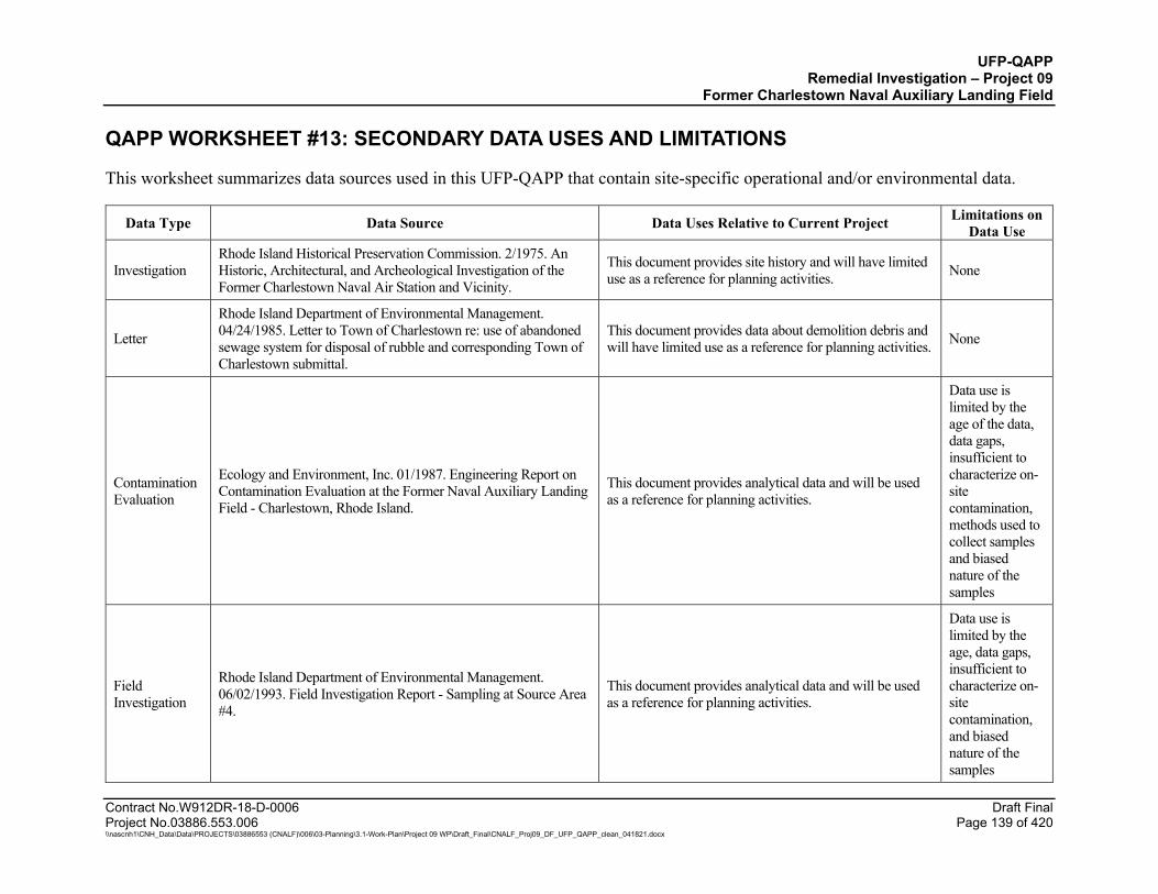
UFP-QAPP Remedial Investigation – Project 09
Former Charlestown Naval Auxiliary Landing Field
Contract No.W912DR-18-D-0006 Draft Final Project No.03886.553.006 Page 139 of 420 \\nascnh1\CNH_Data\Data\PROJECTS\03886553 (CNALF)\006\03-Planning\3.1-Work-Plan\Project 09 WP\Draft_Final\CNALF_Proj09_DF_UFP_QAPP_clean_041821.docx
QAPP WORKSHEET #13: SECONDARY DATA USES AND LIMITATIONS
This worksheet summarizes data sources used in this UFP-QAPP that contain site-specific operational and/or environmental data.
Data Type Data Source Data Uses Relative to Current Project Limitations on Data Use
Investigation Rhode Island Historical Preservation Commission. 2/1975. An Historic, Architectural, and Archeological Investigation of the Former Charlestown Naval Air Station and Vicinity.
This document provides site history and will have limited use as a reference for planning activities. None
Letter
Rhode Island Department of Environmental Management. 04/24/1985. Letter to Town of Charlestown re: use of abandoned sewage system for disposal of rubble and corresponding Town of Charlestown submittal.
This document provides data about demolition debris and will have limited use as a reference for planning activities. None
Contamination Evaluation
Ecology and Environment, Inc. 01/1987. Engineering Report on Contamination Evaluation at the Former Naval Auxiliary Landing Field ‐ Charlestown, Rhode Island.
This document provides analytical data and will be used as a reference for planning activities.
Data use is limited by the age of the data, data gaps, insufficient to characterize on-site contamination, methods used to collect samples and biased nature of the samples
Field Investigation
Rhode Island Department of Environmental Management. 06/02/1993. Field Investigation Report - Sampling at Source Area #4.
This document provides analytical data and will be used as a reference for planning activities.
Data use is limited by the age, data gaps, insufficient to characterize on-site contamination, and biased nature of the samples
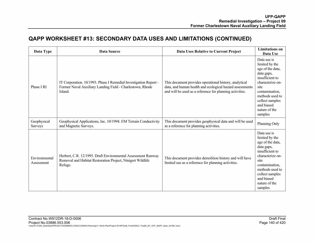
UFP-QAPP Remedial Investigation – Project 09
Former Charlestown Naval Auxiliary Landing Field QAPP WORKSHEET #13: SECONDARY DATA USES AND LIMITATIONS (CONTINUED)
Contract No.W912DR-18-D-0006 Draft Final Project No.03886.553.006 Page 140 of 420 \\nascnh1\CNH_Data\Data\PROJECTS\03886553 (CNALF)\006\03-Planning\3.1-Work-Plan\Project 09 WP\Draft_Final\CNALF_Proj09_DF_UFP_QAPP_clean_041821.docx
Data Type Data Source Data Uses Relative to Current Project Limitations on Data Use
Phase I RI IT Corporation. 10/1993. Phase I Remedial Investigation Report - Former Naval Auxiliary Landing Field - Charlestown, Rhode Island.
This document provides operational history, analytical data, and human health and ecological hazard assessments and will be used as a reference for planning activities.
Data use is limited by the age of the data, data gaps, insufficient to characterize on-site contamination, methods used to collect samples and biased nature of the samples
Geophysical Surveys
Geophysical Applications, Inc. 10/1994. EM Terrain Conductivity and Magnetic Surveys.
This document provides geophysical data and will be used as a reference for planning activities. Planning Only
Environmental Assessment
Herbert, C.R. 12/1995. Draft Environmental Assessment Runway Removal and Habitat Restoration Project, Ninigret Wildlife Refuge.
This document provides demolition history and will have limited use as a reference for planning activities.
Data use is limited by the age of the data, data gaps, insufficient to characterize on-site contamination, methods used to collect samples and biased nature of the samples
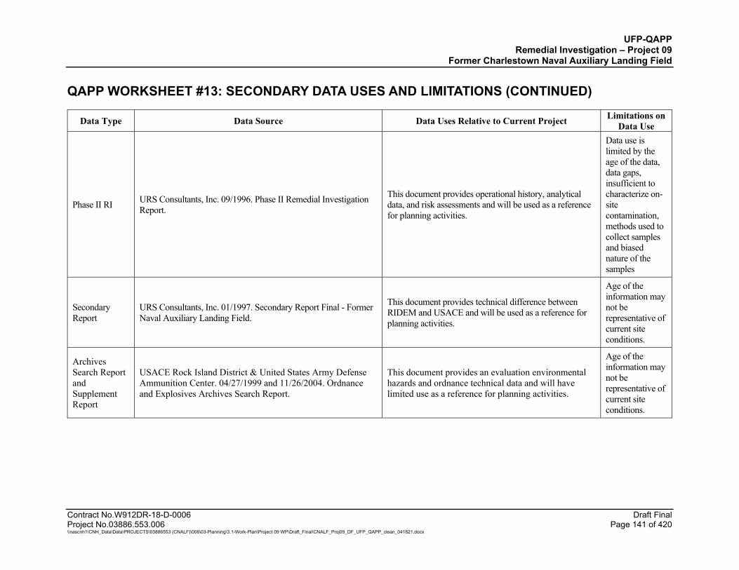
UFP-QAPP Remedial Investigation – Project 09
Former Charlestown Naval Auxiliary Landing Field QAPP WORKSHEET #13: SECONDARY DATA USES AND LIMITATIONS (CONTINUED)
Contract No.W912DR-18-D-0006 Draft Final Project No.03886.553.006 Page 141 of 420 \\nascnh1\CNH_Data\Data\PROJECTS\03886553 (CNALF)\006\03-Planning\3.1-Work-Plan\Project 09 WP\Draft_Final\CNALF_Proj09_DF_UFP_QAPP_clean_041821.docx
Data Type Data Source Data Uses Relative to Current Project Limitations on Data Use
Phase II RI URS Consultants, Inc. 09/1996. Phase II Remedial Investigation Report.
This document provides operational history, analytical data, and risk assessments and will be used as a reference for planning activities.
Data use is limited by the age of the data, data gaps, insufficient to characterize on-site contamination, methods used to collect samples and biased nature of the samples
Secondary Report
URS Consultants, Inc. 01/1997. Secondary Report Final - Former Naval Auxiliary Landing Field.
This document provides technical difference between RIDEM and USACE and will be used as a reference for planning activities.
Age of the information may not be representative of current site conditions.
Archives Search Report and Supplement Report
USACE Rock Island District & United States Army Defense Ammunition Center. 04/27/1999 and 11/26/2004. Ordnance and Explosives Archives Search Report.
This document provides an evaluation environmental hazards and ordnance technical data and will have limited use as a reference for planning activities.
Age of the information may not be representative of current site conditions.
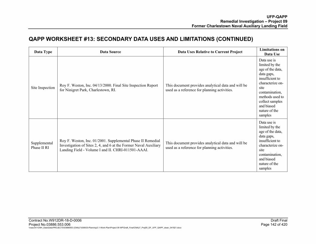
UFP-QAPP Remedial Investigation – Project 09
Former Charlestown Naval Auxiliary Landing Field QAPP WORKSHEET #13: SECONDARY DATA USES AND LIMITATIONS (CONTINUED)
Contract No.W912DR-18-D-0006 Draft Final Project No.03886.553.006 Page 142 of 420 \\nascnh1\CNH_Data\Data\PROJECTS\03886553 (CNALF)\006\03-Planning\3.1-Work-Plan\Project 09 WP\Draft_Final\CNALF_Proj09_DF_UFP_QAPP_clean_041821.docx
Data Type Data Source Data Uses Relative to Current Project Limitations on Data Use
Site Inspection Roy F. Weston, Inc. 04/13/2000. Final Site Inspection Report for Ninigret Park, Charlestown, RI.
This document provides analytical data and will be used as a reference for planning activities.
Data use is limited by the age of the data, data gaps, insufficient to characterize on-site contamination, methods used to collect samples and biased nature of the samples
Supplemental Phase II RI
Roy F. Weston, Inc. 01/2001. Supplemental Phase II Remedial Investigation of Sites 2, 4, and 6 at the Former Naval Auxiliary Landing Field - Volume I and II. CHRI-011501-AAAI.
This document provides analytical data and will be used as a reference for planning activities.
Data use is limited by the age of the data, data gaps, insufficient to characterize on-site contamination, and biased nature of the samples
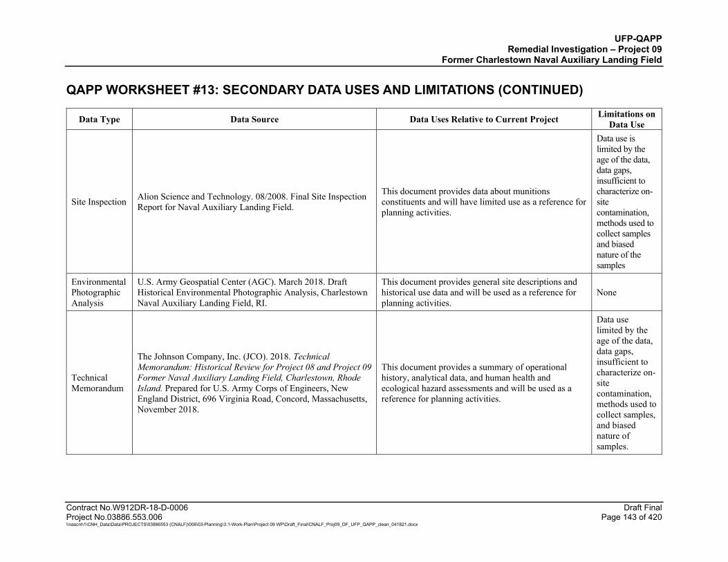
UFP-QAPP Remedial Investigation – Project 09
Former Charlestown Naval Auxiliary Landing Field QAPP WORKSHEET #13: SECONDARY DATA USES AND LIMITATIONS (CONTINUED)
Contract No.W912DR-18-D-0006 Draft Final Project No.03886.553.006 Page 143 of 420 \\nascnh1\CNH_Data\Data\PROJECTS\03886553 (CNALF)\006\03-Planning\3.1-Work-Plan\Project 09 WP\Draft_Final\CNALF_Proj09_DF_UFP_QAPP_clean_041821.docx
Data Type Data Source Data Uses Relative to Current Project Limitations on Data Use
Site Inspection Alion Science and Technology. 08/2008. Final Site Inspection Report for Naval Auxiliary Landing Field.
This document provides data about munitions constituents and will have limited use as a reference for planning activities.
Data use is limited by the age of the data, data gaps, insufficient to characterize on-site contamination, methods used to collect samples and biased nature of the samples
Environmental Photographic Analysis
U.S. Army Geospatial Center (AGC). March 2018. Draft Historical Environmental Photographic Analysis, Charlestown Naval Auxiliary Landing Field, RI.
This document provides general site descriptions and historical use data and will be used as a reference for planning activities.
None
Technical Memorandum
The Johnson Company, Inc. (JCO). 2018. Technical Memorandum: Historical Review for Project 08 and Project 09 Former Naval Auxiliary Landing Field, Charlestown, Rhode Island. Prepared for U.S. Army Corps of Engineers, New England District, 696 Virginia Road, Concord, Massachusetts, November 2018.
This document provides a summary of operational history, analytical data, and human health and ecological hazard assessments and will be used as a reference for planning activities.
Data use limited by the age of the data, data gaps, insufficient to characterize on-site contamination, methods used to collect samples, and biased nature of samples.

UFP-QAPP Remedial Investigation – Project 09
Former Charlestown Naval Auxiliary Landing Field
Contract No.W912DR-18-D-0006 Draft Final Project No.03886.553.006 Page 144 of 420 \\nascnh1\CNH_Data\Data\PROJECTS\03886553 (CNALF)\006\03-Planning\3.1-Work-Plan\Project 09 WP\Draft_Final\CNALF_Proj09_DF_UFP_QAPP_clean_041821.docx
QAPP WORKSHEETS #14 & 16: PROJECT TASKS & SCHEDULE The primary tasks associated with Project 09 are described in Worksheet #17. The proposed schedule for implementation including approximate dates and durations of each task is provided in Attachment E. At this time, start dates and field durations have been estimated and will be verified prior to procurements and plans being finalized. This will include tracking revisions from the accepted baseline schedule.
A Draft RI Report will be prepared by WESTON and submitted to USACE for review and approval, and will include the following information:
A summary of the purpose of the RI and supporting background information, including previous investigations and rationale for proposed investigations;
A summary of the field investigations completed including sampling completed and dates that each activity was performed;
Deviations from the UFP-QAPP encountered during the field task implementation, if any, including explanations for each deviation;
A summary of the physical characteristics of each site based on historical and new site data;
A detailed presentation of the site characterization surveys and sampling results for the media investigated describing the nature and extent of contamination at each site;
A summary of munitions investigation activities with a detailed inventory of observations of MEC and munitions debris (MD) items with conclusions and recommendations regarding the extent of MEC hazard at each of the landfills;
An evaluation of the contaminant fate and transport routes of migration, persistence and potential for contaminant migration at each site;
Updated Conceptual Site Models for each site illustrating the current understanding of the nature and extent of contamination, exposure pathways, contaminant fate and transport.
Baseline human health risk assessment and screening level environmental risk assessments based on the new data generated during the RI;
Conclusions of the RI with recommendations and basis for conducting and a FS, if needed.
UFP-QAPP Remedial Investigation – Project 09
Former Charlestown Naval Auxiliary Landing Field
Contract No.W912DR-18-D-0006 Draft Final Project No.03886.553.006 Page 145 of 420 \\nascnh1\CNH_Data\Data\PROJECTS\03886553 (CNALF)\006\03-Planning\3.1-Work-Plan\Project 09 WP\Draft_Final\CNALF_Proj09_DF_UFP_QAPP_clean_041821.docx
Based on the results of the RI and the risk assessments, a FS may be performed for the Project 09 sites. This FS, if performed, will focus on developing remedial alternatives only for contamination linked to DoD-related activities. The FS, if performed, will follow the general process outlined in Guidance for Conducting Remedial Investigations and Feasibility Studies under CERCLA – Interim Final (USEPA, 1988). The FS provides a basis for USACE to select the preferred remedial alternative and develop a Proposed Plan for public comment. After considering public comments on the Proposed Plan, USACE would select a final remedy that is then documented in a Decision Document.
UFP-QAPP Remedial Investigation – Project 09
Former Charlestown Naval Auxiliary Landing Field
Contract No.W912DR-18-D-0006 Draft Final Project No.03886.553.006 Page 146 of 420 \\nascnh1\CNH_Data\Data\PROJECTS\03886553 (CNALF)\006\03-Planning\3.1-Work-Plan\Project 09 WP\Draft_Final\CNALF_Proj09_DF_UFP_QAPP_clean_041821.docx
QAPP WORKSHEET #15: PROJECT ACTION LIMITS AND LABORATORY-SPECIFIC DETECTION/QUANTITATION LIMITS
Please see Attachment J.
UFP-QAPP Remedial Investigation – Project 09
Former Charlestown Naval Auxiliary Landing Field
Contract No.W912DR-18-D-0006 Draft Final Project No.03886.553.006 Page 147 of 420 \\nascnh1\CNH_Data\Data\PROJECTS\03886553 (CNALF)\006\03-Planning\3.1-Work-Plan\Project 09 WP\Draft_Final\CNALF_Proj09_DF_UFP_QAPP_clean_041821.docx
QAPP WORKSHEET #17: SAMPLING DESIGN AND RATIONALE
This worksheet provides the field investigation procedures and rationale for the RI at CNALF.
17.1 MOBILIZATION
Prior to mobilization, WESTON will procure subcontractors for the following activities: wetland delineation, vegetative cover surveys, surveying, utility clearance, site clearing, air monitoring for asbestos and radiological surveys, drilling, test pit installation, laboratory analysis of environmental samples, and data validation. The WESTON project team will communicate with USACE, property owners, the Town of Charlestown and USFWS, to coordinate schedule and other requirements before mobilizing for field activities at CNALF. Once at the site, WESTON will familiarize field personnel (including any subcontractors) with the CNALF property and evaluate routes of ingress and egress. Before field work commences, personnel will attend a site-specific orientation and safety training based on the Final APP/SSHP. The purpose of the orientation and training will be to review remedial investigation field activities, activity hazard analyses, and emergency response procedures as specified in the project APP/SSHP (Attachment A). The Site Health and Safety Officer (SHSO) will also conduct and document daily safety briefings encompassing the planned activities for each day. Documentation will include attendance sheets with attached curriculum. Additionally, equipment and supplies delivered to CNALF will be inspected (as required) prior to use.
17.2 WETLAND DELINEATION
Stell Environmental Enterprises, Inc., (StellEE) performed a preliminary wetland inspection survey at the Project 09 sites in September 2020. The results of the inspection survey were provided in the Wetland Assessment, Soil, Analysis and Vegetation Survey Report prepared by Stell Environmental Enterprises (Stell, 2020). The wetland margins in the vicinity of the Project 09 sites and wetland background SUs will be delineated and marked in the field using wood stakes and/or flagging prior to clearing and sampling activities. These field delineated boundaries will be surveyed using a Differential Global Positioning System (DGPS) with sub-meter accuracy. Field staff working near the identified wetlands during the clearing and sampling activities will be shown the marked boundaries and will be provided with field maps of the nearby delineated wetland boundaries. Wetland characterization will be completed to distinguish limits of wetland sediment sampling transects for purposes of site characterization, exposure assessment and correlation of sample results from like habitats. This information will be used to confirm the appropriate selection of assessment endpoints in the ecological risk assessment.
17.3 VEGETATIVE COVER SURVEY
Stell Environmental Enterprises, Inc. completed a preliminary vegetative cover survey at the four project sites in September 2020 in areas requiring clearing of vegetation. The surveys were limited to the areas proposed for clearing to document the prevalent species, including invasive species and any protected species that may be present. The survey was conducted when vegetation was fully established.
UFP-QAPP Remedial Investigation – Project 09
Former Charlestown Naval Auxiliary Landing Field
Contract No.W912DR-18-D-0006 Draft Final Project No.03886.553.006 Page 148 of 420 \\nascnh1\CNH_Data\Data\PROJECTS\03886553 (CNALF)\006\03-Planning\3.1-Work-Plan\Project 09 WP\Draft_Final\CNALF_Proj09_DF_UFP_QAPP_clean_041821.docx
Instances of invasive species were be taken at % landcover for a 15-ft radius (177 sq ft). Even with the use of a submeter Global Positioning System (GPS) the first three categories are too fine a resolution to create defined polygons. Points were dropped for trace, small, moderate areas as follows:
Large will be greater than 25% (177 sq ft) and will have the area encircled for a boundary.
Moderate will be 5-25% (44 sq ft).
Small will be 1-5% (9 sq ft).
Trace will be 0-1%.
The survey included aerial documentation of the site using a drone. Photographs and drone aerial imagery were obtained before and after vegetation clearance at the Project 09 sites to document flora changes because of clearance. Drone survey preparation and flights followed the guidance outlined in the Aviation Policy Letter 19-09, USACE Aviation Small Unmanned Aircraft Systems (SUAS) Policies and Procedures (USACE, 2019).
Within each observed habitat type at each of the four areas (as initially identified by desktop analysis), a representative number of vegetation survey transects and/or plots was established to document the existing vegetative community structure. Along these transects, sample plots were identified and marked, and within these plots, the vegetation was noted. Sample plot locations were documented by DGPS using a sub-meter Trimble Geo7X GPS unit. Vegetation data collection included species inventory within the plot by absolute percent cover for each stratum. Each plot included a photo station for photo documentation in each cardinal direction. Field notes included general observations, including wildlife sightings, recent impacts, and other notable site conditions. Information obtained from this survey will be used to support the risk assessment. Due to limitations of access in densely vegetated areas, additional vegetation survey transects and drone survey may be necessary prior to clearing and sampling activities for the proposed background soil sampling areas that were not included in the September 2020 survey. In addition, timing and extent of clearing and sampling activities may be modified if areas of concern are identified by the USFWS, to address potential interference with wildlife nesting season or sensitive habitat locations.
17.4 SITE PREPARATION
Cook Land Clearing will clear access paths and work areas of vegetation and brush using a combination of mechanical and manual means to minimize the amount of vegetation removed. Clearing is required for equipment/vehicle access to each location, to perform geophysical surveys, test pitting, drill rig access for monitoring well installation, site inspections and subsurface soil sampling. A UXO TIII will conduct an inspection of the areas to be cleared prior to clearing activities to ensure avoidance of potential surface related munitions. Munitions items found will be managed in the same manner for items encountered in test pits as described in Section 17.11.2. Vegetation clearing will be minimized to the extent practicable, and areas that require clearing are
UFP-QAPP Remedial Investigation – Project 09
Former Charlestown Naval Auxiliary Landing Field
Contract No.W912DR-18-D-0006 Draft Final Project No.03886.553.006 Page 149 of 420 \\nascnh1\CNH_Data\Data\PROJECTS\03886553 (CNALF)\006\03-Planning\3.1-Work-Plan\Project 09 WP\Draft_Final\CNALF_Proj09_DF_UFP_QAPP_clean_041821.docx
noted on Figures 23, 24, and 25 for the landfill geophysical transect areas. The geophysical survey transects will be spaced 10 ft on center with a width of approximately 6 ft. In addition, brush clearing will be required to sample background soil ISM transects. The proposed background sample areas shown on Figure 30 include four 1-acre areas on the Ninigret National Wildlife Refuge property that are currently densely vegetated, and two 1-acre areas at the disc golf course on the Town of Charlestown property that will require partial clearing. Two additional areas for background sampling on the Town property will not require clearing. Background area transects will be approximately 6 ft wide, 22 ft on center, and include up to 1.7 miles of transects. Trees greater than 4-inch diameter will remain in place, where practical to allow completion of the necessary surveys. Vegetation less than 4-inch diameter will be cut as close to the ground surface as possible and chipped in place to minimize the potential spread of invasive species.
17.5 GEOPHYSICAL INVESTIGATION
17.5.1 Geophysical Surveys
WESTON will conduct electromagnetic survey transects using both EM31 and EM61-MK2 technologies at each of the three landfill areas. Geophysical transect surveys using EM31 will be performed across the site to map subsurface anomalies within established landfill boundaries, and extending beyond the mapped fill areas to define the horizontal limits of each landfill. Analysis of EM31 data will be performed to map lateral extents of each landfill area and identify anomalous locations for further investigation. Selected locations will be surveyed using EM61-MK2 to better define the electromagnetic extents of each selected location and to better identify potential disposal pits, trenches, and individual items to pinpoint the best location and orientation of test pits. The following subsections summarize equipment features and summarize the planned geophysical field investigations.
17.5.1.1 Geophysical Survey Equipment
Digital and analog instruments will be used at the landfill sites during the RI field activities. Analog detectors will be used by UXO technicians for anomaly avoidance during field investigations. Analog instruments will include a Schonstedt GA-52Cx, or equivalent detector. Geophysical instruments include the Geonics EM31 and Geonics EM61-MK2.
Geonics EM31
The frequency-domain electromagnetic induction equipment selected for the landfill mapping investigation is the Geonics EM31 terrain conductivity meter (EM31) coupled to a digital data logger and a real-time kinematic (RTK) GPS. The Geonics EM31 is battery-powered and operates at a frequency of 9.8 kilohertz (kHz). It consists of a transmitter at one end and a receiver coil at the other. An alternating current is applied to the transmitter coil, causing the coil to radiate a primary electromagnetic field. This time varying magnetic field generates eddy currents in conductive subsurface materials. These eddy currents have an associated secondary magnetic field with a strength and phase shift (relative to the primary field) that are dependent on the conductivity of the medium. The combined effect of the primary and secondary fields is measured by the receiver coil where the 90 degrees out of phase (quadrature) is combined with the primary field

UFP-QAPP Remedial Investigation – Project 09
Former Charlestown Naval Auxiliary Landing Field
Contract No.W912DR-18-D-0006 Draft Final Project No.03886.553.006 Page 150 of 420 \\nascnh1\CNH_Data\Data\PROJECTS\03886553 (CNALF)\006\03-Planning\3.1-Work-Plan\Project 09 WP\Draft_Final\CNALF_Proj09_DF_UFP_QAPP_clean_041821.docx
which is used to determine apparent conductivity. Most geologic materials are poor conductors. Current flow through geologic materials takes place primarily in the pore fluids (Keller and Frischknecht, 1966); as such, conductivity is predominantly a function of soil type, porosity, permeability, pore fluid ion content, and degree of saturation. The EM31 is calibrated so that the out of phase component is converted to electrical conductivity in units of milliSiemens per meter (mS/m) (McNeill, 1980). The design of the EM31 allows for mapping of large features such as pits or trenches containing metal debris that has contrasting conductivity with the native soils. As such, the two physical properties captured—apparent conductivity and magnetic susceptibility—are anticipated to readily outline the landfill edges while providing a preliminary discernment of pit contents. The lateral detection of the EM-31 for any given feature is approximately the same as the maximum depth of penetration of approximately 18 ft (5.8 m) below ground surface (bgs) under ideal conditions, as measured from the center point of the transmitter/receiver coils. The instrument system will be validated using an EM31 repeat line which will be collected in the beginning and the end of each day similar to an instrument verification strip (IVS), as described in Subsection 17.5.7.1. Refer to GEO-SOP-5 for general setup and operation of the EM31 (Attachment F).
EM61-MK2
The EM61-MK2 sensor is a high-resolution time-domain metal detector system manufactured by Geonics. The system transmits a time-varying electromagnetic pulse in the subsurface capable of detecting, with high spatial resolution, ferrous and non-ferrous objects. The EM61-MK2 is battery-powered, consists of air-cored coincident transmitter and receiver coils (1.0 x 0.5 meter coils), and operates at a maximum output of 10,000 millivolts. The transmitter generates a pulsed magnetic field that induces eddy currents in conductive objects within the subsurface. These currents are proportional to the conductive nature of the material below the instrument. When conductive objects are present below the instrument, the amplitude and decay time of the induced eddy currents vary in response to the size, mass, and orientation of the objects. The receiver measures the amplitude of these eddy currents at 216, 366, 660, and 1260 micro-second intervals during the decay period.
A single EM61-MK2 sensor will be hand-pulled on a wheel-mounted cart or carried by two people on a litter. A RTK GPS antenna/receiver will be mounted over the center of the sensor. The receiver captures the real-time differential corrections from a fixed local base station and outputs a National Marine Electronics Association (NMEA) GGA message (a code used by NMEA that provides 3D location and accuracy data from the GPS unit) directly into the Allegro Data Logger® at one-second intervals. Direct interfacing between the GPS and EM61-MK2 uses a single clock and streams position information directly into the raw EM61-MK2 data file. A sampling frequency will be set at 10 hertz, resulting in an average sampling rate of between three and four measurements per linear foot. Measurements of the four time gates of the bottom coil will be digitally recorded and stored in memory using the Allegro Data Logger®. The instrument system will be validated using an IVS, as described in Subsection 17.5.7.1. Refer to GEO-SOP-2 for general setup and operation of the EM61-MK2 (Attachment F).

UFP-QAPP Remedial Investigation – Project 09
Former Charlestown Naval Auxiliary Landing Field
Contract No.W912DR-18-D-0006 Draft Final Project No.03886.553.006 Page 151 of 420 \\nascnh1\CNH_Data\Data\PROJECTS\03886553 (CNALF)\006\03-Planning\3.1-Work-Plan\Project 09 WP\Draft_Final\CNALF_Proj09_DF_UFP_QAPP_clean_041821.docx
17.5.1.2 Schonstedt GA-52Cx
The Schonstedt GA-52Cx magnetic locator is a hand-held unit that detects changes in the Earth’s ambient magnetic field caused by ferrous metal. Two fluxgate sensors are mounted a fixed distance apart and aligned in gradiometer configuration to eliminate a response to the Earth’s ambient field. The magnetic locators generate an audio output and a meter deflection when either of the two sensors is exposed to a disturbance of the Earth’s ambient field associated with a ferrous target and/or the presence of a permanent field associated with a ferrous target. Schonstedts will be checked and tested at the IVS each day they are used as described in Subsection 17.5.7.1. Documentation of these checks will be included in the QC log. See Attachment G for a sample form.
The UXO Technicians will operate the Schonstedts during anomaly avoidance activities. Anomaly avoidance will be performed in accordance with MR-SOP-1 (Attachment F).
17.5.1.3 Navigation and Positioning Systems
The following types of navigation and positioning systems will be used by the project team during the RI:
Trimble RTK GPS — Increases the accuracy of GPS readings by using a stationary receiver that sends real-time corrections to the rover. RTK GPS will be used for the EM31 and EM61-MK2 surveys. The RTK GPS will also be used to place grid corners and IVS and grid seed items.
Trimble Geo7X GPS (or similar) — Capable of sub-meter accuracy and will be used for the test pit surveys at the landfills.
The accuracy of vertical and horizontal measurements will be ± 0.1 ft and ± 0.01 ft, respectively. The horizontal coordinates for each location will be in Rhode Island State Plane Coordinates (North American Datum of 1983). Elevations will reference the North American Vertical Datum, 1988 Adjustment (NAVD 88).
17.5.2 EM31 Surveys
The Geophysical Team will perform the digital geophysical mapping (DGM) surveys using the EM31 terrain conductivity meter equipped with a RTK GPS and a digital data logger at the three landfill areas. Data will be continuously collected at a nominal transect spacing of 10 ft on center and will cover the entire areas shown in Figures 23, 24, and 25. Spacing may vary slightly based on site conditions and physical barriers (trees, physical objects, etc.). Vegetation will be removed where necessary to ensure that a minimum 3-ft wide walking path along each transect is maintained for adequate coverage. Vegetation clearing will be minimized to the extent practicable. During EM31 surveys, the geophysical survey team will inspect the area for exposed metal and debris that may interfere with the EM31 survey, and document and record the GPS positions for correlation with the data results. Additional transects may be added as determined by the geophysics team to fill in additional information if needed. Transects will initially extend 50 ft beyond the presumptive

UFP-QAPP Remedial Investigation – Project 09
Former Charlestown Naval Auxiliary Landing Field
Contract No.W912DR-18-D-0006 Draft Final Project No.03886.553.006 Page 152 of 420 \\nascnh1\CNH_Data\Data\PROJECTS\03886553 (CNALF)\006\03-Planning\3.1-Work-Plan\Project 09 WP\Draft_Final\CNALF_Proj09_DF_UFP_QAPP_clean_041821.docx
landfill boundary to ensure that the horizontal extent of buried material is delineated. The EM31 survey area includes two freshwater ponds measuring approximately 100 ft by 150 ft and 200 ft by 150 ft. To ensure complete, continual, and comparable coverage the EM31 will be mounted on a non-metallic inflatable raft to collect data over the shallow-water ponds. The raft will be maneuvered across the pond using ropes held by equipment operators stationed on either side of the pond. Background responses seen in the data due to the pond will be filtered from the data during processing. Data collected over the pond will be integrated with the terrestrial EM31 data to provide final data results and interpretations across the site.
Setup and operation of the EM31 will be completed as documented in GEO-SOP-5 (Attachment F).
EM31 will be assembled and operated in accordance with GEO-SOP-5, Setup and Operation of EM31. Data quality inspections during this investigation will include testing the equipment in the morning and evening over an EM31 test lane. The test lane will be located by the field team prior to data collection and will consist of an instrument response that can be repeated on a daily basis. The test lane response should be caused by a known structure or interface the location of which can be measured (i.e. utility vault, pavement/grass interface). In addition to the test lane, a repeat line will be collected over production data each day to ensure instrument functionality. The repeat line will be collected over approximately 100 feet of previously surveyed data over a noticeable feature as determined by the equipment operator.
EM31 data will be reviewed in conjunction with topographic analysis and surface items to determine the lateral boundaries of the potential disposal structures. Test pit locations will be determined based on EM31-MK2 survey results, and historical information on previously-identified debris burial areas as evaluated by WESTON and USACE. A representative number of test pit locations is shown on Figures 23, 24, and 25.
17.5.3 EM61-MK2 Surveys
Each selected test pit area will be surveyed with an EM61-MK2 to refine the location of buried metallic objects and to support excavation of the test pit locations. EM61-MK2 surveys are performed in accordance with GEO-SOP-2 (Attachment F). The EM61-MK2 integrated with a RTK GPS for survey positioning will have the ability to identify anomalous areas as well as individual objects and will be used to position the test pits. EM61-MK2 data will be collected over local survey grids (approximately 25 ft by 25 ft) that will be established by the geophysics team in the area of each test pit location. Surveys will be conducted with a nominal transect spacing of 3 ft within each grid. The EM61-MK2 data will be processed and analyzed by a WESTON Senior Geophysicist to determine an appropriate test pit location and to identify anomalies or saturated boundaries that may be present. Test pit locations will be converted to digital polygon files and field reacquisition will be performed by the Geophysical Field Technician using RTK GPS or equivalent.

UFP-QAPP Remedial Investigation – Project 09
Former Charlestown Naval Auxiliary Landing Field
Contract No.W912DR-18-D-0006 Draft Final Project No.03886.553.006 Page 153 of 420 \\nascnh1\CNH_Data\Data\PROJECTS\03886553 (CNALF)\006\03-Planning\3.1-Work-Plan\Project 09 WP\Draft_Final\CNALF_Proj09_DF_UFP_QAPP_clean_041821.docx
17.5.4 Drilling and Utility Clearance Surveys
Drilling locations will be located and marked using a high-accuracy DGPS unit (i.e., Trimble Geo7X GPS unit) and flagging. The GIS coordinates will be provided to the WESTON survey team based on the coordinates derived from georeferenced GIS maps. The coordinates will be uploaded to the GPS unit, and the unit will be used to guide the field team to acquire the location in the field. The coordinates for each location will be in Rhode Island State Plane Coordinates (North American Datum of 1983). Ground surface elevation will not be surveyed at the boring locations. The boring locations will be identified in accordance with Worksheet #18 and flagged prior to intrusive activities. Dig Safe will be contacted at least 72 hours prior to initiating intrusive activities to clear these locations.
Utility clearance will be performed in accordance with WESTON Field Operation Procedure FLD 34 (Attachment F). Utility clearance will consist of, at a minimum:
Requesting public utility marking for proposed subsurface work area via the public DigSafe System.
Maintaining a minimum 5-ft buffer from the outermost mark of any marked utility.
Photo-documenting proposed areas of subsurface work before, during, and after intrusive work.
When near suspected utilities, hand digging, daylighting, or soft digging proposed drilling locations to a depth of at least 5 ft bgs.
Reviewing as-built utility drawings if available.
Retaining the services of a private utility locator.
Proposed intrusive work areas will be screened using GSSI UtilityScan ground-penetrating radar or equivalent and GSSI Radiodetection RD7000 radiofrequency marker locator or equivalent.
Private utility locator will field mark utility findings on the ground in accordance with American Public Works Association Uniform Color Code.
Private utility locator will generate a map/drawing of findings.
Recording data obtained from this subsurface utility investigation; mapping using GPS/GIS and providing as a deliverable by WESTON to USACE.
Hager-Richter Geoscience, Inc. (HRGS), a utility locating subcontractor, will perform utility locating and geophysical survey services in the subsurface work areas using ground penetrating radar (GPR), time domain electromagnetic induction metal detection (EM), and precision utility location (PUL). PUL only will be used at the background hand auger boring locations because manual methods are being used to access limitations and limit clearing activities.
UFP-QAPP Remedial Investigation – Project 09
Former Charlestown Naval Auxiliary Landing Field
Contract No.W912DR-18-D-0006 Draft Final Project No.03886.553.006 Page 154 of 420 \\nascnh1\CNH_Data\Data\PROJECTS\03886553 (CNALF)\006\03-Planning\3.1-Work-Plan\Project 09 WP\Draft_Final\CNALF_Proj09_DF_UFP_QAPP_clean_041821.docx
The GPR data will be acquired along traverses spaced no more than 5 ft apart and oriented in two mutually perpendicular directions in the accessible exterior portions of the areas of interest. The GPR method is useful for detecting and identifying both metallic and non-metallic objects. The GPR survey will be conducted using either a Geophysical Survey Systems, Inc. (GSSI) UtilityScan® DF subsurface imaging radar system or a GSSI SIR 4000 subsurface imaging radar system. The UtilityScan® DF acquires data simultaneously from 800-megahertz (MHz) and 300-MHz antennas. The GSSI SIR 4000 would be used with a 350-MHz, hyper-stacking antenna. Data are recorded digitally, and the GPR data can be reviewed in the field. The system includes a survey wheel that triggers the recording of the data at fixed intervals, thereby increasing the accuracy of the locations of features detected along the survey lines.
The EM data will be acquired at approximately 8-inch intervals along lines spaced 5 ft apart across the accessible portions of the areas of interest. EM is an excellent method to screen areas for buried objects containing metal. However, the EM method cannot provide information on the type of objects causing an EM anomaly. The EM data will be collected with a Geonics EM61-MK2 time domain electromagnetic induction metal detector. EM61 is a time domain electromagnetic induction-type instrument designed specifically for detecting buried metal objects. An air-cored, 1-meter by 0.5-meter transmitter coil generates a pulsed primary magnetic field in the earth, thereby inducing eddy currents in nearby metal objects. The decay of the eddy current produces a secondary magnetic field that is sensed by two receiver coils, one coincident with the transmitter and one positioned 40 centimeters above the main coil. By measuring the secondary magnetic field after the current in the ground has dissipated, but before the current in metal objects has dissipated, the instrument responds only to the secondary magnetic field produced by metal objects. Four channels of secondary response are measured in millivolts and are recorded on a digital data logger. The system is generally operated by pushing the coils mounted as a wagon with an odometer mounted on the axle to trigger the data logger automatically at approximately 8-inch intervals.
The PUL method will be used to search for subsurface utilities in the accessible exterior portions of the areas of interest by passively searching for signals from active electric lines and by tracing utilities from direct connections to surface features, such as valves and conduits. The PUL equipment is useful for tracking metallic pipes, cables, and conduits. The PUL survey will be conducted using a Radiodetection RD8000 precision pipe and cable location system. The RD8000 is an electromagnetic instrument that consists of a separate transmitter and receiver. The receiver can detect subsurface utilities and cables in three modes: by detecting a signal on the utility sent from the transmitter, by passively detecting signals from nearby power lines, or by passively detecting signals from distant radio transmitters.
HGRS will clear a minimum 10-ft by 10-ft area at each landfill boring location (12 well locations at Charlestown Landfill, 11 well locations at Eastern Area Landfill, and 12 well locations at Ninigret Wildlife Refuge Landfill). Due to the number of locations that need to be cleared at the Burn Pit Area (90 ISM subsurface soil sampling locations at the Burn Pit Area, 11 well locations at the Burn Pit Area), HGRS will clear the entire 3-acres of the site’s investigation area.
The locations of detected utilities will be marked in the field with spray paint and/or pin flags at the time of the survey using the American Public Works Association color code. Boring clearance sketches will be generated for each location or cluster of locations showing the detected features.
UFP-QAPP Remedial Investigation – Project 09
Former Charlestown Naval Auxiliary Landing Field
Contract No.W912DR-18-D-0006 Draft Final Project No.03886.553.006 Page 155 of 420 \\nascnh1\CNH_Data\Data\PROJECTS\03886553 (CNALF)\006\03-Planning\3.1-Work-Plan\Project 09 WP\Draft_Final\CNALF_Proj09_DF_UFP_QAPP_clean_041821.docx
Data obtained from the subsurface utility investigations will be recorded and mapped using GPS/GIS and included as a deliverable to CENAE.
17.5.5 Geophysical Project Personnel
17.5.5.1 Project Geophysicist
The Project Geophysicist will have overall responsibility for design, implementation, and management of all geophysical investigations but may not necessarily be on site full-time. The Project Geophysicist will have overall responsibility for monitoring scoped geophysical work including but not limited to the following:
Quality of the data collection and coverage;
Quality of the data processing; and
Work has been documented appropriately.
17.5.5.2 Data Processing Geophysicist
The Project Geophysicist may also function as the Data Processing Geophysicist. This person has overall responsibility of ensuring that production area and QC test data are processed and documented in accordance with the project-specific planning documents. The responsibilities of the Data Processing Geophysicist are as follows:
Processes and monitors QC and production data, as described in Section 17.5.6 Submits all data to QC Geophysicist for review; and Delivers data from WESTON to USACE.
17.5.5.3 QC Geophysicist
The QC Geophysicist has overall responsibility of ensuring that project-specific operations are performed in accordance with this UFP-QAPP. The QC Geophysicist maintains a discrete distance from technical/field operations in order to avoid any conflict of interest between the roles and responsibilities of the QC Geophysicist, the Project and Data Processing Geophysicists and other members of the data collection team. The Senior Geophysicist may fill this role. The roles and responsibilities of the QC Geophysicist are as follows:
Monitors established protocols for collection and recording of field data. Prepares QC reports detailing system performance against measurement performance criteria (MPCs) identified in Worksheet #22 and measurement quality objectives (MQOs) identified in Worksheet #12.27;
Reviews QC testing results and verifies results are documented in the QC database;
Initiates corrective actions if MQOs are not being met, or if a trend towards the MQO limits is observed; and
Reviews checklists to ensure that all documentation is complete.
UFP-QAPP Remedial Investigation – Project 09
Former Charlestown Naval Auxiliary Landing Field
Contract No.W912DR-18-D-0006 Draft Final Project No.03886.553.006 Page 156 of 420 \\nascnh1\CNH_Data\Data\PROJECTS\03886553 (CNALF)\006\03-Planning\3.1-Work-Plan\Project 09 WP\Draft_Final\CNALF_Proj09_DF_UFP_QAPP_clean_041821.docx
17.5.5.4 Geophysical Survey Team
The Geophysical Survey Team will consist of two Geophysical Field Technicians, and one UXO Technician III (TIII) for anomaly avoidance safety per EM 385-1-97. Responsibilities of Geophysical Survey Team members are provided in the following subsections.
17.5.5.5 Geophysical Technicians
The Geophysical Survey Technicians will perform the field related geophysical operations with oversight by the Project Geophysicist and the Senior Geophysicist. Responsibilities of the Geophysical Technicians will include:
Perform data collection and QC tests; Generate required documentation; and Upload all data collected.
17.5.5.6 UXO Technicians
UXO-qualified personnel (i.e., UXO TIII or higher) who meet or exceed the qualification requirements listed in DoD Explosives Safety Board (DDESB) Technical Paper (TP) 18 will provide explosives hazards safety and anomaly avoidance support during geophysical and other relevant field operations (DDESB, 2016).
17.5.6 Geophysical Data Processing and Interpretation
Geophysical data processing and interpretation will proceed in accordance with GEO-SOP-2 and GEO-SOP-5 (Attachment F). Data will be processed and analyzed using the most up-to-date version of the industry standard Geosoft Oasis Montaj®. An experienced Data Processing Geophysicist will process and analyze the data to ensure it meets all applicable requirements found in EM 200-1-15.
The Data Processing Geophysicist will process EM31 in-phase and quadrature datasets ensuring correct coordinate system, latency corrections, and data filters. Data processors will utilize the EM31 transect data to define the anomaly boundaries based on in-phase and quadrature data sets by drawing a polygon that will encompass the entire footprint of the electromagnetic response above background that is indicative of subsurface disposal structures. EM31 in-phase and quadrature data will be reviewed in conjunction with topographic analysis and surface items to determine the lateral boundaries of the potential disposal structures to be selected for test pitting. The coordinates of the vertices for each polygon will then be used to guide the general areas for performance of EM61-MK2 surveys. Each selected test pit area will be surveyed with an EM61-MK2 to refine the location of buried metallic objects and to support excavation of the test pit locations. Test pit locations will be determined based on EM31-MK2 survey results, historical information on previously-identified burial areas as evaluated by WESTON and USACE. Test pitting activities are described in Section 17.11. After completion of geophysical surveys and processing activities, all EM31-MK2 and EM61-MK2 results will be provided in a geophysical summary technical memorandum with maps that display the geophysical anomalies, identified

UFP-QAPP Remedial Investigation – Project 09
Former Charlestown Naval Auxiliary Landing Field
Contract No.W912DR-18-D-0006 Draft Final Project No.03886.553.006 Page 157 of 420 \\nascnh1\CNH_Data\Data\PROJECTS\03886553 (CNALF)\006\03-Planning\3.1-Work-Plan\Project 09 WP\Draft_Final\CNALF_Proj09_DF_UFP_QAPP_clean_041821.docx
physical features, and test pit locations in both a .pdf and spatially referenced Oasis Montaj Geosoft map format.
As part of the data processing, data filtering will be used to account for the varying backgrounds throughout the site including areas of standing water, wetland and ponds. Instruments are calibrated prior to surveying and in the case of the EM61 can be “nulled” in a specific area prior to collection. The EM31 will be calibrated at a chosen location prior to data collection but due to the size of this investigation we will inherently be traversing through areas with varying backgrounds. The instrument collects two simultaneous datasets (In-Phase, and Conductivity) which record metal content and ground conductivity, respectively. Changes in backgrounds my affect each dataset, but specifically, the conductivity can be affected by different soil types, areas of general ground disturbances or soil water content. Raw data will be processed and inspected to assess varying background levels. During typical processing, filters are commonly applied to remove instrument drift. Depending on the exact filter and parameters used, background variations can be “leveled” so that they are essentially removed from the data. In more challenging cases, an individual area can be separated from the rest of the site to be processed completely separately. The methods used will be ultimately determined by the data itself. For this survey, the primary objective is in identifying responses/anomalies above the background, however, both unfiltered and filtered datasets will be considered during data analysis.
17.5.7 Geophysical Quality Control
The geophysical system verification (GSV) approach will be used to monitor and verify DGM equipment functionality during the geophysical mapping activities. The GSV approach uses an IVS and is a USACE-accepted alternative to the traditional Geophysical Prove-Out. The GSV approach capitalizes on the known performance of the geophysical sensors. It provides the advantage of reallocating resources traditionally devoted to a Geophysical Prove-Out to support a simplified, yet more rigorous, verification method for geophysical system operations. The geophysical data will not be used to select individual items for intrusive investigation during this survey, therefore, no blind seeds will be emplaced in the EM31 or EM 61 survey areas.
17.5.7.1 Instrument Verification Strip (IVS)
The objective of the IVS is to provide a means to verify that the geophysical detection system is operating properly. Procedures for establishing an IVS are provided in GEO-SOP-1. The EM31 instrument performance will be tested on an established EM31 repeat line. The EM31 repeat line will be established prior to surveying over a local anomaly that is identified to be suitable for MQO assessments. One IVS will be used to test both the EM61-MK2 and analog equipment as follows:
Applicable Instrumentation — The IVS will be used to evaluate the Geonics EM61-MK2 and associated positioning systems and instrument operators performing DGM surveys. The seed items placed within the IVS should be observed in the geophysical data with a signal consistent with the physics-based sensor response curves developed for the EM61-MK2. Analog geophysical instruments will be tested at the IVS to confirm functionality.
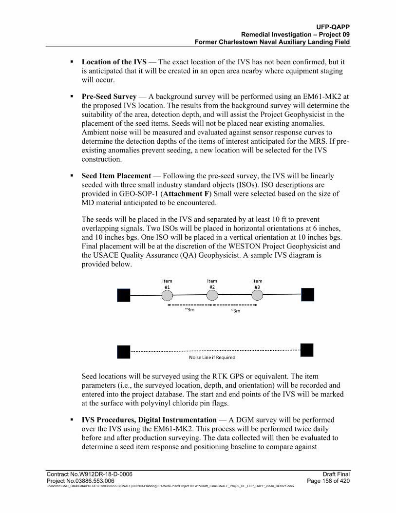
UFP-QAPP Remedial Investigation – Project 09
Former Charlestown Naval Auxiliary Landing Field
Contract No.W912DR-18-D-0006 Draft Final Project No.03886.553.006 Page 158 of 420 \\nascnh1\CNH_Data\Data\PROJECTS\03886553 (CNALF)\006\03-Planning\3.1-Work-Plan\Project 09 WP\Draft_Final\CNALF_Proj09_DF_UFP_QAPP_clean_041821.docx
Location of the IVS — The exact location of the IVS has not been confirmed, but it is anticipated that it will be created in an open area nearby where equipment staging will occur.
Pre-Seed Survey — A background survey will be performed using an EM61-MK2 at the proposed IVS location. The results from the background survey will determine the suitability of the area, detection depth, and will assist the Project Geophysicist in the placement of the seed items. Seeds will not be placed near existing anomalies. Ambient noise will be measured and evaluated against sensor response curves to determine the detection depths of the items of interest anticipated for the MRS. If pre-existing anomalies prevent seeding, a new location will be selected for the IVS construction.
Seed Item Placement — Following the pre-seed survey, the IVS will be linearly seeded with three small industry standard objects (ISOs). ISO descriptions are provided in GEO-SOP-1 (Attachment F) Small were selected based on the size of MD material anticipated to be encountered.
The seeds will be placed in the IVS and separated by at least 10 ft to prevent overlapping signals. Two ISOs will be placed in horizontal orientations at 6 inches, and 10 inches bgs. One ISO will be placed in a vertical orientation at 10 inches bgs. Final placement will be at the discretion of the WESTON Project Geophysicist and the USACE Quality Assurance (QA) Geophysicist. A sample IVS diagram is provided below.
Seed locations will be surveyed using the RTK GPS or equivalent. The item parameters (i.e., the surveyed location, depth, and orientation) will be recorded and entered into the project database. The start and end points of the IVS will be marked at the surface with polyvinyl chloride pin flags.
IVS Procedures, Digital Instrumentation — A DGM survey will be performed over the IVS using the EM61-MK2. This process will be performed twice daily before and after production surveying. The data collected will then be evaluated to determine a seed item response and positioning baseline to compare against
UFP-QAPP Remedial Investigation – Project 09
Former Charlestown Naval Auxiliary Landing Field
Contract No.W912DR-18-D-0006 Draft Final Project No.03886.553.006 Page 159 of 420 \\nascnh1\CNH_Data\Data\PROJECTS\03886553 (CNALF)\006\03-Planning\3.1-Work-Plan\Project 09 WP\Draft_Final\CNALF_Proj09_DF_UFP_QAPP_clean_041821.docx
production surveys. Response values will also be monitored against the instrument response curves for the ISOs.
Test Strip Procedures, Analog Instrumentation — Each UXO Technician will traverse the IVS daily prior to starting survey work using the Schonstedt to verify proper sensor operation. The operators will tune the instruments to ensure detection of all seed items. The instruments will be swept side to side while the operator traverses the IVS centerline. The UXO Team Leader will ensure that each operator clearly verifies proper sensor operation by detecting all items in the strip. Results of each test will be documented by operator and instrument identification number. The analog instrument checkout list, which will be used to document each operator’s name, instrument identification, and IVS verification on a daily basis, is provided in Attachment G. The checkout list will be maintained in the project file located on-site and reviewed daily by the UXO Team Leader to evaluate equipment and operator performance.
IVS Results (Initial) — The WESTON Project Geophysicist and the USACE QA Geophysicist will discuss the initial results of the IVS. The results will be provided in a brief letter report. The peak responses from the IVS seed items will be plotted against the respective instrument response curves. All seed item responses should plot higher than the calculated response curve for the least favorable orientation response curve. The positional accuracy of the anomaly location will be checked against the measured seed item location. The average noise values across the unseeded test strip will be calculated and monitored. The daily IVS results will be included in the digital geophysical data packages. The IVS results will include the following:
As-built drawing of the IVS, including depth and orientation of seeded items. Representative photographs of the ISO seed items (initial results). Color plots of the DGM data. Instrument response curves. Seed target list showing comprehensive results (e.g., response and position of
anomalies versus actual surveyed locations).
17.5.7.2 Instrument Standardization and Performance Criteria
Geophysical instruments will be field tested daily to ensure that they are operating properly. Equipment start-up and functional checks for EM31 are detailed in GEO-SOP-5 and for EM61-MK2 in GEO-SOP-2 and frequency and testing requirements are summarized on Worksheet #22. Additional requirements for Measurement Performance Criteria (MPCs) for Geophysical Surveys, and Equipment Field Testing, Inspection, and QC are provided in Worksheet #12.27.
17.6 SURFACE AND SUBSURFACE SOIL SAMPLING
Surface soil sampling for the Project 09 sites includes collecting surface soil ISM investigative samples at each of the landfills, the Burn Pit Area and background locations across the NWR in areas away from the Project 09 sites that are not known or suspected of contaminant impacts other than widespread anthropogenic impacts or naturally occurring conditions. Subsurface ISM
UFP-QAPP Remedial Investigation – Project 09
Former Charlestown Naval Auxiliary Landing Field
Contract No.W912DR-18-D-0006 Draft Final Project No.03886.553.006 Page 160 of 420 \\nascnh1\CNH_Data\Data\PROJECTS\03886553 (CNALF)\006\03-Planning\3.1-Work-Plan\Project 09 WP\Draft_Final\CNALF_Proj09_DF_UFP_QAPP_clean_041821.docx
investigative samples will be collected only at the Burn Pit Area. ISM sampling will be completed in accordance with SOP-18 “Incremental Sampling Methodology” (Attachment F). Test pit soil sampling at the landfills is discussed in Section 17.11 and will be completed using composite sampling.
The ISM approach was selected based on the larger exposure area scenarios applicable to the four sites, with a 1-acre DU area considered adequate for characterizing the potential risk to human and ecological receptors. A 1-acre DU is an appropriate exposure unit size for this publicly-owned undeveloped open space, part of which is within a wildlife refuge. The ISM approach is considered to be statistically more conservative than a discrete sampling approach for approximating the mean contaminant concentrations because it eliminates more sources of sampling error due to the larger density of aliquots included in samples, and the randomly selected locations over a DU area (ITRC, 2012). The approach employed for this project includes subdividing each DU into three equal-area SUs that will allow for evaluation of distribution of mean contaminant concentrations within each site. Decisions concerning potential exposure risk and the need for follow-on investigation will be made at the 1-acre scale. The proposed layout of the DUs and SUs is provided in SOP-18 (Attachment F). DU/SU boundaries may be adjusted based on actual wetland boundaries in the field. Based on results from initial sampling, if step-out sampling is warranted to define the extent of contamination, sample parameters will be limited to the COPCs identified in the initial samples.
Surface soil increments will be cored from 0 to 1 ft bgs using a steel plunge corer or similar device. Sampling DU boundaries will be determined in advance and loaded onto a GPS unit to facilitate sampling grid layout and sample collection in the field. During surface soil sampling activities, the sample technicians will note the location and type of exposed solid waste/debris, staining or other indication of potential contamination (e.g., areas barren of vegetation). Characteristics of the soil aliquots being collected will be noted. Additional details of the sampling approach are discussed in the following Subsections.
After samples are collected, sample containers will be sealed and labeled, placed in a cooler on ice, and shipped to the laboratory under chain-of-custody (COC) procedures. Field duplicate and MS/MSD samples will be collected to assess variability related to field sampling handling and sample heterogeneity at a rate of 10% and 5% of samples collected, respectively. An equipment blank will be collected from the sampling device at a rate of 5% with a minimum of 1 per sampling event. A trip blank will be included in each cooler containing samples for VOC analysis, and will be analyzed for VOCs. Trip blanks will be prepared by the laboratory and will accompany VOC sample containers at all times. Laboratory analytical parameters to be collected and analyzed from each area and media are discussed in the following Subsections.
ISM and composite soil samples will not be processed in the field. Samples will be transported to the laboratory for processing in the laboratory to prepare a representative sample prior to analysis as described in the SOP-18 and in Subsection 17.6.1.
17.6.1 Laboratory Preparation of Incremental Sampling Methodology (ISM) and Composite Samples
The laboratory sample preparation process is presented in the Laboratory Processing Flow Chart For CNALF Project 09 ISM and Composite Soil Samples. The sample preparation process

UFP-QAPP Remedial Investigation – Project 09
Former Charlestown Naval Auxiliary Landing Field
Contract No.W912DR-18-D-0006 Draft Final Project No.03886.553.006 Page 161 of 420 \\nascnh1\CNH_Data\Data\PROJECTS\03886553 (CNALF)\006\03-Planning\3.1-Work-Plan\Project 09 WP\Draft_Final\CNALF_Proj09_DF_UFP_QAPP_clean_041821.docx
consists of three “Steps” and the aliquots for each parameter obtained from each “Step” are shown on the Flow Chart. Depending on the analytical suite, as many as five ALS laboratories will perform the analysis for Project 09 samples. Parameters, with the laboratory performing the analysis, are shown on the flow chart. The ISM sample will be shipped to ALS-Middletown for ISM sample processing. For any analyses not performed in-house, ALS-Middletown will be responsible for shipping the processed aliquots to the designated in-network laboratory for extraction and analysis. ALS-Middletown will perform percent solids determination for each of the three “Steps” and provide the percent solids data to the in-network laboratories.
Step 1 involves homogenizing the “wet” soil or sediment sample. Any large pieces of soil will be disaggregated prior to subsampling in Step 1 and rocks and vegetation (sticks, leaves, and roots) will be removed from the sample. Sample aliquots for semivolatile parameters (i.e., low-level SVOCs, 1,4-Dioxane, and PAHs), percent solids, or other parameters that have short holding times or that could be potentially affected by air drying (i.e., hexavalent chromium, TOC, pH, total sulfide, and ferrous iron) will be collected during Step 1. The laboratory will use the 2D Japanese slabcake method and flat bottomed square-sided scoop and collect a minimum of 30 increments into a single container for the laboratory to subsequently subsample from for each analytical aliquot. Sufficient wet sample will be provided to each ALS laboratory to be able to subsample for at least two extraction/digestion volumes and any QC analyses requested for the sample (matrix spikes and laboratory replicates). The ALS laboratory performing the extraction/digestion and analysis will subsample from the container by homogenizing the soil in the container and obtaining the required mass of sample needed; ISM subsampling will not be required for the secondary sample container. Some additional sample volume will be included in the container which may be reserved for further sampling or sample processing.
Step 2 involves air drying the entire remaining soil or sediment sample followed by disaggregation and sieving through a No. 10 sieve. The laboratory will record the weight of the entire air dried sample prior to disaggregation and sieving and then re-weigh the entire sample and record the weights on bench sheets which will be included with the final laboratory deliverable. After weighing out the sieved sample, ALS Middletown will again use the 2D Japanese slabcake method and sampling scoop to collect a minimum of thirty (30) increments to collect the sample volume for TAL metals (including mercury) and percent solids. Some additional sample volume will be included in the container which may be reserved for further sampling or sample processing.
Step 3 involves grinding the entire remaining soil or sediment sample using a puck mill. Sample aliquots will be prepared using the 2D Japanese slabcake method and scoop followed by collection of a minimum of 30 increments for each container supplied to the analytical laboratories (PCBs by ALS Kelso. Dioxin/furans by ALS Burlington, and Perchlorate by ALS Houston). Sufficient ground sample will be provided to each ALS laboratory to be able to subsample for at least two extraction volumes and any QC analyses requested for the sample (matrix spikes and laboratory replicates). The ALS laboratory performing the extraction/digestion and analysis will subsample from the container by homogenizing the soil in the container and obtaining the required mass of sample needed; ISM subsampling will not be required for the secondary sample container. One container will be reserved by ALS-Middletown for the explosives and percent solids sample aliquots; this container will also store the remaining volume of ground ISM sample.

UFP-QAPP Remedial Investigation – Project 09
Former Charlestown Naval Auxiliary Landing Field
Contract No.W912DR-18-D-0006 Draft Final Project No.03886.553.006 Page 162 of 420 \\nascnh1\CNH_Data\Data\PROJECTS\03886553 (CNALF)\006\03-Planning\3.1-Work-Plan\Project 09 WP\Draft_Final\CNALF_Proj09_DF_UFP_QAPP_clean_041821.docx
Table 17-1 Laboratory Processing Flow Chart for CNALF Project 09 ISM and Composite Samples
UFP-QAPP Remedial Investigation – Project 09
Former Charlestown Naval Auxiliary Landing Field
Contract No.W912DR-18-D-0006 Draft Final Project No.03886.553.006 Page 163 of 420 \\nascnh1\CNH_Data\Data\PROJECTS\03886553 (CNALF)\006\03-Planning\3.1-Work-Plan\Project 09 WP\Draft_Final\CNALF_Proj09_DF_UFP_QAPP_clean_041821.docx
17.6.2 Charlestown Landfill Surface Soil Sampling
Surficial soil samples will be collected from 9 investigative DUs (overall landfill area of approximately 13-acres) within the landfill area (Figure 26). Each DU will be subdivided into three, equal-area investigative SUs, with one ISM sample collected from each SU. One exception to this is DU-9, which is a small, isolated area of a suspected former trench that has a single 1/3- acre SU sample defining the DU. Each investigative SU ISM sample will be comprised of 30 increments of soil collected from systematically random locations within 30 equal cells in each SU as described in SOP-18. The samples will be sent to the analytical laboratory, where they will be processed to obtain a representative sample prior to analysis for low-level SVOCs, 1,4-dioxane by SIM, PAHs by SIM, PCBs, explosives, TAL metals (23 metals list including mercury), and hexavalent chromium. Additional ancillary analyses for total sulfide, TOC, and leachable ferrous iron will be requested only for soil samples designated for hexavalent chromium matrix spike (5% of hexavalent chromium analyses). Surface soil samples will be analyzed for explosives compounds if munitions are found during the geophysical survey at each landfill. The MC metals to be analyzed include antimony, copper, lead, nickel and zinc, and are included in the TAL metals analysis. In addition, TOC and soil pH will be analyzed from one ISM sample per DU, for calculating an average value for use in fate and transport evaluation and risk characterization. The WESTON Risk Assessor will calculate trivalent chromium concentrations from the difference between total chromium and hexavalent chromium results. A single incremental sample is proposed for DU-9 to investigate the presence/absence of contamination. An average concentration for this DU will be extrapolated using the relative standard deviation (RSD) measured in another DU within the landfill to calculate respective 95% UCLs for the purpose of decision making and to be used in the risk assessment. The estimated 95%UCL will be calculated as the Concentration + (Concentration * RSD), where the RSD is calculated as the standard deviation divided by the mean of the 3 SU results for another DU. The most conservative RSD of the other DUs will be used in the calculation. A precision estimate is not needed for DU-9 because contamination is not expected. The uncertainty associated with this extrapolation will be discussed in the risk assessment. VOCs are not proposed for analysis in surface soils due to the age of the landfill and the unlikely persistence of VOCs in surface soil at the site; the source material in a landfill is in the subsurface and covered. The analytical results will be used to characterize the nature and extent of contaminants at the surface of the landfill and used in the human and ecological risk assessments to evaluate potential risk to human and ecological receptors.
Subsurface composite soil samples will be collected from the Charlestown Landfill as part of test pitting activities, as described in Section 17.11.
17.6.3 Eastern Area Landfill Surface Soil Sampling
Surficial soil samples will be collected utilizing ISM from four 1-acre investigative DUs (overall landfill area of approximately 6-acres) within the landfill area (Figure 27). Each investigative DU will be divided into three equal-area investigative SUs, with one ISM sample collected from each SU. Each investigative SU sample will be comprised of 30 increments of soil collected from systematically random locations within 30 equal cells in each SU. The samples will be sent to the analytical laboratory, where they will be processed to obtain a representative sample prior to analysis for low-level SVOCs, 1,4-Dioxane by SIM, PAHs by SIM, PCBs, explosives, TAL metals

UFP-QAPP Remedial Investigation – Project 09
Former Charlestown Naval Auxiliary Landing Field
Contract No.W912DR-18-D-0006 Draft Final Project No.03886.553.006 Page 164 of 420 \\nascnh1\CNH_Data\Data\PROJECTS\03886553 (CNALF)\006\03-Planning\3.1-Work-Plan\Project 09 WP\Draft_Final\CNALF_Proj09_DF_UFP_QAPP_clean_041821.docx
(23 metals list including mercury), and hexavalent chromium. Ancillary analysis for total sulfide, TOC, and leachable ferrous iron will be requested for the soil sample designated for hexavalent chromium matrix spike (5% of hexavalent chromium analyses). Surface soil samples will be analyzed for explosives compounds if munitions are found during the geophysical survey at each landfill. The MC metals to be analyzed include antimony, copper, lead, nickel and zinc, which are already included in the TAL metals analysis. In addition, TOC and soil pH will be analyzed from one ISM sample per DU, for calculating an average value for use in fate and transport evaluation and risk characterization. The WESTON Risk Assessor will calculate trivalent chromium concentrations from the difference between total chromium and hexavalent chromium results. VOCs are not proposed for analysis in surface soils due to the age of the landfill and the unlikely persistence of VOCs in surface soil at the site; the source material in a landfill is in the subsurface and covered. The analytical results will be used to characterize the nature and extent of contaminants at the surface of the landfill and used in the human and ecological risk assessments to evaluate potential risk to human and ecological receptors.
Subsurface soil samples will be collected at Eastern Area Landfill as part of test pitting activities, as described in Section 17.11.
17.6.4 Ninigret Wildlife Refuge Landfill Surface Soil Sampling
Surficial soil samples will be collected utilizing ISM from four 1-acre investigative DUs (overall landfill area of approximately 4-acres) from the landfill (Figure 28). The area of soil covering the munitions bunker will not be included in the sampling due DUs to safety concerns for the structural integrity of the bunker. Each DU will be divided into three equal-area investigative SUs, with one ISM sample collected from each SU. Each investigative SU sample will be comprised of 30 increments of soil collected from systematically random locations within 30 equal cells in each SU. The samples will be sent to the analytical laboratory, where they will be processed to obtain a representative sample prior to analysis for low-level SVOCs, 1,4-Dioxane by SIM, PAHs by SIM, PCBs, Explosives, TAL metals (23 metals list including mercury), and hexavalent chromium. Ancillary analysis for total sulfide, TOC, and leachable ferrous iron will be requested for the soil sample designated for hexavalent chromium matrix spike (5% of hexavalent chromium analyses). Surface soil samples will be analyzed for explosives compounds and perchlorate, if munitions are found during the geophysical survey at each landfill. The MC metals to be analyzed for include antimony, copper, lead, nickel and zinc, which are already included in the TAL metals analysis. Perchlorate will be analyzed at only the National Wildlife Refuge Landfill based on the presence of the former munitions bunker. In addition, TOC and soil pH will be analyzed from one ISM sample per DU, for calculating an average value for use in fate and transport evaluation and risk characterization. VOCs are not proposed for analysis in surface soils due to the age of the landfill and the unlikely persistence of VOCs in surface soil at the site the source material in a landfill is in the subsurface and covered. The analytical results will be used to characterize the nature and extent of contaminants at the surface of the landfill and used in the human and ecological risk assessments to evaluate potential risk to human and ecological receptors. The WESTON Risk Assessor will calculate trivalent chromium concentrations from the difference between total chromium and hexavalent chromium results.
UFP-QAPP Remedial Investigation – Project 09
Former Charlestown Naval Auxiliary Landing Field
Contract No.W912DR-18-D-0006 Draft Final Project No.03886.553.006 Page 165 of 420 \\nascnh1\CNH_Data\Data\PROJECTS\03886553 (CNALF)\006\03-Planning\3.1-Work-Plan\Project 09 WP\Draft_Final\CNALF_Proj09_DF_UFP_QAPP_clean_041821.docx
Subsurface soil samples will be collected at the Ninigret Wildlife Refuge Landfill as part of test pitting activities, as described in Section 17.11.
17.6.5 Burn Pit Area Surface and Subsurface Soil Sampling
Surface soil samples will be collected at the Burn Pit Area utilizing ISM from three 1-acre investigative DUs (Burn Pit Area overall area of approximately 3-acres) encompassing areas of past fire training exercises based on historical air photos and visual observations of debris and stained soils at the site (Figure 29). Each surface soil sample investigative DU will be divided into three equal investigative SUs, with one ISM sample collected from each SU. Each investigative SU sample will be comprised of 30 increments of soil collected from the 0-1 ft depth interval from systematically random locations within 30 equal cells in each SU.
Subsurface soil samples will be collected at the Burn Pit Area utilizing ISM from the same three 1-acre investigative DUs as defined for surface soil samples (Figure 29). Each subsurface soil sample investigative DU will be divided into three equal-area investigative SUs, with one ISM sample collected from each SU. Each investigative SU sample will be comprised of 70 increments of soil collected from 10 systematically random located borings per SU. One soil increment will be collected from each one foot of boring depth from systematically random selected 6-inch core slices within each one foot interval (7 increments per boring) in the 1 ft to 8 ft bgs depth interval as described in SOP-18. Soil samples will utilize a drill rig with continuous macrocore sampling to complete borings to the depth of the high historic water table depth (approximately 8 ft bgs). A WESTON geoscientist will field screen the soil cores using a photoionization detector (PID) and log the soil lithology in accordance with the USCS for inclusion in a boring log form provided in Attachment G.
Soil samples from the Burn Pit Area will be sent to the analytical laboratory where they will be processed to obtain a representative sample prior to analysis for dioxins/furans, PAHs by SIM, TAL metals (23 metals including mercury), as well as hexavalent chromium. Ancillary analysis for total sulfide, TOC, and leachable ferrous iron will be requested for the soil sample designated for hexavalent chromium matrix spike. Although historical soil and groundwater results did not detect PCBs at the Burn Pit Area, the prior sampling was limited, consisting of biased discrete samples. In addition, due the potential concern for the occurrence of dioxins/furans that may be derived from combustion of PCB-contaminated oil, PCBs will be analyzed in surface soil only at the 3 SUs within the central DU. These results will be used to verify the presence or absence of PCBs; the relationship to dioxins/furans, if present; provide representative data for the human health and ecological risk assessments; and determine whether additional sampling is necessary to assess the extent of PCB contamination. Dioxins/furans are included in proposed soil analyses for each DUs as they were not analyzed in historical samples and are included to assess their presence/absence as a byproduct of burning activities at the site. In addition, TOC and soil pH will be analyzed from one surface soil and subsurface soil ISM sample per DU, for calculating an average value for use in fate and transport evaluation and risk characterization. The WESTON Risk Assessor will calculate trivalent chromium concentrations from the difference between total chromium and hexavalent chromium results.

UFP-QAPP Remedial Investigation – Project 09
Former Charlestown Naval Auxiliary Landing Field
Contract No.W912DR-18-D-0006 Draft Final Project No.03886.553.006 Page 166 of 420 \\nascnh1\CNH_Data\Data\PROJECTS\03886553 (CNALF)\006\03-Planning\3.1-Work-Plan\Project 09 WP\Draft_Final\CNALF_Proj09_DF_UFP_QAPP_clean_041821.docx
VOCs are not proposed for analysis in soils at the Burn Pit Area based on the absence of prior VOC detections in soil and groundwater samples at the site; and the unlikely persistence of VOCs in surface soil at the site based on the age and temperatures that the soil were exposed to during fire training exercises.
The analytical results for the listed parameters will be used to characterize the nature and extent of contaminants at the surface and subsurface of the Burn Pit Area. Surface soil sample results will be used in the human and ecological risk assessments to evaluate potential risk to human and ecological receptors. Subsurface soil results will be used to support risk evaluation for a construction worker exposure scenario.
17.6.6 Background Surface Soil Sampling
Background surface soil samples will be collected utilizing ISM from eight 1-acre background SUs that target undeveloped areas of the NWR (Figure 30). Historic aerial photography dating back to 1945 have been reviewed to confirm that the proposed background SUs are on areas of NWR that have not been historically developed (i.e., not a vehicle travel way, or the site of a structure); an area of the site that is away from known sources (i.e., does not receive runoff from runways); and the soil in the area does not contain anthropogenic material fragments or other evidence of disturbance or fill (Figures 30a through 30f). Sample locations will avoid areas of known or suspected contamination, such as the landfills and material that has been re-worked or placed by the current landowners. The background SUs are located in upland soil areas mapped by the state GIS system as “loess over fluvial deposits” as shown on Figure 31. Sampling of eight background SUs is considered adequate to statistically establish an estimate of the mean constituent concentrations with a high level of confidence, for comparison to site soil sample results. Background SUs will have the same size area and same total number of increments as the corresponding investigative DU samples. Each 1-acre background SU sample will be comprised of 90 increments of soil collected from the 0 to 1 ft bgs depth interval from systematically random locations within 90 equal cells in each SU.
Boundaries of the surface soil background SUs will be determined in advance and loaded onto a GPS to facilitate grid location and sample collection in the field. Soil samples from the background SUs will be sent to the analytical laboratory where they will be processed to obtain a representative sample prior to analysis for PAHs by SIM, TAL metals (23 metals including mercury), hexavalent chromium, pH, and TOC. The WESTON Risk Assessor will calculate trivalent chromium concentrations from the difference between total chromium and hexavalent chromium results. Ancillary analysis for total sulfide, TOC, and leachable ferrous iron will be requested for the soil sample designated for hexavalent chromium matrix spike. TOC and soil pH will be analyzed from 3 randomly selected SU ISM samples for calculating an average value for use in risk characterization. Analysis for VOCs, SVOCs other than PAHs, dioxin/furans, PCBs, explosives, or perchlorate in background soil samples is not proposed as these compounds are not considered naturally occurring and not anticipated be widely distributed at CNALF beyond existing site boundaries based on the site CSMs. The analytical results for listed parameters will be used to determine statistically valid estimates of mean constituent concentrations for background soil for comparison to site investigative DU soil sample results to determine COPC at each site as described in the Risk Assessment Work Plan (Attachment D).
UFP-QAPP Remedial Investigation – Project 09
Former Charlestown Naval Auxiliary Landing Field
Contract No.W912DR-18-D-0006 Draft Final Project No.03886.553.006 Page 167 of 420 \\nascnh1\CNH_Data\Data\PROJECTS\03886553 (CNALF)\006\03-Planning\3.1-Work-Plan\Project 09 WP\Draft_Final\CNALF_Proj09_DF_UFP_QAPP_clean_041821.docx
17.7 MONITORING WELL INSTALLATION
Proposed monitoring well locations are shown of Figures 32, 33, 34, and 35 for the Charlestown Landfill, Eastern Area Landfill, Ninigret Wildlife Refuge Landfill and the Burn Pit Area, respectively. These locations are approximate and the actual locations may be adjusted based on field conditions, utility conflicts as a result from the utility clearance procedures (Section 17.5.1), or access considerations. To the extent feasible, the data and field observations acquired from other investigation activities prior to well installations, and access limitations will be considered evaluated by WESTON and USACE to adjust well locations. The materials used in well construction will be thoroughly documented and avoid use of materials potentially containing PFAS in the event that PFAS analyses are required during monitoring events.
Groundwater monitoring wells installed in unconsolidated deposits (“overburden”) above bedrock will be constructed as 2-inch inside diameter polyvinyl chloride (PVC) casings. The borings will be advanced using either hollow-stem augers, roto-sonic drilling, or similar technique until bedrock is encountered. At locations where the saturated thickness of the overburden is over 12 ft, a shallow and deep overburden well pair will be installed. Overburden well pairs will be installed in two separate boreholes. Continuous split-spoon or direct-push soil core samples will be collected from ground surface to the top of bedrock at each well pair location for lithologic characterization by a WESTON geoscientist. Headspace photoionization detector (PID) screening for VOCs will be performed on each soil core. Soil lithologic descriptions and PID readings will be documented on a boring log form in accordance with the USCS (Attachment G). PID screening results will be considered when selecting the vertical placement of well screens at each location.
Well screen intervals of 5 ft are planned and may be modified to target zones of suspected contamination based on visual evidence and/or PID screening results or achieve better vertical coverage of the saturated zone. For example, if a single well screen is installed at a location with a saturated overburden thickness slightly less than 12 ft, a longer (up to 10-ft) well screen may be installed to intersect the water table and most of the saturated overburden thickness. Shallow overburden well screens up to 10 ft in length placed across the water table would accommodate seasonal and/or tidal variability in water table elevations while maintaining sufficient well screen depth below the water table to collect samples during dryer conditions. Well screens will be constructed of machine-slotted 0.010-inch slotted PVC pipe with flush-threaded and O-ring sealed joints.
The procedure for bedrock well installations is outlined below. An 8-inch diameter borehole will be drilled through the overburden and extended 10 ft into bedrock. A 6-inch diameter steel conductor casing will be grouted in-place into the bedrock socket. The casing grout will be allowed to set approximately 24-hours prior to advancing the bedrock borehole. An HQ-core, or equivalent, will be advanced through the casing a minimum of 15 ft below the depth of the casing bottom (25 ft into bedrock). The rock cores will be collected at 5 to 10 ft intervals and immediately examined to assess the occurrence of potential water-bearing fractures. If there is evidence of a potential water-bearing fracture in the core (open cracks, staining, etc.) then drilling will cease while a short purge test is conducted to estimate the yield of the shallow bedrock zone. The well will be overpumped to draw down the water level in the well and then allowed to recover while documenting the purge rate and recovery rates of the borehole. Water level readings collected
UFP-QAPP Remedial Investigation – Project 09
Former Charlestown Naval Auxiliary Landing Field
Contract No.W912DR-18-D-0006 Draft Final Project No.03886.553.006 Page 168 of 420 \\nascnh1\CNH_Data\Data\PROJECTS\03886553 (CNALF)\006\03-Planning\3.1-Work-Plan\Project 09 WP\Draft_Final\CNALF_Proj09_DF_UFP_QAPP_clean_041821.docx
during this period will be used to assess the relative well yield. A well yield of at least 0.25 gallon per minute will be considered adequate for monitoring purposes.
If the minimum yield is achieved for the shallow bedrock well depth, then the well will be developed and completed as an open hole well. If a sufficient yield is not encountered in the first 15 ft of open bedrock borehole, then coring will be continued to complete the well as a deep bedrock well with a maximum depth of 100 ft below ground surface or until a water-bearing fracture is encountered, whichever is shallower. Short term testing of the borehole by overpumping may be repeated as necessary to verify the borehole yield as the borehole is advanced. If a water bearing fracture is encountered, the borehole will be advanced approximately 5 ft beyond the fracture and the well will be developed as an open borehole deep bedrock well. If no significant yield is encountered prior to reaching a maximum depth of 100 ft bgs, then the borehole will be completed at that depth as an open-hole deep bedrock well. Borehole geophysical logging will be used to characterize the bedrock in deep bedrock wells, including identifying the depth and orientation of fractures intersecting the borehole. No geophysical logging is planned for the shallow bedrock wells.
Bedrock cores will be logged following procedures described in ASTM D5434-12 and D6032-08. Bedrock cores will be preserved temporarily in core boxes, photographed, and examined to characterize the rock types, veins and evidence of potentially significant hydraulic features. If multiple water‐bearing fractures are encountered in a deep bedrock well, or borehole collapse is a problem, the well may be completed by installing 2‐inch diameter PVC screen, riser, filter pack and seal or remain as an open‐hole well. Well screens installed in bedrock will be 5-ft in length and constructed of 2-inch diameter machine slotted 0.010-inch aperture PVC screen with flush-threaded and O-ring sealed joints. Longer screens (up to 20 ft in length) may be used if the bedrock exhibits low permeability and a shorter screen is expected to provide insufficient yield for low flow groundwater sampling methods. Well screens may be placed across any water-bearing fractures as determined by the core examination, purge tests, and/or results of geophysical logging. For bedrock wells, it will be necessary to drill out the borehole a nominal 6-inch diameter prior to well completion and development.
For monitor well installations, clean filter sand will be used to backfill the soil boring interval surrounding each well screen, extending from the bottom of the screen interval to approximately 2 ft above each screen. Above each sand pack, a bentonite chip or pellet seal will be constructed by backfilling the boring annulus a minimum of 2 ft above the sand pack. The bentonite seal will be hydrated for a minimum of 30 minutes before tremie-grouting the remaining annulus to ground surface using cement-bentonite grout.
Monitoring wells will be completed with approximately 3 ft high above-ground protective casings with locking caps secured within 2 ft diameter, 6-inch thick concrete pads. In areas accessible to vehicles, protective bollards will be installed to prevent well damage. For PVC wells with compression caps, the top of the innermost casing will be cut horizontal with a small drill hole or saw cut below the cap to allow venting to atmospheric pressure. Monitoring wells will be clearly labeled inside the protective casing cap and on the outside of the protective casing. A sawcut or indelible mark will be made on the rim of the innermost casing to designate the water level monitoring datum as surveyed. A Rhode Island licensed professional land surveyor will survey
UFP-QAPP Remedial Investigation – Project 09
Former Charlestown Naval Auxiliary Landing Field
Contract No.W912DR-18-D-0006 Draft Final Project No.03886.553.006 Page 169 of 420 \\nascnh1\CNH_Data\Data\PROJECTS\03886553 (CNALF)\006\03-Planning\3.1-Work-Plan\Project 09 WP\Draft_Final\CNALF_Proj09_DF_UFP_QAPP_clean_041821.docx
well locations, top of well innermost casing, top of protective casing and ground surface elevations at each new monitoring well, in addition to resurvey of existing wells. Surveyed well locations will be accurate to within 0.1 ft horizontally; top of the innermost casing to 0.01 ft vertically; and ground surface to 0.1 ft vertically. Survey data will have a datum of WGS84 and a projection of Universal Transverse Mercator (UTM) Zone 18N. Data with a vertical component will be referenced to the Rhode Island state plane coordinate system and relative to the 1988 North American Vertical Datum with units of U.S. Survey Feet. Spatial reference will have a precision of at least 1000.
Well construction details will be recorded on a well completion log that documents relevant material quantities and placement depths for each monitoring well installed. A Monitoring Well Completion Log is included in Attachment G.
No sooner than 24 hours after installation, newly installed monitoring wells will be developed by overpumping and surging to:
Remove stagnant water from the well.
Remove accumulated sediment and debris from the bottom of the well.
Remove drilling sediment and fine materials from the sand pack, adjacent formation and fractures.
Establish an effective hydraulic connection to the formation and fractures.
Document field parameters of the purge water and estimate the yield of the well.
Existing monitoring wells that can be located (Figures 32, 33, 34, and 35) will be assessed, redeveloped, as needed, and resurveyed. A surge block and inertial valve pump or a submersible pump will be used to surge and purge the well while pumping at a rate much greater than would be used for sampling. Development will be continued until discharge water becomes visibly clear quickly after surging and when field water quality parameters including temperature, specific conductivity, salinity, and turbidity reach stabilized conditions as listed within the Well Development SOP-23 (Attachment F):
pH within ±0.1%; conductivity within ±3%; DO within ±10%; Salinity within ± 10%
ORP within ±10%; Turbidity within ±10%; and Temperature within ±1°C;
If water does not become clear within 2 hours of development or after removal of a minimum of 5 borehole volumes, development will be discontinued and the conditions will be recorded. Results of well installation and development activities will be reviewed and evaluated by WESTON and USACE to determine whether additional actions are necessary prior to sampling activities. At well cluster location, water levels will be recorded initially and periodically from each well during development of each well to assess whether hydraulic connection between the wells is indicated.

UFP-QAPP Remedial Investigation – Project 09
Former Charlestown Naval Auxiliary Landing Field
Contract No.W912DR-18-D-0006 Draft Final Project No.03886.553.006 Page 170 of 420 \\nascnh1\CNH_Data\Data\PROJECTS\03886553 (CNALF)\006\03-Planning\3.1-Work-Plan\Project 09 WP\Draft_Final\CNALF_Proj09_DF_UFP_QAPP_clean_041821.docx
The well development activities will be documented on Groundwater Monitoring Well Development Log for each well (Attachment G).
Investigation-derived waste (IDW) including drill cuttings, purged groundwater, and decontamination water will be containerized for characterization prior to off-site disposal, unless the on-site discharge of materials documented as not contaminated is approved by RIDEM. WESTON will coordinate with the USACE, Town of Charlestown and USFWS to identify appropriate on-site staging areas for IDW until off-site transport and disposal at a properly-licensed facility.
17.7.1 Charlestown Landfill Monitoring Wells
New overburden monitoring wells will be installed at 13 locations, upgradient and on the downgradient (eastern) perimeter of the landfill (Figure 32). If the thickness of the saturated overburden is greater than 12 ft, a shallow and deep overburden well pair may be installed, otherwise a single overburden well will be installed. Bedrock monitoring wells will be installed at 7 overburden well locations. Three overburden well locations and two bedrock well location are located upgradient of the landfill to evaluate the potential impact of the landfill on groundwater by comparing results to data from downgradient wells. Seven overburden well locations and four bedrock well locations are proposed between the landfill and the residential area to the northeast to monitor potential contaminant migration from the landfill in that direction. Two overburden well locations and one bedrock well location will be installed on the downgradient side of the landfill to supplement the existing well network. These wells will assess potential contaminant migration from the landfill to Ninigret Pond.
The new monitoring wells and the existing monitoring well network (6 existing overburden wells) will be used to collect groundwater samples for evaluation of the nature and extent of groundwater contamination associated with the landfill. Water level and slug test data collected from the wells will be used to assess groundwater flow directions, gradients and hydraulic conductivity in overburden and bedrock. Results will be used to assess potential impacts to nearby drinking water sources and Ninigret Pond.
17.7.2 Eastern Area Landfill Monitoring Wells
New overburden monitoring wells will be installed at 13 locations, upgradient and on the downgradient (eastern) perimeter of the landfill (Figure 33). If the thickness of the saturated overburden is greater than 12 ft, a shallow and deep overburden well pair may be installed, otherwise a single overburden well will be installed. Bedrock monitoring wells will be installed at 5 overburden well locations. Five overburden two well locations and one bedrock well location are located upgradient of the landfill to evaluate the potential impact of the landfill on groundwater by comparing results to data from downgradient wells. Seven overburden well locations and three bedrock well locations are proposed between the landfill and Ninigret Pond to supplement the existing well network and monitor potential contaminant migration from the landfill. These wells will assess potential contaminant migration from the landfill to Ninigret Pond.

UFP-QAPP Remedial Investigation – Project 09
Former Charlestown Naval Auxiliary Landing Field
Contract No.W912DR-18-D-0006 Draft Final Project No.03886.553.006 Page 171 of 420 \\nascnh1\CNH_Data\Data\PROJECTS\03886553 (CNALF)\006\03-Planning\3.1-Work-Plan\Project 09 WP\Draft_Final\CNALF_Proj09_DF_UFP_QAPP_clean_041821.docx
The new monitoring wells and the existing monitoring well network (5 existing overburden wells) will be used to collect groundwater samples for evaluation of the nature and extent of groundwater contamination associated with the landfill. Water level and slug test data collected from the wells will be used to assess groundwater flow directions and gradients and hydraulic conductivity in overburden and bedrock. Results will be used to assess potential impacts to nearby drinking water sources and Ninigret Pond.
17.7.3 Ninigret Wildlife Refuge Landfill Monitoring Wells
New overburden monitoring wells will be installed at 9 locations, upgradient and on the downgradient (eastern) perimeter of the landfill (Figure 34). If the thickness of the saturated overburden is greater than 12 ft, a shallow and deep overburden well pair may be installed, otherwise a single overburden well will be installed. Bedrock monitoring wells will be installed at 3 overburden well locations. Three overburden well locations and one bedrock well location are located upgradient of the landfill to evaluate the potential impact of the landfill on groundwater by comparing results to data from downgradient wells. Six overburden well locations and two bedrock well locations are proposed between the landfill and adjacent wetlands, Ninigret Pond and Coon Cove to supplement the existing well network and monitor potential contaminant migration from the landfill. These wells will assess potential contaminant migration from the landfill to the wetlands, Coon Cove and Ninigret Pond.
The new monitoring wells and the existing monitoring well network (3 existing overburden wells) will be used to collect groundwater samples for evaluation of the nature and extent of groundwater contamination associated with the landfill. Water level and slug test data collected from the wells will be used to assess groundwater flow directions and gradients and hydraulic conductivity in overburden and bedrock. Results will be used to assess potential impacts to adjacent wetlands, Coon Cove and Ninigret Pond.
17.7.4 Burn Pit Area Monitoring Wells
New overburden monitoring wells will be installed at 8 locations, upgradient and on the downgradient (southern) perimeter of the Burn Pit Area (Figure 35). If the thickness of the saturated overburden is greater than 12 ft, a shallow and deep overburden well pair may be installed, otherwise a single overburden well will be installed at each location. Bedrock monitoring wells will be installed at 3 overburden well locations. Two overburden well locations and one bedrock well location are located upgradient of the Burn Pit Area to evaluate the potential impact of the Burn Pit Area on groundwater by comparing results to data from downgradient wells. Five overburden well locations and two bedrock well locations are proposed downgradient of the Burn Pit Area to supplement the existing overburden well and monitor potential contaminant migration from the Burn Pit Area. These wells will assess potential contaminant migration from the Burn Pit Area toward Ninigret Pond.
The new monitoring wells and the existing monitoring well network (1 existing overburden well) will be used to collect groundwater samples for evaluation of the nature and extent of groundwater contamination associated with the Burn Pit Area. Water level and slug test data collected from the wells will be used to assess groundwater flow directions and gradients and hydraulic conductivity
UFP-QAPP Remedial Investigation – Project 09
Former Charlestown Naval Auxiliary Landing Field
Contract No.W912DR-18-D-0006 Draft Final Project No.03886.553.006 Page 172 of 420 \\nascnh1\CNH_Data\Data\PROJECTS\03886553 (CNALF)\006\03-Planning\3.1-Work-Plan\Project 09 WP\Draft_Final\CNALF_Proj09_DF_UFP_QAPP_clean_041821.docx
in overburden and bedrock. Results will be used to assess potential impacts to Ninigret Pond and nearby drinking water sources north of the Burn Pit Area.
17.8 GROUNDWATER SAMPLING AND WATER SUPPLY WELL SAMPLING
Water samples will be collected from groundwater monitoring wells at the four Project 09 sites, seven drinking water supply wells at Ninigret Park and from up to 15 residential drinking water supply wells northeast of CNALF. Groundwater sampling events for the Project 09 sites includes collecting synoptic water level data and discrete groundwater samples from new wells and existing wells at each of the landfills and the Burn Pit Area. Drinking water supply well sampling will include discrete tapwater sampling of 7 water supply wells within Ninigret Park and up to 15 residential drinking water supply wells from the residential neighborhood northeast of the CNALF boundary. An inspection will be conducted for each system to document the system configuration prior to sampling. The results of the inspections and proposed sample collection point will be reviewed and evaluated by WESTON and USACE prior to sampling.
Two groundwater monitoring well sampling events are planned. One water supply well sampling event is planned. A second water supply well sampling event may be completed based on results of the first event. A synoptic water level round will be completed from each new and existing monitoring well prior to each groundwater sample collection event. A steel rod will be placed at the upgradient margin of the freshwater ponds adjacent to the Charlestown Landfill, the Eastern Area Landfill, and the wetland margin downgradient of Ninigret Wildlife Refuge Landfill with the top of the rod surveyed to 0.01 ft accuracy for correlation with monitoring well data. Water levels will be measured with an electronic interface probe in accordance with SOP-13. The interface probe will be decontaminated between wells according to SOP-10 (Attachment F). Water level monitoring will be coordinated to collect the readings within a 6 hour period corresponding to one half of a tidal cycle and beginning within one hour of the high or low tide for that cycle. Wells that do not have vented caps or risers will require a 1 hour equilibration timeframe after opening before measurement. A reading will be collected upon initial opening for comparison with the subsequent reading to assess whether equilibration has occurred. Separate measurement teams will take readings from one common well at the beginning and end of the monitoring event as a quality control check on instrumentation and tidal variation during the event. To assess tidal diurnal tidal fluctuation affects in site groundwater levels, and potential hydraulic head changes in bedrock due to nearby water supply well usage, one overburden monitoring well and one bedrock well from each site will be monitored using a transducer for a 24-hour period. The water level data collected will be used to assess groundwater flow direction, vertical gradients, tidal variation, and potential hydraulic connection between drinking water supply wells and groundwater at each site.
In the four Project 09 sites, the new monitoring wells, as well as the redeveloped existing wells, will be sampled using low-flow sampling methods in accordance with latest EPA Low Stress/Low Flow Guidance and SOP-14 (EPA, 2017). Low-flow sampling methods will yield a higher quality groundwater sample without the turbidity associated with bailers. Because the depth to water is expected to be within the practical suction limit, peristaltic pumps will be used for purging and sampling. High density polyethylene (HDPE) tubing will be dedicated to each well. HDPE is the preferred tubing in the event that subsequent sampling for PFAS is necessary. Silicon tubing will be used to connect the HDPE tubing to the peristaltic pump. The tubing intake will be positioned
UFP-QAPP Remedial Investigation – Project 09
Former Charlestown Naval Auxiliary Landing Field
Contract No.W912DR-18-D-0006 Draft Final Project No.03886.553.006 Page 173 of 420 \\nascnh1\CNH_Data\Data\PROJECTS\03886553 (CNALF)\006\03-Planning\3.1-Work-Plan\Project 09 WP\Draft_Final\CNALF_Proj09_DF_UFP_QAPP_clean_041821.docx
at the approximate midpoint of the saturated well screen. Sample intervals for open-hole bedrock wells will be determined based on drilling observations, core evaluation, well development observations and borehole geophysical logging results related to transmissive fracture depths. After samples are collected, sample containers will be sealed, placed in a cooler on ice, and shipped to the laboratory under COC procedures. Field duplicate and MS/MSD samples will be collected at a rate of 1 per 10 (10%) and 1 per 20 (5%) samples, respectively. An equipment blank will be collected from the interface probe. A trip blank will be included in each cooler containing samples for VOC analysis, and will be analyzed for VOCs. Trip blanks will be prepared by the laboratory and will accompany VOC sample containers at all times.
A multiparameter instrument will be used to measure standard field parameters (pH, temperature, specific conductance, ORP, salinity, and DO) during purging. A turbidity meter will be used to collect turbidity measurements. The multiparameter instrument and turbidity meter will be calibrated daily before use and checked at the end of each day used in accordance with the manufacturer’s instructions and SOP-14. Calibration information will be recorded on the Instrument Calibration Sheet and Turbidity Meter Calibration Sheet (Attachment G). Purged groundwater will be screened for organic vapors with a PID using the jar headspace method. During purging, the field parameters measurements will be recorded on Groundwater Monitoring Well Sample Collection Record Forms (Attachment G) at approximately 5-minute intervals. Samples will be collected after parameters have stabilized, with three consecutive readings within the following limits:
Turbidity = <5 Nephelometric turbidity unit (NTU) goal or ± 10% for values above 5 NTU if reduced pumping rates cannot achieve 5 NTU goal;
DO = ± 10% for values greater than 0.5 mg/L, if three DO values are less than 0.5 mg/L, consider the values as stabilized;
Specific Conductance = ± 3%;
Temperature = ± 0.2 degrees Celsius (°C);
pH = ± 0.1 units; and
ORP = ± 10 millivolts;
Salinity = + 10% parts per thousand.
If one or more sample parameters are not stabilized within 2 hours of purging, then the conditions will be noted in the log and the samples will be collected. This information will be used to assess modifications to the sampling methodology or redevelopment of the monitoring well prior to the seconds sampling event.
Slug tests will be performed in overburden and bedrock monitoring wells at each Project site as specified below to estimate the hydraulic conductivity of the surrounding formation. Locations will be selected to represent the range of observed soil or bedrock conditions observed during well installations and development. The tests will be performed in accordance with SOP-04. All

UFP-QAPP Remedial Investigation – Project 09
Former Charlestown Naval Auxiliary Landing Field
Contract No.W912DR-18-D-0006 Draft Final Project No.03886.553.006 Page 174 of 420 \\nascnh1\CNH_Data\Data\PROJECTS\03886553 (CNALF)\006\03-Planning\3.1-Work-Plan\Project 09 WP\Draft_Final\CNALF_Proj09_DF_UFP_QAPP_clean_041821.docx
information relative to the slug test shall be recorded on the Slug Test Data Sheet (Attachment G). Slug tests will be performed in the following well locations:
Charlestown Landfill: Four downgradient overburden well locations, two crossgradient overburden locations, and one overburden upgradient location. Two bedrock well locations will be tested at a location paired with an overburden well.
Eastern Area Landfill: Four downgradient overburden well locations, two crossgradient overburden locations, and one upgradient overburden location. Two bedrock well locations will be tested at a location paired with an overburden well.
Ninigret Wildlife Refuge Landfill: Four downgradient overburden well locations, two crossgradient overburden locations, and one upgradient overburden location. Two bedrock well locations will be tested at a location paired with an overburden well.
Burn Pit Area: Two downgradient locations, one crossgradient locations, and one upgradient location. Two bedrock well locations will be tested at a location paired with an overburden well.
At each location, slug tests will be performed in both the shallow and deep paired overburden wells, if present. Slug tests will also be performed in at least two bedrock monitoring wells at each site. If stratified soil conditions are observed in the overburden, the slug test locations will be selected to represent each distinct hydrogeologic unit or soil type present at each site. Bedrock well slug test locations will be selected to represent the range of hydraulic conductivities present, based on estimated well yields, rock type, and well depth.
17.8.1 Landfill Monitoring Well Groundwater Sampling
Monitoring well groundwater samples collected from the landfills will be submitted to the laboratory to be analyzed for VOCs, low-level SVOCs, 1,4-Dioxane by SIM, PAHs by SIM, and total (unfiltered) TAL metals (23 metals including mercury), hexavalent chromium, and explosives. The MC metals (antimony, copper, lead, nickel, and zinc) are included in the TAL metals list. Perchlorate will be analyzed only at the Ninigret Wildlife Refuge Landfill based on the presence of the former munitions bunker. The WESTON Risk Assessor will calculate trivalent chromium from the difference between total chromium and hexavalent chromium results.
PCBs are not included in the groundwater parameter list based on historical data that did not detect PCBs in soil or groundwater at the Eastern Area Landfill or Ninigret Wildlife Refuge Landfill. One historical subsurface test pit soil sample collected below the fill/waste layer detected an estimated low concentration of PCBs at the Charlestown Landfill. PCBs are not anticipated to migrate significantly in groundwater but may be included in analysis of groundwater samples if determined to be a COPC based on evaluation of new surface soil and test pit soil sample results at the landfills. If necessary, groundwater samples from select well locations could be analyzed for PCBs during the second groundwater sampling event depending on potential source locations.
UFP-QAPP Remedial Investigation – Project 09
Former Charlestown Naval Auxiliary Landing Field
Contract No.W912DR-18-D-0006 Draft Final Project No.03886.553.006 Page 175 of 420 \\nascnh1\CNH_Data\Data\PROJECTS\03886553 (CNALF)\006\03-Planning\3.1-Work-Plan\Project 09 WP\Draft_Final\CNALF_Proj09_DF_UFP_QAPP_clean_041821.docx
Groundwater metals samples will be unfiltered only during the first sampling event. Results from the first event will be evaluated along with the turbidity measurements from individual wells to determine whether filtered and unfiltered samples will be collected from individual wells during the second sampling event to support fate and transport evaluation.
Due to the low probability of detecting explosives in groundwater, if explosives compounds are not detected in the first sampling event, they will not be sampled in subsequent sampling rounds. If detected, analysis may be limited to select downgradient locations to assess contaminant migration.
Hexavalent chromium and mercury will be analyzed during the first round of groundwater sampling and, if not detected, will not be analyzed during the second sampling event.
Samples for VOC analysis will be collected first, followed by samples for low-level SVOCs, 1,4-Dioxane by SIM, PAHs by SIM, TAL metals including mercury, hexavalent chromium, explosives, and (if needed) PCBs. In addition, perchlorate will be analyzed in groundwater samples from the Ninigret Wildlife Refuge Landfill only. The monitoring results will be used to assess whether landfill contaminants have impacted groundwater at levels of potential concern. In accordance with the Risk Assessment Guidance for Superfund (USEPA, 1989), human health risk evaluation for metals will be based on unfiltered sample results. Dissolved metal sample results, if collected, will only be used to support the fate and transport evaluation. Results will be used in conjunction with soil results and test pit observations to determine whether additional focused source area characterization of soil and debris within the landfills is necessary. Based on results from initial sampling, if step-out sampling is warranted to define the extent of contamination, sample parameters will be limited to the COPCs identified in the initial samples.
17.8.2 Burn Pit Area Monitoring Well Groundwater Sampling
Monitoring well groundwater samples collected from the Burn Pit Area will be submitted to the laboratory to be analyzed for PAHs by SIM, dioxins/furans, and total metals (23 TAL metals including mercury), and hexavalent chromium based on historical activities and existing sample data indicating the presence of PAHs and metals. Prior analyses did not include dioxins/furans and are included to assess their presence/absence as a result of burning activities at the site. The WESTON Risk Assessor will calculate trivalent chromium from the difference between total chromium and hexavalent chromium results.
PCBs are not included in the groundwater parameter list based on historical data that did not detect PCBs in soil or groundwater at the Burn Pit Area. PCBs are not anticipated to migrate significantly in groundwater but may be included in analysis of groundwater samples if determined to be a COPC based on evaluation of new surface soil sample results. If necessary, PCBs may be analyzed in groundwater samples during the second groundwater sampling event.
Groundwater metals samples will be unfiltered during the first sampling event. Results from the first event will be evaluated along with the turbidity measurements from individual wells to determine whether filtered and unfiltered samples will be collected from individual wells during the second sampling event.
UFP-QAPP Remedial Investigation – Project 09
Former Charlestown Naval Auxiliary Landing Field
Contract No.W912DR-18-D-0006 Draft Final Project No.03886.553.006 Page 176 of 420 \\nascnh1\CNH_Data\Data\PROJECTS\03886553 (CNALF)\006\03-Planning\3.1-Work-Plan\Project 09 WP\Draft_Final\CNALF_Proj09_DF_UFP_QAPP_clean_041821.docx
Hexavalent chromium and mercury will be analyzed during the first round of groundwater sampling and, if not detected, will not be analyzed during the second sampling event.
Groundwater sample results will be used to assess whether or not contaminants from the Burn Pit Area have impacted groundwater at levels of potential concern. In accordance with the Risk Assessment Guidance for Superfund (USEPA, 1989), human health risk evaluation for metals will be based on unfiltered sample results. Dissolved metal sample results, if collected, will only be used to support the fate and transport evaluation. Results will be used in conjunction with soil results and boring observations to identify areas within the Burn Pit Area where additional focused source area characterization may be necessary. Analysis of PFAS in monitoring well groundwater samples may be conducted at the Burn Pit Area, pending USACE review of results from drinking water supply well samples from Ninigret Park and residential water supply wells.
17.8.3 Existing Ninigret Park Water Supply Well Sampling
Water samples will be collected from 7 existing water supply wells in Ninigret Park (Figures 6 and 7). Supply well samples of untreated water will be analyzed for VOCs, low-level SVOCs, 1,4-dioxane by SIM, PAHs by SIM, PCBs, TAL metals (23 metals including mercury), hexavalent chromium, explosives, and PFAS (33 PFAS compounds and other listed contaminants in Attachment J, Worksheet #15E). The WESTON Risk Assessor will calculate trivalent chromium from the difference between total chromium and hexavalent chromium results.
Sampling for PFAS requires the specific sampling protocol, outlined in the following Subsections and in SOP-21 that is also applicable to monitoring well sampling. For water supply systems that have existing filtration or treatment systems, after-treatment water samples will be collected and analyzed for the same analyte list as untreated samples for the initial sampling event only. Results of after-treatment samples will be compared to untreated sample results to assess potential exposure and the effectiveness of the existing treatment system.
USACE will obtain a right of entry (ROE) for sampling activities and provide a questionnaire for the Town of Charlestown to answer questions about their water supply wells and any water treatment. Existing well information previously provided by the Town of Charlestown for the on-site wells are provided in Attachment B. WESTON will coordinate with the Town of Charlestown prior to sampling to inspect the on-site well locations and obtain additional information to expedite sampling activities and evaluation of results (well depth, yield, date of installation, well log, and the configuration of the water delivery system including pressure tanks, filtration and treatment systems). Sampling will be performed in accordance with the procedures below for PFAS sampling and SOP-21. The preferred pretreatment sampling station at each well location is the location closest to the point of entry from the well to minimize sources of influence. Interior ports may require the use of a hose or bucket to remove purge water; where feasible, treatment systems will be bypassed to collect an untreated sample; aerators will be temporarily removed from taps. After-treatment samples will be collected from the treated tapwater most frequently used by the occupants, typically the kitchen sink. The water will be allowed to run freely until the distribution system is flushed for up to 10 minutes. WESTON will coordinate with USACE to prepare follow-up letters as needed to provide results to the Town of Charlestown.
UFP-QAPP Remedial Investigation – Project 09
Former Charlestown Naval Auxiliary Landing Field
Contract No.W912DR-18-D-0006 Draft Final Project No.03886.553.006 Page 177 of 420 \\nascnh1\CNH_Data\Data\PROJECTS\03886553 (CNALF)\006\03-Planning\3.1-Work-Plan\Project 09 WP\Draft_Final\CNALF_Proj09_DF_UFP_QAPP_clean_041821.docx
Analytical results from the first sampling event will be compared to existing USEPA Tapwater RSLs, MCLs and the PFAS 70 ppt HAL to determine if these water supply wells are impacted by site-related contaminants and if mitigation measures are necessary to protect human health. If first round results detect contaminant considered attributable to a DoD release at CNALF, then a second round of sampling may be completed to verify the initial result. If an MCL and/or the PFAS HAL is exceeded and the contaminant is attributable to historical DOD activities at CNALF, it is anticipated that a response action will be implemented by USACE to supply potable water and/or a treatment system. If necessary, the second sampling event samples would be collected from untreated water approximately 6 months later to verify the initial sampling results. If sample results for PFAS exceed the 70 ppt HA for combined PFOA plus PFOS concentrations and/or VOCs exceeding MCLs are detected, and the contaminant is considered attributable to a DoD release at CNALF, an alternative drinking water source such as bottled water may be provided by USACE under a separate Work Plan. If a treatment system is determined to be necessary, design, installation and operation and maintenance monitoring of a system may be implemented under a separate Work Plan/UFP-QAPP. The need for and frequency of monitoring of drinking water PFAS concentrations detected below the 70 ppt HA or other contaminants detected below MCLs beyond the first two sampling events will be determined based on an evaluation of the results from the first two sampling events and whether they are attributable to historical DoD activities.
17.8.3.1 Field Clothing and Personal Protective Equipment (PPE)
Clothing worn while sampling will not be known to contain PFAS, including but not limited to clothing treated for water or stain resistance, Gore-Tex, Tyvek®, etc. Clothing will be primarily cotton clothing that has been laundered several times since purchase.
Boots will be polyurethane, PVC or well-worn and untreated leather boots.
Rain gear will be constructed from polyurethane, PVC, or wax-coated materials.
Powderless nitrile gloves will be worn at all times while handling sample bottles and equipment and will be changed often. A new pair of gloves will be used prior to:
Equipment decontamination;
Handling decontaminated equipment;
Preparing tubing for sampling (measure, cutting, tripping down well, inserting tubing into peristaltic pump, etc.)
Sample collection, including QA/QC samples; and,
Sample packaging for shipment.
Sampling personnel will avoid the use of personal hygiene and beauty products (cosmetics, lotions, moisturizers, etc.) the day of sample collection.
UFP-QAPP Remedial Investigation – Project 09
Former Charlestown Naval Auxiliary Landing Field
Contract No.W912DR-18-D-0006 Draft Final Project No.03886.553.006 Page 178 of 420 \\nascnh1\CNH_Data\Data\PROJECTS\03886553 (CNALF)\006\03-Planning\3.1-Work-Plan\Project 09 WP\Draft_Final\CNALF_Proj09_DF_UFP_QAPP_clean_041821.docx
Sampling personnel should only use sunscreens and insect repellants that contain 100% natural ingredients and have been approved by the Field Manager.
17.8.3.2 Field Equipment
No sampling equipment components and sample containers will come in contact with PFAS-containing materials. Some PFAS-containing materials include: aluminum foil, low-density polyethylene, glass, or polytetrafluorethylene (Teflon) materials, including sample bottle cap liners with a polytetrafluorethylene layer.
Tubing used for sampling will be made from high-density polyethylene (HDPE) or silicon.
Only Alconox soap and laboratory-supplied PFAS-free water will be used for decontamination of sample equipment.
Squirt bottles used for decontamination detergent solution and rinse water will be high-density polyethylene (HDPE).
All equipment that does contact potentially PFAS-containing materials (including knives and tape measures) will be decontaminated using detergent solution followed by a water rinse with laboratory-supplied PFAS-free water prior to being used for PFAS sample equipment and supplies.
Plain paper and aluminum field clipboards will be used; no plastic field books, plastic binders or folders, waterproof/treated paper, or adhesive notes will be allowed on-site.
Ball point pens, indelible pencils, or Sharpies® brand markers will be used at the location of sampling; no waterproof pens will be used. Sharpies® are recommended for filling out the sampling labels while the ball point pens and indelible pencils are recommended for the field forms.
17.8.3.3 Sample Handling and Preservation
Immediately following groundwater sample collection, each PFAS sample bottle will be sealed, placed in a resealable bag, and placed in a plastic lined cooler dedicated to PFAS samples with double bagged ice – no reusable ice packs will be used for PFAS sample preservation. PFAS sample bottles will not be reopened except by the analytical laboratory.
At each sampling location, PFAS sample collection will be performed immediately after purging is completed, prior to filling sample containers for other analyses. The PFAS samples will be removed from the immediate sampling area before handling/filling any other sample bottes.
PFAS samples will be stored and shipped in separate coolers from non-PFAS sample containers, with separate chain-of-custody documentation.
UFP-QAPP Remedial Investigation – Project 09
Former Charlestown Naval Auxiliary Landing Field
Contract No.W912DR-18-D-0006 Draft Final Project No.03886.553.006 Page 179 of 420 \\nascnh1\CNH_Data\Data\PROJECTS\03886553 (CNALF)\006\03-Planning\3.1-Work-Plan\Project 09 WP\Draft_Final\CNALF_Proj09_DF_UFP_QAPP_clean_041821.docx
17.8.3.4 Food and Drink
Sampling personnel will avoid food and drink packaging materials during sampling. No food or drink will be permitted near PFAS sampling locations. Food, bottled water, and sports drinks can be consumed within the staging area.
Sampling personnel will thoroughly wash hands with soap and water after contacting food wrappers prior to resuming sampling activities.
17.8.3.5 Quality Assurance/Quality Control
One field reagent blank (FRB) will be collected each day per sampling team on days that PFAS samples are collected. The FRB is to evaluate the potential for sample contamination from the sampling and handling process and ambient air at the time of sampling. The FRB utilizes four 250-mL PFAS sample bottles, two filled by the laboratory with PFAS-free water and two empty 250-mL PFAS sample bottles. On each day of PFAS sampling, field personnel will transfer the PFAS-free water slowly from the full bottles to the empty bottles. Two bottles of FRB water are provided to the laboratory; the second bottle is provided to the laboratory as a backup aliquot. Both filled FRB bottles will be returned to the laboratory and the empty bottles will be discarded as IDW. The FRB will be handled as described in the “Sampling Handling and Preservation” procedure as outlined above.
Information for each well will be collected through a records review of State and Town records to verify well information including depth, yield, aquifer type, well log, and date of installation. Visual inspection of the configuration of the accessible parts water delivery system (e.g., pressure tanks, treatment systems) will be made at the time of sampling. Sampling access and schedule will be coordinated with the Town of Charlestown and, if applicable, the private group using the facility (e.g., Senior Center, Frosty Drew Nature Center). The preferred sampling station at each water supply is the location closest to the point of entry from the well to minimize sources of influence. Interior ports may require the use of a hose or bucket to remove purge water; where feasible, treatment systems will be bypassed to collect an untreated sample; aerators will be temporarily removed from taps. The water will be allowed to run freely until the distribution system is flushed for a minimum of 20 minutes.
Analytical results will determine if these water supply wells are impacted by site contaminants and if mitigation measures are necessary to protect human health.
17.8.4 Off-Site Residential Wells
Tap water samples will be collected from up to 15 residences located east and northeast of the CNALF boundary, cross-gradient and potentially downgradient of the Charlestown Landfill, and analyzed for PFAS and VOCs only in the same manner as described for on-site water supply wells in Section 17.8.3. A records review with the Rhode Island Department of Health was completed by USACE in 2020 to obtain information on the wells in this area. State records were not available that could be fully correlated to all the individual residences in this area. The available information indicates that shallow overburden and bedrock water supply wells may exist in this area. There is
UFP-QAPP Remedial Investigation – Project 09
Former Charlestown Naval Auxiliary Landing Field
Contract No.W912DR-18-D-0006 Draft Final Project No.03886.553.006 Page 180 of 420 \\nascnh1\CNH_Data\Data\PROJECTS\03886553 (CNALF)\006\03-Planning\3.1-Work-Plan\Project 09 WP\Draft_Final\CNALF_Proj09_DF_UFP_QAPP_clean_041821.docx
no town public water supply; therefore, it is assumed that each residence obtains water from a private well. The parcels in these neighborhoods which are located along Dudley Lane, Hunters Harbor Road, Colony Road, and South Arnolda Road are shown in Figure 36 and in Attachment B.
Property owners for each parcel of interest with a residence/well will be contacted by CENAE to obtain a right of entry (ROE) for sampling activities and provide a questionnaire for residents to answer questions about their water supply and any water treatment. At the time of sampling, WESTON will obtain additional information from the property owner, if available, regarding existing wells on each property sampled including well depth, yield, date of installation, well log, and the configuration of the water delivery system (e.g., pressure tanks, treatment systems). The sampling efforts will be coordinated with the residents at their convenience. Sampling will be performed in accordance with the above procedures for PFAS sampling and SOP-21. PFAS samples will be collected prior to VOC samples to avoid exposure to Teflon septa of the VOA vials. The preferred pretreatment sampling station at each residence is the location closest to the point of entry from the well to minimize sources of influence. Interior ports may require the use of a hose or bucket to remove purge water; where feasible, treatment systems will be bypassed to collect an untreated sample; aerators will be temporarily removed from taps. Pretreatment and after-treatment samples will be collected in the first sampling event at residences with treatment and/or filtration systems in place. The after-treatment samples will assess potential exposure to the residents and the effectiveness of the current treatment system for removing PFAS from the water. The water will be allowed to run freely until the distribution system is flushed for up to 10 minutes. WESTON will coordinate with USACE to prepare follow-up letters as needed to provide results to property owners.
As described in Section 17.8.3, analytical results will determine if these water supply wells are impacted by PFAS and/or VOCs attributable to DoD-related activities at CNALF and if mitigation measures are necessary to protect human health. Results from the first round samples will be evaluated to determine whether a second round of sampling is necessary and whether immediate action is necessary by USACE to supply residences with an alternative water supply such as bottled water and/or a treatment system. If necessary, the second round of samples would be collected from pretreatment locations approximately 6 months later to verify the initial round results. If sample results for PFAS exceed the 70 ppt HA for combined PFOA plus PFOS concentrations and/or VOCs exceeding MCLs are detected, and the contaminant is considered attributable to a DoD release at CNALF, an alternative drinking water source such as bottled water may be provided by USACE under a separate Work Plan. If a treatment system is determined to be necessary, design, installation and operation and maintenance monitoring of a system may be implemented under a separate Work Plan/UFP-QAPP. The need for and frequency of monitoring of drinking water PFAS concentrations detected below the 70 ppt HAL or other contaminants detected below MCLs beyond the first two sampling events will be determined based on an evaluation of the results from the first two sampling events and whether they are attributable to historical DoD activities

UFP-QAPP Remedial Investigation – Project 09
Former Charlestown Naval Auxiliary Landing Field
Contract No.W912DR-18-D-0006 Draft Final Project No.03886.553.006 Page 181 of 420 \\nascnh1\CNH_Data\Data\PROJECTS\03886553 (CNALF)\006\03-Planning\3.1-Work-Plan\Project 09 WP\Draft_Final\CNALF_Proj09_DF_UFP_QAPP_clean_041821.docx
17.9 ISM SEDIMENT SAMPLING
Sediment samples will be collected from each investigative DU concurrently with other media samples.
Sediment sampling for the Project 09 sites includes linear investigative ISM sediment sampling in the pond east of Charlestown Landfill (East Pond); the pond south of Eastern Area Landfill (South Pond); the wetlands surrounding Ninigret Wildlife Refuge Landfill; and portions of the shoreline of Ninigret Pond adjacent to and downgradient of the three landfills. Background ISM sediment samples will be collected for evaluation of investigative sample results based on the 3 types of sediment being sampled for characterization including: tidal shoreline sediment (segments of tidal shoreline along Ninigret Pond and Foster Cove); tidal wetland sediment (segments of tidal wetland near the northern margin of Ninigret Pond); and freshwater sediment (segments of wetland northwest of Ninigret Wildlife Refuge Landfill). Based on results from initial sampling, if stepout sampling is warranted to define the extent of contamination, sample parameters will be limited to the COPCs identified in the initial samples
ISM sediment samples will be collected from linear shoreline DUs or wetland margin DUs. Shoreline DU samples will be collected from the unvegetated portion of the intertidal zone below the beach head. Tidal wetland sediment samples will be from vegetated saltwater wetlands generally inland from the beach head. Tidal shoreline sediment DUs will be 600 ft in length, tidal wetland sediment DUs will be 430 ft in length, and freshwater wetland sediment DUs will be 400 ft in length. These DU lengths were determined by the existing lengths of wetland margin and shoreline adjacent to the sites. DUs will have a uniform width of 5 ft. Tidal shoreline samples will be collected from the intertidal zone. Wetland samples will be collected long the margin of the wetland. Each DU will be divided into three equal investigative SUs, with one ISM sample collected from each SU. Each investigative SU sample will be comprised of increments of sediment. Each increment location will be selected by the systematic random approach from 30 equal cells within each SU as described in SOP-18 (Attachment F). Background SUs for each sediment type will be the same length as the corresponding investigative DUs. Each background SU sample will be comprised of 90 systematic random selected increments of sediment from 90 equal area cells within each background SU.
VOC samples of sediment will be collected as discrete samples, not by ISM, due to the potential data quality issues associated with sample handling and analysis from combining multiple sample increments over a wide area. Biased, discrete sampling for VOCs in sediment is recommended as a more conservative approach to identifying potential sediment impacts. If VOCs are determined to be COPCs in sediment, VOC samples will be collected as collocated samples with surface water and pore water samples at 3 biased locations for each DU from locations most likely impacted by upgradient sources as defined by upgradient soil and groundwater results.
The approximate coordinates of the DU and SU boundaries will be determined prior to sampling and loaded onto a GPS unit to facilitate markout of the limits of the sampling area in the field. Sediment sample increments will be collected from the 0- to 6-inch depth interval using a plunge corer, or similar hand coring device in accordance with SOP-18. Sample increments will be combined into a single sample in the field for processing by the analytical laboratory to obtain a

UFP-QAPP Remedial Investigation – Project 09
Former Charlestown Naval Auxiliary Landing Field
Contract No.W912DR-18-D-0006 Draft Final Project No.03886.553.006 Page 182 of 420 \\nascnh1\CNH_Data\Data\PROJECTS\03886553 (CNALF)\006\03-Planning\3.1-Work-Plan\Project 09 WP\Draft_Final\CNALF_Proj09_DF_UFP_QAPP_clean_041821.docx
representative sample for analysis. After samples are collected, sample containers will be sealed, placed in a cooler on ice, and shipped to the laboratory under COC procedures. Field duplicate and MS/MSD samples will be collected at a rate of 1 per 10 (10%) and 1 per 20 (5%) of samples collected, respectively. Non-dedicated sampling equipment will be decontaminated between SUs. An equipment blank will be collected from the coring device at a frequency of 1 per 20 (5%) of samples collected per event. Sediment samples maybe analyzed for VOCs; trip blanks will accompany each cooler of VOC samples.
ISM sediment samples will not be processed in the field however the field sampler will decant any supernatant liquid from the sediment samples. Samples will be transported to the laboratory for processing in the laboratory to prepare a representative sample prior to analysis as described in the ISM Field Sampling SOP-18. ISM sediment samples will be processed in the same manner as ISM soil samples (as described in section 17.6).
17.9.1 Charlestown Landfill Sediment Sampling
Investigative ISM sediment samples are proposed from 1 investigative DU at East Pond, 1 investigative DU in the tidal wetland southeast of East Pond and 1 investigative DU along the shoreline of Ninigret Pond downgradient of the landfill (Figures 37 and 38). The samples will be submitted to the laboratory for analysis of VOCs (discrete samples) and ISM samples for low-level SVOCs, 1,4-dioxane by SIM, PAHs by SIM, total metals (23 metals including mercury), hexavalent chromium, explosives, and TOC. Ancillary analysis for total sulfide, TOC, and leachable ferrous iron will be requested for the sediment sample designated for hexavalent chromium matrix spike. In addition, TOC analysis will be completed on 1 SU sample from each investigative DU to support the risk assessment (total of 3 TOC ISM samples). Explosives analysis will only be performed if munitions are discovered and explosive compounds are detected in landfill soil samples. The WESTON Risk Assessor will calculate trivalent chromium from the difference between total chromium and hexavalent chromium results. The analytical results will be used to characterize the nature and extent of contaminants in the sediment and whether site-related impacts exist. Results will be used to evaluate potential human health and ecological risk.
17.9.2 Eastern Area Landfill Sediment Sampling
Investigative ISM sediment samples will be collected from 1 investigative DU at South Pond and 2 investigative DUs along the adjacent tidal shoreline of Ninigret Pond (Figures 37 and 38). The samples will be submitted to the laboratory for analysis of VOCs (discrete samples) and ISM samples for low-level SVOCs, 1,4-dioxane by SIM, PAHs by SIM, total metals (23 metals including mercury), hexavalent chromium, explosives, and TOC. Ancillary analysis for total sulfide, TOC, and leachable ferrous iron will be requested for the sediment sample designated for hexavalent chromium matrix spike. In addition, TOC analysis will be completed on 1 SU sample from each investigative sediment DU (South Pond and tidal shoreline) to support the risk assessment (total of 2 TOC ISM samples). Explosives analysis will only be performed if munitions are discovered and explosive compounds are detected in landfill soil samples. The WESTON Risk Assessor will calculate trivalent chromium from the difference between total chromium and hexavalent chromium results. The analytical results will be used to characterize the nature and
UFP-QAPP Remedial Investigation – Project 09
Former Charlestown Naval Auxiliary Landing Field
Contract No.W912DR-18-D-0006 Draft Final Project No.03886.553.006 Page 183 of 420 \\nascnh1\CNH_Data\Data\PROJECTS\03886553 (CNALF)\006\03-Planning\3.1-Work-Plan\Project 09 WP\Draft_Final\CNALF_Proj09_DF_UFP_QAPP_clean_041821.docx
extent of contaminants in the sediment and whether site-related impacts exist. Results will be used to evaluate potential human health and ecological risk.
17.9.3 Ninigret Wildlife Refuge Landfill Sediment Sampling
Investigative ISM sediment samples will be collected from 4 tidal wetland investigative DUs adjacent to Ninigret Wildlife Refuge Landfill and 1 tidal shoreline investigative DU along the shoreline of Ninigret Pond downgradient of the landfill (Figures 28 and 37). The samples will be submitted to the laboratory for analysis of VOCs (discrete samples) and ISM samples for low-level SVOCs, 1,4-dioxane by SIM, PAHs by SIM, TAL metals (23 metals including mercury), hexavalent chromium, explosives, perchlorate, and TOC. Ancillary analysis for total sulfide, TOC, and leachable ferrous iron will be requested for the sediment sample designated for hexavalent chromium matrix spike. Explosives and perchlorate analysis will only be performed if munitions are discovered and explosive compounds are detected in landfill soil samples. Perchlorate will be analyzed at only the Ninigret Wildlife Refuge Landfill based on the presence of the former munitions bunker. In addition, TOC analysis will be completed on 1 SU sample from each investigative DU to support risk assessments (total of 5 TOC ISM samples). The WESTON Risk Assessor will calculate trivalent chromium from the difference between total chromium and hexavalent chromium results. The analytical results will be used to characterize the nature and extent of contaminants in the sediment and whether site-related impacts exist. Results will be used to evaluate potential human health and ecological risk.
17.9.4 Background Tidal Shoreline Sediment Sampling
Background ISM sediment samples will be collected from 8 background tidal shoreline sediment SUs along the shoreline of Ninigret Pond and Foster Cove (Figure 37). The samples will be analyzed for PAHs by SIM, TAL metals (23 metals including mercury), hexavalent chromium and TOC. MC metals to be analyzed include antimony, copper, lead, nickel, and zinc, and are included in the TAL metals analysis. Ancillary analysis for total sulfide, TOC, and leachable ferrous iron will be requested for the sediment sample designated for hexavalent chromium matrix spike. The WESTON Risk Assessor will calculate trivalent chromium from the difference between total chromium and hexavalent chromium results. TOC will be analyzed from 3 tidal shoreline sediment background SUs for calculating an average value for use in risk assessments. Results will be used to statistically determine background concentrations for the target analytes in shoreline sediment as described in Attachment D (Risk Assessment Work Plan). Background concentrations will be used to determine COPCs in shoreline sediment potentially related to each site. This information will be incorporated into the risk assessments to evaluate potential human and ecological risks.
As shown in the sample location figure (Figure 37), multiple duck hunting blinds are located along the shorelines of Ninigret Pond. Assuming a typical range of 400 yards for bird shot, most of Ninigret Pond east of CNALF may be impacted with lead from the recreational use of bird shot. Therefore, background sample locations were selected to minimize samples collected from areas potentially impacted by bird shot.

UFP-QAPP Remedial Investigation – Project 09
Former Charlestown Naval Auxiliary Landing Field
Contract No.W912DR-18-D-0006 Draft Final Project No.03886.553.006 Page 184 of 420 \\nascnh1\CNH_Data\Data\PROJECTS\03886553 (CNALF)\006\03-Planning\3.1-Work-Plan\Project 09 WP\Draft_Final\CNALF_Proj09_DF_UFP_QAPP_clean_041821.docx
17.9.5 Background Tidal Wetland Sediment Sampling
Background ISM sediment samples will be collected from 8 background tidal wetland SUs. These background SUs will be located along the northern margin of Ninigret Pond away from investigative areas potentially impacted by the CNALF sites (Figure 37). The samples will be analyzed for PAHs by SIM, TAL metals (23 metals including mercury), hexavalent chromium and TOC. MC metals to be analyzed include antimony, copper, lead, nickel, and zinc, and are included in the TAL metals analysis. Ancillary analysis for total sulfide, TOC, and leachable ferrous iron will be requested for the sediment sample designated for hexavalent chromium matrix spike. The WESTON Risk Assessor will calculate trivalent chromium from the difference between total chromium and hexavalent chromium results. TOC will be analyzed from 3 randomly selected tidal wetland sediment background SUs for calculating an average value for use in risk assessments. Results will be used to statistically determine background concentrations for the target analytes in tidal wetland sediment as described in Attachment D (Risk Assessment Work Plan). Background concentrations will be used to determine COPCs in tidal wetland sediment potentially related to the Ninigret Wildlife Refuge Landfill. This information will be incorporated into the risk assessments to evaluate potential human and ecological risks.
17.9.6 Background Freshwater Sediment Sampling
Background ISM sediment samples will be collected from 8 background freshwater sediment SUs located in wetland areas within the NWR, northwest and upgradient of Ninigret Wildlife Refuge Landfill and northeast of Foster Cove (Figure 38). These locations were selected due to their isolated locations away from historical anthropogenic activities and their similarity to the habitat surrounding the small freshwater ponds at the Charlestown Landfill and Eastern Area Landfill. The samples will be analyzed for PAHs by SIM, TAL metals (23 metals including mercury), hexavalent chromium and TOC. MC metals to be analyzed include antimony, copper, lead, nickel, and zinc, and are included in the TAL metals analysis. Ancillary analysis for total sulfide, TOC, and leachable ferrous iron will be requested for the sediment sample designated for hexavalent chromium matrix spike. The WESTON Risk Assessor will calculate trivalent chromium from the difference between total chromium and hexavalent chromium results. TOC will be analyzed from 3 randomly selected freshwater sediment background SUs for calculating an average value for use in risk assessments. Results will be used to statistically determine estimated mean background concentrations for the target analytes in freshwater wetland sediment as described in Attachment D (Risk Assessment Work Plan). Background concentrations will be used to determine COPCs in freshwater wetland sediment potentially related to the Charlestown Landfill and Eastern Area Landfill. This information will be incorporated into the risk assessments to evaluate potential human and ecological risks.
17.10 INVESTIGATIVE SURFACE WATER AND PORE WATER SAMPLING AND BACKGROUND SURFACE WATER SAMPLING
Discrete surface water and pore water samples will be collected from each site sediment investigative DU concurrently with sediment samples. Sample locations are shown on Figures 37 and 38.
UFP-QAPP Remedial Investigation – Project 09
Former Charlestown Naval Auxiliary Landing Field
Contract No.W912DR-18-D-0006 Draft Final Project No.03886.553.006 Page 185 of 420 \\nascnh1\CNH_Data\Data\PROJECTS\03886553 (CNALF)\006\03-Planning\3.1-Work-Plan\Project 09 WP\Draft_Final\CNALF_Proj09_DF_UFP_QAPP_clean_041821.docx
Three discrete surface water samples and co-located pore water samples will be collected from each investigative DU. The locations of the samples will be biased toward areas where there is visible evidence of discharge of groundwater or overland flow into the surface water. Surface water samples will be collected as discrete samples from the mid-point of the surface water column in accordance with SOP-16. Surface water samples will be analyzed for VOCs, low-level SVOCs, 1,4-dioxane by SIM, PAHs by SIM, dissolved (filtered) TAL metals (23 metals including mercury), hexavalent chromium, explosives, and hardness (by calculation). Samples for metal analyses will be field-filtered using a 0.45-micron filter. Filtering will be performed by using a peristaltic pump to pass the sample through the filter and into each sample container. Samples associated with the Ninigret Wildlife Refuge Landfill may also be analyzed for perchlorate due to the presence of the former munitions bunker at this site. Explosives and perchlorate analysis will only be performed if munitions are discovered and explosive compounds are detected in landfill soil samples. Based on results from initial sampling, if stepout sampling is warranted to define the extent of contamination, sample parameters will be limited to the COPCs identified in the initial samples. The WESTON Risk Assessor will calculate trivalent chromium from the difference between total chromium and hexavalent chromium results.
One surface water sample will be collected from 8 background SUs (8 samples). Background surface water samples will be located within the background sediment SUs. Background pore water samples will not be collected. Background surface water SUs will have only one sample per SU collected from the midpoint of the SU. Background surface water samples will be analyzed for PAHs by SIM, dissolved (filtered) TAL metals (23 metals including mercury), hexavalent chromium and hardness (by calculation). Analysis for VOCs, PCBs, explosives and perchlorate in background surface water samples is not proposed as these compounds are not considered naturally occurring and not anticipated be widely distributed at CNALF beyond existing site boundaries based on the site CSMs. MC metals (antimony, copper, lead, nickel, and zinc) are included in the TAL metals analysis.
Pore water samples will be collected from each DU from the upper 0.5 ft of the sediment using a push-point sampler or similar pore water extracting device as detailed in SOP-19 (Attachment F). The sampling end of the pore water device is inserted into the sediment to the desired depth, and pore water is extracted using a peristaltic pump. Pore water samples will be analyzed for the same analyte list as for investigative surface water samples. Samples for metal analyses will be field-filtered using a 0.45-micron filter. Filtering will be performed by using a peristaltic pump to pass the sample through the filter and into each sample container. Pore water samples will be analyzed for VOCs, low-level SVOCs, 1,4-dioxane by SIM, PAHs by SIM, and dissolved (filtered) TAL metals (23 metals including mercury), hexavalent chromium, explosives, and hardness (by calculation). MC metals (antimony, copper, lead, nickel, and zinc) are included in the TAL metals analysis. Explosives and perchlorate analysis will only be performed if munitions are discovered and explosive compounds are detected in landfill soil samples. The WESTON Risk Assessor will calculate trivalent chromium from the difference between total chromium and hexavalent chromium results.
Prior to surface water sample collection, one set of field parameter will be recorded using multiparameter instrument to measure pH, temperature, specific conductance, DO, ORP, salinity, and turbidity. Field parameter measurements will be recorded on Sample Collection Record Forms
UFP-QAPP Remedial Investigation – Project 09
Former Charlestown Naval Auxiliary Landing Field
Contract No.W912DR-18-D-0006 Draft Final Project No.03886.553.006 Page 186 of 420 \\nascnh1\CNH_Data\Data\PROJECTS\03886553 (CNALF)\006\03-Planning\3.1-Work-Plan\Project 09 WP\Draft_Final\CNALF_Proj09_DF_UFP_QAPP_clean_041821.docx
(Attachment G). Samples will be collected after stable parameters have been recorded. Properly calibrated meter probes will be placed directly into the sample source where possible. If infeasible, a representative sample will be placed in a clean container for recording measurements. Sample locations will be recorded using a GPS unit. Field duplicate and MS/MSD samples will be collected at a rate of 1 per 10 (10%) and 1 per 20 (5%) of samples collected, respectively. An equipment blank will be collected from non-dedicated equipment.
For pore water, a multiparameter instrument will be used to measure multiple sets of standard field parameters (pH, temperature, specific conductance, ORP, salinity, turbidity and DO via peristaltic pump into flow through cell) in order to document initial development as well as stabilization after initial purging for 5 minutes or less, due to the anticipated low yield of the probe. A turbidity meter will be used to collect a turbidity measurement prior to filtration. Field parameter measurements will be recorded on Sample Collection Record Forms (Attachment G). Samples will be collected after parameters have stabilized equivalent to EPA latest Low Stress/Low Flow Groundwater Sampling Guidance criteria and been recorded. After the sample is collected and where feasible, the relative difference between the static water level in the extraction tubing and the surface water level will be measured to assess whether there is an upward or downward gradient between the surface water and the sediment at the time of sample collection. The observation will be recorded on the Sample Collection Record Form.
Surface water results will be used to evaluate whether a relationship exists between site-related contaminants and constituents detected in surface water as described in Attachment D (Risk Assessment Work Plan). Background concentrations will be used to determine COPCs in surface water potentially related to the Charlestown Landfill and Eastern Area Landfill. This information will be incorporated into the risk assessments to evaluate potential human and ecological risks.
Pore water results will be used to evaluate whether a relationship exists between site-related contaminants and constituents detected in pore water and surface water as described in Attachment D (Risk Assessment Work Plan). This information will be incorporated into the risk assessment evaluate potential ecological risks. Non-statistical methods will be used to compare pore water concentrations to groundwater and surface water background results.
17.11 TEST PIT EXCAVATION AND SOIL SAMPLING
Test pits will be advanced within the three landfills to define the vertical extent of fill and debris at each landfill and catalogue their contents. To the greatest extent practicable, intrusive activities associated with the project will be conducted in a manner that will avoid and minimize impacts to land resources. Details on the measures that will be employed to minimize and avoid environmental impacts are discussed in Section 17.21.3.
The estimated number of test pits to be dug in each of the three project areas are as follows:
Charlestown Landfill: 21 locations (Figure 26) Eastern Area Landfill: 13 locations (Figure 27) Ninigret Wildlife Refuge Landfill: 8 locations (Figure 28).
UFP-QAPP Remedial Investigation – Project 09
Former Charlestown Naval Auxiliary Landing Field
Contract No.W912DR-18-D-0006 Draft Final Project No.03886.553.006 Page 187 of 420 \\nascnh1\CNH_Data\Data\PROJECTS\03886553 (CNALF)\006\03-Planning\3.1-Work-Plan\Project 09 WP\Draft_Final\CNALF_Proj09_DF_UFP_QAPP_clean_041821.docx
The final number and locations of the test pits will be determined by the results from the geophysical survey described in Section 17.5, so that anomalies can be investigated and the limits of waste area assessed, potentially including areas beyond the primary landfill footprint where historical aerial imaging analysis indicates filling activities. Locations and number of test pits will be reviewed and evaluated by WESTON and USACE prior to excavation. Locations will be distributed to assess a range of anomaly areas over the landfill footprint. Soil samples will be collected to assess potential contaminants present that may impact site groundwater. Information from the test pitting activities will be used to assess the horizontal and vertical extent of solid waste fill in the landfills and potential source areas.
17.11.1 Polygon Reacquisition
Each test pit location will be defined by the results of the DGM surveys (Section 17.5). A reacquisition team consisting of at least one UXO TIII (or above) escort will reacquire the boundaries of the surveyed anomalies selected following the geophysical effort. The team will accomplish this task using the waypoint files that are loaded onto an RTK GPS. Reacquired test pit locations will be marked using plastic pin flags (or equivalent non-metallic flags) to identify excavation locations or bound the areas for easy identification. The reacquired locations will be used to define the excavation footprint.
17.11.2 Intrusive Activities
The use of earth moving machinery will be employed to advance each test pit. Mechanical equipment (i.e., mini-excavator or appropriately-sized equipment) will be operated by a certified equipment operator and all personnel directing and/or performing excavation work and their associated level of PPE are established within the APP (Attachment A). In addition, a UXO TIII will monitor the excavation activities for possible munitions items. The excavation process to be implemented will follow the standard safety protocols that comply with the requirements of Defense Explosives Safety Regulation (DESR) 6055.09 Edition 1 (DoD, 2019) and USACE EM 385-1-97 (USACE, 2013).
Test pits will be excavated in accordance with SOP-20 and the Accident Prevention Plan (APP) (Attachment A). Test pits will be one to two widths of the excavator bucket, approximately 3-6 ft, and the length of the excavator arm reach, approximately 8 ft. The ultimate dimensions of the test pit will be adjusted based on the lithology and fill types encountered and so that a safe work area exists. The depth of each test pit will be dependent upon the depth of the fill material in each landfill. Each test pit will be excavated to 1 ft below the visible waste (see Figures 19, 20, and 21) to minimize the disturbance of native soil and potential archeological resources. If the water table is encountered, excavation will proceed, as feasible, with caution to determine fill thickness as characterization will be impaired. No aqueous samples are planned. The dimensions of the test pits may need to be expanded to prevent collapse in the deeper excavations and to allow for safe characterization. Drums or containers that are encountered will be left in-place, the location will be documented and the test pit will be widened to avoid disturbing the item to complete the investigation to define nature and extent at that location. If drums or containers are encountered that contain liquids, sludges, or solids, WESTON will notify USACE to determine the appropriate characterization, removal, and disposal approach. In the event a buried container is unintentionally
UFP-QAPP Remedial Investigation – Project 09
Former Charlestown Naval Auxiliary Landing Field
Contract No.W912DR-18-D-0006 Draft Final Project No.03886.553.006 Page 188 of 420 \\nascnh1\CNH_Data\Data\PROJECTS\03886553 (CNALF)\006\03-Planning\3.1-Work-Plan\Project 09 WP\Draft_Final\CNALF_Proj09_DF_UFP_QAPP_clean_041821.docx
damaged during excavation resulting in a release to the ground, WESTON will notify USACE and the container will be removed from the excavation and overpacked. Soils impacted by the released materials will be excavated and containerized to immediately to mitigate the release. These materials will be sampled for disposal characterization and managed with other IDW as described in Section 17.14.
Overburden material will be temporarily stockpiled adjacent to the excavation on 6-mil polyethylene sheeting or on other impermeable material for screening and chemical sampling. The stockpiles shall not be placed within 5 horizontal ft from the edge of the test pit excavations. Test pit investigations will be supported by a UXO TIII or above using a Schonstedt analog geophysical instrument to conduct a visual and geophysical search of the excavation to further pin point the anomaly source as needed. All anomalies detected within the base of the excavation will be resolved so that no anomaly signal remains or that a rationale for the remaining signal is determined through lines of evidence during the intrusive work or through approval by the PDT. If the anomaly source extends significantly beyond the boundary of the test pit, the test pit will be backfilled and additional test pits may be installed to define extent.
Munitions debris (MD) and non-munitions debris items (NMRD) that are removed from the excavation will be separated into respective waste streams for later processing. No MEC/MPPEH items will be handled by the UXO TIII during field activities. If suspect MEC/MPPEH is encountered, the team leader will stop activities at that location and immediately call 911 to properly dispose of the item. The field team will retreat from the area and follow the emergency notification procedures as described in Section 17.22. Local emergency responders will safely destroy the item as required, and the resulting MDAS will be handled by WESTON as described in Section 17.12.
During test pit excavation the UXO TIII will visually inspect debris to identify MD or MPPEH and the surrounding soil will be inspected to determine whether there is staining or other evidence that would suggest soil contamination of non-native material. If evidence of soil contamination exists, the field team will collect MC samples in accordance with Section 17.11.4. Test pits will be over excavated vertically to a depth of at least 1 ft below the visual evidence of fill until it is determined native soil has been reached or the water table is encountered and soil stability prevents deeper excavation.
Munitions debris will be stored in a locked container and will be inspected by the UXO Team Leader (UXO TIII) at the conclusion of the project for certification and verification per Section 17.12. All NMRD will be temporarily stockpiled and will be backfilled prior to placing soil back into the test pit. Soil will be stockpiled for sampling (in accordance with Section 17.11.4) after metallic material has been removed and segregated.
Dig sheets will be used at the excavations to document the following:
Photographs and written descriptions of any item(s). Any non-native material visible at the cut of the sidewall of each test pit will be photographed and described, removed from an area, including information regarding approximate depth (within 6 inches), item type, approximate size, and material.
UFP-QAPP Remedial Investigation – Project 09
Former Charlestown Naval Auxiliary Landing Field
Contract No.W912DR-18-D-0006 Draft Final Project No.03886.553.006 Page 189 of 420 \\nascnh1\CNH_Data\Data\PROJECTS\03886553 (CNALF)\006\03-Planning\3.1-Work-Plan\Project 09 WP\Draft_Final\CNALF_Proj09_DF_UFP_QAPP_clean_041821.docx
Photographs of final open area.
Final physical descriptions of each excavated area, including depth to native soil, and maximum depth excavated.
Complete and accurate soil and fill description of soil type and color via USCS.
Test pits will be backfilled with the stockpiled material the same day the material was removed. If the test pit is left open and the stockpile needs to be stored overnight, the test pit will be bordered off with temporary fencing and the stockpile will be covered by polyethylene sheeting and secured using sand bags and a rope netting system or equivalent. Test pit excavation will not be conducted in the rain to prevent stormwater erosion.
17.11.3 Air Monitoring
Air monitoring for organic vapors (VOCs, oxygen levels, and lower explosive limit) and nuisance dust in ambient air will be performed by WESTON during excavation activities to ensure worker safety and appropriate PPE selection. Action levels for PID screening are included in Table 17-2 below and in the APP Table 9-8 (Attachment A). If action levels are met or exceeded, the area will be ventilated, readings taken again, and then an evaluation will be made to determine whether work area is safe for personnel to continue work, per the APP.
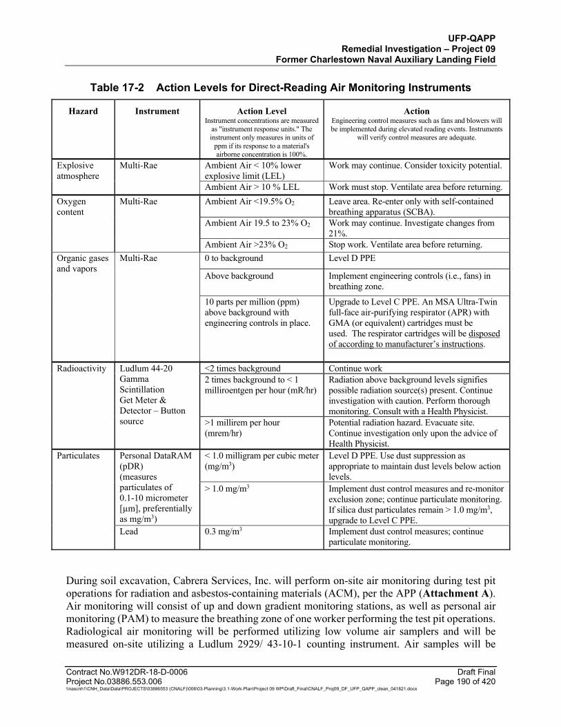
UFP-QAPP Remedial Investigation – Project 09
Former Charlestown Naval Auxiliary Landing Field
Contract No.W912DR-18-D-0006 Draft Final Project No.03886.553.006 Page 190 of 420 \\nascnh1\CNH_Data\Data\PROJECTS\03886553 (CNALF)\006\03-Planning\3.1-Work-Plan\Project 09 WP\Draft_Final\CNALF_Proj09_DF_UFP_QAPP_clean_041821.docx
Table 17-2 Action Levels for Direct-Reading Air Monitoring Instruments
Hazard Instrument Action Level Instrument concentrations are measured
as "instrument response units." The instrument only measures in units of
ppm if its response to a material's airborne concentration is 100%.
Action Engineering control measures such as fans and blowers will be implemented during elevated reading events. Instruments
will verify control measures are adequate.
Explosive atmosphere
Multi-Rae Ambient Air < 10% lower explosive limit (LEL)
Work may continue. Consider toxicity potential.
Ambient Air > 10 % LEL Work must stop. Ventilate area before returning. Oxygen content
Multi-Rae Ambient Air <19.5% O2 Leave area. Re-enter only with self-contained breathing apparatus (SCBA).
Ambient Air 19.5 to 23% O2 Work may continue. Investigate changes from 21%.
Ambient Air >23% O2 Stop work. Ventilate area before returning. Organic gases and vapors
Multi-Rae 0 to background Level D PPE
Above background Implement engineering controls (i.e., fans) in breathing zone.
10 parts per million (ppm) above background with engineering controls in place.
Upgrade to Level C PPE. An MSA Ultra-Twin full-face air-purifying respirator (APR) with GMA (or equivalent) cartridges must be used. The respirator cartridges will be disposed of according to manufacturer’s instructions.
Radioactivity Ludlum 44-20 Gamma Scintillation Get Meter & Detector – Button source
<2 times background Continue work 2 times background to < 1 milliroentgen per hour (mR/hr)
Radiation above background levels signifies possible radiation source(s) present. Continue investigation with caution. Perform thorough monitoring. Consult with a Health Physicist.
>1 millirem per hour (mrem/hr)
Potential radiation hazard. Evacuate site. Continue investigation only upon the advice of Health Physicist.
Particulates Personal DataRAM (pDR) (measures particulates of 0.1-10 micrometer [µm], preferentially as mg/m3)
< 1.0 milligram per cubic meter (mg/m3)
Level D PPE. Use dust suppression as appropriate to maintain dust levels below action levels.
> 1.0 mg/m3 Implement dust control measures and re-monitor exclusion zone; continue particulate monitoring. If silica dust particulates remain > 1.0 mg/m3, upgrade to Level C PPE.
Lead 0.3 mg/m3 Implement dust control measures; continue particulate monitoring.
During soil excavation, Cabrera Services, Inc. will perform on-site air monitoring during test pit operations for radiation and asbestos-containing materials (ACM), per the APP (Attachment A). Air monitoring will consist of up and down gradient monitoring stations, as well as personal air monitoring (PAM) to measure the breathing zone of one worker performing the test pit operations. Radiological air monitoring will be performed utilizing low volume air samplers and will be measured on-site utilizing a Ludlum 2929/ 43-10-1 counting instrument. Air samples will be

UFP-QAPP Remedial Investigation – Project 09
Former Charlestown Naval Auxiliary Landing Field
Contract No.W912DR-18-D-0006 Draft Final Project No.03886.553.006 Page 191 of 420 \\nascnh1\CNH_Data\Data\PROJECTS\03886553 (CNALF)\006\03-Planning\3.1-Work-Plan\Project 09 WP\Draft_Final\CNALF_Proj09_DF_UFP_QAPP_clean_041821.docx
measured for alpha and beta radiation and will be compared to applicable derived air concentration (DAC) limits for potential site radionuclides. ACM air monitoring samples will be submitted to an off-site laboratory for analysis. WESTON will perform the required monitoring to evaluate the effectiveness of the prescribed PPE and to evaluate work exposure. If conditions change, the SSHP and APP will be amended, followed by review and approval by the WESTON Regional Environmental Health and Safety Manager and acceptance by USACE.
17.11.4 Radiation Field Screening
Soil and debris objects excavated from the test pits will undergo radiological field screening by Cabrera Services, Inc, the radiation monitoring subcontractor. Cabrera will have one qualified Senior Radiological Control Technician (RCT) on-site to perform the radiological screening and institute necessary radiological controls in the event that elevated levels of radiation are identified. Soil and debris excavated from the test pit will be screened for elevated gamma radiation utilizing a Ludlum 2221/44-10 sodium iodide detector (2-inch by 2-inch NaI), as well as a Ludlum Model 12/ 44-9 Geiger-Mueller pancake probe (or equivalent) for gross alpha-beta radiation. The primary purpose of the radiation monitoring is to assess the potential presence of potential radium used on aircraft instrument panels. If elevated radiation levels are detected, Cabrera will have instrumentation on-site to collect dose rate measurements. Instrument backgrounds will be determined in a non-impacted area of the site that exhibits a similar radiological background as the test pit soils. An action level of two-times (2x) the instrument background will be used to identify elevated radioactivity. The action levels for the radiation field screening are included in Table 17-2 and the APP Table 9-8 (Attachment A). No samples will be collected for radionuclide analysis at an off-site laboratory. If radiation levels above the action levels are detected, work at that location will stop, and WESTON will notify USACE for direction. The on-site RCT will collect the necessary measurements and institute radiological controls until further direction is given. Workers will remain a safe distance from any identified source of radiation. If any items are identified that exhibit elevated radiation levels, but are determined to be naturally occurring radioactive material (NORM), the items will be documented and reburied in place, along with excavated debris, upon completion of the test pit, per the APP.
17.11.5 Soil Sampling
The field technician will log fill depth, contents, and other observations on the Test Pit Log Form (Attachment G) following the procedures outlined in SOP-20 (Attachment F). One composite soil sample will be collected from each test pit. Three individual soil aliquots will be collected from each excavator bucket as the test pit is excavated and combined into a single composite sample of approximately 1.5 kilograms (e.g., 5 excavator buckets with 3 aliquots collected per bucket for a total of 15 aliquots) for non-volatile parameter analyses. The sample will not be processed in the field prior to submittal to the laboratory. Laboratory processing will follow the same method as ISM soil sample preparation (except for VOCs and asbestos) to minimize bias in the sample aliquot to be analyzed as described in ISM SOP-18. The asbestos composite soil samples will be collected as separate samples from the remaining analytes and submitted directly to ProScience Laboratory for analysis. These samples will be manually homogenized within the sample bag to minimize mechanical manipulation of the sample prior to analysis and not undergo ISM sample processing.
UFP-QAPP Remedial Investigation – Project 09
Former Charlestown Naval Auxiliary Landing Field
Contract No.W912DR-18-D-0006 Draft Final Project No.03886.553.006 Page 192 of 420 \\nascnh1\CNH_Data\Data\PROJECTS\03886553 (CNALF)\006\03-Planning\3.1-Work-Plan\Project 09 WP\Draft_Final\CNALF_Proj09_DF_UFP_QAPP_clean_041821.docx
The soil in each excavation bucket will undergo PID field screening to determine the appropriate soil to be sampled. VOC samples of test pit soil will be collected as discrete samples, not as composite samples. Biased discrete samples for VOCs are more conservative due to the potential loss of contaminants associated with collecting multiple increments and limitation for sample shipment where a large volume of methanol would be required. Biased, discrete sampling for VOCs is recommended as a more conservative approach to identifying the presence or absence of potential VOC soil contaminants in potential source areas. Three discrete soil VOC samples will be collected from each test pit based on PID screening or observed staining in excavated soil.
Test pit soil sample parameters will include analysis of asbestos, VOCs, low-level SVOCs, 1,4-dioxane by SIM, PAHs by SIM, PCBs, TAL metals (including mercury), hexavalent chromium, and explosives. Ninigret Landfill test pit samples will also be analyzed for perchlorate. In addition, any test pit soil sample designated for hexavalent chromium matrix spike will also be analyzed for ancillary parameters (total sulfide, TOC, and leachable ferrous iron). MC metals (antimony, copper, lead, nickel, and zinc) are included in the TAL metals analysis. Analysis of explosives compounds or perchlorate will only be performed if munitions are discovered during test pit activities. After samples are collected, sample containers will be sealed, placed in a cooler on ice, and shipped to the laboratory under COC procedures. An equipment blank will be collected from non-dedicated equipment for the same analytical suite as test pit soils. A trip blank will be included in each cooler containing samples for VOC analysis, and the trip blank will be analyzed for VOCs. Trip blanks will be prepared by the laboratory and will accompany VOC sample containers at all times. Based on results from initial test pit investigation and sampling, if stepout test pits are warranted, sample parameters will be limited to the COPCs identified in the initial samples.
Data from test pit soil samples will be used to determine if there is a potential for hazardous materials sources to be present within the landfills. In additional to visual observations, the analytical results will be compared to chemical-specific soil saturation concentrations to assess the potential for free product. PCB concentrations will be compared to TSCA thresholds to assess the proper handling of PCBs (i.e., TSCA-regulated PCB-Contaminated [>50 ppm and <500 ppm] and TSCA-regulated PCBs [≥ 500 ppm]). Results from these samples will also be used to assess whether a relationship may exist between buried materials in the landfill and potential downgradient groundwater impacts evaluated by monitoring well sampling.
The test pit samples will be biased toward geophysical anomalies that warrant characterization to assess potential contaminant sources within the landfills, and will not be considered representative of any specific source area within the landfills. If a potential site-related contaminant source is identified, additional sampling would be needed to determine the extent of the source area and whether remedial action may be necessary. The composite test pit samples will be collected to characterize contaminants that may be attributed to the test pit objects, and are not intended to be evaluated in the risk assessment because there is no current or future complete exposure pathway for direct contact with the landfill items.
Up to 5 test pit object samples (consisting of munitions, waste material including visually-impacted soil or drum contents) will be analyzed per landfill site. Depending on the type of material found, the test pit object may be analyzed for the same analytical suite as the corresponding test pit soils with the exception of asbestos. No test pit object samples will be
UFP-QAPP Remedial Investigation – Project 09
Former Charlestown Naval Auxiliary Landing Field
Contract No.W912DR-18-D-0006 Draft Final Project No.03886.553.006 Page 193 of 420 \\nascnh1\CNH_Data\Data\PROJECTS\03886553 (CNALF)\006\03-Planning\3.1-Work-Plan\Project 09 WP\Draft_Final\CNALF_Proj09_DF_UFP_QAPP_clean_041821.docx
analyzed for asbestos. Based on field observations and at the discretion of WESTON Technical staff, the analytical suite may include the following: VOCs, SVOCs (regular full scan including 1,4-dioxane and PAHs), PCBs, 23 TAL metals (including mercury), hexavalent chromium, explosives, and perchlorate. In the event that the test pit object needs to be removed from the site, additional waste characterization parameters specified under Resource Conservation and Recovery Act (RCRA) (i.e., corrosivity, ignitability, and reactivity) may also be analyzed to determine the presence or absence of hazardous chemicals. The results may be compared to USEPA solid waste and RCRA waste disposal criteria to determine proper removal and off-site disposal methods, as necessary, if an object is removed from the landfill. In addition, landfill object sample results will be compared to test pit soil results and monitoring well groundwater results to evaluate a relationship of potential groundwater contaminant to source materials in the landfills. Non-statistical methods (i.e., lines of evidence) will be used to evaluate if there is a link between the detected contaminants and groundwater results, such as detection of the same analyte in both media and highly elevated concentrations in these media.
17.12 INSPECTION, MANAGEMENT, AND DISPOSAL OF MDAS
As stated previously in Section 17.11.2, no MEC/MPPEH items will be handled by WESTON during field activities. If suspect MEC/MPPEH is encountered, the UXO TIII will stop activities at that location and immediately call 911 to properly dispose of the item. The field team will retreat from the area and follow the emergency notification procedures as described in Section 17.22. Local emergency responders will safely destroy the item as required, and the resulting MDAS will be handled by WESTON as follows.
Cultural debris (NRMD) and MDAS will be transported to a secure area on-site prior to final disposition off-site. A second UXO TIII (or above) will be on site and will perform a second inspection prior to the material being loaded, to ensure it is segregated correctly.
When certified and verified as free of explosive hazards, the material collected during the RI will be placed in containers and sealed. Each container will be closed in a manner that requires that the seal be broken to gain access to the interior of the container. The containers will be labeled with a unique ID as follows:
USACE/CD/Weston Solutions, Inc./Container number (e.g., 0001)/Seal number.
The DD Form 1348-1A (Attachment G) will be used as the certification/verification documentation for MDAS. The DD Form 1348-1A will clearly show the printed names of the UXO TIII Team Leader and USACE OESS, organization, signature, and contractor’s home office and field office phone numbers of the UXO TIII Team Leader. The DD Form 1348-1A will list the following:
Basic material content Estimated weight Unique ID of each of the container and seal number Location where the MDAS was obtained

UFP-QAPP Remedial Investigation – Project 09
Former Charlestown Naval Auxiliary Landing Field
Contract No.W912DR-18-D-0006 Draft Final Project No.03886.553.006 Page 194 of 420 \\nascnh1\CNH_Data\Data\PROJECTS\03886553 (CNALF)\006\03-Planning\3.1-Work-Plan\Project 09 WP\Draft_Final\CNALF_Proj09_DF_UFP_QAPP_clean_041821.docx
Certified MDAS will be transferred to a qualified receiver with the completed DD Form 1348-1A. The receiver will render the MDAS unrecognizable from its original condition through shredding, smelting, or deforming prior to being released into the metals recycling waste stream. The UXO TIII Team Leader will sign the Certificate as follows: “This certifies and verifies that the material listed has been 100 percent inspected and to the best of our knowledge and belief, is inert and/or free of explosive hazards.”
In accordance with 40 CFR 261.6(a)(3), scrap metal, if recycled, is not subject to Parts 262-266, or 268, 270, or 124. WESTON will recycle scrap metal (NMRD) generated as a result of necessary removal and maintain records of recycling.
17.13 RISK ASSESSMENTS
17.13.1 Evaluation of Risks Associated with Explosive Hazards
Following the RI, an evaluation of hazards at each MRS will be performed using the framework of logic presented within the USACE Study Paper: Decision Logic to Assess Risks Associated with Explosive Hazards and to Develop Remedial Action Objectives (RAOs) for Munitions Response Sites (USACE, 2016). The purpose of this risk assessment associated with explosive hazards is to provide USACE with decision logic to differentiate acceptable versus unacceptable site conditions at an MRS, to establish a systematic approach for developing remedial action objectives (RAOs), and to assists in developing acceptable response alternatives to meet the RAOs. Data are processed similar to the Department of the Army Pamphlet for Risk Management (DA PAM 385-30), by defining factors more appropriate for MMRP sites, to include site-specific CSM data to relate accessibility, munitions sensitivity, and severity of an explosive event if it were to occur, to determine baseline risks specific to explosive hazards at each MRS. This evaluation will be conducted using four different matrices:
Matrix 1, the Likelihood of Encounter; Matrix 2, the Severity of an Incident; Matrix 3, the Likelihood of Detonation; and Matrix 4, combines the results of the above categories to differentiate Acceptable and
Unacceptable Site Conditions.
More information on this risk assessment can be found in the Study Paper (USACE, 2016).
17.13.2 Assessment of Chemical and Munitions Constituent Risk
Chemical data collected during the RI will be used to prepare a baseline HHRA and SLERA to evaluate potential risks to human and ecological receptors from hazardous chemicals and explosives (if munitions found) at CNALF. The goals of the HHRA and SLERA are to evaluate the potential risks to human health and ecological receptors from releases of hazardous substances at CNALF and to assess whether these risks should be addressed by response actions. Risk assessment provides risk managers the information needed to understand existing or potential risks by identifying the relevant exposure pathways by which contaminants may reach receptors, the
UFP-QAPP Remedial Investigation – Project 09
Former Charlestown Naval Auxiliary Landing Field
Contract No.W912DR-18-D-0006 Draft Final Project No.03886.553.006 Page 195 of 420 \\nascnh1\CNH_Data\Data\PROJECTS\03886553 (CNALF)\006\03-Planning\3.1-Work-Plan\Project 09 WP\Draft_Final\CNALF_Proj09_DF_UFP_QAPP_clean_041821.docx
human and/or ecological receptors that may be exposed to the contamination, and the location and magnitude of potential effects.
The HHRA will identify potential likely human receptors and exposure routes, and quantitatively evaluate the potential risk of harm resulting from exposure to DoD-related COPCs at the site. The HHRA will consist of four main components: hazard identification, exposure assessment, dose-response (toxicity) assessment, and risk characterization. In addition, the HHRA will include an uncertainty analysis that identifies the nature, direction, and, when possible, the magnitude of the uncertainty associated with the HHRA and potential biases on the conclusions.
A SLERA will be completed to identify constituents that have the potential to present a risk to terrestrial or aquatic receptors, and thus require further investigation. The SLERA is designed to eliminate constituents that present insignificant hazards while retaining for further study contaminants with concentrations associated with potential risk. Potential effects on both aquatic and terrestrial receptors will be evaluated, using data collected as described in this UFP-QAPP. This evaluation will include an additional SLERA refinement step in which the conservative conclusions of the SLERA are re-evaluated using a broader array of effects and contaminant distribution data to more accurately identify constituents that warrant further evaluation. The SLERA will consist of the following main components: habitat assessment, problem formulation, risk estimation, risk calculation, SLERA refinement, summary and conclusions, and uncertainty analysis.
Additional details for the planned risk assessments are included in Attachment D.
17.14 INVESTIGATION-DERIVED WASTE MANAGEMENT
The field activities described above are anticipated to generate solid and liquid IDW. Liquid IDW is anticipated to include purged groundwater and decontamination water and will be staged in 55-gallon drums on-site until characterized prior to off-site transport. Solid IDW is anticipated to include soil cuttings, sampling equipment (e.g., disposable valves, fittings, and sample tubing used to collect samples), and PPE. The plastic, glass, paper, and PPE IDW will be double bagged in plastic trash bags and placed into a dumpster for disposal at a municipal landfill. Brush and vegetation debris will be managed by chipping in-place and left on-site in coordination with the property owner. Soil will be collected in 55-gallon drums and will be staged on-site prior to disposal. Waste characterization samples will be collected from potentially contaminated IDW per disposal facility requirements for characterization of toxicity, reactivity, corrosivity and ignitability to determine the appropriate waste disposal method.
IDW will be stored in a USACE-designated central IDW storage area on the CNALF property while pending final disposal. Although WESTON will be responsible for the proper handling and management of IDW generated during the implementation of field activities, USACE will be considered the “generator” of all IDW produced during the field program. WESTON will provide waste characterization forms for USACE approval and coordinate USACE sign-off on waste manifests, prior to transport and off-site disposal. USACE may need to acquire a temporary USEPA ID number for the site. The off-site transport and disposal of IDW will be performed by a qualified contractor in accordance with applicable state and federal regulations.
UFP-QAPP Remedial Investigation – Project 09
Former Charlestown Naval Auxiliary Landing Field
Contract No.W912DR-18-D-0006 Draft Final Project No.03886.553.006 Page 196 of 420 \\nascnh1\CNH_Data\Data\PROJECTS\03886553 (CNALF)\006\03-Planning\3.1-Work-Plan\Project 09 WP\Draft_Final\CNALF_Proj09_DF_UFP_QAPP_clean_041821.docx
No MEC/MPPEH items will be handled by WESTON during field activities. If suspect MEC/MPPEH is encountered, the UXO TIII will stop activities at that location and immediately call 911 to properly dispose of the item. The field team will retreat from the area and follow the emergency notification procedures as described in Section 17.22. Local emergency responders will safely destroy the item as required, and the resulting MDAS will be handled by WESTON as described in Section 17.12.
17.15 POTENTIAL FUTURE ACTIVITIES IN THE CERCLA PROCESS Based on the results of the RI and the hazard/risk assessments, an FS may be performed for CNALF. This FS, if performed, will focus on developing remedial alternatives only for contamination linked to DoD-related activities and for MEC hazards identified during the landfill geophysical survey and test pit activities. The FS, if performed, will follow the general process outlined in Guidance for Conducting Remedial Investigations and Feasibility Studies under CERCLA – Interim Final (USEPA, 1988), and the U.S. Army MMRP Munitions Response Remedial Investigation/Feasibility Study Guidance (U.S. Army, 2009). The following steps are included in an FS:
Step 1: Develop remedial action objectives for the Site specific to DoD-related activities; identify applicable or relevant and appropriate requirements (ARARs); establish allowable exposure levels based on the HHRA and SLERA; identify COPCs and preliminary remediation goals; and identify areas and media requiring remediation.
Step 2: Develop General Response Actions; determine remedial options to be evaluated; identify and screen remedial technology types and process options; conduct a preliminary screening to include effectiveness, ability for implementation, and cost.
Step 3: Identify and develop potentially feasible remedial alternatives by assembling technology types and/or process options that are potentially feasible; evaluate alternatives in detail; and compare remedial alternatives to each other.
The FS provides a basis for USACE to select the preferred remedial alternative. Based on the results of the RI and if needed and FS, a Proposed Plan will be developed for public comment. After considering public comments on the Proposed Plan, USACE would select a final remedy that is then documented in a Decision Document.
17.16 EQUIPMENT DECONTAMINATION PROCEDURES
Equipment involved in sampling or entering an area during field work must be thoroughly decontaminated prior to sampling, between sampling locations and prior to leaving the site to minimize the spread of contamination and prevent adverse health effects, per SOP-10 (Attachment F).
The procedure for decontaminating reusable sampling equipment is as follows:
Place dirty equipment on a plastic ground sheet at the head of the decontamination line.
UFP-QAPP Remedial Investigation – Project 09
Former Charlestown Naval Auxiliary Landing Field
Contract No.W912DR-18-D-0006 Draft Final Project No.03886.553.006 Page 197 of 420 \\nascnh1\CNH_Data\Data\PROJECTS\03886553 (CNALF)\006\03-Planning\3.1-Work-Plan\Project 09 WP\Draft_Final\CNALF_Proj09_DF_UFP_QAPP_clean_041821.docx
Rinse equipment with potable water to remove surface dirt and mud if necessary.
Scrub equipment with a bristle brush using a non-phosphate detergent (e.g., Liquinox) and potable water. To clean the inside of a probe, use a bottlebrush.
Rinse off soap with potable water.
Using a squirt bottle, rinse with 10% ultrapure nitric acid (use 1% nitric acid for metallic sampling materials) if equipment will be used for the collection of metals samples. Collect nitric acid rinsate in a tub or bucket.
Rinse with ASTM Type II reagent-grade water, deionized water or distilled water.
For equipment used to collect samples analyzed for organics, rinse with medical-grade isopropanol or equivalent. Collect solvent rinsate in a tub or bucket separate from the nitric acid rinsate.
For equipment used to collect samples analyzed for PCBs, moisten a paper towel with hexane and wipe down the equipment.
Rinse with ASTM Type II reagent-grade water, deionized or distilled water.
Allow equipment to air dry.
Wrap equipment with aluminum foil (shiny side facing out).
Sampling equipment used to collect samples for organic analyses will not be allowed to contact any type of plastic after decontamination.
Equipment that cannot be washed and rinsed (e.g., PID) should be covered with a plastic bag while sampling, with only the probe tip exposed.
Material and equipment will be inspected upon arrival and decontaminated as necessary prior to intrusive activities.
Non-dedicated sampling equipment that will be used includes materials such as stainless steel bowls, trowels, scoops, split spoons, and augers. Equipment to be used during sampling will be decontaminated at a centralized decontamination area site at which the equipment is being used. Dedicated sampling equipment will be used to the greatest extent practicable in order to reduce the need for decontamination and reduce generation of IDW. All non-dedicated sampling equipment will be decontaminated after use to prevent cross-contamination between sampling points.
Procedures for equipment decontamination during test pit operations, sampling, and other field investigation procedures are described in SOP-10 (Attachment F). Decontamination procedures associated with field personnel are provided in and the APP/SSHP (Attachment A).
UFP-QAPP Remedial Investigation – Project 09
Former Charlestown Naval Auxiliary Landing Field
Contract No.W912DR-18-D-0006 Draft Final Project No.03886.553.006 Page 198 of 420 \\nascnh1\CNH_Data\Data\PROJECTS\03886553 (CNALF)\006\03-Planning\3.1-Work-Plan\Project 09 WP\Draft_Final\CNALF_Proj09_DF_UFP_QAPP_clean_041821.docx
17.17 POST-REMEDIAL INVESTIGATION SITE RESTORATION PLAN
After completing RI activities proposed in this UFP-QAPP, these four areas in CNALF will be restored to the extent practicable by grading and seeding where appropriate. Anticipated site restoration activities include pulling stakes, backfilling holes, returning disturbed areas to grade, and seeding test pit excavation areas. Seed mix and seeding activities will be coordinated with the property owners. All other vegetation will be allowed to re-establish naturally. Disturbed areas will be visually inspected by USACE immediately after restoration is completed and verified by current property owners, and RIDEM for final acceptance.
At completion of field activities, field equipment, toilet facilities, and work trailers will be demobilized. Soil cuttings and all other IDW will be disposed of as described in Worksheet #26 & 27. A final inspection walk-through of the project area will occur prior to demobilization. Demobilization by WESTON will only occur after approval by the USACE Project Manager.
17.18 DAMAGE TO SITE STRUCTURES
The RI activities will involve subsurface investigations and the use of heavy equipment. In the course of the project, precautions will be taken to avoid damage to CNALF roadways and larger trees. Track equipment will be used to prevent excessive rutting or similar damage. Cones, stakes, and/or flagging shall be placed as needed around investigation locations and travel corridors as necessary to protect sensitive objects (e.g., large trees). Contingency planning for damage (beyond intentional cutting/clearing and minor rutting) includes the following:
The Field Manager will be responsible for assessing and documenting damage and repairs in daily reports. Documentation will include photographs of the damage. USACE will be immediately notified by WESTON of the damage.
Depending on the scope of the damage, repairs will be made in a timeframe commensurate with the degree of damage and planning required for mitigation.
Equipment refueling will be performed off-site whenever possible prior to arrival onsite. On-site refueling will be performed as needed. Plastic will be laid on the ground and extend at least 5 ft in all directions from the fill port to intercept any drips or minor spills that may occur and a spill kit will be maintained onsite. Onsite bulk storage of fuel is not anticipated.
17.19 EROSION AND SEDIMENT CONTROL PLAN
In order to complete the geophysical surveys, approximately 15 acres on the surface of the 3 landfills will be cleared of understory vegetation. To the greatest extent practicable, activities associated with the project will be conducted in a manner that will avoid and minimize impacts to land resources. Minimal disturbance to surface soil is anticipated at individual drilling and field sampling activities. Test pit areas within each landfill area are collectively anticipated to be less than 1,000 square feet in area and widely distributed in each landfill area. The area of soil that may potentially be disturbed on the project is not anticipated to be above the threshold (5,000 square
UFP-QAPP Remedial Investigation – Project 09
Former Charlestown Naval Auxiliary Landing Field
Contract No.W912DR-18-D-0006 Draft Final Project No.03886.553.006 Page 199 of 420 \\nascnh1\CNH_Data\Data\PROJECTS\03886553 (CNALF)\006\03-Planning\3.1-Work-Plan\Project 09 WP\Draft_Final\CNALF_Proj09_DF_UFP_QAPP_clean_041821.docx
feet of disturbed soil) that requires an Erosion and Sediment Control Plan and provisions as described in the Rhode Island Coastal Resources Management Council (RICRMC) Coastal Management Program - Red Book (Section 1.3.1.B.C). Erosion and sedimentation controls including installation of silt fence will be employed during test pit activities, as necessary, adjacent to surface water and wetland areas to prevent erosion of disturbed soils into surface water and wetland areas.
The clearing activities will not include removing trees greater than 4 inches in diameter and will not include grubbing. By leaving the vegetation root systems in the ground, and the topsoil itself undisturbed, potential for erosion is minimized and the existing vegetation will be allowed to regrow after the investigation is complete. See Section 17.21.3 for additional detail on measures that will be taken to minimize the impact of vegetation clearing.
17.20 STORMWATER MANAGEMENT PLAN
The RICRMC Coastal Management Program Red Book requires a stormwater management plan to be prepared for construction/development activities that create new impervious surfaces or disturb an area of 10,000 square ft or more of impervious surface coverage. This RI does not include these types of activities; therefore, a Stormwater Management Plan is not required.
17.21 ENVIRONMENTAL PROTECTION PLAN (EPP)
The purpose of the following EPP is to avoid, minimize, and/or mitigate potential environmental impacts to the maximum extent practicable without compromising the ability to achieve the primary objectives of the investigation. EPPs are particularly important for remedial construction activities that create significant environmental disturbances. For investigation activities, such as in this work plan, the primary activities that cause disturbance are clearing vegetation and transporting heavy equipment (e.g., drill rig and excavator) to the investigation points. This EPP addresses these activities.
USACE will perform environmental coordination with USFWS, SHPO, tribal, and/or state regulatory offices for archeological, threatened and endangered species, and cultural compliance reviews.
17.21.1 Biological Resources
A summary of current knowledge on biological resources is included in Section 10.2.5. Additional data about the flora and the fauna of CNALF will be obtained during the wetland inspection and vegetative cover survey. This will include information on native, as well as invasive species. A letter report will be submitted following the inspections to document the results. The USFWS will be contacted to identify specific known locations of sensitive flora or fauna that require protection during field activities.
17.21.2 Archeological/Cultural Resources
A summary of current knowledge on archeological/cultural resources is in Section 10.2.6. Additional data regarding these resources will be provided to WESTON by USACE. Weston will
UFP-QAPP Remedial Investigation – Project 09
Former Charlestown Naval Auxiliary Landing Field
Contract No.W912DR-18-D-0006 Draft Final Project No.03886.553.006 Page 200 of 420 \\nascnh1\CNH_Data\Data\PROJECTS\03886553 (CNALF)\006\03-Planning\3.1-Work-Plan\Project 09 WP\Draft_Final\CNALF_Proj09_DF_UFP_QAPP_clean_041821.docx
coordinate with CENAE, USFWS and the SHPO to ensure that site activities do not conflict with known sensitive areas. Additional coordination with the Navy may be necessary to assess the historical significance of items potentially encountered during test pit activities in the landfills. Wherever possible, sample locations may be relocated to avoid the potential for conflicts with archeological sensitive areas. Workers will be made aware of the potential for encountering artifacts. In the event artifacts are found, work will be stopped and CENAE will be contacted immediately for direction.
17.21.3 Measures to Avoid, Minimize, and/or Compensate for Environmental Impacts Archeological and Cultural Impacts
This section describes measures that will be employed to avoid, minimize, and, if required, compensate for environmental impacts. These measures include seasonal work restrictions, worker education, special work practices to minimize unavoidable impacts, and standard work practices such as spill control and prevention to protect water resources.
Federal and State agencies and stakeholders associated with threatened and endangered species and cultural resources will have the opportunity to review the UFP-QAPP for CNALF prior to the commencement of any work. The review will allow USACE to identify work areas which may potentially contain threatened and endangered species and their habitats.
Seasonal restrictions for clearing and investigation activities may be requested to minimize impacts to wetland, bird nesting, and marine resources. These restrictions will be determined by the environmental compliance review being performed by USACE.
Field personnel will be trained on the identification and avoidance of selected threatened or endangered species. Before the start of RI activities, all on-site personnel will be briefed on health and safety issues and the need for avoiding, minimizing, and/or mitigating potential impacts on sensitive biological resources in accordance with this EPP.
Clearing vegetation, transporting heavy equipment and test pit excavation are the three activities in this work plan that will have the greatest unavoidable impacts on the environment. To minimize the impact of clearing vegetation, the clearing activities will not include removing trees greater than 4 inches in diameter and will not include grubbing. By leaving the vegetation root systems in the ground, erosion is minimized and the existing vegetation will be allowed to regrow after the investigation is complete. To minimize the amount of clearing required for heavy equipment access roads, existing access roads and trails will be used to the extent practicable, and equipment will be selected to utilize the smallest equipment practical to accomplish the work in an efficient manner. Tracked equipment will be utilized wherever possible to minimize rutting on access roads. To minimize potential impact on undisturbed soils, the bottom of test pit excavations will not be extended more than 1 foot below the bottom of waste materials
Invasive plants, such as oriental bittersweet, are present at the site. Methods to control the spread of these plants will be determined based on the types of invasive plants identified during the vegetative cover survey. In general, many invasive plants spread by the transfer of seeds, fruits, and/or pieces of the above-ground plant or root. Therefore, hand-held equipment, PPE and heavy
UFP-QAPP Remedial Investigation – Project 09
Former Charlestown Naval Auxiliary Landing Field
Contract No.W912DR-18-D-0006 Draft Final Project No.03886.553.006 Page 201 of 420 \\nascnh1\CNH_Data\Data\PROJECTS\03886553 (CNALF)\006\03-Planning\3.1-Work-Plan\Project 09 WP\Draft_Final\CNALF_Proj09_DF_UFP_QAPP_clean_041821.docx
equipment used in the investigation will be visually examined and brushed off or washed to remove plant material and traces of soil prior to entering and exiting the site. Also, invasive plants removed as part of clearing activities will be disposed as requested by the property owner to prevent spreading of these plants. This may include offsite disposal or onsite controlled burning.
The following are the primary standard work practices that will be employed at the site to avoid or minimize environmental impacts; these work practices are described in other sections of this document:
Waste Disposal, Worksheet #26 & 27 Erosion and Sediment Control, Worksheet #17 Section 17.19 Spill Control/Prevention, APP/SSHP (Attachment A) Decontamination, APP/SSHP (Attachment A)
17.21.4 Dust, Vapor, Odor, and Noise Control
Intrusive activities, i.e., drilling, test pitting, and site clearing activities are not anticipated to create excessive dust, vapors, or odors. However, engineering controls will be applied if needed to manage dust, vapors, or odors emitted during the RI activities. These activities will be qualitatively monitored at the work site and at the property boundary. If dust, vapors, or odors are observed related to site clearing, drilling or test pitting activities, they will be mitigated using engineering controls (e.g., spraying the source of dust with water from a public water supply). Under no circumstances shall any water from the investigation activities be allowed to enter surface water.
Activities requiring heavy equipment will be limited to normal work hours to minimize potential noise impact to nearby residents and park visitors. Work may occur seven days per week.
Any noise, odor, or dust complaints received from the public will be evaluated immediately, and practices will be changed to mitigate the situation. USACE will be informed immediately by WESTON of the complaint and the response measures.
17.22 CONTINGENCY PLAN AND SITE SECURITY
As stated previously Section 17.11.2, no MEC/MPPEH items will be handled by WESTON during field activities. If suspect MEC/MPPEH is encountered, the UXO TIII will stop activities at that location and immediately call 911 to properly dispose of the item. The field team will retreat from the area and WESTON will immediately call 911, and inform all parties on the notification roster provided in Table 17-3.
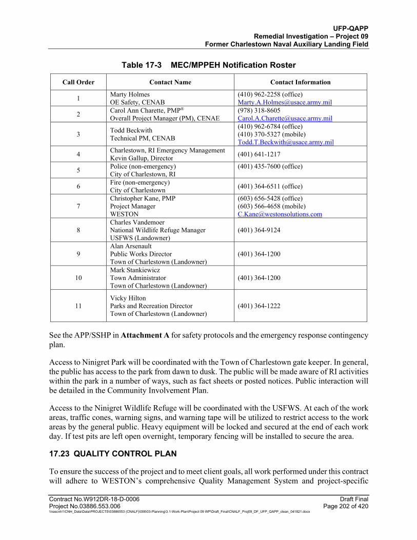
UFP-QAPP Remedial Investigation – Project 09
Former Charlestown Naval Auxiliary Landing Field
Contract No.W912DR-18-D-0006 Draft Final Project No.03886.553.006 Page 202 of 420 \\nascnh1\CNH_Data\Data\PROJECTS\03886553 (CNALF)\006\03-Planning\3.1-Work-Plan\Project 09 WP\Draft_Final\CNALF_Proj09_DF_UFP_QAPP_clean_041821.docx
Table 17-3 MEC/MPPEH Notification Roster
Call Order Contact Name Contact Information
1 Marty Holmes OE Safety, CENAB
(410) 962-2258 (office) [email protected]
2 Carol Ann Charette, PMP® Overall Project Manager (PM), CENAE
(978) 318-8605 [email protected]
3 Todd Beckwith Technical PM, CENAB
(410) 962-6784 (office) (410) 370-5327 (mobile) [email protected]
4 Charlestown, RI Emergency Management Kevin Gallup, Director (401) 641-1217
5 Police (non-emergency) City of Charlestown, RI
(401) 435-7600 (office)
6 Fire (non-emergency) City of Charlestown (401) 364-6511 (office)
7 Christopher Kane, PMP Project Manager WESTON
(603) 656-5428 (office) (603) 566-4658 (mobile) [email protected]
8 Charles Vandemoer National Wildlife Refuge Manager USFWS (Landowner)
(401) 364-9124
9 Alan Arsenault Public Works Director Town of Charlestown (Landowner)
(401) 364-1200
10 Mark Stankiewicz Town Administrator Town of Charlestown (Landowner)
(401) 364-1200
11 Vicky Hilton Parks and Recreation Director Town of Charlestown (Landowner)
(401) 364-1222
See the APP/SSHP in Attachment A for safety protocols and the emergency response contingency plan.
Access to Ninigret Park will be coordinated with the Town of Charlestown gate keeper. In general, the public has access to the park from dawn to dusk. The public will be made aware of RI activities within the park in a number of ways, such as fact sheets or posted notices. Public interaction will be detailed in the Community Involvement Plan.
Access to the Ninigret Wildlife Refuge will be coordinated with the USFWS. At each of the work areas, traffic cones, warning signs, and warning tape will be utilized to restrict access to the work areas by the general public. Heavy equipment will be locked and secured at the end of each work day. If test pits are left open overnight, temporary fencing will be installed to secure the area.
17.23 QUALITY CONTROL PLAN
To ensure the success of the project and to meet client goals, all work performed under this contract will adhere to WESTON’s comprehensive Quality Management System and project-specific
UFP-QAPP Remedial Investigation – Project 09
Former Charlestown Naval Auxiliary Landing Field
Contract No.W912DR-18-D-0006 Draft Final Project No.03886.553.006 Page 203 of 420 \\nascnh1\CNH_Data\Data\PROJECTS\03886553 (CNALF)\006\03-Planning\3.1-Work-Plan\Project 09 WP\Draft_Final\CNALF_Proj09_DF_UFP_QAPP_clean_041821.docx
requirements. Work conducted by WESTON will require concurrence from the USACE Contracting Officer’s Representative (COR) and be consistent to meet the evaluation and quality control (QC) criteria set forth in this UFP-QAPP.
The WESTON Project Manager or designee will work directly with USACE and other key stakeholders to ensure that the program requirements and the project expectations are on track. Project plans and deliverables will be subjected to QC reviews to ensure they meet contractual requirements and that changes to existing documents are communicated to project personnel. Lessons learned and corrective actions taken will be submitted by WESTON to USACE as part of monthly progress reporting. A Daily Report, included in Attachment G, will be completed and provided to the USACE Project Manager to document daily activities at the site.
17.23.1 Quality Management Structure
WESTON’s staff of experienced technical professionals and subcontractors will execute the project. Project personnel will be responsible for ensuring that quality methods and procedures are implemented. The quality management structure and specific quality duties are detailed in the following sections.
17.23.1.1 Project Manager
The Project Manager is responsible for project activities and for ensuring that contractual requirements are met and that the project is performed in an efficient, safe, and quality manner. Additional responsibilities include implementing project QC procedures and ensuring that corrective actions are implemented and lessons learned are documented.
17.23.1.2 Site Manager
The Site Manager is responsible for managing, overseeing, and guiding field operations and sampling teams. The Site Manager is also responsible for ensuring that field personnel are properly trained, and that they have the necessary experience and skills to perform the assigned tasks. The Site Manager will ensure that the project activities are in compliance with DoD directives and federal, state, and local statutes and codes. Additionally, the Site Manager is responsible for providing subject matter expertise and leadership to ensure the team’s safety and the quality of the project.
17.23.1.3 Quality Control Manager
The QC Officer reports independently to the Project Manager on quality-related matters. The QC Officer is responsible for monitoring project activities affecting quality and for ensuring that these activities are being carried out in accordance with established requirements and protocols in this QC Plan. The QC Officer is responsible for conducting QC inspections of work for compliance with the established procedures. The QC Officer will perform daily reviews of the work activities and issue corrective actions as necessary. The QC Officer will prepare Daily QC Reports documenting QC processes and results.
UFP-QAPP Remedial Investigation – Project 09
Former Charlestown Naval Auxiliary Landing Field
Contract No.W912DR-18-D-0006 Draft Final Project No.03886.553.006 Page 204 of 420 \\nascnh1\CNH_Data\Data\PROJECTS\03886553 (CNALF)\006\03-Planning\3.1-Work-Plan\Project 09 WP\Draft_Final\CNALF_Proj09_DF_UFP_QAPP_clean_041821.docx
17.23.1.4 Project Chemist
The Project Chemist is responsible for ensuring the implementation of the sampling QC program in accordance with project requirements, as specified in the UFP-QAPP. In addition, the Project Chemist is responsible for reviewing the technical quality of the analytical data, the data validation, and the reports.
17.23.1.5 Safety Officer
The Safety Officer (SO) is responsible for ensuring the safety of field operations through ensuring proper implementation of the APP/SSHP. The responsibilities and training requirements of the SO are documented in the APP/SSHP (provided as a separate document).
17.23.1.6 Other Project Personnel
Other project personnel (geologist, sample technicians) are responsible for understanding and complying with all requirements established in plans, procedures, and regulations. They are responsible for executing their work in accordance with standard and accepted techniques and protocols and ensuring that they provide a quality product. Project personnel have the responsibility of notifying the SO, QC, or Project Manager of conditions that would compromise the safety or quality of the project at the earliest possible moment after the condition is identified.
17.23.2 Personnel Qualifications and Training
Key project personnel will be qualified as documented in Worksheet #4, 7, and 8. Prior to beginning field work or new phases of work, the QC Officer will review the work processes with project personnel to ensure that they are adequately trained in the work requirements, standards, and procedures. The health and safety training requirements are documented in the APP/SSHP (under separate cover).
17.23.3 Documenting Deficiencies and Corrective Actions
The QC Officer is responsible for verifying compliance with the QCP through audits and inspections of field activities. The Project Manager will also coordinate with the QC Officer, as deemed necessary following reviews, audits, and inspections at the project level, to confirm that work is progressing in accordance with the UFP-QAPP. Discrepancies are to be communicated to the responsible individual and documented in the QC Report.
17.23.3.1 Corrective Action Process
The Project Manager and QC Officer are responsible for ensuring that the procedures for reporting, evaluating, and correcting nonconformances are addressed through the planned QC procedures. The determination of any nonconforming conditions must be supported with objective evidence. The nonconforming conditions will be evaluated and corrected and may be considered as opportunities to improve work processes during the project.
UFP-QAPP Remedial Investigation – Project 09
Former Charlestown Naval Auxiliary Landing Field
Contract No.W912DR-18-D-0006 Draft Final Project No.03886.553.006 Page 205 of 420 \\nascnh1\CNH_Data\Data\PROJECTS\03886553 (CNALF)\006\03-Planning\3.1-Work-Plan\Project 09 WP\Draft_Final\CNALF_Proj09_DF_UFP_QAPP_clean_041821.docx
17.23.3.2 Continuous Improvement
Personnel are encouraged to continuously review their processes and to suggest changes that improve the process, provide benefits, or improve project efficiency, safety, and quality. These suggestions can be submitted either formally through a written memorandum to the Site Manager, or the QC Officer, or informally through verbal discussions at project meetings.
17.23.3.3 Deficiency Identification and Resolution
Personnel have the responsibility to identify and report conditions adverse to quality. The deficiencies will be identified, documented, investigated, and corrected. The Project Manager and QC Officer are responsible for evaluating the causes of the deficiencies or the nonconformances and for recommending solutions to correct the deficiency identified. The QC Officer will be responsible for verifying implementation and monitoring the effectiveness of the corrective action.
17.23.3.4 Corrective Action Request
A Corrective Action Request (CAR) can be issued by any member of the project team, including subcontractor personnel. A CAR will also be issued by the QC Officer when a discrepancy is identified that cannot be resolved following the definable feature of work (DFW) inspection (at any phase). The CAR will be provided to the Project Manager, who will evaluate the request based on input from the QC Officer and subject matter experts. If the CAR is accepted, the Project Manager will develop a corrective strategy, assign resources, and specify a schedule for corrective actions. The QC Officer will verify the effectiveness of the corrective action after it has been implemented and completed. Recurring reviews of the CAR will be performed to ensure that the established protocols for corrective actions are being implemented properly and the desired intent is being achieved.
As part of the CAR, a root-cause analysis will be conducted to identify the factors that led to the problem. Criteria to be considered in the analysis will include personnel qualifications, training, adequacy of procedures, adequacy of equipment, and adequacy of QC inspections and measures. Input will be obtained from field personnel and technical experts as necessary to support the analysis. The nonconformance will be traced back to the problem using reverse engineering, as applicable.
17.23.3.5 Corrective Action Tracking
Each CAR will be tracked with a unique identifier for the duration of the field activities. The date when the corrective action will need to be completed and integrated will be discussed with the project team and documented on the CAR and QC Report. The review, approval, implementation, and completion dates will be tracked in a tabular format in the project file.
17.23.3.6 Lessons Learned
Lessons learned will be documented to provide for exchange of information regarding any problems that may occur during the remedial action. Documentation will consist of CARs that will be attached to the Daily QC Reports. The intent is to transparently document discrepancies and
UFP-QAPP Remedial Investigation – Project 09
Former Charlestown Naval Auxiliary Landing Field
Contract No.W912DR-18-D-0006 Draft Final Project No.03886.553.006 Page 206 of 420 \\nascnh1\CNH_Data\Data\PROJECTS\03886553 (CNALF)\006\03-Planning\3.1-Work-Plan\Project 09 WP\Draft_Final\CNALF_Proj09_DF_UFP_QAPP_clean_041821.docx
corrective actions while sharing lessons learned with the project team. The CARs will be topics of daily tailgate meetings, as appropriate, to ensure that project staff are aware of the situation and the corrective strategy.
17.23.4 Project Communication
Daily briefings will be held with the field personnel to review the project activities and to discuss technical and safety issues. The QC Officer will conduct meetings and ensure that the Daily Safety QC Tailgate Meeting is completed and that the field personnel have signed the attendance sheet to verify their attendance. The QC Officer may schedule additional meetings to discuss technical and quality issues at any time. The QC Officer will maintain communications with the project management team and report any significant problems or decisions to the Project Manager for assistance. The project QC aspects will also be documented in the QC Officer Log and QC Report for specific field activities.
17.23.4.1 Weekly Project Meeting
A project team meeting with the field operations and project management personnel will be held at least once a week during the remedial action field activities. The meeting will be used to discuss project progress and QC-related issues. An agenda will be distributed prior to the meeting. Notes from the meeting will be prepared and distributed for review and approval. This meeting may be conducted on-site with additional parties participating through a teleconference call.
17.23.4.2 Project Documentation
The Project Manager will control the project documentation to ensure that the documents are prepared and approved as part of the contractual requirements. The Project Manager will monitor and track the submission of the project documentation and delegate reviews to the appropriate quality management staff based on the document type, content, and work performed.
The comments received during the documentation review will be tracked in the project file and disseminated to the project team to ensure that corrective actions are incorporated for the life of the project. A response to comments document will be prepared and submitted to the reviewer for approval. After approval, the comments and responses will be incorporated into the document and it will be resubmitted.
17.23.4.3 Logs, Records, and Reports
The documentation and minimum required content for the remedial action field activities are described in Table 17-4. Examples of the documentation are provided in Attachment G.

UFP-QAPP Remedial Investigation – Project 09
Former Charlestown Naval Auxiliary Landing Field
Contract No.W912DR-18-D-0006 Draft Final Project No.03886.553.006 Page 207 of 420 \\nascnh1\CNH_Data\Data\PROJECTS\03886553 (CNALF)\006\03-Planning\3.1-Work-Plan\Project 09 WP\Draft_Final\CNALF_Proj09_DF_UFP_QAPP_clean_041821.docx
Table 17-4 QC Reporting Logs and Records
Report/Form/Log Name Description and Minimum Requirements
UFP-QAPP Acknowledgement Manager: QC Officer
All WESTON employees and applicable subcontractors will read and acknowledge by signature that they have read and understand the UFP-QAPP.
APP/SSHP Acknowledgement Manager: QC Officer/SO
All WESTON employees and subcontractors will read and acknowledge by signature that they have read and understand the APP/SSHP. This form will be used as the daily sign-in sheet and tailgate safety brief acknowledgement.
Daily Summary Report Manager: Site Manager, QC Officer/SO
The Daily Summary Report will summarize the day’s activities and tasks performed for field activities and may include the following as appropriate: QC findings Safety and health findings Soil sampling activity summary Soil removal activity summary Records of work and progress Photographs
QC Report Manager: QC Officer
The QC Report will provide inspection results for each activity that was monitored. It will generally document and summarize the information recorded in the QC Officer log. The QC Report includes: Each field activity undergoing inspection Results of inspection Summary of discrepancies Summary of nonconformance Resulting actions
Site Manager Log Manager: Site Manager
The log is maintained by the Site Manager and records at a minimum: Activities started and completed Work stoppage Official correspondence Personnel list Team location and assigned activities Visitors
QC Officer Log Manager: QC Officer
The log is maintained by the QC Officer and records at a minimum: Equipment testing and results QC inspections and documentation as required by the QC Report Work stoppage resulting from QC issues Date and personnel observed/checked
Field Sampling Logs Manager: Geologist
The log will be completed when sampling is conducted, as required. Records include: Date and time of activity Sample ID Container Preservation Personnel collecting sample Visual observations Collection method and equipment Log of photographs
Instrument Calibration/Maintenance Log Manager: Geologist
Sampling instruments will be tested/and calibrated prior to use daily as required by manufacturer’s instructions and SOPs, and will be documented daily. Malfunctioning instruments will be taken out of service and replaced or repaired and demonstrated to be properly functioning. Serial numbers, date of test, and operability will be recorded.

UFP-QAPP Remedial Investigation – Project 09
Former Charlestown Naval Auxiliary Landing Field
Table 17-4 QC Reporting Logs and Records (Continued)
Contract No.W912DR-18-D-0006 Draft Final Project No.03886.553.006 Page 208 of 420 \\nascnh1\CNH_Data\Data\PROJECTS\03886553 (CNALF)\006\03-Planning\3.1-Work-Plan\Project 09 WP\Draft_Final\CNALF_Proj09_DF_UFP_QAPP_clean_041821.docx
Report/Form/Log Name Description and Minimum Requirements
Drilling Activity Form Manager: Geologist
The form is completed to identify and describe a boring, piezometer, well, or test pit. Records include: Location type (borehole, well, or test pit) Measurement information (length, width, depth to bedrock, surface elevation) Site sketch
Location Identification Form Manager: Geologist
The form is completed to identify and describe a boring, piezometer, well, or test pit. Records include: Location type (borehole, well, or test pit) Measurement information (length, width, depth to bedrock, surface elevation) Site sketch
Borehole Logging Form Manager: Geologist
The form is completed to identify samples and describe soil as a boring is advanced. Records include: Borehole number Date and time Sampling method, sampling interval, recovery, sample ID Overburden description Bedrock description Comments
Well Development Form Manager: Geologist
The form is completed during well development. Records include: Location ID Date Purpose and problem Treatment (chemical or mechanical) Initial and Final well volume, initial well yield, and drawdown Field measurements (depth to water, purge rate, purge volume, turbidity) Comments
Low Flow Sampling Data Sheet Manager: Geologist
The form is completed during low flow groundwater sampling. Records include: Well information (number, depth, diameter, screened/open interval) PID/FID readings Purging readings and change over time (pH, specific conductivity, ORP, DO,
turbidity, temperature, pumping rate, depth to water), salinity Comments
Daily Analog Instrument Testing Log Manager: UXO TIII Team Leader
Analog instrument testing results at the instrument test strip will be documented daily. Instruments will be taken out of service until repaired and functionality can be demonstrated. Serial numbers, date of test, and operability will be recorded.
DGM Checklist, Daily Operations, and Grid Notes Manager: Geophysicist
The forms to be completed daily during geophysical activities. Records include: Project, date, site location Instrument type, configuration, survey type Geophysical survey crew/personnel Daily operations, functional and QC checklist requirements Grid notes
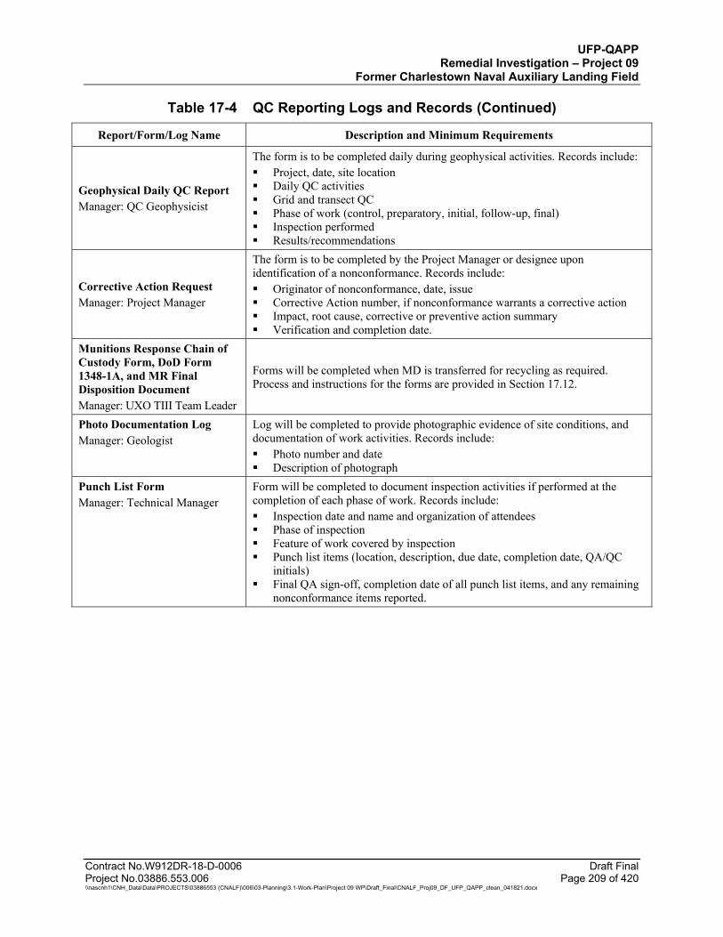
UFP-QAPP Remedial Investigation – Project 09
Former Charlestown Naval Auxiliary Landing Field
Table 17-4 QC Reporting Logs and Records (Continued)
Contract No.W912DR-18-D-0006 Draft Final Project No.03886.553.006 Page 209 of 420 \\nascnh1\CNH_Data\Data\PROJECTS\03886553 (CNALF)\006\03-Planning\3.1-Work-Plan\Project 09 WP\Draft_Final\CNALF_Proj09_DF_UFP_QAPP_clean_041821.docx
Report/Form/Log Name Description and Minimum Requirements
Geophysical Daily QC Report Manager: QC Geophysicist
The form is to be completed daily during geophysical activities. Records include: Project, date, site location Daily QC activities Grid and transect QC Phase of work (control, preparatory, initial, follow-up, final) Inspection performed Results/recommendations
Corrective Action Request Manager: Project Manager
The form is to be completed by the Project Manager or designee upon identification of a nonconformance. Records include: Originator of nonconformance, date, issue Corrective Action number, if nonconformance warrants a corrective action Impact, root cause, corrective or preventive action summary Verification and completion date.
Munitions Response Chain of Custody Form, DoD Form 1348-1A, and MR Final Disposition Document Manager: UXO TIII Team Leader
Forms will be completed when MD is transferred for recycling as required. Process and instructions for the forms are provided in Section 17.12.
Photo Documentation Log Manager: Geologist
Log will be completed to provide photographic evidence of site conditions, and documentation of work activities. Records include: Photo number and date Description of photograph
Punch List Form Manager: Technical Manager
Form will be completed to document inspection activities if performed at the completion of each phase of work. Records include: Inspection date and name and organization of attendees Phase of inspection Feature of work covered by inspection Punch list items (location, description, due date, completion date, QA/QC
initials) Final QA sign-off, completion date of all punch list items, and any remaining
nonconformance items reported.
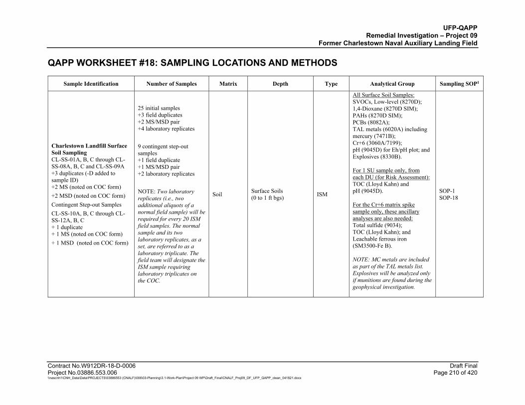
UFP-QAPP Remedial Investigation – Project 09
Former Charlestown Naval Auxiliary Landing Field
Contract No.W912DR-18-D-0006 Draft Final Project No.03886.553.006 Page 210 of 420 \\nascnh1\CNH_Data\Data\PROJECTS\03886553 (CNALF)\006\03-Planning\3.1-Work-Plan\Project 09 WP\Draft_Final\CNALF_Proj09_DF_UFP_QAPP_clean_041821.docx
QAPP WORKSHEET #18: SAMPLING LOCATIONS AND METHODS
Sample Identification Number of Samples Matrix Depth Type Analytical Group Sampling SOP1
Charlestown Landfill Surface Soil Sampling CL-SS-01A, B, C through CL-SS-08A, B, C and CL-SS-09A +3 duplicates (-D added to sample ID) +2 MS (noted on COC form) +2 MSD (noted on COC form) Contingent Step-out Samples CL-SS-10A, B, C through CL-SS-12A, B, C + 1 duplicate + 1 MS (noted on COC form) + 1 MSD (noted on COC form)
25 initial samples +3 field duplicates +2 MS/MSD pair +4 laboratory replicates 9 contingent step-out samples +1 field duplicate +1 MS/MSD pair +2 laboratory replicates NOTE: Two laboratory replicates (i.e., two additional aliquots of a normal field sample) will be required for every 20 ISM field samples. The normal sample and its two laboratory replicates, as a set, are referred to as a laboratory triplicate. The field team will designate the ISM sample requiring laboratory triplicates on the COC.
Soil Surface Soils (0 to 1 ft bgs) ISM
All Surface Soil Samples: SVOCs, Low-level (8270D); 1,4-Dioxane (8270D SIM); PAHs (8270D SIM); PCBs (8082A); TAL metals (6020A) including mercury (7471B); Cr+6 (3060A/7199); pH (9045D) for Eh/pH plot; and Explosives (8330B). For 1 SU sample only, from each DU (for Risk Assessment): TOC (Lloyd Kahn) and pH (9045D). For the Cr+6 matrix spike sample only, these ancillary analyses are also needed: Total sulfide (9034); TOC (Lloyd Kahn); and Leachable ferrous iron (SM3500-Fe B). NOTE: MC metals are included as part of the TAL metals list. Explosives will be analyzed only if munitions are found during the geophysical investigation.
SOP-1 SOP-18
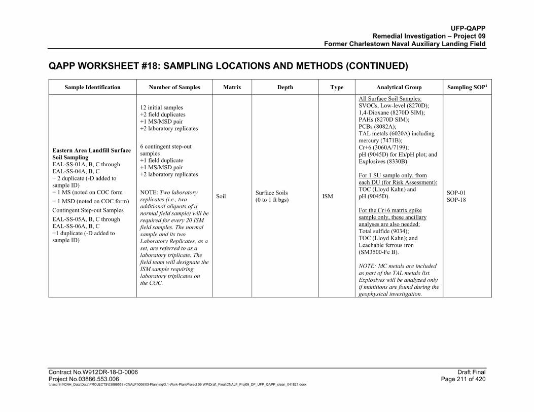
UFP-QAPP Remedial Investigation – Project 09
Former Charlestown Naval Auxiliary Landing Field QAPP WORKSHEET #18: SAMPLING LOCATIONS AND METHODS (CONTINUED)
Contract No.W912DR-18-D-0006 Draft Final Project No.03886.553.006 Page 211 of 420 \\nascnh1\CNH_Data\Data\PROJECTS\03886553 (CNALF)\006\03-Planning\3.1-Work-Plan\Project 09 WP\Draft_Final\CNALF_Proj09_DF_UFP_QAPP_clean_041821.docx
Sample Identification Number of Samples Matrix Depth Type Analytical Group Sampling SOP1
Eastern Area Landfill Surface Soil Sampling EAL-SS-01A, B, C through EAL-SS-04A, B, C + 2 duplicate (-D added to sample ID) + 1 MS (noted on COC form + 1 MSD (noted on COC form) Contingent Step-out Samples EAL-SS-05A, B, C through EAL-SS-06A, B, C +1 duplicate (-D added to sample ID)
12 initial samples +2 field duplicates +1 MS/MSD pair +2 laboratory replicates 6 contingent step-out samples +1 field duplicate +1 MS/MSD pair +2 laboratory replicates NOTE: Two laboratory replicates (i.e., two additional aliquots of a normal field sample) will be required for every 20 ISM field samples. The normal sample and its two Laboratory Replicates, as a set, are referred to as a laboratory triplicate. The field team will designate the ISM sample requiring laboratory triplicates on the COC.
Soil Surface Soils (0 to 1 ft bgs) ISM
All Surface Soil Samples: SVOCs, Low-level (8270D); 1,4-Dioxane (8270D SIM); PAHs (8270D SIM); PCBs (8082A); TAL metals (6020A) including mercury (7471B); Cr+6 (3060A/7199); pH (9045D) for Eh/pH plot; and Explosives (8330B). For 1 SU sample only, from each DU (for Risk Assessment): TOC (Lloyd Kahn) and pH (9045D). For the Cr+6 matrix spike sample only, these ancillary analyses are also needed: Total sulfide (9034); TOC (Lloyd Kahn); and Leachable ferrous iron (SM3500-Fe B). NOTE: MC metals are included as part of the TAL metals list. Explosives will be analyzed only if munitions are found during the geophysical investigation.
SOP-01 SOP-18
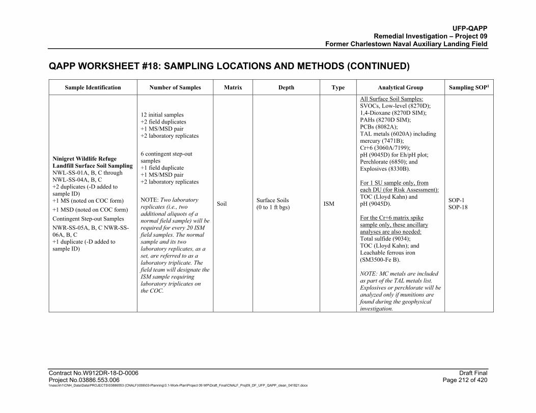
UFP-QAPP Remedial Investigation – Project 09
Former Charlestown Naval Auxiliary Landing Field QAPP WORKSHEET #18: SAMPLING LOCATIONS AND METHODS (CONTINUED)
Contract No.W912DR-18-D-0006 Draft Final Project No.03886.553.006 Page 212 of 420 \\nascnh1\CNH_Data\Data\PROJECTS\03886553 (CNALF)\006\03-Planning\3.1-Work-Plan\Project 09 WP\Draft_Final\CNALF_Proj09_DF_UFP_QAPP_clean_041821.docx
Sample Identification Number of Samples Matrix Depth Type Analytical Group Sampling SOP1
Ninigret Wildlife Refuge Landfill Surface Soil Sampling NWL-SS-01A, B, C through NWL-SS-04A, B, C +2 duplicates (-D added to sample ID) +1 MS (noted on COC form) +1 MSD (noted on COC form) Contingent Step-out Samples NWR-SS-05A, B, C NWR-SS-06A, B, C +1 duplicate (-D added to sample ID)
12 initial samples +2 field duplicates +1 MS/MSD pair +2 laboratory replicates 6 contingent step-out samples +1 field duplicate +1 MS/MSD pair +2 laboratory replicates NOTE: Two laboratory replicates (i.e., two additional aliquots of a normal field sample) will be required for every 20 ISM field samples. The normal sample and its two laboratory replicates, as a set, are referred to as a laboratory triplicate. The field team will designate the ISM sample requiring laboratory triplicates on the COC.
Soil Surface Soils (0 to 1 ft bgs) ISM
All Surface Soil Samples: SVOCs, Low-level (8270D); 1,4-Dioxane (8270D SIM); PAHs (8270D SIM); PCBs (8082A); TAL metals (6020A) including mercury (7471B); Cr+6 (3060A/7199); pH (9045D) for Eh/pH plot; Perchlorate (6850); and Explosives (8330B). For 1 SU sample only, from each DU (for Risk Assessment): TOC (Lloyd Kahn) and pH (9045D). For the Cr+6 matrix spike sample only, these ancillary analyses are also needed: Total sulfide (9034); TOC (Lloyd Kahn); and Leachable ferrous iron (SM3500-Fe B). NOTE: MC metals are included as part of the TAL metals list. Explosives or perchlorate will be analyzed only if munitions are found during the geophysical investigation.
SOP-1 SOP-18
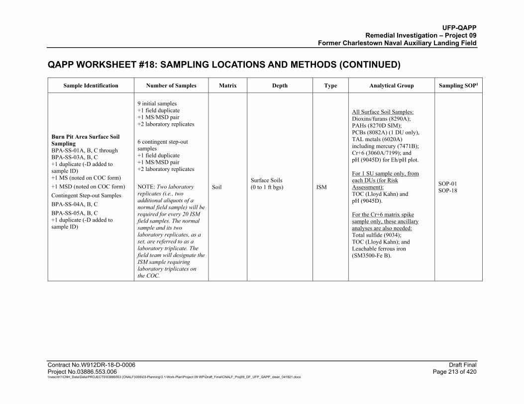
UFP-QAPP Remedial Investigation – Project 09
Former Charlestown Naval Auxiliary Landing Field QAPP WORKSHEET #18: SAMPLING LOCATIONS AND METHODS (CONTINUED)
Contract No.W912DR-18-D-0006 Draft Final Project No.03886.553.006 Page 213 of 420 \\nascnh1\CNH_Data\Data\PROJECTS\03886553 (CNALF)\006\03-Planning\3.1-Work-Plan\Project 09 WP\Draft_Final\CNALF_Proj09_DF_UFP_QAPP_clean_041821.docx
Sample Identification Number of Samples Matrix Depth Type Analytical Group Sampling SOP1
Burn Pit Area Surface Soil Sampling BPA-SS-01A, B, C through BPA-SS-03A, B, C +1 duplicate (-D added to sample ID) +1 MS (noted on COC form) +1 MSD (noted on COC form) Contingent Step-out Samples BPA-SS-04A, B, C BPA-SS-05A, B, C +1 duplicate (-D added to sample ID)
9 initial samples +1 field duplicate +1 MS/MSD pair +2 laboratory replicates 6 contingent step-out samples +1 field duplicate +1 MS/MSD pair +2 laboratory replicates NOTE: Two laboratory replicates (i.e., two additional aliquots of a normal field sample) will be required for every 20 ISM field samples. The normal sample and its two laboratory replicates, as a set, are referred to as a laboratory triplicate. The field team will designate the ISM sample requiring laboratory triplicates on the COC.
Soil Surface Soils (0 to 1 ft bgs)
ISM
All Surface Soil Samples: Dioxins/furans (8290A); PAHs (8270D SIM); PCBs (8082A) (1 DU only), TAL metals (6020A) including mercury (7471B); Cr+6 (3060A/7199); and pH (9045D) for Eh/pH plot. For 1 SU sample only, from each DUs (for Risk Assessment): TOC (Lloyd Kahn) and pH (9045D). For the Cr+6 matrix spike sample only, these ancillary analyses are also needed: Total sulfide (9034); TOC (Lloyd Kahn); and Leachable ferrous iron (SM3500-Fe B).
SOP-01 SOP-18
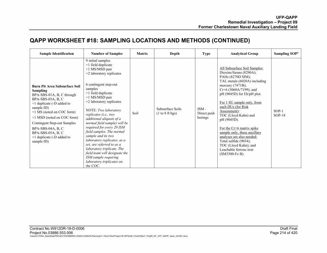
UFP-QAPP Remedial Investigation – Project 09
Former Charlestown Naval Auxiliary Landing Field QAPP WORKSHEET #18: SAMPLING LOCATIONS AND METHODS (CONTINUED)
Contract No.W912DR-18-D-0006 Draft Final Project No.03886.553.006 Page 214 of 420 \\nascnh1\CNH_Data\Data\PROJECTS\03886553 (CNALF)\006\03-Planning\3.1-Work-Plan\Project 09 WP\Draft_Final\CNALF_Proj09_DF_UFP_QAPP_clean_041821.docx
Sample Identification Number of Samples Matrix Depth Type Analytical Group Sampling SOP1
Burn Pit Area Subsurface Soil Sampling BPA-SBS-01A, B, C through BPA-SBS-03A, B, C +1 duplicate (-D added to sample ID) +1 MS (noted on COC form) +1 MSD (noted on COC form) Contingent Step-out Samples BPA-SBS-04A, B, C BPA-SBS-05A, B, C +1 duplicate (-D added to sample ID)
9 initial samples +1 field duplicate +1 MS/MSD pair +2 laboratory replicates 6 contingent step-out samples +1 field duplicate +1 MS/MSD pair +2 laboratory replicates NOTE: Two laboratory replicates (i.e., two additional aliquots of a normal field sample) will be required for every 20 ISM field samples. The normal sample and its two laboratory replicates, as a set, are referred to as a laboratory triplicate. The field team will designate the ISM sample requiring laboratory triplicates on the COC.
Soil Subsurface Soils (1 to 8 ft bgs)
ISM -Direct push borings
All Subsurface Soil Samples: Dioxins/furans (8290A); PAHs (8270D SIM); TAL metals (6020A) including mercury (7471B); Cr+6 (3060A/7199); and pH (9045D) for Eh/pH plot. For 1 SU sample only, from each DUs (for Risk Assessment): TOC (Lloyd Kahn) and pH (9045D). For the Cr+6 matrix spike sample only, these ancillary analyses are also needed: Total sulfide (9034); TOC (Lloyd Kahn); and Leachable ferrous iron (SM3500-Fe B).
SOP-1 SOP-18

UFP-QAPP Remedial Investigation – Project 09
Former Charlestown Naval Auxiliary Landing Field QAPP WORKSHEET #18: SAMPLING LOCATIONS AND METHODS (CONTINUED)
Contract No.W912DR-18-D-0006 Draft Final Project No.03886.553.006 Page 215 of 420 \\nascnh1\CNH_Data\Data\PROJECTS\03886553 (CNALF)\006\03-Planning\3.1-Work-Plan\Project 09 WP\Draft_Final\CNALF_Proj09_DF_UFP_QAPP_clean_041821.docx
Sample Identification Number of Samples Matrix Depth Type Analytical Group Sampling SOP1
Background Surface Soil Sampling BG9-SS-01 through BG9-SS-08 +1 duplicate (-D added to sample ID) +1 MS (noted on COC form) +1 MSD (noted on COC form)
8 initial samples +1 field duplicate +1 MS/MSD pair +2 laboratory replicates NOTE: Two laboratory replicates (i.e., two additional aliquots of a normal field sample) will be required for every 20 ISM field samples. The normal sample and its two laboratory replicates, as a set, are referred to as a laboratory triplicate. The field team will designate the ISM sample requiring laboratory triplicates on the COC.
Soil Surface Soils (0 to 1 ft bgs) ISM
All Surface Soil Samples: PAHs (8270D SIM) and TAL metals (6020A) including mercury (7471B); Cr+6, (3060A/7199); and pH (9045D) for Eh/pH plot. For 3 SU samples only (for Risk Assessment): TOC (Lloyd Kahn) and pH (9045B). For the Cr+6 matrix spike sample only, these ancillary analyses are also needed: Total sulfide (9034); TOC (Lloyd Kahn); and Leachable ferrous iron (SM3500-Fe B). NOTE: MC metals are included as part of the TAL metals list.
SOP-01 SOP-18
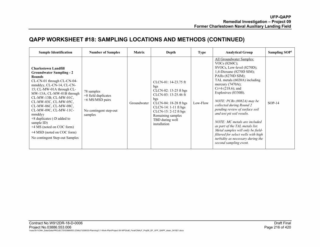
UFP-QAPP Remedial Investigation – Project 09
Former Charlestown Naval Auxiliary Landing Field QAPP WORKSHEET #18: SAMPLING LOCATIONS AND METHODS (CONTINUED)
Contract No.W912DR-18-D-0006 Draft Final Project No.03886.553.006 Page 216 of 420 \\nascnh1\CNH_Data\Data\PROJECTS\03886553 (CNALF)\006\03-Planning\3.1-Work-Plan\Project 09 WP\Draft_Final\CNALF_Proj09_DF_UFP_QAPP_clean_041821.docx
Sample Identification Number of Samples Matrix Depth Type Analytical Group Sampling SOP1
Charlestown Landfill Groundwater Sampling - 2 Rounds CL-CN-01 through CL-CN-04-mmddyy, CL-CN-14, CL-CN-15; CL-MW-01A through CL-MW-13A; CL-MW-01B through CL-MW-13B; CL-MW-01C, CL-MW-03C, CL-MW-05C, CL-MW-06C, CL-MW-08C, CL-MW-09C, CL-MW-11C-mmddyy +8 duplicates (-D added to sample ID) +4 MS (noted on COC form) +4 MSD (noted on COC form) No contingent Step-out Samples
78 samples +8 field duplicates +6 MS/MSD pairs No contingent step-out samples
Groundwater
CLCN-01: 14-23.75 ft bgs CLCN-02: 13-25 ft bgs CLCN-03: 13-25.46 ft bgs CLCN-04: 18-28 ft bgs CLCN-14: 1-11 ft bgs CLCN-15: 2-12 ft bgs Remaining samples TBD during well installation
Low-Flow
All Groundwater Samples: VOCs (8260C); SVOCs, Low-level (8270D); 1,4-Dioxane (8270D SIM); PAHs (8270D SIM); TAL metals (6020A) including mercury (7470A); Cr+6 (218.6); and Explosives (8330B). NOTE: PCBs (8082A) may be collected during Round 2 pending review of surface soil and test pit soil results. NOTE: MC metals are included as part of the TAL metals list. Metal samples will only be field-filtered for select wells with high turbidity as necessary during the second sampling event.
SOP-14

UFP-QAPP Remedial Investigation – Project 09
Former Charlestown Naval Auxiliary Landing Field QAPP WORKSHEET #18: SAMPLING LOCATIONS AND METHODS (CONTINUED)
Contract No.W912DR-18-D-0006 Draft Final Project No.03886.553.006 Page 217 of 420 \\nascnh1\CNH_Data\Data\PROJECTS\03886553 (CNALF)\006\03-Planning\3.1-Work-Plan\Project 09 WP\Draft_Final\CNALF_Proj09_DF_UFP_QAPP_clean_041821.docx
Sample Identification Number of Samples Matrix Depth Type Analytical Group Sampling SOP1
Eastern Area Landfill Groundwater Sampling - 2 Rounds EAL-CN-06 through EAL-CN-08, EAL-CN-16, EAL-LF201, EAL-MW-01A through EAL-MW-11A, EAL-MW-01B through EAL-MW-11B, EAL-MW-01C, EAL-CN-04C, EAL-MW-05C, EAL-MW-08C, EAL-MW-11C-mmddyy +8 duplicates (-D added to sample ID) +4 MS (noted on COC form) +4 MSD (noted on COC form) No Step-out Samples
72 samples +8 field duplicates +4 MS/MSD pairs No contingent step-out samples
Groundwater
EALCN-06: 10-20 ft bgs EALCN-07: 10-22 ft bgs EALCN-08 10-18.38 ft bgs EALCN-16: 4.5-14.5 ft bgs EALF201: 4-14 ft bgs Remaining samples TBD during well installation
Low-Flow
All Groundwater Samples: VOCs (8260C); SVOCs, Low-level (8270D); 1,4-Dioxane (8270D-SIM); PAHs (8270D SIM); TAL metals (6020A) including mercury (7470A); Cr+6, (218.6), and Explosives (8330B). NOTE: PCBs (8082A) may be collected during Round 2 pending review of surface soil and test pit soil results. NOTE: MC metals are included as part of the TAL metals list. Metal samples will only be field-filtered for select wells with high turbidity as necessary during the second sampling event.
SOP-14
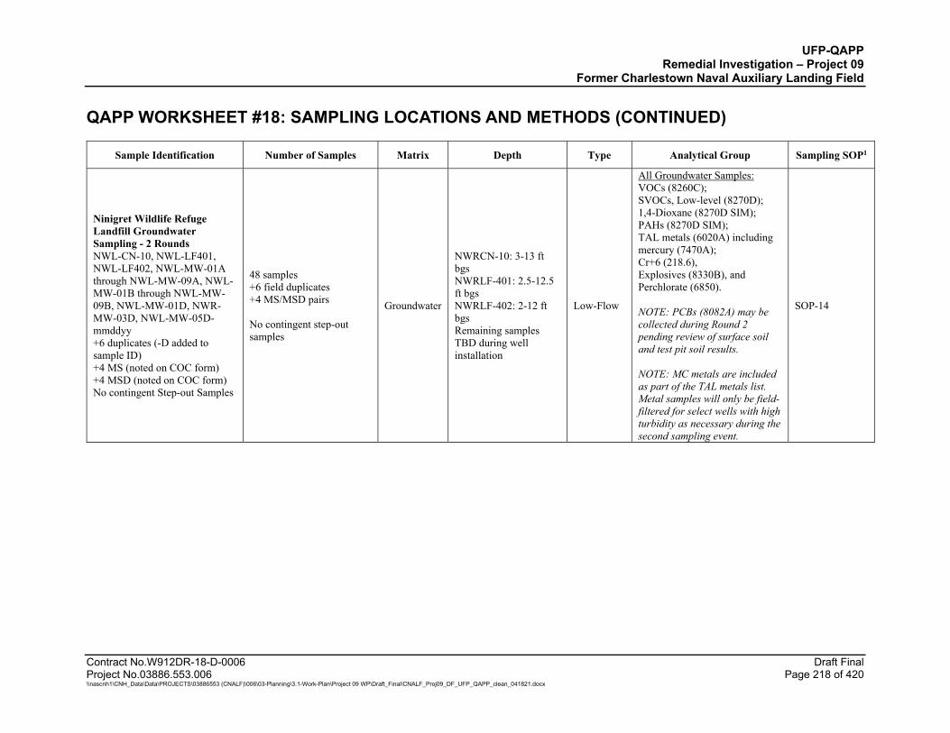
UFP-QAPP Remedial Investigation – Project 09
Former Charlestown Naval Auxiliary Landing Field QAPP WORKSHEET #18: SAMPLING LOCATIONS AND METHODS (CONTINUED)
Contract No.W912DR-18-D-0006 Draft Final Project No.03886.553.006 Page 218 of 420 \\nascnh1\CNH_Data\Data\PROJECTS\03886553 (CNALF)\006\03-Planning\3.1-Work-Plan\Project 09 WP\Draft_Final\CNALF_Proj09_DF_UFP_QAPP_clean_041821.docx
Sample Identification Number of Samples Matrix Depth Type Analytical Group Sampling SOP1
Ninigret Wildlife Refuge Landfill Groundwater Sampling - 2 Rounds NWL-CN-10, NWL-LF401, NWL-LF402, NWL-MW-01A through NWL-MW-09A, NWL-MW-01B through NWL-MW-09B, NWL-MW-01D, NWR-MW-03D, NWL-MW-05D-mmddyy +6 duplicates (-D added to sample ID) +4 MS (noted on COC form) +4 MSD (noted on COC form) No contingent Step-out Samples
48 samples +6 field duplicates +4 MS/MSD pairs No contingent step-out samples
Groundwater
NWRCN-10: 3-13 ft bgs NWRLF-401: 2.5-12.5 ft bgs NWRLF-402: 2-12 ft bgs Remaining samples TBD during well installation
Low-Flow
All Groundwater Samples: VOCs (8260C); SVOCs, Low-level (8270D); 1,4-Dioxane (8270D SIM); PAHs (8270D SIM); TAL metals (6020A) including mercury (7470A); Cr+6 (218.6), Explosives (8330B), and Perchlorate (6850). NOTE: PCBs (8082A) may be collected during Round 2 pending review of surface soil and test pit soil results. NOTE: MC metals are included as part of the TAL metals list. Metal samples will only be field-filtered for select wells with high turbidity as necessary during the second sampling event.
SOP-14
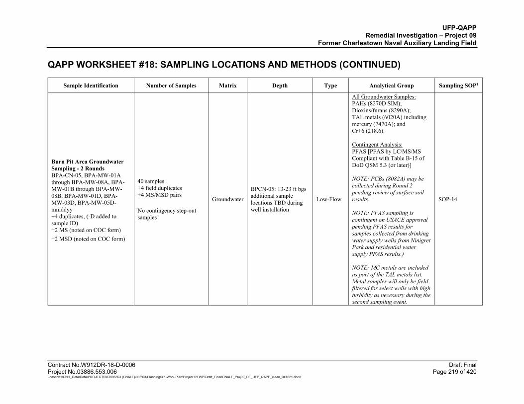
UFP-QAPP Remedial Investigation – Project 09
Former Charlestown Naval Auxiliary Landing Field QAPP WORKSHEET #18: SAMPLING LOCATIONS AND METHODS (CONTINUED)
Contract No.W912DR-18-D-0006 Draft Final Project No.03886.553.006 Page 219 of 420 \\nascnh1\CNH_Data\Data\PROJECTS\03886553 (CNALF)\006\03-Planning\3.1-Work-Plan\Project 09 WP\Draft_Final\CNALF_Proj09_DF_UFP_QAPP_clean_041821.docx
Sample Identification Number of Samples Matrix Depth Type Analytical Group Sampling SOP1
Burn Pit Area Groundwater Sampling - 2 Rounds BPA-CN-05, BPA-MW-01A through BPA-MW-08A, BPA-MW-01B through BPA-MW-08B, BPA-MW-01D, BPA-MW-03D, BPA-MW-05D-mmddyy +4 duplicates, (-D added to sample ID) +2 MS (noted on COC form) +2 MSD (noted on COC form)
40 samples +4 field duplicates +4 MS/MSD pairs No contingency step-out samples
Groundwater
BPCN-05: 13-23 ft bgs additional sample locations TBD during well installation
Low-Flow
All Groundwater Samples: PAHs (8270D SIM); Dioxins/furans (8290A); TAL metals (6020A) including mercury (7470A); and Cr+6 (218.6). Contingent Analysis: PFAS [PFAS by LC/MS/MS Compliant with Table B-15 of DoD QSM 5.3 (or later)] NOTE: PCBs (8082A) may be collected during Round 2 pending review of surface soil results. NOTE: PFAS sampling is contingent on USACE approval pending PFAS results for samples collected from drinking water supply wells from Ninigret Park and residential water supply PFAS results.) NOTE: MC metals are included as part of the TAL metals list. Metal samples will only be field-filtered for select wells with high turbidity as necessary during the second sampling event.
SOP-14
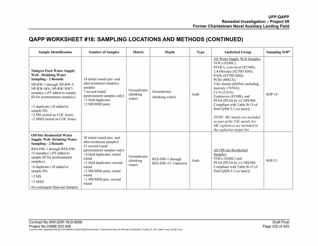
UFP-QAPP Remedial Investigation – Project 09
Former Charlestown Naval Auxiliary Landing Field QAPP WORKSHEET #18: SAMPLING LOCATIONS AND METHODS (CONTINUED)
Contract No.W912DR-18-D-0006 Draft Final Project No.03886.553.006 Page 220 of 420 \\nascnh1\CNH_Data\Data\PROJECTS\03886553 (CNALF)\006\03-Planning\3.1-Work-Plan\Project 09 WP\Draft_Final\CNALF_Proj09_DF_UFP_QAPP_clean_041821.docx
Sample Identification Number of Samples Matrix Depth Type Analytical Group Sampling SOP1
Ninigret Park Water Supply Well - Drinking Water Sampling - 2 Rounds NP-RW-1 through NP-RW-5, NP-RW-SF6, NP-RW-NW7-mmddyy (-PT added to sample ID for posttreatment samples;) +3 duplicate (-D added to sample ID) +2 MS (noted on COC form) +2 MSD (noted on COC form)
14 initial round (pre- and after-treatment samples) samples 7 second round (pretreatment samples only) +3 field duplicates +2 MS/MSD pairs
Groundwater (drinking water)
Groundwater (drinking water)
Grab
All Water Supply Well Samples: VOCs (8260C); SVOCs, Low-level (8270D); 1,4-Dioxane (8270D SIM); PAHs (8270D SIM); PCBs (8082A); TAL metals (6020A) including mercury (7470A); Cr+6 (218.6); Explosives (8330B), and PFAS [PFAS by LC/MS/MS Compliant with Table B-15 of DoD QSM 5.3 (or later)]. NOTE: MC metals are included as part of the TAL metals list. MC explosives are included in the explosives target list.
SOP-14
Off-Site Residential Water Supply Well -Drinking Water Sampling - 2 Rounds RES-DW-1 through RES-DW-15-mmddyy (-PT added to sample ID for posttreatment samples;) +6 duplicate (-D added to sample ID) +3 MS +3 MSD No contingent Step-out Samples
30 initial round (pre- and after-treatment samples) 15 second round (pretreatment samples only) +4 field duplicates, initial round +2 field duplicates, second round +2 MS/MSD pairs, initial round +1 MS/MSD pair, second round
Groundwater (drinking water)
RES-DW-1 through RES-DW-15: Unknown
Grab
All Off-site Residential Samples: VOCs (8260C) and PFAS [PFAS by LC/MS/MS Compliant with Table B-15 of DoD QSM 5.3 (or later)].
SOP-21

UFP-QAPP Remedial Investigation – Project 09
Former Charlestown Naval Auxiliary Landing Field QAPP WORKSHEET #18: SAMPLING LOCATIONS AND METHODS (CONTINUED)
Contract No.W912DR-18-D-0006 Draft Final Project No.03886.553.006 Page 221 of 420 \\nascnh1\CNH_Data\Data\PROJECTS\03886553 (CNALF)\006\03-Planning\3.1-Work-Plan\Project 09 WP\Draft_Final\CNALF_Proj09_DF_UFP_QAPP_clean_041821.docx
Sample Identification Number of Samples Matrix Depth Type Analytical Group Sampling SOP1
Charlestown Landfill Freshwater Wetland & Tidal Wetland & Tidal Shoreline Sediment Sampling CL-FWSD-01A, B, C, CL-TWSD-01A, B, C CL-TSLSD-01A, B, C +1 duplicate (-D added to sample ID) +1 MS (noted on COC form) +1 MSD (noted on COC form) Contingent Step-out Samples CL-FWSD-02A, B, C through CL-FWSD-03A, B, C +1 duplicate (-D added to sample ID)
9 initial samples +1 field duplicate +1 MS/MSD pair +2 laboratory replicates 6 step-out samples +1 field duplicate +1 MS/MSD pair +2 laboratory replicates NOTE: Two laboratory replicates (i.e., two additional aliquots of a normal field sample) will be required for every 20 ISM field samples. The normal sample and its two laboratory replicates, as a set, are referred to as a laboratory triplicate. The field team will designate the ISM sample requiring laboratory triplicates on the COC.
Freshwater Wetland and Tidal Shoreline Sediment
0 to 0.5 ft below sediment surface
ISM, VOCs-Discrete
All Sediment Samples: VOCs (8260C); SVOCs, Low-level (8270D); 1,4-Dioxane (8270D SIM); PAHs (8270D SIM); TAL metals (6020A) including mercury (7471B); Cr+6 (3060A/7199); pH (9045D) for Eh/pH plot; Explosives (8330B). For Risk Assessment, 1 sample each sediment DU (3 total): TOC (Lloyd Kahn) For the Cr+6 matrix spike sample only, these ancillary analyses are also needed: Total sulfide (9034); TOC (Lloyd Kahn); and Leachable ferrous iron (SM3500-Fe B). NOTE: MC metals are included as part of the TAL metals list. MC explosives are included in the explosives target list. Explosives will be analyzed only if munitions are found during the geophysical investigation, test pit excavation or detected in landfill soil samples.
SOP-17 SOP-18
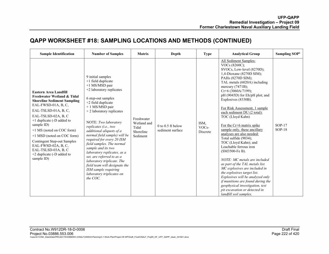
UFP-QAPP Remedial Investigation – Project 09
Former Charlestown Naval Auxiliary Landing Field QAPP WORKSHEET #18: SAMPLING LOCATIONS AND METHODS (CONTINUED)
Contract No.W912DR-18-D-0006 Draft Final Project No.03886.553.006 Page 222 of 420 \\nascnh1\CNH_Data\Data\PROJECTS\03886553 (CNALF)\006\03-Planning\3.1-Work-Plan\Project 09 WP\Draft_Final\CNALF_Proj09_DF_UFP_QAPP_clean_041821.docx
Sample Identification Number of Samples Matrix Depth Type Analytical Group Sampling SOP1
Eastern Area Landfill Freshwater Wetland & Tidal Shoreline Sediment Sampling EAL-FWSD-01A, B, C, EAL-TSLSD-01A, B, C, EAL-TSLSD-02A, B, C +1 duplicate (-D added to sample ID) +1 MS (noted on COC form) +1 MSD (noted on COC form) Contingent Step-out Samples EAL-FWSD-02A, B, C, EAL-TSLSD-03A, B, C +2 duplicate (-D added to sample ID)
9 initial samples +1 field duplicate +1 MS/MSD pair +2 laboratory replicates 6 step-out samples +2 field duplicate + 1 MS/MSD pair + 2 laboratory replicates NOTE: Two laboratory replicates (i.e., two additional aliquots of a normal field sample) will be required for every 20 ISM field samples. The normal sample and its two laboratory replicates, as a set, are referred to as a laboratory triplicate. The field team will designate the ISM sample requiring laboratory triplicates on the COC.
Freshwater Wetland and Tidal Shoreline Sediment
0 to 0.5 ft below sediment surface
ISM, VOCs-Discrete
All Sediment Samples: VOCs (8260C); SVOCs, Low-level (8270D); 1,4-Dioxane (8270D SIM); PAHs (8270D SIM); TAL metals (6020A) including mercury (7471B); Cr+6 (3060A/7199); pH (9045D) for Eh/pH plot; and Explosives (8330B). For Risk Assessment, 1 sample each sediment DU (2 total): TOC (Lloyd Kahn) For the Cr+6 matrix spike sample only, these ancillary analyses are also needed: Total sulfide (9034); TOC (Lloyd Kahn); and Leachable ferrous iron (SM3500-Fe B). NOTE: MC metals are included as part of the TAL metals list. MC explosives are included in the explosives target list. Explosives will be analyzed only if munitions are found during the geophysical investigation, test pit excavation or detected in landfill soil samples.
SOP-17 SOP-18
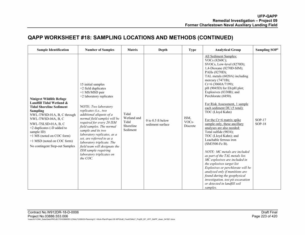
UFP-QAPP Remedial Investigation – Project 09
Former Charlestown Naval Auxiliary Landing Field QAPP WORKSHEET #18: SAMPLING LOCATIONS AND METHODS (CONTINUED)
Contract No.W912DR-18-D-0006 Draft Final Project No.03886.553.006 Page 223 of 420 \\nascnh1\CNH_Data\Data\PROJECTS\03886553 (CNALF)\006\03-Planning\3.1-Work-Plan\Project 09 WP\Draft_Final\CNALF_Proj09_DF_UFP_QAPP_clean_041821.docx
Sample Identification Number of Samples Matrix Depth Type Analytical Group Sampling SOP1
Ninigret Wildlife Refuge Landfill Tidal Wetland & Tidal Shoreline Sediment Sampling NWL-TWSD-01A, B, C through NWL-TWSD-04A, B, C NWL-TSLSD-01A, B, C +2 duplicates (-D added to sample ID) +1 MS (noted on COC form) +1 MSD (noted on COC form) No contingent Step-out Samples
15 initial samples +2 field duplicates +1 MS/MSD pair +2 laboratory replicates NOTE: Two laboratory replicates (i.e., two additional aliquots of a normal field sample) will be required for every 20 ISM field samples. The normal sample and its two laboratory replicates, as a set, are referred to as a laboratory triplicate. The field team will designate the ISM sample requiring laboratory triplicates on the COC.
Tidal Wetland and Tidal Shoreline Sediment
0 to 0.5 ft below sediment surface
ISM, VOCs-Discrete
All Sediment Samples: VOCs (8260C); SVOCs, Low-level (8270D); 1,4-Dioxane (8270D-SIM); PAHs (8270D); TAL metals (6020A) including mercury (7471B); Cr+6 (3060A/7199); pH (9045D) for Eh/pH plot; Explosives (8330B); and Perchlorate (6850). For Risk Assessment, 1 sample each sediment DU (5 total): TOC (Lloyd Kahn) For the Cr+6 matrix spike sample only, these ancillary analyses are also needed: Total sulfide (9034); TOC (Lloyd Kahn); and Leachable ferrous iron (SM3500-Fe B). NOTE: MC metals are included as part of the TAL metals list. MC explosives are included in the explosives target list Explosives or perchlorate will be analyzed only if munitions are found during the geophysical investigation, test pit excavation or detected in landfill soil samples.
SOP-17 SOP-18
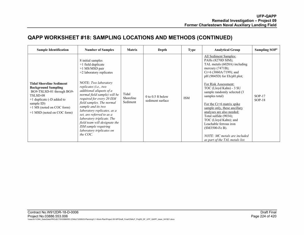
UFP-QAPP Remedial Investigation – Project 09
Former Charlestown Naval Auxiliary Landing Field QAPP WORKSHEET #18: SAMPLING LOCATIONS AND METHODS (CONTINUED)
Contract No.W912DR-18-D-0006 Draft Final Project No.03886.553.006 Page 224 of 420 \\nascnh1\CNH_Data\Data\PROJECTS\03886553 (CNALF)\006\03-Planning\3.1-Work-Plan\Project 09 WP\Draft_Final\CNALF_Proj09_DF_UFP_QAPP_clean_041821.docx
Sample Identification Number of Samples Matrix Depth Type Analytical Group Sampling SOP1
Tidal Shoreline Sediment Background Sampling BG9-TSLSD-01 through BG9-TSLSD-08 +1 duplicate (-D added to sample ID) +1 MS (noted on COC form) +1 MSD (noted on COC form)
8 initial samples +1 field duplicate +1 MS/MSD pair +2 laboratory replicates NOTE: Two laboratory replicates (i.e., two additional aliquots of a normal field sample) will be required for every 20 ISM field samples. The normal sample and its two laboratory replicates, as a set, are referred to as a laboratory triplicate. The field team will designate the ISM sample requiring laboratory triplicates on the COC.
Tidal Shoreline Sediment
0 to 0.5 ft below sediment surface
ISM
All Sediment Samples: PAHs (8270D SIM); TAL metals (6020A) including mercury (7471B); Cr+6 (3060A/7199); and pH (9045D) for Eh/pH plot; For Risk Assessment: TOC (Lloyd Kahn) - 3 SU sample randomly selected (3 samples total) For the Cr+6 matrix spike sample only, these ancillary analyses are also needed: Total sulfide (9034); TOC (Lloyd Kahn); and Leachable ferrous iron (SM3500-Fe B). NOTE: MC metals are included as part of the TAL metals list.
SOP-17 SOP-18

UFP-QAPP Remedial Investigation – Project 09
Former Charlestown Naval Auxiliary Landing Field QAPP WORKSHEET #18: SAMPLING LOCATIONS AND METHODS (CONTINUED)
Contract No.W912DR-18-D-0006 Draft Final Project No.03886.553.006 Page 225 of 420 \\nascnh1\CNH_Data\Data\PROJECTS\03886553 (CNALF)\006\03-Planning\3.1-Work-Plan\Project 09 WP\Draft_Final\CNALF_Proj09_DF_UFP_QAPP_clean_041821.docx
Sample Identification Number of Samples Matrix Depth Type Analytical Group Sampling SOP1
Tidal Wetland Sediment Background Sampling BG9-TWSD-01 through BG9-TWSD-08 +1 Duplicate (-D added to sample ID) +1 MS (noted on COC form) +1 MSD (noted on COC form)
8 initial samples +1 field duplicate +1 MS/MSD pair +2 laboratory replicates NOTE: Two laboratory replicates (i.e., two additional aliquots of a normal field sample) will be required for every 20 ISM field samples. The normal sample and its two laboratory replicates, as a set, are referred to as a laboratory triplicate. The field team will designate the ISM sample requiring laboratory triplicates on the COC.
Tidal Wetland Sediment
0 to 0.5 ft below sediment surface
ISM
All Sediment Samples: PAHs (8270D SIM); TAL metals (6020A) including mercury (7471B); Cr+6 (3060A/7199); and pH (9045D) for Eh/pH plot; For Risk Assessment: TOC (Lloyd Kahn) - 3 SU sample randomly selected (3 total) For the Cr+6 matrix spike sample only, these ancillary analyses are also needed: Total sulfide (9034); TOC (Lloyd Kahn); and Leachable ferrous iron (SM3500-Fe B). NOTE: MC metals are included as part of the TAL metals list.
SOP-17 SOP-18
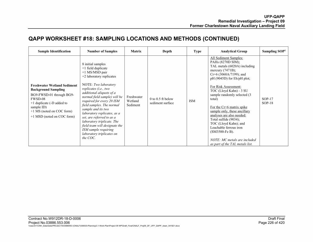
UFP-QAPP Remedial Investigation – Project 09
Former Charlestown Naval Auxiliary Landing Field QAPP WORKSHEET #18: SAMPLING LOCATIONS AND METHODS (CONTINUED)
Contract No.W912DR-18-D-0006 Draft Final Project No.03886.553.006 Page 226 of 420 \\nascnh1\CNH_Data\Data\PROJECTS\03886553 (CNALF)\006\03-Planning\3.1-Work-Plan\Project 09 WP\Draft_Final\CNALF_Proj09_DF_UFP_QAPP_clean_041821.docx
Sample Identification Number of Samples Matrix Depth Type Analytical Group Sampling SOP1
Freshwater Wetland Sediment Background Sampling BG9-FWSD-01 through BG9-FWSD-08 +1 duplicate (-D added to sample ID) +1 MS (noted on COC form) +1 MSD (noted on COC form)
8 initial samples +1 field duplicate +1 MS/MSD pair +2 laboratory replicates NOTE: Two laboratory replicates (i.e., two additional aliquots of a normal field sample) will be required for every 20 ISM field samples. The normal sample and its two laboratory replicates, as a set, are referred to as a laboratory triplicate. The field team will designate the ISM sample requiring laboratory triplicates on the COC.
Freshwater Wetland Sediment
0 to 0.5 ft below sediment surface ISM
All Sediment Samples: PAHs (8270D SIM); TAL metals (6020A) including mercury (7471B); Cr+6 (3060A/7199); and pH (9045D) for Eh/pH plot; For Risk Assessment: TOC (Lloyd Kahn) - 3 SU sample randomly selected (3 total) For the Cr+6 matrix spike sample only, these ancillary analyses are also needed: Total sulfide (9034); TOC (Lloyd Kahn); and Leachable ferrous iron (SM3500-Fe B). NOTE: MC metals are included as part of the TAL metals list.
SOP-17 SOP-18
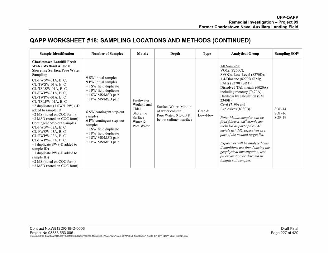
UFP-QAPP Remedial Investigation – Project 09
Former Charlestown Naval Auxiliary Landing Field QAPP WORKSHEET #18: SAMPLING LOCATIONS AND METHODS (CONTINUED)
Contract No.W912DR-18-D-0006 Draft Final Project No.03886.553.006 Page 227 of 420 \\nascnh1\CNH_Data\Data\PROJECTS\03886553 (CNALF)\006\03-Planning\3.1-Work-Plan\Project 09 WP\Draft_Final\CNALF_Proj09_DF_UFP_QAPP_clean_041821.docx
Sample Identification Number of Samples Matrix Depth Type Analytical Group Sampling SOP1
Charlestown Landfill Fresh Water Wetland & Tidal Shoreline Surface/Pore Water Sampling CL-FWSW-01A, B, C, CL-TWSW-01A, B, C CL-TSLSW-01A, B, C, CL-FWPW-01A, B, C, CL-TWPW-01A, B, C CL-TSLPW-01A, B. C +2 duplicates (1 SW/1 PW) (-D added to sample ID) +2 MS (noted on COC form) +2 MSD (noted on COC form) Contingent Step-out Samples CL-FWSW-02A, B, C CL-FWSW-03A, B, C CL-FWPW-02A, B, C CL-FWPW-03A, B, C +1 duplicate SW (-D added to sample ID) +1 duplicate PW (-D added to sample ID) +2 MS (noted on COC form) +2 MSD (noted on COC form)
9 SW initial samples 9 PW initial samples +1 SW field duplicate +1 PW field duplicate +1 SW MS/MSD pair +1 PW MS/MSD pair 6 SW contingent step-out samples 6 PW contingent step-out samples +1 SW field duplicate +1 PW field duplicate +1 SW MS/MSD pair +1 PW MS/MSD pair
Freshwater Wetland and Tidal Shoreline Surface Water & Pore Water
Surface Water: Middle of water column Pore Water: 0 to 0.5 ft below sediment surface
Grab & Low-Flow
All Samples: VOCs (8260C); SVOCs, Low-Level (8270D); 1,4-Dioxane (8270D SIM); PAHs (8270D SIM); Dissolved TAL metals (6020A) including mercury (7470A); Hardness by calculation (SM 2340B); Cr+6 (7199) and Explosives (8330B). Note: Metals samples will be field-filtered. MC metals are included as part of the TAL metals list. MC explosives are part of the method target list. Explosives will be analyzed only if munitions are found during the geophysical investigation, test pit excavation or detected in landfill soil samples.
SOP-14 SOP-16 SOP-19
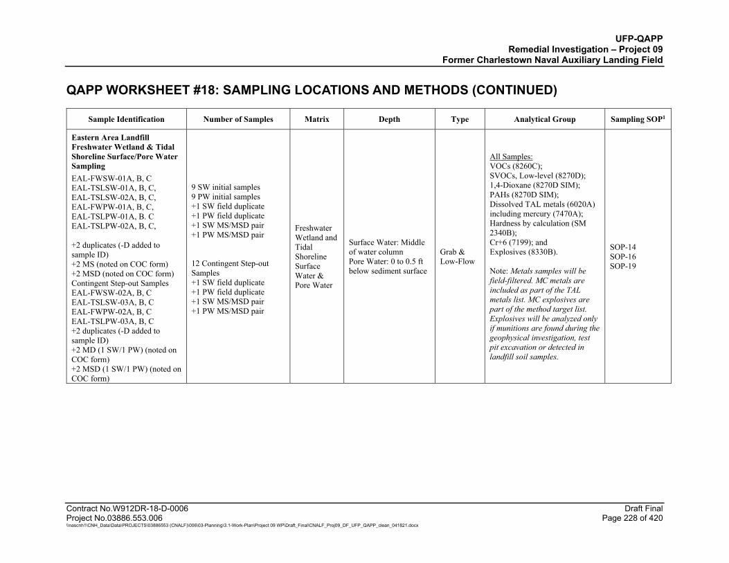
UFP-QAPP Remedial Investigation – Project 09
Former Charlestown Naval Auxiliary Landing Field QAPP WORKSHEET #18: SAMPLING LOCATIONS AND METHODS (CONTINUED)
Contract No.W912DR-18-D-0006 Draft Final Project No.03886.553.006 Page 228 of 420 \\nascnh1\CNH_Data\Data\PROJECTS\03886553 (CNALF)\006\03-Planning\3.1-Work-Plan\Project 09 WP\Draft_Final\CNALF_Proj09_DF_UFP_QAPP_clean_041821.docx
Sample Identification Number of Samples Matrix Depth Type Analytical Group Sampling SOP1
Eastern Area Landfill Freshwater Wetland & Tidal Shoreline Surface/Pore Water Sampling EAL-FWSW-01A, B, C EAL-TSLSW-01A, B, C, EAL-TSLSW-02A, B, C, EAL-FWPW-01A, B, C, EAL-TSLPW-01A, B. C EAL-TSLPW-02A, B, C, +2 duplicates (-D added to sample ID) +2 MS (noted on COC form) +2 MSD (noted on COC form) Contingent Step-out Samples EAL-FWSW-02A, B, C EAL-TSLSW-03A, B, C EAL-FWPW-02A, B, C EAL-TSLPW-03A, B, C +2 duplicates (-D added to sample ID) +2 MD (1 SW/1 PW) (noted on COC form) +2 MSD (1 SW/1 PW) (noted on COC form)
9 SW initial samples 9 PW initial samples +1 SW field duplicate +1 PW field duplicate +1 SW MS/MSD pair +1 PW MS/MSD pair 12 Contingent Step-out Samples +1 SW field duplicate +1 PW field duplicate +1 SW MS/MSD pair +1 PW MS/MSD pair
Freshwater Wetland and Tidal Shoreline Surface Water & Pore Water
Surface Water: Middle of water column Pore Water: 0 to 0.5 ft below sediment surface
Grab & Low-Flow
All Samples: VOCs (8260C); SVOCs, Low-level (8270D); 1,4-Dioxane (8270D SIM); PAHs (8270D SIM); Dissolved TAL metals (6020A) including mercury (7470A); Hardness by calculation (SM 2340B); Cr+6 (7199); and Explosives (8330B). Note: Metals samples will be field-filtered. MC metals are included as part of the TAL metals list. MC explosives are part of the method target list. Explosives will be analyzed only if munitions are found during the geophysical investigation, test pit excavation or detected in landfill soil samples.
SOP-14 SOP-16 SOP-19
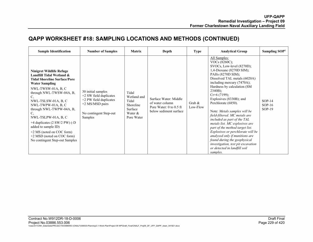
UFP-QAPP Remedial Investigation – Project 09
Former Charlestown Naval Auxiliary Landing Field QAPP WORKSHEET #18: SAMPLING LOCATIONS AND METHODS (CONTINUED)
Contract No.W912DR-18-D-0006 Draft Final Project No.03886.553.006 Page 229 of 420 \\nascnh1\CNH_Data\Data\PROJECTS\03886553 (CNALF)\006\03-Planning\3.1-Work-Plan\Project 09 WP\Draft_Final\CNALF_Proj09_DF_UFP_QAPP_clean_041821.docx
Sample Identification Number of Samples Matrix Depth Type Analytical Group Sampling SOP1
Ninigret Wildlife Refuge Landfill Tidal Wetland & Tidal Shoreline Surface/Pore Water Sampling NWL-TWSW-01A, B, C through NWL-TWSW-04A, B, C, NWL-TSLSW-01A, B, C NWL-TWPW-01A, B, C through NWL-TWPW-04A, B, C, NWL-TSLPW-01A, B, C +4 duplicates (2 SW/2 PW) (-D added to sample ID) +2 MS (noted on COC form) +2 MSD (noted on COC form) No contingent Step-out Samples
30 initial samples +2 SW field duplicates +2 PW field duplicates +2 MS/MSD pairs No contingent Step-out Samples
Tidal Wetland and Tidal Shoreline Surface Water & Pore Water
Surface Water: Middle of water column Pore Water: 0 to 0.5 ft below sediment surface
Grab & Low-Flow
All Samples: VOCs (8260C); SVOCs, Low-level (8270D); 1,4-Dioxane (8270D SIM); PAHs (8270D SIM); Dissolved TAL metals (6020A) including mercury (7470A); Hardness by calculation (SM 2340B); Cr+6 (7199); Explosives (8330B); and Perchlorate (6850). Note: Metals samples will be field-filtered. MC metals are included as part of the TAL metals list. MC explosives are part of the method target list. Explosives or perchlorate will be analyzed only if munitions are found during the geophysical investigation, test pit excavation or detected in landfill soil samples.
SOP-14 SOP-16 SOP-19
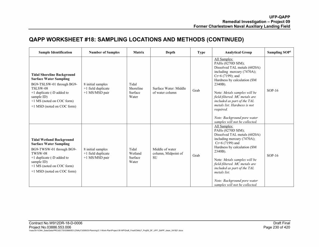
UFP-QAPP Remedial Investigation – Project 09
Former Charlestown Naval Auxiliary Landing Field QAPP WORKSHEET #18: SAMPLING LOCATIONS AND METHODS (CONTINUED)
Contract No.W912DR-18-D-0006 Draft Final Project No.03886.553.006 Page 230 of 420 \\nascnh1\CNH_Data\Data\PROJECTS\03886553 (CNALF)\006\03-Planning\3.1-Work-Plan\Project 09 WP\Draft_Final\CNALF_Proj09_DF_UFP_QAPP_clean_041821.docx
Sample Identification Number of Samples Matrix Depth Type Analytical Group Sampling SOP1
Tidal Shoreline Background Surface Water Sampling BG9-TSLSW-01 through BG9-TSLSW-08 +1 duplicate (-D added to sample ID) +1 MS (noted on COC form) +1 MSD (noted on COC form)
8 initial samples +1 field duplicate +1 MS/MSD pair
Tidal Shoreline Surface Water
Surface Water: Middle of water column Grab
All Samples: PAHs (8270D SIM); Dissolved TAL metals (6020A) including mercury (7470A); Cr+6 (7199); and Hardness by calculation (SM 2340B). Note: Metals samples will be field-filtered. MC metals are included as part of the TAL metals list. Hardness is not required. Note: Background pore water samples will not be collected.
SOP-16
Tidal Wetland Background Surface Water Sampling BG9-TWSW-01 through BG9-TWSW-08 +1 duplicate (-D added to sample ID) +1 MS (noted on COC form) +1 MSD (noted on COC form)
8 initial samples +1 field duplicate +1 MS/MSD pair
Tidal Wetland Surface Water
Middle of water column, Midpoint of SU
Grab
All Samples: PAHs (8270D SIM); Dissolved TAL metals (6020A) including mercury (7470A); Cr+6 (7199) and Hardness by calculation (SM 2340B). Note: Metals samples will be field-filtered. MC metals are included as part of the TAL metals list. Note: Background pore water samples will not be collected.
SOP-16
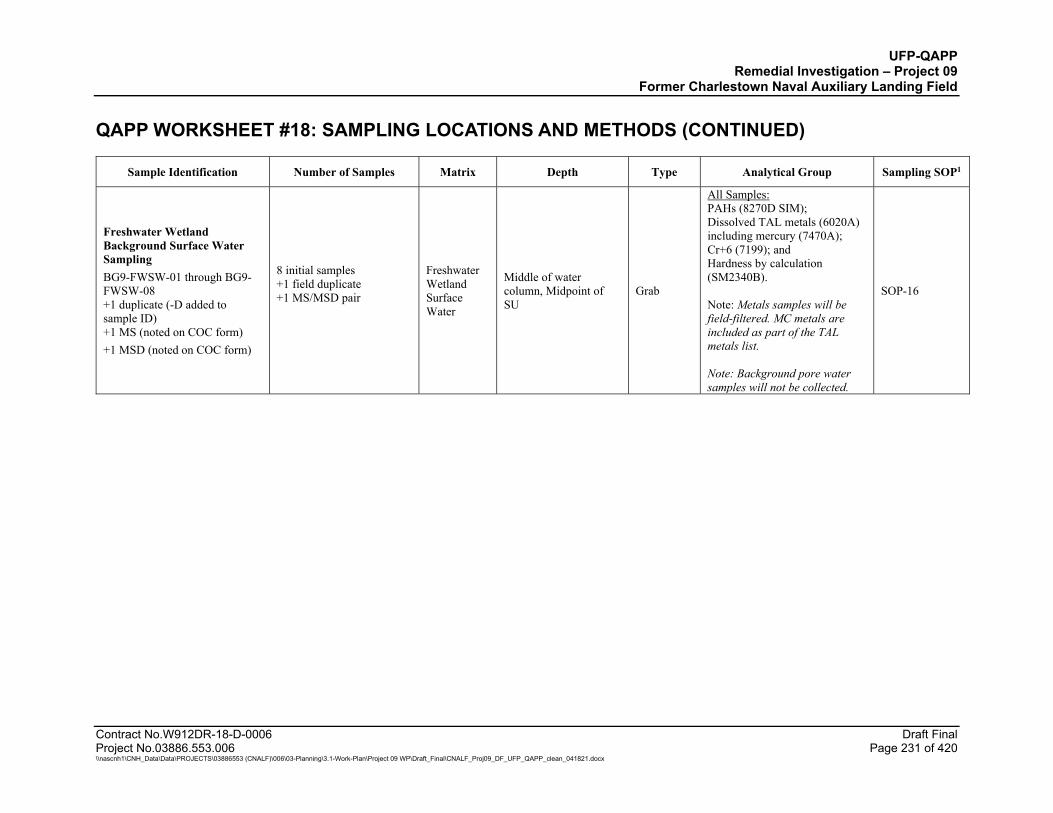
UFP-QAPP Remedial Investigation – Project 09
Former Charlestown Naval Auxiliary Landing Field QAPP WORKSHEET #18: SAMPLING LOCATIONS AND METHODS (CONTINUED)
Contract No.W912DR-18-D-0006 Draft Final Project No.03886.553.006 Page 231 of 420 \\nascnh1\CNH_Data\Data\PROJECTS\03886553 (CNALF)\006\03-Planning\3.1-Work-Plan\Project 09 WP\Draft_Final\CNALF_Proj09_DF_UFP_QAPP_clean_041821.docx
Sample Identification Number of Samples Matrix Depth Type Analytical Group Sampling SOP1
Freshwater Wetland Background Surface Water Sampling BG9-FWSW-01 through BG9-FWSW-08 +1 duplicate (-D added to sample ID) +1 MS (noted on COC form) +1 MSD (noted on COC form)
8 initial samples +1 field duplicate +1 MS/MSD pair
Freshwater Wetland Surface Water
Middle of water column, Midpoint of SU
Grab
All Samples: PAHs (8270D SIM); Dissolved TAL metals (6020A) including mercury (7470A); Cr+6 (7199); and Hardness by calculation (SM2340B). Note: Metals samples will be field-filtered. MC metals are included as part of the TAL metals list. Note: Background pore water samples will not be collected.
SOP-16
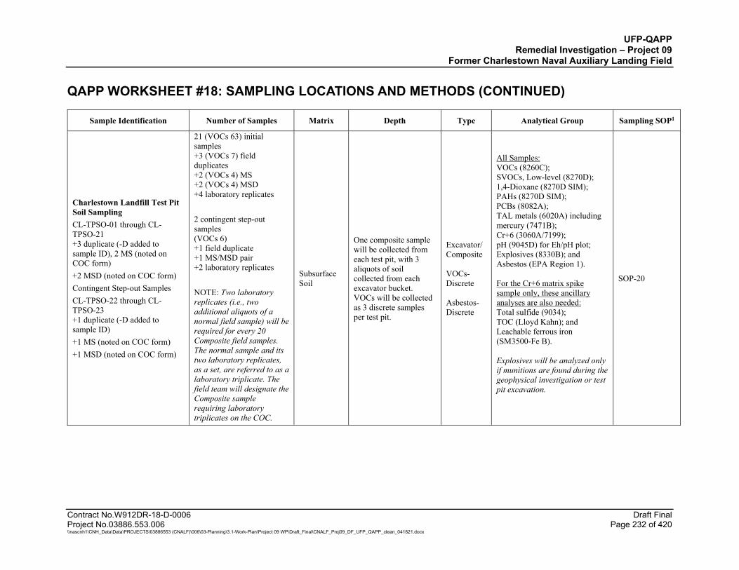
UFP-QAPP Remedial Investigation – Project 09
Former Charlestown Naval Auxiliary Landing Field QAPP WORKSHEET #18: SAMPLING LOCATIONS AND METHODS (CONTINUED)
Contract No.W912DR-18-D-0006 Draft Final Project No.03886.553.006 Page 232 of 420 \\nascnh1\CNH_Data\Data\PROJECTS\03886553 (CNALF)\006\03-Planning\3.1-Work-Plan\Project 09 WP\Draft_Final\CNALF_Proj09_DF_UFP_QAPP_clean_041821.docx
Sample Identification Number of Samples Matrix Depth Type Analytical Group Sampling SOP1
Charlestown Landfill Test Pit Soil Sampling CL-TPSO-01 through CL-TPSO-21 +3 duplicate (-D added to sample ID), 2 MS (noted on COC form) +2 MSD (noted on COC form) Contingent Step-out Samples CL-TPSO-22 through CL-TPSO-23 +1 duplicate (-D added to sample ID) +1 MS (noted on COC form) +1 MSD (noted on COC form)
21 (VOCs 63) initial samples +3 (VOCs 7) field duplicates +2 (VOCs 4) MS +2 (VOCs 4) MSD +4 laboratory replicates 2 contingent step-out samples (VOCs 6) +1 field duplicate +1 MS/MSD pair +2 laboratory replicates NOTE: Two laboratory replicates (i.e., two additional aliquots of a normal field sample) will be required for every 20 Composite field samples. The normal sample and its two laboratory replicates, as a set, are referred to as a laboratory triplicate. The field team will designate the Composite sample requiring laboratory triplicates on the COC.
Subsurface Soil
One composite sample will be collected from each test pit, with 3 aliquots of soil collected from each excavator bucket. VOCs will be collected as 3 discrete samples per test pit.
Excavator/ Composite VOCs-Discrete Asbestos- Discrete
All Samples: VOCs (8260C); SVOCs, Low-level (8270D); 1,4-Dioxane (8270D SIM); PAHs (8270D SIM); PCBs (8082A); TAL metals (6020A) including mercury (7471B); Cr+6 (3060A/7199); pH (9045D) for Eh/pH plot; Explosives (8330B); and Asbestos (EPA Region 1). For the Cr+6 matrix spike sample only, these ancillary analyses are also needed: Total sulfide (9034); TOC (Lloyd Kahn); and Leachable ferrous iron (SM3500-Fe B). Explosives will be analyzed only if munitions are found during the geophysical investigation or test pit excavation.
SOP-20
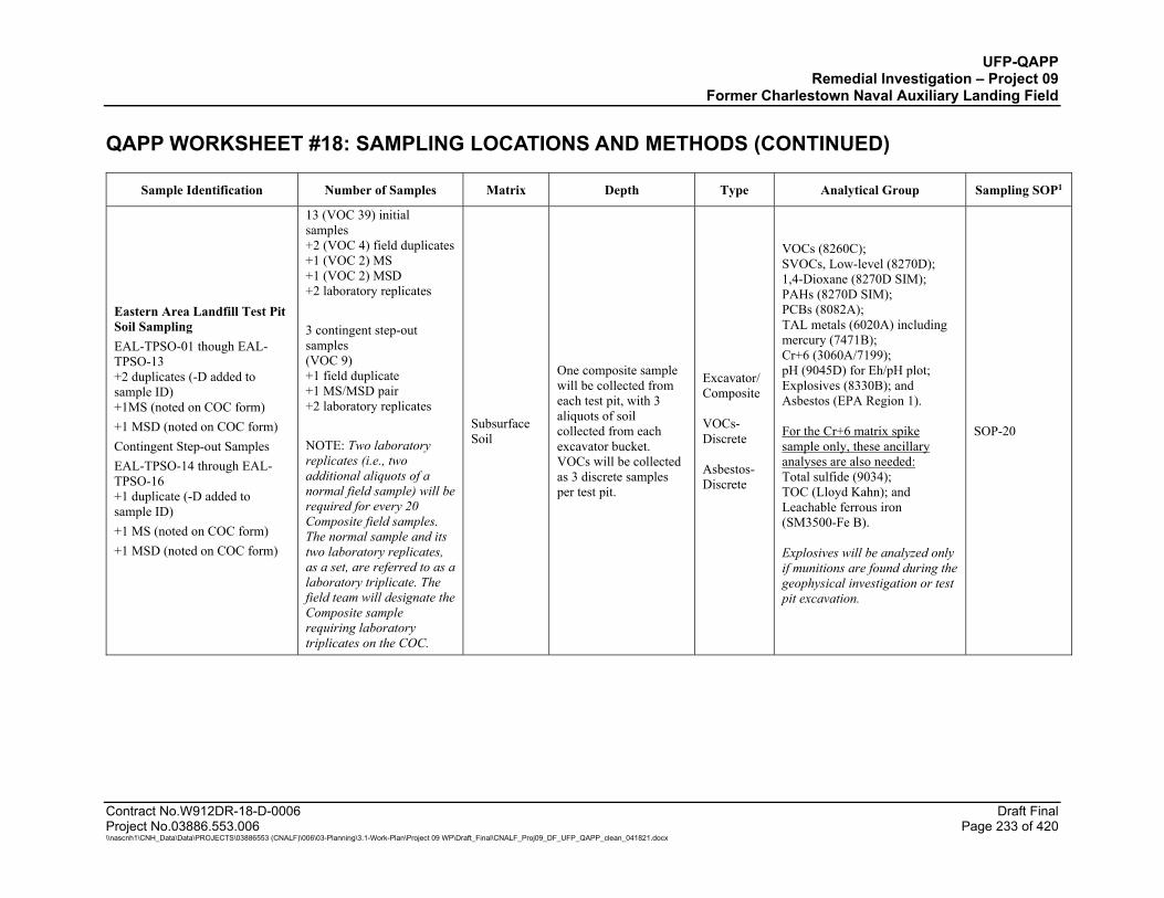
UFP-QAPP Remedial Investigation – Project 09
Former Charlestown Naval Auxiliary Landing Field QAPP WORKSHEET #18: SAMPLING LOCATIONS AND METHODS (CONTINUED)
Contract No.W912DR-18-D-0006 Draft Final Project No.03886.553.006 Page 233 of 420 \\nascnh1\CNH_Data\Data\PROJECTS\03886553 (CNALF)\006\03-Planning\3.1-Work-Plan\Project 09 WP\Draft_Final\CNALF_Proj09_DF_UFP_QAPP_clean_041821.docx
Sample Identification Number of Samples Matrix Depth Type Analytical Group Sampling SOP1
Eastern Area Landfill Test Pit Soil Sampling EAL-TPSO-01 though EAL-TPSO-13 +2 duplicates (-D added to sample ID) +1MS (noted on COC form) +1 MSD (noted on COC form) Contingent Step-out Samples EAL-TPSO-14 through EAL-TPSO-16 +1 duplicate (-D added to sample ID) +1 MS (noted on COC form) +1 MSD (noted on COC form)
13 (VOC 39) initial samples +2 (VOC 4) field duplicates +1 (VOC 2) MS +1 (VOC 2) MSD +2 laboratory replicates 3 contingent step-out samples (VOC 9) +1 field duplicate +1 MS/MSD pair +2 laboratory replicates NOTE: Two laboratory replicates (i.e., two additional aliquots of a normal field sample) will be required for every 20 Composite field samples. The normal sample and its two laboratory replicates, as a set, are referred to as a laboratory triplicate. The field team will designate the Composite sample requiring laboratory triplicates on the COC.
Subsurface Soil
One composite sample will be collected from each test pit, with 3 aliquots of soil collected from each excavator bucket. VOCs will be collected as 3 discrete samples per test pit.
Excavator/ Composite VOCs-Discrete Asbestos- Discrete
VOCs (8260C); SVOCs, Low-level (8270D); 1,4-Dioxane (8270D SIM); PAHs (8270D SIM); PCBs (8082A); TAL metals (6020A) including mercury (7471B); Cr+6 (3060A/7199); pH (9045D) for Eh/pH plot; Explosives (8330B); and Asbestos (EPA Region 1). For the Cr+6 matrix spike sample only, these ancillary analyses are also needed: Total sulfide (9034); TOC (Lloyd Kahn); and Leachable ferrous iron (SM3500-Fe B). Explosives will be analyzed only if munitions are found during the geophysical investigation or test pit excavation.
SOP-20
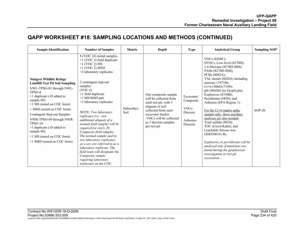
UFP-QAPP Remedial Investigation – Project 09
Former Charlestown Naval Auxiliary Landing Field QAPP WORKSHEET #18: SAMPLING LOCATIONS AND METHODS (CONTINUED)
Contract No.W912DR-18-D-0006 Draft Final Project No.03886.553.006 Page 234 of 420 \\nascnh1\CNH_Data\Data\PROJECTS\03886553 (CNALF)\006\03-Planning\3.1-Work-Plan\Project 09 WP\Draft_Final\CNALF_Proj09_DF_UFP_QAPP_clean_041821.docx
Sample Identification Number of Samples Matrix Depth Type Analytical Group Sampling SOP1
Ninigret Wildlife Refuge Landfill Test Pit Soil Sampling NWL-TPSO-01 through NWL-TPSO-8 +1 duplicate (-D added to sample ID) +1 MS (noted on COC form) + MSD (noted on COC form) Contingent Step-out Samples NWR-TPSO-09 through NWR-TPSO-10 +1 duplicate (-D added to sample ID) +1 MS (noted on COC form) +1 MSD (noted on COC form)
8 (VOC 24) initial samples +1 (VOC 3) field duplicate +1 (VOC 2) MS +1 (VOC 2) MSD +2 laboratory replicates 2 contingent step-out samples (VOC 6) +1 field duplicate +1 MS/MSD pair +2 laboratory replicates NOTE: Two laboratory replicates (i.e., two additional aliquots of a normal field sample) will be required for every 20 Composite field samples. The normal sample and its two laboratory replicates, as a set, are referred to as a laboratory triplicate. The field team will designate the Composite sample requiring laboratory triplicates on the COC.
Subsurface Soil
One composite sample will be collected from each test pit, with 3 aliquots of soil collected from each excavator bucket VOCs will be collected as 3 discrete samples per test pit
Excavator/ Composite VOCs- Discrete Asbestos- Discrete
VOCs (8260C); SVOCs, Low-level (8270D); 1,4-Dioxane (8270D-SIM); PAHs (8270D-SIM); PCBs (8082A); TAL metals (6020A) including mercury (7471B); Cr+6 (3060A/7199); pH (9045D) for Eh/pH plot; Explosives (8330B); Perchlorate (6850); and Asbestos (EPA Region 1). For the Cr+6 matrix spike sample only, these ancillary analyses are also needed: Total sulfide (9034); TOC (Lloyd Kahn); and Leachable ferrous iron (SM3500-Fe B). Explosives or perchlorate will be analyzed only if munitions are found during the geophysical investigation or test pit excavation.
SOP-20
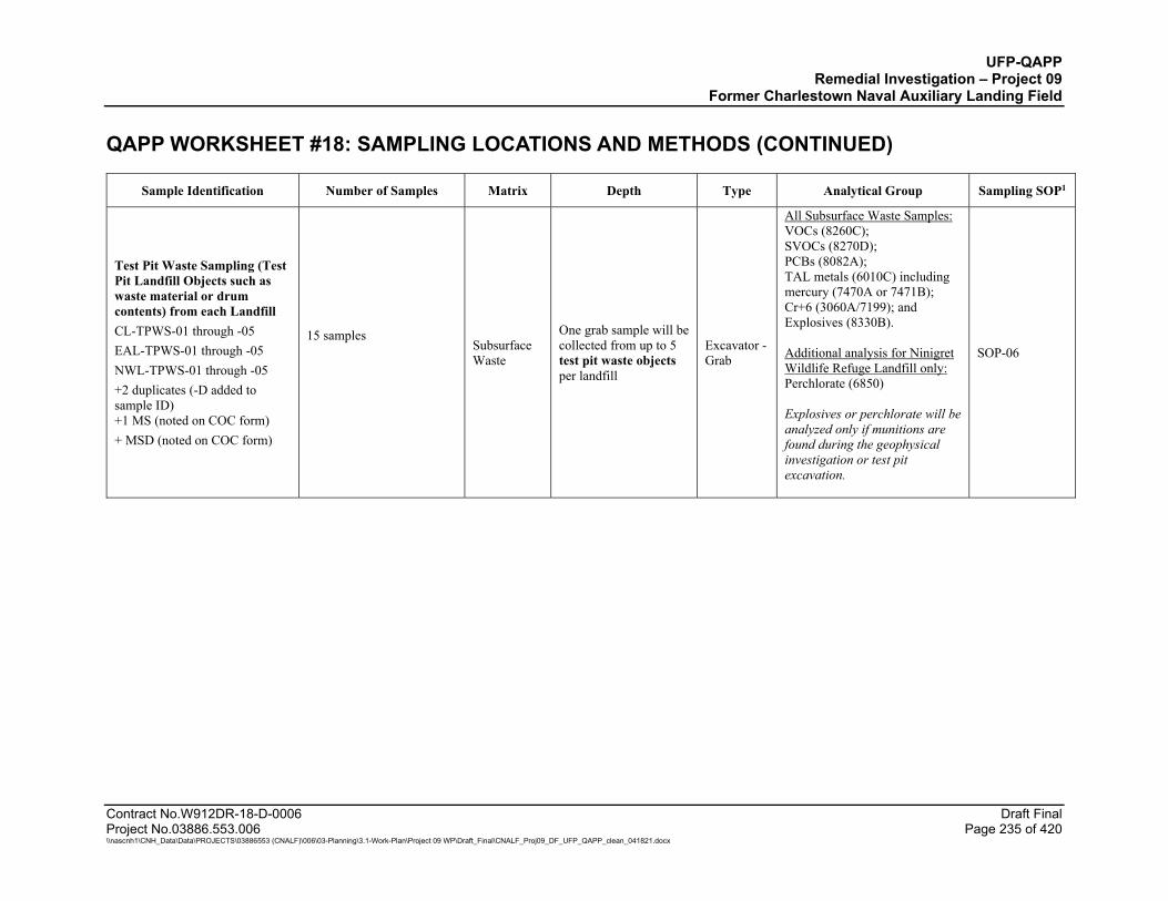
UFP-QAPP Remedial Investigation – Project 09
Former Charlestown Naval Auxiliary Landing Field QAPP WORKSHEET #18: SAMPLING LOCATIONS AND METHODS (CONTINUED)
Contract No.W912DR-18-D-0006 Draft Final Project No.03886.553.006 Page 235 of 420 \\nascnh1\CNH_Data\Data\PROJECTS\03886553 (CNALF)\006\03-Planning\3.1-Work-Plan\Project 09 WP\Draft_Final\CNALF_Proj09_DF_UFP_QAPP_clean_041821.docx
Sample Identification Number of Samples Matrix Depth Type Analytical Group Sampling SOP1
Test Pit Waste Sampling (Test Pit Landfill Objects such as waste material or drum contents) from each Landfill CL-TPWS-01 through -05 EAL-TPWS-01 through -05 NWL-TPWS-01 through -05 +2 duplicates (-D added to sample ID) +1 MS (noted on COC form) + MSD (noted on COC form)
15 samples
Subsurface Waste
One grab sample will be collected from up to 5 test pit waste objects per landfill
Excavator -Grab
All Subsurface Waste Samples: VOCs (8260C); SVOCs (8270D); PCBs (8082A); TAL metals (6010C) including mercury (7470A or 7471B); Cr+6 (3060A/7199); and Explosives (8330B). Additional analysis for Ninigret Wildlife Refuge Landfill only: Perchlorate (6850) Explosives or perchlorate will be analyzed only if munitions are found during the geophysical investigation or test pit excavation.
SOP-06

UFP-QAPP Remedial Investigation – Project 09
Former Charlestown Naval Auxiliary Landing Field QAPP WORKSHEET #18: SAMPLING LOCATIONS AND METHODS (CONTINUED)
Contract No.W912DR-18-D-0006 Draft Final Project No.03886.553.006 Page 236 of 420 \\nascnh1\CNH_Data\Data\PROJECTS\03886553 (CNALF)\006\03-Planning\3.1-Work-Plan\Project 09 WP\Draft_Final\CNALF_Proj09_DF_UFP_QAPP_clean_041821.docx
Sample Identification Number of Samples Matrix Depth Type Analytical Group Sampling SOP1
IDW Waste Sampling Soil: IDW-SO-01 through -10- mmddyy Water: IDW-WTR-01 through -10-mmddyy Munitions Debris: IDW-MD-01 through -10-mmddyy No duplicate or MS/MSD samples
Soil: 10 Water: 10 MD: 10
IDW soil, water
One grab sample will be collected from each container.
Grab
Any of the following parameters may be required by disposal facility to supplement investigative sample results: Reactive Cyanide (Chapter 7.3/ 9012B) for solid and water; Reactive Sulfide for solids (Chapter 7.3/ 9034); Reactive Sulfide for water (Chapter 7.3/SM4500-S-2 F); Corrosivity (pH) for solid (9045D); Corrosivity (pH) for aqueous liquid (9040C); Flashpoint for liquids (1010A); Ignitability for solids (1030); TCLP VOCs (1311/8260C) for solids or VOCs (8260C) for liquids; TCLP SVOCs (1311/8270D) for solids or SVOCs (8270D) for liquids; TCLP metals including mercury (1311/6010C/7470A) for solids or RCRA metals (6010C/7470A) for liquids; PCBs (8082A); Dioxin/furans (8290A); Explosives (8330B); Perchlorate (6850); and TPH GRO/DRO/ORO (8015D).
SOP-06
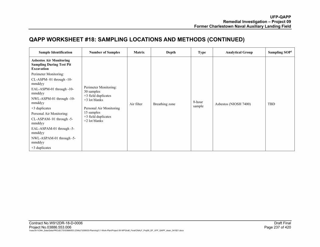
UFP-QAPP Remedial Investigation – Project 09
Former Charlestown Naval Auxiliary Landing Field QAPP WORKSHEET #18: SAMPLING LOCATIONS AND METHODS (CONTINUED)
Contract No.W912DR-18-D-0006 Draft Final Project No.03886.553.006 Page 237 of 420 \\nascnh1\CNH_Data\Data\PROJECTS\03886553 (CNALF)\006\03-Planning\3.1-Work-Plan\Project 09 WP\Draft_Final\CNALF_Proj09_DF_UFP_QAPP_clean_041821.docx
Sample Identification Number of Samples Matrix Depth Type Analytical Group Sampling SOP1
Asbestos Air Monitoring Sampling During Test Pit Excavation Perimeter Monitoring: CL-ASPM- 01 through -10-mmddyy EAL-ASPM-01 through -10-mmddyy NWL-ASPM-01 through -10-mmddyy +3 duplicates Personal Air Monitoring: CL-ASPAM- 01 through -5-mmddyy EAL-ASPAM-01 through -5-mmddyy NWL-ASPAM-01 through -5-mmddyy +3 duplicates
Perimeter Monitoring: 30 samples +3 field duplicates +3 lot blanks Personal Air Monitoring 15 samples +3 field duplicates +2 lot blanks
Air filter Breathing zone 8-hour sample Asbestos (NIOSH 7400) TBD
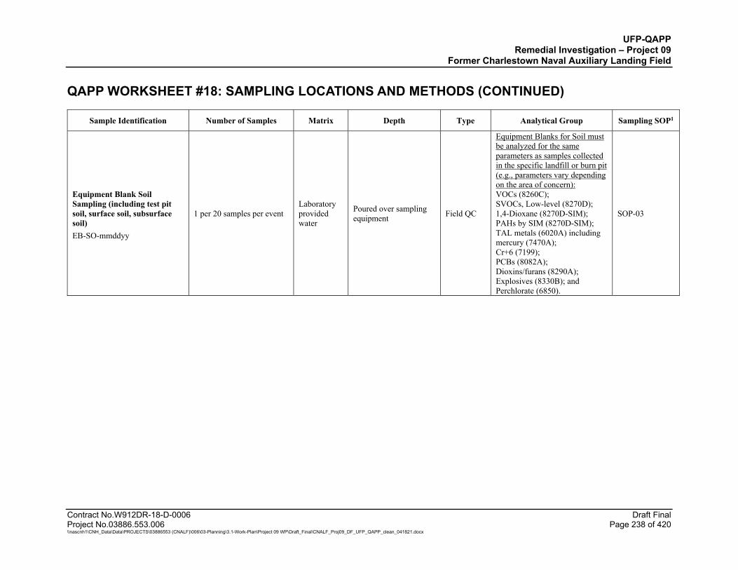
UFP-QAPP Remedial Investigation – Project 09
Former Charlestown Naval Auxiliary Landing Field QAPP WORKSHEET #18: SAMPLING LOCATIONS AND METHODS (CONTINUED)
Contract No.W912DR-18-D-0006 Draft Final Project No.03886.553.006 Page 238 of 420 \\nascnh1\CNH_Data\Data\PROJECTS\03886553 (CNALF)\006\03-Planning\3.1-Work-Plan\Project 09 WP\Draft_Final\CNALF_Proj09_DF_UFP_QAPP_clean_041821.docx
Sample Identification Number of Samples Matrix Depth Type Analytical Group Sampling SOP1
Equipment Blank Soil Sampling (including test pit soil, surface soil, subsurface soil) EB-SO-mmddyy
1 per 20 samples per event Laboratory provided water
Poured over sampling equipment Field QC
Equipment Blanks for Soil must be analyzed for the same parameters as samples collected in the specific landfill or burn pit (e.g., parameters vary depending on the area of concern): VOCs (8260C); SVOCs, Low-level (8270D); 1,4-Dioxane (8270D-SIM); PAHs by SIM (8270D-SIM); TAL metals (6020A) including mercury (7470A); Cr+6 (7199); PCBs (8082A); Dioxins/furans (8290A); Explosives (8330B); and Perchlorate (6850).
SOP-03

UFP-QAPP Remedial Investigation – Project 09
Former Charlestown Naval Auxiliary Landing Field QAPP WORKSHEET #18: SAMPLING LOCATIONS AND METHODS (CONTINUED)
Contract No.W912DR-18-D-0006 Draft Final Project No.03886.553.006 Page 239 of 420 \\nascnh1\CNH_Data\Data\PROJECTS\03886553 (CNALF)\006\03-Planning\3.1-Work-Plan\Project 09 WP\Draft_Final\CNALF_Proj09_DF_UFP_QAPP_clean_041821.docx
Sample Identification Number of Samples Matrix Depth Type Analytical Group Sampling SOP1
Equipment Blank (Groundwater Sampling) EB-GW-CL, EB-GW-EAL, EB-GW-NWL, EB-GW-BPA-mmddyy
1 per 20 samples per event Laboratory provided water
Poured over sampling equipment Field QC
For the same parameters as associated samples: VOCs (8260C); SVOCs, Low-level (8270D); 1,4-Dioxane (8270D-SIM); PAHs (8270D-SIM); TAL metals (6020A) including mercury (7470A); Cr+6 (218.6); PCBs (8082A); and Explosives (8330B). Additional analysis for Ninigret Wildlife Refuge Landfill: Perchlorate (6850). Potential additional analysis for Burn Pit Area and Ninigret Water Supply Wells: PFAS [PFAS by LC/MS/MS Compliant with Table B-15 of DoD QSM 5.3 (or later)].
SOP-03
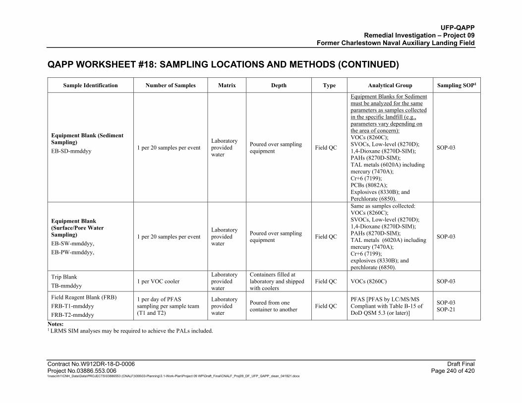
UFP-QAPP Remedial Investigation – Project 09
Former Charlestown Naval Auxiliary Landing Field QAPP WORKSHEET #18: SAMPLING LOCATIONS AND METHODS (CONTINUED)
Contract No.W912DR-18-D-0006 Draft Final Project No.03886.553.006 Page 240 of 420 \\nascnh1\CNH_Data\Data\PROJECTS\03886553 (CNALF)\006\03-Planning\3.1-Work-Plan\Project 09 WP\Draft_Final\CNALF_Proj09_DF_UFP_QAPP_clean_041821.docx
Sample Identification Number of Samples Matrix Depth Type Analytical Group Sampling SOP1
Equipment Blank (Sediment Sampling) EB-SD-mmddyy
1 per 20 samples per event Laboratory provided water
Poured over sampling equipment Field QC
Equipment Blanks for Sediment must be analyzed for the same parameters as samples collected in the specific landfill (e.g., parameters vary depending on the area of concern): VOCs (8260C); SVOCs, Low-level (8270D); 1,4-Dioxane (8270D-SIM); PAHs (8270D-SIM); TAL metals (6020A) including mercury (7470A); Cr+6 (7199); PCBs (8082A); Explosives (8330B); and Perchlorate (6850).
SOP-03
Equipment Blank (Surface/Pore Water Sampling) EB-SW-mmddyy, EB-PW-mmddyy,
1 per 20 samples per event Laboratory provided water
Poured over sampling equipment Field QC
Same as samples collected: VOCs (8260C); SVOCs, Low-level (8270D); 1,4-Dioxane (8270D-SIM); PAHs (8270D-SIM); TAL metals (6020A) including mercury (7470A); Cr+6 (7199); explosives (8330B); and perchlorate (6850).
SOP-03
Trip Blank TB-mmddyy
1 per VOC cooler Laboratory provided water
Containers filled at laboratory and shipped with coolers
Field QC VOCs (8260C) SOP-03
Field Reagent Blank (FRB) FRB-T1-mmddyy FRB-T2-mmddyy
1 per day of PFAS sampling per sample team (T1 and T2)
Laboratory provided water
Poured from one container to another Field QC
PFAS [PFAS by LC/MS/MS Compliant with Table B-15 of DoD QSM 5.3 (or later)]
SOP-03 SOP-21
Notes: 1 LRMS SIM analyses may be required to achieve the PALs included.
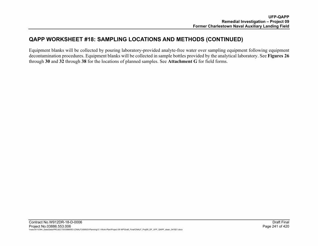
UFP-QAPP Remedial Investigation – Project 09
Former Charlestown Naval Auxiliary Landing Field QAPP WORKSHEET #18: SAMPLING LOCATIONS AND METHODS (CONTINUED)
Contract No.W912DR-18-D-0006 Draft Final Project No.03886.553.006 Page 241 of 420 \\nascnh1\CNH_Data\Data\PROJECTS\03886553 (CNALF)\006\03-Planning\3.1-Work-Plan\Project 09 WP\Draft_Final\CNALF_Proj09_DF_UFP_QAPP_clean_041821.docx
Equipment blanks will be collected by pouring laboratory-provided analyte-free water over sampling equipment following equipment decontamination procedures. Equipment blanks will be collected in sample bottles provided by the analytical laboratory. See Figures 26 through 30 and 32 through 38 for the locations of planned samples. See Attachment G for field forms.

UFP-QAPP Remedial Investigation – Project 09
Former Charlestown Naval Auxiliary Landing Field
Contract No.W912DR-18-D-0006 Draft Final Project No.03886.553.006 Page 242 of 420 \\nascnh1\CNH_Data\Data\PROJECTS\03886553 (CNALF)\006\03-Planning\3.1-Work-Plan\Project 09 WP\Draft_Final\CNALF_Proj09_DF_UFP_QAPP_clean_041821.docx
QAPP WORKSHEETS #19 & 30: SAMPLE CONTAINERS, PRESERVATION, AND HOLD TIMES
Five ALS laboratories and one asbestos laboratory (ProScience Analytical Services, Inc.) will support the analysis of project samples. ALS Middletown will serve as the primary ALS laboratory and will generally distribute samples to the other laboratories for analysis; unless directed otherwise by ALS, samples will be shipped to ALS Middletown except for two sample types: Water samples for hexavalent chromium will be shipped directly from the field to ALS Rochester to meet the 24-hour holding
time. PFAS samples will be shipped directly to ALS Kelso to facilitate rapid laboratory turnaround time requested for this analysis.
Laboratory contact information is listed below along with the relevant certifications and their expiration dates. Laboratories are certified for all analytes of interest except for the following:
ALS Kelso’s DoD Environmental Laboratory Accreditation Program (ELAP) certificate does not include the following five analytes listed for SVOCs by EPA 8270D (low-level full scan): 1,1’-Biphenyl, Acetophenone, Atrazine, Benzaldehyde, and Caprolactam. ALS Kelso plans to update its DoD ELAP certificate to include these missing five compounds and detection limits for these compounds are listed on Worksheet 15. ALS Kelso is, however, certified for these compounds on its Oregon ELAP certificate which is also provided with the DoD ELAP certificate.
ALS Middletown is DoD ELAP certified for TPH-GRO and TPH-DRO, does not have DoD ELAP certification for the TPH-ORO analysis.
Laboratories and their certifications are listed below:
Accreditations/Certifications:
Laboratory 1: ALS Middletown (ALS Mdt), 301 Fulling Mill Road, Middletown, PA 17057; Telephone: (717) 944-5541 DoD ELAP (PJLA Certificate No. L20-101-R1); expires 02/28/2022.
Laboratory 2: ALS Kelso, 1317 South 13th Avenue, Kelso, WA 98626; Telephone: (360) 577-7222 DoD ELAP (PJLA Certificate No. L20-395), expires 07/10/2022. Oregon Environmental Laboratory Accreditation Program (ORELAP) (State of Oregon NELAC Certificate No. WA100010 - 024); expires 02/10/2022.

UFP-QAPP Remedial Investigation – Project 09
Former Charlestown Naval Auxiliary Landing Field
WORKSHEETS 19 & 30: SAMPLE CONTAINERS, PRESERVATION, AND HOLD TIMES (CONTINUED)
Contract No.W912DR-18-D-0006 Draft Final Project No.03886.553.006 Page 243 of 420 \\nascnh1\CNH_Data\Data\PROJECTS\03886553 (CNALF)\006\03-Planning\3.1-Work-Plan\Project 09 WP\Draft_Final\CNALF_Proj09_DF_UFP_QAPP_clean_041821.docx
Laboratory 3: ALS Rochester (ALS Roch), 1565 Jefferson Road, Building 300, Suite 360, Rochester, NY 14623; Telephone: (585) 288-5380 DoD ELAP (PJLA Certificate No. L20-297); expires 05/31/2022.
Laboratory 4: ALS Houston (ALS Hou), 10450 Stancliff Road, Suite 210, Houston TX 77099; Telephone: (281) 530-5656 DoD ELAP) (PJLA Certificate No. L20-507-R1; expires 12/22/2021.
Laboratory 5: ALS Burlington (ALS Burl), 1435 Norjohn Court Unit 1, Burlington, Ontario L7L 0E6; Telephone: (905) 331-3111 DoD ELAP (PJLA Certificate No. L20-339-R1); expires 07/31/2022.
Laboratory 6: ProScience Analytical Services, Inc., 22 Cummings Park, Woburn, MA 01801; Telephone: (781) 935-3212 AIHA Laboratory Accreditation Programs, LLC (AIHA Certificate No. LAP-102754); expires 07/01/2022.
Rhode Island Department of Health Asbestos Analytical Services Certification (Certification No, PLM00093); expires 2/28/2022. Rhode Island Department of Health Asbestos Analytical Services Certification (Certification No, PCM00093); expires 2/28/2022. U.S. Dept. of Commerce National Institute of Standards and Technology National Voluntary Laboratory Accreditation Program (NVLAP) Certificate of Accreditation to ISO/IEC 17025:2017, NVLAP Lab Code 200090-0; expires 12/31/2021.
Sample Delivery Method: Laboratory courier or commercial carrier to ALS Middletown where samples will be shipped to other ALS labs. Asbestos samples will be hand delivered to ProScience Analytical Services, Inc. Note: Accreditation expiration dates for each laboratory are noted above. Each laboratory performing the listed analyses is identified in the table below rather than the accreditation expiration date which is shown above. Soil/sediment samples may be collected as discrete (grab) samples or by Incremental Sampling Methodology (ISM) depending on the location. The table below includes container requirements for ISM and discrete soil sample collection. The analytical parameters for ISM samples also may vary by site; for example, perchlorate will only be requested for ISM samples collected at the Ninigret Wildlife Refuge Landfill. Refer to QAPP Worksheet 20 for an accurate list of parameters for each matrix type and location.
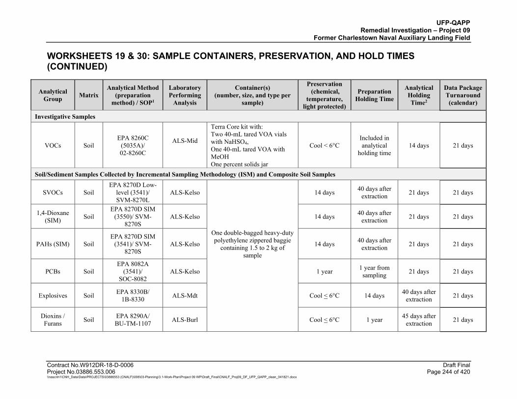
UFP-QAPP Remedial Investigation – Project 09
Former Charlestown Naval Auxiliary Landing Field
WORKSHEETS 19 & 30: SAMPLE CONTAINERS, PRESERVATION, AND HOLD TIMES (CONTINUED)
Contract No.W912DR-18-D-0006 Draft Final Project No.03886.553.006 Page 244 of 420 \\nascnh1\CNH_Data\Data\PROJECTS\03886553 (CNALF)\006\03-Planning\3.1-Work-Plan\Project 09 WP\Draft_Final\CNALF_Proj09_DF_UFP_QAPP_clean_041821.docx
Analytical Group Matrix
Analytical Method (preparation
method) / SOP1
Laboratory Performing
Analysis
Container(s) (number, size, and type per
sample)
Preservation (chemical,
temperature, light protected)
Preparation Holding Time
Analytical Holding Time2
Data Package Turnaround (calendar)
Investigative Samples
VOCs Soil EPA 8260C
(5035A)/ 02-8260C
ALS-Mid
Terra Core kit with: Two 40-mL tared VOA vials with NaHSO4, One 40-mL tared VOA with MeOH One percent solids jar
Cool < 6°C Included in analytical
holding time 14 days 21 days
Soil/Sediment Samples Collected by Incremental Sampling Methodology (ISM) and Composite Soil Samples
SVOCs Soil EPA 8270D Low-
level (3541)/ SVM-8270L
ALS-Kelso 14 days 40 days after extraction 21 days 21 days
1,4-Dioxane (SIM) Soil
EPA 8270D SIM (3550)/ SVM-
8270S ALS-Kelso 14 days 40 days after
extraction 21 days 21 days
PAHs (SIM) Soil EPA 8270D SIM
(3541)/ SVM-8270S
ALS-Kelso
One double-bagged heavy-duty polyethylene zippered baggie
containing 1.5 to 2 kg of sample
14 days 40 days after extraction 21 days 21 days
PCBs Soil EPA 8082A
(3541)/ SOC-8082
ALS-Kelso 1 year 1 year from sampling 21 days 21 days
Explosives Soil EPA 8330B/ 1B-8330 ALS-Mdt Cool < 6°C 14 days 40 days after
extraction 21 days
Dioxins / Furans Soil EPA 8290A/
BU-TM-1107 ALS-Burl Cool < 6°C 1 year 45 days after extraction 21 days
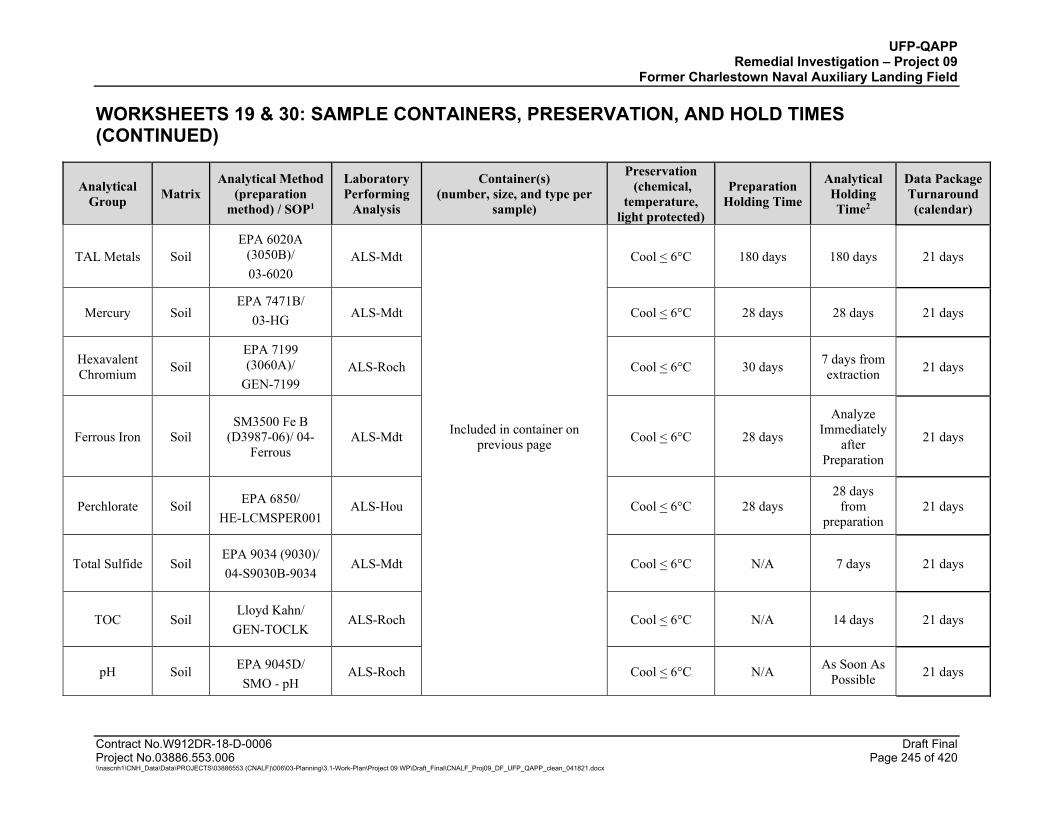
UFP-QAPP Remedial Investigation – Project 09
Former Charlestown Naval Auxiliary Landing Field
WORKSHEETS 19 & 30: SAMPLE CONTAINERS, PRESERVATION, AND HOLD TIMES (CONTINUED)
Contract No.W912DR-18-D-0006 Draft Final Project No.03886.553.006 Page 245 of 420 \\nascnh1\CNH_Data\Data\PROJECTS\03886553 (CNALF)\006\03-Planning\3.1-Work-Plan\Project 09 WP\Draft_Final\CNALF_Proj09_DF_UFP_QAPP_clean_041821.docx
Analytical Group Matrix
Analytical Method (preparation
method) / SOP1
Laboratory Performing
Analysis
Container(s) (number, size, and type per
sample)
Preservation (chemical,
temperature, light protected)
Preparation Holding Time
Analytical Holding Time2
Data Package Turnaround (calendar)
TAL Metals Soil EPA 6020A
(3050B)/ 03-6020
ALS-Mdt Cool < 6°C 180 days 180 days 21 days
Mercury Soil EPA 7471B/
03-HG ALS-Mdt Cool < 6°C 28 days 28 days 21 days
Hexavalent Chromium Soil
EPA 7199 (3060A)/
GEN-7199 ALS-Roch Cool < 6°C 30 days 7 days from
extraction 21 days
Ferrous Iron Soil SM3500 Fe B
(D3987-06)/ 04-Ferrous
ALS-Mdt Included in container on previous page Cool < 6°C 28 days
Analyze Immediately
after Preparation
21 days
Perchlorate Soil EPA 6850/ HE-LCMSPER001
ALS-Hou Cool < 6°C 28 days 28 days
from preparation
21 days
Total Sulfide Soil EPA 9034 (9030)/ 04-S9030B-9034
ALS-Mdt Cool < 6°C N/A 7 days 21 days
TOC Soil Lloyd Kahn/
GEN-TOCLK ALS-Roch Cool < 6°C N/A 14 days 21 days
pH Soil EPA 9045D/ SMO - pH
ALS-Roch Cool < 6°C N/A As Soon As Possible 21 days
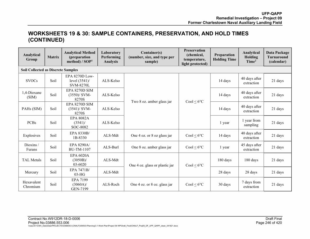
UFP-QAPP Remedial Investigation – Project 09
Former Charlestown Naval Auxiliary Landing Field
WORKSHEETS 19 & 30: SAMPLE CONTAINERS, PRESERVATION, AND HOLD TIMES (CONTINUED)
Contract No.W912DR-18-D-0006 Draft Final Project No.03886.553.006 Page 246 of 420 \\nascnh1\CNH_Data\Data\PROJECTS\03886553 (CNALF)\006\03-Planning\3.1-Work-Plan\Project 09 WP\Draft_Final\CNALF_Proj09_DF_UFP_QAPP_clean_041821.docx
Analytical Group Matrix
Analytical Method (preparation
method) / SOP1
Laboratory Performing
Analysis
Container(s) (number, size, and type per
sample)
Preservation (chemical,
temperature, light protected)
Preparation Holding Time
Analytical Holding Time2
Data Package Turnaround (calendar)
Soil Collected as Discrete Samples
SVOCs Soil EPA 8270D Low-
level (3541)/ SVM-8270L
ALS-Kelso
Two 8 oz. amber glass jar Cool < 6°C
14 days 40 days after extraction 21 days
1,4-Dioxane (SIM) Soil
EPA 8270D SIM (3550)/ SVM-
8270S ALS-Kelso 14 days 40 days after
extraction 21 days
PAHs (SIM) Soil EPA 8270D SIM
(3541)/ SVM-8270S
ALS-Kelso 14 days 40 days after extraction 21 days
PCBs Soil EPA 8082A
(3541)/ SOC-8082
ALS-Kelso 1 year 1 year from sampling 21 days
Explosives Soil EPA 8330B/ 1B-8330 ALS-Mdt One 4 oz. or 8 oz glass jar Cool < 6°C 14 days 40 days after
extraction 21 days
Dioxins / Furans Soil EPA 8290A/
BU-TM-1107 ALS-Burl One 8 oz. amber glass jar Cool < 6°C 1 year 45 days after extraction 21 days
TAL Metals Soil EPA 6020A
(3050B)/ 03-6020
ALS-Mdt One 4 oz. glass or plastic jar Cool < 6°C
180 days 180 days 21 days
Mercury Soil EPA 7471B/ 03-HG ALS-Mdt 28 days 28 days 21 days
Hexavalent Chromium Soil
EPA 7199 (3060A)/
GEN-7199 ALS-Roch One 4 oz. or 8 oz. glass jar Cool < 6°C 30 days 7 days from
extraction 21 days
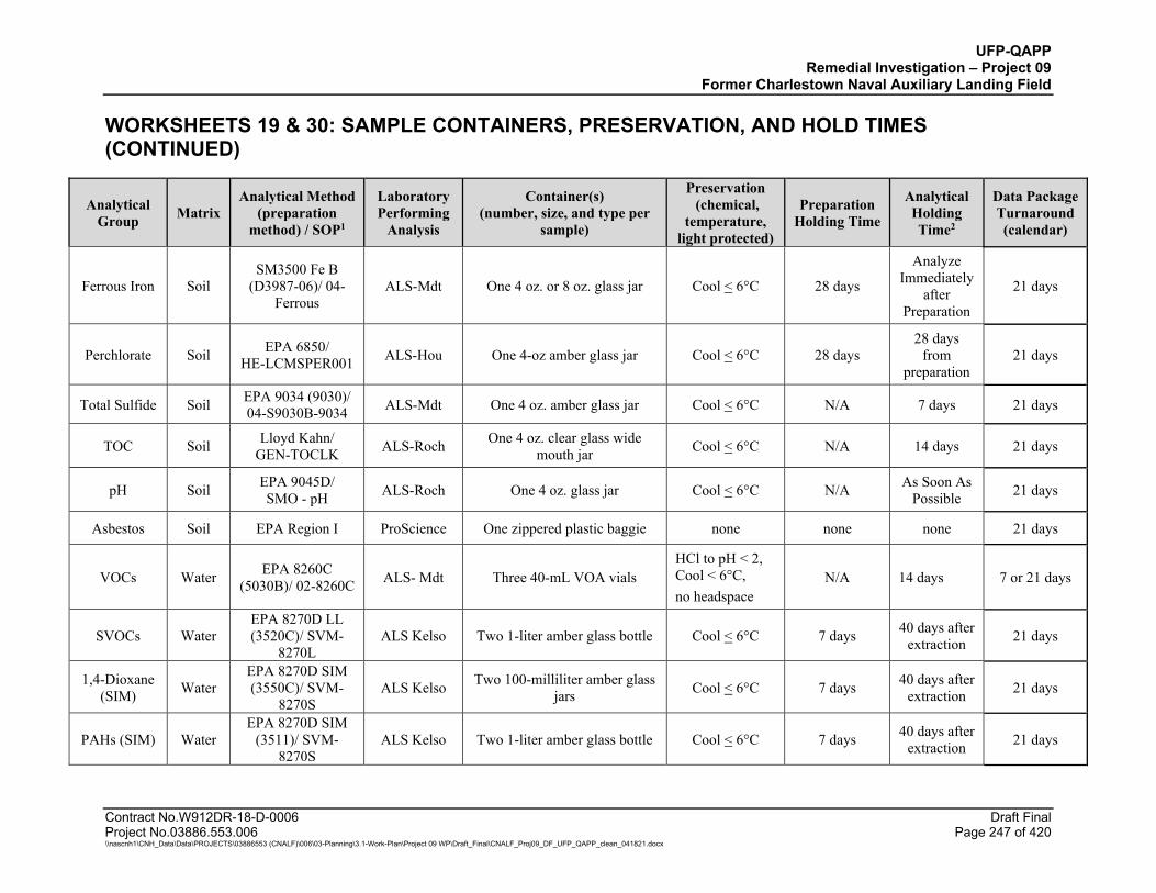
UFP-QAPP Remedial Investigation – Project 09
Former Charlestown Naval Auxiliary Landing Field
WORKSHEETS 19 & 30: SAMPLE CONTAINERS, PRESERVATION, AND HOLD TIMES (CONTINUED)
Contract No.W912DR-18-D-0006 Draft Final Project No.03886.553.006 Page 247 of 420 \\nascnh1\CNH_Data\Data\PROJECTS\03886553 (CNALF)\006\03-Planning\3.1-Work-Plan\Project 09 WP\Draft_Final\CNALF_Proj09_DF_UFP_QAPP_clean_041821.docx
Analytical Group Matrix
Analytical Method (preparation
method) / SOP1
Laboratory Performing
Analysis
Container(s) (number, size, and type per
sample)
Preservation (chemical,
temperature, light protected)
Preparation Holding Time
Analytical Holding Time2
Data Package Turnaround (calendar)
Ferrous Iron Soil SM3500 Fe B
(D3987-06)/ 04-Ferrous
ALS-Mdt One 4 oz. or 8 oz. glass jar Cool < 6°C 28 days
Analyze Immediately
after Preparation
21 days
Perchlorate Soil EPA 6850/ HE-LCMSPER001 ALS-Hou One 4-oz amber glass jar Cool < 6°C 28 days
28 days from
preparation 21 days
Total Sulfide Soil EPA 9034 (9030)/ 04-S9030B-9034 ALS-Mdt One 4 oz. amber glass jar Cool < 6°C N/A 7 days 21 days
TOC Soil Lloyd Kahn/ GEN-TOCLK ALS-Roch One 4 oz. clear glass wide
mouth jar Cool < 6°C N/A 14 days 21 days
pH Soil EPA 9045D/ SMO - pH ALS-Roch One 4 oz. glass jar Cool < 6°C N/A As Soon As
Possible 21 days
Asbestos Soil EPA Region I ProScience One zippered plastic baggie none none none 21 days
VOCs Water EPA 8260C (5030B)/ 02-8260C ALS- Mdt Three 40-mL VOA vials
HCl to pH < 2, Cool < 6°C, no headspace
N/A 14 days 7 or 21 days
SVOCs Water EPA 8270D LL (3520C)/ SVM-
8270L ALS Kelso Two 1-liter amber glass bottle Cool < 6°C 7 days 40 days after
extraction 21 days
1,4-Dioxane (SIM) Water
EPA 8270D SIM (3550C)/ SVM-
8270S ALS Kelso Two 100-milliliter amber glass
jars Cool < 6°C 7 days 40 days after extraction 21 days
PAHs (SIM) Water EPA 8270D SIM
(3511)/ SVM-8270S
ALS Kelso Two 1-liter amber glass bottle Cool < 6°C 7 days 40 days after extraction 21 days
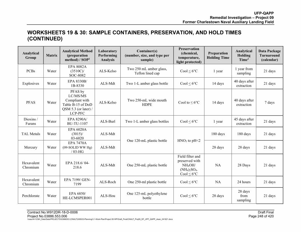
UFP-QAPP Remedial Investigation – Project 09
Former Charlestown Naval Auxiliary Landing Field
WORKSHEETS 19 & 30: SAMPLE CONTAINERS, PRESERVATION, AND HOLD TIMES (CONTINUED)
Contract No.W912DR-18-D-0006 Draft Final Project No.03886.553.006 Page 248 of 420 \\nascnh1\CNH_Data\Data\PROJECTS\03886553 (CNALF)\006\03-Planning\3.1-Work-Plan\Project 09 WP\Draft_Final\CNALF_Proj09_DF_UFP_QAPP_clean_041821.docx
Analytical Group Matrix
Analytical Method (preparation
method) / SOP1
Laboratory Performing
Analysis
Container(s) (number, size, and type per
sample)
Preservation (chemical,
temperature, light protected)
Preparation Holding Time
Analytical Holding Time2
Data Package Turnaround (calendar)
PCBs Water EPA 8082A
(3510C)/ SOC-8082
ALS-Kelso Two 250 mL amber glass, Teflon lined cap Cool < 6°C 1 year 1 year from
sampling 21 days
Explosives Water EPA 8330B/ 1B-8330 ALS-Mdt Two 1-L amber glass bottle Cool < 6°C 14 days 40 days after
extraction 21 days
PFAS Water
PFAS by LC/MS/MS
Compliant with Table B-15 of DoD QSM 5.3 (or later) /
LCP-PFC
ALS-Kelso Two 250-mL wide mouth HDPE Cool to ≤ 6°C 14 days 40 days after
extraction 7 days
Dioxins / Furans Water EPA 8290A/
BU-TU-1107 ALS-Burl Two 1-L amber glass bottles Cool < 6°C 1 year 45 days after extraction 21 days
TAL Metals Water EPA 6020A
(3015)/ 03-6020
ALS-Mdt
One 120-mL plastic bottle HNO3 to pH<2
180 days 180 days 21 days
Mercury Water EPA 7470A
(09-SOLID WW Hg) / 03-HG
ALS-Mdt 28 days 28 days 21 days
Hexavalent Chromium Water EPA 218.6/ 04-
218.6 ALS-Mdt One 250-mL plastic bottle
Field filter and preserved with
NH4OH/ (NH4)2SO4. Cool < 6°C
NA 28 Days 21 days
Hexavalent Chromium Water EPA 7199/ GEN-
7199 ALS-Roch One 250-ml plastic bottle Cool < 6°C NA 24 hours 21 days
Perchlorate Water EPA 6850/ HE-LCMSPER001 ALS-Hou One 125-mL polyethylene
bottle Cool < 6°C 28 days 28 days
from sampling
21 days
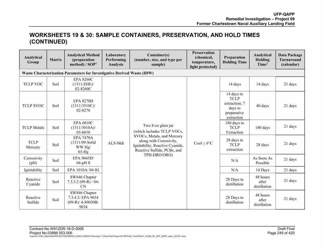
UFP-QAPP Remedial Investigation – Project 09
Former Charlestown Naval Auxiliary Landing Field
WORKSHEETS 19 & 30: SAMPLE CONTAINERS, PRESERVATION, AND HOLD TIMES (CONTINUED)
Contract No.W912DR-18-D-0006 Draft Final Project No.03886.553.006 Page 249 of 420 \\nascnh1\CNH_Data\Data\PROJECTS\03886553 (CNALF)\006\03-Planning\3.1-Work-Plan\Project 09 WP\Draft_Final\CNALF_Proj09_DF_UFP_QAPP_clean_041821.docx
Analytical Group Matrix
Analytical Method (preparation
method) / SOP1
Laboratory Performing
Analysis
Container(s) (number, size, and type per
sample)
Preservation (chemical,
temperature, light protected)
Preparation Holding Time
Analytical Holding Time2
Data Package Turnaround (calendar)
Waste Characterization Parameters for Investigative Derived Waste (IDW)
TCLP VOC Soil EPA 8260C (1311/ZHE)/
02-8260C
ALS-Mdt
Two 8-oz glass jar (which includes TCLP VOCs, SVOCs, Metals, and Mercury
along with Corrosivity, Ignitability, Reactive Cyanide, Reactive Sulfide, PCBs, and
TPH-DRO/ORO)
Cool < 6°C
14 days 14 days 21 days
TCLP SVOC Soil EPA 8270D
(1311/3510C)/ 02-8270
14 days to TCLP
extraction; 7 days to
preparative extraction
40 days 21 days
TCLP Metals Soil EPA 6010C
(1311/3010A)/ 03-6010
180 days to TCLP
Extraction 180 days 21 days
TCLP Mercury Soil
EPA 7470A (1311/09-Solid
WW Hg/ 03-Hg
28 days to TCLP
extraction 28 days 21 days
Corrosivity (pH) Soil EPA 9045D/
04-pH S N/A As Soon As Possible
21 days
Ignitability Soil EPA 1010A/ 04-IG N/A 14 Days 21 days
Reactive Cyanide Soil
SW846 Chapter 7.3.3.2 (09-R) / 04-
CN
28 Days to distillation
48 hours after
distillation 21 days
Reactive Sulfide Soil
SW846 Chapter 7.3.4.2/ EPA 9034 (09-R)/ 4-S9030B-
9034
28 Days to distillation
48 hours after
distillation 21 days
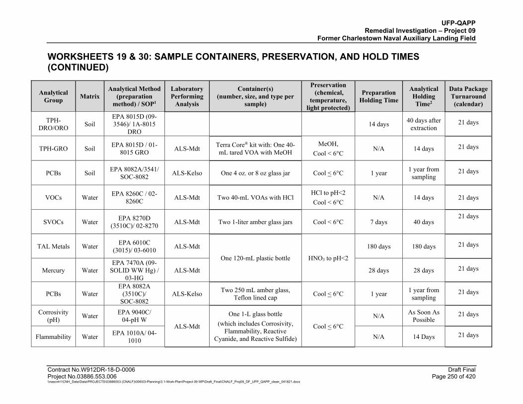
UFP-QAPP Remedial Investigation – Project 09
Former Charlestown Naval Auxiliary Landing Field
WORKSHEETS 19 & 30: SAMPLE CONTAINERS, PRESERVATION, AND HOLD TIMES (CONTINUED)
Contract No.W912DR-18-D-0006 Draft Final Project No.03886.553.006 Page 250 of 420 \\nascnh1\CNH_Data\Data\PROJECTS\03886553 (CNALF)\006\03-Planning\3.1-Work-Plan\Project 09 WP\Draft_Final\CNALF_Proj09_DF_UFP_QAPP_clean_041821.docx
Analytical Group Matrix
Analytical Method (preparation
method) / SOP1
Laboratory Performing
Analysis
Container(s) (number, size, and type per
sample)
Preservation (chemical,
temperature, light protected)
Preparation Holding Time
Analytical Holding Time2
Data Package Turnaround (calendar)
TPH-DRO/ORO Soil
EPA 8015D (09-3546)/ 1A-8015
DRO 14 days 40 days after
extraction 21 days
TPH-GRO Soil EPA 8015D / 01-8015 GRO ALS-Mdt Terra Core® kit with: One 40-
mL tared VOA with MeOH MeOH,
Cool < 6°C N/A 14 days 21 days
PCBs Soil EPA 8082A/3541/ SOC-8082 ALS-Kelso One 4 oz. or 8 oz glass jar Cool < 6°C 1 year 1 year from
sampling 21 days
VOCs Water EPA 8260C / 02-8260C ALS-Mdt Two 40-mL VOAs with HCl
HCl to pH<2 Cool < 6°C
N/A 14 days 21 days
SVOCs Water EPA 8270D (3510C)/ 02-8270 ALS-Mdt Two 1-liter amber glass jars Cool < 6°C 7 days 40 days
21 days
TAL Metals Water EPA 6010C (3015)/ 03-6010 ALS-Mdt
One 120-mL plastic bottle HNO3 to pH<2
180 days 180 days 21 days
Mercury Water EPA 7470A (09-
SOLID WW Hg) / 03-HG
ALS-Mdt 28 days 28 days 21 days
PCBs Water EPA 8082A
(3510C)/ SOC-8082
ALS-Kelso Two 250 mL amber glass, Teflon lined cap Cool < 6°C 1 year 1 year from
sampling 21 days
Corrosivity (pH) Water EPA 9040C/
04-pH W ALS-Mdt
One 1-L glass bottle (which includes Corrosivity,
Flammability, Reactive Cyanide, and Reactive Sulfide)
Cool < 6°C N/A As Soon As
Possible 21 days
Flammability Water EPA 1010A/ 04-1010 N/A 14 Days 21 days
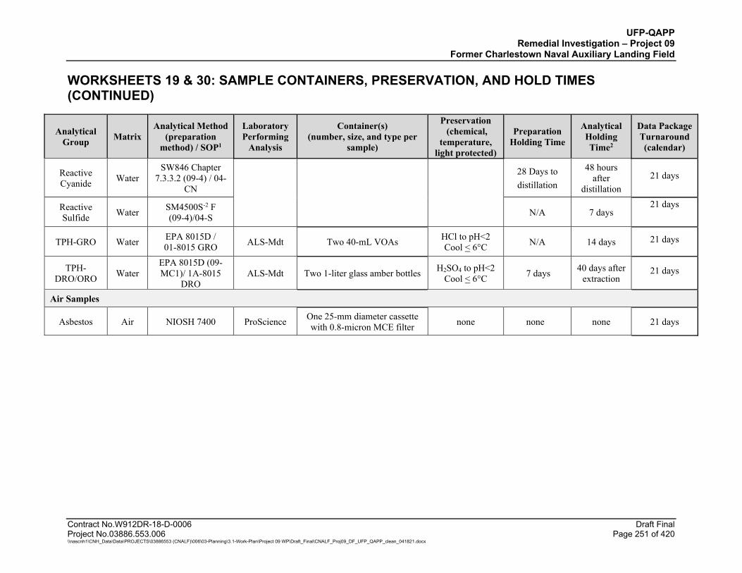
UFP-QAPP Remedial Investigation – Project 09
Former Charlestown Naval Auxiliary Landing Field
WORKSHEETS 19 & 30: SAMPLE CONTAINERS, PRESERVATION, AND HOLD TIMES (CONTINUED)
Contract No.W912DR-18-D-0006 Draft Final Project No.03886.553.006 Page 251 of 420 \\nascnh1\CNH_Data\Data\PROJECTS\03886553 (CNALF)\006\03-Planning\3.1-Work-Plan\Project 09 WP\Draft_Final\CNALF_Proj09_DF_UFP_QAPP_clean_041821.docx
Analytical Group Matrix
Analytical Method (preparation
method) / SOP1
Laboratory Performing
Analysis
Container(s) (number, size, and type per
sample)
Preservation (chemical,
temperature, light protected)
Preparation Holding Time
Analytical Holding Time2
Data Package Turnaround (calendar)
Reactive Cyanide Water
SW846 Chapter 7.3.3.2 (09-4) / 04-
CN
28 Days to distillation
48 hours after
distillation 21 days
Reactive Sulfide Water SM4500S-2 F
(09-4)/04-S N/A 7 days 21 days
TPH-GRO Water EPA 8015D / 01-8015 GRO ALS-Mdt Two 40-mL VOAs HCl to pH<2
Cool < 6°C N/A 14 days 21 days
TPH-DRO/ORO Water
EPA 8015D (09-MC1)/ 1A-8015
DRO ALS-Mdt Two 1-liter glass amber bottles H2SO4 to pH<2
Cool < 6°C 7 days 40 days after extraction
21 days
Air Samples
Asbestos Air NIOSH 7400 ProScience One 25-mm diameter cassette with 0.8-micron MCE filter none none none 21 days
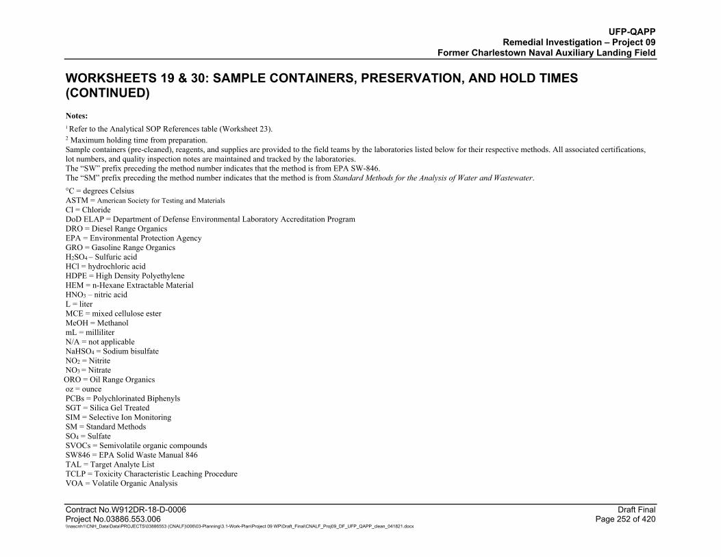
UFP-QAPP Remedial Investigation – Project 09
Former Charlestown Naval Auxiliary Landing Field
WORKSHEETS 19 & 30: SAMPLE CONTAINERS, PRESERVATION, AND HOLD TIMES (CONTINUED)
Contract No.W912DR-18-D-0006 Draft Final Project No.03886.553.006 Page 252 of 420 \\nascnh1\CNH_Data\Data\PROJECTS\03886553 (CNALF)\006\03-Planning\3.1-Work-Plan\Project 09 WP\Draft_Final\CNALF_Proj09_DF_UFP_QAPP_clean_041821.docx
Notes: 1 Refer to the Analytical SOP References table (Worksheet 23).
2 Maximum holding time from preparation. Sample containers (pre-cleaned), reagents, and supplies are provided to the field teams by the laboratories listed below for their respective methods. All associated certifications, lot numbers, and quality inspection notes are maintained and tracked by the laboratories. The “SW” prefix preceding the method number indicates that the method is from EPA SW-846. The “SM” prefix preceding the method number indicates that the method is from Standard Methods for the Analysis of Water and Wastewater. °C = degrees Celsius ASTM = American Society for Testing and Materials Cl = Chloride DoD ELAP = Department of Defense Environmental Laboratory Accreditation Program DRO = Diesel Range Organics EPA = Environmental Protection Agency GRO = Gasoline Range Organics H2SO4 – Sulfuric acid HCl = hydrochloric acid HDPE = High Density Polyethylene HEM = n-Hexane Extractable Material HNO3 – nitric acid L = liter MCE = mixed cellulose ester MeOH = Methanol mL = milliliter N/A = not applicable NaHSO4 = Sodium bisulfate NO2 = Nitrite NO3 = Nitrate ORO = Oil Range Organics oz = ounce PCBs = Polychlorinated Biphenyls SGT = Silica Gel Treated SIM = Selective Ion Monitoring SM = Standard Methods SO4 = Sulfate SVOCs = Semivolatile organic compounds SW846 = EPA Solid Waste Manual 846 TAL = Target Analyte List TCLP = Toxicity Characteristic Leaching Procedure VOA = Volatile Organic Analysis
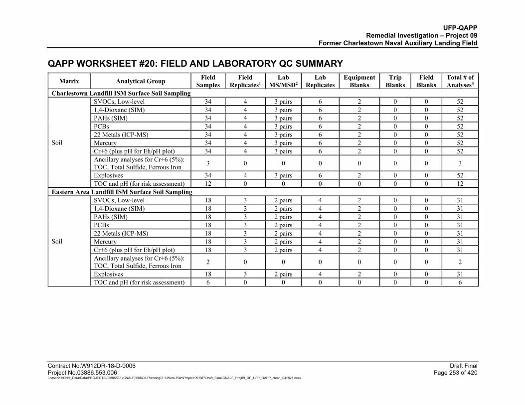
UFP-QAPP Remedial Investigation – Project 09
Former Charlestown Naval Auxiliary Landing Field
Contract No.W912DR-18-D-0006 Draft Final Project No.03886.553.006 Page 253 of 420 \\nascnh1\CNH_Data\Data\PROJECTS\03886553 (CNALF)\006\03-Planning\3.1-Work-Plan\Project 09 WP\Draft_Final\CNALF_Proj09_DF_UFP_QAPP_clean_041821.docx
QAPP WORKSHEET #20: FIELD AND LABORATORY QC SUMMARY
Matrix Analytical Group Field Samples
Field Replicates1
Lab MS/MSD2
Lab Replicates
Equipment Blanks
Trip Blanks
Field Blanks
Total # of Analyses3
Charlestown Landfill ISM Surface Soil Sampling
Soil
SVOCs, Low-level 34 4 3 pairs 6 2 0 0 52 1,4-Dioxane (SIM) 34 4 3 pairs 6 2 0 0 52 PAHs (SIM) 34 4 3 pairs 6 2 0 0 52 PCBs 34 4 3 pairs 6 2 0 0 52 22 Metals (ICP-MS) 34 4 3 pairs 6 2 0 0 52 Mercury 34 4 3 pairs 6 2 0 0 52 Cr+6 (plus pH for Eh/pH plot) 34 4 3 pairs 6 2 0 0 52 Ancillary analyses for Cr+6 (5%): TOC, Total Sulfide, Ferrous Iron 3 0 0 0 0 0 0 3
Explosives 34 4 3 pairs 6 2 0 0 52 TOC and pH (for risk assessment) 12 0 0 0 0 0 0 12
Eastern Area Landfill ISM Surface Soil Sampling
Soil
SVOCs, Low-level 18 3 2 pairs 4 2 0 0 31 1,4-Dioxane (SIM) 18 3 2 pairs 4 2 0 0 31 PAHs (SIM) 18 3 2 pairs 4 2 0 0 31 PCBs 18 3 2 pairs 4 2 0 0 31 22 Metals (ICP-MS) 18 3 2 pairs 4 2 0 0 31 Mercury 18 3 2 pairs 4 2 0 0 31 Cr+6 (plus pH for Eh/pH plot) 18 3 2 pairs 4 2 0 0 31 Ancillary analyses for Cr+6 (5%): TOC, Total Sulfide, Ferrous Iron 2 0 0 0 0 0 0 2
Explosives 18 3 2 pairs 4 2 0 0 31 TOC and pH (for risk assessment) 6 0 0 0 0 0 0 6
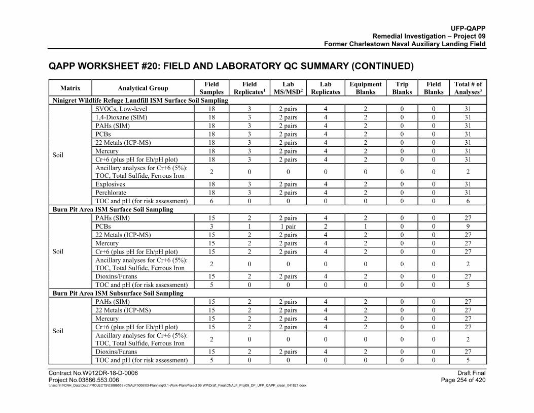
UFP-QAPP Remedial Investigation – Project 09
Former Charlestown Naval Auxiliary Landing Field QAPP WORKSHEET #20: FIELD AND LABORATORY QC SUMMARY (CONTINUED)
Contract No.W912DR-18-D-0006 Draft Final Project No.03886.553.006 Page 254 of 420 \\nascnh1\CNH_Data\Data\PROJECTS\03886553 (CNALF)\006\03-Planning\3.1-Work-Plan\Project 09 WP\Draft_Final\CNALF_Proj09_DF_UFP_QAPP_clean_041821.docx
Matrix Analytical Group Field Samples
Field Replicates1
Lab MS/MSD2
Lab Replicates
Equipment Blanks
Trip Blanks
Field Blanks
Total # of Analyses3
Ninigret Wildlife Refuge Landfill ISM Surface Soil Sampling
Soil
SVOCs, Low-level 18 3 2 pairs 4 2 0 0 31 1,4-Dioxane (SIM) 18 3 2 pairs 4 2 0 0 31 PAHs (SIM) 18 3 2 pairs 4 2 0 0 31 PCBs 18 3 2 pairs 4 2 0 0 31 22 Metals (ICP-MS) 18 3 2 pairs 4 2 0 0 31 Mercury 18 3 2 pairs 4 2 0 0 31 Cr+6 (plus pH for Eh/pH plot) 18 3 2 pairs 4 2 0 0 31 Ancillary analyses for Cr+6 (5%): TOC, Total Sulfide, Ferrous Iron 2 0 0 0 0 0 0 2
Explosives 18 3 2 pairs 4 2 0 0 31 Perchlorate 18 3 2 pairs 4 2 0 0 31 TOC and pH (for risk assessment) 6 0 0 0 0 0 0 6
Burn Pit Area ISM Surface Soil Sampling
Soil
PAHs (SIM) 15 2 2 pairs 4 2 0 0 27 PCBs 3 1 1 pair 2 1 0 0 9 22 Metals (ICP-MS) 15 2 2 pairs 4 2 0 0 27 Mercury 15 2 2 pairs 4 2 0 0 27 Cr+6 (plus pH for Eh/pH plot) 15 2 2 pairs 4 2 0 0 27 Ancillary analyses for Cr+6 (5%): TOC, Total Sulfide, Ferrous Iron 2 0 0 0 0 0 0 2
Dioxins/Furans 15 2 2 pairs 4 2 0 0 27 TOC and pH (for risk assessment) 5 0 0 0 0 0 0 5
Burn Pit Area ISM Subsurface Soil Sampling
Soil
PAHs (SIM) 15 2 2 pairs 4 2 0 0 27 22 Metals (ICP-MS) 15 2 2 pairs 4 2 0 0 27 Mercury 15 2 2 pairs 4 2 0 0 27 Cr+6 (plus pH for Eh/pH plot) 15 2 2 pairs 4 2 0 0 27 Ancillary analyses for Cr+6 (5%): TOC, Total Sulfide, Ferrous Iron 2 0 0 0 0 0 0 2
Dioxins/Furans 15 2 2 pairs 4 2 0 0 27 TOC and pH (for risk assessment) 5 0 0 0 0 0 0 5
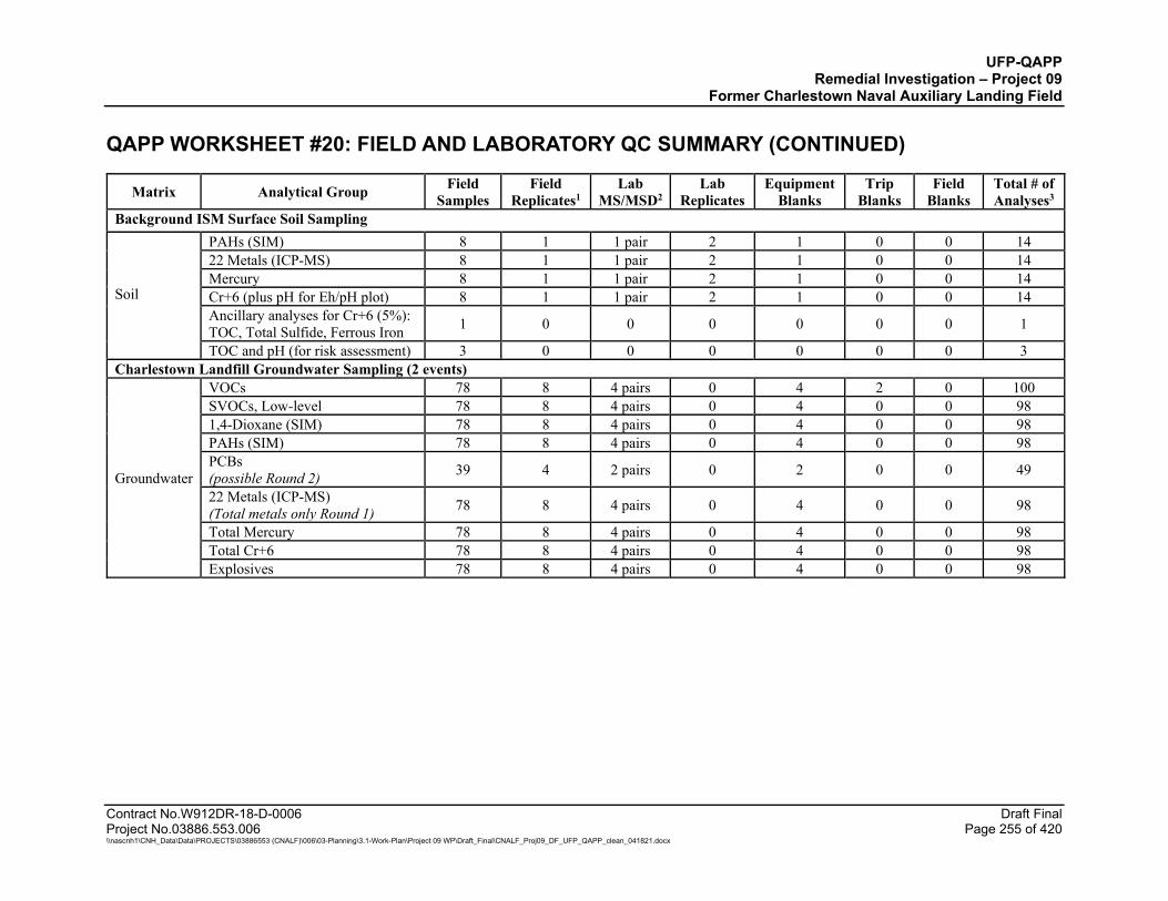
UFP-QAPP Remedial Investigation – Project 09
Former Charlestown Naval Auxiliary Landing Field QAPP WORKSHEET #20: FIELD AND LABORATORY QC SUMMARY (CONTINUED)
Contract No.W912DR-18-D-0006 Draft Final Project No.03886.553.006 Page 255 of 420 \\nascnh1\CNH_Data\Data\PROJECTS\03886553 (CNALF)\006\03-Planning\3.1-Work-Plan\Project 09 WP\Draft_Final\CNALF_Proj09_DF_UFP_QAPP_clean_041821.docx
Matrix Analytical Group Field Samples
Field Replicates1
Lab MS/MSD2
Lab Replicates
Equipment Blanks
Trip Blanks
Field Blanks
Total # of Analyses3
Background ISM Surface Soil Sampling
Soil
PAHs (SIM) 8 1 1 pair 2 1 0 0 14 22 Metals (ICP-MS) 8 1 1 pair 2 1 0 0 14 Mercury 8 1 1 pair 2 1 0 0 14 Cr+6 (plus pH for Eh/pH plot) 8 1 1 pair 2 1 0 0 14 Ancillary analyses for Cr+6 (5%): TOC, Total Sulfide, Ferrous Iron 1 0 0 0 0 0 0 1
TOC and pH (for risk assessment) 3 0 0 0 0 0 0 3 Charlestown Landfill Groundwater Sampling (2 events)
Groundwater
VOCs 78 8 4 pairs 0 4 2 0 100 SVOCs, Low-level 78 8 4 pairs 0 4 0 0 98 1,4-Dioxane (SIM) 78 8 4 pairs 0 4 0 0 98 PAHs (SIM) 78 8 4 pairs 0 4 0 0 98 PCBs (possible Round 2)
39 4 2 pairs 0 2 0 0 49
22 Metals (ICP-MS) (Total metals only Round 1)
78 8 4 pairs 0 4 0 0 98
Total Mercury 78 8 4 pairs 0 4 0 0 98 Total Cr+6 78 8 4 pairs 0 4 0 0 98 Explosives 78 8 4 pairs 0 4 0 0 98
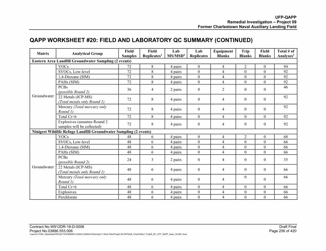
UFP-QAPP Remedial Investigation – Project 09
Former Charlestown Naval Auxiliary Landing Field QAPP WORKSHEET #20: FIELD AND LABORATORY QC SUMMARY (CONTINUED)
Contract No.W912DR-18-D-0006 Draft Final Project No.03886.553.006 Page 256 of 420 \\nascnh1\CNH_Data\Data\PROJECTS\03886553 (CNALF)\006\03-Planning\3.1-Work-Plan\Project 09 WP\Draft_Final\CNALF_Proj09_DF_UFP_QAPP_clean_041821.docx
Matrix Analytical Group Field Samples
Field Replicates1
Lab MS/MSD2
Lab Replicates
Equipment Blanks
Trip Blanks
Field Blanks
Total # of Analyses3
Eastern Area Landfill Groundwater Sampling (2 events)
Groundwater
VOCs 72 8 4 pairs 0 4 2 0 94 SVOCs, Low-level 72 8 4 pairs 0 4 0 0 92 1,4-Dioxane (SIM) 72 8 4 pairs 0 4 0 0 92 PAHs (SIM) 72 8 4 pairs 0 4 0 0 92 PCBs (possible Round 2) 36 4 2 pairs 0 2 0 0 46
22 Metals (ICP-MS) (Total metals only Round 1) 72 8 4 pairs 0 4 0 0 92
Mercury (Total mercury only Round 1) 72 8 4 pairs 0 4 0 0 92
Total Cr+6 72 8 4 pairs 0 4 0 0 92 Explosives (assumes Round 2 samples will be collected) 72 8 4 pairs 0 4 0 0 92
Ninigret Wildlife Refuge Landfill Groundwater Sampling (2 events)
Groundwater
VOCs 48 6 4 pairs 0 4 2 0 68 SVOCs, Low-level 48 6 4 pairs 0 4 0 0 66 1,4-Dioxane (SIM) 48 6 4 pairs 0 4 0 0 66 PAHs (SIM) 48 6 4 pairs 0 4 0 0 66 PCBs (possible Round 2) 24 3 2 pairs 0 4 0 0 35
22 Metals (ICP-MS) (Total metals only Round 1) 48 6 4 pairs 0 4 0 0 66
Mercury (Total mercury only Round 1) 48 6 4 pairs 0 4 0 0 66
Total Cr+6 48 6 4 pairs 0 4 0 0 66 Explosives 48 6 4 pairs 0 4 0 0 66 Perchlorate 48 6 4 pairs 0 4 0 0 66
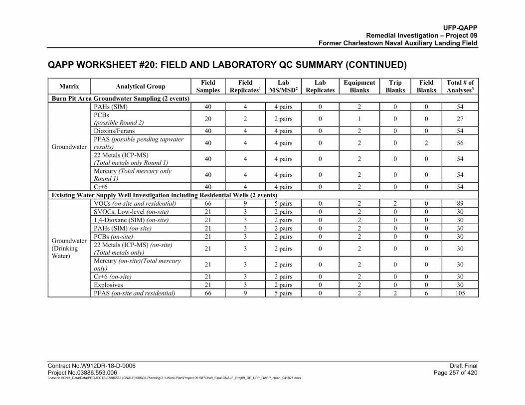
UFP-QAPP Remedial Investigation – Project 09
Former Charlestown Naval Auxiliary Landing Field QAPP WORKSHEET #20: FIELD AND LABORATORY QC SUMMARY (CONTINUED)
Contract No.W912DR-18-D-0006 Draft Final Project No.03886.553.006 Page 257 of 420 \\nascnh1\CNH_Data\Data\PROJECTS\03886553 (CNALF)\006\03-Planning\3.1-Work-Plan\Project 09 WP\Draft_Final\CNALF_Proj09_DF_UFP_QAPP_clean_041821.docx
Matrix Analytical Group Field Samples
Field Replicates1
Lab MS/MSD2
Lab Replicates
Equipment Blanks
Trip Blanks
Field Blanks
Total # of Analyses3
Burn Pit Area Groundwater Sampling (2 events)
Groundwater
PAHs (SIM) 40 4 4 pairs 0 2 0 0 54 PCBs (possible Round 2) 20 2 2 pairs 0 1 0 0 27
Dioxins/Furans 40 4 4 pairs 0 2 0 0 54 PFAS (possible pending tapwater results) 40 4 4 pairs 0 2 0 2 56
22 Metals (ICP-MS) (Total metals only Round 1) 40 4 4 pairs 0 2 0 0 54
Mercury (Total mercury only Round 1) 40 4 4 pairs 0 2 0 0 54
Cr+6 40 4 4 pairs 0 2 0 0 54 Existing Water Supply Well Investigation including Residential Wells (2 events)
Groundwater (Drinking Water)
VOCs (on-site and residential) 66 9 5 pairs 0 2 2 0 89 SVOCs, Low-level (on-site) 21 3 2 pairs 0 2 0 0 30 1,4-Dioxane (SIM) (on-site) 21 3 2 pairs 0 2 0 0 30 PAHs (SIM) (on-site) 21 3 2 pairs 0 2 0 0 30 PCBs (on-site) 21 3 2 pairs 0 2 0 0 30 22 Metals (ICP-MS) (on-site) (Total metals only) 21 3 2 pairs 0 2 0 0 30
Mercury (on-site)(Total mercury only) 21 3 2 pairs 0 2 0 0 30
Cr+6 (on-site) 21 3 2 pairs 0 2 0 0 30 Explosives 21 3 2 pairs 0 2 0 0 30 PFAS (on-site and residential) 66 9 5 pairs 0 2 2 6 105

UFP-QAPP Remedial Investigation – Project 09
Former Charlestown Naval Auxiliary Landing Field QAPP WORKSHEET #20: FIELD AND LABORATORY QC SUMMARY (CONTINUED)
Contract No.W912DR-18-D-0006 Draft Final Project No.03886.553.006 Page 258 of 420 \\nascnh1\CNH_Data\Data\PROJECTS\03886553 (CNALF)\006\03-Planning\3.1-Work-Plan\Project 09 WP\Draft_Final\CNALF_Proj09_DF_UFP_QAPP_clean_041821.docx
Matrix Analytical Group Field Samples
Field Replicates1
Lab MS/MSD2
Lab Replicates
Equipment Blanks
Trip Blanks
Field Blanks
Total # of Analyses3
Charlestown Landfill Sediment Sampling (ISM for all except VOCs)
Sediment
VOCs 15 2 2 pairs 0 2 2 0 25 SVOCs, Low-level 15 2 2 pairs 4 2 0 0 27 1,4-Dioxane (SIM) 15 2 2 pairs 4 2 0 0 27 PAHs (SIM) 15 2 2 pairs 4 2 0 0 27 22 Metals (ICP-MS) 15 2 2 pairs 4 2 0 0 27 Mercury 15 2 2 pairs 4 2 0 0 27 Cr+6 (plus pH for Eh/pH plot) 15 2 2 pairs 4 2 0 0 27 Ancillary analyses for Cr+6: TOC, Total Sulfide, Ferrous Iron 2 0 0 0 0 0 0 2
Explosives 15 2 2 pairs 4 2 0 0 27 TOC (risk assessment) 5 0 0 0 0 0 0 5
Eastern Area Landfill Sediment Sampling (ISM for all except VOCs)
Sediment
VOCs 15 2 2 pairs 0 2 2 0 25 SVOCs, Low-level 15 2 2 pairs 4 2 0 0 27 1,4-Dioxane (SIM) 15 2 2 pairs 4 2 0 0 27 PAHs (SIM) 15 2 2 pairs 4 2 0 0 27 22 Metals (ICP-MS) 15 2 2 pairs 4 2 0 0 27 Mercury 15 2 2 pairs 4 2 0 0 27 Cr+6 (plus pH for Eh/pH plot) 15 2 2 pairs 4 2 0 0 27 Ancillary analyses for Cr+6: TOC, Total Sulfide, Ferrous Iron 2 0 0 0 0 0 0 2
Explosives 15 2 2 pairs 4 2 0 0 27 TOC (risk assessment) 5 0 0 0 0 0 0 5

UFP-QAPP Remedial Investigation – Project 09
Former Charlestown Naval Auxiliary Landing Field QAPP WORKSHEET #20: FIELD AND LABORATORY QC SUMMARY (CONTINUED)
Contract No.W912DR-18-D-0006 Draft Final Project No.03886.553.006 Page 259 of 420 \\nascnh1\CNH_Data\Data\PROJECTS\03886553 (CNALF)\006\03-Planning\3.1-Work-Plan\Project 09 WP\Draft_Final\CNALF_Proj09_DF_UFP_QAPP_clean_041821.docx
Matrix Analytical Group Field Samples
Field Replicates1
Lab MS/MSD2
Lab Replicates
Equipment Blanks
Trip Blanks
Field Blanks
Total # of Analyses3
Ninigret Wildlife Refuge Landfill Sediment Sampling (ISM for all except VOCs)
Sediment
VOCs 15 2 1 pair 0 2 2 0 22 SVOCs, Low-level 15 2 1 pair 2 1 0 0 22 1,4-Dioxane (SIM) 15 2 1 pair 2 1 0 0 22 PAHs (SIM) 15 2 1 pair 2 1 0 0 22 22 Metals (ICP-MS) 15 2 1 pair 2 1 0 0 22 Mercury 15 2 1 pair 2 1 0 0 22 Cr+6 (plus pH for Eh/pH plot) 15 2 1 pair 2 1 0 0 22 Ancillary analyses for Cr+6: TOC, Total Sulfide, Ferrous Iron 1 0 0 0 0 0 0 1
TOC (risk assessment) 5 0 0 0 0 0 0 5 Explosives 15 2 1 pair 2 1 0 0 22 Perchlorate 15 2 1 pair 2 1 0 0 22
Background Sediment Sampling (Freshwater Wetland, Tidal Wetland and Tidal Shoreline) (ISM)
Sediment
PAHs (SIM) 24 3 3 pairs 6 2 0 0 39 22 Metals (ICP-MS) 24 3 3 pairs 6 2 0 0 39 Mercury 24 3 3 pairs 6 2 0 0 39 Cr+6 (plus pH for Eh/pH plot) 24 3 3 pairs 6 2 0 0 39 Ancillary analyses for Cr+6: TOC, Total Sulfide, Ferrous Iron 3 0 0 0 0 0 0 3
TOC (risk assessment) 9 0 0 0 0 0 0 9 Charlestown Landfill Surface/Pore Water Sampling
Aqueous (Surface Water / Pore Water)
VOCs 30 4 4 pairs 0 2 2 0 46 SVOCs, Low-level 30 4 4 pairs 0 2 0 0 44 1,4-Dioxane (SIM) 30 4 4 pairs 0 2 0 0 44 PAHs (SIM) 30 4 4 pairs 0 2 0 0 44 22 Metals (ICP-MS) - Dissolved 30 4 4 pairs 0 2 0 0 44 Hardness by calculation 30 0 0 0 0 0 0 30 Dissolved Mercury 30 4 4 pairs 0 2 0 0 44 Dissolved Cr+6 30 4 4 pairs 0 2 0 0 44 Explosives 30 4 4 pairs 0 2 0 0 44
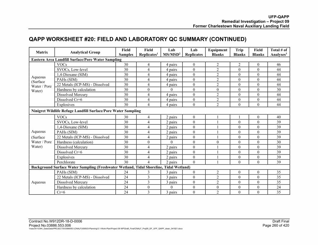
UFP-QAPP Remedial Investigation – Project 09
Former Charlestown Naval Auxiliary Landing Field QAPP WORKSHEET #20: FIELD AND LABORATORY QC SUMMARY (CONTINUED)
Contract No.W912DR-18-D-0006 Draft Final Project No.03886.553.006 Page 260 of 420 \\nascnh1\CNH_Data\Data\PROJECTS\03886553 (CNALF)\006\03-Planning\3.1-Work-Plan\Project 09 WP\Draft_Final\CNALF_Proj09_DF_UFP_QAPP_clean_041821.docx
Matrix Analytical Group Field Samples
Field Replicates1
Lab MS/MSD2
Lab Replicates
Equipment Blanks
Trip Blanks
Field Blanks
Total # of Analyses3
Eastern Area Landfill Surface/Pore Water Sampling
Aqueous (Surface Water / Pore Water)
VOCs 30 4 4 pairs 0 2 2 0 46 SVOCs, Low-level 30 4 4 pairs 0 2 0 0 44 1,4-Dioxane (SIM) 30 4 4 pairs 0 2 0 0 44 PAHs (SIM) 30 4 4 pairs 0 2 0 0 44 22 Metals (ICP-MS) - Dissolved 30 4 4 pairs 0 2 0 0 44 Hardness by calculation 30 0 0 0 0 0 0 30 Dissolved Mercury 30 4 4 pairs 0 2 0 0 44 Dissolved Cr+6 30 4 4 pairs 0 2 0 0 44 Explosives 30 4 4 pairs 0 2 0 0 44
Ninigret Wildlife Refuge Landfill Surface/Pore Water Sampling
Aqueous (Surface Water / Pore Water)
VOCs 30 4 2 pairs 0 1 1 0 40 SVOCs, Low-level 30 4 2 pairs 0 1 0 0 39 1,4-Dioxane (SIM) 30 4 2 pairs 0 1 0 0 39 PAHs (SIM) 30 4 2 pairs 0 1 0 0 39 22 Metals (ICP-MS) - Dissolved 30 4 2 pairs 0 1 0 0 39 Hardness (calculation) 30 0 0 0 0 0 0 30 Dissolved Mercury 30 4 2 pairs 0 1 0 0 39 Dissolved Cr+6 30 4 2 pairs 0 1 0 0 39 Explosives 30 4 2 pairs 0 1 0 0 39 Perchlorate 30 4 2 pairs 0 1 0 0 39
Background Surface Water Sampling (Freshwater Wetland, Tidal Shoreline, Tidal Wetland)
Aqueous
PAHs (SIM) 24 3 3 pairs 0 2 0 0 35 22 Metals (ICP-MS) - Dissolved 24 3 3 pairs 0 2 0 0 35 Dissolved Mercury 24 3 3 pairs 0 2 0 0 35 Hardness by calculation 24 0 0 0 0 0 0 24 Cr+6 24 3 3 pairs 0 2 0 0 35
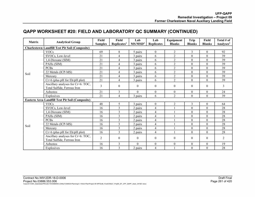
UFP-QAPP Remedial Investigation – Project 09
Former Charlestown Naval Auxiliary Landing Field QAPP WORKSHEET #20: FIELD AND LABORATORY QC SUMMARY (CONTINUED)
Contract No.W912DR-18-D-0006 Draft Final Project No.03886.553.006 Page 261 of 420 \\nascnh1\CNH_Data\Data\PROJECTS\03886553 (CNALF)\006\03-Planning\3.1-Work-Plan\Project 09 WP\Draft_Final\CNALF_Proj09_DF_UFP_QAPP_clean_041821.docx
Matrix Analytical Group Field Samples
Field Replicates1
Lab MS/MSD2
Lab Replicates
Equipment Blanks
Trip Blanks
Field Blanks
Total # of Analyses3
Charlestown Landfill Test Pit Soil (Composite)
Soil
VOCs 69 8 5 pairs 0 2 3 0 92 SVOCs, Low-level 21 4 3 pairs 6 2 0 0 39 1,4-Dioxane (SIM) 21 4 3 pairs 6 2 0 0 39 PAHs (SIM) 21 4 3 pairs 6 2 0 0 39 PCBs 21 4 3 pairs 6 2 0 0 39 22 Metals (ICP-MS) 21 4 3 pairs 6 2 0 0 39 Mercury 21 4 3 pairs 6 2 0 0 39 Cr+6 (plus pH for Eh/pH plot) 21 4 3 pairs 6 2 0 0 39 Ancillary analyses for Cr+6: TOC, Total Sulfide, Ferrous Iron 3 0 0 0 0 0 0 3
Asbestos 21 3 0 0 0 0 0 24 Explosives 21 4 3 pairs 6 2 0 0 39
Eastern Area Landfill Test Pit Soil (Composite)
Soil
VOCs 48 5 3 pairs 0 2 3 0 64 SVOCs, Low-level 16 3 2 pairs 4 1 0 0 28 1,4-Dioxane (SIM) 16 3 2 pairs 4 1 0 0 28 PAHs (SIM) 16 3 2 pairs 4 1 0 0 28 PCBs 16 3 2 pairs 4 1 0 0 28 22 Metals (ICP-MS) 16 3 2 pairs 4 1 0 0 28 Mercury 16 3 2 pairs 4 1 0 0 28 Cr+6 (plus pH for Eh/pH plot) 16 3 2 pairs 4 1 0 0 28 Ancillary analyses for Cr+6: TOC, Total Sulfide, Ferrous Iron 2 0 0 0 0 0 0 2
Asbestos 16 3 0 0 0 0 0 19 Explosives 16 3 2 pairs 4 1 0 0 28
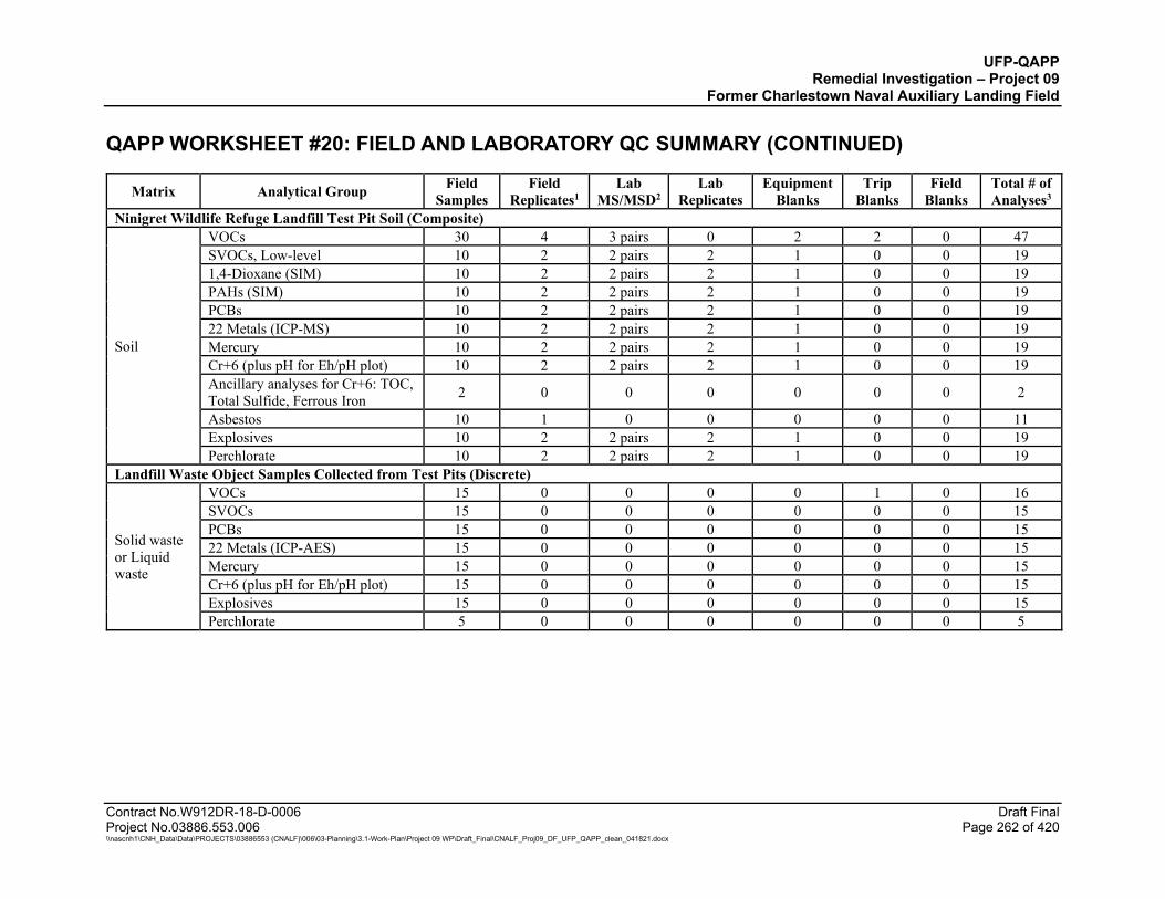
UFP-QAPP Remedial Investigation – Project 09
Former Charlestown Naval Auxiliary Landing Field QAPP WORKSHEET #20: FIELD AND LABORATORY QC SUMMARY (CONTINUED)
Contract No.W912DR-18-D-0006 Draft Final Project No.03886.553.006 Page 262 of 420 \\nascnh1\CNH_Data\Data\PROJECTS\03886553 (CNALF)\006\03-Planning\3.1-Work-Plan\Project 09 WP\Draft_Final\CNALF_Proj09_DF_UFP_QAPP_clean_041821.docx
Matrix Analytical Group Field Samples
Field Replicates1
Lab MS/MSD2
Lab Replicates
Equipment Blanks
Trip Blanks
Field Blanks
Total # of Analyses3
Ninigret Wildlife Refuge Landfill Test Pit Soil (Composite)
Soil
VOCs 30 4 3 pairs 0 2 2 0 47 SVOCs, Low-level 10 2 2 pairs 2 1 0 0 19 1,4-Dioxane (SIM) 10 2 2 pairs 2 1 0 0 19 PAHs (SIM) 10 2 2 pairs 2 1 0 0 19 PCBs 10 2 2 pairs 2 1 0 0 19 22 Metals (ICP-MS) 10 2 2 pairs 2 1 0 0 19 Mercury 10 2 2 pairs 2 1 0 0 19 Cr+6 (plus pH for Eh/pH plot) 10 2 2 pairs 2 1 0 0 19 Ancillary analyses for Cr+6: TOC, Total Sulfide, Ferrous Iron 2 0 0 0 0 0 0 2
Asbestos 10 1 0 0 0 0 0 11 Explosives 10 2 2 pairs 2 1 0 0 19 Perchlorate 10 2 2 pairs 2 1 0 0 19
Landfill Waste Object Samples Collected from Test Pits (Discrete)
Solid waste or Liquid waste
VOCs 15 0 0 0 0 1 0 16 SVOCs 15 0 0 0 0 0 0 15 PCBs 15 0 0 0 0 0 0 15 22 Metals (ICP-AES) 15 0 0 0 0 0 0 15 Mercury 15 0 0 0 0 0 0 15 Cr+6 (plus pH for Eh/pH plot) 15 0 0 0 0 0 0 15 Explosives 15 0 0 0 0 0 0 15 Perchlorate 5 0 0 0 0 0 0 5
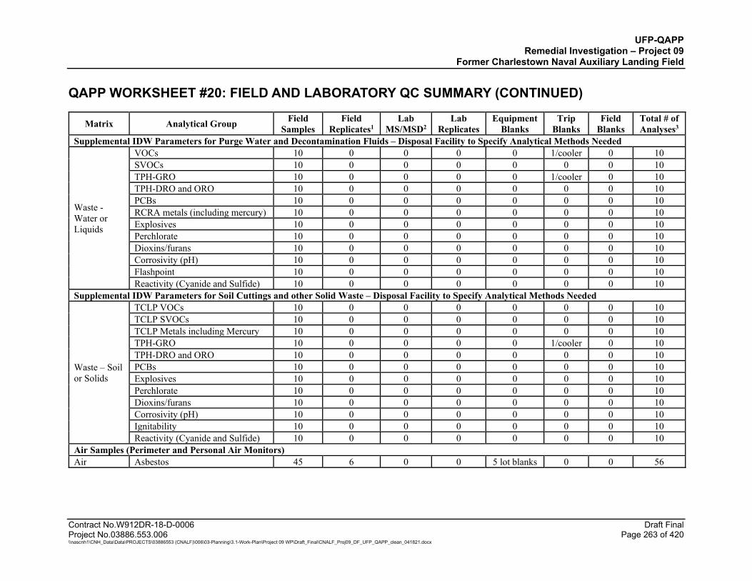
UFP-QAPP Remedial Investigation – Project 09
Former Charlestown Naval Auxiliary Landing Field QAPP WORKSHEET #20: FIELD AND LABORATORY QC SUMMARY (CONTINUED)
Contract No.W912DR-18-D-0006 Draft Final Project No.03886.553.006 Page 263 of 420 \\nascnh1\CNH_Data\Data\PROJECTS\03886553 (CNALF)\006\03-Planning\3.1-Work-Plan\Project 09 WP\Draft_Final\CNALF_Proj09_DF_UFP_QAPP_clean_041821.docx
Matrix Analytical Group Field Samples
Field Replicates1
Lab MS/MSD2
Lab Replicates
Equipment Blanks
Trip Blanks
Field Blanks
Total # of Analyses3
Supplemental IDW Parameters for Purge Water and Decontamination Fluids – Disposal Facility to Specify Analytical Methods Needed
Waste - Water or Liquids
VOCs 10 0 0 0 0 1/cooler 0 10 SVOCs 10 0 0 0 0 0 0 10 TPH-GRO 10 0 0 0 0 1/cooler 0 10 TPH-DRO and ORO 10 0 0 0 0 0 0 10 PCBs 10 0 0 0 0 0 0 10 RCRA metals (including mercury) 10 0 0 0 0 0 0 10 Explosives 10 0 0 0 0 0 0 10 Perchlorate 10 0 0 0 0 0 0 10 Dioxins/furans 10 0 0 0 0 0 0 10 Corrosivity (pH) 10 0 0 0 0 0 0 10 Flashpoint 10 0 0 0 0 0 0 10 Reactivity (Cyanide and Sulfide) 10 0 0 0 0 0 0 10
Supplemental IDW Parameters for Soil Cuttings and other Solid Waste – Disposal Facility to Specify Analytical Methods Needed
Waste – Soil or Solids
TCLP VOCs 10 0 0 0 0 0 0 10 TCLP SVOCs 10 0 0 0 0 0 0 10 TCLP Metals including Mercury 10 0 0 0 0 0 0 10 TPH-GRO 10 0 0 0 0 1/cooler 0 10 TPH-DRO and ORO 10 0 0 0 0 0 0 10 PCBs 10 0 0 0 0 0 0 10 Explosives 10 0 0 0 0 0 0 10 Perchlorate 10 0 0 0 0 0 0 10 Dioxins/furans 10 0 0 0 0 0 0 10 Corrosivity (pH) 10 0 0 0 0 0 0 10 Ignitability 10 0 0 0 0 0 0 10 Reactivity (Cyanide and Sulfide) 10 0 0 0 0 0 0 10
Air Samples (Perimeter and Personal Air Monitors) Air Asbestos 45 6 0 0 5 lot blanks 0 0 56
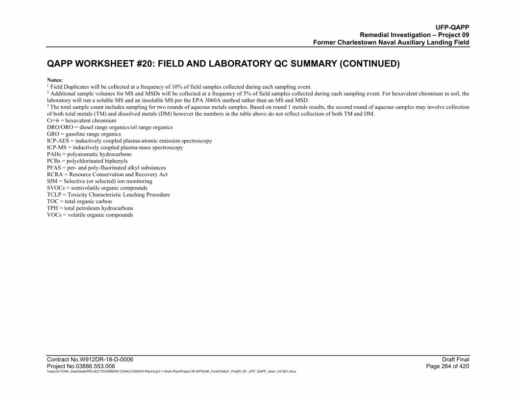
UFP-QAPP Remedial Investigation – Project 09
Former Charlestown Naval Auxiliary Landing Field QAPP WORKSHEET #20: FIELD AND LABORATORY QC SUMMARY (CONTINUED)
Contract No.W912DR-18-D-0006 Draft Final Project No.03886.553.006 Page 264 of 420 \\nascnh1\CNH_Data\Data\PROJECTS\03886553 (CNALF)\006\03-Planning\3.1-Work-Plan\Project 09 WP\Draft_Final\CNALF_Proj09_DF_UFP_QAPP_clean_041821.docx
Notes: 1 Field Duplicates will be collected at a frequency of 10% of field samples collected during each sampling event. 2 Additional sample volumes for MS and MSDs will be collected at a frequency of 5% of field samples collected during each sampling event. For hexavalent chromium in soil, the laboratory will run a soluble MS and an insoluble MS per the EPA 3060A method rather than an MS and MSD. 3 The total sample count includes sampling for two rounds of aqueous metals samples. Based on round 1 metals results, the second round of aqueous samples may involve collection of both total metals (TM) and dissolved metals (DM) however the numbers in the table above do not reflect collection of both TM and DM. Cr+6 = hexavalent chromium DRO/ORO = diesel range organics/oil range organics GRO = gasoline range organics ICP-AES = inductively coupled plasma-atomic emission spectroscopy ICP-MS = inductively coupled plasma-mass spectroscopy PAHs = polyaromatic hydrocarbons PCBs = polychlorinated biphenyls PFAS = per- and poly-fluorinated alkyl substances RCRA = Resource Conservation and Recovery Act SIM = Selective (or selected) ion monitoring SVOCs = semivolatile organic compounds TCLP = Toxicity Characteristic Leaching Procedure TOC = total organic carbon TPH = total petroleum hydrocarbons VOCs = volatile organic compounds
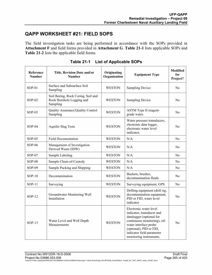
UFP-QAPP Remedial Investigation – Project 09
Former Charlestown Naval Auxiliary Landing Field
Contract No.W912DR-18-D-0006 Draft Final Project No.03886.553.006 Page 265 of 420 \\nascnh1\CNH_Data\Data\PROJECTS\03886553 (CNALF)\006\03-Planning\3.1-Work-Plan\Project 09 WP\Draft_Final\CNALF_Proj09_DF_UFP_QAPP_clean_041821.docx
QAPP WORKSHEET #21: FIELD SOPS
The field investigation tasks are being performed in accordance with the SOPs provided in Attachment F and field forms provided in Attachment G. Table 21-1 lists applicable SOPs and Table 21-2 lists the applicable field forms.
Table 21-1 List of Applicable SOPs
Reference Number
Title, Revision Date and/or Number
Originating Organization Equipment Type
Modified for
Project?
SOP-01 Surface and Subsurface Soil Sampling WESTON Sampling Device No
SOP-02 Soil Boring, Rock Coring, Soil and Rock Borehole Logging and Sampling
WESTON Sampling Device No
SOP-03 Quality Assurance/Quality Control Sampling WESTON ASTM Type II reagent-
grade water. No
SOP-04 Aquifer Slug Tests WESTON
Water pressure transducers, electronic data logger, electronic water level indicator,
No
SOP-05 Field Documentation WESTON N/A No
SOP-06 Management of Investigation Derived Waste (IDW) WESTON N/A No
SOP-07 Sample Labeling WESTON N/A No
SOP-08 Sample Chain-of-Custody WESTON N/A No
SOP-09 Sample Packing and Shipping WESTON N/A No
SOP-10 Decontamination WESTON Buckets, brushes, decontamination fluids No
SOP-11 Surveying WESTON Surveying equipment, GPS No
SOP-12 Groundwater Monitoring Well Installation WESTON
Drilling equipment (drill rig, decontamination equipment, PID or FID, water level indicator
No
SOP-13 Water Level and Well Depth Measurements WESTON
Electronic water level indicator, transducer and datalogger (optional for continuous monitoring), oil-water interface probe (optional), PID or FID, indicator field parameter monitoring instruments.
No
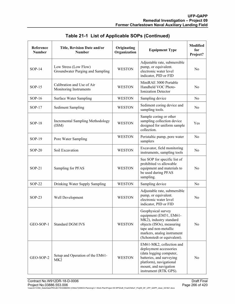
UFP-QAPP Remedial Investigation – Project 09
Former Charlestown Naval Auxiliary Landing Field
Table 21-1 List of Applicable SOPs (Continued)
Contract No.W912DR-18-D-0006 Draft Final Project No.03886.553.006 Page 266 of 420 \\nascnh1\CNH_Data\Data\PROJECTS\03886553 (CNALF)\006\03-Planning\3.1-Work-Plan\Project 09 WP\Draft_Final\CNALF_Proj09_DF_UFP_QAPP_clean_041821.docx
Reference Number
Title, Revision Date and/or Number
Originating Organization Equipment Type
Modified for
Project?
SOP-14 Low Stress (Low Flow) Groundwater Purging and Sampling WESTON
Adjustable rate, submersible pump, or equivalent. electronic water level indicator, PID or FID
No
SOP-15 Calibration and Use of Air Monitoring Instruments WESTON
MiniRAE 3000 Portable Handheld VOC Photo-Ionization Detector
No
SOP-16 Surface Water Sampling WESTON Sampling device No
SOP-17 Sediment Sampling WESTON Sediment coring device and sampling tools. No
SOP-18 Incremental Sampling Methodology (ISM) WESTON
Sample coring or other sampling collection device designed for uniform sample collection.
Yes
SOP-19 Pore Water Sampling WESTON Peristaltic pump, pore water samplers
No
SOP-20 Soil Excavation WESTON Excavator, field monitoring instruments, sampling tools No
SOP-21 Sampling for PFAS WESTON
See SOP for specific list of prohibited vs allowable equipment and materials to be used during PFAS sampling.
No
SOP-22 Drinking Water Supply Sampling WESTON Sampling device No
SOP-23 Well Development WESTON
Adjustable rate, submersible pump, or equivalent. electronic water level indicator, PID or FID
No
GEO-SOP-1 Standard DGM IVS WESTON
Geophysical survey equipment (EM31, EM61-MK2), industry standard objects (ISOs), measuring tape and non-metallic markers, analog instrument (Schonstedt or equivalent).
No
GEO-SOP-2 Setup and Operation of the EM61-MK2 WESTON
EM61-MK2, collection and deployment accessories (data logging computer, batteries, and surveying platform), navigational mount, and navigation instrument (RTK GPS).
No

UFP-QAPP Remedial Investigation – Project 09
Former Charlestown Naval Auxiliary Landing Field
Table 21-1 List of Applicable SOPs (Continued)
Contract No.W912DR-18-D-0006 Draft Final Project No.03886.553.006 Page 267 of 420 \\nascnh1\CNH_Data\Data\PROJECTS\03886553 (CNALF)\006\03-Planning\3.1-Work-Plan\Project 09 WP\Draft_Final\CNALF_Proj09_DF_UFP_QAPP_clean_041821.docx
Reference Number
Title, Revision Date and/or Number
Originating Organization Equipment Type
Modified for
Project?
GEO-SOP-5 Setup and Operation of the EM31 WESTON
EM31, data collection computer, data positioning and contouring software, navigational mount, navigation instrument (RTK GPS), and navigation markers.
No
GEO-SOP-7 Setup and Operation of the RTK GPS WESTON RTK GPS system No
MR-SOP-1 Anomaly Avoidance WESTON Analog instrument (Schonstedt) No
MR-SOP-3 Digital Anomaly Removal Operations WESTON
Analog instrument (Schonstedt), DGM survey equipment (EM61-MK2),
No
MR-SOP-4 Management of MPPEH WESTON N/A No
OP-3304 Operating Procedure for Air Sampling Pumps CABRERA
High and low volume pumps, sampling media, sampling train attachments
No
OP-3401 (OP-358)
Operating Procedure for Health Physics Instrument General Quality Control Procedure
CABRERA Project specific, see above for equipment No
OP-3403 (OP-243)
Operating Procedure for Personnel Frisking and Decontamination CABRERA
Ludlum 43-89/93 or equivalent, Ludlum 44-9 Geiger-Mueller or equivalent, wipes, gloves, tape, detergent, cotton swabs
No
OP-3407 (OP-020)
Operating Procedure for Operation of Contamination Survey Meters CABRERA Ludlum Model 43-5 and 44-
9 probes No
OP-3601 (OP-001)
Operating Procedure for Radiological Surveys CABRERA Project Specific, see above
for equipment No
Notes: N/A = not applicable
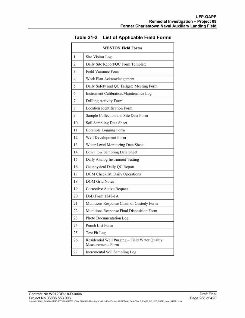
UFP-QAPP Remedial Investigation – Project 09
Former Charlestown Naval Auxiliary Landing Field
Contract No.W912DR-18-D-0006 Draft Final Project No.03886.553.006 Page 268 of 420 \\nascnh1\CNH_Data\Data\PROJECTS\03886553 (CNALF)\006\03-Planning\3.1-Work-Plan\Project 09 WP\Draft_Final\CNALF_Proj09_DF_UFP_QAPP_clean_041821.docx
Table 21-2 List of Applicable Field Forms
WESTON Field Forms
1 Site Visitor Log
2 Daily Site Report/QC Form Template
3 Field Variance Form
4 Work Plan Acknowledgement
5 Daily Safety and QC Tailgate Meeting Form
6 Instrument Calibration/Maintenance Log
7 Drilling Activity Form
8 Location Identification Form
9 Sample Collection and Site Data Form
10 Soil Sampling Data Sheet
11 Borehole Logging Form
12 Well Development Form
13 Water Level Monitoring Data Sheet
14 Low Flow Sampling Data Sheet
15 Daily Analog Instrument Testing
16 Geophysical Daily QC Report
17 DGM Checklist, Daily Operations
18 DGM Grid Notes
19 Corrective Active Request
20 DoD Form 1348-1A
21 Munitions Response Chain of Custody Form
22 Munitions Response Final Disposition Form
23 Photo Documentation Log
24 Punch List Form
25 Test Pit Log
26 Residential Well Purging – Field Water Quality Measurements Form
27 Incremental Soil Sampling Log
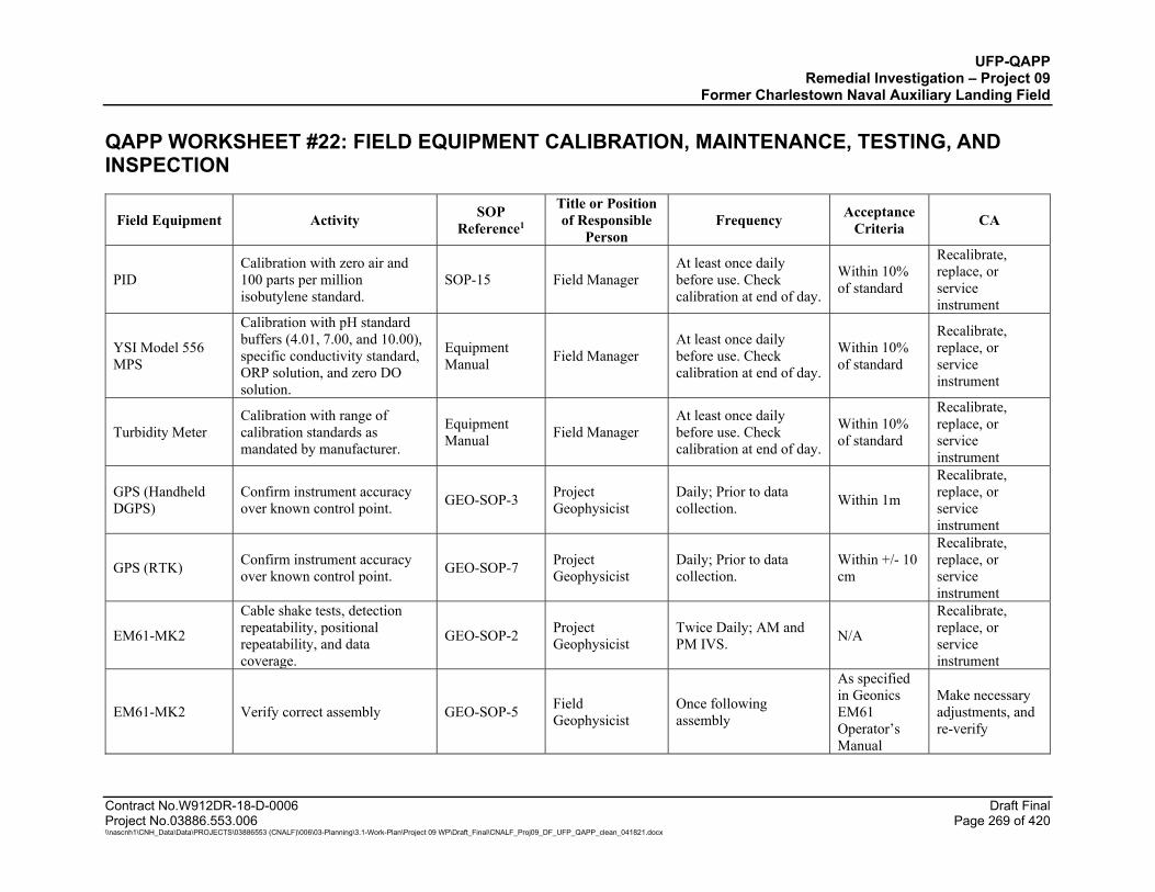
UFP-QAPP Remedial Investigation – Project 09
Former Charlestown Naval Auxiliary Landing Field
Contract No.W912DR-18-D-0006 Draft Final Project No.03886.553.006 Page 269 of 420 \\nascnh1\CNH_Data\Data\PROJECTS\03886553 (CNALF)\006\03-Planning\3.1-Work-Plan\Project 09 WP\Draft_Final\CNALF_Proj09_DF_UFP_QAPP_clean_041821.docx
QAPP WORKSHEET #22: FIELD EQUIPMENT CALIBRATION, MAINTENANCE, TESTING, AND INSPECTION
Field Equipment Activity SOP Reference1
Title or Position of Responsible
Person Frequency Acceptance
Criteria CA
PID Calibration with zero air and 100 parts per million isobutylene standard.
SOP-15 Field Manager At least once daily before use. Check calibration at end of day.
Within 10% of standard
Recalibrate, replace, or service instrument
YSI Model 556 MPS
Calibration with pH standard buffers (4.01, 7.00, and 10.00), specific conductivity standard, ORP solution, and zero DO solution.
Equipment Manual Field Manager
At least once daily before use. Check calibration at end of day.
Within 10% of standard
Recalibrate, replace, or service instrument
Turbidity Meter Calibration with range of calibration standards as mandated by manufacturer.
Equipment Manual Field Manager
At least once daily before use. Check calibration at end of day.
Within 10% of standard
Recalibrate, replace, or service instrument
GPS (Handheld DGPS)
Confirm instrument accuracy over known control point. GEO-SOP-3 Project
Geophysicist Daily; Prior to data collection. Within 1m
Recalibrate, replace, or service instrument
GPS (RTK) Confirm instrument accuracy over known control point. GEO-SOP-7 Project
Geophysicist Daily; Prior to data collection.
Within +/- 10 cm
Recalibrate, replace, or service instrument
EM61-MK2
Cable shake tests, detection repeatability, positional repeatability, and data coverage.
GEO-SOP-2 Project Geophysicist
Twice Daily; AM and PM IVS. N/A
Recalibrate, replace, or service instrument
EM61-MK2 Verify correct assembly GEO-SOP-5 Field Geophysicist
Once following assembly
As specified in Geonics EM61 Operator’s Manual
Make necessary adjustments, and re-verify
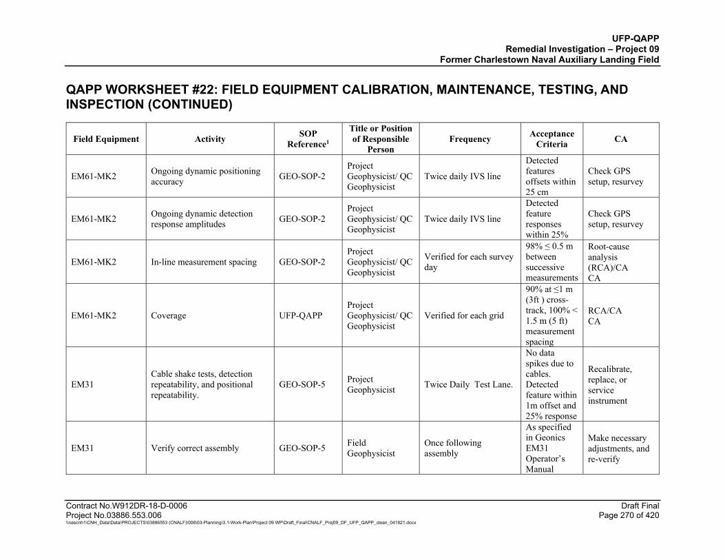
UFP-QAPP Remedial Investigation – Project 09
Former Charlestown Naval Auxiliary Landing Field QAPP WORKSHEET #22: FIELD EQUIPMENT CALIBRATION, MAINTENANCE, TESTING, AND INSPECTION (CONTINUED)
Contract No.W912DR-18-D-0006 Draft Final Project No.03886.553.006 Page 270 of 420 \\nascnh1\CNH_Data\Data\PROJECTS\03886553 (CNALF)\006\03-Planning\3.1-Work-Plan\Project 09 WP\Draft_Final\CNALF_Proj09_DF_UFP_QAPP_clean_041821.docx
Field Equipment Activity SOP Reference1
Title or Position of Responsible
Person Frequency Acceptance
Criteria CA
EM61-MK2 Ongoing dynamic positioning accuracy GEO-SOP-2
Project Geophysicist/ QC Geophysicist
Twice daily IVS line
Detected features offsets within 25 cm
Check GPS setup, resurvey
EM61-MK2 Ongoing dynamic detection response amplitudes GEO-SOP-2
Project Geophysicist/ QC Geophysicist
Twice daily IVS line
Detected feature responses within 25%
Check GPS setup, resurvey
EM61-MK2 In-line measurement spacing GEO-SOP-2 Project Geophysicist/ QC Geophysicist
Verified for each survey day
98% ≤ 0.5 m between successive measurements
Root-cause analysis (RCA)/CA CA
EM61-MK2 Coverage UFP-QAPP Project Geophysicist/ QC Geophysicist
Verified for each grid
90% at ≤1 m (3ft ) cross-track, 100% < 1.5 m (5 ft) measurement spacing
RCA/CA CA
EM31 Cable shake tests, detection repeatability, and positional repeatability.
GEO-SOP-5 Project Geophysicist Twice Daily Test Lane.
No data spikes due to cables. Detected feature within 1m offset and 25% response
Recalibrate, replace, or service instrument
EM31 Verify correct assembly GEO-SOP-5 Field Geophysicist
Once following assembly
As specified in Geonics EM31 Operator’s Manual
Make necessary adjustments, and re-verify
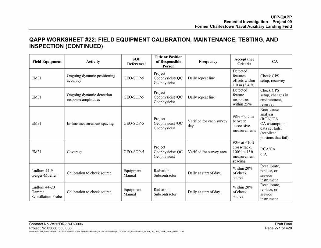
UFP-QAPP Remedial Investigation – Project 09
Former Charlestown Naval Auxiliary Landing Field QAPP WORKSHEET #22: FIELD EQUIPMENT CALIBRATION, MAINTENANCE, TESTING, AND INSPECTION (CONTINUED)
Contract No.W912DR-18-D-0006 Draft Final Project No.03886.553.006 Page 271 of 420 \\nascnh1\CNH_Data\Data\PROJECTS\03886553 (CNALF)\006\03-Planning\3.1-Work-Plan\Project 09 WP\Draft_Final\CNALF_Proj09_DF_UFP_QAPP_clean_041821.docx
Field Equipment Activity SOP Reference1
Title or Position of Responsible
Person Frequency Acceptance
Criteria CA
EM31 Ongoing dynamic positioning accuracy GEO-SOP-5
Project Geophysicist/ QC Geophysicist
Daily repeat line
Detected features offsets within 1.0 m (3.4 ft)
Check GPS setup, resurvey
EM31 Ongoing dynamic detection response amplitudes GEO-SOP-5
Project Geophysicist /QC Geophysicist
Daily repeat line
Detected feature responses within 25%
Check GPS setup, changes in environment, resurvey
EM31 In-line measurement spacing GEO-SOP-5 Project Geophysicist /QC Geophysicist
Verified for each survey day
98% ≤ 0.5 m between successive measurements
Root-cause analysis (RCA)/CA CA assumption: data set fails, (recollect portions that fail)
EM31 Coverage GEO-SOP-5 Project Geophysicist/ QC Geophysicist
Verified for survey area
90% at ≤10ft cross-track, 100% < 15ft measurement spacing
RCA/CA CA
Ludlum 44-9 Geiger-Mueller Calibration to check source. Equipment
Manual Radiation Subcontractor Daily at start of day.
Within 20% of check source
Recalibrate, replace, or service instrument
Ludlum 44-20 Gamma Scintillation Probe
Calibration to check source. Equipment Manual
Radiation Subcontractor Daily at start of day.
Within 20% of check source
Recalibrate, replace, or service instrument
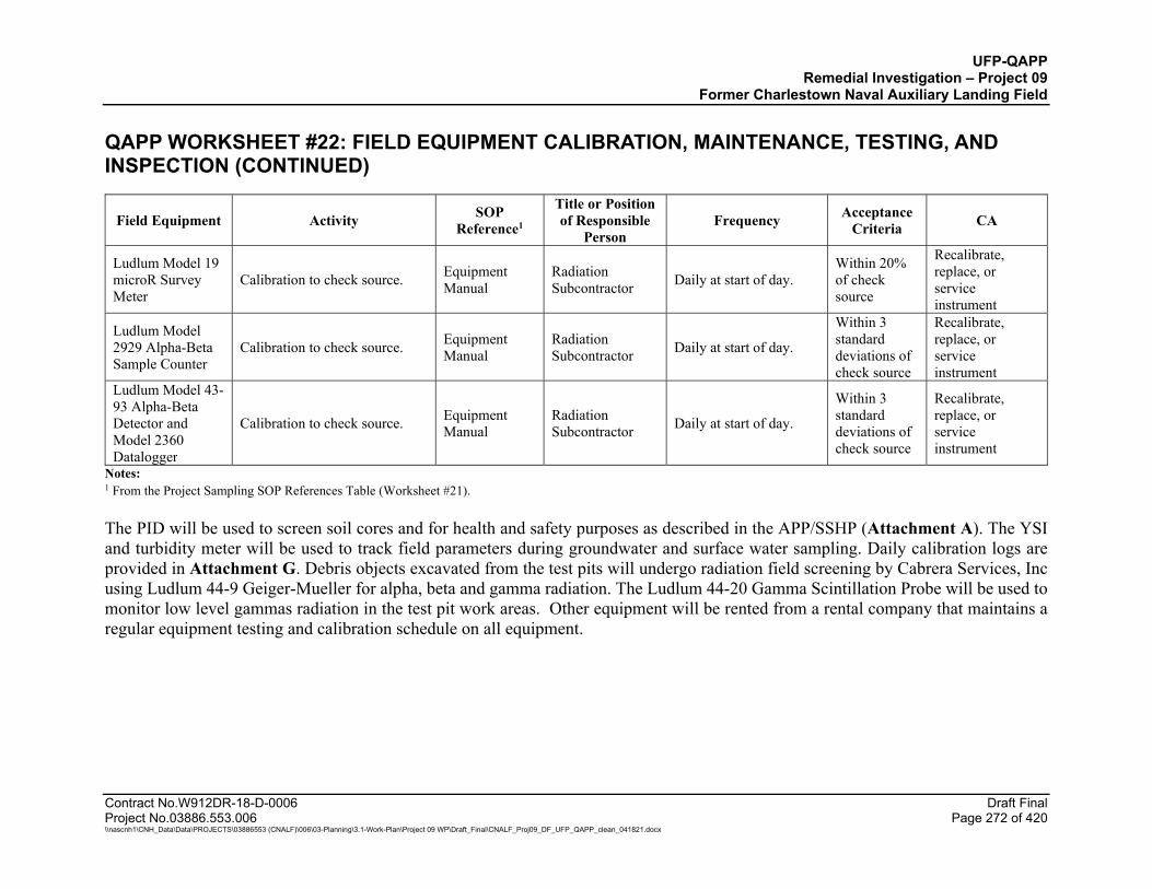
UFP-QAPP Remedial Investigation – Project 09
Former Charlestown Naval Auxiliary Landing Field QAPP WORKSHEET #22: FIELD EQUIPMENT CALIBRATION, MAINTENANCE, TESTING, AND INSPECTION (CONTINUED)
Contract No.W912DR-18-D-0006 Draft Final Project No.03886.553.006 Page 272 of 420 \\nascnh1\CNH_Data\Data\PROJECTS\03886553 (CNALF)\006\03-Planning\3.1-Work-Plan\Project 09 WP\Draft_Final\CNALF_Proj09_DF_UFP_QAPP_clean_041821.docx
Field Equipment Activity SOP Reference1
Title or Position of Responsible
Person Frequency Acceptance
Criteria CA
Ludlum Model 19 microR Survey Meter
Calibration to check source. Equipment Manual
Radiation Subcontractor Daily at start of day.
Within 20% of check source
Recalibrate, replace, or service instrument
Ludlum Model 2929 Alpha-Beta Sample Counter
Calibration to check source. Equipment Manual
Radiation Subcontractor Daily at start of day.
Within 3 standard deviations of check source
Recalibrate, replace, or service instrument
Ludlum Model 43-93 Alpha-Beta Detector and Model 2360 Datalogger
Calibration to check source. Equipment Manual
Radiation Subcontractor Daily at start of day.
Within 3 standard deviations of check source
Recalibrate, replace, or service instrument
Notes: 1 From the Project Sampling SOP References Table (Worksheet #21).
The PID will be used to screen soil cores and for health and safety purposes as described in the APP/SSHP (Attachment A). The YSI and turbidity meter will be used to track field parameters during groundwater and surface water sampling. Daily calibration logs are provided in Attachment G. Debris objects excavated from the test pits will undergo radiation field screening by Cabrera Services, Inc using Ludlum 44-9 Geiger-Mueller for alpha, beta and gamma radiation. The Ludlum 44-20 Gamma Scintillation Probe will be used to monitor low level gammas radiation in the test pit work areas. Other equipment will be rented from a rental company that maintains a regular equipment testing and calibration schedule on all equipment.
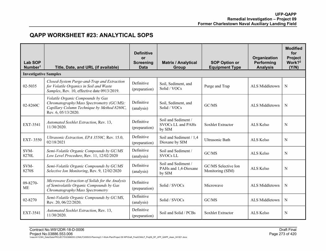
UFP-QAPP Remedial Investigation – Project 09
Former Charlestown Naval Auxiliary Landing Field
Contract No.W912DR-18-D-0006 Draft Final Project No.03886.553.006 Page 273 of 420 \\nascnh1\CNH_Data\Data\PROJECTS\03886553 (CNALF)\006\03-Planning\3.1-Work-Plan\Project 09 WP\Draft_Final\CNALF_Proj09_DF_UFP_QAPP_clean_041821.docx
QAPP WORKSHEET #23: ANALYTICAL SOPS
Lab SOP Number1 Title, Date, and URL (if available)
Definitive or
Screening Data
Matrix / Analytical Group
SOP Option or Equipment Type
Organization Performing
Analysis
Modified for
Project Work?2
(Y/N) Investigative Samples
02-5035 Closed-System Purge-and-Trap and Extraction for Volatile Organics in Soil and Waste Samples, Rev. 10, effective date 0913/2019.
Definitive (preparation)
Soil, Sediment, and Solid / VOCs Purge and Trap ALS Middletown N
02-8260C
Volatile Organic Compounds by Gas Chromatography/Mass Spectrometry (GC/MS): Capillary Column Technique by Method 8260C, Rev. 6, 05/13/2020.
Definitive (analysis)
Soil, Sediment, and Solid / VOCs GC/MS ALS Middletown N
EXT-3541 Automated Soxhlet Extraction, Rev. 13, 11/30/2020.
Definitive (preparation)
Soil and Sediment / SVOCs LL and PAHs by SIM
Soxhlet Extractor ALS Kelso N
EXT- 3550 Ultrasonic Extraction, EPA 3550C, Rev. 15.0, 02/18/2021
Definitive (preparation)
Soil and Sediment / 1,4 Dioxane by SIM Ultrasonic Bath ALS Kelso N
SVM-8270L
Semi-Volatile Organic Compounds by GC/MS Low Level Procedure, Rev. 11, 12/02/2020
Definitive (analysis)
Soil and Sediment / SVOCs LL GC/MS ALS Kelso N
SVM-8270S
Semi-Volatile Organic Compounds by GC/MS Selective Ion Monitoring, Rev. 9, 12/02/2020
Definitive (analysis)
Soil and Sediment / PAHs and 1,4-Dioxane by SIM
GC/MS Selective Ion Monitoring (SIM) ALS Kelso N
09-8270-ME
Microwave Extraction of Solids for the Analysis of Semivolatile Organic Compounds by Gas Chromatography/Mass Spectrometry
Definitive (preparation)
Solid / SVOCs Microwave ALS Middletown N
02-8270 Semi-Volatile Organic Compounds by GC/MS, Rev. 20, 06/22/2020.
Definitive (analysis) Solid / SVOCs GC/MS ALS Middletown N
EXT-3541 Automated Soxhlet Extraction, Rev. 13, 11/30/2020.
Definitive (preparation)
Soil and Solid / PCBs Soxhlet Extractor ALS Kelso N
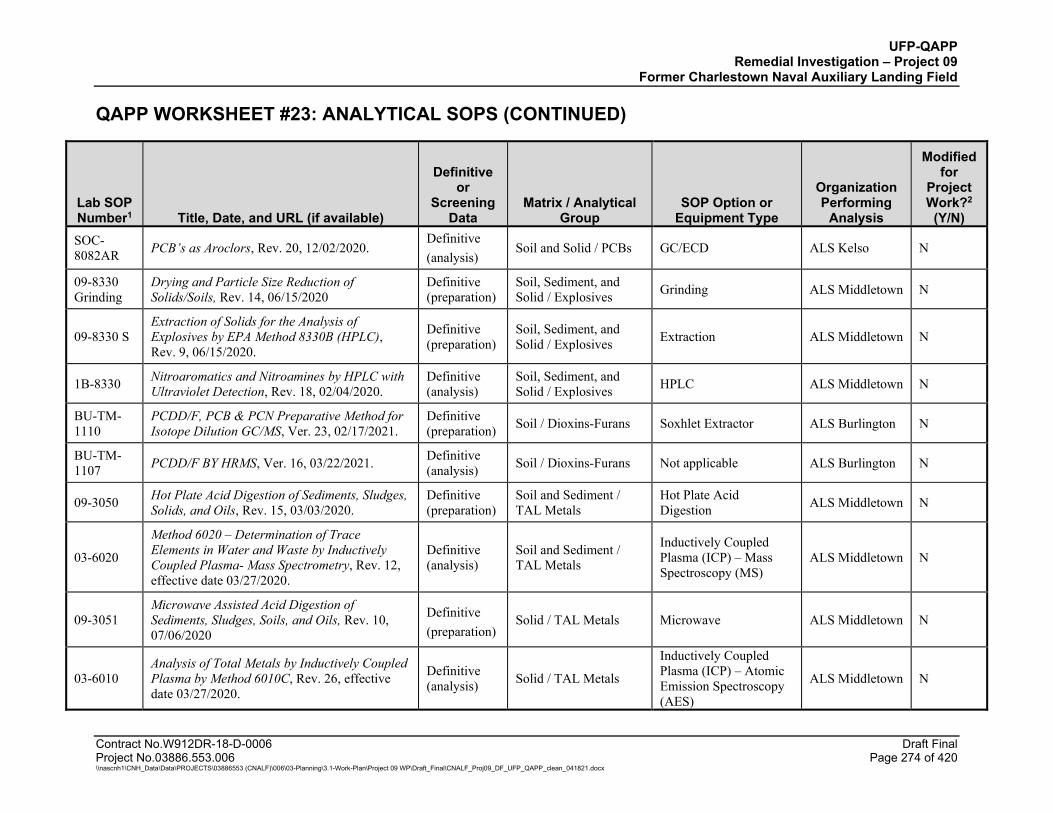
UFP-QAPP Remedial Investigation – Project 09
Former Charlestown Naval Auxiliary Landing Field
QAPP WORKSHEET #23: ANALYTICAL SOPS (CONTINUED)
Contract No.W912DR-18-D-0006 Draft Final Project No.03886.553.006 Page 274 of 420 \\nascnh1\CNH_Data\Data\PROJECTS\03886553 (CNALF)\006\03-Planning\3.1-Work-Plan\Project 09 WP\Draft_Final\CNALF_Proj09_DF_UFP_QAPP_clean_041821.docx
Lab SOP Number1 Title, Date, and URL (if available)
Definitive or
Screening Data
Matrix / Analytical Group
SOP Option or Equipment Type
Organization Performing
Analysis
Modified for
Project Work?2
(Y/N) SOC-8082AR PCB’s as Aroclors, Rev. 20, 12/02/2020.
Definitive (analysis)
Soil and Solid / PCBs GC/ECD ALS Kelso N
09-8330 Grinding
Drying and Particle Size Reduction of Solids/Soils, Rev. 14, 06/15/2020
Definitive (preparation)
Soil, Sediment, and Solid / Explosives Grinding ALS Middletown N
09-8330 S Extraction of Solids for the Analysis of Explosives by EPA Method 8330B (HPLC), Rev. 9, 06/15/2020.
Definitive (preparation)
Soil, Sediment, and Solid / Explosives Extraction ALS Middletown N
1B-8330 Nitroaromatics and Nitroamines by HPLC with Ultraviolet Detection, Rev. 18, 02/04/2020.
Definitive (analysis)
Soil, Sediment, and Solid / Explosives HPLC ALS Middletown N
BU-TM-1110
PCDD/F, PCB & PCN Preparative Method for Isotope Dilution GC/MS, Ver. 23, 02/17/2021.
Definitive (preparation) Soil / Dioxins-Furans Soxhlet Extractor ALS Burlington N
BU-TM-1107 PCDD/F BY HRMS, Ver. 16, 03/22/2021. Definitive
(analysis) Soil / Dioxins-Furans Not applicable ALS Burlington N
09-3050 Hot Plate Acid Digestion of Sediments, Sludges, Solids, and Oils, Rev. 15, 03/03/2020.
Definitive (preparation)
Soil and Sediment / TAL Metals
Hot Plate Acid Digestion ALS Middletown N
03-6020
Method 6020 – Determination of Trace Elements in Water and Waste by Inductively Coupled Plasma- Mass Spectrometry, Rev. 12, effective date 03/27/2020.
Definitive (analysis)
Soil and Sediment / TAL Metals
Inductively Coupled Plasma (ICP) – Mass Spectroscopy (MS)
ALS Middletown N
09-3051 Microwave Assisted Acid Digestion of Sediments, Sludges, Soils, and Oils, Rev. 10, 07/06/2020
Definitive (preparation)
Solid / TAL Metals Microwave ALS Middletown N
03-6010 Analysis of Total Metals by Inductively Coupled Plasma by Method 6010C, Rev. 26, effective date 03/27/2020.
Definitive (analysis) Solid / TAL Metals
Inductively Coupled Plasma (ICP) – Atomic Emission Spectroscopy (AES)
ALS Middletown N
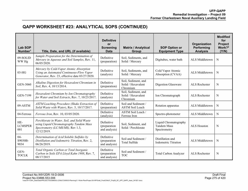
UFP-QAPP Remedial Investigation – Project 09
Former Charlestown Naval Auxiliary Landing Field
QAPP WORKSHEET #23: ANALYTICAL SOPS (CONTINUED)
Contract No.W912DR-18-D-0006 Draft Final Project No.03886.553.006 Page 275 of 420 \\nascnh1\CNH_Data\Data\PROJECTS\03886553 (CNALF)\006\03-Planning\3.1-Work-Plan\Project 09 WP\Draft_Final\CNALF_Proj09_DF_UFP_QAPP_clean_041821.docx
Lab SOP Number1 Title, Date, and URL (if available)
Definitive or
Screening Data
Matrix / Analytical Group
SOP Option or Equipment Type
Organization Performing
Analysis
Modified for
Project Work?2
(Y/N)
09-SOLID WW Hg
Sample Preparation for the Determination of Mercury in Aqueous and Soil Samples, Rev. 11, 06/05/2020.
Definitive (preparation)
Soil, Sediments, and Solid / Mercury Digitubes, water bath ALS Middletown N
03-HG Mercury by Cold-Vapor Atomic Absorption Using an Automated Continuous-Flow Vapor Generator, Rev. 23, effective date 03/27/2020.
Definitive (analysis)
Soil, Sediments, and Solid / Mercury
Cold Vapor Atomic Absorption (CVAA) ALS Middletown N
GEN-3060 Alkaline Digestion for Hexavalent Chromium in Soil, Rev. 4, 10/13/2014.
Definitive (preparation)
Soil, Sediment, and Solid / Hexavalent Chromium
Digestion Glassware ALS Rochester N
GEN-7199 Hexavalent Chromium by Ion Chromatography for Water and Soil Extracts, Rev. 7, 10/23/2017.
Definitive (analysis)
Soil, Sediment, and Solid / Hexavalent Chromium
Ion Chromatograph ALS Rochester N
09-ASTM ASTM Leaching Procedure (Shake Extraction of Solid Waste with Water), Rev. 5, 10/17/2017.
Definitive (preparation)
Soil and Sediment / ASTM Soil Leach Rotation apparatus ALS Middletown N
04-Ferrous Ferrous Iron, Rev. 10, 03/05/2020. Definitive (analysis)
ASTM Soil Leach / Ferrous Iron Spectro-photometer ALS Middletown N
HE-LCMSPER001
Perchlorate in Water, Soil, and Solid Waste using Liquid Chromatography Tandem Mass Spectrometry (LC/MS/MS), Rev 1.3, 12/12/2019.
Definitive (preparation and analysis)
Soil, Sediment, and Solid / Perchlorate
Liquid Chromatography Tandem Mass Spectrometry
ALS Houston N
04-S9030B-9034
Determination of Acid Soluble Sulfides by Distillation and Iodometric Titration, Rev. 2, 06/26/2019.
Definitive (preparation and analysis)
Soil and Sediment / Total Sulfide
Distillation and Iodometric Titration ALS Middletown N
GEN-TOCLK
Total Organic Carbon or Total Inorganic Carbon in Soils EPA Lloyd Kahn 1988, Rev. 7, 08/17/2015
Definitive (preparation and analysis)
Soil and Sediment / TOC Total Carbon Analyzer ALS Rochester N
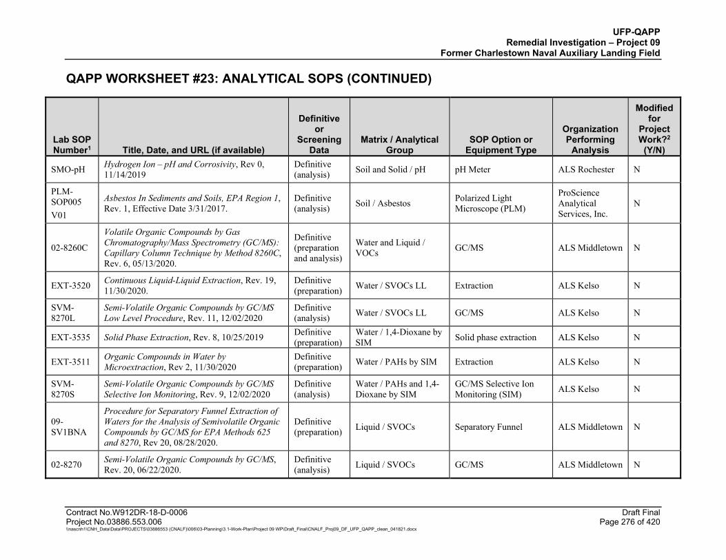
UFP-QAPP Remedial Investigation – Project 09
Former Charlestown Naval Auxiliary Landing Field
QAPP WORKSHEET #23: ANALYTICAL SOPS (CONTINUED)
Contract No.W912DR-18-D-0006 Draft Final Project No.03886.553.006 Page 276 of 420 \\nascnh1\CNH_Data\Data\PROJECTS\03886553 (CNALF)\006\03-Planning\3.1-Work-Plan\Project 09 WP\Draft_Final\CNALF_Proj09_DF_UFP_QAPP_clean_041821.docx
Lab SOP Number1 Title, Date, and URL (if available)
Definitive or
Screening Data
Matrix / Analytical Group
SOP Option or Equipment Type
Organization Performing
Analysis
Modified for
Project Work?2
(Y/N)
SMO-pH Hydrogen Ion – pH and Corrosivity, Rev 0, 11/14/2019
Definitive (analysis) Soil and Solid / pH pH Meter ALS Rochester N
PLM-SOP005 V01
Asbestos In Sediments and Soils, EPA Region 1, Rev. 1, Effective Date 3/31/2017.
Definitive (analysis) Soil / Asbestos Polarized Light
Microscope (PLM)
ProScience Analytical Services, Inc.
N
02-8260C
Volatile Organic Compounds by Gas Chromatography/Mass Spectrometry (GC/MS): Capillary Column Technique by Method 8260C, Rev. 6, 05/13/2020.
Definitive (preparation and analysis)
Water and Liquid / VOCs GC/MS ALS Middletown N
EXT-3520 Continuous Liquid-Liquid Extraction, Rev. 19, 11/30/2020.
Definitive (preparation) Water / SVOCs LL Extraction ALS Kelso N
SVM-8270L
Semi-Volatile Organic Compounds by GC/MS Low Level Procedure, Rev. 11, 12/02/2020
Definitive (analysis) Water / SVOCs LL GC/MS ALS Kelso N
EXT-3535 Solid Phase Extraction, Rev. 8, 10/25/2019 Definitive (preparation)
Water / 1,4-Dioxane by SIM Solid phase extraction ALS Kelso N
EXT-3511 Organic Compounds in Water by Microextraction, Rev 2, 11/30/2020
Definitive (preparation) Water / PAHs by SIM Extraction ALS Kelso N
SVM-8270S
Semi-Volatile Organic Compounds by GC/MS Selective Ion Monitoring, Rev. 9, 12/02/2020
Definitive (analysis)
Water / PAHs and 1,4-Dioxane by SIM
GC/MS Selective Ion Monitoring (SIM) ALS Kelso N
09-SV1BNA
Procedure for Separatory Funnel Extraction of Waters for the Analysis of Semivolatile Organic Compounds by GC/MS for EPA Methods 625 and 8270, Rev 20, 08/28/2020.
Definitive (preparation) Liquid / SVOCs Separatory Funnel ALS Middletown N
02-8270 Semi-Volatile Organic Compounds by GC/MS, Rev. 20, 06/22/2020.
Definitive (analysis) Liquid / SVOCs GC/MS ALS Middletown N

UFP-QAPP Remedial Investigation – Project 09
Former Charlestown Naval Auxiliary Landing Field
QAPP WORKSHEET #23: ANALYTICAL SOPS (CONTINUED)
Contract No.W912DR-18-D-0006 Draft Final Project No.03886.553.006 Page 277 of 420 \\nascnh1\CNH_Data\Data\PROJECTS\03886553 (CNALF)\006\03-Planning\3.1-Work-Plan\Project 09 WP\Draft_Final\CNALF_Proj09_DF_UFP_QAPP_clean_041821.docx
Lab SOP Number1 Title, Date, and URL (if available)
Definitive or
Screening Data
Matrix / Analytical Group
SOP Option or Equipment Type
Organization Performing
Analysis
Modified for
Project Work?2
(Y/N)
EXT-3510 Separatory Funnel Liquid-Liquid Extraction, Rev 14.0, 11/30/2020
Definitive (preparation)
Water and Liquid / PCBs GC/ECD ALS Kelso N
SOC-8082AR
PCB’s as Aroclors, Rev. 20, 12/02/2020.
Definitive (analysis)
Water and Liquid / PCBs GC/ECD ALS Kelso N
09-8330 W Solid Phase Extraction of Water for the Analysis of Explosives by EPA Method 8330B (HPLC), Rev. 11, 05/22/2020.
Definitive (preparation)
Water and Liquid / Explosives Solid Phase Extraction ALS Middletown N
1B-8330 Nitroaromatics and Nitroamines by HPLC with Ultraviolet Detection, Rev. 18, 02/04/2020.
Definitive (analysis)
Water and Liquid / Explosives HPLC/UV ALS Middletown N
LCP-PFC Pe- and Polyfluoroalkyl Substances (PFAS) by (HPLC/MS/MS), Rev 11.0, 03/02/2021.
Definitive (preparation and analysis)
Water / PFAS HPLC/MS/MS ALS Kelso N
BU-TM-1110
PCDD/F, PCB & PCN Preparative Method for Isotope Dilution GC/MS, Ver. 23, 02/17/2021.
Definitive (preparation) Water / Dioxins-Furans Soxhlet Extractor ALS Burlington N
BU-TM-1107 PCDD/F BY HRMS, Ver. 16, 03/22/2021. Definitive
(cleanup) Water / Dioxins-Furans Not applicable ALS Burlington N
09-3015
Microwave Assisted Acid Digestion of Aqueous Samples and Extracts for Total Metals Analysis by ICP or ICP-MS Spectroscopy, Rev. 19, 07/06/2020.
Definitive (preparation)
Water and Liquid / TAL Metals Microwave ALS Middletown N
03-6020
Method 6020 – Determination of Trace Elements in Water and Waste by Inductively Coupled Plasma – Mass Spectrometry, Rev. 12, effective date 03/27/2020.
Definitive (analysis) Water / TAL Metals ICP-MS ALS Middletown N
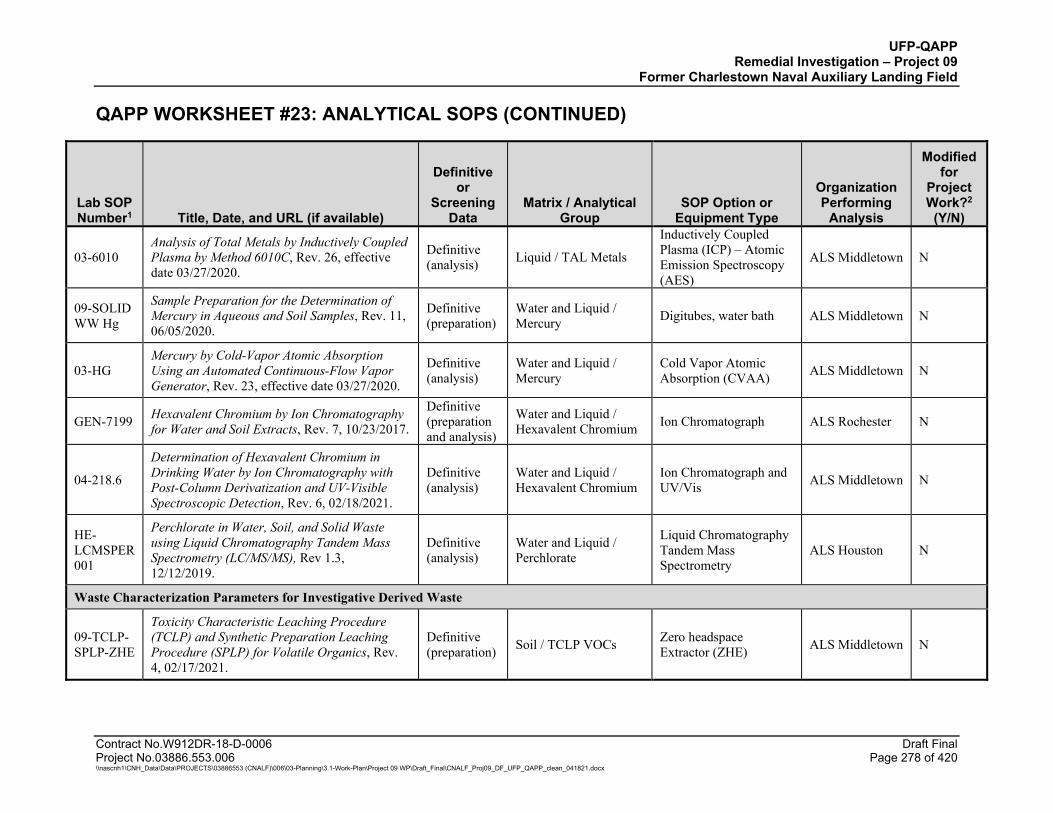
UFP-QAPP Remedial Investigation – Project 09
Former Charlestown Naval Auxiliary Landing Field
QAPP WORKSHEET #23: ANALYTICAL SOPS (CONTINUED)
Contract No.W912DR-18-D-0006 Draft Final Project No.03886.553.006 Page 278 of 420 \\nascnh1\CNH_Data\Data\PROJECTS\03886553 (CNALF)\006\03-Planning\3.1-Work-Plan\Project 09 WP\Draft_Final\CNALF_Proj09_DF_UFP_QAPP_clean_041821.docx
Lab SOP Number1 Title, Date, and URL (if available)
Definitive or
Screening Data
Matrix / Analytical Group
SOP Option or Equipment Type
Organization Performing
Analysis
Modified for
Project Work?2
(Y/N)
03-6010 Analysis of Total Metals by Inductively Coupled Plasma by Method 6010C, Rev. 26, effective date 03/27/2020.
Definitive (analysis) Liquid / TAL Metals
Inductively Coupled Plasma (ICP) – Atomic Emission Spectroscopy (AES)
ALS Middletown N
09-SOLID WW Hg
Sample Preparation for the Determination of Mercury in Aqueous and Soil Samples, Rev. 11, 06/05/2020.
Definitive (preparation)
Water and Liquid / Mercury Digitubes, water bath ALS Middletown N
03-HG Mercury by Cold-Vapor Atomic Absorption Using an Automated Continuous-Flow Vapor Generator, Rev. 23, effective date 03/27/2020.
Definitive (analysis)
Water and Liquid / Mercury
Cold Vapor Atomic Absorption (CVAA) ALS Middletown N
GEN-7199 Hexavalent Chromium by Ion Chromatography for Water and Soil Extracts, Rev. 7, 10/23/2017.
Definitive (preparation and analysis)
Water and Liquid / Hexavalent Chromium Ion Chromatograph ALS Rochester N
04-218.6
Determination of Hexavalent Chromium in Drinking Water by Ion Chromatography with Post-Column Derivatization and UV-Visible Spectroscopic Detection, Rev. 6, 02/18/2021.
Definitive (analysis)
Water and Liquid / Hexavalent Chromium
Ion Chromatograph and UV/Vis ALS Middletown N
HE-LCMSPER001
Perchlorate in Water, Soil, and Solid Waste using Liquid Chromatography Tandem Mass Spectrometry (LC/MS/MS), Rev 1.3, 12/12/2019.
Definitive (analysis)
Water and Liquid / Perchlorate
Liquid Chromatography Tandem Mass Spectrometry
ALS Houston N
Waste Characterization Parameters for Investigative Derived Waste
09-TCLP-SPLP-ZHE
Toxicity Characteristic Leaching Procedure (TCLP) and Synthetic Preparation Leaching Procedure (SPLP) for Volatile Organics, Rev. 4, 02/17/2021.
Definitive (preparation) Soil / TCLP VOCs Zero headspace
Extractor (ZHE) ALS Middletown N
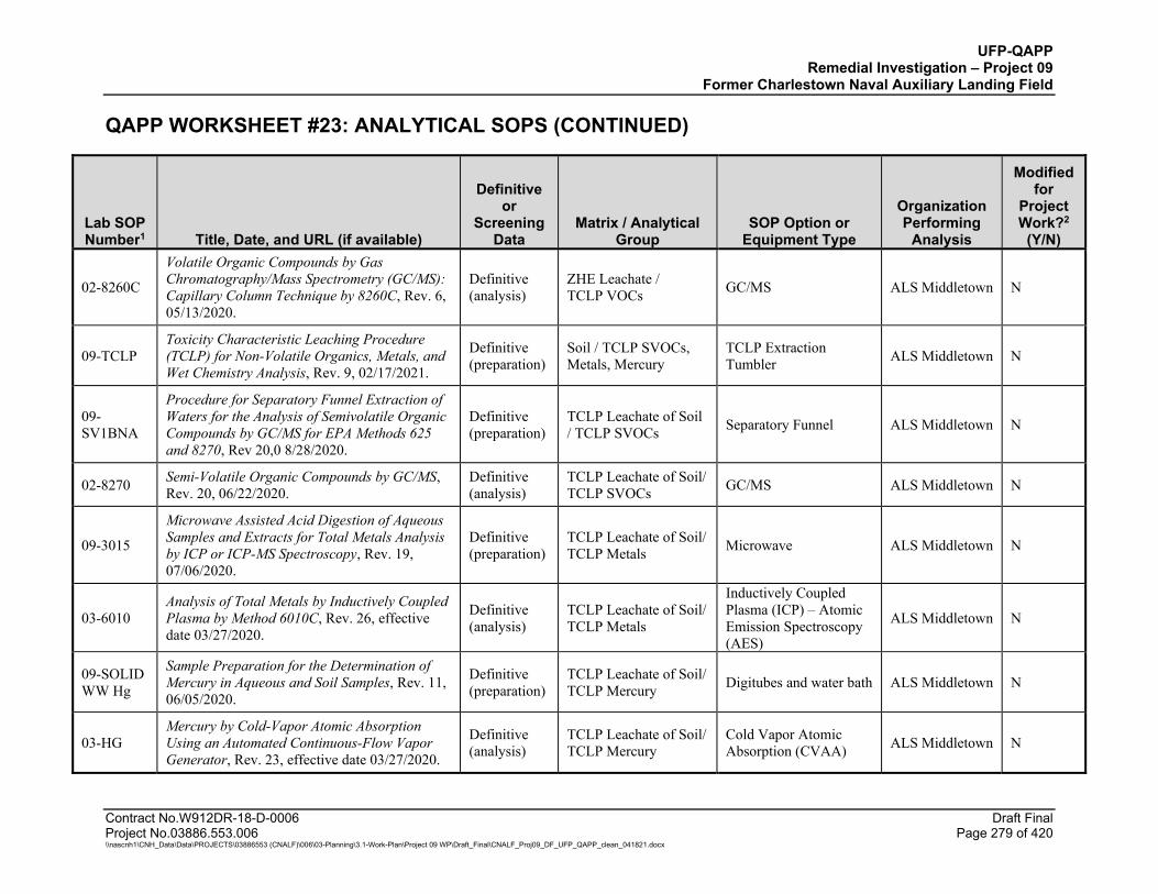
UFP-QAPP Remedial Investigation – Project 09
Former Charlestown Naval Auxiliary Landing Field
QAPP WORKSHEET #23: ANALYTICAL SOPS (CONTINUED)
Contract No.W912DR-18-D-0006 Draft Final Project No.03886.553.006 Page 279 of 420 \\nascnh1\CNH_Data\Data\PROJECTS\03886553 (CNALF)\006\03-Planning\3.1-Work-Plan\Project 09 WP\Draft_Final\CNALF_Proj09_DF_UFP_QAPP_clean_041821.docx
Lab SOP Number1 Title, Date, and URL (if available)
Definitive or
Screening Data
Matrix / Analytical Group
SOP Option or Equipment Type
Organization Performing
Analysis
Modified for
Project Work?2
(Y/N)
02-8260C
Volatile Organic Compounds by Gas Chromatography/Mass Spectrometry (GC/MS): Capillary Column Technique by 8260C, Rev. 6, 05/13/2020.
Definitive (analysis)
ZHE Leachate / TCLP VOCs GC/MS ALS Middletown N
09-TCLP Toxicity Characteristic Leaching Procedure (TCLP) for Non-Volatile Organics, Metals, and Wet Chemistry Analysis, Rev. 9, 02/17/2021.
Definitive (preparation)
Soil / TCLP SVOCs, Metals, Mercury
TCLP Extraction Tumbler ALS Middletown N
09-SV1BNA
Procedure for Separatory Funnel Extraction of Waters for the Analysis of Semivolatile Organic Compounds by GC/MS for EPA Methods 625 and 8270, Rev 20,0 8/28/2020.
Definitive (preparation)
TCLP Leachate of Soil / TCLP SVOCs Separatory Funnel ALS Middletown N
02-8270 Semi-Volatile Organic Compounds by GC/MS, Rev. 20, 06/22/2020.
Definitive (analysis)
TCLP Leachate of Soil/ TCLP SVOCs GC/MS ALS Middletown N
09-3015
Microwave Assisted Acid Digestion of Aqueous Samples and Extracts for Total Metals Analysis by ICP or ICP-MS Spectroscopy, Rev. 19, 07/06/2020.
Definitive (preparation)
TCLP Leachate of Soil/ TCLP Metals Microwave ALS Middletown N
03-6010 Analysis of Total Metals by Inductively Coupled Plasma by Method 6010C, Rev. 26, effective date 03/27/2020.
Definitive (analysis)
TCLP Leachate of Soil/ TCLP Metals
Inductively Coupled Plasma (ICP) – Atomic Emission Spectroscopy (AES)
ALS Middletown N
09-SOLID WW Hg
Sample Preparation for the Determination of Mercury in Aqueous and Soil Samples, Rev. 11, 06/05/2020.
Definitive (preparation)
TCLP Leachate of Soil/ TCLP Mercury Digitubes and water bath ALS Middletown N
03-HG Mercury by Cold-Vapor Atomic Absorption Using an Automated Continuous-Flow Vapor Generator, Rev. 23, effective date 03/27/2020.
Definitive (analysis)
TCLP Leachate of Soil/ TCLP Mercury
Cold Vapor Atomic Absorption (CVAA) ALS Middletown N
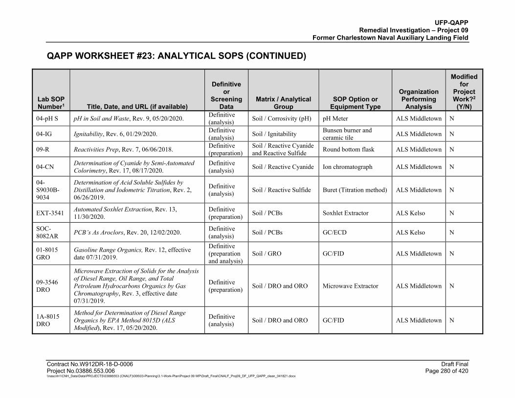
UFP-QAPP Remedial Investigation – Project 09
Former Charlestown Naval Auxiliary Landing Field
QAPP WORKSHEET #23: ANALYTICAL SOPS (CONTINUED)
Contract No.W912DR-18-D-0006 Draft Final Project No.03886.553.006 Page 280 of 420 \\nascnh1\CNH_Data\Data\PROJECTS\03886553 (CNALF)\006\03-Planning\3.1-Work-Plan\Project 09 WP\Draft_Final\CNALF_Proj09_DF_UFP_QAPP_clean_041821.docx
Lab SOP Number1 Title, Date, and URL (if available)
Definitive or
Screening Data
Matrix / Analytical Group
SOP Option or Equipment Type
Organization Performing
Analysis
Modified for
Project Work?2
(Y/N)
04-pH S pH in Soil and Waste, Rev. 9, 05/20/2020. Definitive (analysis) Soil / Corrosivity (pH) pH Meter ALS Middletown N
04-IG Ignitability, Rev. 6, 01/29/2020. Definitive (analysis) Soil / Ignitability Bunsen burner and
ceramic tile ALS Middletown N
09-R Reactivities Prep, Rev. 7, 06/06/2018. Definitive (preparation)
Soil / Reactive Cyanide and Reactive Sulfide Round bottom flask ALS Middletown N
04-CN Determination of Cyanide by Semi-Automated Colorimetry, Rev. 17, 08/17/2020.
Definitive (analysis) Soil / Reactive Cyanide Ion chromatograph ALS Middletown N
04-S9030B-9034
Determination of Acid Soluble Sulfides by Distillation and Iodometric Titration, Rev. 2, 06/26/2019.
Definitive (analysis) Soil / Reactive Sulfide Buret (Titration method) ALS Middletown N
EXT-3541 Automated Soxhlet Extraction, Rev. 13, 11/30/2020.
Definitive (preparation) Soil / PCBs Soxhlet Extractor ALS Kelso N
SOC-8082AR PCB’s As Aroclors, Rev. 20, 12/02/2020. Definitive
(analysis) Soil / PCBs GC/ECD ALS Kelso N
01-8015 GRO
Gasoline Range Organics, Rev. 12, effective date 07/31/2019.
Definitive (preparation and analysis)
Soil / GRO GC/FID ALS Middletown N
09-3546 DRO
Microwave Extraction of Solids for the Analysis of Diesel Range, Oil Range, and Total Petroleum Hydrocarbons Organics by Gas Chromatography, Rev. 3, effective date 07/31/2019.
Definitive (preparation) Soil / DRO and ORO Microwave Extractor ALS Middletown N
1A-8015 DRO
Method for Determination of Diesel Range Organics by EPA Method 8015D (ALS Modified), Rev. 17, 05/20/2020.
Definitive (analysis) Soil / DRO and ORO GC/FID ALS Middletown N
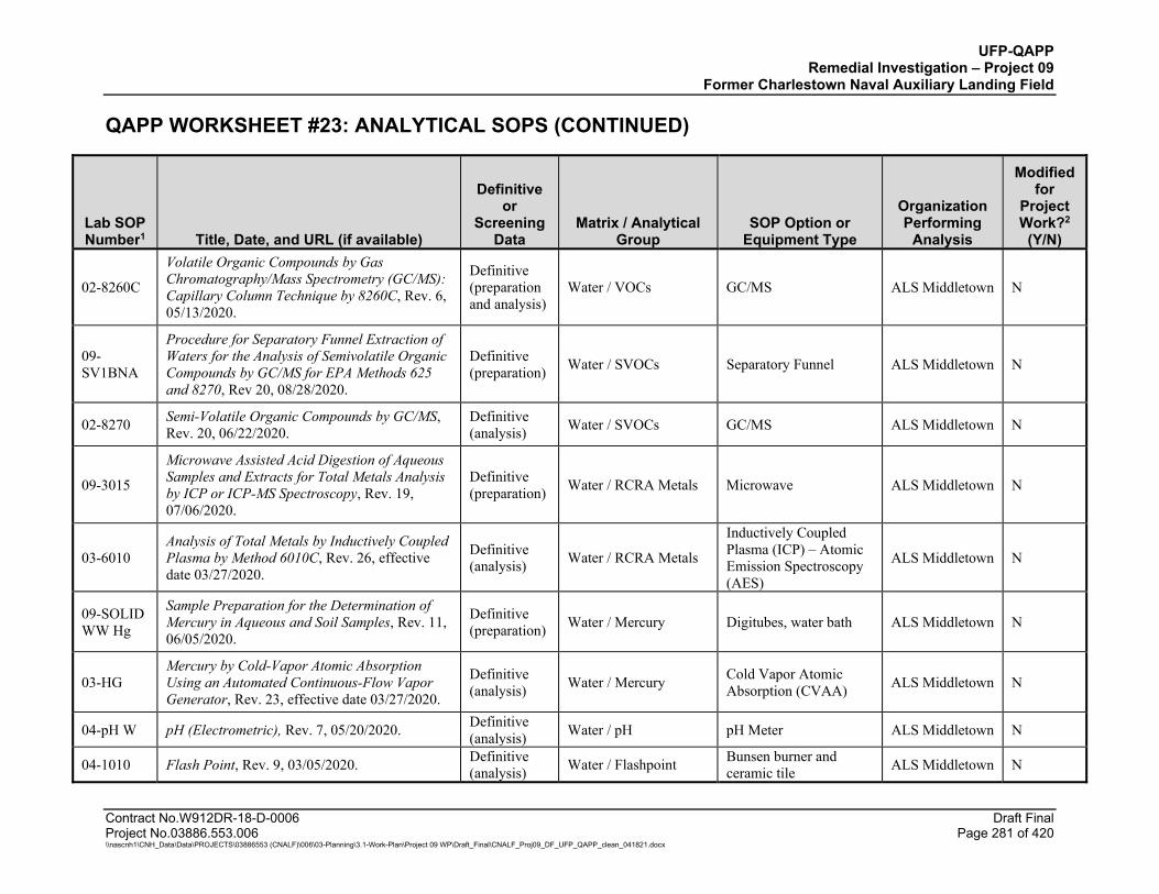
UFP-QAPP Remedial Investigation – Project 09
Former Charlestown Naval Auxiliary Landing Field
QAPP WORKSHEET #23: ANALYTICAL SOPS (CONTINUED)
Contract No.W912DR-18-D-0006 Draft Final Project No.03886.553.006 Page 281 of 420 \\nascnh1\CNH_Data\Data\PROJECTS\03886553 (CNALF)\006\03-Planning\3.1-Work-Plan\Project 09 WP\Draft_Final\CNALF_Proj09_DF_UFP_QAPP_clean_041821.docx
Lab SOP Number1 Title, Date, and URL (if available)
Definitive or
Screening Data
Matrix / Analytical Group
SOP Option or Equipment Type
Organization Performing
Analysis
Modified for
Project Work?2
(Y/N)
02-8260C
Volatile Organic Compounds by Gas Chromatography/Mass Spectrometry (GC/MS): Capillary Column Technique by 8260C, Rev. 6, 05/13/2020.
Definitive (preparation and analysis)
Water / VOCs GC/MS ALS Middletown N
09-SV1BNA
Procedure for Separatory Funnel Extraction of Waters for the Analysis of Semivolatile Organic Compounds by GC/MS for EPA Methods 625 and 8270, Rev 20, 08/28/2020.
Definitive (preparation) Water / SVOCs Separatory Funnel ALS Middletown N
02-8270 Semi-Volatile Organic Compounds by GC/MS, Rev. 20, 06/22/2020.
Definitive (analysis) Water / SVOCs GC/MS ALS Middletown N
09-3015
Microwave Assisted Acid Digestion of Aqueous Samples and Extracts for Total Metals Analysis by ICP or ICP-MS Spectroscopy, Rev. 19, 07/06/2020.
Definitive (preparation) Water / RCRA Metals Microwave ALS Middletown N
03-6010 Analysis of Total Metals by Inductively Coupled Plasma by Method 6010C, Rev. 26, effective date 03/27/2020.
Definitive (analysis) Water / RCRA Metals
Inductively Coupled Plasma (ICP) – Atomic Emission Spectroscopy (AES)
ALS Middletown N
09-SOLID WW Hg
Sample Preparation for the Determination of Mercury in Aqueous and Soil Samples, Rev. 11, 06/05/2020.
Definitive (preparation) Water / Mercury Digitubes, water bath ALS Middletown N
03-HG Mercury by Cold-Vapor Atomic Absorption Using an Automated Continuous-Flow Vapor Generator, Rev. 23, effective date 03/27/2020.
Definitive (analysis) Water / Mercury Cold Vapor Atomic
Absorption (CVAA) ALS Middletown N
04-pH W pH (Electrometric), Rev. 7, 05/20/2020. Definitive (analysis) Water / pH pH Meter ALS Middletown N
04-1010 Flash Point, Rev. 9, 03/05/2020. Definitive (analysis) Water / Flashpoint Bunsen burner and
ceramic tile ALS Middletown N
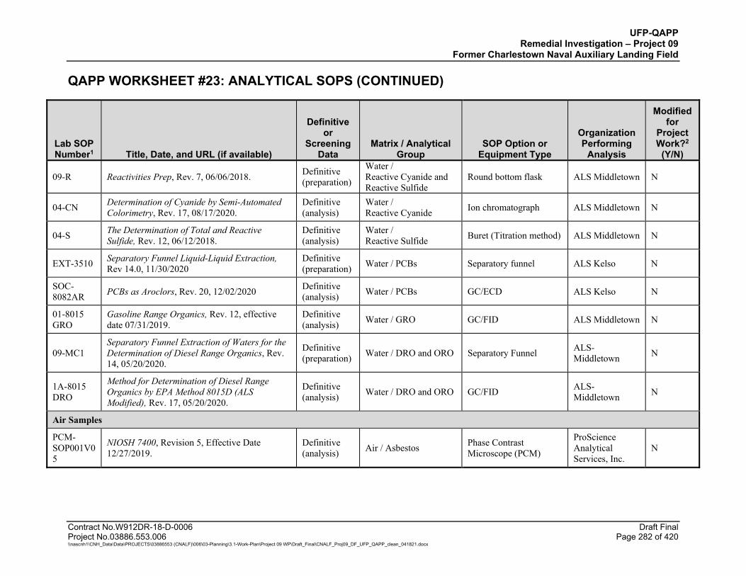
UFP-QAPP Remedial Investigation – Project 09
Former Charlestown Naval Auxiliary Landing Field
QAPP WORKSHEET #23: ANALYTICAL SOPS (CONTINUED)
Contract No.W912DR-18-D-0006 Draft Final Project No.03886.553.006 Page 282 of 420 \\nascnh1\CNH_Data\Data\PROJECTS\03886553 (CNALF)\006\03-Planning\3.1-Work-Plan\Project 09 WP\Draft_Final\CNALF_Proj09_DF_UFP_QAPP_clean_041821.docx
Lab SOP Number1 Title, Date, and URL (if available)
Definitive or
Screening Data
Matrix / Analytical Group
SOP Option or Equipment Type
Organization Performing
Analysis
Modified for
Project Work?2
(Y/N)
09-R Reactivities Prep, Rev. 7, 06/06/2018. Definitive (preparation)
Water / Reactive Cyanide and Reactive Sulfide
Round bottom flask ALS Middletown N
04-CN Determination of Cyanide by Semi-Automated Colorimetry, Rev. 17, 08/17/2020.
Definitive (analysis)
Water / Reactive Cyanide Ion chromatograph ALS Middletown N
04-S The Determination of Total and Reactive Sulfide, Rev. 12, 06/12/2018.
Definitive (analysis)
Water / Reactive Sulfide Buret (Titration method) ALS Middletown N
EXT-3510 Separatory Funnel Liquid-Liquid Extraction, Rev 14.0, 11/30/2020
Definitive (preparation) Water / PCBs Separatory funnel ALS Kelso N
SOC-8082AR PCBs as Aroclors, Rev. 20, 12/02/2020 Definitive
(analysis) Water / PCBs GC/ECD ALS Kelso N
01-8015 GRO
Gasoline Range Organics, Rev. 12, effective date 07/31/2019.
Definitive (analysis) Water / GRO GC/FID ALS Middletown N
09-MC1 Separatory Funnel Extraction of Waters for the Determination of Diesel Range Organics, Rev. 14, 05/20/2020.
Definitive (preparation) Water / DRO and ORO Separatory Funnel ALS-
Middletown N
1A-8015 DRO
Method for Determination of Diesel Range Organics by EPA Method 8015D (ALS Modified), Rev. 17, 05/20/2020.
Definitive (analysis) Water / DRO and ORO GC/FID ALS-
Middletown N
Air Samples
PCM-SOP001V05
NIOSH 7400, Revision 5, Effective Date 12/27/2019.
Definitive (analysis) Air / Asbestos Phase Contrast
Microscope (PCM)
ProScience Analytical Services, Inc.
N
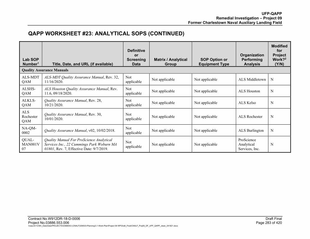
UFP-QAPP Remedial Investigation – Project 09
Former Charlestown Naval Auxiliary Landing Field
QAPP WORKSHEET #23: ANALYTICAL SOPS (CONTINUED)
Contract No.W912DR-18-D-0006 Draft Final Project No.03886.553.006 Page 283 of 420 \\nascnh1\CNH_Data\Data\PROJECTS\03886553 (CNALF)\006\03-Planning\3.1-Work-Plan\Project 09 WP\Draft_Final\CNALF_Proj09_DF_UFP_QAPP_clean_041821.docx
Lab SOP Number1 Title, Date, and URL (if available)
Definitive or
Screening Data
Matrix / Analytical Group
SOP Option or Equipment Type
Organization Performing
Analysis
Modified for
Project Work?2
(Y/N) Quality Assurance Manuals
ALS-MDT QAM
ALS-MDT Quality Assurance Manual, Rev. 32, 11/16/2020.
Not applicable Not applicable Not applicable ALS Middletown N
ALSHS- QAM
ALS Houston Quality Assurance Manual, Rev. 11.6, 09/18/2020.
Not applicable Not applicable Not applicable ALS Houston N
ALKLS-QAM
Quality Assurance Manual, Rev. 28, 10/21/2020.
Not applicable Not applicable Not applicable ALS Kelso N
ALS Rochester QAM
Quality Assurance Manual, Rev. 30, 10/01/2020.
Not applicable Not applicable Not applicable ALS Rochester N
NA-QM-0002 Quality Assurance Manual, v02, 10/02/2018. Not
applicable Not applicable Not applicable ALS Burlington N
QUAL-MAN001V07
Quality Manual For ProScience Analytical Services Inc., 22 Cummings Park Woburn MA 01801, Rev. 7, Effective Date: 9/7/2019.
Not applicable Not applicable Not applicable
ProScience Analytical Services, Inc.
N
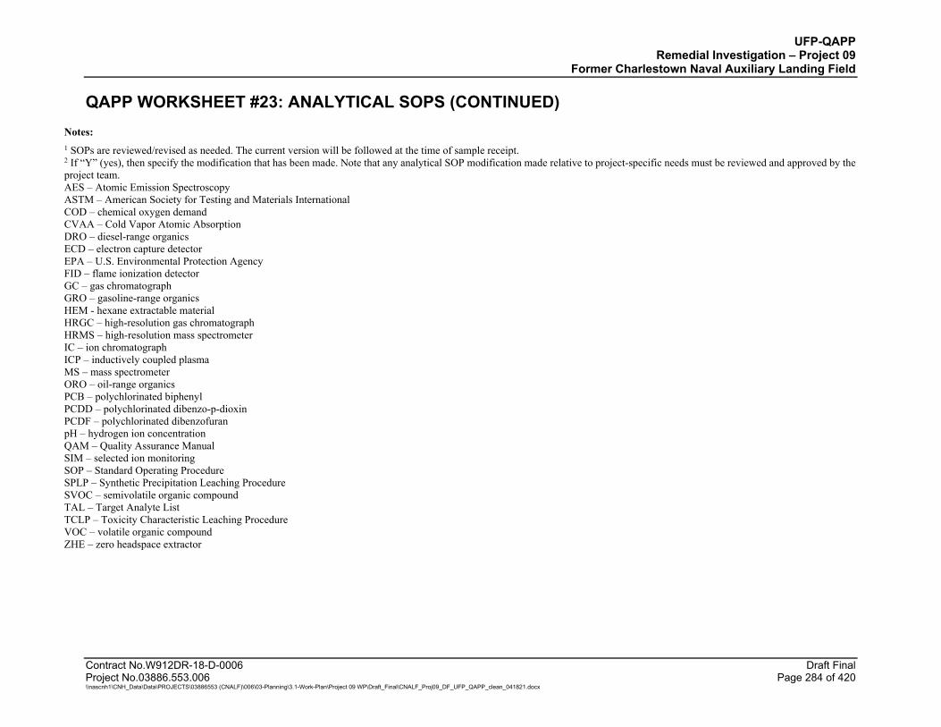
UFP-QAPP Remedial Investigation – Project 09
Former Charlestown Naval Auxiliary Landing Field
QAPP WORKSHEET #23: ANALYTICAL SOPS (CONTINUED)
Contract No.W912DR-18-D-0006 Draft Final Project No.03886.553.006 Page 284 of 420 \\nascnh1\CNH_Data\Data\PROJECTS\03886553 (CNALF)\006\03-Planning\3.1-Work-Plan\Project 09 WP\Draft_Final\CNALF_Proj09_DF_UFP_QAPP_clean_041821.docx
Notes: 1 SOPs are reviewed/revised as needed. The current version will be followed at the time of sample receipt. 2 If “Y” (yes), then specify the modification that has been made. Note that any analytical SOP modification made relative to project-specific needs must be reviewed and approved by the project team. AES – Atomic Emission Spectroscopy ASTM – American Society for Testing and Materials International COD – chemical oxygen demand CVAA – Cold Vapor Atomic Absorption DRO – diesel-range organics ECD – electron capture detector EPA – U.S. Environmental Protection Agency FID – flame ionization detector GC – gas chromatograph GRO – gasoline-range organics HEM - hexane extractable material HRGC – high-resolution gas chromatograph HRMS – high-resolution mass spectrometer IC – ion chromatograph ICP – inductively coupled plasma MS – mass spectrometer ORO – oil-range organics PCB – polychlorinated biphenyl PCDD – polychlorinated dibenzo-p-dioxin PCDF – polychlorinated dibenzofuran pH – hydrogen ion concentration QAM – Quality Assurance Manual SIM – selected ion monitoring SOP – Standard Operating Procedure SPLP – Synthetic Precipitation Leaching Procedure SVOC – semivolatile organic compound TAL – Target Analyte List TCLP – Toxicity Characteristic Leaching Procedure VOC – volatile organic compound ZHE – zero headspace extractor
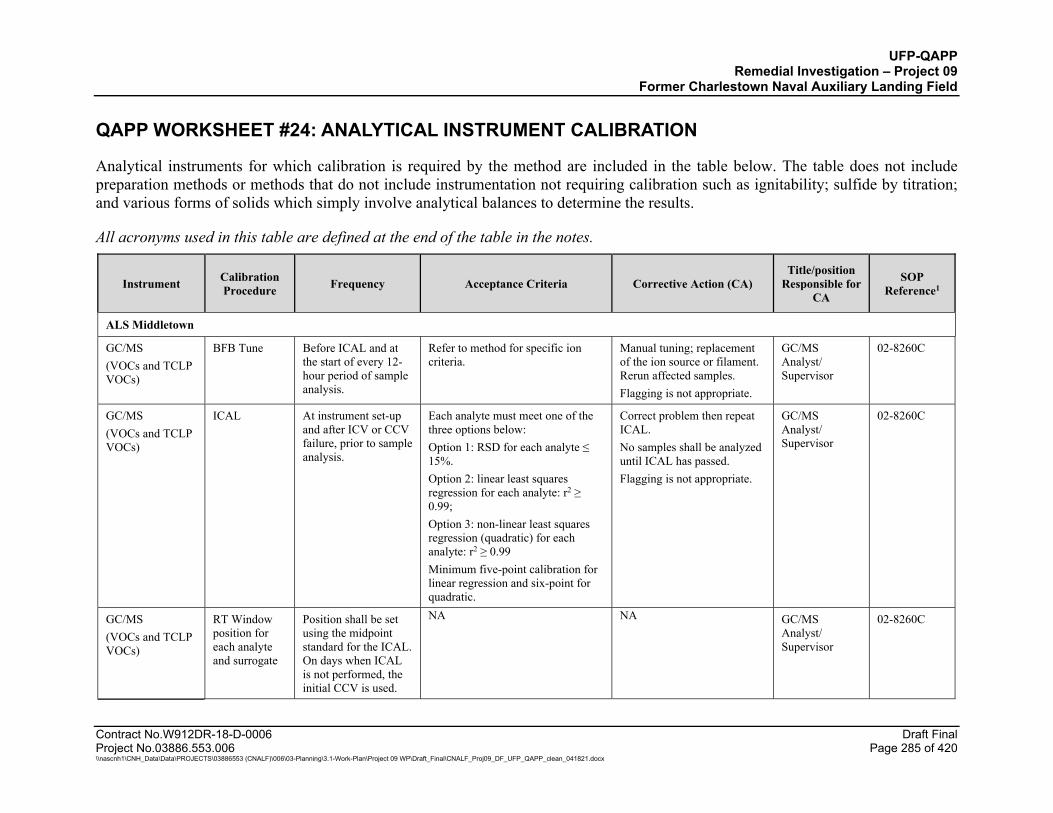
UFP-QAPP Remedial Investigation – Project 09
Former Charlestown Naval Auxiliary Landing Field
Contract No.W912DR-18-D-0006 Draft Final Project No.03886.553.006 Page 285 of 420 \\nascnh1\CNH_Data\Data\PROJECTS\03886553 (CNALF)\006\03-Planning\3.1-Work-Plan\Project 09 WP\Draft_Final\CNALF_Proj09_DF_UFP_QAPP_clean_041821.docx
QAPP WORKSHEET #24: ANALYTICAL INSTRUMENT CALIBRATION
Analytical instruments for which calibration is required by the method are included in the table below. The table does not include preparation methods or methods that do not include instrumentation not requiring calibration such as ignitability; sulfide by titration; and various forms of solids which simply involve analytical balances to determine the results.
All acronyms used in this table are defined at the end of the table in the notes.
Instrument Calibration Procedure Frequency Acceptance Criteria Corrective Action (CA)
Title/position Responsible for
CA
SOP Reference1
ALS Middletown
GC/MS (VOCs and TCLP VOCs)
BFB Tune Before ICAL and at the start of every 12-hour period of sample analysis.
Refer to method for specific ion criteria.
Manual tuning; replacement of the ion source or filament. Rerun affected samples. Flagging is not appropriate.
GC/MS Analyst/ Supervisor
02-8260C
GC/MS (VOCs and TCLP VOCs)
ICAL At instrument set-up and after ICV or CCV failure, prior to sample analysis.
Each analyte must meet one of the three options below: Option 1: RSD for each analyte ≤ 15%. Option 2: linear least squares regression for each analyte: r2 ≥ 0.99; Option 3: non-linear least squares regression (quadratic) for each analyte: r2 ≥ 0.99 Minimum five-point calibration for linear regression and six-point for quadratic.
Correct problem then repeat ICAL. No samples shall be analyzed until ICAL has passed. Flagging is not appropriate.
GC/MS Analyst/ Supervisor
02-8260C
GC/MS (VOCs and TCLP VOCs)
RT Window position for each analyte and surrogate
Position shall be set using the midpoint standard for the ICAL. On days when ICAL is not performed, the initial CCV is used.
NA NA GC/MS Analyst/ Supervisor
02-8260C
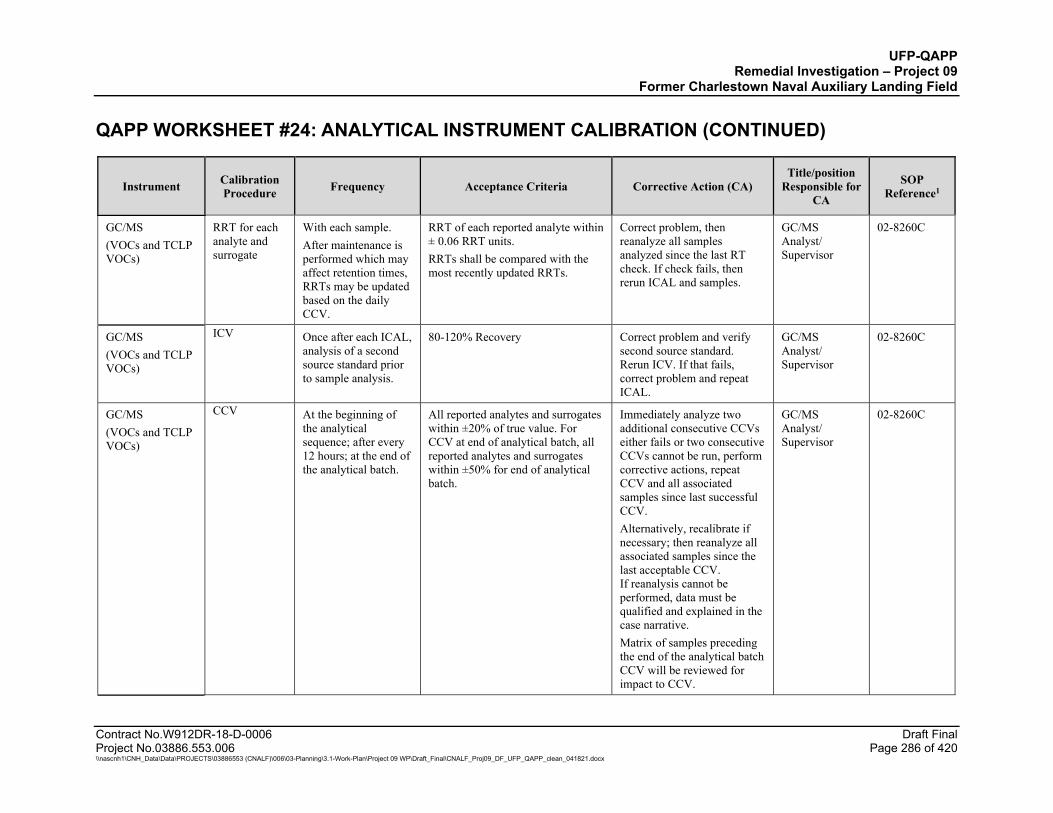
UFP-QAPP Remedial Investigation – Project 09
Former Charlestown Naval Auxiliary Landing Field QAPP WORKSHEET #24: ANALYTICAL INSTRUMENT CALIBRATION (CONTINUED)
Contract No.W912DR-18-D-0006 Draft Final Project No.03886.553.006 Page 286 of 420 \\nascnh1\CNH_Data\Data\PROJECTS\03886553 (CNALF)\006\03-Planning\3.1-Work-Plan\Project 09 WP\Draft_Final\CNALF_Proj09_DF_UFP_QAPP_clean_041821.docx
Instrument Calibration Procedure Frequency Acceptance Criteria Corrective Action (CA)
Title/position Responsible for
CA
SOP Reference1
GC/MS (VOCs and TCLP VOCs)
RRT for each analyte and surrogate
With each sample. After maintenance is performed which may affect retention times, RRTs may be updated based on the daily CCV.
RRT of each reported analyte within ± 0.06 RRT units. RRTs shall be compared with the most recently updated RRTs.
Correct problem, then reanalyze all samples analyzed since the last RT check. If check fails, then rerun ICAL and samples.
GC/MS Analyst/ Supervisor
02-8260C
GC/MS (VOCs and TCLP VOCs)
ICV Once after each ICAL, analysis of a second source standard prior to sample analysis.
80-120% Recovery Correct problem and verify second source standard. Rerun ICV. If that fails, correct problem and repeat ICAL.
GC/MS Analyst/ Supervisor
02-8260C
GC/MS (VOCs and TCLP VOCs)
CCV At the beginning of the analytical sequence; after every 12 hours; at the end of the analytical batch.
All reported analytes and surrogates within ±20% of true value. For CCV at end of analytical batch, all reported analytes and surrogates within ±50% for end of analytical batch.
Immediately analyze two additional consecutive CCVs either fails or two consecutive CCVs cannot be run, perform corrective actions, repeat CCV and all associated samples since last successful CCV. Alternatively, recalibrate if necessary; then reanalyze all associated samples since the last acceptable CCV. If reanalysis cannot be performed, data must be qualified and explained in the case narrative. Matrix of samples preceding the end of the analytical batch CCV will be reviewed for impact to CCV.
GC/MS Analyst/ Supervisor
02-8260C
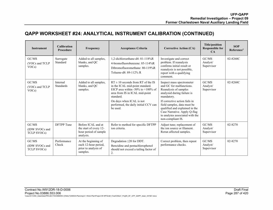
UFP-QAPP Remedial Investigation – Project 09
Former Charlestown Naval Auxiliary Landing Field QAPP WORKSHEET #24: ANALYTICAL INSTRUMENT CALIBRATION (CONTINUED)
Contract No.W912DR-18-D-0006 Draft Final Project No.03886.553.006 Page 287 of 420 \\nascnh1\CNH_Data\Data\PROJECTS\03886553 (CNALF)\006\03-Planning\3.1-Work-Plan\Project 09 WP\Draft_Final\CNALF_Proj09_DF_UFP_QAPP_clean_041821.docx
Instrument Calibration Procedure Frequency Acceptance Criteria Corrective Action (CA)
Title/position Responsible for
CA
SOP Reference1
GC/MS (VOCs and TCLP VOCs)
Surrogate Standard
Added to all samples, blanks, and QC samples.
1,2-dichloroethane-d4: 81-118%R 4-bromofluorobenzene: 85-114%R Dibromofluoromethane: 80-119%R Toluene-d8: 89-112% R
Investigate and correct problem. If reanalysis confirms initial result or reanalysis is not possible, report with a qualifying comment.
GC/MS Analyst/ Supervisor
02-8260C
GC/MS (VOCs and TCLP VOCs)
Internal Standards
Added to all samples, blanks, and QC samples.
RT ± 10 seconds from RT of the IS in the ICAL mid-point standard. EICP area within -50% to +100% of area from IS in ICAL mid-point standard. On days when ICAL is not performed, the daily initial CCV can be used.
Inspect mass spectrometer and GC for malfunctions. Reanalysis of samples analyzed during failure is mandatory. If corrective action fails in field samples, data must be qualified and explained in the Case Narrative. Apply Q-flag to analytes associated with the non-compliant IS.
GC/MS Analyst/ Supervisor
02-8260C
GC/MS (IDW SVOCs and TCLP SVOCs)
DFTPP Tune Before ICAL and at the start of every 12-hour period of sample analysis.
Refer to method for specific DFTPP ion criteria.
Adjust tune; replacement of the ion source or filament. Rerun affected samples.
GC/MS Analyst/ Supervisor
02-8270
GC/MS (IDW SVOCs and TCLP SVOCs)
Performance Check
At the beginning of each 12-hour period, prior to analysis of samples.
Degradation ≤20 for DDT. Benzidine and pentachlorophenol should not exceed a tailing factor of 2.
Correct problem, then repeat performance checks.
GC/MS Analyst/ Supervisor
02-8270
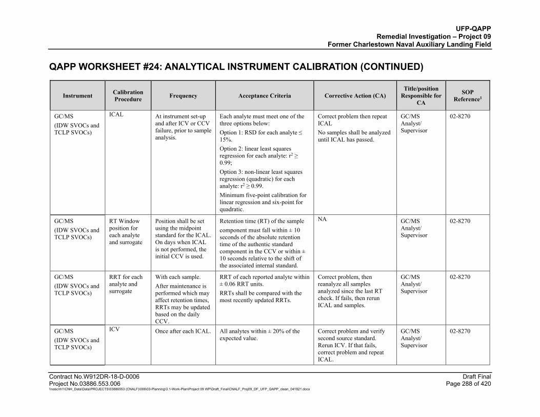
UFP-QAPP Remedial Investigation – Project 09
Former Charlestown Naval Auxiliary Landing Field QAPP WORKSHEET #24: ANALYTICAL INSTRUMENT CALIBRATION (CONTINUED)
Contract No.W912DR-18-D-0006 Draft Final Project No.03886.553.006 Page 288 of 420 \\nascnh1\CNH_Data\Data\PROJECTS\03886553 (CNALF)\006\03-Planning\3.1-Work-Plan\Project 09 WP\Draft_Final\CNALF_Proj09_DF_UFP_QAPP_clean_041821.docx
Instrument Calibration Procedure Frequency Acceptance Criteria Corrective Action (CA)
Title/position Responsible for
CA
SOP Reference1
GC/MS (IDW SVOCs and TCLP SVOCs)
ICAL At instrument set-up and after ICV or CCV failure, prior to sample analysis.
Each analyte must meet one of the three options below: Option 1: RSD for each analyte ≤ 15%. Option 2: linear least squares regression for each analyte: r2 ≥ 0.99; Option 3: non-linear least squares regression (quadratic) for each analyte: r2 ≥ 0.99. Minimum five-point calibration for linear regression and six-point for quadratic.
Correct problem then repeat ICAL No samples shall be analyzed until ICAL has passed.
GC/MS Analyst/ Supervisor
02-8270
GC/MS (IDW SVOCs and TCLP SVOCs)
RT Window position for each analyte and surrogate
Position shall be set using the midpoint standard for the ICAL. On days when ICAL is not performed, the initial CCV is used.
Retention time (RT) of the sample component must fall within ± 10 seconds of the absolute retention time of the authentic standard component in the CCV or within ± 10 seconds relative to the shift of the associated internal standard.
NA GC/MS Analyst/ Supervisor
02-8270
GC/MS (IDW SVOCs and TCLP SVOCs)
RRT for each analyte and surrogate
With each sample. After maintenance is performed which may affect retention times, RRTs may be updated based on the daily CCV.
RRT of each reported analyte within ± 0.06 RRT units. RRTs shall be compared with the most recently updated RRTs.
Correct problem, then reanalyze all samples analyzed since the last RT check. If fails, then rerun ICAL and samples.
GC/MS Analyst/ Supervisor
02-8270
GC/MS (IDW SVOCs and TCLP SVOCs)
ICV Once after each ICAL. All analytes within ± 20% of the expected value.
Correct problem and verify second source standard. Rerun ICV. If that fails, correct problem and repeat ICAL.
GC/MS Analyst/ Supervisor
02-8270

UFP-QAPP Remedial Investigation – Project 09
Former Charlestown Naval Auxiliary Landing Field QAPP WORKSHEET #24: ANALYTICAL INSTRUMENT CALIBRATION (CONTINUED)
Contract No.W912DR-18-D-0006 Draft Final Project No.03886.553.006 Page 289 of 420 \\nascnh1\CNH_Data\Data\PROJECTS\03886553 (CNALF)\006\03-Planning\3.1-Work-Plan\Project 09 WP\Draft_Final\CNALF_Proj09_DF_UFP_QAPP_clean_041821.docx
Instrument Calibration Procedure Frequency Acceptance Criteria Corrective Action (CA)
Title/position Responsible for
CA
SOP Reference1
GC/MS (IDW SVOCs and TCLP SVOCs)
CCV At the beginning of the analytical sequence; after every 12 hours; at the end of the analytical batch.
All reported analytes and surrogates within ±20% of true value. For CCV at end of analytical batch, all reported analytes and surrogates within ±50% for end of analytical batch.
Immediately analyze two additional consecutive CCVs either fails or two consecutive CCVs cannot be run, perform corrective actions, repeat CCV and all associated samples since last successful CCV. Alternatively, recalibrate if necessary; then reanalyze all associated samples since the last acceptable CCV. If reanalysis cannot be performed, data must be qualified and explained in the case narrative. Matrix of samples preceding the end of the analytical batch CCV will be reviewed for impact to CCV.
GC/MS Analyst/ Supervisor
02-8270
GC/MS (IDW SVOCs and TCLP SVOCs)
Surrogate Standard
Added to all samples, blanks, and QC samples.
Compare surrogate recoveries to the control limits. If the recovery is within control limits, then the analysis is in control and the sample data may be reported.
Investigate and correct problem. If reanalysis confirms initial result or reanalysis is not possible, report with a qualifying comment.
GC/MS Analyst/ Supervisor
02-8270

UFP-QAPP Remedial Investigation – Project 09
Former Charlestown Naval Auxiliary Landing Field QAPP WORKSHEET #24: ANALYTICAL INSTRUMENT CALIBRATION (CONTINUED)
Contract No.W912DR-18-D-0006 Draft Final Project No.03886.553.006 Page 290 of 420 \\nascnh1\CNH_Data\Data\PROJECTS\03886553 (CNALF)\006\03-Planning\3.1-Work-Plan\Project 09 WP\Draft_Final\CNALF_Proj09_DF_UFP_QAPP_clean_041821.docx
Instrument Calibration Procedure Frequency Acceptance Criteria Corrective Action (CA)
Title/position Responsible for
CA
SOP Reference1
GC/MS (IDW SVOCs and TCLP SVOCs)
Internal Standards
Added to all samples, blanks, and QC samples.
RT ± 10 seconds from RT of the IS in the ICAL mid-point standard. EICP area within -50% to +100% of area from IS in ICAL mid-point standard. On days when ICAL is not performed, the daily initial CCV can be used.
Inspect mass spectrometer and GC for malfunctions. Re-analysis of samples analyzed during failure is mandatory. If corrective action fails in field samples, data must be qualified and explained in the Case Narrative. Apply Q-flag to analytes associated with the non-compliant IS.
GC/MS Analyst/ Supervisor
02-8270
HPLC (Explosives)
ICAL Initially and after ICV or CCV failure, prior to sample analysis.
ICAL must meet one of the following: 1. Averaged Calibration Factor: RSD≤15% 2. Linear or quadratic regression: r2≥0.99.
Correct problem then re-calibrate.
Analyst / Supervisor
1B-8330
HPLC (Explosives)
ICV After each ICAL prepared from a second source standard prior to sample analysis.
All reported analytes within ± 20% of the expected value.
Correct problem and verify second source standard. Rerun ICV. If that fails, correct problem and repeat ICAL.
Analyst / Supervisor
1B-8330
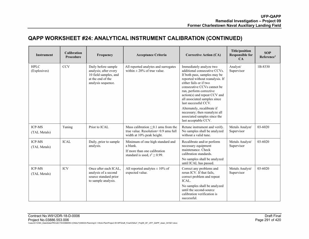
UFP-QAPP Remedial Investigation – Project 09
Former Charlestown Naval Auxiliary Landing Field QAPP WORKSHEET #24: ANALYTICAL INSTRUMENT CALIBRATION (CONTINUED)
Contract No.W912DR-18-D-0006 Draft Final Project No.03886.553.006 Page 291 of 420 \\nascnh1\CNH_Data\Data\PROJECTS\03886553 (CNALF)\006\03-Planning\3.1-Work-Plan\Project 09 WP\Draft_Final\CNALF_Proj09_DF_UFP_QAPP_clean_041821.docx
Instrument Calibration Procedure Frequency Acceptance Criteria Corrective Action (CA)
Title/position Responsible for
CA
SOP Reference1
HPLC (Explosives)
CCV Daily before sample analysis; after every 10 field samples, and at the end of the analysis sequence.
All reported analytes and surrogates within ± 20% of true value.
Immediately analyze two additional consecutive CCVs. If both pass, samples may be reported without reanalysis. If either fails or if two consecutive CCVs cannot be run, perform corrective action(s) and repeat CCV and all associated samples since last successful CCV. Alternately, recalibrate if necessary; then reanalyze all associated samples since the last acceptable CCV.
Analyst/ Supervisor
1B-8330
ICP-MS (TAL Metals)
Tuning Prior to ICAL Mass calibration < 0.1 amu from the true value. Resolution< 0.9 amu full width at 10% peak height.
Retune instrument and verify. No samples shall be analyzed without a valid tune.
Metals Analyst/ Supervisor
03-6020
ICP-MS (TAL Metals)
ICAL Daily, prior to sample analysis.
Minimum of one high standard and a blank. If more than one calibration standard is used, r2 > 0.99.
Recalibrate and/or perform necessary equipment maintenance. Check calibration standards. No samples shall be analyzed until ICAL has passed.
Metals Analyst/ Supervisor
03-6020
ICP-MS (TAL Metals)
ICV Once after each ICAL, analysis of a second source standard prior to sample analysis.
All reported analytes ± 10% of expected value.
Correct any problems and rerun ICV. If that fails, correct problem and repeat ICAL. No samples shall be analyzed until the second-source calibration verification is successful.
Metals Analyst/ Supervisor
03-6020

UFP-QAPP Remedial Investigation – Project 09
Former Charlestown Naval Auxiliary Landing Field QAPP WORKSHEET #24: ANALYTICAL INSTRUMENT CALIBRATION (CONTINUED)
Contract No.W912DR-18-D-0006 Draft Final Project No.03886.553.006 Page 292 of 420 \\nascnh1\CNH_Data\Data\PROJECTS\03886553 (CNALF)\006\03-Planning\3.1-Work-Plan\Project 09 WP\Draft_Final\CNALF_Proj09_DF_UFP_QAPP_clean_041821.docx
Instrument Calibration Procedure Frequency Acceptance Criteria Corrective Action (CA)
Title/position Responsible for
CA
SOP Reference1
ICP-MS (TAL Metals)
CCV After every 10 field samples and at the end of the analysis sequence.
All analytes within ± 10% of true value.
Immediately analyze two additional consecutive CCVs. If both pass, samples may be reported without reanalysis. If either fails or if two consecutive CCVs cannot be run, perform corrective action(s) and repeat CCV and all associated samples since last successful CCV. Alternately, recalibrate if necessary; then reanalyze all associated samples since the last acceptable CCV. If reanalysis cannot be performed, data must be qualified and explained in the Case Narrative.
Metals Analyst/ Supervisor
03-6020
ICP-MS (TAL Metals)
Low-level calibration check standard (LLCCV)
Daily, after the ICAL Within ± 20% of true value. LLCCV should be < the LOQ. If the concentration of the lowest calibration standard is < the LOQ, the lowest standard may be requantified against the calibration curve as LLCCV. Otherwise, a separate standard must be analyzed as the LLCCV prior to the analysis of any samples.
Correct problem, rerun calibration verification. If that fails, then repeat ICAL.
Metals Analyst/ Supervisor
03-6020

UFP-QAPP Remedial Investigation – Project 09
Former Charlestown Naval Auxiliary Landing Field QAPP WORKSHEET #24: ANALYTICAL INSTRUMENT CALIBRATION (CONTINUED)
Contract No.W912DR-18-D-0006 Draft Final Project No.03886.553.006 Page 293 of 420 \\nascnh1\CNH_Data\Data\PROJECTS\03886553 (CNALF)\006\03-Planning\3.1-Work-Plan\Project 09 WP\Draft_Final\CNALF_Proj09_DF_UFP_QAPP_clean_041821.docx
Instrument Calibration Procedure Frequency Acceptance Criteria Corrective Action (CA)
Title/position Responsible for
CA
SOP Reference1
ICP-MS (TAL Metals)
ICS (ICSA and ICSAB)
After ICAL and prior to sample analysis.
ICS-A: Absolute value of concentration for all non-spiked project analytes < LOD (unless they are a verified trace impurity from one of the spiked analytes); ICS-AB: Within ± 20% of true value.
Terminate analysis; locate and correct problem; reanalyze ICS, reanalyze all samples. If corrective action fails, data must be qualified and explained in the case narrative.
Metals Analyst/ Supervisor
03-6020
ICP-MS (TAL Metals)
ICB/CCB Immediately after the ICV and immediately after every CCV.
The absolute values of all analytes must be < ½ LOQ or < 1/10th the amount measured in any sample.
Correct problem and repeat ICV/ICB analysis. If that fails, rerun ICAL. All samples following the last acceptable calibration blank must be reanalyzed. CCBs may not be reanalyzed without reanalysis of the associated samples and CCV(s). Results may not be reported without valid Calibration Blanks. Non-detects associated with positive blank infractions may be reported. Sample results > 10 times the LOQ associated with negative blanks may be reported. For CCB, failures due to carryover may not require an ICAL.
Metals Analyst/ Supervisor
03-6020
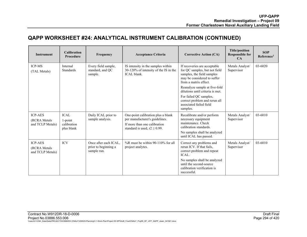
UFP-QAPP Remedial Investigation – Project 09
Former Charlestown Naval Auxiliary Landing Field QAPP WORKSHEET #24: ANALYTICAL INSTRUMENT CALIBRATION (CONTINUED)
Contract No.W912DR-18-D-0006 Draft Final Project No.03886.553.006 Page 294 of 420 \\nascnh1\CNH_Data\Data\PROJECTS\03886553 (CNALF)\006\03-Planning\3.1-Work-Plan\Project 09 WP\Draft_Final\CNALF_Proj09_DF_UFP_QAPP_clean_041821.docx
Instrument Calibration Procedure Frequency Acceptance Criteria Corrective Action (CA)
Title/position Responsible for
CA
SOP Reference1
ICP-MS (TAL Metals)
Internal Standards
Every field sample, standard, and QC sample.
IS intensity in the samples within 30-120% of intensity of the IS in the ICAL blank.
If recoveries are acceptable for QC samples, but not field samples, the field samples may be considered to suffer from a matrix effect. Reanalyze sample at five-fold dilutions until criteria is met. For failed QC samples, correct problem and rerun all associated failed field samples.
Metals Analyst/ Supervisor
03-6020
ICP-AES (RCRA Metals and TCLP Metals)
ICAL 1-point calibration plus blank
Daily ICAL prior to sample analysis.
One-point calibration plus a blank per manufacturer's guidelines. If more than one calibration standard is used, r2 ≥ 0.99.
Recalibrate and/or perform necessary equipment maintenance. Check calibration standards. No samples shall be analyzed until ICAL has passed.
Metals Analyst/ Supervisor
03-6010
ICP-AES (RCRA Metals and TCLP Metals)
ICV Once after each ICAL, prior to beginning a sample run.
%R must be within 90-110% for all project analytes.
Correct any problems and rerun ICV. If that fails, correct problem and repeat ICAL. No samples shall be analyzed until the second-source calibration verification is successful.
Metals Analyst/ Supervisor
03-6010
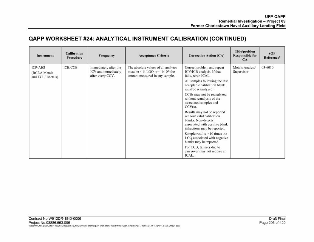
UFP-QAPP Remedial Investigation – Project 09
Former Charlestown Naval Auxiliary Landing Field QAPP WORKSHEET #24: ANALYTICAL INSTRUMENT CALIBRATION (CONTINUED)
Contract No.W912DR-18-D-0006 Draft Final Project No.03886.553.006 Page 295 of 420 \\nascnh1\CNH_Data\Data\PROJECTS\03886553 (CNALF)\006\03-Planning\3.1-Work-Plan\Project 09 WP\Draft_Final\CNALF_Proj09_DF_UFP_QAPP_clean_041821.docx
Instrument Calibration Procedure Frequency Acceptance Criteria Corrective Action (CA)
Title/position Responsible for
CA
SOP Reference1
ICP-AES (RCRA Metals and TCLP Metals)
ICB/CCB Immediately after the ICV and immediately after every CCV.
The absolute values of all analytes must be < ½ LOQ or < 1/10th the amount measured in any sample.
Correct problem and repeat ICV/ICB analysis. If that fails, rerun ICAL. All samples following the last acceptable calibration blank must be reanalyzed. CCBs may not be reanalyzed without reanalysis of the associated samples and CCV(s). Results may not be reported without valid calibration blanks. Non-detects associated with positive blank infractions may be reported. Sample results > 10 times the LOQ associated with negative blanks may be reported. For CCB, failures due to carryover may not require an ICAL.
Metals Analyst/ Supervisor
03-6010
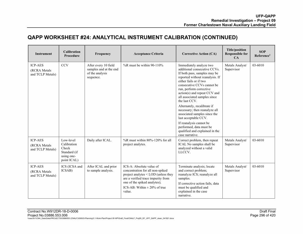
UFP-QAPP Remedial Investigation – Project 09
Former Charlestown Naval Auxiliary Landing Field QAPP WORKSHEET #24: ANALYTICAL INSTRUMENT CALIBRATION (CONTINUED)
Contract No.W912DR-18-D-0006 Draft Final Project No.03886.553.006 Page 296 of 420 \\nascnh1\CNH_Data\Data\PROJECTS\03886553 (CNALF)\006\03-Planning\3.1-Work-Plan\Project 09 WP\Draft_Final\CNALF_Proj09_DF_UFP_QAPP_clean_041821.docx
Instrument Calibration Procedure Frequency Acceptance Criteria Corrective Action (CA)
Title/position Responsible for
CA
SOP Reference1
ICP-AES (RCRA Metals and TCLP Metals)
CCV After every 10 field samples and at the end of the analysis sequence.
%R must be within 90-110% Immediately analyze two additional consecutive CCVs. If both pass, samples may be reported without reanalysis. If either fails or if two consecutive CCVs cannot be run, perform corrective action(s) and repeat CCV and all associated samples since the last CCV. Alternately, recalibrate if necessary; then reanalyze all associated samples since the last acceptable CCV. If reanalysis cannot be performed, data must be qualified and explained in the case narrative.
Metals Analyst/ Supervisor
03-6010
ICP-AES (RCRA Metals and TCLP Metals)
Low-level Calibration Check Standard (if using one-point ICAL)
Daily after ICAL. %R must within 80%-120% for all project analytes.
Correct problem, then repeat ICAL No samples shall be analyzed without a valid LLCCV.
Metals Analyst/ Supervisor
03-6010
ICP-AES (RCRA Metals and TCLP Metals)
ICS (ICSA and ICSAB)
After ICAL and prior to sample analysis.
ICS-A: Absolute value of concentration for all non-spiked project analytes < LOD (unless they are a verified trace impurity from one of the spiked analytes); ICS-AB: Within ± 20% of true value.
Terminate analysis; locate and correct problem; reanalyze ICS; reanalyze all samples. If corrective action fails, data must be qualified and explained in the case narrative.
Metals Analyst/ Supervisor
03-6010

UFP-QAPP Remedial Investigation – Project 09
Former Charlestown Naval Auxiliary Landing Field QAPP WORKSHEET #24: ANALYTICAL INSTRUMENT CALIBRATION (CONTINUED)
Contract No.W912DR-18-D-0006 Draft Final Project No.03886.553.006 Page 297 of 420 \\nascnh1\CNH_Data\Data\PROJECTS\03886553 (CNALF)\006\03-Planning\3.1-Work-Plan\Project 09 WP\Draft_Final\CNALF_Proj09_DF_UFP_QAPP_clean_041821.docx
Instrument Calibration Procedure Frequency Acceptance Criteria Corrective Action (CA)
Title/position Responsible for
CA
SOP Reference1
CVAA (Mercury and TCLP Mercury)
ICAL - 5 points plus a calibration blank (CB) CCB, 0.2 µg/L to 10 µg/L
Daily ICAL prior to sample analysis.
Correlation coefficient r2 ≥ 0.99. Recalibrate and/or perform necessary equipment maintenance. Check calibration standards. No samples shall be analyzed until ICAL has passed.
Metals Analyst/ Supervisor
03-HG
CVAA (Mercury and TCLP Mercury)
ICV Once after each ICAL, analysis of a second source standard prior to sample analysis.
%R must be within 90-110%. Correct problem and verify second source standard. Rerun ICV. If that fails, correct problem and repeat ICAL. No samples shall be analyzed until calibration has been verified with a second source.
Metals Analyst/ Supervisor
03-HG
CVAA (Mercury and TCLP Mercury)
Low-level Calibration Check Standard (LLCCV)
Daily after ICAL. %R must within 80%-120% for all project analytes.
Correct problem, then repeat ICAL No samples shall be analyzed without a valid LLCCV.
Metals Analyst/ Supervisor
03-HG
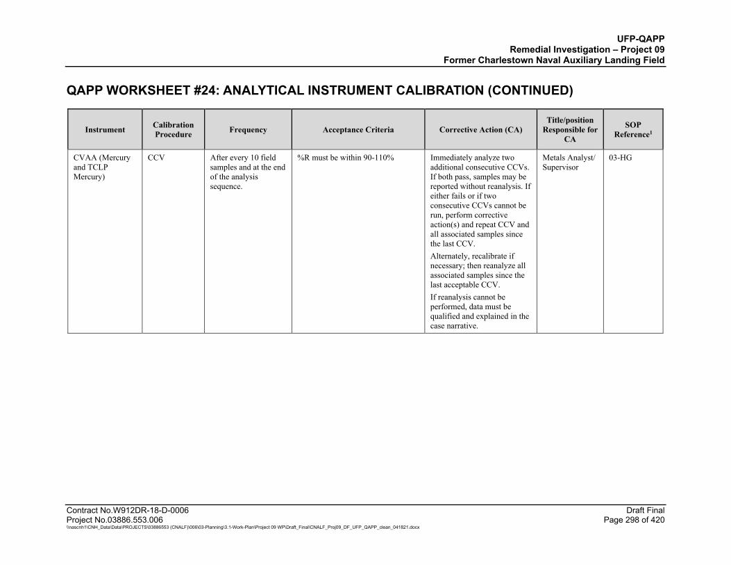
UFP-QAPP Remedial Investigation – Project 09
Former Charlestown Naval Auxiliary Landing Field QAPP WORKSHEET #24: ANALYTICAL INSTRUMENT CALIBRATION (CONTINUED)
Contract No.W912DR-18-D-0006 Draft Final Project No.03886.553.006 Page 298 of 420 \\nascnh1\CNH_Data\Data\PROJECTS\03886553 (CNALF)\006\03-Planning\3.1-Work-Plan\Project 09 WP\Draft_Final\CNALF_Proj09_DF_UFP_QAPP_clean_041821.docx
Instrument Calibration Procedure Frequency Acceptance Criteria Corrective Action (CA)
Title/position Responsible for
CA
SOP Reference1
CVAA (Mercury and TCLP Mercury)
CCV After every 10 field samples and at the end of the analysis sequence.
%R must be within 90-110% Immediately analyze two additional consecutive CCVs. If both pass, samples may be reported without reanalysis. If either fails or if two consecutive CCVs cannot be run, perform corrective action(s) and repeat CCV and all associated samples since the last CCV. Alternately, recalibrate if necessary; then reanalyze all associated samples since the last acceptable CCV. If reanalysis cannot be performed, data must be qualified and explained in the case narrative.
Metals Analyst/ Supervisor
03-HG
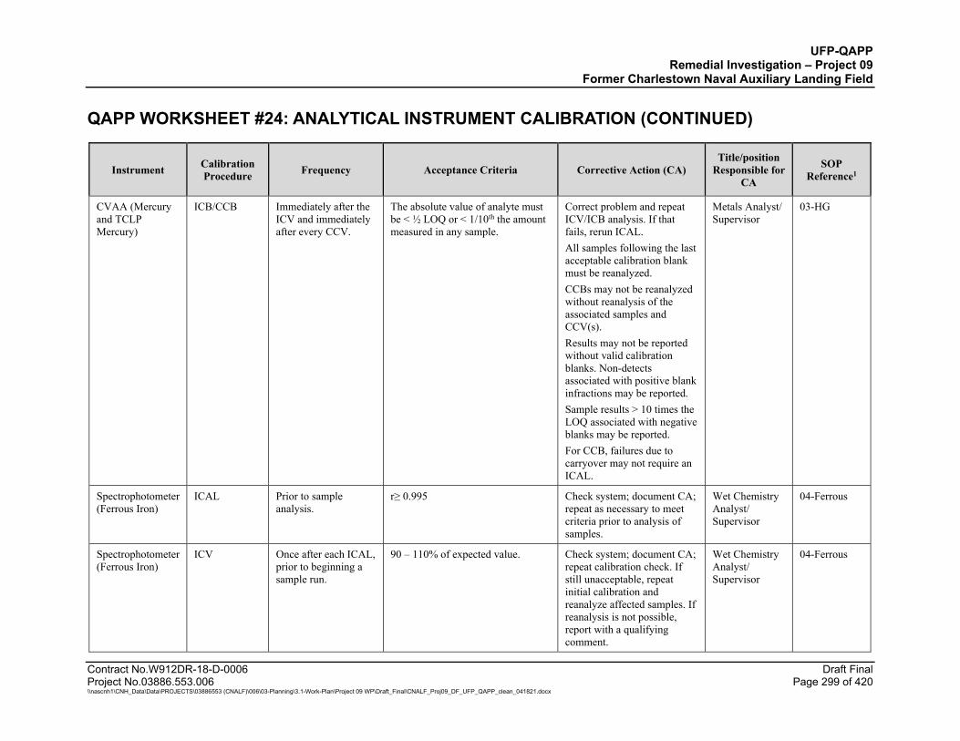
UFP-QAPP Remedial Investigation – Project 09
Former Charlestown Naval Auxiliary Landing Field QAPP WORKSHEET #24: ANALYTICAL INSTRUMENT CALIBRATION (CONTINUED)
Contract No.W912DR-18-D-0006 Draft Final Project No.03886.553.006 Page 299 of 420 \\nascnh1\CNH_Data\Data\PROJECTS\03886553 (CNALF)\006\03-Planning\3.1-Work-Plan\Project 09 WP\Draft_Final\CNALF_Proj09_DF_UFP_QAPP_clean_041821.docx
Instrument Calibration Procedure Frequency Acceptance Criteria Corrective Action (CA)
Title/position Responsible for
CA
SOP Reference1
CVAA (Mercury and TCLP Mercury)
ICB/CCB Immediately after the ICV and immediately after every CCV.
The absolute value of analyte must be < ½ LOQ or < 1/10th the amount measured in any sample.
Correct problem and repeat ICV/ICB analysis. If that fails, rerun ICAL. All samples following the last acceptable calibration blank must be reanalyzed. CCBs may not be reanalyzed without reanalysis of the associated samples and CCV(s). Results may not be reported without valid calibration blanks. Non-detects associated with positive blank infractions may be reported. Sample results > 10 times the LOQ associated with negative blanks may be reported. For CCB, failures due to carryover may not require an ICAL.
Metals Analyst/ Supervisor
03-HG
Spectrophotometer (Ferrous Iron)
ICAL Prior to sample analysis.
r≥ 0.995 Check system; document CA; repeat as necessary to meet criteria prior to analysis of samples.
Wet Chemistry Analyst/ Supervisor
04-Ferrous
Spectrophotometer (Ferrous Iron)
ICV Once after each ICAL, prior to beginning a sample run.
90 – 110% of expected value. Check system; document CA; repeat calibration check. If still unacceptable, repeat initial calibration and reanalyze affected samples. If reanalysis is not possible, report with a qualifying comment.
Wet Chemistry Analyst/ Supervisor
04-Ferrous
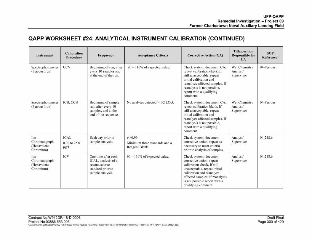
UFP-QAPP Remedial Investigation – Project 09
Former Charlestown Naval Auxiliary Landing Field QAPP WORKSHEET #24: ANALYTICAL INSTRUMENT CALIBRATION (CONTINUED)
Contract No.W912DR-18-D-0006 Draft Final Project No.03886.553.006 Page 300 of 420 \\nascnh1\CNH_Data\Data\PROJECTS\03886553 (CNALF)\006\03-Planning\3.1-Work-Plan\Project 09 WP\Draft_Final\CNALF_Proj09_DF_UFP_QAPP_clean_041821.docx
Instrument Calibration Procedure Frequency Acceptance Criteria Corrective Action (CA)
Title/position Responsible for
CA
SOP Reference1
Spectrophotometer (Ferrous Iron)
CCV Beginning of run, after every 10 samples and at the end of the run.
90 – 110% of expected value. Check system; document CA; repeat calibration check. If still unacceptable, repeat initial calibration and reanalyze affected samples. If reanalysis is not possible, report with a qualifying comment.
Wet Chemistry Analyst/ Supervisor
04-Ferrous
Spectrophotometer (Ferrous Iron)
ICB, CCB Beginning of sample run, after every 10 samples, and at the end of the sequence.
No analytes detected > 1/2 LOQ. Check system; document CA; repeat calibration blank. If still unacceptable, repeat initial calibration and reanalyze affected samples. If reanalysis is not possible, report with a qualifying comment.
Wet Chemistry Analyst/ Supervisor
04-Ferrous
Ion Chromatograph (Hexavalent Chromium)
ICAL 0.02 to 25.0 µg/L
Each day prior to sample analysis.
r2>0.99 Minimum three standards and a Reagent Blank.
Check system; document corrective action; repeat as necessary to meet criteria prior to analysis of samples.
Analyst/ Supervisor
04-218.6
Ion Chromatograph (Hexavalent Chromium)
ICV One time after each ICAL, analysis of a second source standard prior to sample analysis.
90 – 110% of expected value. Check system; document corrective action; repeat calibration check. If still unacceptable, repeat initial calibration and reanalyze affected samples. If reanalysis is not possible report with a qualifying comment.
Analyst/ Supervisor
04-218.6

UFP-QAPP Remedial Investigation – Project 09
Former Charlestown Naval Auxiliary Landing Field QAPP WORKSHEET #24: ANALYTICAL INSTRUMENT CALIBRATION (CONTINUED)
Contract No.W912DR-18-D-0006 Draft Final Project No.03886.553.006 Page 301 of 420 \\nascnh1\CNH_Data\Data\PROJECTS\03886553 (CNALF)\006\03-Planning\3.1-Work-Plan\Project 09 WP\Draft_Final\CNALF_Proj09_DF_UFP_QAPP_clean_041821.docx
Instrument Calibration Procedure Frequency Acceptance Criteria Corrective Action (CA)
Title/position Responsible for
CA
SOP Reference1
Ion Chromatograph (Hexavalent Chromium)
CCV Daily before sample analysis, after every 10 samples and at the end of the analytical sequence.
90 – 110% of expected value. Immediately analyze two additional consecutive CCVs. If both pass, samples may be reported without reanalysis. If either fails or if two consecutive CCVs cannot be run, perform corrective action(s) and repeat CCV and all associated samples since last successful CCV. Alternately, recalibrate if necessary; then reanalyze all associated samples since the last acceptable CCV.
Analyst/ Supervisor
04-218.6
Ion Chromatograph (Hexavalent Chromium)
ICB Immediately following the ICV
< ½ LOQ Reanalyze all associated samples. If samples cannot be reanalyzed, report with a qualifying statement
Analyst/ Supervisor
04-218.6
Ion Chromatograph (Hexavalent Chromium)
CCB Immediately following CCVs and at end of run.
< ½ LOQ Reanalyze all associated samples. If samples cannot be reanalyzed, report with a qualifying statement.
Analyst/ Supervisor
04-218.6
Ion Chromatograph with flow injection analyzer (Reactive Cyanide)
ICAL 0.005 to 0.25 mg/L
Daily prior to sample analysis
Correlation coefficient r2 ≥ 0.99. Identify and correct the source of the problem. Re-calibrate. Flagging is not appropriate.
Wet chemistry analyst/ Supervisor
04-CN

UFP-QAPP Remedial Investigation – Project 09
Former Charlestown Naval Auxiliary Landing Field QAPP WORKSHEET #24: ANALYTICAL INSTRUMENT CALIBRATION (CONTINUED)
Contract No.W912DR-18-D-0006 Draft Final Project No.03886.553.006 Page 302 of 420 \\nascnh1\CNH_Data\Data\PROJECTS\03886553 (CNALF)\006\03-Planning\3.1-Work-Plan\Project 09 WP\Draft_Final\CNALF_Proj09_DF_UFP_QAPP_clean_041821.docx
Instrument Calibration Procedure Frequency Acceptance Criteria Corrective Action (CA)
Title/position Responsible for
CA
SOP Reference1
Ion Chromatograph with flow injection analyzer (Reactive Cyanide)
ICV Once after each ICAL, analysis of a second source standard prior to sample analysis.
90 – 110% of expected value. Correct problem. Rerun ICV. If that fails, repeat ICAL. No samples shall be analyzed until calibration has been verified.
Wet chemistry analyst/ Supervisor
04-CN
Ion Chromatograph with flow injection analyzer (Reactive Cyanide)
CCV Beginning of run, after every ten field samples, and at the end of the run.
90 – 110% of expected value. Immediately analyze two additional consecutive CCVs. If both pass, samples may be reported without reanalysis. If either fails or if two consecutive CCVs cannot be run, perform corrective action(s) and repeat CCV and all associated samples since last successful CCV. Alternately, recalibrate if necessary; then reanalyze all associated samples since the last acceptable CCV.
Wet chemistry analyst/ Supervisor
04-CN
Ion Chromatograph with flow injection analyzer (Reactive Cyanide)
Retention Time (RT) window position establishment
Once per multipoint calibration
Position shall be set using the midpoint standard of the ICAL curve when ICAL is performed. On days when ICAL is not performed, the initial CCV is used.
NA Wet chemistry analyst/ Supervisor
04-CN
Ion Chromatograph with flow injection analyzer (Reactive Cyanide)
RT window width
At method set-up and after major maintenance
RT width is ± three times standard deviation for each analyte RT over a 24-hour period.
NA Wet chemistry analyst/ Supervisor
04-CN
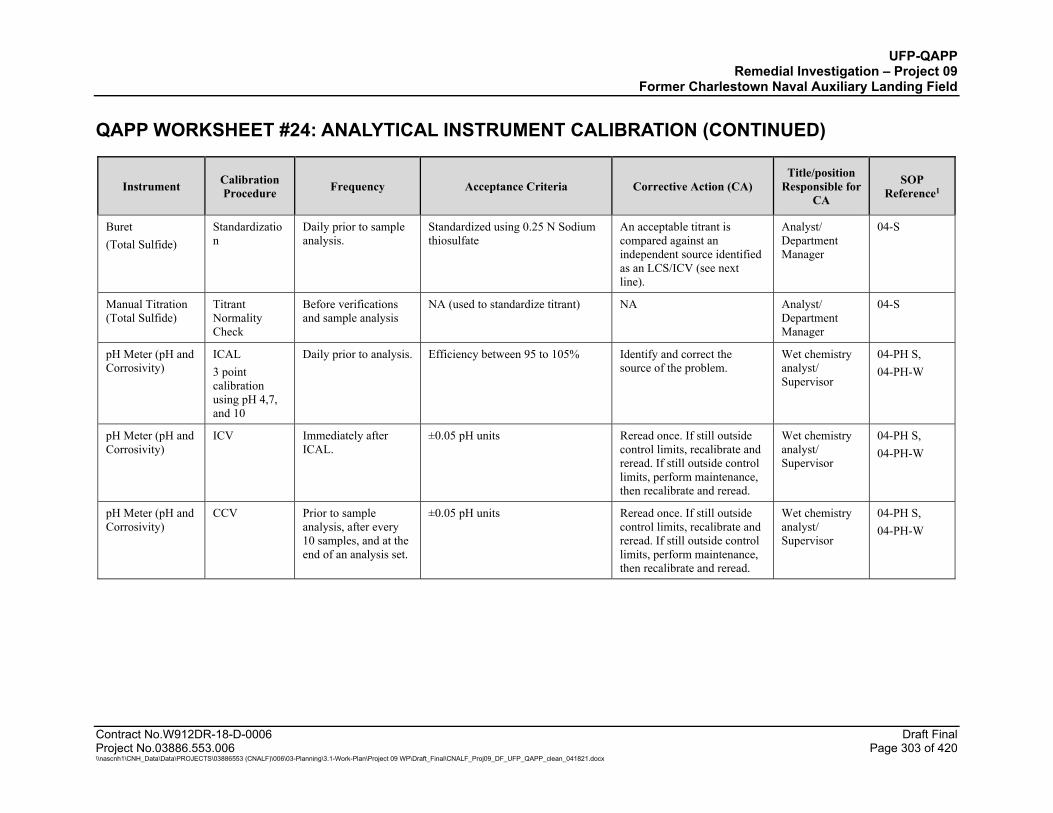
UFP-QAPP Remedial Investigation – Project 09
Former Charlestown Naval Auxiliary Landing Field QAPP WORKSHEET #24: ANALYTICAL INSTRUMENT CALIBRATION (CONTINUED)
Contract No.W912DR-18-D-0006 Draft Final Project No.03886.553.006 Page 303 of 420 \\nascnh1\CNH_Data\Data\PROJECTS\03886553 (CNALF)\006\03-Planning\3.1-Work-Plan\Project 09 WP\Draft_Final\CNALF_Proj09_DF_UFP_QAPP_clean_041821.docx
Instrument Calibration Procedure Frequency Acceptance Criteria Corrective Action (CA)
Title/position Responsible for
CA
SOP Reference1
Buret (Total Sulfide)
Standardization
Daily prior to sample analysis.
Standardized using 0.25 N Sodium thiosulfate
An acceptable titrant is compared against an independent source identified as an LCS/ICV (see next line).
Analyst/ Department Manager
04-S
Manual Titration (Total Sulfide)
Titrant Normality Check
Before verifications and sample analysis
NA (used to standardize titrant) NA Analyst/ Department Manager
04-S
pH Meter (pH and Corrosivity)
ICAL 3 point calibration using pH 4,7, and 10
Daily prior to analysis. Efficiency between 95 to 105% Identify and correct the source of the problem.
Wet chemistry analyst/ Supervisor
04-PH S, 04-PH-W
pH Meter (pH and Corrosivity)
ICV Immediately after ICAL.
±0.05 pH units Reread once. If still outside control limits, recalibrate and reread. If still outside control limits, perform maintenance, then recalibrate and reread.
Wet chemistry analyst/ Supervisor
04-PH S, 04-PH-W
pH Meter (pH and Corrosivity)
CCV Prior to sample analysis, after every 10 samples, and at the end of an analysis set.
±0.05 pH units Reread once. If still outside control limits, recalibrate and reread. If still outside control limits, perform maintenance, then recalibrate and reread.
Wet chemistry analyst/ Supervisor
04-PH S, 04-PH-W
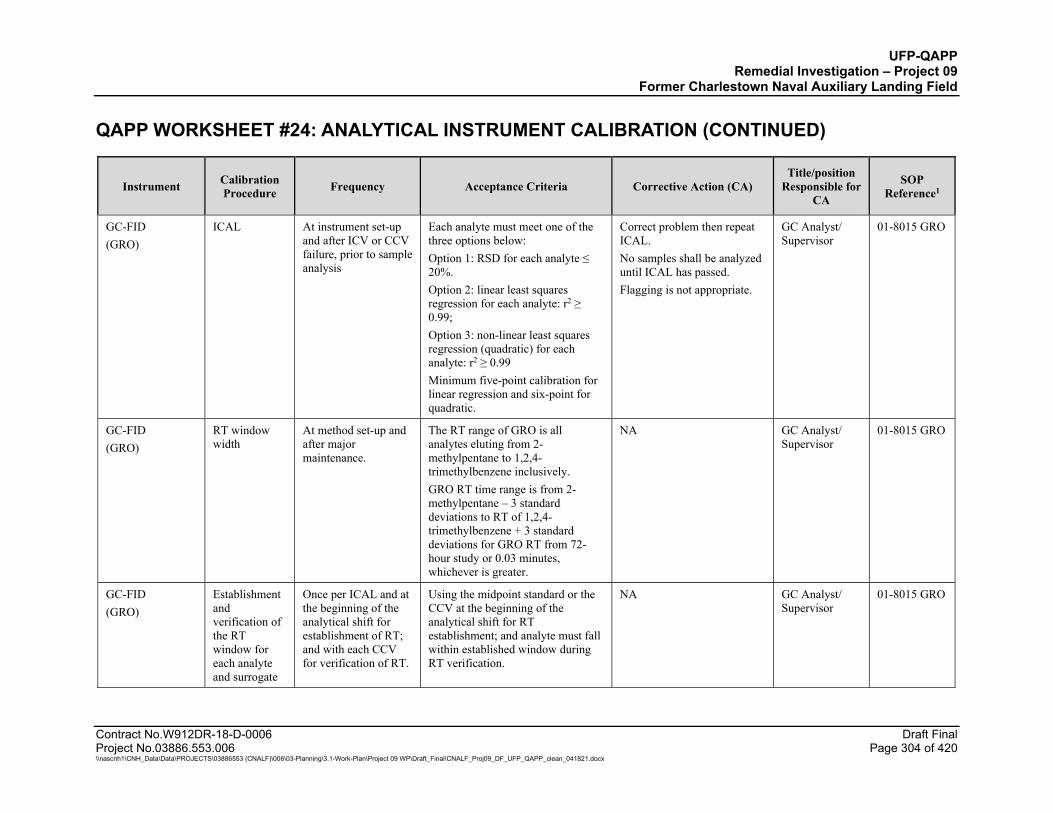
UFP-QAPP Remedial Investigation – Project 09
Former Charlestown Naval Auxiliary Landing Field QAPP WORKSHEET #24: ANALYTICAL INSTRUMENT CALIBRATION (CONTINUED)
Contract No.W912DR-18-D-0006 Draft Final Project No.03886.553.006 Page 304 of 420 \\nascnh1\CNH_Data\Data\PROJECTS\03886553 (CNALF)\006\03-Planning\3.1-Work-Plan\Project 09 WP\Draft_Final\CNALF_Proj09_DF_UFP_QAPP_clean_041821.docx
Instrument Calibration Procedure Frequency Acceptance Criteria Corrective Action (CA)
Title/position Responsible for
CA
SOP Reference1
GC-FID (GRO)
ICAL At instrument set-up and after ICV or CCV failure, prior to sample analysis
Each analyte must meet one of the three options below: Option 1: RSD for each analyte ≤ 20%. Option 2: linear least squares regression for each analyte: r2 ≥ 0.99; Option 3: non-linear least squares regression (quadratic) for each analyte: r2 ≥ 0.99 Minimum five-point calibration for linear regression and six-point for quadratic.
Correct problem then repeat ICAL. No samples shall be analyzed until ICAL has passed. Flagging is not appropriate.
GC Analyst/ Supervisor
01-8015 GRO
GC-FID (GRO)
RT window width
At method set-up and after major maintenance.
The RT range of GRO is all analytes eluting from 2-methylpentane to 1,2,4-trimethylbenzene inclusively. GRO RT time range is from 2-methylpentane – 3 standard deviations to RT of 1,2,4-trimethylbenzene + 3 standard deviations for GRO RT from 72-hour study or 0.03 minutes, whichever is greater.
NA GC Analyst/ Supervisor
01-8015 GRO
GC-FID (GRO)
Establishment and verification of the RT window for each analyte and surrogate
Once per ICAL and at the beginning of the analytical shift for establishment of RT; and with each CCV for verification of RT.
Using the midpoint standard or the CCV at the beginning of the analytical shift for RT establishment; and analyte must fall within established window during RT verification.
NA GC Analyst/ Supervisor
01-8015 GRO
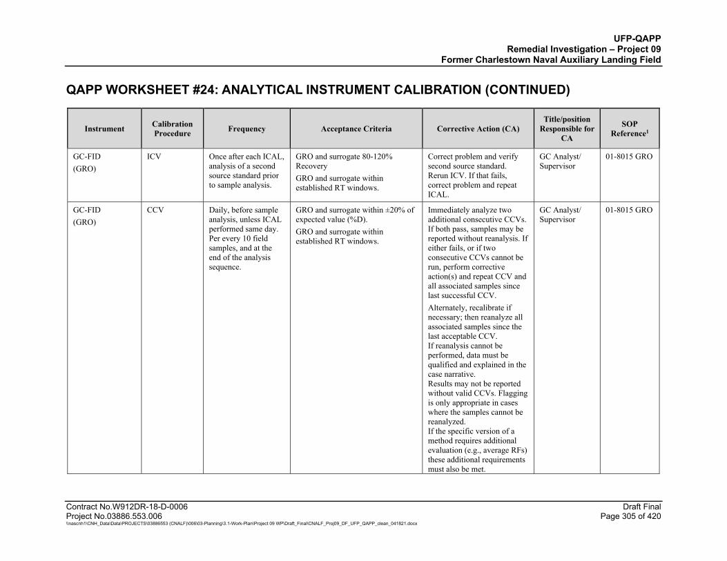
UFP-QAPP Remedial Investigation – Project 09
Former Charlestown Naval Auxiliary Landing Field QAPP WORKSHEET #24: ANALYTICAL INSTRUMENT CALIBRATION (CONTINUED)
Contract No.W912DR-18-D-0006 Draft Final Project No.03886.553.006 Page 305 of 420 \\nascnh1\CNH_Data\Data\PROJECTS\03886553 (CNALF)\006\03-Planning\3.1-Work-Plan\Project 09 WP\Draft_Final\CNALF_Proj09_DF_UFP_QAPP_clean_041821.docx
Instrument Calibration Procedure Frequency Acceptance Criteria Corrective Action (CA)
Title/position Responsible for
CA
SOP Reference1
GC-FID (GRO)
ICV Once after each ICAL, analysis of a second source standard prior to sample analysis.
GRO and surrogate 80-120% Recovery GRO and surrogate within established RT windows.
Correct problem and verify second source standard. Rerun ICV. If that fails, correct problem and repeat ICAL.
GC Analyst/ Supervisor
01-8015 GRO
GC-FID (GRO)
CCV Daily, before sample analysis, unless ICAL performed same day. Per every 10 field samples, and at the end of the analysis sequence.
GRO and surrogate within ±20% of expected value (%D). GRO and surrogate within established RT windows.
Immediately analyze two additional consecutive CCVs. If both pass, samples may be reported without reanalysis. If either fails, or if two consecutive CCVs cannot be run, perform corrective action(s) and repeat CCV and all associated samples since last successful CCV. Alternately, recalibrate if necessary; then reanalyze all associated samples since the last acceptable CCV. If reanalysis cannot be performed, data must be qualified and explained in the case narrative. Results may not be reported without valid CCVs. Flagging is only appropriate in cases where the samples cannot be reanalyzed. If the specific version of a method requires additional evaluation (e.g., average RFs) these additional requirements must also be met.
GC Analyst/ Supervisor
01-8015 GRO

UFP-QAPP Remedial Investigation – Project 09
Former Charlestown Naval Auxiliary Landing Field QAPP WORKSHEET #24: ANALYTICAL INSTRUMENT CALIBRATION (CONTINUED)
Contract No.W912DR-18-D-0006 Draft Final Project No.03886.553.006 Page 306 of 420 \\nascnh1\CNH_Data\Data\PROJECTS\03886553 (CNALF)\006\03-Planning\3.1-Work-Plan\Project 09 WP\Draft_Final\CNALF_Proj09_DF_UFP_QAPP_clean_041821.docx
Instrument Calibration Procedure Frequency Acceptance Criteria Corrective Action (CA)
Title/position Responsible for
CA
SOP Reference1
GC-FID (GRO)
Surrogate Standard
Added to all samples, blanks, and QC samples.
a,a,a-trifluorotoluene – use laboratory limits
Investigate and correct problem. If reanalysis confirms initial result or reanalysis is not possible, report with a qualifying comment.
GC Analyst/ Supervisor
01-8015 GRO
GC-FID (GRO)
Internal Standards
Added to all samples, blanks, and QC samples
CCV can be used. RT within ± 0.06 RRT units from retention time of the midpoint standard in the ICAL; Internal standard signal (area or height) within -50% to +100% of ICAL midpoint standard. On days when ICAL is not performed, the daily initial
Inspect GC for malfunctions. Reanalysis of samples analyzed during failure is mandatory. If corrective action fails in field samples, data must be qualified and explained in the Case Narrative. Apply Q-flag to analytes associated with the non-compliant IS.
GC Analyst/ Supervisor
01-8015 GRO
GC-FID (DRO-ORO)
ICAL At instrument set-up and after ICV or CCV failure, prior to sample analysis
Each analyte must meet one of the three options below: Option 1: RSD for each analyte ≤ 20%. Option 2: linear least squares regression for each analyte: r2 ≥ 0.99; Option 3: non-linear least squares regression (quadratic) for each analyte: r2 ≥ 0.99 Minimum five-point calibration for linear regression and six-point for quadratic.
Correct problem then repeat ICAL No samples shall be analyzed until ICAL has passed. Flagging is not appropriate
GC Analyst/ Supervisor
1A-8015 DRO

UFP-QAPP Remedial Investigation – Project 09
Former Charlestown Naval Auxiliary Landing Field QAPP WORKSHEET #24: ANALYTICAL INSTRUMENT CALIBRATION (CONTINUED)
Contract No.W912DR-18-D-0006 Draft Final Project No.03886.553.006 Page 307 of 420 \\nascnh1\CNH_Data\Data\PROJECTS\03886553 (CNALF)\006\03-Planning\3.1-Work-Plan\Project 09 WP\Draft_Final\CNALF_Proj09_DF_UFP_QAPP_clean_041821.docx
Instrument Calibration Procedure Frequency Acceptance Criteria Corrective Action (CA)
Title/position Responsible for
CA
SOP Reference1
GC-FID (DRO-ORO)
RT window width
At method set-up and after major maintenance.
The RT range of DRO is all analytes eluting from nC10-nC28 inclusively. The RT range of ORO is all analytes eluting from nC20-nC44 inclusively. DRO RT time range is from nC10 – 3 standard deviations to RT of nC28 + 3 standard deviations for DRO RT from 72-hour study or 0.03 minutes, whichever is greater. ORO RT time range is from nC20 – 3 standard deviations to RT of nC44 + 3 standard deviations for ORO RT from 72-hour study or 0.03 minutes, whichever is greater.
NA GC Analyst/ Supervisor
1A-8015 DRO
GC-FID (DRO-ORO)
Establishment and verification of the RT window for each analyte and surrogate
Once per ICAL and at the beginning of the analytical shift for establishment of RT; and with each CCV for verification of RT.
Using the midpoint standard or the CCV at the beginning of the analytical shift for RT establishment; and analyte must fall within established window during RT verification.
NA GC Analyst/ Supervisor
1A-8015 DRO
GC-FID (DRO-ORO)
ICV Once after each ICAL, analysis of a second source standard prior to sample analysis.
DRO – ORO and surrogates 80-120% Recovery All reported analytes within established RT windows.
Correct problem and verify second source standard. Rerun ICV. If that fails, correct problem and repeat ICAL.
GC Analyst/ Supervisor
1A-8015 DRO
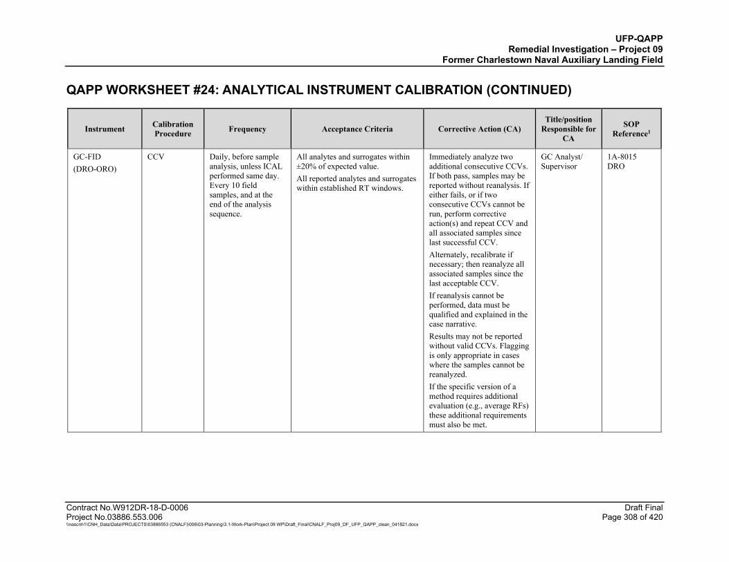
UFP-QAPP Remedial Investigation – Project 09
Former Charlestown Naval Auxiliary Landing Field QAPP WORKSHEET #24: ANALYTICAL INSTRUMENT CALIBRATION (CONTINUED)
Contract No.W912DR-18-D-0006 Draft Final Project No.03886.553.006 Page 308 of 420 \\nascnh1\CNH_Data\Data\PROJECTS\03886553 (CNALF)\006\03-Planning\3.1-Work-Plan\Project 09 WP\Draft_Final\CNALF_Proj09_DF_UFP_QAPP_clean_041821.docx
Instrument Calibration Procedure Frequency Acceptance Criteria Corrective Action (CA)
Title/position Responsible for
CA
SOP Reference1
GC-FID (DRO-ORO)
CCV Daily, before sample analysis, unless ICAL performed same day. Every 10 field samples, and at the end of the analysis sequence.
All analytes and surrogates within ±20% of expected value. All reported analytes and surrogates within established RT windows.
Immediately analyze two additional consecutive CCVs. If both pass, samples may be reported without reanalysis. If either fails, or if two consecutive CCVs cannot be run, perform corrective action(s) and repeat CCV and all associated samples since last successful CCV. Alternately, recalibrate if necessary; then reanalyze all associated samples since the last acceptable CCV. If reanalysis cannot be performed, data must be qualified and explained in the case narrative. Results may not be reported without valid CCVs. Flagging is only appropriate in cases where the samples cannot be reanalyzed. If the specific version of a method requires additional evaluation (e.g., average RFs) these additional requirements must also be met.
GC Analyst/ Supervisor
1A-8015 DRO

UFP-QAPP Remedial Investigation – Project 09
Former Charlestown Naval Auxiliary Landing Field QAPP WORKSHEET #24: ANALYTICAL INSTRUMENT CALIBRATION (CONTINUED)
Contract No.W912DR-18-D-0006 Draft Final Project No.03886.553.006 Page 309 of 420 \\nascnh1\CNH_Data\Data\PROJECTS\03886553 (CNALF)\006\03-Planning\3.1-Work-Plan\Project 09 WP\Draft_Final\CNALF_Proj09_DF_UFP_QAPP_clean_041821.docx
Instrument Calibration Procedure Frequency Acceptance Criteria Corrective Action (CA)
Title/position Responsible for
CA
SOP Reference1
GC-FID (DRO-ORO)
Surrogate Standard
Added to all samples, blanks, and QC samples.
o-terphenyl – use laboratory limits Investigate and correct problem. If reanalysis confirms initial result or reanalysis is not possible, report with a qualifying comment.
GC Analyst/ Supervisor
1A-8015 DRO
ALS Kelso
GC/MS (SVOCs Low Level)
DFTPP Tune Before ICAL and at the start of every 12-hour period of sample analysis.
Refer to method for specific DFTPP ion criteria.
Adjust tune; replacement of the ion source or filament. Rerun affected samples.
GC/MS Analyst/ Supervisor
SVM-8270L
GC/MS (SVOCs Low Level)
Performance Check
At the beginning of each 12-hour period, prior to analysis of samples.
Degradation ≤20 for DDT. Correct problem, then repeat performance checks.
GC/MS Analyst/ Supervisor
SVM-8270L
GC/MS (SVOCs Low Level)
ICAL 0.75 to 120 µg/mL on-column
At instrument set-up and after ICV or CCV failure, prior to sample analysis
Each analyte must meet one of the three options below: Option 1: RSD for each analyte ≤ 15%. Option 2: linear least squares regression for each analyte: r2 ≥ 0.99; Option 3: non-linear least squares regression (quadratic) for each analyte: r2 ≥ 0.99 Minimum five-point calibration for linear regression and six-point for quadratic.
Correct problem then repeat ICAL No samples shall be analyzed until ICAL has passed.
GC/MS Analyst/ Supervisor
SVM-8270L
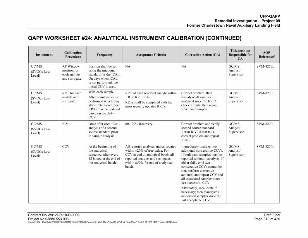
UFP-QAPP Remedial Investigation – Project 09
Former Charlestown Naval Auxiliary Landing Field QAPP WORKSHEET #24: ANALYTICAL INSTRUMENT CALIBRATION (CONTINUED)
Contract No.W912DR-18-D-0006 Draft Final Project No.03886.553.006 Page 310 of 420 \\nascnh1\CNH_Data\Data\PROJECTS\03886553 (CNALF)\006\03-Planning\3.1-Work-Plan\Project 09 WP\Draft_Final\CNALF_Proj09_DF_UFP_QAPP_clean_041821.docx
Instrument Calibration Procedure Frequency Acceptance Criteria Corrective Action (CA)
Title/position Responsible for
CA
SOP Reference1
GC/MS (SVOCs Low Level)
RT Window position for each analyte and surrogate
Position shall be set using the midpoint standard for the ICAL. On days when ICAL is not performed, the initial CCV is used.
NA NA GC/MS Analyst/ Supervisor
SVM-8270L
GC/MS (SVOCs Low Level)
RRT for each analyte and surrogate
With each sample. After maintenance is performed which may affect retention times, RRTs may be updated based on the daily CCV.
RRT of each reported analyte within ± 0.06 RRT units. RRTs shall be compared with the most recently updated RRTs.
Correct problem, then reanalyze all samples analyzed since the last RT check. If fails, then rerun ICAL and samples.
GC/MS Analyst/ Supervisor
SVM-8270L
GC/MS (SVOCs Low Level)
ICV Once after each ICAL, analysis of a second source standard prior to sample analysis.
80-120% Recovery Correct problem and verify second source standard. Rerun ICV. If that fails, correct problem and repeat ICAL.
GC/MS Analyst/ Supervisor
SVM-8270L
GC/MS (SVOCs Low Level)
CCV At the beginning of the analytical sequence; after every 12 hours; at the end of the analytical batch.
All reported analytes and surrogates within ±20% of true value. For CCV at end of analytical batch, all reported analytes and surrogates within ±50% for end of analytical batch.
Immediately analyze two additional consecutive CCVs. If both pass, samples may be reported without reanalysis. If either fails, or if two consecutive CCVs cannot be run, perform corrective action(s) and repeat CCV and all associated samples since last successful CCV. Alternately, recalibrate if necessary; then reanalyze all associated samples since the last acceptable CCV.
GC/MS Analyst/ Supervisor
SVM-8270L
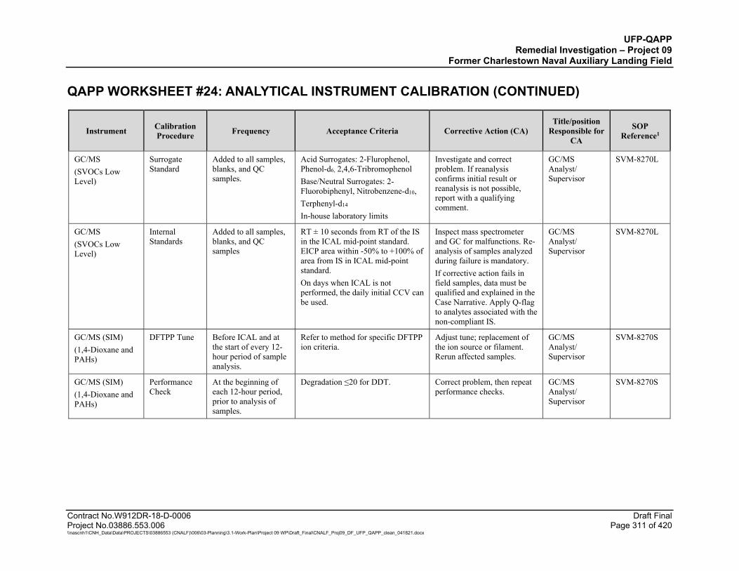
UFP-QAPP Remedial Investigation – Project 09
Former Charlestown Naval Auxiliary Landing Field QAPP WORKSHEET #24: ANALYTICAL INSTRUMENT CALIBRATION (CONTINUED)
Contract No.W912DR-18-D-0006 Draft Final Project No.03886.553.006 Page 311 of 420 \\nascnh1\CNH_Data\Data\PROJECTS\03886553 (CNALF)\006\03-Planning\3.1-Work-Plan\Project 09 WP\Draft_Final\CNALF_Proj09_DF_UFP_QAPP_clean_041821.docx
Instrument Calibration Procedure Frequency Acceptance Criteria Corrective Action (CA)
Title/position Responsible for
CA
SOP Reference1
GC/MS (SVOCs Low Level)
Surrogate Standard
Added to all samples, blanks, and QC samples.
Acid Surrogates: 2-Flurophenol, Phenol-d6, 2,4,6-Tribromophenol Base/Neutral Surrogates: 2-Fluorobiphenyl, Nitrobenzene-d10, Terphenyl-d14 In-house laboratory limits
Investigate and correct problem. If reanalysis confirms initial result or reanalysis is not possible, report with a qualifying comment.
GC/MS Analyst/ Supervisor
SVM-8270L
GC/MS (SVOCs Low Level)
Internal Standards
Added to all samples, blanks, and QC samples
RT ± 10 seconds from RT of the IS in the ICAL mid-point standard. EICP area within -50% to +100% of area from IS in ICAL mid-point standard. On days when ICAL is not performed, the daily initial CCV can be used.
Inspect mass spectrometer and GC for malfunctions. Re-analysis of samples analyzed during failure is mandatory. If corrective action fails in field samples, data must be qualified and explained in the Case Narrative. Apply Q-flag to analytes associated with the non-compliant IS.
GC/MS Analyst/ Supervisor
SVM-8270L
GC/MS (SIM) (1,4-Dioxane and PAHs)
DFTPP Tune Before ICAL and at the start of every 12-hour period of sample analysis.
Refer to method for specific DFTPP ion criteria.
Adjust tune; replacement of the ion source or filament. Rerun affected samples.
GC/MS Analyst/ Supervisor
SVM-8270S
GC/MS (SIM) (1,4-Dioxane and PAHs)
Performance Check
At the beginning of each 12-hour period, prior to analysis of samples.
Degradation ≤20 for DDT. Correct problem, then repeat performance checks.
GC/MS Analyst/ Supervisor
SVM-8270S

UFP-QAPP Remedial Investigation – Project 09
Former Charlestown Naval Auxiliary Landing Field QAPP WORKSHEET #24: ANALYTICAL INSTRUMENT CALIBRATION (CONTINUED)
Contract No.W912DR-18-D-0006 Draft Final Project No.03886.553.006 Page 312 of 420 \\nascnh1\CNH_Data\Data\PROJECTS\03886553 (CNALF)\006\03-Planning\3.1-Work-Plan\Project 09 WP\Draft_Final\CNALF_Proj09_DF_UFP_QAPP_clean_041821.docx
Instrument Calibration Procedure Frequency Acceptance Criteria Corrective Action (CA)
Title/position Responsible for
CA
SOP Reference1
GC/MS (SIM) (1,4-Dioxane and PAHs)
ICAL 0.02 to 3.0 µg/mL on-column
At instrument set-up and after ICV or CCV failure, prior to sample analysis.
Each analyte must meet one of the three options below: Option 1: RSD for each analyte ≤ 15%. Option 2: linear least squares regression for each analyte: r2 ≥ 0.99; Option 3: non-linear least squares regression (quadratic) for each analyte: r2 ≥ 0.99 Minimum five-point calibration for linear regression and six-point for quadratic.
Correct problem then repeat ICAL No samples shall be analyzed until ICAL has passed. Flagging is not appropriate.
GC/MS Analyst/ Supervisor
SVM-8270S
GC/MS (SIM) (1,4-Dioxane and PAHs)
RT Window position for each analyte and surrogate
Position shall be set using the midpoint standard for the ICAL. On days when ICAL is not performed, the initial CCV is used.
NA NA GC/MS Analyst/ Supervisor
SVM-8270S
GC/MS (SIM) (1,4-Dioxane and PAHs)
RRT for each analyte and surrogate
With each sample. After maintenance is performed which may affect retention times, RRTs may be updated based on the daily CCV.
RRT of each reported analyte within ± 0.06 RRT units. RRTs shall be compared with the most recently updated RRTs.
Correct problem, then reanalyze all samples analyzed since the last RT check. If check fails, then rerun ICAL and samples.
GC/MS Analyst/ Supervisor
SVM-8270S
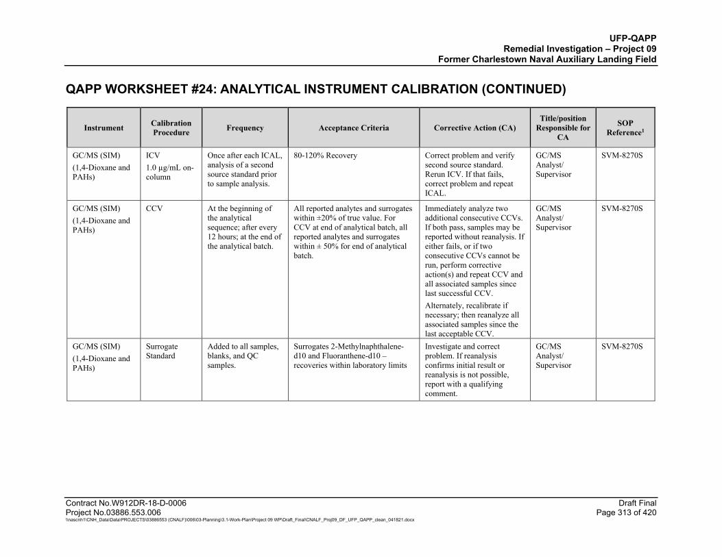
UFP-QAPP Remedial Investigation – Project 09
Former Charlestown Naval Auxiliary Landing Field QAPP WORKSHEET #24: ANALYTICAL INSTRUMENT CALIBRATION (CONTINUED)
Contract No.W912DR-18-D-0006 Draft Final Project No.03886.553.006 Page 313 of 420 \\nascnh1\CNH_Data\Data\PROJECTS\03886553 (CNALF)\006\03-Planning\3.1-Work-Plan\Project 09 WP\Draft_Final\CNALF_Proj09_DF_UFP_QAPP_clean_041821.docx
Instrument Calibration Procedure Frequency Acceptance Criteria Corrective Action (CA)
Title/position Responsible for
CA
SOP Reference1
GC/MS (SIM) (1,4-Dioxane and PAHs)
ICV 1.0 µg/mL on-column
Once after each ICAL, analysis of a second source standard prior to sample analysis.
80-120% Recovery Correct problem and verify second source standard. Rerun ICV. If that fails, correct problem and repeat ICAL.
GC/MS Analyst/ Supervisor
SVM-8270S
GC/MS (SIM) (1,4-Dioxane and PAHs)
CCV At the beginning of the analytical sequence; after every 12 hours; at the end of the analytical batch.
All reported analytes and surrogates within ±20% of true value. For CCV at end of analytical batch, all reported analytes and surrogates within ± 50% for end of analytical batch.
Immediately analyze two additional consecutive CCVs. If both pass, samples may be reported without reanalysis. If either fails, or if two consecutive CCVs cannot be run, perform corrective action(s) and repeat CCV and all associated samples since last successful CCV. Alternately, recalibrate if necessary; then reanalyze all associated samples since the last acceptable CCV.
GC/MS Analyst/ Supervisor
SVM-8270S
GC/MS (SIM) (1,4-Dioxane and PAHs)
Surrogate Standard
Added to all samples, blanks, and QC samples.
Surrogates 2-Methylnaphthalene-d10 and Fluoranthene-d10 – recoveries within laboratory limits
Investigate and correct problem. If reanalysis confirms initial result or reanalysis is not possible, report with a qualifying comment.
GC/MS Analyst/ Supervisor
SVM-8270S
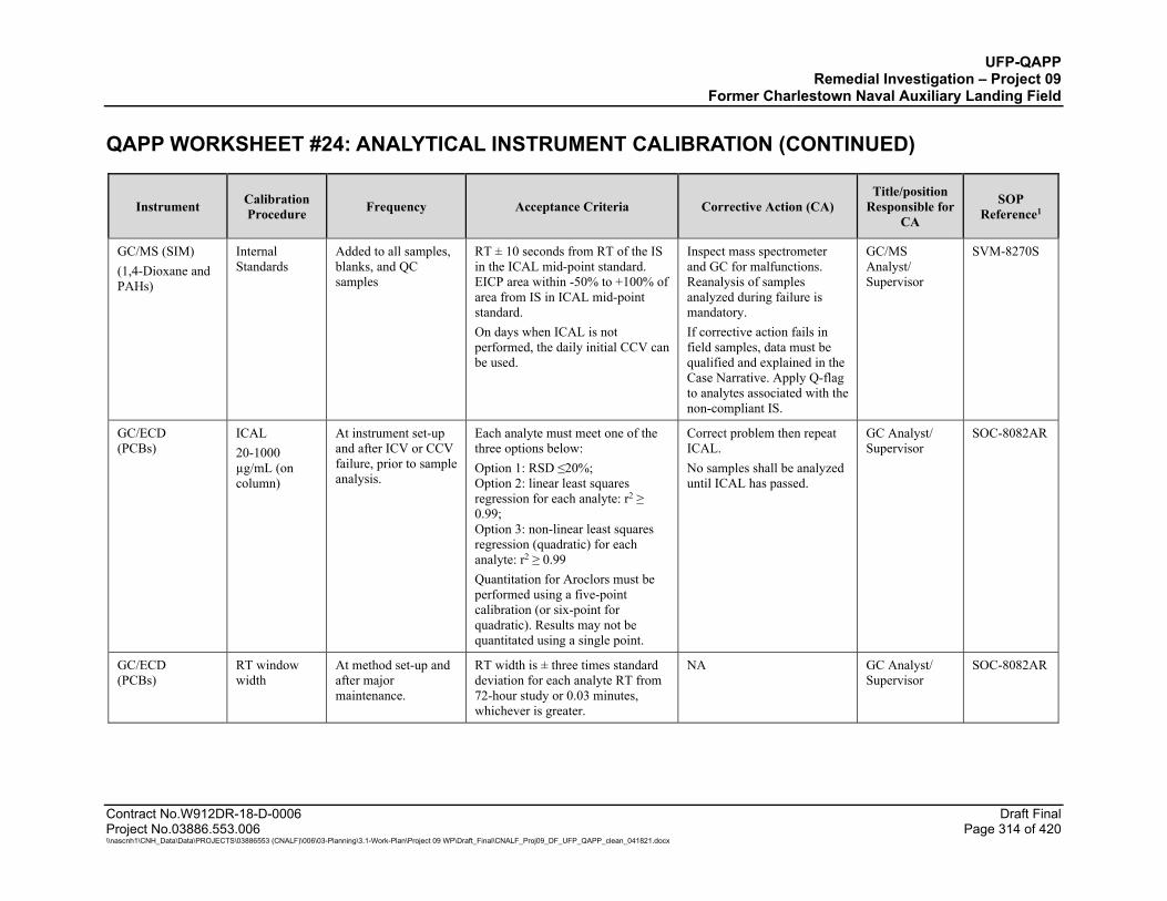
UFP-QAPP Remedial Investigation – Project 09
Former Charlestown Naval Auxiliary Landing Field QAPP WORKSHEET #24: ANALYTICAL INSTRUMENT CALIBRATION (CONTINUED)
Contract No.W912DR-18-D-0006 Draft Final Project No.03886.553.006 Page 314 of 420 \\nascnh1\CNH_Data\Data\PROJECTS\03886553 (CNALF)\006\03-Planning\3.1-Work-Plan\Project 09 WP\Draft_Final\CNALF_Proj09_DF_UFP_QAPP_clean_041821.docx
Instrument Calibration Procedure Frequency Acceptance Criteria Corrective Action (CA)
Title/position Responsible for
CA
SOP Reference1
GC/MS (SIM) (1,4-Dioxane and PAHs)
Internal Standards
Added to all samples, blanks, and QC samples
RT ± 10 seconds from RT of the IS in the ICAL mid-point standard. EICP area within -50% to +100% of area from IS in ICAL mid-point standard. On days when ICAL is not performed, the daily initial CCV can be used.
Inspect mass spectrometer and GC for malfunctions. Reanalysis of samples analyzed during failure is mandatory. If corrective action fails in field samples, data must be qualified and explained in the Case Narrative. Apply Q-flag to analytes associated with the non-compliant IS.
GC/MS Analyst/ Supervisor
SVM-8270S
GC/ECD (PCBs)
ICAL 20-1000 µg/mL (on column)
At instrument set-up and after ICV or CCV failure, prior to sample analysis.
Each analyte must meet one of the three options below: Option 1: RSD ≤20%; Option 2: linear least squares regression for each analyte: r2 ≥ 0.99; Option 3: non-linear least squares regression (quadratic) for each analyte: r2 ≥ 0.99 Quantitation for Aroclors must be performed using a five-point calibration (or six-point for quadratic). Results may not be quantitated using a single point.
Correct problem then repeat ICAL. No samples shall be analyzed until ICAL has passed.
GC Analyst/ Supervisor
SOC-8082AR
GC/ECD (PCBs)
RT window width
At method set-up and after major maintenance.
RT width is ± three times standard deviation for each analyte RT from 72-hour study or 0.03 minutes, whichever is greater.
NA GC Analyst/ Supervisor
SOC-8082AR
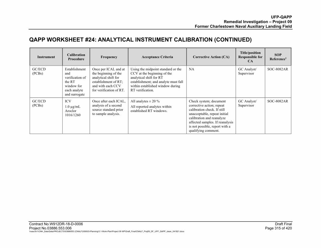
UFP-QAPP Remedial Investigation – Project 09
Former Charlestown Naval Auxiliary Landing Field QAPP WORKSHEET #24: ANALYTICAL INSTRUMENT CALIBRATION (CONTINUED)
Contract No.W912DR-18-D-0006 Draft Final Project No.03886.553.006 Page 315 of 420 \\nascnh1\CNH_Data\Data\PROJECTS\03886553 (CNALF)\006\03-Planning\3.1-Work-Plan\Project 09 WP\Draft_Final\CNALF_Proj09_DF_UFP_QAPP_clean_041821.docx
Instrument Calibration Procedure Frequency Acceptance Criteria Corrective Action (CA)
Title/position Responsible for
CA
SOP Reference1
GC/ECD (PCBs)
Establishment and verification of the RT window for each analyte and surrogate
Once per ICAL and at the beginning of the analytical shift for establishment of RT; and with each CCV for verification of RT.
Using the midpoint standard or the CCV at the beginning of the analytical shift for RT establishment; and analyte must fall within established window during RT verification.
NA GC Analyst/ Supervisor
SOC-8082AR
GC/ECD (PCBs)
ICV 1.0 µg/mL Aroclor 1016/1260
Once after each ICAL, analysis of a second source standard prior to sample analysis.
All analytes ± 20 % All reported analytes within established RT windows.
Check system; document corrective action; repeat calibration check. If still unacceptable, repeat initial calibration and reanalyze affected samples. If reanalysis is not possible, report with a qualifying comment.
GC Analyst/ Supervisor
SOC-8082AR
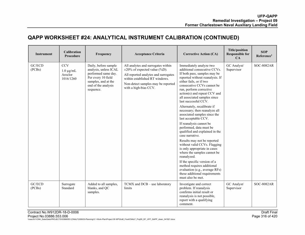
UFP-QAPP Remedial Investigation – Project 09
Former Charlestown Naval Auxiliary Landing Field QAPP WORKSHEET #24: ANALYTICAL INSTRUMENT CALIBRATION (CONTINUED)
Contract No.W912DR-18-D-0006 Draft Final Project No.03886.553.006 Page 316 of 420 \\nascnh1\CNH_Data\Data\PROJECTS\03886553 (CNALF)\006\03-Planning\3.1-Work-Plan\Project 09 WP\Draft_Final\CNALF_Proj09_DF_UFP_QAPP_clean_041821.docx
Instrument Calibration Procedure Frequency Acceptance Criteria Corrective Action (CA)
Title/position Responsible for
CA
SOP Reference1
GC/ECD (PCBs)
CCV 1.0 µg/mL Aroclor 1016/1260
Daily, before sample analysis, unless ICAL performed same day. Per every 10 field samples, and at the end of the analysis sequence.
All analytes and surrogates within ±20% of expected value (%D). All reported analytes and surrogates within established RT windows. Non-detect samples may be reported with a high-bias CCV.
Immediately analyze two additional consecutive CCVs. If both pass, samples may be reported without reanalysis. If either fails, or if two consecutive CCVs cannot be run, perform corrective action(s) and repeat CCV and all associated samples since last successful CCV. Alternately, recalibrate if necessary; then reanalyze all associated samples since the last acceptable CCV. If reanalysis cannot be performed, data must be qualified and explained in the case narrative. Results may not be reported without valid CCVs. Flagging is only appropriate in cases where the samples cannot be reanalyzed. If the specific version of a method requires additional evaluation (e.g., average RFs) these additional requirements must also be met.
GC Analyst/ Supervisor
SOC-8082AR
GC/ECD (PCBs)
Surrogate Standard
Added to all samples, blanks, and QC samples.
TCMX and DCB – use laboratory limits
Investigate and correct problem. If reanalysis confirms initial result or reanalysis is not possible, report with a qualifying comment.
GC Analyst/ Supervisor
SOC-8082AR
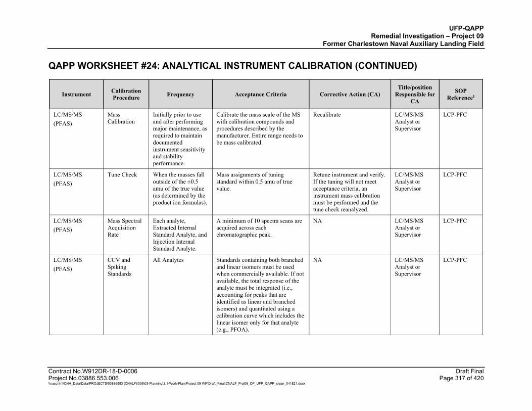
UFP-QAPP Remedial Investigation – Project 09
Former Charlestown Naval Auxiliary Landing Field QAPP WORKSHEET #24: ANALYTICAL INSTRUMENT CALIBRATION (CONTINUED)
Contract No.W912DR-18-D-0006 Draft Final Project No.03886.553.006 Page 317 of 420 \\nascnh1\CNH_Data\Data\PROJECTS\03886553 (CNALF)\006\03-Planning\3.1-Work-Plan\Project 09 WP\Draft_Final\CNALF_Proj09_DF_UFP_QAPP_clean_041821.docx
Instrument Calibration Procedure Frequency Acceptance Criteria Corrective Action (CA)
Title/position Responsible for
CA
SOP Reference1
LC/MS/MS (PFAS)
Mass Calibration
Initially prior to use and after performing major maintenance, as required to maintain documented instrument sensitivity and stability performance.
Calibrate the mass scale of the MS with calibration compounds and procedures described by the manufacturer. Entire range needs to be mass calibrated.
Recalibrate LC/MS/MS Analyst or Supervisor
LCP-PFC
LC/MS/MS (PFAS)
Tune Check When the masses fall outside of the ±0.5 amu of the true value (as determined by the product ion formulas).
Mass assignments of tuning standard within 0.5 amu of true value.
Retune instrument and verify. If the tuning will not meet acceptance criteria, an instrument mass calibration must be performed and the tune check reanalyzed.
LC/MS/MS Analyst or Supervisor
LCP-PFC
LC/MS/MS (PFAS)
Mass Spectral Acquisition Rate
Each analyte, Extracted Internal Standard Analyte, and Injection Internal Standard Analyte.
A minimum of 10 spectra scans are acquired across each chromatographic peak.
NA LC/MS/MS Analyst or Supervisor
LCP-PFC
LC/MS/MS (PFAS)
CCV and Spiking Standards
All Analytes Standards containing both branched and linear isomers must be used when commercially available. If not available, the total response of the analyte must be integrated (i.e., accounting for peaks that are identified as linear and branched isomers) and quantitated using a calibration curve which includes the linear isomer only for that analyte (e.g., PFOA).
NA LC/MS/MS Analyst or Supervisor
LCP-PFC

UFP-QAPP Remedial Investigation – Project 09
Former Charlestown Naval Auxiliary Landing Field QAPP WORKSHEET #24: ANALYTICAL INSTRUMENT CALIBRATION (CONTINUED)
Contract No.W912DR-18-D-0006 Draft Final Project No.03886.553.006 Page 318 of 420 \\nascnh1\CNH_Data\Data\PROJECTS\03886553 (CNALF)\006\03-Planning\3.1-Work-Plan\Project 09 WP\Draft_Final\CNALF_Proj09_DF_UFP_QAPP_clean_041821.docx
Instrument Calibration Procedure Frequency Acceptance Criteria Corrective Action (CA)
Title/position Responsible for
CA
SOP Reference1
LC/MS/MS (PFAS)
Ion Transitions (Parent-> Product)
Prior to method implementation.
The chemical derivation of the ion transitions, both those used for quantitation and those used for confirmation, must be documented. Two transitions and the ion transition ratio per analyte shall be monitored and documented with the exception of PFBA and PFPeA. In order to avoid biasing results high due to known interferences for some transitions, the following transitions must be used for the quantification of the following analytes: PFOA: 413 —› 369 PFOS: 499 —› 80 PFHxS: 399 —› 80 PFBS: 299 —› 80 4:2 FTS: 327 —› 307 6:2 FTS: 427 —› 407 8:2 FTS: 527 —› 507 NEtFOSAA: 584 —› 419 NMeFOSAA: 570 —›419 If these transitions are not used, the reason must be technically justified and documented (e.g., alternate transition was used due to observed interferences).
NA LC/MS/MS Analyst or Supervisor
LCP-PFC

UFP-QAPP Remedial Investigation – Project 09
Former Charlestown Naval Auxiliary Landing Field QAPP WORKSHEET #24: ANALYTICAL INSTRUMENT CALIBRATION (CONTINUED)
Contract No.W912DR-18-D-0006 Draft Final Project No.03886.553.006 Page 319 of 420 \\nascnh1\CNH_Data\Data\PROJECTS\03886553 (CNALF)\006\03-Planning\3.1-Work-Plan\Project 09 WP\Draft_Final\CNALF_Proj09_DF_UFP_QAPP_clean_041821.docx
Instrument Calibration Procedure Frequency Acceptance Criteria Corrective Action (CA)
Title/position Responsible for
CA
SOP Reference1
LC/MS/MS (PFAS)
(ICAL) At instrument set-up and after ICV or CCV failure, prior to sample analysis.
The isotopically labeled analog of an analyte (Extracted Internal Standard Analyte) must be used for quantitation if commercially available (Isotope Dilution Quantitation). If a labeled analog is not commercially available, the Extracted Internal Standard Analyte with the closest retention time to the analyte must be used for quantitation. (Internal Standard Quantitation) S/N Ratio: ≥ 10:1 for all ions used for quantification. For analytes having a promulgated standard, (e.g., HA levels for PFOA and PFOS), the qualitative confirmation) transition ion must have a S/N Ratio of ≥ 3:1. The RSD of the RFs for all analytes must be <20% or the linear/ nonlinear calibrations must have r2 ≥ 0.99 for each analyte. Analytes must be within 70-130% of their true value for each calibration standard.
Correct problem, then repeat ICAL.
LC/MS/MS Analyst or Supervisor
LCP-PFC
LC/MS/MS (PFAS)
Instrument Sensitivity Check
Prior to analysis and at least once every 12 hours
Analyte concentrations must be at LOQ; concentrations must be within ±30% of their true values.
Correct problem, rerun ISC. If problem persists, repeat ICAL.
LC/MS/MS Analyst or Supervisor
LCP-PFC
LC/MS/MS (PFAS)
Initial Calibration Verification (ICV)
Once after each ICAL analysis of a second standard prior to sample analysis.
Analyte concentrations must be within ±30% of their true value.
Correct problem, rerun ICV. If problem persists, repeat ICAL.
LC/MS/MS Analyst or Supervisor
LCP-PFC
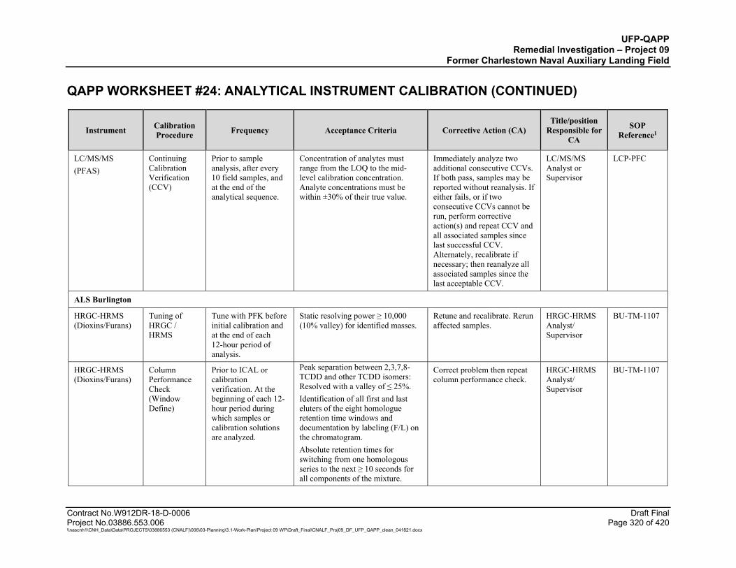
UFP-QAPP Remedial Investigation – Project 09
Former Charlestown Naval Auxiliary Landing Field QAPP WORKSHEET #24: ANALYTICAL INSTRUMENT CALIBRATION (CONTINUED)
Contract No.W912DR-18-D-0006 Draft Final Project No.03886.553.006 Page 320 of 420 \\nascnh1\CNH_Data\Data\PROJECTS\03886553 (CNALF)\006\03-Planning\3.1-Work-Plan\Project 09 WP\Draft_Final\CNALF_Proj09_DF_UFP_QAPP_clean_041821.docx
Instrument Calibration Procedure Frequency Acceptance Criteria Corrective Action (CA)
Title/position Responsible for
CA
SOP Reference1
LC/MS/MS (PFAS)
Continuing Calibration Verification (CCV)
Prior to sample analysis, after every 10 field samples, and at the end of the analytical sequence.
Concentration of analytes must range from the LOQ to the mid-level calibration concentration. Analyte concentrations must be within ±30% of their true value.
Immediately analyze two additional consecutive CCVs. If both pass, samples may be reported without reanalysis. If either fails, or if two consecutive CCVs cannot be run, perform corrective action(s) and repeat CCV and all associated samples since last successful CCV. Alternately, recalibrate if necessary; then reanalyze all associated samples since the last acceptable CCV.
LC/MS/MS Analyst or Supervisor
LCP-PFC
ALS Burlington
HRGC-HRMS (Dioxins/Furans)
Tuning of HRGC / HRMS
Tune with PFK before initial calibration and at the end of each 12-hour period of analysis.
Static resolving power ≥ 10,000 (10% valley) for identified masses.
Retune and recalibrate. Rerun affected samples.
HRGC-HRMS Analyst/ Supervisor
BU-TM-1107
HRGC-HRMS (Dioxins/Furans)
Column Performance Check (Window Define)
Prior to ICAL or calibration verification. At the beginning of each 12-hour period during which samples or calibration solutions are analyzed.
Peak separation between 2,3,7,8-TCDD and other TCDD isomers: Resolved with a valley of ≤ 25%. Identification of all first and last eluters of the eight homologue retention time windows and documentation by labeling (F/L) on the chromatogram. Absolute retention times for switching from one homologous series to the next ≥ 10 seconds for all components of the mixture.
Correct problem then repeat column performance check.
HRGC-HRMS Analyst/ Supervisor
BU-TM-1107
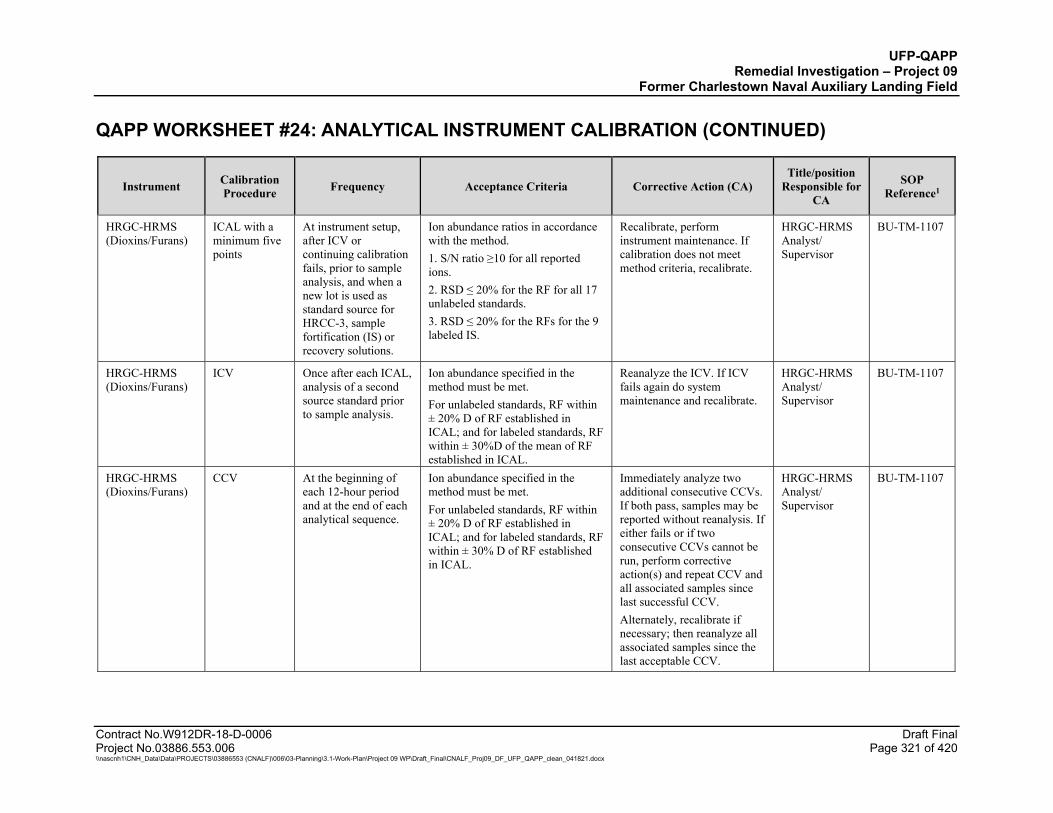
UFP-QAPP Remedial Investigation – Project 09
Former Charlestown Naval Auxiliary Landing Field QAPP WORKSHEET #24: ANALYTICAL INSTRUMENT CALIBRATION (CONTINUED)
Contract No.W912DR-18-D-0006 Draft Final Project No.03886.553.006 Page 321 of 420 \\nascnh1\CNH_Data\Data\PROJECTS\03886553 (CNALF)\006\03-Planning\3.1-Work-Plan\Project 09 WP\Draft_Final\CNALF_Proj09_DF_UFP_QAPP_clean_041821.docx
Instrument Calibration Procedure Frequency Acceptance Criteria Corrective Action (CA)
Title/position Responsible for
CA
SOP Reference1
HRGC-HRMS (Dioxins/Furans)
ICAL with a minimum five points
At instrument setup, after ICV or continuing calibration fails, prior to sample analysis, and when a new lot is used as standard source for HRCC-3, sample fortification (IS) or recovery solutions.
Ion abundance ratios in accordance with the method. 1. S/N ratio ≥10 for all reported ions. 2. RSD ≤ 20% for the RF for all 17 unlabeled standards. 3. RSD ≤ 20% for the RFs for the 9 labeled IS.
Recalibrate, perform instrument maintenance. If calibration does not meet method criteria, recalibrate.
HRGC-HRMS Analyst/ Supervisor
BU-TM-1107
HRGC-HRMS (Dioxins/Furans)
ICV Once after each ICAL, analysis of a second source standard prior to sample analysis.
Ion abundance specified in the method must be met. For unlabeled standards, RF within ± 20% D of RF established in ICAL; and for labeled standards, RF within ± 30%D of the mean of RF established in ICAL.
Reanalyze the ICV. If ICV fails again do system maintenance and recalibrate.
HRGC-HRMS Analyst/ Supervisor
BU-TM-1107
HRGC-HRMS (Dioxins/Furans)
CCV At the beginning of each 12-hour period and at the end of each analytical sequence.
Ion abundance specified in the method must be met. For unlabeled standards, RF within ± 20% D of RF established in ICAL; and for labeled standards, RF within ± 30% D of RF established in ICAL.
Immediately analyze two additional consecutive CCVs. If both pass, samples may be reported without reanalysis. If either fails or if two consecutive CCVs cannot be run, perform corrective action(s) and repeat CCV and all associated samples since last successful CCV. Alternately, recalibrate if necessary; then reanalyze all associated samples since the last acceptable CCV.
HRGC-HRMS Analyst/ Supervisor
BU-TM-1107
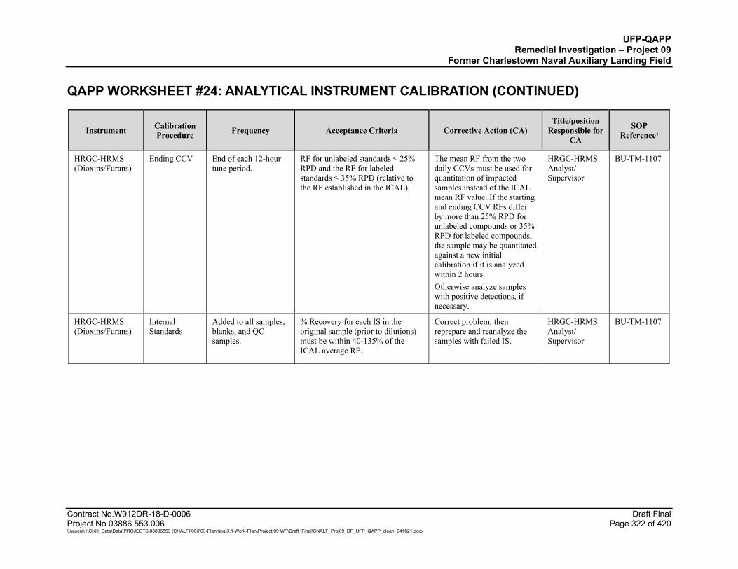
UFP-QAPP Remedial Investigation – Project 09
Former Charlestown Naval Auxiliary Landing Field QAPP WORKSHEET #24: ANALYTICAL INSTRUMENT CALIBRATION (CONTINUED)
Contract No.W912DR-18-D-0006 Draft Final Project No.03886.553.006 Page 322 of 420 \\nascnh1\CNH_Data\Data\PROJECTS\03886553 (CNALF)\006\03-Planning\3.1-Work-Plan\Project 09 WP\Draft_Final\CNALF_Proj09_DF_UFP_QAPP_clean_041821.docx
Instrument Calibration Procedure Frequency Acceptance Criteria Corrective Action (CA)
Title/position Responsible for
CA
SOP Reference1
HRGC-HRMS (Dioxins/Furans)
Ending CCV End of each 12-hour tune period.
RF for unlabeled standards ≤ 25% RPD and the RF for labeled standards ≤ 35% RPD (relative to the RF established in the ICAL),
The mean RF from the two daily CCVs must be used for quantitation of impacted samples instead of the ICAL mean RF value. If the starting and ending CCV RFs differ by more than 25% RPD for unlabeled compounds or 35% RPD for labeled compounds, the sample may be quantitated against a new initial calibration if it is analyzed within 2 hours. Otherwise analyze samples with positive detections, if necessary.
HRGC-HRMS Analyst/ Supervisor
BU-TM-1107
HRGC-HRMS (Dioxins/Furans)
Internal Standards
Added to all samples, blanks, and QC samples.
% Recovery for each IS in the original sample (prior to dilutions) must be within 40-135% of the ICAL average RF.
Correct problem, then reprepare and reanalyze the samples with failed IS.
HRGC-HRMS Analyst/ Supervisor
BU-TM-1107

UFP-QAPP Remedial Investigation – Project 09
Former Charlestown Naval Auxiliary Landing Field QAPP WORKSHEET #24: ANALYTICAL INSTRUMENT CALIBRATION (CONTINUED)
Contract No.W912DR-18-D-0006 Draft Final Project No.03886.553.006 Page 323 of 420 \\nascnh1\CNH_Data\Data\PROJECTS\03886553 (CNALF)\006\03-Planning\3.1-Work-Plan\Project 09 WP\Draft_Final\CNALF_Proj09_DF_UFP_QAPP_clean_041821.docx
Instrument Calibration Procedure Frequency Acceptance Criteria Corrective Action (CA)
Title/position Responsible for
CA
SOP Reference1
HRGC-HRMS (Dioxins/Furans)
Surrogate All field samples and QC samples.
In-house laboratory limits. Correct problem, then reprepare and reanalyze all failed samples for all surrogates in the associated preparatory batch if sufficient sample material is available. If obvious chromatographic interference is present, reanalysis may not be necessary, but the client must be notified prior to reporting data and the failures must be discussed in the Case Narrative.
HRGC-HRMS Analyst/ Supervisor
BU-TM-1107
ALS - Houston
LC/MS/MS (Perchlorate)
Tune Check Prior to ICAL and after any mass calibration or maintenance is performed.
Tuning standards must span the mass range of 45-350 amu.
Retune instrument and verify. If the tuning will not meet acceptance criteria, an instrument mass calibration must be performed and the tune check reanalyzed.
LC/MS/MS Analyst or Supervisor
HE-LCMSPER001
LC/MS/MS (Perchlorate)
ICAL 0.1 ppb – 50 ppb
Initially and after ICV or CCV failure, prior to sample analysis.
ICAL must meet one of the two options below: Option 1: RSD for each analyte ≤ 15%; Option 2: linear least squares regression for each analyte: r2 ≥ 0.995.
Correct problem the re-calibrate.
LC/MS/MS Analyst or Supervisor
HE-LCMSPER001
LC/MS/MS (Perchlorate)
ICV Once right after the ICAL.
Perchlorate concentration must be within ± 15% of its true value.
Correct problem. Rerun ICV. If that fails, repeat ICAL.
LC/MS/MS Analyst or Supervisor
HE-LCMSPER001

UFP-QAPP Remedial Investigation – Project 09
Former Charlestown Naval Auxiliary Landing Field QAPP WORKSHEET #24: ANALYTICAL INSTRUMENT CALIBRATION (CONTINUED)
Contract No.W912DR-18-D-0006 Draft Final Project No.03886.553.006 Page 324 of 420 \\nascnh1\CNH_Data\Data\PROJECTS\03886553 (CNALF)\006\03-Planning\3.1-Work-Plan\Project 09 WP\Draft_Final\CNALF_Proj09_DF_UFP_QAPP_clean_041821.docx
Instrument Calibration Procedure Frequency Acceptance Criteria Corrective Action (CA)
Title/position Responsible for
CA
SOP Reference1
LC/MS/MS (Perchlorate)
CCV On days an ICAL is performed, after every 10 field samples, and at the end of the analytical sequence. On days an ICAL is not performed, at the beginning of the sequence, after every 10 field samples, and at the end of the analytical sequence.
Perchlorate concentration must be within ± 15% of its true value.
Immediately analyze two additional consecutive CCVs. If both pass, samples may be reported without reanalysis. If either fails or if two consecutive CCVs cannot be run, perform corrective action(s) and repeat CCV and all associated samples since last successful CCV. Alternately, recalibrate if necessary; then reanalyze all associated samples since the last acceptable CCV.
LC/MS/MS Analyst or Supervisor
HE-LCMSPER001
ALS - Rochester
Ion Chromatograph (Hexavalent Chromium)
ICAL 0.01 to 1.00 mg/L
Each day prior to sample analysis.
r2 > 0.99 Minimum three standards and a Reagent Blank.
Check system; document corrective action; repeat as necessary to meet criteria prior to analysis of samples.
Analyst/ Supervisor
GEN-7199
Ion Chromatograph (Hexavalent Chromium)
MRL Verification
At the beginning of each analytical batch
Recovery between 50 – 150%. Repeat analysis using a fresh standard. If still out, correct the source of the problem before continuing.
Analyst/ Supervisor
GEN-7199
Ion Chromatograph (Hexavalent Chromium)
ICV One time after each ICAL, analysis of a second source standard prior to sample analysis.
90 – 110% of expected value. Check system; document corrective action; repeat calibration check. If still unacceptable, repeat initial calibration and reanalyze affected samples. If reanalysis is not possible report with a qualifying comment.
Analyst/ Supervisor
GEN-7199
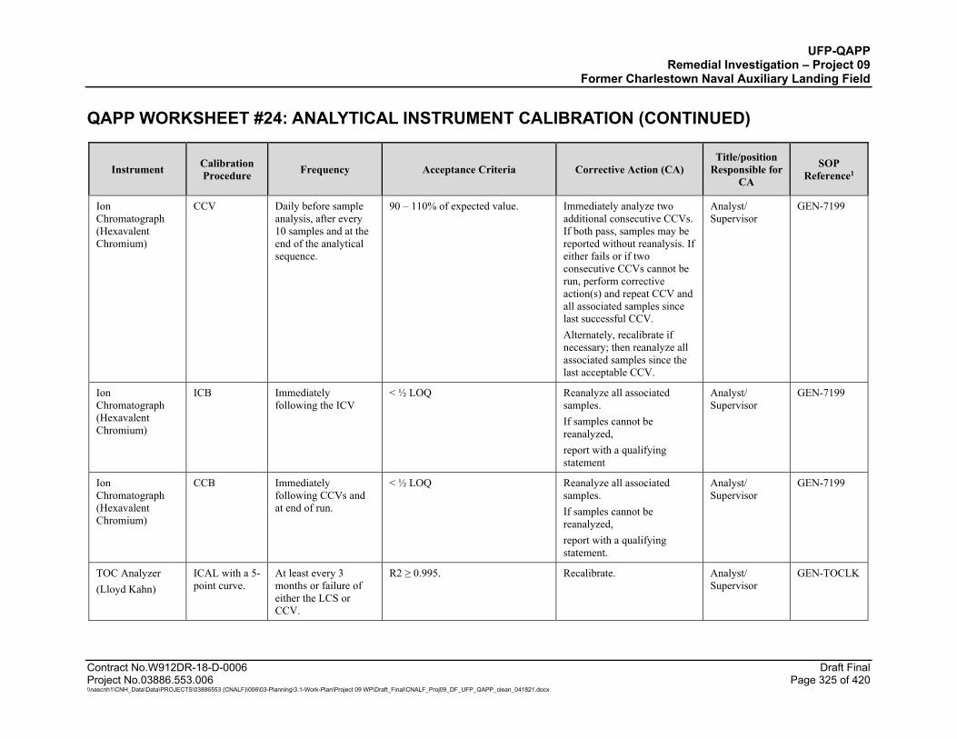
UFP-QAPP Remedial Investigation – Project 09
Former Charlestown Naval Auxiliary Landing Field QAPP WORKSHEET #24: ANALYTICAL INSTRUMENT CALIBRATION (CONTINUED)
Contract No.W912DR-18-D-0006 Draft Final Project No.03886.553.006 Page 325 of 420 \\nascnh1\CNH_Data\Data\PROJECTS\03886553 (CNALF)\006\03-Planning\3.1-Work-Plan\Project 09 WP\Draft_Final\CNALF_Proj09_DF_UFP_QAPP_clean_041821.docx
Instrument Calibration Procedure Frequency Acceptance Criteria Corrective Action (CA)
Title/position Responsible for
CA
SOP Reference1
Ion Chromatograph (Hexavalent Chromium)
CCV Daily before sample analysis, after every 10 samples and at the end of the analytical sequence.
90 – 110% of expected value. Immediately analyze two additional consecutive CCVs. If both pass, samples may be reported without reanalysis. If either fails or if two consecutive CCVs cannot be run, perform corrective action(s) and repeat CCV and all associated samples since last successful CCV. Alternately, recalibrate if necessary; then reanalyze all associated samples since the last acceptable CCV.
Analyst/ Supervisor
GEN-7199
Ion Chromatograph (Hexavalent Chromium)
ICB Immediately following the ICV
< ½ LOQ Reanalyze all associated samples. If samples cannot be reanalyzed, report with a qualifying statement
Analyst/ Supervisor
GEN-7199
Ion Chromatograph (Hexavalent Chromium)
CCB Immediately following CCVs and at end of run.
< ½ LOQ Reanalyze all associated samples. If samples cannot be reanalyzed, report with a qualifying statement.
Analyst/ Supervisor
GEN-7199
TOC Analyzer (Lloyd Kahn)
ICAL with a 5-point curve.
At least every 3 months or failure of either the LCS or CCV.
R2 ≥ 0.995. Recalibrate. Analyst/ Supervisor
GEN-TOCLK

UFP-QAPP Remedial Investigation – Project 09
Former Charlestown Naval Auxiliary Landing Field QAPP WORKSHEET #24: ANALYTICAL INSTRUMENT CALIBRATION (CONTINUED)
Contract No.W912DR-18-D-0006 Draft Final Project No.03886.553.006 Page 326 of 420 \\nascnh1\CNH_Data\Data\PROJECTS\03886553 (CNALF)\006\03-Planning\3.1-Work-Plan\Project 09 WP\Draft_Final\CNALF_Proj09_DF_UFP_QAPP_clean_041821.docx
Instrument Calibration Procedure Frequency Acceptance Criteria Corrective Action (CA)
Title/position Responsible for
CA
SOP Reference1
TOC Analyzer (Lloyd Kahn)
ICV Once after each ICAL, prior to beginning a sample run
%R within ± 15% of true value. If the ICV fails high, report samples that are non-detected and reanalyze samples with detections.
Analyst/ Supervisor
GEN-TOCLK
TOC Analyzer (Lloyd Kahn)
CCV Prior to sample analysis, after every 10 samples and at the end of a sequence.
%R within ± 15% of true value. If the CCV fails high, report samples that are non-detected. Recalibrate and/or reanalyze samples analyzed after the last acceptable CCV.
Analyst/ Supervisor
GEN-TOCLK
TOC Analyzer (Lloyd Kahn)
ICB Immediately following the ICV
< ½ LOQ Reanalyze all associated samples. If samples cannot be reanalyzed, report with a qualifying statement
Analyst/ Supervisor
GEN-TOCLK
TOC Analyzer (Lloyd Kahn)
CCB Immediately following CCVs and at end of run.
< ½ LOQ Reanalyze all associated samples. If samples cannot be reanalyzed, report with a qualifying statement.
Analyst/ Supervisor
GEN-TOCLK
pH Meter (pH and Corrosivity)
ICAL 3 point calibration using pH 4,7, and 10
Daily prior to analysis. Efficiency between 95 to 105% Identify and correct the source of the problem.
Wet chemistry analyst/ Supervisor
SMO-pH
pH Meter (pH and Corrosivity)
ICV Immediately after ICAL.
±0.05 pH units Reread once. If still outside control limits, recalibrate and reread. If still outside control limits, perform maintenance, then recalibrate and reread.
Wet chemistry analyst/ Supervisor
SMO-pH
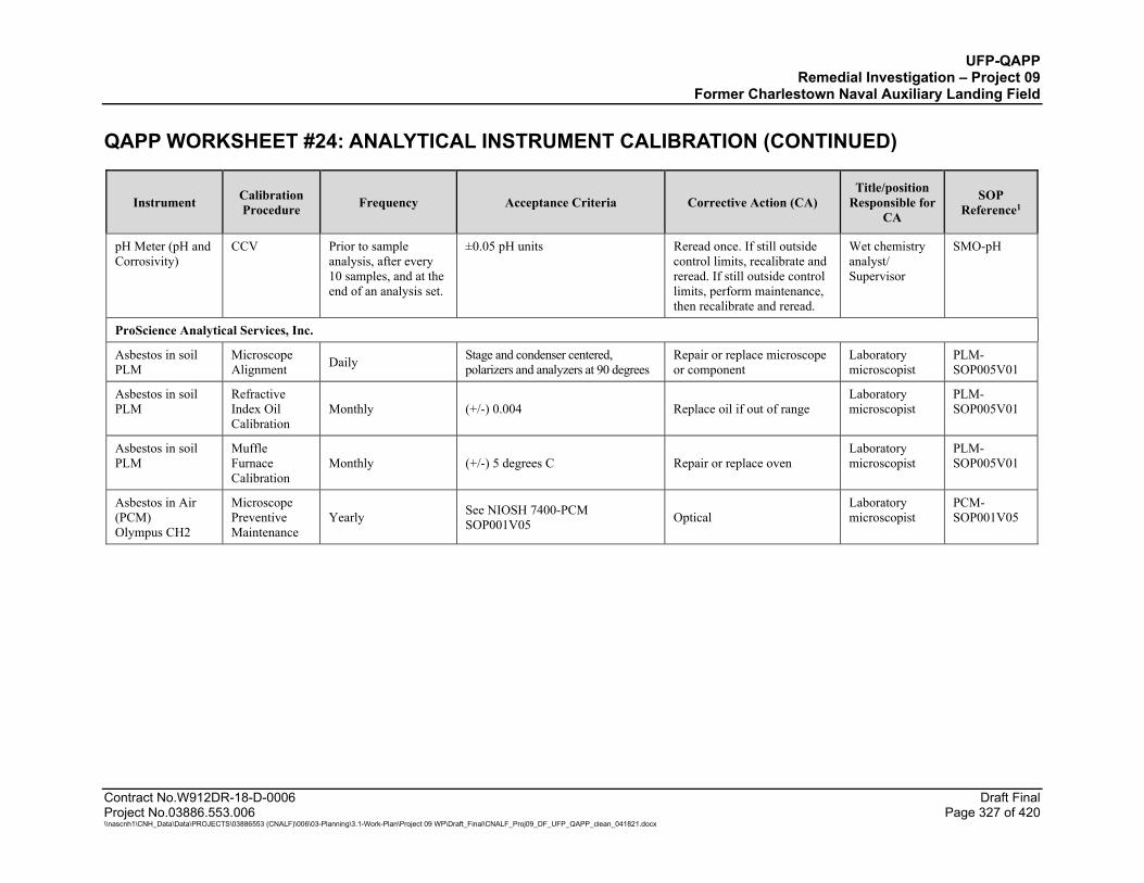
UFP-QAPP Remedial Investigation – Project 09
Former Charlestown Naval Auxiliary Landing Field QAPP WORKSHEET #24: ANALYTICAL INSTRUMENT CALIBRATION (CONTINUED)
Contract No.W912DR-18-D-0006 Draft Final Project No.03886.553.006 Page 327 of 420 \\nascnh1\CNH_Data\Data\PROJECTS\03886553 (CNALF)\006\03-Planning\3.1-Work-Plan\Project 09 WP\Draft_Final\CNALF_Proj09_DF_UFP_QAPP_clean_041821.docx
Instrument Calibration Procedure Frequency Acceptance Criteria Corrective Action (CA)
Title/position Responsible for
CA
SOP Reference1
pH Meter (pH and Corrosivity)
CCV Prior to sample analysis, after every 10 samples, and at the end of an analysis set.
±0.05 pH units Reread once. If still outside control limits, recalibrate and reread. If still outside control limits, perform maintenance, then recalibrate and reread.
Wet chemistry analyst/ Supervisor
SMO-pH
ProScience Analytical Services, Inc.
Asbestos in soil PLM
Microscope Alignment Daily Stage and condenser centered,
polarizers and analyzers at 90 degrees Repair or replace microscope or component
Laboratory microscopist
PLM-SOP005V01
Asbestos in soil PLM
Refractive Index Oil Calibration
Monthly (+/-) 0.004 Replace oil if out of range Laboratory microscopist
PLM-SOP005V01
Asbestos in soil PLM
Muffle Furnace Calibration
Monthly (+/-) 5 degrees C Repair or replace oven Laboratory microscopist
PLM-SOP005V01
Asbestos in Air (PCM) Olympus CH2
Microscope Preventive Maintenance
Yearly See NIOSH 7400-PCM SOP001V05 Optical
Laboratory microscopist
PCM-SOP001V05
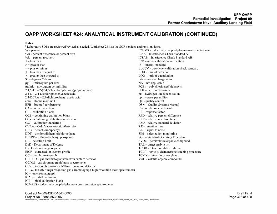
UFP-QAPP Remedial Investigation – Project 09
Former Charlestown Naval Auxiliary Landing Field QAPP WORKSHEET #24: ANALYTICAL INSTRUMENT CALIBRATION (CONTINUED)
Contract No.W912DR-18-D-0006 Draft Final Project No.03886.553.006 Page 328 of 420 \\nascnh1\CNH_Data\Data\PROJECTS\03886553 (CNALF)\006\03-Planning\3.1-Work-Plan\Project 09 WP\Draft_Final\CNALF_Proj09_DF_UFP_QAPP_clean_041821.docx
Notes: 1 Laboratory SOPs are reviewed/revised as needed. Worksheet 23 lists the SOP versions and revision dates. % = percent ICP-MS - inductively coupled plasma-mass spectrometer %D - percent difference or percent drift ICSA – Interference Check Standard A %R – percent recovery ICSAB – Interference Check Standard AB < – less than ICV – initial calibration verification > = greater than IS – internal standard ± – plus or minus LLCCV - Low-level calibration check standard ≤ – less than or equal to LOD - limit of detection ≥ – greater than or equal to LOQ - limit of quantitation ºC – degrees Celsius m/z – mass to charge ratio µg/L – microgram per liter NA – not applicable µg/mL – microgram per milliliter PCBs – polychlorinated biphenyls 2,4,5-TP – 2-(2,4,5-Trichlorophenoxy)propionic acid PFK – Perfluorokerosene 2,4-D - 2,4-Dichlorophenoxyacetic acid pH - hydrogen ion concentration 2,4-DCAA – 2,4-dichlorophenyl acetic acid ppm – parts per million amu – atomic mass unit QC - quality control BFB – bromofluorobenzene QSM - Quality Systems Manual CA – corrective action r2 – correlation coefficient CB – calibration blank RF – response factor CCB – continuing calibration blank RPD – relative percent difference CCV - continuing calibration verification RRT – relative retention time CS3 – calibration standard 3 RSD – relative standard deviation CVAA – Cold Vapor Atomic Absorption RT – retention time DCB – decachlorobiphenyl S/N – signal to noise DDT – dichlorodiphenyltrichloroethane SIM – selected ion monitoring DFTPP – difluorotriphenyl phosphine SOP – Standard Operating Procedure DL – detection limit SVOC – semivolatile organic compound DoD - Department of Defense TAL – target analyte list DRO – diesel-range organic TCDD - tetrachlorodibenzodioxin EICP – extracted ion current profile TCLP – toxicity characteristic leaching procedure GC – gas chromatograph TCMX – tetrachloro-m-xylene GC/ECD – gas chromatograph/electron capture detector VOC - volatile organic compound GC/MS - gas chromatograph/mass spectrometer GC-FID – gas chromatograph/flame ionization detector HRGC-HRMS = high resolution gas chromatograph-high resolution mass spectrometer IC – ion chromatograph ICAL – initial calibration ICB – initial calibration blank ICP-AES - inductively coupled plasma-atomic emission spectrometer
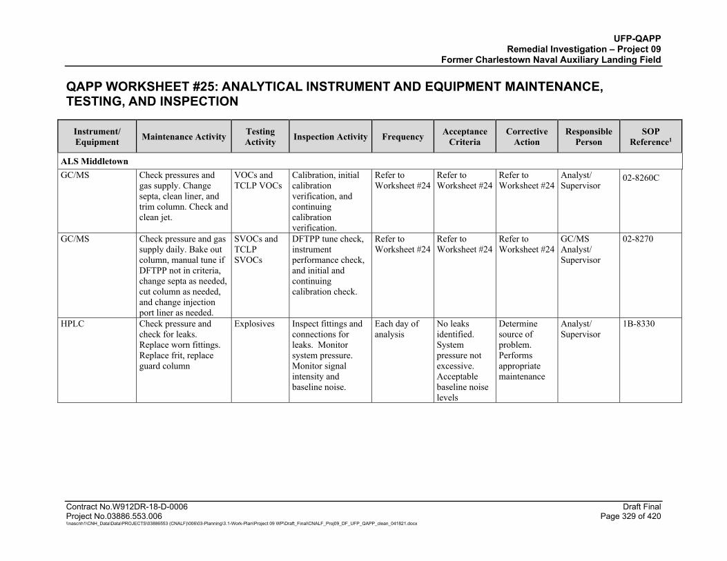
UFP-QAPP Remedial Investigation – Project 09
Former Charlestown Naval Auxiliary Landing Field
Contract No.W912DR-18-D-0006 Draft Final Project No.03886.553.006 Page 329 of 420 \\nascnh1\CNH_Data\Data\PROJECTS\03886553 (CNALF)\006\03-Planning\3.1-Work-Plan\Project 09 WP\Draft_Final\CNALF_Proj09_DF_UFP_QAPP_clean_041821.docx
QAPP WORKSHEET #25: ANALYTICAL INSTRUMENT AND EQUIPMENT MAINTENANCE, TESTING, AND INSPECTION
Instrument/ Equipment Maintenance Activity Testing
Activity Inspection Activity Frequency Acceptance Criteria
Corrective Action
Responsible Person
SOP Reference1
ALS Middletown GC/MS Check pressures and
gas supply. Change septa, clean liner, and trim column. Check and clean jet.
VOCs and TCLP VOCs
Calibration, initial calibration verification, and continuing calibration verification.
Refer to Worksheet #24
Refer to Worksheet #24
Refer to Worksheet #24
Analyst/ Supervisor
02-8260C
GC/MS Check pressure and gas supply daily. Bake out column, manual tune if DFTPP not in criteria, change septa as needed, cut column as needed, and change injection port liner as needed.
SVOCs and TCLP SVOCs
DFTPP tune check, instrument performance check, and initial and continuing calibration check.
Refer to Worksheet #24
Refer to Worksheet #24
Refer to Worksheet #24
GC/MS Analyst/ Supervisor
02-8270
HPLC Check pressure and check for leaks. Replace worn fittings. Replace frit, replace guard column
Explosives Inspect fittings and connections for leaks. Monitor system pressure. Monitor signal intensity and baseline noise.
Each day of analysis
No leaks identified. System pressure not excessive. Acceptable baseline noise levels
Determine source of problem. Performs appropriate maintenance
Analyst/ Supervisor
1B-8330
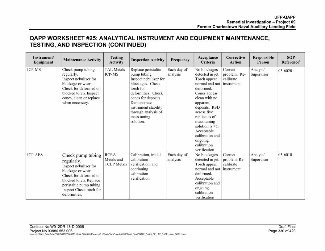
UFP-QAPP Remedial Investigation – Project 09
Former Charlestown Naval Auxiliary Landing Field
QAPP WORKSHEET #25: ANALYTICAL INSTRUMENT AND EQUIPMENT MAINTENANCE, TESTING, AND INSPECTION (CONTINUED)
Contract No.W912DR-18-D-0006 Draft Final Project No.03886.553.006 Page 330 of 420 \\nascnh1\CNH_Data\Data\PROJECTS\03886553 (CNALF)\006\03-Planning\3.1-Work-Plan\Project 09 WP\Draft_Final\CNALF_Proj09_DF_UFP_QAPP_clean_041821.docx
Instrument/ Equipment Maintenance Activity Testing
Activity Inspection Activity Frequency Acceptance Criteria
Corrective Action
Responsible Person
SOP Reference1
ICP-MS Check pump tubing regularly. Inspect nebulizer for blockage or wear. Check for deformed or blocked torch. Inspect cones, clean or replace when necessary.
TAL Metals - ICP-MS
Replace peristaltic pump tubing. Inspect nebulizer for blockages. Check torch for deformities. Check cones for deposits. Demonstrate instrument stability through analysis of mass tuning solution.
Each day of analysis
No blockages detected in jet. Torch appear normal and not deformed. Cones appear clean with no apparent deposits. RSD across five replicates of mass tuning solution is <5. Acceptable calibration and ongoing calibration verification
Correct problem. Re-calibrate instrument
Analyst/ Supervisor
03-6020
ICP-AES Check pump tubing regularly. Inspect nebulizer for blockage or wear. Check for deformed or blocked torch. Replace peristaltic pump tubing. Inspect Check torch for deformities.
RCRA Metals and TCLP Metals
Calibration, initial calibration verification, and continuing calibration verification.
Each day of analysis
No blockages detected in jet. Torch appear normal and not deformed. Acceptable calibration and ongoing calibration verification
Correct problem. Re-calibrate instrument
Analyst/ Supervisor
03-6010
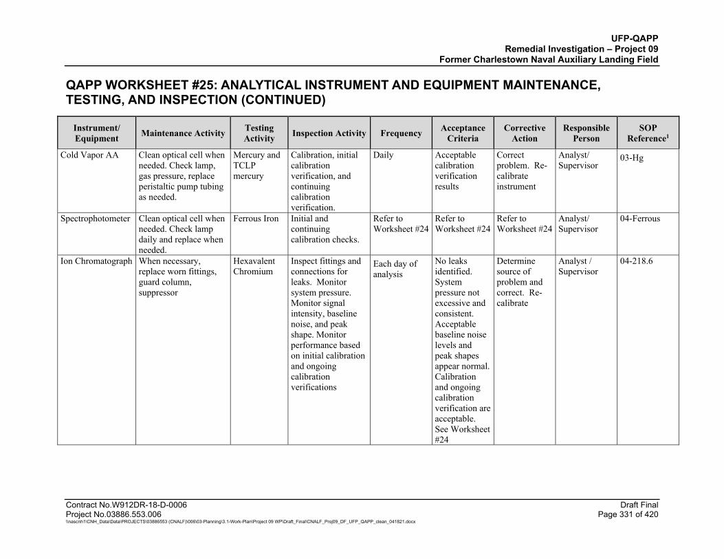
UFP-QAPP Remedial Investigation – Project 09
Former Charlestown Naval Auxiliary Landing Field
QAPP WORKSHEET #25: ANALYTICAL INSTRUMENT AND EQUIPMENT MAINTENANCE, TESTING, AND INSPECTION (CONTINUED)
Contract No.W912DR-18-D-0006 Draft Final Project No.03886.553.006 Page 331 of 420 \\nascnh1\CNH_Data\Data\PROJECTS\03886553 (CNALF)\006\03-Planning\3.1-Work-Plan\Project 09 WP\Draft_Final\CNALF_Proj09_DF_UFP_QAPP_clean_041821.docx
Instrument/ Equipment Maintenance Activity Testing
Activity Inspection Activity Frequency Acceptance Criteria
Corrective Action
Responsible Person
SOP Reference1
Cold Vapor AA Clean optical cell when needed. Check lamp, gas pressure, replace peristaltic pump tubing as needed.
Mercury and TCLP mercury
Calibration, initial calibration verification, and continuing calibration verification.
Daily Acceptable calibration verification results
Correct problem. Re-calibrate instrument
Analyst/ Supervisor
03-Hg
Spectrophotometer Clean optical cell when needed. Check lamp daily and replace when needed.
Ferrous Iron Initial and continuing calibration checks.
Refer to Worksheet #24
Refer to Worksheet #24
Refer to Worksheet #24
Analyst/ Supervisor
04-Ferrous
Ion Chromatograph When necessary, replace worn fittings, guard column, suppressor
Hexavalent Chromium
Inspect fittings and connections for leaks. Monitor system pressure. Monitor signal intensity, baseline noise, and peak shape. Monitor performance based on initial calibration and ongoing calibration verifications
Each day of analysis
No leaks identified. System pressure not excessive and consistent. Acceptable baseline noise levels and peak shapes appear normal. Calibration and ongoing calibration verification are acceptable. See Worksheet #24
Determine source of problem and correct. Re-calibrate
Analyst / Supervisor
04-218.6
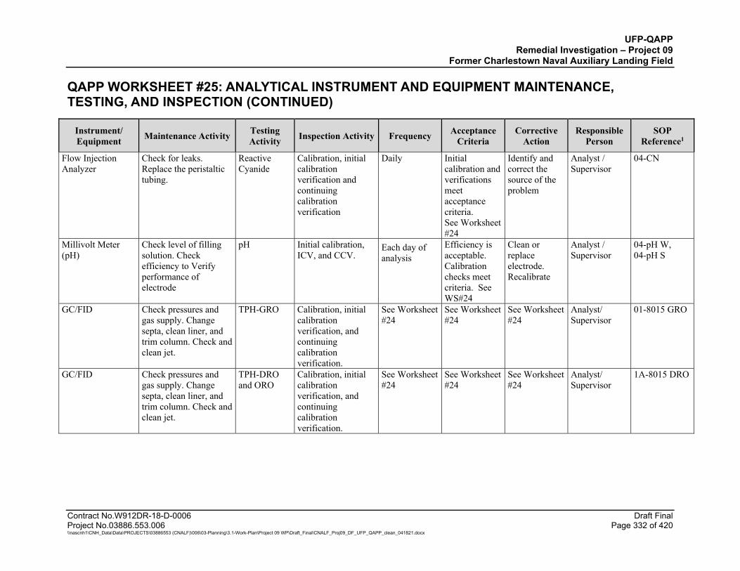
UFP-QAPP Remedial Investigation – Project 09
Former Charlestown Naval Auxiliary Landing Field
QAPP WORKSHEET #25: ANALYTICAL INSTRUMENT AND EQUIPMENT MAINTENANCE, TESTING, AND INSPECTION (CONTINUED)
Contract No.W912DR-18-D-0006 Draft Final Project No.03886.553.006 Page 332 of 420 \\nascnh1\CNH_Data\Data\PROJECTS\03886553 (CNALF)\006\03-Planning\3.1-Work-Plan\Project 09 WP\Draft_Final\CNALF_Proj09_DF_UFP_QAPP_clean_041821.docx
Instrument/ Equipment Maintenance Activity Testing
Activity Inspection Activity Frequency Acceptance Criteria
Corrective Action
Responsible Person
SOP Reference1
Flow Injection Analyzer
Check for leaks. Replace the peristaltic tubing.
Reactive Cyanide
Calibration, initial calibration verification and continuing calibration verification
Daily Initial calibration and verifications meet acceptance criteria. See Worksheet #24
Identify and correct the source of the problem
Analyst / Supervisor
04-CN
Millivolt Meter (pH)
Check level of filling solution. Check efficiency to Verify performance of electrode
pH Initial calibration, ICV, and CCV.
Each day of analysis
Efficiency is acceptable. Calibration checks meet criteria. See WS#24
Clean or replace electrode. Recalibrate
Analyst / Supervisor
04-pH W, 04-pH S
GC/FID Check pressures and gas supply. Change septa, clean liner, and trim column. Check and clean jet.
TPH-GRO Calibration, initial calibration verification, and continuing calibration verification.
See Worksheet #24
See Worksheet #24
See Worksheet #24
Analyst/ Supervisor
01-8015 GRO
GC/FID Check pressures and gas supply. Change septa, clean liner, and trim column. Check and clean jet.
TPH-DRO and ORO
Calibration, initial calibration verification, and continuing calibration verification.
See Worksheet #24
See Worksheet #24
See Worksheet #24
Analyst/ Supervisor
1A-8015 DRO

UFP-QAPP Remedial Investigation – Project 09
Former Charlestown Naval Auxiliary Landing Field
QAPP WORKSHEET #25: ANALYTICAL INSTRUMENT AND EQUIPMENT MAINTENANCE, TESTING, AND INSPECTION (CONTINUED)
Contract No.W912DR-18-D-0006 Draft Final Project No.03886.553.006 Page 333 of 420 \\nascnh1\CNH_Data\Data\PROJECTS\03886553 (CNALF)\006\03-Planning\3.1-Work-Plan\Project 09 WP\Draft_Final\CNALF_Proj09_DF_UFP_QAPP_clean_041821.docx
Instrument/ Equipment Maintenance Activity Testing
Activity Inspection Activity Frequency Acceptance Criteria
Corrective Action
Responsible Person
SOP Reference1
ALS Kelso GC/MS Swabbing or changing
o-rings, septa, injection port liner as needed. Cut column as needed, Pump oil change as needed. MS source cleaning performed as needed
SVOCs Low Level
Initial calibration verification and continuing calibration verification.
As needed Refer to Worksheet #24
Refer to Worksheet #24
Analyst/ Supervisor
SVM-8270L
GC/MS Swabbing or changing o-rings, septa, injection port liner as needed. Cut column as needed, Pump oil change as needed. MS source cleaning performed as needed
1,4-Dioxane and PAHs by SIM
Initial calibration verification and continuing calibration verification.
As needed Refer to Worksheet #24
Refer to Worksheet #24
Analyst/ Supervisor
SVM-8270S
GC/ECD Check pressures and gas supply. Change glass insert/sleeve, o-rings, septa, injection port liner as needed, system baking, cut column as needed, clean autosampler syringe, as needed
PCBs Initial calibration verification and continuing calibration verification. Analytical QC.
Initial Startup As needed.
Refer to Worksheet #24
Refer to Worksheet #24
Analyst/ Supervisor
SOC-8082AR
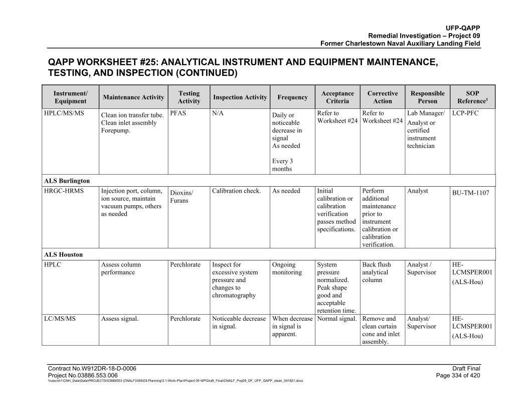
UFP-QAPP Remedial Investigation – Project 09
Former Charlestown Naval Auxiliary Landing Field
QAPP WORKSHEET #25: ANALYTICAL INSTRUMENT AND EQUIPMENT MAINTENANCE, TESTING, AND INSPECTION (CONTINUED)
Contract No.W912DR-18-D-0006 Draft Final Project No.03886.553.006 Page 334 of 420 \\nascnh1\CNH_Data\Data\PROJECTS\03886553 (CNALF)\006\03-Planning\3.1-Work-Plan\Project 09 WP\Draft_Final\CNALF_Proj09_DF_UFP_QAPP_clean_041821.docx
Instrument/ Equipment Maintenance Activity Testing
Activity Inspection Activity Frequency Acceptance Criteria
Corrective Action
Responsible Person
SOP Reference1
HPLC/MS/MS Clean ion transfer tube. Clean inlet assembly Forepump.
PFAS N/A Daily or noticeable decrease in signal As needed Every 3 months
Refer to Worksheet #24
Refer to Worksheet #24
Lab Manager/ Analyst or certified instrument technician
LCP-PFC
ALS Burlington HRGC-HRMS Injection port, column,
ion source, maintain vacuum pumps, others as needed
Dioxins/ Furans
Calibration check. As needed Initial calibration or calibration verification passes method specifications.
Perform additional maintenance prior to instrument calibration or calibration verification.
Analyst BU-TM-1107
ALS Houston HPLC Assess column
performance Perchlorate Inspect for
excessive system pressure and changes to chromatography
Ongoing monitoring
System pressure normalized. Peak shape good and acceptable retention time.
Back flush analytical column
Analyst / Supervisor
HE-LCMSPER001 (ALS-Hou)
LC/MS/MS Assess signal. Perchlorate Noticeable decrease in signal.
When decrease in signal is apparent.
Normal signal. Remove and clean curtain cone and inlet assembly.
Analyst/ Supervisor
HE-LCMSPER001 (ALS-Hou)
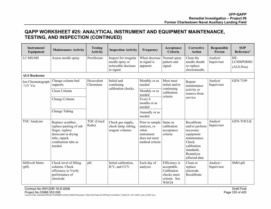
UFP-QAPP Remedial Investigation – Project 09
Former Charlestown Naval Auxiliary Landing Field
QAPP WORKSHEET #25: ANALYTICAL INSTRUMENT AND EQUIPMENT MAINTENANCE, TESTING, AND INSPECTION (CONTINUED)
Contract No.W912DR-18-D-0006 Draft Final Project No.03886.553.006 Page 335 of 420 \\nascnh1\CNH_Data\Data\PROJECTS\03886553 (CNALF)\006\03-Planning\3.1-Work-Plan\Project 09 WP\Draft_Final\CNALF_Proj09_DF_UFP_QAPP_clean_041821.docx
Instrument/ Equipment Maintenance Activity Testing
Activity Inspection Activity Frequency Acceptance Criteria
Corrective Action
Responsible Person
SOP Reference1
LC/MS/MS Assess needle spray. Perchlorate Inspect for irregular needle spray or noticeable decrease in signal.
When decrease in signal is apparent.
Normal spray pattern and signal.
Clean the needle sheath or replace electroneedle.
Analyst/ Supervisor
HE-LCMSPER001 (ALS-Hou)
ALS Rochester
Ion Chromatograph / UV Vis
Change column bed supports
Hexavalent Chromium
Initial and continuing calibration checks.
Monthly or as needed
Must meet initial and/or continuing calibration criteria
Repeat maintenance activity or remove from service
Analyst/ Supervisor
GEN-7199
Clean Column Monthly or as needed
Change Column Every 6 months or as needed
Change Tubing Annually or as needed
TOC Analyzer Replace scrubber, replace packing of ash finger, replace desiccant in drying tube, repack combustion tube as needed
TOC (Lloyd Kahn)
Check gas supply, check lamp, tubing, reagent volumes
Prior to sample analysis, or when instrument does not meet method criteria
Same as calibration acceptance criteria
Recalibrate and/or perform necessary equipment maintenance. Check calibration standards. Reanalyze affected data
Analyst/ Supervisor
GEN-TOCLK
Millivolt Meter (pH)
Check level of filling solution. Check efficiency to Verify performance of electrode
pH Initial calibration, ICV, and CCV.
Each day of analysis
Efficiency is acceptable. Calibration checks meet criteria. See WS#24
Clean or replace electrode. Recalibrate
Analyst / Supervisor
SMO-pH

UFP-QAPP Remedial Investigation – Project 09
Former Charlestown Naval Auxiliary Landing Field
QAPP WORKSHEET #25: ANALYTICAL INSTRUMENT AND EQUIPMENT MAINTENANCE, TESTING, AND INSPECTION (CONTINUED)
Contract No.W912DR-18-D-0006 Draft Final Project No.03886.553.006 Page 336 of 420 \\nascnh1\CNH_Data\Data\PROJECTS\03886553 (CNALF)\006\03-Planning\3.1-Work-Plan\Project 09 WP\Draft_Final\CNALF_Proj09_DF_UFP_QAPP_clean_041821.docx
Instrument/ Equipment Maintenance Activity Testing
Activity Inspection Activity Frequency Acceptance Criteria
Corrective Action
Responsible Person
SOP Reference1
ProScience Analytical Services, Inc. Polarized Light Microscope (PLM) Hood Calibration.
Sample Slides are prepared in hood.
Velocity/ Leak check Bi-annual Pass or Fail
Change HEPA Filter or replace motor
Hygienist
PLM-SOP005V01
Polarized Light Microscope (PLM) Scope Maintenance.
Using for identifying asbestos.
Cleaning and or repair Annual Pass or Fail
Repair or replace
ProScience Instrument Specialist
PLM-SOP005V01
Polarized Light Microscope (PLM)
Scope Maintenance. Using for identifying asbestos.
RI oils checked Monthly basis
Within expected ranges (+/- 0.004 per SOP)
Repair or replace
ProScience Instrument Specialist
PLM-SOP005V01
Polarized Light Microscope (PLM)
Scope Maintenance. Using for identifying asbestos.
Refractive oil Calibration
Refractive oils from series A and series B must be checked before use as they are infrequently used.
+/- 0.004
Repair or replace
ProScience Instrument Specialist
PLM-SOP005V01
Polarized Light Microscope (PLM) Scope Maintenance.
Using for identifying asbestos.
Muffle furnace Calibrated monthly
+/- 5 degrees C
Repair or replace
ProScience Instrument Specialist
PLM-SOP005V01
Olympus CH2 PCM Microscope: Preventative Maintenance.
PCM Analysis. Yearly Yearly Per SOP Per SOP ProScience
Optical
PCM-SOP001V05 NIOSH 7400
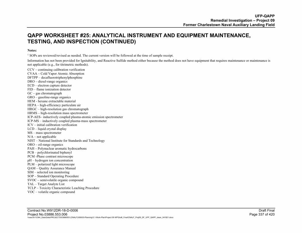
UFP-QAPP Remedial Investigation – Project 09
Former Charlestown Naval Auxiliary Landing Field
QAPP WORKSHEET #25: ANALYTICAL INSTRUMENT AND EQUIPMENT MAINTENANCE, TESTING, AND INSPECTION (CONTINUED)
Contract No.W912DR-18-D-0006 Draft Final Project No.03886.553.006 Page 337 of 420 \\nascnh1\CNH_Data\Data\PROJECTS\03886553 (CNALF)\006\03-Planning\3.1-Work-Plan\Project 09 WP\Draft_Final\CNALF_Proj09_DF_UFP_QAPP_clean_041821.docx
Notes: 1 SOPs are reviewed/revised as needed. The current version will be followed at the time of sample receipt. Information has not been provided for Ignitability, and Reactive Sulfide method either because the method does not have equipment that requires maintenance or maintenance is not applicable (e.g., for titrimetric methods). CCV – continuing calibration verification CVAA – Cold Vapor Atomic Absorption DFTPP – decafluorotriphenylphosphine DRO – diesel-range organics ECD – electron capture detector FID – flame ionization detector GC – gas chromatograph GRO – gasoline-range organics HEM - hexane extractable material HEPA – high-efficiency particulate air HRGC – high-resolution gas chromatograph HRMS – high-resolution mass spectrometer ICP-AES– inductively coupled plasma-atomic emission spectrometer ICP-MS – inductively coupled plasma-mass spectrometer ICV – initial calibration verification LCD – liquid crystal display MS – mass spectrometer N/A – not applicable NIST – National Institute for Standards and Technology ORO – oil-range organics PAH – Polynuclear aromatic hydrocarbons PCB – polychlorinated biphenyl PCM -Phase contrast microscope pH – hydrogen ion concentration PLM – polarized light microscope QAM – Quality Assurance Manual SIM – selected ion monitoring SOP – Standard Operating Procedure SVOC – semivolatile organic compound TAL – Target Analyte List TCLP – Toxicity Characteristic Leaching Procedure VOC – volatile organic compound
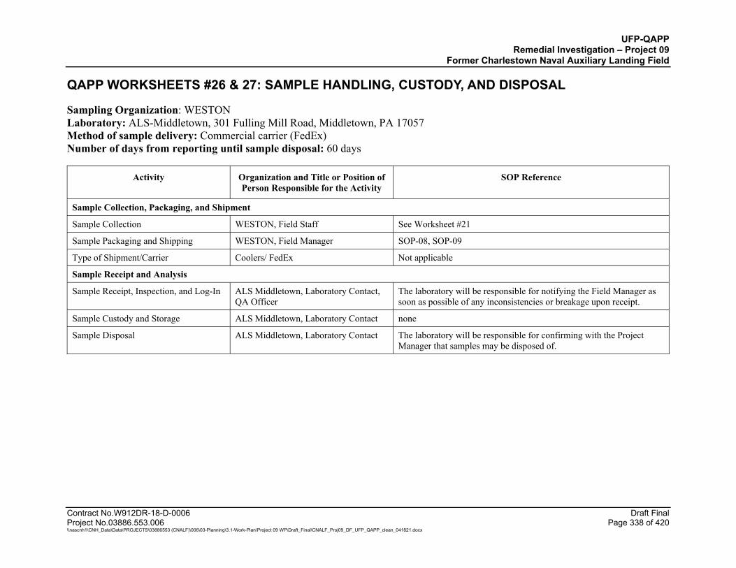
UFP-QAPP Remedial Investigation – Project 09
Former Charlestown Naval Auxiliary Landing Field
Contract No.W912DR-18-D-0006 Draft Final Project No.03886.553.006 Page 338 of 420 \\nascnh1\CNH_Data\Data\PROJECTS\03886553 (CNALF)\006\03-Planning\3.1-Work-Plan\Project 09 WP\Draft_Final\CNALF_Proj09_DF_UFP_QAPP_clean_041821.docx
QAPP WORKSHEETS #26 & 27: SAMPLE HANDLING, CUSTODY, AND DISPOSAL
Sampling Organization: WESTON Laboratory: ALS-Middletown, 301 Fulling Mill Road, Middletown, PA 17057 Method of sample delivery: Commercial carrier (FedEx) Number of days from reporting until sample disposal: 60 days
Activity Organization and Title or Position of Person Responsible for the Activity
SOP Reference
Sample Collection, Packaging, and Shipment
Sample Collection WESTON, Field Staff See Worksheet #21
Sample Packaging and Shipping WESTON, Field Manager SOP-08, SOP-09
Type of Shipment/Carrier Coolers/ FedEx Not applicable
Sample Receipt and Analysis
Sample Receipt, Inspection, and Log-In ALS Middletown, Laboratory Contact, QA Officer
The laboratory will be responsible for notifying the Field Manager as soon as possible of any inconsistencies or breakage upon receipt.
Sample Custody and Storage ALS Middletown, Laboratory Contact none
Sample Disposal ALS Middletown, Laboratory Contact The laboratory will be responsible for confirming with the Project Manager that samples may be disposed of.
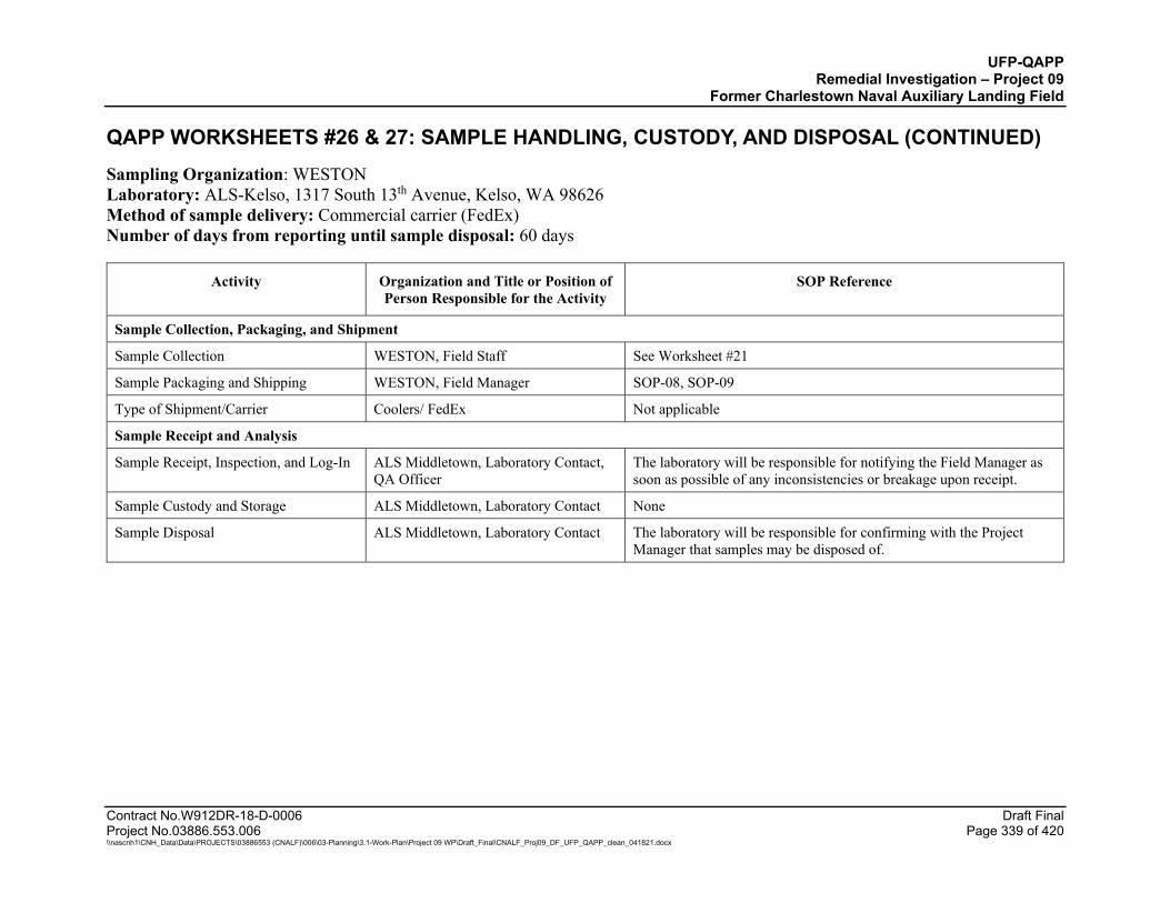
UFP-QAPP Remedial Investigation – Project 09
Former Charlestown Naval Auxiliary Landing Field
QAPP WORKSHEETS #26 & 27: SAMPLE HANDLING, CUSTODY, AND DISPOSAL (CONTINUED)
Contract No.W912DR-18-D-0006 Draft Final Project No.03886.553.006 Page 339 of 420 \\nascnh1\CNH_Data\Data\PROJECTS\03886553 (CNALF)\006\03-Planning\3.1-Work-Plan\Project 09 WP\Draft_Final\CNALF_Proj09_DF_UFP_QAPP_clean_041821.docx
Sampling Organization: WESTON Laboratory: ALS-Kelso, 1317 South 13th Avenue, Kelso, WA 98626 Method of sample delivery: Commercial carrier (FedEx) Number of days from reporting until sample disposal: 60 days
Activity Organization and Title or Position of Person Responsible for the Activity
SOP Reference
Sample Collection, Packaging, and Shipment
Sample Collection WESTON, Field Staff See Worksheet #21
Sample Packaging and Shipping WESTON, Field Manager SOP-08, SOP-09
Type of Shipment/Carrier Coolers/ FedEx Not applicable
Sample Receipt and Analysis
Sample Receipt, Inspection, and Log-In ALS Middletown, Laboratory Contact, QA Officer
The laboratory will be responsible for notifying the Field Manager as soon as possible of any inconsistencies or breakage upon receipt.
Sample Custody and Storage ALS Middletown, Laboratory Contact None
Sample Disposal ALS Middletown, Laboratory Contact The laboratory will be responsible for confirming with the Project Manager that samples may be disposed of.
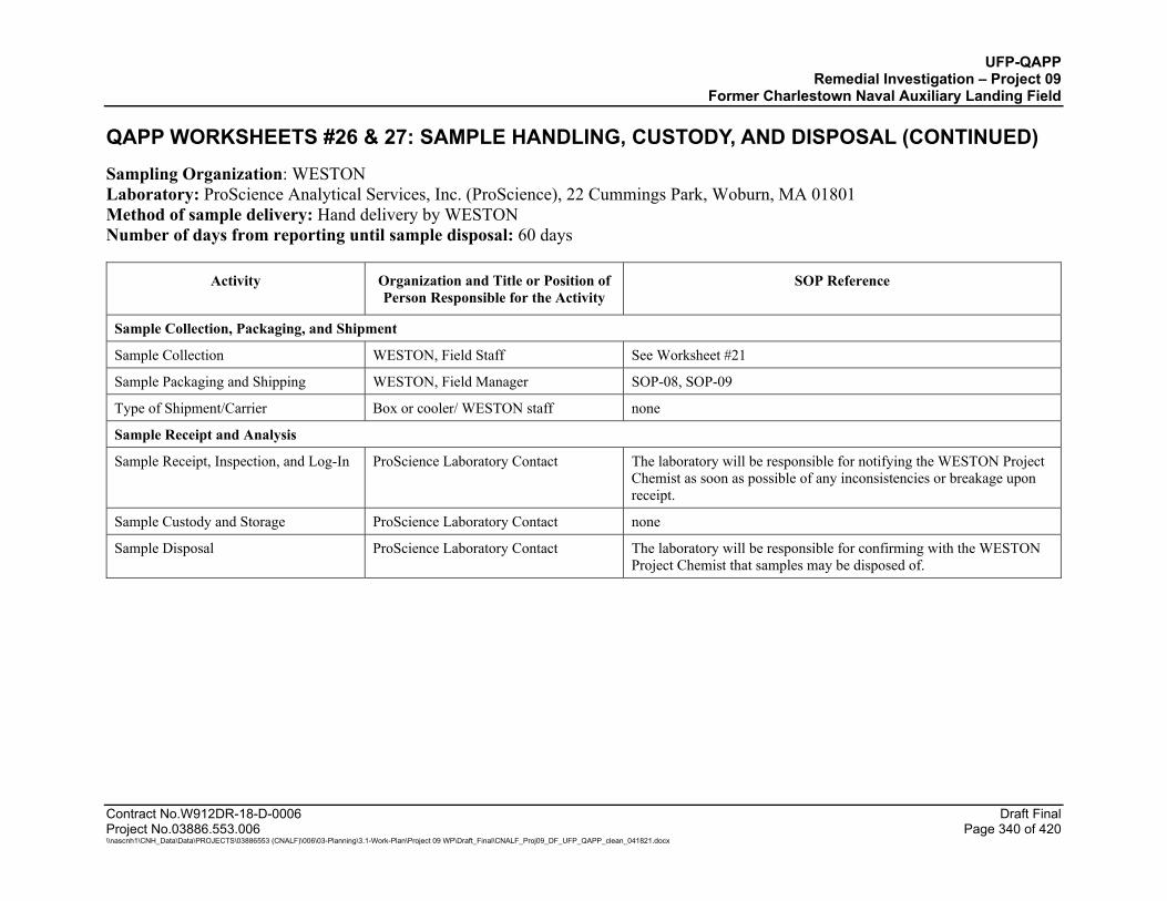
UFP-QAPP Remedial Investigation – Project 09
Former Charlestown Naval Auxiliary Landing Field
QAPP WORKSHEETS #26 & 27: SAMPLE HANDLING, CUSTODY, AND DISPOSAL (CONTINUED)
Contract No.W912DR-18-D-0006 Draft Final Project No.03886.553.006 Page 340 of 420 \\nascnh1\CNH_Data\Data\PROJECTS\03886553 (CNALF)\006\03-Planning\3.1-Work-Plan\Project 09 WP\Draft_Final\CNALF_Proj09_DF_UFP_QAPP_clean_041821.docx
Sampling Organization: WESTON Laboratory: ProScience Analytical Services, Inc. (ProScience), 22 Cummings Park, Woburn, MA 01801 Method of sample delivery: Hand delivery by WESTON Number of days from reporting until sample disposal: 60 days
Activity Organization and Title or Position of Person Responsible for the Activity
SOP Reference
Sample Collection, Packaging, and Shipment
Sample Collection WESTON, Field Staff See Worksheet #21
Sample Packaging and Shipping WESTON, Field Manager SOP-08, SOP-09
Type of Shipment/Carrier Box or cooler/ WESTON staff none
Sample Receipt and Analysis
Sample Receipt, Inspection, and Log-In ProScience Laboratory Contact The laboratory will be responsible for notifying the WESTON Project Chemist as soon as possible of any inconsistencies or breakage upon receipt.
Sample Custody and Storage ProScience Laboratory Contact none
Sample Disposal ProScience Laboratory Contact The laboratory will be responsible for confirming with the WESTON Project Chemist that samples may be disposed of.

UFP-QAPP Remedial Investigation – Project 09
Former Charlestown Naval Auxiliary Landing Field
Contract No.W912DR-18-D-0006 Draft Final Project No.03886.553.006 Page 341 of 420 \\nascnh1\CNH_Data\Data\PROJECTS\03886553 (CNALF)\006\03-Planning\3.1-Work-Plan\Project 09 WP\Draft_Final\CNALF_Proj09_DF_UFP_QAPP_clean_041821.docx
QAPP WORKSHEET #28: LABORATORY QUALITY CONTROL AND CORRECTIVE ACTION Worksheet 28 includes quality control (QC) sample requirements and project-specific measurement performance criteria (MPC) for investigative soil/sediment samples, investigative water samples (tapwater, groundwater, pore water, and surface water). For supplemental parameters and soil and water IDW samples, the QC requirements and MPC are streamlined. The following supplemental analyses will be used to support risk assessment and the interpretation of hexavalent chromium results: ferrous iron, total sulfide, TOC, and pH. Field blank MPC (trip blank, equipment blank, and field reagent blank) are included in Worksheet 12.
QAPP WORKSHEET #28.1: VOLATILE ORGANIC COMPOUNDS (VOCS) BY GAS CHROMATOGRAPHY/MASS SPECTROMETRY (GC/MS)
Matrix: Soil/Sediment, Water (tapwater, groundwater, pore/surface water, trip/equipment blanks), TCLP VOCs, Solid/Liquid Test Pit Waste Object Laboratory: ALS Middletown Analytical Group: VOCs Analytical Method (Prep Method) / Analytical SOP (Prep SOP) Soil/Sediment/Solid: EPA 8260C (5035A) / 02-8260C (02-5035) Analytical Method (Prep Method) / Analytical SOP (Prep SOP) Water/Liquid: EPA 8260C (5030C) / 02-8260C (02-8260C) Analytical Method (Prep Method) / Analytical SOP (Prep SOP) TCLP Leachate: EPA 8260C (1311 and 5030C) / 02-8260C (09-TCLP-SPLP-ZHE and 02-8260C)
QC Sample Number/ Frequency
Method/SOP Acceptance Criteria Corrective Action (CA)
Title/Position of Person
Responsible for CA
Project-Specific MPC
Field Duplicates (investigative samples only, not IDW or Test Pit Waste objects)
1 per 10 samples
Not applicable Confirm identity of field duplicates and RPD calculation. Assess field records for evidence of sample non-homogeneity. Review sampling procedures.
Data Validator, Field Sampling Team, and Project Manager
Soil/Sediment RPD ≤ 50% and Water RPD ≤ 30% when detects for both field duplicate samples are ≥ 2x sample-specific LOQ; if one or both sample detections are < 2x LOQ, the data validation acceptance limit is ± 2x LOQ.
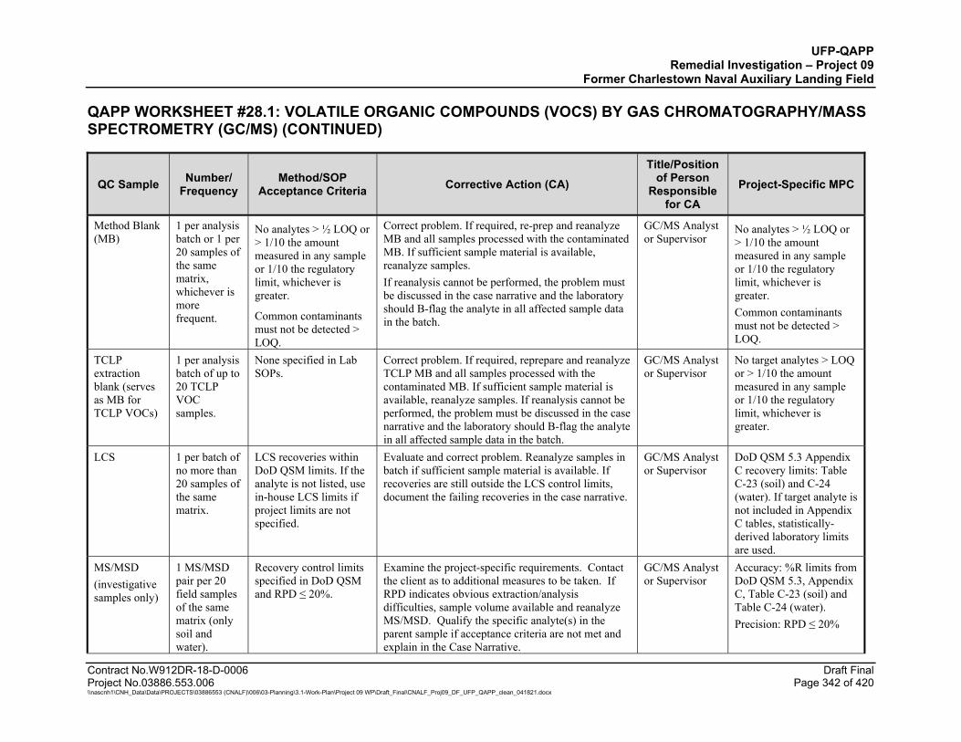
UFP-QAPP Remedial Investigation – Project 09
Former Charlestown Naval Auxiliary Landing Field
QAPP WORKSHEET #28.1: VOLATILE ORGANIC COMPOUNDS (VOCS) BY GAS CHROMATOGRAPHY/MASS SPECTROMETRY (GC/MS) (CONTINUED)
Contract No.W912DR-18-D-0006 Draft Final Project No.03886.553.006 Page 342 of 420 \\nascnh1\CNH_Data\Data\PROJECTS\03886553 (CNALF)\006\03-Planning\3.1-Work-Plan\Project 09 WP\Draft_Final\CNALF_Proj09_DF_UFP_QAPP_clean_041821.docx
QC Sample Number/ Frequency
Method/SOP Acceptance Criteria Corrective Action (CA)
Title/Position of Person
Responsible for CA
Project-Specific MPC
Method Blank (MB)
1 per analysis batch or 1 per 20 samples of the same matrix, whichever is more frequent.
No analytes > ½ LOQ or > 1/10 the amount measured in any sample or 1/10 the regulatory limit, whichever is greater.
Common contaminants must not be detected > LOQ.
Correct problem. If required, re-prep and reanalyze MB and all samples processed with the contaminated MB. If sufficient sample material is available, reanalyze samples. If reanalysis cannot be performed, the problem must be discussed in the case narrative and the laboratory should B-flag the analyte in all affected sample data in the batch.
GC/MS Analyst or Supervisor
No analytes > ½ LOQ or > 1/10 the amount measured in any sample or 1/10 the regulatory limit, whichever is greater. Common contaminants must not be detected > LOQ.
TCLP extraction blank (serves as MB for TCLP VOCs)
1 per analysis batch of up to 20 TCLP VOC samples.
None specified in Lab SOPs.
Correct problem. If required, reprepare and reanalyze TCLP MB and all samples processed with the contaminated MB. If sufficient sample material is available, reanalyze samples. If reanalysis cannot be performed, the problem must be discussed in the case narrative and the laboratory should B-flag the analyte in all affected sample data in the batch.
GC/MS Analyst or Supervisor
No target analytes > LOQ or > 1/10 the amount measured in any sample or 1/10 the regulatory limit, whichever is greater.
LCS 1 per batch of no more than 20 samples of the same matrix.
LCS recoveries within DoD QSM limits. If the analyte is not listed, use in-house LCS limits if project limits are not specified.
Evaluate and correct problem. Reanalyze samples in batch if sufficient sample material is available. If recoveries are still outside the LCS control limits, document the failing recoveries in the case narrative.
GC/MS Analyst or Supervisor
DoD QSM 5.3 Appendix C recovery limits: Table C-23 (soil) and C-24 (water). If target analyte is not included in Appendix C tables, statistically-derived laboratory limits are used.
MS/MSD (investigative samples only)
1 MS/MSD pair per 20 field samples of the same matrix (only soil and water).
Recovery control limits specified in DoD QSM and RPD ≤ 20%.
Examine the project-specific requirements. Contact the client as to additional measures to be taken. If RPD indicates obvious extraction/analysis difficulties, sample volume available and reanalyze MS/MSD. Qualify the specific analyte(s) in the parent sample if acceptance criteria are not met and explain in the Case Narrative.
GC/MS Analyst or Supervisor
Accuracy: %R limits from DoD QSM 5.3, Appendix C, Table C-23 (soil) and Table C-24 (water). Precision: RPD ≤ 20%
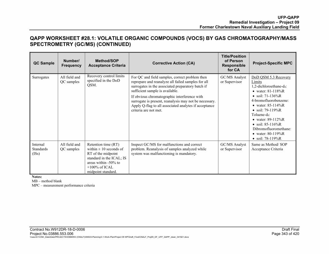
UFP-QAPP Remedial Investigation – Project 09
Former Charlestown Naval Auxiliary Landing Field
QAPP WORKSHEET #28.1: VOLATILE ORGANIC COMPOUNDS (VOCS) BY GAS CHROMATOGRAPHY/MASS SPECTROMETRY (GC/MS) (CONTINUED)
Contract No.W912DR-18-D-0006 Draft Final Project No.03886.553.006 Page 343 of 420 \\nascnh1\CNH_Data\Data\PROJECTS\03886553 (CNALF)\006\03-Planning\3.1-Work-Plan\Project 09 WP\Draft_Final\CNALF_Proj09_DF_UFP_QAPP_clean_041821.docx
QC Sample Number/ Frequency
Method/SOP Acceptance Criteria Corrective Action (CA)
Title/Position of Person
Responsible for CA
Project-Specific MPC
Surrogates All field and QC samples
Recovery control limits specified in the DoD QSM.
For QC and field samples, correct problem then reprepare and reanalyze all failed samples for all surrogates in the associated preparatory batch if sufficient sample is available. If obvious chromatographic interference with surrogate is present, reanalysis may not be necessary. Apply Q-flag to all associated analytes if acceptance criteria are not met.
GC/MS Analyst or Supervisor
DoD QSM 5.3 Recovery Limits 1,2-dichloroethane-d4: water: 81-118%R soil: 71-136%R
4-bromofluorobenzene: water: 85-114%R soil: 79-119%R
Toluene-d8: water: 89-112%R soil: 85-116%R Dibromofluoromethane: water: 80-119%R soil: 78-119%R
Internal Standards (ISs)
All field and QC samples
Retention time (RT) within ± 10 seconds of RT of the midpoint standard in the ICAL; IS areas within -50% to +100% of ICAL midpoint standard.
Inspect GC/MS for malfunctions and correct problem. Reanalysis of samples analyzed while system was malfunctioning is mandatory.
GC/MS Analyst or Supervisor
Same as Method/ SOP Acceptance Criteria
Notes: MB – method blank MPC – measurement performance criteria
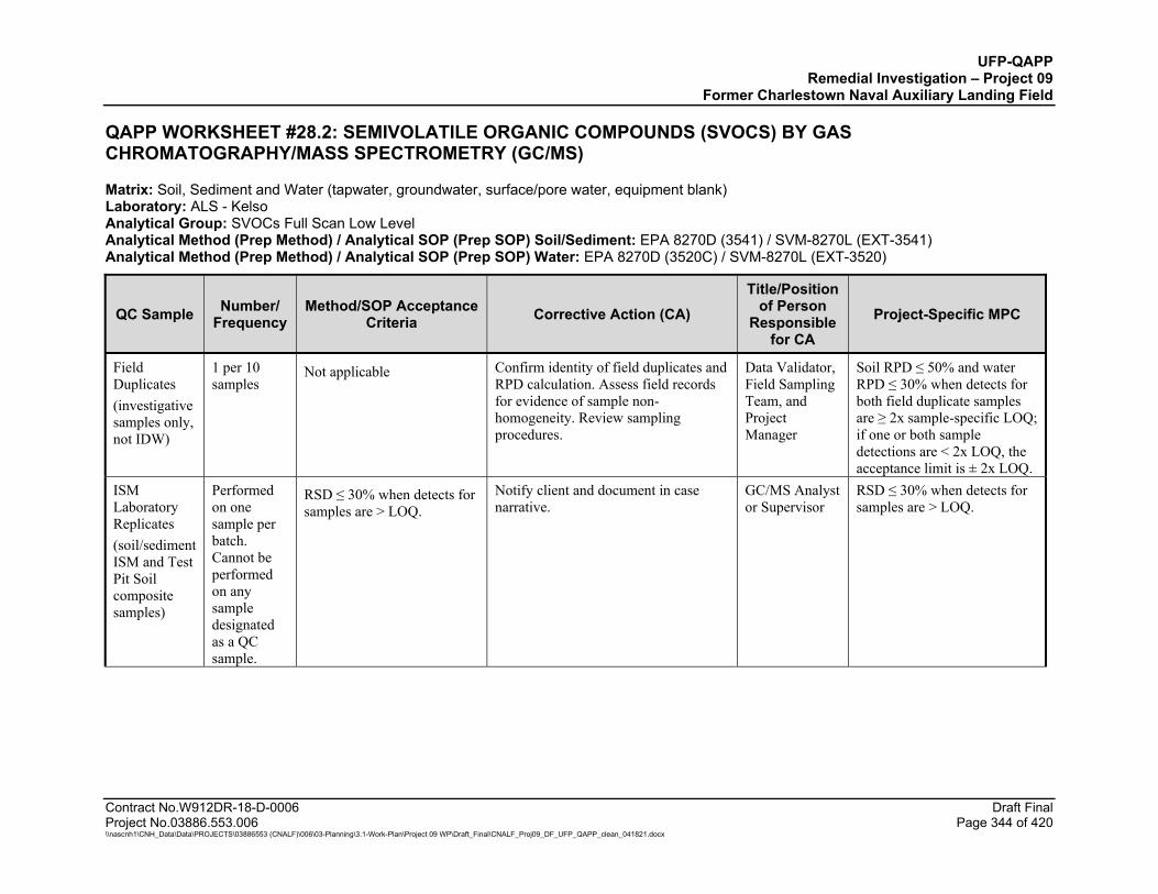
UFP-QAPP Remedial Investigation – Project 09
Former Charlestown Naval Auxiliary Landing Field
Contract No.W912DR-18-D-0006 Draft Final Project No.03886.553.006 Page 344 of 420 \\nascnh1\CNH_Data\Data\PROJECTS\03886553 (CNALF)\006\03-Planning\3.1-Work-Plan\Project 09 WP\Draft_Final\CNALF_Proj09_DF_UFP_QAPP_clean_041821.docx
QAPP WORKSHEET #28.2: SEMIVOLATILE ORGANIC COMPOUNDS (SVOCS) BY GAS CHROMATOGRAPHY/MASS SPECTROMETRY (GC/MS)
Matrix: Soil, Sediment and Water (tapwater, groundwater, surface/pore water, equipment blank) Laboratory: ALS - Kelso Analytical Group: SVOCs Full Scan Low Level Analytical Method (Prep Method) / Analytical SOP (Prep SOP) Soil/Sediment: EPA 8270D (3541) / SVM-8270L (EXT-3541) Analytical Method (Prep Method) / Analytical SOP (Prep SOP) Water: EPA 8270D (3520C) / SVM-8270L (EXT-3520)
QC Sample Number/ Frequency
Method/SOP Acceptance Criteria Corrective Action (CA)
Title/Position of Person
Responsible for CA
Project-Specific MPC
Field Duplicates (investigative samples only, not IDW)
1 per 10 samples
Not applicable Confirm identity of field duplicates and RPD calculation. Assess field records for evidence of sample non-homogeneity. Review sampling procedures.
Data Validator, Field Sampling Team, and Project Manager
Soil RPD ≤ 50% and water RPD ≤ 30% when detects for both field duplicate samples are ≥ 2x sample-specific LOQ; if one or both sample detections are < 2x LOQ, the acceptance limit is ± 2x LOQ.
ISM Laboratory Replicates (soil/sediment ISM and Test Pit Soil composite samples)
Performed on one sample per batch. Cannot be performed on any sample designated as a QC sample.
RSD ≤ 30% when detects for samples are > LOQ.
Notify client and document in case narrative.
GC/MS Analyst or Supervisor
RSD ≤ 30% when detects for samples are > LOQ.

UFP-QAPP Remedial Investigation – Project 09
Former Charlestown Naval Auxiliary Landing Field
QAPP WORKSHEET #28.2: SEMIVOLATILE ORGANIC COMPOUNDS (SVOCS) BY GAS CHROMATOGRAPHY/MASS SPECTROMETRY (GC/MS) (CONTINUED)
Contract No.W912DR-18-D-0006 Draft Final Project No.03886.553.006 Page 345 of 420 \\nascnh1\CNH_Data\Data\PROJECTS\03886553 (CNALF)\006\03-Planning\3.1-Work-Plan\Project 09 WP\Draft_Final\CNALF_Proj09_DF_UFP_QAPP_clean_041821.docx
QC Sample Number/ Frequency
Method/SOP Acceptance Criteria Corrective Action (CA)
Title/Position of Person
Responsible for CA
Project-Specific MPC
MB 1 per analysis batch or 1 per 20 samples of the same matrix, whichever is more frequent.
No analytes > ½ LOQ or > 1/10 the amount measured in any sample or 1/10 the regulatory limit, whichever is greater. Common contaminants must not be detected > LOQ.
Correct problem. If required, re-prep and reanalyze MB and all samples processed with the contaminated MB. If sufficient sample material is available, reanalyze samples. If reanalysis cannot be performed, the problem must be discussed in the case narrative and the laboratory should B-flag the analyte in all affected sample data in the batch.
GC/MS Analyst or Supervisor
No analytes > ½ LOQ or > 1/10 the amount measured in any sample or 1/10 the regulatory limit, whichever is greater.
LCS 1 per batch of no more than 20 samples of the same matrix.
LCS recoveries within DoD QSM limits. If the analyte is not listed, use in-house LCS limits if project limits are not specified.
Evaluate and correct problem. Reanalyze samples in batch if sufficient sample material is available. If recoveries are still outside the LCS control limits, document the failing recoveries in the case narrative.
GC/MS Analyst or Supervisor
DoD QSM 5.3 Appendix C recovery limits: Table C-25 (soil) and C-26 (water). If target is not included in Appendix C tables, statistically-derived laboratory limits are used.

UFP-QAPP Remedial Investigation – Project 09
Former Charlestown Naval Auxiliary Landing Field
QAPP WORKSHEET #28.2: SEMIVOLATILE ORGANIC COMPOUNDS (SVOCS) BY GAS CHROMATOGRAPHY/MASS SPECTROMETRY (GC/MS) (CONTINUED)
Contract No.W912DR-18-D-0006 Draft Final Project No.03886.553.006 Page 346 of 420 \\nascnh1\CNH_Data\Data\PROJECTS\03886553 (CNALF)\006\03-Planning\3.1-Work-Plan\Project 09 WP\Draft_Final\CNALF_Proj09_DF_UFP_QAPP_clean_041821.docx
QC Sample Number/ Frequency
Method/SOP Acceptance Criteria Corrective Action (CA)
Title/Position of Person
Responsible for CA
Project-Specific MPC
Surrogates All field and QC samples
Recovery control limits specified in the DoD QSM.
For QC and field samples, correct problem then re-prep and reanalyze all failed samples for all surrogates in the associated preparatory batch if sufficient sample is available. If obvious chromatographic interference with surrogate is present, reanalysis may not be necessary. Apply Q-flag to all associated analytes if acceptance criteria are not met.
GC/MS Analyst or Supervisor
DoD QSM 5.3 Recovery Limits 2,4,6-Tribromophenol: water: 43-140%R soil: 39-132%R
2-Fluorobiphenyl: water: 44-119%R soil: 44-115%R
2-Fluorophenol: water: 19-119%R soil: 35-115%R Nitrobenzene-d5: water: 80-119%R soil: 37-122%R
Terphenyl-d14: water: 50-134%R soil: 54-127%R
Laboratory Limits for Phenol-d6: water: 39-109%R soil: 10-88%R

UFP-QAPP Remedial Investigation – Project 09
Former Charlestown Naval Auxiliary Landing Field
QAPP WORKSHEET #28.2: SEMIVOLATILE ORGANIC COMPOUNDS (SVOCS) BY GAS CHROMATOGRAPHY/MASS SPECTROMETRY (GC/MS) (CONTINUED)
Contract No.W912DR-18-D-0006 Draft Final Project No.03886.553.006 Page 347 of 420 \\nascnh1\CNH_Data\Data\PROJECTS\03886553 (CNALF)\006\03-Planning\3.1-Work-Plan\Project 09 WP\Draft_Final\CNALF_Proj09_DF_UFP_QAPP_clean_041821.docx
QC Sample Number/ Frequency
Method/SOP Acceptance Criteria Corrective Action (CA)
Title/Position of Person
Responsible for CA
Project-Specific MPC
MS/MSD (investigative samples only)
1 MS/MSD pair per 20 field samples of the same matrix.
Recovery control limits specified in DoD QSM and RPD ≤ 20%.
Examine the project-specific requirements. Contact the client as to additional measures to be taken. If RPD indicates obvious extraction/analysis difficulties, sample volume available and reanalyze MS/MSD. Qualify the specific analyte(s) in the parent sample if acceptance criteria are not met and explain in the Case Narrative.
GC/MS Analyst or Supervisor
Accuracy: %R limits from DoD QSM 5.3, Appendix C, Table C-25 (soil) and Table C-26 (water). Precision: RPD ≤ 20%
ISs All field and QC samples
Retention time (RT) within ± 10 seconds of RT of the midpoint standard in the ICAL; IS areas within -50% to +100% of ICAL midpoint standard.
Inspect GC/MS for malfunctions and correct problem. Reanalysis of samples analyzed while system was malfunctioning is mandatory.
GC/MS Analyst or Supervisor
Same as Method/ SOP Acceptance Criteria
Notes: Laboratory will use the surrogate phenol-d6 instead of phenol-d5

UFP-QAPP Remedial Investigation – Project 09
Former Charlestown Naval Auxiliary Landing Field
Contract No.W912DR-18-D-0006 Draft Final Project No.03886.553.006 Page 348 of 420 \\nascnh1\CNH_Data\Data\PROJECTS\03886553 (CNALF)\006\03-Planning\3.1-Work-Plan\Project 09 WP\Draft_Final\CNALF_Proj09_DF_UFP_QAPP_clean_041821.docx
QAPP WORKSHEET #28.3: 1,4-DIOXANE BY SELECTED ION MONITORING BY GAS CHROMATOGRAPHY/MASS SPECTROMETRY (GC/MS)
Matrix: Soil, Sediment, and Water (tapwater, groundwater, surface/pore water, equipment blank) Laboratory: ALS - Kelso Analytical Group: 1,4-Dioxane by SIM Analytical Method (Prep Method) / Analytical SOP (Prep SOP) Soil/Sediment: EPA 8270D SIM (3550C/ SVM-8270S (EXT-3550) Analytical Method (Prep Method) / Analytical SOP (Prep SOP) Water: EPA 8270D SIM (3535A) / SVM-8270S (EXT-3535)
QC Sample Number/ Frequency
Method/SOP Acceptance Criteria Corrective Action (CA)
Title/Position of Person
Responsible for CA
Project-Specific MPC
Field Duplicates
(investigative samples only, not IDW)
1 per 10 samples
Not applicable Confirm identity of field duplicates and RPD calculation. Assess field records for evidence of sample non-homogeneity. Review sampling procedures.
Data Validator, Field Sampling Team, and Project Manager
Soil RPD ≤ 50% and water RPD ≤ 30% when detects for both field duplicate samples are ≥ 2x sample-specific LOQ; if one or both sample detections are < 2x LOQ, the data validation acceptance limit is ± 2x LOQ.
ISM Laboratory Replicates (soil/sediment ISM and Test Pit Soil composite samples)
Performed on one sample per batch. Cannot be performed on any sample designated as a QC sample.
RSD ≤ 30% when detects for samples are > LOQ.
Notify client and document in case narrative.
GC/MS Analyst or Supervisor
RSD ≤ 30% when detects for samples are > LOQ.
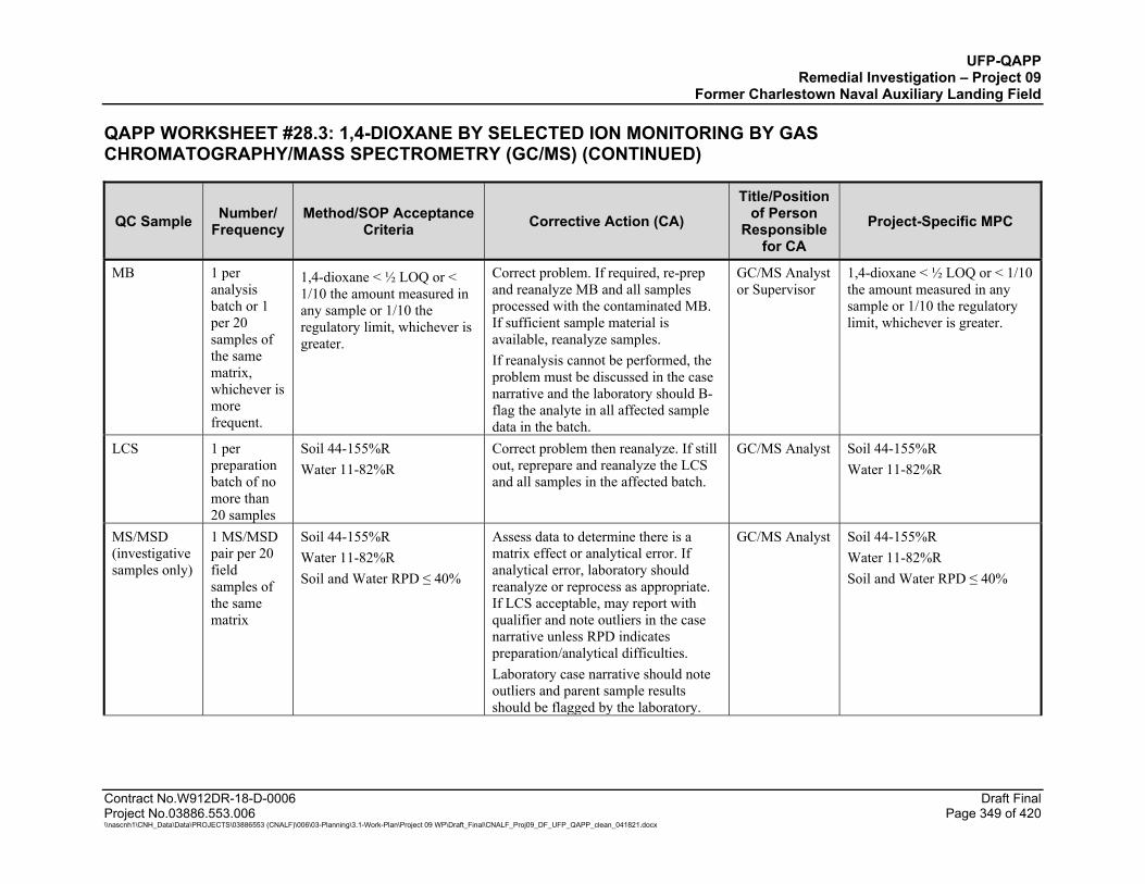
UFP-QAPP Remedial Investigation – Project 09
Former Charlestown Naval Auxiliary Landing Field
QAPP WORKSHEET #28.3: 1,4-DIOXANE BY SELECTED ION MONITORING BY GAS CHROMATOGRAPHY/MASS SPECTROMETRY (GC/MS) (CONTINUED)
Contract No.W912DR-18-D-0006 Draft Final Project No.03886.553.006 Page 349 of 420 \\nascnh1\CNH_Data\Data\PROJECTS\03886553 (CNALF)\006\03-Planning\3.1-Work-Plan\Project 09 WP\Draft_Final\CNALF_Proj09_DF_UFP_QAPP_clean_041821.docx
QC Sample Number/ Frequency
Method/SOP Acceptance Criteria Corrective Action (CA)
Title/Position of Person
Responsible for CA
Project-Specific MPC
MB 1 per analysis batch or 1 per 20 samples of the same matrix, whichever is more frequent.
1,4-dioxane < ½ LOQ or < 1/10 the amount measured in any sample or 1/10 the regulatory limit, whichever is greater.
Correct problem. If required, re-prep and reanalyze MB and all samples processed with the contaminated MB. If sufficient sample material is available, reanalyze samples. If reanalysis cannot be performed, the problem must be discussed in the case narrative and the laboratory should B-flag the analyte in all affected sample data in the batch.
GC/MS Analyst or Supervisor
1,4-dioxane < ½ LOQ or < 1/10 the amount measured in any sample or 1/10 the regulatory limit, whichever is greater.
LCS 1 per preparation batch of no more than 20 samples
Soil 44-155%R Water 11-82%R
Correct problem then reanalyze. If still out, reprepare and reanalyze the LCS and all samples in the affected batch.
GC/MS Analyst Soil 44-155%R Water 11-82%R
MS/MSD (investigative samples only)
1 MS/MSD pair per 20 field samples of the same matrix
Soil 44-155%R Water 11-82%R Soil and Water RPD ≤ 40%
Assess data to determine there is a matrix effect or analytical error. If analytical error, laboratory should reanalyze or reprocess as appropriate. If LCS acceptable, may report with qualifier and note outliers in the case narrative unless RPD indicates preparation/analytical difficulties. Laboratory case narrative should note outliers and parent sample results should be flagged by the laboratory.
GC/MS Analyst Soil 44-155%R Water 11-82%R Soil and Water RPD ≤ 40%
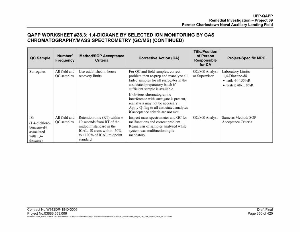
UFP-QAPP Remedial Investigation – Project 09
Former Charlestown Naval Auxiliary Landing Field
QAPP WORKSHEET #28.3: 1,4-DIOXANE BY SELECTED ION MONITORING BY GAS CHROMATOGRAPHY/MASS SPECTROMETRY (GC/MS) (CONTINUED)
Contract No.W912DR-18-D-0006 Draft Final Project No.03886.553.006 Page 350 of 420 \\nascnh1\CNH_Data\Data\PROJECTS\03886553 (CNALF)\006\03-Planning\3.1-Work-Plan\Project 09 WP\Draft_Final\CNALF_Proj09_DF_UFP_QAPP_clean_041821.docx
QC Sample Number/ Frequency
Method/SOP Acceptance Criteria Corrective Action (CA)
Title/Position of Person
Responsible for CA
Project-Specific MPC
Surrogates All field and QC samples
Use established in house recovery limits.
For QC and field samples, correct problem then re-prep and reanalyze all failed samples for all surrogates in the associated preparatory batch if sufficient sample is available. If obvious chromatographic interference with surrogate is present, reanalysis may not be necessary. Apply Q-flag to all associated analytes if acceptance criteria are not met.
GC/MS Analyst or Supervisor
Laboratory Limits 1,4-Dioxane-d8 soil: 44-155%R water: 48-118%R
ISs (1,4-dichloro-benzene-d4 associated with 1,4-dioxane)
All field and QC samples
Retention time (RT) within ± 10 seconds from RT of the midpoint standard in the ICAL; IS areas within -50% to +100% of ICAL midpoint standard.
Inspect mass spectrometer and GC for malfunctions and correct problem. Reanalysis of samples analyzed while system was malfunctioning is mandatory.
GC/MS Analyst Same as Method/ SOP Acceptance Criteria

UFP-QAPP Remedial Investigation – Project 09
Former Charlestown Naval Auxiliary Landing Field
Contract No.W912DR-18-D-0006 Draft Final Project No.03886.553.006 Page 351 of 420 \\nascnh1\CNH_Data\Data\PROJECTS\03886553 (CNALF)\006\03-Planning\3.1-Work-Plan\Project 09 WP\Draft_Final\CNALF_Proj09_DF_UFP_QAPP_clean_041821.docx
QAPP WORKSHEET #28.4: POLYAROMATIC HYDROCARBONS (PAHS) BY GAS CHROMATOGRAPHY/MASS SPECTROMETRY (GC/MS) SIM
Matrix: Soil, Sediment, and Water (tapwater, groundwater, surface/pore water, equipment blank) Laboratory: ALS - Kelso Analytical Group: PAHs (SIM) Analytical Method (Prep Method) / Analytical SOP (Prep SOP) Soil/Sediment: EPA 8270D SIM (3541) / SVM-8270S (EXT-3541) Analytical Method (Prep Method) / Analytical SOP (Prep SOP) Water: EPA 8270D SIM (3511) / SVM-8270S (EXT-3511)
QC Sample Number/ Frequency
Method/SOP Acceptance Criteria Corrective Action (CA)
Title/Position of Person
Responsible for CA
Project-Specific MPC
Field Duplicates (investigative samples only, not IDW)
1 per 10 samples
Not applicable Confirm identity of field duplicates and RPD calculation. Assess field records for evidence of sample non-homogeneity. Review sampling procedures.
Data Validator, Field Sampling Team, and Project Manager
Soil RPD ≤ 50% and water RPD ≤ 30% when detects for both field duplicate samples are ≥ 2x sample-specific LOQ; if one or both sample detections are < 2x LOQ, the data validation acceptance limit is ± 2x LOQ.
ISM Laboratory Replicates (soil/sediment ISM and Test Pit Soil composite samples)
Performed on one sample per batch. Cannot be performed on any sample designated as a QC sample.
RSD ≤ 30% when detects for samples are > LOQ.
Notify client and document in case narrative.
GC/MS Analyst or Supervisor
RSD ≤ 30% when detects for samples are > LOQ.
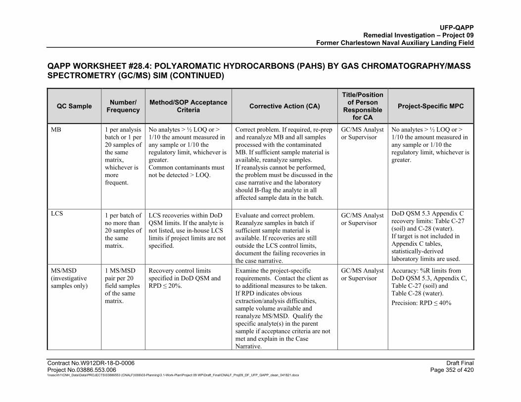
UFP-QAPP Remedial Investigation – Project 09
Former Charlestown Naval Auxiliary Landing Field
QAPP WORKSHEET #28.4: POLYAROMATIC HYDROCARBONS (PAHS) BY GAS CHROMATOGRAPHY/MASS SPECTROMETRY (GC/MS) SIM (CONTINUED)
Contract No.W912DR-18-D-0006 Draft Final Project No.03886.553.006 Page 352 of 420 \\nascnh1\CNH_Data\Data\PROJECTS\03886553 (CNALF)\006\03-Planning\3.1-Work-Plan\Project 09 WP\Draft_Final\CNALF_Proj09_DF_UFP_QAPP_clean_041821.docx
QC Sample Number/ Frequency
Method/SOP Acceptance Criteria Corrective Action (CA)
Title/Position of Person
Responsible for CA
Project-Specific MPC
MB 1 per analysis batch or 1 per 20 samples of the same matrix, whichever is more frequent.
No analytes > ½ LOQ or > 1/10 the amount measured in any sample or 1/10 the regulatory limit, whichever is greater. Common contaminants must not be detected > LOQ.
Correct problem. If required, re-prep and reanalyze MB and all samples processed with the contaminated MB. If sufficient sample material is available, reanalyze samples. If reanalysis cannot be performed, the problem must be discussed in the case narrative and the laboratory should B-flag the analyte in all affected sample data in the batch.
GC/MS Analyst or Supervisor
No analytes > ½ LOQ or > 1/10 the amount measured in any sample or 1/10 the regulatory limit, whichever is greater.
LCS 1 per batch of no more than 20 samples of the same matrix.
LCS recoveries within DoD QSM limits. If the analyte is not listed, use in-house LCS limits if project limits are not specified.
Evaluate and correct problem. Reanalyze samples in batch if sufficient sample material is available. If recoveries are still outside the LCS control limits, document the failing recoveries in the case narrative.
GC/MS Analyst or Supervisor
DoD QSM 5.3 Appendix C recovery limits: Table C-27 (soil) and C-28 (water). If target is not included in Appendix C tables, statistically-derived laboratory limits are used.
MS/MSD (investigative samples only)
1 MS/MSD pair per 20 field samples of the same matrix.
Recovery control limits specified in DoD QSM and RPD ≤ 20%.
Examine the project-specific requirements. Contact the client as to additional measures to be taken. If RPD indicates obvious extraction/analysis difficulties, sample volume available and reanalyze MS/MSD. Qualify the specific analyte(s) in the parent sample if acceptance criteria are not met and explain in the Case Narrative.
GC/MS Analyst or Supervisor
Accuracy: %R limits from DoD QSM 5.3, Appendix C, Table C-27 (soil) and Table C-28 (water). Precision: RPD ≤ 40%

UFP-QAPP Remedial Investigation – Project 09
Former Charlestown Naval Auxiliary Landing Field
QAPP WORKSHEET #28.4: POLYAROMATIC HYDROCARBONS (PAHS) BY GAS CHROMATOGRAPHY/MASS SPECTROMETRY (GC/MS) SIM (CONTINUED)
Contract No.W912DR-18-D-0006 Draft Final Project No.03886.553.006 Page 353 of 420 \\nascnh1\CNH_Data\Data\PROJECTS\03886553 (CNALF)\006\03-Planning\3.1-Work-Plan\Project 09 WP\Draft_Final\CNALF_Proj09_DF_UFP_QAPP_clean_041821.docx
QC Sample Number/ Frequency
Method/SOP Acceptance Criteria Corrective Action (CA)
Title/Position of Person
Responsible for CA
Project-Specific MPC
Surrogates All field and QC samples
Recovery control limits specified in the DoD QSM.
For QC and field samples, correct problem then re-prep and reanalyze all failed samples for all surrogates in the associated preparatory batch if sufficient sample is available. If obvious chromatographic interference with surrogate is present, reanalysis may not be necessary. Apply Q-flag to all associated analytes if acceptance criteria are not met.
GC/MS Analyst or Supervisor
DoD QSM 5.3 Recovery Limits Fluoranthene-d10: water: 50-150%R soil 50-150 %R
2-Methylnaphthalene-d10: water: 50-150%R soil: 50-150%R
Fluorene: water: 50-150 %R soil 50-150 %R
Terphenyl-d14: water: 58-132%R soil 50-150 %R
ISs All field and QC samples
Retention time (RT) within ± 10 seconds of RT of the midpoint standard in the ICAL; IS areas within -50% to +100% of ICAL midpoint standard.
Inspect GC/MS for malfunctions and correct problem. Reanalysis of samples analyzed while system was malfunctioning is mandatory.
GC/MS Analyst or Supervisor
Retention time (RT) within ± 10 seconds of RT of the midpoint standard in the ICAL; IS areas within -50% to +100% of ICAL midpoint standard.
Characteristic Ions for MS confirmation3
Minimum 3 ions
The relative intensities of the characteristic ions of target analytes agree within 30% of the relative intensities in the reference spectrum and the relative intensities must be > 0.
No data can be reported without MS confirmation. Internal standard and surrogates can use fewer than 3 ions.
GC/MS Analyst or Supervisor
The relative intensities of the characteristic ions of target analytes agree within 30% of the relative intensities in the reference spectrum and the relative intensities must be > 0.
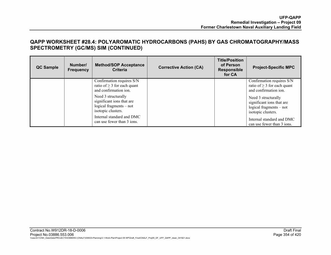
UFP-QAPP Remedial Investigation – Project 09
Former Charlestown Naval Auxiliary Landing Field
QAPP WORKSHEET #28.4: POLYAROMATIC HYDROCARBONS (PAHS) BY GAS CHROMATOGRAPHY/MASS SPECTROMETRY (GC/MS) SIM (CONTINUED)
Contract No.W912DR-18-D-0006 Draft Final Project No.03886.553.006 Page 354 of 420 \\nascnh1\CNH_Data\Data\PROJECTS\03886553 (CNALF)\006\03-Planning\3.1-Work-Plan\Project 09 WP\Draft_Final\CNALF_Proj09_DF_UFP_QAPP_clean_041821.docx
QC Sample Number/ Frequency
Method/SOP Acceptance Criteria Corrective Action (CA)
Title/Position of Person
Responsible for CA
Project-Specific MPC
Confirmation requires S/N ratio of ≥ 3 for each quant and confirmation ion. Need 3 structurally significant ions that are logical fragments – not isotopic clusters. Internal standard and DMC can use fewer than 3 ions.
Confirmation requires S/N ratio of ≥ 3 for each quant and confirmation ion.
Need 3 structurally significant ions that are logical fragments – not isotopic clusters.
Internal standard and DMC can use fewer than 3 ions.

UFP-QAPP Remedial Investigation – Project 09
Former Charlestown Naval Auxiliary Landing Field
Contract No.W912DR-18-D-0006 Draft Final Project No.03886.553.006 Page 355 of 420 \\nascnh1\CNH_Data\Data\PROJECTS\03886553 (CNALF)\006\03-Planning\3.1-Work-Plan\Project 09 WP\Draft_Final\CNALF_Proj09_DF_UFP_QAPP_clean_041821.docx
QAPP WORKSHEET #28.5: POLYCHLORINATED BIPHENYLS (PCBS) BY GC/ECD
Matrix: Soil and Water (tapwater, groundwater, equipment blanks), IDW (soil/water)Test Pit Waste Objects (Solid/Liquid) Laboratory: ALS - Kelso Analytical Group: PCBs Analytical Method (Prep Method) / Analytical SOP (Prep SOP) Soil: EPA 8082A (Soil 3541) / SOC-8082AR (EXT-3541) Analytical Method (Prep Method) / Analytical SOP (Prep SOP) Water: EPA 8082A (Water 3510C) / SOC-8082AR (EXT-3510)
QC Sample Number/ Frequency
Method/SOP Acceptance Criteria Corrective Action (CA)
Title/Position of Person
Responsible for CA
Project-Specific MPC
Field Duplicates (investigative samples only, and not Test Pit Waste Objects)
1 per 10 samples
Not applicable Confirm identity of field duplicates and RPD calculation. Assess field records for evidence of sample non-homogeneity. Review sampling procedures.
Data Validator, Field Sampling Team, and Project Manager
Soil RPD ≤ 50% and water RPD ≤ 30% when detects for both field duplicate samples are ≥ 2x sample-specific LOQ; if one or both sample detections are < 2x LOQ, the data validation acceptance limit is ± 2x LOQ.
ISM Laboratory Replicates (soil/sediment ISM and Test Pit Soil composite samples)
Performed on one sample per batch. Cannot be performed on any sample designated as a QC sample.
RSD ≤ 30% when detects for samples are > LOQ.
Notify client and document in case narrative.
GC/MS Analyst or Supervisor
RSD ≤ 20% when detects for samples are > LOQ.
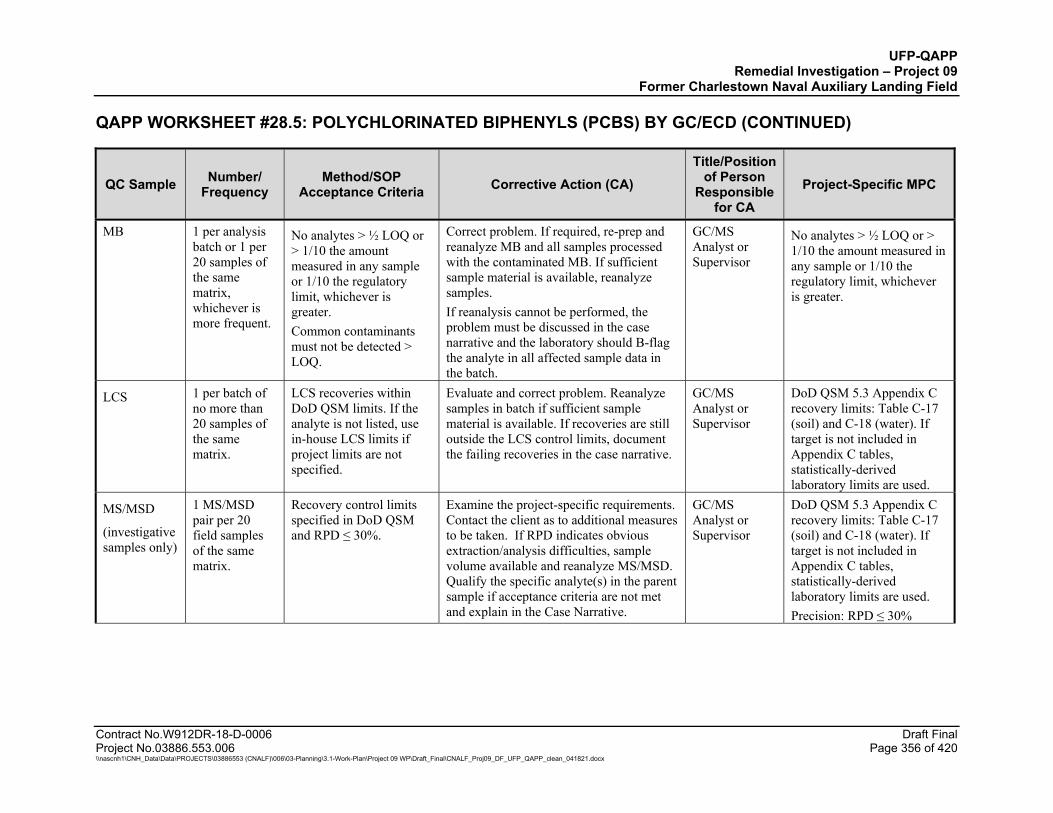
UFP-QAPP Remedial Investigation – Project 09
Former Charlestown Naval Auxiliary Landing Field
QAPP WORKSHEET #28.5: POLYCHLORINATED BIPHENYLS (PCBS) BY GC/ECD (CONTINUED)
Contract No.W912DR-18-D-0006 Draft Final Project No.03886.553.006 Page 356 of 420 \\nascnh1\CNH_Data\Data\PROJECTS\03886553 (CNALF)\006\03-Planning\3.1-Work-Plan\Project 09 WP\Draft_Final\CNALF_Proj09_DF_UFP_QAPP_clean_041821.docx
QC Sample Number/ Frequency
Method/SOP Acceptance Criteria Corrective Action (CA)
Title/Position of Person
Responsible for CA
Project-Specific MPC
MB 1 per analysis batch or 1 per 20 samples of the same matrix, whichever is more frequent.
No analytes > ½ LOQ or > 1/10 the amount measured in any sample or 1/10 the regulatory limit, whichever is greater. Common contaminants must not be detected > LOQ.
Correct problem. If required, re-prep and reanalyze MB and all samples processed with the contaminated MB. If sufficient sample material is available, reanalyze samples. If reanalysis cannot be performed, the problem must be discussed in the case narrative and the laboratory should B-flag the analyte in all affected sample data in the batch.
GC/MS Analyst or Supervisor
No analytes > ½ LOQ or > 1/10 the amount measured in any sample or 1/10 the regulatory limit, whichever is greater.
LCS 1 per batch of no more than 20 samples of the same matrix.
LCS recoveries within DoD QSM limits. If the analyte is not listed, use in-house LCS limits if project limits are not specified.
Evaluate and correct problem. Reanalyze samples in batch if sufficient sample material is available. If recoveries are still outside the LCS control limits, document the failing recoveries in the case narrative.
GC/MS Analyst or Supervisor
DoD QSM 5.3 Appendix C recovery limits: Table C-17 (soil) and C-18 (water). If target is not included in Appendix C tables, statistically-derived laboratory limits are used.
MS/MSD
(investigative samples only)
1 MS/MSD pair per 20 field samples of the same matrix.
Recovery control limits specified in DoD QSM and RPD ≤ 30%.
Examine the project-specific requirements. Contact the client as to additional measures to be taken. If RPD indicates obvious extraction/analysis difficulties, sample volume available and reanalyze MS/MSD. Qualify the specific analyte(s) in the parent sample if acceptance criteria are not met and explain in the Case Narrative.
GC/MS Analyst or Supervisor
DoD QSM 5.3 Appendix C recovery limits: Table C-17 (soil) and C-18 (water). If target is not included in Appendix C tables, statistically-derived laboratory limits are used. Precision: RPD ≤ 30%

UFP-QAPP Remedial Investigation – Project 09
Former Charlestown Naval Auxiliary Landing Field
QAPP WORKSHEET #28.5: POLYCHLORINATED BIPHENYLS (PCBS) BY GC/ECD (CONTINUED)
Contract No.W912DR-18-D-0006 Draft Final Project No.03886.553.006 Page 357 of 420 \\nascnh1\CNH_Data\Data\PROJECTS\03886553 (CNALF)\006\03-Planning\3.1-Work-Plan\Project 09 WP\Draft_Final\CNALF_Proj09_DF_UFP_QAPP_clean_041821.docx
QC Sample Number/ Frequency
Method/SOP Acceptance Criteria Corrective Action (CA)
Title/Position of Person
Responsible for CA
Project-Specific MPC
Surrogates All field and QC samples
Use established in house recovery limits.
For QC and field samples, correct problem then re-prep and reanalyze all failed samples for all surrogates in the associated preparatory batch if sufficient sample is available. If obvious chromatographic interference with surrogate is present, reanalysis may not be necessary. Apply Q-flag to all associated analytes if acceptance criteria are not met.
GC/MS Analyst or Supervisor
Laboratory Limits Tetrachloro-m-xylene: water: 21-114%R soil: 30-125%R
Decachlorobiphenyl: water: 36-113%R soil: 43-148%R
Confirmation of positive results (second column)
Every sample with reported detections >DL
Calibration and QC criteria for second column are the same as for initial or primary column analysis. Results between primary and secondary column RPD ≤ 40%.
Apply J-flag if RPD > 40%. Discuss in case narrative.
GC/MS Analyst or Supervisor
RPD > 40%
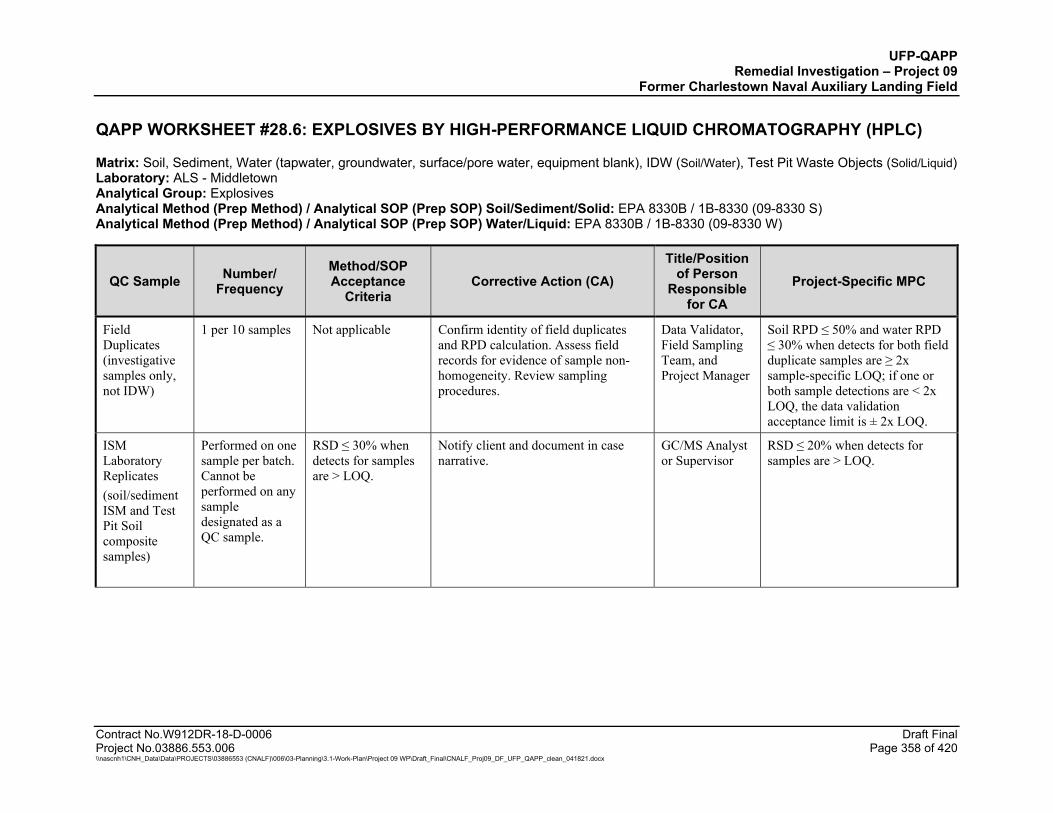
UFP-QAPP Remedial Investigation – Project 09
Former Charlestown Naval Auxiliary Landing Field
Contract No.W912DR-18-D-0006 Draft Final Project No.03886.553.006 Page 358 of 420 \\nascnh1\CNH_Data\Data\PROJECTS\03886553 (CNALF)\006\03-Planning\3.1-Work-Plan\Project 09 WP\Draft_Final\CNALF_Proj09_DF_UFP_QAPP_clean_041821.docx
QAPP WORKSHEET #28.6: EXPLOSIVES BY HIGH-PERFORMANCE LIQUID CHROMATOGRAPHY (HPLC)
Matrix: Soil, Sediment, Water (tapwater, groundwater, surface/pore water, equipment blank), IDW (Soil/Water), Test Pit Waste Objects (Solid/Liquid) Laboratory: ALS - Middletown Analytical Group: Explosives Analytical Method (Prep Method) / Analytical SOP (Prep SOP) Soil/Sediment/Solid: EPA 8330B / 1B-8330 (09-8330 S) Analytical Method (Prep Method) / Analytical SOP (Prep SOP) Water/Liquid: EPA 8330B / 1B-8330 (09-8330 W)
QC Sample Number/ Frequency
Method/SOP Acceptance
Criteria Corrective Action (CA)
Title/Position of Person
Responsible for CA
Project-Specific MPC
Field Duplicates (investigative samples only, not IDW)
1 per 10 samples Not applicable Confirm identity of field duplicates and RPD calculation. Assess field records for evidence of sample non-homogeneity. Review sampling procedures.
Data Validator, Field Sampling Team, and Project Manager
Soil RPD ≤ 50% and water RPD ≤ 30% when detects for both field duplicate samples are ≥ 2x sample-specific LOQ; if one or both sample detections are < 2x LOQ, the data validation acceptance limit is ± 2x LOQ.
ISM Laboratory Replicates (soil/sediment ISM and Test Pit Soil composite samples)
Performed on one sample per batch. Cannot be performed on any sample designated as a QC sample.
RSD ≤ 30% when detects for samples are > LOQ.
Notify client and document in case narrative.
GC/MS Analyst or Supervisor
RSD ≤ 20% when detects for samples are > LOQ.
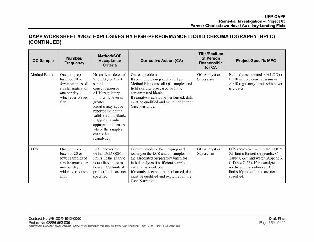
UFP-QAPP Remedial Investigation – Project 09
Former Charlestown Naval Auxiliary Landing Field
QAPP WORKSHEET #28.6: EXPLOSIVES BY HIGH-PERFORMANCE LIQUID CHROMATOGRAPHY (HPLC) (CONTINUED)
Contract No.W912DR-18-D-0006 Draft Final Project No.03886.553.006 Page 359 of 420 \\nascnh1\CNH_Data\Data\PROJECTS\03886553 (CNALF)\006\03-Planning\3.1-Work-Plan\Project 09 WP\Draft_Final\CNALF_Proj09_DF_UFP_QAPP_clean_041821.docx
QC Sample Number/ Frequency
Method/SOP Acceptance
Criteria Corrective Action (CA)
Title/Position of Person
Responsible for CA
Project-Specific MPC
Method Blank One per prep batch of 20 or fewer samples of similar matrix; or one per day, whichever comes first
No analytes detected > ½ LOQ or >1/10 sample concentration or >1/10 regulatory limit, whichever is greater. Results may not be reported without a valid Method Blank. Flagging is only appropriate in cases where the samples cannot be reanalyzed.
Correct problem. If required, re-prep and reanalyze Method Blank and all QC samples and field samples processed with the contaminated blank. If reanalysis cannot be performed, data must be qualified and explained in the Case Narrative.
GC Analyst or Supervisor
No analytes detected > ½ LOQ or >1/10 sample concentration or >1/10 regulatory limit, whichever is greater.
LCS One per prep batch of 20 or fewer samples of similar matrix; or one per day, whichever comes first.
LCS recoveries within DoD QSM limits. If the analyte is not listed, use in-house LCS limits if project limits are not specified.
Correct problem, then re-prep and reanalyze the LCS and all samples in the associated preparatory batch for failed analytes if sufficient sample material is available. If reanalysis cannot be performed, data must be qualified and explained in the Case Narrative.
GC Analyst or Supervisor
LCS recoveries within DoD QSM 5.3 limits for soil (Appendix C Table C-37) and water (Appendix C Table C-36). If the analyte is not listed, use in-house LCS limits if project limits are not specified.

UFP-QAPP Remedial Investigation – Project 09
Former Charlestown Naval Auxiliary Landing Field
QAPP WORKSHEET #28.6: EXPLOSIVES BY HIGH-PERFORMANCE LIQUID CHROMATOGRAPHY (HPLC) (CONTINUED)
Contract No.W912DR-18-D-0006 Draft Final Project No.03886.553.006 Page 360 of 420 \\nascnh1\CNH_Data\Data\PROJECTS\03886553 (CNALF)\006\03-Planning\3.1-Work-Plan\Project 09 WP\Draft_Final\CNALF_Proj09_DF_UFP_QAPP_clean_041821.docx
QC Sample Number/ Frequency
Method/SOP Acceptance
Criteria Corrective Action (CA)
Title/Position of Person
Responsible for CA
Project-Specific MPC
Surrogates Each field and QC sample
Recovery control limits specified in the DoD QSM 5.3.
Correct problem, then re-prep and reanalyze all failed samples for all surrogates in the associated preparatory batch if sufficient sample material is available and within holding time. If obvious chromatographic interference is present, reanalysis may not be necessary, but the failures must be discussed in the Case Narrative.
GC Analyst or Supervisor
Recovery control limits specified in the DoD QSM 5.3.
MS/MSD or Matrix Duplicate (MD) (investigative samples only)
One per prep batch of 20 or fewer samples of similar matrix; or one per day, whichever comes first
Recovery control limits specified in DoD QSM 5.3. Precision: MSD or MD: RPD of all analytes ≤ 20% (between MS and MSD or sample and MD).
Examine the project-specific requirements. Contact the client as to additional measures to be taken. If RPD indicates obvious extraction/analysis difficulties, sample volume available and reanalyze MS/MSD. Qualify the specific analyte(s) in the parent sample if acceptance criteria are not met and explain in the Case Narrative.
GC Analyst or Supervisor
Recovery control limits specified in DoD QSM 5.3 for soil (Appendix C Table C-37) and water (Appendix C Table C-36). Precision: ≤ 20%.
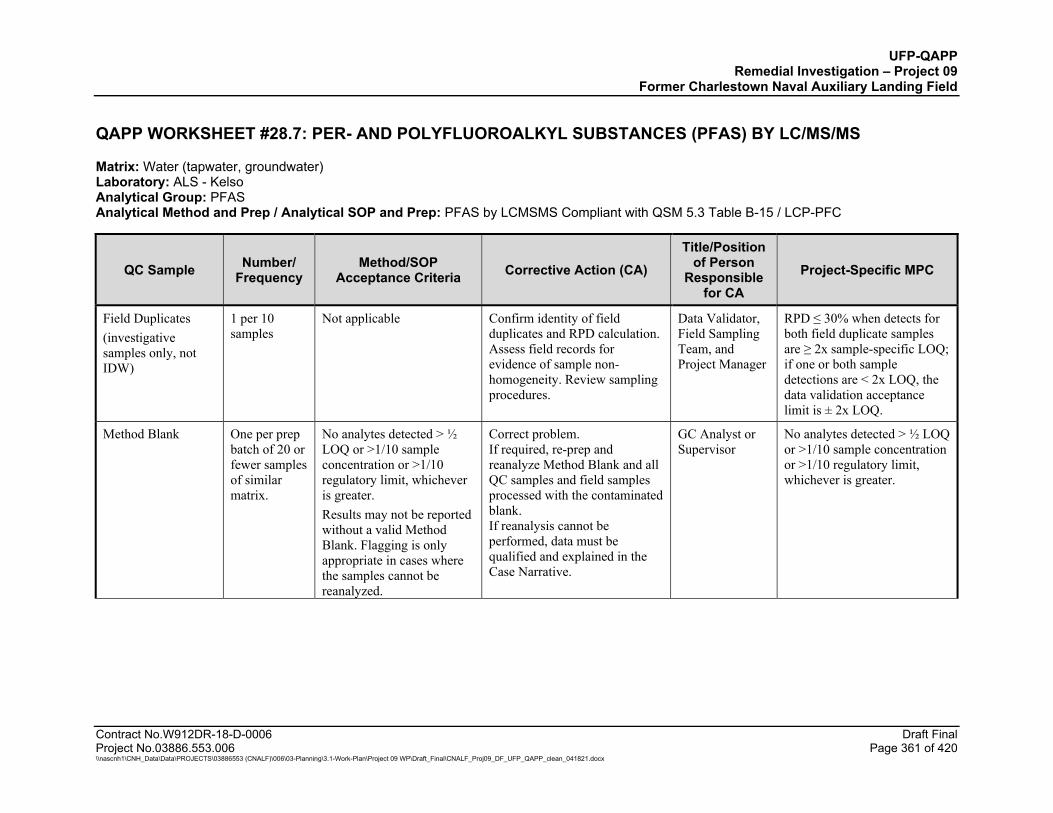
UFP-QAPP Remedial Investigation – Project 09
Former Charlestown Naval Auxiliary Landing Field
Contract No.W912DR-18-D-0006 Draft Final Project No.03886.553.006 Page 361 of 420 \\nascnh1\CNH_Data\Data\PROJECTS\03886553 (CNALF)\006\03-Planning\3.1-Work-Plan\Project 09 WP\Draft_Final\CNALF_Proj09_DF_UFP_QAPP_clean_041821.docx
QAPP WORKSHEET #28.7: PER- AND POLYFLUOROALKYL SUBSTANCES (PFAS) BY LC/MS/MS
Matrix: Water (tapwater, groundwater) Laboratory: ALS - Kelso Analytical Group: PFAS Analytical Method and Prep / Analytical SOP and Prep: PFAS by LCMSMS Compliant with QSM 5.3 Table B-15 / LCP-PFC
QC Sample Number/ Frequency
Method/SOP Acceptance Criteria Corrective Action (CA)
Title/Position of Person
Responsible for CA
Project-Specific MPC
Field Duplicates (investigative samples only, not IDW)
1 per 10 samples
Not applicable Confirm identity of field duplicates and RPD calculation. Assess field records for evidence of sample non-homogeneity. Review sampling procedures.
Data Validator, Field Sampling Team, and Project Manager
RPD ≤ 30% when detects for both field duplicate samples are ≥ 2x sample-specific LOQ; if one or both sample detections are < 2x LOQ, the data validation acceptance limit is ± 2x LOQ.
Method Blank One per prep batch of 20 or fewer samples of similar matrix.
No analytes detected > ½ LOQ or >1/10 sample concentration or >1/10 regulatory limit, whichever is greater. Results may not be reported without a valid Method Blank. Flagging is only appropriate in cases where the samples cannot be reanalyzed.
Correct problem. If required, re-prep and reanalyze Method Blank and all QC samples and field samples processed with the contaminated blank. If reanalysis cannot be performed, data must be qualified and explained in the Case Narrative.
GC Analyst or Supervisor
No analytes detected > ½ LOQ or >1/10 sample concentration or >1/10 regulatory limit, whichever is greater.
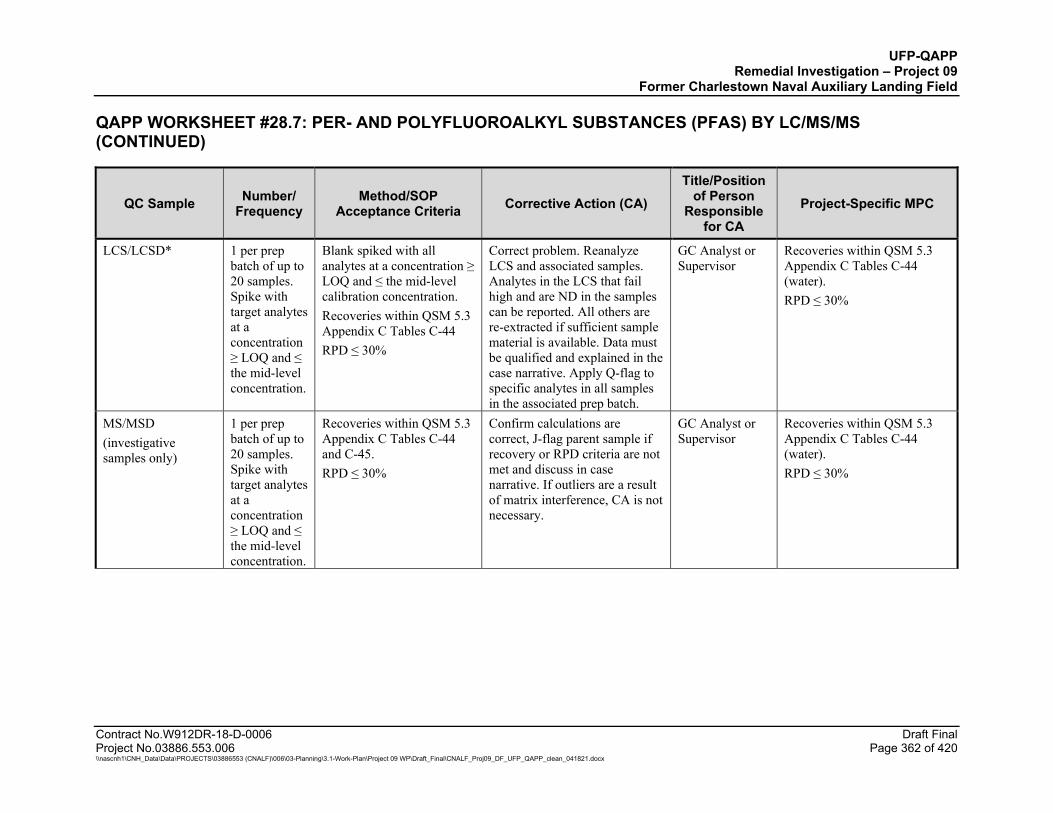
UFP-QAPP Remedial Investigation – Project 09
Former Charlestown Naval Auxiliary Landing Field
QAPP WORKSHEET #28.7: PER- AND POLYFLUOROALKYL SUBSTANCES (PFAS) BY LC/MS/MS (CONTINUED)
Contract No.W912DR-18-D-0006 Draft Final Project No.03886.553.006 Page 362 of 420 \\nascnh1\CNH_Data\Data\PROJECTS\03886553 (CNALF)\006\03-Planning\3.1-Work-Plan\Project 09 WP\Draft_Final\CNALF_Proj09_DF_UFP_QAPP_clean_041821.docx
QC Sample Number/ Frequency
Method/SOP Acceptance Criteria Corrective Action (CA)
Title/Position of Person
Responsible for CA
Project-Specific MPC
LCS/LCSD* 1 per prep batch of up to 20 samples. Spike with target analytes at a concentration ≥ LOQ and ≤ the mid-level concentration.
Blank spiked with all analytes at a concentration ≥ LOQ and ≤ the mid-level calibration concentration. Recoveries within QSM 5.3 Appendix C Tables C-44 RPD ≤ 30%
Correct problem. Reanalyze LCS and associated samples. Analytes in the LCS that fail high and are ND in the samples can be reported. All others are re-extracted if sufficient sample material is available. Data must be qualified and explained in the case narrative. Apply Q-flag to specific analytes in all samples in the associated prep batch.
GC Analyst or Supervisor
Recoveries within QSM 5.3 Appendix C Tables C-44 (water). RPD ≤ 30%
MS/MSD (investigative samples only)
1 per prep batch of up to 20 samples. Spike with target analytes at a concentration ≥ LOQ and ≤ the mid-level concentration.
Recoveries within QSM 5.3 Appendix C Tables C-44 and C-45. RPD ≤ 30%
Confirm calculations are correct, J-flag parent sample if recovery or RPD criteria are not met and discuss in case narrative. If outliers are a result of matrix interference, CA is not necessary.
GC Analyst or Supervisor
Recoveries within QSM 5.3 Appendix C Tables C-44 (water). RPD ≤ 30%
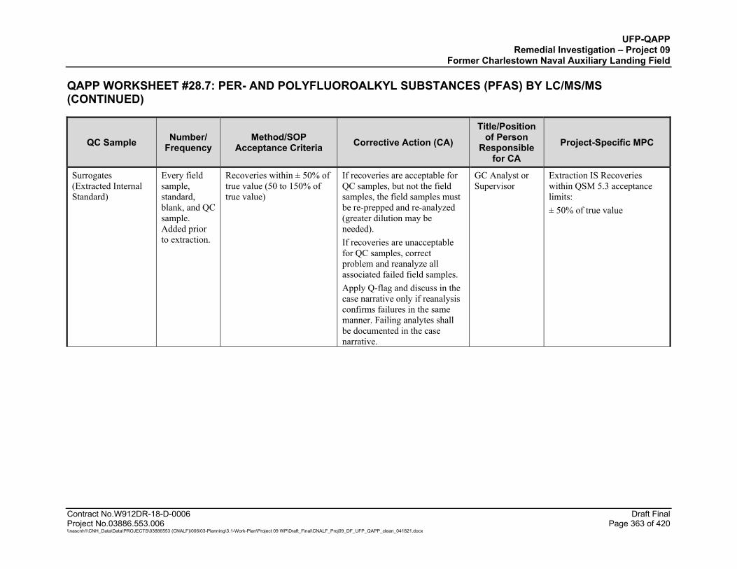
UFP-QAPP Remedial Investigation – Project 09
Former Charlestown Naval Auxiliary Landing Field
QAPP WORKSHEET #28.7: PER- AND POLYFLUOROALKYL SUBSTANCES (PFAS) BY LC/MS/MS (CONTINUED)
Contract No.W912DR-18-D-0006 Draft Final Project No.03886.553.006 Page 363 of 420 \\nascnh1\CNH_Data\Data\PROJECTS\03886553 (CNALF)\006\03-Planning\3.1-Work-Plan\Project 09 WP\Draft_Final\CNALF_Proj09_DF_UFP_QAPP_clean_041821.docx
QC Sample Number/ Frequency
Method/SOP Acceptance Criteria Corrective Action (CA)
Title/Position of Person
Responsible for CA
Project-Specific MPC
Surrogates (Extracted Internal Standard)
Every field sample, standard, blank, and QC sample. Added prior to extraction.
Recoveries within ± 50% of true value (50 to 150% of true value)
If recoveries are acceptable for QC samples, but not the field samples, the field samples must be re-prepped and re-analyzed (greater dilution may be needed). If recoveries are unacceptable for QC samples, correct problem and reanalyze all associated failed field samples. Apply Q-flag and discuss in the case narrative only if reanalysis confirms failures in the same manner. Failing analytes shall be documented in the case narrative.
GC Analyst or Supervisor
Extraction IS Recoveries within QSM 5.3 acceptance limits: ± 50% of true value
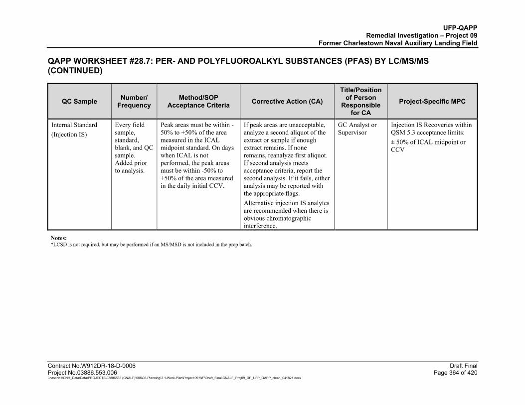
UFP-QAPP Remedial Investigation – Project 09
Former Charlestown Naval Auxiliary Landing Field
QAPP WORKSHEET #28.7: PER- AND POLYFLUOROALKYL SUBSTANCES (PFAS) BY LC/MS/MS (CONTINUED)
Contract No.W912DR-18-D-0006 Draft Final Project No.03886.553.006 Page 364 of 420 \\nascnh1\CNH_Data\Data\PROJECTS\03886553 (CNALF)\006\03-Planning\3.1-Work-Plan\Project 09 WP\Draft_Final\CNALF_Proj09_DF_UFP_QAPP_clean_041821.docx
QC Sample Number/ Frequency
Method/SOP Acceptance Criteria Corrective Action (CA)
Title/Position of Person
Responsible for CA
Project-Specific MPC
Internal Standard (Injection IS)
Every field sample, standard, blank, and QC sample. Added prior to analysis.
Peak areas must be within -50% to +50% of the area measured in the ICAL midpoint standard. On days when ICAL is not performed, the peak areas must be within -50% to +50% of the area measured in the daily initial CCV.
If peak areas are unacceptable, analyze a second aliquot of the extract or sample if enough extract remains. If none remains, reanalyze first aliquot. If second analysis meets acceptance criteria, report the second analysis. If it fails, either analysis may be reported with the appropriate flags. Alternative injection IS analytes are recommended when there is obvious chromatographic interference.
GC Analyst or Supervisor
Injection IS Recoveries within QSM 5.3 acceptance limits: ± 50% of ICAL midpoint or CCV
Notes: *LCSD is not required, but may be performed if an MS/MSD is not included in the prep batch.
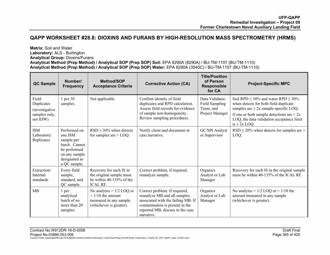
UFP-QAPP Remedial Investigation – Project 09
Former Charlestown Naval Auxiliary Landing Field
Contract No.W912DR-18-D-0006 Draft Final Project No.03886.553.006 Page 365 of 420 \\nascnh1\CNH_Data\Data\PROJECTS\03886553 (CNALF)\006\03-Planning\3.1-Work-Plan\Project 09 WP\Draft_Final\CNALF_Proj09_DF_UFP_QAPP_clean_041821.docx
QAPP WORKSHEET #28.8: DIOXINS AND FURANS BY HIGH-RESOLUTION MASS SPECTROMETRY (HRMS)
Matrix: Soil and Water Laboratory: ALS - Burlington Analytical Group: Dioxins/Furans Analytical Method (Prep Method) / Analytical SOP (Prep SOP) Soil: EPA 8290A (8290A) / BU-TM-1107 (BU-TM-1110) Analytical Method (Prep Method) / Analytical SOP (Prep SOP) Water: EPA 8290A (3540C) / BU-TM-1107 (BU-TM-1110)
QC Sample Number/ Frequency
Method/SOP Acceptance Criteria Corrective Action (CA)
Title/Position of Person
Responsible for CA
Project-Specific MPC
Field Duplicates (investigative samples only, not IDW)
1 per 10 samples.
Not applicable Confirm identity of field duplicates and RPD calculation. Assess field records for evidence of sample non-homogeneity. Review sampling procedures.
Data Validator, Field Sampling Team, and Project Manager
Soil RPD ≤ 50% and water RPD ≤ 30% when detects for both field duplicate samples are ≥ 2x sample-specific LOQ; if one or both sample detections are < 2x LOQ, the data validation acceptance limit is ± 2x LOQ.
ISM Laboratory Replicates
Performed on one ISM sample per batch. Cannot be performed on any sample designated as a QC sample.
RSD ≤ 30% when detects for samples are > LOQ.
Notify client and document in case narrative.
GC/MS Analyst or Supervisor
RSD ≤ 20% when detects for samples are > LOQ.
Extraction/ Internal standards
Every field sample, standard, and QC sample.
Recovery for each IS in the original sample must be within 40-135% of the ICAL RF.
Correct problem, if required, reanalyze sample.
Organics Analyst or Lab Manager
Recovery for each IS in the original sample must be within 40-135% of the ICAL RF.
MB 1 per analytical batch of no more than 20 samples.
No analytes > 1/2 LOQ or > 1/10 the amount measured in any sample (whichever is greater).
Correct problem. If required, reanalyze MB and all samples associated with the failing MB. If contamination is present in the reported MB, discuss in the case narrative.
Organics Analyst or Lab Manager
No analytes > 1/2 LOQ or > 1/10 the amount measured in any sample (whichever is greater).
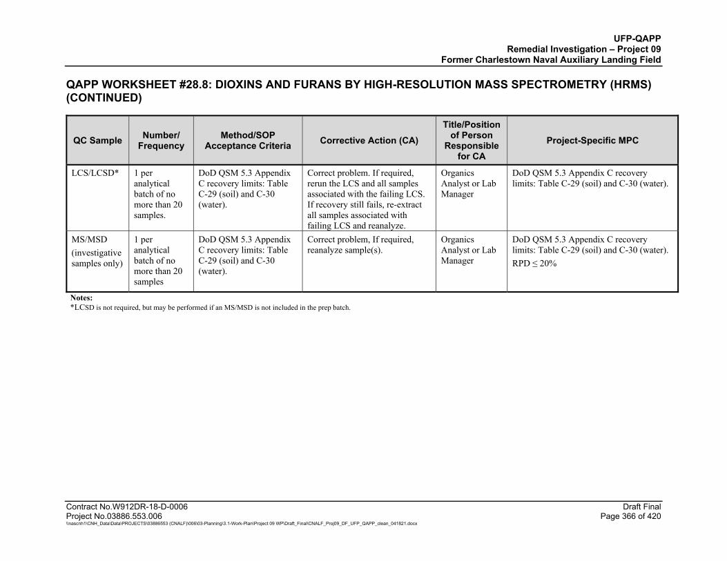
UFP-QAPP Remedial Investigation – Project 09
Former Charlestown Naval Auxiliary Landing Field
QAPP WORKSHEET #28.8: DIOXINS AND FURANS BY HIGH-RESOLUTION MASS SPECTROMETRY (HRMS) (CONTINUED)
Contract No.W912DR-18-D-0006 Draft Final Project No.03886.553.006 Page 366 of 420 \\nascnh1\CNH_Data\Data\PROJECTS\03886553 (CNALF)\006\03-Planning\3.1-Work-Plan\Project 09 WP\Draft_Final\CNALF_Proj09_DF_UFP_QAPP_clean_041821.docx
QC Sample Number/ Frequency
Method/SOP Acceptance Criteria Corrective Action (CA)
Title/Position of Person
Responsible for CA
Project-Specific MPC
LCS/LCSD* 1 per analytical batch of no more than 20 samples.
DoD QSM 5.3 Appendix C recovery limits: Table C-29 (soil) and C-30 (water).
Correct problem. If required, rerun the LCS and all samples associated with the failing LCS. If recovery still fails, re-extract all samples associated with failing LCS and reanalyze.
Organics Analyst or Lab Manager
DoD QSM 5.3 Appendix C recovery limits: Table C-29 (soil) and C-30 (water).
MS/MSD (investigative samples only)
1 per analytical batch of no more than 20 samples
DoD QSM 5.3 Appendix C recovery limits: Table C-29 (soil) and C-30 (water).
Correct problem, If required, reanalyze sample(s).
Organics Analyst or Lab Manager
DoD QSM 5.3 Appendix C recovery limits: Table C-29 (soil) and C-30 (water). RPD ≤ 20%
Notes: *LCSD is not required, but may be performed if an MS/MSD is not included in the prep batch.
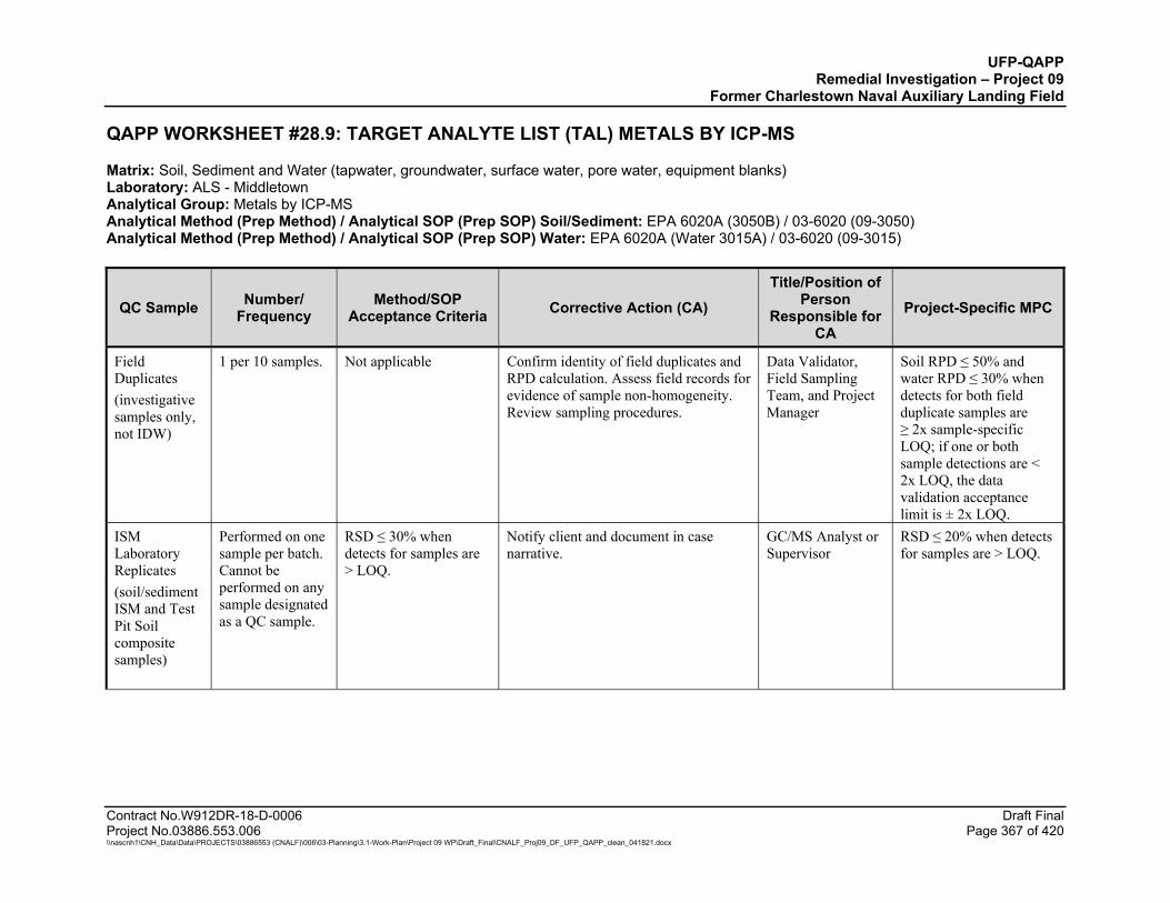
UFP-QAPP Remedial Investigation – Project 09
Former Charlestown Naval Auxiliary Landing Field
Contract No.W912DR-18-D-0006 Draft Final Project No.03886.553.006 Page 367 of 420 \\nascnh1\CNH_Data\Data\PROJECTS\03886553 (CNALF)\006\03-Planning\3.1-Work-Plan\Project 09 WP\Draft_Final\CNALF_Proj09_DF_UFP_QAPP_clean_041821.docx
QAPP WORKSHEET #28.9: TARGET ANALYTE LIST (TAL) METALS BY ICP-MS
Matrix: Soil, Sediment and Water (tapwater, groundwater, surface water, pore water, equipment blanks) Laboratory: ALS - Middletown Analytical Group: Metals by ICP-MS Analytical Method (Prep Method) / Analytical SOP (Prep SOP) Soil/Sediment: EPA 6020A (3050B) / 03-6020 (09-3050) Analytical Method (Prep Method) / Analytical SOP (Prep SOP) Water: EPA 6020A (Water 3015A) / 03-6020 (09-3015)
QC Sample Number/ Frequency
Method/SOP Acceptance Criteria Corrective Action (CA)
Title/Position of Person
Responsible for CA
Project-Specific MPC
Field Duplicates (investigative samples only, not IDW)
1 per 10 samples. Not applicable Confirm identity of field duplicates and RPD calculation. Assess field records for evidence of sample non-homogeneity. Review sampling procedures.
Data Validator, Field Sampling Team, and Project Manager
Soil RPD ≤ 50% and water RPD ≤ 30% when detects for both field duplicate samples are ≥ 2x sample-specific LOQ; if one or both sample detections are < 2x LOQ, the data validation acceptance limit is ± 2x LOQ.
ISM Laboratory Replicates (soil/sediment ISM and Test Pit Soil composite samples)
Performed on one sample per batch. Cannot be performed on any sample designated as a QC sample.
RSD ≤ 30% when detects for samples are > LOQ.
Notify client and document in case narrative.
GC/MS Analyst or Supervisor
RSD ≤ 20% when detects for samples are > LOQ.
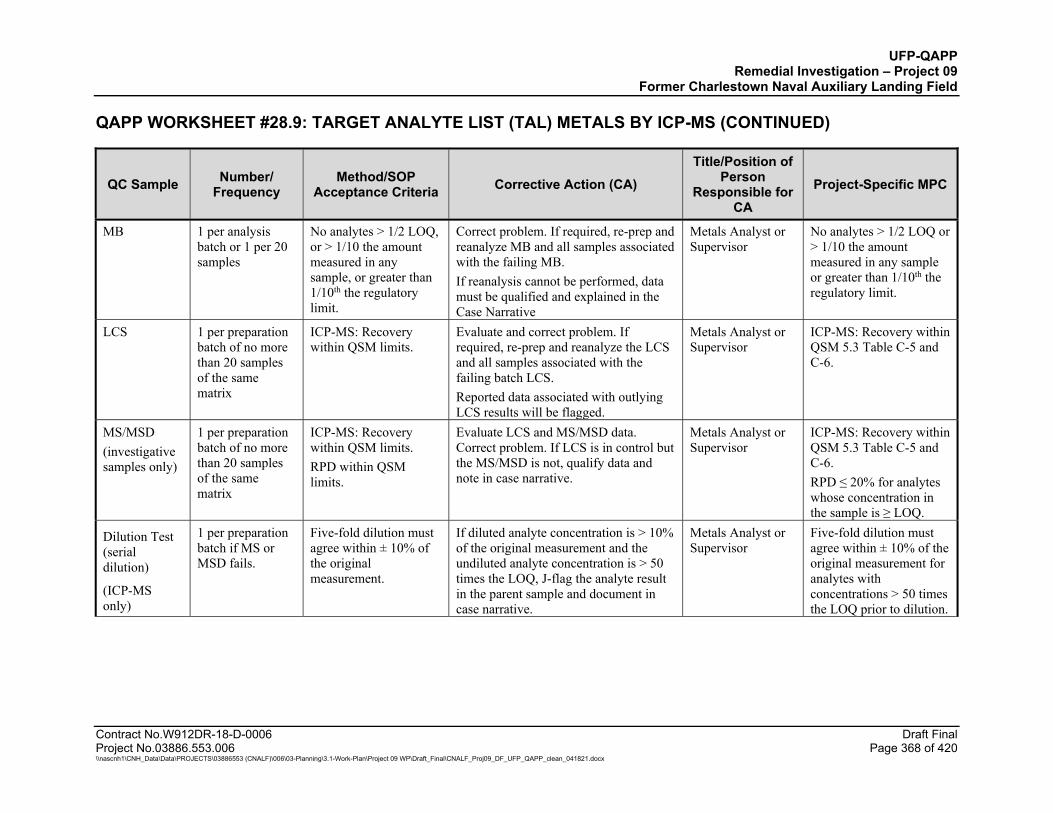
UFP-QAPP Remedial Investigation – Project 09
Former Charlestown Naval Auxiliary Landing Field
QAPP WORKSHEET #28.9: TARGET ANALYTE LIST (TAL) METALS BY ICP-MS (CONTINUED)
Contract No.W912DR-18-D-0006 Draft Final Project No.03886.553.006 Page 368 of 420 \\nascnh1\CNH_Data\Data\PROJECTS\03886553 (CNALF)\006\03-Planning\3.1-Work-Plan\Project 09 WP\Draft_Final\CNALF_Proj09_DF_UFP_QAPP_clean_041821.docx
QC Sample Number/ Frequency
Method/SOP Acceptance Criteria Corrective Action (CA)
Title/Position of Person
Responsible for CA
Project-Specific MPC
MB 1 per analysis batch or 1 per 20 samples
No analytes > 1/2 LOQ, or > 1/10 the amount measured in any sample, or greater than 1/10th the regulatory limit.
Correct problem. If required, re-prep and reanalyze MB and all samples associated with the failing MB. If reanalysis cannot be performed, data must be qualified and explained in the Case Narrative
Metals Analyst or Supervisor
No analytes > 1/2 LOQ or > 1/10 the amount measured in any sample or greater than 1/10th the regulatory limit.
LCS 1 per preparation batch of no more than 20 samples of the same matrix
ICP-MS: Recovery within QSM limits.
Evaluate and correct problem. If required, re-prep and reanalyze the LCS and all samples associated with the failing batch LCS. Reported data associated with outlying LCS results will be flagged.
Metals Analyst or Supervisor
ICP-MS: Recovery within QSM 5.3 Table C-5 and C-6.
MS/MSD (investigative samples only)
1 per preparation batch of no more than 20 samples of the same matrix
ICP-MS: Recovery within QSM limits. RPD within QSM limits.
Evaluate LCS and MS/MSD data. Correct problem. If LCS is in control but the MS/MSD is not, qualify data and note in case narrative.
Metals Analyst or Supervisor
ICP-MS: Recovery within QSM 5.3 Table C-5 and C-6. RPD ≤ 20% for analytes whose concentration in the sample is ≥ LOQ.
Dilution Test (serial dilution)
(ICP-MS only)
1 per preparation batch if MS or MSD fails.
Five-fold dilution must agree within ± 10% of the original measurement.
If diluted analyte concentration is > 10% of the original measurement and the undiluted analyte concentration is > 50 times the LOQ, J-flag the analyte result in the parent sample and document in case narrative.
Metals Analyst or Supervisor
Five-fold dilution must agree within ± 10% of the original measurement for analytes with concentrations > 50 times the LOQ prior to dilution.

UFP-QAPP Remedial Investigation – Project 09
Former Charlestown Naval Auxiliary Landing Field
QAPP WORKSHEET #28.9: TARGET ANALYTE LIST (TAL) METALS BY ICP-MS (CONTINUED)
Contract No.W912DR-18-D-0006 Draft Final Project No.03886.553.006 Page 369 of 420 \\nascnh1\CNH_Data\Data\PROJECTS\03886553 (CNALF)\006\03-Planning\3.1-Work-Plan\Project 09 WP\Draft_Final\CNALF_Proj09_DF_UFP_QAPP_clean_041821.docx
QC Sample Number/ Frequency
Method/SOP Acceptance Criteria Corrective Action (CA)
Title/Position of Person
Responsible for CA
Project-Specific MPC
Post-Digestion Spike (PDS) addition
(ICP-MS only)
1 per preparation batch if MS or MSD fails (using same sample as used for the MS/MSD if possible).
PDS recovery within 80-120%R.
For the specific analyte(s) in the parent sample, apply J-flag if acceptance criteria are not met. Explain in case narrative.
Metals Analyst or Supervisor
Recovery within 80-120%R for analytes with concentrations > 50 times the LOQ prior to dilution.
Internal Standard (IS)
(ICP-MS only)
Every field sample and QC sample.
IS intensity in the samples within 30-120% of the intensity of the IS in the ICAL blank.
If recoveries are acceptable for QC samples, but not field samples, the field samples may be considered to suffer from a matrix effect. Reanalyze sample at five-fold dilutions until criteria is met. For failed QC samples, correct problem and rerun all associated failed field samples.
Metals Analyst or Supervisor
IS intensity in the samples within 30-120% of the intensity of the IS in the ICAL blank.
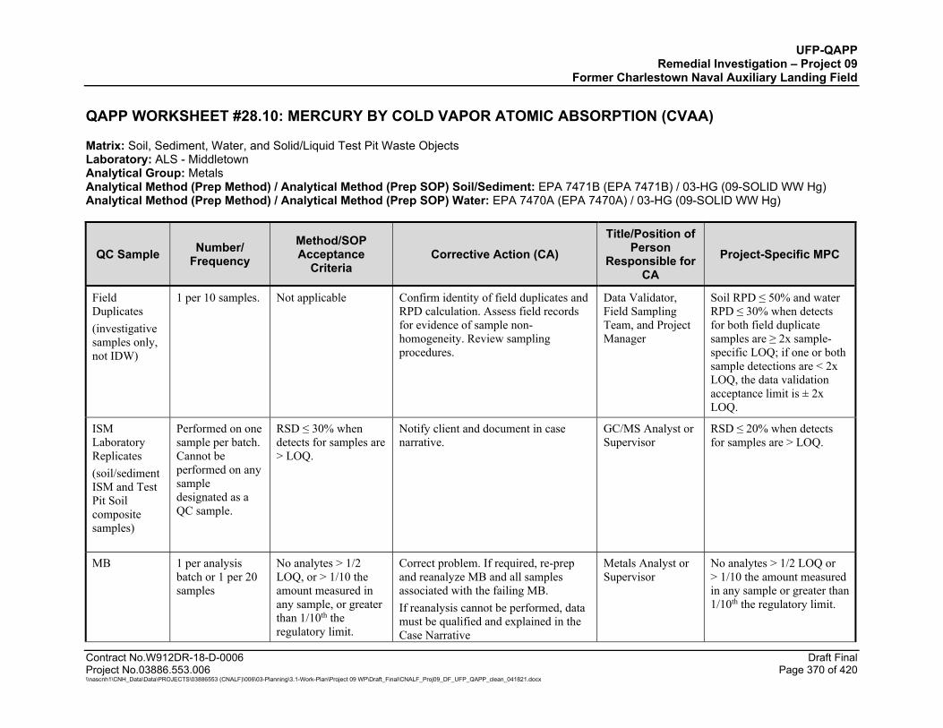
UFP-QAPP Remedial Investigation – Project 09
Former Charlestown Naval Auxiliary Landing Field
Contract No.W912DR-18-D-0006 Draft Final Project No.03886.553.006 Page 370 of 420 \\nascnh1\CNH_Data\Data\PROJECTS\03886553 (CNALF)\006\03-Planning\3.1-Work-Plan\Project 09 WP\Draft_Final\CNALF_Proj09_DF_UFP_QAPP_clean_041821.docx
QAPP WORKSHEET #28.10: MERCURY BY COLD VAPOR ATOMIC ABSORPTION (CVAA)
Matrix: Soil, Sediment, Water, and Solid/Liquid Test Pit Waste Objects Laboratory: ALS - Middletown Analytical Group: Metals Analytical Method (Prep Method) / Analytical Method (Prep SOP) Soil/Sediment: EPA 7471B (EPA 7471B) / 03-HG (09-SOLID WW Hg) Analytical Method (Prep Method) / Analytical Method (Prep SOP) Water: EPA 7470A (EPA 7470A) / 03-HG (09-SOLID WW Hg)
QC Sample Number/ Frequency
Method/SOP Acceptance
Criteria Corrective Action (CA)
Title/Position of Person
Responsible for CA
Project-Specific MPC
Field Duplicates (investigative samples only, not IDW)
1 per 10 samples. Not applicable Confirm identity of field duplicates and RPD calculation. Assess field records for evidence of sample non-homogeneity. Review sampling procedures.
Data Validator, Field Sampling Team, and Project Manager
Soil RPD ≤ 50% and water RPD ≤ 30% when detects for both field duplicate samples are ≥ 2x sample-specific LOQ; if one or both sample detections are < 2x LOQ, the data validation acceptance limit is ± 2x LOQ.
ISM Laboratory Replicates (soil/sediment ISM and Test Pit Soil composite samples)
Performed on one sample per batch. Cannot be performed on any sample designated as a QC sample.
RSD ≤ 30% when detects for samples are > LOQ.
Notify client and document in case narrative.
GC/MS Analyst or Supervisor
RSD ≤ 20% when detects for samples are > LOQ.
MB 1 per analysis batch or 1 per 20 samples
No analytes > 1/2 LOQ, or > 1/10 the amount measured in any sample, or greater than 1/10th the regulatory limit.
Correct problem. If required, re-prep and reanalyze MB and all samples associated with the failing MB. If reanalysis cannot be performed, data must be qualified and explained in the Case Narrative
Metals Analyst or Supervisor
No analytes > 1/2 LOQ or > 1/10 the amount measured in any sample or greater than 1/10th the regulatory limit.
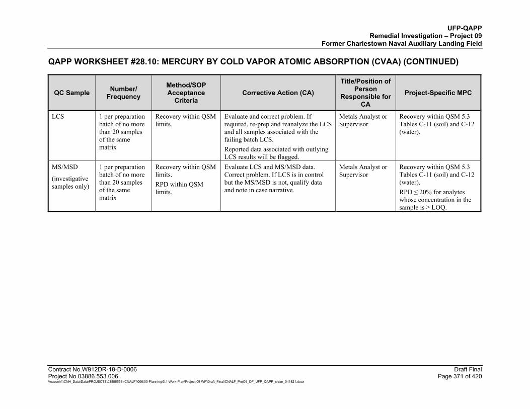
UFP-QAPP Remedial Investigation – Project 09
Former Charlestown Naval Auxiliary Landing Field
QAPP WORKSHEET #28.10: MERCURY BY COLD VAPOR ATOMIC ABSORPTION (CVAA) (CONTINUED)
Contract No.W912DR-18-D-0006 Draft Final Project No.03886.553.006 Page 371 of 420 \\nascnh1\CNH_Data\Data\PROJECTS\03886553 (CNALF)\006\03-Planning\3.1-Work-Plan\Project 09 WP\Draft_Final\CNALF_Proj09_DF_UFP_QAPP_clean_041821.docx
QC Sample Number/ Frequency
Method/SOP Acceptance
Criteria Corrective Action (CA)
Title/Position of Person
Responsible for CA
Project-Specific MPC
LCS 1 per preparation batch of no more than 20 samples of the same matrix
Recovery within QSM limits.
Evaluate and correct problem. If required, re-prep and reanalyze the LCS and all samples associated with the failing batch LCS. Reported data associated with outlying LCS results will be flagged.
Metals Analyst or Supervisor
Recovery within QSM 5.3 Tables C-11 (soil) and C-12 (water).
MS/MSD
(investigative samples only)
1 per preparation batch of no more than 20 samples of the same matrix
Recovery within QSM limits. RPD within QSM limits.
Evaluate LCS and MS/MSD data. Correct problem. If LCS is in control but the MS/MSD is not, qualify data and note in case narrative.
Metals Analyst or Supervisor
Recovery within QSM 5.3 Tables C-11 (soil) and C-12 (water). RPD ≤ 20% for analytes whose concentration in the sample is ≥ LOQ.
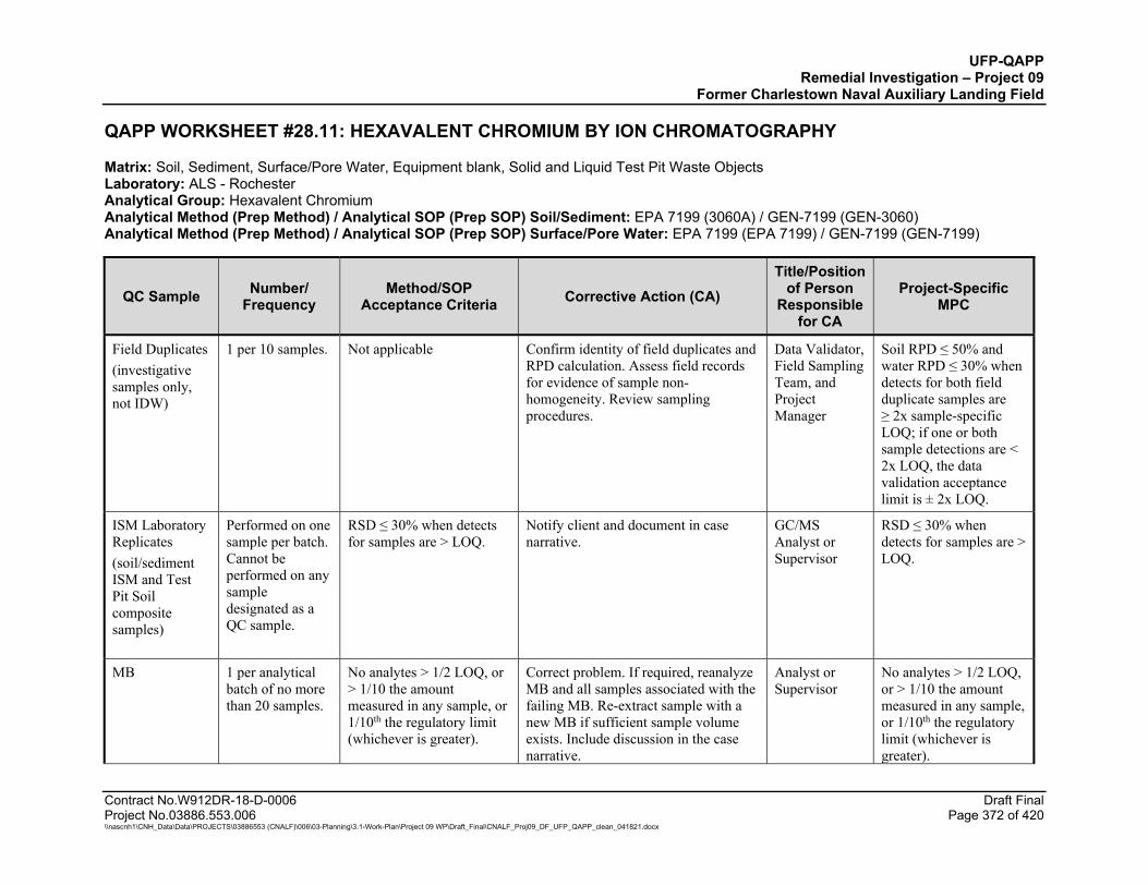
UFP-QAPP Remedial Investigation – Project 09
Former Charlestown Naval Auxiliary Landing Field
Contract No.W912DR-18-D-0006 Draft Final Project No.03886.553.006 Page 372 of 420 \\nascnh1\CNH_Data\Data\PROJECTS\03886553 (CNALF)\006\03-Planning\3.1-Work-Plan\Project 09 WP\Draft_Final\CNALF_Proj09_DF_UFP_QAPP_clean_041821.docx
QAPP WORKSHEET #28.11: HEXAVALENT CHROMIUM BY ION CHROMATOGRAPHY
Matrix: Soil, Sediment, Surface/Pore Water, Equipment blank, Solid and Liquid Test Pit Waste Objects Laboratory: ALS - Rochester Analytical Group: Hexavalent Chromium Analytical Method (Prep Method) / Analytical SOP (Prep SOP) Soil/Sediment: EPA 7199 (3060A) / GEN-7199 (GEN-3060) Analytical Method (Prep Method) / Analytical SOP (Prep SOP) Surface/Pore Water: EPA 7199 (EPA 7199) / GEN-7199 (GEN-7199)
QC Sample Number/ Frequency
Method/SOP Acceptance Criteria Corrective Action (CA)
Title/Position of Person
Responsible for CA
Project-Specific MPC
Field Duplicates (investigative samples only, not IDW)
1 per 10 samples. Not applicable Confirm identity of field duplicates and RPD calculation. Assess field records for evidence of sample non-homogeneity. Review sampling procedures.
Data Validator, Field Sampling Team, and Project Manager
Soil RPD ≤ 50% and water RPD ≤ 30% when detects for both field duplicate samples are ≥ 2x sample-specific LOQ; if one or both sample detections are < 2x LOQ, the data validation acceptance limit is ± 2x LOQ.
ISM Laboratory Replicates (soil/sediment ISM and Test Pit Soil composite samples)
Performed on one sample per batch. Cannot be performed on any sample designated as a QC sample.
RSD ≤ 30% when detects for samples are > LOQ.
Notify client and document in case narrative.
GC/MS Analyst or Supervisor
RSD ≤ 30% when detects for samples are > LOQ.
MB 1 per analytical batch of no more than 20 samples.
No analytes > 1/2 LOQ, or > 1/10 the amount measured in any sample, or 1/10th the regulatory limit (whichever is greater).
Correct problem. If required, reanalyze MB and all samples associated with the failing MB. Re-extract sample with a new MB if sufficient sample volume exists. Include discussion in the case narrative.
Analyst or Supervisor
No analytes > 1/2 LOQ, or > 1/10 the amount measured in any sample, or 1/10th the regulatory limit (whichever is greater).
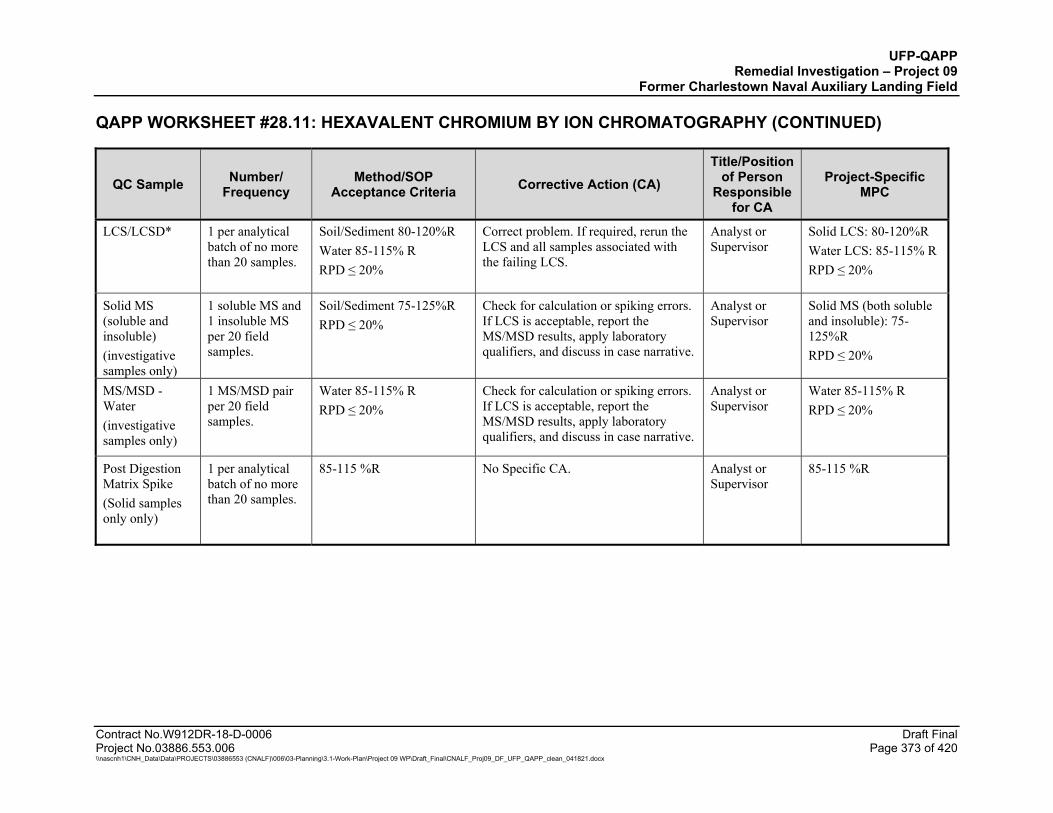
UFP-QAPP Remedial Investigation – Project 09
Former Charlestown Naval Auxiliary Landing Field
QAPP WORKSHEET #28.11: HEXAVALENT CHROMIUM BY ION CHROMATOGRAPHY (CONTINUED)
Contract No.W912DR-18-D-0006 Draft Final Project No.03886.553.006 Page 373 of 420 \\nascnh1\CNH_Data\Data\PROJECTS\03886553 (CNALF)\006\03-Planning\3.1-Work-Plan\Project 09 WP\Draft_Final\CNALF_Proj09_DF_UFP_QAPP_clean_041821.docx
QC Sample Number/ Frequency
Method/SOP Acceptance Criteria Corrective Action (CA)
Title/Position of Person
Responsible for CA
Project-Specific MPC
LCS/LCSD* 1 per analytical batch of no more than 20 samples.
Soil/Sediment 80-120%R Water 85-115% R RPD ≤ 20%
Correct problem. If required, rerun the LCS and all samples associated with the failing LCS.
Analyst or Supervisor
Solid LCS: 80-120%R Water LCS: 85-115% R RPD ≤ 20%
Solid MS (soluble and insoluble) (investigative samples only)
1 soluble MS and 1 insoluble MS per 20 field samples.
Soil/Sediment 75-125%R RPD ≤ 20%
Check for calculation or spiking errors. If LCS is acceptable, report the MS/MSD results, apply laboratory qualifiers, and discuss in case narrative.
Analyst or Supervisor
Solid MS (both soluble and insoluble): 75-125%R RPD ≤ 20%
MS/MSD - Water (investigative samples only)
1 MS/MSD pair per 20 field samples.
Water 85-115% R RPD ≤ 20%
Check for calculation or spiking errors. If LCS is acceptable, report the MS/MSD results, apply laboratory qualifiers, and discuss in case narrative.
Analyst or Supervisor
Water 85-115% R RPD ≤ 20%
Post Digestion Matrix Spike (Solid samples only only)
1 per analytical batch of no more than 20 samples.
85-115 %R No Specific CA. Analyst or Supervisor
85-115 %R
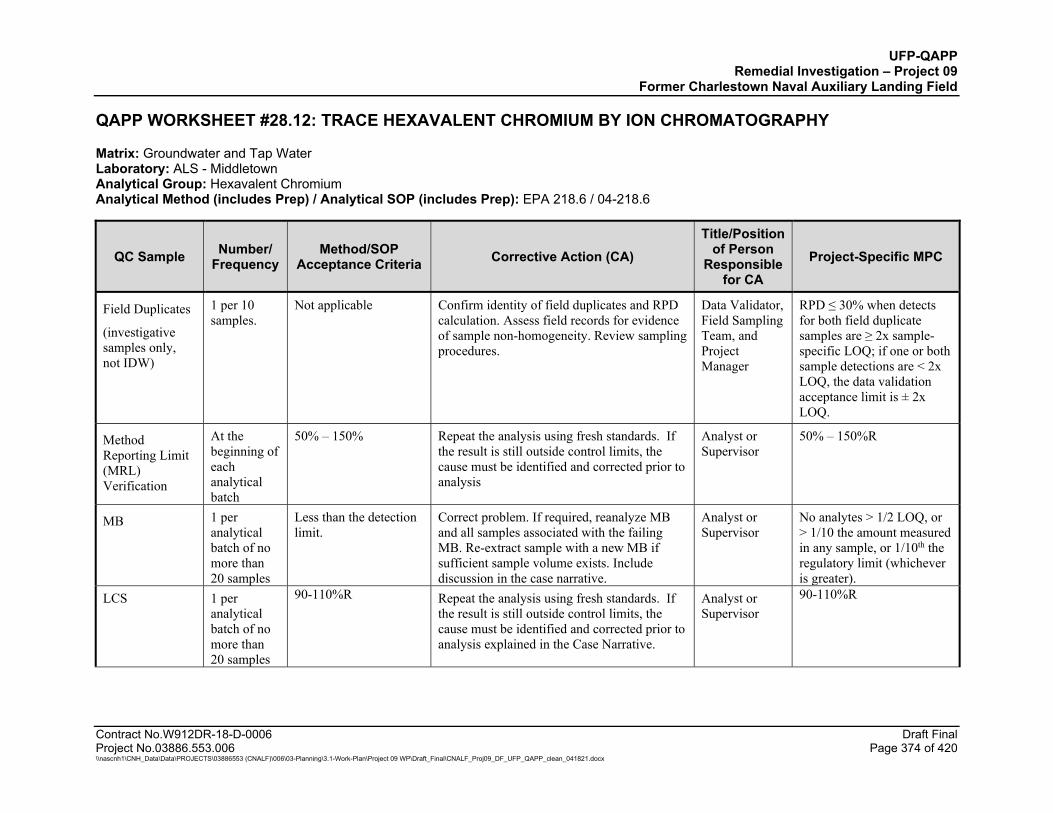
UFP-QAPP Remedial Investigation – Project 09
Former Charlestown Naval Auxiliary Landing Field
Contract No.W912DR-18-D-0006 Draft Final Project No.03886.553.006 Page 374 of 420 \\nascnh1\CNH_Data\Data\PROJECTS\03886553 (CNALF)\006\03-Planning\3.1-Work-Plan\Project 09 WP\Draft_Final\CNALF_Proj09_DF_UFP_QAPP_clean_041821.docx
QAPP WORKSHEET #28.12: TRACE HEXAVALENT CHROMIUM BY ION CHROMATOGRAPHY
Matrix: Groundwater and Tap Water Laboratory: ALS - Middletown Analytical Group: Hexavalent Chromium Analytical Method (includes Prep) / Analytical SOP (includes Prep): EPA 218.6 / 04-218.6
QC Sample Number/ Frequency
Method/SOP Acceptance Criteria Corrective Action (CA)
Title/Position of Person
Responsible for CA
Project-Specific MPC
Field Duplicates
(investigative samples only, not IDW)
1 per 10 samples.
Not applicable Confirm identity of field duplicates and RPD calculation. Assess field records for evidence of sample non-homogeneity. Review sampling procedures.
Data Validator, Field Sampling Team, and Project Manager
RPD ≤ 30% when detects for both field duplicate samples are ≥ 2x sample-specific LOQ; if one or both sample detections are < 2x LOQ, the data validation acceptance limit is ± 2x LOQ.
Method Reporting Limit (MRL) Verification
At the beginning of each analytical batch
50% – 150% Repeat the analysis using fresh standards. If the result is still outside control limits, the cause must be identified and corrected prior to analysis
Analyst or Supervisor
50% – 150%R
MB 1 per analytical batch of no more than 20 samples
Less than the detection limit.
Correct problem. If required, reanalyze MB and all samples associated with the failing MB. Re-extract sample with a new MB if sufficient sample volume exists. Include discussion in the case narrative.
Analyst or Supervisor
No analytes > 1/2 LOQ, or > 1/10 the amount measured in any sample, or 1/10th the regulatory limit (whichever is greater).
LCS 1 per analytical batch of no more than 20 samples
90-110%R Repeat the analysis using fresh standards. If the result is still outside control limits, the cause must be identified and corrected prior to analysis explained in the Case Narrative.
Analyst or Supervisor
90-110%R
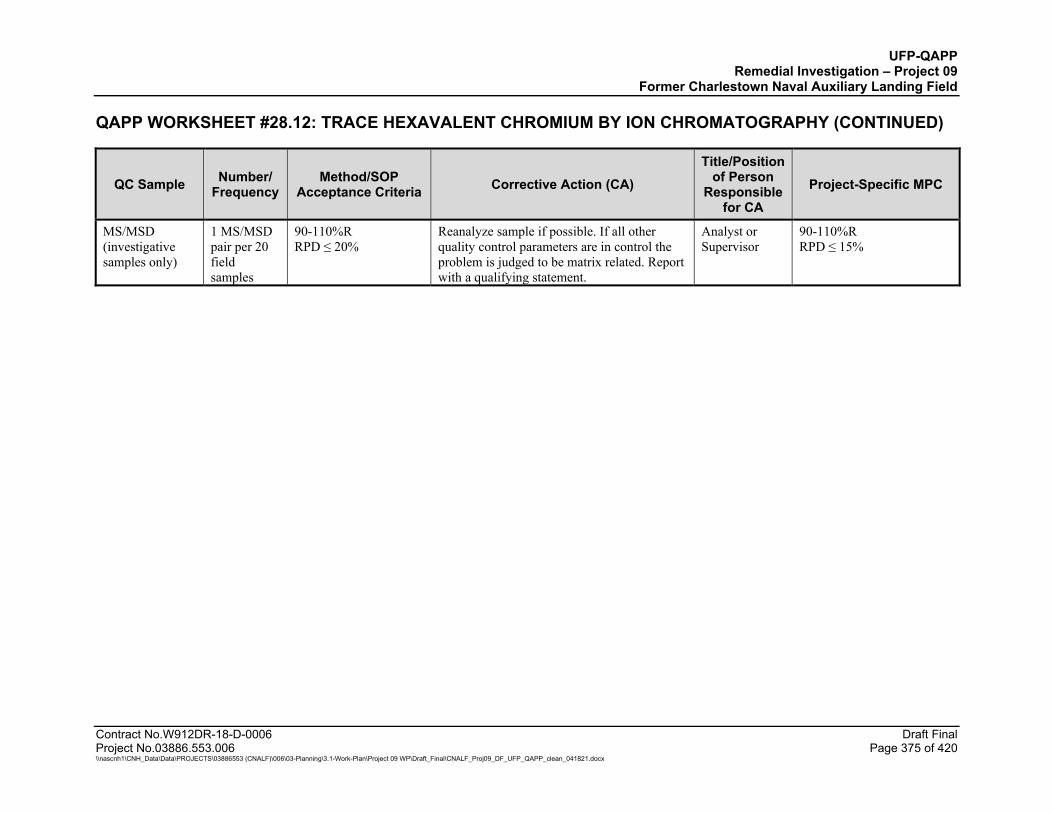
UFP-QAPP Remedial Investigation – Project 09
Former Charlestown Naval Auxiliary Landing Field
QAPP WORKSHEET #28.12: TRACE HEXAVALENT CHROMIUM BY ION CHROMATOGRAPHY (CONTINUED)
Contract No.W912DR-18-D-0006 Draft Final Project No.03886.553.006 Page 375 of 420 \\nascnh1\CNH_Data\Data\PROJECTS\03886553 (CNALF)\006\03-Planning\3.1-Work-Plan\Project 09 WP\Draft_Final\CNALF_Proj09_DF_UFP_QAPP_clean_041821.docx
QC Sample Number/ Frequency
Method/SOP Acceptance Criteria Corrective Action (CA)
Title/Position of Person
Responsible for CA
Project-Specific MPC
MS/MSD (investigative samples only)
1 MS/MSD pair per 20 field samples
90-110%R RPD ≤ 20%
Reanalyze sample if possible. If all other quality control parameters are in control the problem is judged to be matrix related. Report with a qualifying statement.
Analyst or Supervisor
90-110%R RPD ≤ 15%
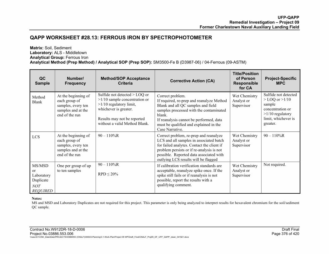
UFP-QAPP Remedial Investigation – Project 09
Former Charlestown Naval Auxiliary Landing Field
Contract No.W912DR-18-D-0006 Draft Final Project No.03886.553.006 Page 376 of 420 \\nascnh1\CNH_Data\Data\PROJECTS\03886553 (CNALF)\006\03-Planning\3.1-Work-Plan\Project 09 WP\Draft_Final\CNALF_Proj09_DF_UFP_QAPP_clean_041821.docx
QAPP WORKSHEET #28.13: FERROUS IRON BY SPECTROPHOTOMETER
Matrix: Soil, Sediment Laboratory: ALS - Middletown Analytical Group: Ferrous Iron Analytical Method (Prep Method) / Analytical SOP (Prep SOP): SM3500-Fe B (D3987-06) / 04-Ferrous (09-ASTM)
QC Sample
Number/ Frequency
Method/SOP Acceptance Criteria Corrective Action (CA)
Title/Position of Person
Responsible for CA
Project-Specific MPC
Method Blank
At the beginning of each group of samples, every ten samples and at the end of the run
Sulfide not detected > LOQ or >1/10 sample concentration or >1/10 regulatory limit, whichever is greater.
Results may not be reported without a valid Method Blank.
Correct problem. If required, re-prep and reanalyze Method Blank and all QC samples and field samples processed with the contaminated blank. If reanalysis cannot be performed, data must be qualified and explained in the Case Narrative.
Wet Chemistry Analyst or Supervisor
Sulfide not detected > LOQ or >1/10 sample concentration or >1/10 regulatory limit, whichever is greater.
LCS At the beginning of each group of samples, every ten samples and at the end of the run
90 – 110%R Correct problem, re-prep and reanalyze LCS and all samples in associated batch for failed analytes. Contact the client if problem persists or if re-analysis is not possible. Reported data associated with outlying LCS results will be flagged
Wet Chemistry Analyst or Supervisor
90 – 110%R
MS/MSD or Laboratory Duplicate NOT REQUIRED
One per group of up to ten samples
90 – 110%R RPD ≤ 20%
If calibration verification standards are acceptable, reanalyze spike once. If the spike still fails or if reanalysis is not possible, report the results with a qualifying comment.
Wet Chemistry Analyst or Supervisor
Not required.
Notes: MS and MSD and Laboratory Duplicates are not required for this project. This parameter is only being analyzed to interpret results for hexavalent chromium for the soil/sediment QC sample.
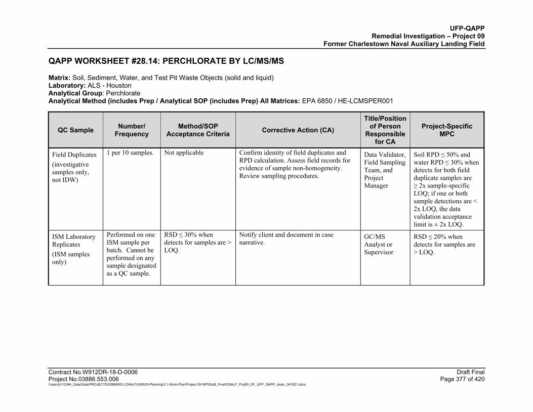
UFP-QAPP Remedial Investigation – Project 09
Former Charlestown Naval Auxiliary Landing Field
Contract No.W912DR-18-D-0006 Draft Final Project No.03886.553.006 Page 377 of 420 \\nascnh1\CNH_Data\Data\PROJECTS\03886553 (CNALF)\006\03-Planning\3.1-Work-Plan\Project 09 WP\Draft_Final\CNALF_Proj09_DF_UFP_QAPP_clean_041821.docx
QAPP WORKSHEET #28.14: PERCHLORATE BY LC/MS/MS
Matrix: Soil, Sediment, Water, and Test Pit Waste Objects (solid and liquid) Laboratory: ALS - Houston Analytical Group: Perchlorate Analytical Method (includes Prep / Analytical SOP (includes Prep) All Matrices: EPA 6850 / HE-LCMSPER001
QC Sample Number/ Frequency
Method/SOP Acceptance Criteria Corrective Action (CA)
Title/Position of Person
Responsible for CA
Project-Specific MPC
Field Duplicates (investigative samples only, not IDW)
1 per 10 samples. Not applicable Confirm identity of field duplicates and RPD calculation. Assess field records for evidence of sample non-homogeneity. Review sampling procedures.
Data Validator, Field Sampling Team, and Project Manager
Soil RPD ≤ 50% and water RPD ≤ 30% when detects for both field duplicate samples are ≥ 2x sample-specific LOQ; if one or both sample detections are < 2x LOQ, the data validation acceptance limit is ± 2x LOQ.
ISM Laboratory Replicates (ISM samples only)
Performed on one ISM sample per batch. Cannot be performed on any sample designated as a QC sample.
RSD ≤ 30% when detects for samples are > LOQ.
Notify client and document in case narrative.
GC/MS Analyst or Supervisor
RSD ≤ 20% when detects for samples are > LOQ.
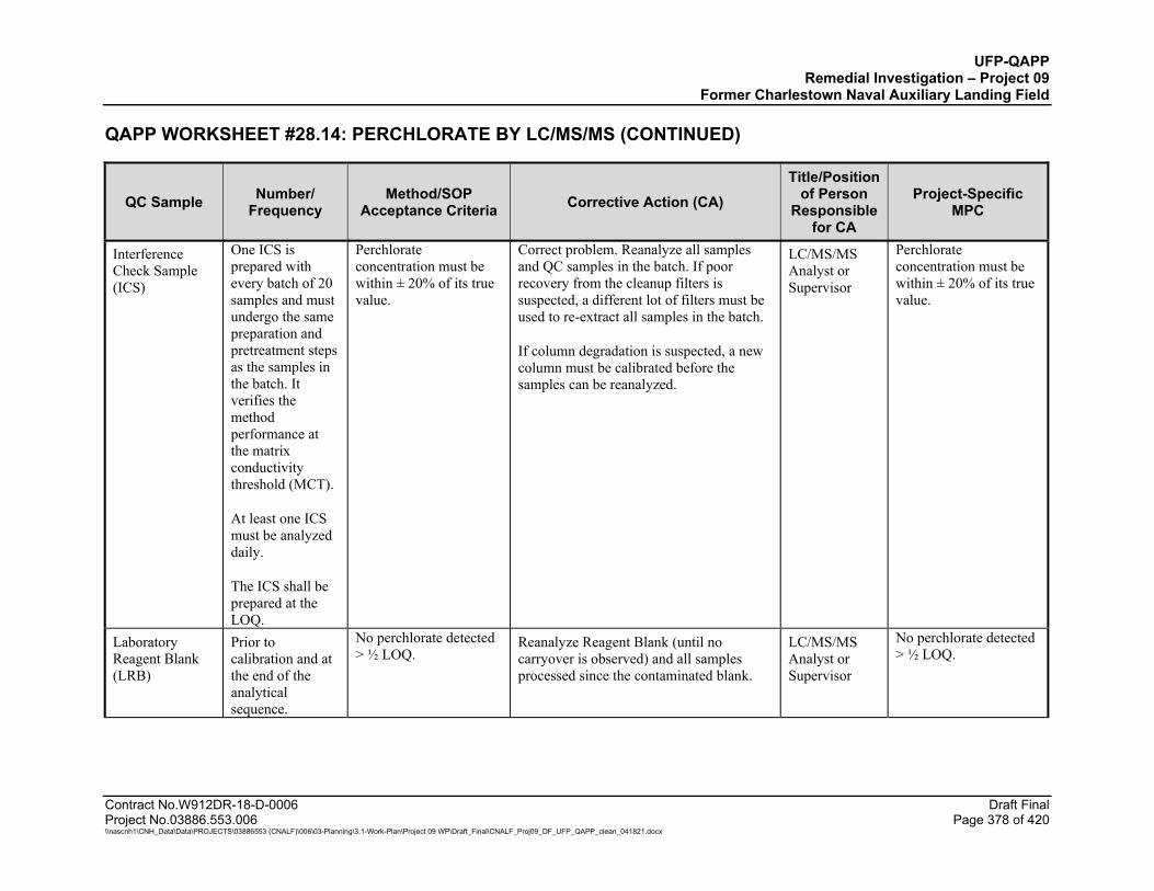
UFP-QAPP Remedial Investigation – Project 09
Former Charlestown Naval Auxiliary Landing Field
QAPP WORKSHEET #28.14: PERCHLORATE BY LC/MS/MS (CONTINUED)
Contract No.W912DR-18-D-0006 Draft Final Project No.03886.553.006 Page 378 of 420 \\nascnh1\CNH_Data\Data\PROJECTS\03886553 (CNALF)\006\03-Planning\3.1-Work-Plan\Project 09 WP\Draft_Final\CNALF_Proj09_DF_UFP_QAPP_clean_041821.docx
QC Sample Number/ Frequency
Method/SOP Acceptance Criteria Corrective Action (CA)
Title/Position of Person
Responsible for CA
Project-Specific MPC
Interference Check Sample (ICS)
One ICS is prepared with every batch of 20 samples and must undergo the same preparation and pretreatment steps as the samples in the batch. It verifies the method performance at the matrix conductivity threshold (MCT).
At least one ICS must be analyzed daily.
The ICS shall be prepared at the LOQ.
Perchlorate concentration must be within ± 20% of its true value.
Correct problem. Reanalyze all samples and QC samples in the batch. If poor recovery from the cleanup filters is suspected, a different lot of filters must be used to re-extract all samples in the batch.
If column degradation is suspected, a new column must be calibrated before the samples can be reanalyzed.
LC/MS/MS Analyst or Supervisor
Perchlorate concentration must be within ± 20% of its true value.
Laboratory Reagent Blank (LRB)
Prior to calibration and at the end of the analytical sequence.
No perchlorate detected > ½ LOQ.
Reanalyze Reagent Blank (until no carryover is observed) and all samples processed since the contaminated blank.
LC/MS/MS Analyst or Supervisor
No perchlorate detected > ½ LOQ.
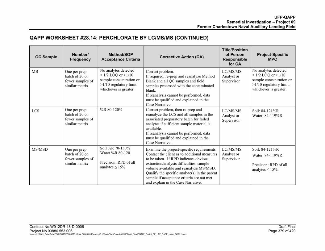
UFP-QAPP Remedial Investigation – Project 09
Former Charlestown Naval Auxiliary Landing Field
QAPP WORKSHEET #28.14: PERCHLORATE BY LC/MS/MS (CONTINUED)
Contract No.W912DR-18-D-0006 Draft Final Project No.03886.553.006 Page 379 of 420 \\nascnh1\CNH_Data\Data\PROJECTS\03886553 (CNALF)\006\03-Planning\3.1-Work-Plan\Project 09 WP\Draft_Final\CNALF_Proj09_DF_UFP_QAPP_clean_041821.docx
QC Sample Number/ Frequency
Method/SOP Acceptance Criteria Corrective Action (CA)
Title/Position of Person
Responsible for CA
Project-Specific MPC
MB One per prep batch of 20 or fewer samples of similar matrix
No analytes detected > 1/2 LOQ or >1/10 sample concentration or >1/10 regulatory limit, whichever is greater.
Correct problem. If required, re-prep and reanalyze Method Blank and all QC samples and field samples processed with the contaminated blank. If reanalysis cannot be performed, data must be qualified and explained in the Case Narrative.
LC/MS/MS Analyst or Supervisor
No analytes detected > 1/2 LOQ or >1/10 sample concentration or >1/10 regulatory limit, whichever is greater.
LCS One per prep batch of 20 or fewer samples of similar matrix
%R 80-120%
Correct problem, then re-prep and reanalyze the LCS and all samples in the associated preparatory batch for failed analytes if sufficient sample material is available. If reanalysis cannot be performed, data must be qualified and explained in the Case Narrative.
LC/MS/MS Analyst or Supervisor
Soil: 84-121%R Water: 84-119%R
MS/MSD One per prep batch of 20 or fewer samples of similar matrix
Soil %R 70-130% Water %R 80-120 Precision: RPD of all analytes ≤ 15%.
Examine the project-specific requirements. Contact the client as to additional measures to be taken. If RPD indicates obvious extraction/analysis difficulties, sample volume available and reanalyze MS/MSD. Qualify the specific analyte(s) in the parent sample if acceptance criteria are not met and explain in the Case Narrative.
LC/MS/MS Analyst or Supervisor
Soil: 84-121%R Water: 84-119%R Precision: RPD of all analytes ≤ 15%.
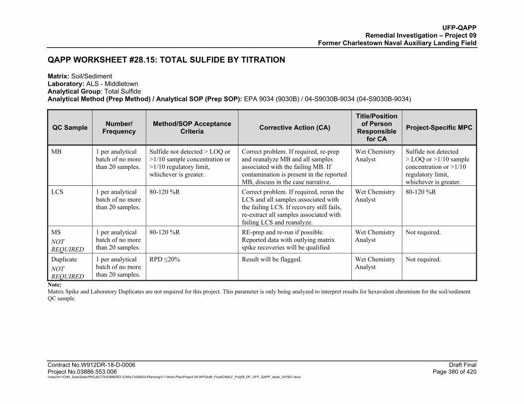
UFP-QAPP Remedial Investigation – Project 09
Former Charlestown Naval Auxiliary Landing Field
Contract No.W912DR-18-D-0006 Draft Final Project No.03886.553.006 Page 380 of 420 \\nascnh1\CNH_Data\Data\PROJECTS\03886553 (CNALF)\006\03-Planning\3.1-Work-Plan\Project 09 WP\Draft_Final\CNALF_Proj09_DF_UFP_QAPP_clean_041821.docx
QAPP WORKSHEET #28.15: TOTAL SULFIDE BY TITRATION
Matrix: Soil/Sediment Laboratory: ALS - Middletown Analytical Group: Total Sulfide Analytical Method (Prep Method) / Analytical SOP (Prep SOP): EPA 9034 (9030B) / 04-S9030B-9034 (04-S9030B-9034)
QC Sample Number/ Frequency
Method/SOP Acceptance Criteria Corrective Action (CA)
Title/Position of Person
Responsible for CA
Project-Specific MPC
MB 1 per analytical batch of no more than 20 samples.
Sulfide not detected > LOQ or >1/10 sample concentration or >1/10 regulatory limit, whichever is greater.
Correct problem. If required, re-prep and reanalyze MB and all samples associated with the failing MB. If contamination is present in the reported MB, discuss in the case narrative.
Wet Chemistry Analyst
Sulfide not detected > LOQ or >1/10 sample concentration or >1/10 regulatory limit, whichever is greater.
LCS 1 per analytical batch of no more than 20 samples.
80-120 %R
Correct problem. If required, rerun the LCS and all samples associated with the failing LCS. If recovery still fails, re-extract all samples associated with failing LCS and reanalyze.
Wet Chemistry Analyst
80-120 %R
MS NOT REQUIRED
1 per analytical batch of no more than 20 samples.
80-120 %R
RE-prep and re-run if possible. Reported data with outlying matrix spike recoveries will be qualified
Wet Chemistry Analyst
Not required.
Duplicate NOT REQUIRED
1 per analytical batch of no more than 20 samples.
RPD ≤20% Result will be flagged. Wet Chemistry Analyst
Not required.
Note: Matrix Spike and Laboratory Duplicates are not required for this project. This parameter is only being analyzed to interpret results for hexavalent chromium for the soil/sediment QC sample.
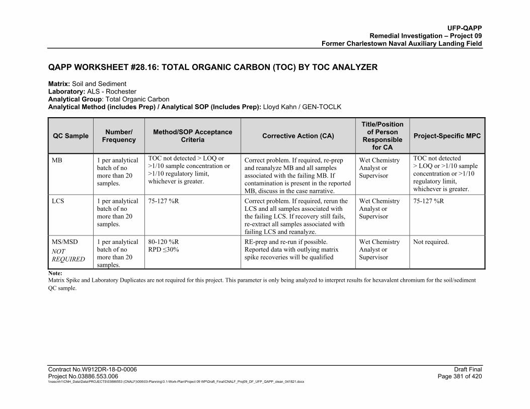
UFP-QAPP Remedial Investigation – Project 09
Former Charlestown Naval Auxiliary Landing Field
Contract No.W912DR-18-D-0006 Draft Final Project No.03886.553.006 Page 381 of 420 \\nascnh1\CNH_Data\Data\PROJECTS\03886553 (CNALF)\006\03-Planning\3.1-Work-Plan\Project 09 WP\Draft_Final\CNALF_Proj09_DF_UFP_QAPP_clean_041821.docx
QAPP WORKSHEET #28.16: TOTAL ORGANIC CARBON (TOC) BY TOC ANALYZER
Matrix: Soil and Sediment Laboratory: ALS - Rochester Analytical Group: Total Organic Carbon Analytical Method (includes Prep) / Analytical SOP (Includes Prep): Lloyd Kahn / GEN-TOCLK
QC Sample Number/ Frequency
Method/SOP Acceptance Criteria Corrective Action (CA)
Title/Position of Person
Responsible for CA
Project-Specific MPC
MB 1 per analytical batch of no more than 20 samples.
TOC not detected > LOQ or >1/10 sample concentration or >1/10 regulatory limit, whichever is greater.
Correct problem. If required, re-prep and reanalyze MB and all samples associated with the failing MB. If contamination is present in the reported MB, discuss in the case narrative.
Wet Chemistry Analyst or Supervisor
TOC not detected > LOQ or >1/10 sample concentration or >1/10 regulatory limit, whichever is greater.
LCS 1 per analytical batch of no more than 20 samples.
75-127 %R
Correct problem. If required, rerun the LCS and all samples associated with the failing LCS. If recovery still fails, re-extract all samples associated with failing LCS and reanalyze.
Wet Chemistry Analyst or Supervisor
75-127 %R
MS/MSD NOT REQUIRED
1 per analytical batch of no more than 20 samples.
80-120 %R RPD ≤30%
RE-prep and re-run if possible. Reported data with outlying matrix spike recoveries will be qualified
Wet Chemistry Analyst or Supervisor
Not required.
Note: Matrix Spike and Laboratory Duplicates are not required for this project. This parameter is only being analyzed to interpret results for hexavalent chromium for the soil/sediment QC sample.
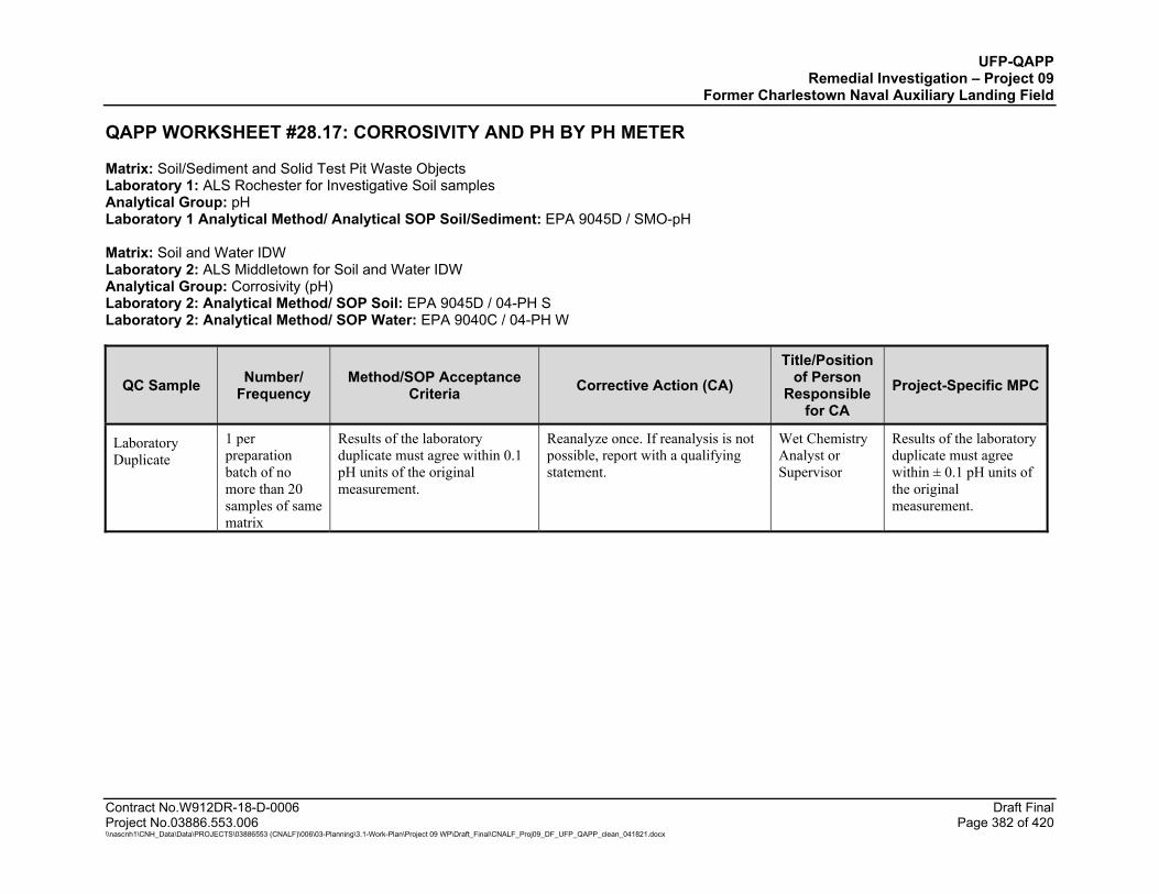
UFP-QAPP Remedial Investigation – Project 09
Former Charlestown Naval Auxiliary Landing Field
Contract No.W912DR-18-D-0006 Draft Final Project No.03886.553.006 Page 382 of 420 \\nascnh1\CNH_Data\Data\PROJECTS\03886553 (CNALF)\006\03-Planning\3.1-Work-Plan\Project 09 WP\Draft_Final\CNALF_Proj09_DF_UFP_QAPP_clean_041821.docx
QAPP WORKSHEET #28.17: CORROSIVITY AND PH BY PH METER
Matrix: Soil/Sediment and Solid Test Pit Waste Objects Laboratory 1: ALS Rochester for Investigative Soil samples Analytical Group: pH Laboratory 1 Analytical Method/ Analytical SOP Soil/Sediment: EPA 9045D / SMO-pH Matrix: Soil and Water IDW Laboratory 2: ALS Middletown for Soil and Water IDW Analytical Group: Corrosivity (pH) Laboratory 2: Analytical Method/ SOP Soil: EPA 9045D / 04-PH S Laboratory 2: Analytical Method/ SOP Water: EPA 9040C / 04-PH W
QC Sample Number/ Frequency
Method/SOP Acceptance Criteria Corrective Action (CA)
Title/Position of Person
Responsible for CA
Project-Specific MPC
Laboratory Duplicate
1 per preparation batch of no more than 20 samples of same matrix
Results of the laboratory duplicate must agree within 0.1 pH units of the original measurement.
Reanalyze once. If reanalysis is not possible, report with a qualifying statement.
Wet Chemistry Analyst or Supervisor
Results of the laboratory duplicate must agree within ± 0.1 pH units of the original measurement.
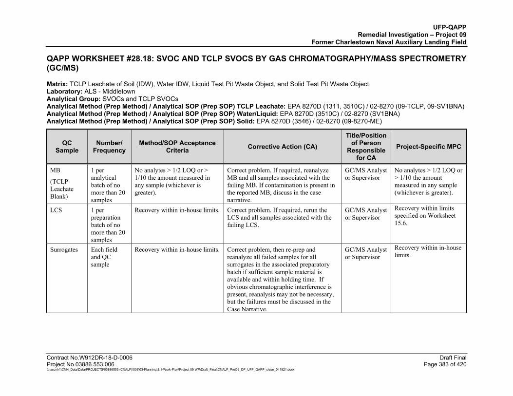
UFP-QAPP Remedial Investigation – Project 09
Former Charlestown Naval Auxiliary Landing Field
Contract No.W912DR-18-D-0006 Draft Final Project No.03886.553.006 Page 383 of 420 \\nascnh1\CNH_Data\Data\PROJECTS\03886553 (CNALF)\006\03-Planning\3.1-Work-Plan\Project 09 WP\Draft_Final\CNALF_Proj09_DF_UFP_QAPP_clean_041821.docx
QAPP WORKSHEET #28.18: SVOC AND TCLP SVOCS BY GAS CHROMATOGRAPHY/MASS SPECTROMETRY (GC/MS)
Matrix: TCLP Leachate of Soil (IDW), Water IDW, Liquid Test Pit Waste Object, and Solid Test Pit Waste Object Laboratory: ALS - Middletown Analytical Group: SVOCs and TCLP SVOCs Analytical Method (Prep Method) / Analytical SOP (Prep SOP) TCLP Leachate: EPA 8270D (1311, 3510C) / 02-8270 (09-TCLP, 09-SV1BNA) Analytical Method (Prep Method) / Analytical SOP (Prep SOP) Water/Liquid: EPA 8270D (3510C) / 02-8270 (SV1BNA) Analytical Method (Prep Method) / Analytical SOP (Prep SOP) Solid: EPA 8270D (3546) / 02-8270 (09-8270-ME)
QC Sample
Number/ Frequency
Method/SOP Acceptance Criteria Corrective Action (CA)
Title/Position of Person
Responsible for CA
Project-Specific MPC
MB
(TCLP Leachate Blank)
1 per analytical batch of no more than 20 samples
No analytes > 1/2 LOQ or > 1/10 the amount measured in any sample (whichever is greater).
Correct problem. If required, reanalyze MB and all samples associated with the failing MB. If contamination is present in the reported MB, discuss in the case narrative.
GC/MS Analyst or Supervisor
No analytes > 1/2 LOQ or > 1/10 the amount measured in any sample (whichever is greater).
LCS 1 per preparation batch of no more than 20 samples
Recovery within in-house limits. Correct problem. If required, rerun the LCS and all samples associated with the failing LCS.
GC/MS Analyst or Supervisor
Recovery within limits specified on Worksheet 15.6.
Surrogates Each field and QC sample
Recovery within in-house limits. Correct problem, then re-prep and reanalyze all failed samples for all surrogates in the associated preparatory batch if sufficient sample material is available and within holding time. If obvious chromatographic interference is present, reanalysis may not be necessary, but the failures must be discussed in the Case Narrative.
GC/MS Analyst or Supervisor
Recovery within in-house limits.
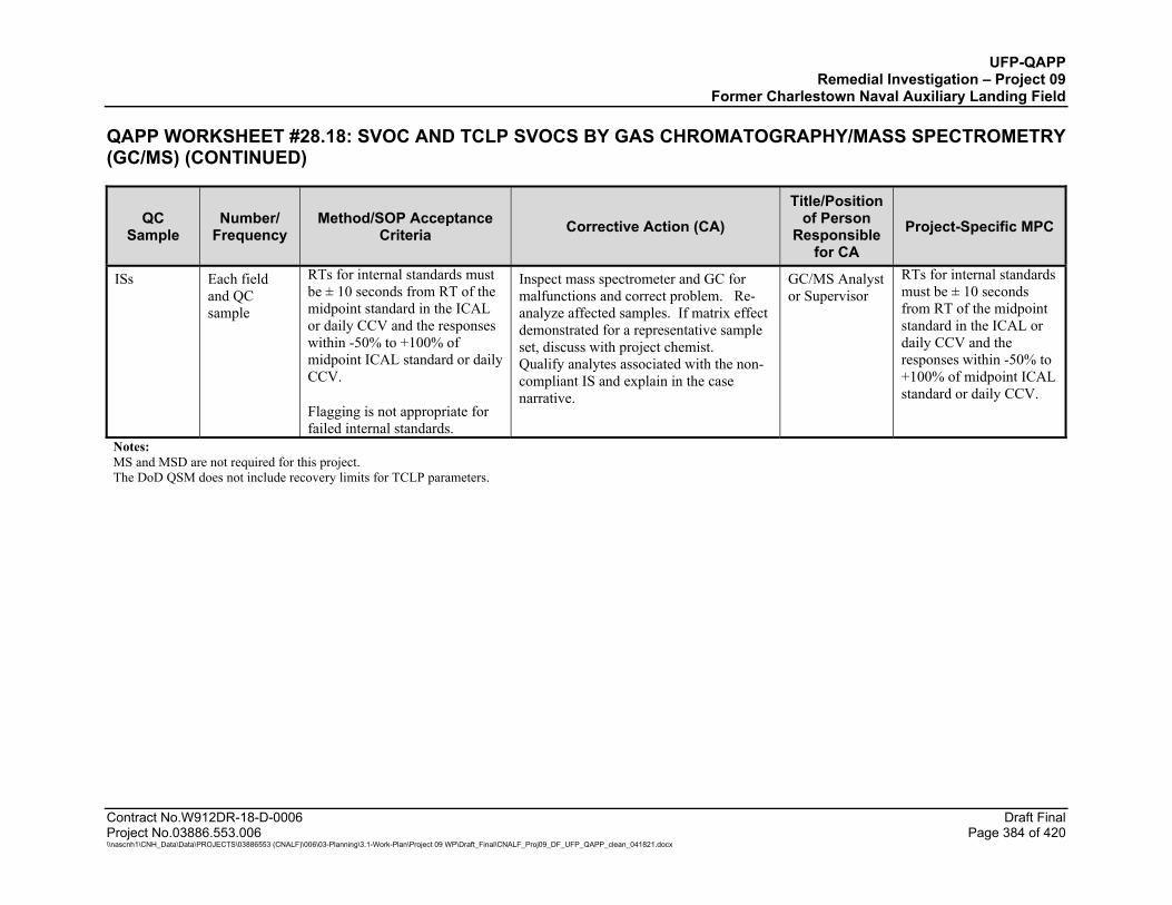
UFP-QAPP Remedial Investigation – Project 09
Former Charlestown Naval Auxiliary Landing Field
QAPP WORKSHEET #28.18: SVOC AND TCLP SVOCS BY GAS CHROMATOGRAPHY/MASS SPECTROMETRY (GC/MS) (CONTINUED)
Contract No.W912DR-18-D-0006 Draft Final Project No.03886.553.006 Page 384 of 420 \\nascnh1\CNH_Data\Data\PROJECTS\03886553 (CNALF)\006\03-Planning\3.1-Work-Plan\Project 09 WP\Draft_Final\CNALF_Proj09_DF_UFP_QAPP_clean_041821.docx
QC Sample
Number/ Frequency
Method/SOP Acceptance Criteria Corrective Action (CA)
Title/Position of Person
Responsible for CA
Project-Specific MPC
ISs Each field and QC sample
RTs for internal standards must be ± 10 seconds from RT of the midpoint standard in the ICAL or daily CCV and the responses within -50% to +100% of midpoint ICAL standard or daily CCV.
Flagging is not appropriate for failed internal standards.
Inspect mass spectrometer and GC for malfunctions and correct problem. Re-analyze affected samples. If matrix effect demonstrated for a representative sample set, discuss with project chemist. Qualify analytes associated with the non-compliant IS and explain in the case narrative.
GC/MS Analyst or Supervisor
RTs for internal standards must be ± 10 seconds from RT of the midpoint standard in the ICAL or daily CCV and the responses within -50% to +100% of midpoint ICAL standard or daily CCV.
Notes: MS and MSD are not required for this project. The DoD QSM does not include recovery limits for TCLP parameters.
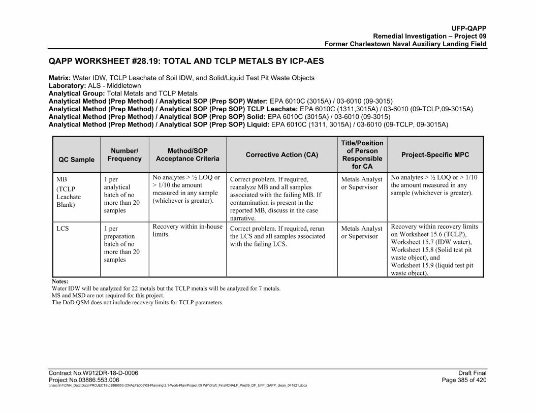
UFP-QAPP Remedial Investigation – Project 09
Former Charlestown Naval Auxiliary Landing Field
Contract No.W912DR-18-D-0006 Draft Final Project No.03886.553.006 Page 385 of 420 \\nascnh1\CNH_Data\Data\PROJECTS\03886553 (CNALF)\006\03-Planning\3.1-Work-Plan\Project 09 WP\Draft_Final\CNALF_Proj09_DF_UFP_QAPP_clean_041821.docx
QAPP WORKSHEET #28.19: TOTAL AND TCLP METALS BY ICP-AES
Matrix: Water IDW, TCLP Leachate of Soil IDW, and Solid/Liquid Test Pit Waste Objects Laboratory: ALS - Middletown Analytical Group: Total Metals and TCLP Metals Analytical Method (Prep Method) / Analytical SOP (Prep SOP) Water: EPA 6010C (3015A) / 03-6010 (09-3015) Analytical Method (Prep Method) / Analytical SOP (Prep SOP) TCLP Leachate: EPA 6010C (1311,3015A) / 03-6010 (09-TCLP,09-3015A) Analytical Method (Prep Method) / Analytical SOP (Prep SOP) Solid: EPA 6010C (3015A) / 03-6010 (09-3015) Analytical Method (Prep Method) / Analytical SOP (Prep SOP) Liquid: EPA 6010C (1311, 3015A) / 03-6010 (09-TCLP, 09-3015A)
QC Sample
Number/ Frequency
Method/SOP Acceptance Criteria Corrective Action (CA)
Title/Position of Person
Responsible for CA
Project-Specific MPC
MB (TCLP Leachate Blank)
1 per analytical batch of no more than 20 samples
No analytes > ½ LOQ or > 1/10 the amount measured in any sample (whichever is greater).
Correct problem. If required, reanalyze MB and all samples associated with the failing MB. If contamination is present in the reported MB, discuss in the case narrative.
Metals Analyst or Supervisor
No analytes > ½ LOQ or > 1/10 the amount measured in any sample (whichever is greater).
LCS 1 per preparation batch of no more than 20 samples
Recovery within in-house limits.
Correct problem. If required, rerun the LCS and all samples associated with the failing LCS.
Metals Analyst or Supervisor
Recovery within recovery limits on Worksheet 15.6 (TCLP), Worksheet 15.7 (IDW water), Worksheet 15.8 (Solid test pit waste object), and Worksheet 15.9 (liquid test pit waste object).
Notes: Water IDW will be analyzed for 22 metals but the TCLP metals will be analyzed for 7 metals. MS and MSD are not required for this project. The DoD QSM does not include recovery limits for TCLP parameters.
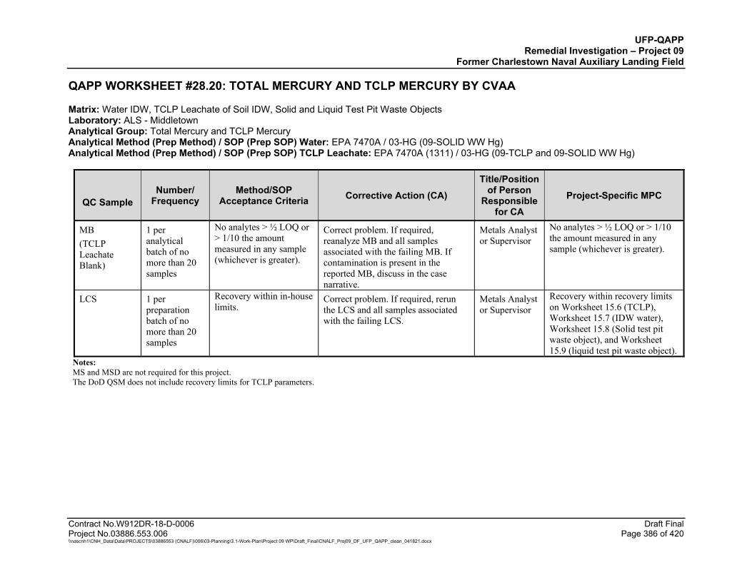
UFP-QAPP Remedial Investigation – Project 09
Former Charlestown Naval Auxiliary Landing Field
Contract No.W912DR-18-D-0006 Draft Final Project No.03886.553.006 Page 386 of 420 \\nascnh1\CNH_Data\Data\PROJECTS\03886553 (CNALF)\006\03-Planning\3.1-Work-Plan\Project 09 WP\Draft_Final\CNALF_Proj09_DF_UFP_QAPP_clean_041821.docx
QAPP WORKSHEET #28.20: TOTAL MERCURY AND TCLP MERCURY BY CVAA
Matrix: Water IDW, TCLP Leachate of Soil IDW, Solid and Liquid Test Pit Waste Objects Laboratory: ALS - Middletown Analytical Group: Total Mercury and TCLP Mercury Analytical Method (Prep Method) / SOP (Prep SOP) Water: EPA 7470A / 03-HG (09-SOLID WW Hg) Analytical Method (Prep Method) / SOP (Prep SOP) TCLP Leachate: EPA 7470A (1311) / 03-HG (09-TCLP and 09-SOLID WW Hg)
QC Sample
Number/ Frequency
Method/SOP Acceptance Criteria Corrective Action (CA)
Title/Position of Person
Responsible for CA
Project-Specific MPC
MB (TCLP Leachate Blank)
1 per analytical batch of no more than 20 samples
No analytes > ½ LOQ or > 1/10 the amount measured in any sample (whichever is greater).
Correct problem. If required, reanalyze MB and all samples associated with the failing MB. If contamination is present in the reported MB, discuss in the case narrative.
Metals Analyst or Supervisor
No analytes > ½ LOQ or > 1/10 the amount measured in any sample (whichever is greater).
LCS 1 per preparation batch of no more than 20 samples
Recovery within in-house limits.
Correct problem. If required, rerun the LCS and all samples associated with the failing LCS.
Metals Analyst or Supervisor
Recovery within recovery limits on Worksheet 15.6 (TCLP), Worksheet 15.7 (IDW water), Worksheet 15.8 (Solid test pit waste object), and Worksheet 15.9 (liquid test pit waste object).
Notes: MS and MSD are not required for this project. The DoD QSM does not include recovery limits for TCLP parameters.
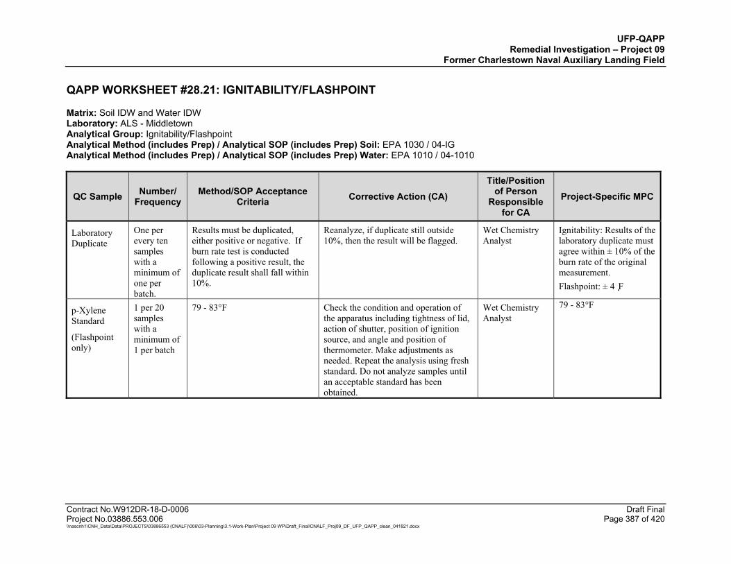
UFP-QAPP Remedial Investigation – Project 09
Former Charlestown Naval Auxiliary Landing Field
Contract No.W912DR-18-D-0006 Draft Final Project No.03886.553.006 Page 387 of 420 \\nascnh1\CNH_Data\Data\PROJECTS\03886553 (CNALF)\006\03-Planning\3.1-Work-Plan\Project 09 WP\Draft_Final\CNALF_Proj09_DF_UFP_QAPP_clean_041821.docx
QAPP WORKSHEET #28.21: IGNITABILITY/FLASHPOINT
Matrix: Soil IDW and Water IDW Laboratory: ALS - Middletown Analytical Group: Ignitability/Flashpoint Analytical Method (includes Prep) / Analytical SOP (includes Prep) Soil: EPA 1030 / 04-IG Analytical Method (includes Prep) / Analytical SOP (includes Prep) Water: EPA 1010 / 04-1010
QC Sample Number/ Frequency
Method/SOP Acceptance Criteria Corrective Action (CA)
Title/Position of Person
Responsible for CA
Project-Specific MPC
Laboratory Duplicate
One per every ten samples with a minimum of one per batch.
Results must be duplicated, either positive or negative. If burn rate test is conducted following a positive result, the duplicate result shall fall within 10%.
Reanalyze, if duplicate still outside 10%, then the result will be flagged.
Wet Chemistry Analyst
Ignitability: Results of the laboratory duplicate must agree within ± 10% of the burn rate of the original measurement. Flashpoint: ± 4�F
p-Xylene Standard
(Flashpoint only)
1 per 20 samples with a minimum of 1 per batch
79 - 83°F Check the condition and operation of the apparatus including tightness of lid, action of shutter, position of ignition source, and angle and position of thermometer. Make adjustments as needed. Repeat the analysis using fresh standard. Do not analyze samples until an acceptable standard has been obtained.
Wet Chemistry Analyst
79 - 83°F

UFP-QAPP Remedial Investigation – Project 09
Former Charlestown Naval Auxiliary Landing Field
Contract No.W912DR-18-D-0006 Draft Final Project No.03886.553.006 Page 388 of 420 \\nascnh1\CNH_Data\Data\PROJECTS\03886553 (CNALF)\006\03-Planning\3.1-Work-Plan\Project 09 WP\Draft_Final\CNALF_Proj09_DF_UFP_QAPP_clean_041821.docx
QAPP WORKSHEET #28.22: REACTIVE CYANIDE AND REACTIVE SULFIDE BY FLOW INJECTION ANALYZER AND TITRATION
Matrix: Soil IDW and Water IDW Laboratory: ALS - Middletown Analytical Group: Reactive Cyanide and Reactive Sulfide Analytical Method/ (Prep Method) / Analytical SOP (Prep SOP) Reactive Cyanide Solid: EPA 9012B (Chapter 7.3.3) / 04-CN (09-R) Analytical Method/ (Prep Method) / Analytical SOP (Prep SOP) Reactive Sulfide Solid: EPA 9034 (Chapter 7.3.4) / 04-S 9030B-9034 (09-R) Analytical Method/ (Prep Method) / Analytical SOP (Prep SOP) Reactive Cyanide Water: EPA 9012B (Chapter 7.3.3) / 04-CN (09-R) Analytical Method/ (Prep Method) / Analytical SOP (Prep SOP) Reactive Sulfide Water: SM4500 S-2 F Chapter 7.3.4 / 04-S (09-R)
QC Sample Number/ Frequency
Method/SOP Acceptance Criteria Corrective Action (CA)
Title/Position of Person
Responsible for CA
Project-Specific MPC
MB 1 per analytical batch of no more than 20 samples
Reactive Cyanide: < RL of 10 mg/kg. Reactive Sulfide: < RL of 6.25 mg/kg.
Correct problem. If required, re-prep and reanalyze MB and all samples associated with the failing MB. If contamination is present in the reported MB, discuss in the case narrative.
Wet Chemistry Analyst
Reactive Cyanide: < LOD of 10 mg/kg. Reactive Sulfide: < LOD of 6.25 mg/kg.
LCS 1 per analytical batch of no more than 20 samples
Reactive Cyanide: 0-90%R Reactive Sulfide: 49-148%R
Correct problem. If required, rerun the LCS and all samples associated with the failing LCS. If recovery still fails, re-extract all samples associated with failing LCS and reanalyze.
Wet Chemistry Analyst
Reactive Cyanide: 0-90%R Reactive Sulfide: 49-148%R
Laboratory Duplicate
1 per analytical batch of no more than 20 samples
RPD ≤ 20% Reanalyze, if duplicate still outside 10%, then the result will be flagged.
Wet Chemistry Analyst
RPD ≤ 20%
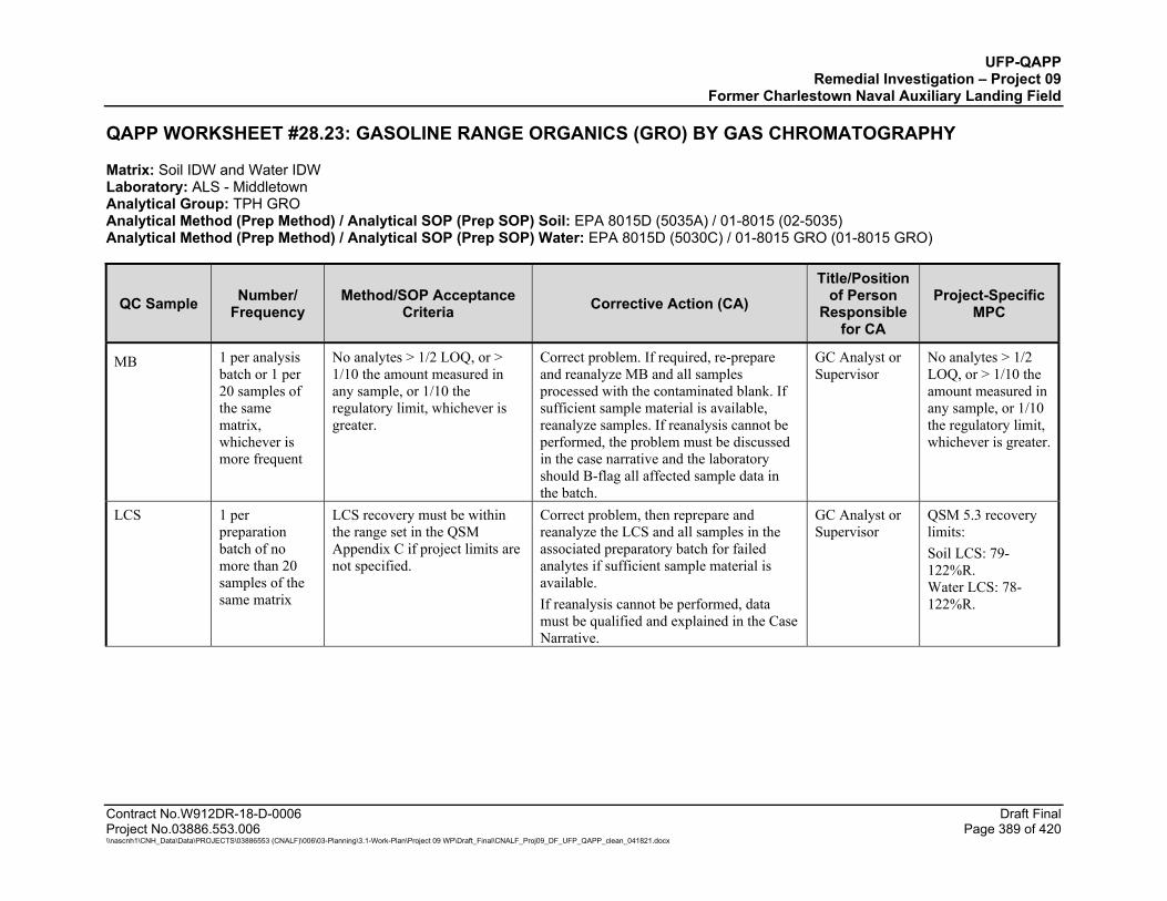
UFP-QAPP Remedial Investigation – Project 09
Former Charlestown Naval Auxiliary Landing Field
Contract No.W912DR-18-D-0006 Draft Final Project No.03886.553.006 Page 389 of 420 \\nascnh1\CNH_Data\Data\PROJECTS\03886553 (CNALF)\006\03-Planning\3.1-Work-Plan\Project 09 WP\Draft_Final\CNALF_Proj09_DF_UFP_QAPP_clean_041821.docx
QAPP WORKSHEET #28.23: GASOLINE RANGE ORGANICS (GRO) BY GAS CHROMATOGRAPHY
Matrix: Soil IDW and Water IDW Laboratory: ALS - Middletown Analytical Group: TPH GRO Analytical Method (Prep Method) / Analytical SOP (Prep SOP) Soil: EPA 8015D (5035A) / 01-8015 (02-5035) Analytical Method (Prep Method) / Analytical SOP (Prep SOP) Water: EPA 8015D (5030C) / 01-8015 GRO (01-8015 GRO)
QC Sample Number/ Frequency
Method/SOP Acceptance Criteria Corrective Action (CA)
Title/Position of Person
Responsible for CA
Project-Specific MPC
MB 1 per analysis batch or 1 per 20 samples of the same matrix, whichever is more frequent
No analytes > 1/2 LOQ, or > 1/10 the amount measured in any sample, or 1/10 the regulatory limit, whichever is greater.
Correct problem. If required, re-prepare and reanalyze MB and all samples processed with the contaminated blank. If sufficient sample material is available, reanalyze samples. If reanalysis cannot be performed, the problem must be discussed in the case narrative and the laboratory should B-flag all affected sample data in the batch.
GC Analyst or Supervisor
No analytes > 1/2 LOQ, or > 1/10 the amount measured in any sample, or 1/10 the regulatory limit, whichever is greater.
LCS 1 per preparation batch of no more than 20 samples of the same matrix
LCS recovery must be within the range set in the QSM Appendix C if project limits are not specified.
Correct problem, then reprepare and reanalyze the LCS and all samples in the associated preparatory batch for failed analytes if sufficient sample material is available. If reanalysis cannot be performed, data must be qualified and explained in the Case Narrative.
GC Analyst or Supervisor
QSM 5.3 recovery limits: Soil LCS: 79-122%R. Water LCS: 78-122%R.
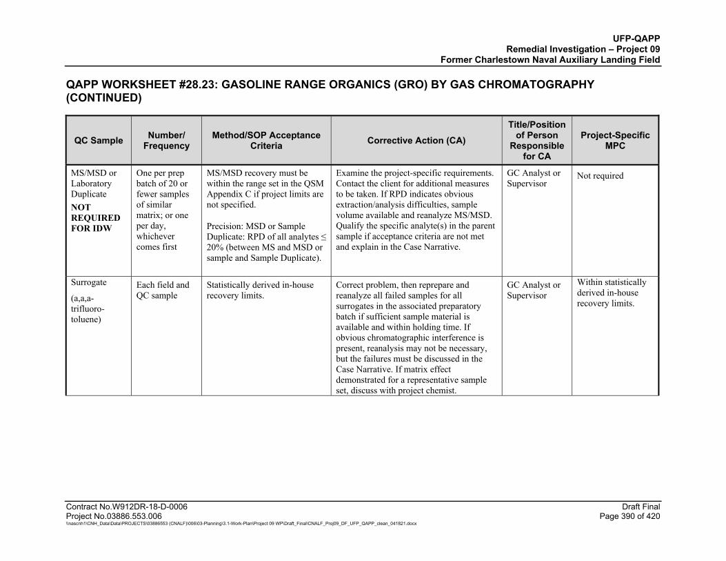
UFP-QAPP Remedial Investigation – Project 09
Former Charlestown Naval Auxiliary Landing Field
QAPP WORKSHEET #28.23: GASOLINE RANGE ORGANICS (GRO) BY GAS CHROMATOGRAPHY (CONTINUED)
Contract No.W912DR-18-D-0006 Draft Final Project No.03886.553.006 Page 390 of 420 \\nascnh1\CNH_Data\Data\PROJECTS\03886553 (CNALF)\006\03-Planning\3.1-Work-Plan\Project 09 WP\Draft_Final\CNALF_Proj09_DF_UFP_QAPP_clean_041821.docx
QC Sample Number/ Frequency
Method/SOP Acceptance Criteria Corrective Action (CA)
Title/Position of Person
Responsible for CA
Project-Specific MPC
MS/MSD or Laboratory Duplicate NOT REQUIRED FOR IDW
One per prep batch of 20 or fewer samples of similar matrix; or one per day, whichever comes first
MS/MSD recovery must be within the range set in the QSM Appendix C if project limits are not specified.
Precision: MSD or Sample Duplicate: RPD of all analytes ≤ 20% (between MS and MSD or sample and Sample Duplicate).
Examine the project-specific requirements. Contact the client for additional measures to be taken. If RPD indicates obvious extraction/analysis difficulties, sample volume available and reanalyze MS/MSD. Qualify the specific analyte(s) in the parent sample if acceptance criteria are not met and explain in the Case Narrative.
GC Analyst or Supervisor
Not required
Surrogate
(a,a,a-trifluoro-toluene)
Each field and QC sample
Statistically derived in-house recovery limits.
Correct problem, then reprepare and reanalyze all failed samples for all surrogates in the associated preparatory batch if sufficient sample material is available and within holding time. If obvious chromatographic interference is present, reanalysis may not be necessary, but the failures must be discussed in the Case Narrative. If matrix effect demonstrated for a representative sample set, discuss with project chemist.
GC Analyst or Supervisor
Within statistically derived in-house recovery limits.
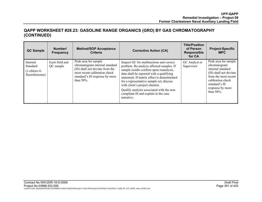
UFP-QAPP Remedial Investigation – Project 09
Former Charlestown Naval Auxiliary Landing Field
QAPP WORKSHEET #28.23: GASOLINE RANGE ORGANICS (GRO) BY GAS CHROMATOGRAPHY (CONTINUED)
Contract No.W912DR-18-D-0006 Draft Final Project No.03886.553.006 Page 391 of 420 \\nascnh1\CNH_Data\Data\PROJECTS\03886553 (CNALF)\006\03-Planning\3.1-Work-Plan\Project 09 WP\Draft_Final\CNALF_Proj09_DF_UFP_QAPP_clean_041821.docx
QC Sample Number/ Frequency
Method/SOP Acceptance Criteria Corrective Action (CA)
Title/Position of Person
Responsible for CA
Project-Specific MPC
Internal Standard (1-chloro-4-fluorobenzene)
Each field and QC sample
Peak area for sample chromatogram internal standard (IS) shall not deviate from the most recent calibration check standard’s IS response by more than 50%.
Inspect GC for malfunctions and correct problem. Re-analyze affected samples. If sample results confirm upon reanalysis, data shall be reported with a qualifying statement. If matrix effect is demonstrated for a representative sample set, discuss with client’s project chemist. Qualify analytes associated with the non-compliant IS and explain in the case narrative.
GC Analyst or Supervisor
Peak area for sample chromatogram internal standard (IS) shall not deviate from the most recent calibration check standard’s IS response by more than 50%.
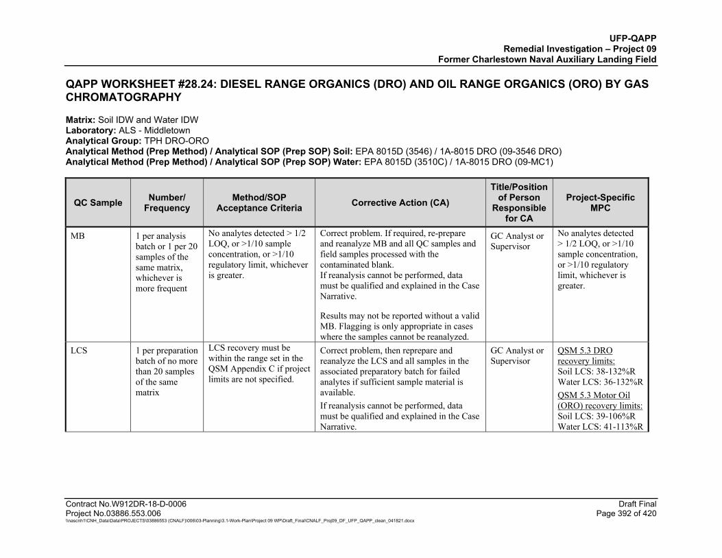
UFP-QAPP Remedial Investigation – Project 09
Former Charlestown Naval Auxiliary Landing Field
Contract No.W912DR-18-D-0006 Draft Final Project No.03886.553.006 Page 392 of 420 \\nascnh1\CNH_Data\Data\PROJECTS\03886553 (CNALF)\006\03-Planning\3.1-Work-Plan\Project 09 WP\Draft_Final\CNALF_Proj09_DF_UFP_QAPP_clean_041821.docx
QAPP WORKSHEET #28.24: DIESEL RANGE ORGANICS (DRO) AND OIL RANGE ORGANICS (ORO) BY GAS CHROMATOGRAPHY
Matrix: Soil IDW and Water IDW Laboratory: ALS - Middletown Analytical Group: TPH DRO-ORO Analytical Method (Prep Method) / Analytical SOP (Prep SOP) Soil: EPA 8015D (3546) / 1A-8015 DRO (09-3546 DRO) Analytical Method (Prep Method) / Analytical SOP (Prep SOP) Water: EPA 8015D (3510C) / 1A-8015 DRO (09-MC1)
QC Sample Number/ Frequency
Method/SOP Acceptance Criteria Corrective Action (CA)
Title/Position of Person
Responsible for CA
Project-Specific MPC
MB 1 per analysis batch or 1 per 20 samples of the same matrix, whichever is more frequent
No analytes detected > 1/2 LOQ, or >1/10 sample concentration, or >1/10 regulatory limit, whichever is greater.
Correct problem. If required, re-prepare and reanalyze MB and all QC samples and field samples processed with the contaminated blank. If reanalysis cannot be performed, data must be qualified and explained in the Case Narrative.
Results may not be reported without a valid MB. Flagging is only appropriate in cases where the samples cannot be reanalyzed.
GC Analyst or Supervisor
No analytes detected > 1/2 LOQ, or >1/10 sample concentration, or >1/10 regulatory limit, whichever is greater.
LCS 1 per preparation batch of no more than 20 samples of the same matrix
LCS recovery must be within the range set in the QSM Appendix C if project limits are not specified.
Correct problem, then reprepare and reanalyze the LCS and all samples in the associated preparatory batch for failed analytes if sufficient sample material is available. If reanalysis cannot be performed, data must be qualified and explained in the Case Narrative.
GC Analyst or Supervisor
QSM 5.3 DRO recovery limits: Soil LCS: 38-132%R Water LCS: 36-132%R QSM 5.3 Motor Oil (ORO) recovery limits: Soil LCS: 39-106%R Water LCS: 41-113%R
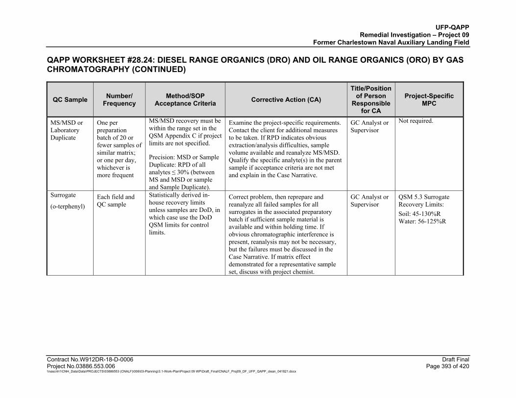
UFP-QAPP Remedial Investigation – Project 09
Former Charlestown Naval Auxiliary Landing Field
QAPP WORKSHEET #28.24: DIESEL RANGE ORGANICS (DRO) AND OIL RANGE ORGANICS (ORO) BY GAS CHROMATOGRAPHY (CONTINUED)
Contract No.W912DR-18-D-0006 Draft Final Project No.03886.553.006 Page 393 of 420 \\nascnh1\CNH_Data\Data\PROJECTS\03886553 (CNALF)\006\03-Planning\3.1-Work-Plan\Project 09 WP\Draft_Final\CNALF_Proj09_DF_UFP_QAPP_clean_041821.docx
QC Sample Number/ Frequency
Method/SOP Acceptance Criteria Corrective Action (CA)
Title/Position of Person
Responsible for CA
Project-Specific MPC
MS/MSD or Laboratory Duplicate
One per preparation batch of 20 or fewer samples of similar matrix; or one per day, whichever is more frequent
MS/MSD recovery must be within the range set in the QSM Appendix C if project limits are not specified.
Precision: MSD or Sample Duplicate: RPD of all analytes ≤ 30% (between MS and MSD or sample and Sample Duplicate).
Examine the project-specific requirements. Contact the client for additional measures to be taken. If RPD indicates obvious extraction/analysis difficulties, sample volume available and reanalyze MS/MSD. Qualify the specific analyte(s) in the parent sample if acceptance criteria are not met and explain in the Case Narrative.
GC Analyst or Supervisor
Not required.
Surrogate
(o-terphenyl) Each field and QC sample
Statistically derived in-house recovery limits unless samples are DoD, in which case use the DoD QSM limits for control limits.
Correct problem, then reprepare and reanalyze all failed samples for all surrogates in the associated preparatory batch if sufficient sample material is available and within holding time. If obvious chromatographic interference is present, reanalysis may not be necessary, but the failures must be discussed in the Case Narrative. If matrix effect demonstrated for a representative sample set, discuss with project chemist.
GC Analyst or Supervisor
QSM 5.3 Surrogate Recovery Limits: Soil: 45-130%R Water: 56-125%R

UFP-QAPP Remedial Investigation – Project 09
Former Charlestown Naval Auxiliary Landing Field
QAPP WORKSHEET #28.24: DIESEL RANGE ORGANICS (DRO) AND OIL RANGE ORGANICS (ORO) BY GAS CHROMATOGRAPHY (CONTINUED)
Contract No.W912DR-18-D-0006 Draft Final Project No.03886.553.006 Page 394 of 420 \\nascnh1\CNH_Data\Data\PROJECTS\03886553 (CNALF)\006\03-Planning\3.1-Work-Plan\Project 09 WP\Draft_Final\CNALF_Proj09_DF_UFP_QAPP_clean_041821.docx
QC Sample Number/ Frequency
Method/SOP Acceptance Criteria Corrective Action (CA)
Title/Position of Person
Responsible for CA
Project-Specific MPC
Internal Standard (1-chloro-4-fluorobenzene)
Each field and QC sample
Peak area for sample chromatogram IS shall not deviate from the most recent calibration check standard’s IS response by more than 50%.
Inspect GC for malfunctions and correct problem. Reanalyze affected samples. If sample results are confirmed upon reanalysis, data shall be reported with a qualifying statement. If matrix effect is demonstrated for a representative sample set, discuss with client’s project chemist. Qualify analytes associated with the non-compliant IS and explain in the case narrative.
GC Analyst or Supervisor
Same as Method/ SOP Acceptance Criteria
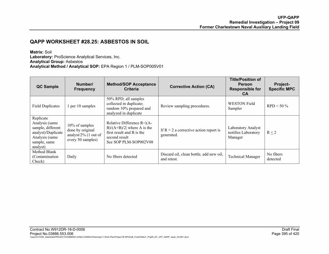
UFP-QAPP Remedial Investigation – Project 09
Former Charlestown Naval Auxiliary Landing Field
Contract No.W912DR-18-D-0006 Draft Final Project No.03886.553.006 Page 395 of 420 \\nascnh1\CNH_Data\Data\PROJECTS\03886553 (CNALF)\006\03-Planning\3.1-Work-Plan\Project 09 WP\Draft_Final\CNALF_Proj09_DF_UFP_QAPP_clean_041821.docx
QAPP WORKSHEET #28.25: ASBESTOS IN SOIL
Matrix: Soil Laboratory: ProScience Analytical Services, Inc. Analytical Group: Asbestos Analytical Method / Analytical SOP: EPA Region 1 / PLM-SOP005V01
QC Sample Number/ Frequency
Method/SOP Acceptance Criteria Corrective Action (CA)
Title/Position of Person
Responsible for CA
Project-Specific MPC
Field Duplicates 1 per 10 samples
50% RPD; all samples collected in duplicate; random 10% prepared and analyzed in duplicate
Review sampling procedures. WESTON Field Sampler RPD < 50 %
Replicate Analysis (same sample, different analyst)/Duplicate Analysis (same sample, same analyst)
10% of samples done by original analyst/2% (1 out of every 50 samples)
Relative Difference R=|(A-B)/(A+B)/2| where A is the first result and B is the second result See SOP PLM-SOP002V08
If R > 2 a corrective action report is generated.
Laboratory Analyst notifies Laboratory Manager
R < 2
Method Blank (Contamination Check)
Daily No fibers detected Discard oil, clean bottle, add new oil, and retest. Technical Manager No fibers
detected
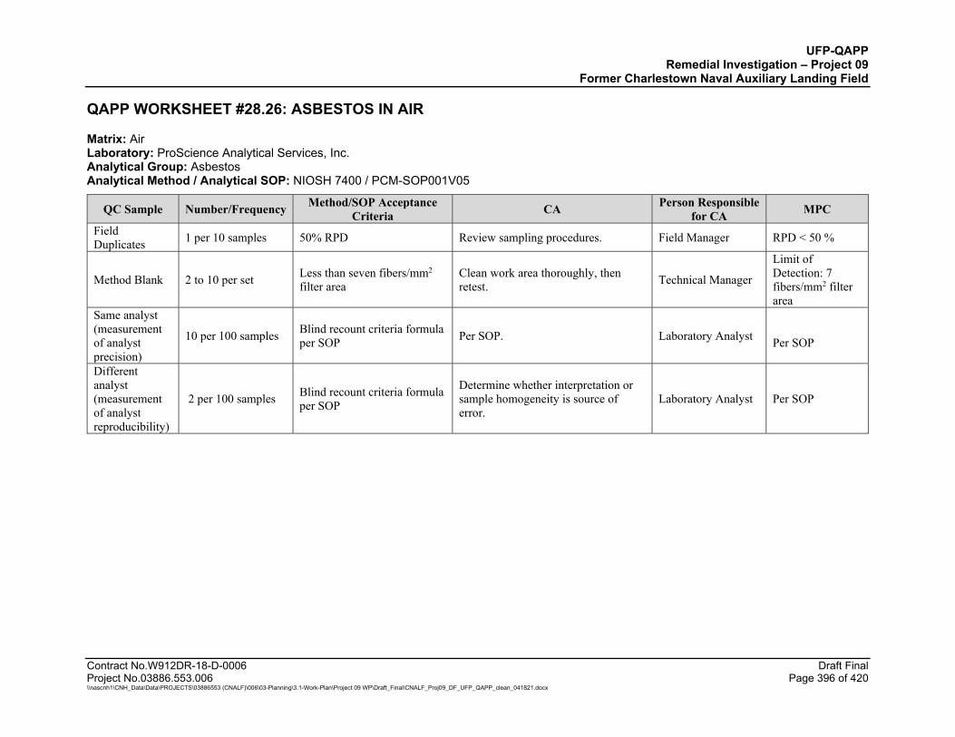
UFP-QAPP Remedial Investigation – Project 09
Former Charlestown Naval Auxiliary Landing Field
Contract No.W912DR-18-D-0006 Draft Final Project No.03886.553.006 Page 396 of 420 \\nascnh1\CNH_Data\Data\PROJECTS\03886553 (CNALF)\006\03-Planning\3.1-Work-Plan\Project 09 WP\Draft_Final\CNALF_Proj09_DF_UFP_QAPP_clean_041821.docx
QAPP WORKSHEET #28.26: ASBESTOS IN AIR
Matrix: Air Laboratory: ProScience Analytical Services, Inc. Analytical Group: Asbestos Analytical Method / Analytical SOP: NIOSH 7400 / PCM-SOP001V05
QC Sample Number/Frequency Method/SOP Acceptance Criteria CA Person Responsible
for CA MPC
Field Duplicates 1 per 10 samples 50% RPD Review sampling procedures. Field Manager RPD < 50 %
Method Blank 2 to 10 per set Less than seven fibers/mm2 filter area
Clean work area thoroughly, then retest. Technical Manager
Limit of Detection: 7 fibers/mm2 filter area
Same analyst (measurement of analyst precision)
10 per 100 samples Blind recount criteria formula per SOP Per SOP. Laboratory Analyst
Per SOP
Different analyst (measurement of analyst reproducibility)
2 per 100 samples Blind recount criteria formula per SOP
Determine whether interpretation or sample homogeneity is source of error.
Laboratory Analyst Per SOP
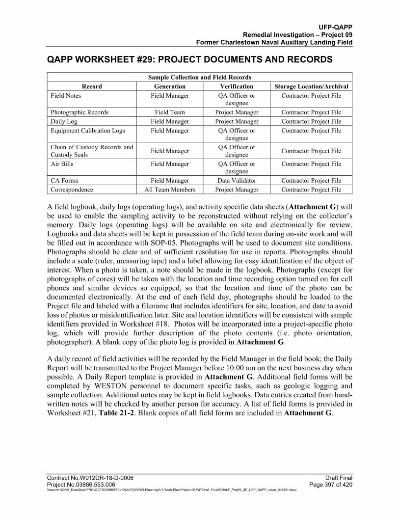
UFP-QAPP Remedial Investigation – Project 09
Former Charlestown Naval Auxiliary Landing Field
Contract No.W912DR-18-D-0006 Draft Final Project No.03886.553.006 Page 397 of 420 \\nascnh1\CNH_Data\Data\PROJECTS\03886553 (CNALF)\006\03-Planning\3.1-Work-Plan\Project 09 WP\Draft_Final\CNALF_Proj09_DF_UFP_QAPP_clean_041821.docx
QAPP WORKSHEET #29: PROJECT DOCUMENTS AND RECORDS
Sample Collection and Field Records Record Generation Verification Storage Location/Archival
Field Notes Field Manager QA Officer or designee
Contractor Project File
Photographic Records Field Team Project Manager Contractor Project File Daily Log Field Manager Project Manager Contractor Project File Equipment Calibration Logs Field Manager QA Officer or
designee Contractor Project File
Chain of Custody Records and Custody Seals Field Manager QA Officer or
designee Contractor Project File
Air Bills Field Manager QA Officer or designee
Contractor Project File
CA Forms Field Manager Data Validator Contractor Project File Correspondence All Team Members Project Manager Contractor Project File
A field logbook, daily logs (operating logs), and activity specific data sheets (Attachment G) will be used to enable the sampling activity to be reconstructed without relying on the collector’s memory. Daily logs (operating logs) will be available on site and electronically for review. Logbooks and data sheets will be kept in possession of the field team during on-site work and will be filled out in accordance with SOP-05. Photographs will be used to document site conditions. Photographs should be clear and of sufficient resolution for use in reports. Photographs should include a scale (ruler, measuring tape) and a label allowing for easy identification of the object of interest. When a photo is taken, a note should be made in the logbook. Photographs (except for photographs of cores) will be taken with the location and time recording option turned on for cell phones and similar devices so equipped, so that the location and time of the photo can be documented electronically. At the end of each field day, photographs should be loaded to the Project file and labeled with a filename that includes identifiers for site, location, and date to avoid loss of photos or misidentification later. Site and location identifiers will be consistent with sample identifiers provided in Worksheet #18. Photos will be incorporated into a project-specific photo log, which will provide further description of the photo contents (i.e. photo orientation, photographer). A blank copy of the photo log is provided in Attachment G.
A daily record of field activities will be recorded by the Field Manager in the field book; the Daily Report will be transmitted to the Project Manager before 10:00 am on the next business day when possible. A Daily Report template is provided in Attachment G. Additional field forms will be completed by WESTON personnel to document specific tasks, such as geologic logging and sample collection. Additional notes may be kept in field logbooks. Data entries created from hand-written notes will be checked by another person for accuracy. A list of field forms is provided in Worksheet #21, Table 21-2. Blank copies of all field forms are included in Attachment G.

UFP-QAPP Remedial Investigation – Project 09
Former Charlestown Naval Auxiliary Landing Field
QAPP WORKSHEET #29: PROJECT DOCUMENTS AND RECORDS (CONTINUED)
Contract No.W912DR-18-D-0006 Draft Final Project No.03886.553.006 Page 398 of 420 \\nascnh1\CNH_Data\Data\PROJECTS\03886553 (CNALF)\006\03-Planning\3.1-Work-Plan\Project 09 WP\Draft_Final\CNALF_Proj09_DF_UFP_QAPP_clean_041821.docx
Project Assessments
Record Generation Verification Storage Location/Archival
Desktop Field Audit Checklists Field Manager QA Officer or
designee Contractor Project File
Data Validation Report Project Chemist/Data Validator
QA Officer or designee Contractor Project File
Data Usability Assessment Report
Project Chemist/Data Validator, Field Manager
QA Officer or designee Contractor Project File
Laboratory Records
Record Generation Verification Storage Location/Archival
Chain of Custody Upon Sample Receipt Laboratory Data Validator/QA
Officer or designee Contractor Project File
Laboratory Reports Laboratory Data Validator/QA Officer or designee Contractor Project File
Equipment Calibration, Testing, Maintenance, and Inspection Logs
Laboratory Laboratory Contact Laboratory Project File
Raw Data and Reported Results for Samples, Standards, QC Checks, and QC Samples
Laboratory Laboratory Contact and Data Validator
Laboratory Project File and Contractor Project File
Geophysical Records
Record Generation Verification Storage Location/Archival
IVS Technical Memorandum Project Geophysicist IVS and test lane Electronic File
Daily Status Reports Project Geophysicist Document daily activities Hard copy/Electronic File
Geophysical QC Report QC Geophysicist Geophysical QC Results Electronic File
DUAs (EM31 and EM 61) QC Geophysicist Data usability Electronic File

UFP-QAPP Remedial Investigation – Project 09
Former Charlestown Naval Auxiliary Landing Field
QAPP WORKSHEET #29: PROJECT DOCUMENTS AND RECORDS (CONTINUED)
Contract No.W912DR-18-D-0006 Draft Final Project No.03886.553.006 Page 399 of 420 \\nascnh1\CNH_Data\Data\PROJECTS\03886553 (CNALF)\006\03-Planning\3.1-Work-Plan\Project 09 WP\Draft_Final\CNALF_Proj09_DF_UFP_QAPP_clean_041821.docx
Laboratory Data Deliverables
Record
VO
Cs
SVO
Cs
Was
te C
hara
cter
izat
ion
Asb
esto
s
PFA
S
Met
als
Mer
cury
Cr+
6
Dio
xins
/ Fur
ans
PCB
s
MC
TO
C
Har
dnes
s
Perc
hlor
ate
Narrative X X X X X X X X X X X X X X
Chain of Custody X X X X X X X X X X X X X X
Sample Receipt Report X X X X X X X X X X X X X X
Summary Results X X X X X X X X X X X X X X
QC Summary Results X X X X X X X X X X X X X X
Chromatograms X X X X X X X X X X X X X X
Instrument Raw Data (calibration reports including documentation of re-quantitation of the low standard for alternate calibration methods, QC sample raw data, and field sample raw data)
X X X X X X X X X X X X X X
Laboratory Bench Sheets/Logs X X X X X X X X X X X X X X
Stage 2a Electronic Data Deliverable version 5.2 X X X X X X X X X X X X X X
The laboratory will provide the final data report in both pdf and hardcopy formats.
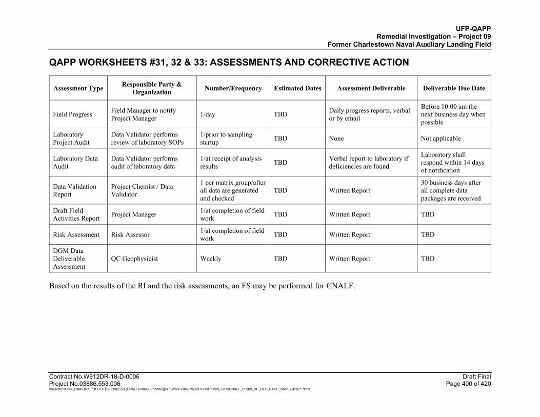
UFP-QAPP Remedial Investigation – Project 09
Former Charlestown Naval Auxiliary Landing Field
Contract No.W912DR-18-D-0006 Draft Final Project No.03886.553.006 Page 400 of 420 \\nascnh1\CNH_Data\Data\PROJECTS\03886553 (CNALF)\006\03-Planning\3.1-Work-Plan\Project 09 WP\Draft_Final\CNALF_Proj09_DF_UFP_QAPP_clean_041821.docx
QAPP WORKSHEETS #31, 32 & 33: ASSESSMENTS AND CORRECTIVE ACTION
Assessment Type Responsible Party & Organization Number/Frequency Estimated Dates Assessment Deliverable Deliverable Due Date
Field Progress Field Manager to notify Project Manager 1/day TBD Daily progress reports, verbal
or by email
Before 10:00 am the next business day when possible
Laboratory Project Audit
Data Validator performs review of laboratory SOPs
1/prior to sampling startup TBD None Not applicable
Laboratory Data Audit
Data Validator performs audit of laboratory data
1/at receipt of analysis results TBD Verbal report to laboratory if
deficiencies are found
Laboratory shall respond within 14 days of notification
Data Validation Report
Project Chemist / Data Validator
1 per matrix group/after all data are generated and checked
TBD Written Report 30 business days after all complete data packages are received
Draft Field Activities Report Project Manager 1/at completion of field
work TBD Written Report TBD
Risk Assessment Risk Assessor 1/at completion of field work TBD Written Report TBD
DGM Data Deliverable Assessment
QC Geophysicist Weekly TBD Written Report TBD
Based on the results of the RI and the risk assessments, an FS may be performed for CNALF.
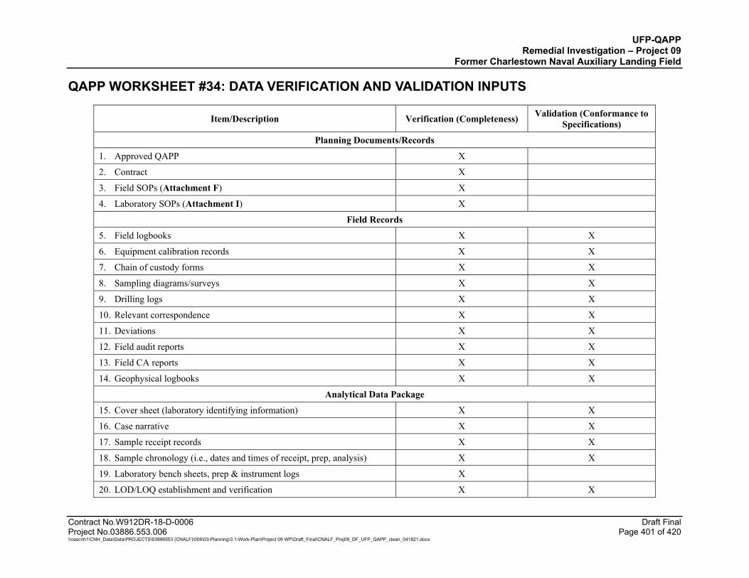
UFP-QAPP Remedial Investigation – Project 09
Former Charlestown Naval Auxiliary Landing Field
Contract No.W912DR-18-D-0006 Draft Final Project No.03886.553.006 Page 401 of 420 \\nascnh1\CNH_Data\Data\PROJECTS\03886553 (CNALF)\006\03-Planning\3.1-Work-Plan\Project 09 WP\Draft_Final\CNALF_Proj09_DF_UFP_QAPP_clean_041821.docx
QAPP WORKSHEET #34: DATA VERIFICATION AND VALIDATION INPUTS
Item/Description Verification (Completeness) Validation (Conformance to Specifications)
Planning Documents/Records
1. Approved QAPP X
2. Contract X
3. Field SOPs (Attachment F) X
4. Laboratory SOPs (Attachment I) X
Field Records
5. Field logbooks X X
6. Equipment calibration records X X
7. Chain of custody forms X X
8. Sampling diagrams/surveys X X
9. Drilling logs X X
10. Relevant correspondence X X
11. Deviations X X
12. Field audit reports X X
13. Field CA reports X X
14. Geophysical logbooks X X
Analytical Data Package
15. Cover sheet (laboratory identifying information) X X
16. Case narrative X X
17. Sample receipt records X X
18. Sample chronology (i.e., dates and times of receipt, prep, analysis) X X
19. Laboratory bench sheets, prep & instrument logs X
20. LOD/LOQ establishment and verification X X

UFP-QAPP Remedial Investigation – Project 09
Former Charlestown Naval Auxiliary Landing Field
QAPP WORKSHEET #34: DATA VERIFICATION AND VALIDATION INPUTS (CONTINUED)
Contract No.W912DR-18-D-0006 Draft Final Project No.03886.553.006 Page 402 of 420 \\nascnh1\CNH_Data\Data\PROJECTS\03886553 (CNALF)\006\03-Planning\3.1-Work-Plan\Project 09 WP\Draft_Final\CNALF_Proj09_DF_UFP_QAPP_clean_041821.docx
Item/Description Verification (Completeness) Validation (Conformance to Specifications)
21. Standards traceability X X
22. Instrument calibration records X X
23. Definition of laboratory qualifiers X X
24. Results reporting forms X X
25. QC sample results (including association to field samples) X X
26. CA reports (summarized in Case Narrative) X X
27. Raw data for tunes, calibrations, QC samples, and field samples X X
28. Electronic data deliverable X X
29. Certification Summary X X
30. IVS Technical Memorandum X X
31. Geophysical data deliverables X X
32. Geophysical DUA X X

UFP-QAPP Remedial Investigation – Project 09
Former Charlestown Naval Auxiliary Landing Field
Contract No.W912DR-18-D-0006 Draft Final Project No.03886.553.006 Page 403 of 420 \\nascnh1\CNH_Data\Data\PROJECTS\03886553 (CNALF)\006\03-Planning\3.1-Work-Plan\Project 09 WP\Draft_Final\CNALF_Proj09_DF_UFP_QAPP_clean_041821.docx
QAPP WORKSHEET #35: DATA VERIFICATION PROCEDURES
Records Reviewed
Requirement Documents
Process Description Responsible Person, Organization
Field forms QAPP, field SOPs
Verify that records are present and complete for each day of field activities. Verify that all planned samples including field QC samples were collected and that sample collection locations are documented. Verify that meteorological data were provided for each day of field activities. Verify that changes/exceptions are documented and were reported in accordance with requirements. Verify that any required field monitoring was performed and results are documented.
During field activities – Field Manager. At conclusion of field activities – QA Officer.
COC forms QAPP, SOP-08
Verify the completeness of COC records. Examine entries for consistency with the field logbook and/or sampling forms. Check that appropriate methods and sample preservation have been recorded. Verify that the required volume of sample has been collected and that sufficient sample volume is available for QC samples (e.g., MS/MSD). Verify that all required signatures and dates are present. Check for transcription errors. Verify that laboratory receipt and log-in conform to field COC requests and to the QAPP. Notify the Field Manager and the Project Manager of any sample issues.
During field activities – Field Manager During and at conclusion of field activities – Data Validator and QA Officer
General Geophysics Documentation
QAPP Verify and confirm that the documentation is complete, including all raw data files, processed data products, and QC inspections. Validate that all MQOs have been achieved with any exceptions noted. If appropriate, Cas have been completed.
Project Geophysicist/QC Geophysicist
Laboratory deliverable QAPP
Verify that the laboratory deliverable contains all records specified in the QAPP. Check sample receipt records to ensure sample condition upon receipt was noted, and any missing/broken sample containers were noted and reported according to plan. Compare the data package with the COCs to verify that results were provided for all collected samples. Review the narrative to ensure all QC exceptions are described. Establish that all QAPP-required QC samples were run and met required criteria. Determine that all sample results met the project quantitation limits specified in QAPP Worksheet #15 (Attachment J). Check for evidence that any required notifications were provided to project personnel as specified in the QAPP. Verify that necessary signatures and dates are present. Ensure non-conformance report and all electronic data submitted to the Automated Data Review (ADR) program are correct. The laboratory must correct errors and resubmit the data deliverable.
Data Validator
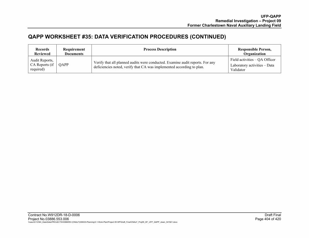
UFP-QAPP Remedial Investigation – Project 09
Former Charlestown Naval Auxiliary Landing Field
QAPP WORKSHEET #35: DATA VERIFICATION PROCEDURES (CONTINUED)
Contract No.W912DR-18-D-0006 Draft Final Project No.03886.553.006 Page 404 of 420 \\nascnh1\CNH_Data\Data\PROJECTS\03886553 (CNALF)\006\03-Planning\3.1-Work-Plan\Project 09 WP\Draft_Final\CNALF_Proj09_DF_UFP_QAPP_clean_041821.docx
Records Reviewed
Requirement Documents
Process Description Responsible Person, Organization
Audit Reports, CA Reports (if required)
QAPP Verify that all planned audits were conducted. Examine audit reports. For any deficiencies noted, verify that CA was implemented according to plan.
Field activities – QA Officer Laboratory activities – Data Validator

UFP-QAPP Remedial Investigation – Project 09
Former Charlestown Naval Auxiliary Landing Field
Contract No.W912DR-18-D-0006 Draft Final Project No.03886.553.006 Page 405 of 420 \\nascnh1\CNH_Data\Data\PROJECTS\03886553 (CNALF)\006\03-Planning\3.1-Work-Plan\Project 09 WP\Draft_Final\CNALF_Proj09_DF_UFP_QAPP_clean_041821.docx
QAPP WORKSHEET #36: DATA VALIDATION PROCEDURES
Data Validator: Environmental Synectics, Inc. (Synectics)
WESTON will generate an electronic QAPP (eQAPP) that will include analytical acceptance limits specified in DoD QSM 5.3 for investigative samples to be collected and submitted to ALS laboratories for analysis. Investigative samples (e.g., soil, sediment, surface water, pore water, groundwater, tapwater, and solid and liquid test pit waste objects) along with associated field blanks (trip, equipment, and field reagent blanks) will be validated electronically and manually to support the Remedial Investigation. Parameters include in this category include VOCs, SVOCs, low-level SVOCs, 1,4-dioxane, PAHs (SIM), PCBs, explosives, dioxins/furans, TAL metals (including mercury), hexavalent chromium, PFAS, and perchlorate.
The eQAPP will also include ancillary analytical methods which will be used to interpret hexavalent chromium results (e.g., pH, TOC, leachable ferrous iron, and total sulfide) and for risk assessment (TOC, pH, and hardness by calculation). These data will not require automated or manual data validation by Synectics, although the QC limits for pH and TOC will be included into the eQAPP to facilitate any automated data review (ADR) function of FUDSChem if needed in the future. A simple completeness check will be completed by WESTON for these ancillary analyses.
The eQAPP will also include additional methods for waste characterization of IDW samples (i.e., purge water, decontamination water, and soil cuttings). If sample concentrations or field screening data suggest that off-site disposal is required, the TSDF will specify the required analytical methods needed for waste disposal characterization. This QAPP includes the following parameters for IDW samples which is expected to cover all the potential IDW analyses for this site: VOCs, TCLP VOCs, SVOCs, TCLP VOCs, TAL metals (including mercury), TCLP metals (including mercury), TPH-GRO, TPH-DRO/ORO, PCBs, explosives, perchlorate, dioxins/furans, corrosivity, ignitability/flashpoint, reactive cyanide, and reactive sulfide. IDW data will not require automated or manual data validation by Synectics, although the QC limits will be included into the eQAPP to facilitate any automated data review (ADR) function of FUDSChem if needed in the future. A simple completeness check will be completed by WESTON for these ancillary analyses.
Asbestos air and soil samples will not require data validation by Synectics. Air samples for asbestos will be collected solely for perimeter air monitoring and for personal air monitoring. Soil asbestos samples will be collected only as part of test pitting operations. The asbestos laboratory, ProScience Analytical Services, Inc. does not have the ability to provide a SEDD 2a format deliverable and will only provide a laboratory report in pdf format which will be used to assess for the presence of asbestos in test pit soils and air to inform other site decisions. The eQAPP will not include asbestos.
The eQAPP will be provided to the USACE for approval prior to field sampling. Once approved, the eQAPP will be available from the FUDSCHEM portal to the subcontract laboratory for use in screening the Staged Electronic Data Deliverable (SEDD) submittals. Prior to finalization and USACE approval, the laboratory must review the eQAPP to verify that the laboratory analytical criteria entries for accuracy and precision, QC, holding times, and reporting limits for all target analytes are accurate.
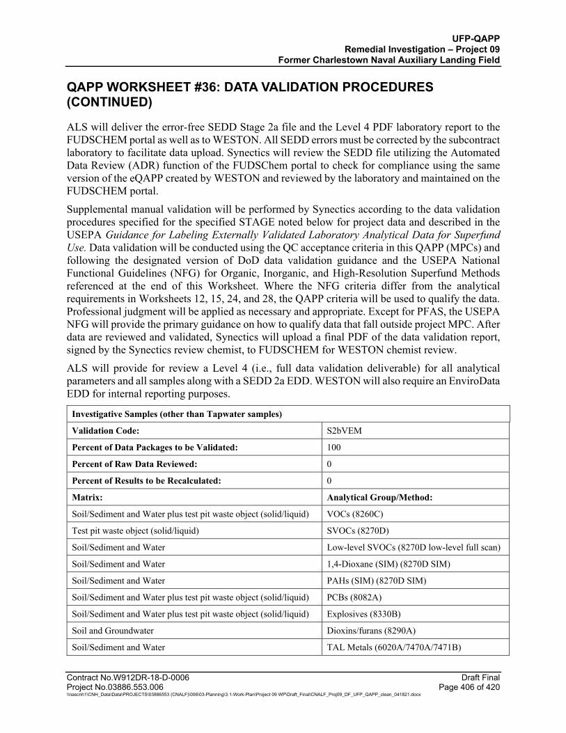
UFP-QAPP Remedial Investigation – Project 09
Former Charlestown Naval Auxiliary Landing Field
QAPP WORKSHEET #36: DATA VALIDATION PROCEDURES (CONTINUED)
Contract No.W912DR-18-D-0006 Draft Final Project No.03886.553.006 Page 406 of 420 \\nascnh1\CNH_Data\Data\PROJECTS\03886553 (CNALF)\006\03-Planning\3.1-Work-Plan\Project 09 WP\Draft_Final\CNALF_Proj09_DF_UFP_QAPP_clean_041821.docx
ALS will deliver the error-free SEDD Stage 2a file and the Level 4 PDF laboratory report to the FUDSCHEM portal as well as to WESTON. All SEDD errors must be corrected by the subcontract laboratory to facilitate data upload. Synectics will review the SEDD file utilizing the Automated Data Review (ADR) function of the FUDSChem portal to check for compliance using the same version of the eQAPP created by WESTON and reviewed by the laboratory and maintained on the FUDSCHEM portal.
Supplemental manual validation will be performed by Synectics according to the data validation procedures specified for the specified STAGE noted below for project data and described in the USEPA Guidance for Labeling Externally Validated Laboratory Analytical Data for Superfund Use. Data validation will be conducted using the QC acceptance criteria in this QAPP (MPCs) and following the designated version of DoD data validation guidance and the USEPA National Functional Guidelines (NFG) for Organic, Inorganic, and High-Resolution Superfund Methods referenced at the end of this Worksheet. Where the NFG criteria differ from the analytical requirements in Worksheets 12, 15, 24, and 28, the QAPP criteria will be used to qualify the data. Professional judgment will be applied as necessary and appropriate. Except for PFAS, the USEPA NFG will provide the primary guidance on how to qualify data that fall outside project MPC. After data are reviewed and validated, Synectics will upload a final PDF of the data validation report, signed by the Synectics review chemist, to FUDSCHEM for WESTON chemist review.
ALS will provide for review a Level 4 (i.e., full data validation deliverable) for all analytical parameters and all samples along with a SEDD 2a EDD. WESTON will also require an EnviroData EDD for internal reporting purposes.
Investigative Samples (other than Tapwater samples)
Validation Code: S2bVEM
Percent of Data Packages to be Validated: 100
Percent of Raw Data Reviewed: 0
Percent of Results to be Recalculated: 0
Matrix: Analytical Group/Method:
Soil/Sediment and Water plus test pit waste object (solid/liquid) VOCs (8260C)
Test pit waste object (solid/liquid) SVOCs (8270D)
Soil/Sediment and Water Low-level SVOCs (8270D low-level full scan)
Soil/Sediment and Water 1,4-Dioxane (SIM) (8270D SIM)
Soil/Sediment and Water PAHs (SIM) (8270D SIM)
Soil/Sediment and Water plus test pit waste object (solid/liquid) PCBs (8082A)
Soil/Sediment and Water plus test pit waste object (solid/liquid) Explosives (8330B)
Soil and Groundwater Dioxins/furans (8290A)
Soil/Sediment and Water TAL Metals (6020A/7470A/7471B)
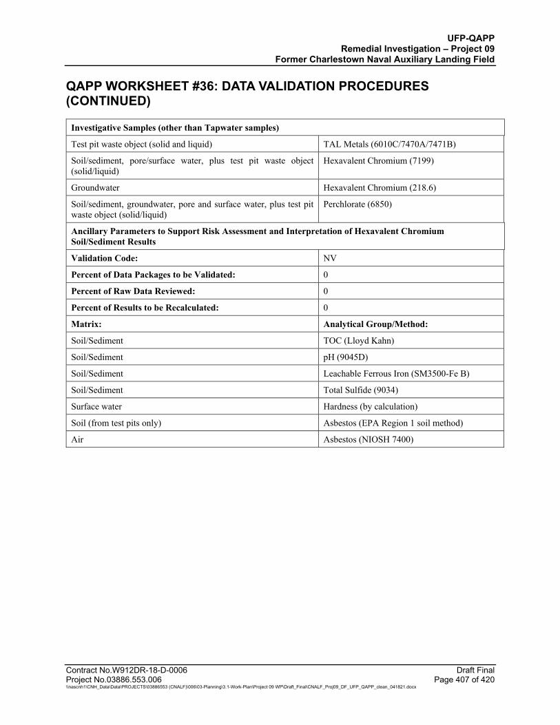
UFP-QAPP Remedial Investigation – Project 09
Former Charlestown Naval Auxiliary Landing Field
QAPP WORKSHEET #36: DATA VALIDATION PROCEDURES (CONTINUED)
Contract No.W912DR-18-D-0006 Draft Final Project No.03886.553.006 Page 407 of 420 \\nascnh1\CNH_Data\Data\PROJECTS\03886553 (CNALF)\006\03-Planning\3.1-Work-Plan\Project 09 WP\Draft_Final\CNALF_Proj09_DF_UFP_QAPP_clean_041821.docx
Investigative Samples (other than Tapwater samples)
Test pit waste object (solid and liquid) TAL Metals (6010C/7470A/7471B)
Soil/sediment, pore/surface water, plus test pit waste object (solid/liquid)
Hexavalent Chromium (7199)
Groundwater Hexavalent Chromium (218.6)
Soil/sediment, groundwater, pore and surface water, plus test pit waste object (solid/liquid)
Perchlorate (6850)
Ancillary Parameters to Support Risk Assessment and Interpretation of Hexavalent Chromium Soil/Sediment Results
Validation Code: NV
Percent of Data Packages to be Validated: 0
Percent of Raw Data Reviewed: 0
Percent of Results to be Recalculated: 0
Matrix: Analytical Group/Method:
Soil/Sediment TOC (Lloyd Kahn)
Soil/Sediment pH (9045D)
Soil/Sediment Leachable Ferrous Iron (SM3500-Fe B)
Soil/Sediment Total Sulfide (9034)
Surface water Hardness (by calculation)
Soil (from test pits only) Asbestos (EPA Region 1 soil method)
Air Asbestos (NIOSH 7400)

UFP-QAPP Remedial Investigation – Project 09
Former Charlestown Naval Auxiliary Landing Field
QAPP WORKSHEET #36: DATA VALIDATION PROCEDURES (CONTINUED)
Contract No.W912DR-18-D-0006 Draft Final Project No.03886.553.006 Page 408 of 420 \\nascnh1\CNH_Data\Data\PROJECTS\03886553 (CNALF)\006\03-Planning\3.1-Work-Plan\Project 09 WP\Draft_Final\CNALF_Proj09_DF_UFP_QAPP_clean_041821.docx
Investigative Samples – Tapwater matrix only
Validation Code: PFAS and VOCs: S4VEM (100% of samples) Remaining parameters: S4VEM (10% of overall investigative samples) and S2bVEM (90% of overall investigative samples)
Percent of Data Packages to be Validated: See above
Percent of Raw Data Reviewed: 10%
Percent of Results to be Recalculated: 10%
Matrix: Analytical Group/Method:
Tapwater (onsite and residential wells) VOCs (8260C)
Tapwater (onsite and residential wells) PFAS (PFAS by LCMSMS Compliant with QSM 5.3 Table B-15)
Tapwater (onsite) Low-level SVOCs (8270D low-level full scan)
Tapwater (onsite) 1,4-Dioxane (SIM) (8270D SIM)
Tapwater (onsite) PAHs (SIM) (8270D SIM)
Tapwater (onsite) PCBs (8082A)
Tapwater (onsite) Explosives (8330B)
Tapwater (onsite) TAL Metals (6020A/7470A)
Tapwater (onsite) Hexavalent Chromium (218.6)
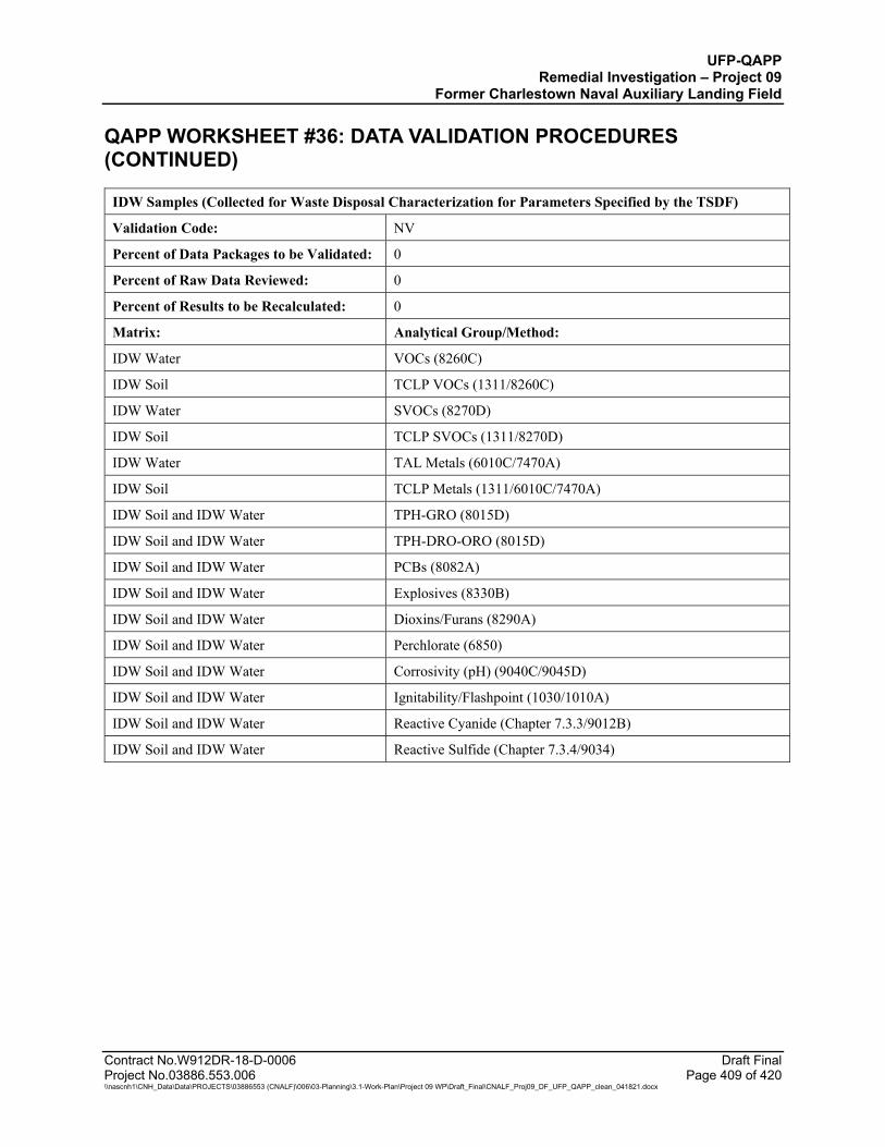
UFP-QAPP Remedial Investigation – Project 09
Former Charlestown Naval Auxiliary Landing Field
QAPP WORKSHEET #36: DATA VALIDATION PROCEDURES (CONTINUED)
Contract No.W912DR-18-D-0006 Draft Final Project No.03886.553.006 Page 409 of 420 \\nascnh1\CNH_Data\Data\PROJECTS\03886553 (CNALF)\006\03-Planning\3.1-Work-Plan\Project 09 WP\Draft_Final\CNALF_Proj09_DF_UFP_QAPP_clean_041821.docx
IDW Samples (Collected for Waste Disposal Characterization for Parameters Specified by the TSDF)
Validation Code: NV
Percent of Data Packages to be Validated: 0
Percent of Raw Data Reviewed: 0
Percent of Results to be Recalculated: 0
Matrix: Analytical Group/Method:
IDW Water VOCs (8260C)
IDW Soil TCLP VOCs (1311/8260C)
IDW Water SVOCs (8270D)
IDW Soil TCLP SVOCs (1311/8270D)
IDW Water TAL Metals (6010C/7470A)
IDW Soil TCLP Metals (1311/6010C/7470A)
IDW Soil and IDW Water TPH-GRO (8015D)
IDW Soil and IDW Water TPH-DRO-ORO (8015D)
IDW Soil and IDW Water PCBs (8082A)
IDW Soil and IDW Water Explosives (8330B)
IDW Soil and IDW Water Dioxins/Furans (8290A)
IDW Soil and IDW Water Perchlorate (6850)
IDW Soil and IDW Water Corrosivity (pH) (9040C/9045D)
IDW Soil and IDW Water Ignitability/Flashpoint (1030/1010A)
IDW Soil and IDW Water Reactive Cyanide (Chapter 7.3.3/9012B)
IDW Soil and IDW Water Reactive Sulfide (Chapter 7.3.4/9034)
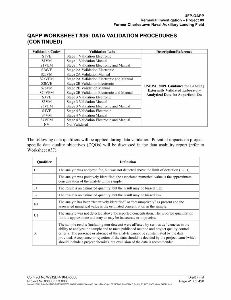
UFP-QAPP Remedial Investigation – Project 09
Former Charlestown Naval Auxiliary Landing Field
QAPP WORKSHEET #36: DATA VALIDATION PROCEDURES (CONTINUED)
Contract No.W912DR-18-D-0006 Draft Final Project No.03886.553.006 Page 410 of 420 \\nascnh1\CNH_Data\Data\PROJECTS\03886553 (CNALF)\006\03-Planning\3.1-Work-Plan\Project 09 WP\Draft_Final\CNALF_Proj09_DF_UFP_QAPP_clean_041821.docx
Validation Code* Validation Label Description/Reference S1VE Stage 1 Validation Electronic
USEPA. 2009. Guidance for Labeling Externally Validated Laboratory
Analytical Data for Superfund Use
S1VM Stage 1 Validation Manual S1VEM Stage 1 Validation Electronic and Manual S2aVE Stage 2A Validation Electronic S2aVM Stage 2A Validation Manual
S2aVEM Stage 2A Validation Electronic and Manual S2bVE Stage 2B Validation Electronic S2bVM Stage 2B Validation Manual
S2bVEM Stage 2B Validation Electronic and Manual S3VE Stage 3 Validation Electronic S3VM Stage 3 Validation Manual
S3VEM Stage 3 Validation Electronic and Manual S4VE Stage 4 Validation Electronic S4VM Stage 4 Validation Manual
S4VEM Stage 4 Validation Electronic and Manual NV Not Validated
The following data qualifiers will be applied during data validation. Potential impacts on project-specific data quality objectives (DQOs) will be discussed in the data usability report (refer to Worksheet #37).
Qualifier Definition
U The analyte was analyzed for, but was not detected above the limit of detection (LOD).
J The analyte was positively identified; the associated numerical value is the approximate concentration of the analyte in the sample.
J+ The result is an estimated quantity, but the result may be biased high.
J- The result is an estimated quantity, but the result may be biased low.
NJ The analyte has been “tentatively identified” or “presumptively” as present and the associated numerical value is the estimated concentration in the sample.
UJ The analyte was not detected above the reported concentration. The reported quantitation limit is approximate and may or may be inaccurate or imprecise.
X
The sample results (including non-detects) were affected by serious deficiencies in the ability to analyze the sample and to meet published method and project quality control criteria. The presence or absence of the analyte cannot be substantiated by the data provided. Acceptance or rejection of the data should be decided by the project team (which should include a project chemist), but exclusion of the data is recommended.
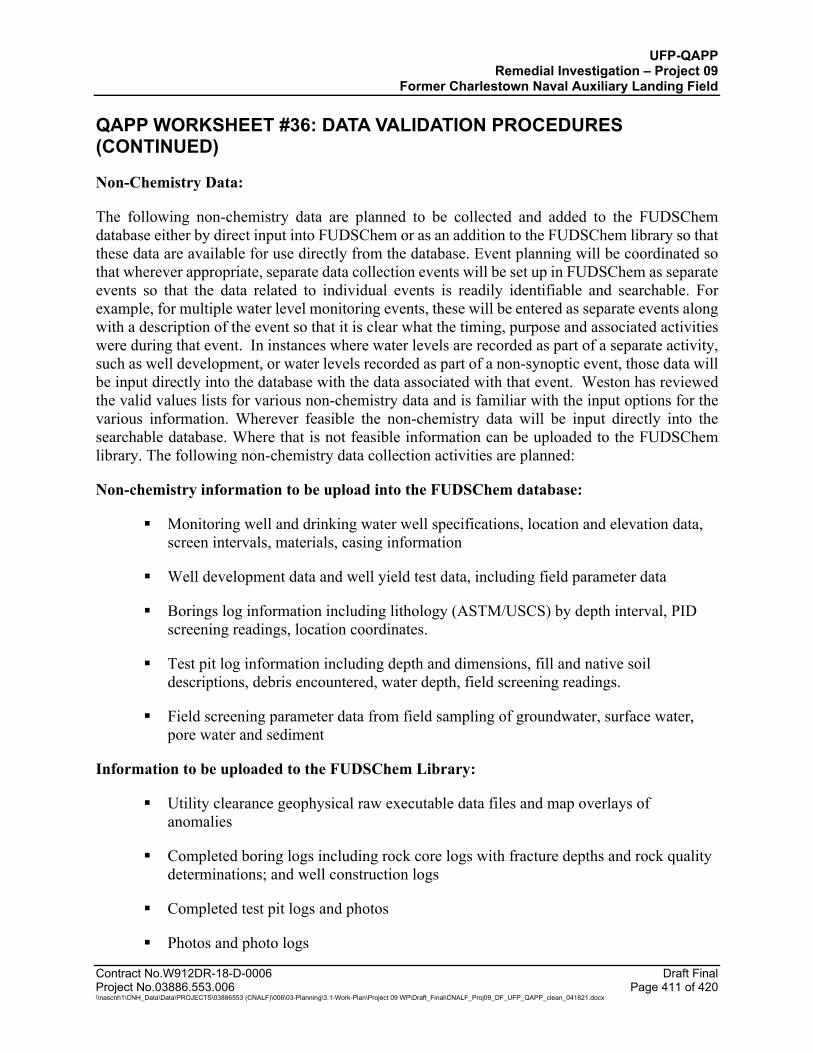
UFP-QAPP Remedial Investigation – Project 09
Former Charlestown Naval Auxiliary Landing Field
QAPP WORKSHEET #36: DATA VALIDATION PROCEDURES (CONTINUED)
Contract No.W912DR-18-D-0006 Draft Final Project No.03886.553.006 Page 411 of 420 \\nascnh1\CNH_Data\Data\PROJECTS\03886553 (CNALF)\006\03-Planning\3.1-Work-Plan\Project 09 WP\Draft_Final\CNALF_Proj09_DF_UFP_QAPP_clean_041821.docx
Non-Chemistry Data:
The following non-chemistry data are planned to be collected and added to the FUDSChem database either by direct input into FUDSChem or as an addition to the FUDSChem library so that these data are available for use directly from the database. Event planning will be coordinated so that wherever appropriate, separate data collection events will be set up in FUDSChem as separate events so that the data related to individual events is readily identifiable and searchable. For example, for multiple water level monitoring events, these will be entered as separate events along with a description of the event so that it is clear what the timing, purpose and associated activities were during that event. In instances where water levels are recorded as part of a separate activity, such as well development, or water levels recorded as part of a non-synoptic event, those data will be input directly into the database with the data associated with that event. Weston has reviewed the valid values lists for various non-chemistry data and is familiar with the input options for the various information. Wherever feasible the non-chemistry data will be input directly into the searchable database. Where that is not feasible information can be uploaded to the FUDSChem library. The following non-chemistry data collection activities are planned:
Non-chemistry information to be upload into the FUDSChem database:
Monitoring well and drinking water well specifications, location and elevation data, screen intervals, materials, casing information
Well development data and well yield test data, including field parameter data
Borings log information including lithology (ASTM/USCS) by depth interval, PID screening readings, location coordinates.
Test pit log information including depth and dimensions, fill and native soil descriptions, debris encountered, water depth, field screening readings.
Field screening parameter data from field sampling of groundwater, surface water, pore water and sediment
Information to be uploaded to the FUDSChem Library:
Utility clearance geophysical raw executable data files and map overlays of anomalies
Completed boring logs including rock core logs with fracture depths and rock quality determinations; and well construction logs
Completed test pit logs and photos
Photos and photo logs
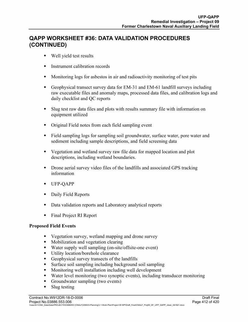
UFP-QAPP Remedial Investigation – Project 09
Former Charlestown Naval Auxiliary Landing Field
QAPP WORKSHEET #36: DATA VALIDATION PROCEDURES (CONTINUED)
Contract No.W912DR-18-D-0006 Draft Final Project No.03886.553.006 Page 412 of 420 \\nascnh1\CNH_Data\Data\PROJECTS\03886553 (CNALF)\006\03-Planning\3.1-Work-Plan\Project 09 WP\Draft_Final\CNALF_Proj09_DF_UFP_QAPP_clean_041821.docx
Well yield test results
Instrument calibration records
Monitoring logs for asbestos in air and radioactivity monitoring of test pits
Geophysical transect survey data for EM-31 and EM-61 landfill surveys including raw executable files and anomaly maps, processed data files, and calibration logs and daily checklist and QC reports
Slug test raw data files and plots with results summary file with information on equipment utilized
Original Field notes from each field sampling event
Field sampling logs for sampling soil groundwater, surface water, pore water and sediment including sample descriptions, and field screening data
Vegetation and wetland survey raw file data for mapped location and plot descriptions, including wetland boundaries.
Drone aerial survey video files of the landfills and associated GPS tracking information
UFP-QAPP
Daily Field Reports
Data validation reports and Laboratory analytical reports
Final Project RI Report
Proposed Field Events
Vegetation survey, wetland mapping and drone survey Mobilization and vegetation clearing Water supply well sampling (on-site/offsite-one event) Utility location/borehole clearance Geophysical survey transects of the landfills Surface soil sampling including background soil sampling Monitoring well installation including well development Water level monitoring (two synoptic events), including transducer monitoring Groundwater sampling (two events) Slug testing
UFP-QAPP Remedial Investigation – Project 09
Former Charlestown Naval Auxiliary Landing Field
QAPP WORKSHEET #36: DATA VALIDATION PROCEDURES (CONTINUED)
Contract No.W912DR-18-D-0006 Draft Final Project No.03886.553.006 Page 413 of 420 \\nascnh1\CNH_Data\Data\PROJECTS\03886553 (CNALF)\006\03-Planning\3.1-Work-Plan\Project 09 WP\Draft_Final\CNALF_Proj09_DF_UFP_QAPP_clean_041821.docx
Sediment, surface water, pore water sampling (one event) Test pit excavations Investigation-derived waste management
Geophysical Data:
WESTON Geophysicists will ensure that the Geophysical data has been validated through inspection of all data. QC Geophysicist will ensure that that all MQOs have been achieved and data is able to meet the objectives of this investigation.
References:
DoD EDQW (DoD Environmental Data Quality Workgroup). 2019. General Data Validation Guidelines, Revision 1. November.
DoD EDQW (DoD Environmental Data Quality Workgroup). 2020. Data Validation Guidelines Module 3: Data Validation Procedure for Per- and Polyfluoroalkyl Substances Analysis by QSM Table B-15. May.
EPA (U.S. Environmental Protection Agency). 2009. Guidance for Labeling Externally Validated Laboratory Analytical Data for Superfund Use, EPA 540-R-08-005, January.
EPA (U.S. Environmental Protection Agency). 2016. National Functional Guidelines for High Resolution Superfund Methods Data Review. EPA 542-B-16-001. April.
EPA (U.S. Environmental Protection Agency). 2017. National Functional Guidelines for Inorganic Superfund Methods Data Review. EPA 540-R-2017-001. January.
EPA (U.S. Environmental Protection Agency). 2017. National Functional Guidelines for Organic Superfund Methods Data Review. EPA 540-R-2017-002. January.

UFP-QAPP Remedial Investigation – Project 09
Former Charlestown Naval Auxiliary Landing Field
Contract No.W912DR-18-D-0006 Draft Final Project No.03886.553.006 Page 414 of 420 \\nascnh1\CNH_Data\Data\PROJECTS\03886553 (CNALF)\006\03-Planning\3.1-Work-Plan\Project 09 WP\Draft_Final\CNALF_Proj09_DF_UFP_QAPP_clean_041821.docx
QAPP WORKSHEET #37: DATA USABILITY ASSESSMENT
The personnel responsible for participating in the data usability assessment are as follows:
Project Manager: Chris Kane, WESTON Project Technical Manager: Vinnie Dello Russo, WESTON Project Chemist: Gretchen Fodor, WESTON Project Risk Assessor: Terry Bosko, WESTON Project Manager: Carol Ann Charette, CENAE Project Manager: Todd Beckwith, CENAB Project Geologist: Tracy Dorgan, CENAE Risk Assessor: Cynthia Auld, CENAE Chemist: Mary Kozik, CENAE Risk Assessor: Amy Rosenstein, CENAE Project Biologist/Ecologist: Dave Oster, CENAE
A data usability assessment will be completed at the conclusion of each data collection and sampling effort phase to support the determination of additional sampling requirements and at the end of the field sampling effort. The results of each Data Usability Assessment will be reviewed by WESTON and USACE after each phase of effort and included in the Remedial Investigation report. The process for the Data Usability Assessment is as follows:
Step 1
Review the project’s objectives and sampling design
Review the key outputs defined during systematic planning (i.e., DQOs) to make sure they are still applicable. Review the sampling design for consistency with stated objectives. This provides the context for interpreting the data in subsequent steps.
Step 2
Review the data verification and data validation outputs
Perform a review of the accuracy, precision, representativeness, and completeness of analytical results based on criteria specified in the analytical methods used. Review available QA reports, including the data verification and data validation reports. Perform basic calculations and summarize the data (using graphs, maps, tables, etc.). Look for patterns, trends, and anomalies (i.e., unexpected results). Review deviations from planned activities (e.g., number and locations of samples, holding time exceedances, damaged samples, and SOP deviations) and determine their impacts on the data usability. Evaluate implications of unacceptable QC sample results.
Step 3
Verify the assumptions of the selected statistical method
Verify whether underlying assumptions for selected statistical methods are valid. Common assumptions include the distributional form of the data, independence of the data, dispersion characteristics, homogeneity, etc. Depending on the robustness of the statistical method, minor deviations from assumptions usually are not critical to statistical analysis and data interpretation. If serious deviations from assumptions are discovered, then another statistical method may need to be selected.
Step 4
Implement the statistical method
Implement the specified statistical procedures for analyzing the data and review underlying assumptions. For decision projects that involve hypothesis testing (e.g., “concentrations of lead in groundwater are below the action level”) consider the consequences for selecting the incorrect alternative; for estimation projects (e.g., establishing a boundary for surface soil contamination), consider the tolerance for uncertainty in measurements.
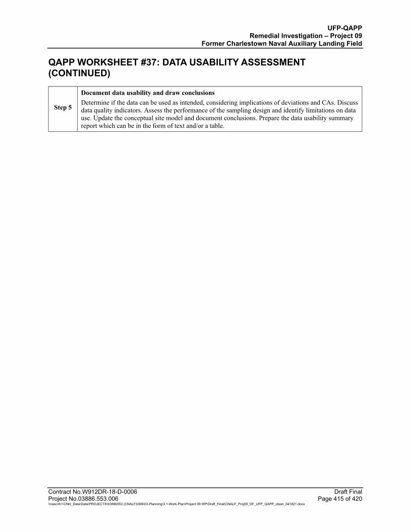
UFP-QAPP Remedial Investigation – Project 09
Former Charlestown Naval Auxiliary Landing Field
QAPP WORKSHEET #37: DATA USABILITY ASSESSMENT (CONTINUED)
Contract No.W912DR-18-D-0006 Draft Final Project No.03886.553.006 Page 415 of 420 \\nascnh1\CNH_Data\Data\PROJECTS\03886553 (CNALF)\006\03-Planning\3.1-Work-Plan\Project 09 WP\Draft_Final\CNALF_Proj09_DF_UFP_QAPP_clean_041821.docx
Step 5
Document data usability and draw conclusions Determine if the data can be used as intended, considering implications of deviations and CAs. Discuss data quality indicators. Assess the performance of the sampling design and identify limitations on data use. Update the conceptual site model and document conclusions. Prepare the data usability summary report which can be in the form of text and/or a table.
UFP-QAPP Remedial Investigation – Project 09
Former Charlestown Naval Auxiliary Landing Field
Contract No.W912DR-18-D-0006 Draft Final Project No.03886.553.006 Page 416 of 420 \\nascnh1\CNH_Data\Data\PROJECTS\03886553 (CNALF)\006\03-Planning\3.1-Work-Plan\Project 09 WP\Draft_Final\CNALF_Proj09_DF_UFP_QAPP_clean_041821.docx
REFERENCES
Alion Science and Technology (Alion). 2008. Final Site Inspection Report for Naval Auxiliary Landing Field. Prepared for U.S. Army Engineers and Support Center, Huntsville and U.S. Army Corps of Engineers, Baltimore District. August 2008.
Charlestown School High Incentive Program (CHIP). 1982. A Report on the History of that Piece of Land in Charlestown, Rhode Island known as the Naval Air Base or now Ninigret Park as presented to the Charlestown Historical Society. February 1982.
Department of Defense (DoD). 2008. Department of Defense Instruction (DoDI) 4140.62, Material Potentially Presenting an Explosive Hazard. November 2008.
DoD. 2019. Defense Explosives Safety Regulation (DESR) 6055.09 Edition 1, Ammunition and Explosives Safety Standards. January 2019.
DoD. 2019. Department of Defense (DoD) Department of Energy (DOE) Consolidated Quality Systems Manual (QSM) for Environmental Laboratories. Version 5.3. May 2019.
DoD Environmental Data Quality Workgroup (EDQW). 2020. Data Validation Guidelines Module 3: Data Validation Procedure for Per- and Polyfluoroalkyl Substances Analysis by QSM Table B-15, 01 May 2020.
DoD EDQW. 2019. General Data Validation Guidelines, 04 November 2019.
Department of Defense Explosives Safety Board (DDESB). 2016. Technical Paper (TP) 18, Minimum Qualifications for Personnel Conducting Munitions and Explosives of Concern-Related Activities. September 2016.
Ecology and Environment, Inc. (E&E, 1987). Engineering Report on Contamination Evaluation at the Former Naval Auxiliary Landing Field, Charlestown, Rhode Island. Prepared for U.S. Army Corps of Engineers Huntsville Division, Huntsville, Alabama. March 1987.
Freeman, P. 2018). Abandoned & Little-Known Airfield: Rhode Island, Accessed November 14, 2018, http://www.airfields-freeman.com/RI/Airfields_RI.htm.
General Services Administration Region I (GSA). 1979. Final Environmental Impact Statement, Naval Auxiliary Landing Field, Charlestown, Rhode Island. 1979.
Geophysical Applications, Inc. (Geophysical Applications). 1994. EM Terrain Conductivity and Magnetic Surveys, Naval Auxiliary Landing Field Site, Charlestown, Rhode Island. Prepared for URS Consultants, Inc. October 1994.
Google Earth Pro. 2001. Historical Imagery for Charlestown, RI, Accessed November 14, 2018.
Graham, W.H. 2017. Memorandum USACE DERP-FUNS Revised INPR for Property No. DO1R10008, Navy Auxiliary Landing Field, Charlestown, RI. January 2017.
UFP-QAPP Remedial Investigation – Project 09
Former Charlestown Naval Auxiliary Landing Field
Contract No.W912DR-18-D-0006 Draft Final Project No.03886.553.006 Page 417 of 420 \\nascnh1\CNH_Data\Data\PROJECTS\03886553 (CNALF)\006\03-Planning\3.1-Work-Plan\Project 09 WP\Draft_Final\CNALF_Proj09_DF_UFP_QAPP_clean_041821.docx
Herbert, C.R. 1995. Draft Environmental Assessment Runway Removal and Habitat Restoration Project, Ninigret National Wildlife Refuge. December 1995.
IT Corporation (ITC, 1993). Phase I Remedial Investigation Report: Former Naval Auxiliary Landing Field, Charlestown, Rhode Island. Prepared for U.S. Army Corps of Engineers, Omaha District, Omaha, Nebraska. October 1993.
Interstate Technology & Regulatory Council (ITRC). Incremental Sampling Methodology Technology Regulatory and Guidance Document, February 2012.
ITRC. Aqueous Film-Forming Foam (AFFF). Fact Sheet. https://pfas-1.itrcweb.org/fact_sheets_page/PFAS_Fact_Sheet_AFFF_April2020.pdf April 2020.
Keller, G.V. and F.C. Frischknecht, 1966. Electrical methods in geophysical prospecting. Oxford: Pergamon Press, 1966. Print. International series in electromagnetic waves.
McNeill, J.D. 1980. Electromagnetic Terrain Conductivity Measurement at Low Induction Numbers. Technical Note TN-6. October 1980.
Rhode Island Department of Environmental Management (RIDEM). 1993. Preliminary Assessment of Ninigret Park, Charlestown, R.I., RID987480910. September 1993.
RIDEM. 2009. A Summary of Rhode Island Groundwater Classification and Groundwater Standards. September 2009.
Rhode Island Historical Preservation Commission (RIHPC). 1975. An Historic, Architectural, and Archeological Investigation of the Former Charlestown Naval Air Station and Vicinity. February 1975.
Roy F. Weston, Inc. (WESTON). 2000. Final Site Inspection Report for Ninigret Park, Charlestown, Rhode Island. Prepared for U.S. Environmental Protection Agency, Region I, Office of Site Remediation and Restoration, 1 Congress Street, Suite 1100, Boston, MA. April 2000.
WESTON. 2001. Supplemental Phase II Remedial Investigation (Phase II Study) of Sites 2, 4, and 6 at the Former Naval Auxiliary Landing Field (NALF), Charlestown, Rhode Island. Prepared for U.S. Army Corps of Engineers New England District, 696 Virginia Road, Concord, Massachusetts. January 2001.
Shacklette, H. and J. Boerngen. 1984. Element Concentrations in Soils and Other Surficial Materials of the Conterminous United States. U.S. Geological Survey Professional Paper 1270.
The Johnson Company, Inc. (JCO). 2018. Technical Memorandum: Historical Review for Project 08 and Project 09 Former Naval Auxiliary Landing Field, Charlestown, Rhode Island. Prepared for U.S. Army Corps of Engineers, New England District, 696 Virginia Road, Concord, Massachusetts. November 2018.
UFP-QAPP Remedial Investigation – Project 09
Former Charlestown Naval Auxiliary Landing Field
Contract No.W912DR-18-D-0006 Draft Final Project No.03886.553.006 Page 418 of 420 \\nascnh1\CNH_Data\Data\PROJECTS\03886553 (CNALF)\006\03-Planning\3.1-Work-Plan\Project 09 WP\Draft_Final\CNALF_Proj09_DF_UFP_QAPP_clean_041821.docx
JCO. 2019. Draft Final UFP-Quality Assurance Project Plan, Remedial Investigation - Project 09, Former Naval Auxiliary Landing Field, Charlestown, Rhode Island. Prepared for U.S. Army Corps of Engineers, New England District, 696 Virginia Road, Concord, Massachusetts. October 2019.
Town of Charlestown. 2018. Personal communication between Christopher Turner of JCO and Stephen McCandless, Town of Charlestown GIS Manager. November 19, 2018.
URS Consultants, Inc. (URS). 1996. Phase II Remedial Investigation Report: Former Naval Auxiliary Landing Field, Charlestown, Rhode Island. Prepared for United States Army Corps of Engineers, Omaha District, Omaha, Nebraska. September 1996.
URS. 1997. Secondary Report – Final, Former Naval Auxiliary Landing Field, Charlestown, Rhode Island. Prepared for U.S. Army Corps of Engineers Omaha District. January 1997.
U.S. Army Corps of Engineers, Rock Island District (USACE). 1999. Ordnance and Explosives Archives Search Report for the former Naval Auxiliary Landing Field, Charlestown, Rhode Island. April 1999.
USACE. 2004. Archives Search Report Supplement for Naval Auxiliary Landing Field, FUDS Property Number D01RI0008. November 2004.
USACE. 2013. Safety Explosives Safety and Health Requirements Manual. May 2013.
USACE. 2016. Study Paper: Decision Logic to Assess Risks Associated with Explosive Hazards and to Develop Remedial Action Objectives (RAOs) for Munitions Response Sites. Final. December 2016.
USACE. 2019. Aviation Policy Letter 19-08, USACE Aviation SUAS Policies and Procedures. 13 November 2019.
U.S. Army Geospatial Center (AGC). 2018. Final Historical Environmental Photographic Analysis, Charlestown Naval Auxiliary Landing Field, RI. August 2018.
U.S. Army Military Munitions Response Program. 2009. Munitions Response Remedial Investigation/Feasibility Study Guidance. November 2009.
U.S. Department of the Interior Fish and Wildlife Service, New England Ecological Services Field Office (USFWS). 2018. Letter in reply to Consultation Code: 05E1NE00-2019-SLI-0273, Event Code: 05E1NE00-2019-E-00607, Project Name: CNALF FUDS. Subject: List of threatened and endangered species that may occur in your proposed project location, and/or may be affected by your proposed project. November 2018.
USFWS. 2019. Information, Planning and Consultation System (IPaC System), Accessed May 28, 2019, https://www.fws.gov/ipac/.
UFP-QAPP Remedial Investigation – Project 09
Former Charlestown Naval Auxiliary Landing Field
Contract No.W912DR-18-D-0006 Draft Final Project No.03886.553.006 Page 419 of 420 \\nascnh1\CNH_Data\Data\PROJECTS\03886553 (CNALF)\006\03-Planning\3.1-Work-Plan\Project 09 WP\Draft_Final\CNALF_Proj09_DF_UFP_QAPP_clean_041821.docx
U.S. Environmental Protection Agency (USEPA). 1988. Guidance for Conducting Remedial Investigations and Feasibility Studies under CERCLA. Interim Final. EPA540G89004.
USEPA. 1989. Risk Assessment Guidance for Superfund, Volume I, Human Health Evaluation Manual (Part A). Interim Final. EPA/540/1-89/002. December 1989.
USEPA. 1994. Region 2 Technical Assistance Document For Complying With the TC Rule And Implementing The Toxicity Characteristic Leaching Procedure (TCLP). EPA-902-B-94-001. Revised May 1994.
USEPA. 2017. Region 1 - Low Stress (low flow) Purging and Sampling Procedure for the Collection of Groundwater Samples from Monitoring Wells. EQASOP-GW4. Revision 4 September 19, 2017.

UFP-QAPP Remedial Investigation – Project 09
Former Charlestown Naval Auxiliary Landing Field
Contract No.W912DR-18-D-0006 Draft Final Project No.03886.553.006 Page 420 of 420 \\nascnh1\CNH_Data\Data\PROJECTS\03886553 (CNALF)\006\03-Planning\3.1-Work-Plan\Project 09 WP\Draft_Final\CNALF_Proj09_DF_UFP_QAPP_clean_041821.docx
(This page intentionally left blank)

\\nascnh1\CNH_Data\Data\PROJECTS\03886553 (CNALF)\006\03-Planning\3.1-Work-Plan\Project 09 WP\Draft\Figures\Figures_breaker.docx 12/3/2020
FIGURES

FIGURE #:DATE:CLIENT NAME:
PROJECT:
LEGEND: TITLE:
Ninigret Pond
FosterCove
Ninigret Pond
Charlestown Breachway
Block Island Sound
R
FIGURE 1: SITE LOCATIONFORMER NAVAL AUXILIARY LANDING FIELD
CHARLESTOWN, RHODE ISLAND
¬
AtlanticOcean
CT
MARhodeIsland
Inset Map
1,600 0 1,600800
Graphic Scale in Feet
U.S. Army Corps of Engineers November 2020 1
Source:1. Aerial Imagery. Nearmap US, Inc. https://www.nearmap.com/. Imagery Date: April 11, 2019.
CNALF Boundary
P:\C
NA
LF\G
IS\M
XD
\202
0_11
_Prj0
9_Q
AP
PW
P\2
6204
_CN
ALF
_Site
_Loc
atio
n.m
xd
Project 09 UFP-QAPP
DRAFT

Project 9:Bu rn Pit Area
Project 9:Charlestown Landfill – MRS 4 Du mp Site
Project 9: Eastern Area Landfill – MRS 3 Hu nter Island Du mp Site
Project 9:Ninigret Wildlife Refu ge Landfill - MRS 2 Inland Toxic Waste Du mp
FosterCove
NinigretPond
Form
er R
unwa
y 4
Former R
unway 35
Former Runway 30
USFWS - NINIGRET WILDLIFE REFUGE
TOWN OF CHARLESTOWN - NINIGRET PARK
LittleNini
Pond(freshwater)
Zone 2, Area D
Zone 1, Area A
Zone 3, Area C
Area B
Area E
Zone 4
FIGURE #:DATE:CLIENT NAME:
PROJECT:
SCALE: TITLE:
Project 09 QAPP/WP
U.S. Army Corps of Engineers November 2020 2
FIGURE 2: PROJECT 09 SITE LAYOUTSFORMER NAVAL AUXILIARY LANDING FIELD
CHARLESTOWN, RHODE ISLAND
SM
P:\C
NAL
F\G
IS\M
XD\2
020_
11_P
rj09_
QAP
PWP\
2620
5_C
NAL
F_Si
te_L
ayou
t.mxd
850 0 850425
Graphic Scale in Feet
¬
Note:1. All locations and dimensions are approximate.Source:1. Aerial Imagery. Nearmap US, Inc. https://www.nearmap.com/. Imagery Date: April 11, 2019.
LegendProject Site Boundary
Historic Edge of Pavement
Archaeological Sensitivity Area/Zone
CNALF Boundary
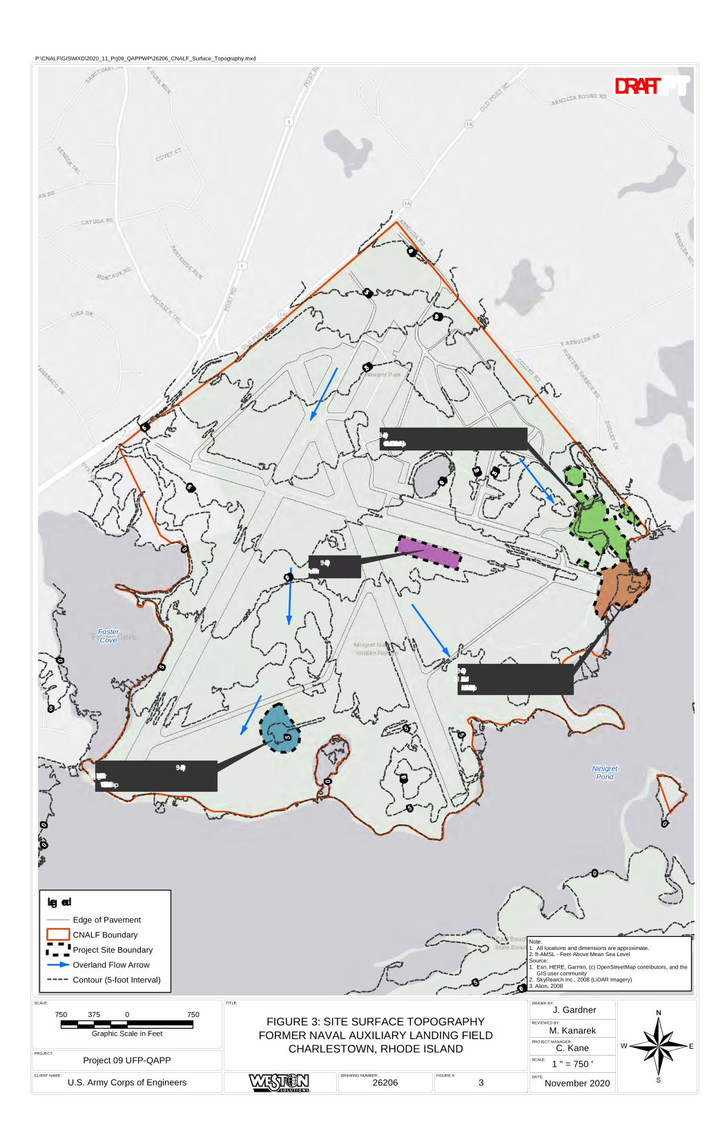
NinigretPond
FosterCove
Project 9:Charlestow n Landfill – MRS 4 Dump Site
Project 9: Eastern Area Landfill –MRS 3 Hunter Island Dump Site
Project 9:Burn Pit Area
Project 9:Ninig ret Wildlife Refug e Landfill -MRS 2 Inland Toxic Waste Dump
15
0
100
10
0
40
35
25
20
30
25
10
5
5
1510
10
5
0
5
5 5
5
5
0
00
FIGURE #:DRAWING NUMBER:CLIENT NAME:
PROJECT:
SCALE: TITLE:
PROJECT MANAGER:
SCALE:
DATE:
DRAWN BY:
REVIEWED BY:
Note:1. All locations and dimensions are approximate.2. ft-AMSL - Feet-Above Mean Sea LevelSource:1. Esri, HERE, Garmin, (c) OpenStreetMap contributors, and the GIS user community2. SkyRearch Inc., 2008 (LiDAR Imagery)3. Alion, 2008
¬FIGURE 3: SITE SURFACE TOPOGRAPHY
FORMER NAVAL AUXILIARY LANDING FIELDCHARLESTOWN, RHODE ISLAND
26206 3U.S. Army Corps of Engineers
Project 09 UFP-QAPP
J. Gardner
M. Kanarek
C. Kane
November 2020
1 " = 750 '
750 0 750375
Graphic Scale in Feet
P:\CNALF\GIS\MXD\2020_11_Prj09_QAPPWP\26206_CNALF_Surface_Topography.mxd
Leg endEdge of Pavement
CNALF Boundary
Project Site Boundary
Overland Flow Arrow
Contour (5-foot Interval)
DRAFT
R

Bunk er
Project 9:Ninigret Wildlife Refu ge Landfill - MRS 2 Inland Toxic Waste Du mp
Project 9:Bu rn Pit Area
Project 9:Charlestown Landfill – MRS 4 Du mp Site
Project 9: Eastern Area Landfill – MRS 3 Hu nter Island Du mp Site
FosterCove
NinigretPond
USFWS - NINIGRET WILDLIFE REFUGE
TOWN OF CHARLESTOWN - NINIGRET PARK
Little NiniPond
Park Entrance
Ninigret ParkGate House Restroom
Facilities
CNAL F Memorial
RecreationO ffice
Garage
Kimball Pavilion
CriteriumBicycle Course
Picnic S helter
L ittle NiniPond Park
Frosty DrewO bservatory
Frosty DrewNature Center
Dog Park
Disc GolfCourse
Boat L aunch
CharlestownCommunity Garden
Gate
Beach
Kids' PlacePlayground
CharlestownS enior Center
Bask etball Court
Tennis Courts
S occer Fields
Pistol Range
S mall Arms Range Complex – S k eet Range
S mall Arms Range Complex – T rap RangeS hoe-in-Butt(back stop)
Machine Gun Range
FIGU RE #:DAT E:CL IENT NAME:
PRO JECT :
S CAL E: T IT L E:
Project 09 U FP-QAPP
U .S . Army Corps of Engineers November 2020 4
FIGU RE 4: CU RRENT NINIGRET PARK FEAT U RESFORMER NAVAL AU X IL IARY L ANDING FIEL D
CHARL ES T O WN, RHODE IS L AND
S M
P:\CNALF\GIS\MXD\2020_11_Prj09_QAPPWP\26207_CNALF_Ninigret_Park_Features.mxd
850 0 850425
Graphic S cale in Feet
¬
Note:1. All locations and dimensions are approximate.S ource:1. Aerial Imagery. Nearmap U S , Inc. https://www.nearmap.com/. Imagery Date: April 11, 2019.2. RIGIS (2013, 2018).
LegendCNAL F BoundaryProperty BoundariesNinigret Park FeatureS hellfish Harvest ApprovedProject S ite Boundary
DRAFT
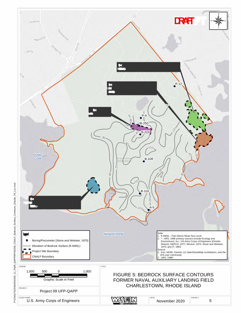
FIGURE #:DATE:CLIENT NAME:
PROJECT:
LEGEND: TITLE:
Ninigret Pond
FosterCove
Project 9:Ninigret Wildlife Refuge Landfill -MRS 2 Inland Toxic Waste Dump
Project 9:Burn Pit Area
Project 9: Eastern Area Landfill –MRS 3 Hunter Island Dump Site
Project 9:Charlestown Landfill – MRS 4 Dump Site
P-9
A-5
P-12
B-250
B-224
B-108
B-116
-20
-30
-10-5
-40
-50
-20-40
-30
-30
-20
-10
-40
-2 0
-30
-4 0
-40
R
FIGURE 5: BEDROCK SURFACE CONTOURSFORMER NAVAL AUXILIARY LANDING FIELD
CHARLESTOWN, RHODE ISLAND
¬
1,000 0 1,000500
Graphic Scale in Feet
U.S. Army Corps of Engineers November 2020 5
Note:1. ft-AMSL - Feet Above Mean Sea Level2. * - URS, 1996 primary sources include Ecology and Environment, Inc.; US Army Corps of Engineers (Omaha District); NEPCO, 1977; Weston, 1974; Stone and Webster, 1975; and IT, 1993Source:1. Esri, HERE, Garmin, (c) OpenStreetMap contributors, and the GIS user community2. URS, 1996*.
LegendBoring/Piezometer [Stone and Webster, 1975]
Elevation of Bedrock Surface (ft-AMSL)
Project Site Boundary
CNALF Boundary
P:\C
NA
LF\G
IS\M
XD
\202
0_11
_Prj0
9_Q
AP
PW
P\2
6208
_CN
ALF
_Bed
rock
_Sur
face
_Con
tour
s_G
laci
al_T
ill_L
oc.m
xd
Project 09 UFP-QAPP
DRAFT
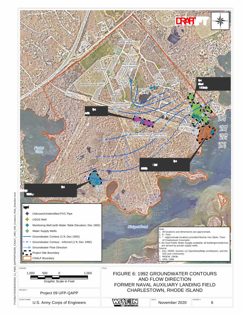
FIGURE #:DATE:CLIENT NAME:
PROJECT:
LEGEND: TITLE:
!A
!A
!A
!A
!A
!A
!A
!A
!A
!A
!A
!A!A
!A!A!A
!A!A!A!A
!A
!A!A
Ninigret Pond
FosterCove
Project 9:Ninigret Wildlife Refuge Landfill -MRS 2 Inland Toxic Waste Dump
Project 9:Burn Pit Area
Project 9: Eastern Area Landfill –
MRS 3 Hunter Island Dump Site
Project 9:Charlestown Landfill– MRS 4 Dump Site
CN-03[2.43]
CN-04[2.13]
CN-06[0.95]CN-08[0.81]
CN-07[0.71]
CN-02[2.21]
CN-01[2.39]
CN-05[5.5]
CN-10[1.92]
CN-12[8.52]
CN-13[8.47]
CN-09[6.57]
RW-3 (GateHouse Home)
RW-5 (BicycleTrack Pavilion)
RW-4(Pavilion)
RW-1 (Frosty DrewNature Center)
RW-2(Senior Center)
Navy Well*
Seafood Festival Well*
CHW-18
Pump House No. 4 - Well No. 12(condition unknown, not in use)
43
6
5
78
2
1
4
55
36
2
2
R
FIGURE 6: 1992 GROUNDWATER CONTOURSAND FLOW DIRECTION
FORMER NAVAL AUXILIARY LANDING FIELDCHARLESTOWN, RHODE ISLAND
¬
1,000 0 1,000500
Graphic Scale in Feet
U.S. Army Corps of Engineers November 2020 6
Note:1. All locations and dimensions are approximate.2. ft - Feet3. * - Approximate locations provided Bonnie Van Slyke, Town of Charlestown Counselor.4. No local Public Water Supply available; all buildings/residences are served by private supply wells.Source:1. Esri, HERE, Garmin, (c) OpenStreetMap contributors, and the GIS user community.2. RIDEM, 1993b.3. URS, 1996.
Legend!A Unknown/Unidentified PVC Pipe
!A USGS Well
!A Monitoring Well (with Water Table Elevation; Dec 1992)
!A Water Supply Wells
Groundwater Contour (1 ft; Dec 1992)
Groundwater Contour - Inferred (1 ft; Dec 1992)
Groundwater Flow Direction
Project Site Boundary
CNALF Boundary
P:\C
NA
LF\G
IS\M
XD
\202
0_11
_Prj0
9_Q
AP
PW
P\2
6209
_CN
ALF
_199
2_G
W_C
onto
urs_
Flow
_Dire
ctio
n.m
xd
Project 09 UFP-QAPP
DRAFT
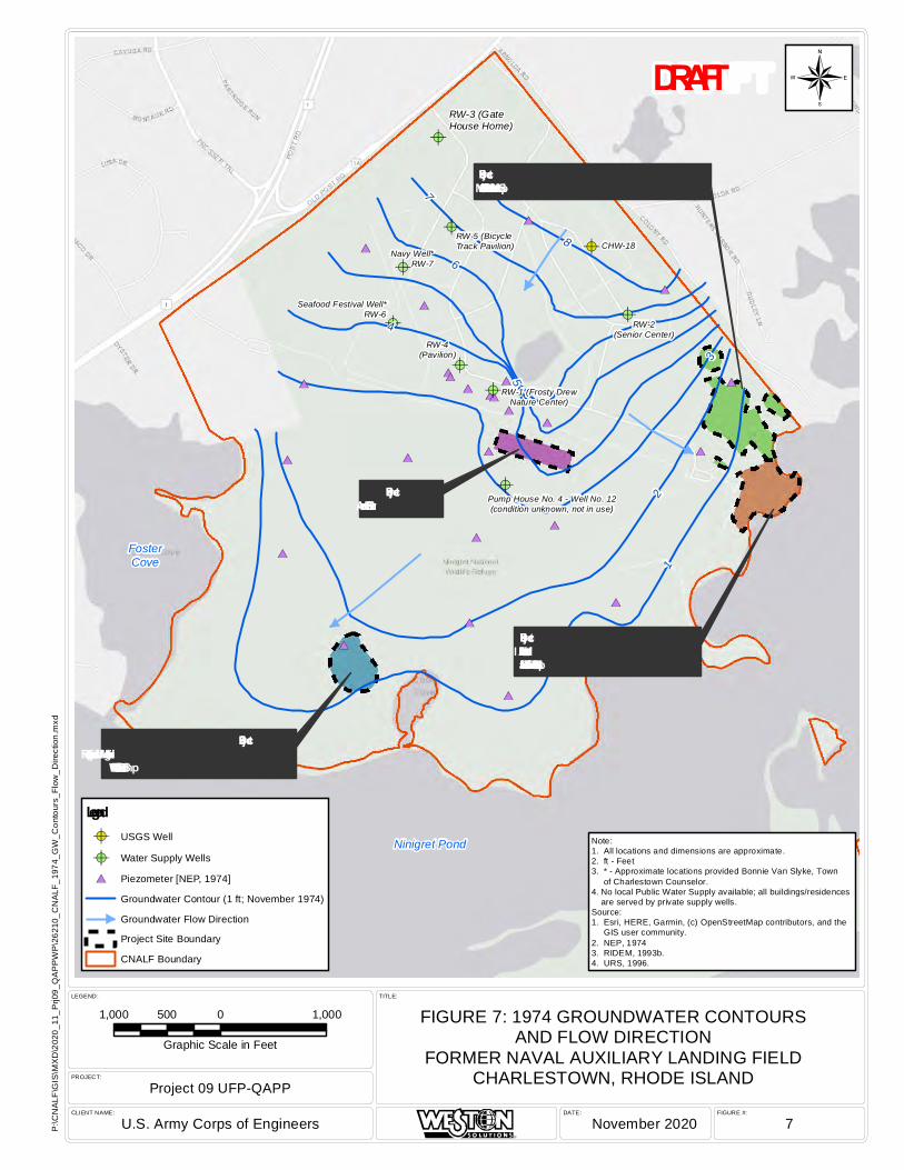
FIGURE #:DATE:CLIENT NAME:
PROJECT:
LEGEND: TITLE:
#*
#*
#*
#*
#*
#*
#*
#*
#*
#*
#*
#*
#*
#*
#*
#*#*#*
#*
#*
#*
#*
#*
#*
#*!A
!A
!A
!A
!A
!A
!A
!A
!A
Ninigret Pond
FosterCove
Project 9:Charlestown Landfill – MRS 4 Dump Site
Project 9:Burn Pit Area
Project 9: Eastern Area Landfill –MRS 3 Hunter Island Dump Site
Project 9:Ninigret Wildlife Refuge Landfill -MRS 2 Inland Toxic Waste Dump
RW-3 (GateHouse Home)
RW-5 (BicycleTrack Pavilion)
RW-4(Pavilion)
RW-1 (Frosty DrewNature Center)
RW-2(Senior Center)
Navy Well*RW-7
Seafood Festival Well*RW-6
CHW-18
Pump House No. 4 - Well No. 12(condition unknown, not in use)
12
3
4
5
6
7
8
R
FIGURE 7: 1974 GROUNDWATER CONTOURSAND FLOW DIRECTION
FORMER NAVAL AUXILIARY LANDING FIELDCHARLESTOWN, RHODE ISLAND
¬
1,000 0 1,000500
Graphic Scale in Feet
U.S. Army Corps of Engineers November 2020 7
Note:1. All locations and dimensions are approximate.2. ft - Feet3. * - Approximate locations provided Bonnie Van Slyke, Town of Charlestown Counselor.4. No local Public Water Supply available; all buildings/residences are served by private supply wells.Source:1. Esri, HERE, Garmin, (c) OpenStreetMap contributors, and the GIS user community.2. NEP, 19743. RIDEM, 1993b.4. URS, 1996.
Legend!A USGS Well
!A Water Supply Wells
#* Piezometer [NEP, 1974]
Groundwater Contour (1 ft; November 1974)
Groundwater Flow Direction
Project Site Boundary
CNALF Boundary
P:\C
NA
LF\G
IS\M
XD
\202
0_11
_Prj0
9_Q
AP
PW
P\2
6210
_CN
ALF
_197
4_G
W_C
onto
urs_
Flow
_Dire
ctio
n.m
xd
Project 09 UFP-QAPP
DRAFT

Project 9:Burn Pit Area
Project 9:Charlestown Landfill – MRS 4 Dump Site
Project 9: Eastern Area Landfill –MRS 3 Hunter Island Dump Site
Project 9:Ninigret Wildlife Refuge Landfill -MRS 2 Inland Toxic Waste Dump
FosterCove
NinigretPond
LittleNini
Pond(freshwater)
FIGURE #:DATE:CLIENT NAME:
PROJECT:
SCALE: TITLE:
Project 09 UFP-QAPP
U.S. Army Corps of Engineers November 2020 8
FIGURE 8: WELL PROTECTION AREASAND GROUNDWATER CLASSIFICATION
FORMER NAVAL AUXILIARY LANDING FIELDCHARLESTOWN, RHODE ISLAND
SM
P:\C
NA
LF\G
IS\M
XD
\202
0_11
_Prj0
9_Q
AP
PW
P\2
6211
_CN
ALF
_Wel
l_P
rote
ct_A
reas
_GW
_Cla
ssify
.mxd
1,200 0 1,200600
Graphic Scale in Feet
¬
Note:1. All locations and dimensions are approximate.2. No local Public Water Supply available; all buildings/residences are served by private supply wells.Source:1. Aerial Imagery. Nearmap US, Inc. https://www.nearmap.com/. Imagery Date: April 11, 2019.2. RIGIS, 2012-2014
LegendProject Site Boundary
Community WellheadProtection Area
Non-Community WellheadProtection Area
Class GAA Groundwater Area
Class GA Groundwater Area
CNALF Boundary
DRAFT
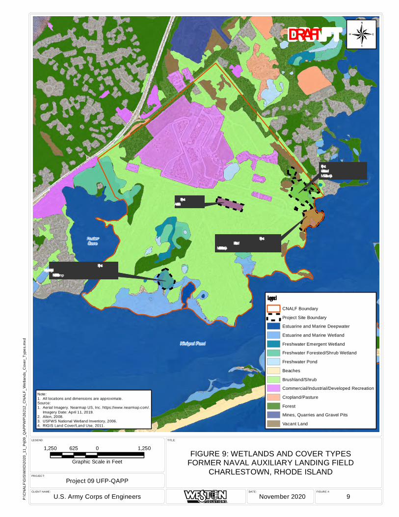
FIGURE #:DATE:CLIENT NAME:
PROJECT:
LEGEND: TITLE:
Ninigret Pond
FosterCove
Block Island Sound
Project 9:Ninigret Wildlife Refuge Landfill -MRS 2 Inland Toxic Waste Dump
Project 9:Burn Pit Area
Project 9: Eastern Area Landfill –
MRS 3 Hunter Island Dump Site
Project 9:Charlestown Landfill –MRS 4 Dump Site
R
FIGURE 9: WETLANDS AND COVER TYPESFORMER NAVAL AUXILIARY LANDING FIELD
CHARLESTOWN, RHODE ISLAND
¬
1,250 0 1,250625
Graphic Scale in Feet
U.S. Army Corps of Engineers November 2020 9
Note:1. All locations and dimensions are approximate.Source:1. Aerial Imagery. Nearmap US, Inc. https://www.nearmap.com/. Imagery Date: April 11, 2019.2. Alion, 2008.3. USFWS National Wetland Inventory, 2006.4. RIGIS Land Cover/Land Use, 2011.
LegendCNALF Boundary
Project Site Boundary
Estuarine and Marine Deepwater
Estuarine and Marine Wetland
Freshwater Emergent Wetland
Freshwater Forested/Shrub Wetland
Freshwater Pond
Beaches
Brushland/Shrub
Commercial/Industrial/Developed Recreation
Cropland/Pasture
Forest
Mines, Quarries and Gravel Pits
Vacant Land
P:\C
NA
LF\G
IS\M
XD
\202
0_11
_Prj0
9_Q
AP
PW
P\2
6212
_CN
ALF
_Wet
land
s_C
over
_Typ
es.m
xd
Project 09 UFP-QAPP
DRAFT
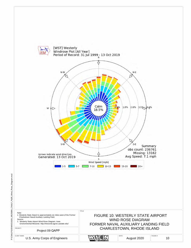
FIGURE #:DATE:CLIENT NAME:
PROJECT:
TITLE:
R
FIGURE 10: WESTERLY STATE AIRPORTWIND ROSE DIAGRAM
FORMER NAVAL AUXILIARY LANDING FIELDCHARLESTOWN, RHODE ISLAND
U.S. Army Corps of Engineers August 2020 10
Note:1. Westerly State Airport is approximately six miles west of the Former Charlestown Naval Auxiliary Landing Field.Source:1. Westerly State Airport Wind Rose Diagram. Iowa Environmental Mesonet. http://mesonet.agron.uastate.edu/
P:\C
NAL
F\G
IS\M
XD\2
020_
08\2
5884
_CN
ALF_
Prj0
9_W
ind_
Ros
e_D
iagr
am.m
xd
Project 09 QAPP

!A
!A!A
!A
"/
"/
!A
!A#*
!A
"/
"/
%2
%2%2
%2
"/
"/
%2
%2%2
%2
MunitionsDebris
[Alion, 2008]
Former Sand Filters
Former SewageDisposal Area
Form
er Du
mp TOWN OF CHARLESTOWN - NINIGRET PARK
USFWS - NINIGRET WILDLIFE REFUGE
S D-06
S D-04/S D-05
Freshwaterpond
NinigretPond
Approximate FormerFreshwater Pond andDischarge Channellocation based on
1945 aerial.
S ED-2 [URS , 1996]
NAL-DS -S B-24-01[Alion 2008]
NAL-DS -S S -02-01[Alion 2008]
CN-01
CN-02
CN-03CN-04
(present 2018)CN-10
CN-09
CN-15 [URS , 1996](present 2018)
CN-14 [URS , 1996]
S -W -1-8
NAL-DS -S D-02-01[Alion 2008]
ClDriveClDrive
1944Possible
Dump Site
Active Dump 1951/1954[AGC, 2018]
1963 Filled-In Pit(possible buried waste)
Feature Type: Ground S carNote: Ground scar?Source Year: 2006
Feature Type: ObjectsNote: Concrete block pile Source Year: 1951
Feature Type: MaterialNote: Debris PileSource Year: 2020 (GPS )
Feature Type: Mounded MaterialNote: N oneSource Year: 1947
Feature Type: Mounded MaterialNote: N oneSource Year: 1947
Feature Type: Mounded MaterialNote: N oneSource Year: 1947
Feature Type: Mounded MaterialNote: N oneSource Year: 1947
Feature Type: Mounded MaterialNote: N oneSource Year: 1947
Feature Type: Mounded MaterialNote: N oneSource Year: 1947
T P-1No fill
T P-6No fill
T P-2No fill
T P-3Fill depth 7'
T P-4Fill depth 10'
T P-10Fill depth 12'
T P-5Fill depth 10'
18
12
18
168
24
20
14 10
18
16
22
6
4
12
10
12
14
82
10
20 18
1610
14
12
108
18
12
810
12
6
6
2
14
16
4
FIGURE #:DAT E:CLIEN T N AME:
PROJ ECT :
S CALE: T IT LE:
Project 09 UFP-QAPP
U.S . Arm y Corps of Engineers Novem ber 2020 11
FIGURE 11: PREVIOUS ENVIRONMEN T AL INVES T IGAT ION SAT CHARLES T OW N LANDFILL – MRS 4 DUMP S IT EFORMER NAVAL AUX ILIARY LANDING FIELD
CHARLES T OW N, RHODE IS LAND
SM
P:\CNALF\GIS\MXD\2020_11_Prj09_QAPPWP\26214_CNALF_Project09_Charlestown_Landfill.mxd
N ote:1. All locations and dim ensions are approx im ate.2. No local Public W ater S upply available; all buildings/residences are served by private supply wells.S ource:1. Aerial Im agery. N earm ap US , Inc. h ttps://www.nearm ap.com /. Im agery Date: April 11, 2019.2. Map of Aux iliary Air S tation by U.S .N., J une 30, 1951.3. E&E, 1987.4. IT C, 1993.5. URS , 1996.6. W eston, 2001a.7. Alion, 2000.8. Alion, 2008.9. AGC, 2018.10. S kyRearch Inc., 2008 (LiDAR Im agery)
Location in CNALF
LegendCNALF BoundaryProposed Investigation Boundary
%2S edim ent S am ple [W eston 2000 unlessoth erwise noted]
!AMonitoring W ell [E&E, 1987 unless oth erwisenoted
"/S oil S am ple [E&E, 1987 unless oth erwisenoted]
#* S urface W ater S am ple [URS , 1996]Gravel Pit [AGC, 2018]1954 T rench [AGC, 2018]1947 Multiple Ground Disturbances withPossible T rench [AGC, 2018]Fresh water Pond Disch arge Ch annel [AGC,2018]Test Pit [URS , 1996]
Features from 1951 US N MapReported Buried 9 Aircraft (partiallyex cavated/rem oved in 1977) [US ACE, 2018]Town of Ch arlestown S urface Debris [URS ,1996]Landfill Ex tent Delineated by URS [1996]Possible Ex cavation from 1947 Aerial [AGC,2018]Ground S car from 1963 Aerial [AGC, 2018]Possible Dum p/Fill S ites from Aerials [AGC,2018]Form er Building FootprintS urface Contour (2 ft Interval)Overland Flow Arrow
140 0 14070
Graph ic S cale in Feet
¬ DRAFT
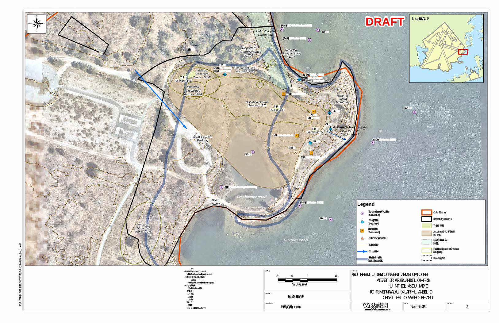
!A
!A
!A
%2
%2
%2
%2 !. "/
"/
!A!A
!.
"/
"/
!A
!A
!A
%2
%2
%2
%2 !.
!A!A
!.
"/
"/
%2
"/
"/
%2
%2
%2%2
%2
%2
%2
%2%2
PossibleDiscarded
Items - 1944
ReportedBuried Aircraft
#1703
Assumed GroundwaterFlow to E/SE[URS, 1996]Boat Launch
Parking
BoatLaunch
Freshwater pond
Ninigret Pond
NAL -HI-SD-02-01 [Alion 2008]
NAH-HI-SS-02-01
NAL -HI-SB-24-01
CN-08
CN-07
CN-06
SED-2
SED-3
SED-4
SED-1
L F202
CN-12 [E&E 1987]
CN-11[E&E 1987]
CN-16 [U RS, 1996](present 2018; no protective cover/cap)
L F201[Weston, 2001a](present 2018)
1944 PossibleDump Site
PossibleDiscarded
Items - 1944
PossibleDiscarded
Items - 1954
Disturbed Groundobserved 1970
ReportedBuried
Aircraft #20
Reported BuriedAircraft #1702
ReportedBuried Aircraft
#1704
SD-01 [Weston 2000]
SD-02 [Weston 2000]
SD-03 [Weston 2000]
SD-04/SD-05 [Weston 2000]
6
2
10
8
8
108
10
12
6
10
6
8
2
4
T P-7Fill depth 6.5'
T P-8Fill depth 5'
T P-9Fill depth 3.5'
#66
FIGU RE #:DAT E:CL IENT NAME:
PRO JECT :
SCAL E: T IT L E:
Project 09 U FP-QAPP
U .S. Army Corps of Engineers November 2020 12
FIGU RE 12: PREVIO U S ENVIRONMENT AL INVEST IGAT IONSAT EAST ERN AREA L ANDFIL L – MRS 3
HU NT ER ISL AND DU MP SIT EFO RMER NAVAL AU X IL IARY L ANDING FIEL D
CHARL EST O WN, RHODE ISL AND
SM
P:\CNALF\GIS\MXD\2020_11_Prj09_QAPPWP\26215_CNALF_Project09_Eastern_Area_Landfill.mxd
Note:1. All locations and dimensions are approximate.2. No local Public Water Supply available; all buildings/residences are served by private supply wells.Source:1. Aerial Imagery . Nearmap U S, Inc. https://www.nearmap.com/. Imagery Date: April 11, 2019.2. Map of Auxiliary Air Station by U .S.N., June 30, 1951.3. IT C, 1993.4. U RS, 1996.5. Weston, 2000.6. Weston, 2001a.7. Alion, 2008.8. AGC, 2018.9. Sky Rearch Inc., 2008 (L iDAR Imagery )
L ocation in CNAL F
¬
80 0 8040
Graphic Scale in Feet
Legend%2
Sediment Sample [Weston 2000 unlessotherwise noted]
!AMonitoring Well [E&E, 1987 unlessotherwise noted
"/Soil Sample [E&E, 1987 unlessotherwise noted]
#* Surface Water Sample [U RS, 1996]
Surface Contour (2 ft Interval)O verland Flow Arrow1941 Hunter Island and Shoreline Priorto CNAL F Construction [AGC, 2018]
CNAL F BoundaryProposed Investigation BoundaryTest Pit [U RS, 1996]Approximate CNAL F L andfill Extent[U RS, 1996]Possible Dump/Fill Sites from Aerials[AGC, 2018]Possible Buried or Discarded O bjectsfrom Aerials [AGC, 2018]Former Building Footprint
DRAFT
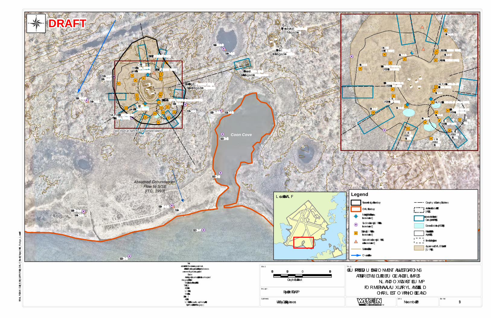
!A"/
"/
"/
"/"/
"/
"/ !A
!A
"/"/
"/
%2
%2
%2
%2
%2
%2
%2
%2
%2
%2
%2
%2
"/
"/
"/
"/
"/
"/
"/
"/"/
"/ "/
"/
"/
!A"/
"/
"/
"/"/
"/
"/ !A
!A
"/"/
"/
#*#*
#*#*
#*
#*
#*
#*
#*
%2
%2
%2
%2
%2
%2
%2
%2
%2
%2
%2
%2
"/
"/
"/
"/
"/
"/
"/
"/"/
"/ "/
"/
"/
"/
"/
%2
Assumed Groundwater Flow to S/SE[ITC, 1993]
#59 Fuse and Detonator Magazine
#58 SmallArms Magazine
#57 Py rotechnicalMagazine
See inset at right for soil sample labelsCoon Cove
CN-10 [IT C, 1993] (present 2018)
L F401[Weston, 2001](present 2018)
L F402(present 2018) SW-4-1 SW-4-2
SW-4-3SW-4-4
SW-4-5
SW-4-6
SW-4-7
CN-16 [E&E 1987]
CN-17 [E&E 1987]
SED-5
SED-6
SED-7
SED-8
SED-4-1
SED-4-2
SED-4-3SED-4-4
SED-4-5
SED-4-6
SED-4-7
NAL -T W-SD-02-01[Alion, 2008]
#60 - Former HighExplosive Magazine
4
8
4
6
4
4
4
6
8
6
10
8
14
2
8
14
8 12
12
2 10
8
8
2
2
2
14
2
2
6
6
6
6
12
4
4
10
8
4
6
4
2
FIGU RE #:DAT E:CL IENT NAME:
PRO JECT :
SCAL E: T IT L E:
Project 09 U FP-QAPP
U .S. Army Corps of Engineers November 2020 13
FIGU RE 13: PREVIO U S ENVIRONMENT AL INVEST IGAT IONSAT NINIGRET WIL DL IFE REFU GE L ANDFIL L – MRS 2
INL AND T O X IC WAST E DU MPFO RMER NAVAL AU X IL IARY L ANDING FIEL D
CHARL EST O WN, RHODE ISL AND
SM
P:\CNALF\GIS\MXD\2020_11_Prj09_QAPPWP\26216_CNALF_Project09_Ningret_Wildlife_Refuge_Landfill.mxd
Note:1. All locations and dimensions are approximate.2. No local Public Water Supply available; all buildings/residences are served by private supply wells.Source:1. Aerial Imagery . Nearmap U S, Inc. https://www.nearmap.com/. Imagery Date: April 11, 2019.2. Map of Auxiliary Air Station by U .S.N., June 30, 1951.3. IT C, 1993.4. RIDEM, 1993.5. U RS, 1996.6. Weston, 2001a.7. Alion, 2008.8. AGC, 2018.9. U SACE, 2018 (interview with L arry Webster, July 2018).10. Sky Rearch Inc., 2008 (L iDAR Imagery )
L ocation in CNAL F
!A
"/
"/
"/
"/
"/
"/
"/ !A
!A
"/
"/
"/
%2
%2
%2
"/
"/
"/
"/
"/
"/
"/
"/
"/
"/ "/
"/
"/
!A
"/
"/
"/
"/
"/
"/
"/ !A
!A
"/
"/
"/
#*
#*
#*
#*
%2
%2
%2
"/
"/
"/
"/
"/
"/
"/
"/
"/
"/ "/
"/
"/
"/
"/
%2
SS-4-1
SS-4-8SS-4-6
SS-4-3SS-4-7
SS-4-5
CN-15[E&E 1987]
SS-4-2 SS-4-9
SS-4-4
SED-4-1
NAL -T W-SS-02-01 [Alion 2008]
NAL -T W-SB-24-01[Alion 2008]
SS #2 (112592-2)[RIDEM 1993]
SS #3 (112592-3)[RIDEM 1993]
SS #4 (112592-4)[RIDEM 1993]
L H-1[RIDEM 1993]
L H-2[RIDEM1993] L H-3
[RIDEM1993]
L H-4[RIDEM1993]
L H-6[RIDEM 1993]
L H-5[RIDEM1993]
L H-7 [RIDEM 1993]
L H-8 [RIDEM 1993]
4
18
16
4
14
2
212
108
2
6
4
180 0 18090
Graphic Scale in Feet
¬ DRAFT
LegendProposed Investigation BoundaryCNAL F Boundary
!AMonitoring Well [Weston, 2001a unlessotherwise noted]
%2 Sediment Sample [U RS, 1996 unlessotherwise noted]
"/Soil Sample [U RS, 1996 unlessotherwise noted]
#* Surface Water Sample [U RS, 1996unless otherwise noted]Surface Contour (2 ft Interval)O verland Flow Arrow
Geophy sical Survey Extent L inesArea of Possible Debris 1970-1972[AGC, 2018]Interpreted Area of Metallic orConductive Fill [U RS, 1996]Drum and Debris Area [RIDEM, 1993]Possible Extent of Fill Area from 1979Aerial [AGC, 2018]Former Building FootprintApproximate CNAL F L andfill Extent[U RS, 1996]
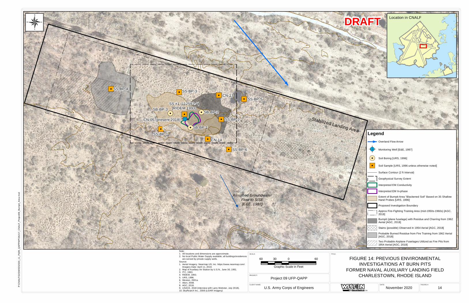
!A!.
!.!.
"/
"/
"/"/
"/
"/
"/
"/
"/!A!.
!.!.
"/
"/
"/"/
"/
"/
"/
"/
"/Stabilized Landing Area
Assumed GroundwaterFlow to S/SE[E&E, 1987]
SS #1 (112592-1)[RIDEM 1993]
CN-05 (present 2018)
SB-BP-1
SB-BP-2SB-BP-3
SS-BP-1
SS-BP-2
SS-BP-3SS-BP-4
SS-BP-5
SS-BP-6
CN-13
CN-14
1412
12
10
12
12
86 8 10
12
10
10
12
FIGURE #:DATE:CLIENT NAME:
PROJECT:
SCALE: TITLE:
Project 09 UFP-QAPP
U.S. Army Corps of Engineers November 2020 14
FIGURE 14: PREVIOUS ENVIRONMENTALINVESTIGATIONS AT BURN PITS
FORMER NAVAL AUXILIARY LANDING FIELDCHARLESTOWN, RHODE ISLAND
SM
P:\C
NA
LF\G
IS\M
XD
\202
0_11
_Prj0
9_Q
AP
PW
P\2
6217
_CN
ALF
_Pro
ject
09_B
urnp
it_A
rea.
mxd
Note:1. All locations and dimensions are approximate.2. No local Public Water Supply available; all buildings/residences are served by private supply wells.Source:1. Aerial Imagery. Nearmap US, Inc. https://www.nearmap.com/. Imagery Date: April 11, 2019.2. Map of Auxiliary Air Station by U.S.N., June 30, 1951.3. ITC, 1993.4. RIDEM, 1993.5. URS, 1996.6. Weston, 2001a.7. Alion, 2008.8. AGC, 2018.9. USACE, 2018 (interview with Larry Webster, July 2018).10. SkyRearch Inc., 2008 (LiDAR Imagery)
Location in CNALF
60 0 6030
Graphic Scale in Feet
¬
LegendOverland Flow Arrow
!A Monitoring Well [E&E, 1987]
!. Soil Boring [URS, 1996]
"/ Soil Sample [URS, 1996 unless otherwise noted]
Surface Contour (2 ft Interval)
Geophysical Survey Extent
Interpreted EM Conductivity
Interpreted EM In-phase
Extent of Burnpit Area "Blackened Soil" Based on 35 ShallowHand Probes [URS, 1996]
Proposed Investigation Boundary
Approx Fire-Fighting Training Area (mid-1950s-1960s) [AGC,2018]
Burnpit (plane fuselage) with Residue and Charring from 1962Aerial [AGC, 2018]
Stains (possible) Observed in 1954 Aerial [AGC, 2018]
Probable Burned Residue from Fire Training from 1962 Aerial[AGC, 2018]
Two Probable Airplane Fuselages Utilized as Fire Pits from1954 Aerial [AGC, 2018]
DRAFT
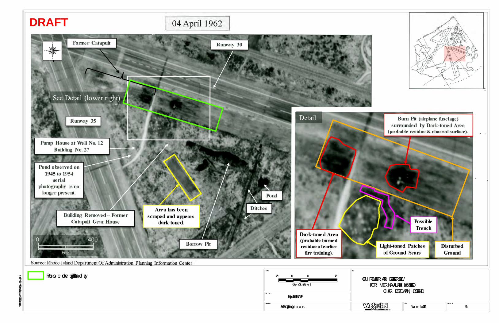
R W-1
S-W-1-8S-W-1-8
R W-1
CN-14
R W-1
S-W-1-8
NAL-HI-SD-02-01
R W-1
ClDrive
ClDrive
ClDrive ClDrive
FIGU R E #:DATE:CLIENT NAME:
PR OJECT:
SCALE: TITLE:
Proje c t 09 UFP-QAPP
U.S. Arm y Corps of Engine e rs Nove m be r 2020 14a
FIGU R E 14a: BU R N PIT AR EA – 1962 AER IAL VIEWFOR MER NAVAL AUXILIAR Y LANDING FIELD
CHAR LESTOWN, R HODE ISLAND
SM
P:\CNALF\GIS\MXD\2020_11_Prj09_QAPPWP\26325_CNALF_Project09_Burnpit_1962.mxd
220 0 220110
Graphic Scale in Fe e t
¬
DRAFT
Propos e d Inve s tigation Boundary
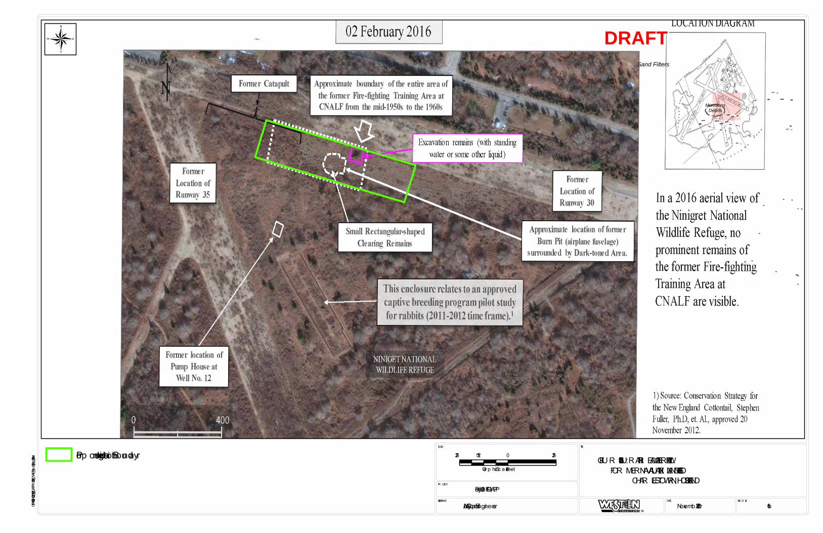
MunitionsDebris
Sand Filters
NAL-DS-SB-24-01[Alion 2008]
NAL-DS-SS-02-01 [Alion 2008]
NAL-DS-SD-02-01
NAL-DS-GW-02-01
NAL-DS-SB-24-01
NAL-DS-SS-02-01
NAL-DS-SD-02-01
NAL-DS-GW-02-01
CN-01
CN-02
CN-03
CN-04
R W-1
CN-10
CN-09
CN-15
CN-14
S-W-1-8CN-03 S-W-1-8
CN-01
CN-02
CN-04
R W-1
CN-10
CN-09
CN-15
CN-14
LF201
NAL-HI-SD-02-01
NAL-DS-SB-24-01
NAL-DS-SS-02-01
NAL-DS-SD-02-01
NAL-DS-GW-02-01
CN-02
CN-01
CN-03
CN-04
R W-1
CN-10
CN-09
CN-15
CN-14
S-W-1-8
LF201
S-W-1-8
NAL-DS-GW-02-01NAL-DS-SS-02-01
NAL-HI-SD-02-01
CN-01
CN-02
CN-03
CN-04
R W-1
CN-10
CN-09
CN-15
CN-14
LF201
NAL-DS-SD-02-01
NAL-DS-SB-24-01
Mo nume nt
ClDrive
ClDrive
ClDrive
ClDrive
ClDrive
ClDrive ClDrive
FIGU R E #:DATE:CLIENT NAME:
PR OJECT:
SCALE: TITLE:
Projec t 09 UFP-QAPP
U.S. Army Corp s of Engineers Novemb er 2020 14b
FIGU R E 14b: BU R N PIT AR EA – 2016 AER IAL VIEWFOR MER NAVAL AUXILIAR Y LANDING FIELD
CHAR LESTOWN, R HODE ISLAND
SM
P:\CNALF\GIS\MXD\2020_11_Prj09_QAPPWP\26326_CNALF_Project09_Burnpit_2016.mxd
225 0 225112.5
Gra p hic Sc a le in Feet
¬ DRAFT
Prop osed Investiga tion Bounda ry
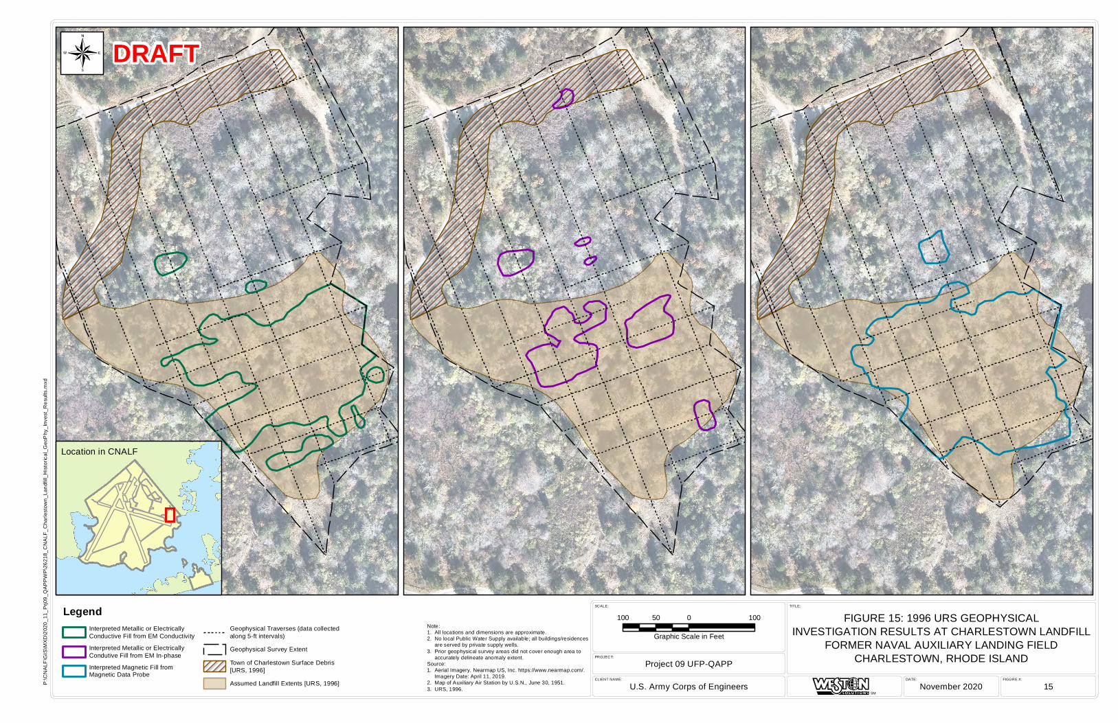
FIGURE #:DATE:CLIENT NAME:
PROJECT:
SCALE: TITLE:
Project 09 UFP-QAPP
U.S. Army Corps of Engineers November 2020 15
FIGURE 15: 1996 URS GEOPHYSICALINVESTIGATION RESULTS AT CHARLESTOWN LANDFILL
FORMER NAVAL AUXILIARY LANDING FIELDCHARLESTOWN, RHODE ISLAND
SM
P:\C
NA
LF\G
IS\M
XD
\202
0_11
_Prj0
9_Q
AP
PW
P\2
6218
_CN
ALF
_Cha
rlest
own_
Land
fill_
His
toric
al_G
eoP
hy_I
nves
t_R
esul
ts.m
xd
Note:1. All locations and dimensions are approximate.2. No local Public Water Supply available; all buildings/residences are served by private supply wells.3. Prior geophysical survey areas did not cover enough area to accurately delineate anomaly extent.Source:1. Aerial Imagery. Nearmap US, Inc. https://www.nearmap.com/. Imagery Date: April 11, 2019.2. Map of Auxiliary Air Station by U.S.N., June 30, 1951.3. URS, 1996.
Location in CNALF
LegendInterpreted Metallic or ElectricallyConductive Fill from EM Conductivity
Interpreted Metallic or ElectricallyCondutive Fill from EM In-phase
Interpreted Magnetic Fill fromMagnetic Data Probe
Geophysical Traverses (data collectedalong 5-ft intervals)
Geophysical Survey Extent
Town of Charlestown Surface Debris[URS, 1996]
Assumed Landfill Extents [URS, 1996]
¬
100 0 10050
Graphic Scale in Feet
DRAFT
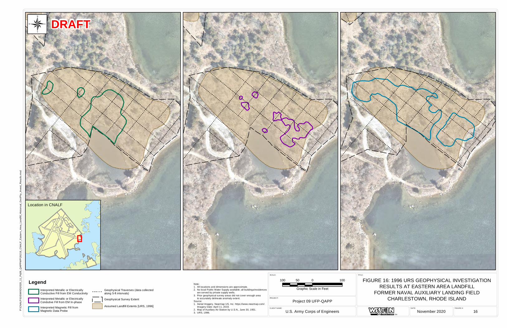
FIGURE #:DATE:CLIENT NAME:
PROJECT:
SCALE: TITLE:
Project 09 UFP-QAPP
U.S. Army Corps of Engineers November 2020 16
FIGURE 16: 1996 URS GEOPHYSICAL INVESTIGATIONRESULTS AT EASTERN AREA LANDFILL
FORMER NAVAL AUXILIARY LANDING FIELDCHARLESTOWN, RHODE ISLAND
SM
P:\C
NA
LF\G
IS\M
XD
\202
0_11
_Prj0
9_Q
AP
PW
P\2
6219
_CN
ALF
_Eas
tern
_Are
a_La
ndfil
l_H
isto
rical
_Geo
Phy
_Inv
est_
Res
ults
.mxd
Note:1. All locations and dimensions are approximate.2. No local Public Water Supply available; all buildings/residences are served by private supply wells.3. Prior geophysical survey areas did not cover enough area to accurately delineate anomaly extent.Source:1. Aerial Imagery. Nearmap US, Inc. https://www.nearmap.com/. Imagery Date: April 11, 2019.2. Map of Auxiliary Air Station by U.S.N., June 30, 1951.3. URS, 1996.
Location in CNALF
100 0 10050
Graphic Scale in Feet
LegendInterpreted Metallic or ElectricallyConductive Fill from EM Conductivity
Interpreted Metallic or ElectricallyCondutive Fill from EM In-phase
Interpreted Magnetic Fill fromMagnetic Data Probe
Geophysical Traverses (data collectedalong 5-ft intervals)
Geophysical Survey Extent
Assumed Landfill Extents [URS, 1996]
¬ DRAFT
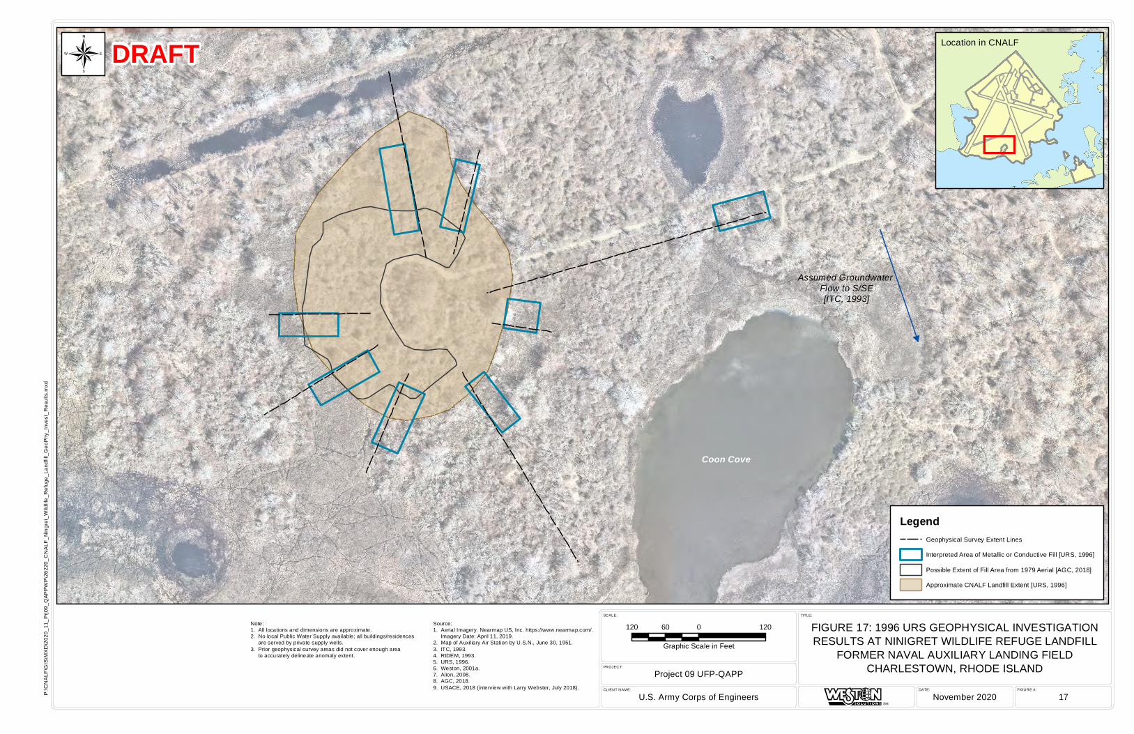
Assumed Groundwater Flow to S/SE[ITC, 1993]
Coon Cove
FIGURE #:DATE:CLIENT NAME:
PROJECT:
SCALE: TITLE:
Project 09 UFP-QAPP
U.S. Army Corps of Engineers November 2020 17
FIGURE 17: 1996 URS GEOPHYSICAL INVESTIGATIONRESULTS AT NINIGRET WILDLIFE REFUGE LANDFILL
FORMER NAVAL AUXILIARY LANDING FIELDCHARLESTOWN, RHODE ISLAND
SM
P:\C
NA
LF\G
IS\M
XD
\202
0_11
_Prj0
9_Q
AP
PW
P\2
6220
_CN
ALF
_Nin
gret
_Wild
life_
Ref
uge_
Land
fill_
Geo
Phy
_Inv
est_
Res
ults
.mxd
Source:1. Aerial Imagery. Nearmap US, Inc. https://www.nearmap.com/. Imagery Date: April 11, 2019.2. Map of Auxiliary Air Station by U.S.N., June 30, 1951.3. ITC, 1993.4. RIDEM, 1993.5. URS, 1996.6. Weston, 2001a.7. Alion, 2008.8. AGC, 2018.9. USACE, 2018 (interview with Larry Webster, July 2018).
Location in CNALF
120 0 12060
Graphic Scale in Feet
¬
LegendGeophysical Survey Extent Lines
Interpreted Area of Metallic or Conductive Fill [URS, 1996]
Possible Extent of Fill Area from 1979 Aerial [AGC, 2018]
Approximate CNALF Landfill Extent [URS, 1996]
DRAFT
Note:1. All locations and dimensions are approximate.2. No local Public Water Supply available; all buildings/residences are served by private supply wells.3. Prior geophysical survey areas did not cover enough area to accurately delineate anomaly extent.
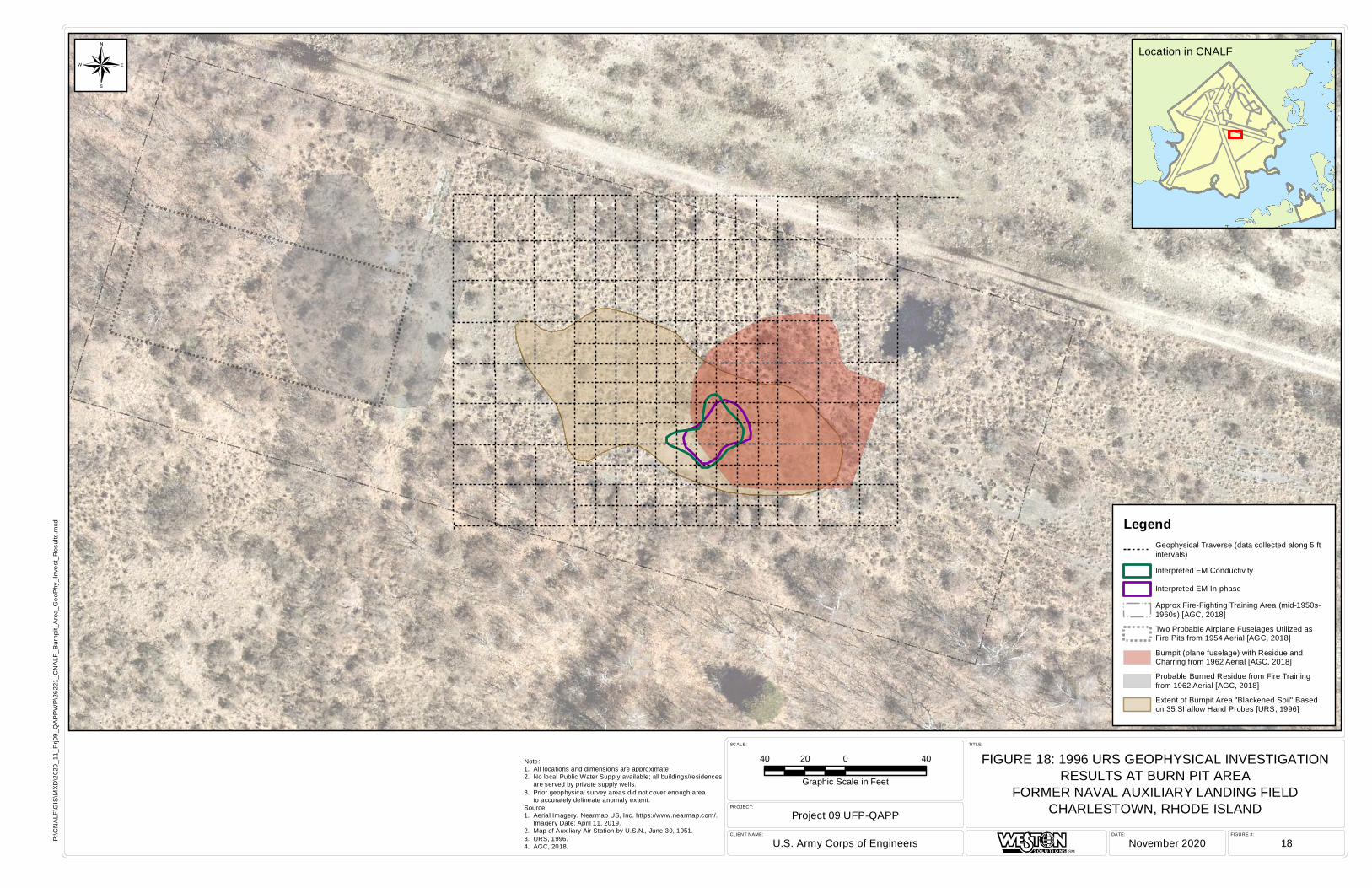
FIGURE #:DATE:CLIENT NAME:
PROJECT:
SCALE: TITLE:
Project 09 UFP-QAPP
U.S. Army Corps of Engineers November 2020 18
FIGURE 18: 1996 URS GEOPHYSICAL INVESTIGATIONRESULTS AT BURN PIT AREA
FORMER NAVAL AUXILIARY LANDING FIELDCHARLESTOWN, RHODE ISLAND
SM
P:\C
NA
LF\G
IS\M
XD
\202
0_11
_Prj0
9_Q
AP
PW
P\2
6221
_CN
ALF
_Bur
npit_
Are
a_G
eoP
hy_I
nves
t_R
esul
ts.m
xd
Note:1. All locations and dimensions are approximate.2. No local Public Water Supply available; all buildings/residences are served by private supply wells.3. Prior geophysical survey areas did not cover enough area to accurately delineate anomaly extent.Source:1. Aerial Imagery. Nearmap US, Inc. https://www.nearmap.com/. Imagery Date: April 11, 2019.2. Map of Auxiliary Air Station by U.S.N., June 30, 1951.3. URS, 1996.4. AGC, 2018.
Location in CNALF
40 0 4020
Graphic Scale in Feet
LegendGeophysical Traverse (data collected along 5 ftintervals)
Interpreted EM Conductivity
Interpreted EM In-phase
Approx Fire-Fighting Training Area (mid-1950s-1960s) [AGC, 2018]
Two Probable Airplane Fuselages Utilized asFire Pits from 1954 Aerial [AGC, 2018]
Burnpit (plane fuselage) with Residue andCharring from 1962 Aerial [AGC, 2018]
Probable Burned Residue from Fire Trainingfrom 1962 Aerial [AGC, 2018]
Extent of Burnpit Area "Blackened Soil" Basedon 35 Shallow Hand Probes [URS, 1996]
¬

DATE:
FIGURE #:
CLIENT NAME:
PROJECT: TITLE:
R
FIGURE 19: PROJECT 09 CHARLESTOWN LANDFILLCONCEPTUAL SITE MODEL
FORMER NAVAL AUXILIARY LANDING FIELDCHARLESTOWN, RHODE ISLAND
Not To Scale
U.S. Army Corps of Engineers
Project 09 UFP-QAPP
November 2020
19
Note:1. Landfill soils may be in direct contact with groundwater and/or surface water in some areas. The landfill boundaries and fill depths have been adjusted based on the current understanding of the landfill extents.Source:1. The Johnson Company
DRAFT
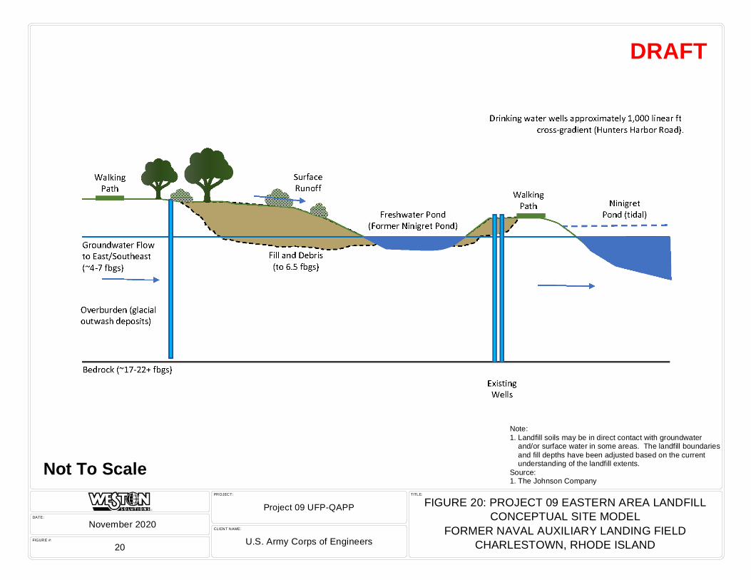
DATE:
FIGURE #:
CLIENT NAME:
PROJECT: TITLE:
R
FIGURE 20: PROJECT 09 EASTERN AREA LANDFILLCONCEPTUAL SITE MODEL
FORMER NAVAL AUXILIARY LANDING FIELDCHARLESTOWN, RHODE ISLANDU.S. Army Corps of Engineers
Project 09 UFP-QAPP
November 2020
20
Not To Scale
DRAFT
Note:1. Landfill soils may be in direct contact with groundwater and/or surface water in some areas. The landfill boundaries and fill depths have been adjusted based on the current understanding of the landfill extents.Source:1. The Johnson Company
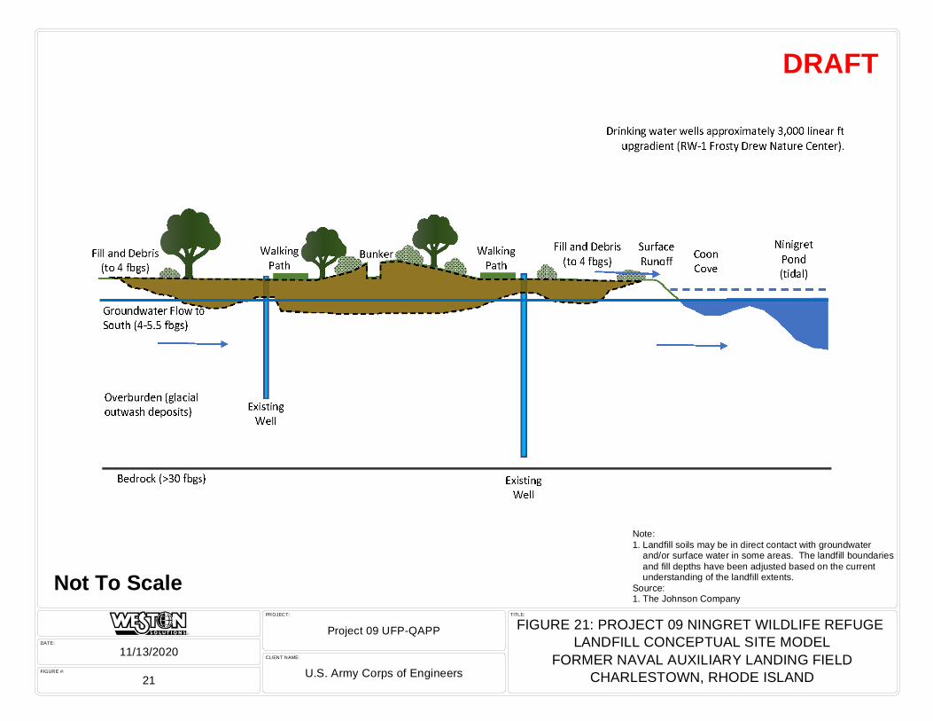
DATE:
FIGURE #:
CLIENT NAME:
PROJECT: TITLE:
R
FIGURE 21: PROJECT 09 NINGRET WILDLIFE REFUGE LANDFILL CONCEPTUAL SITE MODEL
FORMER NAVAL AUXILIARY LANDING FIELDCHARLESTOWN, RHODE ISLANDU.S. Army Corps of Engineers
Project 09 UFP-QAPP
11/13/2020
21
Not To Scale
DRAFT
Note:1. Landfill soils may be in direct contact with groundwater and/or surface water in some areas. The landfill boundaries and fill depths have been adjusted based on the current understanding of the landfill extents.Source:1. The Johnson Company
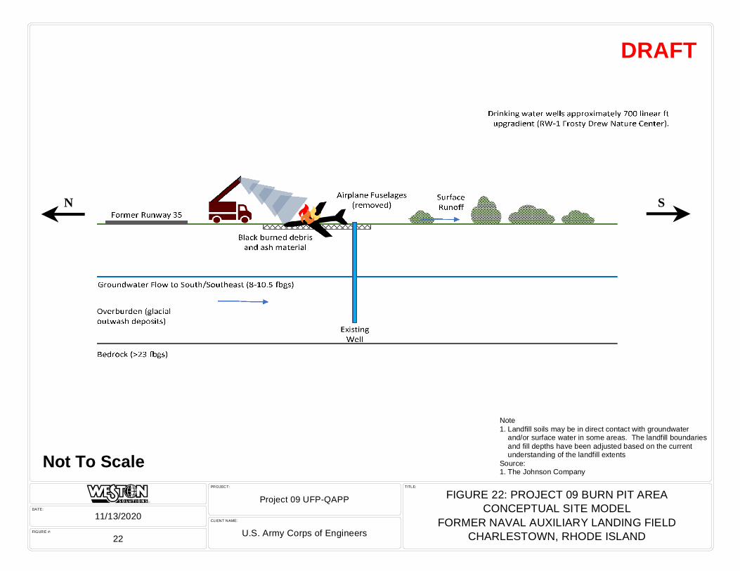
DATE:
FIGURE #:
CLIENT NAME:
PROJECT: TITLE:
R
FIGURE 22: PROJECT 09 BURN PIT AREACONCEPTUAL SITE MODEL
FORMER NAVAL AUXILIARY LANDING FIELDCHARLESTOWN, RHODE ISLANDU.S. Army Corps of Engineers
Project 09 UFP-QAPP
11/13/2020
22
Not To Scale
DRAFT
Note1. Landfill soils may be in direct contact with groundwater and/or surface water in some areas. The landfill boundaries and fill depths have been adjusted based on the current understanding of the landfill extentsSource:1. The Johnson Company
llN S

³³
³³
³³
³³
³³
³³
³³
³³
³³
³³
³³
³³
³³
³³
³³
³³
³³
³³
³³
³³
³³
!A
!A
!A
!A
!A
!A !A
!A
!A
!A
!A
!A
!A
!A
!A
!A
!A
!>
!>
!>
!>
!>
!>
!>
!>
1963 Filled-In Pit(possible buried waste)
Active Dump 1951/1954[AGC, 2018]
1944Possible
Dump Site
MunitionsDebris
[Alion, 2008]
Former Sand Filters
Former SewageDisposal Area
Form
er Du
mp
Assumed GroundwaterFlow to E/SE[URS, 1996]
Freshwaterpond
NinigretPond
Approximate FormerFreshwater Pond and
Discharge Channellocation based on
1945 aeria l.
Feature Type: MaterialNote: Debris Pile
Source Year: 2020
Feature Type: ObjectsNote: Concrete Block Pile
Source Year: 1951
Feature Type: Ground ScarNote: Ground ScarSource Year: 2006
Feature Type: ObjectsNote: Concrete Block Pile
Source Year: 1951
Feature Type: Mounded MaterialNote: None
Source Year: 1947
Feature Type: Mounded MaterialNote: None
Source Year: 1947
Feature Type: Mounded MaterialNote: None
Source Year: 1947
Feature Type: Mounded MaterialNote: None
Source Year: 1947
Area B
FIGURE #:DATE:CLIENT NAME:
PROJECT:
SCALE: TITLE:
Project 09 UFP-QAPP
U.S. Army Corps of Engineers March 2021 23
FIGURE 23: CHARLESTOWN LANDFILL - MRS 4 DUMP SITEPROPOSED GEOPHYSICAL INVESTIGATIONFORMER NAVAL AUXILIARY LANDING FIELD
CHARLESTOWN, RHODE ISLAND
SM
P:\C
NA
LF\G
IS\M
XD
\202
1_03
\266
81_C
NA
LF_P
09_C
TL_G
eoP
hy_R
esul
ts_P
ropo
se_T
rans
ects
_rev
Mar
2021
.mxd
Note:1. All locations and dimensions are approximate.2. No local Public Water Supply available; all buildings/residences are served by private supply wells.Source:1. Aerial Imagery. Nearmap US, Inc. https://www.nearmap.com/. Imagery Date: April 11, 2019.2. Map of Auxiliary Air Station by U.S.N., June 30, 1951.3. E&E, 1987.4. ITC, 1993.5. URS, 1996.6. Weston, 2001a.7. Alion, 2000.8. Alion, 2008.9. AGC, 2018.10. USACE, 2018 (interview with Larry Webster, July 2018).
Location in CNALF
150 0 15075
Graphic Scale in Feet
LegendProposed Geophysical transect (10 foot)
³³ Proposed Test Pit Excavation
!> Proposed Bedrock Monitoring Well
!> New Proposed Bedrock Monitoring Well
!A Proposed Overburden Monitoring Well Nest
!A New Proposed Overburden Monitoring Well Nest
Interpreted Magnetic FillInterpreted EM In-phase
Interpreted Metallic or Electrically Conductive Fillfrom EM Conductivity
Potential Obstructions to Geophysical Survey
Sloped Regions that could impact GeophysicalTransect Surveys
Gravel Pit [AGC, 2018]
1954 Trench [AGC, 2018]1947 Multiple Ground Disturbances with PossibleTrench [AGC, 2018]
Freshwater Pond Discharge Channel [AGC,2018]
Reported Buried 9 Aircraft (partiallyexcavated/removed in 1977) [USACE, 2018]
Features from 1951 USN Map
Town of Charlestown Surface Debris [URS,1996]
Landfill Extent Delineated by URS [1996]
Possible Excavation from 1947 Aerial [AGC,2018]
Ground Scar from 1963 Aerial [AGC, 2018]
Archaeological Sensitivity Area/Zone
CNALF Boundary
¬
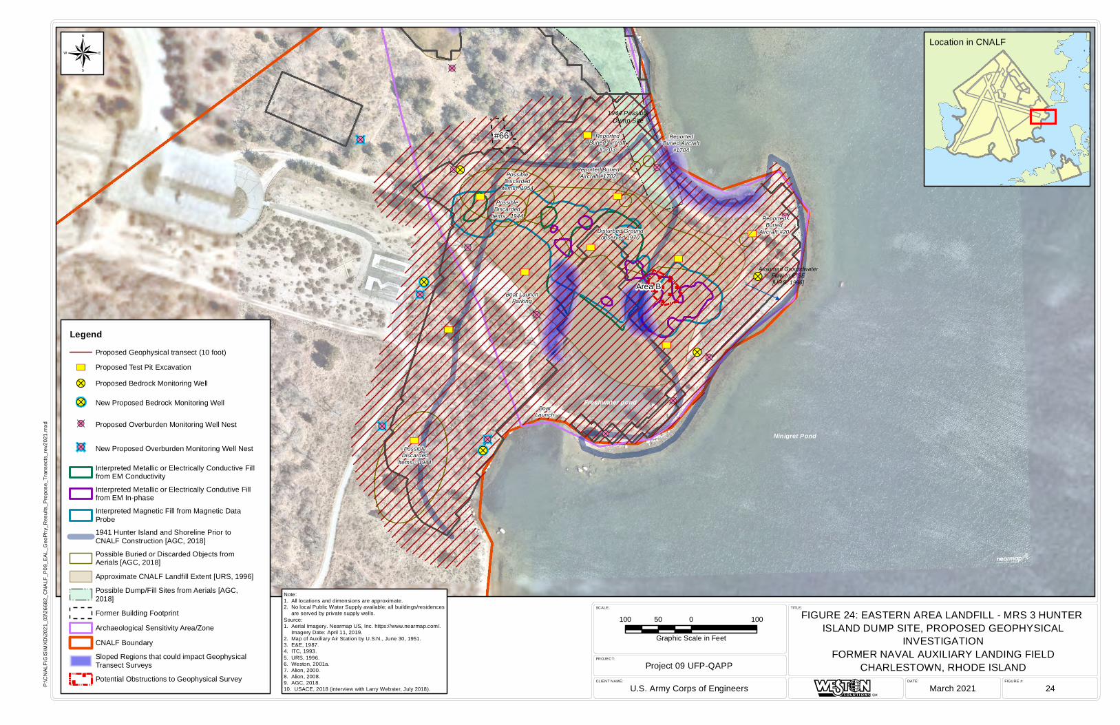
³³
³³
³³
³³
³³
³³
³³
³³
³³
³³
!A
!A
!A !A
!A
!A
!A
!A
!A
!A
!A
!A!A
!>
!>
!>
!>
!>
1944 PossibleDump Site
ReportedBuried Aircraft
#1704
Reported BuriedAircraft #1702
ReportedBuried
Aircraft #20Disturbed Groundobserved 1970
PossibleDiscarded
Items - 1954
PossibleDiscarded
Items - 1944
PossibleDiscarded
Items - 1944
ReportedBuried Aircraft
#1703
Assumed GroundwaterFlow to E/SE[URS, 1996]
Boat LaunchParking
BoatLaunch
Freshwater pond
Ninigret Pond
Area B
#66
FIGURE #:DATE:CLIENT NAME:
PROJECT:
SCALE: TITLE:
Project 09 UFP-QAPP
U.S. Army Corps of Engineers March 2021 24
FIGURE 24: EASTERN AREA LANDFILL - MRS 3 HUNTER ISLAND DUMP SITE, PROPOSED GEOPHYSICAL
INVESTIGATIONFORMER NAVAL AUXILIARY LANDING FIELD
CHARLESTOWN, RHODE ISLAND
SM
P:\C
NA
LF\G
IS\M
XD
\202
1_03
\266
82_C
NA
LF_P
09_E
AL_
Geo
Phy
_Res
ults
_Pro
pose
_Tra
nsec
ts_r
ev20
21.m
xd
Note:1. All locations and dimensions are approximate.2. No local Public Water Supply available; all buildings/residences are served by private supply wells.Source:1. Aerial Imagery. Nearmap US, Inc. https://www.nearmap.com/. Imagery Date: April 11, 2019.2. Map of Auxiliary Air Station by U.S.N., June 30, 1951.3. E&E, 1987.4. ITC, 1993.5. URS, 1996.6. Weston, 2001a.7. Alion, 2000.8. Alion, 2008.9. AGC, 2018.10. USACE, 2018 (interview with Larry Webster, July 2018).
Location in CNALF
100 0 10050
Graphic Scale in Feet
LegendProposed Geophysical transect (10 foot)
³³ Proposed Test Pit Excavation
!> Proposed Bedrock Monitoring Well
!> New Proposed Bedrock Monitoring Well
!A Proposed Overburden Monitoring Well Nest
!A New Proposed Overburden Monitoring Well Nest
Interpreted Metallic or Electrically Conductive Fillfrom EM Conductivity
Interpreted Metallic or Electrically Condutive Fillfrom EM In-phase
Interpreted Magnetic Fill from Magnetic DataProbe
1941 Hunter Island and Shoreline Prior toCNALF Construction [AGC, 2018]
Possible Buried or Discarded Objects fromAerials [AGC, 2018]
Approximate CNALF Landfill Extent [URS, 1996]
Possible Dump/Fill Sites from Aerials [AGC,2018]
Former Building Footprint
Archaeological Sensitivity Area/Zone
CNALF Boundary
Sloped Regions that could impact GeophysicalTransect Surveys
Potential Obstructions to Geophysical Survey
¬
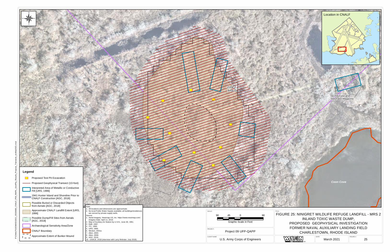
³³
³³
³³
³³
³³
³³
³³
³³
³³
³³
#59 Fuse and Detonator Magazine
Coon Cove
Zone 2,Area D
FIGURE #:DATE:CLIENT NAME:
PROJECT:
SCALE: TITLE:
Project 09 UFP-QAPP
U.S. Army Corps of Engineers March 2021 25
FIGURE 25: NINIGRET WILDLIFE REFUGE LANDFILL - MRS 2INLAND TOXIC WASTE DUMP,
PROPOSED GEOPHYSICAL INVESTIGATIONFORMER NAVAL AUXILIARY LANDING FIELD
CHARLESTOWN, RHODE ISLAND
SM
P:\C
NA
LF\G
IS\M
XD
\202
1_03
\266
83_C
NA
LF_P
09_N
WR
L_G
eoP
hy_R
esul
ts_P
ropo
se_T
rans
ects
_rev
Mar
2021
.mxd
Location in CNALF
90 0 9045
Graphic Scale in Feet
Legend
³³ Proposed Test Pit Excavation
Proposed Geophysical Transect (10-foot)
Interpreted Area of Metallic or ConductiveFill [URS, 1996]
1941 Hunter Island and Shoreline Prior toCNALF Construction [AGC, 2018]
Possible Buried or Discarded Objectsfrom Aerials [AGC, 2018]
Approximate CNALF Landfill Extent [URS,1996]
Possible Dump/Fill Sites from Aerials[AGC, 2018]
Archaeological Sensitivity Area/Zone
CNALF Boundary
Approximate Extent of Bunker Mound
¬
Note:1. All locations and dimensions are approximate.2. No local Public Water Supply available; all buildings/residences are served by private supply wells.Source:1. Aerial Imagery. Nearmap US, Inc. https://www.nearmap.com/. Imagery Date: April 11, 2019.2. Map of Auxiliary Air Station by U.S.N., June 30, 1951.3. E&E, 1987.4. ITC, 1993.5. URS, 1996.6. Weston, 2001a.7. Alion, 2000.8. Alion, 2008.9. AGC, 2018.10. USACE, 2018 (interview with Larry Webster, July 2018).
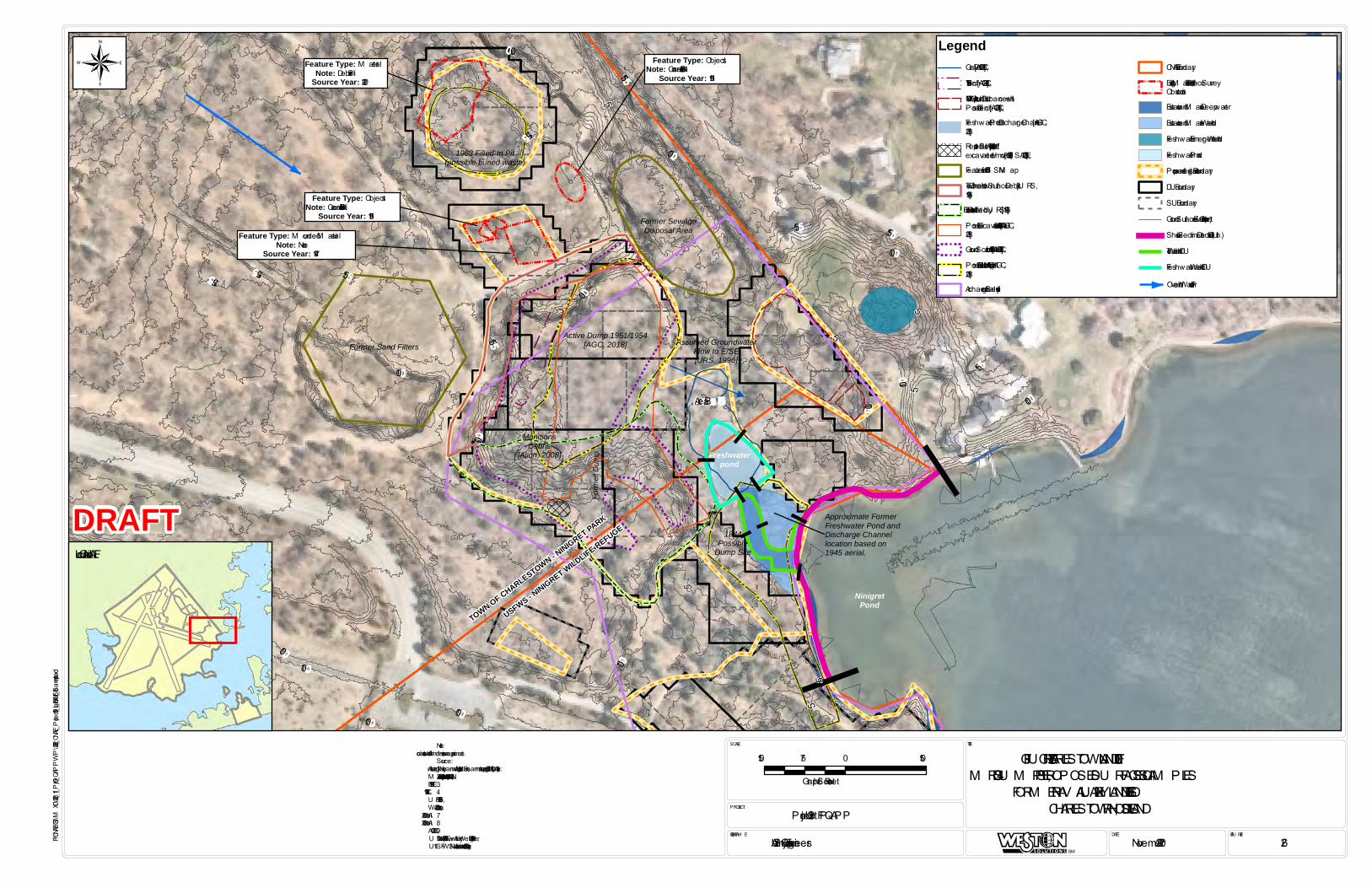
MunitionsDebris
[Alion, 2008]
Former Sand Filters
Former SewageDisposal Area
Form
er Du
mp
TOWN OF CHARLESTOWN - NINIGRET PARK
USFWS - NINIGRET WILDLIFE REFUGE
Assumed GroundwaterFlow to E/SE[URS, 1996]
Freshwaterpond
NinigretPond
Approximate FormerFreshwater Pond andDischarge Channellocation based on1945 aerial.
1944Possible
Dump Site
Active Dump 1951/1954[AGC, 2018]
1963 Filled-In Pit(possible buried waste)
Feature Type: M ounded M aterialNote: None
Source Year: 1947
Feature Type: ObjectsNote: Concrete Block Pile
Source Year: 1951
Feature Type: M aterialNote: Debris Pile
Source Year: 2020
Feature Type: ObjectsNote: Concrete Block Pile
Source Year: 1951
Area B
15
10
1510
10 5
10
5
5
10
5
15
15
5
10
10
15
10
15
10
5
10
5
151515
10
10
1010
10
1010 10
FIGU RE #:DATE:CLIENT NAM E:
PROJECT:
SCALE: TITLE:
Project 09 U FP-QAPP
U . S. Army Corps of Engineers Novemer 2020 26
FIGU RE 26: CHARLESTOWN LANDFILL – M RS 4 DU M P SITE, PROPOSED SU RFACE SOIL SAM PLES
FORM ER NAV AL AU XILIARY LANDING FIELDCHARLESTOWN, RHODE ISLAND
SM
P:\CNALF\GIS\MXD\2020_11_Prj09_QAPPWP\26232_CNALF_Project09_Landfill_SurfSoil_Samples.mxd
Note:1. All locations and dimensions are approximate.Source:1. Aerial Imagery. Nearmap U S, Inc. https://www.nearmap.com/. Imagery Date: April 11, 2019.2. M ap of Auxiliary Air Station by U .S.N., June 30, 1951.3. E&E, 1987.4. ITC, 1993.5. U RS, 1996.6. Weston, 2001a.7. Alion, 2000.8. Alion, 2008.9. AGC, 2018.10. U SACE, 2018 (interview with Larry Webster, July 2018). 11. U SFWS National Wetland Inventory, 2006.
Location in CNALF
150 0 15075
Graphic Scale in Feet
¬Legend
Gravel Pit [AGC, 2018]1954 Trench [AGC, 2018]1947 M ultiple Ground Disturbances withPossible Trench [AGC, 2018]Freshwater Pond Discharge Channel [AGC,2018]Reported Buried 9 Aircraft (partiallyexcavated/removed in 1977) [U SACE, 2018]Features from 1951 U SN M apTown of Charlestown Surface Debris [U RS,1996]Landfill Extent Delineated by U RS [1996]Possible Excavation from 1947 Aerial [AGC,2018]Ground Scar from 1963 Aerial [AGC, 2018]Possible Dump/Fill Sites from Aerials [AGC,2018]Archaeological Sensitivity
CNALF BoundaryExisting M aterial Pile, Surface SurveyObstructionEstuarine and M arine DeepwaterEstuarine and M arine WetlandFreshwater Emergent WetlandFreshwater PondProposed Investigation BoundaryDU BoundarySU BoundaryGround Surface Elevation Contour (feet)Shoreline Sediment Decision U nit (DU )Tidal Wetland DUFreshwater Wetland DU
DRAFT
Overland Water Flow
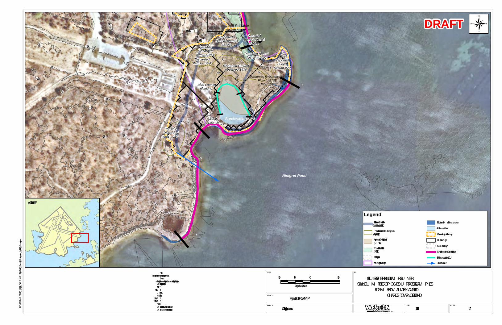
PossibleDiscarded
Items - 1944
ReportedBuried Aircraft
#1703
Assumed GroundwaterFlow to E/SE[URS, 1996]Boat Launch
Parking
BoatLaunch
Freshwater pond
Ninigret Pond
1944 PossibleDump Site
PossibleDiscarded
Items - 1944
PossibleDiscarded
Items - 1954
Disturbed Groundobserved 1970
ReportedBuried
Aircraft #20
Reported BuriedAircraft #1702
ReportedBuried Aircraft
#1704
Area B
5
3
7 6
65
53
65
10
9
10
9
8
7
9
99
7
76
4
1
5
6
10
8 5
5
2
2
10
10
10
109
10
10
109
9
9
6
6
6
4
4
4
5
3
2
1
8
4
#66
FIGU RE #:DATE:CLIENT NAM E:
PROJECT:
SCALE: TITLE:
Project 09 U FP-QAPP
U . S. Army Corps of Engineers 11/25/2020 27
FIGU RE 27: EASTERN LANDFILL – M RS 3 HU NTER ISLAND DU M P SITE, PROPOSED SU RFACE SOIL SAM PLES
FORM ER NAV AL AU XILIARY LANDING FIELDCHARLESTOWN, RHODE ISLAND
SM
P:\CNALF\GIS\MXD\2020_11_Prj09_QAPPWP\26233_CNALF_Project09_Eastern_Area_Landfill_SurfSoil_Samples.mxd
Note:1. All locations and dimensions are approximate.Source:1. Aerial Imagery. Nearmap U S, Inc. https://www.nearmap.com/. Imagery Date: April 11, 2019.2. M ap of Auxiliary Air Station by U .S.N., June 30, 1951.3. E&E, 1987.4. ITC, 1993.5. U RS, 1996.6. Weston, 2001a.7. Alion, 2000.8. Alion, 2008.9. AGC, 2018.10. U SACE, 2018 (interview with Larry Webster, July 2018).11. U SFWS National Wetland Inventory, 2006.
Location in CNALF
150 0 15075
Graphic Scale in Feet
¬
Legend1941 Hunter Island and Shoreline Priorto CNALF Construction [AGC, 2018]Possible Buried or Discarded Objectsfrom Aerials [AGC, 2018]Approximate CNALF Landfill Extent[U RS, 1996]Possible Dump/Fill Sites from Aerials[AGC, 2018]Former Building FootprintArchaeological Sensitivity
Estuarine and M arine DeepwaterFreshwater PondProposed Investigation BoundaryDU BoundarySU BoundaryShoreline Sediment Decision U nit (DU )Freshwater Wetland DU
DRAFT
Overland Water Flow

Assumed Groundwater Flow to S/SE[ITC, 1993]
#59 Fuse and Detonator Magazine
#58 SmallArms Magazine
#57 PyrotechnicalMagazine
Coon Cove
Zone 2,Area D
#60 - Former HighExplosive Magazine
DU: 4
30 ft
DU: 430 ft
DU: 430 ft
DU: 430 ft
Zone 3,Area C
14
1210
10
8
86
86
86
8
6
6
4
4
2
104
2
6
4
8
6
4
6
6
4
6
6
6
6
6
6
4
4
44
4
4
4
44
4
4
4
44
4
4
4
2
FIGURE #:DATE:CLIENT NAME:
PROJECT:
SCALE: TITLE:
Project 09 UFP-QAPP
U. S. Army Corps of Engineers 4/7/2021 28
FIGURE 28: NINIGRET WILDLIFE REFUGE LANDFILL -MRS 2 INLAND TOXIC WASTE DUMP,
PROPOSED SURFACE SOIL AND WETLAND SEDIMENT SAMPLESFORMER NAVAL AUXILIARY LANDING FIELD
CHARLESTOWN, RHODE ISLAND
SM
P:\C
NAL
F\G
IS\M
XD\2
020_
11_P
rj09_
QAP
PWP\
2623
4_C
NAL
F_Pr
ojec
t09_
Nin
gret
_Wild
life_
Ref
uge_
Land
fill_
SurfS
oil_
Sam
ples
.mxd
Note:1. All locations and dimensions are approximate.Source:1. Aerial Imagery. Nearmap US, Inc. https://www.nearmap.com/. Imagery Date: April 11, 2019.2. Map of Auxiliary Air Station by U.S.N., June 30, 1951.3. E&E, 1987.4. ITC, 1993.5. URS, 1996.6. Weston, 2001a.7. Alion, 2000.8. Alion, 2008.9. AGC, 2018.10. USACE, 2018 (interview with Larry Webster, July 2018). 11. USFWS National Wetland Inventory, 2006.
Location in CNALFDRAFT
130 0 13065
Graphic Scale in Feet
¬
LegendArea of Possible Debris 1970-1972 [AGC, 2018]
Reported Buried Aircraft[USACE, 2018]
Possible Extent of Fill Areafrom 1979 Aerial [AGC, 2018]
Approximate Ningret LandfillExtent [URS, 1996]
Former Bunker
Archaeological SensitivityArea/Zone
Estuarine and MarineDeepwater
Estuarine and Marine Wetland
Freshwater Emergent Wetland
Freshwater Forested/ShrubWetland
Freshwater Pond
Ground Surface ElevationContour (feet)
Proposed InvestigationBoundary
DU Boundary
SU Boundary
Area of Bunker Not Included inBrush Clearing or GeophysicalSurvey
Shoreline Sediment DecisionUnit (DU)
Tidal Wetland Sediment DU
Overland Water Flow

Assumed GroundwaterFlow to S/SE[E&E, 1987]
FIGURE #:DATE:CLIENT NAME:
PROJECT:
SCALE: TITLE:
Project 09 UFP-QAPP
U. S. Army Corps of Engineers 11/25/2020 29
FIGURE 29: BURN PIT AREASURFACE AND SUBSURFACE SOIL SAMPLESFORMER NAVAL AUXILIARY LANDING FIELD
CHARLESTOWN, RHODE ISLAND
SM
P:\C
NAL
F\G
IS\M
XD\2
020_
11_P
rj09_
QAP
PWP\
2623
5_C
NAL
F_Pr
ojec
t09_
Burn
pit_
Area
_Soi
lSam
ples
_1Ac
re.m
xd
Note:1. All locations and dimensions are approximate.Source:1. Aerial Imagery. Nearmap US, Inc. https://www.nearmap.com/. Imagery Date: April 11, 2019.2. Map of Auxiliary Air Station by U.S.N., June 30, 1951.3. E&E, 1987.4. ITC, 1993.5. URS, 1996.6. Weston, 2001a.7. Alion, 2000.8. Alion, 2008.9. AGC, 2018.10. USACE, 2018 (interview with Larry Webster, July 2018).
Location in CNALF
DRAFT
70 0 7035
Graphic Scale in Feet
¬
LegendExtent of Burnpit Area "Blackened Soil" Based on35 Shallow Hand Probes [URS, 1996]
Approx Fire-Fighting Training Area (mid-1950s-1960s) [AGC, 2018]
Burn Pit (plane fuselage) with Residue andCharring from 1962 Aerial [AGC, 2018]
Stains (possible) Observed in 1954 Aerial [AGC,2018]
Probable Burned Residue from Fire Training from1962 Aerial [AGC, 2018]
Two Probable Airplane Fuselages Utilized as FirePits from 1954 Aerial [AGC, 2018]
Overland Flow
Historic Edge of Pavement
Proposed Investigation Boundary
DU Boundary
SU Boundary
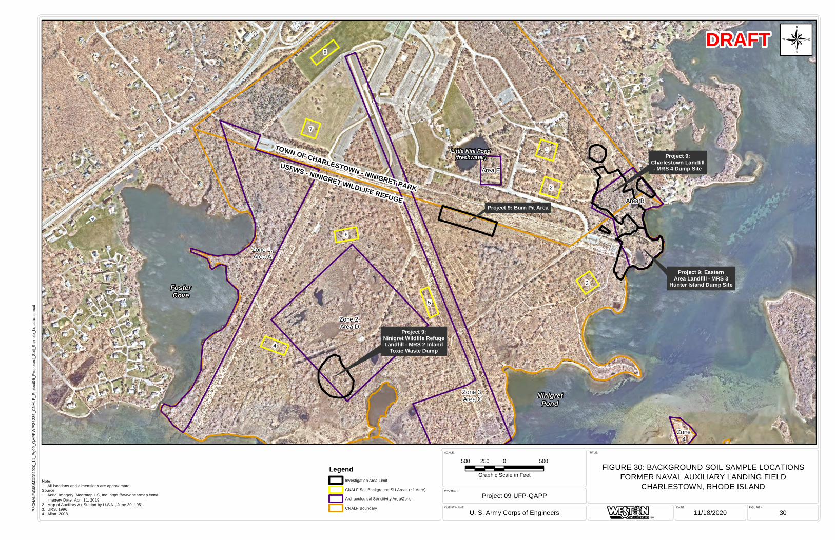
TOWN OF CHARLESTOWN - NINIGRET PARK
USFWS - NINIGRET WILDLIFE REFUGE
Project 9:Ninigret Wildlife RefugeLandfill - MRS 2 Inland
Toxic Waste Dump
Project 9: Burn Pit Area
Project 9: EasternArea Landfill - MRS 3
Hunter Island Dump Site
Project 9:Charlestown Landfill- MRS 4 Dump Site
Little Nini Pond(freshwater)
FosterCove
NinigretPond
7
6
5
3
2
4
8
1
Zone 1,Area A
Zone 2,Area D
Zone 3,Area C
Area E
Area B
Zone4
FIGURE #:DATE:CLIENT NAME:
PROJECT:
SCALE: TITLE:
Project 09 UFP-QAPP
U. S. Army Corps of Engineers 11/18/2020 30
FIGURE 30: BACKGROUND SOIL SAMPLE LOCATIONSFORMER NAVAL AUXILIARY LANDING FIELD
CHARLESTOWN, RHODE ISLAND
SM
P:\C
NA
LF\G
IS\M
XD
\202
0_11
_Prj0
9_Q
AP
PW
P\2
6236
_CN
ALF
_Pro
ject
09_P
ropo
sed_
Soi
l_S
ampl
e_Lo
catio
ns.m
xd
Note:1. All locations and dimensions are approximate.Source:1. Aerial Imagery. Nearmap US, Inc. https://www.nearmap.com/. Imagery Date: April 11, 2019.2. Map of Auxiliary Air Station by U.S.N., June 30, 1951.3. URS, 1996.4. Alion, 2008.
DRAFT
500 0 500250
Graphic Scale in Feet
¬
LegendInvestigation Area Limit
CNALF Soil Background SU Areas (~1 Acre)
Archaeological Sensitivity Area/Zone
CNALF Boundary
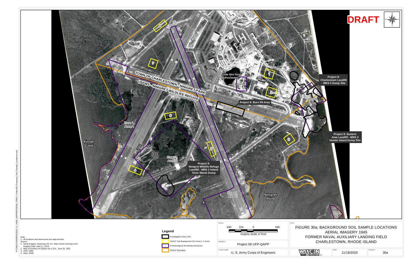
TOWN OF CHARLESTOWN - NINIGRET PARK
USFWS - NINIGRET WILDLIFE REFUGE
Project 9:Ninigret Wildlife RefugeLandfill - MRS 2 Inland
Toxic Waste Dump
Project 9: Burn Pit Area
Project 9: EasternArea Landfill - MRS 3
Hunter Island Dump Site
Project 9:Charlestown Landfill- MRS 4 Dump Site
Little Nini Pond(freshwater)
FosterCove
NinigretPond
7
6
5
3
2
4
8
1
Zone 1,Area A
Zone 2,Area D
Zone 3,Area C
Area E
Area B
Zone4
FIGURE #:DATE:CLIENT NAME:
PROJECT:
SCALE: TITLE:
Project 09 UFP-QAPP
U. S. Army Corps of Engineers 11/18/2020 30a
FIGURE 30a: BACKGROUND SOIL SAMPLE LOCATIONSAERIAL IMAGERY 1945
FORMER NAVAL AUXILIARY LANDING FIELDCHARLESTOWN, RHODE ISLAND
SM
P:\C
NA
LF\G
IS\M
XD
\202
0_11
_Prj0
9_Q
AP
PW
P\2
6236
_CN
ALF
_Pro
ject
09_P
ropo
sed_
Soi
l_S
ampl
e_Lo
catio
ns.m
xd
Note:1. All locations and dimensions are approximate.Source:1. Aerial Imagery. Nearmap US, Inc. https://www.nearmap.com/. Imagery Date: April 11, 2019.2. Map of Auxiliary Air Station by U.S.N., June 30, 1951.3. URS, 1996.4. Alion, 2008.
DRAFT
630 0 630315
Graphic Scale in Feet
¬
LegendInvestigation Area Limit
CNALF Soil Background SU Areas (~1 Acre)
Archaeological Sensitivity Area/Zone
CNALF Boundary
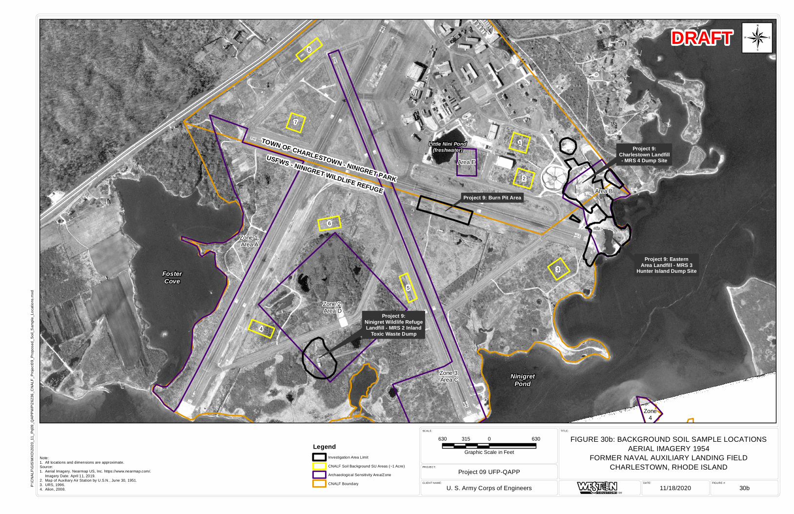
TOWN OF CHARLESTOWN - NINIGRET PARK
USFWS - NINIGRET WILDLIFE REFUGE
Project 9:Ninigret Wildlife RefugeLandfill - MRS 2 Inland
Toxic Waste Dump
Project 9: Burn Pit Area
Project 9: EasternArea Landfill - MRS 3
Hunter Island Dump Site
Project 9:Charlestown Landfill- MRS 4 Dump Site
Little Nini Pond(freshwater)
FosterCove
NinigretPond
7
6
5
3
2
4
8
1
Zone 1,Area A
Zone 2,Area D
Zone 3,Area C
Area E
Area B
Zone4
FIGURE #:DATE:CLIENT NAME:
PROJECT:
SCALE: TITLE:
Project 09 UFP-QAPP
U. S. Army Corps of Engineers 11/18/2020 30b
FIGURE 30b: BACKGROUND SOIL SAMPLE LOCATIONSAERIAL IMAGERY 1954
FORMER NAVAL AUXILIARY LANDING FIELDCHARLESTOWN, RHODE ISLAND
SM
P:\C
NA
LF\G
IS\M
XD
\202
0_11
_Prj0
9_Q
AP
PW
P\2
6236
_CN
ALF
_Pro
ject
09_P
ropo
sed_
Soi
l_S
ampl
e_Lo
catio
ns.m
xd
Note:1. All locations and dimensions are approximate.Source:1. Aerial Imagery. Nearmap US, Inc. https://www.nearmap.com/. Imagery Date: April 11, 2019.2. Map of Auxiliary Air Station by U.S.N., June 30, 1951.3. URS, 1996.4. Alion, 2008.
DRAFT
630 0 630315
Graphic Scale in Feet
¬
LegendInvestigation Area Limit
CNALF Soil Background SU Areas (~1 Acre)
Archaeological Sensitivity Area/Zone
CNALF Boundary
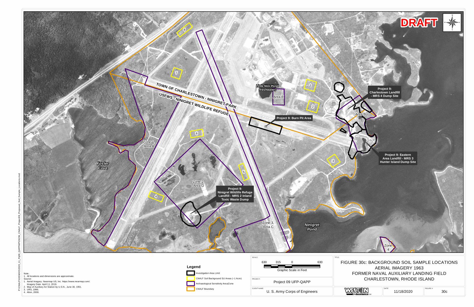
TOWN OF CHARLESTOWN - NINIGRET PARK
USFWS - NINIGRET WILDLIFE REFUGE
Project 9:Ninigret Wildlife RefugeLandfill - MRS 2 Inland
Toxic Waste Dump
Project 9: Burn Pit Area
Project 9: EasternArea Landfill - MRS 3
Hunter Island Dump Site
Project 9:Charlestown Landfill- MRS 4 Dump Site
Little Nini Pond(freshwater)
FosterCove
NinigretPond
7
6
5
3
2
4
8
1
Zone 1,Area A
Zone 2,Area D
Zone 3,Area C
Area E
Area B
Zone4
FIGURE #:DATE:CLIENT NAME:
PROJECT:
SCALE: TITLE:
Project 09 UFP-QAPP
U. S. Army Corps of Engineers 11/18/2020 30c
FIGURE 30c: BACKGROUND SOIL SAMPLE LOCATIONSAERIAL IMAGERY 1963
FORMER NAVAL AUXILIARY LANDING FIELDCHARLESTOWN, RHODE ISLAND
SM
P:\C
NA
LF\G
IS\M
XD
\202
0_11
_Prj0
9_Q
AP
PW
P\2
6236
_CN
ALF
_Pro
ject
09_P
ropo
sed_
Soi
l_S
ampl
e_Lo
catio
ns.m
xd
Note:1. All locations and dimensions are approximate.Source:1. Aerial Imagery. Nearmap US, Inc. https://www.nearmap.com/. Imagery Date: April 11, 2019.2. Map of Auxiliary Air Station by U.S.N., June 30, 1951.3. URS, 1996.4. Alion, 2008.
DRAFT
630 0 630315
Graphic Scale in Feet
¬
LegendInvestigation Area Limit
CNALF Soil Background SU Areas (~1 Acre)
Archaeological Sensitivity Area/Zone
CNALF Boundary
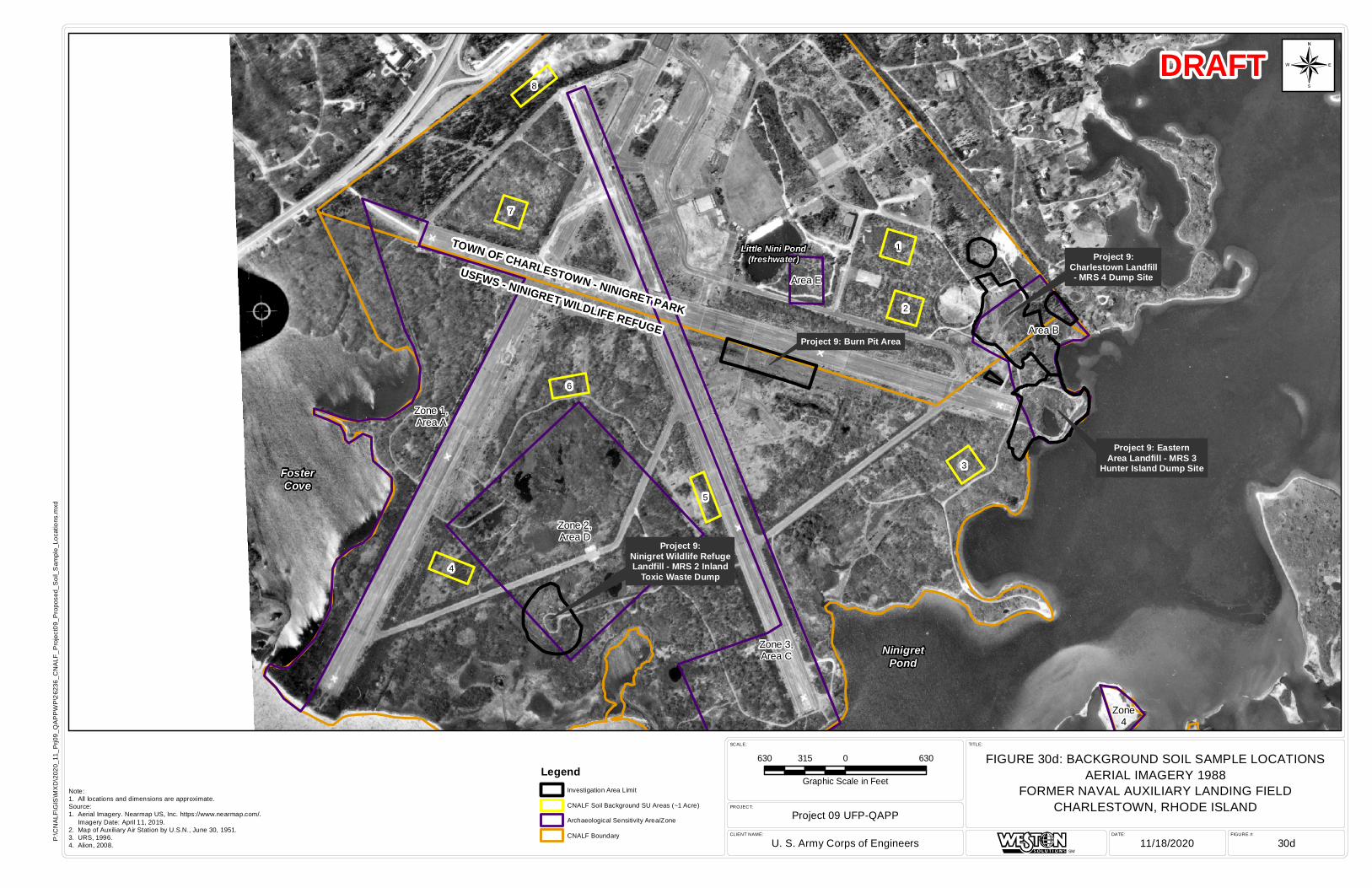
TOWN OF CHARLESTOWN - NINIGRET PARK
USFWS - NINIGRET WILDLIFE REFUGE
Project 9:Ninigret Wildlife RefugeLandfill - MRS 2 Inland
Toxic Waste Dump
Project 9: Burn Pit Area
Project 9: EasternArea Landfill - MRS 3
Hunter Island Dump Site
Project 9:Charlestown Landfill- MRS 4 Dump Site
Little Nini Pond(freshwater)
FosterCove
NinigretPond
7
6
5
3
2
4
8
1
Zone 1,Area A
Zone 2,Area D
Zone 3,Area C
Area E
Area B
Zone4
FIGURE #:DATE:CLIENT NAME:
PROJECT:
SCALE: TITLE:
Project 09 UFP-QAPP
U. S. Army Corps of Engineers 11/18/2020 30d
FIGURE 30d: BACKGROUND SOIL SAMPLE LOCATIONSAERIAL IMAGERY 1988
FORMER NAVAL AUXILIARY LANDING FIELDCHARLESTOWN, RHODE ISLAND
SM
P:\C
NA
LF\G
IS\M
XD
\202
0_11
_Prj0
9_Q
AP
PW
P\2
6236
_CN
ALF
_Pro
ject
09_P
ropo
sed_
Soi
l_S
ampl
e_Lo
catio
ns.m
xd
Note:1. All locations and dimensions are approximate.Source:1. Aerial Imagery. Nearmap US, Inc. https://www.nearmap.com/. Imagery Date: April 11, 2019.2. Map of Auxiliary Air Station by U.S.N., June 30, 1951.3. URS, 1996.4. Alion, 2008.
DRAFT
630 0 630315
Graphic Scale in Feet
¬
LegendInvestigation Area Limit
CNALF Soil Background SU Areas (~1 Acre)
Archaeological Sensitivity Area/Zone
CNALF Boundary
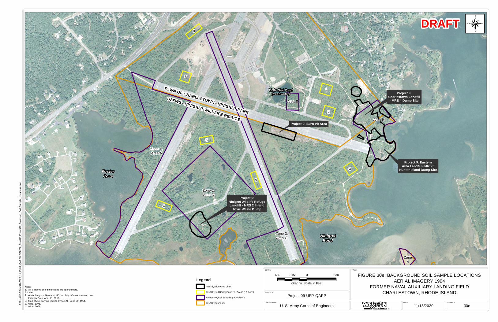
TOWN OF CHARLESTOWN - NINIGRET PARK
USFWS - NINIGRET WILDLIFE REFUGE
Project 9:Ninigret Wildlife RefugeLandfill - MRS 2 Inland
Toxic Waste Dump
Project 9: Burn Pit Area
Project 9: EasternArea Landfill - MRS 3
Hunter Island Dump Site
Project 9:Charlestown Landfill- MRS 4 Dump Site
Little Nini Pond(freshwater)
FosterCove
NinigretPond
7
6
5
3
2
4
8
1
Zone 1,Area A
Zone 2,Area D
Zone 3,Area C
Area E
Area B
Zone4
FIGURE #:DATE:CLIENT NAME:
PROJECT:
SCALE: TITLE:
Project 09 UFP-QAPP
U. S. Army Corps of Engineers 11/18/2020 30e
FIGURE 30e: BACKGROUND SOIL SAMPLE LOCATIONSAERIAL IMAGERY 1994
FORMER NAVAL AUXILIARY LANDING FIELDCHARLESTOWN, RHODE ISLAND
SM
P:\C
NA
LF\G
IS\M
XD
\202
0_11
_Prj0
9_Q
AP
PW
P\2
6236
_CN
ALF
_Pro
ject
09_P
ropo
sed_
Soi
l_S
ampl
e_Lo
catio
ns.m
xd
Note:1. All locations and dimensions are approximate.Source:1. Aerial Imagery. Nearmap US, Inc. https://www.nearmap.com/. Imagery Date: April 11, 2019.2. Map of Auxiliary Air Station by U.S.N., June 30, 1951.3. URS, 1996.4. Alion, 2008.
DRAFT
630 0 630315
Graphic Scale in Feet
¬
LegendInvestigation Area Limit
CNALF Soil Background SU Areas (~1 Acre)
Archaeological Sensitivity Area/Zone
CNALF Boundary
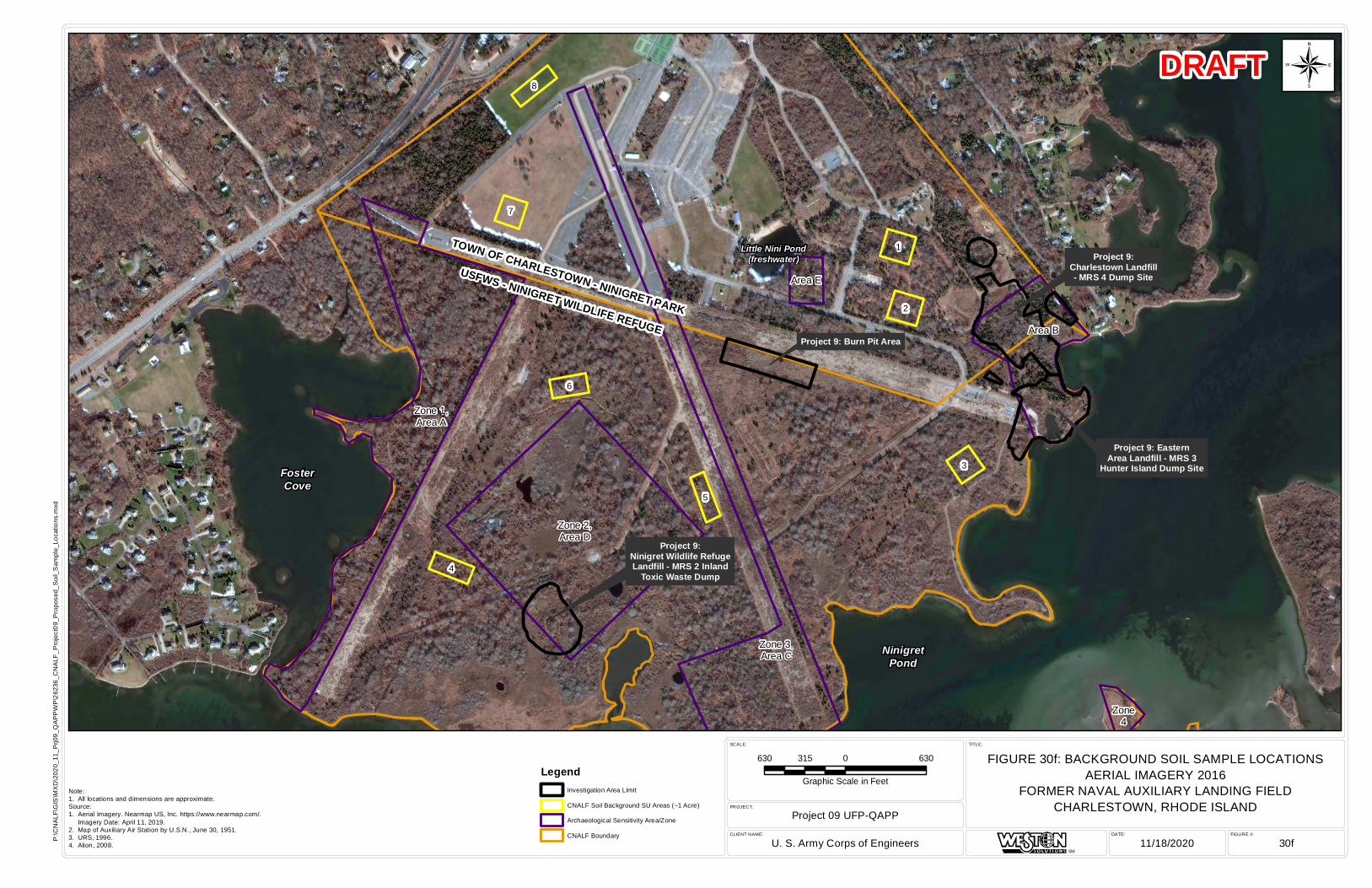
TOWN OF CHARLESTOWN - NINIGRET PARK
USFWS - NINIGRET WILDLIFE REFUGE
Project 9:Ninigret Wildlife RefugeLandfill - MRS 2 Inland
Toxic Waste Dump
Project 9: Burn Pit Area
Project 9: EasternArea Landfill - MRS 3
Hunter Island Dump Site
Project 9:Charlestown Landfill- MRS 4 Dump Site
Little Nini Pond(freshwater)
FosterCove
NinigretPond
7
6
5
3
2
4
8
1
Zone 1,Area A
Zone 2,Area D
Zone 3,Area C
Area E
Area B
Zone4
FIGURE #:DATE:CLIENT NAME:
PROJECT:
SCALE: TITLE:
Project 09 UFP-QAPP
U. S. Army Corps of Engineers 11/18/2020 30f
FIGURE 30f: BACKGROUND SOIL SAMPLE LOCATIONSAERIAL IMAGERY 2016
FORMER NAVAL AUXILIARY LANDING FIELDCHARLESTOWN, RHODE ISLAND
SM
P:\C
NA
LF\G
IS\M
XD
\202
0_11
_Prj0
9_Q
AP
PW
P\2
6236
_CN
ALF
_Pro
ject
09_P
ropo
sed_
Soi
l_S
ampl
e_Lo
catio
ns.m
xd
Note:1. All locations and dimensions are approximate.Source:1. Aerial Imagery. Nearmap US, Inc. https://www.nearmap.com/. Imagery Date: April 11, 2019.2. Map of Auxiliary Air Station by U.S.N., June 30, 1951.3. URS, 1996.4. Alion, 2008.
DRAFT
630 0 630315
Graphic Scale in Feet
¬
LegendInvestigation Area Limit
CNALF Soil Background SU Areas (~1 Acre)
Archaeological Sensitivity Area/Zone
CNALF Boundary
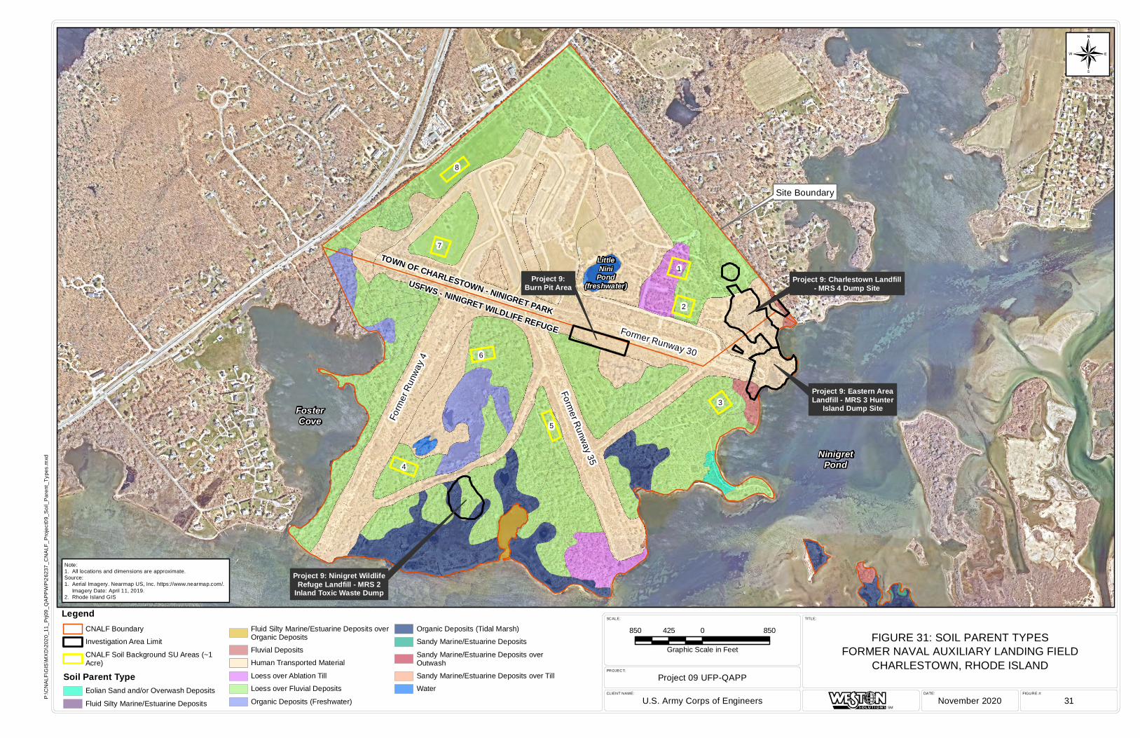
FIGURE #:DATE:CLIENT NAME:
PROJECT:
SCALE: TITLE:
Project 09 UFP-QAPP
U.S. Army Corps of Engineers November 2020 31
FIGURE 31: SOIL PARENT TYPESFORMER NAVAL AUXILIARY LANDING FIELD
CHARLESTOWN, RHODE ISLAND
SM
P:\C
NA
LF\G
IS\M
XD
\202
0_11
_Prj0
9_Q
AP
PW
P\2
6237
_CN
ALF
_Pro
ject
09_S
oil_
Par
ent_
Type
s.m
xd
DRAFT
Site Boundary
FosterCove
NinigretPond
Form
er R
unwa
y 4
Former R
unway 35
Former Runway 30
USFWS - NINIGRET WILDLIFE REFUGE
TOWN OF CHARLESTOWN - NINIGRET PARK
LittleNini
Pond(freshwater)
Project 9: Ninigret WildlifeRefuge Landfill - MRS 2
Inland Toxic Waste Dump
Project 9:Burn Pit Area
Project 9: Eastern AreaLandfill - MRS 3 Hunter
Island Dump Site
Project 9: Charlestown Landfill- MRS 4 Dump Site
7
6
5
3
2
4
8
1
850 0 850425
Graphic Scale in Feet
¬
CNALF Boundary
Investigation Area Limit
CNALF Soil Background SU Areas (~1Acre)
Soil Parent TypeEolian Sand and/or Overwash Deposits
Fluid Silty Marine/Estuarine Deposits
Fluid Silty Marine/Estuarine Deposits overOrganic Deposits
Fluvial Deposits
Human Transported Material
Loess over Ablation Till
Loess over Fluvial Deposits
Organic Deposits (Freshwater)
Organic Deposits (Tidal Marsh)
Sandy Marine/Estuarine Deposits
Sandy Marine/Estuarine Deposits overOutwash
Sandy Marine/Estuarine Deposits over Till
Water
Note:1. All locations and dimensions are approximate.Source:1. Aerial Imagery. Nearmap US, Inc. https://www.nearmap.com/. Imagery Date: April 11, 2019.2. Rhode Island GIS
Legend
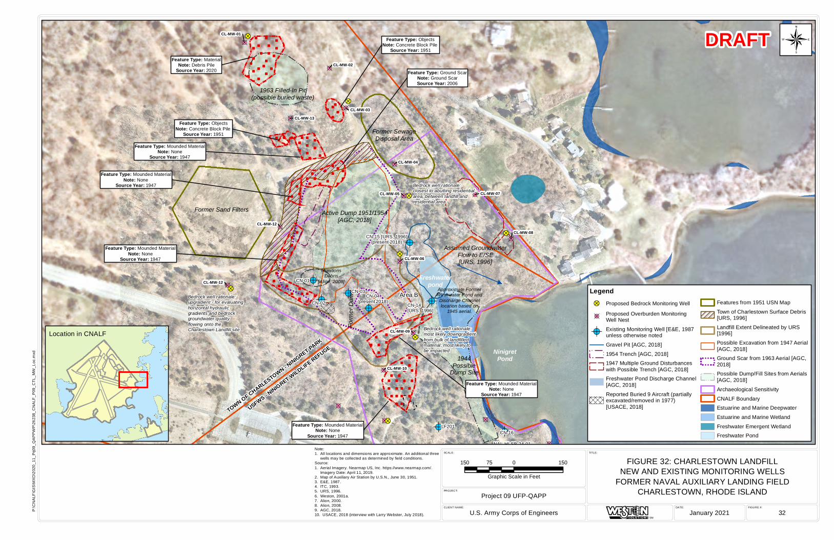
!A
!A
!A!A
!A
!A
!A
!A!A
!A
!A
!A
!A
!A
!A !A
!A
!A
!A
!A
!A
!A
!A
!A
!A
!A
!>
!>
!>
!>
!>
!>
!>
!>
MunitionsDebris
[Alion, 2008]
Former Sand Filters
Former SewageDisposal Area
Form
er Du
mp
TOWN OF CHARLESTOWN - NINIGRET PARK
USFWS - NINIGRET WILDLIFE REFUGE
Assumed GroundwaterFlow to E/SE[URS, 1996]
Freshwaterpond
NinigretPond
Approximate FormerFreshwater Pond andDischarge Channellocation based on
1945 aerial.
Bedrock well rationale:closest to abutting residentialarea; between landfill andresidential area
Bedrock well rationale:upgradient - for evaluatinghorizontal hydraulicgradients and bedrockgroundwater qualityflowing onto the Charlestown Landfill site Bedrock well rationale:
most likely downgradientfrom bulk of landfilledmaterial; most likely tobe impacted
CL-MW-12
CN-01
CN-02
CN-03CN-04
(present 2018)
CN-15 [URS, 1996](present 2018)
CN-14[URS, 1996]
CN-16LF201
NAL-HI-SB-24-01
1944Possible
Dump Site
Active Dump 1951/1954[AGC, 2018]
1963 Filled-In Pit(possible buried waste)
Feature Type: ObjectsNote: Concrete Block Pile
Source Year: 1951
Feature Type: Ground ScarNote: Ground ScarSource Year: 2006
Feature Type: MaterialNote: Debris Pile
Source Year: 2020
Feature Type: ObjectsNote: Concrete Block Pile
Source Year: 1951
Feature Type: Mounded MaterialNote: None
Source Year: 1947
Feature Type: Mounded MaterialNote: None
Source Year: 1947
Feature Type: Mounded MaterialNote: None
Source Year: 1947
Feature Type: Mounded MaterialNote: None
Source Year: 1947
Feature Type: Mounded MaterialNote: None
Source Year: 1947
CL-MW-04
CL-MW-05
CL-MW-09
CL-MW-10
CL-MW-12
CL-MW-06
CL-MW-01
CL-MW-13CL-MW-03
CL-MW-02
CL-MW-07
CL-MW-08
Area B
FIGURE #:DATE:CLIENT NAME:
PROJECT:
SCALE: TITLE:
Project 09 UFP-QAPP
U.S. Army Corps of Engineers January 2021 32
FIGURE 32: CHARLESTOWN LANDFILLNEW AND EXISTING MONITORING WELLS
FORMER NAVAL AUXILIARY LANDING FIELDCHARLESTOWN, RHODE ISLAND
SM
P:\C
NA
LF\G
IS\M
XD
\202
0_11
_Prj0
9_Q
AP
PW
P\2
6238
_CN
ALF
_P09
_CTL
_MW
_Loc
.mxd
DRAFT
Note:1. All locations and dimensions are approximate. An additional three wells may be collected as determined by field conditions.Source:1. Aerial Imagery. Nearmap US, Inc. https://www.nearmap.com/. Imagery Date: April 11, 2019.2. Map of Auxiliary Air Station by U.S.N., June 30, 1951.3. E&E, 1987.4. ITC, 1993.5. URS, 1996.6. Weston, 2001a.7. Alion, 2000.8. Alion, 2008.9. AGC, 2018.10. USACE, 2018 (interview with Larry Webster, July 2018).
150 0 15075
Graphic Scale in Feet
¬
Legend!> Proposed Bedrock Monitoring Well
!AProposed Overburden MonitoringWell Nest
!A Existing Monitoring Well [E&E, 1987unless otherwise noted
Gravel Pit [AGC, 2018]
1954 Trench [AGC, 2018]1947 Multiple Ground Disturbanceswith Possible Trench [AGC, 2018]Freshwater Pond Discharge Channel[AGC, 2018]
Reported Buried 9 Aircraft (partiallyexcavated/removed in 1977)[USACE, 2018]
Features from 1951 USN Map
Town of Charlestown Surface Debris[URS, 1996]
Landfill Extent Delineated by URS[1996]
Possible Excavation from 1947 Aerial[AGC, 2018]Ground Scar from 1963 Aerial [AGC,2018]Possible Dump/Fill Sites from Aerials[AGC, 2018]
Archaeological Sensitivity
CNALF BoundaryEstuarine and Marine Deepwater
Estuarine and Marine Wetland
Freshwater Emergent WetlandFreshwater Pond
Location in CNALF
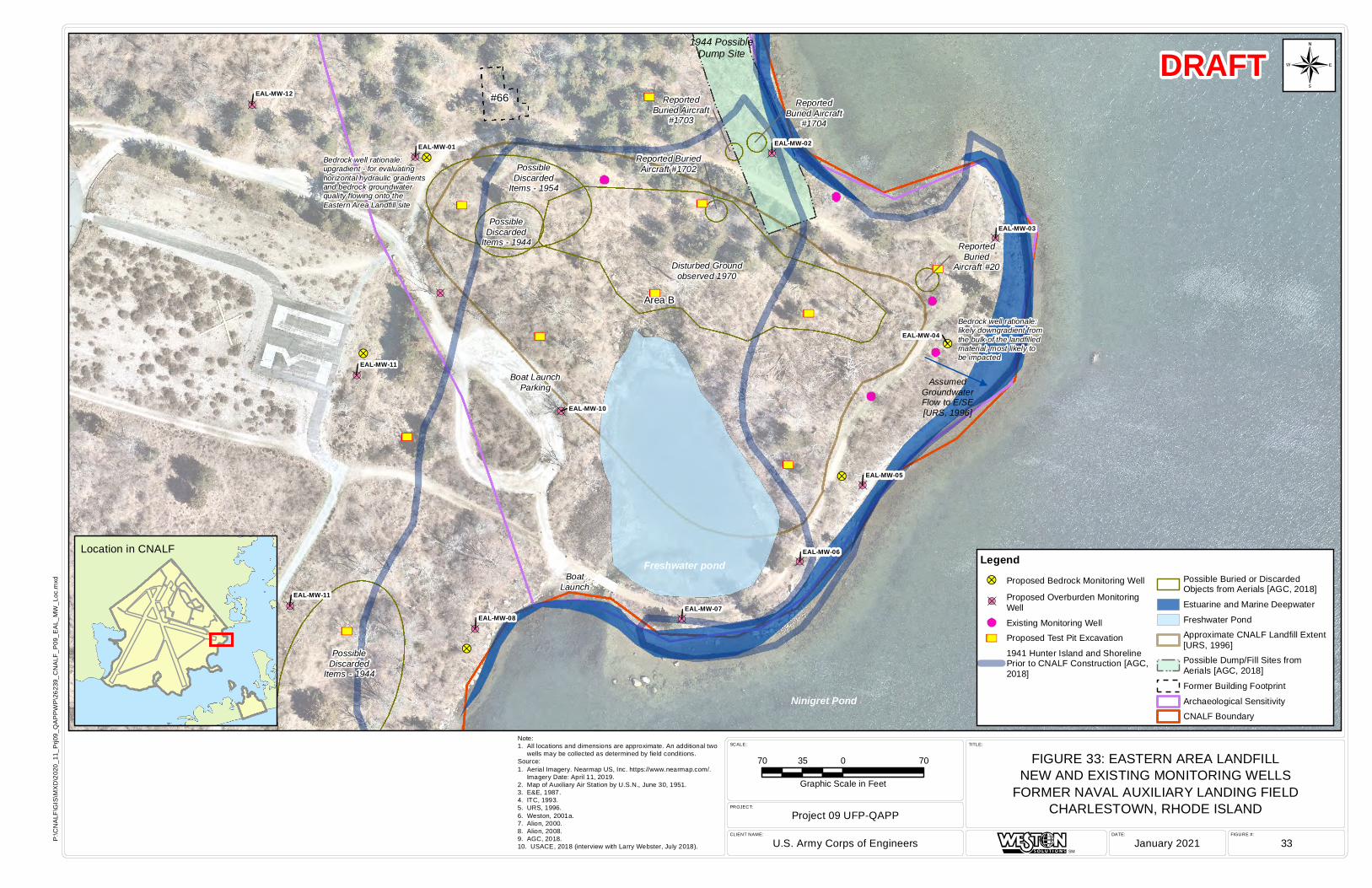
(
(
(
(
(
³³
³³
³³
³³
³³
³³
³³
³³
³³
³³
!A
!A!A
!A
!A
!A
!A
!A
!A
!A
!A
!A
!>
!>
!>
!>
!>
PossibleDiscarded
Items - 1944
ReportedBuried Aircraft
#1703
AssumedGroundwaterFlow to E/SE[URS, 1996]
Boat LaunchParking
BoatLaunch
Freshwater pond
Ninigret Pond
Bedrock well rationale:likely downgradient fromthe bulk of the landfilledmaterial; most likely to be impacted
Bedrock well rationale:upgradient - for evaluatinghorizontal hydraulic gradientsand bedrock groundwaterquality flowing onto theEastern Area Landfill site
EAL-MW-04
1944 PossibleDump Site
PossibleDiscarded
Items - 1944
PossibleDiscarded
Items - 1954
Disturbed Groundobserved 1970
ReportedBuried
Aircraft #20
Reported BuriedAircraft #1702
ReportedBuried Aircraft
#1704
EAL-MW-01 EAL-MW-02
EAL-MW-03
EAL-MW-05
EAL-MW-06
EAL-MW-07
EAL-MW-10
EAL-MW-12
EAL-MW-11
EAL-MW-11
EAL-MW-08
Area B
#66
FIGURE #:DATE:CLIENT NAME:
PROJECT:
SCALE: TITLE:
Project 09 UFP-QAPP
U.S. Army Corps of Engineers January 2021 33
FIGURE 33: EASTERN AREA LANDFILLNEW AND EXISTING MONITORING WELLS
FORMER NAVAL AUXILIARY LANDING FIELDCHARLESTOWN, RHODE ISLAND
SM
P:\C
NA
LF\G
IS\M
XD
\202
0_11
_Prj0
9_Q
AP
PW
P\2
6239
_CN
ALF
_P09
_EA
L_M
W_L
oc.m
xd
DRAFT
Note:1. All locations and dimensions are approximate. An additional two wells may be collected as determined by field conditions.Source:1. Aerial Imagery. Nearmap US, Inc. https://www.nearmap.com/. Imagery Date: April 11, 2019.2. Map of Auxiliary Air Station by U.S.N., June 30, 1951.3. E&E, 1987.4. ITC, 1993.5. URS, 1996.6. Weston, 2001a.7. Alion, 2000.8. Alion, 2008.9. AGC, 2018.10. USACE, 2018 (interview with Larry Webster, July 2018).
70 0 7035
Graphic Scale in Feet
¬
Legend!> Proposed Bedrock Monitoring Well
!AProposed Overburden MonitoringWell
( Existing Monitoring Well
³³ Proposed Test Pit Excavation
1941 Hunter Island and ShorelinePrior to CNALF Construction [AGC,2018]
Possible Buried or DiscardedObjects from Aerials [AGC, 2018]
Estuarine and Marine Deepwater
Freshwater PondApproximate CNALF Landfill Extent[URS, 1996]Possible Dump/Fill Sites fromAerials [AGC, 2018]
Former Building Footprint
Archaeological SensitivityCNALF Boundary
Location in CNALF
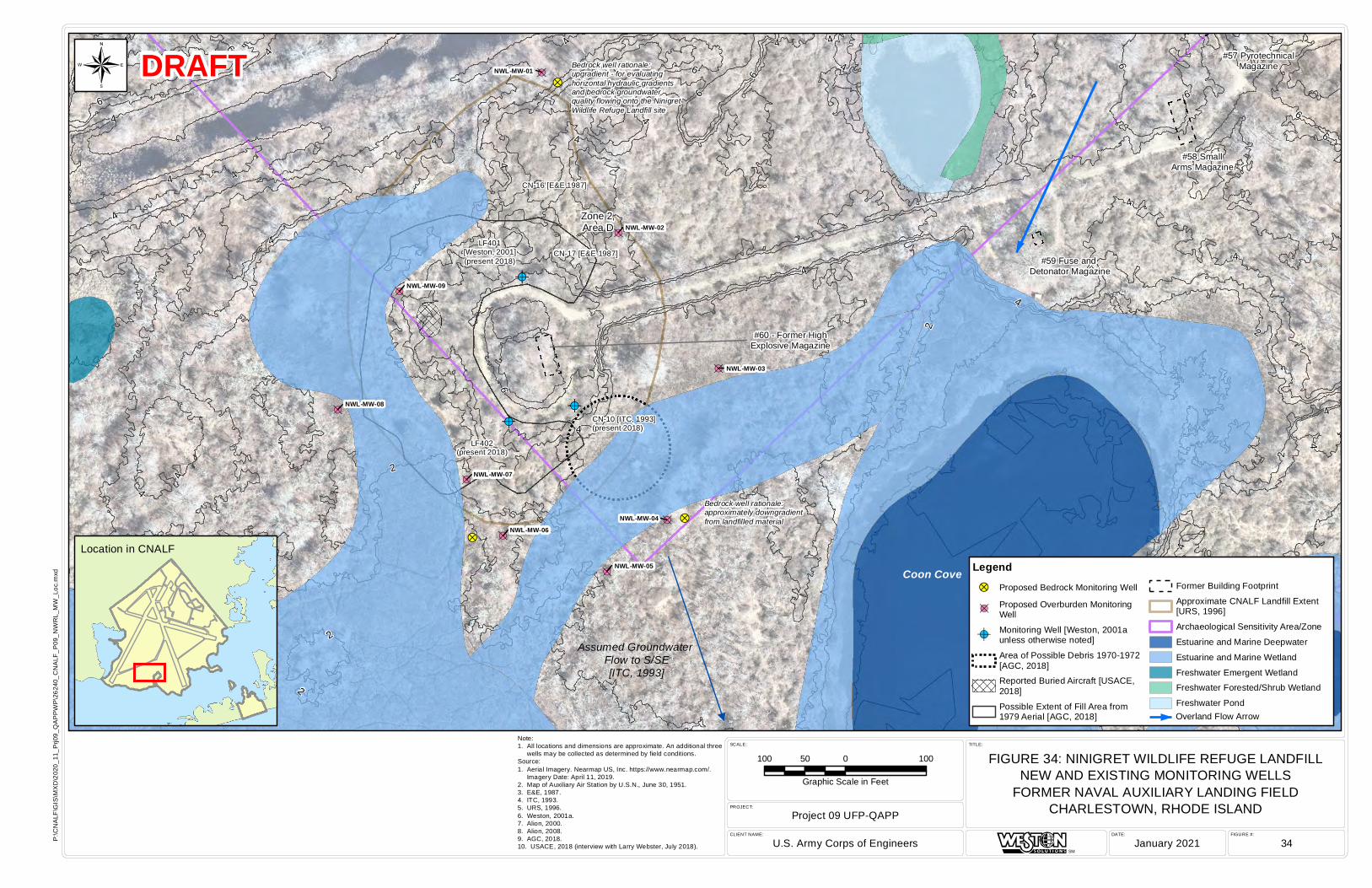
!A
!A
!A
!A
!A
!A
!A
!A
!A
!A
!A
!A
!A
!A
!A
!>
!>
!>
Assumed Groundwater Flow to S/SE[ITC, 1993]
#59 Fuse and Detonator Magazine
#58 SmallArms Magazine
#57 PyrotechnicalMagazine
Coon Cove
Bedrock well rationale:upgradient - for evaluating horizontal hydraulic gradientsand bedrock groundwaterquality flowing onto the NinigretWildlife Refuge Landfill site
Bedrock well rationale:approximately downgradientfrom landfilled material
CN-10 [ITC, 1993](present 2018)
LF401[Weston, 2001](present 2018)
LF402(present 2018)
CN-16 [E&E 1987]
CN-17 [E&E 1987]
#60 - Former HighExplosive Magazine
NWL-MW-01
NWL-MW-08
NWL-MW-07
NWL-MW-06
NWL-MW-05
NWL-MW-03
NWL-MW-04
NWL-MW-02
NWL-MW-09
Zone 2,Area D
Zone 3,Area C
6
46
4
4
2
6
4
64
6
4
4
2
4
2
4
4
2
6
4
6
6
4
4
6
4
2
4
2
4
4
4
4
2
6
6
44
4
4
4 4
2
2
FIGURE #:DATE:CLIENT NAME:
PROJECT:
SCALE: TITLE:
Project 09 UFP-QAPP
U.S. Army Corps of Engineers January 2021 34
FIGURE 34: NINIGRET WILDLIFE REFUGE LANDFILLNEW AND EXISTING MONITORING WELLS
FORMER NAVAL AUXILIARY LANDING FIELDCHARLESTOWN, RHODE ISLAND
SM
P:\C
NA
LF\G
IS\M
XD
\202
0_11
_Prj0
9_Q
AP
PW
P\2
6240
_CN
ALF
_P09
_NW
RL_
MW
_Loc
.mxd
DRAFT
100 0 10050
Graphic Scale in Feet
¬
Legend!> Proposed Bedrock Monitoring Well
!AProposed Overburden MonitoringWell
!AMonitoring Well [Weston, 2001aunless otherwise noted]
Area of Possible Debris 1970-1972[AGC, 2018]Reported Buried Aircraft [USACE,2018]
Possible Extent of Fill Area from1979 Aerial [AGC, 2018]
Former Building Footprint
Approximate CNALF Landfill Extent[URS, 1996]
Archaeological Sensitivity Area/Zone
Estuarine and Marine Deepwater
Estuarine and Marine Wetland
Freshwater Emergent WetlandFreshwater Forested/Shrub Wetland
Freshwater Pond
Note:1. All locations and dimensions are approximate. An additional three wells may be collected as determined by field conditions.Source:1. Aerial Imagery. Nearmap US, Inc. https://www.nearmap.com/. Imagery Date: April 11, 2019.2. Map of Auxiliary Air Station by U.S.N., June 30, 1951.3. E&E, 1987.4. ITC, 1993.5. URS, 1996.6. Weston, 2001a.7. Alion, 2000.8. Alion, 2008.9. AGC, 2018.10. USACE, 2018 (interview with Larry Webster, July 2018).
Location in CNALF
Overland Flow Arrow
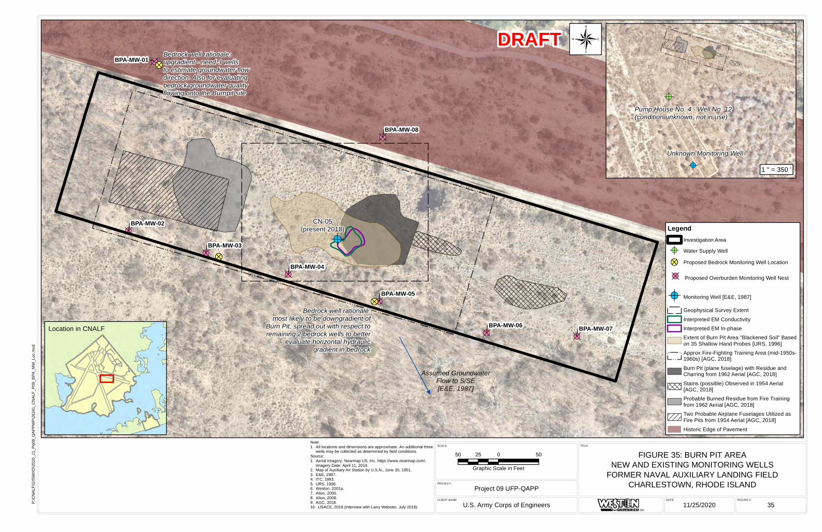
!A
!A
!A
!A
!A !A
!A
!A
!A
!?
!?
!?
Assumed GroundwaterFlow to S/SE[E&E, 1987]
CN-05(present 2018)
Bedrock well rationale:upgradient - need 3 wellsto estimate groundwater flowdirection. Also for evaluatingbedrock groundwater qualityflowing onto the Burnpit site
Bedrock well rationale:most likely to be downgradient of
Burn Pit, spread out with respect toremaining 2 bedrock wells to better
evaluate horizontal hydraulicgradient in bedrock
BPA-MW-01
BPA-MW-08
BPA-MW-05
BPA-MW-06 BPA-MW-07
BPA-MW-04
BPA-MW-03
BPA-MW-02
FIGURE #:DATE:CLIENT NAME:
PROJECT:
SCALE: TITLE:
Project 09 UFP-QAPP
U.S. Army Corps of Engineers 11/25/2020 35
FIGURE 35: BURN PIT AREANEW AND EXISTING MONITORING WELLS
FORMER NAVAL AUXILIARY LANDING FIELDCHARLESTOWN, RHODE ISLAND
SM
P:\C
NAL
F\G
IS\M
XD\2
020_
11_P
rj09_
QAP
PWP\
2624
1_C
NAL
F_P0
9_BP
A_M
W_L
oc.m
xd
DRAFT
Note:1. All locations and dimensions are approximate. An additional three wells may be collected as determined by field conditions.Source:1. Aerial Imagery. Nearmap US, Inc. https://www.nearmap.com/. Imagery Date: April 11, 2019.2. Map of Auxiliary Air Station by U.S.N., June 30, 1951.3. E&E, 1987.4. ITC, 1993.5. URS, 1996.6. Weston, 2001a.7. Alion, 2000.8. Alion, 2008.9. AGC, 2018.10. USACE, 2018 (interview with Larry Webster, July 2018).
50 0 5025
Graphic Scale in Feet
LegendInvestigation Area
!A Water Supply Well
!? Proposed Bedrock Monitoring Well Location
!A Proposed Overburden Monitoring Well Nest
!A Monitoring Well [E&E, 1987]
Geophysical Survey Extent
Interpreted EM ConductivityInterpreted EM In-phaseExtent of Burn Pit Area "Blackened Soil" Basedon 35 Shallow Hand Probes [URS, 1996]Approx Fire-Fighting Training Area (mid-1950s-1960s) [AGC, 2018]
Burn Pit (plane fuselage) with Residue andCharring from 1962 Aerial [AGC, 2018]
Stains (possible) Observed in 1954 Aerial[AGC, 2018]Probable Burned Residue from Fire Trainingfrom 1962 Aerial [AGC, 2018]Two Probable Airplane Fuselages Utilized asFire Pits from 1954 Aerial [AGC, 2018]
Historic Edge of Pavement
¬
!A
!APump House No. 4 - Well No. 12(condition unknown, not in use)
Unknown Monitoring Well
Location in CNALF
1 " = 350 '
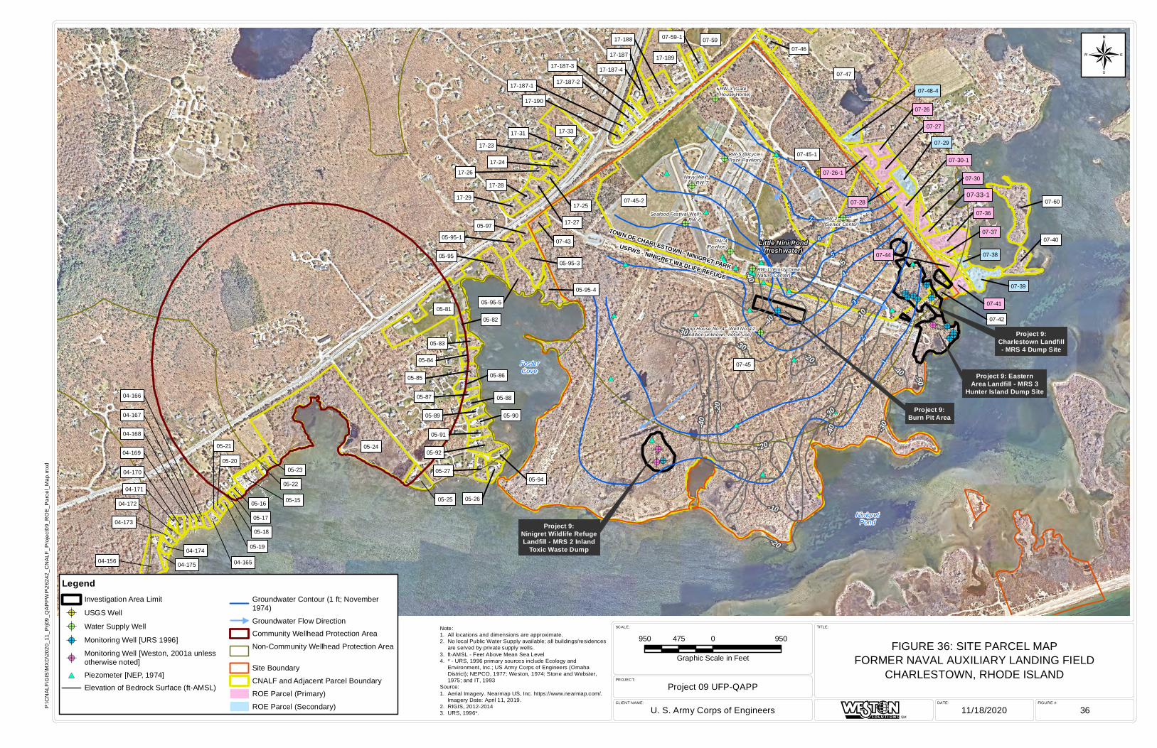
#*
#*
#*
#*
#*
#*
#*
#*
#*
#*
#*
#*
#*
#*
#*
#*#*#*
#*
#*
#*
#*
#*
#*
#*
!A
!A
!A!A!A
!A!A!A!A
!A!A
!A!A
!A!A
!A
!A
!A
!A
!A
!A
!A
!A
!A
Project 9:Burn Pit Area
Project 9:Charlestown Landfill- MRS 4 Dump Site
Project 9: EasternArea Landfill - MRS 3
Hunter Island Dump Site
Project 9:Ninigret Wildlife RefugeLandfill - MRS 2 Inland
Toxic Waste Dump
FosterCove
NinigretPond
USFWS - NINIGRET WILDLIFE REFUGE
TOWN OF CHARLESTOWN - NINIGRET PARK
Little Nini Pond(freshwater)
07-45
07-45-2
07-45-1
07-47
05-81
07-59
17-189
07-60
17-33
07-36
05-95-3
17-31
05-95-5
17-188
07-39
05-95
07-40
07-27
05-92
05-95-4
07-30-117-24
17-23
07-44
07-41
17-27
17-187-4
07-26-1
07-59-1
07-43
05-27
05-83
17-29
05-82 07-42
05-86
17-28
05-26
07-30
05-90
05-84
07-46
05-89
07-28
05-94
05-87
05-91
05-95-1
17-187
07-48-4
17-26
05-88
05-97
07-38
17-187-3
17-187-2
07-33-117-25
17-187-1
17-190
07-37
05-85
07-29
07-26
05-23
05-22
05-17
05-18
05-19
04-16504-156 04-175
04-174
04-173
04-172
04-171
04-170
04-169
04-168
04-167
04-166
05-21
05-20
05-16 05-15
05-24
05-25
RW-3 (GateHouse Home)
RW-5 (BicycleTrack Pavilion)
RW-2(Senior Center)
RW-4(Pavilion)
RW-1 (Frosty DrewNature Center)
Navy Well*RW-7
Seafood Festival Well*RW-6
Pump House No. 4 - Well No. 12(condition unknown, not in use) 2
3
4
5
6
7
8
1
-20
-30
-10
-5-40
-50
-20-40
-30
-30
-20
-10
-40
-20
-30
-40
-40
FIGURE #:DATE:CLIENT NAME:
PROJECT:
SCALE: TITLE:
Project 09 UFP-QAPP
U. S. Army Corps of Engineers 11/18/2020 36
FIGURE 36: SITE PARCEL MAPFORMER NAVAL AUXILIARY LANDING FIELD
CHARLESTOWN, RHODE ISLAND
SM
P:\C
NA
LF\G
IS\M
XD
\202
0_11
_Prj0
9_Q
AP
PW
P\2
6242
_CN
ALF
_Pro
ject
09_R
OE
_Par
cel_
Map
.mxd
950 0 950475
Graphic Scale in Feet
¬
Note:1. All locations and dimensions are approximate.2. No local Public Water Supply available; all buildings/residences are served by private supply wells.3. ft-AMSL - Feet Above Mean Sea Level4. * - URS, 1996 primary sources include Ecology and Environment, Inc.; US Army Corps of Engineers (Omaha District); NEPCO, 1977; Weston, 1974; Stone and Webster, 1975; and IT, 1993Source:1. Aerial Imagery. Nearmap US, Inc. https://www.nearmap.com/. Imagery Date: April 11, 2019.2. RIGIS, 2012-20143. URS, 1996*.
LegendInvestigation Area Limit
!A USGS Well
!A Water Supply Well
!A Monitoring Well [URS 1996]
!AMonitoring Well [Weston, 2001a unlessotherwise noted]
#* Piezometer [NEP, 1974]Elevation of Bedrock Surface (ft-AMSL)
Groundwater Contour (1 ft; November1974)
Groundwater Flow DirectionCommunity Wellhead Protection Area
Non-Community Wellhead Protection Area
Site Boundary
CNALF and Adjacent Parcel Boundary
ROE Parcel (Primary)
ROE Parcel (Secondary)
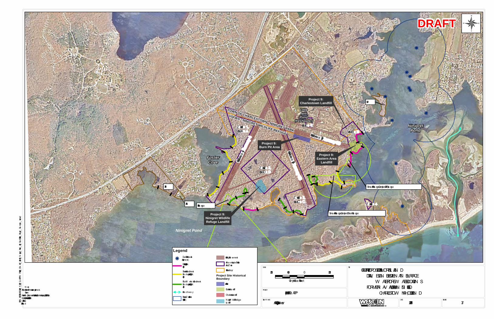
k
kk
k
k
k
k
kk
k
k
Ninigret Pond
FosterCove
NinigretPond
Former Runwa y 4
Former Runwa y 35
Former Runwa y 30
USFWS - NINIGRET WILDLIFE REFUGE
TOWN OF CHARLESTOWN - NINIGRET PARK
LittleNini
Pond(freshwater)
Sma ll Arms Ra nge Complex – Tra p Ra nge
Sma ll Arms Ra nge Complex – Skeet Ra nge
Pistol Ra nge
Project 9:Ninigret WildlifeRefuge Landfill
Project 9: Burn Pit Area
Project 9:Eastern Area
Landfill
Project 9:Charlestown Landfill 07-60
05-24
05-25
Z one 1,Area A
Z one 2,Area D
Z one 3,Area C
Area EArea B
Z one 4
FIGURE #:DATE:CLIEN T N AME:
PROJECT:
SCALE: TITLE:
Project 09 UFP-QAPP
U. S. Army Corps of Engineers 11/25/2020 37
FIGURE 37: PROPOSED TIDAL SHORELIN E AN D TIDAL W ETLAN D SEDIMEN T AN D SURFACE
W ATER/POREW ATER LOCATION SFORMER N AV AL AUXILIARY LAN DIN G FIELD
CHARLESTOW N , RHODE ISLAN D
SM
P:\CNALF\GIS\MXD\2020_11_Prj09_QAPPWP\26243_CNALF_Project09_Ningret_Pond_Prop_SedSurfPore_Bkgrd_Sample_Loc.mxd
N ote:1. All loca tions a nd dimensions a re a pproxima te.Source:1. Aeria l Ima gery. N ea rma p US, Inc. https://www.nea rma p.com/. Ima gery Da te: April 11, 2019.2. Ma p of Auxilia ry Air Sta tion by U.S.N ., June 30, 1951.3. URS, 1996.4. Alion, 2008.
DRAFT
1,200 0 1,200600
Gra phic Sca le in Feet
¬
Legendk
Duck Blind Loca tion(Approxima te)Decision Unit (DU) (Length:600ft)Shoreline SedimentBa ckground (SU) (Length:600ft)Tida l W etla nd SedimentBa ckground (SU) (Length:430ft)Brea chwa yPotentia l Z one of Shot fromBlind (400 yd)
Historic Edge of Pa vementArcha eologica l SensitivityArea /Z oneSite Bounda ry
Project Site HistoricalBoundary
Burn Pit AreaEa stern Area La ndfillCha rlestown La ndfillN inigret W ildlife RefugeLa ndfill
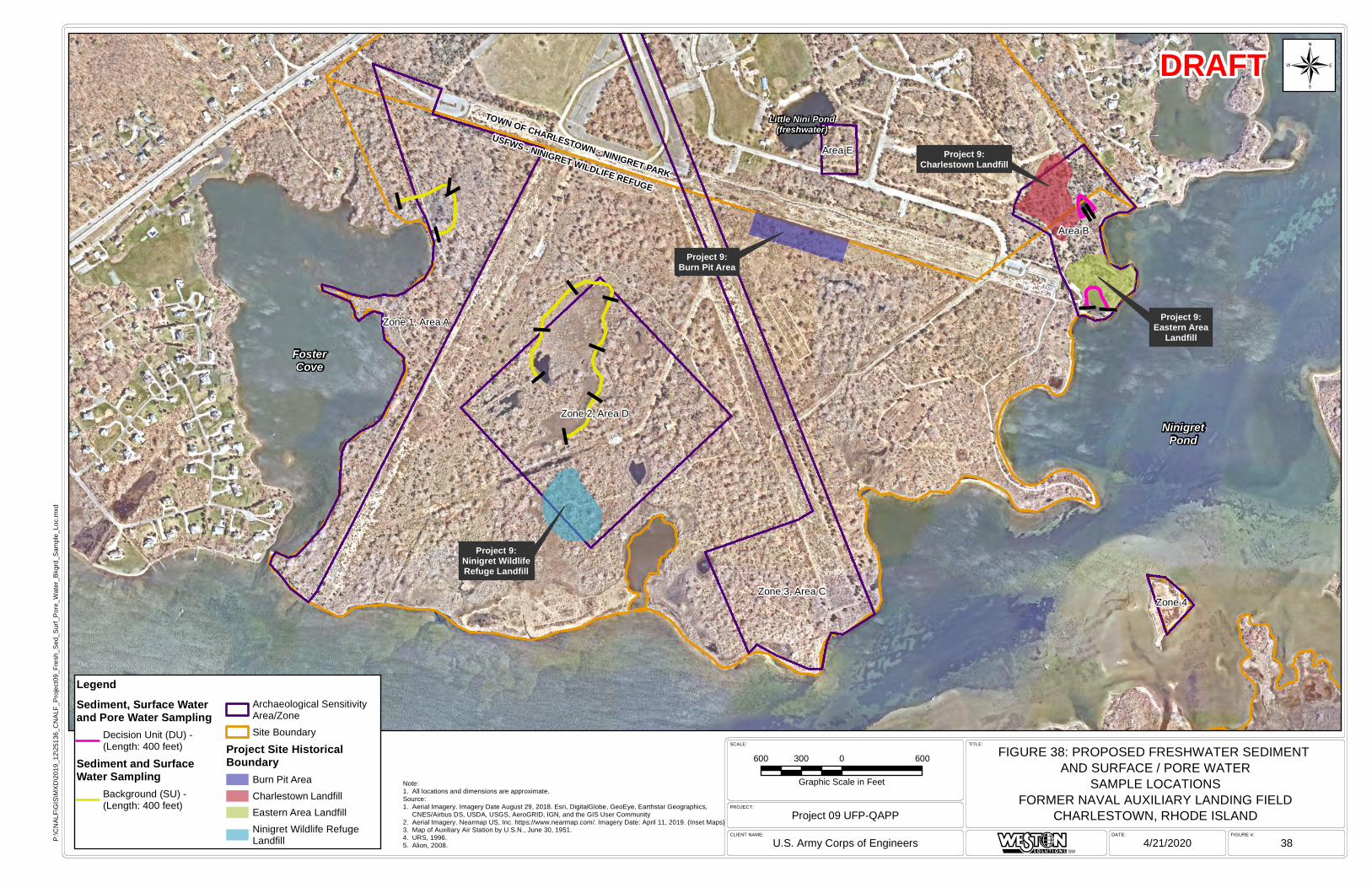
Little Nini Pond(freshwater)
NinigretPond
USFWS - NINIGRET WILDLIFE REFUGE
TOWN OF CHARLESTOWN - NINIGRET PARK
FosterCove
Project 9:Ninigret WildlifeRefuge Landfill
Project 9:Burn Pit Area
Project 9:Eastern Area
Landfill
Project 9:Charlestown Landfill
Zone 2, Area D
Zone 1, Area A
Zone 3, Area C
Area B
Area E
Zone 4
FIGURE #:DATE:CLIENT NAME:
PROJECT:
SCALE: TITLE:
Project 09 UFP-QAPP
U.S. Army Corps of Engineers 4/21/2020 38
FIGURE 38: PROPOSED FRESHWATER SEDIMENT AND SURFACE / PORE WATER
SAMPLE LOCATIONSFORMER NAVAL AUXILIARY LANDING FIELD
CHARLESTOWN, RHODE ISLAND
SM
P:\C
NAL
F\G
IS\M
XD
\201
9_12
\251
36_C
NA
LF_P
roje
ct09
_Fre
sh_S
ed_S
urf_
Por
e_W
ater
_Bkg
rd_S
ampl
e_Lo
c.m
xd
Note:1. All locations and dimensions are approximate.Source:1. Aerial Imagery. Imagery Date August 29, 2018. Esri, DigitalGlobe, GeoEye, Earthstar Geographics,
CNES/Airbus DS, USDA, USGS, AeroGRID, IGN, and the GIS User Community2. Aerial Imagery. Nearmap US, Inc. https://www.nearmap.com/. Imagery Date: April 11, 2019. (Inset Maps)3. Map of Auxiliary Air Station by U.S.N., June 30, 1951.4. URS, 1996.5. Alion, 2008.
DRAFT
600 0 600300
Graphic Scale in Feet
¬
LegendSediment, Surface Waterand Pore Water Sampling
Decision Unit (DU) -(Length: 400 feet)
Sediment and SurfaceWater Sampling
Background (SU) -(Length: 400 feet)
Archaeological SensitivityArea/ZoneSite Boundary
Project Site HistoricalBoundary
Burn Pit AreaCharlestown Landfill Eastern Area LandfillNinigret Wildlife Refuge Landfill


