Embed Size (px)
Citation preview
Downlink Throughput Maximization in CDMA WirelessNetworks∗
M. Kemal Karakayali Roy Yates Leonid V. RazoumovDepartment of Electrical and Computer Engineering
Wireless Information Networks Laboratory (WINLAB)
Rutgers University, 73 Brett Road Piscataway, NJ 08854-8060
e-mail: kemal,ryates,[email protected]
June 27, 2004
Abstract
We investigate optimum rate assignment scheme maximizing network throughputon the downlink of a multirate CDMA wireless network. Systems employing orthog-onal variable spreading factor (OVSF) codes as well as systems employing multiplecodes have been studied. Our objective is to maximize the network throughput underconstraints on total transmit power, total bandwidth and individual QoS requirementsspecified in terms of minimum rates. First, users are ordered based on their transmitenergy per bit requirements to achieve the target received energy per bit to interferencepower spectral density ratio at the receivers. Based on the initial ordering, we provethat for systems employing multiple codes, greedy rate scheduling yields maximumnetwork throughput. For systems employing variable spreading codes, we show thatgreedy rate scheduling is optimal if the minimum rate requirement of a user is largerthan or equal to the minimum rate requirement of any other user with a larger trans-mit energy per bit requirement. Simulation results verify the superiority of the greedyalgorithm under various system and channel assumptions.
1 Introduction
Wireless data networks provide access to multimedia applications such as video streaming
and internet, together with classical applications such as voice. While there is an increasingly
high demand for wireless services, radio resources are often scarce, and therefore a careful and
efficient allocation of limited resources is vital. The challenge is that different applications
have different quality of service requirements. For example, while downloading a music file
may be delayed a few minutes or more, real time services such as voice are delay intolerant,
∗This paper was presented, in part, at the IEEE Wireless Communications and Networking Conference(WCNC), New Orleans, LA., March 2003. This work is supported in part by the NJ Commission on Scienceand Technology under the NJCWT program.
1

and require a minimum service rate. In this study, we consider minimum service rate as
a quality of service metric, and investigate how to maximize the network throughput in a
multirate CDMA downlink.
For the CDMA uplink, resource allocation problems are studied extensively in [1–6]. The
common objective in these studies is either to maximize the sum of rates (or utility), or
to minimize the total transmit power, subject to constraints on individual transmit power
assignments, total bandwidth, the quality of reception in terms of SINR targets, minimum
service requirement of each user (fairness), or delay. For the CDMA downlink, resource
allocation problems are studied in [7–14]. A hierarchical SIR and rate control algorithm is
proposed in [7]. First, the mobiles determine their SIR targets using mobile specific infor-
mation, and then the base station determines rate assignments using the limited feedback
from the mobiles. In this paper, our analysis will answer how the base station algorithm in
the hierarchical structure should work. Downlink scheduling for delay tolerant data services
is considered in [8–11]. It is shown in [8] that a time division scheme in which users transmit
one by one within each cell provides energy efficiency and increased capacity. Similarly,
in [9], it is proven that, for data-only networks, the optimal scheme is to transmit to only
one data user at a time, which is the technique used in the HDR system [10,15]. While these
schemes attempt to guarantee long term nonzero average throughput to each user, they are
not suitable if users have instantaneous service requirements, as in the case of voice, or real-
time multimedia. In this paper, we define the instantaneous minimum rate as a quality of
service metric, and analyze the optimal rate assignment scheme in this case. Our results
coincide with the one user at a time conclusion [8–11], when there is no minimum service
rate requirement.
A simplifying approach in resource optimization problems is to assume continuous rate
and power assignments, instead of practical discrete system parameters, at the expense of an
approximate solution. Here, we assume discrete rates corresponding to systems employing
2

either multiple codes or variable spreading codes. In this case, the throughput maximization
becomes a discrete optimization problem. We show that for systems employing multiple
codes, the problem can be solved efficiently by a simple greedy algorithm with polynomial
complexity. For systems employing variable spreading codes, the problem is more compli-
cated and the greedy algorithm is optimal if the minimum rate requirements are ordered by
the channel qualities.
The organization of the paper is as follows. The system model is described in Section 2.
The problem statement is given in Section 3. In Sections 4, the rate assignment algorithms
are introduced, and the optimality analysis are provided. Section 5 is on examples and
simulation results for CDMA networks. We conclude the paper in Section 6.
2 System Model
Multiple Access Scheme: In CDMA wireless networks, multiple users share a common
communication medium by means of spreading codes. There are two ways to assign spreading
codes in such systems. First, in the third generation W-CDMA standard [16], multirate data
service is provided by assigning each user a single spreading code with variable length. In
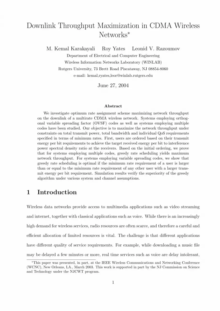
such a scheme, spreading codes are obtained from a binary tree structure (Figure 1) and
are called Orthogonal Variable Spreading Factor (OVSF) codes [17]. On the other hand, in
multicode CDMA systems, each user can be provided with multiple spreading codes of fixed
length, depending on the users’ rate requests.
Figure 1 shows how OVSF codes are obtained from a binary tree structure. In the
figure, Ci,j represents jth node on layer i on the binary tree, and it corresponds to a unique
spreading code (signature sequence) of length 2i and rate R0/2i where R0 is the root rate
corresponding to the node C0,1. Moreover, orthogonality of the assigned spreading codes is
guaranteed by the fact that none of the parent-child node pairs is assigned at the same time.
As an example, the nodes C1,2 and C2,4 in Figure 1 cannot be in use at the same time since
3

C1,2 is a prefix of C2,4. Therefore, the assigned signature codes must have the prefix-free
property.
Accordingly the prefix-free property imposes a constraint on the set of spreading codes
available in OVSF CDMA systems. It is a well-known fact that the Kraft inequality deter-
mines whether a set of codes with specified lengths can be placed on the binary tree as a
prefix-free set [18]. Denoting the length of the branch from the root node (C0,1 in Figure 1)
to the uth user’s node by lu and number of users by N , the Kraft Inequality,
N∑u=1
2−lu ≤ 1, (1)
must be satisfied to obtain a prefix-free set.
In the context of CDMA spreading codes, the Kraft inequality is a bandwidth constraint.
Since R0 denotes the root rate and represents the maximum total rate or the bandwidth of
the system, it follows that the rate of user u is
Ru =R0
2lu(2)
Multiplying both sides of (1) by R0, the Kraft inequality becomes
N∑u=1
Ru ≤ R0 (3)
which states that R0 is an upper bound on the throughput of an OVSF CDMA system. It
is trivial to generalize the constraint (3) to the multicode CDMA case and R0 represents the
system bandwidth in this case.
Channel Model: We consider a single cell CDMA downlink with N mobiles. Each mobile
has a different application running, and therefore each has a specific QoS requirement in
terms of a minimum service rate. For each transmitted bit of user u, there is a target
received energy per bit to interference power spectral density ratio, (E/I)ru ≥ γu, with which
the receiver can decode the transmitted bits with an acceptable bit error rate (BER).
4

The channel between the base station and each mobile can be modeled either as a fre-
quency flat single path channel, or as a frequency selective multipath channel. These two
models have quite different implications on the problem definition. Unlike the uplink where
random spreading codes are used, orthogonal spreading codes are used on the downlink. In
frequency flat channels, the orthogonality of the transmitted waveforms is preserved at the
receiver. On the other hand, in a frequency selective multipath channel, the orthogonal-
ity is lost at the receivers. Our problem formulation will be general enough to account for
both channel models. For each channel model, we determine the transmit energy per bit
requirements to achieve the target SINR per bit γu at the receivers.
In a frequency flat channel, the orthogonality implies that the overall system can be
modeled as a number of parallel channels. Since there is no interference across parallel
channels, the system only compensates for the background noise, i.e. (E/I)ru = (E/N0)
ru ≥
γu, and therefore user u requires received energy per bit Eru ≥ γuN0 where N0 is the noise
power spectral density. In this case, the transmit energy per bit should satisfy Etu = Er
u/hu ≥
γuN0/hu, where hu denotes the link gain for user u.
When there is multipath in the channel, delayed versions of orthogonal spreading codes
arrive at each receiver, leading to multi-access interference due to the loss of orthogonality
between spreading codes. In the CDMA downlink, the loss of orthogonality can be character-
ized by the orthogonality factor (OF), which is defined as the fraction of received downlink
power converted by multipath into multi-access interference [19,20]. As noted in [19,20], the
orthogonality factor is a time-varying parameter that depends on the instantaneous multi-
path channels as well as the receiver structure and the spreading codes employed. On the
other hand, in the analysis of the downlink, time average value of the orthogonality factor
is traditionally employed [19, 20]. This is due to the fact that data symbols, which are first
spread by orthogonal codes, are then multiplexed and scrambled by cell-specific random long
codes before transmission. In this case, the analysis is more tractable if the interference is
5

modeled using its average over the length of the random long code. Here we follow the same
convention, and assume that user u has an average orthogonality factor of βu. In this case,
we can express (E/I)ru as
(E
I
)r
u
=W
Ru
puhu
(βu
∑i 6=u pihu + N0W )
=W
Ru
puhu
(βuhu
∑i pi − βupuhu + N0W )
≥ γu (4)
where W denotes the spreading bandwidth, Ru denotes the rate assignment, and pu is the
transmit power. In deriving (4), we inherently assume rake reception where the gain sum of
all paths is represented by the path loss hu.
Here we are interested in a practical power limited system where the power constraint
is a bottleneck on system throughput. In this case, it is expected that the base station
uses any nonzero residual power to increase the throughput with some nonzero rate (or for
some users to achieve higher received SINR per bit and better reception quality). The base
station therefore transmits at its peak power. This is the case in [7] and [14] where the rate
assignments are not restricted to be discrete, and it is shown that either the power constraint
is achieved with equality, i.e∑
i pi = P , or the whole bandwidth is allocated. Our design in
this paper will be a conservative one in which the received SINR is guaranteed to exceed γu
given∑
i pi ≤ P . By upperbounding∑
i pi by P and using (4), we require that
(E
I
)r
u
≥ W
Ru
puhu
(βuhuP − βupuhu + N0W )
(a)
≥ γu (5)
Thus, the set of rate and power assignments satisfying (a) will satisfy the inequality (4)
as well. Rewriting (a), it follows that
puhu ≥Ru
W(βuhuP + N0W )γu
1 + Ruγuβu
W
(6)
Using (6) and the fact that the transmit power is pu = EtuRu, we obtain
Etu =
pu
Ru
≥ (βuhuP + N0W )γu
(W + Ruβuγu)hu
(7)
Notice that when βu = 0, (7) reduces to Etu ≥ γuN0/hu, which is the SINR constraint
in flat channels. We note that, in the multicode CDMA case, Etu is required for one of the
6

multicodes (we will denote its rate by Rs in the rest of the paper). Assignment of multiple
codes to a user generates self interference. In this case, each spreading code needs to be
treated separately, and Etu has to be calculated for each as if every other spreading code is
an interferer signal.
3 Problem Statement
For both multicode CDMA systems and OVSF CDMA systems, the throughput maxi-
mization can be formulated as the following discrete optimization problem over the vector
η = (η1, . . . , ηN) of user rates:
maxη
N∑u=1
ηu ≤ R0 (8)
subject toN∑
u=1
Etuηu ≤ P (8a)
ηu ≥ ηmin,u u = 1, . . . , N (8b)
ηu ∈ S = {η1, η2, . . . , ηM} (8c)
where each user selects a rate ηu from the set S = {η1, η2, . . . , ηM} such that the sum rate
is maximized within the bandwidth constraint (8). Note that (8a) is the constraint on the
total transmit power, and each bit of user u is transmitted with energy Etu so as to satisfy
the target received SINR γu, i.e. to satisfy (7) with equality. Moreover, (8b) represents the
users’ individual bandwidth constraints.
For multicode CDMA systems, ηu = Rsnu where Rs denotes the rate corresponding to a
single spreading code, and nu denotes the number of spreading code assignments. Thus, the
set of possible rate assignments are given by S = {Rs, 2Rs, 3Rs, . . . ,MRs}, where M is the
total number of multicodes.
For OVSF CDMA systems, ηu = R02−lu where R0 denotes the root rate on the bi-
nary code tree, and lu denotes the length of the branch from the root node (C0,1 in Fig-
ure 1) to the uth user’s node. Thus, the set of possible rate assignments are given by
7

S = {R0, R0/2, R0/4, . . . }. On the other hand, each user has a minimum rate requirement
ηmin,u = R0/2Lu where Lu is the minimum depth on the binary code tree below which
spreading codes cannot provide the user’s minimum rate.
4 Algorithms and Analysis
For systems using OVSF codes, the rate assignment problem is equivalent to determining
the relative distances lu of spreading codes to the root node on the binary code tree. In
terms of the vector l = (l1, . . . , lN) of distances, the problem (8) becomes
maxl
N∑u=1
R02−lu (9)
subject toN∑
u=1
EtuR02
−lu ≤ P (9a)
N∑u=1
2−lu ≤ 1 (9b)
lu ∈ {0, 1, . . . , Lu} (9c)
where the bandwidth constraint in (8) is written in terms of the Kraft inequality (9b), and
the minimum rate constraint (8b) is embedded in the set of possible distances (9c).
The objective function (9) is a nonlinear function of integer branch length lu. Moreover,
the energy per bit Etu depends on the rate assignment (7), and therefore is a function of the
branch length lu, which complicates the problem further. The problem above is a mixed-
integer nonlinear program (MINLP), which is generally hard to solve, and requires exhaustive
search over the set of possible rate combinations because MINLP problems combine the
difficulties of their subclasses: the combinatorial nature of mixed integer programs, and the
difficulty in solving nonlinear programs, both of which are among the class of NP-complete
problems. Fortunately, we realize that under certain conditions on the constraint set, and
under realistic system assumptions, the problem can be solved by a simple algorithm with
polynomial complexity. First, an instance of interest is when Eti < Et
j implies Li ≤ Lj
8

for all i and j, i.e. when the minimum rate requirement of a user is larger than or equal
to the minimum rate requirement of any other user with a larger transmit energy per bit
requirement. Second, we are interested in the cases where the transmit energy per bit Etu
does not depend on the rate assignment Ru. This is clearly the case in flat channels where
βu = 0 in (7). On the other hand, in frequency selective channels, we make the large system
assumption, and notice that in a system with a large number of users, each having nonzero
minimum rate requirements, it is unlikely to have users dominating the whole available
bandwidth by themselves, i.e W À Ru = R02−lu in general. For example in a WCDMA
downlink, the spreading bandwidth is W = 3.84 × 10⁶ chips/second while the minimum
spreading length is 4 chips, corresponding to the root rate of R0 = 0.96 × 106 bits/second.
Even in a very lightly loaded system, say there are only 2 users, the user with the better
channel can receive at most half of the root rate (since 2 users can only be placed somewhere
below the root node on the binary code tree), which is 0.48× 106 bits/second, and the ratio
W/Ru is 8. This ratio will increase geometrically down the binary code tree and can be as
large as 512, which many users will have in a highly loaded system. In this case, it can be
shown that the dependence of Etu on Ru is not significant. Notice that a tighter constraint
on Etu can be written as
Etu
(a)
≥ (βuhuP + N0W )γu
Whu
(b)
≥ (βuhuP + N0W )γu
(W + Ruβuγu)hu
(10)
where (a) and (b) implies (7). On the other hand, for typical values of βu ≈ 0.3 [20], γu = 5
(≈ 7 dB) and under the assumption W À Ru, (b) can be approximated by an equality1, and
therefore the constraint on Etu does not depend significantly on Ru. While this analysis is
quite accurate for very low data rates, users with relatively high rates achieve larger SINR
per bit when the constraint (a) is satisfied.
1A similar assumption [7] that in a system with a large number of users with nonzero minimum rates,transmit power for a single user is much less than the total power constraint, i.e. P =
∑i pi À pu, leads to
the same result.
9

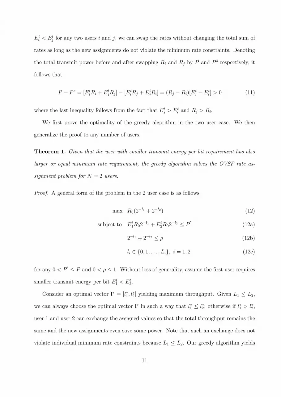
4.1 Rate Assignment Algorithm in OVSF CDMA Systems
The rate assignment algorithm is given in Figure 2. First, the minimum rate requirement
of each user is provided. The rest of the algorithm is greedy in nature, and the objective is
to increase (to double in the binary tree case) the rate of the user who requires minimum
energy per bit. Based on the initial ordering by transmit energy per bit Etu requirements,
the algorithm attempts to maximize the rate of a user at each greedy step within the total
transmit power constraint (9a) and the bandwidth constraint (9b) expressed in terms of the
Kraft inequality.
Notice that spreading code of user u resides on layer lu of the binary code tree in Figure
1. Although lu uniquely determines the rate assignment (2), it does not tell us which node
on layer lu of the code tree should be assigned to user u. On the other hand, satisfying the
Kraft Inequality (1) guarantees the fact there is at least a set of N spreading codes on the
binary code tree such that spreading code of user u is placed on layer lu, the rates of all
other users are not affected by this placement (although spreading codes might shift on the
same layer) and all spreading codes in the set are mutually orthogonal as a result of the
prefix free property. The shifts or replacements of spreading codes on the same layer on the
binary code tree are implementation issues and such shifts do not affect the assigned rate of
a user. Thus, the way the spreading code replacements or shifts occurs at each step of the
algorithm, the subject of [21, 22], is not addressed in this study.
4.2 Greedy Optimality in OVSF CDMA Systems
The basic idea is that the set of rate assignments by any existing optimal algorithm can be
made more “greedy” by reordering and reassigning user rates in a way to favor the users with
better channels, and all these reassignments are feasible on the binary code tree. Moreover,
as the rate assignments by the optimal algorithm look more like the greedy assignments, the
total power is reduced while keeping the total throughput constant. Note that if Ri < Rj and
10
Eti < Et
j for any two users i and j, we can swap the rates without changing the total sum of
rates as long as the new assignments do not violate the minimum rate constraints. Denoting
the total transmit power before and after swapping Ri and Rj by P and P s respectively, it
follows that
P − P s = [EtiRi + Et
jRj]− [EtiRj + Et
jRi] = (Rj −Ri)[Etj − Et
i ] > 0 (11)
where the last inequality follows from the fact that Etj > Et
i and Rj > Ri.
We first prove the optimality of the greedy algorithm in the two user case. We then
generalize the proof to any number of users.
Theorem 1. Given that the user with smaller transmit energy per bit requirement has also
larger or equal minimum rate requirement, the greedy algorithm solves the OVSF rate as-
signment problem for N = 2 users.
Proof. A general form of the problem in the 2 user case is as follows
max R0(2−l1 + 2−l2) (12)
subject to Et1R02
−l1 + Et2R02
−l2 ≤ P′
(12a)
2−l1 + 2−l2 ≤ ρ (12b)
li ∈ {0, 1, . . . , Li}, i = 1, 2 (12c)
for any 0 < P′ ≤ P and 0 < ρ ≤ 1. Without loss of generality, assume the first user requires
smaller transmit energy per bit Et1 < Et
2.
Consider an optimal vector l∗ = [l∗1, l∗2] yielding maximum throughput. Given L1 ≤ L2,
we can always choose the optimal vector l∗ in such a way that l∗1 ≤ l∗2; otherwise if l∗1 > l∗2,
user 1 and user 2 can exchange the assigned values so that the total throughput remains the
same and the new assignments even save some power. Note that such an exchange does not
violate individual minimum rate constraints because L1 ≤ L2. Our greedy algorithm yields
11
the vector l = [l1, l2], such that
l1 = min{l ∈ £|2−l + 2−L2 ≤ ρ, Et1R02
−l + Et2R02
−L2 ≤ P′}, (13)
l2 = min{l ∈ £|2−l + 2−l1 ≤ ρ, Et2R02
−l + Et1R02
−l1 ≤ P′}. (14)
We compare l∗ and l,
• Assume l∗1 < l1 : For user 1, the greedy algorithm finds the smallest l1 on the binary
tree, while power and bandwidth constraints are satisfied and the second user’s spread-
ing code resides on layer L2. Thus l∗1 < l1 is impossible; otherwise l1 would not be the
local minimum choice.
• Assume l∗1 > l1 : In this case the smallest possible value of l∗1 is l1 + 1. Since l∗1 ≤ l∗2,
we have l1 + 1 ≤ l∗1 ≤ l∗2. It follows that
R0(2−l∗1 + 2−l∗2) ≤ R0(2
−(l1+1) + 2−(l1+1)) = R02−l1 < R0(2
−l1 + 2−l2) (15)
since 0 ≤ l2 ≤ L2. Equation (15) asserts that the rate achieved by l∗ is strictly less
than the rate achieved by l, which contradicts the optimality of l∗ implying that l∗1 > l1
is also impossible. As a result we conclude that l∗1 = l1.
Similarly, the greedy algorithm makes a local minimum choice for user 2 while the first
user’s spreading code resides on layer l1. Because l∗1 = l1, and l2 is a local minimum, l2 ≤ l∗2
must be true. On the other hand if l2 < l∗2, then the optimal l∗ offers smaller throughput
compared to the greedy l, which is a contradiction. Therefore l∗2 = l2 must be true.
Theorem 2. Given that the minimum rate requirement of a user is larger than or equal
to the minimum rate requirement of any other user with a larger transmit energy per bit
requirement, the greedy algorithm solves the OVSF rate assignment problem.
Proof. Here we will prove a more general statement that the greedy algorithm solves rate
maximization problem for any power constraint 0 < P′ ≤ P and any bandwidth constraint
12
0 < ρ ≤ 1, corresponding to a “partial” binary code tree. The general form of the problem
is
maxN∑
u=1
R02−lu (16)
subject toN∑
u=1
EtuR02
−lu ≤ P′ ≤ P (16a)
N∑u=1
2−lu ≤ ρ ≤ 1 (16b)
lu ∈ {0, 1, . . . , Lu} (16c)
Without loss of generality, we can assume that Et1 < Et
2 < · · · < EtN . Consider an
optimal vector l∗ = [l∗1, l∗2, . . . , l
∗N ] yielding maximum total throughput. Given L1 ≤ L2 ≤
· · · ≤ LN , any feasible set of optimal rate assignments can be reordered in such a way that
l∗1 ≤ l∗2 ≤ · · · ≤ l∗N , without violating individual minimum rate constraints. It is important
to notice that, given Eti < Et
j and l∗i > l∗j , an exchange between assignments of users i and
j does not violate minimum rate constraints if Li ≤ Lj. In addition, such an exchange
always saves power (11); therefore the power constraint is not violated while the throughput
remains constant.
Our greedy algorithm yields the vector l = [l1, l2, . . . , lN ]. The proof goes by induction.
We already proved the greedy optimality for the two user case in Theorem 1. Here, we
assume that Theorem 2 is true for any system of N < N users. We also assume that there
is a feasible rate assignment vector for the problem (16). Therefore, optimal and greedy
solutions are both feasible and we will consider them below.
Definition 1. Let A be a user index such that lu = l∗u for u = 1, . . . , A− 1, and lA 6= l∗A.
Due to local optimality of the greedy algorithm, we have lA ≤ l∗A − 1. First, we suppose
A > 1. In this case at least the first user gets the same rate assignment by both algorithms
(greedy and optimal). The remaining N − 1 users can be assigned in a greedy fashion
because our induction hypothesis stipulates that for any N < N users, greedy assignments
13
are optimal. This proves Theorem 2 for the case of A > 1. Thus, it remains to consider the
case of A = 1. Since optimal l∗ achieves maximum total throughput, employing lA ≤ l∗A − 1
for the case A = 1, we can write that
2−l∗1 +N∑
u=2
2−l∗u ≥ 2−l1 +N∑
u=2
2−lu ≥ 2−(l∗1−1) +N∑
u=2
2−Lu (17)
Equation (17) asserts there is a new set of rate assignments on the binary code tree in
which the rate of user 1 is doubled from the optimal 2−l∗1 to 2−(l∗1−1), while the rest of the users
get their minimum rates; clearly the throughput of the new assignments does not exceed the
optimal throughput of l∗. The question is whether the new assignments of users 2, . . . , N
can be further increased on the binary code tree until achieving the optimal throughput of
l∗, and without violating the power constraint.
Lemma 1. For any l∗ = [l∗1, l∗2, . . . , l
∗N ] satisfying (17), we can always find a set of assign-
ments l∗2, . . . , l∗N such that
2−l∗1 +N∑
u=2
2−l∗u = 2−(l∗1−1) +N∑
u=2
2−l∗u (18)
l∗u ≤ l∗u ≤ Lu, u = 2, . . . , N (19)
Proof of Lemma 1. Here we give a constructive proof of Lemma 1 by providing an explicit
algorithm, Figure 3, which computes the new assignments l∗2, . . . , l∗N . The algorithm starts
with l∗, and halves the rate of a chosen user (releases half of the user’s bandwidth) at each
iteration n. We denote the amount of bandwidth released at nth iteration by 4n, and the
aggregate bandwidth released up to the nth iteration by Jn. The basic idea is to show that
eventually there will be enough bandwidth released to double the rate of user 1, i.e. Jn equals
to 2−l∗1 at some point, and that the algorithm falls through Step 3 and always terminates.
Let’s assume that there is no n such that Jn = 2−l∗1 . Together with (17) it means that
there will be such an iteration t for which
Jt−1 =t−1∑n=1
4n < 2−l∗1 , Jt =t∑
n=1
4n > 2−l∗1 . (20)
14

We also observe that
2−l∗1 ≥ 41 ≥ 42 ≥ · · · ≥ 4t. (21)
Partial ordering in (21) follows from Step 1 of the algorithm which always chooses the
largest rate user to release its bandwidth. Due to the ordering in (21) and the definition of
t, the difference between Jt and 2−l∗1 is smaller that the contribution from the last iteration
Jt − 2−l∗1 =t∑
n=1
4n − 2−l∗1 < 4t (22)
We emphasize here that by construction 4n is always some negative integer power of
two. Therefore, (21) implies that the ratios 4n/4t are integers for n = 1, . . . , t. Next, we
divide both sides of (22) by 4t, yielding
(t∑
n=1
4n
4t
)− 2−l∗1
4t
< 1. (23)
In the above inequality, the left side is a positive integer due to (20), while the right
side is a fractional number less than one. Therefore (23) contains a contradiction, proving
that Step 3 terminates the algorithm which results in the set of assignments l∗2, . . . , l∗N as in
Lemma 1.
With the help of Lemma 1, we can immediately construct a new rate assignment vector
l∗ = [l∗1 − 1, l∗2, . . . , l∗N ] yielding the same throughput as the optimal assignments l∗, yet
because of (19), it consumes less energy. Notice that l∗ looks more “greedy” than l∗, i.e.
user 1 with the minimum transmit energy per bit requirement gets an enhanced rate while
the other users get less than or equal to their rate assignments in l∗ due to (19).
To complete the proof of Theorem 2 in the case of A = 1, Lemma 1 can be applied to l∗
as well, i.e. starting from the new set of optimal assignments l∗, we can construct another
optimal set with the first user receiving l∗1 − 2 and all other users receive less than or equal
to their assignments in l∗, but more than their minimum requirements. We can continue in
15
this fashion until the first user receives l1, the assignment by the greedy algorithm, in an
optimal set of assignments. At this point, we already proved the greedy optimality, i.e. for
A > 1 using our induction hypothesis that greedy assignments are optimal for any N < N
users. The greedy optimality proof of Theorem 1 in the two user case is therefore generalized
to any number of users by induction.
It is interesting to note that the optimality of the greedy algorithm in OVSF CDMA
systems depends on the minimum rate constraints. When users with worse channels require
larger minimum rates, the greedy algorithm may not be the optimal way to assign user rates.
As a simple example, assume there are two users in the system; the first with Et1 = 1, and
the second with Et2 = 1.25. The power constraint is 11, and minimum rate requirements
are R1,min = 1 and R2,min = 4. Total power to provide the minimum rates is Pmin =
∑2u=1 Et
uRu,min = 6. Since the first user requires smaller transmit energy per bit, the greedy
algorithm would double the first user’s initial rate assignment using the remaining power
budget of 11− 6 = 5. In this case, the greedy algorithm could at most assign 4 units of rate
to user one, which requires an additional 3 units of power. The remaining 11 − 6 − 3 = 2
units of power would not be enough to double second user’s initial assignment from 4 to 8,
therefore the greedy algorithm would conclude R1 = 4, R2 = 4 and a total throughput of 8
units of rate. On the other hand, optimal throughput is 9 units of rate which is achieved
when R1 = 1 and R2 = 8.
4.3 Rate Assignment Algorithm in Multicode CDMA Systems
A simple polynomial time greedy algorithm, given in Figure 4, solves the rate assignment
problem in multicode systems. The optimal algorithm favors the user with the smallest
transmit energy per bit requirement. After the algorithm assigns minimum rates and allo-
cates corresponding spreading codes to each user, only the rate of the user with the minimum
energy per bit requirement is maximized using the remaining power budget.
16

The intuition is that if a spreading code is to be assigned, it is better if it is assigned
to the user who can receive it with the smallest power (the smallest contribution to the
total power). On the other hand, unlike the uplink where the multiaccess interference at
the receiver depends on the channels of all users and the individual power assignments, the
multiaccess interference on the downlink is a function of the user’s own channel and the
power assignments of interferer spreading codes. Thus, a reduction in the power of any
interferer signal is beneficial to all users no matter who the spreading code is assigned to.
Theorem 3. The greedy algorithm solves any instance of the multicode rate assignment
problem (8).
Proof. The optimality proof is similar to the one in the OVSF case. We refer to [23] for
further details.
5 Examples and Simulations
We apply the algorithms on the downlink of a single cell CDMA wireless network. The
system assumptions are consistent with 3G system specifications [16, 17]. Spreading gain is
assumed to be in the range from a minimum of 4 up to 512, which corresponds to 8 levels
on the binary code tree including the root node. The spreading bandwidth is 3.84 MHz, the
maximum base station transmission power is 10 Watts, the receiver noise, NoW , is 10−10
Watts, and the target (E/I)ru = γu is 5 (7dB) (different applications may have different γu
targets, the algorithms are applicable in such cases as well). The x any y coordinates of each
mobile are selected uniformly on (0-2000m) in a square cell of 4km2. The path loss Lp at
any given distance d is given by [24]
Lp = L0 + 10ε log10(d/d0) + S; d ≥ d0 (24)
where L0 is the decibel path loss at distance d0, ε is the path loss exponent, and S is the
shadow fading variation. The numerical values are d0=100 m, L0=78 dB, S is normal with
17
0 mean and σ=8 dB, and ε=4. The multipath characteristics, or the frequency selectivity,
of the channels are represented by the orthogonality factor β; for simplicity we assume that
all users have the same average β. The first experiment is conducted for β = 0, which
corresponds to a flat channel, β = 0.1, β = 0.2, β = 0.5 and β = 0.8. For each mobile, we
randomly choose a minimum rate corresponding to one of {128, 256, 512} length spreading
codes with equal probability. We assume fixed modulation and coding2.
The average throughput of the greedy algorithm in an OVSF CDMA system is compared
to the average optimal throughput of a system using multiple codes. The average throughput
values are obtained over 500 simulation runs for a given number of users. In each simulation
run, a random set of user locations, a set of independent random shadow fades, and a set
of minimum rate requirements are generated. In case minimum rate requirements are not
feasible, i.e. if providing minimum rates to each user at the target (E/I)ru = γu requires
more power than P , a new set of minimum rates are generated by decreasing the minimum
rate requirements of the users who require the largest transmit energy per bit.
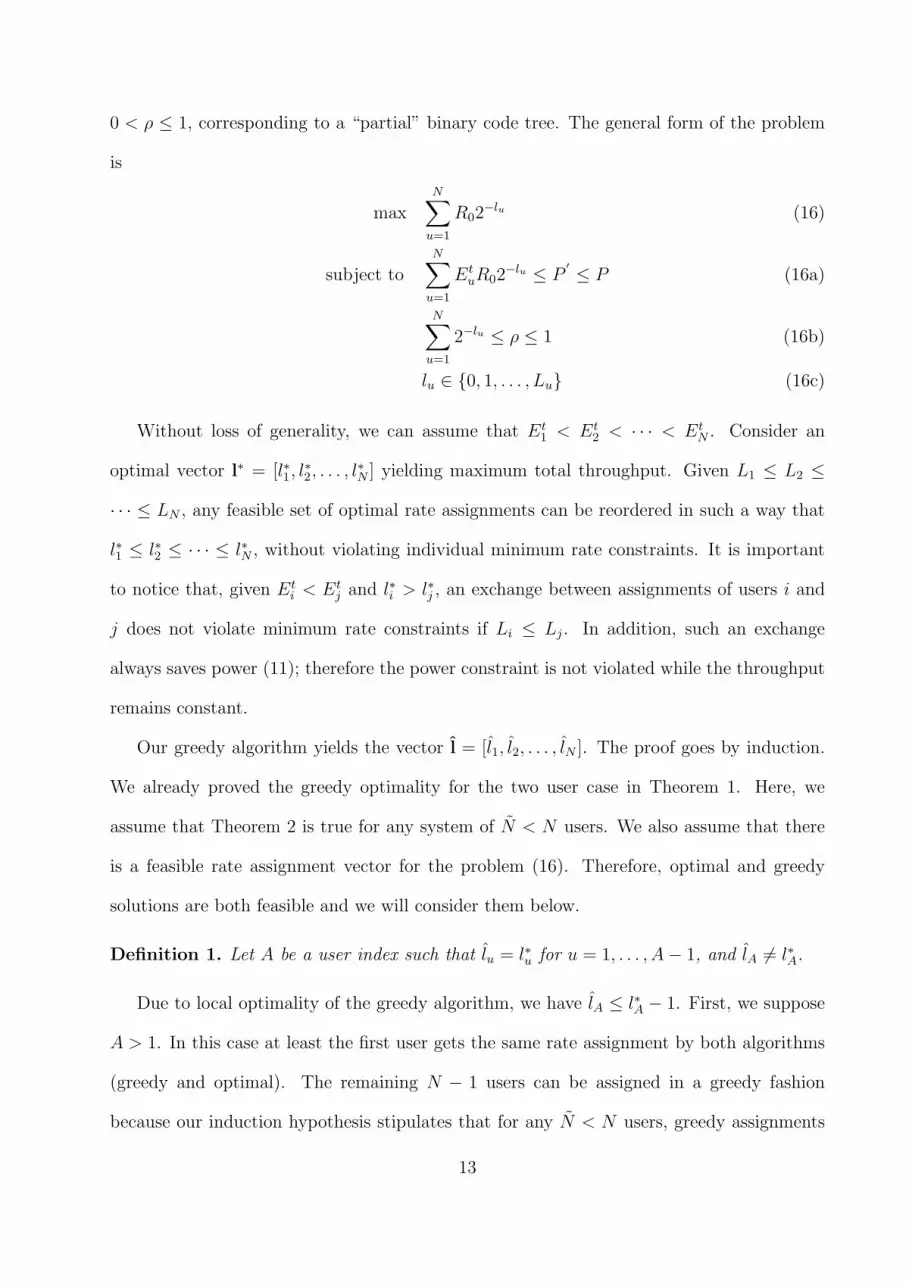
Figure 5 compares average throughput results in multirate CDMA systems. In the figure,
the solid lines represent the OVSF throughput determined by the greedy algorithm, and the
dotted lines represent the optimal throughput of a multicode system, which is achieved by
the greedy algorithm for any set of minimum rates. Since any set of rates offered by variable
spreading factor codes can be realized by multiple codes (for example a spreading code of
length 128 offers the same rate as 4 spreading codes of length 512), the optimal throughput
of a multicode system can be thought of as an upperbound to the average throughput of
an OVSF system. The figure shows that the greedy OVSF throughput is very close to the
optimal greedy multicode throughput, especially for large number of users. Moreover, we
2There is no explicit assumption on modulation and coding format. The only assumption is that theyare the same and fixed for all users, which implies that spreading codes with the same lengths correspondto the same rate, and the rate assignments are proportional to the number of spreading code assignments inmulticode systems, and are determined by the lengths of the spreading codes in variable spreading systems.In numerical calculations, we assumed uncoded QPSK, while the algorithms and analysis are valid for anyfixed coding and modulation format.
18

observe that the performance gap between multicode throughput and OVSF throughput
closes as the number of users increases and the holes on the binary code tree get filled more
efficiently by more users. Notice that it is much easier to manage orthogonal spreading
codes in a multicode CDMA system; for example in a 2 user OVSF system, the user with a
better channel can achieve at most half of the bandwidth (the node below the root node),
while in a multicode CDMA system the same user can have the whole available bandwidth
as long as the power constraint permits. Also note that, for large values of β, there is a
decline in total throughput as the number of users increases. This is counter-intuitive since
we expect the optimal scheme to exploit the multiuser diversity, i.e. users with favorable
channel conditions, when the number of users increases. On the other hand, since each user
requires a nonzero minimum rate, a large increase in the number of users results in larger
interference floor for the system, and thus reduces the system capacity. This fact suggests
that we employ a call admission scheme which limits the number admitted real-time users
(i.e. users with minimum service rate requirements) to a certain number (6 − 7 users in
Figure 5), instead of a call admission scheme which admits as many users as possible based
on the feasibility of the minimum rates.
In Table 1 and Table 2, we present two sample cases in order to understand how various
system parameters affect the rate assignment policy. In Table 1, individual rate assignments
and corresponding path loss values are presented for a sample case of 10 users in a system
using OVSF codes. Notice that except path loss, all other factors affecting the transmit
energy per bit are the same for all users in the example. As a result, users with relatively
small path loss values receive high throughput since they require lower transmit energy per
bit. In the second example of Table 2, we assign rates to users who are close to the base
station (or in a short range system) where the path loss is small, and the received multiaccess
interference power may be much larger than the receiver noise, i.e. βuhuP À N0W . A simple
link budget calculation shows that if the path loss is smaller than 50− 60 dB, the transmit
19

energy per bit is mainly affected by the loss of orthogonality between spreading codes due
to the multipath channel, and is independent of the path loss. For example, if P = 100 mW,
βu ≈ 0.1, N0W ≈ 10−10 Watts, and hu > 10−6, then
Etu =
1
hu
(βuhuP + N0W )γu
W + Ruβuγu
≈ βuPγu
W + Ruβuγu
(25)
which is independent of hu. In this case, the rate assignment policy is mainly affected by
the orthogonality factor βu. We observe in Table 2 that the user with a moderate path loss
(50 dB) but with the smallest orthogonality factor achieves the largest throughput.
6 Conclusion
In this paper, we investigated the throughput maximization problem on the downlink of
CDMA wireless networks. For systems employing multiple codes, we derive the optimal
greedy rate assignment scheme. For systems employing variable spreading codes, we derive
and prove the conditions for the optimality of the greedy algorithm. Our simulation results
show that the greedy algorithm, even when it is suboptimal in some instances of an OVSF
system, is a good heuristic yielding close to optimal average throughput results in OVSF
systems. As a future work, an interesting question is how to combine an admission control
scheme with our rate assignment algorithm in a system with a dynamic traffic flow. In
addition, one of our followup studies [25] investigates the effects of multiuser receivers, power
control and spreading code selection on the downlink performance.
Acknowledgements
We would like to thank Dr. Larry Greenstein for his invaluable comments on the early draft.
References
[1] S. Ramakrishna and J.M. Holtzman. A Scheme for Throughput Maximization in a Dual-
class CDMA System. IEEE Journal on Selected Areas in Communications, 16:830–844,
20

August 1998.
[2] S. Ulukus and L. J. Greenstein. Throughput Maximization in CDMA Uplinks Using
Adaptive Spreading and Power Control. In IEEE Symposium on Spread Spectrum Tech-
niques and Applications, September 2000.
[3] S-J. Oh and K.M. Wasserman. Optimality of Greedy Power Control and Variable
Spreading Gain in Multi-class CDMA Mobile Networks. In ACM/IEEE MobiCom,
1999.
[4] J. B. Kim and M.L Honig. Resource Allocation for Multiple Classes of DS-CDMA
Traffic. IEEE Transactions on Vehicular Technology, 49:506–519, March 2000.
[5] F. Berggren and S.-L. Kim. Energy-Efficient Control of Rate and Power in DS-CDMA
Systems. To appear in IEEE Transactions on Wireless Communications.
[6] A. Goldsmith S.A. Jafar. Adaptive Multirate CDMA for Uplink Throughput Maximiza-
tion. IEEE Transactions on Wireless Communications, 2(2):218–228, March 2003.
[7] L. Song and N. Mandayam. Hierarchical SIR and Rate Control on the Forward Link for
CDMA Data Users under Delay and Error Constraints. IEEE JSAC, 19(10):1871–1882,
October 2001.
[8] F. Berggren, S.-L. Kim, R. Jntti, and J. Zander. Joint Power Control and Intra-cell
Scheduling of DS-CDMA Non-real Time Data. IEEE Journal on Selected Areas in
Communications, 19(10):1860–1870, 2001.
[9] A. Bedekar, Simon C. Borst, K. Ramanan, P. A. Whiting, and E. M. Yeh. Downlink
Scheduling in CDMA Data Networks. Technical Report PNA-R9910, 31, 1999.
[10] Sem C. Borst and Phil Whiting. Dynamic Rate Control Algorithms for CDMA Through-
put Optimization. In INFOCOM, pages 976–985, 2001.
21

[11] M. Andrews, K. Kumaran, K. Ramanan, A. Stolyar, R. Vijayakumar, and P. Whit-
ing. Providing Quality of Service over a Shared Wireless Link. IEEE Communications
Magazine, February 2001.
[12] N. Joshi, S.R. Kadaba, S. Patel, and G.S. Sundaram. Downlink Scheduling in CDMA
Data Networks. In ACM Mobicom 2000.
[13] C. Zhou, M.L Honig, S. Jordan, and R. Berry. Forward-link Resource Allocation for a
Two-cell Voice Network with Multiple Service Classes. Wireless Communications and
Networking, 2:1060–1065, March 2003.
[14] J. W. Lee, R. Mazumdar, and N. B. Shroff. Joint Power and Data Rate Allocation for
the Downlink in Multi-class CDMA Wireless Networks. In The Fortieth Annual Allerton
Conference on Communication, Control, and Computing, Monticello, IL, October 2002.
[15] P. Bender, P. Black, M. Grob, R. Padovani, N. Sindhushayana, and A. Viterbi.
CDMA/HDR: A Bandwidth-efficient High-speed Wireless Data Service for Nomadic
Users. IEEE Communications Magazine, pages 70–77, July 2000.
[16] F. Adachi, M. Sawahashi, and H. Suda. Wideband DS-CDMA for Next-Generation Mo-
bile Communication Systems. IEEE Communications Magazine, 36(9):56–69, Septem-
ber 1998.
[17] F. Adachi, M. Sawahashi, and K. Okawa. Tree-structured Generation of Orthogonal
Spreading Codes with Different Lengths for Forward Link of DS-CDMA Mobile Radio.
IEEE Electronics Letters, 33(1):27–28, January 1997.
[18] T. Cover and J. Thomas. Elements of Information Theory. John Wiley Sons, 1991.
22

[19] O. Awoniyi, N. Mehta, and L.J. Greenstein. Characterizing the Orthogonality Factor
in WCDMA Downlinks. IEEE Transactions on Wireless Communications., 2(4), July
2003.
[20] N.B. Mehta, L.J. Greenstein, III T.M Willis, and Z. Kostic. Analysis Results for the
Orthogonality Factor in WCDMA Downlinks. IEEE Transactions on Wireless Commu-
nications, 2002. to be published.
[21] T. Minn and K.-Y Siu. Dynamic Assignment of Orthogonal Variable Spreading Factor
Codes in W-CDMA. IEEE J. Selected Areas Commun., 18(8):1429–1440, August 2000.
[22] Y-C. Tseng, C-M. Chao, and S-L Wu. Code Placement and Replacement Strategies
for Wideband CDMA OVSF Code Tree Management. In Proc. of IEEE Globecom,
volume 1, pages 562–566, 2001.
[23] M. Kemal Karakayali. Resource Allocation in Downlink Wireless Systems. Master’s the-
sis, Department of Electrical and Computer Engineering, Rutgers University, October
2003.
[24] V. Erceg, L.J. Greenstein, S.Y. Tjandra, S.R. Parkoff, A. Gupta, B. Kulic, A.A. Julius,
and R. Bianchi. An Empirically Based Path Loss Model for Wireless Channels in
Suburban Environments. IEEE JSAC, 17(7), July 1999.
[25] M. K. Karakayali, R. D. Yates, and L. Razumov. Joint Power and Rate Control in
Multiaccess Systems with Multirate Services. In CISS’03, The Johns Hopkins Univer-
sity,MD, March 2003.
23

0,1 =(1)
C 1,1 =(1,1)
C 1,2 =(1,-1)
C 2,1 =(1,1,1,1)
C 2,2 =(1,1,-1,-1)
C 2,3 =(1,-1,1,-1)
C 2,4 =(1,-1,-1,1)
C 3,1
C 3,2
C 3,3
C 3,4
C 3,5
C 3,6
C 3,7
C 3,8
C
SF=1layer 1SF=2
layer 0 layer 2 SF=4
layer 3 SF=8
Rate=R Rate=R/2 Rate=R/4 Rate=R/8
Figure 1: OVSF Code Tree. Ci,j represents node j on layer i and has a length of SF=2i
Input : R0, P , £u = {0, 1, . . . , Lu}, Etb = [Et
1, Et2, . . . , E
tN ] (in increasing order)
Output : l=[l1, . . . , lN ]Initialization : for u = 1, . . . , N , lu = Lu
Pt =∑N
u=1 EtuR02
−Lu
for u = 1 : Nlu = min{l ∈ £u| 2−l +
∑v 6=u 2−lv ≤ 1, 2−l − 2−Lu ≤ P−Pt
EtuR0}
Pt = Pt + EtuR0(2
−lu − 2−Lu)end
Figure 2: Rate Assignment Algorithm for OVSF CDMA Systems
User Index 1 2 3 4 5 6 7 8 9 10Path Loss (dB) 41 48 63 67 77 78 80 94 97 99Ru,min (Kbps) 15 60 15 15 15 15 15 60 15 60Ru (Kbps), β = 0 960 480 240 60 15 15 15 60 15 60Ru (Kbps), β = 0.1 960 480 240 60 15 15 15 60 15 60Ru (Kbps), β = 0.5 960 240 120 15 15 15 15 60 15 60Ru (Kbps), β = 0.8 480 240 30 15 15 15 15 60 15 60
Table 1: Throughput vs Path Loss for a system using OVSF codes, for 10 users. UncodedQPSK is assumed. The target SINR per bit is γ = 5 (≈ 7dB), corresponding to a probabilityof a symbol error of Pb ≈ 5× 10⁻³.
24

Input : l∗ = [l∗1, l∗2, . . . , l
∗N ], L = [L1, L2, . . . , LN ], Et
b = [Et1, E
t2, . . . , E
tN ]
Output : l∗ = [l∗1, l∗2, . . . , l
∗N ]
Initialization :n := 0; J0 := 0; for u = 1, . . . , N , l∗u := l∗u; S := {2, . . . , N}Step 1 :U := {u ∈ S | l∗u = minu
′∈S l∗u′};
um := arg maxu∈U Etu;
if l∗um= Lum then S := S − {um} and repeat Step 1;
Step 2n := n + 1;l∗um
:= l∗um+ 1;
4n := 2−l∗um ;Jn := Jn−1 +4n;Step 3: if Jn 6= 2−l∗1 goto Step 1;Step4 : l∗1 := l∗1 − 1;end
Figure 3: Algorithm for Lemma 1
Input : P , Rs, R0, ℵu = {n′u, n′u +1, . . . , R0/Rs}, Etb = [Et
1, Et2, . . . , E
tN ] (in increasing order)
Output : n=[n1, . . . , nN ]Initialization : for u = 1, . . . , N , nu = n
′u
Pt =∑N
u=1 EtuRsn
′u
n1 = max{n ∈ ℵ1| n +∑
v 6=u nv ≤ R0/RS, (n− n′1) ≤ P−Pt
Et1Rs}
end
Figure 4: Rate Assignment Algorithm for Multicode CDMA Systems
2 4 6 8 10 12 14 16 18 200.2
0.4
0.6
0.8
1
1.2
1.4
1.6
1.8x 10
6
number of active users
Thr
ough
put i
n bi
ts/s
ec
beta=0 (multicode)beta=0.1beta=0.2beta=0.5beta=0.8beta=0 (OVSF)beta=0.1beta=0.2beta=0.5beta=0.8
Figure 5: Comparison of the Average Throughput Results
25
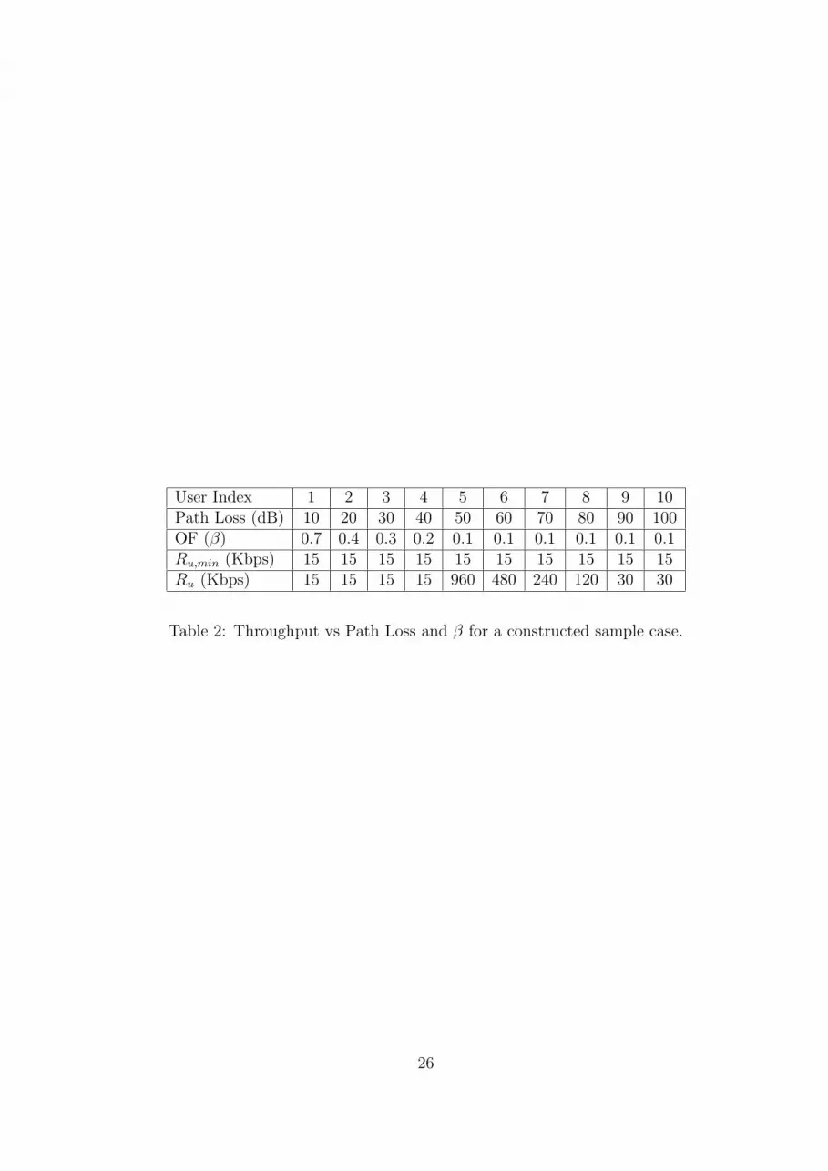
User Index 1 2 3 4 5 6 7 8 9 10Path Loss (dB) 10 20 30 40 50 60 70 80 90 100OF (β) 0.7 0.4 0.3 0.2 0.1 0.1 0.1 0.1 0.1 0.1Ru,min (Kbps) 15 15 15 15 15 15 15 15 15 15Ru (Kbps) 15 15 15 15 960 480 240 120 30 30
Table 2: Throughput vs Path Loss and β for a constructed sample case.
26