Embed Size (px)
Citation preview
01773 531531 I [email protected] I www.bowerselec.co.uk
2021
Distribution Transformers
Operating & Maintenance Manual
Tel: 01773 531531 [email protected] www.bowerselec.co.uk
Bowers Group of Companies are proud to be members of:
2
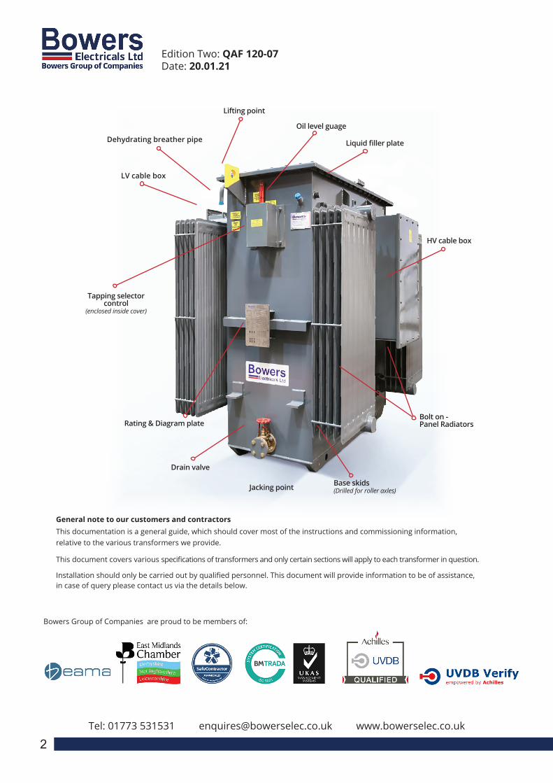
Edition Two: QAF 120-07Date: 20.01.21
Bolt on - Panel Radiators
Drain valve
Dehydrating breather pipe
Lifting point
HV cable box
LV cable box
Rating & Diagram plate
Liquid filler plate
Tapping selector control
(enclosed inside cover)
Base skids(Drilled for roller axles)Jacking point
Oil level guage
General note to our customers and contractorsThis documentation is a general guide, which should cover most of the instructions and commissioning information, relative to the various transformers we provide.
This document covers various specifications of transformers and only certain sections will apply to each transformer in question.
Installation should only be carried out by qualified personnel. This document will provide information to be of assistance, in case of query please contact us via the details below.
3
INSTALLATION, USE AND MAINTENANCE MANUALEN
APPENDIX
1.0 – REFERENCE STANDARDS2.0 – RATING PLATE3.0 – LIST OF COMPONENTS AND ACCESSORIES4.0 – IMPORTANT NOTICE5.0 – RECEIVING, HANDLING AND STORING
5.1 – RECEIVING5.2 – HANDLING5.3 – STORAGE
6.0 – INSTALLATION6.1 – SITE PREPARATION6.2 – STANDARD INSTALLATION CONDITIONS6.3 – WORKING TEMPERATURE6.4 – VENTILATION
6.4.1 – NATURAL / FORCED VENTILATION OF THE INSTALLATION ROOM 6.4.2 – FORCED VENTILATION OF THE TRANSFORMER
6.5 – INSULATION DISTANCES6.6 – SAFETY DISTANCE6.7 – TIGHTENING TORQUE FOR ELECTRICAL & MECHNICAL
CONNECTIONS6.8 – VISUAL INSPECTION
Bowers Electricals Ltd, Heanor Gate Road, Heanor, Derbyshire DE75 7GXTelephone: 01773 531531 (24 hours) Fax: 01773 716171
E-mail: [email protected]
CAST RESIN TRANSFORMER:Installation, Operation &
Maintenance Manual
3
Distribution Transformers
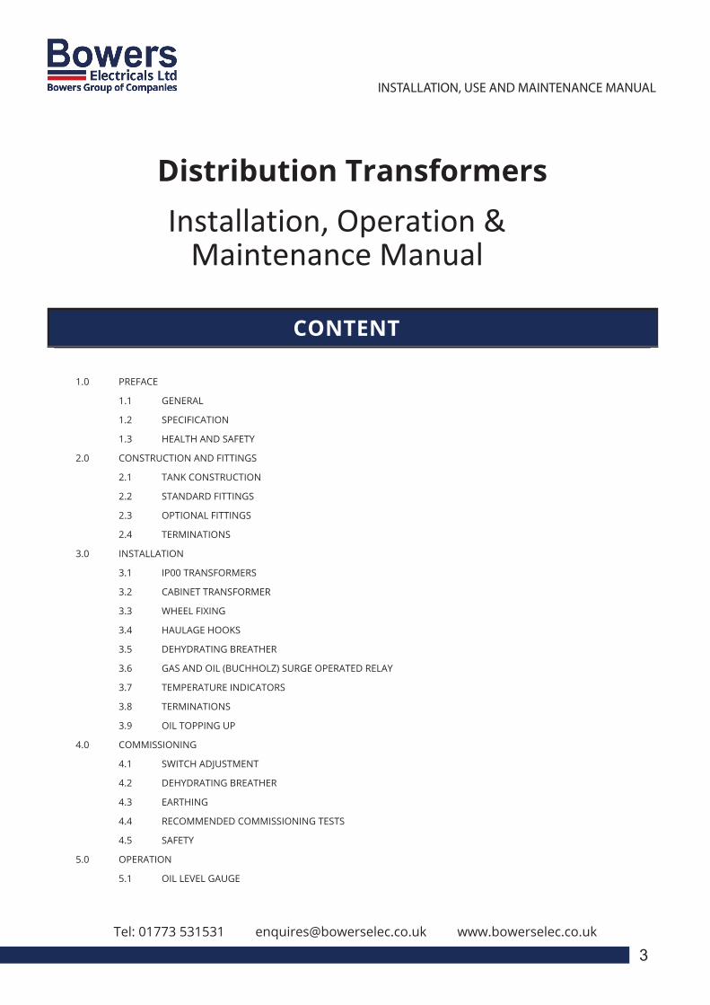
1.0 PREFACE
1.1 GENERAL
1.2 SPECIFICATION
1.3 HEALTH AND SAFETY
2.0 CONSTRUCTION AND FITTINGS
2.1 TANK CONSTRUCTION
2.2 STANDARD FITTINGS
2.3 OPTIONAL FITTINGS
2.4 TERMINATIONS
3.0 INSTALLATION
3.1 IP00 TRANSFORMERS
3.2 CABINET TRANSFORMER
3.3 WHEEL FIXING
3.4 HAULAGE HOOKS
3.5 DEHYDRATING BREATHER
3.6 GAS AND OIL (BUCHHOLZ) SURGE OPERATED RELAY
3.7 TEMPERATURE INDICATORS
3.8 TERMINATIONS
3.9 OIL TOPPING UP
4.0 COMMISSIONING
4.1 SWITCH ADJUSTMENT
4.2 DEHYDRATING BREATHER
4.3 EARTHING
4.4 RECOMMENDED COMMISSIONING TESTS
4.5 SAFETY
5.0 OPERATION
5.1 OIL LEVEL GAUGE
Tel: 01773 531531 [email protected] www.bowerselec.co.uk
3
INSTALLATION, USE AND MAINTENANCE MANUALEN
APPENDIX
1.0 – REFERENCE STANDARDS2.0 – RATING PLATE3.0 – LIST OF COMPONENTS AND ACCESSORIES4.0 – IMPORTANT NOTICE5.0 – RECEIVING, HANDLING AND STORING
5.1 – RECEIVING5.2 – HANDLING5.3 – STORAGE
6.0 – INSTALLATION6.1 – SITE PREPARATION6.2 – STANDARD INSTALLATION CONDITIONS6.3 – WORKING TEMPERATURE6.4 – VENTILATION
6.4.1 – NATURAL / FORCED VENTILATION OF THE INSTALLATION ROOM 6.4.2 – FORCED VENTILATION OF THE TRANSFORMER
6.5 – INSULATION DISTANCES6.6 – SAFETY DISTANCE6.7 – TIGHTENING TORQUE FOR ELECTRICAL & MECHNICAL
CONNECTIONS6.8 – VISUAL INSPECTION
Bowers Electricals Ltd, Heanor Gate Road, Heanor, Derbyshire DE75 7GXTelephone: 01773 531531 (24 hours) Fax: 01773 716171
E-mail: [email protected]
CAST RESIN TRANSFORMER:Installation, Operation &
Maintenance Manual
CONTENT
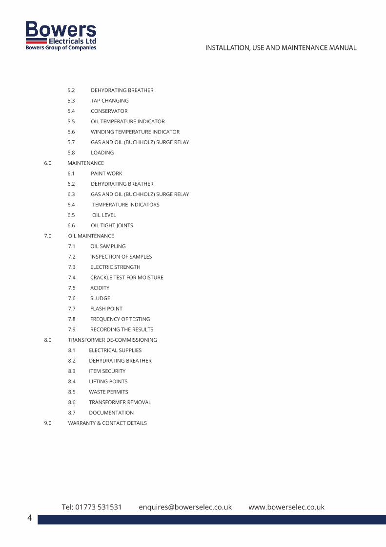
5.2 DEHYDRATING BREATHER
5.3 TAP CHANGING
5.4 CONSERVATOR
5.5 OIL TEMPERATURE INDICATOR
5.6 WINDING TEMPERATURE INDICATOR
5.7 GAS AND OIL (BUCHHOLZ) SURGE RELAY
5.8 LOADING
6.0 MAINTENANCE
6.1 PAINT WORK
6.2 DEHYDRATING BREATHER
6.3 GAS AND OIL (BUCHHOLZ) SURGE RELAY
6.4 TEMPERATURE INDICATORS
6.5 OIL LEVEL
6.6 OIL TIGHT JOINTS
7.0 OIL MAINTENANCE
7.1 OIL SAMPLING
7.2 INSPECTION OF SAMPLES
7.3 ELECTRIC STRENGTH
7.4 CRACKLE TEST FOR MOISTURE
7.5 ACIDITY
7.6 SLUDGE
7.7 FLASH POINT
7.8 FREQUENCY OF TESTING
7.9 RECORDING THE RESULTS
8.0 TRANSFORMER DE-COMMISSIONING
8.1 ELECTRICAL SUPPLIES
8.2 DEHYDRATING BREATHER
8.3 ITEM SECURITY
8.4 LIFTING POINTS
8.5 WASTE PERMITS
8.6 TRANSFORMER REMOVAL
8.7 DOCUMENTATION
9.0 WARRANTY & CONTACT DETAILS
Tel: 01773 531531 [email protected] www.bowerselec.co.uk
3
INSTALLATION, USE AND MAINTENANCE MANUALEN
APPENDIX
1.0 – REFERENCE STANDARDS2.0 – RATING PLATE3.0 – LIST OF COMPONENTS AND ACCESSORIES4.0 – IMPORTANT NOTICE5.0 – RECEIVING, HANDLING AND STORING
5.1 – RECEIVING5.2 – HANDLING5.3 – STORAGE
6.0 – INSTALLATION6.1 – SITE PREPARATION6.2 – STANDARD INSTALLATION CONDITIONS6.3 – WORKING TEMPERATURE6.4 – VENTILATION
6.4.1 – NATURAL / FORCED VENTILATION OF THE INSTALLATION ROOM 6.4.2 – FORCED VENTILATION OF THE TRANSFORMER
6.5 – INSULATION DISTANCES6.6 – SAFETY DISTANCE6.7 – TIGHTENING TORQUE FOR ELECTRICAL & MECHNICAL
CONNECTIONS6.8 – VISUAL INSPECTION
Bowers Electricals Ltd, Heanor Gate Road, Heanor, Derbyshire DE75 7GXTelephone: 01773 531531 (24 hours) Fax: 01773 716171
E-mail: [email protected]
CAST RESIN TRANSFORMER:Installation, Operation &
Maintenance Manual
4

Tel: 01773 531531 [email protected] www.bowerselec.co.uk
3
INSTALLATION, USE AND MAINTENANCE MANUALEN
APPENDIX
1.0 – REFERENCE STANDARDS2.0 – RATING PLATE3.0 – LIST OF COMPONENTS AND ACCESSORIES4.0 – IMPORTANT NOTICE5.0 – RECEIVING, HANDLING AND STORING
5.1 – RECEIVING5.2 – HANDLING5.3 – STORAGE
6.0 – INSTALLATION6.1 – SITE PREPARATION6.2 – STANDARD INSTALLATION CONDITIONS6.3 – WORKING TEMPERATURE6.4 – VENTILATION
6.4.1 – NATURAL / FORCED VENTILATION OF THE INSTALLATION ROOM 6.4.2 – FORCED VENTILATION OF THE TRANSFORMER
6.5 – INSULATION DISTANCES6.6 – SAFETY DISTANCE6.7 – TIGHTENING TORQUE FOR ELECTRICAL & MECHNICAL
CONNECTIONS6.8 – VISUAL INSPECTION
Bowers Electricals Ltd, Heanor Gate Road, Heanor, Derbyshire DE75 7GXTelephone: 01773 531531 (24 hours) Fax: 01773 716171
E-mail: [email protected]
CAST RESIN TRANSFORMER:Installation, Operation &
Maintenance Manual
1.1 General
1.1.1 The product to which this manual refers should be installed, commissioned, operated and maintained under the
supervision of a competent electrical engineer, in accordance with relevant statutory requirements and good
engineering practice, including Codes of Practice, where applicable, and properly used within the terms of the
specification.
1.1.2 The contents of this approved manual include advice and instructions to secure safe and satisfactory service.
In the event of any doubt, query, or the need for further information, please contact Bowers Electricals Limited.
1.1.3 The product should receive regular inspection in accordance with the manufacturer’s guidelines.
It is recommended that the transformer should be thoroughly inspected every 12 months, and attention
given to maintenance of all items where necessary (refer to section 6).
1.1.4 In any communication please quote the following information: (see rating plate) serial number, kVA rating,
Bowers’ job number and year of manufacture.
1.1.5 It shall be noted that any reference within this manual to ‘oil’ or ‘fluid’ will be equally applicable to transformer
mineral oil to BSEN60296 and synthetic organic Ester eg “Midel 7131” complying with the requirements of EN61099
and natural esters complying with the requirements of EN62770.
1.1.6 Starting from 1 July 2015, all new small, medium and large power transformers placed in the market of the
EU Member States are designed according to Commission Regulation (EU) No 548/2014 of 21 May 2014 on
implementing Ecodesign directive 2009/125/EC of the European Parliament and of the Council.
1.2 Specification
1.2.1 The product has been designed and tested in accordance with the specification and standards quoted in our
acknowledgement of the order and any subsequent modifications.
1.2.2 Some of the components referred to in this manual are supplied only when specified and will not be incorporated
into all products.
1.2.3 For the relevant UK and International Standards and Codes of Practice, reference should be made to the current
edition of the following publications: B.S.I. Standards Catalogue; ENATS 35-1; I.E.C. Catalogue of
Publications; I.S.O. Standards Catalogue.
1.3 Health & Safety
1.3.1 The Electricity at Work Regulations 1989 supported by Memorandum of Guidance (ISBN 011
8839632) apply to UK electrical installations.
1.3.2 The current edition of the IEE wiring regulations, apply to all installations.
1.3.3 IEC 60364 Low Voltage “Electrical Installations in Buildings” also covers safety aspects.
1.3.4 We would in particular stress the importance of care in: Site selection and design, embodying features
which provide adequate ventilation, protection and security and which have taken account of appropriate
fire, moisture and explosion hazards.
1.3.7 Excessive or prolonged skin contact with transformer oil (mineral oil) should be avoided. For further
information regarding transformer oil handling, please refer to relevant material safety data sheets.
1. PREFACE
5

Tel: 01773 531531 [email protected] www.bowerselec.co.uk
3
INSTALLATION, USE AND MAINTENANCE MANUALEN
APPENDIX
1.0 – REFERENCE STANDARDS2.0 – RATING PLATE3.0 – LIST OF COMPONENTS AND ACCESSORIES4.0 – IMPORTANT NOTICE5.0 – RECEIVING, HANDLING AND STORING
5.1 – RECEIVING5.2 – HANDLING5.3 – STORAGE
6.0 – INSTALLATION6.1 – SITE PREPARATION6.2 – STANDARD INSTALLATION CONDITIONS6.3 – WORKING TEMPERATURE6.4 – VENTILATION
6.4.1 – NATURAL / FORCED VENTILATION OF THE INSTALLATION ROOM 6.4.2 – FORCED VENTILATION OF THE TRANSFORMER
6.5 – INSULATION DISTANCES6.6 – SAFETY DISTANCE6.7 – TIGHTENING TORQUE FOR ELECTRICAL & MECHNICAL
CONNECTIONS6.8 – VISUAL INSPECTION
Bowers Electricals Ltd, Heanor Gate Road, Heanor, Derbyshire DE75 7GXTelephone: 01773 531531 (24 hours) Fax: 01773 716171
E-mail: [email protected]
CAST RESIN TRANSFORMER:Installation, Operation &
Maintenance Manual
6
2.1 Tank Construction
Tanks are designed to be lifted via the lifting points or jacked via the designated points (Figure 1). All transformers
have been designed and tested to be oil leak free. All ground mounted transformer tanks are fitted with skid under
bases suitable for handling with roller bars. The skids are drilled to accommodate axles and rollers when required.
Radiators, when fitted, are attached to the main tank on naturally cooled (type ONAN or KNAN) units. A detachable
cover is fitted, the gasket material being synthetic resin bonded cork. (Figure 2)
2. CONSTRUCTION AND FITTINGS
2.2 Standards Fittings
The “Standard Fittings” listed below are those which are considered to be the
minimum for the correct and safe operation of a Bowers Electricals Standard
Transformer.
These Standard Fittings conform to the requirements of: BSEN60076.
• Diagram and Rating Plate (illustrated)
• Off-Circuit Tapping Switch
• Lifting Lugs
• Earthing Terminal
• Oil Level Indicator
• Drain Valve
• Thermometer Pocket
• Jacking facilities
• Dehydrating breather.
Figure 2.
Figure 1.
REFERENCE STANDARD
kVA
TYPE OF COOLING
PHASES
FREQUENCY
CONDUCTOR MATERIAL
INSULATION LEVEL
RATED CURRENT
CORE & WINDINGS MASS
TEMP. RISE OIL./Wdg.
Hz
K
kg
2N
3
2U 2V 2W
1U 1V 1W
5
4
6
8
7
3
5
4
6
8
7
3
5
4
6
8
7
TYPE OF INSULATING LIQUID
INSULATING LIQUID REFERENCE NO.
9 9 9
1
2
1
2
1
2
1
2
1
2
1
2
VOLTS H.V.
(NO LOAD) L.V.
H.V.
L.V.
{H.V.
L.V.
H.V.
L.V.
{
{DIAGRAM DWG. NO
SERIAL NO.
JOB NO.
OWNER NO.
YEAR OF MFG.
LIQUID VOLUME
LIQUID MASS
L
kg
CORE MATERIAL
CORE MASS kg
CONDUCTOR MASS kg
NO LOAD LOSS W
LOAD LOSS W
1W
1U
1V
HV
LV
2U
2V
2W
HV LV
HV SWITCH
CONNPOS'NHV VOLTS
11275 3 7-4
10725
4 4-811000 (RATED)
5 8-3
10450 6 3-9
11550 2 5-7
11825 1 6-5
AMPS
HV
DISTRIBUTION TRANSFORMER
IMPEDANCE
VECTOR GROUP
%
Bowers Electricals Limited,
Heanor Gate Road, Heanor,
Derbyshire, DE75 7GX, UK
Tel 01773-531 531 / Fax 716 171
Email: [email protected]
BowersElectricals Ltd
kgTOTAL MASS OF TRANSFORMER
TRANSPORT MASS WHEN kg
VACUUM WITHSTAND P.S.l.g
LOSS CLASS
SUPPLIED WITH HV / LV
SWITCHGEAR
25.60
26.20
26.92
27.62
24.99
24.41
IEC 60076
500
ONAN
3
50
LI: 75 AC: 28
26.20
695.6
1100
60/65
UNINHIBITED, MINERAL OIL
IEC 60296
ALUMINUM
11000
415
3
LI: - AC: 3
270
4
Ao Ck
555
475
CRGO
640
Dyn11
2250
NA
WD2128
S110127
x
2021
x
x
x
012
SYSTEMS
MANAGEMENT
UKAS
BMTRADA
SYSTEM
CERT I F I CAT
ION
I SO 9 0 0 1
Size
WD2128
A4
FIRST ANGLE
DRG No.
± 2mm FOR DIMENSIONS OVER 1000mm.± 1mm FOR DIMENSIONS UP TO 1000mm:± 0.5mm FOR DIMENSIONS UP TO 250mm:
TOLERANCE UNLESS OTHERWISE STATED
the property of Bowers Electricals Ltd.
without prior written consent of the company. c
RevNo Revision Note Date Signature Checked
Bowers
Heanor, Derbyshire. DE75 7GX
E-mail: [email protected]
Tel: 01773 531531 Fax: 01773 716171
Heanor Gate Road,
Electricals Ltd
This drawing is COPYRIGHT and
Drawn By Checked ByJ.COLLINS
Approved ByJ.COLLINS
Job No.S110127
DateScaleNTS
Revision Sheet0
it must not be copied (in whole or in part)
SYSTEMS
MANAGEMENT
UKAS
SYSTEM
CERT I F I CAT
ION
I SO 9 0 0 1
Size
FIRST ANGLE
DRG No.
c
RevNo Revision Note Date Signature Checked
Drawn ByT.BRADLEY
Checked By Approved By Job No.19/03/21 1
RATING PLATE DIAGRAM FOR 500kVA 11000/415V
TRANSFORMER
Diagram and Rating Plate.
Tel: 01773 531531 [email protected] www.bowerselec.co.uk
3
INSTALLATION, USE AND MAINTENANCE MANUALEN
APPENDIX
1.0 – REFERENCE STANDARDS2.0 – RATING PLATE3.0 – LIST OF COMPONENTS AND ACCESSORIES4.0 – IMPORTANT NOTICE5.0 – RECEIVING, HANDLING AND STORING
5.1 – RECEIVING5.2 – HANDLING5.3 – STORAGE
6.0 – INSTALLATION6.1 – SITE PREPARATION6.2 – STANDARD INSTALLATION CONDITIONS6.3 – WORKING TEMPERATURE6.4 – VENTILATION
6.4.1 – NATURAL / FORCED VENTILATION OF THE INSTALLATION ROOM 6.4.2 – FORCED VENTILATION OF THE TRANSFORMER
6.5 – INSULATION DISTANCES6.6 – SAFETY DISTANCE6.7 – TIGHTENING TORQUE FOR ELECTRICAL & MECHNICAL
CONNECTIONS6.8 – VISUAL INSPECTION
Bowers Electricals Ltd, Heanor Gate Road, Heanor, Derbyshire DE75 7GXTelephone: 01773 531531 (24 hours) Fax: 01773 716171
E-mail: [email protected]
CAST RESIN TRANSFORMER:Installation, Operation &
Maintenance Manual
7
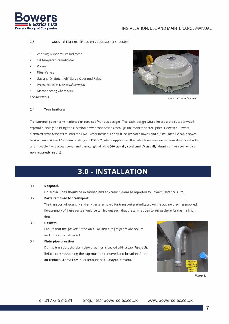
2.3 Optional Fittings - (Fitted only at Customer’s request)
• Winding Temperature Indicator
• Oil Temperature Indicator
• Rollers
• Filter Valves
• Gas and Oil (Buchholz) Surge Operated Relay
• Pressure Relief Device (illustrated)
• Disconnecting Chambers
Conservators.
2.4 Terminations
Transformer power terminations can consist of various designs. The basic design would incorporate outdoor weath-
erproof bushings to bring the electrical power connections through the main tank steel plate. However, Bowers
standard arrangements follows the ENATS requirements of air filled HV cable boxes and air insulated LV cable boxes,
having porcelain and /or resin bushings to BS2562, where applicable. The cable boxes are made from sheet steel with
a removable front access cover and a metal gland plate (HV usually steel and LV usually aluminium or steel with a
non-magnetic insert).
Pressure relief device.
3.0 - INSTALLATION
3.1 Despatch
On arrival units should be examined and any transit damage reported to Bowers Electricals Ltd.
3.2 Parts removed for transport
The transport oil quantity and any parts removed for transport are indicated on the outline drawing supplied.
Re-assembly of these parts should be carried out such that the tank is open to atmosphere for the minimum
time.
3.3 Gaskets
Ensure that the gaskets fitted on all oil and airtight joints are secure
and uniformly tightened.
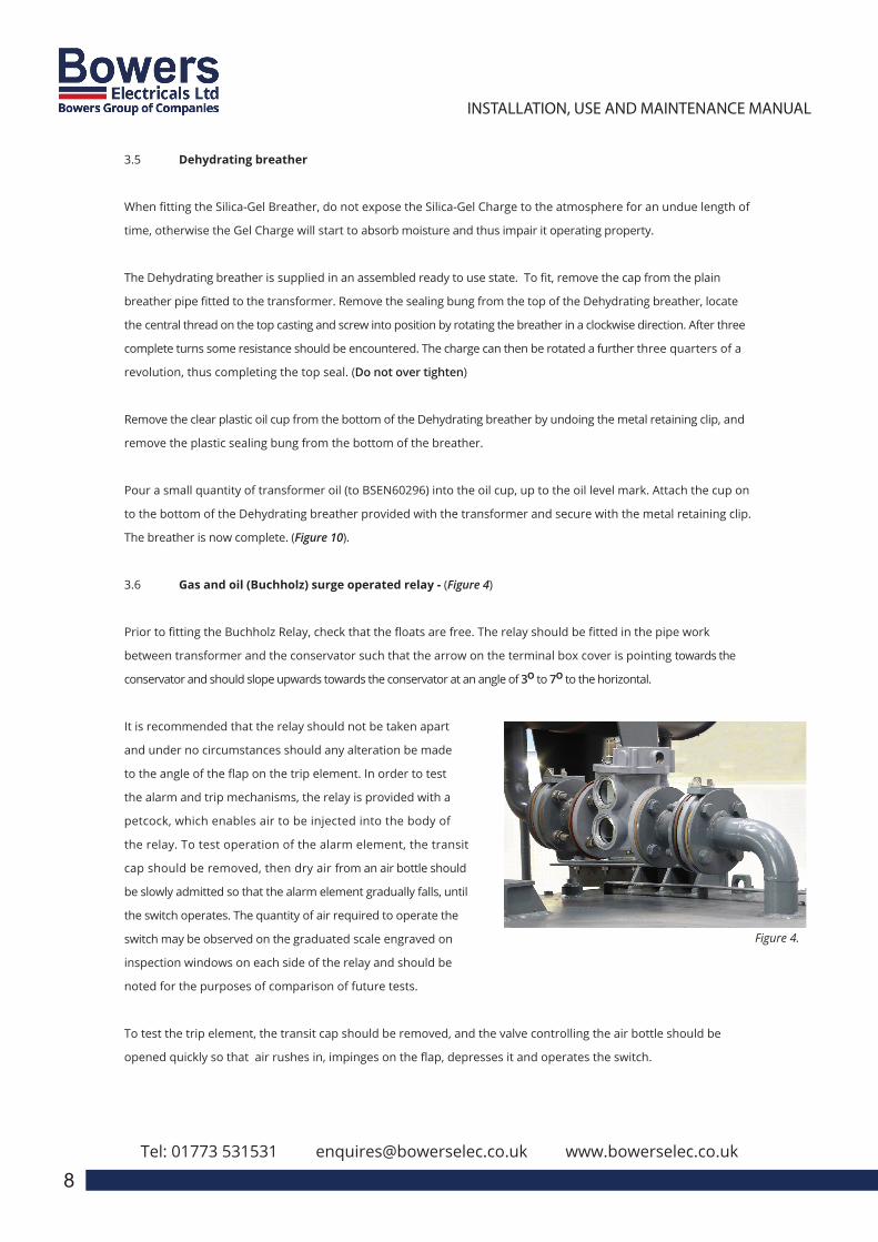
3.4 Plain pipe breather
During transport the plain pipe breather is sealed with a cap (Figure 3).
Before commissioning the cap must be removed and breather fitted,
on removal a small residual amount of oil maybe present.
Figure 3.
3.5 Dehydrating breather
When fitting the Silica-Gel Breather, do not expose the Silica-Gel Charge to the atmosphere for an undue length of
time, otherwise the Gel Charge will start to absorb moisture and thus impair it operating property.
The Dehydrating breather is supplied in an assembled ready to use state. To fit, remove the cap from the plain
breather pipe fitted to the transformer. Remove the sealing bung from the top of the Dehydrating breather, locate
the central thread on the top casting and screw into position by rotating the breather in a clockwise direction. After three
complete turns some resistance should be encountered. The charge can then be rotated a further three quarters of a
revolution, thus completing the top seal. (Do not over tighten)
Remove the clear plastic oil cup from the bottom of the Dehydrating breather by undoing the metal retaining clip, and
remove the plastic sealing bung from the bottom of the breather.
Pour a small quantity of transformer oil (to BSEN60296) into the oil cup, up to the oil level mark. Attach the cup on
to the bottom of the Dehydrating breather provided with the transformer and secure with the metal retaining clip.
The breather is now complete. (Figure 10).
3.6 Gas and oil (Buchholz) surge operated relay - (Figure 4)
Prior to fitting the Buchholz Relay, check that the floats are free. The relay should be fitted in the pipe work
between transformer and the conservator such that the arrow on the terminal box cover is pointing towards the
conservator and should slope upwards towards the conservator at an angle of 3o to 7o to the horizontal.
It is recommended that the relay should not be taken apart
and under no circumstances should any alteration be made
to the angle of the flap on the trip element. In order to test
the alarm and trip mechanisms, the relay is provided with a
petcock, which enables air to be injected into the body of
the relay. To test operation of the alarm element, the transit
cap should be removed, then dry air from an air bottle should
be slowly admitted so that the alarm element gradually falls, until
the switch operates. The quantity of air required to operate the
switch may be observed on the graduated scale engraved on
inspection windows on each side of the relay and should be
noted for the purposes of comparison of future tests.
To test the trip element, the transit cap should be removed, and the valve controlling the air bottle should be
opened quickly so that air rushes in, impinges on the flap, depresses it and operates the switch.
Tel: 01773 531531 [email protected] www.bowerselec.co.uk
3
INSTALLATION, USE AND MAINTENANCE MANUALEN
APPENDIX
1.0 – REFERENCE STANDARDS2.0 – RATING PLATE3.0 – LIST OF COMPONENTS AND ACCESSORIES4.0 – IMPORTANT NOTICE5.0 – RECEIVING, HANDLING AND STORING
5.1 – RECEIVING5.2 – HANDLING5.3 – STORAGE
6.0 – INSTALLATION6.1 – SITE PREPARATION6.2 – STANDARD INSTALLATION CONDITIONS6.3 – WORKING TEMPERATURE6.4 – VENTILATION
6.4.1 – NATURAL / FORCED VENTILATION OF THE INSTALLATION ROOM 6.4.2 – FORCED VENTILATION OF THE TRANSFORMER
6.5 – INSULATION DISTANCES6.6 – SAFETY DISTANCE6.7 – TIGHTENING TORQUE FOR ELECTRICAL & MECHNICAL
CONNECTIONS6.8 – VISUAL INSPECTION
Bowers Electricals Ltd, Heanor Gate Road, Heanor, Derbyshire DE75 7GXTelephone: 01773 531531 (24 hours) Fax: 01773 716171
E-mail: [email protected]
CAST RESIN TRANSFORMER:Installation, Operation &
Maintenance Manual
8
Figure 4.
: 01773 531531 [email protected] www.bowerselec.co.uk
3
INSTALLATION, USE AND MAINTENANCE MANUALEN
APPENDIX
1.0 – REFERENCE STANDARDS2.0 – RATING PLATE3.0 – LIST OF COMPONENTS AND ACCESSORIES4.0 – IMPORTANT NOTICE5.0 – RECEIVING, HANDLING AND STORING
5.1 – RECEIVING5.2 – HANDLING5.3 – STORAGE
6.0 – INSTALLATION6.1 – SITE PREPARATION6.2 – STANDARD INSTALLATION CONDITIONS6.3 – WORKING TEMPERATURE6.4 – VENTILATION
6.4.1 – NATURAL / FORCED VENTILATION OF THE INSTALLATION ROOM 6.4.2 – FORCED VENTILATION OF THE TRANSFORMER
6.5 – INSULATION DISTANCES6.6 – SAFETY DISTANCE6.7 – TIGHTENING TORQUE FOR ELECTRICAL & MECHNICAL
CONNECTIONS6.8 – VISUAL INSPECTION
Bowers Electricals Ltd, Heanor Gate Road, Heanor, Derbyshire DE75 7GXTelephone: 01773 531531 (24 hours) Fax: 01773 716171
E-mail: [email protected]
CAST RESIN TRANSFORMER:Installation, Operation &
Maintenance Manual
9
The approximate minimum air pressure required to operate the switch should be recorded for the
purpose of future comparison.
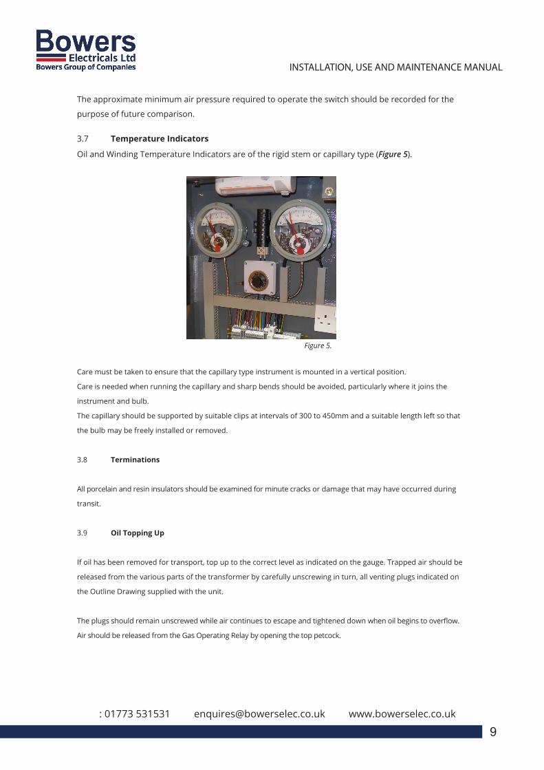
3.7 Temperature Indicators
Oil and Winding Temperature Indicators are of the rigid stem or capillary type (Figure 5).
Figure 5.
Care must be taken to ensure that the capillary type instrument is mounted in a vertical position.
Care is needed when running the capillary and sharp bends should be avoided, particularly where it joins the
instrument and bulb.
The capillary should be supported by suitable clips at intervals of 300 to 450mm and a suitable length left so that
the bulb may be freely installed or removed.
3.8 Terminations
All porcelain and resin insulators should be examined for minute cracks or damage that may have occurred during
transit.
3.9 Oil Topping Up
If oil has been removed for transport, top up to the correct level as indicated on the gauge. Trapped air should be
released from the various parts of the transformer by carefully unscrewing in turn, all venting plugs indicated on
the Outline Drawing supplied with the unit.
The plugs should remain unscrewed while air continues to escape and tightened down when oil begins to overflow.
Air should be released from the Gas Operating Relay by opening the top petcock.
Tel: 01773 531531 [email protected] www.bowerselec.co.uk
3
INSTALLATION, USE AND MAINTENANCE MANUALEN
APPENDIX
1.0 – REFERENCE STANDARDS2.0 – RATING PLATE3.0 – LIST OF COMPONENTS AND ACCESSORIES4.0 – IMPORTANT NOTICE5.0 – RECEIVING, HANDLING AND STORING
5.1 – RECEIVING5.2 – HANDLING5.3 – STORAGE
6.0 – INSTALLATION6.1 – SITE PREPARATION6.2 – STANDARD INSTALLATION CONDITIONS6.3 – WORKING TEMPERATURE6.4 – VENTILATION
6.4.1 – NATURAL / FORCED VENTILATION OF THE INSTALLATION ROOM 6.4.2 – FORCED VENTILATION OF THE TRANSFORMER
6.5 – INSULATION DISTANCES6.6 – SAFETY DISTANCE6.7 – TIGHTENING TORQUE FOR ELECTRICAL & MECHNICAL
CONNECTIONS6.8 – VISUAL INSPECTION
Bowers Electricals Ltd, Heanor Gate Road, Heanor, Derbyshire DE75 7GXTelephone: 01773 531531 (24 hours) Fax: 01773 716171
E-mail: [email protected]
CAST RESIN TRANSFORMER:Installation, Operation &
Maintenance Manual
4. COMMISSIONING
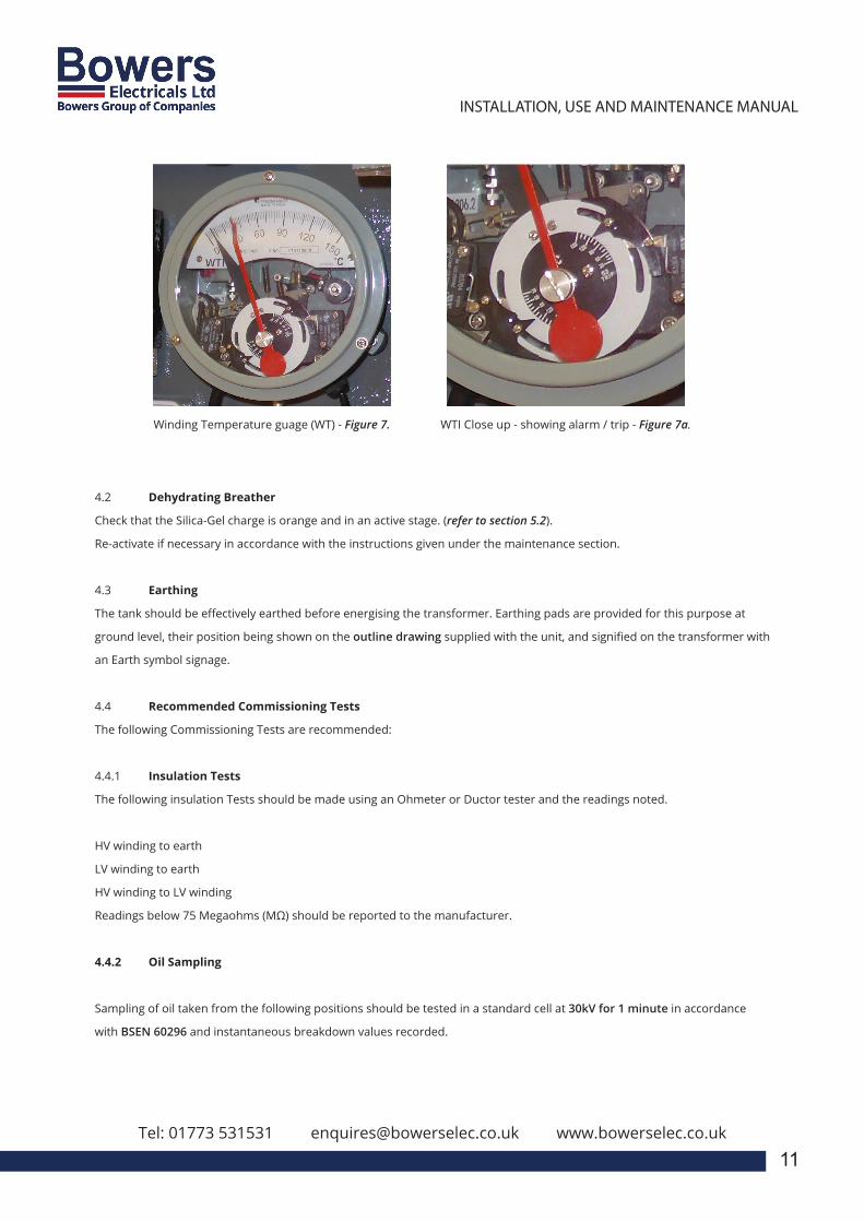
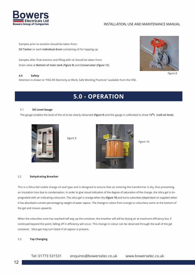
4.1 Switch Adjustment
Switches should be adjusted to operate at the required values. Recommended maximum settings are:
Liquid Temperature Winding Temperature
Alarm Contact 85 oc 105 oc
Trip Contact 95 oc 115 oc
To adjust switches, remove the instrument bezel and slacken the switch clamp screw located on the extremity of the switch
arm. Adjust the switch to the desired operating temperature on the setting scale and re-tighten the clamp screw (Figure
7-7a). When carrying out this adjustment, the switch table should be supported so that excessive pressure is not applied to
the Bourdon movement.
10
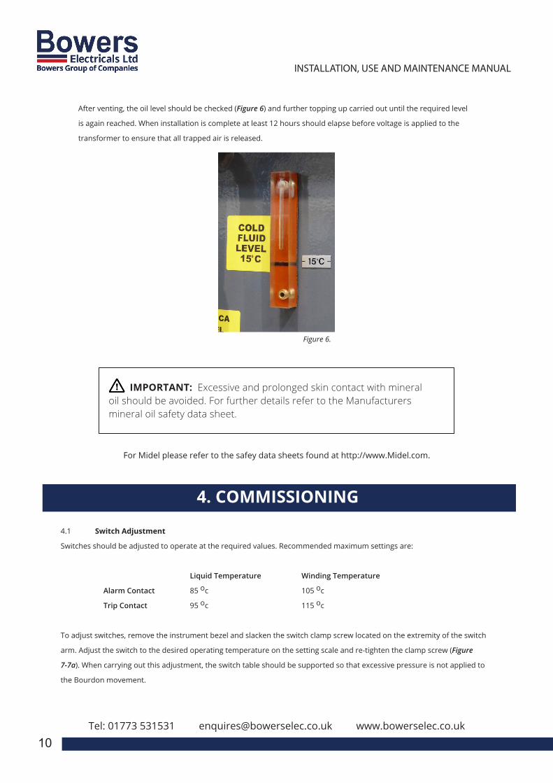
After venting, the oil level should be checked (Figure 6) and further topping up carried out until the required level
is again reached. When installation is complete at least 12 hours should elapse before voltage is applied to the
transformer to ensure that all trapped air is released.
Figure 6.
IMPORTANT: Excessive and prolonged skin contact with mineral oil should be avoided. For further details refer to the Manufacturers mineral oil safety data sheet.
For Midel please refer to the safey data sheets found at http://www.Midel.com.
Tel: 01773 531531 [email protected] www.bowerselec.co.uk
3
INSTALLATION, USE AND MAINTENANCE MANUALEN
APPENDIX
1.0 – REFERENCE STANDARDS2.0 – RATING PLATE3.0 – LIST OF COMPONENTS AND ACCESSORIES4.0 – IMPORTANT NOTICE5.0 – RECEIVING, HANDLING AND STORING
5.1 – RECEIVING5.2 – HANDLING5.3 – STORAGE
6.0 – INSTALLATION6.1 – SITE PREPARATION6.2 – STANDARD INSTALLATION CONDITIONS6.3 – WORKING TEMPERATURE6.4 – VENTILATION
6.4.1 – NATURAL / FORCED VENTILATION OF THE INSTALLATION ROOM 6.4.2 – FORCED VENTILATION OF THE TRANSFORMER
6.5 – INSULATION DISTANCES6.6 – SAFETY DISTANCE6.7 – TIGHTENING TORQUE FOR ELECTRICAL & MECHNICAL
CONNECTIONS6.8 – VISUAL INSPECTION
Bowers Electricals Ltd, Heanor Gate Road, Heanor, Derbyshire DE75 7GXTelephone: 01773 531531 (24 hours) Fax: 01773 716171
E-mail: [email protected]
CAST RESIN TRANSFORMER:Installation, Operation &
Maintenance Manual
11
Winding Temperature guage (WT) - Figure 7. WTI Close up - showing alarm / trip - Figure 7a.
4.2 Dehydrating Breather
Check that the Silica-Gel charge is orange and in an active stage. (refer to section 5.2).
Re-activate if necessary in accordance with the instructions given under the maintenance section.
4.3 Earthing
The tank should be effectively earthed before energising the transformer. Earthing pads are provided for this purpose at
ground level, their position being shown on the outline drawing supplied with the unit, and signified on the transformer with
an Earth symbol signage.
4.4 Recommended Commissioning Tests
The following Commissioning Tests are recommended:
4.4.1 Insulation Tests
The following insulation Tests should be made using an Ohmeter or Ductor tester and the readings noted.
HV winding to earth
LV winding to earth
HV winding to LV winding
Readings below 75 Megaohms (MΩ) should be reported to the manufacturer.
4.4.2 Oil Sampling
Sampling of oil taken from the following positions should be tested in a standard cell at 30kV for 1 minute in accordance
with BSEN 60296 and instantaneous breakdown values recorded.
3
INSTALLATION, USE AND MAINTENANCE MANUALEN
APPENDIX
1.0 – REFERENCE STANDARDS2.0 – RATING PLATE3.0 – LIST OF COMPONENTS AND ACCESSORIES4.0 – IMPORTANT NOTICE5.0 – RECEIVING, HANDLING AND STORING
5.1 – RECEIVING5.2 – HANDLING5.3 – STORAGE
6.0 – INSTALLATION6.1 – SITE PREPARATION6.2 – STANDARD INSTALLATION CONDITIONS6.3 – WORKING TEMPERATURE6.4 – VENTILATION
6.4.1 – NATURAL / FORCED VENTILATION OF THE INSTALLATION ROOM 6.4.2 – FORCED VENTILATION OF THE TRANSFORMER
6.5 – INSULATION DISTANCES6.6 – SAFETY DISTANCE6.7 – TIGHTENING TORQUE FOR ELECTRICAL & MECHNICAL
CONNECTIONS6.8 – VISUAL INSPECTION
Bowers Electricals Ltd, Heanor Gate Road, Heanor, Derbyshire DE75 7GXTelephone: 01773 531531 (24 hours) Fax: 01773 716171
E-mail: [email protected]
CAST RESIN TRANSFORMER:Installation, Operation &
Maintenance Manual
Samples prior to erection should be taken from:
Oil Tanker or each individual drum containing oil for topping up.
Samples after final erection and filling with oil should be taken from:
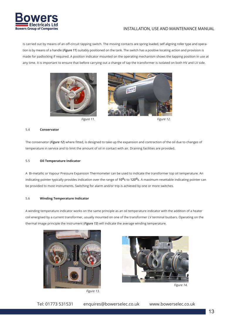
Drain valve at Bottom of main tank (Figure 8) and Conservator (Figure 12).
4.5 SafetyAttention is drawn to “HSG 85 Electricity at Work, Safe Working Practices” available from the HSE.
Tel: 01773 531531 [email protected] www.bowerselec.co.uk
12
Figure 8.
5.0 - OPERATION
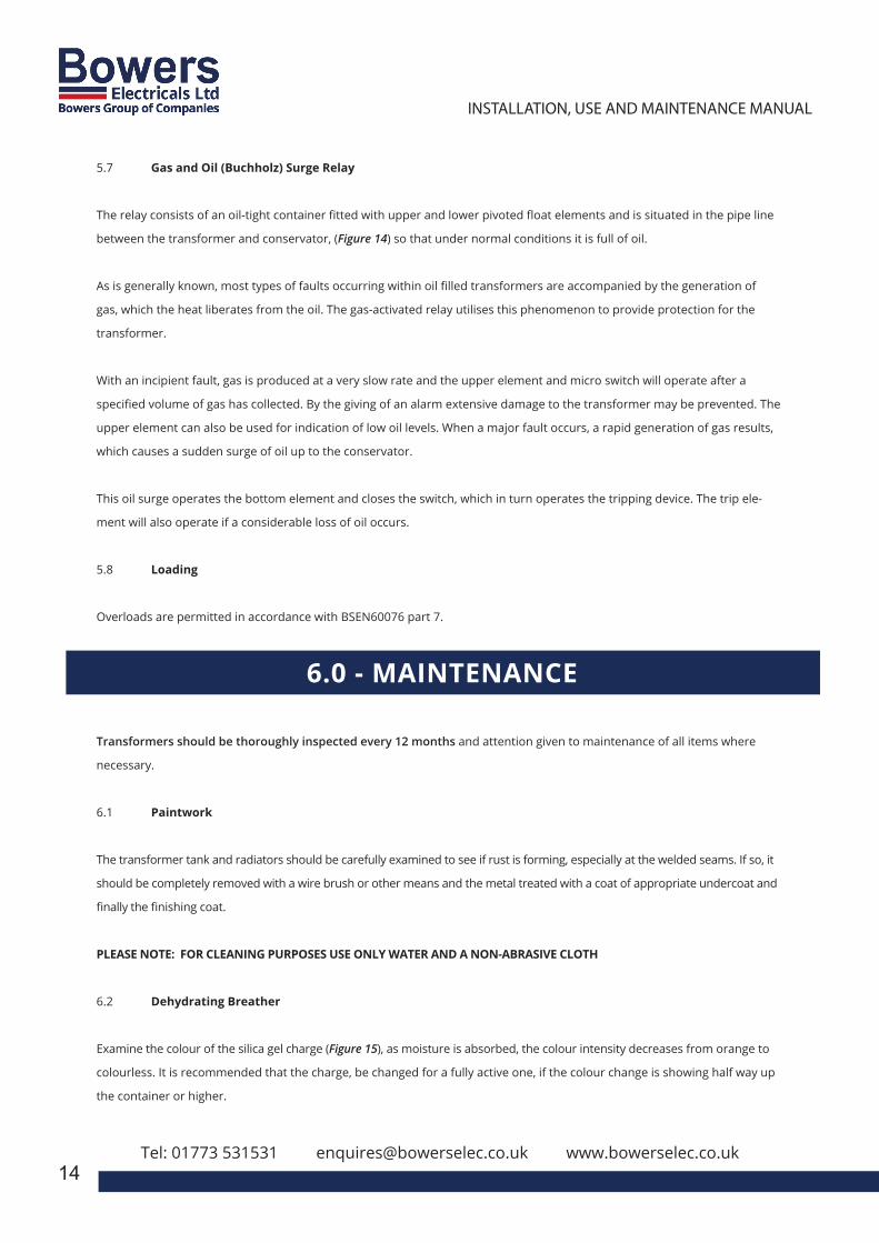
5.1 Oil Level Gauge
The gauge enables the level of the oil to be clearly observed (Figure 9) and the gauge is calibrated to show 15oc (cold oil level).
Figure 9.
5.2 Dehydrating Breather
This is a Silica-Gel visible charge oil seal type and is designed to ensure that air entering the transformer is dry, thus preventing
an insulation loss due to condensation. In order to give visual indication of the degree of saturation of the charge, the silica gel is im-
pregnated with an indicating colourant. The silica gel is orange when dry (Figure 10) and turns colourless (dependant on supplier) when
it has absorbed a certain percentage by weight of water vapour. The change in colour from orange to colourless starts at the bottom of
the gel and moves upwards.
When the colourless zone has reached half way up the container, the breather will still be drying air at maximum efficiency but, if
continued beyond this point, falling off in efficiency will occur. This change in colour can be observed through the wall of the gel
container. Silica gel may turn black if oil vapour is present.
5.3 Tap Changing
Figure 10.
Is carried out by means of an off-circuit tapping switch. The moving contacts are spring loaded, self aligning roller type and opera-
tion is by means of a handle (Figure 11) suitably positioned on the tank. The switch has a positive locating action and provision is
made for padlocking if required. A position indicator mounted on the operating mechanism shows the tapping position in use at
any time. It is important to ensure that before carrying out a change of tap the transformer is isolated on both HV and LV side.
5.4 Conservator
The conservator (Figure 12) where fitted, is designed to take up the expansion and contraction of the oil due to changes of
temperature in service and to limit the amount of oil in contact with air. Draining facilities are provided.
5.5 Oil Temperature Indicator
A Bi-metallic or Vapour Pressure Expansion Thermometer can be used to indicate the transformer top oil temperature. An
indicating pointer typically provides indication over the range of 10oc to 120oc. A maximum resettable indicating pointer can
be provided to most instruments. Switching for alarm and/or trip is achieved by one or more switches.
5.6 Winding Temperature Indicator
A winding temperature indicator works on the same principle as an oil temperature indicator with the addition of a heater
coil energised by a current transformer, usually mounted on one of the transformer LV terminal busbars. Operating on the
thermal image principle the instrument (Figure 13) will indicate the average winding temperature.
3
INSTALLATION, USE AND MAINTENANCE MANUALEN
APPENDIX
1.0 – REFERENCE STANDARDS2.0 – RATING PLATE3.0 – LIST OF COMPONENTS AND ACCESSORIES4.0 – IMPORTANT NOTICE5.0 – RECEIVING, HANDLING AND STORING
5.1 – RECEIVING5.2 – HANDLING5.3 – STORAGE
6.0 – INSTALLATION6.1 – SITE PREPARATION6.2 – STANDARD INSTALLATION CONDITIONS6.3 – WORKING TEMPERATURE6.4 – VENTILATION
6.4.1 – NATURAL / FORCED VENTILATION OF THE INSTALLATION ROOM 6.4.2 – FORCED VENTILATION OF THE TRANSFORMER
6.5 – INSULATION DISTANCES6.6 – SAFETY DISTANCE6.7 – TIGHTENING TORQUE FOR ELECTRICAL & MECHNICAL
CONNECTIONS6.8 – VISUAL INSPECTION
Bowers Electricals Ltd, Heanor Gate Road, Heanor, Derbyshire DE75 7GXTelephone: 01773 531531 (24 hours) Fax: 01773 716171
E-mail: [email protected]
CAST RESIN TRANSFORMER:Installation, Operation &
Maintenance Manual
Tel: 01773 531531 [email protected] www.bowerselec.co.uk
13
Figure 11. Figure 12.
Figure 13.
Figure 14.
5.7 Gas and Oil (Buchholz) Surge Relay
The relay consists of an oil-tight container fitted with upper and lower pivoted float elements and is situated in the pipe line
between the transformer and conservator, (Figure 14) so that under normal conditions it is full of oil.
As is generally known, most types of faults occurring within oil filled transformers are accompanied by the generation of
gas, which the heat liberates from the oil. The gas-activated relay utilises this phenomenon to provide protection for the
transformer.
With an incipient fault, gas is produced at a very slow rate and the upper element and micro switch will operate after a
specified volume of gas has collected. By the giving of an alarm extensive damage to the transformer may be prevented. The
upper element can also be used for indication of low oil levels. When a major fault occurs, a rapid generation of gas results,
which causes a sudden surge of oil up to the conservator.
This oil surge operates the bottom element and closes the switch, which in turn operates the tripping device. The trip ele-
ment will also operate if a considerable loss of oil occurs.
5.8 Loading
Overloads are permitted in accordance with BSEN60076 part 7.
3
INSTALLATION, USE AND MAINTENANCE MANUALEN
APPENDIX
1.0 – REFERENCE STANDARDS2.0 – RATING PLATE3.0 – LIST OF COMPONENTS AND ACCESSORIES4.0 – IMPORTANT NOTICE5.0 – RECEIVING, HANDLING AND STORING
5.1 – RECEIVING5.2 – HANDLING5.3 – STORAGE
6.0 – INSTALLATION6.1 – SITE PREPARATION6.2 – STANDARD INSTALLATION CONDITIONS6.3 – WORKING TEMPERATURE6.4 – VENTILATION
6.4.1 – NATURAL / FORCED VENTILATION OF THE INSTALLATION ROOM 6.4.2 – FORCED VENTILATION OF THE TRANSFORMER
6.5 – INSULATION DISTANCES6.6 – SAFETY DISTANCE6.7 – TIGHTENING TORQUE FOR ELECTRICAL & MECHNICAL
CONNECTIONS6.8 – VISUAL INSPECTION
Bowers Electricals Ltd, Heanor Gate Road, Heanor, Derbyshire DE75 7GXTelephone: 01773 531531 (24 hours) Fax: 01773 716171
E-mail: [email protected]
CAST RESIN TRANSFORMER:Installation, Operation &
Maintenance Manual
Transformers should be thoroughly inspected every 12 months and attention given to maintenance of all items where
necessary.
6.1 Paintwork
The transformer tank and radiators should be carefully examined to see if rust is forming, especially at the welded seams. If so, it
should be completely removed with a wire brush or other means and the metal treated with a coat of appropriate undercoat and
finally the finishing coat.
PLEASE NOTE: FOR CLEANING PURPOSES USE ONLY WATER AND A NON-ABRASIVE CLOTH
6.2 Dehydrating Breather
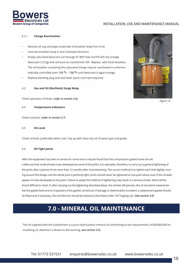
Examine the colour of the silica gel charge (Figure 15), as moisture is absorbed, the colour intensity decreases from orange to
colourless. It is recommended that the charge, be changed for a fully active one, if the colour change is showing half way up
the container or higher.
Tel: 01773 531531 [email protected] www.bowerselec.co.uk14
6.0 - MAINTENANCE
3
INSTALLATION, USE AND MAINTENANCE MANUALEN
APPENDIX
1.0 – REFERENCE STANDARDS2.0 – RATING PLATE3.0 – LIST OF COMPONENTS AND ACCESSORIES4.0 – IMPORTANT NOTICE5.0 – RECEIVING, HANDLING AND STORING
5.1 – RECEIVING5.2 – HANDLING5.3 – STORAGE
6.0 – INSTALLATION6.1 – SITE PREPARATION6.2 – STANDARD INSTALLATION CONDITIONS6.3 – WORKING TEMPERATURE6.4 – VENTILATION
6.4.1 – NATURAL / FORCED VENTILATION OF THE INSTALLATION ROOM 6.4.2 – FORCED VENTILATION OF THE TRANSFORMER
6.5 – INSULATION DISTANCES6.6 – SAFETY DISTANCE6.7 – TIGHTENING TORQUE FOR ELECTRICAL & MECHNICAL
CONNECTIONS6.8 – VISUAL INSPECTION
Bowers Electricals Ltd, Heanor Gate Road, Heanor, Derbyshire DE75 7GXTelephone: 01773 531531 (24 hours) Fax: 01773 716171
E-mail: [email protected]
CAST RESIN TRANSFORMER:Installation, Operation &
Maintenance Manual
Tel: 01773 531531 [email protected] www.bowerselec.co.uk15
Figure 15.
6.2.1 Charge Reactivation
• Remove oil cup and wipe underside of breather body free of oil.
• Unscrew breather body in anti-clockwise direction:
• Empty saturated desiccant out through ¾” BSP hole and fill with dry orange
desiccant (1/2 kg) and remount on transformer OR - Replace with fresh breather.
The oil breather containing the saturated charge may be reactivated in a thermo-
statically controlled oven 120 oc – 130 oc until desiccant is again orange.
• Replace blanking plug and seal lower ports until next required.
6.3 Gas and Oil (Buchholz) Surge Relay
Check operation of floats. (refer to section 3.6)
6.4 Temperature Indicators
Check contacts. (refer to section 3.7)
6.5 Oil Level
Check oil level, preferably when cold. Top up with clean dry oil of same type and grade.
6.6 Oil Tight Joints
After the equipment has been in service for some time it may be found that the compression gaskets have shrunk
a little and that small oil leaks have developed at some of the joints. It is advisable, therefore, to carry out a general tightening of
the joints after a period of not more than 12 months after commissioning. The correct method is to tighten each bolt slightly, mov-
ing around the flange until the whole joint is perfectly tight. Joints should never be tightened at one point alone, even if the oil leaks
appear to have developed at this point. Failure to adopt this method of tightening may result in a serious oil leak, which will be
found difficult to check. If, after carrying out the tightening described above, the oil leak still persists, the oil should be lowered be-
low the gasket level and an inspection of the gasket carried out. If damage or deterioration is evident, a replacement gasket should
be fitted and, if necessary, the transformer should be vented as described under “Oil Topping Up”. (See section 3.9)
7.0 - MINERAL OIL MAINTENANCE
The oil supplied with the transformer is a pure hydrocarbon mineral oil conforming to the requirements of BSEN60296 for
insulating oil. Attention is drawn to the warning, (see section 3.9).
3
INSTALLATION, USE AND MAINTENANCE MANUALEN
APPENDIX
1.0 – REFERENCE STANDARDS2.0 – RATING PLATE3.0 – LIST OF COMPONENTS AND ACCESSORIES4.0 – IMPORTANT NOTICE5.0 – RECEIVING, HANDLING AND STORING
5.1 – RECEIVING5.2 – HANDLING5.3 – STORAGE
6.0 – INSTALLATION6.1 – SITE PREPARATION6.2 – STANDARD INSTALLATION CONDITIONS6.3 – WORKING TEMPERATURE6.4 – VENTILATION
6.4.1 – NATURAL / FORCED VENTILATION OF THE INSTALLATION ROOM 6.4.2 – FORCED VENTILATION OF THE TRANSFORMER
6.5 – INSULATION DISTANCES6.6 – SAFETY DISTANCE6.7 – TIGHTENING TORQUE FOR ELECTRICAL & MECHNICAL
CONNECTIONS6.8 – VISUAL INSPECTION
Bowers Electricals Ltd, Heanor Gate Road, Heanor, Derbyshire DE75 7GXTelephone: 01773 531531 (24 hours) Fax: 01773 716171
E-mail: [email protected]
CAST RESIN TRANSFORMER:Installation, Operation &
Maintenance Manual
Tel: 01773 531531 [email protected] www.bowerselec.co.uk
16
The British Standard BSEN60422 deals comprehensively with methods of sampling, testing and treatment. The maintenance
engineer is, therefore, advised to refer to this publication. The oil in a transformer, operating under normal load conditions
adequately ventilated and free from moisture, will show little oil deterioration after years of service. If, due to overload or in-
adequate ventilating condition, the oil temperature is high for prolonged periods, deterioration of the oil will be accelerated.
Routine oil sampling and testing should be carried out periodically, so that from the information obtained it may be possible
to determine whether the oil is suitable for further service.
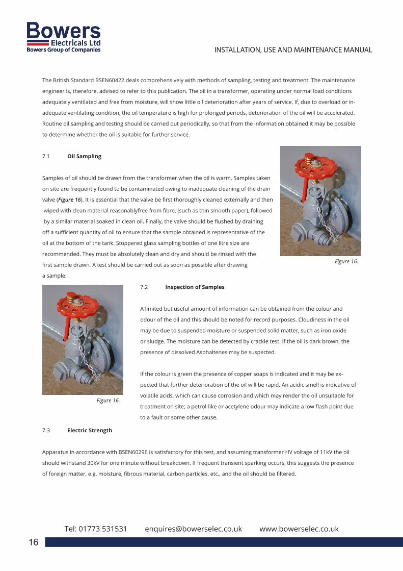
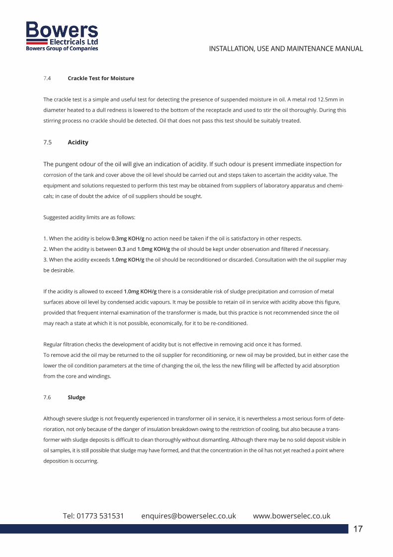
7.1 Oil Sampling
Samples of oil should be drawn from the transformer when the oil is warm. Samples taken
on site are frequently found to be contaminated owing to inadequate cleaning of the drain
valve (Figure 16). It is essential that the valve be first thoroughly cleaned externally and then
wiped with clean material reasonablyfree from fibre, (such as thin smooth paper), followed
by a similar material soaked in clean oil. Finally, the valve should be flushed by draining
off a sufficient quantity of oil to ensure that the sample obtained is representative of the
oil at the bottom of the tank. Stoppered glass sampling bottles of one litre size are
recommended. They must be absolutely clean and dry and should be rinsed with the
first sample drawn. A test should be carried out as soon as possible after drawing
a sample.
Figure 16.
Figure 16.
7.2 Inspection of Samples
A limited but useful amount of information can be obtained from the colour and
odour of the oil and this should be noted for record purposes. Cloudiness in the oil
may be due to suspended moisture or suspended solid matter, such as iron oxide
or sludge. The moisture can be detected by crackle test. If the oil is dark brown, the
presence of dissolved Asphaltenes may be suspected.
If the colour is green the presence of copper soaps is indicated and it may be ex-
pected that further deterioration of the oil will be rapid. An acidic smell is indicative of
volatile acids, which can cause corrosion and which may render the oil unsuitable for
treatment on site; a petrol-like or acetylene odour may indicate a low flash point due
to a fault or some other cause.
7.3 Electric Strength
Apparatus in accordance with BSEN60296 is satisfactory for this test, and assuming transformer HV voltage of 11kV the oil
should withstand 30kV for one minute without breakdown. If frequent transient sparking occurs, this suggests the presence
of foreign matter, e.g. moisture, fibrous material, carbon particles, etc., and the oil should be filtered.
3
INSTALLATION, USE AND MAINTENANCE MANUALEN
APPENDIX
1.0 – REFERENCE STANDARDS2.0 – RATING PLATE3.0 – LIST OF COMPONENTS AND ACCESSORIES4.0 – IMPORTANT NOTICE5.0 – RECEIVING, HANDLING AND STORING
5.1 – RECEIVING5.2 – HANDLING5.3 – STORAGE
6.0 – INSTALLATION6.1 – SITE PREPARATION6.2 – STANDARD INSTALLATION CONDITIONS6.3 – WORKING TEMPERATURE6.4 – VENTILATION
6.4.1 – NATURAL / FORCED VENTILATION OF THE INSTALLATION ROOM 6.4.2 – FORCED VENTILATION OF THE TRANSFORMER
6.5 – INSULATION DISTANCES6.6 – SAFETY DISTANCE6.7 – TIGHTENING TORQUE FOR ELECTRICAL & MECHNICAL
CONNECTIONS6.8 – VISUAL INSPECTION
Bowers Electricals Ltd, Heanor Gate Road, Heanor, Derbyshire DE75 7GXTelephone: 01773 531531 (24 hours) Fax: 01773 716171
E-mail: [email protected]
CAST RESIN TRANSFORMER:Installation, Operation &
Maintenance Manual
Tel: 01773 531531 [email protected] www.bowerselec.co.uk Tel: 01773 531531 [email protected] www.bowerselec.co.uk
17
7.4 Crackle Test for Moisture
The crackle test is a simple and useful test for detecting the presence of suspended moisture in oil. A metal rod 12.5mm in
diameter heated to a dull redness is lowered to the bottom of the receptacle and used to stir the oil thoroughly. During this
stirring process no crackle should be detected. Oil that does not pass this test should be suitably treated.
7.5 Acidity
The pungent odour of the oil will give an indication of acidity. If such odour is present immediate inspection for
corrosion of the tank and cover above the oil level should be carried out and steps taken to ascertain the acidity value. The
equipment and solutions requested to perform this test may be obtained from suppliers of laboratory apparatus and chemi-
cals; in case of doubt the advice of oil suppliers should be sought.
Suggested acidity limits are as follows:
1. When the acidity is below 0.3mg KOH/g no action need be taken if the oil is satisfactory in other respects.
2. When the acidity is between 0.3 and 1.0mg KOH/g the oil should be kept under observation and filtered if necessary.
3. When the acidity exceeds 1.0mg KOH/g the oil should be reconditioned or discarded. Consultation with the oil supplier may
be desirable.
If the acidity is allowed to exceed 1.0mg KOH/g there is a considerable risk of sludge precipitation and corrosion of metal
surfaces above oil level by condensed acidic vapours. It may be possible to retain oil in service with acidity above this figure,
provided that frequent internal examination of the transformer is made, but this practice is not recommended since the oil
may reach a state at which it is not possible, economically, for it to be re-conditioned.
Regular filtration checks the development of acidity but is not effective in removing acid once it has formed.
To remove acid the oil may be returned to the oil supplier for reconditioning, or new oil may be provided, but in either case the
lower the oil condition parameters at the time of changing the oil, the less the new filling will be affected by acid absorption
from the core and windings.
7.6 Sludge
Although severe sludge is not frequently experienced in transformer oil in service, it is nevertheless a most serious form of dete-
rioration, not only because of the danger of insulation breakdown owing to the restriction of cooling, but also because a trans-
former with sludge deposits is difficult to clean thoroughly without dismantling. Although there may be no solid deposit visible in
oil samples, it is still possible that sludge may have formed, and that the concentration in the oil has not yet reached a point where
deposition is occurring.
When comparison of records as suggested under “Recording of Results” indicates the presence of precipitated sludge it may be
necessary, even though the acidity may be within the prescribed limit, to consider applying treatment or changing the oil. When
sludge is allowed to accumulate, the oil circulating ducts become choked which results in higher core and winding temperatures with
consequent formation of still more sludge, the action being cumulative.
7.7 Flash-Point (closed)
Flash-point tests should be made if the oil has been subjected to a high temperature due to an internal fault, or shows any sign of
unusual odour, but they are not otherwise necessary. A slow fall of the flash point of oil in a transformer may occur with increas-
ing age and is not harmful.
A fall exceeding 16.5oc or a flash-point below 135oc may indicate unsatisfactory conditions such as electrical discharge,
excessively high internal temperature, core faults or foreign matter providing a conducting path between live parts and the
frame of the transformer, in which case the unit should be taken out of service for examination.
7.8 Frequency of Testing
Oil in transformer tanks should be inspected annually and, where possible, tested for physicals and dissolved gas analy-
sis. The acidity of the oil should be determined every two years. In special cases, where severe operating conditions are
encountered, or it is known that the oil or windings are deteriorating at an abnormal rate, tests may be desirable at monthly
intervals to verify the rate of deterioration.
7.9 Recording the Results
It is essential to keep records of all tests. The acidity should be plotted on a graph with time as the base and the records
should include relevant operating data such as maximum loads and maximum oil temperatures.
3
INSTALLATION, USE AND MAINTENANCE MANUALEN
APPENDIX
1.0 – REFERENCE STANDARDS2.0 – RATING PLATE3.0 – LIST OF COMPONENTS AND ACCESSORIES4.0 – IMPORTANT NOTICE5.0 – RECEIVING, HANDLING AND STORING
5.1 – RECEIVING5.2 – HANDLING5.3 – STORAGE
6.0 – INSTALLATION6.1 – SITE PREPARATION6.2 – STANDARD INSTALLATION CONDITIONS6.3 – WORKING TEMPERATURE6.4 – VENTILATION
6.4.1 – NATURAL / FORCED VENTILATION OF THE INSTALLATION ROOM 6.4.2 – FORCED VENTILATION OF THE TRANSFORMER
6.5 – INSULATION DISTANCES6.6 – SAFETY DISTANCE6.7 – TIGHTENING TORQUE FOR ELECTRICAL & MECHNICAL
CONNECTIONS6.8 – VISUAL INSPECTION
Bowers Electricals Ltd, Heanor Gate Road, Heanor, Derbyshire DE75 7GXTelephone: 01773 531531 (24 hours) Fax: 01773 716171
E-mail: [email protected]
CAST RESIN TRANSFORMER:Installation, Operation &
Maintenance Manual
Tel: 01773 531531 [email protected] www.bowerselec.co.uk
18
8.0 - TRANSFORMER DE-COMMISSIONING
8.1 Electrical Supply
Ensure ALL Electrical supplies are dead and ALL cable connections (including Auxiliary wiring) are removed from the Trans-
former in question. Refer to HSG 85 Electricity at Work, Safe Working Practices” available from the HSE.”
8.2 Dehydrating Breather
Remove the Transformer Breather (if fitted) and blank off the breather pipe with a fixed oil tight plug (Figure 17). This is
required to ensure that NO spillages occur during transport.
3
INSTALLATION, USE AND MAINTENANCE MANUALEN
APPENDIX
1.0 – REFERENCE STANDARDS2.0 – RATING PLATE3.0 – LIST OF COMPONENTS AND ACCESSORIES4.0 – IMPORTANT NOTICE5.0 – RECEIVING, HANDLING AND STORING
5.1 – RECEIVING5.2 – HANDLING5.3 – STORAGE
6.0 – INSTALLATION6.1 – SITE PREPARATION6.2 – STANDARD INSTALLATION CONDITIONS6.3 – WORKING TEMPERATURE6.4 – VENTILATION
6.4.1 – NATURAL / FORCED VENTILATION OF THE INSTALLATION ROOM 6.4.2 – FORCED VENTILATION OF THE TRANSFORMER
6.5 – INSULATION DISTANCES6.6 – SAFETY DISTANCE6.7 – TIGHTENING TORQUE FOR ELECTRICAL & MECHNICAL
CONNECTIONS6.8 – VISUAL INSPECTION
Bowers Electricals Ltd, Heanor Gate Road, Heanor, Derbyshire DE75 7GXTelephone: 01773 531531 (24 hours) Fax: 01773 716171
E-mail: [email protected]
CAST RESIN TRANSFORMER:Installation, Operation &
Maintenance Manual
Tel: 01773 531531 [email protected] www.bowerselec.co.uk
19
8.3 Item Security
Check round the Transformer and ensure ALL items are securely attached and NO loose items can fall off the transformer in
transit.
8.4 Lifting Points
Ensure ALL lifting points are sound and NO obstacles will hinder the lift.
8.5 Waste Permits
If the unit is to be removed to a waste treatment site, ensure ALL correct permits are in place under a valid Pollution preven-
tion and Control licience or waste management licence. If in doubt contact the Environment Agency.
8.6 Transformer Removal
Remove the transformer (under the correct permits) on to transport for forward shipment to the waste treatment site.
8.7 Documentation
Retain the signed copies of the ‘Waste Transfer’ documents for inspection as required by law.
9.0 - WARRANTY & CONTACT DETAILS
All the equipment is covered by warranty, for a time period specified in the agreed contract. The warranty is limited to the repair or replacement of the damaged transformer and / or accessories, excluding transportation. Bowers Electricals Ltd, declines any claims referred to indirect damages caused by any transformer fault.
To report a problem, please contact Bowers Electricals Ltd, providing the following information:
• Serial number of the transformer
• Place of installation and application of the transformer
• Detailed description of the claim, including photographs if possible.
• Your contact details.

Tel: 01773 531531 [email protected] www.bowerselec.co.uk
Installation, Operation & Maintenance Manual
Edition Two: QAF 120-01Printed 04.03.21
01773 531531 I [email protected] I www.bowerselec.co.uk
Distribution Transformers


